H100 Manual
User Manual:
Open the PDF directly: View PDF ![]() .
.
Page Count: 659 [warning: Documents this large are best viewed by clicking the View PDF Link!]

This operation manual is intended for users with basic knowledge of electricity and electric devices.
* LSLV-H100 is the official name for the H100 series inverters.
* The H100 series software may be updated without prior notice for better performance. To check
the latest software, visit our website at http://www.lsis.com.
Safety Information
ii
Safety Information
Read and follow all safety instructions in this manual precisely to avoid unsafe operating
conditions, property damage, personal injury, or death.
Safety symbols in this manual
Indicates an imminently hazardous situation which, if not avoided, will result in severe injury or death.
Indicates a potentially hazardous situation which, if not avoided, could result in injury or death.
Indicates a potentially hazardous
situation that, if not avoided, could result in minor injury or property
damage.
Safety information
• Do not open the cover of the equipment while it is on or operating. Likewise, do not operate the
inverter while the cover is open. Exposure of high voltage terminals or charging area to the
external environment may result in an electric shock. Do not remove any covers or touch the
internal circuit boards (PCBs) or electrical contacts on the product when the power is on or during
operation. Doing so may result in serious injury, death, or serious property damage.
• Do not open the cover of the equipment even when the power supply to the inverter has been
turned off unless it is necessary for maintenance or regular inspection. Opening the cover may
result in an electric shock even when the power supply is off.
• The equipment may hold charge long after the power supply has been turned off. Use a multi-
meter to make sure that there is no voltage before working on the inverter, motor or motor cable.
•
Supply earthing system: TT, TN, not suitable for corner-earthed systems
• This equipment must be grounded for safe and proper operation.
• Do not supply power to a faulty inverter. If you find that the inverter is faulty, disconnect the
power supply and have the inverter professionally repaired.
• The inverter becomes hot during operation. Avoid touching the inverter until it has cooled to
avoid burns.

iii
Safety Information
• Do not allow foreign objects, such as screws, metal chips, debris, water, or oil to get inside the
inverter. Allowing foreign objects inside the inverter may cause the inverter to malfunction or
result in a fire.
•
Do not operate the inverter with wet hands. Doing so may result in electric shock.
• Do not modify the interior workings of the inverter. Doing so will void the warranty.
• The inverter is designed for 3-phase motor operation. Do not use the inverter to operate a single
phase motor.
• Do not place heavy objects on top of electric cables. Doing so may damage the cable and result
in an electric shock.
Note
Maximum allowed prospective short-circuit current at the input power connection is defined in
IEC 60439-1 as 100 kA. LSLV-H100 is suitable for use in a circuit capable of delivering not more
than 100kA RMS at the drive’s maximum rated voltage, depending on the selected MCCB. RMS
symmetrical amperes for recommended MCCB are the following table.
Remarque
Le courant maximum de court-circuit présumé autorisé au connecteur d’alimentation électrique
est défini dans la norme IEC 60439-1 comme égal à 100 kA. Selon le MCCB sélectionné, la série
LSLV-H100 peut être utilisée sur des circuits pouvant fournir un courant RMS symétrique de
100 kA maximum en ampères à la tension nominale maximale du variateur. Le tableau suivant
indique le MCCB recommandé selon le courant RMS symétrique en ampères.
Working
Voltage
UTE100
(E/N)
UTS150
(N/H/L)
UTS250
(N/H/L)
UTS400
(N/H/L)
240V(50/60Hz)
50/65kA
65/100/150kA
65/100/150kA
65/100/150kA
480V(50/60Hz)
25/35kA
35/65/100kA
35/65/100kA
35/65/100kA
Working
Voltage ABS33c
ABS53c ABS63c ABS103c
ABS203c ABS403c
240V(50/60Hz)
30kA 35kA 35kA 85kA 85kA 75kA
480V(50/60Hz)
7.5kA 10kA 10kA 26kA 26kA 35kA

Quick Reference Table
iv
Quick Reference Table
The following table contains situations frequently encountered by users while working with
inverters. Refer to the typical and practical situations in the table to quickly and easily locate
answers to your questions.
Situation
Reference
I want to configure the inverter to start operating as soon as the power source is
applied. p.17
I want to configure the motor’s parameters.
p.
219
Something seems to be wrong with the inverter or the motor.
p.
345
,
p.
566
What is auto tuning?
p.
219
What are the recommended wiring lengths?
p.
40
The motor is too noisy.
p.
250
I want to apply PID control on my system.
p.
163
What are the factory default settings for
P1
–
P7 multi
-
function terminals?
p.
38
I want to view all of the parameters I have modified.
p.
259
I want to review recent fault trip and warning histories.
p.
59
I want to change the inverter’s
operation frequency using a potentiometer.
p.
90
I want to install a frequency meter using an analog terminal.
p.
38
I want to display the supply current to motor.
p.
55
I want to operate the inverter using a multi
-
step speed configuration.
p.
104
The motor runs too hot.
p.
321
The inverter is too hot.
p.
333
The cooling fan does not
work.
p.
574
I want to change the items that are monitored on the keypad.
p.
316
I want to display the supply current to motor.
p.
316

Table of Contents
v
Table of Contens
1
Preparing the Installation ............................................................................................1
1.1
Product Identification .................................................................................................................. 1
1.2
Part Names ......................................................................................................................................... 3
1.3
Installation Considerations ..................................................................................................... 10
1.4
Selecting and Preparing a Site for Installation .............................................................. 11
1.5
Cable Selection ............................................................................................................................. 14
2
Installing the Inverter ................................................................................................ 17
2.1
Mounting the Inverter .............................................................................................................. 19
2.2
Enabling the RTC (Real-Time Clock) Battery .................................................................. 23
2.3
Cable Wiring ................................................................................................................................... 26
2.4
Post-Installation Checklist ....................................................................................................... 48
2.5
Test Run ............................................................................................................................................ 50
3
Perform Basic Operations ......................................................................................... 52
3.1
About the Keypad ....................................................................................................................... 52
3.1.1
Operation Keys ............................................................................................................ 52
3.1.2
About the Display ...................................................................................................... 55
3.1.3
Display Modes ............................................................................................................. 59
3.2
Learning to Use the Keypad................................................................................................... 63
3.2.1
Display Mode Selection .......................................................................................... 63
3.2.2
Operation Modes ....................................................................................................... 64
3.2.3
Switching between Groups in Parameter Display Mode ...................... 66
3.2.4
Switching between Groups in User & Macro Mode ................................. 67
3.2.5
Navigating through the Codes (Functions) .................................................. 68
3.2.6
Navigating Directly to Different Codes ........................................................... 70
3.2.7
Parameter Settings available in Monitor Mode .......................................... 72
3.2.8
Setting the Monitor Display Items .................................................................... 73
3.2.9
Selecting the Status Bar Display Items ............................................................ 75
3.3
Fault Monitoring .......................................................................................................................... 77
3.3.1
Monitoring Faults during Inverter Operation .............................................. 77
3.3.2
Monitoring Multiple Fault Trips........................................................................... 78
3.4
Parameter Initialization ............................................................................................................ 79
4
Learning Basic Features ............................................................................................. 80

Table of Contents
vi
4.1
Switching between the Operation Modes (HAND / AUTO / OFF) ...................... 83
4.2
Setting Frequency Reference ................................................................................................ 88
4.2.1
Keypad as the Source (KeyPad-1 setting) ...................................................... 89
4.2.2
Keypad as the Source (KeyPad-2 setting) ...................................................... 89
4.2.3
V1 Terminal as the Source ...................................................................................... 89
4.2.4
Setting a Frequency Reference with Input Voltage (Terminal I2) ...... 99
4.2.5
Setting a Frequency with TI Pulse Input ....................................................... 100
4.2.6
Setting a Frequency Reference via RS-485 Communication ............. 102
4.3
Frequency Hold by Analog Input ...................................................................................... 103
4.4
Changing the Displayed Units (Hz↔Rpm) .................................................................. 104
4.5
Setting Multi-step Frequency ............................................................................................. 104
4.6
Command Source Configuration ...................................................................................... 106
4.6.1
The Keypad as a Command Input Device ................................................... 106
4.6.2
Terminal Block as a Command Input Device (Fwd/Rev run
commands) ............................................................................................................... 107
4.6.3
Terminal Block as a Command Input Device (Run and Rotation
Direction Commands).......................................................................................... 108
4.6.4
RS-485 Communication as a Command Input Device ......................... 109
4.7
Forward or Reverse Run Prevention ................................................................................ 110
4.8
Power-on Run .............................................................................................................................. 111
4.9
Reset and Restart ....................................................................................................................... 113
4.10
Setting Acceleration and Deceleration Times ............................................................ 114
4.10.1
Acc/Dec Time Based on Maximum Frequency ......................................... 114
4.10.2
Acc/Dec Time Based on Operation Frequency ......................................... 117
4.10.3
Multi-step Acc/Dec Time Configuration ....................................................... 118
4.10.4
Configuring Acc/Dec Time Switch Frequency .......................................... 120
4.11
Acc/Dec Pattern Configuration .......................................................................................... 121
4.12
Stopping the Acc/Dec Operation ..................................................................................... 124
4.13
V/F (Voltage/Frequency) Control ...................................................................................... 125
4.13.1
Linear V/F Pattern Operation.............................................................................. 125
4.13.2
Square Reduction V/FPattern Operation ..................................................... 126
4.13.3
User V/F Pattern Operation ................................................................................. 127
4.14
Torque Boost ................................................................................................................................ 129
4.14.1
Manual Torque Boost ............................................................................................. 129
4.14.2
Auto Torque Boost ................................................................................................... 130
4.14.3
Auto Torque Boost 2 (No Motor Parameter Tuning Required) .......... 130
4.15
Output Voltage Setting .......................................................................................................... 131

Table of Contents
vii
4.16
Start Mode Setting.................................................................................................................... 132
4.16.1
Acceleration Start ..................................................................................................... 132
4.16.2
Start After DC Braking ............................................................................................ 132
4.17
Stop Mode Setting .................................................................................................................... 133
4.17.1
Deceleration Stop .................................................................................................... 133
4.17.2
Stop After DC Braking ............................................................................................ 134
4.17.3
Free Run Stop ............................................................................................................. 135
4.17.4
Power Braking ............................................................................................................ 136
4.18
Frequency Limit ......................................................................................................................... 137
4.18.1
Frequency Limit Using Maximum Frequency and Start Frequency
.......................................................................................................................................... 137
4.18.2
Frequency Limit Using Upper and Lower Limit Frequency Values 137
4.18.3
Frequency Jump ....................................................................................................... 140
4.19
2
nd
Operation Mode Setting................................................................................................. 141
4.20
Multi-function Input Terminal Control ........................................................................... 142
4.21
Multi-function Input Terminal On/Off Delay Control .............................................. 144
5
Learning Advanced Features .................................................................................. 145
5.1
Operating with Auxiliary References ............................................................................... 147
5.2
Jog Operation.............................................................................................................................. 153
5.2.1
Jog Operation 1-Forward Jog by Multi-function Terminal ................. 153
5.2.2
Jog Operation 2-Forward/Reverse Jog by Multi-function Terminal
.......................................................................................................................................... 154
5.3
Up-down Operation ................................................................................................................ 155
5.4
3- Wire Operation ...................................................................................................................... 157
5.5
Safe Operation Mode .............................................................................................................. 158
5.6
Dwell Operation ......................................................................................................................... 160
5.7
Slip Compensation Operation ............................................................................................ 162
5.8
PID Control .................................................................................................................................... 163
5.8.1
PID Basic Operation ................................................................................................ 164
5.8.2
Soft Fill Operation .................................................................................................... 179
5.8.3
PID Sleep Mode ......................................................................................................... 181
5.8.4
PID Switching (PID Openloop) .......................................................................... 183
5.9
External PID .................................................................................................................................. 184
5.10
Damper Operation ................................................................................................................... 194
5.11
Lubrication Operation............................................................................................................. 196
5.12
Flow Compensation ................................................................................................................. 197
5.13
Payback Counter ......................................................................... 198

Table of Contents
viii
5.14
Pump Clean Operation ........................................................................................................... 200
5.15
Start & End Ramp Operation ............................................................................................... 204
5.16
Decelerating Valve Ramping ............................................................................................... 206
5.17
Load Tuning .................................................................................................................................. 207
5.18
Level Detection........................................................................................................................... 209
5.19
Pipe Break Detection ............................................................................................................... 213
5.20
Pre-heating Function ............................................................................................................... 216
5.21
Auto Tuning .................................................................................................................................. 219
5.22
Time Event Scheduling ........................................................................................................... 222
5.23
Kinetic Energy Buffering ........................................................................................................ 237
5.24
Anti-hunting Regulation (Resonance Prevention) ................................................... 239
5.25
Fire Mode Operation................................................................................................................ 240
5.26
Energy Saving Operation ...................................................................................................... 242
5.26.1
Manual Energy Saving Operation ................................................................... 242
5.26.2
Automatic Energy Saving Operation ............................................................. 242
5.27
Speed Search Operation ........................................................................................................ 243
5.28
Auto Restart Settings ............................................................................................................... 248
5.29
Operational Noise Settings (Carrier Frequency Settings) ..................................... 250
5.30
2
nd
Motor Operation ................................................................................................................. 251
5.31
Supply Power Transition ........................................................................................................ 253
5.32
Cooling Fan Control ................................................................................................................. 254
5.33
Input Power Frequency and Voltage Settings ............................................................ 255
5.34
Read, Write, and Save Parameters ..................................................................................... 256
5.35
Parameter Initialization .......................................................................................................... 257
5.36
Parameter View Lock ............................................................................................................... 258
5.37
Parameter Lock ........................................................................................................................... 258
5.38
Changed Parameter Display ................................................................................................ 259
5.39
User Group .................................................................................................................................... 260
5.40
Easy Start On ................................................................................................................................ 261
5.41
Config (CNF) Mode ................................................................................................................... 263
5.42
Macro Selection.......................................................................................................................... 264
5.43
Timer Settings ............................................................................................................................. 265
5.44
Multiple Motor Control (MMC) ........................................................................................... 266
5.44.1
Multiple Motor Control (MMC) Basic Sequence ....................................... 274
5.44.2
Standby Motor .......................................................................................................... 279

Table of Contents
ix
5.44.3
Auto Change .............................................................................................................. 280
5.44.4
Interlock ........................................................................................................................ 286
5.44.5
Aux Motor Time Change ...................................................................................... 290
5.44.6
Regular Bypass .......................................................................................................... 291
5.44.7
Aux Motor PID Compensation .......................................................................... 292
5.44.8
Master Follower......................................................................................................... 294
5.45
Multi-function Output On/Off Control ........................................................................... 300
5.46
Press Regeneration Prevention .......................................................................................... 301
5.47
Analog Output ............................................................................................................................ 303
5.47.1
Voltage and Current Analog Output .............................................................. 303
5.47.2
Analog Pulse Output .............................................................................................. 306
5.48
Digital Output ............................................................................................................................. 309
5.48.1
Multi-function Output Terminal and Relay Settings .............................. 309
5.48.2
Fault Trip Output using Multi-function Output Terminal and Relay
............. 314
5.48.3
Multi-function Output Terminal Delay Time Settings ........................... 315
5.49
Operation State Monitor........................................................................................................ 316
5.50
Operation Time Monitor ........................................................................................................ 318
5.51
PowerOn Resume Using the Communication ........................................................... 319
6
Learning Protection Features ................................................................................. 321
6.1
Motor Protection ....................................................................................................................... 321
6.1.1
Electronic Thermal Motor Overheating Prevention (ETH) .................. 321
6.1.2
Motor Over Heat Sensor ....................................................................................... 323
6.1.3
Overload Early Warning and Trip ..................................................................... 325
6.1.4
Stall Prevention and Flux Braking .................................................................... 327
6.2
Inverter and Sequence Protection ................................................................................... 331
6.2.1
Open-phase Protection ........................................................................................ 331
6.2.2
External Trip Signal .................................................................................................. 332
6.2.3
Inverter Overload Protection (IOLT) ............................................................... 333
6.2.4
Speed Command Loss .......................................................................................... 334
6.2.5
Dynamic Braking (DB) Resistor Configuration .......................................... 338
6.2.6
Low Battery Voltage Warning ............................................................................ 339
6.3
Under load Fault Trip and Warning .................................................................................. 340
6.3.1
Fan Fault Detection ................................................................................................. 341
6.3.2
Low Voltage Fault Trip ............................................................................................ 342
6.3.3
Selecting Low Voltage 2 Fault During Operation .................................... 342
6.3.4
Output Block via the Multi-function Terminal ........................................... 343
6.3.5
Trip Status Reset........................................................................................................ 343

Table of Contents
x
6.3.6
Operation Mode for Option Card Trip ........................................................... 344
6.3.7
No Motor Trip ............................................................................................................. 345
6.3.8
Broken Belt .................................................................................................................. 346
6.4
Parts Life Expectancy ............................................................................................................... 347
6.4.1
Main Capacitor Life Estimation ......................................................................... 347
6.4.2
Fan Life Estimation .................................................................................................. 349
6.5
Fault/Warning List ..................................................................................................................... 351
7
RS-485 Communication Features .......................................................................... 354
7.1
Communication Standards .................................................................................................. 354
7.2
Communication System Configuration ......................................................................... 355
7.2.1
Communication Line Connection ................................................................... 355
7.2.2
Setting Communication Parameters ............................................................. 357
7.2.3
Setting Operation Command and Frequency .......................................... 359
7.2.4
Command Loss Protective Operation ........................................................... 359
7.3
LS INV 485/Modbus-RTU Communication .................................................................. 362
7.3.1
Setting Virtual Multi-function Input ............................................................... 362
7.3.2
Saving Parameters Defined by Communication ..................................... 362
7.3.3
Total Memory Map for Communication ...................................................... 364
7.3.4
Parameter Group for Data Transmission ...................................................... 365
7.3.5
Parameter Group for User/Macro Group ..................................................... 366
7.3.6
LS INV 485 Protocol ................................................................................................. 367
7.3.7
Modbus-RTU Protocol ........................................................................................... 373
7.3.8
Compatible Common Area Parameter ......................................................... 378
7.3.9
H100 Expansion Common Area Parameter ............................................... 382
7.4
BACnet Communication ........................................................................................................ 398
7.4.1
What is BACnet Communication? ................................................................... 398
7.4.2
BACnet Communication Standards ............................................................... 398
7.4.3
BACnet Quick Communication Start ............................................................. 398
7.4.4
Protocol Implementation .................................................................................... 401
7.4.5
Object Map .................................................................................................................. 401
7.5
Metasys-N2 Communication .............................................................................................. 410
7.5.1
Metasys-N2 Quick Communication Start .................................................... 410
7.5.2
Metasys-N2 Communication Standard ........................................................ 410
7.5.3
Metasys-N2 Protocol I/O Point Map ............................................................... 411
8
Table of Functions .................................................................................................... 415
8.1
Drive Group (DRV) .................................................................................................................... 415
8.2
......................................................................
Basic Function Group (BAS)

Table of Contents
xi
420
8.3
Expanded Function Group (ADV) ..................................................................................... 427
8.4
Control Function Group (CON) ........................................................................................... 433
8.5
Input Terminal Group (IN) ..................................................................................................... 436
8.6
Output Terminal Block Function Group (OUT) ........................................................... 445
8.7
Communication Function Group (COM) ....................................................................... 451
8.8
Advanced Function Group(PID Functions) .................................................................. 458
8.9
EPID Function Group (EPID) ................................................................................................. 470
8.10
Application 1 Function Group (AP1) ................................................................................ 477
8.11
Application 2 Function Group (AP2) ................................................................................ 483
8.12
Application 3 Function Group (AP3) ................................................................................ 489
8.13
Protection Function Group (PRT) ...................................................................................... 496
8.14
2nd Motor Function Group (M2) ....................................................................................... 506
8.15
Trip (TRIP Last-x) and Config (CNF) Mode ..................................................................... 510
8.15.1
Trip Mode (TRP Last-x) ........................................................................................... 510
8.15.2
Config Mode (CNF) .................................................................................................. 511
8.16
Macro Groups .............................................................................................................................. 516
8.16.1
Compressor (MC1) Group .................................................................................... 516
8.16.2
Supply Fan (MC2) Group ...................................................................................... 519
8.16.3
Exhaust Fan (MC3) Group .................................................................................... 521
8.16.4
Cooling Tower (MC4) Group ............................................................................... 542
8.16.5
Circululation Pump (MC5) Group .................................................................... 545
8.16.6
Vacuum Pump (MC6) Group .............................................................................. 549
8.16.7
Constant Torque (MC7) Group .......................................................................... 558
9
Troubleshooting ....................................................................................................... 561
9.1
Trip and Warning ....................................................................................................................... 561
9.1.1
Fault Trips ..................................................................................................................... 561
9.1.2
Warning Message .................................................................................................... 565
9.2
Troubleshooting Fault Trips ................................................................................................. 566
9.3
Troubleshooting Other Faults ............................................................................................. 569
10
Maintenance .............................................................................................................. 576
10.1
Regular Inspection Lists ......................................................................................................... 576
10.1.1
Daily Inspection ........................................................................................................ 576
10.1.2
Annual Inspection ................................................................................................... 577
10.1.3
Bi-annual Inspection .............................................................................................. 579
10.2
Real Time Clock (RTC) Battery Replacement ............................................................... 580

Table of Contents
xii
10.3
Storage and Disposal ............................................................................................................... 584
10.3.1
Storage .......................................................................................................................... 584
10.3.2
Disposal ......................................................................................................................... 584
11
Technical Specification ............................................................................................ 585
11.1
Input and Output Specifications ....................................................................................... 585
11.2
Product Specification Details .............................................................................................. 591
11.3
External Dimensions ............................................................................................................. 595
11.4
Peripheral Devices .................................................................................................................... 600
11.5
Fuse and Reactors Specifications ...................................................................................... 603
11.6
Terminal Screw Specifications ............................................................................................ 604
11.7
Dynamic breaking unit (DBU) and Resistors ............................................................... 606
11.7.1
Dynamic breaking unit (DBU) ............................................................................ 606
11.7.2
Terminal arrangement ........................................................................................... 608
11.7.3
Dynamic Breaking (DB)Unit & DB resistor basic wiring ........................ 612
11.7.4
Dimensions ................................................................................................................. 613
11.7.5
Display Functions ..................................................................................................... 616
11.7.6
DB Resistors ................................................................................................................. 616
11.8
Inverter Continuous Rated Current Derating ............................................................. 618
12
Applying Drives to Single-phase Input Application .......................................... 622
12.1
Introduction ................................................................................................................................. 622
12.2
Power(HP), Input Current and Output Current .......................................................... 623
12.3
Input Frequency and Voltage Tolerance ........................................................................ 624
12.4
Wiring .............................................................................................................................................. 625
12.5
Precautions for 1–phase input to 3-phase drive ....................................................... 625
Product Warranty ............................................................................................................. 626
UL mark .............................................................................................................................. 628
EAC mark ............................................................................................................................ 628
Index ................................................................................................................................... 633

Preparing
the Installation
1
1 Preparing the Installation
This chapter provides details on product identification, part names, correct installation and cable
specifications. To install the inverter correctly and safely, carefully read and follow the instructions.
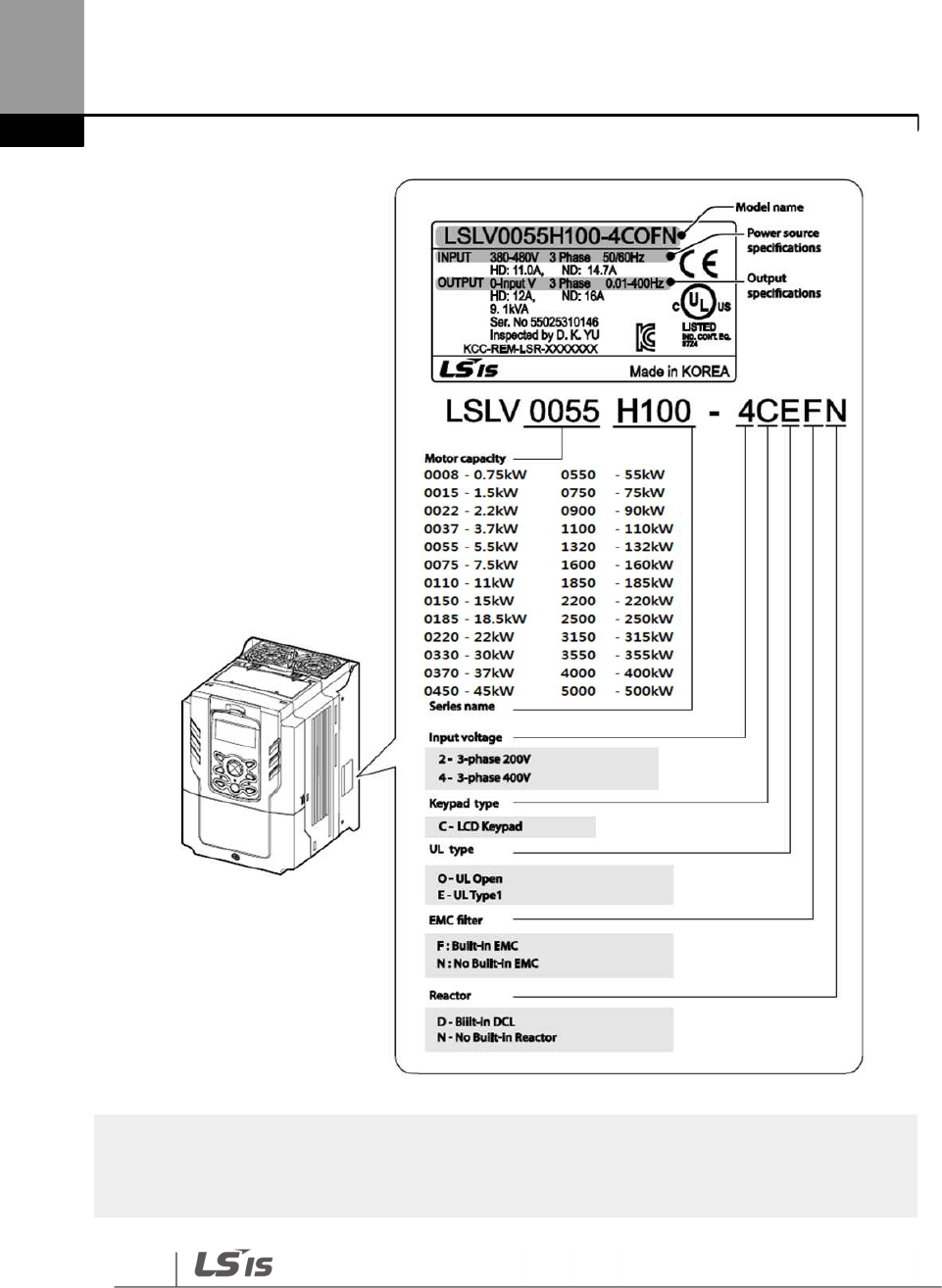
1.1 Product Identification
The H100 Inverter is manufactured in a range of product groups based on drive capacity and
power source specifications. Product name and specifications are detailed on the rating plate.
Check the rating plate before installing the product and make sure that the product meets your
requirements. For more detailed product specifications, refer to 11.1 Input and Output
Specifications on page 585.
Note
Check the product name, open the packaging, and then confirm that the product
is free from defects.
Contact your supplier if you have any issues or questions about your product.
Preparing the Installation
2
Note
The H100 75/90 kW, 400 V inverters satisfy the EMC standard EN61800
-
3 without installation of
optional EMC filters.
Preparing
the Installation
3
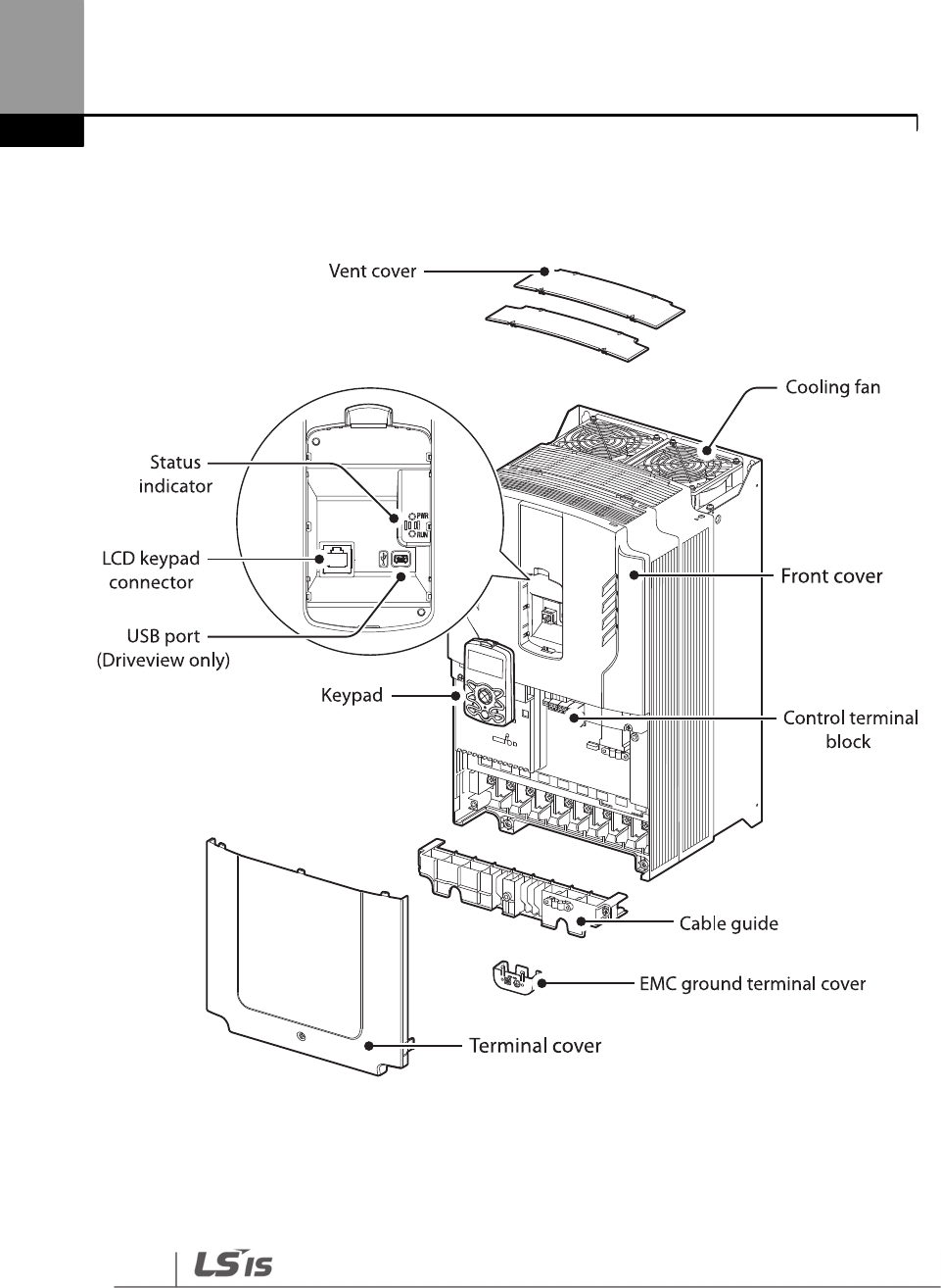
1.2 Part Names
The illustration below displays part names. Details may vary between product groups.
0.75–30 kW (3-Phase)
Preparing the Installation
4
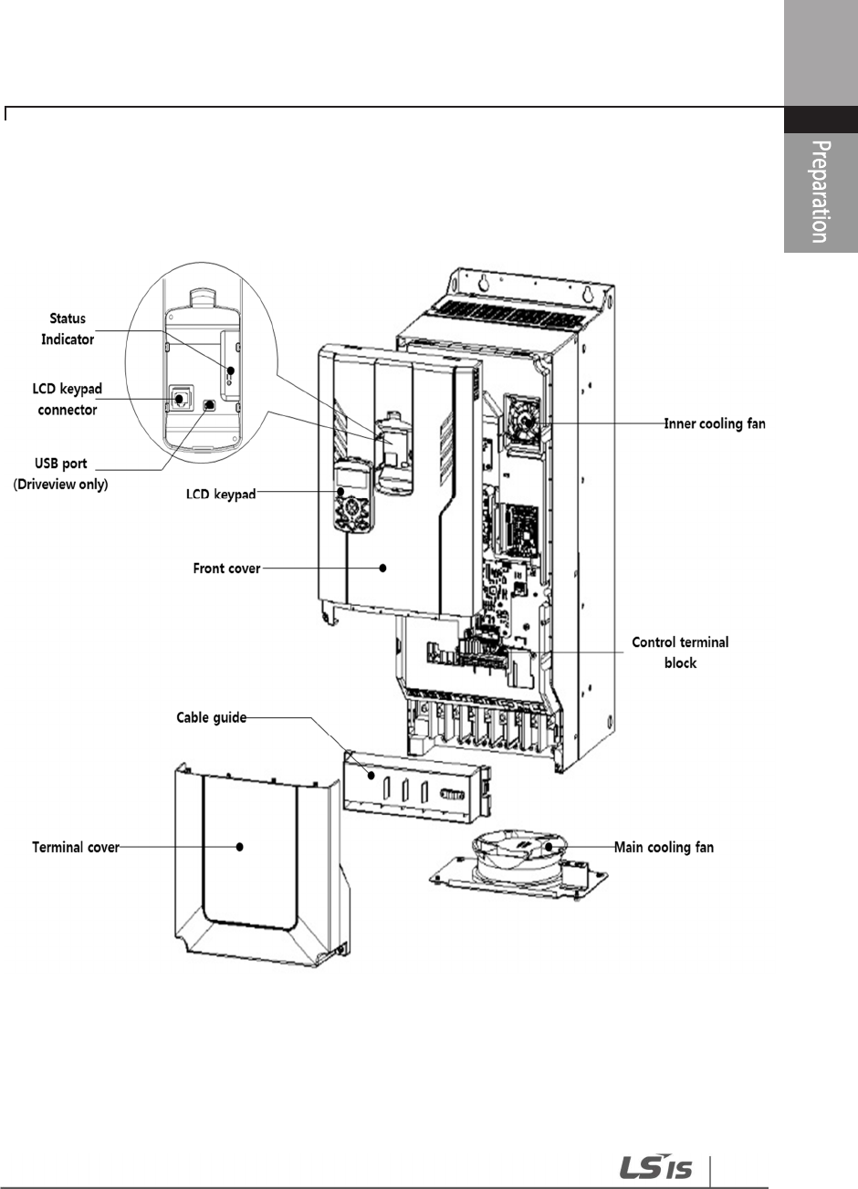
37–90 kW (3-Phase)
Preparing
the Installation
5
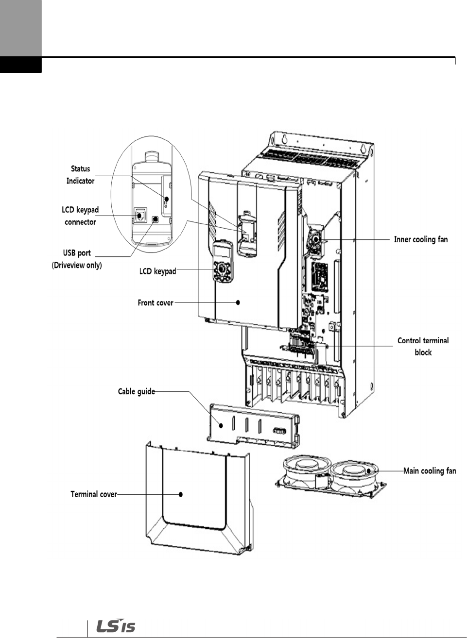
110–132 kW (3-Phase)
Preparing the Installation
6
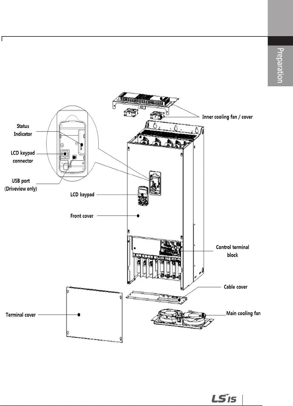
160–185 kW (3-Phase)
Preparing
the Installation
7
220–250 kW (3-Phase)
Preparing the Installation
8
315–400 kW (3-Phase)
Preparing
the Installation
9
500 kW (3-Phase)
Preparing the Installation
10
1.3 Installation Considerations
Inverters are composed of various precision, electronic devices, and therefore the installation
environment can significantly impact the lifespan and reliability of the product. The table below
details the ideal operation and installation conditions for the inverter.
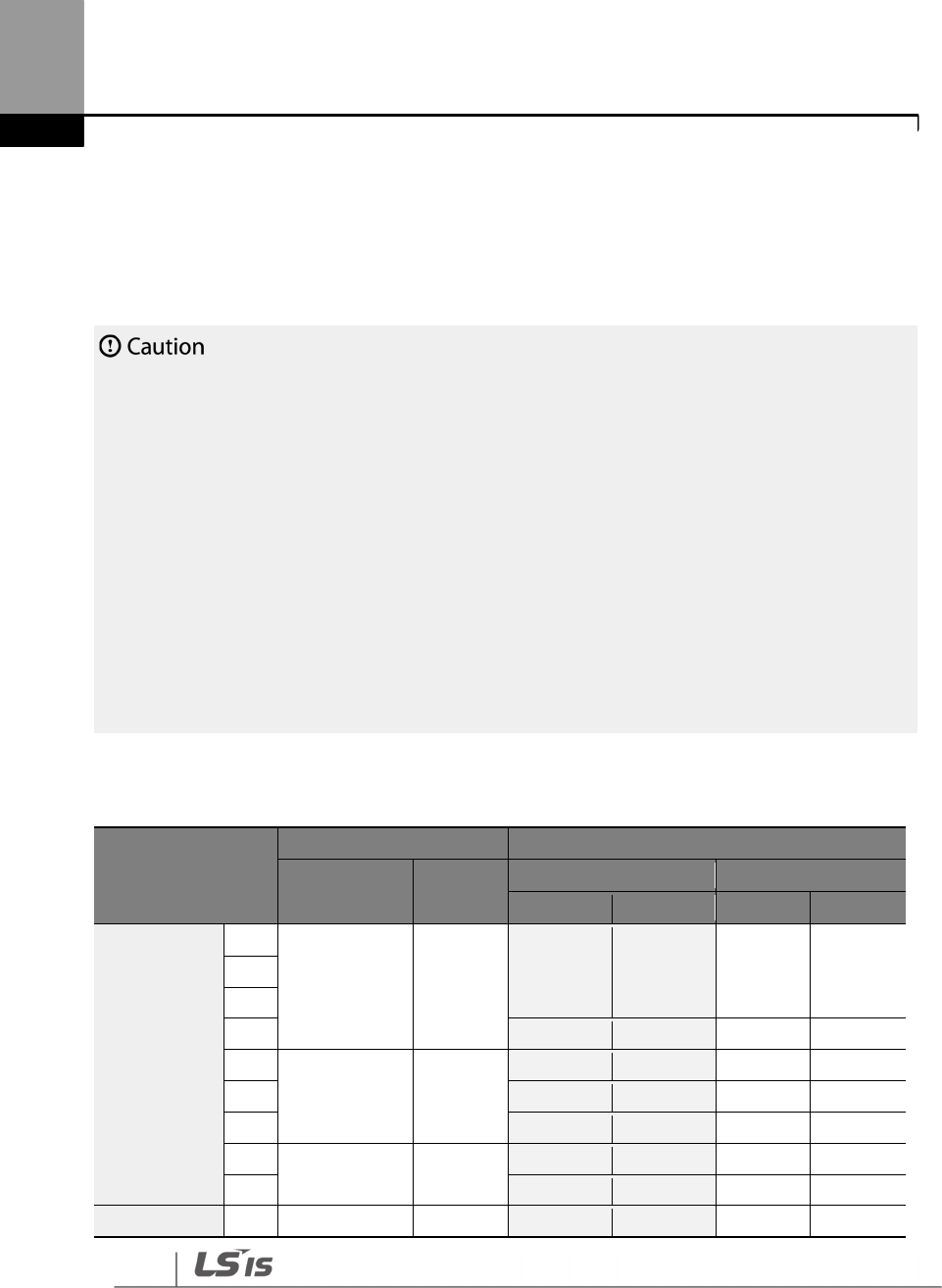
Items
Description
Ambient Temperature* -10 ℃–50 ℃ (40 ℃ and above, 2.5% / ℃ Current Derating search.
50 ℃ 75% of the rated current of the drive if possible)
Ambient Humidity
9
5
% relative humidity (no condensation)
Storage Temperature - 4–149 °F (-20–65 ℃)
Environmental Factors
An environment free from corrosive or flammable gases, oil residue or
dust
Altitude
Maximum 3,280 ft (1,000m) above sea
level for standard operation.
After that the driver rated voltage and the rated output current derating
by 1% for every extra 328 ft (100m) up to 13,123 ft (4,000m).
Vibration
less than
1.0
G (
9.8
m/sec
2
)
Air Pressure
70
–
106 kPa
* The ambient temperature is the temperature measured at a point 2” (5 cm) from the surface of
the inverter.
Do not allow the ambient temperature to exceed the allowable range while
operating the inverter.
Preparing
the Installation
11
1.4 Selecting and Preparing a Site for Installation
When selecting an installation location consider the following points:
• The inverter must be installed on a wall that can support the inverter’s weight.
• The location must be free from vibration. Vibration can adversely affect the operation of the
inverter.
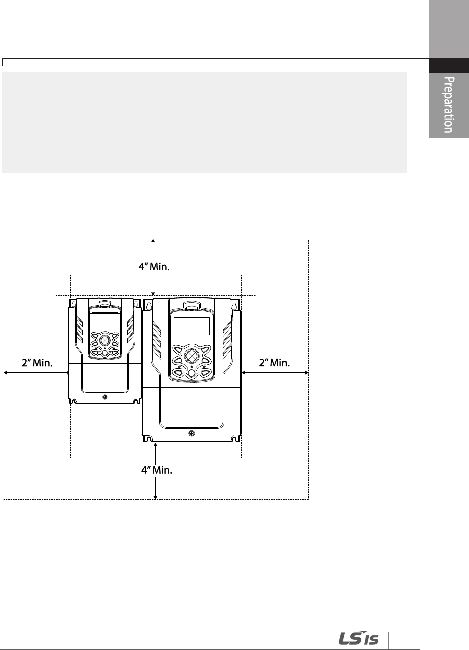
• The inverter can become very hot during operation. Install the inverter on a surface that is
fire-resistant or flame-retardant and with sufficient clearance around the inverter to allow air
to circulate. The illustrations below detail the required installation clearances.
Preparing the Installation
12
• Ensure sufficient air circulation is provided around the inverter when it is installed. If the
inverter is to be installed inside a panel, enclosure, or cabinet rack, carefully consider the
position of the inverter’s cooling fan and the ventilation louver. The cooling fan must be
positioned to efficiently transfer the heat generated by the operation of the inverter.
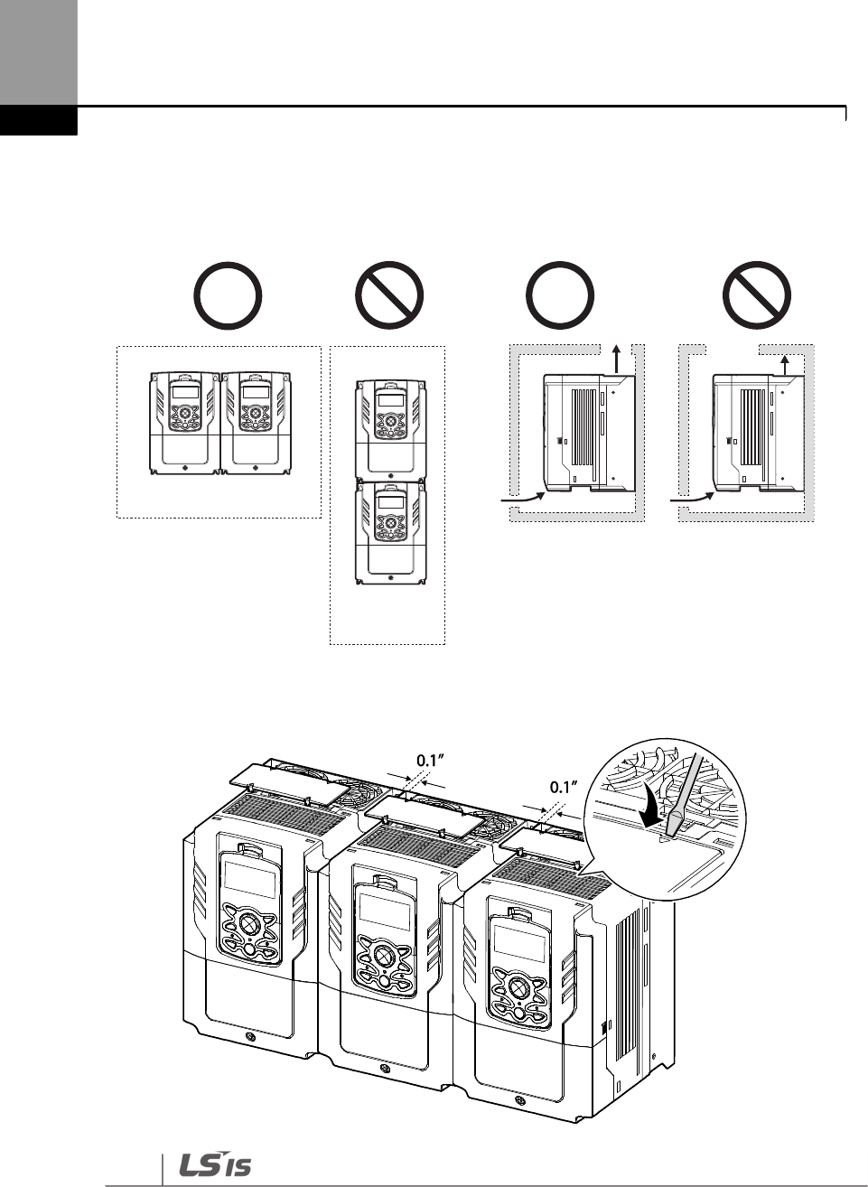
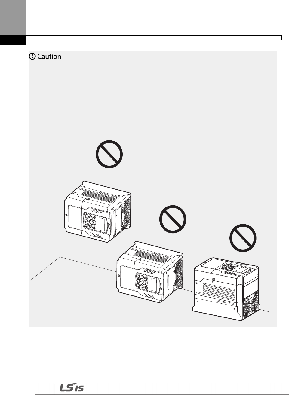
• If you are installing multiple inverters in one location, arrange them side-by-side and remove
the vent covers. Use a flat head screwdriver to remove the vent covers. Only the H100
inverters rated for up to 30 kW may be installed side-by-side.
Preparing
the Installation
13
Note
• The vent covers must be removed for side-by-side installations.
• Side-by-side installation cannot be used for the H100 inverters rated for 37 kW and above.
• For the H100 inverters rated for 37 kW and above, if the installation site satisfies the UL Open
Type requirements and there is no danger of foreign objects getting inside the inverter and
causing trouble, the vent cover may be removed to improve cooling efficiency.
• If you are installing multiple inverters of different ratings, provide sufficient clearance to meet
the clearance specifications of the larger inverter.The H100 inverters rated for up to 30 kW
may be installed side-by-side.
Preparing the Installation
14
1.5 Cable Selection
When you install power and signal cables in the terminal blocks, only use cables that meet the
required specification for the safe and reliable operation of the product. Refer to the following
information to assist you with cable selection.
• Wherever possible use cables with the largest cross-sectional area for mains power wiring, to
ensure that voltage drop does not exceed 2%.
• Use copper cables rated for 600 V, 75 ℃ for power terminal wiring.
• Use copper cables rated for 300 V, 75 ℃ for control terminal wiring.
• The inverters in the range between 15 and 90 kW must be grounded conveniently with fixed
connections.
• The inverters in the range between 5,5kW and 11kW must be grounded with and industrial
connector according to IEC 60309.
• The minimum size of the protective earthing conductor shall comply with the local safety
regulations for high protective earthing conductor current equipment.
•
Only one conductor per terminal should be simultaneously connected
Ground Cable and Power Cable Specifications
Load (kW)
Ground Wire
Input/Output Power Wire
mm
2
AWG
mm
2
AWG
R/S/T
U/V/W
R/S/T
U/V/W
3-Phase 200 V
0.75
3.5 12 1.5 1.5 16 16
1.5
2.2
3.7
2.5
2.5
14
14
5.5
10 10
4
4
12
12
7.5
6
6
10
10
11
10
10
8
8
15
14 6
16
16
6
6
18.5
25
22
4
4
3
-
Phase 400 V
0.75
2
14
1.5
1.5
16
16
Preparing
the Installation
15
Load (kW)
Ground Wire
Input/Output Power Wire
mm
2
AWG
mm
2
AWG
R/S/T
U/V/W
R/S/T
U/V/W
1.5
2.2
3.7
5.5
4 12
2.5
2.5
14
14
7.5
4
2.5
12
14
11
4
4
12
12
15
16 9
6
6
10
10
18.5
16
10
6
8
22
14 6
16
10
6
8
30
25
16
4
6
37
25 4
25
25
4
4
45
25
25
4
4
55
50
50
1/0
1/0
75
38 2
70
70
1/0
1/0
90
70
70
1/0
1/0
110
50X2 1X2
70X2
70X2
-
-
132
95X2
95X2
-
-
160
50X2
70X2 1/0 x2 95X2 95X2 - -
185
70x2
95x2 3/0 x2 120X2 120X2 - -
220
95x2
250x2
150X2
150X2
-
-
250
300 x2
185X2
185X2
-
-
315
60X4
150X2 2/0 x4,
120
X4,
400X2
120
X4,
400X2 - -
355
70X4
150X2 3/0 x4
120X4,
400X2
120X4,
400X2 - -
400
95X4
200X2 4/0 x4
120X4,
400X2
120X4,
400X2 - -
500
120X4
350X2
4/0 x4
750X2
185X4,
630X2
185X4,
630X2 - -
* Lugs of the field wiring must be UL approved.

Preparing the Installation
16
Signal (Control) Cable Specifications
1) Use STP (shielded twisted-pair) cables for signal wiring.
Terminals
Wire thickness
1)
mm
2
AWG
P1
–
P7/CM/VR/V1/I2/24/TI
0.33
–
1.25
16
–
22
AO1/AO2/CM/Q1/EG
0.33
–
2.0
14
–
22
A1/B1/C1/A2/C2/A3/C3/A4/C4/A5/C5
0.33
–
2.0
14
–
22
S+,S
-
,SG
0.75
18
17
Installing
the Inverter
2 Installing the Inverter
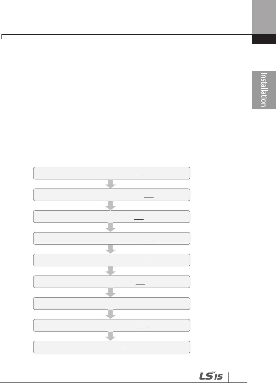
This chapter describes the physical and electrical installation of the H100 series inverters,
including mounting and wiring of the product. Refer to the flowchart and basic configuration
diagram provided below to understand the procedures and installation instructions to be
followed to install the product correctly.
Installation Flowchart
The following flowchart lists the sequence to be followed during installation. The steps cover
equipment installation and testing of the product. More information on each step is referenced in
the steps.
Power and Signal Wiring
(
p.
29
)
Post
-
Installation Checks
(
p.
48
)
Turning on the Inverter
Parameter Configuration
(
p.
61
)
Testing
(
p.
50
)
Mounting the Inverter
(
p.
19
)
Wiring the Ground Connection
(
p.
27
)
Product Identification
(
p.
1
)
Select the Installation Location
(
p.
10
)
Installing the Inverter
18
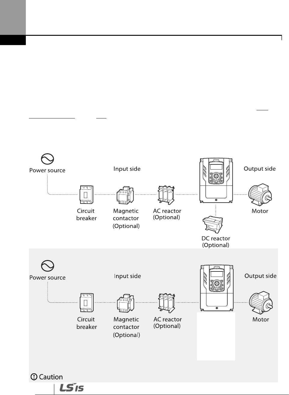
Basic configuration diagram
The reference diagram below shows a typical system configuration showing the inverter and
peripheral devices.
Prior to installing the inverter, ensure that the product is suitable for the application (power rating,
capacity, etc). Ensure that all of the required peripherals and optional devices (resistor brakes,
contactors, noise filters, etc.) are available. For more details on peripheral devices, refer to 11.4
Peripheral Devices on page 600.
200[V] : 0.75~18.5kW, 400[V] : 0.75~90kW
400[V] : 110~500kW

19
Installing
the Inverter
• Figures in this manual are shown with covers or circuit breakers removed to show a more
detailed view of the installation arrangements. Install covers and circuit breakers before
operating the inverter. Operate the product according to the instructions in this manual.
•
Do not start or stop the inverter using a magnetic contactor installed on the input power supply.
• If the inverter is damaged and loses control, the machine may cause a dangerous situation.
Install an additional safety device such as an emergency brake to prevent these situations.
• High levels of current draw during power-on can affect the system. Ensure that correctly rated
circuit breakers are installed to operate safely during power-on situations.
• Reactors can be installed to improve the power factor. Note that reactors may be installed within
32.8 ft (10 m) from the power source if the input power exceeds 600 kVA. Refer to 11.5 Fuse and
Reactors Specifications on page 603 and carefully select a reactor that meets the requirements.
2.1 Mounting the Inverter
Mount the inverter on a wall or inside a panel following the procedures provided below. Before
installation, ensure that there is sufficient space to meet the clearance specifications, and that
there are no obstacles impeding the cooling fan’s air flow.
Select a wall or panel suitable to support the installation. Refer to 11.3 External Dimensions on page
595 and check the inverter’s mounting bracket dimensions.
1 Use a level to draw a horizontal line on the mounting surface, and then carefully mark the
fixing points.
2 Drill the two upper mounting bolt holes, and then install the mounting bolts. Do not fully
tighten the bolts at this time. Fully tighten the mounting bolts after the inverter has been
mounted.
3 Mount the inverter on the wall or inside a panel using the two upper bolts, and then fully
tighten the upper mounting bolts.
200[V] : 0.75~18.5kW, 400[V] : 0.75~185kW
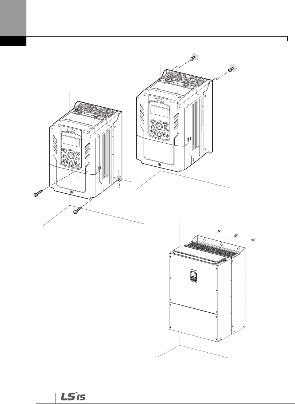
Installing the Inverter
20
400[V] : 220~500kW
4 Install the two lower mounting bolts. Ensure that the inverter is placed flat on the mounting
surface, and that the installation surface can securely support the weight of the inverter.
200[V] : 0.75~18.5kW, 400[V] : 0.75~185kW
21
Installing
the Inverter
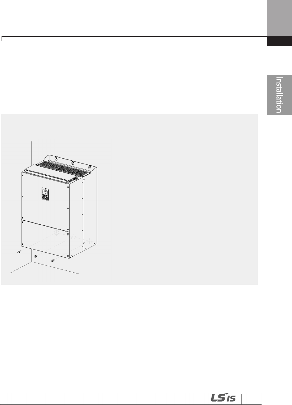
400[V] : 220~500kW
Installing the Inverter
22
• Do not transport the inverter by lifting with the inverter’s covers or plastic surfaces. The inverter
may tip over if covers break, causing injuries or damage to the product. Always support the
inverter using the metal frames when moving it.
• Hi-capacity inverters are very heavy and bulky. Use an appropriate transport method that is
suitable for the weight.
• Do not install the inverter on the floor or mount it sideways against a wall. The inverter must be
installed vertically, on a wall or inside a panel, with its rear flat on the mounting surface.
23
Installing
the Inverter
2.2 Enabling the RTC (Real-Time Clock) Battery
The H100 series inverter comes from the factory with a CR2032 lithium-manganese battery pre-
installed on the I/O PCB. The battery powers the inverter’s built-in RTC. The battery is installed
with a protective insulation strip to prevent battery discharge; remove this protective film before
installing and using the inverter.
ESD (Electrostatic discharge) from the human body may damage sensitive electronic components on
the PCB. Therefore, be extremely careful not to touch the PCB or the components on the PCB with bare
hands while you work on the I/O PCB.
To prevent damage to the PCB from ESD, touch a metal object with your hands to discharge any
electricity before working on the PCB, or wear an anti-static wrist strap and ground it on a metal object.
Follow the instructions below to remove the protective insulation strip and enable the RTC feature
on the H100 series inverters.
1 Turn off the inverter and make sure that DC link voltage has dropped to a safe level.
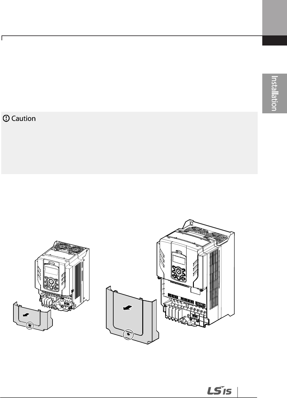
2 Loosen the screw on the power cover then remove the power cover.
0.75–30 kW Models
37
–
90 kW Models
110~185kW
Models
220~500kW Models
Installing the Inverter
24
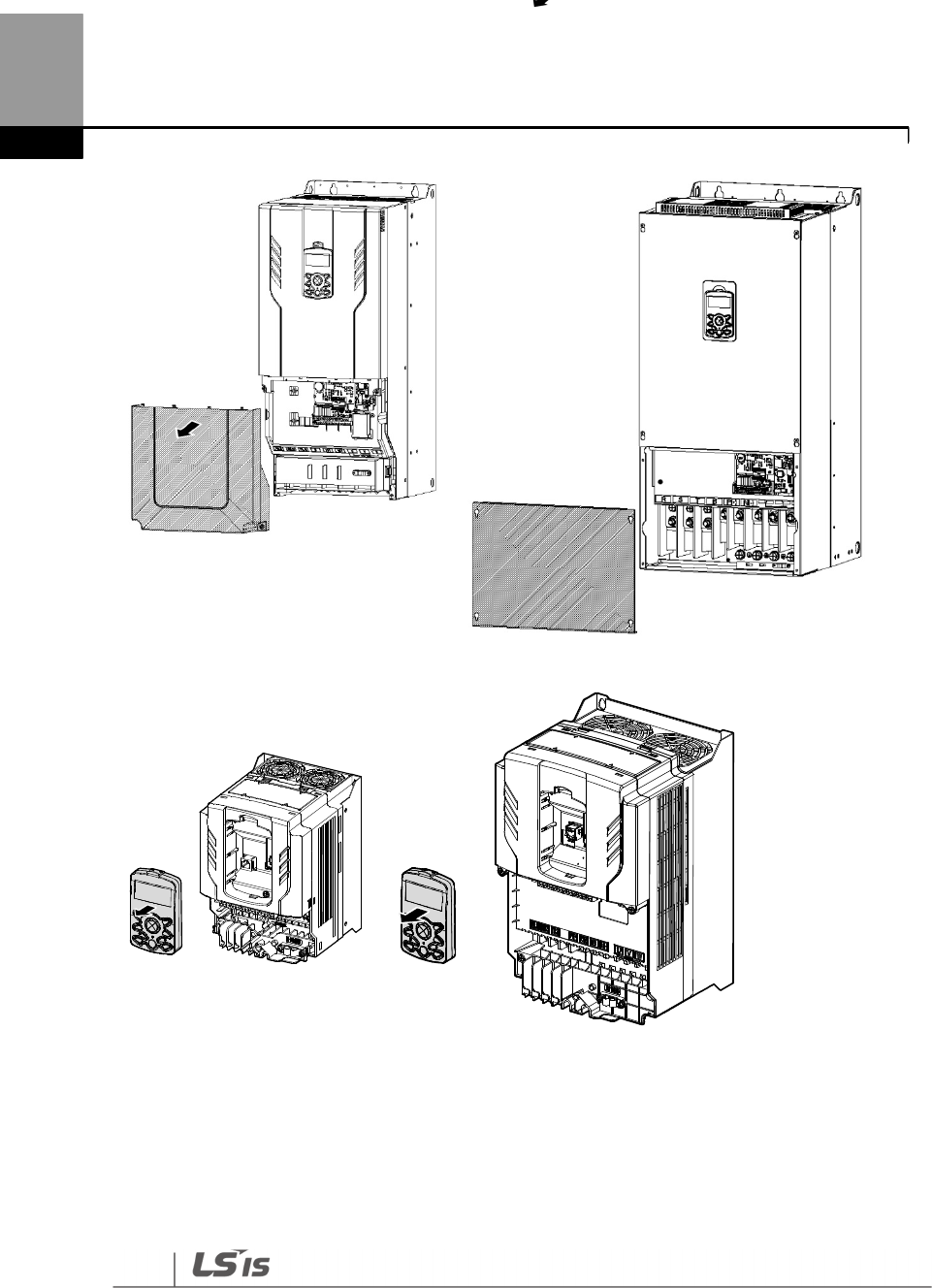
3 Remove the keypad from the inverter body.
0.75–30 kW Models
37–90 kW Models
25
Installing
the Inverter
4 Loosen the screws securing the front cover, and remove the front cover by lifting it. The main
PCB is exposed.
0.75
–
30 kW Models
37
–
90 kW Models
5 Locate the RTC battery holder on the I/O PCB, and remove the protective insulation strip by
gently pulling it.
6 Reattach the front cover, the power cover, and the keypad back onto the inverter body
7 For detailed information on the RTC battery, refer to the battery specifications on page 580.
Ensur
e that the inverter is turned off and DC link voltage has dropped to a safe level before opening
the terminal cover and installing the RTC battery.

Installing the Inverter
26
2.3 Cable Wiring
Open the terminal cover, remove the cable guides, and then install the ground connection as
specified. Complete the cable connections by connecting an appropriately rated cable to the
terminals on the power and control terminal blocks.
Read the following information carefully before carrying out wiring connections to the inverter. All
warning instructions must be followed.
• Install the inverter before carrying out wiring connections.
• Ensure that no small metal debris, such as wire clippings, remain inside the inverter. Metal debris
in the inverter may cause inverter failure.
• Tighten terminal screws to their specified torque. Loose terminal block screws may allow the
cables to disconnect and cause a short circuit or inverter failure. Refer to page 604.
• Do not place heavy objects on top of electric cables. Heavy objects may damage the cable and
result in electric shock.
• Use cables with the largest cross-sectional area, appropriate for power terminal wiring, to ensure
that voltage drops do not exceed 2%.
• Use copper cables rated at 600 V, 75 ℃ for power terminal wiring.
• Use copper cables rated at 300 V, 75 ℃ for control terminal wiring.
• If you need to re-wire the terminals due to wiring-related faults, ensure that the inverter keypad
display is turned off and the charge lamp under the terminal cover is off before working on wiring
connections. The inverter may hold a high voltage electric charge long after the power supply has
been turned off.
• The accessible connections and parts listed below are of protective class 0. It means that the
protection of these circuits relies only upon basic insulation and becomes hazardous in the event
of a failure of the basic insulation. Therefore, devices connected to these circuits must provide
electrical-shock protection as if the device was connected to supply mains voltage. In addition,
during installation these parts must be considered, in relation with electrical-shock, as supply
mains voltage circuits.
[ Class 0 circuits]
MULTI FUNCTION INPUT : P1-P7, CM
ANALOG INPUT : VR, V1, I2, TI
ANALOG OUTPUT : AO1, AO2, TO
•
CONTACT : Q1, EG, 24,A1, C1, B1, A2~5, C2~5, S+, S-, SG
27
Installing
the Inverter
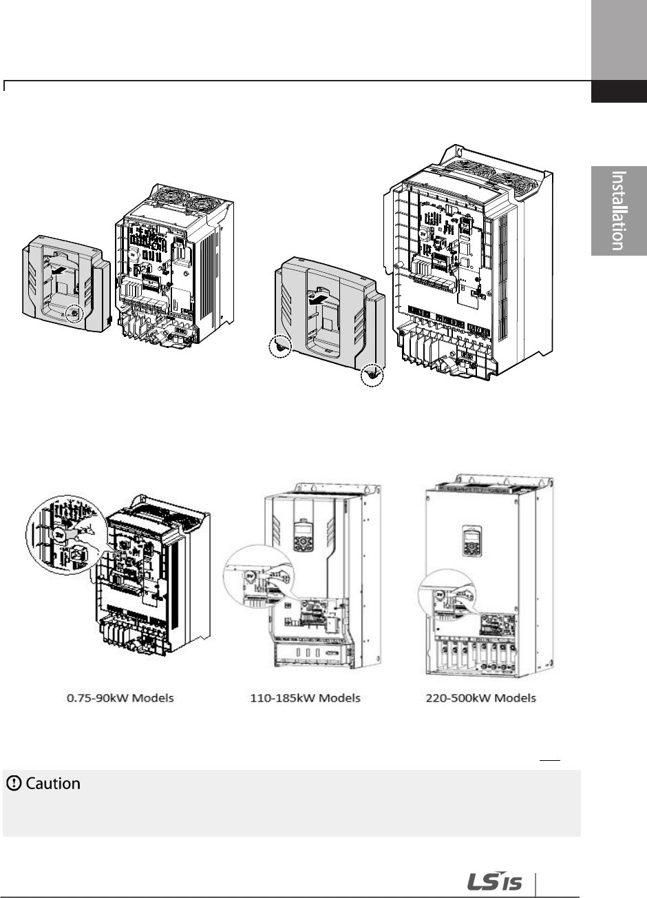
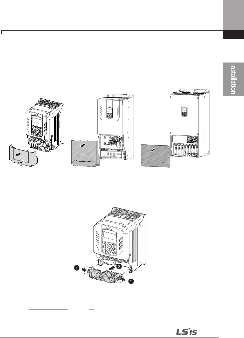
Step 1 Terminal Cover and Cable Guide
The terminal cover and cable guide must be removed to install cables. Refer to the following
procedures to remove the covers and cable guide. The steps to remove these parts may vary
depending on the inverter model.
1 Loosen the bolt that secures the terminal cover. Then remove the cover by lifting it from the
bottom and away from the front.
0.75–90 kW Models 110–185 kW Models 220–500 kW Models
2 Push and hold the levers on both sides of the cable guide (❶) and then remove the cable
guide by pulling it directly away from the front of the inverter (❷). In some models (37~90kW)
where the cable guide is secured by a bolt, remove the bolt first.
0.75~30 / 110~185 kW Models
3 Connect the cables to the power terminals and the control terminals. For cable specifications,
refer to 1.5 Cable Selection on page 14.
Step 2 Ground Connection
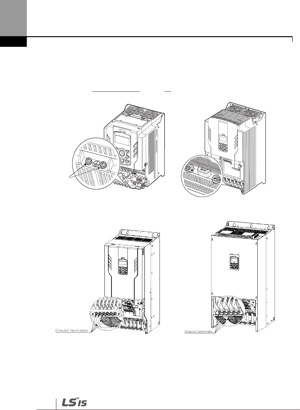
Installing the Inverter
28
Remove the terminal cover(s) and cable guide. Then follow the instructions below to install the
ground connection for the inverter.
1 Locate the ground terminal and connect an appropriately rated ground cable to the
terminals. Refer to 1.5 Cable Selection on page 14 to find the appropriate cable specification
for your installation.
0.75–30 kW (3-Phase) 37–90 kW (3-Phase)
110~185kW (3-Phase) 220-250kW (3-Phase)
Ground terminals
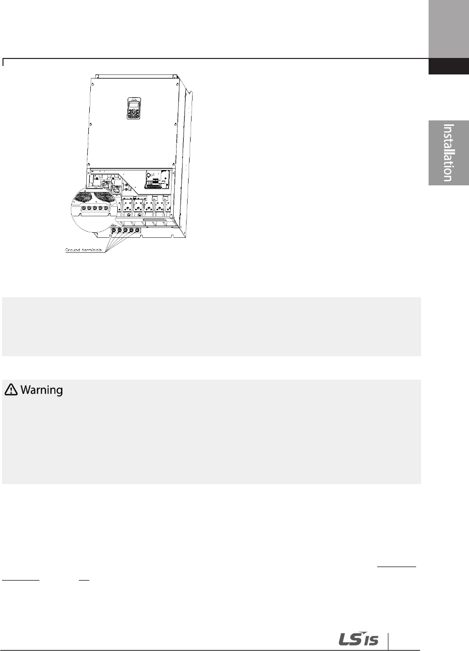
29
Installing
the Inverter
315~500kW (3-Phase)
2 Connect the other ends of the ground cables to the supply earth (ground) terminal
Note
• 200 V products require Class 3 grounding. Resistance to ground must be
≤
100 Ω.
•
400 V products require Special Class 3 grounding. Resistance to ground must be
≤
10 Ω.
Install ground
connections for the inverter and the motor by following the correct specifications to
ensure safe and accurate operation. Using the inverter and the motor without the specified grounding
connections may result in electric shock.
This product can cause a D.C current in the protective earthing conductor. If a RCD or monitoring
(RCM) device is used for protection, only RCD or RCM of Type B is allowed on supply side of this
product.
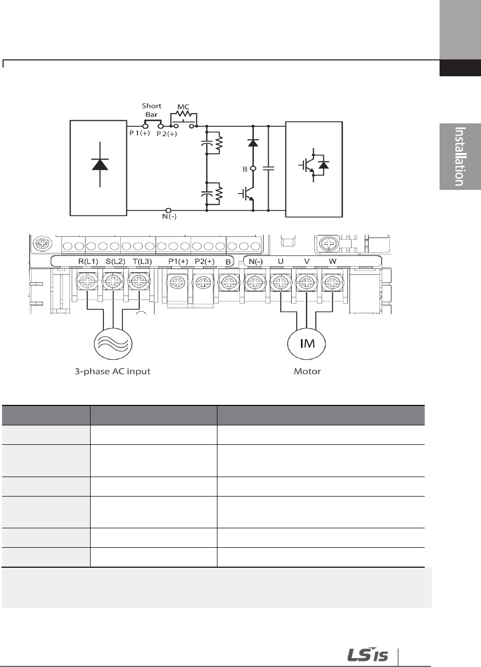
Step 3 Power Terminal Wiring
The following illustration shows the terminal layout on the power terminal block. Refer to the
detailed descriptions to understand the function and location of each terminal before making
wiring connections. Ensure that the cables selected meet or exceed the specifications in 1.5 Cable
Selection on page 14 before installing them.

Installing the Inverter
30
• Apply rated torques to the terminal screws. Loose screws may cause short circuits and
malfunctions. Tightening the screw too much may damage the terminals and cause short circuits
and malfunctions.
• Use copper wires only with 600 V, 75 ℃ rating for the power terminal wiring, and 300 V, 75 ℃
rating for the control terminal wiring.
• Power supply wirings must be connected to the R, S, and T terminals. Connecting them to the U,
V, W terminals causes internal damages to the inverter. Motor should be connected to the U, V,
and W Terminals. Arrangement of the phase sequence is not necessary.
• Equipment must only be fitted to the closed electric operating areas.
Attention
• Appliquer des couples de marche aux vis des bornes. Des vis desserrées peuvent provoquer
des courts-circuits et des dysfonctionnements. Ne pas trop serrer la vis, car cela risque
d’endommager les bornes et de provoquer des courts-circuits et des dysfonctionnements.
• Utiliser uniquement des fils de cuivre avec une valeur nominale de 600 V, 90 pour le ℃
câblage de la borne d’alimentation, et une valeur nominale de 300 V, 75 pour le câblage ℃
de la borne de commande.
• Les câblages de l’alimentation électrique doivent être connectés aux bornes R, S et T. Leur
connexion aux bornes U, V et W provoque des dommages internes à l’onduleur. Le moteur
doit être raccordé aux bornes U, V et W. L’arrangement de l’ordre de phase n’est pas
nécessaire.
31
Installing
the Inverter
0.75–30 kW (3-Phase)
Power Terminal Labels and Descriptions
Terminal Labels
Name
Description
R(L1)/S(L2)/T(L3)
AC power input terminal
Mains
supply AC power connections.
P1(+) + DC link terminal
+ DC voltage terminal.
Used for connecting an external reactor.
P2
(
+
)
+ DC link terminal
Used for DC power inverter DC (+) connection.
N- - DC link terminal
-
DC voltage terminal.
Used for a DC power inverter DC (-) connection.
P2
(
+
)
/B
Brake resistor terminals
Brake resistor wiring connection
.
U/V/W
Motor output
terminals
3
-
phase induction motor wiring connections.
Note
Apply a DC input to the P2 (+) and N (
-
) terminals to operate the inverter on DC current input.
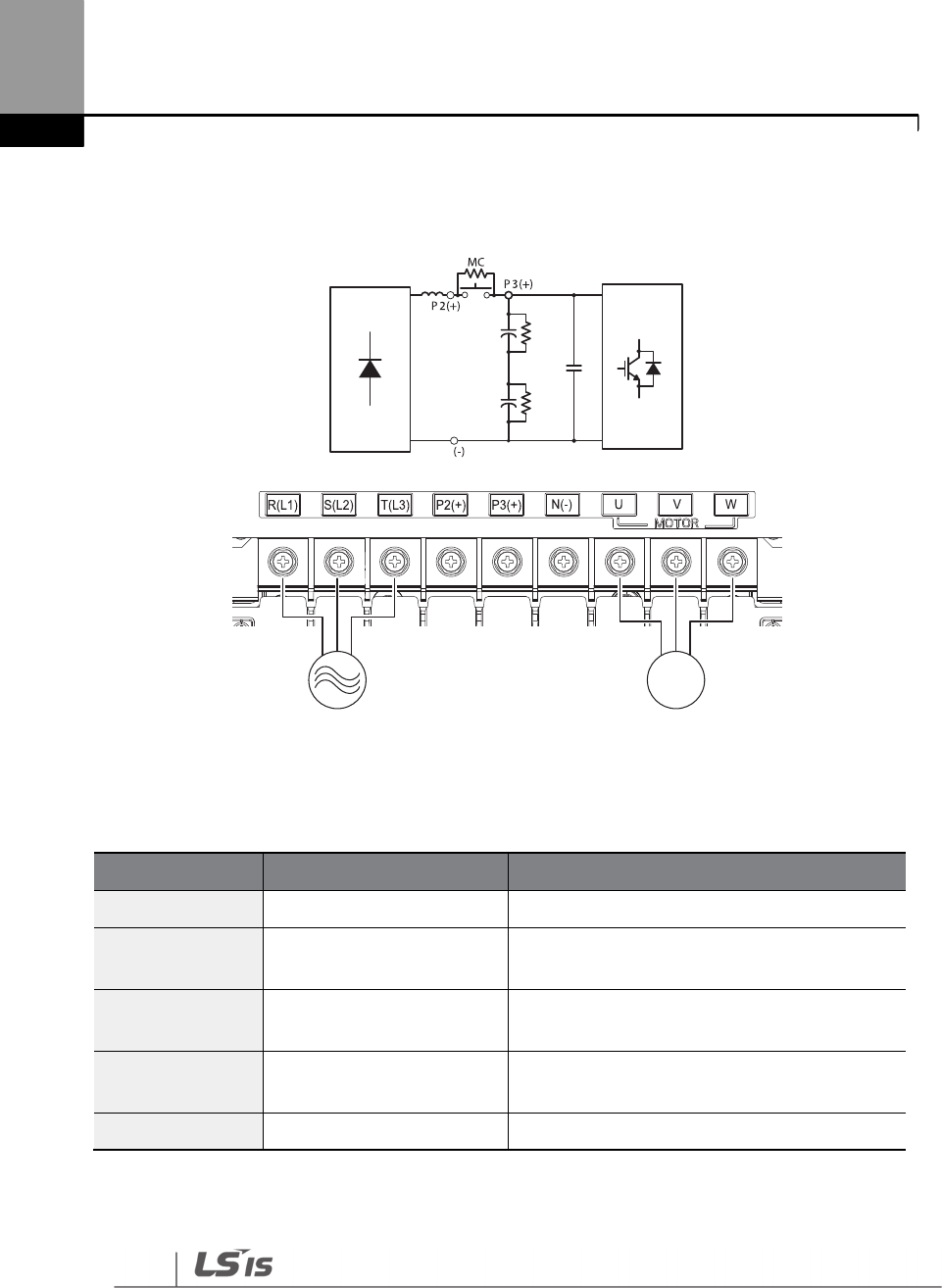
Installing the Inverter
32
37–90 kW (3-Phase)
Power Terminal Labels and Descriptions
Terminal Labels
Name
Description
R(L1)/S(L2)/T(L3)
AC power input terminal
Mains
supply AC power connections.
P2(+) + DC link terminal
+ DC voltage terminal.
Used for connecting an external reactor.
P3(+) + DC link terminal
Used for a DC power inverter DC (+)
connection.
N- - DC link terminal
-
DC voltage terminal.
Used for a DC power inverter DC (-) connection.
U/V/W
Motor output terminals
3
-
phase induction motor wiring connections.
N
IM
3-phase AC input Motor
33
Installing
the Inverter
110–250kW (3-Phase)
N(-)
P(+)
Power Terminal Labels and Descriptions
Terminal Labels
Name
Description
R(L1)/S(L2)/T(L3)
AC power input terminal
Mains supply AC power connections.
B Brake resistor terminals
It can not be used because it does not
provide a braking unit
P
(
+
)
+ DC link terminal
+ DC voltage terminal.
N- - DC link terminal
-
DC voltage terminal.
Used for a DC power inverter DC (-)
connection.
U/V/W Motor output terminals
3
-
phase induction motor wiring
connections.
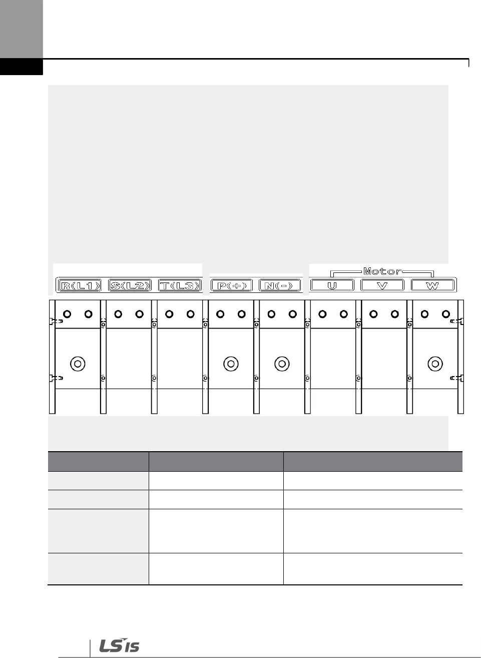
Installing the Inverter
34
315
–
5
0
0kW (3
-
Phase
)
N(-)
P(+)
Terminal Labels
Name
Description
R(L1)/S(L2)/T(L3)
AC power input terminal
Mains supply AC
power connections.
P
(
+
)
+ DC link terminal
+ DC voltage terminal.
N- - DC link terminal
-
DC v
oltage terminal.
Used for a DC power inverter DC (-)
connection.
U/V/W Motor output terminals
3
-
phase induction motor wiring
connections.
3
5
Installing
the Inverter
Note
• Apply a DC input to the P2 (+) and N (-) terminals to operate the inverter on DC current input.
• Use STP (Shielded Twisted Pair) cables to connect a remotely located motor with the inverter. Do
not use 3 core cables.
• Make sure that the total cable length does not exceed 492 ft (150 m). For inverters < = 3.7 kW
capacity, ensure that the total cable length does not exceed 165 ft (50 m).
• Long cable runs can cause reduced motor torque in low frequency applications due to voltage
drop. Long cable runs also increase a circuit’s susceptibility to stray capacitance and may trigger
over-current protection devices or result in malfunction of equipment connected to the inverter.
• Voltage drop is calculated by using the following formula:
• Voltage Drop (V) = [√3 X cable resistance (mΩ/m) X cable length (m) X current (A)] / 1000
• Use cables with the largest possible cross-sectional area to ensure that voltage drop is minimized
over long cable runs. Lowering the carrier frequency and installing a micro surge filter may also
help to reduce voltage drop.
Distance
< 165 ft (50 m)
< 330 ft (100 m)
> 330 ft (100 m)
Allowed Carrier Frequency
<15 kHz
<5 kHz
<2.5 kHz
Do not connect power to the inverter until installation has been
fully completed and the inverter is
ready to be operated. Doing so may result in electric shock.
• Power supply cables must be connected to the R, S, and T terminals. Connecting power cables to
other terminals will damage the inverter.
• Use insulated ring lugs when connecting cables to R/S/T and U/V/W terminals.
• The inverter’s power terminal connections can cause harmonics that may interfere with other
communication devices located near to the inverter. To reduce interference the installation of
noise filters or line filters may be required.
• To avoid circuit interruption or damaging connected equipment, do not install phase-advanced
condensers, surge protection, or electronic noise filters on the output side of the inverter.
• To avoid circuit interruption or damaging connected equipment, do not install magnetic
contactors on the output side of the inverter.
Installing the Inverter
36
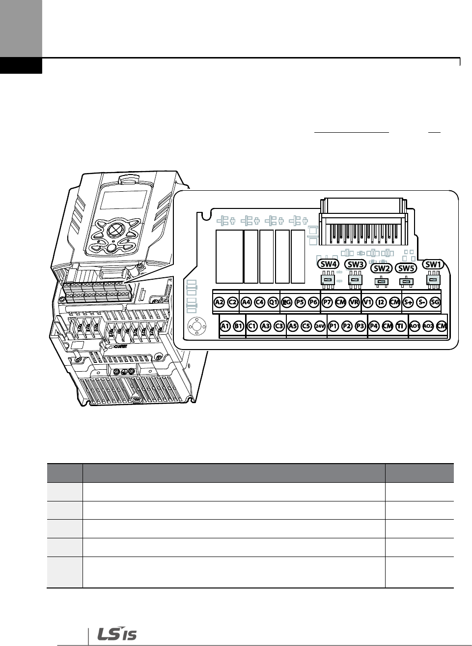
Step 4 Control Terminal Wiring
The illustrations below show the detailed layout of control wiring terminals and control board
switches. Refer to the detailed information provided below and 1.5 Cable Selection on page 14
before installing control terminal wiring and ensure that the cables used meet the required
specifications.
Switch Symbols and Description
Switch
Description
Factory Default
SW1
Terminating Resistor selection switch
(Left: On, Right: Off)
Right: OFF
SW2
NPN/PNP mode selection switch
(Left: PNP, Right: NPN)
Right: NPN
SW3
V1/T1 (PTC) mode selection switch
(Left: V1, Right: T1)
Left: V1
SW4
analog voltage/current input terminal selection switch
(Left: I2, Right: V2)
Left: I2
SW5
analog voltage/current output terminal selection switch
(Left: VO, Right: IO) Left: VO
37
Installing
the Inverter
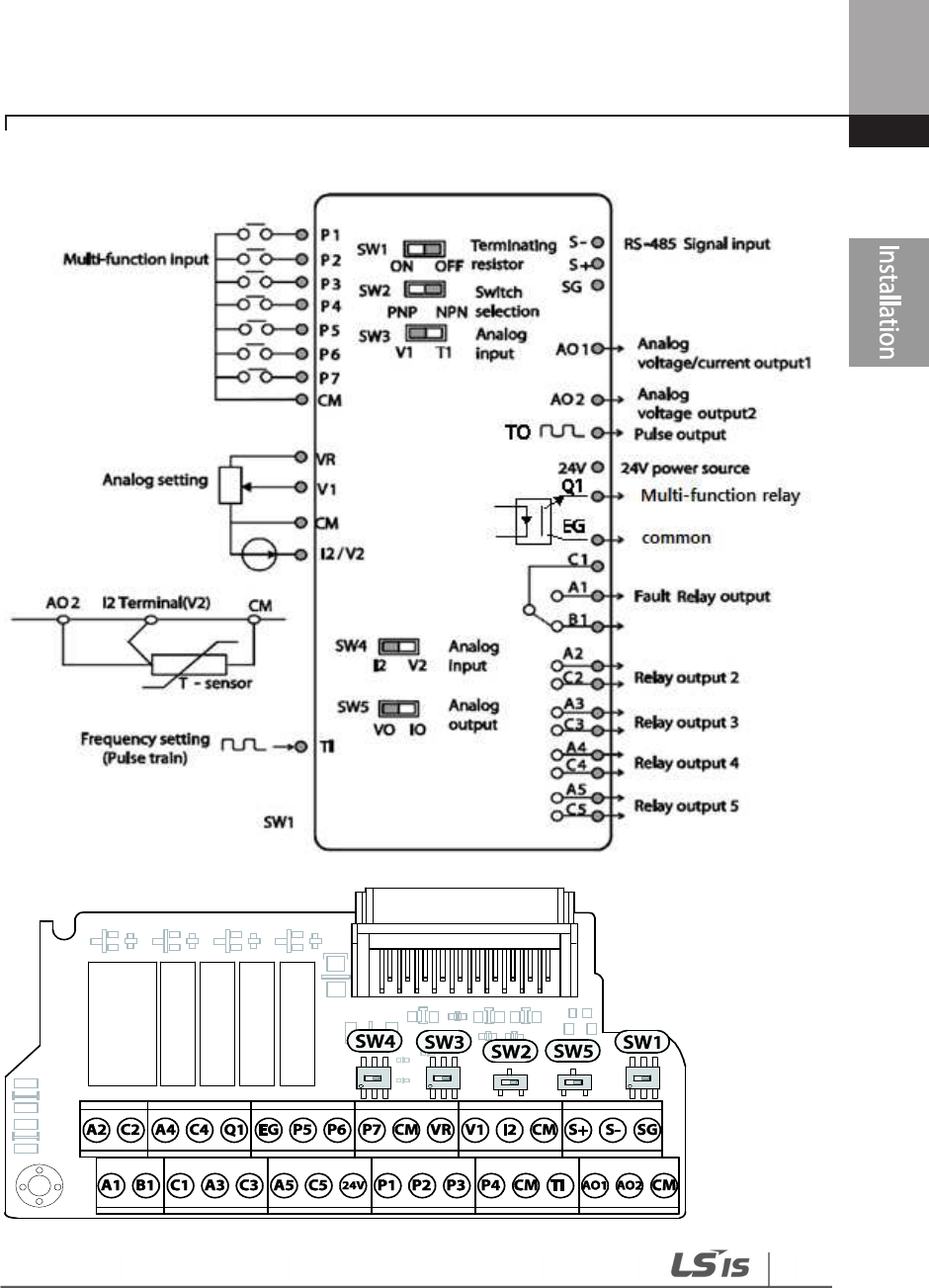
Input and Output Control Terminal Block Wiring Diagram
5.5~90kW
Installing the Inverter
38
110~500kW
Input Terminal Labels and Descriptions
Function
Label
Name
Description
Multi-function
terminal
configuration
P1–P5
Multi-function Input 1-7
Configurable for multi
-
function input
terminals. Factory default terminals and
setup are as follows :
P1: Fx
P2: Rx
P3: BX
P4: RST
P5: Speed-L
P6: Speed-M
P7: Speed-H
CM Common
Sequence
Common terminal for analog terminal inputs
and outputs.
Analog input
configuration
VR
Potentiometer power
supply
Used to setup or modify a frequency
reference via analog voltage or current input.
Maximum Voltage Output: 12 V
Maximum Current Output: 12 mA
Potentiometer : 1–10k Ω
V1 Voltage input for
frequency reference
Used to setup or modify a frequency
reference via analog voltage input terminal.
Unipolar: 0–10 V(12 V Max)
Bipolar: -10–10 V(±12 V Max)

39
Installing
the Inverter
Function
Label
Name
Description
V2/I2 Voltage/current input for
frequency reference input
Used to setup or modify a frequency
reference via analog voltage or current input
terminals.
Switch between voltage (V2) and current (I2)
modes using a control board switch (SW4).
Input current: 0–20 mA
Maximum Input current: 24 mA
Input resistance 249 Ω
TI
Pulse input for frequency
reference input (pulse
train)
Setup or modify frequency references using
pulse inputs from 0 to 32 kHz.
Low Level: 0–0.8 V, High Level: 3.5–12 V
Output/Communication Terminal Labels and Descriptions
Function
Label
Name
Description
Analog
output AO Voltage/Current
Output
Used to send inverter output information to external
devices: output frequency, output current, output
voltage, or a DC voltage.
Operate switch (SW5) to select the signal output type
(voltage or current) at the AO terminal.
Output Signal Specifications:
Output voltage: 0–10 V
Maximum output voltage/current: 12 V/10 mA
Output current: 0–20 mA
Maximum output current: 24 mA
Factory default output: Frequency
Terminal
Contacts
Q1
Multi-function
(Open Collector)
Pulse Output
Selects a multi
-
function output signal or pulse
output, output frequency, output current, output
voltage, DC voltage by selecting one of the outputs.
DC 26 V, 50 mA or less
Pulse output terminal
Output frequency: 0–32 kHz
Output voltage: 0–12 V
EG Common
Common ground contact for an open collector (with
external power source)

Installing the Inverter
40
Function
Label
Name
Description
24 24 V power supply
-
Maximum output current: 100 mA
-Do not use this terminal for any purpose other than
supplying power to a PNP mode circuit configuration
(e.g. supplying power to other external devices).
A1/C1/B1
Fault relay output
A,B contact
Sends out alarm signals when the inverter’s safety
features are activated.
( N.O.: AC250 V ≤2 A , DC 30 V ≤3 A
N.C.: AC250 V ≤1 A , DC 30 V ≤ 1 A)
Fault condition: A1 and C1 contacts are connected
(B1 and C1 open connection)
Normal operation: B1 and C1 contacts are connected
(A1 and C1 open connection)
Factory default: Frequency
A2/
C
2
A3/C3
A4/C4
A5/C5
Multi-function relay
output A contact
Defined in the inverter signal features such as output
via the multi-function output terminal.
(AC 250 V≤ 5 A, DC 30 V≤ 5 A).
S+/S-/SG RS-485 signal line
Used to send or receive RS
-
485 signals. Refer to
7
RS
-
485 Communication Features on page 354 for more
details.
Note
• While making wiring connections at the control terminals ensure that the total cable length does
not exceed 165 ft (50 m).
• Ensure that the length of any safety related wiring does not exceed 100 ft (30 m).
• Ensure that the cable length between the keypad and the inverter does not exceed 10 ft (3.04 m).
Cable connections longer than 10 ft (3.04 m) may cause signal errors.
• Use ferrite material to protect signal cables from electro-magnetic interference.
• Take care when supporting cables using cable ties, to apply the cable ties no closer than 6 inches
from the inverter. This provides sufficient access to fully close the terminal cover.
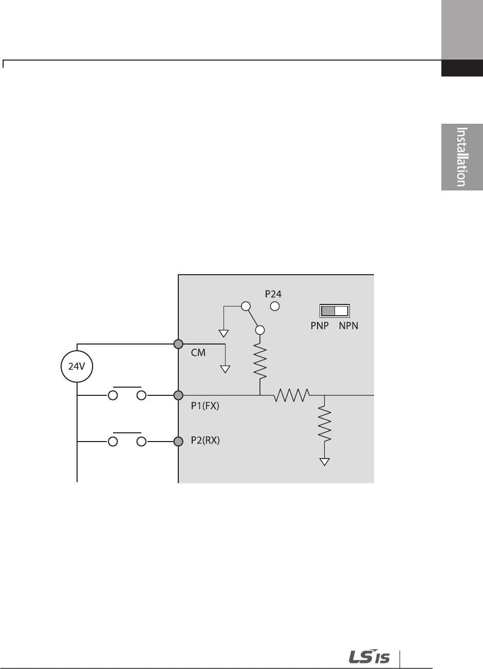
41
Installing
the Inverter
Step 5 PNP/NPN Mode Selection
The H100 inverter supports both PNP (Source) and NPN (Sink) modes for sequence inputs at the
terminal. Select an appropriate mode to suit requirements using the PNP/NPN selection switch
(SW2) on the control board. Refer to the following information for detailed applications.
PNP Mode (Source)
Select PNP using the PNP/NPN selection switch (SW2). Note that the factory default setting is NPN
mode. CM is the common ground terminal for all analog inputs at the terminal, and P24 is 24 V
internal source. If you are using an external 24 V source, build a circuit that connects the external
source (-) and the CM terminal.
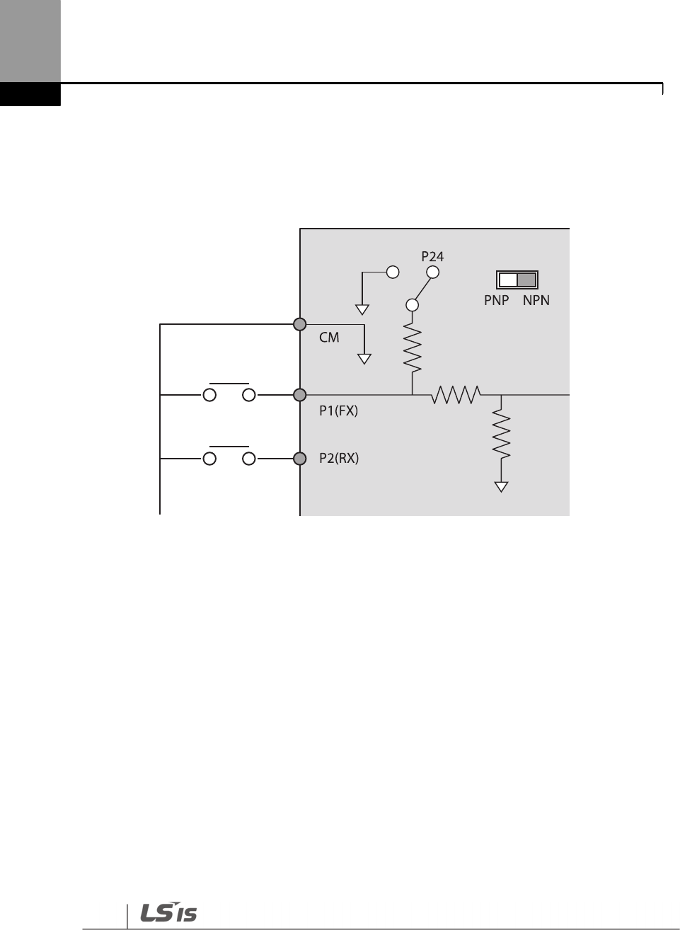
Installing the Inverter
42
NPN Mode (Sink)
Select NPN using the PNP/NPN selection switch (SW2). Note that the factory default setting is NPN
mode. CM is the common ground terminal for all analog inputs at the terminal, and P24 is 24 V
internal source.
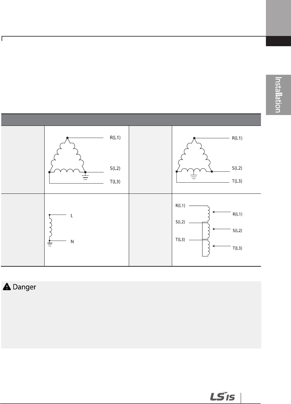
43
Installing
the Inverter
Step 6 Disabling the EMC Filter for Power Sources with Asymmetrical Grounding
H100, 400 V 0.75–55 kW, 110~500kW(3 phase) inverters have EMC filters built-in and activated as a
factory default design. An EMC filter prevents electromagnetic interference by reducing radio
emissions from the inverter. EMC filter use is not always recommended, as it increases leakage
current. If an inverter uses a power source with an asymmetrical grounding connection, the EMC
filter must be turned off.
Asymmetrical Grounding Connection
One phase of
a delta
connection is
grounded
(TN Systems)
Intermediate
grounding
point on one
phase of a
delta
connection
(TN Systems)
The end of a
single phase is
grounded
(TN Systems)
A 3-phase
connection
without
grounding
(TN Systems)
• Do not activate the EMC filter if the inverter uses a power source with an asymmetrical grounding
structure (corner-earthed systems), for example a grounded delta connection. Personal injury or
death by electric shock may result.
• Wait at least 10 minutes before opening the covers and exposing the terminal connections.
Before starting work on the inverter, test the connections to ensure all DC voltage has been fully
discharged. Personal injury or death by electric shock may result.
Before using the inverter, confirm the power supply’s grounding system. Disable the EMC filter if
the power source has an asymmetrical grounding connection.
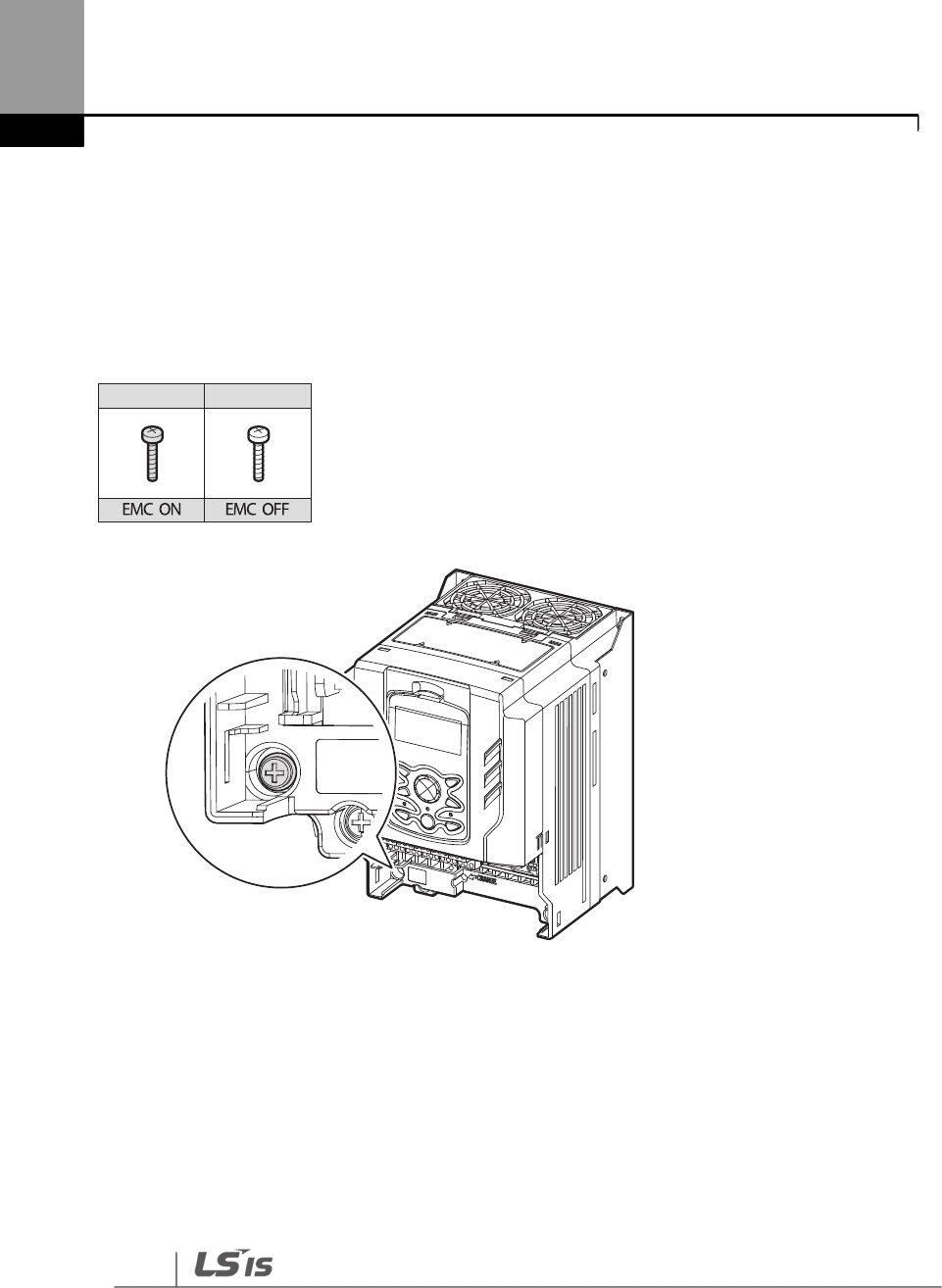
Installing the Inverter
44
Disabling the Built-in EMC Filter for 0.75–30 kW (3–Phase) Inverters
Refer to the figures below to locate the EMC filter on/off terminal and replace the metal bolt with
the plastic bolt. If the EMC filter is required in the future, reverse the steps and replace the plastic
bolt with the metal bolt to reconnect the EMC filter.
If the EMC filter is required in the future, reverse the steps and replace the plastic bolt with the
metal bolt to enable the EMC filter.
Steel bolt Plastic bolt
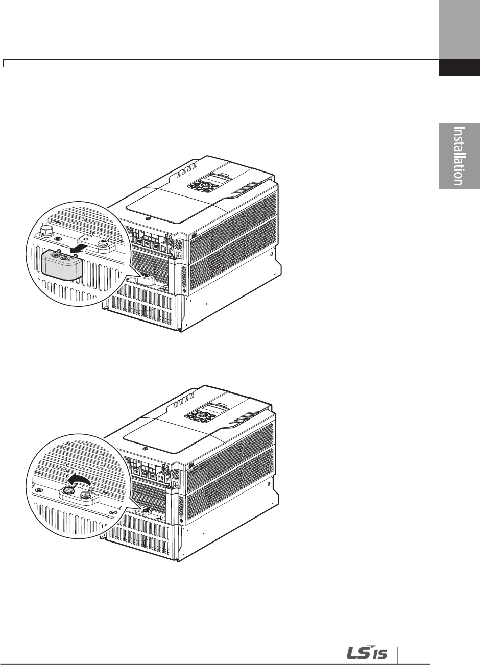
45
Installing
the Inverter
Disabling the Built-in EMC Filter for 37–55 kW (3–Phase) Inverters
Follow the instructions listed below to disable the EMC filters for the H100 inverters rated for 37–
55 kW.
1 Remove the EMC ground cover located at the bottom of the inverter.
2 Remove the EMC ground cable from the right terminal (EMC filter-ON / factory default), and
connect it to the left terminal (EMC filter-OFF / for power sources with asymmetrical
grounding).
If the EMC filter is required in the future, reverse the steps and connect the EMC ground cable to
the right terminal to enable the EMC filter.
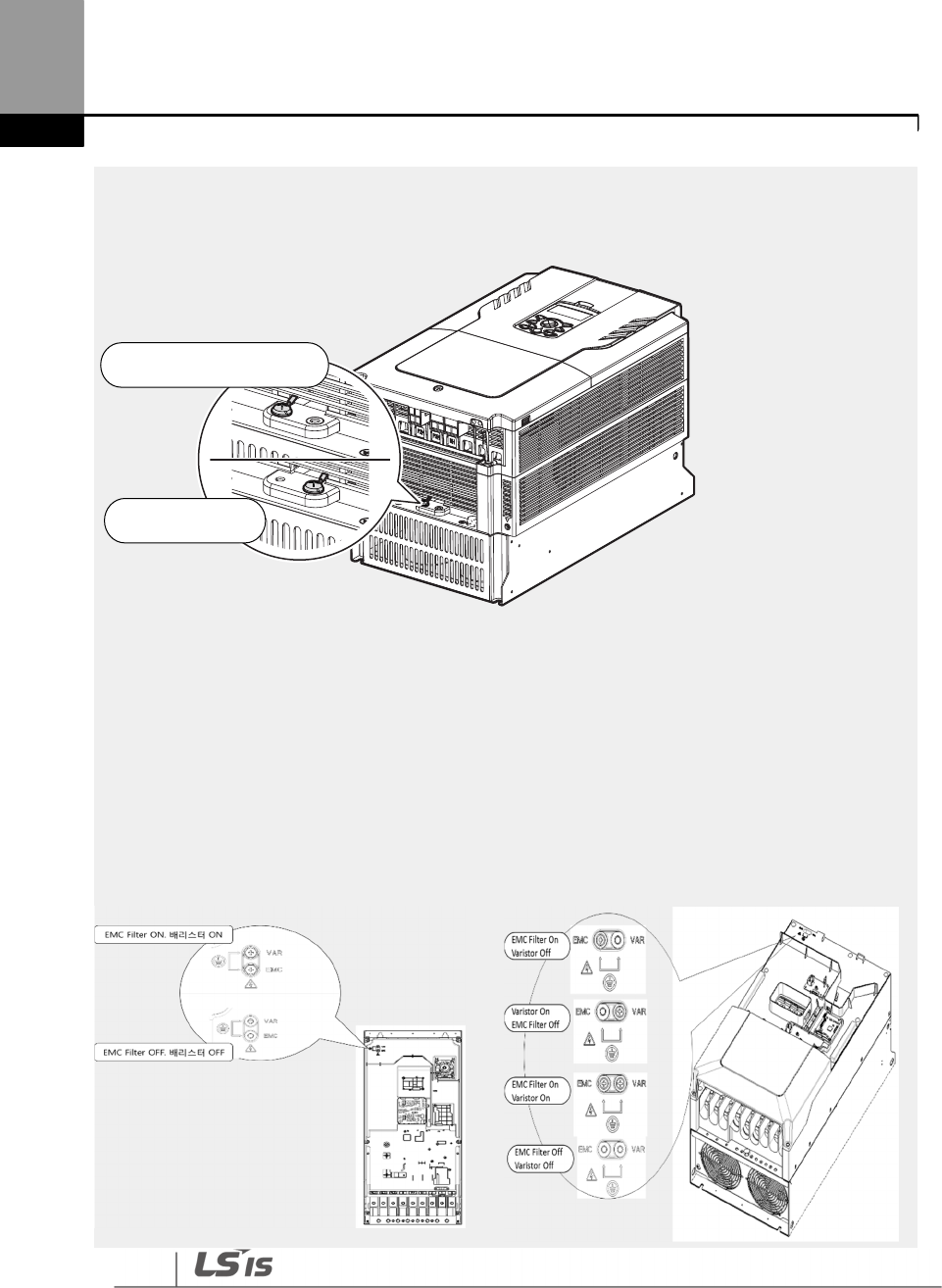
Installing the Inverter
46
Note
The terminal on the right is used to ENA
BLE the EMC filter (factory default). The terminal on the left is
used to DISABLE the EMC filter (for power sources with asymmetrical grounding).
Disabling the Built-in EMC Filter for 110–500 kW (3–Phase) Inverters
Follow the instructions listed below to disable the EMC filters for the H100 inverters rated for 110–
500 kW.
1 Remove the front cover located at the top of the inverter.
2 Remove the EMC ground cable from the right terminal (EMC filter-ON / factory default), and
connect it to the left terminal (EMC filter-OFF / for power sources with asymmetrical
grounding).
110–132 kW (3-Phase) 160–185 kW (3-Phase)
EMC Filter ON
(Factory default)
EMC Filter OFF
(W/ asymetrically grounded PWR)
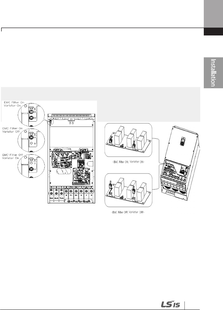
47
Installing
the Inverter
220–250 kW (3-Phase) 315~500 kW(3-Phase)
Step 7 Re-assembling the Covers and Routing Bracket
Re-assemble the cable routing bracket and the covers after completing the wiring and basic
configurations. Note that the assembly procedure may vary according to the product group or
frame size of the product.
Installing the Inverter
48
2.4 Post-Installation Checklist
After completing the installation, check the items in the following table to make sure that the
inverter has been safely and correctly installed.
Items
Check Point
Ref.
Result
Installation
Location/Power
I/O Verification
Is the installation location appropriate?
p.
10
Does the environment meet the inverter’s operating
conditions? p.11
Does the power source match the inverter’s rated input?
p.
585
Is the inverter’s rated output sufficient to supply the
equipment?
(Degraded performance will result in certain circumstances.
Refer to 11.8 Inverter Continuous Rated Current Derating on
page 618 for details.
p.585
Power Terminal
Wiring
Is a circuit breaker installed on the input side of the inverter? p.18
Is the circuit breaker correctly rated?
p.
600
Are the power source cables correctly connected to the
R/S/T terminals of the inverter?
(Caution: connecting the power source to the U/V/W
terminals may damage the inverter.)
p.29
Are the motor output cables connected in the correct phase
rotation (U/V/W)?
(Caution: motors will rotate in reverse direction if three phase
cables are not wired in the correct rotation.)
p.29
Are the cables used in the power terminal connections
correctly rated? p.14
Is the inverter grounded correctly?
p.
27
Are the power terminal screws and the ground terminal
screws tightened to their specified torques? p.29
Are the overload protection circuits installed correctly on the
motors (if multiple motors are run using one inverter)? -
Is the inverter separated from the power source by a
magnetic contactor (if a braking resistor is in use)? p.18
49
Installing
the Inverter
Items
Check Point
Ref.
Result
Are advanced
-
phase capacitors, surge protection and
electromagnetic interference filters installed correctly?
(These devices MUST not be installed on the output side of
the inverter.)
p.29
Control Terminal
Wiring
Are STP (shielded twisted pair) cables used for control
terminal wiring? -
Is the shielding of the STP wiring properly grounded? -
If 3-wire operation is required, are the multi-function input
terminals defined prior to the installation of the control
wiring connections?
p.36
Are the control cables properly wired? p.36
Are the control terminal screws tightened to their specified
torques? p.21
Is the total cable length of all control wiring < 165 ft (100 m)?
p.40
Is the total length of safety wiring < 100 ft (30 m)? p.40
Miscellaneous
Are optional cards connected correctly? -
Is there any debris left inside the inverter? p.21
Are any cables contacting adjacent terminals, creating a
potential short circuit risk? -
Are the control terminal connections separated from the
power terminal connections? -
Have the capacitors been replaced if they have been in use
for > 2 years? -
Has a fuse been installed for the power source? p.603
Are the connections to the motor separated from other
connections? -
Note
STP (Shielded Twisted Pair) cable has a highly conductive, shielded screen around twisted cable pairs.
STP cables protect conductors from electromagnetic interference.

Installing the Inverter
50
2.5 Test Run
After the post-installation checklist has been completed, follow the instructions below to test the
inverter.
1 Turn on the power supply to the inverter. Ensure that the keypad display light is on.
2 Select the command source.
3 Set a frequency reference, and then check the following:
• If V1 is selected as the frequency reference source, does the reference change according to
the input voltage at VR?
• If V2 is selected as the frequency reference source, is the voltage/current selector switch
(SW4) set to ‘voltage’, and does the reference change according to the input voltage?
• If I2 is selected as the frequency reference source, is the voltage/current selector switch
(SW4) set to ‘current’, and does the reference change according to the input current?
4 Set the acceleration and deceleration time.
5 Start the motor and check the following:
• Ensure that the motor rotates in the correct direction (refer to the note below).
• Ensure that the motor accelerates and decelerates according to the set times, and that the
motor speed reaches the frequency reference.
Note
If the forward command (Fx) is on, the motor should rotate counterclockwise when viewed from the
load side of the motor. If the motor rotates in the reverse direction, switch the cables at the U and V
terminals.
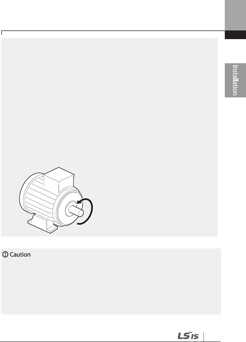
51
Installing
the Inverter
Remarque
Si la commande avant (Fx) est activée, le moteur doit tourner dans le sens anti-horaire si on le
regarde côté charge du moteur. Si le moteur tourne dans le sens inverse, inverser les câbles aux
bornes U et V.
Verifying the
Motor Rotation
1 On the keypad, set DRV-07 to ‘1 (Keypad)’.
2 Set a frequency reference.
3 If the inverter is in OFF mode, press the [AUTO] key twice on the keypad to operate the
inverter in the forward (Fx) direction.
4 If the inver ter is operating in AUTO mode, press the [AUTO] key once on the keypad to
operate the inverter in the forward (Fx) direction.
5 Observe the motor’s rotation from the load side and ensure that the motor rotates
counterclockwise (forward).
• Check the parameter settings before running the inverter. Parameter settings may have to be
adjusted depending on the load.
• To avoid damaging the inverter, do not supply the inverter with an input voltage that exceeds the
rated voltage for the equipment.
•
Before running the motor at maximum speed, confirm the motor’s rated capacity. As inverters can
be used to easily increase motor speed, use caution to ensure that motor speeds do not
accidently exceed the motor’s rated capacity.
Forward operation

Perform Basic Operations
52
3 Perform Basic Operations
This chapter describes the keypad layout and functions. It also introduces parameter groups and
codes required to perform basic operations. The chapter also outlines the correct operation of the
inverter before advancing to more complex applications. Examples are provided to demonstrate
how the inverter actually operates.
3.1 About the Keypad
The keypad is composed of two main components – the display and the operation (input) keys.
Refer to the following illustration to identify part names and functions.
3.1.1 Operation Keys
The following table lists the names and functions of the keypad’s operation keys.
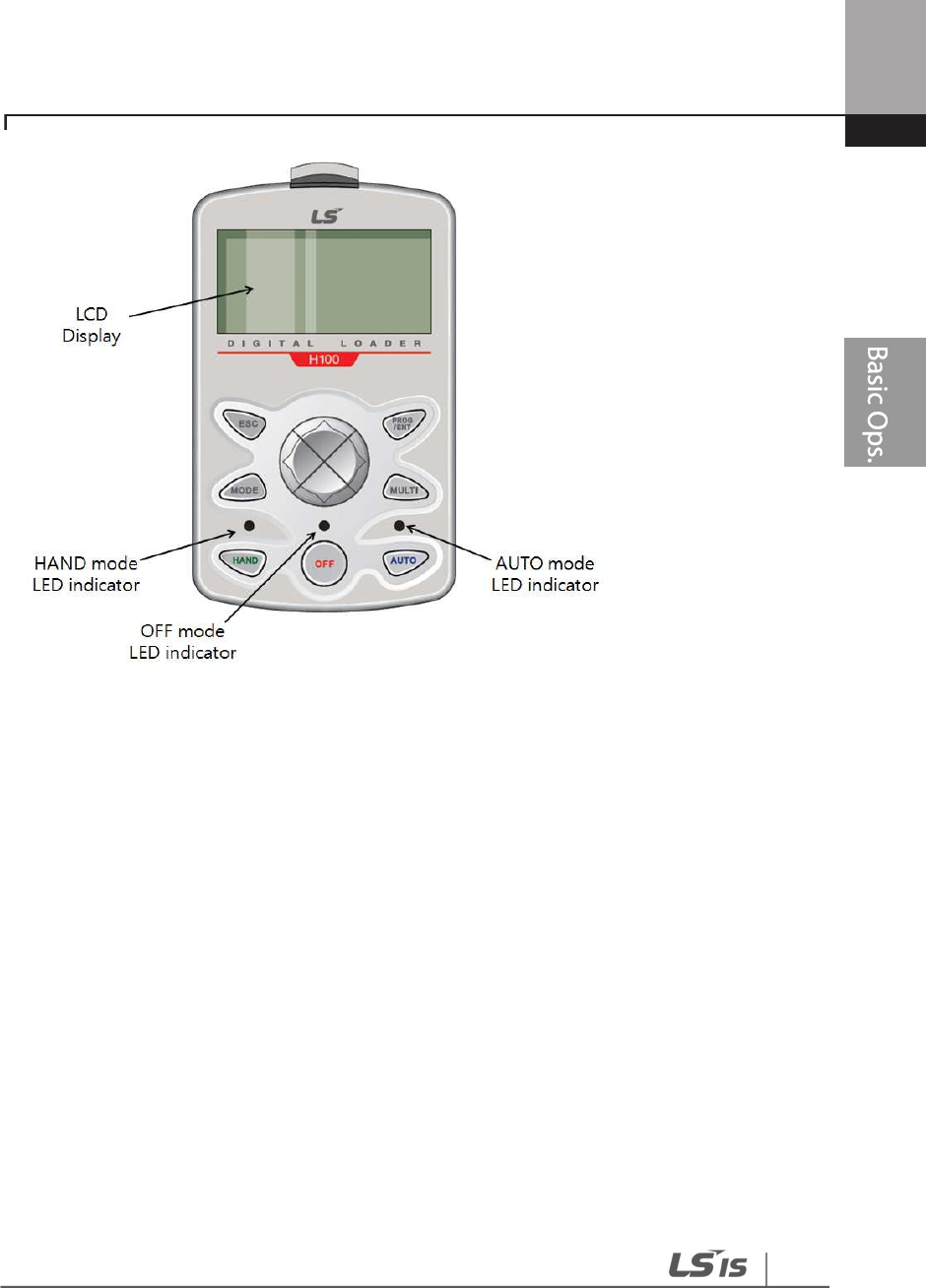
Perform Basic Operations
53
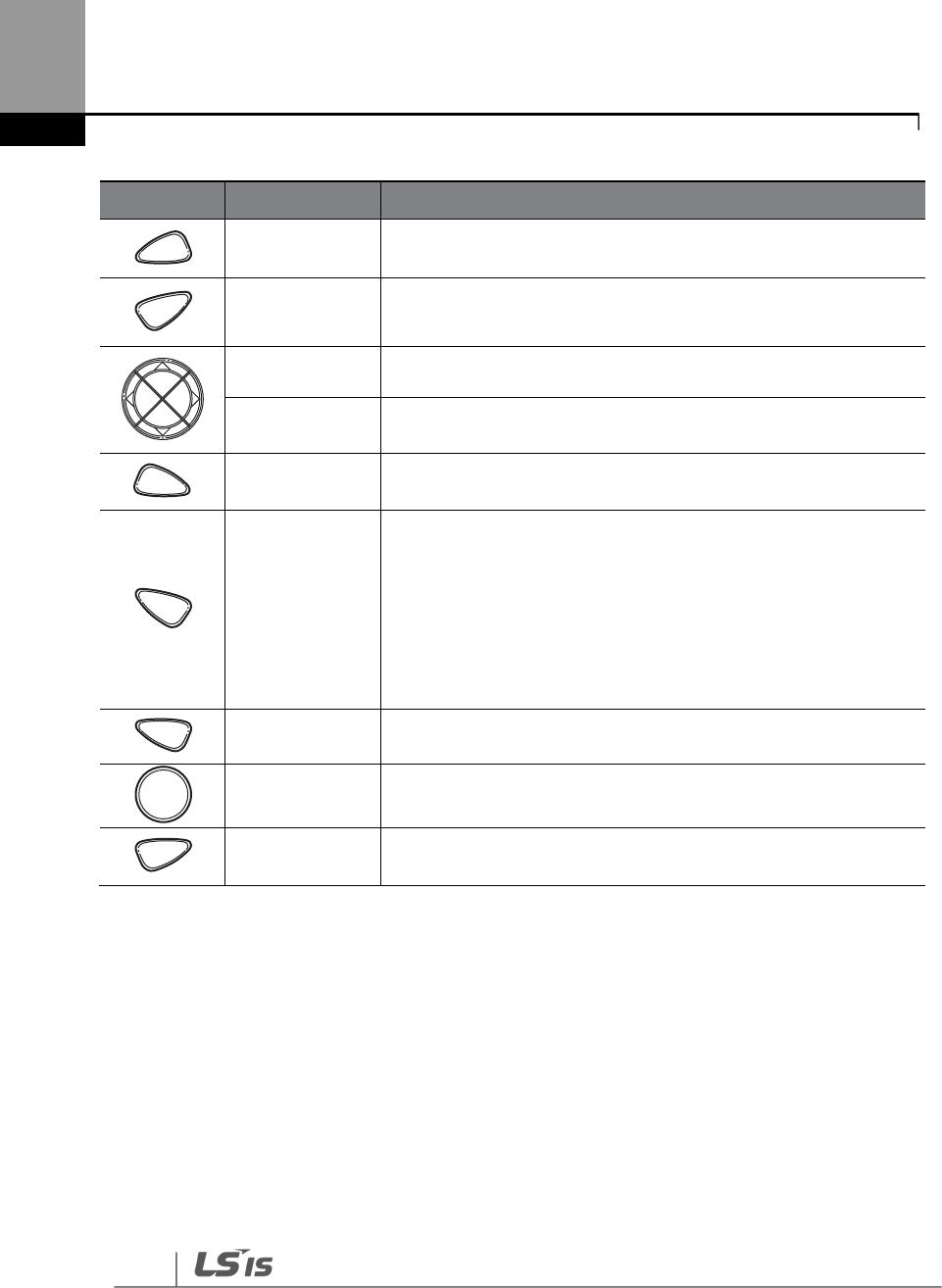
Perform Basic Operations
54
Key Name Description
[MODE] Key Used to switch between modes.
[PROG / Ent] Key Used to select, confirm, or save a parameter value.
[Up] key
[Down] key Switch between codes or increase or decrease parameter values.
[Left] key
[Right] key
Switch between groups or move the cursor during parameter
setup or modification.
[MULTI] Key Used to perform special functions, such as user code registration.
[ESC] Key
Used to cancel an input during parameter setup.
Pressing the [ESC] key before pressing the [PROG / ENT] key reverts
the parameter value to the previously set value.
Pressing the [ESC] key while editing the codes in any function
group makes the keypad display the first code of the function
group.
Pressing the [ESC] key while moving through the modes makes
the keypad display Monitor mode.
[HAND] Key Used to switch to HAND (local/manual) operation mode.
[OFF] Key Used to switch to OFF (standby) mode or to reset the inverter
faults.
[AUTO] Key Used to switch to AUTO (remote) operation mode.
MODE
PROG
/ENT
MULTI
ESC
HAND
OFF
AUTO
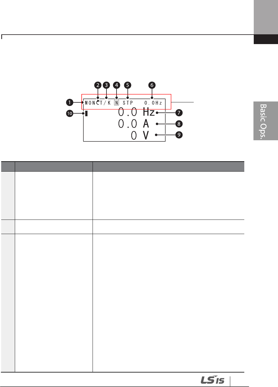
Perform Basic Operations
55
3.1.2 About the Display
Monitor mode display
The following table lists display icons and their names/functions.
No.
Name
Description
1 Operation mode
Displays one of the
following inverter modes:
Mon: Monitor mode
PAR: Parameter mode
U&M: User defined and Macro mode
TRP: Trip mode
CNF: Config mode
2 Rotational direction Displays the motor’s rotational direction: - Fx or Rx.
3 Command Source /
Frequency reference
Displays a combination of a
command source and a
frequency reference.
Command source
K: Keypad
O: Optional Fieldbus module
A: Application option
E: Time event
R: Built-in RS-485 communication
T: Terminal block
Frequency reference source
K: Keypad
V: V1 terminal
I: I2 terminal
P: Pulse terminal
U: Up operation frequency (Up-down operation)
D: Down operation frequency (Up-down operation)
S: Stop operation frequency (Up-down operation)
O: Optional Fieldbus module
Status bar

Perform Basic Operations
56
No.
Name
Description
J: Jog frequency
R: Built-in RS-485 frequency
1–7: Multi-step frequency
4 Multi-function key (UserGrp
SelKey) configuration
The multi function key (the [MULTI] key) on the keypad is
used to register or delete User group parameters in
Parameter mode.
5 Operating status
Displays one of the following operation states:
STP: Stop
FWD: Forward operation
REV: Reverse operation
: Forward command given
: Reverse command given
DC: DC output
WAN: Warning
STL: Stall
SPS: Speed search
OSS: S/W over current protection is on
OSH: H/W overcurrent protection
TUN: Auto tuning
PHT: Pre-heat
FIR: Fire mode operation
SLP: Sleep mode operation
LTS: Load tuning
CAP: Capacity diagnostics
PCL: Pump clean
6 Status display item Status bar display item
7 Monitor mode item 1 Monitor mode display item 1
8 Monitor mode item 2 Monitor mode display item 2
9 Monitor mode item 3 Monitor mode display item 3
10 Monitor mode cursor Used to highlight currently selected items.
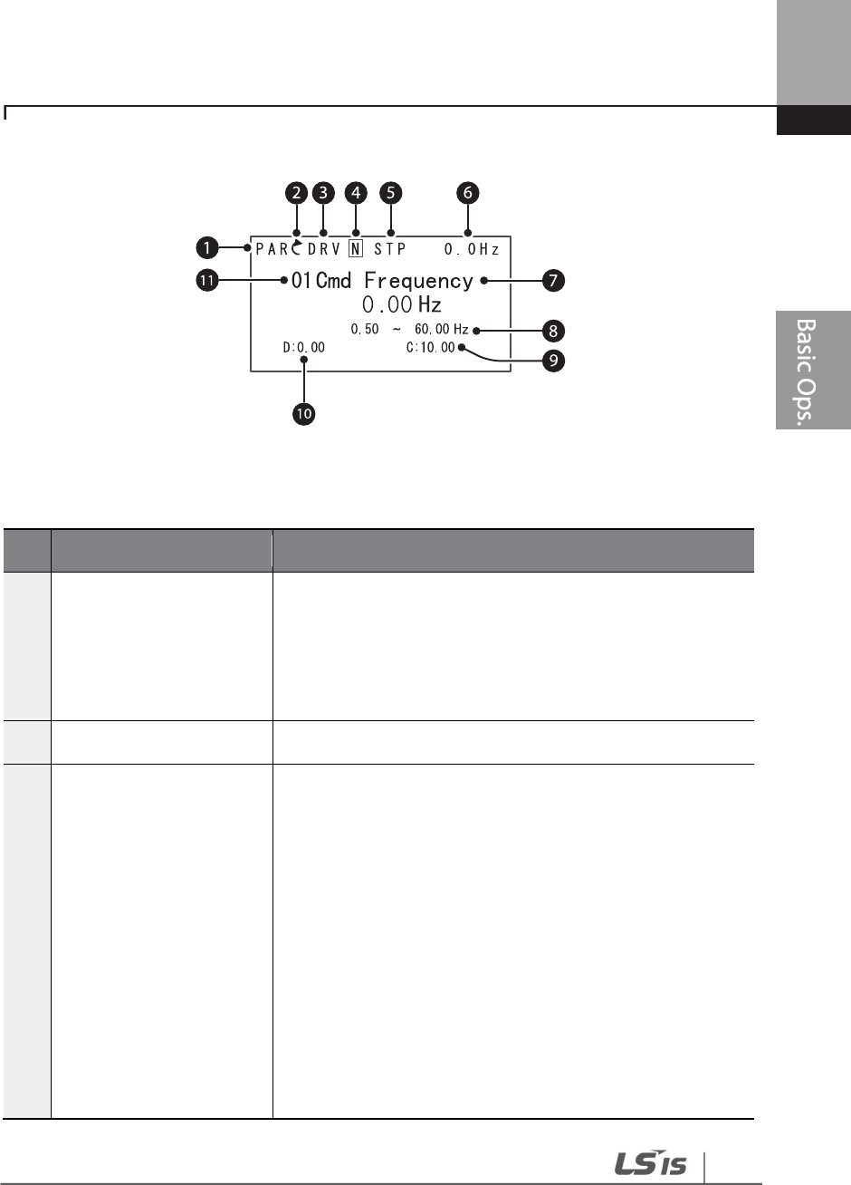
Perform Basic Operations
57
Parameter edit mode display
The following table lists display icons and their names/functions.
No. Name Description
1 Operation mode
Displays one of
the following inverter modes:
Mon: Monitor mode
PAR: Parameter mode
U&M: User defined and Macro mode
TRP: Trip mode
CNF: Config mode
2 Rotational direction Displays the motor’s rotational direction: - Fx or Rx.
3 Parameter group
Displays one of the following parameter group names:
DRV: Drive group
BAS: Basic group
ADV: Advanced group
CON: Control group
IN: Input terminal group
OUT: Output terminal group
COM: Communication group
PID: PID group
EPI: External PID group
AP1: Application 1 group
AP2: Application 2 group
AP3: Application 3 group
PRT: Protection function group
M2: 2nd motor group

Perform Basic Operations
58
No. Name Description
4
Multi
-
function key (UserGrp
SelKey)configuration
Used to register or delete User group parameters in Parameter
mode.
5 Operating status
Displays one of the following operation states:
STP: Stop
FWD: Forward operation
REV: Reverse operation
: Forward command given
: Reverse command given
DC: DC output
WAN: Warning
STL: Stall
SPS: Speed search
OSS: S/W over current protection is on
OSH: H/W overcurrent protection
TUN: Auto tuning
PHT: Pre-heat
FIR: Fire mode operation
SLP: Sleep mode operation
LTS: Load tuning
CAP: Capacity diagnostics
PCL: Pump clean
6 Display item
Displays the value of a monitor display item
selected at CNF
-
20
(Anytime Para).
7 Parameter value Displays the parameter value of currently selected code.
8 Setting range Displays the value range for the selected parameter.
9 Set value Displays the currently set value for the code.
10 Default Displays the factory default value for the code.
11 Code no. and name Displays the number and name of the currently selected code.
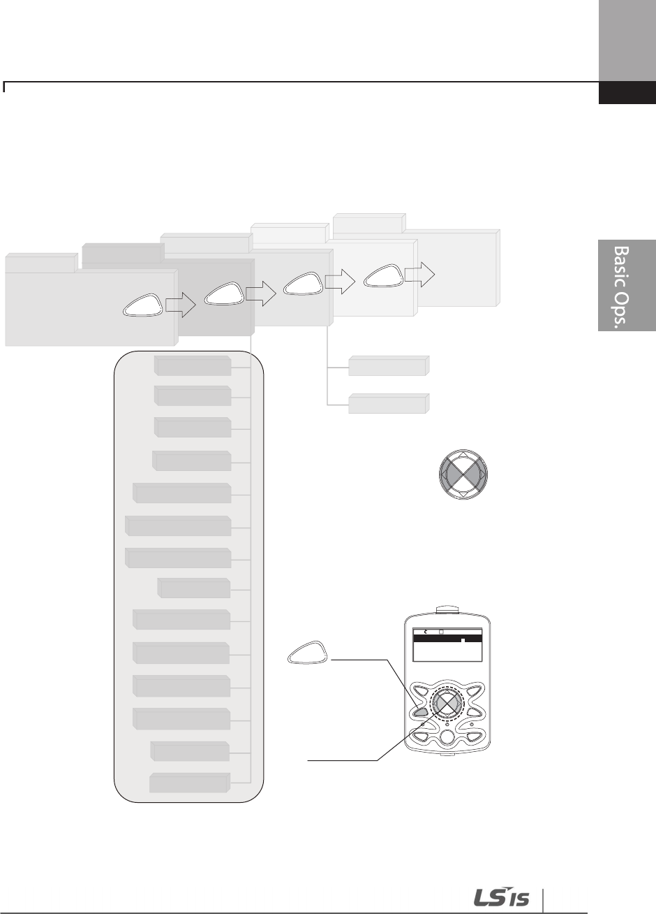
Perform Basic Operations
59
3.1.3 Display Modes
The H100 inverter uses 5 modes to monitor or configure different functions. The parameters in
Parameter mode and User & Macro mode are divided into smaller groups of relevant functions.
Cong
Trip
UserDrive
Basic
Advanced
Control
Input Terminal
Output Terminal
Communication
Appilcation 1
Protection
M2
PID
External PID
Appilcation 2
Appilcation 3
Macro
User &Macro
Parameter
Monitor
Press the [MODE] key to navigate between groups
MODE
MODE
MODE
MODE
In the Parameter group,
press the [LEFT] or [RIGHT]
cursor key to navigate
between dierent groups.
MODE MULTI
ESC
HAND OFF AUTO
PROG
/ENT
MODE [MODE] key
Cursor keys
F r e q u e n c y
0 . 0 0 H z
0 . 0
A
0
V
0
M O N T/ K N S T P 0 . 0 H z

Perform Basic Operations
60
Table of Display Modes
The following table lists the 5 display modes used to control the inverter functions.
Mode Name
Keypad
Display
Description
Monitor mode MON
Displays the inverter’s operation status information. In this
mode, information including the inverter’s frequency
reference, operation frequency, output current, and voltage
may be monitored.
Parameter mode PAR
Used to configure the functions required to operate the
inverter. These functions are divided into 14 groups based
on purpose and complexity.
User & Macro
mode U&M
Used to define User groups and Macro groups. These user
-
definable groups allow specific functions of the inverter to
be grouped and managed in separate groups.
This mode is not displayed when you navigate through the
modes if no user groups or Macro groups have been
defined.
Trip mode TRP
Used to monitor the inverter’s fault trip information,
including the previous fault trip history.
When a fault trip occurs during inverter operation, the
operation frequency, output current, and output voltage of
the inverter at the time of the fault may be monitored.
This mode is not displayed if the inverter is not at fault and
fault trip history does not exist.
Config mode CNF
Used to configure the inverter features that are not directly
related to the operation of the inverter. The settings you
can configure in the Config mode include keypad display
language options, monitor mode environment settings,
communication module display settings, and parameter
duplication and initialization.

Perform Basic Operations
61
Parameter Setting Mode
The following table lists the functions groups under Parameter mode.
Function Group Name
Keypad
Display
Description
Drive DRV
Configures basic operation parameters. These
include jog operation, motor capacity evaluation, and
torque boost.
Basic BAS
Configures basic operation parameters. These
parameters include motor parameters and multi-step
frequency parameters.
Advanced ADV
Configures acceleration or deceleration patterns,
frequency limits, energy saving features, and,
regeneration prevention features.
Control CON
Configures the features related to speed search and KEB
(kinetic energy buffering).
Input Terminal IN
Configures input terminal
–
related features, including
digital multi–functional inputs and analog inputs.
Output Terminal OUT
Configures output terminal
–
related features, including
digital multi–functional outputs and analog outputs.
Communication COM
Configures the USB
-
related features and communication
features for the RS-485, Modbus-RTU, LS Bus, Metasys
N2, and BACnet. Optional communication module
related features may be configured as well, if one is
installed.
PID process
PID
Configures the PID control
-
related features.
EPID process
EPI
Configures the external PID control
-
related features.
Application 1 AP1
Configures the Sleep Boost, SoftFill, and Multiple motor
control (MMC) features related to the PID control.

Perform Basic Operations
62
Function Group Name
Keypad
Display
Description
Application 2 AP2
Configures the
HVAC features by setting the features
such as load tuning, pump cleaning, and pay back
counter.
Application 3
AP3
Configures the time event
-
related features.
Protection
PRT
Configures motor and inverter protection features.
Motor 2 (Secondary
motor) M2 Configures the secondary motor-related features.

Perform Basic Operations
63
User & Macro Mode
Function Group Name
Keypad
Display
Description
User USR
Used to put the frequently accessed function
parameters together into a group. User parameter
groups can be configured using the multi-function key
on the keypad.
Macro MCx
Provides different factory
-
preset group
s of functions
based on the type of load.
Groups MC1, MC2, or MC3 is displayed when the user
selects the type of desired load. Macro groups can be
selected in CNF mode.
3.2 Learning to Use the Keypad
The keypad enables movement between groups and codes. It also enables users to select and
configure functions. At code level, you can set parameter values to turn specific functions on or off
or decide how the functions will be used. For detailed information on the codes in each function
group, refer to 8 Table of Functions on page 415. Confirm the correct values (or the correct range of
the values), then follow the examples below to configure the inverter with the keypad.
3.2.1 Display Mode Selection
The following figure illustrates how the display modes change when you press the [Mode] button
on the keypad. You can continue to press the [Mode] key until you get to the desired mode.
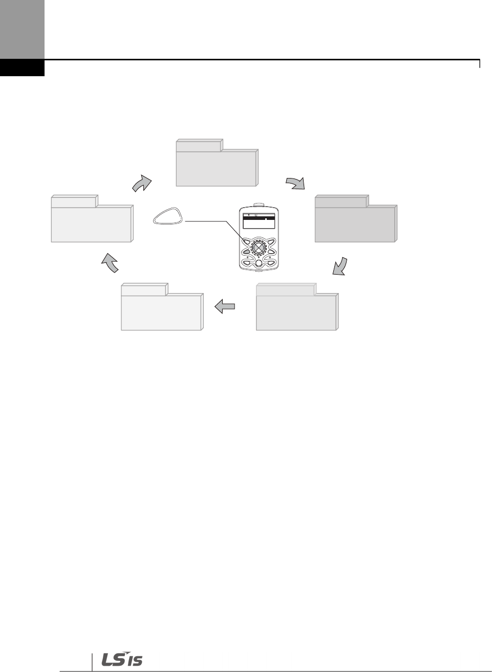
Perform Basic Operations
64
User & Macro mode and Trip mode are not displayed when all the inverter settings are set to the
factory default (User & Macro mode must be configured before it is displayed on the keypad, and
Trip mode is displayed only when the inverter is at fault, or has previous trip fault history).
3.2.2 Operation Modes
The inverter is operable only when it is in HAND or AUTO mode. HAND mode is for local control
using the keypad, while AUTO mode is for remote control via communication. On the other hand,
the inverter stops operating when it is in OFF mode. Select one of the modes (HAND / AUTO / OFF)
to operate the inverter or stop the operation.
Follow the examples below to learn how to switch between operation modes.
Operating the Inverter in HAND mode
1 Turn on the inverter. The inverter enters OFF mode and the OFF LED turns on.
2 Move to Parameter mode and set DRV-07 (frequency reference) to ‘0 (keypad)’.
3 Press the [HAND] key to enter HAND mode (local control mode). HAND mode LED turns on
(the OFF LED turns off) and the inverter begins to operate.
4 Press the [OFF] key to stop the inverter operation. The inverter stops operating and the OFF
LED turns on.
Monitor
Parameter
User &Macro
Cong
Trip
MODE MULTI
ESC
HAND OFF AUTO
PROG
/ENT
MODE [MODE] key
F r e q u e n c y
0 . 0 0 H z
0 . 0 A
0 V
0
M O N T/ K N S T P 0 . 0 H z

Perform Basic Operations
65
Operating the inverter in AUTO Mode
1 In OFF mode (when the OFF LED is on), move to Parameter mode and configure the
command source at DRV-07 (frequency reference source).
2 Press the [AUTO] key to enter AUTO mode. In AUTO mode, the inverter operates based on the
input from the command source set at DRV-07. For example, if DRV-07 (frequency reference
source) is set to ‘0 (Keypad)’, the frequency reference is set, and the run command is set to ‘ON’,
the inverter starts operating as soon as the [AUTO] key on the keypad is pressed.
3 Press the [Auto] key again to stop the inverter operation using the keypad. In AUTO mode,
the inverter begins or stops operating when the [AUTO] key is pressed.
Note
• You can stop the inverter operation by pressing the [OFF] key when the command source is set to
‘Keypad.’ In this case, however, the inverter enters OFF mode from AUTO mode.
• If the network communication is set as the command source, the inverter is operable only in
AUTO mode. For example, if the run command is set to ‘ON’ via the network communication and
the inverter is in OFF mode, the [AUTO] key must be pressed to start the inverter operation.
• The inverter is operable only in HAND and AUTO modes, but the Fire mode functions operate
even when the inverter is in OFF mode.
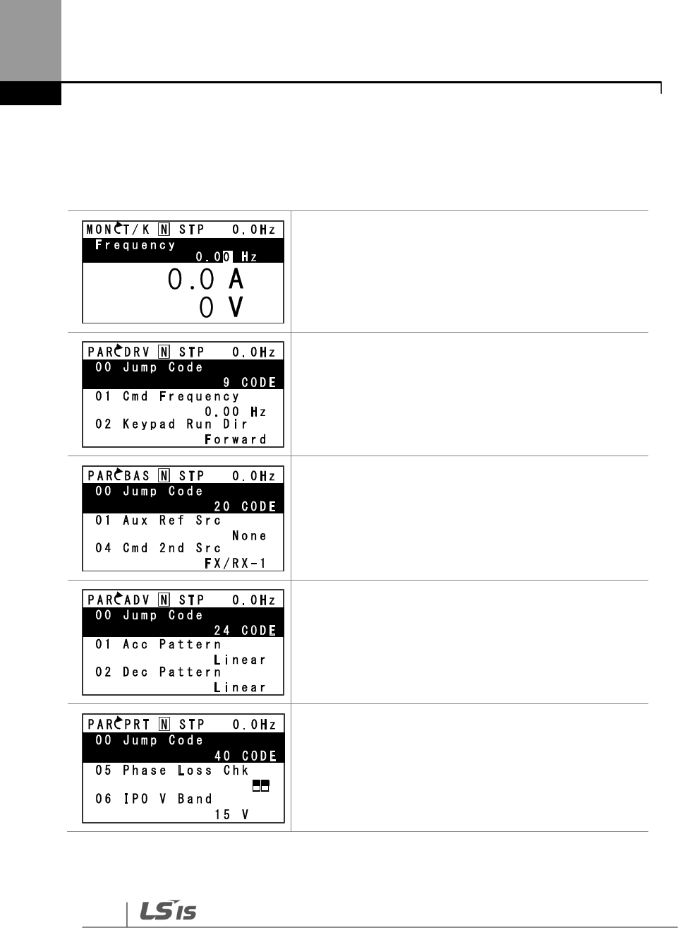
Perform Basic Operations
66
3.2.3 Switching between Groups in Parameter Display Mode
After entering Parameter mode from Monitor mode, press the [Right] key to move to the next
code. Press the [Left] key to go back to the previous code.
The keypad OFF LED is turned OFF, and the keypad displays
Monitor mode.
• Press the [Mode] key to change the mode.
Parameter mode is displayed.
• The Drive group is currently selected.
• Press the [Right] key.
• The Basic group is selected.
• Press the [Right] key.
• The Advanced group is selected.
• Press the [Right] key 9 times.
• The Protection group is selected.
• Press the [Right] key.
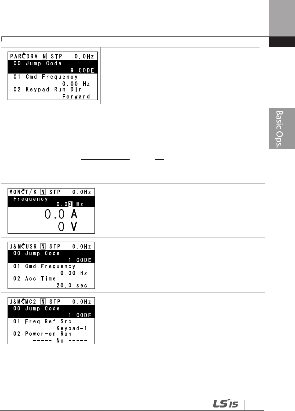
Perform Basic Operations
67
• The Drive group is selected again.
3.2.4 Switching between Groups in User & Macro Mode
User & Macro mode is accessible only when the user codes are registered or when the macro
features are selected. Refer to 8.16 Macro Groups on page 516 for details about user code
registration or macro group selection. After registering the user codes, or selecting a macro group,
follow the examples below to access the User & Macro group.
• Monitor mode is displayed on the keypad.
• Press the [MODE] key twice.
• User (USR) group in User & Macro mode is displayed.
• Press the [Right] key.
• The Macro (MC2) group in User & Macro mode is
displayed.
• Press the [Right] key.
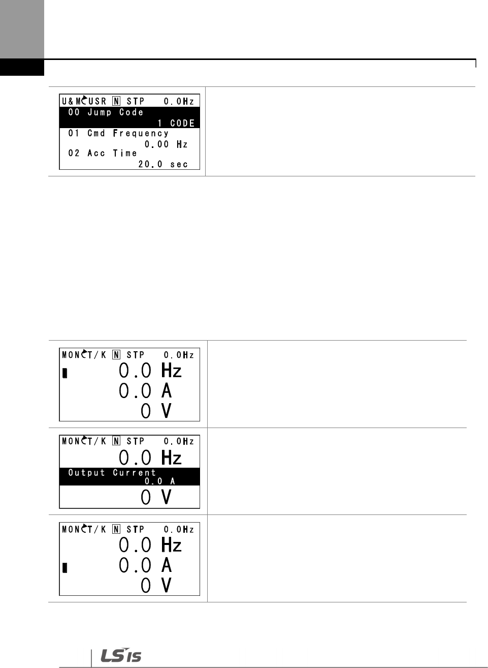
Perform Basic Operations
68
• User (USR) group in User & Macro mode is displayed
again.
3.2.5 Navigating through the Codes (Functions)
Code Navigation in Monitor mode
The display items in Monitor mode are available only when the inverter is in AUTO mode. In
Monitor mode, press the [Up] or [Down] key to move the cursor up or down. Different values, such
as the operating frequency, the output current, or voltage are displayed according to the cursor
position. The cursor does not move up or down in HAND mode or in OFF mode.
• In AUTO mode, the cursor appears to the left of the
frequency information.
• Press the [Down] key.
• Information about the second item in Monitor mode
(Output Current) is displayed.
• Wait for 2 seconds until the information on the display
disappears.
• Information about the second item in Monitor mode
(Output Current) disappears and the cursor reappears
to the left of the second item.
• Press the [Down] key.
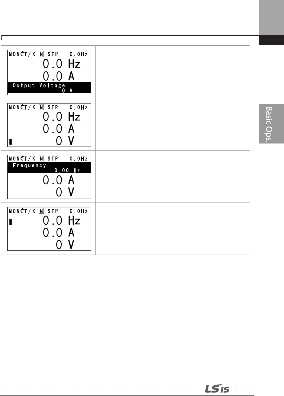
Perform Basic Operations
69
• Information about the third item in Monitor mode
(Output Voltage) is displayed.
• Wait for 2 seconds until the information on the display
disappears.
• Information about the third item in Monitor mode
(Output Voltage) disappears and the cursor appears to
the left of the third item.
• Press the [Up] key twice.
• Information about the first item in Monitor mode
(Frequency) is displayed.
• Wait for 2 seconds until the information on the display
disappears.
• Information about the first item in Monitor mode
(Frequency) disappears and the cursor appears to the
left of the first item.
• Press the [Up] or [Down] key to move to a desired item
and view the information.
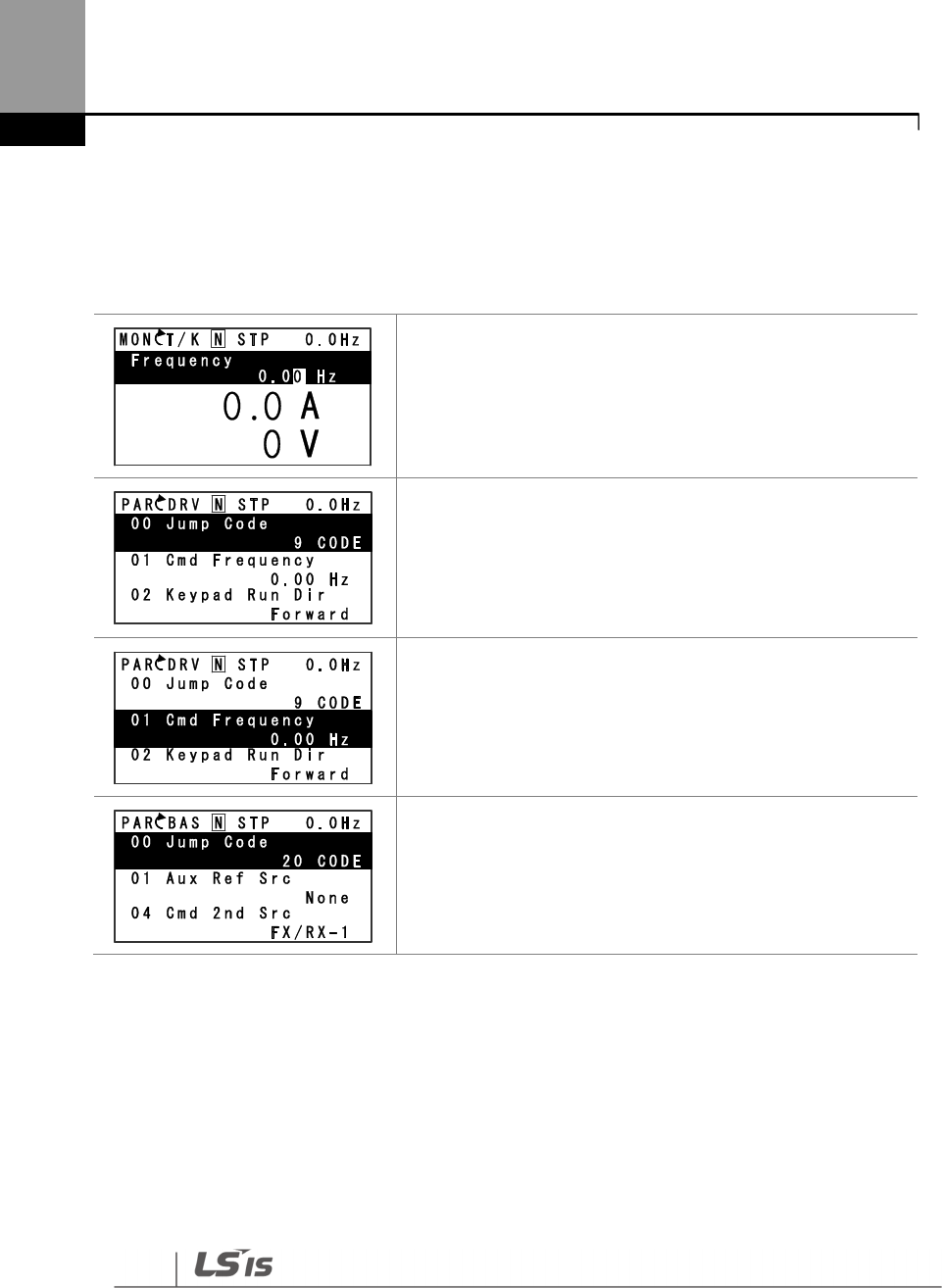
Perform Basic Operations
70
Code Navigation in Parameter mode
The following examples show you how to move through codes in different function groups (Drive
group and Basic group) in Parameter mode. In Parameter mode, press the [Up] or [Down] key to
move to the desired functions.
• Display turns on when the inverter is powered on.
Monitoring mode is displayed.
• Press the [MODE] key.
• Drive group (DRV) in Parameter mode is displayed. The
first code in the Drive group (DRV 00 Jump Code) is
currently selected.
• If any other group is displayed, press the [MODE] key until
the Drive group is displayed, or press the [ESC] key.
• Press the [Down] key to move to the second code (DRV
01) of the Drive group.
• Press the [Right] key to move to the next function group.
• The Basic group (BAS) is displayed.
• Press the [Up] or [Down] key to move to the desired
codes and configure the inverter functions.
3.2.6 Navigating Directly to Different Codes
Parameter mode, User & Macro mode, and Config mode allow direct jumps to specific codes. The
code used for this feature is called the Jump Code. The Jump Code is the first code of each mode.
The Jump Code feature is convenient when navigating for a code in a function group that has
many codes.
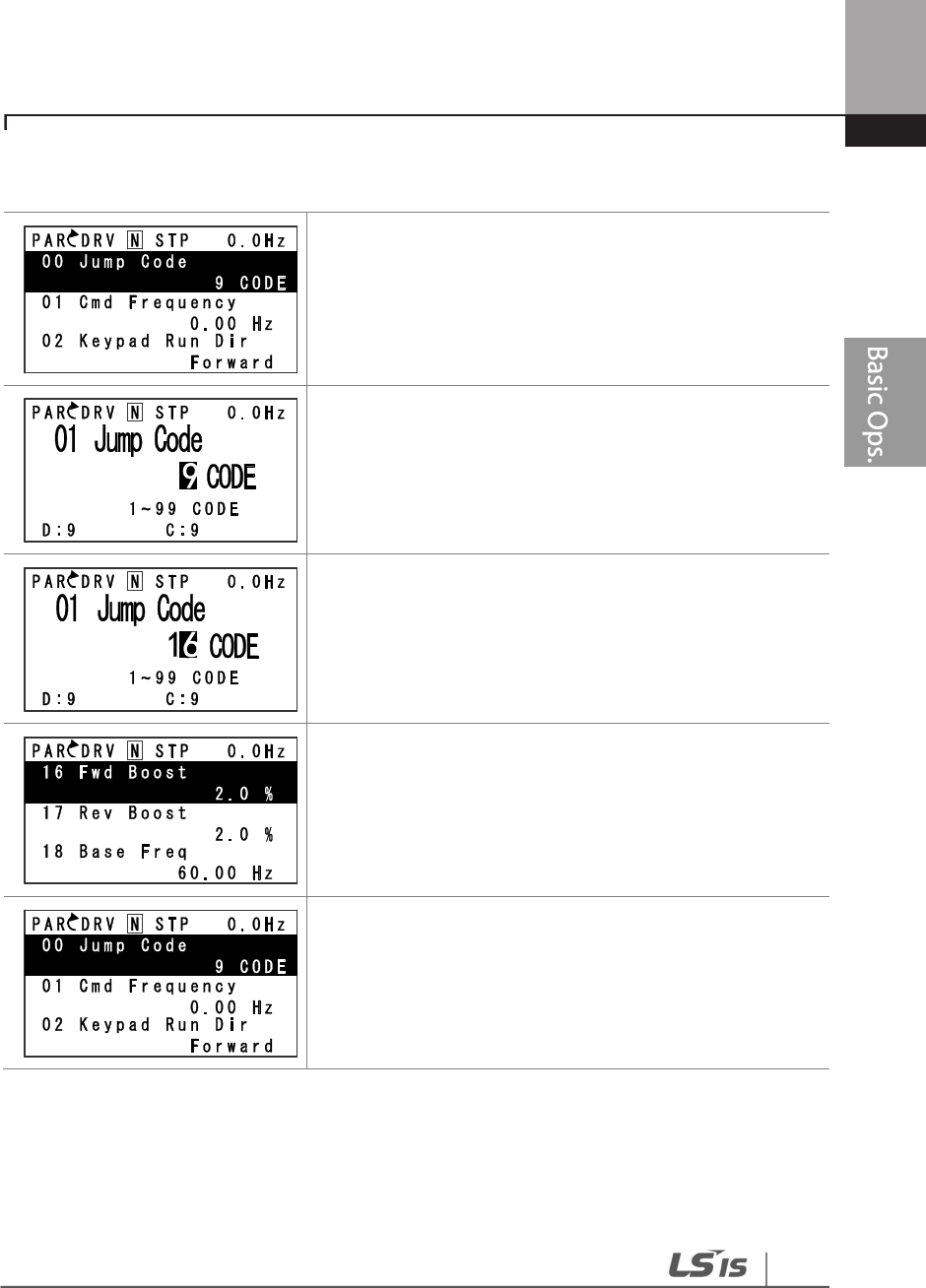
Perform Basic Operations
71
The following example shows how to navigate directly to code DRV- 09 from the initial code (DRV-
00 Jump Code) in the Drive group.
• The Drive group (DRV) is displayed in Parameter mode.
Make sure that the fist code in the Drive group (DRV 00
Jump Code) is currently selected.
• Press the [PROG/ENT] key.
• The Code input screen is displayed and the cursor
flashes. A flashing cursor indicates that it is waiting for
user input.
• Press the [Up] key to increase the number to 16, and
then press the [PROG/ENT] key to jump to code DRV-16.
• DRV-16 (Fwd boost) is displayed.
• Press the [MODE] key to view the options available and
use the [Up] or [Down] key to move to a desired option.
• Press the [PROG/ENT] key to save the selection.
• The setting is saved and the code is displayed again.
• Press the ESC key to go back to the initial code of the
Drive group (DRV-00).
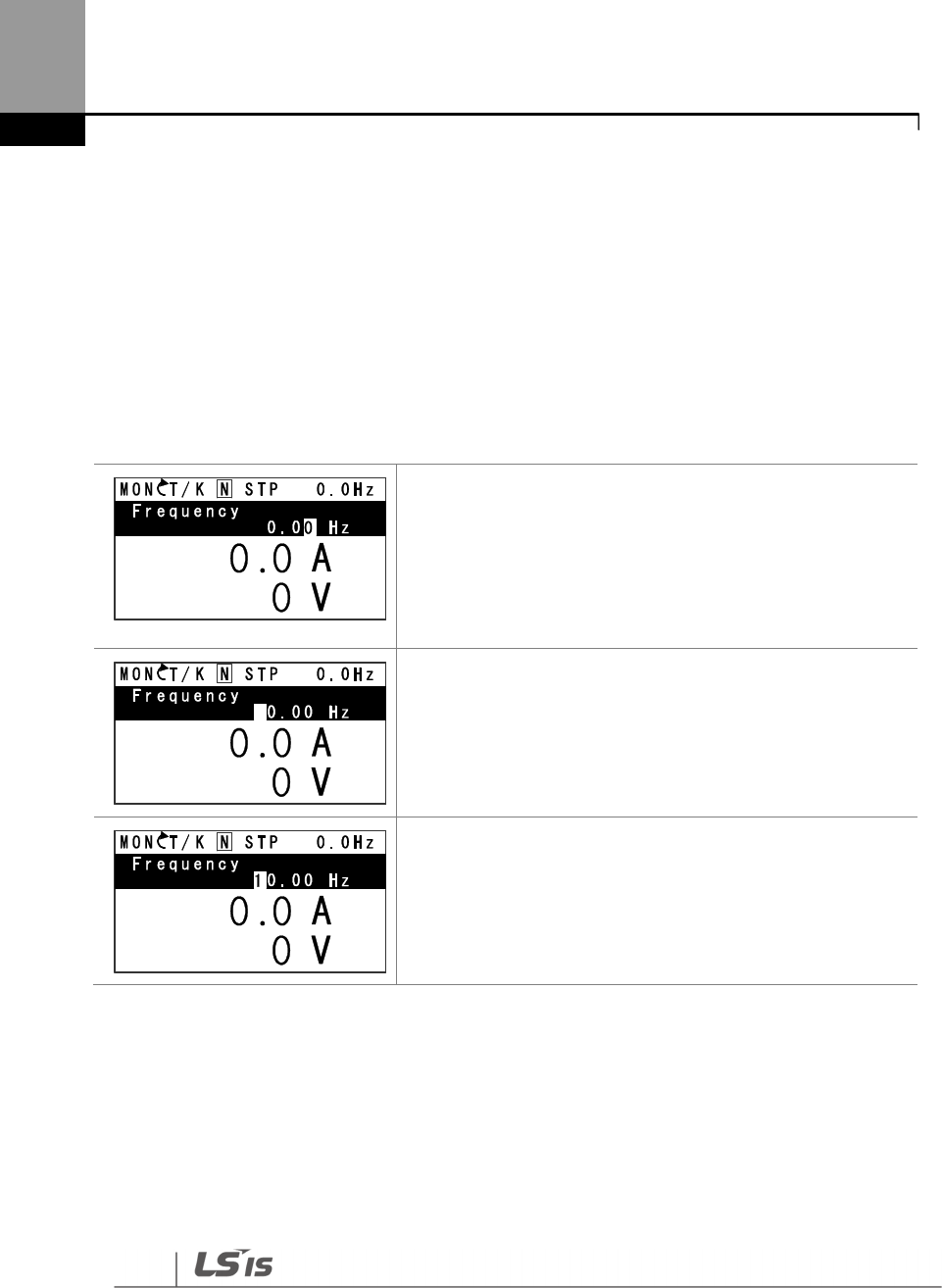
Perform Basic Operations
72
3.2.7 Parameter Settings available in Monitor Mode
The H100 inverter allows basic parameters, such as the frequency reference, to be modified in
Monitor mode. When the inverter is in Hand or OFF mode, the frequency reference can be entered
directly from the monitor screen. When the inverter is in AUTO mode, press the [PROG/ENT] key to
access the input screen for a frequency reference.
Parameter setting in HAND/OFF mode
• Ensure that the cursor is at the frequency reference item.
If not, move the cursor to the frequency reference item.
• When the cursor is at the frequency reference item,
detailed information is displayed and the cursor flashes
at the input line. A flashing cursor indicates that it is
waiting for user input.
• Press the [Left] or [Right] key to change places.
• Press the [Up] or [Down] keys to increase or decrease
the numbers, and then press the [Prog/ENT] key to save
the change.
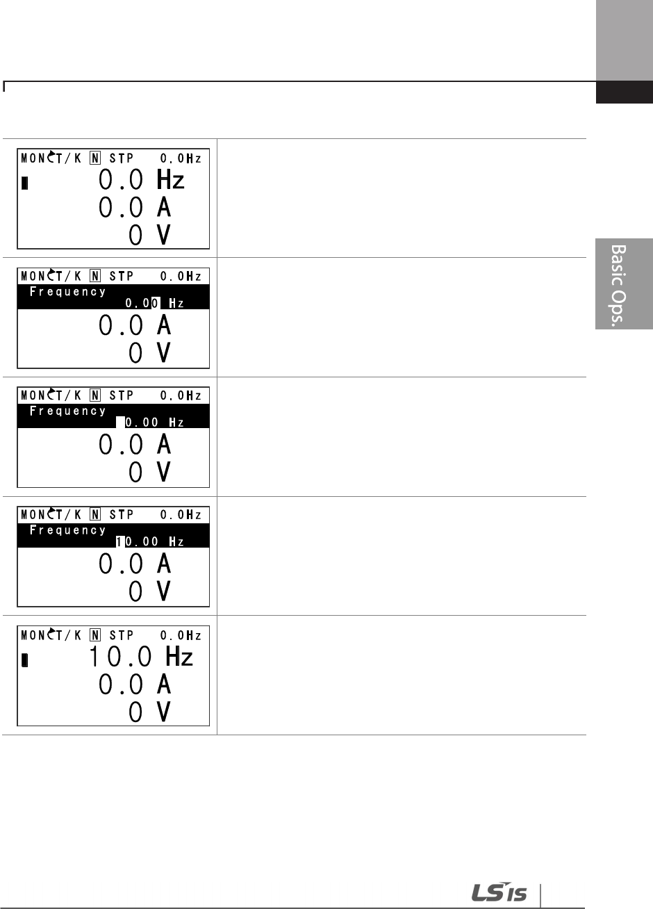
Perform Basic Operations
73
Parameter setting in AUTO mode
3.2.8 Setting the Monitor Display Items
In Monitor mode, 3 different items may be monitored at once. Certain monitor items, such as the
frequency reference, are selectable. The display items to be displayed on the screen can be
selected by the user in the Config (CNF) mode. However, in HAND mode or in OFF mode, the first
display item is permanently fixed as the frequency reference. On the top- right
• Ensure that the cursor is at the frequency reference item.
If not, move the cursor to the frequency reference item.
• While the cursor is at the frequency reference monitor
item, press the [PROG/ENT] key to edit the frequency
reference.
• Detailed information is displayed and the cursor flashes at
the input line. A flashing cursor indicates that it is waiting
for user input.
• Press the [Left] or [Right] key to move the cursor.
• Press the [Up] or [Down] key to increase or decrease the
numbers.
• When you are done changing the frequency reference,
press [PROG/ENT] key to finish setting the parameters.
• The newly entered frequency reference is displayed.
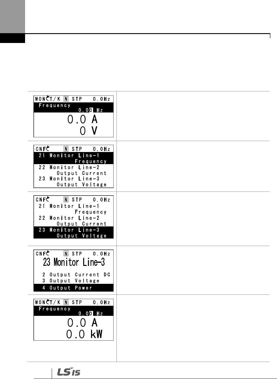
Perform Basic Operations
74
corner of the keypad display’s status bar, another frequency item is displayed. This item refers to
the frequency reference when the inverter is not operating and the output frequency when the
inverter is operating.
The following example shows how to configure the display items in HAND mode.
• Monitor mode is displayed on the keypad. The output
frequency, output current, and output voltage are
displayed (factory default).
• Go to the Config (CNF) mode. In the Config mode, codes
CNF-21–23 are used to select the three monitoring
display items. The currently selected display item and its
setting are highlighted.
• To view the available display items and change the
setting for the third monitoring display item, press the
[Down] key to move to CNF-23 and press the [PROG/ENT]
key.
• The currently selected display item for CNF-23 (Monitor
Line–3) is ‘Output Voltage.’
• Press the [Up] or [Down] key to view the available display
items.
• Move to ‘4 Output Power’ and press the [PROG/ENT] key
to change the setting.
• Press the [MODE] key to go back to Monitor mode. The
third display item has been changed to the inverter
output power (kW).
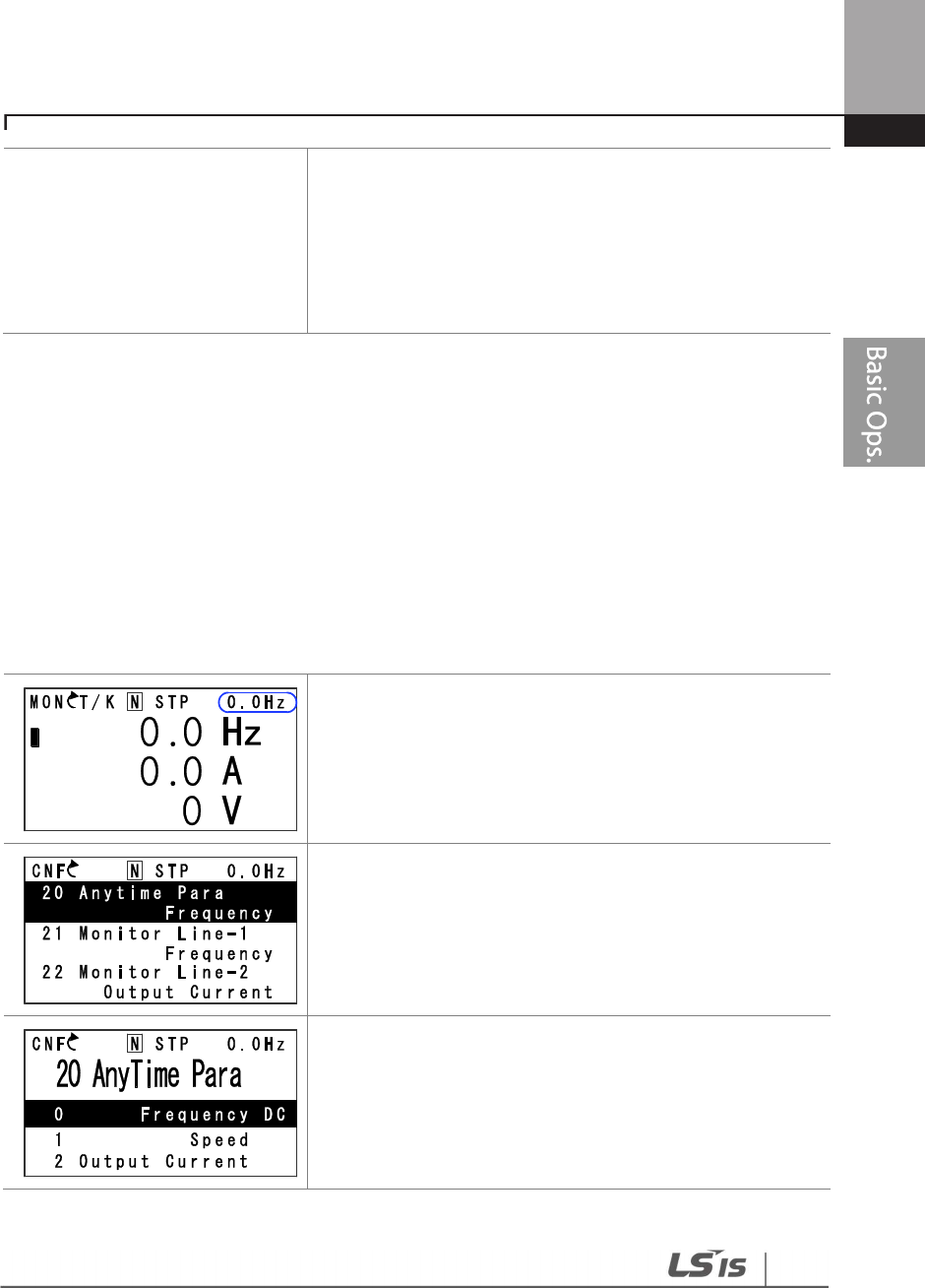
Perform Basic Operations
7
5
3.2.9 Selecting the Status Bar Display Items
On the top-right corner of the display, there is a monitoring display item. This monitoring item is
displayed as long as the inverter is turned on, regardless of the mode the inverter is operating in.
Configure this monitoring item to display the type of information that suits your needs.
This item can be configured only when the inverter is operating in AUTO mode. In HAND or OFF
mode, this monitoring item displays frequency reference only.
The following example shows how to configure this monitoring item in AUTO mode.
• Monitor mode is displayed.
• On the top-right edge of the display, the frequency
reference is displayed (factory default).
• Enter Config mode and go to CNF-20 to select the items
to display.
• Press the [PROG/ENT] key. The currently selected item is
highlighted.
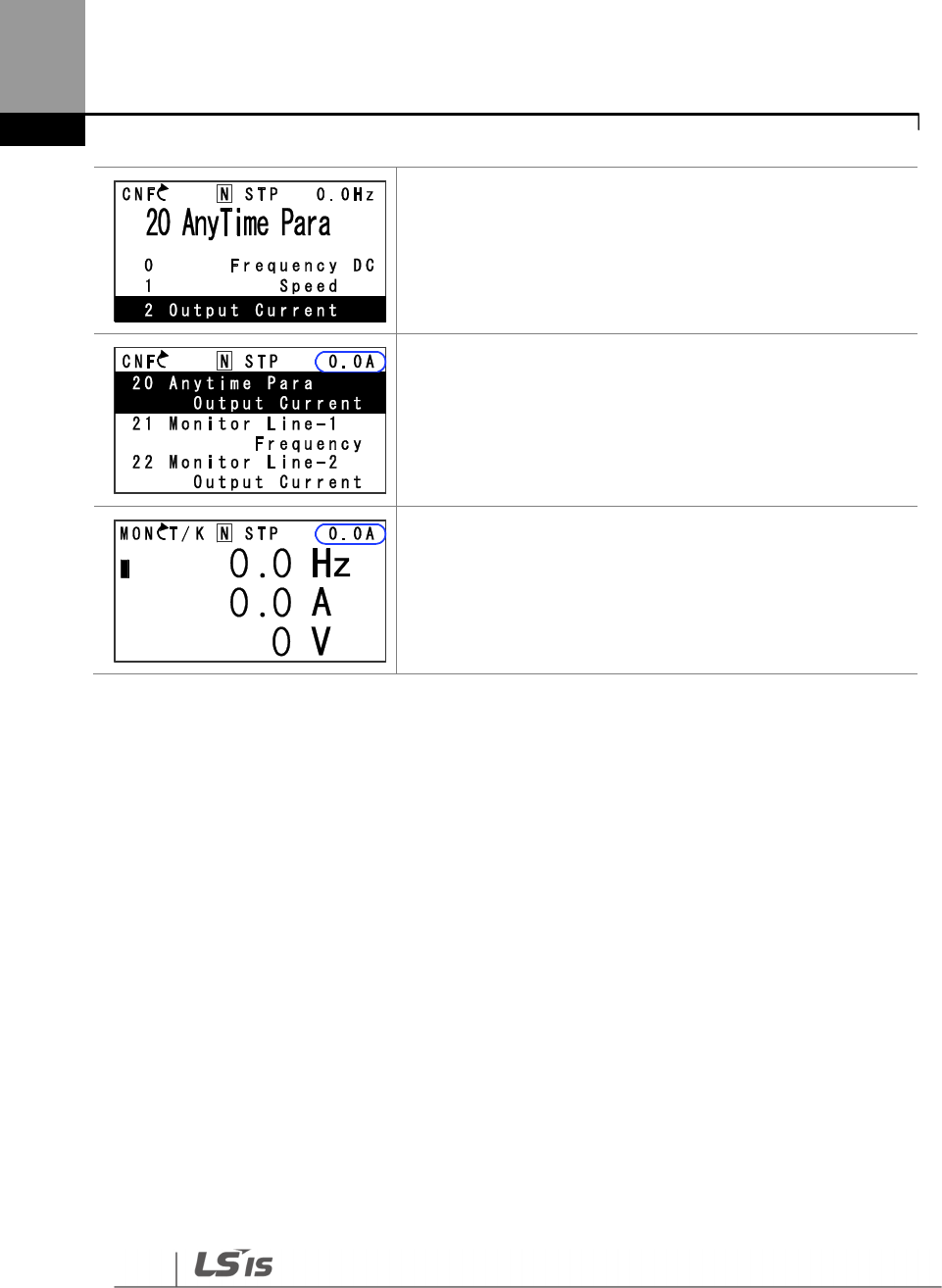
Perform Basic Operations
76
• Press the [Down] key twice to move to ‘2 (Output
Current)’, and then press the [PROG/ENT] key to select it.
• The currently selected item is highlighted at CNF- 20 (the
display item is changed from ‘Frequency’ to ‘Output
Current’).
• Press the [MODE] key to return to Monitor mode.
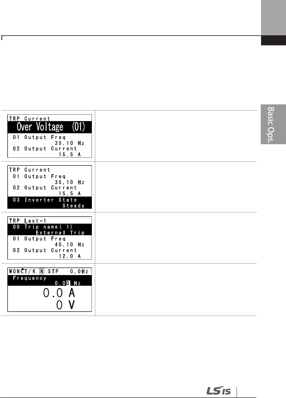
Perform Basic Operations
77
3.3 Fault Monitoring
3.3.1 Monitoring Faults during Inverter Operation
The following example shows how to monitor faults that occurred during inverter operation.
• If a fault trip occurs during inverter operation, the inverter
enters Trip mode automatically and displays the type of
fault trip that occurred.
• Press the [Down] key to view the information on the
inverter at the time of fault, including the output
frequency, output current, and operation type.
• If there were any fault trips that occurred previously, press
the [Right] key to display the fault trip information at the
times of previous fault trips.
• When the inverter is reset and the fault trip is released,
the keypad display returns to the screen it was at when
the fault trip occurred.
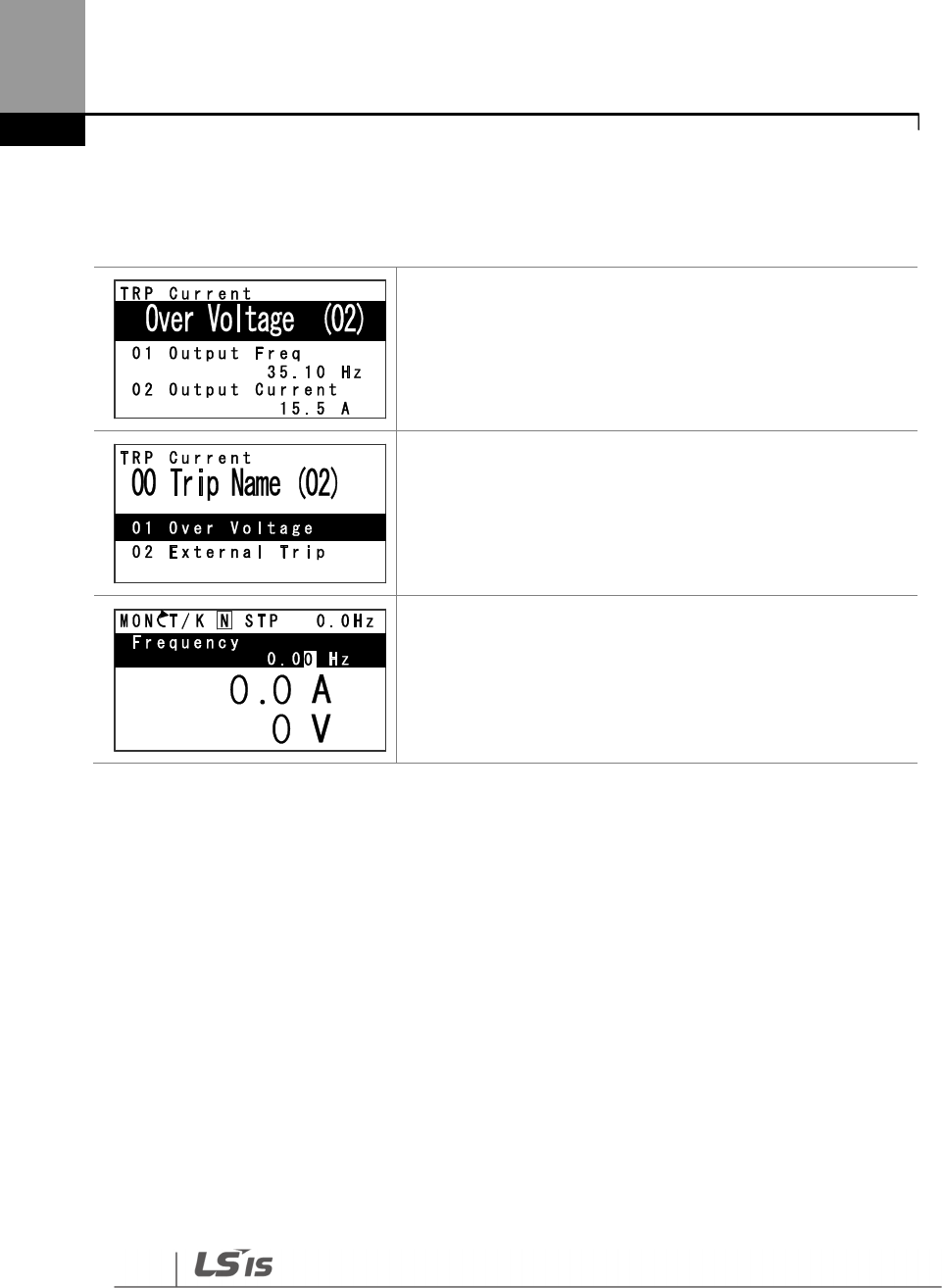
Perform Basic Operations
78
3.3.2 Monitoring Multiple Fault Trips
The following example shows how to monitor multiple faults that occur at the same time.
• If multiple fault trips occur at the same time, the number
of fault trips occurred is displayed on the right side of
the fault trip type.
• Press the [PROG/ENT] key to view the list of all the fault
trips.
• The list of all the fault trips is displayed.
• Press the [Down] key to view the types of fault trips that
occurred.
• Press the [Right] key to display the fault trip information.
• When the inverter is reset and the fault trip is released,
the keypad display returns to the screen it was at when
the fault trip occurred.
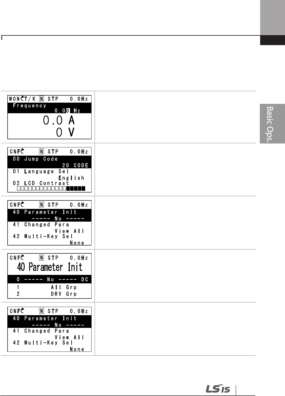
Perform Basic Operations
79
3.4 Parameter Initialization
The following example demonstrates how to revert all the parameter settings back to the factory
default (Parameter Initialization). Parameter initialization may be performed for separate groups in
Parameter mode as well.
• Monitor mode is displayed.
• Press the [MODE] key to move to the Config (CNF)
mode.
• Press the [Down] key to go to CNF-40 (Parameter Init).
• Press the [PROG/ENT] key to configure the parameter
initialization options.
• In the list of options, select ‘1(All Grp),’ and then press the
[PROG/ENT] key to perform parameter initialization.
• The parameter initialization option is displayed again
when the initialization is complete.

80
Learning Basic Features
4 Learning Basic Features
This chapter describes the basic features of the H100 inverter. Check the reference page in the
table to see the detailed description for each of the advanced features.
Basic Tasks
Description
Ref.
Operation mode selection
(HAND / AUTO / OFF) Used to select the operation mode. p.83
Frequency reference source
configuration for the keypad
Configures the inverter to allow you to setup or modify a
frequency reference using the Keypad. p.88
Frequency reference source
configuration for the
terminal block (input
voltage)
Configures the inverter to allow input voltages at the
terminal block (V1, V2) and to setup or modify a frequency
reference.
p.89
p.99
Frequency reference source
configuration for the
terminal block (input
current)
Configures the inverter to allow input currents at the
terminal block (I2) and to setup or modify a frequency
reference.
p.96
Frequency reference source
configuration for the
terminal block (input pulse)
Configures the inverter to allow input pulse at the terminal
block (TI) and to setup or modify a frequency reference. p.100
Frequency reference source
configuration for RS-485
communication
Configures the inverter to allow communication signals
from upper level controllers, such as PLCs or PCs, and to
setup or modify a frequency reference.
p.102
Frequency control using
analog inputs
Enables the user to hold a frequency using analog inputs
at terminals. p.102
Motor operation display
options
Configures the display of motor operation values. Motor
operation is displayed either in frequency (Hz) or speed
(rpm).
p.102
Multi
-
step speed (frequency)
configuration
Configures multi
-
step fr
equency operations by receiving
an input at the terminals defined for each step frequency. p.104
Command source
configuration for keypad
buttons
Command source configuration for keypad buttons. p.106
Command source
configuration for terminal
Configures the inverter to accept inputs at the FX/RX
terminals. p.107
81
Learning Basic Features
Basic Tasks
Description
Ref.
block inputs
Command source
configuration for RS-485
communication
Configures the inverter to accept communication signals
from upper level controllers, such as PLCs or PCs. p.109
Motor rotation control
Configures the inverter to limit a motor’s rotation direction.
p.
109
Automatic start-up at power-
on
Configures the inverter to start operating at power
-
on.
With this configuration, the inverter begins to run and the
motor accelerates as soon as power is supplied to the
inverter. To use automatic start-up configuration, the
operation command terminals at the terminal block must
be turned on.
p.111
Automatic restart after reset
of a fault trip condition
Configures the inverter to start operating when the
inverter is reset following a fault trip. In this configuration,
the inverter starts to run and the motor accelerates as soon
as the inverter is reset following a fault trip condition.
For automatic start-up configuration to work, the
operation command terminals at the terminal block must
be turned on.
p.113
Acc/Dec time configuration
based on the Max.
Frequency
Configures the acceleration and deceleration times for a
motor based on a defined maximum frequency. p.114
Acc/Dec time configuration
based on the frequency
reference
Configures acceleration and deceleration times for a motor
based on a defined frequency reference. p.117
Multi
-
stage Acc/Dec time
configuration using the
multi-function terminal
Configures multi
-
stage acceleration and deceleration
times for a motor based on defined parameters for the
multi-function terminals.
p.118
Acc/Dec time transition
speed (frequency)
configuration
Enables modification of acceleration a
nd deceleration
gradients without configuring the multi-functional
terminals.
p.120
Acc/Dec pattern
configuration
Enables modification of
the acceleration and deceleration
gradient patterns. Basic patterns to choose from include
linear and S-curve patterns.
p.121
Acc/Dec stop command
Stops the current acceleration or deceleration and controls
motor operation at a constant speed. Multi-function
terminals must be configured for this command.
p.123

82
Learning Basic Features
Basic Tasks
Description
Ref.
Linear V/F pattern operation
Configures the inverter to run a motor at a constant
torque. To maintain the required torque, the operating
frequency may vary during operation.
p.125
Square reduction V/F pattern
operation
Configures the inverter to run
the motor at a square
reduction V/F pattern. Fans and pumps are appropriate
loads for square reduction V/F operation.
p.126
User V/F pattern
configuration
Enables the user to configure a V/F pattern to match the
characteristics of a motor. This configuration is for special-
purpose motor applications to achieve optimal
performance.
p.127
Manual torque boost
Manual configuration of the inverter to
produce a
momentary torque boost. This configuration is for loads
that require a large amount of starting torque, such as
elevators or lifts.
p.129
Automatic torque boost
Automatic configuration of the inverter that
provides ”auto tuning” that produces a momentary torque
boost. This configuration is for loads that require a large
amount of starting torque, such as elevators or lifts.
p.130
Output voltage adjustment
Adjusts the output voltage to the motor when the power
supply to the inverter differs from the motor’s rated input
voltage.
p.131
Accelerating start
Accelerating start is the general way to start motor
operation. The typical application configures the motor to
accelerate to a target frequency in response to a run
command, however there may be other start or
acceleration conditions defined.
p.132
Start after DC braking
Configures the inverter to perform DC braking before the
motor starts rotating again. This configuration is used
when the motor will be rotating before the voltage is
supplied from the inverter.
p.132
Deceleration stop
Deceleration stop is the typical method used to stop a
motor. The motor decelerates to 0 Hz and stops on a stop
command, however there may be other stop or
deceleration conditions defined.
p.133
Stopping by DC braking
Configures the inverter to apply DC braking during motor
deceleration. The frequency at which DC braking occurs
must be defined and during deceleration, when the motor
p.134

83
Learning Basic Features
Basic Tasks
Description
Ref.
reaches the defined frequency, DC braking is applied.
Free-run stop
Configures the inverter to stop output to the motor using
a stop command. The motor will free-run until it slows
down and stops.
p.135
Power braking
Configures the inverter to provide optimal, motor
deceleration, without tripping over-voltage protection. p.136
Start/maximum frequency
configuration
Configures the frequency reference limits by defining a
start frequency and a maximum frequency. p.137
Upper/lower frequency limit
configuration
Configures the frequency reference limits by defining an
upper limit and a lower limit. p.137
Frequency jump
Configures the inverter to avoid running a motor in
mechanically resonating frequencies. p.140
2
nd
Operation Configuration
Used to configure the 2
nd
operation mode and switch
between operation modes according to your
requirements.
p.141
Multi
-
function input
terminal control
configuration
Enables the user to improve the responsiveness of the
multi-function input terminals. p.142
4.1 Switching between the Operation Modes (HAND /
AUTO / OFF)
The H100 series inverters have two operation modes–the HAND and AUTO modes. HAND mode is
used for local control using the keypad. AUTO mode is used for remote control using the terminal
inputs or networks commands (the keypad may still be used in AUTO mode if the command
source is set as ‘keypad’).
HAND Mode Operation
Follow the instructions listed below to operate the inverter in HAND mode.
1 On the keypad, use the [Up], [Down], [Left], or [Right] keys to set the frequency reference.
2 Press the [HAND] key. The HAND LED turns on and the inverter starts operating in HAND
mode.

84
Learning Basic Features
3 Press the [OFF] key. The OFF LED turns on and the inverter stops operating.
AUTO Mode Operation
Follow the instructions listed below to operate the inverter in AUTO mode.
1 Press the [AUTO] key to switch to AUTO mode.
2 Operate the inverter using the terminal block input, commands via communication, or
keypad input.
3 Press the [OFF] key. The OFF LED turns on and the inverter stops operating.
Mode Keys and LED Status
Keys / LED
Description
Used to enter the HAND operation mode.
Used to enter the OFF mode (standby mode) or to reset fault trips.
Used to enter the AUTO operation mode or to
start or stop inverter operation in
AUTO mode.
HAND LED
Turns on green (steady) during HAND mode operation.
OFF LED
Turns on red (steady) while the inverter is in OFF mode (standby), and flashes
t
hen
a fault trip occurs. The LED turns on red (steady) again when the fault trip condition
is released.
AUTO LED
Turns on green (steady) when the inverter operates in Auto mode, and flashes
green when the inverter is in AUTO mode, but is not operating.
HAND
OFF
AUTO

85
Learning Basic Features
Basic HAND/AUTO/OFF Mode Operations
Mode
Description
HAND Mode
(Locally
controlled
operation mode)
In HAND mode, operation is available only by the keypad input. In Monitor
mode, the currently set frequency reference is displayed at all times.
Also, in HAND mode:
• The first monitoring item is used to adjust the frequency with the up/down
and left/right keys. The set frequency is reflected in DRV-02 (HAND Cmd
Freq).
• The motor’s rotation direction can be set at DRV-02 (Keypad Run Dir).
• Terminal block functions do not operate (with the exception of BX, External
Trip, and multi-step acc/dec operation related terminal functions).
• Fire mode commands take the highest priority (if any are given).
• The following advanced features are not available:
- PID / EPID control
- Flow compensation
- Pump clean
- Load tuning
- Motor preheating
- Time scheduling
- PowerOn resume
- Multiple motor control
•
Inverter monitoring and protection features are available in HAND mode.
OFF Mode
(Standby)
In OFF mode, the inverter operation s
tops. Pressing the OFF key during
HAND/AUTO mode operations will cause the OFF LED to turn on. Then, the
inverter stops operating or decelerates and stops, according to the deceleration
options set by the user.
Also, in AUTO mode:
• Terminal block functions do not operate (with the exception of BX, External
Trip and multi-step acc/dec operation related terminal functions).
•
Fire mode commands take the highest priority (if any are given).
AUTO Mode
(Remotely
controlled
operation mode)
In AUTO mode, the inverter operates based on the command from the
command source set at DRV-06 (Cmd Source), with the frequency reference from
the source set at DRV-07 (Freq Ref Src).
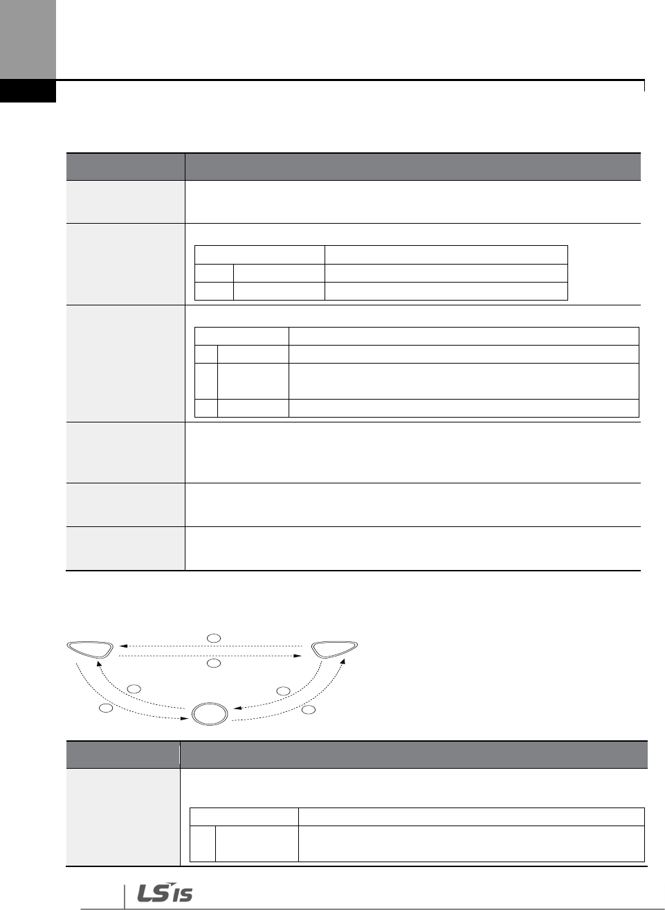
86
Learning Basic Features
Function Codes related to HAND/AUTO/OFF Operation Modes
Codes / Functions
Description
DRV
-
01
Cmd Frequency Frequency reference in AUTO mode when DRV-07 is set to’ KeyPad’.
DRV
-
02
KeyPad Run Dir
Rotation direction of the keypad command in the HAND or AUTO
mode.
Settings
Description
0
Forward
Fx operation
1
Reverse
Rx operation
DRV
-
05
KPD H.O.A Lock
To make HAND
-
OFF
-
AUTO enabled/disabled
Settings
Description
0
Locked
To make HAND
-
OFF
-
AUTO disabled and turn Auto mode
1
During
Run
If [DRV
-
06 Cmd
Source] is Fx/Rx
-
1, Fx/Rx
-
2, Int485 or fieldbus,
HAND-OFF-AUTO is enabled only during working
3
Unlocked
To make HAND
-
OFF
-
AUTO enabled
DRV-25
HAND Cmd Freq
Frequency displayed at the monitor display item (Monitor Line
-
1) when the
HAND key is pressed in other modes (default frequency reference for HAND
mode).
OUT
-
31
–
36
Relay 1–5 Set AUTO State (36) to ensure that the inverter is in AUTO mode.
OUT
-
31
–
36
Relay 1–5 Set HAND State (37) to ensure that the inverter is in HAND mode.
Switching between the HAND/AUTO/OFF Modes
Mode
Description
AUTOHAND
Press the HAND key in AUTO mode to switch to HAND mode. The inverter
operates as follows based on the setting at DRV-26 (Hand Ref Mode).
Settings
Description
0
Hand
Parameter
The inverter operates based on the operation direction set
at DRV-02 (Keypad Run Dir) and the frequency reference
HAND
OFF
AUTO
1
2
3
4
5
6

87
Learning Basic Features
Mode
Description
set at DRV
-
25 (HAND Cmd Freq).
1
Follow Auto
The inverter takes over the operation direction and the
frequency reference from the settings for AUTO mode and
keeps performing the same operation. If the inverter was
stopped in AUTO mode, the operation direction is set as Fx
and the frequency reference is set as 0 (no inverter output).
2HANDAUTO
Press th
e AUTO key in HAND mode to switch to AUTO mode. The inverter
operates based on the command source and frequency reference settings set at
DRV-06 and DRV-07. If DRV-06 (Cmd Source) is set to ‘keypad’ press the AUTO key
once again to start inverter operation.
3AUTOOFF
Press the OFF key in AUTO mode to stop the inverter operation (the inverter
enters OFF mode).
4OFFAUTO
Press the AUTO key in OFF mode to switch to AUTO mode. The inverter operates
based on the command source and frequency reference settings set at DRV-06
and DRV-07. If DRV-06 (Cmd Source) is set to ‘keypad’ press the AUTO key once
again to start inverter operation.
5HANDOFF
Press the OFF key in HAND mode to stop the inverter operation (the inverter
enters OFF mode).
6OFFHAND
Press the
HAND key in OFF mode to switch to HAND mode. The inverter operates
based on the operation direction set at DRV-02 (Keypad Run Dir) and the
frequency reference set at DRV-25 (HAND Cmd Freq).
Operation Mode at Power Recovery
If a power interruption occurs during inverter operation in the OFF or HAND mode, the inverter
halts the operation with low voltage fault trip. Then, when the power is recovered, the inverter
turns on in OFF mode.
If the inverter was operating in AUTO mode at the time of the low voltage trip following the power
interruption, the inverter turns on in AUTO mode, and the operation may vary depending on the
inverter’s ‘PowerOn Resume’ and ‘Power-on run’ settings.
Not
e
• To operate the inverter using the keypad in AUTO mode, set DRV-06 (CMD Source) to
‘KeyPad’ and press the AUTO key to enter AUTO mode. Then, press the AUTO key on the
keypad once again to start the inverter operation.
• If a fault trip occurs during an operation in the AUTO or HAND mode, the inverter can be
reset by pressing the OFF key. After the reset, the fault trip is released and the inverter enters
88
Learning Basic Features
OFF mode.
• If a fault trip occurs during an operation in the AUTO or HAND mode, the inverter can be
reset using the reset signal from the multi-function input terminal as well. In this case, the
inverter turns back on in AUTO mode after the fault trip is released.
Use caution when the inverter is set to operate in AUTO
mode by commands over
communication, and if COM-96 (PowerOn Resume) is set to ‘yes’, as the motor will begin rotating
when the inverter starts up, without additional run commands.
4.2 Setting Frequency Reference
The H100 inverter provides several methods to setup and modify a frequency reference for an
operation. The keypad, analog inputs [for example voltage (V1, V2) and current (I2) signals], or RS-
485 (digital signals from higher-level controllers, such as PC or PLC) can be used.
Group
Code
Name
LCD Display
Parameter Setting
Setting Range
Unit
DRV 7 Frequency
reference source
Freq Ref Src
0
KeyPad
-
1
0–11 -
1
KeyPad
-
2
2
V1
4
V2
5
I2
6
Int 485
7
Field Bus
9
Pulse
10
*
V3
11
I3
* ‘10(V3)~11(I3)’ of DRV-07 are available when Extension IO option is equipped. Refer to
Extension IO option manual for more detailed information.

89
Learning Basic Features
4.2.1 Keypad as the Source (KeyPad-1 setting)
You can modify frequency reference by using the keypad and apply changes by pressing the
[ENT/PROG] key. To use the keypad as a frequency reference input source, go to DRV-07
(Frequency reference source) and change the parameter value to ‘0 (Keypad-1)’. Input the
frequency reference for an operation at DRV-01 (Frequency reference).
Group
Code
Name
LCD Display
Parameter Setting
Setting Range
Unit
DRV
01 Frequency
reference Cmd Frequency 0.00
0.00, Low
Freq– High
Freq*
Hz
07
Frequency
reference source
Freq Ref Src 0 KeyPad-1
0–11 -
* You cannot set a frequency reference that exceeds the Max. Frequency, as configured with DRV-
20.
4.2.2 Keypad as the Source (KeyPad-2 setting)
You can use the [UP] and [DOWN] cursor keys to modify a frequency reference. To use this as a
second option, set the keypad as the source of the frequency reference, by going to DRV-07
(Frequency reference source) and change the parameter value to ‘1 (Keypad-2)’. This allows
frequency reference values to be increased or decreased by pressing the [UP] and [DOWN] cursor
keys.
Group
Code
Name
LCD Display
Parameter Setting
Setting Range
Unit
DRV
07
Frequency
reference source
Freq Ref
Src 1 KeyPad-2
0–11 -
01
Frequency
reference 0.00
0.00, Low Freq
–
High Freq* Hz
*You cannot set a frequency reference that exceeds the Max. Frequency, as configured with DRV-
20.
4.2.3 V1 Terminal as the Source
You can set and modify a frequency reference by setting voltage inputs when using the V1
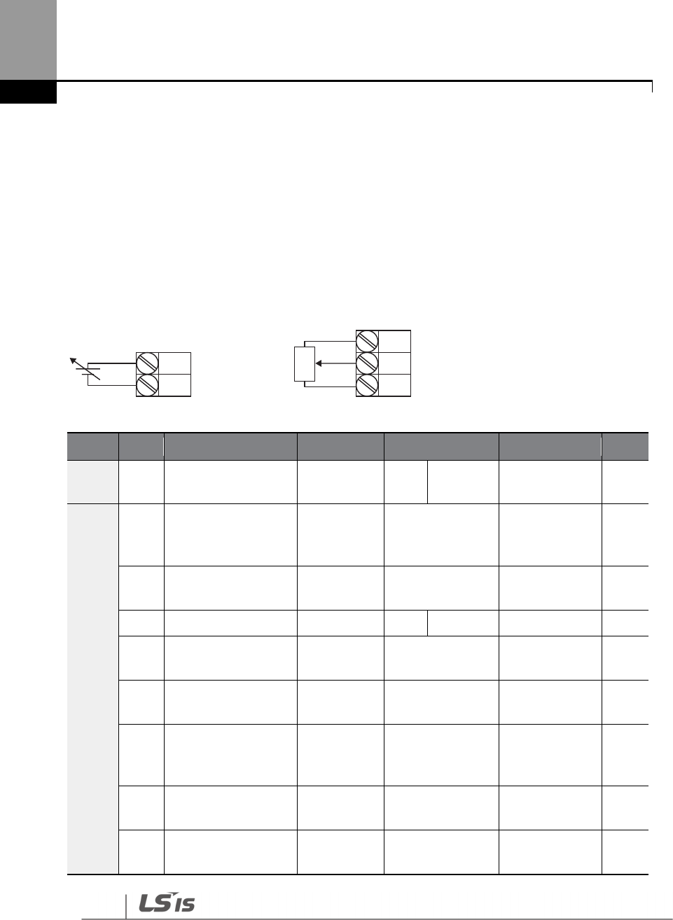
90
Learning Basic Features
terminal. Use voltage inputs ranging from 0–10 V (unipolar) for forward only operation. Use
voltage inputs ranging from -10 to +10 V (bipolar) for both directions, where negative voltage
inputs are used in reverse operations.
4.2.3.1 Setting a Frequency Reference for 0–10 V Input
Set IN-06 (V1 Polarity) to ‘0 (unipolar)’. Use a voltage output from an external source or use the
voltage output from the VR terminal to provide inputs to V1. Refer to the diagrams below for the
wiring required for each application.
[External source application] [Internal source (VR) application]
Group
Code
Name
LCD Display
Parameter Setting
Setting Range
Unit
DRV 07
Frequency reference
source Freq Ref Src 2 V1 0–11 -
IN
01
Frequency at
maximum analog
input
Freq at
100%
Maximum
frequency
0.00
–
Max.
Frequency
Hz
05 V1 input monitor
V1
Monitor[V] 0.00 0.00–12.00 V
06
V1 polarity options
V1 Polarity
0
Unipolar
0
–
1
-
07
V1 input filter time
constant V1 Filter 10 0–10000 msec
08
V1 minimum input
voltage V1 volt x1 0.00 0.00–10.00 V
09
V1 output at
minimum voltage
(%)
V1 Perc y1 0.00 0.00–100.00 %
10
V1 maximum input
voltage V1 Volt x2 10.00 0 .00– 12.00 V
11
V1 output at
maximum voltage V1 Perc y2 100.00 0–100 %
V1
CM
VR
V1
CM
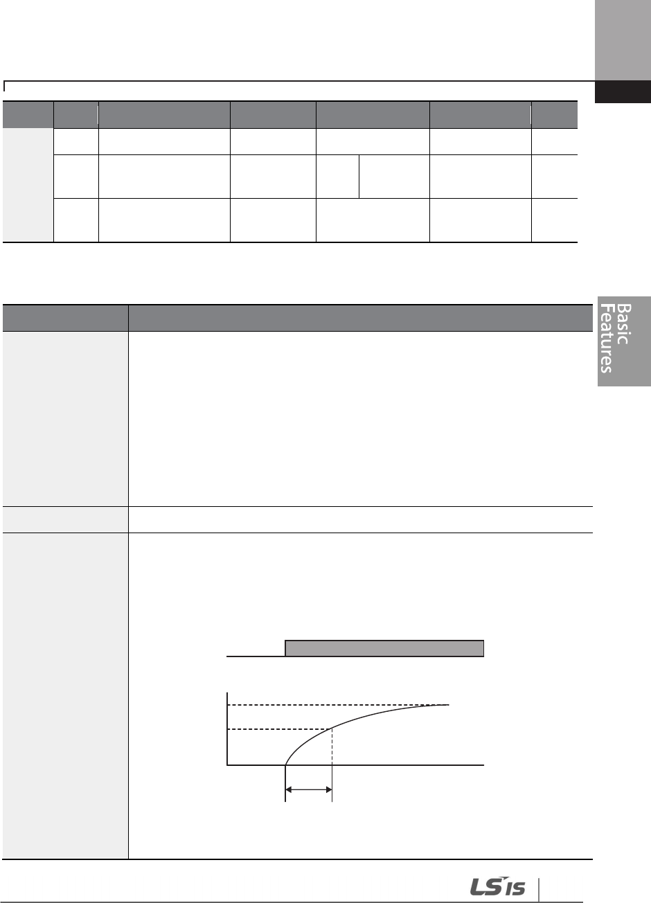
91
Learning Basic Features
Group
Code
Name
LCD Display
Parameter Setting
Setting Range
Unit
(%)
16
Rotation direction
options V1 Inverting
0 No 0–1 -
17 V1 Quantizing level
V1
Quantizing 0.04
0.00*, 0.04
–
10.00 %
* Quantizing is disabled if ‘0’ is selected.
Code
Description
IN-01 Freq at 100%
Configures the frequency reference at the maximum input voltage when a
potentiometer is connected to the control terminal block. A frequency set with
code IN-01 becomes the maximum frequency only if the value set in code IN-11
(or IN-15) is 100 (%).
• Set code IN-01 to 40.00 and use default values for codes IN-02–IN-16. Motor
will run at 40.00 Hz when a 10 V input is provided at V1.
• Set code IN-11 to 50.00 and use default values for codes IN-01–IN-16. Motor
will run at 30.00 Hz (50% of the default maximum frequency–60 Hz) when
a 10 V input is provided at V1.
IN
-
05 V1 Monitor[V]
Configures the
inverter to monitor the input voltage at V1.
IN-07
V1 Filter
V1 Filter may be used when there are large variations between reference
frequencies. Variations can be mitigated by increasing the time constant, but
this requires an increased response time.
The value t (time) indicates the time required for the frequency to reach 63% of
the reference, when external input voltages are provided in multiple steps.
[V1 Filter ]
100%
63%
V1 Filter(t)
V1 input from
external source
Frequency
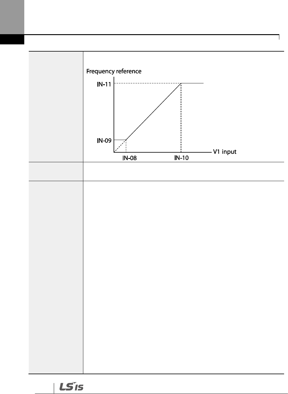
92
Learning Basic Features
IN-08 V1 volt x1–
IN-11 V1 Perc y2
These parameters are used to configure the
gradient level and offset values of
the Output Frequency, based on the Input Voltage.
IN-16 V1 Inverting
Inverts the direction of rotation. Set this code to ‘1 (Yes)’ if you need the motor to
run in the opposite direction from the current rotation.
IN-17 V1 Quantizing
Quantizing may be used when the noise level is high in the analog input (V1
terminal) signal.
Quantizing is useful when you are operating a noise-sensitive system, because it
suppresses any signal noise. However, quantizing will diminish system
sensitivity (resultant power of the output frequency will decrease based on the
analog input).
You can also turn on the low-pass filter using code IN-07 to reduce the noise, but
increasing the value will reduce responsiveness and may cause pulsations
(ripples) in the output frequency.
Parameter values for quantizing refer to a percentage based on the maximum
input. Therefore, if the value is set to 1% of the analog maximum input (60 Hz),
the output frequency will increase or decrease by 0.6 Hz per 0.1 V difference.
When the analog input is increased, an increase to the input equal to 75% of the
set value will change the output frequency, and then the frequency will increase
according to the set value. Likewise, when the analog input decreases, a
decrease in the input equal to 75% of the set value will make an initial change to
the output frequency.
As a result, the output frequency will be different at acceleration and
deceleration, mitigating the effect of analog input changes over the output
frequency.
(ripple)
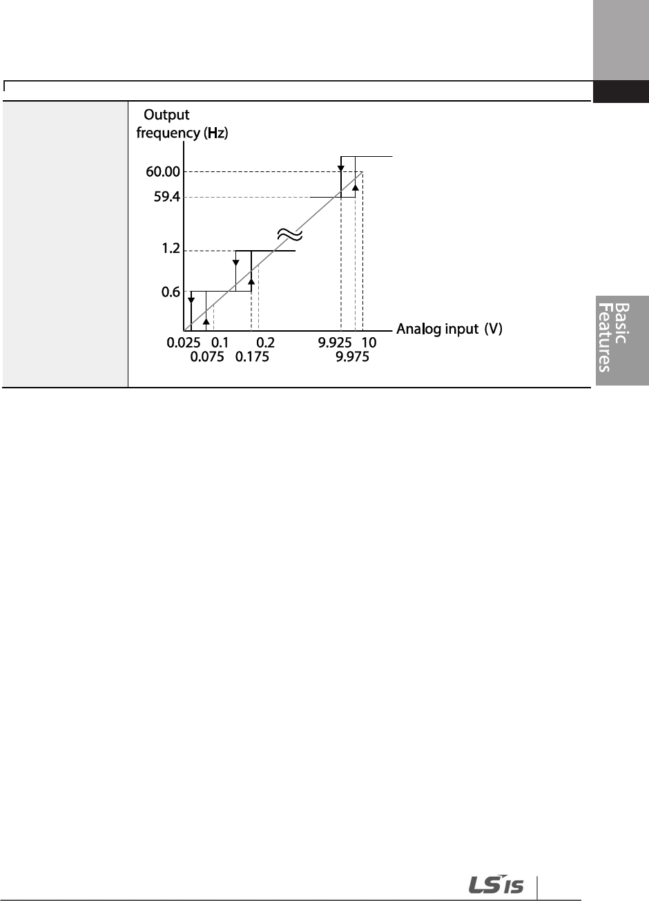
93
Learning Basic Features
0–10 V Input Voltage Setting Details
[V1 Quantizing]

94
Learning Basic Features
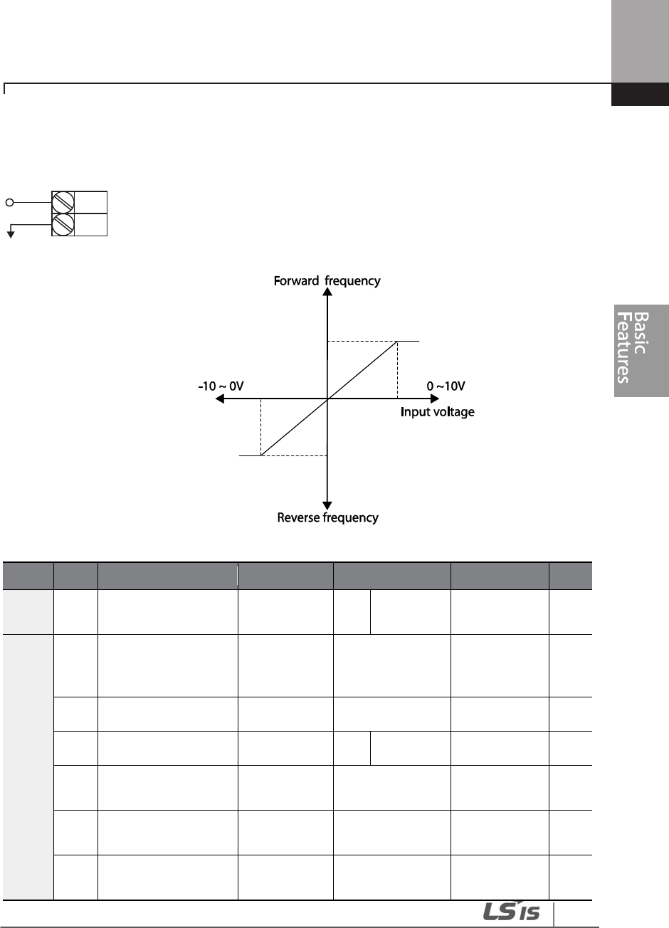
95
Learning Basic Features
4.2.3.3 Setting a Frequency Reference for -10–+10 V Input
Set DRV-07 (Frequency reference source) to ‘2 (V1)’, and then set IN- 06 (V1 Polarity) to ‘1 (bipolar)’.
Use the output voltage from an external source to provide input to V1.
[V1 terminal wiring]
[Bipolar input voltage and output frequency]
Group
Code
Name
LCD Display
Parameter Setting
Setting Range
Unit
DRV 07
Frequency reference
source Freq Ref Src 2 V1 0–11 -
IN
01
Frequency at
maximum analog
input
Freq at 100% 60.00 0– Max
Frequency Hz
05 V1 input monitor V1 Monitor 0.00 -12.00–12.00 V V
06 V1 polarity options V1 Polarity 1 Bipolar 0–1 -
12
V1 minimum input
voltage V1- volt x1 0.00 -10.00–0.00 V V
13
V1 output at
minimum voltage (%)
V1- Perc y1 0.00
-
100.00
–
0.00% %
14
V1 maximum input
voltage V1- Volt x2 -10.00 -12.00 –0.00 V V
V1
CM
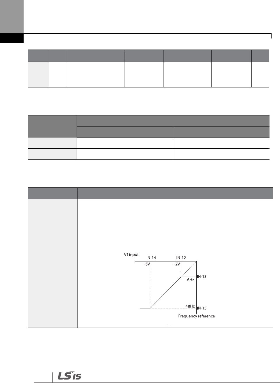
96
Learning Basic Features
Group
Code
Name
LCD Display
Parameter Setting
Setting Range
Unit
15
V1 output at
maximum voltage
(%)
V1- Perc y2 -100.00 -100.00–
0.00% %
Rotational Directions for Different Voltage Inputs
Command /
Voltage Input
Input voltage
0
–
10 V
-
10
–
0 V
FWD
Forward
Reverse
REV
Reverse
Forward
-10–10 V Voltage Input Setting Details
Code
Description
IN-12 V1- volt x1–
IN-15 V1- Perc y2
Sets the gradient level and off
-
set value of the output frequency in relation to
the input voltage. These codes are displayed only when IN-06 is set to ‘1
(bipolar)’.
As an example, if the minimum input voltage (at V1) is set to -2 (V) with 10%
output ratio, and the maximum voltage is set to -8 (V) with 80% output ratio
respectively, the output frequency will vary within the range of 6–48 Hz.
For details about the 0–+10 V analog inputs, refer to the code descriptions IN-08
V1 volt x1–IN-11 V1 Perc y2 on page 92.

97
Learning Basic Features
4.2.3.4 Setting a Reference Frequency using Input Current (I2)
You can set and modify a frequency reference using input current at the I2 terminal after selecting
current input at SW4. Set DRV-07 (Frequency reference source) to ‘5 (I2)’ and apply 0–20 mA input
current to I2.
Group
Code
Name
LCD Display
Parameter Setting
Setting Range
Unit
DRV 07
Frequency reference
source Freq Ref Src 5 I2 0–11 -
IN
01
Frequency at
maximum analog
input
Freq at 100%
60.00 0–Maximum
Frequency Hz
50
I2 input monitor
I2 Monitor
0.00
0.00
–
24.00
mA
52
I2 input filter time
constant I2 Filter 10 0–10000 ms
53
I2 minimum input
current I2 Curr x1 4.00 0.00–20.00 mA
54
I2 output at minimum
current (%) I2 Perc y1 0.00 0–100 %
55
I2 maximum input
current I2 Curr x2 20.00 0.00–24.00 mA
56
I2 output at
maximum current (%)
I2 Perc y2 100.00 0.00–100.00 %
61
I2 rotation direction
options I2 Inverting 0 No 0–1 -
62 I2 Quantizing level I2 Quantizing
0.04
0.00*, 0.04
–
10.00 %
* Quantizing is disabled if ‘0’ is selected.
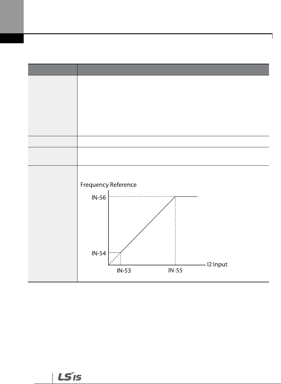
98
Learning Basic Features
Input Current (I2) Setting Details
Code
Description
IN-01 Freq at
100%
Configures the frequency reference for operation at the maximum current
(when IN-55 is set to 100%).
• If IN-01 is set to 40.00, and default settings are used for IN-53–56, 20 mA
input current (max) to I2 will produce a frequency reference of 40.00 Hz.
• If IN-56 is set to 50.00, and default settings are used for IN-01 (60 Hz) and
IN-53–55, 20 mA input current (max) to I2 will produce a frequency
reference of 30.00 Hz (50% of 60 Hz).
IN
-
50 I2 Monitor
Used to monitor input current at I2.
IN-52 I2 Filter
Configures the time for the operation frequency to reach 63% of target
frequency based on the input current at I2.
IN-53 I2 Curr x1–
IN-56 I2 Perc y2
Configures the gradient level and off
-
set value of the output frequency.
[Gradient and off-set configuration based on output frequency]

99
Learning Basic Features
4.2.4 Setting a Frequency Reference with Input Voltage (Terminal I2)
Set and modify a frequency reference using input voltage at I2 (V2) terminal by setting SW2 to V2.
Set the DRV-07 (Frequency reference source) to 4 (V2) and apply 0–12 V input voltage to I2 (=V2,
Analog current/voltage input terminal). Codes IN-35–47 will not be displayed when I2 is set to
receive current input (DRV-07 is set to ‘5’).
Group
Code
Name
LCD Display
Parameter Setting
Setting Range
Unit
DRV 07
Frequency
reference source Freq Ref Src 4 V2 0–11 -
IN
35
V2 input display
V2 Monitor
0.00
0.00
–
12.00
V
37
V2 input filter time
constant V2 Filter 10 0–10000 msec
38
Minimum V2 input
voltage V2 Volt x1 0.00 0.00–10.00 V
39
Output% at
minimum V2
voltage
V2 Perc y1 0.00 0.00–100.00 %
40
Maximum V2 input
voltage V2 Volt x2 10.00 0.00–10.00 V
41
Output% at
maximum V2
voltage
V2 Perc y2 100.00 0.00–100.00 %
46
Invert V2 rotational
direction V2 Inverting
0 No 0–1 -
47 V2 quantizing level
V2
Quantizing 0.04 0.00*, 0.04–10.00
%
* Quantizing is disabled if ‘0’ is selected.

100
Learning Basic Features
4.2.5 Setting a Frequency with TI Pulse Input
Set a frequency reference by setting the Frq (Frequency reference source) code (code 07) in DRV
group to 9 (Pulse) and provide 0–32.00 kHz pulse frequency to TI terminal.
Group
Code
Name
LCD Display
Parameter Setting
Setting Range
Unit
DRV 07
Frequency
reference source Freq Ref Src 9 Pulse 0–11 -
IN
01
Frequency at
maximum analog
input
Freq at
100% 60.00
0.00
–
Maximum
frequency
Hz
91 Pulse input display TI Monitor 0.00 0.00–50.00 kHz
92 TI input filter time
constant TI Filter 10 0–9999 mse
c
93 TI input minimum
pulse TI Pls x1 0.00 0.00–32.00 kHz
94 Output% at TI
minimum pulse TI Perc y1 0.00 0.00–100.00 %
95 TI Input maximum
pulse TI Pls x2 32.00 0.00–32.00 kHz
96 Output% at TI
maximum pulse TI Perc y2 100.00 0.00–100.00 %
97 Invert TI direction of
rotation TI Inverting 0 No 0–1 -
98 TI quantizing level
TI
Quantizing 0.04
0.00*, 0.04
–
10.00 %
*Quantizing is disabled if ‘0’ is selected.
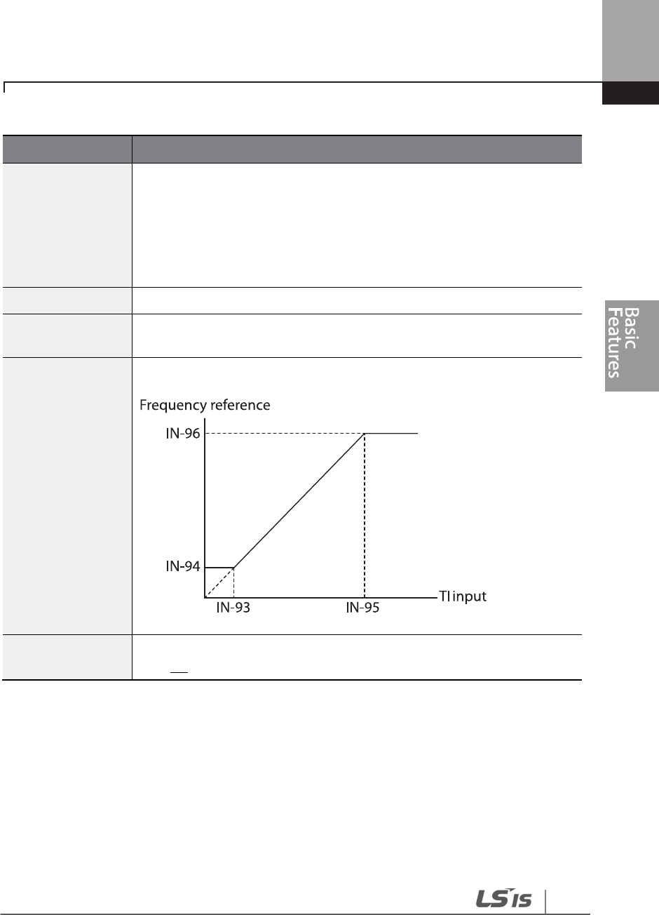
101
Learning Basic Features
TI Pulse Input Setting Details
Code
Description
IN-01 Freq at 100%
Configures
the frequency reference at the maximum pulse input. The
frequency reference is based on 100% of the value set with IN-96.
• If IN-01 is set to 40.00 and codes IN-93–96 are set at default, 32 kHz
input to TI yields a frequency reference of 40.00 Hz.
• If IN-96 is set to 50.00 and codes IN-01, IN-93–95 are set at default, 32
kHz input to the TI terminal yields a frequency reference of 30.00 Hz.
IN
-
91 TI Monitor
Displays the pulse frequency supplied at TI.
IN-92 TI Filter
Sets the time for the pulse input at TI
to reach 63% of its nominal frequency
(when the pulse frequency is supplied in multiple steps).
IN-93 TI Pls x1–
IN-96 TI Perc y2
Configures the gradient level and offset values for the output frequency.
IN-97 TI Inverting–
IN-98 TI Quantizing
Identical to IN-16–17 (refer to IN-16 V1 Inverting/IN-17 V1 Quantizing on
page 92)

102
Learning Basic Features
4.2.6 Setting a Frequency Reference via RS-485 Communication
Control the inverter with upper-level controllers, such as PCs or PLCs, via RS-485 communication.
Set the Frq (Frequency reference source) code (code 07) in the DRV group to 6 (Int 485) and use
the RS-485 signal input terminals (S+/S-/SG) for communication. Refer to 7 RS-485
Communication features on page 354.
*If AP1-40 is set to ‘4(Serve Drv)’, MaxComID is ‘8’, and if COM-02 is set to ‘4(BACnet), MaxComID is
‘127’. Otherwise MaxComID is ‘250’.
** COM-02 is automatically set to ‘6(Modbus Master)’ when AP1-40 is set to ‘2 or 3’. Otherwise a
user can set the parameter value at user’s choice.
Group Code Name LCD Display Parameter Setting Setting Range Unit
DRV 07
Frequency reference
source Freq Ref Src 6 Int 485 0–11 -
COM
01
Integrated RS-485
communication
inverter ID
Int485 St ID - 1 1–MaxComID*
-
02
Integrated
communication
protocol
Int485 Proto
0 ModBus RTU
0–6 -
2 LS Inv 485
4 BACnet
5
Metasys
-
N2
6**
Modbus
Master
03 Integrated
communication speed
Int485
BaudR 3 9600 bps 0–8 -
04
Integrated
communication frame
configuration
Int485 Mode
0 D8/PN/S1
0–3 -
1 D8/PN/S2
2 D8/PE/S1
3 D8/PO/S1
103
Learning Basic Features
4.3 Frequency Hold by Analog Input
If you set a frequency reference via analog input at the control terminal block, you can hold the
operation frequency of the inverter by assigning a multi-function input as the analog frequency
hold terminal. The operation frequency will be fixed upon an analog input signal.
Group
Code
Name LCD Display Parameter Setting
Setting
Range Unit
DRV 07 Frequency reference
source Freq Ref Src
0
Keypad
-
1
0–11 -
1 Keypad-2
2
V1
4
V2
5
I2
6
Int 485
7 Fied Bus
9
Pulse
10
*
V
3
11
I
3
IN
65
–
71
Px terminal
configuration
Px Define(Px:
P1–P7) 23
Analog
Hold 0–55 -
*‘10(V3)~11(I3)’ of DRV-07 are available when Extension IO option is equipped. Refer to Extension
IO option manual for more detailed information.
Px
Frequency reference
Operating frequency
Run command

104
Learning Basic Features
4.4 Changing the Displayed Units (Hz↔
↔↔
↔Rpm)
You can change the units used to display the operational speed of the inverter by setting DRV- 21
(Speed unit selection) to 0 (Hz Display) or 1 (Rpm Display).
Group
Code
Name
LCD Display
Parameter Setting
Setting Range
Unit
DRV 21 Speed unit
selection Hz/Rpm Sel
0
Hz Display
0–1 -
1
Rpm Display
4.5 Setting Multi-step Frequency
Multi-step operations can be carried out by assigning different speeds (or frequencies) to the Px
terminals. Step 0 uses the frequency reference source set at DRV-07. Px terminal parameter values
7 (Speed-L), 8 (Speed-M) and 9 (Speed-H) are recognized as binary commands and work in
combination with Fx or Rx run commands. The inverter operates according to the frequencies set
with BAS-50–56 (multi-step frequency 1–7) and the binary command combinations.
Group
Code
Name
LCD Display
Parameter Setting
Setting Range
Unit
BAS 50–56
Multi
-
step
frequency 1–7 Step Freq - 1–7 -
0.00, Low Freq
–
High Freq* Hz
IN
65–71
Px terminal
configuration
Px Define(Px: P1–
P7)
7
Speed
-
L
0–55
-
8
Speed
-
M
-
9
Speed
-
H
-
89
Multi
-
step
command delay
time
InCheck Time 1 1–5000 ms
105
Learning Basic Features
Multi-step Frequency Setting Details
Code
Description
BAS Group 50
–
56
Configure multi
-
step frequency 1
–
7.
IN-65–71 Px
Define
Choose the terminals to setup as multi
-
step inputs, and then set the relevant
codes (IN-65–71) to 7 (Speed-L), 8 (Speed-M), or 9 (Speed-H).
Provided that terminals P5, P6, and P7 have been set to Speed-L, Speed-M and
Speed-H respectively, the following multi-step operation will be available.
[An example of a multi-step operation]
Speed
Fx/Rx
P7
P6
P5
0
-
-
-
1
-
-
2
-
-
3
-
4
-
-
5
-
6
-
7
IN-89 InCheck
Time
Set a time interval for the inverter to check for additional terminal block inputs
after receiving an input signal.
After adjusting IN-89 to 100 ms and an input signal is received at P6, the inverter
will search for inputs at other terminals for 100 ms, before proceeding to
accelerate or decelerate based on the configuration at P6.
106
Learning Basic Features
4.6 Command Source Configuration
Various devices can be selected as command input devices for the H100 inverter. Input devices
available to select include keypad, multi-function input terminal, RS-485 communication and field
bus adapter.
Group
Code
Name
LCD Display
Parameter Setting
Setting Range
Unit
DRV 06 Command
Source Cmd Source
0
Keypad
0–5 -
1 Fx/Rx-1
2 Fx/Rx-2
3 Int 485
4
Field Bus
5
Time Event
4.6.1 The Keypad as a Command Input Device
To use the keypad as the command source, press the [AUTO] key to enter AUTO mode. Set DRV-06
to ‘0 (Keypad)’ to select the keypad as the command source and set the operation direction at
DRV-02 (Keypad Run Dir).
Since the keypad is now the command source, operation starts when the AUTO key is pressed,
and it stops when the AUTO key is pressed again.
The OFF key may be used to stop the operation as well, but the inverter operation mode will be
changed to OFF mode.
Group
Code Name LCD Display Parameter Setting Setting Range Unit
DRV 06 Command source
Cmd Source 0 KeyPad 0–5 -
107
Learning Basic Features
4.6.2 Terminal Block as a Command Input Device (Fwd/Rev run
commands)
Multi-function terminals can be selected as a command input device. This is configured by setting
DRV-06 (command source) in the Drive group to ‘1 (Fx/Rx)’. Select 2 terminals for the forward and
reverse operations, and then set the relevant codes (2 of the 7 multi-function terminal codes, IN-
65–71 for P1–P7) to ‘1 (Fx)’ and ‘2 (Rx)’ respectively. This application enables both terminals to be
turned on or off at the same time, constituting a stop command that will cause the inverter to stop
operation.
Group Code Name LCD Display Parameter Setting
Setting
Range Unit
IN 02 Operation direction
for Keypad
Keypad Run
Dir
0
Reverse
0–1 -
1
Forward
DRV
06
Command source
Cmd Source
1
Fx/Rx
-
1
0
–
5
-
IN 65–71
Px terminal
configuration
Px Define(Px:
P1– P7)
1
Fx
0–55 -
2
Rx
Fwd/Rev Command by Multi-function Terminal – Setting Details
Code
Description
DRV
-
06Cmd Source
Set to 1 (Fx/Rx
-
1).
IN-65–71 Px Define
Assign a terminal for forward (Fx) operation.
Assign a terminal for reverse (Rx) operation.
FX
RX
Frequency reference
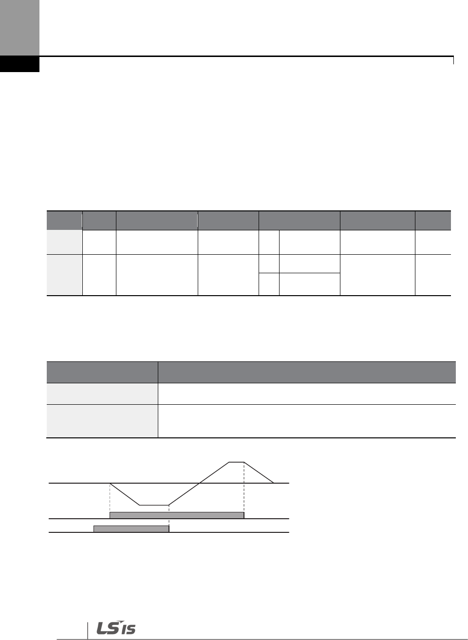
108
Learning Basic Features
4.6.3 Terminal Block as a Command Input Device (Run and Rotation
Direction Commands)
Multi-function terminals can be selected as a command input device. This is configured by setting
DRV-06 (command source) in the Drive group to 2(Fx/Rx-2). Select 2 terminals for run and rotation
direction commands, and then select the relevant codes (2 of the 5 multi-function terminal codes,
IN-65–71 for P1–P7) to 1 (Fx) and 2 (Rx) respectively. This application uses an Fx input as a run
command, and an Rx input to change a motor’s rotation direction (On: Rx, Off: Fx).
Group
Code
Name
LCD Display
Parameter Setting
Setting Range
Unit
DRV 06 Command source
Cmd Source 2 Fx/Rx-2 0–5 -
IN 65–71
Px terminal
configuration
Px Define
(Px: P1 – P7)
1
Fx
0–55 -
2 Rx
Run Command and Fwd/Rev Change Command Using Multi-function Terminal – Setting
Details
Code Description
DRV-06 Cmd Source Set to ‘2 (Fx/Rx-2)'.
IN-65–71 Px Define
Assign a terminal for run command (Fx).
Assign a terminal for changing rotation direction (Rx).
FX
RX
Frequency

109
Learning Basic Features
4.6.4 RS-485 Communication as a Command Input Device
Internal RS-485 communication can be selected as a command input device by setting DRV-06
(command source) in the Drive group to ‘3 (Int 485)’. This configuration uses upper level controllers
such as PCs or PLCs to control the inverter by transmitting and receiving signals via the S+, S-, and
RS-485 signal input terminals at the terminal block. For more details, refer to 7 RS-485
Communication Features on page 354.
Group
Code
Name LCD Display
Parameter
Setting Setting Range Unit
DRV
06
Command
source
Cmd Source
3
Int 485
0
–
5
-
COM
01
Integrated
communication
inverter ID
Int485 St ID 1 1–
MaxComID* -
02
Integrated
communication
protocol
Int485 Proto 0 ModBus
RTU 0–6 -
03
Integrated
communication
speed
Int485 BaudR 3 9600
bps 0–8 -
04
Integrated
communication
frame setup
Int485 Mode 0 D8 / PN /
S1 0–3 -
*If AP1-40 is set to ‘4(Serve Drv)’, MaxComID is ‘8’, and if COM-02 is set to ‘4(BACnet), MaxComID is
‘127’. Otherwise MaxComID is ‘250’
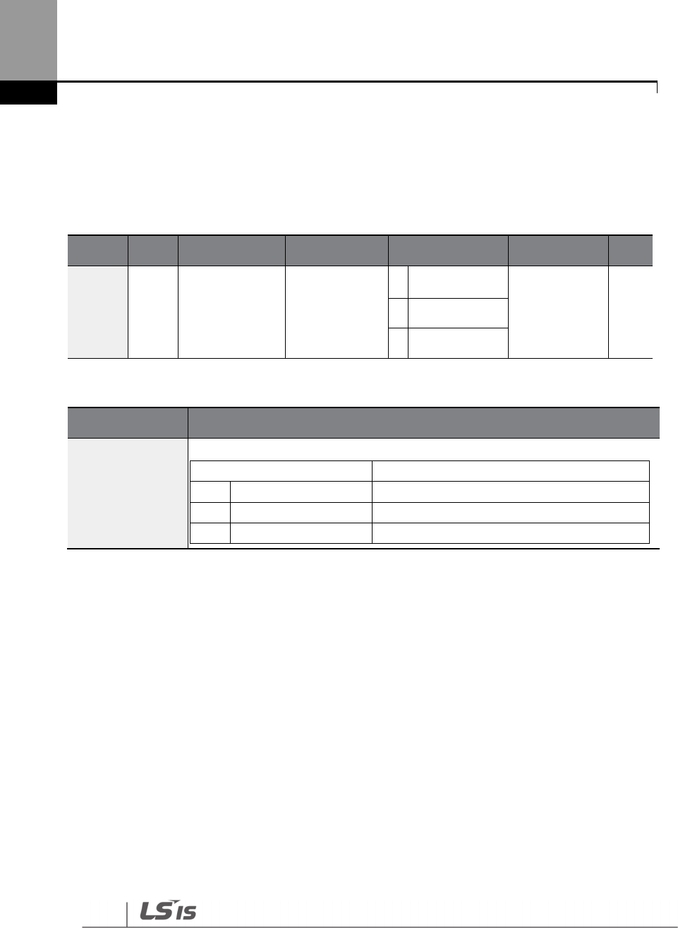
110
Learning Basic Features
4.7 Forward or Reverse Run Prevention
The rotation direction of motors can be configured to prevent motors to only run in one direction.
Pressing the [REV] key on the keypad when direction prevention is configured, will cause the
motor to decelerate to 0 Hz and stop. The inverter will remain on.
Group Code Name LCD Display Parameter Setting Setting Range Unit
ADV 09 Run prevention
options Run Prevent
0
None
0–2 -
1
Forward Prev
2
Reverse Prev
Forward/Reverse Run Prevention Setting Details
Code Description
ADV-09 Run
Prevent
Choose a direction to prevent.
Setting
Description
0
None
Do not set run prevention.
1
Forward Prev
Set forward
run prevention.
2
Reverse Prev
Set reverse
run prevention.
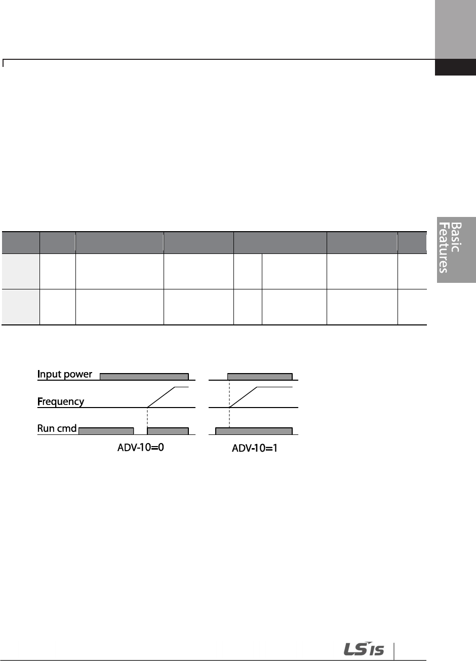
111
Learning Basic Features
4.8 Power-on Run
A power-on run feature can be setup to start an inverter operation after powering up based on
the run commands by terminal inputs or communication (if they are configured). In AUTO mode,
the inverter starts operating at power-on when the following conditions are met.
Terminal block input as the command source
(If they have been configured). To enable power-on run, set DRV-06 (command source) to ‘1
(Fx/Rx-1)’ or ‘2 (Fx/Rx-2)’ in the Drive group and ADV-10 to ‘1’ in the Advanced group.
Group Code Name LCD Display Parameter Setting Setting Range Unit
DRV 06
Command source
Cmd Source 1, 2 Fx/Rx-1 or
Fx/Rx-2 0–5 -
ADV 10 Power-on run Power-on
Run 1 Yes 0–1 -
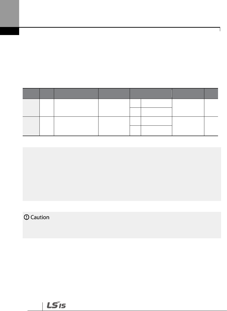
112
Learning Basic Features
Communication as the command source
To enable power-on resume, set COM-96 (PowerOn Resume) to ‘YES’, and set DRV-06 to ‘3 (Int 485)’
or ‘4 (Field Bus).’ If the power input to the inverter is cut off due to a power interruption, the inverter
memorizes the run command, frequency reference, and the acc/dec time settings at the time of
power interruption. If COM-96 (PowerOn Resume) is set to ‘Yes’, the inverter starts operating based
on these settings as soon as the power supply resumes.
Group
Code
Name LCD Display Settings Setting Range Unit
DRV 06 Command source Cmd Source
3
Int 485
0 - 5 -
4
Field Bus
COM 96 Power-on resume PowerOn
Resume
0
No
0 - 1 -
1 Yes
Note
• To prevent a repeat fault trip from occurring, set CON-71 (speed search options) bit 4 the same as
bit 1. The inverter will perform a speed search at the beginning of the operation.
• If the speed search is not enabled, the inverter will start its operation in a normal V/F pattern and
accelerate the motor. If the inverter has been turned on without ‘reset and restart’ enabled, the
terminal block command must be first turned off, and then turned on again to begin the
inverter’s operation.
Use caution when operating the inverter with
Power
-
on Run enabled as the motor will begin rotating
when the inverter starts up.
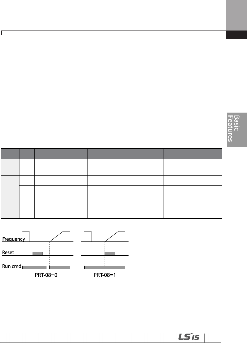
113
Learning Basic Features
4.9 Reset and Restart
Reset and restart operations can be setup for inverter operation following a fault trip, based on the
terminal block operation command (if it is configured). When a fault trip occurs, the inverter cuts
off the output and the motor will free-run. Another fault trip may be triggered if the inverter
begins its operation while motor load is in a free-run state. In PRT-08, bit 1 sets the option for all
the fault trips, other than low voltage trips, and bit 2 sets the option for low voltage trips. PRT-10
sets the delay time for restart (the time for the inverter to wait before it restarts).
The number of auto-restarts (PRT-09) refers to the number of times the inverter will try restarting
its operation. If fault trips occur again after restart, the retry number counts down each time the
inverter restarts until the number becomes ‘0.’ Once the inverter restarts successfully after the
initial fault trip, the inverter does not restart until the next fault trip occurs. The number of auto-
restarts set at PRT-09 that decreased after a restart reverts to the original setting value if successful
operation continues for certain period of time.
Group
Code
Name
LCD Display
Parameter Setting
Setting Range
Unit
DRV 06 Command source
Cmd
Source
1
Fx/Rx-1 0–5 -
PRT
08
Reset restart setup
RST Restart
00
00
–
11
Bit
09 No. of auto restart
Retry
Number 6 0–10 -
10
Auto restart delay
time Retry Delay
5.0 0.1–600.0 sec

114
Learning Basic Features
Note
• To prevent a repeat fault trip from occurring, set CON-71 (speed search options) bit 2 the same as
bit 1. The inverter will perform a speed search at the beginning of the operation.
• If the speed search is not enabled, the inverter will start its operation in a normal V/F pattern and
accelerate the motor. If the inverter has been turned on without ‘reset and restart’ enabled, the
terminal block command must be first turned off, and then turned on again to begin the
inverter’s operation.
4.10 Setting Acceleration and Deceleration Times
4.10.1 Acc/Dec Time Based on Maximum Frequency
Acc/Dec time values can be set based on maximum frequency, not on inverter operation
frequency. To set Acc/Dec time values based on maximum frequency, set BAS- 08 (Acc/Dec
reference) in the Basic group to ‘0 (Max Freq)’.
Acceleration time set at DRV-03 (Acceleration time) refers to the time required for the inverter to
reach the maximum frequency from a stopped (0 Hz) state. Likewise, the value set at the DRV-04
(Deceleration time) refers to the time required to return to a stopped state (0 Hz) from the
maximum frequency.
Group Code Name LCD Display Parameter Setting Setting Range Unit
DRV
03 Acceleration
time Acc Time
20.0
0.75
~90KW
0.0–600.0 sec
60.0
110~250KW
100.0
315~500KW
04 Deceleration
time Dec Time
30.0
0.75
~90KW
0.0–600.0 Sec
90.0
110~250KW
150.0
315~500KW
Use caution when operating the inverter with Power
-
on Run enabled as the motor wil
l begin
rotating when the inverter starts up.
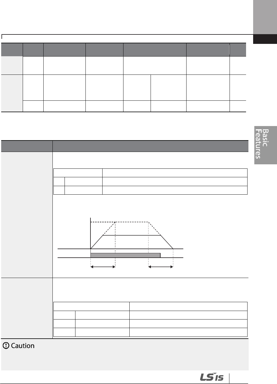
115
Learning Basic Features
Group Code Name LCD Display Parameter Setting Setting Range Unit
20
Maximum
frequency Max Freq 60.00 40.00–400.00 Hz
BAS 08
Acc/Dec
reference
frequency
Ramp T
Mode 0 Max Freq 0–1 -
09
Time scale
Time scale
1
0.1 sec
0
–
2
-
Acc/Dec Time Based on Maximum Frequency – Setting Details
Code
Description
BAS-08 Ramp T
Mode
Set the parameter value to 0 (Max Freq) to setup Acc/Dec time based on
maximum frequency.
Configuration
Description
0
Max Freq
Set the Acc/Dec time based on maximum frequency.
1
Delta Freq
Set the Acc/Dec time based on operating frequency.
If, for example, maximum frequency is 60.00 Hz, the Acc/Dec times are set to 5
seconds, and the frequency reference for operation is set at 30 Hz (half of 60
Hz), the time required to reach 30 Hz therefore is 2.5 seconds (half of 5 seconds).
BAS-09 Time scale
Use the time scale for all time
-
related values. It is parti
cularly useful when a
more accurate Acc/Dec times are required because of load characteristics, or
when the maximum time range needs to be extended.
Configuration
Description
0
0.01 sec
Sets 0.01 second as the minimum
unit.
1
0.1 sec
Sets 0.1 second as the minimum unit.
2
1 sec
Sets 1 second as the minimum unit.
Note that the range of maximum time values may change automatically when the units are
changed. If for example, the acceleration time is set at 6000 seconds, a time scale change from 1
Max. Freq.
Frequency
Run cmd
Acc. time Dec. time

116
Learning Basic Features
second to 0.01 second will result in a modified acceleration time of 60
.00 seconds.
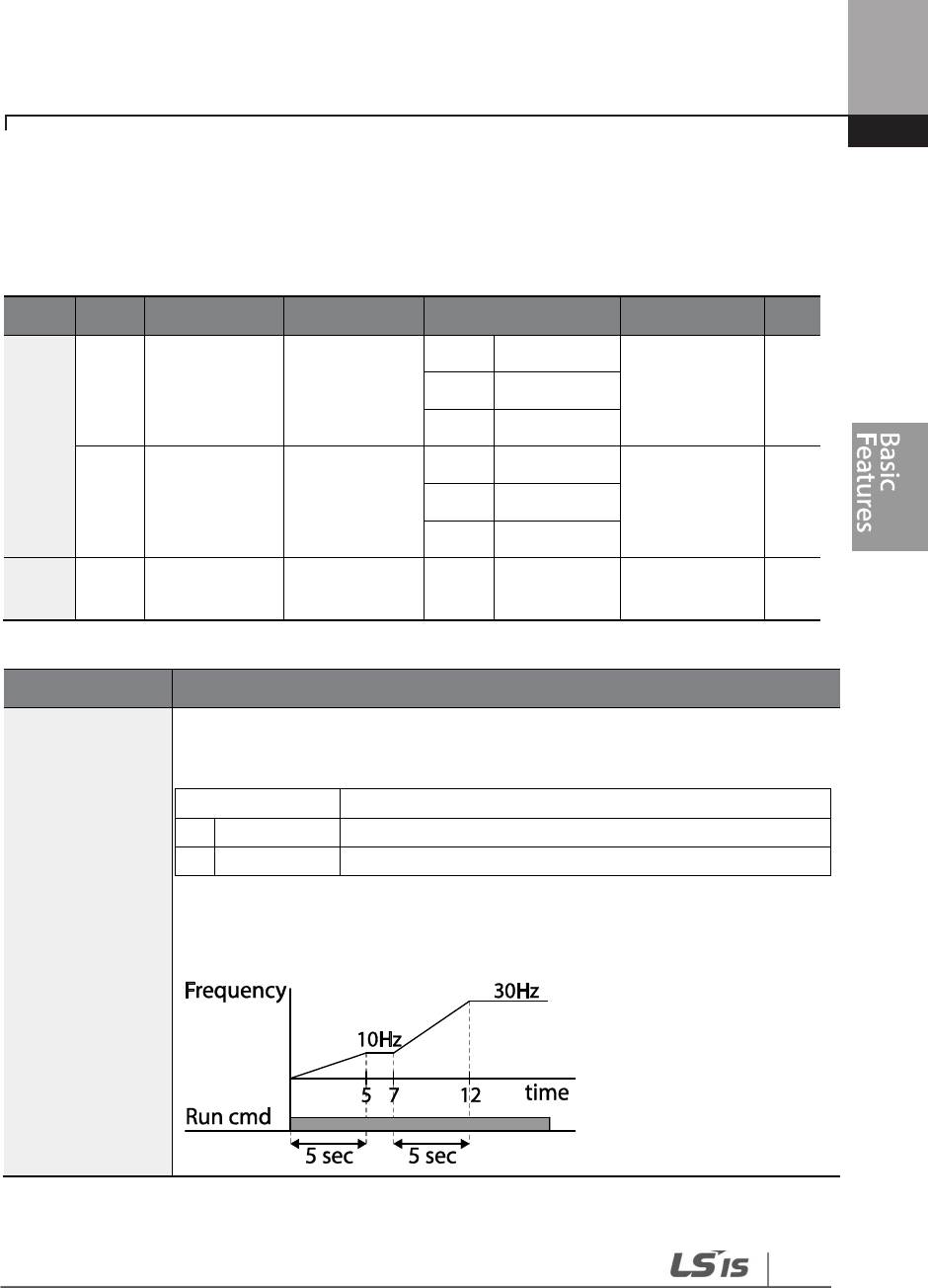
117
Learning Basic Features
4.10.2 Acc/Dec Time Based on Operation Frequency
Acc/Dec times can be set based on the time required to reach the next step frequency from the
existing operation frequency. To set the Acc/Dec time values based on the existing operation
frequency, set BAS-08 (acc/dec reference) in the Basic group to ‘1 (Delta Freq)’.
Group
Code
Name
LCD Display
Settings
Setting Range
Unit
DRV
03 Acceleration
time Acc Time
20.0
0.75
~90KW
0.0 - 600.0 sec
60.0
110~250KW
100.0
315~500KW
04 Deceleration
time Dec Time
30.0
0.75
~90KW
0.0 - 600.0 sec
90.0
110~250KW
150.0
315~500KW
BAS 08
Acc/Dec
reference Ramp T Mode 1 Delta Freq 0 - 1 -
Acc/Dec Time Based on Operation Frequency – Setting Details
Code
Description
BAS-08 Ramp T
Mode
Set the parameter value to 1 (Delta Freq) to set Acc/Dec times based on
Maximum frequency.
Configuration
Description
0
Max Freq
Set the Acc/Dec time based on Maximum frequency.
1
Delta Freq
Set the Acc/Dec time based on Operation frequency.
If Acc/Dec times are set to 5 seconds, and multiple frequency references are used
in the operation in 2 steps, at 10 Hz and 30 Hz, each acceleration stage will take 5
seconds (refer to the graph below).

118
Learning Basic Features
4.10.3 Multi-step Acc/Dec Time Configuration
Acc/Dec times can be configured via a multi-function terminal by setting the ACC (acceleration
time) and DEC (deceleration time) codes in the DRV group.
Group Code Name LCD Display Parameter Setting Setting Range Unit
DRV
03
Acceleration
time
Acc Time
20.0 0.75~90KW
0.0–600.0 sec 60.0 110~250KW
100.0
315~500KW
04 Deceleration
time Dec Time
30.0 0.75 ~90KW
0.0–600.0 sec 90.0 110~250KW
150.0
315~500KW
BAS 70–
83
Multi
-
step
acceleration/De
celeration
time1–7
Acc Time 1–7 x.xx 0.0–600.0 sec
Dec Time 1–7 x.xx 0.0–600.0 sec
IN
65–
71
Px terminal
configuration
Px Define
(Px: P1–P7)
11 XCEL-L
0–55 -
12 XCEL-M
13 XCEL-H
89
Multi-step
command
delay time
In Check Time 1 1–5000 ms
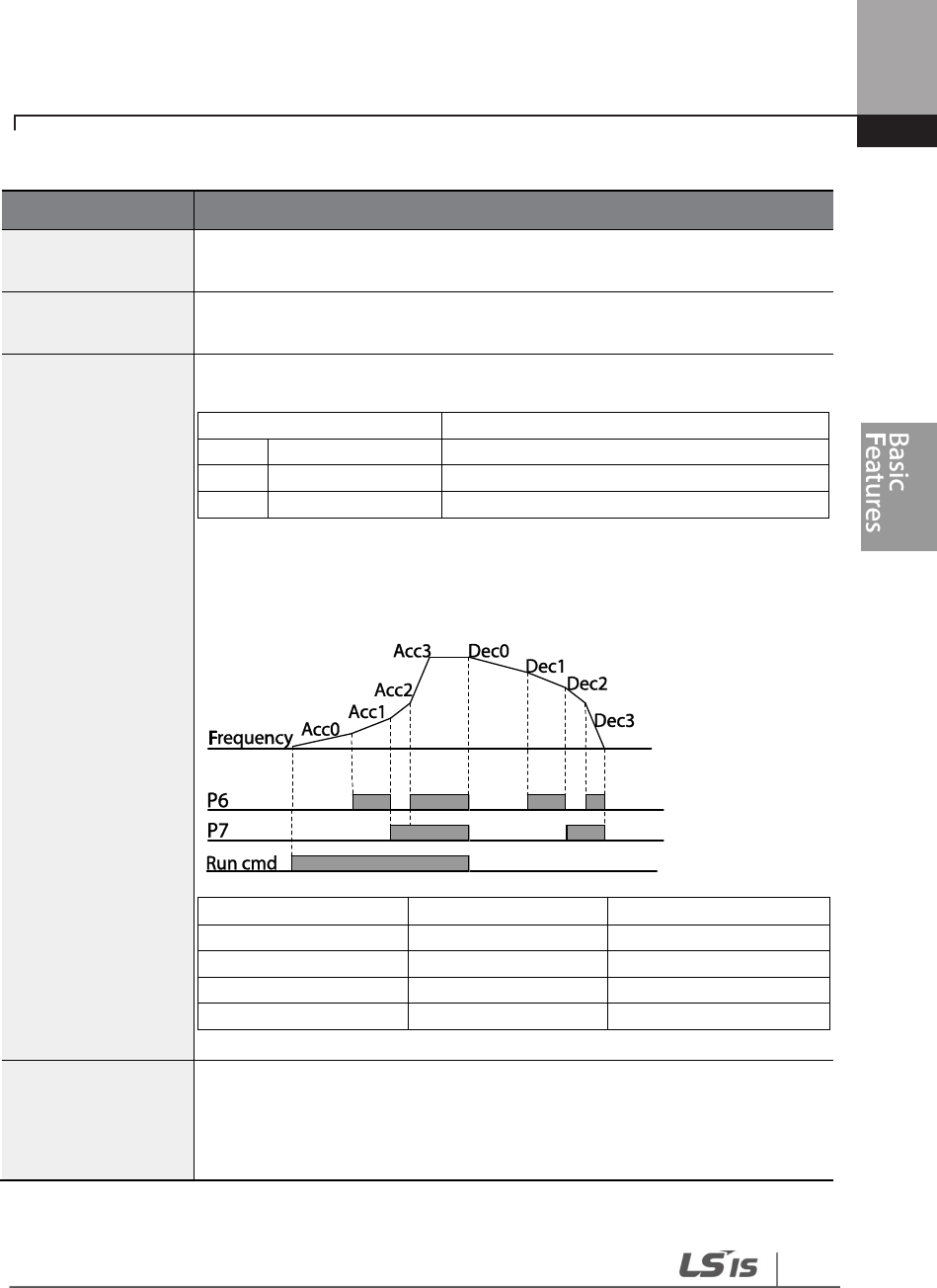
119
Learning Basic Features
Acc/Dec Time Setup via Multi-function Terminals – Setting Details
Code
Description
BAS
-
70
–
82
Acc Time 1–7
Set multi-step acceleration time1–7.
BAS
-
71
–
83
Dec Time 1–7
Set multi-step deceleration time1–7.
IN-65–71
Px Define (P1–P7)
Choose and configure the terminals to use for multi
-
step Acc/Dec time
inputs
Configuration
Description
11
XCEL
-
L
Acc/Dec command
-
L
12
XCEL
-
M
Acc/Dec command
-
M
13
XCEL
-
H
Acc/Dec
command
-
H
Acc/Dec commands are recognized as binary code inputs and will control the
acceleration and deceleration based on parameter values set with BAS-70–82
and BAS-71–83.
If, for example, the P6 and P7 terminals are set as XCEL-L and XCEL-M
respectively, the following operation will be available.
Acc/Dec time
P7
P6
0
-
-
1
-
2
-
3
[Multi-function terminal P6, P7 configuration]
IN-89 In Check Time
Set the time for the inverter to check for other terminal block inputs. If IN-
89 is set to 100 ms and a signal is supplied to the P6 terminal, the inverter
searches for other inputs over the next 100 ms. When the time expires,
the Acc/Dec time will be set based on the input received at P6

120
Learning Basic Features
4.10.4 Configuring Acc/Dec Time Switch Frequency
You can switch between two different sets of Acc/Dec times (Acc/Dec gradients) by configuring
the switch frequency without configuring the multi-function terminals.
Group
Code
Name LCD Display Parameter Setting Setting Range Unit
DRV
03 Acceleration time Acc Time
20.0
0.75
~90KW
0.0–600.0 sec
60.0
110~250KW
100.0
315~500KW
04 Deceleration time
Dec Time
30.0
0.75
~90KW
0.0–600.0 sec
90.0
110~250KW
150.0
315~500KW
BAS
70
Multi
-
step
acceleration time1
Acc Time-1 20.0 0.0–600.0 sec
71
Multi
-
step
deceleration
time1
Dec Time-1 20.0 0.0–600.0 sec
ADV 60
Acc/Dec time
switch frequency
Xcel Change
Fr 30.00
0
–
Maximum
frequency Hz
Acc/Dec Time Switch Frequency Setting Details
Code
Description
ADV-60
Xcel Change Fr
After the Acc/Dec switch frequency has been set, Acc/Dec gradients configured
at BAS-70 and 71 will be used when the inverter’s operation frequency is at or
below the switch frequency. If the operation frequency exceeds the switch
frequency, the gradient level configured for the acceleration and deceleration
times (set at DRV-03 and DRV-04) will be used.
If you configure the P1–P7 multi-function input terminals for multi-step Acc/Dec
gradients (XCEL-L, XCEL-M, XCEL-H), the inverter will operate based on the
Acc/Dec inputs at the terminals instead of the Acc/Dec switch frequency
configurations.
The ‘Xcel Change Fr’ parameter is applied only when ADV-24 (Freq Limit Mode)
is set to ‘NO’.
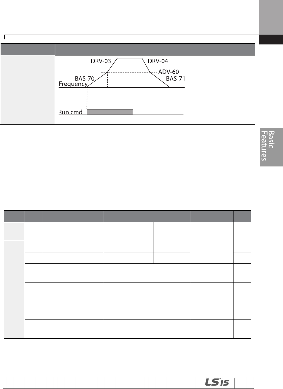
121
Learning Basic Features
Code
Description
4.11 Acc/Dec Pattern Configuration
Acc/Dec gradient level patterns can be configured to enhance and smooth the inverter’s
acceleration and deceleration curves. Linear pattern features a linear increase or decrease to the
output frequency, at a fixed rate. For an S-curve pattern a smoother and more gradual increase or
decrease of output frequency, ideal for lift-type loads or elevator doors, etc. S-curve gradient level
can be adjusted using codes ADV-03–06 in the advanced group.
Group
Code
Name
LCD Display
Parameter Setting
Setting Range
Unit
BAS 08 Acc/Dec reference
Ramp T
mode 0 Max Freq 0–1 -
ADV
01
Acceleration pattern
Acc Pattern
0
Linear
0–1
-
02
Deceleration pattern
Dec Pattern
1
S
-
curve
-
03
S
-
curve Acc start
gradient Acc S Start 40 1–100 %
04
S
-
curve Acc end
gradient Acc S End 40 1–100 %
05
S
-
curve Dec start
gradient Dec S Start 40 1–100 %
06
S
-
curve Dec end
gradient Dec S End 40 1–100 %
Acc/Dec Pattern Setting Details
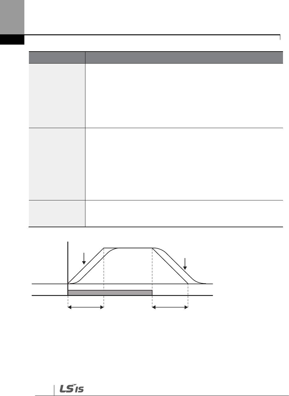
122
Learning Basic Features
Code
Description
ADV-03 Acc S Start
Sets the gradient level as acceleration starts when using an S
-
curve, Acc/Dec
pattern. ADV-03 defines S-curve gradient level as a percentage, up to half of
total acceleration.
If the frequency reference and maximum frequency are set at 60 Hz and ADV-
03 is set to 50%, ADV-03 configures acceleration up to 30 Hz (half of 60 Hz). The
inverter will operate S-curve acceleration in the 0-15 Hz frequency range (50%
of 30 Hz). Linear acceleration will be applied to the remaining acceleration
within the 15–30 Hz frequency range.
ADV-04 Acc S End
Sets the gradient level as acceleration ends when using an S
-
curve Acc/Dec
pattern. ADV-03 defines S-curve gradient level as a percentage, above half of
total acceleration.
If the frequency reference and the maximum frequency are set at 60 Hz and
ADV-04 is set to 50%, setting ADV-04 configures acceleration to increase from
30 Hz (half of 60 Hz) to 60 Hz (end of acceleration). Linear acceleration will be
applied within the 30-45 Hz frequency range. The inverter will perform an S-
curve acceleration for the remaining acceleration in the 45–60 Hz frequency
range.
ADV-05 Dec S Start –
ADV-06 Dec S End
S
ets the rate of S
-
curve deceleration. Configuration for codes ADV
-
05 and
ADV-06 may be performed the same way as configuring codes ADV-03 and
ADV-04.
[Acceleration / deceleration pattern configuration]
S -curve
Linear
Acc. time Dec. time
Frequency
Run cmd
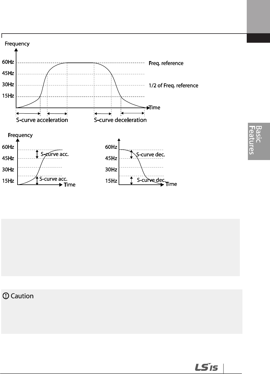
123
Learning Basic Features
[Acceleration / deceleration S-curve pattern configuration]
Note
The Actual Acc/Dec time during an S
-
curve application
Actual acceleration time = user-configured acceleration time + user-configured acceleration time x
starting gradient level/2 + user-configured acceleration time x ending gradient level/2.
Actual deceleration time = user-configured deceleration time + user-configured deceleration time x
starting gradient level/2 + user-configured deceleration time x ending gradient level/2.
Note that
actual Acc/Dec times become greater than user defined Acc/Dec times when S
-
curve
Acc/Dec patterns are in use.
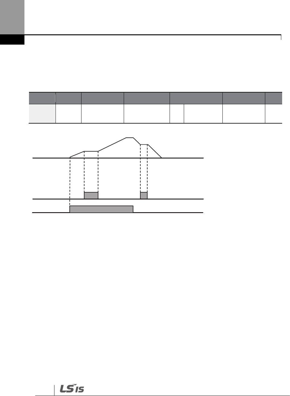
124
Learning Basic Features
4.12 Stopping the Acc/Dec Operation
Configure the multi-function input terminals to stop acceleration or deceleration and operate the
inverter at a fixed frequency.
Group
Code
Name
LCD Display
Parameter Setting
Setting Range
Unit
IN 65–71
Px terminal
configuration
Px Define
(Px: P1– P7) 14 XCEL Stop 0–55 -
Px
Frequency
Run cmd
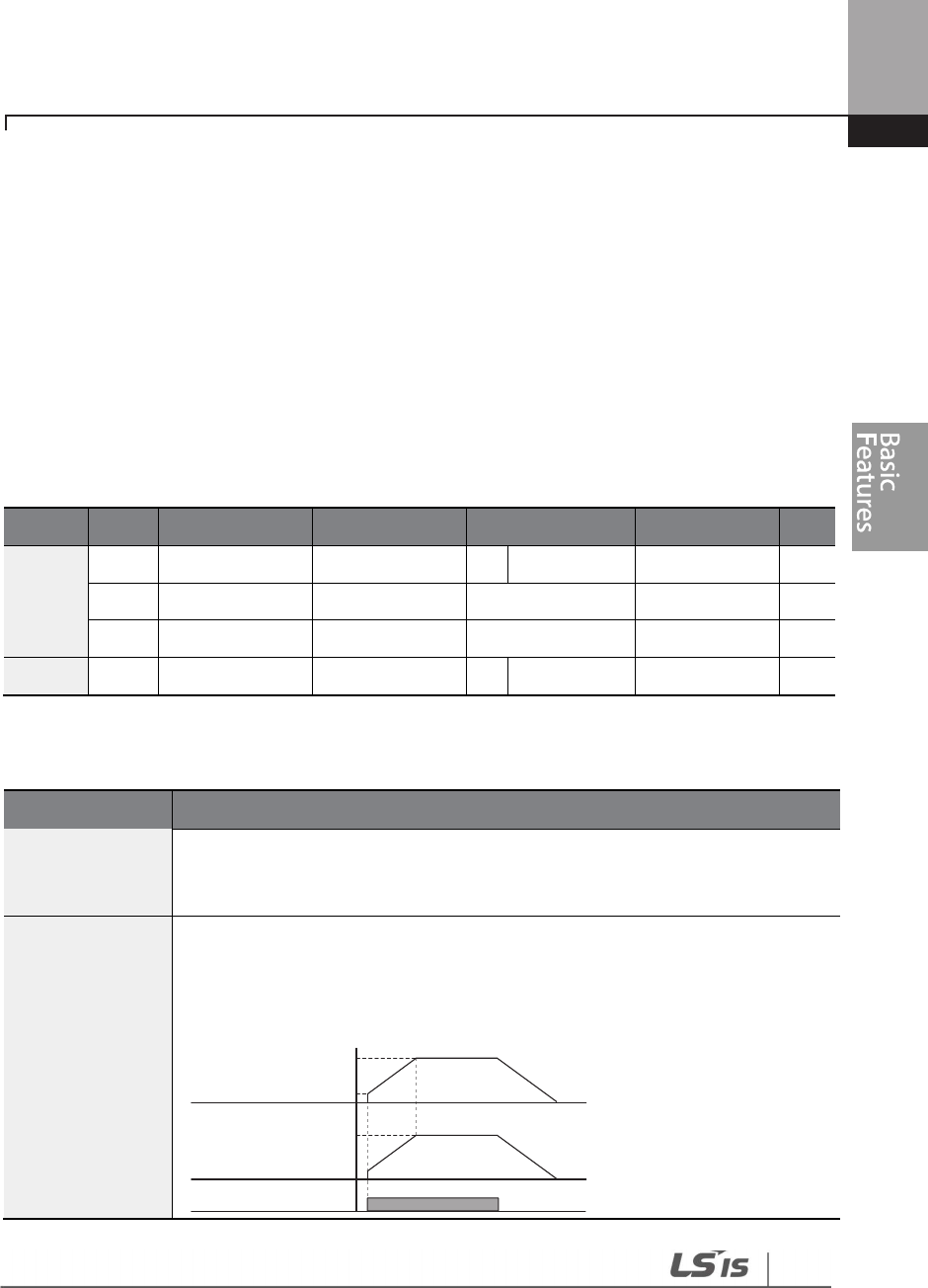
12
5
Learning Basic Features
4.13 V/F (Voltage/Frequency) Control
Configure the inverter’s output voltages, gradient levels, and output patterns to achieve a target
output frequency with V/F control. The amount of torque boost used during low frequency
operations can also be adjusted.
4.13.1 Linear V/F Pattern Operation
A linear V/F pattern configures the inverter to increase or decrease the output voltage at a fixed
rate for different operation frequencies based on V/F characteristics. A linear V/F pattern is
particularly useful when a constant torque load is applied.
Group
Code
Name
LCD Display
Parameter Setting
Setting Range
Unit
IN
09
Control mode
Control Mode
0
V/F
0
–
1
-
18
Base frequency
Base Freq
60.00
30.00
–
400.00
Hz
19
Start frequency
Start
Freq
0.50
0.01
–
10.00
Hz
BAS
07
V/F pattern
V/F Pattern
0
Linear
0
–
3
-
Linear V/F Pattern Setting Details
Code
Description
DRV-18 Base Freq
Sets the base frequency
.
A base frequency is the inverter’s output frequency
when running at its rated voltage. Refer to the motor’s rating plate to set this
parameter value.
DRV-19 Start Freq
Sets the start frequency
.
A star
t frequency is a frequency at which the inverter
starts voltage output. The inverter does not produce output voltage while the
frequency reference is lower than the set frequency. However, if a deceleration
stop is made while operating above the start frequency, output voltage will
continue until the operation frequency reaches a full-stop (0 Hz).
Frequency
Voltage
Run cmd
Base Freq.
Start Freq.
Inverter’s
rated voltage
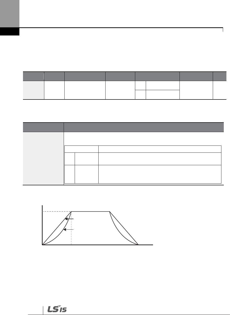
126
Learning Basic Features
4.13.2 Square Reduction V/FPattern Operation
Square reduction V/F pattern is ideal for loads such as fans and pumps. It provides non-linear
acceleration and deceleration patterns to sustain torque throughout the whole frequency range.
Group
Code
Name
LCD Display
Parameter Setting
Setting Range
Unit
BAS 07 V/F pattern V/F Pattern
1
Square
0–3 -
3
Square2
Square Reduction V/F pattern Operation - Setting Details
Code
Description
BAS-07 V/F
Pattern
Sets the parameter value to ‘1 (Square)’ or ‘2 (Square2)’
according to the load’s
start characteristics.
Setting
Function
1
Square
The inverter produces output voltage proportional to 1.5
square of the operation frequency.
3
Square2
The inverter produces output voltage proportional to 2
square of the operation frequency. This setup is ideal for
variable torque loads such as fans or pumps.
100%
Voltage
Linear
Square
reduction Frequency
Base frequency

127
Learning Basic Features
4.13.3 User V/F Pattern Operation
The H100 inverter allows the configuration of user-defined V/F patterns to suit the load
characteristics of special motors.
Group
Code
Name
LCD Display
Parameter Setting
Setting Range
Unit
BAS
07
V/F
pattern
V/F Pattern
2
User V/F
0
–
3
-
41 User Frequency 1 User Freq 1 15.00
0
–
Maximum
frequency Hz
42
User Voltage 1
User Volt 1
25
0
–
100%
%
43 User Frequency 2 User Freq 2 30.00
0
–
Maximum
frequency Hz
44
User Voltage 2
User Volt 2
50
0
–
100%
%
45 User Frequency 3 User Freq 3 45.00
0
–
Maximum
frequency Hz
46
User Voltage 3
User Volt 3
75
0
–
100%
%
47 User Frequency 4 User Freq 4
Maximum
frequency
0
–
Maximum
frequency Hz
48
User Voltage 4
User Volt 4
100
0
–
100%
%
User V/F pattern Setting Details
Code
Description
BAS-41 User Freq 1
–BAS-48 User Volt 4
Set the parameter values to assign arbitrary frequencies (User Freq x) for start
and maximum frequencies. Voltages can also be set to correspond with each
frequency, and for each user voltage (User Volt x).
The 100% output voltage in the figure below is based on the parameter settings of BAS-15 (motor
rated voltage). If BAS-15 is set to ‘0’ it will be based on the input voltage.
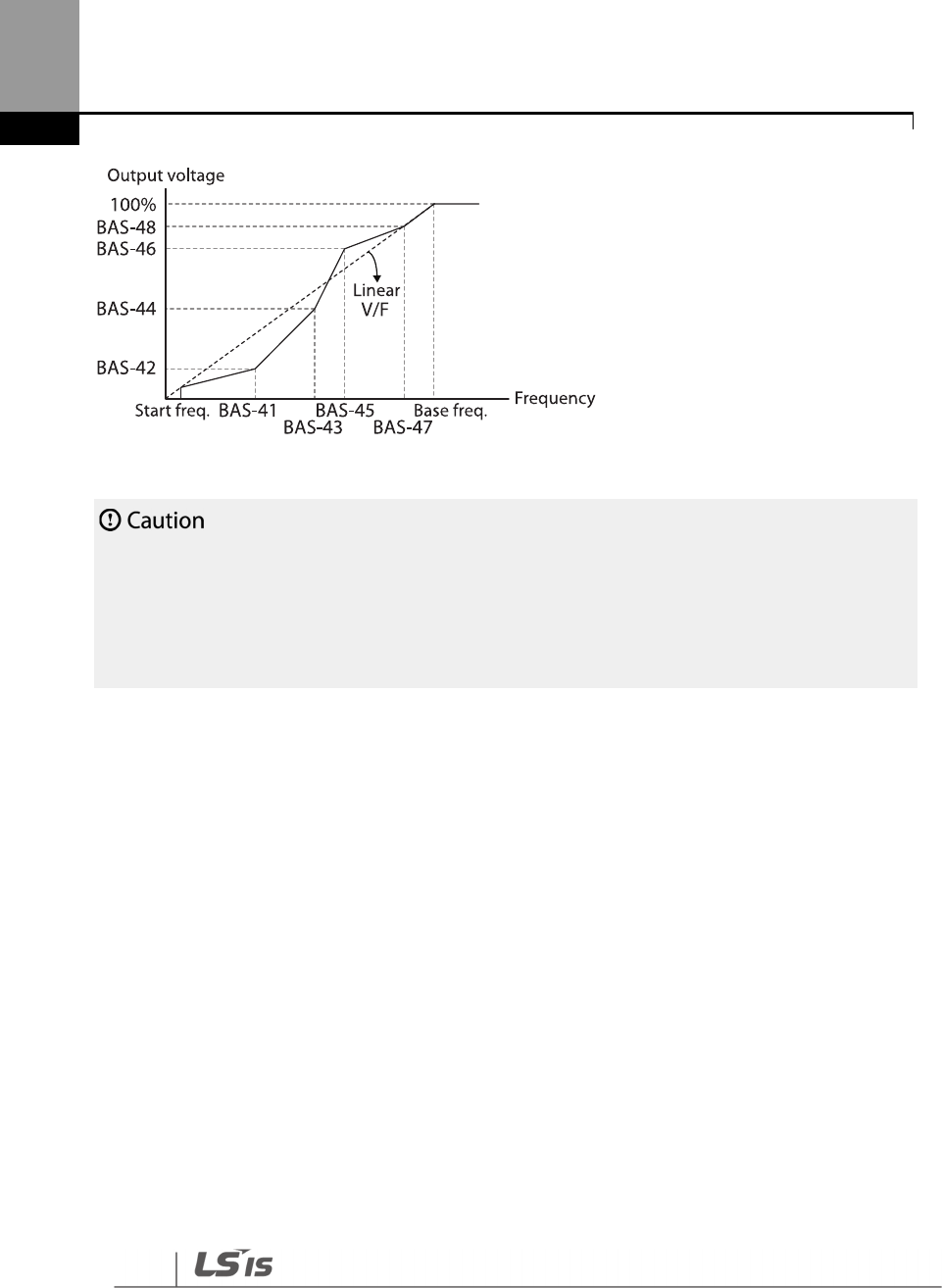
128
Learning Basic Features
• When a normal induction motor is in use, care must be taken not to configure the output pattern
away from a linear V/F pattern. Non-linear V/F patterns may cause insufficient motor torque or
motor overheating due to over-excitation.
• When a user V/F pattern is in use, forward torque boost (DRV-16) and reverse torque boost (DRV-
17) do not operate.
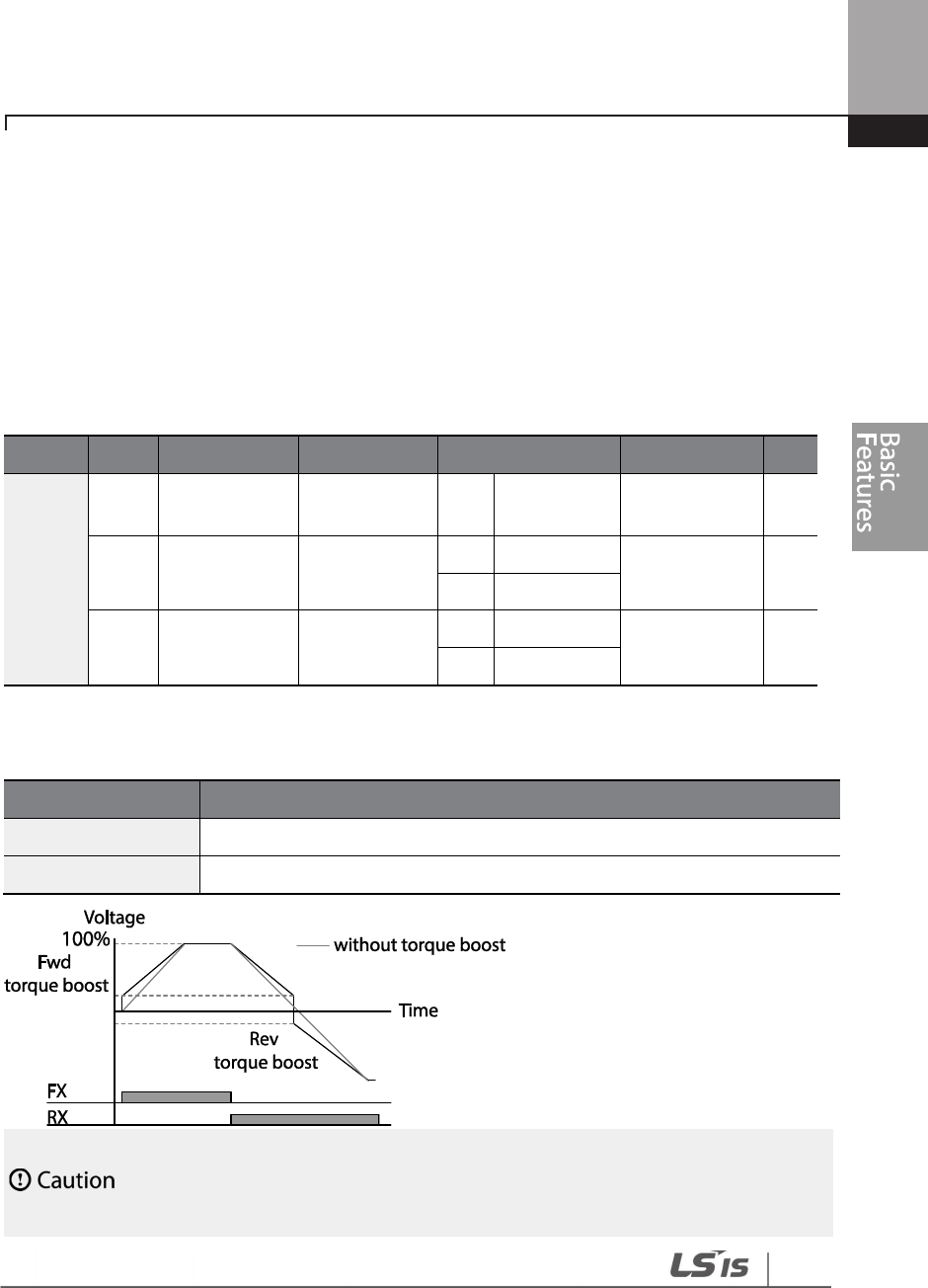
129
Learning Basic Features
4.14 Torque Boost
4.14.1 Manual Torque Boost
Manual torque boost enables users to adjust output voltage during low speed operation or motor
start. Increase low speed torque or improve motor starting properties by manually increasing
output voltage. Configure manual torque boost while running loads that require high starting
torque, such as lift-type loads.
Group
Code
Name
LCD Display
Parameter Setting
Setting Range
Unit
DRV
15
Torque boost
options Torque Boost 0 Manual 0–2 -
16 Forward
torque boost Fwd Boost
2.0
0.75~90
kW
0.0–15.0 %
1.0
110~500kW
17 Reverse torque
boost Rev Boost
2.0
0.75~90
kW
0.0–15.0 %
1.0
110~500kW
Manual Torque Boost Setting Details
Code
Description
DRV
-
16 Fwd Boost
Set torque boost for forward operation.
DRV
-
17 Rev Boost
Set torque boost for reverse operation.
Excessive torque boost will result in over
-
excitation and motor overheating

130
Learning Basic Features
4.14.2 Auto Torque Boost
Set DRV-15 to ‘Auto 1’ or ‘Auto 2’ to select the type of torque boost. While manual torque boost
adjusts the inverter output based on the setting values regardless of the type of load used in the
operation, auto torque boost enables the inverter to automatically calculate the amount of output
voltage required for torque boost based on the entered motor parameters. Because auto torque
boost requires motor-related parameters such as stator resistance, inductance, and no-load
current, auto tuning (BAS-20) has to be performed before auto torque boost can be configured.
Similarly to manual torque boost, configure auto torque boost while running a load that requires
high starting torque, such as lift-type loads. Refer to 5.21 Auto Tuning on page 219.
4.14.3 Auto Torque Boost 2 (No Motor Parameter Tuning Required)
By adjusting the auto torque boost voltage gain set at DRV-15 (ATB Volt Gain), automatic torque
boost may be operated without tuning the motor-related parameter values. The DRV-15 (ATB Volt
Gain) value is used to adjust the amount of compensation required for each load. It prevents stalls
or overcurrent fault trips at start up.
Group
Code
Name
LCD Display
Parameter Setting
Setting Range
Unit
DRV
15
torque boost mode
Torque Boost
1
Auto 1
0
–
2
-
BAS
20
auto tuning
Auto Tuning
3
Rs+Lsigma
0
–
3
-
Group
Code
Name
LCD Display
Settings
Setting Range
Unit
DRV 15
Torque boost
mode Torque Boost
2 Auto 2 0–2 -
CON 21
Auto torque boost
filter gain ATB Filt Gain 10 1 - 9999 msec
CON 22
Auto torque boost
voltage gain ATB Volt Gain
100.0 0 - 300.0 %
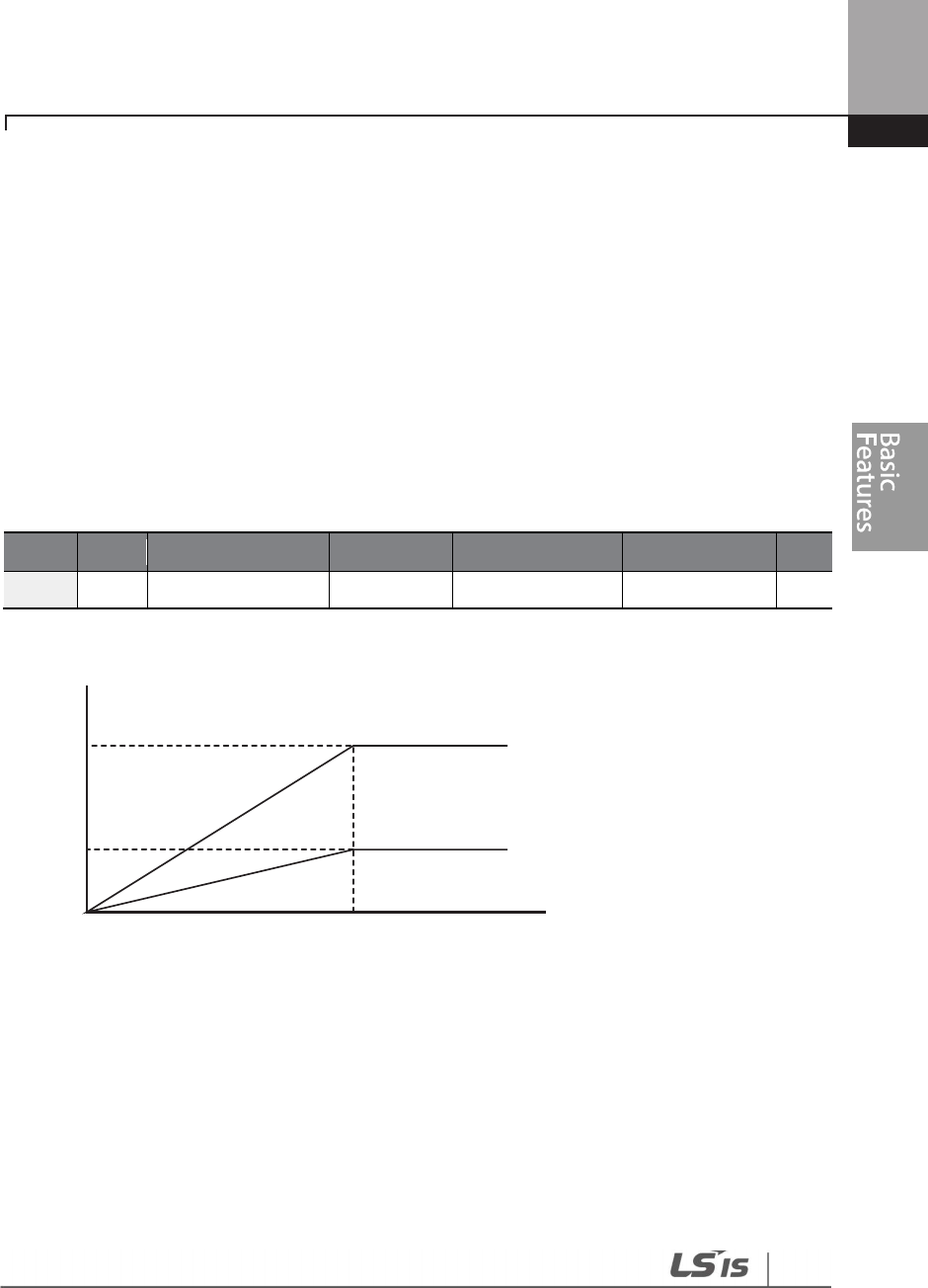
131
Learning Basic Features
4.15 Output Voltage Setting
Output voltage settings are required when a motor’s rated voltage differs from the input voltage
to the inverter. Set BAS-15 to configure the motor’s rated operating voltage. The set voltage
becomes the output voltage of the inverter’s base frequency. When the inverter operates above
the base frequency, and when the motor’s voltage rating is lower than the input voltage at the
inverter, the inverter adjusts the voltage and supplies the motor with the voltage set at BAS-15
(motor rated voltage). If the motor’s rated voltage is higher than the input voltage at the inverter,
the inverter will supply the inverter input voltage to the motor.
If BAS-15 (motor rated voltage) is set to ‘0’, the inverter corrects the output voltage based on the
input voltage in the stopped condition. If the frequency is higher than the base frequency, when
the input voltage is lower than the parameter setting, the input voltage will be the inverter output
voltage.
Group
Code
Name
LCD Display
Parameter Setting
Setting Range
Unit
BAS
15
Motor rated voltage
Rated Volt
0
0
, 170
–
50
0
V
480V
170V
Output voltage
Base freq. Output freq.
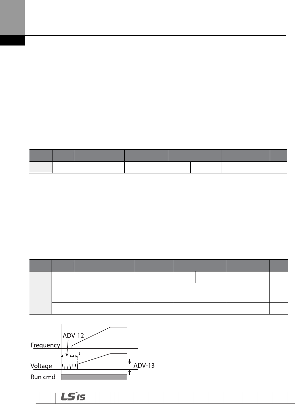
132
Learning Basic Features
4.16 Start Mode Setting
Select the start mode to use when the operation command is input with the motor in the stopped
condition.
4.16.1 Acceleration Start
Acceleration start is a general acceleration mode. If there are no extra settings applied, the motor
accelerates directly to the frequency reference when the command is input.
Group
Code
Name
LCD Display
Parameter Setting
Set
ting Range
Unit
ADV
07
Start mode
Start mode
0
Acc
0
–
1
-
4.16.2 Start After DC Braking
This start mode supplies a DC voltage for a set amount of time to provide DC braking before an
inverter starts to accelerate a motor. If the motor continues to rotate due to its inertia, DC braking
will stop the motor, allowing the motor to accelerate from a stopped condition. DC braking can
also be used with a mechanical brake connected to a motor shaft when a constant torque load is
applied, if a constant torque is required after the the mechanical brake is released.
Group
Code
Name
LCD Display
Parameter Setting
Setting Range
Unit
ADV
07
Start mode
Start Mode
1
DC
-
Start
0
–
1
-
12 Start DC braking time
DC
-
Start
Time 0.00 0.00–60.00 sec
13
DC Injection Level
DC Inj Level
50
0
–
200
%
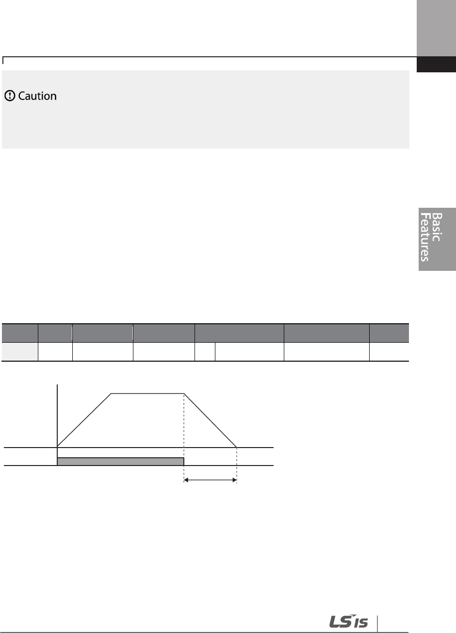
133
Learning Basic Features
The amount of DC braking required is based on the motor’s rated current. Do not use DC braking
resistance values that can cause current draw to exceed the rated current of the inverter. If the DC
braking resistance is too high or brake time is too long, the motor may overheat or
be damaged
4.17 Stop Mode Setting
Select a stop mode to stop the inverter operation.
4.17.1 Deceleration Stop
Deceleration stop is a general stop mode. If there are no extra settings applied, the motor
decelerates down to 0 Hz and stops, as shown in the figure below.
Group
Code
Name
LCD Display
Parameter Setting
Setting Range
Unit
ADV
08
Stop
mode
Stop Mode
0
Dec
0
–
4
-
Frequency
Run cmd
Deceleration time

134
Learning Basic Features
4.17.2 Stop After DC Braking
When the operation frequency reaches the set value during deceleration (DC braking frequency)
the inverter stops the motor by supplying DC power to the motor. With a stop command input,
the inverter begins decelerating the motor. When the frequency reaches the DC braking
frequency set at ADV-17, the inverter supplies DC voltage to the motor and stops it.
Group
Code
Name
LCD Display
Parameter Setting
Setting Range
Unit
ADV
08
Stop mode
Stop Mode
1
DC Brake
0
–
4
-
14 Output block time
before braking
DC-Block
Time
0.00
0.75~90kW
0.00–60.00 sec
2.00
110~500kW
15 DC braking time
DC
-
Brake
Time 1.00 0–60 sec
16 DC braking amount
DC
-
Brake
Level 50 0–200 %
17
DC braking
frequency
DC
-
Brake
Freq 5.00 0.00–60.00 Hz
DC Braking After Stop Setting Details
Code
Description
ADV-14 DC-Block
Time
Set the time to block the inverter output before DC
braking. If the inertia of the
load is great, or if DC braking frequency (ADV-17) is set too high, a fault trip may
occur due to overcurrent conditions when the inverter supplies DC voltage to the
motor. Prevent overcurrent fault trips by adjusting the output block time before
DC braking.
ADV
-
15 DC
-
Brake
Time Set the time duration for the DC voltage supply to the motor.
ADV
-
16 DC
-
Brake
Level
Set the amount of DC braking to apply. The parameter setting is based on the
rated current of the motor.
ADV-17 DC-Brake
Freq
Set the frequency to start DC braking. When the frequency is reached, the inverter
starts deceleration. If the dwell frequency is set lower than the DC braking
frequency, dwell operation will not work and DC braking will start instead.
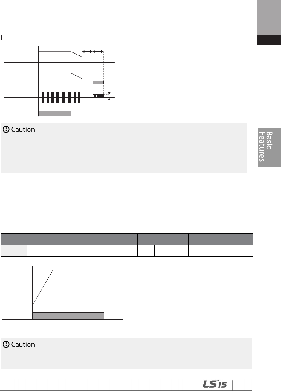
135
Learning Basic Features
• Note that the motor can overheat or be damaged if excessive amount of DC braking is applied
to the motor or DC braking time is set too long.
• DC braking is configured based on the motor’s rated current. To prevent overheating or
damaging motors, do not set the current value higher than the inverter’s rated current.
4.17.3 Free Run Stop
When the Operation command is off, the inverter output turns off, and the load stops due to
residual inertia.
Group
Code
Nam
e
LCD Display
Parameter Setting
Setting Range
Unit
ADV
08
Stop Method
Stop mode
2
Free
-
Run
0
–
4
-
Note that when there is high inertia on the output side and the motor is operating at high speed, the
load’s inertia will cause the motor to continue rotating even if the inverter output is blocked
ADV-17
ADV-14 ADV-15
ADV-16
Frequency
Voltage
Current
Run cmd
Frequency,
voltage
Run cmd

136
Learning Basic Features
4.17.4 Power Braking
When the inverter’s DC voltage rises above a specified level due to motor regenerated energy a
control is made to either adjust the deceleration gradient level or reaccelerate the motor in order
to reduce the regenerated energy. Power braking can be used when short deceleration times are
needed without brake resistors, or when optimum deceleration is needed without causing an
over voltage fault trip.
• To prevent overheating or damaging the motor, do not apply power braking to the loads that
require frequent deceleration.
• Stall prevention and power braking only operate during deceleration, and power braking takes
priority over stall prevention. In other words, when both bit 3 of PRT-50 (stall prevention and flux
braking) and ADV-08 (braking options) are set, power braking will take precedence and operate.
• Note that if deceleration time is too short or inertia of the load is too great, an overvoltage fault
trip may occur.
• Note that if a free run stop is used, the actual deceleration time can be longer than the pre-set
deceleration time.
Group
Code
Name
LCD Display
Parameter Setting
Setting Range
Unit
ADV
08
Stop mode
Stop Mode
4
Power Braking
0
–
4
-

137
Learning Basic Features
4.18 Frequency Limit
Operation frequency can be limited by setting maximum frequency, start frequency, upper limit
frequency, and lower limit frequency.
4.18.1 Frequency Limit Using Maximum Frequency and Start
Frequency
Group
Code
Name
LCD Display
Parameter Setting
Setting Range
Unit
DRV
19
Start frequency
Start Freq
0.50
0.01
–
10.00
Hz
20
Maximum
frequency Max Freq 60.00 40.00–400.00 Hz
Frequency Limit Using Maximum Frequency and Start Frequency - Setting Details
Code
Description
DRV-19 Start Freq
Set the lower limit value for speed unit parameters that are expressed in Hz or
rpm. If an input frequency is lower than the start frequency, the parameter
value will be 0.00.
DRV-20 Max Freq
Set upper and lower frequency limits. All frequency selections are restricted to
frequencies from within the upper and lower limits.
This restriction also applies when you in input a frequency reference using the
keypad.
If you use a high speed motor over 60Hz, there will be individual response
due to the difference in characteristics. Please contact LSIS.
4.18.2 Frequency Limit Using Upper and Lower Limit Frequency Values
Group
Code
Name
LCD Display
Parameter Setting
Setting Range
Unit
ADV
24
Frequency limit
Freq Limit
0
No
0
–
1
-
25
Frequency lower
limit value Freq Limit Lo
0.50
0.0
–
maximum
frequency Hz
26
Frequency upper
limit value Freq Limit Hi
Maximum
frequency
minimum
–
maximum Hz

138
Learning Basic Features
Group
Code
Name
LCD Display
Parameter Setting
Setting Range
Unit
frequency
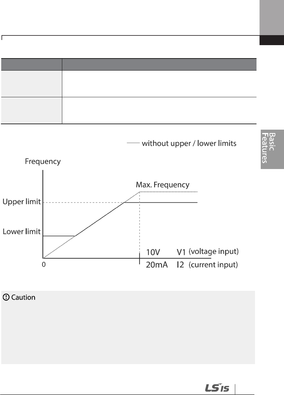
139
Learning Basic Features
Frequency Limit Using Upper and Lower Limit Frequencies - Setting Details
Code
Description
ADV-24 Freq Limit
The initial setting is ‘0 (No)’. Changing the setting to ‘1 (Yes)’ allows the setting
of frequencies between the lower limit frequency (ADV-25) and the upper
limit frequency (ADV-26).
ADV-25 Freq Limit Lo
ADV-26 Freq Limit Hi
Set an upper limit frequency to all speed unit parameters that are expressed
in Hz or rpm, except for the base frequency (DRV-18). Frequency cannot be
set higher.
• When ADV-24 (Freq Limit) is set to ‘Yes,’ the frequency set at ADV-25 (Freq Limit Lo) is the
minimum frequency (Low Freq). If ADV-24 (Freq Limit) is set to ‘No,’ the frequency set at DRV-19
(Start Freq) becomes the minimum frequency.
• When ADV-24 (Freq Limit) is set to ‘Yes,’ the frequency set at ADV-26 (Freq Limit Hi) is the
maximum frequency (High Freq). If ADV-24 (Freq Limit) is set to ‘No,’ the frequency set at DRV-20
(Max Freq) becomes the maximum frequency.

140
Learning Basic Features
4.18.3 Frequency Jump
Use frequency jump to avoid mechanical resonance frequencies. The inverter will avoid identified
ranges during acceleration and deceleration. Operation frequencies cannot be set within the pre-
set frequency jump band.
When a frequency setting is increased, while the frequency parameter setting value (voltage,
current, RS-485 communication, keypad setting, etc.) is within a jump frequency band the
frequency will be maintained at the lower limit value of the frequency band. Then, the frequency
will increase when the frequency parameter setting exceeds the range of frequencies used by the
frequency jump band.
Group Code Name LCD Display
Parameter
Setting Setting Range Unit
ADV
27
Frequency jump
Jump Freq
0
0
–
1
0
–
1
-
28
Jump frequency
lower limit1 Jump Lo 1 10.00
0.00
–
Jump frequency
upper limit 1 Hz
29 Jump frequency
upper limit1 Jump Hi 1 15.00
Jump frequency lower
limit 1–Maximum
frequency
Hz
30
Jump frequency
lower limit 2 Jump Lo 2 20.00
0.00
–
Jump frequency
upper limit 2 Hz
31 Jump frequency
upper limit 2 Jump Hi 2 25.00
Jump frequency lower
limit 2–Maximum
frequency
Hz
32
Jump frequency
lower limit 3 Jump Lo 3 30.00
0.00
–
Jump frequency
upper limit 3 Hz
33
Jump frequency
upper limit 3 Jump Hi 3 35.00
Jump frequency lower
limit 3–Maximum Hz
ADV-33
ADV-32
ADV-31
ADV-30
ADV-29
ADV-28 10V V1
20mA I
0
(voltage input)
(current input)
when the frequency reference decreases
Run cmd
Frequency
when the frequency reference increases
141
Learning Basic Features
Group Code Name LCD Display
Parameter
Setting Setting Range Unit
frequency
4.19 2nd Operation Mode Setting
Apply two types of operation modes and switch between them as required. For both the first and
second command source, set the frequency after shifting operation commands to the multi-
function input terminal. Mode switching can be used to stop remote control during an operation
using the communication option and to switch operation mode to operate via the local panel, or
to operate the inverter from another remote control location.
Select one of the multi-function terminals from codes IN-65–71 and set the parameter value to 15
(2nd Source).
Group
Code
Name
LCD Display
Parameter Setting
Setting Range
Unit
DRV
06
Command source
Cmd Source
1
Fx/Rx
-
1
0
–
5
-
07
Frequency reference
source Freq Ref Src 2 V1 0–11 -
BAS
04
2nd Command
source Cmd 2nd Src 0 Keypad 0–5 -
05
2nd Frequency
reference source Freq 2nd Src 0 KeyPad-1 0–11 -
IN 65–71
Px terminal
configuration
Px Define
(Px: P1–P7) 17 2nd Source 0–55 -
2nd Operation Mode Setting Details
Code
Description
BAS-04 Cmd 2nd Src
BAS-05 Freq 2nd Src
If signals are provided to the multi
-
function terminal set as the 2
nd
command source (2nd Source), the operation can be performed using the
set values from BAS-04-05 instead of the set values from the DRV-7 and
DRV-01.
The 2nd command source settings cannot be changed while operating
with the 1
st
command source (Main Source).
142
Learning Basic Features
• When setting the multi-function terminal to the 2nd command source (2nd Source) and input
(On) the signal, operation state is changed because the frequency setting and the Operation
command will be changed to the 2nd command. Before shifting input to the multi-function
terminal, ensure that the 2nd command is correctly set. Note that if the deceleration time is too
short or inertia of the load is too high, an overvoltage fault trip may occur.
• Depending on the parameter settings, the inverter may stop operating when you switch the
command modes.
4.20 Multi-function Input Terminal Control
Filter time constants and the type of multi-function input terminals can be configured to improve
the response of input terminals.
Group
Code
Name
LCD Display
Parameter Sett
ing
Setting Range
Unit
IN
85
Multi
-
function input
terminal On filter DI On Delay 10 0–10000
mse
c
86
Multi
-
function input
terminal Off filter DI Off Delay 3 0–10000
mse
c
87
Multi
-
function input
terminal selection DI NC/NO Sel 000 0000* - -
90
Multi
-
function input
terminal status DI Status 000 0000* - -
* From the last bit to the first, the bits are for multi-purpose input 1–7 (the last bit is for input 1, and
the first bit for input 7).
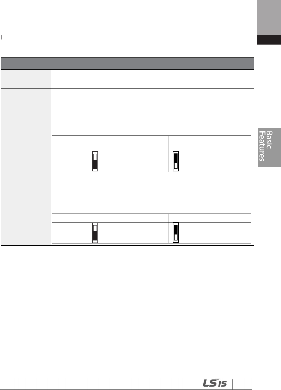
143
Learning Basic Features
Multi-function Input Terminal Control Setting Details
Code
Description
IN
-
85 DI
On Delay,
IN-86 DI Off Delay
If the input terminal’s state is not changed during the set time, when the terminal
receives an input, it is recognized as On or Off.
IN-87 DI NC/NO
Sel
Select terminal contact types
for each input terminal. The position of the
indicator light corresponds to the segment that is on as shown in the table
below. With the bottom segment on, it indicates that the terminal is configured
as a A terminal (Normally Open) contact. With the top segment on, it indicates
that the terminal is configured as a B terminal (Normally Closed) contact.
Terminals are numbered P1–P7, from right to left.
Type
B terminal status (Normally
Closed)
A terminal status (Normally
Open)
Keypad
IN-90 DI Status
Display the configuration of each contact. When a segment is configured as A
terminal, using DRV-87, the On condition is indicated by the top segment turning
on. The Off condition is indicated when the bottom segment is turned on. When
contacts are configured as B terminals, the segment lights behave conversely.
Terminals are numbered P1–P7, from right to left.
Type
A terminal setting (On)
A terminal setting (Off)
Keypad

144
Learning Basic Features
4.21 Multi-function Input Terminal On/Off Delay Control
Availability of using On/Off Delay about Multi-function Input Terminal can be set
Group Code Name LCD Display Parameter
Setting Setting Range Unit
IN
83 Availability of applying
DI On Delay.
DI On
DelayEn
111 1111 000 0000 ~
111 1111
-
84 Availability of applying
DI Off Delay.
DI Off
DelayEn
111 1111 000 0000 ~
111 1111
-
Multi-function Input Terminal On/Off Delay Control Setting Details
Code Description
IN-83 DI On Delay En
IN-84 DI Off Delay En
Every Input Terminal, it is possible to set availability of using On/Off Delay
of Input Terminal.
From right, Availability of using On/Off Delay about Multi-function Input
Terminal can be set with a sequence such as P1~P7.
1: Activate D1 On/Off Delay
0: Inactivate D1 On/Off Delay

145
Learning Advanced Features
5 Learning Advanced Features
This chapter describes the advanced features of the H100 inverter. Check the reference page in the
table to see the detailed description for each of the advanced features.
Advanced Tasks
Description
Ref.
Auxiliary frequency
operation
Use the main and auxiliary frequencies in the predefined formulas
to create various operating conditions. Auxiliary frequency
operation is ideal for Draw Operation* as this feature enables fine-
tuning of operation speeds.
p.147
Jog operation
Jog operation is a kind of a manual operation. The inverter operates
to a set of parameter settings predefined for Jog operation while
the Jog command button is pressed.
p.153
Up-down operation
Uses the upper and lower limit value switch output signals (i.e.
signals from a flow meter) as Acc/Dec commands to motors. p.155
3-wire operation
3
-
wire operation is used to latch an input signal. This configuration
is used to operate the inverter by a push button. p.157
Safety operation
mode
This safety feature allows the inverter’s operation only after a signal
is input to the multi-function terminal designated for the safety
operation mode. This feature is useful when extra care is needed in
operating the inverter using the multi-purpose terminals.
p.158
Dwell operation
Use this feature for the lift
-
type loads such as elevators
, when the
torque needs to be maintained while the brakes are applied or
released.
p.160
Slip compensation
This feature ensures that the motor rotates at a const
ant speed, by
compensating for the motor slip as a load increases. p.162
PID control
PID control provides constant automated control of flow, pressure,
and temperature by adjusting the output frequency of the inverter. p.163
Sleep-wakeup
operation
When the inverter operation continues below the PID conditions
for a set time period, the PID reference is automatically raised to
extend the operation standby time. This keeps the inverter in a
standby (sleep) mode when the demand is very low.
p.180
Auto-tuning
Used to automatically measure the motor control parameters to
optimize the inverter’s control mode performance. p.219
Energy buffering
operation
Used to maintain the DC link voltage
for as long as possible by
controlling the inverter output frequency during power
interruptions, thus to delay a low voltage fault trip.
p.197
Energy saving
operation
Used to save energy by reducing the voltage supplied to motors
during low-load and no-load conditions. p.239
Speed search
operation
Used to prevent fault trips when the inverter voltage is output while
the motor is idling or free-running. p.243

146
Learning Advanced Features
Advanced Tasks
Description
Ref.
Auto restart
operation
Auto restart configuration is used to automatically restart the
inverter when a trip condition is released, after the inverter stops
operating due to activation of protective devices (fault trips).
p.248
Second motor
operation
Used to switch equipment operation by connecting two motors to
one inverter. Configure and operate the second motor using the
terminal input defined for the second motor operation.
p.251
Commercial power
source switch
operation
Used to switch the power source to the motor from the inverter
output to a commercial power source, or vice versa. p.253
Cooling fan control Used to control the cooling fan of the inverter.
p.
254
Multi
-
function
output On/Off
control
Set standard values and turn On/Off the output relays or multi-
function output terminals according to the analog input value. p.294
Regeneration
prevention for press
operation.
Used during a press operation to avoid motor regeneration, by
increasing the motor operation speed. p.253
Damper operation
Controls the fan motor optimally when a damper is used in the
system. p.194
Lubrication
operation
Supplies lubricant to the machinery before starting the inverter and
the mechanical system connected to it. p.196
Flow compensation Compensates for pressure loss in a system with long pipelines. p.194
Energy savings
display
Displays the amount of energy saved by the use of the inverter,
compared to when a commercial power source is used without an
inverter.
p.198
Pump clean
operation
Cleans the pumps by removing the scales or deposits that are
attached to the impeller. p.200
Inclination setting
for operation and
stop
Sets the initial operating conditions for a pump by adjusting the
acceleration and deceleration times. p.204
Valve deceleration
time setting
Prevents possible pump damage that may be caused by abrupt
deceleration. p.206
Load tuning
Creates load
-
specific curves for light load operations and the pump
clean operation. p.207
Level detection
Detects and displays the level set by the user.
p.
209
Pipe breakage
detection Detects breakages in the pipeline during a PID operation. p.213
Motor preheating
Prevents motors and pumps from freezing when they are not
operated. p.216
Scheduled
operation
Uses the built
-
in real
-
time clock (RTC) to operate the inverter
according to the desired time schedule. p.222

147
Learning Advanced Features
Advanced Tasks
Description
Ref.
Fire mode operation
Operates the inverter in a way to cope with emergency situations,
such as fire, by controlling the operation of ventilation (intake and
exhaust) fans.
p.240
5.1 Operating with Auxiliary References
Frequency references can be configured with various calculated conditions that use the main and
auxiliary frequency references simultaneously. The main frequency reference is used as the
operating frequency, while auxiliary references are used to modify and fine-tune the main
reference.
Group
Code
LCD Display
LCD Display
Parameter Setting
Setting Range
Unit
DRV 06
Frequency reference
source Freq Ref Src 0 Keypad-1 0–11 -
BAS
01
Auxiliary frequency
reference source Aux Ref Src 1 V1 0–13 -
02
Auxiliary
frequency
reference calculation
type
Aux Calc
Type 0 M+(G*A) 0–7 -
03
Auxiliary frequency
reference gain Aux Ref Gain
100.0 100.0 -200.0–200.0 %
IN
65
–
71
Px terminal
configuration Px Define 36 dis Aux Ref
0–55 -
The table above lists the available calculated conditions for the main and auxiliary frequency
references. Refer to the table to see how the calculations apply to an example where the DRV-06
Frq Src code has been set to ‘0 (Keypad-1)’, and the inverter is operating at a main reference
frequency of 30.00 Hz. Signals at -10 to +10 V are received at terminal V1, with the reference gain
set at 5%. In this example, the resulting frequency reference is fine-tuned within the range of
27.00–33.00 Hz [Codes IN-01–16 must be set to the default values, and IN-06 (V1 Polarity), set to ‘1
(Bipolar)’].
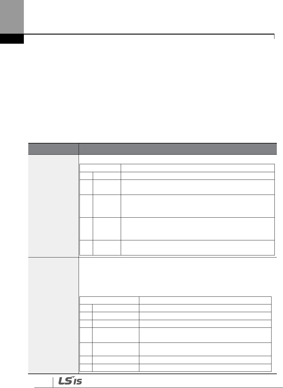
148
Learning Advanced Features
Auxiliary Reference Setting Details
Code
Description
BAS-01 Aux Ref
Src
Set the input type to be used for the auxiliary frequency reference
.
Configuration
Description
0
None
Auxiliary frequency reference is disabled
1
V1
Sets the V1 (voltage) terminal at the control terminal block as
the source of auxiliary frequency reference.
3
V2
Sets the I2 (voltage) terminal at the control terminal block as
the source of auxiliary frequency reference (SW4 must be set
to ‘voltage’).
4
I2
Sets the I2 (current) terminal at the control terminal block as
the source of auxiliary frequency reference (SW4 must be set
to ‘current’).
5
Pulse
Sets the TI (pulse) terminal at the control terminal block as the
source of auxiliary frequency reference.
BAS-02
Aux Calc Type
Set the auxiliary reference gain with BAS
-
03 (Aux Ref Gain) to
configure the
auxiliary reference and set the percentage to be reflected when calculating the
main reference. Note that items 4–7 below may result in either plus (+) or minus
(-) references (forward or reverse operation) even when unipolar analog inputs
are used.
Configuration
Formula for frequency reference
0
M+(G*A)
Main reference +(BAS
-
03x BAS
-
01xIN
-
01)
1
M*(G*A)
Main reference x(BAS
-
03x BAS
-
01)
2
M/(G*A)
Main reference /( BAS
-
03x BAS
-
01)
3
M+{M*(G*A)}
Main reference +{ Main reference x(BAS
-
03x
BAS
-
01)}
4
M+G*2*(A
-
50)
Main reference + BAS
-
03x2x(BAS
-
01
–
50)xIN
-
01
5
M*{G*2*(A
-
50)}
Main reference x{ BAS
-
03x2x(BAS
-
01
–
50)}
6
M/{G*2*(A
-
50)}
Main reference /{ BAS
-
03x2x(BAS
-
01
–
50)}
149
Learning Advanced Features
7
M+M*G*2*(A
-
50)
Main reference + Main reference x
BAS
-
03x2x(BAS
-
01–50)
M: Main frequency reference (Hz or rpm)
G: Auxiliary reference gain (%)
A: Auxiliary frequency reference (Hz or rpm) or gain (%)
BAS
-
03 Aux Ref
Gain
Adjust the size of the input
(BAS
-
01 Aux Ref Src) configured for auxiliary
frequency.
IN-65–71 Px
Define
Set one of the multi
-
function input terminals to 36 (dis Aux Ref) and turn it on to
disable the auxiliary frequency reference. The inverter will operate using the
main frequency reference only.

150
Learning Advanced Features
Auxiliary Reference Operation Ex #1
Keypad Frequency Setting is Main Frequency and V1 Analog Voltage is Auxiliary Frequency
• Main frequency: Keypad (operation frequency 30 Hz)
• Maximum frequency setting (DRV-20): 400 Hz
• Auxiliary frequency setting (BAS-01): V1[Display by percentage(%) or auxiliary frequency (Hz)
depending on the operation setting condition]
• Auxiliary reference gain setting (BAS-03): 50%
• IN-01–32: Factory default
Example: an input voltage of 6 V is supplied to V1, and the frequency corresponding to 10 V is 60
Hz. The table below shows the auxiliary frequency A as 36 Hz[=60 Hz X (6 V/10 V)] or 60%[= 100% X
(6 V/10 V)].
Setting
*
Calculating final command frequency**
0
M[Hz]+(G[%]*A[Hz])
30 Hz(M)+(50%(G)x36 Hz(A))=48 Hz
1
M[Hz]*(G[%]*A[%])
30 Hz(M)x(50%(G)x60%(A))=9 Hz
2
M[Hz]/(G[%]*A[%])
30 Hz(M)/(50%(G)x60%(A))=100 Hz
3
M[Hz]+{M[Hz]*(G[%]*A[%])}
30 Hz(M)+{30[Hz]x(50%(G)x60%(A))}=39 Hz
4
M[Hz]+G[%]*2*(A[%]
-
50[%])[Hz]
30 Hz(M)+50%(G)x2x(60%(A)
–
50%)x60 Hz=36 Hz
5
M[HZ]*{G[%]*2*(A[%]
-
50[%])}
30 Hz(M)x{50%(G)x2x(60%(A)
–
50%)}=3 Hz
6
M[HZ]/{G[%]*2*(A[%]
-
50[%])}
30 Hz(M)/{50%(G)x2x(60%
–
50%)}=300 Hz
7
M[HZ]+M[HZ]*G[%]*2*(A[%]
-
50[%])
30 Hz(M)+30
Hz(M)x50%(G)x2x(60%(A)
–
50%)=33
Hz
* M: main frequency reference (Hz or rpm)/G: auxiliary reference gain (%)/A: auxiliary
frequency reference (Hz or rpm) or gain (%).
**If the frequency setting is changed to rpm, it is converted to rpm instead of Hz.

151
Learning Advanced Features
Auxiliary Reference Operation Ex #2
Keypad Frequency Setting is Main Frequency and I2 Analog Voltage is Auxiliary Frequency
• Main frequency: Keypad (Operation frequency 30 Hz)
• Maximum frequency setting (BAS-20): 400 Hz
• Auxiliary frequency setting (BAS-01): I2 [Display by percentage (%) or auxiliary frequency (Hz)
depending on the operation setting condition]
• Auxiliary reference gain setting (BAS-03): 50%
• IN-01–32: Factory default
Example: an input current of 10.4 mA is applied to I2, with the frequency corresponding to 20 mA
of 60 Hz. The table below shows auxiliary frequency as 24 Hz(=60[Hz] X {(10.4[mA]-4[mA])/(20[mA]
- 4[mA])} or 40%(=100[%] X {(10.4[mA] - 4[mA])/(20[mA] - 4[mA])}.
Setting*
Calculating final command frequency**
0
M[Hz]+(G[%]*A[Hz])
30Hz(M)+(50%(G)x24Hz(A))=42Hz
1
M[Hz]*(G[%]*A[%])
30Hz(M)x(50%(G)x40%(A))=6Hz
2
M[Hz]/(G[%]*A[%])
30Hz(M)/(50%(G)x40%(A))=150Hz
3
M[Hz]+{M[Hz]*(G[%]*A[%])}
30Hz(M)+{30[Hz]x(50%(G)x40%(A))}=36Hz
4
M[Hz]+G[%]*2*(A[%]
-
50[%])[Hz]
30Hz(M)+50%(G)x2x(40%(A)
–
5
0%)x60Hz=24Hz
5
M[HZ]*{G[%]*2*(A[%]
-
50[%])
30Hz(M)x{50%(G)x2x(40%(A)–50%)} = -
3Hz( Reverse )
6
M[HZ]/{G[%]*2*(A[%]
-
50[%])}
30Hz(M)/{50%(G)x2x(60%–40%)} = -
300Hz( Reverse )
7
M[HZ]+M[HZ]*G[%]*2*(A[%]
-
50[%])
30Hz(M)+30Hz(M)x50%(G)x2x (40%(A)
–
50%)=27Hz
* M: main frequency reference (Hz or rpm)/G: auxiliary reference gain (%)/A: auxiliary
frequency reference Hz or rpm) or gain (%).
**If the frequency setting is changed to rpm, it is converted to rpm instead of Hz.

152
Learning Advanced Features
Note
When the maximum frequency value is high, output frequency deviation
may result due to analog
input variation and deviations in the calculations.
Auxiliary Reference Operation Ex #3
V1
is Main Frequency and I2 is Auxiliary Frequency
• Main frequency: V1 (frequency command setting to 5 V and is set to 30 Hz)
• Maximum frequency setting (DRV-20): 400 Hz
• Auxiliary frequency (BAS-01): I2[Display by percentage (%) or auxiliary frequency (Hz)
depending on the operation setting condition]
• Auxiliary reference gain (BAS-03): 50%
• IN-01–32: Factory default
Example: An input current of 10.4 mA is applied to I2, with the frequency corresponding to 20 mA
of 60 Hz. The table below shows auxiliary frequency Aas 24 Hz (=60[Hz]x{(10.4[mA]-
4[mA])/(20[mA]-4[mA])} or 40% (=100[%] x {(10.4[mA] - 4[mA]) /(20 [mA] - 4[mA])}.
Setting*
Calculating final command frequency**
0
M[Hz]+(G[%]*A[Hz])
30 Hz(M)+(50%(G)x24 Hz(A))=42 Hz
1
M[Hz]*(G[%]*A[%])
30
Hz(M)x(50%(G)x40%(A))=6 Hz
2
M[Hz]/(G[%]*A[%])
30 Hz(M)/(50%(G)x40%(A))=150 Hz
3
M[Hz]+{M[Hz]*(G[%]*A[%])}
30 Hz(M)+{30[Hz]x(50%(G)x40%(A))}=36 Hz
4
M[Hz]+G[%]*2*(A[%]
-
50[%])[Hz]
30 Hz(M)+50%(G)x2x(40%(A)
–
50%)x60 Hz=24 Hz
5
M[HZ]*{G[%]*2*(A[%]
-
50[%])}
30 Hz(M)x{50%(G)x2x(40%(A)
–
50%)}=
-
3
Hz( Reverse )
6
M[HZ]/{G[%]*2*(A[%]
-
50[%])}
30 Hz(M)/{50%(G)x2x(60%
–
40%)}=
-
300
Hz( Reverse )
7
M[HZ]+M[HZ]*G[%]*2*(A[%]
-
50[%])
30 Hz(M)+30 Hz(M)x50%(G)x2x(40%(A)
–
50%)=27
Hz
* M: main frequency reference (Hz or rpm)/G: auxiliary reference gain (%)/A: auxiliary
frequency reference (Hz or rpm) or gain (%).
**If the frequency setting is changed to rpm, it is converted to rpm instead of Hz.
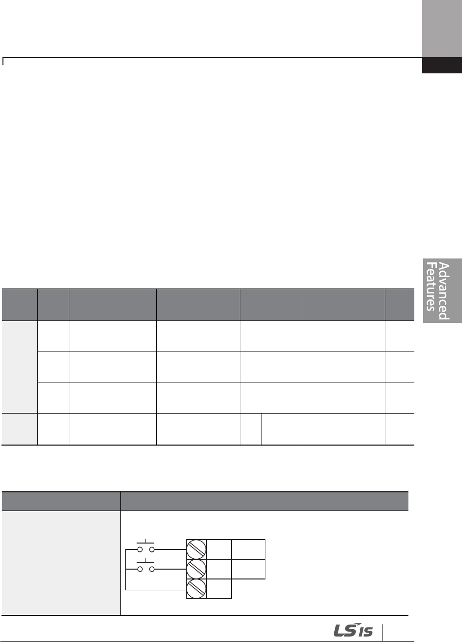
153
Learning Advanced Features
5.2 Jog Operation
The jog operation allows for a temporary control of the inverter. You can enter a jog operation
command using the multi-function terminals or by using the [ESC] key on the keypad.
The jog operation is the second highest priority operation, after the dwell operation. If a jog
operation is requested while operating the multi-step, up-down, or 3-wire operation modes, the
jog operation overrides all other operation modes.
5.2.1 Jog Operation 1-Forward Jog by Multi-function Terminal
The jog operation is available in either forward or reverse direction, using the keypad or multi-
function terminal inputs. The table below lists parameter setting for a forward jog operation using
the multi-function terminal inputs.
Group
Code LCD Display LCD Display
Parameter
Setting Setting Range Unit
DRV
11 Jog frequency JOG Frequency 10.00
0.00, Low
Freq
–
High Freq Hz
12
Jog operation
acceleration time JOG Acc Time 20.00 0.00–600.00 sec
13
Jog operation
deceleration time JOG Dec Time 30.00 0.00–600.00 sec
IN
65
–
71
Px terminal
configuration
Px Define
(Px: P1–P7) 6 JOG 0-55 -
Forward Jog Description Details
Code
Description
IN-65–71 Px Define
Select the jog frequency from P1
-
P7 and then select 6. Jog from IN
-
65-71.
[Terminal settings for jog operation]
P1
P5
CM
1(FX)
6(JOG)
154
Learning Advanced Features
Code
Description
DRV
-
11 JOG Frequency
Set the operation frequency.
DRV
-
12 JOG Acc Time
Set the acceleration speed.
DRV
-
13 JOG Dec Time
Set the deceleration speed.
If a signal is entered at the jog terminal while an FX operation command is on, the operation
frequency changes to the jog frequency and the jog operation begins.
5.2.2 Jog Operation 2-Forward/Reverse Jog by Multi-function Terminal
For jog operation 1, an operation command must be entered to start operation, but while using
jog operation 2, a terminal that is set for a forward or reverse jog also starts an operation. The
priorities for frequency, Acc/Dec time and terminal block input during operation in relation to
other operating modes (Dwell, 3-wire, up/down, etc.) are identical to jog operation 1. If a different
operation command is entered during a jog operation, it is ignored and the operation maintains
the jog frequency.
Group
Code
Name
LCD Display
Parameter setting
Setting Range
Unit
DRV
11 Jog frequency
JOG
Frequency 10.00
0.00, Low Freq
–
High Freq Hz
12
Jog operation
acceleration time
JOG Acc
Time 20.00 0.00–600.00 sec
13
Operation
deceleration time
JOG Dec
Time 30.00 0.00–600.00 sec
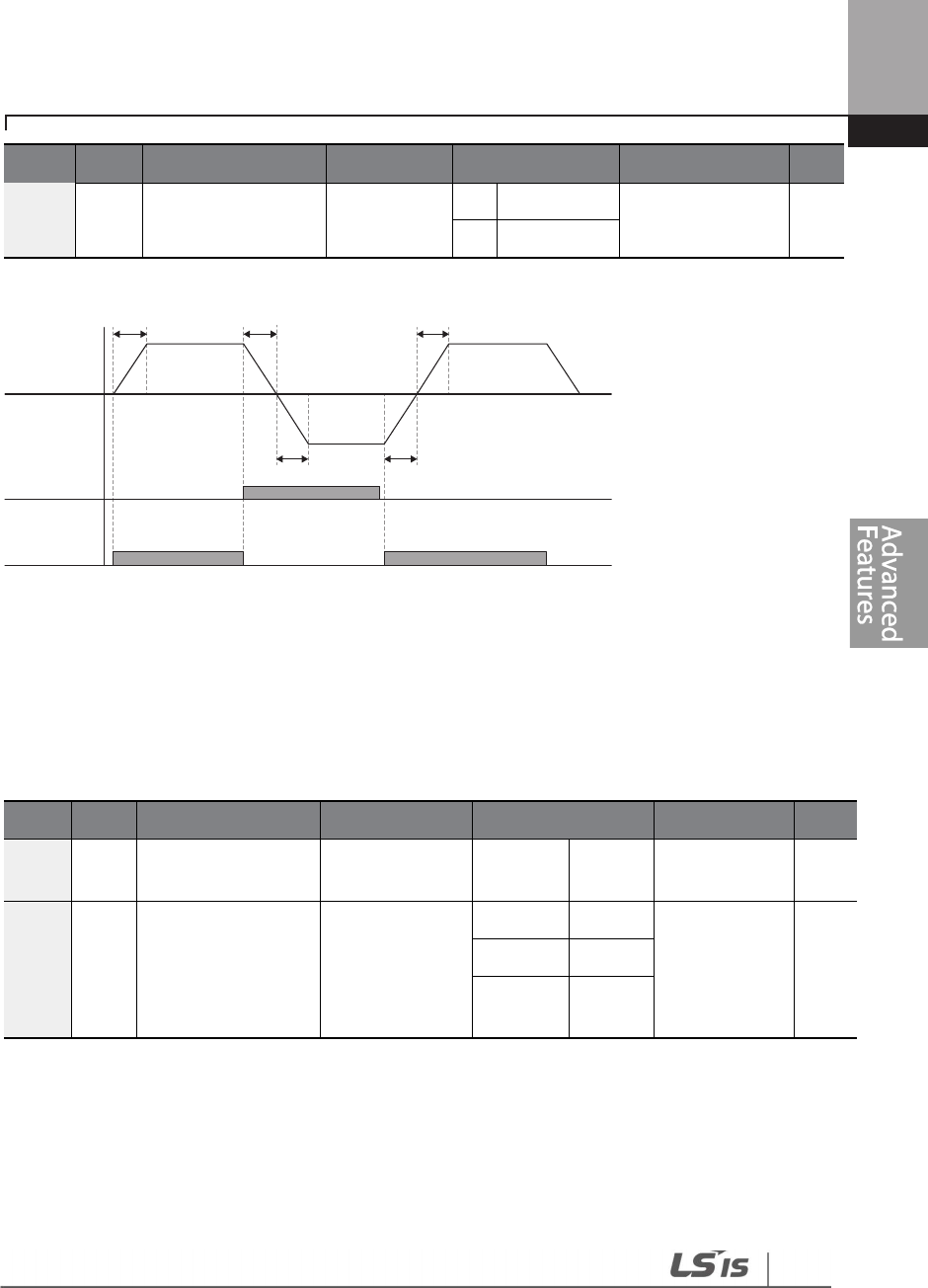
155
Learning Advanced Features
Group
Code
Name
LCD Display
Parameter setting
Setting Range
Unit
IN 65–
71
Px terminal
configuration
Px Define
(Px: P1–P7)
38
FWD JOG
0-55 -
39
REV JOG
5.3 Up-down Operation
The Acc/Dec time can be controlled through input at the multi-function terminal block. Similar to
a flowmeter, the up-down operation can be applied easily to a system that uses the upper-lower
limit switch signals for Acc/Dec commands.
Group
Code
Name
LCD Display
Parameter Setting
Setting Range
Unit
ADV 65
Up
-
down operation
frequency save U/D Save Mode 1 Yes 0–1 -
IN 65–
71
Px terminal
configuration
Px Define(Px:
P1–P7)
19
Up
0–55 -
20
Down
22
U/D
Clear
REV Jog
FWD Jog
DRV-11 DRV-11
DRV-11
DRV-12
DRV-12 DRV-13
DRV-13 DRV-12
Frequency
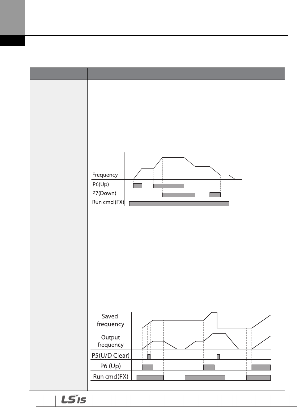
156
Learning Advanced Features
Up-down Operation Setting Details
Code
Description
IN-65–71 Px Define
Select two terminals for up
-
down operation and set them to ‘19 (Up)’ and ‘20
(Down)’, respectively. With the operation command input, acceleration
begins when the Up terminal signal is on. Acceleration stops and constant
speed operation begins when the signal is off.
During operation, deceleration begins when the Down signal is on.
Deceleration stops and constant speed operation begins when both Up and
Down signals are entered at the same time.
ADV-65 U/D Save
Mode
During a constant speed operation, the operating frequency is saved
automatically in the following conditions: the operation command (Fx or Rx)
is off, a fault trip occurs, or the power is off.
When the operation command is turned on again, or when the inverter
regains the power source or resumes to a normal operation from a fault trip,
it resumes operation at the saved frequency. To delete the saved frequency,
use the multi-function terminal block. Set one of the multi-function
terminals to 22 (U/D Clear) and apply signals to it during constant speed
operation. The saved frequency and the up-down operation configuration
will be deleted.
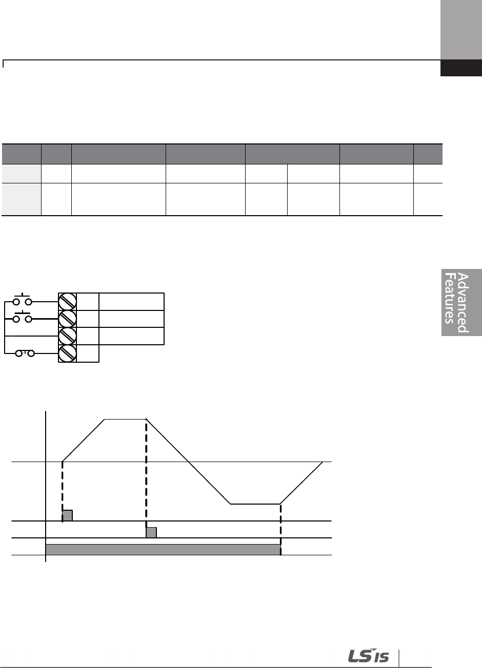
157
Learning Advanced Features
5.4 3- Wire Operation
The 3-wire operation latches the signal input (the signal stays on after the button is released), and
is used when operating the inverter with a push button.
Group
Code
Name
LCD Display
Parameter Setting
Setting Range
Unit
DRV
07
Command source
Cmd Source*
1
Fx/Rx
-
1
0
-
11
-
IN
65
–
71
Px terminal
configuration
Px
Define(Px:
P1–P7) 16 3-Wire 0-55 -
To enable the 3-wire operation, the following circuit sequence is necessary. The minimum input
time (t) for 3-wire operation is 2 ms, and the operation stops when both forward and reverse
operation commands are entered at the same time.
P1
P5
CM
(1):FX
(6):JOG
P7 (16):3-Wire
[Terminal connections for 3-wire operation]
FX
RX
3-Wire
Freq .
[3- wire operation]

158
Learning Advanced Features
5.5 Safe Operation Mode
When the multi-function terminals are configured to operate in safe mode, operation commands
can be entered in the Safe operation mode only. Safe operation mode is used to safely and
carefully control the inverter through the multi-function terminals.
Group Code Name LCD Display Parameter Setting
Setting
Range Unit
ADV
70
Safe operation
selection Run En Mode 1 DI Dependent 0-1 -
71
Safe operation
stop mode Run Dis Stop 0 Free-Run 0–2 -
72
Safe operation
deceleration
time
Q-Stop Time 5.0 0.0–600.0 sec
IN 65–71
Px terminal
configuration
Px Define(Px: P1
–
P7) 15
RUN Enable 0-55 -
Safe Operation Mode Setting Details
Code
Description
IN-65–71 Px Define
From the multi
-
function terminals, select a terminal to operate in safe
operation mode and set it to ‘15 (RUN Enable)’.
ADV-70 Run En
Mode
Setting
Function
0
Always
Enable
Enables safe operation mode
1
DI Dependent
Recognizes the operation command from a multi
-
function input terminal.
ADV-71 Run Dis
Stop
Set the operation of the inverter when the multi
-
function input terminal in safe
operation mode is off.
When the safety operation mode terminal signal is given, the inverter
decelerates based on the settings at the Q-Stop time. The inverter decelerates
and stops based on the deceleration time (Dec Time) settings if the run
command is off.
Setting
Function
1
Free
-
Run
Blocks the inverter output when the multi
-
function
terminal is off.
2
Q
-
Stop
The deceleration time (Q
-
Stop Time) used in safe
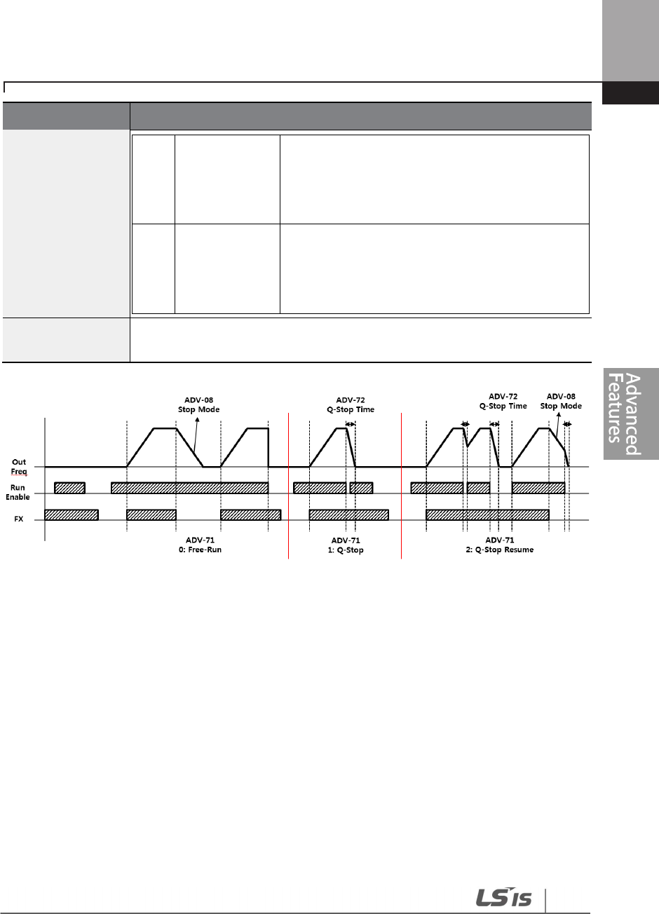
159
Learning Advanced Features
Code
Description
operation mode. It stops after deceleration and
then the operation can resume only when the
operation command is entered again. The
operation will not begin if only the multi-function
terminal is on.
3
Q
-
Stop
Resume
The inverter decelerates to the deceleration time
(Q-Stop Time) in safe operation mode. It stops after
deceleration. Then if the multi-function terminal is
on, the operation resumes as soon as the operation
command is entered again.
ADV
-
72 Q
-
Stop
Time
Sets the deceleration time when ADV
-
71 Run Dis Stop is set to ‘1 (Q
-
Stop)’ or ‘2
(Q-Stop Resume)’.
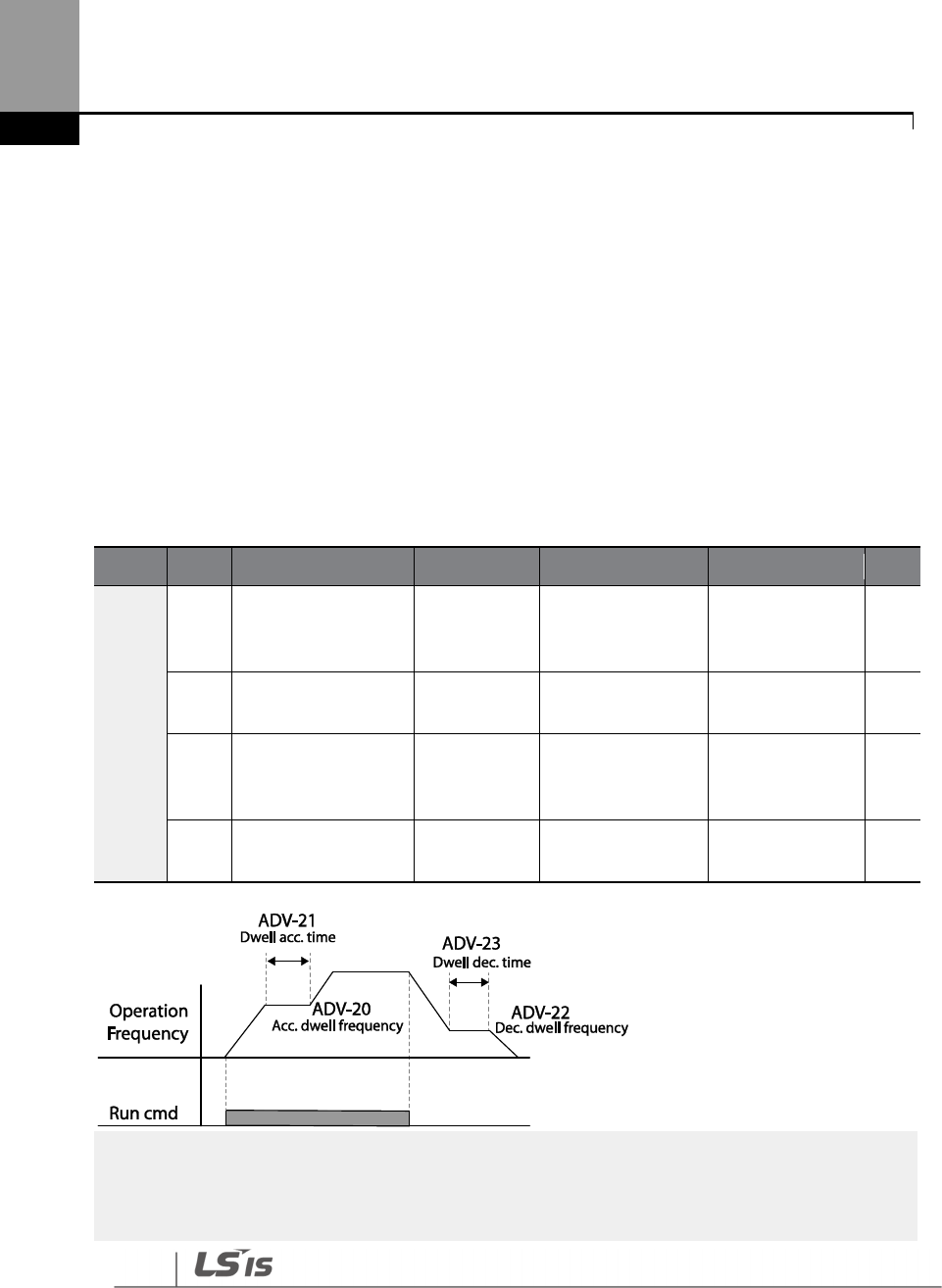
160
Learning Advanced Features
5.6 Dwell Operation
The dwell operation is used to maintain torque during the application and release of the
mechanical brakes on lift-type loads. Inverter dwell operation is based on the Acc/Dec dwell
frequency and the dwell time set by the user. The following points also affect dwell operation.
• Acceleration Dwell Operation: When an operation command runs, acceleration continues
until the acceleration dwell frequency and constant speed is reached within the acceleration
dwell operation time (Acc Dwell Time). After the Acc Dwell Time has passed, acceleration is
carried out based on the acceleration time and the operation speed that was originally set.
• Deceleration Dwell Operation: When a stop command is run, deceleration continues until
the deceleration dwell frequency and constant speed are reached within the deceleration
dwell operation time (Dec Dwell Freq). After the set time has passed, deceleration is carried
out based on the deceleration time that was originally set, then the operation stops.
Group
Code
Name
LCD Display
Parameter Setting
Setting Range
Unit
ADV
20 Dwell frequency
during acceleration
Acc Dwell
Freq 5.00
Start frequency
– Maximum
frequency
Hz
21
Operation time
during acceleration
Acc Dwell
Time 0.0 0.0–10.0 sec
22 Dwell frequency
during deceleration
Dec Dwell
Freq 5.00
Start frequency
– Maximum
frequency
Hz
23
Operation time
during deceleration
Dec Dwell
Time 0.0 0 .0– 60.0 sec
Note
Dwell operation does not work when:
•
Dwell operation time is set to 0 sec or dwell frequency is set to 0 Hz.
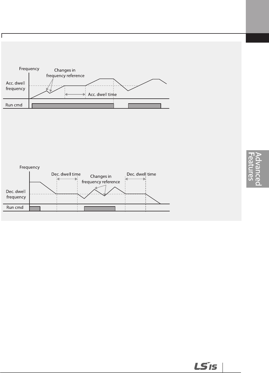
161
Learning Advanced Features
• Re-acceleration is attempted from stop or during deceleration, as only the first acceleration dwell
operation command is valid.
[Acceleration dwell operation]
• Although deceleration dwell operation is carried out whenever stop commands are entered
and the deceleration dwell frequency is passed through, it does not work during a
deceleration by simple frequency change (which is not a deceleration due to a stop
operation), or during external brake control applications.
[Deceleration dwell operation]

162
Learning Advanced Features
5.7 Slip Compensation Operation
Slip refers to the variation between the setting frequency (synchronous speed) and motor rotation
speed. As the load increases there can be variations between the setting frequency and motor
rotation speed. Slip compensation is used for loads that require compensation of these speed
variations.
Group
Code
Name
LCD Display
Parameter Setting
Setting Range
Unit
DRV
09 Control Mode
Control
Mode 1
Slip
Compen
- -
14 Motor Capacity
Motor
Capacity 2 5.5 kW 0–20 -
BAS
11
Number of
motor poles Pole Number
4 2–48 -
12 Rated slip speed
Rated Slip 40 (5.5 kW based) 0–3000
Rp
m
13
Rated motor
current Rated Curr 3.6 (5.5 kW based) 1.0–1000.0 A
14
Motor no
-
load
current Noload Curr 1.6 (5.5 kW based) 0.5–1000.0 A
16
Motor efficiency
Efficiency
72 (5.5 kW based)
70
–
100
%
Slip Compensation Operation Setting Details
Code
Description
DRV-09 Control Mode
Set DRV
-
09 to ‘2 (Slip Compen)’ to carry out the slip compensation
operation.
DRV
-
14 Motor Capacity
Set the capacity of the motor connected to the inverter.
BAS
-
11 Pole Number
Enter the
number of poles from the motor rating plate.
BAS-12 Rated Slip
Enter the number of rated rotations from the motor rating plate.
= Rated slip frequency
= Rated frequency
= Number of the rated motor rotations
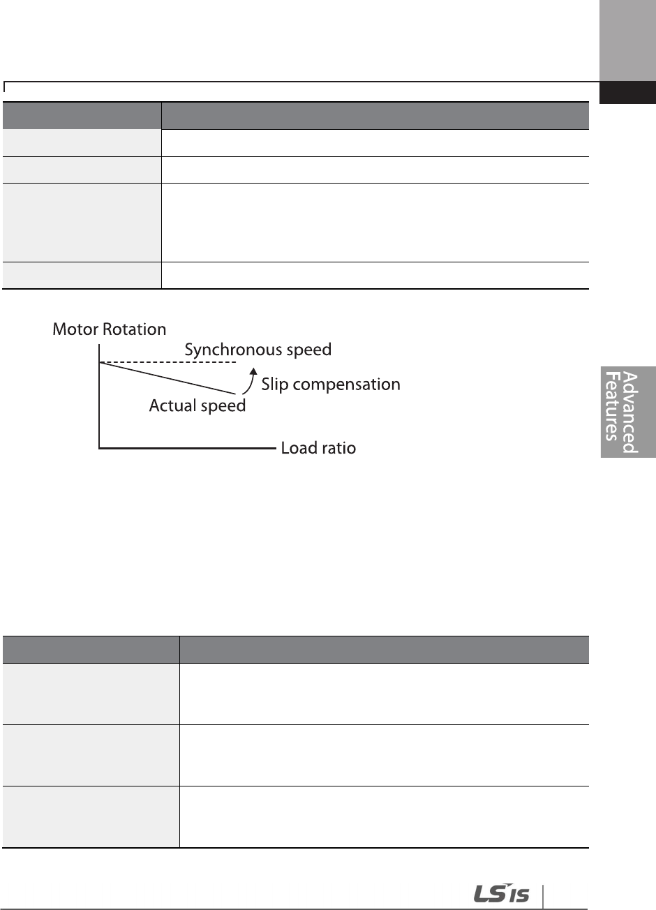
163
Learning Advanced Features
Code
Description
=
Number of motor poles
BAS
-
13 Rated Curr
Enter the rated current from the motor rating plate.
BAS-14 Noload Curr
Enter the measured current when the load on the motor axis is removed
and when the motor is operated at the rated frequency. If no-load
current is difficult to measure, enter a current equivalent to 30-50% of the
rated motor current.
BAS
-
16 Efficiency
Enter the efficiency from the motor rating place.
5.8 PID Control
PID control is one of the most common auto-control methods. It uses a combination of
proportional, integral, and differential (PID) controls that provide more effective control for
automated systems. The functions of PID control that can be applied to the inverter operation are
as follows:
Purpo
se
Function
Speed Control
Controls speed by monitoring the current speed levels of the
equipment or machinery being controlled. Control maintains
consistent speed or operates at the target speed.
Pressure Control
Controls pressure by monitoring the current pressure levels of the
equipment or machinery being controlled. Control maintains
consistent pressure or operates at the target pressure.
Flow Control
Controls flow by monitoring the current amount of flow in the
equipment or machinery being controlled. Control maintains
consistent flow or operates at a target flow.

164
Learning Advanced Features
Purpo
se
Function
Temperature Control
Controls temperature by monitoring
the current temperature levels
of the equipment or machinery to be controlled. Control maintains a
consistent temperature or operates at a target temperature.
5.8.1 PID Basic Operation
PID operates by controlling the output frequency of the inverter, through automated system
process control to maintain speed, pressure, flow, temperature or tension.
Group
Code
Name
LCD Display
Parameter Setting
Setting Range
Unit
PID
01 PID Options PID Sel 0 No 0–1 -
03
PID output
monitor PID Output - - -
04
PID
reference
monitor PID Ref Value - - -
05
PID feedback
monitor PID Fdb Value - - -
06 PID Error Monitor PID Err Value
10
PID reference
source
PID Ref
1
Source 0 Keypad 0–11 -
11
PID reference
setting PID Ref Set Unit Default
Unit Min
–
Unit
Max Unit
12
PID reference 1
auxiliary source
selection
PID
Ref1AuxSrc 0 None 0–13 -
13
PID reference 1
auxiliary mode
selection
PID
Ref1AuxMod 0 M+(G*A) 0–13 -
14 PID reference
auxiliary gain
PID Ref 1 Aux
G
0.0 -200.0–200.0 Unit
15
PID reference 2
auxiliary source PID Ref 2 Src 0 Keypad 0–11 -

165
Learning Advanced Features
Group
Code
Name
LCD Display
Parameter Setting
Setting Range
Unit
selection
16
PID reference 2
keypad setting PID Ref 2 Set Unit Default
Unit Min
–
Unit
Max Unit
17
PID reference 2
auxiliary source
selection
PID
Ref2AuxSrc 0 None 0–13 -
18
PID reference 2
auxiliary mode
selection
PID
Ref2AuxMod 0 M+(G*A) 0–12 -
19
PID reference 2
auxiliary gain PID Ref2 Aux G
0.0 -200.0–200.0 Unit
20
PID feedback
source selection PID Fdb Src 0 V1 0–9
21
PID feedback
auxiliary source
selection
PID Fdb
AuxSrc 0 None 0–11
22
PID feedback
auxiliary mode
selection
PID Fdb
AuxMod 0 M+(G+A) 0–13
23
PID feedback
auxiliary gain PID Fdb Aux G 0.0 -200.0–200.0 Unit
24
PID feedback
band PID Fdb Band 0 0–Unit Band Unit
25
PID proportional
gain 1 PID P-Gain 1 50.0 0.0–300.00 Unit
26 PID integral time 1
PID I-Time 1 10.0 0.0–200.0 sec
27
PID differential
time 1 PID D-Time 1 0.00 0–1.00 sec
28
PID feed forward
gain PID FF-Gain 0.0 0.0–1000.0 Unit
29 PID output filter PID Out LPF 0.00 0–10.00 sec
30
PID
output upper
limit PID Limit Hi 100.00
PID Limit Lo
–
100.00 Unit

166
Learning Advanced Features
Group
Code
Name
LCD Display
Parameter Setting
Setting Range
Unit
31
PID output lower
limit PID Limit Lo 0.00
-
100.00
–
PID
Limit Hi Unit
32
PID proportional
gain 2 PID P-Gain 2 5.0 0.0–300.00 Unit
33 PID integral time 2
PID I-Time 2 10.0 0.0–200.0 sec
34
PID differential
time 2 PID D-Time 2 0.00 0–1.00 sec
35
PID output mode
setting PID Out Mode 4 PID or Main 0–4
36 PID output reverse
PID Out Inv 0 No 0–1
37 PID output scale PID Out Scale 100.0 0.1–1000.0 Unit
40
PID multi
-
step
reference setting 1
PID Step Ref 1 Unit Default
Unit Min
–
Unit
Max Unit
41
PID multi
-
step
reference setting 2
PID Step Ref 2 Unit Default
Unit Min
–
Unit
Max Unit
42
PID multi
-
step
reference setting 3
PID Step Ref 3 Unit Default
Unit Min
–
Unit
Max Unit
43
PID
multi
-
step
reference setting 4
PID Step Ref 4 Unit Default
Unit Min
–
Unit
Max Unit
44
PID multi
-
step
reference setting 5
PID Step Ref 5 Unit Default
Unit Min
–
Unit
Max Unit
45
PID multi
-
step
reference setting 6
PID Step Ref 6 Unit Default
Unit Min
–
Unit
Max Unit
46
PID multi
-
step
reference setting 7
PID Step Ref 7 Unit Default
Unit Min
–
Unit
Max Unit
50
PID controller unit
selection PID Unit Sel 0 % 0–40 -
51
PID control setting
scale PID Unit Scale 2 X 1 0–4 -
52 PID control 0%
setting figure PID Unit 0% 0.00
Differ
depending on
PID-50 setting

167
Learning Advanced Features
Group
Code
Name
LCD Display
Parameter Setting
Setting Range
Unit
53 PID control 100%
setting figure PID Unit 100% 100.00
Differ
depending on
PID-50 setting
IN
65
–
71
Px circuit function
setting
Px Define(Px:
P1–P7) 1 none 0–55 -
Note
• Normal PID output (PID OUT) is bipolar and is limited by PID-46 (PID Limit Hi) and PID-47 (PID
Limit Lo) settings. DRV-20 (MaxFreq) value equals a 100% of PID OUT.
• The following are the variables used in PID operation, and how they are calculated:
- Unit MAX = PID Unit 100% (PID-68)
- Unit Min = (2xPID Unit 0% (PID-67)–PID Unit 100%)
- Unit Default = (PID Unit 100%-PID Unit 0%)/2
- Unit Band = Unit 100%-Unit 0%
• PID control may be utilized for the following operations:
Soft fill, auxiliary PID reference compensation, MMC, flow compensation, pipe breakage
detection
• During a PID operation, the PID output becomes the frequency reference. The inverter
accelerates or decelerates to the frequency reference based on the Acc/Dec times.
PID Basic Operation Setting Details
Code
Description
PID
-
01
PID Sel
Sets the code to ‘1 (Yes)’ to select functions for the process PID.
PID-03 PID Output
Displays the existing output value of the PID controller. The unit, gain, and
scale that were set in the PID group are applied on the display.
PID-04 PID Ref Value
Displays the existing reference value set for the PID controller. The unit, gain,
and scale that were set in the PID group are applied on the display.
PID-05 PID Fdb Value
Displays the latest feedback value of the PID controller. The unit, gain, and
scale that were set in the PID group are applied on the display.
PID-06 PID Err Value
Displays the differences between the existing reference and the feedback
(error value). The unit, gain, and scale that were set in the PID group are
applied on the display.
PID-10 PID Ref 1 Src
Selects the reference input for the PID control. If the V1 terminal is set to a PID
feedback source (PID F/B Source), the V1 terminal cannot be set to the PID
reference source (PID Ref Source). To set V1 as a reference source, change the
168
Learning Advanced Features
Code
Description
feedback source.
Setting
Function
0
Keypad
Keypad
1
V1
-
10
-
10 V input voltage terminal
3
V2
I2 analog input terminal
When the analog voltage/current input terminal
selection switch (SW4) at the terminal block is set to I
(current), input 0-20 mA current. If it is set to V
(voltage), input 0–10 V.
4
I2
5
Int. 485
RS
-
485 input terminal
7
FieldBus
Communication command via a communication
option card
8
Pulse
TI Pulse input terminal (0
-
32 kHz Pulse input)
9
E
-
PID
Output
External PID output
10
V
3
V
3 analoge input
terminal
of Extension IO option
When the analog voltage/current input terminal
selection switch (SW2) at the terminal block is set to
I3(current), input 0-20 mA current. If it is set to V3
(voltage), input 0–10 V.
11
I
3
PID-11 PID Ref Set
A reference value can be entered if the PID reference type (PID
-
10) is set to ‘0
(Keypad)’.
PID-12 PID
Ref1AuxSrc
Selects the external input source to be used as the reference for a PID control.
If an external input source is selected, the reference is determined using the
input value at the source (set at PID-10) and the value set at PID-13 PID
Ref1AuxMod.
Setting
Function
0
None
Not used
1
V1
-
10
-
10 V input voltage terminal
3
V2
I2 analog input terminal
[If the analog voltage/current input terminal selection
switch (SW4) at the terminal block is set to I (current),
input 0-20 mA current. If it is set to V (voltage), input
0–10 V]
4
I2
6
Pulse
TI Pulse input terminal (0
-
32 kHz Pulse input)
7
Int. 485
RS
-
485 input terminal
8
FieldBus
Communication command via a communication
option card
10
EPID1
External PID 1 Output
169
Learning Advanced Features
Code
Description
Output
11
EPID1 Fdb
Val
External PID 1 feedback value
12
V
3
V
3 analog input
terminal
of Extension IO option
When the analog voltage/current input terminal
selection switch (SW2) at the terminal block is set to
I3 (current), input 0-20 mA current. If it is set to V3
(voltage), input 0–10 V.
13
I
3
PID-13 PID Ref1
AuxMod
PID
-
13 (PID Ref1) provides formulas to calculate the reference 1 value. If PID
-
12 (PID RefAuxSrc) is set to any other value than ‘None,’ the final reference 1
value is calculated using the input value at the source (set at PID-10) and the
input value set at PID-12).
Setting
0
M+(G*A)
1
M*(G*A)
2
M/(G*A)
3
M+(M*(G*A))
4
M+G*2*(A
-
50)
5
M*(G*2*(A
-
50))
6
M/(G*2*(A
-
50))
7
M+M*G*2*(A
-
50)
8
(M
-
A)^2
9
M^2+A^2
10
MAX(M,A)
11
MIN(M,A)
12
(M+A)/2
13
Square Root(M+A)
M= Value by the source set at PID-10
G= Gain value set at PID-14
A= Value input by the source set at PID-12
PID
-
14 PID Ref1 Aux
G Gain value for the formulas provided by PID-13.
PID-20 PID Fdb Src
Selects feedback input for PID control. If the V1 terminal is set as the PID
feedback source (PID F/B Source), the V1 terminal cannot be set as the PID
reference source (PID Ref Source). To set V1 as a feedback source, change the
reference source.
Setting
Function
0
V1
-
10
-
10 V input voltage terminal
2
V2
I2 analog input terminal
170
Learning Advanced Features
Code
Description
3
I2
[If the analog
voltage/current input terminal selection
switch (SW4) at the terminal block is set to I (current),
input 0-20 mA current. If it is set to V (voltage), input 0–
10 V]
4
Int. 485
RS
-
485 input terminal
5
FieldBus
Communication command via a
communication
option card
7
Pulse
TI Pulse input terminal (0
-
32 kHz Pulse input)
8
EPID1
Output
External PID 1 output
9
EPID1 Fdb
Val
External PID 1 feedback
PID-21 PID Fdb
AuxSrc
Selects the external input source to be used as the reference for a
PID control.
When the external input source is selected, the reference is determined
using the input value at the source (set at PID-10) and the value set at PID-13
PID Ref1AuxMod.
Setting
Function
0
None
Not used
1
V1
-
10
-
10 V input voltage terminal
3
V2
I2 analog input terminal
[When the analog voltage/current input terminal
selection switch (SW4) at the terminal block is set to I
(current), input 0-20 mA current. If it is set to V
(voltage), input 0–10 V]
4
I2
6
Pulse
TI Pulse input terminal (0
-
32
kHz Pulse input)
7
Int. 485
RS
-
485 input terminal
8
FieldBus
Communication command via a communication
option card
10
EPID1
Output
External PID 1 output
11
EPID1 Fdb
Val
External PID 1 feedback
PID-22 PID FDB
AuxMod
The PID
-
30 (PID FDB AuxMod) provides formulas to calculate the final
feedback value. If PID-31 (PID RefAuxSrc) is set to any other value than ‘None,’
the final feedback is calculated using the input values at the sources (set at
PID-31 and PID-32).
Settin
g
0
M+(G*A)
1
M*(G*A)

171
Learning Advanced Features
Code
Description
2
M/(G*A)
3
M+(M*(G*A))
4
M+G*2*(A
-
50)
5
M*(G*2*(A
-
50))
6
M/(G*2*(A
-
50))
7
M+M*G*2*(A
-
50)
8
(M
-
A)^2
9
M^2+A^2
10
MAX(M,A)
11
MIN(M,A)
12
(M+A)/2
13
Square Root(M+A)
M= Value by the source set at PID-30
G= Gain value set at PID-33
A= Value by the source set at PID-31
PID
-
23 PID Fdb Aux G
Gain value used a formula set at PID
-
22.
PID-24
PID Fdb Band
Sets the maximum and minimum value by adding or subtracting the PID
Fdb Band value (set at PID-24) from the reference value. When the feedback
value is between the maximum and minimum value, this code maintains the
PID output.
PID
-
25
PID P-Gain1
PID-32
PID P-Gain2
Set the output ratio for differences (errors) between the reference and
feedback. If the P Gain is set to 50%, then 50% of the error is output.
PID-26
PID I- Time 1
PID-33
PID I- Time 2
Sets the time to output accumulated errors. When the error is 100%, the time
taken for 100% output is set. When the integral time (PID I-Time) is set to 1
second, 100% output occurs after 1 second of the error remaining at 100%.
Differences in a normal state can be reduced by PID I Time. When the multi-
function terminal block is set to ‘24 (I-Term Clear)’ and is turned on, all of the
accumulated errors are deleted.
PID output (final frequency reference) is affected by the gains set at PID-26,
PID-33, and the Acc/Dec times to achieve the PID output change based on
the DRV-03 and DRV-04 settings. Therefore, consider the relationship
between these values when configuring the gains and the Acc/Dec times.
PID
-
27
PID D-Time 1
PID-34
PID D-Time 2
Sets the output volume for the rate of change in errors. If the differential time
(PID D-Time) is set to 1 ms and the rate of change in errors per sec is 100%,
output occurs at 1% per 10 ms.
172
Learning Advanced Features
Code
Description
PID-28 PID FF-Gain
Sets the ratio that adds the target to the PID output. Adjusting this value
leads to a faster response.
PID-29
PID Out LPF
Used when the PID controller output changes too quickly or the entire
system is unstable, due to severe oscillation. In general, a lower value (default
value=0) is used to speed up response time, but in some cases a higher value
increases stability. The higher the value, the more stable the PID controller
output is, but the slower the response time.
PID
-
30 PID Limit Hi,
PID-31 PID Limit Lo Limit the output of the controller.
PID-35
PID Out Mode
Selects one of the PID output modes to modify the PID output. Modifications
can be made by adding input values and the main operation frequency of
the PID output to the final PID output value.
The following table lists the 5 modes that are available.
Setting
0
PID Output
1
PID+Main Freq
2
PID+EPID1 Out
3
PID+EPID1+Main
4
PID or Main
PID
-
36
PID Out Inv
When PID
-
36 (PID Out Inv) is set to ‘Yes,’ the difference (error) between
the
reference and the feedback is set as the feedback–reference value.
PID
-
37 PID Out Scale
Adjusts the volume of the controller output.
PID
-
40
–
46 Step Ref
1–7 Sets the PID reference by multi-function input settings at IN 65–71.
D-50
PID Unit Sel
Sets
the unit for the control variable.
0: CUST is a custom unit defined by the user.
Setting
0
CUST
21
m 3/m(m 3/min)
1
%
22
m 3/h(m 3/h)
2
PSI
23
l/s
3
˚F
24
l/m
4
˚C
25
l/h
5
inWC
26
kg/s
6
inM
27
kg/m
7
Bar
28
kg/h

173
Learning Advanced Features
Code
Description
8
mBar
29
gl/s
9
Pa
30
gl/m
10
kPa
31
gl/h
11
Hz
32
ft/s
12
Rpm
33
f3/s(ft3/min)
13
V
34
f3/h (ft3/h)
14
I
35
lb/s
15
kW
36
lb/m
16
HP
37
lb/m
17
mpm
38
lb/h
18
ft
39
ppm
19
m/s
40
pps
20
m3/s(m 3/S)
PID
-
51
PID Unit Scale Adjusts the scale to fit the unit selected at PID-50 PID Unit Sel.
PID
-
52
PID Unit 0 %
PID-53
PID Unit 100%
Sets the Unit 0% and Unit 100% values as the minimum and maximum
values set at PID-50.

174
Learning Advanced Features
PID Command Block
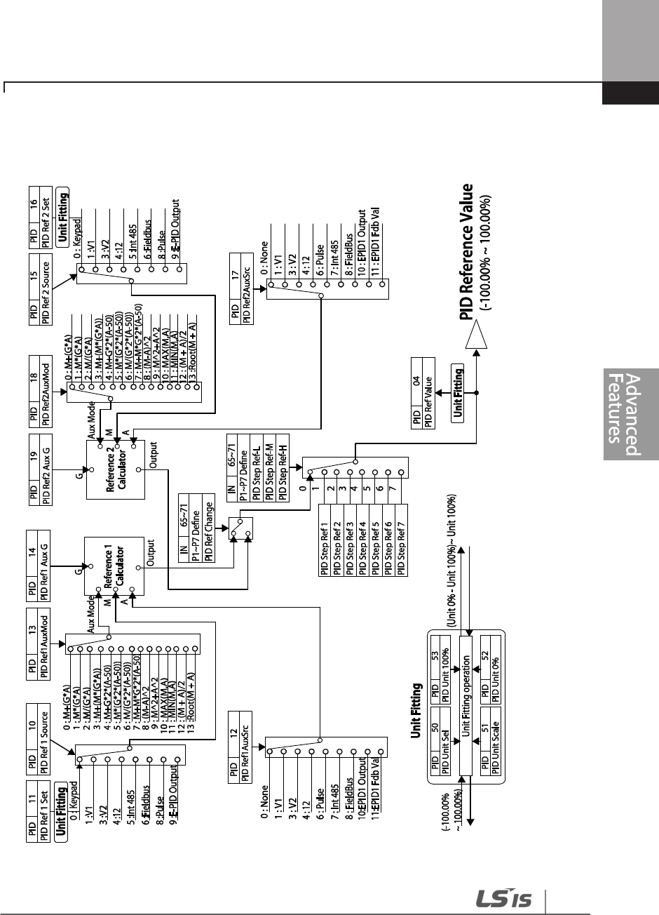
175
Learning Advanced Features
176
Learning Advanced Features
PID Feedback Block
1
77
Learning Advanced Features
PID Output Block
178
Learning Advanced Features
PID Output Mode Block

179
Learning Advanced Features
5.8.2 Soft Fill Operation
A soft fill operation is used to prevent excessive pressure from building in the pipe system at the
initial stage of a pump operation. When the operation command is given, a general acceleration
(without PID control) begins and continues until the output reaches the frequency set at AP1-21,
for the time set at AP1-22. Then, the soft fill PID operation is performed unless the feedback value
has reached the value set at AP1-23 (Soft Fill Set value). The soft fill PID operation continues until
the feedback or the soft fill PID reference value reaches the value set at AP1-23 (Soft Fill Set value).
When the soft fill operation ends, a normal PID operation starts.
Group
Code Name LCD Display Parameter Setting
Setting Range Unit
AP1
20
Soft Fill options
Soft Fill Sel
0
No
0
–
1
-
21
Pr
-
PID operation
frequency Pre-PID Freq 30.00
Low Freq
–
High Freq Hz
22
Pre
-
PID duration
Pre
-
PID Delay
60.0
600.0
sec
23 Soft fill escape value Soft Fill Set 20.00
Unit Min
–
Unit
Max %
24
Soft fill reference
increment Fill Step Set 2.00 0–Unit Band %
25
Soft fill reference
increment cycle Fill Step Time 20 0–9999 sec
26
Soft fill feedback
difference Fill Fdb Diff 0.00 0–Unit Band %
Soft Fill Operation Setting Details
Code Description
AP1-20
Soft Fill Sel Enables or disables the soft fill PID.
AP1-21
Pre-PID Freq
Sets the frequency range for a general acceleration without PID c
ontrol. If AP1
-
21 (Pre-PID Freq) is set to 30 Hz, general operation is performed until the PID
feedback reaches the value set at AP1-23 (Soft Fill Set). However, if the PID
reference or feedback exceeds the value set at AP1-23 during the pre-PID
operation, a normal PID operation starts immediately.
AP1-22 Pre-PID In general, a PID operation starts when the feedback volume (controlled
180
Learning Advanced Features
Code Description
Delay
AP1-23
Soft Fill Set
variables) of PID controller exceeds the value set at AP1
-
23. However, if AP1
-
22
(Pre-PID Delay) is set, the feedback after the set time becomes the default value
for the soft fill PID reference, and the inverter starts the soft fill operation.
When the feedback or the Soft Fill PID Reference exceeds the Soft Fill Set value,
the soft fill operation ends and a normal process PID operation begins.
AP1
-
24
Fill Step Set
AP1-25
Fill Step Time
AP1-26
Fill Fdb Diff
The Soft Fill PID Reference increases each time the set time [at AP1-25 (Fill Step
Time)] is elapsed, by the amount set at AP1-24 (Fill Step Set).
However, note that if the difference between the Soft Fill PID Reference value
and the feedback value is greater than the value set at AP1-26 (Fill Fdb Diff
value), the Soft Fill PID Reference value does not increase.
When a PID process is performed after the soft fill PID operation, the PID Reference value becomes
the PID-11 PID Ref1 Set value.

181
Learning Advanced Features
5.8.3 PID Sleep Mode
If an operation continues at a frequency lower than the PID operation conditions, a boost
operation is performed to extend sleep mode by raising the PID Reference, and then the inverter
enters PID sleep mode. In PID sleep mode, the inverter resumes PID operation when the PID
feedback falls below the PID Wakeup level and maintains the condition for the time set at AP1-09
(PID WakeUp1 DT) or AP1-13 (PID WakeUp2DT).
Note
PID Wakeup level may be calculated using the following formula:
PID Wakeup Level = PID-04 (PID Ref Value)–AP1-10 (PID WakeUp1Dev) or, PID-04 (PID Ref Value) - AP1-
14 PID (WakeUp2Dev).
Two sets of configurations are available in PID sleep mode for sleep mode frequency, sleep mode
delay time, wakeup variation, and wakeup delay time. One of the two configurations may be
selected depending on the multi-function input terminal configuration and input conditions.
Group
Code
Name
LCD Displays
Parameter Setting
Setting Range
Unit
AP1
05 Sleep boost settings
Sleep Bst Set 0.00 0–Unit Max Unit
06 Sleep boost speed Sleep Bst Freq 60.00 0.00, Low Freq–
High Freq Hz
07 PID sleep mode 1
delay time PID Sleep 1 DT 20.0 0–6000.0 sec
08 PID sleep mode 1
frequency PID Sleep1Freq
0.00 0.00, Low Freq–
High Freq Hz
09 PID wakeup 1 delay
time
PID WakeUp1
DT 20.0 0–6000.0 sec
10 PID wakeup 1 value PID
WakeUp1Dev 20.00 0–Unit Band Unit
11 PID sleep mode 2
delay time PID Sleep 2 DT 20.0 0–6000.0 sec
12 PID sleep mode 2
frequency PID Sleep2Freq
0.00 0.00, Low Freq–
High Freq Hz

182
Learning Advanced Features
Group
Code
Name
LCD Displays
Parameter Setting
Setting Range
Unit
13
PID wakeup 2
delay
time
PID WakeUp2
DT 20.0 0–6000.0 sec
14 PID wakeup 2 value
PID
WakeUp2Dev 20.00 0–Unit Band Unit
20 Soft Fill options Soft Fill Sel 0 No 0–1 -
PID Operation Sleep Mode Setting Details
Code
Description
AP1-05 Sleep Bst Set
Sets the sleep boost
volume. Feedback must reach the boost level
(PID Reference+Sleep Bst Set) for the inverter to enter the Sleep
Mode.
AP1
-
06 Sleep Bst Freq
Sets the inverter operation frequency to reach sleep boost level.
AP1-07 PID Sleep1 DT
AP1-11 PID Sleep2 DT
AP1-08 PID Sleep1Freq
AP1-12 PID Sleep2Freq
If the operating frequency stays below the frequencies set at AP1
-
08
and AP1-12 for the set times at AP1-07 and AP1-11, the inverter
accelerates to the PID sleep boost frequency (PID Sleep Bst Freq).
Then, when the feedback reaches the value set at the boost level, the
inverter enters standby mode.
AP1
-
09 PID WakeUp1 DT
AP1-13 PID WakeUp2 DT
AP1-10 PID WakeUp1Dev
AP1-14 PID WakeUp2Dev
Sets the reference for PID operation in PID sleep mode. PID operation
resumes when PID feedback variation (from the PID reference)
exceeds the values set at AP1-10 and AP1-14, and maintains the
condition for times set at AP1-09 or AP1-13.
IN-65–71
P1–7 Define
When the PID Sleep Wake 2 terminal is set and input, PID operation
sleep mode is operated based on the parameter settings at AP1-11–
14.
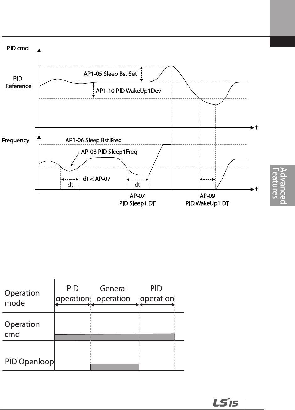
183
Learning Advanced Features
5.8.4 PID Switching (PID Openloop)
When one of the multi-function terminals (IN-65–71) is set to ‘25 (PID Openloop)’ and is turned on,
the PID operation stops and is switched to general operation. When the terminal turns off, the PID
operation starts again.

184
Learning Advanced Features
5.9 External PID
External PID refers to the PID features other than the basic PID features required to control the inverter.
The following table shows the areas where external PID controls can be applied.
Depending on the PID output mode, the EPID output value can be overlapped to the PID output.
External output is also available through the analog output settings at OUT-01 and OUT-07.
Group
Code
Name
LCD Display
Parameter Setting
Setting Range
Unit
EPI
00
Jump Code
Jump Code
40
1
–
99
01
EPID 1 Mode
Selection EPID1 Mode 0 None 0–3
02
EPID1output
monitor value
EPID1
Output 0.00 -100.00–100.00%
Unit
03
EPID1 reference
monitor value EPID1 Ref Val
- - -
04
EPID1 feedback
monitor value EPID1 Fdb Val
- - -
05
EPID1error monitor
value EPID1 Err Val - - -
06
EPID1 command
source selection EPID1 Ref Src
0 Keypad 0–10 -
07
EPID1 keypad
command value EPID1 Ref Set
Unit Min
Unit Min
–
Unit
Max %
Purpose
Function
Speed Control
Controls speed by monitoring
the current speed levels of the equipment or
machinery being controlled. Control maintains consistent speed or operates
at the target speed.
Pressure Control
Controls pressure by monitoring the current pressure levels of the
equipment or machinery being controlled. Control maintains consistent
pressure or operates at the target pressure.
Flow Control
Controls flow by monitoring the amount of flow in the equipment or
machinery to be controlled. Control maintains consistent flow or operates at
a target flow.
Temperature Control
Controls temperature by monitoring the current temperature levels of the
equipment or machinery to be controlled. Control maintains a consistent
temperature or operates at a target temperature.

185
Learning Advanced Features
Group
Code
Name
LCD Display
Parameter Setting
Setting Range
Unit
08
EPID1 feedback
source selection
EPID1 Fdb
Src 0 V1 0–9 -
09
EPID1 proportional
gain EPID1 P-Gain
50.0 0.0–300.0% Unit
10
EPID1 integral time
EPID1
I
-
Time
10.0
0.0
–
200.0
Sec
11
EPID1 differentiation
time EPID1 D-Time
0.00 0–0.00 Sec
12
EPID1 feed
-
forward
gain
EPID1 FF
-
Gain 0.0 0.0–1000.0 Unit
13 EPID1 output filter
EPID1 Out
LPF 0 0–10.00 Sec
14
EPID1 output upper
limit
EPID1 Limit
Hi 100.00
EPID1 Limit Lo
–
100.00 -
15 EPID1 lower limit
EPID1 Limit
Lo 0.00
-
100.00
–
EPID1
Limit Hi -
16
EPID1 output
inverse
EPID1 Out
Inv 0 No 0–1 -
17 EPID1 unit
EPID1 Unit
Sel 1: %
Refer to EPID unit
details table -
18 EEPID1 unit scale EPID1 Unit
Scl 2: X1
0: X100
1: X10
2: X1
3: X0.1
4: X0.01
-
19 EPID1 unit 0% value
EPID1
Unit0%
Differs depending
on the unit setting
X100:
-
32000
–
Unit 100%
X10: -3200.0–
Unit 100%
X1: -320.00–
Unit 100%
X0.1: -32.000–
Unit 100%
X0.01: -3.2000–
Unit 100%
-

186
Learning Advanced Features
Group
Code
Name
LCD Display
Parameter Setting
Setting Range
Unit
20 EPID1 unit 100%
value
EPID1
Unit100%
Differs depending
on the unit setting
X100: Unit 0%
–
32000
X10: Unit
0%–3200.0
X1: Unit
0%–320.00
X0.1: Unit
0%–32.000
X0.01: Unit 0%–
3.2000
-
31
EPID2 Mode
selection EPID2 Mode 0 None 0–3 -
32
EPID2 output
monitor value
EPID2
Output 0.00 -100.00–100.00%
Unit
33
EPID2 reference
monitor value EPID2 Ref Val
- - -
34
EPID2 feedback
monitor value EPID2 Fdb Val
- - -
35
EPID2 error monitor
value EPID2 Err Val - - -
36
EPID2 command
source selection EPID2 Ref Src
0 Keypad 0–10 -
37
EPID2 keypad
command value EPID2 Ref Set
Unit Min
Unit Min
–
Unit
Max Unit
38
EPID2 feedback
source selection
EPID2 Fdb
Src 0 V1 0–9 -
39
EPID2 proportional
gain EPID2 P-Gain
50.0 0.0–300.0 Unit
40
EPID2 integral time
EPID2 I
-
Time
10.0
0.0
–
200.0
Sec
41
EPID2 differentiation
time EPID2 D-Time
0.00 0–1.00 Sec
42
EPID2 feed
-
forward
gain
EPID2 FF
-
Gain 0.0 0.0–1000.0 Unit
43 EPID2 output filter
EPID2 Out
LPF 0 0–10.00 Sec

187
Learning Advanced Features
Group
Code
Name
LCD Display
Parameter Setting
Setting Range
Unit
44
EPID2 output upper
limit
EPID2 Limit
Hi 100.00
EPID2 Limit Lo
–
100.00 -
45
EPID2 output lower
limit
EPID2 Limit
Lo 0.00
-
100.00
–
EPID2
Limit Hi -
46 EPID2 output
inverse
EPID2 Out
Inv 0: No
0
No
-
1
Yes
47 EPID2 unit
EPID2 Unit
Sel 0: CUST
Refer to EPID unit
details table -
48 EPID2 unit scale EPID2 Unit
Scl 2: X1
0: X100
1: X10
2: X1
3: X0.1
4: X0.01
-
49 EPID2 unit 0% value
EPID2
Unit0%
Differs depending
on the unit setting
X100:
-
32000
–
Unit 100%
X10: -3200.0–Unit
100%
X1: -320.00–Unit
100%
X0.1: -32.000–
Unit -100%
X0.01: -3.2000–
Unit 100%
-
50
EPID2 unit 100%
value
EPID2
Unit100%
Differs depending
on the unit setting
X100: Unit 0%
–
32000
X10: Unit 0%–
3200.0
X1: Unit 0%–
320.00
X0.1: Unit 0%–
32.000
X0.01: Unit 0%–
3.2000
-
Note
• The EPID1–2 output (EPID OUT) is bipolar, and is limited by the EPI-14 (EPID 1 Limit Hi) and EPI-15
(EPID 1 Limit Lo) settings.
•
The following are the variables used in PID operation, and how they are calculated:

188
Learning Advanced Features
-
Unit MAX = EPID1 (EPID2) Unit 100% (PID
-
68 )
- Unit Min = (2xEPID1 (EPID2) Unit0%-EPID1 (EPID2) Unit 100%)
- Unit Default = (EPID1 (EPID2) Unit 100%-EPID1 (EPID2) Unit 0%)/2
189
Learning Advanced Features
EPID Basic Operation Setting Details
Code
Description
EPI-01 EPID1 Mode
Sets the EPID1 modes.
Setting
Function
0
None
EPID1 is not used.
1
Always On
EPID1 operates at all times.
2
During Run
Operates only when the inverter is running.
3
DI Dependent
Operates when terminal input (EPID1 Run) is
on.
EPI-02 PID Output
Displays the existing output value for the EPID controller. The unit, gain,
and scale that were set in the EPID group are applied on the display.
EPI-03 EPID Ref Value
Displays the existing reference value set for the EPID controller. The unit,
gain, and scale that were set in the EPID group are applied on the
display.
EPI-04 EPID1 Fdb Value
Displays the existing feedback value set for the EPID controller. The unit,
gain, and scale that were set in the EPID group are applied on the
display.
EPI-05 EPID1 Err Value
Displays the difference between the existing reference and the
feedback
(error value). The unit, gain, and scale that were set in the PID group are
applied on the display.
EPI1-06 EPID1 Ref Src
Selects the reference input for the EPID control. If the V1 terminal is set
to an EPID1 feedback source (EPID1 F/B Source), V1 cannot be set as the
EPID1 reference source (EPID1 Ref Source). To set V1 as a reference
source, change the feedback source.
Setting
Function
0
Keypad
Keypad
1
V1
-
10
-
10 V input voltage terminal
3
V2
I2 analog input terminal [When analog
voltage/current input terminal selection switch
(SW2) at the terminal block is set to I (current),
input 0-20 mA current. If it is set to V (voltage),
input 0–10 V]
4
I2
5
Int. 485
RS
-
485 input terminal
7
FieldBus
Communication command via a
communication
option card
8
Pulse
TI Pulse input terminal (0
-
32 kHz Pulse input)

190
Learning Advanced Features
Code
Description
EPI-07 EPID1 Ref Set
Set the EPI control reference type (EPI
-
06) to ‘0 (Keypad)’ to enter the
reference value.
EPI-09 EPID1 P-Gain
Sets the output ratio for differences (errors) between the reference and
feedback. If the P-Gain x 2 is set to 50%, then 50% of the error is output.
The setting range for P-Gain is 0.0-1,000%.
EPI-08 EDPID1 Fdb Src
Selects the feedback input for the EPID
control. When the V1 terminal is
set to an EPID feedback source (PID F/B Source), V1 cannot be set as the
PID reference source (PID Ref Source). To set V1 as a reference source,
change the feedback source.
Setting
Function
0
Keypad
Keypad
1
V1
-
10
-
10 V
input voltage terminal
3
V2
I2 analog input terminal [When analog
voltage/current input terminal selection switch
(SW4) at the terminal block is set to I (current),
input 0-20 mA current. If it is set to V (voltage),
input 0–10 V voltage]
4
I2
5
Int.
485
RS
-
485 input terminal
7
FieldBus
Communication command via a communication
option card
EPI-10 EPID1 I- Time
Sets the time to output accumulated errors. When the error is 100%, the
time taken for 100% output is set. When the integral time (EPID I-Time) is
set to 1 second, 100% output occurs after 1 second of the error
remaining at 100%. Differences in a normal state can be reduced by
EPID I Time.
All the accumulated errors can be deleted by setting the multi-function
terminal block to ‘42 (EPID1 ITerm Clr)’ or ‘48 (EPID2 ITerm Clr)’.
EPI-11
EPI1 D-Time
Sets the output volume for the rate of change in errors.
If the differential
time (EPID1 D-Time) is set to 1 ms and the rate of change in errors per
sec is 100%, output occurs at 1% per 10 ms.
EPI-12 EPID1 FF-Gain
Sets the ratio that adds the target to the EPID output. Adjusting this
value leads to a faster response.
EPI-13EPID1 Out LPF
Used when the output of the EPID controller changes too fast or the
entire system is unstable, due to severe oscillation. In general, a lower
value (default value=0) is used to speed up response time, but in some
cases a higher value increases stability. The higher the value, the more

191
Learning Advanced Features
Code
Description
stable the EPID controller output is, but the slower the response time.
EPI
-
14 EPID1 Limit Hi,
EPI-15 EPID1 Limit Lo Limits the output of the controller.
EPI
-
16
EPID1 Out Inv
If EPID Out Inv is
set to ‘Yes,’ the difference (error) value between the
reference and the feedback is set as the feedback–reference value.
EPI-17 EPID1 Unit Sel
Sets the unit for the control variable.
0: CUST is a custom unit defined by the user.
Setting
0
CUST
21
m 3/m(m 3/min)
1
%
22
m 3/h(m 3/h)
2
PSI
23
l/s
3
˚F
24
l/m
4
˚C
25
l/h
5
inWC
26
kg/s
6
inM
27
kg/m
7
Bar
28
kg/h
8
mBar
29
gl/s
9
Pa
30
gl/m
10
kPa
31
gl/h
11
Hz
32
ft/s
12
Rpm
33
f3/s(ft3/min)
13
V
34
f3/h (ft3/h)
14
I
35
lb/s
15
kW
36
lb/m
16
HP
37
lb/m
17
mpm
38
lb/h
18
ft
39
ppm
19
m/s
40
pps
20
m3/s(m 3/S)
EPI
-
18 EPID1 Unit Scl
Adjusts the scale to fit the unit selected at EPI
-
17 EPI1 Unit Sel.
EPI
-
19 EPID1 Unit 0 %
EPI-20 EPID1 Unit 100%
Sets the EPID1 Unit 0% value and the EPID1 Unit 100% value as the
minimum and maximum values set at EPI1-17.
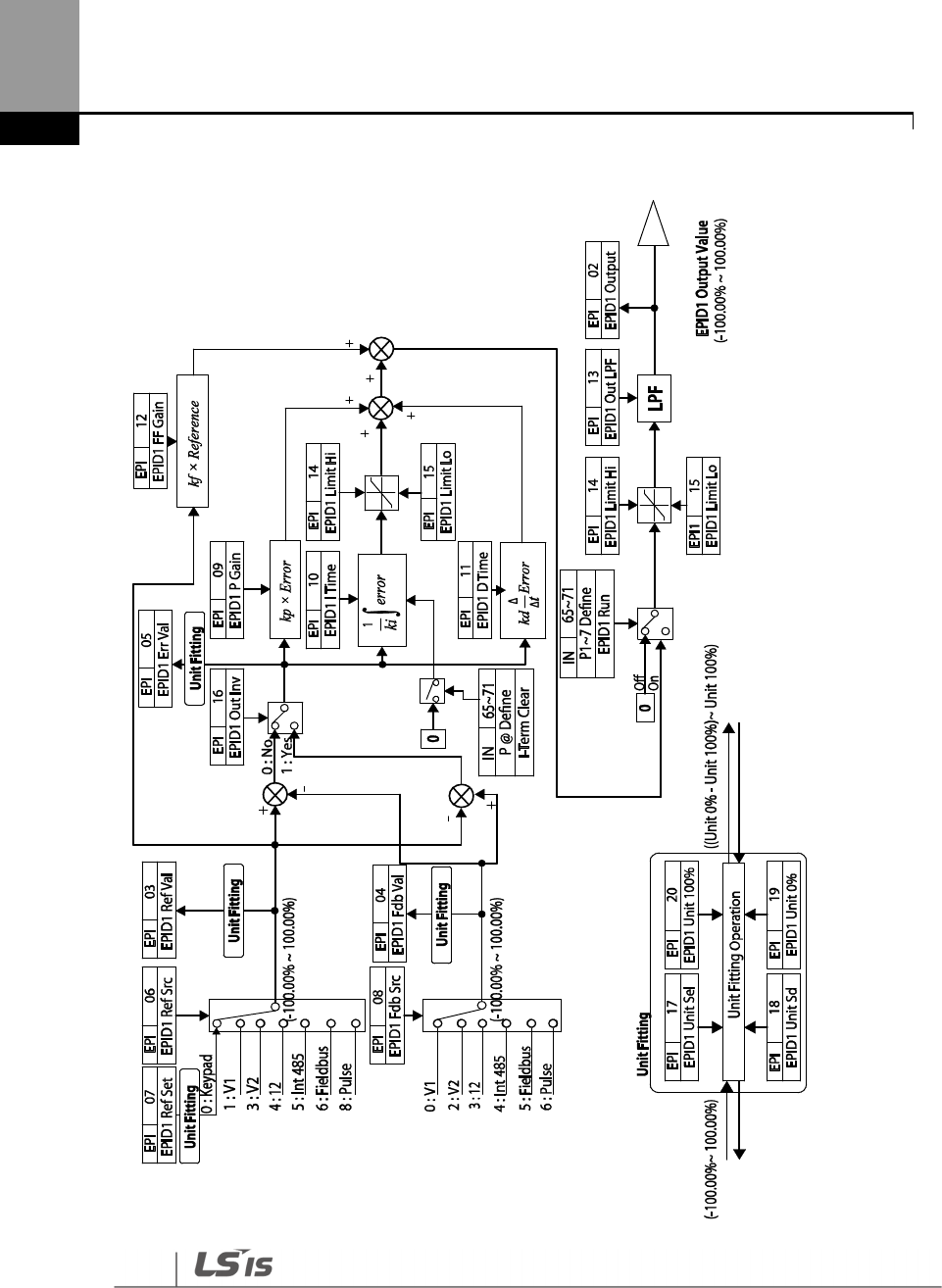
192
Learning Advanced Features
EPID1 Control block
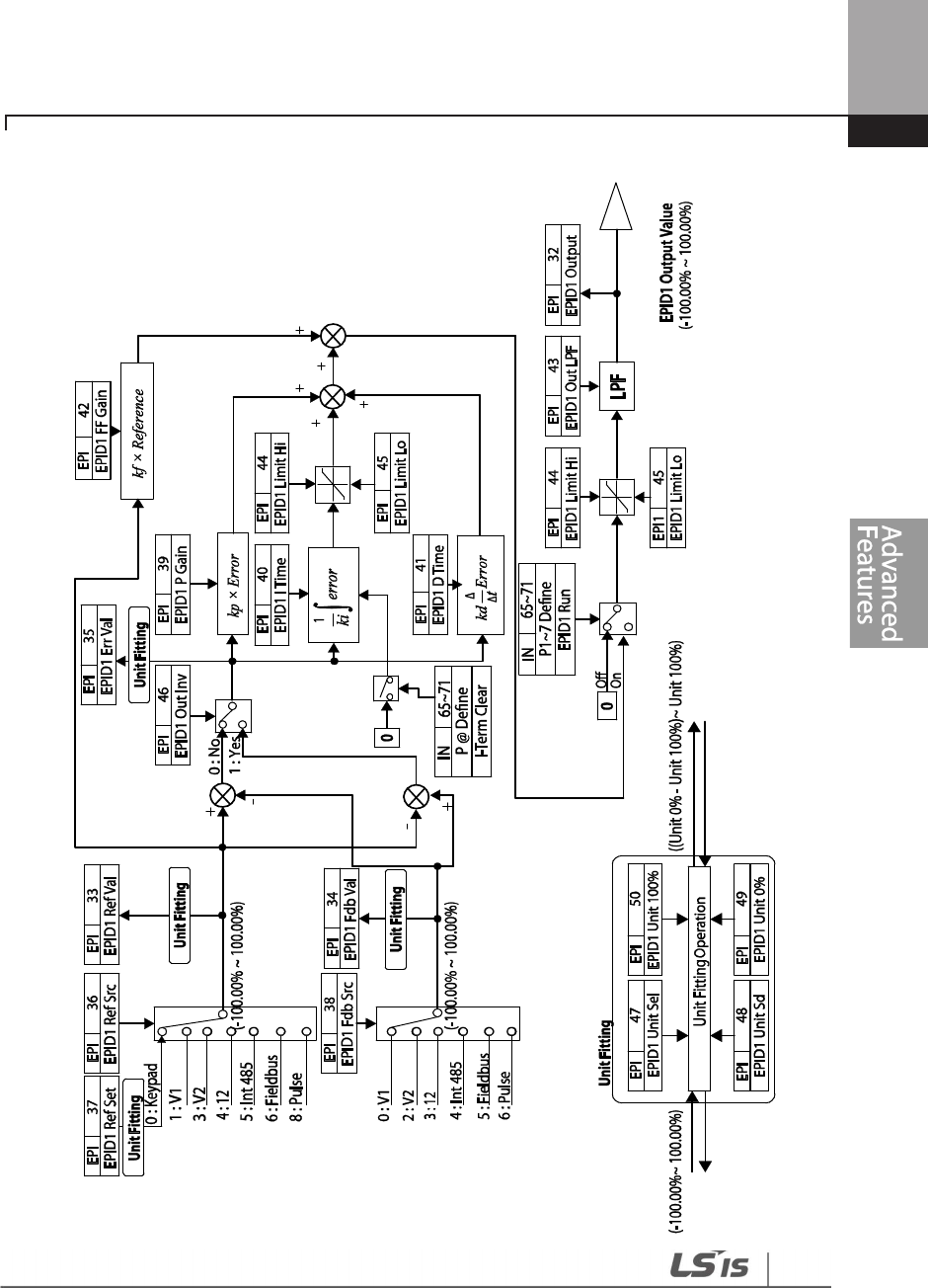
193
Learning Advanced Features
EPID2 Control block

194
Learning Advanced Features
5.10 Damper Operation
A damper is a device that controls the flow in a ventilation system. If a fan and a damper are used
together in a system, the inverter may be configured to operate according to the damper’s
operation status. During a damper operation, one of the relay outputs
OUT-31–35 (Relay 1–5) may
be set to ‘33 (Damper Control)’ to output a signal based on the damper’s operation status. O
ne of the
multi-function terminal inputs (IN-65–71) may also be set to ‘45 (Damper Open)’ to receive the
damper status input. The inverter starts operating when both the run command and the damper
open signal are turned on (relay output setting at
OUT-31–35 is not necessary)
.
When the time difference between the inverter run command and the damper open signal
exceeds the delay time set at AP2-45 (Damper DT), damper error (Damper Err) occurs. If the
damper open relay output and damper control input are set at the same time, and if the damper
open signal is not received until the time set at AP2-45 (Damper DT) is elapsed (when the inverter
is not operating), damper error (Damper Err) occurs.
Group
Code
Name
LCD Display
Parameter Setting
Setting Range
Unit
AP2 45
Damper check
time Damper DT - 0.1–600.0 sec
IN 65-71
P1
–
7 Px terminal
configuration P1–P7 Define
45
(Damper open) - -
OUT 31-35
Multi
-
function
relay 1–5 Relay 1–5
33
(Damper Control) - -
Damper Operation Setting Details
Code
Description
AP2-45 Damper DT
Sets the damper open delay time.
Detects the inverter run command or the damper open signal (whichever is
received first) and outputs a damper error (Damper Err) if the other signal is
not received until the time set at AP2-45 elapses.
IN-65–71 P1–7 define
Sets one of the multi
-
function
al terminals to ’45 (Damper Open)’ to enable
damper operation.
OUT-31–35 Relay 1–5
Sets one of the relay outputs to ’33 (Damper Control)’ to provide a relay
output when the inverter run command is turned on.
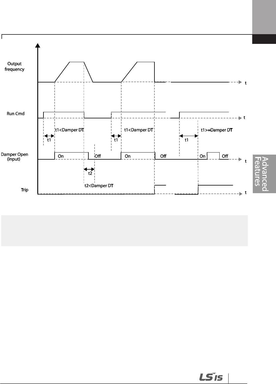
195
Learning Advanced Features
Note
Damper operation is one of the essential system features that are available in both HAND and AUTO
modes.
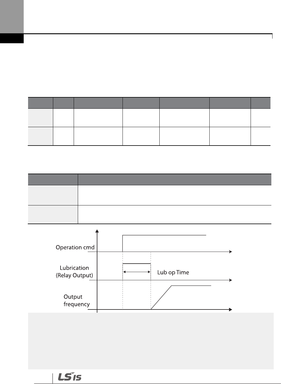
196
Learning Advanced Features
5.11 Lubrication Operation
During a lubrication operation, the inverter outputs the lubrication signal through one of the
output relays when the inverter receives a run command. The inverter does not start operating
until the time set at AP2-46 (Lub Op Time) has elapsed and the Lubrication signal is turned off.
Group
Code
Name
LCD Display
Parameter
Setting
Setting Range
Unit
AP2 46
Lubrication
operation time Lub Op Time
0.1–600.0 (sec)
OUT 31-35
Multi
-
function
relay 1–5 Relay 1–5
33 (Damper
Control) - -
Lubrication Operation Setting Details
Code
Description
AP2-46 Lub Op
Time
Outputs the lubrication signal for a set time when the inverter run command is
turned on. The inverter starts operating when the set time has elapsed.
OUT
-
31
–
35 Relay
1–5
Sets one of the output relays (OUT
-
31
–
35) to ‘30 (Lubrication)’ to enable the
Lubrication function.
Note
• The lubrication function can be used to delay inverter operations, depending on the working
environment, since the inverter waits for the time set at AP2-46 (Lub Op Time) each time a run
command is received.
• Lubrication operation is one of the essential system features that are available in both HAND and
AUTO modes.
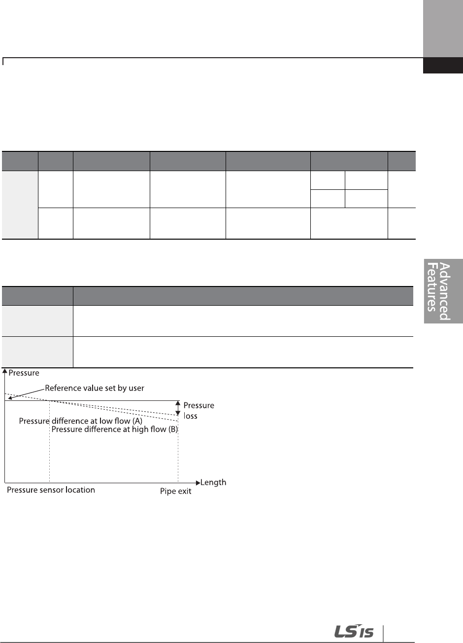
197
Learning Advanced Features
5.12 Flow Compensation
In a system with a pipeline, longer pipes and higher flow rate cause greater pressure loss. A flow
compensation operation can compensate for pressure loss by increasing the volume of the PID
reference.
Group
Code
Name
LCD Display
Parameter Setting
Setting Range
Unit
AP1
30 Flow Comp
function options
Flow Comp Sel -
0
No
-
1
Yes
31
Max Comp
amount
Max Comp
Value - 0–Unit Band -
Flow Compensation Setting Details
Code
Description
AP1
-
30 Flow
Comp Sel Sets the Flow Compensation function options.
AP1
-
31 Max
Comp Value
Sets the maximum
compensation volume. This function is based on a PID
operation. The volum
e
is given the same unit used for the PID reference.
Longer pipes cause the actual pressure to decrease, which in turn increases the difference
between the pressure reference and the actual pressure. When the pipe lengths are equal in two
different systems, more pressure loss is caused in the system with greater flow. This explains the
pressure difference between (A) and (B) in the figure (when the flows are different). To compensate
for the pressure loss above, the value of AP1-31 is set to the maximum volume of compensation
when the inverter has the maximum frequency, and adds to the PID reference after calculating
compensation volume based on the output frequency.
The final PID reference=PID-11+Compensation amount, and compensation amount is shown
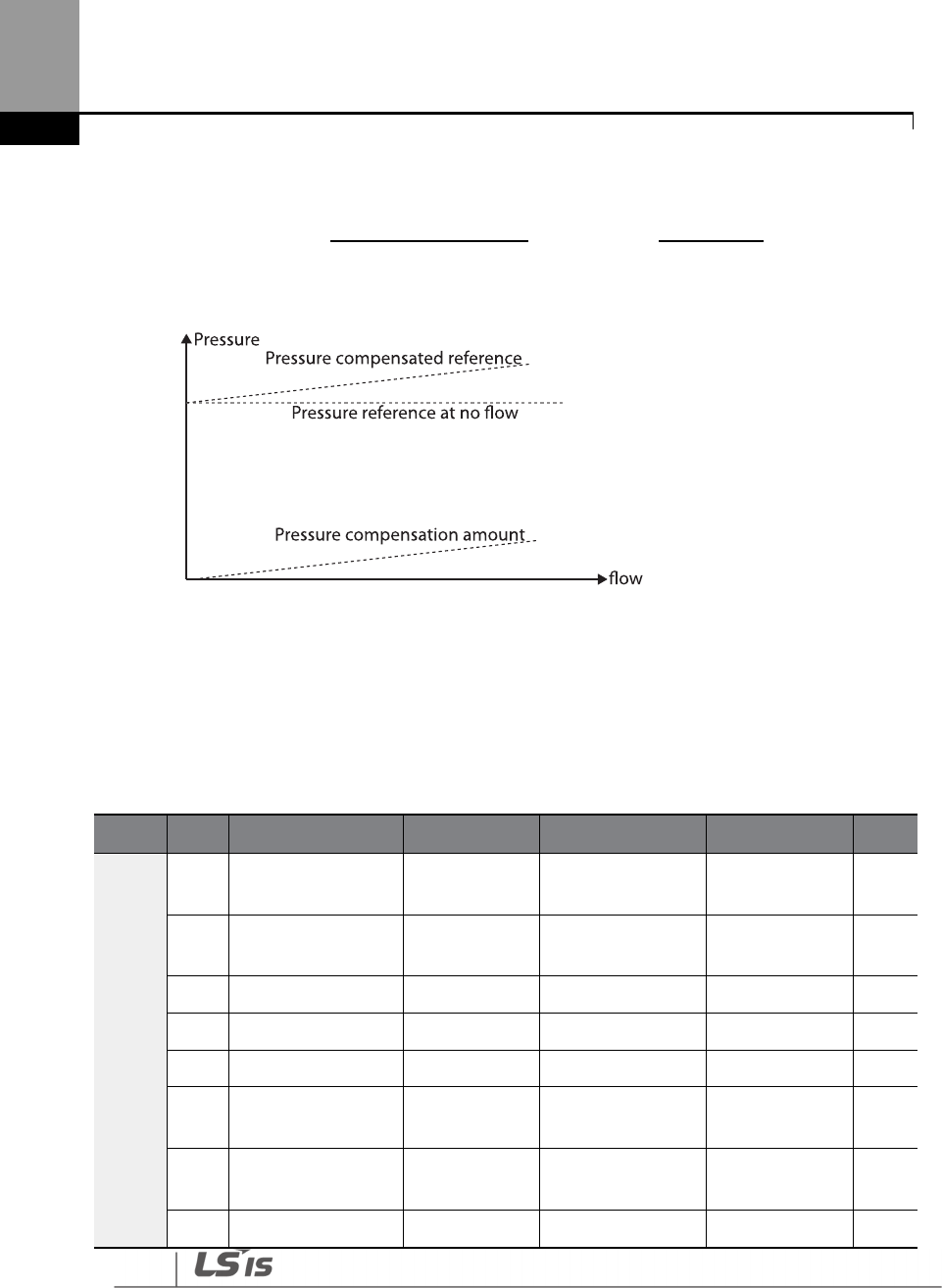
198
Learning Advanced Features
below.
PID-53: PID Output Maximum value
5.13 Payback Counter
The payback counter displays energy savings information by comparing the average energy
efficiency for operations with and without the inverter. The energy savings information is
displayed as kWh, saved energy cost, and CO2 emission level.
Group
Code
Name
LCD Display
Parameter Setting
Setting Range
Unit
AP2
87
1
st
MOTOR average
POWER M1 AVG PWR Inverter capacity 0.1–500.0 kW
88
2
nd
MOTOR average
POWER M2 AVG PWR Inverter capacity 0.1–500.0 kW
89
Cost per kWh
Cost per kWh
0
0.0
–
1000.0
kW
90
Saved kWh
Saved kWh
0
-
999.9
–
999.9
kWh
91
Saved MWh
Saved MWh
0
-
32000
–
32000
MWh
92
Saved Cost below
1000 unit Saved Cost1 0 -999.9–999.9 -
93
Saved Cost over
1000 unit Saved Cost2 0 -32000–32000 -
94
Reduced CO2
CO2 Factor
0.5
0.1
–
5.0
-
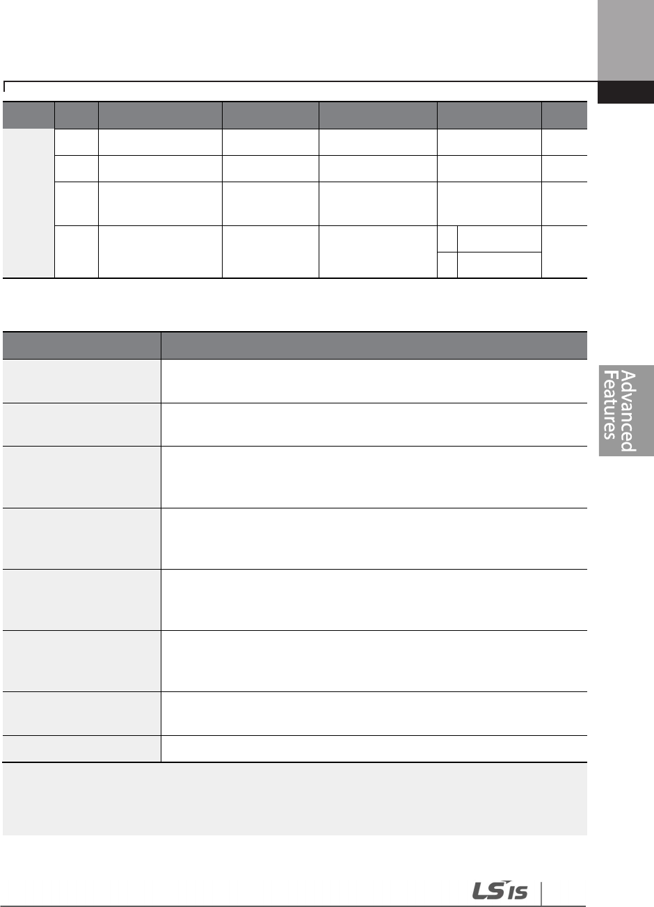
199
Learning Advanced Features
Group
Code
Name
LCD Display
Parameter Setting
Setting Range
Unit
conversion Factor
95
Reduced CO2 (Ton)
Saved CO2
-
1
0
-
9999
–
9999
Ton
96
Reduced CO2
(1000 Ton) Saved CO2 - 2 0 -160–160 Ton
97 Reset Energy
payback parameter
Reset Energy 0 0
No -
1
Yes
Energy Payback Value Function Setting Details
Note
Note that the actual saved energy may differ from the displayed values, since the resulting values are
affected by user-defined codes such as AP2-87 and AP2-88.
Code
Description
AP2-87 M1 AVG PWR
Sets the average power value of the #1 motor and calculates the energy
savings based on the set value.
AP2-88 M2 AVG PWR
Sets the average power of
the #2 motor and calculates energy savings
based on the set value.
AP2-89 Cost per kWh
Sets the cost per 1 kWh. Multiply the energy payback counter value with
the value set at AP2-89 to calculate the total saved cost. This value is
displayed in AP2-92–93.
AP2-90 Saved kWh
AP2-91 Saved MWh
Displays the saved energy in kWh (AP2
-
90) and MWh (AP2
-
91).
When the value reaches 999.9 (kWh) and continues to increase, AP2-91
becomes 1 (MWH), AP2-90 resets to 0.0, and it continues to increase.
AP2-92 Saved Cost1
AP2-93 Saved Cost2
Displays the saved cost to the one
-
tenth place at AP2
-
92. When the value
reaches 999.9 and continues to increase, AP2-93 becomes 1, AP2-92
resets to 0.0, and it continues to increase.
AP2-94 CO2 Factor
Sets the CO2 reduction rate per 1
MW (default value=0.5). The value is
multiplied with AP2-90 and AP2-91, and the resulting values are
displayed at AP2-95 and AP2-96.
AP2
-
95 Saved CO2
-
1
AP2-96 Saved CO2-2 Displays the CO2 reduction rate in tons (AP2-95) and kilo-tons (AP2-96).
AP2
-
97
Reset Energy
Resets all the saved energy parameters.

200
Learning Advanced Features
5.14 Pump Clean Operation
The pump clean operation is used to remove the scales and deposits attached on the impeller
inside a pump. This operation keeps the pump clean by performing a repetitive run-and-stop
operation of a pump. This prevents loss in pump performance and premature pump failures.
Group
Code
Name
LCD Display
Parameter Setting
Setting Range
Unit
AP2
15 Pump clean
mode 1
Pump Clean
Mode1 0: None
0
None
-
1
DI Dep
endent
2
Output Power
3
Output Current
16 Pump clean
mode 2
Pump Clean
Mode2 0: None
0
None
-
1
Start
2
Stop
3
Start & Stop
17
Pump clean load
setting
PC Curve
Rate 100.0 100.0–200.0 %
18
Pump clean
reference band
PC Curve
Band 5.0 0.0–100.0 %
19
Pump clean
operation delay
time
PC Curve DT 60.0 0–6000.0 sec
20
Pump clean start
delay time PC Start DT 10.0 0–6000.0 Sec
21
0 speed
operating time
at Fx/Rx
switching
PC Step DT 5.0 1.0–6000.0 Sec
22
Pump clean Acc
time PC Acc Time 10.0 0–600.0 Sec
23
Pump clean Dec
time PC Dec Time 10.0 0–600.0 Sec
24
Forward step
run time
Fwd Steady T
10.0 1.0–6000.0 Sec
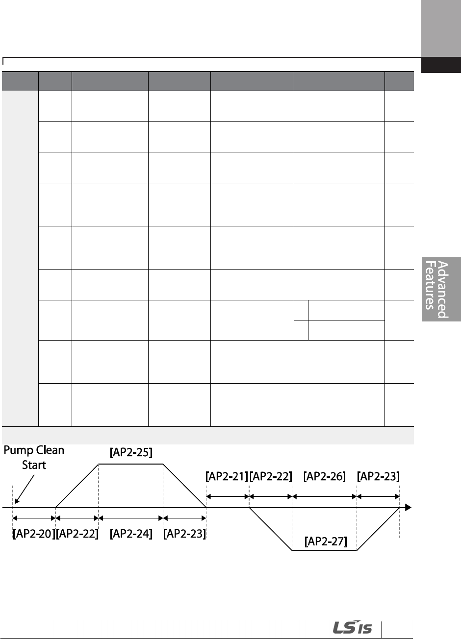
201
Learning Advanced Features
Group
Code
Name
LCD Display
Parameter Setting
Setting Range
Unit
25
Forward step
run frequency
Fwd
SteadyFreq 30
0.00, Low Freq
–
High Freq Hz
26
Reverse step run
time
Rev Steady T
10.0 1.0–6000.0 Sec
27
Reverse step run
frequency
Rev
SteadyFreq 30
0.00, Low Freq
–
High Freq Hz
28
Number of
Fx/Rx steps for
pump clean
PC Num of
Steps 5 0–10 -
29
Pump clean
cycle
monitoring
Repeat Num
Mon - - -
30
Pump clean
repeat number
Repeat Num
Set 5 0–10 -
31 Operation after
pump clean
PC End
Mode 0 0
Stop -
1
Run
32
Pump clean
continuous time
limit
PC Limit
Time 10 6–60 min
33
Pump clean
continuous
number limit
PC Limit
Num 3 0–10 -
<Basic Pump Clean Operation>
When a pump clean start command is given, the inverter waits until the delay time set at AP2-19

202
Learning Advanced Features
elapses, accelerates by the acceleration time set at AP2-22, and operates at the frequency set at
AP2-25. The pump runs for the time set at AP2-24, decelerates by the time set at AP2-23, and then
stops. This operation repeats in the forward and reverse directions (one after another) for the
number of times set at AP2-28 (PC Num of Step). Each time the steps (Fx/Rx) switch, the inverter
waits at a stop state for the time set at AP2-21 before going on with the next step. One step in the
forward direction and another step in the reverse direction makes one cycle. The number of pump
clean cycles is set at AP2-30. In the figure above, AP2-28 is set to ‘1’, and AP2-30 is set to ‘1’.
Pump Clean Function Setting Details
Code
Description
AP2-15 PumpClean Mode
Sets the pump mode.
Setting
Function
0
None
Pump Clean function is not used.
1
DI
defendant
Set one of the terminal inputs to ‘46 (Pump
Clean Sel)’ and performs the pump clean
operation by turning on the terminal.
2
Power
Performs a pump clean operation when a
pump consumes more power than it is
supposed to consume in a normal operation.
3
Current
Performs a pump clean operation when a
pump consumes more current than it is
supposed to consume in a normal operation.
AP2-16 PumpClean Sel
Sets the pump clean start mode.
Setting
Function
0
None
Pump clean is performed only by the
function set at AP2-20.
1
Start
Pump clean is performed each time the
inverter starts operating.
2
Stop
Pump clean is performed each time the
inverter stops operating.
3
Start & Stop
Pump clean is performed each time the
inverter starts or stops operating.
AP2-17 PC Curve Rate
AP2-18 PC Curve Band
AP2-19 PC Curve DT
If AP2
-
15 is
set to ‘Power’ or ‘Current,’ multiply the load
characteristic curve set at AP2-2–AP2-10 by the value set at AP2-
17 (100[%]+AP2-17[%]), and reset the load characteristic curve for
the pump clean operation (refer to the load tune features for AP2-
2–AP2-10 setting values).
Apply (rated inverter current x AP2-18 setting value) and (rated
203
Learning Advanced Features
Code
Description
motor x AP2
-
18 setting value) to the pump clean load curve
calculated by AP2-17 to calculate the final pump clean load curve.
The inverter performs pump clean operation when the inverter
continues operating for the time set at AP2-19.
AP2-20 Clean Start DT
When AP2
-
15 is set to ‘Power’ or ‘Current’, a pump clean is
performed if the inverter operation power or current stays above
the pump clean load characteristic curve (defined by AP2-17 and
AP2-18) for the time set at AP2-19.
AP2-21 Clean Step DT
Sets the time for the inverter to maintain 0 speed (stop) before the
inverter switches from forward to reverse operation during a
pump clean.
AP2
-
22 PumpClean AccT
AP2-23 PumpClean DecT Sets the Acc/Dec times for pump clean operations.
AP2
-
24 Fwd Steady Time
AP2-26 Rev Steady Time Sets the time to maintain forward and reverse operations.
AP2
-
25 Fwd SteadyFreq
AP2-27 Rev SteadyFreq Sets the forward and reverse operation frequencies.
AP2-28 PC Num of Steps
Determines the number of steps (acceleration/deceleration/stop)
in one cycle. Each operation, either in the forward or reverse
direction, constitutes one step.
If set to ‘2,’ one forward step and one reverse step constitute one
cycle.
AP2-31 PC End Mode
Determines the inverter operation after pump clean operation.
Setting
Function
0
Stop
This stops the inverter after pump cleaning.
1
Start
The inverter operates based on the inverter’s
command status after the pump cleaning. (If a
terminal command is received, the inverter
performs the operation it was performing before
the pump clean operation.)
AP2
-
29 Repeat Num Mon
Displays the number of the current pump cleaning cycle.
AP2-30 Repeat Num Set
Sets the number of cycles for
one pump clean operation set at
AP2-21–AP2-28.
AP2-32 PC Limit Time
AP2-33 PC Limit Num
Frequent pump clean operations may indicate a serious system
problem. To warn the users of potential system problems, an error
(CleanRPTErr) occurs if the number of pump clean operation

204
Learning Advanced Features
Code
Description
exceeds the number set at AP2
-
33 within the time period set at
AP2-32.
Note
• When the run prevent feature is active and an operation in the prevented direction is required to
perform a pump clean operation, the inverter operates at the 0 speed for the time set at AP2-24
and AP2-26 (Steady Time).
• To stop the pump clean operation, press the OFF key on the keypad or turn it off at the terminal
input.
• If the pump clean operation is configured for terminal input and it is turned on, and if ADV-10
(PowerOn Resume) is set to ‘Yes’, a pump clean operation is performed when the inverter is turned
on.
• When performing a pump clean operation via terminal input,
- if the terminal input is turned off instantly after it is turned on (the operation is triggered),
1 pump clean cycle is operated.
- if ADV-10 (PowerOn Resume) is set to ‘Yes’, and the terminal input is turned off instantly
after it is turned on (the operation is triggered), and if the inverter is turned off during a
pump clean then is turned back on again, the pump clean operation is not resumed
(because the input terminal is not on when the inverter is turned on).
- if the terminal input is kept on after it is initially turned on, 1 pump clean cycle is
operated.
5.15 Start & End Ramp Operation
This function is used to rapidly accelerate the pump to the normal operating level, or to rapidly
decelerate the pump and stop it. Start & End ramp operation is performed when ADV-24 (Freq
Limit) is set to ‘1 (Yes).’
Group
Code
Name
LCD Display
Parameter Setting
Setting Range
Unit
AP2
40 Start & End Ramp
Gradient Start&End Ramp
0: No
0
No
-
1
Yes
41
StartRampAcc
StartRampAcc
10.0
0
–
600.0
Sec
42
EndRampDec
EndRampDec
10.0
0
–
600.0
Sec
205
Learning Advanced Features
Group
Code
Name
LCD Display
Parameter Setting
Setting Range
Unit
ADV
24 Frequency limit
options Freq Limit 0: No
0
No
-
1
Yes
25
Low Freq
minimum value Freq Limit Lo 30.00
Start Freq
–
Max Freq Hz
26
Low Freq
maximum value Freq Limit Hi 60.00
Freq Limit Lo
–
Max Freq Hz
Start & End Ramp Operation Setting Details
Code
Description
AP2-40 Start&End
Ramp
Sets the pump Start & End Ramp options.
Setting
Function
0
No
The Start & End Ramp operation is not used.
1
Yes
Use the Start & End Ramp operation.
AP2-41 Start Ramp
Acc
Refers to the time it takes to reach the minimum pump
operation frequency
for a Start & End Ramp operation (Freq Limit Lo) set at ADV-25 when the
inverter starts (it is different from DRV-03 acceleration gradient).
AP2-42 End Ramp
Dec
Refers to the time it takes to reach the 0 step (stop) from the minimum pu
mp
operation frequency for a Start & End Ramp operation (Freq Limit Lo) set at
ADV-25 (it is different from DRV-03 deceleration gradient).
< Start&End Ramp Adjustment>
In the figure above, AP2-41 defines the acceleration time to the minimum operation frequency
ADV-25 (
Freq Limt Lo)
. AP2-42 defines the deceleration time from the minimum operation
frequency to a stopped state. Time A (normal acceleration time set at DRV-03) and Time B (normal
deceleration time set at DRV-04) in the figure will change according to the Acc/Dec gradients
defined by AP2-41 and AP2-42.
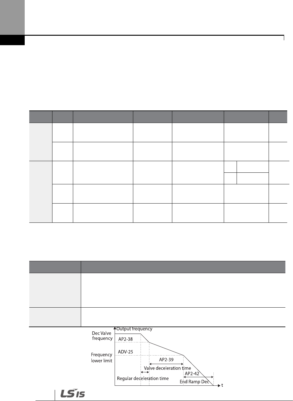
206
Learning Advanced Features
5.16 Decelerating Valve Ramping
This function is used to prevent pump damage due to abrupt deceleration. When the pump
operation frequency reaches the valve ramp frequency (
AP2-38 Dec Valve Freq) while
decelerating
rapidly based on the deceleration ramp time (set at AP2-42), it begins to slow down the
deceleration based on the deceleration valve ramp time (set at
AP2-39
DecValve Time).
Decelerating valve ramp operates when ADV-24 (Freq Limit) is set to ‘1 (Yes)’.
Deceleration Valve Ramping Setting Details
Group
Code
Name
LCD Display
Parameter Setting
Setting Range
Unit
AP2
38
Dec valve ramping
start frequency
Dec Valve
Freq 40.00
Low Freq
–
High
Freq Hz
39
Dec valve
ramping
time
DecValve
Time 0.0 0–6000.0 Sec
ADV
24 Frequency limit
options Limit Mode 0: No
0
No
-
1
Yes
25
Low Freq minimum
value Freq Limit Lo
30.00
Start Freq
–
Max
Freq Hz
26
Low Freq maximum
value Freq Limit Hi
60.00
Freq Limit Lo
–
Max Freq Hz
Code
Description
AP2-38 Dec Valve
Freq
Sets the start frequency where
the slow deceleration begins in order to prevent
pump damage when the inverter stops. Decelerating valve ramping is
performed from the frequency set at AP2-38 to the frequency limit set at ADV-
25 (low frequency limit for pump operation).
AP2
-
39 DecValve
Time
Sets the time it takes to decelerate from the frequency set at AP2
-
38 to the
frequency limit set at ADV-25 (low frequency limit for pump operation).

207
Learning Advanced Features
The time set at AP2-39 refers to the absolute time that it takes for the pump to decelerate from the
frequency set at AP2-38 to the frequency limit set at ADV-25.
5.17 Load Tuning
Load tuning refers to an operation that detects the load applied to a specific section of the inverter
operation (current and voltage) and creates an ideal load curve for the under load and pump
clean operations. The two set points to define the section are user-definable, and are set at 50%
and 85% of the base frequency (DRV-18 Base Freq) by default. The load tuning result values are
saved at codes AP2-2–AP2-10. These values are user definable as well.
The minimum set point for the load tuning begins at 15% of the base frequency (DRV-18 Base
Freq), and the maximum set point can be set up to the base frequency. If the frequency limit is set
to ‘1 (Yes)’ at ADV-24 (Freq Limit), the range is limited within the frequencies set at ADV-25 (Freq
Limit Lo) and ADV-26 (Freq Limit Hi).
Group
Code
Name
LCD Display
Parameter Setting
Setting Range
Unit
AP2
01 Load curve
Tuning Load Tune No
0
No
-
1
Yes
02
Load curve Low
Freq
Load Fit
LFreq 30.00
Base Freq*15%
–
Load Fit HFreq Hz
03
Current for Low
Freq
Load Fit
LCurr 40.0 0.0–200.0 %
04
Power for Low
Freq Load Fit LPwr
30.0 0.0–200.0 %
08
Load curve High
Freq
Load Fit
HFreq 51.00
Load Fit LFreq
–
High Freq Hz
09
Current for High
Freq
Load Fit
HCurr 80.0 0.0–200.0 %
10
Power for High
Freq
Load Fit
HPwr 80.0 0.0–200.0 %
11
Load current for
frequency
Load Curve
Cur - - %
12
Load power for
frequency
Load Curve
Pwr - - %
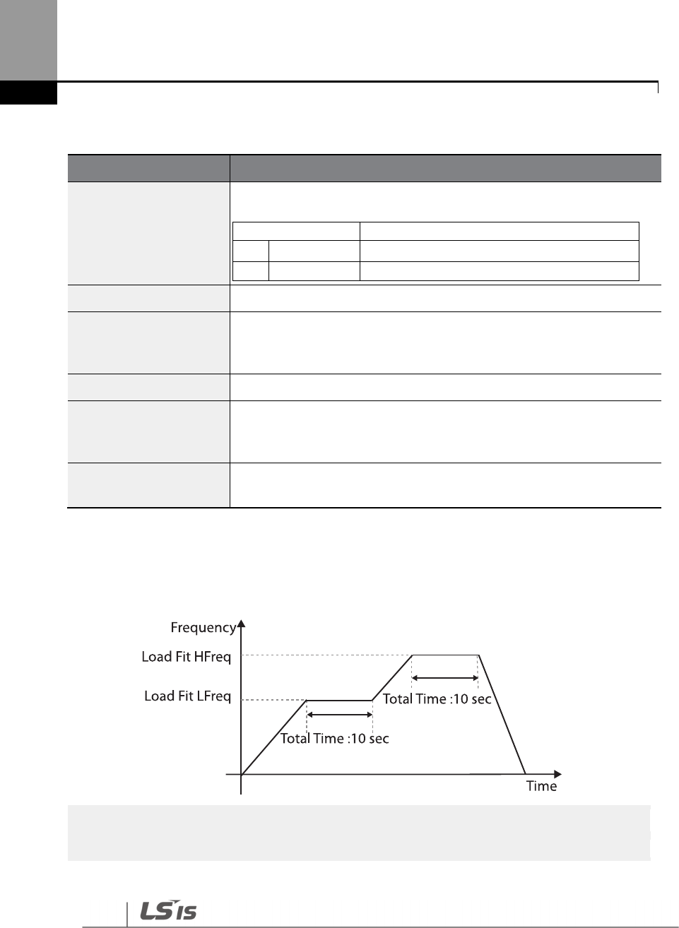
208
Learning Advanced Features
Load Tuning Setting Details
Code
Description
AP2-01 Load Tune
The inverter performs an automatic tuning to generate an ideal system
load curve.
Setting
Function
0
None
Load tuning is not used.
1
Load Tune
Start load tuning.
AP2
-
02 Load Fit
LFreq
Defines the first frequency set point for load tuning (user definable).
AP2-03 Load Fit LCurr
AP2-04 Load Fit LPwr
Displays the current and power measured at the frequency set at AP2
-
02
as a percentage (%) value, based on motor rated current and rated
power. Values for AP2-03 and AP2-04 are user definable.
AP2
-
08 Load fit HFreq
Defines the second frequency set point for load tunin
g
(user definable).
AP2-09 Load Fit HCurr
AP2-10 Load Fit HPwr
Displays the current and power measured at the frequency
set at AP2
-
08
as a percentage (%) value, based on motor rated current and rated
power. Values for AP2-09 and AP2-10 are user definable.
AP2
-
11 Load Curve Cur
AP2-12 Load Curve PWR
Monitors the load curve value set at AP2
-
1 (Load Tune) based on the
current output frequency.
When a load tuning is performed, the inverter measures for 10 seconds the motor current and
power, at the frequencies set at AP2-02 and AP2-09. The motor current and power values
measured here are used to generate an ideal load curve.
Note
Load tuning i
s not available while the inverter is operating.
209
Learning Advanced Features
• If the frequencies for AP2-02 (Low Freq) and AP2-08 (High Freq) are set too close to each other,
the resulting load curve may not reflect the actual (ideal) load curve. Therefore, it is recommended
that you keep the AP2-02 and AP2-08 frequencies as close to the factory defaults as possible.
• If a secondary motor is in use, note that the existing load curve for the main motor will be applied
to the secondary motor unless a load tuning has been performed for the secondary motor.
5.18 Level Detection
When the inverter is operating at or above the frequency set at PRT-74 (
LDT Level)
, this function is
used to triggers a fault trip or sets a relay output if the source value is out of the range of the user-
defined values. If the reset restart feature is turned on, the inverter continues to operate based on
the run command after the LDT fault trip is released.
Group
Code
Name
LCD Display
Parameter Setting
Setting Range
Unit
PRT
70
Level detection
mode LDT Sel Warning None/Warning/Trip
71
Level detection
range LDT Area Sel 1 . Above Level 0–1 -
72
Level detection
source LDT Source 0: Output Current 0–12 -
73
Level detection
delay time LDT Dly Time
2.0 0–9999 Sec
74
Level
detection
reference value LDT Level
Source setting is
used
Source setting is
used -
75
Level detection
bandwidth
LDT Band
width
Source setting is
used
Source setting is
used -
76
Level detection
frequency LDT Freq 20.00 0.00–Max Freq (Hz) Hz
77
Level detection
trip restart time
LDT Restart
DT 60.0 0.0–3000.0 Min
96
LDT Auto restart
count LDT Rst Cnt 1 0~6000 -
97
LDT Auto restart
LDT Rst Cnt
-
0~6000
-
210
Learning Advanced Features
Group
Code
Name
LCD Display
Parameter Setting
Setting Range
Unit
cycle count
M
98
LDT Auto restart
cycle
Initialization time
LDT Cnt Clr T
60 0~6000 Sec
Level Detection Setting Details
Code
Description
PRT-70 LDT Sel
Determines the inverter operation when a level detection trip occurs.
Setting
Functions
0
None
No operation
1
Warning
The inverter displays a warning message.
2
Free
-
Run
The inverter free
-
runs, then stops.
3
Dec
The inverter decelerates, then stops.
PRT-71 Level
Detect
Sets the level detection range.
Setting
Operation
1
Below
Triggers a level detect fault
trip when the inverter operates
below the frequency set by the user.
2
Above
Triggers a level detect fault trip when the inverter operates
above the frequency set by the user.
211
Learning Advanced Features
Code
Description
PRT-72 LDT
Source
Selects a source for level detection.
Setting
Function
0
Output Current
Sets the output current as the source.
1
DC Link Voltage
Sets the DC link voltage as the source.
2
Output Voltage
Sets the output voltage as the source.
3
kW
Sets the output power as the source.
4
hp
Sets the output power as the
source.
5
V1
Sets the V1 terminal input as the source.
6
V2
Sets the V2 terminal input as the source.
7
I2
Sets the I2 terminal input as the source.
8
PID Ref Value
Sets the PID reference as the source.
9
PID Fdb Val
Sets the PID feedback as the
source.
10
PID Output
Sets the PID output as the source.
1
1
EPID1 Fdb Val
Sets the external PID feedback 1 as the source.
1
2
EPID2 Fdb Val
Sets the external PID feedback 2 as the source.
PRT
-
73 LDT Dly
Time Sets the delay time for the operation set at PRT-70.
PRT-74 LDT Level
Sets the level for the level detection.
The following are the setting ranges and default values by the source.
Source
Default Value
Setting Range
Output
Current
Rated current
0
–
150% of the rated current
DC Link
Voltage
350
700
0
–
450 V (2 Type)
0–900 V (4 Type)
Output
Voltage
230
460
0
–
250 (2 Type)
0–500 (4 Type)
kW
90% of the Inverter
rated power
0
–
150% of the Inverter rated
power
V1
9.00 V
0.00
–
12.00
V2
9.00
-
12.00
–
12.00
I2
18.00
0.00
–
25.00
PID Ref
Value
50
PID Unit Min
–
PID Unit Max
PID Fdb Val
50
PID Unit Min
–
PID Unit Max
PID Output
50
-
100.00%
–
100.00%
EPID1 Fdb
Val
50
EPID1 Unit Min
–
EPID1 Unit Max

212
Learning Advanced Features
Code
Description
EPID2 Fdb
Val
50
EPID2 Unit Min
–
EPID2 Unit Max
PRT-75 LDT Band
Width
If the source is detected below the set level, it must be adjusted to be above
the ‘LDT Level + LDT Band Width’ value to release the level detection fault trip.
If the source is detected above the set level, it must be adjusted to be below
the ‘LDT Level - LDT Band Width’ value to release the level detection fault trip.
The level detection trip bandwidth is 10% of the maximum source value.
PRT-76 LDT Freq Sets the start frequency for the level detection. When setting the level
detection frequency,
take into consideration the source type and the LDT level.
PRT-77 LDT
Restart DT
If PRT
-
08 (RST restart) is set to ‘YES,’ the inverter restarts after the time set at PRT
-
76 elapses when an LDT trip is released. The LDT Restart operates each time an
LDT trip is released.
If PRT-77 is set to any other value than ‘0’ and the inverter is operating in HAND
mode, the inverter resets and the LDT trip is released. However, the inverter
stays in OFF mode and does not restart the operation instantly.
PRT-96 LDT Rst
Cnt
PRT-97 LDT Rst
Cnt M
PRT-98 LDT Cnt
Clr T
When the LDT trip occurs, the number of automatic restart is set by PRT-
96.
If an LDT trip occurs, the inverter automatically restarts after the time set
in PRT-77 (LDT Restart DT) has elapsed. The PRT-97 is incremented by
1 each time it is automatically restarted.
When the value of PRT-97 becomes equal to PRT-96, it does not try to
restart automatically.
The LDT trip will be restarted within the time set in PRT-98 after auto
restart
If not, PRT-97 is initialized to 0.
OUT
-
31
–
35 Relay
1–5 Sets one of the output relays to ‘32
(LDT)’ to monitor the level detection status.
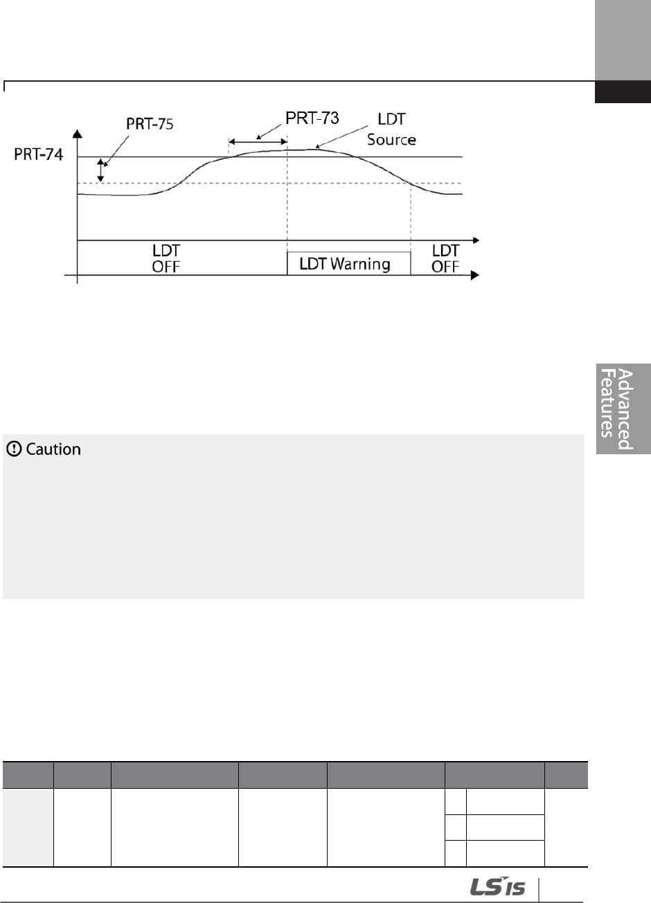
213
Learning Advanced Features
<An example of PRT-71 set to (1: Above Level )>
As shown in the figure above, level detection can be carried out (relay output is ‘on’) as the output
frequency is above PRT-76 and the detection value is greater than the value of PRT-74.
The LDT
operation is released if the value is less than the value subtracted from the value of band of, when the
value of the feedback is set from PRT-74 to PRT-75.
• The LDT operation is carried out if the inverter operation is above PRT-74.
• Modify PRT-74 and PRT-75 appropriately when modifying LDT Source of PRT-71.
• PRT-74 and PRT-75 become default value if the LDT Source is modified.
• PRT-77 (Restart DT) and PRT-08 (RST restart) features operate separately.
• The inverter waits until the delay time set at PRT-
73 (LDT Dly Time) before it operates based on the
setting in LDT-70 when the level detection time condition is met.
5.19 Pipe Break Detection
This function detects Pipe Breaks while the PID operation is on. The fault trip or a warning signal
will occur if the feedback does not reach the level set by users during the operation with the
maximum output (PID maximum output or the maximum speed set).
Group
Code
Name
LCD Display
Parameter Setting
Setting Range
Unit
PRT 60 Pipe Break
Detection setting
PipeBroken
Sel 0
0
None
1
Warning
2
Free
-
Run
214
Learning Advanced Features
Group
Code
Name
LCD Display
Parameter Setting
Setting Range
Unit
3
Dec
61
Pipe Break
Detection variation
PipeBroken
Dev 97.5 0–100 %
62
Pipe Break
Detection time
PipeBr
o
k
en
DT 10.0 0–6000.0 Sec
OUT
31
–
36
Relay output 1
–
5
Relay1
–
5
28
Pipe B
roken
-
Pipe Break Detection Details
Code
Description
PRT-60
PipeBroken Sel
Select the operation while detecting Pipe Breaks
Setting
Function
0
None
No operation
1
Warning
The inverter displays a warning message.
2
Free
-
Run
The inverter free
-
runs, then
stops.
3
Dec
The inverter decelerates, then stops.
PRT
-
61
PipeBroken Dev
Sets the Pipe Break Detection level. Set the detect level by multiplying the set
value for PRT-61 by PID Reference.
PRT
-
62
PipeBroken DT
Sets the detect delay time. Pipe Break operates if the Pipe Break situation is
maintained for a set amount of time.
OUT31–36 Define
If Pipe Break (28) is set, when a Pipe Break occurs, the inverter sends out output
with Relay.
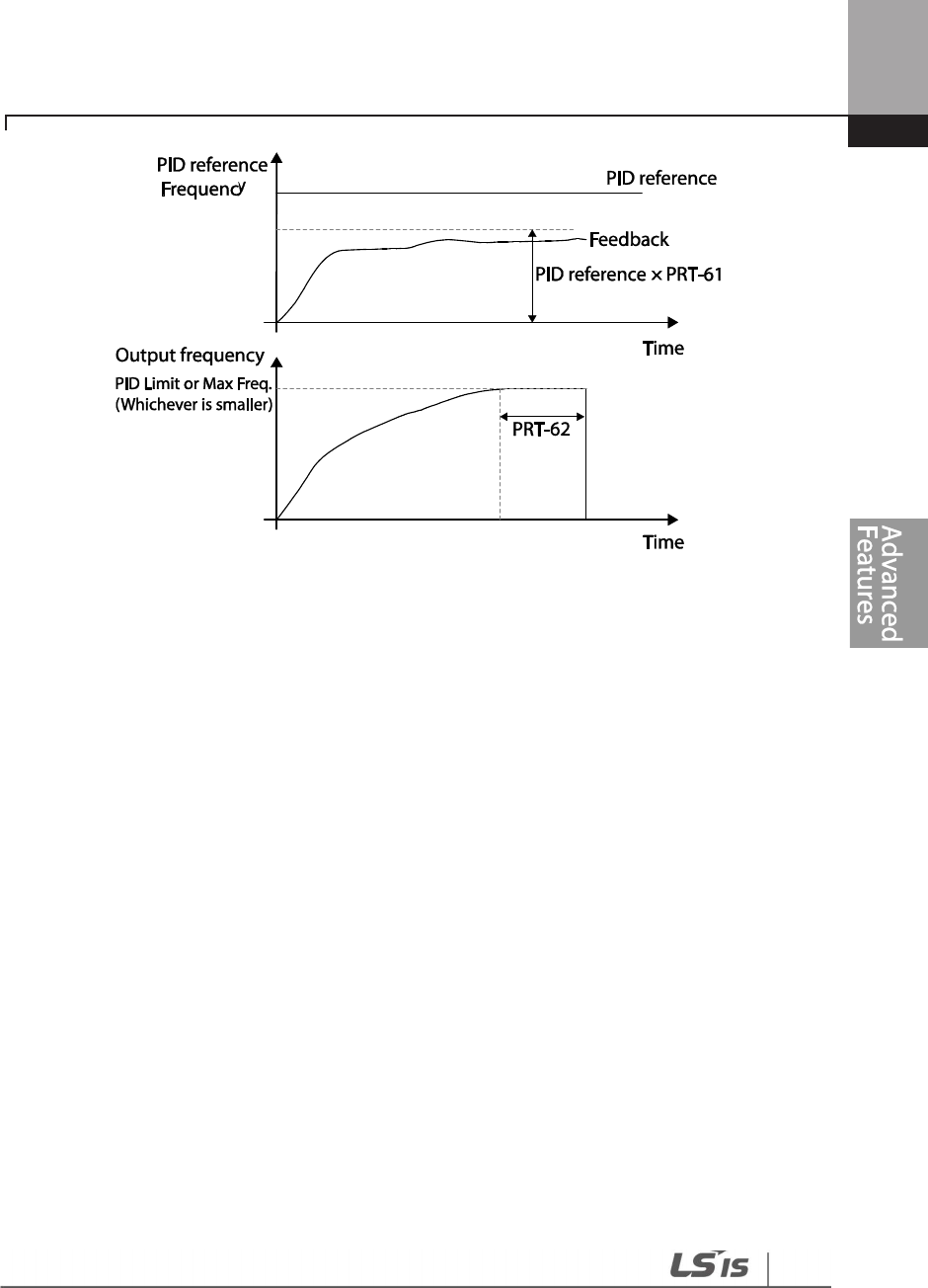
215
Learning Advanced Features

216
Learning Advanced Features
In the graph above, Pipe Break occurs if the feedback is smaller than the value calculated by
multiplying the two values set at PID-04 and PRT-61(PID-04 x PRT-61) at the inverter’s maximum
output (when PID output is the maximum set value, or the inverter is running at the frequency set
at DRV-20).
5.20 Pre-heating Function
This function uses current to heat up the motor or pump to avoid the motor or the pump freezing
when they are not in operation.
Group
Code
Name
LCD Display
Parameter
Setting
Setting Range
Unit
AP2
48
Initial heating
output current Pre Heat Level 20 1–100 %
49
Initial heating
output duty Pre Heat Duty 30 1–100 %
50
DC input delay
time DC Inj Delay T 60.0 0.0–600.0 sec
IN 65–71
Terminal block
input 1–7 P1–7 Define 44 Pre Heat -
Initial Heating Setting Details
Code
Description
AP2-48 Pre Heat Curr
Sets the current to be used for initial heating. Sets the current to motor no
-
load current % value.
AP2-49 Pre Heat Duty
Sets the duty (time) for the current to be used for initial heating, from 10
seconds to % value.
AP2-50 DC Inj Delay T
Sets a certain delay time to prevent from an over current trip that may
occur when a DC input is performed after the inverter Free-Run stop.
IN
-
65
–
71 P1
–
7 Define
Performs the Pre Heat function if the Pre Heat (44) terminal is set.
The initial heating function continually operates when the set multi-function input terminal is on
and until the inverter command is on. If an inverter command is input while the initial heating
function is operating, the inverter starts operation immediately.
217
Learning Advanced Features
The initial heating operation starts to run after an inverter operation stops, when the initial heating
function’s terminal input is on after the inverter operation command is off.

218
Learning Advanced Features
The diagram above shows the operation waveform related to AP2-50 DC Inj Delay T. The Pre Heat
function performs when the inverter stop mode is set to Free Run and the Pre Heat signal is
supplied. Then, if the inverter operation command is on, the inverter maintains acceleration and a
fixed frequency. If the inverter operation command is off, the motor is in Free Run and the Pre Heat
operations starts after the time amount set in AP2-50.
• If the value for AP2-48 Pre Heat Curr is above the rated motor current value, it is limited by the
rated motor current value.
• If the value for AP2-48 Pre Heat Curr is too high or the DC current output time is too long, the
motor may overheat or be damaged and the Inver IOLT may also malfunction. Reduce the DC
output current amount and DC output time to prevent from such damages.

219
Learning Advanced Features
5.21 Auto Tuning
The motor parameters can be measured automatically and can be used for an auto torque boost.
Example - Auto Tuning Based on 5.5 kW, 200 V Motor
Group
Code
Name
LCD Display
Parameter Setting
Setting Range
Unit
DRV 14 Motor capacity
Motor
Capacity 9 5.5 kW 7–20 -
BAS
11
Motor pole
number Pole Number 4 2–48 -
12
Rated slip speed
Rated Slip
45
0
–
3000
Rpm
13
Rated motor
current Rated Curr 21.0 1.0–1000.0 A
14
Motor no
-
load
current Noload curr 7.1 0.5–1000.0 A
15
Motor rated
voltage Rated Volt 220 170–500 V
16
Motor efficiency
Efficiency
85
70
–
100
%
20
Auto
tuning
Auto Tuning
0
None
-
-
21 Stator resistance Rs 0.314
Depends on the
motor setting Ω
22
Leakage
inductance Lsigma 3.19
Depends on the
motor setting mH

220
Learning Advanced Features
Auto Tuning Default Parameter Setting
Motor Capacity
(kW)
Rated
Current
(A)
No-load
Current
(A)
Rated Slip
Frequency
(Hz)
Stator
Resistance
(
Ω
ΩΩ
Ω
)
Leakage
Inductance
(mH)
200 V
0.75
3.4
1.7
3.00
2.60
17.94
1.5
6.4
2.6
2.67
1.17
2.29
2.2
8.6
3.3
2.3
0.84
6.63
3.7
13.8
5.0
2.3
0.50
4.48
5.5
21.0
7.1
1.50
0.314
3.19
7.5
28.2
9.3
1.33
0.169
2.844
11
40.0
12.4
1.00
0.120
1.488
15
53.6
15.5
1.00
0.084
1.118
18.5
65.6
19.0
1.00
0.0676
0.819
400 V
0.75
2.0
1.0
3.00
7.81
53.9
1.5
3.7
1.5
2.67
3.52
27.9
2.2
5.0
1.9
2.3
2.52
19.95
3.7
8.0
2.9
2.3
1.50
13.45
5.5
12.1
4.1
1.50
0.940
9.62
7.5
16.3
5.4
1.33
0.520
8.53
11
23.2
7.2
1.00
0.360
4.48
15
31.0
9.0
1.00
0.250
3.38
18.5
38.0
11.0
1.00
0.168
2.457
22
44.5
12.5
1.00
0.168
2.844
30
60.5
16.9
1.00
0.1266
2.133
37
74.4
20.1
1.00
0.1014
1.704
45
90.3
24.4
1.00
0.0843
1.422
55
106.6
28.8
1.00
0.0693
1.167
75
141.6
35.4
1.00
0.0507
0.852
90
167.6
41.9
1.00
0.0399
0.715
221
Learning Advanced Features
Motor Capacity
(kW)
Rated
Current
(A)
No-load
Current
(A)
Rated Slip
Frequency
(Hz)
Stator
Resistance
(
Ω
ΩΩ
Ω
)
Leakage
Inductance
(mH)
400 V
110
203.5
48.8
1.00
0.0326
0.585
132
242.3
58.1
1.00
0.0272
0.488
160
290.5
69.7
1.00
0.0224
0.403
185
335.0
77.0
1.00
0.0210
0.380
220
405.0
93.1
1.00
0.1630
2.930
250
467.8
104.9
1.00
0.1455
2.615
315
604.0
132.8
1.00
0.1140
2.040
355
687.8
146.4
1.00
0.1020
1.820
400
782.0
161.2
1.00
0.0906
1.616
500
985.3
206.2
1.00
0.0700
1.330
Auto Tuning Parameter Setting Details
Code
Description
DRV-14 Motor Capacity
Sets the motor capacity to be used. The maximum motor capacity is
limited by the inverter capacity and the keypad only displays the
inverter capacity.
BAS-20 Auto Tuning
Select an auto tuning type and run it. Select one of the options and
then press the [ENT] key to run the auto tuning.
Setting
Function
0
None
Auto tuning function is disabled. Also, if you
select one of the auto tuning options and run it,
the parameter value will revert back to ‘0’ when
the auto tuning is complete.
1
All
(rotating
type)
Measures all motor parameters while the motor
is rotating, including stator resistance (Rs), no-
load current (Noload Curr), rotor time constant
(Tr), etc. Since the motor is rotating while the
parameters are being measured, if the load is
connected to the motor spindle, the parameters
may not be measured accurately. For accurate
measurements, remove the load attached to the
motor spindle.

222
Learning Advanced Features
Code
Description
Note that the rotor time constant (Tr) must be
measured in a stopped position.
2
All (static
type)
Measures all parameters while the motor is in
the stopped position, including stator resistance
(Rs), no-load current (Noload Curr), rotor time
constant (Tr), etc. Since the motor is not rotating
while the parameters are measured, the
measurements are not affected when the load is
connected to the motor spindle. However, when
measuring parameters, do not rotate the motor
spindle on the load side.
BAS-14 Noload Curr,
BAS-21 Rs–BAS-24 Tr
Displays motor
parameters measured by auto tuning. For parameters
that are not included in the auto tuning measurement list, the default
setting will be displayed.
• Perform auto tuning ONLY after the motor has completely stopped running.
• Auto tuning operates when the inverter’s auto mode is off.
• Before you run auto tuning, check the motor pole number, rated slip, rated current, rated voltage,
and efficiency on the motor’s rating plate and enter the data. The default parameter setting is
used for values that are not entered.
• When measuring all parameters after selecting 2 ( All-static type) at BAS-20: compared with
rotation type auto tuning where parameters are measured while the motor is rotating, parameter
values measured with static auto tuning may be less accurate. Inaccuracy of the measured
parameters may degrade the performance of operations. Therefore, run static-type auto tuning
by selecting 2 (All) only when the motor cannot be rotated (when gearing and belts cannot be
separated easily, or when the motor cannot be separated mechanically from the load).
• If auto tuning operates without wiring the motor, ‘Rs Tune Err’ or ‘Lsig Tune Err’ warning messages
are displayed. It can be reset if you press ‘STOP/RESET’ button of the keypad.
5.22 Time Event Scheduling
223
Learning Advanced Features
Time Event function enables the user to operate the inverter using the RTC (Real-Time Clock)
feature at certain times that the user would like to set. An RTC battery is installed on the I/O board
of the H100 inverter, and it lasts approximately 25,800 hours with the inverter turned off, and
53,300 hours with the inverter turned on.
To use the Time Event, set the current date and time. Three parameters need to be set to configure
the Time event feature: Time Period Module, Time Event, and Exception Date.
Time Period
Description
Time Period
Used to set the time of operation.
Time
Event
Used to set the time of operation.
Exception Date
Used to specify the exception date. Exception date has the highest priority.
4 Time period Module types, 8 Time Event Module types, and 8 Exception day types can be used
to configure time events. The Time Event function works based on a series of configuration using
the modules listed in the table above.
Group
Code
Name
LCD Display
Parameter Setting
Setting Range
Unit
AP3
01 Current date Now Date 01/01/2000
01/01
/
2000
~
12/31/2099 (Date) Hz
02
Current time
Now Time
0: 00
0: 00
–
23: 59
Sec
03
Current day of
the week
Now
Weekday 0000001 0000000–1111111 -
04
Summer Time
Start date
Summer T
Start 04/01
01/01
~
Summer T
Stop Day
05
Summer Time
Finish date
Summer T
Stop 11/31
Summer T Start ~
12/31(Date) Day
10
Period
connection
status
Period Status
- - -
11
Time Period 1
Start time
Period1
StartT 24: 00 00:00 ~ 24:00 Min
12
Time Period 1
End time
Period1 Stop
T 24: 00
Period1 StartT ~
24:00(Min) Min
13
Time Period 1
Day of the week
Period1 Day 0000000 0000000~1111111 -
14
Time Period 2
Period2
24: 00
00:00 ~ 24:00
Min

224
Learning Advanced Features
Group
Code
Name
LCD Display
Parameter Setting
Setting Range
Unit
Start time
StartT
15
Time Period 2
End time
Period2 Stop
T 24: 00
Period2 StartT ~
24:00(Min) Min
16
Time Period 2
Day of the week
Period2 Day 00000000 0000000~1111111 -
17
Time Period 3
Start time
configuration
Period3
StartT 24: 00 00:00 ~ 24:00 Min
18
Time Period 3
End time
Period3 Stop
T
24: 00
Period3 StartT ~
24:00(Min)
Min
19
Time Period 3
Day of the week
Period3 Day 0000000 0000000~1111111 -
20
Time Period 4
Start time
Period4
StartT 24: 00 00:00 ~ 24:00 Min
21
Time Period 4
End time
Period4 Stop
T 24: 00
Period
4
StartT ~
24:00(Min) Min
22
Time Period 4
Day of the week
Period4 Day 0000000 0000000~1111111 -
30
Except1 Date
Start time
Except1
StartT 24: 00 00:00 ~ 24:00 Min
31
Except1 Date
End time
Except1 Stop
T 24: 00
Except1 StartT ~
24:00(Min) Min
32
Except1 Date
Except1 Date
01/01
01/01
–
12/31
Day
33-53
Exception Date 2
–
Exception Date 8 Parameter (The same condition and setting as
Exception Date 1)
70 Time Event
functions
Time Event
En 0: No 0 No
1 Yes
71
Time Event
configuration
status
T-Event
Status - -
72
Time Event 1
Connection
T
-
Event1Period
000000000000
00000000000
0
~111111111111
225
Learning Advanced Features
Group
Code
Name
LCD Display
Parameter Setting
Setting Range
Unit
73 Time Event 1
functions
T-
Event1Defin
e
0: None
0
None
1
Fx
2
Rx
3
Speed
-
L
4
Speed
-
M
5
Speed
-
H
7
Xcel
-
L
8
Xcel
-
M
9
Xcel
-
H
10
Xcel Stop
11
Run Enable
12
2nd Source
13
Exchange
14
Analog Hold
15
I
-
Term Clear
16
PID
Openloop
17
PID Gain 2
18
PID Ref
Change
19
2nd Motor
20
Timer In
21
Dias
Aux Ref
22
EPID1 Run
23
EPID1 ITerm
Clr
24
Pre Heat
25
EPID2 Run
26
EPID2 iTerm
Clr

226
Learning Advanced Features
Group
Code
Name
LCD Display
Parameter Setting
Setting Range
Unit
27
Sleep Wake
Chg
28
PID Step Ref L
29
PID Step Ref
M
30
PID Step Ref
H
74–87
Time Event 2
–
Time Event 8
Parameter
(The same setting range and initial value as Time Event 1)
Time Event Function Setting Details
Code
Description
AP3-01 Now Date
AP3-02 Now Time
AP3-03 Now Weekday
Sets the current date, time, and day of the week. The Time Event
function is based on the setting. When the user sets the summer time
start date, the current time is subtracted by one hour. ex) [AP3-04
Summer T Start] is set to April 1, and if it is 1:59 on April 1, it will not
be 2:00 a minute later and it will be 1:00 on April 1. If [AP3-05
Summer T Stop] is set to December 25th, then it will be 1:59 on
December 25th, and it will be 3:00 on December 25 instead of 2:00
a minute later. Summer time is different for each country. The
parameter is based on 2 o'clock. If there is no charge on the RTC
battery, it is initialized to 00:00 on January 1, 2000 when the
inverter power is off / on.
AP3
-
04 Summer T Start
AP3-05 Summer T Stop Set the Summer time start and finish date.
AP3-06 Date format
Select the desired date format.
Conf
iguration
Function
0
YYYY/MM/DD
Year/Month/Day is displayed.
1
MM/DD/YYYY
Month/Day/Year is displayed (USA).
2
DD/MM/YYYY
The format of Day/Month/Year is displayed
(Europe).
AP3-10 Period Status
Bits 0
–
3 are used to indicate the time module that is
currently in use
among the 4 different time modules set at AP3-11–AP3-22.
Bits 4–11 are used to indicate the exception day that is set at AP3-30–
AP3-53.
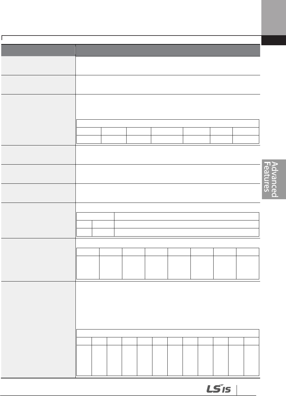
227
Learning Advanced Features
Code
Description
AP3
-
11
–
AP3
-
20 Period 1
–
4
Start T The start time for the 4 time periods can be set up to 4.
AP3
-
12
–
AP
3
-
21 Period 1
–
4
Stop T The end time for the 4 time periods can be set up to 4.
AP3-13–AP3-22
Period 1~4 Day
The Time period date for the operation can be set up to 4. It can be set
on a weekly basis. If the bit is ‘1 (on)’, it indicates the relevant day is
selected. If the Bit is ‘0 (off)’, it indicates the relevant day is not selected.
Bit
6
5
4
3
2
1
0
Sunday
Monday
Tuesday
Wednesday
Thursday
Friday
Saturday
AP3
-
30
–
AP3
-
51
Exception1–8 Start T The operation start time for the 8 Exception days can be set.
AP3
-
31
–
AP3
-
52
Exception1–8 Stop T The operation end time for the 8 Exception days can be set.
AP3
-
32
–
AP3
-
53
Exception1–8 Date The date for the 8 Exception days can be set.
AP3-70 Time Event En
Enables or disables the Time Event
Setting
Function
0
No
Time Event is not used.
1
Yes
Time Event is used.
AP3-71 T-Event Status
It shows which T
-
Event from 1
–
8 is being performed.
7
6
5
4
3
2
1
0
T
-
Event
8
T
-
Event
7
T
-
Event
6
T
-
Event
5
T
-
Event
4
T
-
Event
3
T
-
Event
2
T
-
Event
1
AP3-72–86 T-Event1–8
Period
Select the desired module of the Time Module and Exception Day set in
AP3-11–AP3-53 for the relevant events.
If the bit is 1, it indicates the relevant Time Module or Exception Day is
selected. If the Bit is 0, it indicates the Time Module or Exception Day is
not selected.
bit
11
10
9
8
7
6
5
4
3
2
1
0
Exception
Date 8
Exception
Date 7
Exception
Date 6
Exception
Date 5
Exception
Date 4
Exception
Date 3
Exception
Date 2
Exception
Date 1
Period 4
Period 3
Period 2
Period 1
228
Learning Advanced Features
Code
Description
AP3-73–87 T-Event1–8
Define
Select the desired Event.
Setting
0
None
16
PID Openloop
1
Fx
17
PID Gain 2
2
Rx
18
PID Ref Change
3
Speed
-
L
19
2nd Motor
4
Speed
-
M
20
Timer In
5
Speed
-
H
21
Dias Aux Ref
6
Xcel
-
L
22
EPID1 Run
7
Xcel
-
M
23
EPID1 Openloop
8
Xcel
-
H
24
Pre Heat
9
Xcel Stop
25
EPID2 Run
10
Run Enable
26
EPID2 Openloop
11
2nd Source
27
Sleep Wake Chg
12
Exchange
28
PID Step Ref L
13
Analog Hold
29
PID Step Ref M
14
I
-
Term Clear
30
PID Step Ref H
15
None
Time Period Parameter Setting
There are 4 Time Period Sets in the Time Event. Each Time Period Set has: period 1–4 Start (Start
time), Period 1–4 Stop T (End time), and Period 1–4 Day (Operation day) for which they can be set.
Time Period
Schedule
Time Period 1
Every Sunday, Monday,
Wednesday, Thursday, and Friday at 06: 00 (On) and 18: 00
(Off)
Time Schedule
Code
Function
Setting
AP3
-
11
Period1 StartT
06: 00
AP3
-
12
Period1 StopT
18: 00
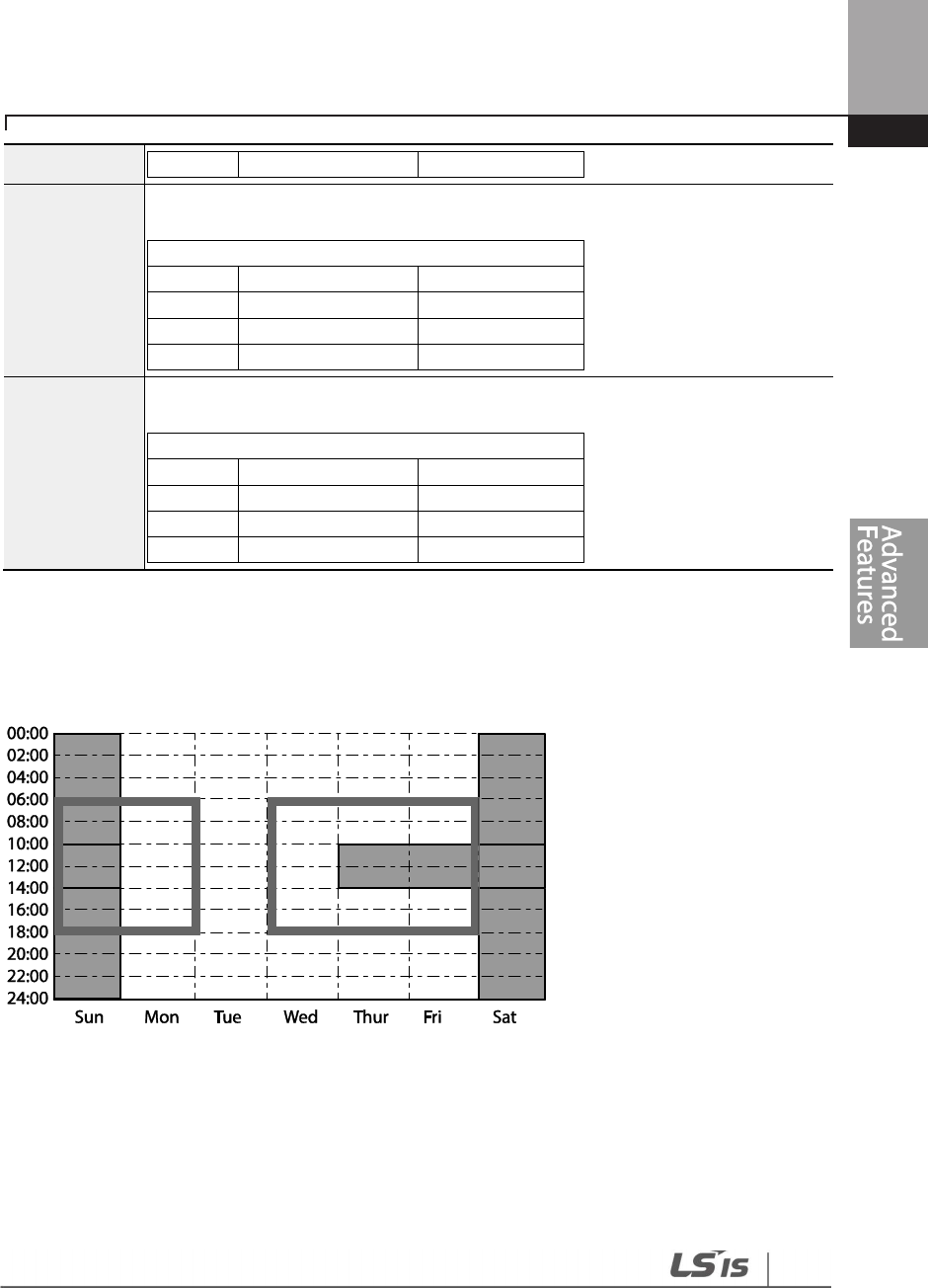
229
Learning Advanced Features
The tables below show the parameter values for Time Period 1, Time Period 2, and Time Period 3.
When the parameters are set for the Time Periods 1-3 as shown in the tables below, this indicates
the Time Event function turns on and off on the following days and time.
<Time Period setting Time Chart>
Parameters Setting for Exception Date
There are 8 Exception date modules in the Time Event function. They are used to specify the
operation on particular days (public holidays, etc.). The settings for the start time and the end time
are the same as the settings for the modules and can be set for particular days. The Exception
AP3
-
13
Period1 Day
1101110
Time Period 2
Every Sunday and Saturday for 24 hours (On)
Time
Schedule
Code
Function
Setting
AP3
-
14
Period2 StartT
00: 00
AP3
-
15
Period2 StopT
24: 00
AP3
-
16
Period2 Day
1000001
Time Period 3
Every Sunday, Thursday, Friday, and Saturday at 10: 00 (On) and 14: 00 (Off)
Time Schedule
Code
Function
Setting
AP3
-
17
Period3 StartT
10: 00
AP3
-
18
Period3 StopT
14: 00
AP3
-
19
Period3 Day
1000111
230
Learning Advanced Features
dates can be set redundantly with the Time periods. If the Time Periods and the Exception Dates
are set redundantly, the inverter operates on the Exception Dates set.
Title
Setting Range
Description
Except1
–
8 Start
T
00: 00
–
24: 00
Hour: Minutes (by the minute)
Except1
–
8 Stop T
00: 00
–
24: 00
Hour: Minutes
Except1
–
8 Date
1/1
–
12/31
Select the particular date (between 1/1 and 12/31)
Time Period
Schedule
Exception
Date 1
Every Sunday, Monday, Wednesday, Thursday, and Friday at 06: 00 (On) and 18: 00
(Off)
Time Schedule
Code
Function
Setting
AP3
-
30
Except1 StartT
06: 00
AP3
-
31
Except1 StopT
18: 00
AP3
-
32
Except1 Day
12/25
Exception
Date 2
Every Sunday and Saturday for 24 hours (On)
Time Schedule
Code
Function
Setting
AP3
-
33
Except2 StartT
00: 00
AP3
-
34
Except2 StopT
24: 00
AP3
-
35
Except2 Day
01/01
Exception
Date 3
Every Sunday, Thursday, Friday, and Saturday at 10:
00 (On) and 14: 00 (Off)
Time Schedule
Code
Function
Setting
AP3
-
36
Except3 StartT
10: 00
AP3
-
37
Except3 StopT
14: 00
AP3
-
38
Except3 Day
01/01
Title
Setting Range
Remarks
Except1
–
8 StartT
00: 00
–
24: 00
Hour: Minutes (by the minute)
Except1
–
8 Stop
T
00: 00
–
24: 00
Hour: Minutes
Except1
–
8 Date
1/1
–
12/31
Select the particular date (between 1/1 and 12/31)
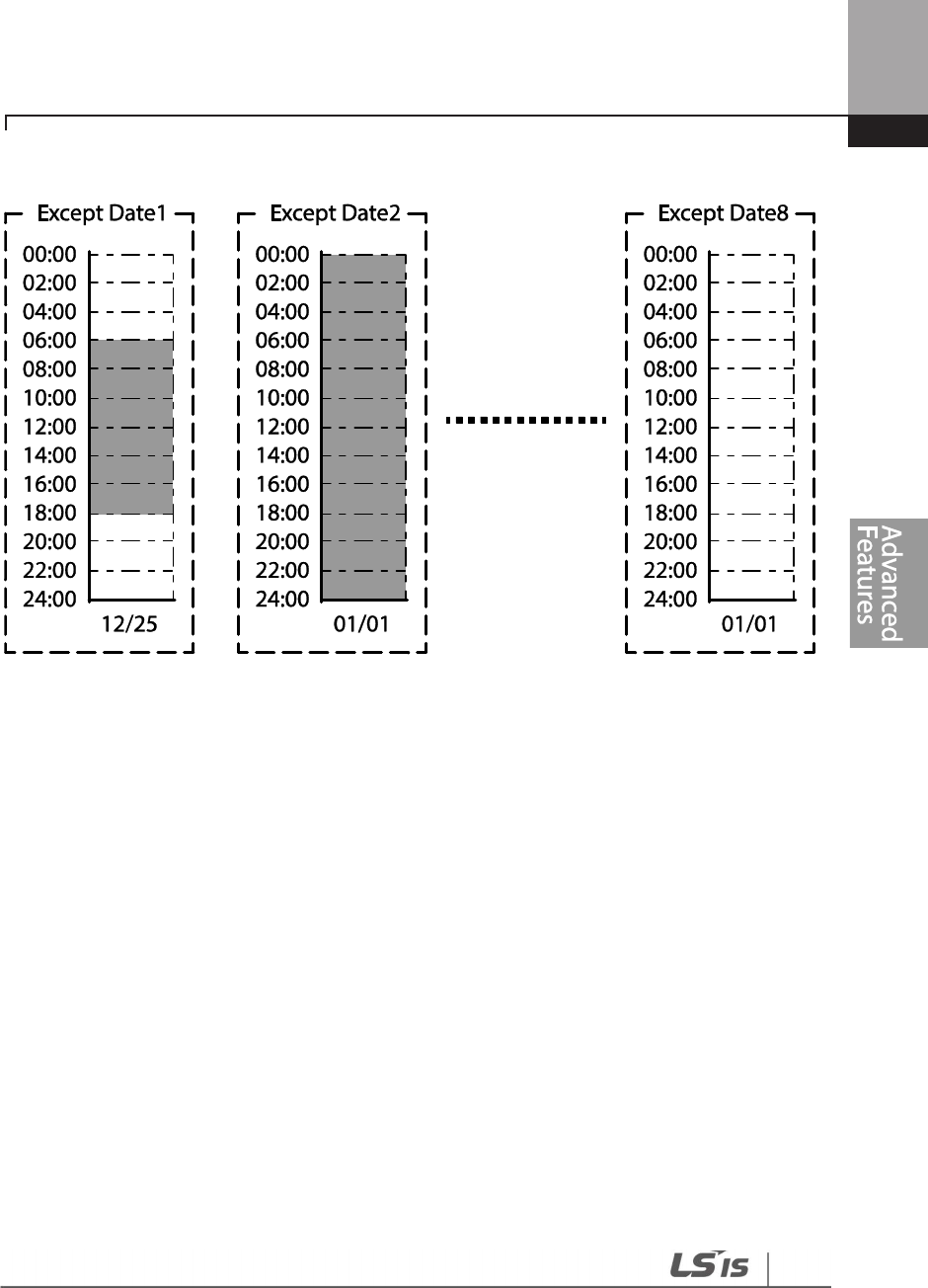
231
Learning Advanced Features
<The Time Chart for the Exception Day>
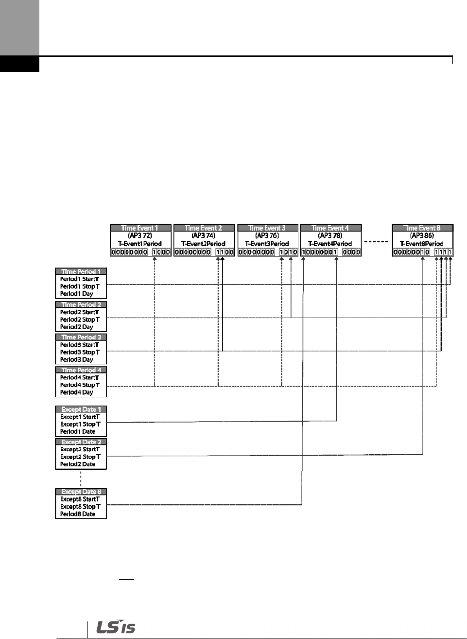
232
Learning Advanced Features
The connection settings for Time Period and Time Event
There are 8 Time event modules in the Time Event function. The parameters for T-Events 1–8 are
used to set the connections to each module for the Time Period and the Exception Date. The
parameters for T-Event 1–8 are used to specify the operation on particular days. Each Time event
module can be set for the connections to 4 Time period modules and 8 Exception days. Time
event modules are set as a bit unit in the parameters for Events 1–8.
The diagram below shows
the connections between the Time event modules and the time period modules. The Time Event 1
is connected to Time Period 4. The Time Event 8 is connected to Time Periods 1–4 and the
Exception Dates 2.
Time Event Module Function Settings
The functions to be performed in the Time Event for T-Events 1–8 can be set. 30 functions can be
set (refer to page 228). There are 8 Time event modules in the Time Event. The parameters for T-
Events 1–8 are used to set the connections to each module for the Time Period and the Exception
Date. The parameters for T-Events 1–8 are used to specify the operation on particular days.

233
Learning Advanced Features
Example of the Time Event operations
If the Time events are set as the parameters below, the inverter operates as illustrated.
Group
Code
Name
LCD Display
Parameter
Setting
Setting Range
Unit
DRV
06
Command
Source Cmd Ref Src 5: Time Event 0–9 -
07
Frequency
command
source
Freq Ref Src 0: KeyPad 0–11 -
AP3
11
Time Period 1
Start time Period1 StartT 10: 00 00: 00–24: 00 Min
12
Time Period 1
End time Period1 Stop T 20: 00 00: 00–24: 00 Min
13
Time Period 1
Day of the
week
Period1 Day 0110000 0000000–
1111111
14
Time Period 2
Start time Period2 StartT 12: 00 00: 00–24: 00 Min
15
Time
Period 2
End time Period2 Stop T 17: 00 00: 00–24: 00 Min
16
Time Period 2
Day of the
week
Period2 Day 00100000 0000000–
1111111 -
70 Time Event
configuration
Time Event En 1: YES
0
No
-
1
Yes
72
Time Event 1
connection
configuration
T-Event1Period 00000000001 000000000001–
111111111111
73 Time Event 1
functions T-Event1Define 1: Fx
0
None
1
Fx
2
Rx
3
Speed
-
L
4
Speed
-
M
5
Speed
-
H

234
Learning Advanced Features
7
Xcel
-
L
8
Xcel
-
M
9
Xcel
-
H
10
Xcel Stop
11
Run Enable
12
2nd Source
13
Exchange
14
Analog Hold
15
I
-
Term Clear
16
PID
Openloop
17
PID Gain 2
18
PID Ref
Change
19
2nd Motor
20
Timer In
21
Dias Aux Ref
22
EPID1 Run
23
EPID1 ITerm
Clr
24
Pre Heat
25
EPID2 R
u
n
26
EPID2 ITerm
Clr
27
Sleep Wake
Chg
28
PID Step Ref
L
29
PID Step Ref
M
30
PID Step Ref
H
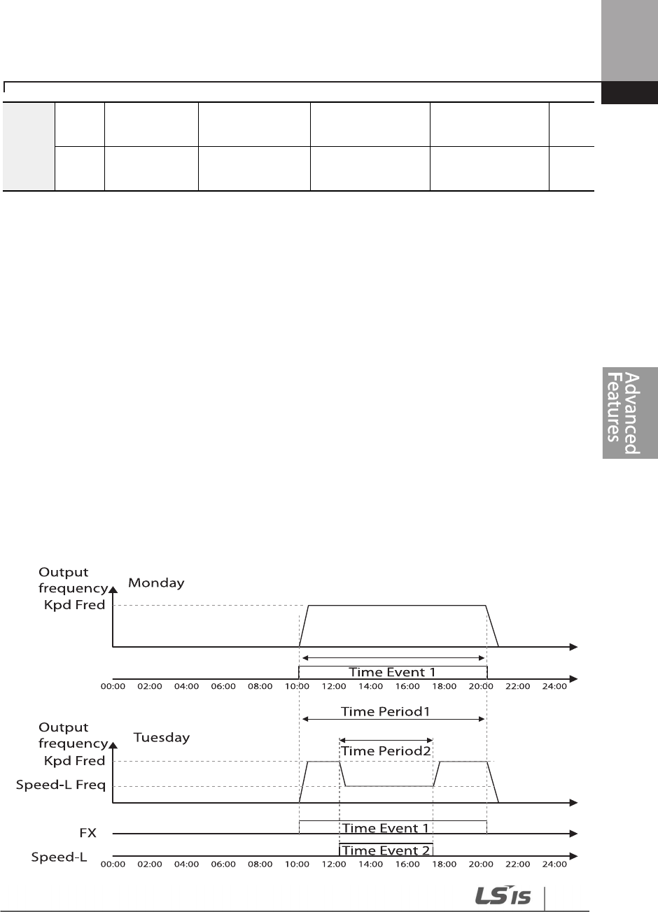
235
Learning Advanced Features
The parameters in the table above shows the frequency command sources for the keypad and the
operation command sources for the Time Event.
The following is an example of an inverter operation utilizing the Time Period modules 1 and 2
with Time Events 1 and 2:
Time Period 1 is used to operate the inverter on Mondays and Tuesdays from 10AM to 8PM. Time
Period 2 is used to operate the inverter on Tuesday from 12PM to 5PM.
Time Event 1 triggers forward operations based on the frequency input on the keypad and
continues the operation for the time set at Time Period module 1. Time Event 2 operates the
inverter at Speed-L for the time set at Time Period module 2.
On Mondays, the inverter operates in the forward direction based on the frequency input on the
keypad from 10AM to 8PM (Time Event 1). On Tuesdays, it operates again in the forward direction
based on the keypad frequency input from 10AM to 12PM (Time Event 1), and then operates at
Speed-L from 12PM to 5PM (Time Event 2). When the operation assigned by Time Event 2 is
complete, the inverter resumes its Time Event 1 operation (the inverter operates based on the
keypad frequency input from 5PM to 8PM).
74
Time Event 2
connection T-Event1Period 00000000010
000000000001
–
111111111111
75
Time Event 2
functions T-Event2Define 3: Speed-L Refer to AP3-73

236
Learning Advanced Features
<An example of Time Event>
Note
When repetitive frequency commands related to the frequency input command occur while the Time
Event function is performing, Time Event performs its function in the order of the frequency command
sources set in Freq Ref Src for DRV-07 (followed by Jog operation and multi-step acc/dec).
If a fault trip occurs during a time event operation, the inverter stops the operation and stays in a
trip state. When this happens, there are two options to resume the stopped operation:
• Set PRT-08 (RST Restart) to ‘YES’ to allow the inverter to automatically restart after the trip
condition is released.
• Refresh the setting at AP3-70 (Time Event En). Set AP3-70 to ‘Yes’ from ‘No’. If one of the input
terminals (IN-65–71 Px Define) is assigned to it, turn the switch off then turn it back on to
resume the time event operation.

237
Learning Advanced Features
5.23 Kinetic Energy Buffering
When the input power supply is disconnected, the inverter’s DC link voltage decreases, and a low
voltage trip occurs blocking the output. A kinetic energy buffering operation uses regenerative
energy generated by the motor during the blackout to maintain the DC link voltage. This extends
the time for a low voltage trip to occur, after an instantaneous power interruption.
Group
Code
Name
LCD Display
Pa
rameter Setting
Setting range
Unit
CON
77
Kinetic energy
buffering selection KEB Select 1 Yes 0–1 -
78
Kinetic energy
buffering start level KEB Start Lev
130 110–140 %
79
Kinetic energy
buffering stop level KEB Stop Lev
135 115–145 %
80
Kinetic
energy
buffering slip gain KEB Slip Gain
300 0–20000 -
81
Kinetic energy
buffering P-Gain KEB P Gain 1000 0–20000 -
82
Kinetic energy
buffering I gain KEB I Gain 500 1–20000 -
83
Kinetic energy
buffering
acceleration time
KEB Acc Time
10.0
0.75~90kW 0.0–600.0 Sec
30.0
110~500kW
Kinetic Energy Buffering Operation Setting Details
Code
Description
CON-77
KEB Select
Select the kinetic energy buffering operation when the input power is
disconnected.
Setting
Function
0
No
General deceleration is carried out until a low
voltage trip occurs.
1
Yes
The inverter power frequency is controlled and
the regeneration energy from the motor is
charged by the inverter.

238
Learning Advanced Features
Code
Description
CON
-
78
KEB Start Lev,
CON-79
KEB Stop Lev
Sets the start and stop points of the kinetic energy buffering operation. The set
values must be based on the low voltage trip level at 100%, and the stop level
(CON-79) must be set higher than the start level (CON-78).
CON
-
80
KEB Slip Gain
Used to prevent malfunctions caused by low voltage from initial kinetic energy
buffering occurring due to power interruptions.
CON-81
KEB P Gain
Used to maintain the voltage during the kinetic energy buffering operation. It
operates the inverter by modifying the set value to prevent malfunctions
caused by low voltage after power interruptions.
CON-82
KEB I Gain
Used to maintain the voltage during the kinetic energy buffering operation.
Sets the gain value to maintain the operation until the frequency stops during
the kinetic energy buffering operation.
CON
-
83
KEB Acc Time
Sets the acceleration time for the frequency reference when the inverter’s
operation becomes normal after the kinetic energy buffering operation.
Note
• The KEB functions may perform differently depending on the size of the loads. The KEB Gains can
be set for a better performance.
• If a low voltage trip occurs after a power interruption, it indicates the load inertia and level are
high. In such cases, the KEB functions can be performed better by increasing the KEB I Gain and
the KEB Slip Gain.
• If motor vibration or torque variation occurs during the KEB function operation after power
interruptions, the KEB functions can be performed better by increasing the KEB P Gain or
decreasing the KEB I Gain.
Depending on the duration of instantaneous power interruptions and the amount of load inertia, a low
voltage trip may occur even during a kinetic energy buffering operation. Motors may vibrate during
kinetic energy buffering operation for some loads, except for variable torque loads (for example, fan or
pump loads).

239
Learning Advanced Features
5.24 Anti-hunting Regulation (Resonance Prevention)
This function is used to prevent the hunting of a V/F controlled fan or motor caused by current
distortion or oscillation, due to mechanical resonance or other reasons.
Group Code Name LCD Display Parameter Setting Setting Range Unit
CON
13
Enable or
disable anti-
hunting
regulation
(resonance
prevention)
AHR Sel 1 Yes
0
No
-
1
Yes
14
Anti
-
hunting
regulation P-
Gain
AHR P-Gain 1000 0–32767 -
15
Anti
-
hunting
regulation start
frequency
AHR Low Freq 0 0–AHR High
Freq Hz
16
Anti
-
hunting
regulation end
frequency
AHR High Freq
400.00 AHR Low Freq–
400.00 Hz
17
Anti
-
hunting
regulation
compensation
voltage limit
AHR Limit 2 0–20 %
Anti-hunting Regulation Setting Details
Code
Description
CON-13 AHR Sel
Selects the Anti
-
hunting regulator operation.
Setting
Function
0
No
Disable anti
-
hunting regulation.
1
Yes
Enable anti
-
hunting regulation.
CON-14 AHR P-Gain
Increasing AHR proportional gain improves responsiveness of the
anti-hunting regulation. However, current oscillation may result if
AHR proportional gain is set too high.
CON-15 AHR Low Freq
CON-16 AHR High Freq
Sets the lower limit frequency (CON-15) and the maxim limit
frequency (CON-16) for anti-hunting regulation.

240
Learning Advanced Features
5.25 Fire Mode Operation
This function is used to allow the inverter to ignore minor faults during emergency situations, such
as fire, and provides continuous operation to protect other systems, such as ventilating fans. In Fire
mode, the inverter continues to operate based on the Fire mode run direction and frequency set
at PRT-46 and PRT-47.
Group
Code
Name
LCD Display
Parameter Setting
Setting Range
Unit
PRT
44
Fire mode
password Fire Mode PW 3473 - -
45 Fire mode
setting Fire Mode Sel 0: None
0
None
-
1
Fire Mode
2
Test Mode
46 Fire mode run
direction Fire Mode Dir 0: Forward
0
Forward
-
1
Reverse
47
Fire mode run
frequency
Fire Mode
Freq 60.00 0–max Freq Hz
48
Fire mode
operation count Fire Mode Cnt
0 - -
IN 65–75
Digital input
configuration Px Define 40: Fire Mode 0-55 -
OUT
31–35
Digital output
configuration Relay1-5 27: Fire Mode 0-41 -
36
TR output
configuration Q1 define 27: Fire Mode 0-41 -
When the multi-function terminal configured for Fire mode is turned on, the inverter ignores all
other commands and operates in the direction set at PRT-46 (Fire mode run direction) at the
speed set at PRT-47 (Fire mode run frequency). In Fire mode, the inverter ignores any faults, other
than ‘ASHT,’ ‘Over Current 1,’ ‘Over Voltage,’ ‘Ground F,’ and continues to operate. If any of the faults
that can stop inverter operation occur, the inverter automatically performs a reset restart to
continue the operation.
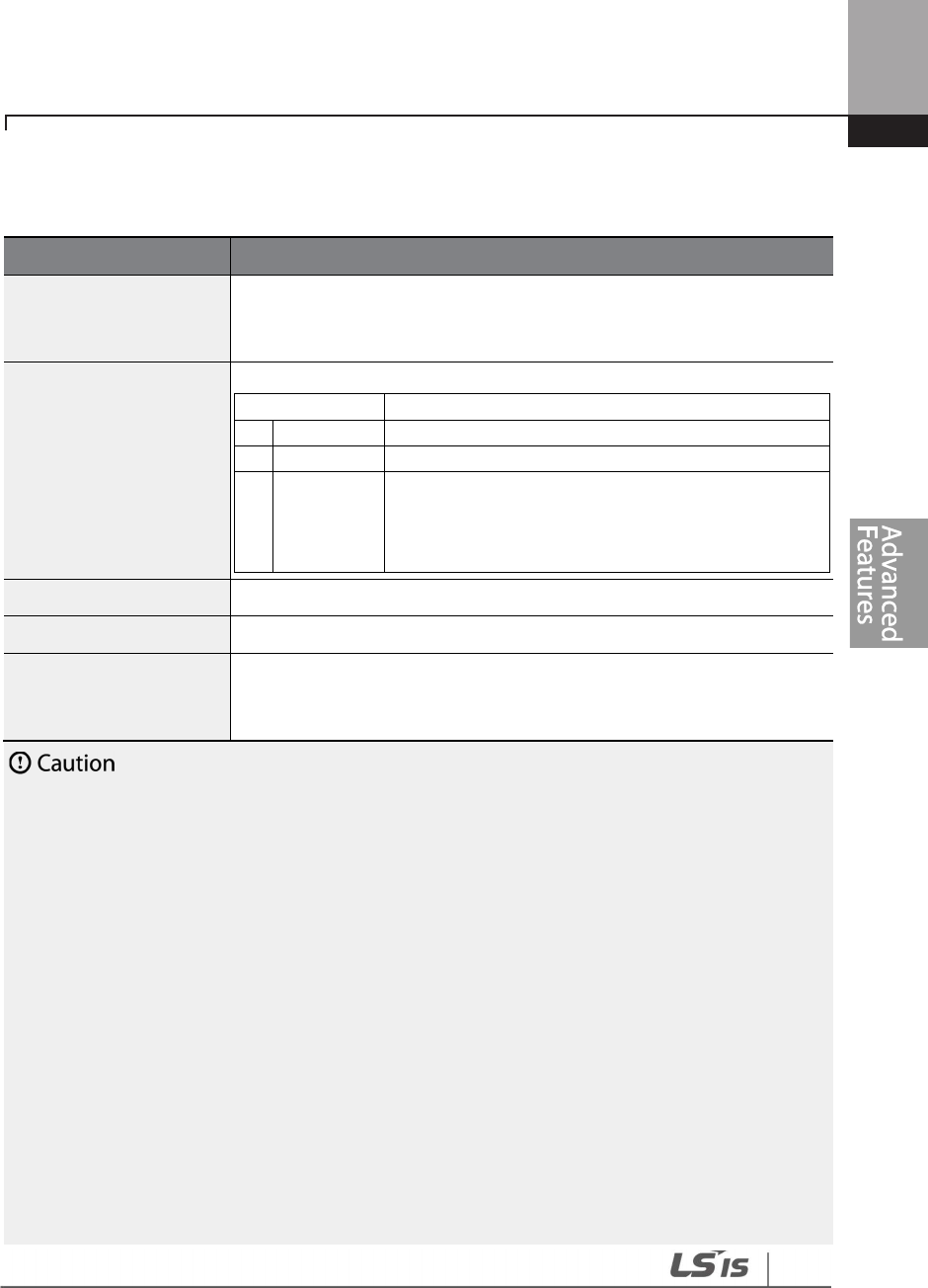
241
Learning Advanced Features
Fire Mode Function Setting Details
Code
Description
PRT-44 Fire Mode PW
Fire mode password
is 3473.
A password must be created to enable Fire mode. PRT-45 (Fire Mode Sel)
can be modified only after the password is entered.
PRT-45 Fire Mode Sel
Sets the Fire Mode.
Setting
Function
0
None
Fire mode is not used.
1
Fire Mode
Normal Fire mode
2
Test Mode
Fire mode test mode
In Fire test mode, faults are normally processed.
Using Fire test mode does not increase the count
value at PRT-48 (Fire Mode Cnt).
PRT
-
46 Fire Mode Dir
Sets the run direction for Fire mode operation.
PRT
-
47 Fire Mode Freq
Sets the operation frequency for Fire mode.
PRT-48 Fire Mode Cnt
Counts the number of the Fire mode operations. The number increases
only when PRT-45 (Fire Mode Sel) is set to ‘Fire Mode’. The count increases
up to 99, then it does not increase any more.
• If damper or lubrication operations are set for the inverter, Fire mode operation is performed after
the delay times set in the relevant operations.
• Note that Fire mode operation voids the product warranty.
• In Fire mode test mode, the inverter does not ignore the fault trips or perform a reset restart. All
the fault trips will be processed normally. Fire mode test mode does not increase the Fire mode
count (PRT-48).
• When the Fire mode operation is complete, the inverter stops operating and is turned off.
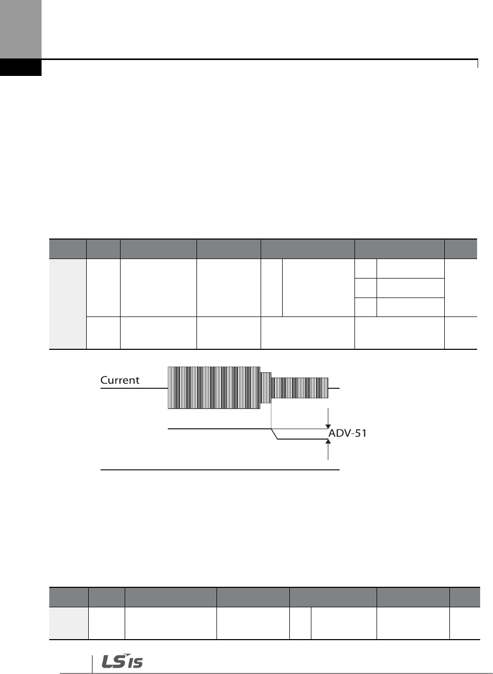
242
Learning Advanced Features
5.26 Energy Saving Operation
5.26.1 Manual Energy Saving Operation
If the inverter output current is lower than the current set at BAS-14 (Noload Curr), the output
voltage must be reduced as low as the level set at ADV-51 (Energy Save). The voltage before the
energy saving operation starts will become the base value of the percentage. Manual energy
saving operation will not be carried out during acceleration and deceleration.
Group
Code
Name
LCD Display
Parameter Setting
Setting Range
Unit
ADV
50 Energy saving
operation E-Save Mode
1 Manual
0
None
-
1
Manual
2
Auto
51
Energy saving
amount Energy Save 30 0–30 %
5.26.2 Automatic Energy Saving Operation
The inverter finds the optimal energy saving point for the time set at ADV-52 based on the rated
motor current and the voltage output. The Energy saving operation is effective for the normal
duty operations. It does operate when the load level is more than 80% of the rated motor current.
Group
Code
Name
LCD Display
Parameter Setting
Setting Range
Unit
ADV 50
Energy saving
operation E-Save Mode 2 Auto 0–2 -
Voltage output
243
Learning Advanced Features
Group
Code
Name
LCD Display
Parameter Setting
Setting Range
Unit
52
Energy saving
point search time E-Save Det T 20.0 0.0–100.0 Sec
If the operation frequency is changed, or acceleration or deceleration is carried out during an energy
saving operation, the actual Acc/Dec time may take longer than the set time due to the time required
to return to general operations from the energy saving operation.
5.27 Speed Search Operation
Speed search operation is used to prevent fault trips that can occur when the inverter voltage
output is disconnected and the motor is idling. Since this feature estimates the motor rotation
speed based on the inverter output current, it does not give the exact speed.
Group Code Name LCD Display Parameter Setting Setting Range Unit
CON
70 Speed search mode
selection SS Mode 0 Flying Start-1 - -
71 Speed search
operation selection
Speed
Search 0000 - bit
72 Speed search
reference current
SS Sup-
Current
90
0.75~90kW
50–120 %
80
110~500kW
73 Speed search
proportional gain SS P-Gain 100 0–9999 -
74 Speed search
integral gain SS I-Gain 200 0–9999 -
75 Output block time
before speed search
SS Block
Time 1.0 0–60 sec
OUT
31 Multi-function relay
1 item Relay 1
19
Speed Search - -
33
Multi
-
function
output 1 item Q1 Define
244
Learning Advanced Features
Code
Description
CON-70 SS Mode
Select a speed search type.
Setting
Function
0
Flying
Start
-
1
The speed search is carried out as it controls the
inverter output current during idling below the CON-
72 (SS Sup-Current) parameter setting. If the
direction of the idling motor and the direction of
operation command at restart are the same, a stable
speed search function can be performed at about 10
Hz or lower. However, if the direction of the idling
motor and the direction of operation command at
restart are different, the speed search does not
produce a satisfactory result because the direction of
idling cannot be established.
1
Flying Start
-
2
The speed search is carried out as it PI controls the
ripple current which is generated by the counter
electromotive force during no-load rotation. Because
this mode establishes the direction of the idling
motor (forward/reverse), the speed search function is
stable regardless of the direction of the idling motor
and direction of operation command. However
because the ripple current is used which is generated
by the counter electromotive force at idle (the
counter electromotive force is proportional to the
idle speed), the idle frequency is not determined
accurately and re-acceleration may start from zero
speed when the speed search is performed for the
idling motor at low speed (about 10 - 15 Hz, though it
depends on motor characteristics).
CON-71 Speed
Search
Speed search can be selected from the following 4 options. If the top
display segment is on, it is enabled (On). If the bottom segment is on, it is
disabled (Off).
Item
Bit Setting On Status
Bit setting Off Status
Keypad
Type and Functions of Speed Search Setting
Setting
Function
bit4
bit3
bit2
bit1

245
Learning Advanced Features
Speed search for general
acceleration
Initialization after a fault trip
Restart after instantaneous power
interruption
Starting with power
-
on
Speed search for general acceleration: If bit 1 is set to ‘1’ and the inverter
operation command runs, acceleration starts with the speed search
operation. When the motor is rotating under load, a fault trip may occur if
the operation command is run for the inverter to provide voltage output.
The speed search function prevents such fault trips from occurring.
Initialization after a fault trip other than an LV trip: If bit 2 is set to ‘1’ and
PRT-08 (RST Restart) is set to ‘1 (Yes)’, the speed search operation
automatically accelerates the motor to the operation frequency used before
the fault trip when the [Reset] key is pressed (or the terminal block is
initialized) after a fault trip.
Automatic restart after a power interruption: If bit 3 is set to ‘1,’ and if a
low voltage trip occurs due to a power interruption but the power is
restored before the internal power shuts down, the speed search operation
accelerates the motor back to its frequency reference before the low
voltage trip.
If an instantaneous power interruption occurs and the input power is
disconnected, the inverter generates a low voltage trip and blocks the
output. When the input power returns, the operation frequency before the
low voltage trip and the voltage is increased by the inverter’s inner PI
control.
If the current increases above the value set at CON-72, the voltage stops
increasing and the frequency decreases (t1 zone). If the current decreases
below the value set at CON-27, the voltage increases again and the
frequency stops decelerating (t2 zone). When the normal frequency and
voltage are resumed, the speed search operation accelerates the motor
back to its frequency reference before the fault trip.
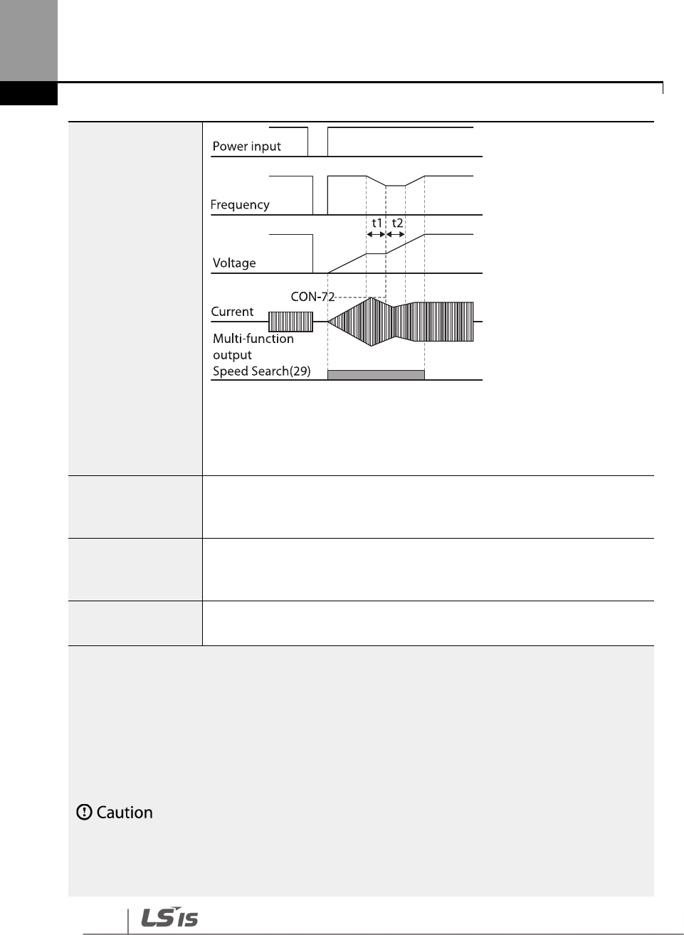
246
Learning Advanced Features
Starting with power-on: Set bit 4 to ‘1’ and ADV-10 (Power-on Run) to ‘1
(Yes)’. If inverter input power is supplied while the inverter operation
command is on, the speed search operation will accelerate the motor up to
the frequency reference.
CON-72 SS Sup-
Current
The amount of current flow is controlled during speed search operation
based on the motor’s rated current. If CON-70 (SS mode) is set to ‘1 (Flying
Start-2)’, this code is not visible.
CON-73 SS P-Gain,
CON-74 SS I-Gain
The P/I gain
of the speed search controller can
be adjusted. If CON
-
70 (SS
Mode) is set to ‘1(Flying Start-2)’, different factory defaults, based on motor
capacity, are used and defined in DRV-14 (Motor Capacity).
CON
-
75 SS Block
Time
The block time parameter prevents overvoltage trips due to counter
electromotive force.
Note
If operated within the rated output, the H100 series inverter is designed to withstand instantaneous
power interruptions within 8 ms and maintain normal operation. The DC voltage inside the inverter
may vary depending on the output load. If the power interruption time is longer than 8 ms, a low
voltage trip may occur.
Select the Speed search function (normal
acceleration) for a proper re
-
operation during a free
-
run.
If the speed search function (normal acceleration) is not selected during the acceleration, an over
current trip or an overload trip may occur.

247
Learning Advanced Features
Speed Search Operation Setting Details

248
Learning Advanced Features
5.28 Auto Restart Settings
When inverter operation stops due to a fault and a fault trip is activated, the inverter
automatically restarts based on the parameter settings.
Group Code Name LCD Display
Parameter
Setting Setting Range Unit
PRT
08
Select start at trip reset
RST Restart
11
-
-
09
Auto restart count
Retry Number
6
0
–
10
-
10
Auto restart delay time
Retry Delay
1.0
0.1
–
60.0
sec
CON
71
Select speed search
operation Speed Search - 0000–1111 bit
72
Speed search startup
current SS Sup-Current 90 70–120 %
73
Speed search
proportional gain SS P-Gain 100 0–9999
74
Speed search integral
gain SS I-Gain 200 0–9999
75
Output block time before
speed search SS Block Time 1.0 0.0–60.0 sec
Auto Restart Setting Details
Code
Description
PRT
-
08
RST Restart
The Reset restart function can be performed by one of the two different
types. If the top segment is turned on, it indicates the function is on. If the
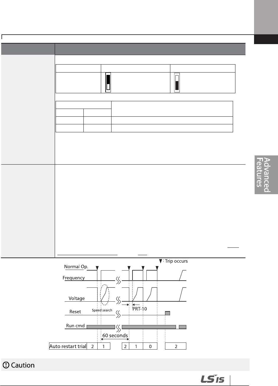
249
Learning Advanced Features
Code
Description
bottom segment is turned on, it indicates the function is off.
Type
Bit On
Bit Off
LCD Display
Reset Restart function
Setting
Function
Bit1
Bit 0
For fault trips other
than LV
For LV fault trips
For fault trips other than LV: If the Bit 0 is turned on, the inverter restarts
after a trip occurs and triggers a reset.
For LV fault trips: If the Bit 1 is turned on, the inverter restarts after a trip
occurs and triggers a reset.
PRT-09
Retry Number,
PRT-10
Retry Delay
The number of available auto restarts can be set at PRT
-
09. If a fault trip
occurs during an operation, the inverter restarts after the time set at PRT-10
(Retry Delay). At each restart, the inverter counts the number of tries and
subtracts it from the number set at PRT-09 until the retry number count
reaches 0. After an auto restart, if a fault trip does not occur within 60 sec, it
will increase the restart count number. The maximum count number is
limited by the number set at PRT-09.
If the inverter stops due to over current or hardware diagnosis, an auto
restart is not activated. At auto restart, the acceleration options are identical
to those of speed search operation. Codes CON-72–75 can be set based on
the load. Information about the speed search function can be found at 5.27
Speed Search Operation on page 243.
[Example of auto restart with a setting of 2]

250
Learning Advanced Features
• If the auto restart number is set, be careful when the inverter resets from a fault trip. The motor
may automatically start to rotate.
• In HAND mode, auto restart resets the trip condition but it does not restart the inverter operation.
• In AUTO mode,
- if the auto restart is configured, the inverter restarts after a trip condition is released
(command via digital input is used to restart the operation).
- if the auto restart is not configured and the trip condition is released using the OFF key,
or the switches at the terminal input, the inverter stays in the OFF state. Because the
command information is reset along with the trip condition, a new command is required
to operate the inverter.
5.29 Operational Noise Settings (Carrier Frequency
Settings)
Group Code Name LCD Display Parameter Setting
Setting
Range Unit
CON 04 Carrier Frequency
Carrier Freq
3.0
0.75~90kW
1.0
–
15.0
kHz
2.0
110~355kW
1.0~5.0
1.5
400/500kW
1.0~4.0
05
Switching Mode
PWM* Mode
0
Normal PWM
0
–
1
-
* PWM: Pulse width modulation
Operational Noise Setting Details
Code
Description
CON-04
Carrier Freq
Adjusts motor operational noise by changing carrier frequency settings. Power
transistors (IGBT) in the inverter generate and supply high frequency switching
voltage to the motor. The switching speed in this process refers to the carrier
frequency. If the carrier frequency is set high, it reduces operational noise from
the motor. If the carrier frequency is set low, it increases operational noise from
the motor.
CON-05 PWM
Mode
The heat loss and leakage current from the inverter can be reduced by changing
the load rate option at CON-05 (PWM Mode). Selecting ‘1 (LowLeakage PWM)’
reduces heat loss and leakage current, compared to when ‘0 (Normal PWM)’ is
selected. However, it increases the motor noise. Low leakage PWM uses a 2
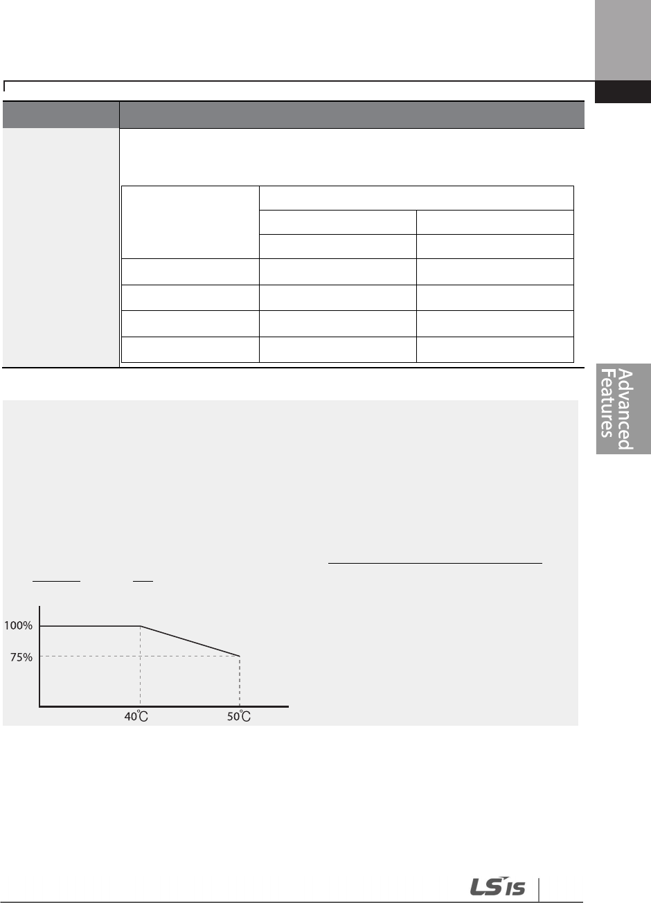
251
Learning Advanced Features
Code
Description
phase PWM modulation mode, which helps minimize degradation and reduces
switching loss by approximately 30%.
Item
Carrier
Frequency
1.0 kHz
15 kHz
LowLeakage PWM
Normal PWM
Motor noise
↑ ↓
Heat generation
↓ ↑
Leakage current
↓ ↑
Leakage current
↓ ↑
Note
• Carrier Frequency at Factory Default Settings:
- 0.75~90kW : 3 kHz, 110~355kW : 2kHz, 400/500kW : 1.5kHz
• H100 Series Inverter Derating Standard (Derating): The over load rate represents an
acceptable load amount that exceeds rated load, and is expressed as a ratio based on the rated
load and the duration. The overload capacity on the H100 series inverter is 120%/1 min for
normal loads. The current rating differs from the load rating, as it also has an ambient
temperature limit. For derating specifications refer to 11.8 Inverter Continuous Rated Current
Derating on page 618.
• Current rating for ambient temperature at normal load operation.
5.30 2nd Motor Operation
The 2
nd
motor operation is used when a single inverter switch operates two motors. Using the 2
nd
motor operation, a parameter for the 2
nd
motor is set. The 2
nd
motor is operated when a multi-
function terminal input, defined as a 2
nd
motor function, is turned on.

252
Learning Advanced Features
Group
Code
Name
LCD Display
Parameter Setting
Setting Range
Unit
IN 65–71
Px terminal
configuration
Px Define
(Px: P1–P7) 28
2nd Motor 0-55 -
2
nd
Motor Operation Setting Details
Code
Description
IN-65–71 Px
Define
Set one of the multi
-
function input
terminals (P1
–
P5) to 26 (2nd Motor) to
display the M2 (2nd motor group) group. An input signal to a multi-function
terminal set to 2nd motor will operate the motor according to the code settings
listed below. However, if the inverter is in operation, input signals to the multi-
function terminals will not read as a 2nd motor parameter.
PRT-50 (Stall Prevent) must be set first, before M2-28 (M2-Stall Lev) settings can
be used. Also, PRT-40 (ETH Trip Sel) must be set first, before M2-29 (M2-ETH 1
min) and M2-30 (M2-ETH Cont) settings.
Parameter Setting at Multi-function Terminal Input on a 2nd Motor
Code
Description
Code
Description
M2
-
04 Acc Time
Acceleration time
M2
-
15 M2
-
Efficiency
Motor efficiency
M2
-
05 M2
-
Dec Time
Deceleration time
M2
-
17 M2
-
Rs
Stator
resistance
M2
-
06 M2
-
Capacity
Motor capacity
M2
-
18 M2
-
Lsigma
Leakage inductance
M2
-
07 M2
-
Base Freq
Motor base frequency
M2
-
25 M2
-
V/F Patt
V/F pattern
M2
-
08 M2
-
Ctrl Mode
Control mode
M2
-
26 M2
-
Fwd Boost
Forward torque boost
M2
-
10 M2
-
Pole Num
Pole number
M2
-
27 M2
-
Rev Boost
Reverse torque boost
M2
-
11 M2
-
Rate Slip
Rated slip
M2
-
28 M2
-
Stall Lev
Stall prevention level
M2-12 M2-Rated Curr Rated current M2-29 M2-ETH 1 min
Motor heat protection
1 min rating
M2-13 M2-Noload Curr No-load current M2-30 M2-ETH Cont
Motor heat protection
continuous rating
M2
-
14 M2
-
Rated Volt
Motor rated voltage
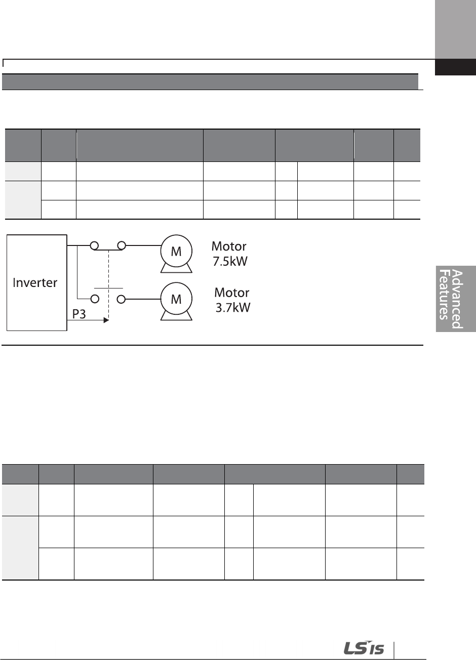
253
Learning Advanced Features
Example - 2nd Motor Operation
Use the 2nd motor operation when switching operation between a 7.5 kW motor and a secondary 3.7
kW motor connected to terminal P3. Refer to the following settings.
Group
Code Name LCD Display
Parameter
Setting
Setting
Range Unit
IN
67
Terminal P3 configuration
P3 Define
26
2nd Motor
-
-
M2
06
Motor capacity
M2
-
Capacity
-
3.7 kW
-
-
08
Control mode
M2
-
Ctrl Mode
0
V/F
-
-
5.31 Supply Power Transition
A supply power transition is used to switch the power source for the motor connected to the
inverter from the inverter output power to the main supply power source (commercial power
source), or vice versa.
Group
Code
Name
LCD Display
Parameter Setting
Setting Range
Unit
IN 65–71
Px terminal
configuration
Px Define
(Px: P1–P7) 18 Exchange 0-55 -
OUT
31
Multi
-
function
relay 1 items Relay1 17 Inverter Line 0-41 -
33
Multi
-
function
output 1 items Q1 Define 18 Comm Line 0-41 -
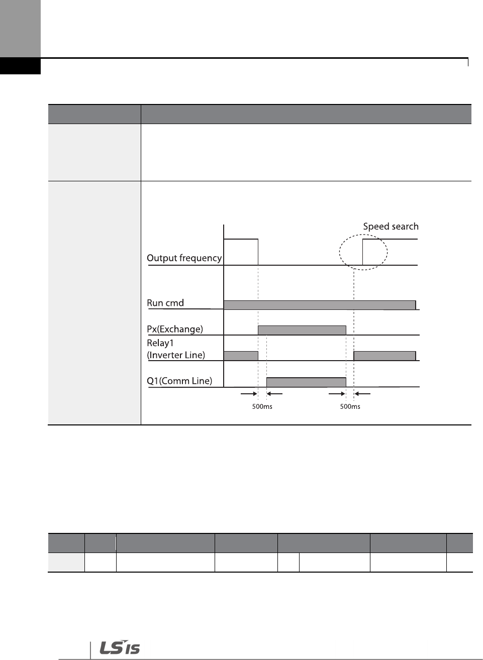
254
Learning Advanced Features
Supply Power Transition Setting Details
5.32 Cooling Fan Control
This function turns the inverter’s heat-sink cooling fan on and off. It is used in situations where the
load stops and starts frequently or a noise-free environment is required. The correct use of cooling
fan controls can extend the cooling fan’s life.
Group
Code
Name
LCD Display
Parameter Setting
Setting Range
Unit
ADV
64
Cooling fan control
Fan Control
0
During Run
0
–
2
-
Cooling Fan Control Detail Settings
Code
Description
IN-65–71
Px Define
When the motor power source changes from inverter output to main supply
power, select a terminal to use and set the code value to ‘18 (Exchange)’. Power
will be switched when the selected terminal is on. To reverse the transition,
switch off the terminal.
OUT-31 Relay 1–
OUT-36 Q1 Define
Set multi
-
function relay or multi
-
function output to ‘17 (Inverter Line)’ or ‘18
(Comm Line)’. The relay operation sequence is as follows.

255
Learning Advanced Features
Code
Description
ADV-64 Fan Control
Settings
Description
0
During Run
The cooling fan runs when the power is supplied to the
inverter and the operation command is on. The cooling
fan stops when the power is supplied to the inverter and
the operation command is off. When the inverter heat
sink temperature is higher than its set value, the cooling
fan operates automatically regardless of its operation
status.
1
Always On
Cooling fan runs constantly if the
power is supplied to
the inverter.
2
Temp
Control
With power connected and the run operation command
on: if the setting is in Temp Control, the cooling fan will
not operate unless the temperature in the heat sink
reaches the set temperature.
Note
Despite setting ADV
-
64 to ‘0 (During Run)’, if the heat sink temperature reaches a set level by current
input harmonic wave or noise, the cooling fan may run as a protective function.
A capacity of 110 kW or more has a small built-in fan installed to cool the internal temperature. The
internal fan controls on / off in conjunction with the operation command of the inverter main control
fan
5.33 Input Power Frequency and Voltage Settings
Select the frequency for inverter input power. If the frequency changes from 60 Hz to 50 Hz, all
other frequency (or RPM) settings, including the maximum frequency, base frequency, etc., will
change to 50 Hz. Likewise, changing the input power frequency setting from 50 Hz to 60 Hz will
change all related function item settings from 50 Hz to 60 Hz.
Group
Code
Name
LCD Display
Parameter Setting
Setting Range
Unit
BAS
10
Input power frequency
60/50 Hz Sel
0
60 Hz
0
–
1
-
Set Inverter input power voltage. Low voltage fault trip level changes automatically to the set

256
Learning Advanced Features
voltage standard.
Group
Code
Name
LCD Display
Parameter Setting
Setting Range
Unit
BAS 19
Input
power
voltage
AC Input Volt
200 Type
220
170
–
240
V
400 Type 380
320
–
480
0.75~90kW
320
-
550
110
~500
kW
5.34 Read, Write, and Save Parameters
Use read, write, and save function parameters on the inverter to copy parameters from the
inverter to the keypad or from the keypad to the inverter.
Group
Code
Name
LCD Display
Parameter Setting
Setting Range
Unit
CNF
46
Parameter read
Parameter Read
1
Yes
-
-
47
Parameter write
Parameter Write
1
Yes
-
-
48
Parameter save
Parameter Save
1
Yes
-
-
Read, Write, and Save Parameter Setting Details
Code
Description
CNF-46 Parameter
Read
Copies saved parameters from the inverter to the keypad. Saved parameters
on the keypad will be deleted and replaced with the copied parameters.
CNF-47 Parameter
Write
Copies saved parameters from
the keypad to the inverter. Saved parameters
on the inverter will be deleted and replaced with the copied parameters. If
an error occurs during parameter writing, the previously saved data will be
used. If there is no saved data on the Keypad, ‘EEP Rom Empty’ will be
displayed.
CNF-48 Parameter
Save
As parameters set during communication transmission are saved to RAM,
the setting values will be lost if the power goes off and on. When setting
parameters during communication transmission, select ‘1 (Yes)’ at CNF-48 to
save the set parameter.
257
Learning Advanced Features
Code
Description
5.35 Parameter Initialization
User changes to parameters can be initialized (reset) to factory default settings on all or selected
groups. However, during a fault trip situation or operation, parameters cannot be reset.
Group
Code
Name
LCD Display
Parameter Setting
Setting Range
Unit
CNF
40 Parameter initialization
Parameter Init
0
No
0
–
15
Parameter Initialization Setting Details
Code
Description
CNF-40
Parameter Init
Setting
LCD Display
Function
0
No
No
-
1 Initialize all groups All Grp
Initialize all data. Select ‘1 (All
Grp)’ and press the [PROG/ENT]
key to start initialization. On
completion, ‘0 (No)’ will be
displayed.
2
Initialize DRV group
DRV Grp
Initialize data by groups. Select
initialize group and press the
[PROG/ENT] key to start
initialization. On completion, ‘0
(No)’ will be displayed.
3
Initialize BAS group
BAS Grp
4
Initialize
ADV group
ADV Grp
5
Initialize CON group
CON Grp
6
Initialize IN group
IN Grp
7
Initialize OUT group
OUT Grp
8
Initialize COM group
COM Grp
9
Initialize PID group
PID Grp
10
Initialize EPI group
EPI Grp
11
Initialize AP1 group
AP1 Grp
12
Initialize AP2 group
AP2 Grp
13
Initialize AP3 group
AP3 Grp
14
Initialize PRT group
PRT Grp
15
Initialize M2 group
M2 Grp

258
Learning Advanced Features
5.36 Parameter View Lock
Use parameter view lock to hide parameters after registering and entering a user password.
Parameter View Lock Setting Details
Code
Description
CNF-51 View Lock Pw
Register a password to allow access to parameter view lock. Follow the
steps below to register a password.
No
Procedure
1
[PROG/ENT] key on CNF
-
51
code will show the previous
password input window. If registration is made for the first time,
enter ‘0.’ It is the factory default.
2
If a password had been set, enter the saved password.
3
If the entered password matches the saved password, a new
window prompting the user to enter a new password will be
displayed (the process will not progress to the next stage until
the user enters a valid password).
4
Register a new password.
5
After registration, code CNF
-
51 will be displayed.
CNF-50 View Lock Set
To enable parameter view lock, enter a registered password. The [Locked]
sign will be displayed on the screen to indicate that parameter view lock
is enabled. To disable parameter view lock, re-enter the password. The
[locked] sign will disappear.
5.37 Parameter Lock
Use parameter lock to prevent unauthorized modification of parameter settings. To enable
parameter lock, register and enter a user password first.
Group
Code
Name
LCD Display
Parameter Setting
Setting Range
Unit
CNF
50
Parameter view lock
View Lock Set
Un
-
locked
0
–
9999
51
Parameter view lock
password View Lock Pw Password 0–9999
259
Learning Advanced Features
Group
Code
Name
LCD Display
Parameter Setting
Setting Range
Unit
CNF
52
Parameter lock
Key Lock Set
Un
-
locked
0
–
9999
-
53
Parameter lock
password Key Lock Pw Password 0–9999 -
Parameter Lock Setting Details
Code
Description
CNF-53 Key Lock
PW
Register a
password to prohibit parameter modifications. Follow the
procedures below to register a password.
No
Procedures
1
Press the [PROG/ENT] key on CNF
-
53 code and the saved password
input window will be displayed. If password registration is being made
for the first time, enter ‘0’. It is the factory default.
2
If a saved password has been set, enter the saved password.
3
If the entered password matches the saved password, then a new
window to enter a new password will be displayed. (The process will
not move to next stage until the user enters a valid password).
4
Register a new password.
5
After registration, Code CNF
-
53 will be displayed.
CNF-52 Key Lock
Set
To enable parameter lock, enter the registered password. The [Locked] sign will
be displayed on the screen to indicate that prohibition is enabled. Once
enabled, pressing the [PROG/ENT] key at once function code will not allow the
display edit mode to run. To disable parameter modification prohibition, re-
enter the password. The [Locked] sign will disappear.
If parameter view lock and parameter lock functions are enabled, no inverter operation
related
function changes can be made. It is very important that you memorize the password.
5.38 Changed Parameter Display
This feature displays all the parameters that are different from the factory defaults. Use this feature
to track changed parameters.
260
Learning Advanced Features
Group
Code
Name
LCD Display
Parameter Setting
Setting Range
Unit
CNF 41 Changed parameter
display Changed Para 0 View All - -
Changed Parameter Display Setting Details
Code
Description
CNF-41
Changed Para
Setting
Function
0
View All
Display all parameters
1
View Changed
Display changed parameters only
5.39 User Group
Create a user defined group and register user-selected parameters from the existing function
groups. The user group can carry up to a maximum of 64 parameter registrations.
Group
Code
Name
LCD Display
Parameter Setting
Setting Range
Unit
CNF
42
Multi
-
function key
settings Multi Key Sel
3 UserGrp SelKey - -
45
Delete all user
registered codes
UserGrp
AllDel 0 No - -
User Group Setting Details
Code
Description
CNF-42 Multi Key Sel
Select 3 (UserGrp SelKey)
from the multi
-
function key setting options. If
user group parameters are not registered, setting the multi-function key to
the user group select key (UserGrp SelKey) will not display user group (USR
Grp) items on the Keypad.
Follow the procedures below to register parameters to a user group.
No
Procedure
1
Set CNF- 42 to ‘3 (UserGrp SelKey)’. A icon will be displayed at
the top of the LCD display.
2
In the parameter mode (PAR Mode), move to the parameter you
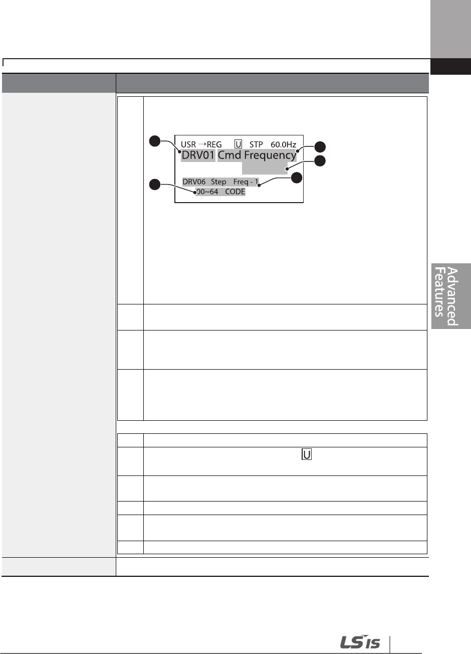
261
Learning Advanced Features
Code
Description
need to register and press the [MULTI] key. For example, if the
[MULTI] key is pressed in the frequency reference in DRV-01 (Cmd
Frequency), the screen below will be displayed.
Group name and code number of the parameter
Name of the parameter
Code number to be used in the user group. Pressing the
[PROG/ENT] key on the code number (40 Code) will register DRV-
01 as code 40 in the user group.
Existing parameter registered as the user group code 40
Setting range of the user group code. Entering ‘0’ cancels the
settings.
3
Set a code number
to use to register the parameter in the user
group. Select the code number and press the [PROG/ENT] key.
4
Changing the value in
will also change the value in
.
If no
code is registered, ‘Empty Code’ will be displayed. Entering ‘0’
cancels the settings.
5
The registered parameters are listed in the user group in U&M
mode. You can register one parameter multiple times if necessary.
For example, a parameter can be registered as code 2, code 11, and
more in the user group.
Follow the procedures below to delete parameters in the user group.
No.
Settings
1
Set CNF- 42 to ‘3 (UserGrp SelKey)’. A icon will be displayed at
the top of the LCD display.
2
In the USR group in U&M mode, move the cursor to the code that
is to be deleted.
3
Press the [MULTI] key
.
4
Move to ‘YES’ on the deletion confirmation screen, and press the
[PROG/ENT] key.
5
Deletion completed.
CNF
-
25 UserGrp AllDel
Set to ‘1
(Yes)’ to delete all registered parameters in the user group.
5.40 Easy Start On
40 CODE
1
54
3
2

262
Learning Advanced Features
Run Easy Start On to easily setup the basic motor parameters required to operate a motor in a
batch. Set CNF-61 (Easy Start On) to ‘1 (Yes)’ to activate the feature, initialize all parameters by
setting CNF-40 (Parameter Init) to ‘1 (All Grp)’, and restart the inverter to activate Easy Start On.
Group
Code
Name
LCD Display
Parameter Setting
Setting Range
Unit
CNF 61
Parameter easy start
settings Easy Start On
1 Yes - -
Code Description
CNF-61
Easy Start
On
Follow the procedures listed below to set the easy start on parameters.
No
Procedures
1
Set CNF
-
61 (Easy Start On)
to
‘1(Yes)’.
2
Select
‘
1 (All Grp)’ in CNF-40
(Parameter Init) to initialize all parameters
3
Restarting the inverter will activate Easy Start On. Set the values in the following
screens on the Keypad. To escape from Easy Start On, press the [ESC] key.
• Start Easy Set: Select ‘Yes’.
• CNF-43: Select a macro.
• BAS-10 60/50 Hz Sel: Set motor rated frequency.
• DRV-14 Motor Capacity: Set motor capacity.
• BAS-13 Rated Curr: Set motor rated current.
• BAS-15 Rated Volt: Set motor rated voltage.
• BAS-11 Pole Number: Set motor pole number.
• BAS-19 AC Input Volt: Set input voltage.
• PRT-08 Select start at trip reset
• PRT-09 Retry Number: Sets the number of restart trial when
performing a trip reset.
• COM-96 PowerOn Resume: Sets the serial communication restart
function.
• CON-71 SpeedSearch: Set SpeedSearch.
• DRV-06 Cmd Source: Set command source.
• DRV-07 Freq Ref Src: Set Frequency Reference source.
• AP3-01 Now Date : Set the current date.
• AP3-02 Now Time : Set the current time.
When the settings are complete, the minimum parameter settings on the motor
have been made. The Keypad will return to a monitoring display. Now the motor
263
Learning Advanced Features
Easy Start On Setting Details
Use caution when turning on the inverter after Easy Start On configuration. If codes such as PRT-08 (Reset
Restart), COM-96 (PowerOn Resume), or CON-71 (SpeedSearch) are configured in Easy Start On, the inverter
may start operating as soon as it is powered on.
5.41 Config (CNF) Mode
The config mode parameters are used to configure keypad related features.
can be operated with the command source set at DRV
-
06.
Group
Code
Name
LCD Display
Parameter Setting
Setting Range
Unit
CNF*
2
LCD
brightness/contrast
adjustment
LCD Contrast
- -
10
Inverter
S/W version
Inv S/W Ver
x.xx
-
11 Keypad S/W version
Keypad S/W
Ver x.xx - -
12
Keypad title version
KPD Title Ver
x.xx
-
-
30–32 Power slot type
Option
-
x
Type None - -
44
Erase trip history
Erase All Trip
No
-
-
60
Add title update
Add Title Up
No
-
-
62
Initialize
accumulated electric
energy
WH Count
Reset No - -

264
Learning Advanced Features
Config Mode Parameter Setting Details
Code
Description
CNF-2 LCD Contrast Adjusts LCD brightness/contrast on the keypad.
CNF
-
10 Inv S/W Ver,
CNF-11 Keypad S/W Ver Checks the OS version in the inverter and on the keypad.
CNF-12 KPD Title Ver Checks the title version on the keypad.
CNF-30–32 Option-x Type
Checks the type of option board installed in the option slot.
The H100 inverters use type-1 option boards only (CNF-30 Option-1
Type). CNF-31 and CNF-32 are not used.
CNF
-
44 Erase All Trip
Deletes the
stored trip history.
CNF-60 Add Title Up
When inverter SW version is updated and more code is added, CNF
-
60 settings will add, display, and operate the added codes. Set CNF-
60 to ‘1 (Yes)’ and disconnect the keypad from the inverter.
Reconnecting the keypad to the inverter updates titles.
CNF
-
62 WH Count Reset
Initialize the accumulated electric energy consumption count.
5.42 Macro Selection
Group
Code
Name
LCD Display
Parameter Setting
Setting Range
Unit
CNF 43 Macro selection Macro Select
0
Basic
0–7 -
1
Compressor
2
Supply Fan
3
Exhaust Fan
4
Cooling Tower
5
Circul. Pump
6
Vacuum Pump

265
Learning Advanced Features
The Macro selection function is used to put various application functions together in a group. For
applications with the H100 series inverters, 7 basic Macro configurations are currently available.
Macro functions cannot be added by the user, but the data can be modified.
Macro Selection Details
Code
Description
CNF-43 Macro
Select
A list of Macro settings is displayed for user selection. When a Macro function is
selected, all the related parameters are automatically changed based on the
inverter’s Macro settings.
If ‘0 (Basic)’ is selected, all the inverter parameters, including the parameters
controlled by the Macro function, are initialized.
For other macro application settings (settings 1–7), refer to 5.42 Macro Selection
on page 264.
5.43 Timer Settings
Set a multi-function input terminal to a timer. Sets the On/Off controls to the multi-function
outputs and relays according to the timer settings.
Group
Code
Name
LCD Display
Parameter Setting
Setting Range
Unit
IN 65–71
Px terminal
configuration
Px
Define
(Px: P1–P7) 35
Timer In 0-55 -
OUT
31
Multi
-
function
relay 1 Relay 1
22
Timer Out 0-41 -
33
Multi
-
function
output 1 Q1 Define
55
Timer on delay
TimerOn Delay
3.00
0.00
–
100.00
sec
56
Timer off delay
TimerOff Delay
1.00
0.00
–
100.00
sec
Timer Setting Details
Code
Description
IN-65–71 Px Define
Choose one of the multi
-
function input terminals and change it to a timer
terminal by setting it to ‘35(Timer In)’.
7
Constant Torq
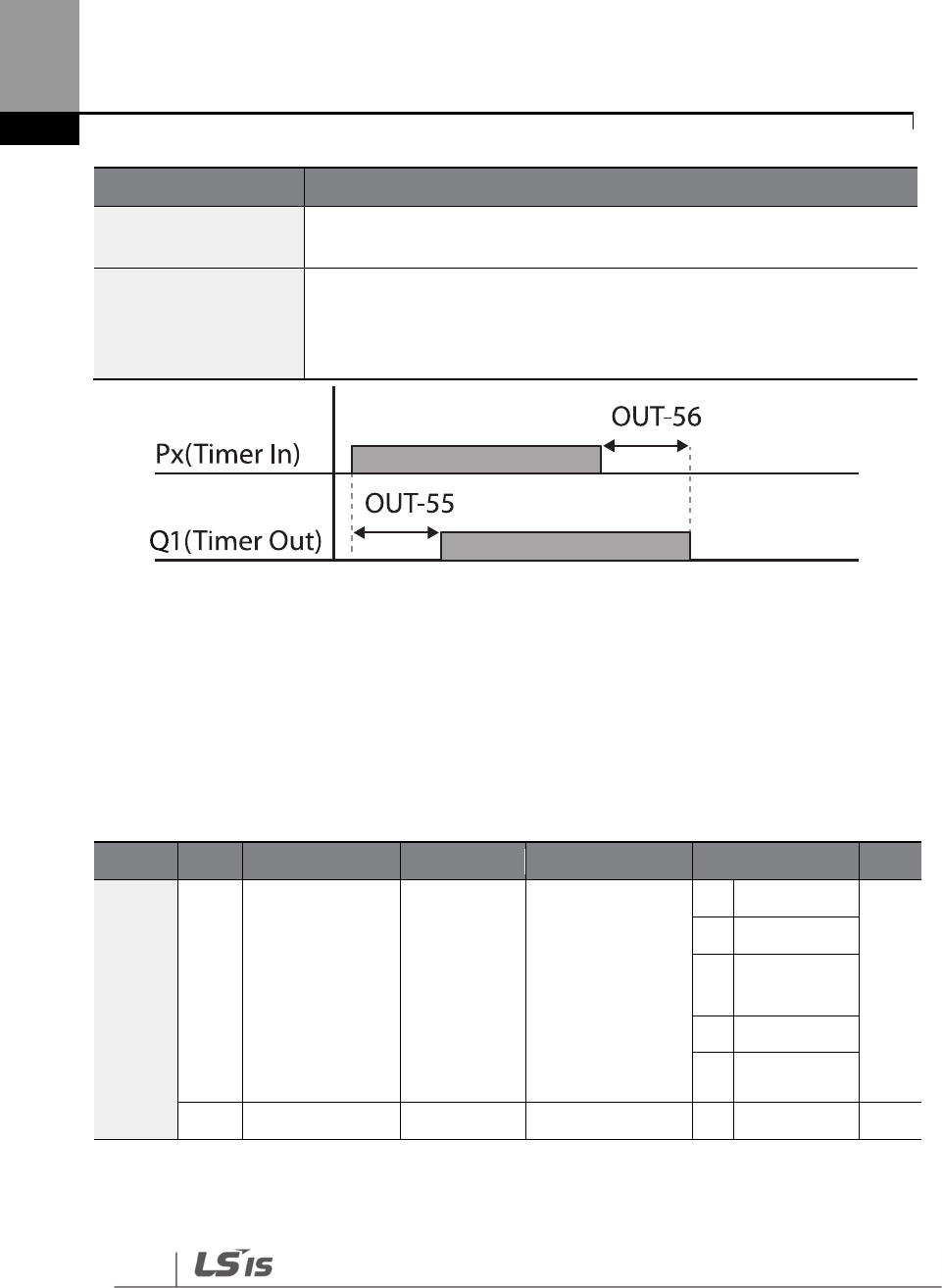
266
Learning Advanced Features
Code
Description
OUT
-
31 Relay 1,
OUT-36 Q1 Define
Set the multi
-
function output terminal or
relay to be used as a timer to ’22
(Timer out)’.
OUT
-
55
TimerOn Delay,
OUT-56
TimerOff Delay
Input a signal (On) to the timer terminal to operate a timer output (Timer
out) after the time set at OUT-55 has passed. When the multi-function
input terminal is off, the multi-function output or relay turns off after the
time set at OUT-56.
5.44 Multiple Motor Control (MMC)
The MMC (Multiple Motor Control) function is used to control multiple motors for a pump system.
The main motor connected with the inverter output is controlled by the PID controller. The
auxiliary motors are connected with the supply power and turned on and off by the relay within
the inverter.
Group
Code
Name
LCD Display
Parameter Setting
Setting Ra
nge
Unit
AP1 40 MMC function
selection MMC Sel 0: None
0
None
-
1
Single Ctrl
2
Multi
Follower
3
Multi Master
41
Serve Drv
41
Bypass selection
Regul Bypass
0: No
0
No
-
1
AP1-47~87 and AP1-91~98 are not displayed when AP1-40 is set to ’4(Serve Drv)’.

267
Learning Advanced Features
Group
Code
Name
LCD Display
Parameter Setting
Setting Ra
nge
Unit
1
Yes
42 Number of
auxiliary motors
Num of Aux
5
1
–
AuxMaxMotor2 -
433
Auxiliary starting
motor selection
Starting Aux
1 1–5 -
44
Number of
operating
auxiliary motors
Aux Motor
Run - - -
45 Auxiliary motor
(#1– 4) priority Aux Priority 1
- - -
46
Auxiliary motor
(#5– 8) priority Aux Priority 2
- - -
48 Auxiliary motor
operation at stop
Aux All Stop
0: No 0 No -
1
Yes
49 Stop order for
auxiliary motors
FIFO/FILO
0: FILO
0
FILO
-
1
FIFO
2
Op Time
Order
50
Auxiliary motor
pressure
difference
Actual Start
Diff 2 0–100 Unit
51
Main motor
acceleration time
when auxiliary
motor # is
reduced
Aux Acc Time
2 0–600.0 Sec
52 Main motor Aux Dec 2 0–600.0 Sec
2
If Extension IO option is equipped or AP1-40 is set to ‘2 or 3’, AuxMaxMotor is set to ‘8’. Otherwise
AuxMaxMotor is set to ‘5’.
3
If AP1-49 is set to ‘2(Op Time Order)’, the parameter cannot be set by a user and it is
automatically changed as the operation time of aux motors.

268
Learning Advanced Features
Group
Code
Name
LCD Display
Parameter Setting
Setting Ra
nge
Unit
deceleration
time when
auxiliary motor is
added
Time
53
Auxiliary motor
start delay time
Aux Start DT
5 0.0–999.9 Sec
54
Auxiliary motor
stop delay time
Aux Stop DT
5 0.0–999.9 Sec
55 Auto change
mode selection
Auto Ch
Mode 0: None
0
None
-
1
AUX
Exchange
2
MAIN
Exchange
56
Auto change
time
Auto Ch
Time 72: 00 00: 00–99: 00 Min
57
Auto change
frequency
Auto Ch
Level 20.00
Low Freq
–
High
Freq Hz
58
Auto change
operation time
Auto Op
Time - - -
59
A
uxiliary mot
or
pressure
difference
Aux Stop Diff
2 0~100 Unit
60
Target frequency
of Aux Motor
while Multi
Master is
operating
Follower
Freq 60.00 Low Freq~ High
Freq
Hz
61
#1 auxiliary
motor start
frequency
Start Freq 1
45 Low Freq–High
Freq Hz
62
#2 auxiliary
motor start
frequency
Start Freq 2
45 Low Freq–High
Freq Hz
63
#3 auxiliary
motor start Start Freq 3
45
Low Freq
–
High
Freq Hz

269
Learning Advanced Features
Group
Code
Name
LCD Display
Parameter Setting
Setting Ra
nge
Unit
frequency
64
#4 auxiliary
motor start
frequency
Start Freq 4
45 Low Freq–High
Freq Hz
65
#5 auxiliary
motor start
frequency
Start Freq 5
45 Low Freq–High
Freq Hz
664
#
6
auxiliary
motor start
frequency
Start Freq 6 45 Low Freq–High
Freq Hz
67
#
7
auxiliary
motor start
frequency
Start Freq 7 45 Low Freq–High
Freq Hz
68
#
8
auxiliary
motor start
frequency
Start Freq 8 45 Low Freq–High
Freq Hz
70
#1 auxiliary
motor stop
frequency
Stop Freq 1
20 Low Freq–High
Freq Hz
71
#2 auxiliary
motor stop
frequency
Stop Freq 2
20 Low Freq–High
Freq Hz
72
#3 auxiliary
motor stop
frequency
Stop Freq 3
20 Low Freq–High
Freq Hz
73
#4 auxiliary
motor stop
frequency
Stop Freq 4
20 Low Freq–High
Freq Hz
74
#5 auxiliary
motor stop
frequency
Stop Freq 5
20 Low Freq–High
Freq Hz
4
AP1-66~68 , AP1-75~77 and AP1-85~87 are displayed when Extension IO option is equipped or
AP1-40 is set to ‘2 or 3’.

270
Learning Advanced Features
Group
Code
Name
LCD Display
Parameter Setting
Setting Ra
nge
Unit
75
#
6
auxiliary
motor stop
frequency
Stop Freq 6
20 Low Freq–High
Freq Hz
76
#
7
auxiliary
motor stop
frequency
Stop Freq 7
20 Low Freq–High
Freq Hz
77
#
8
auxiliary
motor stop
frequency
Stop Freq 8
20 Low Freq–High
Freq Hz
80
#1 auxiliary
motor reference
compensation
Aux1 Ref
Comp 0 0–Unit Band Unit
81
#2 auxiliary
motor reference
compensation
Aux2 Ref
Comp 0 0–Unit Band Unit
82
#3 auxiliary
motor reference
compensation
Aux3 Ref
Comp 0 0–Unit Band Unit
83
#4 auxiliary
motor reference
compensation
Aux4 Ref
Comp 0 0–Unit Band Unit
84
#5 auxiliary
motor reference
compensation
Aux5 Ref
Comp 0 0–Unit Band Unit
85
#
6
auxiliary
motor reference
compensation
Aux6 Ref
Comp 0 0–Unit Band Unit
86
#
7
auxiliary
motor reference
compensation
Aux7 Ref
Comp 0 0–Unit Band Unit
87
#
8
auxiliary
motor reference
compensation
Aux8 Ref
Comp 0 0–Unit Band Unit
90 Interlock
selection Interlock 0: No
0
No
-
1
Yes

271
Learning Advanced Features
Group
Code
Name
LCD Display
Parameter Setting
Setting Ra
nge
Unit
91
Delay time
before an
operation for the
next motor when
an interlock or an
auto change on
the main motor
occur.
Interlock DT
5.0 0–360.0 Sec
955
Selecting
auxiliary motor
to indicate in
[AP1-96] [AP1-
97].
AuxRunTime
Sel
0 Aux 1
1
Aux 2
2
Aux 3
3
Aux 4
4
Aux 5
56
Aux 6
6
Aux 7
7
Aux 8
96
Operating
time(Day) of
auxiliary motor
chosen in [AP1-
95].
AuxRunTime
Day 0 0~65535
97
Operating time
of auxiliary
motor chosen in
[AP1-95].
AuxRunTime
Min 00:00 00:00 ~ 23:59
98
Deleting
operating time of
auxiliary motor.
AuxRunTime
Clr
0 None
1 All
5
AP1-95~98 are available when MMC and Master Follower functions are performed.
6
‘5(Aux6)~7(Aux8)’ of AP1-95 and ‘7(Aux6)~9(Aux8)’ of AP1-98 and displayed when Extension IO
option is equipped or AP1-40 is set to ‘2 or 3’.
272
Learning Advanced Features
Group
Code
Name
LCD Display
Parameter Setting
Setting Ra
nge
Unit
2 Aux 1
3 Aux 2
4 Aux 3
5 Aux 4
6
Aux 5
7
Aux 6
8
Aux 7
9
Aux 8

273
Learning Advanced Features
MMC Setting Details
Code
Description
AP1-40 MMC Sel
Selects the MMC operation settings.
-None : Deactivates MMC function
-Single Ctrl : Activates general MMC function
-Multi Follower : Activates Master Follower as Multi Follower mode
-Multi Master: Activates Master Follower as Multi Master mode
-Serve Drv: Sets Serve Drv used at Master Follower.
AP1
-
42 Num of Aux
Decides the number of auxiliary motors to use.
AP1
-
43 Starting Aux
Sets
the start auxiliary motor.
AP1
-
44 Aux Motor Run
Indicates the number of the operating auxiliary motors.
AP1-45–46 Aux Priority1–2
Indicates the operating priority of auxiliary motors.
According to setting by users, it can be influenced by Interlock,
AutoChange and operating time
Each four-digit numbers for the parameter mean the auxiliary motor
numbers and indicate the priority of auxiliary motors. In other words,
the most right number of [AP1-45 Aux Priority1] indicates the priority
of Auxiliary motor 1 and the second number from the right of [AP1-
45 Aux Priority1] indicates the priority of Auxiliary motor 2.
[AP1-45 Aux Priority1]
xxxx
The Priority of
the Aux motor1
The Priority of
the Aux motor4
[AP1-46 Aux Priority2]
x x x x
The Priority of
the Aux motor5
The Priority of
the Aux motor8
AP1-48 Aux All Stop
When [AP1
-
48 Aux All Stop] is set to “No” during input to
stop
operating, auxiliary motors are turned off at the same time. When
[AP1-48 Aux All Stop] is set to “YES”, auxiliary motors are turned off
gradually based on time of [AP1-54 Aux Stop DT].
AP1-49 FIFO/FILO
Sets the operating priority o
f MMC.
FIFO : Same as On/Off order of auxiliary motors.
FILO: Opposite to On/Off order auxiliary motors.
Op Time Order : setting automatically according to operating time of
auxiliary motors.
AP1-50 Aux Start Diff
AP1-59 Aux Stop Diff
One of the
conditions to turn on and off the next auxiliary motors.
Parameters to set the difference when the difference between the
reference and feedback is more than regular value

274
Learning Advanced Features
5.44.1 Multiple Motor Control (MMC) Basic Sequence
Multiple motor control (MMC) is an operation based on PID control. During an MMC operation,
the main and auxiliary motors organically operate together.
During a PID operation, the auxiliary motors are turned on when the inverter frequency reaches
the start frequencies set at AP1-61–65 (Start freq), and the difference between the PID reference
and feedback is bigger than the value set at AP1-50. Then, the auxiliary motors stop operating
when the operation frequency reach the stop frequency set at AP1-70–74 (Stop Freq 1–5) and the
difference between the PID feedback and reference becomes greater than the value set at AP1-50.
AP1-51 Acc Time
AP1-52 Dec Time
Parameters used when AP1
-
40 is set to
‘
Single Ctrl
’
When an auxiliary motor starts or stops, the main motor stops the
PID control, and performs general acceleration and deceleration.
When an auxiliary motor starts, the main motor decelerates to the
auxiliary motor deceleration frequency set at AP1-70–74 (Stop Freq
1–5) based on the deceleration time set at AP1-52 (Dec Time).
When the auxiliary motor stops, the main motor accelerates up to
the auxiliary motor restart frequency set at AP1-61–65 (Start Freq 1–
5) based on the acceleration time set at AP1-51 (Acc Time).
AP1-53 Aux Start DT
AP1-54 Aux Stop DT
The auxiliary motors turns on or off after the auxiliary motor stop
delay time or the auxiliary motor restart delay time elapses, or if the
difference between the current reference and the feedback is greater
than the value set at AP1-50 (Actual Pr Diff).
AP1
-
6
1
–
6
5
Start Freq1
–
5
Sets the auxiliary motor start frequency.
AP1
-
70
–
74 Stop Freq 1
–
5
Sets the auxiliary motor stop frequency.
AP1
-
95
AuxRunTime
Sel
Selects
auxiliary
motor
to be used in AP1
-
96 and AP1
-
97
.
AP1
-
96
AuxRunTime Day
Indicates
operating time(day) selected in AP1
-
95.
AP1
-
97
AuxRunTime Min
Indicates operating time of
auxiliary
motors selected in AP1
-
95
.
AP1
-
98
AuxRunTime Clr
Deletes operating time of auxiliary motors
.
OUT-31–35 Relay 1–5
OUT-36 Q1 Define
Configure the output
terminals to ’21 (MMC)’ to use the terminals to
control the auxiliary motors. The number of the configured output
terminals determines the total number of auxiliary motors to be
used.

275
Learning Advanced Features
Group
Code
Name
LCD Display
Param
eter Setting
Setting Range
Unit
AP1
61–65
#
1
–
5 auxiliary
motor start
frequency
Start Freq 1–5
Frequency value
within the range
Low Freq–
High Freq Hz
50
Auxiliary motors
pressure
difference
Actual Pr Diff Percentage value
within the range 0–100 (%) %
70–74
#1
–
5 auxiliary
motor stop
frequency
Stop Freq 1–5
Frequency value
within the range
Low Freq–
High Freq Hz
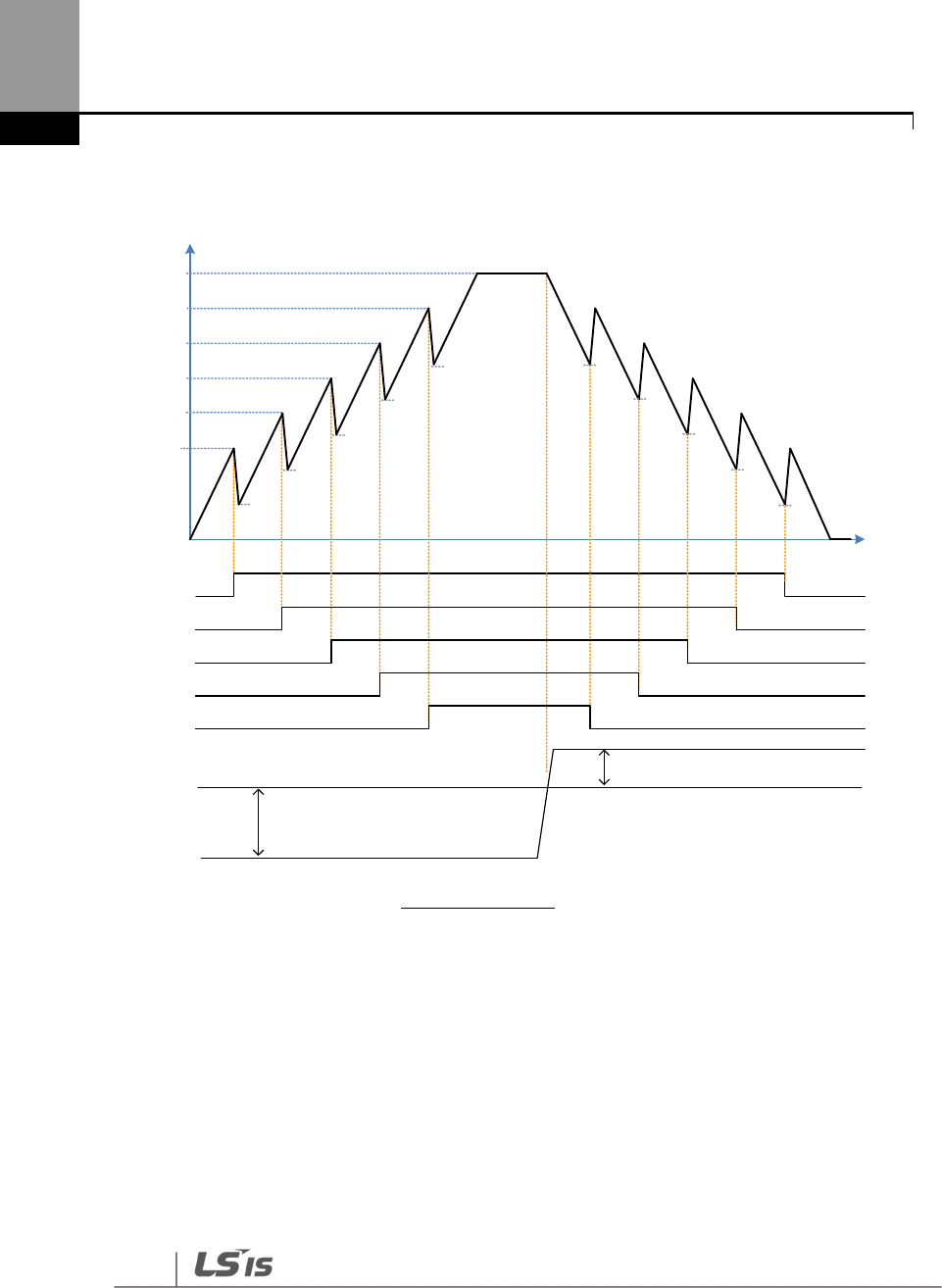
276
Learning Advanced Features
The following diagram describes the MMC basic sequence based on FILO and FIFO settings.
AP1-61
AP1-62
AP1-63
AP1-64
AP1-65
Max Freq
Frequency
Output
frequency
Aux Motor 1 Off
On
PID Feedback
AP1-71
AP1-70
AP1-72
AP1-73
AP1-74 AP1-74
AP1-71
AP1-72
AP1-73
AP1-70
Aux Motor 2
Aux Motor 3
Aux Motor 4
Aux Motor 5
PID Reference
AP1-50
AP1-59
Time
MMC Basic operation(FILO)
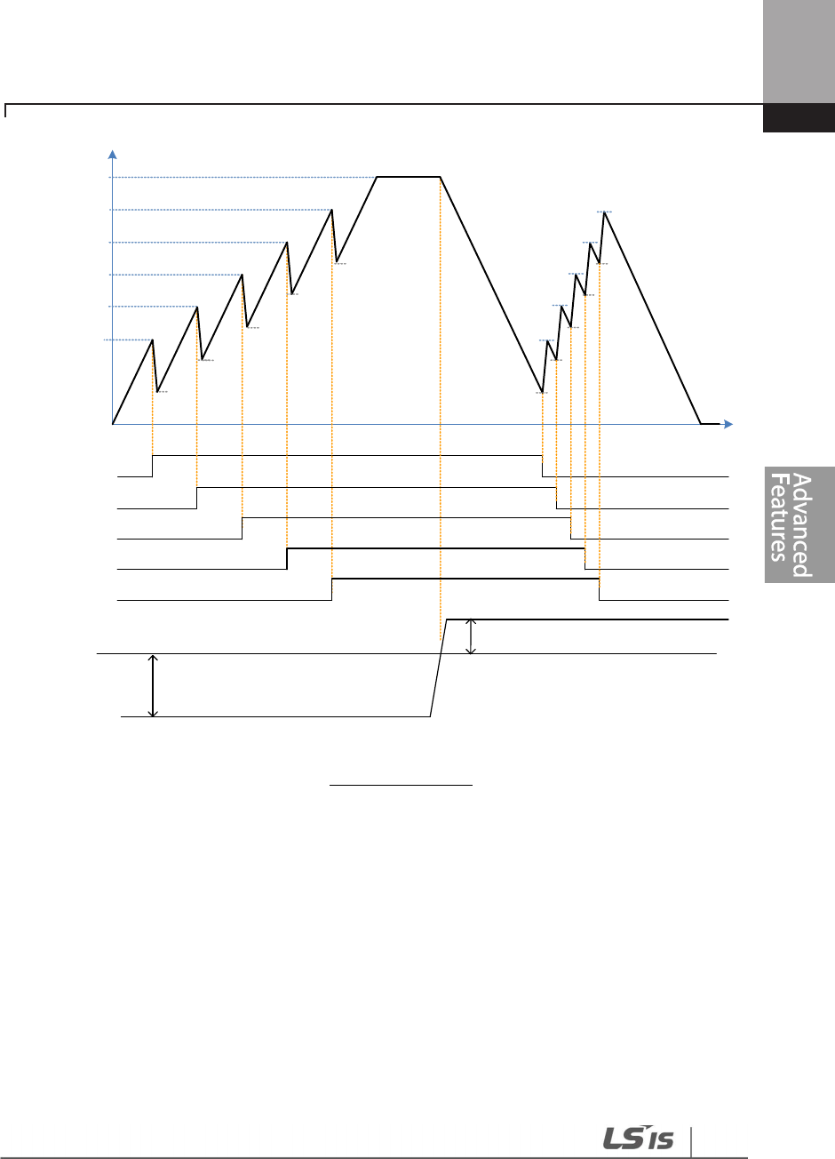
277
Learning Advanced Features
Frequency
Output
frequency
Off
On
PID Feedback
Aux Motor 1
Aux Motor 2
Aux Motor 3
Aux Motor 4
Aux Motor 5
PID Reference
AP1-50
AP1-59
AP1-61
AP1-62
AP1-63
AP1-64
AP1-65
AP1-71
AP1-72
AP1-73
AP1-74
AP1-70 AP1-70
AP1-71
AP1-72
AP1-73
AP1-74
AP1-65
AP1-64
AP1-63
AP1-62
AP1-61
MMC Basic operation(FIFO)
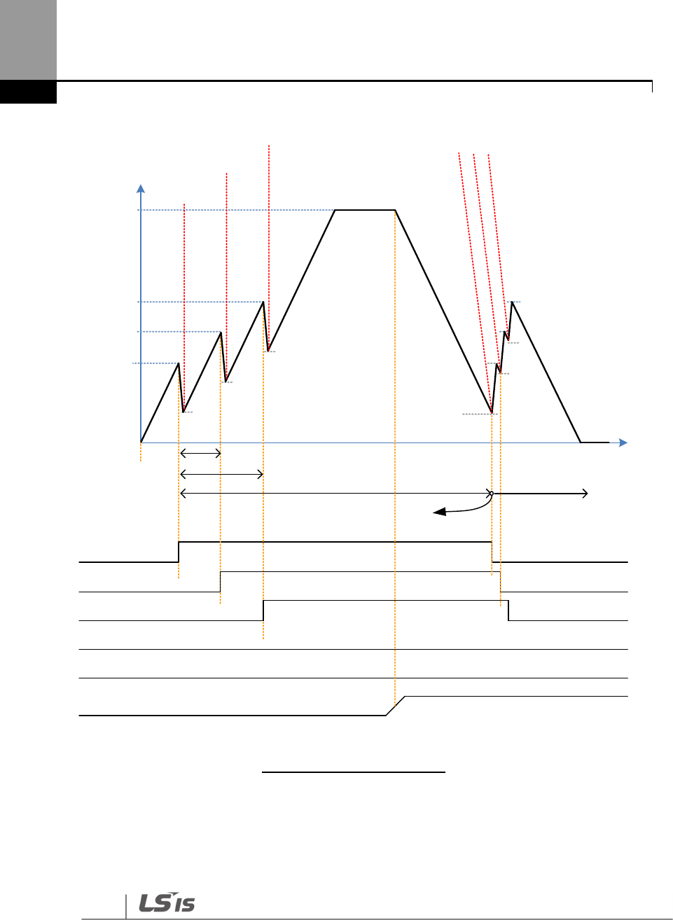
278
Learning Advanced Features
AP1-61
AP1-62
AP1-63
AP1-64
AP1-65
Max Freq
Frequency
AP1-70
AP1-71
AP1-72
Aux Motor 1
Aux Motor 2
Aux Motor 3
Aux Motor 4
Aux Motor 5
Feedback
AP1-71
AP1-71
AP1-72
AP1-62
AP1-63
0%
100%
Priority at the moment
M2 M1 M3 /
M4 M5
Priority at the moment
M1 M2 M3 /
M4 M5
Priority at the moment
M3 M2 M1 /
M4 M5
Priority at the moment
M3 M2 M1 /
M4 M5
5min
10min
AP1-61
30min Operation time
M1(30min) / M2(25min) /
M3(20min)
Supposing its operating in
less than 1 minute
Output
frequency
MMC Basic operation(OP Time Order)
The following diagram is an operation graph based on the start and stop delay times set at AP1-53 (Aux
start DT) and AP1-54 (Aux stop DT). When the start or stop frequencies are reached, the auxiliary motor
waits for the time set at AP1-53 (Aux start DT) or AP1-54 (Aux stop DT) before it
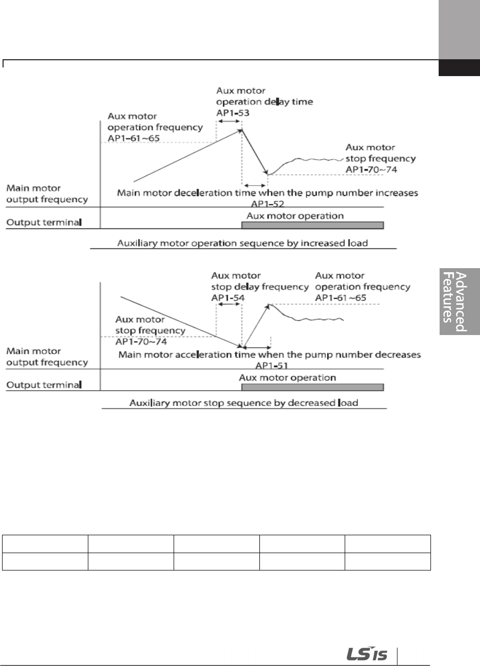
279
Learning Advanced Features
starts or stops.
5.44.2 Standby Motor
In case that the number set to MMC in [Relay 1~5] of OUT group is lower than the number of [Num of
Aux], auxiliary motor becomes Standby motor state as much as the difference.
.
Ex) In case that Replay1, 2, 3 and 4, and 5 are set to MMC and the number of [Num of Aux] is 3.
Relay1 Relay2 Relay3 Relay4 Relay5
Operable Operable Operable Standby Standby
In this case, though only Relay1, 2, 3 operate MMC function and the output of Relay is set to MMC, it
doesn’t work as long as the order is not changed by Interlock and Auto Change.
Standby auxiliary motor becomes operable when there is Interlock or Auto change in Operable
auxiliary motor.
280
Learning Advanced Features
5.44.3 Auto Change
The auto change function enables the inverter to automatically switch operations between main
and auxiliary motors. Prolonged continuous operation of a motor deteriorates motor capabilities.
The auto change function switches the motors automatically when certain conditions are met to
avoid biased use of certain motors and protect them from deterioration.
Group
Code
Name
LCD Display
Parameter Setting
Setting Range
Unit
AP1
55 Auto change mode
selection Auto Ch Mode
0
None
0
None
-
1
Aux motor 1
AUX
Exchange
2
Main motor 2
Main
Exchange
56 Auto change time Auto Ch Mode
Time value within
the range 00: 00–99: 00 Sec.
57
Auto change
frequency Auto Ch Level
Frequency value
within the range
Low Freq
–
High Freq Hz
58
Auto change
operation time Auto Op Time
Time value within
the range - Sec.
Auto Change Setting Details
Code
Description
AP1-55 Auto Ch Mode
Select the motors to apply the auto change function.
Setting
Description
0
None
1
Aux
Exchange
2
Main
Exchange
Refer to Examples of Auto Change Sequences below for details.
AP1
-
56 Auto Ch Time
Sets the auto change intervals.
AP1-57 Auto Ch Level
The parameter is for Main Exchange. In case that
[AP1
-
55 Auto Ch Mode]
is set to Main Exchange, all the conditions for Auto Change are met
under the frequency in which output frequency of Main motors are set
in AP1-57. AP1-57 is the frequency to activate Auto Change.
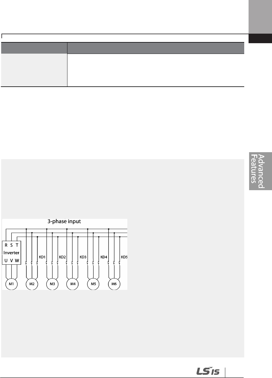
281
Learning Advanced Features
Code
Description
AP1-58 Auto Op Time
Indicates time t
o activate Auto Change. In case that other conditions for
Auto Change are not met in spite of meeting the condition of AP1-56,
the value of time in AP1-58 might be bigger than the value set at Auto
Ch Time of AP1-56 because of the failure of Auto Change.
When
AP1-55 (Auto Ch Mode) is set to ‘
0 (None),’ the auxiliary motors operates based on the order
(sequence) set at AP1-43 (Starting Aux). Auto Change functionality is disabled.
When
AP1-55 (Auto Ch Mode) is set to ‘1
(Aux Exchange)’, the auxiliary motors operate based on the
order (sequence) set at AP1-43 (Starting Aux). Auto Change is activated when auxiliary motors
are in the operating state over time of AP1-56 and then every auxiliary motor is stopped.
Once the auto change is operated, the auxiliary motor that started first is given the lowest priority
and all the other auxiliary motors’ priority level increases by 1. Then, general MMC operation
continues.
NOTE
Auto change does not work while the
auxiliary motors are operating. Auto change is operated only
when all the auxiliary motors are stopped and if all the conditions set for the auto change are met.
When the inverter stops, all motors stop operating, and the auxiliary motor with the highest priority
becomes the starting auxiliary motor. If the inverter power is turned off then turned back on, the
auxiliary motor set at AP1-43 (Starting Aux) becomes the starting auxiliary motor.
Start order and stop order of the auxiliary motors are based on the order set at AP1-49 (FIFO/FILO).
The following diagrams depict the auxiliary motor start and stop sequence, based on a FIFO
configuration, when the inverter operation time exceeds the auto change interval set at AP1-58. If all
the auxiliary motors are turned off and the inverter operation frequency is below the frequency set at
AP1-58 (Auto Op Time), auto change is operated. Then, when the inverter frequency increases due to
decrease in the feedback, auxiliary motor #2 starts instead of auxiliary motor #1 due to this auto
change (auxiliary motor #1 starts last, for it has the lowest priority).
Later on during the operation, when the feedback increases and the auxiliary motors begin to stop,
the FILO setting is applied to control the order for the auxiliary motors to stop.
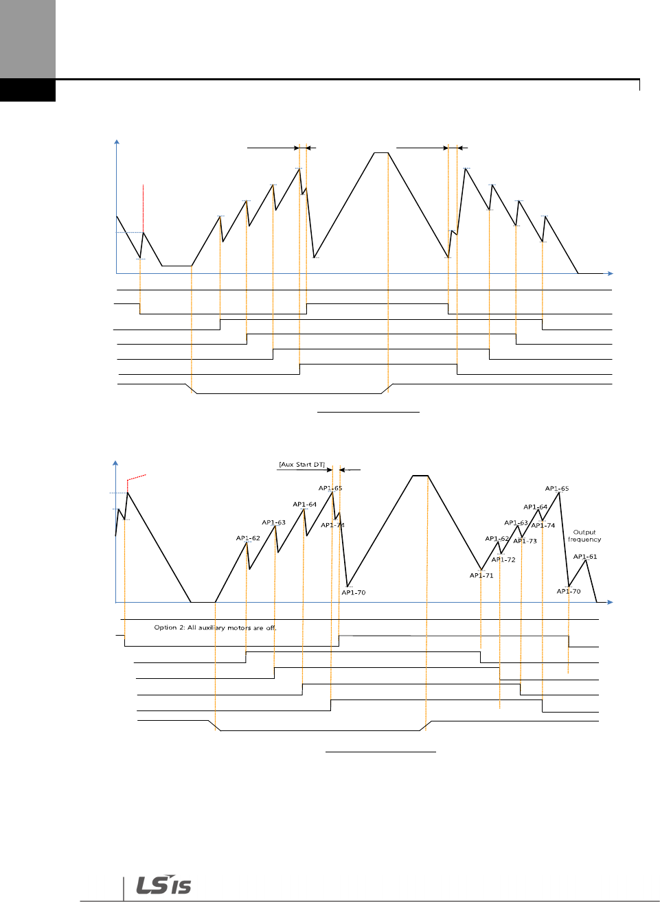
282
Learning Advanced Features
Max Freq
Output
frequency
Feedback
Perform Aux_Exch
Reset the [Auto Op Time]
[Aux Start DT] [Aux Stop DT]
0%
Fx Off
On
Aux Motor 1
Aux Motor 2
Aux Motor 3
Aux Motor 4
Aux Motor 5
AP1-61
AP1-62
AP1-63
AP1-64
AP1-65
AP1-62
AP1-63
AP1-64
AP1-65
AP1-62
AP1-63
AP1-64
AP1-65
AP1-72
AP1-73
AP1-74
Option 2: All auxiliary motors are off.
Aux Auto Change operation(FILO)
AP1-57
100%
AP1-70 AP1-70
AP1-61
Option 1: [AP1-58 Auto Op Time] >= [AP1-56: Auto Ch Time]
AP1-70
Aux Auto Change operation(FIFO)
option 1: [AP1-58 Auto Op Time] >= [AP1-56: Auto Ch Time]
Max Freq
Output
frequency
Feedback
0%
Fx Off
On
Aux Motor 1
Aux Motor 2
Aux Motor 3
Aux Motor 4
Aux Motor 5
AP1-61
AP1-62
AP1-63
AP1-64
AP1-65
AP1-57
100%
AP1-74
Perform Aux_Exch
Reset the [Auto Op Time]
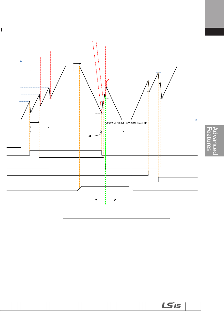
283
Learning Advanced Features
AP1-61
AP1-62
AP1-63
AP1-64
AP1-65
Max Freq
Inverter
Out Freq
AP1-70
AP1-71
AP1-72
Aux Motor 1
Aux Motor 2
Aux Motor 3
Aux Motor 4
Aux Motor 5
Feedback
AP1-70
AP1-71
AP1-72
Perform Aux_Exch
Reset the [Auto Op Time]
AP1-62
AP1-63
AP1-64
0%
100%
Fx Off
On
Pr iority of the moment
M2 M1 M3 /
M4 M5
Priority of the moment
M1 M2 M3 /
M4 M5
Priority of the moment
M3 M2 M1 /
M4 M5
Priority of the moment
M3 M2 M1 /
M4 M5
5min
10min
AP1-61
Priority of the moment
M4 M5 M3 /
M2 M1
30min Operation time
M1(30min) / M2(25min) /
M3(20min)
AP1-73
Priority of the moment
M4 M5 M3 /
M2 M1
Motor to operate MMC : M1, M2, M3
Standby motor : M4, M5
Motor to operate MMC : M3, M4, M5
Standby motor : M1, M2
Supposing its operation in
less than 1 minute
AP1-74
AP1-72
AP1-65
Aux Auto Change operation (Op Time Order) when operable motor and standby motor are set to 3 and 2 each
Option 1: [AP1-58 Auto Op Time] >= [AP1-56: Auto Ch Time]
When
AP1-55 (Auto Ch Mode) is set to ‘2
(Main Exchange),’ the system uses all the motors (main and
auxiliary motors) regardless of the types. The auxiliary motor with the highest priority is operated
first and used as the main motor. Then, when the auto change conditions are met, this motor is
stopped and the motor priorities are re-arranged. This way, the system always operates the motor
with the highest priority and uses it as the main motor of the MMC operation. In this case, before
auto change is operated for the main motor, the interlock delay time set at AP1-91 (Interlock DT) is
applied.
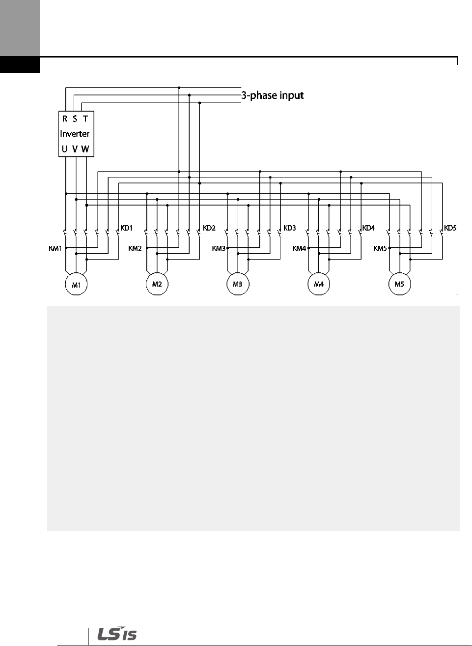
284
Learning Advanced Features
NOTE
Auto change does not work while the
auxiliary motors are operating. Auto change is operated only
when all the auxiliary motors are stopped and if all the conditions set for the auto change are met. When
the inverter stops, all motors stop operating, and the auxiliary motor with the highest p
riority becomes
the starting auxiliary motor. If the inverter power is turned off then turned back on, the auxiliary motor
set at AP1-43 (Starting Aux) becomes the starting auxiliary motor.
The following diagrams depict the auto change operation when AP1-55 (Auto Ch Mode) is set to ‘2
(Main),’ when the inverter operation time exceeds the auto change interval set at AP1-
58. If the inverter
operation frequency is below the frequency set at AP1-
57, all the auxiliary motors including the start
auxiliary motor are turned off. After the delay time set at AP1-
91 (Interlock DT) elapses, the ‘Main’ auto
change is operated. After the ‘Main’ auto change, the auxiliary motor that was turned on after the
starting auxiliary motor becomes the main motor.
In the following
diagrams, because auxiliary motor #1 is the starting auxiliary motor. Auxiliary motor #2
becomes the main motor after the auto change. The auxiliary motor on/off operation is identical to that
of Aux Exchange, and the ‘off’ conditions differ based on the FIFO/FILO configuration.

285
Learning Advanced Features
Main
MainMain
Main_
__
_Exch occurs
Exch occursExch occurs
Exch occurs
AP1-70
Output
frequency
Main Motor
Option 3: AP1-91: [Interlock DT]
AP1-70
Off
Stop
On
Run
Main Auto Change operation(FILO)
Max Freq
Freqency
Fx
Inv State
Max Freq
Frequency
Main
MainMain
Main_
__
_Exch occurs
Exch occursExch occurs
Exch occurs
AP1-70
Output
frequency
Main Motor
Option 3: AP1-91: [Interlock DT]
AP1-70
Fx
Off
Stop
Inv State
On
Run
Main Auto Change operation(FIFO)

286
Learning Advanced Features
AP1-61
AP1-62
AP1-63
AP1-64
AP1-65
Max Freq
Frequency
AP1-71
AP1-72
Aux Motor 1
Aux Motor 2
Aux Motor 3
Aux Motor 4
Aux Motor 5
Feedback
AP1-71
AP1-72
Perform Main_Exch
Reset the [Auto Op Time]
AP1-62
AP1-63
0%
100%
Fx
Off
On
Stop
Run
Inv State
Main Motor
Main Motor
5min
10min
30min Operation time
M1(30min) / M2(25min) /
M3(20min)
Pr iority at the moment
M1 M2 M3 /
M4 M5
Pr iori ty at the moment
M1 M3 M2 /
M4 M5
Pr iority at the moment
M4 M5 M3 /
M2 M1
Supposing its operation in
less than 1minute
AP1-65
AP1-
74
Motor to operate MMC : M1, M2, M3
Standby motor : M4, M5
Motor to operate MMC : M3, M4, M5
Standby motor : M1, M2
AP1-72
Main Auto Change operation (Op Time Order) when Operable Motor and Standby Motor are set to 3 and 2 each
Option 3: AP1-91: [Interlock DT]
5.44.4 Interlock
When there is motor trouble, the interlock feature is used to stop the affected motor and replace it
with another that is not currently operating (off state). To activate the interlock feature, connect
the cables for abnormal motor signal to the inverter input terminal and configure the terminals as
interlock 1–5 inputs. Then, the inverter decides the motor’s availability based on the signal inputs.
The order in which the alternative motor is selected is decided based on the auto change mode
selection options set at AP1-55.
Group
Code
Name
LCD Display
Parameter Setting
Setting Range
Unit
AP1 90 Interlock selection Interlock 1 0 NO
-
1 YES
After configuring the IN-65–71 multi-purpose input terminals as Interlock input 1–5, if an interlock
signal is received from an auxiliary motor, the output contacts are turned off for the motor and the

287
Learning Advanced Features
motor is excluded from the MMC operation. This causes the priority level of the auxiliary motors
with lower priority level than the interlocked motor to be increased by 1.
The interlock is released when the input terminals (IN-65–71) are turned off, and the relevant
auxiliary motor is included in the MMC operation again, with lowest priority.
When the inverter stops, all motors stop operating, and the auxiliary motor with the highest
priority becomes the starting auxiliary motor.
When the multi-purpose input terminals (IN-65–71, P1–7 Define) are set for the interlock feature,
an interlock is ‘Off’ when the contacts are valid, and ‘On’ when they are invalid.
InterLock Setting Details
Code
Description
AP1
-
90 InterLock
Enables or disables the Interlock.
AP1
-
91 Interlock DT
Sets the delay time before the Interlock occurs.
Note
IN
-
65
–
71 PxDefine: Select the terminal from the input terminal function group (IN
-
65
–
71) and set
Interlock 1-5 respectively with the correct motor order. When auto change mode selection (AP1–55) is
set to ‘0 (None)’ or ‘1 (Aux)’, and if 5 motors are operated, including the main motor, the interlock
numbers 1,2,3,4,5 refer to the motors connected to Relay 1,2,3,4,5 (If interlock numbers 1,2,3,4,5 are
connected to Relay 1,2,3,4,5 at the inverter output terminal).
However, if auto change mode selection (AP1-55) is set to ‘2 (Main)’, and the main and auxiliary motors
are connected to the inverter output terminal Relay 1,2,3,4, Interlock 1,2,3,4 are the monitors
connected to Relay 1,2,3,4.
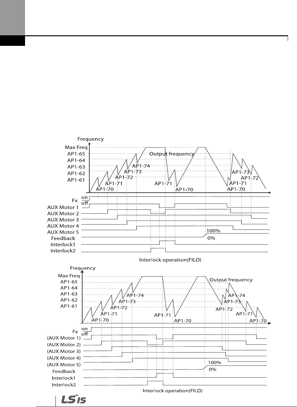
288
Learning Advanced Features
The figure below shows the motor operating as a sequence by FILO. The motor turns on from the
starting auxiliary motor (Starting Aux) by order, and turns off depending on the rise of PID
feedback. At this point, the interlock occurs at auxiliary motor #2 by multi-function input, the
auxiliary motor turns off. The output frequency falls to the frequency set at AP1-71, and rises again.
Then, the interlock occurs at auxiliary motor #1. The auxiliary motor stops and falls to the
frequency set at AP1-71, and then rises again. Interlock #2 should be released first, then release
interlock #1 to let the auxiliary motor operate (When interlocks are released, they will have the
lowest priority of the operating motors). If the auxiliary motor turns off by a rise of Feedback, the
auxiliary motors turns off in order from 1 to 5, because auxiliary motor #1 turned on last. The
interlocked auxiliary motor will have the lowest priority.
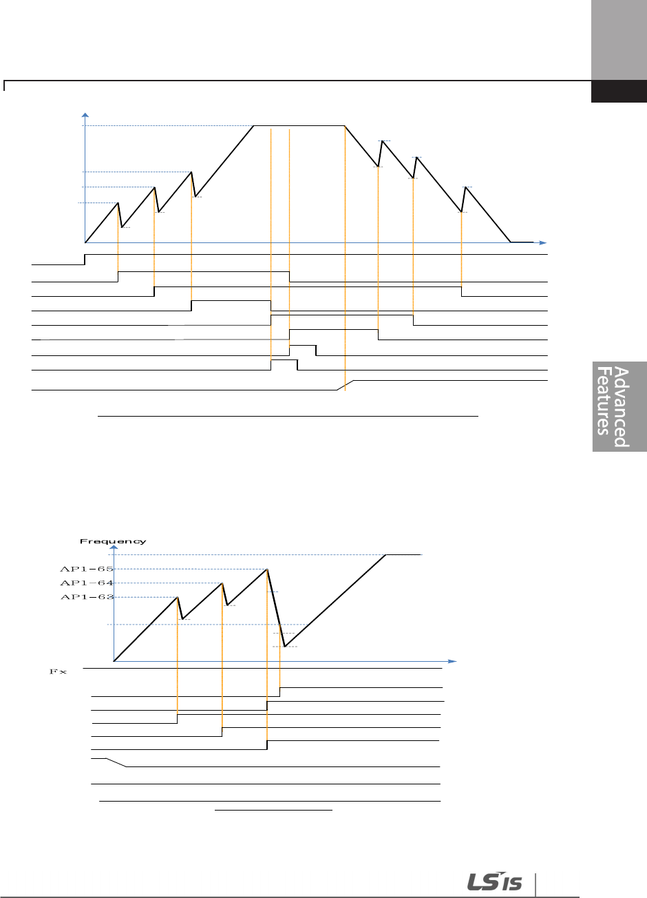
289
Learning Advanced Features
AP1-61
AP1-62
AP1-63
AP1-64
AP1-65
Max Freq
Frequency
AP1-70
AP1-71
AP1-72
Aux Motor 1
Aux Motor 2
Aux Motor 3
Aux Motor 4
Aux Motor 5
Feedback
AP1-71
0%
100%
Fx Off
On
Interlock 1
Interlock 3
AP1-74
AP1-65
AP1-73
AP1-64
AP1-62
Interlock operation(Op time Order) when Operable Motor and Standby Motor are set to 3 and 2 each
When interlock is released, the auxiliary motor’s priority becomes different. When Interlock occurs
at auxiliary motor #3, the priority is number 1>3>4>5>2. When it occurs at auxiliary motor #1, the
priority is number 3>4>5>2>1. The figure below shows the order of the auxiliary motors
activating depending on the priority (of Interlock occurring and releasing). In the figure, the order
is the same for FILO/FIFO, because the auxiliary motor turns on.
Max
Freq
Off
On
AP1-62
AP1-61
AP1-74
AP1-73
AP1-72
AP1-71
AP1-70
Interlock operation
Feedback
Interlock 1
Interlock 2
Aux Motor 1
Aux Motor 2
Aux Motor 3
Aux Motor 4
Aux Motor 5
In case that Operable Motor and Standby Motor are set to 3 and 2 each, it operates in the order of
“Aux Motor 2 Aux Motor 4 Aux Motor 5”.
290
Learning Advanced Features
5.44.5 Aux Motor Time Change
It is used to set a motor to the smallest number among Drives not inter-locked by [AP1-43 Starting
Aux] and place others in order based on it when operating time of every motor is deleted through
<1:All> of [AP1-98 AuxRunTime Clr].
In case that operating time of each motor is deleted through <2: Aux1> ~ <6: Aux5> of [AP1-98
AuxRunTime Clr] or changed by combining [AP1-96 AuxRunTime Day] and [AP1-97 AuxRunTime
Min], motor stopped changes the priority with motor stopped as operating motor does with
operating motor.
The table below shows the case to change the operating time of Aux Motor2 running on the same
condition of Sequence1.
Sequences
Aux Priority 1
(Operating
time: min)
Aux Priority 2
(Operating
time: min)
Aux Priority 3
(Operating
time: min)
Aux Priority 4
(Operating
time: min)
Aux Priority 5
(Operating
time: min)
1
Aux Motor3
(00:30)
<Operating>
Aux Motor2
(00:40)
<Operating>
Aux Motor1
(00:50)
<Operating>
Aux Motor4
(01:30)
<Operating>
Aux Motor 5
(01:50)
<Operating>
Set <3 Aux2of [AP1-98 AuxRunTime Clr]
2
Aux Motor2
(00:00)
<Operating>
Aux Motor3
(00:30)
<Operating>
Aux Motor1
(00:50)
<Operating>
Aux Motor4
(01:30)
<Operating>
Aux Motor 5
(01:50)
<Operating>
Set time of Aux2to 2:00 through [AP1-97 AuxRunTime Min]
3
Aux Motor3
(00:30)
<Operating>
Aux Motor1
(00:50)
<Operating>
Aux Motor2
(02:00)
<Operating>
Aux Motor4
(01:30)
<Stopping>
Aux Motor 5
(01:50)
< Stopping >
The table below shows the case to change the operating time of Aux Motor5 stopped on the
same condition of Sequence1
Sequences
Aux Priority 1
(Operating
time: min)
Aux Priority 2
(Operating
time: min)
Aux Priority 3
(Operating
time: min)
Aux Priority 4
(Operating
time: min)
Aux Priority 5
(Operating
time: min)
1
Aux Motor3
(00:30)
<Operating>
Aux Motor2
(00:40)
<Operating>
Aux Motor1
(00:50)
<Operating>
Aux Motor4
(01:30)
<Stopping>
Aux Motor 5
(01:50)
<Stopping>
Set <6: Aux5> of [AP1-98 AuxRunTime Clr]
2
Aux Motor3
(00:30)
<Operating>
Aux Motor2
(00:40)
<Operating>
Aux Motor1
(00:50)
<Operating>
Aux Motor 5
(0)
<Stopping>
Aux Motor 4
(01:30)
<Stopping>
Set time of Aux5 to 2:00 through [AP1-97 AuxRunTime Min]
3
Aux Motor3
(00:30)
<Operating>
Aux Motor2
(00:40)
<Operating>
Aux Motor1
(00:50)
<Operating>
Aux Motor4
(01:30)
<Stopping>
Aux Motor 5
(02:00)
<Stopping>
291
Learning Advanced Features
5.44.6 Regular Bypass
This function controls the motor speed based on the feedback amount instead of using the PID.
Auxiliary motors may be controlled with this feature based on the feedback amount.
Group
Code
Name
LCD Display
Parameter Setting
Setting Range
Unit
AP1
41 Bypass selection Regul Bypass
1
0
No
-
1
Yes
61–
65
#1
–
5 auxiliary
motor start
frequency
Start Freq
1–5
Frequency value
within the range
Freq Low
Limit–Freq
High limit
Hz
70–
74
#1
–
5 auxiliary
motor stop
frequency
Stop Freq
1–5
Frequency value
within the range
Low Freq–
High Freq Hz
OUT
31
–
35
Multi
-
function
relay1–5 Relay 1–5
21
Multiple motor
control(MMC) - -
36
Multi
-
function 1
item Q1 Define 40
KEB Operation
- -
Regular Bypass Detail Settings
Code
Description
AP1-41 Regular Bypass
Sets the regular bypass mode.
Mode
Setting
0
No
1
Yes
AP1
-
6
1
–
6
5
Start Freq 1
–
5
Sets the auxiliary motor start frequency.
AP1
-
70
–
74 Stop Freq 1
–
5
Sets the auxiliary motor stop frequency.
OUT-31–35 Relay 1–5
OUT-36 Q1 Define
Set OUT31
–
35 to ’21
(MMC)’ to use the out terminal for auxiliary
motor operation. The number of configured output terminals
determines the total number of auxiliary motors to be used.
When an input set by the PID feedback of the analog input terminal (I or V1 or Pulse) is 100%,
divide the area by the number of motors being used (including the main motor). Each auxiliary
motor turns on when feedback reaches the relevant level and turns off when feedback goes
below the relevant level. The primary motor increases its speed based on the feedback and when
it reaches the start frequency of the relevant auxiliary motor and decelerates to the stop
frequency.
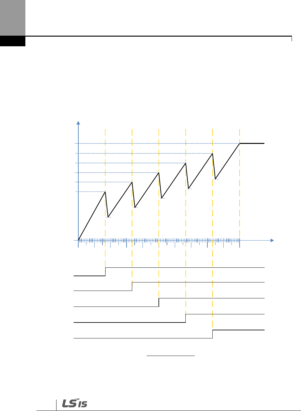
292
Learning Advanced Features
The primary motor reaccelerates when the frequency increases, depending on the feedback
increase. If the relevant auxiliary motor is turned off because of the feedback decrease, the primary
motor accelerates from the stop frequency to the start frequency.
To use the regular bypass function, ‘1 (Yes)’ has to be selected in the MMC and PID functions. Only
FILO operates between the AP1-49 (FIFO/FILO) in a regular bypass function.
Out Freq
10% 20% 30% 40% 50% 60% 70% 80% 90% 100%
16.6% 33.3% 49.9% 66.6% 83.3%
0%
area(6)
Off
On
Aux Motor 1
Max Freq
AP1-61
AP1-62
AP1-63
AP1-64
AP1-65
AP1-71
AP1-72
AP1-73
AP1-74
AP1-70
Regular ByPass
area(5)area(4)
area(3)
area(2)area(1)
Aux Motor 2
Aux Motor 3
Aux Motor 4
Aux Motor 5
5.44.7 Aux Motor PID Compensation
293
Learning Advanced Features
When the number of operating auxiliary motors increases, the flow rate of the pipe also increases
and the pressure of the pipe line decreases. Aux motor PID compensation compensates for this
pressure when the number of the auxiliary motor increases. By adding the additional PID
reference value (relevant to the auxiliary motor) to the current reference, the loss of pressure can
be compensated for.
Auxiliary PID Compensation Detailed Settings
Code
Description
AP1-80–84
Aux 1–5 Ref
Comp
Set the relevant
PID reference compensation rate whenever the auxiliary motor is
turned on. The PID reference can be set over 100%, but when it exceeds 100%, the
maximum value of the PID reference is limited to 100%.
Unit band value is the value between unit 100%–0%.
< Auxiliary motor PID compensation>
NOTE

294
Learning Advanced Features
When the aux reference value is set to 100%, the final PID reference becomes 100%. In this case,
output frequency of the inverter does not decelerate because the PID output does not decelerate
even if the input feedback value is 100%.
5.44.8 Master Follower
It is used to control multiple inverters with an inverter. When [AP1-40 MMC Sel] is set to <2 : Multi
Follower> or <3 : Multi Master>, it is called as {Leader Drive}. The rest inverters set to <4 : Serve
Drv> are called as {Serve Drive}.
Leader Drive
It is an inverter to execute PID control with PID Feedback from sensor, control Multi Motor and
function as Master of communication.
In addition, if it is set to Leader Drive, Drive turned on at first performs functions of Soft Fill(Pre-
PID), Sleep/WakeUp and Aux Motor PID Compensation).
Serve Drive
It is an inverter to operate motors with Leader Drive.
Each inverter and motor has the same number(ID), [COM-01 Int485 St ID].
Among the operating motors, the motor with the lowest priority is called Main Motor and the rest
of motors are called as Aux Motor.
※In case that every motor is stopped, the motor with the highest priority is called as Main Motor.
This is, Main Motor and Aux Motor are changed according to the situation and Leader Drive and
Serve Drive are fixed.
The picture below represents foundational composition.
295
Learning Advanced Features
Leader Drive
ID 1
Main
Motor
M1 M2 M3 M4 M8
Serve Drive
ID 2
Serve Drive
ID 3
Serve Drive
ID 4
Serve Drive
ID 8
Inverter
Setting
Communication
Line
Sensor
Aux
Motor
Aux
Motor
Aux
Motor
Aux
Motor
5.44.8.1 Multi Mater Mode
Only Main Motor can be controlled by PID and Aux Motor performs the operating mode with
Follower Freq.
The picture below shows that the priority is “Motor1 (M1)Motor2 (M2)Motor3 (M3)”.
(The priority can be changed automatically according to operating time)
Start Freq 1
Start Freq 3
Out Freq
Run Cmd
Follower Freq
t
M1 OutFreq M2 OutFreq
FeedBack
Stop Freq 2
PID Reference
Start Freq 2
Stop Freq 3
M3 OutFreq
M1, M2
M3 M1M2
M1 Cmd Freq
PID Ctrl
Follower Freq
M2 Cmd Freq
M3 Cmd Freq
PID Ctrl
Follower Freq
PID Ctrl
PID Ctrl
Main Motor
Main Motor Main Motor
Main Motor
Main Motor
Aux Motor
Aux Motor Aux Motor Aux Motor
Aux Motor Aux Motor
PID Output
PID Limit Hig h
PID Ctrl
M1, M2, M3
M1, M2
.

296
Learning Advanced Features
A condition that extra Aux Motor is turned on .
After a real operating frequency reaches the frequency set in Start Freq belonging to the next
priority number and the time set in AP1-53(Aux Start DT) passes, AP1-44(Aux Motor Run) increases
(+1) and it becomes Aux Motor, accelerating based on time of [DRV-03 Acc Time]/[DRV-04 Dec
Time] until [AP1-60 Follower Freq].
At the same time, as an inverter corresponding to the next priority is turned on, the motor
becomes Main Motor(available PID control). It is possible to check the priority in [AP1-45/46 Aux
Priority].
A condition that Aux Motor is turned off.
If the real operating frequency of Main Motor is lower than the frequency set in Stop Freq, AP1-
44(Aux Motor Run) decreases(-1) after the time set in AP1-54(Aux Stop DT) and the present Main
Motor becomes Aux Motor, decelerating based on time of [DRV-04 Dec Time] until 0Hz.
At the same time, the motor corresponding to the previous priority becomes Main
Motor(available PID control). It is possible to check the priority in [AP1-45/46 Aux Priority].
5.44.8.2 Multi Follower Mode
It is a mode to control motors turned on with the same PID output frequency.
The picture below shows that the priority is “Motor1 (M1)Motor2 (M2)Motor3 (M3)”.
(The priority can be changed automatically according to operating time).
297
Learning Advanced Features
St art Freq 1
St art Freq 3
Out Freq
High Freq
t
M1 OutFreq M2 OutFreq
Stop Freq 2
St art Freq 2
Stop Freq 3
M3 OutFreq
Run Cmd
FeedB ack PID Reference
M1 Cmd Freq
PID Ctrl
M2 Cmd Freq
M3 Cmd Freq
Main Motor
M1, M2
M3
M2
PID Ctrl
PID Ctrl
Main Motor
Main Motor
Main
Motor
Aux Motor Main Motor
Aux Motor Aux Motor
Aux Motor
Aux MotorAux Motor
PID Output
PI D Limit High
M1
M1, M2
A condition that extra Aux Motor is turned on .
After a real operating frequency reaches the frequency set in Start Freq belonging to the next
priority number and the time set in AP1-53(Aux Start DT) passes, AP1-44(Aux Motor Run) increases
(+1). In addition, Aux Motor with the next priority of Main Motor is turned on and the new
operating Aux Motor becomes Main Motor. Operating motors can be controlled together by PID.
It is possible to check the priority in [AP1-45/46 Aux Priority].
A condition that Aux Motor is turned off.
If the real operating frequency of Main Motor is lower than the frequency set in Stop Freq, AP1-
44(Aux Motor Run) decreases(-1) after the time set in AP1-54(Aux Stop DT) and the present Main
Motor becomes Aux Motor, decelerating based on time of [DRV-04 Dec Time] until 0Hz.
At the same time, the rest of operating motors last PID control. It is possible to check the priority in
[AP1-45/46 Aux Priority].
5.44.8.3 Re-arrangement of priority based on operating time.
The priority of each Motor is arranged automatically based on operating time.
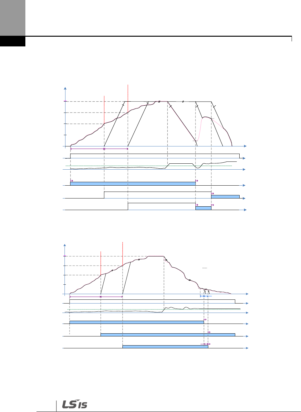
298
Learning Advanced Features
Among operating Motors, Motor with the longest operating time is placed at the last.
The moment for the priority arrangement is the time when the number of motor is changed.
Start Freq 1
Start Freq 3
Out Freq
Run Cmd
Follower Freq
M1 OutFreq M2 OutFreq
FeedBack PID Reference
Start Freq 2
M3 OutFreq
M2, M3, M1
M1 Cmd Freq
PID Ctrl
M2 Cmd Freq
M3 Cmd Freq
Main Motor Aux Motor
PID Output
PID Limit High
Pr iority at the moment
M2 M1 M3
Initial Priority
M1 M2 M3
Pr iority at the moment
M2 M3 M1
More than 1min Less than 1min t
M3 M2
Stop Freq 3
Stop Freq 1
Follower Freq
Follower Freq
PID Ctrl
Main Motor
Aux Motor
Aux Motor
Aux Motor
PID Ctrl
Main Motor
M1
M2 M3
M2, M3
The picture below shows the operating time of M1 is the longest during Multi Follower Mode.
Start Freq 1
Start Freq 3
Out Freq
High Freq
M1 OutFreq M2 OutFreq
Start Freq 2
M3 OutFreq
M2, M3, M1
Run Cmd
FeedBack PID Refer ence
M1 Cmd Freq
PID Ctrl
M2 Cmd Freq
M3 Cmd Freq
Main Motor
PID Ctrl
PID Ctrl
Aux Motor
Aux Motor
PID Output
PID Limit High
More than 1min Less than 1min
M2, M1
Pr iority at the m oment
M2 M1 M3
Initial Priority
M1 M2 M3
Pr iority at the m oment
M2 M3 M1
M1
Stop Freq 1
Stop Freq 3
M2, M3, M1
[Aux Stop DT]
M2, M3, M1
M3 M2
M2, M3
t
Main Motor Aux Motor
Aux Motor
Main Motor
The conditions that Aux Motor is turned on and off are same as the description of Multi Master
Mode and Multi Follower Mode.
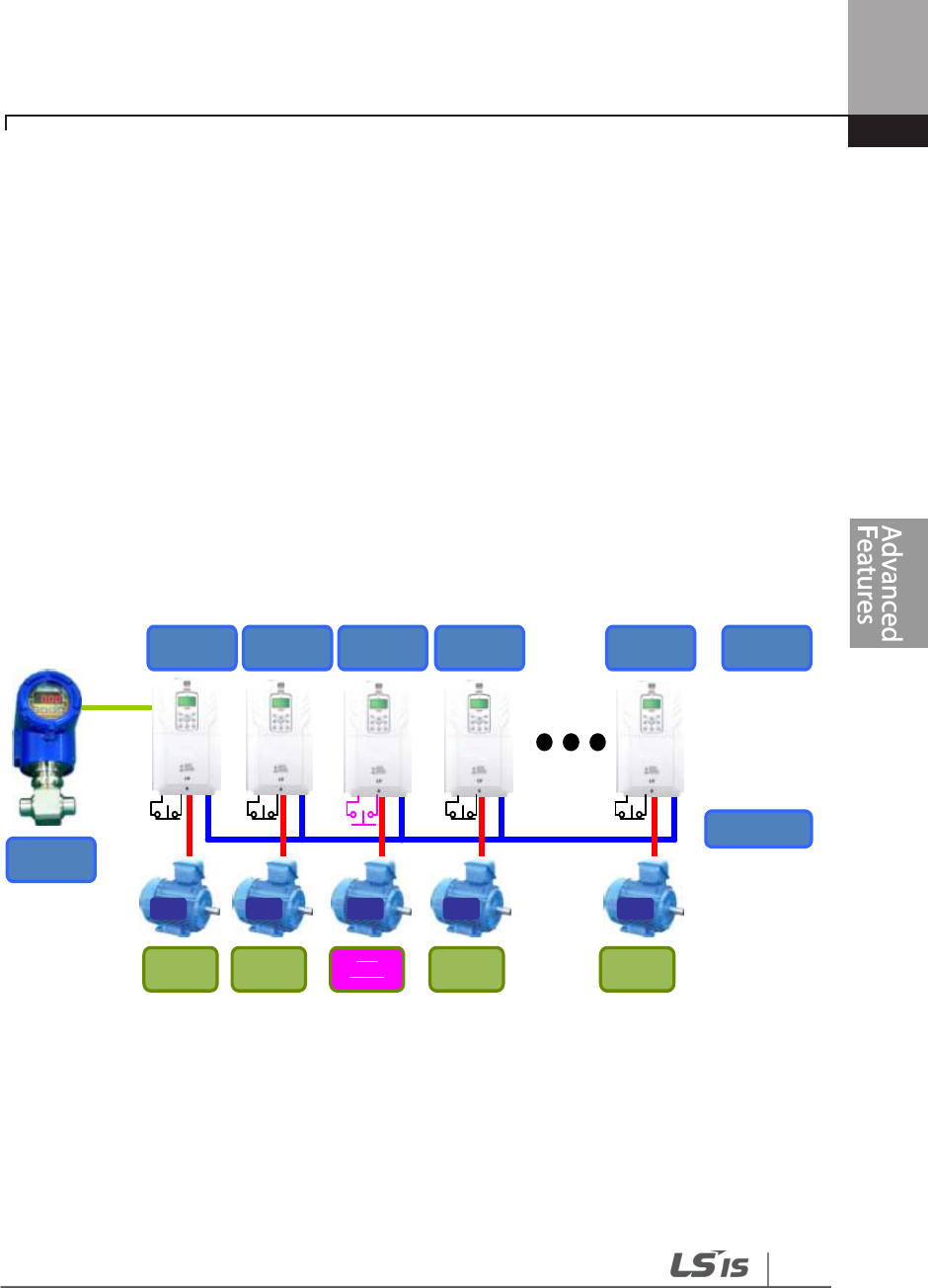
299
Learning Advanced Features
5.44.8.4 Master Follower Interlock
As Interlock signals are sent from Serve Drive, Leader Drive puts together through Communication
Line. Every Trip such as HAND State or OFF State of Serve Drive is processed by Interlock in Leader
Drive .
This is, other Server Drives keep performing Master Follower function except the cases that it is in
HAND/OFF State or there are trips
If Leader Drive is HAND State or OFF state, Master Follower system is not activated.
In case that Pipe Broken and Interlock Trip are caused in Leader Drive, every drive operating is
stopped and Master Follower keeps performing the function except Leader Drive if there is
another Trip.
(Leader Drive executes PID control and overall system control consistently.)
In this operating priority (M1 M2 M3 M4 M5 M6 M7 M8), if interlock3 or any ↔ ↔ ↔ ↔ ↔ ↔ ↔
trip and HAND/OFF State are caused, the motor is activated in this order(M1 M2 M4 M5 ↔ ↔ ↔
M6 M7 M8). ↔ ↔ ↔
Interlock1 Interlock2 Interlock3 Interlock4 Interlock8
Leader Drive
ID 1
Serve Drive
ID 2
Serve Drive
ID 3
Serve Drive
ID 4
Serve Drive
ID 8
Inverter
Setting
Main
Motor
M1 M2 M3 M4 M8
Sensor
Aux
Motor
Aux
Motor
Aux
Motor
Aux
Motor
Communication
Line
The picture below shows the function in case that M3 becomes HAND/OFF State or interlock and
Trip are caused.(supposing that the priority is not changed),(interlock is the function
corresponding to B terminal(Normal close)).
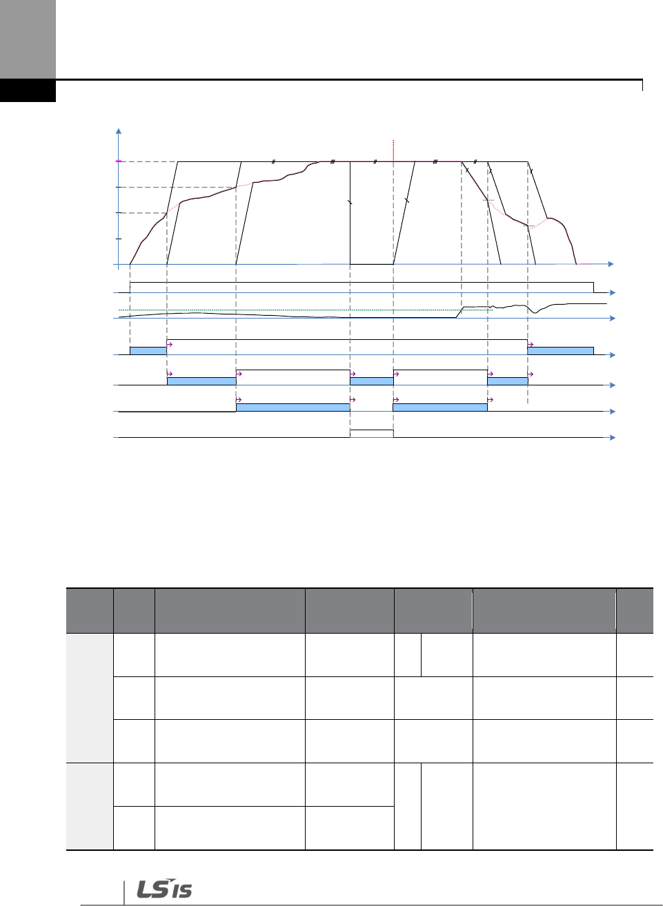
300
Learning Advanced Features
Start Freq 1
Start Freq 3
Out Freq
Run Cmd
Follower Freq
t
M1 OutFreq M2 OutFreq
FeedBack
Stop Freq 2
PID Reference
Start Freq 2
Stop Fre q 3
M3 OutFreq
M1, M2
M3 M1M2
M1 Cmd Freq
PID Ctrl
Follower Freq
M2 Cmd Freq
M3 Cmd Freq
PID Ct rl
Follower Freq
PID Ct rl
PID Ctrl
Main Motor
Main Motor Main Motor
Main Motor
Main Motor
Aux Motor
Aux Motor Aux Motor Aux Motor
Aux Motor Aux Motor
PID Output
PID Limit High
PID Ct rl
M1, M2, M3
M1, M2
M3
State
ChangeInterlock
or Trip
M3
FreeRun
M1, M2 M1, M2, M3
M3
Time to sort the priority
acco rding to the operation
time.
Aux Motor
Main Motor
PID Ct rl
PID Ct rl
Main Motor
Aux Motor
5.45 Multi-function Output On/Off Control
Set reference values (on/off level) for analog input and control output relay or multi-function
output terminal on/off status accordingly.
Group
Code
Name LCD Display
Parameter
Setting Setting Range Unit
ADV
66
Output terminal on/off
control mode
On/Off Ctrl
Src 1 V1 0–8 -
67
Output terminal on
level On-C Level 90.00
Output terminal off
level–100.00% %
68
Output terminal off
level Off-C Level 10.00
0.00
–
Output terminal
on level %
OUT
31
Multi
-
function relay 1
item Relay 1
26
On/Off
- -
33
Multi
-
function output
1
item Q1 Define
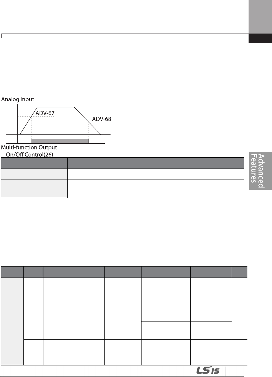
301
Learning Advanced Features
Multi-function Output On/Off Control Setting Details
Code
Description
ADV
-
66 OnOff Ctrl Src
Select analog input On/Off control.
ADV
-
67 On Ctrl Level ,
ADV-68 Off Ctrl Level Set On/Off level at the output terminal.
5.46 Press Regeneration Prevention
Press regeneration prevention is used during press operations to prevent braking during the
regeneration
process. If motor regeneration occurs during a press operation, motor operation speed
automatically goes up to avoid the regeneration zone
.
Group
Code
Name
LCD Display
Parameter Setting
Setting Range
Unit
ADV
74
Select press
regeneration
prevention for press
RegenAvd
Sel 0 No 0–1 -
75
Press regeneration
prevention operation
voltage level
RegenAvd
Level
350 V
200 V class:
300–400 V V
700 V
400 V class:
600–800 V
76
Press regeneration
prevention
compensation
CompFreq
Limit 1.00 (Hz) 0.00–10.00 Hz Hz
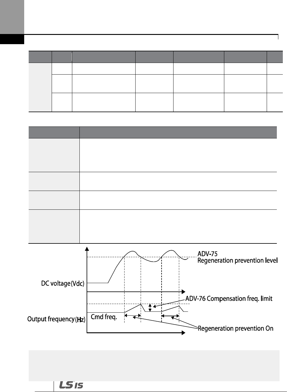
302
Learning Advanced Features
Group
Code
Name
LCD Display
Parameter Setting
Setting Range
Unit
frequency limit
77
Press regeneration
prevention P-Gain
RegenAvd
Pgain 50.0 (%) 0 .0–100.0% %
78
Press regeneration
prevention I gain
RegenAvd
Igain 500 (ms) 20–30000 ms ms
Press Regeneration Prevention Setting Details
Code
Description
ADV-74
RegenAvd Sel
Frequent regeneration voltage from a press load during a constant speed
motor operation may force excessive stress on the brake unit, which may
damage or shorten brake life. To prevent this, select ADV-74 (RegenAvd Sel) to
control DC link voltage and disable the brake unit operation.
ADV
-
75
RegenAvd Level
S
et brake operation prevention level voltage when the DC link voltage goes up
due to regeneration.
ADV
-
76
CompFreq Limit
Set an alternative frequency width that can replace actual operation frequency
during regeneration prevention.
ADV
-
77
RegenAvd Pgain
ADV-78
RegenAvd Igain
To prevent regeneration zone, set P-Gain/I gain in the DC link voltage suppress
PI controller.
Note
Press regeneration prevention does not operate during accelerations or decelerations; it only operates
during constant speed motor operation. When regeneration prevention is activated, output frequency

303
Learning Advanced Features
5.47 Analog Output
An analog output terminal provides an output of 0–10 V voltage, 4–20 mA current, or 0–32 kHz
pulse.
5.47.1 Voltage and Current Analog Output
An output size can be adjusted by selecting an output option at the AO (Analog Output) terminal.
Set the analog voltage/current output terminal setting switch (SW5) to change the output type
(voltage/current).
Group
Code
Name
LCD Display
Parameter Setting
Setting Range
Unit
OUT
01
Analog output1
AO1 Mode
0
Frequency
0
–
15
-
02
Analog output1 gain
AO1 Gain
100.0
-
1000.0
–
1000.0
%
03
Analog output1 bias
AO1 Bias
0.0
-
100.0
–
100.0
%
04
Analog output1 filter
AO1 Filter
5
0
–
10000
ms
05
Analog constant
output1 AO1 Const %
0.0 0.0–100.0 %
06
Analog output1
monitor AO1 Monitor
0.0 0.0–1000.0 %
may change within the range set at ADV
-
76 (CompFreq Li
mit).

304
Learning Advanced Features
Code
Description
OUT-01 AO1
Mode
Select a constant
value for output. The following example for output voltage
setting.
Setting
Function
0
Frequency
Outputs operation frequency as a standard. 10 V output is
made from the frequency set at DRV-20 (Max Freq).
1
Output
Current
10 V output is made from 150%
of inverter rated current.
2
Output
Voltage
Sets the outputs based on the inverter output voltage. 10 V
output is made from a set voltage in BAS-15 (Rated V).
If 0 V is set in BAS-15, 200 V/400 V models output
10 V based on the actual input voltages (240 V and 480 V
respectively).
3
DC Link
Volt
Outputs inverter DC link voltage as a standard.
Outputs 10 V when the DC link voltage is 410 V DC for 200 V
models, and 820 V DC for 400 V models.
4
Output
Power
Monitors output wattage. 150% of rated output
is the
maximum display voltage (10 V).
7
Target
Freq
Outputs set frequency as a standard. Outputs 10 V at the
maximum frequency (DRV-20).
8
Ramp
Freq
Outputs frequency calculated with Acc/Dec function as a
standard. May vary with actual output frequency. Outputs 10 V.
9
PID Ref
Value
Outputs command value of a PID controller as a standard.
Outputs approximately 6.6 V at 100%.
10
PID Fdk
Value
Outputs feedback volume of a PID controller as a standard.
Outputs approximately 6.6 V at 100%.
11
PID
Output
Outputs output value of a PID controller as a standard. Outputs
approximately 10 V at 100%.
12
Constant
Outputs OUT
-
05 (AO1 Const %) value as a standard.
13
EPID1
Output
Output is based on the output value of the external PID1
controller. Outputs 10 V in 100%.
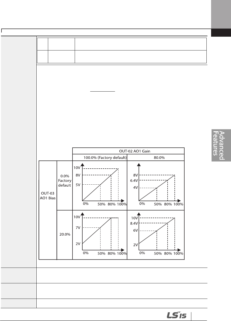
305
Learning Advanced Features
14
EPID Ref
Val
Output is based on the reference value of the external PID1
controller. Outputs 6.6 V in 100%.
15
EPID Fdb
Val
Output is based on the feedback amount of the external PID1
controller. Outputs 6.6 V in 100%.
OUT-02 AO1
Gain,
OUT-03 AO1
Bias
Adjusts output value and offset. If frequency is selected as an output item, it will
operate as shown below.
The graph below illustrates how the analog voltage output (AO1) changes
depending on OUT-02 (AO1 Gain) and OUT-3 (AO1 Bias) values. The Y-axis is analog
output voltage (0–10 V), and the X-axis is a % value of the output item.
Example, if the maximum frequency set at DRV-20 (Max Freq) is 60 Hz and the
present output frequency is 30 Hz, then the x-axis value on the next graph is 50%.
OUT
-
04 AO1
Filter Set filter time constant on analog output.
OUT
-
05 A01
Const %
If the analog output at OUT
-
01 (AO1 Mode) is set to ’12 (Constant)’, the analog
voltage output is dependent on the set parameter values (0–100%).
OUT
-
06 AO1
Monitors the analog output value. Displays the maximum output voltage as a

306
Learning Advanced Features
Voltage and Current Analog Output Setting Details
5.47.2 Analog Pulse Output
Output item selection and pulse size adjustment can be made for the TO (Pulse Output) terminal.
Group Code Name LCD Display Parameter Setting Setting Range Unit
OUT
61
Pulse output setting
TO Mode
0
Frequency
0
–
15
-
62 Pulse output gain TO Gain 100.0
-
1000.0
–
1000.0 -
63
Pulse output bias
TO Bias
1000.0
-
100.0
–
100.0
-
64
Pulse output filter
TO Filter
5
0
–
10000
-
65
Pulse output constant
output2 TO Const % 0.0 0.0–100.0 %
66
Pulse output monitor
TO Monitor
0.0
0
–
1000.0
%
Analog Pulse Output Setting Details
Code
Description
OUT-62 TO Gain, OUT-
63 TO Bias
Adjusts output value and offset. If frequency is selected as an output, it will
operate as shown below.
The following graph illustrates that the pulse output (TO) changes depend
on OUT-62 (TO Gain) and OUT-63 (TO Bias) values. The Y-axis is an analog
output current (0–32 kHz), and X-axis is a % value of the output item.
For example, if the maximum frequency set at DRV-20 (Max Freq) is 60 Hz
and present output frequency is 30 Hz, then the x-axis value on the next
Monitor
percentage (%) with 10 V as the standard.
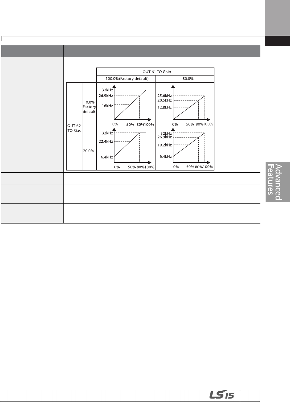
307
Learning Advanced Features
Code
Description
graph is 50%.
OUT
-
64 TO Filter
Sets filter time constant on analog output.
OUT-65 TO Const %
If the analog output item is set to constant, the analog pulse output is
dependent on the set parameter values.
OUT-66 TO Monitor
Monitors the analog output value. It displays th
e maximum output pulse (32
kHz) as a percentage (%) of the standard.

308
Learning Advanced Features
NOTE
OUT
-
08 AO2 Gain and OUT
-
09 AO2 Bias Tuning Mode on 0
–
20 mA output
1 Set OUT-07 (AO2 Mode) to ‘constant’ and set OUT-11 (AO2 Const %) to 0.0 %.
2 Set OUT-09 (AO2 Bias) to 20.0% and then check the current output. 4 mA output should be
displayed.
• If the value is less than 4 mA, gradually increase OUT-
09 (AO2 Bias) until 4 mA is measured.
• If the value is more than 4 mA, gradually decrease OUT-09 (AO2 Bias) until 4 mA is
measured.
3 Set OUT-11 (AO2 Const %) to 100.0%.
4 Set OUT-08 (AO2 Gain) to 80.0% and measure the current output at 20 mA.
• If the value is less than 20 mA, gradually increase OUT-08 (AO2 Gain) until 20 mA is
measured.
• If the value is more than 20 mA, gradually decrease OUT-08 (AO2 Gain) until 20 mA is
measured.
The functions for each code are identical to the descriptions for the 0–10 V voltage outputs with an
output range 4–20 mA.

309
Learning Advanced Features
5.48 Digital Output
5.48.1 Multi-function Output Terminal and Relay Settings
Group
Code
Name
LCD Display
Parameter Setting
Setting Range
Unit
OUT
31
Multi
-
function relay 1
setting Relay 1 23
Trip - -
32
Multi
-
function relay 2
setting Relay 2 14
Run - -
33
Multi
-
function relay 3
setting Relay 3 0 None - -
34
Multi
-
function relay 4
setting Relay 4 0 None - -
35
Multi
-
function relay 5
setting Relay 5 0 None - -
36
Multi
-
function output
setting Q1 define 0 None - -
41
Multi
-
function output
monitor DO Status - 00–11 bit
57 Detection frequency
FDT
Frequency 30.00 0.00–
Maximum
frequency
Hz
58
Detection frequency
band FDT Band 10.00
IN
65
–
71
Px terminal
configuration Px Define 18
Exchange 0-55 -
Multi-function Output Terminal and Relay Setting Details
Code
Description
OUT-31–35
Relay1–5
Set relay (Relay 1
–
5) output options.
Setting
Function
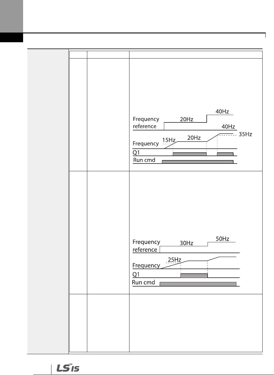
310
Learning Advanced Features
0
None
No output signal
1
FDT
-
1
Detects inverter output frequency reaching the user
set frequency. Outputs a signal when the absolute
value (set frequency–output frequency) < detected
frequency width/2.
When the detected frequency width is 10 Hz, FDT-1
output is as shown in the graph below.
2
FDT
-
2
Outputs a signal when the user
-
set freq
uency and
detected frequency (FDT Frequency) are equal, and
fulfills FDT-1 condition at the same time.
[Absolute value (set frequency-detected frequency) <
detected frequency width/2 & FDT-1]
Detected frequency width is 10 Hz. When the detected
frequency is set to 30 Hz, FDT-2 output is as shown in
the graph below.
3
FDT
-
3
Outputs a signal when the Absolute value (output
frequency–operation frequency) < detected
frequency width/2.
Detected frequency width is 10 Hz. When the detected
frequency is set to 30 Hz, FDT-3 output is as shown in
the graph below.
311
Learning Advanced Features
4
FDT
-
4
The output signal can be separately set for
acceleration and deceleration conditions.
• In acceleration: Operation frequency Detected
frequency
• In deceleration: Operation frequency >
(Detected frequency–Detected frequency
width/2)
Detected frequency width is 10 Hz. When the detected
frequency is set to 30 Hz, FDT-4 output is as shown in
the graph below.
5
Over Load
O
utputs a signal at motor overload.
6
IOL
Outputs a signal
w
hen the inverter input current
exceeds the rated current and a protective function is
activated to prevent damage to the inverter, based on
inverse proportional characteristics.
7
Under Load
Outputs a signal at load fault warning.
8
Fan Warning
Outputs a signal at fan fault warning.
9
Stall
Outputs a signal when a motor is overloaded and
stalled.
10
Over Voltage
Outputs a signal when the inverter DC link voltage
rises above the protective operation voltage.
11
Low Voltage
Outputs a signal when the inverter DC link voltage
drops below the low voltage protective level.
12
Over Heat
Outputs signal when the inverter overheats.
13
Lost Command
Outputs a signal when there is a loss of analog
input
terminal and RS-485 communication command at the
terminal block.
312
Learning Advanced Features
Outputs a signal when communication power is
present and an I/O expansion card is installed. It also
outputs a signal when losing analog input and
communication power commands.
14
RUN
Outputs a signal when an operation command is
entered and the inverter outputs voltage.
No signal output during DC braking.
15
Stop
Outputs a signal at operation command off, and when
there is no inverter output voltage.
16
Steady
Outputs a signal in
steady operation.
17
Inverter Line
Outputs a signal while the motor is driven by the
inverter line.
18
Comm Line
Outputs a signal when multi
-
function input terminal
(switching) is entered. For details, refer to 5.31Supply
Power Transition page on 253.
19
Speed Search
Outputs a signal during inverter speed search
operation.
For details, refer to 5.27Speed Search Operation on page
243.
20
Ready
Outputs a signal when the inverter is in stand by mode
and ready to receive external operation commands.
21
MMC
Used as a multi
-
motor control function. By configuring
the relay output and the multi-function output to
MMC and configuring the AP1-40–AP1-92, it can
conduct the necessary operations for multi-motor
control function.
22
Timer Out
A timer function to operate terminal output after a
certain time by using multi-function terminal block
input. For details, refer to 5.43Timer Settings on page
265.
23
Trip
Outputs a signal after a fault trip.
Refer to 5.45 Multi-function Output On/Off Control on
page 259 .
25
DB Warn %ED
Refer to 0.
Dynamic Braking (DB) Resistor
Configuration on page 295.
313
Learning Advanced Features
• FDT-1 and FDT-2 functions are related to the frequency setting of the inverter. If the inverter
enters standby mode by pressing the off key during auto mode operation, FDT-1 and FDT-2
function operation may be different because the set frequency of the inverter is different
compared to the set frequency of the auto mode.
26
On/Off Control
Outputs a signal using an analog input value as a
standard.
Refer to 5.45 Multi-function Output On/Off Control on
page 259 .
27
Fire Mode
Outputs a signal when Fire mode is in operation.
28
Pipe Break
Outputs a signal when a pipe is broken.
29
Damper Err
Outputs a signal when damper open signal is not
entered. For more details, refer to 0
Damper Operation on page 194.
30
Lubrication
Outputs a signal when a lubrication function is in
operation.
31
PumpClean Sel
Outputs a signal when a pump cleaning function is in
operation.
32
LDT Trip
Outputs a signal when an LDT trip occurs.
33
Damper
Control
Outputs a signal when a damper open signal is set at
IN-65–71 multi-function terminals and run command
is on.
34
CAP.Warning
Outputs a signal when value of the PRT
-
85 is lower
than the value of the PRT-86 (CAP life cycle
examination do not operate properly).
35
Fan Exchange
Outputs a signal when fan needs to be replaced.
36
AUTO State
Outputs a signal in AUTO mode.
37
HAND State
Outputs a signal in HAND mode.
38
TO
Outputs a signal at pulse output.
39
Except Date
Outputs a signal
when operating the exception day
schedule.
40
KEB Operating
Outputs a signal at KEB operation.
41
BrokenBelt Outputs a signal when a Broken belt is in operation.
OUT
-
36 Q1
Define
Select an output item for the multi
-
function output terminal (Q1) of the
terminal
block. Q1 stands for the open collector TR output.
OUT
-
41 DO
State Used to check On/Off state of the D0 by each bit.
314
Learning Advanced Features
• If monitoring signals such as ‘Under load’ or’ LDT’ are configured at multi-function output
terminals, signal outputs are maintained unless certain conditions defined for signal cutoff are
met.
5.48.2
Fault Trip Output using Multi-function Output Terminal and Relay
The inverter can output a fault trip state using the multi-function output terminal (Q1) and relay
(Relay 1).
Group Code Name LCD Display
Parameter
Setting Setting Range Unit
OUT
30 Fault trip output mode Trip Out Mode 010 - bit
31 Multi-function relay 1 Relay 1 23 Trip - -
32 Multi-function relay 2 Relay 2 14 Run - -
33 Multi-function relay 3 Relay 3 0 none -
34 Multi-function relay 4 Relay 4 0 none -
35 Multi-function relay 5 Relay 5 0 none -
36 Multi-function output1 Q1 Define 0 none - -
53 Fault trip output on delay TripOut OnDly 0.00 0.00–100.00 sec
54 Fault trip output off delay TripOut OffDly 0.00 0.00–100.00 sec
315
Learning Advanced Features
Fault Trip Output by Multi-function Output Terminal and Relay - Setting Details
5.48.3 Multi-function Output Terminal Delay Time Settings
Set on-delay and off-delay times separately to control the output terminal and relay operation
times. The delay time set at codes OUT-50–51 applies to multi-function output terminal (Q1) and
relay, except when the multi-function output function is in fault trip mode.
Group
Code
Name
LCD Display
Parameter Setting
Setting Range
Unit
OUT
50
Multi
-
function output
On delay DO On Delay
0.00 0.00–100.00 sec
51
Multi
-
function output
Off delay DO Off Delay
0.00 0.00–100.00 sec
52
Select multi
-
function
output terminal
DO
NC/NO
Sel 000000* 00–11 bit
*Multi-function output terminals are numbered. Starting from the right (number 1), the number
increases to the left.
Code
Description
OUT-30
Trip Out Mode
Fault trip relay operates based on the fault trip output settings.
Item bit on bit off
Keypad
display
Select a fault trip output terminal/relay and select ‘29’ (Trip Mode) at codes OUT- 31–
33. When a fault trip occurs in the inverter, the relevant terminal and relay will
operate. Depending on the fault trip type, terminal and relay operation can be
configured as shown in the table below.
Setting Function
bit3
bit2 bit1
Operates when low voltage fault trips occur
Operates when fault trips other than low voltage occur
Operates when auto restart fails (PRT-08–09)
OUT-31–35 Relay1–
5 Set relay output (Relay 1–5).
OUT-36
Q1 Define Select output for multi-function output terminal (Q1). Q1 is open collector TR output.
316
Learning Advanced Features
Output Terminal Delay Time Setting Details
5.49 Operation State Monitor
The inverter’s operation condition can be monitored using the keypad. If the monitoring option is
selected in config (CNF) mode, a maximum of four items can be monitored simultaneously.
Monitoring mode displays three different items on the keypad, but only one item can be
displayed in the status window at a time.
Group
Code
Name
LCD Display
Parameter Setting
Setting Range
Unit
CNF
20
Display item condition
display window
AnyTime
Para 0 Frequency - -
21
Monitor mode
display 1
Monitor
Line-1 0 Frequency - Hz
Code
Description
OUT-50
DO On Delay
When a relay operation signal (operation set in OUT 31–35, 36) occurs, the relay
turns on or the multi-function output operates after the time delay set at OUT-50.
OUT
-
51
DO Off Delay
When relay or multi
-
function output is initialized (off signal occurs), the relay turns
off or multi-function output turns off after the time delay set at OUT-54.
OUT-52
DO NC/NO Sel
Select the terminal type for the relay and multi
-
function output terminal. By setting
the relevant bit to ‘0,’ it will operate A terminal (Normally Open). Setting it to ‘1’ will
operate B terminal (Normally Closed). Shown below in the table are Relay 1–5 and
Q1 settings starting from the right bit.
Item
B terminal
(Normal close)
A terminal (Normal open)
Keypad
display
317
Learning Advanced Features
Group
Code
Name
LCD Display
Parameter Setting
Setting Range
Unit
22
Monitor mode
display 2
Monitor
Line-2 2
Output
Current - A
23
Monitor mode
display 3
Monitor
Line-3 3
Output
Voltage - V
24 Monitor mode initialize
Mon Mode
Init 0 No - -
Operation State Monitor Setting Details
Code
Description
CNF-20
AnyTime Para
Select items to display on the top
-
right side of the keypad screen. Choose the
parameter settings based on the information to be displayed. Codes CNF-20–23
share the same setting options as listed below.
Setting
Function
0
Frequency
On stop, displays the set frequency. During operation,
displays the actual output frequency (Hz).
1
Speed
On stop, displays the set speed (rpm).
During operation,
displays the actual operating speed (rpm).
2
Output
Current
Displays output current.
3
Output
Voltage
Displays output voltage.
4
Output Power
Displays output power.
5
WHour
Counter
Displays inverter power consumption
.
6
DCLink
Voltage
Displays DC link voltage within the inverter.
7
DI Status
Displays input terminal status of the terminal block.
Starting from the right, displays P1–P8.
8
DO Status
Displays output terminal status of the terminal block.
Starting from the right: Relay1, Relay2, and Q1.
9
V1 Monitor[V]
Displays the input voltage value at terminal V1 (V).
10
V1 Monitor[%]
Displays input voltage terminal V1 value as a
percentage. If -10 V, 0 V, +10 V is measured,
-100%, 0%, 100% will be displayed.
13
V2 Monitor[V]
Displays input voltage terminal V2 value (V).
14
V2 Monitor[%]
Displays input voltage terminal V2 value as a
percentage.
15
I2
Displays input current terminal I2 value (A).
318
Learning Advanced Features
Code
Description
Monitor[mA]
16
I2
Monitor[%]
Displays input current terminal I2 value as a percentage.
17
PID Output
Displays the PID controller output.
18
PID Ref Value
Displays the scale of the reference value and sets the
value of PID reference.
19
PID Fdb Value
Displays the PID
controller feedback volume.
20
EPID1 Mode
Displays the External PID1 mode.
21
EPID1 Output
Displays the External PID1output value.
23
EPID1 Ref Val
Displays the External PID1 reference value.
CNF-21–23
Monitor Line-x
Select the items to be displayed
in monitor mode. Monitor mode is the first mode
displayed when the inverter is powered on. A total of three items, from monitor
line-1 to monitor line- 3, can be displayed simultaneously.
CNF
-
24 Mon
Mode Init Selecting ‘1 (Yes)’ initializes CNF-20–23.
5.50 Operation Time Monitor
Note
Inverter power consumption
Values are calculated using voltage and current. Electric power is calculated every second and the results
are accumulated. Setting CNF-62 (WH Count Reset) value to ‘1 (Yes)’ will reset cumulated electric energy
consumption. Power consumption is displayed as shown below:
• Less than 1,000 kW: Units are in kW, displayed in 999.9 kW format.
• 1–99 MW: Units are in MW, displayed in 99.99 MWh format.
• 100–999 MW: Units are in MW, displayed in 999.9 MWh format.
• More than 1,000 MW: Units are in MW, displayed in 9,999 MWh format and can be displayed up to
65,535 MW. (Values exceeding 65,535 MW will reset the value to 0, and units will return to kW. It will
be displayed in 999.9 kW format).

319
Learning Advanced Features
This feature is used to monitor the inverter and fan operation times.
Group Code Name LCD Display Parameter Setting
Setting
Range Unit
CNF
70
C
umulated
inverter
power-on time On-time 00000DAY 00:00 -
Day
hh:mm
71
Cumulated i
nverter
operation time Run-time 00000DAY 00:00 -
Day
hh:mm
72
Inverter operation
accumulated time
initialization
Time Reset 0 No 0–1 -
74
Cooling fan operation
accumulated time Fan time 00000DAY 00:00 -
Day
hh:mm
75
Cooling fan operation
accumulated time
initialization
Fan Time
Reset 0 No 0–1 -
Operation Time Monitor Setting Details
Code
Description
CNF-70 On-time
Displays accumulated power supply time. Information is displayed in
[
Day
Hr:
Min (00000DAY 00:00)] format.
CNF-71 Run-time
Displays accumulated time of voltage output by operation command input.
Information is displayed in [Day Hr: Min (00000DAY 00:00 )] format.
CNF-72 Time Reset
Setting ‘1 (Yes)’ will delete the power supply accumulated time (On
-
time) and
operation accumulated time (Run-time)
CNF-74 Fan time
Displays accumulated time of the inverter cooling fan operation. Information
will be displayed in [Day Hr: Min (00000DAY 00:00 )] format.
CNF
-
75
Fan Time Reset
Setting ‘1 (Yes)’ will delete the cooling fa
n operation accumulated time (Fan
-
time)
5.51 PowerOn Resume Using the Communication
If there is a run command when recovering the power after instantaneous power interruption

320
Learning Advanced Features
using communication (BAC net, LonWorks, Modbus RTU), the inverter carries out the run
command which was set before the instantaneous power interruption.
Group Code Name LCD Display Parameter Setting Setting Range Unit
COM 96 Automatic restart of the
communication restart
PowerOn
Resume 0 No 0–1 -
• If proper communication is unavailable after the instantaneous power interruption, even if
the COM-96 PowerOn Resume function is set to ‘Yes,’ do not operate the inverter.
• The Power-on Run function operates separately (Power-on Run function and PowerOn
Resume function is set to ‘Yes’ and power turns off and turns on, inverter maintains for the
time set in Power-on run function and then, by the Power On Resume function, if the
inverter is in operation by the communication command before the power interruptions,
the inverter is in operation after the power recovery.)
321
Learning Protection Features
6 Learning Protection Features
Protection features provided by the H100 series inverter are categorized into two types: protection
from overheating damage to the motor and protection against the inverter malfunction.
6.1 Motor Protection
6.1.1 Electronic Thermal Motor Overheating Prevention (ETH)
ETH is a protective function that uses the output current of the inverter, without a separate
temperature sensor, to predict a rise in motor temperature to protect the motor based on its heat
characteristics.
Group
Cod
e
Name
LCD Display
Parameter Setting
Setting range
Unit
PRT
40
Electronic thermal
prevention fault trip
selection
ETH Trip Sel 0 None 0–2 -
41
Motor cooling fan type
Motor Cooling
0
Self
-
cool
-
-
42
Electronic thermal one
minute rating ETH 1 min 120 100–150 %
43
Electronic thermal
prevention continuous
rating
ETH Cont 100 50–150 %
Code
Description
PRT-40 ETH Trip Sel
ETH can be selected to provide motor thermal protection
. The LCD screen
displays”E-Thermal.”
Setting
Function
0
None
The ETH function is not activated.
1
Free
-
Run
The inverter output is blocked. The motor coasts to a halt
(free-run).
2
Dec
The inverter decelerates
the motor to a stop.
322
Learning Protection Features
Electronic Thermal (ETH) Prevention Function Setting Details
PRT-41 Motor
Cooling
Select the drive mode of the cooling fan, attached to the motor.
Setting
Function
0
Self
-
cool
As the cooling fan is connected to the motor axis, the
cooling effect varies based on motor speed. Most
universal induction motors have this design.
1
Forced
-
cool
Additional power is supplied to operate the cooling fan.
This provides extended operation at low speeds. Motors
designed for inverters typically have this design.
PRT-42 ETH 1 min The amount of input current that can be continuously supplied to the motor
for 1 minute, based on the motor-rated current (BAS-13).
PRT-43 ETH Cont
Sets the amount of current with the ETH function activated. The range below
details the set values that can be used during continuous operation without
the protection function.
PRT-41=0

323
Learning Protection Features
6.1.2 Motor Over Heat Sensor
To operate the motor overheat protection, connect the overheat protection temperature sensor
(PT 100, PTC) installed in the motor to the inverter’s analog input terminal.
Group
Code Name LCD Display
Parameter
Setting
Setting
Range Unit
PRT
34
Selecting the operation after
the detection of the motor
overheat detection sensor
Thermal-T
Sel 0 None 0–1 -
35
Selecting the input of the
motor overheat detection
sensor
Thermal In
Src 0 Thermal In 0–1
36
Fault level of the motor
overheat detection sensor
Thermal
-
T
Lev 50.0 0.0–100.0 %
37
Fault area of the motor
overheat detection sensor
Thermal
-
T
Area 0 Low 0–1
OUT
07
Analog output 2 item
AO2 Mode
14
Constant
0
–
18
08
Analog output 2 gain
AO2 Gain
100
0
–
100
%
Motor Overheat Protect Sensor Input Detail Settings
Code
Description
PRT-34
Thermal-T Sel
Sets
the inverter operation state when motor is overheated.
Setting
Function
0
None
Do not operate when motor overheating is detected.
1 Free-Run
When the motor is overheated, the inverter output is
blocked and the motor will free-run by inertia.
3 Dec
When
the motor is over heated, the motor decelerates
and stops.
PRT-35
Thermal In Src
Selects the type of the terminal when the motor overheat protect sensor is
connected to the volt (V1) or current (I2) input terminal of the terminal block
in the inverter.
Setting
Function
0 Thermal In
Configure the motor overheat protect sensor
connection to terminal block V1.
1
V2
Configure the motor overheat protect sensor
324
Learning Protection Features
Code
Description
connection to terminal block I2.
PRT
-
36
Thermal-T Lev Configure the fault level of the motor overheat detect sensor.
PRT-37
Thermal-T Area
Setting
Function
0 Low
Operates when the motor overheat sensor input is
smaller than PRT-36.
1 High
Operates when the motor overheat sensor input is
bigger that PRT-36.
OUT-07 AO2 Mode,
OUT-08 AO2 Gain
Used when supplying the constant current to the temperature sensor and
receives input through the I2 or V1 terminal block by using the analog output
terminal.
Using the temperature sensor (PTC) by connecting it to the analog input terminal
When the AO2(analog current output) terminal is connected to the temperature sensor installed
on a motor, the inverter supplies constant current to the temperature sensor. Then, connecting the
motor signal wire to one of the inverter’s analog input terminals allows the inverter to detect the
changes in the PTC resistance and translates it into voltage. If the I2 terminal is used to receive the
signal, set the selection switch on the I/O board to V2. If the V1 terminal is used, set the switch to
T1. The sensor does not operate if SW3 is set to’ V1’.
325
Learning Protection Features
To receive PTC signal at V1 input terminal, set PRT-35 (Thermal InSrc) to ‘0 (Thermal In)’ and set the
Analog1 input selection switch (SW3) to T1.
To receive PTC signal at I2 input terminal, set PRT-35 (Thermal InSrc) to ‘1 (V2)’ and set SW 4
(Analog2 input selection switch) to V2. The sensor does not operate if SW4 is set to ‘I2’.When the
inverter detects a motor overheat, motor overheat trip occurs with internal delay time. The trip
delay time is not reset instantly when the trip condition is released, but it only decreases as time
passes.
6.1.3 Overload Early Warning and Trip
Group
Code
Name
LCD Display
Parameter Setting
Setting range
Unit
PRT
17
Overload warning
selection OL Warn Select 1 Yes 0–1 -
18
Overload warning
level OL Warn Level 110 30–150 %
19
Overload warning
time OL Warn Time 10.0 0–30 sec
20
Motion at
overload
trip OL Trip Select 1 Free-Run - -
21
Overload trip level
OL Trip Level
120
30
–
150
%
22
Overload trip time
OL Trip Time
60.0
0
–
60.0
sec
OUT
31
–
35
Multi
-
function relay
1–5 item Relay 1–5 5 Over Load - -
36
Multi
-
function
Q1
Define
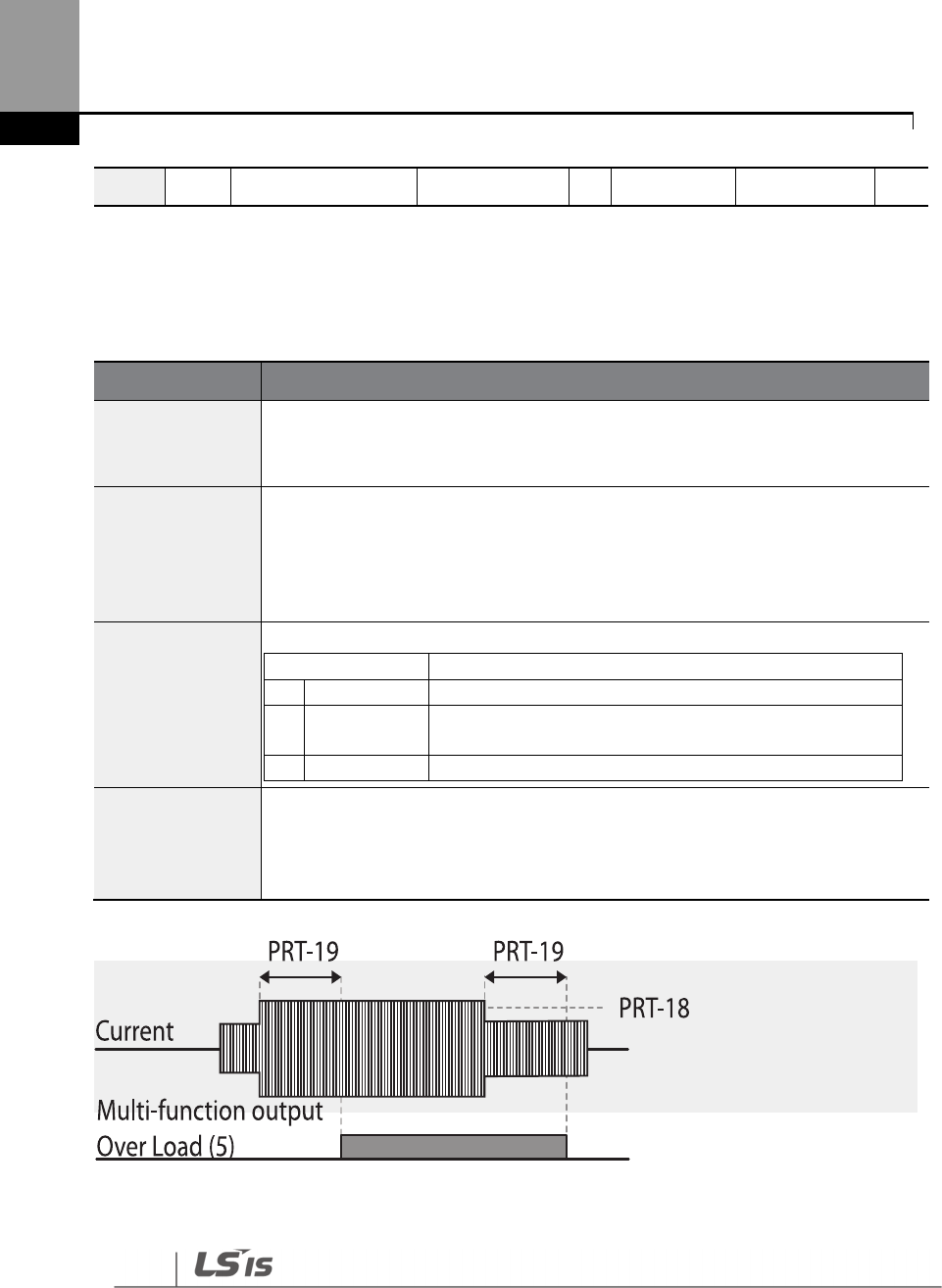
326
Learning Protection Features
A warning or fault trip (cutoff) occurs when the motor reaches an overload state, based on the
motor’s rated current. The amount of current for warnings and trips can be set separately.
Overload Early Warning and Trip Setting Details
output 1 item
Code
Description
PRT-17
OL Warn Select
If the overload
reaches the warning level, the terminal block multi
-
function
output terminal and relay are used to output a warning signal. If ‘1 (Yes)’ is
selected, it will operate. If ‘0 (No)’ is selected, it will not operate.
PRT-18
OL Warn Level,
PRT-19
OL Warn Time
When the input current to the motor is greater than the overload warning level
(OL Warn Level) and continues at that level during the overload warning time (OL
Warn Time), the multi-function output (Relay 1, Q1) sends a warning signal. When
Over Load is selected at OUT-31, OUT-33, the multi-function output terminal or
relay outputs a signal. The signal output does not block the inverter output.
PRT-20
OL Trip Select
Select the inverter protective action in the event of an overload fault trip.
Setting
F
unction
0
None
No protective action is taken.
1
Free
-
Run
In the event of an overload fault, inverter output is
blocked and the motor will free-run due to inertia.
3
Dec
If a fault trip occurs, the motor decelerates and stops.
PRT
-
21 OL Trip
Level,
PRT-22 OL Trip
Time
When the current supplied to the motor is greater than the preset value of the
overload trip level (OL Trip Level) and continues to be supplied during the
overload trip time (OL Trip Time), the inverter output is either blocked according
to the preset mode from PRT-17 or slows to a stop after deceleration.
Note
Overload warnings warn of an overload before an overload fault trip occurs. The overload warning
signal may not work in an overload fault trip situation, if the overload warning level (OL Warn Level)
and the overload warning time (OL Warn Time) are set higher than the overload trip level (OL Trip
Level) and the overload trip time (OL Trip Time).

327
Learning Protection Features
6.1.4 Stall Prevention and Flux Braking
The stall prevention function is a protective function that prevents motors from stalling due to
overloads. If a motor stall occurs due to an overload, the inverter operation frequency is adjusted
automatically. When a stall is caused by overload, high currents induced in the motor may cause
motor overheating or damage the motor and interrupt operation of the motor-driven devices.
In this case, the motor decelerates with optimum deceleration without a braking resistor by using
flux braking. If the deceleration time is too short, an over voltage fault trip may occur because of
regenerative energy from the motor. The flux braking makes the motor use regenerate energy,
therefore optimum deceleration is available without over voltage fault trip.
To protect the motor from overload faults, the inverter output frequency is adjusted automatically,
based on the size of load.
Group
Code
Name
LCD Display
Parameter Setting
Setting range
Unit
PRT
50
Stall prevention and
flux braking Stall Prevent 0100 - bit
51 Stall frequency 1 Stall Freq 1 60.00
Start Freq
–
Stall
Freq 1 Hz
52
Stall level 1
Stall Level 1
130
30
–
150
%
53 Stall frequency 2 Stall Freq 2 60.00
Stall Freq 1
–
Stall Freq 3 Hz
54
Stall level 2
Stall Level 2
130
30
–
150
%
55 Stall frequency 3 Stall Freq 3 60.00
Stall Freq 2
–
Stall Freq 4 Hz
56
Stall level 3
Stall Level 3
130
30
–
150
%
57 Stall frequency 4 Stall Freq 4 60.00
Stall Freq 3
–
Max Freq Hz
58
Stall level 4
Stall Level
4
130
30
–
150
%
59 Flux Braking Gain Flux Brake kp 0
0.75
-
90kW 0–150
-
110
-
500kW
0–10
OUT
31
–35
Multi
-
function relay
1–5 item Relay 1–5 9
Stall - -
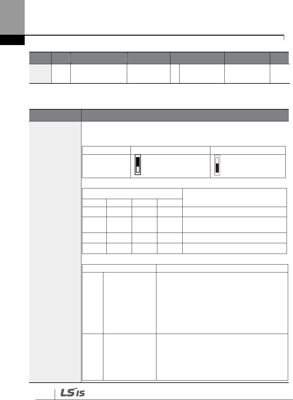
328
Learning Protection Features
Group
Code
Name
LCD Display
Parameter Setting
Setting range
Unit
36
Multi
-
function
output 1 item Q1 Define
Code
Description
PRT-50 Stall
Prevent
Stall prevention can be configured for acceleration, deceleration, or while
operating a motor at constant speed.When the LCD segment is on, the
corresponding bit is off.
Item
Bit Status (On)
Bit Stat
us (Off)
Keypad display
Setting
Function
Bit 4
Bit 3
Bit 2
Bit 1
Stall protection during acceleration
Stall protection while operating at a
constant speed
Stall protection during deceleration
Flux braking during deceleration
Setting
Function
0001
Stall protection
during
acceleration
If inverter output current exceeds the preset stall
level (PRT- 52, 54, 56, 58) during acceleration, the
motor stops accelerating and starts decelerating. If
current level stays above the stall level, the motor
decelerates to the start frequency (DRV-19). If the
current level causes deceleration below the preset
level while operating the stall protection function,
the motor resumes acceleration.
0010
Stall pro
tection
while operating at
constant speed
Similar to stall protection function during
acceleration, the output frequency automatically
decelerates when the current level exceeds the
preset stall level while operating at constant
speed. When the load current decelerates below
the preset level, it resumes acceleration.
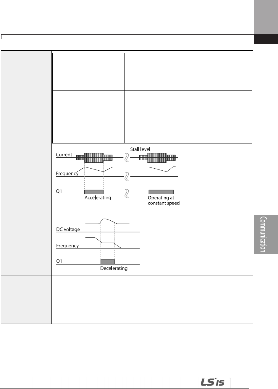
329
Learning Protection Features
0100
Stall protection
during
deceleration
The inverter decelerates and keeps the DC link
voltage below a certain level to prevent an over
voltage fault trip during deceleration. As a result,
deceleration times can be longer than the set time
depending on the load.
1000
Flux braking
during
deceleration
When using flux braking, deceleration time may
be reduced because regenerative energy is
expended at the motor.
1100
Stall protection
and flux braking
during
deceleration
Stall protection and flux braking operate together
during deceleration to achieve the shortest and
most stable deceleration performance.
PRT-51 Stall Freq
1– PRT-58 Stall
Leve l4
Additional stall protection levels can be
configured for different frequencies,
based on the load type. As shown in the graph below, the stall level can be set
above the base frequency. The lower and upper limits are set using numbers that
correspond in ascending order. For example, the range for Stall Frequency 2 (Stall
Freq 2) becomes the lower limit for Stall Frequency 1 (Stall Freq 1) and the upper
limit for Stall Frequency 3 (Stall Freq 3).
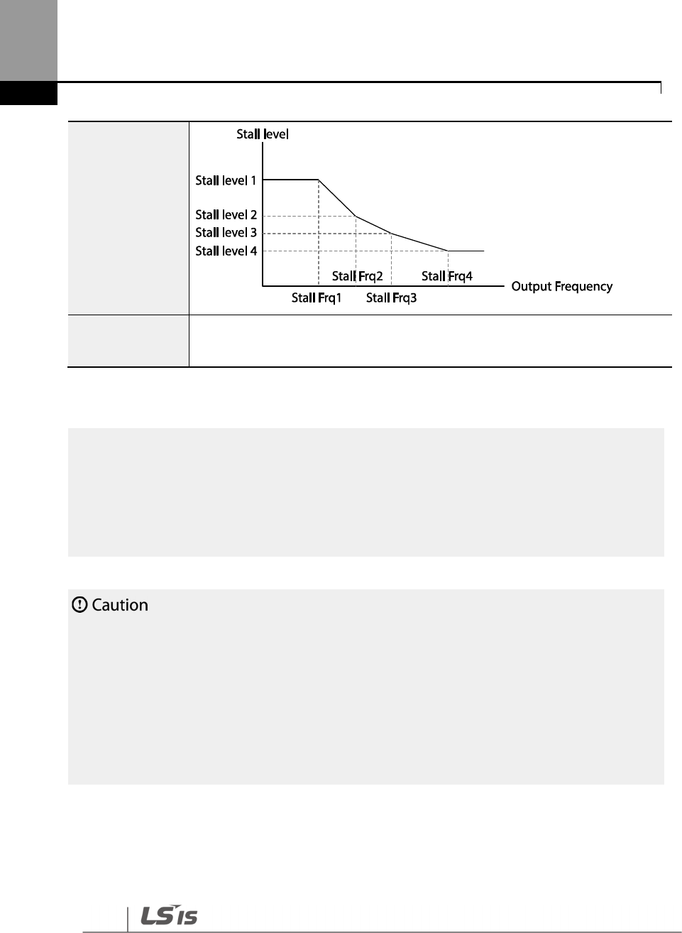
330
Learning Protection Features
Stall Prevention Function and Flux Braking Setting Details
• Use caution when decelerating while using stall protection since the deceleration time can take
longer than the time set, depending on the load. Acceleration stops when stall protection
operates during acceleration. This may make the actual acceleration time longer than the preset
acceleration time.
• When the motor is operating, Stall Level 1 applies and determines the operation of stall
protection.
• If the input voltage exceeds the nominal voltage, there is a possibility that the deceleration stall
does not work properly.
PRT-59 Flux Brake
Kp
A gain used to decelerate without over voltage fault trip. It compensates for
the inverter output voltage.
Note
Stall protection and flux braking operate together only during deceleration. Turn on the third and
fourth bits of PRT-50 (Stall Prevention) to achieve the shortest and most stable deceleration
performance without triggering an over voltage fault trip for loads with high inertia and short
deceleration times. Do not use this function when frequent deceleration of the load is required, as the
motor can overheat and be easily damaged.
331
Learning Protection Features
6.2 Inverter and Sequence Protection
6.2.1 Open-phase Protection
Open-phase protection is used to prevent over current levels induced by the inverter inputs due
to an open-phase within the input power supply. Open-phase output protection is also available.
An open-phase at the connection between the motor and the inverter output may cause the
motor to stall, due to a lack of torque.
Group
Code
Name
LCD Display
Parameter Setting
Setting
range
Unit
PRT
05
Input/output open
-
phase protection Phase Loss Chk
00 - bit
06
Open
-
phase input
voltage band IPO V Band 40 1–100 V V
Input and Output Open-phase Protection Setting Details
Code
Description
PRT-05 Phase Loss
Chk
PRT-06 IPO V Band
When open
-
phase protection is operating, input and output configurations are
displayed differently. When the LCD segment is On, the corresponding bit is set
to ‘Off’.
Item
Bit status (On)
Bit status (Off)
Keypad
display
Setting
Function
Bit 2
Bit
1
Output open
-
phase protection
Input open
-
phase protection
332
Learning Protection Features
6.2.2 External Trip Signal
Set one of the multi-function input terminals to 4 (External Trip) to allow the inverter to stop
operation when abnormal operating conditions arise.
Group
Code
Name
LCD Display
Parameter Setting
Setting range
Unit
IN
65–71
Px terminal setting
options
Px Define
(Px: P1–P7) 4 External Trip 0-55 -
87
Multi
-
function
input contact
selection
DI NC/NO Sel
- bit
External Trip Signal Setting Details
Code
Description
IN-87 DI NC/NO
Sel
Selects the type of input contact. If the mark of the switch is at the bottom (0), it
operates as an A contact (Normally Open). If the mark is at the top (1), it
operates as a B contact (Normally Closed).
The corresponding terminals for each bit are as follows:
Bit
7
6
5
4
3
2
1
Terminal
P7
P6
P5
P4
P3
P2
P1

333
Learning Protection Features
6.2.3 Inverter Overload Protection (IOLT)
When the inverter input current exceeds the rated current, a protective function is activated to
prevent damage to the inverter, based on inverse proportional characteristics.
Group
Code
Name
LCD Display
Parameter Setting
Setting range
Unit
OUT
31
–
35
Multi
-
function relay
1–5 Relay 1–5
6 IOL - -
36
Multi
-
function
output 1 Q1 Define
Note
A warning signal output can be provided in advance by the multi
-
function output terminal before the
inverter overload protection function (IOLT) operates. When the overcurrent time reaches 60% of the
allowed overcurrent (120%, 1 min; 140%, 5 sec), a warning signal output is provided (signal output at
120%, 36 sec).

334
Learning Protection Features
6.2.4 Speed Command Loss
When setting operation speed using an analog input at the terminal block, communication
options, or the keypad, speed command loss setting can be used to select the inverter operation
for situations when the speed command is lost due to the disconnection of signal cables.
Group
Code
Name
LCD Display
Parameter Setting
Setting range
Unit
PRT
11
Keypad command
loss operation
mode
Lost KPD
Mode 0 None
0
None
-
1
Warning
2
Free
-
Run
3
Dec
12
Speed command
loss operation
mode
Lost Cmd
Mode 1 Free-Run - -
13
Time to determine
speed command
loss
Lost Cmd
Time 1.0 0.1–120.0 sec
14
Operation
frequency at speed
command loss
Lost Preset F 0.00
Start
frequency–Max.
frequency
Hz
15
Analog input loss
decision level AI Lost Level 0 Half of x1 -
OUT
31
–35
Multi
-
function Relay
1–5 Relay 1–5
13
Lost
Command - -
36
Multi
-
function
output 1 Q1 Define

335
Learning Protection Features
Speed Command Loss Setting Details
Code
Description
PRT-11 Lost KPD
Mode
Set the operation command source to keypad. If there is a communication error
with the keypad or connection problem between the keypad and the inverter,
select the inverter’s operation.
Setting
Function
0 None
The speed command immediately becomes the
operation frequency without any protection function.
1 Warning
Select 24: Lost keypad from OUT
-
31
–
36, one of the multi
function terminal blocks, outputs a relevant warning
signal when abnormal operating conditions arise.
2 Free-Run
The inverter blocks output. The motor performs in free
-
run condition.
3 Dec
The motor decelerates and then stops at the time set at
PRT-07 (Trip Dec Time).
PRT-12 Lost Cmd
Mode
In situations when speed commands are lost, the inverter can be configured to
operate in a specific mode:
Setting
Function
0
None
The speed command immediately becomes the
operation frequency without any protection function.
1
Free
-
Run
The inverter
blocks output. The motor performs in free
-
run condition.
2
Dec
The motor decelerates and then stops at the time set at
PRT-07 (Trip Dec Time).
3 Hold Input
The inverter calculates the average input value for 10
seconds before the loss of the speed command and
uses it as the speed reference.
4 Hold
Output
The inverter calculates the average output value for 10
seconds before the loss of the speed command and
uses it as the speed reference.
5 Lost Preset
The inverter operates at the frequency set at PRT
-
14
(Lost Preset F).
PRT-15 AI Lost Level,
PRT-13 Lst Cmd
Time
Configure the voltage and decision time for speed command loss when using
analog input.
Setting
Function
0 Half of x1
Based on the values set at IN
-
08 and IN
-
12, a protective
operation starts when the input signal is reduced to half
of the initial value of the analog input set using the
speed command (DRV-01) and it continues for the time
(speed loss decision time) set at PRT-13 (Lost Cmd
336
Learning Protection Features
Code
Description
Time). For example, set the speed command to ‘2 (V1)’
at DRV-07, and set IN-06 (V1 Polarity) to ‘0 (Unipolar)’.
When the voltage input drops to less than half of the
value set at IN-08 (V1 Volt x 1), the protective function is
activated.
1 Below of x1
The protective operation starts when the signal
becomes smaller than the initial value of the analog
input set by the speed command and it continues for
the speed loss decision time set at PRT-13 (Lost Cmd
Time). Codes IN-08 and IN-12 are used to set the
standard values.
If the set value of the IN-08 and IN-12 is ‘0,’ the LostCmd function does not
operate.
PRT-14 Lost Preset F
In situations where speed commands are lost, set the operation mode (PRT
-
12
Lost Cmd Mode) to ‘5 (Lost Preset)’. This operates the protection function and
sets the frequency so that the operation can continue.
Set IN-06 (V1 Polarity) to ‘Unipolar’ and IN-08 to ‘5 (V)’. Set PRT-15 (AI Lost Level) to ‘1 (Below x1)’ and
PRT-12 (Lost Cmd Mode) to ‘2 (Dec)’ and then set PRT-13 (Lost Cmd Time) to 5 seconds. Then the
inverter operates as follows:
Note
If speed command is lost while using communication options or the integrated RS
-
485

337
Learning Protection Features
communication, the protection function operates after the command loss decision time
set at PRT
-
13
(Lost Cmd Time) is elapsed.
338
Learning Protection Features
6.2.5 Dynamic Braking (DB) Resistor Configuration
For H100 series, the braking resistor circuit is integrated inside the inverter.
Group
Code
Name
LCD Display
Parameter Setting
Setting range
Unit
PRT 66
Braking resistor
configuration DB Warn %ED 0 0–30 %
OUT
31
–
35
Multi
-
function
relay 1–5 item Relay 1–5
25 DB Warn %ED - -
36
Multi
-
function
output 1 item Q1 Define
Dynamic Breaking Resistor Setting Details
Code
Description
PRT-66 DB
Warn %ED
Set the braking resistor configuration
(%ED:
Enable Duty
)
. The braking resistor
configuration sets the rate at which the braking resistor operates for one
operation cycle. The maximum time for continuous braking is 15 sec and the
braking resistor signal is not output from the inverter after the 15 sec period
elapses. An example of braking resistor set up is as follows:
[Example 1]
[Example 2]
339
Learning Protection Features
Code
Description
• T_acc: Acceleration time to set frequency
• T_steady: Constant speed operation time at set frequency
• T_dec: Deceleration time to a frequency lower than constant speed
operation or the stop time from constant speed operation frequency
•
T_stop: Stop time until operation resumes
Do not set the braking resistor to
exceed the resistor’s power rating. If overloaded; it can overheat
and cause a fire. When using a resistor with a heat sensor, the sensor output can be used as an
external trip signal for the inverter’s multi-function input.
6.2.6 Low Battery Voltage Warning
The H100 series has a battery low voltage warning feature. If the low battery voltage warning
function is set to ‘Yes,’ a low battery voltage warning occurs when the battery voltage is lower than
2 V (normal voltage is 3 V). Replace the battery when the low battery warning is displayed.
Group
Code
Name
LCD Display
Parameter Setting
Setting Range
Unit
PRT 90 Low battery
voltage detection Low Battery 0 No
0
No
-
1
Yes
Low Battery Voltage Warning Detail Settings
Code
Description
PRT-90 Low Battery
The low battery voltage warning for RTC function installed in the inverter
can be enabled or disabled. The low battery voltage warning occurs when
the battery voltage is lower than 2 V.
340
Learning Protection Features
• Be careful when replacing the battery. Remaining voltage in the battery may cause electric shock.
• Make sure that the battery doesn’t fall inside of the inverter.
6.3 Under load Fault Trip and Warning
The following table lists the under load fault trip and warning features of the H100 series inverter.
Group
Code
Name
LCD Display
Parameter Setting
Setting range
Unit
PRT
23
Under load
detection Source UL Source 0
Output
Current 0–1 -
24
Under load
detection Band UL Band 10.0 0.0–100.0 %
25
Under load
warning selection UL Warn Sel 1 Yes 0–1 -
26
Under load
warning time UL Warn Time 10.0 0–600.0 sec
27
Under load trip
selection UL Trip Sel 1 Free-Run - -
28
Under load trip
timer UL Trip Time 30.0 0–600.0 sec
Under Load Trip and Warning Setting Details
Code
Description
PRT
-
23
UL Source
Select a source to detect the under load trip. An under load trip can be detected
using output current or output power.
PRT-24
UL Band
Make a standard value
for the under load fault occurrence using system load%
-
UL Band value set in each frequency of the load characteristics curve made by the
AP2-01 Load Tune.
PRT-25
UL Warn Sel
Select the under load warning options. Set the multi
-
function output terminals
(at OUT-31–35 and 36) to ‘7’ (Under load). The warning signals are output when
under load conditions occur.
341
Learning Protection Features
Code
Description
PRT
-
26
UL Warn Time
A protect function operates when under load level condition explained above
maintains for the warning time set.
PRT-27
UL Trip Sel
Sets the inverter operation mode for situations when an under load trip occurs. If
set to ‘1 (Free-Run)’, the output is blocked in an under load fault trip event. If set to
‘2 (Dec)’, the motor decelerates and stops when an under load trip occurs.
PRT
-
28
UL Trip Time
A protect function operates when under load level conditions explained above
maintain for the trip time set.
To operate under load trip properly, a load tuning (AP2
-
01 Load Tune) must be performed in advance.
If you cannot perform a load tuning, manually set the load fit frequencies (AP2-02 Load Fit Lfreq–AP2-
10 Load Fit Hfreq). The Under Load protection does not operate while the Energy Save function is in
operation.
6.3.1 Fan Fault Detection
Group
Code
Name
LCD Display
Parameter Setting
Setting range
Unit
PRT 79
Cooling fan fault
selection Fan Trip Mode
0 Trip
OUT 31–35
Multi
-
function relay
1–5 Relay 1–5
8 Fan
Warning -
OUT 36
Multi
-
function
output 1 Q1 Define
* With a capacity of 110 kW or more, failure mode of internal fan is selected by selection of PRT-97.
Fan Fault Detection Setting Details
Code
Description
PRT-79 Fan Trip Mode
Set the cooling fan fault mode.
Setting
Function
0
Trip
The
inverter output is blocked and the fan trip is
displayed when a cooling fan error is detected.
1
Warning
When OUT
-
36 (Q1 Define) and OUT
-
31
–
35 (Relay1
–
5)
are set to ‘8 (FAN Warning)’, the fan error signal is output
and the operation continues.

342
Learning Protection Features
Code
Description
OUT-36 Q1 Define,
OUT-31–35 Relay1–5
When the code value is set to ‘8 (FAN Warning)’, the fan error signal is output
and operation continues. However, when the inverter’s inside temperature
rises above a certain level, output is blocked due to activation of overheat
protection.
6.3.2 Low Voltage Fault Trip
When inverter input power is lost and the internal DC link voltage drops below a certain voltage
level, the inverter stops output and a low voltage trip occurs.
Group
Code
Name
LCD Display
Parameter Setting
Setting range
Unit
PRT 81
Low voltage trip
decision delay time LVT Delay 0.0 0–60.0 sec
OUT
31
–
35
Multi
-
function relay
1–5 Relay 1–5
11 Low
Voltage -
36
Multi
-
function
output 1 Q1 Define
Low Voltage Fault Trip Setting Details
Code
Description
PRT-81
LVT Delay
If the code value is set to ‘11 (Low Voltage)’, the inverter stops the output first when a
low voltage trip condition occurs, then a fault trip occurs after the low voltage trip
decision time elapses. The warning signal for a low voltage fault trip can be provided
using the multi-function output or a relay. However, the low voltage trip delay time
(LVT Delay time) does not apply to warning signals.
6.3.3 Selecting Low Voltage 2 Fault During Operation

343
Learning Protection Features
Group
Code
Name
LCD Display
Setting
Setting range
Unit
PRT 82
Low voltage trip
decision during
operation
Low Voltage2
0 No
0–1
1 Yes
If input power is disconnected during inverter operation and internal DC voltage decreases lower
than a certain voltage, the inverter disconnects the output and displays low voltage ‘2 (Low
Voltage 2)'.
Even if the voltage increases and goes back to the normal state, unlike a low voltage fault, it
remains in a fault state until the user unlocks the fault state.
6.3.4 Output Block via the Multi-function Terminal
When the multi-function input terminal is set as the output block signal terminal and the signal is
input to the terminal, then the operation stops.
Group
Code
Name
LCD Display
Parameter Setting
Setting range
Unit
IN 65–71
Px terminal
setting options
Px Define
(Px: P1–P7) 5 BX 0-55 -
Output Block by Multi-function Terminal Setting Details
Code
Description
IN-65–71
Px Define
When the
operation of the multi
-
function input terminal is set to ‘5 (BX)’ and is turned
on during operation, the inverter blocks the output and ‘BX’ is displayed on the keypad
display. While ‘BX’ is displayed on the keypad screen, the inverter’s operation
information including the operation frequency and current at the time of the BX signal
can be monitored. The inverter resumes operation when the BX terminal turns off and
operation command is input.
6.3.5 Trip Status Reset
Restart the inverter, using the keypad or analog input terminal, to reset the trip status.

344
Learning Protection Features
Group
Code
Name
LCD Display
Parameter Setting
Setting range
Unit
IN 65–71
Px terminal setting
options
Px Define
(Px: P1–P7) 3 RST 0-55 -
Trip Status Reset Setting Details
Code
Description
IN-65–71
Px Define
Press the [Stop/Reset] key on the keypad or use the multi
-
function input terminal to
restart the inverter. Set the multi-function input terminal to ‘3’ (RST) and turn on the
terminal to reset the trip status.
6.3.6 Operation Mode for Option Card Trip
Option card trips may occur when an option card is used with the inverter. Set the operation
mode for the inverter when a communication error occurs between the option card and the
inverter body, or when the option card is detached during operation.
Group
Code
Name
LCD Display
Parameter Setting
Setting range
Unit
PRT 80 Operation mode
for option card trip Opt Trip Mode
0
None
0–3 -
1
Free
-
Run
2
Dec
Operation Mode on Option Trip Setting Details
Code
Description
PRT-80
Opt Trip Mode
Setting
Function
0
None
No operation
1 Free-Run
The inverter output is blocked and fault trip information is
shown on the keypad.
2 Dec
The motor decelerates to the value set at PRT
-
07 (Trip Dec
Time).
345
Learning Protection Features
6.3.7 No Motor Trip
If an operation command is run when the motor is disconnected from the inverter output
terminal, a ‘no motor trip’ occurs and a protective operation is performed by the system.
Group
Code
Name
LCD Display
Parameter Setting
Setting range
Unit
PRT
31
Operation for no
motor trip No Motor Trip 0 None - -
32
No motor trip
current level No Motor Level 5 1–100 %
33
No motor
detection time No Motor Time 3.0 0.1–10 sec
No Motor Trip Setting Details
Code
Description
PRT-32 No Motor Level,
PRT-33 No Motor Time
If the output current value [based on the rated current (BAS
-
13)] is lower
than the value set at PRT-32 (No Motor Level), and if this continues for the
time set at PRT-33 (No Motor Time), a ‘no motor trip’ occurs.
If BAS
-
07 (V/F Pattern) is set to ‘1 (Square)’, set PRT
-
32 (No Motor Level) to a value lower than the factory
default. Otherwise, a ‘no motor trip,’ due to a lack of output current, will occur when the ‘no motor trip’
operation is set.
346
Learning Protection Features
6.3.8 Broken Belt
It is a function to detect a problem in case that a Belt or Coupling is broken while a pump is used.
Group Code Name LCD Display Parameter
Setting Setting range Unit
PRT
91 Set broken belt
function BrokenBelt Sel 0 : None
0 None
- 1 Warning
2 Free Run
92 Function frequency of
broken belt BrokenBelt Freq 15.00 15.00~MaxFreq Hz
93* Motor torque current
Current Trq - 0~100.0 %
94** Function torque
current of broken belt
BrokenBelt Trq 10.0 0~100.0 %
95 Function Delay time
of broken belt BrokenBelt Dly 10.0 10.0 S
* Current output torque value compared to motor rated torque(%)
** Broken belt operation torque compared to motor rated torque(%)
After inverter is operating in the frequency over PRT-92 and current torque reaches the limit set at
PRT-94 and then it meets the conditions at the time above set PRT-95, Broken Belt is activated.
[BrokenBelt Trq %]
Torque Current
[A]
t
Time count
[BrokenBelt Dly]
t
Broken Belt Warning or Trip
t
[Current Trq %]
at [Broke nBelt Freq]
No action
347
Learning Protection Features
6.4 Parts Life Expectancy
Examine the life cycle of the parts (fan and main capacitor) of the inverter. By examining these
parts you can use inverter more safely.
6.4.1 Main Capacitor Life Estimation
The life of the main capacitor in the inverter can be predicted by looking at the changes in the
capacitance value.
Group Code Name LCD Display
Parameter
Setting Setting Range Unit
PRT
83
Estimated current
level of the
capacitance
CAP.Diag
Perc 0.0 10.0–100.0 %
84 CAP estimating mode
CAP.Diag 0: None
0
None
%
1
CAP. Diag 1
2
CAP. Diag 2
3
CAP. Init
85
CAP. deterioration
level CAP.Level1 0 0.0–100.0 %
86
CAP. detected level
CAP.Level2
0
0.0
–
100.0
%
OUT
31
–
35
Output relay 1
–
5
Relay 1
–
5
34
CAP. Warning
-
348
Learning Protection Features
Main Capacitor Life Estimation Detail Settings
Code
Description
PRT-83 CAP.
Diag Perc
Configure the current level of the
inverter’s output when capacitance life
examination is in operation. For life examination, the value must be set higher than
0%.
PRT-84 CAP.
Diag
Configure the capacitance life examination mode. This mode is separated into
installing the inverter mode and maintenance mode. To use the capacitance life
examination function, proper setting is required.
Setting
Function
0
None
Do not use capacitance life examination function.
1
CAP. Diag 1
When installing the inverter for the first time,
estimate initial capacitance.
2
CAP. Diag 2
Estimate the capacitance while maintaining the
inverter.
3
CAP. Init
Initialize the estimated value of the capacitance to 0.
PRT
-
85 CAP.
Level 1 Set the standard level for the capacitance replacement.
PRT-86 CAP.
Level 2
Display estimated capacitance value according to the mode in PRT
-
84. If this value
is lower than the value set in PRT-85, the warning message”CAP Warning” appears
on the display.
• Be careful when replacing the battery. Remaining voltage in the battery may cause electric shock.
• Make sure that the battery doesn’t fall inside of the inverter.
• The main capacitor life examination is only for reference and cannot be used as an absolute
value.
• The main capacitor life examination only operates in AUTO mode and when inverter is
stopped.
349
Learning Protection Features
6.4.2 Fan Life Estimation
The inverter records the amount of time the fan is used and sets off the alarm to replace the fan if
the fan is used longer than the certain period of time.
Group
Code
Name
LCD Display
Parameter Setting
Setting Range
Unit
PRT
87
Fan accumulated
time percentage Fan Time Perc
0.0 0.0–6553.5 %
88
Fan replacement
alarm level
Fan
Exchange 0.0 0.0–100.0 %
CNF 75
Initializing the
accumulation time
of the fan operation
Fan Time Rst 0: No
0 No
1 Yes
OUT
31
–
35
Relay 1
–
5 output
Relay 1
–
5
35
Fan Exchange
-
When PRT-88 value is 0%, Fan Exchange alarm does not occur and user can use the function when
it is set to a value other than 0%.
Fan Life Estimation Setting Details
Code
Description
PRT-87
Fan Time Perc
Displays the
time the fan is used in percentage based on 50,000 hours.
If this value is bigger than the value in PRT-88, the warning message”Fan
Exchange” appears on the display.
PRT
-
88
Fan Exchange Displays the life replacement standard of the fan in percentage.
CNF-75
Fan Time Rst
Initializes the accumulation time of the fan operation.
Setting
Function
0
No
Do not initialize the accumulated operation time of the fan.
1
Yes
Initialize the accumulated operation
time of the fan.
• Be careful when replacing the battery. Remaining voltage in the battery may cause electric shock.
•
Make sure that the battery doesn’t fall inside of the inverter.

350
Learning Protection Features
•
Fan life examination is only for the reference and cannot be used as an absolute value.

351
Learning Protection Features
6.5 Fault/Warning List
The following list shows the types of faults and warnings that can occur while using the H100
inverter. For details, refer to 6 Learning Protection Features on page 321.
Category
LCD Display
Details
Major fault Latch type
Over Current1 Over current trip
Over Voltage
Over voltage trip
External Trip
Trip due to an external signal
NTC Open
Temperature sensor fault trip
Over Current2
ARM short current fault trip
Option Trip
-
x*
Option fault trip
*
Over Heat
Over heat fault trip
Out Phase Open
Output open
-
phase fault trip
In Phase Open
Input open
-
phase fault trip
Ground Trip
Ground fault trip
Fan Trip
Fan fault trip
E
-
Thermal
Motor overheat fault trip
IO Board Trip
IO Board connection fault trip
No Motor Trip
No
motor fault trip
Low Voltage2
Low voltage fault trip during operation
ParaWrite Trip
Write parameter fault trip
Pipe Br
oken
Pipe Break fault trip
Damper Err
Damper Err trip
Over Load
Motor overload fault trip
Under Load
Motor under load fault trip
CleanRPTErr
Pump clean trip
Level Detect
Level detect trip
MMC Interlock
MMC Interlock
trip
Inverter OLT
Inverter overheating trip

352
Learning Protection Features
T
h
ermal Trip
Motor overheating trip
Lost Keypad
Lost keypad trip
Broken Belt
Broken belt trip
Pipe Broken
Pipe Broken trip
Fuse Open
Fuse Open trip (315~500kW)
InFAN Trip
I
nner Fan trip
(110
~500
kW)
Level type
Low Voltage
Low voltage fault trip
BX
Emergency stop fault trip
Lost Command
Command loss trip
Lost Keypad Lost keypad trip
Hardware
damage (Fatal)
EEP Err
External memory error
ADC Off Set
Analog input error
IO Board Trip
IO Board
connection fault trip
Watch Dog
-
1
CPU Watch Dog fault trip
Watch Dog
-
2
Warning
Lost Command
Command loss fault trip warning
Over Load
Overload warning
Under Load
Under load warning
Inv Over Load
Inverter overload warning
Fan Warning
Fan operation warning
DB Warn %ED
Braking resistor braking rate warning
Low Battery
Low battery warning
Fire Mode
Fire mode warning
Pipe Br
o
k
en
Pipe Break warning
Level Detect
Level detect warning
CAP. Warning
Capacitor lifetime warning
Fan
Exchange
Fan
replacement
warning
Lost Keypad
Lost keypad warning
Load Tune
Load
curve tun
ing warning

353
Learning Protection Features
Note
• In a latch type trip, the inverter cannot unlock the fault if the user does not reset the inverter, even
if the trip state is released after the trip occurs.
• In level type trip, the inverter can unlock the fault by itself if the trip state is unlocked after the trip
occurs.
• In a fetal type trip, there is no way to unlock the fault other than turning the inverter off then back
on after the trip occurs.
Broken Belt
Broken belt warning
ParaWrite Fail
Smart copier error warning
Rs Tune Err
Auto tu
ning warning(Rs)
Lsig Tune Err
Auto tu
ning warning(Lsigma)
InFAN Warning
Inner Fan Warning (
110
~500
kW)

354
RS-485 Communication Features
7 RS-485 Communication Features
This section in the user manual explains how to control the inverter with a PLC or a computer over
a long distance using the RS-485 communication features. To use the RS-485 communication
features, connect the communication cables and set the communication parameters on the
inverter. Refer to the communication protocols and parameters to configure and use the RS-485
communication features.
7.1 Communication Standards
Following the RS-485 communication standards, H100 products exchange data with a PLC and
computer. The RS-485 communication standards support the Multi-drop Link System and offer an
interface that is strongly resistant to noise. Please refer to the following table for details about the
communication standards.
Item
Standar
d
Communication method/
Transmission type RS-485/Bus type, Multi-drop Link System
Inverter type name
H100
Number of connected
inverters/ Transmission
distance
Maximum of 16 inverters / Maximum1,200 m (recommended
distance: within 700 m)
Recommended cable size
0.75 mm
²
,
(
18
AWG), Shielded Type Twisted
-
Pair (STP) Wire
Installation type
Dedicated terminals (S+/S
-
/SG) on the control terminal block
Power supply
Supplied by the inverter
-
insulated power source from the invert
er’s
internal circuit
Communication speed
1,200/2,400/4800/9,600/19,200/38,400/57,600/115,200 bps
BACNET: 9600/19200/38400/76800 bps
Control procedure
Asynchronous communications system
Communication system
Half duplex system
Character system
Modbus
-
RTU: Binary / LS Bus: ASCII
Stop bit length
1
-
bit/2
-
bit
Frame error check
2 bytes
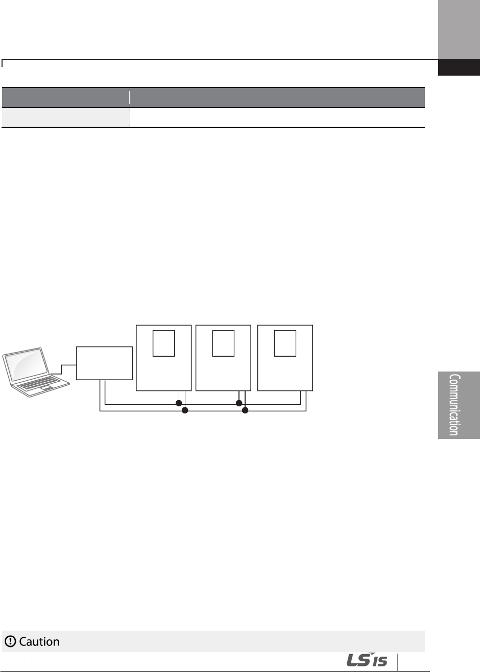
355
RS-485 Communication Features
Item
Standar
d
Parity check
None/Even/Odd
7.2 Communication System Configuration
In an RS-485 communication system, the PLC or computer is the master device and the inverter is
the slave device. When using a computer as the master, the RS-232 converter must be integrated
with the computer, so that it can communicate with the inverter through the RS-232/RS-485
converter. Specifications and performance of converters may vary depending on the
manufacturer, but the basic functions are identical. Please refer to the converter manufacturer’s
user manual for details about features and specifications.
Connect the wires and configure the communication parameters on the inverter by referring to
the following illustration of the communication system configuration.
7.2.1 Communication Line Connection
Make sure that the inverter is turned off completely, and then connect the RS-485 communication
line to the S+/S-/SG terminals of the terminal block. The maximum number of inverters you can
connect is 16. For communication lines, use shielded twisted pair (STP) cables.
The maximum length of the communication line is 1,200 meters, but it is recommended to use no
more than 700 meters of communication line to ensure stable communication. Please use a
repeater to enhance the communication speed when using a communication line longer than
1,200 meters or when using a large number of devices. A repeater is effective when smooth
communication is not available due to noise interference.
RS-232/485
Inverter #1
Converter
Computer
Inverter #2 Inverter #n

356
RS-485 Communication Features
When wiring the communication line, make sure that the SG terminals on the PLC and inverter are
connected. SG terminals prevent communication errors due to electronic noise interference.

357
RS-485 Communication Features
7.2.2 Setting Communication Parameters
Before proceeding with setting communication configurations, make sure that the
communication lines are connected properly. Turn on the inverter and set the communication
parameters.
Group
Code Name LCD Display
Parameter
Setting
Setting
range Unit
COM
01
Built-in communication
inverter ID
Int485 St ID 1
1
–
MaxComID
7
-
02
Built-in communication
protocol
Int485 Proto
0
ModBus
RTU 0-6 -
03
Built-in communication
speed
Int485
BaudR 3
9600 bps 0–8 -
04
Built-in communication
frame setting
Int485
Mode 0
D8/PN/S1 0–3 -
05
Transmission delay after
reception
Resp Delay 5 0–1000 msec
Communication Parameters Setting Details
Code
Description
COM
-
01 Int485 St ID
Sets the inverter station ID between 1 and
MaxComID
.
COM-02 Int485 Proto
Select one of the four built
-
in protocols: Modbus
-
RTU, LS INV 485, BACnet
or Metasys-N2.
Setting
Function
0
Modbus
-
RTU
Modbus
-
RTU compatible protocol
2
LS INV 485
Dedicated protocol for the LS inverter
4
BACnet
BAC net protocol
5
Metasys
-
N2
Metasys
-
N2 protocol
6
ModBus Master
Dedicated protocol for ModBus Master
COM
-
03 Int485 BaudR
Set a communication setting speed
up to 115,200 bps.
7
If AP1-40 is set to ‘4(Serve Drv)’, MaxComID is ‘8’, and if COM-02 is set to ‘4(BACnet), MaxComID is
‘127’. Otherwise MaxComID is ‘250’.
358
RS-485 Communication Features
Code
Description
The maximum setting range changes depending on the protocol.
Setting
Communication Speed
0
1200 bps
1
2400 bps
2
4800 bps
3
9600 bps
4
19200 bps
5
38400 bps
6
56 Kbps (57,600 bps)
7
76.8 Kbps (76,800 bps)
8
115 Kbps (115,200 bps)
If the COM-02 Int485 Proto setting is BACnet, the available
communication speed settings are 9600 bps, 19200 bps, 76.8 kbps.
If the COM-02 Int485 Proto setting is Metasys-N2, the communication
speed is fixed to 9600 bps and COM-03 Int485 BaudR is not shown.
COM-04 Int485 Mode
Set a communication configuration. Set the data length, parity check
method, and the number of stop bits.
Setting
Function
0
D8/PN/S1
8
-
bit data / no parity check / 1 stop bit
1
D8/PN/S2
8
-
bit data / no parity check / 2 stop bits
2
D8/PE/S1
8
-
bit data / even parity / 1 stop bit
3
D8/PO/S1
8
-
bit data / odd parity / 1 stop bit
If the COM-02 Int485 Proto setting is Metasys-N2, the communication
frame composition is fixed to D8/PN/S1 and COM-04 Int485 Mode is not
visible.
COM-05 Resp Delay
Set the response time for the slave (inverter) to react to the request from
the master. Response time is used in a system where the slave device
response is too fast for the master device to process. Set this code to an
appropriate value for smooth master-slave communication.
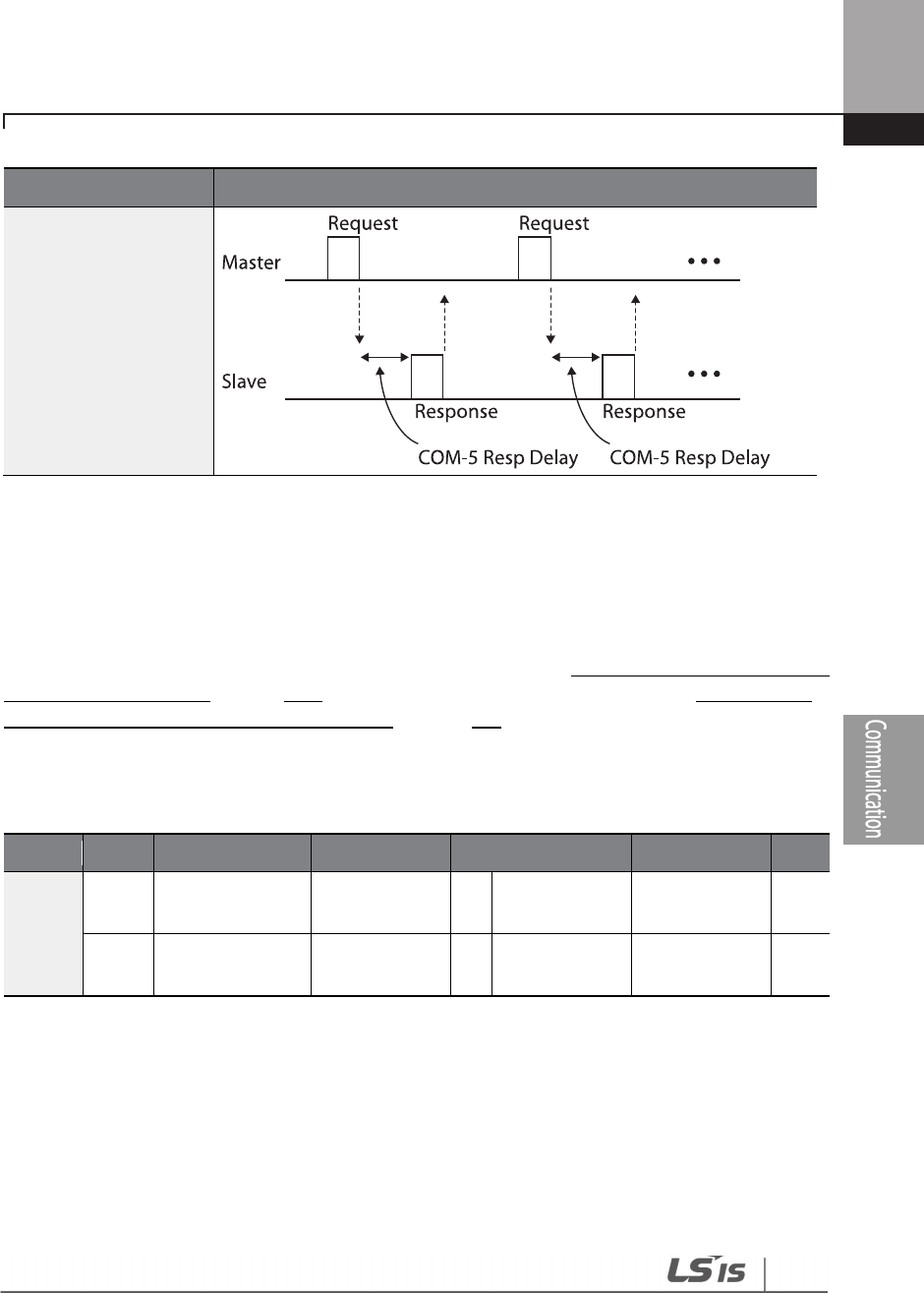
359
RS-485 Communication Features
Code
Description
7.2.3 Setting Operation Command and Frequency
After setting the DRV-06 Cmd Source code to ‘3 (Int 485)’ and DRV-07 Freq Ref Src code to ‘6 (Int
485)’, you can set common area parameters for the operation command and frequency via
communication. For details about the operation command, refer to 4.6.4 RS-485 Communication as
a Command Input Device on page 109 and about the frequency command, refer to 4.2.6 Setting a
Frequency Reference via RS-485 Communication on page 102.
To select the built-in RS485 communication as the source of command, set DRV-07 to ‘6 (Int485)’
on the keypad. Then, set common area parameters for the operation command and frequency via
communication.
Group
Code
Name
LCD Display
Parameter Setting
Setting range
Unit
DRV
06
Command
source Cmd Source 3 Int 485 0–5 -
07
Frequency
setting method Freq Ref Src 6 Int 485 0–11 -
7.2.4 Command Loss Protective Operation
Configure the command loss decision standards and protective operations run when a
communication problem lasts for a specified period of time.

360
RS-485 Communication Features
Group
Code
Name
LCD Display
Parameter Setting
Setting
range
Unit
PRT
12
Speed command loss
operation mode
Lost Cmd
Mode 0 None 0–5 -
13
Time to determine
speed command loss
Lost Cmd
Time 6 1.0 0.1–120.0 Sec

361
RS-485 Communication Features
Command Loss Protective Operation Setting Details
Code
Description
PRT-12 Lost Cmd
Mode,
PRT-13 Lost Cmd
Time
Select the operation to run when a communication error has occurred and
lasted exceeding the time set at PRT-13.
Setting
Function
0
None
The speed command immediately becomes the
operation frequency without any protection function.
1
Free
-
Run
The inverter blocks output. The motor performs in free
-
run condition.
2
Dec
The motor decelerates and then stops
.
3
Hold Input
Operates continuously with the speed of the inputted
speed command until the loss of the speed command.
The inverter calculates the average input value for 10
seconds before the loss of the speed command and uses
it as the speed reference.
4
Hold Output
Operates continuously with the operate frequency
before the speed loss. The inverter calculates the average
output value for 10 seconds before the loss of the speed
command and uses it as the speed reference.
5
Lost Preset
The inverter operates at the frequency set at PRT
-
14 (Lost
Preset F).

362
RS-485 Communication Features
7.3 LS INV 485/Modbus-RTU Communication
7.3.1 Setting Virtual Multi-function Input
Multi-function input can be controlled using a communication address (0h0385). Set codes COM-
70–77 to the functions to operate, and then set the BIT relevant to the function to 1 at 0h0385 to
operate it. Virtual multi-function operates independently from IN-65–71 analog multi-function
inputs and cannot be set redundantly. Virtual multi-function input can be monitored using COM-
86 (Virt Dl Status). Before you configure the virtual multi-function inputs, set the DRV code
according to the command source.
Group
Code
Name
LCD Display
Parameter Setting
Setting range
Unit
COM
70
–
77
Communication
multi-function input x
Virtual DI x
(x: 1–8) 0 None 0–55 -
86
Communication
multi-function input
monitoring
Virt DI Status
- - - -
Example: When sending an Fx command by controlling virtual multi-function input in the
common area via Int485, set COM-70 to ‘FX’ and set address 0h0385 to ‘0h0001’.
7.3.2 Saving Parameters Defined by Communication
If you turn off the inverter after setting the common area parameters or keypad parameters via
communication and operate the inverter, the changes are lost and the values changed via
communication revert to the previous setting values when you turn on the inverter.
Set CNF-48 to ‘1 (Yes)’ to allow all the changes over communication to be saved, so that the
inverter retains all the existing values even after the power has been turned off.
Group
Code
Name
LCD Display
Parameter Setting
Setting range
Unit
CNF
48
Save parameters
Parameter Save
0
No
0
–
1
-

363
RS-485 Communication Features
Setting address 0h03E0 to ‘0’ and then setting it again to ‘1’ via communication allows the existing
parameter settings to be saved. However, setting address 0h03E0 to ‘1’ and then setting it to ‘0’
does not carry out the same function.
1
Yes

364
RS-485 Communication Features
7.3.3 Total Memory Map for Communication
Communication Area
Memory Map
Details
Communication common
compatible area 0h0000–0h00FF
iS5, iP5A, iV5, iG5A, S100, H100 compatible
area
Parameter registration type
area
0h0100–0h01FF
Areas registered at COM
-
31
–
38 and COM
-
51
–
58
0h0200
–
0h023F
Area registered for User Group
0h0240
–
0h027F
Area registered for Macro Group
0h0280
–
0h02FF
Reserved
Communication common
area
0h0300
–
0h037F
Inverter monitoring area
0h0380
–
0h03DF
Inverter control area
0h03E0
–
0h03FF
Inverter memory
control area
0h0400
–
0h0FFF
Reserved
0h1100
DRV Group
0h1200
BAS Group
0h1300
ADVGroup
0h1400
CON Group
0h1500
IN Group
0h1600
OUT Group
0h1700
COM Group
0h1800
PID Group
0h1900
EPI Group
0h1A00
AP1 Group
0h1B00
AP2 Group
0h1C00
AP3 Group
0h1D00
PRT Group
0h1E00
M2 Group

365
RS-485 Communication Features
7.3.4 Parameter Group for Data Transmission
By defining a parameter group for data transmission, the communication addresses registered in
the communication function group (COM) can be used in communication. Parameter group for
data transmission may be defined to transmit multiple parameters at once, into the
communication frame.
Group Code Name LCD Display Parameter Setting Setting range Unit
COM
31–38
Output
communication
address x
Para Status-x - 0000–FFFF Hex
51–58
Input
communication
address x
Para Control-x - 0000–FFFF Hex
Currently Registered CM Group Parameter
Note
When registering control parameters, register the operation speed (0h0005, 0h0380, 0h0381) and
operation command (0h0006, 0h0382) parameters at the end of a parameter control frame. For
example, when the parameter control frame has 5 parameter control items (Para Control - x), register
the operation speed at Para Control-4 and the operation command to Para Control-5.
Address
Parameter
Assigned content by bit
0h0100–0h0107
Status Parameter
-
1
–
Status Parameter-8
Parameter communication code value registered at
COM-31–38 (Read-only)
0h0110–0h0117
Control Parameter
-
1
–
Control Parameter-8
Parameter communication code value registered at
COM-51–58 (Read/Write access)

366
RS-485 Communication Features
7.3.5 Parameter Group for User/Macro Group
By defining user/macro parameter groups, communication can be carried out using the user
defined group (USR Grp) and macro group (MAC Grp) addresses that are registered at the U&M
mode. Parameter groups can only be defined when using the keypad.
Currently Registered User Group Parameters
Address Parameter Assigned Content by Bit
0h0200 User Grp. Code 1 Parameter value registered at U&M > USR 1 (Read/Write) access)
0h0201 User Grp. Code 2 Parameter value registered at U&M > USR 2 (Read/Write) access)
.
.
.
.
.
.
.
.
.
0h023E User Grp. Code 63 Parameter value registered at U&M > USR 63 (Read/Write)
(Read/Write access)
0h023F User Grp. Code 64 Parameter value registered at U&M > USR 64 (Read/Write)
(Read/Write access)
Currently Registered Macro Group Parameters
Address Parameter Assigned Content by Bit
0h0240 Macro Grp. Code 1 Parameter value registered at U&M > MC 1
0h0241 Macro Grp. Code 2 Parameter value registered at U&M > MC 1
.
.
.
.
.
.
.
.
.
0h02A2 Macro Grp. Code 98 Parameter value registered at U&M > MC 98
0h02A3 Macro Grp. Code 99 Parameter value registered at U&M > MC 99
367
RS-485 Communication Features
7.3.6 LS INV 485 Protocol
The slave device (inverter) responds to read and write requests from the master device (PLC or PC).
Request
ENQ
Station ID
CMD
Data
SUM
EOT
1 byte 2 bytes 1 byte n bytes 2 bytes 1 byte
Normal Response
ACK
Station ID
CMD
Data
SUM
EOT
1 byte
2 bytes
1 byte
n x 4 bytes
2 bytes
1 byte
Error Response
• A request starts with ENQ and ends with EOT.
• A normal response starts with ACK and ends with EOT.
• An error response starts with NAK and ends with EOT.
• A station ID indicates the inverter number and is displayed as a two-byte ASCII-HEX string
that uses characters 0-9 and A-F.
• CMD: Uses uppercase characters (returns an IF error if lowercase characters are
encountered)—please refer to the following table.
Character ASCII-HEX Command
‘R’
52h
Read
‘W’
57h
Write
‘X’
58h
Request monitor registration
‘Y’
59h
Perform monitor registration
NAK
Station ID
CMD
Error code
SUM
EOT
1 byte
2 bytes
1 byte
2 bytes
2 bytes
1 byte

368
RS-485 Communication Features
• Data: ASCII-HEX (for example, when the data value is 3000: 3000 → ‘0’’B’’B’’8’h → 30h 42h
42h 38h)
• Error code: ASCII-HEX (refer to 7.3.6.4 Error Code on page 371)
• Transmission/reception buffer size: Transmission=39 bytes, Reception=44 bytes
• Monitor registration buffer: 8 Words
• SUM: Checks communication errors via sum.
• SUM=a total of the lower 8 bits values for station ID, command and data (Station
ID+CMD+Data) in ASCII-HEX.
• For example, a command to read 1 address from address 3000:
SUM=‘0’+‘1’+’R’+‘3’+‘0’+‘0’+‘0’+’1’ = 30h+31h+52h+33h+30h+30h+30h+31h = 1A7h (the
control value is not included: ENQ, ACK, NAK, etc
ENQ
Station ID
CMD
A
ddress
Number of Addresses
SUM
EOT
05h
‘01’
‘R’
‘3000’
‘1’
‘A7’
04h
1 byte
2 bytes
1 byte
4 bytes
1 byte
2 bytes
1 byte
Note
Broadcasting
Broadcasting sends commands to all inverters connected to the network simultaneously. When
commands are sent from station ID 255, each inverter acts on the command regardless of the station
ID. However no response is issued for commands transmitted by broadcasting
7.3.6.1 Detailed Read Protocol
Read Request: Reads successive n words from address XXXX.
ENQ Station ID CMD Address Number of Addresses SUM EOT
05h
‘01’
–
’FA’
‘R’
‘XXXX‘
‘1’
–
‘8’ = n
‘XX’
04h
1 byte
2 bytes
1 byte
4 bytes
1 byte
2 bytes
1 byte
Total bytes=12. Characters are displayed inside single quotation marks(‘).

369
RS-485 Communication Features
Read Normal Response
Total bytes= (7 x n x 4): a maximum of 39
Read Error Response
Total bytes=9
7.3.6.2 Detailed Write Protocol
Write Request
Total bytes= (12 + n x 4): a maximum of 44
Write Normal Response
Total bytes= (7 + n x 4): a maximum of 39
Write Error Response
ACK
Station ID
CMD
Data
SUM
EOT
06h
‘01’
–
‘FA’
‘R’
‘XXXX’
‘XX’
04h
1 byte
2 bytes
1 byte
n x 4 bytes
2 bytes
1 byte
NAK
Station ID
CMD
Error code
SUM
EOT
15h
‘01’
-
‘FA’
‘R’
‘**’
‘XX’
04h
1 byte
2 bytes
1 byte
2 bytes
2 bytes
1 byte
ENQ
Station ID
CMD
Address
Number of Addresses
Data
SUM
EOT
05h
‘01’
–
‘FA’
‘W’
‘XXXX’
‘1’
–
‘8’ = n
‘XXXX…’
‘XX’
04h
1 byte
2 bytes
1 byte
4 bytes
1 byte
n x 4 bytes
2 bytes
1 byte
ACK
Station ID
CMD
Data
SUM
EOT
06h
‘01’
–
‘FA’
‘W’
‘XXXX…’
‘XX’
04h
1 byte
2 bytes
1 byte
n x 4
bytes
2 bytes
1 byte
NAK
Station ID
CMD
Error Code
SUM
EOT
15h
‘01’
–
‘FA’
‘W’
‘**’
‘XX’
04h
1 byte
2 bytes
1 byte
2 bytes
2 bytes
1 byte
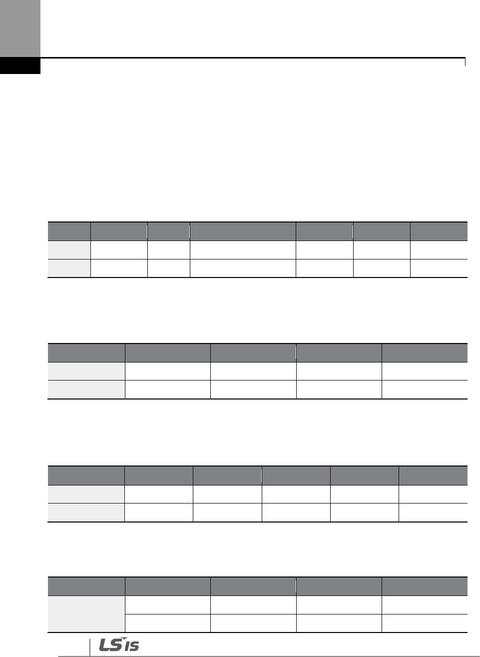
370
RS-485 Communication Features
Total bytes=9
7.3.6.3 Monitor Registration Detailed Protocol
Monitor registration request is made to designate the type of data that requires continuous
monitoring and periodic updating.
Monitor Registration Request: Registration requests for n addresses (where n refers to the
number of addresses. The addresses do not have to be contiguous.)
Total bytes= (8 + n x 4): a maximum of 40
Monitor Registration Normal Response
Total bytes=7
Monitor Registration Error Response
Total bytes=9
Monitor Registration Perform Request: A data read request for a registered address, received
ENQ Station ID CMD Number of Addresses Address SUM EOT
05h ‘01’–‘FA’ ‘X’ ‘1’–‘8’=n ‘XXXX…’ ‘XX’ 04h
1 byte 2 bytes 1 byte 1 byte n x 4 bytes 2 bytes 1 byte
ACK Station ID CMD SUM EOT
06h ‘01’–‘FA’ ‘X’ ‘XX’ 04h
1 byte 2 bytes 1 byte 2 bytes 1 byte
NAK Station ID CMD Error Code SUM EOT
15h ‘01’–‘FA’ ‘X’ ‘**’ ‘XX’ 04h
1 byte 2 bytes 1 byte 2 bytes 2 bytes 1 byte
ENQ Station ID CMD SUM EOT
05h ‘01’–‘FA’ ‘Y’ ‘XX’ 04h
1 byte 2 bytes 1 byte 2 bytes 1 byte

371
RS-485 Communication Features
from a monitor registration request
Total bytes=7
Monitor Registration Execution Normal Response
Totalbytes= (7 + n x 4): a maximum of 39
Monitor Registration Execution Error Response
NAK
Station ID
CMD
Error Code
SUM
EOT
15h
‘01’
–
‘FA’
‘Y’
‘**’
‘XX’
04h
1 byte
2 bytes
1 byte
2 bytes
2 bytes
1 byte
Total bytes=9
7.3.6.4 Error Code
Code
Abbreviation
Description
ILLEGAL FUNCTION IF
The requested function cannot be
performed by a slave
because the corresponding function does not exist.
ILLEGAL DATA
ADDRESS IA The received parameter address is invalid at the slave.
ILLEGAL
DATA VALUE
ID
The received parameter data is invalid at the slave.
WRITE MODE ERROR WM
Tried writing (W) to a parameter that does not allow writing
(read-only parameters, or when writing is prohibited
during operation)
ACK Station ID CMD Data SUM EOT
06h ‘01’–‘FA’ ‘Y’ ‘XXXX…’ ‘XX’ 04h
1 byte 2 bytes 1 byte n x 4 bytes 2 bytes 1 byte
372
RS-485 Communication Features
Code
Abbreviation
Description
FRAME ERROR
FE
The frame size does not match.
7.3.6.5 ASCII Code
Character
Hex
Character
Hex
Character
Hex
A
B
C
D
E
F
G
H
I
J
K
L
M
N
O
P
Q
R
S
T
U
V
W
X
Y
Z
a
b
c
d
e
f
g
41
42
43
44
45
46
47
48
49
4A
4B
4C
4D
4E
4F
50
51
52
53
54
55
56
57
58
59
5A
61
62
63
64
65
66
67
q
r
s
t
u
v
w
x
y
z
0
1
2
3
4
5
6
7
8
9
space
!
"
#
$
%
&
'
(
)
*
+
,
71
72
73
74
75
76
77
78
79
7A
30
31
32
33
34
35
36
37
38
39
20
21
22
23
24
25
26
27
28
29
2A
2B
2C
@
[
\
]
{
|
}
–
BEL
BS
CAN
CR
DC1
DC2
DC3
DC4
DEL
DLE
EM
ACK
ENQ
EOT
ESC
ETB
ETX
FF
FS
GS
HT
LF
40
5B
5C
5D
5E
5F
60
7B
7C
7D
7E
07
08
18
0D
11
12
13
14
7F
10
19
06
05
04
1B
17
03
0C
1C
1D
09
0A

373
RS-485 Communication Features
Character
Hex
Character
Hex
Character
Hex
h
i
j
k
l
m
n
o
p
68
69
6A
6B
6C
6D
6E
6F
70
-
.
/
:
;
<
=
>
?
2D
2E
2F
3A
3B
3C
3D
3E
3F
NAK
NUL
RS
S1
SO
SOH
STX
SUB
SYN
US
VT
15
00
1E
0F
0E
01
02
1A
16
1F
0B
7.3.7 Modbus-RTU Protocol
7.3.7.1 Function Code and Protocol
In the following section, station ID is the value set at COM-01 (Int485 St ID), and the starting
address is the communication address (starting address size is in bytes). For more information
about communication addresses, refer to 7.3.8 Compatible Common Area Parameter on page 378.
Reading up to 8 Consecutive Inverter Parameters Based on the Set Number - Read Holding
Register (Func. Code: 0x03) and Read Input Register (Func. Code: 0x04)
Read Holding Registers (Func. Code: 0x03) and Read Input Registers (Func. Code: 0x04) are
processed identically by the inverter.
Codes
Description
Start Addr.
Starting address 1
of the inverter parameters (common area or keypad) to be
read from.
No. of Reg.
Number of the inverter parameters (common area or keypad) to be read.
Byte Count
Byte number of normal response values based on the number of registers (No.
of Reg).
Except. Code
Error codes

374
RS-485 Communication Features
Request
Slave
Station ID
Func.
Code
Start Addr
(Hi)
Start Addr
(Lo)
No of Reg
(Hi)
No of Reg
(Lo)
CRC
(Lo)
CRC
(Hi)
1 byte 1 byte 1 byte 1 byte 1 byte 1 byte 1 byte 1 byte
Normal Response
Slave
Station ID
Func.
Code
Byte
Count
Value
(Hi)
Value
(Lo) …
Value
(Hi)
Value
(Lo)
CRC
(Lo)
CRC
(Hi)
1 byte 1 byte 1 byte 1 byte 1 byte … 1 byte 1 byte 1 byte 1 byte
* The number of Value(Hi) and Value(Lo) is changed by the [Request No. of Reg].
Error Response
Slave Station ID Func. Code Except. Code CRC(Lo) CRC(Hi)
1 byte 1 byte 1 byte 1 byte 1 byte
* Func. Code of the error response is [Request Func. Code] + 0x80.
Writing One Inverter Parameter Value (Func. Code: 0x06)
Codes
Description
Addr.
Address 1 of the inverter parameter
(common area or keypad) to be written to.
Reg. Value
The inverter parameter (common area or keypad) value to write with.
Except. Code
Error codes
Request
Slave
Station ID Func.Code
Addr (Hi) Addr(Lo) Value(Hi) Value(Lo) CRC(Lo) CRC(Hi)
1 byte 1 byte 1 byte 1 byte 1 byte 1 byte 1 byte 1 byte
Normal Response
375
RS-485 Communication Features
Slave
Station ID
Func.Code
Addr (Hi) Addr(Lo) Value(Hi) Value(Lo) CRC(Lo) CRC(Hi)
1 byte 1 byte 1 byte 1 byte 1 byte 1 byte 1 byte 1 byte
Error Response
Slave Station ID Func. Code Except. Code CRC(Lo) CRC (Hi)
1 byte 1 byte 1 byte 1 byte 1 byte
* Func. Code of the error response is [Request Func. Code] + 0x80.
Writing Multiple Registers (Func. Code: 0x10)
Codes
Description
Start Addr.
Starting address 1 of the inverter parameters (common
area or keypad) to be
written to.
No. of Reg.
Number of the inverter parameters (common area or keypad) to be written.
Reg. Value
The inverter parameter (common area or keypad) values to write with.
Except. Code
Error codes
Request
Slave
Station
ID
Func.
Code
Start
Addr.
(Hi)
Start
Addr.
(Lo)
No of
Reg.
(Hi)
No of
Reg.
(Lo)
Byte
Count
Reg.
Value
(Hi)
Reg.
Value
(Lo)
CRC
(Lo)
CRC
(Hi)
1 byte 1 byte 1 byte 1 byte 1 byte 1 byte 1 byte 1 byte 1 byte 1 byte
1 byte
Normal Response

376
RS-485 Communication Features
Slave
Station ID
Func.
Code
Start Addr
(Hi)
Start Addr
(Lo)
No of Reg.
(Hi)
No of Reg.
(Lo)
CRC
(Lo)
CRC
(Hi)
1 byte
1 byte
1 byte
1 byte
1 byte
1 byte
1 byte
1 byte
Error Response
Slave Station ID Func. Code Except. Code CRC(Lo) CRC(Hi)
1 byte 1 byte 1 byte 1 byte 1 byte
* Func. Code of the error response is [Request Func. Code] + 0x80.

377
RS-485 Communication Features
Exception Code
Code
01: ILLEGAL FUNCTION
02: ILLEGAL DATA ADDRESS
03: ILLEGAL DATA VALUE
06: SLAVE DEVICE BUSY
14: Write
-
Protection
Example of Modbus
-
RTU Communication In Use
When the Acc time (Communication address 0x1103) is changed to 5.0 sec and the Dec time
(Communication address 0x1104) is changed to 10.0 sec.
Frame Transmission from Master to Slave
Item
Station
ID Function
Starting
Address
# of
Register
Byte
Count Data 1 Data 2 CRC
Hex
0x01
0x10
0x1102
0x0002
0x04
0x0032
0x0064
0x1202
Des
cript
ion
COM
-
01
Int485
St ID
Preset
Multiple
Register
Start
Address-1
(0x1103-1)
- -
50
(Acc time
5.0 sec)
100
(Dec time
10.0 sec)
-
Frame Transmission from Slave to Master
Item
Station Id
Function
Starting Address
# of Register
CRC
Hex
0x01
0x10
0x1102
0x0002
0xE534
Description
COM
-
01 Int485
St ID
Preset Multiple
Register
Starting Address
-
1
(0x1103-1) - -

378
RS-485 Communication Features
7.3.8 Compatible Common Area Parameter
The following are common area parameters partly compatible with the iS5, iP5A, iV5, iG5A, S100
series inverters. .( Addresses 0h0000-0h0011 are for compatible common area parameters.
Addresses 0h0012-0h001B are for H100 series inverter parameters.)
Comm.
Address
Parameter Scale Unit R/W Assigned Content by Bit
0h0000
Inverter model
-
-
R
F: H100
0h0001 Inverter capacity - - R
0: 0.75
kW, 1: 1.5kW, 2: 2.2kW
3: 3.7kW 4: 5.5kW, 5: 7.5kW
6: 11kW, 7: 15kW, 8: 18.5kW
9: 22kW, 10: 30kW, 11: 37kW
12: 45kW ,13: 55kW, 14: 75kW,
15: 90kW, 16: 110kW, 17: 132kW
18: 160kW, 19: 185kW, 20: 220kW
21: 250kW, 22: 315kW, 23: 355kW
24: 400kW, 25: 500kW
0h0002 Inverter input voltage
- - R
0: 220 V product
1: 440 V product
0h0003 Version - - R
(Example) 0h0064: Version 1.00
(Example) 0h0065: Version 1.01
0h0004
Reserved
-
-
R
-
0h0005
Command frequency
0.01
Hz
R/W
-
0h0006 Operation command
(option) - - R
B15
Reserved
B14
0: Keypad Freq,
2-8: Terminal block multi-step
speed
17: Up, 18: Down
19: STEADY
22: V1, 24: V2, 25: I2,
26: PULSE
27: Built-in 485
28: Communication option
30: JOG, 31: PID
B13
B12
B11
B10
B9
B8
0: Keypad
1: Fx/Rx-1
B7

379
RS-485 Communication Features
B6
2: Fx/Rx
-
2
3: Built-in 485
4: Communication option
5: Time Event
R/W
B5
Reserved
B4
Emergency stop
B3
W: Trip initialization (0
1),
R: Trip status
B2
Reverse operation (R)
B1
Forward operation (F)
B0
Stop (S)
0h0007
Acceleration time
0.1
sec
R/W
-
0h0008
Deceleration time
0.1
sec
R/W
-
0h0009
Output current
0.1
A
R
-
0h000A
Output frequency
0.01
Hz
R
-
0h000B
Output voltage
1
V
R
-
0h000C
DC link voltage
1
V
R
-
0h000D
Output power
0.1
kW
R
-
0h000E Operation status - - R
B15
0: HAND, 1: AUTO
B14
1: Frequency command source
by communication (built-in,
option)
B13
1: Operation command source
by communication (built-in,
option)
B12
Reverse operation command
B11
Forward operation command
B10
Reserved
B9
Jog mode
B8
Drive stopping
B7
DC Braking
B6
Speed reached

380
RS-485 Communication Features
B5
Decelerating
B4
Accelerating
B3
Fault
Trip
-
operates according
to OUT-30 setting
B2
Operating in reverse direction
B1
Operating in forward direction
B0
Stopped
0h000F Fault trip information
- - R
B15
Reserved
B14
Reserved
B13
Reserved
B12
Reserved
B11
Reserved
B10
H/W
-
Diag
B9
Reserved
B8
Reserved
B7
Reserved
B6
Reserved
B5
Reserved
B4
Reserved
B3 Level Type trip
B2
Reserved
B1
Reserved
B0
Latch Type trip
0h0010 Input terminal
information - - R
B15
–B7
Reserved
B6
P7
B5
P6
B4
P5
B3
P4
B2
P3

381
RS-485 Communication Features
B1
P2
B0
P1
0h0011 Output terminal
information - - R
B15
Reserved
B14
Reserved
B13
Reserved
B12
Reserved
B11
Reserved
B10
Q1
B9
Reserved
B8
Reserved
B7
Reserved
B6
Reserved
B5
Reserved
B4
Relay 5
B3
Relay 4
B2
Relay 3
B1
Relay 2
B0
Relay 1
0h0012
V1
0.1
%
R
V1 input voltage
0h0013
Thermal
0.1
%
R
Input
Thermal
0h0014
V
2
0.1
%
R
V2 input voltage
0h0015
I2
0.1
%
R
I2 input Current
0h0016
Motor rotation speed
1
Rpm
R
Displays existing motor rotation speed
0h0017
–0h0019 Reserved - - - -
0h001A
Select Hz/rpm
-
-
R
0: Hz unit, 1: rpm unit
0h001B
Display
the number
of poles for the
selected motor
- - R Display the number of poles for the
selected motor

382
RS-485 Communication Features
7.3.9 H100 Expansion Common Area Parameter
7.3.9.1 Monitoring Area Parameter (Read Only)
Comm.
Address Parameter Scale Unit Assigned content by bit
0h0300 Inverter model - - H100: 000Fh
0h0301 Inverter capacity - -
0.75
kW
: 4008
h, 1.5
kW
: 4015h
2.2 kW: 4022h, 3.7 kW: 4037h
5.5 kW: 4055h, 7.5 kW: 4075h
11 kW: 40B0h, 15 kW: 40F0h
18.5 kW: 4125h, 22 kW: 4160h
30 kW: 41E0h, 37 kW: 4250h,
45 kW: 42D0h,55 kW: 4370h,
75 kW: 44B0h,90 kW: 45A0h,
110 kW: 46E0h, 132 kW: 4840h
160 kW: 4A00h, 185kW: 4B90h,
220 kW: 4DC0h, 250 kW: 4FA0h,
315 kW: 53B0h, 355 kW: 5630h,
400 kW: 5900h, 500 kW: 5F40h
0h0302
Inverter input
voltage/power (Single
phase, 3-phase)/cooling
method
- -
200 V 3-phase forced cooling: 0231h
400 V 3-phase forced cooling: 0431h
0h0303 Inverter S/W version - -
(ex) 0h0064: Version 1.00
0h0065: Version 1.01
0h0304 Reserved - - -
0h0305 Inverter operation state - -
B15 0: Normal state
4: Warning occurred
8: Fault occurred
B14

383
RS-485 Communication Features
B13
B12
B11–
-
B8
B7
1: Speed searching
2: Accelerating
3: Operating at constant rate
4: Decelerating
5: Decelerating to stop
6: H/W OCS
7: S/W OCS
8: Dwell operating
B6
B5
B4
B3
0: Stopped
1: Operating in forward direction
2: Operating in reverse direction
3: DC operating
B2
B1
B0
0h0306
Inverter operation
frequency command
source
- -
B15
Operation command source
0: Keypad
1: Communication option
3: Built-in RS 485
4: Terminal block
B14
B13
B12
B11
B10
B9
B8
B7
Frequency command source
0: Keypad speed
1: Keypad torque
2-4: Up/Down operation speed
5: V1, 7: V2, 8: I2
9: Pulse
B6
B5
B4
B3

384
RS-485 Communication Features
B2
10: Built
-
in RS 485
11: Communication option
13: Jog
14: PID
25-31: Multi-step speed frequency
B1
B0
0h0307
Keypad S/W version
-
-
(Ex.) 0h0064: Version 1.00
0h0308
Keypad title version
-
-
(Ex.) 0h0065: Version 1.01
0h0309 IO Board Version - -
(Ex.) 0h0064: Version 1.00
(Ex.) 0h0065: Version 1.01
0h030A
–
0h30F Reserved - - -
0h0310
Output current
0.1
A
-
0h0311
Output frequency
0.01
Hz
-
0h0312
Output rpm
0
Rpm
-
0h0313
Reserved
-
-
-
0h0314
Output voltage
1
V
-
0h0315
DC Link voltage
1
V
-
0h0316
Output power
0.1
kW
-
0h0317
Reserved
-
-
-
0h0318
PID
reference
0.1
%
PID reference value
0h0319
PID feedback
0.1
%
PID feedback value
0h031A
Display the number of
poles for the 1
st
motor - -
Displays the number of poles for the first
motor
0h031B
Display the number of
poles for the 2
nd
motor - -
Displays the number of poles for the 2nd
motor
0h031C
Display the number of
poles for the selected
motor
- - Displays the number of poles for the
selected motor
0h031D
Select Hz/rpm
-
-
0: Hz, 1: rpm
0h031E
–0h031F Reserved - - -
0h0320 Digital input information
B15
–
B7 Reserved

385
RS-485 Communication Features
B6
P7 (I/O board)
B5
P6 (I/O board)
B4
P5 (I/O board)
B3
P4 (I/O board)
B2
P3 (I/O board)
B1
P2 (I/O board)
B0
P1 (I/O board)
0h0321 Digital output
information - -
B15
–
B11 Reserved
B10
Q1
B9
–
B5 Reserved
B4
Relay 5
B3
Relay 4
B2
Relay 3
B1
Relay 2
B0
Relay 1
0h0322 Virtual digital input
information - -
B15
–
B8 Reserved
B7
Virtual DI 8 (COM
-
77)
B6
Virtual DI 7 (COM
-
76)
B5
Virtual DI 6
(COM
-
75)
B4
Virtual DI 5 (COM
-
74)
B3
Virtual DI 4 (COM
-
73)
B2
Virtual DI 3 (COM
-
72)
B1
Virtual DI 2 (COM
-
71)
B0
Virtual DI 1 (COM
-
70)
0h0323
Display the selected
motor - - 0: 1st motor/1: 2nd motor
0h0324
AI1
0.01
%
Analog input
V1 or Thermal
(I/O board)

386
RS-485 Communication Features
0h0325
AI2
0.01
%
Analog input V2 or I2 (I/O board)
0h0326
Reserved
-
-
Reserved
0h0327
Reserved
-
-
Reserved
0h0328
AO1
0.01
%
Analog output 1 (I/O board)
0h0329
AO2
0.01
%
Analog output 2 (I/O board)
0h032A
Reserved
0.01
%
Reserved
0h032B
Reserved
0.01
%
Reserved
0h032C
Reserved
-
-
Reserved
0h032D
Reserved
-
-
Reserved
0h032E
Consumption energy
(kWh) 0.1 kWh Consumption energy (kWh)
0h032F
Consumption energy
(MWh) 1 MWh
Consumption energy (MWh)
0h0330 Latch type trip
information - 1 - -
B15
PC Repeat Err
B14
Over Heat Trip
B13
Reserved
B12
External Trip
B11
Damper Err
B10
Pipe Break
B9
NTC Open
B8
Reserved
B7
Reserved
B6
In Phase Open
B5
Out Phase Open
B4
Low
Voltage2
B3
E
-
Thermal
B2
Inverter OLT
B1
Under Load
B0
Over Load
0h0331
Latch type trip
-
-
B15
Reserved

387
RS-485 Communication Features
information
-
2
B14
MMC Interlock
B13
Reserved
B12
Reserved
B11
Reserved
B10
Option Trip
-
1
B9
No
Motor Trip
B8
Reserved
B7
IO Board Trip
B6
Broken Belt
B5
ParaWrite Trip
B4
TB Trip
B3
Fan Trip
B2
Thermal Trip
B1
Level Detect
B0
Reserved
0h0332 Level type trip
information - -
B15
–
B4 Reserved
B3
Lost
Keypad
B2
Lost Command
B1
Low Voltage
B0
BX
0h0333 H/W Diagnosis Trip
information - -
B15
–
B3 Reserved
B2
Watchdog
-
1 error
B1
EEP Err
B0
ADC Offset
0h0334 Warning information-1 - -
B15
Broken Belt
B14
Low Battery
B13 Load Tune

388
RS-485 Communication Features
B12 Fan Exchange
B11 CAP. Warning
B10
Level Detect
B9 Reserved
B8 Lost Keypad
B7 Pipe Break
B6 Fire Mode
B5
DB Warn %ED
B4
Fan Warning
B3
Lost Command
B2
Inv Over Load
B1
Under Load
B0
Over Load
0h0335 Latch type trip
information -3 - -
B15
Reserved
–
Reserved
B4
Reserved
B3
Overcurrent2 Trip
B2
Overvoltage Trip
B1
Overcurrent1 Trip
B0
Ground Fault Trip
0h0336 Warning information-2 - -
B15
Reserved
~ Reserved
B3 KPD H.O.A Lock
B2 Lsig Tune Err
B1 Rs Tune Err
B0 ParaWrite Fail

389
RS-485 Communication Features
0h0337–
0h0339 Reserved - - Reserved
0h033A Proc PID Output 0.01 % Process PID Output (%)
0h033B Proc PID UnitScale Ref Proc
Unit
Proc
Unit Unit Scaled Process PID reference value
0h033C Proc PID UnitScale Fdb Proc
Unit
Proc
Unit Unit Scaled Process PID feedback value
0h0340 On Time date 0 Day
Total number of days the inverter has been
powered on
0h0341 On Time Minute 0 Min
Total number of
minutes excluding the total
number of On Time days
0h0342 Run Time date 0 Day
Total number of days the inverter has driven
the motor
0h0343 Run Time minute 0 Min
Total number of minutes excluding the total
number of Run Time days
0h0344 Fan Time date 0 Day Total number of days the heat sink fan has
been running
0h0345 Fan Time minute 0 Min
Total number of minutes excluding the total
number of Fan Time days
0h0346
–0h0348 Reserved - - Reserved
0h0349
Reserved
-
-
-
0h034A Option 1 - - 0: None, 5: LonWorks
0h034B
Reserved
-
-
Reserved
0h034C
Reserved
Reserved
0h034D–
0h034F Reserved - - Reserved
0h0350 E-PID 1 Output 0.01 % External PID 1 output
0h0351 E-PID 1 Ref 0.1 % External PID 1 Reference

390
RS-485 Communication Features
0h0352 E-PID 1 Fdb 0.1 % External PID 1 feedback
0h0353 E-PID 1 Unit Scale Ref Proc
Unit
Proc
Unit Unit Scale External PID 1 Reference
0h0354 E-PID 1 Unit Scale Fdb Proc
Unit
Proc
Unit Unit Scale External PID 1 feedback
0h0355 Reserved - - Reserved
0h0356 Reserved - - Reserved
0h0357 E-PID 2 Output 0.01 % External PID 2 output
0h0358 E-PID 2 Ref 0.1 % External PID 2 Reference
0h0359 E-PID 2 Fdb 0.1 % External PID 2 feedback
0h035A E-PID 2 Unit Scale Ref Proc
Unit
Proc
Unit Unit Scale External PID 2 Reference
0h035B E-PID 2 Unit Scale Fdb Proc
Unit
Proc
Unit Unit Scale External PID 2 feedback
0h035C Application Status - -
B15
–B2
Reserved
B1 Fire Mode
B0 Pump Clean
0h035D Inv Temperature 0 ℃ Heatsink Temperature
0h035E Power Factor 0.1 - Output power factor
0h035F Inv Fan Time - % INV Fan running time(%)
0h0360 Multi motor control
terminal output - -
B15
Reserved
–
Reserved
B5 Reserved
B4 5
th
motor running

391
RS-485 Communication Features
B3 4
th
motor running
B2 3
rd
motor running
B1 2
nd
motor running
B0 1
st
motor running

392
RS-485 Communication Features
7.3.9.2 Control Area Parameter (Read/Write)

393
RS-485 Communication Features
Comm.
Address Parameter Scale Unit Assigned Content by Bit
0h0380
Frequency command
0.01
Hz
Command frequency setting
0h0381
RPM
command
1
Rpm
Command rpm setting
0h0382 Operation command - -
B15
–
B4
Reserved
B3
0
1: Free
-
run stop
B2
0
1: Trip initialization
B1
0: Reverse command, 1:
Forward command
B0
0: Stop command, 1: Run
command
Example:
Forward
operation command
0003h,
Reverse operation command 0001h
0h0383
Acceleration time
0.1
sec
Acceleration time setting
0h0384
Deceleration time
0.1
sec
Deceleration time setting
0h0385 Virtual digital input
control (0: Off, 1: On) - -
B15
–
B8
Reserved
B7
Virtual DI 8 (COM
-
77)
B6
Virtual DI 7 (COM
-
76)
B5
Virtual DI 6 (COM
-
75)
B4
Virtual DI 5 (COM
-
74)
B3
Virtual DI 4 (COM
-
73)
B2
Virtual DI 3 (COM
-
72)
B1
Virtual DI 2 (COM
-
71)
B0
Virtual DI 1 (COM
-
70)
0h0386 Digital output control
(0: Off, 1: On) - -
B15
–
B11
Reserved
B10
Q1
B9
–
B5 Reserved
B4
Relay 5
B3
Relay 4

394
RS-485 Communication Features
B2
Relay 3
B1
Relay 2
B0
Relay 1
0h0387
KPD H.O.A Lock
1
-
0 : Locked, 1 : During
Run
, 2 : Unlocked
0h0388
PID
reference
0.1
%
Process PID reference
0h0389
PID feedback value
0.1
%
Process PID feedback
0h038A
Motor rated current
0.1
A
-
0h038B
Motor rated voltage
1
V
-
0h038C
–
0h038D Reserved - - Reserved
0h038E
Proc PID Unit
Reference
Proc
Unit
Proc
Unit Unit Scale Process PID reference
0h038F
Proc PID Unit
Feedback
Proc
Unit
Proc
Unit Unit Scale Process PID feedback
0h0390
–
0h0399 Reserved - - Reserved
0h039A Anytime Para - -
Set the CNF
-
20 value (refer to
5.49
Operation
State Monitor on page 316)
0h039B Monitor Line-1 - -
Set the CNF
-
21 value (refer
to
5.49
Operation
State Monitor on page 316)
0h039C Monitor Line-2 - -
Set the CNF
-
22 value (refer
to
5.49
Operation
State Monitor on page 316)
0h039D Monitor Line-3 - -
Set the CNF
-
23 value (refer
to
5.49
Operation
State Monitor on page 316)
0h039E
–
0h039F Reserved Reserved
0h03A0
PID Ref 1 Aux Value
0.1
%
PID Aux 1 reference
0h03A1
PID Ref 2 Aux Value
0.1
%
PID Aux 2 reference
0h03A2
PID Feedback Aux
Value 0.1 % PID Aux feedback
0h03A3
Proc
PID Aux 1 Unit
Scale
Proc
Unit
Proc
Unit Unit Scale PID Aux 1 reference
0h03A4
Proc PID Aux 2 Unit
Proc
Proc
Unit Scale PID Aux 2 reference

395
RS-485 Communication Features
Note
A frequency set via communication using the common area frequency address (0h0380, 0h0005) is
not saved even when used with the parameter save function. To save a changed frequency to use
after a power cycle, follow these steps:
1 Set DRV-07 to ‘Keypad-1’ and select a target frequency.
2 Set the frequency via communication into the parameter area frequency address (0h1101).
3 Perform the parameter save (0h03E0: '1') before turning off the power. After the power
cycle, the frequency set before turning off the power is displayed.
Scale
Unit
Unit
0h03A5
Proc PID Fdb Aux Unit
Scale
Proc
Unit
Proc
Unit Unit Scale PID Aux feedback
0h03A6
–
0h03AF Reserved Reserved
0h03B0
E
-
PID 1 Ref
0.1
%
External PID 1 reference
0h03B1
E
-
PID 1 Fdb
0.1
%
External PID 1 reference
0h03B2 E-PID 1 Unit Scale Ref
Proc
Unit
Proc
Unit Unit Scale External PID 1 reference
0h03B3 E-PID 1 Unit Scale Fdb
Proc
Unit
Proc
Unit Unit Scale External PID 1 feedback
0h03B4
Reserved
Reserved
0h03B5
E
-
PID 2 Ref
0.1
%
External PID 2 reference
0h03B6
E
-
PID 2 Fdb
0.1
%
External PID 2 feedback
0h03B7 E-PID 2 Unit Scale Ref
Proc
Unit
Proc
Unit Unit Scale External PID 2 reference
0h03B8 E-PID 2 Unit Scale Fdb
Proc
Unit
Proc
Unit Unit Scale External PID 2 feedback

396
RS-485 Communication Features
7.3.9.3 Inverter Memory Control Area Parameter (Read and Write)
Comm.
Address Parameter Scale Unit
Changeable
During
Running
Function
0h03E0 Save parameters - - X 0: No, 1: Yes
0h03E1 Monitor mode initialization - - O 0: No, 1: Yes
0h03E2 Parameter initialization - - X
0: No,
1: All Grp
2: DRV Grp
3: BAS Grp
4: ADV Grp
5: CON Grp
6: IN Grp
7: OUT Grp
8: COM Grp
9: PID Grp
10: EPID Grp
11: AP1 Grp
12: AP2 Grp
13: AP3 Grp
14: PRT Grp
15: M2 Grp
Setting is
prohibited
during fault trip
interruptions.
0h03E3 Display changed - - O 0: No, 1: Yes
0h03E4 Macro Function Setting - - X
0: Basic
1: Compressor
2: Supply Fan
3: Exhaust Fan
4: Cooling Tower
5: Circul. Pump
6: Vacuum Pump
7: Constant Torq
0h03E5 Delete all fault history - - O 0: No, 1: Yes
0h03E6 Delete user-registrated
codes - - O 0: No, 1: Yes
0h03E7 Hide parameter mode 0 Hex O Write: 0–9999
Read: 0: Unlock, 1: Lock
0h03E8 Lock parameter mode 0 Hex O Write: 0–9999
Read: 0: Unlock, 1: Lock
0h03E9 Easy start on (easy
parameter setup mode) - - O 0: No, 1: Yes
0h03EA Initializing power
consumption - - O 0: No, 1: Yes

397
RS-485 Communication Features
Note
• When setting parameters in the inverter memory control area, the values are reflected to the
inverter operation and saved. Parameters set in other areas via communication are reflected to
the inverter operation, but are not saved. All set values are cleared following an inverter power
cycle and revert back to its previous values. When setting parameters via communication,
ensure that a parameter save is completed prior to shutting the inverter down.
• Set parameters very carefully. After setting a parameter to ‘0’ via communication, set it to
another value. If a parameter has been set to a value other than ‘0’ and a non-zero value is
entered again, an error message is returned. The previously-set value can be identified by
reading the parameter when operating the inverter via communication.
• The addresses 0h03E7 and 0h03E8 are parameters for entering the password. When the
password is entered, the condition will change from Lock to Unlock, and vice versa. When the
same parameter value is entered continuously, the parameter is executed just once. Therefore, if
the same value is entered again, change it to another value first and then re-enter the previous
value. For example, if you want to enter 244 twice, enter it in the following order: 244 0
244.
• If the communication parameter settings are initialized by setting the address 0h03E2 to [1: All
Grp] or [8: COM Grp], or if any Macro function item is modified by setting the address 0h03E4, all
the communication parameter settings are reverted to the factory default. If this happens, the
inverter may not be able to properly receive responses from the upper-level devices due to the
changes in the settings.
• If there is an undefined address in the addresses for reading multiple consecutive data defined
in the common area, the undefined address returns0xFFFF while all the others return normal
response. If all the consecutive addresses are undefined, one return code is received from the
first undefined address only.
• If there is an undefined address in the addresses for writing into multiple consecutive data
defined in the common area, or if the value that is being written is not a valid one, no error
response about the wring operation is returned. If all the consecutive addresses are undefined,
or if all the date is invalid, one return code is received from the first undefined address only.
It may take longer to set the
parameter values in the inverter memory control area because all data is
saved to the inverter. Be careful as communication may be lost during parameter setup if parameter
setup is continues for an extended period of time.
0h03EB Initialize inverter operation
accumulative time - - O 0: No, 1: Yes
0h03EC Initialize cooling fan
accumulated operation time
- - O 0: No, 1: Yes

398
RS-485 Communication Features
7.4 BACnet Communication
7.4.1 What is BACnet Communication?
BACnet (Building Automation and Control network) is a communication network frequently used
in building automation. BACnet introduces the concept of object-oriented systems, and defines
standardized objects. By exchanging data, this function makes communication possible between
products from different companies. It also standardizes some of the general services carried out by
using these standard objects.
7.4.2 BACnet Communication Standards
Application
Items
Specification
Connection
Interface
5 Pin Pluggable connector
Data transmission
RS
-
485
MS/TP, Half
-
duplex
Cable
Twisted pair (1 pair and shield)
Communication
BACnet MS/TP
Stated in ANSI/ASHRAE Standards 135
-
2004
Baud Rate
Supports 9600, 19200, 38400, 76800 bps
MAC Address
1
–
127
Start/Stop bit
Start 1 bit, Stop ½ bit
Parity check
None/Even/Odd
7.4.3 BACnet Quick Communication Start
Follow the instructions below to configure the BACnet network for a quick start.
1 Set five multi-function input terminals (IN-65–71 PxDefine) to ‘Interlock 1’ – ‘Interlock 5’
respectively, in the correct motor order.
Note
• When auto change mode selection (AP1–55) is set to ‘0 (None)’ or ‘1 (Aux)’, and if 5 motors
are operated, including the main motor, the interlock numbers 1,2,3,4,5 refer to the
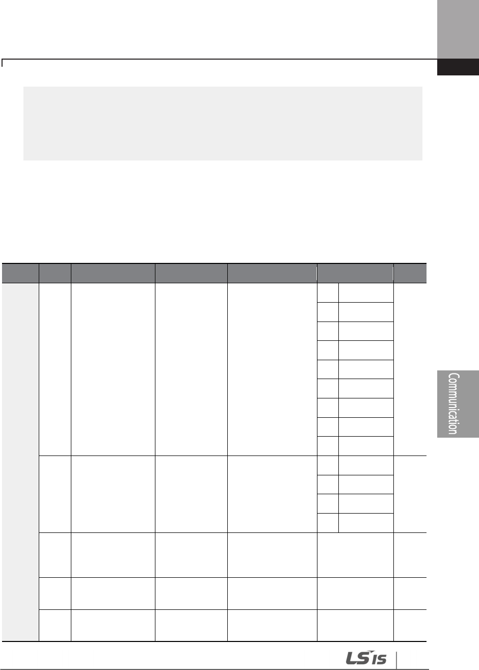
399
RS-485 Communication Features
monitors connected to Relay 1,2,3,4,5 (If interlock numbers 1,2,3,4,5 are connected to Relay
1,2,3,4,5 at the inverter output terminal).
• If auto change mode selection (AP1-55) is set to ‘2 (Main)’, and the main and auxiliary
motors are connected to the inverter output terminal Relay 1,2,3,4, Interlock 1,2,3,4 are the
monitors connected to Relay 1,2,3,4. Set COM-04 Int485 Mode.
2 Set the Device Object Instances for COM-21 and 22 and dfine the values. The device object
instances must have unique values.
3 Set COM-01 (Int485 St ID) by entering a value (for BACnet, the Int485 station ID must be set
within a range of 0–127). The station ID value set at COM-01 must be within the value range
defined by the Max Master Property of different Master for MS/TP token passing.
4 Test the network and make sure the BACnet communication is working properly.
Group
Code
Name
LCD display
Parameter Setting
Setting Range
Unit
COM
03 Communication
Speed Baudrate 9600 bps
0
1200
1)
1
2400
1)
2
4800
1)
3
9600
4
19200
5
38400
6
57600
1)
7
76800
8
115200
1)
04 Communication
Mode Int485 Mode D8/PN/S1
0
D8/PN/S1
1
D8/PN/S2
2
D8/PE/S1
3
D8/PO/S1
20
Maximum
number of
BACnet Masters
BAC Max
Master 0 0–127 -
21
BACnet device
number 1 BAC Dev Inst1 237 0–4149 -
22
BACnet device
number 2 BAC Dev Inst1 0 0–999 -

400
RS-485 Communication Features
Group
Code
Name
LCD display
Parameter Setting
Setting Range
Unit
23
BACnet device
password BAC PassWord
0 0–32767 -
1) 1200 bps, 2400 bps, 4800 bps, 57600 bps, 115200 bps cannot be set in communication speed
setting in case of BACnet communication.
BACnet Parameter Setting Details
Code
Description
COM-01
Int485 ST ID
(MAC ID)
Refers to MACID setting parameter used in BACnet. All MACIDs of the inverter
using BACnet must be set before connecting to BUS. MACID must have the
unique value from the Network to be connected to MACID. If BACnet is used,
the value must be within 0–127. Communication is not available if the value is
not included in the range.
COM
-
03
Baud Rate Sets the communication speed to use in the network.
COM
-
20
BAC Mas Master
Range for Max Master that is the number of devices currently connected to
the communication Line is 1–127, and the default value is 127.
COM-21–22 BAC
Dev
Inst 1–2
BACnet Device Instance is used to identify BACnet Device, and must be set as
the unique value in the BACnet network. It is used efficiently when finding
BACnet Device of other Devices while installing.
The following formula is used to calculate the Device Instance value:
(COM-21 X 1000) + COM-22
Therefore, in the Device Instance value, COM-21 takes the thousands and
higher places (fourth digit and over) and COM-22 takes the hundreds and
lower places (third digit and below). COM-21 and COM-22 have the ranges of
0–4194 and 0–999 respectively, because Device Instance can have the value
within 0–4,194,302.
COM-23
BAC Password
Refers to the password used for Warm/Cold Start.
COM
-
23 Password
parameter can be set within 0–32767, and the default value is 0. If the
parameter setting range is set to 1–32768, the Password value set at BACnet
Master and the value set at COM-23 must be the same to operate Warm/Cold
Start.
If COM-23 Password is set to ‘0’, the password of BACnet Master is ignored and
Warm/Cold Start is operated.
Note
MaxMaster and MACID affect performing Network communication. It is recommended to set as small

401
RS-485 Communication Features
value as possible, and to set the continuous value for MA
CID. If the values are set as explained above,
efficient Token Passing Configuration is possible because each Master tries to give Token to Device set
as its own (MACD+1).
7.4.4 Protocol Implementation
The following table sums the information required to implement a BACnet system. Refer to each
section of the table to implement a BACnet system properly.
Category
Items
Remarks
BACnet Services
I
-
Am (Answer to Who
-
Is, when
broadcast or reset after power-up)
I
-
Have (Answer to Who
-
Has)
Read Property
Write Property
Device Communication Control
Ignores Password in Device
Communication Control
Reinitialize Device
Warm/Cold Starts (Supports Password)
Start Backup, End Backup, Start Restore,
End Restore, or Abort Restore services
are NOT available.
Data Link Layer
BACnet communication card
supports an MS/TP Master Data Link
Layer
Supported Standards: MS/TP Available
speed: 9600, 19200, 38400, and 76800
bps
MAC
ID/Device
Object Instance
configuration
Set at COM
-
01 Int485 ST ID (MAC ID).
The Device Object Instances are set
at COM-21 and COM-22.
MAX Master
Property
Set at COM
-
20
(MAX Master Value).
7.4.5 Object Map

402
RS-485 Communication Features
Property
Object Type
Device
BI
BV
AI
AO
MSI
MVI
Object Identifier
O
O
O
O
O
O
O
Object Name
O
O
O
O
O
O
O
Object Type
O
O
O
O
O
O
O
System Status
O
Vendor Name
O
Vendor
Identifier
O
Model Name
O
Firmware Revision
O
Appl Software Revision
O
Location
O
Protocol Version
O
Protocol Revision
O
Services Supported
O
Object Types Supported
O
Object List
O
Max
APDU Length
O
APDU Timeout
O
Number APDU Retries
O
Max Master
O
Max Info Frames
O
Device Address Binding
O
Database Revision
O
Preset Value
O
O
O
O
O
O
Description
O
O
O
O
O
O
O
Status Flags
O
O
O
O
O
O
Event State
O
O
O
O
O
O
Reliability
O
O
O
O
O
O
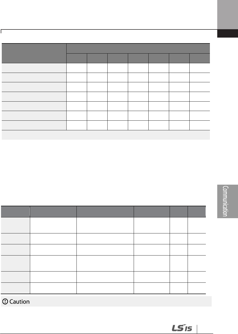
403
RS-485 Communication Features
Property
Object Type
Device
BI
BV
AI
AO
MSI
MVI
Out
-
of
-
Service
O
O
O
O
O
O
Number of states
O
O
State text
O
O
Units
O
O
Polarity
O
Active Text
O
O
Inactive Text
O
O
* BI–Binary Input / BV–Binary Value / AI–Analog Input / AV–Analog Value / MSI–Multistate Input /
MSV–Multistate Value
You can read/write in Location and Description only if it is the device object. You can write a
maximum of 29 words.
7.4.5.1 Analog Value Object Instance
Instance ID Object Name Description Setting Range Units R/W
AV1 CommTimeoutSet
Command timeout
setting 0.1–120.0 Secs R/W
AV2 AccelTimeSet Accelerate time setting 0.0–600.0 Secs R/W
AV3 DecelTimeSet Decelerate time setting 0.0–600.0 Secs R/W
AV4 CommandFreqSet
Command frequency
setting** 0.00–DRV-20 Hz R/W
AV5 PIDReferenceSet PID reference setting 0–100.0 % R/W
AV6 PIDFeedbackSet PID feedback setting 0–100.0 % R/W

404
RS-485 Communication Features
7.4.5.2 Multi-state Value Object Instance
Instance ID Object Name Description Setting Range Units R/W
MSV1 LostCommand Command lost
operation setting
0: None
1: FreeRun
2: Dec
3: HoldInput
4: HoldOutput
5: LostPreset
MSG R/W
7.4.5.3 Binary Value Object Instance
Instance ID Object Name Description Active /Inactive Text R/W
BV1 StopCmd Stop command False/True R/W
BV2 RunForwardCmd Run forward command False/True R/W
BV3 RunReverseCmd Run reverse command False/True R/W
BV4 ResetFaultCmd Fault reset command False/True R/W
BV5 FreeRunStopCmd Free run stop command False/True R/W
BV6 Relay1Cmd Relay 1 On/Off command
False/True R/W
BV7 Relay2Cmd Relay 2 On/Off command
False/True R/W
BV8 Relay3Cmd Relay 3 On/Off command
False/True R/W
• When PowerOn Resume (COM-96) is set to ‘yes’, value is saved even if the power of the inverter is
disconnected. When PowerOn Resume (COM-96) is set to ‘no’, value is not saved if the power of
the inverter is disconnected.
• A value higher than the maximum frequency (DRV-20) cannot be used. The maximum f
requency
can be set by using the keypad. This value can be used when Freq Ref Src (DRV-07) is set to ‘Int
485’.
• AV2, AV3 and AV4 are used to provide acceleration/deceleration rate and frequency reference
commands. These can be written in AUTO mode only.
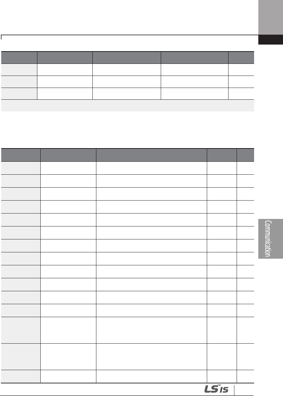
405
RS-485 Communication Features
Instance ID Object Name Description Active /Inactive Text R/W
BV9 Relay4Cmd Relay 4 On/Off command
False/True R/W
BV10 Relay5Cmd Relay 5 On/Off command
False/True R/W
BV11 Q1Cmd Q 1 On/Off command False/True R/W
7.4.5.4 Analog Input Object Instance
Instance ID Object Name Description Units R/W
AI1 InvCap (kW) Inverter capacity kW R
AI2 InvCap (HP) Inverter capacity HP R
AI3 InvVoltageClass Inverter voltage type Volts R
AI4 OutputCurrent Output current Amps R
AI5 OutputFreq Output frequency Hz R
AI6 OutputVolgate Output voltage Volts R
AI7 DCLinkVoltage DC Link voltage Volts R
AI8 OutputPower Output power kW R
AI9 AI1 Value of Analog 1 % R
AI10 AI2 Values of Analog 2 % R
AI11 OutputRPM Output speed RPM R
AI12 Pole Pole number of the motor - R
AI13 InvStatus
Information of the inverter state
(Refer to address 0h0305 in the common
area)
(Note1)
- R
AI14 LatchTripInfo1
Latch type trip
information1
(Refer to address 0h0330 in the common
area)
(Note1)
- R
AI15 LatchTripInfo2 Latch type trip information2 - R

406
RS-485 Communication Features
Instance ID Object Name Description Units R/W
(Refer to address 0h0331 in the common
area)
(Note1)
AI16 LatchTripInfo3
Latch type trip information3
(Refer to address 0h0335 in the common
area)
(Note1)
- R
AI17 LevelTripInfo
Level type trip information
(Refer to address 0h0332 in the common
area)
(Note1)
- R
AI18 HWDIagInfo
H/W Diagnosis trip information
(Refer to address 0h0333 in the common
area)*
- R
AI19 WarningInfo
Warning
information
(Refer to address 0h0334 in the common
area)*
- R
AI20 KiloWattHour Output power by kW/h kW/h R
AI21 MegaWattHour Output power by MW/h MW/h R
AI22 PowerFactor Power factor - R
AI23 RunTimeDay Run time by day Day R
AI24 RunTimeMin Run time by minute Day R
AI25 PidOutValue PID Output Value % R
AI26 PidReferenceValue PID Reference Value % R
AI27 PidFeedbackValue PID Feedback Value % R
*Refer to the relevant addresses in 7.3.8 communication compatible common area parameters.
Instance ID
Object Name
Description
R/W
BI1 Stopped Stop state R
BI2 RunningForward Running forward R
BI3 RunningReverse Running reverse R

407
RS-485 Communication Features
BI4 Tripped Trip occurred R
BI5 Accelerating Accelerating R
BI6 Decelerating Decelerating R
BI7 SteadySpeed Operating at steady speed R
BI8 RunningDC Operating at a 0 step speed R
BI9 Stopping Stopping R
BI10 FwdRunCommandState Forward run command state R
BI11 RevRunCommandState Reverse run command state R
BI12 P1 P1 state R
BI13 P2 P2 state R
BI14 P3 P3 state R
BI15 P4 P4 state R
BI16 P5 P5 state R
BI17 P6 P6 state R
BI18 P7 P7 state R
BI19
Relay1
Relay1 state*
R
BI20
Relay2
Relay2 state*
R
BI21
Relay3
Relay3 state*
R
BI22
Relay4
Relay4 state*
R
BI23
Relay5
Relay5 state*
R
BI24
Q1
Q1 state
R
BI25
SpeedSearch
Speed search operating
R
BI26
HWOCS
H/W OCS occurred
R
BI27
SWOCS
S/W OCS occurred
R
BI28
RunningDwell
Dwell operating state
R
BI29
SteadyState
Steady state
R
408
RS-485 Communication Features
7.4.5.5 Binary Input Object Instance
OUT
-
31
–
35 (Relay1
–
5) must be set to ‘0 (none)’ to control outputs via communication.
7.4.5.6 MultiState Input Object Instance
Instance ID Object Name Description Units R/W
MSI1 UnitsDisplay Displays Unit setting
1 Hz
2 RPM R
7.4.5.7 Error Message
Display
Description
serviceserror+7 Inconsistent parameters
propertyerror+9
Invalid data type
serviceserror+10
Invalid access method
serviceserror+11 Invalid file start
serviceserror+29
Service request denied
objecterror+31 Unknown object
propertyerror+0
Property other
propertyerror+27 Read access denied
propertyerror+32
Unknown property
propertyerror+37
Value out of range
propertyerror+40 Write access denied
propertyerror+42
Invalid array index
BI30
Warning
Warning state
R

409
RS-485 Communication Features
Display
Description
clienterror+31
Unknown device
resourceserror+0 Resources other
clienterror+30
Time out
abortreason+4
Segmentation not supported
rejectreason+4 Invalid tag
clienterror+0xFF
No invoke id
securityerror+26 Password failure

410
RS-485 Communication Features
7.5 Metasys-N2 Communication
7.5.1 Metasys-N2 Quick Communication Start
Follow the instructions below to configure the Metasys-N2 network for a quick start.
1 Set COM-02 (Int485 Proto) to ‘5 (Metasys-N2)’.
2 Set the network communication speed to ‘9600 bps.’
3 Configure the communication modes and make sure that they are fixed to Data Bit 8 / No
Parity Bit/ Start Bit 1 / Stop Bit 1.
4 Test the network and make sure Metasys-N2 communication is working properly.
7.5.2 Metasys-N2 Communication Standard
Item Standards
Communication speed 9600 bps
Control procedure Asynchronous communications system
Communication system Half duplex system
Cable Twisted pair (1 pair and shield)
Character system
LS485: ASCII (8bit)
Modbus-RTU: Binary (7/8 bit)
Metasys-N2: ASCII (8bit)
Start/Stop bit Start 1bit, Stop 1bit
Error check
RS485: Checksum (2byte)
Modbus
-
RTU: CRC16 (2byte)
Metastys-N2: CRC16 (2byte)
Parity check None

411
RS-485 Communication Features
7.5.3 Metasys-N2 Protocol I/O Point Map
7.5.3.1 Analog Output
The output point map controlling the inverter from the Metasys-N2 master.
No.
Name
Range
Unit
Description
AO1
Command
Frequency 0.0–Max Freq Hz Command frequency setting**
AO2
Accel Time
0.0
–
600.0
Sec
ACC time setting*
AO3
Decel Time
0.0
–
600.0
Sec
DEC time setting*
AO4 Drive mode
0 KeyPad
- Drive mode setting
1
Fx/Rx
-
1
2
Fx/Rx
-
2
3
Int. 485
4
FieldBus
5
Time Event
AO5 Freq mode
0
–
KeyPad
-
1
- Frequency mode setting
1
–
KeyPad
-
2
2
V1
3
–
Reversed
4
V2
5
I2
6
Int485
7
FieldBus
8
Reversed
9
Pulse
412
RS-485 Communication Features
• When PowerOn Resume (COM-96) is set to ‘yes’, value is saved even if the power of the inverter is
disconnected. If PowerOn Resume (COM-96) is set to ‘no’, value is not saved when the power of
the inverter is disconnected.
• Cannot set the value higher than the maximum frequency (DRV-20). The maximum frequency
can be set by using the keypad. This value can be used when Freq Ref Src (DRV-07) is set to ‘Int
485’.
7.5.3.2 Binary Output
The output point map controlling the inverter from the Metasys-N2 master.
No.
Name
Range
Description
BO1
Stop Command
1: Stop
Stop command
BO2
Run Forward Command
1: Forward Run
Forward run command
BO3
Run Reverse
Command 1: Reverse Run Reverse run command
BO4
Reset
Fault
1: Reset
Fault reset command
BO5
Free
-
Run Stop
1: Bx
Free
-
run stop command
7.5.3.3 Analog Input
Metasys-N2 master monitors inverter state.
No.
Name
Unit
Description
AI1
Output
Current
Amps
Output current
AI2
Output Frequency
Hz
Output frequency
AI3
Output Speed
RPM
Output speed
AI4 Trip Code -
Trip code information
(Refer to Common Area parameter address 0h000F)*
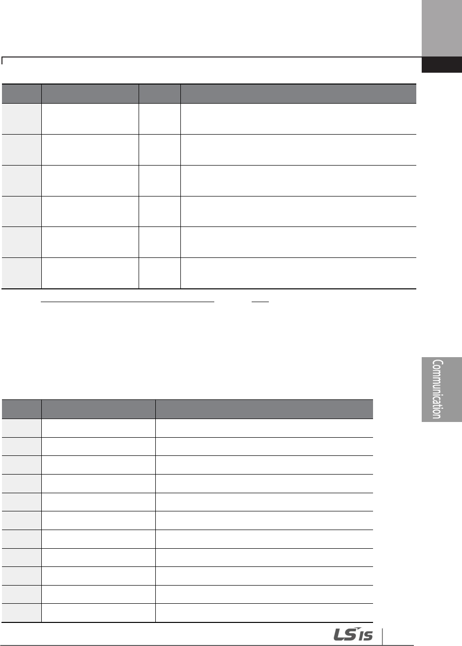
413
RS-485 Communication Features
No.
Name
Unit
Description
AI5 Latch Trip Info1 -
‘Latch’ type fault trip information 1
(Refer to Common Area parameter address 0h0330)*
AI6 Latch Trip Info2 -
‘Latch’ type fault trip information 2
(Refer to Common Area parameter address 0h0331)*
AI7 Latch Trip Info3 -
‘Latch’ type fault trip information 3
(Refer to Common Area parameter address 0h0335)*
AI8 Level Trip Info -
‘Level’ type fault trip information
(Refer to Common Area parameter address 0h0332)(1)
AI9
H/W Diagnosis Trip
Info -
H/W Diagnosis fault trip information
(Refer to Common Area parameter address 0h0333)(1)
AI10 Warning Info -
Warning information
(Refer to Common Area parameter address 0h0334)(1)
* Refer to 7.3.8Compatible Common Area Parameteron page 378.
7.5.3.4 Binary Input
Metasys-N2 master unit monitors the inverter input and output status in binary codes. The
following table lists the binary codes used and their meanings.
No.
Name
Description
BI1
Stopped
1
–
Stopped
BI2
Running Forward
1
–
Forward operation is running.
BI3
Running Reverse
1
–
Reverse operation is running.
BI4
Tripped
1
–
Fau
lt trip occurred.
BI5
Accelerating
1
–
Accelerating
BI6
Decelerating
1
–
Decelerating
BI7
Reached Full Speed
1
–
Running at a steady speed (frequency refer
e
nce)
BI8
DC Braking
1
–
Running on DC power source
BI9
Stopping
1
–
Stopping is in progress.
BI10
P1 Input
1
–
True / 0
-
False
BI11
P2 Input
1
–
True / 0
–
False

414
RS-485 Communication Features
No.
Name
Description
BI12
P3 Input
1
–
True / 0
–
False
BI13
P4 Input
1
–
True / 0
–
False
BI14
P5 Input
1
–
True / 0
–
False
BI15
P6 Input
1
–
True
/ 0
–
False
BI16
P7 Input
1
–
True / 0
–
False
BI17
Relay1 State
1
–
On / 0
-
Off
BI18
Relay2 State
1
–
On / 0
-
Off
BI19
Relay3 State
1
–
On / 0
-
Off
BI20
Relay4 State
1
–
On / 0
-
Off
BI21
Relay5 State
1
–
On / 0
-
Off
BI22
Q1 (OC1) State
1
–
On / 0
-
Off
7.5.3.5 Error Code
Defined Codes
Description
00
The device has been reset. Currently waiting for the ‘Identity Yourself’
command.
01
Undefined command
02
Checksum error has occurred.
03
Data size exceeded the input buffer (
message
is bigger than the device buffer
size).
05
Data field error (input message size does not fit the command type)
10
Invalid data (message value is out of the range)
11
Invalid command for data type (command does not fit the message frame)
12
Command is not accepted (device has ignored a command due to a fault. The
master device sends a ‘Status Update Request’).

Table of Functions
415
8 Table of Functions
This chapter lists all the function settings for the H100 series inverter. Use the references listed in
this document to set the parameters. If an entered set value is out of range, the messages that will
be displayed on the keypad are also provided in this chapter. In these situations, the [ENT] key will
not operate to program the inverter.
8.1 Drive Group (DRV)
Data in the following table will be displayed only when the related code has been selected.
*O: Write-enabled during operation, Δ: Write-enabled when operation stops, X: Write-
disabled
Code Comm.
Address Name LCD Display Setting Range Initial value Prope
rty* Ref.
00 -
Jump
Code Jump Code 1–99 9 O p.70
01 0h1101
Target
frequency
Cmd
Frequency
0.00, Low Freq
–
High Freq 0.00 O p.88
02 0h1102
Keypad
run
direction
Keypad Run
Dir
0
Reverse
1 O p.86
1 Forward
03 0h1103 Accelerati
on time Acc Time 0.0–600.0 (sec)
20.0
0.75~
90kW
O p.114 60.0
110~
250kW
100.0
315~
500kW
04 0h1104 Decelerati
on time Dec Time 0.0–600.0 (sec)
30.0
0.75~
90kW
O p.114 90.0
110~
250kW
150.0
315~
500kW
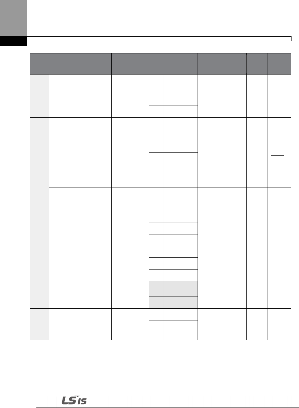
Table of Functions
416
Code Comm.
Address Name LCD Display Setting Range Initial value Prope
rty* Ref.
05 0h1105
HAND-
OFF-AUTO
Key Lock
KPD H.O.A
Lock
0
Locked
1 Δ p.75 1
During
Run
2
Unlocked
06 0h1106 Comman
d source Cmd Source
0
Keypad
1:
Fx/Rx-1 Δ p.106
1
Fx/Rx
-
1
2
Fx/Rx
-
2
3
Int 485
4
Field Bus
5
Time Event
07 0h1107
Frequency
reference
source
Freq Ref Src
0
Keypad
-
1
0: Keypad-1 Δ p.88
1
Keypad
-
2
2
V1
4
V2
5
I2
6
Int 485
7
FieldBus
9
Pulse
108
V3
11
I3
09 0h1109 Control
mode
Control
Mode
0
V/F
0: V/F Δ p.125,
p.162,
1
Slip
Compen
8
‘10(V3)~11(I3)’ of DRV-07 are available when Extension IO option is equipped. Refer to Extension
IO option manual for more detailed information.
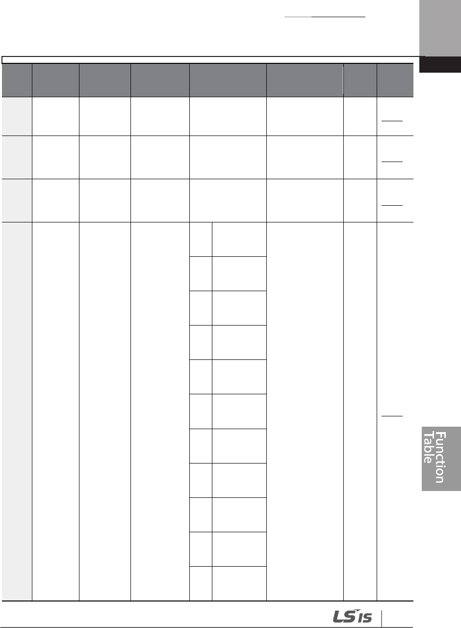
Table of Functions
417
Code Comm.
Address Name LCD Display Setting Range Initial value Prope
rty* Ref.
11 0h110B Jog
frequency
Jog
Frequency
0.00, Low Freq–
High Freq 10.00 O p.153
12 0h110C
Jog run
accelerati
on time
Jog Acc
Time 0.0–600.0 (sec) 20.0 O p.153
13 0h110D
Jog run
decelerati
on time
Jog Dec
Time 0.0–600.0 (sec) 30.0 O p.153
14 0h110E Motor
capacity
Motor
Capacity
0 0.2 Kw
(0.3HP)
Dependent on
motor setting Δ p.219
1 0.4 kW
(0.5HP)
2 0.75 kW
(1.0HP)
3 1.1 kW
(1.5HP)
4 1.5 kW
(2.0HP)
5 2.2 kW
(3.0HP)
6 3.0 kW
(4.0HP)
7 3.7 kW
(5.0HP)
8 4.0 kW
(5.5HP)
9 5.5 kW
(7.5HP)
10 7.5 kW
(10.0HP)

Table of Functions
418
Code Comm.
Address Name LCD Display Setting Range Initial value Prope
rty* Ref.
11 11.0 kW
(15.0HP)
12 15.0 kW
(20.0HP)
13 18.5 kW
(25.0HP)
14 22.0 kW
(30.0HP)
15 30.0 kW
(40.0HP)
16 37.0 kW
(50.0HP)
17 45.0 kW
(60.0HP)
18 55.0 kW
(75.0HP)
19 75.0kW
(100.0HP)
20 90.0kW
(125.0HP)
21 110.0kW
(150.0HP)
22 132.0kW
(220.0HP)
23 160.0kW
(250.0HP)
24 185.0kW
(300.0HP)
25 220.0kW
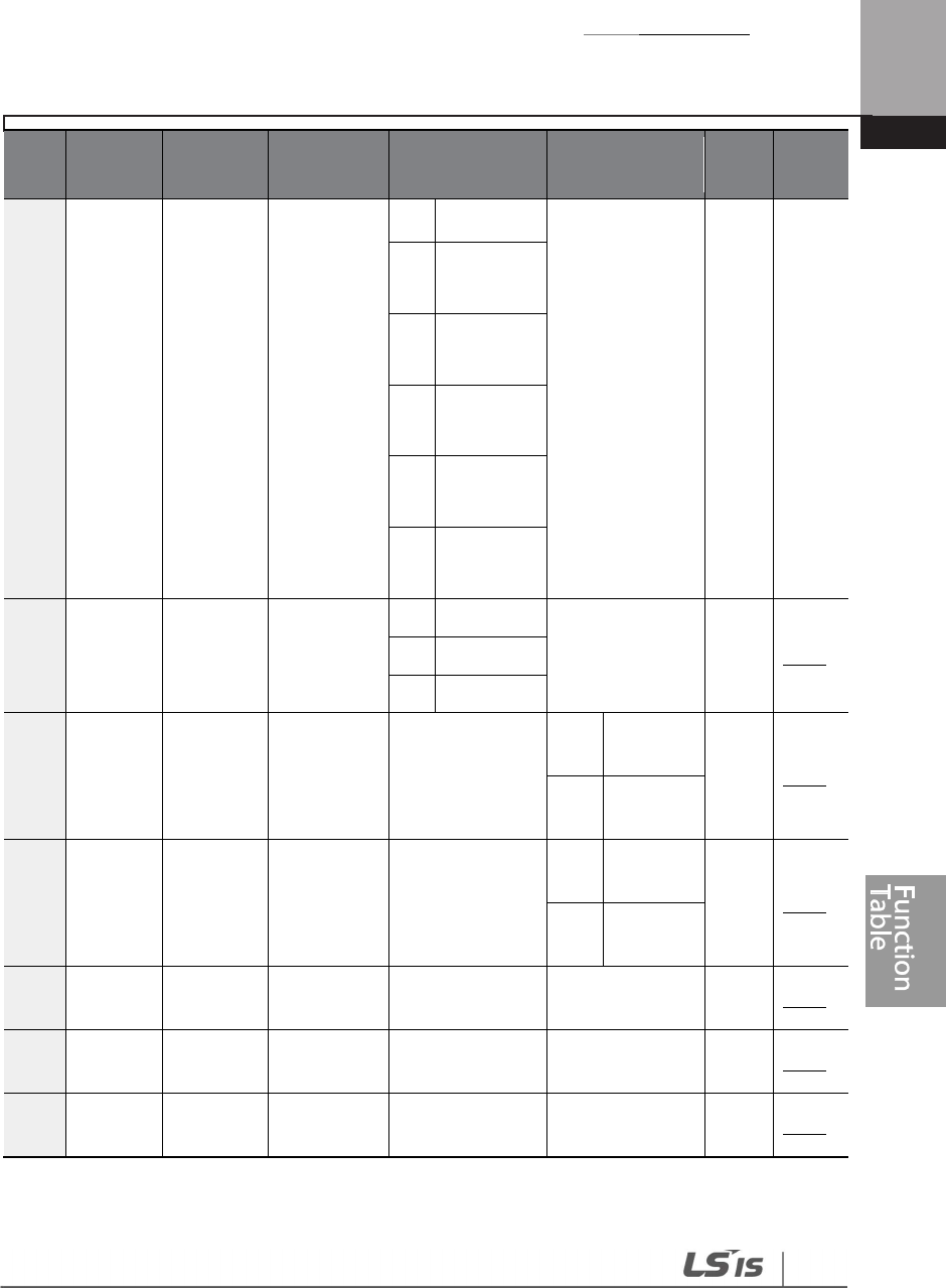
Table of Functions
419
Code Comm.
Address Name LCD Display Setting Range Initial value Prope
rty* Ref.
(350.0HP)
26 250.0kW
(400.0HP)
27 315.0kW
(500.0HP)
28 355.0kW
(550.0HP)
29 400.0kW
(650.0HP)
30 500.0kW
(800.0HP)
15 0h110F
Torque
boost
options
Torque
Boost
0
Manual
0: Manual Δ p.129
1
Auto 1
2 Auto 2
169 0h1110
Forward
Torque
boost
Fwd Boost 0.0–15.0 (%)
2.0
0.75~
90kW Δ p.129
1.0
110~
500kW
17 0h1111
Reverse
Torque
boost
Rev Boost 0.0–15.0 (%)
2.0
0.75~
90kW Δ p.129
1.0
110~
500kW
18 0h1112
Base
frequency
Base Freq
30.00
–
400.00
(Hz) 60.00 Δ p.125
19 0h1113
Start
frequency
Start Freq 0.01–10.00 (Hz) 0.50 Δ p.125
20 0h1114
Maximum
frequency
Max Freq
40.00
-
400.00
(Hz) 60.00 Δ p.137
9
DRV-16–17 are displayed when DRV-15 is set to ‘0 (Manual)’.

Table of Functions
420
Code Comm.
Address Name LCD Display Setting Range Initial value Prope
rty* Ref.
21 0h1115 Select
speed unit
Hz/Rpm Sel
0
Hz Display
0: Hz Display O p.104
1
RPM
Display
25 0h1119
Hand
mode
operation
frequency
HAND Cmd
Freq
0.00, Low Freq-
High Freq 0.00 O p.83
26 0h111A
Hand
mode
operation
Frequency
reference
source
HAND Ref
Mode
0
HAND
Parameter
0: HAND
Parameter Δ p.83
1 Follow
AUTO
30 0h111E
kW/HP
unit
selection
kW/HP Unit
Sel
0
kW
1:HP O -
1 HP
91 0h115B Smart
Copy SmartCopy
0
N
one
0:None Δ
1
SmartDow
nload
3
SmartUplo
ad
98 0h1162
Display
I/O,S/W
Version
I/O S/W Ver - - - X -
8.2 Basic Function Group (BAS)
Data in the following table will be displayed only when the related code has been selected.
*O: Write-enabled during operation, Δ: Write-enabled when operation stops, X: Write-disabled
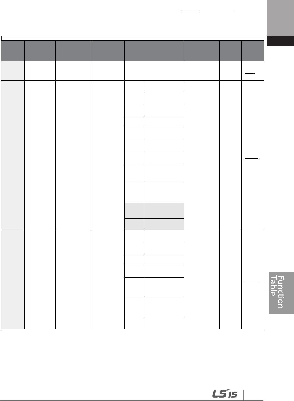
Table of Functions
421
Code
Comm.
Address Name
LCD
Display Setting Range Initial value
Prope
rty* Ref.
00 - Jump Code
Jump
Code 1-99 20 O p.70
01 0h1201
Auxiliary
reference
source
Aux Ref
Src
0
None
0: None Δ p.147
1
V1
3
V2
4
I2
6
Pulse
7
Int 485
8
FieldBus
10
EPID1
Output
11
EPID1 Fdb
Val
1210 V3
13
I
3
0211 0h1202
Auxiliary
command
calculation
type
Aux Calc
Type
0
M+(G*A)
0: M+(G*A)
Δ p.147
1
Mx (G*A)
2
M/(G*A)
3
M+[M*(G*A)]
4
M+G*2 (A
-
50%)
5
M*[G*2 (A
-
50%)
6
M/[G*2 (A
-
10
‘12(V3)~13(I3)’ of BAS-01 are available when Extension IO option is equipped. Refer to
Extension IO option manual for more detailed information.
11
BAS-02–03 are displayed when BAS-01 is not ‘0 (None)’.
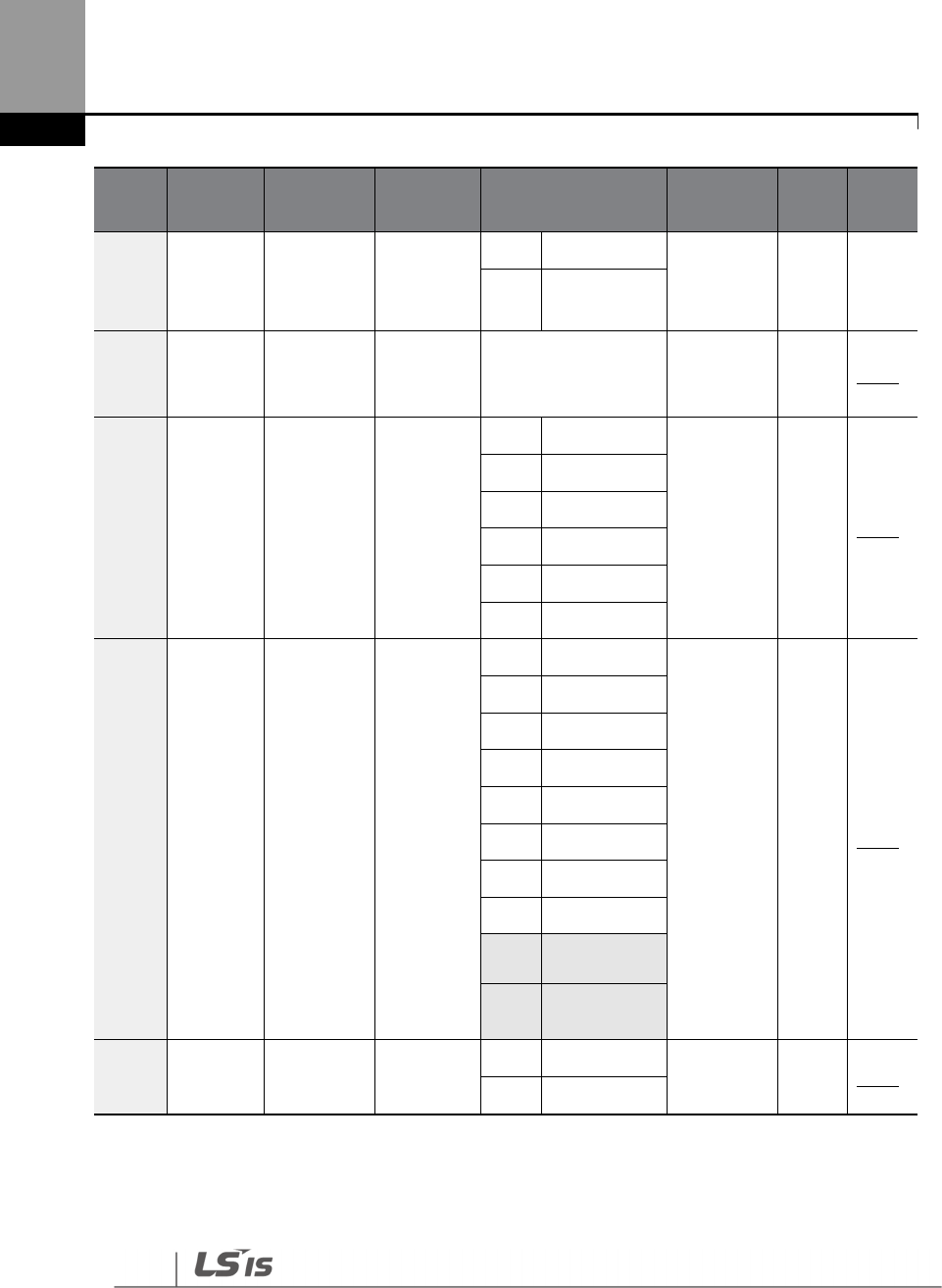
Table of Functions
422
Code
Comm.
Address Name
LCD
Display Setting Range Initial value
Prope
rty* Ref.
50%)]
7
M+M*G*2
(A-50%)
03 0h1203
Auxiliary
command
gain
Aux Ref
Gain -200.0-200.0 (%) 100.0 O p.147
04 0h1204
Second
command
source
Cmd 2nd
Src
0
Keypad
1: Fx/Rx-1 Δ p.141
1
Fx/Rx
-
1
2
Fx/Rx
-
2
3
Int 485
4
FieldBus
5
T
i
me Event
05 0h1205
Second
frequency
source
Freq 2nd
Src
0
Keypad
-
1
0: Keypad-
1 O p.141
1
Keypad
-
2
2
V1
4
V2
5
I2
6
Int 485
7
FieldBus
9
Pulse
1012 V3
11 I3
07 0h1207 V/F pattern
options
V/F
Pattern
0
Linear
0: Linear Δ p.125
1
Square
12
‘10(V3)~11(I3)’ of BAS-05 are available when Extension IO option is equipped. Refer to
Extension IO option manual for more detailed information.

Table of Functions
423
Code
Comm.
Address Name
LCD
Display Setting Range Initial value
Prope
rty* Ref.
2
User V/F
3
Square 2
08 0h1208
Acc/Dec
standard
frequency
Ramp T
Mode
0
Max Freq
0: Max Freq
Δ p.114
1 Delta Freq
09 0h1209 Time scale
settings Time Scale
0
0.01 sec
1: 0.1 sec Δ p.114
1
0.1 sec
2
1 sec
10 0h120A
Input
power
frequency
60/50 Hz
Sel
0
60 Hz
0: 60 Hz Δ p.255
1 50 Hz
11 0h120B
Number of
motor
poles
Pole
Number 2-48
Dependent
on motor
setting
Δ p.162
12 0h120C
Rated slip
speed Rated Slip 0-3000 (RPM) Δ p.162
13 0h120D
Motor
rated
current
Rated Curr
1.0-1000.0 (A) Δ p.162
14 0h120E
Motor no
-
load
current
NoloadCur
r 0.0-1000.0 (A) Δ p.162
15 0h120F
Motor
rated
voltage
Rated Volt 0, 170-480 (V) 0 Δ p.131
16 0h1210 Motor
efficiency Efficiency 70-100 (%)
Dependent
on motor
setting
Δ p.219
18 0h1212
Trim power
display
Trim
Power % 70-130 (%) 100 O -
19 0h1213
Input
power
voltage
AC Input
Volt
170
~
264V
0.75~
18.5kW 220 V O p.255
320~
0.75~
380 V

Table of Functions
424
Code
Comm.
Address Name
LCD
Display Setting Range Initial value
Prope
rty* Ref.
528V
90kW
320~
550V
110~
500kW
20 - Auto
Tuning
Auto
Tuning
0
None
0: None Δ p.219
1
All (Rotation
type)
2
All (Static type)
3
Rs+ Lsigma
(Rotation type)
21 -
Stator
resistor Rs 0.000-9.999 (Ω) Dependent
on motor
setting
Δ p.219
22 - Leakage
inductance
Lsigma 0.00-99.99 (mH) Δ p.219
4113 0h1229
User
frequency1
User Freq
1
0.00
-
Maximum
frequency (Hz) 15.00 Δ p.127
42 0h122A
User
voltage1 User Volt 1
0–100 (%) 25 Δ p.127
43 0h122B
User
frequency2
User Freq
2
0.00
-
Maximum
frequency (Hz) 30.00 Δ p.127
44 0h122C
User
voltage2 User Volt 2
0-100 (%) 50 Δ p.127
45 0h122D
User
frequency3
User Freq
3
0.00
-
Maximum
frequency (Hz) 45.00 Δ p.127
46 0h122E
User
voltage3 User Volt 3
0-100 (%) 75 Δ p.127
47 0h122F
User
frequency4
User Freq
4
0.00
-
Maximum
frequency (Hz) 60.00 Δ p.127
48 0h1230
User
voltage4 User Volt 4
0-100 (%) 100 Δ p.127
13
BAS-41–48 are displayed when BAS-07 or M2-25 is set to ‘2 (User V/F)’.

Table of Functions
425
Code
Comm.
Address Name
LCD
Display Setting Range Initial value
Prope
rty* Ref.
5014 0h1232
Multi
-
step
speed
frequency1
Step Freq-
1 Low Freq- High Freq 10.00 O p.104
51 0h1233
Multi
-
step
speed
frequency2
Step Freq-
2 Low Freq- High Freq 20.00 O p.104
52 0h1234
Multi
-
step
speed
frequency3
Step Freq-
3
Low Freq- High
Freq 30.00 O p.104
53 0h1235
Multi
-
step
speed
frequency4
Step Freq-
4 Low Freq- High Freq 40.00 O p.104
54 0h1236
Multi
-
step
speed
frequency5
Step Freq-
5 Low Freq- High Freq 50.00 O p.104
55 0h1237
Multi
-
step
speed
frequency6
Step Freq-
6 Low Freq- High Freq 60.00 O p.104
56 0h1238
Multi
-
step
speed
frequency7
Step Freq-
7 Low Freq-High Freq 60.00 O p.104
70 0h1246
Multi
-
step
deceleratio
n time1
Acc Time-1
0.0-600.0 (sec) 20.0 O p.118
71 0h1247
Multi
-
step
deceleratio
n time1
Dec Time-
1 0.0-600.0 (sec) 20.0 O p.118
7215 0h1248
Multi
-
step
deceleratio
n time2
Acc Time-2
0.0-600.0 (sec) 30.0 O p.118
14
BAS-50–56 are displayed whenIN-65-71 is set to ‘Speed–L/M/H’.
15
BAS-72–83 are displayed when IN-65–71is set to ‘Xcel-L/M/H’

Table of Functions
426
Code
Comm.
Address Name
LCD
Display Setting Range Initial value
Prope
rty* Ref.
73 0h1249
Multi
-
step
deceleratio
n time2
Dec Time-
2 0.0-600.0 (sec) 30.0 O p.118
74 0h124A
Multi
-
step
deceleratio
n time3
Acc Time-3
0.0-600.0 (sec) 40.0 O p.118
75 0h124B
Multi
-
step
deceleratio
n time3
Dec Time-
3 0.0-600.0 (sec) 40.0 O p.118
76 0h124C
Multi
-
step
acceleratio
n time4
Acc Time-4
0.0-600.0 (sec) 50.0 O p.118
77 0h124D
Multi
-
step
acceleratio
n time4
Dec Time-
4 0.0-600.0 (sec) 50.0 O p.118
78 0h124E
Multi
-
step
acceleratio
n time5
Acc Time-5
0.0-600.0 (sec) 40.0 O p.118
79 0h124F
Multi
-
step
acceleratio
n time5
Dec Time-
5 0.0-600.0 (sec) 40.0 O p.118
80 0h1250
Multi
-
step
acceleratio
n time6
Acc Time-6
0.0-600.0 (sec) 30.0 O p.118
81 0h1251
Multi
-
step
deceleratio
n time6
Dec Time-
6 0.0-600.0 (sec) 30.0 O p.118
82 0h1252
Multi
-
step
acceleratio
n time7
Acc Time-7
0.0-600.0 (sec) 20.0 O p.118
83 0h1253
Multi
-
step
acceleratio
n time7
Dec Time-
7 0.0-600.0 (sec) 20.0 O p.118

Table of Functions
427
8.3 Expanded Function Group (ADV)
Data in the following table will be displayed only when the related code has been selected.
*O: Write-enabled during operation, Δ: Write-enabled when operation stops, X: Write-disabled
Code
Comm.
Address Name
LCD
Display Setting Range Initial Value
Prope
rty* Ref.
00 - Jump Code
Jump
Code 1-99 24 O p.70
01 0h1301
Acceleration
pattern
Acc
Pattern 0 Linear
0: Linear
Δ p.121
02 0h1302
Deceleration
pattern
Dec
Pattern 1 S-curve Δ p.121
0316 0h1303
S
-
curve
acceleration
start point
gradient
Acc S
Start 1–100 (%) 40 Δ p.121
04 0h1304
S
-
curve
acceleration
end point
gradient
Acc S
End 1–100 (%) 40 Δ p.121
0517 0h1305
S
-
curve
deceleration
start point
gradient
Dec S
Start 1–100 (%) 40 Δ p.121
06 0h1306
S
-
curve
deceleration
end point
gradient
Dec S
End 1–100 (%) 40 Δ p.121
07 0h1307 Start Mode Start
Mode
0
Acc
0: Acc Δ p.132
1
DC
-
Start
08 0h1308 Stop Mode Stop
Mode
0
Dec
0: Dec Δ p.133
1
DC
-
Brake
16
ADV-03–04 are displayed when ADV-01 is set to ‘1 (S-curve)’.
17
ADV-05–06 are displayed when ADV-02 is set to ‘1 (S-curve)’.

Table of Functions
428
Code
Comm.
Address Name
LCD
Display Setting Range Initial Value
Prope
rty* Ref.
2
Free
-
Run
4
Power
Braking
09 0h1309
Selection of
prohibited
rotation
direction
Run
Prevent
0
None
0: None Δ p.110
1
Forward Prev
2
Reverse Prev
10 0h130A Starting with
power on
Power-
on Run
0
No
0: No O p.111
1
Yes
1118 0h130B
Power
-
on
run delay
time
Power-
On Delay
0.0 -6000.0 (sec) 0.0 O p.111
1219 0h130C
DC braking
time at
startup
DC-Start
Time 0.00-60.00 (sec) 0.00 Δ p.132
13 0h130D
Amount of
applied DC
DC Inj
Level 0–200 (%) 50 Δ p.132
1420 0h130E
Output
blocking
time before
DC braking
DC-Block
Time 0.00- 60.00 (sec)
0.00
0.
75~
90kW Δ p.133
2.00
110~
500kW
15 0h130F DC braking
time
DC
-
Brake
Time
0.00- 60.00 (sec) 1.00 Δ p.133
16 0h1310 DC braking
rate
DC
-
Brake
Level
0–200 (%) 50 Δ p.133
17
0h1311
DC braking
DC
-
Startfrequency
-
5.00
Δ
p.
133
18
ADV-11 is displayed when ADV-10 is set to ‘1 (YES)’.
19
ADV-12 is displayed when ADV-07 is set to ‘1 (DC-Start)’.
20
ADV-14 is displayed when ADV-08 is set to ‘1 (DC-Brake)’.

Table of Functions
429
Code
Comm.
Address Name
LCD
Display Setting Range Initial Value
Prope
rty* Ref.
frequency
Brake
Freq
60 Hz
20 0h1314
Dwell
frequency on
acceleration
Acc
Dwell
Freq
Start frequency
-
Maximum
frequency (Hz)
5.00 Δ p.160
21 0h1315
Dwell
operation
time on
acceleration
Acc
Dwell
Time
0.0-60.0 (sec) 0.0 Δ p.160
22 0h1316
Dwell
frequency on
deceleration
Dec
Dwell
Freq
Start frequency
-
Maximum
frequency (Hz)
5.00 Δ p.160
23 0h1317
Dwell
operation
time on
deceleration
Dec
Dwell
Time
0.0-60.0 (sec) 0.0 Δ p.160
24 0h1318 Frequency
limit
Freq
Limit
0
No
0: No Δ p.137
1
Yes
25 0h1319
Frequency
lower limit
value
Freq
Limit Lo
0.00-Upper limit
frequency (Hz) 0.50 Δ p.137
26 0h131A
Frequency
upper limit
value
Freq
Limit Hi
Lower limit
frequency-
Maximum
frequency (Hz)
Max freq Δ p.137
27 0h131B Frequency
jump
Jump
Freq
0
No
0: No Δ p.140
1
Yes
2821 0h131C
Jump
frequency
lower limit1
Jump Lo
1
0.00
-
Jump
frequency upper
limit1 (Hz)
10.00 O p.140
29 0h131D
Jump
frequency
Jump Hi
1
Jump frequency
lower limit1- 15.00 O p.140
21
ADV-28–33 are displayed when ADV-27 is set to ‘1 (Yes)’.

Table of Functions
430
Code
Comm.
Address Name
LCD
Display Setting Range Initial Value
Prope
rty* Ref.
upper limit1
Maximum
frequency (Hz)
30 0h131E
Jump
frequency
lower limit2
Jump Lo
2
0.00
-
Jump
frequency upper
limit2 (Hz)
20.00 O p.140
31 0h131F
Jump
frequency
upper limit2
Jump Hi
2
Jump frequency
lower limit2-
Maximum
frequency (Hz)
25.00 O p.140
32 0h1320
Jump
frequency
lower limit3
Jump Lo
3
0.00
-
Jump
frequency upper
limit3 (Hz)
30.00 O p.140
33 0h1321
Jump
frequency
upper limit3
Jump Hi
3
Jump frequency
lower limit3-
Maximum
frequency (Hz)
35.00 O p.140
50 0h1332
Energy
saving
operation
E-Save
Mode
0
None
0: None Δ p.242
1
Manual
2
Auto
5122 0h1333
Energy
saving level
Energy
Save 0–30 (%) 0 O p.242
52 0h1334
Energy
saving point
search time
E-Save
Det T 0.0-100.0 (sec) 20.0 Δ p.242
60 0h133C
Acc/Dec
time
transition
frequency
Xcel
Change
Fr
0.00-Maximum
frequency (Hz) 0.00 Δ p.120
64
0h1340
Cooling fan
Fan
0
During Run
0: During Run
O
22
ADV-51 is displayed when ADV-50 is set to ‘1 (Manual)’.
ADV-52 is displayed when ADV-50 is set to ‘2 (Auto)’.
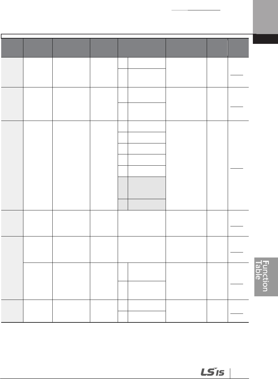
Table of Functions
431
Code
Comm.
Address Name
LCD
Display Setting Range Initial Value
Prope
rty* Ref.
control
Control
1
Always ON
p.254
2
Temp
Control
65 0h1341
Up/Down
operation
frequency
save
U/D Save
Mode
0
No
0: No O p.155
1
Yes
66 0h1342
Output
contact
On/Off
control
options
On/Off
Ctrl Src
0
None
0: None O p.294
1
V1
3
V2
4
I2
6
Pulse
7
23
V3
8
I3
67 0h1343
Output
contact On
level
On-Ctrl
Level
Output contact
off level-
100.00%
90.00 Δ p.294
68 0h1344
Output
contact Off
level
Off-Ctrl
Level
-
100.00
-
outputcontact
on level (%)
10.00 Δ p.294
70 0h1346
Safe
operation
selection
Run En
Mode
0
Always
Enable 0: Always
Enable Δ p.158
1
DI
Dependent
7124 0h1347 Safe
operation
Run Dis
Stop
0
Free
-
Run
0: Free-Run Δ p.158
1
Q
-
Stop
23
‘10(V3)~11(I3)’ of ADV-66 are available when Extension IO option is equipped. Refer to
Extension IO option manual for more detailed information.
24
ADV-71–72 are displayed when ADV-70 is set to ‘1 (DI Dependent)’.

Table of Functions
432
Code
Comm.
Address Name
LCD
Display Setting Range Initial Value
Prope
rty* Ref.
stop options
2
Q
-
Stop
Resume
72 0h1348
Safe
operation
deceleration
time
Q-Stop
Time 0.0-600.0 (sec) 5.0 O p.158
74 0h134A
Selection of
regeneration
evasion
function for
press
RegenAv
dSel
0
No
0: No Δ p.301
1
Yes
75 0h134B
Voltage level
of
regeneration
evasion
motion for
press
RegenAv
d Level
200 V: 300-400 V 350
Δ p.301
400 V: 600-800 V 700
7625 0h134C
Compensati
on frequency
limit of
regeneration
evasion for
press
CompFre
q Limit 0.00-10.00 Hz 1.00 Δ p.301
77 0h134D
Regeneratio
n evasion for
press P-Gain
RegenAv
dPgain 0.0-100.0% 50.0 O p.301
78 0h134E
Regeneratio
n evasion for
press I gain
RegenAv
dIgain 20–30000 (msec)
500 O p.301
25
ADV-76–78 are displayed when ADV-74 is set to ‘1 (Yes)’.

Table of Functions
433
8.4 Control Function Group (CON)
Data in the following table will be displayed only when the related code has been selected.
*O: Write-enabled during operation, Δ: Write-enabled when operation stops, X: Write-
disabled
Code Comm.
Address Name LCD
Display Setting Range Initial Value Prope
rty* Ref.
00 - Jump Code
Jump
Code 1-99 4 O p.70
04 0h1404 Carrier
frequency
Carrier
Freq
1.0~15.0
(kHz)
0.75~90
kW
3.0
O p.250
1.0~5.0
(kHz)
110~355
kW
2.0
1.0~4.0
(kHz)
400~500
kW
1.5
05 0h1405 Switching
mode
PWM
Mode
0
Normal
PWM
0: Normal PWM Δ p.250
1
Low
leakage
PWM
13 0h140D
Anti
-
hunting
regulator
mode
AHR Sel 0 No 1 : Yes Δ p.239
1 Yes
14 0h140E
Anti
-
hunting
regulator P-
Gain
AHR P-
Gain 0-32767 1000 O p.239
15 0h140F
Anti
-
hunting
regulator
start
frequency
AHR Low
Freq
0.00-AHR High
Freq 0.50 O p.239
16 0h1410
Anti
-
hunting
regulator
end
frequency
AHR High
Freq
AHR Low Freq-
400.00 400.00 O p.239
17
0h1411
Anti
-
hunting
AHR limit
0
-
20
2
O
p.
239

Table of Functions
434
Code Comm.
Address Name LCD
Display Setting Range Initial Value Prope
rty* Ref.
regulator
compensatio
n voltage
limit rate
2126 0h1415
Auto torque
boost filter
gain
ATB Filt
Gain
1 – 9999
(msec) 10 O p.130
22 0h1416
Auto torque
boost
voltage
ATB Volt
Gain 0.0-300.0% 100.0 O p.130
70 0h1446
Speed search
mode
selection
SS Mode
0
Flying
Start-1 0:
Flying Start-1 Δ p.243
1
Flying
Start-2
71 0h1447
Speed search
operation
selection
Speed
Search
Bit
0000
-
1111
0000 Δ p.243
Bit
0
Speed
search
on
accelerati
on
Bit
1
Restart
after
trips
(other
than LV
trip)
Bit
2
Restart
after
instantan
eous
interrupti
on
26
CON-21–22 are displayed when DRV-15 is set to ‘Auto 2’.
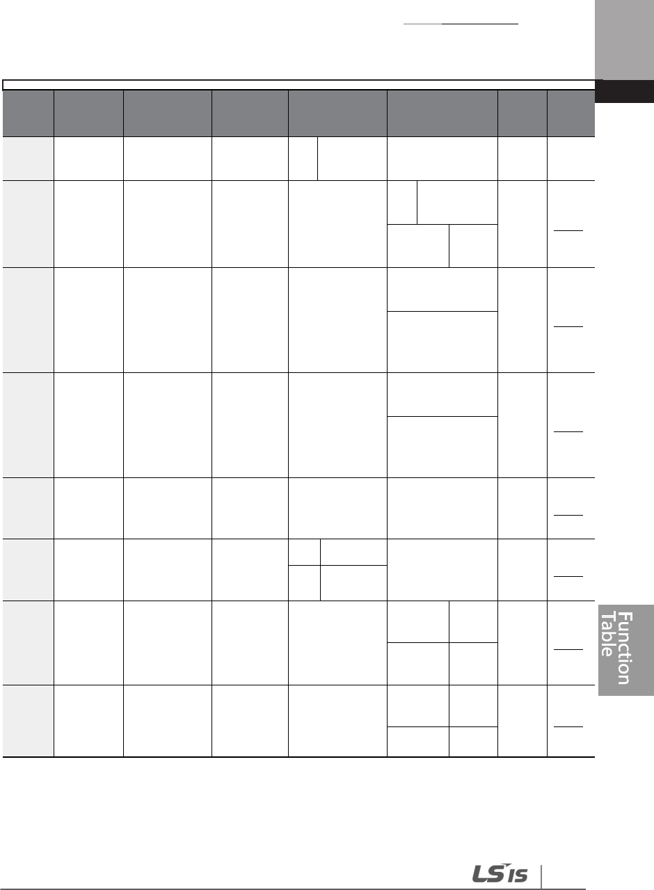
Table of Functions
435
Code Comm.
Address Name LCD
Display Setting Range Initial Value Prope
rty* Ref.
Bit
3
Power
-
on
run
7227 0h1448
Speed search
reference
current
SS Sup-
Current 50–120 (%)
90
0.75~
250kW O p.243
80
315~
500kW
7328 0h1449
Speed search
proportional
gain
SS P-Gain 0-9999
Flying Start
-
1
: 100
O p.243
Flying Start
-
2
: Dependent on
motor setting
74 0h144A Speed search
integral gain
SS I-Gain 0-9999
Flying Start
-
1
: 200
O p.243
Flying Start
-
2
: Dependent on
motor setting
75 0h144B
Output block
time before
speed search
SS Block
Time 0.0-60.0 (sec) 1.0 Δ p.243
77 0h144D
Energy
buffering
selection
KEB Select
0
No
0: No Δ p.197
1 Yes
7829 0h144E
Energy
buffering
start level
KEB Start
Lev
110.0-140.0
(%)
125.0
0.75~
90kW
Δ p.197
115.0
110~
500
kW
79 0h144F
Energy
buffering
stop level
KEB Stop
Lev
KEB Start Lev *
125.0-145.0
(%)
130.0
0.75~
90kW
Δ p.197
125.0
110~
27
CON-72 is displayed after Flying Start-1 and when any CON-71 bit is set to ‘1’.
28
CON-73–75 are displayed when any CON-71bit is set to ‘1’.
29
CON-78–83 are displayed when CON-77 is set to ‘1 (Yes)’.

Table of Functions
436
Code Comm.
Address Name LCD
Display Setting Range Initial Value Prope
rty* Ref.
500
kW
80 0h1450
Energy
buffering slip
gain
KEB Slip
Gain
buffering
slip gain
0-20000 300 O p.197
81 0h1451
Energy
buffering P-
Gain
KEB P Gain
0-20000 1000 O p.197
82 0h1452
Energy
buffering I
gain
KEB I Gain 1-20000 500 O p.197
83 0h1453
Energy
buffering
acceleration
time
KEB Acc
Time 0.0-600.0
10.0
0.75~
90kW
O p.197
30.0
110~
500
kW
8.5 Input Terminal Group (IN)
Data In the following table will be displayed only when the related code has been selected.
*O: Write-enabled during operation, Δ: Write-enabled when operation stops, X: Write-disabled
Code Comm.
Address Name LCD Display Setting Range Initial
Value
Prope
rty* Ref.
00
-
Jump Code
Jump Code
1
-
99
65
O
p.
70
01 0h1501
Frequency at
maximum
analog input
Freq at
100%
Start frequency-
Maximum
frequency (Hz)
Maximu
m
frequenc
y
O p.90
0530 0h1505 V1 input V1 0~12.00(V) or 0.00 X p.90
30
‘IN-05’ setting range can be changed according to the ‘IN-06’ settings.

Table of Functions
437
Code Comm.
Address Name LCD Display Setting Range Initial
Value
Prope
rty* Ref.
voltage display
Monitor(V)
-
12.00
~
12.00 (V)
06 0h1506
V1 input
polarity
selection
V1 Polarity
0
Unipolar
0:
Unipolar Δ p.90
1 Bipolar
07 0h1507
Time constant
of V1 input
filter
V1 Filter 0–10000 (ms) 10 O p.90
08 0h1508
V1 minimum
input voltage
V1 Volt x1 0.00-10.00 (V) 0.00 O p.90
09 0h1509
Output at V1
minimum
voltage (%)
V1 Perc y1 0.00-100.00 (%) 0.00 O p.90
10 0h150A
V1 maximum
input voltage
(%)
V1 Volt x2 0.00-12.00 (V) 10.00 O p.90
11 0h150B
Output
at V1
maximum
voltage (%)
V1 Perc y2 0.00-100.00 (%) 100.00 O p.90
1231 0h150C
V1 input at
minimum
voltage (%)
V1 –Volt x1’ -10.00- 0.00 (V) 0.00 O p.93
13 0h150D
Output at V1
minimum
voltage (%)
V1 –Perc y1’
-100.00-0.00 (%) 0.00 O p.93
14 0h150E
V1 maximum
input voltage
(%)
V1 –Volt x2’ -12.00- 0.00 (V) -10.00 O p.93
15 0h150F
Output at V1
maximum
voltage (%)
V1 –Perc y2’
-100.00-0.00 (%) -100.00 O p.93
16 0h1510 V2 rotation V1 Inverting
0 No 0: No O p.90
31
IN-12–17 are displayed when IN-06 is set to ‘1 (Bipolar)’.

Table of Functions
438
Code Comm.
Address Name LCD Display Setting Range Initial
Value
Prope
rty* Ref.
direction
change 1 Yes
17 0h1511 V1quantizatio
n change
V1
Quantizing
0.0032, 0.04-10.00
(%) 0.04 O p.90
2033 0h1514
Temperature
monitor T1 Monitor 0.00 - 100.00 (%) - X p.323
3534 0h1523
V2 input rate
monitor
V2 Monitor
(V) 0.00-12.00 (V) 0.00 O p.99
37 0h1525
V2 input filter
time V2 Filter 0-10000 (msec) 10 O p.99
38 0h1526
V2 minimum
input voltage
V2 Volt x1 0.00-10.00 (V) 0.00 O p.99
39 0h1527
Output at V2
minimum
voltage (%)
V2 Perc y1 0.00-100.00 (%) 0.00 O p.99
40 0h1528
V2 maximum
input voltage
V2 Volt x2 0.00-10.00 (V) 10.00 O p.99
41 0h1529
Output at V2
maximum
voltage (%)
V2 Perc y2 0.00-100.00 (%) 100.00 O p.99
46 0h152E
V2 Rotation
direction
options
V2 Inverting
0
No
0: No O p.99
1 Yes
47 0h152F
V2 Quantizing
level
V2
Quantizing 0.0035, 0.04 O p.99
32
* Quantizing is disabled if ‘0’ is selected.
33
IN-20 is displayed when the analog current/voltage input circuit selection switch (SW3) is
selected on T1.
34
IN-35–47 are displayed when the analog current/voltage input circuit selection switch (SW4) is
selected on V2.
35
* Quantizing is disabled if ‘0’ is selected.
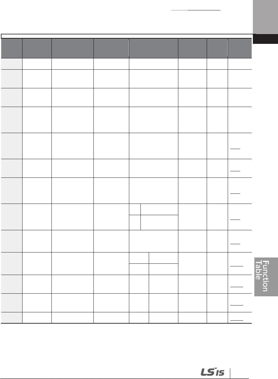
Table of Functions
439
Code Comm.
Address Name LCD Display Setting Range Initial
Value
Prope
rty* Ref.
0.04
-
10.00 (%)
5036 0h1532
I2 input
monitor
I2 Monitor
(mA) 0–24 (mA) 0 O p.96
52 0h1534
I2 input filter
time I2 Filter 0–10000 (msec) 10 O p.96
53 0h1535
I2 minimum
input power
supply
I2 Curr x1 0.00-20.00 (mA) 4.00 O p.96
54 0h1536
Output at I2
maximum
current (%)
I2 Perc y1 0.00-100.00 (%) 0.00 O p.96
55 0h1537
I2 maximum
input current I2 Curr x2 0.00-24.00 (mA) 20.00 O p.96
56 0h1538
Output at I2
maximum
current (%)
I2 Perc y2 0.00-100.00 (%) 100.00 O p.96
61 0h153D
I2 rotation
direction
options
I2 Inverting
0
No
0: No O p.96
1 Yes
62 0h153E I2 Quantizing
level
I2
Quantizing
0.0037
0.04-10.00 (%) 0.04 O p.96
65 0h1541 P1 Px terminal
configuration
P1 Define
0
None
1: Fx Δ p.106
1
Fx
66 0h1542
P2 Px terminal
configuration P2 Define 2 Rx 2: Rx Δ p.106
67 0h1543
P3 Px terminal
configuration P3 Define 3 RST 5: BX Δ p.343
68
0h1544
P4 Px terminal
P4 Define
4
External
3: RST
Δ
p.
342
36
IN-50–62 are displayed when the analog current/voltage input circuit selection switch (SW5) is
selected on I2.
37
* Quantizing is disabled if ‘0’ is selected.
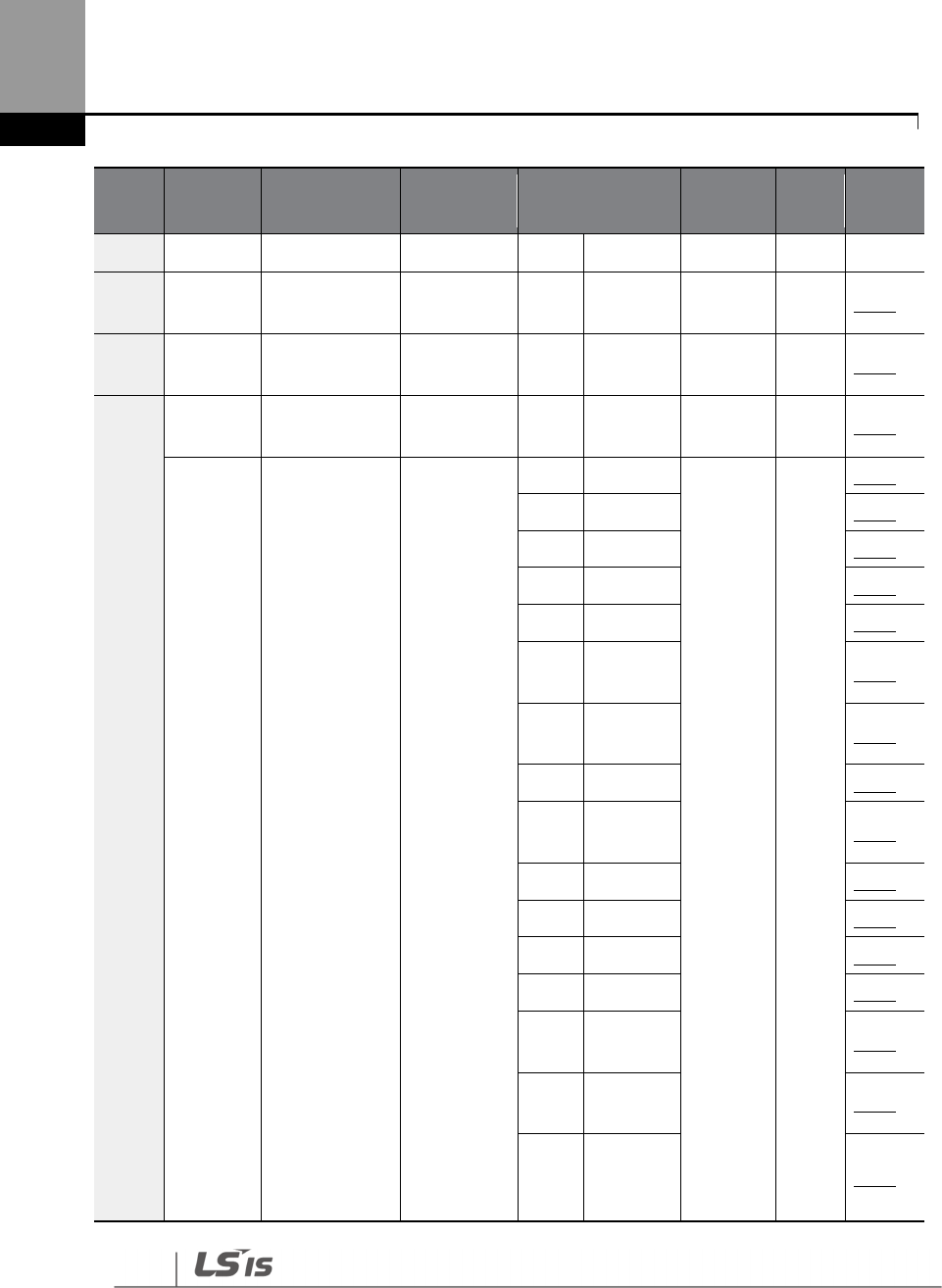
Table of Functions
440
Code Comm.
Address Name LCD Display Setting Range Initial
Value
Prope
rty* Ref.
configuration
Trip
69 0h1545
P5 Px terminal
configuration P5 Define 5 BX 7: Sp-L Δ p.342
70 0h1546
P6 Px terminal
configuration P6 Define 6 JOG 8: Sp-M Δ p.153
71 0h1547
P7 Px terminal
configuration P7 Define 7 Speed-L 9: Sp-H Δ p.104
8
Speed
-
M
p.
104
9 Speed-H
p.
104
11
XCEL
-
L
p.
118
12
XCEL
-
M
p.
118
13
XCEL
-
H
p.
118
14
XCEL
Stop p.124
15
RUN
Enable p.158
16
3
-
Wire
p.
157
17
2nd
Source p.141
18
Exchange
p.
253
19
Up
p.
155
20
Down
p.
155
22
U/D Clear
p.
155
23
Analog
Hold p.102
24
I
-
Term
Clear p.164
25
PID
Openloo
p
p.164
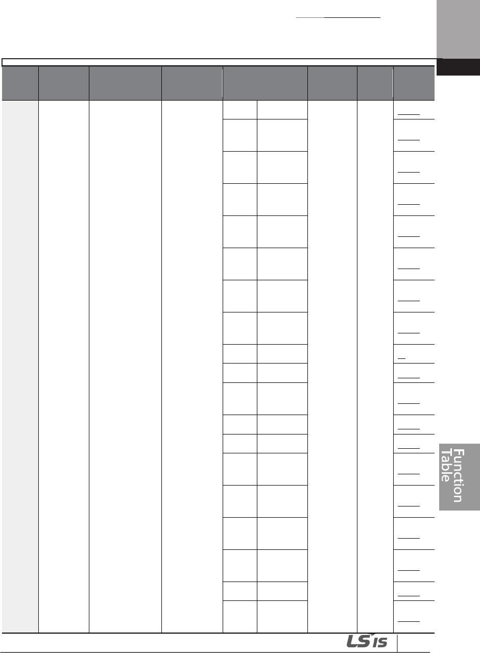
Table of Functions
441
Code Comm.
Address Name LCD Display Setting Range Initial
Value
Prope
rty* Ref.
26
PID Gain2
p.
164
27
PID Ref
Change p.124
28
2nd
Motor p.251
29
Interlock
1 p.286
30
Interlock
2 p.286
31
Interlock
3 p.286
32
Interlock
4 p.286
33
Interlock
5 p.286
34
Pre Excite
-
35
Timer In
p.
265
37
dis Aux
Ref p.147
38
FWD JOG
p.
154
39
REV JOG
p.
154
40
Fire
Mode p.240
41
EPID1
Run p.184
42
EPID1
ItermClr p.184
43
Time
Event En p.222
44
Pre Heat
p.
216
45
Damper
Open p.194
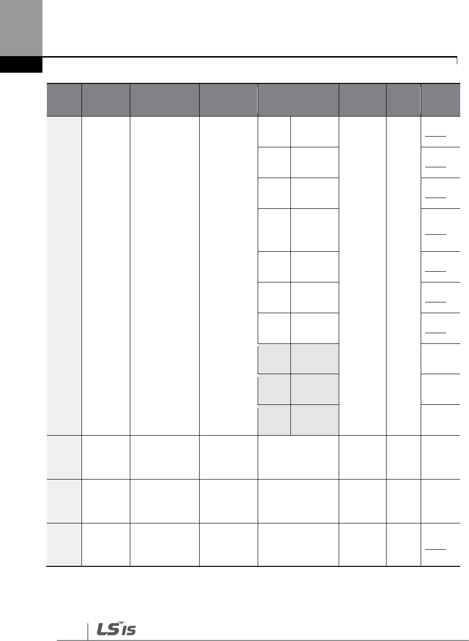
Table of Functions
442
Code Comm.
Address Name LCD Display Setting Range Initial
Value
Prope
rty* Ref.
46
PumpCle
an p.200
47
EPID2
Run p.184
48
EPID2
ItermClr p.184
49
Sleep
Wake
Chg
p.184
50
PID Step
Ref L p.164
51
PID Step
Ref M p.164
52
PID Step
Ref H p.164
5338
Interlock
6
54
Interlock
7
55
Interlock
8
83 0h1553 DI On Delay
Selection
DI On
DelayEn
000 0000 ~
111 1111
111
1111 Δ
84 0h1554 DI Off Delay
Selection
DI Off
DelayEn
000 0000 ~
111 1111
111
1111 Δ
85 0h1555
Multi
-
function
input terminal
On filter
DI On Delay
0–10000 (msec) 10 O p.142
38
‘53(Interlock6)~55(Interlock8)’ of IN-65~71 are available when Extension IO option is equipped.
Refer to Extension IO option manual for more detailed information

Table of Functions
443
Code Comm.
Address Name LCD Display Setting Range Initial
Value
Prope
rty* Ref.
86 0h1556
Multi
-
function
input terminal
Off filter
DI Off Delay
0–10000 (msec) 3 O p.142
87 0h1557
Multi-function
input terminal
selection
DI NC/NO
Sel
P7
–
P1
000 0000
Δ p.142
0
A
Terminal
(NO)
1
B
Terminal
(NC)
89 0h1559
Multi
-
step
command
delay time
InCheck
Time 1–5000 (msec) 1 Δ p.104
90 0h155A
Multi-function
input terminal
status
DI Status
P7 – P1
000 0000
O p.142
0
Contact
(Off)
1
Contact (On)
91 0h155B
Pulse input
amount
display
TI Monitor 0.00-50.00 (kHz) 0.00 X p.100
92 0h155C
TI minimum
input pulse TI Filter 0–9999 (msec) 10 O p.100
93 0h155D
TI minimum
input pulse TI Pls x1 0 - TI Pls x2 0.00 O p.100
94 0h153E
Output at TI
minimum
pulse (%)
TI Perc y1 0.00-100.00 (%) 0.00 O p.100
95 0h155F
TI maximum
input pulse TI Pls x2 TI Pls x1-32.00 32.00 O p.100
96 0h1560
Output at TI
maximum
pulse (%)
TI Perc y2 0.00-100.00 (%) 100.00 O p.100
97
0h1561
TI rotation
TI Inverting
0
No
0: No
O

Table of Functions
444
Code Comm.
Address Name LCD Display Setting Range Initial
Value
Prope
rty* Ref.
direction
change 1 Yes p.100
98 0h1562 TI quantization
level
TI
Quantizing
0.0039,
0.04-10.00 (%) 0.04 O p.100
39
Quantizing is disabled if ‘0’ is selected.
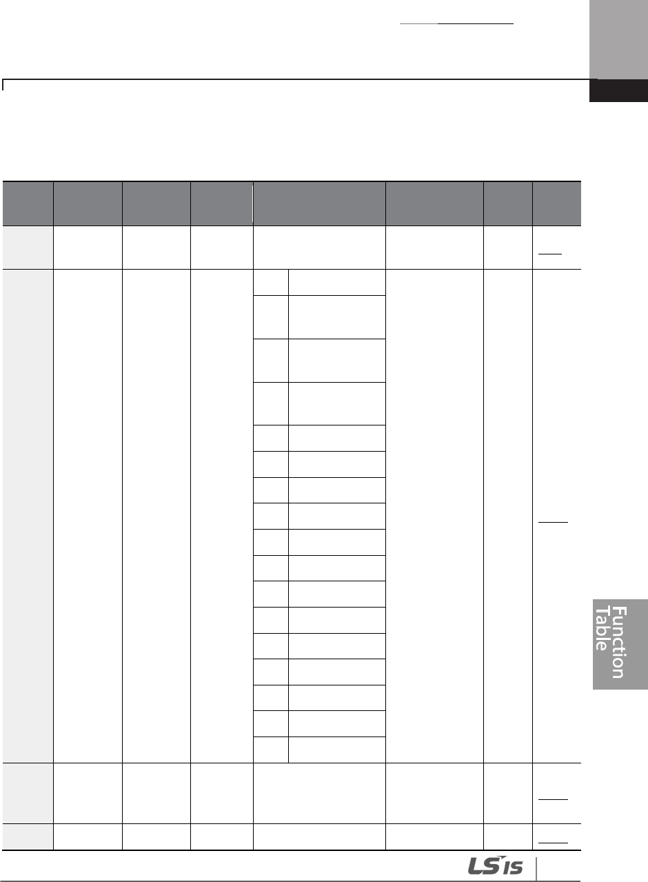
Table of Functions
445
8.6 Output Terminal Block Function Group (OUT)
Data in the following table will be displayed only when the related code has been selected.
*O: Write-enabled during operation, Δ: Write-enabled when operation stops, X: Write-disabled
Code
Comm.
Address Name
LCD
Display Parameter Setting Initial Value
Prope
rty* Ref.
00 -
Jump
Code
Jump
Code 1-99 30 O p.70
01 0h1601 Analog
output1
AO1
Mode
0
Frequency
0: Frequency O p.303
1
Output
Current
2
Output
Voltage
3
DCLink
Voltage
4
Output Power
7
Target Freq
8
Ramp Freq
9
PID Ref Value
10
PID Fdb Value
11
PID Output
12
Constant
13
EPID1 Output
14
EPID1 RefVal
15
EPID1 FdbVal
16
EPID2 Output
17
EPID2 RefVal
18
EPID2 FdbVal
02 0h1602
Analog
output1
gain
AO1
Gain -1000.0-1000.0 (%) 100.0 O p.303
03
0h1603
Analog
AO1 Bias
-
100.0
-
100.0 (%)
0.0
O
p.
303

Table of Functions
446
Code
Comm.
Address Name
LCD
Display Parameter Setting Initial Value
Prope
rty* Ref.
output1
bias
04 0h1604
Analog
output1
filter
AO1
Filter 0–10000 (msec) 5 O p.303
05 0h1605
Analog
constant
output1
AO1
Const %
0.0-100.0 (%) 0.0 O p.303
06 0h1606
Analog
output1
monitor
AO1
Monitor
0.0-1000.0 (%) 0.0 X p.303
07 0h1607 Analog
output2
AO2
Mode
Identical to the OUT
-
02 AO1 Mode
selected range
0: Frequency O p.303
08 0h1608
Analog
output2
gain
AO2
Gain -1000.0-1000.0 (%) 100.0 O p.303
09 0h1609
Analog
output2
bias
AO2 Bias
-100.0-100.0 (%) 0.0 O p.303
10 0h160A
Analog
output2
filter
AO2
Filter 0–10000 (msec) 5 O p.303
11 0h160B
Analog
constant
output2
AO2
Const %
0.0-100.0 (%) 0.0 O p.303
12 0h160C
Analog
output2
monitor
AO2
Monitor
0.0-1000.0 (%) 0.0 X p.303
30 0h161E
Fault
output
item
Trip
OutMod
e
bit
000
-
111
010 O p.314
Bit
0 Low voltage
Bit
1
Any faults
other than low

Table of Functions
447
Code
Comm.
Address Name
LCD
Display Parameter Setting Initial Value
Prope
rty* Ref.
voltage
Bit
2
Automatic
restart final
failure
31 0h161F
Multi-
function
relay1
Relay 1
0
None
23:Trip O p.308
1
FDT
-
1
2
FDT
-
2
3
FDT
-
3
4
FDT
-
4
5
Over Load
6
IOL
7
Under Load
8
Fan Warning
9
Stall
10
Over Voltage
11
Low Voltage
12
Over Heat
13
Lost
Command
14
Run
15
Stop
16
Steady
17
Inverter Line
18
Comm Line
19
Speed Search
20
Ready
21
MMC
22
Timer Out

Table of Functions
448
Code
Comm.
Address Name
LCD
Display Parameter Setting Initial Value
Prope
rty* Ref.
23
Trip
24
Lost Keypad
25
DB Warn%ED
26
On/Off Control
27
Fire Mode
28
Pipe Broken
29
Damper Err
30
Lubrication
31
Pump Clean
32
Level Detect
33
Damper
Control
34
CAP.Warning
35
Fan Exchange
32 0h1620
Multi
-
function
relay2
Relay 2 36 AUTO State 14: RUN O p.308
33 0h1621
Multi
-
function
relay3
Relay 3 37 Hand State 0: None O p.308
34 0h1622
Multi
-
function
relay4
Relay 4 38 TO 0: None O p.308
35 0h1623
Multi
-
function
relay5
Relay 5 39 Except Date 0: None O p.308
36 0h1624
Multi-
function
1 item
Q1
Define
40 KEB Operating
0: None O p.308
41 BrokenBelt
41 0h1629 Multi- DO DO Status 00 0000 X
p.
308
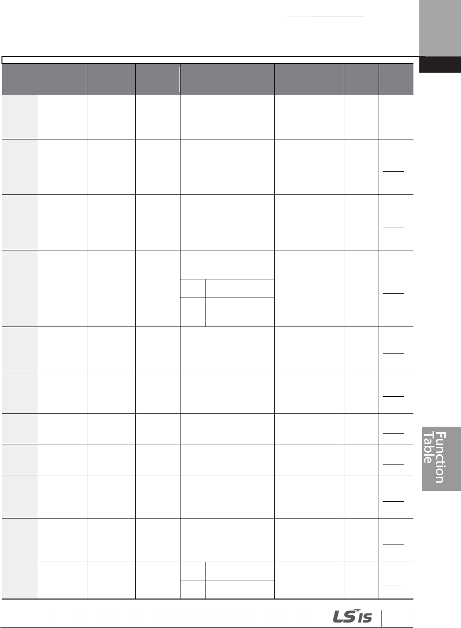
Table of Functions
449
Code
Comm.
Address Name
LCD
Display Parameter Setting Initial Value
Prope
rty* Ref.
function
output
monitor
Status
50 0h1632
Multi
-
function
output
On delay
DO On
Delay 0.00-100.00 (sec) 0.00 O p.315
51 0h1633
Multi
-
function
output
Off delay
DO Off
Delay 0.00-100.00 (sec) 0.00 O p.315
52 0h1634
Multi-
function
output
contact
selection
DO
NC/NO
Sel
Q1,Relay5-Relay1
00 0000 Δ p.315
0
A contact (NO)
1 B contact (NC)
53 0h1635
Fault
output
On delay
TripOut
OnDly 0.00-100.00 (sec) 0.00 O p.314
54 0h1636
Fault
output
Off delay
TripOut
OffDly 0.00-100.00 (sec) 0.00 O p.314
55 0h1637
Timer On
delay
TimerOn
Delay 0.00-100.00 (sec) 0.00 O p.264
56 0h1638
Timer Off
delay
TimerOff
Delay 0.00-100.00 (sec) 0.00 O p.264
57 0h1639
Detected
frequenc
y
FDT
Frequen
cy
0.00-Maximum
frequency (Hz) 30.00 O p.308
58 0h163A
Detected
frequenc
y band
FDT
Band
0.00-Maximum
frequency (Hz) 10.00 O p.308
61 0h163D Pulse
output
TO
Mode
0
Frequency
0: Frequency O p.306
1
Output

Table of Functions
450
Code
Comm.
Address Name
LCD
Display Parameter Setting Initial Value
Prope
rty* Ref.
item
Current
2
Output
Voltage
3
DCLink
Voltage
4
Output Power
7
Target Freq
8
Ramp Freq
9
PID Ref Value
10
PID Fdb Value
11
PID Output
12
Constant
13
EPID1 Output
14
EPID1 RefVal
15
EPID1 FdbVal
16
EPID2 Output
17
EPID2 RefVal
18
EPID2 FdbVal
62 0h163E
Pulse
output
gain
TO Gain -1000.0-1000.0 (%) 100.0 O p.306
63 0h163F
Pulse
output
bias
TO Bias -100.0-100.0 (%) 0.0 O p.306
64 0h1640
Pulse
output
filter
TO Filter
0–10000 (msec) 5 O p.306
65 0h1641
Pulse
output
constant
output 2
TO
Const %
0.0-100.0 (%) 0.0 O p.306
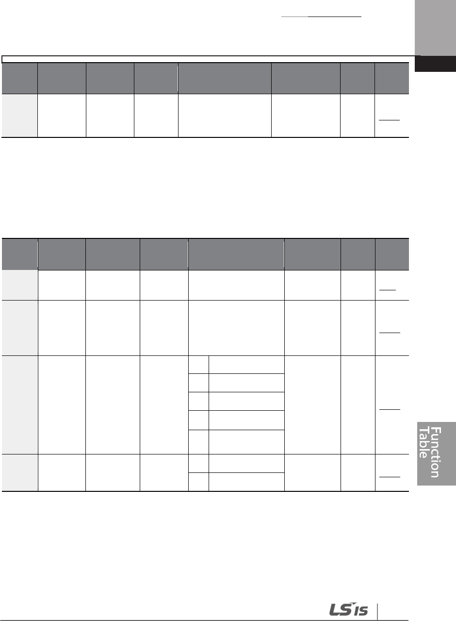
Table of Functions
451
Code
Comm.
Address Name
LCD
Display Parameter Setting Initial Value
Prope
rty* Ref.
66 0h1642
Pulse
output
monitor
TO
Monitor
0.0-1000.0 (%) 0.0 X p.306
8.7 Communication Function Group (COM)
Data in the following table will be displayed only when the related code has been selected.
*O: Write-enabled during operation, Δ: Write-enabled when operation stops, X: Write-disabled
Code
Comm.
Address Name
LCD
Display Parameter Setting Initial Value
Prope
rty* Ref.
00 -
Jump
Code
Jump
Code 1-99 20 O p.70
01 0h1701
Built
-
in
communic
ation
inverter ID
Int485 St
ID 1-MaxComID40 1 O p.357
02 0h1702
Built-in
communic
ation
protocol
Int485
Proto
0
ModBus RTU
0:
ModBusRT
U
O p.357
2
LS Inv 485
4
BACnet
5 Metasys-N2
641
ModBus Master
03 0h1703 Built-in
communic
Int485
BaudR
0
1200 bps
3: 9600 bps
O p.357
1
2400 bps
40
If AP1-40 is set to ‘4(Serve Drv)’, MaxComID is ‘8’, and if COM-02 is set to ‘4(BACnet), MaxComID is
‘127’. Otherwise MaxComID is ‘250’.
41
COM-02 is automatically set to ‘6(Modbus Master)’ when AP1-40 is set to ‘2 or 3’. Otherwise a
user can set the parameter value at user’s choice.

Table of Functions
452
Code
Comm.
Address Name
LCD
Display Parameter Setting Initial Value
Prope
rty* Ref.
ation
speed
2
4800 bps
3
9600 bps
4
19200 bps
5
38400 bps
6
56 Kbps
7
76.8 kbps
8 115.2 Kbps
42
04 0h1704
Built-in
communic
ation
frame
setting
Int485
Mode
0
D8/PN/S1
0: D8/PN/S1
O p.357
1
D8/PN/S2
2
D8/PE/S1
3
D8/PO/S1
05 0h1705
Transmissi
on delay
after
reception
Resp
Delay 0-1000 (msec) 5 O p.357
0643 0h1706
Communic
ation
option S/W
version
FBus S/W
Ver
- - O -
07 0h1707
Communic
ation
option
inverter ID
FBus ID 0-255 1 O -
08 0h1708
FIELD BUS
communic
ation
speed
FBUS
BaudRate
- 12 Mbps O -
42
115,200 bps
43
COM-06–09 are displayed only when a communication option card is installed.
Please refer to the communication option manual for details.

Table of Functions
453
Code
Comm.
Address Name
LCD
Display Parameter Setting Initial Value
Prope
rty* Ref.
09 0h1709
Communic
ation
option LED
status
FieldBus
LED - - O -
20 0h1714
BACnet
maximum
master
number
BAC Max
Master 1~127 127 O p.398
21 0h1715
BACnet
device
number1
BAC Dev
Inst1 0~4194 237 O p.398
22 0h1716
BACnet
device
number2
BAC Dev
Inst2 0-999 0 O p.398
23 0h1717
BACnet
password
BAC
PassWord
0-32767 0 O p.398
28 0h171C USB
Protocol
USB
Protocol
0
Modbus RTU
2: LS Inv
485 O -
2
LS Inv 485
30 0h171E
Number of
output
parameters
ParaStatu
sNum 0-8 3 O p.366
31 0h171F
Output
Communic
ation
address1
Para
Status-1 0000-FFFF Hex 000A O p.366
32 0h1720
Output
Communic
ation
address2
Para
Status-2 0000-FFFF Hex 000E O p.366
33 0h1721
Output
Communic
ation
address3
Para
Statuss-3 0000-FFFF Hex 000F O p.366
34 0h1722
Output
Communic
Para
Status-4 0000-FFFF Hex 0000 O p.366

Table of Functions
454
Code
Comm.
Address Name
LCD
Display Parameter Setting Initial Value
Prope
rty* Ref.
ation
address4
35 0h1723
Output
Communic
ation
address5
Para
Status-5 0000-FFFF Hex 0000 O p.366
36 0h1724
Output
Communic
ation
address6
Para
Status-6 0000-FFFF Hex 0000 O p.366
37 0h1725
Output
Communic
ation
address7
Para
Status-7 0000-FFFF Hex 0000 O p.366
38 0h1726
Output
Communic
ation
address8
Para
Status-8 0000-FFFF Hex 0000 O p.366
50 0h1732
Number of
input
parameters
Para Ctrl
Num 0-8 2 O p.366
51 0h1733
Input
Communic
ation
address1
Para
Control-1
0000-FFFF Hex 0005 O p.366
52 0h1734
Input
Communic
ation
address2
Para
Control-2
0000-FFFF Hex 0006 O p.366
53 0h1735
Input
Communic
ation
address3
Para
Control-3
0000-FFFF Hex 0000 O p.366
54 0h1736
Input
Communic
ation
Para
Control-4
0000-FFFF Hex 0000 O p.366

Table of Functions
455
Code
Comm.
Address Name
LCD
Display Parameter Setting Initial Value
Prope
rty* Ref.
address 4
55 0h1737
Input
Communic
ation
address 5
Para
Control-5
0000-FFFF Hex 0000 O p.366
56 0h1738
Input
Communic
ation
address 6
Para
Control-6
0000-FFFF Hex 0000 O p.366
57 0h1739
Input
Communic
ation
address 7
Para
Control-7
0000-FFFF Hex 0000 O p.366
58 0h173A
Input
Communic
ation
address 8
Para
Control-8
0000-FFFF Hex 0000 O p.366
70 0h1746
Communic
ation
multi-
function
input 1
Virtual DI
1 0 None 0: None O p.393
71 0h1747
Communic
ation
multi-
function
input 2
Virtual DI
2 1 Fx 0: None O p.393
72 0h1748
Communic
ation
multi-
function
input 3
Virtual DI
3 2 Rx 0: None O p.393
73 0h1749
Communic
ation
multi-
function
Virtual DI
4 3 RST 0: None O p.393

Table of Functions
456
Code
Comm.
Address Name
LCD
Display Parameter Setting Initial Value
Prope
rty* Ref.
input 4
74 0h174A
Communic
ation
multi-
function
input 5
Virtual DI
5 4 External Trip 0: None O p.393
75 0h174B
Communic
ation
multi-
function
input 6
Virtual DI
6 5 BX 0: None O p.393
76 0h174C
Communic
ation
multi-
function
input 7
Virtual DI
7 6 JOG 0: None O p.393
77 0h174D
Communic
ation
multi-
function
input 8
Virtual DI
8
7 Speed-L
0: None O p.393
8 Speed-M
9 Speed-H
11
XCEL-L
12
XCEL-M
13
XCEL-H
14
XCEL-Stop
15
Run Enable
16
3-wire
17
2
nd
source
18
Exchange
19
Up
20
Down
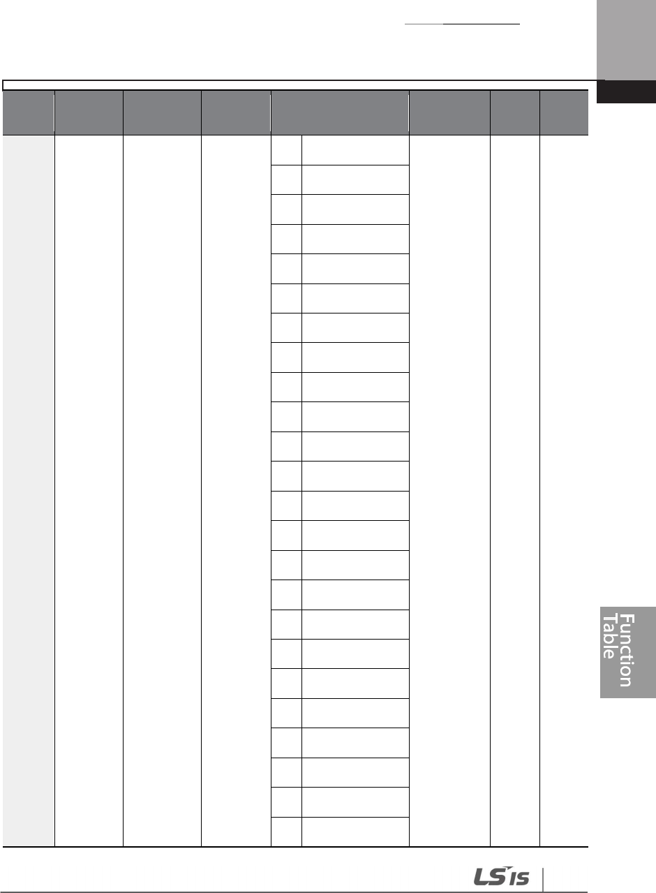
Table of Functions
457
Code
Comm.
Address Name
LCD
Display Parameter Setting Initial Value
Prope
rty* Ref.
22
U/D Clear
23
Analog Hold
24
I-Term Clear
25
PID Openloop
26
PID Gain 2
27
PID Ref Change
28
2
nd
Motor
29
Interlock1
30
Interlock2
31
Interlock3
32
Interlock4
33
Interlock5
34
Pre Excite
35
Timer In
37
dis Aux Ref
38
FWD JOG
39
REV JOG
40
Fire Mode
41
EPID1 Run
42
EPID1 ItermClr
43
Time Event En
44
Pre Heat
45
Damper Open
46
Pump Clean
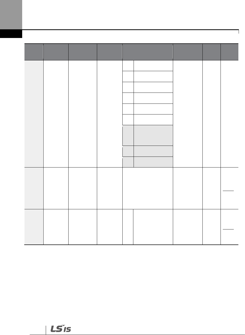
Table of Functions
458
Code
Comm.
Address Name
LCD
Display Parameter Setting Initial Value
Prope
rty* Ref.
47
EPID2 Run
48
EPID2 ItermClr
49
Sleep Wake Chg
50
PID Step Ref L
51
PID Step Ref M
52
PID Step Ref H
53
44 Interlock6
54
Interlock7
55
Interlock8
86 0h1756
Communic
ation
multi-
function
input
monitoring
Virt DI
Status
0000 0000
– 1111 1111 0000 0000 Δ p.362
96 0h173C
Communic
ation
operation
auto
resume
Power
On
Resume
0 No 0: No Δ p.319
8.8 Advanced Function Group(PID Functions)
Data in the following table will be displayed only when the related code has been selected.
44
‘53 (Interlock6)~55(Interlock8)’ of ADV-66 are available when Extension IO option is equipped.
Refer to Extension IO option manual for more detailed information.

Table of Functions
459
Unit MAX = PID Unit100%(PID-68)
Unit Min = (2xPID Unit 0%(PID-67)-PID Unit 100%)
Unit Default = (PID Unit 100%-PID Unit 0%)/2
Unit Band = Unit 100%-Unit 0%
*O /X: Write-enabled during operation,Δ: Writing available when operation stops
Code
Comm.
Address Name LCD Display
Parameter Setting Initial Value
Prope
rty* Ref.
00 - Jump Code
Jump
Code 1–99 50 O p.70
01 0h1801 PID mode
selection PID Sel
0
No
0: No Δ p.164
1
Yes
02 0h1802 E-PID
selection E-PID Sel
0
No
0: No O p.184
1
Yes
03 0h1803
PID output
monitor PID Output
- - X p.164
04 0h1804
PID
reference
monitor
PID Ref
Value - - X p.164
05 0h1805
PID
feedback
monitor
PID Fdb
Value - - X p.164
06 0h1806
PID error
monitor
value
PID Err
Value - - X p.164
10 0h180A
PID
reference 1
source
selection
PID Ref 1
Src
0
KeyPad
0:
Keypad Δ p.164
1
V1
3
V2
4
I2
5
Int485
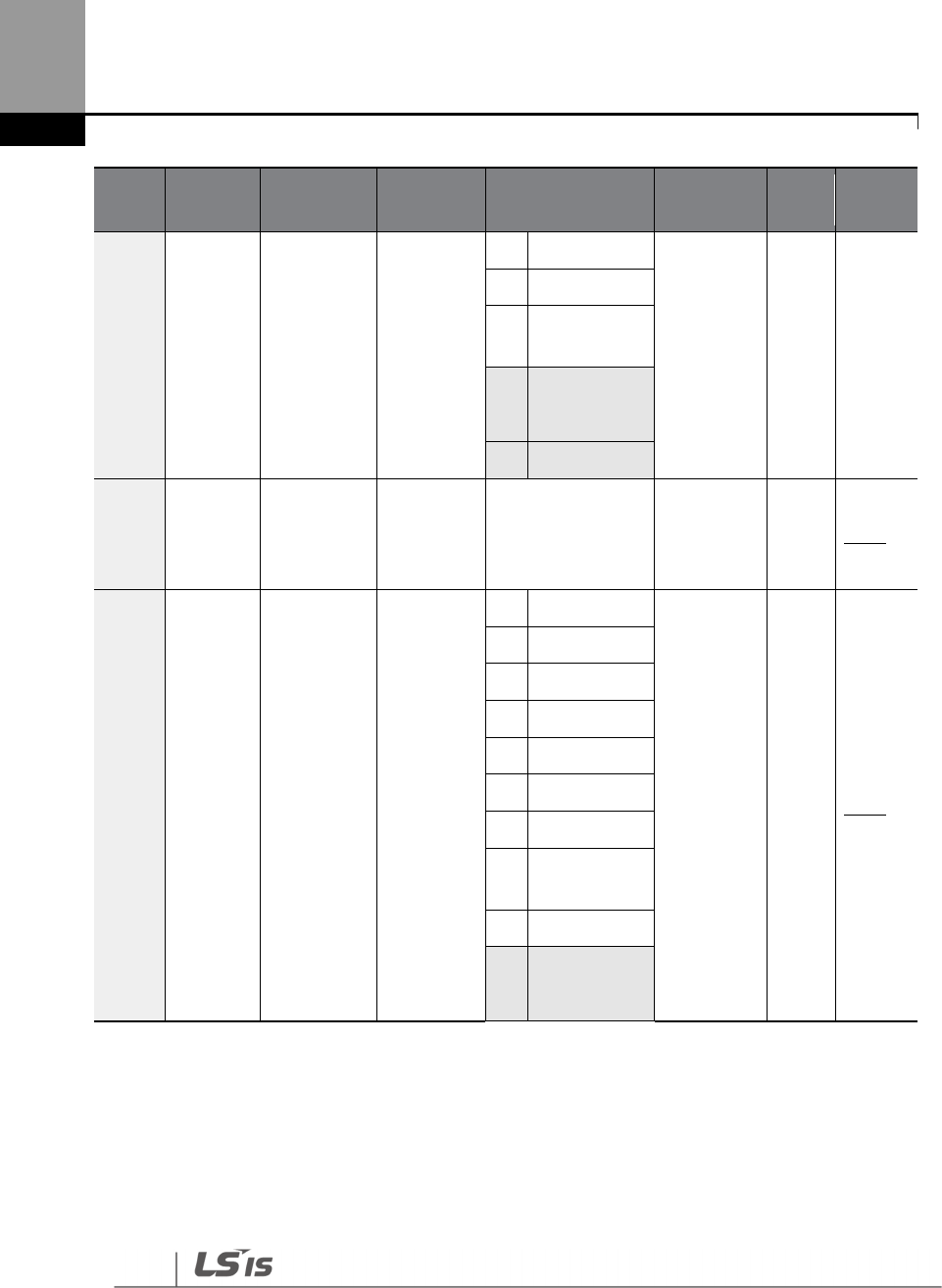
Table of Functions
460
Code
Comm.
Address Name LCD Display
Parameter Setting Initial Value
Prope
rty* Ref.
6
Fieldbus
8
Pulse
9
EPID1
Output
10
45 V3
11
I3
11 0h180B
PID
reference 1
keypad
value
PID Ref 1
Set Unit Min–Unit Max
Unit
Default O p.164
12 0h180C
PID
reference 1
auxiliary
source
selection
PIDRef1Au
xSrc
0
None
0: None Δ p.164
1
V1
3
V2
4
I2
6
Pulse
7
Int 485
8
FieldBus
10
EPID1
Output
11
E
-
PID Fdb Val
12
46 V3
45
‘10(V3)~11(I3)’ of PID-10 are available when Extension IO option is equipped. Refer to Extension
IO option manual for more detailed information.
46
‘12(V3)~13(I3)’ of PID-12 are available when Extension IO option is equipped. Refer to Extension
IO option manual for more detailed information.

Table of Functions
461
Code
Comm.
Address Name LCD Display
Parameter Setting Initial Value
Prope
rty* Ref.
13
I3
13 0h180D
PID
reference 1
auxiliary
mode
selection
PID
Ref1AuxM
od
0
M+(G*A)
0: M+(G*A) O p.164
1
M*(G*A)
2
M/(G*A)
3
M+(M*(G*A))
4
M+G*2*(A
-
50)
5
M*(G*2*(A
-
50))
6
M/(G*2*(A
-
50))
7
M+M*G*2*(A
-
50)
8
(M
-
A)^2
9
M^2+A^2
10
MAX(M,A)
11
MIN(M,A)
12
(M + A)/2
13
Root(M+A)
14 0h180E
PID
reference
auxiliary
gain
PID Ref1
Aux G -200.0–200.0 (%) 0.0 O p.164
15 0h180F
PID
reference 2
auxiliary
source
selection
PID Ref 2
Src
0
Keypad
0: KeyPad Δ p.164
1
V1
3
V2
4
I2
5
Int 485
6
Fieldbus
8
Pulse
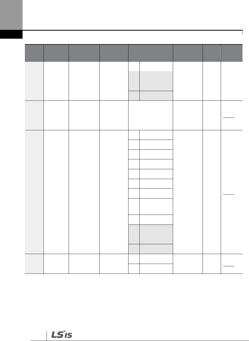
Table of Functions
462
Code
Comm.
Address Name LCD Display
Parameter Setting Initial Value
Prope
rty* Ref.
9
E
-
PID Output
10
47 V3
11
I3
16 0h1810
PID
reference 2
keypad
setting
PID Ref 2
Set Unit Min–Unit Max
Unit
Default O p.164
17 0h1811
PID
reference 2
auxiliary
source
selection
PID
Ref2AuxSrc
0
None
0: None Δ p.164
1
V1
3
V2
4
I2
6
Pulse
7
Int 485
8
FieldBus
10
EPID1
Output
11
EPID1 Fdb Val
12
48 V3
13
I3
18 0h1812 PID
reference 2
PID
Ref2AuxM
0
M+(G*A)
0: M+(G*A) O p.164
1
M*(G*A)
47
‘10(V3)~11(I3)’ of PID-15 are available when Extension IO option is equipped. Refer to Extension
IO option manual for more detailed information.
48
‘12(V3)~13(I3)’ of PID-17 are available when Extension IO option is equipped. Refer to Extension
IO option manual for more detailed information.
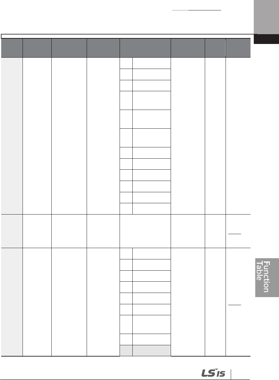
Table of Functions
463
Code
Comm.
Address Name LCD Display
Parameter Setting Initial Value
Prope
rty* Ref.
auxiliary
mode
selection
od
2
M/(G*A)
3
M+(M*(G*A))
4
M+G*2*(A
-
50)
5
M*(G*2*(A
-
50))
6
M/(G*2*(A
-
50))
7
M+M*G*2*(A
-
50)
8
(M
-
A)^2
9
M^2+A^2
10
MAX(M,A)
11
MIN(M,A)
12
(M + A)/2
13
Root(M+A)
19 0h1813
PID
reference 2
auxiliary
gain
PID Ref2
Aux G -200.0–200.0 (%) 0.0 O p.164
20 0h1814
PID
feedback
selection
PIDFdb
Source
0
V1
0: V1 Δ p.164
2
V2
3
I2
4
Int 485
5
FieldBus
7
Pulse
8
EPID1
Output
9
EPID1 Fdb Val
10
V3
Table of Functions
464
Code
Comm.
Address Name LCD Display
Parameter Setting Initial Value
Prope
rty* Ref.
49
11
I3
21 0h1815
PID
feedback
auxiliary
source
selection
PID Fdb
Aux Src
0
None
0: None Δ p.164
1
V1
3
V2
4
I2
6
Pulse
7
Int 485
8
FieldBus
10
EPID1
Output
11
EPID1 Fdb Val
12
50 V3
13
I3
22 0h1816
PID
feedback
auxiliary
mode
selection
PID
FdbAuxMo
d
0
M+(G*A)
0: M+(G*A) O p.164
1
M*(G*A)
2
M/(G*A)
3
M+(M*(G*A))
4
M+G*2*(A
-
50)
5
M*(G*2*(A
-
50))
49
‘10(V3)~11(I3)’ of PID-20 are available when Extension IO option is equipped. Refer to Extension
IO option manual for more detailed information.
50
‘12(V3)~13(I3)’ of PID-21 are available when Extension IO option is equipped. Refer to Extension
IO option manual for more detailed information.

Table of Functions
465
Code
Comm.
Address Name LCD Display
Parameter Setting Initial Value
Prope
rty* Ref.
6
M/(G*2*(A
-
50))
7
M+M*G*2*(A
-
50)
8
(M
-
A)^2
9
M^2+A^2
10
MAX(M,A)
11
MIN(M,A)
12
(M+A)/2
13
Root(M+A)
23 0h1817
PID
feedback
auxiliary
gain
PID Fdb
Aux G -200.0–200.0 (%) 0.0 O p.164
24 0h1818
PID
feed
back band
PID Fdb
Band 0.00 – Unit Band 0.00 O p.164
25 0h1819
PID
controller
proportiona
l gain 1
PID P-Gain
1 0.00–300.00 (%) 50.00 O p.164
26 0h181A
PID contro
ller integral
time 1
PID I-Time
1 0.0–200.0 (sec) 10.0 O p.164
27 0h181B
PID
controller
differential
time 1
PID D-Time
1 0.00–1.00 (sec) 0.00 O p.164
28 0h181C
PID controller
feed forward
gain
PID FF-
Gain 0.0–1000.0 (%) 0.0 O p.164
29 0h181D
PID output
filter
PID Out
LPF 0.00–10.00 (sec) 0.00 O p.164
30
0h181E
PID output
PID Limit
PID Limit Lo
–
100.00
O
p.
164

Table of Functions
466
Code
Comm.
Address Name LCD Display
Parameter Setting Initial Value
Prope
rty* Ref.
upper
limit
Hi
100.00
31 0h181F
PID output
lower limit
PID Limit
Lo
-
100.00
–
PID Limit
Hi 0.00 O p.164
32 0h1820
PID
controller
proportiona
l gain 2
PID P-Gain
2 0.00–300.00 (%) 50.0 O p.164
33 0h1821
PID
controller
integral
time 2
PID I-Time
2 0.0–200.0 (sec) 10.0 O p.164
34 0h1822
PID
controller
differential
time 2
PID D-Time
2 0.00–1.00 (sec) 0.00 O p.164
35 0h1823 PID output
mode
PID Out
Mode
0
PID Out
put
4 : PID or
Main O p.164
1
PID+ Main
Freq
2
PID+EPID1
Out
3
PID+EPID1+
Main
4 PID or Main
36 0h1824 PID output
inverse PID Out Inv
0
No
0: No Δ p.164
1
Yes
37 0h1825
PID output
scale
PID Out
Scale 0.1–1000.0 (%) 100.0 Δ p.164
40 0h1828
PID multi
-
step
reference
setting 1
PID Step
Ref 1 Unit Min–Unit Max
Unit
Default O p.164
41 0h1829
PID multi
-
step
PID Step
Ref 2 Unit Min–Unit Max
Unit
Default O p.164
Table of Functions
467
Code
Comm.
Address Name LCD Display
Parameter Setting Initial Value
Prope
rty* Ref.
reference
setting 2
42 0h182A
PID multi
-
step
reference
setting 3
PID Step
Ref 3 Unit Min–Unit Max
Unit
Default O p.164
43 0h182B
PID multi
-
step
reference
setting 4
PID Step
Ref 4 Unit Min–Unit Max
Unit
Default O p.164
44 0h182C
PID multi
-
step
reference
setting 5
PID Step
Ref 5 Unit Min–Unit Max
Unit
Default O p.164
45 0h182D
PID multi
-
step
reference
setting 6
PID Step
Ref 6 Unit Min–Unit Max
Unit
Default O p.164
46 0h182E
PID multi
-
step
reference
setting 7
PID Step
Ref 7 Unit Min–Unit Max
Unit
Default O p.164
50 0h1832
PID
controller
unit
selection
PID Unit
Sel
Refer to the Unit
List
1: % O p.164
0
CUST
1
%
2
PSI
3 ˚F
4 ˚C
5
inWC
6
inM
7
mBar
Table of Functions
468
Code
Comm.
Address Name LCD Display
Parameter Setting Initial Value
Prope
rty* Ref.
8
Bar
9
Pa
10
kPa
11
Hz
12
rpm
13
V
14
A
15
kW
16
HP
17
mpm
18
ft
19
m/s
20
m3/s
21
m3/m
22
m 3/h
23
l/s
24
l/m
25
l/h
26
kg/s
27
kg/m
28
kg/h
29
gl/s
30
gl/m
31
gl/h
32
ft/s
33
f3/s
34
f3/
m
Table of Functions
469
Code
Comm.
Address Name LCD Display
Parameter Setting Initial Value
Prope
rty* Ref.
35
f3/h
36
lb/s
37
lb/m
38
lb/h
39
ppm
40
pps
51 0h1833 PID unit
scale
PID Unit
Scale
0
x100
2: x 1 O p.164
1
x10
2
x1
3
x 0.1
4
x0.01
52 0h1834
PID control
0% setting
figure
PID Unit
0%
X100
-
30000
–
Unit Max
Range
varies
depending
on PID-50
setting
O p.164
X10
-
3000.0
–
Unit Max
X1
-
300.00
–
Unit Max
X0.1
-
30.000
–
Unit Max
X0.01
-
3.0000
–
Unit Max
53 0h1835
PID control
100%
setting
figure
PID Unit
100%
X100
Unit Min
–30000
Range
differs
depending
on PID-50
setting
O p.164
X10
Unit Min
–3000.0
X1
Unit Min
–300.00
X0.1
Unit
Min
–30.000
X0.01
Unit Min
–3.0000

Table of Functions
470
8.9 EPID Function Group (EPID)
51
5151
51
Data in the following table will be displayed only when the related code has been selected.
Unit MAX = EPID1 (EPID2) Unit 100%
Unit Min = (2xEPID1 (EPID2) Unit0%-EPID1 (EPID2) Unit100%)
Unit Default = (EPID1 (EPID2) Unit 100%-EPID1 (EPID2) Unit 0%)/2
*O/X : Write-enabled during operation,Δ: Writing available when operation stops
Code
Comm.
Address Name
LCD
Display Setting Range Initial Value
Prope
rty* Ref.
00 - Jump Code
Jump
Code 1–99 1 O p.70
01 0h1901
EPID 1
Mode
Selection
EPID1
Mode
0
None
0: None O p.184
1
Always ON
2
During Run
3
DI
dependent
0252 0h1902
EPID1outp
ut monitor
value
EPID1
Output -100.00–100.00% 0.00 X p.184
03 0h1903
EPID1
standard
monitor
EPID1 Ref
Val - - X p.184
04 0h1904
EPID1
feedback
monitor
value
EPID1
Fdb Val - - X p.184
05 0h1905
EPID1error
monitor
value
EPID1 Err
Val - - X p.184
51
EPID Group is displayed when PID-02 code is set to 'Yes'.
52
EPID-02–20 are displayed when EPID-01 code is not ‘0 (None)’.
Table of Functions
471
Code
Comm.
Address Name
LCD
Display Setting Range Initial Value
Prope
rty* Ref.
06 0h1906
EPID1
command
source
selection
EPID1 Ref
Src
0
Keypad
0: KeyPad Δ p.184
1
V1
3
V2
4
I2
5
Int 485
6
FieldBus
8
Pulse
9
53
V3
10 I3
07 0h1907
EPID1
keypad
command
value
EPID1 Ref
Set Unit Min–Unit Max
Unit Min O p.184
08 0h1908
EPID1
feedback
source
selection
EPID1
FdbSrc
0
V1
0: V1 O p.184
2
V2
3
I2
4
Int485
5
FieldBus
7
Pulse
854 V3
9
I3
09 0h1909
EPID1
proportion
al gain
EPID1 P-
Gain 0.00–300.00 (%) 50.00 O p.184
53
‘9(V3)~10(I3)’ of EPID-06 are available when Extension IO option is equipped. Refer to Extension
IO option manual for more detailed information.
54
‘8(V3)~9(I3)’ of EPID-08 are available when Extension IO option is equipped. Refer to Extension
IO option manual for more detailed information.
Table of Functions
472
Code
Comm.
Address Name
LCD
Display Setting Range Initial Value
Prope
rty* Ref.
10 0h190A
EPID1
integral
time
EPID1 I-
Time 0.0–200.0 (sec) 10.0 O p.184
11 0h190B
EPID1
differentiati
on time
EPID1 D-
Time 0.00–1.00 (sec) 0.00 O p.184
12 0h190C
EPID1 feed
-
forward
gain
EPID1 FF-
Gain 0.0–1000.0 (%) 0.0 O p.184
13 0h190D
EPID1
output
filter
EPID1
Out LPF 0.00–10.00 (sec) 0.00 O p.184
14 0h190E
EPID1
output
upper limit
EPID1
Limit Hi
EPID1 Limit Lo–
100.00 100.00 O p.184
15 0h190F
EPID1
lower limit
EPID1
Limit Lo
-
100.00
–
EPID1
Limit Hi 0.00 O p.184
16 0h1910
EPID1
output
inverse
EPID1
Out Inv
0 No
0: No O p.184
1 Yes
17 0h1911 EPID1 unit EPID1
Unit Sel
Refer to the EPID
Unit details table
(p.184)
1: % O p.184
18 0h1912 EPID1 unit
scale
EPID1
Unit Scl
0
X100
2: X1 O p.184
1
X10
2
X1
3
X0.1
4
X0.01
19 0h1913 EPID1 unit
0% value
EPID1
Unit0%
X
100
-
30000
–
Unit Max
Values vary
depending
on the unit
setting
O p.184
X10
-
3000.0
–
Unit
Max

Table of Functions
473
Code
Comm.
Address Name
LCD
Display Setting Range Initial Value
Prope
rty* Ref.
X1
-
300.00
–
Unit
Max
X
0.1
-
30.000
–
Unit
Max
X
0.01
-
3.0000
–
Unit
Max
20 0h1914
EPID1 unit
100% value
EPID1
Unit100%
X
100
Unit Min
–
30000
Values vary
depending
on the unit
setting
O p.184
X10
Unit Min
–
3000.0
X1
Unit Min
–
300.00
X
0.1
Unit Min
–
30.000
X
0.01
Unit Min
–
3.0000
31 0h191F
EPID2
Mode
selection
EPID2
Mode
0
None
0: None O p.184
1
Always ON
2
During Run
3
DI
dependent
3255 0h1920
EPID2
output
monitor
value
EPID2
Output -100.00–100.00% 0.00 X p.184
33 0h1921
EPID2
reference
monitor
value
EPID2 Ref
Val - - X p.184
55
EPID-32–50 are displayed when EPID-31 code is not ‘0 (None)’.
Table of Functions
474
Code
Comm.
Address Name
LCD
Display Setting Range Initial Value
Prope
rty* Ref.
34 0h1922
EPID2
feedback
monitor
value
EPID2
Fdb Val - - X p.184
35 0h1923
EPID2 error
monitor
value
EPID2 Err
Val - - X p.184
36 0h1924
EPID2
command
source
selection
EPID2 Ref
Src
0 Keypad
0: Keypad Δ p.184
1
V1
3
V2
4
I2
5
Int 485
6
FieldBus
8
Pulse
956 V3
10
I3
37 0h1925
EPID2
keypad
command
value
EPID2 Ref
Set Unit Min–Unit Max
Unit Min O p.184
38 0h1926
EPID2
feedback
source
selection
EPID2
FdbSrc
0 V1
0: V1 O p.184
2 V2
3 I2
4 Int 485
5 FieldBus
7 Pulse
56
‘9(V3)~10(I3)’ of EPID-36 are available when Extension IO option is equipped. Refer to Extension
IO option manual for more detailed information.
Table of Functions
475
Code
Comm.
Address Name
LCD
Display Setting Range Initial Value
Prope
rty* Ref.
857 V3
9 I3
39 0h1927
EPID2
proportion
al gain
EPID2 P-
Gain 0.00–300.00 (%) 50.0 O p.184
40 0h1928
EPID2
integral
time
EPID2 I-
Time 0.0–200.0 (sec) 10.0 O p.184
41 0h1929
EPID2
differentiati
on time
EPID2 D-
Time 0.00–1.00 (sec) 0.00 O p.184
42 0h192A
EPID2 feed
-
forward
gain
EPID2 FF-
Gain 0.0–1000.0 (%) 0.0 O p.184
43 0h192B
EPID2
output
filter
EPID2
Out LPF 0.00–10.00 (sec) 0.00 O p.184
44 0h192C
EPID2
output
upper limit
EPID2
Limit Hi
EPID2 Limit Lo–
100.00 100.00 O p.184
45 0h192D
EPID2
output
lower limit
EPID2
Limit Lo
-100.00–EPID2
Limit Hi 0.00 O p.184
46 0h192E
EPID2
output
inverse
EPID2
Out Inv
0 No
0: No O p.184
1 Yes
47 0h192F EPID2 unit
EPID2
Unit Sel
Refer to EPID Unit
details table (p.184)
0: CUST O p.184
48 0h1930 EPID2 unit
scale
EPID2
Unit Scl
0
X100
2: X1 O p.184
1
X10
57
‘8(V3)~9(I3)’ of EPID-38 are available when Extension IO option is equipped. Refer to Extension
IO option manual for more detailed information.

Table of Functions
476
Code
Comm.
Address Name
LCD
Display Setting Range Initial Value
Prope
rty* Ref.
2 X1
3
X0.1
4
X0.01
49 0h1931 EPID2 unit
0% value
EPID2
Unit0%
X
100
-
30000
–
Unit
Max
Values vary
depending
on the unit
setting
O p.184
X10
-
3000.0
–
Unit Max
X1
-
300.00
–
Unit
Max
X
0.1
-30.000–
Unit Max
X
0.01
-
3.0000
–
Unit
Max
50 0h1932 EPID2 unit
0% value
EPID2
Unit100%
X
100
Unit Min
–
30000
Values vary
depending
on the unit
setting
O p.184
X10
Unit Min
–
3000.0
X1
Unit Min
–
300.00
X
0.1
Unit Min–
30.000
X
0.01
Unit Min
–
3.0000

Table of Functions
477
8.10 Application 1 Function Group (AP1)
Data in the following table will be displayed only when the related code has been selected.
Unit MAX = PID Unit 100%
Unit Min = (2xPID Unit 0%-PID Unit 100%)
Unit Default = (PID Unit 100%-PID Unit 0%)/2
Unit Band = Unit 100%-Unit 0%
*O/X: Write-enabled during operation,Δ: Writing available when operation stops
Code
Comm.
Address Name
LCD
Display Setting Range Initial Value
Prope
rty* Ref.
00 - Jump Code
Jump
Code 1–99 20 O p.70
05 0h1A05
Sleep boost
amount
Sleep Bst
Set 0.00–Unit Max 0.00 O p.180
06 0h1A06
Sleep boost
speed
Sleep
BstFreq
0.00, Low Freq
–
High Freq 60.00 O p.180
07 0h1A07 PID sleep mode
1 delay time
PID Sleep
1 DT 0.0–6000.0 (sec) 20.0 O p.180
08 0h1A08 PID sleep mode
1 frequency
PID
Sleep1Fre
q
0.00, Low Freq–
High Freq 0.00 O p.180
09 0h1A09 PID wakeup 1
delay time
PID
WakeUp1
DT
0.0–6000.0 (sec) 20.0 O p.180
10 0h1A0A PID wakeup 1
value
PID
WakeUp1
Dev
0.00–Unit Band 20.00 O p.180
11 0h1A0B
PID sleep mode
2 delay time
PID Sleep
2 DT 0.0–6000.0 (sec) 20.0 O p.180
12 0h1A0C PID sleep mode
2 frequency
PID
Sleep2Fre
q
0.00, Low Freq–
High Freq 0.00 O p.180

Table of Functions
478
Code
Comm.
Address Name
LCD
Display Setting Range Initial Value
Prope
rty* Ref.
13 0h1A0D PID wakeup 2
delay time
PID
WakeUp2
DT
0.0–6000.0 (sec) 20.0 O p.180
14 0h1A0E PID wakeup 2
value
PID
WakeUp2
Dev
0.00–Unit Band 20.00 O p.180
20 0h1A14 Soft Fill function
options
Soft Fill
Sel
0 No 0: No O p.179
1
Yes
21 0h1A15
Pre
-
PID
operation
frequency
Pre-PID
Freq
Low Freq– High
Freq 30.00 O p.179
22 0h1A16
Pre
-
PID delay
time
Pre
-
PID
Delay 0.0–600.0 (sec) 60.0 O p.179
23 0h1A17
Soft Fill escape
value
Soft
Fill
Set
Unit Min
–
Unit
Max 20.00 O p.179
24 0h1A18
Soft Fill
reference
increasing value
Fill Step
Set 0.00–Unit Band 2.00 O p.179
25 0h1A19
Soft Fill reference
increasing cycle
Fill Step
Time 0–9999 (sec) 20 O p.179
26 0h1A1A
Soft Fill
changing
amount
Fill Fdb
Diff 0.00–Unit Band 0.00 O p.179
30 0h1A1E
Flow Comp
function
options
Flow
Comp Sel
0 No
0: No O p.194
1 Yes
31 0h1A1F Max Comp
amount
Max
Comp
Value
0.00–Unit Band 0.00 O p.194
0h1A28 MMC option
selection MMC Sel
0 None
0: None Δ p.266
1 Single Ctrl
2 Multi

Table of Functions
479
Code
Comm.
Address Name
LCD
Display Setting Range Initial Value
Prope
rty* Ref.
4058
Follower
3
Multi
Master
4 Serve Drv
4159 0h1A29 Bypass selection
Regul
Bypass
0
No
0: No Δ p.38
1
Yes
42 0h1A2A
Number of
auxiliary motors
Num of
Aux 1–5 5 Δ p.266
43 0h1A2B Select starting
auxiliary motor
Starting
Aux 1–5 1 Δ p.266
44 0h1A2C
Display the
number of
running
auxiliary motors
Aux
Motor
Run
- - X p.266
45 0h1A2D
Display auxiliary
motors 1– 4
priority
Aux
Priority 1 - - X p.266
46 0h1A2E
Display auxiliary
motors 5– 8
priority
Aux
Priority 2 - - X p.266
48 0h1A30
Auxiliary motor
options for
inverter stop
Aux All
Stop
0 No
1: Yes O p.266
1 Yes
49 0h1A31 Auxiliary motor
stop order.
Aux
On/Off
Seq
0 FILO
0: FILO Δ p.266
1 FIFO
2
Op time
Order
58
Set PID-1 to 'YES' to configure AP1-40.
59
Set AP1-40 to 'YES' to configure AP1-41.

Table of Functions
480
Code
Comm.
Address Name
LCD
Display Setting Range Initial Value
Prope
rty* Ref.
50 0h1A32
Auxiliary motors
pressure
difference
Aux Start
Diff 0–100 (%) 2 O p.266
51 0h1A33
Main motor
acceleration
time when the
number of
auxiliary motors
is reduced
Aux Acc
Time 0.0–600.0 (sec) 2.0 O p.266
52 0h1A34
Main motor
acceleration
time when the
number of
auxiliary motors
is increased
Aux Dec
Time 0.0–600.0 (sec) 2.0 O p.266
53 0h1A35
Auxiliary motors
start delay time
Aux Start
DT 0.0–3600.0 (sec) 60.0 O p.266
54 0h1A36
Auxiliary motors
stop delay time
Aux Stop
DT 0.0–3600.0 (sec) 60.0 O p.266
55 0h1A37 Auto change
mode selection
Auto Ch
Mode
0
None
1: AUX
Exchange Δ p.266
1
AUX
Exchange
2
Main
Exchange
56 0h1A38
Auto change
time
Auto Ch
Time 00: 00–99: 00 72: 00 O p.266
57 0h1A39 Auto change
frequency
Auto Ch
Level
Low Freq–
High Freq 20.00 O p.266
58 0h1A3A
Auto
change
operation time
Auto Op
Time - - X p.266
59 0h1A3B
Auxiliary motor
pressure
difference
Aux Stop
Diff 0~100 2

Table of Functions
481
Code
Comm.
Address Name
LCD
Display Setting Range Initial Value
Prope
rty* Ref.
6060 0h1A3C
Target
frequency of
Aux motor
during Multi
Master
Follower
Freq
Low Freq ~ High
Freq 60.00
61 0h1A3D
#1 auxiliary
motor start
frequency
Start Freq
1
Freq Low Limit
–
Freq High limit
(Hz)
45.00 O p.266
62 0h1A3E
#2 auxiliary
motor start
frequency
Start Freq
2
Low Freq–
High Freq 45.00 O p.266
63 0h1A3F
#3 auxiliary
motor start
frequency
Start Freq
3
Low Freq–
High Freq 45.00 O p.266
64 0h1A40
#4 auxiliary
motor start
frequency
Start Freq
4
Low Freq–
High Freq 45.00 O p.266
65 0h1A41
#5 auxiliary
motor start
frequency
Start Freq
5
Low Freq–
High Freq 45.00 O p.266
70 0h1A46
#1 auxiliary
motor stop
frequency
Stop Freq
1
Low Freq–
High Freq 20.00 O p.266
71 0h1A47
#2 auxiliary
motor stop
frequency
Stop Freq
2
Low Freq–
High Freq 20.00 O p.266
72 0h1A48
#3 auxiliary
motor stop
frequency
Stop Freq
3
Low Freq–
High Freq 20.00 O p.266
73 0h1A49
#4 auxiliary
motor stop
frequency
Stop Freq
4
Low Freq–
High Freq 20.00 O p.266
60
API-60 only appears when AP1-40 MMC Sel is set to '2' or '3'.

Table of Functions
482
Code
Comm.
Address Name
LCD
Display Setting Range Initial Value
Prope
rty* Ref.
74 0h1A4A
#5 auxiliary
motor stop
frequency
Stop Freq
5
Low Freq–
High Freq 20.00 O p.266
80 0h1A50
#1 auxiliary
motor’s
reference
compensation
Aux1 Ref
Comp 0.00–Unit Band 0.00 O p.266
81 0h1A51
#2 auxiliary
motor reference
compensation
Aux2 Ref
Comp 0.00–Unit Band 0.00 O p.266
82 0h1A52
#3 auxiliary
motor reference
compensation
Aux3 Ref
Comp 0.00–Unit Band 0.00 O p.266
83 0h1A53
#4 auxiliary
motor reference
compensation
Aux4 Ref
Comp 0.00–Unit Band 0.00 O p.266
84 0h1A54
#5 auxiliary
motor reference
compensation
Aux5 Ref
Comp 0.00–Unit Band 0.00 O p.266
90 0h1A5A Interlock
selection
Interlock
0
NO
0: No O p.286
1
YES
91 0h1A5B
Delay time
before next
motor operates
when an
interlock or an
auto change on
the main motor
occurs.
Interlock
DT 0.1–360.0 (Sec) 5.0 O p.286
0h1A5F Selection of
Auxiliary motor
AuxRunTi
me Sel
0 Aux 1 0: Aux1 O
1 Aux 2

Table of Functions
483
Code
Comm.
Address Name
LCD
Display Setting Range Initial Value
Prope
rty* Ref.
9561
to display [AP1
-
96] [AP1-97]
2 Aux 3
3 Aux 4
4 Aux 5
96 0h1A60
Operation
time(Day) of
Auxiliary motor
selected in
[AP1-95]
AuxRunTi
me Day
0
–
65535
0 O
97 0h1A61
Operat
ion
time
of Auxiliary
motor selected
in [AP1-95]
(Hour:Minute)
AuxRunTi
me Min
00:00 - 23:59
00:00 O
98 0h1A62
Deleting
operation time
of Auxiliary
motor
AuxRunTi
me Clr
0 None
0: None O
1 All
2 Aux 1
3 Aux 2
4 Aux 3
5 Aux 4
6 Aux 5
8.11 Application 2 Function Group (AP2)
61
AP1-95~98 is available when MMC and Master Follower functions are performed.

Table of Functions
484
Data In the following table will be displayed only when the related code has been selected.
*O/X: Write-enabled during operation,Δ: Writing available when operation stops
Code
Comm.
Address Name
LCD
Display Setting Range Initial Value
Prope
rty* Ref.
00 - Jump Code
Jump
Code 1–99 40 O p.70
0162 0h1B01 Load curve
Tuning Load Tune 0 No No Δ p.207
1
Yes
02 0h1B02 Low Freq
load curve
Load Fit
Lfreq
Base Freq*15%–
Load Fit HFreq 30.00 Δ p.207
03 0h1B03 Low Freq
current
Load Fit
LCurr 0.0–80.0 (%) 40.0 Δ p.207
04 0h1B04 Low Freq
power total
Load Fit
LPwr 0.0–80.0 (%) 30.0 Δ p.207
08 0h1B08 High Freq
load curve
Load Fit
Hfreq
Load Fit LFreq–
HighFreq 51.00 Δ p.207
09 0h1B09 High Freq
current.
Load Fit
HCurr
Load Fit LCurr –
200.0 (%) 80.0 Δ p.207
10 0h1B0A High Freq
total power
Load Fit
HPwr
Load Fit LPwr –
200.0 (%) 80.0 Δ p.207
11 0h1B0B Current load
curve
Load Curve
Cur - - X p.207
12 0h1B0C
Power load
curve
Load Curve
Pwr - - X p.207
15 0h1B0F Pump clean
setting1
Pump
Clean
0 None 0: None O p.200
1 DI
62
Set the operation mode to AUTO to configure AP2-01.
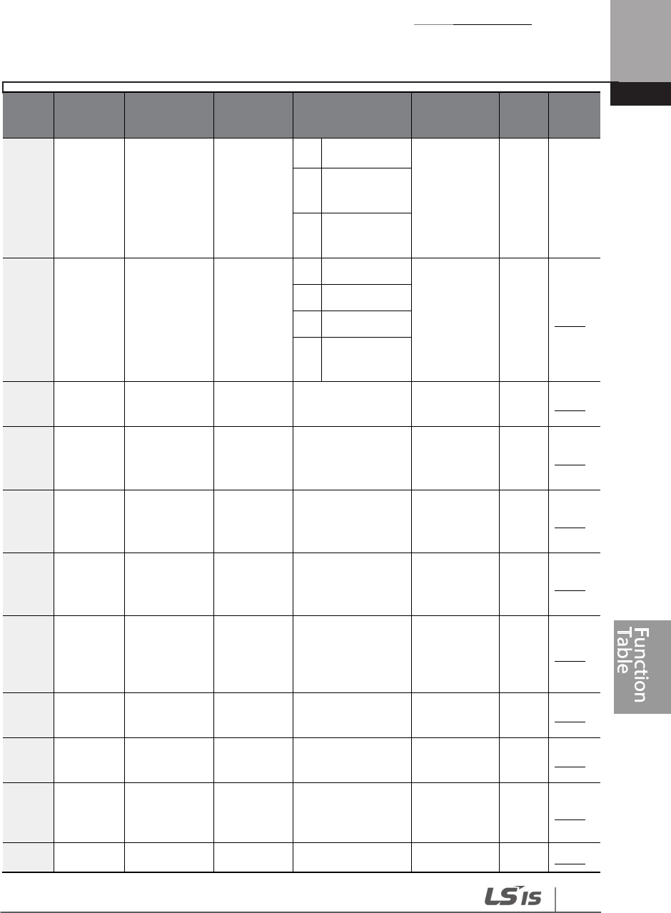
Table of Functions
485
Code
Comm.
Address Name
LCD
Display Setting Range Initial Value
Prope
rty* Ref.
Mode1
Dependent
2
Output
Power
3
Output
Current
16 0h1B10 Pump clean
setting2
Pump
Clean
Mode2
0
None
0: None Δ p.200
1
Start
2
Stop
3
Start and
Stop
17 0h1B11
Pump clean
load setting
PC Curve
Rate 0.1–200.0 (%) 100.0 O p.200
18 0h1B12
Pump clean
reference
band
PC Curve
Band 0.0–100.0 (%) 5.0 O p.200
19 0h1B13
Pump clean
operation
delay time
PC Curve
DT 0.0–6000.0 (sec) 60.0 O p.200
20 0h1B14
Pump clean
start delay
time
PC Start DT
0.0–6000.0 (sec) 10.0 O p.200
21 0h1B15
0 speed
operating
time at Fx/Rx
switching
PC Step DT
0.1–6000.0 (sec) 5.0 O p.200
22 0h1B16
Pump clean
Acc time
PC Acc
Time 0.0–600.0 (sec) 10.0 O p.200
23 0h1B17
Pump clean
Dec time
PC Dec
Time 0.0–600.0 (sec) 10.0 O p.200
24 0h1B18
Forward step
maintaining
time
FwdSteady
Time 0.0–600.0 (sec) 10.0 O p.200
25 0h1B19 Forward FwdSteady 0.00, Low Freq– 30.00 O p.200

Table of Functions
486
Code
Comm.
Address Name
LCD
Display Setting Range Initial Value
Prope
rty* Ref.
step
maintaining
frequency
Freq
High Freq
26 0h1B1A
Reverse step
running time
Rev
SteadyTim
e
0.0–600.0 (sec) 10.0 O p.200
27 0h1B1B
Reverse step
running
frequency
Rev
SteadyFreq
0.00, Low Freq–
High Freq 30.00 O p.200
28 0h1B1C
Pump clean
number of
Fx/Rx steps
PC Num of
Steps 1–10 2 O p.200
29 0h1B1D
Pump clean
function
cycle
monitoring
Repeat
Num Mon - - X p.200
30 0h1B1E
Number of
pump clean
repetitions
Repeat
Num Set 0–10 2 O p.200
31 0h1B1F
Operation
after pump
clean end
PC End
Mode
0
Stop
0:Stop Δ p.200
1
Run
32 0h1B20
Pump clean
continuous
limit time
PC Limit
Time 6–60 (min) 10 O p.200
33 0h1B21
Pump clean
continuous
limit numbers
PC Limit
Num 0–10 3 O p.200
38 0h1B26
Dec Valve
operation
frequency
Dec Valve
Freq
Low Freq–
High Freq 40.00 O p.206
39 0h1B27
Dev Valve
Dec time
Dev Valve
Time 0.0–6000.0 (sec) 0.0 O p.206
40 0h1B28 Start and Start&End 0
No 0: No Δ p.204
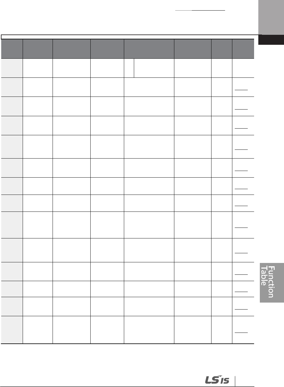
Table of Functions
487
Code
Comm.
Address Name
LCD
Display Setting Range Initial Value
Prope
rty* Ref.
End ramp
settings
Ramp
1
Yes
41 0h1B29
Start Ramp
Acc time
Start Ramp
Acc 0.0–600.0 (sec) 10.0 O p.204
42 0h1B2A End Ramp
Dec time
End Ramp
Dec
0.0–600.0 (sec) 10.0 O p.204
45 0h1B2D
Damper
check time
Damper
DT 0.0 – 600.0 (sec) 5.0 O p.194
46 0h1B2E
Lubrication
operation
time
Lub Op
Time 0.0–600.0 (sec) 5.0 O p.196
4863 0h1B30
Pre heat
level
Pre Heat
Level 1–100 (%) 20 O p.216
49 0h1B31
Pre
-
heat
duty
Pre
-
Heat
Duty
1–100 (%) 30 O p.216
50 0h1B32
DC input
delay time
DC Inj
Delay T
0.0–600.0 (sec) 60.0 O p.216
87 0h1B57
#1 Motor
average
power
M1 AVG
PWR 0.1–500.0 (kW) - O p.198
88 0h1B58
#2 Motor
average
power
M2 AVG
PWR 0.1–500.0 (kW) - O p.198
89 0h1B59
Cost per
kWh
Cost per
kWh 0.0–1000.0 0.0 O p.198
90 0h1B5A Saved kWh Saved kWh
- 0.0 X p.198
91 0h1B5B Saved MWh
Saved
MWh - 0 X p.198
92 0h1B5C
Saved Cost
below 1000
unit
Saved
Cost1 - 0.0 X p.198
63
AP2-48–49 are displayed when IN-65–71is set to ‘Pre-Heat’.

Table of Functions
488
Code
Comm.
Address Name
LCD
Display Setting Range Initial Value
Prope
rty* Ref.
93 0h1B5D
Saved Cost
over 1000
unit
Saved
Cost2 - 0 X p.198
94 0h1B5E
Saved CO2
conversion
Factor
CO2 Factor
0.0–5.0 0.0 O p.198
95 0h1B5F Saved CO2
(Ton)
Saved CO2
– 1 - 0.0 X p.198
96 0h1B60 Saved CO2
(kTon)
Saved CO2
– 2 - 0 X p.198
97 0h1B61
Saved energy
reset
Reset
Energy
0
No 0.No Δ p.198
1
Yes

Table of Functions
489
8.12 Application 3 Function Group (AP3)
Data In the following table will be displayed only when the related code has been selected.
*O/X: Write-enabled during operation, Δ: Writing available when operation stops
Code
Comm.
Address Name
LCD
Display Setting Range Initial Value
Prope
rty* Ref.
00 - Jump code
Jump
Code 1–99 70 O p.70
01 0h1C01 Current date
Now Date
01/01/2000 ~
12/31/2099 (Date)
01/01/2000 O p.222
02
0h1C02
Current time
Now Time
0: 00
–
23: 59 (min)
0: 00
O
p.
222
03 0h1C03 Current day
Now
Weekday
0000000
–
1111111 (Bit)
0000001 O p.222
04 0h1C04
Summer
Time
Start date
Summer
T Start
01/01 ~
Summer T Stop 04/01 O p.222
05 0h1C05
Summer
Time
Finish date
Summer
T Stop
Summer T Start
~12/31(Date) 11/31 O p.222
0664 0h1C06 Date display
format
Date
Format
0
YYYY/MM/DD
Date Format O p.222
1
MM/DD/YYYY
2
DD/MM/YYYY
10 0h1C0A
Period
connection
status
Period
Status - - X p.222
11 0h1C0B
Time Period1
Start time
configuration
Period1
Start T
0: 00–24: 00
(min) 24: 00 O p.222
12 0h1C0C
Time Period1
End time
configuration
Period1
Stop T
Period1 Start T –
24: 00 (min) 24: 00 O p.222
64
The date format can be changed according to the AP3-06 settings.

Table of Functions
490
Code
Comm.
Address Name
LCD
Display Setting Range Initial Value
Prope
rty* Ref.
13 0h1C0D
Time Period1
Day of the
week
configuration
Period1
Day
0000000–
1111111 (Bit) 0000000 p.222
14 0h1C0E
Time Period2
Start time
configuration
Period2
Start T 0: 00–24: 00 (min)
24: 00 O p.222
15 0h1C0F
Time Period2
End time
configuration
Period2
Stop T
Period2 Start T –
24: 00 (min) 24: 00 O p.222
16 0h1C10
Time Period2
Day of the
week
configuration
Period2
Day
0000000–
1111111 (Bit) 00000000 O p.222
17 0h1C11
Time Period3
Start time
configuration
Period3
Start T 0: 00–24: 00 (min)
24: 00 O p.222
18 0h1C12
Time Period3
End time
configuration
Period3
Stop T
Period3 Start T –
24: 00 (min) 24: 00 O p.222
19 0h1C13
Time Period3
Day of the
week
configuration
Period3
Day
0000000–
1111111 (Bit) 0000000 O p.222
20 0h1C14
Time Period4
Start time
configuration
Period4
Start T 0: 00–24: 00 (min)
24: 00 O p.222
21 0h1C15
Time Period4
End time
configuration
Period4
Stop T
Period4 Start T –
24: 00 (min) 24: 00 O p.222
22 0h1C16
Time Period
Day of the
week
configuration
Period4
Day
0000000–
1111111 (Bit) 0000000 O p.222

Table of Functions
491
Code
Comm.
Address Name
LCD
Display Setting Range Initial Value
Prope
rty* Ref.
30 0h1C1E
Except1 Date
Start time
configuration
Except1
Start T 0: 00–24: 00 (min)
24: 00 O p.222
31 0h1C1F
Except1 Date
End time
configuration
Except1
Stop T
Except1 StartT –
24: 00 (min) 24: 00 O p.222
32 0h1C20
Except1 Date
configuration
Except1D
ate
01/01
–
12/31
(Date) 01/01 O p.222
33 0h1C21
Except2 Date
Start time
configuration
Except2
Start T 0: 00–24: 00 (min)
24: 00 O p.222
34 0h1C22
Except2 Date
Stop time
configuration
Except2
Stop T
Except2 StartT –
24: 00 (min) 24: 00 O p.222
35 0h1C23
Except2 Date
configuration
Except2D
ate
01/01
–
12/31
(Date) 01/01 O p.222
36 0h1C24
Except3 Date
Start time
configuration
Except3
Start T 0: 00–24: 00 (min)
24: 00 O p.222
37 0h1C25
Except3 Date
End time
configuration
Except3
Stop T
Except3 StartT –
24: 00 (min) 24: 00 O p.222
38 0h1C26
Except3
Date
configuration
Except3D
ate
01/01–12/31
(Date) 01/01 O p.222
39 0h1C27
Except4 Date
Start time
configuration
Except4
Start T 0: 00–24: 00 (min)
24: 00 O p.222
40 0h1C28
Except4 Date
End time
configuration
Except4
Stop T
Except4 StartT –
24: 00 (min) 24: 00 O p.222
41 0h1C29
Except4
Date
configuration
Except4D
ate
01/01–12/31
(Date) 01/01 O p.222
42 0h1C2A
Except5 Date
Except5 0: 00–24: 00 (min)
24: 00 O p.222

Table of Functions
492
Code
Comm.
Address Name
LCD
Display Setting Range Initial Value
Prope
rty* Ref.
Start time
configuration
Start T
43 0h1C2B
Except5 Date
End time
configuration
Except5
Stop T
Except5 StartT –
24: 00 (min) 24: 00 O p.222
44 0h1C2C
Except5 Date
configuration
Except5
Date
01/01
–
12/31
(Date) 01/01 O p.222
45 0h1C2D
Except6 Date
Start time
configuration
Except6
Start T 0: 00–24: 00 (min)
24: 00 O p.222
46 0h1C2E
Except6 Date
End time
configuration
Except6
Stop T
Except6 StartT –
24: 00 (min) 24: 00 O p.222
47 0h1C2F
Except6 Date
configuration
Except6
Date
01/01–12/31
(Date) 01/01 O p.222
48 0h1C30
Except7 Date
Start time
configuration
Except7
Start T 0: 00–24: 00 (min)
24: 00 O p.222
49 0h1C31
Except7 Date
End time
configuration
Except7
Stop T
Except7 StartT –
24: 00 (min) 24: 00 O p.222
50 0h1C32
Except7 Date
configuration
Except7
Date
01/01
–
12/31
(Date) 01/01 O p.222
51 0h1C33
Except8 Date
Start time
configuration
Except8
Start T 0: 00–24: 00 (min)
24: 00 O p.222
52 0h1C34
Except8 Date
End time
configuration
Except8
Stop T
Except8 StartT –
24: 00 (min) 24: 00 O p.222
53 0h1C35
Except8 Date
configuration
Except8
Date
01/01
–
12/31
(Date) 01/01 O p.222
70 0h1C46
Time Event
Time 0 No 0: NO Δ p.222
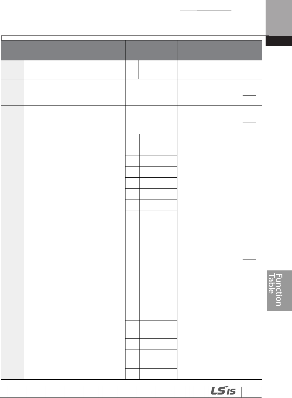
Table of Functions
493
Code
Comm.
Address Name
LCD
Display Setting Range Initial Value
Prope
rty* Ref.
function
configuration
Event En
1 Yes
71 0h1C47
Time Event
configuration
status
T-Event
Status - - X p.222
72 0h1C48
Time Event 1
connection
status
T-Event1
Period
000000000000 –
111111111111
00000000000
0 Δ p.222
73 0h1C49
Time Event 1
functions
T-Event1
Define
0
None
0: None Δ p.222
1
Fx
2
Rx
3
Speed
-
L
4
Speed
-
M
5
Speed
-
H
7
Xcel
-
L
8
Xcel
-
M
9
Xcel
-
H
10
Xcel Stop
11 Run Enable
12
2nd
Source
13 Exchange
14 Analog Hold
15 I-Term Clear
16
PID
Openloop
17
PID Gain 2
18
PID Ref
Change
19
2nd Motor

Table of Functions
494
Code
Comm.
Address Name
LCD
Display Setting Range Initial Value
Prope
rty* Ref.
20
Timer In
21 Dias Aux Ref
22
EPID1 Run
23 EPID1
ITermClr
24
Pre Heat
25
EPID2
R
u
n
26
EPID2
ITermClr
27
Sleep Wake
Chg
28
PID Step Ref
L
29 PID Step Ref
M
30
PID Step Ref
H
74 0h1C4A
Time Event 2
connection
configuration
T-Event2
Period
000000000000 –
111111111111
00000000000
0 Δ p.222
75 0h1C4B
Time Event 2
functions
T-Event2
Define
Identical to the
setting range for
AP3-73
0: None Δ p.222
76 0h1C4C
Time Event 3
connection
configuration
T-Event2
Period
000000000000 –
111111111111
00000000000
0 Δ p.222
77 0h1C4D
Time Event 3
functions
T-Event3
Define
Identical to the
setting range for
AP3
-
73
0: None Δ p.222
78 0h1C4E
Time Event 4
connection
configuration
T-Event4
Period
000000000000 –
111111111111
00000000000
0 Δ p.222

Table of Functions
495
Code
Comm.
Address Name
LCD
Display Setting Range Initial Value
Prope
rty* Ref.
79 0h1C4F
Time Event 4
functions
T-Event4
Define
Identical to the
setting range for
AP3-73
0: None Δ p.222
80 0h1C50
Time Event 5
connection
configuration
T-Event5
Period
000000000000 –
111111111111
00000000000
0 Δ p.222
81 0h1C51
Time Event 5
functions
T-Event5
Define
Identical to the
setting range for
AP3-73
0: None Δ p.222
82 0h1C52
Time Event 6
connection
configuration
T-Event6
Period
000000000000 –
111111111111
00000000000
0 Δ p.222
83 0h1C53
Time Event 6
functions
T-Event6
Define
Identical to the
setting range for
AP3
-
73
0: None Δ p.222
84 0h1C54
Time Event 7
connection
configuration
T-Event7
Period
000000000000 –
111111111111
00000000000
0 Δ p.222
85 0h1C55
Time Event 7
functions
T-Event7
Define
Same setting
range for
AP3
-
73
0: None Δ p.222
86 0h1C56
Time Event 8
connection
configuration
T-Event8
Period
000000000000 –
111111111111
00000000000
0 Δ p.222
87 0h1C57
Time Event 8
functions
T-Event8
Define
Same setting
range as AP3-73 0: None Δ p.222

Table of Functions
496
8.13 Protection Function Group (PRT)
Data In the following table will be displayed only when the related code has been selected.
O : Write-enabled during operation, Δ: Write-enabled when stopped, X: Write disabled
Code
Comm.
Address Name
LCD
Display Setting Range Initial Value
Prope
rty* Ref.
00 - Jump Code
Jump
Code 1–99 40 O p.70
05 0h1D05
Input/output
open-phase
protection
Phase
Loss Chk
Bit
00
–
11
00 Δ p.331
Bit
0
Output
open
phase
Bit
1
Input open
phase
06 0h1D06
Input voltage
range during
open-phase
IPO V
Band 1–100 (V) 15 O p.331
07 0h1D07
Deceleration
time at fault
trip
Trip Dec
Time 0.0–600.0 (sec)
3.0 0.75~
90kW
O -
90.0 110~
500kW
08 0h1D08
Selection of
startup on trip
reset
RST
Restart
Bit
00
–
11
00 O p.248
Bit
0
Fault trips
other than
LV trip
Bit
1
LV Trip
09 0h1D09
Number of
automatic
restarts
Retry
Number 0–10 0 O p.248
10 0h1D0A
Automatic
restart delay
time
Retry
Delay 0.1–600.0 (sec) 5.0 O p.248
11 0h1D0B Keypad
command loss
Lost KPD
Mode
0
None
O p.334
1
Warning
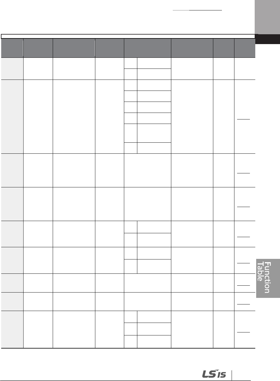
Table of Functions
497
Code
Comm.
Address Name
LCD
Display Setting Range Initial Value
Prope
rty* Ref.
operation
mode
2
Free
-
Run
0: None
3
Dec
12 0h1D0C
Speed
command loss
operation
mode
Lost Cmd
Mode
0
None
0: None O p.334
1
Free
-
Run
2
Dec
3
Hold Input
4
Hold
Output
5
Lost Preset
1365 0h1D0D
Time to
determine
speed
command loss
Lost Cmd
Time 0.1–120.0 (sec) 1.0 O p.334
14 0h1D0E
Operation
frequency at
speed
command loss
Lost
Preset F
0.00, Low Freq–
High Freq 0.00 O p.334
15 0h1D0F
Analog input
loss decision
level
AI Lost
Level
0 Half of x1
0: Half of x1 O p.334
1 Below x1
17 0h1D11
Overload
warning
selection
OL Warn
Select
0 No
0: No O p.323
1 Yes
18 0h1D12
Overload
warning level
OL Warn
Level
30
–
OL Trip
Level(%) 110 O p.323
19 0h1D13
Overload
warning time
OL Warn
Time 0.0–30.0 (sec) 10.0 O p.323
20 0h1D14 Motion at
overload trip
OL Trip
Select
0 None
1: Free-Run O p.323
1 Free-Run
2 Dec
65
PRT-13–15 are displayed when PRT-12 is not set to ‘0 (NONE)’.

Table of Functions
498
Code
Comm.
Address Name
LCD
Display Setting Range Initial Value
Prope
rty* Ref.
21 0h1D15
Overload trip
level
OL Trip
Level 30–150 (%) 120 O p.323
22 0h1D16
Overload trip
time
OL Trip
Time 0.0–60.0 (sec) 60.0 O p.323
23 0h1D17
Under load
detection
Source
UL
Source
0
Output
Current 0: Output
Current Δ p.340
1
Output
Power
24 0h1D18
Under load
detection
band
UL Band 0.0–100.0 (%) 10.0 Δ p.340
25 0h1D19
Under load
warning
selection
UL Warn
Sel
0 No
0: No O p.340
1 Yes
26 0h1D1A
Under load
warning time
UL Warn
Time 0.0–600.0 (sec) 10.0 O p.340
27 0h1D1B Under load trip
selection
UL Trip
Sel
0
None
0: None O p.340
1
Free
-
Run
2
Dec
28 0h1D1C
Under load trip
timer
UL Trip
Time 0.0–600.0 (sec) 30.0 O p.340
31 0h1D1F Operation on
no motor trip
No Motor
Trip
0 None 0: None O p.345
1 Free-Run
32 0h1D20
No motor trip
current level
No Motor
Level 1–100 (%) 5 O p.345
33 0h1D21 No motor
detection time
No Motor
Time 0.1–10.0 (sec) 3.0 O p.345
34 0h1D22
Operation at
motor
overheat
detection
Thermal-
T Sel
0 None
0: None O p.323 1 Free-Run
2 Dec

Table of Functions
499
Code
Comm.
Address Name
LCD
Display Setting Range Initial Value
Prope
rty* Ref.
35 0h1D23 Thermal
sensor input
Thermal
In Src
0 Thermal In 0: Thermal In O p.323
1 V2
36 0h1D24
Thermal
sensor fault
level
Thermal-
T Lev 0.0–100.0 (%) 50.0 O p.323
37 0h1D25
Thermal
sensor fault
range
Thermal-
T
0 Low
0: Low O p.323
1 High
3866 0h1D26
Motor
overheat
detection
sensor
Thermal
Monitor - - X p.323
40 0h1D28
Electr
onic
thermal
prevention
fault trip
selection
ETH Trip
Sel
0 None
0: None O p.321
1 Free-Run
2 Dec
41 0h1D29 Motor cooling
fan type
Motor
Cooling
0 Self-cool
0: Self-cool O p.321
1
Forced
-
cool
42 0h1D2A
Electronic
thermal one
minute rating
ETH 1
min
ETH Cont–150
(%) 120 O p.321
43 0h1D2B
Electronic
thermal
prevention
continuous
rating
ETH Cont
50–120 (%) 100 O p.321
44 0h1D2C Fire mode
password
Fire
Mode
PW
0~9999 3473 O p.240
0
None
66
PRT-38 is displayed when PRT-34 is not set to ‘0 (NONE)’.

Table of Functions
500
Code
Comm.
Address Name
LCD
Display Setting Range Initial Value
Prope
rty* Ref.
4567 0h1D2D Fire mode
setting
Fire
Mode Sel
1
Fire Mode
0: None O p.334
2
Test Mode
4668 0h1D2E
Fire mode
direction
setting
Fire
Mode Dir
0 Reverse
1: Forward O p.334
1 Forward
4769 0h1D2F
Fire mode
frequency
setting
Fire
Mode
Freq
0.00–max Freq 60.00 O p.334
48 0h1D30
Number of fire
mode
operations
Fire
Mode
Cnt
- 0 X p.334
50 0h1D32
Stall
prevention
and flux
braking
Stall
Prevent
bit
0000–1111
0100 Δ p.327
Bit
0
At
acceleration
Bit
1
At constant
speed
Bit
2
At
deceleration
Bit
3 Flux braking
51 0h1D33 Stall frequency
1
Stall Freq
1
Start frequency
-
Stall
frequency2 (Hz)
60.00 O p.327
52 0h1D34 Stall level 1
Stall
Level 1
30-150 (%) 130 Δ p.327
67
PRT-45 can only be set when PRT-44 is in Fire mode. To change the mode in PRT-44, create a
new password for PRT-44.
68
PRT-46–47 are displayed when PRT-45 is not set to ‘0 (NONE)’.
69
When Fire mode is set at PRT-45, PRT-46 is automatically set to forward, and the frequency set
at PRT-47 cannot be edited. When PRT-45 is set to Test mode, PRT-46 and PRT-47 settings are
editable.

Table of Functions
50
1
Code
Comm.
Address Name
LCD
Display Setting Range Initial Value
Prope
rty* Ref.
53 0h1D35 Stall frequency
2
Stall Freq
2
Stall frequency1
-
Stall frequency3
(Hz)
60.00 O p.327
54 0h1D36 Stall level 2 Stall
Level 2 30-150 (%) 130 Δ p.327
55 0h1D37 Stall frequency
3
Stall Freq
3
Stall
frequency2
-
Stall frequency 4
(Hz)
60.00 O p.327
56 0h1D38 Stall level 3
Stall
Level 3
30–150 (%) 130 Δ p.327
57 0h1D39 Stall frequency
4
Stall Freq
4
Stall
frequency3
-
Maximum
frequency (Hz)
60.00 O p.327
58 0h1D3A Stall level 4
Stall
Level 4
30–150 (%) 130 Δ p.327
59 0h1D3B Flux braking
gain
Flux
Brake Kp
0.75
-
90kW
0
–
150
(%)
0 O
110-
500kW
0–10
(%)
60 0h1D3C
Pipe break
detection
setting
PipeBrok
enSel
0
None
0: None O p.213
1
Warning
2
Free
-
Run
3
Dec
61 0h1D3D
Pipe break
detection
variation
PipeBrok
en Lev 0.0–100.0 (%) 97.5 O p.213
62 0h1D3E Pipe break
detection time
PipeBrok
en DT 0.0–6000.0 (Sec) 10.0 O p.213
66 0h1D42
Braking
resistor
configuration
DB
Warn %E
D
0–30 (%) 0 O p.338
0
None

Table of Functions
502
Code
Comm.
Address Name
LCD
Display Setting Range Initial Value
Prope
rty* Ref.
70 0h1D46
Level detect
mode
selection
LDT Sel
1
Warning
0: None O p.209
2
Free
-
Run
3
Dec
71 0h1D47 Level detect
range setting
LDT Area
Sel
0 Below Level
0: Below Level O p.209
1
Above
Level
72 0h1D48 Level detect
source
LDT
Source
0
Output
Current
0: Output
Current O p.209
1 DC Link
Voltage
2
Output
3
kW
4
HP
5
V
1
6
V2
7
I2
8
PID Ref
9
PID Fdb
10
PID Output
11
EPID1 Fdb
12
EPID2 Fdb
Val
73 0h1D49 Level detect
delay time
LDT
DlyTime 0–9999 (sec) 2 O p.209
74 0h1D4A
Level detect
standard set
value
LDT Level
Source setting Source setting
O p.209

Table of Functions
503
Code
Comm.
Address Name
LCD
Display Setting Range Initial Value
Prope
rty* Ref.
75 0h1D4B Level detect
band width
LDT Band
width Source setting Source setting
O p.209
76 0h1D4C
Level detect
frequency
LDT Freq
0.00
–
High Freq
(Hz)
20.00 O p.209
77 0h1D4D
Level detect
trip restart
time
LDT
Restart
DT
0.0–3000.0 (Min)
60.0 O p.209
79 0h1D4F Cooling fan
fault selection
Fan Trip
Mode
0 Trip 0: Trip O p.341
1 Warning
80 0h1D50
Operation
mode on
optional card
trip
Opt Trip
Mode
0 None
1: Free-Run O p.344 1 Free-Run
2 Dec
81 0h1D51
Low voltage
trip decision
delay time
LVT
Delay 0.0–60.0 (sec) 0.0 Δ p.342
82 0h1D52
Low voltage
trip decision
during
operation
LV2
Trip Sel
0 No
0: No Δ p.342
1 Yes
83 0h1D53
Remaining
capacitor life
diagnosis level
CAP.Diag
Perc 10–100 (%) 0 O p.346
8470 -
Capacitor life
diagnosis
mode
CAP.
Diag
0
None
0: None Δ p.346
1 Cap.Diag 1
2 Cap.Diag 2
3
Cap.Init
70
PRT-84 is displayed when PRT-83 is set to more than ‘0(%)’. PRT- 84 can only be set in Auto-State.

Table of Functions
504
Code
Comm.
Address Name
LCD
Display Setting Range Initial Value
Prope
rty* Ref.
85 0h1D55
Capacitor life
diagnosis level
1
CAP.
Level1 50.0–95.0 (%) 0.0 Δ p.346
8671 0h1D56
Capacitor life
diagnosis level
2
CAP.
Level2 - 0.0 X p.346
87 0h1D57
Fan
accumulated
operating time
operation %
Fan Time
Perc - 0 X p.348
88 0h1D58
Fan
replacement
alarm level
Fan
Exchange
0.0–100.0 (%) 0.0 O p.348
90 0h1D5A Low battery
voltage setting
Low
Battery
0 None 0:None O p.339
1 Warning
91
0h1D5B
Setting the
function of
Broken belt
BrokenBe
lt Sel 0 None
0:None
Δ
1 Warning
2 Free-Run
92
0h1D5C
Operating the
frequency of
Broken belt
BrokenBe
lt Freq 15.00~MzxFreq 15.00
Δ
93
0h1D5D
Motor torque
current
Current
Trq
- -
X
94
0h1D5E
Torque
current
of operating
Broken belt
BrokenBe
lt Trq 0.0~100.0% 10.0
Δ
95
0 h1D5F
Delay of
operating
Broken belt
BrokenBe
lt Dly 0~600.0[sec] 10.0
Δ
71
PRT-86 is read only.

Table of Functions
505
Code
Comm.
Address Name
LCD
Display Setting Range Initial Value
Prope
rty* Ref.
96
0h1D60
LDT Auto
restart count
LDT Rst
Cnt 0~6000 1
Δ
P205
97
0h1D61
LDT Auto
restart cycle
count
LDT Rst
Cnt M 0~6000 0
X
P205
98
0h1D62
LDT Auto
restart cycle
I
nitialization
LDT Cnt
Clr T 0~5000 60
Δ
P205

Table of Functions
506
8.14 2nd Motor Function Group (M2)
The second motor function group is displayed when one or more of the IN-65–71 codes is set to
‘28 (2nd MOTOR)’. Data in the following table will be displayed only when the related code has
been selected.
*O: Write-enabled during operation, Δ: Write-enabled when stopped, X: Write disabled
Code
Comm.
Address Name
LCD
Display Setting Range Initial Value
Prope
rty* Ref.
00 - Jump code
Jump
Code 1–99 14 O p.70
04 0h1E04 Acceleratio
n time
M2-Acc
Time 0.0–600.0 (sec)
20.0
0.75~
90kW
O p.251 60.0
110~
250kW
100.0
315~
500kW
05 0h1E05 Decelerati
on time
M2-Dec
Time 0.0–600.0 (sec)
30.0
0.75~
90kW
O p.251 90.0
110~
250kW
150.0
315~
500kW
06 0h1E06 Motor
capacity
M2-
Capacity
0 0.2 kW
(0.3HP)
- Δ p.251
1 0.4 kW
(0.5HP)
2 0.75 kW
(1.0HP)
3 1.1 kW
(1.5HP)
4 1.5 kW
(2.0HP)
Table of Functions
507
Code
Comm.
Address Name
LCD
Display Setting Range Initial Value
Prope
rty* Ref.
5 2.2 kW
(3.0HP)
6 3.0 kW
(4.0HP)
7 3.7 kW
(5.0HP)
8 4.0 kW
(5.5HP)
9 5.5 kW
(7.5HP)
10 7.5 Kw
(10.0HP)
11 11.0 kW
(15.0HP)
12 15.0 kW
(20.0HP)
13 18.5 kW
(25.0HP)
14 22.0 kW
(30.0HP)
15 30.0 kW
(40.0HP)
16 37.0 kW
(50.0HP)
17 45.0 kW
(60.0HP)
18 55.0 kW
(75.0HP)

Table of Functions
508
Code
Comm.
Address Name
LCD
Display Setting Range Initial Value
Prope
rty* Ref.
19 75.0kW
(100.0HP)
20 90.0kW
(125.0HP)
21 110.0kW
(150.0HP)
22 132.0kW
(200.0HP)
23 160.0kW
(250.0HP)
24 185.0kW
(300.0HP)
25 220.0kW
(350.0HP)
26 250.0kW
(400.0HP)
27 315.0kW
(500.0HP)
28 355.0kW
(550.0HP)
29 400.0kW
(650.0HP)
30 500.0kW
(800.0HP)
07 0h1E07
Base
frequency
M2
-
Base
Freq
30.00
–
400.00
(Hz) 60.00 Δ p.251
08 0h1E08 Control
mode
M2-Ctrl
Mode
0 V/F
0: V/F Δ p.251
2
Slip
Compen

Table of Functions
509
Code
Comm.
Address Name
LCD
Display Setting Range Initial Value
Prope
rty* Ref.
10 0h1E0A
Number of
motor
poles
M2-Pole
Num 2–48
Dependent on
motor
settings
Δ p.251
11 0h1E0B Rated slip
speed
M2-Rated
Slip 0–3000 (RPM) Δ p.251
12 0h1E0C
Motor
rated
current
M2-Rated
Curr 1.0–1000.0 (A) Δ p.251
13 0h1E0D
Motor no
-
load
current
M2
-
Noload
Curr
0.0–1000.0 (A) Δ p.251
14 0h1E0E
Motor
rated
voltage
M2-Rated
Volt 072, 170–480 (V)
Δ p.251
15 0h1E0F
Motor
efficiency
M2
-
Efficiency 70–100 (%) Δ p.251
17 -
Stator
resistor M2-Rs 0.000–9.999 (Ω) Δ p.251
18 0h1E12
Leakage
inductance
M2
-
Lsigma 0.00–99.99 (mH)
Δ p.251
25 0h1E19 V/F pattern
M2-V/F
Patt
0
Linear
0: Linear Δ p.251
1
Square
2
User V/F
26 0h1E1A
Forward
torque
boost
M2-Fwd
Boost 0.0–15.0 (%)
2.0
0.75~
90kW Δ p.251
1.0
110~
500kW
27 0h1E1B
Reverse
torque
boost
M2-Rev
Boost 0.0–15.0 (%) 2.0
0.75~
90kW Δ p.251
1.0 110~
72
Refer to <4.15 Output Voltage Setting>

Table of Functions
510
Code
Comm.
Address Name
LCD
Display Setting Range Initial Value
Prope
rty* Ref.
500kW
28 0h1E1C
Stall
prevention
level
M2-Stall
Lev 30–150 (%) 130 Δ p.251
29 0h1E1D
Electronic
thermal 1
minute
rating
M2-ETH 1
min 100–150 (%) 120 Δ p.251
30 0h1E1E
Electronic
thermal
continuous
rating
M2-ETH
Cont 50–120 (%) 100 Δ p.251
8.15 Trip (TRIP Last-x) and Config (CNF) Mode
8.15.1 Trip Mode (TRP Last-x)
Code Name LCD Display Setting Range Initial Value Ref.
00 Trip type display Trip Name(x) - - -
01 Frequency reference at
trip Output Freq - - -
02 Output current at trip Output Current - - -
03 Acceleration/
Deceleration state at trip Inverter State - - -
04 DC section state DCLink Voltage - - -
05 NTC temperature Temperature - - -
06 Input terminal state DI State - 0000 0000 -
Table of Functions
511
Code Name LCD Display Setting Range Initial Value Ref.
07 Output terminal state DO State - 000 -
08 Trip time after Power on Trip On Time - 00/00/00 00: 00 -
09
Trip time after operation
start Trip Run Time - 00/00/00 00: 00 -
10 Delete trip history Trip Delete? 0 No -
1
Yes
8.15.2 Config Mode (CNF)
Code Name LCD Display Setting Range Initial Value Ref.
00
Jump code
Jump Code
1
–
99
42
p.
70
01
Keypad language
selection Language Sel 0: English 0: English
02
LCD contrast
adjustment
LCD Contrast - - p.263
10
Inverter S/W
version
Inv S/W Ver - - p.263
11
Keypad S/W
version
KeypadS/W Ver - - p.263
12
Keypad title
version KPD Title Ver - - p.263
20
Display item
condition
display window
Anytime Para 0 Frequency 0: Frequency p.316
21
Monitor mode
display 1
Monitor Line-1 1 Speed 0: Frequency p.316
22
Monitor mode
display 2 Monitor Line-2 2 Output Current
2:
OutputCurrent p.316
23 Monitor mode
display 3 Monitor Line-3 3 Output Voltage 3:
OutputVoltage p.316
4
Output Power
Table of Functions
512
Code Name LCD Display Setting Range Initial Value Ref.
5
WHour Counter
6
DCLink Voltage
7
DI State
8
DO State
9
V1 Monitor(V)
10
V1 Monitor(%)
13
V2 Monitor(V)
14
V2 Monitor(%)
15
I2 Monitor(mA)
16
I2 Monitor(%)
17
PID Output
18
PID Ref Value
19
PID Fdb Value
20
EPID1 Out
21
EPID1 Ref Val
22
EPID1 Fdb Val
23
EPID2 Out
24
EPID2 Ref Val
25
EPID2Fdb Val
24 Monitor mode
initialize Mon Mode Init
0
No
0: No p.316
1
Yes
3073
Option slot 1 type
display Option-1 Type - - p.263
31
Option slot 2 type
display
Option-2 Type - - p.263
32
Option slot 3 type
display Option-3 Type - - p.263
73
Please refer to the communication option manual for details.
Table of Functions
513
Code Name LCD Display Setting Range Initial Value Ref.
40 Parameter
initialization Parameter Init
0
No
0: No p.257
1
All Grp
2
DRV Grp
3
BAS Grp
4
ADV Grp
5
CON Grp
6
IN Grp
7
OUT Grp
8
COM Grp
9
PID Grp
10
EPI Grp
11
AP1 Grp
12
AP2 Grp
13
AP3 Grp
14
PRT Grp
15 M2 Grp
41 Display changed
Parameter Changed Para
0
View
All
0: View All p.259
1
View Changed
42 Multi key item Multi Key Sel
0
None
0: None p.259
1
UserGrpSelKey
43 Macro function
item Macro Select
0
Basic
0: Basic p.264
1
Compressor
2
Supply Fan
3
Exhaust Fan
4
Cooling Tower
5
Circul. Pump
6
Vacuum Pump
7 Constant Torque

Table of Functions
514
Code Name LCD Display Setting Range Initial Value Ref.
44 Trip history
deletion Erase All Trip
0 No
0: No p.263
1 Yes
45 User registration
code deletion UserGrpAllDel 0 No 0: No p.260
1 Yes
46 Read parameters Parameter Read 0 No 0: No p.256
1 Yes
47 Write parameters Parameter
Write
0 No 0: No p.256
1 Yes
48 Save parameters Parameter Save 0 No 0: No p.256
1 Yes
50
Hide parameter
mode
View Lock Set 0-9999 Un-locked p.258
51
Password
protection (hide
parameters)
View Lock Pw 0-9999 Password p.258
52 Lock parameter
edit Key Lock Set 0–9999 Un-locked p.258
53
Password for
locking parameter
edit
Key Lock Pw 0–9999 Password p.258
60 Additional title
update Add Title Up 0 No 0: No p.263
1 Yes
61 Simple parameter
setting Easy Start On 0 No 1: Yes p.261
1 Yes
62
Power
consumption
initialization
WHCount Reset
0 No
0: No p.261
1 Yes

Table of Functions
515
Code Name LCD Display Setting Range Initial Value Ref.
70
Accumulated
inverter motion
time
On-time 00000DAY 00:00 - p.318
71
Accumulated
inverter operation
time
Run-time 00000DAY 00:00 - p.318
72
Accumulated
inverter operation
time initialization
Time Reset
0 No 0: No
p.318
1 Yes
7374 Real Time Real Time Date-Format
74
Accumulated
cooling fan
operation time
Fan Time 00000DAY 00:00 - p.318
75
Reset of
accumulated
cooling fan
operation time
Fan Time Rst
0 No
0: No p.318
1 Yes
74
The date format can be changed according to the AP3-06 settings.

Table of Functions
516
8.16 Macro Groups
The following table lists detailed parameter settings for each macro configuration.
8.16.1 Compressor (MC1) Group

Table of Functions
517
Macro
Code Code
LCD
Display Initial Value
Macro
Code Code
LCD
Display Initial Value
0 - Jump
Code 1: CODE 1 DRV-3
Acc Time
0.75~90k
W 10.0
110~250
kW 30.0
315~
500
kW 50.0
2 DRV-4
Dec
Time
0.75~90k
W 20.0
3 DRV-7
Freq Ref
Src 1: Keypad-2
110~250
kW 60.0
315~500
kW 100.0
4 DRV-9
Control
Mode 1: Slip Compen 5 DRV-
11
JOG
Frequenc
y
20.00
6 DRV-
12
JOG
Acc
Time
13.0 7 DRV-
13
JOG Dec
Time 20.0
8
DRV
-
15
Torque
Boost 1: Auto1 9
BAS
-
70
Acc Time
-
1 10.0
10
BAS
-
71
Dec
Time-1 20.0 11
ADV
-
10
Power
-
on
Run 1: Yes
12 ADV-
65
U/D
Save
Mode
1: Yes 13 CON-
4
Carrier
Freq 3.0
14
CON
-
70
SS
Mode 0: Flying Start-1 15
CON
-
77
KEB
Select 1: Yes
16
OUT
-
32 Relay 2 14: Run 17 PID-1 PID Sel 1: Yes
18 PID-3
PID
Output
0.00 19 PID-4
PID Ref
Value -
20 PID-5
PID Fdb
Value - 21
PID
-
10
PID Ref 1
Src 4: I2

Table of Functions
518
22
PID
-
11
PID Ref
1 Set 0.5000 23
PID
-
25
PID P
-
Gain 1 70.00
24
PID
-
26
PID I
-
Time 1 5.0 25
PID
-
50
PID Unit
Sel 5: inWC
Macro
Code Code LCD Display Initial Value
Macro
Code Code LCD Display Initial Value
26 PID-51
PID Unit
Scale 4: x0.01 27 AP-1 8
PID
Sleep1Freq 5.00
28 AP1-21
Pre-PID Freq 30.00 29 AP1-22 Pre-PID Delay
120.0
30 PRT-8 RST Restart 11 31 PRT-9
Retry
Number 3
32 PRT-10 Retry Delay 4.0 33
PRT
-
011
Lost KPD
Mode 3: Dec
34 PRT-12
Lost Cmd
Mode 2: Dec 35 PRT-13
Lost Cmd
Time 4.0
36 PRT-40 ETH Trip Sel 1: Free Run 37 PRT-42 ETH 1 min 120
38 PRT-52 Stall Level 1 130 39 PRT-66
DB
Warn %ED 10
40 PRT-70 LDT Sel 1: Warning 41 PRT-72 LDT Source
0: Output
Current
42 PRT-75 LDT Band
Width
LDT
Source/10%
of the Max.
value
43 PRT-76 LDT Freq 20.00
44 M2-4 M2-Acc Time 10.0 45 M2-5 M2-Dec Time
20.0
46 M2-8
M2
-
Ctrl
Mode
1: Slip
Compen 47 M2-28
M2-Stall Lev 125
48 M2-29
M2
-
ETH 1
min 120

Table of Functions
519
Macro
Code Code LCD Display Initial Value
Macro
Code Code LCD Display Initial Value
26 PID-51
PID Unit
Scale 4: x0.01 27 AP-1 8
PID
Sleep1Freq 5.00
28 AP1-21
Pre-PID Freq 30.00 29 AP1-22 Pre-PID Delay
120.0
30 PRT-8 RST Restart 11 31 PRT-9
Retry
Number 3
32 PRT-10 Retry Delay 4.0 33
PRT
-
011
Lost KPD
Mode 3: Dec
34 PRT-12
Lost Cmd
Mode 2: Dec 35 PRT-13
Lost Cmd
Time 4.0
36 PRT-40 ETH Trip Sel 1: Free Run 37 PRT-42 ETH 1 min 120
38 PRT-52 Stall Level 1 130 39 PRT-66
DB
Warn %ED 10
40 PRT-70 LDT Sel 1: Warning 41 PRT-72 LDT Source
0: Output
Current
42 PRT-75 LDT Band
Width
LDT
Source/10%
of the Max.
value
43 PRT-76 LDT Freq 20.00
44 M2-4 M2-Acc Time 10.0 45 M2-5 M2-Dec Time
20.0
46 M2-8
M2
-
Ctrl
Mode
1: Slip
Compen 47 M2-28
M2-Stall Lev 125
48 M2-29
M2
-
ETH 1
min 120
8.16.2 Supply Fan (MC2) Group

Table of Functions
520
Macro
Code Code
LCD
Display Initial Value
Macro
Code Code
LCD
Display Initial Value
0 - Jump
Code 1: CODE 1 DRV-3 Acc
Time
0.75~90
kW 20.0
110~250k
W 60.0
315~
500k
W 100.0
2 DRV-4 Dec
Time
0.75~90
kW 30.0
3 DRV-7 Freq Ref
Src
1:
Keypad-2
110~250k
W 90.0
315~500k
W 150.0
4 DRV-11
JOG
Frequen
cy
15.00 5 BAS-7 V/F
Pattern 1: Square
6 BAS-70
Acc
Time-1 20.0 7 BAS-71
Dec
Time-1 30.0
8 ADV-10
Power
-
on Run 1: Yes 9 ADV-50
E
-
Save
Mode 2: Auto
10 ADV-64
FAN
Control 2: Temp Control 11 ADV-65
U/D
Save
Mode
1: Yes
12 CON-4
Carrier
Freq 3.0 13 CON-70
SS
Mode 1: Flying Start-2
14 CON-77
KEB
Select 1: Yes 15 OUT-32
Relay 2 10: Over Voltage
16 PID-1 PID Sel 1: Yes 17 PID-3
PID
Output -
18 PID-4
PID Ref
Value - 19 PID-5
PID Fdb
Value -
20 PID-10
PID Ref
1 Src 4: I2 21 PID-11
PID Ref
1 Set 0.5000
22 PID-25
PID P
-
Gain 1 40.00 23 PID-26
PID I
-
Time 1 20.0
24 PID-36
PID Out
Inv 1: Yes 25 PID-50
PID Unit
Sel 5: inWC
26 PID-51
PID Unit
Scale 4: x0.01 27 AP- 21
Pre
-
PID
Freq 30.00
28 AP1-22
Pre
-
PID
Delay 120.0 29 PRT- 8
RST
Restart 11

Table of Functions
521
30 PRT-9
Retry
Number
0 31 PRT-10
Retry
Delay 20.0
32 PRT-11
Lost
KPD
Mode
3: Dec 33 PRT-12
Lost
Cmd
Mode
3: Hold Input
34 PRT-40
ETH Trip
Sel 1: Free Run 35 PRT-42
ETH 1
min 120
36 PRT-52
Stall
Level 1 130 37 PRT-70 LDT Sel 1: Warning
38 PRT-72 LDT
Source 0: Output Current 39 PRT-75
LDT
Band
Width
LDT Source
/10% of the Max.
value
40 PRT-76 LDT
Freq 10.00 41 PRT-77
LDT
Restart
DT
500.0
42 M2-25
M2
-
V/F
Patt 1: Square 43 M2-28
M2
-
Stall
Lev 110
44 M2-29 M2-ETH
1 min 110
8.16.3 Exhaust Fan (MC3) Group

Table of Functions
522
Macro
Code Code
LCD
Displa
y
Initial Value
Macro
Code Code LCD
Display Initial Value
0 - Jump
Code 1: CODE 1 DRV-3 Acc Time
0.75~90
kW 20.0
110~250k
W 60.0
315~
500k
W 100.0
2 DRV-4 Dec
Time
0.75~90
kW 30.0
3 DRV-7 Freq Ref
Src 1: Keypad-2
110~250k
W 90.0
315~500k
W 150.0
4 DRV-11
JOG
Frequ
ency
15.00 5 BAS-7 V/F
Pattern 1: Square
6 BAS-70
Acc
Time-
1
20.0 7 BAS-71
Dec Time-
1 30.0
8 BAS-72
Acc
Time-
2
22.5 9 BAS-73
Dec Time-
2 32.5
10 BAS-74
Acc
Time-
3
25.0 11 BAS-75
Dec Time-
3 35.0
12 BAS-76
Acc
Time-
4
27.5 13 BAS-77
Dec Time-
4 37.5
14 BAS-78
Acc
Time-
5
30.0 15 BAS-80
Acc Time-
6 32.5
16 BAS-81
Dec
Time-
6
42.5 17 BAS-82
Acc Time-
7 35.0
18 BAS-83
Dec
Time-
7
45.0 19 ADV-
10
Power-on
Run 1: Yes
20
ADV
-
50
E
-
Save
Mode
2: Auto 21
ADV
-
64
FAN
Control 2: Temp Control
22 ADV- U/D 1: Yes 23 CON-4
Carrier 3.0

Table of Functions
523
Macro
Code Code
LCD
Displa
y
Initial Value
Macro
Code Code LCD
Display Initial Value
0 - Jump
Code 1: CODE 1 DRV-3 Acc Time
0.75~90
kW 20.0
110~250k
W 60.0
315~
500k
W 100.0
2 DRV-4 Dec
Time
0.75~90
kW 30.0
3 DRV-7 Freq Ref
Src 1: Keypad-2
110~250k
W 90.0
315~500k
W 150.0
4 DRV-11
JOG
Frequ
ency
15.00 5 BAS-7 V/F
Pattern 1: Square
6 BAS-70
Acc
Time-
1
20.0 7 BAS-71
Dec Time-
1 30.0
8 BAS-72
Acc
Time-
2
22.5 9 BAS-73
Dec Time-
2 32.5
10 BAS-74
Acc
Time-
3
25.0 11 BAS-75
Dec Time-
3 35.0
12 BAS-76
Acc
Time-
4
27.5 13 BAS-77
Dec Time-
4 37.5
14 BAS-78
Acc
Time-
5
30.0 15 BAS-80
Acc Time-
6 32.5
16 BAS-81
Dec
Time-
6
42.5 17 BAS-82
Acc Time-
7 35.0
18 BAS-83
Dec
Time-
7
45.0 19 ADV-
10
Power-on
Run 1: Yes
20
ADV
-
50
E
-
Save
Mode
2: Auto 21
ADV
-
64
FAN
Control 2: Temp Control
65
Save
Freq

Table of Functions
524
Macro
Code Code
LCD
Displa
y
Initial Value
Macro
Code Code LCD
Display Initial Value
0 - Jump
Code 1: CODE 1 DRV-3 Acc Time
0.75~90
kW 20.0
110~250k
W 60.0
315~
500k
W 100.0
2 DRV-4 Dec
Time
0.75~90
kW 30.0
3 DRV-7 Freq Ref
Src 1: Keypad-2
110~250k
W 90.0
315~500k
W 150.0
4 DRV-11
JOG
Frequ
ency
15.00 5 BAS-7 V/F
Pattern 1: Square
6 BAS-70
Acc
Time-
1
20.0 7 BAS-71
Dec Time-
1 30.0
8 BAS-72
Acc
Time-
2
22.5 9 BAS-73
Dec Time-
2 32.5
10 BAS-74
Acc
Time-
3
25.0 11 BAS-75
Dec Time-
3 35.0
12 BAS-76
Acc
Time-
4
27.5 13 BAS-77
Dec Time-
4 37.5
14 BAS-78
Acc
Time-
5
30.0 15 BAS-80
Acc Time-
6 32.5
16 BAS-81
Dec
Time-
6
42.5 17 BAS-82
Acc Time-
7 35.0
18 BAS-83
Dec
Time-
7
45.0 19 ADV-
10
Power-on
Run 1: Yes
20
ADV
-
50
E
-
Save
Mode
2: Auto 21
ADV
-
64
FAN
Control 2: Temp Control
Mode

Table of Functions
525
Macro
Code Code
LCD
Displa
y
Initial Value
Macro
Code Code LCD
Display Initial Value
0 - Jump
Code 1: CODE 1 DRV-3 Acc Time
0.75~90
kW 20.0
110~250k
W 60.0
315~
500k
W 100.0
2 DRV-4 Dec
Time
0.75~90
kW 30.0
3 DRV-7 Freq Ref
Src 1: Keypad-2
110~250k
W 90.0
315~500k
W 150.0
4 DRV-11
JOG
Frequ
ency
15.00 5 BAS-7 V/F
Pattern 1: Square
6 BAS-70
Acc
Time-
1
20.0 7 BAS-71
Dec Time-
1 30.0
8 BAS-72
Acc
Time-
2
22.5 9 BAS-73
Dec Time-
2 32.5
10 BAS-74
Acc
Time-
3
25.0 11 BAS-75
Dec Time-
3 35.0
12 BAS-76
Acc
Time-
4
27.5 13 BAS-77
Dec Time-
4 37.5
14 BAS-78
Acc
Time-
5
30.0 15 BAS-80
Acc Time-
6 32.5
16 BAS-81
Dec
Time-
6
42.5 17 BAS-82
Acc Time-
7 35.0
18 BAS-83
Dec
Time-
7
45.0 19 ADV-
10
Power-on
Run 1: Yes
20
ADV
-
50
E
-
Save
Mode
2: Auto 21
ADV
-
64
FAN
Control 2: Temp Control
24 CON- SS 1: Flying Start-2 25 CON- KEB 1: Yes

Table of Functions
526
Macro
Code Code
LCD
Displa
y
Initial Value
Macro
Code Code LCD
Display Initial Value
0 - Jump
Code 1: CODE 1 DRV-3 Acc Time
0.75~90
kW 20.0
110~250k
W 60.0
315~
500k
W 100.0
2 DRV-4 Dec
Time
0.75~90
kW 30.0
3 DRV-7 Freq Ref
Src 1: Keypad-2
110~250k
W 90.0
315~500k
W 150.0
4 DRV-11
JOG
Frequ
ency
15.00 5 BAS-7 V/F
Pattern 1: Square
6 BAS-70
Acc
Time-
1
20.0 7 BAS-71
Dec Time-
1 30.0
8 BAS-72
Acc
Time-
2
22.5 9 BAS-73
Dec Time-
2 32.5
10 BAS-74
Acc
Time-
3
25.0 11 BAS-75
Dec Time-
3 35.0
12 BAS-76
Acc
Time-
4
27.5 13 BAS-77
Dec Time-
4 37.5
14 BAS-78
Acc
Time-
5
30.0 15 BAS-80
Acc Time-
6 32.5
16 BAS-81
Dec
Time-
6
42.5 17 BAS-82
Acc Time-
7 35.0
18 BAS-83
Dec
Time-
7
45.0 19 ADV-
10
Power-on
Run 1: Yes
20
ADV
-
50
E
-
Save
Mode
2: Auto 21
ADV
-
64
FAN
Control 2: Temp Control
70
Mode
77
Select

Table of Functions
527
Macro
Code Code
LCD
Displa
y
Initial Value
Macro
Code Code LCD
Display Initial Value
0 - Jump
Code 1: CODE 1 DRV-3 Acc Time
0.75~90
kW 20.0
110~250k
W 60.0
315~
500k
W 100.0
2 DRV-4 Dec
Time
0.75~90
kW 30.0
3 DRV-7 Freq Ref
Src 1: Keypad-2
110~250k
W 90.0
315~500k
W 150.0
4 DRV-11
JOG
Frequ
ency
15.00 5 BAS-7 V/F
Pattern 1: Square
6 BAS-70
Acc
Time-
1
20.0 7 BAS-71
Dec Time-
1 30.0
8 BAS-72
Acc
Time-
2
22.5 9 BAS-73
Dec Time-
2 32.5
10 BAS-74
Acc
Time-
3
25.0 11 BAS-75
Dec Time-
3 35.0
12 BAS-76
Acc
Time-
4
27.5 13 BAS-77
Dec Time-
4 37.5
14 BAS-78
Acc
Time-
5
30.0 15 BAS-80
Acc Time-
6 32.5
16 BAS-81
Dec
Time-
6
42.5 17 BAS-82
Acc Time-
7 35.0
18 BAS-83
Dec
Time-
7
45.0 19 ADV-
10
Power-on
Run 1: Yes
20
ADV
-
50
E
-
Save
Mode
2: Auto 21
ADV
-
64
FAN
Control 2: Temp Control
26 OUT- Relay 10: Over Voltage 27 PID-1 PID Sel 1: Yes

Table of Functions
528
Macro
Code Code
LCD
Displa
y
Initial Value
Macro
Code Code LCD
Display Initial Value
0 - Jump
Code 1: CODE 1 DRV-3 Acc Time
0.75~90
kW 20.0
110~250k
W 60.0
315~
500k
W 100.0
2 DRV-4 Dec
Time
0.75~90
kW 30.0
3 DRV-7 Freq Ref
Src 1: Keypad-2
110~250k
W 90.0
315~500k
W 150.0
4 DRV-11
JOG
Frequ
ency
15.00 5 BAS-7 V/F
Pattern 1: Square
6 BAS-70
Acc
Time-
1
20.0 7 BAS-71
Dec Time-
1 30.0
8 BAS-72
Acc
Time-
2
22.5 9 BAS-73
Dec Time-
2 32.5
10 BAS-74
Acc
Time-
3
25.0 11 BAS-75
Dec Time-
3 35.0
12 BAS-76
Acc
Time-
4
27.5 13 BAS-77
Dec Time-
4 37.5
14 BAS-78
Acc
Time-
5
30.0 15 BAS-80
Acc Time-
6 32.5
16 BAS-81
Dec
Time-
6
42.5 17 BAS-82
Acc Time-
7 35.0
18 BAS-83
Dec
Time-
7
45.0 19 ADV-
10
Power-on
Run 1: Yes
20
ADV
-
50
E
-
Save
Mode
2: Auto 21
ADV
-
64
FAN
Control 2: Temp Control
32
2

Table of Functions
529
Macro
Code Code
LCD
Displa
y
Initial Value
Macro
Code Code LCD
Display Initial Value
0 - Jump
Code 1: CODE 1 DRV-3 Acc Time
0.75~90
kW 20.0
110~250k
W 60.0
315~
500k
W 100.0
2 DRV-4 Dec
Time
0.75~90
kW 30.0
3 DRV-7 Freq Ref
Src 1: Keypad-2
110~250k
W 90.0
315~500k
W 150.0
4 DRV-11
JOG
Frequ
ency
15.00 5 BAS-7 V/F
Pattern 1: Square
6 BAS-70
Acc
Time-
1
20.0 7 BAS-71
Dec Time-
1 30.0
8 BAS-72
Acc
Time-
2
22.5 9 BAS-73
Dec Time-
2 32.5
10 BAS-74
Acc
Time-
3
25.0 11 BAS-75
Dec Time-
3 35.0
12 BAS-76
Acc
Time-
4
27.5 13 BAS-77
Dec Time-
4 37.5
14 BAS-78
Acc
Time-
5
30.0 15 BAS-80
Acc Time-
6 32.5
16 BAS-81
Dec
Time-
6
42.5 17 BAS-82
Acc Time-
7 35.0
18 BAS-83
Dec
Time-
7
45.0 19 ADV-
10
Power-on
Run 1: Yes
20
ADV
-
50
E
-
Save
Mode
2: Auto 21
ADV
-
64
FAN
Control 2: Temp Control
28 PID-3 PID - 29 PID-4 PID Ref -

Table of Functions
530
Macro
Code Code
LCD
Displa
y
Initial Value
Macro
Code Code LCD
Display Initial Value
0 - Jump
Code 1: CODE 1 DRV-3 Acc Time
0.75~90
kW 20.0
110~250k
W 60.0
315~
500k
W 100.0
2 DRV-4 Dec
Time
0.75~90
kW 30.0
3 DRV-7 Freq Ref
Src 1: Keypad-2
110~250k
W 90.0
315~500k
W 150.0
4 DRV-11
JOG
Frequ
ency
15.00 5 BAS-7 V/F
Pattern 1: Square
6 BAS-70
Acc
Time-
1
20.0 7 BAS-71
Dec Time-
1 30.0
8 BAS-72
Acc
Time-
2
22.5 9 BAS-73
Dec Time-
2 32.5
10 BAS-74
Acc
Time-
3
25.0 11 BAS-75
Dec Time-
3 35.0
12 BAS-76
Acc
Time-
4
27.5 13 BAS-77
Dec Time-
4 37.5
14 BAS-78
Acc
Time-
5
30.0 15 BAS-80
Acc Time-
6 32.5
16 BAS-81
Dec
Time-
6
42.5 17 BAS-82
Acc Time-
7 35.0
18 BAS-83
Dec
Time-
7
45.0 19 ADV-
10
Power-on
Run 1: Yes
20
ADV
-
50
E
-
Save
Mode
2: Auto 21
ADV
-
64
FAN
Control 2: Temp Control
Outp
Value

Table of Functions
531
Macro
Code Code
LCD
Displa
y
Initial Value
Macro
Code Code LCD
Display Initial Value
0 - Jump
Code 1: CODE 1 DRV-3 Acc Time
0.75~90
kW 20.0
110~250k
W 60.0
315~
500k
W 100.0
2 DRV-4 Dec
Time
0.75~90
kW 30.0
3 DRV-7 Freq Ref
Src 1: Keypad-2
110~250k
W 90.0
315~500k
W 150.0
4 DRV-11
JOG
Frequ
ency
15.00 5 BAS-7 V/F
Pattern 1: Square
6 BAS-70
Acc
Time-
1
20.0 7 BAS-71
Dec Time-
1 30.0
8 BAS-72
Acc
Time-
2
22.5 9 BAS-73
Dec Time-
2 32.5
10 BAS-74
Acc
Time-
3
25.0 11 BAS-75
Dec Time-
3 35.0
12 BAS-76
Acc
Time-
4
27.5 13 BAS-77
Dec Time-
4 37.5
14 BAS-78
Acc
Time-
5
30.0 15 BAS-80
Acc Time-
6 32.5
16 BAS-81
Dec
Time-
6
42.5 17 BAS-82
Acc Time-
7 35.0
18 BAS-83
Dec
Time-
7
45.0 19 ADV-
10
Power-on
Run 1: Yes
20
ADV
-
50
E
-
Save
Mode
2: Auto 21
ADV
-
64
FAN
Control 2: Temp Control
ut

Table of Functions
532
Macro
Code Code
LCD
Displa
y
Initial Value
Macro
Code Code LCD
Display Initial Value
0 - Jump
Code 1: CODE 1 DRV-3 Acc Time
0.75~90
kW 20.0
110~250k
W 60.0
315~
500k
W 100.0
2 DRV-4 Dec
Time
0.75~90
kW 30.0
3 DRV-7 Freq Ref
Src 1: Keypad-2
110~250k
W 90.0
315~500k
W 150.0
4 DRV-11
JOG
Frequ
ency
15.00 5 BAS-7 V/F
Pattern 1: Square
6 BAS-70
Acc
Time-
1
20.0 7 BAS-71
Dec Time-
1 30.0
8 BAS-72
Acc
Time-
2
22.5 9 BAS-73
Dec Time-
2 32.5
10 BAS-74
Acc
Time-
3
25.0 11 BAS-75
Dec Time-
3 35.0
12 BAS-76
Acc
Time-
4
27.5 13 BAS-77
Dec Time-
4 37.5
14 BAS-78
Acc
Time-
5
30.0 15 BAS-80
Acc Time-
6 32.5
16 BAS-81
Dec
Time-
6
42.5 17 BAS-82
Acc Time-
7 35.0
18 BAS-83
Dec
Time-
7
45.0 19 ADV-
10
Power-on
Run 1: Yes
20
ADV
-
50
E
-
Save
Mode
2: Auto 21
ADV
-
64
FAN
Control 2: Temp Control
30 PID-5 PID - 31 PID-10
PID Ref 1 4: I2

Table of Functions
533
Macro
Code Code
LCD
Displa
y
Initial Value
Macro
Code Code LCD
Display Initial Value
0 - Jump
Code 1: CODE 1 DRV-3 Acc Time
0.75~90
kW 20.0
110~250k
W 60.0
315~
500k
W 100.0
2 DRV-4 Dec
Time
0.75~90
kW 30.0
3 DRV-7 Freq Ref
Src 1: Keypad-2
110~250k
W 90.0
315~500k
W 150.0
4 DRV-11
JOG
Frequ
ency
15.00 5 BAS-7 V/F
Pattern 1: Square
6 BAS-70
Acc
Time-
1
20.0 7 BAS-71
Dec Time-
1 30.0
8 BAS-72
Acc
Time-
2
22.5 9 BAS-73
Dec Time-
2 32.5
10 BAS-74
Acc
Time-
3
25.0 11 BAS-75
Dec Time-
3 35.0
12 BAS-76
Acc
Time-
4
27.5 13 BAS-77
Dec Time-
4 37.5
14 BAS-78
Acc
Time-
5
30.0 15 BAS-80
Acc Time-
6 32.5
16 BAS-81
Dec
Time-
6
42.5 17 BAS-82
Acc Time-
7 35.0
18 BAS-83
Dec
Time-
7
45.0 19 ADV-
10
Power-on
Run 1: Yes
20
ADV
-
50
E
-
Save
Mode
2: Auto 21
ADV
-
64
FAN
Control 2: Temp Control
Fdb
Src

Table of Functions
534
Macro
Code Code
LCD
Displa
y
Initial Value
Macro
Code Code LCD
Display Initial Value
0 - Jump
Code 1: CODE 1 DRV-3 Acc Time
0.75~90
kW 20.0
110~250k
W 60.0
315~
500k
W 100.0
2 DRV-4 Dec
Time
0.75~90
kW 30.0
3 DRV-7 Freq Ref
Src 1: Keypad-2
110~250k
W 90.0
315~500k
W 150.0
4 DRV-11
JOG
Frequ
ency
15.00 5 BAS-7 V/F
Pattern 1: Square
6 BAS-70
Acc
Time-
1
20.0 7 BAS-71
Dec Time-
1 30.0
8 BAS-72
Acc
Time-
2
22.5 9 BAS-73
Dec Time-
2 32.5
10 BAS-74
Acc
Time-
3
25.0 11 BAS-75
Dec Time-
3 35.0
12 BAS-76
Acc
Time-
4
27.5 13 BAS-77
Dec Time-
4 37.5
14 BAS-78
Acc
Time-
5
30.0 15 BAS-80
Acc Time-
6 32.5
16 BAS-81
Dec
Time-
6
42.5 17 BAS-82
Acc Time-
7 35.0
18 BAS-83
Dec
Time-
7
45.0 19 ADV-
10
Power-on
Run 1: Yes
20
ADV
-
50
E
-
Save
Mode
2: Auto 21
ADV
-
64
FAN
Control 2: Temp Control
Value

Table of Functions
535
Macro
Code Code
LCD
Displa
y
Initial Value
Macro
Code Code LCD
Display Initial Value
0 - Jump
Code 1: CODE 1 DRV-3 Acc Time
0.75~90
kW 20.0
110~250k
W 60.0
315~
500k
W 100.0
2 DRV-4 Dec
Time
0.75~90
kW 30.0
3 DRV-7 Freq Ref
Src 1: Keypad-2
110~250k
W 90.0
315~500k
W 150.0
4 DRV-11
JOG
Frequ
ency
15.00 5 BAS-7 V/F
Pattern 1: Square
6 BAS-70
Acc
Time-
1
20.0 7 BAS-71
Dec Time-
1 30.0
8 BAS-72
Acc
Time-
2
22.5 9 BAS-73
Dec Time-
2 32.5
10 BAS-74
Acc
Time-
3
25.0 11 BAS-75
Dec Time-
3 35.0
12 BAS-76
Acc
Time-
4
27.5 13 BAS-77
Dec Time-
4 37.5
14 BAS-78
Acc
Time-
5
30.0 15 BAS-80
Acc Time-
6 32.5
16 BAS-81
Dec
Time-
6
42.5 17 BAS-82
Acc Time-
7 35.0
18 BAS-83
Dec
Time-
7
45.0 19 ADV-
10
Power-on
Run 1: Yes
20
ADV
-
50
E
-
Save
Mode
2: Auto 21
ADV
-
64
FAN
Control 2: Temp Control
32 PID-11
PID 0.5000 33 PID-25
PID P- 35.00

Table of Functions
536
Macro
Code Code
LCD
Displa
y
Initial Value
Macro
Code Code LCD
Display Initial Value
0 - Jump
Code 1: CODE 1 DRV-3 Acc Time
0.75~90
kW 20.0
110~250k
W 60.0
315~
500k
W 100.0
2 DRV-4 Dec
Time
0.75~90
kW 30.0
3 DRV-7 Freq Ref
Src 1: Keypad-2
110~250k
W 90.0
315~500k
W 150.0
4 DRV-11
JOG
Frequ
ency
15.00 5 BAS-7 V/F
Pattern 1: Square
6 BAS-70
Acc
Time-
1
20.0 7 BAS-71
Dec Time-
1 30.0
8 BAS-72
Acc
Time-
2
22.5 9 BAS-73
Dec Time-
2 32.5
10 BAS-74
Acc
Time-
3
25.0 11 BAS-75
Dec Time-
3 35.0
12 BAS-76
Acc
Time-
4
27.5 13 BAS-77
Dec Time-
4 37.5
14 BAS-78
Acc
Time-
5
30.0 15 BAS-80
Acc Time-
6 32.5
16 BAS-81
Dec
Time-
6
42.5 17 BAS-82
Acc Time-
7 35.0
18 BAS-83
Dec
Time-
7
45.0 19 ADV-
10
Power-on
Run 1: Yes
20
ADV
-
50
E
-
Save
Mode
2: Auto 21
ADV
-
64
FAN
Control 2: Temp Control
Ref 1
Gain 1

Table of Functions
537
Macro
Code Code
LCD
Displa
y
Initial Value
Macro
Code Code LCD
Display Initial Value
0 - Jump
Code 1: CODE 1 DRV-3 Acc Time
0.75~90
kW 20.0
110~250k
W 60.0
315~
500k
W 100.0
2 DRV-4 Dec
Time
0.75~90
kW 30.0
3 DRV-7 Freq Ref
Src 1: Keypad-2
110~250k
W 90.0
315~500k
W 150.0
4 DRV-11
JOG
Frequ
ency
15.00 5 BAS-7 V/F
Pattern 1: Square
6 BAS-70
Acc
Time-
1
20.0 7 BAS-71
Dec Time-
1 30.0
8 BAS-72
Acc
Time-
2
22.5 9 BAS-73
Dec Time-
2 32.5
10 BAS-74
Acc
Time-
3
25.0 11 BAS-75
Dec Time-
3 35.0
12 BAS-76
Acc
Time-
4
27.5 13 BAS-77
Dec Time-
4 37.5
14 BAS-78
Acc
Time-
5
30.0 15 BAS-80
Acc Time-
6 32.5
16 BAS-81
Dec
Time-
6
42.5 17 BAS-82
Acc Time-
7 35.0
18 BAS-83
Dec
Time-
7
45.0 19 ADV-
10
Power-on
Run 1: Yes
20
ADV
-
50
E
-
Save
Mode
2: Auto 21
ADV
-
64
FAN
Control 2: Temp Control
Set

Table of Functions
538
Macro
Code Code
LCD
Displa
y
Initial Value
Macro
Code Code LCD
Display Initial Value
0 - Jump
Code 1: CODE 1 DRV-3 Acc Time
0.75~90
kW 20.0
110~250k
W 60.0
315~
500k
W 100.0
2 DRV-4 Dec
Time
0.75~90
kW 30.0
3 DRV-7 Freq Ref
Src 1: Keypad-2
110~250k
W 90.0
315~500k
W 150.0
4 DRV-11
JOG
Frequ
ency
15.00 5 BAS-7 V/F
Pattern 1: Square
6 BAS-70
Acc
Time-
1
20.0 7 BAS-71
Dec Time-
1 30.0
8 BAS-72
Acc
Time-
2
22.5 9 BAS-73
Dec Time-
2 32.5
10 BAS-74
Acc
Time-
3
25.0 11 BAS-75
Dec Time-
3 35.0
12 BAS-76
Acc
Time-
4
27.5 13 BAS-77
Dec Time-
4 37.5
14 BAS-78
Acc
Time-
5
30.0 15 BAS-80
Acc Time-
6 32.5
16 BAS-81
Dec
Time-
6
42.5 17 BAS-82
Acc Time-
7 35.0
18 BAS-83
Dec
Time-
7
45.0 19 ADV-
10
Power-on
Run 1: Yes
20
ADV
-
50
E
-
Save
Mode
2: Auto 21
ADV
-
64
FAN
Control 2: Temp Control
34 PID-26
PID I- 15.0 35 PID-36
PID Out 1: Yes

Table of Functions
539
Macro
Code Code
LCD
Displa
y
Initial Value
Macro
Code Code LCD
Display Initial Value
0 - Jump
Code 1: CODE 1 DRV-3 Acc Time
0.75~90
kW 20.0
110~250k
W 60.0
315~
500k
W 100.0
2 DRV-4 Dec
Time
0.75~90
kW 30.0
3 DRV-7 Freq Ref
Src 1: Keypad-2
110~250k
W 90.0
315~500k
W 150.0
4 DRV-11
JOG
Frequ
ency
15.00 5 BAS-7 V/F
Pattern 1: Square
6 BAS-70
Acc
Time-
1
20.0 7 BAS-71
Dec Time-
1 30.0
8 BAS-72
Acc
Time-
2
22.5 9 BAS-73
Dec Time-
2 32.5
10 BAS-74
Acc
Time-
3
25.0 11 BAS-75
Dec Time-
3 35.0
12 BAS-76
Acc
Time-
4
27.5 13 BAS-77
Dec Time-
4 37.5
14 BAS-78
Acc
Time-
5
30.0 15 BAS-80
Acc Time-
6 32.5
16 BAS-81
Dec
Time-
6
42.5 17 BAS-82
Acc Time-
7 35.0
18 BAS-83
Dec
Time-
7
45.0 19 ADV-
10
Power-on
Run 1: Yes
20
ADV
-
50
E
-
Save
Mode
2: Auto 21
ADV
-
64
FAN
Control 2: Temp Control
Time
Inv

Table of Functions
540
Macro
Code Code
LCD
Displa
y
Initial Value
Macro
Code Code LCD
Display Initial Value
0 - Jump
Code 1: CODE 1 DRV-3 Acc Time
0.75~90
kW 20.0
110~250k
W 60.0
315~
500k
W 100.0
2 DRV-4 Dec
Time
0.75~90
kW 30.0
3 DRV-7 Freq Ref
Src 1: Keypad-2
110~250k
W 90.0
315~500k
W 150.0
4 DRV-11
JOG
Frequ
ency
15.00 5 BAS-7 V/F
Pattern 1: Square
6 BAS-70
Acc
Time-
1
20.0 7 BAS-71
Dec Time-
1 30.0
8 BAS-72
Acc
Time-
2
22.5 9 BAS-73
Dec Time-
2 32.5
10 BAS-74
Acc
Time-
3
25.0 11 BAS-75
Dec Time-
3 35.0
12 BAS-76
Acc
Time-
4
27.5 13 BAS-77
Dec Time-
4 37.5
14 BAS-78
Acc
Time-
5
30.0 15 BAS-80
Acc Time-
6 32.5
16 BAS-81
Dec
Time-
6
42.5 17 BAS-82
Acc Time-
7 35.0
18 BAS-83
Dec
Time-
7
45.0 19 ADV-
10
Power-on
Run 1: Yes
20
ADV
-
50
E
-
Save
Mode
2: Auto 21
ADV
-
64
FAN
Control 2: Temp Control
1

Table of Functions
541
36 PID-50
PID Unit Sel 5: inWC
37 PID-51
PID Unit
Scale 4: x0.01
38
AP1
-
21 Pre-PID Freq
30.00 39 PRT-8
RST
Restart 11
40 PRT-9
Retry
Number 0 41 PRT-10
Retry
Delay 10.0
42 PRT-11
Lost KPD
Mode 3: Dec 43 PRT-12
Lost Cmd
Mode 3: Hold Input
44 PRT-40
ETH Trip Sel 1:Free-Run
45 PRT-42
ETH 1 min
120
46 PRT-52
Stall Level 1 130 47 PRT-70
LDT Sel 1: Warning
48 PRT-72
LDT Source
0: Output
Current 49 PRT-75
LDT Band
Width
LDT Source/10% of
the Max. value
50 PRT-76
LDT Freq 10.00 51 PRT-77
LDT
Restart DT
300.0
52 M2-4
M2-Acc Time
10.0 53 M2-5
M2
-
Dec
Time 20.0
54
M2
-
25 M2-V/F Patt 1: Square 55
M2
-
28
M2
-
Stall
Lev 110
56
M2
-
29
M2
-
ETH 1
min 110

Table of Functions
542
8.16.4 Cooling Tower (MC4) Group

Table of Functions
543
Macro
Code Code LCD Display Initial Value
Macro
Code Code
LCD
Display Initial Value
0 - Jump Code
1: CODE 1 DRV-
3 Acc Time
0.75~90
kW 20.0
110~250
kW 60.0
315~500
kW 100.0
2 DRV-
4 Dec Time
0.75~90
kW 30.0
3 DRV-
7
Freq Ref
Src 1: Keypad-2
110~250
kW 90.0
315~500
kW 150.0
4
DRV
-
11
JOG
Frequency 15.00 5 BAS-7
V/F
Pattern 1: Square
6
BAS
-
70 Acc Time-1 20.0 7
BAS
-
71
Dec Time
-
1 30.0
8
BAS
-
072 Acc Time-2 22.5 9
BAS
-
73
Dec Time
-
2 32.5
10
BAS
-
74 Acc Time-3 25.0 11
BAS
-
75
Dec Time
-
3 35.0
12
BAS
-
76 Acc Time-4 27.5 13
BAS
-
77
Dec Time
-
4 37.5
14
BAS
-
78 Acc Time-5 30.0 15
BAS
-
80
Acc Time
-
6 32.5
16
BAS
-
81 Dec Time-6
42.5 17
BAS
-
82
Acc Time
-
7 35.0
18
BAS
-
83 Dec Time-7
45.0 19
ADV
-
10
Power
-
on
Run 1: Yes
20
ADV
-
50
E
-
Save
Mode 2: Auto 21
ADV
-
64
FAN
Control 2: Temp Control
22
ADV
-
65
U/D Save
Mode 1: Yes 23
CON
-
4
Carrier
Freq 3.0

Table of Functions
544
24
CON
-
70 SS Mode 1: Flying Start-2 25
CON
-
77 KEB Select
1: Yes
26
OUT
-
32 Relay 2 10: Over Voltage 27 PID-1
PID Sel 1: Yes
28 PID-3 PID Output -
29 PID-4 PID Ref Value
-
30 PID -5
PID Fdb
Value - 31 PID-10 PID Ref 1 Src 4: I2
32 PID-11 PID Ref 1 Set 50.00 33 PID-25 PID P-Gain 1 40.00
34 PID-26 PID I-Time 1 15.0 35 PID-36 PID Out Inv 1: Yes
36 PID-50 PID Unit Sel 3: °F 37 PID-51
PID Unit
Scale 2: x1
38 AP1-21
Pre-PID Freq 30.00 39 AP1-22
Pre-PID Delay
120.0
40 PRT-8 RST Restart 11 41 PRT-9
Retry
Number 0
42 PRT-10 Retry Delay 10.0 43 PRT-11
Lost KPD
Mode 3: Dec
44 PRT-12
Lost Cmd
Mode 3: Hold Input
45 PRT-40 ETH Trip Sel 1: Free Run
46 PRT-42 ETH 1 min 120 47 PRT-52 Stall Level 1 130
48 PRT-70 LDT Sel 1: Warning 49 PRT-72 LDT Source
0: Output
Current
50 PRT-75 LDT Band
Width
LDT
Source/10%
of the Max.
value
51 PRT-76 LDT Freq 10.00
52 PRT 77
LDT Restart
DT 300.0 53 M2-25
M2-V/F Patt 1: Square
54 M2 28
M2-Stall Lev 110 55 M2-29
M2
-
ETH 1
min 110

Table of Functions
545
8.16.5 Circulation Pump (MC5) Group

Table of Functions
546
Macro
Code Code
LCD
Display Initial Value
Macro
Code Code LCD Display Initial Value
0 - Jump
Code 1:CODE 1 DRV-3
Acc Time
0.75~90
kW 30.0
110~250
kW 90.0
315~500
kW 150.0
2 DRV-
4 Dec Time
0.75~90
kW 50.0
3 DRV-7
Freq Ref Src 1: Keypad-2
110~250
kW 150.0
315~500
kW 250.0
4
DRV
-
9
Control
Mode 1: Slip Compen 5
DRV
-
11
JOG
Frequency 15.00
6
DRV
-
12
JOG Acc
Time 30.0 7
DRV
-
13
JOG Dec
Time 50.0
8
DRV
-
15
Torque
Boost 1: Auto1 9 BAS-7
V/F Pattern 1: Square
10
BAS
-
70
Acc Time
-
1 30.0 11
BAS
-
71 Dec Time-1 50.0
12
BAS
-
72
Acc Time
-
2 32.0 13
BAS
-
73 Dec Time-2 52.0
14
BAS
-
74
Acc Time
-
3 34.0 15
BAS
-
75 Dec Time-3 54.0
16
BAS
-
76
Acc Time
-
4 36.0 17
BAS
-
77 Dec Time-4 56.0
18
BAS
-
78
Acc Time
-
5 38.0 19
BAS
-
79 Dec Time-5 58.0
20
BAS
-
80
Acc Time
-
6 40.0 21
BAS
-
81 Dec Time-6 59.0
22
BAS
-
82
Acc Time
-
7 42.0 23
BAS
-
83 Dec Time-7 60.0

Table of Functions
547
24
ADV
-
10
Power
-
on
Run 1: Yes 25
ADV
-
25 Freq Limit Lo
20.00
26
ADV
-
50
E
-
Save
Mode 2: Auto 27
ADV
-
64 FAN Control 2: Temp Control
28
ADV
-
65
U/D Save
Mode 1: Yes 29 CON-4 Carrier Freq 3.0
30
CON
-
70 SS Mode 0: Flying Start-1
31 CON-77 KEB Select 1: Yes
32
OUT
-
32 Relay 2 14: Run 33 PID-1 PID Sel 1: Yes
34 PID-3
PID Output - 35 PID-4
PID Ref
Value -
36 PID-5
PID Fdb
Value - 37 PID-10 PID Ref 1 Src
4: I2
38
PID
-
11
PID Ref 1
Set 5.000 39 PID-25 PID P-Gain 1
50.00
40
PID
-
26 PID I-Time 1
5.0 41 PID-50 PID Unit Sel
2: PSI
42
PID
-
51
PID Unit
Scale 3: x0.1 43 AP1-8
PID
Sleep1Freq 10.00
44
AP1
-
21 Pre-PID Freq
30.00 45 AP1-22
Pre
-
PID
Delay 120.0
46 PRT-8
RST Restart 11 47 PRT-9
Retry
Number 3
48
PRT
-
10 Retry Delay 5.0 49 PRT-11
Lost KPD
Mode 3: Dec
50
PRT
-
12
Lost Cmd
Mode 3: Hold Input 51 PRT-40 ETH Trip Sel 1: Free Run
52
PRT
-
42 ETH 1 min 120 53 PRT-52 Stall Level 1 130
54
PRT
-
60
PipeBroken
Sel 1: Warning 55 PRT-61
PipeBroken
Lev 90.0
56
PRT
-
62
Pipe Broken
DT 22.0 57 PRT-70 LDT Sel 1: Warning

Table of Functions
548
58
PRT
-
72 LDT Source
0: Output
Current 59 PRT-75
LDT Band
Width
LDT Source/10%
of the Max. value
60 PRT-76
LDT Freq 10.00 61 PRT-77
LDT Restart DT
100.0
62 M2-4
M2
-
Acc
Time 10.0 63 M2-5 M2-Dec Time 20.0
64
M2
-
25 M2-V/F Patt
1: Square 65
M2
-
28 M2-Stall Lev 125
66
M2
-
29
M2
-
ETH 1
min 120

Table of Functions
549
8.16.6 Vacuum Pump (MC6) Group

Table of Functions
550
Macro
Code Code
LCD
Display Initial Value
Macro
Code Code
LCD
Display Initial Value
0 - Jump
Code 1: CODE 1 DRV-
3 Acc Time
0.75~90
kW 30.0
110~250
kW 90.0
315~500
kW 150.0
2 DRV-
4 Dec Time
0.75~90
kW 60.0
3 DRV-
7
Freq Ref
Src 1: Keypad-2
110~250
kW 180.0
315~500
kW 300.0
4 DRV-
9
Control
Mode 1: Slip Compen 5 DRV-
11
JOG
Frequenc
y
20.00
6
DRV
-
12
JOG Acc
Time 30.0 7
DRV
-
13
JOG Dec
Time 60.0
8
DRV
-
15
Torque
Boost 1: Auto1 9 BAS-7
V/F
Pattern 1: Square
10
BAS
-
70
Acc Time
-
1 30.0 11
BAS
-
71
Dec Time
-
1 50.0
12
BAS
-
72
Acc Time
-
2 32.0 13
BAS
-
73
Dec Time
-
2 52.0
14
BAS
-
74
Acc Time
-
3 34.0 15
BAS
-
75
Dec Time
-
3 54.0
16
BAS
-
76
Acc Time
-
4 36.0 17
BAS
-
77
Dec Time
-
4 56.0
18
BAS
-
78
Acc Time
-
5 38.0 19
BAS
-
79
Dec Time
-
5 58.0
20
BAS
-
80
Acc Time
-
6 40.0 21
BAS
-
81
Dec Time
-
6 59.0
22
BAS
-
82
Acc Time
-
7 42.0 23
BAS
-
83
Dec Time
-
7 60.0

Table of Functions
551
Macro
Code Code
LCD
Display Initial Value
Macro
Code Code
LCD
Display Initial Value
0 - Jump
Code 1: CODE 1 DRV-
3 Acc Time
0.75~90
kW 30.0
110~250
kW 90.0
315~500
kW 150.0
2 DRV-
4 Dec Time
0.75~90
kW 60.0
3 DRV-
7
Freq Ref
Src 1: Keypad-2
110~250
kW 180.0
315~500
kW 300.0
4 DRV-
9
Control
Mode 1: Slip Compen 5 DRV-
11
JOG
Frequenc
y
20.00
6
DRV
-
12
JOG Acc
Time 30.0 7
DRV
-
13
JOG Dec
Time 60.0
8
DRV
-
15
Torque
Boost 1: Auto1 9 BAS-7
V/F
Pattern 1: Square
10
BAS
-
70
Acc Time
-
1 30.0 11
BAS
-
71
Dec Time
-
1 50.0
12
BAS
-
72
Acc Time
-
2 32.0 13
BAS
-
73
Dec Time
-
2 52.0
14
BAS
-
74
Acc Time
-
3 34.0 15
BAS
-
75
Dec Time
-
3 54.0
16
BAS
-
76
Acc Time
-
4 36.0 17
BAS
-
77
Dec Time
-
4 56.0
24
ADV
-
10
Power
-
on
Run 1: Yes 25
ADV
-
25
Freq Limit
Lo 40.00
26
ADV
-
64
FAN
Control 2: Temp Control 27
ADV
-
65
U/D Save
Mode 1: Yes
28
CON
-
4
Carrier
Freq 3.0 29
CON
-
70 SS Mode 0: Flying Start-1

Table of Functions
552
Macro
Code Code
LCD
Display Initial Value
Macro
Code Code
LCD
Display Initial Value
0 - Jump
Code 1: CODE 1 DRV-
3 Acc Time
0.75~90
kW 30.0
110~250
kW 90.0
315~500
kW 150.0
2 DRV-
4 Dec Time
0.75~90
kW 60.0
3 DRV-
7
Freq Ref
Src 1: Keypad-2
110~250
kW 180.0
315~500
kW 300.0
4 DRV-
9
Control
Mode 1: Slip Compen 5 DRV-
11
JOG
Frequenc
y
20.00
6
DRV
-
12
JOG Acc
Time 30.0 7
DRV
-
13
JOG Dec
Time 60.0
8
DRV
-
15
Torque
Boost 1: Auto1 9 BAS-7
V/F
Pattern 1: Square
10
BAS
-
70
Acc Time
-
1 30.0 11
BAS
-
71
Dec Time
-
1 50.0
12
BAS
-
72
Acc Time
-
2 32.0 13
BAS
-
73
Dec Time
-
2 52.0
14
BAS
-
74
Acc Time
-
3 34.0 15
BAS
-
75
Dec Time
-
3 54.0
16
BAS
-
76
Acc Time
-
4 36.0 17
BAS
-
77
Dec Time
-
4 56.0
30
CON
-
77 KEB Select
1: Yes 31
OUT
-
32 Relay 2 14: Run
32 PID-1
PID Sel 1: Yes 33 PID-3
PID
Output -
34 PID-4
PID Ref
Value - 35 PID-5
PID Fdb
Value -

Table of Functions
553
Macro
Code Code
LCD
Display Initial Value
Macro
Code Code
LCD
Display Initial Value
0 - Jump
Code 1: CODE 1 DRV-
3 Acc Time
0.75~90
kW 30.0
110~250
kW 90.0
315~500
kW 150.0
2 DRV-
4 Dec Time
0.75~90
kW 60.0
3 DRV-
7
Freq Ref
Src 1: Keypad-2
110~250
kW 180.0
315~500
kW 300.0
4 DRV-
9
Control
Mode 1: Slip Compen 5 DRV-
11
JOG
Frequenc
y
20.00
6
DRV
-
12
JOG Acc
Time 30.0 7
DRV
-
13
JOG Dec
Time 60.0
8
DRV
-
15
Torque
Boost 1: Auto1 9 BAS-7
V/F
Pattern 1: Square
10
BAS
-
70
Acc Time
-
1 30.0 11
BAS
-
71
Dec Time
-
1 50.0
12
BAS
-
72
Acc Time
-
2 32.0 13
BAS
-
73
Dec Time
-
2 52.0
14
BAS
-
74
Acc Time
-
3 34.0 15
BAS
-
75
Dec Time
-
3 54.0
16
BAS
-
76
Acc Time
-
4 36.0 17
BAS
-
77
Dec Time
-
4 56.0
36
PID
-
10
PID Ref 1
Src 4: I2 37
PID
-
11
PID Ref 1
Set 5.000
38
PID
-
25
PID P
-
Gain
1 50.00 39
PID
-
26
PID I
-
Time
1 2.5
40
PID
-
50
PID Unit
Sel 5: inWC 41
PID
-
51
PID Unit
Scale 3: x0.1

Table of Functions
554
Macro
Code Code
LCD
Display Initial Value
Macro
Code Code
LCD
Display Initial Value
0 - Jump
Code 1: CODE 1 DRV-
3 Acc Time
0.75~90
kW 30.0
110~250
kW 90.0
315~500
kW 150.0
2 DRV-
4 Dec Time
0.75~90
kW 60.0
3 DRV-
7
Freq Ref
Src 1: Keypad-2
110~250
kW 180.0
315~500
kW 300.0
4 DRV-
9
Control
Mode 1: Slip Compen 5 DRV-
11
JOG
Frequenc
y
20.00
6
DRV
-
12
JOG Acc
Time 30.0 7
DRV
-
13
JOG Dec
Time 60.0
8
DRV
-
15
Torque
Boost 1: Auto1 9 BAS-7
V/F
Pattern 1: Square
10
BAS
-
70
Acc Time
-
1 30.0 11
BAS
-
71
Dec Time
-
1 50.0
12
BAS
-
72
Acc Time
-
2 32.0 13
BAS
-
73
Dec Time
-
2 52.0
14
BAS
-
74
Acc Time
-
3 34.0 15
BAS
-
75
Dec Time
-
3 54.0
16
BAS
-
76
Acc Time
-
4 36.0 17
BAS
-
77
Dec Time
-
4 56.0
42
AP1
-
21
Pre
-
PID
Freq 30.00 43 PRT-8
RST
Restart 11
44 PRT-9
Retry
Number 3 45
PRT
-
10
Retry
Delay 4.0
46
PRT
-
11
Lost KPD
Mode 3: Dec 47
PRT
-
12
Lost Cmd
Mode 3: Hold Input

Table of Functions
555
Macro
Code Code
LCD
Display Initial Value
Macro
Code Code
LCD
Display Initial Value
0 - Jump
Code 1: CODE 1 DRV-
3 Acc Time
0.75~90
kW 30.0
110~250
kW 90.0
315~500
kW 150.0
2 DRV-
4 Dec Time
0.75~90
kW 60.0
3 DRV-
7
Freq Ref
Src 1: Keypad-2
110~250
kW 180.0
315~500
kW 300.0
4 DRV-
9
Control
Mode 1: Slip Compen 5 DRV-
11
JOG
Frequenc
y
20.00
6
DRV
-
12
JOG Acc
Time 30.0 7
DRV
-
13
JOG Dec
Time 60.0
8
DRV
-
15
Torque
Boost 1: Auto1 9 BAS-7
V/F
Pattern 1: Square
10
BAS
-
70
Acc Time
-
1 30.0 11
BAS
-
71
Dec Time
-
1 50.0
12
BAS
-
72
Acc Time
-
2 32.0 13
BAS
-
73
Dec Time
-
2 52.0
14
BAS
-
74
Acc Time
-
3 34.0 15
BAS
-
75
Dec Time
-
3 54.0
16
BAS
-
76
Acc Time
-
4 36.0 17
BAS
-
77
Dec Time
-
4 56.0
48
PRT
-
40
ETH Trip
Sel 1: Free Run 49
PRT
-
42 ETH 1 min
120
50
PRT
-
52
Stall Level
1 130 51
PRT
-
60
PipeBroke
n Sel 1: Warning
52
PRT
-
61
PipeBroke
n Lev 90.0 53
PRT
-
62
Pipe
Broken DT
22.0

Table of Functions
556
Macro
Code Code
LCD
Display Initial Value
Macro
Code Code
LCD
Display Initial Value
0 - Jump
Code 1: CODE 1 DRV-
3 Acc Time
0.75~90
kW 30.0
110~250
kW 90.0
315~500
kW 150.0
2 DRV-
4 Dec Time
0.75~90
kW 60.0
3 DRV-
7
Freq Ref
Src 1: Keypad-2
110~250
kW 180.0
315~500
kW 300.0
4 DRV-
9
Control
Mode 1: Slip Compen 5 DRV-
11
JOG
Frequenc
y
20.00
6
DRV
-
12
JOG Acc
Time 30.0 7
DRV
-
13
JOG Dec
Time 60.0
8
DRV
-
15
Torque
Boost 1: Auto1 9 BAS-7
V/F
Pattern 1: Square
10
BAS
-
70
Acc Time
-
1 30.0 11
BAS
-
71
Dec Time
-
1 50.0
12
BAS
-
72
Acc Time
-
2 32.0 13
BAS
-
73
Dec Time
-
2 52.0
14
BAS
-
74
Acc Time
-
3 34.0 15
BAS
-
75
Dec Time
-
3 54.0
16
BAS
-
76
Acc Time
-
4 36.0 17
BAS
-
77
Dec Time
-
4 56.0
54
PRT
-
66
DB
Warn %ED
10 55
PRT
-
70 LDT Sel 1: Warning
56
PRT
-
72
LDT
Source 0: Output Current 57
PRT
-
75
LDT Band
Width
LDT Source /10%
of the Max. value
58
PRT
-
76 LDT Freq 15.00 59
PRT
-
77
LDT
Restart DT
100.0

Table of Functions
557
Macro
Code Code
LCD
Display Initial Value
Macro
Code Code
LCD
Display Initial Value
0 - Jump
Code 1: CODE 1 DRV-
3 Acc Time
0.75~90
kW 30.0
110~250
kW 90.0
315~500
kW 150.0
2 DRV-
4 Dec Time
0.75~90
kW 60.0
3 DRV-
7
Freq Ref
Src 1: Keypad-2
110~250
kW 180.0
315~500
kW 300.0
4 DRV-
9
Control
Mode 1: Slip Compen 5 DRV-
11
JOG
Frequenc
y
20.00
6
DRV
-
12
JOG Acc
Time 30.0 7
DRV
-
13
JOG Dec
Time 60.0
8
DRV
-
15
Torque
Boost 1: Auto1 9 BAS-7
V/F
Pattern 1: Square
10
BAS
-
70
Acc Time
-
1 30.0 11
BAS
-
71
Dec Time
-
1 50.0
12
BAS
-
72
Acc Time
-
2 32.0 13
BAS
-
73
Dec Time
-
2 52.0
14
BAS
-
74
Acc Time
-
3 34.0 15
BAS
-
75
Dec Time
-
3 54.0
16
BAS
-
76
Acc Time
-
4 36.0 17
BAS
-
77
Dec Time
-
4 56.0
60
M2
-
4
M2
-
Acc
Time 10.0 61
M2
-
5
M2
-
Dec
Time 20.0
62
M2
-
8
M2
-
Ctrl
Mode 1: Slip Compen 63
M2
-
25
M2
-
V/F
Patt 1: Square
64
M2
-
28
M2
-
Stall
Lev 125 65
M2
-
29
M2
-
ETH 1
min 120

Table of Functions
558
8.16.7 Constant Torque (MC7) Group
Macro
Code Code LCD Display Initial Value
Macro
Code Code LCD Display Initial Value
0 - Jump Code 1:CODE 1 DRV-3
Acc Time
0.75~90
kW 30.0
110~250
kW 90.0
315~500
kW 150.0
2 DRV-4
Dec Time
0.75~90
kW 32.0
3 DRV-7
Freq Ref Src
1: Keypad-2
110~250
kW 60.0
315~500
kW 100.0
4 DRV-9
Control
Mode 1: Slip Compen 5
DRV
-
12
JOG Acc
Time 10.0
6
DRV
-
13
JOG Dec
Time 20.0 7
DRV
-
15
Torque
Boost 1: Auto1
8
BAS
-
70 Acc Time-1 10.0 9
BAS
-
71 Dec Time-1
20.0
10
BAS
-
72 Acc Time-2 12.5 11
BAS
-
73 Dec Time-2
22.5
12
BAS
-
74 Acc Time-3 15.0 13
BAS
-
75 Dec Time-3
25.0
14
BAS
-
76 Acc Time-4 17.5 15
BAS
-
77 Dec Time-4
27.5
16
BAS
-
78 Acc Time-5 20.0 17
BAS
-
79 Dec Time-5
30.0
18
BAS
-
80 Acc Time-6 22.5 19
BAS
-
81 Dec Time-6
32.5
20
BAS
-
82 Acc Time-7 25.0 21
BAS
-
83 Dec Time-7
35.0

Table of Functions
559
Macro
Code Code LCD Display Initial Value
Macro
Code Code LCD Display Initial Value
0 - Jump Code 1:CODE 1 DRV-3
Acc Time
0.75~90
kW 30.0
110~250
kW 90.0
315~500
kW 150.0
2 DRV-4
Dec Time
0.75~90
kW 32.0
3 DRV-7
Freq Ref Src
1: Keypad-2
110~250
kW 60.0
315~500
kW 100.0
4 DRV-9
Control
Mode 1: Slip Compen 5
DRV
-
12
JOG Acc
Time 10.0
6
DRV
-
13
JOG Dec
Time 20.0 7
DRV
-
15
Torque
Boost 1: Auto1
8
BAS
-
70 Acc Time-1 10.0 9
BAS
-
71 Dec Time-1
20.0
10
BAS
-
72 Acc Time-2 12.5 11
BAS
-
73 Dec Time-2
22.5
22 ADV-1
Acc Pattern 1: S-curve 23 ADV-2
Dec Pattern
1: S-curve
24
ADV
-
25
Freq Limit
Lo 20.00 25
ADV
-
74
RegenAvd
Sel 1: Yes
26 CON-4
Carrier Freq 3.0 27
CON
-
70 SS Mode 0: Flying Start-1
28
CON
-
77 KEB Select 1: Yes 29
OUT
-
32 Relay 2 14: Run
30
AP1
-
21 Pre-PID Freq
30.00 31
AP1
-
22
Pre
-
PID
Delay 120.0
32
PRT
-
12
Lost Cmd
Mode 2: Dec 33 PRT-40
ETH-Trip Sel
2:Dec

Table of Functions
560
Macro
Code Code LCD Display Initial Value
Macro
Code Code LCD Display Initial Value
0 - Jump Code 1:CODE 1 DRV-3
Acc Time
0.75~90
kW 30.0
110~250
kW 90.0
315~500
kW 150.0
2 DRV-4
Dec Time
0.75~90
kW 32.0
3 DRV-7
Freq Ref Src
1: Keypad-2
110~250
kW 60.0
315~500
kW 100.0
4 DRV-9
Control
Mode 1: Slip Compen 5
DRV
-
12
JOG Acc
Time 10.0
6
DRV
-
13
JOG Dec
Time 20.0 7
DRV
-
15
Torque
Boost 1: Auto1
8
BAS
-
70 Acc Time-1 10.0 9
BAS
-
71 Dec Time-1
20.0
10
BAS
-
72 Acc Time-2 12.5 11
BAS
-
73 Dec Time-2
22.5
34 PRT-
66
DB
Warn %ED 10 35 PRT-70
LDT Sel 1: Warning
36 PRT-
72 LDT Source 0:Output
Current 37 PRT-75
LDT Band
Width
LDT Source/10%
of the Max.
value
38
PRT
-
76 LDT Freq 5.00 39 PRT-77
LDT Restart
DT 250.0
40 M2-4
M2
-
Acc
Time 10.0 41 M2-5
M2
-
Dec
Time 20.0
42 M2-8
M2
-
Ctrl
Mode 1: Slip Compen

561
Troubleshooting
9 Troubleshooting
This chapter explains how to troubleshoot a problem when inverter protective functions, fault
trips, warning signals, or faults occur. If the inverter does not work normally after following the
suggested troubleshooting steps, please contact the LSIS customer service center.
9.1 Trip and Warning
When the inverter detects a fault, it stops the operation (trips) or sends out a warning signal. When
a trip or warning occurs, the keypad displays the information briefly. Detailed information is
shown on the LCD display. Users can read the warning message at PRT-90. When more than 2 trips
occur at roughly the same time, the keypad displays the higher priority fault information. In the
keypad, fault trips with higher priority are displayed first. Use the [Up], [Down], [Left] or [Right]
cursor key on the keypad to view the fault trip information. The fault conditions can be
categorized as follows
• Level: When the fault is corrected, the trip or warning signal disappears and the fault is not
saved in the fault history.
• Latch: When the fault is corrected and a reset input signal is provided, the trip or warning
signal disappears.
• Fatal: When the fault is corrected, the fault trip or warning signal disappears only after the
user turns off the inverter, waits until the charge indicator light goes off, and turns the inverter
on again. If the inverter is still in a fault condition after powering it on again, please contact
the supplier or the LSIS customer service center.
9.1.1 Fault Trips
Protection Functions for Output Current and Input Voltage
LCD Display
Type
Description
Over Load Latch
Displayed when the motor overload trip is activated and the actual
load level exceeds the set level. Operates when PRT-20 is set to a
value other than ‘0’.

Troubleshooting
562
LCD Display
Type
Description
Under Load Latch
Displayed when the motor underload trip is activated and the
actual load level is less than the set level. Operates when PRT-27 is
set to a value other than ‘0’.
Over Current1 Latch
Displaye
d when inverter output current exceeds 180% of the rated
current.
Over Voltage Latch
Displayed when internal DC circuit voltage exceeds the specified
value.
Low Voltage Level
Displayed when internal DC circuit vol
tage is less than the specified
value.
Low Voltage2 Latch
Displayed when internal DC circuit voltage is less than the specified
value during inverter operation.
Ground Trip Latch
Displayed when a ground fault trip
occurs on the output side of the
inverter and causes the current to exceed the specified value. The
specified value varies depending on inverter capacity.
E-Thermal Latch
Displayed based on inverse time
-
limit thermal characteristics to
prevent motor overheating. Operates when PRT-40 is set to a value
other than ‘0’.
Out Phase Open Latch
Displayed when a 3
-
phase inverter output has one or more phases
in an open circuit condition. Operates when bit 1 of PRT-05 is set to
‘1’.
In Phase Open Latch
Displayed when a 3
-
phase inverter input has one or more phases in
an open circuit condition. Operates only when bit 2 of PRT-05 is set
to ‘1’.
Inverter OLT Latch
Displayed when the
inverter has been protected from overload and
resultant overheating, based on inverse time-limit thermal
characteristics. Allowable overload rates for the inverter are 120%
for 1 min and 140% for 5 sec.
No Motor Trip Latch
Displayed
when the motor is not connected during inverter
operation. Operates when PRT-31 is set to ‘1’.
Protection Functions Using Abnormal Internal Circuit Conditions and External Signals
LCD Display
Type
Description
Over Heat
Latch
Displayed
when the temperature of the inverter heat sink exceeds

563
Troubleshooting
LCD Display
Type
Description
the specified value.
Over Current2 Latch
Displayed when the DC circuit in the inverter detects a specified
level of excessive, short circuit current.
External Trip Latch
Displayed when an external fault signal is provided by the multi
-
function terminal. Set one of the multi-function input terminals at
IN-65-71 to ‘4 (External Trip)’ to enable external trip.
BX Level
Displayed when
the inverter output is blocked by a signal provided
from the multi-function terminal. Set one of the multi-function
input terminals at IN-65-71 to ‘5 (BX)’ to enable input block function.
H/W-Diag Fatal
Displayed when an error is detected in the memory (E
EPRom),
analog-digital converter output (ADC Off Set) or CPU watchdog
(Watch Dog-1, Watch Dog-2).
EEP Err: An error in reading/writing parameters due to keypad or
memory (EEPRom) fault.
ADC Off Set: An error in the current sensing circuit
(U/V/W terminal, current sensor, etc.).
NTC Open Latch
Displayed when an error is detected in the temperature sensor of
the Insulated Gate Bipolar Transistor (IGBT).
Fan Trip Latch
Displayed when an error is detected in the cooling
fan. Set PRT
-
79
to ‘0’ to activate fan trip (for models below 22 kW capacity).
InFan Trip
Latch
It occurs when an abnormality is detected in the cooling fan inside
the inverter with inverter capacity of 110 kW to 500 kW.
Selecting PRT - 79 code to 0 will work.
Thermal Trip Latch
Triggered when the input temperature is higher than the
temperature set by the user.
Lost KeyPad Latch
Triggered when a communication error occurs between the
keypad and the inverter, when the keypad is the command source,
and PRT-11 (Lost KPD Mode) is set to any other value than ‘0’.
Fuse Open Latch
If an input stage fuse breaks with an inverter of 315 kW or more, a
fault will occur.

Troubleshooting
564
General Fault Trips
LCD Display
Type
Description
Damper Err Latch
Triggered when the damper open signal or run command signal is
longer than the value set at AP2-45 (Damper Check T) during a fan
operation.
MMC Interlock Latch Triggered when AP1-55 is set to ‘2’ and all auxiliary motors are
interlocked during an MMC operation.
CleanRPTErr Latch
Triggered when the pump clean operation is operated frequently.
The conditions may be modified with theAP2-36–AP2-37 settings.
Pipe Broken Latch
Triggered when a pipe is broken during the pump operation. Set
PRT-60.
Level Detect Latch
Triggered when the inverter output current or power is lower or
higher than the values set by the user. Set the values at PRT-71–
PRT-77.
Broken Belt Latch Triggered when PRT-91 is set to Free Run
Option Protection
LCD Display
Type
Description
Lost Command Level
Displayed when a frequency or operation command
error is
detected during inverter operation by controllers other than the
keypad (e.g., using a terminal block and a communication mode).
Activate by setting PRT-12 to any value other than ‘0’.
IO Board Trip Latch
Displayed when the
I/O board or external communication card is
not connected to the inverter or there is a bad connection.
ParaWrite Trip Latch
Displayed when communication fails during parameter writing.
Occurs due to a control cable fault or a bad connection.
Option Trip-1 Latch
Displayed when a communication error is detected between the
inverter and the communication board. Occurs when the
communication option card is installed.

565
Troubleshooting
9.1.2 Warning Message
LCD Display
Description
Over Load
Displayed when a motor is overloaded. Set PRT
-
17 to ‘1’ to enable. Set
OUT
-
31–35 or OUT-36 to ‘5 (Over Load)’ to receive the overload warning output
signals.
Under Load
Displayed when the motor is underloaded.
Set
PRT
-
25 is to ‘1’. Set the digital
output terminal or relay (OUT-31–35 or OUT-36) to’ 7 (Under Load)’ to receive
the underload warning output signals.
INV Over Load
Displayed when the overload time equivalent to 60% of the inverter overheat
protection (inverter IOLT) level, is accumulated. Set the digital output
terminals or relay (OUT-31–35 or OUT-36) to ‘6 (IOL)’ to receive the inverter
overload warning output signals.
Lost Command
Lost command warning alarm occurs even with PRT
-
12 set to ‘0’. The warning
alarm occurs based on the condition set at PRT-13-15. Set the digital output
terminals or relay (OUT-31–35 or OUT-36) to ‘13 (Lost Command)’ to receive
the lost command warning output signals.
Fan Warning
Displayed when an error is detected from the cooling fan while PRT
-
79 is set
to’1’. Set the digital output terminals or relay (OUT-31–35 or OUT-36) to ‘8 (Fan
Warning)’ to receive the fan warning output signals.
DB Warn %ED
Displayed when the DB resistor usage rate exceeds the set value. Set the
detection level at PRT-66.
Fire Mode
When there is a fire, Fire Mode forces the inverter to ignore certain fault trips
and continue to operate. Set the digital output terminals or relay (OUT-31–35
or OUT-36) to ‘27 (Fire Mode)’ to receive the fire mode warning output signals.
Pipe Broken
Displayed when a pipe is broken during pump operation. Set the digital
output terminals or relay (OUT-31–35 or OUT-36) to ‘28 (Pipe Broken)’ to
receive the pipe break warning output signals.
Lost Keypad
Displayed when a communication error occurs between the keypad and the
inverter, when PRT-11 (Lost KPD Mode) is set to any other value than ‘0’, and a
run command is given from the keypad. Set the digital output terminals or
relay (OUT-31–35 or OUT-36) to ‘24 (Lost KPD)’ to receive the lost keypad
warning output signals.
Level Detect
Displayed during a level detect state. Set PRT
-
70 to ‘1 (w
arning)’ to enable.
CAP. Warning
Displayed when capacitor life expectancy level goes below the level set by the

Troubleshooting
566
LCD Display
Description
user. Set the digital output terminal
s
or relay
(
OUT
-
31
–
35
or
OUT
-
36) to ‘
34
(CAPWarning)’ to receive the capacitor life warning output signals.
Fan ExChange
Displayed when the cooling fans need replacing. Set the digital output
terminals or relay (OUT-31–35 or OUT-36) to ‘35 (FanExChange)’ to receive the
fan replacement warning output signals.
Low Battery
Displayed when
the RTC battery voltage drops to or below 2 V.
To receive a
warning output signal, set PRT-90 (Low Battery) to ‘Yes’.
Broken Belt
Displayed when PRT
-
91 is set to
w
a
rning
and
the
inverter
become
s
on the
condition of broken belt.
Load Tune
Displayed when the values of
‘
AP2
-
03 and AP2
-
04
’
are more than the values of
‘AP2-09 and AP2-10’ and the function of load tuning is not normal.
PareWrite Fail Displayed when the function of smart copier is not normal.
Rs Tune Err
Displayed when the function of Rs tuning is not normal . For example, auto
tuning is performed without wiring the motor.
Lsig Tune Err
Displayed when the function of Lsigma tuning is not normal . For
example,
auto tuning is performed without wiring the motor.
KPD H.O.A Lock
If [DRV
-
05 KPD H.O.A Lock] sets HAND
-
OFF
-
AUTO disabled, it lasts one second
when HAND-OFF-AUTO key is pressed using user keypad
InFan Warning
It occurs when an abnormality is
detected in the cooling fan inside the
inverter with inverter capacity of 110 kW to 500 kW.
9.2 Troubleshooting Fault Trips
When a fault trip or warning occurs due to a protection function, refer to the following table for
possible causes and remedies.
Type
Cause
Remedy
Over Load
The load is greater than the motor’s
rated capacity.
Ensure that the motor and inverter have
appropriate capacity ratings.
The set value for the overload trip
level
(PRT-21) is too low.
Increase the set value for the overload trip
level.
Under Load
There is a motor
-
load connection
Replace the motor and inverter with

567
Troubleshooting
Type
Cause
Remedy
problem.
models with lower capacity.
The set value for underload level (PRT
-
24) is less than the system’s minimum
load.
Reduce the set value for the underload
level.
Over
Current1
Acc/Dec time is too short, compared to
load inertia (GD
2
). Increase Acc/Dec time.
The inverter load is greater than the
rated capacity.
Replace the inverter with a
model that has
increased capacity.
The inverter supplied an output while
the motor was idling.
Operate the inverter after the motor has
stopped or use the speed search function
(CON-70).
The mechanical brake of the motor is
operating too fast. Check the mechanical brake.
Over Voltage
Deceleration time is too short for the
load inertia (GD
2
). Increase the acceleration time.
A generative load occurs at the inverter
output. Use the braking unit.
The input voltage is too high.
Determine if the input
voltage is above the
specified value.
Low Voltage
The input voltage is too low.
Determine if the input voltage is below the
specified value.
A load greater than the power capacity
is connected to the system ( a welder,
direct motor connection, etc.)
Increase the power capacity.
The magnetic contactor connected to
the power source has a faulty
connection.
Replace the magnetic contactor.
Low
Voltage2
The input voltage has decreased during
the operation.
Determine if the input voltage is above the
specified value.
An input phase
-
loss has occurred.
Check the input wiring.
The power supply magnetic contactor
is faulty. Replace the magnetic contractor.

Troubleshooting
568
Type
Cause
Remedy
Ground Trip
A ground fault has occurred in the
inverter output wiring. Check the output wiring.
The motor insulation is damaged.
Replace the motor.
E-Thermal
The motor has overheated.
Reduce the load or operation frequency.
The inverter load is greater than the
rated capacity.
Replace the inverter with a model that has
increased capacity.
The
set value for electronic thermal
protection is too low. Set an appropriate electronic thermal level.
The inverter has been operated at low
speed for an extended duration.
Replace the motor with a model that
supplies extra power to the cooling fan.
Out Phase
Open
The magnetic contactor on the output
side has a connection fault.
Check the magnetic contactor on the
output side.
The output wiring is faulty.
Check the output wiring.
In Phase
Open
The magnetic contactor on the input
side has a connection fault.
Check the magnetic contactor on the
input side.
The input wiring is faulty.
Check the input wiring.
The DC link capacitor needs to be
replaced.
Replace the DC link capacitor. Contact the
retailer or the LSIS customer service center.
Inverter OLT
The load is greater than the rated motor
capacity.
Replace the motor and inverter with
models that have increased capacity.
The torque boost level is too high.
Reduce the torque boost level.
Over Heat
There is a problem with the cooling
system.
Determine if a foreign object is obstructing
the air inlet, outlet, or vent.
The inverter cooling fan has been
operated for an extended period. Replace the cooling fan.
The ambient temperature is too high.
Keep the ambient temperature below
50 ℃.
Over
Current2
Output wiring is short
-
circuited.
Check the output wiring.
There is a fault with the electronic
semiconductor (IGBT).
Do not operate the inverter. Contact the
retailer or the LSIS customer service center.
NTC Open The ambient temperature is too low.
Keep the ambient temperature above
-
10 ℃.

569
Troubleshooting
Type
Cause
Remedy
There is a fault with the internal
temperature sensor.
Contact the retailer or the LSIS customer
service center.
Fan Lock
/ In Fan
A foreign object is obstructing the fan’s
air vent.
Remove the
foreign object from the air
inlet or outlet.
The cooling fan needs to be replaced.
Replace the cooling fan.
9.3 Troubleshooting Other Faults
When a fault other than those identified as fault trips or warnings occurs, refer to the following
table for possible causes and remedies.
Type
Cause
Remedy
Parameters
cannot be set.
The inverter is in operation (driving
mode).
Stop the inverter to change to
program mode and set the
parameter.
The parameter access is incorrect.
Check the correct parameter access
level and set the parameter.
The password is incorrect.
Check the password, disable the
parameter lock and set the parameter.
Low voltage is detected.
Check the power input to resolve the
low voltage and set the parameter.
The motor does
not rotate.
The frequency command source is set
incorrectly.
Check the frequency command
source setting.
The operation command source is set
incorrectly.
Check the operation command
source setting.
Power is not supplied to
the terminal
R/S/T.
Check the terminal connections R/S/T
and U/V/W.
The charge lamp
is turned off.
Turn on the inverter.
The operation command is off.
Turn on the operation
command.
(RUN).
The motor is locked.
Unlock the motor or lower the load

Troubleshooting
570
Type
Cause
Remedy
level.
The load is too high.
Operate the motor independently.
An emergency stop signal is input.
Reset the emergency stop signal.
The wiring for the control circuit terminal
is incorrect.
Check the wiring for the control circuit
terminal.
The input option for the frequency
command is incorrect.
Check the input option for the
frequency command.
The input voltage or current for the
frequency command is incorrect.
Check the i
nput voltage or current for
the frequency command.
The PNP/NPN mode is selected
incorrectly. Check the PNP/NPN mode setting.
The frequency command value is too
low.
Check the frequency command and
input a value above the minimum
frequency.
The [OFF] key is pressed.
Check that the stop state is normal, if
so resume operation normally.
Motor torque is too low.
Increase the volume of the torque
boost. If the fault remains, replace the
inverter with a model with increased
capacity.
The motor
rotates in the
opposite
direction to the
command.
The wiring for the motor output cable is
incorrect.
Determine if the cable on the output
side is wired correctly to the phase
(U/V/W) of the motor.
The signal connection between the
control circuit terminal (forward/reverse
rotation) of the inverter and the
forward/reverse rotation signal on the
control panel side is incorrect.
Check the forward/reverse rotation
wiring.
The motor only
rotates in one
direction.
Reverse rotation prevention is selected.
Remove
the reverse rotation
prevention.
The reverse rotation signal is not
provided, even when a 3-wire sequence
is selected.
Check the input signal associated
with the 3-wire operation and adjust
as necessary.
The motor is
The load is too heavy.
Reduce the load.

571
Troubleshooting
Type
Cause
Remedy
overheating.
Increase the Acc/Dec time.
Check the motor parameters and set
the correct values.
Replace the motor and the inverter
with models with appropriate
capacity for the load.
The ambient temperature of the motor
is too high.
Lower the
ambient temperature of
the motor.
The phase-to-phase voltage of the
motor is insufficient.
Use a motor that can withstand
phase-to-phase voltages surges
greater than the maximum surge
voltage.
Only use motors suitable
for
applications with inverters.
Connect the AC reactor to the inverter
output (set the carrier frequency to 3
kHz).
The motor fan has stopped or the fan is
obstructed with debris.
Check the motor fan and remove any
foreign objects.
The motor stops
during
acceleration.
The load is too high.
Reduce the load.
Increase the volume of the torque
boost.
Replace the motor and the inverter
with models with capacity
appropriate for the load.
The current is too big.
If the output current exceeds the
rated load, decrease the torque boost.
The motor stops
when connected
to load.
The load is too high.
Reduce the load.
Replace the motor and the inverter
with models with capacity
appropriate for the load.
The motor
does
The frequency command value is low.
Set an appropriate value.

Troubleshooting
572
Type
Cause
Remedy
not accelerate.
/The
acceleration
time is too long.
The load is too high.
Reduce the load and increase the
acceleration time. Check the
mechanical brake status.
The acceleration time is
too long.
Change the acceleration time.
The combined values of the motor
properties and the inverter parameter
are incorrect.
Change the motor related
parameters.
The stall prevention level during
acceleration is low. Change the stall prevention level.
The stall prevention level during
operation is low. Change the stall prevention level.
Motor speed
varies during
operation.
There is a high variance in load.
Replace the motor and inverter with
models with increased capacity.
The input voltage
varies.
Reduce input voltage variation.
Motor speed variations occur at a
specific frequency.
Adjust the output frequency to avoid
a resonance area.
The motor
rotation is
different from
the setting.
The V/F pattern is set incorrectly. Set a V/F pattern that is suitable for
the motor specification.
The motor
deceleration
time is too long
even with
Dynamic Braking
(DB) resistor
connected.
The deceleration time is set too long.
Change the setting accordingly.
The motor torque is insufficient.
If motor
parameters are normal, it is
likely to be a motor capacity fault.
Replace the motor with a model with
increased capacity.
The load is higher than the internal
torque limit determined by the rated
current of the inverter.
Replace the inverter with a model
with increased capacity.
While the
inverter is in
operation, a
control unit
malfunctions or
noise occurs.
Noise occurs due to switching inside the
inverter.
Change the carrier frequency to the
minimum value.
Install a micro surge filter in the
inverter output.

573
Troubleshooting
Type
Cause
Remedy
When the
inverter is
operating, the
earth leakage
breaker is
activated.
An earth leakage breaker will interrupt
the supply if current flows to ground
during inverter operation.
Connect the inverter to a ground
terminal.
Check that the ground resistance is
less than 100Ω for 200 V inverters and
less than 10Ω for 400 V inverters.
Check the capacity of the earth
leakage breaker and make the
appropriate connection, based on the
rated current of the inverter.
Lower the carrier frequency.
Make the cable length between the
inverter and the motor as short as
possible.
The motor
vibrates severely
and does not
rotate normally.
Phase-to-phase voltage of 3-phase
power source is not balanced.
Check the input voltage and balance
the voltage.
Check and test the motor’s insulation.
The motor
makes
humming, or
loud noises.
Resonance occurs between the motor's
natural frequency and the carrier
frequency.
Slightly increase or decrease the
carrier frequency.
Resonance occurs between the motor's
natural frequency and the inverter’s
output frequency.
Slightly increase or decrease the
carrier frequency.
Use the frequency jump function to
avoid the frequency band where
resonance occurs.
The motor
vibrates/hunts.
The frequency input command is an
external, analog command.
In situations of noise inflow on the
analog input side that results in
command interference, change the
input filter time constant (IN-07).
The wiring length between the inverter
and the motor is too long.
Ensure that the total cable length
between the inverter and the motor is
less than 200 m (50 m for motors
rated 3.7 kW or lower).
The motor does
It is difficult to decelerate sufficiently,
Adjust the DC braking parameter.

Troubleshooting
574
Type
Cause
Remedy
not come to a
complete stop
when the
inverter output
stops.
because DC braking is not operating
normally.
Increase the set value for the DC
braking current.
Increase the set value for the DC
braking stopping time.
The output
frequency does
not increase to
the frequency
reference.
The frequency reference is within the
jump frequency range.
Set the frequency reference higher
than the jump frequency range.
The frequency reference is exceeding
the upper limit of the frequency
command.
Set the upper limit of the frequency
command higher than the frequency
reference.
Because the load is too heavy, the stall
prevention function is working.
Replace the inverter with a model
with increased capacity.
The cooling fan
does not rotate.
The control parameter for the cooling
fan is set incorrectly.
Check the control parameter setting
for the cooling fan.

575
Troubleshooting
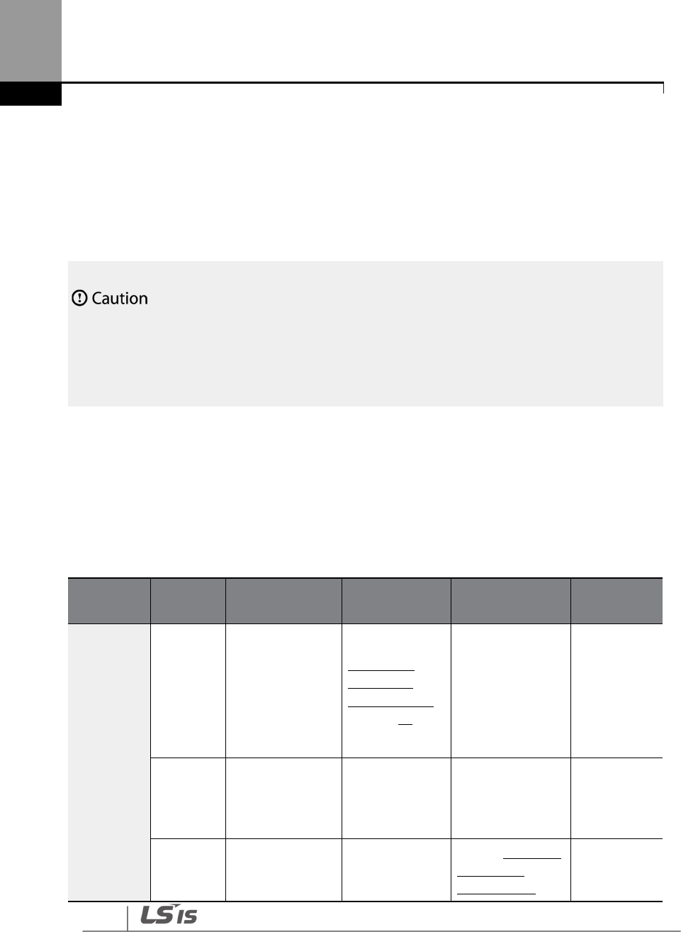
Maintenance
576
10 Maintenance
This chapter explains how to replace the cooling fan, the regular inspections to complete, and
how to store and dispose of the product. An inverter is vulnerable to environmental conditions
and faults also occur due to component wear and tear. To prevent breakdowns, please follow the
maintenance recommendations in this section.
• Before you inspect the product, read all safety instructions contained in this manual.
• Before you clean the product, ensure that the power is off.
• Clean the inverter with a dry cloth. Cleaning with wet cloths, water, solvents, or detergents may
result in electric shock or damage to the product .
10.1 Regular Inspection Lists
10.1.1 Daily Inspection
Inspection
area
Inspection
item Inspection details
Inspection
method
Inspection
standard
Inspection
equipment
All
Ambient
environm
ent
Is the ambient
temperature and
humidity within
the design range,
and is there any
dust or foreign
objects present?
Refer to 1.3
Installation
Considerations
on page 10
No icing (ambient
temperature: -10 -
+50) and no
condensation
(ambient
humidity below
95%)
Thermomete
r,
hygrometer,
recorder
Inverter
Is there any
abnormal
vibration or
noise?
Visual
inspection No abnormality
Power
voltage
Is
the input and
output voltages
normal?
Measure
voltages
between R/ S/ T-
Refer
to
11.1
Input
and Output
Specifications on
Digital
multimeter
tester

Maintenance
577
577
Inspection
area
Inspection
item Inspection details
Inspection
method
Inspection
standard
Inspection
equipment
phases in. the
inverter terminal
block.
page
585
Input/Outp
ut circuit
Smoothin
g
capacitor
Is there any
leakage from the
inside? Visual
inspection
No abnormality -
Is the capacitor
swollen?
Cooling
system
Cooling
fan
Is there any
abnormal
vibration or
noise?
Turn off the
system and
check operation
by rotating the
fan manually.
Fan rotates
smoothly -
Display Measuring
device
Is the display
value normal?
Check the
display value on
the panel.
Check and
manage specified
values.
Voltmeter,
ammeter, etc.
Motor All
Is there any
abnormal
vibration or
noise?
Visual
inspection
No abnormality -
Is there any
abnormal smell?
Check for
overheating or
damage.
10.1.2 Annual Inspection
Inspection
area
Inspection
item Inspection details
Inspection
method
Judgment
standard
Inspection
equipment
Input/Outp
ut circuit All
Megger test
(between
input/output
terminals and
earth terminal)
Disconnect
inverter and
short
R/S/T/U/V/W
terminals, and
then measure
from each
Must be above
5 MΩ
DC 500 V
Megger

Maintenance
578
Inspection
area
Inspection
item Inspection details
Inspection
method
Judgment
standard
Inspection
equipment
terminal to the
ground
terminal using
a Megger.
Is there anything
loose in the
device?
Tighten all
screws. No
abnormality
Is there any
evidence of parts
overheating?
Visual
inspection
Cable
connections
Are there any
corroded cables? Visual
inspection
No
abnormality -
Is there any
damage to cable
insulation?
Terminal
block
Is there any
damage?
Visual
inspection
No
abnormality -
Smoothing
condenser
Measure
electrostatic
capacity.
Measure with
capacity
meter.
Rated capacity
over 85% Capacity meter
Relay
Is there any
chattering noise
during operation?
Visual
inspection
No
abnormality -
Is there any
damage to the
contacts?
Visual
inspection
Braking
resistor
Is there any
damage from
resistance?
Visual
inspection
No
abnormality Digital
multimeter /
analog tester
Check for
disconnection.
Disconnect
one side and
measure with
a tester.
Must be within
±10% of the
rated value of
the resistor.
Control
circuit
Operation
check
Check for output
voltage imbalance
Measure
voltage
Balance the
voltage
Digital
multimeter or

Maintenance
579
579
Inspection
area
Inspection
item Inspection details
Inspection
method
Judgment
standard
Inspection
equipment
Protection
circuit
while the inverter
is in operation.
between the
inverter
output
terminal U/ V/
W.
between
phases: within
4 V for 200 V
series and
within 8 V for
400 V series.
DC voltmeter
Is there an error in
the display circuit
after the
sequence
protection test?
Test the
inverter
output
protection in
both short
and open
circuit
conditions.
The circuit
must work
according to
the sequence.
Cooling
system Cooling fan Are any of the fan
parts loose?
Check all
connected
parts and
tighten all
screws.
No
abnormality -
Display Display
device
Is the display
value normal?
Check the
command
value on the
display device.
Specified and
managed
values must
match.
Voltmeter,
Ammeter, etc.
10.1.3 Bi-annual Inspection
Inspection
area
Inspection
item Inspection details
Inspection
method
Judgment
standard
Inspection
equipment
Motor Insulation
resistance
Megger test
(between the input,
output and earth
terminals)
Disconnect
the cables for
terminals U/V/
W and test the
wiring.
Must be above
5 MΩ
DC 500 V
Megger

Maintenance
580
Do not run an insulation
resistance test (Megger)
on the control circuit as it may result in damage to
the product.
10.2 Real Time Clock (RTC) Battery Replacement
A CR2032 Lithium-Manganese battery to power the inverter’s built-in RTC (real time clock) is
installed on the main PCB. When the battery charge is low, a low battery voltage level warning is
given on the keypad display.
The RTC feature and any other features related to the RTC feature, such as the time event control,
do not work properly when the battery runs out. Refer to the following battery specifications
when a battery replacement is required.
RTC Battery Specifications
Model type: CR 2032 (lithium-manganese)
Nominal voltage: 3 V
Nominal capacity: 220 mAh
Operating temperature range: -20–80 degrees C
Life span (approximately): 53,300 hrs (inverter on) / 25,800 hrs (inverter off)
Follow the instructions below to replace the RTC battery.
ESD (Electrostatic discharge) from the human body may damage sensitive electronic components on
the PCB. Therefore, be extremely careful not to touch the PCB or the components on the PCB with bare
hands while you work on the main PCB.
To prevent damage to the PCB from ESD, touch a metal object with your hands to discharge any
electricity before working on the PCB, or wear an anti-static wrist strap and ground it on a metal object.
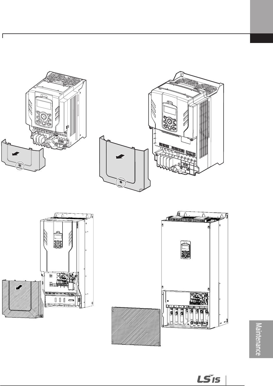
Maintenance
581
581
1 Turn off the inverter and make sure that DC link voltage has dropped to a safe level.
2 Loosen the screw on the power cover then remove the power cover.
0.75
–
30 kW Models
110~185kW Models
37
–
90 kW Models
220~500kW Models
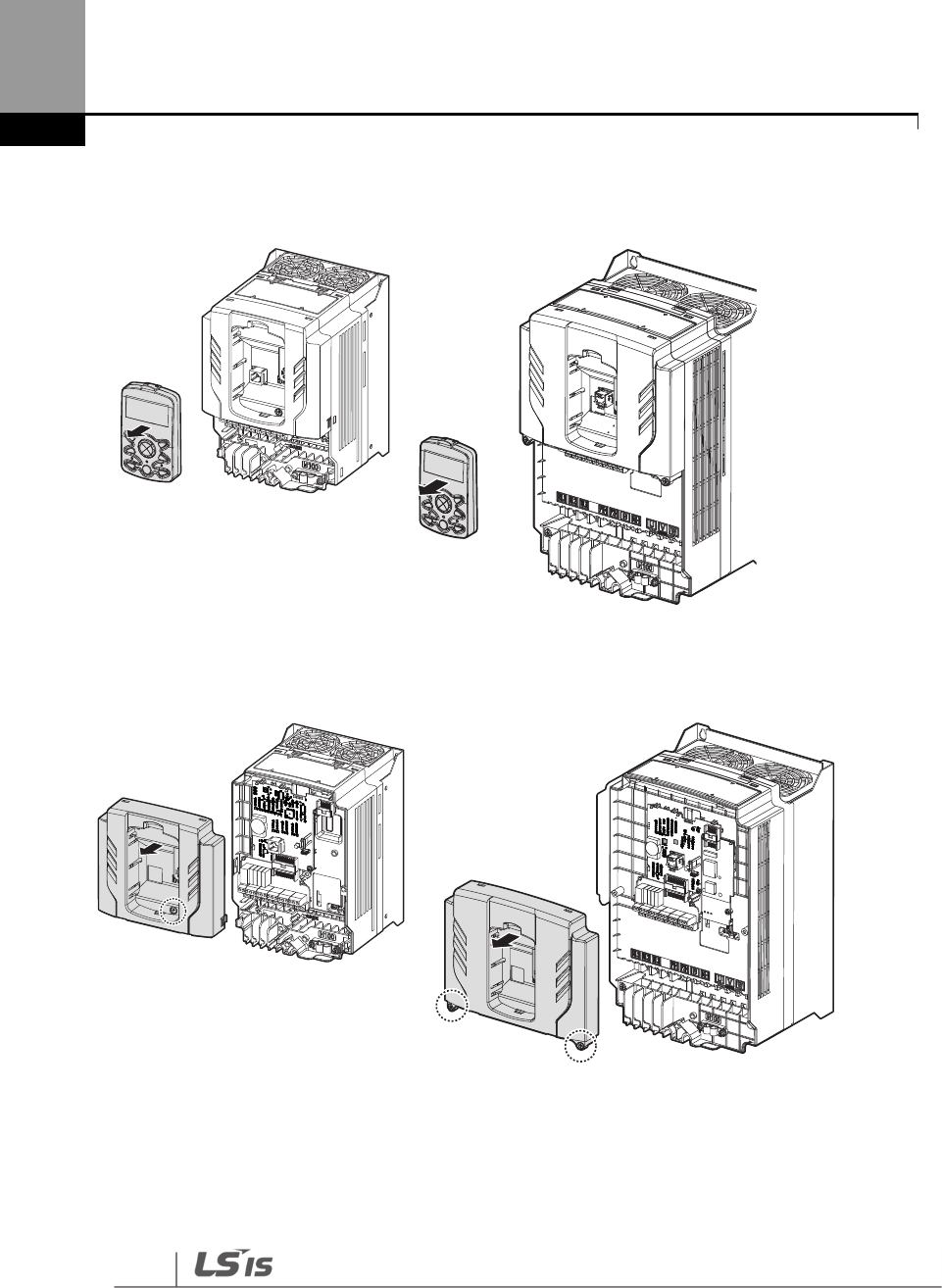
Maintenance
582
3 Remove the keypad from the inverter body.
0.75
–
30 kW
Models
37
–
90 kW Models
4 Loosen the screws securing the front cover, and remove the front cover by lifting it. The main
PCB is exposed.
0.75
–
30 kW
Models
37
–
90 kW Models
3V
3V
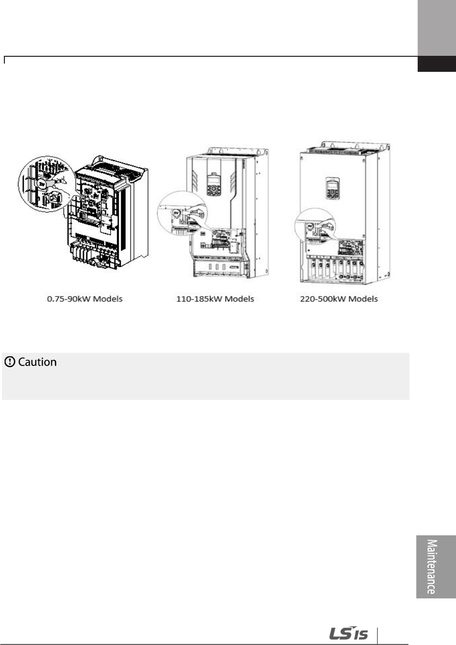
Maintenance
583
583
5 Locate the RTC battery holder on the main PCB, and replace the battery.
6 Reattach the front cover, the power cover, and the keypad back onto the inverter body
Ensure that the inverter is turned off and DC link voltage has dropped to a safe level before opening
the terminal cover and installing the RTC battery.

Maintenance
584
10.3 Storage and Disposal
10.3.1 Storage
If you are not using the product for an extended period, store it in the following way:
• Store the product in the same environmental conditions as specified for operation (Refer to
Installation Considerationson page 10).
• When storing the product for a period longer than 3 months, store it between -10 ˚C and 30
˚C, to prevent depletion of the electrolytic capacitor.
• Do not expose the inverter to snow, rain, fog, or dust.
• Package the inverter in a way that prevents contact with moisture. Keep the moisture level
below 70% in the package by including a desiccant, such as silica gel.
• Do not allow the inverter to be exposed to dusty or humid environments. If the inverter is
installed in such environments (for example, a construction site) and the inverter will be
unused for an extended period, remove the inverter and store it in a safe place.
10.3.2 Disposal
When disposing of the product, categorize it as general industrial waste. Recyclable materials are
included in the product, so recycle them whenever possible. The packing materials and all metal
parts can be recycled. Although plastic can also be recycled, it can be incinerated under controlled
conditions in some regions.
If the inverter has not been operated for a long time, capacitors lose their charging characteristics and
are depleted. To
prevent depletion, turn on the product once a year and allow the device to operate for
30-60 min. Run the device under no-load conditions.
Technical Specification
585
11 Technical Specification
11.1 Input and Output Specifications
Three Phase 200 V (0.75–3.7 kW)
Model
H100
XXXX
–
2
00
08
00
15
0
022
0
037
Applied Motor
HP
1.0
2.0
3.0
5.0
kW
0.75
1.5
2.2
3.7
Rated
output
Rated Capacity
(kVA)
1.9
3.0
4.5
6.1
Rated
Current (A)
Three
-
Phase
5
8
12
16
Single
-
Phase
2.9
4.4
6.4
8.4
Output
Frequency
0
–
400 Hz
Output Voltage
(V)
3
-
Phase 200
–
240 V
Rated
input
Working
Voltage (V)
Three
-
Phase
3
-
Phase 200
–
240 VAC (
-
15%
–
+10%)
Single
-
Phase
1
-
Phase 240 VAC (
-
5%
–
+10%)
Input
Frequency
Three-Phase
50–60 Hz (
±
5%)
Single-Phase
60 Hz(
±
5%)
Rated Current
(A)
4.9
8.4
12.9
17.5
Weight
(kg)
3.3
3.3
3.3
3.3
• The standard motor capacity is based on a standard 4-pole motor.
• The standard used for 200 V inverters is based on a 220 V supply voltage, and 400 V inverters
are based on a 440 V supply voltage.
• The rated output current is limited based on the carrier frequency set at CON-04.

Technical Specification
586
Three Phase 200 V (5.5–18.5 kW)
Model
H100 XXXX–2 0055 0075 0110 0150 0185
Applied Motor HP 7.5 10 15 20 25
kW 5.5 7.5 11 15 18.5
Rated
output
Rated Capacity (kVA) 8.4 11.4 16.0 21.3 26.3
Rated
Current (A)
Three-Phase 22 30 42 56 69
Single-Phase 11 16 23 30 37
Output Frequency 0–400 Hz
Output Voltage (V) 3-Phase 200–240 V
Rated
input
Working
Voltage (V)
Three-Phase 3-Phase 200–240 VAC (-15%–+10%)
Single-Phase 1-Phase 240 VAC (-5%–+10%)
Input
Frequency
Three-Phase 50–60 Hz (±5%)
Single-Phase 60 Hz(±5%)
Rated Current (A) 23.7 32.7 46.4 62.3 77.2
Weight (kg) 3.3 3.3 3.3 4.6 7.1
• The standard motor capacity is based on a standard 4-pole motor.
• The standard used for 200 V inverters is based on a 220 V supply voltage, and 400 V inverters
are based on a 440 V supply voltage.
• The rated output current is limited based on the carrier frequency set at CON-04.

Technical Specification
587
Three Phase 400 V (0.75–3.7 kW)
Model
H100
XXXX
–
4
00
08
00
15
0
022
0
037
Applied Motor
HP
1.0
2.0
3.0
5.0
kW
0.75
1.5
2.2
3.7
Rated
output
Rated Capacity
(kVA)
1.9
3.0
4.5
6.1
Rated
Current (A)
Three
-
Phase
2.5
4
6
8
Single
-
Phase
1.6
2.4
3.5
4.6
Output Frequency
0
–
400 Hz
Output Voltage
(V)
3
-
Phase 380
–
480 V
Rated
input
Working
Voltage (V)
Three
-
Phase
3
-
Phase 380
–
480 VAC (
-
15%
–
+10%)
Single
-
Phase
1
-
Phase
480
VAC (
-
5%
–
+10%)
Input
Frequency
Three-Phase
50–60 Hz (
±
5%)
Single-Phase
60 Hz(
±
5%)
Rated Current
(A)
2.4
4.2
6.5
8.7
Weight
(kg)
3.3
3.3
3.3
3.3
• The standard motor capacity is based on a standard 4-pole motor.
• The standard used for 200 V inverters is based on a 220 V supply voltage, and 400 V inverters
are based on a 440 V supply voltage.
• The rated output current is limited based on the carrier frequency set at CON-04.
Technical Specification
588
Three Phase 400 V (5.5–22 kW)
Model
H100
XXXX
–
4
0055
0075
0110
0150
0185
0220
Applied Motor
HP
7.5
10
15
20
25
30
kW
5.5
7.5
11
15
18.5
22
Rated
output
Rated Capacity(kVA)
9.1
12.2
18.3
23.0
29.0
34.3
Rated
Current(A)
Three
-
Phase
12
16
24
30
38
45
Single
-
Phase
6.8
9.2
14
17
22
26
Output Frequency
0
–
400 Hz
Output Voltage(V)
3
-
Phase 380
–
480 V
Rated
input
Working
Voltage(V)
Three
-
Phase
3
-
Phase 380
–
480 VAC (
-
15%
–
+10%)
Single
-
Phase
1
-
Phase
480
VAC (
-
5%
–
+10%)
Input
Frequency
Three-Phase
50–60 Hz (
±
5%)
Single-Phase
60 Hz(
±
5%)
Rated Current(A)
12.2
17.5
26.5
33.4
42.5
50.7
Weight(kg)
3.3
3.3
3.4
4.6
4.8
7.5
• The standard motor capacity is based on a standard 4-pole motor.
• The standard used for 200 V inverters is based on a 220 V supply voltage, and 400 V inverters
are based on a 440 V supply voltage.
• The rated output current is limited based on the carrier frequency set at CON-04.

Technical Specification
589
Three Phase 400 V (30.0–90.0 kW)
Model
H100 XXXX–4 0300 0370 0450 0550 0750 0900
Applied Motor HP 40 50 60 75 100 125
kW 30 37 45 55 75 90
Rated
output
Rated Capacity (kVA) 46.5 57.1 69.4 82.0 108.2 128.8
Rated
Current (A)
Three-Phase 61 75 91 107 142 169
Single-Phase 36 39 47 55 73 86
Output Frequency 0–400 Hz
Output Voltage (V) 3-Phase 380–480 V
Rated
input
Working
Voltage (V)
Three-Phase 3-Phase 380–480 VAC (-15%–+10%)
Single-Phase 1-Phase 480 VAC (-5%–+10%)
Input
Frequency
Three-Phase 50–60 Hz (±5%)
Single-Phase 60 Hz(±5%)
Rated Current (A) 69.1 69.3 84.6 100.1 133.6 160.0
Weight (kg) 7.5 26 35 35 43 43
• The standard motor capacity is based on a standard 4-pole motor.
• The standard used for 200 V inverters is based on a 220 V supply voltage, and 400 V inverters
are based on a 440 V supply voltage.
• The rated output current is limited based on the carrier frequency set at CON-04.

Technical Specification
590
Three Phase 400 V (110.0–500.0 kW)
Model
H100 XXXX–4 1100
1320
1600
1850
2200
2500
3150
3550
4000
5000
Applied Motor HP 150
200
250
300
350
400
500
550
650
800
kW 110
132
160
185
220
250
315
355
400
500
Rated
outpu
t
Rated
Capacity
(kVA) 170
201
248
282
329
367
467
520
587
733
Rated
Current (A)
Three
Phase
223
264
325
370
432
481
613
683
770
962
Output Frequency 0–400 Hz
Output Voltage (V) 3-Phase 380–500 V
Rated
input
Working
Voltage (V)
Three
Phase 3-Phase 380–500VAC (-15%–+10%)
Input
Frequency
Three
Phase 50–60 Hz (±5%)
Rated Current (A)
215.1 254.6 315.3 358.9 419.1 469.3 598.1 666.4 751.3 938.6
Weight (kg)
55.8 55.8 74.7 74.7 120.0 120.0 185.5 185.5 185.5 265
• The standard motor capacity is based on a standard 4-pole motor.
• The standard used for 200 V inverters is based on a 220 V supply voltage, and 400 V inverters
are based on a 440 V supply voltage.
• The rated output current is limited based on the carrier frequency set at CON-04.

Technical Specification
591
11.2 Product Specification Details
Items Description
Control
Control method V/F control, Slip compensation.
Frequency settings
power resolution
Digital command: 0.01 Hz
Analog command: 0.06 Hz (60 Hz standard)
Frequency accuracy
1% of maximum output frequency.
V/F pattern Linear, square reduction, user V/F.
Overload capacity
0.75~90kW
Rated current: 120% 1 min.
110~500kW
Rated current: 11
0% 1 min.
Torque boost Manual torque boost, automatic torque boost.
Operation
Operation type
Select key pad, terminal strip, or communication operation.
Frequency settings
Analog type:
-
10
–
10 V, 0
–
10 V, 0
–
20 mA
Digital type: key pad, pulse train input
Operation function
PID control
3-wire
operation
Frequency
limit
Second
function
Anti-forward
and reverse
direction
rotation
Commercial
transition
Speed search
Power braking
Leakage
reduction
Up-down operation
DC braking
Frequency jump
Slip compensation
Automatic restart
Automatic tuning
Energy buffering
Flux braking
Energy Saving
Input
Multi
function
terminal
Select PNP (Source) or NPN (Sink) mode. Functions can be
set according to IN-65- IN-71 codes and parameter settings.

Technical Specification
592
Items Description
(7EA)
P1-P7
Forward
direction
operation
Reset
Emergency
stop
Multi step
speed
frequency-
high/med/low
DC braking
during stop
Frequency
increase
3-wire
Select
acc/dec/stop
MMC Interlock
Reverse direction operation
External trip
Jog operation
Multi step acc/dec-high/med/low
Second motor selection
Frequency reduction
Fix analog command frequency
Transtion from PID to general operation Pre
Heat
Pump Cleaning
RTC(Time Event)
Pulse
train 0–32 kHz, Low Level: 0–0.8 V, High Level: 3.5–12 V
Output
Multi
function
open
collector
terminal
Fault output
and inverter
operation
status output
Less than DC 26 V, 50 mA
Fault
signal
relay
terminal
N.O.: Less than AC 250 V 2A, DC 30 V, 3A
N.C.: Less than AC 250 V 1A, DC 30 V 1A
Multi
function
relay
terminal
Less than AC 250 V, 5 A
Less than DC 30 V, 5 A
Analog
output
0
–
12 Vdc(0
–
20 mA): Select frequency, output current, output
voltage, DC terminal voltage, and others.
Pulse
train Maximum 32 kHz, 0–12 V

Technical Specification
593
Items Description
Protection
function
Trip
Over current
trip
External signal
trip
ARM short
circuit current
trip
Over heat trip
Input imaging
trip
Ground trip
Motor over
heat trip
I/O board link
trip
No motor trip
Parameter
writing trip
Emergency
stop trip
Command
loss trip
External
memory error
CPU
watchdog trip
Motor under
load trip
Over voltage trip
Temperature sensor trip
Inverter over heat
Option trip
Output imaging trip
Inverter overload trip
Fan trip
Low voltage trip during operation
Low voltage trip
Analog input error
Motor overload trip
Pipe broken trip
Keypad command lost trip
Damper trip
Level Detect trip
MMC Interlock trip
PumpCleannig trip
Alarm
Command loss trip alarm, overload alarm, normal load
alarm, inverter overload alarm, fan operation alarm,
resistance braking rate alarm, Capacitor life alarm, Pump
Clean alarm, Fire Mode Alarm, LDT Alarm.
Instantaneous
blackout
Less than 8 ms: Continue Operation (must be within the
rated input voltage and rated output range)
More than 8 ms: Auto restart operation
Structure/
working
environment
Cooling type
Forced fan cooling
structure
Protection structure
IP 20(0.75~185
kW), IP
00(220~500kW)
UL Open & Enclosed Type 1 (option)
(UL Enclosed Type 1 is satisfied by conduit installation

Technical Specification
594
Items Description
option.)
Ambient
temperature
-10 ℃–50 ℃ (2.5% current derating is applied above
40 ℃)
No ice or frost should be present.
Working under normal load at 50 ℃ (122 °F), it is
recommended that less than 75% load is applied.
Ambient humidity
Relative humidity less than 9
5
% RH (to avoid condensation
forming)
Storage
temperature. -20 °C-65 °C (-4–149 °F)
Surrounding
environment
Prevent contact with corrosive gases, inflammable gases, oil
stains, dust, and other pollutants.
(0.75~90kW Pollution Degree 3 Environment)
(110~500kW Pollution Degree 2 Environment)
Operation
altitude
Maximum 3,280 ft (1,000m) above sea level for standard
operation.
After that the driver rated voltage and the rated output
current derating by 1% for every extra 328 ft (100m) up to
13,123 ft (4,000m).
Operation
oscillation Less than 1.0 G (9.8 m/sec
2
).
Pressure
70
-
106 kPa
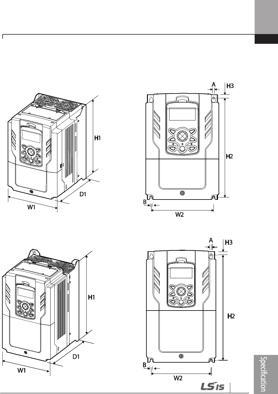
Technical Specification
595
11.3 External Dimensions
0.75–30 kW (3-phase)
37–90 kW (3-phase)
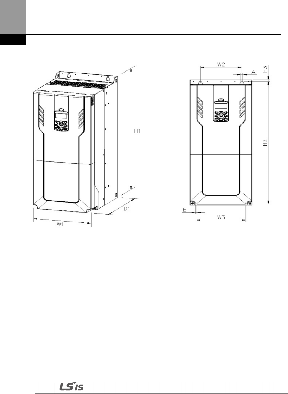
Technical Specification
596
110–185 kW (3-phase)
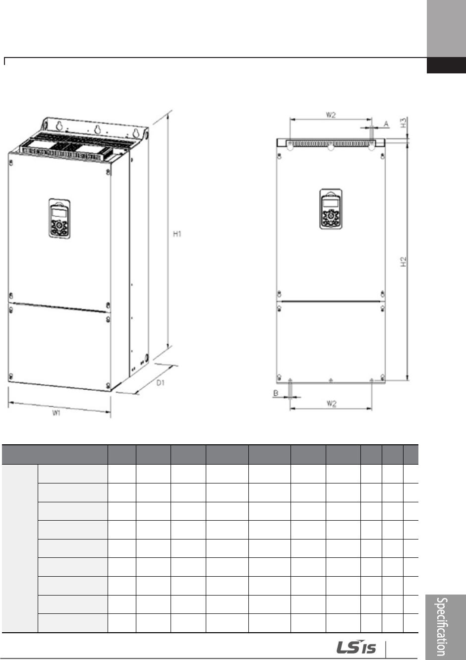
Technical Specification
597
220–500 kW (3-phase)
Units: mm
Items
W1
W2
W3
H1
H2
H3
D1
A
B
Φ
3-
phase
200 V
0008H100
-
2
160
137
-
232
216.5
10.5
181
5
5
-
0015H100
-
2
160
137
-
232
216.5
10.5
181
5
5
-
0022H100
-
2
160
137
-
232
216.5
10.5
181
5
5
-
0037H100
-
2
160
137
-
232
216.5
10.5
181
5
5
-
0055H100
-
2
160
137
-
232
216.5
10.5
181
5
5
-
0075H100
-
2
160
137
-
232
216.5
10.5
181
5
5
-
0110H100
-
2
160
137
-
232
216.5
10.5
181
5
5
-
0150H100
-
2
180
157
-
290
273.7
11.3
205.3
5
5
-
0185H100
-
2
220
193.8
-
350
331
13
223.2
6
6
-

Technical Specification
598
Items
W1
W2
W3
H1
H2
H3
D1
A
B
Φ
3-
phase
400 V
0008H100-4 160
137 - 232 216.5 10.5 181 5 5 -
0015H100-4 160
137 - 232 216.5 10.5 181 5 5 -
0022H100-4 160
137 - 232 216.5 10.5 181 5 5 -
0037H100-4 160
137 - 232 216.5 10.5 181 5 5 -
0055H100-4 160
137 - 232 216.5 10.5 181 5 5 -
0075H100-4 160
137 - 232 216.5 10.5 181 5 5 -
0110H100-4 160
137 - 232 216.5 10.5 181 5 5 -
0150H100-4 180
157 - 290 273.7 11.3 205.3
5 5 -
0185H100-4 180
157 - 290 273.7 11.3 205.3
5 5 -
0220H100-4 220
193.8
- 350 331 13 223.2
6 6 -
0300H100-4 220
193.8
- 350 331 13 223.2
6 6 -
0370H100-4 275
232 - 450 428.5 14 284 7 7 -
0450H100-4 325
282 - 510 486.5 16 284 7 7 -
0550H100-4 325
282 - 510 486.5 16 284 7 7 -
0750H100-4 325
275 - 550 524.5 16 309 9 9 -
0900H100-4 325
275 - 550 524.5 16 309 9 9 -
11
00H100
-
4
300
200 240 706 688.5 9.5 386 9 9 -
132
0H100
-
4
300
200 240 706 688.5 9.5 386 9 9 -
16
00H100
-
4
380
300 300 705 685.5 9.5 396 9 9 -
185
0H100
-
4
380
300 300 705 685.5 9.5 396 9 9 -
220
0H100
-
4
440
320 - 922.3 895.5 15.5 440 11
11
-
250
0H100
-
4
440
320 - 922.3 895.5 15.5 440 11
11
-
315
0H100
-
4
600
420 - 1000 972 15 500 14
14
-
355
0H100
-
4
600
420 - 1000 972 15 500 14
14
-
40
00H100
-
4
600
420 - 1000 972 15 500 14
14
-
50
00H100
-
4
776
500 - 1054 1021 20 500 14
14
-

Technical Specification
599
Units : inches
Items W1 W2 W3 H1 H2 H3 D1 A B Φ
3-
phase
200 V
0008H100
-
2
6.30
5.39
-
9.13
8.52
0.
41
7.13
0.20
0.20
-
0015H100
-
2
6.30
5.39
-
9.13
8.52
0.
41
7.13
0.20
0.20
-
0022H100
-
2
6.30
5.39
-
9.13
8.52
0.
41
7.13
0.20
0.20
-
0037H100
-
2
6.30
5.39
-
9.13
8.52
0.
41
7.13
0.20
0.20
-
0055H100
-
2
6.30
5.39
-
9.13
8.52
0.
41
7.13
0.20
0.20
-
0075H100
-
2
6.30
5.39
-
9.13
8.52
0.
4
1
7.13
0.20
0.20
-
0110H100
-
2
6.30
5.39
-
9.13
8.52
0.
41
7.13
0.20
0.20
-
0150H100
-
2
7.09
6.18
-
11.42
10.78
0.
45
8.08
0.20
0.20
-
0185H100
-
2
8.66
7.63
-
13.78
13.03
0.
51
8.79
0.24
0.24
-
3-
Phase
400 V
0008H100-4 6.30 5.39 - 9.13 8.52 0.41
7.13 0.20
0.20
-
0015H100-4 6.30 5.39 - 9.13 8.52 0.41
7.13 0.20
0.20
-
0022H100-4 6.30 5.39 - 9.13 8.52 0.41
7.13 0.20
0.20
-
0037H100-4 6.30 5.39 - 9.13 8.52 0.41
7.13 0.20
0.20
-
0055H100-4 6.30 5.39 - 9.13 8.52 0.41
7.13 0.20
0.20
-
0075H100-4 6.30 5.39 - 9.13 8.52 0.41
7.13 0.20
0.20
-
0110H100-4 6.30 5.39 - 9.13 8.52 0.41
7.13 0.20
0.20
-
0150H100-4 7.09 6.18 - 11.42
10.78
0.45
8.08 0.20
0.20
-
0185H100-4 7.09 6.18 - 11.42
10.78
0.45
8.08 0.20
0.20
-
0220H100-4 8.66 7.63 - 13.78
13.03
0.51
8.79 0.24
0.24
-
0300H100-4 8.66 7.63 - 13.78
13.03
0.51
8.79 0.24
0.24
-
0370H100-4 10.83
9.13 - 17.72
16.87
0.55
11.18
0.28
0.28
-
0450H100-4 12.80
11.10
- 20.08
19.15
0.63
11.18
0.28
0.28
-
0550H100-4 12.80
11.10
- 20.08
19.15
0.63
11.18
0.28
0.28
-
0750H100-4 12.80
10.83
- 21.65
20.65
0.63
12.17
0.35
0.35
-
0900H100-4 12.80
10.83
- 21.65
20.65
0.63
12.17
0.35
0.35
-
1100H100-4 11.81
7.87 9.45 27.80
27.11
0.37
15.20
0.35
0.35
-
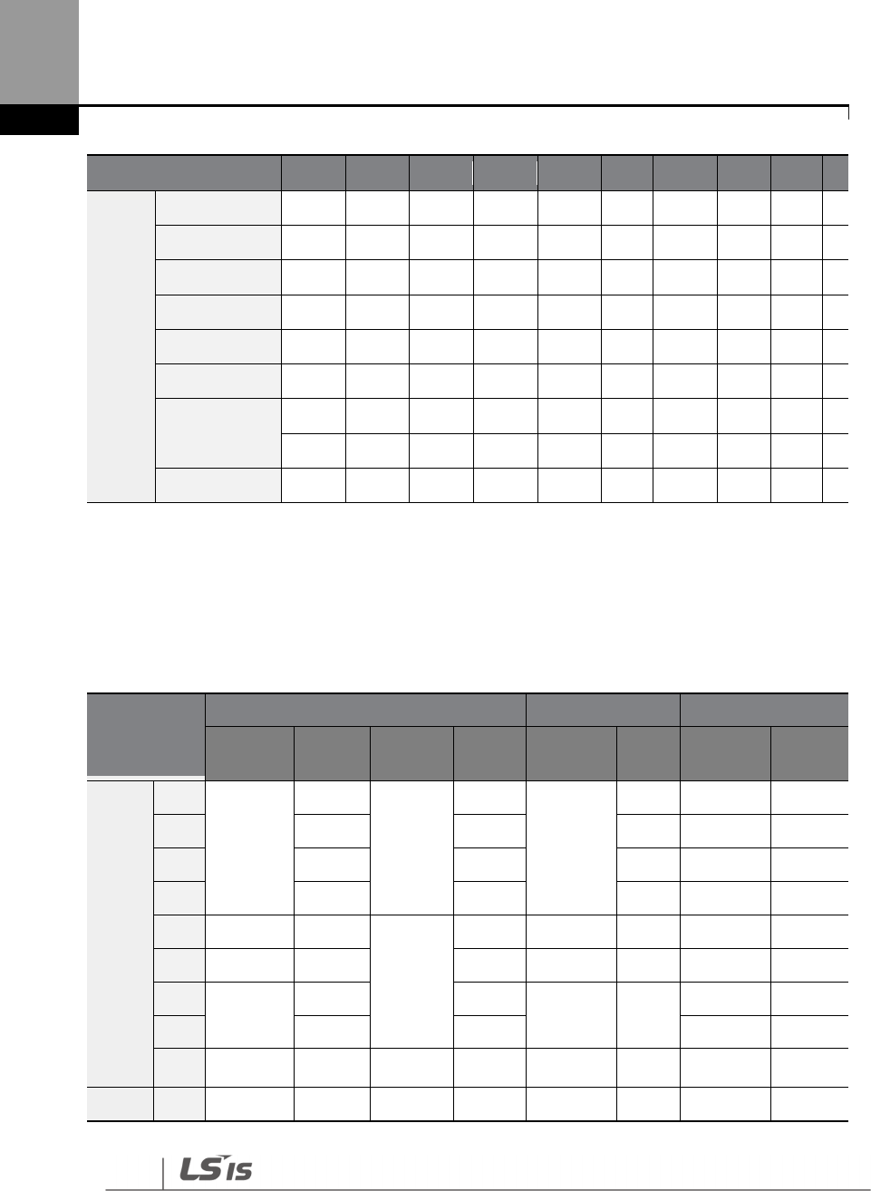
Technical Specification
600
Items
W1
W2
W3
H1
H2
H3
D1
A
B
Φ
1320H100-4 11.81
7.87 9.45 27.80
27.11
0.37
15.20
0.35
0.35
-
1600H100-4 14.96
11.81
11.81
27.76
26.99
0.37
15.59
0.35
0.35
-
1850H100-4 14.96
11.81
11.81
27.76
26.99
0.37
15.59
0.35
0.35
-
2200H100-4 17.32
12.60
- 36.31
35.26
0.61
17.32
0.43
0.43
-
2500H100-4 17.32
12.60
- 36.31
35.26
0.61
17.32
0.43
0.43
-
3150H100-4 23.62
16.54
- 39.37
38.27
0.59
19.69
0.55
0.55
-
3550H100-4 23.62
16.54
- 39.37
38.27
0.59
19.69
0.55
0.55
-
4000H100-4 23.62
16.54
- 39.37
38.27
0.59
19.69
0.55
0.55
-
5000H100-4 30.55
19.69
- 41.50
40.20
0.79
19.69
0.55
0.55
-
11.4 Peripheral Devices
Compatible Circuit Breaker, Leakage Breaker and Magnetic Contactor Models
(manufactured by LSIS)
Product (kW)
Circuit Breaker Leakage Breaker Magnetic Contactor
Model Rated
Current Model Rated
Current Model Rated
Current Model Rated
Current
3-Phase
200 V
0.75
ABS33c
15
UTE100
15
EBS33c
15 MC-9a 11
1.5 15 15 15 MC-18a 18
2.2 30 15 30 MC-32a 32
3.7 30 15 30 MC-32a 32
5.5 ABS53c 50
UTE100
50 EBS53c 50 MC-50a 55
7.5 ABS63c 60 60 EBS63c 60 MC-65a 65
11 ABS103c 100 100 EBS103c 100 MC-85a 85
15 100 100 MC-130a 130
18.5
ABS203c 150 UTS150 150 EBS203c 200 MC-150a 150
3-Phase
0.75
ABS33c 10 UTE100 15 EBS33C 10 MC-6a 9

Technical Specification
601
Product (kW)
Circuit Breaker Leakage Breaker Magnetic Contactor
Model Rated
Current Model Rated
Current Model Rated
Current Model Rated
Current
400 V 1.5 10 15 10 MC-6a 9
2.2 15 15 15 MC-9a 11
3.7 15 15 15 MC-12a 13
5.5 ABS53c 50
UTE100
50 EBS33C 30 MC-22b 22
7.5 50 50 30 MC-32a 32
11 ABS63c 60 60 EBS53c 50 MC-50a 50
15 ABS63c 60 80 EBS63c 60 MC-65a 65
18.5
ABS103c 100 100
EBS103c
100 MC-85a 85
22 ABS103c 125 UTS150 125 125 MC-100a 105
30 ABS103c 125 125 125 MC-130a 130
37 ABS203c 175
UTS250
175
EBS203c
200 MC-150a 150
45 ABS203c 225 225 225 MC-185a 185
55 ABS203c 250 250 250 MC-185a 185
75 ABS403c 300 UTS400 300 EBS403C 300 MC-225a 225
90 ABS403c 350 350 350 MC-330a 330
110 ABS603c 500
UTS600
500 EBS603c 500 MC-400a 400
132 ABS603c 600 600 EBS603c 630 MC-400a 400
160 ABS603c 630 600 EBS603c 630 MC-630a 630
185 ABS803c 800
UTS800
800 EBS803c 800 MC-630a 630
220 ABS803c 800 800 EBS803c 800 MC-800a 800
250 ABS1003c
1000 800 EBS1003b
1000 MC-800a 800
315 ABS1203b
1200
UTS1200
1200 EBS1203b
1200 1200a 1200
355 ABS1203b
1200 1200 EBS1203b
1200 1200a 1200
400 - 1600 - 1600
500 - 1600 - 1600
3-
Phase
110 ABS603c 500 UTS600 500 EBS603c 500 MC-400a 400
132 ABS603c 600 600 EBS603c 630 MC-400a 400
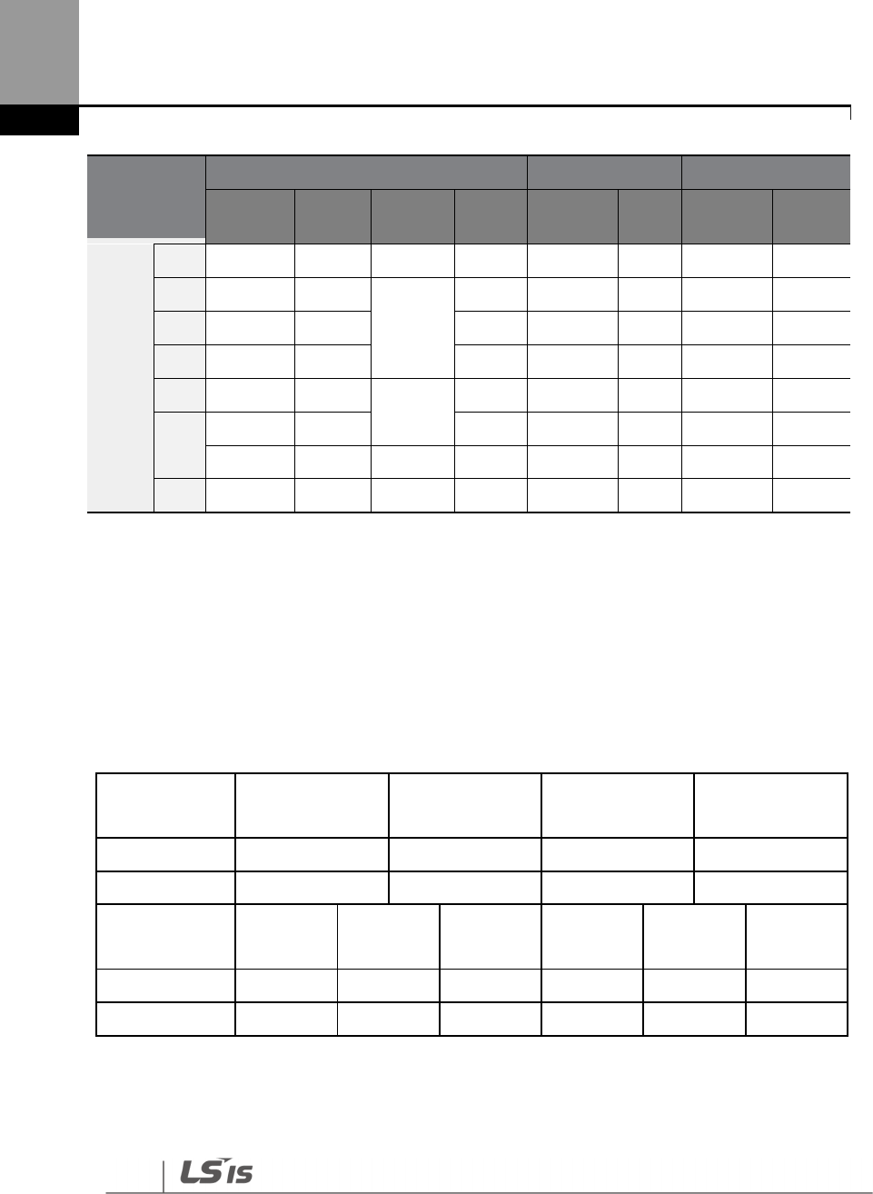
Technical Specification
602
Product (kW)
Circuit Breaker Leakage Breaker Magnetic Contactor
Model Rated
Current Model Rated
Current Model Rated
Current Model Rated
Current
500V 160 ABS603c 630 600 EBS603c 630 MC-630a 630
185 ABS803c 800
UTS800
800 EBS803c 800 MC-630a 630
220 ABS803c 800 800 EBS803c 800 MC-800a 800
250 ABS803c 800 800 EBS803c 800 MC-800a 800
315 ABS1203b 1200 UTS1200 1200 EBS1203c
1200 1200a 1200
355 ABS1203b 1200 1200 EBS1203c
1200 1200a 1200
400 - 1600 - 1600 - - - -
500 - 1600 - 1600 - - - -
* In the case of inverter 400/500 kW, there is no Circuit Brake capacity qualified as UL standard.
* If you want to use UL Type products, please use that ACB product.
Maximum allowed prospective short-circuit current at the input power connection is defined in
IEC 60439-1 as 100 kA. LSLV-H100 is suitable for use in a circuit capable of delivering not more than
100kA RMS at the drive’s maximum rated voltage, depending on the selected MCCB. RMS
symmetrical amperes for recommended MCCB are the following table.
Working
Voltage
UTE100
(E/N)
UTS150
(N/H/L)
UTS250
(N/H/L)
UTS400
(N/H/L)
240V(50/60Hz)
50/65kA 65/100/150kA 65/100/150kA 65/100/150kA
480V(50/60Hz)
25/35kA 35/65/100kA 35/65/100kA 35/65/100kA
Working
Voltage ABS33c ABS53c ABS63c ABS103c ABS203c ABS403c
240V(50/60Hz)
30kA 35kA 35kA 85kA 85kA 75kA
480V(50/60Hz)
7.5kA 10kA 10kA 26kA 26kA 35kA
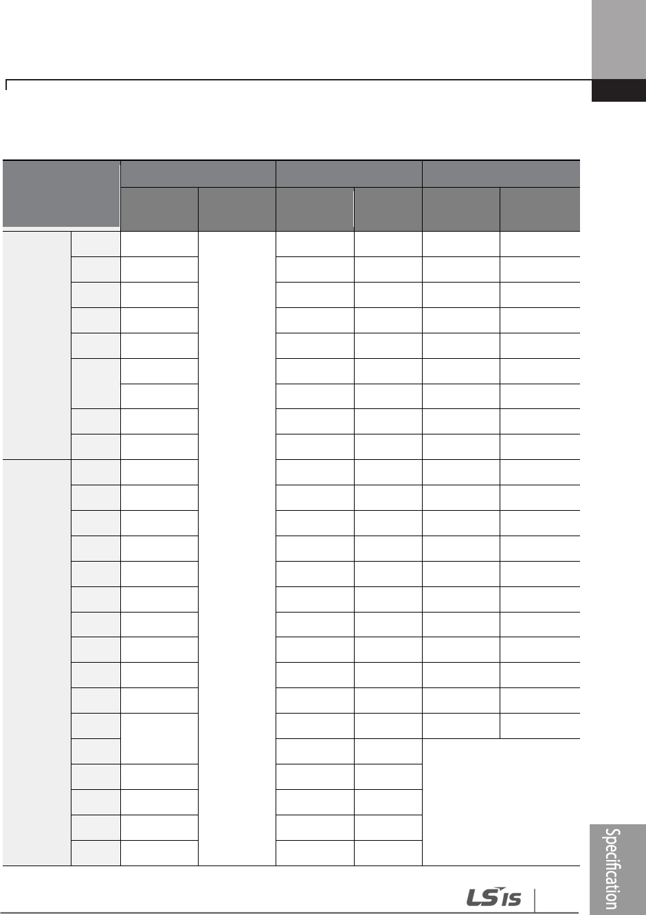
Technical Specification
603
11.5 Fuse and Reactors Specifications
Products(kW)
AC Input Fuse
AC reactor
DC Reactor
Current
(A)
Voltage
(V)
Inductance
(mH)
Current
(A)
Inductance
(mH)
Current
(A)
3-Phase
200 V
0.75
10
600[V]
2.02
5
4.04
5
1.5
10
1.26
8
2.53
8
2.2
15
0.78
12
1.68
12
3.7
20
0.59
16
1.26
16
5.5
50
0.43
24
0.93
25
7.5
63
0.31
33
0.73
32
11
80
0.22
46
0.53
50
15
100
0.16
62
0.32
62
18.5
125
0.13
77
0.29
80
3-Phase
400 V
0.75
10
8.09
2.5
16.17
3
1.5
10
5.05
4
10.11
4
2.2
15
3.37
6
6.74
6
3.7
20
2.25
9
5.05
8
5.5
32
1.56
13
3.56
13
7.5
35
1.16
17
2.53
18
11
50
0.76
27
1.64
26
15
63
0.61
33
1.42
33
18.5
70
0.48
43
0.98
42
22
100
0.40
51
0.88
50
30
125
0.29
69
0.59
68
37
0.29
69
Built-In
45
160
0.24
85
55
200
0.20
100
75
250
0.15
134
90
350
0.13
160
Technical Specification
604
Products(kW)
AC Input Fuse
AC reactor
DC Reactor
Current
(A)
Voltage
(V)
Inductance
(mH)
Current
(A)
Inductance
(mH)
Current
(A)
110
350
0.1
217
132
400
0.08
257
160
450
0.07
318
185
550
0.06
362
220
630
0.05
423
250
700
0.05
474
315
800
0.04
604
355
1000
0.03
673
400
1100
0.03
759
Use Class H or RK5 UL Listed Input Fuse and UL Listed Breaker Only. See the table above
f
or the Voltage
and Current rating of the fuse and the breaker.
Attention
Utiliser UNIQUEMENT des fusibles d’entrée homologués de Classe H ou RK5 UL et des disjoncteurs UL .
Se reporter au tableau ci-dessus pour la tension et le courant nominal des fusibless et des disjoncteurs.
11.6 Terminal Screw Specifications
Input/Output Termianl Screw Specification
Product
(kW)
Terminal Screw Size
Screw Torque
(Kgf
c m/Nm)
3-Phase
200 V
0.75
M4 7.1–12.2/0.7–1.2
1.5
2.2
3.7
5.5
7.5

Technical Specification
605
Product
(kW)
Terminal Screw Size
Screw Torque
(Kgf
c m/Nm)
11
15
M5 24.5~31.8/2.4~3.1
18.5
3-Phase
400 V
0.75
M4
7.1–12.2/0.7–1.2
1.5
2.2
3.7
5.5
7.5
11
15
M5 24.5~31.8/2.4~3.1
18.5
22
30
37
M8 61.2–91.8/6–9
45
55
75
90
110
M10 89.7~122.0/8.8~11.96
132
160
M12 182.4~215.0/17.87~21.07
185
220
250
315
M8 X 2
M12 X 1
61.2–91.8/6–9
182.4~215.0/17.87~21.07
355
400
500
M10 X
2
89.7~122.0/8.8~11.96
Technical Specification
606
Product
(kW)
Terminal Screw Size
Screw Torque
(Kgf
c m/Nm)
M16 X
1
490.9~
511.0/48.05~50.11
Control Circuit Terminal Screw Specification
Terminal
Terminal Screw Size
Screw Torque(Kgf
cm/Nm)
P1–P7/
CM/VR/V1/I2/AO/Q1/EG/24/TI/
TO/SA,SB,SC/S+,S-,SG
A1/B1/C1
M3 2.2–2.5/0.22–0.25
Apply rated torques to the terminal screws. Loose screws may cause short circuits and malfunctions.
Tightening the screw too much may damage the terminals and cause short circuits and malfuctions.
Use copper wires only with 600 V, 90 ℃ rating for the power terminal wiring, and 300 V, 75 ℃ rating
for the control terminal wiring.
Attention
Appliquer des couples de marche aux vis des bornes. Des vis desserrées peuvent provoquer des
courts-circuits et des dysfonctionnements. Ne pas trop serrer la vis, car cela risque d’endommager les
bornes et de provoquer des courts-circuits et des dysfonctionnements. Utiliser uniquement des fils de
cuivre avec une valeur nominale de 600 V, 90 ℃ pour le câblage de la borne d’alimentation, et une
valeur nominale de 300 V, 75 ℃ pour le câblage de la borne de commande.
11.7 Dynamic breaking unit (DBU) and Resistors
11.7.1 Dynamic breaking unit (DBU)
UL form Type Volta
ge
Capacity of
applied motor Braking unit
Terminal
arrangement
&Dimensions
UL type
Type A
200V
30,
37 kW
SV370DBU
-
2U
Refer to the

Technical Specification
607
(Resistance
of DB
Resistor
refer to the
table of
“11.7.6 DB
Resistors”)
45,
55 kW
SV550DBU
-
2U
appearance of
Group 1.
75 kW
SV370DBU
-
2U, 2Set
400V
30,
37 kW
SV370DBU
-
4U
45,
55 kW
SV550DBU
-
4U
75 kW SV750DBU-4U
90 kW SV550DBU-4U, 2Set
110, 132kW SV750DBU-4U, 2Set
160kW SV750DBU-4U, 3Set
Non UL
type
Type B
(Resistance
of DB
Resistor
refer to the
manual of
DB Unit)
200V 30, 37 kW SV037DBH-2 Refer to the
appearance of
Group 2
400V
30, 37 kW SV037DBH-4
45, 55, 75 kW
SV075DBH-4
SV075DB-4
Refer to the
appearance of
Group 3
185, 220kW SV2200DB-4
Refer to the
appearance of
Group 4
250~355kW SV2200DB-4, 2Set
Type C
(Resistance
of DB
Resistor
refer to the
manual of
DB Unit)
200V
30, 37 kW
LSLV0370DBU-2LN
Refer to the
appearance of
Group 5
LSLV0370DBU-2HN
Refer to the
appearance of
Group 6
45, 55, 75 kW
LSLV0750DBU-2LN
Refer to the
appearance of
Group 5
LSLV0750DBU-2HN
Refer to the
appearance of
Group 6
400V
30, 37 kW
LSLV0370DBU-4LN
Refer to the
appearance of
Group 5
LSLV0370DBU-4HN
Refer to the
appearance of
Group 6
45, 55, 75kW LSLV0750DBU-4LN
Refer
to the
appearance of
Group 5
90 kW LSLV0900DBU-4HN Refer to the
appearance of
Group 6
110, 132kW LSLV1320DBU-4HN
160kW LSLV1600DBU-4HN
185, 220kW LSLV2200DBU-4HN
Technical Specification
608
250~355kW
LSLV2200DBU
-
4HN,
2Set
400, 500kW
LSLV2200DBU
-
4HN,
2Set
Note
• It is not necessary to use option type dynamic braking unit for H100 0.75~18.5kW(200V)
and 0.75~30kW(400V) because basically the dynamic braking unit is built in.
• You must refer to dynamic braking unit manual for usage recommended dynamic braking
unit in the table above due to changeable table.
• Resistance/watt/breaking torque/%ED of DB Resistor for Type A DB Unit refer to the table
of “11.7.6 DB Resistors" and Resistance of DB Resistor for type B and C refer to the manual
of DB Unit.
11.7.2 Terminal arrangement
Group 1:
Group 2:
Terminals Functions
G
Ground Terminal
B2
Terminal for connection with B2 of DBU
B1
Terminal for connection with B1 of DBU
N
Terminal for connection with N of Inverter
P
Terminal for connection with P1 of Inverter
*
Note: READ DBU User manual certainly when selecting DB resistors.
Group 3:
B1
B1B1
B1
N
NN
N
P
PP
P
G
GG
G
B2
B2B2
B2
N
NN
N
B2
B2B2
B2
P/B1
P/B1P/B1
P/B1
G
GG
G
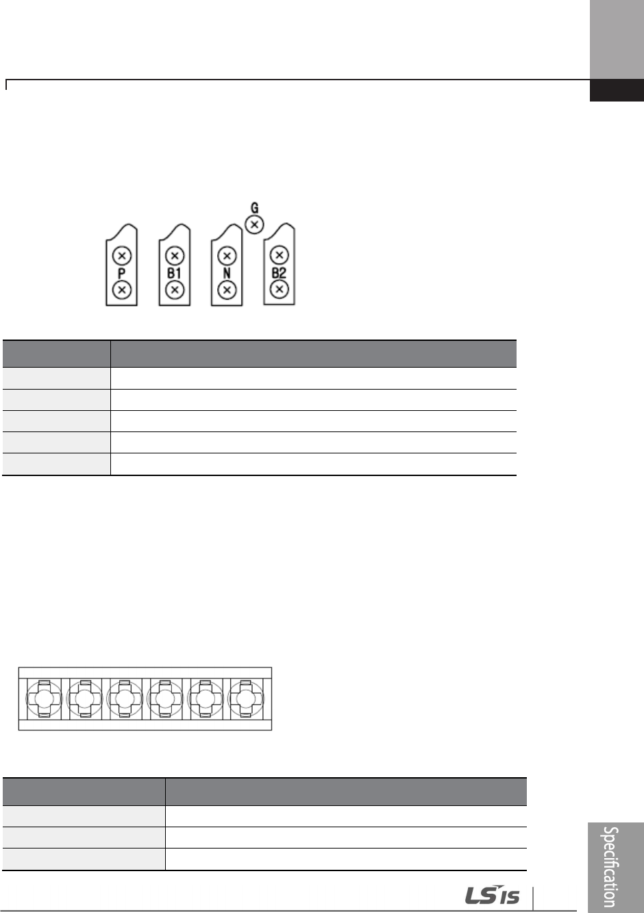
Technical Specification
6
09
Group 4:
Terminals Functions
G
Ground Terminal
B
2
Terminal for connection with B2 of DBU
B1
Terminal for connection with B1 of DBU
N
Terminal for connection with N of Inverter
P
Terminal for connection with P of Inverter
Group 5:
Terminals Functions
P(+)
Terminal for connection with P of Inverter
N(
-
)
Terminal for connection with N of Inverter
B1
Terminal for connection with B1 of DBU
P(+)
P(+)P(+)
P(+) N(
N(N(
N(-
--
-)
) )
)
B1 B2 N.C E
B1 B2 N.C EB1 B2 N.C E
B1 B2 N.C E
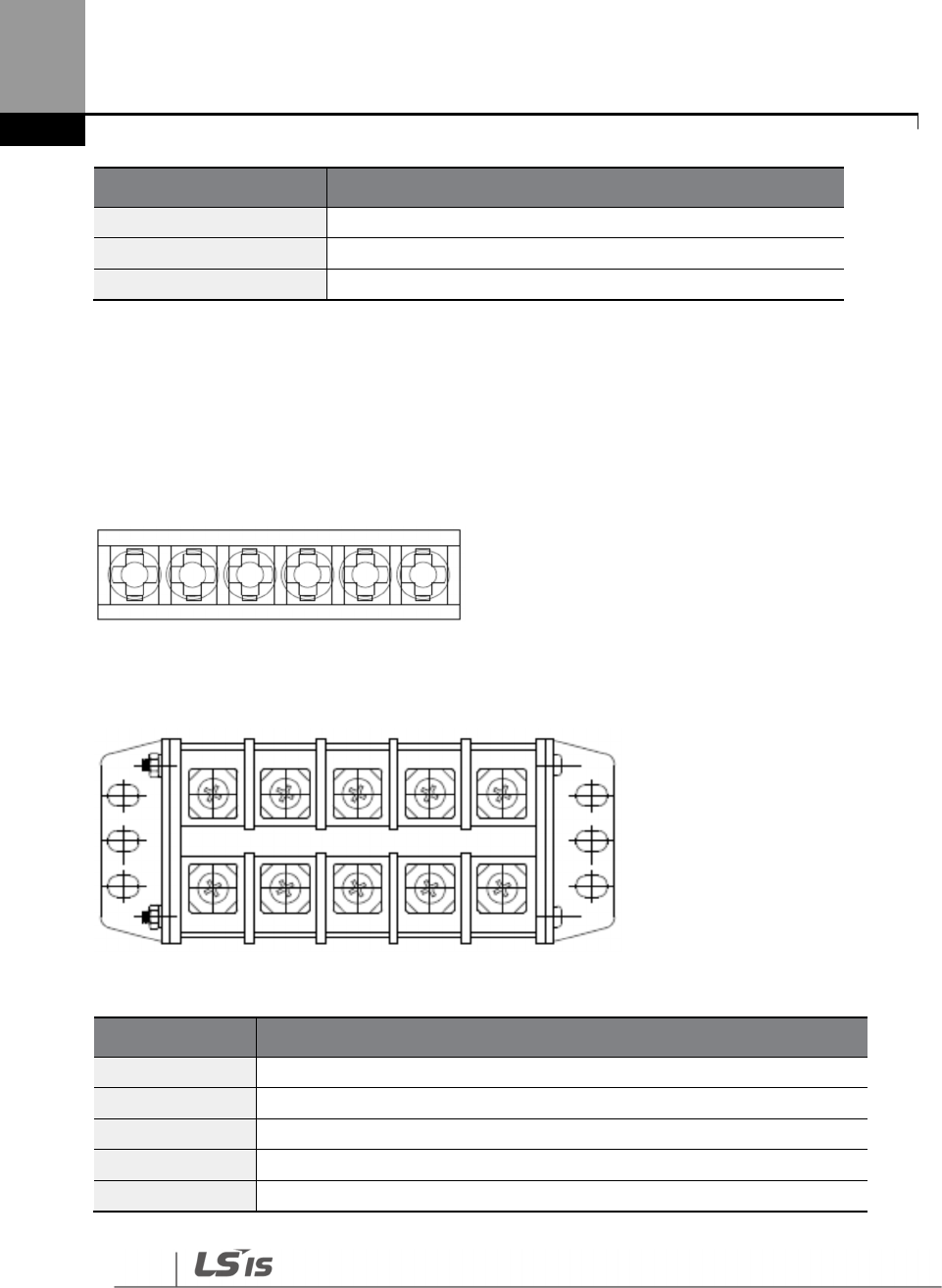
Technical Specification
610
Terminals Functions
B2
Terminal for connection with B2 of DBU
N.C
Unused
E
Ground Terminal
Group6:
A Frame (37kW, 75kW-4)
B /C Frame (75kW-2, 90~220kW)
Terminals Functions
P(+)
Terminal for connection with P of Inverter
N(
-
)
Terminal for connection with N of Inverter
B1
Terminal for connection with B1 of DBU
B2
Terminal for connection with B2 of DBU
E
Unused
P(+)
P(+)P(+)
P(+) N(
N(N(
N(-
--
-)
) )
)
B1 B2 N.C E
B1 B2 N.C EB1 B2 N.C E
B1 B2 N.C E
P(+)
P(+)P(+)
P(+)
N(
N(N(
N(-
--
-)
))
)
B1 B2 E
B1 B2 EB1 B2 E
B1 B2 E

Technical Specification
611
Note
You must refer to dynamic braking unit manual for choice the braking resistor to use
the dynamic braking unit.
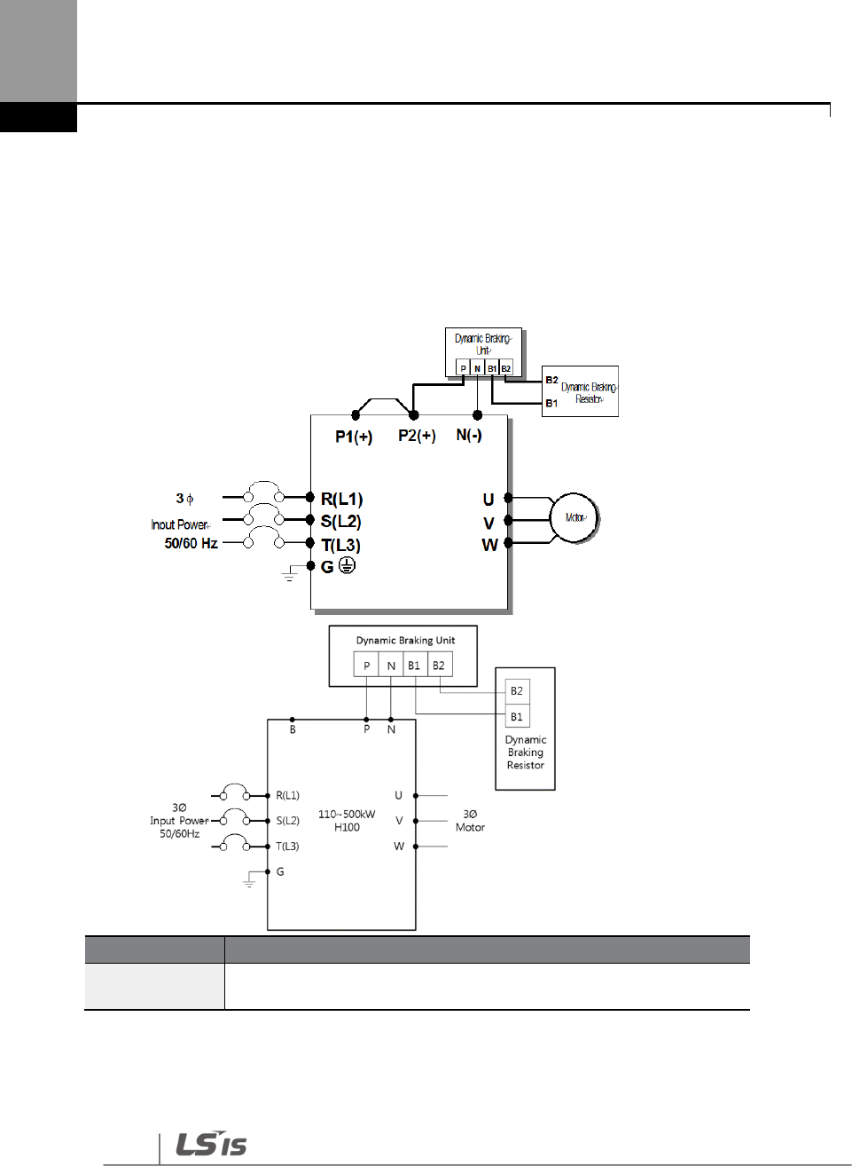
Technical Specification
612
11.7.3 Dynamic Breaking (DB)Unit & DB resistor basic wiring
0.75~90kW
110~500kW
DBU Terminals Description
B1,B2 Wire correctly referring to wiring diagram. DB Resistors connect with
B1, B2 of DB Unit.
In case of large capacity, it may be necessary to connect more than 2 sets of DB Unit
according to the usage environment.
In such cases, check the DB Unit manual.
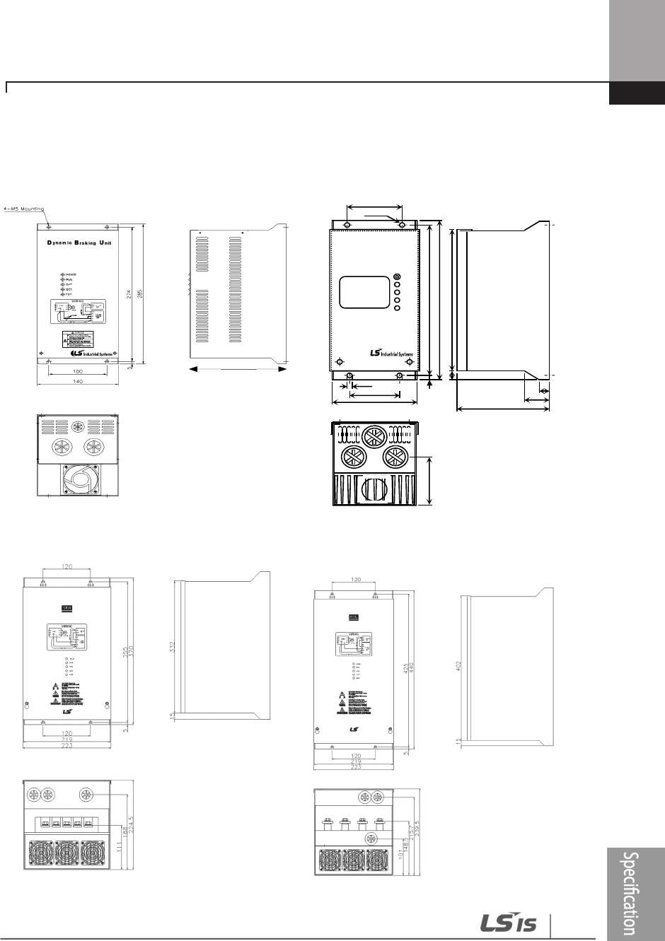
Technical Specification
613
11.7.4 Dimensions
-Group1 - Group2
-Group3 - Group4
166.2
5.
5.5.
5.
25
25
25
25
5
5
5
5
24
24
24
24
2
22
2
-
--
-
80
8080
80
80
8080
80
123
123123
123
Dynamic
RESE
RESERESE
RESE
POWE
POWEPOWE
POWE
RUN
RUNRUN
RUN
OHT
OHTOHT
OHT
OCT
OCTOCT
OCT
231
231
231
231
1
1
1
1
15
1515
15
27
2727
27
130
130130
130
7
7
7
7
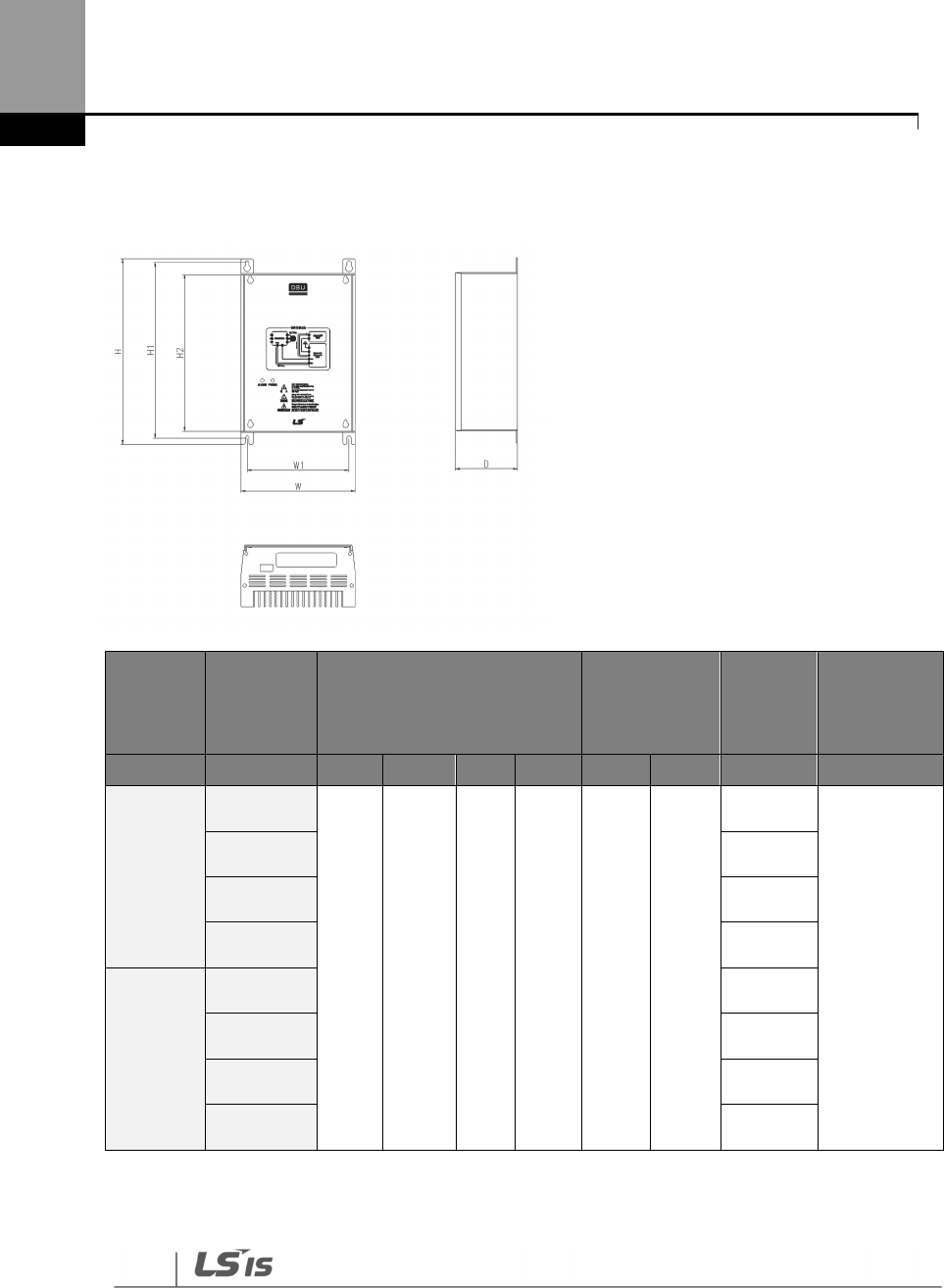
Technical Specification
614
- Group5
Voltage
Capacity
of applied
motor
Dimension (mm)
Hole position
for
installation
(mm)
Weight Hole size for
installation
(V) (kW) W H H2 D W1 H1 (kg) (φ
φφ
φ)
220
15
140 227.4 192
76.4 125 215.4
1.50
M4
22 1.55
37 1.57
75 1.84
440
15 1.53
22 1.55
37 1.56
75 1.85
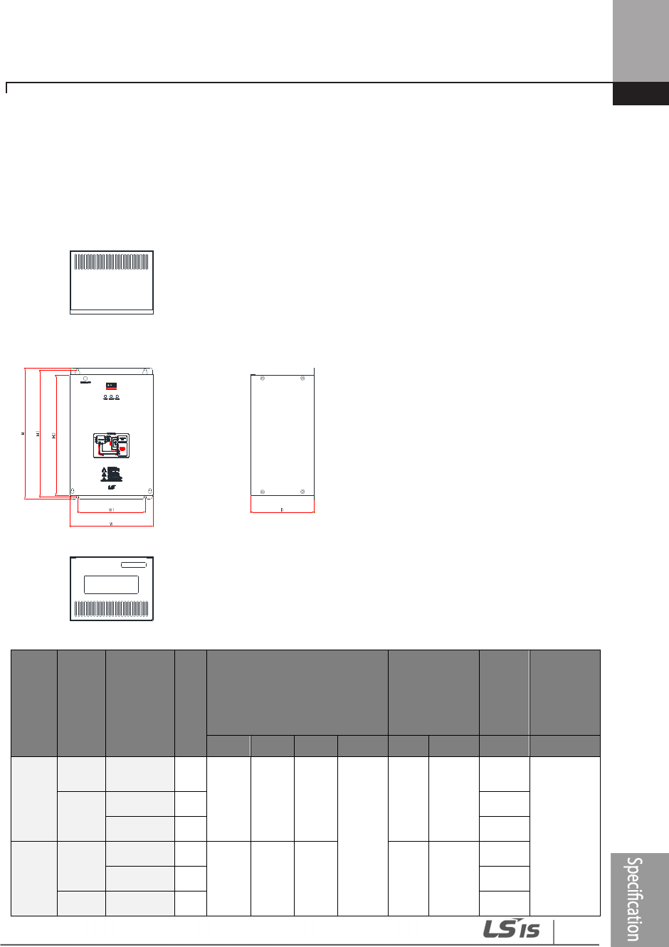
Technical Specification
615
- Group6
F
R
A
M
E
Volta
ge
Capacity
of
applied
motor
%
E
D
Dimension (mm)
Hole
position for
installation
(mm)
Weig
ht
Hole size
for
installati
on
W H H2 D W1 H1 (Kg) (φ
φφ
φ)
A
Fram
e
220
[V] 37 [kW] 50
200 219 190
165.2
160
208.5
3.77
M6
440
[V]
37 [kW] 50
3.84
75 [kW] 50
3.98
B
Fram
e
220
[V]
75 [kW] 50
215 340 311 175
329.5
8.26
90 [kW] 50
8.48
440 90 [kW] 50
8.30
Technical Specification
616
[V] 132 [kW]
50
8.40
C
Fram
e
440
[V]
160 [kW]
50
240 380 351 200
369.5
9.40
220 [kW]
50
9.70
11.7.5 Display Functions
DB Resistors connect with B1, B2 of DB Unit. DBU has 3 LEDs. Red LED which is located in middle displays
supplying main power, one Green LED which is right side displays under breaking and another green
LED which is left side displays Over Heat Trip(OHT).
Displays
Function description
POWER
(Red LED)
POWER LED is turned On when main power is supplied.Generally, POWER LED is turn
On while main power supplied because DBU is connected with inverter.
RUN
(Green LED) RUN LED is turned off while DBU is ON by regenerative energy of Motor.
OHT
(Green LED)
Under Breaking, if the temperature is exceeded over setting value due to over heat of
Heatsink, Cut the TURN ON signal of DBU and LED is turn on by working overheat
protection function.
11.7.6 DB Resistors
Product
(kW) DB unit
Torque 100% Torque 150%
Resistor
(Ω)
Wattage
[W]
(%ED=5%)
Wattage
[W]
(%ED=10%)
Resistor
(Ω)
Wattage
[W]
(%ED=5%)
Wattage
[W]
(%ED=10%)
3-
Phase
200 V
0.75
- 200 100 200 150 150 300
1.5 - 100 200 400 60 300 600
2.2 - 60 300 600 50 400 800
3.7 - 40 500 1000 33 600 1200
5.5 - 33 600 1200 20 800 1600
7.5 - 20 800 1600 15 1200 2400
11 - 15 1200 2400 10 2400 4800
15 - 10 2400 4800 8 2400 4800

Technical Specification
617
Product
(kW) DB unit
Torque 100% Torque 150%
Resistor
(Ω)
Wattage
[W]
(%ED=5%)
Wattage
[W]
(%ED=10%)
Resistor
(Ω)
Wattage
[W]
(%ED=5%)
Wattage
[W]
(%ED=10%)
18.5
- 8 2400 4800 6 2600 5200
3-
Phase
400 V
0.75
- 900 100 200 600 150 300
1.5 - 450 200 400 300 300 600
2.2 - 300 300 600 200 400 800
3.7 - 200 400 800 130 600 1200
5.5 - 120 700 1400 85 1000 2000
7.5 - 90 1000 2000 60 1200 2400
11 - 60 1200 2400 40 2000 4000
15 45 2000 4000 32 2400 4800
18.5
- 35 2400 4800 20 3600 7200
22 - 30 2400 4800 20 3600 7200
30 - 20 3600 7200 16 5000 10000
37
DBU-U 16.9 3200 6400 - - -
DBH 16.9 3200 6400 12 5000 10000
LSLV-DB
16.9 3200 6400 12 5000 10000
45
DBU-U 11.4 4800 9600 - - -
DBH 11.4 4800 9600 10 6400 12800
LSLV-DB
11.4 4800 9600 10 6400 12800
55
DBU-U 11.4 4800 9600 - - -
DBH 11.4 4800 9600 8.4 7200 14400
LSLV-DB
11.4 4800 9600 8.4 7200 14400
75
DBU-U 8.4 6400 12800 - - -
DBH 8.4 6400 12800 6 10000 20000
DB 8.4 6400 12800 6 10000 20000
90 LSLV-DB
6 10000 20000 5 13000 26000
110 LSLV-DB
5 13000 26000 4 16000 32000
132 LSLV-DB
4 16000 32000 3.4 20000 40000
160 LSLV-DB
3.4 20000 40000 2.8 24000 48000
185 LSLV-DB
2.8 24000 48000 2.4 26000 52000
Technical Specification
618
Product
(kW) DB unit
Torque 100% Torque 150%
Resistor
(Ω)
Wattage
[W]
(%ED=5%)
Wattage
[W]
(%ED=10%)
Resistor
(Ω)
Wattage
[W]
(%ED=5%)
Wattage
[W]
(%ED=10%)
220 LSLV-DB
2.4 26000 52000 2 30000 60000
250 132kW DB Unit and Resistor * 2 Set (Parallel)
315 160kW DB Unit and Resistor * 2 Set (Parallel)
355 185kW DB Unit and Resistor * 2 Set (Parallel)
400 220kW DB Unit and Resistor * 2 Set (Parallel)
500 185kW DB Unit and Resistor * 3 Set (Parallel)
Note
• It is not necessary to use option type dynamic braking unit for H100 0.75~18.5kW(200V) and
0.75~30kW(400V) because basically the dynamic braking unit is built in.
• The resistance/rated capacity/breaking torque/%ED of DB Resistor are valid only for the DB unit
of type A and the values of DB Resistor for type B and C refer to the manual of DB Unit..
• Rating Watt of DBU has to be doubled when %ED is doubled.
11.8 Inverter Continuous Rated Current Derating
Derating by carrier frequency
The continuous rated current of the inverter is limited based on the carrier frequency. Refer to the
following graph.
<200[V], 0.75[kW]–18.5[kW], 400[V] 0.75–30[kW] Current Derating Rate>
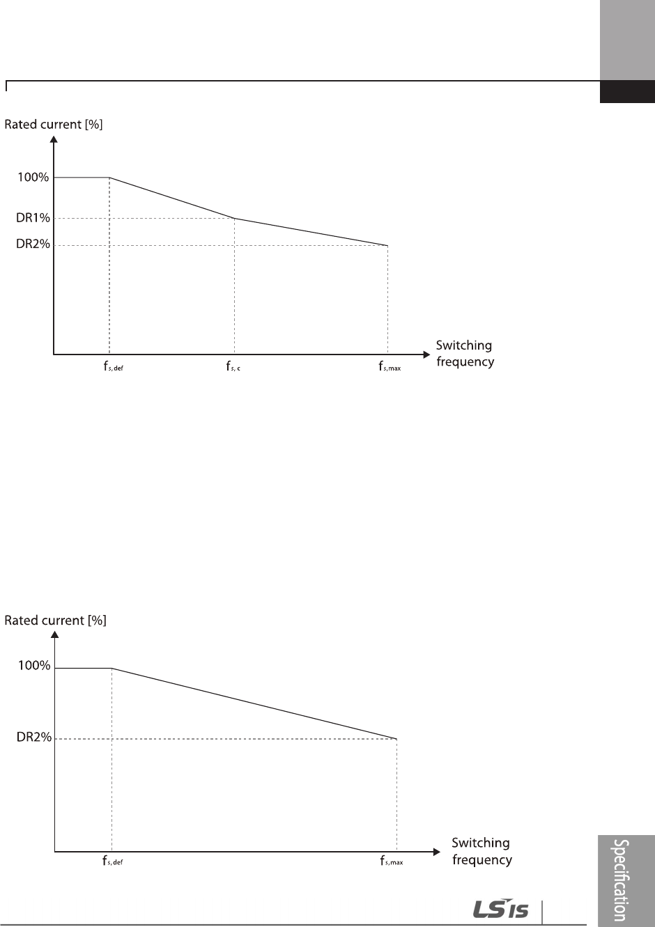
Technical Specification
619
<400[V] 37–500[kW] Current Derating Rate >

Technical Specification
620
Item Unit
200 V
400 V
0.75
–
18.5 kW
0.75
–
18.5 kW
22
–
30 kW
37
–
55 kW
75
–
90 kW
110
-
355 kW 400 kW 500 kW
fs,def
kHz
3
3
3
3
3
2
1.5
1.5
fs,c
kHz
8
8
8
-
-
-
2
4
fs,max
kHz
15
15
15
10
7
5
4
4
DR1 %
%
70
65
65
-
-
-
95
92
DR2 %
%
60
55
50
60
55
76
75
65
*fs,def: Switching frequency for continued operation
fs,c: Switching frequency where the first
current derating ends.
ffs.max: The maximum switching frequency (where the second
current derating begins)
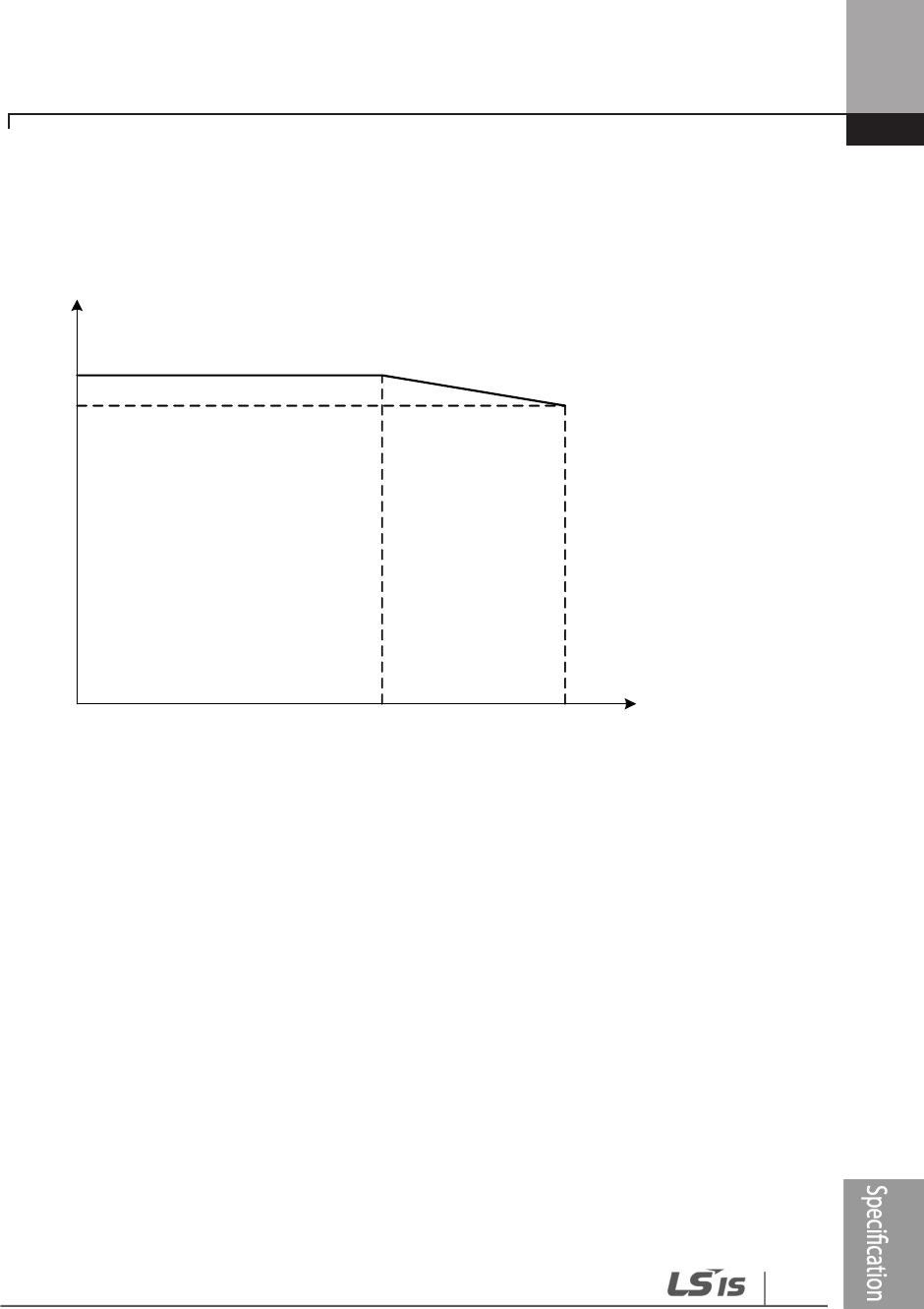
Technical Specification
621
Derating by Input Voltage
The continuous rated current of the inverter is limited based on the input voltage. Refer to the
following graph.
정격 전류[%]
입력전압
200[V]
380[V]
380[V]
240[V]
480[V]
500[V]
100%
91%
264[V]
528[V]
550[V]
110[kW] 이상만 해당
Derating by Ambient Temperature and Installation Type
Ambient temperature and installation type determine the constant-rated current of the inverter.
Refer to the following graph. A 2.5% current derating is applied during operation when the
ambient temperature is above 40℃. The inverter must be operated at less than 75% of its rated
capacity when the ambient temperature is above 50℃.
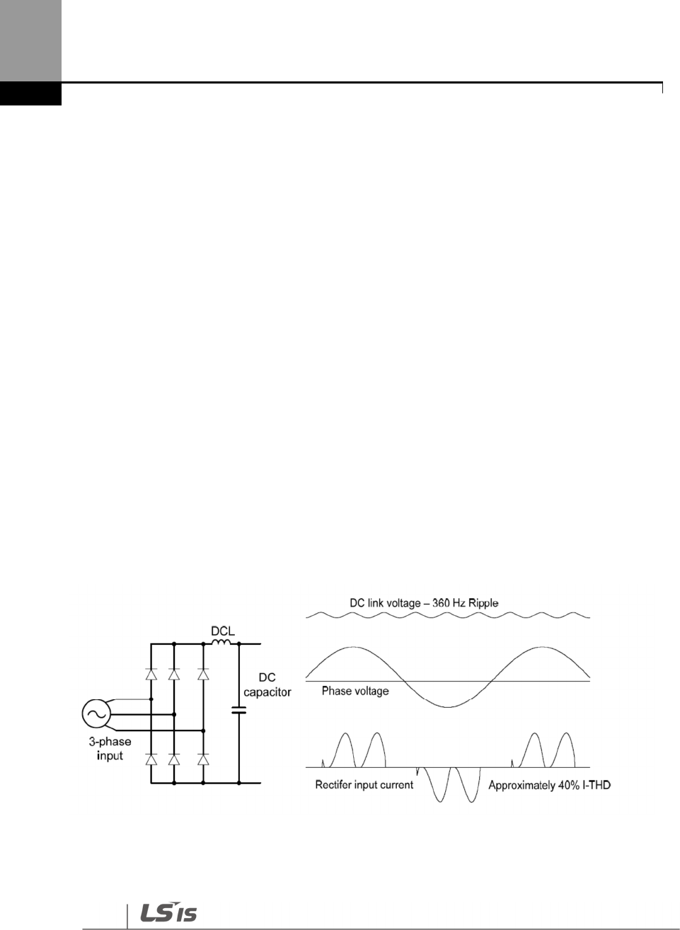
Applying
Drives to Single-phase
Input Application
622
12 Applying Drives to Single-phase Input
Application
12.1 Introduction
LSLV-H100 is a three-phase standard variable frequency drive(VFD). When applying single-phase
power to a three-phase VFD, there are several constraints that need to be considered. Standard
Pulse-Width-Modulated (PWM) VFDs use a 6-pulse diode rectifier. The 6-pulse rectification results
in 360 Hz DC bus ripple when used with a three-phase 60 Hz supply.
However, under single-phase use, the DC bus ripple becomes 120 Hz and the VFDs DC bus circuit
is subject to higher stress in order to deliver equivalent power.
Additionally, input currents and harmonics increase beyond those encountered with three-phase
input.
Input current distortion of 90% THD and greater can be expected under single-phase input,
compared to approximately 40% with three-phase input as indicated in Figure 2.
Therefore, single-phase use requires the three-phase VFD power rating be reduced (derated) to
avoid over stressing the rectifier and DC link components.
Figure-1 Typical Three-Phase Configuration
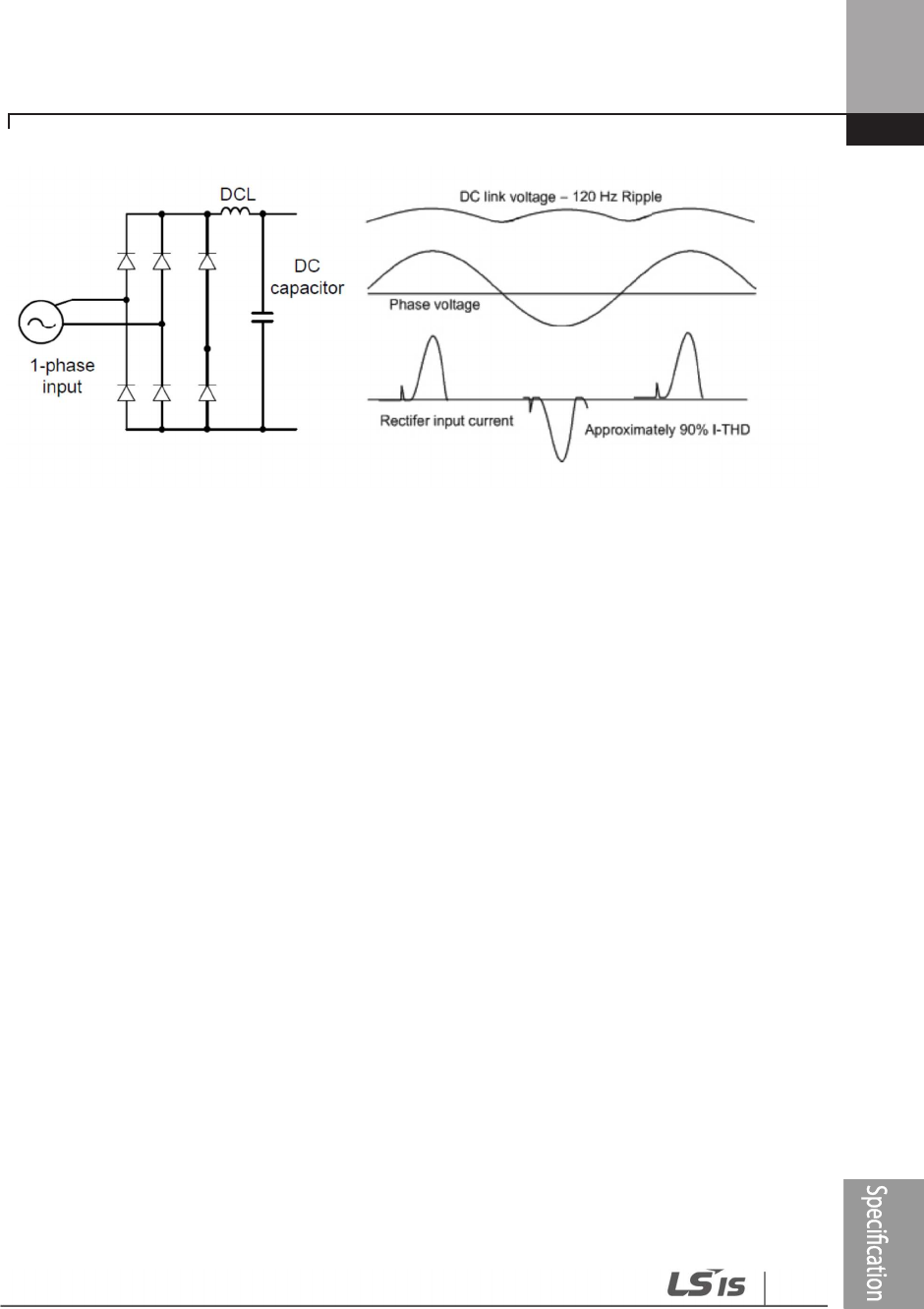
Applying
Drives to Single-
phase
Input Application
623
Figure-2 Typical Single-Phase Configuration
12.2 Power(HP), Input Current and Output Current
When using a three-phase VFD with single-phase input, derating the drive’s output current and
horsepower will be necessary because of the increase in DC bus ripple voltage and current.
In addition, the input current through the remaining two phases on the diode bridge converter
will approximately double, creating another derating consideration for the VFD. Input current
harmonic distortion will increase beyond that with a three-phase supply making the overall input
power factor low. Input current distortion over 100% is likely under single-phase conditions
without a reactor.
Therefore, the reactor is always required. When using a motor that is selected by the three-phase
drive rating criteria when using single-phase input, it may result in poor performance, premature
drive failure. The selected drive of single-phase current ratings must meet or exceed the motor
current rating.
In case of single-phase input, the rating of the inverter is smaller than that of the motor.
Please check the rating table of 11.1.

Applying
Drives to Single-phase
Input Application
624
12.3 Input Frequency and Voltage Tolerance
The single-phase current ratings are valid for 60Hz input only.
For single-phase input AC voltage, products with 90 kW or less are within -5% to + 10% of 240/480
Vac. Products with 110 kW or more are in the range of -5% to + 10% of 380/500 Vac. Standard
product with three-phase voltage input has an allowable range of +10% to –15%. Therefore, a
stricter input voltage tolerance of +10 to –5% applies when using the drive with a single-phase
supply. The average bus voltage with single-phase input is lower than the equivalent of a three-
phase input.
Therefore, the maximum output voltage (motor voltage) will be lower with a single-phase input.
The minimum input voltage must be no less than 228Vac for 240 volt models and 456Vac for 480
volt models, to ensure motor voltage production of 207Vac and 415Vac, respectively.
Thus, if full motor torque must be developed near base speed (full power) it will be necessary to
maintain a rigid incoming line voltage so that adequate motor voltage can be produced.
Operating a motor at reduced speed (reduced power), or using a motor with a base voltage that is
lower than the incoming AC supply rating (ex. 208Vac motor with a 240Vac supply), will also
minimize the effect of voltage deprivation. ( 240VAC Input 208V motor, 480VAC Input 400V
motor )
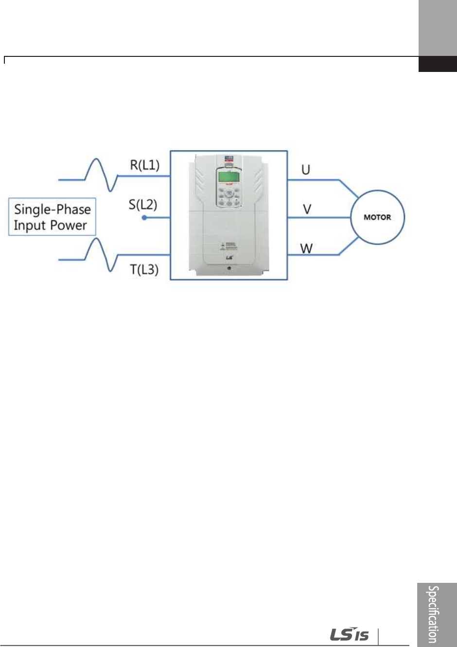
Applying
Drives to Single-
phase
Input Application
625
12.4 Wiring
Please connect single-phase input to R(L1) and T(L3).
Figure-3 Terminal Wiring Diagram
12.5 Precautions for 1–phase input to 3-phase drive
• Please connect single-phase input to R(L1) and T(L3).
• AC or DC reactor is necessary to reduce DC ripple. Please select built-in reactor type for
37~500kW. For 0.75~30kW, external AC or DC reactor should be installed.
• Same peripheral devices (including a fuse and reactor) as 3 phases can be used for single
phase as well.
• If phase open trip occurs, please turn off the input phase open protection(PRT-05).
• Protection for output current like OCT or IOLT is based on 3-phase input ratings which is
larger than single-phase input. User should set the parameters that are relative to motor
information(BAS-11~16), overload trip(PRT-17~22) and E-thermal functions(PRT-40~43).
•
The minimum input voltage must be larger than 228Vac for 240Vac supply and 456Vac for 480Vac supply
to ensure motor voltage production of 207Vac and 415Vac, respectively.
• To minimize the effect of voltage deprivation, please choose 208Vac motor for 240Vac supply
and 400Vac motor for 480Vac supply.

Product Warranty
626
Product Warranty
Warranty Information
Fill in this warranty information form and keep this page for future reference or when warranty service
may be required.
Product Name
LSIS Standard Inverter
Date of Installation
Model Name
LSLV-H100
Warranty Period
Customer Info
Name
(or company)
Address
Contact Info.
Retailer Info
Name
Address
Contact info.
Warranty Period
The product warranty covers product malfunctions, under normal operating conditions, for 12
months from the date of installation. If the date of installation is unknown, the product warranty
is valid for 18 months from the date of manufacturing. Please note that the product warranty
terms may vary depending on purchase or installation contracts.
Warranty Service Information
During the product warranty period, warranty service (free of charge) is provided for product
malfunctions caused under normal operating conditions. For warranty service, contact an official LSIS
agent or service center.

Product
Warranty
627
Non
-
Warranty Service
A service fee will be incurred for malfunctions in the following cases:
• intentional abuse or negligence
• power supply problems or from other appliances being connected to the product
• acts of nature (fire, flood, earthquake, gas accidents, etc.)
• modifications or repair by unauthorized persons
• missing authentic LSIS rating plates
•
expired warranty period
Visit Our Website
Visit us at http: //www.lsis.com
for detailed service information.

628
UL mark
The UL mark applies to products in the United States and Canada. This mark indicates that UL has
tested and evaluated the products and determined that the products satisfy the UL standards for
product safety. If a product received UL certification, this means that all components inside the
product had been certified for UL standards as well. Suitable for Installation in a Compartment
Handing Conditioned Air
CE mark
The CE mark indicates that the products carrying this mark comply with European safety and
environmental regulations. European standards include the Machinery Directive for machine
manufacturers, the Low Voltage Directive for electronics manufacturers and the EMC guidelines
for safe noise control.
Low Voltage Directive
We have confirmed that our products comply with the Low Voltage Directive
(EN 61800-5-1).
EMC Directive
The Directive defines the requirements for immunity and emissions of electrical equipment used
within the European Union. The EMC product standard (EN 61800-3) covers requirements stated
for drives.
EAC mark
The EAC (EurAsian Conformity) mark is applied to the products before they are placed on the
market of the Eurasian Customs Union member states.

629
It indicates the compliance of the products with the following technical regulations and
requirements of the Eurasian Customs Union:
Technical Regulations of the Customs Union 004/2011 “On safety of low voltage equipment”
Technical Regulations of the Customs Union 020/2011 “On electromagnetic compatibility of
technical products”
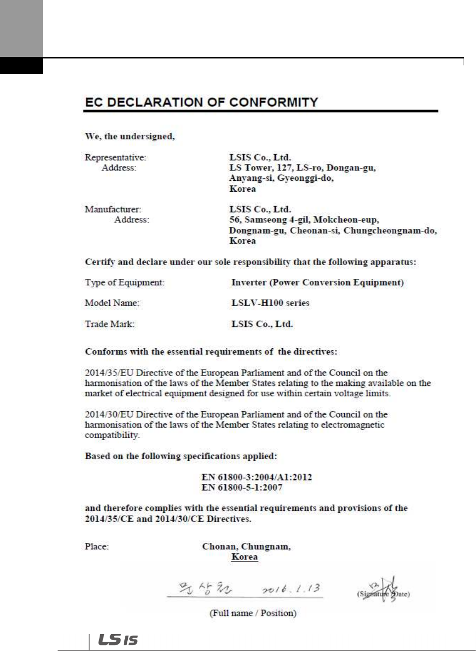
630
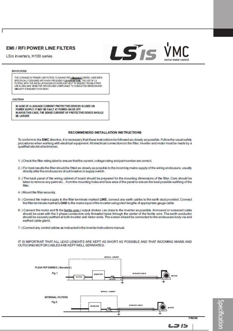
631
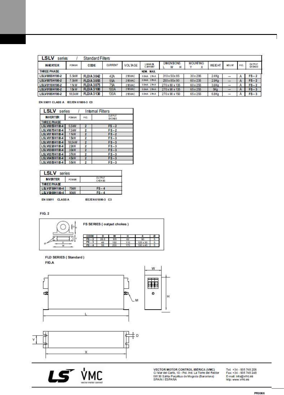
632

633
Index
[
[AUTO] key ........................................................................................ 53
[DOWN] key ..................................................................................... 53
[ESC] key ............................................................................................. 53
[HAND] key ....................................................................................... 53
[LEFT] key............................................................................................ 53
[Mode] key ........................................................................................ 53
[MULTI] key ....................................................................................... 53
[MULTI] key configuration ..................................................... 55
[OFF] key ............................................................................................. 53
[PROG / Ent] key........................................................................... 53
[RIGHT] key ....................................................................................... 53
[UP] key................................................................................................ 53
2
24 terminal ............................................................................... 40, 41
2
nd
motor operation ............................................................... 239
2
nd
operation mode ................................................................ 136
2
nd
command source ............................................................ 136
Shared command (Main Source) ................................... 136
Shared command (Main Source)) .................................. 136
3
3-wire operation ........................................................................ 151
4
4-pole standard motor ......... 529, 530, 531, 532, 533,
534
A
A terminal (Normally Open) ............................................. 138
A1/C1/B1 terminal ....................................................................... 40
AC power input terminal ..... Refer to R/S/T terminal
Acc/Dec pattern ................................................................ 79, 117
linear pattern ............................................................................. 117
S-curve pattern ........................................................................ 117
Acc/Dec reference .................................................................... 113
Delta Freq .................................................................................... 112
Max Freq ...................................................................................... 112
Acc/Dec reference frequency .......................................... 112
Ramp T Mode............................................................................ 112
Acc/Dec stop ....................................................................... 79, 120
Acc/Dec time ................................................................................ 111
Acc/Dec time switch frequency ...................................... 116
configuration via multi-function terminal ................ 114
maximum frequency ............................................................ 111
operation frequency ............................................................. 113
Acc/Dec time configuration ................................................. 79
accelerating start .......................................................................... 80
add User group
UserGrp SelKey ........................................................................ 247
ADV (advanced) ............................................................................ 60
ADV (Expanded funtction group) ................................. 401
advanced features group ....................................................... 60
Advanced function groupRefer to ADV (advanced)
function group
analog frequency hold.......................................................... 100
analog hold ................................................................................ 100
analog hold ................ Refer to
analog frequency hold
analog input ............................................................................ 38, 60
I2 current input ...........................................................................94
I2 voltage input ...........................................................................96
TI pulse input ................................................................................97
V1 voltage input .........................................................................88

634
analog input selection switch (SW2)............................. 96
analog input selection switch (SW4)............................. 36
analog output ..................................................................... 39, 288
AO terminal ...................................................................................39
pulse output .............................................................................. 291
voltage and current output .............................................. 288
analog output selection switch (SW5) ............. 36, 288
anti-hunting regulation ........................................................ 228
AO terminal .......................................................................... 39, 288
analog output selection switch (SW5) ...........................36
AP1 (Application 1 function group) ........................... 452
AP1 (Application1 function group) ................................ 60
AP2 (Application 2 function group) .................. 60, 459
AP3 (Application 3 function group) .................. 60, 464
ARM short current fault trip ..................... Refer to
Over
Current2
ASCII code ...................................................................................... 349
asymmetric ground power ................................................... 43
asymmetric ground structure
disabling the EMC filter...........................................................43
asynchronous communications system................... 335
auto restart .................................................................................... 236
auto restart settings .............................................................. 236
auto torque boost .................................................................... 126
auto torque boost 1............................................................... 126
auto torque boost 2............................................................... 126
auto tuning ................................................................................ 208
auto tuning ........................................................................ 208, 398
All (rotating) ............................................................................... 210
All (static) ..................................................................................... 211
default parameter setting .................................................. 209
automatic reset after a trip .................................................. 79
automatic start-up at power-on ....................................... 79
automatic torque boost .......................................................... 80
auto-tuning .................................................................................... 208
auxiliary command source.................................................... 81
auxiliary frequency ................................................................... 142
auxiliary frequency reference configuration ........... 143
auxiliary reference .................................................................. 142
auxiliary reference gain ....................................................... 143
final command frequency calculation ........................ 144
main reference ......................................................................... 142
auxiliary motor PID compensation ................. 279, 280
B
B terminal (Normally Closed) .......................................... 138
BACnet ................................................................................... 337, 373
analog input object ............................................................... 380
analog value object ............................................................... 378
binary input object ................................................................ 382
binary object ............................................................................. 379
communication standard .................................................. 373
data link layer ............................................................................ 376
defining ........................................................................................ 373
error message ........................................................................... 383
MAC ID/Sevice object Instance ....................................... 376
Max Master Property ............................................................ 376
multi-state input object ...................................................... 383
multi-state object ................................................................... 379
object map ................................................................................. 376
parameter setup ...................................................................... 373
protocol ........................................................................................ 373
protocol implement .............................................................. 376
quick start ................................................................................... 373
BACnet object
analog ........................................................................................... 378
analog input .............................................................................. 380
binary ............................................................................................ 379
binary input ............................................................................... 382
error message ........................................................................... 383
multi-state................................................................................... 379
multi-state input...................................................................... 383
BAS (Basic function group) ................................................ 394
BAS (Basic group) ........................................................................ 60
basic configuration diagram ........................................... 18
Basic group ....... Refer to BAS (Basic function group)
basic operation .............................................................................. 52
battery replacement ............................................................... 524
bipolar .......................................................................................... 39, 92

635
bit 138
bit (Off) ......................................................................................... 138
bit (On) .......................................................................................... 138
bit setting .................................................................................... 138
multi-function input setting .................................. 138, 139
multi-function output setting.......................................... 298
Reset Restart configuration .......................................... 236
speed search configuration .............................................. 233
stall prevention ........................................................................ 311
brake unit ........................................................................................ 287
braking resistor .............................................................................. 31
braking resistors ............................................................................ 18
broadcast ......................................................................................... 346
built-in communication ...........................Refer to
RS-485
BX 332, 507
C
cable .................................................................... 14, 27, 28, 29, 36
ground cable specifications .................................................14
power cable specifications ...................................................14
selection........................................................... 14, 27, 28, 29, 36
shielded twisted pair ...............................................................49
cable tie ............................................................................................... 40
CAP. Warning ................................................................................ 509
carrier frequency ........................................................................ 238
derating ........................................................................................ 561
factory default ....................................................................... 239
charge indicator .................................................... 26, 505, 513
charge lamp ..................................................................................... 26
Circululation Pump (MC5) .................................................. 499
cleaning ............................................................................................ 520
CleanRPTErr ................................................................................... 508
CM terminal ............................................................................ 38, 41
COM (Communication function group) ..................... 60
command ........................................................................................ 103
Cmd Source ............................................................................... 103
configuration ............................................................................ 103
command source
fwd/rev command terminal ............................................. 104
keypad .......................................................................................... 103
RS-485 ........................................................................................... 106
commercial power source transition ......................... 241
common terminal .......................... Refer to EG terminal
communication ........................................................................... 335
BACnet .......................................................................................... 373
command loss protective operation ........................... 339
communication address ..................................................... 351
communication line connection.................................... 336
communication parameters............................................. 337
communication speed ........................................................ 337
communication standards ................................................ 335
memory map ............................................................................ 342
parameter group for data transmission ..................... 343
PLC .................................................................................................. 335
saving parameters defined by communication .... 341
setting virtual multi-function input .............................. 341
Communication function group........... Refer to COM
(communication function group)
communication system configuration ...................... 336
compatible common area parameter ....................... 355
CON (Control function group)............................... 60, 408
Config (CNF) mode ................................................................. 250
inverter S/W version .......................................................... 250
keypad S/W version............................................................ 250
keypad title update ............................................................ 250
LCD contrast ............................................................................ 250
reset cumulative power consuption ....................... 250
Config mode ................................................................................ 486
Config mode (CNF) ................................................................. 487
configuration mode ................................................................... 59
considerations for installation
air pressure ....................................................................................10
considerations for installation ............................................ 10
altitude/vibration .......................................................................10
ambient humidity .....................................................................10
ambient temperature ..............................................................10
environmental factors .............................................................10
storing temperature .................................................................10
Control group ............ Refer to CON (control function
group)
control terminal board wiring ............................................ 36
cooling fan

636
cumulated fan operation time ........................................ 302
fan control ................................................................................... 242
fan malfunctions ..................................................................... 323
initialize cumulated fan operation time ..................... 302
Cooling Tower (MC4) ............................................................. 497
cursor keys ........................................................................................ 53
[DOWN] key ..................................................................................53
[LEFT] key .......................................................................................53
[RIGHT] key ....................................................................................53
[UP] key ...........................................................................................53
D
damper .............................................................................................. 186
Damper Err Trip ..................... Refer to
Damper Err Trip
damper operation .................................................................... 186
damper open delay time .................................................... 186
DB resistor
braking resistor circuit .......................................................... 320
DB Warn %ED ............................................................................ 320
DB Warn %ED .................................................................. 320, 509
DC braking after start ............................................................ 128
DC braking after stop ............................................................ 130
DC braking frequency ........................................................... 130
DC link voltage ........................................................................... 140
Dec valve ramping ................................................................... 198
deceleration stop ......................................................................... 80
delta wiring ....................................................................................... 43
derating ............................................................................... 239, 561
digital output................................................................................ 293
display ................................................................................................... 54
command source.......................................................................54
display mode table ...................................................................59
display modes .............................................................................58
frequency reference .................................................................54
operation mode .........................................................................54
rotational direction ...................................................................54
disposal ................................................................................. 520, 528
draw operation ........................................................................... 140
Drive group........................... Refer to DRV (Drive group)
DRV (Drive function group) ................................................. 60
DRV (Drive group) .................................................................... 389
dwell operation ........................................................................... 154
Acc/Dec dewel frequency .................................................. 154
acceleration dwell .................................................................. 154
deceleration dwell .................................................................. 154
dynamic braking (DB) resistor configuration....... 320
E
earth leakage breaker............................................................ 516
Easy Start On ................................................................................ 249
EEP Rom Empty.......................................................................... 244
EG terminal ....................................................................................... 40
electronic thermal overheating protection (ETH)
.......................................................................................................... 304
EMC filter ............................................................................................ 43
asymmetric power source ....................................................43
disabling .................................................................. 43, 44, 45, 46
enable ..............................................................................................44
enabling .......................................................................... 44, 45, 46
emergency stop fault trip .................................Refer to
BX
Enclosed Type 1 ......................................................................... 537
energy saving ............................................................................... 190
energy saving operation ..................................................... 231
automatic energy saving operation ............................. 231
manual energy saving operation ................................... 231
EPID (EPID control) group ..................................................... 60
EPID (External PID function group) ............................. 445
EPID control
external PID ................................................................................ 177
EPID control group ..................................................................... 60
ETH .................Refer to
electronic thermal overheating
protection (ETH)
E-Thermal ........................................................................................ 506
Exception Date ............................................................................ 212
Exhaust Fan (MC3) ................................................................... 495

637
external 24V power terminal.... Refer to 24 terminal
External Trip ................................................................................... 507
external trip signal .................................................................... 315
F
falut trips .......................................................................................... 505
fan life estimation ..................................................................... 331
fan replacement level ........................................................... 331
fan time ........................................................................................ 331
fan operation warning .......................................................... 332
fan replacement warning .................................................... 510
Fan Trip .................................................................................. 323, 507
Fan Warning ...................................................................... 323, 509
fatal ...................................................................................................... 505
fault ...................................................................................................... 332
fatal ................................................................................................. 505
latch ................................................................................................ 505
level ................................................................................................ 505
major fault .................................................................................. 332
fault monitoring ............................................................................ 75
multiple fault trips .....................................................................76
fault signal output terminal ........ Refer to A1/C1/B1
terminal
fault trip mode ............................................................................... 59
fault/warning list ........................................................................ 332
braking resistor braking rate warning ......................... 332
capacitor lifetime warning ................................................. 332
CleanRPTErr Trip ...................................................................... 332
CPU Watch Dog fault trip .................................................... 332
Damper Err Trip ........................................................................ 332
E-Thermal .................................................................................... 332
External Trip ............................................................................... 332
fan replacement warning ................................................... 332
Fan Trip ......................................................................................... 332
Fan Warning ............................................................................... 332
Fire mode Warning ................................................................ 332
Ground Trip ................................................................................ 332
In Phase Open .......................................................................... 332
IO Board Trip .............................................................................. 332
Level Detect trip ...................................................................... 332
Level Detect Warning ........................................................... 332
Lost Command ........................................................................ 332
Low Battery Warning ............................................................ 332
Low Voltage ............................................................................... 332
Low Voltage2 ............................................................................ 332
No Motor Trip ............................................................................ 332
NTC Open .................................................................................... 332
Option Trip-x ............................................................................. 332
Out Phase Open ...................................................................... 332
Over Current1 ........................................................................... 332
Over Current2 ........................................................................... 332
Over Heat .................................................................................... 332
Over Load Trip .......................................................................... 332
Over Voltage .............................................................................. 332
ParaWrite Trip ............................................................................ 332
Pipe Broken Trip ....................................................................... 332
Pipe Broken Warning ............................................................ 332
Under Load Trip ....................................................................... 332
FE (Frame Error) .......................................................................... 349
ferrite...................................................................................................... 40
fieldbus ..................................................................................... 86, 103
communication option ....................................................... 136
FIFO/FILO ......................................................................................... 259
filter time constant ...................................................................... 88
filter time constant number .............................................. 137
Fire mode ........................................................................................ 229
Fire Mode Warning ................................................................ 509
flow compensation .................................................................. 189
maximum compensation value ..................................... 189
flux braking .................................................................................... 310
forward or reverse run prevention .............................. 107
free-run stop ........................................................................ 81, 131
frequency hold by analog input ................................... 100
frequency jump ................................................................. 81, 135
frequency limit ................................................................... 81, 133
frequency jump ....................................................................... 135
frequency upper and lower limit value ...................... 133
maximum/start frequency ................................................ 133
frequency reference ....................................................... 87, 128
frequency reference for 0–10V input ........................... 88
frequency reference for -10–10V Input ...................... 92
frequency reference source configuration ............... 78
frequency setting ......................................................................... 86
I2 current input ...........................................................................94

638
I2 voltage input ...........................................................................96
keypad .............................................................................................87
RS-485 ..............................................................................................99
TI pulse input ................................................................................97
V1 voltage input .........................................................................88
frequency setting (Pulse train) terminal... Refer to
TI
terminal
frequency setting(voltage) terminal ..........Refer to
V1
terminal
frequency upper and lower limit value
Frequency lower limit value.............................................. 133
Frequency upper limit value ............................................ 133
fuse specifications ..................................................................... 547
G
ground .................................................................................................. 27
class 3 ground ..............................................................................29
ground cable specifications .................................................14
ground fault trip ............................... Refer to
Ground Trip
Ground Trip .................................................................................... 506
H
H100 expansion common area parameter ........... 359
control area parameter (Read/Write) ........................... 368
memory control area parameter (Read/Write) ....... 371
monitor area parameter (read only) ............................. 359
half duplex system ................................................................... 335
I
I/O point map.............................................................................. 385
I2 39
analog input selection switch (SW4) ...............................39
frequency setting(current/voltage) terminal .............39
I2 Terminal ......................................................................................... 94
IA (illegal data address) ........................................................ 349
ID (illegal data value) ............................................................. 349
IF (illegal
function) .................................................................................... 349
IN (Input terminal function group) .................... 60, 411
In Phase Open ............................................................................. 506
initializing accumulated electric energy count ... 250
input and output specifications ..529, 564, 565, 566
input open-phase fault trip .............. Refer to
In Phase
Open
input phase open
input open-phase protection .......................................... 314
input power frequency ......................................................... 243
input power voltage ............................................................... 243
input power voltage settings ........................................... 243
input terminal ..................................................................... 38, 138
A (NO) or B (NC) terminal configuration ..................... 138
bit setting .................................................................................... 138
CM terminal ..................................................................................38
I2 terminal ......................................................................................39
NO/NC configuration ........................................................... 138
P1–P7 terminal ............................................................................38
TI terminal ......................................................................................39
V1 terminal ....................................................................................38
VR terminal ....................................................................................38
input terminal contact
A contact ..................................................................................... 315
B contact ...................................................................................... 315
Input terminal function group ...... Refer to IN (Input
terminal function group)
inspection
annual inspection ................................................................... 521
bi-annual inspection ............................................................. 523
daily inspection ........................................................................ 520
installation .......................................................................................... 17
basic configuration diagram...........................................18
installation flowchart ...............................................................17
location............................................................................................11
mounting the Inverter ............................................................19
side-by-side installation .........................................................12
wiring ...............................................................................................26
installation conditions ............................................................... 10
INV Over Load

639
Inv Over Load Warning ........................................................ 509
Inverter OLT ................................................................................... 506
inverter overload protection (IOLT) ............................. 316
Inverter overload warning .................................................. 332
IO Board connection fault trip ...... Refer to
IO
Board
Trip
IO Board Trip ................................................................................ 508
IP 20 .................................................................................................... 537
IP 20 Type external dimensions ..................................... 539
J
Jog operation ............................................................................... 147
FWD Jog ....................................................................................... 147
Jog frequency ........................................................................... 147
Jog operation 2 by terminal input ................................. 148
Jog operation 2-Rev Jog by terminal input ......... 148
jump frequency .......................................................................... 135
K
keypad .................................................................................................. 52
[AUTO] key .....................................................................................53
[ESC] key .........................................................................................53
[HAND] key ....................................................................................53
[Mode] key .....................................................................................53
[MULTI] key ............................................................................ 53, 56
[OFF] key .........................................................................................53
[PROG / Ent] key..........................................................................53
code information .......................................................................57
Config mode (CNF) ................................................................ 487
configuration mode .................................................................59
cursor keys .................................................................................53
display ...................................................................................... 52, 54
display item ...................................................................................57
display mode................................................................................58
LCD brightness/contrast ..................................................... 250
monitor mode .............................................................................59
monitor mode cursor ..............................................................55
monitor mode item ..................................................................55
navigating between groups ................................................58
operating status ................................................................. 55, 57
operation keys .............................................................................52
operation mode .........................................................................56
parameter group .......................................................................56
parameter mode ........................................................................59
parameter value .........................................................................57
rotational direction ...................................................................56
S/W version ................................................................................ 250
set value ..........................................................................................57
setting range ................................................................................57
status bar configuration .........................................................55
trip mode .......................................................................................59
User & Macro mode ..................................................................59
wiring length ................................................................................40
keypad display ................................................................................ 54
keypad features
fault monitoring .........................................................................75
navigating directly to different codes ............................68
navigating through the codes ............................................66
operation modes .......................................................................62
parameter settings ....................................................................70
selecting a display mode .......................................................61
selecting the status bar display item ...............................73
setting the monitor display items.....................................71
switching between groups in Parameter Display
mode .........................................................................................64
switching between groups in User & Macro mode 65
keypad title update ................................................................. 250
keypad trip mode ..................................................................... 486
kinetic energy buffering ....................................................... 226
L
latch ..................................................................................................... 505
LCD display ....................................................................................... 54
leakage breaker .......................................................................... 544
learning basic features ............................................................. 78
level ...................................................................................................... 505
level dectectiontrip restart time ..................................... 201
Level Detect ................................................................................... 508
Level Detect Warning ........................................................... 509
Level Detect Trip ........................................................................ 332
level detection control .......................................................... 201
lift-type load ...................................................................... 117, 125
linear pattern ................................................................................ 117

64
0
linear V/F operation ................................................................... 80
linear V/F pattern operation ............................................. 121
base frequency ........................................................................ 121
start frequency ......................................................................... 121
load tuning..................................................................................... 199
Lost Command ........................................................................... 508
command loss fault trip warning ................................... 332
command loss trip ................................................................. 332
Lost Command Warning .................................................... 509
Lost KeyPad ................................................................................... 507
Lost KeyPad Warning ............................................................ 509
Low Battery
low battery warning .............................................................. 510
low battery warning ................................................................ 321
low voltage .................................................................................... 324
low voltage fault trip .................................................. 324, 332
Low Voltage................................................................................... 506
Low voltage fault trip during operation ....... Refer to
Low Voltage2 Trip
Low Voltage2................................................................................ 506
LowLeakage PWM ................................................................... 238
LS INV 485 communication .............................................. 341
LS INV 485 Detailed Read Protocol............................ 346
LS INV 485 Detailed Write Protocol ........................... 347
LS INV 485 error code .......................................................... 349
FE (Frame Error) ........................................................................ 349
IA (illegal data address) ........................................................ 349
ID (illegal data value) ......................................................... 349
IF (illegal function) .................................................................. 349
WM (write mode error) ........................................................ 349
LS INV 485 protocol ............................................................... 345
LSINV 485 ....................................................................................... 337
lubrication ....................................................................................... 188
lubrication operation .............................................................. 188
M
M2 (Secondary Motor function group) ................... 482
M2 (secondary
motor-related features) group .................................... 60
Macro
Circulation Pump (MC5) ...................................................... 499
Constant Torque (MC7) ........................................................ 503
Cooling Tower (MC4) ............................................................ 497
Exhaust Fan (MC3) .................................................................. 495
Supply Fan (MC2) .................................................................... 494
Vacuum Pump (MC6) ........................................................... 501
Macro function group ........................................................... 492
Macro group ................................................................................. 492
Macro mode .................................................................................... 61
macro selection .......................................................................... 251
Macro selection
Basic ............................................................................................... 251
Circulation Pump .................................................................... 251
Compressor................................................................................ 251
Constant Torque ...................................................................... 251
Coolong Tower ......................................................................... 251
Supply Fan .................................................................................. 251
Vacuum Pump .......................................................................... 251
magnetic contactor ........................................................ 35, 544
main capacitor life estimation ......................................... 329
CAP Level 1 ................................................................................. 330
CAP Level 2 ................................................................................. 330
maintenance ................................................................................. 520
manual torque boost .................................................... 80, 125
master ................................................................................................ 336
maximum allowed prospective short-circuit
current ............................................................................................. iii
megger test ....................................................................... 521, 524
Metasys-N2 ................................................................................... 337
analog input .............................................................................. 386
analog output ........................................................................... 385
binary input ............................................................................... 387
binary output ............................................................................ 386
communication standard .................................................. 384
error code .................................................................................... 388
I/O point map ........................................................................... 385
protocol ........................................................................................ 384
metasys-N2 communication ............................................ 384

641
Metasys-N2 I/O map
analog input .............................................................................. 386
analog output ........................................................................... 385
binary input ............................................................................... 387
binary output ............................................................................ 386
MMC ................................................................................................... 253
auto cahnge................................................ 265, 266, 276, 277
auto change aux ..................................................................... 270
basic sequence ......................................................................... 260
interlock ....................................................................................... 272
레귤러 바이패스 .................................. 281, 282, 283, 284
MMC Interlock ............................................................................ 508
Modbus-RTU ................................................................................ 337
Modbus-RTU communication ........................................ 341
Modbus-RTU function code and protocol ........... 351
Modbus-RTU protocol
exception code ...................................................................... 354
read holding resister ............................................................. 351
read input resister ................................................................... 351
momentary power interruption ..................................... 233
monitoring
monitor mode .............................................................................59
monitor mode cursor ..............................................................55
monitor mode display ............................................................54
monitor mode item ..................................................................55
monitor registration protocol details ........................... 348
operation state monitoring............................................... 300
operation time monitoring ............................................... 302
motor features
capacity ........................................................................................ 156
efficiency ..................................................................................... 156
no-load current ........................................................................ 156
operation display options .....................................................78
output voltage adjustment ............................................... 127
overheat sensor ....................................................................... 306
protection ................................................................................... 304
rotation control ...........................................................................79
thermal protection(ETH)
E-Thermal .......................................................................... 304
verifying rotational direction ...............................................51
Motor overheat fault trip .................................................... 332
motor thermal protection(ETH)
ETH trip ......................................................................................... 304
mounting bolt ................................................................................ 19
Multi Key
Multi key item ........................................................................... 489
Multi Key Sel .............................................................................. 489
multi-drop link system .......................................................... 335
multi-function input terminal ............................................. 38
factory default .............................................................................38
IN 65–71 ....................................................................................... 414
multi-function input terminal Off filter ....................... 137
multi-function input terminal On filter ....................... 137
P1–P7................................................................................................38
Px Define ..................................................................................... 414
Px terminal configuration .................................................. 414
multi-function input terminal control ........... 137, 139
multi-function input terminals
factory default .............................................................................38
multi-function output terminal
multi-function output category (Q1 Define) ........... 424
multi-function output on/off control ..................... 285
multi-function output terminal and relay settings
.................................................................................................... 293
multi-function output terminal delay time settings
.................................................................................................... 299
multi-function relay1 category (Relay 1) .................... 422
multi-function relay2 category (Relay 2) .................... 423
multi-function relay3category (Relay 3) ..................... 423
multi-function relay4 category (Relay 4) .................... 423
multi-function relay5 category (Relay 5) .................... 423
trip output by multi-function output terminal and relay
.................................................................................................... 298
multi-function terminal configuration.......................... 81
multiple motor control ......................................................... 253
multi-step frequency .............................................................. 101
setting ........................................................................................... 101
Speed-L/Speed-M/Speed-H ............................................. 102
multi-step speed (frequency).............................................. 78
N
N- terminal (- DC link terminal) ............ 31, 32, 33, 34
no motor trip ............................................................................... 326
No Motor Trip.............................................................................. 506
noise .............................................................................................. 43, 89

642
Normal PWM ............................................................................... 238
NPN mode (Sink) ......................................................................... 42
NTC Open ....................................................................................... 507
number of motor poles ....................................................... 156
O
open-phase protection ......................................................... 314
operation frequency ......... Refer to
frequency setting
operation mode selection ..................................................... 78
operation noise .......................................................................... 238
carrier frequency ..................................................................... 238
frequency jump ....................................................................... 135
operation time ............................................................................ 302
cumulated operation time ................................................ 302
initialize cumulated operation time ............................. 302
inverter power-on time ....................................................... 302
option trip ............................... 326, Refer to
Option Trip-x
Option Trip-1 ................................................................................ 508
Option Trip-x
option trip ................................................................................... 332
OUT (Output terminal function group) .......... 60, 420
Out Phase Open ........................................................................ 506
output block by multi-function terminal ................ 325
output open-phase fault trip ...... Refer to
Out Phase
Open
output terminal ............................ Refer to R/S/T terminal
Output terminal function group ............ Refer to OUT
(Output terminal function group)
output/communication terminal ...................................... 39
24 terminal ..................................................................................40
A1/C1/B1 terminal ..................................................................40
AO terminal .................................................................................39
EG terminal ..................................................................................40
S+/S-/SG terminal ...................................................................40
over current trip .......................... Refer to
Over Current1
Over Current1 .............................................................................. 506
Over Current2 .............................................................................. 507
Over Heat ........................................................................................ 506
over heat fault trip .............................. Refer to
Over Heat
Over Load ....................................................................................... 505
Over Load Warning ................................................................ 509
overload fault trip ................................................................... 332
overload warning ................................................................... 332
Over Voltage ................................................................................. 506
over voltage trip ............................ Refer to
Over Voltage
overload....................................................... Refer to
Over Load
overload trip .............................................................................. 308
overload warning ................................................................... 308
overload rate ................................................................................ 239
overload trip............................................. Refer to
Over Load
P
P(+) terminal (+ DC link terminal) ......................... 33, 34
P/I gain .............................................................................................. 233
P1+ terminal (+ DC link terminal) .................................. 31
P2+ terminal (+ DC link terminal) ......................... 31, 32
P2+/B terminal ............................................................................... 31
P3+ terminals (+ DC link terminal) ................................ 32
parameter ........................................................................................... 70
display changed parameter .............................................. 247
hide parameter mode .......................................................... 245
initializing the parameters ....................................................77
parameter initialization .................................................. 244
parameter lock ......................................................................... 246
parameter settings ....................................................................70
password .......................................................................... 245, 246
Parameter Initialization ......................................................... 244
parameter mode........................................................................... 59
parameter setting mode ........................................................ 60
ParaWrite Trip ............................................................................... 508
parmeter
read/write/save ........................................................................ 243
part names ........................................................................................... 3
parts illustrated ................................................................................. 3
parts life ............................................................................................ 329

643
capacitor life estimation ...................................................... 329
fan life ............................................................................................ 331
password .................................................................. 245, 246, 372
payback counter ........................................................................ 190
peripheral devices ..................................................................... 544
phase-to-phase voltage ....................................................... 515
PID
flow control ................................................................................ 157
pressure control ....................................................................... 157
speed control ............................................................................ 157
temperature control .............................................................. 157
PID (Advanced function group) ..................................... 434
PID (PID control) group .......................................................... 60
PID control
PID openloop ............................................................................ 176
PID operation sleep mode ................................................. 174
PID operation switching ..................................................... 176
PID reference ............................................................................. 168
PID control group ................ Refer to PID (PID control)
group)
pipe break ....................................................................................... 204
pipe break dectection control
Pipe Broken ................................................................................ 204
pipe break detection control
Pipe Broken ................................................................................ 508
Pipe Broken Warning ............................................................ 509
Pipe Broken fault trip ........... Refer to
PipeBroken Trip
PNP mode (Source).................................................................... 41
PNP/NPN mode selection switch (SW2) ................... 36
NPN mode (Sink) ........................................................................42
PNP mode (Source)...................................................................41
post-installation checklist ....................................................... 48
potentiometer ................................................................................. 38
power braking ................................................................................ 81
power consumption ................................................... 300, 301
power input terminalRefer to
R/S/T terminal
, Refer
to
R/S/T terminal
, Refer to
R/S/T terminal
power output terminal ......... Refer to
R/S/T terminal
,
Refer to
R/S/T terminal
, Refer to
R/S/T terminal
power terminal board wiring .............................................. 29
power terminals ................................................................... 32, 33
N- terminal .............................................................. 31, 32, 33, 34
P(+) terminal ......................................................................... 33, 34
P(+)/B terminal ............................................................................33
P1+ terminal .................................................................................31
P2+ terminal ......................................................................... 31, 32
P2+/B terminal ............................................................................31
P3+ terminal .................................................................................32
R/S/T terminals ..................................................... 31, 32, 33, 34
U/V/W terminal .................................................... 31, 32, 33, 34
PowerOn Resume ..................................................................... 303
PowerOn Resume by serial communication ........ 303
Power-on Run .............................................................................. 108
pre-heating .................................................................................... 206
preparing the installation .......................................................... 1
press regeneration prevention ....................................... 286
P gain/I gain ............................................................................... 287
product identification................................................................... 1
product specification details ............................................ 535
protocol
BACnet protocol ...................................................................... 373
LS INV 485 protocol ............................................................... 345
Metasys-N2 protocol............................................................. 384
PRT (protection features) group ....................................... 60
PRT (Protection function group) ................................... 472
Pulse output terminal ................. Refer to TO terminal
pump clean .................................................................................... 192
Pump clean trip ................... Refer to
Pump Clean Trip
PWM ................................................................................................... 238
frequency modulation ......................................................... 238
Q
quantizing .......................................................................................... 89
Quantizing
noise ..................................................................................................89
quick reference ................................................................................ iv
R
R/S/T terminals ........................................ 31, 32, 33, 34, 513

644
R/S/T terminals .............................................................................. 35
rating
derating ........................................................................................ 561
rated motor current ............................................................... 156
rated motor voltage .............................................................. 208
rated slip frequency ............................................................... 156
rated slip speed ........................................................................ 156
rating plate ........................................................................................... 1
reactor .......................................................................................... 18, 19
reactors specifications ........................................................... 547
real-time clock ................................................................................ 23
regenerated energy ................................................................. 132
Reset Restart ................................................................................. 110
settings ....................................................................................... 236
resonance frequency
carrier frequency ..................................................................... 238
restarting after a trip
Reset Restart .............................................................................. 110
retry number ................................................................................ 110
ripple ...................................................................................................... 89
RS-232 ............................................................................................... 336
communication ....................................................................... 336
RS-485 ............................................................................................... 335
communication ....................................................................... 336
converter ..................................................................................... 336
integrated communication ..................................................99
setting command and frequency.................................. 339
signal terminal ..................................................................... 40, 99
RS-485 signal input terminal ...... Refer to S+/S-/SG
terminal
RTC battery ........................................................................... 23, 524
enabling ..........................................................................................23
replacing ...................................................................................... 524
specifications............................................................................. 524
run prevention
Fwd ................................................................................................. 107
Rev .................................................................................................. 107
S
S/W version ................................................................................... 250
inverter ......................................................................................... 250
keypad .......................................................................................... 250
S+/S-/SG terminal ....................................................................... 40
safe operation mode ............................................................. 152
safety information ........................................................................... ii
screw specification
control circuit terminal screw ........................................... 550
input/output terminal screw ............................................ 549
screw size .................................................................................... 549
screw torque .............................................................................. 549
S-curve pattern ........................................................................... 117
actual Acc/Dec time .............................................................. 119
secondary motor-related features group ..... Refer to
M2 (the secondary motor-related features)
group
selecting operation modes ......................................... 62, 81
auto mode operation ..............................................................82
basic operation ...........................................................................83
function codes.............................................................................84
hand mode operation .............................................................81
mode keys and indicators .....................................................82
Power-on Run/PowerOn Resume in each mode .....85
switching between the modes ..........................................84
sequence common terminal .. Refer to
CM terminal
side-by-side installation .......................................................... 12
slave ..................................................................................................... 336
slip ......................................................................................................... 156
slip compensation operation ........................................... 156
soft fill control
soft fill operation ..................................................................... 172
speed command loss ............................................................ 317
speed search operation ....................................................... 232
Flying Start-1 ............................................................................. 233
Flying Start-2 ............................................................................. 233
options.......................................................................................... 233
P/I gain .......................................................................................... 233
speed unit selection (Hz or Rpm) ................................ 101

645
square reduction........................................................................... 80
square reduction load .......................................................... 122
V/F pattern operation ........................................................... 122
stall ....................................................................................................... 310
bit On/Off .................................................................................... 311
stall prevention ........................................................................ 310
start after DC braking ............................................................... 80
start at power-on
PowerOn Resume ................................................................... 109
Power-on Run ........................................................................... 108
start mode ...................................................................................... 128
acceleration start ..................................................................... 128
start after DC braking ........................................................... 128
Start&End Ramp operation .............................................. 196
Station ID ......................................................................................... 351
stop mode ...................................................................................... 129
DC braking after stop ........................................................... 130
deceleration stop .................................................................... 129
free run stop .............................................................................. 131
power braking .......................................................................... 132
storage .............................................................................................. 528
Supply Fan (MC2) ..................................................................... 494
surge killer ................................................................................ 35, 49
SW1 .............. Refer to Terminating Resistor selection
switch (SW1)
SW2 ......... Refer to PNP/NPN mode selection switch
(SW2)
SW3 .... Refer to V1/T1 (PTC) mode selection switch
(SW3)
SW4 .. Refer to analog input selection switch (SW4)
SW5 ............ Refer to analog output selection switch
(SW5)
switch
analog input selection switch (SW4) ...............................36
analog output selection switch (SW5) ...........................36
PNP/NPN mode selection switch (SW2) .......................36
Terminating Resistor selection switch (SW1) ..............36
V1/T1 (PTC) mode selection switch (SW3) ...................36
Switches ............................................................................................... 36
T
target frequency
Cmd frequency ........................................................................ 389
Temperature sensor fault trip .........................
NTC Open
terminal
A terminal......................................................................... 138, 299
B terminal ......................................................................... 138, 299
terminal for frequency reference setting ...... Refer to
VR terminal
terminal screw specifications ........................................... 548
Terminating Resistor selection switch (SW1) .......... 36
test run ................................................................................................. 50
Thermal Trip .................................................................................. 507
TI terminal ................................................................................. 39, 97
Time Event ...................................................................................... 212
time event scheduling ........................................................... 212
Exception Date ......................................................................... 212
module types ............................................................................ 212
parameters ................................................................................. 212
RTC battery ................................................................................. 212
RTC clock ..................................................................................... 212
Time Event .................................................................................. 212
Time Period Module .............................................................. 212
Time Period Module ............................................................... 212
time scale setting ...................................................................... 112
0.01sec .......................................................................................... 112
0.1sec ............................................................................................. 112
1sec ................................................................................................. 112
timer ................................................................................................... 252
protection features groupPRT (protection features)
group
TO terminal .................................................................................... 291
torque.................................................................................................... 26
torque boost ................................................................................. 125
auto torque boost .................................................................. 126
manual torque boost ............................................................ 125
overexcitation ........................................................................... 125
trip ........................................................................................................ 505
erasing trip history ................................................................. 250
fault/waring list ........................................................................ 332

646
trip no motor trip ......................................................... 326, 328
trip status reset ......................................................................... 325
troubleshooting ...................................................................... 510
Trip mode ........................................................................................... 59
Trip mode ........................................................................................ 486
troubleshooting .......................................................................... 505
fault trips ...................................................................................... 510
other faults ................................................................................. 513
U
U&M mode ....................................................................... 248, 344
U/V/W terminals ............................ 31, 32, 33, 34, 35, 513
Under Load
Under Load Trip ............................................................ 322, 505
Under Load Warning .................................................. 322, 509
underload fault trip................................................................ 332
underload warning ................................................................ 332
underload fault trip ........................ Refer to
Under Load
Unipolar ............................................................................................... 39
up-down operation ................................................................. 149
User & Macro mode ............................................... 58, 59, 61
User group ..................................................................................... 247
delete parameters .................................................................. 248
parameter registration ......................................................... 247
User mode......................................................................................... 61
user V/F pattern operation ................................................ 123
User/Macro group
parameter group .................................................................... 344
U&M mode ................................................................................. 344
using the keypad.......................................................................... 61
V
V/F control...................................................................................... 121
linear V/F pattern operation.............................................. 121
square reductionV/F pattern operation ..................... 122
user V/F pattern operation ................................................ 123
V/F pattern configuration .....................................................80
V1 terminal............................................................................... 38, 88
V1/T1 (PTC) mode selection switch (SW3) ............... 36
V2
analog input selection switch (SW4) ...............................39
V2 input ............................................................................................... 96
I2 voltage input ...........................................................................96
Vacuum Pump (MC6) ............................................................ 501
variable torque load ................................................................ 122
vent cover .......................................................................................... 12
virtual multi-function input ............................................... 341
voltage/current output terminal ................ Refer to AO
terminal
VR terminal ....................................................................................... 38
W
warning ................................................................................. 332, 505
fault/warning list ..................................................................... 332
warning message ................................................................... 509
Warning ............................................................................................ 332
wiring ............................................................................................ 14, 26
circuit breaker ........................................................................... 544
control terminal board wiring.............................................36
copper cable .................................................................................26
disassembling the cover ........................................................27
ferrite ................................................................................................40
ground .............................................................................................27
power terminal board .............................................................29
re-assembling the cover ........................................................47
wiring length ................................................................................40
WM (write mode error) ........................................................ 349
Write parameter fault trip .... Refer to
ParaWrite Trip
