H264 High Profile Decoder 2.0 On HDVICP2 And Media Controller Based Platform User’s Guide User
User Manual:
Open the PDF directly: View PDF ![]() .
.
Page Count: 176 [warning: Documents this large are best viewed by clicking the View PDF Link!]

H.264 High Profile Decoder 2.0 on
HDVICP2 and Media Controller based
platform
User’s Guide
Literature Number: SPRUHF9
April 2015

IMPORTANT NOTICE
Texas Instruments Incorporated and its subsidiaries (TI) reserve the right to make corrections, enhancements, improvements and
other changes to its semiconductor products and services per JESD46, latest issue, and to discontinue any product or service per
JESD48, latest issue. Buyers should obtain the latest relevant information before placing orders and should verify that such
information is current and complete. All semiconductor products (also referred to herein as “components”) are sold subject to TI’s
terms and conditions of sale supplied at the time of order acknowledgment.
TI warrants performance of its components to the specifications applicable at the time of sale, in accordance with the warranty in TI’s
terms and conditions of sale of semiconductor products. Testing and other quality control techniques are used to the extent TI deems
necessary to support this warranty. Except where mandated by applicable law, testing of all parameters of each component is not
necessarily performed.
TI assumes no liability for applications assistance or the design of Buyers’ products. Buyers are responsible for their products and
applications using TI components. To minimize the risks associated with Buyers’ products and applications, Buyers should provide
adequate design and operating safeguards.
TI does not warrant or represent that any license, either express or implied, is granted under any patent right, copyright, mask work
right, or other intellectual property right relating to any combination, machine, or process in which TI components or services are
used. Information published by TI regarding third-party products or services does not constitute a license to use such products or
services or a warranty or endorsement thereof. Use of such information may require a license from a third party under the patents or
other intellectual property of the third party, or a license from TI under the patents or other intellectual property of TI.
Reproduction of significant portions of TI information in TI data books or data sheets is permissible only if reproduction is without
alteration and is accompanied by all associated warranties, conditions, limitations, and notices. TI is not responsible or liable for such
altered documentation. Information of third parties may be subject to additional restrictions.
Resale of TI components or services with statements different from or beyond the parameters stated by TI for that component or
service voids all express and any implied warranties for the associated TI component or service and is an unfair and deceptive
business practice. TI is not responsible or liable for any such statements.
Buyer acknowledges and agrees that it is solely responsible for compliance with all legal, regulatory and safety-related requirements
concerning its products, and any use of TI components in its applications, notwithstanding any applications-related information or
support that may be provided by TI. Buyer represents and agrees that it has all the necessary expertise to create and implement
safeguards which anticipate dangerous consequences of failures, monitor failures and their consequences, lessen the likelihood of
failures that might cause harm and take appropriate remedial actions. Buyer will fully indemnify TI and its representatives against any
damages arising out of the use of any TI components in safety-critical applications.
In some cases, TI components may be promoted specifically to facilitate safety-related applications. With such components, TI’s
goal is to help enable customers to design and create their own end-product solutions that meet applicable functional safety
standards and requirements. Nonetheless, such components are subject to these terms.
No TI components are authorized for use in FDA Class III (or similar life-critical medical equipment) unless authorized officers of
the parties have executed a special agreement specifically governing such use.
Only those TI components which TI has specifically designated as military grade or “enhanced plastic” are designed and
intended for use in military/aerospace applications or environments. Buyer acknowledges and agrees that any military or
aerospace use of TI components which have not been so designated is solely at the Buyer's risk, and that Buyer is solely
responsible for compliance with all legal and regulatory requirements in connection with such use.
TI has specifically designated certain components as meeting ISO/TS16949 requirements, mainly for automotive use. In any case of
use of non-designated products, TI will not be responsible for any failure to meet ISO/TS16949.
Products Applications
Audio www.ti.com/audio Automotive & Transportation www.ti.com/automotive
Amplifiers amplifier.ti.com Communications & Telecom www.ti.com/communications
Data Converters dataconverter.ti.com Computers & Peripherals www.ti.com/computers
DLP® Products www.dlp.com Consumer Electronics www.ti.com/consumer-apps
DSP dsp.ti.com Energy and Lighting www.ti.com/energyapps
Clocks and Timers www.ti.com/clocks Industrial www.ti.com/industrial
Interface interface.ti.com Medical www.ti.com/medical
Logic logic.ti.com Security www.ti.com/security
Power Mgmt power.ti.com Space, Avionics & Defense www.ti.com/space-avionics-defense
Microcontrollers microcontroller.ti.com Video & Imaging www.ti.com/video
RFID www.ti-rfid.com
OMAP Applications Processors www.ti.com/omap TI E2E Community e2e.ti.com
Wireless Connectivity www.ti.com/wirelessconnectivity
Mailing Address: Texas Instruments, Post Office Box 655303, Dallas, Texas 75265
Copyright 2014, Texas Instruments Incorporated

iii
Preface
Read This First
About This Manual
This document describes how to install and work with Texas Instruments’
(TI) H.264 High Profile Decoder implementation on the HDVICP2 and
Media Controller based platform. It also provides a detailed Application
Programming Interface (API) reference and information on the sample
application that accompanies this component.
TI’s codec implementations are based on the eXpressDSP Digital Media
(XDM) standard. XDM is an extension of the eXpressDSP Algorithm
Interface Standard (XDAIS).
Intended Audience
This document is intended for system engineers who want to integrate TI’s
codecs with other software to build a multimedia system based on the
HDVICP2 based platform.
This document assumes that you are fluent in the C language, have a
good working knowledge of Digital Signal Processing (DSP), digital signal
processors, and DSP applications. Good knowledge of eXpressDSP
Algorithm Interface Standard (XDAIS) and eXpressDSP Digital Media
(XDM) standard will be helpful.
How to Use This Manual
This document includes the following chapters:
Chapter 1 - Introduction, provides a brief introduction to the XDAIS
and XDM standards. It also provides an overview of the codec and
lists its supported features.
Chapter 2 - Installation Overview, describes how to install, build,
and run the codec.
Chapter 3 - Sample Usage, describes the sample usage of the
codec.
Chapter 4 - API Reference, describes the data structures and
interface functions used in the codec.
Chapter 5 - Frequently Asked Questions, answers few frequently
asked questions related to using H.264 High Profile Decoder on
HDVICP2 and Media Controller Based Platform.

Read This First
iv
Appendix A- Picture Format, Provides information on format of
YUV buffers provided to decoder.
Appendix B - Meta Data Support, Provides information on writing
out the parsed SEI, VUI data and MB Info data into application
provided buffers.
Appendix C - Error Handling, Provides information on handling of
erroneous situations while decoding.
Appendix D - Parse Header Support, Provides information on
Parse Header Support FOR H264 bit-streams.
Appendix E - Skip Support , Provides information on support for
skipping of decoding non-reference frames
Appendix F - Support for Display Delay and Low DDR Memory
Footprint, Provides information on configuration of decoder to
achieve desired display delay and low DDR footprint (Operate with
lesser number of YUV frames)
Appendix G – Support for Dynamic Change in Resolution,
Provides information on procedure to be followed in case of change
in resolution
Appendix H – Support for Debug Trace, Provides information on
enabling decoder to dump debug trace and collection procedure by
Application
Appendix I – Low Latency / Sub Frame Level Synchronization,
Provides information on procedure to be followed in case of sub-
frame level data exchange between Application and Decoder
Appendix J – Support for Scalable Video Decoding, Provides
information on supported SVC features
Appendix K – Support for Dual YUV Output, Provides information
on procedure to be followed in case of dual YUV output from
Decoder
Appendix L – Support for Watermarking, Provides information on
the support for watermarking in this decoder
Appendix M – Support for N Channel Process Call, Provides
information on the support for decoding N channels in a single
process call in this decoder
Related Documentation From Texas Instruments
The following documents describe TI’s DSP algorithm standards such as,
XDAIS and XDM. To obtain a copy of any of these TI documents, visit the
Texas Instruments website at www.ti.com.
TMS320 DSP Algorithm Standard Rules and Guidelines (literature
number SPRU352) defines a set of requirements for DSP algorithms
that, if followed, allow system integrators to quickly assemble
production-quality systems from one or more such algorithms.

Read This First
v
TMS320 DSP Algorithm Standard API Reference (literature number
SPRU360) describes all the APIs that are defined by the TMS320
DSP Algorithm Inteface Standard (also known as XDAIS)
specification.
Technical Overview of eXpressDSP - Compliant Algorithms for DSP
Software Producers (literature number SPRA579) describes how to
make algorithms compliant with the TMS320 DSP Algorithm
Standard which is part of TI’s eXpressDSP technology initiative.
Using the TMS320 DSP Algorithm Standard in a Static DSP System
(literature number SPRA577) describes how an eXpressDSP-
compliant algorithm may be used effectively in a static system with
limited memory.
DMA Guide for eXpressDSP-Compliant Algorithm Producers and
Consumers (literature number SPRA445) describes the DMA
architecture specified by the TMS320 DSP Algorithm Standard
(XDAIS). It also describes two sets of APIs used for accessing DMA
resources: the IDMA2 abstract interface and the ACPY2 library.
eXpressDSP Digital Media (XDM) Standard API Reference (literature
number SPRUEC8)
The following documents describe TMS320 devices and related
support tools:
Design and Implementation of an eXpressDSP-Compliant DMA
Manager for C6X1X (literature number SPRA789) describes a
C6x1x-optimized (C6211, C6711) ACPY2 library implementation and
DMA Resource Manager.
TMS320c64x+ Megamodule (literature number SPRAA68) describes
the enhancements made to the internal memory and describes the
new features which have been added to support the internal memory
architecture's performance and protection.
TMS320C64x+ DSP Megamodule Reference Guide (literature
number SPRU871) describes the C64x+ megamodule peripherals.
TMS320C64x to TMS320C64x+ CPU Migration Guide (literature
number SPRAA84) describes migration from the Texas Instruments
TMS320C64x™ digital signal processor (DSP) to the
TMS320C64x+™ DSP.
TMS320C6000 Optimizing Compiler v 6.0 Beta User's Guide
(literature number SPRU187N) explains how to use compiler tools
such as compiler, assembly optimizer, standalone simulator, library-
build utility, and C++ name demangler.
TMS320C64x/C64x+ DSP CPU and Instruction Set Reference Guide
(literature number SPRU732) describes the CPU architecture,
pipeline, instruction set, and interrupts of the C64x and C64x+ DSPs.
The Future of Digital Video White Paper (literature number
SPRY066)

Read This First
vi
Related Documentation
You can use the following documents to supplement this user guide:
ISO/IEC 14496-10:2005 (E) Rec.- Information technology – Coding
of audio-visual objects – H.264 (E) ITU-T Recommendation
Abbreviations
The following abbreviations are used in this document.
Table 1-1. List of Abbreviations
Abbreviation
Description
ASO
Arbitrary Slice Ordering
AVC
Advanced Video Coding
BIOS
TI’s simple RTOS for DSPs
CABAC
Context Adaptive Binary Arithmetic Coding
CAVLC
Context Adaptive Variable Length Coding
CPB
Coded Picture Buffer
CSL
Chip Support Library
D1
720x480 or 720x576 resolutions in
progressive scan
DCT
Discrete Cosine Transform
DMA
Direct Memory Access
DMAN
DMA Manager
DPB
Decoded Picture Buffer
EVM
Evaluation Module
FMO
Flexible Macroblock Ordering
HDTV
High Definition Television
IPCM
Intra-frame Pulse Code Modulation
IDR
Instantaneous Decoding Refresh
IRES
Interface standard to request and receive
handles to resources
ITU-T
International Telecommunication Union

Read This First
vii
Abbreviation
Description
IVA
Image Video Accelerator
JM
Joint Menu
JVT
Joint Video Team
MB
Macro Block
MBAFF
Macro Block Adaptive Field Frame
MMCO
Memory Management Control Operation
MPEG
Moving Pictures Experts Group
MV
Motion Vector
NAL
Network Adaptation Layer
NTSC
National Television Standards Committee
PicAFF
Picture Adaptive Field Frame
RMAN
Resource Manager
RTOS
Real Time Operating System
UUID
Unregistered Unique Identifier
VCL
Video Coding Layer
VGA
Video Graphics Array (640 x 480
resolution)
VOP
Video Object Plane
XDAIS
eXpressDSP Algorithm Interface Standard
XDM
eXpressDSP Digital Media
YUV
Color space in luminance and
chrominance form
Text Conventions
The following conventions are used in this document:
Text inside back-quotes (‘‘) represents pseudo-code.
Program source code, function and macro names, parameters, and
command line commands are shown in a mono-spaced font.

Read This First
viii
Product Support
When contacting TI for support on this codec, quote the product name
(H.264 High Profile Decoder on HDVICP2 ) and version number. The
version number of the codec is included in the title of the Release Notes
that accompanies this codec.
Trademarks
Code Composer Studio, DSP/BIOS, eXpressDSP, TMS320, HDVICP2,are
trademarks of Texas Instruments.
All trademarks are the property of their respective owners.

ix
Contents
Read This First ................................................................................................................ iii
About This Manual ..................................................................................................... iii
Intended Audience ..................................................................................................... iii
How to Use This Manual ............................................................................................ iii
Related Documentation From Texas Instruments ...................................................... iv
Related Documentation ............................................................................................. vi
Abbreviations ............................................................................................................. vi
Text Conventions ...................................................................................................... vii
Product Support........................................................................................................ viii
Trademarks .............................................................................................................. viii
Contents .......................................................................................................................... ix
Figures .............................................................................................................................. 1
Introduction ...................................................................................................................... 1
1.1 Overview of XDAIS and XDM ............................................................................. 2
1.1.1 XDAIS Overview ................................................................................................... 2
1.1.2 XDM Overview ...................................................................................................... 3
1.1.3 IRES Overview ...................................................................................................... 4
1.2 Overview of H.264 High Profile Decoder ............................................................. 5
1.3 Supported Services and Features ....................................................................... 8
Installation Overview ....................................................................................................... 1
2.1 System Requirements ......................................................................................... 2
2.1.1 Hardware ............................................................................................................... 2
2.1.2 Software ................................................................................................................ 2
2.2 Installing the Component .................................................................................... 3
2.3 Before Building the Sample Test Application ...................................................... 4
2.3.1 Installing Framework Component (FC) ................................................................. 4
2.3.2 Installing HDVICP2 library ..................................................................................... 5
2.4 Building and Running the Sample Test Application ............................................. 5
2.5 Configuration Files .............................................................................................. 7
2.5.1 Test Vecs File........................................................................................................ 7
2.5.2 Decoder Configuration file ..................................................................................... 7
2.6 Uninstalling the Component .............................................................................. 10
Sample Usage ................................................................................................................. 11
2.7 Overview of the Test Application ....................................................................... 12
2.7.1 Parameter Setup ................................................................................................. 13
2.7.2 Algorithm Instance Creation and Initialization ..................................................... 13
2.7.3 Process Call ........................................................................................................ 14
2.7.4 Algorithm Instance Deletion ................................................................................ 16
2.8 Frame Buffer Management by Application ........................................................ 16
2.8.1 Frame Buffer Input and Output ........................................................................... 16
2.8.2 Frame Buffer Format ........................................................................................... 17
2.8.3 Address Translations .......................................................................................... 17
2.8.4 Frame Buffer Management by Application .......................................................... 18
2.9 Handshaking Between Application and Algorithm ............................................. 19
x
2.10 Sample Test Application ................................................................................... 20
API Reference ................................................................................................................... 1
3.1 Symbolic Constants and Enumerated Data Types .............................................. 2
3.2 Data Structures ................................................................................................. 15
3.2.1 Common XDM Data Structures ........................................................................... 15
3.2.2 H264 Decoder Data Structures ........................................................................... 31
3.3 Default and Supported Parameters ................................................................... 54
3.3.1 Default and Supported values of IVIDDEC3_Params ........................................ 54
3.3.2 Default and Supported values of IVIDDEC3_DynamicParams .......................... 55
3.3.3 Default and Supported values of IH264VDEC_Params ..................................... 56
3.3.4 Default and Supported values of IH264VDEC_DynamicParams ....................... 58
3.4 Interface Functions ........................................................................................... 59
3.4.1 Creation APIs ...................................................................................................... 60
3.4.2 Initialization API ................................................................................................... 62
3.4.3 Control API .......................................................................................................... 63
3.4.4 Data Processing API ........................................................................................... 64
3.4.5 Termination API................................................................................................... 68
Frequenty Asked Questions ............................................................................................ 1
4.1 Release Package ................................................................................................ 1
4.2 Issues with Tools/FC Version .............................................................................. 1
4.3 Supported Features and Performance Related ................................................... 2
4.4 Interlaced Related ............................................................................................... 5
4.5 Others ................................................................................................................. 6
4.6 Trouble Shooting ................................................................................................ 8
Picture Format .................................................................................................................. 1
A.1 NV12 Chroma Format ........................................................................................ 1
A.2 Progressive Picture Format ................................................................................. 2
A.3 Interlaced Picture Format .................................................................................... 4
A.4 Constraints on Buffer Allocation for Decoder....................................................... 6
Meta Data Support............................................................................................................ 1
Error Handling .................................................................................................................. 1
Parse Header Support ...................................................................................................... 1
Skip Support ..................................................................................................................... 1
Support for Display Delay and Low DDR Memory Footprint ......................................... 1
Support for Dynamic Change in Resolution ................................................................... 1
Support for Debug Trace ................................................................................................. 1
H.1 Debug Trace DDR Memory Format in H264 Decoder ......................................... 1
H.2 Method to Configure decoder to collect debug trace: .......................................... 2
H.3 Method for Application to collect debug trace: ..................................................... 2
Low Latency / Sub Frame Level Synchronization .......................................................... 1
I.1 Brief Description ................................................................................................. 1
I.2 Details of using Sub Frame Level data sync at output side: ................................ 1
I.3 Details of using Sub Frame Level data sync at input side: .................................. 4
Support for Scalable Video Decoding ............................................................................. 1
J.1 Brief Description ................................................................................................. 1
J.2 Flow for SVC support .......................................................................................... 1
J.3 SVC feature support ........................................................................................... 1
Support for Dual YUV Output .......................................................................................... 1
K.1 Brief Description ................................................................................................. 1
K.2 Enabling and using Dual Output.......................................................................... 1
Support for Watermarking ............................................................................................... 1
L.1 Brief Description ................................................................................................. 1
xi
L.2 Usage of watermarking feature ........................................................................... 2
Enabling Watermark Support ............................................................................................. 2
Getting the decrypted key from the Decoder ..................................................................... 2
Support for N Channel Process Call ............................................................................... 1
M.1 Brief Description ................................................................................................. 1
M.2 Max value of numChannels (N) ........................................................................... 1
M.3 Limitations when using N channel processing ..................................................... 1
M.4 XDM interface for Multi Channel process call ...................................................... 1
M.5 Steps to achieve N channel processing in single process call ............................. 2
M.6 Backward Compatibility ....................................................................................... 2
Support for decoding only specific frame types using less memory ........................... 1
N.1 Brief Description ................................................................................................. 1
N.2 Steps to enable this feature ................................................................................ 1
N.3 Important points regarding this feature ................................................................ 1
xii
This page is intentionally left blank

0-1
Figures
Figure 1-1. IRES Interface Definition and Function Calling Sequence. ..................... 1-5
Figure 1-2. Flow diagram of the H.264 Decoder .......................................................... 1-7
Figure 2-1. Component Directory Structure ................................................................ 2-3
Figure 3-1. Test Application Sample Implementation ............................................... 3-12
Figure 3-2. Process call with Host release ................................................................ 3-15
Figure 3-3. Interaction of Frame Buffers Between Application and Framework ..... 3-18
Figure 3-4. Interaction Between Application and Codec .......................................... 3-19
Figure 4-5. IVIDEO2_BufDesc With Associated Parameters .................................... 4-20
0-2
This page is intentionally left blank

0-1
Tables
Table 1-1. List of Abbreviations .................................................................................. 0-vi
Table 2-1. Component Directories ............................................................................... 2-3
Table 3-1. Process() Implementation. ........................................................................ 3-20
Table 4-1. List of Enumerated Data Types ................................................................... 4-2
Table 5-2. Error Codes Information .............................................................................. 5-1
0-2
This page is intentionally left blank
1-1
Chapter 1
Introduction
This chapter provides a brief introduction to XDAIS and XDM. It also
provides an overview of TI’s implementation of the H.264 High Profile
Decoder on the HDVICP2 and Media Controller based platform and its
supported features.
Topic Page
1.1 Overview of XDAIS and XDM
1-2
1.2 Overview of H.264 High Profile Decoder
1-5
1.3 Supported Services and Features
1-8

Introduction
1-2
1.1 Overview of XDAIS and XDM
TI’s multimedia codec implementations are based on the eXpressDSP
Digital Media (XDM) standard. XDM is an extension of the eXpressDSP
Algorithm Interface Standard (XDAIS).
1.1.1 XDAIS Overview
An eXpressDSP-compliant algorithm is a module that implements the
abstract interface IALG. The IALG API takes the memory management
function away from the algorithm and places it in the hosting framework.
Thus, an interaction occurs between the algorithm and the framework. This
interaction allows the client application to allocate memory for the algorithm
and also share memory between algorithms. It also allows the memory to be
moved around while an algorithm is operating in the system. In order to
facilitate these functionalities, the IALG interface defines the following APIs:
algAlloc()
algInit()
algActivate()
algDeactivate()
algFree()
The algAlloc() API allows the algorithm to communicate its memory
requirements to the client application. The algInit() API allows the
algorithm to initialize the memory allocated by the client application. The
algFree() API allows the algorithm to communicate the memory to be
freed when an instance is no longer required.
Once an algorithm instance object is created, it can be used to process data
in real-time. The algActivate() API provides a notification to the
algorithm instance that one or more algorithm processing methods is about
to be run zero or more times in succession. After the processing methods
have been run, the client application calls the algDeactivate() API prior
to reusing any of the instance’s scratch memory.
The IALG interface also defines three more optional APIs algControl(),
algNumAlloc(), and algMoved(). For more details on these APIs, see
TMS320 DSP Algorithm Standard API Reference (literature number
SPRU360).
Introduction
1-3
1.1.2 XDM Overview
In the multimedia application space, you have the choice of integrating any
codec into your multimedia system. For example, if you are building a video
decoder system, you can use any of the available video decoders (such as
MPEG4, H.263, or H.264) in your system. To enable easy integration with
the client application, it is important that all codecs with similar functionality
use similar APIs. XDM was primarily defined as an extension to XDAIS to
ensure uniformity across different classes of codecs (for example audio,
video, image, and speech). The XDM standard defines the following two
APIs:
control()
process()
The control() API provides a standard way to control an algorithm
instance and receive status information from the algorithm in real-time. The
control() API replaces the algControl() API defined as part of the
IALG interface. The process() API does the basic processing
(encode/decode) of data.
Apart from defining standardized APIs for multimedia codecs, XDM also
standardizes the generic parameters that the client application must pass to
these APIs. The client application can define additional implementation
specific parameters using extended data structures.
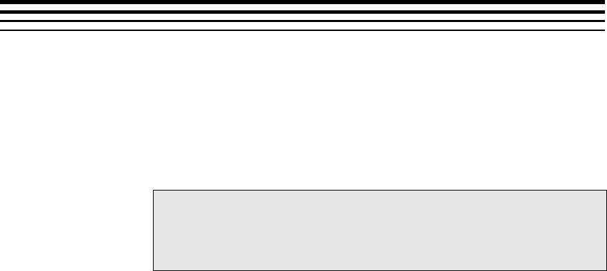
The following figure depicts the XDM interface to the client application.
As depicted in the figure, XDM is an extension to XDAIS and forms an
interface between the client application and the codec component. XDM
insulates the client application from component-level changes. Since TI’s
multimedia algorithms are XDM compliant, it provides you with the flexibility
to use any TI algorithm without changing the client application code. For
example, if you have developed a client application using an XDM-compliant
MPEG4 video decoder, then you can easily replace MPEG4 with another
XDM-compliant video decoder, say H.263, with minimal changes to the
client application.
For more details, see eXpressDSP Digital Media (XDM) Standard API
Reference (literature number SPRUEC8).
Client Application
XDAIS Interface (IALG)
TI’s Codec Algorithms
XDM Interface

Introduction
1-4
1.1.3 IRES Overview
IRES is a generic, resource-agnostic, extendible resource query,
initialization and activation interface. The application framework defines,
implements, and supports concrete resource interfaces in the form of IRES
extensions. Each algorithm implements the generic IRES interface, to
request one or more concrete IRES resources. IRES defines standard
interface functions that the framework uses to query, initialize,
activate/deactivate and reallocate concrete IRES resources. To create an
algorithm instance within an application framework, the algorithm and the
application framework agrees on the concrete IRES resource types that are
requested. The framework calls the IRES interface functions, in addition to
the IALG functions, to perform IRES resource initialization, activation, and
deactivation.
The IRES interface introduces support for a new standard protocol for
cooperative preemption, in addition to the IALG-style non-cooperative
sharing of scratch resources. Co-operative preemption allows activated
algorithms to yield to higher priority tasks sharing common scratch
resources. Framework components include the following modules and
interfaces to support algorithms requesting IRES-based resources:
IRES - Standard interface allowing the client application to query and
provide the algorithm with its requested IRES resources.
RMAN - Generic IRES-based resource manager, which manages
and grants concrete IRES resources to algorithms and applications.
RMAN uses a new standard interface, the IRESMAN, to support run-
time registration of concrete IRES resource managers.
Client applications call the algorithm’s IRES interface functions to query its
concrete IRES resource requirements. If the requested IRES resource type
matches a concrete IRES resource interface supported by the application
framework, and if the resource is available, the client grants the algorithm
logical IRES resource handles representing the allotted resources. Each
handle provides the algorithm with access to the resource as defined by the
concrete IRES resource interface.
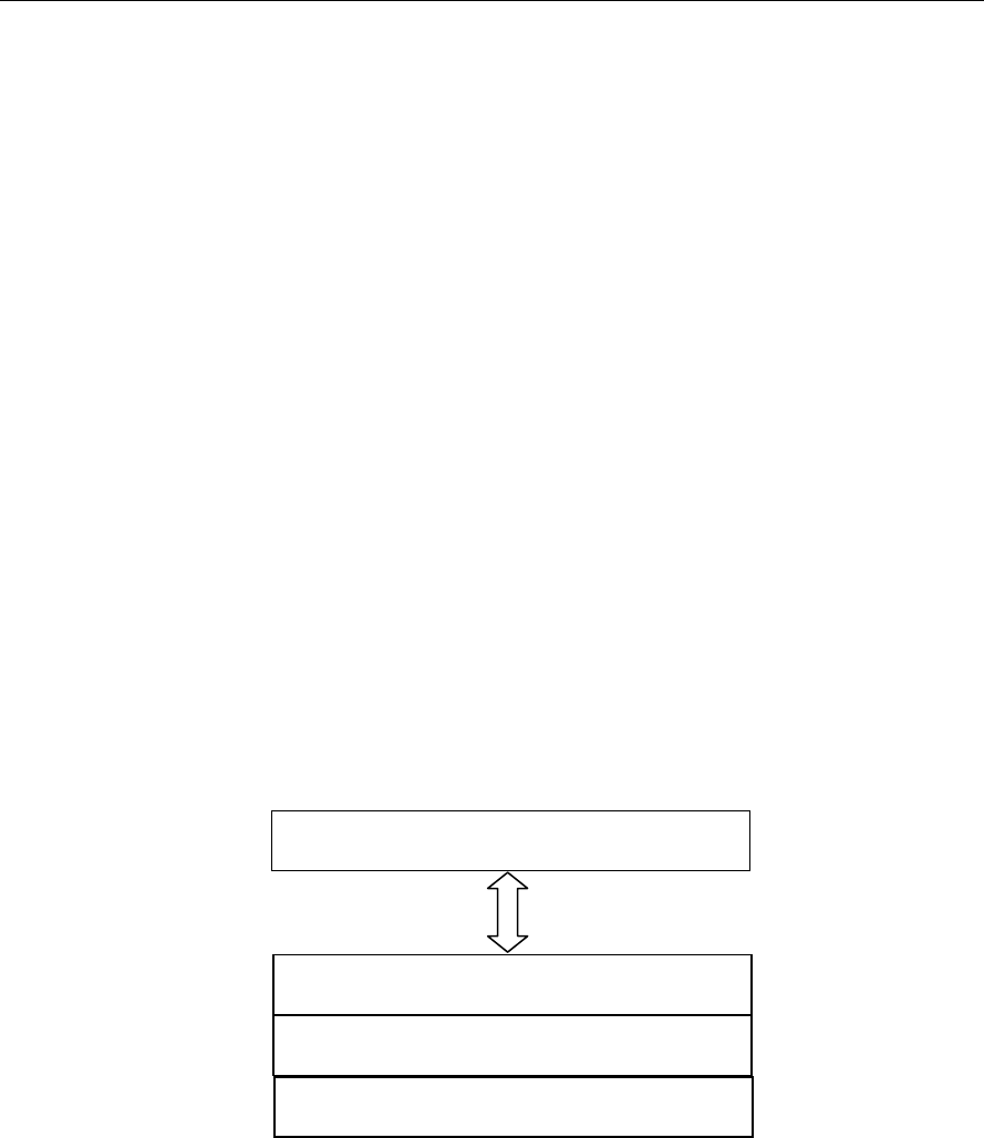
IRES interface definition and function calling sequence is depicted in the
following figure. For more details, see Using IRES and RMAN Framework
Components for C64x+ (literature number SPRAAI5).
Introduction
1-5
Figure 1-1. IRES Interface Definition and Function Calling Sequence.
For more details, see Using IRES and RMAN Framework Components for C64x+
(literature number SPRAAI5).
1.2 Overview of H.264 High Profile Decoder
H.264 (from ITU-T, also called as H.264/AVC) is a popular video coding
algorithm enabling high quality multimedia services on a limited bandwidth
network. H.264 standard defines several profiles and levels that specify
restrictions on the bit-stream and hence limits the capabilities needed to
decode the bit-streams. Each profile specifies a sub-set of algorithmic
features that limits all decoders conforming to that profile may support. Each
level specifies a set of limits on the values that may be taken by the syntax
elements in that profile.
Some important H.264 profiles and their special features are:
Baseline Profile:
o Only I and P type slices are present
o Only frame mode (progressive) picture types are present
o Only CAVLC is supported
Main Profile:
o Only I, P, and B type slices are present
o Frame and field picture modes (in progressive and interlaced modes)
picture types are present
o Both CAVLC and CABAC are supported

Introduction
1-6
High Profile:
o Only I, P, and B type slices are present
o Frame and field picture modes (in progressive and interlaced modes)
picture types are present
o Both CAVLC and CABAC are supported
o 8x8 transform supported
o Scaling matrices supported
The input to the decoder is a H.264 encoded bit-stream in the byte-stream
syntax. The byte-stream consists of a sequence of byte-stream NAL unit
syntax structures. Each byte-stream NAL unit syntax structure contains one
start code prefix of size four bytes and value 0x00000001, followed by one
NAL unit syntax structure. The encoded frame data is a group of slices,
each of which is encapsulated in NAL units. The slice consists of the
following:
Intra coded data: Spatial prediction mode and prediction error data that
is subjected to DCT and later quantized.
Inter coded data: Motion information and residual error data
(differential data between two frames) that is subjected to DCT and
later quantized.
The first frame received by the decoder is IDR (Instantaneous Decode
Refresh) picture frame. The decoder reconstructs the frame by spatial intra-
prediction specified by the mode and by adding the prediction error. The
subsequent frames may be intra or inter coded.
In case of inter coding, the decoder reconstructs the bit-stream by adding
the residual error data to the previously decoded image, at the location
specified by the motion information. This process is repeated until the entire
bit-stream is decoded. The output of the decoder is a YUV sequence, which
is of 420 semi-planar format (Y is a single plane and the Chroma data – cb
and cr are interleaved to form the other plane).
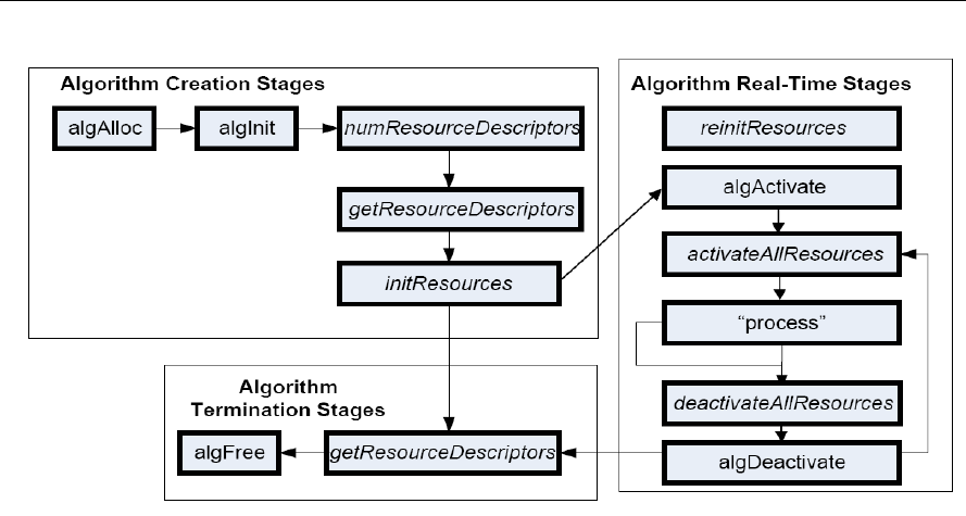
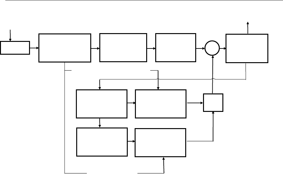
Figure 1-2 depicts the working of the decoder.
Introduction
1-7
Figure 1-2. Flow diagram of the H.264 Decoder
From this point onwards, all references to H.264 Decoder means H.264
High Profile Decoder only.
SW
Multiple
Previous
Picture Store
Motion
Compensation
Process
+
Motion Vectors
Spatial
Compensation
Process
Current
Picture Store
Spatial Prediction Modes
Video Bit-Stream
Buffer
Entropy
Decoding and
Demultiplexing
Inverse Scan
and
Quantization
Inverse
Transform
Deblocking
Filter
Video Out

Introduction
1-8
1.3 Supported Services and Features
This user guide accompanies TI’s implementation of H.264 Decoder on the
HDVICP2 based platform.
This version of the codec has the following supported features:
eXpressDSP Digital Media (XDM IVIDDEC3) compliant
Supports all features of the High Profile (HP)
Supports resolution up to 4320 x 4096
Supports progressive, interlaced, Picture Adaptive Frame Field
(PicAFF) and Macro-block Adaptive Frame Field (MBAFF) type picture
decoding.
Supports multiple slices and multiple reference frames
Supports CAVLC and CABAC decoding
Supports all intra-prediction and inter-prediction modes
Supports up to 16 MV per MB
Supports frame based decoding
Supports picture width and height (resolutions) greater than 64 pixels
including all standard resolutions.
Tested for compliance with JM version 10.1 reference decoder
Supports reference picture list reordering
Supports PCM macro block decoding
Supports graceful exit and error reporting under error conditions
Supports error concealment
Supports parse header functionality
Supports access to Parsed Supplemental Enhancement Information
(SEI) and Video Usability information (VUI) data
Supports YUV420 semi-planar chroma format
Supports memory management and control operations (MMCO)
Supports gaps in frame number
Independent of any Operating System
Ability to plug in any multimedia frameworks (For example, Codec
engine, OpenMax, GStreamer etc.)
Multiple instances of the decoder can be run simultaneously
Supports decoding of one frame each of multiple channels in a single
process call

Introduction
1-9
Supports skip functionality
Supports dynamic change in resolution
Supports configurable display delay for low delay applications
Supports low DDR footprint, in closed loop scenarios
Supports Data Sync at input and output
Supports limited decoding for Scalable Video Coding (SVC)
Supports parsing of stereo SEI and frame packing SEI
Supports configurable Loop Filtering option to save some cycles
Supports trace functionality to log information about last N frames
Supports dual (YUV) output
Supports decryption of watermarking key
This version of the decoder does not support the following features:
ASO/FMO functionality

Introduction
1-10
This page is intentionally left blank
2-1
Chapter 2
Installation Overview
This chapter provides a brief description on the system requirements and
instructions for installing the codec component. It also provides information
on building and running the sample test application.
Topic Page
2.1 System Requirements
2-2
2.2 Installing the Component
2-3
2.3 Before Building the Sample Test Application
2-4
2.4 Building and Running the Sample Test Application
2-5
2.5 Configuration Files
2-7
2.6 Uninstalling the Component
2-10

Installation Overview
2-2
2.1 System Requirements
This section describes the hardware and software requirements for the
normal functioning of the codec component.
2.1.1 Hardware
This codec (simulator release package) has been built and tested with
limited test cases on the HDVICP2 and Media Controller Based Platform.
2.1.2 Software
The following are the software requirements for the normal functioning of the
codec:
Development Environment: This project is developed using Code
Composer Studio (Code Composer Studio v4) version. 4.2.0.09000
Code Composer Studio v4 caN be downladed from the following
location.
http://software-
dl.ti.com/dsps/dsps_registered_sw/sdo_ccstudio/CCSv4/P
rereleases/setup_CCS_4.2.0.09000.zip
Code Generation Tools: This project is compiled, assembled,
archived, and linked using the code generation tools version 4.5.1.
Although CG tools version 4.5.1 is a part of Code Composer Studio v4,
It is recommended that you download and install the CG tools from the
following location
https://www-
a.ti.com/downloads/sds_support/CodeGenerationTools.htm
The project are built using g-make (GNU Make version 3.78.1)
Platform Simulator: This project is developed using DM81Xx/OMAP4
Simulator with CSP version 0.7.1. This release can be obtained by
software updates on Code Composer Studio v4. Make sure that
following site is listed as part of Update sites to visit.
http://software-
dl.ti.com/dsps/dsps_public_sw/sdo_ccstudio/CCSv4/Updates/NETRA/s
ite.xml
Installation Overview
2-3
2.2 Installing the Component
The codec component is released as a compressed archive. To install the
codec, extract the contents of the zip file onto your local hard disk. The zip
file extraction creates a top-level directory called
500.V.H264AVC.D.HP.IVAHD.02.00, under which another directory named
IVAHD_001 is created.
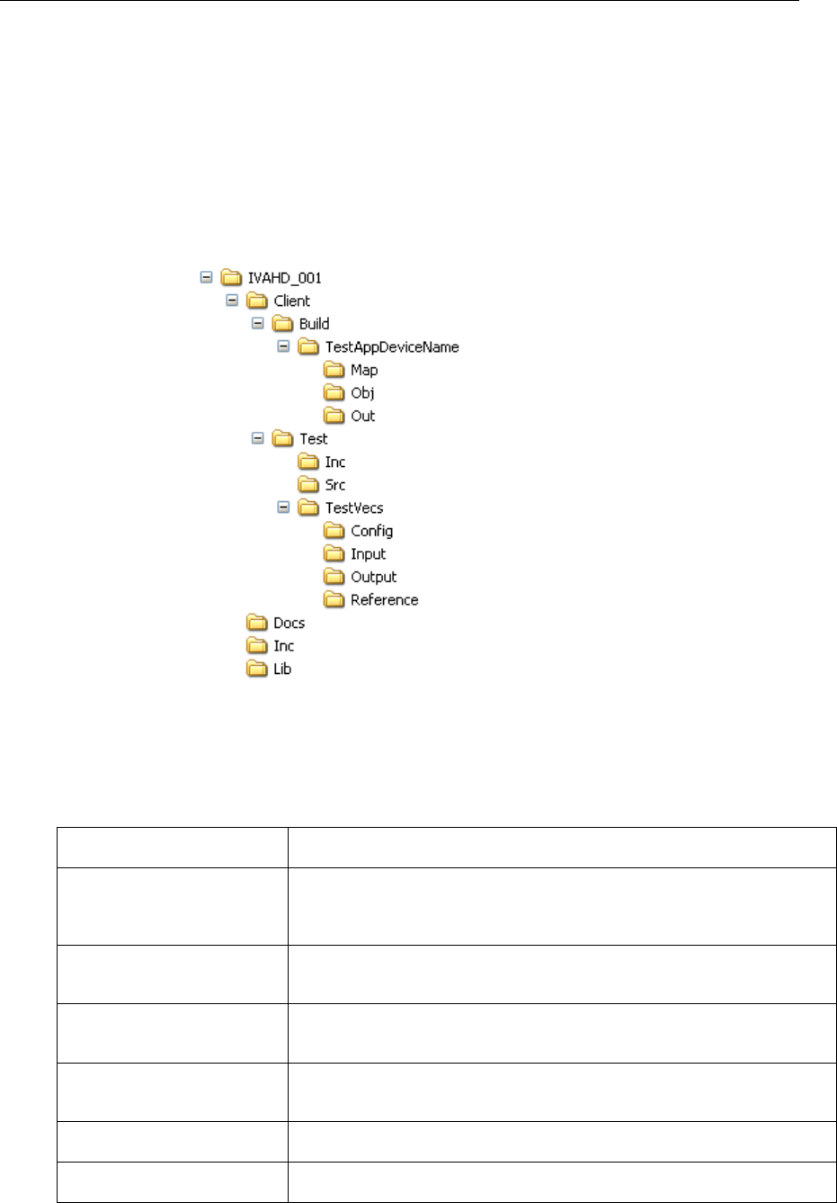
Figure 2-1 shows the sub-directories created in the IVAHD_001 folder.
Figure 2-1. Component Directory Structure
Table 2-1 provides a description of the sub-directories created in the
IVAHD_001 directory.
Table 2-1. Component Directories
Sub-Directory
Description
\Client\Build\TestAppDevice
Name
Contains the Code Composer Studio v4 project files. The name of this
directory will not be same as mentioned here. Instead of device name
string, and actual name of device will be present.
\Client\Build\TestAppDevice
Name \Map
Contains the memory map generated on compilation of the code
\Client\Build\TestAppDevice
Name \Obj
Contains the intermediate .asm and/or .obj file generated on compilation
of the code
\Client\Build\TestAppDevice
Name \Out
Contains the final application executable (.out) file generated by the
sample test application
\Client\Test\Inc
Contains header files needed for the application code
\Client\Test\Src
Contains application C files

Installation Overview
2-4
Sub-Directory
Description
\Client\Test\TestVecs\Config
Contains sample configuration file for H264 decoder
\Client\Test\TestVecs\Input
Contains input test vectors
\Client\Test\TestVecs\Output
Contains output generated by the codec. It is empty directory as part of
release.
\Client\Test\TestVecs\Refere
nce
Contains read-only reference files which is used for verifying against
codec output
\docs
Contains user guide and datasheet
\Inc
Contains H.264 decoder related header files which allow interface to the
codec library
\Lib
Contains the codec library file
2.3 Before Building the Sample Test Application
This codec is accompanied by a sample test application. To run the sample
test application, you need TI Framework Components (FC) and HDVICP2
library.
This version of the codec has been validated on Framework Component
(FC) version 3.20.00.22.
This version of the codec has been validated HDVICP2 library version
01.00.00.22.
2.3.1 Installing Framework Component (FC)
You can download FC from following website:
http://software-
dl.ti.com/dsps/dsps_public_sw/sdo_sb/targetcontent/fc/3_20_00_22/index_
FDS.html
Extract the FC zip file to the same location where you have installed Code
Composer Studio. For example:
<install directory>\CCStudio4.0
Set a system environment variable named FC_INSTALL_DIR pointing to
<install directory>\CCStudio4.0\<fc_directory>
The test application uses the following IRES and XDM files:
HDVICP related ires header files, these are available in the
<install directory>\CCStudio4.0\<fc_directory>\packages
\ti\sdo\fc\ires\hdvicp directory.

Installation Overview
2-5
Tiled memory related header file, these are available in the
<install directory>\CStudio4.0\<fc_directory>\fctools\packages
\ti\sdo\fc\ires\tiledmemory directory.
XDM related header files, these are available in the
<install directory>\CCStudio4.0\<fc_directory>\fctools\packages
\ti\xdais directory.
Memutils file for memory address translation, these are available in the
<install directory>\CStudio4.0\<fc_directory>\
packages\ti\sdo\fc\memutils directory
2.3.2 Installing HDVICP2 library
The HDVICP2 library should be available in the same place as the codec
package.
Set a system environment variable named HDVICP2_INSTALL_DIR
pointing to <hdvicp2_directory>\hdvicp20
The test application uses the HDVICP20 library file (ivahd_ti_api_vM3.lib)
from <hdvicp2_directory>\hdvicp20\lib directory
2.4 Building and Running the Sample Test Application
The sample test application that accompanies this codec component will run
in TI’s Code Composer Studio development environment. To build and run
the sample test application in Code Composer Studio, follow these steps:
1) Verify that you have installed TI’s Code Composer Studio version
4.2.0.09000 and code generation tools version 4.5.1.
2) Start Code Composer Studio and set up the target configuration for
platform specific simulator or emulator.
3) Verify that the following codec object libraries exist in \Lib sub-directory:
o h264vdec_ti.lib: H.264 decoder library for Media Controller
4) Open Code Composer Studio debug window with the appropriate
platform configuration chosen.
5) Build the sample test application project using gmake. The makefile is
present in Client\Build\TestAppDeviceName\make folder.
6) The above step creates an executable file, TestAppDecoder.out in the
\Client\Build\TestAppDeviceName\Out sub-directory.
7) Select Target > Load Program, browse to the \Client\Build\
TestAppDeviceName\Out sub-directory, select the codec executable
created in step 6, and load it onto Media Controller in Code Composer
Studio in preparation for execution. You need not load executables for
iCont1 and iCont2.

Installation Overview
2-6
8) If you are using sub-system simulator then ensure that iCONT1 and
iCONT2 are in running state, even without loading any program. If you
are using platform simulator or EVM then this step is not needed.
9) Select Target > Run on Video Media Controller to execute the sample
test application.
10) The sample test application takes the input files stored in the
\Client\Test\TestVecs\Input sub-directory, runs the codec, and uses the
reference files stored in the \Client\Test\TestVecs\Reference sub-
directory to verify that the codec is functioning as expected.
Note:
Order of triggering the processor to run is important and it should be
as mentioned in above steps.
On successful completion, if you had set the configuration to conformance
mode checking (see section 2.5), then the application displays the following
messages for every display frame:
o "--- Frame # <frame number> Passed ----"
o If output file mode is selected, then the output is written to the file
specified (this can then be manually compared against the
reference).
On failure, the application exits after decoding the frame in which codec
failed to generate correct result (for conformance check mode).

Installation Overview
2-7
2.5 Configuration Files
This codec is shipped along with:
Test Vecs file (Testvecs.cfg) – specifies list of test vectors to get
executed. Each test vector refers to configuration used to decode one
stream
Decoder configuration files (Ex: fruits_p352x288_4.cfg) – specifies the
configuration parameters used by the test application to configure the
Decoder and run a stream.
2.5.1 Test Vecs File
The sample test application shipped along with the codec uses Testvecs.cfg
which specifies list of test vectors to get executed.
A sample Testvecs.cfg file is as shown:
..\..\..\Test\TestVecs\Config\airshow_p176x144_1.cfg
..\..\..\Test\TestVecs\Config\airshow_p352x288_2.cfg
..\..\..\Test\TestVecs\Config\fruits_p176x144_3.cfg
..\..\..\Test\TestVecs\Config\fruits_p352x288_4.cfg
2.5.2 Decoder Configuration file
The decoder configuration file,.specifies the configuration parameters used
by the test application to configure the Decoder and run a stream
A sample decoder configuration file is as shown:
#################################################################
##
# Input and Output
#################################################################
##
inputBitStream =
"..\..\..\Test\TestVecs\Input\fruits_p352x288.264"
outputYUV =
"..\..\..\Test\TestVecs\Output\fruits_p352x288.yuv"
outputDualYUV =
"..\..\..\Test\TestVecs\Output\fruits_p352x288_Dual.yuv"
WaterMarkFile =
"..\..\..\Test\TestVecs\Output\fruits_p352x288_Watermark.bin"
referenceYUV =
"..\..\..\Test\TestVecs\Reference\fruits_p352x288.yuv"
frameSizeFile =
"..\..\..\Test\TestVecs\Input\fruits_p352x288.txt"
TestCompliance = 0 # 0->Dump Mode ,1->[Compare Mode
Not supported]
#################################################################
##
# Create Time Parameters
#################################################################
##
maxHeight = 1088 # Max Image height in Pels
maxWidth = 1920 # Max Image width in Pels
maxFrameRate = 30 # 30 -> Frame rate in fps

Installation Overview
2-8
maxBitRate = 10485760 # Maximum Bit rate in Bytes
dataEndianness = 1 # 1 -> 8-bit Big Endian stream.
forceChromaFormat = 9 # 9 -> XDM_YUV_420SP
operatingMode = 0 # 0 -> Decode Mode, 2->Transcode
displayDelay = 16 # 0 -> No delay (Decode order)
inputDataMode = 3 # 3->Frame Mode, 0,1 -> Sub-
Frame (DataSync) Mode
outputDataMode = 3 # 3->Frame Mode, 2 -> Sub-Frame
(DataSync) Mode
numInputDataUnits = 0 # 0 -> Non-DS mode. Non-Zero
positive for DS mode
numOutputDataUnits = 0 # 0 -> Non-DS mode. Non-Zero
positive for DS mode
errorInfoMode = 0 # 0 -> Error Info off
displayBufsMode = 2 # 1 -> Embedded, 2 - Pointer to
struct
dpbSizeInFrames = -1 # -1 -> Default, otherwise any
non-Negative 0-16
bitStreamFormat = 0 # 0 -> Non-NAL mode, 1-> NAL
mode
errConcealmentMode = 1 # 0 -> Disable EC, 1-> enable EC
temporalDirModePred = 1 # 0 -> Detect temporal direct
mode & report
metadataType_0 = -1 # -1->No Metadata, 0-SEI, 1-VUI,
2-MB Info
metadataType_1 = -1 # -1->No Metadata, 0-SEI, 1-VUI,
2-MB Info
metadataType_2 = -1 # -1->No Metadata, 0-SEI, 1-VUI,
2-MB Info
svcExtensionFlag = 0 # 0 -> Disable, 1-> Enable
svcTargetLayerDID = -1 # -1 -> Default, 0-7 supported
svcTargetLayerTID = -1 # -1 -> Default, 0-7 supported
svcTargetLayerQID = -1 # -1 -> Default, 0-15 supported
presetLevelIdc = 12 # 12 -> Default, 0-15 supported
presetProfileIdc = 2 # 2 -> High Profile
detectCabacAlignErr = 0 # 0 -> disable, 1->enable
detectIPCMAlignErr = 0 # 0 -> disable, 1->enable
debugTraceLevel = 0 # 0 - 4 supported
LastNFramesToLog = 0 # Number of Frames to log the
Debug Trace
enableDualOutput = 1 # 1 -> Enable Dual YUV dump, 2 -
Enable Dual YUV dump with 16-byte alignment, 0 -> Disable Dual
YUV dump
processCallLevel = 0 # 0 -> field level process call,
1 -> frame level process call
enableWatermark = 0 # 1 -> Enable Watermark, 0 ->
Disable Watermark
decodeFrameType = 0 # 2 - > Enable decoding of only I/IDR
frames, 1 -> Enable decoding only I/IDR and P frames , 0 ->
Enable decoding of all frame types (Default)
#################################################################
##
# Dynamic Parameters
#################################################################
##
decodeHeader = 0 # 0 -> Disable decode Header
mode
displayWidth = 0 # 0->Default, otherwise Positive
value
frameSkipMode = 0 # 9 -> Skip non-reference, 0->
No skip
newFrameFlag = 1 # 1 -> True, 0-> false
lateAcquireArg = 0 # 0->Default

Installation Overview
2-9
deblockFilterMode = 3 # 3 -> Default, supports 0,1 and
2 as well
DynSvcTargetLayerDID = -1 # -1 -> Default, 0-7 Supported
DynSvcTargetLayerTID = -1 # -1 -> Default, 0-7 Supported
DynSvcTargetLayerQID = -1 # -1 -> Default, 0-15 Supported
DynSvcELayerDecode = 0 # 0 -> Disable, 1 -> Enable
DynRsvd0 = 0 # 0 -> Default, reserved one for
future use
DynRsvd1 = 0 # 0 -> Default, reserved one for
future use
DynRsvd2 = 0 # 0 -> Default, reserved one for
future use
#################################################################
##
# Application Control Parameters
#################################################################
##
SeiDataWriteMode = 0 # 0->Parse 1->Encoded dump
VuiDataWriteMode = 0 # 0->Parse 1->Encoded dump
MbInfoWriteMode = 0 # 0->disable mbinfo dump 1-
>Enable mbinfo dump
TilerEnable = 0 # 0 -> Disable, 1->Enable TILER
DualTilerEnable = 0 # 0 -> Disable, 1->Enable TILER
(both op is treated as tiler.so this is Valid only when
TilerEnable is 1)
ChromaTilerMode = 0 # 0 -> 16-Bit mode, 1->8-Bit
Mode
BitStreamMode = 0 # 0 -> Buffer Mode, 1->Frame
size Mode
NumFramesToDecode = 8000 # 8000 -> Default
parBoundCheck = 0 # Parameter Boundary check: 0 ->
Disable, 1-> Enable
parExpectedStatus = 0 # Expected Status during Param
Boundary check. 0->Pass, -1 -> Fail
exitLevel = 0 # 1->Create Time, 2->XDM control
time
xdmReset = 0 # 0->Disable XDM reset use, 1-
>Enable XDM reset use
DumpFrom = 0 # 0 -> Default, frame number to
dump from
CRCEnable = 0 # CRC check: 0 -> Disable, 1-
>Enable
ProfileEnable = 0 # Frame level Profiling: 0 ->
Disable, 1->Enable
BaseClassOnly = 0 # 0 -> Use Extended classes, 1-
>Use Base classes Only
DDRConstLocation = 0 # 0->No specific location, 1-
>Specific address for constants
ivahdID = 0 # 0-> Default. Supports 1 & 2
for Netra
AppRsvd0 = 0 # 0 -> Default, reserved one for
future use
Note:
All the settings mentioned in decoder config file are not supported in this
version of release. See Section 1.3 Supported Services and Features for
details on list of supported features in this version of H264 Decoder.

Installation Overview
2-10
2.6 Uninstalling the Component
To uninstall the component, delete the codec directory from your hard disk.

Sample Usage
3-11
Sample Usage
This chapter provides a detailed description of the sample test application
that accompanies this codec component.
Topic Page
2.7 Overview of the Test Application
3-12
2.8 Frame Buffer Management by Application
3-16
2.9 Handshaking Between Application and Algorithm
3-19
2.10 Sample Test Application
3-20
Sample Usage
3-12
2.7 Overview of the Test Application
The test application exercises the IVIDDEC3 base class of the H.264
Decoder library.
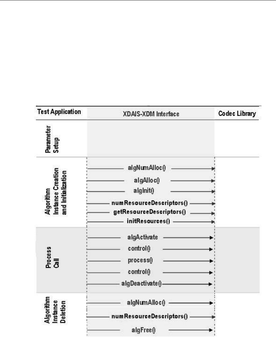
Figure 2-1 depicts the sequence of APIs exercised in the sample test
application. Currently, the test application does not use RMAN resource
manager. However, all the resource allocations happens through IRES
interfaces.
Figure 2-1. Test Application Sample Implementation

Sample Usage
3-13
The test application is divided into four logical blocks:
Parameter setup
Algorithm instance creation and initialization
Process call
Algorithm instance deletion
2.7.1 Parameter Setup
Each codec component requires various codec configuration parameters to
be set at initialization. For example, a video codec requires parameters such
as video height, video width, and so on. The test application obtains the
required parameters from the Decoder configuration files.
In this logical block, the test application does the following:
Opens the generic configuration file, Testvecs.cfg and reads the compliance
checking parameter, Decoder configuration file name (Testparams.cfg),
input file name, and output/reference file name.
Opens the Decoder configuration file, (Testparams.cfg) and reads the
various configuration parameters required for the algorithm. For more details
on the configuration files, see Section 2.5.
Sets the IVIDDEC3_Params structure based on the values it reads from the
Testparams.cfg file.
Reads the input bit-stream into the application input buffer.
After successful completion of these steps, the test application does the
algorithm instance creation and initialization.
2.7.2 Algorithm Instance Creation and Initialization
In this logical block, the test application accepts the various initialization
parameters and returns an algorithm instance pointer. The following APIs
are called in sequence:
algNumAlloc() - To query the algorithm about the number of memory
records it requires.
algAlloc() - To query the algorithm about the memory requirement to be
filled in the memory records.
algInit() - To initialize the algorithm with the memory structures provided
by the application.
A sample implementation of the create function that calls algNumAlloc(),
algAlloc(), and algInit() in sequence is provided in the
ALG_create() function implemented in the alg_create.c file.

Sample Usage
3-14
Note:
Decoder requests only one memory buffer through algNumAlloc.
This buffer is for the algorithm handle.
Other memory buffer requirements are done through IRES
interfaces.
After successful creation of the algorithm instance, the test application does
HDVICP Resource and memory buffer allocation for the algorithm.
Currently, RMAN resource manager is not used. However, all the resource
allocations happen through IRES interfaces:
numResourceDescriptors() - To understand the number of resources
(HDVICP and buffers) needed by algorithm.
getResourceDescriptors() – To get the attributes of the resources.
initResources() - After resources are created, application gives the
resources to algorithm through this API.
2.7.3 Process Call
After algorithm instance creation and initialization, the test application does
the following:
Sets the dynamic parameters (if they change during run-time) by calling the
control() function with the XDM_SETPARAMS command.
Sets the input and output buffer descriptors required for the
process()function call. The input and output buffer descriptors are
obtained by calling the control() function with the XDM_GETBUFINFO
command.
Implements the process call based on the non-blocking mode of operation
explained in step 4. The behavior of the algorithm can be controlled using
various dynamic parameters (see Section 3.2.1.9). The inputs to the
process()functions are input and output buffer descriptors, pointer to the
IVIDDEC3_InArgs and IVIDDEC3_OutArgs structures.
On the call to the process() function for encoding/decoding a single frame
of data, the software triggers the start of encode/decode. After triggering the
start of the encode/decode frame, the video task can be put to SEM-pend
state using semaphores. On receipt of interrupt signal at the end of frame
encode/decode, the application releases the semaphore and resume the
video task, which does any book-keeping operations by the codec and
updates the output parameter of IVIDDEC3_OutArgs structure.
Sample Usage
3-15
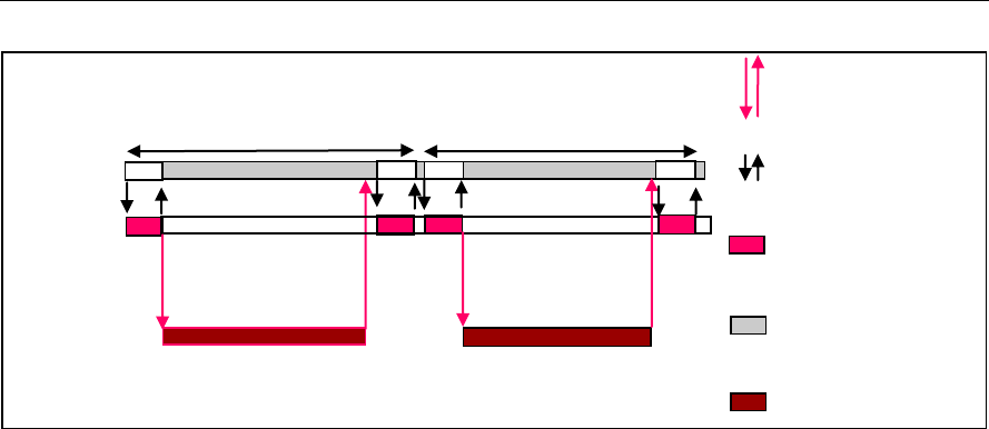
Figure 2-2. Process call with Host release
The control() and process() functions should be called only within the
scope of the algActivate() and algDeactivate() XDAIS functions
which activate and deactivate the algorithm instance respectively. Once an
algorithm is activated, there could be any ordering of control() and
process() functions. The following APIs are called in a sequence:
algActivate() - To activate the algorithm instance.
control() (optional) - To query the algorithm on status or setting of
dynamic parameters and so on, using the six available control commands.
process() - To call the Decoder with appropriate input/output buffer and
arguments information.
control() (optional) - To query the algorithm on status or setting of
dynamic parameters and so on, using the six available control commands.
algDeactivate() - To deactivate the algorithm instance.
The do-while loop encapsulates picture level process() call and updates
the input buffer pointer every time before the next call. The do-while loop
breaks off either when an error condition occurs or when the input buffer
exhausts. It also protects the process() call from file operations by placing
appropriate calls for cache operations. The test application does a cache
invalidate for the valid input buffers before process() and a cache write
back invalidate for output buffers after a control() call with GET_STATUS
command.
In the sample test application, after calling algDeactivate(), the output
data is either dumped to a file or compared with a reference file.
Host
System
application
Process call frame n
HDVICP
Tasks
MB level tasks for
frame n
Host Video
Task
Transfer of
tasks at Host
MB level tasks for
frame n+1
Process call frame n+1
Host system
tasks
HDVICP Busy
Interrupt between
HDVICP and Host

Sample Usage
3-16
2.7.4 Algorithm Instance Deletion
Once decoding/encoding is complete, the test application frees the memory
resources and deletes the current algorithm instance. The following APIs
are called in sequence:
numResourceDescriptors() - To get the number of resources and free
them. If the application needs handles to the resources, it can call
getResourceDescriptors().
algNumAlloc() - To query the algorithm about the number of memory
records it used.
algFree() - To query the algorithm for memory, to free when removing an
instance.
A sample implementation of the delete function that calls algNumAlloc()
and algFree() in sequence is provided in the ALG_delete() function
implemented in the alg_create.c file.
2.8 Frame Buffer Management by Application
2.8.1 Frame Buffer Input and Output
With the new XDM, decoder does not ask for frame buffer at the time of
alg_create(). It uses buffer from XDM2_BufDesc *outBufs, which it
reads during each decode process call. Hence, there is no distinction
between DPB and display buffers. The framework needs to ensure that it
does not overwrite the buffers that are locked by the codec.
H264VDEC_create();
H264VDEC_control(XDM_GETBUFINFO); /* Returns default 1080p
HD size */
do{
H264VDEC_decode(); //call the decode API
H264VDEC_control(XDM_GETBUFINFO); /* updates the memory
required as per the size parsed in stream header */
}
while(all frames)
Note:
Application can take the information retured by the control function
with the XDM_GETBUFINFO command and change the size of the
buffer passed in the next process call.
The output luma buffer size required is :
((width + (2*PADX))alligned to 128 byte
bondary)*(height + (4*PADY))
where PADX =32 and PADY = 24. For chroma buffer, the height
and PADY need to be halved. This assumes worst case padding
requirement, That is, for inetrlaced coding. For the first
GETBUFINFO call, maxheight and maxwidth are used for
calculating buffer size. For subsequent GETBUFINFO calls (That is,

Sample Usage
3-17
after the first process call, when the decoder gets to know the
actual height and width from the headers) the actual height and
with are used. Hence, this can be optionally used by the
application to re allocate the buffer sizes, if required.
Application can re-use the extra buffer space of the 1st frame, if
the above control call returns a small size than that was provided.
The frame pointer given by the application and that returned by the
algorithm may be different. BufferID (InputID/outputID) provides the
unique ID to keep a record of the buffer given to the algorithm and released
by the algorithm.
As explained above, buffer pointer cannot be used as a unique identifier to
keep a record of frame buffers. Any buffer given to algorithm should be
considered locked by algorithm, unless the buffer is returned to the
application through IVIDDEC3_OutArgs->freeBufID[].
Note:
BufferID returned in IVIDDEC3_OutArgs ->outputID[] is only for
display purpose. Application should not consider it free unless it is a part
of IVIDDEC3_OutArgs->freeBufID[].
2.8.2 Frame Buffer Format
The frame buffer format to be used for both progressive and interlaced
pictures is explained in the Appendix on Picture Format.
2.8.3 Address Translations
The buffers addresses (DDR addresses) as seen by Media Controller and
IVA-HD (VDMA) will be different. Hence, address translations are needed to
convert from one address view to another. The application implements a
MEMUTILS function for this address translation ( which will be later
implemented by the framework components). An example of the address
translation function is as shown. The codec will make a call to this function
from the host (Media Controller) library. Therefore, the function name and
arguments will follow the example as shown in the following code snippet.
For a given input address, the function returns the VDMA view of the buffer
(that is, address as seen by HDVICP2).
void *MEMUTILS_getPhysicalAddr(Ptr Addr)
{
return ((void *)((unsigned int)Addr & VDMAVIEW_EXTMEM));
}
Sample Usage
3-18
Sample settings for the macro VDMAVIEW_EXTMEM is as shown in the
following code snippet.
#if defined(HOST_M3)
#define VDMAVIEW_EXTMEM (0xFFFFFFFF)
#else
#define VDMAVIEW_EXTMEM (0x07FFFFFF)
#endif
2.8.4 Frame Buffer Management by Application
The application framework can efficiently manage frame buffers by keeping
a pool of free frames from which it gives the decoder empty frames on
request.
Figure 2-3. Interaction of Frame Buffers Between Application and Framework
The sample application also provides a prototype for managing frame
buffers. It implements the following functions, which are defined in file
TestApp_bufmanager.c provided along with test application.
BUFFMGR_Init() - BUFFMGR_Init function is called by the test
application to initialize the global buffer element array to default and to
allocate the required number of memory data for reference and output
buffers. The maximum required DPB size is defined by the supported
profile and level.
BUFFMGR_ReInit() - BUFFMGR_ReInit function allocates global luma
and chroma buffers and allocates entire space to the first element. This
element will be used in the first frame decode. After the picture height
and width and its luma and chroma buffer requirements are obtained,
the global luma and chroma buffers are re-initialized to other elements
in the buffer array.
BUFFMGR_GetFreeBuffer() - BUFFMGR_GetFreeBuffer function
searches for a free buffer in the global buffer array and returns the
address of that element. Incase none of the elements are free, then it
returns NULL.
Video Decode
Thread
Free
Frame
Buffers
Post
Processing or
Display
Subsystem
Video Decoder
XDM API
GetFreeBuffer( )
ReleaseBuffer( )
Framework
Algorithm

Sample Usage
3-19
BUFFMGR_ReleaseBuffer() - BUFFMGR_ReleaseBuffer function
takes an array of buffer-IDs which are released by the test application.
0 is not a valid buffer ID, hence this function moves until it encounters
a buffer ID as zero or it hits the MAX_BUFF_ELEMENTS.
BUFFMGR_DeInit()- BUFFMGR_DeInit function releases all memory
allocated by buffer manager.
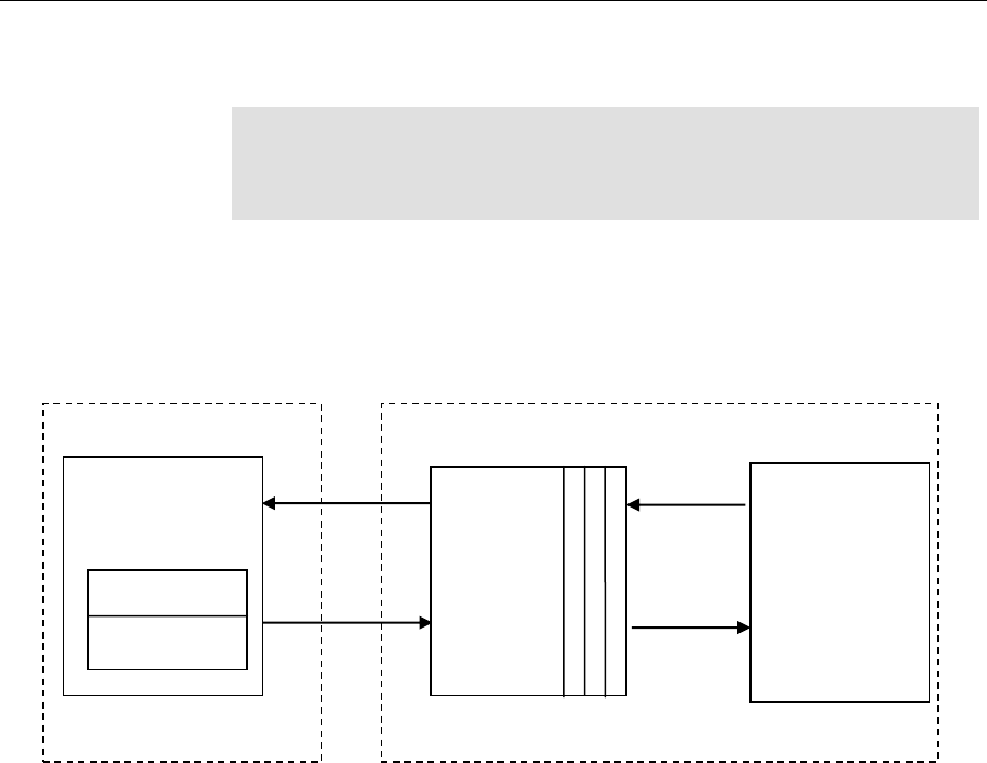
2.9 Handshaking Between Application and Algorithm
Application provides the algorithm with its implementation of functions for
the video task to move to SEM-pend state, when the execution happens in
the co-processor. The algorithm calls these application functions to move
the video task to SEM-pend state.
Figure 2-4. Interaction Between Application and Codec
Note:
Process call architecture to share Host resource among multiple
threads.
ISR ownership is with the Host layer resource manager – outside the
codec.
The actual codec routine to be executed during ISR is provided by the
codec.
OS/System related calls (SEM_pend, SEM_post) also outside the
codec.
Codec implementation is OS independent.
The functions to be implemented by the application are:
Framework Provided
HDVICP Callback APIs
process()
Application Side
Codec
#include <…/ires_hdvicp.h>
void _MyCodecISRFunction();
MYCODEC::IVIDDEC3::process() {
:
//Call to Acquire API */
HDVICP_Acquire(handle,
iresHandle, yieldCtxt,
reloadHDVICP);
…. set up for frame decode
HDVICP_Configure(h264d, h264d-
>hdvicpHandle,
H264DISRFunction);
HDVICP_Wait(h264D, h264d-
>hdvicpHandle);
// Release of HOST
…. End of frame processing
}
void H264DISRFunction(IALG_Handle
handle)
{ H264D_TI_Obj *h264d = (void
*)handle;
HDVICP_done(h264d ,
h264d-
>hdvicpHandle);
}
int _doneSemaphore;
HDVICP_configure(handle,
hdVicpHandle, ISRFunction){
installNonBiosISR(handle,
hdvicpHandle, ISRFunction);
}
HDVICP_Wait(handle,
hdVicpHandle){
SEM_pend(_doneSemaphore);
}
HDVICP_Done(handle,
hdVicpHandle) {
SEM_post(_doneSemaphore)
}

Sample Usage
3-20
void HDVICP_Acquire(IALG_Handle handle,
IRES_HDVICP2_Handle iresHandle, IRES_YieldContext *
yieldCtxt, Bool *reloadHDVICP)
This function is called by the algorithm to acquire the HDVICP2
resource.
HDVICP_Configure(IALG_Handle handle,
IRES_HDVICP2_Handle iresHandle,
void(*IRES_HDVICP2_CallbackFxn)(IALG_Handle handle,
void *cbArgs), void *cbArgs)
This function is called by the algorithm to register its ISR function,
which the application needs to call when it receives interrupts
pertaining to the video task.
HDVICP_Wait (void *hdvicpHandle)
This function is called by the algorithm to move the video task to SEM-
pend state.
HDVICP_Done (void *hdvicpHandle)
This function is called by the algorithm to release the video task from
SEM-pend state. In the sample test application, these functions are
implemented in hdvicp_framework.c file. The application can
implement it in a way considering the underlying system.
Bool HDVICP_Reset(IALG_Handle handle,
IRES_HDVICP2_Handle iresHandle).
This function is called by the algorithm to reset the HDVICP2 resource.
2.10 Sample Test Application
The test application exercises the IVIDDEC3 base class of the H.264
Decoder.
Table 2-1. Process() Implementation.
/*Main Function acting as a client for Video Decode Call*/
BUFFMGR_Init();
TestApp_SetInitParams(¶ms.viddecParams);
/*---------------- Decoder creation -----------------*/
handle = (IALG_Handle) H264VDEC_create();
/* Get Buffer information */
H264VDEC_control(handle, XDM_GETBUFINFO);
/* Do-While Loop for Decode Call for a given stream */
do
{
/* Read the bitstream in the Application Input Buffer */
validBytes = ReadByteStream(inFile);

Sample Usage
3-21
/* Get free buffer from buffer pool */
buffEle = BUFFMGR_GetFreeBuffer();
/* Optional: Set Run-time parameters in the Algorithm via
control() */
H264VDEC_control(handle, XDM_SETPARAMS);
/*----------------------------------------------------*/
/* Start the process : To start decoding a frame */
/*----------------------------------------------------*/
retVal = H264DEC_decodeFrame
(
handle,
(XDM2_BufDesc *)&inputBufDesc,
(XDM_BufDesc *)&outputBufDesc,
(IVIDDEC3_InArgs *)&inArgs,
(IVIDDEC3_OutArgs *)&outArgs
);
/* Get the statatus of the decoder using comtrol */
H264VDEC_control(handle, IH264VDEC_GETSTATUS);
/* Get Buffer information : */
H264VDEC_control(handle, XDM_GETBUFINFO);
/* Optional: Reinit the buffer manager in case the
/* frame size is different */
BUFFMGR_ReInit();
/* Always release buffers - which are released from
/* the algorithm side -back to the buffer manager
*/
BUFFMGR_ReleaseBuffer((XDAS_UInt32
*)outArgs.freeBufID);
} while(1);
/* end of Do-While loop - which decodes frames */
ALG_delete (handle);
BUFFMGR_DeInit();
Note:
This sample test application does not depict the actual function
parameter or control code. It shows the basic flow of the code.

Sample Usage
3-22
This page is intentionally left blank
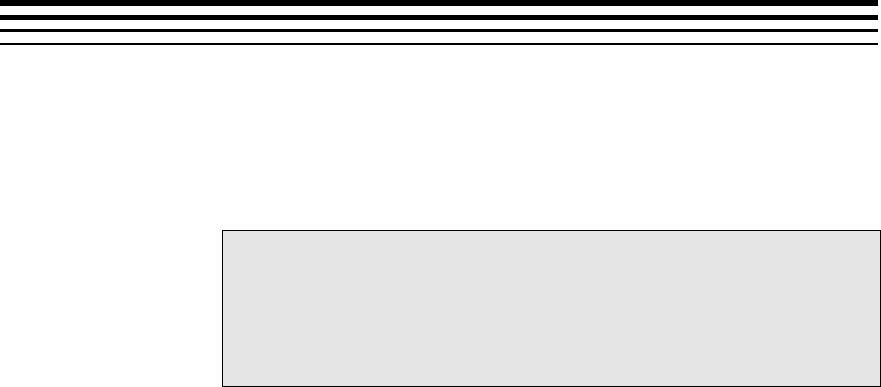
4-1
Chapter 3
API Reference
This chapter provides a detailed description of the data structures and
interfaces functions used in the codec component.
Topic Page
3.1 Symbolic Constants and Enumerated Data Types
4-2
3.2 Data Structures
4-15
3.3 Default and Supported Parameters
4-54
3.4 Interface Functions
4-59

API Reference
4-2
3.1 Symbolic Constants and Enumerated Data Types
This section describes the XDM defined enumerated data types and H264
decoder specific enumerated data types.
Table 3-1. List of Enumerated Data Types
Group or Enumeration Class
Symbolic Constant Name
Description or Evaluation
IVIDEO_FrameType
IVIDEO_NA_FRAME
Frame type not available
IVIDEO_I_FRAME
Intra coded frame
IVIDEO_P_FRAME
Forward inter coded frame
IVIDEO_B_FRAME
Bi-directional inter coded frame
IVIDEO_IDR_FRAME
Intra coded frame that can be used
for refreshing video content
IVIDEO_II_FRAME
Interlaced Frame, both fields are I
frames
IVIDEO_IP_FRAME
Interlaced Frame, first field is an I
frame, second field is a P frame
IVIDEO_IB_FRAME
Interlaced Frame, first field is an I
frame, second field is a B frame
IVIDEO_PI_FRAME
Interlaced Frame, first field is a P
frame, second field is a I frame
IVIDEO_PP_FRAME
Interlaced Frame, both fields are P
frames
IVIDEO_PB_FRAME
Interlaced Frame, first field is a P
frame, second field is a B frame
IVIDEO_BI_FRAME
Interlaced Frame, first field is a B
frame, second field is an I frame.
IVIDEO_BP_FRAME
Interlaced Frame, first field is a B
frame, second field is a P frame
IVIDEO_BB_FRAME
Interlaced Frame, both fields are B
frames
IVIDEO_MBAFF_I_FRAME
Intra coded MBAFF frame
IVIDEO_MBAFF_P_FRAME
Forward inter coded MBAFF frame
IVIDEO_MBAFF_B_FRAME
Bi-directional inter coded MBAFF
frame

API Reference
4-3
Group or Enumeration Class
Symbolic Constant Name
Description or Evaluation
IVIDEO_MBAFF_IDR_FRAME
Intra coded MBAFF frame that can
be used for refreshing video content.
IVIDEO_FRAMETYPE_DEFAUL
T
Default set to IVIDEO_I_FRAME
IVIDEO_ContentType
IVIDEO_CONTENTTYPE_NA
Content type is not applicable
IVIDEO_PROGRESSIVE
IVIDEO_PROGRESSIVE_FRAM
E
Progressive video content
IVIDEO_INTERLACED
IVIDEO_INTERLACED_FRAME
Interlaced video content
IVIDEO_INTERLACED_TOPFI
ELD
Interlaced video content, Top field
IVIDEO_INTERLACED_BOTTO
MFIELD
Interlaced video content, Bottom
field
IVIDEO_CONTENTTYPE_DEFA
ULT
Default set to
IVIDEO_PROGRESSIVE
IVIDEO_FrameSkip
IVIDEO_NO_SKIP
Do not skip the current frame.
Default Value
IVIDEO_SKIP_P
Skip forward inter coded frame.
IVIDEO_SKIP_B
Skip bi-directional inter coded frame.
IVIDEO_SKIP_I
Skip intra coded frame.
IVIDEO_SKIP_IP
Skip I and P frame/field(s)
IVIDEO_SKIP_IB
Skip I and B frame/field(s).
IVIDEO_SKIP_PB
Skip P and B frame/field(s).
IVIDEO_SKIP_IPB
Skip I/P/B/BI frames
IVIDEO_SKIP_IDR
Skip IDR Frame
IVIDEO_SKIP_NONREFERENC
E
Skip non reference frame.
IVIDEO_SKIP_DEFAULT
Default set to IVIDEO_NO_SKIP
IVIDEO_VideoLayout
IVIDEO_FIELD_INTERLEAVE
D
Buffer layout is interleaved.
IVIDEO_FIELD_SEPARATED
Buffer layout is field separated.
IVIDEO_TOP_ONLY
Buffer contains only top field.

API Reference
4-4
Group or Enumeration Class
Symbolic Constant Name
Description or Evaluation
IVIDEO_BOTTOM_ONLY
Buffer contains only bottom field
IVIDEO_OperatingMode
IVIDEO_DECODE_ONLY
Decoding Mode
IVIDEO_ENCODE_ONLY
Encoding Mode
IVIDEO_TRANSCODE_FRAMEL
EVEL
Transcode Mode of operation
(encode/decode), which consumes
/generates transcode information at
the frame level.
IVIDEO_TRANSCODE_MBLEVE
L
Transcode Mode of operation
(encode/decode), which consumes
/generates transcode information at
the MB level.
IVIDEO_TRANSRATE_FRAMEL
EVEL
Transrate Mode of operation for
encoder, which consumes transrate
information at the frame level.
IVIDEO_TRANSRATE_MBLEVE
L
Transrate Mode of operation for
encoder, which consumes transrate
information at the MB level.
IVIDEO_OutputFrameStatus
IVIDEO_FRAME_NOERROR
Output buffer is available.
IVIDEO_FRAME_NOTAVAILAB
LE
Codec does not have any output
buffers.
IVIDEO_FRAME_ERROR
Output buffer is available and
corrupted.
IVIDEO_FRAME_OUTPUTSKIP
The video frame was skipped (that
is not decoded)
IVIDEO_OUTPUTFRAMESTATU
S_DEFAULT
Default set to
IVIDEO_FRAME_NOERROR
IVIDEO_PictureType
IVIDEO_NA_PICTURE
Frame type not available
IVIDEO_I_PICTURE
Intra coded picture
IVIDEO_P_PICTURE
Forward inter coded picture
IVIDEO_B_PICTURE
Bi-directional inter coded picture
IVIDEO_DataMode
IVIDEO_FIXEDLENGTH
Input to the decoder is in multiples
of a fixed length (example, 4K)
(input side for decoder)
IVIDEO_SLICEMODE
Slice mode of operation (Input side
for decoder).

API Reference
4-5
Group or Enumeration Class
Symbolic Constant Name
Description or Evaluation
IVIDEO_NUMROWS
Number of rows, each row is 16
lines of video (output side for
decoder).
IVIDEO_ENTIREFRAME
Processing of entire frame data
IVIDEO_DecodeMode
IVIDEO_DECODE_ONLY
Decoding mode.
IVIDEO_ENCODE_ONLY
Encoding mode.
IVIDEO_TRANSCODE_FRAME
LEVEL
Transcode mode of operation
encode/decode) which
consumes/generates transcode
information at the frame level.
IVIDEO_TRANSRATE_FRAME
LEVEL
Transcode mode of operation
encode/decode) which
consumes/generates transcode
information at the MB level.
IVIDEO_TRANSRATE_MBLEV
EL
Transrate mode of operation
encode/decode) which
consumes/generates transcode
information at the Frame level.
IVIDEO_TRANSCODE_MBLEV
EL
Transrate mode of operation
encode/decode) which
consumes/generates transcode
information at the MB level.
IVIDDEC3_displayDelay
IVIDDEC3_DISPLAY_DELAY_
AUTO
Decoder decides the display delay
IVIDDEC3_DECODE_ORDER
Display frames are in decoded order
without delay
IVIDDEC3_DISPLAY_DELAY_
1
Display the frames with 1 frame
delay
IVIDDEC3_DISPLAY_DELAY_
2
Display the frames with 2 frame
delay
IVIDDEC3_DISPLAY_DELAY_
3
Display the frames with 3 frame
delay
IVIDDEC3_DISPLAY_DELAY_
4
Display the frames with 4 frame
delay
IVIDDEC3_DISPLAY_DELAY_
5
Display the frames with 5 frame
delay

API Reference
4-6
Group or Enumeration Class
Symbolic Constant Name
Description or Evaluation
IVIDDEC3_DISPLAY_DELAY_
6
Display the frames with 6 frame
delay
IVIDDEC3_DISPLAY_DELAY_
7
Display the frames with 7 frame
delay
IVIDDEC3_DISPLAY_DELAY_
8
Display the frames with 8 frame
delay
IVIDDEC3_DISPLAY_DELAY_
9
Display the frames with 9 frame
delay
IVIDDEC3_DISPLAY_DELAY_
10
Display the frames with 10 frame
delay
IVIDDEC3_DISPLAY_DELAY_
11
Display the frames with 11 frame
delay
IVIDDEC3_DISPLAY_DELAY_
12
Display the frames with 12 frame
delay
IVIDDEC3_DISPLAY_DELAY_
13
Display the frames with 13 frame
delay
IVIDDEC3_DISPLAY_DELAY_
14
Display the frames with 14 frame
delay
IVIDDEC3_DISPLAY_DELAY_
15
Display the frames with 15 frame
delay
IVIDDEC3_DISPLAY_DELAY_
16
Display the frames with 16 frame
delay
IVIDDEC3_DISPLAYDELAY_D
EFAULT
Same as
IVIDDEC3_DISPLAY_DELAY_AU
TO
XDM_DataFormat
XDM_BYTE
Big endian stream (default value)
XDM_LE_16
16-bit little endian stream.
XDM_LE_32
32-bit little endian stream.
XDM_LE_64
64-bit little endian stream.
XDM_BE_16
16-bit big endian stream.
XDM_BE_32
32-bit big endian stream.
XDM_BE_64
64-bit big endian stream.

API Reference
4-7
Group or Enumeration Class
Symbolic Constant Name
Description or Evaluation
XDM_ChromaFormat
XDM_YUV_420P
YUV 4:2:0 planar.
XDM_YUV_422P
YUV 4:2:2 planar.
XDM_YUV_422IBE
YUV 4:2:2 interleaved (big endian).
XDM_YUV_422ILE
YUV 4:2:2 interleaved (little endian)
(default value).
XDM_YUV_444P
YUV 4:4:4 planar.
XDM_YUV_411P
YUV 4:1:1 planar.
XDM_GRAY
Gray format.
XDM_RGB
RGB color format.
XDM_YUV_420SP
YUV 4:2:0 chroma semi-planar
XDM_ARGB8888
ARGB8888 color format.
XDM_RGB555
RGB555 color format.
XDM_RGB565
RGB565 color format.
XDM_YUV_444ILE
YUV 4:4:4 interleaved (little endian)
color format.
XDM_MemoryType
XDM_MEMTYPE_ROW
Raw Memory Type
XDM_MEMTYPE_TILED8
2D memory in 8-bit container of tiled
memory space
XDM_MEMTYPE_TILED16
2D memory in 16-bit container of
tiled memory space
XDM_MEMTYPE_TILED32
2D memory in 32-bit container of
tiled memory space
XDM_MEMTYPE_TILEDPAGE
2D memory in page container of
tiled memory space
XDM_CmdId
XDM_GETSTATUS
Query algorithm instance to fill
Status structure
XDM_SETPARAMS
Set run-time dynamic parameters
via the DynamicParams structure

API Reference
4-8
Group or Enumeration Class
Symbolic Constant Name
Description or Evaluation
XDM_RESET
Reset the algorithm.
XDM_SETDEFAULT
Initialize all fields in Params
structure to default values specified
in the library.
XDM_FLUSH
Handle end of stream conditions.
This command forces algorithm
instance to output data without
additional input.
XDM_GETBUFINFO
Query algorithm instance regarding
the properties of input and output
buffers
XDM_GETVERSION
Query the algorithm’s version. The
result will be returned in the data
field of the Status structure.
Application has to allocate memory
for a buffer passed through data
field. The minimum buffer size
required is 50 bytes.
XDM_GETCONTEXTINFO
Query a split codec part for its
context needs. Not supported in this
version of H264 Decoder.
XDM_GETDYNPARAMSDEFAULT
Query algorithm instance regarding
the dynamic parameters default
values
XDM_AccessMode
XDM_ACCESSMODE_READ
The algorithm read from the buffer
using the CPU.
XDM_ACCESSMODE_WRITE
The algorithm wrote from the buffer
using the CPU
XDM_ErrorBit
XDM_APPLIEDCONCEALMENT
Bit 9
1 - applied concealment
0 - Ignore
XDM_INSUFFICIENTDATA
Bit 10
1 - Insufficient data
0 - Ignore
XDM_CORRUPTEDDATA
Bit 11
1 - Data problem/corruption
0 - Ignore
XDM_CORRUPTEDHEADER
Bit 12
1 - Header problem/corruption
0 - Ignore

API Reference
4-9
Group or Enumeration Class
Symbolic Constant Name
Description or Evaluation
XDM_UNSUPPORTEDINPUT
Bit 13
1 - Unsupported
feature/parameter in input
0 - Ignore
XDM_UNSUPPORTEDPARAM
Bit 14
1 - Unsupported input
parameter or configuration
0 - Ignore
XDM_FATALERROR
Bit 15
1 - Fatal error
0 - Recoverable error
IVIDEO_MetadataType
IVIDEO_METADATAPLANE_N
ONE
Used to indicate that no metadata is
requested or available
IVIDEO_METADATAPLANE_M
BINFO
Used to indicate that MB info
metadata is requested or available
IVIDEO_METADATAPLANE_E
INFO
Used to indicate that the Error info
metadata is requested or available
IVIDEO_METADATAPLANE_A
LPHA
Used to indicate that Alpha
metadata is requested or available
IVIDEO_BitRange
IVIDEO_YUVRANGE_FULL
Pixel range for YUV is 0-255
IVIDEO_YUVRANGE_ITU
Pixel range for YUV is as per ITU-T
IH264VDEC_dpbNumFrames
IH264VDEC_DPB_NUMFRAMES
_AUTO
Allow the decoder to choose the dpb
size based on level at which
decoder is created.
IH264VDEC_DPB_NUMFRAMES
_0
DPB size in frames is 0
IH264VDEC_DPB_NUMFRAMES
_1
DPB size in frames is 1
IH264VDEC_DPB_NUMFRAMES
_2
DPB size in frames is 2
IH264VDEC_DPB_NUMFRAMES
_3
DPB size in frames is 3
IH264VDEC_DPB_NUMFRAMES
_4
DPB size in frames is 4
IH264VDEC_DPB_NUMFRAMES
_5
DPB size in frames is 5

API Reference
4-10
Group or Enumeration Class
Symbolic Constant Name
Description or Evaluation
IH264VDEC_DPB_NUMFRAMES
_6
DPB size in frames is 6
IH264VDEC_DPB_NUMFRAMES
_7
DPB size in frames is 7
IH264VDEC_DPB_NUMFRAMES
_8
DPB size in frames is 8
IH264VDEC_DPB_NUMFRAMES
_9
DPB size in frames is 9
IH264VDEC_DPB_NUMFRAMES
_10
DPB size in frames is 10
IH264VDEC_DPB_NUMFRAMES
_11
DPB size in frames is 11
IH264VDEC_DPB_NUMFRAMES
_12
DPB size in frames is 12
IH264VDEC_DPB_NUMFRAMES
_13
DPB size in frames is 13
IH264VDEC_DPB_NUMFRAMES
_14
DPB size in frames is 14
IH264VDEC_DPB_NUMFRAMES
_15
DPB size in frames is 15
IH264VDEC_DPB_NUMFRAMES
_16
DPB size in frames is 16
IH264VDEC_DPB_NUMFRAMES
_DEFAULT
IH264VDEC_DPB_NUMFRAMES_AUT
O
IH264VDEC_ErrorBit
IH264VDEC_ERR_NOSLICE
Bit 0
1 - No error-free slice header
detected in the frame
0 - Ignore
IH264VDEC_ERR_SPS
Bit 1
1 - Error in SPS parsing
0 - Ignore
IH264VDEC_ERR_PPS
Bit 2
1 - Error during in parsing
0 - Ignore
IH264VDEC_ERR_SLICEHDR
Bit 3
1 - Error in slice header parsing
0 - Ignore
IH264VDEC_ERR_MBDATA
Bit 4
1 - Error in MB data parsing
0 - Ignore

API Reference
4-11
Group or Enumeration Class
Symbolic Constant Name
Description or Evaluation
IH264VDEC_ERR_UNAVAILAB
LESPS
Bit 5
1 - SPS rferred in the header is
not available.
0 - Ignore
IH264VDEC_ERR_UNAVAILAB
LEPPS
Bit 6
1 - PPS rferred in the header is
not available
0 - Ignore
IH264VDEC_ERR_INVALIDPA
RAM_IGNORE
Bit 7
1 - Invalid Parameter
0 - Ignore
IH264VDEC_ERR_UNSUPPFEA
TURE
Bit 16
1 - Unsupported feature
0 - Ignore
IH264VDEC_ERR_METADATA_
BUFOVERFLOW
Bit 17
1 - Metadata Buffer overflow
detected
0 - Ignore
IH264VDEC_ERR_STREAM_EN
D
Bit 18
1 - End of stream reached
0 - Ignore
IH264VDEC_ERR_NO_FREEBU
F
Bit 19
1 - No free buffers available for
reference storing reference
frame
0 - Ignore
IH264VDEC_ERR_PICSIZECH
ANGE
Bit 20
1 - Change in resolution
detected
0 - Ignore
IH264VDEC_ERR_UNSUPPRES
OLUTION
Bit 21
1 - Unsupported resolution by
the decoder
0 - ignore
IH264VDEC_ERR_NUMREF_FR
AMES
Bit 22
1 - maxNumRefFrames
parameter is not compliant to
stream properties (does not
comply to stream
requirements).
0 - Ignore
IH264VDEC_ERR_INVALID_M
BOX_MESSAGE
Bit 23
1 - Invalid (unexpected) mail
box message recieved by
HDVICP2
0 - Ignore

API Reference
4-12
Group or Enumeration Class
Symbolic Constant Name
Description or Evaluation
IH264VDEC_ERR_DATA_SYNC
Bit 24
1 - In datasync enable mode,
the input supplied is wrong
0 - Ignore
IH264VDEC_ERR_MISSINGSL
ICE
Bit 25
1 - Missing slice in a frame
0 - Ignore
IH264VDEC_ERR_INPUT_DAT
ASYNC_PARAMS
Bit 26
1 - Input datasync enable
mode, the input parameter is
wrong
0 - Ignore
IH264VDEC_ERR_HDVICP2_I
MPROPER_STATE
Bit 27
1 - HDVICP2 standby failed or
couldn't turn-on/off the IP's
clock or HDVICP reset failed
0 - Ignore
IH264VDEC_ERR_TEMPORAL_
DIRECT_MODE
Bit 28
1 - Temporal direct mode is
present in the bits stream when
disableTemporalDirect
parameter is set
0 - Ignore
IH264VDEC_ERR_DISPLAYWI
DTH
Bit 29
1 - DisplayWidth is less than the
Image width + Padded width
0 - Ignore
IH264VDEC_ERR_NOHEADER
Bit 30
1 - No SPS/PPS header is
decoded in the current
process call when in
PARSE_HEADER mode (or)
No watermark SEI data when
watermark parameter is
enabled.
0 - Ignore
IH264VDEC_ERR_GAPSINFRA
MENUM
Bit 31
1 - Indicates that a gap is
detected in frame_num
0 - Ignore
IH264VDEC_MetadataType
IH264VDEC_PARSED_SEI_DA
TA
Write out Parsed SEI data
IH264VDEC_ENCODED_SEI_D
ATA
Write out Encoded (compressed)
SEI data (Not supported)

API Reference
4-13
Group or Enumeration Class
Symbolic Constant Name
Description or Evaluation
IH264VDEC_PARSED_VUI_DA
TA
Write out Parsed VUI data
IH264VDEC_ENCODED_VUI_D
ATA
Write out Encoded (compressed)
VUI data (Not supported)
IH264VDEC_deblockFilterMo
de
IH264VDEC_DEBLOCK_DISAB
LE_NONE
Perform de-blocking across all
edges
IH264VDEC_DEBLOCK_DISAB
LE_ALL
Disable de-blocking across all edges
IH264VDEC_DEBLOCK_DISAB
LE_SLICE_EDGE
Disable de-blocking only at slice
edges. Internal to slice, edges are
deblocked.
IH264VDEC_DEBLOCK_DEFAU
LT
Perform de-blocking as controlled by
disable_deblocking_filter_idc of the
bit-stream
IH264VDEC_temporalDirMode
Pred
IH264VDEC_DISABLE_TEMPO
RALDIRECT
Do not decode slice with temporal
direct
IH264VDEC_ENABLE_TEMPOR
ALDIRECT
Decode slice with temporal direct
IH264VDEC_bitStreamFormat
IH264VDEC_BYTE_STREAM_F
ORMAT
Input data is in Byte stream format
(stream with start code).
IH264VDEC_NAL_UNIT_FORM
AT
Input data is in NAL stream format
(No start code)
IH264VDEC_ mbErrStatus
IH264VDEC_MB_NOERROR
MB was non-erroneous
IH264VDEC_MB_ERROR
MB was erroneous

API Reference
4-14
Group or Enumeration Class
Symbolic Constant Name
Description or Evaluation
IH264VDEC_svcExtension
IH264VDEC_DISABLE_SVCEX
TENSION
Do not support SVC extension
IH264VDEC_ENABLE_SVCEXT
ENSION
Support SVC extension
IH264VDEC_enableDualOutpu
t
IH264VDEC_DUALOUTPUT_DI
SABLE
Disable dual YUV output
IH264VDEC_DUALOUTPUT_EN
ABLE
Enable dual YUV output
IH264VDEC_DUALOUTPUTALI
GN_ENABLE
Dual output is enabled and has 16-
byte alignment for DDR address
offset(second output) during VDMA
transfers.
IH264VDEC_decodeFrameType
IH264VDEC_DECODE_ALL
Enable decoding of all frame types
IH264VDEC_DECODE_IP_ONL
Y
Enable decoding all only I/IDR and
P frame types
IH264VDEC_DECODE_I_ONLY
Enable decoding of only I/IDR frame
types

API Reference
4-15
3.2 Data Structures
This section describes the XDM defined data structures, which are common
across codec classes. These XDM data structures can be extended to
define any implementation specific parameters for a codec component.
3.2.1 Common XDM Data Structures
This section includes the following common XDM data structures:
XDM2_SingleBufDesc
XDM2_BufDesc
XDM1_AlgBufInfo
IVIDEO2_BufDesc
IVIDDEC3_Fxns
IVIDDEC3_Params
IVIDDEC3_DynamicParams
IVIDDEC3_InArgs
IVIDDEC3_Status
IVIDDEC3_OutArgs
3.2.1.1 XDM2_SingleBufDesc
║ Description
This structure defines the buffer descriptor for single input and output
buffers.
║ Fields
Field
Data Type
Input/
Output
Description
*buf
XDAS_Int8
Input
Pointer to the buffer
memType
XDAS_Int16
Input
Type of memory. See XDM_MemoryType
enumeration for more details.
usageMode
XDAS_Int16
Input
Memory usage descriptor: This field is set by the the
buffer owner (typically the application), and read by
users of the buffer (including the algorithm). See
XDM_MemoryUsageMode enumeration for more
details.
bufSize
XDM2_BufSize
Input
Size of the buffer(for tile memory/row memory)
accessMask
XDAS_Int32
Output
Mask filled by the algorithm, declaring how the buffer
was accessed by the algorithm processor.

API Reference
4-16
Field
Data Type
Input/
Output
Description
If the buffer was not accessed by the algorithm
processor (for example, it was filled through DMA or
other hardware accelerator that does not write through
the algorithm's CPU), then bits in this mask should not
be set.
It is acceptable to set several bits in this mask, if the
algorithm accessed the buffer in several ways.
This mask is used by the application and/or framework
to manage cache on cache-based systems.
See XDM_AccessMode enumeration in Table 3-1 for
more details.
3.2.1.2 XDM2_BufSize
║ Description
This defines the union describing a buffer size.
║ Fields
Field
Data Type
Input/
Output
Description
tileMem
tileMem
input
Structure having the size parameters for TILER
memory/
bytes
XDM2_BufSi
ze
Input
Size of the buffer in bytes
3.2.1.3 tileMem
║ Description
This defines the TILER memory attributes.
║ Fields
Field
Data Type
Input/
Output
Description
width
XDAS_Int32
Input
Width of buffer in 8-bit bytes.
Required only for tile memory.
height
XDAS_Int32
Input
Height of buffer in 8-bit bytes.
Required only for tile memory.

API Reference
4-17
3.2.1.4 XDM2_BufDesc
║ Description
This structure defines the buffer descriptor for output buffers.
║ Fields
Field
Data Type
Input/
Output
Description
numBufs
XDAS_Int32
Input
Number of buffers
descs[XDM_MAX
_IO_BUFFERS]
XDM2_Singl
eBufDesc
Input
Array of buffer descriptors
3.2.1.5 XDM1_AlgBufInfo
║ Description
This structure defines the buffer information descriptor for input and output
buffers. This structure is filled when you invoke the control() function with
the XDM_GETBUFINFO command.
║ Fields
Field
Data Type
Input/
Output
Description
minNumInBufs
XDAS_Int32
Output
Number of input buffers
minNumOutBufs
XDAS_Int32
Output
Number of output buffers
minInBufSize[XDM_MAX_IO
_BUFFERS]
XDM2_BufSize
Output
Size required for each input buffer
minOutBufSize[XDM_MAX_I
O_BUFFERS]
XDM2_BufSize
Output
Size required for each output buffer
inBufMemoryType[XDM_MAX
_IO_BUFFERS]
XDAS_Int32
Output
Memory type for each input buffer
outBufMemoryType[XDM_MA
X_IO_BUFFERS]
XDAS_Int32
Output
Memory type for each output buffer
minNumBufSets
XDAS_Int32
Output
Minimum number of buffer sets for
buffer management. Not supported in
this version of decoder.
Note:
For H264 High Profile Decoder, the buffer details are:
Number of input buffer required is 1.

API Reference
4-18
Number of output buffer required is 2. If no metadata is requested by
the application (one for Y plane and 1 for cb and cr)
If metadata is requested by the application, then See Appendix B
for buffer details.
For frame mode of operation, there is no restriction on input buffer
size except that it should contain atleast one frame of encoded data.
See picture format spec for more details on width and height needed
for an image
3.2.1.6 IVIDEO2_BufDesc
║ Description
This structure defines the buffer descriptor for input and output buffers.
║ Fields
Field
Data Type
Input/
Output
Description
numPlanes
XDAS_Int32
Input/O
utput
Number of buffers for video planes
numMetaPlanes
XDAS_Int32
Input/O
utput
Number of buffers for Metadata
dataLayout
XDAS_Int32
Input/
Output
Video buffer layout. See
IVIDEO_VideoLayout
enumeration for more details
planeDesc
[IVIDEO_MAX_NUM_PLANES]
XDM2_Singl
eBufDesc
Input/
Output
Plane Descriptor for video planes
metadataPlaneDesc
[IVIDEO_MAX_NUM_METADATA_PLA
NES]
XDM2_Singl
eBufDesc
Input/
Output
Plane Descriptor for metadata
planes
secondFieldOffsetWidth[IVIDE
O_MAX_NUM_PLANES]
XDAS_Int32
Input/
Output
Off set value for second field in
planeDesc buffer (width in pixels)
secondFieldOffsetHeight[IVID
EO_MAX_NUM_PLANES]
XDAS_Int32
Input/
Output
Off set value for second field in
planeDesc buffer (height in lines)
imagePitch
[IVIDEO_MAX_NUM_PLANES]
XDAS_Int32
Input/
Output
Image pitch for each plane.
imageRegion
XDM_Rect
Input/
Output
Decoded image region including
padding /encoder input image
activeFrameRegion
XDM_Rect
Input/
Output
Actual display region/capture region
extendedError
XDAS_Int32
Input/
Output
Provision for informing the error type
if any
frameType
XDAS_Int32
Input/
Output
Video frame types. See enumeration
IVIDEO_FrameType.

API Reference
4-19
Field
Data Type
Input/
Output
Description
topFieldFirstFlag
XDAS_Int32
Input/
Output
Indicates when the application
(should display)/(had captured) the
top field first.
Not applicable for progressive
content.
repeatFirstFieldFlag
XDAS_Int32
Input/
Output
Indicates when the first field should
be repeated.
frameStatus
XDAS_Int32
Input/
Output
Video in/out buffer status.
repeatFrame
XDAS_Int32
Input/
Output
Number of times to repeat the
displayed frame.
contentType
XDAS_Int32
Input/
Output
Video content type. See
IVIDEO_ContentType
chromaFormat
XDAS_Int32
Input/
Output
Chroma format for encoder input
data/decoded output buffer. See
XDM_ChromaFormat enumeration
for details.
scalingWidth
XDAS_Int32
Input/
Output
Scaled image width for post
processing for decoder.
scalingHeight
XDAS_Int32
Input/
Output
Scaled image height for post
processing for decoder.
rangeMappingLuma
XDAS_Int32
Input/
Output
Applicable for VC1, set to -1 as
default for other codecs
rangeMappingChroma
XDAS_Int32
Input/
Output
Applicable for VC1, set to -1 as
default for other codecs
enableRangeReductionFlag
XDAS_Int32
Input/
Output
ON/OFF, default is OFF.
Applicable only for VC1.
Note:
IVIDEO_MAX_NUM_PLANES:
Max YUV buffers - one for Y and one for UV
The following parameters are not supported/updated in this version
of the decoder
repeatFirstFieldFlag
repeatFrame
scalingWidth
scalingHeight
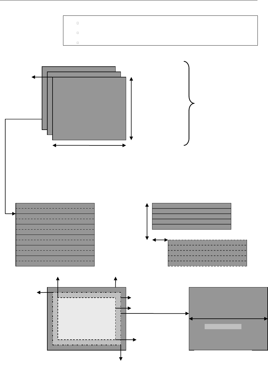
API Reference
4-20
rangeMappingLuma
rangeMappingChroma
enableRangeReductionFlag
Figure 3-5. IVIDEO2_BufDesc With Associated Parameters
IVIDEO_VideoLayout
planeDesc[PLANE_INDEX].bufSize.width,
for memType=tiled
planeDesc[PLANE_IN
DEX].bufSize.height,
for memType=titled
planeDesc[PL
ANE_INDEX].
buf
Video Plane(s)
numPlanes, numMetaPlanes
bottomRight (XBR,YRB)
topLeft (XTL,YTL)
Field Interleaved
Field Separated, top field and
bottom field
secondField
OffsetWidth
secondField
OffsetHeight
bottomRight (X,Y)
activeFrameRegion
imageRegion
topLeft (X,Y)
imagePitch
Video Plane

API Reference
4-21
3.2.1.7 IVIDDEC3_Fxns
║ Description
This structure contains pointers to all the XDAIS and XDM interface
functions.
║ Fields
║
Field
Data Type
Input/
Output
Description
ialg
IALG_Fxns
Input
Structure containing pointers to all the XDAIS
interface functions.
For more details, see TMS320 DSP Algorithm
Standard API Reference (literature number
SPRU360).
*process
XDAS_Int32
Input
Pointer to the process() function
*control
XDAS_Int32
Input
Pointer to the control() function
3.2.1.8 IVIDDEC3_Params
║ Description
This structure defines the creation parameters for an algorithm instance
object. Set this data structure to NULL, if you are not sure of the values to
be specified for these parameters.
║ Fields
║
Field
Data Type
Input/
Output
Description
size
XDAS_Int32
Input
Size of the basic or extended (if being used)
data structure in bytes.
maxHeight
XDAS_Int32
Input
Maximum video height to be supported in pixels
maxWidth
XDAS_Int32
Input
Maximum video width to be supported in pixels
maxFrameRate
XDAS_Int32
Input
Maximum frame rate in fps * 1000 to be
supported.
maxBitRate
XDAS_Int32
Input
Maximum bit-rate to be supported in bits per
second. For example, if bit-rate is 10 Mbps, set
this field to 10485760.
dataEndianness
XDAS_Int32
Input
Endianness of input data. See
XDM_DataFormat enumeration for details.

API Reference
4-22
Field
Data Type
Input/
Output
Description
forceChromaFormat
XDAS_Int32
Input
Sets the output to the specified format. Only 420
semi-planar format supported currently. For
example, if the output should be in YUV 4:2:2
interleaved (little endian) format, set this field to
XDM_YUV_422ILE.
See XDM_ChromaFormat and
eChromaFormat_t enumerations for details.
operatingMode
XDAS_Int32
Input
Video coding mode of operation
(encode/decode/transcode/transrate).
displayDelay
XDAS_Int32
Input
Display delay to start display.
inputDataMode
XDAS_Int32
Input
Input mode of operation.
For decoder, it is fixed length/slice mode/entire
frame.
outputDataMode
XDAS_Int32
Input
Output mode of operation.
For decoder, it is row mode/entire frame.
.
numInputDataUnits
XDAS_Int32
Input
Number of input slices/rows.
.
numOutputDataUnit
s
XDAS_Int32
Input
Number of output slices/rows.
errorInfoMode
XDAS_Int32
Input
Enable/disable packet error information for
input/output
displayBufsMode
XDAS_Int32
Input
Indicates the displayBufs mode. This field
can be set either as
IVIDDEC3_DISPLAYBUFS_EMBEDDED
or IVIDDEC3_DISPLAYBUFS_PTRS.
metadataType[IVID
EO_MAX_NUM_METADA
TA_PLANES]
XDAS_Int32
Input
Type of each metadata plane. See
IVIDEO_MetadataType and
IH264VDEC_MetadataType enmumeration
for details.

API Reference
4-23
3.2.1.9 IVIDDEC3_DynamicParams
║ Description
This structure defines the run-time parameters for an algorithm instance
object. Set this data structure to NULL, if you are not sure of the values to be
specified for these parameters.
║ Fields
Field
Data Type
Input/
Output
Description
size
XDAS_Int32
Input
Size of the basic or extended (if being used) data
structure in bytes.
decodeHeader
XDAS_Int32
Input
Number of access units to decode:
0 (XDM_DECODE_AU) - Decode entire frame
including all the headers
1 (XDM_PARSE_HEADER) - Decode only one
NAL unit
displayWidth
XDAS_Int32
Input
If the field is set to:
0 - Uses decoded image width as pitch
If any other value greater than the decoded image
width is given, then this value in pixels is used as
pitch.
frameSkipMode
XDAS_Int32
Input
Frame skip mode. See IVIDEO_FrameSkip
enumeration for details.
newFrameFlag
XDAS_Int32
Input
Flag to indicate that the algorithm should start a new
frame.
Valid values are XDAS_TRUE and XDAS_FALSE.
This is useful for error recovery, for example, when the
end of frame cannot be detected by the codec but is
known to the application.
*putDataFxn
XDM_DataSy
ncPutFxn
Input
Function pointer to produce data at sub-frame level
(DataSync call back function pointer for putData)
putDataHandle
XDM_DataSy
ncHandle
Input
Handle that identifies the data sync FIFO and is
passed as argument to putData calls
*getDataFxn
XDM_DataSy
ncGetFxn
Input
Function pointer to receive data at sub-frame level
(DataSync call back function pointer for getData)
getDataHandle
XDM_DataSy
ncHandle
Input
Handle that identifies the data sync FIFO and is
passed as argument to getData calls
putBufferFxn
XDM_DataSy
ncPutBuffe
rFxn
Input
Function pointer to receive buffer at sub-frame level
(Not used by the this version of the decoder)

API Reference
4-24
Field
Data Type
Input/
Output
Description
putBufferHand
le
XDM_DataSy
ncHandle
Input
Handle that identifies the data sync FIFO and is
passed as argument to getBufferFxn calls(Not
used by the this version of the decoder)
lateAcquireAr
g
XDAS_Int32
Input
Argument used during late acquire. If the codec
supports late acquisition of resources,and the
application has supplied a lateAcquireArg value
(via #XDM_SETLATEACQUIREARG), then the codec
must also provide this lateAcquireArg value when
requesting resources (i.e. during their call to
acquire() when requesting the resource).
3.2.1.10 IVIDDEC3_InArgs
║ Description
This structure defines the run-time input arguments for an algorithm instance
object.
║ Fields
Field
Data Type
Input/
Output
Description
size
XDAS_Int32
Input
Size of the basic or extended (if being used) data
structure in bytes.
numBytes
XDAS_Int32
Input
Size of input data (in bytes) provided to the algorithm for
decoding
inputID
XDAS_Int32
Input
Application passes this ID to algorithm and decoder will
attach this ID to the corresponding output frames. This is
useful in case of re-ordering (for example, B frames). If
there is no re-ordering, outputID field in the
IVIDDEC3_OutArgs data structure will be same as
inputID field.
Note:
H264 Decoder copies the inputID value to the outputID value of
IVIDDEC3_OutArgs structure after factoring in the display delay.

API Reference
4-25
3.2.1.11 IVIDDEC3_Status
║ Description
This structure defines parameters that describe the status of an algorithm
instance object.
║ Fields
Field
Data Type
Input/
Output
Description
size
XDAS_Int32
Input
Size of the basic or extended (if
being used) data structure in bytes.
extendedError
XDAS_Int32
Output
Extended error code. See
XDM_ErrorBit and
IH264VDEC_ErrorBit
enumerations for details.
data
XDM1_SingleBufDesc
Output
Buffer information structure for
information passing buffer. This is
not populated by this version of the
decoder.
maxNumDisplayBufs
XDAS_Int32
Output
Maximum number of buffers
required by the codec.
maxOutArgsDisplayB
ufs
XDAS_Int32
Output
The maximum number of display
buffers that can be returned through
IVIDDEC3_OutArgs.displayB
ufs.
outputHeight
XDAS_Int32
Output
Output height in pixels
outputWidth
XDAS_Int32
Output
Output width in pixels
frameRate
XDAS_Int32
Output
This value will be derived from VUI
parameters as,
frameRate = (time_scale /
(2 * num_units_in_ticks))
* 1000.
In case the VUI parameters are
absent, the frameRate will be
reported as 0, which should be
inferred as ‘not available’.
bitRate
XDAS_Int32
Output
Average bit-rate in bits per second
contentType
XDAS_Int32
Output
Video content. See
IVIDEO_ContentType
enumeration for details.
sampleAspectRatioH
eight
XDAS_Int32
Output
Sample aspect ratio for height

API Reference
4-26
Field
Data Type
Input/
Output
Description
sampleAspectRatioW
idth
XDAS_Int32
Output
Sample aspect ratio for width
bitRange
XDAS_Int32
Output
Bit range. It is set to
IVIDEO_YUVRANGE_FULL.
forceChromaFormat
XDAS_Int32
Output
Output chroma format. See
XDM_ChromaFormat and
eChromaFormat_t enumeration
for details.
operatingMode
XDAS_Int32
Output
Mode of operation:
Encoder/Decoder/Transcode/Transr
ate. It is set to
IVIDEO_DECODE_ONLY.
frameOrder
XDAS_Int32
Output
Indicates the output frame order.
See IVIDDEC3_displayDelay
enumeration for more details.
inputDataMode
XDAS_Int32
Output
Input mode of operation.
For decoder, it is fixed length/slice
mode/entire frame.
See IVIDEO_DataMode
enumeration for more details.
This version of the decoder supports
only the fixed length and entire
frame mode.
outputDataMode
XDAS_Int32
Output
Output mode of operation.
For decoder, it is the row
mode/entire frame.
See IVIDEO_DataMode
enumeration for more details.
This version of the decoder supports
only the entire frame mode.
bufInfo
XDM1_AlgBufInfo
Output
Input and output buffer information.
See XDM1_AlgBufInfo data
structure for details.
numInputDataUnits
XDAS_Int32
Output
Number of input slices/rows. Units
depend on the inputDataMode,
like number of slices/rows/blocks
etc.
Ignore if inputDataMode is set to
full frame mode.
numOutputDataUnits
XDAS_Int32
Output
Number of output slices/rows. Units
depend on the outputDataMode,
like number of slices/rows/blocks
etc. Ignore if outputDataMode is
set to full frame mode.

API Reference
4-27
Field
Data Type
Input/
Output
Description
configurationID
XDAS_Int32
Output
Configuration ID of given codec is
based on the input stream and can
be used by the framework to
optimize the save/restore overhead
of any resources used.
metadataType[IVIDE
O_MAX_NUM_METADATA
_PLANES]
XDAS_Int32
Output
Type of each metadata plane. See
the enum
IVIDEO_MetadataType.
decDynamicParams
IVIDDEC3_DynamicPar
ams
Output
Current values of the decoder's
dynamic parameters.
Note:
Algorithm sets the bitRate field to a default value 10485760.
H264 Decoder will not use the buffer descriptor meant for passing
additional information between the application and the decoder.
sampleAspectRatioWidth and sampleAspectRatioHeight are
set to 0, if vui parameters are not present.
frameOrder field in the status structure is set to the actual display
delay value used by the decoder, which is minimum of
maxNumRefFrames, and displayDelay.
3.2.1.12 IVIDDEC3_OutArgs
║ Description
This structure defines the run-time output arguments for an algorithm
instance object.
║ Fields
Field
Data Type
Input/
Output
Description
size
XDAS_Int32
Input
Size of the basic or extended (if being used) data
structure in bytes.
extendedError
XDAS_Int32
Output
extendedError Field
bytesConsumed
XDAS_Int32
Output
Bytes consumed per decode call
outputID[IVIDEO2
_MAX_IO_BUFFERS]
XDAS_Int32
Output
Output ID corresponding to displayBufs
A value of zero (0) indicates an invalid ID. The first
zero entry in array will indicate end of valid
outputIDs within the array. Hence, the application
can stop reading the array when it encounters the

API Reference
4-28
Field
Data Type
Input/
Output
Description
first zero entry.
decodedBufs
IVIDEO2_Bu
fDesc
Output
The decoder fills this structure with buffer pointers to
the decoded frame. Related information fields for the
decoded frame are also populated.
When frame decoding is not complete, as indicated
by outBufsInUseFlag, the frame data in this
structure will be incomplete. However, the algorithm
will provide incomplete decoded frame data in case
application may choose to use it for error recovery
purposes.
freeBufID[IVIDEO
2_MAX_IO_BUFFERS
]
XDAS_Int32
Output
This is an array of inputIDs corresponding to the
frames that have been unlocked in the current
process call.
outBufsInUseFlag
XDAS_Int32
Output
Flag to indicate that the outBufs provided with the
process() call are in use. No outBufs are
required to be supplied with the next process()
call.
displayBufsMode
XDAS_Int32
Output
Indicates which mode the displayBufs are
presented in. See the note below for details.
bufDesc [1]
IVIDEO2_Bu
fDesc
Output
Array containing display frames corresponding to
valid ID entries in the outputID array.
See IVIDEO2_BufDesc data structure for more
details
*pBufDesc[IVIDEO
2_MAX_IO_BUFFERS
]
IVIDEO2_Bu
fDesc *
Output
Array containing pointers to display frames
corresponding to valid ID entries in the @c
outputID[]. The parameters . bufDesc[1] and
* pBufDesc[IVIDEO2_MAX_IO_BUFFERS]
form a union and hence only one of them need to be
used.
Note:
IVIDEO2_MAX_IO_BUFFERS - Maximum number of I/O buffers set to
20.
The display buffer mode can be set as either
IVIDDEC3_DISPLAYBUFS_EMBEDDED or
IVIDDEC3_DISPLAYBUFS_PTRS.
The current implementation of the decoder will always return a
maximum of one display buffer per process call. If the mode is
IVIDDEC3_DISPLAYBUFS_EMBEDDED, then the instance of the display
buffer structure will be present in OutArgs. If the mode is
IVIDDEC3_DISPLAYBUFS_PTRS, then a pointer to the instance will be
present in OutArgs,

API Reference
4-29
3.2.1.13 XDM_Point
║ Description
This structure specifies the two dimensional point.
║ Fields
Field
Data Type
Input/
Output
Description
X
XDAS_Int32
Input
X field of the frame
Y
XDAS_Int32
Input
Y field of the frame
3.2.1.14 XDM_Rect
║ Description
This structure defines the region in the image that is decoded
║ Fields
Field
Data Type
Input/
Output
Description
topLeft
XDM_Point
Input
Top left corner of the frame.
See XDM_Point data structure for details.
bottomRight
XDM_Point
Input
Bottom right corner of the frame.
See XDM_Point data structure for details.
3.2.1.15 XDM_DataSyncDesc
║ Description
This structure provides the descriptor for the chunk of data being transferred
in one call to putData or getData.
║ Fields
Field
Data Type
Input/
Output
Description
size
XDAS_Int32
Input/Ou
tput
Size of this structure
scatteredBlo
cksFlag
XDAS_Int32
Input/Ou
tput
Flag indicating whether the individual data blocks
may be scattered in memory.
*baseAddr
XDAS_Int32
Input/Ou
tput
Base address of single data block or pointer to an
array of data block addresses of size numBlocks.
If scatteredBlocksFlag is set to XDAS_FALSE,

API Reference
4-30
Field
Data Type
Input/
Output
Description
this field points directly to the start of the first block,
and is not treated as a pointer to an array.
If scatteredBlocksFlag is set to XDAS_TRUE,
this field points to an array of pointers to data blocks.
numBlocks
XDAS_Int32
Input/Ou
tput
Number of blocks available
varBlockSize
sFlag
XDAS_Int32
Input/Ou
tput
Flag indicating whether any of the data blocks vary in
size.
Valid values are XDAS_TRUE and XDAS_FALSE.
*blockSizes
XDAS_Int32
Input/Ou
tput
Variable block sizes array.
If varBlockSizesFlag is XDAS_TRUE, this array
contains the sizes of each block.
If varBlockSizesFlag is XDAS_FALSE, this
contains the size of same-size blocks.
Memory for this array (of size numBlocks) has to be
allocated by the caller of the putData API.

API Reference
4-31
3.2.2 H264 Decoder Data Structures
This section includes the following H264 Decoder specific data structures:
IH264VDEC_Params
IH264VDEC_DynamicParams
IH264VDEC_InArgs
IH264VDEC_Status
IH264VDEC_OutArgs
IH264VDEC_ProcessParams
IH264VDEC_ProcessParamsList
IH264VDEC_Fxns
3.2.2.1 IH264VDEC_Params
║ Description
This structure defines the creation parameters and any other
implementation specific parameters for an H264 Decoder instance object.
The creation parameters are defined in the XDM data structure,
IVIDDEC3_Params.
║ Fields
Field
Data Type
Input/
Output
Description
viddec3Params
IVIDDEC3_Params
Input
See IVIDDEC3_Params data structure
for details.
maxNumRefFrames
XDAS_Int32
Input
The max number of frames required by
the DPB (Decoded Picture Buffer) . This
is the DPB size in number of frames. See
the note following this section for more
information.
Also, See enum
IH264VDEC_numRefFrames.
See Appendix F for more information
pConstantMemory
XDAS_Int32
Input
This pointer points to the memory area
where constants are located. Default
value is NULL in which case, codec puts
the constants in a default section. See
the note following this section.
bitStreamFormat
XDAS_Int32
Input
Input bit stream format. See the enum
IH264VDEC_bitStreamFormat for
details.

API Reference
4-32
Field
Data Type
Input/
Output
Description
errConcealmentM
ode
XDAS_UInt32
Input
This Mode indicates whether to apply
error concealment or not. See the enum
IH264VDEC_errConcealmentMode
for more details.
temporalDirMode
Pred
XDAS_Int32
Input
Parameter to enabled/disable temporal
direct Prediction mode. See
IH264VDEC_temporalDirModePred
for more details
svcExtensionFla
g
XDAS_UInt32
Input
Flag to indicate support of SVC extension
or not. See
IH264VDEC_svcExtension for more
details
svcTargetLayerD
ID
XDAS_Int32
Input
SVC Spatial target layer ID
svcTargetLayerT
ID
XDAS_Int32
Input
SVC Temporal target layer ID
svcTargetLayerQ
ID
XDAS_Int32
Input
SVC Quality target layer ID
presetLevelIdc
XDAS_Int32
Input
Level at which decoder will be configured
presetProfileId
c
XDAS_Int32
Input
Profile at which decoder will be
configured.
Note: The current configuration of profile
is not supported. The decoder always is
configured for high profile, independent
of value set in this field.
detectCabacAlig
nErr
XDAS_UInt32
Input
This parameter configures the cabac
alignment error detection
detectIPCMAlign
Err
XDAS_UInt32
Input
This parameter configures the IPCM
alignment error detection
debugTraceLevel
XDAS_UInt32
Input
This parameter configures the debug
trace level for the codec
lastNFramesToLo
g
XDAS_UInt32
Input
This parameter configures the codec to
maintain a history of last N
frames/pictures

API Reference
4-33
Field
Data Type
Input/
Output
Description
enableDualOutp
ut
XDAS_UInt32
Input
Set it to
IH264VDEC_DUALOUTPUT_ENABLE to
enable dual YUV output. Set it to
IH264VDEC_DUALOUTPUTALIGN_ENA
BLE to have output address offset 16-
byte aligned. Set to
IH264VDEC_DUALOUTPUT_DISABLE
otherwise. Default value is
IH264VDEC_DUALOUTPUT_DISABLE.
See Appendix K for details on enabling
and using dual output feature.
processCallLev
el
XDAS_UInt32
Input
Set it to
IH264VDEC_FIELDLEVELPROCESSCA
LL to enable field level process call. Set
to
IH264VDEC_FRAMELEVELPROCESSCA
LL to enable frame level process call.
Default value is
IH264VDEC_FIELDLEVELPROCESSCA
LL.
enableWatermar
k
XDAS_UInt32
Input
Set it to
IH264VDEC_WATERMARK_ENABLE to
enable watermarking. Set to
IH264VDEC_WATERMARK_DISABLE
otherwise. Default value is
IH264VDEC_WATERMARK_DISABLE.
See Appendix L for details on enabling
and using watermark feature.
decodeFrameTyp
e
XDAS_UInt32
Input
Set it to IH264VDEC_DECODE_ALL to
enable decoding of all frame
types. Set it to
IH264VDEC_DECODE_IP_ONLY to
decode only I/IDR and P frame
types. Set it to
IH264VDEC_DECODE_I_ONLY to
decode only I/IDR frame
types. Default value is
IH264VDEC_DECODE_ALL. See
Appendix-M for details on
enabling and using this
feature.
3.2.2.2 IH264VDEC_DynamicParams
║ Description

API Reference
4-34
This structure defines the run-time parameters and any other
implementation specific parameters for an H.264 instance object. The run-
time parameters are defined in the XDM data structure,
IVIDDEC3_DynamicParams.
║ Fields
Field
Data Type
Input/
Output
Description
viddec3DynamicParam
s
IVIDDEC3_DynamicPara
ms
Input
See
IVIDDEC3_DynamicParams
data structure for details.
deblockFilterMode
XDAS_Int32
Input
Parameter to indicate mode of
deblocking filter. See enum
IH264VDEC_deblockFilterM
ode for more details
svcTargetLayerDID
XDAS_Int32
Input
SVC Spatial target layer ID
svcTargetLayerTID
XDAS_Int32
Input
SVC Temporal target layer ID
svcTargetLayerQID
XDAS_Int32
Input
SVC Quality target layer ID
svcELayerDecode
XDAS_Int32
Input
Flag to enable or disable decoding
of enhancement layer
reserved[3]
XDAS_Int32
Input
Reserved for future use
3.2.2.3 IH264VDEC_InArgs
║ Description
This structure defines the run-time input arguments for an H264 instance
object.
║ Fields
Field
Data Type
Input/
Output
Description
viddec3InArgs
IVIDDEC3_InArgs
Input
See IVIDDEC3_InArgs data structure for
details.
lateAcquireArg
XDAS_Int32
Input
Argument to indicate late acquire
3.2.2.4 IH264VDEC_Status
║ Description

API Reference
4-35
This structure defines parameters that describe the status of the H264
Decoder and any other implementation specific parameters. The status
parameters are defined in the XDM data structure, IVIDDEC3_Status.
║ Fields
Field
Data Type
Input/
Output
Description
viddec3Status
IVIDDEC3_Status
Output
See IVIDDEC3_Status data structure for details
svcTargetLaye
rDID
XDAS_Int32
Output
SVC Spatial target layer ID
svcTargetLaye
rTID
XDAS_Int32
Output
SVC Temporal target layer ID
svcTargetLaye
rQID
XDAS_Int32
Output
SVC Quality target layer ID
debugTraceLev
el
XDAS_UInt32
Output
reports the debug trace level configured for the
codec
lastNFramesTo
Log
XDAS_UInt32
Output
This parameter reports the number of last N
pictures for which history has been maintained
extMemoryDebu
gTraceAddr
XDAS_UInt32
Output
reports the external memory address (as seen by
Media Controller) where debug trace information is
being dumped
extMemoryDebu
gTraceSize
XDAS_UInt32
Output
reports the external memory buffer size(in bytes)
where debug trace information is being dumped
gapInFrameNum
XDAS_UInt32
Output
This parameter reports the gap in frame_num
observed in the current frame
spsMaxRefFram
es
XDAS_UInt32
Output
This parameter reports max number of reference
frames that gets used for decoding of a given
stream, as present in SPS ->
max_num_ref_frames.
If SPS is not yet parsed, then this parameter holds
value of DPB Size in frames based on create time
level & resolution.
enableDualOut
put
XDAS_UInt32
Input
This Parameter tells whether Dual output is
enable or not. If enable then application needs
to provide two extra buffer (one for DualLuma
and another for DualChroma)
reserved[2]
XDAS_Int32
Reserved for future use
3.2.2.5 IH264VDEC_OutArgs
║ Description

API Reference
4-36
This structure defines the run-time output arguments for the H264 Decoder
instance object.
║ Fields
Field
Data Type
Input/
Output
Description
viddec3OutArgs
IVIDDEC3_OutArgs
Output
See IVIDDEC3_OutArgs data structure for
details.
decryptedKey
XDAS_UInt32
Output
Watermark key decrypted by the decoder.
3.2.2.6 IH264VDEC_ProcessParams
║ Description
This structure defines the container for holding the channel information.
║ Fields
Field
Data Type
Input/
Output
Description
handle
IH264VDEC_Handle
Input
Handle for the channel.
inBufs
XDM2_BufDesc *
Input
Input buffers for the channel.
outBufs
XDM2_BufDesc *
Input
Output buffers for the channel.
inArgs
IVIDDEC3_InArgs *
Input
Input arguments for the channel.
outArgs
IVIDDEC3_OutArgs *
Output
Output arguments for the channel.
3.2.2.7 IH264VDEC_ProcessParamsList
║ Description
This structure defines the container for holding the N channel information.
║ Fields
Field
Data Type
Input/
Output
Description
numEntries
XDAS_Int32
Input
Number of channels in the given container.
processParams[]
IH264VDEC_Pro
cessParams
Input
Array holding the process parameters. The
array has a maximum of
IH264VDEC_MAX_LENGTH_PROCESS_LIST
(24) elements.

API Reference
4-37
3.2.2.8 IH264VDEC_Fxns
║ Description
This structure defines all the operations on H.264 decoder instance objects.
║ Fields
Field
Data Type
Input/
Output
Description
ividdec3
IVIDDEC3_Fxns
Output
See IVIDDEC3_Fxns data structure for details.
processMulti
XDAS_Int32
*fnPtr(IH264VDE
C_ProcessParams
List
*processList)
Output
Function pointer to the multi-channel process call
definition.
3.2.2.8.1 sSeiMessages_t
║ Description
Structure contains Supplemental Enhancement Information messages.
║ Fields
Field
Datatype
Input/
Output
Description
parsed_flag
XDAS_UInt32
Output
1 - Indicates that in the
current process call,
contents of the structure is
updated
0 - Indicates contents of the
structure is not updated
full_frame_freez
e
sFullFrameFreezeRepe
tition_t
Output
Specifies the persistence of the
full-frame freeze SEI message
and may specify a picture order
count interval within which
another full-frame freeze SEI
message or a full-frame freeze
release SEI or the end of the
coded video sequence shall be
present in the bit-stream.
full_frame_freez
e_release
sFullFrameFreezeRele
ase_t
Output
Cancels the effect of any full-
frame freeze SEI message sent
with pictures that precede the
current picture in the output
order.
prog_refine_star
t
sProgRefineStart_t
Output
Specifies the beginning of a set
of consecutive coded pictures

API Reference
4-38
Field
Datatype
Input/
Output
Description
that is labeled as the current
picture followed by a sequence of
one or more pictures of
refinement of the quality of the
current picture, rather than as a
representation of a continually
moving scene.
prog_refine_end
sProgRefineEnd_t
Output
Specifies end of progressive
refinement.
user_data_regist
ered
sUserDataRegisteredI
TUT_t
Output
Message contains user data
registered as specified by ITU-T
Recommendation T.35
user_data_unregi
stered
sUserDataUnregistere
d
Output
Message contains unregistered
user data identified by a UUID
buffering_period
_info
sBufferingPeriod
Output
Message specifies the buffering
period
pan_scan_rect
sPanScanRect_t
Output
Message specifies the
coordinates of a rectangle
relative to the cropping rectangle
of the sequence parameter set
recovery_pt_info
sRecoveryPointInfo_t
Output
The recovery point SEI message
assists a decoder in determining
when the decoding process will
produce acceptable pictures for
display after the decoder initiates
random access or after the
encoder indicates a broken link in
the sequence.
pic_timing
sPictureTiming
Output
Specifies timing information
regarding cpb delays, dpb output
delay, and so on.
stereo_video_inf
o
IH264VDEC_SeiStereoV
ideoInfo
Output
stereo video information SEI
message consist of pair of picture
forming stereo view content.
frame_packing
IH264VDEC_SeiFramePa
cking
Output
This structure contains frame
packing arrangement SEI msg
elements
3.2.2.8.2 sFullFrameFreezeRepetition_t
║ Description
Structure contains information regarding frame freeze.
║ Fields

API Reference
4-39
sFullFrameFreezeRelease_t
║ Description
Structure contains information regarding frame freeze.
║ Fields
Field
Datatype
Input/
Output
Description
parsed_flag
XDAS_UInt32
Output
1 - Indicates that in the current process
call, contents of the structure is updated
0 - Indicates contents of the structure is
not updated
payloadSize
XDAS_UInt32
Output
Size of the frame_freeze_release
payload
3.2.2.8.3 sProgRefineStart_t
║ Description
Structure contains information regarding progressive refinement.
║ Fields
Field
Datatype
Input/
Output
Description
parsed_flag
XDAS_UInt32
Output
1 - Indicates that in the current
process call, contents of the structure
is updated
0 - Indicates contents of the structure
is not updated
progressive_refinem
ent_id
XDAS_UInt32
Output
Specifies an identification number for the
progressive refinement operation.
num_refinement_step
s_minus1
XDAS_UInt32
Output
Specifies the number of reference frames
in the tagged set of consecutive coded
pictures
Field
Datatype
Input/
Output
Description
parsed_flag
XDAS_UInt32
Output
1 - Indicates that in the current process
call, contents of the structure is updated
0 - Indicates contents of the structure is
not updated
full_frame_freeze_
repetition_period
XDAS_UInt32
Output
Specifies the persistence of the full-frame
freeze SEI message

API Reference
4-40
3.2.2.8.4 sProgRefineEnd_t
║ Description
Structure contains information regarding progressive refinement.
║ Fields
Field
Datatype
Input/
Output
Description
parsed_flag
XDAS_UInt32
Output
1 - Indicates that in the current process
call, contents of the structure is
updated
0 - Indicates contents of the structure is
not updated
progressive_
refinement_id
XDAS_UInt32
Output
Specifies an identification number for the
progressive refinement operation.
3.2.2.8.5 sRecoveryPointInfo_t
║ Description
Structure contains information regarding recovery points.
║ Fields
Field
Datatype
Input/
Output
Description
parsed_flag
XDAS_UInt32
Output
1 - Indicates that in the current process
call, contents of the structure is updated
0 - Indicates contents of the structure is
not updated
recovery_frame_cnt
XDAS_UInt32
Output
Specifies the recovery point of output
pictures in output order.
exact_match_flag
XDAS_UInt32
Output
Indicates whether decoded pictures at and
subsequent to the specified recovery point in
output order,
derived by starting the decoding process at
the access unit associated with the recovery
point SEI message, will be an
exact match to the pictures that would be
produced by starting the decoding process
at the location of a previous IDR access unit
in the NAL unit stream.
broken_link_flag
XDAS_UInt32
Output
Indicates the presence or absence of a
broken link in the NAL unit stream
changing_slice_grou
p_idc
XDAS_UInt32
Output
Indicates whether decoded pictures are
correct or approximately correct in content at
and subsequent to the recovery point in
output order when all macro-blocks of the
primary coded pictures are decoded within
the changing slice group period.

API Reference
4-41
3.2.2.8.6 sPictureTiming_t
║ Description
Structure contains timing information such as DPB delay and CPD delay.
║ Fields
Field
Datatype
Input/
Output
Description
parsed_flag
XDAS_UInt32
Output
1 - Indicates that in the current process
call, contents of the structure is
updated
0 - Indicates contents of the structure is
not updated
NumClockTs
XDAS_UInt32
Output
NumClockTS is determined by
pic_struct as specified in Table D-1 of
the h264 standard. There are up to
NumClockTS sets of clock timestamp
information for a picture, as specified
by clock_timestamp_flag[ i ] for each
set.
cpb_removal_delay
XDAS_UInt32
Output
Specifies how many clock ticks to wait after
removal from the CPB of the access unit
associated with the most recent buffering
period SEI message before removing from
the buffer the access unit data associated
with the picture timing SEI message.
dpb_output_delay
XDAS_UInt32
Output
Used to compute the DPB output time of
the picture.
pic_struct
XDAS_UInt32
Output
Indicates whether a picture should be
displayed as a frame or field
clock_timestamp_fla
g[4]
XDAS_UInt32
Output
1 - Indicates number of clock
timestamp syntax elements present
and follow immediately
0 – Indicates associated clock
timestamp syntax elements not present
ct_type[4]
XDAS_UInt32
Output
Indicates the scan type(interlaced or
progressive) of the source material
nuit_field_based_fl
ag[4]
XDAS_UInt32
Output
Used to calculate the clockTimestamp
counting_type[4]
XDAS_UInt32
Output
Specifies the method of dropping values of
n_frames
full_timestamp_flag
[4]
XDAS_UInt32
Output
1 - Specifies that the n_frames
syntax element is followed by
seconds_value, minutes_value,
and hours_value.
0 - Specifies that the n_frames

API Reference
4-42
Field
Datatype
Input/
Output
Description
syntax element is followed by
seconds_flag
discontinuity_flag[
4]
XDAS_UInt32
Output
Indicates whether the difference between
the current value of clockTimestamp
and the value of clockTimestamp
computed from the previous
clockTimestamp in output order can be
interpreted as the time difference between
the times of origin or capture of the
associated frames or fields.
cnt_dropped_flag[4]
XDAS_UInt32
Output
Specifies the skipping of one or more
values of n_frames using the counting
method
n_frames[4]
XDAS_UInt32
Output
Specifies the value of nFrames used to
compute clockTimestamp.
seconds_flag[4]
XDAS_UInt32
Output
Equal to 1 specifies that seconds_value
and minutes_flag are present when
full_timestamp_flag is equal to 0.
minutes_flag[4]
XDAS_UInt32
Output
Equal to 1 specifies that minutes_value
and hours_flag are present when
full_timestamp_flag is equal to 0
and seconds_flag is equal to 1.
hours_flag[4]
XDAS_UInt32
Output
equal to 1 specifies that hours_value is
present when full_timestamp_flag is
equal to 0 and seconds_flag is equal to
1 and minutes_flag is equal to 1
seconds_value[4]
XDAS_UInt32
Output
Specifies the value of sS used to compute
clockTimestamp.
minutes_value[4]
XDAS_UInt32
Output
Specifies the value of mM used to compute
clockTimestamp.
hours_value[4]
XDAS_UInt32
Output
Specifies the value of hH used to compute
clockTimestamp.
time_offset[4]
XDAS_Int32
Output
Specifies the value of tOffset used to
compute clockTimestamp
3.2.2.8.7 sBufferingPeriod_t
║ Description
Structure contains information regarding buffering period
║ Fields

API Reference
4-43
Field
Datatype
Input/
Output
Description
parsed_flag
XDAS_UInt32
Output
1 - Indicates that in the current process
call, contents of the structure is updated
0 - Indicates contents of the structure is
not updated
seq_parameter_set_i
d
XDAS_UInt32
Output
Specifies the sequence parameter set that
contains the sequence HRD attributes
nal_cpb_removal_del
ay[MAXCPBCNT]
XDAS_UInt32
Output
Specifies the delay for the indexed NAL CPB
between the time of arrival in the CPB of the
first bit of the coded data associated with the
access unit associated with the buffering
period SEI message and the time of removal
from the CPB of the coded data associated
with the same access unit, for the first
buffering period after HRD initialization.
nal_cpb_removal_del
ay_offset[MAXCPBCNT
]
XDAS_UInt32
Output
Used for the indexed NAL CPB in
combination with the
cpb_removal_delay to specify the initial
delivery time of coded access units to the
CPB
vcl_cpb_removal_del
ay[MAXCPBCNT]
XDAS_UInt32
Output
Specifies the delay for the indexed VCL CPB
between the time of arrival in the CPB of the
first bit of the coded data associated with the
access unit associated with the buffering
period SEI message and the time of removal
from the CPB of the coded data associated
with the same access unit, for the first
buffering period after HRD initialization.
vcl_cpb_removal_del
ay_offset[MAXCPBCNT
]
XDAS_UInt32
Output
Used for the indexed VCL CPB in
combination with the
cpb_removal_delay to specify the initial
delivery time of coded access units to the
CPB
3.2.2.8.8 sUserDataRegisteredITUT_t
║ Description
Structure contains information regarding the user data SEI message
elements
║ Fields
Field
Datatype
Input/
Output
Description
parsed_flag
XDAS_UInt32
Output
1 - Indicates that in the current process
call, contents of the structure is updated
0 - Indicates contents of the structure is
not updated

API Reference
4-44
Field
Datatype
Input/
Output
Description
num_payload_bytes
XDAS_UInt32
Output
Specifies the size of the payload
itu_t_t35_country_c
ode
unsigned
char
Output
A byte having a value specified as a country
code by ITU-T Recommendation T.35 Annex
A
itu_t_t35_country_c
ode_extension_byte
unsigned
char
Output
A byte having a value specified as a country
code by ITU-T Recommendation T.35 Annex
B
itu_t_t35_payload_b
yte[128]
unsigned
char
Output
A byte containing data registered as
specified by ITU-T Recommendation T.35.
This is restricted to a maximum size of 128
bytes.
dataOverflowFlag
unsigned
char
Output
This indicates if pay load data is more than
the array size i.e.,
IH264VDEC_MAXUSERDATA_PAYLOAD.
3.2.2.8.9 sUserDataUnregistered
║ Description
Structure contains information regarding the unregistered user data SEI
message elements
║ Fields
Field
Datatype
Input/
Output
Description
parsed_flag
XDAS_UInt32
Output
1 - Indicates that in the current process
call, contents of the structure is updated
0 - Indicates contents of the structure is
not updated
num_payload_bytes
XDAS_UInt32
Output
Specifies the size of the payload
uuid_iso_iec_11578[
16]
unsigned
char
Output
Value specified as a UUID according to the
procedures of ISO/IEC 11578:1996 Annex
A.
user_data_payload_b
yte[128]
unsigned
char
Output
Byte containing data having syntax and
semantics as specified by the UUID
generator. This is restricted to a maximum
size of 128 bytes.
dataOverflowFlag
unsigned
char
Output
This indicates if pay load data is more than
the array size i.e.,
IH264VDEC_MAXUSERDATA_PAYLOAD.
3.2.2.8.10 sPanScanRect_t
║ Description

API Reference
4-45
Structure contains information regarding the pan-scan rectangle SEI
message elements
║ Fields
Field
Datatype
Input/
Output
Description
parsed_flag
XDAS_UInt32
Output
1 - Indicates that in the current process
call, contents of the structure is updated
0 - Indicates contents of the structure is
not updated
pan_scan_rect_id
XDAS_UInt32
Output
Specifies an identifying number that may be
used to identify the purpose of the pan-scan
rectangle
pan_scan_rect_cance
l_flag
XDAS_UInt32
Output
Equal to 1 indicates that the SEI message
cancels the persistence of any previous pan-
scan rectangle SEI message in output order.
pan_scan_rect_cancel_flag equal to
0 indicates that pan-scan rectangle
information follows.
pan_scan_cnt_minus1
XDAS_UInt32
Output
Specifies the number of pan-scan rectangles
that are present in the SEI message
pan_scan_rect_left_
offset[3]
int
Output
Specifies as signed integer quantities in
units of one-sixteenth sample spacing
relative to the luma sampling grid, the
location of the pan-scan rectangle
pan_scan_rect_right
_offset[3]
int
Output
Specifies as signed integer quantities in
units of one-sixteenth sample spacing
relative to the luma sampling grid, the
location of the pan-scan rectangle
pan_scan_rect_top_o
ffset[3]
int
Output
Specifies as signed integer quantities in
units of one-sixteenth sample spacing
relative to the luma sampling grid, the
location of the pan-scan rectangle
pan_scan_rect_botto
m_offset[3]
int
Output
Specifies as signed integer quantities in
units of one-sixteenth sample spacing
relative to the luma sampling grid, the
location of the pan-scan rectangle
pan_scan_rect_repet
ition_period
XDAS_UInt32
Output
Specifies the persistence of the pan-scan
rectangle SEI message and may specify a
picture order count interval within which
another pan-scan rectangle SEI message
with the same value of
pan_scan_rect_id or the end of the
coded video sequence shall be present in
the bit-stream

API Reference
4-46
3.2.2.8.11 sSeiStereoVideoInfo
║ Description
This structure defines parameters that describe the values of Stereo
Sequence Parameter Set in the bit-stream.
║ Fields
Field
Datatype
Input/
Output
Description
parsed_flag
XDAS_UInt32
Output
1 - Indicates that in the current process
call, contents of the structure is updated
0 - Indicates contents of the structure is
not updated
field_views_flag
XDAS_UInt32
Output
1 - Indicates that all pictures in the
current coded video sequence are fields
0 - indicates that all pictures in the
current coded video sequence are
frames.
top_field_is_left_v
iew_flag
XDAS_UInt32
Output
1 - top field is a left view.
0 – top field is right view.
current_frame_is_le
ft_view_flag
XDAS_UInt32
Output
1 - current frame is left view.
0 - current frame is right view.
next_frame_is_secon
d_view_flag
XDAS_UInt32
Output
1 - current picture and a next picture in
output order form a stereo video pair.
0 - current picture and a previous
picture in output order form a stereo
video pair.
left_view_self_cont
ained_flag
XDAS_UInt32
Output
1 - it will not use right view as a
reference picture for inter prediction
0 - it may use right view as a reference
picture for inter prediction.
right_view_self_con
tained_flag
XDAS_UInt32
Output
1 - it will not use left view as a reference
picture for inter prediction
0 - it may use left view as a reference
picture for inter prediction.

API Reference
4-47
3.2.2.8.12 sSeiFramePacking
║ Description
This structure defines parameters that describe the values of Frame Packing
Sequence Parameter Set in the bit-stream.
║ Fields
Field
Datatype
Input/
Output
Description
parsed_flag
XDAS_UInt32
Output
1 - Indicates that in the current process
call, contents of the structure is updated
0 - Indicates contents of the structure is
not updated
frame_packing_arran
gement_id
XDAS_UInt32
Output
Contains an identifying number that may be
used to identify the usage of the frame
packing arrangement SEI message.
frame_packing_arran
gement_repetition_p
eriod
XDAS_UInt32
Output
Specifies the persistence of the frame
packing arrangement.
SEI message and may specify a frame order
count interval within which another frame
packing arrangement SEI message with the
same value of
frame_packing_arrangement_id or
the end of the coded video sequence shall
be present in the bit-stream.
frame_packing_arran
gement_cancel_flag
XDAS_UInt8
Output
1 - Equal to 1 indicates that the frame
packing arrangement. SEI message
cancels the persistence of any previous
frame packing arrangement SEI
message in output order.
0 - Indicates that frame packing
arrangement info follows
frame_packing_arran
gement_type
XDAS_UInt8
Output
Indicates the type of packing arrangement of
the frames
quincunx_sampling_f
lag
XDAS_UInt8
Output
1 - Indicates that each color component
plane of each constituent frame is
quincunx sampled
0 - Indicates that each color component
plane of each constituent frame is not
quincunx sampled.
content_interpretat
ion_type
XDAS_UInt8
Output
1 - Frame 0 being associated with the
left view and frame 1. This is associated
with the right view
2 - Frame 0 being associated with the
right view and frame 1.
This is associated with the left view

API Reference
4-48
Field
Datatype
Input/
Output
Description
spatial_flipping_fl
ag
XDAS_UInt8
Output
1 - Spatial flipping is enabled for any
one of the frame constituent, if
frame_packing_arrangement_ty
pe is 3 or 4.
0 - Spatial flipping is disabled for any
one of the frame constituent, if
frame_packing_arrangement_ty
pe is 3 or 4.
frame0_flipped_flag
XDAS_UInt8
Output
1 - Frame 0 is spatially flipped
0 - Frame 1 is spatially flipped
field_views_flag
XDAS_UInt8
Output
1 - Indicates that all pictures in the
current coded video sequence are
coded as complementary field pairs.
0 - Indicates that all pictures in the
current coded video sequence are
coded as frame.
current_frame_is_fr
ame0_flag
XDAS_UInt8
Output
1 - Indicates that the current decoded
frame is constituent frame 0 and the
next decoded frame in output order is
constituent frame 1.
0 - Indicates that the current decoded
frame is constituent frame 1 and the
next decoded frame in output order is
constituent frame 0.
frame0_self_contain
ed_flag
XDAS_UInt8
Output
1 - Indicates that the constituent frame 0
is dependent on constituent frame 1 in
decoding process
0 - Indicates that the constituent frame 0
may dependent on constituent frame 1
in decoding process
frame1_self_contain
ed_flag
XDAS_UInt8
Output
1 - Indicates that the constituent frame 1
is dependent on constituent frame 0 in
decoding process
0 - Indicates that the constituent frame 1
may dependent on constituent frame 0
in decoding process
frame0_grid_positio
n_x
XDAS_UInt8
Output
Specifies the horizontal location of the upper
left sample of constituent frame 0 in the units
of one sixteenth of the luma samples
frame0_grid_positio
n_y
XDAS_UInt8
Output
Specifies the vertical location of the upper
left sample of constituent frame 0 in the units
of one sixteenth of the luma samples
frame1_grid_positio
n_x
XDAS_UInt8
Output
Specifies the horizontal location of the upper
left sample of constituent frame 1 in the units
of one sixteenth of the luma samples
frame1_grid_positio
n_y
XDAS_UInt8
Output
Specifies the vertical location of the upper
left sample of constituent frame 1 in the units

API Reference
4-49
Field
Datatype
Input/
Output
Description
of one sixteenth of the luma samples
frame_packing_arran
gement_reserved_byt
e
XDAS_UInt8
Output
Reserved for the future use.
frame_packing_arran
gement_extension_fl
ag;
XDAS_UInt8
Output
0 - Indicates that no additional data
follows within the frame packing
arrangement SEI message.
1 - Reserved for the future use.
3.2.2.8.13 sVuiParams
║ Description
This structure defines parameters that describe the values of various video
usability parameters that come as a part of Sequence Parameter Set in the
bit-stream.
║ Fields
Field
Datatype
Input/
Output
Description
parsed_flag
XDAS_UInt32
Output
1 - Indicates that in the current process
call, contents of the structure is updated
0 - Indicates contents of the structure is
not updated
aspect_ratio_info_p
resent_flag
XDAS_UInt8
Output
Indicates whether aspect ratio idc is
present or not.
aspect_ratio_idc
XDAS_UInt32
Output
Aspect ratio of Luma samples
sar_width
XDAS_UInt32
Output
Horizontal size of sample aspect ratio
sar_height
XDAS_UInt32
Output
Vertical size of sample aspect ratio
overscan_info_prese
nt_flag
XDAS_UInt8
Output
Overscan_appropriate_flag
overscan_appropriat
e_flag
XDAS_UInt8
Output
Cropped decoded pictures are suitable for
display or not.
video_signal_type_p
resent_flag
XDAS_UInt8
Output
Flag indicates whether video_format,
video_full_range_flag and
colour_description_present_flag
are present or not
video_format
XDAS_UInt8
Output
Video format indexed by a table. For
example, PAL/NTSC

API Reference
4-50
Field
Datatype
Input/
Output
Description
video_full_range_fl
ag
XDAS_UInt8
Output
Black level, luma and chroma ranges. It
should be used for BT.601 compliance
colour_description_
present_flag
XDAS_UInt8
Output
Indicates whether colour_primaries,
transfer_characteristics and
matrix_coefficients are present.
colour_primaries
XDAS_UInt8
Output
Chromaticity co-ordinates of source
primaries
transfer_characteri
stics
XDAS_UInt8
Output
Opto-electronic transfer characteristics of
the source picture
matrix_coefficients
XDAS_UInt8
Output
Matrix coefficients for deriving Luma and
chroma data from RGB components.
chroma_location_inf
o_present_flag
XDAS_UInt8
Output
Flag indicates whether
chroma_sample_loc_type_top
field and chroma_sample_loctype
bottom_field are present.
chroma_sample_loc_t
ype_top_field
XDAS_UInt32
Output
Location of chroma_sample top field
chroma_sample_loc_t
ype_bottom_field
XDAS_UInt32
Output
Location of chroma_sample bottom field
timing_info_present
_flag
XDAS_UInt8
Output
Indicates whether num_units_in_tick,
time_scale, and
fixed_frame_rate_flag are present.
num_units_in_tick
XDAS_UInt32
Output
Number of units of a clock that corresponds
to 1 increment of a clock tick counter
time_scale
XDAS_UInt32
Output
Indicates actual increase in time for 1
increment of a clock tick counter
fixed_frame_rate_fl
ag
XDAS_UInt8
Output
Indicates how the temporal distance
between HRD output times of any two
output pictures is constrained
nal_hrd_parameters_
present_flag
XDAS_UInt8
Output
Indicates whether nal_hrd_parameters
are present
nal_hrd_parameters
sHrdParams
Output
See sHrdParm_t datastructure for
details.
vcl_hrd_parameters_
present_flag
XDAS_UInt8
Output
Indicates whether vcl_hrd_parameters
are present
vcl_hrd_parameters
sHrdParams
Output
See sHrdParm_t datastructure for
details.

API Reference
4-51
Field
Datatype
Input/
Output
Description
low_delay_hrd_flag
XDAS_UInt8
Output
HRD operational mode as in Annex C of the
standard
pic_struct_present_
flag
XDAS_UInt8
Output
Indicates whether picture timing SEI
messages are present
bitstream_restricti
on_flag
XDAS_UInt8
Output
Indicates if the bit-stream restriction
parameters are present
motion_vectors_over
_pic_boundaries_fla
g
XDAS_UInt8
Output
Specifies whether motion vectors can point
to regions outside the picture boundaries
max_bytes_per_pic_d
enom
XDAS_UInt32
Output
Maximum number of bytes not exceeded by
the sum of sizes of all VCL NAL units of a
single coded picture
max_bits_per_mb_den
om
XDAS_UInt32
Output
Maximum number of bits taken by any
coded MB
log2_max_mv_length_
vertical
XDAS_UInt32
Output
Maximum value of any motion vector’s
vertical component
log2_max_mv_length_
horizontal
XDAS_UInt32
Output
Maximum value of any motion vector’s
horizontal component
max_dec_frame_reord
ering
XDAS_UInt32
Output
Maximum number of frames that need to be
re-ordered
num_reorder_frames
XDAS_UInt32
Output
Number of frames that need to be re-
ordered
max_dec_frame_buffe
ring
XDAS_UInt32
Output
Size of HRD decoded buffer (DPB) in terms
of frame buffers
svcVuiParams
IH264VDEC_SV
CVuiParams
Output
struct instance of vui parameters for svc
3.2.2.8.14 sHrdParm
║ Description
This structure defines the HRD parameters that are in H264 bit-stream as a
part of video usability Information.
║ Fields
Field
Datatype
Input/
Output
Description

API Reference
4-52
Field
Datatype
Input/
Output
Description
cpb_cnt_minus1
XDAS_UInt32
Output
Number of alternative CPB specifications in
the bit-stream (minus 1).
bit_rate_scale
XDAS_UInt8
Output
Together with bit_rate_value[i], it
specifies the maximum input bit-rate for the
ith CPB.
cpb_size_scale
XDAS_UInt8
Output
Together with cpb_size_value[i],
specifies the maximum CPB size for the ith
CPB.
bit_rate_value_minu
s1[i]
XDAS_UInt32
Output
Maximum input bitrate for the ith CPB
cpb_size_value_minu
s1[i]
XDAS_UInt32
Output
Maximum CPB size for the ith CPB
vbr_cbr_flag[i]
XDAS_UInt8
Output
Specifies the ith CPB is operated in Constant
Bit-rate mode or variable bit-rate mode
initial_cpb_removal
_delay_length_minus
1
XDAS_UInt8
Output
Length in bits of
initial_cpb_removal_length syntax
element
cpb_removal_delay_l
ength_minus1
XDAS_UInt8
Output
Length in bits of
cpb_removal_delay_length syntax
element
dpb_output_delay_le
ngth_minus1
XDAS_UInt8
Output
Length in bits of
dpb_output_delay_length syntax
element
time_offset_length
XDAS_UInt8
Output
Length in bits of time_offset syntax
element
Note:
SEI / VUI parsing is handled by the decoder as follows (For more details
on metadata access, please see Appendix B for more information).:
A flag, parsed_flag, is present as the first element of structure of every
SEI message, VUI structure and the SEI_VUI structure. This flag when
set to one by the decoder indicates that in the current process call,
contents of this structure was updated.
Currently parsing of the following SEI messages are supported.
Full-frame freeze SEI message
Full-frame freeze release SEI message
Progressive refinement segment start SEI message
Progressive refinement segment end SEI message

API Reference
4-53
Recovery point SEI message
Picture timing SEI message
Buffering period SEI message
User data registered by ITU-T T.35 SEI message
User data unregistered SEI message
Pan-scan Rectangle SEI message
Other types of SEI messages will be simply skipped by the decoder.

API Reference
4-54
3.3 Default and Supported Parameters
This section describes default and supported values for parameters of the
following structures:
IVIDDEC3_Params
IVIDDEC3_DynamicParams
IH264VDEC_Params
IH264VDEC_DynamicParams
3.3.1 Default and Supported values of IVIDDEC3_Params
Field
Default Value
Supported Values
Size
sizeof(IVIDDEC3_Params)
sizeof(IVIDDEC3_Params)
sizeof(IH264VDEC_Params)
maxHeight
1088
64 < = maxHeight < = 4096
maxWidth
1920
64 < = maxWidth < = 4320
maxFrameRate
Don’t Care
Don’t Care
maxBitRate
Don’t Care
Don’t Care
dataEndianness
XDM_BYTE
XDM_BYTE
forceChromaFormat
XDM_YUV_420SP
XDM_YUV_420SP
operatingMode
IVIDEO_DECODE_ONLY
IVIDEO_DECODE_ONLY,
IVIDEO_TRANSCODE_FRAMELEV
EL
displayDelay
IVIDDEC3_DISPLAY_DELAY_AUTO
All possible values of Enumeration
IVIDDEC3_displayDelay
inputDataMode
IVIDEO_ENTIREFRAME
IVIDEO_ENTIREFRAME
IVIDEO_FIXEDLENGTH
IVIDEO_SLICEMODE
IH264VDEC_NALUNIT_MODE
outputDataMode
IVIDEO_ENTIREFRAME
IVIDEO_ENTIREFRAME
IVIDEO_NUMROWS
numInputDataUnits
Don’t care
1
numOutputDataUnit
s
Don’t Care
Any positive number
errorInfoMode
IVIDEO_ERRORINFO_OFF
IVIDEO_ERRORINFO_OFF
displayBufsMode
IVIDDEC3_DISPLAYBUFS_EMBEDDE
D
IVIDDEC3_DISPLAYBUFS_EMBE
DDED
IVIDDEC3_DISPLAYBUFS_PTRS
metadataType
[IVIDEO_MAX_NUM
_METADATA_PLANES]
IVIDEO_METADATAPLANE_NONE
IVIDEO_METADATAPLANE_NONE
IVIDEO_METADATAPLANE_MBIN
FO
IH264VDEC_PARSED_SEI_DATA
IH264VDEC_PARSED_VUI_DATA

API Reference
4-55
Note:
During codec creation, maxHeight and maxWidth as specified in above
table are allowed. Note that maxHeight and maxWidth should be
always greater than or equal to image width and image height.
Minimum width and height supported per frame is 64. So, minimum
width and height supported per field is 32. However during decoder
creation, if either of maxHeight or maxWidth is greater than 2048, then
the minimum width supported per frame is 336 and the minimum width
supported per field is 176.
Decoder will be able to decode streams for which image width or height
are non-multiples of 16. However note that during decoder creation,
maxHeight and maxWidth should be a multiple of 16.
3.3.2 Default and Supported values of IVIDDEC3_DynamicParams
Field
Default Value
Supported Values
Size
sizeof(IVIDDEC3_DynamicParams
)
sizeof(IVIDDEC3_DynamicParams
)
sizeof(IH264VDEC_DynamicParam
s)
decodeHeader
XDM_DECODE_AU
XDM_PARSE_HEADER
XDM_DECODE_AU
displayWidth
0
If YUV buffers are in
RAW/TILED_PAGE region, Any
value > = 0, which is a
multiple of 128 bytes.
If YUV buffers are in TILED
region, then this parameter
value is ignored.
frameSkipMod
e
IVIDEO_NO_SKIP
IVIDEO_NO_SKIP
IVIDEO_SKIP_NONREFERENCE
newFrameFlag
Don’t Care
Don’t Care
putDataFxn
Don’t Care
Valid (Non-NULL) Function
pointer
putDataHandl
e
Don’t Care
Don’t Care
getDataFxn
Don’t Care
Valid (Non-NULL) Function
pointer

API Reference
4-56
Field
Default Value
Supported Values
getDataHandl
e
Don’t Care
Don’t Care
putBufferFxn
Don’t Care
Valid (Non-NULL) Function
pointer
putBufferHan
dle
Don’t Care
Don’t Care
lateAcquireA
rg
IRES_HDVICP2_UNKNOWNLATEACQUI
REARG
Any Value
3.3.3 Default and Supported values of IH264VDEC_Params
Field
Default Value
Supported Value
IVIDDEC3_Par
ams
See Section 3.3.1
See Section 3.3.1
dpbSizeInFra
mes
IH264VDEC_DPB_NUMFRAMES_DEFAU
LT
All possible values of enumeration
IH264VDEC_dpbNumFrames
pConstantMem
ory
NULL
NULL, Any valid address pointing to
constants in DDR
bitStreamFor
mat
IH264VDEC_BYTE_STREAM_FORMAT
IH264VDEC_BYTE_STREAM_FORM
AT
IH264VDEC_NAL_UNIT_FORMAT
errConcealme
ntMode
IH264VDEC_APPLY_CONCEALMENT
IH264VDEC_NO_CONCEALMENT
IH264VDEC_APPLY_CONCEALMEN
T
temporalDirM
odePred
IH264VDEC_ENABLE_TEMPORALDIRE
CT
IH264VDEC_ENABLE_TEMPORALD
IRECT
IH264VDEC_DISABLE_TEMPORAL
DIRECT
svcExtension
Flag
IH264VDEC_DISABLE_SVCEXTENSTI
ON
IH264VDEC_DISABLE_SVCEXTEN
STION
IH264VDEC_ENABLE_SVCEXTENS
ION
svcTargetLay
erDID
IH264VDEC_TARGET_DID_DEFAULT
All possible values of
enumeration type
IH264VDEC_dependancyLayerIds
svcTargetLay
erTID
IH264VDEC_TARGET_TID_DEFAULT
All possible values of
enumeration type
IH264VDEC_temporalLayerIds

API Reference
4-57
Field
Default Value
Supported Value
svcTargetLay
erQID
IH264VDEC_TARGET_QID_DEFAULT
All possible values of
enumeration type
IH264VDEC_qualityLayerIds
presetLevelI
dc
IH264VDEC_LEVEL41
IH264VDEC_LEVEL1
IH264VDEC_LEVEL1B
IH264VDEC_LEVEL11
IH264VDEC_LEVEL12
IH264VDEC_LEVEL13
IH264VDEC_LEVEL2
IH264VDEC_LEVEL21
IH264VDEC_LEVEL22
IH264VDEC_LEVEL3
IH264VDEC_LEVEL31
IH264VDEC_LEVEL32
IH264VDEC_LEVEL4
IH264VDEC_LEVEL41
IH264VDEC_LEVEL42
IH264VDEC_LEVEL5
IH264VDEC_LEVEL51
presetProfil
eIdc
IH264VDEC_PROFILE_HIGH
Don’t care
detectCabacA
lignErr
IH264VDEC_DISABLE_CABACALIGNE
RR_DETECTION
IH264VDEC_DISABLE_CABACALI
GNERR_DETECTION
IH264VDEC_ENABLE_CABACALIG
NERR_DETECTION
detectIPCMAl
ignErr
IH264VDEC_DISABLE_IPCMALIGNER
R_DETECTION
IH264VDEC_DISABLE_IPCMALIG
NERR_DETECTION
IH264VDEC_ENABLE_IPCMALIGN
ERR_DETECTION
debugTraceLe
vel
IH264VDEC_DEBUGTRACE_LEVEL0
IH264VDEC_DEBUGTRACE_LEVEL
0
IH264VDEC_DEBUGTRACE_LEVEL
1
lastNFramesT
oLog
0
Any number >= 0
enableDualOu
tput
IH264VDEC_DUALOUTPUT_DISABLE
IH264VDEC_DUALOUTPUT_DISAB
LE
IH264VDEC_DUALOUTPUT_ENABL
E
IH264VDEC_DUALOUTPUTALIGN_
ENABLE
processCallL
evel
IH264VDEC_FIELDLEVELPROCESSCA
LL
IH264VDEC_FIELDLEVELPROCES
SCALL
IH264VDEC_FRAMELEVELPROCES
SCALL

API Reference
4-58
Field
Default Value
Supported Value
enableWaterm
ark
IH264VDEC_WATERMARK_DISABLE
IH264VDEC_WATERMARK_DISABL
E
IH264VDEC_WATERMARK_ENABLE
decodeFrameT
ype
IH264VDEC_DECODE_ALL
IH264VDEC_DECODE_ALL
IH264VDEC_DECODE_IP_ONLY
IH264VDEC_DECODE_I_ONLY
3.3.4 Default and Supported values of IH264VDEC_DynamicParams
Field
Default Value
Supported Values
viddec3DynamicParams
See Section 4.3.2
See Section 4.3.2
deblockFilterMode
IH264VDEC_DEBLOCK_DEFAU
LT
IH264VDEC_DEBLOCK_DISABLE_
NONE
IH264VDEC_DEBLOCK_DISABLE_
ALL
IH264VDEC_DEBLOCK_DISABLE_
SLICE_EDGE
IH264VDEC_DEBLOCK_DEFAULT
svcTargetLayerDID
IH264VDEC_TARGET_DID_DE
FAULT
All possible values of
enumeration type
IH264VDEC_dependancyLayerIds
svcTargetLayerTID
IH264VDEC_TARGET_TID_DE
FAULT
All possible values of
enumeration type
IH264VDEC_temporalLayerIds
svcTargetLayerQID
IH264VDEC_TARGET_QID_DE
FAULT
All possible values of
enumeration type
IH264VDEC_qualityLayerIds
svcELayerDecode
IH264VDEC_DISABLE_ELAY
ERDECODE
IH264VDEC_DISABLE_ELAYER
DECODE
IH264VDEC_ENABLE_ELAYERD
ECODE
reserved[3]
0
0

API Reference
4-59
3.4 Interface Functions
This section describes the application programming interfaces used in the
H264 Decoder. The H264 Decoder APIs are logically grouped into the
following categories:
Creation – algNumAlloc(), algAlloc()
Initialization – algInit()
Control – control()
Data processing – algActivate(), process(), algDeactivate()
Termination – algFree()
You must call these APIs in the following sequence:
1) algNumAlloc()
2) algAlloc()
3) algInit()
4) algActivate()
5) process()
6) algDeactivate()
7) algFree()
control() can be called any time after calling the algInit() API.

API Reference
4-60
3.4.1 Creation APIs
Creation APIs are used to create an instance of the component. The term
creation could mean allocating system resources, typically memory.
║ Name
algNumAlloc() – determine the number of buffers that an algorithm
requires
║ Synopsis
XDAS_Int32 algNumAlloc(Void);
║ Arguments
Void
║ Return Value
XDAS_Int32; /* number of buffers required */
║ Description
algNumAlloc() returns the number of buffers that the algAlloc() method
requires. This operation allows you to allocate sufficient space to call the
algAlloc() method.
algNumAlloc() may be called at any time and can be called repeatedly
without any side effects. It always returns the same result. The
algNumAlloc() API is optional.
For more details, see TMS320 DSP Algorithm Standard API Reference.
║ See Also
algAlloc()

API Reference
4-61
║ Name
algAlloc() – determine the attributes of all buffers that an algorithm
requires
║ Synopsis
XDAS_Int32 algAlloc(const IALG_Params *params, IALG_Fxns
**parentFxns, IALG_MemRec memTab[]);
║ Arguments
IALG_Params *params; /* algorithm specific attributes */
IALG_Fxns **parentFxns;/* output parent algorithm functions
*/
IALG_MemRec memTab[]; /* output array of memory records */
║ Return Value
XDAS_Int32 /* number of buffers required */
║ Description
algAlloc() returns a table of memory records that describe the size,
alignment, type, and memory space of all buffers required by an algorithm. If
successful, this function returns a positive non-zero value indicating the
number of records initialized.
The first argument to algAlloc() is a pointer to a structure that defines the
creation parameters. This pointer may be NULL; however, in this case,
algAlloc(), must assume default creation parameters and must not fail.
The second argument to algAlloc() is an output parameter. algAlloc()
may return a pointer to its parent’s IALG functions. Since the client does not
require a parent object to be created, this pointer must be set to NULL.
The third argument is a pointer to a memory space of size
nbufs * sizeof(IALG_MemRec) where, nbufs is the number of buffers
returned by algNumAlloc() and IALG_MemRec is the buffer-descriptor
structure defined in ialg.h.
After calling this function, memTab[] is filled up with the memory
requirements of an algorithm.
For more details, see TMS320 DSP Algorithm Standard API Reference.
║ See Also
algNumAlloc(), algFree()

API Reference
4-62
3.4.2 Initialization API
Initialization API is used to initialize an instance of the H264 Decoder. The
initialization parameters are defined in the IVIDDEC3_Params structure (see
Data Structures section for details).
║ Name
algInit() – initialize an algorithm instance
║ Synopsis
XDAS_Int32 algInit(IALG_Handle handle, IALG_MemRec
memTab[], IALG_Handle parent, IALG_Params *params);
║ Arguments
IALG_Handle handle; /* handle to the algorithm instance*/
IALG_memRec memTab[]; /* array of allocated buffers */
IALG_Handle parent; /* handle to the parent instance */
IALG_Params *params; /* algorithm initialization parameters
*/
║ Return Value
IALG_EOK; /* status indicating success */
IALG_EFAIL; /* status indicating failure */
║ Description
algInit() performs all initialization necessary to complete the run-time
creation of an algorithm instance object. After a successful return from
algInit(), the instance object is ready to be used to process data.
The first argument to algInit() is a handle to an algorithm instance. This
value is initialized to the base field of memTab[0].
The second argument is a table of memory records that describe the base
address, size, alignment, type, and memory space of all buffers allocated for
an algorithm instance. The number of initialized records is identical to the
number returned by a prior call to algAlloc().
The third argument is a handle to the parent instance object. If there is no
parent object, this parameter must be set to NULL.
The last argument is a pointer to a structure that defines the algorithm
initialization parameters. All fields in the params structure must be set as
described in IALG_Params structure (see Data Structures section for
details).
For more details, see TMS320 DSP Algorithm Standard API Reference.
║ See Also
algAlloc(), algMoved()

API Reference
4-63
3.4.3 Control API
Control API is used for controlling the functioning of H264 Decoder during
run-time. This is done by changing the status of the controllable parameters
of the decoder during run-time. These controllable parameters are defined in
the IVIDDEC3_DynamicParams data structure (see Data Structures section
for details).
║ Name
control() – change run-time parameters of the H264 Decoder and query
the decoder status
║ Synopsis
XDAS_Int32 (*control)(IVIDDEC3_Handle handle, IVIDDEC3_Cmd
id,IVIDDEC3_DynamicParams *params, IVIDDEC3_Status
*status);
║ Arguments
IVIDDEC3_Handle handle; /* handle to the H264 decoder
instance */
IVIDDEC3_Cmd id; /* H264 decoder specific control
commands*/
IVIDDEC3_DynamicParams *params /* H264 decoder run-time
parameters */
IVIDDEC3_Status *status /* H264 decoder instance status
parameters */
║ Return Value
IALG_EOK; /* status indicating success */
IALG_EFAIL; /* status indicating failure */
║ Description
This function changes the run-time parameters of H264 Decoder and
queries the status of decoder. control() must only be called after a
successful call to algInit() and must never be called after a call to
algFree().
The first argument to control() is a handle to the H264 Decoder instance
object.
The second argument is a command ID. See IVIDDEC3_Cmd in
enumeration table for details.
The third and fourth arguments are pointers to the
IVIDDEC3_DynamicParams and IVIDDEC3_Status data structures
respectively.
║ See Also
algInit()

API Reference
4-64
3.4.4 Data Processing API
Data processing API is used for processing the input data using the H264
Decoder.
║ Name
algActivate()– initialize scratch memory buffers prior to processing.
║ Synopsis
Void algActivate(IALG_Handle handle);
║ Arguments
IALG_Handle handle; /* algorithm instance handle */
║ Return Value
Void
║ Description
algActivate() initializes any of the instance’s scratch buffers using the
persistent memory that is part of the algorithm’s instance object.
The first (and only) argument to algActivate() is an algorithm instance
handle. This handle is used by the algorithm to identify various buffers that
must be initialized prior to calling any of the algorithm’s processing methods.
For more details, see TMS320 DSP Algorithm Standard API Reference.
(literature number SPRU360).
║ See Also
algDeactivate()

API Reference
4-65
║ Name
process() – basic video decoding call
║ Synopsis
XDAS_Int32 (*process)(IVIDDEC3_Handle handle, XDM2_BufDesc
*inBufs, XDM2_BufDesc *outBufs, IVIDDEC3_InArgs *inargs,
IVIDDEC3_OutArgs *outargs);
║ Arguments
IVIDDEC3_Handle handle; /* handle to the H264 decoder
instance */
XDM2_BufDesc *inBufs; /* pointer to input buffer descriptor
data structure */
XDM2_BufDesc *outBufs; /* pointer to output buffer
descriptor data structure */
IVIDDEC3_InArgs *inargs /* pointer to the H264 decoder
runtime input arguments data structure */
IVIDDEC3_OutArgs *outargs /* pointer to the H264 decoder
runtime output arguments data structure */
║ Return Value
IALG_EOK; /* status indicating success */
IALG_EFAIL; /* status indicating failure */
║ Description
This function does the basic H264 video decoding. The first argument to
process() is a handle to the H264 Decoder instance object.
The second and third arguments are pointers to the input and output buffer
descriptor data structures respectively (see XDM2_BufDesc and
XDM_BufDesc data structure for details).
The fourth argument is a pointer to the IVIDDEC3_InArgs data structure
that defines the run-time input arguments for the H264 Decoder instance
object.
Note:
Prior to each decode call, ensure that all fields are set as described in
XDM2_BufDesc and IVIDDEC3_InArgs structures.
The last argument is a pointer to the IVIDDEC3_OutArgs data structure that
defines the run-time output arguments for the H264 Decoder instance
object.
The algorithm may also modify the output buffer pointers. The return value
is IALG_EOK for success or IALG_EFAIL in case of failure. The
extendedError field of the IVIDDEC3_OutArgs and IVIDDEC3_Status
structure contains error conditions flagged by the algorithm. The status
structure can be populated by a calling Control API using XDM_GETSTATUS
command.
║ See Also
control()

API Reference
4-66
║ Name
processMulti() – N channel video decoding call
║ Synopsis
XDAS_Int32 (*processMulti) (IH264VDEC_ProcessParamsList
*processList);
║ Arguments
IH264VDEC_ProcessParamsList *processList; /* Container for
N channels. Each channel contains handle, *inBufs,
*outBufs, *inArgs, *outArgs */
║ Return Value
IALG_EOK; /* status indicating success */
IALG_EFAIL; /* status indicating failure */
║ Description
This function does the basic H264 video decoding for N channels. The
argument to processMulti() is a container for N channels. The structure
IH264VDEC_ProcessParamsList contains five parameters. The first
parameter is a handle to H264 Decoder instance object.
The second and third parameters are pointers to the input and output buffer
descriptor data structures respectively (see XDM2_BufDesc data structure
for details).
The fourth parameter is a pointer to the IVIDDEC3_InArgs data structure
that defines the run-time input arguments for the H264 Decoder instance
object.
Note:
Prior to each decode call, ensure that all fields are set as described in
XDM2_BufDesc and IVIDDEC3_InArgs structures.
The fifth parameter is a pointer to the IVIDDEC3_OutArgs data structure
that defines the run-time output arguments for the H264 Decoder instance
object.
The algorithm may also modify the output buffer pointers. The return value
is IALG_EOK for success or IALG_EFAIL in case of failure. The
extendedError field of the IVIDDEC3_OutArgs and IVIDDEC3_Status
structure contains error conditions flagged by the algorithm. The status
structure can be populated by a calling Control API using XDM_GETSTATUS
command.
║ See Also
control()

API Reference
4-67
║ Name
algDeactivate()– save all persistent data to non-scratch memory
║ Synopsis
Void algDeactivate(IALG_Handle handle);
║ Arguments
IALG_Handle handle; /* algorithm instance handle */
║ Return Value
Void
║ Description
algDeactivate() saves any persistent information to non-scratch buffers
using the persistent memory that is part of the algorithm’s instance object.
The first (and only) argument to algDeactivate() is an algorithm instance
handle. This handle is used by the algorithm to identify various buffers that
must be saved prior to next cycle of algActivate() and processing.
For more details, see TMS320 DSP Algorithm Standard API Reference.
║ See Also
algActivate()

API Reference
4-68
3.4.5 Termination API
Termination API is used to terminate the H264 Decoder and free up the
memory space that it uses.
║ Name
algFree() – determine the addresses of all memory buffers used by the
algorithm
║ Synopsis
XDAS_Int32 algFree(IALG_Handle handle, IALG_MemRec
memTab[]);
║ Arguments
IALG_Handle handle; /* handle to the algorithm instance */
IALG_MemRec memTab[]; /* output array of memory records */
║ Return Value
XDAS_Int32; /* Number of buffers used by the algorithm */
║ Description
algFree() determines the addresses of all memory buffers used by the
algorithm. The primary aim of doing so is to free up these memory regions
after closing an instance of the algorithm.
The first argument to algFree() is a handle to the algorithm instance.
The second argument is a table of memory records that describe the base
address, size, alignment, type, and memory space of all buffers previously
allocated for the algorithm instance.
For more details, see TMS320 DSP Algorithm Standard API Reference
(literature number SPRU360).
║ See Also
algAlloc()

5-1
Chapter 4
Frequenty Asked Questions
This chapter provides answers to few frequently asked questions related to
using this HDVICP2 H264 Decoder.
4.1 Release Package
Question
Answer
Can this codec release be
used on any Media
Controller and HDVICP2
based platform?
Yes, you can use it on any Media Controller and IAHD based platform. But
the Test application shipped along with this release is meant for a particular
platform. Before using it to different platform, you need to ensure that the
addresses provided in linker command file are taken care. In addition, the
HDVICP2 related addresses through HDVICP IRES interface should be
provided correctly.
4.2 Issues with Tools/FC Version
Question
Answer
What tools are required to run
the standalone codec?
To run the codec on standalone setup, you need Framework
components, Code Composer Studio, ARM compiler tools (CG tools).
If you are running on the simulator, then the correct version of the
Platform specific CSP is needed.
Which simulator version should
I use for this release of H.264
decoder on IVA-HD?
Code Composer Studio (CCSv4) version 4.2.0.09000 has to be installed.
DM81xx simulator CSP version 0.7.1 (or newer) has to be installed after
installing Code Composer Studio,
This release can be obtained by software updates on CCSV4. Please
make sure that following site is listed as part of “Update sites to visit”
http://software-
dl.ti.com/dsps/dsps_public_sw/sdo_ccstudio/CCSv4/Updates/NE
TRA/site.xml
What CG tools version is used
for this release?
CG tools version 4.5.1 is used for this release.
What if the application is using
different CG tools version?
The memory layout of the interface data structures does not change with
different version of compilers(if bit-fields are not used). In addition, it does
not change the mechanism of generating signature for functions. This
version can be used even if the application is with different CG tools
because no bit-fields are used in interface.
Is this decoder integrated with
codec engine, if yes with which
version?
Yes, this decoder is integrated with Codec Engine version 3.20.00.16

Frequently Asked Questions
5-2
4.3 Supported Features and Performance Related
Question
Answer
What XDM interface does
codec support?
Codec supports XDM IVIDDEC3 interface
What are the profiles supported
in this version of decoder?
This version of decoder supports baseline, main and high profiles.
ASO/FMO feature is not supported for baseline profile.
What is the maximum level
supported by this decoder?
The decoder supports levels up to 5.1 for functionality.
However note that the bit rate and frame rate supported by decoder in real
time, depends on the frequency of HDVICP2. For ex: At 266 MHz, 1080P
30fps, upto 25 Mbps CABAC is supported.
What is the maximum bit rate
supported?
For CAVLC coded streams, bit rate supported in real time decoding is
around 100 Mbps at 266Mhz
For CABAC coded streams, bit rate supported in real time decoding is
around 25 Mbps at 266Mhz
Slightly more bit rates than above, can be supported in following cases:
- Buffering of some frames are done at display side to average out
the load
- Bits are more evenly / uniformly distributed among frames.
Note that, from functionality perspective, all bit rates are supported.
What stream formats are
supported in this version of
decoder?
This version supports byte-stream and NALU format
What are the output frame
formats supported?
This version supports only YUV420 semi-planar output buffer format.
What are the resolutions
supported?
The decoder supports all resolutions until up to 4320x4096. The minimum
resolution supported is 64x64. However during decoder creation, if either
of maxHeight or maxWidth is greater than 2048 then the minimum
width supported is 336.
Streams with resolutions, which are non-multiples of 16, are also
supported. However, create time resolution has to be multiple of 16.
Does the decoder support meta
data output?
Yes. Refer Appendix for more information.
Does this version of H264
Decoder expose MB Info for a
frame to the application?
Yes. Refer Appendix for more information.
Does this version of decoder
support interlaced coding?
Yes. Both PicAFF and MBAFF.
Does this version of decoder
support decoding multiple slices
in a frame?
Yes.

Frequently Asked Questions
5-3
Question
Answer
Is there a limit on number of
slices supported per frame by
decoder?
Functionality wise, there is no limit. Decoder can support one slice per MB
also.
Note, however, that number of slices per frame supported in Real Time
depends on frequency of HDVICP2 and complexity of the slice header.
Ex: For average complexity slice headers, one slice per row can be
supported at 266 Mhz, 1080p resolution, 30 fps.
Does decoder handle change in
resolution?
Yes. Refer Appendix on details regarding handling of change in resolution.
Does the decoder support multi-
channel operation?
Yes.
Can the decoder support higher
resolutions at lower FPS?
Yes, But maximum resolution supported is 4320x4096. Not beyond that.
What is the maximum FPS at
which the decoder can perform
1080p real time?
It depends on the frequency of HDVICP2 sub-system AND ability of DDR
and data path of the device to provide necessary data throughput to
HDVICP2.
Typical cases:
30 fps, 1080p at 266Mhz of HDVICP2.
60 fps, 1080p at 533Mhz of HDVICP2.
Is the performance quoted in
datasheet the worst case
performance?
No, they are average numbers.
What is the DDR bandwidth?
Actual number depends considerably on the complexity of the stream, in
terms of number of motion vectors per MB and how different the values of
motion vectors are.
As an average number, it is around 800 Mbytes per sec for 1080P @
30fps. (Assuming B frames in GOP, burst size of 4x4 and DDR memory
efficiency of 100%)
Will the decoder sustain the
performance even for error
streams?
No.
In case of errors in the bit stream, cycles consumed by decoder will be
slightly different. Exact amount of difference in cycles will depend on how
many Macro Blocks are in error.
Cycles consumed by decoder will be considerably more if concealment is
enabled.
Is there any unsupported
feature?
ASO/FMO is not supported
What is the decoder behavior for
the unsupported features?
Only unsupported feature currently is ASO/FMO. Bit positions
IH264VDEC_ERR_UNSUPPFEATURE and
XDM_UNSUPPORTEDINPUT will be set in extended error field.
Is there a plan to support
ASO/FMO in future releases?
Not in current plans.

Frequently Asked Questions
5-4
Question
Answer
In data sheet, input buffer size is
mentioned as 1000Kbytes. Does
it mean bit stream buffer (input
buffer) has to be of that size?
No. Not necessarily. This is just a suggestive number for size of input
buffer. Actual size will depend on the application use case.
Note that, when bit stream in provided to decoder at frame level (instead of
sub-frame level), then the buffer should be big enough to accommodate bit
stream of at least one frame. Now max size of one frame of bit stream
depends on the bit rate and encoded YUV content.
In data sheet, Output buffer size
is mentioned as 3441Kbytes.
What is the meaning of this
number?
This is just size of one YUV frame of resolution 1920x1088 and additional
space for padding.
In data sheet Table 3, why is the
TILED8 and TILED16 DDR
memory requirement mentioned
as 0?
Table 3 does not depict input and output buffer sizes. It mentions memory
required during decoder creation. All the memory requested during create
time is of nature TILEDPAGE or RAW.
Table 3 does not include YUV buffers needed for decoder, since YUV
buffers are provided to decoder during process calls as output buffers.
Hence TILED8 and TILED16 are mentioned as zero.
How many YUV buffers are
needed to run the decoder? And
how will application be able to
get this number?
Application needs to perform Control call with XDM_GETSTATUS
command. Decoder reports number of YUV buffers needed in the
parameter maxNumDisplayBufs.
Notes:
1. The number reported in maxNumDisplayBufs is 2N + 1, where N is a
number dependent on Creation time level and resolution of the image.
For Ex:
In case of Level 4.1 and 1920x1080 resolution N = 4.
In case of Level 4.1 and 352x288 resolution N = 16.
2. The number 2N + 1 is a worst case requirement. For typical streams
N+3 or N+4 number of buffers should be enough.
1. Refer Appendix for more information regarding method to reduce DDR
Footprint.
Does decoder support skipping
of frames?
Yes. Refer Appendix for more information.
Does decoder support decoding
of long term reference frames? If
yes, are there any changes
needed from application
perspective?
Yes. Since this is a universal decoder, there is support for decoding of long
term reference frames. No additional changes are needed from application
perspective. No extra memory, compared to regular decoding, is needed
for long term reference frames.

Frequently Asked Questions
5-5
4.4 Interlaced Related
Question
Answer
In case of interlaced, can two
fields of a frame be present in
aribitrary locations?
No. The two fields need to be one below the other, at a certain offset.
Refer Appendix for more details on Picture Format.
In case of interlaced, will single
decode call (Process call),
decode both the fields?
Yes.
In one process call, decoder can decode both the fields by setting create-
time parameter processCallLevel as 1. If the
processCallLevel is 0, we need two process calls to decode both
fields of a frame.
How should YUV buffers be
passed to decoder in case of
interlaced?
In first process call, App needs to give a buffer big enough to
accommodate both fields. In second process call, Application needs to
pass same buffer pointer again.
In case of PicAFF (Sequence
with a mix of frames and fields),
how will the Application
understand whether to send
same buffer again or a new
buffer?
After a process call, Application should check value reported in parameter
outArgs.viddec3OutArgs.outBufsInUseFlag.
If the value is 1, it means decoder has only populated one field. So in this
case Application should send same buffer again.
If the value is 0, it means decoder has populated both fields. So in this
case Application should pass a new buffer.
In case of interlaced, can Bottom
field come first in bit stream?
Yes. A sequence can look like this: BF, TF, BF, TF, BF, TF…
In case of interlaced, can order
of Bottom and Top fields get
shuffled?
Yes. A sequence can look like this: TF, BF, BF, TF, TF, BF, TF, BF…..
In case of interlaced, if bottom
field comes first, will the
placement of Top and bottom
fields in the buffer change?
No. Irrespective of which field comes first, Top Field will always be kept
above and bottom field will be kept below.
In case of interlaced, how will
application understand which
field was decoded first?
Application needs to look at value populated in displayBufs-
>topFieldFirstFlag.
If this value is XDAS_TRUE, it means decoder decoded Top Field first.
If this value is XDAS_FALSE, it means decoder decoded bottom field first.
If a field is missing, what is the
behavior of the decoder?
In the first process call decoder will decode first field. In second process
call, decoder will understand that a field is missing. In this case, decoder
will conceal the missing field, if concealment is enabled. And also decoder
shall not consume bytes belonging to next frame.

Frequently Asked Questions
5-6
4.5 Others
Question
Answer
What is granularity of the
process call?
The decoder supports only frame level decoding API. However, it supports
data sync APIs for sub frame level data exchange between Application
and Decoder, both at input and output side. Refer Appendix for more
information.
Can the decoder be run on any
OS?
Yes.
Decoder implementation is independent of Operating System.
Only necessity is that the component interacting with decoder has to be
VIDDEC3 interface compliant.
Decoder asks few buffers in
TILED memory, can I override
the decoder’s request and
provided buffers in different
space?
Yes, you can over ride the decoder’s request but with below constraints
1. TILED PAGE can be overridden by RAW
2. TILED8, TILED16 can be overridden by TILED PAGE, RAW
3. TILED16 can be overridden by TILED8, RAW, TILED PAGE
However note that in cases, 2 and 3, there will be certain performance
impacts.
Can Application allocate few
Luma buffers in TILED8 and few
in other areas (like RAW
region)?
No. All Luma Buffers for the given instance of the decoder need to be in
same type of area.
Can Application allocate few
Chroma buffers in TILED16 and
few in other areas (like RAW
region)?
No. All Chroma Buffers for the given instance of the decoder need to be in
same type of area.
Can Application allocate all
Luma buffers in one type of area
and all chroma buffers in a
different type of area?
Yes. For example all Luma buffers can be in TILED8, while all chroma
buffers are in RAW region.
Does a Luma buffer and
corresponding Chroma buffer
needs to be contiguous in
memory?
No
What is the behavior of Codec
on cache properties of input and
output buffer
All input and output buffer of decoder are read/written by DMA. So codec
assumes that all input data is valid in DDR memory before feeding in to
decoder. Also output of decoder is gauranteed to be in DDR.
However for the trace and debug related buffers produced by decoder it is
not true. There are some buffers for which data can be in cache memory
and cache write back from application side will be needed from Media
Controller side, Refer Appendix for more details
Decoder starts displaying only
after 5 frames of HD or 17
frames of CIF. Can I display
early?
Yes. Displaying of frames can be forced to begin early in scenarios where
the Application is aware of the GOP structure. Refer Appendix for more
details.
Can DDR footprint of decoder be
reduced? Can the number of
YUV buffers be reduced?
Yes. In scenarios where the Application is aware of the number of
reference frames and GOP structure. Refer Appendix for more details

Frequently Asked Questions
5-7
Question
Answer
Can DDR footprint of decoder be
reduced, if we need to decode
only TI Encoder generated
streams? Can the number of
YUV buffers be reduced?
Yes, significant reduction is possible. Refer Appendix for more details
In use cases, where only D1
resolution OR smaller
resolutions need to be decoded,
can the DDR footprint be
reduced?
Yes. If only D1 needs to be decoded, then decoder can be created at
Level 3.0 and Max Resolution of D1. This will take significantly lesser DDR
footprint than creating decoder at Level 4.1
Is size of DDR memory
requested during create time
dependent on level of the
decoder created?
Yes. Lower the level, lower will be the memory requested.
Can the decoder return NULL
output buffer pointer?
No
Which are the
supported/unsupported GOP
types?
It’s a universal decoder and ALL GOP types are supported.
Does the decoder support a
stream with no IDR frames?
Yes
What could be the reason for
frames getting displayed out of
order?
During decoder creation, if parameters dpbSizeInFrames and displayDelay
are set to DEFAULT, then display can never look out of order.
If they are not set to default, then the values set might not be enough for
the particular stream. There may be a need to increase the values.
Can the decoder start decoding
from a non – I frame?
Yes
If decoder starts decoding from
a non-I frame, what will be used
as reference?
Grey Pixels (128 value) will be used as reference.
Does the bytes consumed in a
process call include any trailing
bytes?
No
If a frame ends in the middle of a
byte, do the bytes consumed
include that byte?
Yes. However note that H264 standard does not allow for syntax compliant
stream to be ending at the middle of a byte.
Is the filler data NAL unit, AUD
NAL unit etc. following a frame
included in the bytes consumed
for that frame?
No
Is it possible to configure the
stream format (Byte stream vs
NAL stream format) at frame
level run-time?
No

Frequently Asked Questions
5-8
Question
Answer
In case of skipping of non-ref
frames, does decoder perform
concealment of skipped frames?
No
Does the decoder behavior
assume anything from the
syntax parameter
“gaps_in_frame_num_value_allo
wed” for skipping frames, if
configured in SKIP MODE?
No
svcElayerDecode flag is not part
of create time, but only dynamic
parameter structure, unlike other
SVC related parameters. Why?
What if the application does not
make SETPARAMS control call?
This flag is used to enable enhancement layer decoding for SVC. By
default, this will be OFF. If the user wants to decode enhancement layer,
he has to make a control call and set this flag.
Is flush call required for every
seek operation?
Yes.
4.6 Trouble Shooting
Problem
Possible Reasons
I am getting a Build error: “code
memory section is not sufficient”
Ensure that project settings are not changed from the release package
settings. Such as, making project setting as File -03 and no debug
information, this throws an error that code memory section is not sufficient.
After running some frames, my
application runs out of buffers
The application should allocate required number of YUV buffers depending
on the resolution of the image and the level at which the decoder is
created. To get this information as to how many buffers are required,
application needs to perform a Control call with XDM_GETSTATUS
command. Decoder reports number of YUV buffers needed in the
parameter maxNumDisplayBufs.
And the freebufID array in outArgs indicates the buffer IDs that can be
freed after each process call. The buffer manager on the application side
should take care that freed buffers are re-allocated for subsequent process
calls.
The decoder gives error during
creation
Create time failure is due to unsupported values for parameter. Refer
section on supported values for parameters for more information.
The XDM control call fails
These are few of reasons for the error:
Control call parameter values are un-supported.
Structure passed might be NULL.
The process call returns error
The following are few of reasons for the error:
The input or output pointers are null
The input or output buffer sizes are not sufficient or incorrect
Run time error occurred during decoding of the frame
Refer Appendix for more infomration on error handling.

Frequently Asked Questions
5-9
Problem
Possible Reasons
In the first process call, I am
getting the error as
IH264VDEC_ERR_HDVICP2_I
MPROPER_STATE
Before HDVICP2 is given to codec, HDVICP2 has to be in standby mode.
Other wise this error will show up. So check the IVAHD_Reset functionality
used on the Application side. For sample flow and implementation, refer
Test Application in the decoder release package. Note that in some
configurations of simulator, reset might not be needed.
Frames are getting displayed out
of order
During decoder creation, if parameters dpbSizeInFrames and displayDelay
are set to DEFAULT, then display can never look out of order.
If they are not set to default, then the values set might not be enough for
the particular stream. There may be a need to increase the values.
I am not able to run the sample
test application on simulator
Check that the macro SIMULATOR_RUN is enabled in the header file
TestApp_Constants.h. For detailed steps, refer section 2.4
Some error streams are failing
on simulator
Error streams are fully tested only on Hardware and not on simulator.
There could be potential issues while running complex streams on
simulator due to hardware modeling deficiencies.
Hence, it is recommended to use hardware for testing error streams and
complicated non-error streams.

Frequently Asked Questions
5-10
This page is intentionally left blank

A-1
Appendix A
Picture Format
This Appendix explains picture format details for decoder. Decoder outputs
YUV frames in NV 12 format.
A.1 NV12 Chroma Format
NV12 is YUV 420 semi-planar with two separate planes, one for Y, one for
U and V interleaved.
Luma Plane
Y0,0
Y0,1
Y1,0
Y1,1
Chroma Plane
U0,0
V0,0
U1,0
V1,0
WIDTH
HEIGHT
HEIGHT/2
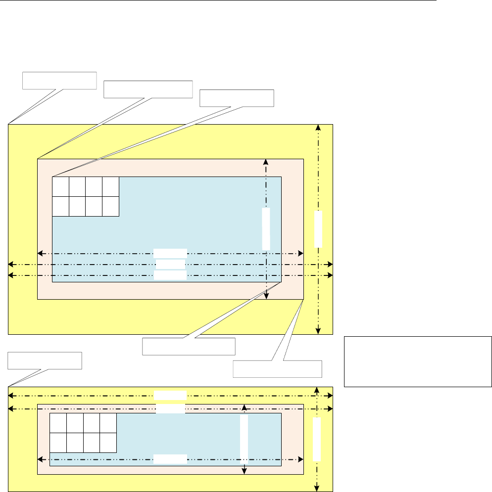
Picture Format
A-2
A.2 Progressive Picture Format
A c tiv eR e g io n a n d Im a g e R e g io n o ffs e ts fo r
c h ro m a a re d e riv e d fro m lu m a o ffs e t
C hro m a X o ffs e t = lu m a X _o ffs e t & 0xfffffffe;
C hro m a Y o ffs e t = (lu m a Y _ o ffs e t>>1) & 0xfffffffe;
A C T IV E R E G IO N (L U M A )
im a g e P itc h
a c tiv e R e g io n .to p L e ft
a c tiv e R e g io n .b o tto m R ig h t
frameHeight
m a x H e ig h t
m a x W id th
A C T IV E R E G IO N (C H R O M A )
p ic C h ro m a B u ffe r A d d r
im a g e P itc h
fra m e H e ig h t/2
m a x H e ig h t /2
m a x W id th
imageRegion.topLeft
p ic L u m a B u ffe rA d d r
im a g e R e g io n .b o tto m R ig h t
U
0 ,0
V
0 ,0
U
0 ,1
V
0 ,1
U
1 ,0
V
1 ,0
U
1 ,1
V
1 ,1
fr a m e W id th
Y
0 ,0
Y
0 ,1
Y
0 ,2
Y
0 ,3
Y
1 ,0
Y
1 ,1
Y
1 ,2
Y
1 ,3
fr a m e W id th

Picture Format
A-3
Note that for decoder in case of progressive sequence:
Luma and chroma buffer addresses can be allocated independently
Application shall provide this through separate buffer addresses
The outermost yellow coloured region is the minimum buffer that
application should allocate for a given maxWidth and maxHeight
activeRegion
o The displayable region after cropping done by application.
o The cropping information is derived from VUI information in the
bitstream
imageRegion
o Image data decoded by the decoder whose dimensions are
always multiple of 16.
o Contains the activeRegion as a proper subset.
Picture Buffer (pic(Luma/Chroma)BufferAddr)
o Contains padded regions and extra region due to alignment
constraints.
o Contains the imageRegion as a proper subset.
imagePitch
o The difference in addresses of two vertically adjacent pixels
o Typically equal to width of the picture Buffer.
Padding Amounts
o In vertical direction (top and bottom), padding amount is 24
pixels for Luma buffer and 12 pixels for chroma buffer.
o In horizontal direction (left and right), padding amount is 32
pixels for both Luma buffer chroma buffer.
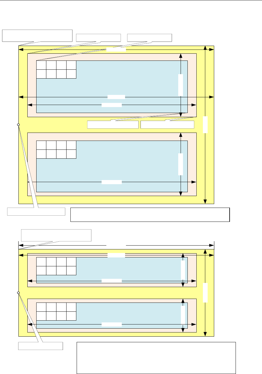
Picture Format
A-4
A.3 Interlaced Picture Format
A C T IV E R E G IO N
T O P F IE L D ( L u m a )
Y
0 ,0
Y
0 ,1
Y
0 , 2
Y
0 ,3
Y
2 ,0
Y
2 ,1
Y
2 , 2
Y
2 ,3
A C T IV E R E G IO N
B O T TO M F IE L D (Lu m a )
Y
1 ,0
Y
1 ,1
Y
1 , 2
Y
1 ,3
Y
3 ,0
Y
3 ,1
Y
3 , 2
Y
3 ,3
A C T IV E R E G IO N
T O P F IE L D (C h ro m a )
U
0 ,0
V
0 ,0
U
0 , 1
V
0 ,1
U
2 ,0
V
2 ,0
U
2 , 1
V
2 ,1
A C T IV E R E G IO N
B O T TO M F IE L D (C h ro m a)
U
1 ,0
V
1 ,0
U
1 , 1
V
1 ,1
U
3 ,0
V
3 ,0
U
3 , 1
V
3 ,1
m a x W i d th
m a x H e ig h t
m a x H e ig h t/ 2
m a x W i d th
im a g e P itc h
fr a m e W id t h
fr a m e W id t h
fr a m e W id t h
fr a m e H e ig h t/2
fra m e H e ig h t /4fr a m e H e ig h t/4 fr a m e H e ig h t/2
im a g e R e g io n .t o p L e ft a c tiv e R e g io n . to p L e ft
p ic L u m a B uffe rA d d r =
lu m a T o p F ie ld O u t p u t
lu m a B o tt o m F ie ld O u t p u t
im a g e P itc h
p ic C hro m a B uffe rA d d r =
c h ro m a T o p F ie ld O u tp u t
c h ro m a T o p F ie ld O u tp u t
fr a m e W id t h
A ctiv e R e g io n a n d Im a g eR e gio n o ffs e ts fo r c h ro m a a re d e r iv e d fro m lu m a
o f fs e t
C h ro m a X o ffs e t = lu m a X _o ffs e t & 0xfffffffe;
C h ro m a Y o ffs e t = (lu m a Y _ o ffs e t >> 1) & 0xfffffffe;
A ctiv e R e g io n a n d Im a g eR e gio n o ffs e ts a re s a m e fo r to p a n d b o tto m fie ld
F o r to p fie ld , offs et s s h o u ld b e c alcu la te d fr o m lu m a T o p F ie ld O u t p u t
F o r b otto m fie ld , o ffse ts sh o u ld b e c a lc u la te d fro m lu m a B o t to m F ie ld O u tp u t
A ctiv e R e g io n a n d Im a g eR e gio n o ffs e ts a re s a m e fo r to p a n d b o tto m fie ld
F o r to p fie ld , offs et s s h ou ld b e c alcu la t e d fro m lu m a T o p F ie ld O u t p u t
F o r b otto m fie ld , o ffse ts sh o u ld b e c a lc u la te d fro m lu m a B o t to m F ie ld O u tp u t
im a g e R e g io n .b o t to m R ig h ta c tiv e R e g io n .b o tt o m R ig h t
Padded region
D ecod e d re g io n m u ltip le o f
16x16 m a c r o b lo c k
D is p la y re g io n of a n y in te g er
n u m b e r o f p ix e ls in h oriz o n ta l
a n d v e rtic a l d ire ctio n

Picture Format
A-5
Note that for decoder in case of interlaced/MBAFF/PicAFF sequence:
Luma and chroma buffers can be allocated independently
Field buffer allocation cannot be independent
For every pair of top and bottom field, decoder shall expect a single
buffer address from the application
The outermost yellow coloured region is the minimum buffer that
application should allocate for a given maxWidth and maxHeight
activeRegion
o The displayable region after cropping done by application.
o The cropping information is derived from VUI information in the
bitstream
imageRegion
o Image data decoded by the decoder.
o Contains the activeRegion as a proper subset.
Picture Buffer (pic(Luma/Chroma)BufferAddr)
o Contains padded regions and extra region due to alignment
constraints.
o Contains the imageRegion as a proper subset.
imagePitch
o The difference in addresses of two vertically adjacent pixels
o Typically equal to width of the picture Buffer.
Padding Amounts
o In vertical direction (top and bottom), for each field, padding
amount is 24 pixels for Luma buffer and 12 pixels for chroma
buffer.
o In horizontal direction (left and right), padding amount is 32
pixels for both Luma buffer chroma buffer.

Picture Format
A-6
A.4 Constraints on Buffer Allocation for Decoder
maxWidth and maxHeight are inputs given by the decoder to the
applications
Application may not know the output format of the decoder.
Therefore, application should allocate Image Buffer based on
maxWidth and maxHeight
o The extra region beyond the (maxWidth x maxHeight)
requirements may be allocated by application due to
alignment, pitch or some other constraints
Application needs to ensure following conditions regarding imagePitch
imagePitch shall be greater or equal to the maxWidth.
imagePitch shall be multiple of 128 bytes (if the buffer is not in
TILED region).
imagePitch shall actually be the tiler space width (i.e. depends
on how many bit per pixel, for 8bpp 16bpp and 32bpp
respectively 16Kbyte, 32Kbyte and 32Kbyte). (if the buffer is in
TILED region).
Application may set imagePitch greater than maxWidth as per
display constraints. However this value must be a multiple of
128 bytes (if the buffer is not in TILED region).
picLumaBufferAddr and picChromaBufferAddr shall be 16-byte aligned
address. (if the buffer is not in TILED region).
ActiveRegion.topLeft and ActiveRegion.bottomRight are decoder
outputs
Application should calculate actual display width and display
height based on these parameters
ActiveRegion.topLeft and ActiveRegion.bottomRight shall be
identical for both fields in case of interlaced format
Maximum and Minimum Resolution is defined as below
Progressive
o Minimum frameWidth = 64
o Minimum frameHeight = 64
o Maximum frameWidth = 4320
o Maximum frameHeight = 4096
Interlaced
o Minimum frameWidth = 64
o Minimum (frameHeight / 2) = 32
o Maximum frameWidth = 4320
o Maximum (frameHeight / 2) = 2048
Typically picture buffer allocation requirements for decoder, after buffer
addresses meet alignment constraints (depends on decoder’s padding
requirements), for both progressive and interlaced are as given below.

Picture Format
A-7
Luma buffer size = maxWidth x maxHeight and Chroma buffer
size = maxWidth x maxHeight/2 where
o maxWidth = frameWidth + 64 (progressive/interlaced)
o maxHeight = frameHeight + 48 (progressive)
o maxHeight = frameHeight + 96 (interlaced)

Picture Format
A-8
This page is intentionally left blank

B-1
Appendix B
Meta Data Support
This version of the decoder supports writing out the parsed SEI, VUI data
and MB Info data into application provided buffers. If SEI and VUI is present
in the stream for this frame, the parsed data is given back to the application.
For the details on SEI and VUI data structures, See section 4.2.2.
This feature can be enabled/disabled through create time parameters
IVIDDEC3_Params::metadataType[IVIDEO_MAX_NUM_METADATA_PLANE
S]. There can be maximum 3 (IVIDEO_MAX_NUM_METADATA_PLANES) meta
data planes possible to be supported with one instance of the decoder.
Each element of metadataType[] array can take following enumerated
values.
Enumeration
Value
IVIDEO_METADATAPLANE_NONE
-1
IVIDEO_METADATAPLANE_MBINFO
0
IVIDEO_METADATAPLANE_EINFO
1
IVIDEO_METADATAPLANE_ALPHA
2
IH264VDEC_PARSED_SEI_DATA
256
IH264VDEC_ENCODED_SEI_DATA
257
IH264VDEC_PARSED_VUI_DATA
258
IH264VDEC_ENCODED_VUI_DATA
259
This version of the decoder supports only following enumerated values:
IVIDEO_METADATAPLANE_NONE
IH264VDEC_PARSED_SEI_DATA
IH264VDEC_PARSED_VUI_DATA
IVIDEO_METADATAPLANE_MBINFO

Meta Data Support
B-2
If user wants to get the SEI data, then
IVIDDEC3_Params::metadataType[0] should be set to
IH264VDEC_PARSED_SEI_DATA. Similarly, if both SEI and VUI data are
needed, then set IVIDDEC3_Params::metadataType[0] should be set to
IH264VDEC_PARSED_SEI_DATA and
IVIDDEC3_Params::metadataType[1] to
IH264VDEC_PARSED_VUI_DATA
If user does not want to use any meta data plane then all the entries of
IVIDDEC3_Params::metadataType[] should be set to
IVIDEO_METADATAPLANE_NONE. Note that the metadataType[] array
need to be filled contiguosly (there cannot be
IVIDEO_METADATAPLANE_NONE between 2 metadata types.
The buffer requirements for metadata can be obtained using Control call
with XDM_GETBUFINFO:
If any of the SEI or VUI metadata is requested during create time, then
the size of the buffer needed for populating SEI and VUI data are
indicated by the decoder in the Status structure during control call of
XDM_GETBUFINFO.
If both SEI and VUI data is requested during create, then the number
of output buffers needed is 4. status->bufInfo.minNumOutBufs =
4 (2 for Y and UV data, one each for SEI and VUI).
If only one of SEI or VUI data is requested, then the number of output
buffers needed is 3. status->bufInfo.minNumOutBufs = 3.
The order of the metadata buffer info supplied using status structure is
same as the order set by the user in the metadataType[] array during
create time. For example if the user has
IVIDDEC3_Params::metadataType[0] =
IH264VDEC_PARSED_SEI_DATA and
IVIDDEC3_Params::metadataType[1]=
IH264VDEC_PARSED_VUI_DATA then status-
>bufInfo.minOutBufSize[2] will have the SEI buffer requirement
and status->bufInfo.minOutBufSize[3].bytes will have VUI
buffer size information.
The buffer pointers for the metadata need to be supplied as below during
process Call:
When the application makes the process() call, the pointers to the
buffers where SEI/VUI data should be stored needs to be provided to
the codec in the output buffer descriptor [outputBufDesc.descs].
OutBufs->numBufs = numBuffers forYUVPlanes + number of meta
data enabled (This is =4 if both SEI and VUI are enabled)
o outBufs->descs[0] -> Y plane
o outBufs->descs[1] -> Cb/Cr plane outBufs.
o outBufs->descs[2] -> Buffer allocated for SEI
o outBufs->descs[3] -> Buffer allocated for VUI

Meta Data Support
B-3
The order of the metadata buffers need to be supplied for the process
call is same as the order set by the user in the metadataType[]
array during create time. For example if the user has
IVIDDEC3_Params::metadataType[0] =
IH264VDEC_PARSED_SEI_DATA and
IVIDDEC3_Params::metadataType[1]=
IH264VDEC_PARSED_VUI_DATA then outBufs->descs[2] will be
assumed as SEI buffer and outBufs->descs[3] will be assumed
as VUI buffer.
Codec internally writes the meta data in appropriate buffer. When the
decoder writes the SEI/VUI message, the number of metadata planes
is indicated by outArgs->decodedBufs.numMetaPlanes (this is 2 if
both SEI and VUI are enabled by the app)
Also, the respective buffer pointer is copied back in the first meta-plane
pointer: outArgs->decodedBufs.metadataPl
aneDesc[0].buf , again the ordering of the metadata is as per the
order supplied by IVIDDEC3_Params::metadataType[] inpput
parameter.
Decoder parses metadata in the current process call and returns in the
same process call. This means, effectively meta data will be given out in
decode order [Not in Display Order]. If application is interested in display
order, it should have a logic to track based on input and output ID. In case of
interlaced pictures, meta data buffers provided for each field (each process
call) is assumed to be independent.
REMAINDER OF THIS APPENDIX GIVES MORE INFORMATION ABOUT
IVIDEO_METADATAPLANE_MBINFO
Decoder shares two types of information at MB Level:
MB Error Map: It’s an array of bytes - One byte per MB (Refer Enum
IH264VDEC_ mbErrStatus). The byte indicates whether the MB is in error or
not.
MB Info structure: It is a structure which defines properties of a MB. Refer
structure IH264VDEC_TI_MbInfo in ih264vdec.h file. Size per MB = 208
bytes.
Decoder also shares a structure, which has information useful for
concealment purposes. Refer structure sErrConcealLayerStr in ih264vdec.h
file.
Case1: If the Application sets viddec3Params.metadataType[x] =
IVIDEO_METADATAPLANE_MBINFO and
IVIDDEC3_Params.operatingMode = IVIDEO_DECODE_ONLY, then
decoder will dump out MB Error Map and error concealment structure at
buffer location given for MB Info meta data.
Case2: If the Application sets viddec3Params.metadataType[x] =
IVIDEO_METADATAPLANE_MBINFO and
IVIDDEC3_Params.operatingMode =
IVIDEO_TRANSCODE_FRAMELEVEL, then decoder will dump out MB
Error Map at buffer location given for MB Info meta data. Error Map will be
followed by MB Info structure for all MBs. This will be followed by error
concealment structure.

Meta Data Support
B-4
Note that if the Application does not set viddec3Params.metadataType[x] =
IVIDEO_METADATAPLANE_MBINFO, then no information will be dumped,
irrespective of the value of IVIDDEC3_Params.operatingMode. Also, as a
minor Interface limitation, there is no provision to dump MB Info structure
alone w/o error map and error concealment structure.
Format details for Case 1 (Dumping of Error map and Error
concealment structure):
Case 1a, Progressive Frame:
Error Map, Size in Bytes = Number of MBs in Frame
Error Concealment Structure, Size in Bytes = sizeof(sErrConcealLayerStr)
Case 1b, Interlaced Frame:
Error Map for Top Field, Size in Bytes = (Number of MBs in Frame / 2)
Error Map for Bottom Field, Size in Bytes = (Number of MBs in Frame / 2)
Error Concealment Structure for Top Field, Size in Bytes =
sizeof(sErrConcealLayerStr)
Error Concealment Structure for Bottom Field, Size in Bytes =
sizeof(sErrConcealLayerStr)
Case 1c, MBAFF Frame:
Error Map for all Top MBs of the MB pair, Size in Bytes = (Number of MBs in
Frame / 2)
Error Map for all Bottom MBs of the MB pair, Size in Bytes = (Number of
MBs in Frame / 2)
Error Concealment Structure for entire frame, Size in Bytes =
sizeof(sErrConcealLayerStr)
Format details for Case 2 (Dumping of Error map, MB Info and Error
concealment structure):
Case 2a, Progressive Frame:
Error Map, Size in Bytes = Number of MBs in Frame
MB Info structure for all MBs, Size in Bytes = 208 * Number of MBs in Frame
Error Concealment Structure, Size in Bytes = sizeof(sErrConcealLayerStr)

Meta Data Support
B-5
Case 2b, Interlaced Frame:
Error Map for Top Field, Size in Bytes = (Number of MBs in Frame / 2)
Error Map for Bottom Field, Size in Bytes = (Number of MBs in Frame / 2)
MB Info structure for all MBs of Top Field, Size in Bytes = 208 * (Number of
MBs in Frame / 2)
MB Info structure for all MBs of Bottom Field, Size in Bytes = 208 * (Number
of MBs in Frame / 2)
Error Concealment Structure for Top Field, Size in Bytes =
sizeof(sErrConcealLayerStr)
Error Concealment Structure for Bottom Field, Size in Bytes =
sizeof(sErrConcealLayerStr)
Case 2c, MBAFF Frame:
Error Map for Top MBs of all MB Pairs, Size in Bytes = (Number of MBs in
Frame / 2)
Error Map for Bottom MBs of all MB Pairs, Size in Bytes = (Number of MBs
in Frame / 2)
MB Info structure for Top MBs of all MB Pairs, Size in Bytes = 208 *
(Number of MBs in Frame / 2)
MB Info structure for Bottom MBs of all MB Pairs, Size in Bytes = 208 *
(Number of MBs in Frame / 2)
Error Concealment Structure for Entire Frame, Size in Bytes =
sizeof(sErrConcealLayerStr)

Meta Data Support
B-6
This page is intentionally left blank

C-1
Appendix C
Error Handling
This version of the decoder supports handling of erroneous situations while
decoding. If decoder encounters errors in bit stream or any other erroneous
situations, decoder shall exit grace fully without any hang or crash. Also
decoder process call shall return IVIDDEC3_EFAIL and relevant error code
will be populated in extendedError field of outArgs. Different error codes
and their meanings are described below.
Definitions of bits numbered 8-15 are as per common XDM definition.
Definition of remaining bits are H264 Decoder specific and as given in below
tabular column. Bit numbering in the 32 bit word extendedError is from
Least Significant Bit to Most Significant Bit.
Some of the erroneous situations will get reported as XDM_FATALERROR by
the decoder. In these cases, Application should perform XDM_RESET of
the decoder. After an XDM_RESET is performed, the decoder will treat the bit
stream provided freshly and it shall use no information from previously
parsed data.
In certain fatal erroneous situations, the Application, might flush out the
locked buffers, if need be. See below table for more details on error
situations when flush can be performed.
In case of non-fatal errors, application need not perform XDM_RESET. It can
proceed with more decode calls, if bit stream is still not exhausted.
Meanings of various error codes and the recommended application behavior
are provided in the following table:
Table 4-2. Error Codes Information
Bit
Error code
Explanation
XDM Error Code
Mapping
Recommended App
Behavior
0
IH264VDEC_ERR
_NOSLICE
Not even a single
error-free slice
header found in this
process call, did
not start MB loop
XDM_CORRUPTEDHE
ADER
If more bytes available in
bit stream, then pass it to
decoder. ELSE if bytes are
not available call Flush
operation.
1
IH264VDEC_ERR
_SPS
Any syntax error
while parsing an
SPS in this process
call
XDM_CORRUPTEDHE
ADER
If more bytes available in
bit stream, then pass it to
decoder. ELSE if bytes are
not available call Flush
operation.

Error Handling
C-2
Bit
Error code
Explanation
XDM Error Code
Mapping
Recommended App
Behavior
2
IH264VDEC_ERR
_PPS
Any syntax error
while parsing a
PPS in this process
call
XDM_CORRUPTEDHE
ADER
If more bytes available in
bit stream, then pass it to
decoder. ELSE if bytes are
not available call Flush
operation.
3
IH264VDEC_ERR
_SLICEHDR
Any syntax error
while parsing a
slice header in this
process call. Can
be first slice or
intermediate slice.
XDM_CORRUPTEDHE
ADER
If more bytes available in
bit stream, then pass it to
decoder. ELSE if bytes are
not available call Flush
operation.
4
IH264VDEC_ERR
_MBDATA
ECD3 reported
error while parsing
MB data OR
decoded more MBs
wrongly in a slice
OR did SC overrun
at end of frame
without finding any
error
XDM_CORRUPTEDDA
TA
If more bytes available in
bit stream, then pass it to
decoder. ELSE if bytes are
not available call Flush
operation.
5
IH264VDEC_ERR
_UNAVAILABLES
PS
The SPS that a
PPS/slice header
referred to in this
process call has
not been received
yet OR it was
erroneous and thus
invalid.
XDM_CORRUPTEDHE
ADER
If more bytes available in
bit stream, then pass it to
decoder. ELSE if bytes are
not available call Flush
operation.
6
IH264VDEC_ERR
_UNAVAILABLEP
PS
The PPS that a
slice header
referred to in this
process call has
not been received
yet OR it was
erroneous and thus
invalid.
XDM_CORRUPTEDHE
ADER
If more bytes available in
bit stream, then pass it to
decoder. ELSE if bytes are
not available call Flush
operation.
7
IH264VDEC_ERR
_INVALIDPARAM
_IGNORE
Some error was
detected while slice
header decoding,
which the codec
corrected and
continued.
Application should
ignore this error.
XDM_CORRUPTEDHE
ADER
If more bytes available in
bit stream, then pass it to
decoder. ELSE if bytes are
not available call Flush
operation.
8
XDM_PARAMSCHA
NGE
Sequence
Parameters
Change
XDM_PARAMSCHANG
E
Refer codec specific error
which causes this

Error Handling
C-3
Bit
Error code
Explanation
XDM Error Code
Mapping
Recommended App
Behavior
9
XDM_APPLIEDCO
NCEALMENT
Applied
concealment
XDM_APPLIEDCONC
EALMENT
Refer codec specific error
which causes this
10
XDM_INSUFFICI
ENTDATA
Insufficient input
data
XDM_INSUFFICIEN
TDATA
Refer codec specific error
which causes this
11
XDM_CORRUPTED
DATA
Data
problem/corruption
XDM_CORRUPTEDDA
TA
Refer codec specific error
which causes this
12
XDM_CORRUPTED
HEADER
Header
problem/corruption
XDM_CORRUPTEDHE
ADER
Refer codec specific error
which causes this
13
XDM_UNSUPPORT
EDINPUT
Unsupported
feature/parameter
XDM_UNSUPPORTED
INPUT
Refer codec specific error
which causes this
14
XDM_UNSUPPORT
EDPARAM
Unsupported input
parameter
XDM_UNSUPPORTED
PARAM
Refer codec specific error
which causes this
15
XDM_FATALERRO
R
Fatal error
XDM_FATALERROR
Refer codec specific error
which causes this
16
IH264VDEC_ERR
_UNSUPPFEATUR
E
Unsupported
feature (FMO) is
present in the bit
stream, indicated
while decoding a
slice header
XDM_UNSUPPORTED
INPUT
Can either continue with
the stream giving a fresh
pointer OR do XDM Reset
and give a fresh stream
17
IH264VDEC_ERR
_METADATA_BUF
OVERFLOW
The size of the
metadata buffer
given by the
application is not
sufficient
XDM_UNSUPPORTED
INPUT
If more bytes available in
bit stream, then pass it to
decoder. ELSE if bytes are
not available call Flush
operation.

Error Handling
C-4
Bit
Error code
Explanation
XDM Error Code
Mapping
Recommended App
Behavior
18
IH264VDEC_ERR
_STREAM_END
End of Stream NAL
was found in this
process call OR
codec is in flush
mode
No XDM mapping
Normal Mode of Decoder -
Do XDM_FLUSH, Else -
XDM_RESET and Next
Stream
19
IH264VDEC_ERR
_NO_FREEBUF
Not used as of now
- Future use
XDM_FATALERROR
20
IH264VDEC_ERR
_PICSIZECHANG
E
A resolution
change is detected
while decoding a
slice header in this
process call
XDM_PARAMSCHANG
E
Perform FLUSH. No need
to perform XDM_RESET.
Do buffer re-allocation
based on new
GETSTATUS call. Pass
the pointer again.
21
IH264VDEC_ERR
_UNSUPPRESOLU
TION
Width or height is
less than the
minimum supported
or more than the
maximum
supported
XDM_FATALERROR
Can do a FLUSH, then
XDM Reset and pass a
fresh stream
22
IH264VDEC_ERR
_NUMREF_FRAME
S
The
num_ref_frames in
active SPS is more
than the supported
max_num_ref_fram
es
XDM_FATALERROR
Can do a FLUSH, then
XDM Reset and pass a
fresh stream
23
IH264VDEC_ERR
_INVALID_MBOX
_MESSAGE
Invalid message
received on MB,
which causes
interrupt on Media
Controller or
HDVICP2,
depending on the
FIFO - Stray writes
into FIFO by some
one other than
codec
XDM_FATALERROR
Should not do
XDM_FLUSH. Do
HDVICP_Reset, XDM
Reset and pass stream
24
IH264VDEC_ERR
_DATA_SYNC
Output datasync
enabled, and buffer
pointer in display
bufs is different
from decode bufs
XDM_FATALERROR
Can do a FLUSH, then
XDM Reset and pass a
fresh stream
25
IH264VDEC_ERR
_MISSINGSLICE
One or more slices
are completely
missing in this
picture
XDM_CORRUPTEDDA
TA
If more bytes available in
bit stream, then pass it to
decoder. ELSE if bytes are
not available call Flush
operation.
26
IH264VDEC_ERR
_INPUT_DATASY
NC_PARAMS
Error in input
datasync
parameters
XDM_UNSUPPORTED
PARAM
If more bytes available in
bit stream, then pass it to
decoder. ELSE if bytes are
not available call Flush
operation.

Error Handling
C-5
Bit
Error code
Explanation
XDM Error Code
Mapping
Recommended App
Behavior
27
IH264VDEC_ERR
_HDVICP2_IMPR
OPER_STATE
Turn on clocks
failed for HWAs,
OR HDVICP
standby failed OR
HDVICP Reset
failed
XDM_FATALERROR
Should not do
XDM_FLUSH. Do
HDVICP_Reset, XDM
Reset and pass stream
28
IH264VDEC_ERR
_TEMPORAL_DIR
ECT_MODE
Temporal direct
mode is disabled
by app, and the
stream contains
temporal direct
mode.
XDM_UNSUPPORTED
INPUT
If more bytes available in
bit stream, then pass it to
decoder. ELSE if bytes are
not available call Flush
operation.
29
IH264VDEC_ERR
_DISPLAYWIDTH
DisplayWidth is
less than the Image
width + Padded
width
XDM_FATALERROR
Should not do
XDM_FLUSH. Perform
XDM_Reset. Do a control
call and set suitable value
of displayWidth. Perform
FLUSH. No need to
perform XDM Reset. Pass
the pointer again.
30
IH264VDEC_ERR
_NOHEADER
Indicates that no
SPS/PPS header is
decoded in the
current process
call, when
operating in
PARSE_HEADER
mode (or) No
watermark SEI data
when
watermark
parameter is
enabled.
XDM_UNSUPPORTED
INPUT
Perform control call and
set decoder in
DECODE_AU mode and
do next process call.
31
IH264VDEC_ERR
_GAPSINFRAMEN
UM
Indicates that a gap
is detected in
frame_num.
Nothing
Application can infer actual
gap in frame number by
performing GET STATUS
control call and can take
any action which it wishes.
However, decoding can be
continued for the
remainder of the stream
normally.

Error Handling
C-6
This page is intentionally left blank

D-1
Appendix D
Parse Header Support
This version of the decoder provides support to parse just header of the
H264 bit stream. For decoder to operate in this mode Application needs to
perform a XDM_SETPARAMS control call with dynamicParams->
decodeHeader = XDM_PARSE_HEADER
Typical usage of this feature by the application is to understand the
resolution of picture in bit stream and allocate frame buffer of size as
needed by that bit stream. Sequence of operations on the application side
typically is as follows:
1. Decoder_Create
2. Control call (XDM_SETPARAMS) to configure decoder in parse
header mode
3. Process call to decoder which shall decode SPS+PPS
4. Control call (XDM_GETBUFINFO) to understand buffer
requirements
5. Allocate buffers of size exactly needed to decode this particular bit
stream
6. Control call (XDM_SETPARAMS) to configure decoder in normal
mode (dynamicParams->decodeHeader = XDM_DECODE_AU)
7. Process calls to decode frames
Note:
Following aspects of decoder behavior when configured in
XDM_PARSE_HEADER mode:.
Decoder shall neglect slice data, if encountered, before obtaining at least
one SPS+PPS in a bit stream. Decoder shall parse multiple SPS and PPS
NALs, if present, in the same process call until a slice header is
encountered.
After encountering at least one SPS+PPS in the bit stream, if decoder
encounters slice data in the same process call, then decoder shall parse
initial portion of slice header to understand SPS ID and hence the resolution
of the image. However bytes consumed value returned by decoder will not
include bytes of slice header.
After at least one SPS+PPS is parsed, if application still performs process
calls with decoder in XDM_PARSE_HEADER mode, then decoder behavior is
as follows:
If decoder encounters SPS/PPS, it shall parse them until slice data is
encountered. After encountering slice data, it shall infer SPS Id and return
from process call

Parse Header Support
D-2
If decoder encounters slice data, w/o encountering SPS+PPS in the current
process call, then decoder shall return H264D_ERR_NOHEADER error,
thereby indicating application to re-configure decoder in XDM_DECODE_AU
mode.
If application creates decoder to parse SEI and VUI, then decoder will parse
SEI / VUI if they are present in bit stream. Hence the application is expected
to pass the buffers for SEI and VUI appropriately.
Output buffers for YUV data is don’t care for decoder, while in parse header
mode

E-1
Appendix E
Skip Support
This version of the decoder provides support for skipping of decoding non-
reference frames. Typical usages of this feature by the application are as
follows:
1. In scenarios where video decoding takes more time and needs to catch
up with real time. So Application would wish decoder to skip decoding of
non-reference frames and hence save some time
2. In certain trick-play scenarios, where application is not interested in
decoding / displaying non-reference frames
To configure decoder in skip mode, Application needs to be perform
XDM_SETPARAMS control call, with dynamicParams-> frameSkipMode =
IVIDEO_SKIP_NONREFERENCE.
When configured in skip mode, if decoder encounters non-reference
pictures, it shall skip the decoding, regardless of slice type. Bit stream is just
parsed to understand end of picture and decoder shall report back the bytes
consumed as equal to bytes of that picture. Decoder shall indicate to the
application that it has skipped decoding by setting decodedBufs-
>frameStatus = IVIDEO_FRAME_OUTPUTSKIP.
Even, when the decoder skips decoding, buffer given by the application
shall be consumed by the decoder and the normal buffer-sharing interface
will be adhered to.
When buffer of the skipped picture is given out for display, decoder indicates
this to the application by setting displayBufs->frameStatus =
IVIDEO_FRAME_OUTPUTSKIP. Also note that decoder does not perform
concealment of skipped frames. Contents of the provided YUV buffer will not
be altered.
To re-configure decoder back into non-skip mode, application needs to
perform XDM_SETPARAMS control call, with dynamicParams->
frameSkipMode = IVIDEO_NO_SKIP

Skip Support
E-2
This page is intentionally left blank

F-1
Appendix F
Support for Display Delay and Low
DDR Memory Footprint
This version of decoder supports configurability to achieve desired display
delay and low DDR memory footprint.
It is recommended to utilize this feature only when the application is well
aware of the nature of the bit stream in terms of the GOP structure and the
number of reference frames used.
Desired display delay can be achieved by the application by setting
IVIDDEC3_Params::displayDelay. Decoder shall start displaying of frames
not later than displayDelay number of frames are decoded.
In certain application use cases, number of reference frames (and hence
DPB size needed) might be less than the standard allowed level limits. In
these cases decoder can be configured to operate with lower DDR footprint
– with respect to the amount of memory requested during create time and in
terms of number of frame buffers locked inside the decoder for referencing.
Application can utilize this feature by configuring
IH264VDEC_Params::dpbSizeInFrames.
For simple GOP structures, typically, it is enough if dpbSizeInFrames is
configured as M+1. And display delay is set as M, where M = SPS ->
max_num_ref_frames. In this case, decoder will not lock more than 2M+2
buffers. Above said values need to be exercised under caution, in closed
loop scenarios only, where the application is well aware of the GOP
structure. Refer Note below for more information.
Note:
If the GOP structure of the stream demands a display delay more than as
set by the application, decoder shall not be able to detect this situation.
Hence frames given out for display will be out of order.
In certain scenarios, decoder can infer that the stream requires more
reference frames than the dpbSizeInFrames set by the application. In these
cases, decoder shall have a process call failure with error code of
H264D_ERR_NUMREF_FRAMES. However, in certain GOP structures,
decoder might not be able to detect this situation and hence in these cases
decoder may lock up more frames than expected.
If the application use case is not well aware of the display delay and number
of reference frames needed by the bit streams, it is strongly recommended,
that the application sets both displayDelay and dpbSizeInFrames as
DEFAULT.

Support for Display Delay and Low DDR Memory Footprint
F-2
This page is intentionally left blank

G-1
Appendix G
Support for Dynamic Change in
Resolution
This version of decoder supports handling of change in resolution in a
stream. Procedure to be followed is as follows:
When the decoder detects that a change in resolution has occurred:
Decoder shall send out an error code of H264VDEC_ERR_PICSIZECHANGE.
bytesConsumed value returned by decoder shall not be inclusive of the slice
belonging to new resolution.
When the application observes the error code of
H264VDEC_ERR_PICSIZECHANGE, it should take the following steps:
Flush out all frames locked inside decoder [These frames will be of the older
resolution]
Perform control call with GET STATUS command to understand the new
resolution
Re-allocate YUV buffers based on the new resolution
Start performing process call again.
Note:
There is no need to perform XDM_Reset in the above flow
Above flow is same irrespective of whether the resolution increases or
decreases

Support for Dynamic Change in Resolution
G-2
This page is intentionally left blank
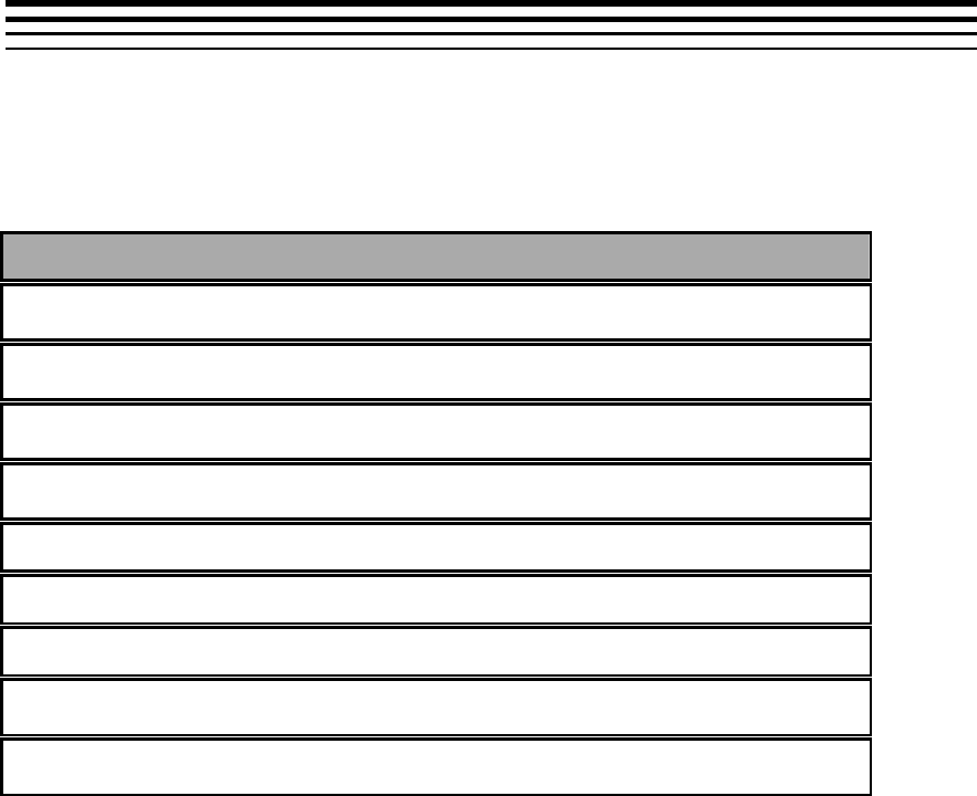
H-1
Appendix H
Support for Debug Trace
This appendix explains the details of Debug Trace generated by decoder.
H.1 Debug Trace DDR Memory Format in H264 Decoder
Debug trace header
Debug Trace Parameters for Process Call 1
Debug Trace Parameters for Process Call 2
Debug Trace Parameters for Process Call 3
Debug Trace Parameters for Process Call 4
:
:
:
Debug Trace Parameters for Process Call N
Debug Trace Parameters for Process Call N+1.
Decoder collects and dumps the Debug Trace Information in DDR in above
format. At the start of the buffer, is a header. Following the header, Debug
Trace parameters for each process call is stored. There are N+1 buffers,
since logs of last N process calls need to be stored and one extra buffer for
current process call logs.
Buffers for N+1 process calls are used in a circular manner by decoder -
once data for N+1 process calls are collected, decoder wraps back in the
buffer and starts storing from first buffer location.

Support for Debug Trace
H-2
H.2 Method to Configure decoder to collect debug trace:
During decoder creation, application needs to set
IH264VDEC_Params::debugTraceLevel =
IH264VDEC_DEBUGTRACE_LEVEL1. And set
IH264VDEC_Params::lastNFramesToLog = N, where N refers to number of
process calls for which trace needs to be collected. Note that the buffer for
debug trace collection will be requested by decoder, in DDR, during create
time and size of it will be linearly proportional to N.
H.3 Method for Application to collect debug trace:
Application can understand the address of the buffer by performing control
call with XDM_GETSTATUS command. Base address of the buffer will be
reported in IH264VDEC_Status::extMemoryDebugTraceAddr. Total size of
the buffer will be reported in
IH264VDEC_Status::extMemoryDebugTraceSize.
NOTE: Before collecting the contents from DDR, Application needs to
perform cache write back of the header portion of the buffer from Media
Controller side. Media Controller_Cache_WriteBack needs to be performed
at address IH264VDEC_Status::extMemoryDebugTraceAddr and for a size
equal to that of header (In this release, size of header is 96 Bytes)

I-1
Appendix I
Low Latency / Sub Frame Level
Synchronization
I.1 Brief Description
Sub frame level data synchronization between decoder and application is
supported in this release at both input and output level.
At decoder input level (Bit Stream), there are two modes of operation:
1. Fixed mode: where in multiples of 1K of bit stream can be
given
2. Slice mode: where in individual NALs can be given.
At decoder output level, decoder can give out reconstructed rows of MB,
instead of waiting until the entire frame is reconstructed.
I.2 Details of using Sub Frame Level data sync at output side:
This section explains the IVIDDEC3 interface details which help to achieve
the sub frame level communications at the output side.
Below tables explain the creation, control and handshake parameters
related to sub frame level data communication for output data of video
decoder respectively.
Details column is a generic column and “valid values” column is specific to
video decoder output.
Creation time parameter related to sub frame level data communication
for output data of video decoder:
Parameter
Name
Details
Valid values
IVIDDEC3_P
arams::output
DataMode
Defines the mode of
producing the output frame.
IVIDEO_ENTIRE
FRAME
entire frame data is
produced by decoder
for display
IVIDEO_NUMRO
WS
Frame data is given in
unit of Number of mb
rows, each mb row is
16 lines of video

Low Latency / Sub Frame Level Synchronization
I-2
IVIDENC2_P
arams::numO
utputDataUnit
s
Unit of output data
Don’t care if
IVIDDEC3_Params::outputDataMode ==
IVIDEO_ENTIREFRAME
If IVIDDEC3_Params::outputDataMode ==
IVIDEO_NUMROWS then it defines the
frequency at which decoder should inform
to application about data availability. For
example numOutputDataUnits = 2 means
that after every 2 MB row (2*16 lines)
availability in display buffer, decoder
should inform to application
Dynamic parameters related to sub frame level data communication for
output data of video decoder:
Parameter
Name
Details
Valid values
IVIDDEC3_
DynamicPar
ams::putDat
aFxn
This function pointer is
provided by the
app/framework to the video
decoder. The decoder calls
this function when sub-frame
data has been put into an
output buffer and is available.
Any non-NULL value if
outputDataMode !=
IVIDEO_ENTIREFRAME
IVIDDEC3_
DynamicPar
ams::putDat
aHandle
It defines the handle to be
used while informing data
availability to application.
This is a handle which the
codec must provide when
calling the app-registered
IVIDDEC3_DynamicParams.
putDataFxn().Apps/framewor
ks that don't support
datasync should set this to
NULL. For an algorithm, this
handle is read-only; it must
not be modified when calling
the app-registered
IVIDDEC3_DynamicParams.
putDataFxn().
The app/framework can use
this handle to differentiate
callbacks from different
algorithms.
Any Value

Low Latency / Sub Frame Level Synchronization
I-3
Handshake parameters related to sub frame level data communication
for output data of video decoder:
Parameter
Name
Details
Valid values
XDM_DataS
yncDesc::siz
e
Size of the XDM_DataSyncDesc structure
Sizeof(XDM_DataSyncDe
sc)
XDM_DataS
yncDesc::
scatteredBlo
cksFlag
Flag indicating whether the individual data
blocks may be scattered in memory.
Note that each individual block must be
physically contiguous.
Valid values are XDAS_TRUE and
XDAS_FALSE.
If set to XDAS_FALSE, the baseAddr field
points directly to the start of the first block,
and is not treated as a pointer to an array.
If set to XDAS_TRUE, the baseAddr array
must contain the base address of each
individual block.
Don’t care, always
assumed to be 0
XDM_DataS
yncDesc::ba
seAddr
Base address of single data block or
pointer to an array of data block
addresses of size numBlocks.
If scatteredBlocksFlag is set to
XDAS_FALSE, this field points directly to
the start of the first block, and is not
treated as a pointer to an array.
If scatteredBlocksFlag is set to
XDAS_TRUE, this field points to an array
of pointers to the data blocks.
Don’t care
XDM_DataS
yncDesc::nu
mBlocks
Number of data blocks
Number of rows given out
by decoder in this call of
putDataFxn. Value can be
k*numOutputDataUnits. K
= 1, 2 etc. Also towards
the end of frame it will
take value = [(no of rows
in picture) mod
(numOutputDataUnits)]
XDM_DataS
yncDesc::va
rBlockSizeFl
ag
Flag indicating whether any of the data
blocks vary in size.
Don’t care, as unit of size
is one row
XDM_DataS
yncDesc::blo
ckSizes
Variable block sizes array.
Don’t care Since unit is
assumed to be multiple of
number of rows which is
indicated by numBlocks.
If application, wants to use video decoder to operate with sub frame on
output side
It should create the video decoder with
IVIDDEC3_Params::outputDataMode = IVIDEO_NUMROWS.

Low Latency / Sub Frame Level Synchronization
I-4
It should also make a control call with
IVIDDEC3_DynamicParams::putDataFxn = non-NULL; to use sub
frame level data communication, control call is mandatory.
Address of the Luma and chroma output buffer will be present in
decoded/display buffs. It will not be communicated via
DataSyncDesc structure.
If Video decode Media Controller thread doesn’t get scheduled
before the next data availability, then in that situation codec give
numBlocks as k*numOutputDataUnits.
Constraint: display order not being same as decode order with
IVIDDEC3_Params::outputDataMode = IVIDEO_NUMROWS, is an
erroneous situation.
IVIDDEC3_DynamicParams::putDataFxn == NULL &&
IVIDDEC3_Params::outputDataMode == IVIDEO_NUMROWS is an
erroneous situation and codec returns error during process call
I.3 Details of using Sub Frame Level data sync at input side:
This section explains the IVIDDEC3 interface details, which help to achieve
the sub frame level communications for input.
Below tables explain the creation and control parameters related to sub
frame level data communication for input data of video decoder respectively.
Details column is a generic column and “valid values” column is specific to
video decoder.
Creation time parameter related to sub frame level data communication
for input data of video decoder:
Parameter
Name
Details
Valid values
IVIDDEC3_
Params::inp
utDataMode
Defines the mode of
accepting the input data.
IVIDEO_ENTIRE
FRAME
Entire frame bit-
stream is provided
to the decoder
IVIDEO_FIXEDL
ENGTH
bit-stream is
provided to decoder
after a fixed length
of bytes. The length
has to be multiple of
1K
IVIDEO_SLICE
MODE
bit-stream is
provided to decoder
after having a
single(or more)
number of slice NAL
Units
IVIDDEC3_
Params::nu
mInputData
Unit of input data
Don’t care

Low Latency / Sub Frame Level Synchronization
I-5
Units
Dynamic parameters related to sub frame level data communication for
input data of video decoder:
Parameter
Name
Details
Valid values
IVIDDEC3_
DynamicPar
ams::getDat
aFxn
This function is provided by
the app/framework to the
video decoder. The decoder
calls this function to get
partial compressed bit-
stream data from the
app/framework.
Apps/frameworks that don't
support datasync should set
this to NULL.
Any non-NULL value if
outputDataMode !=
IVIDEO_ENTIREFRAME
IVIDDEC3_
DynamicPar
ams::getDat
aHandle
It defines the handle to be
used while requesting data to
application. This is a handle
which the codec must
provide when calling
getDataFxn.
Apps/frameworks that don't
support datasync should set
this to NULL.
For an algorithm, this handle
is read-only; it must not be
modified when calling the
app-registered
IVIDDEC3_DynamicParams.
getDataFxn(). The
app/framework can use this
handle to differentiate
callbacks from different
algorithms.
Any Value
Incase of inputDataMode = IVIDEO_SLICEMODE, following points should
be noticed
No data is assumed to be available during process call, hence
IVIDDEC3_InArgs::numBytes is don’t care. All the data has to be
provided via data synch calls
Application can provide maximum 32 non-contiguous buffers of
varying size, but total size of data in one transaction has to be >=
1024 bytes
If the data provided during any data synch transaction is less than
1024 bytes then decoder assumes it as end of frame

Low Latency / Sub Frame Level Synchronization
I-6
At the end of process call IVIDDEC3_OutArgs::bytesConsumed
indicates the sum of total bytes consumed by decoder
Handshake parameters related to sub frame level data communication
for input data of video decoder (inputDataMode =
IVIDEO_SLICEMODE):
Parameter
Name
Details
Valid values
XDM_DataS
yncDesc::siz
e
Size of the XDM_DataSyncDesc structure
sizeof(XDM_DataSyncDe
sc)
XDM_DataS
yncDesc::
scatteredBlo
cksFlag
Flag indicating whether the individual data
blocks may be scattered in memory.
Note that each individual block must be
physically contiguous.
Valid values are XDAS_TRUE and
XDAS_FALSE.
If set to XDAS_FALSE, the baseAddr field
points directly to the start of the first block,
and is not treated as a pointer to an array.
If set to XDAS_TRUE, the baseAddr array
must contain the base address of each
individual block.
Flag indicating whether
the individual data slices
may be scattered in
memory.
XDAS_TRUE or
XDAS_FALSE
XDM_DataS
yncDesc::ba
seAddr
Base address of single data block or
pointer to an array of data block
addresses of size numBlocks.
If scatteredBlocksFlag is set to
XDAS_FALSE, this field points directly to
the start of the first block, and is not
treated as a pointer to an array.
If scatteredBlocksFlag is set to
XDAS_TRUE, this field points to an array
of pointers to the data blocks.
If scatteredBlocksFlag is
set to XDAS_FALSE, this
field points directly to the
start of the first block, and
is not treated as a pointer
to an array.
If scatteredBlocksFlag is
set to XDAS_TRUE, this
field points to an array of
pointers to the data
blocks.
XDM_DataS
yncDesc::nu
mBlocks
Number of data blocks
Constraint App can
provide maximum 32
blocks in one transaction
1 <= numBlocks <= 32
XDM_DataS
yncDesc::va
rBlockSizeFl
ag
Flag indicating whether any of the data
blocks vary in size.
XDAS_TRUE or
XDAS_FALSE(slice sizes
are not constant most of
the time)
XDM_DataS
yncDesc::blo
ckSizes
Variable block sizes array.
If varBlockSizesFlag is
XDAS_TRUE, this array
contains the sizes of each
slice. So
Total_size = sum of
(blockSizes[0] to
blockSizes[numBlocks -1].
If varBlockSizesFlag is
XDAS_FALSE, this

Low Latency / Sub Frame Level Synchronization
I-7
contains the size of same-
size slices. So
Total_size = (numBlocks *
blocSizes[0])
Constraint Total_size >=
1024 otherwise decoder
assumes end of frame
Incase of inputDataMode = IVIDEO_FIXEDLENGTH, following points should
be noticed
No data is assumed to be available during process call, hence
IVIDDEC3_InArgs::numBytes is don’t care. All the data has to be
provided via data synch calls
Application can provide maximum 1 buffers of size as multiple of 1K
during any data synch transaction
o During first data synch transaction, the data provided need
not to be multiple of 1024 bytes
o If the data provided during any data synch transaction is
less than 1024 bytes then decoder assume it as end of
frame
At the end of process call IVIDDEC3_OutArgs::bytesConsumed
indicates the sum of total bytes consumed by decoder
Handshake parameters related to sub frame level data communication
for input data of video decoder (inputDataMode =
IVIDEO_FIXEDLENGTH):
Parameter
Name
Details
Valid values
XDM_DataS
yncDesc::siz
e
Size of the XDM_DataSyncDesc structure
sizeof(XDM_DataSyncDe
sc)
XDM_DataS
yncDesc::
scatteredBlo
cksFlag
Flag indicating whether the individual data
blocks may be scattered in memory.
Note that each individual block must be
physically contiguous.
Valid values are XDAS_TRUE and
XDAS_FALSE.
If set to XDAS_FALSE, the baseAddr field
points directly to the start of the first block,
and is not treated as a pointer to an array.
If set to XDAS_TRUE, the baseAddr array
must contain the base address of each
individual block.
Don’t care assumed to be
XDAS_FALSE
XDM_DataS
yncDesc::ba
seAddr
Base address of single data block or
pointer to an array of data block
addresses of size numBlocks.
If scatteredBlocksFlag is set to
XDAS_FALSE, this field points directly to
This field points directly to
the start of the data

Low Latency / Sub Frame Level Synchronization
I-8
the start of the first block, and is not
treated as a pointer to an array.
If scatteredBlocksFlag is set to
XDAS_TRUE, this field points to an array
of pointers to the data blocks.
XDM_DataS
yncDesc::nu
mBlocks
Number of data blocks
Constraint App can
provide maximum 1 block
in one transaction
1 <= numBlocks <= 1
XDM_DataS
yncDesc::va
rBlockSizeFl
ag
Flag indicating whether any of the data
blocks vary in size.
Don’t care assumed to be
XDAS_FALSE
XDM_DataS
yncDesc::blo
ckSizes
Variable block sizes array.
Total_size =
blockSizes[0];
Constraint Except for first
transaction, in rest all the
transactions Total_size
should be multiple of 1K
bytes. If not decoder
assumes it end of frame
If application want to use video decoder to operate with sub frame on input
side
It should create the video decoder with
IVIDDEC3_Params::inputDataMode = IVIDEO_SLICEMODE
or IVIDEO_FIXEDLENGTH.
It should also make a control call with
IVIDDEC3_DynamicParams::getDataFxn = non-NULL; to use
sub frame level data communication, control call is mandatory.
It should not provide the base address and available data of
the input buffer during process call
IVIDDEC3_DynamicParams::putDataFxn == NULL &&
IVIDDEC3_Params::inputDataMode != IVIDEO_ENTIREFRAME is an
erroneous situation and codec returns error during process call.
Video Decoder input buffer release mechanism:
To facilitate the release of the input buffer, which has been consumed by
video decoder; IVIDDEC3 provides a mechanism.
Once the decoder consumes buffers given by Application during data sync
call, decoder shall notify the application through
VIDDEC3_DynamicParams::putBufferFxn API. Buffers received by decoder
during nth data sync call will be returned by decoder just before (n+2)th data
sync call.
Note: Considering the above mechanism for buffer release, Application
needs to maintain three sets of buffers and rotate among them, so that
buffers are provided to decoder without delay.

J-1
Appendix J
Support for Scalable Video Decoding
J.1 Brief Description
This version of decoder has partial support for Scalable Video Decoding. To
use this support, user needs a wrapper component (500.V.SVC.D.IVAHD),
which in turn calls this decoder as a sub component. Please refer to user
guide for 500.V.SVC.D.IVAHD for all the details.
J.2 Flow for SVC support
To obtain support for SVC, Application needs to interact with the wrapper
component 500.V.SVC.D.IVAHD. This wrapper component will internally
instantiate components of the decoder 500.V.H264AVC.D.IVAHD. Wrapper
component shall perform certain parsing operations and provide data in a
suitable form for the decoder component. Creating and managing the
decoder component is completely taken care by the wrapper component
and the application needs to interact only with the wrapper component.
J.3 SVC feature support
Wrapper component 500.V.SVC.D.IVAHD along with decoder component of
500.V.H264AVC.D.IVAHD, provides support for following features of SVC:
Support for H.264/AVC Annex-G/Scalable Video Coding without
inter layer prediction
SVC Baseline Support
Support for spatial, Temporal, SNR scalabilities without interlayer
prediction

Support for Scalable Video Decoding
J-2
This page is intentionally left blank
K-1
Appendix K
Support for Dual YUV Output
K.1 Brief Description
This decoder supports YUV dump in two buffers. This would be an optional
feature that can be enabled by the application at create time.
When this feature is enabled, the application needs to provide two output
buffers. Both buffers will provide output in display order as usual.
K.2 Enabling and using Dual Output
An additional create time flag has been added to request for secondary
output.
The following parameter has been added to IH264VDEC_Params.
enableDualOutput
Set it to 1 to enable dual YUV output. Set it to 2
to enable dual YUV output and to have 16-byte
aligned DDR offset to second output during
VDMA transfers for DDR Bandwidth
optimization. Set to 0 otherwise. Default value is
0.
If the application enables dual YUV output, it has to provide separate buffers
to hold two frames through XDM2_BufDesc *outBufs while calling
process().
XDM2_BufDesc is defined as follows.
typedef struct XDM2_BufDesc {
XDAS_Int32 numBufs;
XDM2_SingleBufDesc descs[XDM_MAX_IO_BUFFERS];
} XDM2_BufDesc;
numBufs should be set to 4 (two frames of YUV420, separate buffers for Y
and CbCr) if metadata is not enabled. If metadata is enabled, then numBufs
should be set to (4 + number of metadata planes). descs[0] and
descs[1] shall hold descriptors to luma and chroma buffers, respectively,
of output frame buffer 0. descs[2] and descs[3] shall hold descriptors to
luma and chroma buffers, respectively, of output frame buffer 1. Indices 4
and above of descs[] array shall be used for metadata buffers, if
applicable.
Support for Dual YUV Output
K-2
The following table explains the description of buffers.
Buffer Descriptor
Description
descs[0]
Luma buffer of output frame buffer 0
descs[1]
Chroma buffer of output frame buffer 0
descs[2]
Luma buffer of output frame buffer 1
descs[3]
Chroma buffer of output frame buffer 1
The application is expected to provide tiled buffers in descs[0] and
descs[1]. This (output frame buffer 0) would be used as reference buffer
by the decoder.
The decoder shall return the current decoded frame through
IVIDEO2_BufDesc decodedBufs in IH264VDEC_OutArgs, in buffers
pointed by outBufs.descs[0].buf and outBufs.descs[1].buf.
The decoder shall return the frame to be displayed through
IVIDEO2_BufDesc displayBufs in IH264VDEC_OutArgs, in buffers
pointed by outBufs.descs[2].buf and outBufs.descs[3].buf.
The Luma and Chroma output buffers to be displayed is pointed by
displayBufs.pBufDesc[0].planeDesc[0].buf and
displayBufs.pBufDesc[0]. planeDesc[1].buf. The Luma and
Chroma reference buffers is pointed by displayBufs.pBufDesc[1].
planeDesc[0].buf and displayBufs.pBufDesc[1].
planeDesc[1].buf.
Both the output buffers are freed simultaneously through freeBufID[]
field in outArgs when no longer needed as both the buffers share the same
inputID.
If one of the buffers in dual output mode is TILED and another is non-TILED,
it is recommended that application should provide the TILED buffer as
output frame 0 i.e., it should provide the TILED buffer through descs[0] and
descs[1]. Giving the non-TILED buffer as output frame buffer 0 may cause
degradation in performance.
Note:
The buffer requirement for output buffers is doubled when dual output is
enabled.
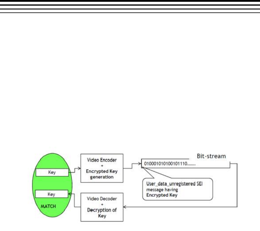
L-1
Appendix L
Support for Watermarking
L.1 Brief Description
With the rapid development of Internet technology, media data are used
more and more widely. This makes media data not only easy to be
transmitted, but also easy to be copied and spread out. Thus, the legal issue
arises that some media data should be protected from unauthorized users
or operations.
Watermarking is a mechanism to add identity to a bitstream to help decoder
to identify the media content. For video security applications, it has become
a de-facto requirement to prevent tampering with video.
IVAHD H.264 codecs support a watermarking scheme at no loss in
performance.
The proposed watermarking mechanism in IVAHD H.264 codec is shown in
the following figure.
H.264 Encoder
Encoder accepts a 32-bit key
Encoder encrypts the key using the properties of bit-stream which
can be obtained on decoder side as well
Encrypted Key = fn(input_key, bit-stream parameters)
Encoder inserts the encrypted key in form of user data unregistered
SEI message in the encoded stream

Support for Watermarking
L-2
H.264 Decoder
Decodes the encrypted key in form of user data unregistered SEI
message
Decrypts the key using the properties of bit-stream
Provides the decrypted 32-bit key
System
Feeds the key on encoder, gets the key from decoder and
compares them to identify content tampering
Note
There would be a delay of 1 frame in the watermarking system. The key given to the
encoder for the nth frame would be output by the decoder at the end of decoding
(n + 1)th frame.
L.2 Usage of watermarking feature
Enabling Watermark Support
An additional create time flag has been added to enable watermarking
feature.
The following parameter has been added to IH264VDEC_Params.
enableWatermark
Set it to IH264VDEC_WATERMARK_ENABLE to
enable watermarking. Set to
IH264VDEC_WATERMARK_DISABLE otherwise.
Default value is
IH264VDEC_WATERMARK_DISABLE.
Getting the decrypted key from the Decoder
The decoder outputs the decrypted key through the following parameter in
IH264VDEC_outArgs.
decryptedKey
Key decrypted by the decoder
The decrypted watermark keys would be given out in display order. At the
decoder side, the display delay can be zero or non-zero. If the display delay
is non-zero, the application receives decrypted keys in display order without
any delay.
Support for Watermarking
L-3
When the display delay is zero, the picture will be displayed immediately
after decoding. Since the watermarking system has one frame delay, it is
not possible to output decrypted keys without delay. So, we maintain one
frame delay in giving out the decrypted key to the application i.e., the
decrypted key given at nth frame will be the key for (n-1)th frame.
When the display delay is one and if the stream has one B-frame, then
watermark decrypted keys will be given out in decode order instead of
display order. In this scenario B-frames were displayed without any delay
and since the watermarking system has one frame delay, the corresponding
B-frame watermark key will be available in the next process call only. So,
along with the B frame we give out previous decoded frame’s watermark
key. Only for this particular case we give watermark keys in decode/stream
order.
After completing the last frame decoding, decoder is invoked once again to
parse watermark SEI data for the last frame and only the decrypted key will
be output to the application. At this point, the decoder returns
IVIDDEC3_EFAIL with XDM_INSUFFICIENTDATA error bit set.
When watermark parameter is enabled, decoder expects watermark SEI
data for every frame except the first frame. If watermark SEI data is
unavailable in any frame, then it returns IVIDDEC3_EFAIL with
IH264VDEC_ERR_NOHEADER error bit set.
Decode order
I1
P1
B1
I2
P2
B2
I3
P3
B3
Display order
I1
B1
P1
I2
B2
P2
I3
B3
Watermark
I1
P1
B1
I2
P2
B2
I3
P3
Freebuf
I1
B1
P1
I2
B2
P2
I3

Support for Watermarking
L-4
This page is intentionally left blank
M-1
Appendix M
Support for N Channel Process Call
M.1 Brief Description
Decoder can support N channel processing in single process call. In this method user has to
provide all the necessary input parameter (like handle, InArgs, outArgs, InBufs, outBuf) for
each channel through newly defined XDM API for multi-channel process call. This method is
useful in reducing the thread overhead at Media Controller. This support can be utilized to
decode one frame each from N channels.
M.2 Max value of numChannels (N)
Max value of number of channels that can be processed in single process call depends on
the maximum create time resolution of the decoder out of the N channels. Below Table gives
the maximum number of channels supported in N channel process call.
Max create
Resolution
Max number of
channels
1920 x 1080
1
1280 x 720
24
720 x 480
24
640 x 480
24
352 x 288
24
176 x 144
24
M.3 Limitations when using N channel processing
Followings are the limitations of N channel process call support
- No DataSync / Low latency feature
- Multiple frames from same channel in the same N channel group is not supported
Multichannel process calls with some channels in FLUSH mode and others in non-FLUSH
mode are not supported. If one channel ends early, application has to make single channel
process calls for completely flushing out that channel and then continue multichannel process
calls with the other channels.
In this method HDVICP acquire is done when first channel processing starts and release is
done after all the channel processing is finished. All the acquire and release is done with the
last channel handle.
M.4 XDM interface for Multi Channel process call
#define IH264VDEC_MAX_LENGTH_PROCESS_LIST (24)
typedef struct
{

Support for N Channel Process Call
M-2
IH264VDEC_Handle handle;
XDM2_BufDesc *inBufs;
XDM2_BufDesc *outBufs;
IVIDDEC3_InArgs *inArgs;
IVIDDEC3_OutArgs *outArgs;
} IH264VDEC_ProcessParams;
typedef struct
{
XDAS_Int32 numEntries ;
IH264VDEC_ProcessParams
processParams[IH264VDEC_MAX_LENGTH_PROCESS_LIST];
} IH264VDEC_ProcessParamsList ;
typedef struct IH264VDEC_Fxns
{
IVIDDEC3_Fxns ividdec3;
XDAS_Int32 (*processMulti)
(IH264VDEC_ProcessParamsList *processList);
} IH264VDEC_Fxns;
New processMulti API has been defined for this purpose.
M.5 Steps to achieve N channel processing in single process call
- Populate all the input parameters (handle, inBufs, outBufs, inArgs, outArgs) for every
channel of input data.
- Prepare the instance of the data type IH264VDEC_ProcessParamsList.
- Call the newly defined API processMulti with address of
IH264VDEC_ProcessParamsList as a single argument.
- After return from the multi process call, utilize the information updated by codec for
each channel in corresponding outArgs and outBufs.
M.6 Backward Compatibility
Backward compatibility is maintained after supporting N channel process call. Older
process call API can still be used for single channel processing in a process call.

N-1
Appendix N
Support for decoding only specific
frame types using less memory
N.1 Brief Description
Decoder supports this feature to decode only I and IDR, IP or all frame types. If user chooses
to decode only I/IDR or IP frame types then memory requested by decoder at create time will
be comparatively less than in case if user chooses to decode all frame types. User is advised
to use this feature if he is aware of frame types in the bitstream. However if a stream having
frame types, which are not requested by user to decode, is given to decoder then it decodes
only frame types requested by user to decode and skips unsupported frame types. Setting of
IVIDDEC3_DynamicParams::frameSkipMode = IVIDEO_SKIP_PB could have been used for
this purpose but it is defined at dynamic level, whereas the intention of this feature is to have
create time indication to codec for lesser memory foot print request. Please refer datasheet
for memory numbers when this feature is enabled.
N.2 Steps to enable this feature
Set the create time parameter – decodeFrameType to
IH264VDEC_DECODE_I_ONLY - To decode only I/IDR frames from the bitstream
IH264VDEC_DECODE_IP_ONLY - To decode I/IDR & P frame types
IH264VDEC_DECODE_ALL - To decode all frame types – I/IDR, P & B
N.3 Important points regarding this feature
The output buffer given for the decoder for a particular process call is displayed and
freed for that process call only if IH264VDEC_DECODE_I_ONLY is requested. The
display delay and DPB size given by user will be overridden to 0.
If IH264VDEC_DECODE_I_ONLY or IH264VDEC_DECODE_IP_ONLY is requested
then decoder requests only one frame size collocated MB Info buffer in high
resolution case (> 2048) and in case of low resolution (< 2048), decoder doesn’t
request any MB Info buffer and number of resources requested by decoder in this
case will be one less than in case of IH264VDEC_DECODE_ALL.
If XDM_FLUSH is called when IH264VDEC_DECODE_I_ONLY feature is enabled,
no display buffers are given out, as no frames are stored in DPB to flush out.
Error concealment will be applied to only those frame types which user requests to
decode and for unsupported frame types, no concealment is applied as we don’t give
out any display buffer in that case.

Support for decoding only specific frame types using less memory
N-2
In case of interlaced, if either of top or bottom fields is slice type which user doesn’t
want decoder to decode then entire frame is not displayed. Suppose if first field
decoded is has slice type which user wants decoder to decode and second field has
slice type which user doesn’t want decoder to decode then, first field is decoded
without any error but when second field is seen as unsupported and entire frame is
not displayed.
Decoder returns IH264VDEC_ERR_UNSUPPFEATURE extended error code
whenever it encounters frame types which user doesn’t want it to decode.
