HCS2maintenance
User Manual: HCS2maintenance
Open the PDF directly: View PDF ![]() .
.
Page Count: 191 [warning: Documents this large are best viewed by clicking the View PDF Link!]
- For safe adjustment and repair
- Index
- Special tool, Measuring equipment, Other
- 1. Outline of mechanism
- 2. Outer covers
- 3. Mechanical mechanism
- 3-1 Basic maintenance
- 3-2 Fixed head
- 3-2-1Exchange of crank
- 3-2-2 Exchange of rod
- 3-2-3 Adjustment of the lowest needle point
- 3-2-4 Exchange of needle bar driver
- 3-2-5 Adjustment of fixing of jump solenoid
- 3-2-6 Exchange of take-up lever cam
- 3-2-7 Exchange of roller shaft ass’y
- 3-2-8 Adjustment of take-up lever timing
- 3-2-9 Exchange of pressure foot cam
- 3-2-10 Check of height of pressure foot
- 3-2-11 Exchange of pressure foot
- 3-2-12 Adjustment of height of pressure foot guide bar
- 3-2-13 Exchange of pressure foot link and block
- 3-2-14 Exchange of pressure foot drive lever
- 3-2-15 Exchange of pressure foot guide
- 3-2-16 Exchange of pulse motor for pressure foot
- 3-2-17 Adjustment of pressure foot bracket ass’y
- 3-2-18 Exchange of thread catcher
- 3-2-19 Exchange of thread catcher guide
- 3-2-20 Disassembling and Cleaning of jump solenoid
- 3-2-21 Adjustment of bobbin winder
- 3-3 Moving head
- 3-3-1 Assemble the upper rail of moving head
- 3-3-2 Adjustment of backlash (back and forth) of moving head
- 3-3-3 Assemble the moving head
- 3-3-4 Adjustment of needle position (back and forth)
- 3-3-5 Check of needle position
- 3-3-6 Adjustment of needle height
- 3-3-7 Exchange of needle bar, needle bar spring and cushion
- 3-3-8 Fixing of needle bar boss guide plate
- 3-3-9 Exchange of take-up lever
- 3-3-10 Exchange of thread adjusting spring
- 3-3-11 Adjustment of tension of thread adjusting spring
- 3-3-12 Adjustment of stroke of thread adjusting spring
- 3-3-13 Adjustment of thread holder
- 3-4 Needle bar change unit
- 3-5 Rotary hook
- 3-6 Thread cut unit
- 3-6-1 Assemble the arm ass’y
- 3-6-2 Exchange of thread cutting roller (except for Rev.A)
- 3-6-3 Exchange of thread cutting roller (for Rev.A)
- 3-6-4 Adjustment of thread cutting stopper (except for Rev.A)
- 3-6-5 Adjustment of thread cut timing (except for Rev.A)
- 3-6-6 Exchange of moving knife
- 3-6-7 Exchange of fixed knife
- 3-6-8 Adjustment of moving knife and fixed knife
- 3-6-9 Adjustment of position of moving knife (except for Rev.A)
- 3-6-9b Adjustment of position of moving knife (for Rev.A)
- 3-6-10 Adjustment of bobbin thread holder
- 3-6-11 Exchange of keeper solenoid
- 3-6-12 Adjustment of position of keeper
- 3-7 Carriage unit
- 3-8 Transmission unit
- 4. Electricity
- 5. Electric documents
- 6. Others
- 6-1 How to respond for some question (As example step)
- 6-2 Trouble shooting
- 6-2-1 Trouble shooting (Electricity doesn’t turn on)
- 6-2-2 Trouble shooting (Thread break)
- 6-2-3 Trouble shooting (Erroneous thread cut)
- 6-2-4 Trouble shooting (Off-registration of pattern)
- 6-2-5 Trouble shooting(Upper thread comes off from needle hole)
- 6-2-6 Trouble shooting(Upper thread remains)
- 6-2-7 Trouble shooting (Malfunction of thread break detection)
- 6-2-8 Trouble shooting (Suspension of upper shaft)
- 6-2-9 Trouble shooting (Malfunction of needle bar change)
- 6-2-10 Trouble shooting (Defect on Thread catcher)
- 6-2-11 Trouble shooting (Others / Mechanical)
- 6-2-12 Trouble shooting (Others / Electric)
- 6-3 Error
- 6-4 Reference date
Maintenance Manual for Embroidery Machine
HCS2-1201-30
Version 2.0
HAPPY Industrial Corporation

2
# For safe adjustment and repair #
In order to conduct adjustment and repair safely and surely,
please b42e sure to abide by what is mentioned in this manual to prevent trouble.
1. When you conduct adjustment and repair of this embroidery machine or handle electric related parts,
you are required to take technical lesson in advance.
2. When you conduct adjustment and repair using this manual, please be sure to use together with instruction
with it in hand.
# Please conduct in accordance with work process in this manual.
# In case there are no specific instructions or explanations in work process.
please be sure to unplug cord from receptacle.
# When you exchange parts, please be sure to use genuine parts designated by us.
# Please never remodel the embroidery machine.
When you handle circuit boards:
# In order to prevent troubles from static electricity, please remove earth from human body.
# Please don't touch metal part of circuit board with bare hand as it will short-circuit
and threaten to break circuit boards.
# When you removed circuits boards from the machine or you store or transport them,
please wrap them in static electricity preventive bag and avoid to give shock.

3
Index
page
For safe adjustment and repair 2
Index 3
Special tool, Measuring equipment, Other 8
1 Outline of mechanism
1-1 Placement of key mechanical parts 12
1-2 Placement of key electronic parts 14
2 Outer covers
2-1 Removal of outer covers 15
3 Mechanical mechanism
3-1 Basic maintenance
3-1-1 Maintenance of thread path 19
3-1-2 Fixing of needle 21
3-1-3 Selection of thread 22
3-1-4 Relation between needle and upper thread 23
3-2 Fixed head
3-2-1 Exchange of crank 24
3-2-2 Exchange of rod 28
3-2-3 Adjustment of the lowest needle point 29
3-2-4 Exchange of needle bar driver 30
3-2-5 Adjustment of fixing of jump solenoid 32
3-2-6 Exchange of take-up lever cam 34
3-2-7 Exchange of roller shaft ass’y 36
3-2-8 Adjustment of take-up lever timing 37
3-2-9 Exchange of pressure foot cam 38
3-2-10 Check of height of pressure foot 39
3-2-11 Exchange of pressure foot 40
3-2-12 Adjustment of height of pressure foot guide bar 41
3-2-13 Exchange of pressure foot link and block 42
3-2-14 Exchange of pressure foot drive lever 43
3-2-15 Exchange of pressure foot guide 46
3-2-16 Exchange of pulse motor for pressure foot 48
3-2-17 Adjustment of pressure foot bracket ass’y 50
3-2-18 Exchange of thread catcher 51

4
Index
page
3-2-19 Exchange of thread catcher guide 52
3-2-20 Disassembling and Cleaning of jump solenoid 53
3-2-21 Adjustment of bobbin winder 54
3-3 Moving head
3-3-1 Assemble the upper rail of moving head 56
3-3-2 Adjustment of backlash (back and forth) of moving head 57
3-3-3 Assemble the moving head 58
3-3-4 Adjustment of needle position (back and forth) 62
3-3-5 Check of needle position 63
3-3-6 Adjustment of needle height 64
3-3-7 Exchange of needle bar, needle bar spring and cushion 66
3-3-8 Fixing of needle bar boss guide plate 68
3-3-9 Exchange of take-up lever 69
3-3-10 Exchange of thread adjusting spring 71
3-3-11 Adjustment of tension of thread adjusting spring 73
3-3-12 Adjustment of stroke of thread adjusting spring 74
3-3-13 Adjustment of thread holder 75
3-4 Needle bar change unit
3-4-1 Fixing of needle bar change unit 77
3-4-2 Setting to detect needle position 78
3-5 Rotary hook
3-5-1 Adjustment of rotary hook timing 80
3-5-2 Adjustment of retainer on rotary hook 82

5
Index
page
3-6 Thread cut unit
3-6-1 Assemble the arm ass’y 83
3-6-2 Exchange of thread cutting roller (except for Rev.A) 85
3-6-3 Exchange of thread cutting roller (for Rev.A) 88
3-6-4 Adjustment of thread cutting stopper (except for Rev.A) 91
3-6-5 Adjustment of thread cut timing (except for Rev.A) 92
3-6-6 Exchange of moving knife 95
3-6-7 Exchange of fixed knife 96
3-6-8 Adjustment of moving knife and fixed knife 97
3-6-9 Adjustment of position of moving knife (except for Rev.A) 98
3-6-9b Adjustment of position of moving knife (for Rev.A) 99
3-6-10 Adjustment of bobbin thread holder 101
3-6-11 Exchange of keeper solenoid 102
3-6-12 Adjustment of position of keeper 103
3-7 Carriage unit
3-7-1 Adjustment of X carriage belt tension 104
3-7-2 Exchange of X carriage belt 106
3-7-3 Adjustment of Y carriage belt tension 109
3-7-4 Exchange of Y carriage belt 112
3-8 Transmission unit
3-8-1 Adjustment of timing belt tension 115
3-8-2 Exchange of timing belt 116
3-8-3 Adjustment of motor belt tension 118
3-8-4 Exchange of motor belt 120
4 Electricity
4-1 Circuit board related parts
4-1-1 Remove LCD and LCD-CE board 122
4-1-2 Setting for LCD-CE board 124
4-1-3 Setting for power supply 125
4-2 Sensors
4-2-1 Adjustment of upper shaft timing (C point / L point) 126
4-2-2 Adjustment of TC board 127
4-2-3 Adjustment of stop position of needle bar change unit 127

6
Index
Page
4-3 Inverter
4-3-1 Remove of Inverter 129
4-3-2 Inverter Installation 131
4-3-3 How to set inverter 134
4-3-4 Initialization of parameter 136
4-4 Initialization of system
4-4-1 Program update procedure 137
4-4-2 Preparation for program update 138
4-4-3 Machine program update (Main program 〜Ver.*1.21) 139
4-4-4 Main program update (Main program 〜Ver.*1.21) 141
4-4-4a Machine program and Main program update (Main program Ver.*1.22〜) 141a
4-4-5 Setting of revolution 142
4-5 Maintenance mode 143
4-5-1 How to enter maintenance mode 143
4-5-2 Machine Test Machine movement 144
4-5-3 Memory All Clear Initialization of memory 146
4-5-4 Record Opereration data display 147
4-5-4-1 Total number of stitch 147
4-5-4-2 Record of Error occurrence 148
4-5-4-3 Number of occurrence in each error display 149
4-5-4-4 Thread break history 150
4-5-4-5 Setup 151
5 Electric documents
5-1 Electric system diagram
5-1-1 Electrical connection diagram (except for Rev.A) 153
5-1-2 List of electrical connection diagrams (except for Rev.A) 155
5-1-3 Electrical connection diagram (for Rev.A) 156
5-1-4 List of electrical connection diagrams (for Rev.A) 158
5-2 Inverter
5-2-1 Connection of inverter 100V 159
5-2-2 Connection of inverter 200V 160
5-3 Explanation of function of circuit board 160a

7
Index
Page
6 Others
6-1 How to respond for some question ( As example step) 161
6-2 Trouble shooting
6-2-1 Electricity doesn’t turn on 162
6-2-2 Thread break 163
6-2-3 Erraneous thread cut 168
6-2-4 Off-registration of pattern 170
6-2-5 Upper thread comes off from needle hole 172
6-2-6 Upper thread remains 174
6-2-7 Malfunction of thread break detection 175
6-2-8 Suspension of upper shaft 177
6-2-9 Malfunction of needle bar change 178
6-2-10 Defect on thread catcher 179
6-2-11 Others (Mechanical) 180
6-2-12 Others (Electronically) 181
6-3 Error
6-3-1 Error and measure 182
6-4 Reference date
6-4-1 Tables for timing / adjustment value 186
8
Special tool, Measuring equipment, Other
HSA90010
Needle bar boss positioning gauge [25mm] (Page 65)
HSA90020
2.0mm thickness gauge (Page 102, 103)
HSA90030
Keeper positioning gauge (Page 103)
HSA90051
Bering positioning gauge [4.85mm] (Page 36)
HSA90061
Gauge for adjustment of height of pressure foot bracket
[24.8 - 25.0mm] (Page 50)
HSA90071
Thread hoIder positioning gauge [47.5mm]
(Page 75)
9
HSA90080
Retainer positioning gauge [0.8mm] (Page 82)
HSA90090
Positioning pin (Page 37)
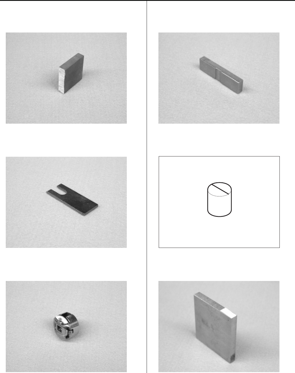
HSA90131
1.2mm thickness gauge (Page 39, 41, 45, 47)
HSA90200
0.03mm thickness gauge (Page 28)
HSA90210
0.2mm thickness gauge (Page 70, 91)
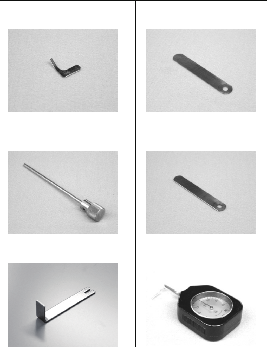
HSA90230
Tensile gauge (Page 55, 101)
10 - 11
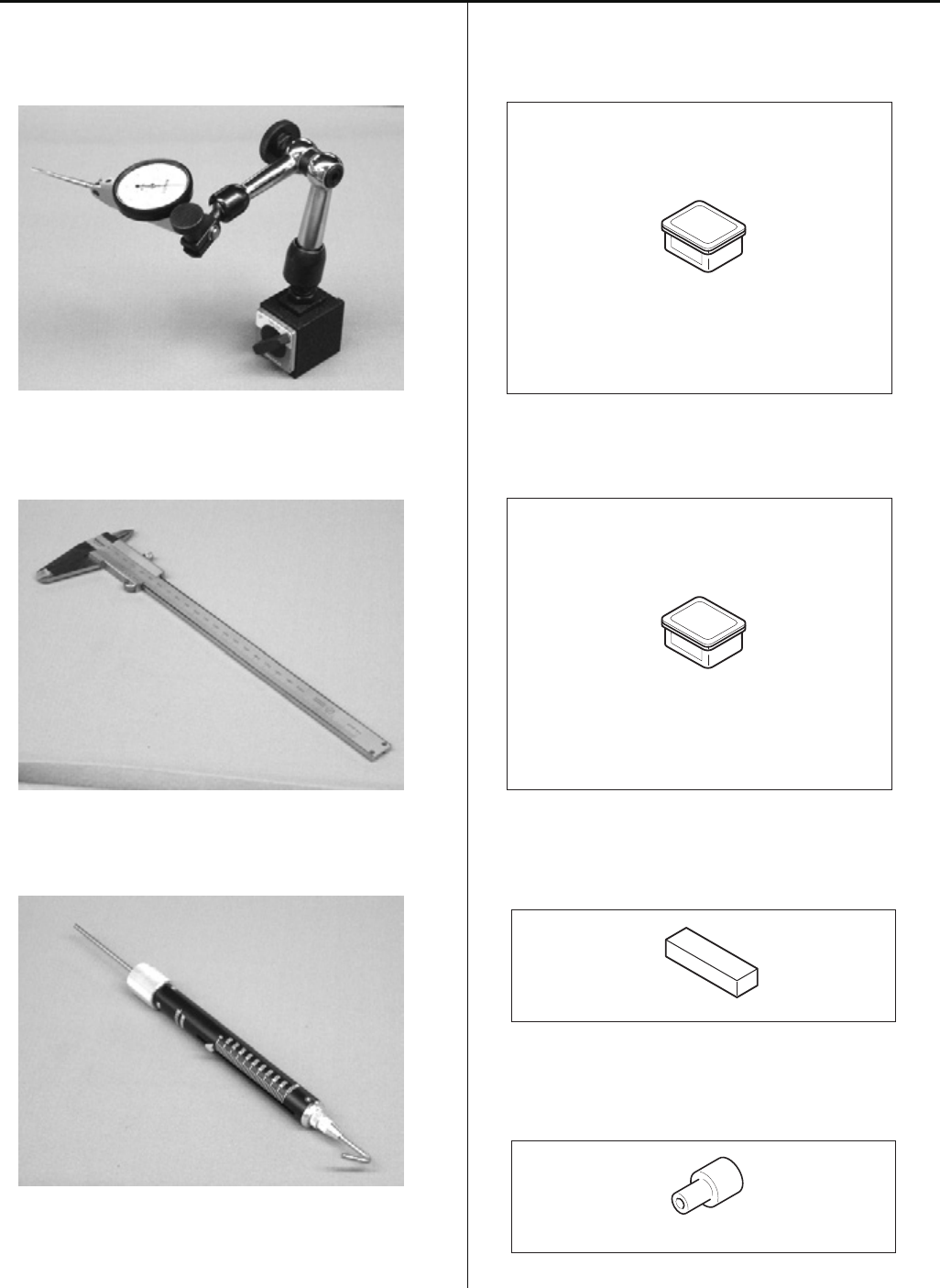
HSA90240
Dial-gauge set (Page 29)
HSA90270
Vernier calliper gauge [200mm]
HSA90280
Tension gauge 1000cN (Page 105, 110, 118)
HSA90311
Shell alvania EP Grease 100g
(Page 38, 44)
HSA90340
Shell Grease7 MIL-G-23827B 50g
(Page 53)
HSA90321
11.5mm thickness gauge (Page 27 , 35)
M0404342
Needle height gauge (Page 65)
12
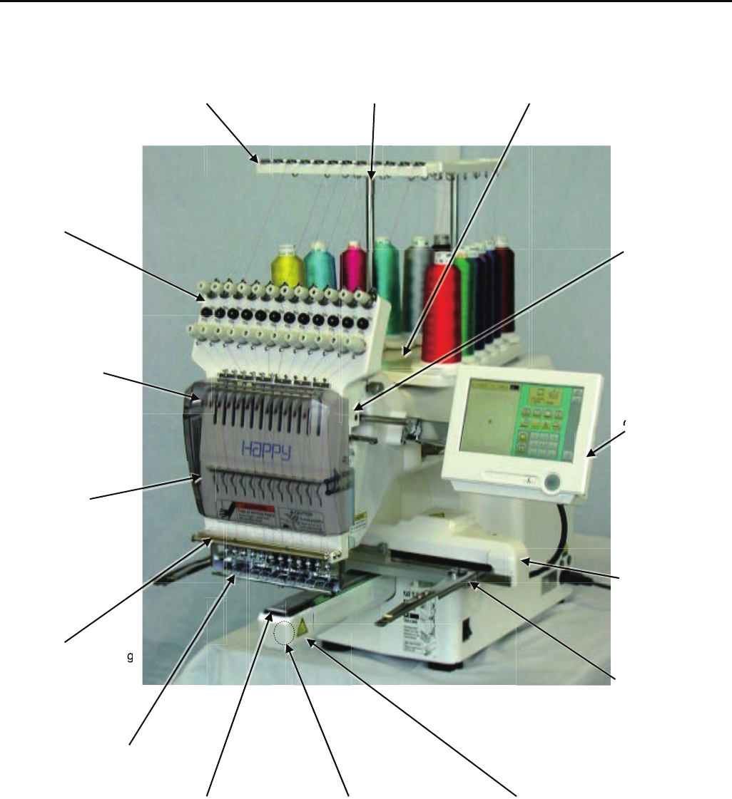
1-1 Placement of key mechanical parts
Thread guide bracket Thread guide pillar Tread stand
Thread tension unit
Moving head
Take-up lever
Control panel
Front cover
X carriage
Thread adjusting spring
Frame base
Thread holder
Needle plate Rotary hook Rotary hook cover
C
g
g
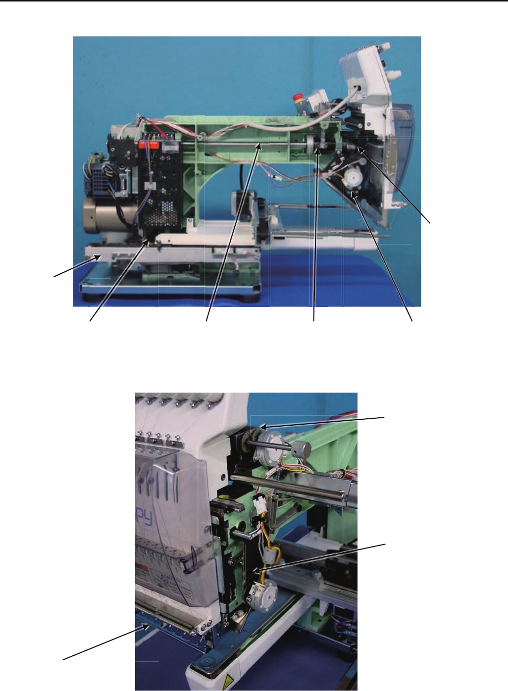
13
Needle bar
driver unit
Y carriage
Thread cutting driver Upper shaft Take-up lever cam Thread cacher
Needle bar change unit
Pressure foot driver unit
Thread holder
14
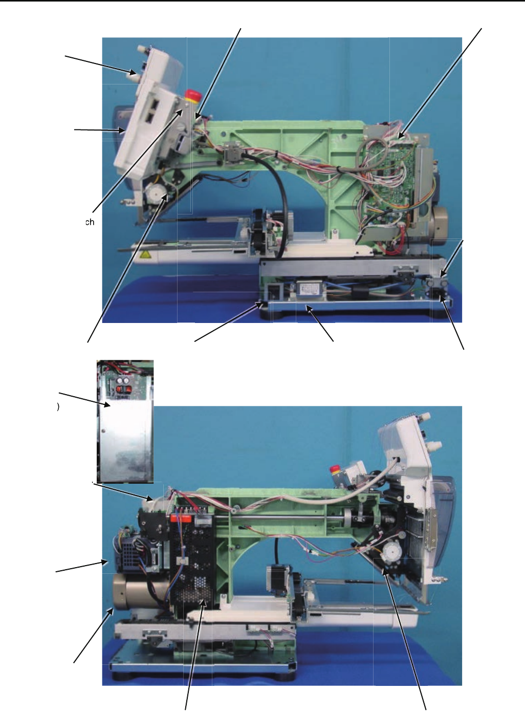
1-2 Placement of key electronic parts
Pulse motor (Needle bar change unit) CONT-S2 board
TC board
Display board
Emergency stop switch
Fuse
Pulse motor (Pressure foot ) Power swich Noise filter AC power
Power supply
(200V)
Timing detecting board
Inverter
Main motor
Power supply (100V) Pulse motor(Thread catcher)
c
ch
d
)
15
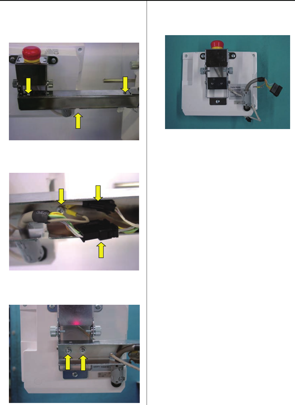
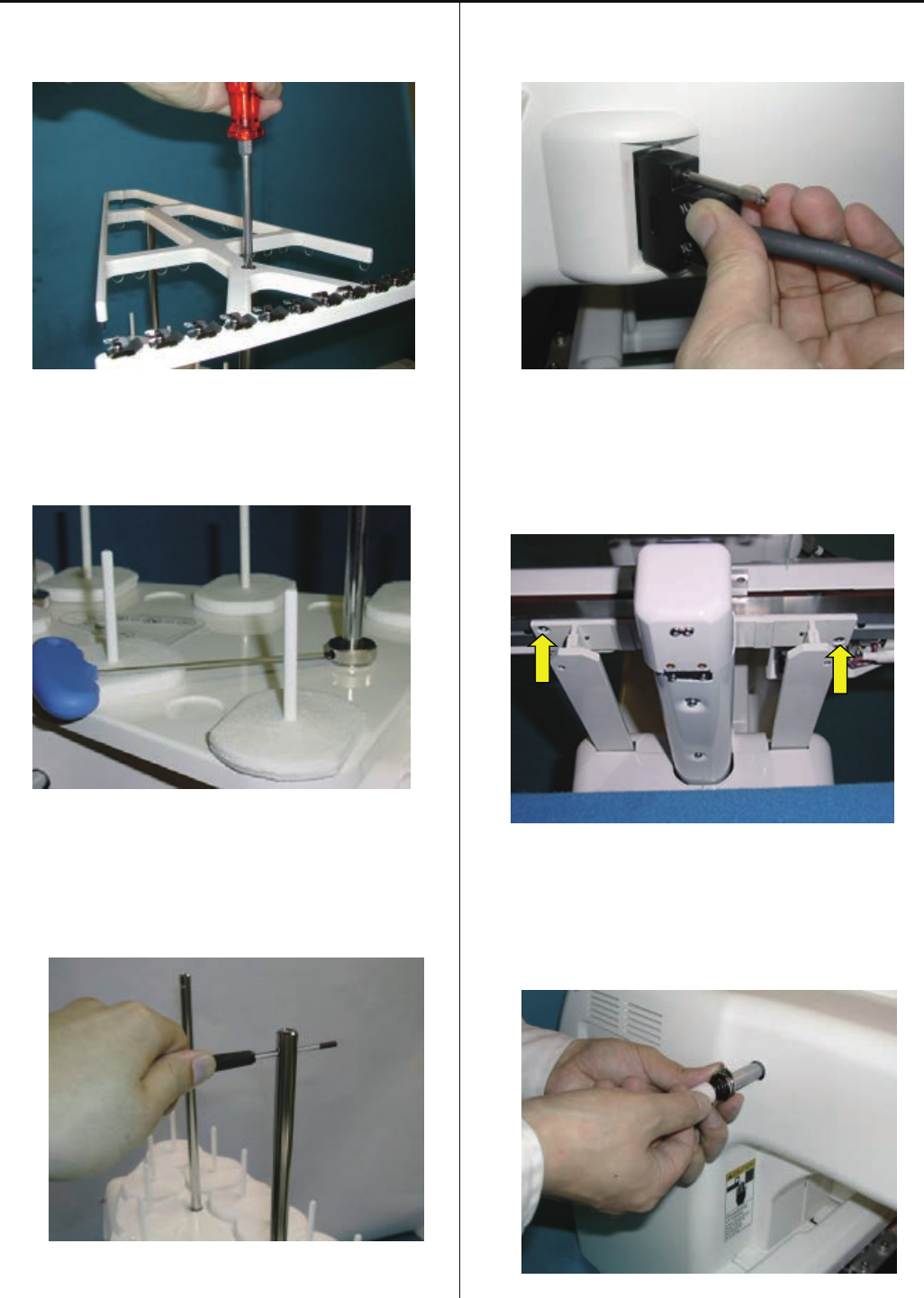
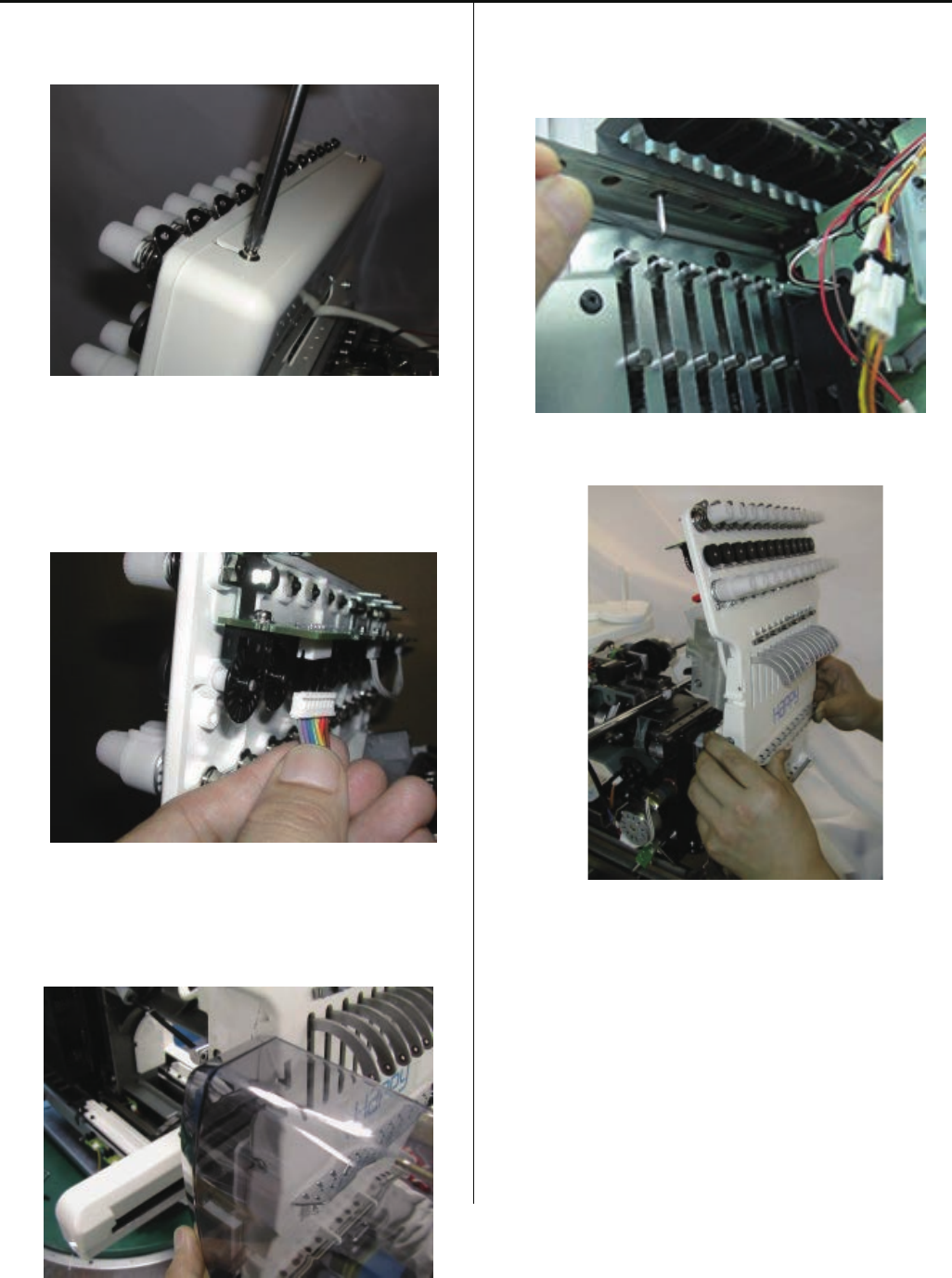
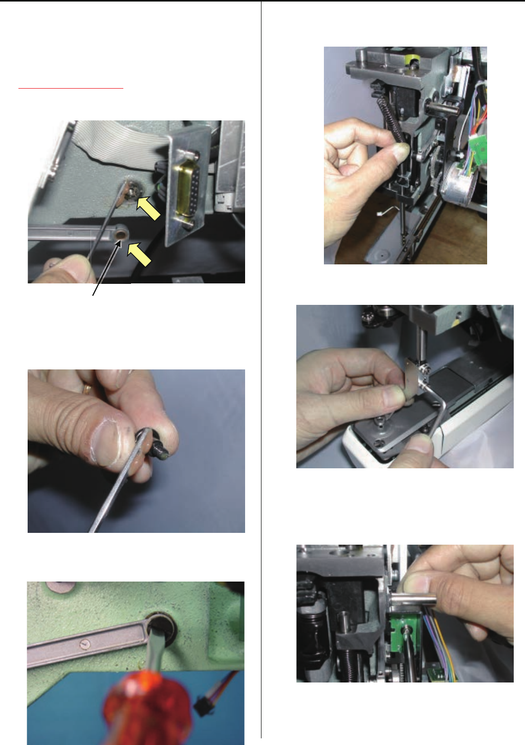
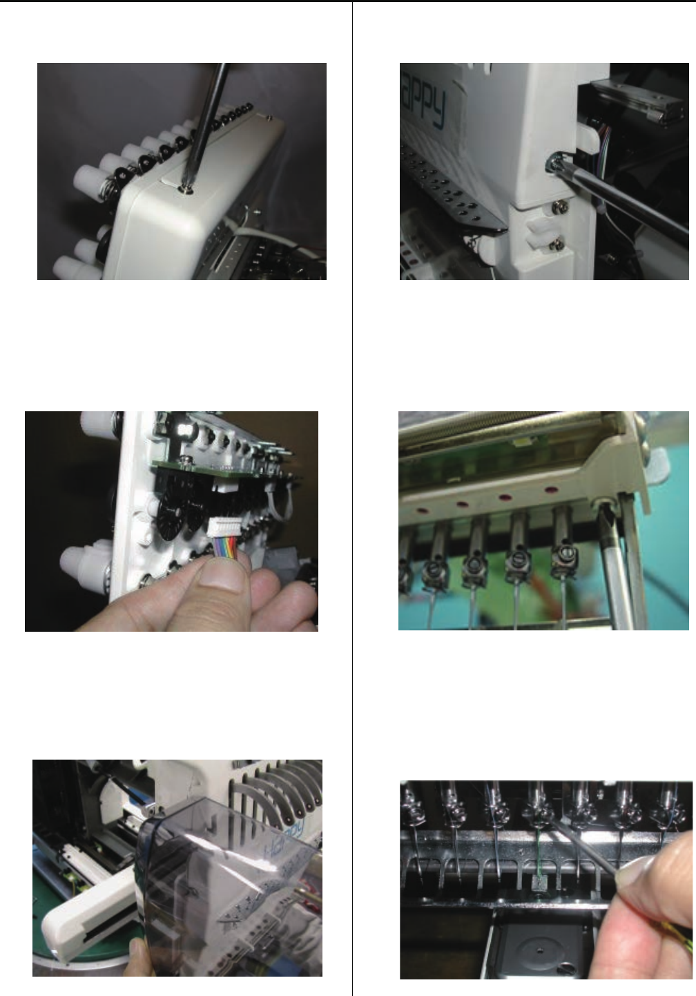
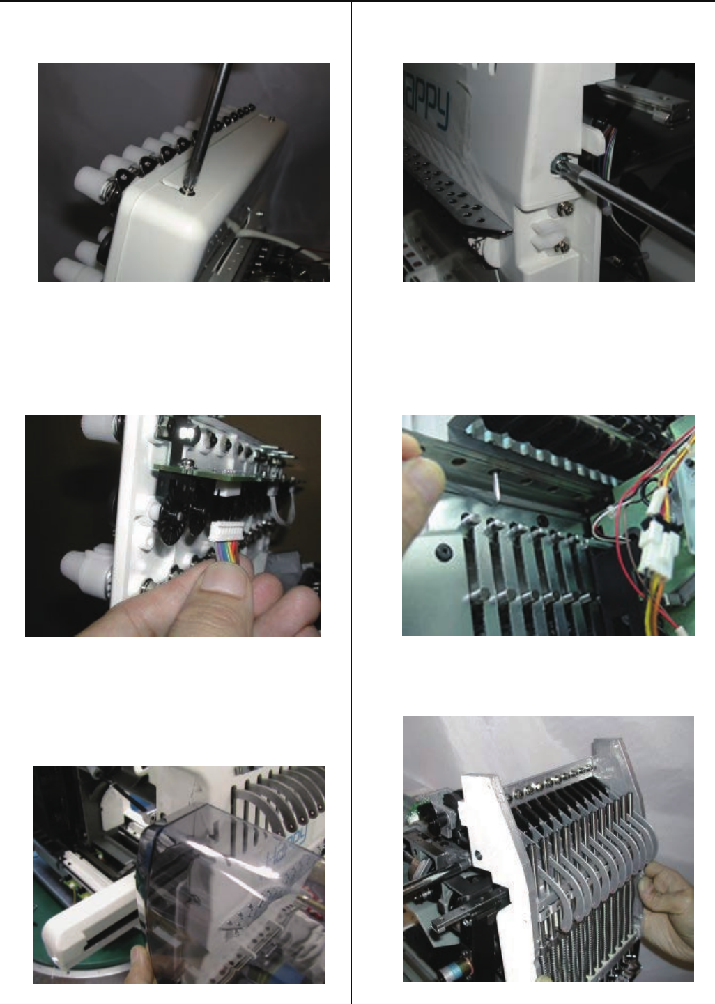
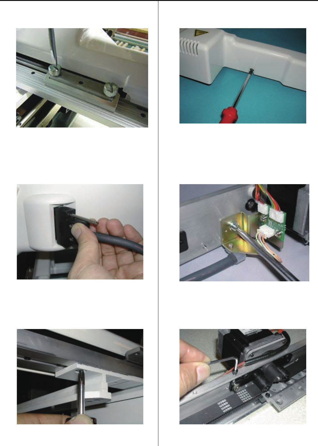
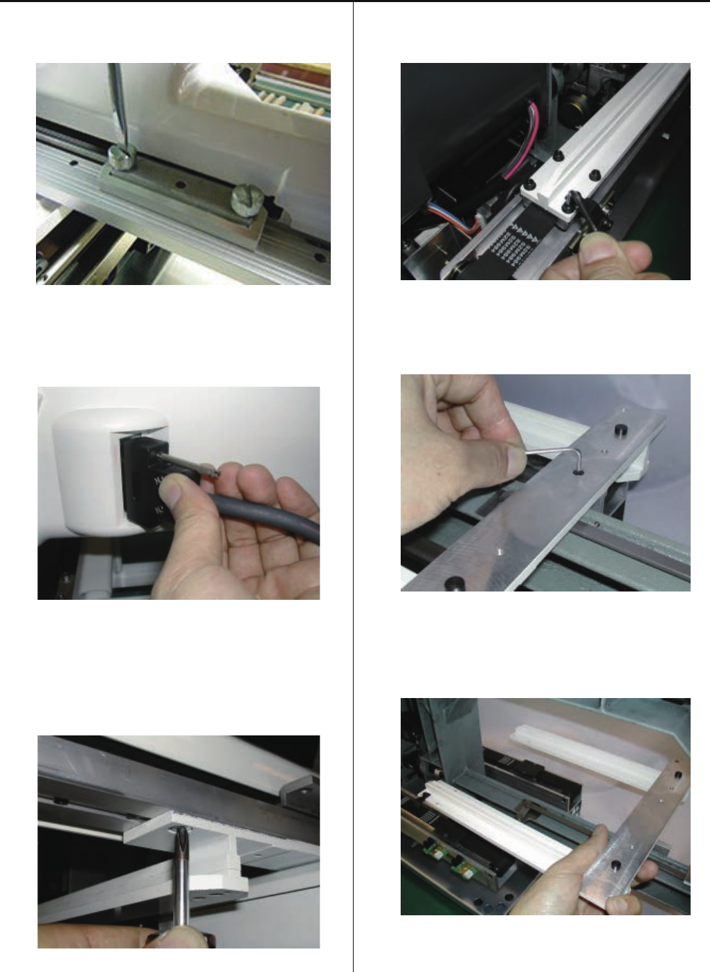
2-1 Removal of outer covers
<Check> Be sure to turn power switch OFF before work.
1. Remove three setscrews of arm E as shown in the figure
below.
2. Disconnect the connectors indicated by the arrows in
the figure below. Remove the screw that fixes cables.
3. Remove three setscrews on arm G as shown in the figure
below.
4. Remove control box.
Please reverse procedure when installing control box.
16
5. Remove thread guide bracket.
6. Loosen a screw of thread guide pillar
7. Remove thread guide pillar and thread stand.
8. Disconnect cable for X carriage.
9. Remove 2 screws, then take the X carriage off.
10. Remove the thread tension ass’y.
17
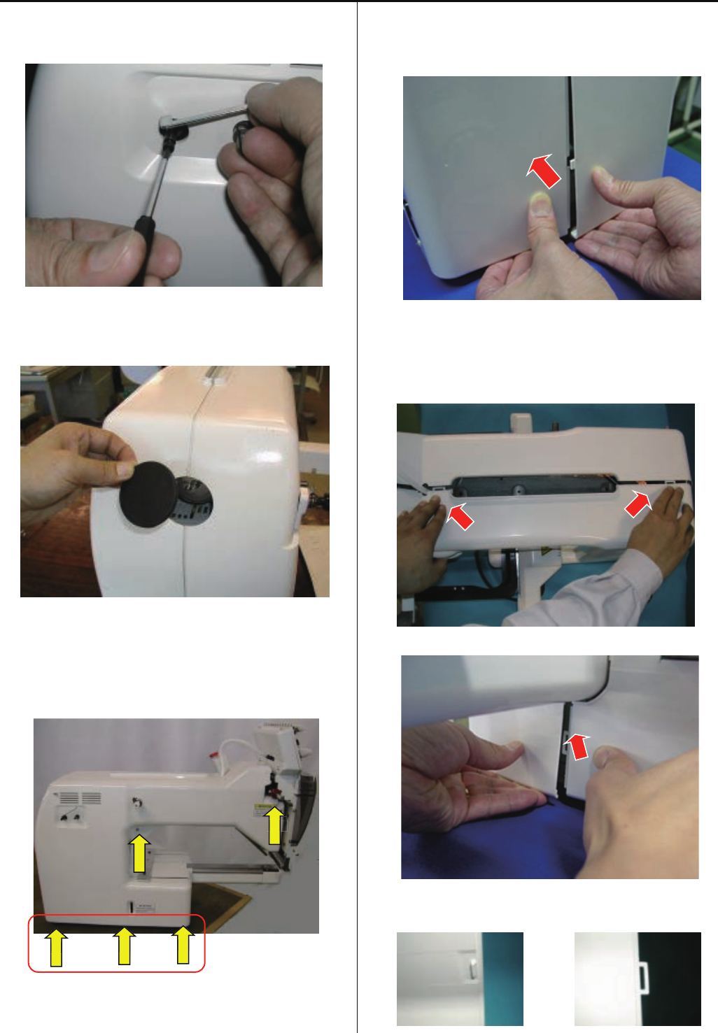
11. Remove the guide.
12. Take off rubber cap.
13. Remove cover (left). (Remove screw in arrow mark)
When the cover is fixed by 3 screws as above picture,
please remove these screws.
14. Unlock nail of the cover (left) by pressing an arrow point of
the cover (right).
15. Remove the cover by pressing an arrow part of
the picture.
(1) Upper part of the cover
(2) Front part of the cover
Nail shape
Male nail shape Female nail shape
x
x
18
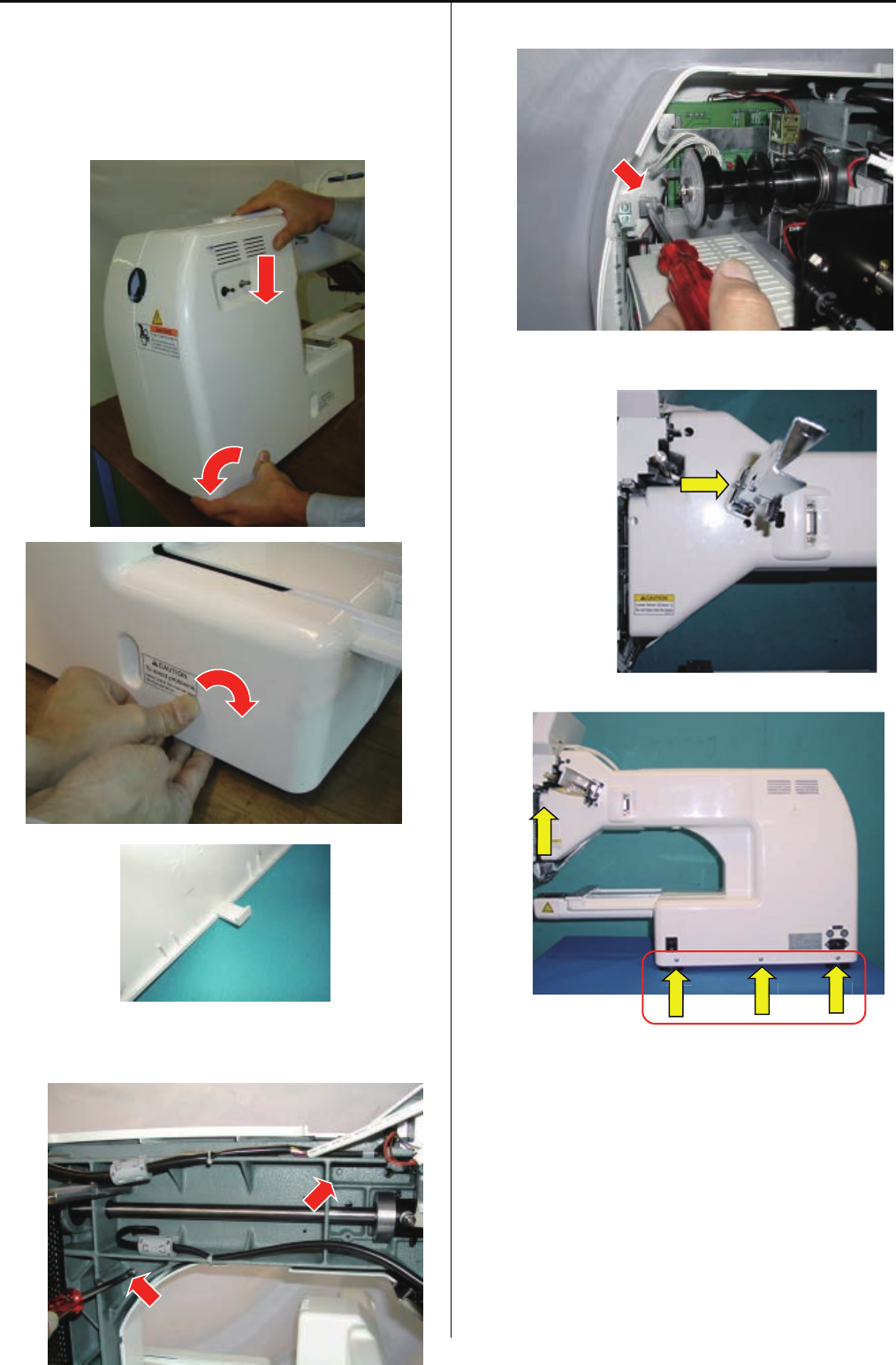
When the cover is not fixed by screws, please tilt
the machine slightly to access locking nail easily.
Push down top of the cover and locking nail area as
picture below, then the nail will be released from
the machine base.
Nail shape
16. Remove the screw of an arrow part of the
picture which fixes cover (right).
17. Remove an arrow marked screw which fixes hold arm D.
18.Remove cover (light). (Remove screw in arrow mark)
When the cover is fixed by 3 screws as above picture,
please remove these screws.
19. Remove the cover (right).
20.By above process, removal of [cover] has finished.
If you need to operate the machine with control box,
please re-assemble the arm and the control box.
x
x
x
x
19
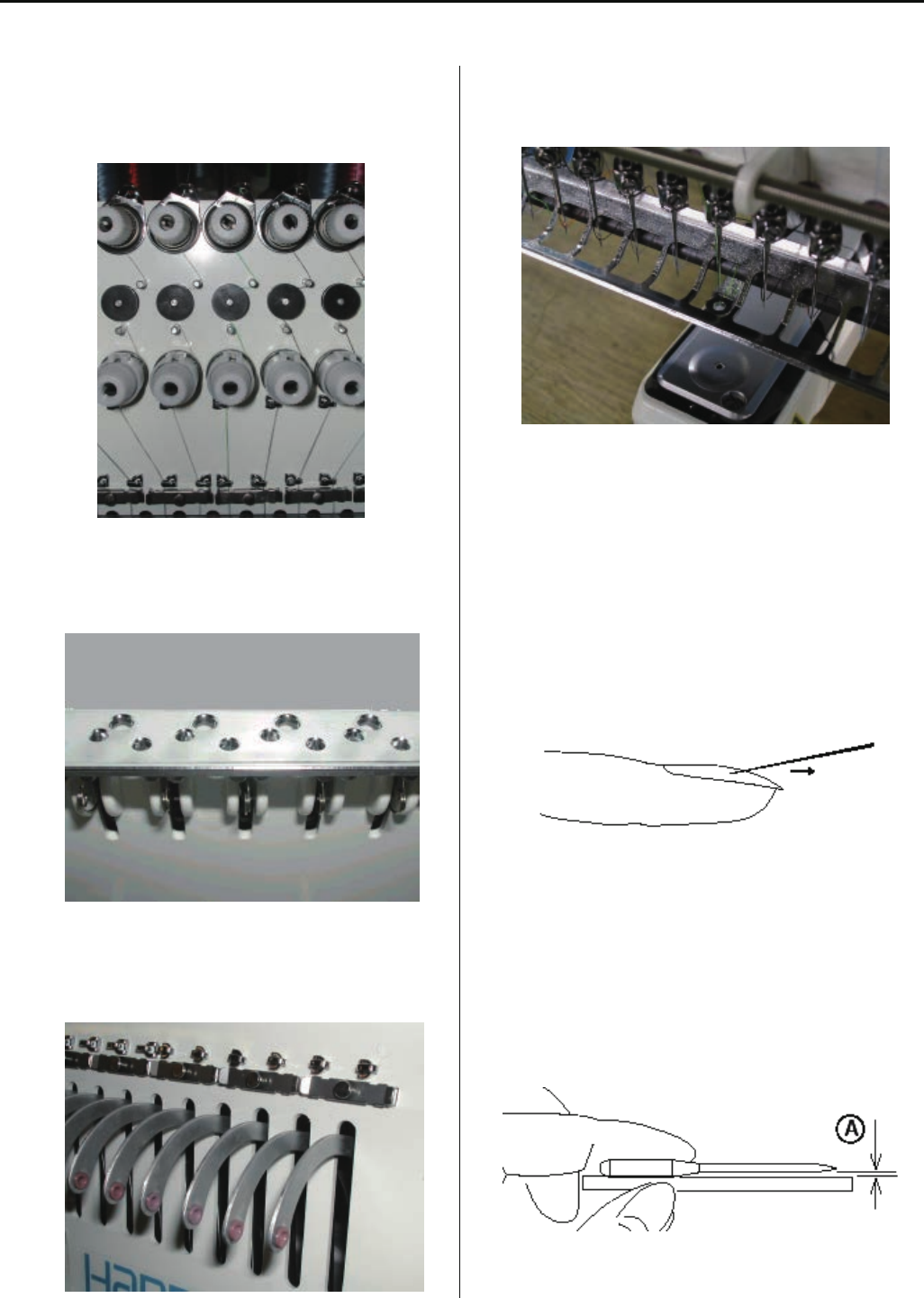
3-1-1 Maintenance of thread path
In a bid to prevent poor sewing finish or thread break, please keep places where thread contacts in the best condition.
1. Thread tension, detecting roller
a) Revolution must be smooth
b) No sticking of lint or dust
2. Holes on thread guide plate
a) No burr and crack
3. Ceramic and rim of take-up lever
a) No burr and crack
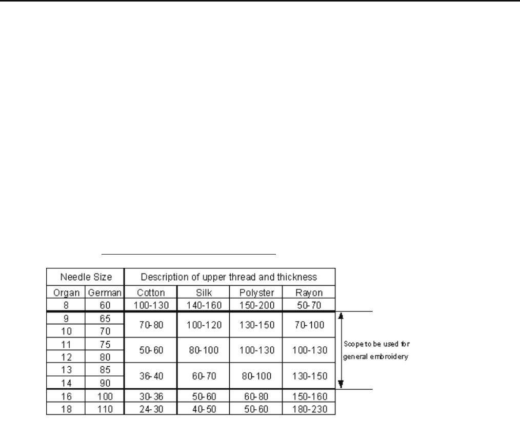
4. Thread path in lower side and needle holder.
a) No burr and crack
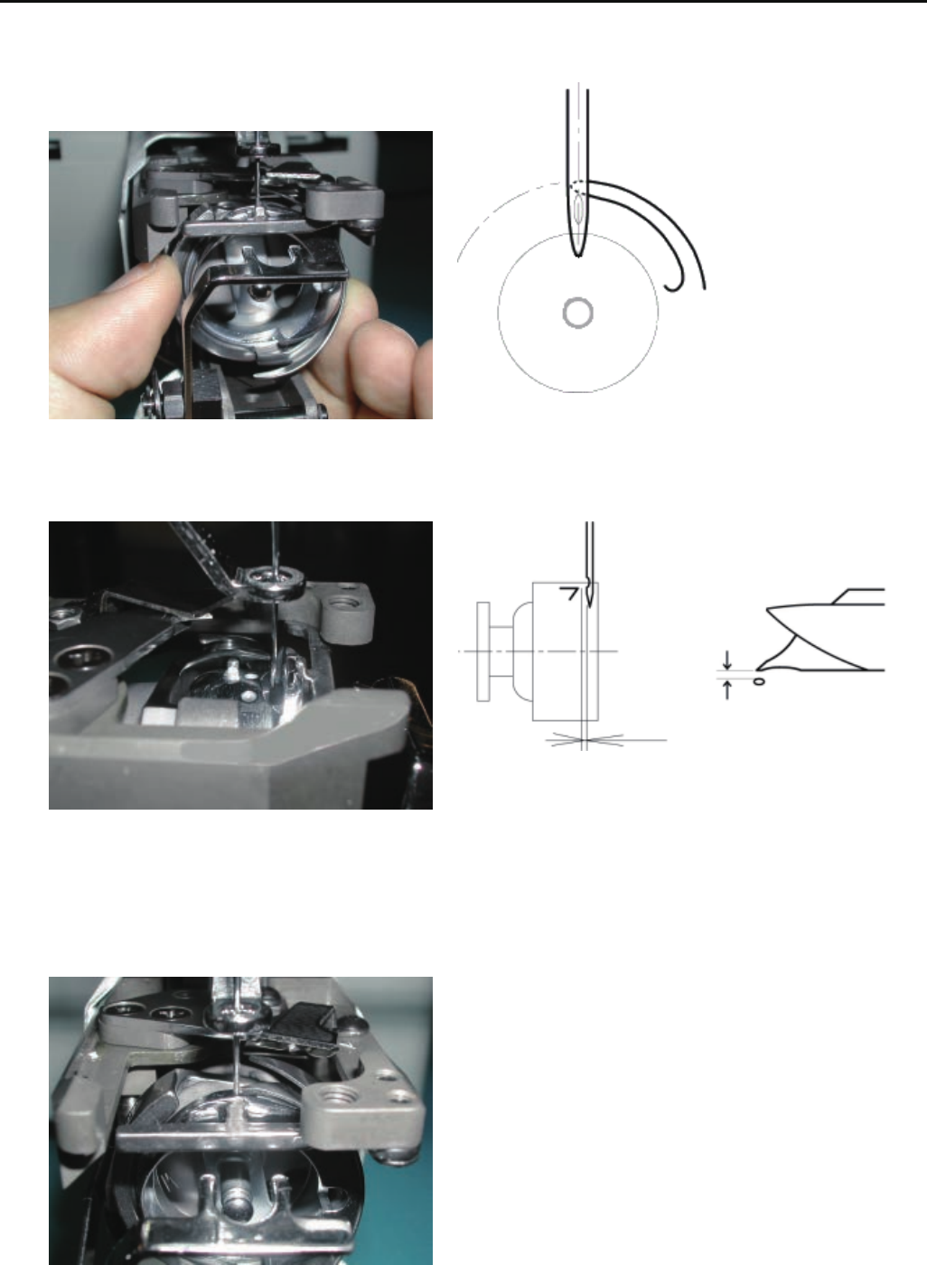
5. Needle
a) Needle tip shouldn't be warped or bent.
When you slide needle tip on surface of nail and
if the nail gets scratched.
needle tip is warped. Please exchange it with new one.
Please place needle on flat surface and check
clearance (A) from side.
If clearance is not equal, needle is bent.
Please replace it with new one.
20
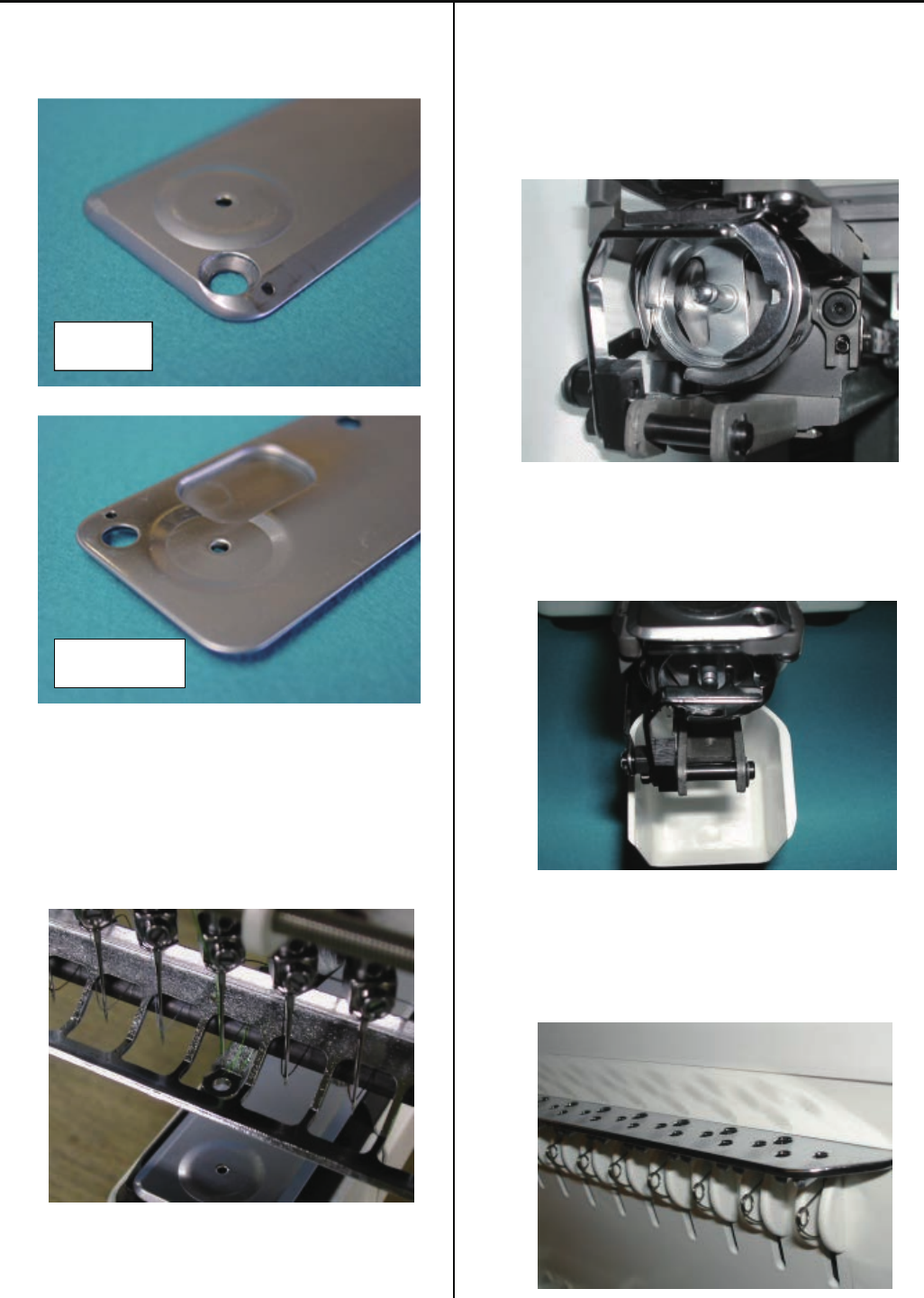
6. Needle plate
a) No burr and crack in needle hole and around it.
7. Pressure foot
a) No burr and crack inside hole
b) Not bent
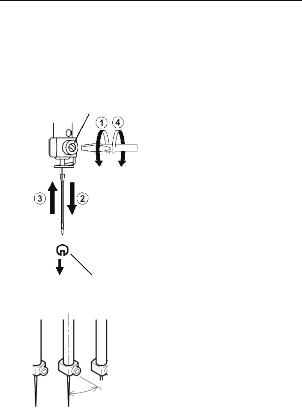
8. Rotary hook
a) No burr and crack.
b) Hook point not warped.
c) Backlash between bobbin case holder and outer hook
should be less.
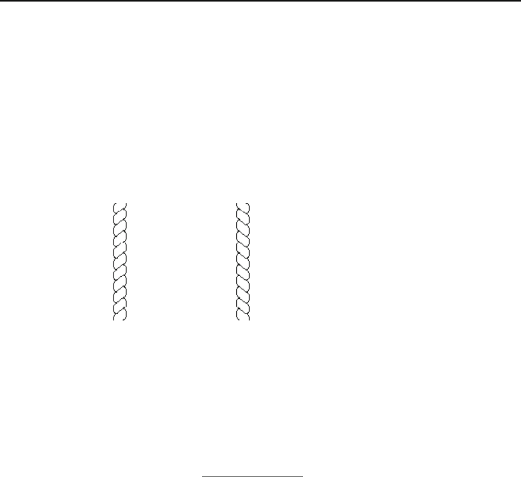
9. Keeper
a) No burr and crack on tip.
10. Thread adjusting spring
a) Should be robust.
Surface
Reverse side
21
3-1-2 Fixing of needle
1. In order of (1)-(4), please remove and fix needle.
(1) Loosen screw holding needle.
(2) Remove needle.
(3) Insert needle till it goes to the end.
(4) Tighten screw holding needle.
Fix needle so that needle groove faces front.
Needle holder
Needle
Front
* Set direction of needle holder as illustrated below.
Check needle holder dose not touch to Needle guard.
About 30 degrees
22
3-1-3 Selection of thread
1. Selection of upper thread.
<Description>
Please select considering cloth, design of pattern and flavour etc.
<Thickness>
Please refer to [Relation between needle and upper thread 3-1-4].
<Twist>
Z twisted thread is to be used.
(As rotary hook turns left- wise, Z twisted thread can prevent loosening of twist)
Z-twisted S-twisted
(Left - twisted) (Right - twisted)
2. Selection of lower thread.
Basically please use cotton thread (#80-120), #120 is recommendable.
Pay attention to the following in selection.
# Thickness should be equal.
# When it is lightly stretched. it doesn't break easily.
# In process of time, it doesn't get inferior.
Commercially available paper bobbin can be used, but please select thread with
thickness corresponding to cotton thread (#80-120).
23
3-1-4 Relation between needle and upper thread
1. Description of needle
Basically please use [DB X K5] in standard accessory.
If description or thickness of cloth doesn't suit needle size, poor sewing finish / thread break / skipping will occur.
Therefore careful attention is required in selecting needle.
2. Relation between needle and upper thread will be found below. (Representative example is shown.)
Needle - Size is [German 75] in standard accessory.
If necessary, please select in accordance with description of thread and cloth.
Thread - In case needle size is [German 75], if thread is rayon,[#120] is recommendable.
Relation between needle and upper thread
Denier(d)
If needle size and thickness of thread don't match, following problem will be likely to occur.
- Thread break
- Skipping
- Poor sewing finish
24
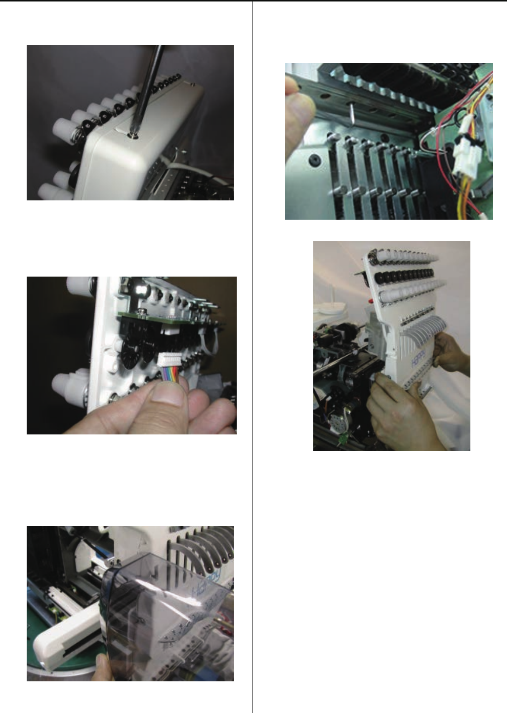
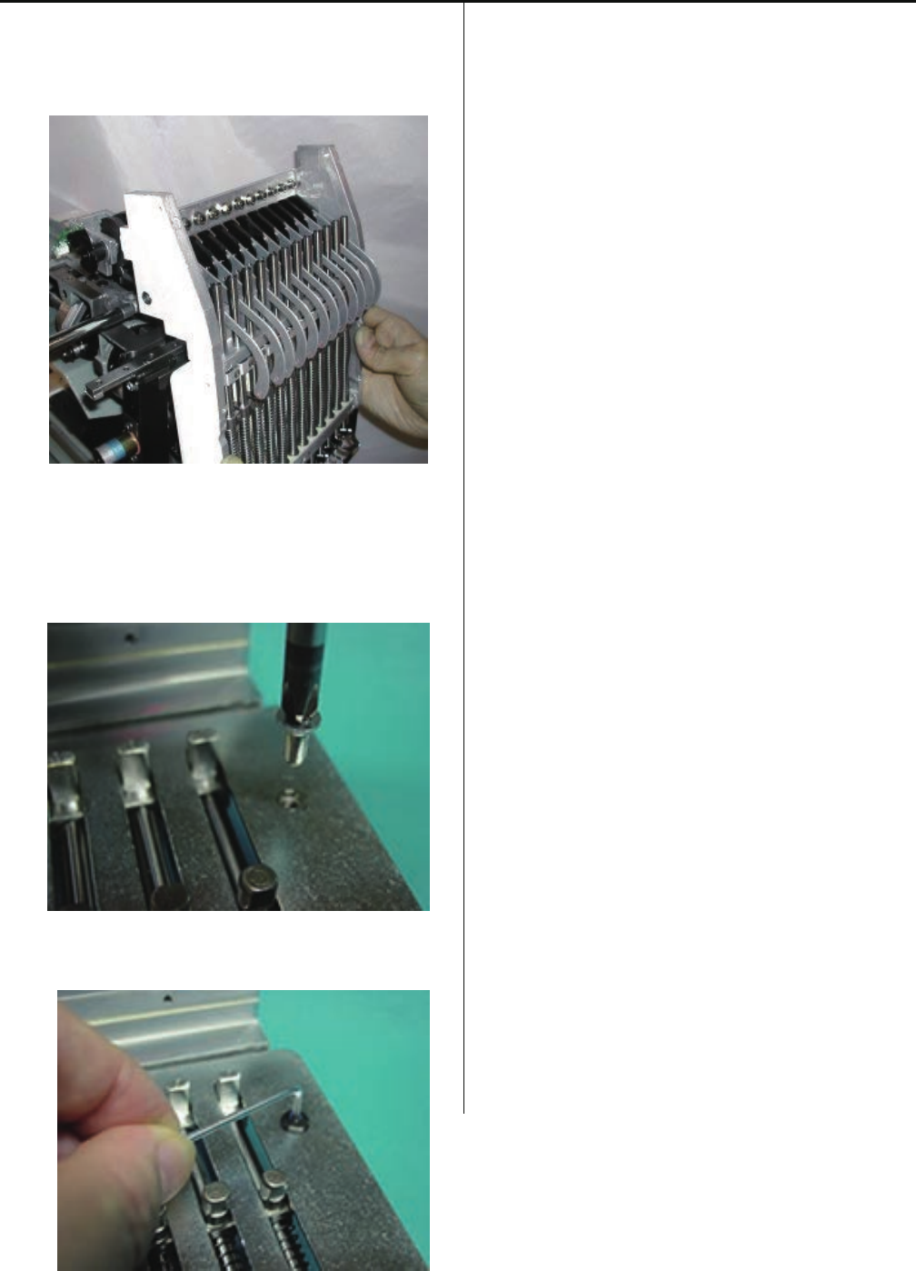
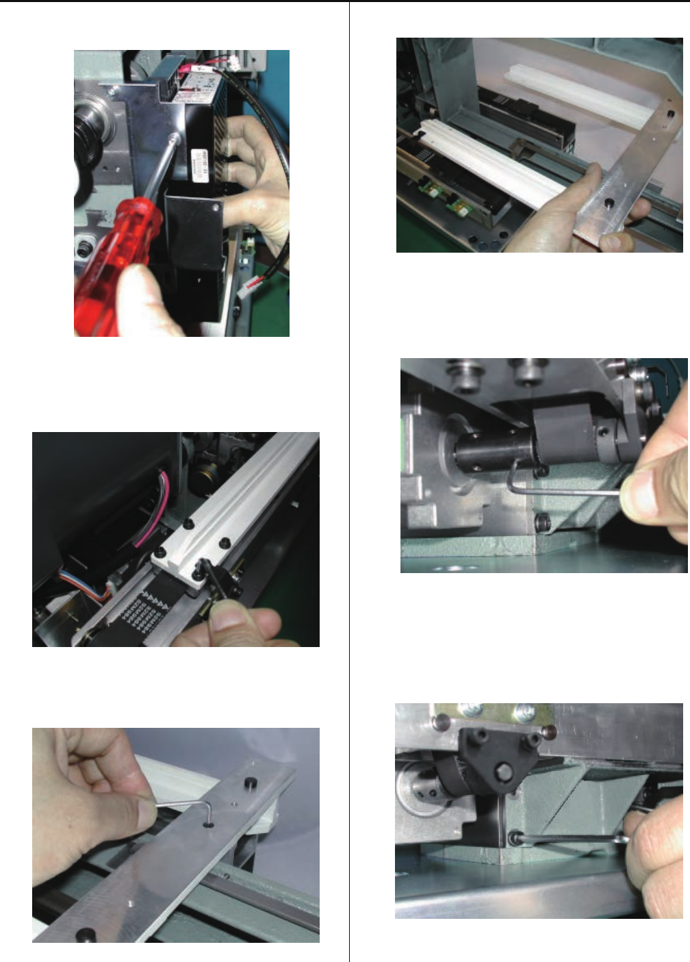
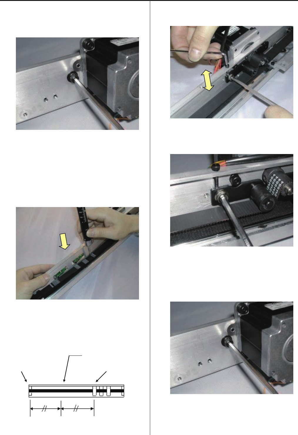
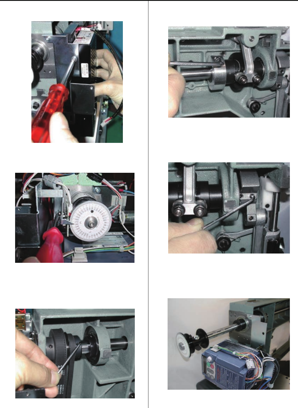
3-2-1Exchange of crank
1. Remove rear cover.
2. Disconnect TC cable and limit switch cable.
3. Remove front cover on front panel.
4. Referring to [3-3-3 Assemble the moving head], remove
moving head.
<Caution> Do not lost simm material.
25
5. Disconnect cables around thread catcher.
6. Remove face plate on the left.
Installation position should be up and back side.
(As shown an arrow)
7. Referring to [3-2-4 Exchange of needle bar driver],
remove needle bar driver ass’y.
8.Remove circuit board assembly for timing detecting board.
26
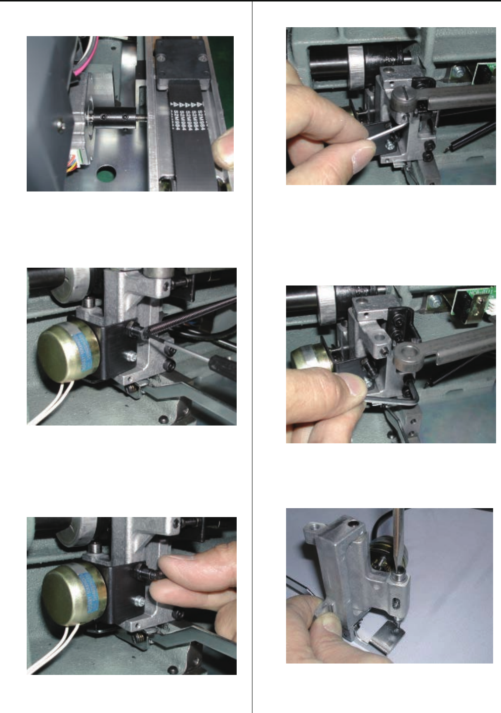
9. Remove bobbin winder and power supply.
10. Loosen screw on upper shaft collar, upper pulley,
drive pulley.
11. Loosen collar screw on take-up lever cam.
12. Loosen screw on crank.
13. Pull out upper shaft. (To the extent that crank comes out)
14. Remove bearing retainer.
27
15. Remove crank ass’y.
16. Put parts once removed back in reverse order
For adjusting fixing of each unit, please refer to process
to adjust fixing of each unit.
<Important> Pay attention to following (1) - (4).
(1)Please fix upper shaft collar, upper pulley, drive pulley
on flat surface of upper shaft with screw tightly.
(2)Make sure that pulleys and collars are attached
without space from machine body except upper pulley.
(3)Position of upper pulley is [2mm] from upper shaft collar.
(3)Position of upper pulley is space from upper
shaft collar.
Type of small
collar
Thickness gauge [11.5mm]
(4)Confirm that belt is not interfere the pulley flange and
not come out from pulley groove.
Adjustment will be done with following pulley.
Timing belt has to be adjusted with upper pulley position.
Motor belt has to be adjusted with motor pulley position.
17. Please check and adjust timing mentioned below to finish.
[ 4-2-1 Upper shaft timing (L point, C point) ]
[ 3-2-8 Take-up lever timing ]
[ 3-5-1 Rotary hook timing ]
[ 3-6-5 Thread cut timing (except (for Rev.A) )
28
3-2-2 Exchange of rod
1. Referring to [3-2-1 Exchange of crank], moving head and
face plate (left) ass’y.
<Caution> Do not lost simm material.
2. Referring to [3-2-4 Exchange of needle bar driver],
remove needle bar driver ass’y.
3. Loosen screw on rod pin to remove rod.
4. Install good parts.
<Important> Leave space of [0.03mm] between
crank and rod.
5. Put each unit back to where it was according to manual.
29
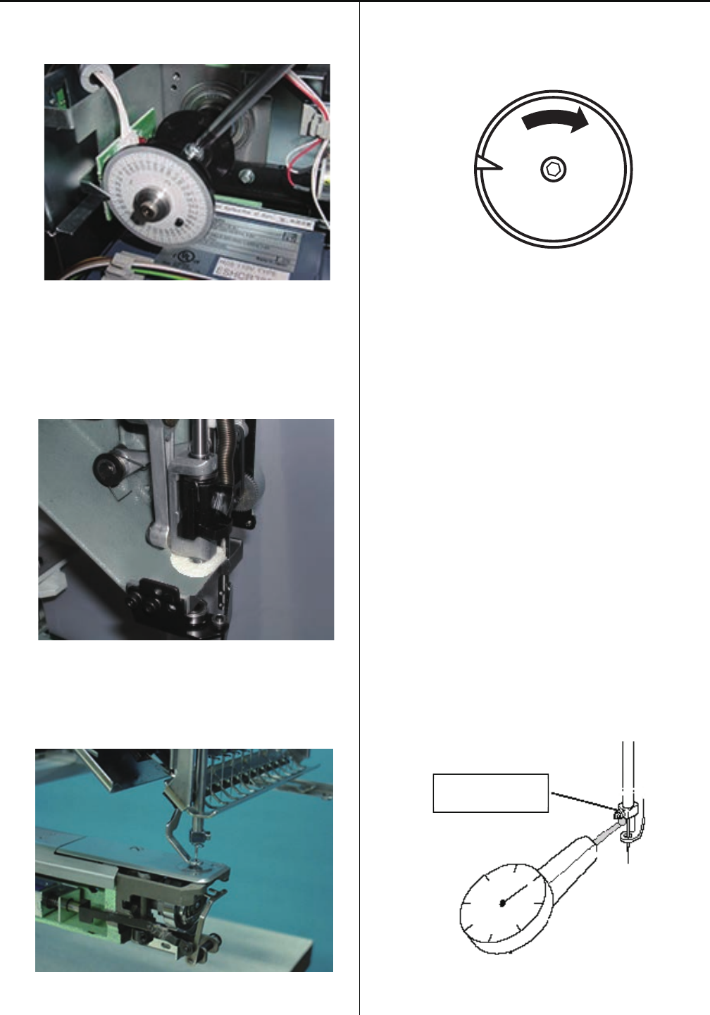
3-2-3 Adjustment of the lowest needle point
1. Loosen screw on detecting disk.
2. Turn upper shaft so that needle bar driver ass’y comes
in the bottom.
In case there is moving head, bring needle bar down.
3. When dial disc reads [0 degree], fix detecting disk.
4. Work will finish by checking and adjusting timing
mentioned below.
[ 4-2-1 Upper shaft timing (L point, C point) ]
[ 3-2-8 Take-up lever timing ]
[ 3-5-1 Rotary hook timing ]
[ 3-6-5 Thread cut timing (except (for Rev.A) ))
Please use dial gauge for strict checking.
Please see that timing on dial disc comes to [0 degree]
when dial swings in highest value.
Dial-gauge
Needle holder
30
3-2-4 Exchange of needle bar driver
1. Refering to [3-2-1 Exchange of crank], moving head and
face plate (left) ass’y.
<Caution> Do not lost simm material.
2. Loosen screw on main shaft in head.
3. Pull out main shaft in head.
31
4. Loosen screw on lower part of needle bar driver ass’y.
5. Remove needle bar driver ass’y.
6. Install good parts.
<Important>
Make sure that Needle bar driver ass’y rotate smoothly
and no clearance between rod and arm.
7. Put each unit back according to manual.
8. After exchange, please be sure to adjust needle height.
Please refer to [3-3-6 Adjustment of needle height].
<Attention>
Head shaft should be positioned slightly lower than
ditch for oil.
32
3-2-5 Adjustment of fixing of jump solenoid
1. Remove rear cover.
2. Disconnect TC cable and LED cable.
3. Remove front cover on front panel.
4. Remove moving head.
<Caution> Do not lost simm material.
33
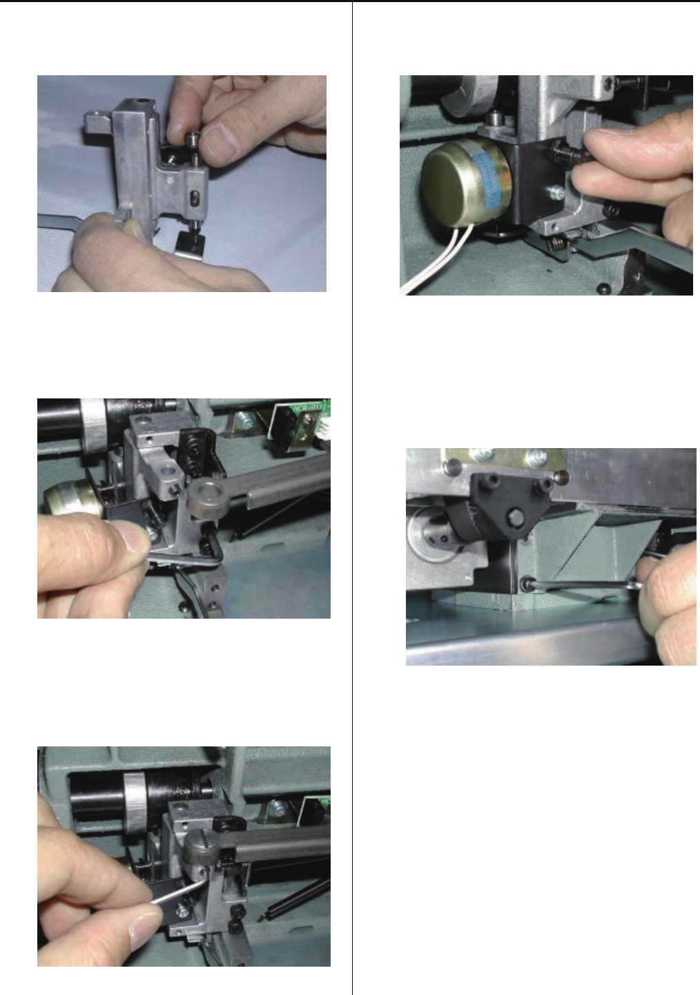
5. Remove jump solenoid ass’y.
6. Install good parts.
Set upper shaft to [80 degrees] to adjust position of plunger
of jump solenoid and jump body as illustrated below.
<Front view>
Viewing from front, jump body should come to center of
Plunger.
Plunger
Jump solenoid ass’y
Jump body
<View from left>
This shows a state that plunger and jump body contacts.
Plunger Jump body
7. Adjust upper shaft to be [180 degrees] and tip of the body
has to be same as the picture below.
8. Please put parts back in reverse order to finish.
For adjustment of fixing of each unit, please refer to
process to adjust fixing of each unit.
90 degrees
Front side
34
3-2-6 Exchange of take-up lever cam
1. Remove bobbin winder and power supply.
2. Remove timing detecting board ass’y.
3. Loosen screws on upper shaft collar, upper pulley and
drive pulley.
4. Loosen screw on fasten collar for take-up lever cam.
5. Loosen screw on crank.
6. Pull out upper shaft (to the extent that shaft comes off from
take-up lever cam).
35
7. Remove take up lever cam.
8. Remove fasten collar.
9. Put good parts back in reverse order.
For adjustment of fixing of each unit, please refer to
process to adjust fixing of each unit.
<Important> Pay attention to following (1) - (4)
(1)Install upper shaft collar, upper pulley, drive pulley and
crank on flat surface of upper shaft with screw tightly.
(2)Make sure that pulleys and collars are attached
without space from machine body except upper pulley.
(3)Position of upper pulley is space from upper
shaft collar.
Type of small
collar
Thickness gauge [11.5mm]
(4)Confirm that belt is not interfere the pulley flange and
not come out from pulley groove.
Adjustment will be done with following pulley.
Timing belt has to be adjusted with upper pulley position.
Motor belt has to be adjusted with motor pulley position.
10. Please check and adjust the following timing to finish.
[ 4-2-1 Upper shaft timing (L point, C point) ]
[ 3-2-8 Take-up lever timing ]
[ 3-5-1 Rotary hook timing ]
[ 3-6-5 Thread cut timing (except (for Rev.A) ))
36
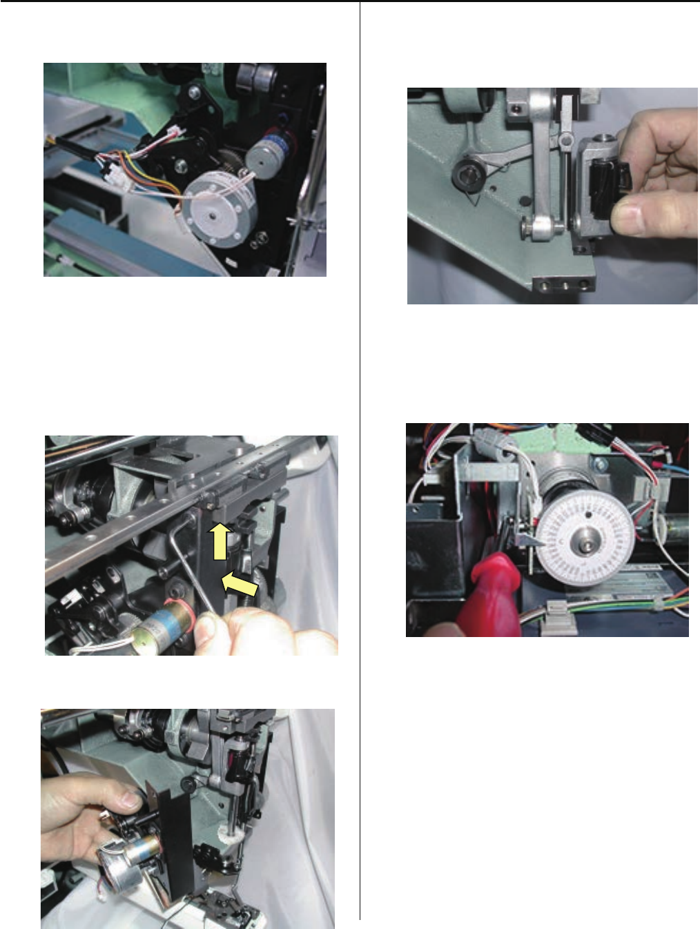
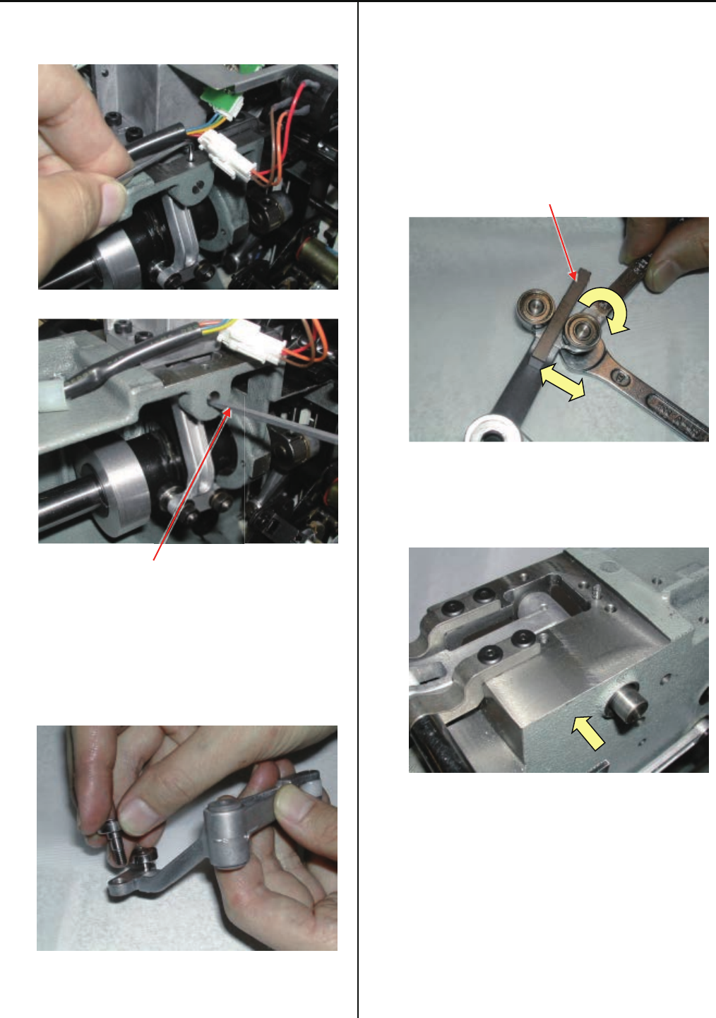
3-2-7 Exchange of roller shaft ass’y
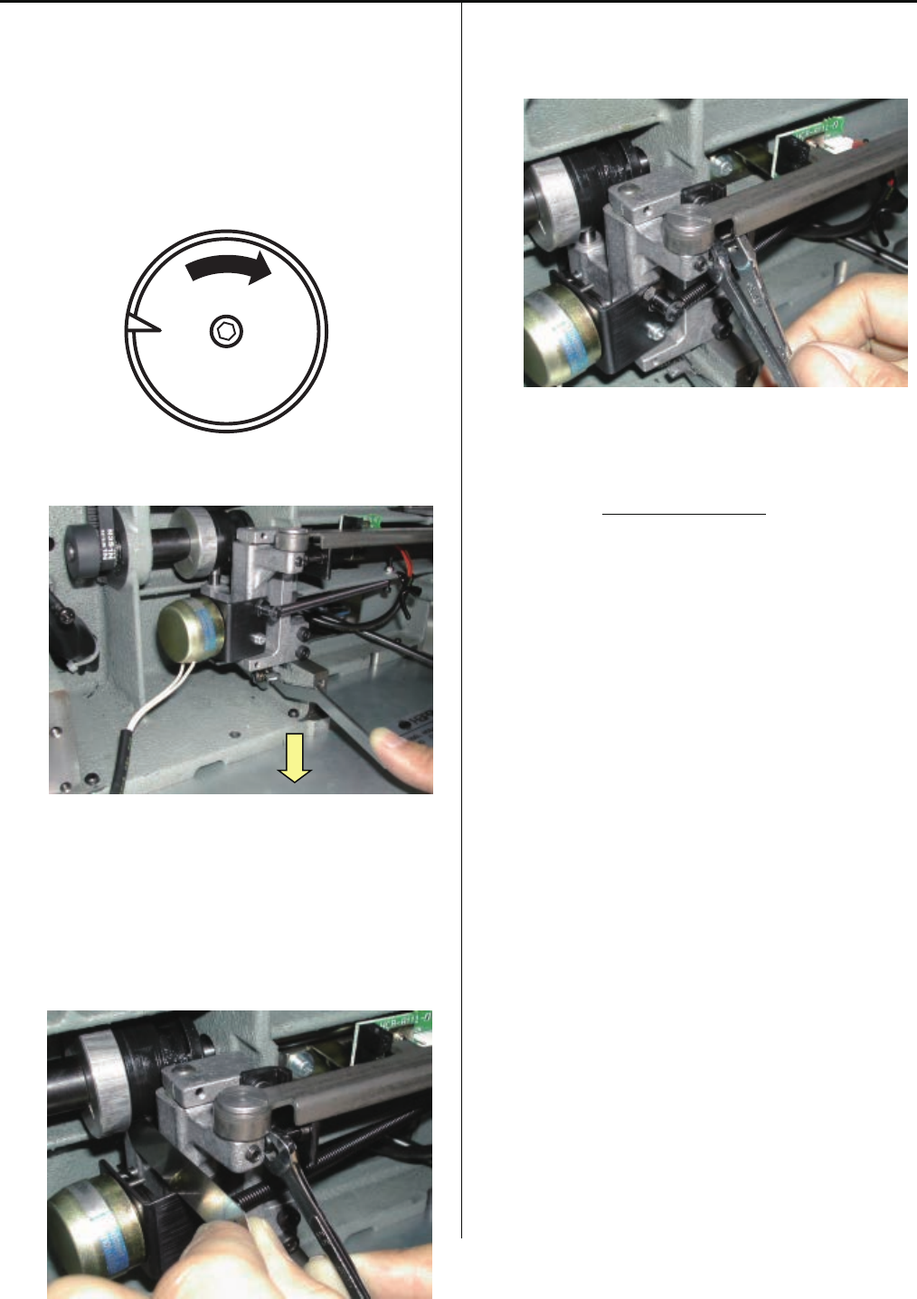
1. Remove take-up lever crank ass’y.
Push take-up lever drive shaft by slender shaft.
(Hexagon wrench etc.)
2.Exchange roller shaft ass’y.
<Spanner> 7mm, 8mm
3. Insert bering positioning gauge [4.85mm] between bering
and bering , and then tighten roller shaft ass’y.
Please adjust roller shaft for machine front side ways.
This roller shaft ass’y is eccentricity.
Turn lean screw and just touch roller to gauge.
Bering positioning gauge [4.85mm]
4. Return take-up lever crank ass’y to previous place to finish.
Please push to arrow ways until stop.
37
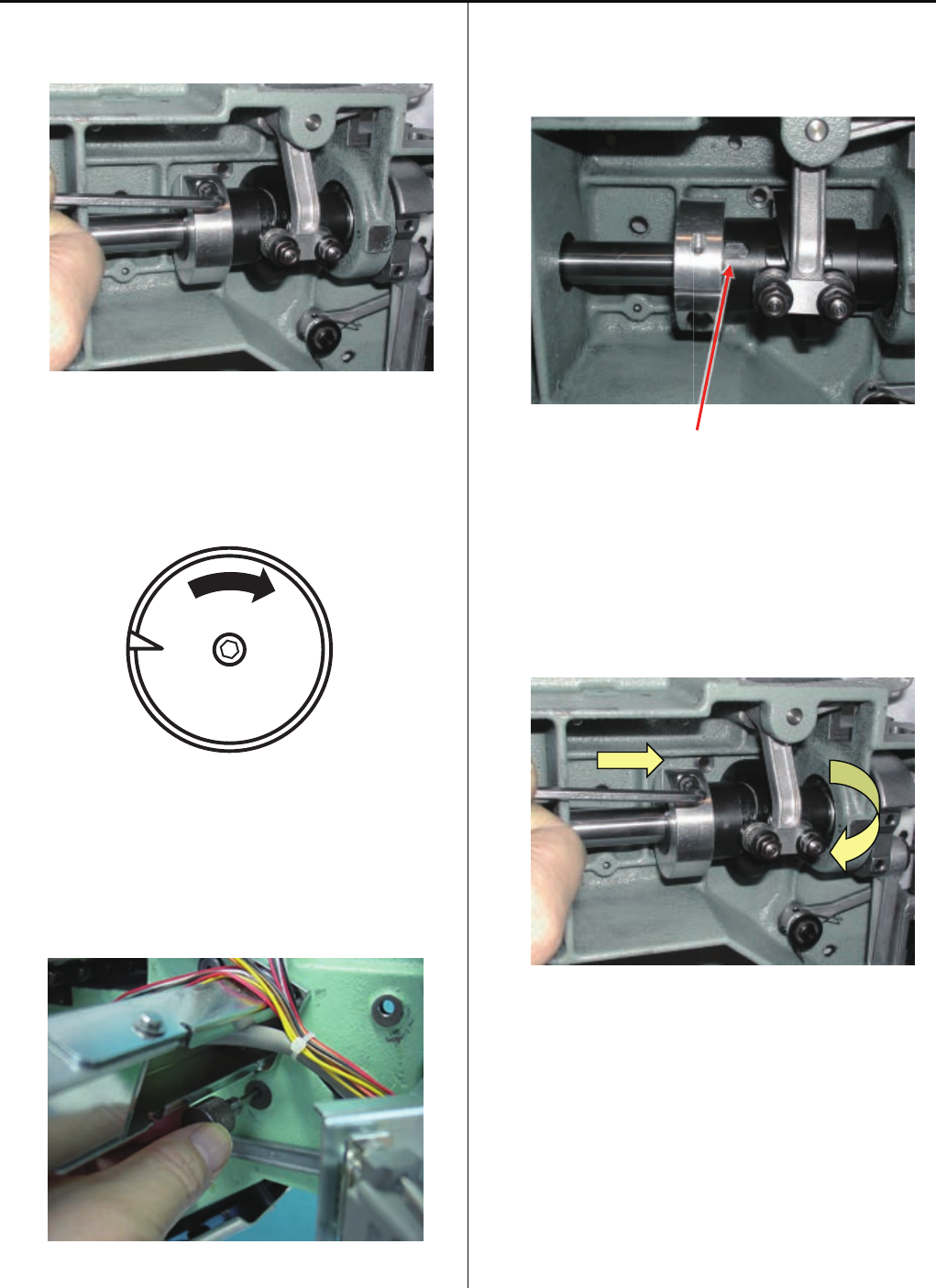
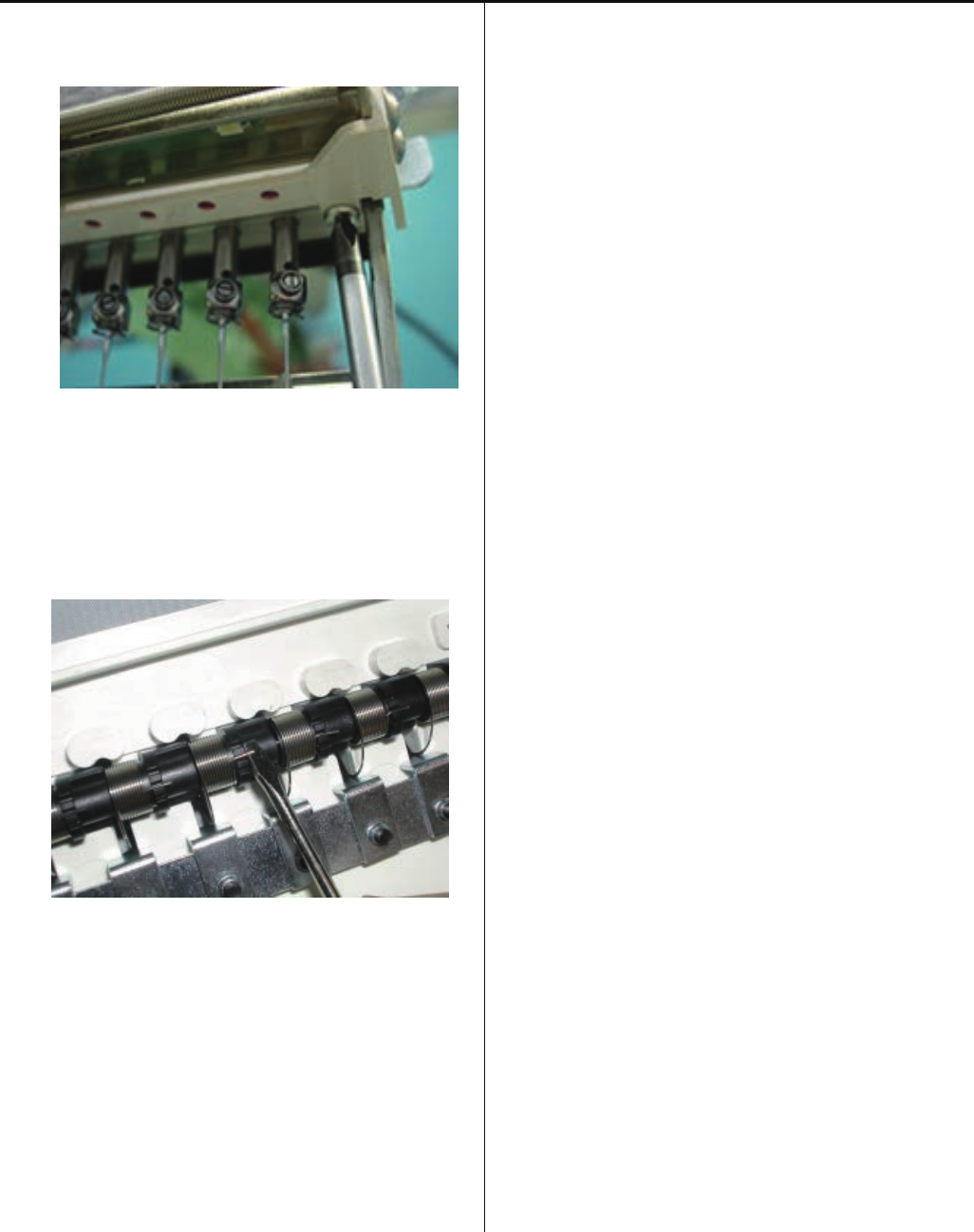
3-2-8 Adjustment of take-up lever timing
1. Loosen screw on fasten collar for take-up lever cam.
2. Set dial disc to [10 degrees].
3. Insert positioning pin from right side.
4. Turn take up lever cam slowly and insert positioning pin
into pin groove.
pin groove
5. Loosen screw.
<Important>
Rotate the Take up lever cam clockwise until pin
ditch touches to positioning pin then tighten the screw.
(No gap between take-up lever cam and crank)
6. Pull out positioning pin.
7. Turn upper shaft and set dial disc to [C] to finish.
38
3-2-9 Exchange of pressure foot cam
1. Remove screw on pressure foot cam.
2. Exchange pressure foot cam.
3. Put on grease to pressure foot cam.
<Grease>
Shell alvania EP Grease2
(Shell Gudas S2 V220 2)
4. Exchange has finished.
39
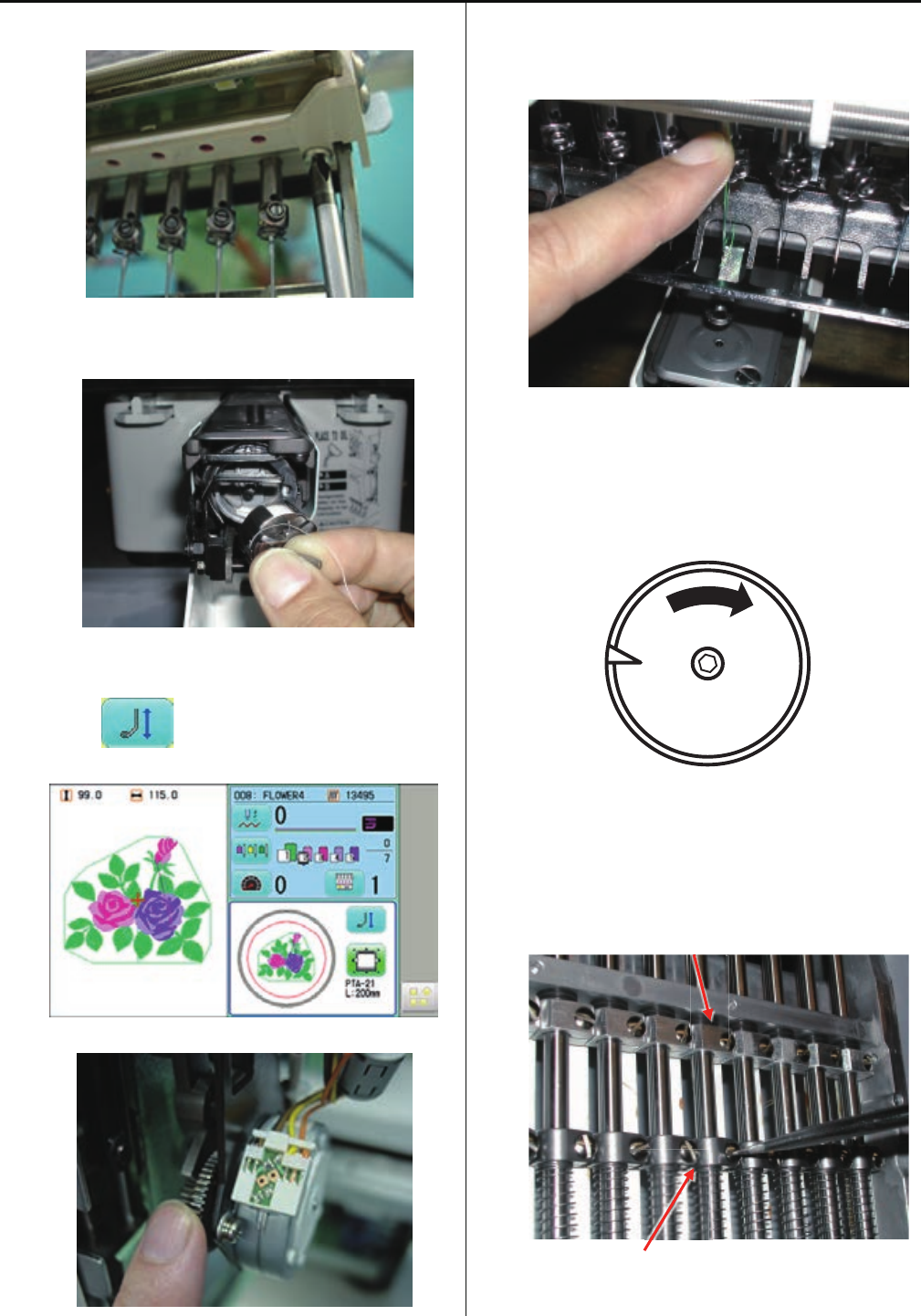
3-2-10 Check of height of pressure foot
1. Bring pressure foot down. (Either way mentioned below)
(1)press P_FOOT key on control box.
(2)Turn gear with finger.
2. Bring needle down.
3. Turn upper shaft and set dial disc to [0 degree].
4. Insert [Gauge I.2mm] between needle plate and pressure
foot.
No gap between gauge and pressure foot or needle plate,
will be OK.
5. If wrong space (not 1.2mm), please adjust height of
pressure foot guide bar.
Please refer to [3-2-12 Adjustment of height of pressure
foot guide bar ].
40
3-2-11 Exchange of pressure foot
1. Remove pressure foot.
2. Install good pressure foot.
3. Adjust height of pressure foot to finish.
Please refer to [3-2-10 Check of height of pressure foot].
41
3-2-12 Adjustment of height of pressure foot guide bar
1. Tighten pressure foot of position for tublar, and then
install needle plate for tublar frame.
2. Loosen the screw which fixes guide bar block.
3. Rotate the upper shaft to be lowest point [0 degrees].
4. Push down block ass’y.
5. Adjust the center between needle hole of needle plate and
hole of pressure foot.
6. Insert thickness gauge [1.2mm] between needle plate and
pressure foot then tighten the screw which fixes guide bar
block.
7. Before terminates the adjustment, reconfirm procedure 5,
Needle hole of needle plate and hole of pressure foot to
be centered.
42
3-2-13 Exchange of pressure foot link and block
1. Move the head shaft lower.
2. Loosen the screw which fixes guide shaft
then move the guide shaft lower.
3. If you exchange block ass’y, loosen the screw which fixes
pressure foot link A then remove block ass’y.
4. If you remove the pressure foot link B ass’y, first remove
the pressure foot cam collar and pressure foot drive cam.
5. Remove pressure foot link B ass’y.
6. Assemble the parts by opposite procedure to terminate this
exchange.
When assembling each unit, please refer to each
procedure Instruction for assemble adjustment.
<Attention>
Position of guide shaft is attached to lowest and the side
of Head.
43
3-2-14 Exchange of pressure foot drive lever
1. Remove face plate.
2.Remove upper rail.
3.Remove pressure foot and pressure foot guide bar.
After remove pressure foot spring 2, remove pressure
foot guide bar to up side.
4.Remove sensor board ass’y.
5.Exchange pressure foot drive lever ass’y.
44
6. Put on grease to bady and oil bush of pressure foot lever
ass’y.
<Grease>
Shell alvania EP Grease2
(Shell Gudas S2 V220 2)
Oil insert bush
7. Put on grease to fulcrum shaft.
<Caution> Do not put on grease to a part of screw.
8. Assemble pressure foot drive lever ass’y.
9. Assemble pressure foot guide bar and pressure foot.
10. Assemble sensor board ass’y.
45
11. Adjust position of pressure foot guide plate A ass’y.
<Caution>
Make sure that pressure foot guide plate A ass’y is mount
perpendicular and parallel to the body.
<Spanner> 7mm
12. Adjust the height of pressure foot guide bar.
Please refer to [3-2-12 Adjustment of height of pressure
foot guide bar].
13. Assemble the upper rail of moving head.
Please refer to [3-3-1 Assemble the upper rail of moving
head].
14. Assemble the face plate.
15. Install parts in reverse order to finish.
For adjustment of fixing of each unit, please refer to
process to adjust fixing of each unit.
90 degrees
46
3-2-15 Exchange of pressure foot guide
1.Remove pressure foot.
2. Loosen the screw which fixes guide bar boss.
3. Remove pressure guide bar.
After remove pressure foot spring 2, remove pressure
foot guide bar to up side.
4. Remove E-ring (E-4) which fixes guide bar boss.
5.Exchange guide.
6.Assemble the pressure foot gude bar and pressure foot.
47
7. Adjust the height of pressure foot guide bar to finish.
Please refer to [3-2-12 Adjustment of height of pressure
foot guide bar.]
48
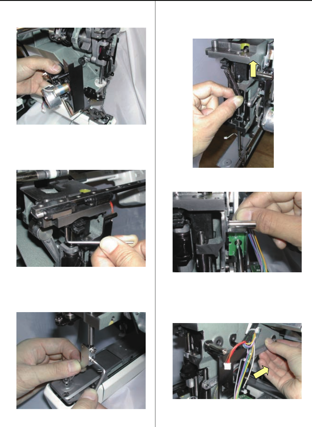
3-2-16 Exchange of pulse motor for pressure foot
1. Disconnect cable from Pulse motor and Sensor board
ass’y.
2. Down the Pressure foot.
3. Remove bracket ass’y.
4. Remove drive gear A.
5. Exchange the pulse motor.
Fix it temporarily.
6. Assemble the drive gear A.
The position should come to the middle of the gear range.
49
7. Adjust position of pulse motor then fix it.
Keep slightly backlash between drive geer A and gear.
(Every point.)
8. Continue to conduct [Adjust the pressure foot bracket
ass’y].
Please refer to [3-2-17 Adjustment of pressure foot bracket
ass’y].
50
3-2-17 Adjustment of pressure foot bracket ass’y
1. Fix pressure foot bracket ass’y tentatively.
2. Lift up pressure foot.
3. Adjust the position of the pressure foot bracket ass’y.
<Important>
The space between needle plate and pressure foot
should be [24.8 - 25.0mm].
Gauge for adjustment of height of pressure foot bracket
4. Adjust position of pressure foot guide plate B ass’y.
<Caution>
Make sure that pressure foot guide plate B ass’y is mount
perpendicular and parallel to the body.
5. Procedure is done after confirming the pressure foot
movement by pressing the on control box.
90 degrees
51
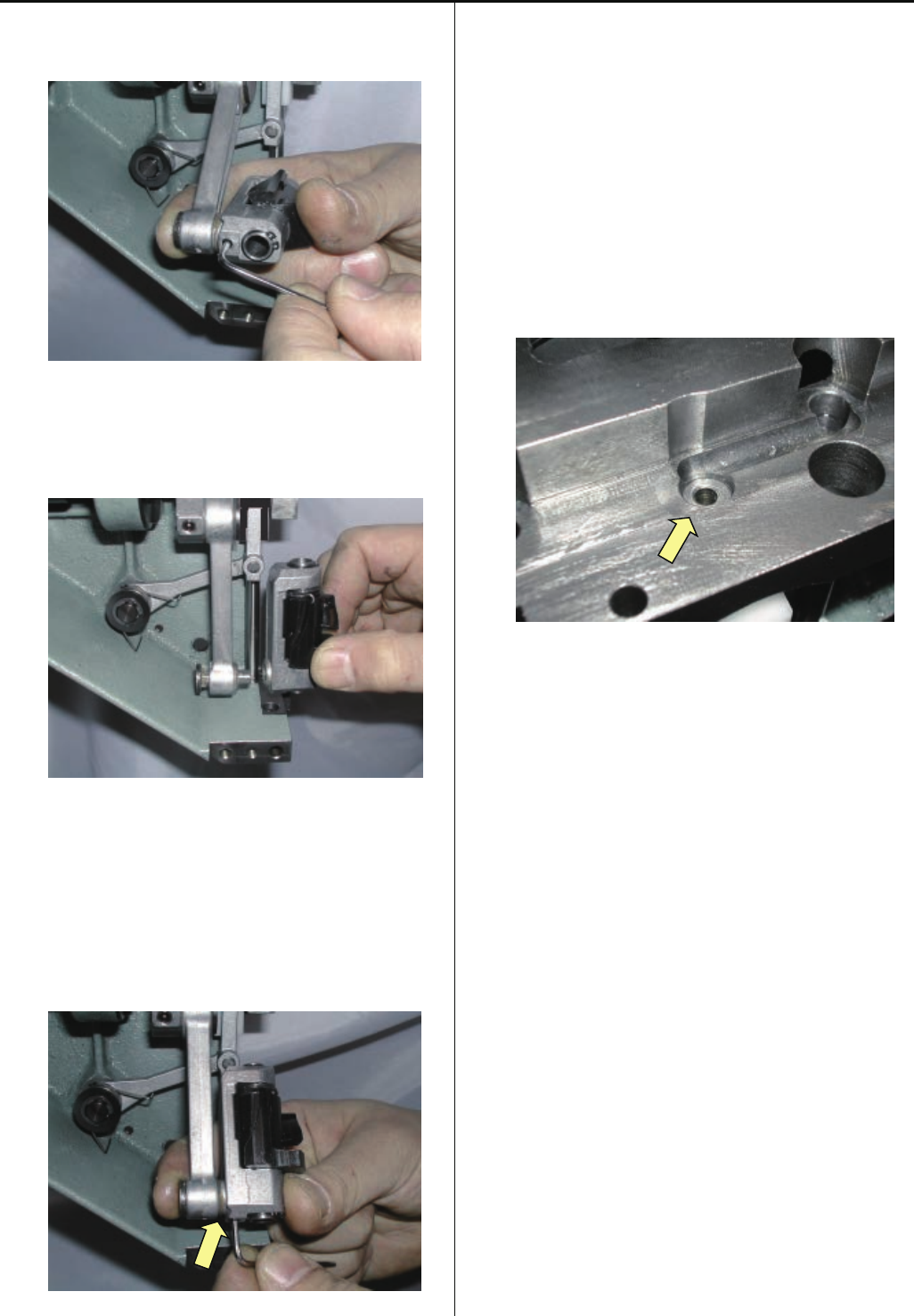
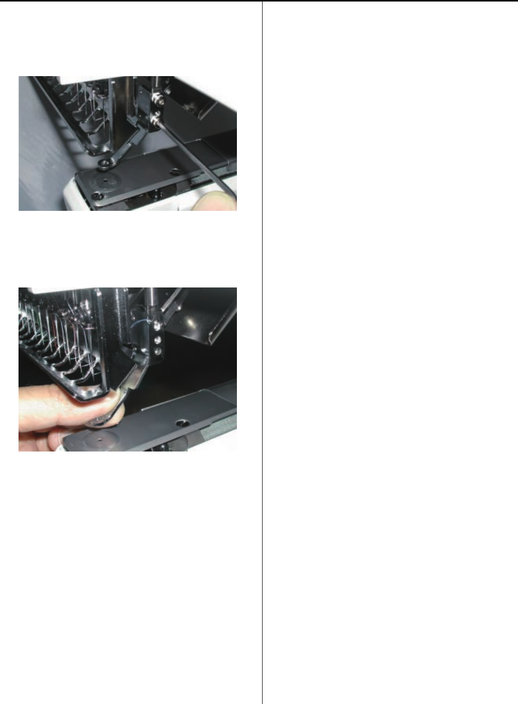
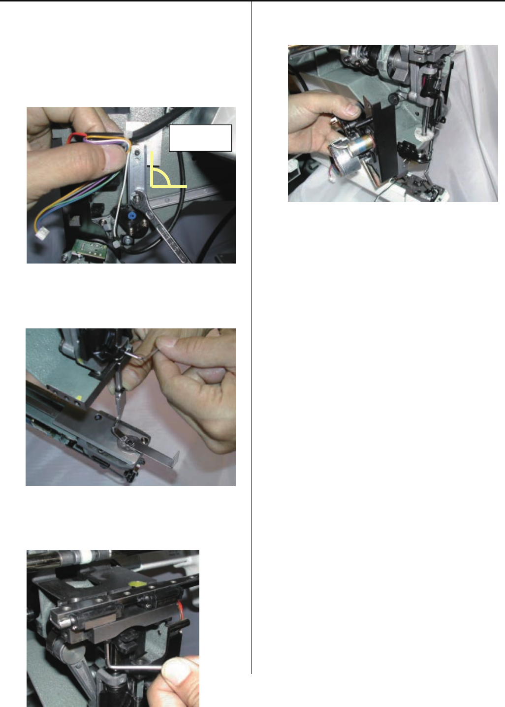
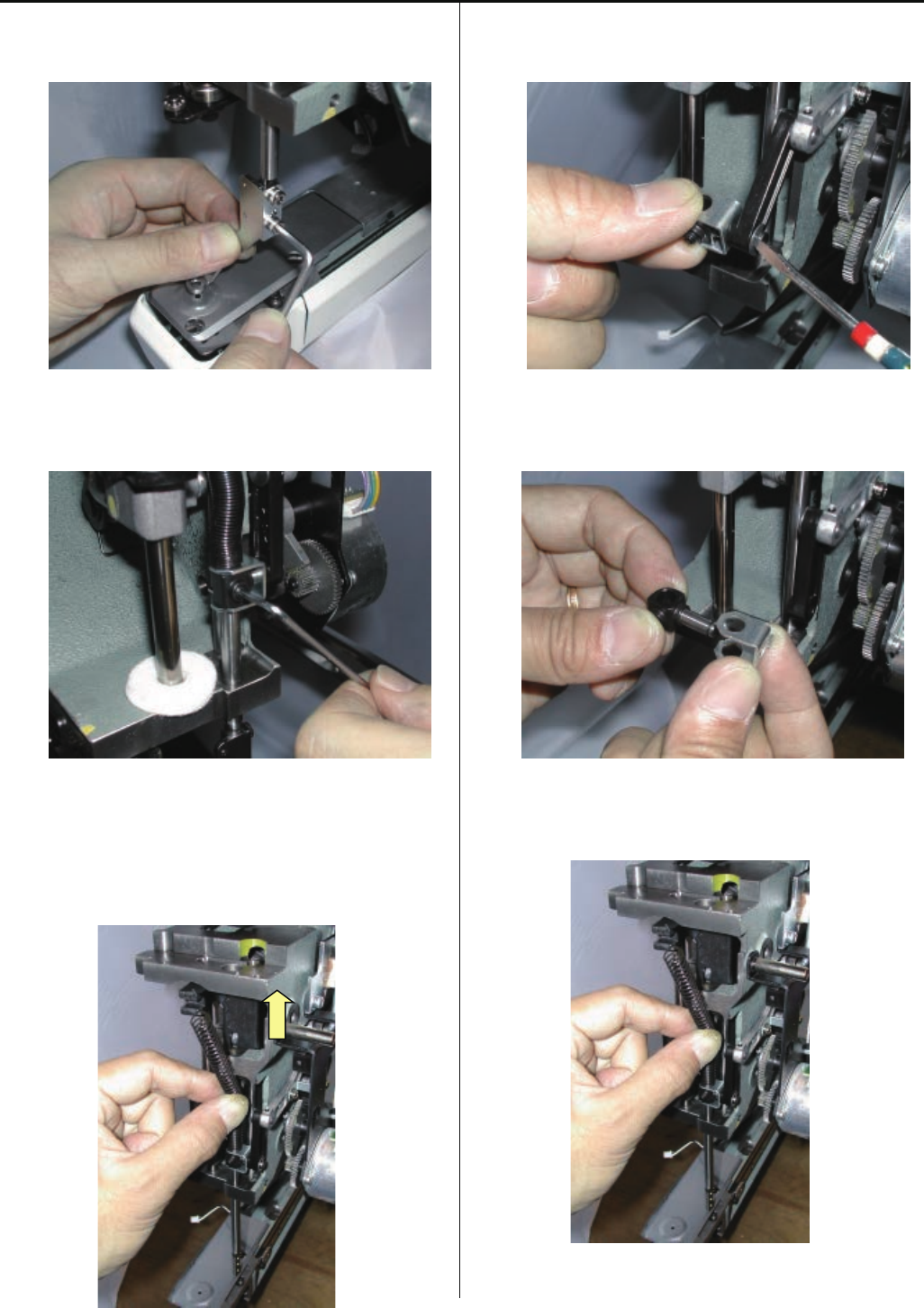
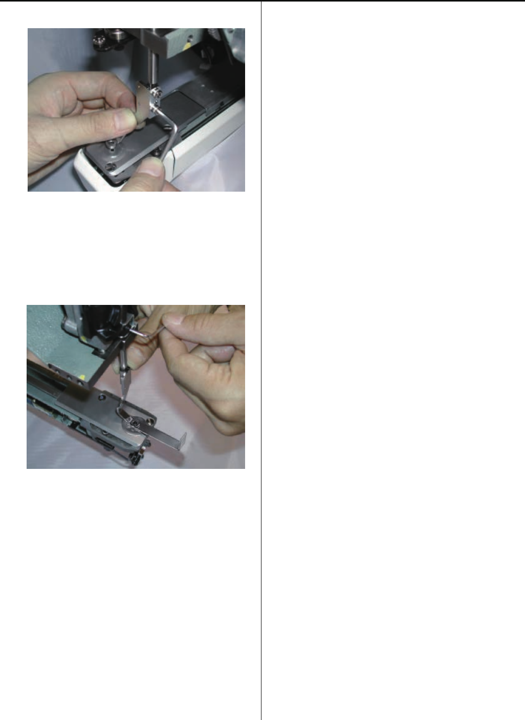
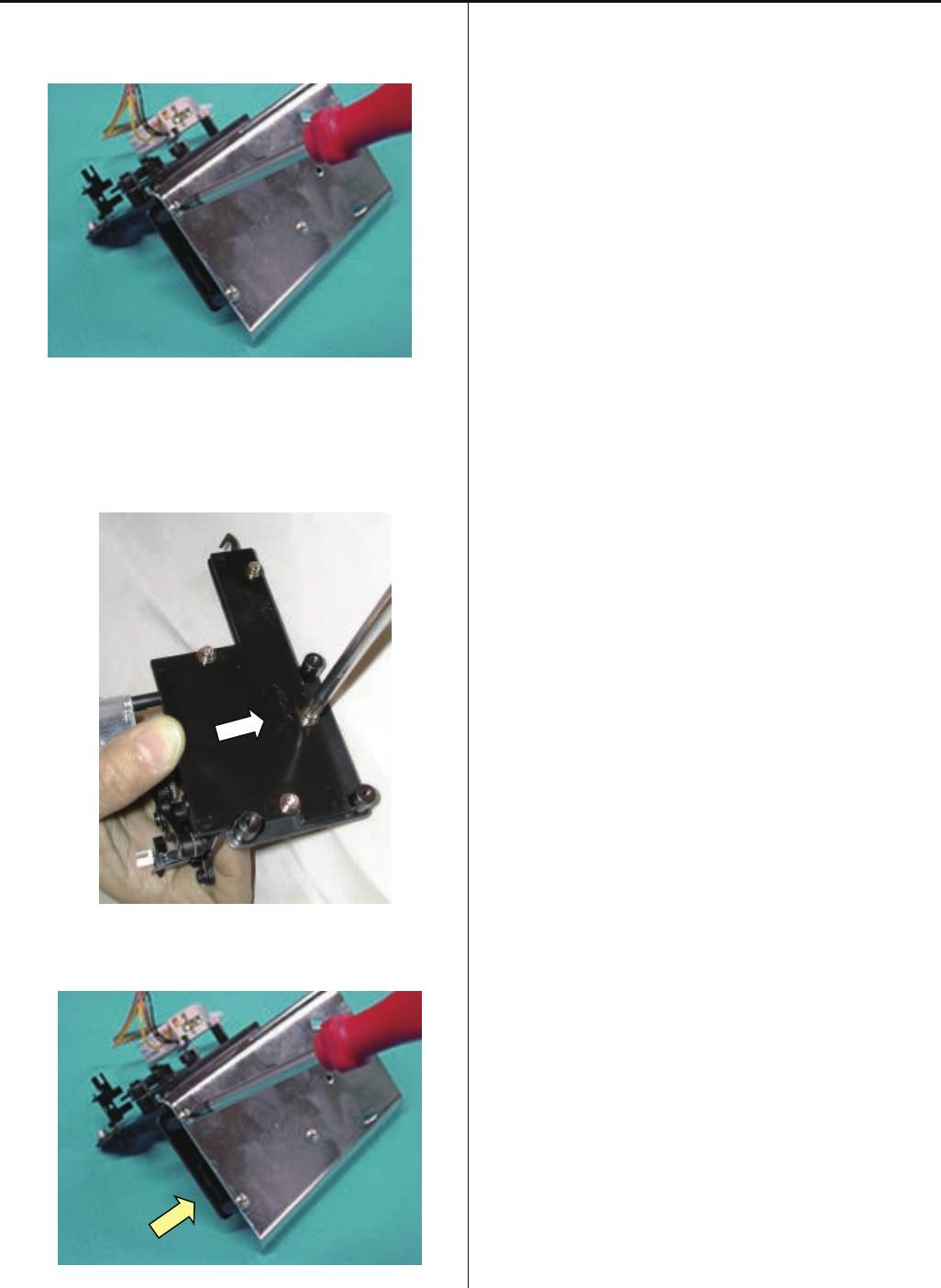
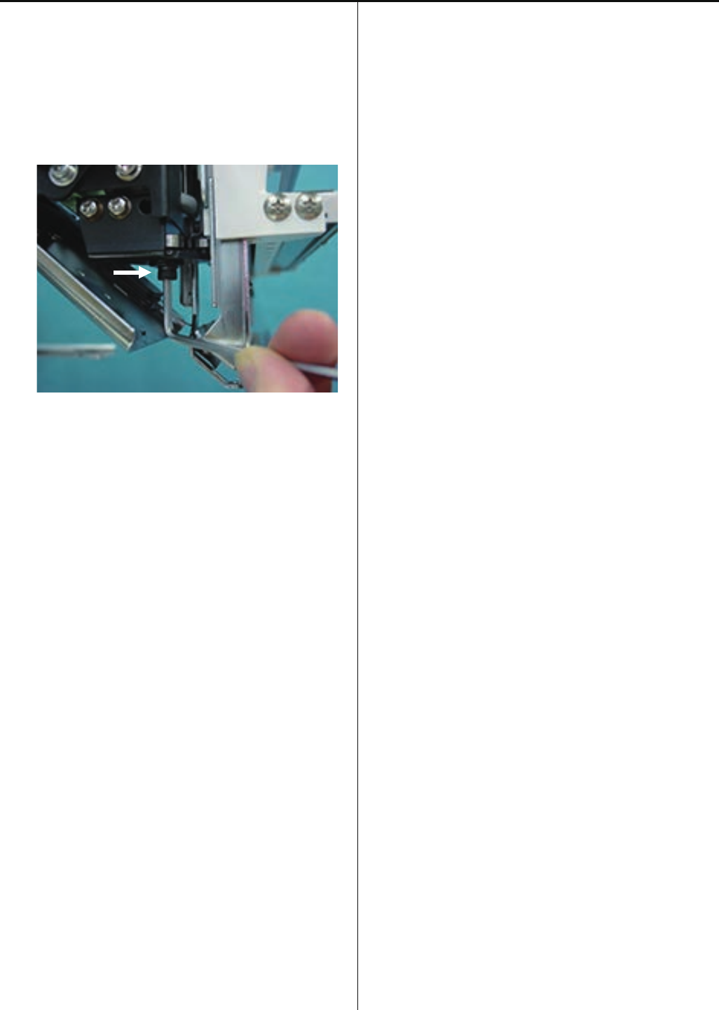
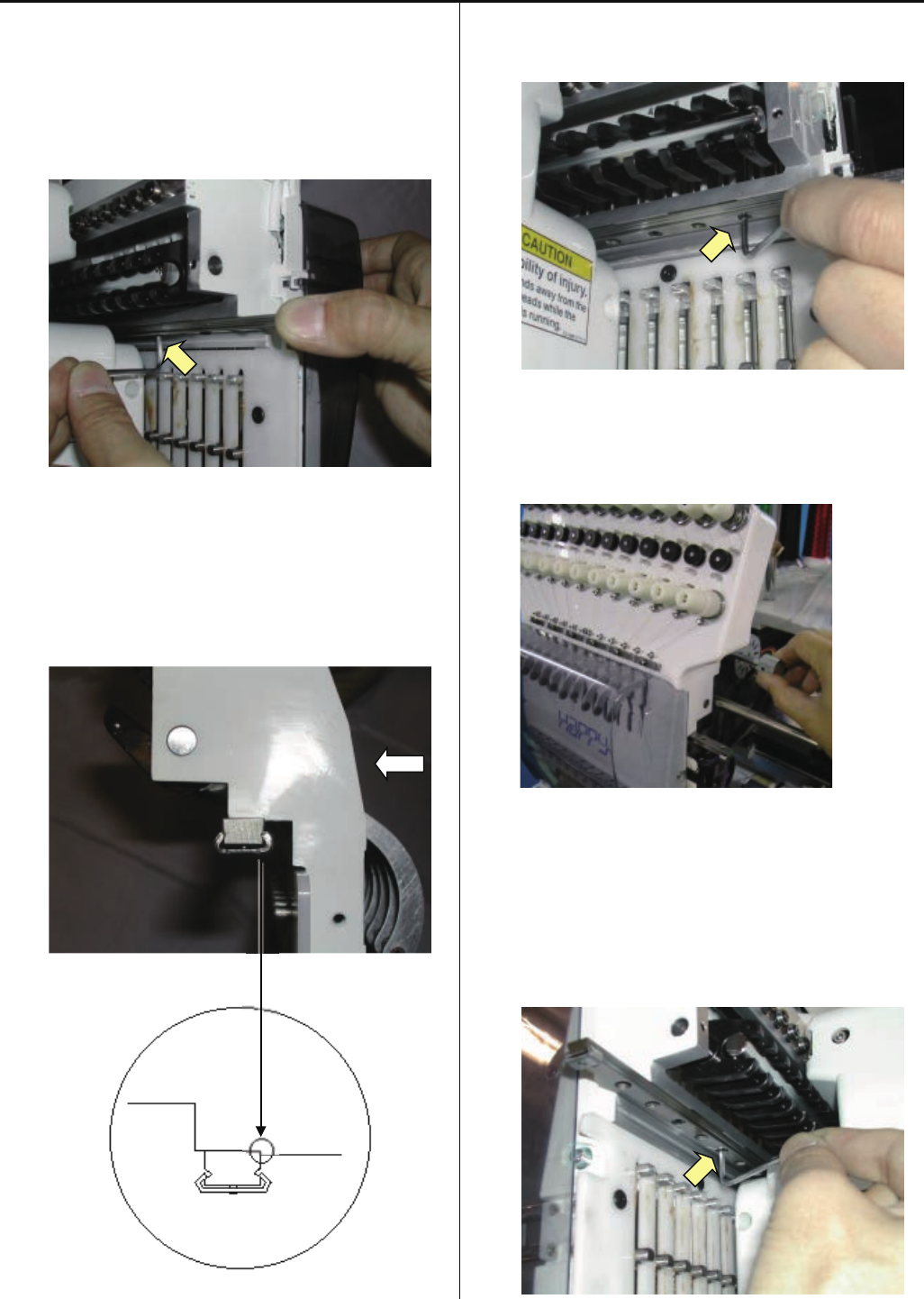
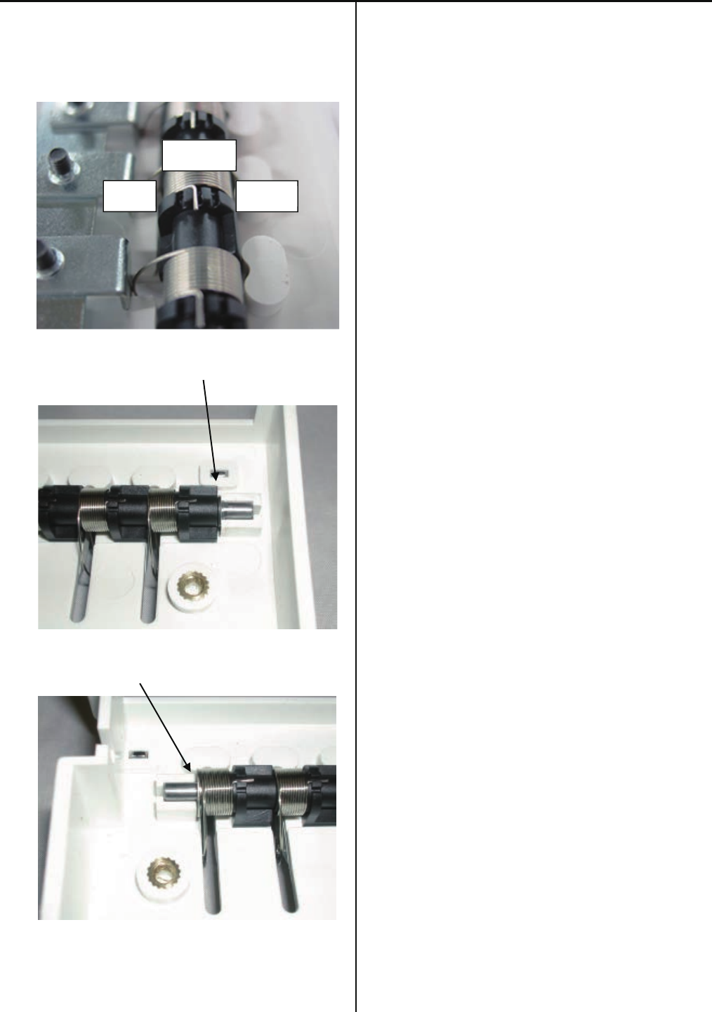
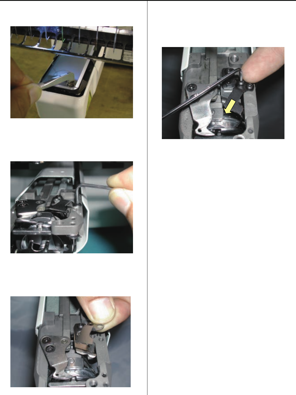
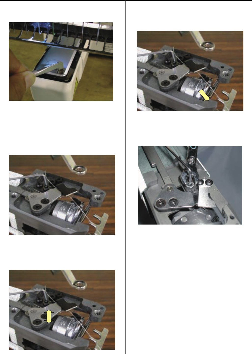
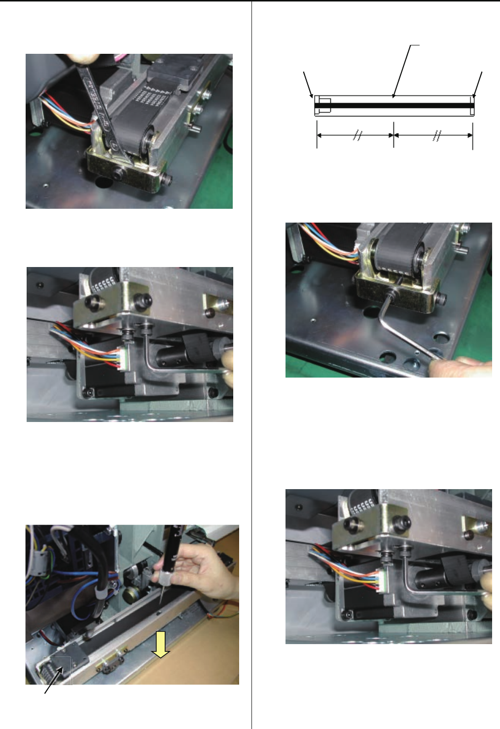
3-2-18 Exchange of thread catcher
1. Install thread catcher tentatively.
2. Tighten thread catcher pushing it upward and forward.
(As shown an arrow.)
3. Continue to conduct [Adjustment of thread holder].
When you adjustment of thread holder, in case of adjust
again thread catcher.
(Follow in [3-3-13 Adjustment of thread holder])
52
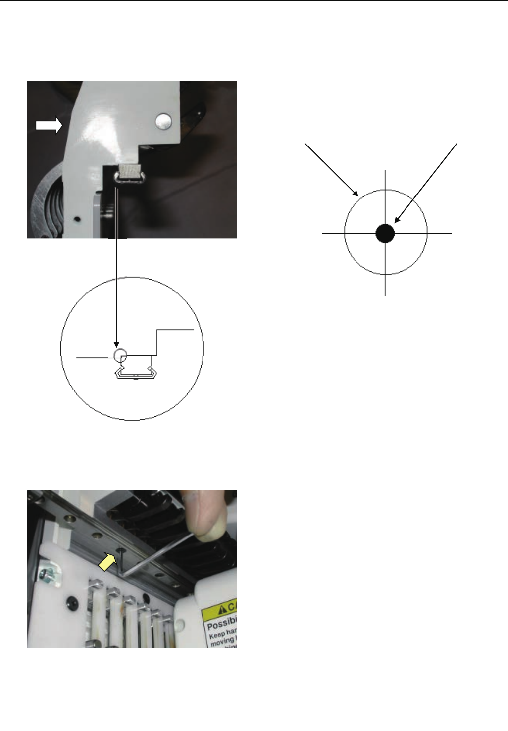
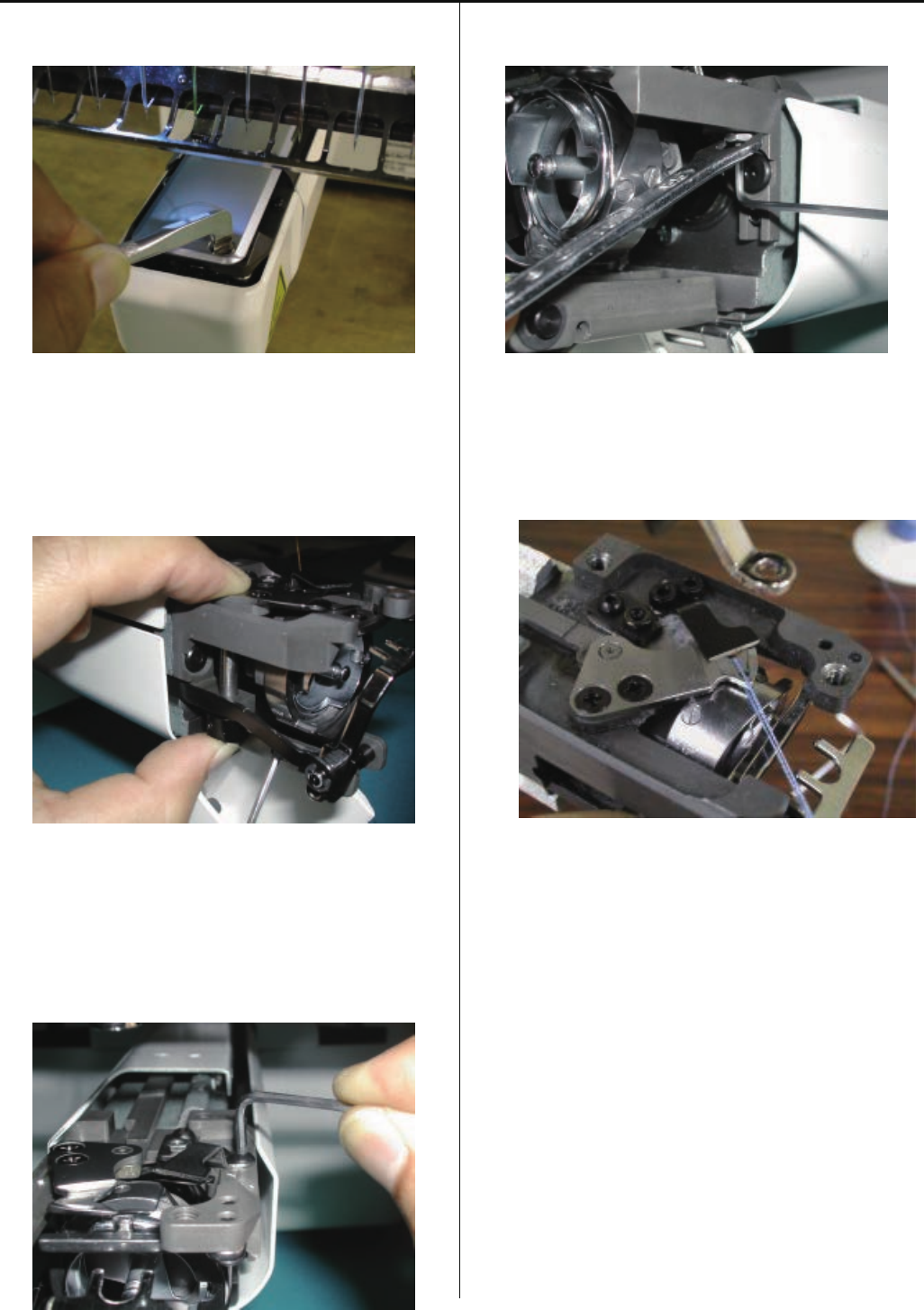
3-2-19 Exchange of thread catcher guide
1. Remove guard plate.
2. Exchange guide.
Fix the guide after moving it to the right.
3. Install the guard plate.
4. Please refer to [3-2-18 Exchange of thread catcher],
install thread chatcer to finish.
53
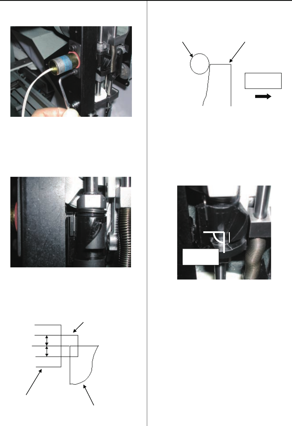
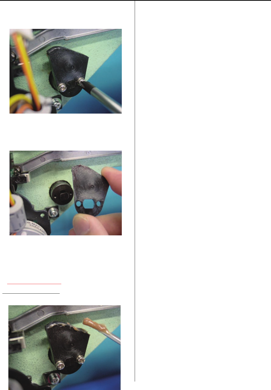
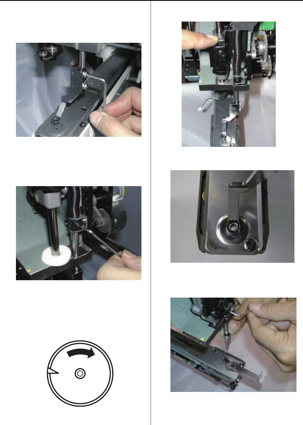
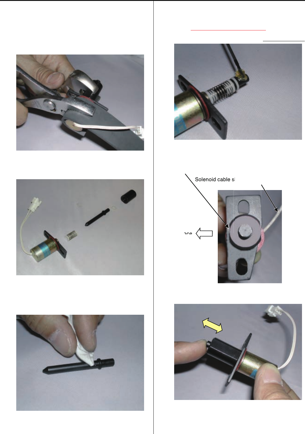
3-2-20 Disassembling and Cleaning of jump solenoid
1. Disassemble the solenoid nut.
Use rubber sheet as safeguard.
2. Clean up the each part of the solenoid.
3. Put the designated grease on plunger part.
<Grease> Shell Grease7 MIL-G-23827B
Equivalent brand.
4. Assemble the solenoid to the original position.
The flat surface of the solenoid nut
should come to the front.
Solenoid cable should come to the back side.
Front face
5. Confirm the movement of the plunger is smooth enough.
6. Procedure is done after assembling the Jump solenoid.
Referring to [3-2-5 Adjustment of fixing of jump solenoid].
a
sh
ace
Solenoid cable s
ace
54
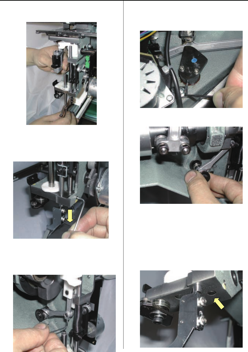
3-2-21 Adjustment of bobbin winder
# Adjust if the thread is leans to one side.
1. Assemble the winder bracket ass’y tentatively.
2. Assemble the left cover with keeping the space
between shaft and the cover hole.
3. Assemble thread tension ass’y.
The marked position by arrow
should come to the center.
4. Assemble guide as tentatively.
5. Confirm that the shaft does not touch the cover
by turning motor.
(Set the empty bobbin and down the Guide.)
If the guide touches the bobbin adjust position
of the winder bracket ass’y.
55
6. Adjust bobbin thread tension [30g] by tension gauge.
7. Rewind the bobbin thread.
8. Adjust the inclination of Winder bracket ass’y
in accordance with thread winding condition.
9.Adjust the height of Guide to adjust volume of thread
to be winded.
10. Reinstall the parts which has been removed.
56
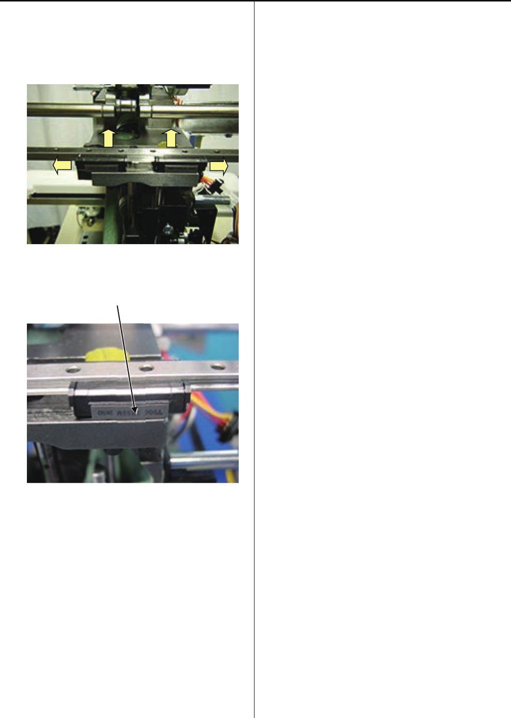
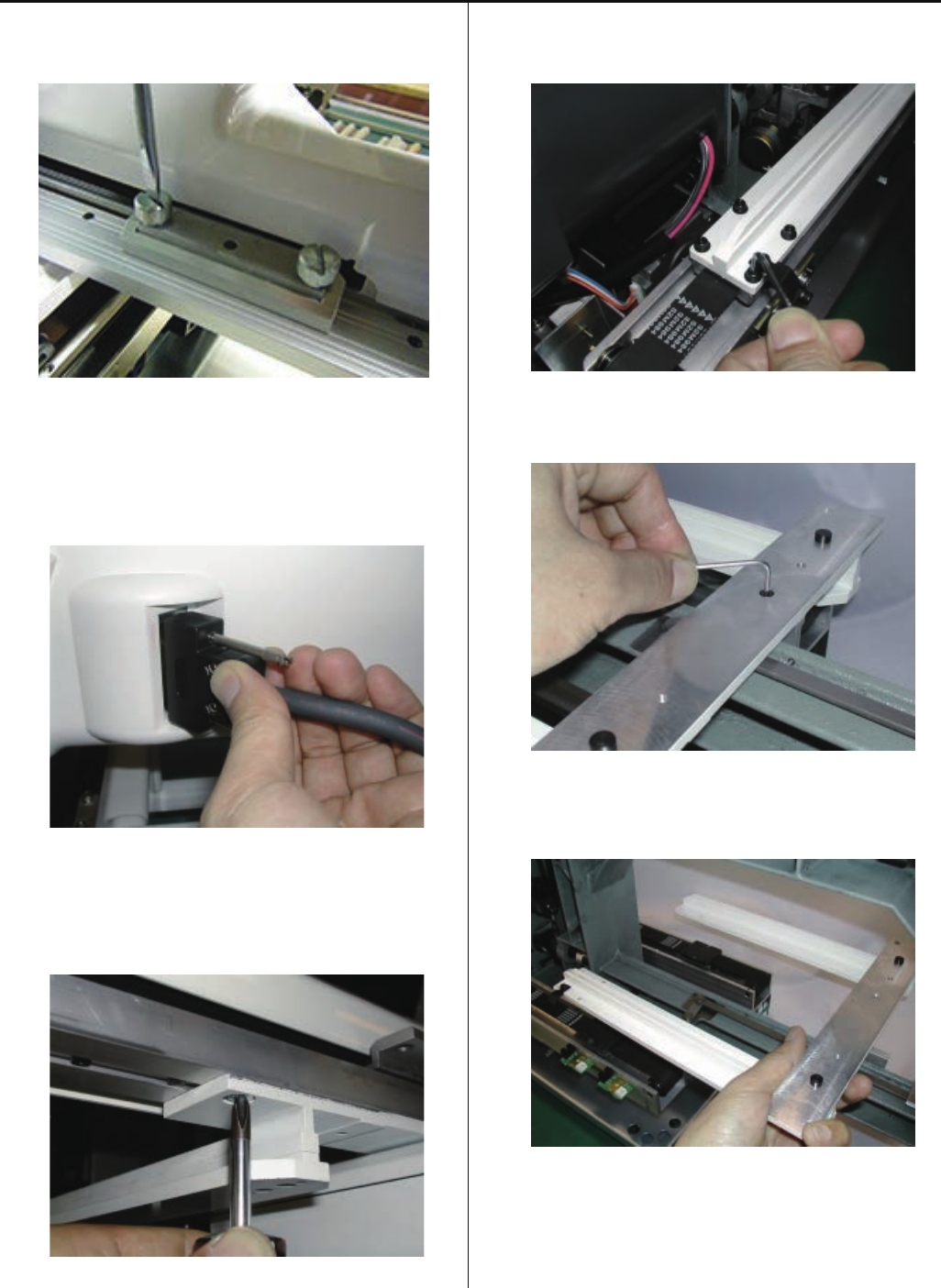
3-3-1 Assemble the upper rail of moving head
1. Tighten right and left LM guide base.
Follow in picture, keep push to allow way each LM guide
base.
<Notice>
Should be front side which letter on side of LM guide base.
57
3-3-2 Adjustment of backlash (back and forth) of moving head
1. Adjust positioning roller shaft so as to put moving rail
(lower) between bearings.
Move moving head back and forth so as not to cause
backlash.
2. After adjustment, check and adjust needle drop to finish
Please refer to [3-3-4 Adjustment of needle position
(back and forth) ].
58
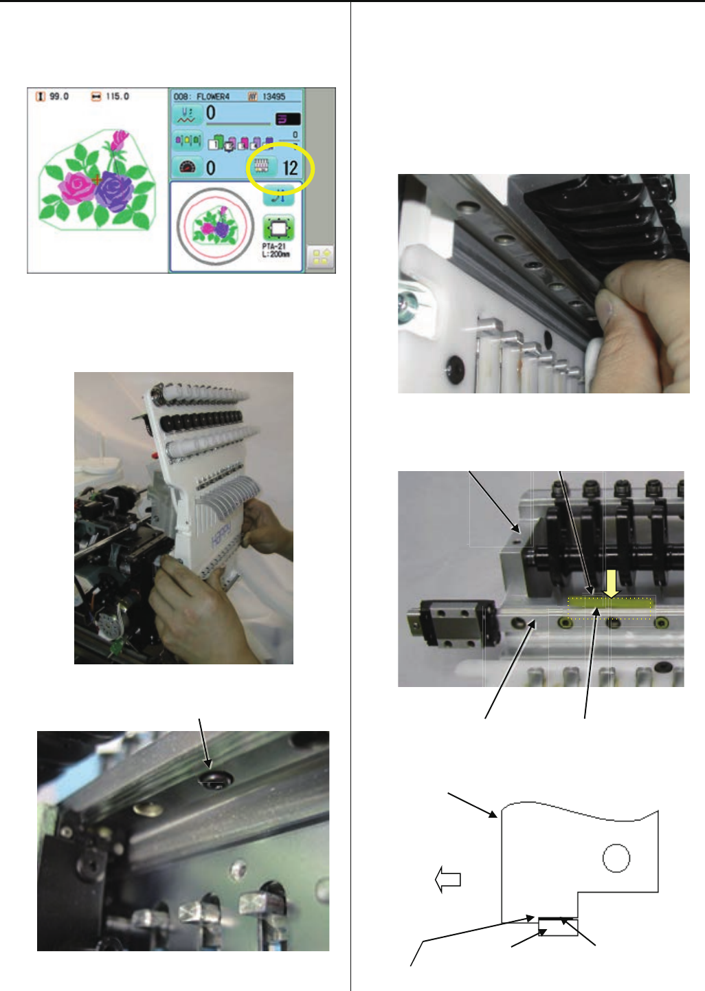
3-3-3 Assemble the moving head
1.Pleaseconfirmthatthepositionofneedlebarchange
unitissetat12thneedle.
2. moving head を12th needles の位置で、Install moving head
tentatively.
<Caution>
Screw head not to come out from LM guide side.
3. Put in SIMM [0.05mm] between a moving head and
LM guide.
* Don't tighten a screw only by inserting SIMM here.
Please give
<Caution> Do not lost simm material.
<View of behind>
Position which SIMM puts in screws
Moving head (central position between)
LM guide SIMM (Right)
<View of right side>
Moving head
Front
LM guide SIMM (Three places)
Position (it puts in to the back) which SIMM puts in
59
4. Turn the drive shaft B screw for manual operation,
and make it the 1st needle.
* When a moving head is caught on the way and does not
carry out horizontal movement.
The screw tightened tentatively in "the work procedure 1"
has come out from LM guide.
A screw from LM guide. Please fasten.
5. Put in SIMM [0.05mm] between a moving head and
LM guide.
<View of behind>
To puts in (central position between screws)
Moving head
SIMM (Middle) SIMM (Left) LM guide
<Veiw of left side>
Moving head
LM guide SIMM (Three places)
Position (it puts in to the back) which SIMM puts in.
* Don't put in SIMM but push up a moving head lightly a case.
<important>
Please do not lower LM guide by any means.
There is a possibility that LM guide may bend.
60
6. Tighten an inside screw (arrow portion in a figure).
<important>
Please perform a screw bundle in order of "inside to
outside."
At this time, a moving head is pushed from the front and it
is LM guide.
It is made for there to be no crevice.
7. An outside screw (arrow portion in a figure) is tightened.
8. Turn the drive shaft B screw for manual operation,
and make it the 12th needles.
9. Tighten an inside screw (arrow portion in a figure).
<important>
Please perform a screw bundle in order of "inside to
outside."
61
At this time, a moving head is pushed from the front and it is
LM guide.
It is made for there to be no crevice.
10. Tighten an outside screw (arrow portion in a figure).
11. Check center (right and left)(back and forth) of needle and
needle hole of needle plate.(Needle No.1 ,6 and 12.)
<Caution>
Should be check needle No.1 ,6 and 12.
Needle hole of needle plate Needle
12. If not center (back and forth),please adjust needle position
(back and forth).
Refer to [3-3-4 Adjustment of needle position (back and
forth)].
13. If not center (right and left), please adjust again
procedure 6-10.
14. If “OK”. Please check [needle position].
Refer to [3-3-5 Check of needle position].
If “NG” this process, adjust again procedure 12-13.
62
3-3-4 Adjustment of needle position (back and forth)
1. Bring pressure foot down. (Either way mentioned below)
(1)press P_FOOT key on control box.
(2)Turn gear with finger.
2. Bring needle down.
3. Turn upper shaft and set needle near to the lowest needle
position [L] to adjust positioning plate ass’y.
* Insert Lower rail to between the two bearing deeply.
(This is for setting of Moving head completely.)
lower rail
positioning plate ass’y
Viewing from side, set to center of needle hole.
#Check and adjust with 1st, 6th and 12th needle.
4. After adjustment, please be sure to check and adjust
clearance between needle and shuttle hook.
Please refer to [3-5-1 Adjustment of rotary hook timing].
63
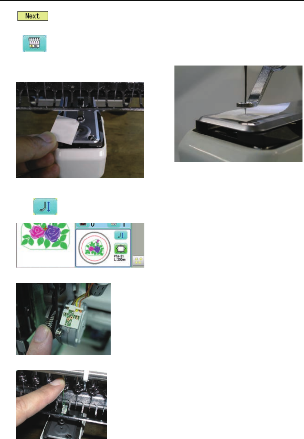
3-3-5 Check of needle position
1. A main switch is turned on.
The is pressed and it changes into an
operation state.
2. Press and make it the 4th needles.
3. Stick a seal on needle hole of a needle plate.
4. Bring pressure foot down. (Either way mentioned below)
(1)press key on control box.
(2)Turn gear with finger.
5. Lower a needle bar with a finger.
6. Turn an upper axis up to [302 degrees - 303 "], and it is the
needle mark to a seal. A hole is made.
<Note>
Needle point will become large if the angle of a dial disc
is made into 304 degrees or more.
An exact needle position check becomes impossible.
7. Reverse-rotate an upper axis, raise a needle bar, and
unite with C [275 degrees].
(It returns to 303 degrees-> 220", and unites with 275
degrees after that.)
<Note>
If a top axis is right-rotated, a needle will enter deeply,
and needle hole is greatly.
It becomes. Therefore, an exact needle position check
becomes impossible.
8. 1st needle and the 12th needles are to 302 degrees - 303
degrees about an upper axis by the above-mentioned
procedure. It turns, a needle is lowered and a needle
position is checked.
It will be O.K. if the needle point goes into the seal hole
made by the 6th needles at this time.
* If “NG”. Please adjust again, follow to [3-3-3 Asemble
the moving head] of procedure 6-10.
The order which the screw which is fixing the move head
fastens -- from an inner side. If it does not carry out
correctly outside, a needle position will shift -- it is –
9. Un-stick a seal on needle plate to finish.
64
3-3-6 Adjustment of needle height
1. Remove lower front panel.
2. Remove bobbin case.
3. Bring pressure foot down. (Either way mentioned below)
(1)press key on control box.
(2)Turn gear with finger.
4. Bring needle down.
5. Turn upper shaft to set dial disc to [5 degrees].
6. Loosen needle bar boss and needle bar boss B.
Needle bar boss B
Needle bar boss
65
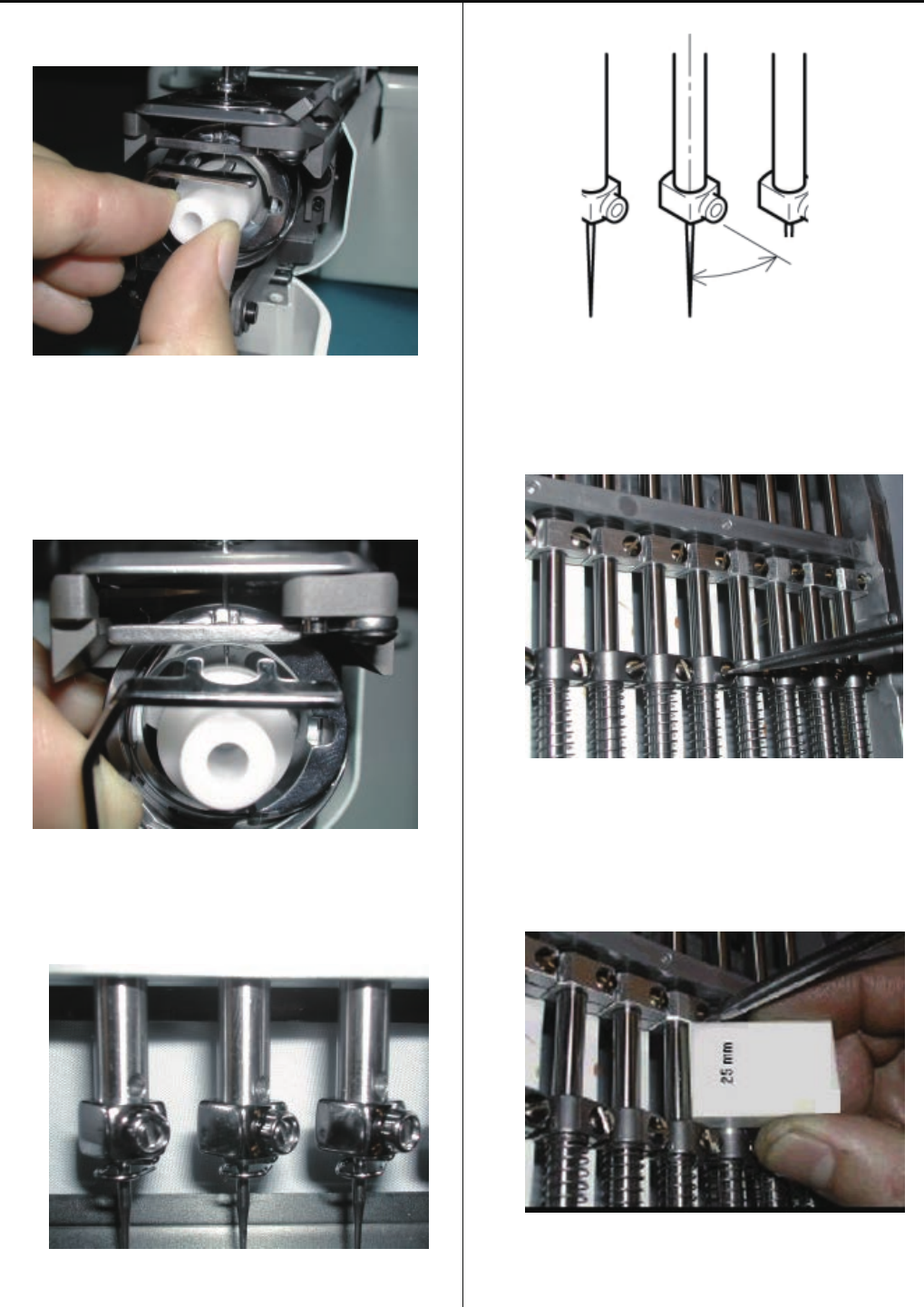
7. Put needle height gauge in rotary hook.
8. Adjust the needle bar height up and down till the needle tip
touches to the gauge slightly.
9. Set direction of needle holder as illustrated below.
About 30 degrees
* Check needle holder dose not touch to Needle guard.
10. Tighten the screw of needle bar boss.
11. Tighten the screw of needle bar boss B.
When tightening needle bar boss B, please insert gauge
[25mm] in-between.
* Check the movement of needle bar goes smoothly.
12. Put things back in reverse order of 1-5 to finish.
66
3-3-7 Exchange of needle bar, needle bar spring and cushion
1. Remove rear cover.
2. Disconnect TC cable and limit switch cable.
3. Remove front cover of front panel.
4. Remove thread tension bracket.
5. Remove lower front paneI.
6. Remove needle and needle holder.
67
7. Loosen needle bar boss and needle bar boss B.
Needle bar boss B
Needle bar boss
8. Pull out needle bar.
At this moment, remove needle bar boss,
needle bar bossB, needle bar spring and cushion.
9. While pressing needle bar spring, insert good needle bar.
10. Fix needle and needle holder.
11. Adjust needle height.
Please refer to [3-3-6 Adjustment of needle height].
12. Put removed parts back to finish.
68
3-3-8 Fixing of needle bar boss guide plate
1. Remove moving head.
Please refer to [3-3-9 Exchange of take-up lever].
2. Exchange of needle bar boss guide plate.
Temporarily, use the pan head screw to center the needle
bar boss guide plate then fix the screw.
3. Fix positioning needle bar boss guide plate.
4. Put moving head and other removed parts back to finish.
69
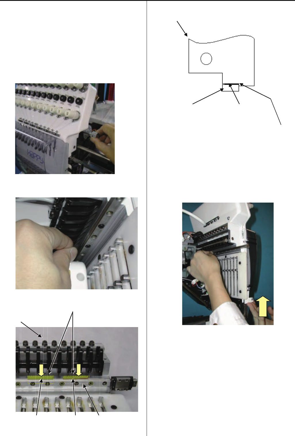
3-3-9 Exchange of take-up lever
1. Remove rear cover.
2. Disconnect TC cable and limit switch cable.
3. Remove front cover on front panel.
4. Remove thread tension bracket.
5. Remove moving head.
70
6. Loosen screw on take-up shaft.
7. Remove the E-ring.
8. Remove the take up lever shaft first then remove the take-
up lever.
9. Install good take-up lever assembly with plastic washer,
E-ring.
10. Leave space of [0.2mm] between take-up lever and
moving head .
Tight screw for “Take up lever shaft”
11. Put moving head in previous position to finish.
71
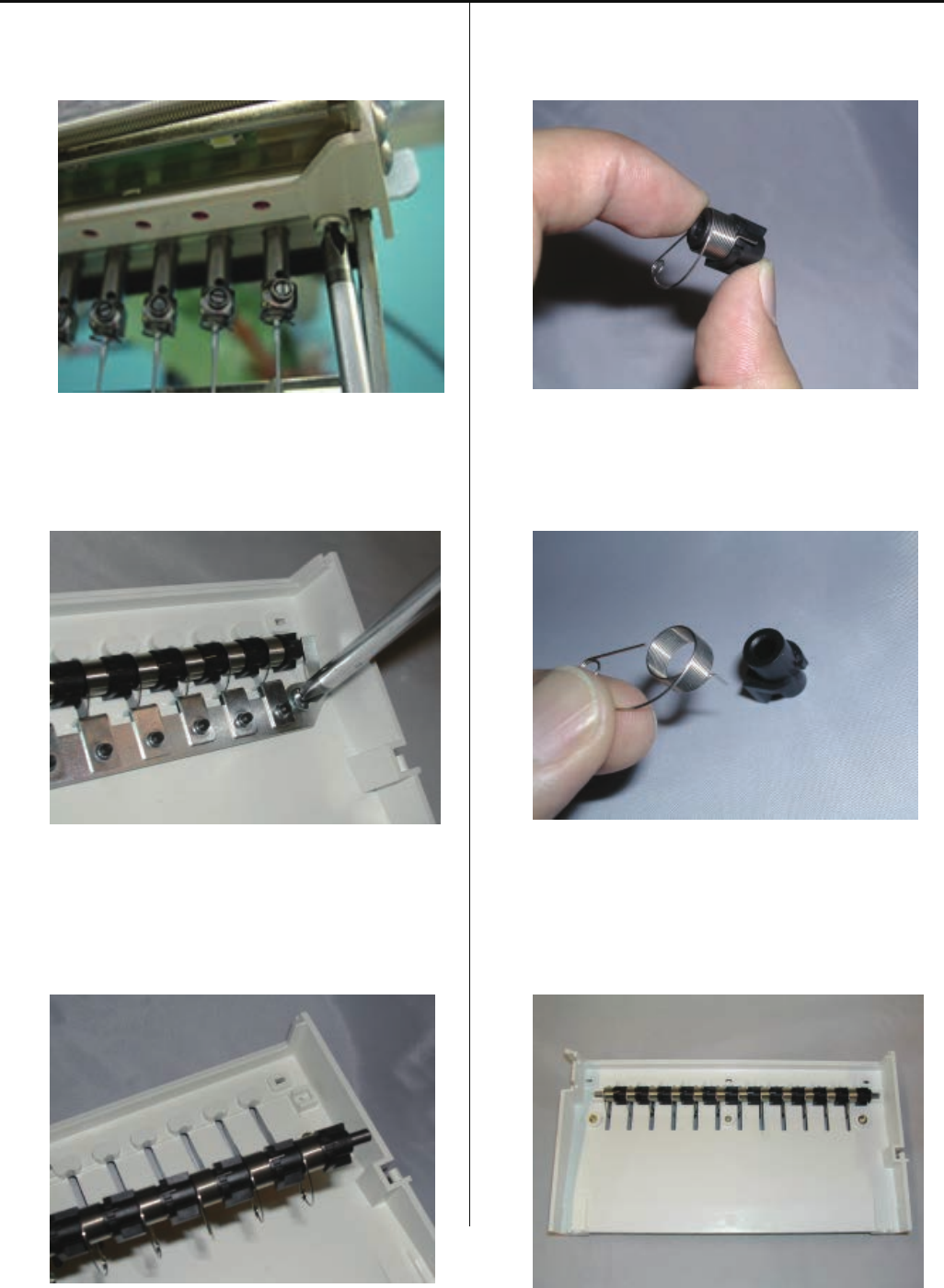
3-3-10 Exchange of thread adjusting spring
1. Remove lower front panel.
2. Remove adjuster base.
3. Remove thread adjusting spring ass’y.
4. Remove thread adjusting spring and spring holder.
5. Exchange thread adjusting spring.
6. Assemble the thread adjusting spring into lower front panel.
72
Set the thread adjusting spring to [Middle] position as
Picture below.
E-ring
Washer
7. Put removed parts back in reverse order.
Middle
Strong
Weak
73
3-3-11 Adjustment of tension of thread adjusting spring
1. Remove lower front panel.
2. Block has spring groove to be able to adjust in three steps
Put tip of spring in desired position.
Strongest tension will be obtained in upper groove.
3. Fix lower front panel to finish.
74
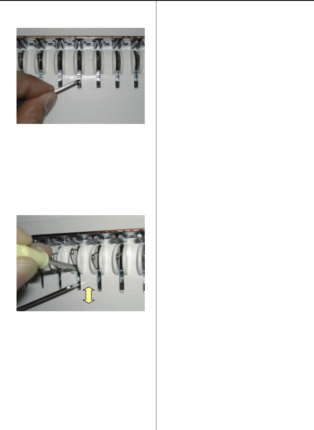
3-3-12 Adjustment of stroke of thread adjusting spring
1. Loosen screw on adjuster.
2. Move adjuster position up and down with small frat-head
driver to change stroke.
When you move adjuster upward,stroke will get small.
When you move it down, stroke will get large.
3. After adjustment, tighten screw to finish.
75
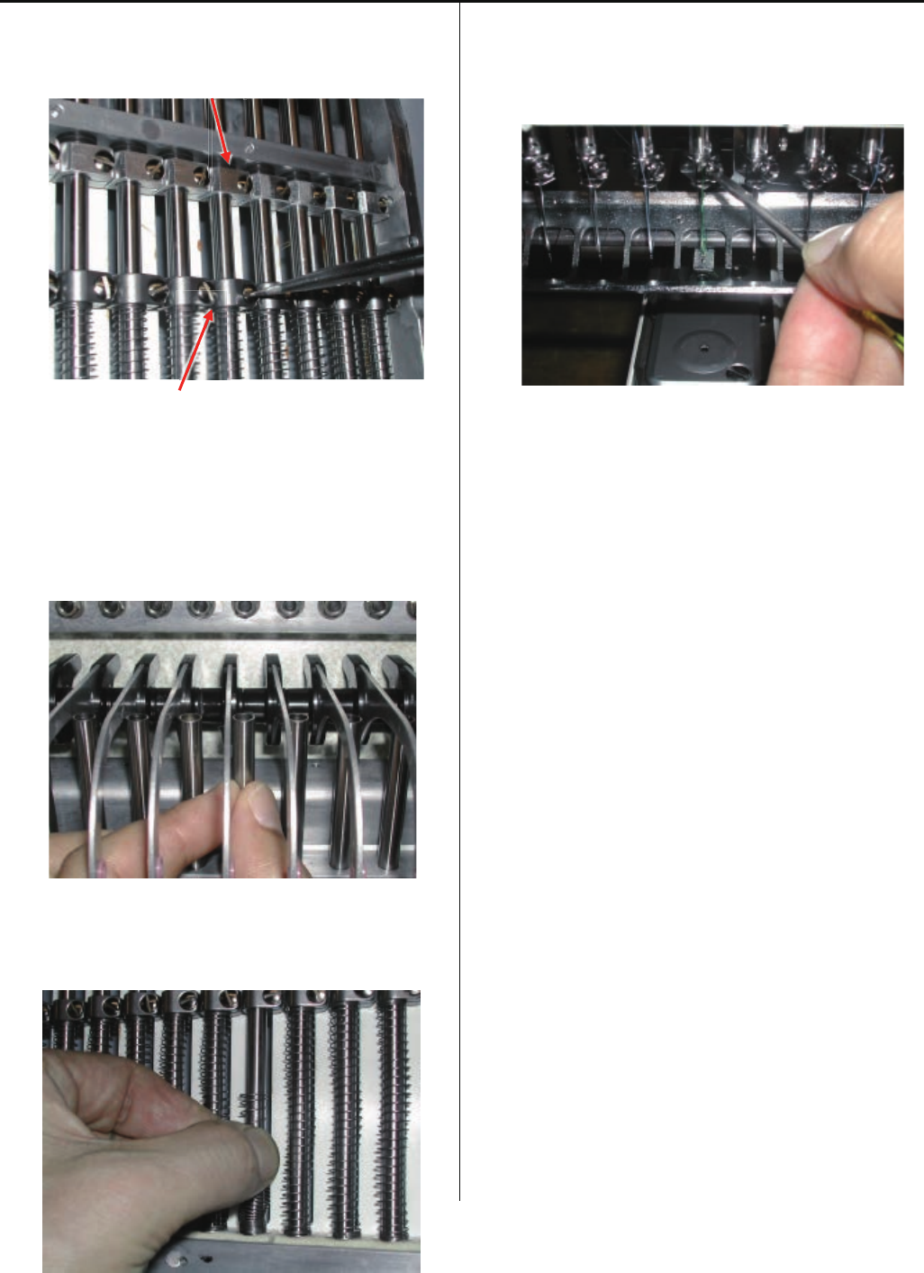
3-3-13 Adjustment of thread holder
1. Remove the lower front panel.
2. Loosen screw to the extent that thread hoIder moves.
3. Insert positioning gauge [47.5±0.1mm] between lower
part of moving head and holder (upper) and mount it
vertical.
4. Hold down the pressurefoot and take the hook in and out
by finger to check movement of hook goes smoothly.
Check this at 1th , 6th , 12th needle.
<Positional relationship between hook and holder (lower)>
5. Thread catcher device should be adjusted if above
clearance is not keepable.

76
6. Check up with thread trimmer function.
7. Assemble lower front panel to terminate this procedure.
77
3-4-1 Fixing of needle bar change unit
1. Place needle bar change unit assembly.
please set positioning hole on unit assembly to
positioning pin.
2. Bring pressure foot down. (Either way mentioned below)
(1)press key on control box.
(2)Turn gear with finger.
3. Bring needle down, turn upper shaft to set near to [L point].
4. Adjust position of unit assembly so that needle comes to
center against needle hole on needle plate.
5. Install parts in reverse order to finish.
For adjustment of fixing of each unit, please refer to
process to adjust fixing of each unit.
78
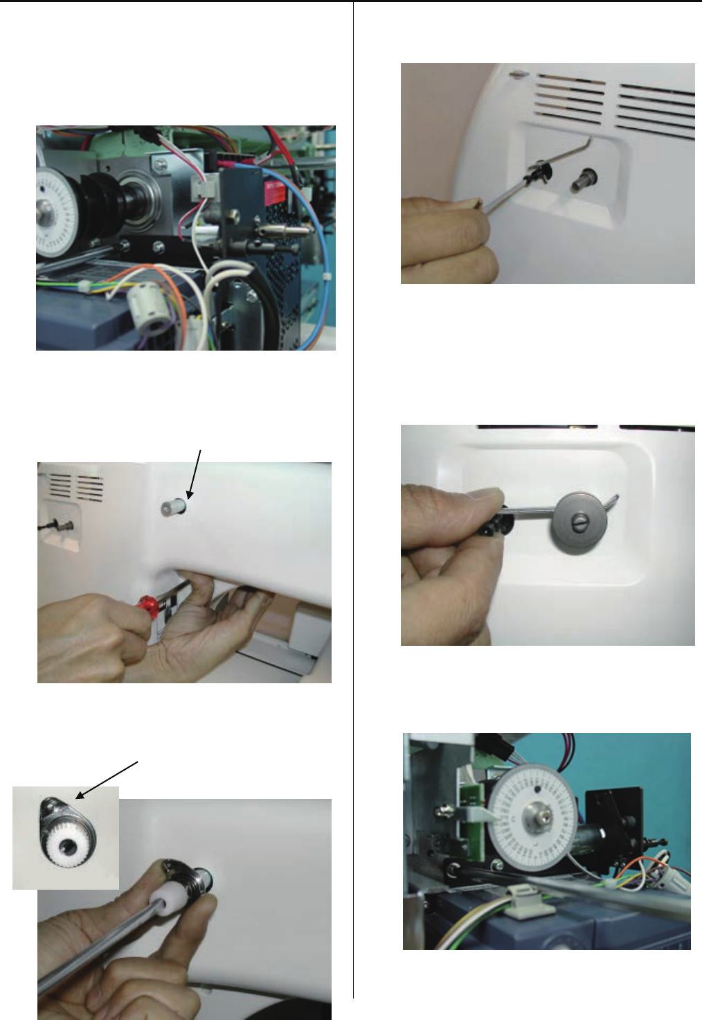
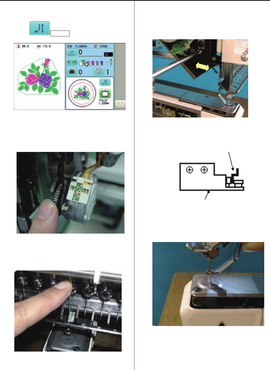
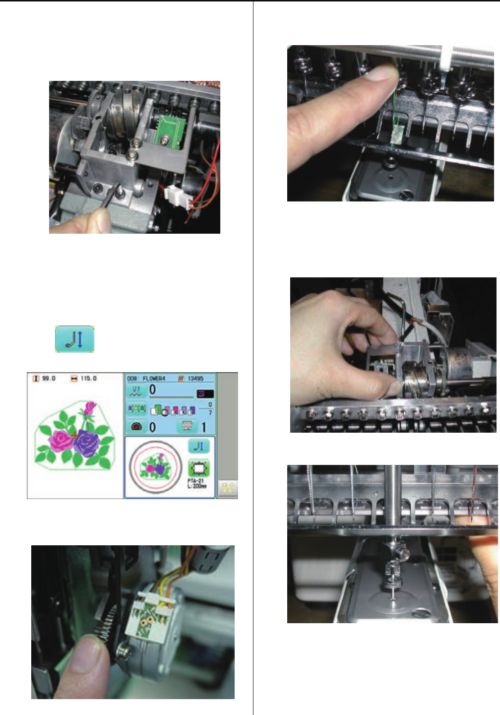
3-4-2 Setting to detect needle position
It is necessary to memorize the value of needle selection
sensor along the needle positions.
Lateral motion of the machine may not be done normally
without the settings.
1. Remove setscrew of slit collar and remove potentiometer.
Do not remove the cable then.
Slit collar Potentionmeter
2. Refer to “4-5-1 How to enter maintenance mode” and enter
maintenance mode.
3. Press Machine Test .
4. Press Needle Adjust
Present needle position of potentiometer is indicated.
The number of needle number on the screen is sometimes
not the same as the number of actual needle position.
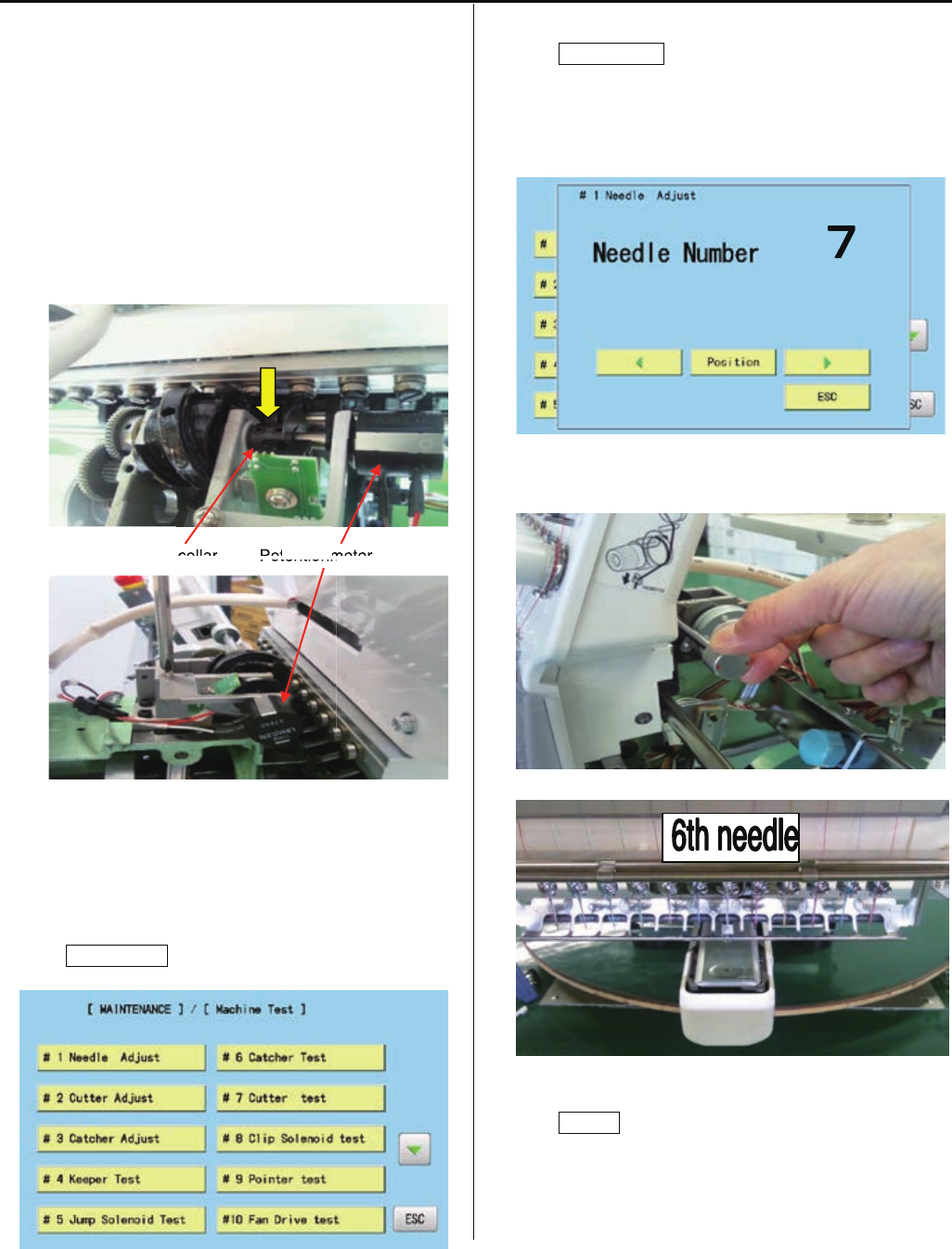
5. Turn knob so that the needle position can be the 6th needle.
6. Press Position .
meter
Potentionm
collar
Pot
79
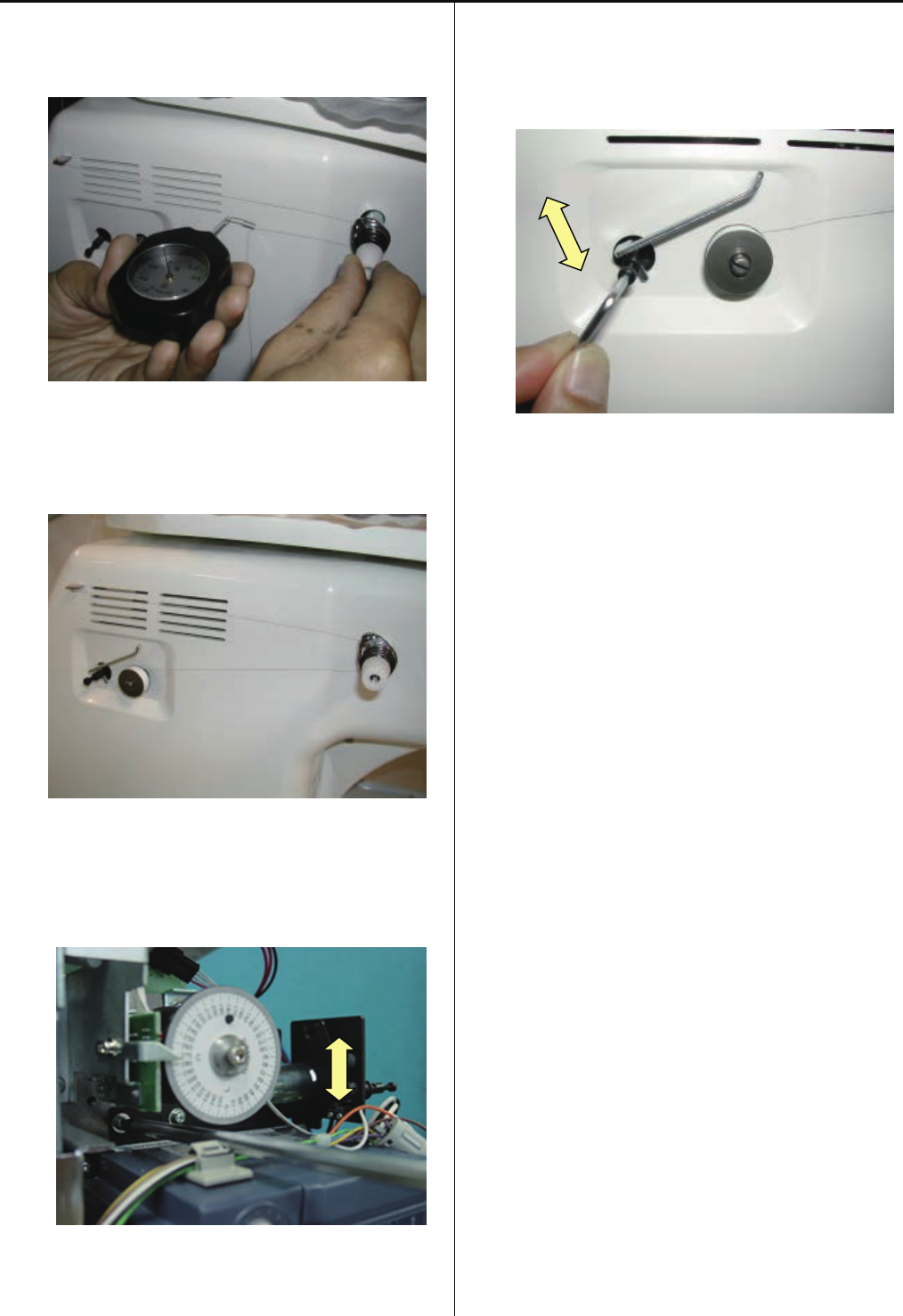
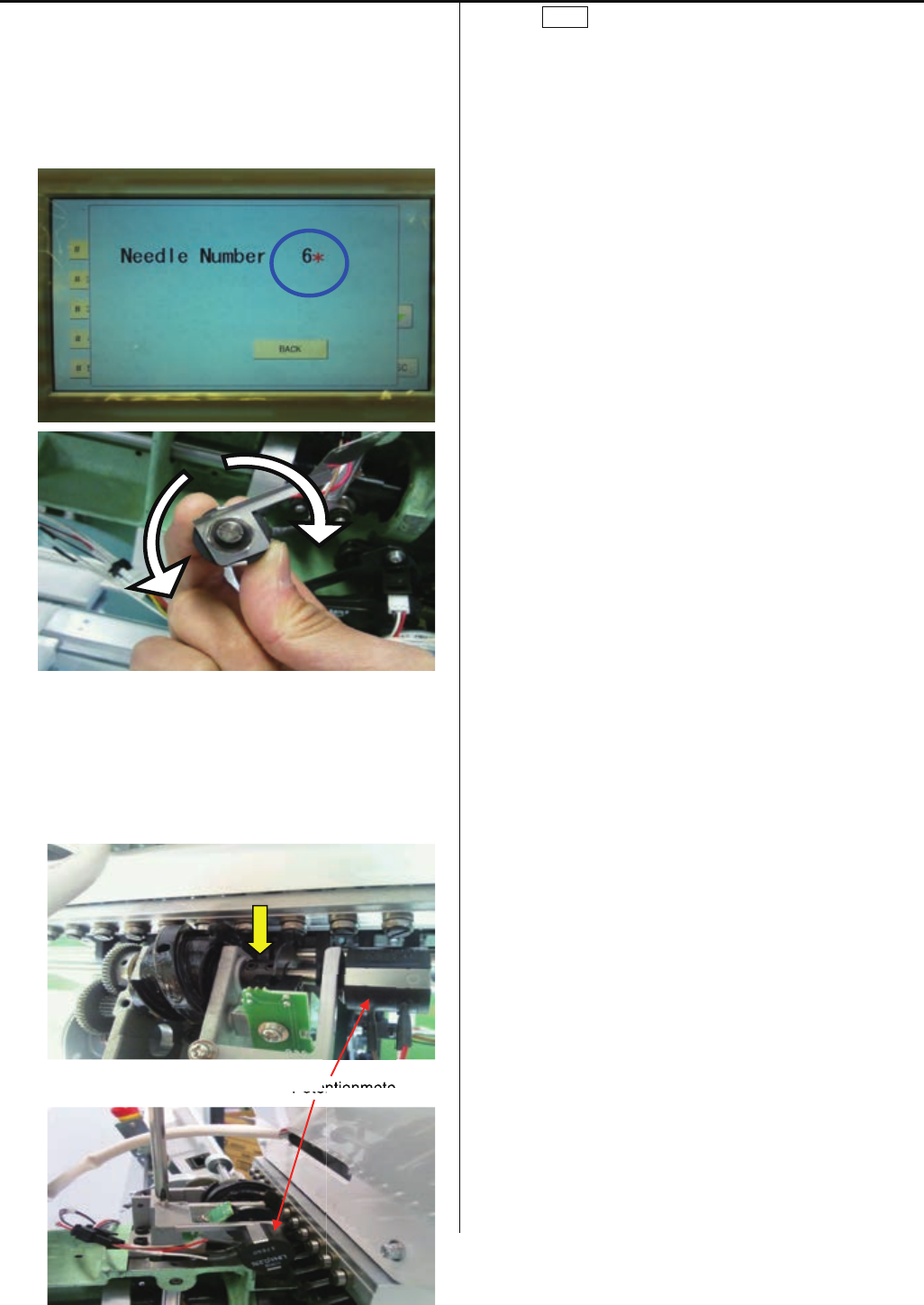
6. Turn the shaft of potentiometer to reach the 6th needle and
continue to turn until *(asterisk) is indicated on the right of
the needle number on the screen.
The machine make a beep once * indicates.
The machine dose not make a beep once * disappears.
Turning the shaft too much make * disappear, and turn
the shaft back and forth, and adjust the position so that
continuous beep is made.
7. Install potentiometer at the 6th position while beep is made
and fix it with setscrew.
Potentionmeter
8. Press BACK to complete settings.
entionmete
Poten
80
3-5-1 Adjustment of rotary hook timing
1. Remove needle plate.
2. Bring pressure foot down. (Either way mentioned below)
(1) press key on control box.
(2) Turn gear with finger.
3. Tighten screw on rotary hook. (3 places)
4. Bring needle down.
5. Turn upper shaft and set dial disc to [25 degrees].
81
6. Adjust rotary hook timing.
This procedure is preconditioned to use needle type
[DB-K5] in which contains with our standard accessory.
At this moment, clearance between needle and rotary
hook should be [0.1-0.2mm].
Check and adjust with 1st, 6th and 12th needle.
7. For making sure, check position of retainer on bobbin case
holder.
Please refer to [3-5-2 Adjustment of retainer on rotary hook]
for adjusting value and follow it.
8. Adjustment has finished.
0.1-0.2mm
82
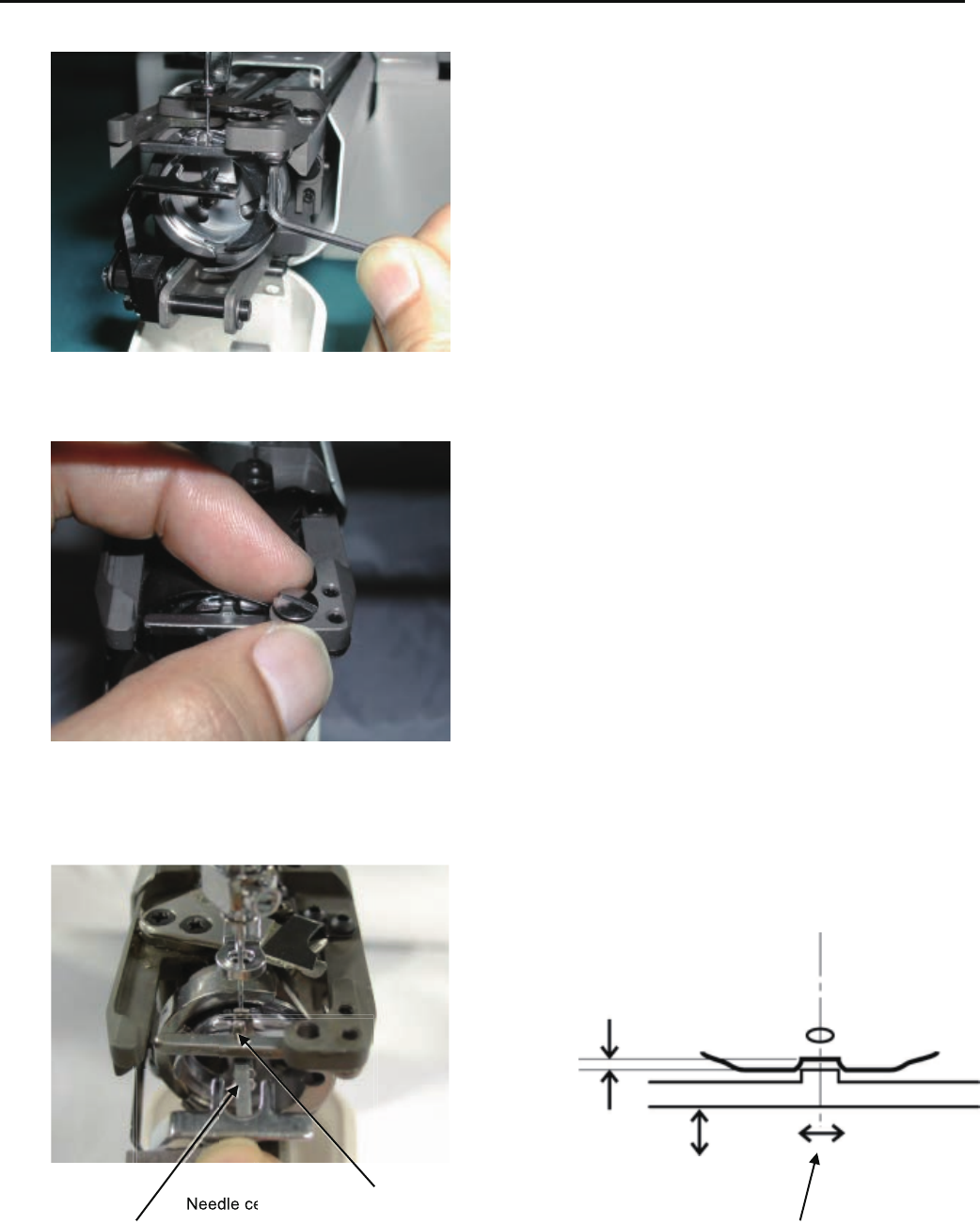
3-5-2 Adjustment of retainer on rotary hook
1. Loosen screw to the extent that retainer on bobbin case holder moves.
2. Install screw for Needle plate. (only front side)
(This avoid interfere of screw and Rotary hook retainer during installing Needle plate)
3. Adjust position back and forth, left and right.
Space has to be [0.8mm] and the position right and left is center of the needle.
0.8mm
Needle center and retainer center should come to same position.
Retainer positioning gauge [0.8mm] Needle center position
4. Adjustment has finished.
e
Needle ce
83
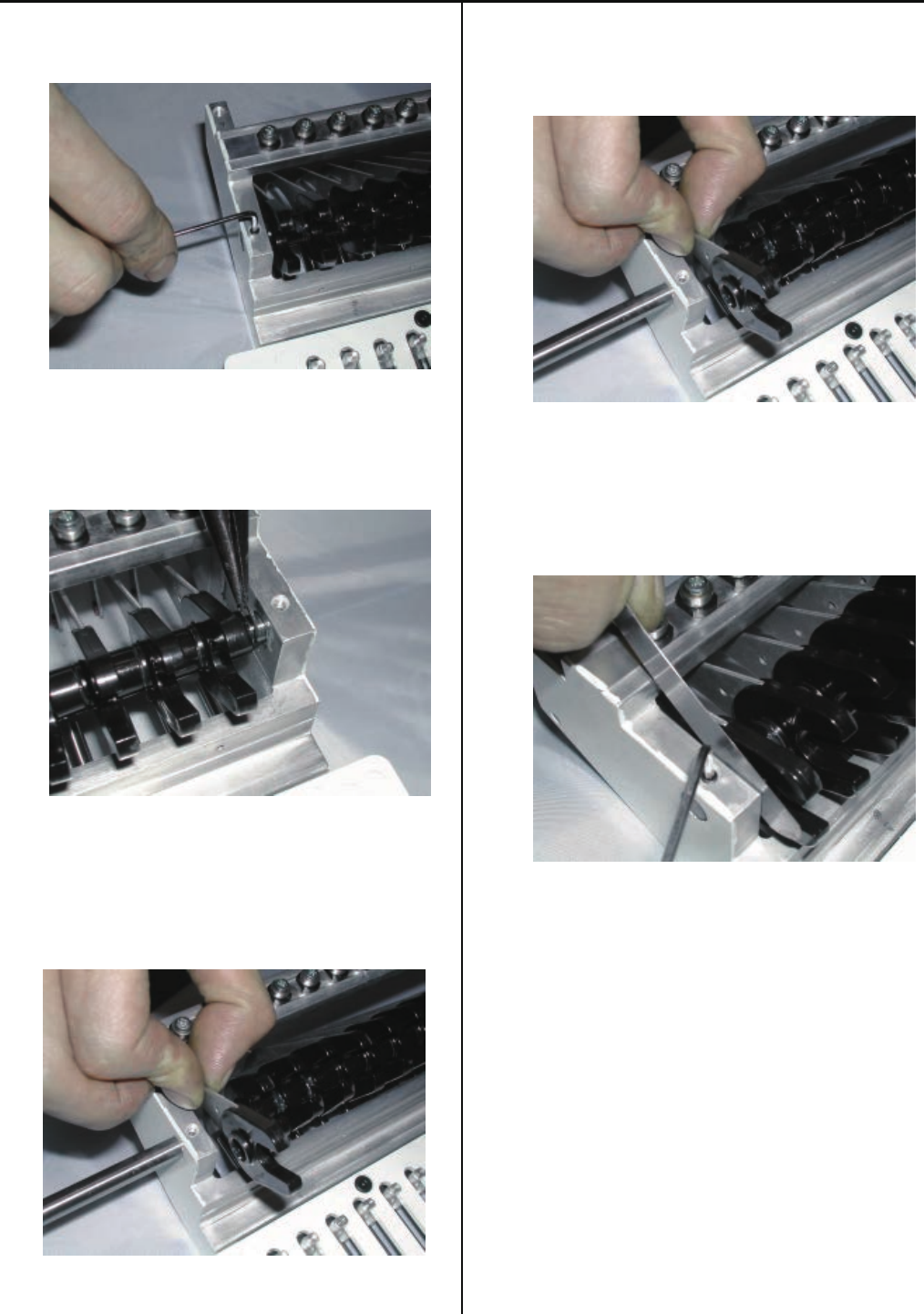
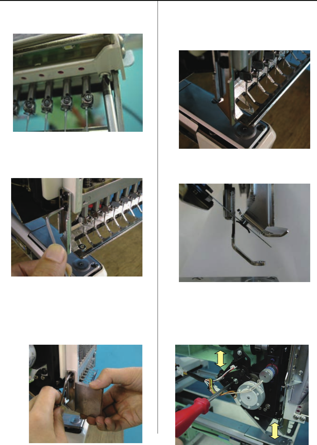
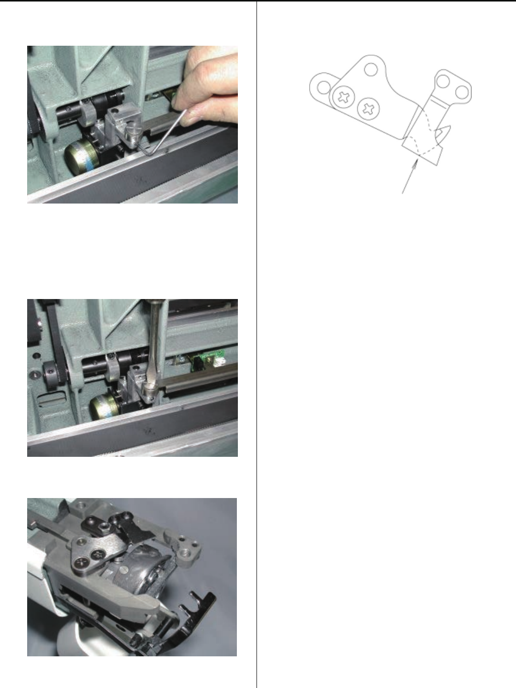
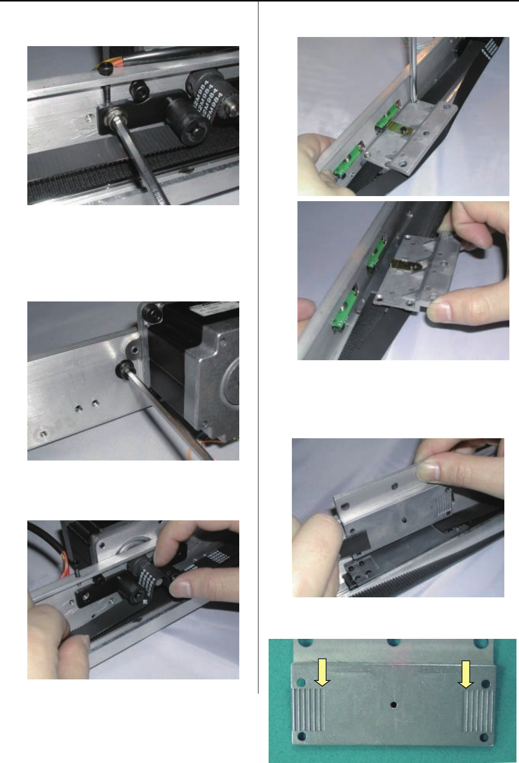
3-6-1 Assemble the arm ass’y
1. Assemble the arm ass’y tentatively.
2. Hold arm to backward and tighten only hithermost screw.
<Caution>
Make sure that there is clearance between arm and
body.
3. Hold the left side of arm to body and tighten screw.
4. Hold the right side of arm to arrow pointed direction
at below picture and tighten screw.
5. Assemble detecting plate.
Make sure that detecting plate is mount perpendicular and
parallel to the arm.
84
6. Check of interference between detecting plate and sensor
or connector of sensor board.
A part of sensor
Sensor
Detecting plate
Conector
A part or conector
7. Adjust by bending detecting plate by hand if you find
any interference with sensor or connector.
8. Finish this process.
85
3-6-2 Exchange of thread cutting roller (except for Rev.A)
1. Remove bobbin winder and power supply.
2. Remove arm.
3. Loosen the screw for coupling of the Y carriage.
4. Remove the screw of Y carriage bracket (left).
86
Remove the Y carriage.
5.Remove E-ring.
6.Remove spring.
7. Remove drive link ass’y from thread cutting driver ass’y .
8. Remove thread cutting driver ass’y .
9. Remove thread cutting roller.
87
10. Fix good parts.
11. Fix thread cutting driver ass’y to the machine.
12. Fix drive link ass’y to thread cutting driver ass’y.
13.Fix spring and E-ring.
14. Fix Y carriage bracket (left) to the machine.
Fix the base with state of pushing it down.
Tighten drive shaft with screw.
15. Connect cable from sensor board.
Place parts back in accordance with manual.
16. Check and adjust position of moving knife and thread cut
timing to finish.
Please refer to respective adjustment.

88
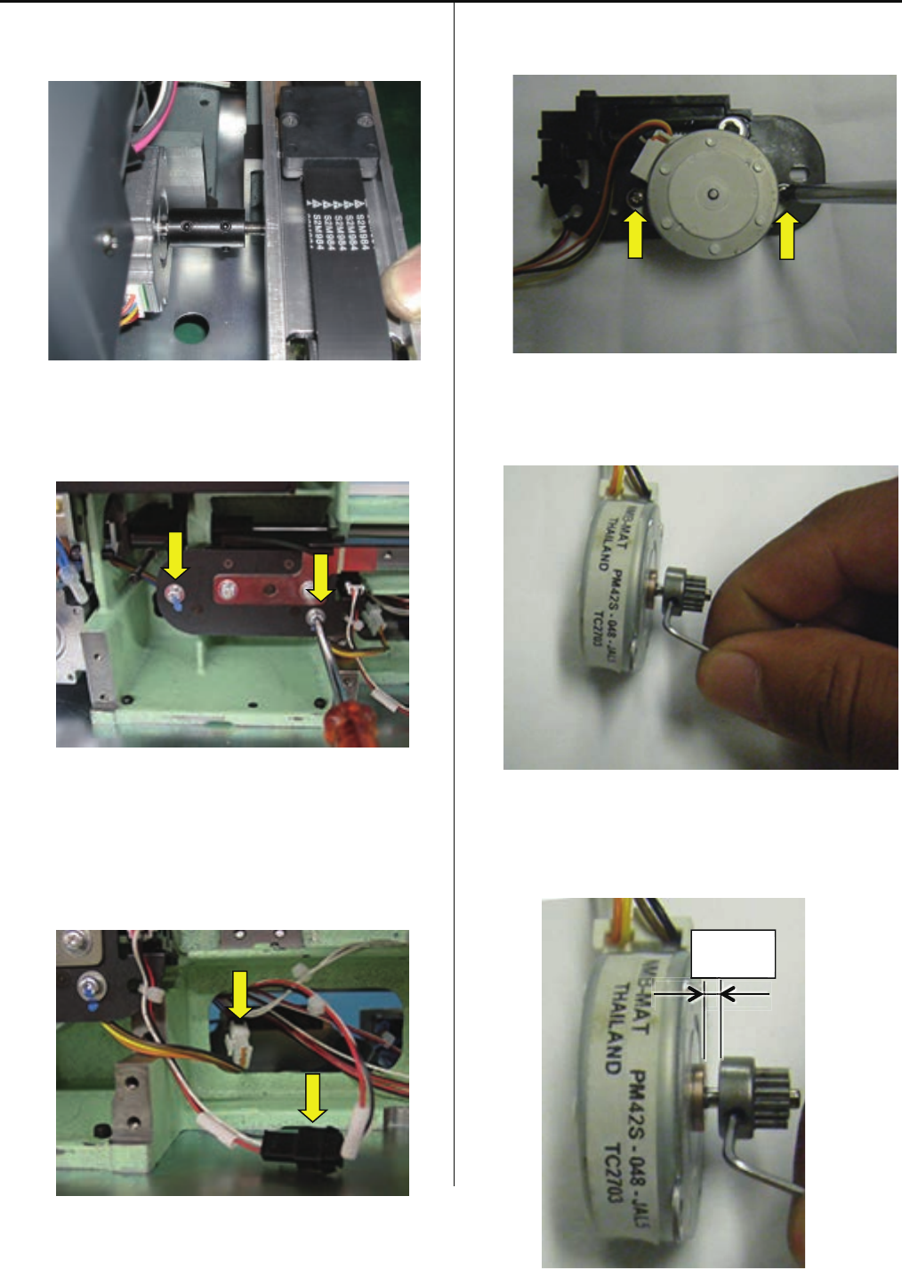
3-6-3 Exchange of thread cutting roller (for Rev.A)
1. Remove bobbin winder and power supply.
2. Remove arm.
3. Disconnect cable from sensor board.
Loosen the screw for coupling of the Y carriage.
4. Remove the screw of Y carriage bracket (left).
89
Remove the Y carriage.
5. Remove thread cutting driver.
6. Disconnect cable.
7. Remove Pulse motor.
8. Remove Drive gear.
9. Install Drive gear on good Pulse motor
Position of Drive gear is space from Pulse motor.
2mm

90
10. Place parts back in accordance with manual.
11. Check and adjust position of moving knife to finish.
Please refer to respective adjustment.
91
3-6-4 Adjustment of thread cutting stopper (except for Rev.A)
1. Adjust the thread cut timing.
Please refer to [3-6-3 Adjustment of thread cut timing].
2.Turn upper shaft to set dial disk to [C (275 degrees)].
3. Keep the lever down.
4. Insert 0.2mm thickness gauge between cam and roller and
adjust the clearance [0.2mm] between cam and roller by
adjusting screw.)
(To be sure that cam and roller are contacted with
thickness gauge and nogap.)
5. Tighten lock nut.
6. On checking the clearance [0.2mm] between cam and
roller by using 0.2mm thikness gauge.
If OK, all the procedure is done.
92
3-6-5 Adjustment of thread cut timing (except for Rev.A)
1. Remove bobbin winder and power supply.
2. Loosen screw on thread cut cam.
3. Set dial disc to [116 degrees].
4. Turn thread cut cam clock-wise while pushing
release lever down.
<Important> Push thread cut cam against rotary hook
shaft collar A so as not to produce clearance
between cam and collar.
5. Tighten screw on thread cut cam when moving knife began
to open.
93 - 94
6. With release lever being pushed down, turn upper shaft
to open and close moving knife repeatedly.
7. On Checking that the knife began to open, at [116 degrees
(+0 / -2degrees)] work has finished.
95
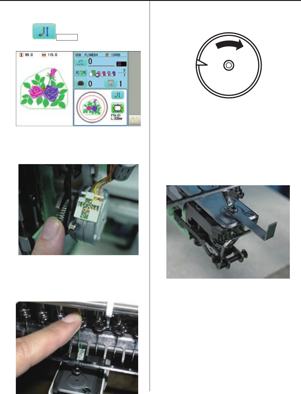
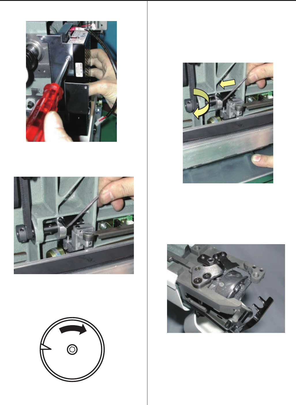
3-6-6 Exchange of moving knife
1. Remove needle plate.
2. Remove knife drive shaft retainer.
3. Pull out knife drive shaft ass’y.
4. Exchange moving knife.
5. Setting drive link hole to moving knife, insert knife drive
shaft assembly.
6. Pushing down moving knife and knife drive shaft retainer
like putting them together, fix knife drive shaft retainer.
# Fix so that there is no backlash in upward and
downward direction and to to move lightly.
7. Referring to [3-6-8 Adjustment of moving knife and
fixed knife],check how well thread is cut and adjust,
then finish this process.
96
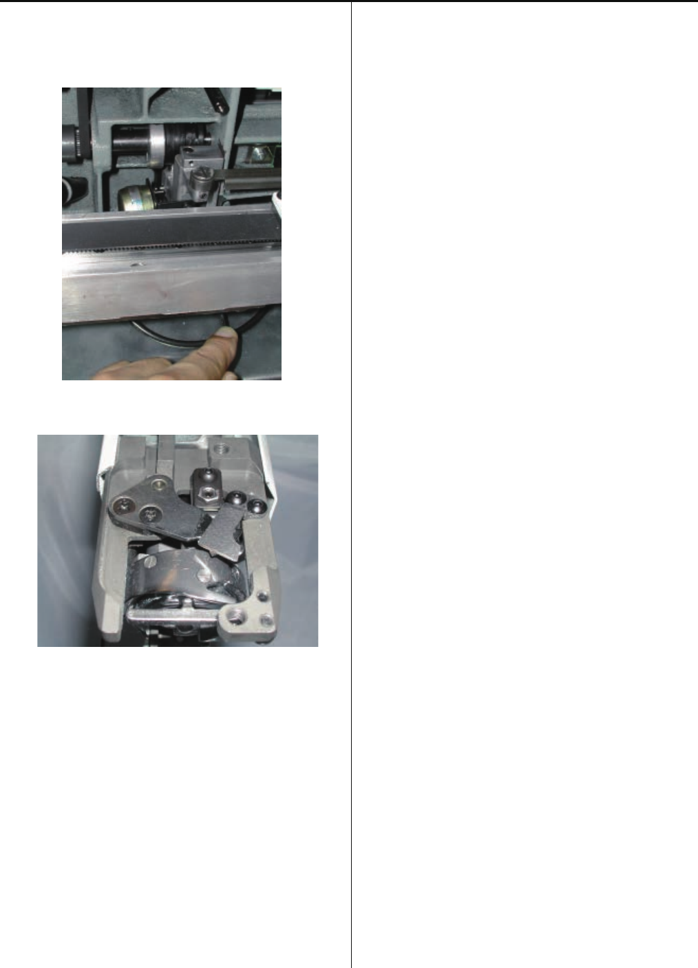
3-6-7 Exchange of fixed knife
1. Remove needle plate.
2. Remove fixed knife.
3. Exchange fixed knife.
4.Tighten fixed knife pushing to forward as full as possible.
<Notice>
In case moving knife and the left side of fixed knife
overlaps excessively when closing, adjust the position of
fixed knife slightly to the right direction.
5. Referring to [3-6-8 Adjustment of moving knife and
fixed knife],check how well thread is cut and adjust,
then finish this process.
97
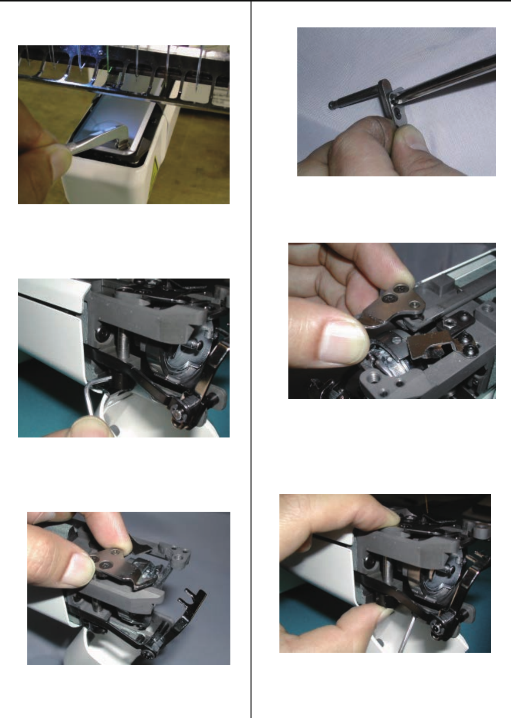
3-6-8 Adjustment of moving knife and fixed knife
1. Remove needle plate.
2. Check if knife drive shaft has no backlash in up and down
direction.
If backlash is found, adjust it referring to [3-6-6 Exchange
of moving knife].
3. Adjust slant of fixed knife with [upper adjustment screw]
and [lower adjustment screw] that fix fixed knife.
<Note> Rub these screws together to the extent that you
don’t feel resistance.
<Spanner> 5.5mm
4. Cut thread and check how well it is cut.
Use two polyester threads for checking.
5. Check several times and if no mistakes are found, finish
this process.
98
3-6-9 Adjustment of position of moving knife (except for Rev.A)
1. Loosen screw on link pin.
2. Turn link pin to adjust position of moving knife.
Adjustment of clearance between moving knife and
fixed knife is where both tip of then are attached.
3. If necessary, please refer to [3-6-8 Adjustment of moving
knife and fixed knife] and check how well thread is cut,
then finish.
99
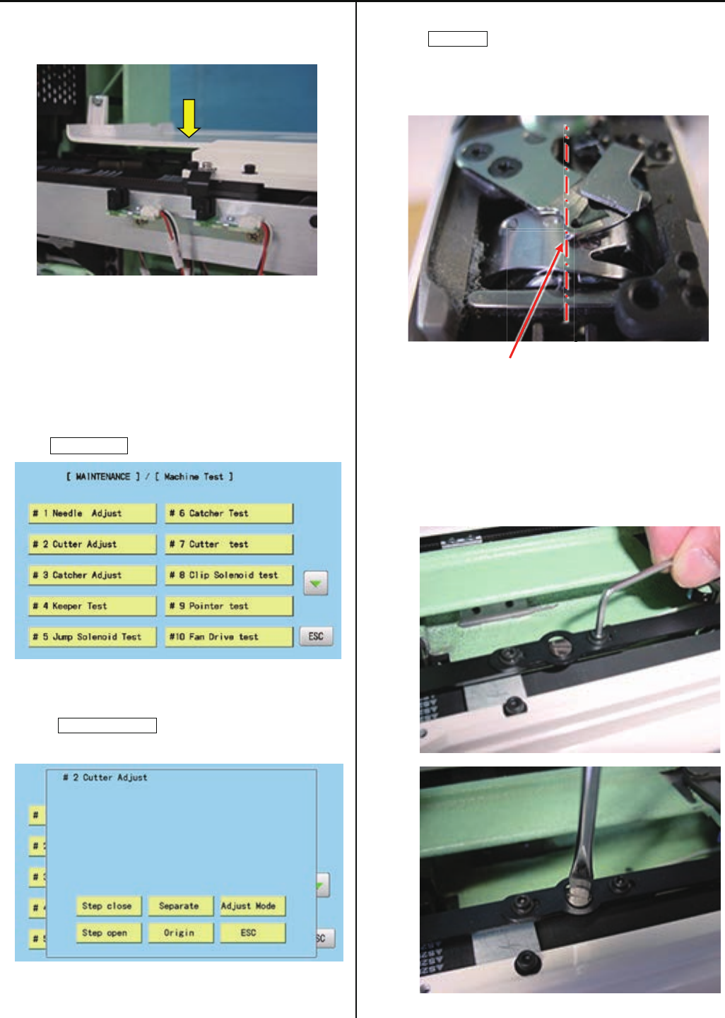
3-6-9b Adjustment of position of moving knife (for Rev.A)
1.Remove Needle plate and Cover (front).
2. Enter maintenance mode in reference to [4-5-1 How to
enter maintenance mode]
3. Press Machine Test .
4.Press #2 Cutter Adjust,
5. Press Separate, then the Moving knife will be opened.
Please confirm that the tip of Moving knife is located at
center of Rotary hook retainer.
Tipofmovingknife
6. In case the tip of moving knife is not in the right position,
loosen screw on Thread cutting rod, then adjust position of
the Moving knife with turnning Eccentric pin.
Tighten screws.

100
7. Press Origin, then the Moving knife will be closed.
Please confirm that the Moving knife is located as
drawing below.
Adjustment of clearance between moving knife and
fixed knife is where both tip of then are attached.
8. Press Separate and Origin by turns to confirm that t
he Moving knife is closed in the right position.
Press ESC to finish「Maintenace mode」.
9. If necessary, please refer to [3-6-8 Adjustment of moving
knife and fixed knife] and check how well thread is cut,
then finish.
101
3-6-10 Adjustment of bobbin thread holder
1. Remove needle plate.
2. Close moving knife like putting bobbin thread between
moving knife and bobbin thread holder.
3. Adjust height of bobbin thread holder with adjusting screw.
4. Pull bobbin thread toward arrow mark and see that bobbin
thread comes off with tensile gauge [20-25g].
5.Tighten lock nut. (Don’t move adjusting screw.)
6. Check several times and if OK, finish this process.
102
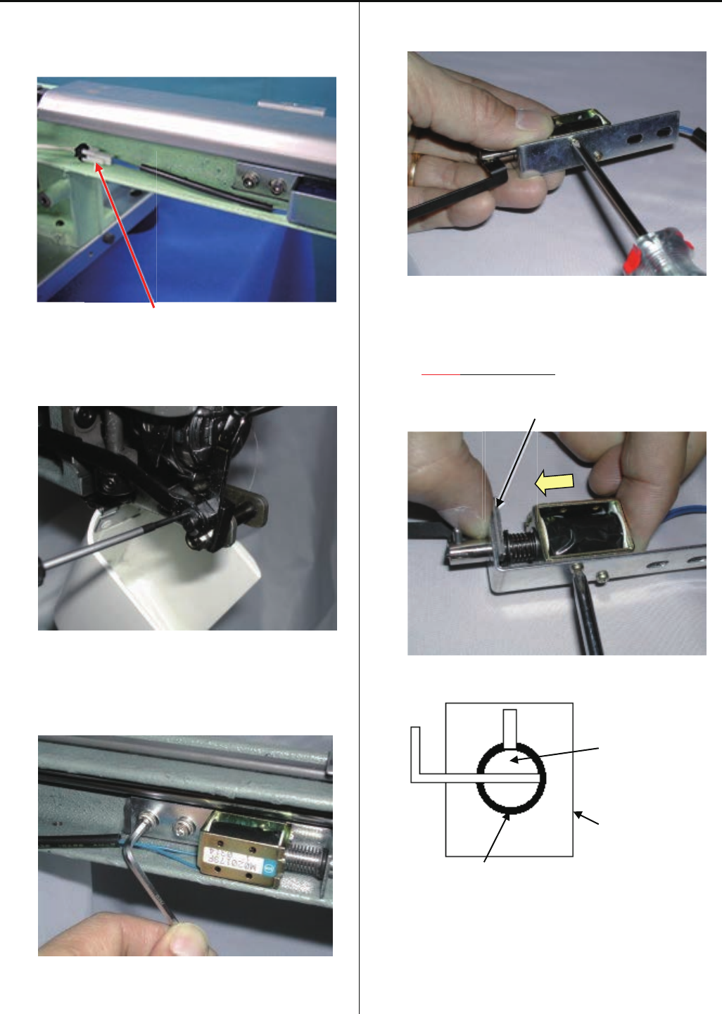
3-6-11 Exchange of keeper solenoid
1. Remove Bed cover (lower) and take connector of Keeper
solenoid out.
Connector
2. Remove E-ring on fulcrum pin.
3. Remove keeper solenoid ass’y.
4. Exchange keeper solenoid.
<Attention>
Pushing keeper solenoid to solenoid base.
Insert 2.0mm thickness gauge between solenoid base to
polyslider.
2.0mm thickness gauge
<Front view>
Keeper plunger
Solenoid base
Clearance between keeper plunger and solenoid base
should be kept as much as equally.
5.Put keeper solenoid ass’y in previous position then
adjustment of position of keeper to finished.
Refering to [3-6-12 Adjustment of position of keeper].
103
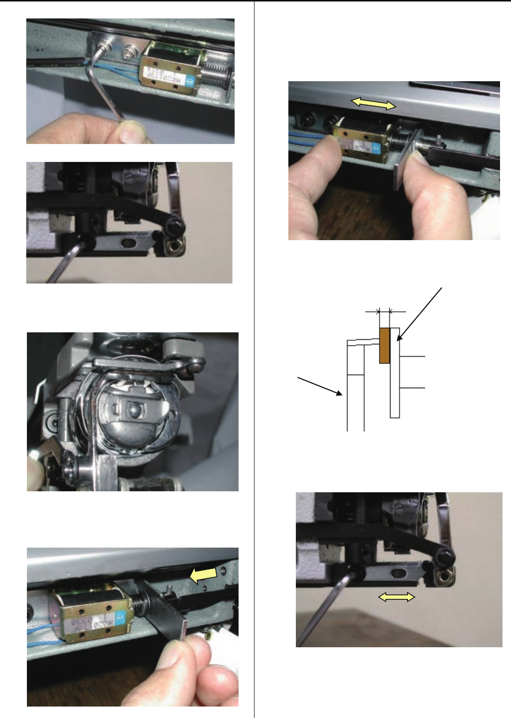
3-6-12 Adjustment of position of keeper
1. Loosen screw on solenoid base.
Loosen screw on stopper bracket.
2. Insert keeper positioning gauge (Bobbin) into rotary hook.
3. Insert [2.0mm] clearance gauge between solenoid base
and slider then pull in keeper solenoid and keeper rod.
4. Adjust solenoid base where tip of keeper contacts
slightly to the gauge then tighten bracket screw.
Clearance between bobbin and keepr is [about 1.0mm].
<View from right>
Keeper positioning gauge
About 1.0mm (Bobbin)
Keeper
5. Adjust position of stopper bracket.
This is the position where tip of keeper contacts to gauge
6. Adjustment has finished.
104
3-7-1 Adjustment of X carriage belt tension
1. Remove frame base.
2. Disconnect X carriage cable.
3. Remove X carriage.
4. Remove X carriage cover.
5. Remove sensor bracket.
6. Loosen fixing screw for tension pulley bracket slightly.
(front side)
105
7. Loosen fixing screw for tension pulley bracket slightly.
(rear side)
8. Adjust belt tension.
Use push and pull gauge.
<Adjustment value>
[200g] at the status of which both belt is touch.
<Note> Slide connecting plate to right as full as possible.
Gauge in the middle of idler pulley and tension pulley.
Measurement point
Idler pulley Tension pulley
Adjustment, tighten fixing screw for tension pulley bracket.
9. Tighten fixing screw for tension pulley bracket. (front side)
10. Tighten fixing screw for tension pulley bracket. (rear side)
11. Return things back to previous places in reverse order.
106
3-7-2 Exchange of X carriage belt
1. Remove frame base.
2. Disconnect X carriage cable.
3.Remove X carriage.
4. Remove X carriage cover.
5. Remove sensor bracket.
6. Loosen screw for tension.
107
7. Remove the screw which fixes tension bracket.
8. Loosen screw (rear) slightly to the extent that tension-
bracket moves.
9. Remove belt from motor pulley.
10. Remove connecting plate.
11. Exchange belt to good one.
<Important>
Exchange it so as not to break groove and belttooth on
belt of connecting plate.
Donotputbelttoothontheinnermostgrooveof
theconnectingplate.

108
12. Adjust the position of belt.
Space between edge of X base and belt is [10mm].
13. Referring to [3-7-1 Adjustment of X carriage belt tension],
adjust tension of belt.
14. Return X carriage assembly and frame base to previous
places to finish.
109
3-7-3 Adjustment of Y carriage belt tension
1. Remove frame base.
2. Disconnect X carriage cable.
3. Remove X carriage.
4. Remove arm.
110
5. Loosen lock nut for tension adjustment screw.
<Spanner> 7mm
6. Loosen tension screw so as to move tension.
7. Adjust belt tension, to use belt tension gauge.
Use push and pull gauge.
<Adjustment value>
Adjusted to be [200g] at state that Belt attaches to Rail.
Push belt holding plate backward as full as possible.
Gauge in the middle of idler pulley.
Measurement point
Idler pulley (rear) Idler pulley (front)
Adjust with screw.
8. Tighten screw on tension.

111
9. Tighten lock nut for tension adjustment screw.
10. Return arm, X carriage assembly and frame base to
previous places to finish.
112
3-7-4 Exchange of Y carriage belt
1. Remove frame base.
2. Disconnect X carriage cable.
3. Remove X carriage.
4. Remove arm.
113
5. Loosen lock nut for tension adjustment screw.
<Spanner> 7mm
6. Loosen tension screw so as to move tension.
7. Loosen screw for tension.
8. Remove belt holding plate.
9. Exchange belt.
10. Set belt to belt groove of guide frame base.
<Important>Exchange it so as not to break belttooth
and convex on belt.
Donotputbelttoothontheinnermostgrooveof
theconnectingplate.

114
11. Fix belt holding plate.
12. Referring to [3-7-3 Adjustment of Y carriage belt tension],
adjust tension of Y belt.
13. Return arm, X carriage ass’y and frame base to
previous places to finish.
115
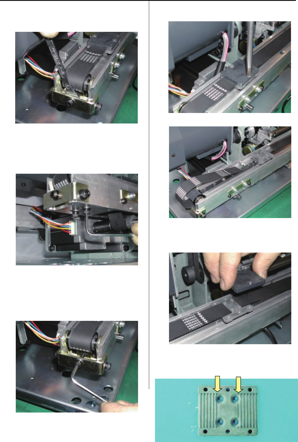
3-8-1 Adjustme nt of timing belt tension
1. Remove bobbin winder and power supply.
2. Adjust tension of timing belt.
<Important>
Tension shaft ass’y to be set at the center against screw
hole of the body.
No need to adjust tension.
Please move tension shaft ass’y upward and
downward to adjust.
3. Please return power supply to previous places to finish.
116
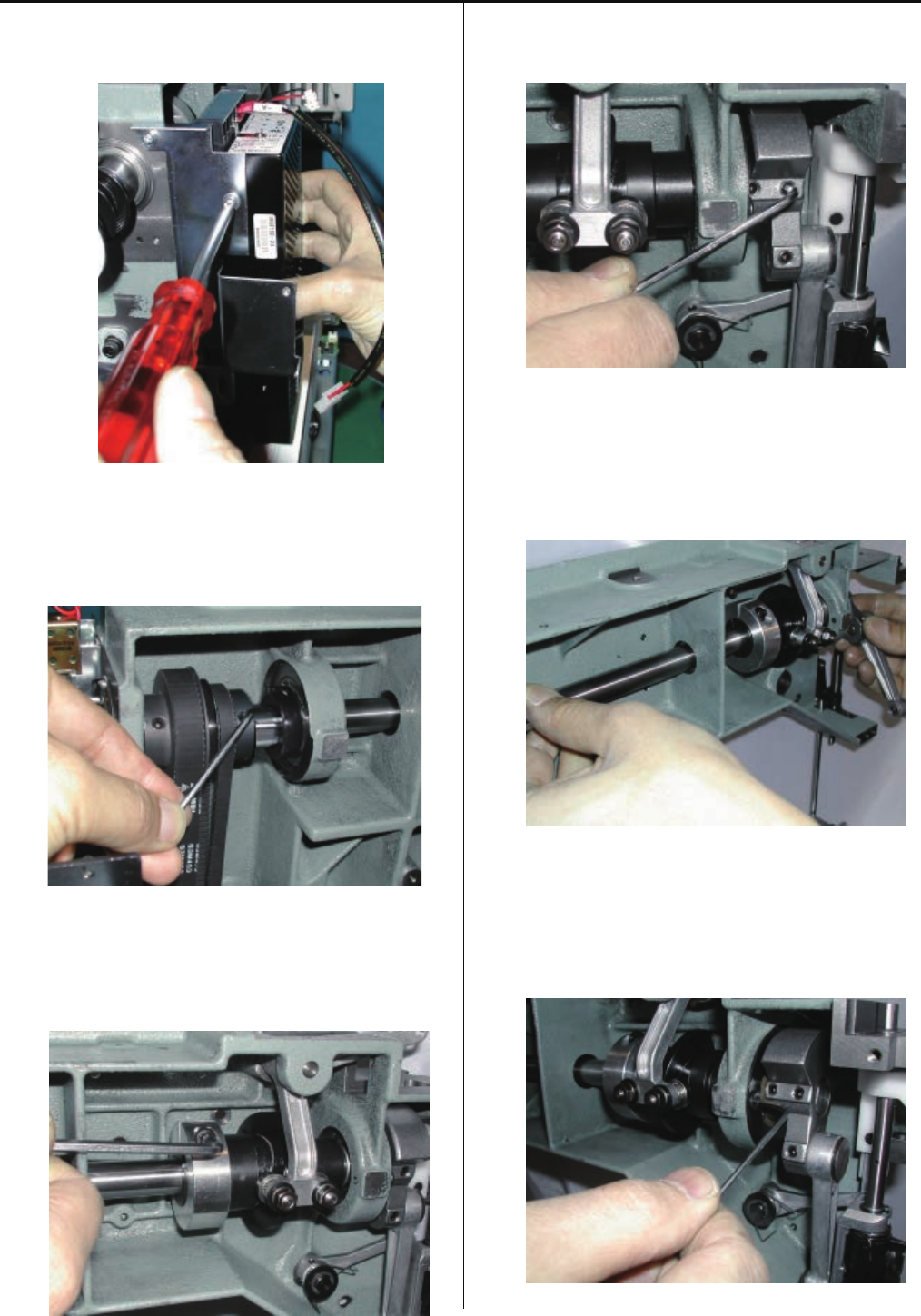
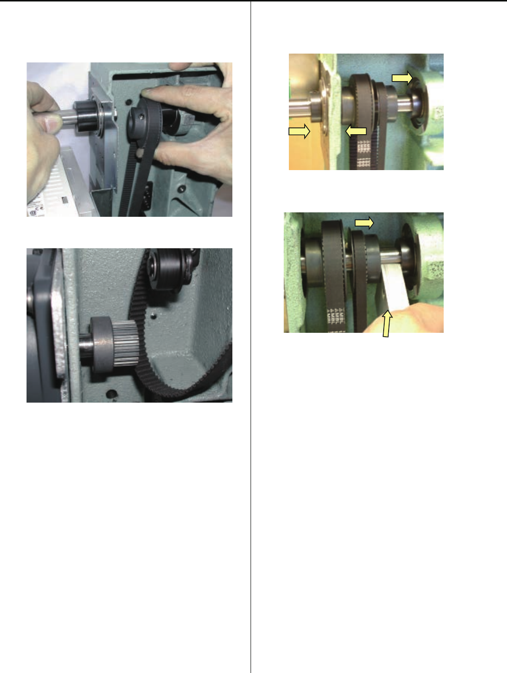
3-8-2 Exchange of timing belt
1. Remove bobbin winder and power supply.
2. Remove timing detecting board ass’y.
Remove support roller ass'y.
3. Loosen screws on upper shaft collar,
upper pulley and drive pulley.
4. Loosen screw on fasten collar for take-up lever cam.
5. Loosen screw on crank.
6. Pull out upper shaft.
117
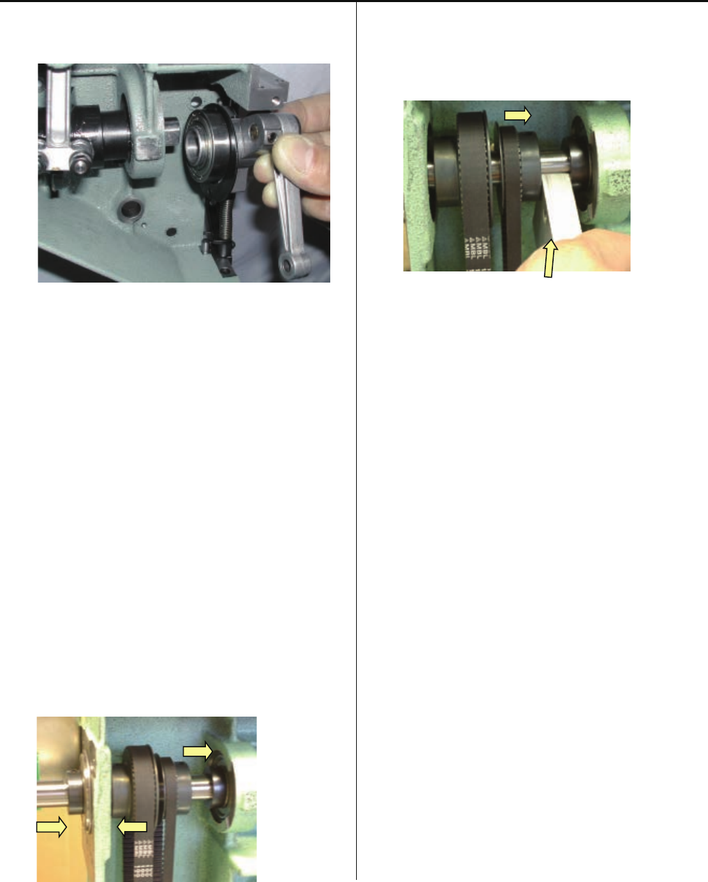
7. Remove upper pulley and timing belt.
Install good timing belt.
8. Install parts in reverse order.
For installation and adjustment of each unit,
please refer to respective manuals.
Referring to [3-8-1 Adjustment of timing belt tension],
adjust tensile strength of timing belt.
<Important> Pay attention to following (1) - (4).
(1)When you install upper shaft collar, upper pulley,
drive pulley and crank, please fix them on flat surface
of upper shaft with screw.
(2)Make sure that pulleys and collars are attached
without space from machine body except upper pulley.
(3)Position of upper pulley is space from upper
shaft collar.
Type of small
collar
Thickness gauge [11.5mm]
(4)Confirm that belt is not interfere the pulley flange and
not come out from pulley groove.
Adjustment will be done with following pulley.
Timing belt has to be adjusted with [upper pulley position].
Motor belt has to be adjusted with [motor pulley position].
9. Check and adjust following timing to finish.
[ 4-2-1 Upper shaft timing (L point, C point) ]
[ 3-2-8 Take-up lever timing ]
[ 3-5-1 Rotary hook timing ]
[ 3-6-5 Thread cut timing (except (for Rev.A) )
118
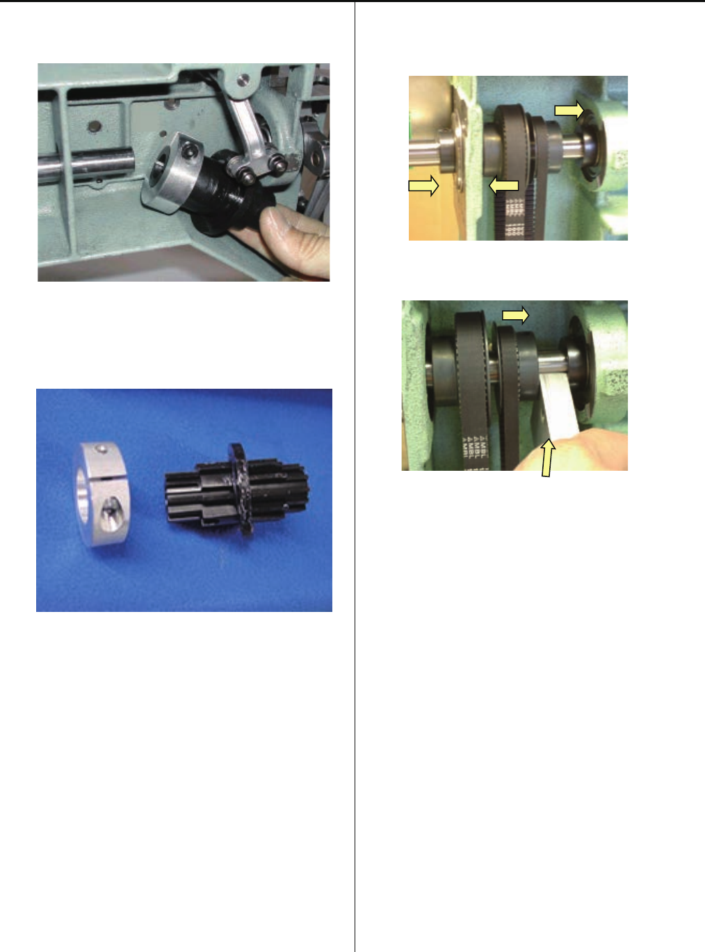
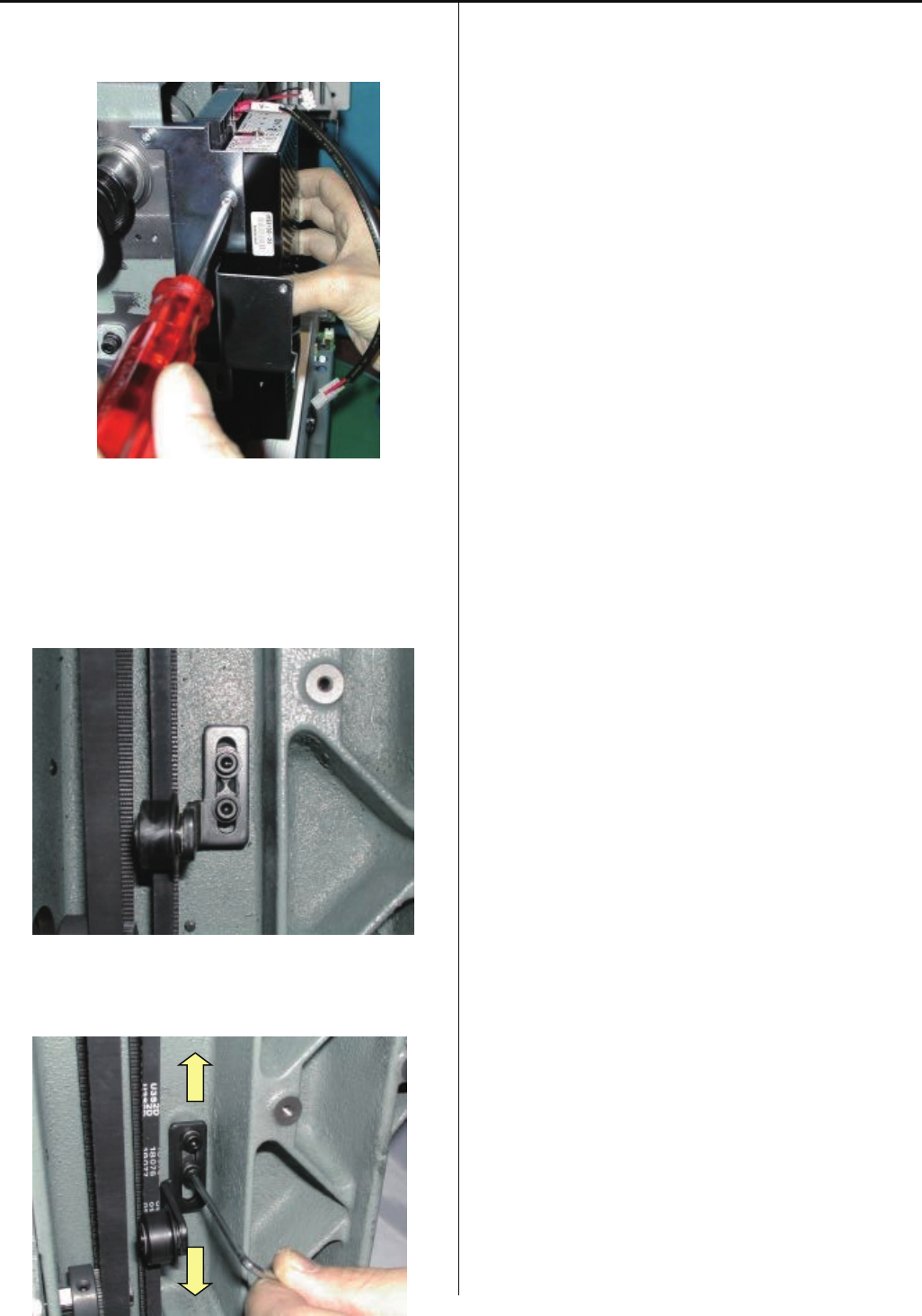
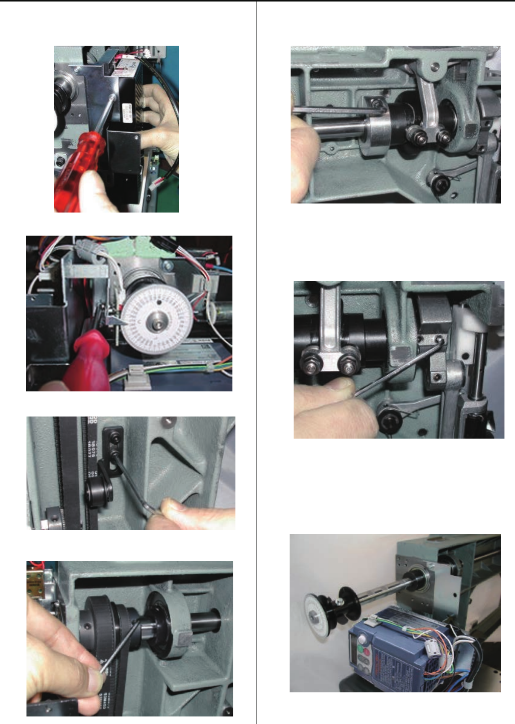
3-8-3 Adjustment of motor belt tension
1. Remove bobbin winder and power supply.
2. Remove inverter.
3. Loosen screw on motor bracket.
4. Adjust motor belt tension.
Use push and pull gauge.
<Adjustment value> 320 - 330 g/3mm
Gauge in the near center between drive pulley and
motor pulley.
Measurement point Drive pulley
Motor pulley
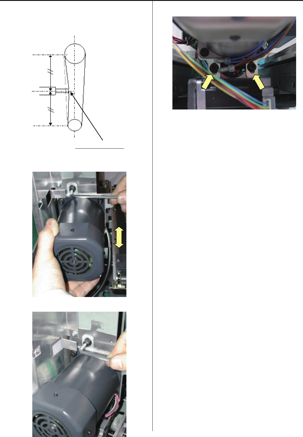
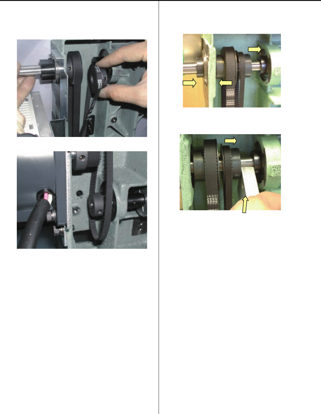
119
Adjust of tension should be 320 – 330g at belt is pressed
3mm.
Belt is pressed 3mm
Move main motor upward and downward to adjust.
5. Tighten screw on motor bracket.
6. Return power supply bracket, power supply, bobbin winder
and inverter to previous places to finish.
120
3-8-4 Exchange of motor belt
1. Remove bobbin winder and power supply.
2. Remove timing detecting board ass’y.
3. Loosen screws on upper shaft collar,
upper pulley and drive pulley.
4. Loosen screw on fasten collar for take-up lever cam.
5. Loosen screw on crank.
6. Pull out upper shaft.
121
7. Remove drive pulley and motor belt.
Install good motor belt.
8. Install each parts in reverse order.
For installation and adjustment of each part,
please refer to respective manuals.
Referring to [3-8-3 Adjustment of motor belt tension],
adjust tensile strength of motor belt.
<Important> Pay attention to following (1) - (4).
(1)When you install upper shaft collar, upper pulley,
drive pulley and crank, please fix them on flat surface
of upper shaft with screw.
(2)Make sure that pulleys and collars are attached
without space from machine body except upper pulley.
(3)Position of upper pulley is space from upper
shaft collar.
Type of small
collar
Thickness gauge [11.5mm]
(4)Confirm that belt is not interfere the pulley flange and
not come out from pulley groove.
Adjustment will be done with following pulley.
Timing belt has to be adjusted with [upper pulley position].
Motor belt has to be adjusted with [motor pulley position].
9. Check and adjust following timing to finish.
[ 4-2-1 Upper shaft timing (L point, C point) ]
[ 3-2-8 Take-up lever timing ]
[ 3-5-1 Rotary hook timing ]
[ 3-6-5 Thread cut timing (except (for Rev.A) )
122
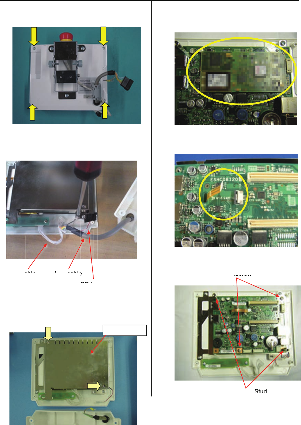
4-1-1 Remove LCD and LCD-CE board
1. Remove four setscrews as shown in the figure
below and remove rear cover.
2. Remove connectors for SW cable, Box cable,
cable for LCD inverter (red/white).
SW cable Box cable
Cable for LCD inverter (red/white)
3. Remove set screw and sealed case A.
4. Remove core module.
5. Remove narrow flat cable for LCD unit.
6. Remove two sets screws and two studs.
Setscrew
Stud
Sealed case A
able B
cable
e
CD i
e
e
tscrew
tscrew
Stud
123
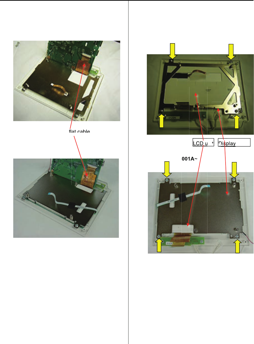
7. Lift LCD-CE board as shown in the figure below.
Remove wide flat cable for LCD unit.
Ser.No. ~1027033
Wide flat cable
Ser.No. 1028001A~
8. Remove four setscrews and LCD unit.
Ser.No. ~1027033
Ser.No. 1028001A~
Please reverse procedure when installing LCD-CE
board.
Display LCD unit
flat cable
D
t
LCD u
Display
p y
Disp
8001A
~
LCD u
LCD u
124
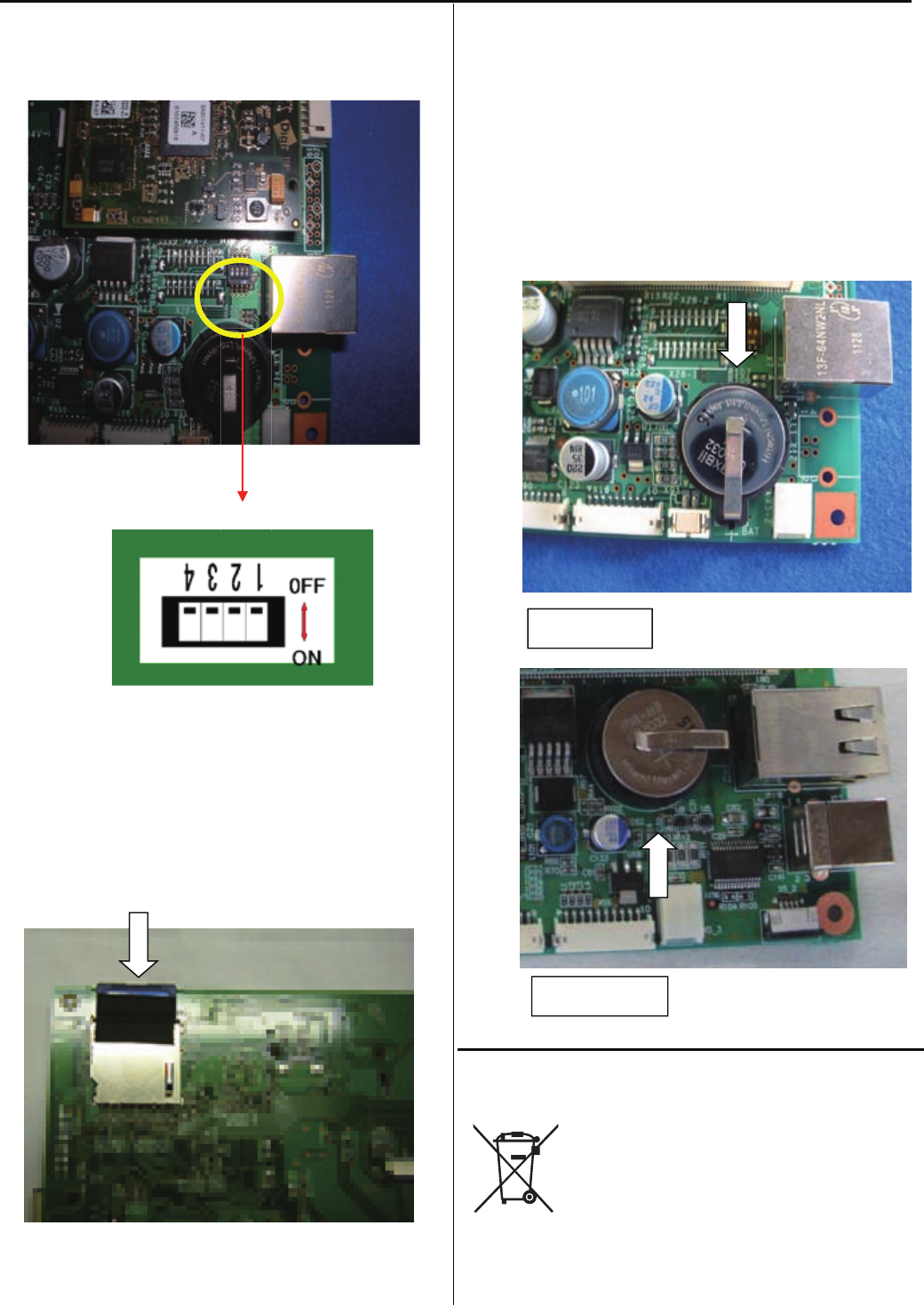
4-1-2 Setting for LCD-CE board
2DIP switch (LCD-CE-U)
Switch to OFF on all the settings for DIP switch.
Memory card
Insert our official memory card (EPZ01220).
Refer to the latest parts list for the parts number.
This memory card contains programs and data for
an embroidery machine.
You cannot use any memory cards on the market.
Coin battery
Insert our official coin battery (EPZ01190).
Refer to the latest parts list for the parts number.
The battery is used for back-up power source of
real-time
clock on an embroidery machine.
Replace new battery if clock dose not indicate
the correct
time after setting a clock and turning power switch
OFF.
Disposal of coin battery of LCD-CE board
Dispose of a coin battery by following
the method
specified by each country or each region.
LCD-CE-MX
LCD-CE-U
125
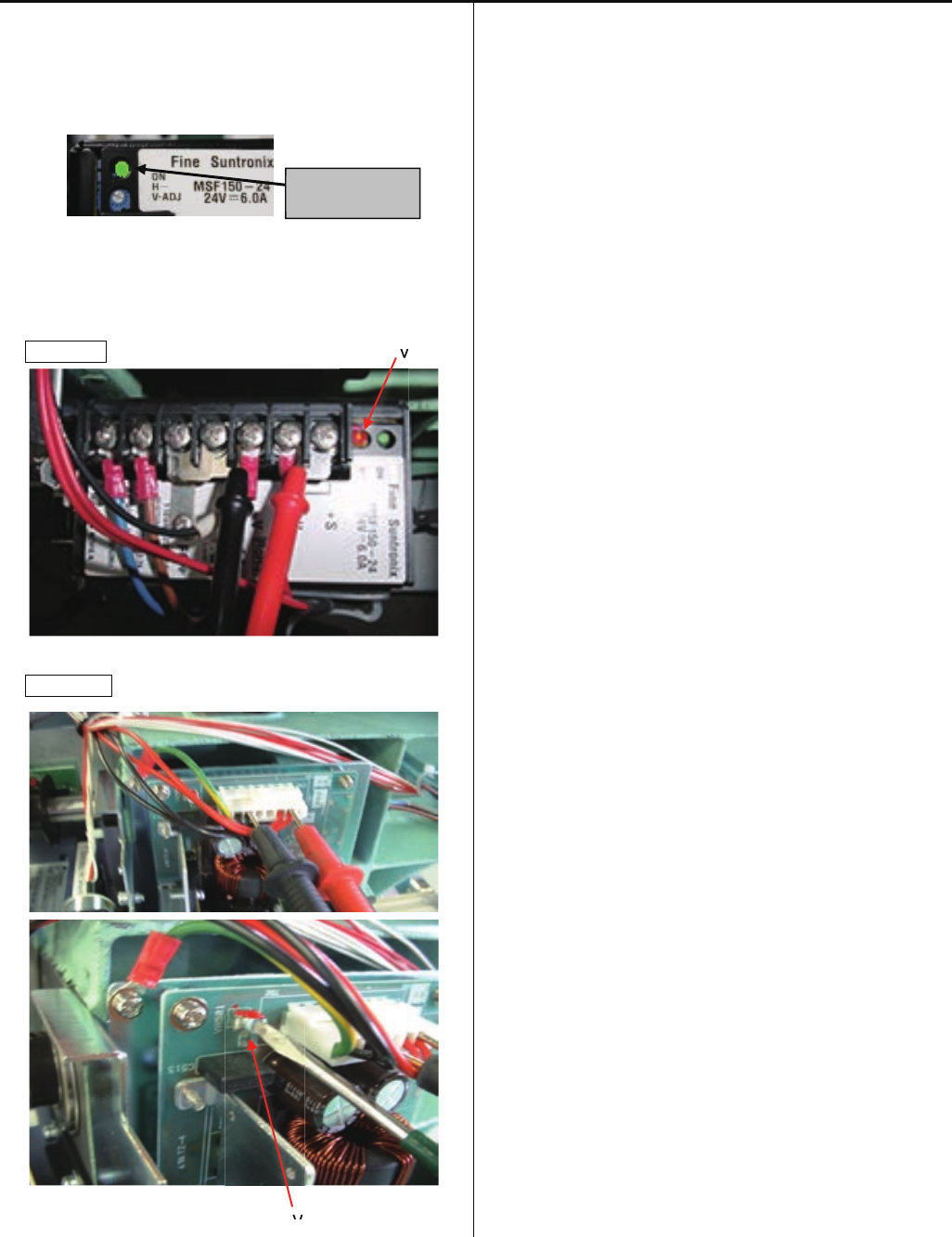
4-1-3 Power supply settings
(Please use digital output tester)
Check : Make sure charge lamp is off on the power supply for
100V before you start to work.
1. Turn the machine on and put tester against terminal plate
or connector, then turn V-ADJ to adjust to [24.6V±0.1V].
for 100V V-ADJ
For 200V
V-ADJ
Notice 1 : Be sure to put cover on power supply terminal plate
on the power supply for 100V.
Notice2 : Make sure the voltage specifications of the machine
and power supply before turn on power.
Charge lamp
V
V
126
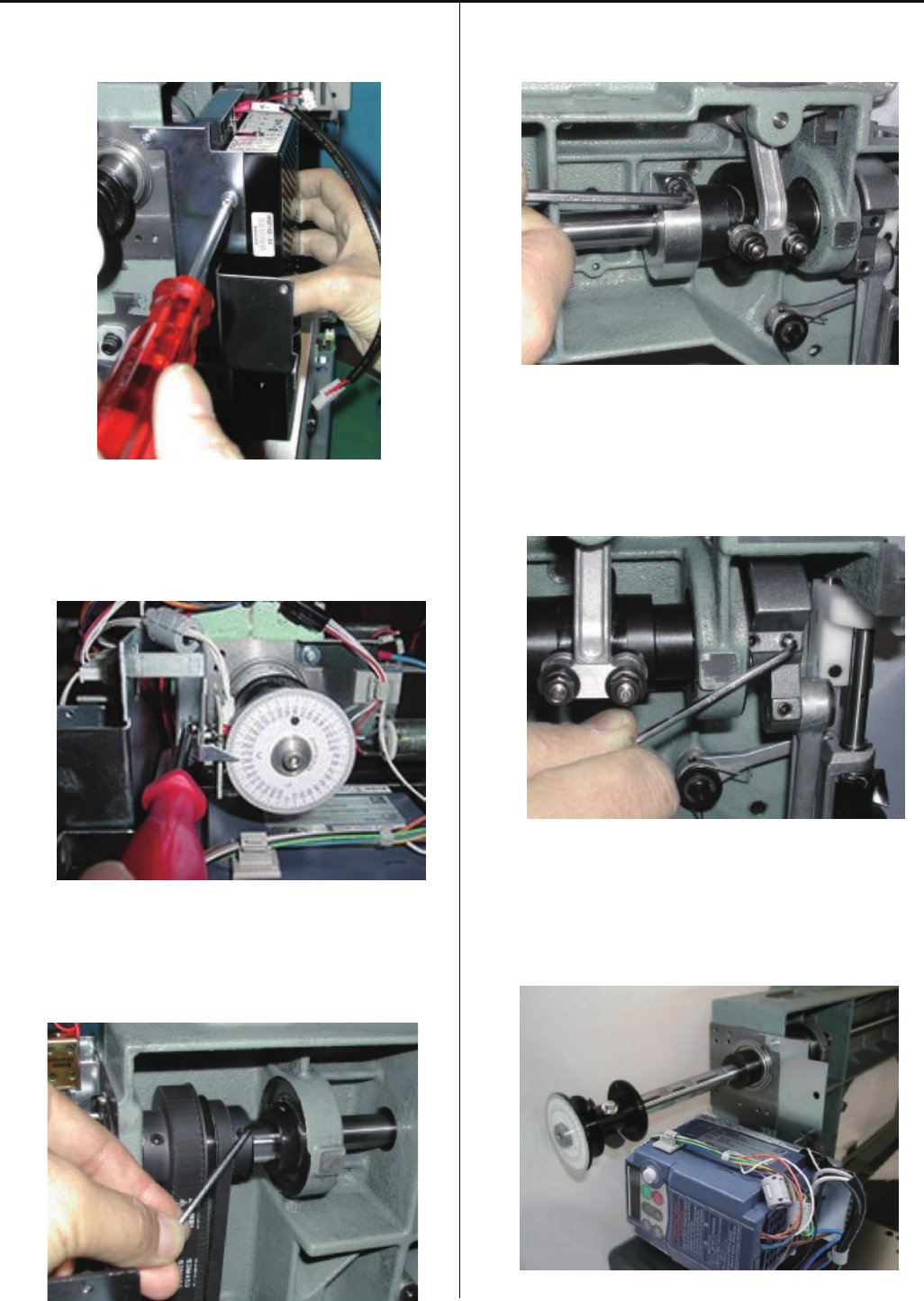
4-2-1 Adjustment of upper shaft timing (C point / L point)
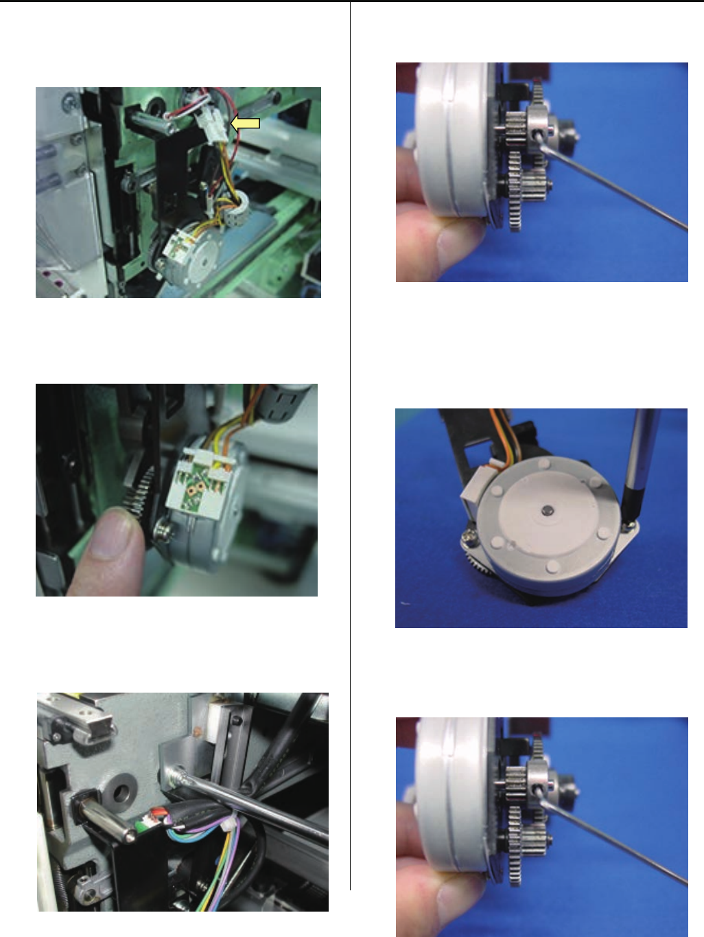
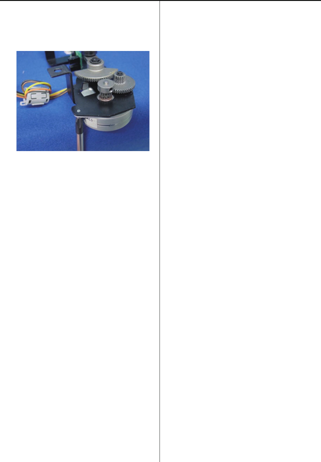
1. Remove bobbin thread winding motor ass’y.
2. Fix 2 screws tentatively timing detecting board.
3. Set upper shaft to [0 degree].
4. Move circuit board up and down and set to position
where LED 2 disappears at [0 degree], then fix with screw.
5. With this state, turn to C point and check if LED1 Iights
between [265 and 282 degrees].
* Check dose not scratch plastic slit to Timing sensor.
6. Put bobbin thread winding motor ass’y back to where
it was.
127
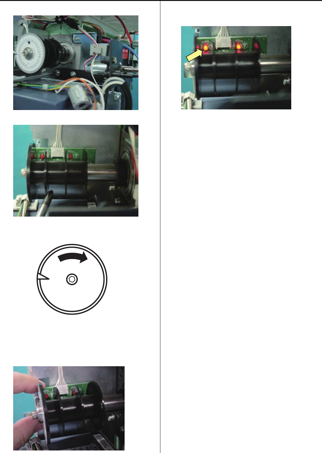
4-2-2 Adjustment of TC board
Viewing from side of circuit board, set slit so that it comes to center of sensor, fix it.
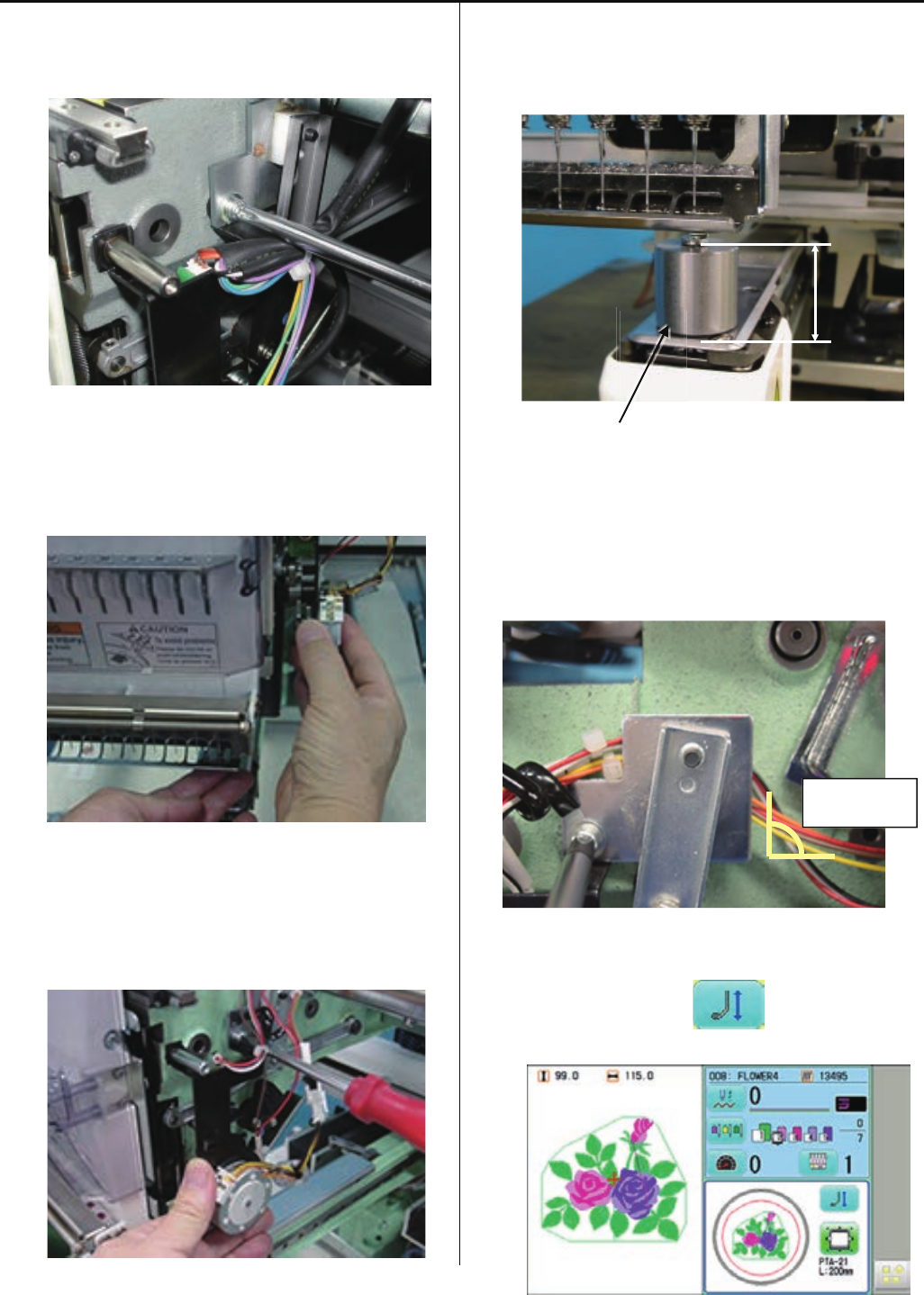
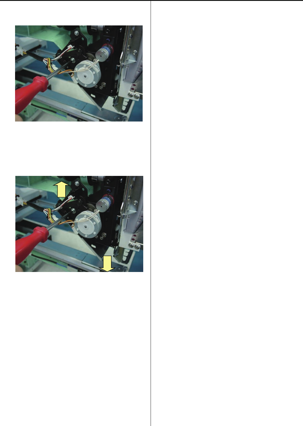
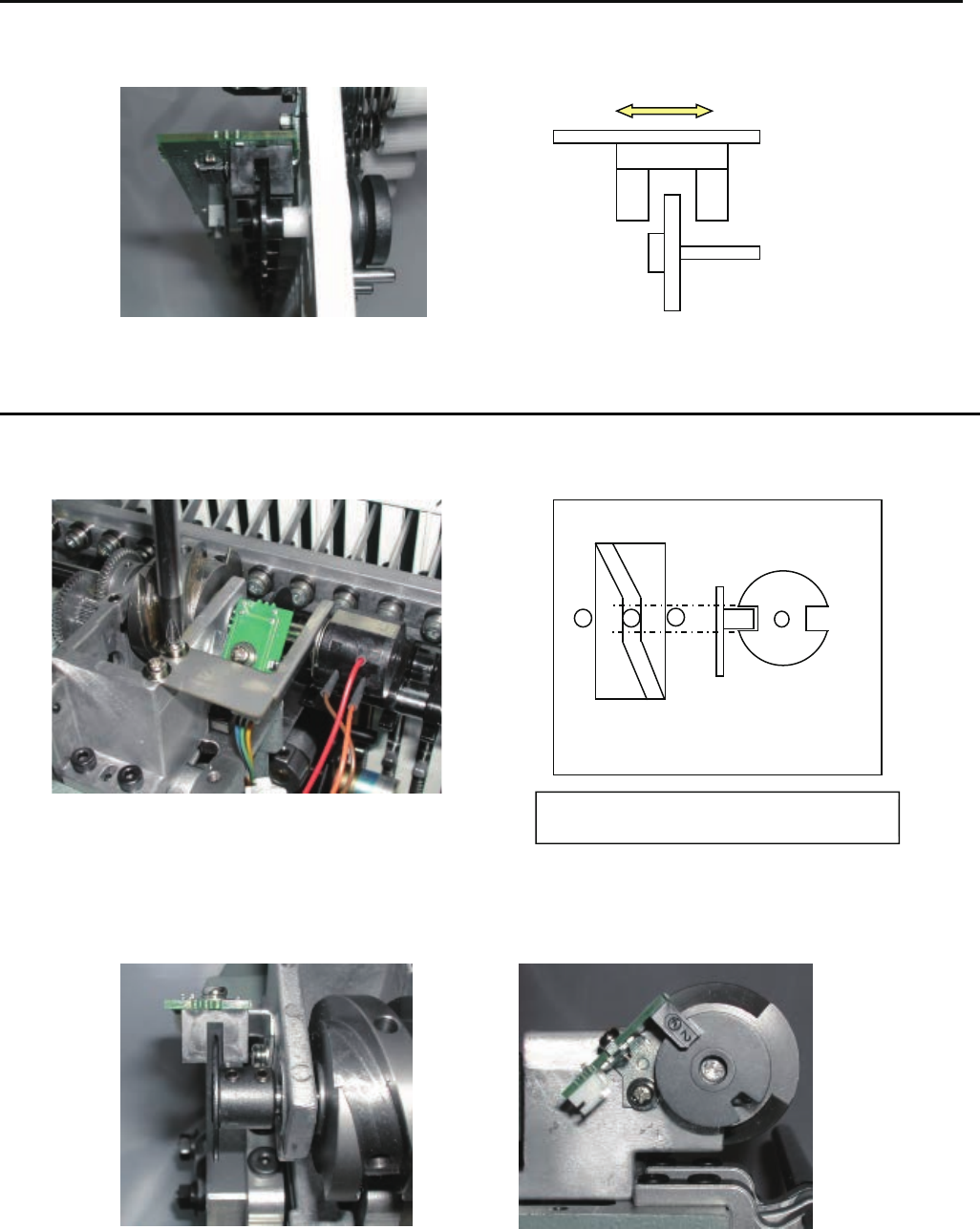
4-2-3 Adjustment of stop position of needle bar change unit
1. Remove potentiometer ass’y.
2. Set position where sensor on sensor board and slit don't cross to area where moving head doesn't move
when turning groove cam.
3. After installation, please fix potentiometer referring to [3-4-2 Setting to detect needle position].
Imagine figure of position sensor and cam
128
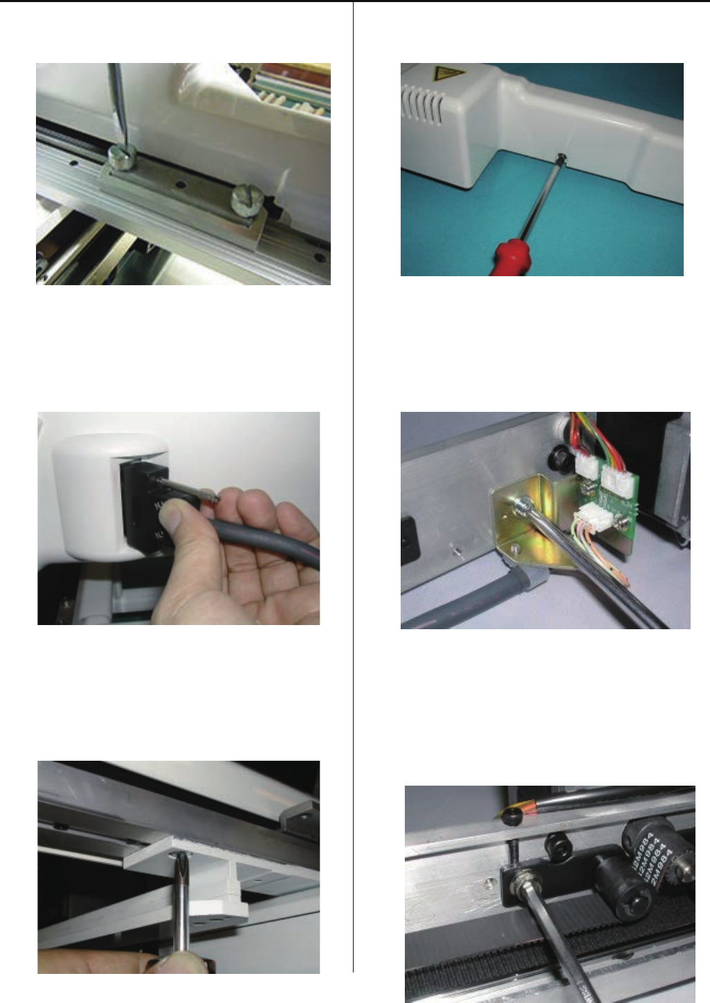
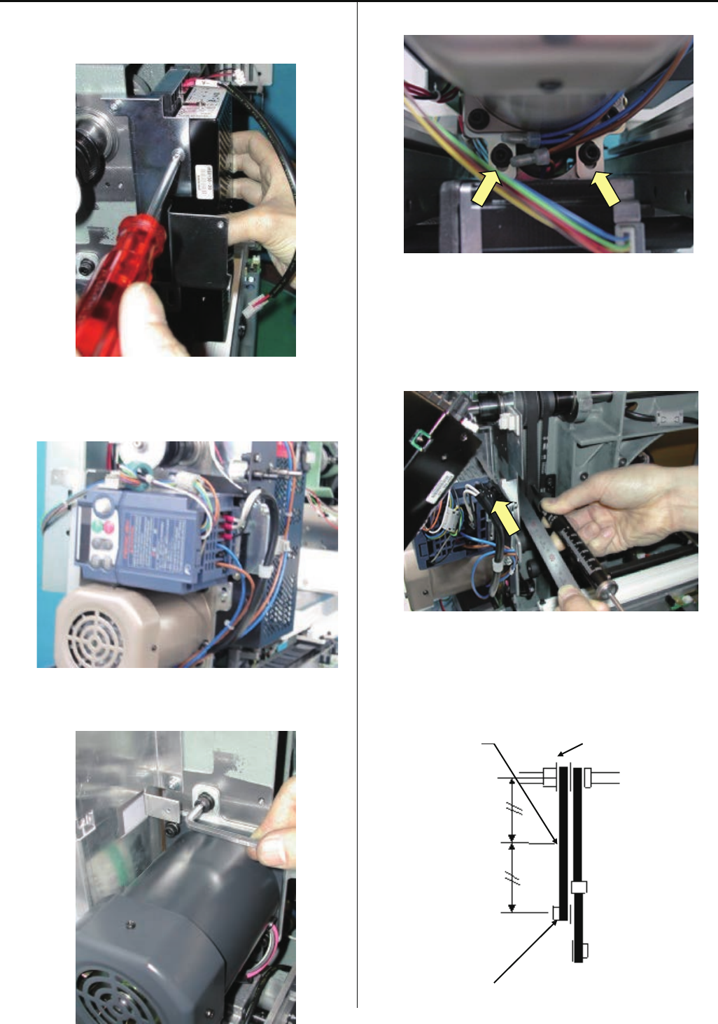
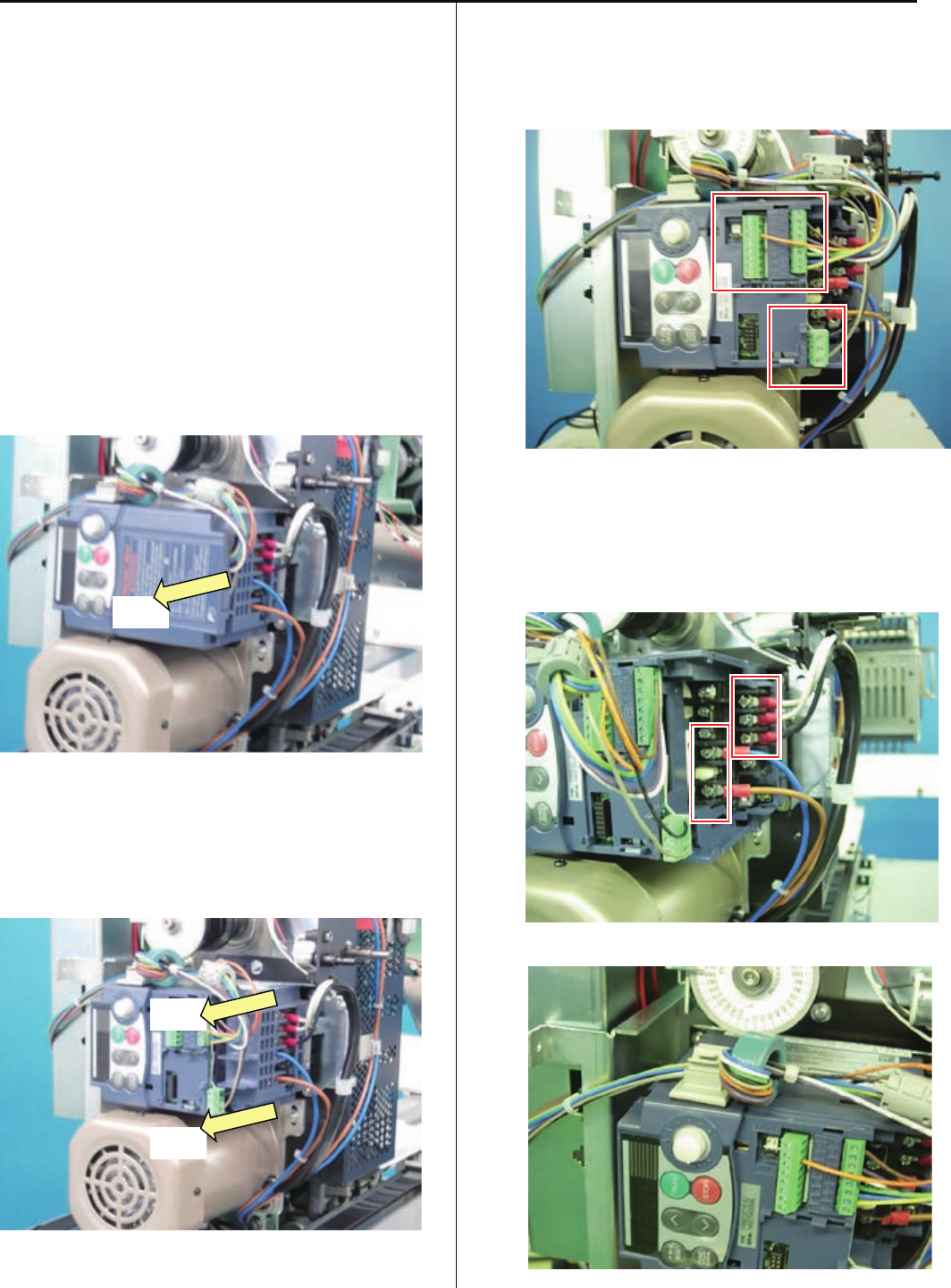
4-3-1 Remove of Inverter
<Notice>
Please disconnect machine inlet from the wall.
<Check>
Before you start to work, make sure the display of
inverter is off.
1. Remove outer cover. Refer to [2-2 How to
remove outer cover].
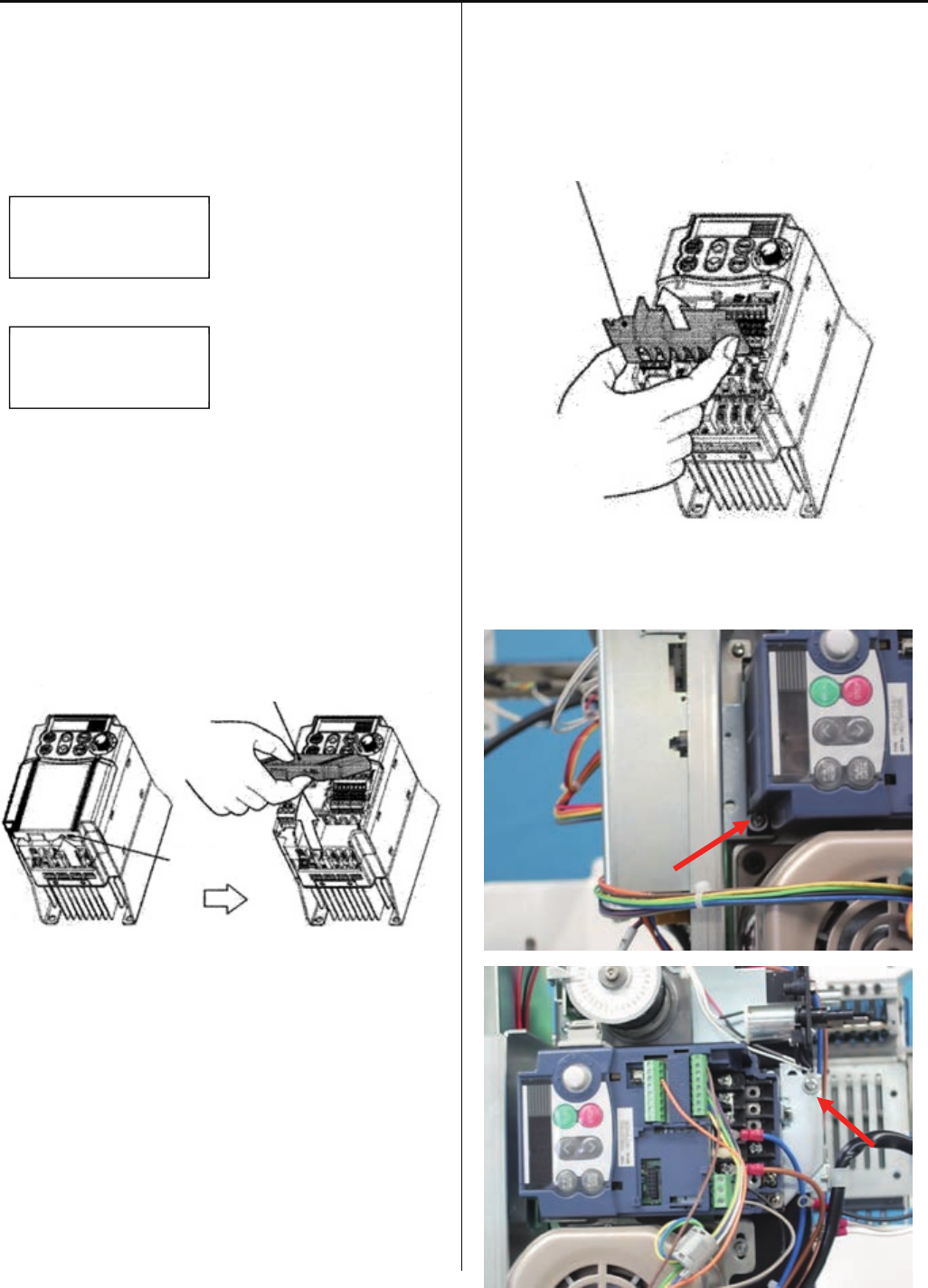
2. Remove control terminal cover.
Insert fingers in a gap (under the “PULL” indication)
on the underside of control terminal cover, and pull
the cover toward yourself and remove it.
3. Remove main terminal cover
Hold both left and right ends of main terminal cover
with fingers and slide the cover toward yourself and
remove it.
4. Loosen screw with Phillips screwdriver for precision
instrument and remove 9 cables. (Cable color:
ORANGE, BROWN, PURPLE, WHITE, GREEN,
BLUE, YELLOW, BLACK, and GLAY)
5. Remove screws with Phillips screwdriver and
remove power cable and motor cable.
(Cable color: GLAY, WHITE BLACK, BLUE, and
BROWN)
6. Remove cable from clamp.
Pull
Pull
Pull
129
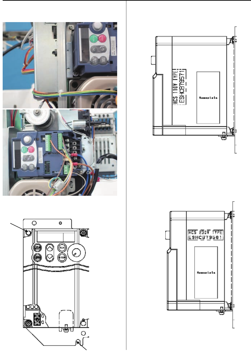
7. Remove two screws shown in the following figure
and inverter.
End of process.
Inverter for 110 - 120V
Inverter for 200 - 230V
Screw
Screw
130
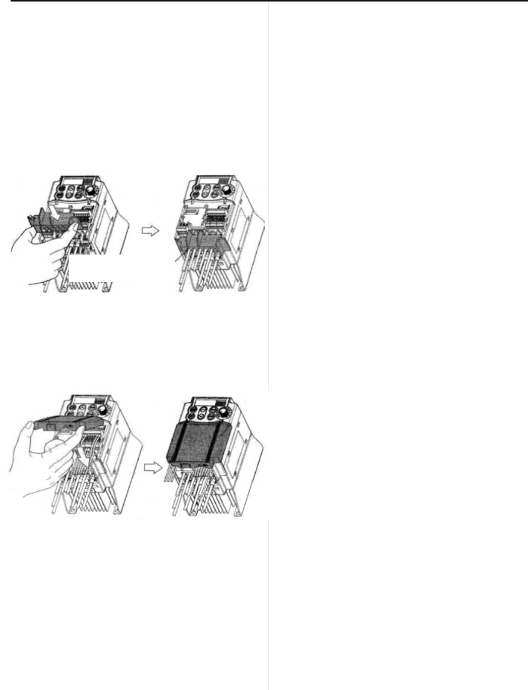
4-3-2 Inverter Installation
<Note>
Please check your replacement inverter type and machine
Voltage specification before replace inverter.
Sticker on inverter
For 110 - 120V
For 200 - 230V
Refer to specification sticker for voltage specifications of
the machine.
1. Remove control terminal cover.
Insert a finger in a gap (under the “PULL” indication)
on the underside of control terminal cover, and pull
the cover toward yourself and remove it.
2. Remove main terminal cover
Hold both left and right ends of main terminal cover with
fingers and slide the cover toward yourself and remove it.
3. Install inverter in the machine with two screws tightened.
HCS 110V TYPE
ESHCB79571
HCS 230V TYPE
ESHCB79561
Control terminal cover
Main terminal cover
“Pull”
131
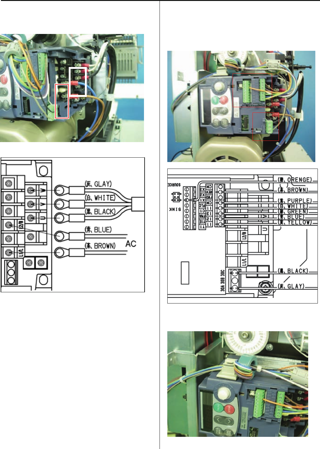
4. Tighten screws with screwdriver to install power cable and
motor cable per the following connection diagram.
(Cable color: GLAY, WHITE, BLACK, BLUE, BROWN)
「11-4 FR-S510W インバーター配線図及び設定パラメーター」参照
5. Tighten screw and connect 9 cables the following
connection diagram. (Cable color: ORANGE, BROWN,
PURPLE, WHITE, GREEN, BLUE, YELLOW, BLACK, and
GLAY)
6. Fix cable to the clamp.
132
7. Set main terminal cover
Install main terminal cover
Hold both left and right ends of main terminal cover
with fingers and install the cover in the inverter
<Note>
Install main terminal cover not to apply stress to
the cable. If stress is applied to the cable, load is
applied to the screws for the main terminal and
the screws might be loosened.
8. Install control terminal cover
Install the cover by inserting the nail on top of the cover to
the ditch of the inverter.
Do not pinch any cables with the cover.
9. Referringto[4-4-5Setting of revolution],
Perform[Initializing of machine speed].
Inverter Installation is done.
<Note>
Check if voltage specifications of the machine and inverter
are matched before installation.
Main terminal cover

133
Prohibition of change
Frequency set mode
Drive / Operation
Maxmum frequency
Base frequency volteage
Acceleration time 1
Deceleration time1
Motor thermal protection
Upper limit freq. limter
DC brake. starting freq.
DC braking current
DC braking time
Start frequency
Carrier frequency
Tone
Load selection
Multi stage frequency 1
Analog input filter
Analog input adjustment
Bias frequency
Motor capacity
Motor rated current
Code Function Setting
Protect
4-3-3 How to set inverter
In case of spare parts supply, parameter is preset. Please contact HAPPY, when you need to change it.
Parameter cannot be set while machine is running .
Pay attention to electric wires as setting is done with power is on.
How to release the setting change prohibition
Release the prohibition by following the procedures below
since parameter is set as setting change prohibition.
1. Press PRG/RESET.
[I.F _ _ ]is displayed.
2. Press FUNC/DATA.
[F 0 0 ]is displayed.
3. Press FUNC/DATA again.
[1 ]is blinking.
(This means setting change is prohibited.)
4. Press Up key or Down key while pressing STOP.
[ 0 ] is blinking.
(This means you can change settings.)
5. Press FUNC/DATA.
After [SAVE] is indicated,
[ F 0 1 ] is displayed.
By above process,you will be able to set parameters.
Next, change each setting.
6. Press Up key and function code is displayed. Select the
function code whose parameter you would like to change.
(Press Up key and the function code returns to the previous
code.)
The following table shows function codes, setting details, and
factory default setting. Functions other than described below
are initial setting of inverter.
Refer to the next clause for the method of initial setting.
7. Select the code you would like to change and press
FUNK/DATA.
Parameter of the function is displayed.
8. Change parameter by pressing Up or Down key.
9. Press FUNK/DATA.
After [SAVE] is displayed, the next function code is displayed.
This means change of the function code is made.
Up key
Down key

134
How to set the prohibition setting
10. After each setting is done, select [ F 0 0 ] by pressing
Up or Down key to return to setting change prohibition.
11. Press FUNC/DATA.
[ 0 ] is blinking.
12. Press Up key while pressing STOP.
[ 1 ] is blinking.
13. Press FUNC/DATA.
After [ S A V E ] is displayed,
[ F 0 1 ] is displayed.
14. Press PRG/RESET.
[ I.F _ _ ] is displayed.
15. PRG/RESET again.
Return to normal mode.

135 - 136
4-3-4 Initialization of parameter
Please note that you are unable to make this setting
while the machine is running.
When setting is mistakenly made in mid way, the
setting will return to parameter in normal standard in
one action.
Thereafter please change to parameter you want to set.
1. Enable parameter to be changed by referring 1. to 5. in
[How to set inverter].
2. Press PRG/RESET.
[ I.F _ _ ] is displayed.
3. Select [ I.H _ _ ] by pressing Down key 3 times.
4. Press FUNC/DATA.
[ H 0 3 ] is displayed.
5. Press FUNC/DATA again.
[ 0 ] is displayed.
6 Press Up key while pressing STOP.
[ 1 ] is displayed.
7. Press FUNC/DATA.
After [ S A V E ] is displayed,
[0.06 ] - [0.07 ] is displayed.
8. Press FUNC/DATA.
[ I.F _ _ ] is displayed.
The settings of inverter become initial settings.
Then, change parameter and return to prohibition
setting by referring to the previous clause.

13
4-4-1 Program update procedure
* The sequence of procedures of program update is described below..
If you need more details, please refer to each manual.
1. Insert the updated program downloaded USB memory to the USB port of
the machine with its power turned “OFF”.
Press NEXT while pressing START/STOP button of the control box at
tne screen after the machine is booted.
2. Enter maintenance mode and update machine program and main program
from the menu.
3. Press [MENU] button and select [System] in menu of [OTHER] for initialization
of system.
4. Press [MENU] button and select [Speed] in menu of [OTHER] for automatic
speed setting.
5. [Replacement of LCD-CE board]
Calender setting
6. end of process
4-4-3 Machine program
update
4-4-4 Main program update
4-4-5 Setting of
revolution
4-4-5 Initializing of
machine speed

138
4-4-2 Preparation for program update
* Download updated program file and decompress the file.
Program
for HCD2, HCS2, HCH, HCR2 " "MainProgramA**** "
*Copy the decompressed file(s) or the folder that contains decompressed file to USB memory.
File names on your PC are shown below:
Program for HCD2, HCS2, HCH, HCR2 " UpDateFile"
<NOTE 1>
・Copy the program to the root folder of USB memory.
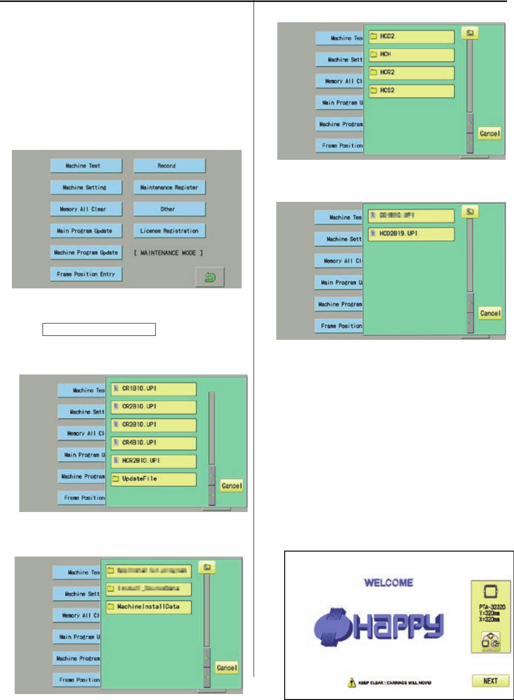
139
4-4-3 Machine program update (Main program 〜Ver.*1.21)
1. Insert USB memory that contains data for version
up into insertion slot on the control box.
2. Refer to [ 4-5-1 How to enter maintenance mode]
and enter maintenance mode.
The screen shows below:
3. Press Machine Program Update.
The screen shows contents of the USB memory.
4. Select [UpdateFile].
5. Select [MachineInstallData].
6. Select the machine model.
7. Select the file.
Installation of program begins.
After successful installation, the display will
return to step no.2.
<NOTE>
* Please do not take out USB memory during
installation.
* Please do not turn off the power during
installation (it will
take for a while for completion of installation).
8. Turn OFF the power and then turn ON the power.

140
9. Press NEXT.
10. Referring to [4-4-5 Setting of revolution],
Perform [Re-Initialization of machine system]
And [Initializing of machine speed].
・* End of process.
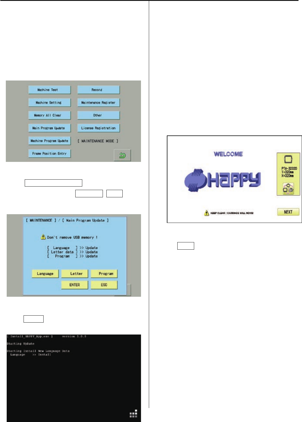
141
4-4-4 Main program update (Main program 〜Ver.*1.21)
1. Insert USB memory that contains data for version
up into insertion slot on the control box.
2. Refer to [ 4-5-1 How to enter maintenance mode ]
and enter
maintenance mode. Display comes as below.
2. Press Main Program Update.
Select 3 items such as Language, Letter and
make the screen show “Update” on each item.
4. Press ENTER.
Installation of program begins.
<NOTE>
* Please do not take out USB memory during
installation.
* Please do not turn off the power during
installation (it will take for a while for completion
of installation).
Retry updating when the screen shows “Error” due
to writing error.
Once update id complete, the machine will be
rebooted automatically.
5 Press NEXT button.
6. Referring to [4-4-5 Setting of revolution],
Perform [Re-Initialization of machine system]
And [Initializing of machine speed].
* End of process.
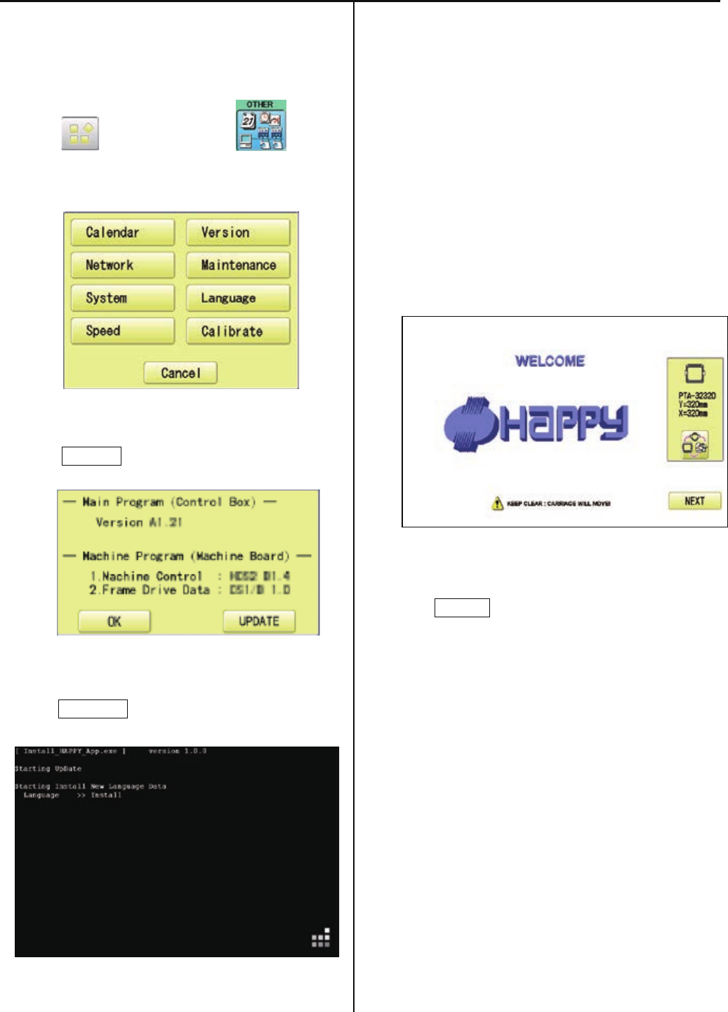
141a
4-4-4a Machine program and Main program update (Main program Ver.*1.22〜)
1. Insert USB memory that contains data for version
up into insertion slot on the control box.
2. Press (MENU) and press
(OTHER).
3. Press Version .
4. Press UPDATE .
Installation of program begins.
<NOTE>
* Please do not take out USB memory during
installation.
* Please do not turn off the power during
installation (it will
take for a while for completion of installation).
Retry updating when the screen shows “Error” due
to writing error.
Once update id complete, the machine will be
rebooted automatically.
5. Press NEXT button.
6. Referring to [4-4-5 Setting of revolution],
Perform [Re-Initialization of machine system]
And [Initializing of machine speed].
* End of process.
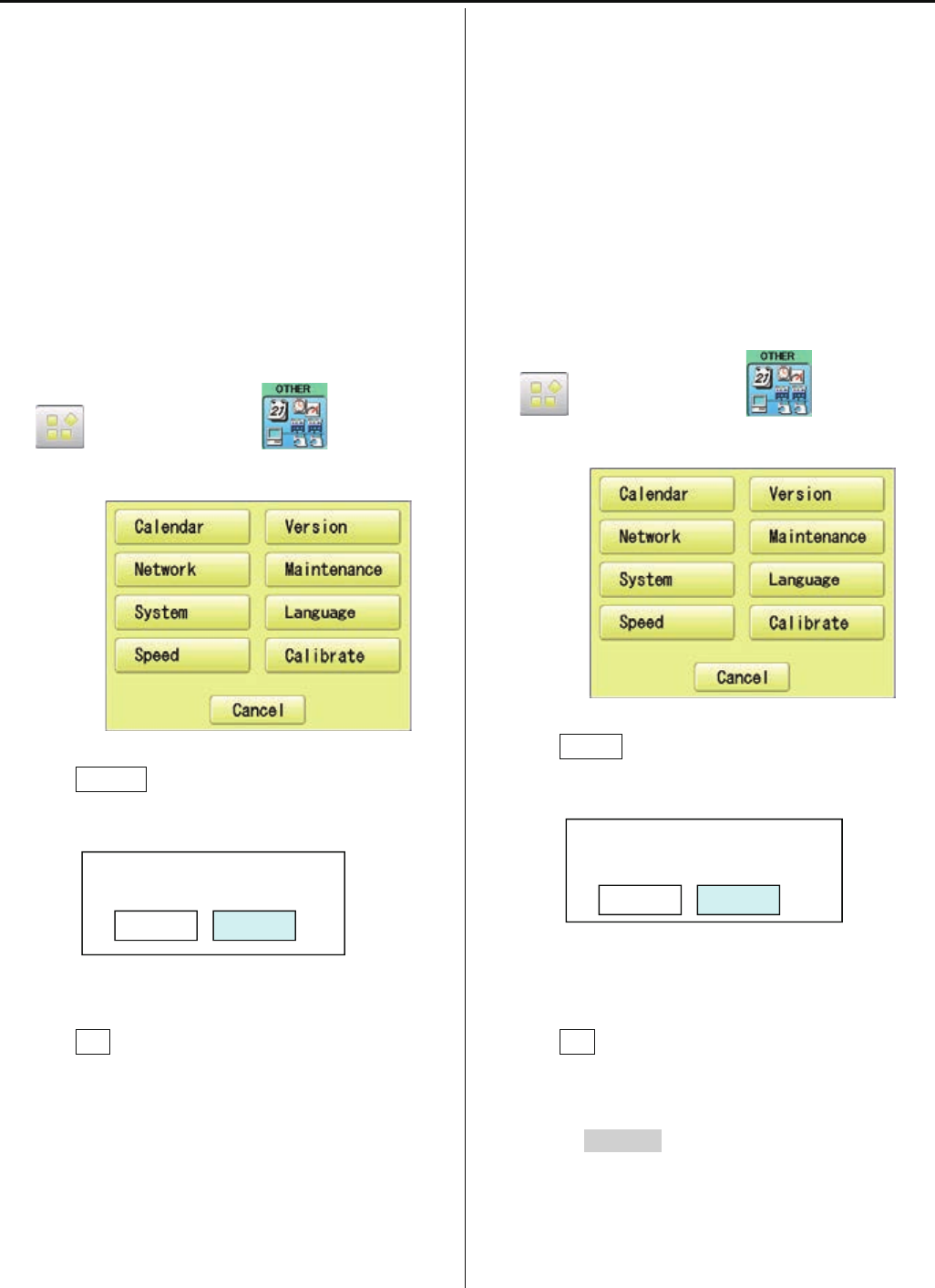
142
4-4-5 Setting of revolution
Re-Initialization of machine system
Perform this function only to fix problems with the
machine.
When performed, all settings in the “OPTION” menu
are lost.
Be sure to reset the “OPTION” menu after
performing this function.
1. Turn on the power. After the program start up,
press
(MENU) and press (OTHER).
2. Press System .
3. Press OK .
Formatting of the machines systems are carried
out.
Indicate HAPPY logo in screen.
End of process.
Initializing of machine speed
Setting of revolution of main shaft, which is suitable
to the machine is required.
If setting is not done, the revolution may not speed
up.
1. Turn on the power. After the program start up,
press
(MENU) and press (OTHER).
2. Press Speed .
3. Press OK .
Main shaft adjusts its revolution speed
automatically.
Message complete will be displayed when setting
is
finished and it goes back to drive mode.
End of process.
System initialize OK?
Cancel OK
Speed setting OK?
CAUTION! <Main shaft turns>
Cancel OK

143
4-5 Maintenance mode
Maintenance mode consists of items as shown below.
Machine Test Movement test, maintenance, and adjustment
Machine Setting Machine control setting
Memory All Clear Initialization of design memory.
Main Program Update Update of operation program and language data
Machine Program Update Update of control program and frame move data
Frame Position Entry Registration of coordinates for positioning sensor (Not used in HCS2)
Record Total number of stitches, Error occurrence record, Occurrence record by error type.
Maintenance Register Registration of machine maintenance date(Normally not used at maintenance)
Other Other (This item is neither configured nor used.)
4-5-1 How to enter maintenance mode
1. Turn on machine.
2. Press NEXT while pressing START/STOP button
at the screen of the control box after booting the
machine.
3. Change to booting screen when you press
.
You can enter maintenance mode again by long key
press
of (Menu) at the Drive screen after
maintenance mode is finished.
However, you cannot use the reentry method above
once
the machine is turned off and rebooted.

144
4-5-2 Machine Test Machine movement
Below operation will be moved solely. In some operations, actuator of motor will be moved, Keep hands
and face away during
movement for your own safety.
#1 Input of Needle bar detect Potentiometer
(For adjustment)
#2 Action test of moving knife Open-Close
(For Rev.A)
#3 Adjusting sensor of Thread catch hook
(Not used in HCS2)
#4 Action test of Keeper solenoid ON-OFF
#5 Movement test of jump solenoid ON-OFF
#6 Movement test of thread catch hook
IN-OUT
#7 Action test of moving knife (for Cam type)
Action test of moving knife Open-Close
(For Rev.A)
#8 Action test of clip type thread holder
(Not used in HCS2)
#9 Action test of laser pointer (Option)
#10 Action test of cooling fan ON-OFF
(Not used in HCS2)
#11 Encoder Check
#12 Confirm frame moving sensor
(Not used in HCS2)
#13 Confirm registration of frame position data
(Not used in HCS2)
#14 Main shaft control test
#15 Sequin test
(Not used in HCS2)
#16 Rotary Hook adjust
(Not used in HCS2)
#17 Needle Posi.
(Not used in HCS2)
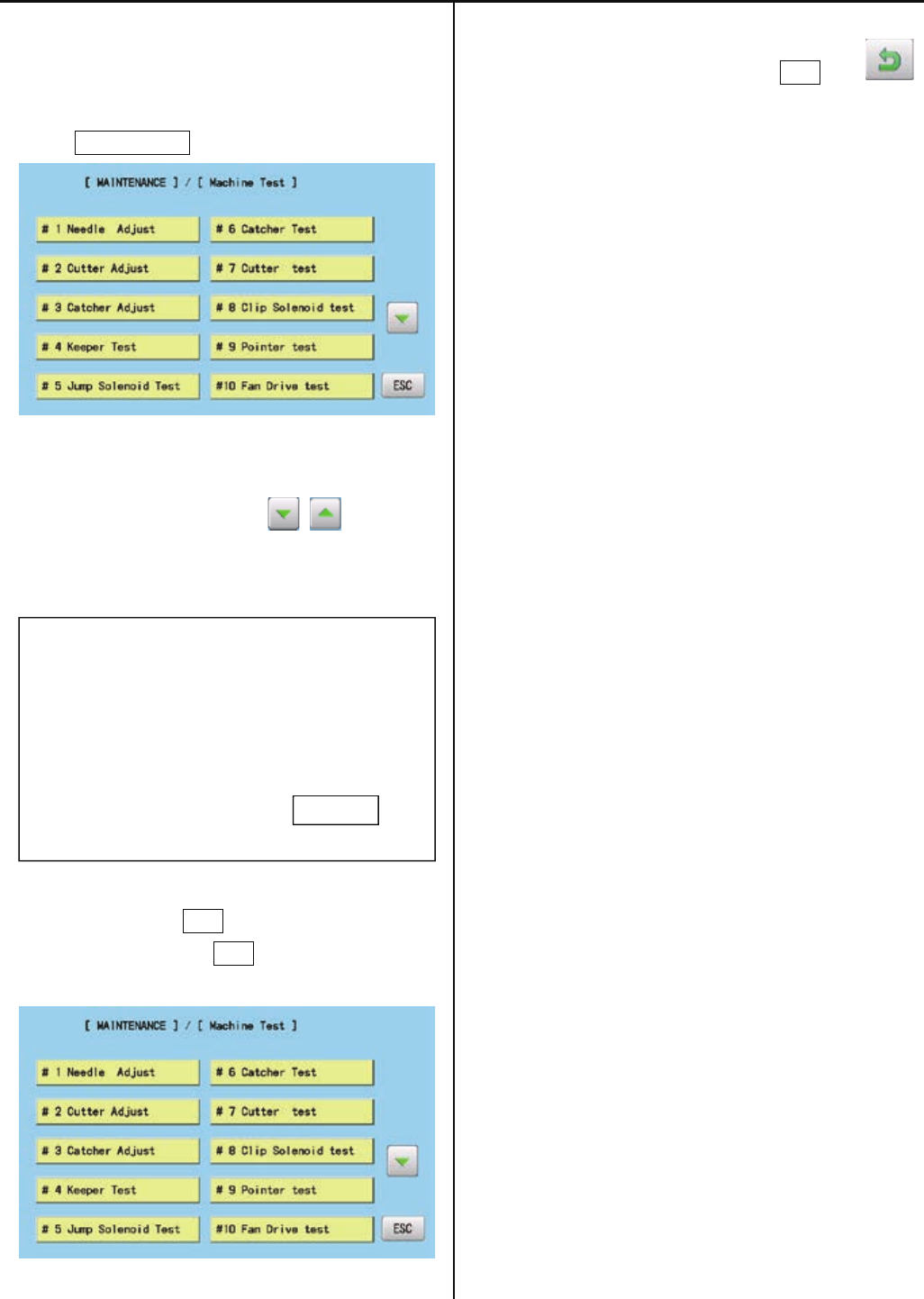
145
1. Enter maintenance mode in reference to [4-5-1
How to enter maintenance mode]
2. Press Machine Test .
3. Select desired number to be confirmed.
Page is switched by pressing .
Selected item will be executed.
# * ***************
4. The screen returns to the [MACHINE TEST]
screen by pressing ESC .
(Unnecessary to press ESC if the item completes
automatically.)
5. Return to drive mode by pressing ESC and .
ESC
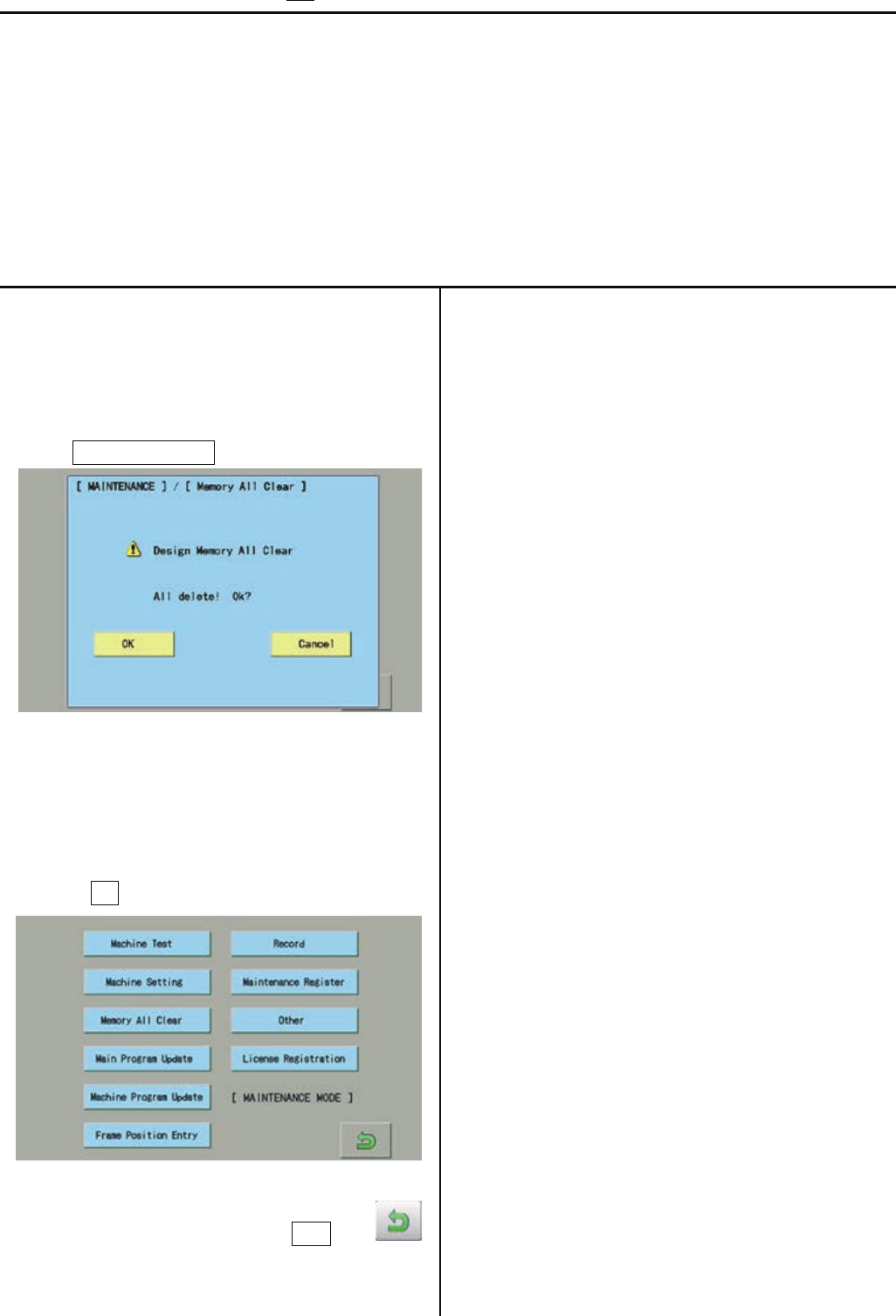
146
4-5-3 Memory All Clear Initialization of design memory
Delete all the design memory.
Execute this function when occurring design breakage or impossibility of design input.
If abnormality is found after deleting all the data, replace LCD-CE board (or Memory card) since the board
might be broken.
<NOTE>
All the internal design memory will be deleted by initialization of design memory.
You have to be careful when initializing design memory.
1. Enter maintenance mode in reference to [4-5-1
How to enter maintenance mode ]
2. Press Memory All Clear .
3. Confirmation of free area and all delete will be
started after
pressing OK .
4. Return to drive mode by pressing ESC and .
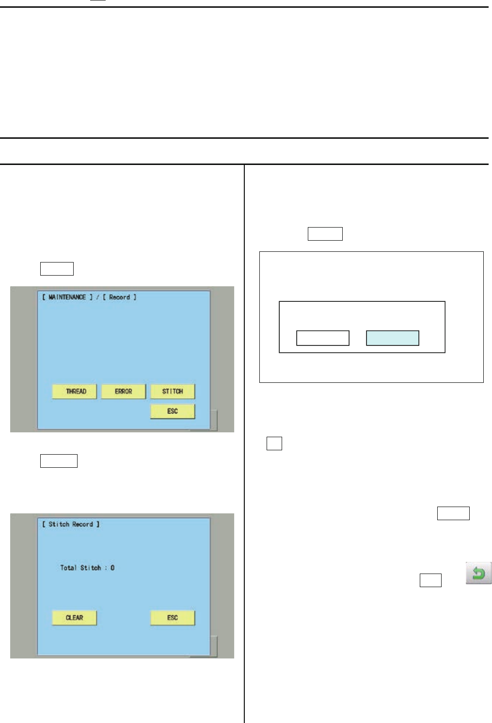
147
4-5-4 Record Operation data display
You can confirm history of operation.
Total number of stitch : Total number of stitch used for embroidery so far
Error occurrence record : Type of errors and its occurrence date for the last 32 errors
Occurrence record by error type : Accumulated number of each error occurrence
Thread break history : The number of thread break by needle bar
4-5-4-1 Total number of stitch
1. Enter maintenance mode in reference to [ 4-5-1
How to enter maintenance mode ]
2. Press Record.
3. Press STITCH.
The screen shows total number stitches used for
embroidery so far.
4. Selection menu of Clear Total Stitch will be
opened when
pressing CLEAR at Procedure 3.
* Total number of stitch is cleared after pressing
OK and
the screen shows one in the procedure 3. Total
number of stitch is 0.
* If you do not prefer to clear it, press Cancel and
the screen shows of the procedure 3 is shown
5. Return to drive mode by pressing ESC and .
Clear Total Stitch ?
Cancel OK
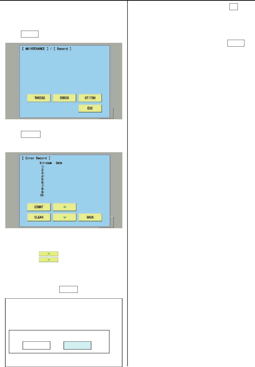
148
4-5-4-2 Record of Error occurrence
1. Enter maintenance mode in reference to [ 4-5-1
How to enter maintenance mode ]
2. Press Record .
3. Press ERROR.
Enable to confirm Record of error occurrence
* Enable to confirm Occurrence date and error
number of last
32 cases with button.
Selection menu of Clear Error Record will be
opened when pressing CLEAR.
* Error record is cleared by pressing OK and the
screen of
the procedure 3 is displayed.
* If you do not prefer to clear it, press Cancel and
the screen of the procedure 3 is displayed..
Clear Error Recode ?
Cancel OK
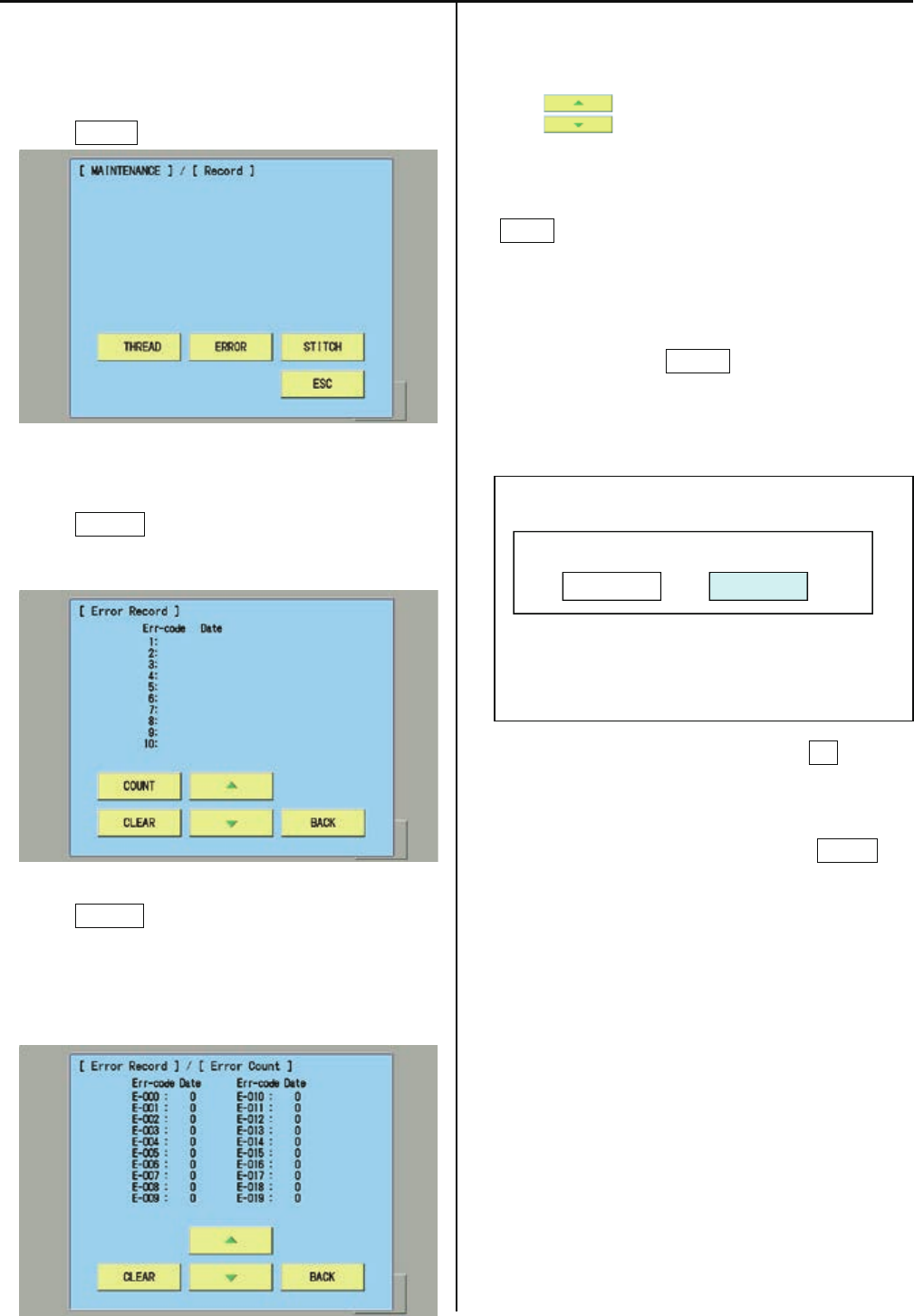
149
4-5-4-3 Number of occurrence in each error display
1. Enter maintenance mode in reference to [ 4-5-1
How to enter maintenance mode ]
2. Press Record .
3. Press ERROR.
You can confirm record of error occurrence.
4. Press COUNT .
You can confirm total number of occurrence in
each error.
(E-000 to E-255 will be displayed )
* You can confirm accumulated number for E-000 to
E-255
with .
* The screen returns to the previous screen by
pressing
BACK.
5. Selection menu of Clear Error Total Count will
be opened
when pressing CLEAR and the screen of
procedure 4
is displayed.
* Error record is cleared by pressing OK and the
screen of
the procedure 4 is displayed.
* If you do not prefer to clear it, press Cancel and
the screen of the procedure 4 is displayed.
Clear Error Total Count ?
Cancel OK
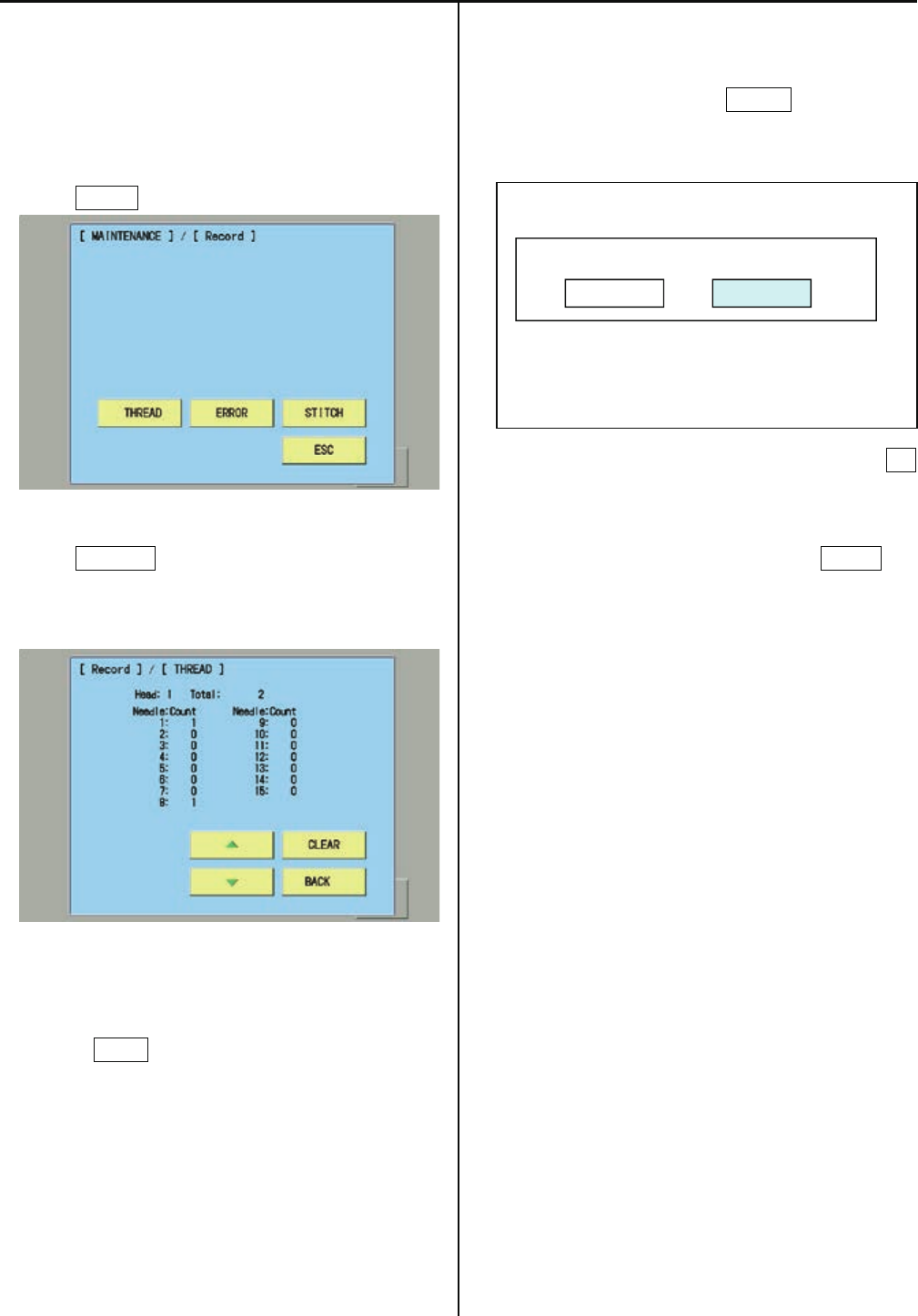
150
4-5-4-4 Thread break history
1. Enter maintenance mode in reference to [ 4-5-1
How to enter
maintenance mode ]
2. Press Record .
3. Press THREAD.
You can confirm thread break history by needle
bar.
・*The screen returns to the previous screen by
pressing BACK.
・
5. Selection menu of Clear Thread Break Count will
be opened when pressing CLEAR at the screen of
procedure 3.
* Thread break history is cleared by pressing OK
and
the screen of the procedure 3 is displayed.
* If you do not prefer to clear it, press Cancel and
the screen of the procedure 3 is displayed.
Clear Thread Break Count ?
Cancel OK

151
4-5-4-5 Setup Machine setting
<NOTE> ( *: Setting is for each indivisual machine, so prohibit to change setting. When you need to chage it,
please contact us in advance)
( $ : Setting is different for each model type. Please check before changing data)
( # : Setting is depending on options installed. Please check before changing data)
Contents
*1 Machine Type : HCS2
*2 Max Needle Number : 12 (1-15) : Number of Needle
*3 Max Head Number : 1 (1-30) : Number of Head
*4 Machine Max Speed : 1000 (500-2000) : Maximum rotation
*5 Machine Max Area X : 290 (1-1000) : Maximum embroidery area at X axis
*6 Machine Max Area Y : 290 (1-1000.) : Maximum embroidery area at Y axis
*7 X Position Sensor : 0 (0-12) : Number of position sensor at X axis
*8 Y Position Sensor : 0 (0-12) : Number of position sensor at Y axis
# 9 LED Needle Pointer : No : Use of LED Pointer Yes or No
*10 Safety Sensor : No. : Use of safety sensor ( rear )Yes or No
*11 N.Safety Sensor : No. : Use of safety sensor (front) Yes or No
*12 Clip Holder Device :No : Use of Clip holder device YES or NO
*13 Borer Device : No. : Use of Borer device Yes or No
$14 Cutter Unit Type : ***** (PulseMtr, Solenoid) : Thread cutting unit type
15 X Start Base Angle : 50 (20-90) : Starting angle of frame movement on X axis
16 Y Start Base Angle : 50 (20-90) : Starting angle of frame movement on Y axis
17 X Start Angle(CAP) :50 (20-90) Starting angle of frame movement on X axis for cap frame
18 Y Start Angle(CAP) :50 (20-90) Starting angle of frame movement on Y axis for cap frame
*19 Color Change Speed :Slow1 (Normal / Slow1 ~ Slow4) Speed of needle bar change
*20 Brush Data [*0.1mm]:200 (0-250) Distance of thread brush (mm) after thread cut
(1:0.1mm , 200:20.0mm … 250:25.0mm)
*21 Clip Close Timing :0 (0-1000) Close timing of Clip when Thread trim (ms)
Set to 200 when the Clip holder device is Yes.
*22 Border Overlap :0 (0-10) Overlap of between heads for border frame
*23 Trace Needle No. :1 (1-15) Needle Number for Trace
*24 Device Com. Speed :19200bps (2400-115200) Communication speed for Sequin device and
Cording device
*25 Sequin Dev. Left :No Use of left side Sequin device Yes or No
*26 Sequin Dev. Right :No Use of right side Sequin device Yes or No
*27 Sequin Dev. Type :Other (Happy) Type of Sequin device
*28 Number of 3-Needle :0 (0-15) Needle number of 3-Needle device
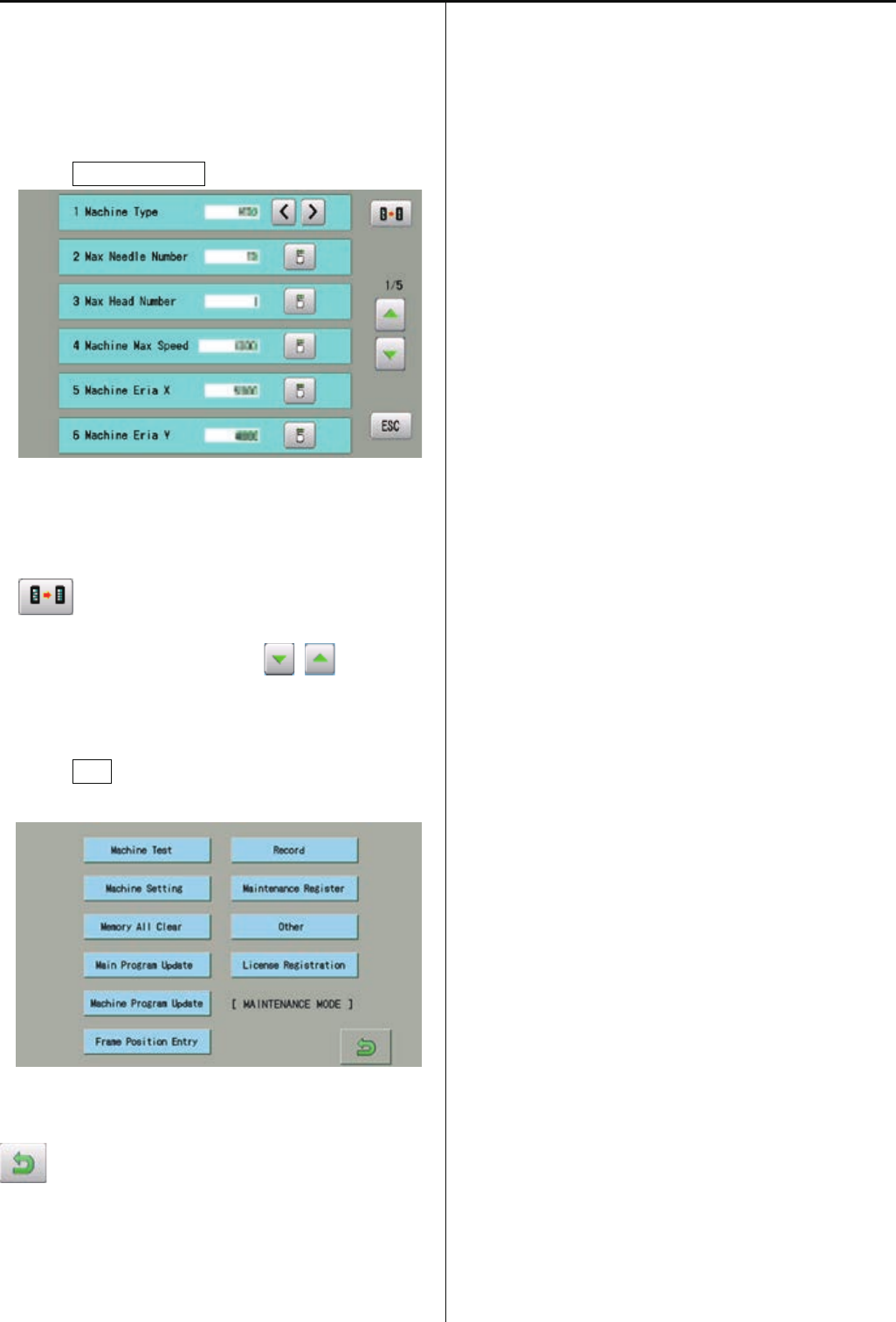
152
1. Enter maintenance mode in reference to [ 4-5-1
How to enter maintenance mode ].
2. Press Machine Setting.
3. Select desired number and modify setting.
・Setting values become default by pressing
.
・Page is switched by pressing .
4. Press ESC button after modifying of setting
number.
5. The screen returns to drive mode by pressing
.
6. Turn off power and on again before use a
machine.
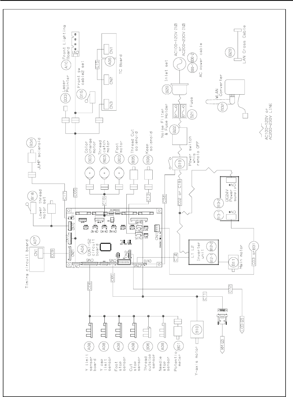
153
5-1-1 Electrical connection diagram (except for Rev.A)
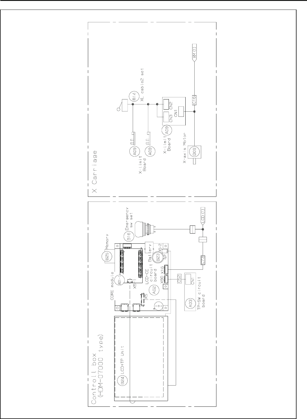
154
5-1-1 Electrical connection diagram (except for Rev.A)

155
5-1-2 List of electrical connection diagrams (except for Rev.A)
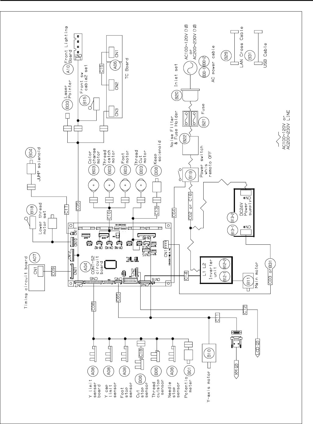
156
5-1-3 Electrical connection diagram (for Rev. A)
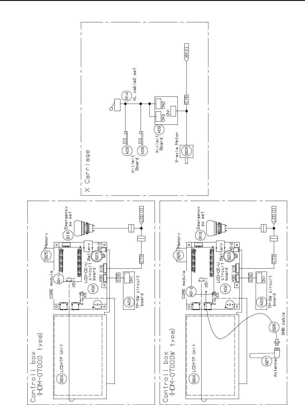
157
5-1-3 Electrical connection diagram (for Rev. A)

158
5-1-4 List of electrical connection diagrams (for Rev. A)
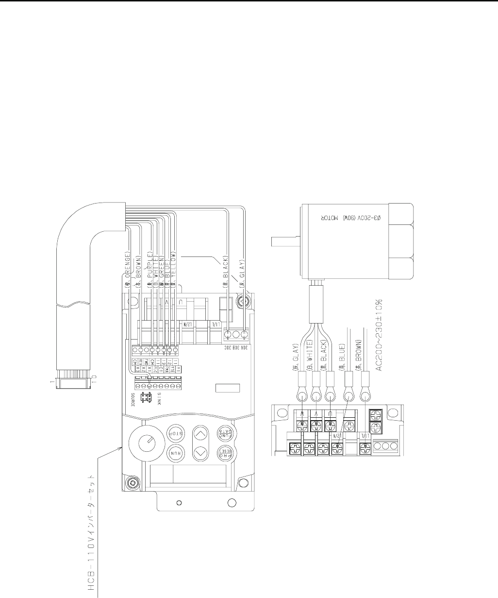
159
5-2-1 Connection of inverter 100V
Inverter set
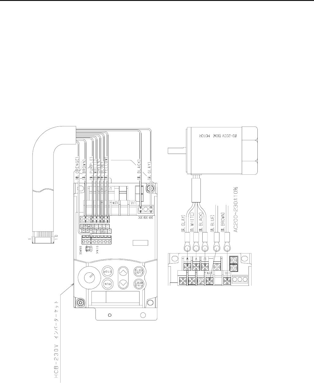
160
5-2-2 Connection of inverter 200V
Inverter set
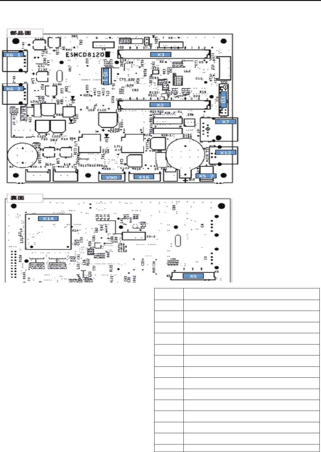
160a
5-3 Explanation of function of circuit board
HCD8121*
LCD-CE-U board Ass'y
CN No. Function
X1 Core module I/F
X2 Core module I/F
D5 7in LCD I/F
D5_1 7in touch panel input
X5_2 7in LCD backlight output
D6_1 USB-A connector 1
D6_2 USB-A connector 2
D7 LAN
D12 USB-B connector
D13 AUX
D14 SD card
X16 TP-SW board I/F
X90 CONT-** board I/F
Other CN Reserved
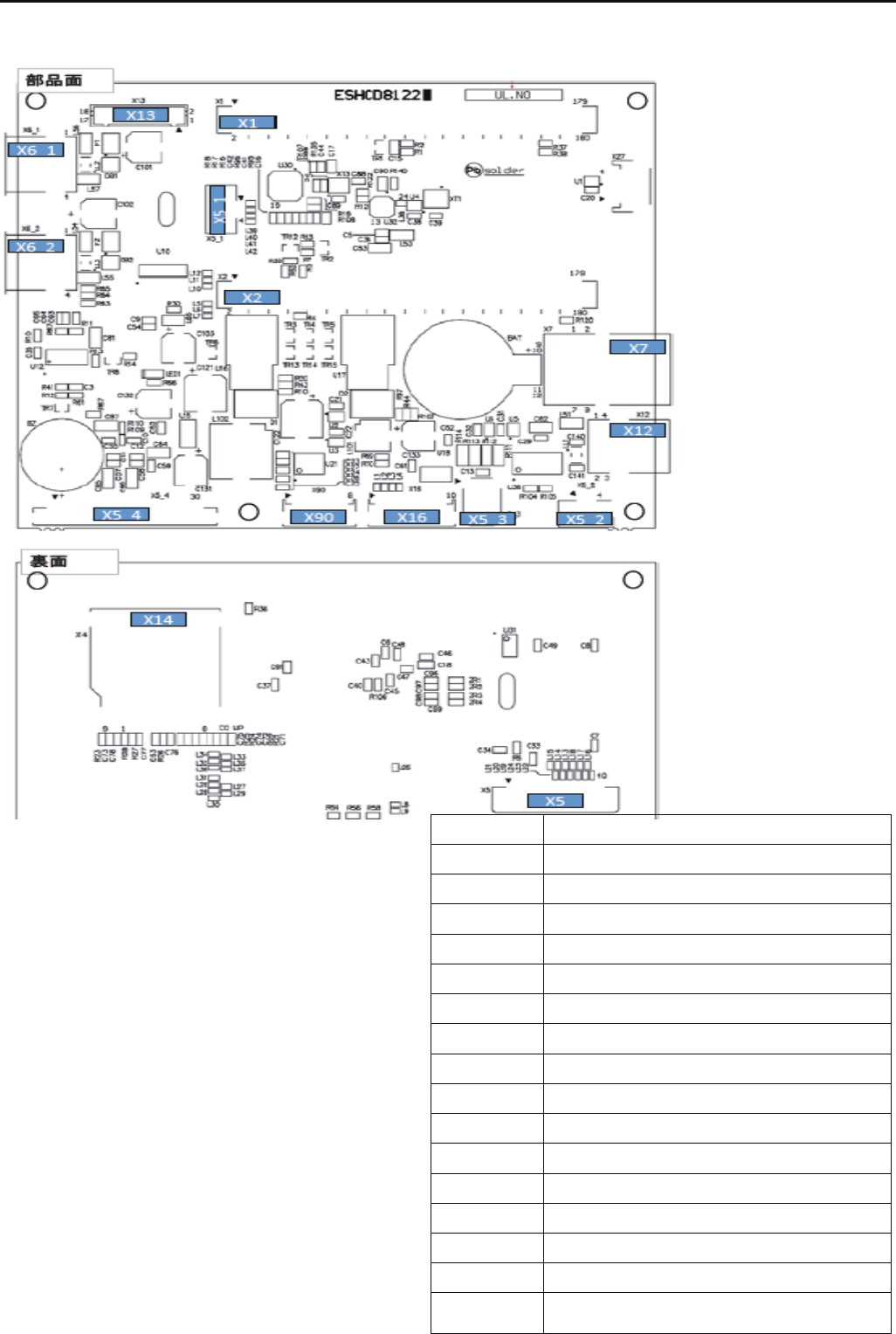
160b
HCD8122*
LCD-CE-MX board Ass'y
CN No. Function
X1 Core module I/F
X2 Core module I/F
X5 7in LCD I/F
X5_1 7in touch panel input
X5_2 10.4in touch panel input
X5_3 7in LCD backlight output
X5_4 10.4in LCD I/F
X6_1 USB-A connector 1
X6_2 USB-A connector 2
X7 LAN
X12 USB-B connector
X13 AUX
X14 SD card
X16 TP-SW board I/F
X90 CONT-** board I/F
OOtherther
Other CN Reserved
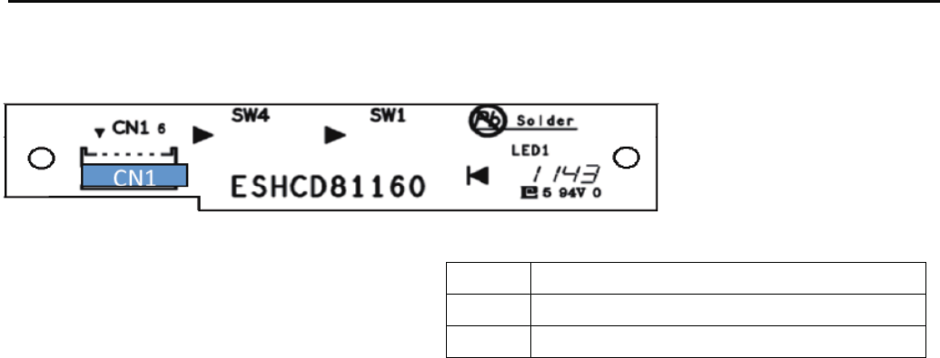
160c
HCD8116*
TP-switch board ass'y
!!6;5,:265
!$=2:,16;:7;:257;:
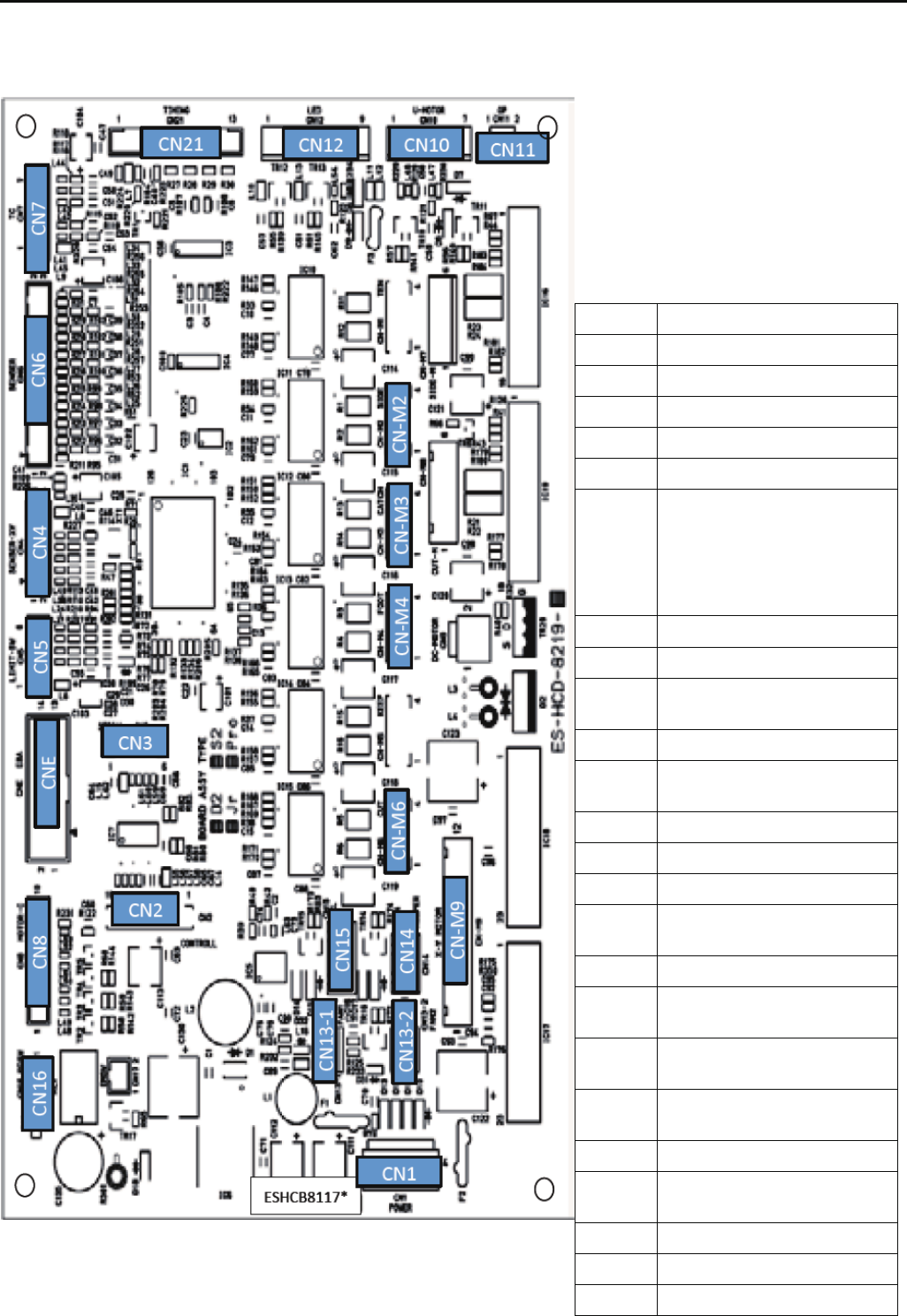
160d
HCB8117*
"!%$+6*8-99?
!!6Function
!57;:6/'76=.896;8,.
!65:863+6>
!"7:265
! ()7692:2659.5968
!&5;9.-
!
57;:6/%18.*-
,*:,1.8!..-3.+*8,1*50.
%18.*-,;::25068209.5968
!..-3.+*8,1*50.
76:.592654.:.8
!%9.5968
!5<.8:.8
!6++25=25-.846:68
6;:7;:
!327963.562-6;:7;:
!*9.87625:.86;:7;:865:
6;:7;:
! *5
! *5
!..7.8963.562-6;:7;:
!%18.*-,;::250963.562-
6;:7;:
! *259=2:,18.46:.6;:7;:
!57;:6/7625?7625:
*2591*/: *503.
! !..-3.+*8,1*50.46:68
6;:7;:
! ";:7;:6/%18.*-,*:,1
46:68
! #8.99;8./66:46:686;:7;:
! %18.*-,;::25046:68
6;:7;:
! ()46:686;:7;:
!&(
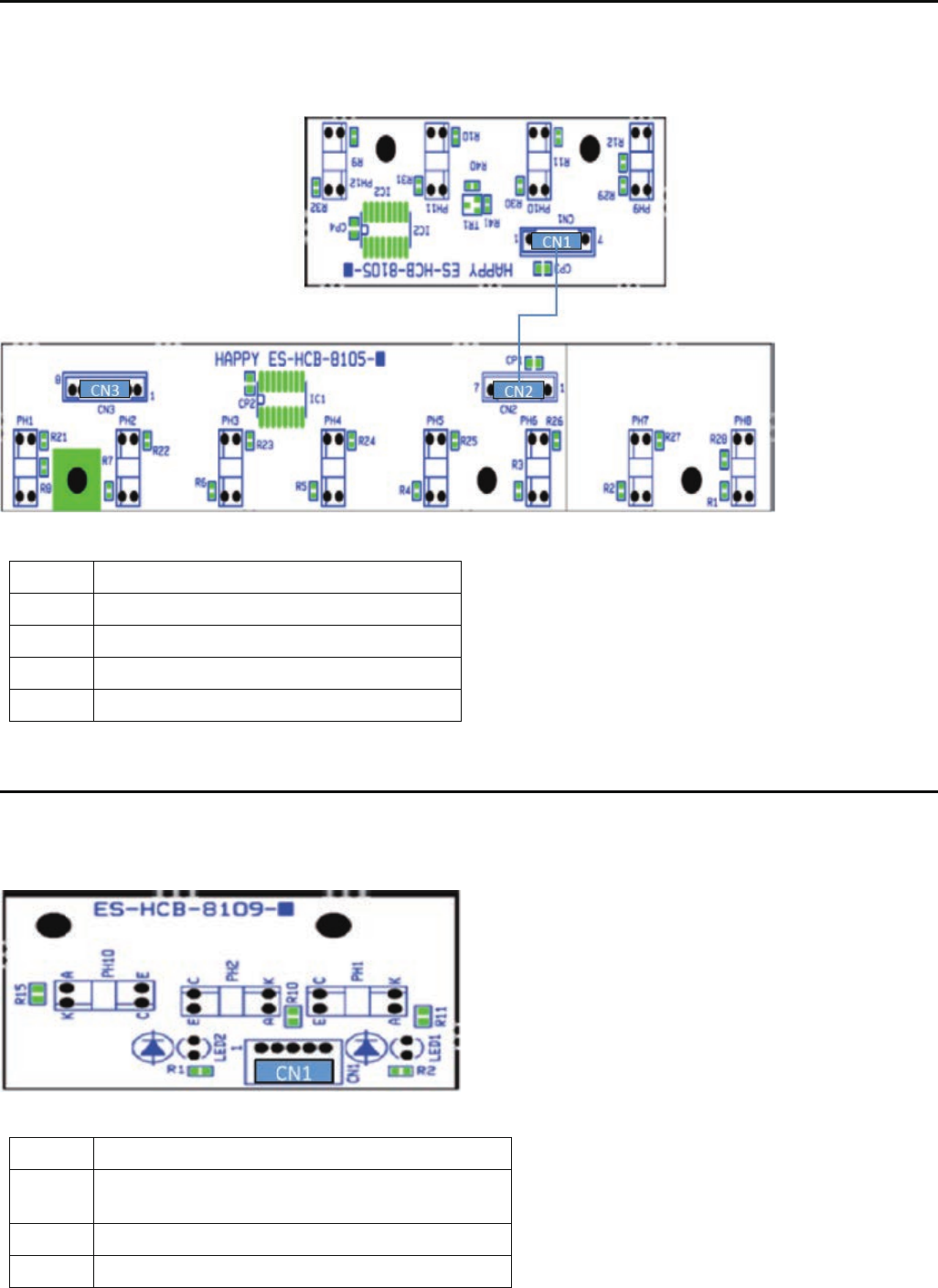
160e
HCB8105*
TC12 board ass'y
HCD8109*
Timing detecting board ass'y
!!6;5,:265
!$.59686;:7;:5..-3.
!$.5968257;:5..-3.
!"!%$+6*8-
!!6;5,:265
!";:7;:6/7625:7625: *503.9.5968
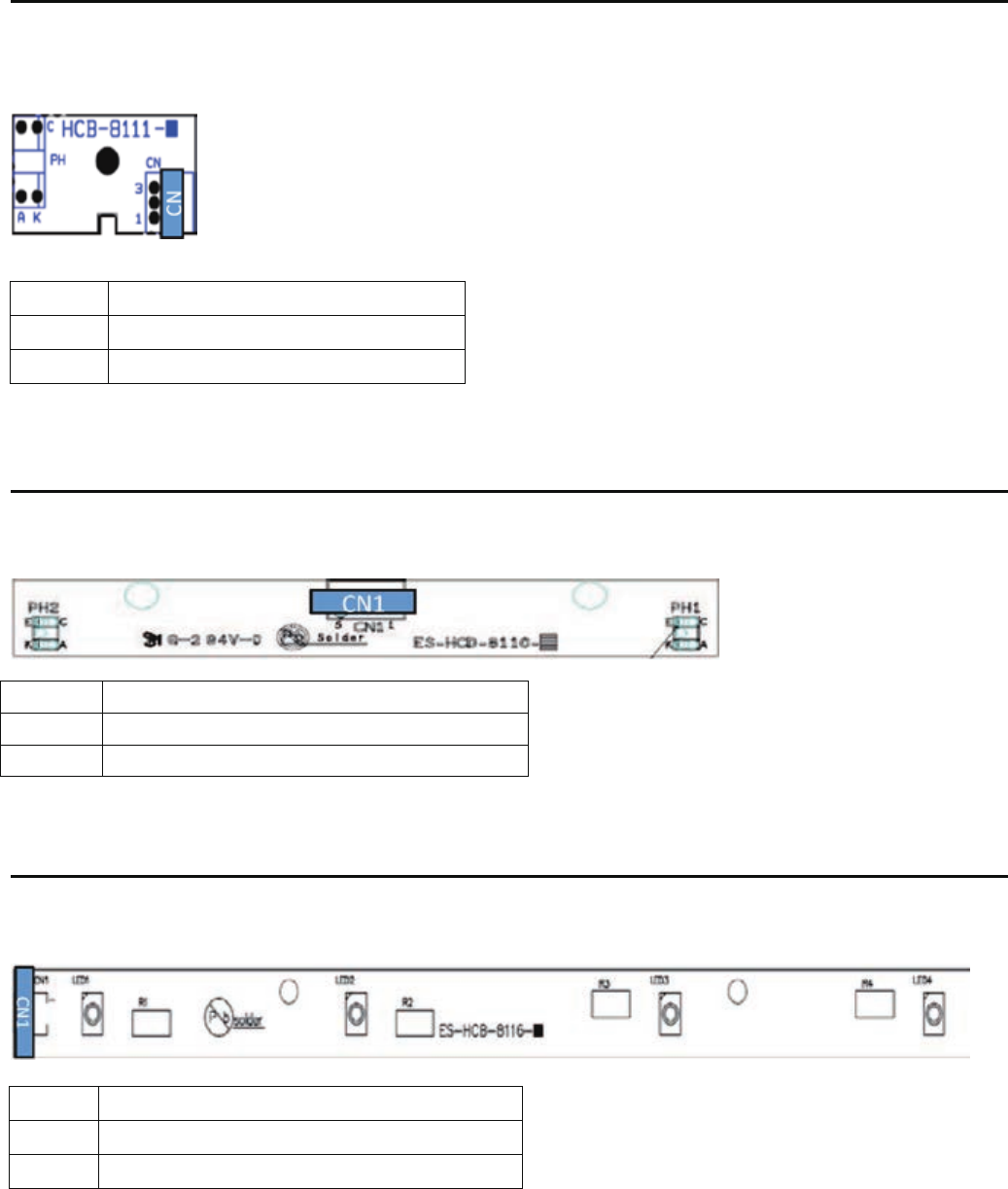
160f
HCB8111*
SENS0R Circuit Board Ass'y
HCD8110*
POSITION SENSOR Circuit Board Ass'y
HCB8116*
FRONT LED Circuit Board Ass'y
CN No. Function
CN1 24V power source input
CN No. Function
CN Sensor output
CN No. Function
CN1 Sensor out put
161
6-1 How to respond for some question (As example step)
*When you receive some question from customer, please use this step for sold problem as sample.
Receive contact from customer
Ask machine serial number
Ask contents of question
*Circumstance of machine (Windy, Dusty, Floor condition and etc)
*Embroidery condition (Frame, Fabric, Thread, Pattern)
*Machine creations. (Create menu)
*Version of machine program.
*Version of Happylinf software.
*About connecting PC.
*etc.
You may prepare instruction book and parts book by customer.
Respond for customer’s question
*Advice by Instruction book and Parts book.
*Advice referencing maintenance manual.
*If you can not immediate, contact again after more detail check.
Ask customer’s contact number
*Phone, Fax and E-mail
OK
*If you find case of respond, contact customer kindly.
NG Visit your technician
*Ask schedule for visit
NG
Send or bring back machine for more detail check
*Estimate repair cost
*If still can not find the case, contact factory rep.

162
6-2-1 Trouble shooting (Electricity doesn’t turn on)
Trouble Factor Cause of trouble and measure Page
Electricity Mechanical 1. Did fuse blow?
doesn't turn on 1-1 If it did, replace it.
2. Check of defect on board.
2-1 Replace of CONT board.
2-2 Replace of LCD-CE board.
3. No problem in power supply?
3-1 Check and adjust the correct voltage. 4-1-3
3-2 Try to replace power supply.
4. Check of Cable catching causes short-circuit.
4-1 Please insulate the cable after removing outer cover.
4-2 Replace of cable.
5. Confirm not getting power supply from same outlet with other embroidery
machine or other machines which contains motor.
5-1 Preferably only 1 embroidery machine should be connected with 1 outlet.
(Maximum 2-3machines)
Operator 1. Didn't press emergency switch?
1-1 Release lock. (3-8)
Environment 1. Is electricity in receptacle?
1-1 Supply power.
( ) ---Reference instruction book

163
6-2-2 Trouble shooting (Thread break)
Trouble Factor Cause of trouble and measure Page
Thread break Mechanical 1. Is needle drop unstable by vibration? (2-4)
1-1 Reconsider where to install the machine.
1-2 Move the machine to floor fully reinforced.
1-3 Use strong table to be able to endure vibration.
2. No burr or scratch in thread guide hole? 3-1-1
2-1 Remove burr and scratch.
2-2 Replace of thread guide.
3. No problem in thread adjusting spring? 3-1-1
3-1 Replace spring if it doesn't spring.
3-2 If weak or broken, replace it.
4. Does detecting roller make smooth turn?
4-1 Clean inside hole of bearing.
4-2 Correct so as for slit disc not to touch sensor. 4-2-2
4-3 Correct so as for cable not to touch slit disc.
4-4 Check cable of TC 12 Board is unconnected
5. No problem in thread guide unit and thread tension ass’y? 3-1-1
5-1 Remove burr and scratch if appeared.
5-2 Remove lints and clean.
6. Does disc on thread tension ass’y. turn smoothly? 3-1-1
6-1 Remove lints and clean.
6-2 Replace
7. Is backlash between take-up lever and take-up crank roller not bigger?
7-1 Replace of take-up lever. 3-3-9
8. No problem in needle holder?
8-1 Remove burr and scratch.
8-2 Make proper fixing. (direction) 3-1-2
8-3 Replace if thread guide is bent. 3-1-1
9. No burr and scratch on needle plate? 3-1-1
9-1 Remove burr and scratch in needle hole.
9-2 Remove burr and scratch around needle hole on back of needle plate.
9-3 Replace it if not furbished.
9-4 If furbishing made needle hole wider, replace it.
10. No problem in pressure foot?
10-1 Remove burr and scratch. 3-1-1
10-2 Correct bent. 3-1-1
10-3 Adjust height. 3-2-12
10-4 Replace of pressure foot. 3-2-11
10-5 Replace of pressure foot drive cam. 3-2-9

164
6-2-2 Trouble shooting (Thread break)
Trouble Factor Cause of trouble and measure Page
Thread break Mechanical 11. No problem in rotary hook? 3-1-1
11-1 Clean it to remove lints. (23-2)
11-2 Furbish scratch. (23-2)
11-3 If backlash of bobbin case holder and outer hook grows bigger, replace them.
11-4 Replace.
12. No problem in rotary hook retainer?
12-1 Remove burr and scratch.
12-2 Adjust position. 3-5-2
13. No problem in needle?
13-1 Fix it properly . 3-1-2
13-2 Select proper size of needle to match thread thickness. 3-1-4
13-3 If tip of needle is warped or bent, replace. 3-1-1
13-4 Replace.
14. No problem in bobbin case?
14-1 Remove rust and scratch.
14-2 If thread guide spring is off, replace it.
15. No problem in bobbin?
15-1 Remove scratch (iron bobbin).
15-2 If distorted. replace it.
16. Is needle bar spring not broken?
16-1 Replace it. 3-3-7
17. Does needle bar make smooth movement?
17-1 If bent, replace it. 3-3-7
18. No backlash in moving head?
18-1 Adjust positioning roller shaft. 3-3-2
19. Needle doesn't drop in the center of needle hole.
19-1 Adjust positioning plate and adjust needle drop back and forth. 3-3-4
19-2 Adjust position of needle selection unit, then adjust needle drop right and left. 3-4-1
20. Is the lowest needle position proper?
20-1 Adjust mechanical lowest needle position. 3-2-3
20-2 Adjust electric lowest needle position. 4-2-1
21. Is needle height proper?
21-1 Adjust as specified. 3-3-6
22. Is rotary hook timing proper?
22-1 Adjust as specified. 3-5-1
23. Is clearance between needle and rotary hook proper?
23-1 Adjust as specified. 3-5-1
( ) ---Reference instruction book

165
6-2-2 Trouble shooting (Thread break)
Trouble Factor Cause of trouble and measure Page
Thread break Mechanical 24. Check tip of keeper hit the bobbin case.
24-1 Adjust it regularly. 3-6-12
25. ls take-up lever timing proper ?
25-1 Adjust as specified. 3-2-8
26. No problem in timing belt ?
26-1 Adjust tension. 3-8-1
26-2 If scratched or damaged, replace it. 3-8-2
27. No problem in motor belt ?
27-1 Adjust tension. 3-8-3
27-2 If scratched or damaged, replace it. 3-8-4
28. Is revolution setting proper ?
28-1 Make automatic speed setting. 4-4-5
29. Is inverter setting proper ?
29-1 Make setting. 4-3-3
Operator 1. Operation is wrong (no proper [OPTION] setting for sewing ?)
1-1 Tell how to operate. (5-1)
2.Is pattern dwindled too much by pattern adjustment ?
2-1 Adjust size so as to produce less thread break.
2-2 Use pattern edited again (density_ change).
3. Is thread tension properly set ?
3-1 <Upper thread> Considering sewing finish, set tension. (8-1)
3-2 <Bobbin thread> Considering upper thread tension, set tension. (4-5)
4. Is bobbin winding proper ?
4-1 Adjusting bobbin winding tension, wind with proper strength. (4-4)
5. Is bobbin put in bobbin case properly ?
5-1 Viewing from front of bobbin case, set so that bobbin turns left-wise. (4-5)
6. Does thread cone stand properly ? (4-6)
6-1 Keep thread from hitting felt.
6-2 Stand vertically.
7. Is passing of thread proper ?
7-1 Pass thread properly. (4-7)
8. Is cloth properly stretched ? (6-2) (7-5)
8-1 No loosening and no too much tightening. Even tension in depth and width.
8-2 Texture should be even in direction of X and Y.
9. Is frame properly set? (6-3) (7-6)
9-1 Frame should be put in positioning hole on tubular-frame.
9-2 No loosening of screw.
( ) ---Reference instruction book

166
6-2-2 Trouble shooting (Thread break)
Trouble Factor Cause of trouble and measure Page
Thread break Operator 10. Is frame used to suit pattern size?
10-1 Use frame to suit pattern size.
11. When you dispose of thread (thread remains around rotary hook),
didn't you damage rotary hook, needle plate with scissors?
11-1 Tell to dispose of thread carefully.
11-2 Open needle plate to dispose of thread.
12. Didn't you neglect cleaning and oiling?
12-1 Tell to always clean and use cleanly. (23-2)
12-2 Tell to oil regularly.
Thread & 1. Is thread used to suit needle size?
cloth 1-1 Use thread to suit needle size. 3-1-4
2. Is thread used to suit embroidery? (thread twist, tender thread). 3-1-3
2-1 Don't use too strongly twisted thread.
2-2 Twist of thread is to be left-wise.
2-3 Use tender thread.
2-4 Don't use thread with knot or uneven size.
3. Is thread properly wound aginst cone?
3-1 Use thread to be wound smoothly.
4. Isn't tip of cone warped or isn't thread caught in scratch?
4-1 Remove warp and scratch.
5. Don't use thread left for a long period? (inferior thread).
5-1 Don't buy thread more than you use.
5-2 Tell not to store thread for a long period.
5-3 Tell how to store. (direct sunshine. humidity dust etc.)
6. Isn't poor unwoven cloth used? Is number of sheets used proper?
Environment 1. Is strength of table and floor enough? (2-4)
1-1 Reconsider place to install the machine.
1-2 Move the machine to place where floor is strong enough.
1-3 Use table with strength endurable against vibration.
2 Are room temperature and humidity proper against thread?
2-1 It is desirable to install air conditioner to keep temperature and humidity
in a certain level.
3. Doesn't embroidery machine receive direct sunlight? (cause of inferior thread)
3-1 See not to expose to sunlight (spread curtain) (2-5)
( ) ---Reference instruction book

167
6-2-2 Trouble shooting (Thread break)
Trouble Factor Cause of trouble and measure Page
Thread break Environment 4. Is there something that produce steam, wasted cotton, dust around.
the embroidery machine?
5-1 Keep the embroidery machine off those things. (2-5)
5. Does thread go out of control by taking wind from outside or heater etc.? (2-5)
6-1 Keep the embroidery machine off such wind.
6-2 Move the embroidery machine to proper place.
Pattern 1. Does thread break occur repeatedly at same place in design?
1-1 Check pattern to modify punching.
2. Is it too narrow between stitches?
2-1 Check pattern to modify punching.
2-2 Setting of [OPTION] menu. (Stitch sweep) (14-4)
3. Too many empty stitches?
3-1 Make [OPTION] setting. (this setting doesn't read empty stitches) (14-4)
Others 1. Using spray paste (adhesive material)
1-1 Clean around rotary hook. (23-2)
1-2 Replace or clean needle. 3-1-2
1-3 Use this paste at a given place and never use in front or back of
the embroidery machine.
( ) ---Reference instruction book

168
6-2-3 Trouble shooting (Erroneous thread cut)
Trouble Factor Cause of trouble and measure Page
Erroneous Mechanical 1. Is thread cut timing proper?
thread cut 1-1 Set timing to specified value. 3-6-3
(E-190) 1-2 Check no loosening of screw on thread cut cam.
(E-193) 2. Isn't rubbing of fixed knife and moving knife weak?
2-1 Adjust to be able to rub properly. 3-6-6
3. Does moving knife make smooth move?
3-1 Check if rubbing of moving knife and fixed knife is not too strong. 3-6-8
4. Check Displace of moving knife.
4-1 Adjust of moving knife position. 3-6-9
5. Check defacement of moving knife or fixed knife.
5-1 If possible, furnish with file.
5-2 Replace 3-6-6 and
3-6-7
6. No backlash in up and down direction of knife drive shaft? 3-6-8
6-1 Check no loosening of screw on moving knife.
6-2 Check no loosening of screw on knife drive shaft.
7. No backlash in fixed knife? 3-6-8
7-1 Check no loosening of screw on fixed knife.
8. Does thread cut solenoid work properly?
8-1 Check cable.
8-2 If trouble found in CONT board, replace.
8-3 If trouble found in thread cut solenoid (or motor), replace.
9. No trouble in thread cut drive?
9-1 If thread cut roller broken, replace. 3-6-2
9-2 If roller screw gets loosened, tighten firmly.
10. Is number of revolution proper at time of thread cut?
10-1 Make automatic speed setting. 4-4-5
10-2 If trouble in CONT board, replace.
11. Is there no skipped stitch?
11-1 Adjust needle depth. 3-3-6
11-2 Adjust clearance between needle and rotary hook. 3-5-1
11-3 Is height of pressure foot proper? 3-2-10
11-4 Is rotary hook timing proper? 3-5-1
11-5 Is relation between needle and thread proper?
( ) ---Reference instruction book

169
6-2-3 Trouble shooting(Erroneous thread cut)
Trouble Factor Cause of trouble and measure Page
Erroneous Mechanical 12. Check the needle bar moves up and down during thread cut.
thread cut 12-1 Adjust position of jump solenoid. 3-2-5
(E-190) 12-2 Replace needle bar cushion. 3-3-7
(E-193) 12-3 Replace needle bar driver. 3-2-4
13. Is position of keeper proper?
13-1 Adjust the fixed position regularly. 3-6-12
14. Check the movement of keeper goes smoothly.
14-1 Readjust if it is not smooth. 3-6-12
Operator 1. No negligence in cleaning thread cut device?
1-1 Tell to clean regularly. (23-2)
# It's desirable to prepare brush with soft hair and air gun.
2. Is drive greased?
2-1 Apply grease to thread cut cam.
3. Is timing of thread tension proper?
3-1 <Upper thread> Considering sewing finish, set tension. (8-1)
3-2 <Bobbin thread> Considering upper thread tension, set tension. (4-5)
Environment 1. Are power and voltage rated and stable?
1-1 Supply rated voltage.
Thread & 1. Is twist of thread too strong?
cloth 1-1 Use thread with proper twist.
2. No skipping by use of lots of paste?
2-1 Use small amount of paste.
2-2 Remove paste stuck to needle.
( ) ---Reference instruction book

170
6-2-4 Trouble shooting (Off-registration of pattern)
Trouble Factor Cause of trouble and measure Page
Off-registration Mechanical 1. Does frame move smoothly?
of pattern 1-1 Avoid curling of thread and cloth.
1-2 Reinstall of outer cover in case of touch with outer cover. 2-1
1-3 Adjust with no clearance between Arm and Connecting plate B.
2. Is bound of frame base too big? (6-1)
2-1 Fix frame base between bearing and base without gap.
3. Is carriage belt tension proper? 3-7-1
3-1 Adjust all belts as specified. 3-7-3
4. No loosening of screws on carriage drive?
4-1 Check screw. If loosened, tighten firmly.
5. No lints or dust around idler pulley on carriage?
5-1 Clean
6. No damage in carriage belt? 3-7-2
6-1 If damaged, replace. 3-7-4
7. No backlash of back and forth in moving head?
7-1 Adjust positioning roller shaft to remove backlash back and forth. 3-3-2
8. Is height of pressure foot proper?
8-1 Adjust as specified. 3-2-12
9. No problem in motion of pulse motor?
9-1 Check wiring. If screw got loosened, tighten more.
9-2 After 9-1, still problem, then replace.
10. No problem in motion of CONT board?
10-1 Check wiring. If screw got loosened, tighten more.
10-2 After 10-1, still problem, then replace.
11. Does't other frame than Happy's genuine one used?
11-1 If frame is too heavy, don't use it.
11-2 If setting is not proper, set it so as not to move.
12. No problem in LCD-CE board?
12-1 Try to initialize. 4-4
12-2 Replace of LCD-CE board.
13. Is number of revolution proper?
13-1 Make automatic speed setting. 4-4-5
14. Not affected by noise?
14-1 Don't use the machine near where noise is generated.
Operator 1. Is setting of frame correct? (6-3) (7-6)
1-1 Frame should be put in positioning hole on tubular frame.
1-2 Set so as for screw not to loosen.
( ) ---Reference instruction book

171
6-2-4 Trouble shooting(Off-registration of pattern)
Trouble Factor Cause of trouble and measure Page
Off-registration Operator 2. Is cloth properly stretched. (6-2) (7-5)
of pattern 2-1 Stretch properly.
3. Is thread tension proper? (4-5) (8-1)
3-1 Observing sewing rhythm, set thread tension properly.
4. Was the machine left for a long time in middle of sewing?
4-1 Try to finish sewing as soon as possible.
Environment 1. Is strength of table and floor enough? (2-4)
1-1 Check where to place the machine again.
1-2 Move to where floor is strong enough.
1-3 Use strong table to be able to endure vibration.
2. No problem in pulse motor driver by low power and voltage (variation)?
2-1 Supply rated voltage.
2-2 Use transformer.
2-3 Use stabilizer.
3. Is there no place where noise is generated near the machine?
3-1 Don't use the machine near where noise is generated.
4. Doesn't drive frame hit obstacle? (2-4)
4-1 Remove obstacle.
4-2 When useing cap frame, see not to hit table. (2-5)
Thread & 1. Not using shrinkable cloth? (4-3)
cloth 1-1 Use backing paper (consider number of sheets to use).
2. Isn't breakable cloth is used by thread tightening? (4-3)
2-1 Use backing paper (consider number of sheets to use).
3. Is proper backing paper used? (4-3)
3-1 Use backing paper to match cloth.
4. Isn't cloth (embroidery) too heavy?
4-1 Don't use extremely heavy cloth.
Pattern 1. Pattern data may be destroyed. (5-6)
1-1 Read again.
1-2 Let new pattern read.
2. Memory pattern was destroyed. (5-6)
2-1 Let new pattern read.
3. No problem in USB memory ?
3-1 Initialize and read again.
3-2 Prepare new USB memory.
( ) ---Reference instruction book

172
6-2-5 Trouble shooting(Upper thread comes off from needle hole)
Trouble Factor Cause of trouble and measure Page
Upper thread Mechanical 1. Is keeper in motion?
comes off 1-1 Check if cable was cut or there is something unusual.
from needle 1-2 In case solenoid is in trouble, replace.
hole 1-3 In case CONT board is in trouble, replace.
2. Is keeper put in right place?
2-1 Put it as specified. 3-6-9
2-2 Modify bent of keeper.
2-3 Adjust it again if movement is not smooth.
3. Is magic-tape on thread catch holder not worn?
3-1 Replace magic-tape.
4. Does bobbin thread holder hold bobbin thread?
4-1 Adjust pressure when contacting moving knife. 3-6-8
4-2 In case bobbin thread holder is in trouble, replace.
4-3 Clean bobbin thread holder.
5. No error in thread cut (2 threads cut)?
5-1 Check and adjust thread cut timing. 3-6-5
5-2 Position moving knife as specified. 3-6-9
5-3 Check and polish burr or scratch on moving knife.
5-4 In case moving knife is in trouble, replace. 3-6-6
6. Are clearance between needle and rotary point and needle height are proper?
6-1 Adjust clearance between needle and rotary hook as specified. 3-5-1
6-2 Adjust needle depth. 3-3-6
7. Doesn't thread catch hook cut upper thread?
7-1 Polish burr on hook.
7-2 In case hook is in trouble, replace.
8. Does thread catch hook hold upper thread?
8-1 Check if cable was cut or there is something unusual.
8-2 In case pulse motor is in trouble, replace.
8-3 Adjust fixing position. 3-2-18
8-4 If hook is bent, modify.
8-5 In case hook is in trouble, replace.
8-6 In case CONT board is in trouble, replace.
9. Check tension of thread adjusting spring is too weak.
9-1 Adjust of tension. 3-3-11
10. Check Stroke of thread adjusting spring is too big.
10-1 Adjust of stroke. 3-3-12
( ) ---Reference instruction book

173
6-2-5 Trouble shooting(Upper thread comes off from needle hole)
Trouble Factor Cause of trouble and measure Page
Upper thread Mechanical 11.Check the needle bar moves when start sewing.
comes off 11-1 Adjust position to fix jump solenoid. 3-2-5
from needle 11-2 Replace needle bar driver. 3-2-4
hole 12. Is number of revolution proper when sewing started?
12-1 Make automatic speed setting. 4-4-5
13.Is height of pressure foot proper?
13-1 Adjust as specified. 3-2-12
Operator 1. Isn't thread tension too strong? (4-5) (8-1)
1-1 Weaken tension not to cause trouble in sewing rhythm.
2. Keen in cleaning thread cut device?
2-1 Clean bobbin thread holder regularly. (23-2)
3. Is setting of bobbin thread proper? (4-5)
3-1 Pass thread on bobbin thread guide surely.
4. Is bobbin thread properly wound? (4-4) (4-5)
4-1 Adjust tensile strength of bobbin winder and check holding plate.
4-2 Pull out bobbin thread to check if it comes out smoothly.
5. Is upper thread properly passed? (4-6) (4-7)
5-1 Pass properly again.
6. Does thread cone stand properly? (4-6)
6-1 Keep thread from hitting felt.
6-2 Stand vertically.
7. Is [OPTION] properly set? (5-1)
7-1 Select longer setting of upper thread length.
Thread & 1. Is thread used to suit embroidery? (thread twist, tender thread). 3-1-3
Cloth 1-1 Don't use too strongly twisted thread.
1-2 Twist of thread is to be left-wise.
1-3 Use tender thread.
1-4 Don't use thread with knot or uneven size.
Environment 1. Does wind let thread go beyond control? (outside wind, heater, and fan etc.) (2-5)
1-1 Keep the embroidery machine off from wind.
2. Is voltage of power as rated and stable?
2-1 Supply rated voltage.
Pattern 1. Is there stop sewing stitch for start sewing?
1-1 Modify pattern.
( ) ---Reference instruction book

174
6-2-6 Trouble shooting(Upper thread remains)
Trouble Factor Cause of trouble and measure Page
Upper thread Mechanical 1. Upper thread is difficult to come out of keeper at time of thread cut (bent or warp etc.).
remains 1-1 Modify bent or warp.
1-2 Replace keeper.
2. Keeper doesn't return properly at time of thread cut.
2-1 Modify bent of keeper.
2-2 Adjust position to fix. 3-6-12
2-3 Adjust it again if movement is not smooth.
3. Upper thread does not come off from magic tape of thread holder.
3-1 Insert something(Thickness 0.1-0.2mm) into holder then move it right and
left to put magic tape in order.
3-2 Replacement of Guard holder (upper) ass'y. 3-3-14
4. Doesn't thread catch hook cut upper thread?
4-1 Polish burr on hook.
4-2 In case hook is in trouble, replace.
Operator 1. Setting of thread tension is weak. (4-5) (8-1)
1-1 Strengthen so as not to cause trouble in sewing rhythm.
2. Is [OPTION] properly set? (5-1)
2-1 Select length of upper thread [standard].
Thread & 1. Using hard cloth make thread difficult to go through.
cloth 1-1 Select needle and thread. 3-1-4
2. Using thick cloth make thread difficult to go through.
2-1 Select needle and thread. 3-1-4
3. Is thread used to suit embroidery? (thread twist, tender thread). 3-1-3
3-1 Don't use too strongly twisted thread.
3-2 Twist of thread is to be left-wise.
3-3 Use tender thread.
3-4 Don't use thread with knot or uneven size.
( ) ---Reference instruction book

175
6-2-7 Trouble shooting (Malfunction of thread break detection)
Trouble Factor Cause of trouble and measure Page
Malfunction of Mechanical 1. Trouble in turning detection roller.
thread break 1-1 Clean roller shaft holder.
detection 1-2 Check if slit disc doesn't contacts sensor. 4-2-2
(empty 1-3 Clean sensor if dust gets stuck.
detection) 1-4 Check if cord doesn't contacts slit disc.
1-5 Check Disconnection of cable.
2. Check circuit board.
2-1 Replace of CONT board.
2-2 Replace of TC 12 board.
3. Sometimes needle bar doesn’t work when start sewing.
3-1 Replace if cushion has been decrepit.
3-2 Replace of needle bar driver. 3-2-4
3-3 Adjust of jump solenoid position. 3-2-5
3-4 Clean and overhaul of Jump solenoid. 3-2-20
3-5 Replace of Jump solenoid.
Operator 1. No thread is passed through detecting roller.
1-1 Pass thread properly. (4-6) (4-7)
2. Is thread tension proper?
2-1 Observing sewing rhythm, adjust thread tension properly. (4-5) (8-1)
3. Is proper detection sensitivity of thread cut selected?
3-1 Select detection sensitivity according to sewing condition of thread and cloth etc. (5-1)
Environment 1. Is there any device to yield lints etc. around the embroidery.
1-1 Keep it off the embroidery machine.
1-2 Move the embroidery machine to other place.
2. Doesn't thread go beyond control by wind? (thread comes off from needle hole by loosing) (2-5)
2-1 Keep thread off wind.
2-2 Move the embroidery machine to other place.
Thread & 1. Isn't silicone agent used on thread?
Cloth (Thread slips at detecting roller part due to adhere of silicone.)
1-1 Clean silicone agent attached to detecting roller groove.
( ) ---Reference instruction book

176
6-2-7 Trouble shooting (Malfunction of thread break detection)
Trouble Factor Cause of trouble and measure Page
Malfunction of Mechanical 1. Check circuit board.
thread break 1-1 Replace of CONT board.
detection 1-2 Replace of TC 12 board.
(not detected) Operator 1. Is thread tension proper?
(slow detected) 1-1 Observing sewing rhythm, adjust to proper thread tension. (4-5) (8-1)
(Adjust it little bits stronger.)
2. Is proper detecting sensitivity of thread cut selected?
2-1 In case of being not detected, make [thread cut detection] setting to [yes]. (5-1)
2-2 Select detection sensitivity of thread cut according to sewing condition of thread and cloth etc.
( ) ---Reference instruction book

177
6-2-8 Trouble shooting (Suspension of upper shaft)
Trouble Factor Cause of trouble and measure Page
Suspension Mechanical 1. Upper thread twine round rotary hook or rotary hook retainer.
of main shaft 1-1 Get rid of it.
(E-18) 2. Check return of keeper goes smooth. (when start sewing.)
(E-51) 2-1Adjust it regularly. 3-6-12
(E-52) 3. Check upper thread is sticking at thread guide part of bobbin case.
3-1 Get rid of it.
3-2 Do not use of bobbin case in which thread guide is coiled type. (use standard type)
4. Out of Needle bar block B from pressure foot block.
4-1 Insert needle bar block B into pressure foot block by doing
needle bar change manually.
4-2 Clean and overhaul of Jump solenoid. 3-2-20
5. Defect on drive part of pressure foot.
5-1 Modify Pin B and hit part of link A and B by sand paper.
5-2 Replace of pressure foot block ass’y and link ass’y. 3-2-13
6. Effect by breakage of parts.
6-1 Repair broken place.
7. No damage in electric parts?
7-1 Replace of CONT board.
7-2 Replace of Timing Board.
7-3 Replace of inverter.
8. Trouble of software in LCD-CE circuit board.
8-1 Initialize, then make automatic speed setting. 4-4-5
9. Trouble in control of number of revolution.
9-1 Make automatic speed setting. 4-4-5
Operator 1. Isn't foreign stuff such as thread or cloth caught in where revolution is driven.
1-1 Get rid of foreign stuff.
1-2 Stretch properly. (6-2) (7-5)
2. Isn't thread tension too strong (stop at time of action of thread cut)? (4-5) (8-1)
2-1 Weaken tension so as not to cause trouble in sewing rhythm.
3. Check condition of lubrication.
3-1 Lubricate (refer to message)
Environment 1. Check adequate level of voltage (refer to trip of inverter).
1-1 Supply rated voltage.
100V – 115V -10V / +15V
200V – 230V -10V / +10V
( ) ---Reference instruction book s ---Standard c ---Color monitor

178
6-2-9 Trouble shooting (Malfunction of needle bar change)
Trouble Factor Cause of trouble and measure Page
Head does not Mechanical 1. Check lint or cloth is seized between Lower Moving rail and Bearing.
move 1-1 Remove seized lint or cloth.
(E-021) 2. Check lint or waste is seized in gap of Moving Cam.
(E-022) 2-1 Remove seized lint or waste.
3. Effect by breakage of parts.
3-1 Repair broken place.
Operator 1. Check Stopper of Moving Head is removed.
1-1 Remove Stopper.
Uncontrollable Mechanical 1. No problem in sensor circuit board ?
Move 1-1 Clean dust attached to sensor.
(E-024) 1-2 Replace sensor circuit board. 4-2-3
(E-025) 2. Trouble in potentiometer.
2-1 Replace 4-2-4
3. Needle number is not exactly recognized.
3-1 Recognize needle number with maintenance mode. 3-4-2
4. Breakage of Pulse Motor .
4-1 Replace Pulse Motor.
( ) ---Reference instruction book

179
6-2-10 Trouble shooting (Defect on Thread catcher)
Trouble Factor Cause of trouble and measure Page
does not catch Mechanical 1. Thead catcher does not extend hook sufficiently.
thread 1-1 Adjust position of Thread catcher . 3-2-18
1-2 Adjust position of Thread holder. 3-3-13
2. Excessive distance between Hook and tip of Needle.
2-1 Adjust position of Thread catcher. 3-2-18
2-2 Adjust position of Thread holder. 3-3-13
Hook of Thread Mechanical 1. Check Hook of Thread catcher bent or not.
catcher does not 1-1 Repair bent Hook.
extend 1-2 Replace Hook.
2. Check position of Thread catcher is proper.
2-1 Adjust 3-2-18
3. Check position of Thread holder is proper.
3-1 Adjust 3-3-13
4. Check Thread catcher.
4-1 Check cable is securely connected.
4-2 Replace Pulse Motor with trouble.
5. Check CPU Board.
5-1 Replace CONT Board.
Hook hits or Mechanical 1. Check Hook is bent or not.
catches Needle 1-1 Repair bent Hook.
(E-193) 1-2 Replace Hook.
2. Check position of Thread catcher is proper.
2-1 Adjust 3-2-18
3. Check position of Thread holder is proper.
3-1 Adjust 3-3-13
Operator 1. Check if Needle is securely set.
1-1 Set Needle properly.
3-1-2
Constant display Mechanical 1. Trouble of Photo sensor.
of E-193 1-1 Replace Photo sensor.
( ) ---Reference instruction book

180
6-2-11 Trouble shooting (Others / Mechanical)
Trouble Factor Cause of trouble and measure Page
Needle Breakage Mechanical 1. Check Needle is not bent.
1-1 Replace bent Needle. 3-1-2
2. Check Moving Head set securely.
2-1 Adjust Positioning Roller Shaft. 3-3-2
3. Secure adequate distance between Needle and Rotary Hook.
3-1 Adjust distance properly. 3-5-1
Operator 1. Is thread method in proper way?
1-1 Threading again in a proper way. (4-7)
2. Check upper thread comes in a smooth way. (Thread stand, Thread tension point, double back etc)
2-1 Adjust place be caught in.
3. Check whether fabric is fixed firmly or not.
3-1 Hooping fabric firmly again. (6-2) (7-5)
Defect of pressure Mechanical 1. Check whether pressure foot and thread catcher holder touch each other or not.
foot movement 1-1 Adjust installment position of thread catch holder. 3-3-13
1-2 In case pressure foot is fixed at an angle, fix it vertically again.
2. Defect of censor circuit board.
2-1 Replace of censor circuit board.
Abnormal noise Mechanical 1. Check whether needle clamp touch needle guard or not.
1-1 Adjust direction of needle clamp. 3-3-6
1-2 Adjust of backward and forward position of thread catch holder. 3-3-13
1-3 In case it has bend of right or left direction, adjust it’s fix.
2. By defect of cover installation. (Pressure foot drive, Carriage etc)
2-1 Take care of insert condition, clearance etc and fix again.
3. By lack of oil inside rotary hook.
3-1 Refuel (23-1)
3-2 Replace of rotary hook 3-5-1
4. Touching of cap switch bracket on X carriage to cover.
4-1 Adjust bend of bracket.
Big noise Mechanical 1. Gap between pressure foot block and needle bar boss B.
1-1 Replace of pressure foot block. 3-2-13
2. Bearing gap of take up crank ass’y.
2-1 Adjust bearing.
2-2 Replace of bearing.
3. Gap between take up lever ass’y and take up clank ass’y.
3-1 Replace of take up lever ass’y. 3-3-9
3-2 Replace of take up lever crank ass’y
( ) ---Reference instruction book

181
6-2-12 Trouble shooting (Others / Electric)
Trouble Factor Cause of trouble and measure Page
Frame overrun Mechanical 1. Interference between censor circuit board and douser.
1-1 Position adjustment of douser.
1-2 Replace of censor circuit board.
2. Check whether cable has problem or not.
2-1 Replace in case damage exists.
2-2 Insert connector again.
3. Check CONT board.
3-1 Replace of CPU circuit board.
Key on control box Mechanical 1. When removing panel in replacing circuit board , due to poor cable bundling,
can not be pressed circuit board being pushed from inside.
down and returned 1-1 Bundle cable again
Defect of LCD Mechanical 1. Check LCD .
1-1 Replace of LCD
2. Inadequate condition of cable insertion
2-1 Insert to the back firmly
3. Check whether LCD-CE board is out of order or not.
3-1 Replace of LCD-CE board
Defect of data Mechanical 1. Check whether cable is insert firmly.
communication 1-1 Insert again
(E-90) 2. Check whether PC has problem or not.
(E-91) 2-1 Affirm whether there is problem or not.
3. Check whether LCD-CE circuit board is out of order or not.
3-1 Replace of CD-CE board.
Pattern disappears Mechanical 1. Trouble in back-up battery
/ Watch doesn't 1-1 Replace battery on CONT board. 4-1-2
indicate time 2. No trouble in memory card on LCD-CE board?
2-1 Conduct [memory all clear] in maintenance mode. 4-5-3
2-2 If above measure doesn't solve the trouble, replace LCD-CE circuit board.
( ) ---Reference instruction book

182
6-3-1 Error and measure
When trouble occurred while the machine is running, error number and error item will be displayed. After confirming contents,
press key [OK] o release error, then restore in accordance with measure in this list.
No. Message Error Measure Page
001 Circuit board Trouble detected in control circuit board. (1)Turn power off once and turn on again.
(2)If recurred, replace LCD-CE board. 4-1-1
002 Power source Power failure or abnormal voltage
004 System memory Trouble in system memory. Replace LCD-CE board. 4-1-1
015 Inverter trip Trouble in drive unit on main shaft. (1)Turn power off, turn main shaft by hand and
Overload on main shaft motor, if no trouble found, turn power on again.
damage in drive unit on main shaft. (2)If trouble found, repair where damaged.
(3)If inverter in trouble, replace. 4-3
(4)Check if voltage high or not. If high,check
origin of power source of factory.
Or use stabilizer, transformer to set to
rated voltage.
018 Main shaft Suspension of main shaft in mid way. (1)Check if trouble found between main shaft
and drive. If trouble found, restore.
(2)If recurred, find cause and fix.
(3)Make automatic speed setting again. 4-4-5
(4)If inverter in trouble, replace. 4-3
020 Needle detect Needle position not detected. (1)Turn needle selection cam by hand to set to
Trouble in stop position of needle regular position.
selection unit. (2)Fix needle selection related mechanical trouble.
(3) Replace sensor circuit board or potentiometer. 4-2-4
021 Needle move Suspension of needle selection motor (1)Turn needle selection cam by hand to set to
022 in mid way. regular position.
Trouble in take-up lever hinders. (2)Fix needle selection related and take up lever
Trouble in position detecting circuit related troubles.
board. (3)Replace sensor circuit board or potentiometer. 4-2-4
( ) ----- Reference instruction book

183
No. message Error measure page
024 Needle center Stop position of needle bar is off center (1)Turn needle selection cam by hand to set to
regular position.
(2)If trouble occurs repeatedly, fix mechanical
trouble in needle selection & its vicinity.
025 Needle over Specified needle number went beyond Adjust position of needle selection cam (poten-
needle number of the machine. tiometer) and needle number of moving head. 3-4-2
026 Needle differ As needle number differed from memory (1)Turn power off once and turn on again.
when power turned on, it was renewed. (2)Let the machine recognize needle number. 3-4-2
030 Slow mismatch Inadequate adjustment of number of (1)Make automatic speed setting. 4-4-5
low speed revolution. (2)If not solved even after speed adjustment, 4-1-1
Low speed revolution doesn't come replace LCD-CE board.
below 100rpm.
050 C point Main shaft stops off its position. (1)Turn main shaft to plus direction to set to C point. ( 24-4 )
051 L sensor Poor lowest needle position sensor (1)If photo sensor is stained, clean. 4-2-1
on timing detecting circuit board. (2)Adjust timing.
Damage in timing detecting circuit (3)Replace main shaft timing circuit board.
board, stained photo sensor, poor
adjustment of slit disc.
052 C sensor Damage in color change point
sensor on timing circuit board.
Damage in timing detecting circuit
board, stained photo sensor, poor
adjustment of slit disc.
055 Take-up cover Take-up cover is open. (1)Please close take-up cover.
Limit switch of take-up cover is defective. (2)Replace the limit switch if defective.
060 X limit Drive frame went beyond limits in X direction. (1) Move drive frame back to limits with
move key.
061 Y limit Drive frame went beyond limits in Y direction. (2) Correct pattern size and setting contents.
( ) ----- Reference instruction book

184
No. message Error measure page
090 Miss reception Error has occurred during data transfer Let the machine read pattern data from first. ( 5-5 )
091 No send Data is not put in for over 10 seconds. Let the machine read data from first. ( 5-5 )
103 Data format Machine unable to determine format of (1)Check format of pattern data. ( 14-4 )
pattern data. (2)By setting reading of pattern data, ( 14-4 )
104 Miss function Timing to read pattern data doesn't Read pattern data again from the first. ( 5-5 )
conform.
105 Dual function One stitch data has more than 2 (1)Read pattern data again from the first. ( 5-5 )
functions. (2)Check and modify the design data if there is wrong.
106 No function Interval between start read time and Read pattern data again from the first ( 5-5 )
time of reception of actual pattern data
108 Improper read While reading pattern data, there Read pattern data again from the first. ( 5-5 )
accrued error in internal processing.
110 Memory full While reading pattern data, memory (1)Delete unnecessary patterns and read from ( 5-B )
exceeded its capacity. the outset.
111 Change over While reading pattern data, the (1)Modify pattern data and reduce frequency of color
frequency of color change (color No.) change of one pattern to less than 250 times.
exceeded 250 times. (2)Divide pattern data and reduce frequency of color
change of one pattern to less than 250 times.
112 Data error Pattern data of pattern to be (1)Read pattern data again from the first. ( 5-B )
embroidered is damaged. (2)Read pattern data again if you have
a backup data.
114 Id over The number of pattern in memory has Delete unnecessary patterns and read. ( 5-B )
reached maximum of 250.
116 Not found Id Specified pattern does not exist. (1)Check setting.
(2)Re-initialize machine system. 4-4
118 Trace data over The stitch number counts over 1024 Set Embroidery area of pattern data within
stitches during preparing Trace data. 2m(X) x 2m(Y).
120 Memory error It became impossible to retain contents (1) Turn power off once and turn on again.
of memory. (2) If problem recurs frequently, replace
LCD-CE board. 4-1-1
( ) ----- Reference instruction book

185
No. message Error measure page
130 Disk error Unable to communicate continuously (1)Turn off power source once and turn it on again.
with memory media. (2)Memory media reading processor may defective.
Replace the LCD-CE board. 4-1-1
131 Device no ready Memory media is not set. Check if memory media is properly set. ( 5-5 )
133 Bad disk Improper or faulty memory media. (1)Memory media might be not eadable with ( 5-5)
the machine. Prepare readable memory
media for the machine.
(2)Memory media might be defective.
Prepare another memory media
which is not defective.
(3)Initialize (FAT 32) the memory media
if it is not initialized.
141 Not found name Designated pattern is not found. Memory media might be not readable with ( 5-5 )
the machine.
Prepare readable memory media for the machine.
142 Disk full Memory media is full to capacity. Clear unnecessary patterns or use a different
memory media.
143 Multi name Another pattern with same name has Change name, use a different memory media,
been detected while attempting to or overwrite existing pattern.
write to memory media.
190 Cut blade Thread cut knife is not at stop position. (1)Restore the moving knife to stop position. ( 24-5 )
(2) Check dirt of trim sensor or position of slit.
(3)Modify the adjustment if the problem repeats.
(4) Adjust sensor position.
191 Cut Sensor Threadcuttingdevicedidnot (1) Press the [CUT] button 2~3 times.
movecorrectly. (2) Check if thread is twined around the moving
knife.
(3) If photo sensor is stained, clean.
(4) Replace the photo sensor board.
193 Catcher Thread catch hook is not in its (1)Check if mistake is found in thread cut. ( 24-6 )
stop position. If found, cut thread and move thread catch
hook to proper position.
(2)Adjust and correct trouble that hinders motion
of thread catch hook.
215 Frm. drive err Frame movement did not complete. (1) Check timing sensor unit and slit.
during normal movement. (Time over) (2) Update program 4-4-3,
4-4-4a
255 Default Error During embroidery, frame movement Re-initialize machine speed setting. 4-4-5
did not complete until main shaft reach Check adjustment of upper shaft timing.
“Lowest needle position". (C point / L point)
( ) ----- Reference instruction book

186
6-4-1 Tables for timing / adjustment value
Tables for Timing/Adjustment value
Take-up lever timing 10 degrees
Rotary hook timing 25 degrees
Needle height 5 degrees
Thread cut timing (except for Rev.A) 116 degrees (+0 / -2degrees)
Main shaft timing
L LED2 light out at 0 degrees
C LED1 light on at 265-282 degrees
Carriage
X 200g
Y 200g
Timing belt -
Motor belt 320 – 330 g

2014 / 3
HAPPY Industrial Corporation
9-5. TAITO 2-CHOME,TAITO-KU,TOKYO,JAPAN
TEL 81-3-3834-0711
FAX 81-3-3835-8917
