HFBK HD1
User Manual: HFBK-HD1
Open the PDF directly: View PDF ![]() .
.
Page Count: 2
•ご使用にあたっては、設置先の機器に付属のオペレーションマニュアル
の「 安 全のために」をよくお読みください。
•装着のしかたは、設置先の機器に付属のオペレーションマニュアルの
「オプション基板の装着」をご覧ください。
For installation instructions, refer to “Mounting an Optional Board”
in the Operation Manual supplied with the product in which this
board is to be mounted.
Pour les instructions d’installation, reportez-vous à « Montage
d’une carte en option » dans le Mode d’emploi livré avec le produit
dans lequel installer la carte.
OPERATION MANUAL
[Japanese/English/French]
HD INTERFACE BOARD
HFBK-HD1
For the customers in the U.S.A.
This equipment has been tested and found to comply with the limits for a
Class A digital device, pursuant to Part 15 of the FCC Rules. These limits
are designed to provide reasonable protection against harmful interference
when the equipment is operated in a commercial environment. This
equipment generates, uses, and can radiate radio frequency energy and, if
not installed and used in accordance with the instruction manual, may
cause harmful interference to radio communications. Operation of this
equipment in a residential area is likely to cause harmful interference in
which case the user will be required to correct the interference at his own
expense.
You are cautioned that any changes or modifications not expressly
approved in this manual could void your authority to operate this equipment.
All interface cables used to connect peripherals must be shielded in order to
comply with the limits for a digital device pursuant to Subpart B of Part 15 of
FCC Rules.
This device complies with part 15 of FCC Rules.
Operation is subject to the following two conditions: (1) This device may not
cause harmful interference, and (2) this device must accept any
interference received, including interference that may cause undesired
operation.
For customers in Canada
This Class A digital apparatus complies with Canadian ICES-003.
Pour les utilisateurs au Canada
Cet appareil numèrique de la classe A est conforme à la norme NMB-003
du Canada.
For the customers in Europe
This product with the CE marking complies with the EMC Directive issued
by the Commission of the European Community.
Compliance with this directive implies conformity to the following European
standards:
• EN55103-1: Electromagnetic Interference (Emission)
• EN55103-2: Electromagnetic Susceptibility (Immunity)
This product is intended for use in the following Electromagnetic
Environment(s):
E1 (residential), E2 (commercial and light industrial),
E3 (urban outdoors) and E4 (controlled EMC environment, ex. TV studio).
The manufacturer of this product is Sony Corporation, 1-7-1 Konan, Minato-
ku, Tokyo, Japan.
The Authorized Representative for EMC and product safety is Sony
Deutschland GmbH, Hedelfinger Strasse 61, 70327 Stuttgart, Germany.
Pour les clients en Europe
Ce produit portant la marque CE est conforme à la Directive sur la
compatibilité électromagnétique (EMC) émise par la Commission de la
Communauté Européenne.
La conformité à cette directive implique la conformité aux normes
européennes suivantes:
• EN55103-1: Interférences électromagnétiques (émission)
• EN55103-2: Sensibilité électromagnétique (immunité)
Ce produit est prévu pour être utilisé dans les environnements
électromagnétiques suivants:
E1 (résidentiel), E2 (commercial et industrie légère),
E3 (urbain extérieur) et E4 (environnement EMC contrôlé, ex. studio de
télévision).
Le fabricant de ce produit est Sony Corporation, 1-7-1 Konan, Minato-ku,
Tokyo, Japon.
Le représentant autorisé pour EMC et la sécurité des produits est Sony
Deutschland GmbH, Hedelfinger Strasse 61, 70327 Stuttgart, Allemagne.
日本語
概要
HFBK-HD1は、以下の機器に装着して使用するオプションボードです。
•HDカメラインターフェースユ ニットHFU-X310
•HD 3CCDカラービデオカメラBRC-H700
•HDオプチカルマルチプレックスユニットBRU-H700
装着した機器に接続したカラービデオカメラから の映像を、HD-SDI信号とし
て出力します。15ピン端子からアナログ(Y/Pb/PrまたはRGB)信号を出力す
ることもできます 。
エンベデッドオーディオとタイムコード対応のHFU-X310に装着したときは、
HFU-X310に入力されたHD-SDI信号のエンベデッドオーディオとタイムコード
をHD-SDI信号に重畳して出力します。
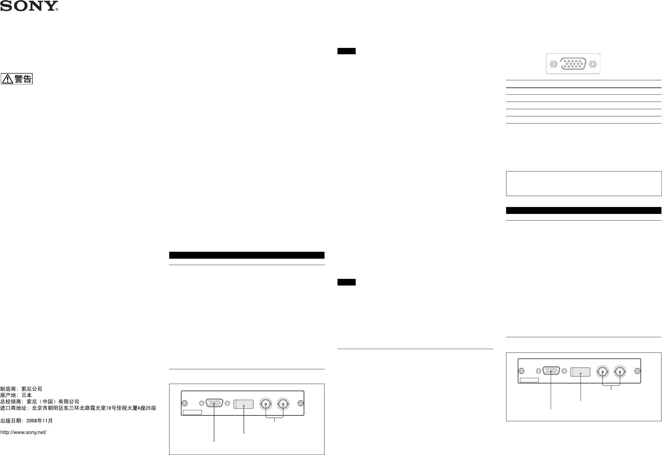
各部の名称と働き
Sony Corporation 2005
Printed in Japan 2008.11.13
3-869-801-05(1)
電気製品は、安全のための注意事項を守らないと、
火災や人身事故になることがあります。
1MONITOR
(モニター出力)端子(D-sub15ピン)
アナログ映像出力です。DIPスイッチの設定によって、出力信号を切り換える
ことが できます 。
2DIPスイッチ
MONITOR端子の出力条件を設定します。
ご注意
装着した機器の電源を切ってからDIPスイッチを切り換えてください。
スイッチ1
(VD/Sync)
MONITOR端子の14ピンから出力される信号を切り換えます。
上( Sync):複合同期信号(3 値シンク)が出力されます。(工場設定)
下( V D ):垂直同期信号が出力されます。
スイッチ2
(Sync)
RGB出力を選択しているとき、R/G/B各信号に同期信号を付加するかどうか
を選択します。
上(Add Sync):R/G/B各信号に同期信号が付加されて出力されます。(工
場設定)
下( No Sync):同期信号は付加されません。
スイッチ3
(RGB/YPbPr)
MONITOR端子のコンポーネント出 力を 切り換えます。
上( YPbPr):コンポ ーネント信 号を出 力します。(工場設定)
下( RGB):RGB 信号を出力します。
スイッチ4、
5、
6
機能しません。工場設定(上)のままで使用してください。
スイッチ7
(Advance)
同期信号に対して映像出力をアドバンスさせるかどうか を 選 択します 。
上( No Advance):アドバンスなし(工場設定)。
下( Advance):89 または 90ライン(HD)アドバンスさせます。
スイッチ8
(89H/90H)
スイッチ 7 でアドバンス選択 時に映 像出力と同期信号との位相差を設定しま
す。
上( 89H):89ライン(HD)アドバンスさせます(工場設定)。
下( 90H):90ライン(HD)アドバンスさせます。
ご注意
スイッチ 7、8 は、アドバンス機能対応バージョンのHDカメラインターフェースユ
ニットHFU-X310に装着したときのみ有効です。
◆スイッチ 7、8の機能について詳しくは、 HFU-X310のオペレーションマニュアル
をご覧ください。
3HD-SDI
(デジタル出力)端子(BNC型)
デジタル映像出力です。2つの端子からは同じ信号が出力されます。
仕様
一般
電源 +12 V DC、 400 mA (装着した機器より供給)
動作温度 5℃∼40℃
保存温度 –20℃∼+60℃
保存湿度 20%∼90% (相対湿度、結露なし)
外形寸法 134×26.2×112.8 mm(幅 /高さ/奥行き)
(端子部および取り付けネジ部含まず)
質量 約0.16 kg
出力端子
HD-SDI BNC型(2)
SMPTE292M準拠、75Ω
MONITOR D-sub 15ピン(1)
出力レベル コンポーネント:
Y:1.0 Vp-p
Pb、 Pr:0.7 Vp-p、75 Ω
R/G/B:1.0 Vp-p、75Ω
HD/VD:TTLレベル
SYNC:0.6 Vp-p、75Ω(3値シンク)
ピン配列
ピン 信号 ピン 信号 ピン 信号
1R/Pr (X) 6 R/Pr (G) 11 NC
2G/Y (X) 7 G/Y (G) 12 NC
3B/Pb (X) 8 B/Pb (G) 13 HD
4NC9NC 14 VD/SYNC
5GND 10GND15NC
付属品
オペレーションマニュアル(1)
本機の仕様および外観は、改良のため予告なく変更することがありますが、ご
了承ください。
お使いになる前に、必ず動作確認を行ってください。故障その他に伴う営
業上の機会損失等は保証期間中および保証期間経過後にかかわらず、補
償はいたしかねますのでご了承ください。
English
Overview
The HFBK-HD1 is an optional board designed to be installed in
the following apparatuses:
•HFU-X310 HD Camera Interface Unit
•BRC-H700 HD 3CCD Color Video Camera
•BRU-H700 HD Optical Multiplex Unit
The board supplies images from the color video camera connected
to the apparatus that accommodates the board as HD-SDI signals.
It also has a 15-pin connector for analog output (Y/Pb/Pr or RGB).
When the board is installed in an HFU-X310 that supports
embedded audio and time code, the embedded audio and time code
of HD-SDI signal supplied to the HFU-X310 are embedded in the
HD-SDI output signal.
Locations and Functions of Parts
1MONITOR connector (D-sub 15-pin)
For analog video output. The configuration of the output signal
can be specified by setting the DIP switches.
3 HD-SDI端子
1 MONITOR端子
2 DIPスイッチ (カバー内)
HFBK-HD1
MONITOR HD-SDI HD-SDI
51
6
10
15 11
3 HD-SDI connectors
2 DIP switches (behind the cover)
1 MONITOR connector
HFBK-HD1
MONITOR HD-SDI HD-SDI
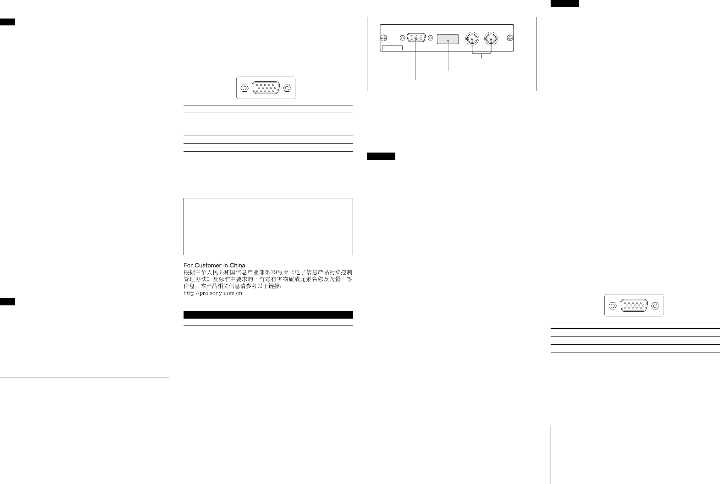
51
6
10
15 11
51
6
10
15 11
2DIP switches
To configure the type of output from the MONITOR connector.
Note
Turn the apparatus that accommodates the board off before
changing the DIP switch settings.
Switch 1 (VD/Sync)
Selects the signal to be supplied from pin 14 of the MONITOR
connector:
Upper (Sync): To output composite sync (3-level sync) (factory
setting)
Lower (VD): To output vertical sync
Switch 2 (Sync)
Specifies whether to add a sync signal to each of the R, G, and B
signals when the RGB output is selected:
Upper (Add Sync): To output each of the R, G, and B signals with
a sync signal (factory setting)
Lower (No Sync): Not to add any sync
Switch 3 (RGB/YPbPr)
Selects the type of component output from the MONITOR
connector:
Upper (YPbPr): To output component signals (factory setting)
Lower (RGB): To output RGB signals
Switches 4, 5, 6
Not used. Leave them in their factory-setting positions (upper).
Switch 7 (Advance)
Specifies whether to advance video output with respect to a sync
signal:
Upper (No Advance): Not to advance (factory setting)
Lower (Advance): To advance 89 or 90 lines (HD)
Switch 8 (89H/90H)
Selects the phase difference to advance when “Advance” is
selected with Switch 7:
Upper (89H): To advance 89 lines (HD) (factory setting)
Lower (90H): To advance 90 lines (HD)
Note
Switches 7 and 8 are valid only when the board is installed in an
HFU-X310 of a version that supports the Advance function.
For details on the functions of Switches 7 and 8, refer to the Operation
Manual of the HFU-X310.
3HD-SDI connectors (BNC type)
For digital video output. The two connectors output the same
signal.
Specifications
General
Power requirements +12 V DC, 400 mA (supplied from the
apparatus that accommodates the board)
Operating temperature
5°C to 40°C (41°F to 104°F)
Storage temperature –20°C to +60°C (–4°F to +140°F)
Storage humidity
20% to 90%
(relative, no condensation)
Dimensions 134 × 26.2 × 112.8 mm (w/h/d)
(53/8 × 11/16 × 41/2 inches)
not including projecting parts
Mass Approx. 0.16 kg (6 oz)
Outputs
HD-SDI BNC type (2)
Conforms to SMPTE292M, 75 Ω
MONITOR D-sub 15-pin (1)
Output level Component:
Y: 1.0 Vp-p
Pb, Pr: 0.7 Vp-p, 75 Ω
R/G/B: 1.0 Vp-p, 75 Ω
HD/VD: TTL level
Sync: 0.6 Vp-p, 75 Ω (3-level sync)
Pin assignment
Pin Signal Pin Signal Pin Signal
1R/Pr (X) 6 R/Pr (G) 11 NC
2G/Y (X) 7 G/Y (G) 12 NC
3B/Pb (X) 8 B/Pb (G) 13 HD
4NC9NC 14 VD/SYNC
5GND 10 GND 15 NC
Supplied accessory
Operation Manual (1)
Design and specifications are subject to change without notice.
Note
Always verify that the unit is operating properly before use. SONY WILL
NOT BE LIABLE FOR DAMAGES OF ANY KIND INCLUDING, BUT
NOT LIMITED TO, COMPENSATION OR REIMBURSEMENT ON
ACCOUNT OF THE LOSS OF PRESENT OR PROSPECTIVE
PROFITS DUE TO FAILURE OF THIS UNIT, EITHER DURING THE
WARRANTY PERIOD OR AFTER EXPIRATION OF THE WARRANTY,
OR FOR ANY OTHER REASON WHATSOEVER.
Français
Description générale
La HFBK-HD1 est une carte en option conçue pour être installée
dans les appareils suivants :
•Interface caméra HD HFU-X310
• Camera vidéo couleur HD 3CCD BRC-H700
•Module multiplex optique HD BRU-H700
La carte fournit des images provenant d’une caméra vidéo couleur
connectée à l’appareil qui contient la carte comme signaux HD-
SDI. Elle comporte aussi un connecteur à 15 broches pour une
sortie analogique (Y/Pb/Pr ou RVB).
Lorsque la carte est installée dans une interface HFU-X310
prenant en charge l’audio intégré et le code temporel, l’audio
intégré et le code temporel du signal HD-SDI fourni à la HFU-
X310 sont intégrés dans le signal de sortie HD-SDI.
Emplacement et fonction des pièces
1Connecteur MONITOR (D-sub 15 broches)
Pour une sortie vidéo analogique. La configuration du signal de
sortie peut être spécifiée en réglant les commutateurs DIP.
2Commutateurs DIP
Pour configurer le type de sortie du connecteur MONITOR.
Remarque
Mettez l’appareil contenant la carte hors tension avant de changer
les réglages des commutateurs DIP.
Commutateur 1 (VD/Synchro)
Permet de sélectionner le signal fourni par la broche 14 du
connecteur MONITOR :
Position supérieure (Synchro) : Sortie d’un signal de synchro
composite (synchro 3 niveaux) (réglage d’usine)
Position inférieure (VD) : Sortie d’un signal de synchro verticale
Commutateur 2 (Synchro)
Permet de spécifier si un signal de synchro sera ajouté à chacun
des signaux R, V et B lorsque la sortie RVB est sélectionnée :
Position supérieure (Ajout de synchro) : Sortie de chacun des
signaux R, V et B avec un signal de synchro (réglage d’usine)
Position inférieure (Pas de synchro) : Pas d’ajout de signal de
synchro
Commutateur 3 (RVB/YPbPr)
Permet de sélectionner le type de signaux composantes sortis par
le connecteur MONITOR :
Position supérieure (YPbPr) : Sortie de signaux composantes
(réglage d’usine)
Position inférieure (RVB) : Sortie de signaux RVB
Commutateurs 4, 5, 6
Non utilisée. Gardez les réglages d’usine tels quels (position
supérieure).
Commutateur 7 (Avance)
Permet de faire avancer ou non la sortie vidéo par rapport au signal
de synchronisation :
Position supérieure (Pas d’avance) : Ne pas faire avancer
(réglage d’usine)
Position inférieure (Avance) : Faire avancer de 89 ou 90 lignes
(HD)
Commutateur 8 (89H/90H)
Permet de sélectionner la différence de phase pour l’avance
lorsque « Avance » est sélectionné avec le commutateur 7 :
Position supérieure (89H) : Faire avancer de 89 lignes (HD)
(réglage d’usine)
Position inférieure (90H) : Faire avancer de 90 lignes (HD)
Remarque
Les commutateurs 7 et 8 ne sont valides que lorsque la carte est
installée dans un HFU-X310 d’une version qui prend en charge la
fonction d’avance.
Pour plus d’informations sur les fonctions des commutateurs 7 et 8,
reportez-vous au mode d’emploi du HFU-X310.
3Connecteurs HD-SDI (type BNC)
Pour une sortie vidéo numérique. Les deux connecteurs sortent le
même signal.
Spécifications
Généralités
Alimentation +12 V CC, 400 mA (fourni par l’appareil
contenant la carte)
Température de fonctionnement
5 °C à 40 °C (41 °F à 104 °F)
Température de rangement
–20 °C à +60 °C (–4 °F à +140 °F)
Humidité de rangement
20 % à 90 % (relatif, sans condensation)
Dimensions 134 × 26,2 × 112,8 mm (l/h/p)
(53/8 × 11/16 × 41/2 pouces)
pièces saillantes non comprises
Poids Environ 0,16 kg (6 oz)
Sorties
HD-SDI Type BNC (2)
Conforme à SMPTE292M, 75 Ω
MONITOR D-sub 15 broches (1)
Niveau de sortie Composantes :
Y: 1,0 Vc-c
Pb, Pr : 0,7 Vc-c, 75 Ω
R/V/B : 1,0 Vc-c, 75 Ω
HD/VD : Niveau TTL
Synchro : 0,6 Vc-c, 75 Ω (synchro 3 niveaux)
Affectation des broches
Broche Signal Broche Signal Broche Signal
1R/Pr (X) 6 R/Pr (G) 11 NC
2V/Y (X) 7 V/Y (G) 12 NC
3B/Pb (X) 8 B/Pb (G) 13 HD
4NC9NC 14 VD/SYNC
5GND 10 GND 15 NC
Accessoires fournis
Mode d’emploi (1)
La conception et les spécifications sont susceptibles d’être
modifiées sans préavis.
Remarque
Vérifiez toujours que l’appareil fonctionne correctement avant
l’utilisation. Sony n'assumera pas de responsabilité pour les
dommages de quelque sorte qu’ils soient, incluant mais ne se
limitant pas à la compensation ou au remboursement, à cause de la
perte de profits actuels ou futurs suite à la défaillance de cet
appareil, que ce soit pendant la période de garantie ou après son
expiration, ou pour toute autre raison quelle qu’elle soit.
3 Connecteurs HD-SDI
2 Commutateurs DIP (derrière le cache)
1 Connecteur MONITOR
HFBK-HD1
MONITOR HD-SDI HD-SDI
