HIWIN CoE Drive User Guide Co E V1.1
User Manual:
Open the PDF directly: View PDF ![]() .
.
Page Count: 86
- HIWIN CoE Drive User Guide
- Table of Contents
- 1. About the User Guide
- 2. EtherCAT Communication
- 3. CiA 402 Drive Profile
- 4. Object Dictionary
- 5. Setting Examples
HIWIN CoE Drive User Guide v1.1
HIWIN Mikrosystem Corp.
HIWIN CoE Drive User Guide
Version 1.1
September 29, 2016
HIWIN CoE Drive User Guide v1.1 Table of Contents
HIWIN Mikrosystem Corp. i
Table of Contents
1. About the User Guide ....................................................................................................... 1
1.1. Instructions before use ........................................................................................... 2
1.2. Safety instructions .................................................................................................. 3
2. EtherCAT Communication ................................................................................................ 7
2.1. Communication specification .................................................................................. 8
2.2. Communication architecture ................................................................................... 9
2.3. EtherCAT state machine ...................................................................................... 11
2.4. PDO mapping ....................................................................................................... 12
2.5. Synchronization mode .......................................................................................... 13
3. CiA 402 Drive Profile ...................................................................................................... 15
3.1. Finite state automation ......................................................................................... 16
3.2. Homing mode ....................................................................................................... 19
3.3. Profile position mode ............................................................................................ 26
3.3.1. Setting of set-point ...................................................................................... 27
3.3.2. Following error protection ........................................................................... 29
3.4. Profile velocity mode ............................................................................................ 30
3.5. Profile torque mode .............................................................................................. 32
3.6. Cyclic synchronous position mode ....................................................................... 33
3.7. Cyclic synchronous velocity mode ........................................................................ 34
3.8. Cyclic synchronous torque mode .......................................................................... 35
3.9. Touch probe function ............................................................................................ 36
4. Object Dictionary ............................................................................................................ 37
4.1. Common object .................................................................................................... 38
4.2. PDO mapping objects .......................................................................................... 39
4.3. Communication objects of Sync manger .............................................................. 40
4.4. Manufacturer defined objects ............................................................................... 42
4.5. Device profile ....................................................................................................... 45
4.6. Objects and device table ...................................................................................... 50
5. Setting Examples ............................................................................................................ 53
5.1. HIWIN CoE drive setting ....................................................................................... 54
5.2. Beckhoff controller (TwinCAT 2) setting ............................................................... 56
5.2.1. DC cycle time setting .................................................................................. 56
5.2.2. EEPROM update ........................................................................................ 60
5.3. Beckhoff controller (TwinCAT 3) setting ............................................................... 62
5.3.1. Communication setting ............................................................................... 62
5.3.2. EEPROM update ........................................................................................ 65
5.4. OMRON controller setting .................................................................................... 67
5.4.1. ESI file update ............................................................................................ 67
5.4.2. Slave ID writing ........................................................................................... 69
5.4.3. Homing example ......................................................................................... 72
5.5. TRIO controller setting.......................................................................................... 77
5.5.1. Communication setting ............................................................................... 77
5.5.2. Motion parameter setting ............................................................................ 79

HIWIN CoE Drive User Guide v1.1 Table of Contents
HIWIN Mikrosystem Corp. ii
Revision History:
Version
Date
Applicability
Remarks
1.0
2014-03-17
D-series CoE drive
Frist release.
1.1
2016-09-29
D-series Drive:
D1COE MDP 0.319 above
D2COE MDP 0.118 above
D1NCOE MDP 0.518 above
Lightening 0.188 above
abily-series:
iKM MDP 0.402 above
Storm 0.002 above
Re-write and re-organize this User Guide
based on Chinese version of HIWIN CoE Drive
User Guide v1.1.
HIWIN CoE Drive User Guide v1.1 Table of Contents
HIWIN Mikrosystem Corp. iii
(This page is intentionally left blank.)

HIWIN CoE Drive User Guide v1.1 1. About the User Guide
HIWIN Mikrosystem Corp. 1
1. About the User Guide
1. About the User Guide ....................................................................................................... 1
1.1. Instructions before use ........................................................................................... 2
1.2. Safety instructions .................................................................................................. 3
HIWIN CoE Drive User Guide v1.1 1. About the User Guide
HIWIN Mikrosystem Corp. 2
1.1. Instructions before use
EtherCAT® is registered trademark and patented technology, licensed by Beckhoff Automation
GmbH, Germany.
Main purposes of this User Guide are to describe EtherCAT communication and CiA 402 drive
profile applied to HIWIN CoE products. About their specifications, dimensions, connections and
wiring, settings and operations, refer to the corresponding User Guide.
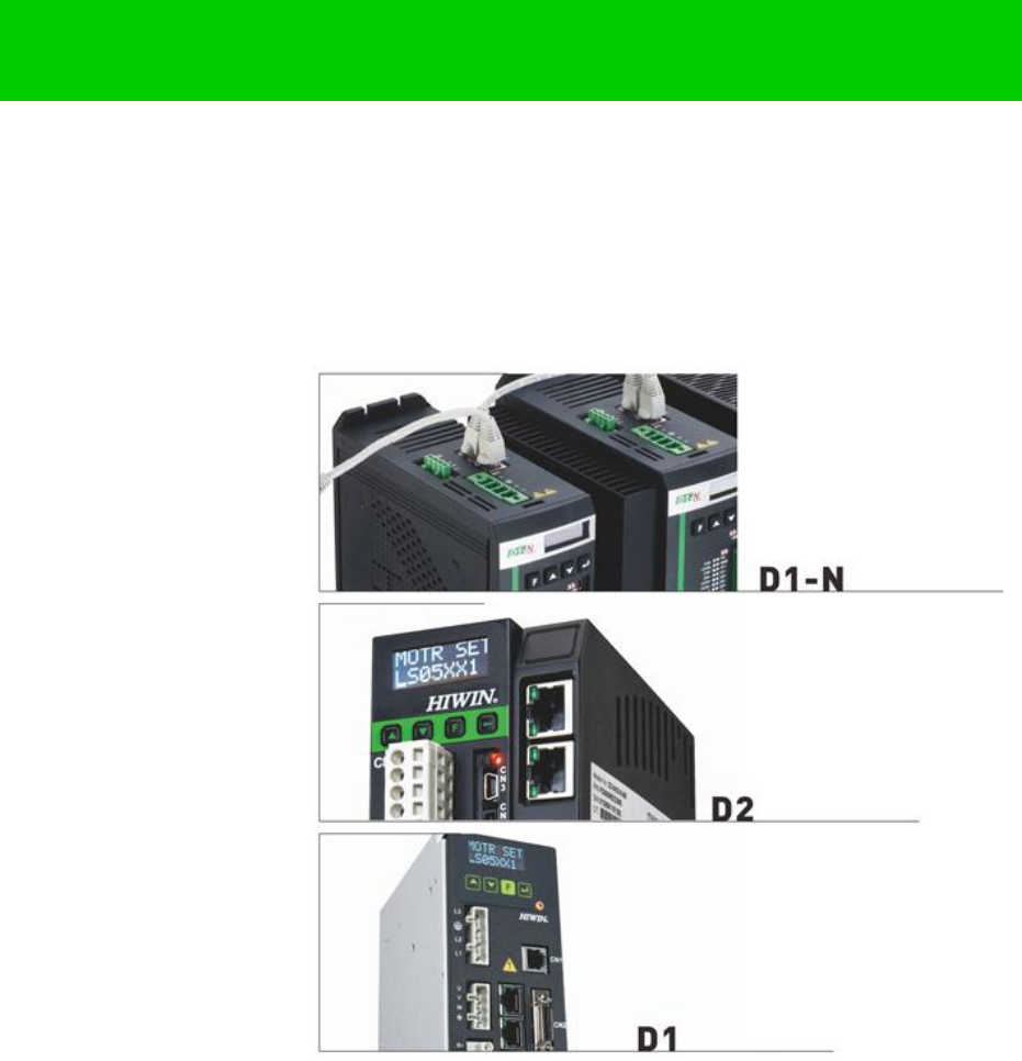
(1) For D1-series drive, refer to “D1 Drive User Guide”. Download path is:
http://www.hiwinmikro.tw/hiwintree/Product_SubType.aspx?type=D1
(2) For D2-series drive, refer to “D2 Drive User Guide”. Download path is:
http://www.hiwinmikro.tw/hiwintree/Product_SubType.aspx?type=D2
(3) For D1-N-series drive, refer to “D1-N Drive User Guide”. Download path is:
http://www.hiwinmikro.tw/hiwintree/Product_SubType.aspx?type=D1-N
(4) For abily-series products, refer to “abilyrobot & abilymotor User Guide”. Download path is:
http://www.hiwinmikro.tw/hiwintree/
Read User Guide carefully before using the product. HIWIN Mikrosystem Corp. (“the Company”)
will not take any responsibility for damages, accidents or injuries caused by installation or use
that is not performed according to these instructions.
Do not dismantle or modify the product. The product has been subject to structural
calculations, computer simulations, and physical tastings to verify its design. Do not
dismantle or modify the product without the consent of professional technicians of the
Company. The Company does not take any responsibility for accidents or damages resulting
from such dismantling or modifications.
Before installing or using the product, check the external appearance and ensure that there is
no damage on the surface of the product. If any damage is identified, please contact the
Company or one of the Company’s distributors immediately.
Refer to the performance specifications on the product label or manufacturer's document
before using the product. Install the product based on these performance limits and
installation instructions indeed.
Read the specification of power voltage on the label before using the product and confirm
that the power supply meets the product requirement. The Company does not take any
responsibility for product damages or personal injuries resulting from incorrect power supply.
Do not use the product over the rated load. The Company does not take any responsibility for
damages or injuries resulting from such misuse.
Do not use the product in an environment where shocks may occur. The company does not
take any responsibility for damages, accidents or injuries resulting from such shocks.
If drive has any error, refer to the troubleshooting of the corresponding user guide. Follow
instructions to turn off drive’s power to do troubleshooting. After the error is eliminated, turn
on drive’s power again.
Do not try to repair any produce malfunction. The product can only be repaired by qualified
technicians.
The warranty period is one year from the ex-factory date. The Company does not take any
responsibility for product replacement or repair caused by inappropriate use or natural disasters.
(Refer to notes and installation instructions in User Guide.)
HIWIN CoE Drive User Guide v1.1 1. About the User Guide
HIWIN Mikrosystem Corp. 3
1.2. Safety instructions
Read User Guide carefully before installation, transportation, maintenance and inspection,
and ensure that the product is used correctly.
Users should read EM information, safety information, and all related instructions before
using the product.
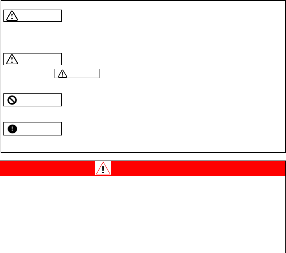
The safety instructions in User Guide are categorized into “Warning”, “Attention”, “Prohibited”,
and “Required”.
Warning
Inappropriate operation may cause dangers resulting in the serious injury or death.
Inappropriate operation may cause dangers resulting in the disability, minor injury or material
damage.
Attention
Actions marked Attention may have serious consequences under different situations.
All such instructions are important and must be followed.
Prohibited
Indicate that the action is forbidden and must not be done.
Required
Indicate that the action is compulsory and must be done.
Danger
‧Always ensure that drive is correctly earthed by using PE bar in the switch cabinet as
reference potential. Safety is not guaranteed if there is no low-ohm earthing.
‧Power connections may be live if motor is not moving. Never disconnect the
electrical connections of motor and drive as live. In the worst case, electric arcs
may form and cause personal injury and damage as contacts.
‧After disconnecting drive from supply voltages, wait at least five minutes before
touching live parts (e.g. contacts, threaded bolts etc.) or breaking connections. For
your own safety, measure the voltage in the intermediate circuit and wait until it has
fallen below 40 Vdc.

HIWIN CoE Drive User Guide v1.1 1. About the User Guide
HIWIN Mikrosystem Corp. 4
Usage instructions
Warning
Do not touch the terminal or inside part when it is powered to
avoid electric shock.
Do not touch the terminal or inside within 10 minutes from power
off. The residual voltage may cause electric shock.
Do not change the wiring when it is powered to avoid electric
shock.
Do not cut the cable, apply too much stress to it, or place heavy
objects on it. Laying the cable between objects may cause fire or
electric shock.
Attention
Do not install the product in a place exposed to moisture or
erosion, or in an environment containing ignitable gas. Do not
use the product close to any flammable objects.
Storage
Prohibited
Do not store the product in a place exposed to water, moisture,
direct sunlight, harmful gas, or liquids.
Handling
Attention
Be careful of handling the product and avoid damaging it.
Use appropriate handling methods and do not apply too much
pressure to the case.
The product shall not be stacked too high to avoid collapsing.
Installation location
Required
Do not install the product in a place exposed to high
temperatures, high humidity, or flying dust, iron powder, or
cutting powder.
Install the product in a place where the ambient temperature
meets the requirement of User Guide. Use one cooling fan if the
temperature is potentially high.
Do not install the product in a place exposed to direct sunlight.
Since the product does not have one waterproof or
moisture-proof case, do not use it outdoors or install it in a place
where water or other liquid exists.
Install the product in a place with low vibrations.
When motor is moving continuously, heat is generated due to
the use frequency. Use one cooling fan, or set to standby status
when motor stops. So that, the ambient temperature of motor
does not exceed its specified value.

HIWIN CoE Drive User Guide v1.1 1. About the User Guide
HIWIN Mikrosystem Corp. 5
Installation
Attention
Do not place any heavy objects on the product to avoid damage.
Do not mix with debris to avoid fire.
Ensure that the product is installed in the required direction to
avoid fire.
Protect the product from strong impact to avoid collapse or
damage.
The weight of mounting body must be taken into account during
installation. Inappropriate installation may cause damage.
Install the product on a metal or noncombustible object to avoid
fire.
Wiring
Attention
Be correct and reliable wiring, otherwise it will cause motor to out
of control or burn out, and make damage or fire.
Operation and transportation
Attention
Ensure that the specification of power source is correct to avoid
damage or fire.
The motor may suddenly start after power is restored instantly.
Do not come too close to machine.
Required
Wire an external emergency stop line to stop the operation and to
cut off power at any time.
Maintenance
Prohibited
Do not dismantle or modify the product.
Do not attempt to repair any product malfunction. Please send it
back to professional technicians of the Company for repair.
HIWIN CoE Drive User Guide v1.1 1. About the User Guide
HIWIN Mikrosystem Corp. 6
(This page is intentionally left blank.)

HIWIN CoE Drive User Guide v1.1 2. EtherCAT Communication
HIWIN Mikrosystem Corp. 7
2. EtherCAT Communication
2. EtherCAT Communication ................................................................................................ 7
2.1. Communication specification .................................................................................. 8
2.2. Communication architecture ................................................................................... 9
2.3. EtherCAT state machine ...................................................................................... 11
2.4. PDO mapping ....................................................................................................... 12
2.5. Synchronization mode .......................................................................................... 13

HIWIN CoE Drive User Guide v1.1 2. EtherCAT Communication
HIWIN Mikrosystem Corp. 8
2.1. Communication specification
Table 2-1
EtherCAT
communication
Communication
standards
IEC 61158 Type 12
IEC 61800-7 CiA 402 drive profile
Physical layer
100BASE-TX (IEEE802.3)
SyncManager
SM0 – Mailbox output (master slave)
SM1 – Mailbox input (slave master)
SM2 – Process data outputs
SM3 – Process data inputs
Process data
Dynamic PDO mapping
Mailbox (CoE)
SDO request
Synchronization
Free run mode
DC mode (DC cycle: 250us, 500us, 1ms, 2ms, 4ms)
CiA 402 drive
profile
Homing mode
Profile position mode
Profile velocity mode
Profile torque mode
Cyclic synchronization position mode
Cyclic synchronization velocity mode
Cyclic synchronization torque mode
Touch probe function
HIWIN CoE Drive User Guide v1.1 2. EtherCAT Communication
HIWIN Mikrosystem Corp. 9
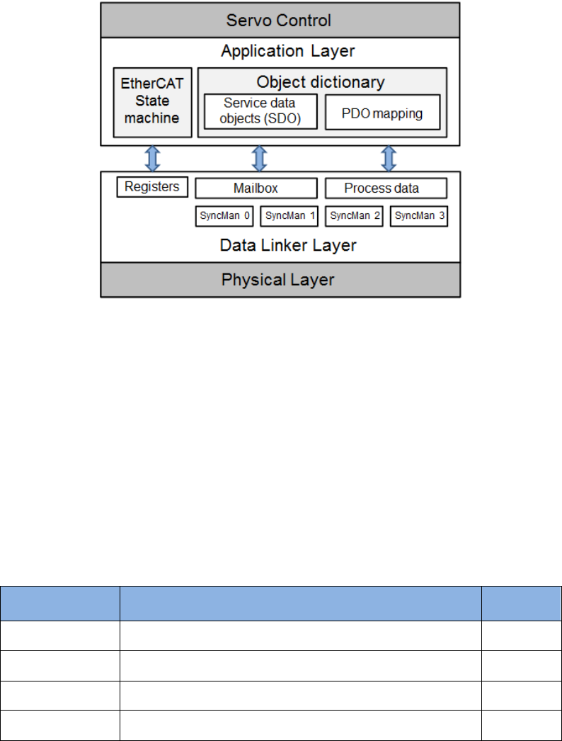
2.2. Communication architecture
The communication architecture of network module for CoE (CANopen over EtherCAT) drive
can be divided into two layers: data link layer (DL) and application layer (AL), as shown in Fig.
2-1. The data link layer manages the interface of data transmission between the master and
slave stations. On the other hand, the application layer implements the function of state
transition compatible between CiA 402 (CANopen Drive Communication Protocol) and
EtherCAT.
Fig. 2-1
There are two modes of data transition between application layer and data link layer:
time-critical and non-time-critical data transitions. The time-critical data means that the data
transition must be completed within a specific time. If not, it may cause the control failure. The
time-critical data is normally used in the periodic communication and is called as cyclic process
data communication. On the other hand, the non-time-critical data can be completed by using
the non-periodic communication, i.e., using the non-periodic mailbox communication.
Process data object (PDO) in the application layer is consisted of objects which can be mapping
to PDO and contents of process data defined in PDO mapping. It reads and writes data via
periodic process data communication. However, service data object (SDO) reads and writes
data in the object dictionary via mailbox data communication. Table 2-2 shows the layout
between the process data of data link layer and the Sync Manager of mailbox data
communication.
Table 2-2
Sync Manager
Purpose
Starting
address
Sync Manager 0
Mailbox data communication - receive Mailbox
0x1800
Sync Manager 1
Mailbox data communication - transmit Mailbox
0x18F6
Sync Manager 2
Process data communication - receive PDO (RxPDO)
0x1000
Sync Manager 3
Process data communication - transmit PDO (TxPDO)
0x1100
HIWIN CoE Drive User Guide v1.1 2. EtherCAT Communication
HIWIN Mikrosystem Corp. 10
Drive supporting EtherCAT communication should provide one file for master station to plan the
layout and communication between the master and slave stations. This file is called as ESI
(EtherCAT slave information) and is made by the extensible markup language (xml). ESI files for
HIWIN CoE drives are given as follows:
(1) For D1-N CoE drive: D1NCOE_.xml
(2) For D1 CoE drive: D1COE_.xml
(3) For D2 CoE drive: D2COE_.xml
(4) For abily series products: abily_.xml
where denotes the release date of ESI file. For example, 20150922 means the
corresponding file is released by September 22, 2015.
HIWIN CoE Drive User Guide v1.1 2. EtherCAT Communication
HIWIN Mikrosystem Corp. 11
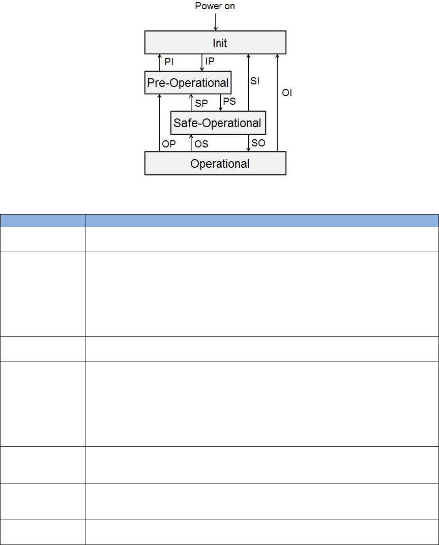
2.3. EtherCAT state machine
EtherCAT state machine (ESM) is used to coordinate applications between the master and slave
stations from start-up to operation. State transition is normally started by the master station.
After receiving the request of state transition, the slave station begins to change state. State
transitions of EtherCAT state machine are shown in Fig. 2-2. When the slave station begins to
transit from “Initialization” state to “Operational” state, it must follow the process of Initialization
(Init) Pre-Operational (Pre-Op) Safe-Operational (Safe-Op) Operational (Op). Leapfrog
switch is not allowed.
Fig. 2-2
Table 2-3
State
Description
Init
(1) No mailbox communication.
(2) No process data communication.
IP
(Init to Pre-Op)
(1) Master station sets following registers for mailbox communication:
- DL Address;
- Sync Manager channels.
(2) Master station initializes the synchronization of distribute clock.
(3) Master station requests to enter “Pre-Op” state.
- Setting AL Control register.
(4) Wait for response from AL Status register.
Pre-Op
(1) Able to use mailbox communication.
(2) No process data communication.
PS
(Pre-Op to
Safe-Op)
(1) Master station uses mailbox communication to set contents of PDO
mapping.
(2) Master station allocates Sync Manager channels for process data
communication.
(3) Master station requests to enter “Safe-Operational” state.
- Setting AL Control register.
(4) Wait for response from AL Status register.
Safe-Op
(1) Able to use mailbox communication.
(2) Able to use process data communication.
- Only input type of process data communication being able to use.
SO
(Safe-Op to Op)
(1) Master station requests to enter “Operational” state.
- Setting AL Control register.
(2) Wait for response from AL Status register.
Op
(1) Able to use mailbox communication.
(2) Able to use both output and input types of process data communication.

HIWIN CoE Drive User Guide v1.1 2. EtherCAT Communication
HIWIN Mikrosystem Corp. 12
2.4. PDO mapping
Based on user’s requirements, the transmitted data between the master and slave stations via
process data communication can be changed. Receiving process data communication can be
implemented by setting RxPDO mapping object 0x1600; while transmitting process data
communication can be implemented by setting TxPDO mapping object 0x1A00. The default of
PDO mapping allocated for process data communication is shown in Table 2-4. For HIWIN CoE
products, the maximum number of allowed RxPDO or TxPDO is 7, and the total size of RxPDO
or TxPDO is 20 bytes.
Table 2-4
Mapping
objects
Data objects
RxPDO
(0x1600)
Controlword
(0x6040)
Target
position
(0x607A)
--
--
--
--
--
TxPDO
(0x1A00)
Statusword
(0x6041)
Position
actual value
(0x6064)
Following error
actual value
(0x60F4)
--
--
--
--
If users want to change the allocation of objects for process data communication, drive must be
at “Pre-Operational” state of EtherCAT state machine. The procedure is done via mailbox data
communication. The procedure of allocation is described as follows:
(1) Change EtherCAT state machine of drive to “Pre-Operational” state.
(2) Close PDO allocation of Sync Manager.
This can be done by setting sub-index 0 of communication objects 0x1C12 and 0x1C13,
where 0x1C12 is used to set the PDO allocation of Sync Manager for RxPDO and 0x1C13 is
used to set the PDO allocation of Sync Manager for TxPDO.
(3) Configure required data objects.
If data objects need to be transmitted by RxPDO, just assign them to sub-indexes 1~7 of
mapping object 0x1600. If by TxPDO, just assign them to sub-indexes 1~7 of 0x1A00.
(4) Enable PDO allocation of Sync Manager.
Set sub-indexes 0 of 0x1C12 and 0x1C13 to 1 to enable PDO transmission.
(5) Change EtherCAT state machine of drive to “Operational” state.
HIWIN CoE Drive User Guide v1.1 2. EtherCAT Communication
HIWIN Mikrosystem Corp. 13
2.5. Synchronization mode
HIWIN CoE drive provides two modes of synchronization: free-run mode and distributed clocks
(DC) mode. The master station configures the synchronization mode by setting register 0x0980
of EtherCAT slave controller (ESC).
(1) Free-run mode
Set ESC register 0x0980 to be 0000h to enable free-run mode. This mode completes the
synchronization function via the event of ESC application layer (register 0x0220). Its bits 10
and 11 are the flag generated by data transmission event. Drive detects these two bits to
trigger the transmission of PDO data.
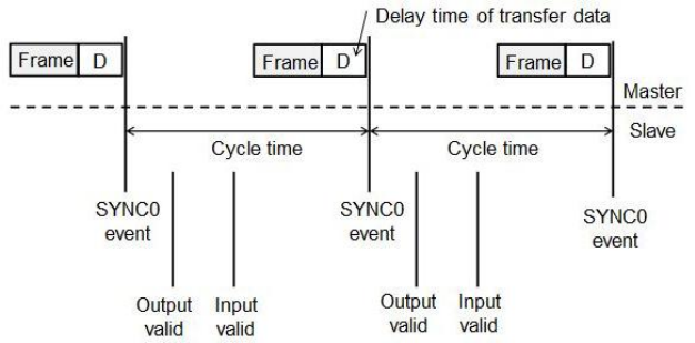
(2) DC mode
Set ESC register 0x0980 to be 0300h to enable DC mode. This mode completes the
synchronization function via the mechanism of distribute clock. Drive takes the internal
SYNC0 event generated by reference clock to complete it. The diagram of synchronization
with DC reference clock is shown in Fig. 2-3.The supported cycle times of drive are 250us,
500us, 1ms, 2ms, and 4ms.
Fig. 2-3
HIWIN CoE Drive User Guide v1.1 2. EtherCAT Communication
HIWIN Mikrosystem Corp. 14
(This page is intentionally left blank.)

HIWIN CoE Drive User Guide v1.1 3. CiA 402 Drive Profile
HIWIN Mikrosystem Corp. 15
3. CiA 402 Drive Profile
3. CiA 402 Drive Profile ...................................................................................................... 15
3.1. Finite state automation ......................................................................................... 16
3.2. Homing mode ....................................................................................................... 19
3.3. Profile position mode ............................................................................................ 26
3.3.1. Setting of set-point ...................................................................................... 27
3.3.2. Following error protection ........................................................................... 29
3.4. Profile velocity mode ............................................................................................ 30
3.5. Profile torque mode .............................................................................................. 32
3.6. Cyclic synchronous position mode ....................................................................... 33
3.7. Cyclic synchronous velocity mode ........................................................................ 34
3.8. Cyclic synchronous torque mode .......................................................................... 35
3.9. Touch probe function ............................................................................................ 36
HIWIN CoE Drive User Guide v1.1 3. CiA 402 Drive Profile
HIWIN Mikrosystem Corp. 16
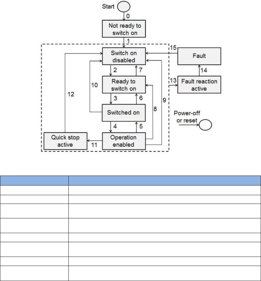
3.1. Finite state automation
The servo drive utilizes the finite sate automation (FSA) of CANOpen to define its state with the
corresponding servo control function. The master station uses Controlword (object 0x6040) to
control the state transition of drive; while drive uses Statusword (object 0x6041) to response the
current status of drive to master station. The flow chart of FSA state transition is shown in Fig.
3-1, and the definition of each state is given in Table 3-1.
Fig. 3-1
Table 3-1
State
Definition
Not ready to switch on
Drive is not at the ready state.
Switch on disabled
The main power of drive is off and motor cannot be enabled.
Ready to switch on
The main power of drive is waiting to be turned on, but motor cannot
be enabled.
Switched on
The main power of drive is turned on, and motor can be enabled by
Controlword.
Operation enabled
Motor has been enabled and drive can be operated normally.
Quick stop active
Drive uses Quick stop deceleration (object 0x6085) to decelerate and
stop motor.
Fault reaction active
Drive error occurred and the correspondiing action is started.
Fault
Drive error occurred and the corresponding action was done. Drive
already disabled motor at this state.
Table 3-2 describes the bit definition of Controlword (object 0x6040) used by the master station
and Table 3-3 the shows command of state transition.

HIWIN CoE Drive User Guide v1.1 3. CiA 402 Drive Profile
HIWIN Mikrosystem Corp. 17
Table 3-2
Bit of Controlword
Definition
0
Switch on
1
Enable voltage
2
Quick stop
3
Enable operation
4 - 6
Operation-mode specific
7
Fault reset
8
Halt
9
Operation-mode specific
10
Reserved
11 - 15
Manufacturer specific
Table 3-3
Bit
Command
Bit 7
Bit 3
Bit 2
Bit 1
Bit 0
Transition
event
Shutdown
0
X
1
1
0
2, 6, 8
Switch on
0
0
1
1
1
3
Switch on + enable operation
0
1
1
1
1
3+4
Enable operation
0
1
1
1
1
4
Disable operation
0
0
1
1
1
5
Disable voltage
0
X
X
0
X
7, 9, 10, 12
Quick stop
0
X
0
1
X
7, 10, 11
Fault reset
0->1
X
X
X
X
15
Table 3-2 describes the bit definition of Statusword (object 0x6041) responded by drive and
Table 3-3 shows the response of current status.
Table 3-4
Bit of Statusword
Definition
0
Ready to switch on
1
Switched on
2
Operation enabled
3
Fault
4
Voltage enabled
5
Quick stop
6
Switch on disabled
7
Warning
8
Manufacturer specific
9
Remote
10
Target reached
11
Internal limit active
12, 13
Operation-mode specific
14, 15
Manufacturer specific

HIWIN CoE Drive User Guide v1.1 3. CiA 402 Drive Profile
HIWIN Mikrosystem Corp. 18
Table 3-5
Bit
Status
Bit 6
Bit 5
Bit 3
Bit 2
Bit 1
Bit 0
Not ready to switch on
0
X
0
0
0
0
Switch on disabled
1
X
0
0
0
0
Ready to switch on
0
1
0
0
0
1
Switch on
0
1
0
0
1
1
Operation enabled
0
1
0
1
1
1
Quick stop active
0
0
0
1
1
1
Fault reaction active
0
X
1
1
1
1
Fault
0
X
1
0
0
0
HIWIN CoE Drive User Guide v1.1 3. CiA 402 Drive Profile
HIWIN Mikrosystem Corp. 19
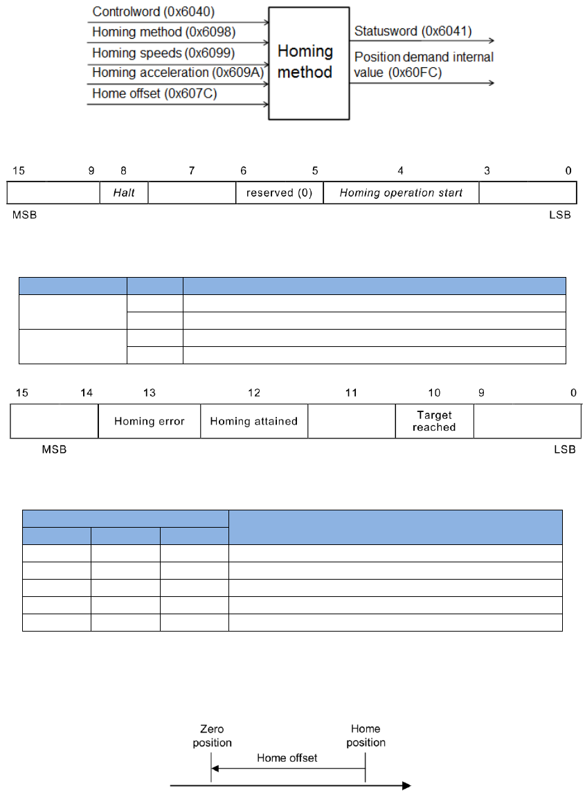
3.2. Homing mode
The relationship of input and output objects for homing (hm) mode is described in Fig. 3-2. The
bit definition of Controlword for hm mode is given in Fig. 3-3 and the supported functions are
described in Table 3-6. The bit definition of Statusword for hm mode is shown in Fig. 3-4, and the
homing statuses are defined in Table 3-7.
Fig. 3-2
Fig. 3-3 Controlword for homing mode
Table 3-6
Bit
Value
Definition
4
0
Stop or do not start homing procedure.
1
Start or continue homing procedure.
8
0
Enable bit 4.
1
Stop motor based on Homing acceleration (object 0x609A).
Fig. 3-4 Statusword for homing mode
Table 3-7
Bit of Statusword
Definition
13
12
10
0
0
0
Homing procedure is in progress.
0
0
1
Homing procedure is interrupted or not started.
0
1
1
Homing procedure is completed successfully.
1
0
0
Homing error occurred and velocity is not 0.
1
0
1
Homing error occurred and velocity is 0.
A. Home offset
During homing procedure, if Home offset (object 0x607C) is not 0, the found home
position is set to be the value of Home offset.
Fig. 3-5
See Table 3-2
See Table 3-2
See Table 3-2
See Table 3-4
See Table 3-4
See Table 3-4
HIWIN CoE Drive User Guide v1.1 3. CiA 402 Drive Profile
HIWIN Mikrosystem Corp. 20
B. Start homing procedure
Steps of stating homing procedure are described as follows:
(1) Set object 0x6060 to be 6 to change drive mode to homing mode.
(2) Set object 0x6098 to be the required homing method. Homing methods supported by
HIWIN CoE drive are given in Table 3-8.
(3) Set Homing acceleration (object 0x609A), Homing speeds (objects 0x6099:01 and
0x6099:02), and Home offset (object 607C).
Note. Object 0x6099:01 is the speed for searching limit switch and home switch. It is
the faster speed. Object 0x6099:02 is the speed for searching index, and is the slower
speed.
(4) Set bit 1 of Controlword (object 0x6040) to be 1 to start homing procedure.
(5) Wait for bits 10 and 12 of Statusword to be 1. This means that the homing procedure
is completed successfully.
(6) Clear bit 4 of Controlword to be 0.
After the homing procedure is completed, there are two following methods to restart
homing procedure.
(1) For the case of bit 4 of Controlword being 1, set Mode of operation (object 0x6060) to
be other supported operation mode. Then, set object 0x6060 back to be 6 (i.e.,
homing mode). Now, the homing procedure can be restarted.
(2) For the case of Mode of operation (object 0x6060) being 6, set bit 4 of Controlword to
be 0, and then set this bit back to be 1. Now, the homing procedure can be restarted.
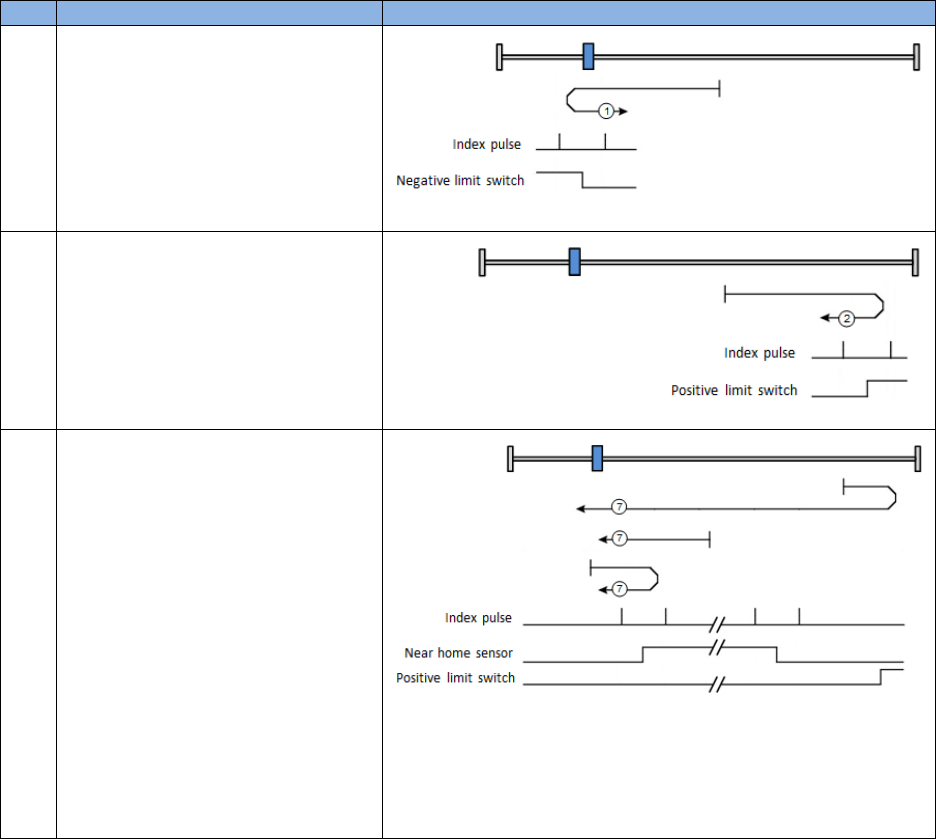
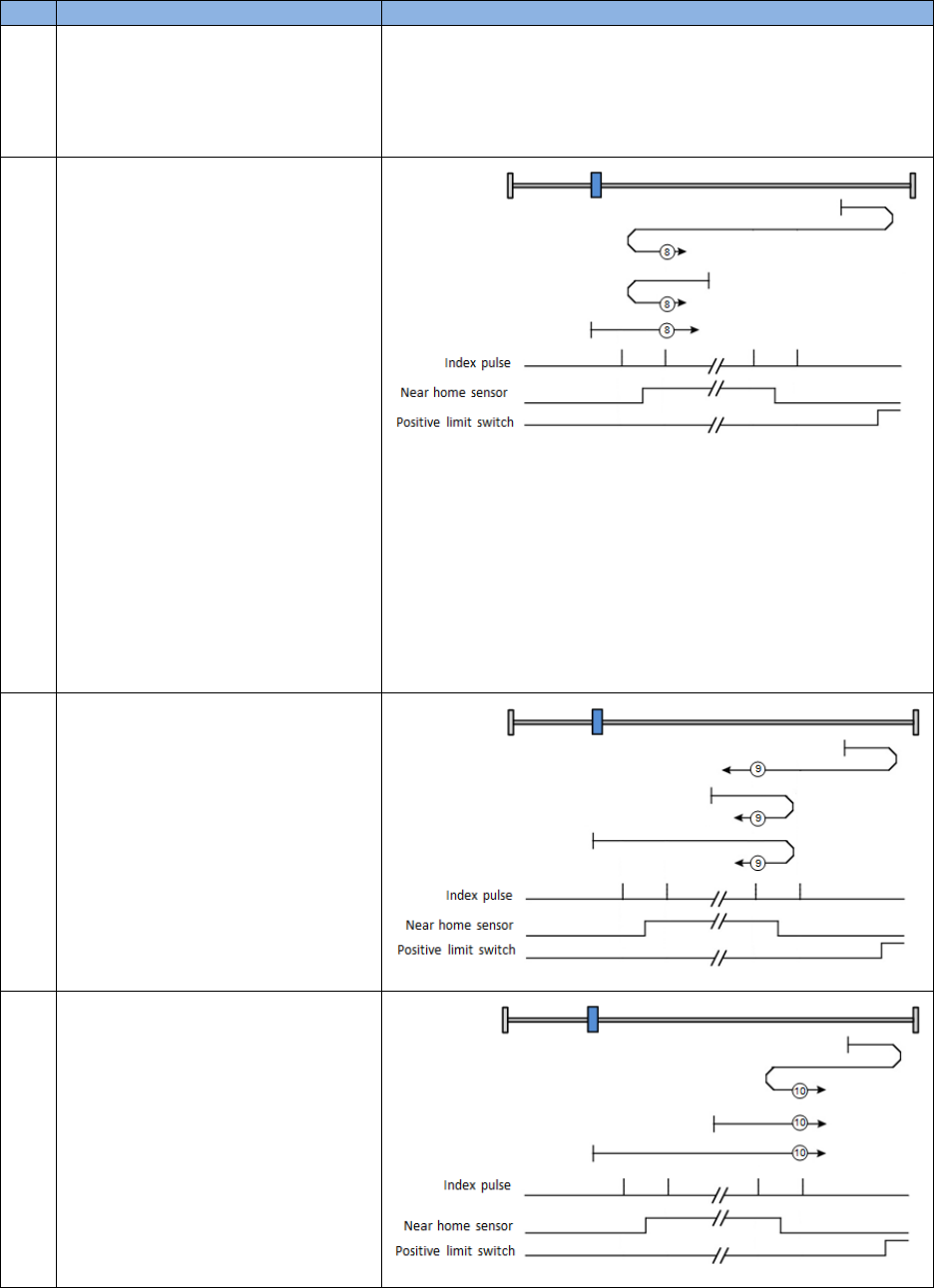
Table 3-8
No.
Description
Explanation
1
Homing on negative limit switch
and index pulse:
Motor searches negative limit
swtich in the negative direction by
using faster speed. After
searched, motor searches index in
the positive direction by using
slower speed.
2
Homing on positive limit switch
and index pulse:
Motor searches positive limit
swtich in the positive direction by
using faster speed. After
searched, motor searches index in
the negative direction by using
slower speed.
7
Homing on home switch and
index pulse – positive initial
motion, left edge of home
switch, left-side index:
(1) Outside home switch: Motor
searches the left edge of
home switch in the positive
direction by using faster
speed. After searched, motor
searches the left-side index of
this signal in the negative
direction by using slower
speed.
(2) Inside home switch: Motor
searches the left edge of
home switch in the negative
direction by using faster
HIWIN CoE Drive User Guide v1.1 3. CiA 402 Drive Profile
HIWIN Mikrosystem Corp. 21
No.
Description
Explanation
speed. After searched, motor
searches the left-side index of
this signal in the negative
direction by using slower
speed.
8
Homing on home switch and
index pulse – positive initial
motion, left edge of home
switch, right-side index:
(1) Outside home switch: Motor
searches the left edge of
home switch in the positive
direction by using faster
speed. After searched, motor
searches the right-side index
of this signal in the positive
direction by using slower
speed.
(2) Inside home switch: Motor
searches the left edge of
home switch in the negative
direction by using faster
speed. After searched, motor
searches the right-side index
of this signal in the positive
direction by using slower
speed.
9
Homing on home switch and
index pulse – positive initial
motion, right edge of home
switch, left-side index:
Motor searches the right edge of
home switch in the positive
direction by using faster speed.
After searched, motor searches
the left-side index of this signal in
the negative direction by using
slower speed.
10
Homing on home switch and
index pulse – positive initial
motion, right edge of home
switch, right-side index:
Motor searches the right edge of
home switch in the positive
direction by using faster speed.
After searched, motor searches
the right-side index of this signal in
the positive direction by using
slower speed.
HIWIN CoE Drive User Guide v1.1 3. CiA 402 Drive Profile
HIWIN Mikrosystem Corp. 22
No.
Description
Explanation
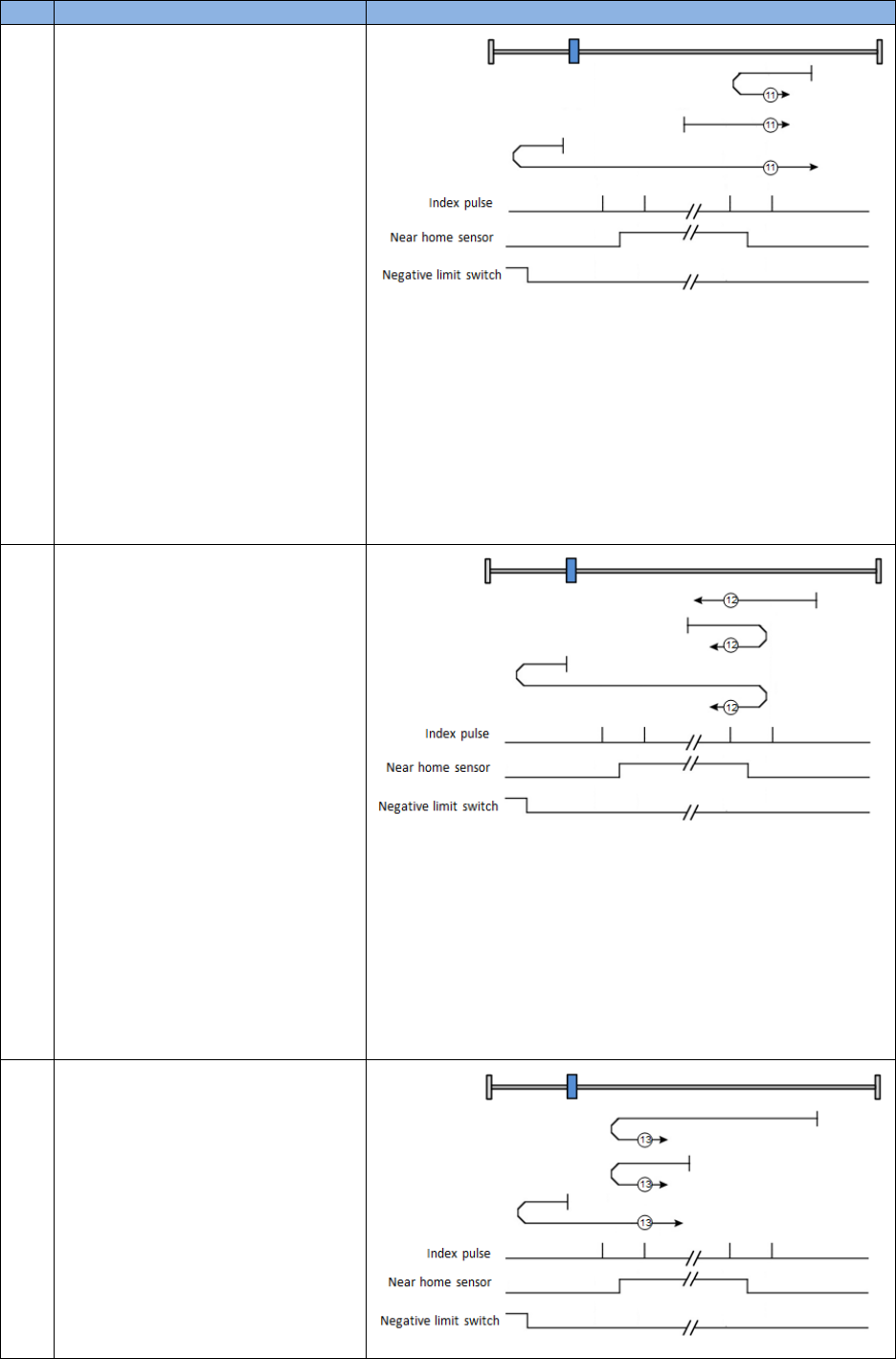
11
Homing on home switch and
index pulse – negative initial
motion, right edge of home
switch, right-side index:
(1) Outside home switch: Motor
searches the right edge of
home switch in the negative
direction by using faster
speed. After searched, motor
searches the right-side index
of this signal in the positive
direction by using slower
speed.
(2) Inside home switch: Motor
searches the right edge of
home switch in the positive
direction by using faster
speed. After searched, motor
searches the right-side index
of this signal in the positive
direction by using slower
speed.
12
Homing on home switch and
index pulse – negative initial
motion, right edge of home
switch, left-side index:
(1) Outside home switch: Motor
searches the right edge of
home switch in the negative
direction by using faster
speed. After searched, motor
searches the left-side index of
this signal in the negative
direction by using slower
speed.
(2) Inside home switch: Motor
searches the right edge of
home switch in the positive
direction by using faster
speed. After searched, motor
searches the left-side index of
this signal in the negative
direction by using slower
speed.
13
Homing on home switch and
index pulse – negative initial
motion, left edge of home
switch, right-side index:
Motor searches the left edge of
home switch in the negative
direction by using faster speed.
After searched, motor searches
the right-side index of this signal in
the positive direction by using
slower speed.
HIWIN CoE Drive User Guide v1.1 3. CiA 402 Drive Profile
HIWIN Mikrosystem Corp. 23
No.
Description
Explanation
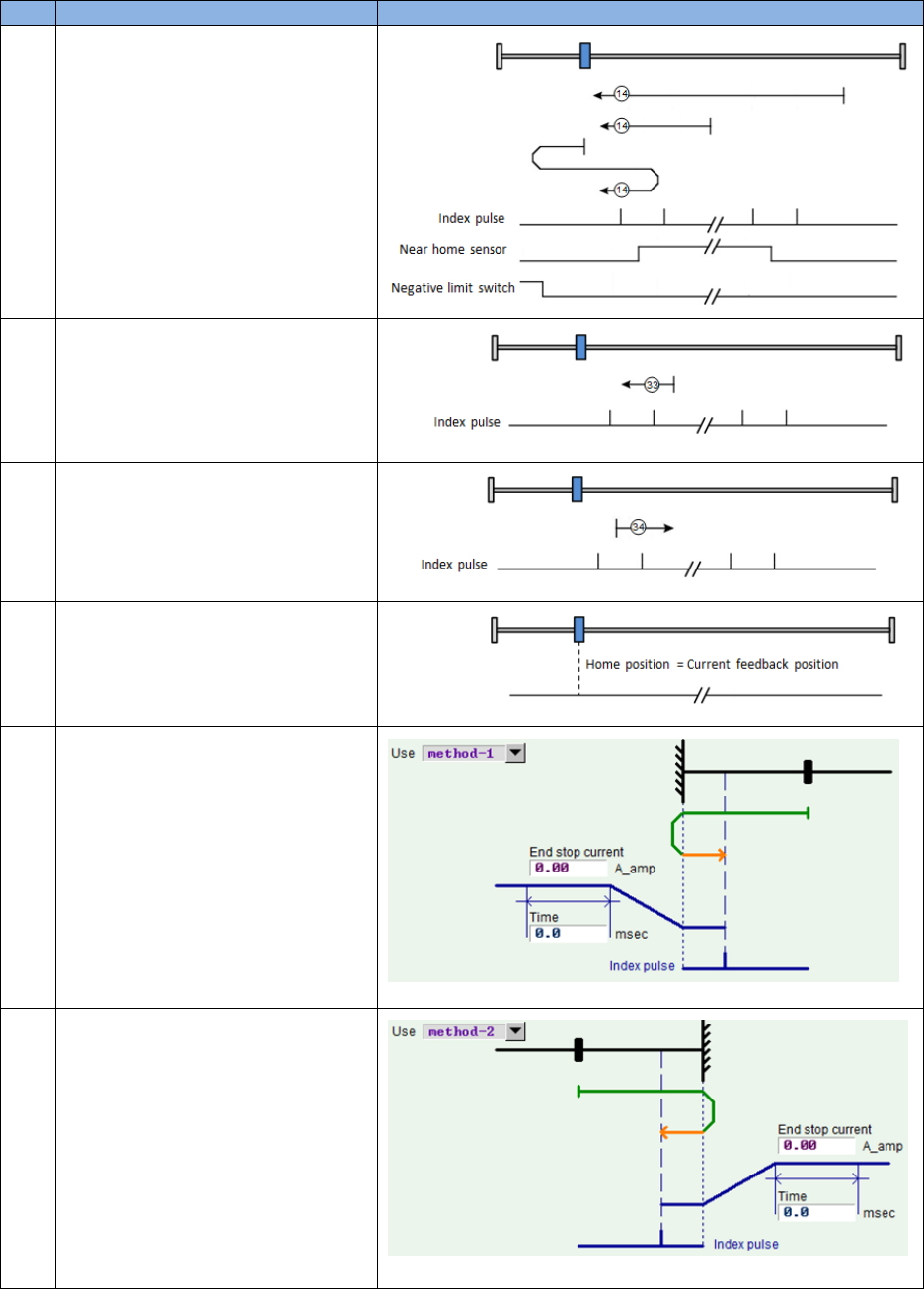
14
Homing on home switch and
index pulse – negative initial
motion, left edge of home
switch, left-side index:
Motor searches the left edge of
home switch in the negative
direction by using faster speed.
After searched, motor searches
the left-side index of this signal in
the negative direction by using
slower speed.
33
Homing on index pulse –
negative initial motion
Motor searches index pulse in the
negative direction by using slower
speed.
34
Homing on index pulse –
positive initial motion
Motor searches index pulse in the
positive direction by using slower
speed.
37
Homing on current position
Take the current position of motor
as home position.
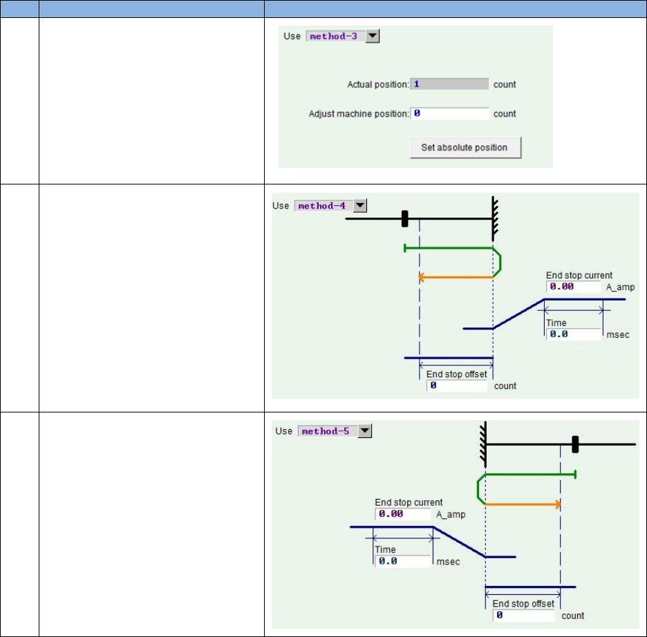
-1
Homing on hard stop and index
pulse – negative initial motion,
Motor searches hard stop in the
negative direction by using faster
speed. After searched, motor
searches index pulse in the
positive direction by using slower
speed.
(Refer to coressponding drive
user guide to find the setting
method of searching hard stop)
-2
Homing on hard stop and index
pulse – positive initial motion,
Motor searches hard stop in the
positive direction by using faster
speed. After searched, motor
searches index pulse in the
negative direction by using slower
speed.
(Refer to coressponding drive
user guide to find the setting
method of searching hard stop)
HIWIN CoE Drive User Guide v1.1 3. CiA 402 Drive Profile
HIWIN Mikrosystem Corp. 24
No.
Description
Explanation
-3
Homing on absolute encoder:
This method is only available for
motor with absolute encoder (the
9-th bit of motor model name is 4).
Take the current position of motor
as absolute target position. Motor
does not move on this method.
(D1 CoE and abily series products
do not support this method)
-4
Homing on hard stop and home
offset – positive initial motion,
Motor searches hard stop in the
positive direction by using faster
speed. After searched, motor
moves to home offset (End stop
offset) in the negative direction by
using slower speed.
(D1 CoE, D2 CoE, and abily
series products do not support this
method)
-5
Homing on hard stop and home
offset – negative initial motion,
Motor searches hard stop in the
negative direction by using faster
speed. After searched, motor
moves to home offset (End stop
offset) in the positive direction by
using slower speed.
(D1 CoE, D2 CoE, and abily
series products do not support this
method)
C. Stop homing procedure
When homing procedure is interrupted, motor will decelerate to stop according to Homing
acceleration (object 0x609A).
(1) No error message reported
Following conditions will stop homing procedure, and report the message of homing
procedure being stopped on Statusword, but do not report error message.
a. There is no error occurred during homing procedure. When FSA state is changed
to other state except for “Operation enabled” state, drive should stop homing
procedure and decelerate motor to stop.
b. Drive receives the command of stopping homing procedure (bit 4 of Controlword is
0).
c. Drive receives the command of halting homing procedure (bit 8 of Controlword is
1).
d. When drive receives the command of changing operation mode to 0 (no mode), it
should stop homing procedure and decelerate motor to stop.
(2) Error message reported
Following conditions will stop homing procedure, report the message of homing error
occurred on Statusword, and report homing error code on Error code (object
HIWIN CoE Drive User Guide v1.1 3. CiA 402 Drive Profile
HIWIN Mikrosystem Corp. 25
0x603F).
a. There is an error occurred during homing procedure. For example, the error of
position error too big occurs when the incorrect hardware limit switch is searched.
At this case, FSA state is changed to “Fault” state. Drive should stop homing
procedure and decelerate motor to stop.
b. Drive receives the command of starting homing (bit 4 of Controlward is 1) at the
illegal setting of Homing method (object 0x6098).
c. Reach hardware limit switch during searching index pulse. Drive should stop
homing procedure and decelerate motor to stop.
d. Drive receives the command of changing to other supported operation mode.
Drive should stop homing procedure and decelerate motor to stop.
HIWIN CoE Drive User Guide v1.1 3. CiA 402 Drive Profile
HIWIN Mikrosystem Corp. 26
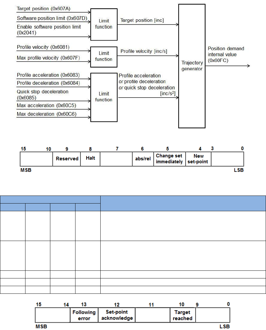
3.3. Profile position mode
In profile position (pp) mode, the master station sends Profile velocity, Profile acceleration/
deceleration, and Target position (object 0x607A) to drive. Drive uses the internal profile
generator to calculate motion commands. Through position, velocity, and current control loops,
the output current is finally generated to drive motor to achieve the purpose of positioning. The
relationship of input and output objects for pp mode is described in Fig. 3-6. The bit definition of
Controlword for pp mode is given in Fig. 3-7, and the supported functions are described in Table
3-9. The bit definition of Statusword for pp mode is shown in Fig. 3-8, and the supported
statuses are defined in Table 3-10.
Fig. 3-6
Fig. 3-7
Table 3-9
Bit of Controlword
Definition
8
6
5
4
0
0
0
0->1
Take Target position (object 0x607A) as new absolute
value of target position. If motor does not arrive the
previous target position, it will complete the previous
target, and then move to new target position.
0
1
0
0->1
Take Target position (object 0x607A) as new relative value
of target position. If motor does not arrive the previous
target position, it will complete the previous target, and
then move to new target position.
0
0
1
0->1
Move to new absolute target position immediately.
0
1
1
0->1
Move to new relative target position immediately.
1
X
X
X
Stop motion. Motor should be decelerated to stop.
Fig. 3-8
See Table 3-2
See Table 3-2
See Table 3-2
See Table 3-4
See Table 3-4
See Table 3-4
HIWIN CoE Drive User Guide v1.1 3. CiA 402 Drive Profile
HIWIN Mikrosystem Corp. 27
Table 3-10
Bit
Value
Definition
10
0
Halt (bit 8 of Controlword) = 0: Target position not reached.
Halt (bit 8 of Controlword) = 1: Motor decelerating.
1
Halt (bit 8 of Controlword) = 0: Target position reached.
Halt (bit 8 of Controlword) = 1: Motor speed being 0.
12
0
Previous set-point already processed and waiting for new set-point.
1
Previous set-point still in process but set-point overwriting being
accepted.
13
0
No following error.
1
Following error occurred.
The pp mode supports functions of software and hardware limit protections. Instructions are
given as follows.
(1) Use hardware limit protection
Set Enable hardware limit protection (object 0x2042) to be 1. When motor reaches hardware
limit switch, motor stops motion. At this monent, only when motor receives the command of
moving in the opposite direction, it moves and leaves the hardware limit switch in the
opposite direcion.
(2) Use software limit protection
Set Enable software limit (object 0x2041) to be 1, and set Min software position limit (object
0x607D:1) and Max software position limit (object 0x607D:2) to the required positions. When
motor reaches software limit position or the current position is over software limit position,
motor will stop moving in the same direction of meeting software limit. At this monent, only
when motor receives the command of moving in the opposite direction, it moves and leaves
the software limit position in the opposite direcion.
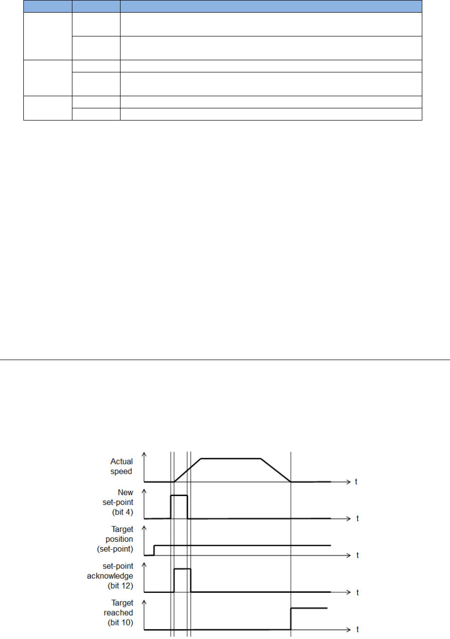
3.3.1. Setting of set-point
The pp mode sets set-point by controlling the timing of the new set-point bit (bit 4) and the
change set immediately bit (bit5) of Controlword. The setting of set-point is validated only when
bit 4 of Controlword changes from 0 to 1 (rising edge). When drive sets the set-point
acknowledge bit (bit 12) of Statusword to be 1, this means the new set-point is accepted, as
shown in Fig. 3-9. If one set-point is still in progress and a new one is validated, drive supports
two handling methods for this condition: single set-point and set of set-points.
Fig. 3-9
HIWIN CoE Drive User Guide v1.1 3. CiA 402 Drive Profile
HIWIN Mikrosystem Corp. 28
(1) Single set-point (bit 5 of Controlword is 1)
If one set-point is in progress and a new one is set by setting bit 4 of Controlword, the new
one will be processed immediately and the previous one is discarded, as shown in Fig. 3-10.
Fig. 3-10
(2) Set of set-points (bit 5 of Controlword is 0)
If one set-point is in progress and a new one is set by setting bit 4 of Controlword, the new
one will be processed until the previous one has been completed, as shown in Fig. 3-11.
Fig. 3-11
HIWIN CoE Drive User Guide v1.1 3. CiA 402 Drive Profile
HIWIN Mikrosystem Corp. 29
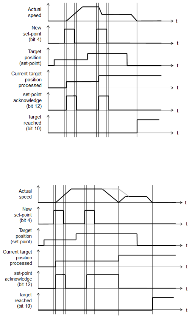
HIWIN CoE products support two set-points. The handling of multiple set-points is shown in
Fig. 3-12.
a. When set-point A is in progress, set-point B is stored in the buffer firstly after being set
(○
1, ○
2). Bit 12 of Statusword will keep to 1 to inform host controller that drive cannot
accept new set-point now.
b. Once set-point A is reached, set-point B is progressed immediately. Bit 12 of Statusword
is changed to 0 to indicate that drive can accept new set-point.
c. If drive has the buffered set-point (○
3, ○
4), the new set-point D will be discarded
immediately after being set, and does not be buffered in the set-point list.
d. If all buffers for set-points are occupied and a new set-point E needs to be progressed
immediately, by setting bit 5 of Controlword to be 1, the progressed set-point B and
buffered set-point C are discarded and set-point E is progressed immediately (○
5).
Fig. 3-12
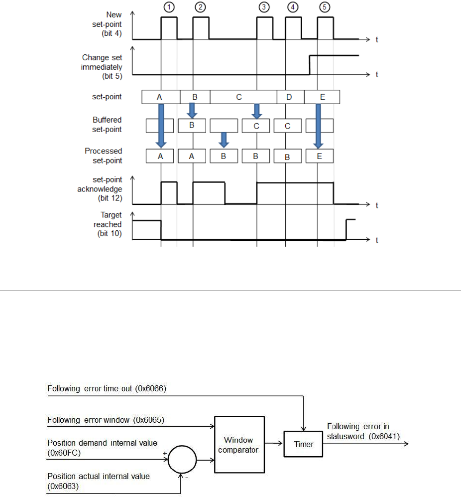
3.3.2. Following error protection
HIWIN CoE drives support the function of following error protection. When the difference
between Position demand internal value (object 0x60FC) and Position actual internal value
(object 0x6063) is greater than Following error window (object 0x6065), and the continuous time
is greater than Following error time out (object 0x6066), the following error bit (bit 13) of
Statusword will be set to be 1. Also, drive will change to “Fault” state and perform the error
handling mechanism subsequently.
Fig. 3-13
HIWIN CoE Drive User Guide v1.1 3. CiA 402 Drive Profile
HIWIN Mikrosystem Corp. 30
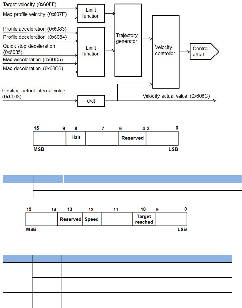
3.4. Profile velocity mode
In profile velocity (pv) mode, the master station lets motor move with a fix velocity by setting
Target velocity (object 0x60FF) and Controlword. The relationship of input and output objects for
pv mode is described in Fig. 3-14, where Velocity actual value (object 0x606C) is calculated
according to Position actual internal value (object 0x6063). The bit definition of Controlword for
pv mode is given in Fig. 3-15, and the supported functions are described in Table 3-11. The bit
definition of Statusword for pv mode is shown in Fig. 3-16, and the supported statuses are
defined in Table 3-12.
Fig. 3-14
Fig. 3-15
Table 3-11
Bit
Value
Definition
8
0
The motion should be executed or continued.
1
Stop motion. Motor should be decelerated to stop.
Fig. 3-16
Table 3-12
Bit
Value
Definition
10
0
Halt (bit 8 of Controlword) = 0: Target velocity not reached.
Halt (bit 8 of Controlword) = 1: Motor decelerating.
1
Halt (bit 8 of Controlword) = 0: Target velocity reached.
Halt (bit 8 of Controlword) = 1: Motor speed being 0.
12
0
Motor speed being unequal to 0.
1
Motor speed being equal to 0.
See Table 3-2
See Table 3-2
See Table 3-2
See Table 3-4
See Table 3-4
See Table 3-4
HIWIN CoE Drive User Guide v1.1 3. CiA 402 Drive Profile
HIWIN Mikrosystem Corp. 31
When drive is at “Operation enabled” state (Controlword = 000Fh), motor will accelerate to
Target velocity (object 0x60FF) by using Profile acceleration (object 0x6083) as Target velocity
being unequal to 0. When the reference speed of drive is unequal to 0, the speed bit (bit 12) of
Statuswors is set to be 1. Only when the reference speed is equal to Target velocity, the target
reached bit (bit 10) of Statusword is set to be 1.
The pv mode only supports the function of hardware limit protection, but does not support the
function of software limit protection. Instructions of hardware limit protection please refer to
Section 3.3.
HIWIN CoE Drive User Guide v1.1 3. CiA 402 Drive Profile
HIWIN Mikrosystem Corp. 32
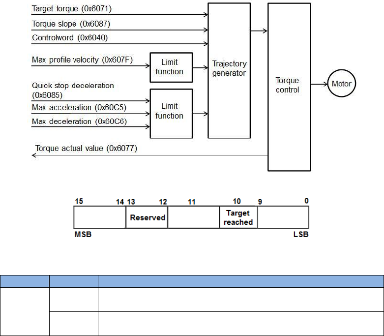
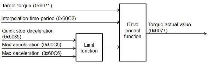
3.5. Profile torque mode
In profile torque (tq) mode, the master station lets motor move with a fix torque by setting Target
torque (object 0x6071) and Controlword. The relationship of input and output objects for tq
mode is described in Fig. 3-17. The bit definition of Controlword for tq mode is the same as that
for pv mode, referred to Fig. 3-15. The supported functions are described in Table 3-11. The bit
definition of Statusword for tq mode is shown in Fig. 3-18, and the supported statuses are
defined in Table 3-13.
Fig. 3-17
Fig. 3-18
Table 3-13
Bit
Value
Definition
10
0
Halt (bit 8 of Controlword) = 0: Target torque not reached.
Halt (bit 8 of Controlword) = 1: Motor decelerating.
1
Halt (bit 8 of Controlword) = 0: Target torque reached.
Halt (bit 8 of Controlword) = 1: Motor speed being 0.
When drive is at “Operation enabled” state (Controlword = 000Fh), motor will move by using
Target torque (object 0x60FF) as this value being unequal to 0. Only when the command current
of drive reaches the corresponding current of Target torque, the target reached bit (bit 10) of
Statusword is set to be 1. The relationship between the output target torque (force) of drive and
Target torque is described by:
Output target torque (force) of drive = motor torque (force) constant
* motor rated current * Target torque (object 0x6071)/1000.
The tq mode only supports the function of hardware limit protection, but does not support the
function of software limit protection. Instructions of hardware limit protection please refer to
Section 3.3.
See Table 3-4
See Table 3-4
See Table 3-4
HIWIN CoE Drive User Guide v1.1 3. CiA 402 Drive Profile
HIWIN Mikrosystem Corp. 33
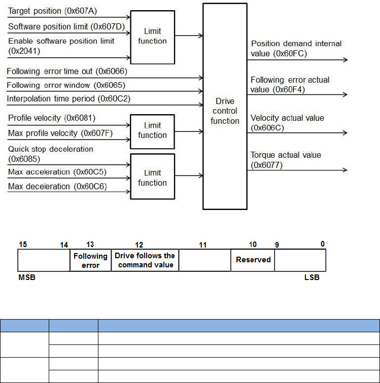
3.6. Cyclic synchronous position mode
In cyclic synchronous position (csp) mode, the master station lets motor move to target position
by setting Target position (object 0x607A). The relationship of input and output objects for csp
mode is described in Fig. 3-19. Controlword for csp mode does not use the bit for
operation-mode specific. The bit definition of Statusword for csp mode is shown in Fig. 3-20, and
the supported statuses are defined in Table 3-14. The csp mode supports the function of
following error protection. Details please refer to Section 3.3.2.
Fig. 3-19
Fig. 3-20
Table 3-14
Bit
Value
Definition
12
0
Target position ignored.
1
Target position used as input to position control loop.
13
0
No following error.
1
Following error occurred.
When drive is at “Operation enabled” state (Controlword = 000Fh), motor will move to target
position as Target position (object 0x607A) being different with Position actual internal value
(object 0x6063).
The csp mode supports functions of software and hardware limit protections. Instructions please
refer to Section 3.3. The cyclic synchronous mode does not support halt function. Therefore,
motor will continue moving and does not stop as setting the halt bit (bit 8) of Controlword to be 1
during the motion.
See Table 3-4
See Table 3-4
See Table 3-4
HIWIN CoE Drive User Guide v1.1 3. CiA 402 Drive Profile
HIWIN Mikrosystem Corp. 34
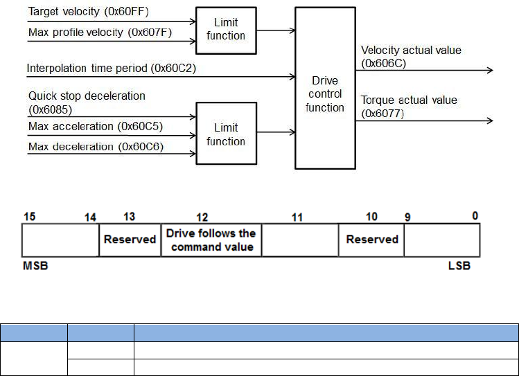
3.7. Cyclic synchronous velocity mode
In cyclic synchronous velocity (csv) mode, the master station lets motor move with a fix velocity
by setting Target velocity (object 0x60FF). The relationship of input and output objects for csv
mode is described in Fig. 3-21. Controlword for csv mode does not use the bit for
operation-mode specific. The bit definition of Statusword for csv mode is shown in Fig. 3-22, and
the supported statuses are defined in Table 3-15.
Fig. 3-21
Fig. 3-22
Table 3-15
Bit
Value
Definition
12
0
Target velocity ignored.
1
Target velocity used as input to velocity control loop.
When drive is at “Operation enabled” state (Controlword = 000Fh), motor will move with Target
velocity (object 0x60FF) as this value being unequal to 0. When the reference speed of drive is
unequal to 0, the speed bit (bit 12) of Statuswors is set to be 1.
The csv mode only supports the function of hardware limit protection, but does not support the
function of software limit protection. Instructions of hardware limit protection please refer to
Section 3.3. The cyclic synchronous mode does not support halt function. Therefore, motor will
continue moving and does not stop as setting the halt bit (bit 8) of Controlword to be 1 during the
motion.
See Table 3-4
See Table 3-4
See Table 3-4
HIWIN CoE Drive User Guide v1.1 3. CiA 402 Drive Profile
HIWIN Mikrosystem Corp. 35
3.8. Cyclic synchronous torque mode
In cyclic synchronous torque (cst) mode, the master station lets motor move with a fix torque
(force) by setting Target torque (object 0x6071). The relationship of input and output objects for
cst mode is described in Fig. 3-23. Controlword for cst mode does not use the bit for
operation-mode specific. The bit definition of Statusword for cst mode is the same as that for csv
mode, referred to Fig. 3-22. The supported statuses are defined in Table 3-15.
Fig. 3-23
When drive is at “Operation enabled” state (Controlword = 000Fh), motor will move by using
Target torque (object 0x60FF) as this value being unequal to 0. Only when the command current
of drive reaches the corresponding current of Target torque, the target reached bit (bit 10) of
Statusword is set to be 1. The relationship between the output target torque (force) of drive and
Target torque is described by:
Output target torque (force) of drive = motor torque (force) constant
* motor rated current * Target torque (object 0x6071)/1000.
The cst mode only supports the function of hardware limit protection, but does not support the
function of software limit protection. Instructions of hardware limit protection please refer to
Section 3.3. The cyclic synchronous mode does not support halt function. Therefore, motor will
continue moving and does not stop as setting the halt bit (bit 8) of Controlword to be 1 during the
motion.

HIWIN CoE Drive User Guide v1.1 3. CiA 402 Drive Profile
HIWIN Mikrosystem Corp. 36
3.9. Touch probe function
Drive supports Touch probe function (object 0x60B8) and takes index pulse as the source of
Touch probe 1. Only Touch probe 1 is supported, but Touch probe 2 is not supported. Moreover,
it does not support the sampling of both positive and negative edges of Touch probe 1
simulantously. Do not set bits 4 and 5 to be 1 simulantously. The bit definition of object 0x60B8
is shown in Table 3-16. The status response for this object is by using Touch probe status
(0x60B9), and its bit definition is given in Table 3-17.
Note. Drive does not support functions of Touch probe source (object 0x60D0) and reserved
touch probe input. When bits 2 and 3 or bits 6 and 7 of object 0x60B8 are set, index
pulse is taken as the source of Touch probe 1.
Table 3-16
Bit
Value
Definition
0
0
Switch off touch probe 1.
1
Enable touch probe 1.
1
0
Trigger first event.
1
Continuous trigger.
2 - 3
-
Reserved.
4
0
Switch off sampling at positive edge of touch probe 1.
1
Enable sampling at positive edge of touch probe 1.
5
0
Switch off sampling at negative edge of touch probe 1.
1
Enable sampling at negative edge of touch probe 1.
6 - 15
-
Reserved.
Table 3-17
Bit
Value
Definition
0
0
Touch probe 1 is switched off.
1
Touch probe 1 is enabled.
1
0
No positive edge of touch probe 1 is stored.
1
Positive edge of touch probe 1 is stored.
2
0
No negative edge of touch probe 1 is stored.
1
Negative edge of touch probe 1 is stored.
3 - 15
-
Reserved.

HIWIN CoE Drive User Guide v1.1 4. Object Dictionary
HIWIN Mikrosystem Corp. 37
4. Object Dictionary
4. Object Dictionary ............................................................................................................ 37
4.1. Common object .................................................................................................... 38
4.2. PDO mapping objects .......................................................................................... 39
4.3. Communication objects of Sync manger .............................................................. 40
4.4. Manufacturer defined objects ............................................................................... 42
4.5. Device profile ....................................................................................................... 45
4.6. Objects and device table ...................................................................................... 50
HIWIN CoE Drive User Guide v1.1 4. Object Dictionary
HIWIN Mikrosystem Corp. 38
4.1. Common object
Table 4-1
Index
Sub-index
Name
Type
Access
Max
Min
Default
Unit
PDO
mapping(1)
0x1000
0x00
Device type
UINT32
RO
-
-
00020192h
-
X
0x1001
0x00
Error register
UINT8
RO
255
0
0
-
X
0x1010
Store parameters
0x00
Number of entries
UINT8
RO
-
-
1
-
X
0x01
Save all
parameters(2)
UINT32
RW
232-1
0
0
-
X
0x1018
Identity object
0x00
Number of entries
UINT8
RO
-
-
4
-
X
0x01
Vendor ID
UINT32
RO
-
-
AAAAh
-
X
0x02
Product code(3)
UINT32
RO
3
1
1
-
X
0x03
Revision number
UINT32
RO
-
-
1
-
X
0x04
Serial number
UINT32
RO
-
-
0
-
X
(1) O: PDO mapping supported;
X: PDO mapping unsupported.
(Hereinafter the same)
(2) When drive is at “Switch on disable” state (servo off status), the command from host
controller received by sub-index 1 of this object is shown in Fig. 4-1. Drive will save
parameters into EEPROM and respond to host controller on the same sub-index to indicate
that parameters saving is completed. After saved, drive should be reset. If the received
command sent by host controller is different with that shown in Fig. 4-1, drive omits this
command.
Fig. 4-1
(3) Product codes of HIWIN CoE products are shown in Table 4-2.
Table 4-2
Drive
Product code
D1-N
1
D1
2
D2
3
abily
4

HIWIN CoE Drive User Guide v1.1 4. Object Dictionary
HIWIN Mikrosystem Corp. 39
4.2. PDO mapping objects
For HIWIN CoE products, the maximum number of allowed RxPDO or TxPDO is 7, and the total
size of RxPDO or TxPDO is 20 bytes.
Table 4-3
Index
Sub-index
Name
Type
Access
Max
Min
Default
Unit
PDO
mapping
0x1600
1st receive PDO mapping
0x00
Number of
objects
UINT8
RW
7
1
2
-
X
0x01
Mapping entry
1
UINT32
RW
FFFFFFFFh
0
60400010h
-
X
0x02
Mapping entry
2
UINT32
RW
FFFFFFFFh
0
607A0020h
-
X
0x03
Mapping entry
3
UINT32
RW
FFFFFFFFh
0
0
-
X
0x04
Mapping entry
4
UINT32
RW
FFFFFFFFh
0
0
-
X
0x05
Mapping entry
5
UINT32
RW
FFFFFFFFh
0
0
-
X
0x06
Mapping entry
6
UINT32
RW
FFFFFFFFh
0
0
-
X
0x07
Mapping entry
7
UINT32
RW
FFFFFFFFh
0
0
-
X
0x1A00
1st transmit PDO mapping
0x00
Number of
objects
UINT8
RW
7
1
3
-
X
0x01
Mapping entry
1
UINT32
RW
FFFFFFFFh
0
60410010h
-
X
0x02
Mapping entry
2
UINT32
RW
FFFFFFFFh
0
60640020h
-
X
0x03
Mapping entry
3
UINT32
RW
FFFFFFFFh
0
60F40020h
-
X
0x04
Mapping entry
4
UINT32
RW
FFFFFFFFh
0
0
-
X
0x05
Mapping entry
5
UINT32
RW
FFFFFFFFh
0
0
-
X
0x06
Mapping entry
6
UINT32
RW
FFFFFFFFh
0
0
-
X
0x07
Mapping entry
7
UINT32
RW
FFFFFFFFh
0
0
-
X

HIWIN CoE Drive User Guide v1.1 4. Object Dictionary
HIWIN Mikrosystem Corp. 40
4.3. Communication objects of Sync manger
Table 4-4
Index
Sub-index
Name
Type
Access
Max
Min
Default
Unit
PDO
mapping
0x1C00
Sync manager communication type
0x00
Number of used
sync manager
UINT8
RO
-
-
4
-
X
0x01
Communication
type sync manager
0
UINT8
RO
-
-
1: mailbox
receive
-
X
0x02
Communication
type sync manager
1
UINT8
RO
-
-
2: mailbox
send
-
X
0x03
Communication
type sync manager
2
UINT8
RO
-
-
3: process data
output
-
X
0x04
Communication
type sync manager
3
UINT8
RO
-
-
4: process data
input
-
X
0x1C10
Sync manager 0 PDO assignment
0x00
Number of
assigned PDOs
UINT8
RO
-
-
0
-
X
0x1C11
Sync manager 1 PDO assignment
0x00
Number of
assigned PDOs
UINT8
RO
-
-
0
-
X
0x1C12
Sync manager 2 PDO assignment
0x00
Number of
assigned RxPDO
UINT8
RW
-
-
1
-
X
0x01
PDO mapping index
of assigned RxPDO
UINT16
RW
-
-
1600h
-
X
0x1C13
Sync manager 3 PDO assignment
0x00
Number of
assigned TxPDO
UINT8
RW
-
-
1
-
X
0x01
PDO mapping
index of assigned
TxPDO
UINT16
RW
-
-
1A00h
-
X
0x1C32
Sync manager 2 synchronization
0x00
Number of
synchronization
parameters
UINT8
RO
-
-
9
-
X
0x01
Synchronization
type(1)
UINT16
RW
2
0
2
-
X
0x02
Cycle time
UINT32
RW
-
-
125000
-
X
0x03
Reserved 1
UINT32
RW
-
-
-
-
-
0x04
Synchronization
types supported(2)
UINT16
RO
-
-
0x5
-
X
0x05
Minimum cycle
time
UINT32
RO
-
-
125000
-
X
0x06
Calc and copy time
UINT32
RO
-
-
62500
-
X
0x07
Reserved 2
UINT32
RO
-
-
-
-
-
0x08
Reserved 3
UINT16
RW
-
-
-
-
-
0x09
Delay time
UINT32
RO
-
-
0
-
X

HIWIN CoE Drive User Guide v1.1 4. Object Dictionary
HIWIN Mikrosystem Corp. 41
Index
Sub-index
Name
Type
Access
Max
Min
Default
Unit
PDO
mapping
0x1C33
Sync manager 3 synchronization
0x00
Number of
Synchronization
Parameters
UINT8
RO
-
-
9
-
X
0x01
Synchronization
Type(1)
UINT16
RO
2
0
2
-
X
0x02
Cycle Time
UINT32
RO
-
-
125000
-
X
0x03
Reserved 1
UINT32
RW
-
-
-
-
-
0x04
Synchronization
Types Supported(2)
UINT16
RO
-
-
5
-
X
0x05
Minimum Cycle
Time
UINT32
RO
-
-
125000
-
X
0x06
Calc and Copy
Time
UINT32
RO
-
-
62500
-
X
0x07
Reserved 2
UINT32
RW
-
-
-
-
-
0x08
Reserved 3
UINT16
RW
-
-
-
-
-
0x09
Delay Time
UINT32
RO
-
-
0
-
X
(1) 0: Use free-run mode;
1: Use DC mode (Synchronous with SYNC0).
(2) The definition of this sub-index is given in Table 4-5.
Table 4-5
Bit
Value
Definition
0
1
Free-run mode supported
3, 2
01b
DC mode supported

HIWIN CoE Drive User Guide v1.1 4. Object Dictionary
HIWIN Mikrosystem Corp. 42
4.4. Manufacturer defined objects
Table 4-6
Index
Sub-index
Name
Type
Access
Max
Min
Default
Unit
PDO
mapping
0x2000
0x00
Motor type(1)
UINT16
RO
2
0
2
-
X
0x2001
0x00
Inner encoder
resolution
INT32
RO
231-1
0
0
count
X
0x2002
0x00
Outer encoder
resolution
INT32
RO
231-1
0
0
count
X
0x2003
0x00
Screw pitch
INT32
RO
231-1
1
1
mm
X
0x2004
Electronic gear
0x00
Number of entries
UINT8
RO
-
-
2
-
X
0x01
Numerator of gear
ratio
INT32
RW
231-1
1
1
-
X
0x02
Denominator of
gear ratio
INT32
RW
231-1
1
1
-
X
0x2010
0x00
Input function(2)
UINT16
RW
3
0
0
-
O
0x2020
0x00
Index signal(3)
INT8
RO
1
0
0
-
O
0x2021
0x00
Latched index
position
INT32
RO
231-1
-231
0
count
O
0x2022
0x00
Motor actual current
REAL32
RO
3.4*1038
-3.4*1038
0
A_rms
O
0x2040
0x00
2nd encoder
option(4)
UINT16
RO
1
0
0
-
X
0x2041
0x00
Enable software
position limit(5)
UINT16
RW
1
0
0
-
X
0x2042
0x00
Enable hardware
limit protection(6)
UINT16
RW
1
0
1
-
X
0x2043
0x00
Input logic inversion
INT16
RW
7FFFh
8000h
07EFh
-
X
0x2050
0x00
Common gain
REAL32
RW
10
0.01
0.3
-
X
0x2051
0x00
Velocity proportional
gain
REAL32
RW
1
0.000001
0.001
-
X
0x2052
0x00
Proportional gain of
the current loop
REAL32
RW
7F7FFFFFh
FF7FFFFFh
500
-
X
0x2053
0x00
Integral gain of the
current loop
REAL32
RW
7F7FFFFFh
FF7FFFFFh
100
-
X
0x2054
0x00
Integral gain of the
velocity loop
REAL32
RW
7F7FFFFFh
FF7FFFFFh
314
-
X
0x2055
0x00
Proportional gain of
the position loop
REAL32
RW
7F7FFFFFh
FF7FFFFFh
314
-
X
0x2060
0x00
Multi Turn Encoder
Reset Flag
UINT8
RW
1
0
0
-
X
0x2100
0x00
Drive error events
1(7)
UINT32
RO
FFFFFFFFh
0
0
-
X
0x2101
0x00
Drive error events
2(8)
UINT32
RO
FFFFFFFFh
0
0
-
X
0x2110
0x00
Drive Warning
Events 1
UINT16
RO
FFFFh
0
0
-
X
0x2111
0x00
Drive Warning
Events 2
UINT16
RO
FFFFh
0
0
-
X
0x2112
0x00
Drive Warning
Events 3
UINT16
RO
FFFFh
0
0
-
X
0x2113
0x00
Drive Warning
Events 4
UINT16
RO
FFFFh
0
0
-
X
Note. Object 0x2060 is only supported by D2 CoE drive with SA35.

HIWIN CoE Drive User Guide v1.1 4. Object Dictionary
HIWIN Mikrosystem Corp. 43
(1) Motor type
Table 4-7
Motor type
Value
Linear
0
Torque
1
AC servo
2
(2) Input function
Table 4-8
Bit
Value
Definition
0
0
Deactivate error mapping
1
Activate error mapping
1
0
Do not reset drive
1
Reset drive
(3) Index signal
Table 4-9
Bit
Value
Definition
0
0
Index signal is not detected
1
Index signal is detected
(4) 2nd encoder option
Table 4-10
Bit
Value
Definition
0
0
Disable dual loop
1
Enable dual loop
(5) Enable software position limit (This object is only valid in pp and csp modes)
This object determines whether software limits defined in object 0x607D (Software position
limit) are valid or not.
Table 4-11
Bit
Value
Definition
0
0
Disable software position limit protection
1
Enable software position limit protection
(6) Enable hardware limit protection (This object is valid in all operation modes)
Table 4-12
Bit
Value
Definition
0
0
Disable hardware position limit protection
1
Enable hardware position limit protection

HIWIN CoE Drive User Guide v1.1 4. Object Dictionary
HIWIN Mikrosystem Corp. 44
(7) Drive error events 1
Table 4-13
Bit
Definition
0
-
1
Encoder error
2 - 5
-
6
Position error too big
7
Soft-thermal threshold reached
8
-
9
HFLT inconsistent error (D1NCOE)
10 - 12
-
13
Serial encoder communication error
14
Motor over temperature sensor activated
15
Amplifier over temperature
16 - 17
-
18
Motor short (over current) detected
19
Over voltage detected
20
Under voltage detected
21
Motor maybe disconnected
22 - 30
-
31
5V for encoder card fail
(8) Drive error events 2
Table 4-14
Bit
Definition
0
-
1
Phase initialization error
2 - 4
-
5
Hall sensor error
6
Hall phase check error
7
STO active
8 - 15
-
16
Current control error
17
HFLT inconsistent error (D1COE/D2COE)
18
Auto phase center not complete error
19
-
20
Hybrid deviation too big
21 - 22
-
23
DC bus voltage abnormal
24
-
25
Fan fault error
26 - 29
-
30
EtherCAT interface disconnected
31
CiA-402 home failed
Note. For D1-N CoE drive, HFLT inconsistent error is at bit 9 of Drive error events 1.
For D1 CoE and D2 CoE drives, it is at bit 17 of Drive error events 2.

HIWIN CoE Drive User Guide v1.1 4. Object Dictionary
HIWIN Mikrosystem Corp. 45
4.5. Device profile
Table 4-15
Index
Sub-index
Name
Type
Access
Max
Min
Default
Unit
PDO
mapping
0x603F
0x00
Error code(1)
UINT16
RO
FFFFh
0
0
-
O
0x6040
0x00
Controlword
UINT16
RW
FFFFh
0
0
-
O
0x6041
0x00
Statusword
UINT16
RO
FFFFh
0
0
-
O
0x6060
0x00
Mode of
operation(2)
INT8
RW
10
0
8
-
O
0x6061
0x00
Mode of
operation
display
INT8
RO
10
0
8
-
O
0x6063
0x00
Position
actual
internal value
INT32
RO
231-1
-231
0
count
X
0x6064
0x00
Position
actual value
INT32
RO
231-1
-231
0
count
O
0x6065
0x00
Following
error window
UINT32
RW
232-1
0
0
count
X
0x6066
0x00
Following
error time out
UINT16
RW
216-1
0
0
ms
X
0x606C
0x00
Velocity
actual value
INT32
RO
231-1
-231
0
count/s
O
0x6071
0x00
Target torque
INT16
RW
1000
-1000
0
0.1%
O
0x6075
0x00
Motor Rated
Current
UINT32
RO
FFFFFFFFh
0
0
-
X
0x6077
0x00
Torque
actual value
INT16
RO
1000
-1000
0
0.1%
O
0x607A
0x00
Target
position
INT32
RW
231-1
-231
0
count
O
0x607C
0x00
Home offset
INT32
RW
231-1
-231
0
count
X
0x607D
Software position limit
0x00
Highest
sub-index
supported
UINT8
RO
-
-
2
-
X
0x01
Min software
position limit
INT32
RW
231-1
-231
-231
count
X
0x02
Max software
position limit
INT32
RW
231-1
-231
-231
count
X
0x607F
0x00
Maximum
profile
velocity
UINT32
RW
232-1
0
0
count/s
X
0x6081
0x00
Profile
velocity
UINT32
RW
232-1
0
0
count/s
X
0x6083
0x00
Profile
acceleration
UINT32
RW
232-1
0
0
count/s2
X
0x6084
0x00
Profile
deceleration
UINT32
RW
232-1
0
0
count/s2
X
0x6085
0x00
Quick stop
deceleration
UINT32
RW
232-1
0
0
count/s2
X
0x6087
0x00
Torque slope
UINT32
RW
232-1
0
0
0.1%/s
X
0x6098
0x00
Homing
method
INT8
RW
37
-3
0
X

HIWIN CoE Drive User Guide v1.1 4. Object Dictionary
HIWIN Mikrosystem Corp. 46
Index
Sub-index
Name
Type
Access
Max
Min
Default
Unit
PDO
mapping
0x6099
Homing Speeds
0x00
Highest
sub-index
supported
UINT8
RD
-
-
2
-
X
0x01
Speed during
search for
switch
UINT32
RW
231-1
0
0
count/s
X
0x02
Speed during
search for
zero
UINT32
RW
231-1
0
0
count/s
X
0x609A
0x00
Homing
acceleration
UINT32
RW
232-1
0
0
count/s2
X
0x60B1
0x00
Velocity
offset
INT32
RW
-
-
-
-
-
0x60B2
0x00
Torque offset
INT16
RW
-
-
-
-
-
0x60B8
0x00
Touch probe
function(3)
UINT16
RW
FFFFh
0
0
-
O
0x60B9
0x00
Touch probe
status
INT32
RO
FFFFFFFFh
0
0
-
O
0x60BA
0x00
Touch probe
1 positive
edge
INT32
RO
231-1
-231
0
Count
O
0x60BB
0x00
Touch probe
1 negative
edge
INT32
RO
231-1
-231
0
count
O
0x60C2
Interpolation Time Period
0x00
Highest
sub-index
supported
INT8
RO
-
-
1
-
X
0x01
Interpolation
time period
UINT8
RW
255
0
0
-
X
0x02
Interpolation
time index
INT8
RW
63
-128
0
-
X
0x60C5
0x00
Max
acceleration
UINT32
RW
231-1
0
10000
count/s2
X
0x60C6
0x00
Max
deceleration
UINT32
RW
231-1
0
10000
count/s2
X
0x60F4
0x00
Following
error actual
value
INT32
RO
231-1
-231
0
Count
O
0x60FC
0x00
Position
demand
internal value
INT32
RO
231-1
-231
0
Count
X
0x60FD
0x00
Digital
inputs(4)
UINT32
RO
FFFFFFFFh
0
0
-
O
0x60FE
Digital Outputs
0x00
Highest
sub-index
supported
INT8
RO
-
-
2
-
O
0x01
Physical
outputs(5)
UINT32
RW
FFFFFFFFh
0
0
-
O
0x02
Bit mask(6)
UINT32
RW
FFFFFFFFh
0
0
-
O
0x60FF
0x00
Target
velocity
INT32
RW
231-1
-231
0
count/s2
O
0x6502
0x00
Supported
drive mode
UINT32
RO
-
-
03ADh
-
X

HIWIN CoE Drive User Guide v1.1 4. Object Dictionary
HIWIN Mikrosystem Corp. 47
(1) Error code
Table 4-16
Error #
Describe
Value
D1 CoE
D2 CoE
D1-N CoE
1
Motor short(over current)
2310h
O
O
O
2
Over voltage
3110h
O
O
O
3
Position error too big
8611h
O
O
O
4
Encoder error
7380h
O
O
O
5
Soft-thermal
2350h
O
O
O
6
Motor maybe disconnected
7180h
O
O
O
7
Amplifier over temperature
4310h
O
O
O
8
Motor over temperature
7383h
O
X
O
9
Under voltage
3220h
O
O
O
10
5V for encoder card fail
5280h
O
O
O
11
Phase initialization error
FF06h
O
O
O
12
Serial encoder com. Error
7381h
O
O
O
13
Hall sensor error
7382h
O
O
O
14
Hall phase error
7384h
O
X
O
15
Current control error
FF02h
O
O
O
17
Hybrid deviation too big
86FFh
X
O
O
18
STO active
FF03h
X
O
O
19
HFLT inconsistent error
FF04h
O
O
O
20
Auto phase center not complete yet
FF05h
O
X
O
22
DC bus voltage abnormal
3210h
O
O
O
23
EtherCAT interface is not detected
7580h
O
O
O
24
CiA-402 Homing error
8613h
O
O
O
25
Fan fault error
5180h
X
O
X
Note. O: Device supports this error code.
X: Device does not support this error code.
(2) Mode of operation
If set to unsupported operation mode, the operation mode will keep to the original operation
mode.
Table 4-17
Value
Definition
0
Stand-alone mode
1
Profile position mode
3
Profile velocity mode
4
Torque profile mode
6
Homing mode
8
Cyclic sync position mode
9
Cyclic sync velocity mode
10
Cyclic sync torque mode
(3) Touch probe function
Table 4-18
Bit
Value
Definition
5, 4
00b
Switch off sampling of touch probe 1.
01b
Enable sampling at positive edge of touch probe 1.
10b
Enable sampling at negative edge of touch probe 1.
11b
Reserved.

HIWIN CoE Drive User Guide v1.1 4. Object Dictionary
HIWIN Mikrosystem Corp. 48
(4) Digital input
I. D1-N CoE drive
31
27
26
25
24
23
22
21
20
19
18
17
16
15
4
3
2
1
0
Unused
I10
I9
I8
I7
I6
I5
Motor Over
Temperature
I4
I3
I2
I1
reserved
Unused
home
switch
positive
limit
switch
negative
limit
switch
II. D1 CoE drive
31
26
25
24
23
22
21
20
19
18
17
16
15
4
3
2
1
0
Unused
I10
I9
I12
I11
I6
I5
I4
I3
I2
I1
reserved
Unused
home
switch
positive
limit
switch
negative
limit
switch
III. D2 CoE drive
31
26
25
24
23
22
21
20
19
18
17
16
15
4
3
2
1
0
Unused
I10
I9
I8
I7
I6
I5
I4
I3
I2
I1
reserved
Unused
home
switch
positive
limit
switch
negative
limit
switch
Fig. 4-2
a. As bit 0 of object 0x2042 (Enable hardware limit protection) being true, bit 1/0 of object
0x60FD (Digital input) will be set to true after positive/negative hardware limit switch is
triggered. At this moment, drive only receives the command of moving in the opposite
direction. When motor moves in the opposite direction, bit 1/0 of this object will be set to
false.
b. If the operation mode is changed from Homing mode (object 0x6060 = 6) to other
operation mode supported by drive, bit 1/0 of this object will be set to false.
c. Suppose that negative or positive limit switch is set to I. As bit 0 of object 0x2042
(Enable hardware limit protection) being true, the signal of I will be changed to high
and the corresponding bit (bit 0 or bit 1) is also set to high at negative or positive limit
switch being triggered to high.
d. Suppose that home switch (near home sensor) is set to I. The signal of I will be
changed to high and the corresponding bit 2 is also set to high at home switch being
triggered to high.
Note. denotes the input index of D-series CoE device.
(5) Digital output – physical outputs
Table 4-19
Bit
Output
Definition
0 - 15
-
Reserved
16
Brake
0: off; 1: on
17
O1
0: off; 1: on
18
O2
0: off; 1: on
19
O3
0: off; 1: on
20
O4
0: off; 1: on
21
O5
0: off; 1: on
22 - 31
-
Reserved

HIWIN CoE Drive User Guide v1.1 4. Object Dictionary
HIWIN Mikrosystem Corp. 49
(6) Digital output – bit mask
Table 4-20
Bit
Output
Definition
0 - 15
-
Reserved
16
Brake
0: disable; 1: enable
17
O1
0: disable; 1: enable
18
O2
0: disable; 1: enable
19
O3
0: disable; 1: enable
20
O4
0: disable; 1: enable
21
O5
0: disable; 1: enable
22 - 31
-
Reserved
Table 4-21 Digital output function description
PDL usage
0x60FE: bit 16 (Brake)
0x60FE: bits 17-20
1
Enable:
X (only control
by drive)
Disable:
1:unlock
0:lock
1: ON
0: OFF
0
Control by internal
a. If host controller wants to output signal via O1-O5, bits 16-20 of object 0x60FE:02 (Digital
output – bit mask) must be set to true. Also, O1-O5 in I/O center of Lightening should be
set to PDL usage (General purpose). After that, host controller can control the output
status of drive by setting bits 16-20 of object 0x60FE:01 (Digital output – physical
outputs).
b. As the trigger condition of O1-O5 in I/O center of Lightening being not set to PDL usage
(General purpose), drive will not set output status based on object 0x60FE:01 (Digital
output – physical outputs) even if host controller sets bits 16-20 of object 0x60FE:02
(Digital output – bit mask) to true.
c. If disable, brake status can be controlled by bit 16 (Brake) of object 0x60FE. However, if
enable, brake status cannot be controlled by bit 16 (Brake) of object 0x60FE, but is
controlled by drive.
Note. For D-series CoE devices, host controller controls statuses of all outputs even if all
output statuses do not be checked, so called as PDL usage.

HIWIN CoE Drive User Guide v1.1 4. Object Dictionary
HIWIN Mikrosystem Corp. 50
4.6. Objects and device table
Table 4-22
Index
Name
D1 CoE
D1-N CoE
D2 CoE
abily
0x1000
Device type
O
O
O
O
0x1001
Error register
O
O
O
O
0x1010
Store parameters
O
O
O
O
0x1018
Identity object
O
O
O
O
0x1600
1st receive PDO mapping
O
O
O
O
0x1A00
1st transmit PDO mapping
O
O
O
O
0x1C00
Sync manager communication type
O
O
O
O
0x1C10
Sync manager 0 PDO assignment
O
O
O
O
0x1C11
Sync manager 1 PDO assignment
O
O
O
O
0x1C12
Sync manager 2 PDO assignment
O
O
O
O
0x1C13
Sync manager 3 PDO assignment
O
O
O
O
0x1C32
Sync manager 2 synchronization
O
O
O
O
0x1C33
Sync manager 3 synchronization
O
O
O
O
0x2000
Motor type
O
O
O
O
0x2001
Inner encoder resolution
O
O
O
O
0x2002
Outer encoder resolution
O
O
O
O
0x2003
Screw pitch
O
O
O
O
0x2004
Electronic gear
O
O
O
O
0x2010
Input function
O
O
O
O
0x2020
Index signal
O
O
O
O
0x2021
Latched index position
O
O
O
O
0x2022
Motor actual current
O
O
O
O
0x2040
2nd encoder option
O
O
O
O
0x2041
Enable software position limit
O
O
O
O
0x2042
Enable hardware limit protection
O
O
O
O
0x2043
Input logic inversion
O
O
O
O
0x2050
Common gain
O
O
O
O
0x2051
Velocity proportional gain
O
O
O
O
0x2052
Proportional gain of the current loop
O
O
O
O
0x2053
Integral gain of the current loop
O
O
O
O
0x2054
Integral gain of the velocity loop
O
O
O
O
0x2055
Proportional gain of the position loop
O
O
O
O
0x2060
Multi Turn Encoder Reset Flag
O
X
O
O
0x2100
Drive error events 1
O
O
O
O
0x2101
Drive error events 2
O
O
O
O
0x2110
Drive Warning Events 1
O
X
O
X
0x2111
Drive Warning Events 2
O
X
O
X
0x2112
Drive Warning Events 3
O
X
O
X
0x2113
Drive Warning Events 4
O
X
O
X
0x603F
Error code
O
O
O
O
0x6040
Controlword
O
O
O
O
0x6041
Statusword
O
O
O
O
0x6060
Mode of operation
O
O
O
O
0x6061
Mode of operation display
O
O
O
O
0x6063
Position actual internal value
O
O
O
O
0x6064
Position actual value
O
O
O
O
0x6065
Following error window
O
O
O
O
0x6066
Following error time out
O
O
O
O
0x606C
Velocity actual value
O
O
O
O

HIWIN CoE Drive User Guide v1.1 4. Object Dictionary
HIWIN Mikrosystem Corp. 51
Index
Name
D1 CoE
D1-N CoE
D2 CoE
abily
0x6071
Target torque
O
O
O
O
0x6075
Motor Rated Current
O
X
O
O
0x6077
Torque actual value
O
O
O
O
0x607A
Target position
O
O
O
O
0x607C
Home offset
O
O
O
O
0x607D
Software position limit
O
O
O
O
0x607F
Maximum profile velocity
O
O
O
O
0x6081
Profile velocity
O
O
O
O
0x6083
Profile acceleration
O
O
O
O
0x6084
Profile deceleration
O
O
O
O
0x6085
Quick stop deceleration
O
O
O
O
0x6087
Torque slope
O
O
O
O
0x6098
Homing method
O
O
O
O
0x6099
Homing Speeds
O
O
O
O
0x609A
Homing acceleration
O
O
O
O
0x60B1
Velocity offset
O
O
O
O
0x60B2
Torque offset
O
O
O
O
0x60B8
Touch probe function
O
O
O
O
0x60B9
Touch probe status
O
O
O
O
0x60BA
Touch probe 1 positive edge
O
O
O
O
0x60BB
Touch probe 1 negative edge
O
O
O
O
0x60C2
Interpolation Time Period
O
O
O
O
0x60C5
Max acceleration
O
O
O
O
0x60C6
Max deceleration
O
O
O
O
0x60F4
Following error actual value
O
O
O
O
0x60FC
Position demand internal value
O
O
O
O
0x60FD
Digital inputs
O
O
O
O
0x60FE
Digital Outputs
O
O
O
O
0x60FF
Target velocity
O
O
O
O
0x6502
Supported drive mode
O
O
O
O
Note. O: Device supports this object;
X: Device does not support this object.
HIWIN CoE Drive User Guide v1.1 4. Object Dictionary
HIWIN Mikrosystem Corp. 52
(This page is intentionally left blank.)

HIWIN CoE Drive User Guide v1.1 5. Setting Examples
HIWIN Mikrosystem Corp. 53
5. Setting Examples
5. Setting Examples ............................................................................................................ 53
5.1. HIWIN CoE drive setting ....................................................................................... 54
5.2. Beckhoff controller (TwinCAT 2) setting ............................................................... 56
5.2.1. DC cycle time setting .................................................................................. 56
5.2.2. EEPROM update ........................................................................................ 60
5.3. Beckhoff controller (TwinCAT 3) setting ............................................................... 62
5.3.1. Communication setting ............................................................................... 62
5.3.2. EEPROM update ........................................................................................ 65
5.4. OMRON controller setting .................................................................................... 67
5.4.1. ESI file update ............................................................................................ 67
5.4.2. Slave ID writing ........................................................................................... 69
5.4.3. Homing example ......................................................................................... 72
5.5. TRIO controller setting.......................................................................................... 77
5.5.1. Communication setting ............................................................................... 77
5.5.2. Motion parameter setting ............................................................................ 79
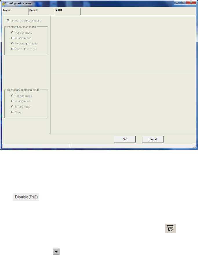
HIWIN CoE Drive User Guide v1.1 5. Setting Examples
HIWIN Mikrosystem Corp. 54
5.1. HIWIN CoE drive setting
Human-machine interface (HMI) for HIWIN drives is called Lightening. It performs functions of
motor initialization, motor configuration, motion control, test run, parameters saving, and so on.
Details please refer to user guide for each series drive. If users want to opearate a new HIWIN
CoE drive normally, its setting is the same as that for HIWIN standard drive. However, there are
three different items given in the following.
Note. If D1 CoE drive is implemented with the hardware version A1 (check if there is “A1” mark
at the end of serial number on the drive label), it needs the firmware version of D1COE
MDP 0.320 (above) to complete EtherCAT communication.
(1) Different operation-mode setting
The setting page of operation mode for HIWIN CoE drive is different with that for other
HIWIN drives. When Lightening communicates with HIWIN CoE drive successfully, it sets
operation mode to “EtherCAT operation mode” automatically, as shown in Fig. 5-1. Users do
not set any parameter for operation mode, but just do next step directly. For D1/D2 CoE
drives, press the “OK” button under the window. For D1-N CoE drive, after setting the main
power of drive (do not forget this step), press the “OK” button under the window.
Fig. 5-1
(2) Different enable method
a. Software enable
The software enable of HIWIN CoE drive is controlled by EtherCAT controller.
Therefore, before saving parameters into Flash, execute the function of software
disable ( ) on performance center.
b. Hardware enable
For EtherCAT applications, host controller normanlly does not wire a line for hardware
enable to drive. Therefore, before EtherCAT communication, drive should be at the
status of hardware enable. Press the icon of I/O center ( ) on the toolbar of
Lightening main window to open I/O center. Check if there is any input function set to
“Axis Enable” on “Inputs” tab. If yes, change its function to “Not Configured” by clicking
the drop-down button ( ) of input function menu, as shown in Fig. 5-3.
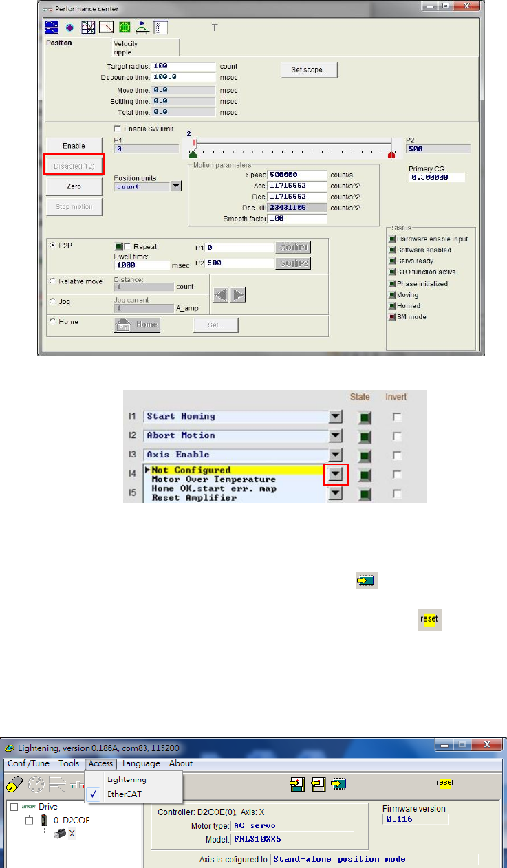
HIWIN CoE Drive User Guide v1.1 5. Setting Examples
HIWIN Mikrosystem Corp. 55
Fig. 5-2
Fig. 5-3
(3) Reset after saving parameters into Flash
After completing parameters setting, save current parameters into Flash by pressing the
icon of “Save parameters from amplifier RAM to Flash” ( ) on Lightening main window.
Therefore, if the drive power is turned off, set parameters do not disapper. After saving
parameters into Flash, reset drive by pressing the icon of “Reset” ( ) on Lightening main
window. After resetting, drive will go to the status of EtherCAT communication automatically.
Open “Access” on the toolbar of Lightening main window and check if it is at the “EtherCAT”
status, as shiown in Fig. 5-4. At this moment, parameter setting and motion controlling for
HIWIN CoE drive only can be done by EtherCAT controller, but not by Lightening. If users
want to modify drive parameter via Lightening, select “Lightening” on “Access”.
Fig. 5-4
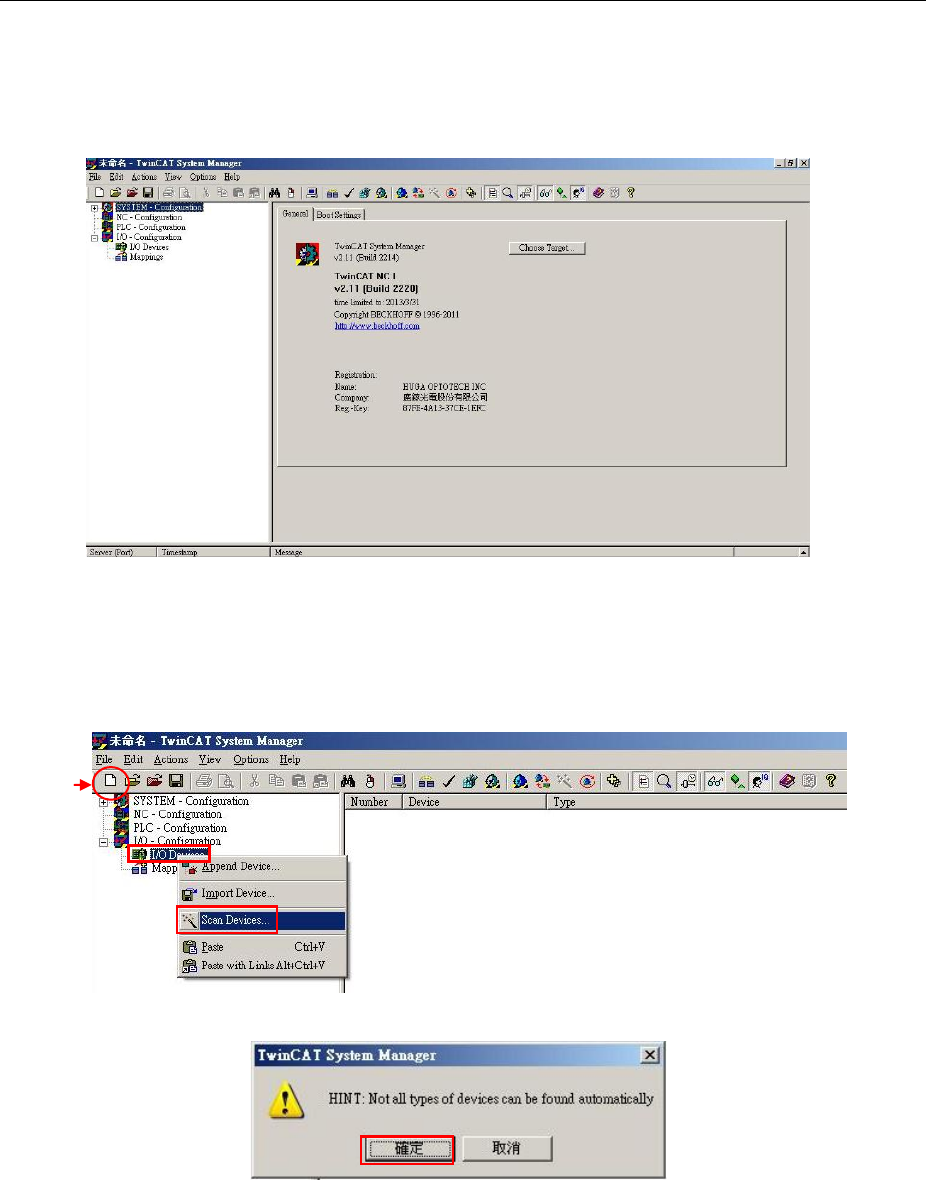
HIWIN CoE Drive User Guide v1.1 5. Setting Examples
HIWIN Mikrosystem Corp. 56
5.2. Beckhoff controller (TwinCAT 2) setting
Before communicating with HIWIN CoE drive, set its parameters by referring to Section 5.1 and
connect it to Beckhoff EtherCAT controller via network cable.
Note. Please place ESI files for HIWIN CoE drives in the folder at the installation
path ..\TwinCAT\Io\EtherCAT.
5.2.1. DC cycle time setting
There is an important function of HIWIN CoE drive – DC SYNC signal. This subsection
describes how to set DC cycle time for HIWIN CoE drive via TwinCAT 2 and enable PDO
communication. In the following, take D1 CoE drive as an example.
(1) Start TwinCAT 2.
Fig. 5-5
(2) After selecting “New” at the toolbar, click the right key of mouse at “I/O Devices” and
select “Scan Devices” within its menu, as shown in Fig. 5-6. The warning window of
Fig. 5-7 will appear to remind that not all types of devices can be found automatically.
Press the “OK” button.
Fig. 5-6
Fig. 5-7
New
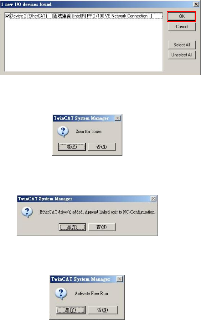
HIWIN CoE Drive User Guide v1.1 5. Setting Examples
HIWIN Mikrosystem Corp. 57
(3) When EtherCAT device is detected, it will be shown in the dialogue window of Fig.
5-8. This example is “Device 2 (EtherCAT)” detected. Press the “OK” button.
Fig. 5-8
(4) The dialogue window of Fig. 5-9 appears to ask if users want to sacn for boxes.
Press the “Yes” button.
Fig. 5-9
(5) When HIWIN CoE drive is added to TwinCAT 2, it will ask if users want to append
linked axis to NC-Configuration. Press the “Yes” button.
Fig. 5-10
(6) The following window appers to ask if users want to change TwinCAT system to Free
Run mode. Press the “No” button to keep in Configuration mode.
Fig. 5-11
(7) Open “Device 2 (EtherCAT)” in “I/O Devices”. If setting is successful, “Drive 1 (D1
CoE Drives)” can be found under “Device 2 (EtherCAT)”. If other device is connected,
the corresponding device name will show in the parentheses.
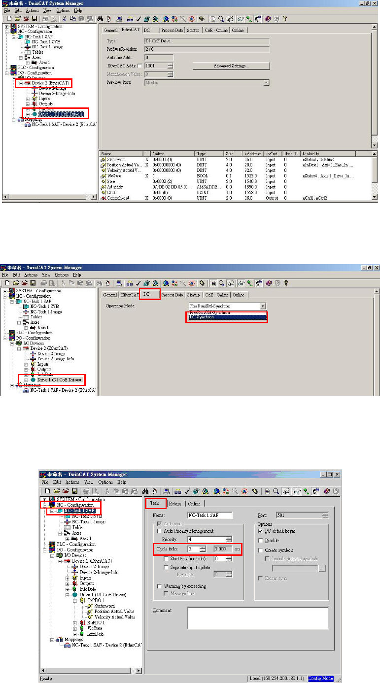
HIWIN CoE Drive User Guide v1.1 5. Setting Examples
HIWIN Mikrosystem Corp. 58
Fig. 5-12
(8) Click “Drive 1 (D1 CoE Drives)” and go to “DC” tab at the right-side window. Set
“DC-Synchron” for “Operation Mode”.
Fig. 5-13
(9) Select “NC-Task 1 SAF” in “NC-Configuration” at the left side of main window. Go to
“Task” tab at the right-side window and set DC cycle time for “Cycle ticks”. Fig. 5-14
gives an example of setting cycle time to be 2 ms.
Fig. 5-14
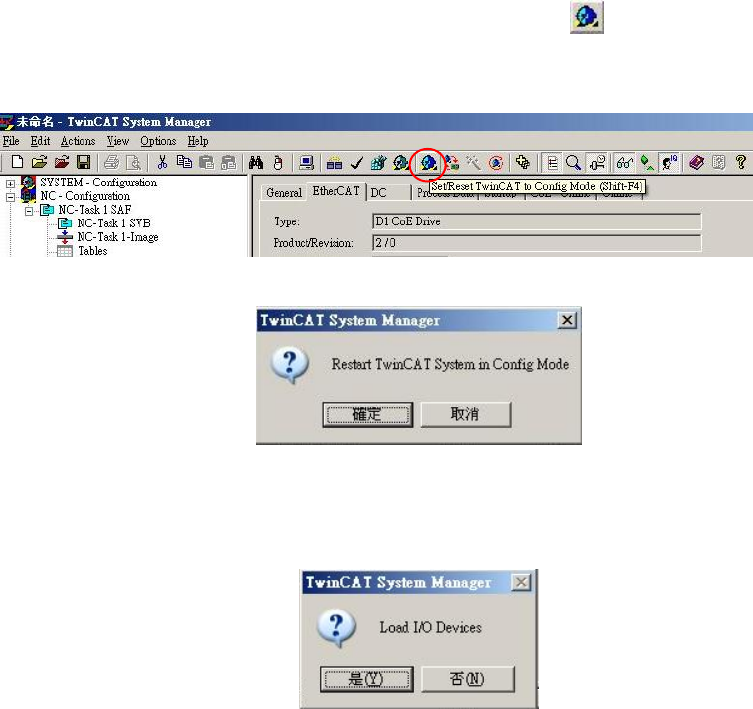
HIWIN CoE Drive User Guide v1.1 5. Setting Examples
HIWIN Mikrosystem Corp. 59
(10) Press the icon of “Set/Reset TwinCAT to Config Mode” ( ) on the toolbar to reset
TwinCAT, as shown in Fig. 5-15. The dialogue window of Fig. 5-16 appears to ask if
users want to reset TwinCAT system to Configuration mode. Press the “OK” button.
Fig. 5-15
Fig. 5-16
(11) The following dialogue window appears to ask if users want to load I/O devices. Press
the “Yes” button.
Fig. 5-17
(12) The dialogue window of Fig. 5-11 appears to ask if users want to change TwinCAT
system to Free Run mode. Press the “Yes” button to enable PDO communication
between TwinCAT and drive.
(13) Ensure PDO communication between TwinCAT and drive.
a. Click “Drive 1 (D1 CoE Drivers)” at the left side of TwinCAT main window. Select
“Position Actual Value” under TxPDO. Go to “Online” tab at the right side of main
window.
b. At the status of motor disable, move motor in manual to check if the feedback
position of motor (X_enc_pos) is the same as the value shown in “Online” tab of
TwinCAT.
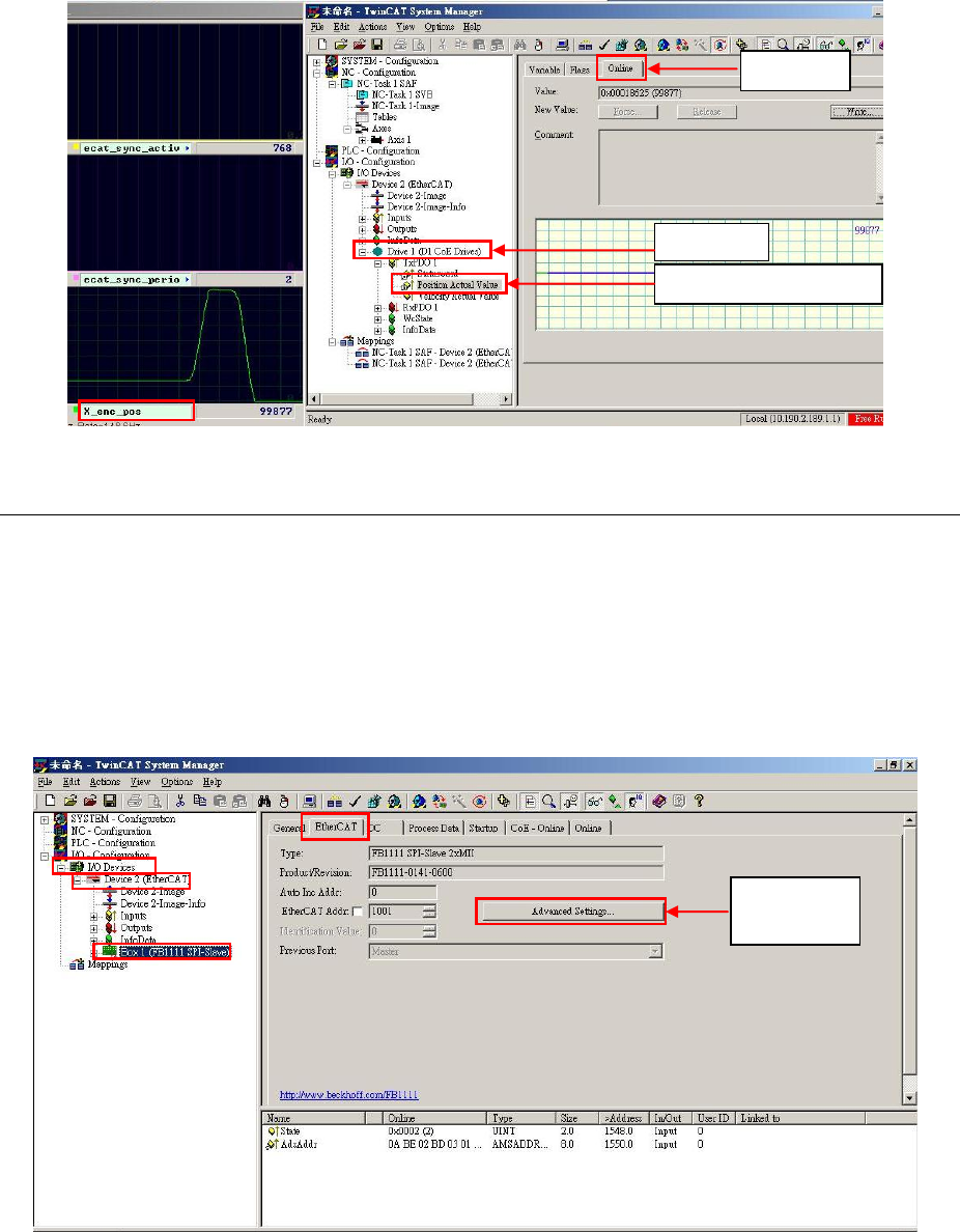
HIWIN CoE Drive User Guide v1.1 5. Setting Examples
HIWIN Mikrosystem Corp. 60
Fig. 5-18
5.2.2. EEPROM update
This subsection describes how to update EEPROM of HIWIN CoE drive via TwinCAT 2.
(1) Execute Steps (1)-(6) given in Section 5.2.1.
(2) Select “Devices 2 (EtherCAT)” in “I/O Devices” at the left side of TwinCAT main window.
There is one sub-item of “Box 1 (FB1111 SPI-Slave)” or unkwnon device. After selecting
device needed to update EEPROM, press the button of “Advanced Settings” on
“EtherCAT” tab at the right-side window, as shown in Fig. 5-19.
Fig. 5-19
(3) Select “E2PROM” in “ESC Access” at the left side of “Advanced Settings” window. After
clicking “Hex Editor”, it can be found that “FB1111 SPI-Slave”, unknown device, or blank
content is on the program note area at the right-side window, as shown in Fig. 5-20.
a. Press the button of “Read from File” under the window to open the location of
HIWIN EtherCAT EEPROM file (.bin file). Let TwinCAT read this file.
b. Press the “Download” button under the window to load new EEPROM file into drive.
c. After completing EEPROM file download, press the “OK” button at the bottom of
window.
Online
Position Actual Value
Drive 1
Advanced
Settings
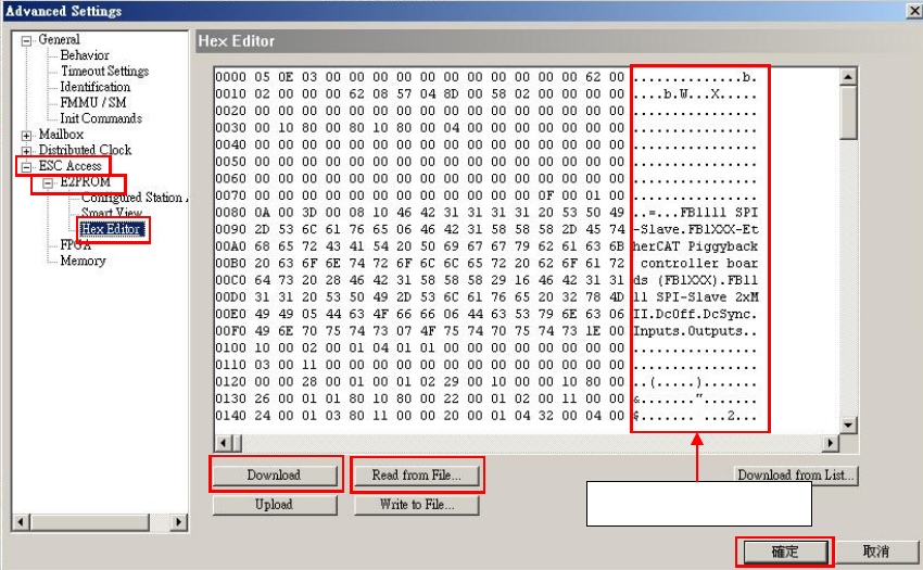
HIWIN CoE Drive User Guide v1.1 5. Setting Examples
HIWIN Mikrosystem Corp. 61
(4) Power cycle drive to complete EEPROM update.
Fig. 5-20
Program note area
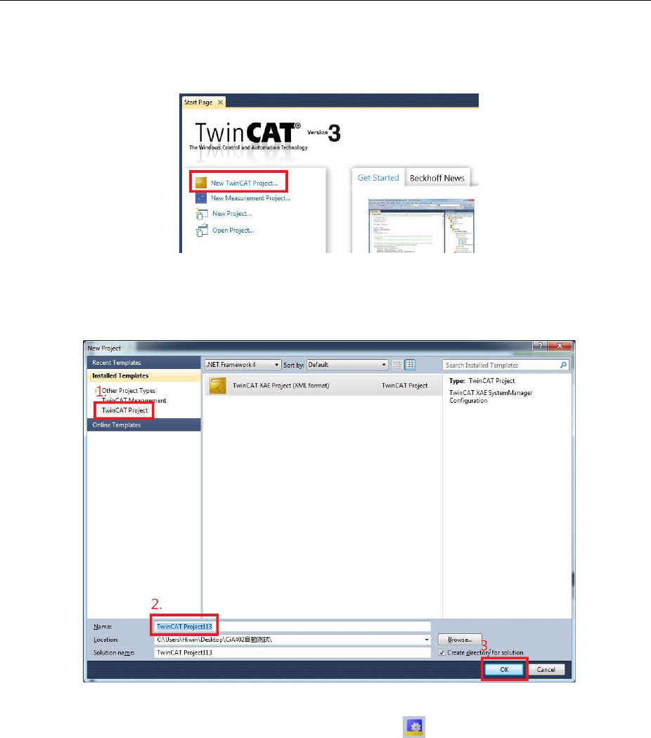
HIWIN CoE Drive User Guide v1.1 5. Setting Examples
HIWIN Mikrosystem Corp. 62
5.3. Beckhoff controller (TwinCAT 3) setting
Before communicating with HIWIN CoE drive, set its parameters by referring to Section 5.1 and
connect it to Beckhoff EtherCAT controller via network cable.
Note. Please place ESI files for HIWIN CoE drives in the folder at the installation
path ..\TwinCAT\3.1\Config\Io\EtherCAT.
5.3.1. Communication setting
This subsection describes how to communicate TwinCAT 3 to HIWIN CoE drive. In the following,
take D2 CoE drive as an example.
(1) Start TwinCAT 3 and select “New TwinCAT Project”.
Fig. 5-21
(2) Select “TwinCAT project” and enter project name and location at the bottom of “New
Project” window. After that, press the “Ok” button to build new project.
Fig. 5-22
(3) Click the icon of “Restart TwinCAT (Config Mode)” ( ) on the toolbar of TwinCAT main
window to change TwinCAT operation mode to Configuration mode. Choose “I/O” at the
left-side window, and click the right key of mouse at “Devices” to execute the function of
“Scan” in the menu.
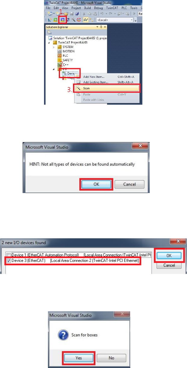
HIWIN CoE Drive User Guide v1.1 5. Setting Examples
HIWIN Mikrosystem Corp. 63
Fig. 5-23
(4) The warning window of Fig. 5-24 appears to remind that not all types of devices can be
found automatically. Press the “OK” button.
Fig. 5-24
(5) If one EtherCAT device is detected, it will be shown in the dialogue window of Fig. 5-25.
This example shows two devices detected. Check the option of “Device 3 (EtherCAT)”
and press the “OK” button.
Fig. 5-25
(6) The dialogue window of Fig. 5-26 appears to ask if users want to scan for boxes. Press
the “Yes” button.
Fig. 5-26
(7) After HIWIN CoE drive is added to TwinCAT, it will ask if users want to append linked
axis to NC- Configuration. Press the “Yes” button.
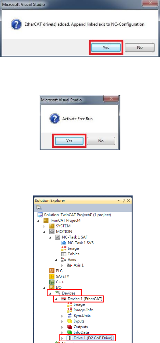
HIWIN CoE Drive User Guide v1.1 5. Setting Examples
HIWIN Mikrosystem Corp. 64
Fig. 5-27
(8) The following dialogue window appears to ask if users want to change the TwinCAT
operation mode to Free Run mode. Press the “Yes” button to activate Free Run mode.
Fig. 5-28
(9) Go to “Devices” in “I/O” at the left side of TwinCAT main window. Check if “Drive 1 (D2
CoE Drive)” appears in “Device 1 (EtherCAT)” or not. If not, the ESI file or drive
EEPROM should be updated.
Fig. 5-29
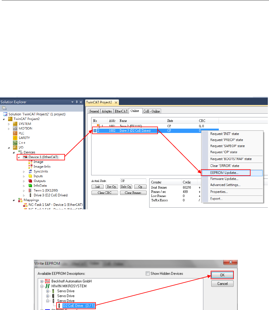
HIWIN CoE Drive User Guide v1.1 5. Setting Examples
HIWIN Mikrosystem Corp. 65
5.3.2. EEPROM update
This subsection describes how to update the EEPROM data of HIWIN CoE drive via TwinCAT 3.
In the following, take D2 CoE drive as an example.
Note. Before update, please check if the correct ESI file is placed in the folder at the installation
path..\TwinCAT\3.1\Config\Io\EtherCAT. For example, the ESI file for D2 CoE drive is
D2COE_.xml.
(1) Execute Steps (1)-(6) given in Section 5.3.1.
(2) Select “Device 1 (EtherCAT)” in “Devices” at the left side of TwinCAT main window. Go
to “Online” tab at the right-side window. Press the right key of mouse at the drive
needed to update EEPROM (D2 CoE Drives) and select “EEPROM Update” in the
menu.
Fig. 5-30
(3) The “Write EEPROM” window shows the supported EEPROM files for drives. Select
one matched EEPROM file for drive. Here, the EEPROM file for D2 CoE drive is
selected to update. If D1/D1-N CoE drive is used, the EEPROM file for D1/D1-N CoE
drive should be selected. After that, press the “OK” button to write EEPROM.
Fig. 5-31
(4) During writing process, the lower left corner of TwinCAT main window displays “Writing”
and the lower right corner shows the current programming schedule.
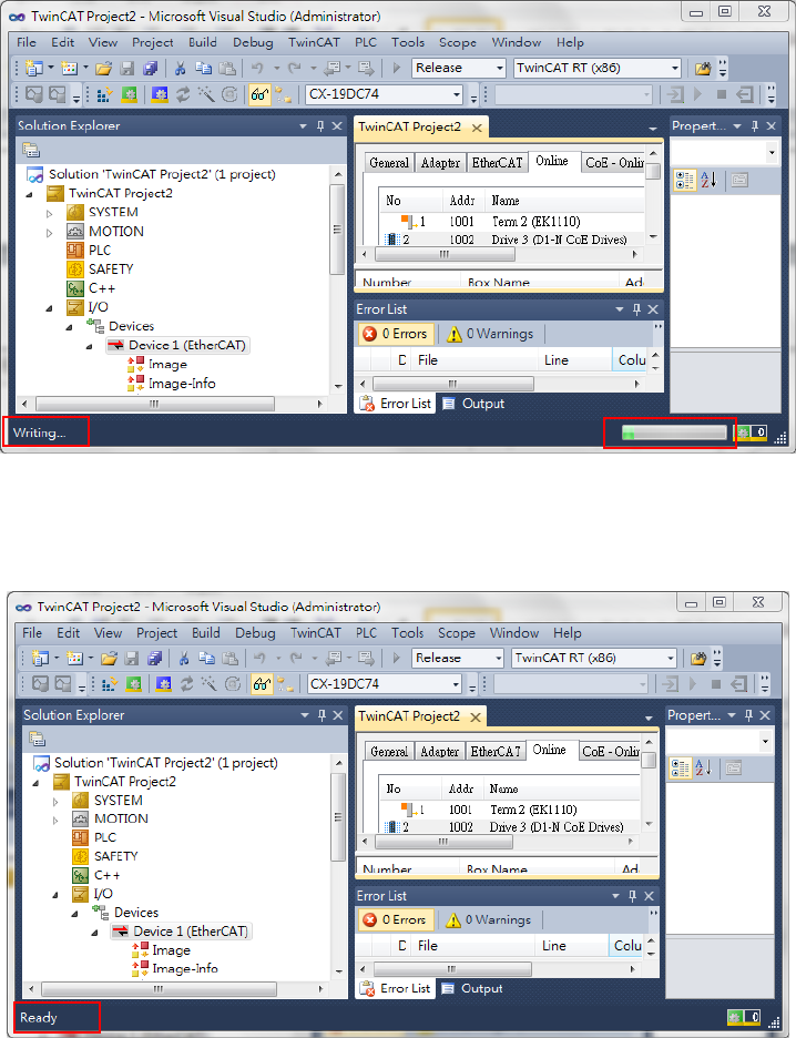
HIWIN CoE Drive User Guide v1.1 5. Setting Examples
HIWIN Mikrosystem Corp. 66
Fig. 5-32
(5) After completing EEPROM writing, the lower left corner of TwinCAT main window
displays “Ready”.
Fig. 5-33
(6) Power cycle HIWIN CoE drive to complete EEPROM update.
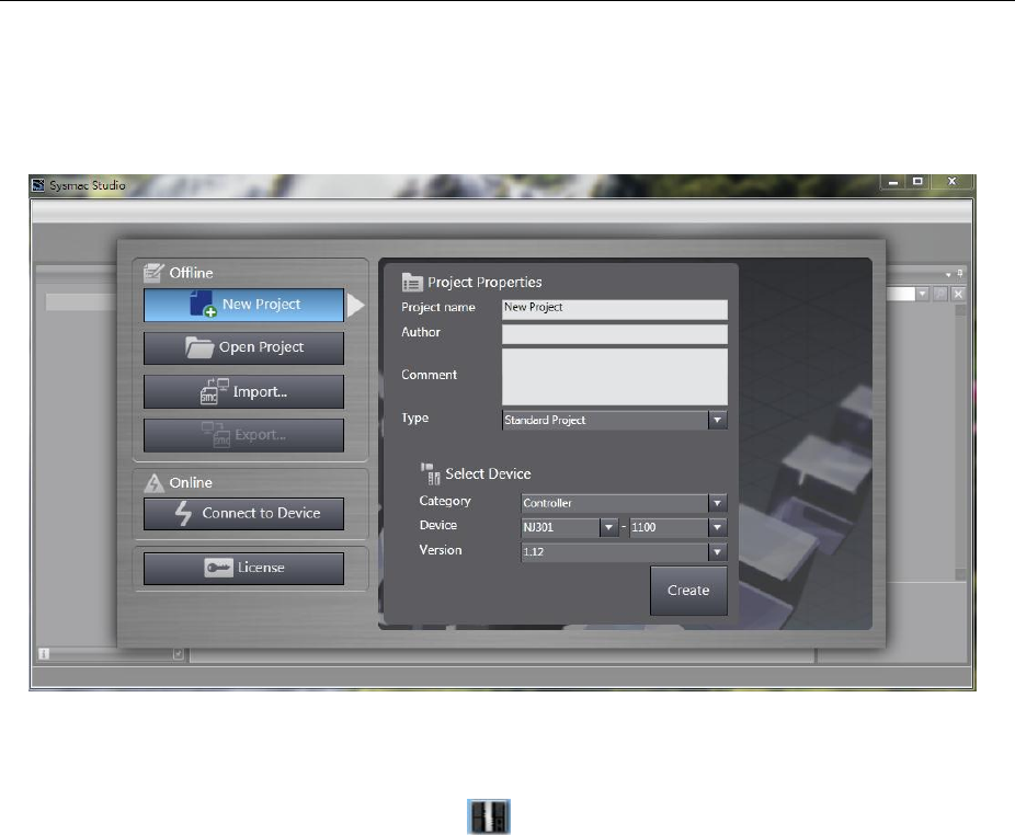
HIWIN CoE Drive User Guide v1.1 5. Setting Examples
HIWIN Mikrosystem Corp. 67
5.4. OMRON controller setting
Before communicating with HIWIN CoE drive, set its parameters by referring to Section 5.1 and
connect it to OMRON EtherCAT controller (NJ series) via network cable.
5.4.1. ESI file update
This subsection describes how to update the ESI file for HIWIN CoE drive at the environment of
OMRON software – Sysmac Studio.
(1) Start Sysmac Studio and select “New Project”. After entering project properties and
setting controller parameters, press the “Create” button.
Fig. 5-34
(2) Select “EtherCAT” in “Configurations and Setup” at the left side of Sysmac Studio main
window, and click the left key of mouse twice to open “EtherCAT” page. Click the right
key of mouse at the controller icon ( ), and select “Display ESI Library”, as shown in
Fig. 5-35.
(3) The “ESI Library” window shows ESI files supported by Sysmac Studio, as given in Fig.
5-36. Check if there is the ESI file for HIWIN CoE drive or not.
a. If there is no HIWIN ESI file, press the green word of “this folder” in the window to
open the folder contained customer’s ESI files. Place the least HIWIN ESI file in this
folder. The path of folder is the installation path ..\OMRON \Sysmac
Studio\IODeviceProfiles\EsiFiles\UserEsiFiles.
b. If there is the old HIWIN ESI file, open the folder contained customer’s ESI files.
After deleting the old file, place the least HIWIN ESI file in this folder.
(4) Close Sysmac Studio and re-start it. Now, Sysmac Studio can support the least HIWIN
ESI file.
Note. If the existed project is built according to the old HIWIN ESI file, the corresponding
drive allocation should be removed. After updating HIWIN ESI file and re-starting
Sysmac Studio, HIWIN CoE drives should be re-allocated and set to let them work
normally.
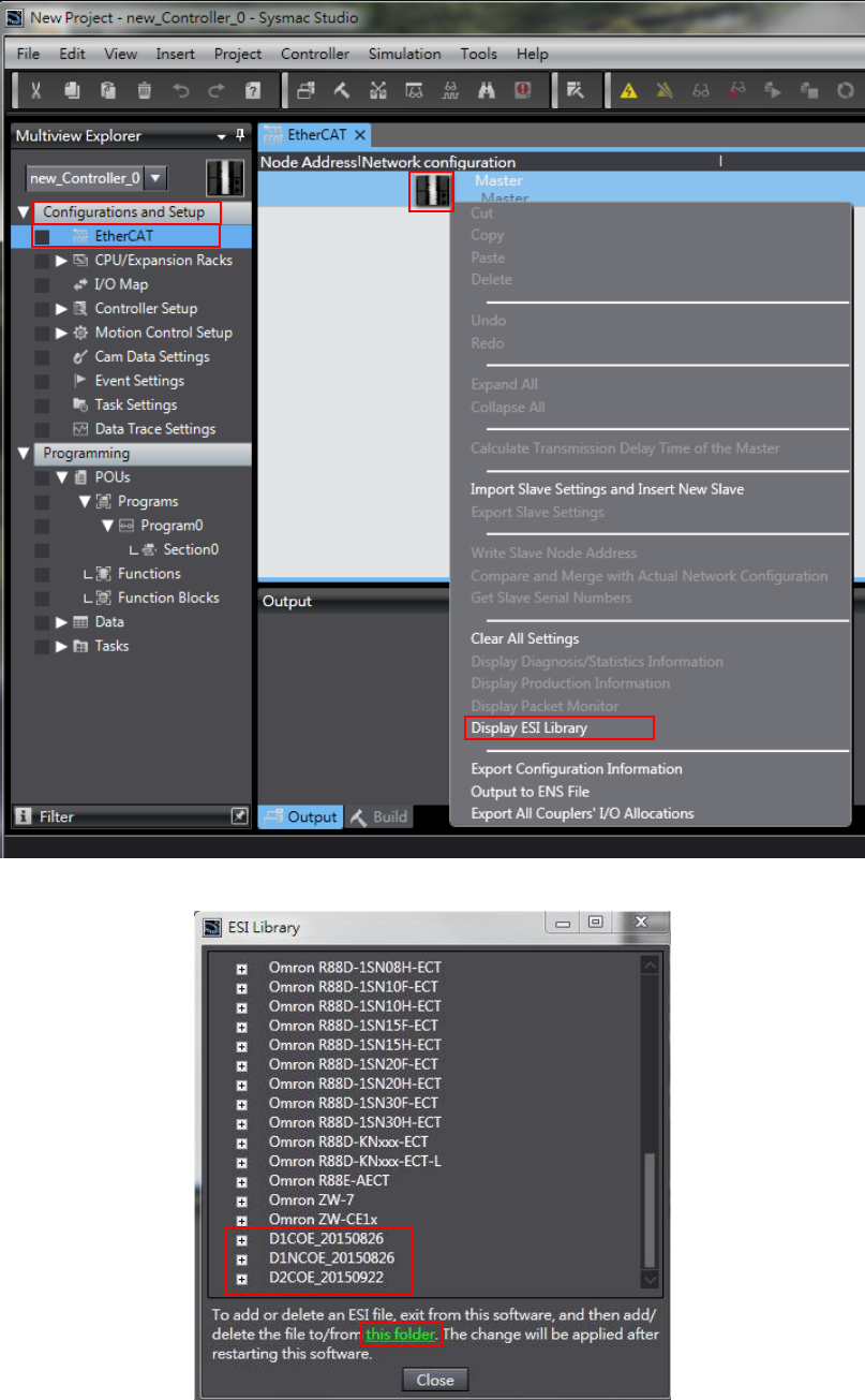
HIWIN CoE Drive User Guide v1.1 5. Setting Examples
HIWIN Mikrosystem Corp. 68
Fig. 5-35
Fig. 5-36
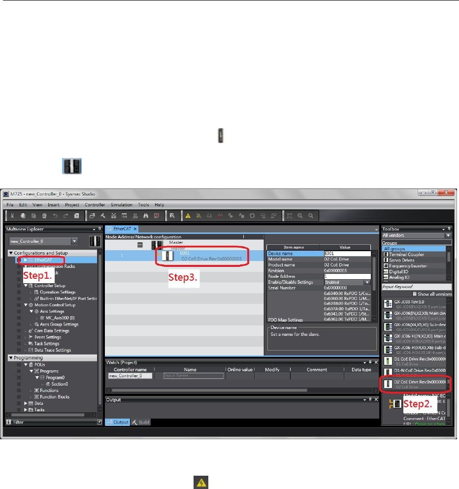
HIWIN CoE Drive User Guide v1.1 5. Setting Examples
HIWIN Mikrosystem Corp. 69
5.4.2. Slave ID writing
This subsection describes how to set one slave ID for HIWIN CoE drive via OMRON software –
Sysmac Studio. In the following, take D2 CoE drive as an example.
Note. With OMRON EtherCAT controller, each CoE drive should have one different slave ID to
let controller configurate network successfully.
(1) Start Sysmac Studio and build one new project.
(2) Set the connection between OMRON EtherCAT controller and HIWIN CoE drive.
a. Select “EtherCAT” in “Configurations and Setup” at the left side of Sysmac Studio
main window.
b. Select the icon of D2 CoE drive ( ) in “Toolbox” at the right-side window.
c. Drag the drive icon to “EtherCAT” tab and put it under the icon of OMRON controller
().
Fig. 5-37
(3) Open the window of “Write Slave Node Address”, as shown in Fig. 5-38.
a. Click the icon of “Online” ( ) at the toolbar of Sysmac Studio to let controller
connect with drive.
b. Click the right key of mouse at the controller icon to appear menu.
c. Select “Write Slave Node Address” in the menu.
(4) Write slave ID in drive in the window of “Slave Node Address Writing”, as shown in Fig.
5-39.
a. Write slave ID in drive (range: 1~192).
b. After pressing the “Write” button at the lower right corner of window, the warning
window will appear to remind that the node address is written to the slave.
c. Press the “Write” button in the warning window to write slave ID in drive.
d. After completing slave ID writing, turn off the main power of controller and drive.
After 5 seconds, turn on their main power again.
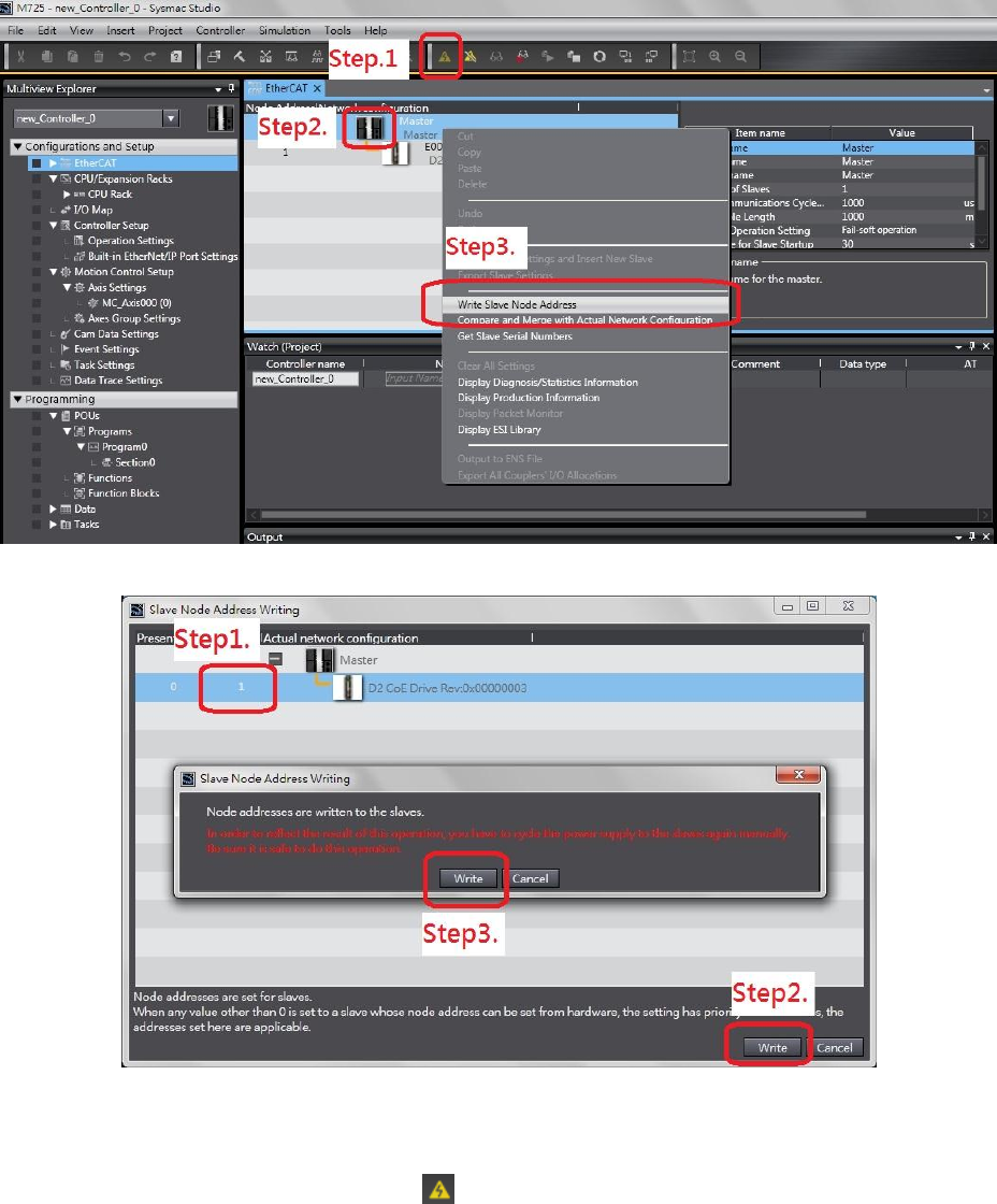
HIWIN CoE Drive User Guide v1.1 5. Setting Examples
HIWIN Mikrosystem Corp. 70
Fig. 5-38
Fig. 5-39
(5) Open the window of “Compare and Merge with Actual Network Configuration”, as
shown in Fig. 5-40.
a. Click the icon of “Online” ( ) at the toolbar of Sysmac Studio to let controller
connect with drive.
b. Click the right key of mouse at the controller icon to appear menu.
c. Select “Compare and Merge with Actual Network Configuration” in the menu. If the
warning window appears, it should be that drive or controller does not power cycle
yet. Power cycle drive or controller.
(6) Check if “Node Address” is the same as the value written in Step (4). If they are the
same, it means that slave ID writing is successful. If the exclamation point appears in
the front of drive, it means that the actual slave ID of drive is different with that in the
network configuration of Sysmac Studio. Press the button of “Apply actual network
configuration” to let the network configuration of Sysmac Studio is the same as the
actual network configuration.
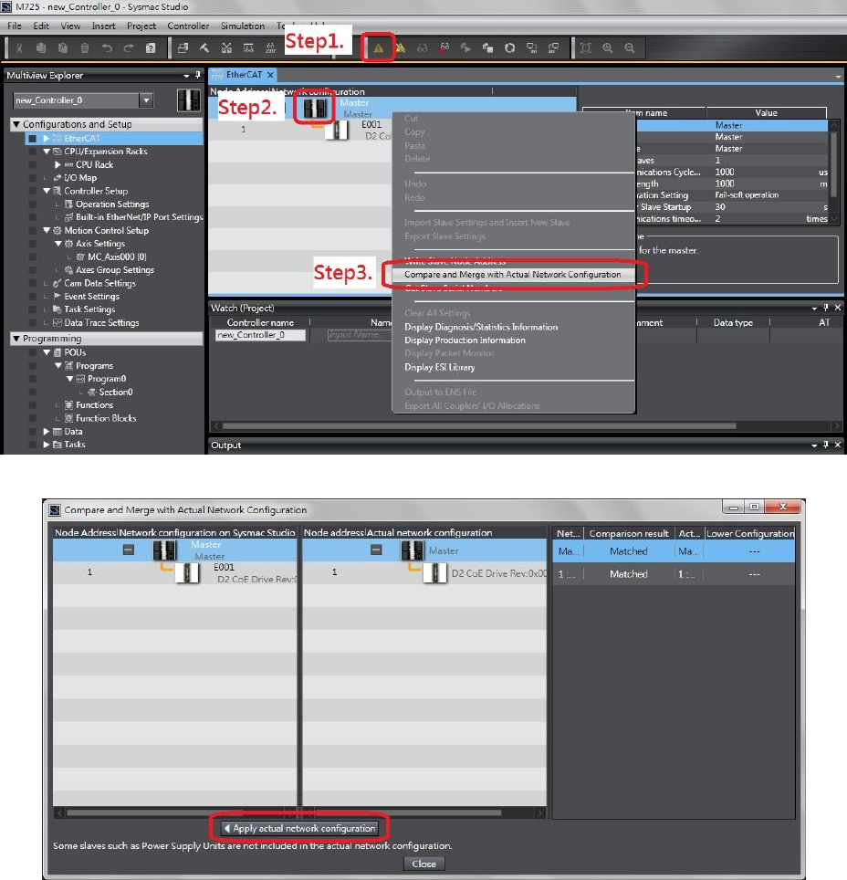
HIWIN CoE Drive User Guide v1.1 5. Setting Examples
HIWIN Mikrosystem Corp. 71
Fig. 5-40
Fig. 5-41
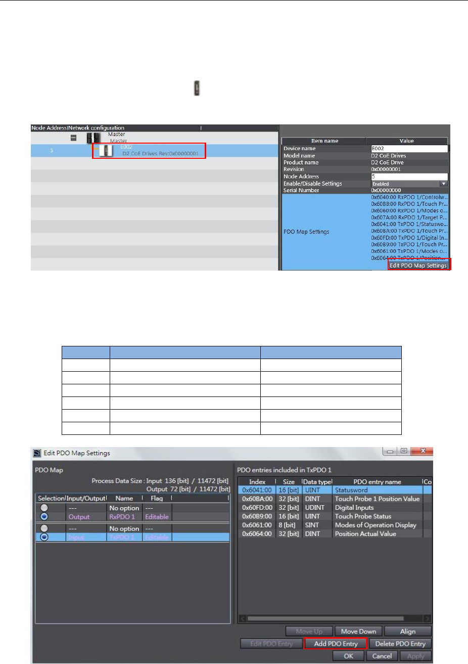
HIWIN CoE Drive User Guide v1.1 5. Setting Examples
HIWIN Mikrosystem Corp. 72
5.4.3. Homing example
This subsection describes how to let HIWIN CoE drive perform homing via OMRON software –
Sysmac Studio. In the following, take D2 CoE drive as an example.
(1) Execute steps given in Section 5.4.2 to complete the network configuration of OMRON
controller with HIWIN CoE drive (Slave ID is set to be 5).
(2) Click the icon of D2 CoE drive ( ) on “EtherCAT” tab and press the button of “Edit PDO
Map Settings” at the right-side window.
Fig. 5-42
(3) Select TxPDO1 and press the button of “Add PDO Entry” in the window of “Edit PDO
Map Settings”. Add objects given in Table 5-1 into TxPDO1, as shown in Fig. 5-43.
Table 5-1
Object
Definition
Description
0x6041
Statusword
Default
0x60BA
Touch Probe 1 Position value
For homing
0x60FD
Digital Inputs
For homing
0x60B9
Touch Probe Status
For homing
0x6061
Modes of Operation Display
For OMRON communication
0x6064
Position Actual Value
Default
Fig. 5-43
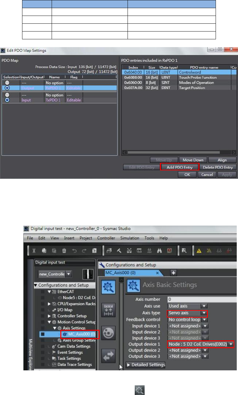
HIWIN CoE Drive User Guide v1.1 5. Setting Examples
HIWIN Mikrosystem Corp. 73
(4) Select RxPDO1 and press the button of “Add PDO Entry” in the window of “Edit PDO
Map Settings”. Add objects given in Table 5-2 into RxPDO1, as shown in Fig. 5-44.
Table 5-2
Object
Definition
Description
0x6040
Controlword
Default
0x60B8
Touch Probe function
For homing
0x6060
Modes of Operation
For OMRON communication
0x607A
Target Position
Default
Fig. 5-44
(5) Set PDO mapping between controller and drive.
a. Select “Motion Control Setup” in “Configurations and Setup” at the left side of
Sysmac Studio main window. Click “MC_Axis000 (0)” in “Axis Settings”.
Fig. 5-45
b. Click the icon of “Axis Basic Settings” ( ) in “MC_Axis000 (0)” tab to open the
“Axis Basic Settings” page. Set “Axis type” to be “Servo axis” and “Output device 1”
to be drive linked to this axis. In the example of Fig. 5-45, it is “Node:5 D2 CoE
Drives (E002)”.
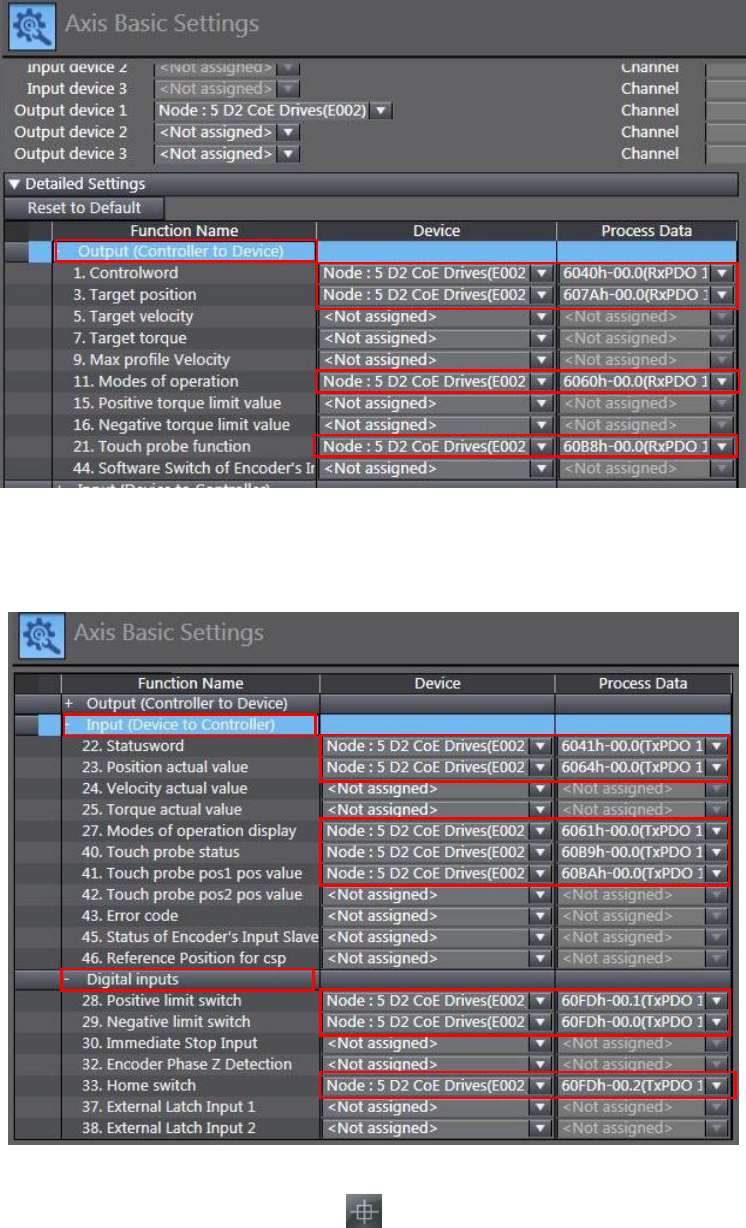
HIWIN CoE Drive User Guide v1.1 5. Setting Examples
HIWIN Mikrosystem Corp. 74
c. Open “Detailed Settings” in “Axis Basic Settings” to set PDO mapping for “Output
(Controller to Device)”, as shown in Fig. 5-46. Note that, the definition of “Process
Data” should be the same as “Function Name”.
Fig. 5-46
d. Set PDO mapping for “Input (Device to Controller)” and “Digital Inputs”, as shown in
Fig. 5-47.
Fig. 5-47
(6) Click the icon of “Homing Settings” ( ) in “MC_Axis000 (0)” tab to open the “Homing
Settings” page. Set homing method, homing velocity, and homing acceleration based
on the actual demand. In the example of Fig. 5-48, “Homing method” is set to be “Home
proximity input ON” and “Home input signal” is set to be “Use Z-phase input as home”.
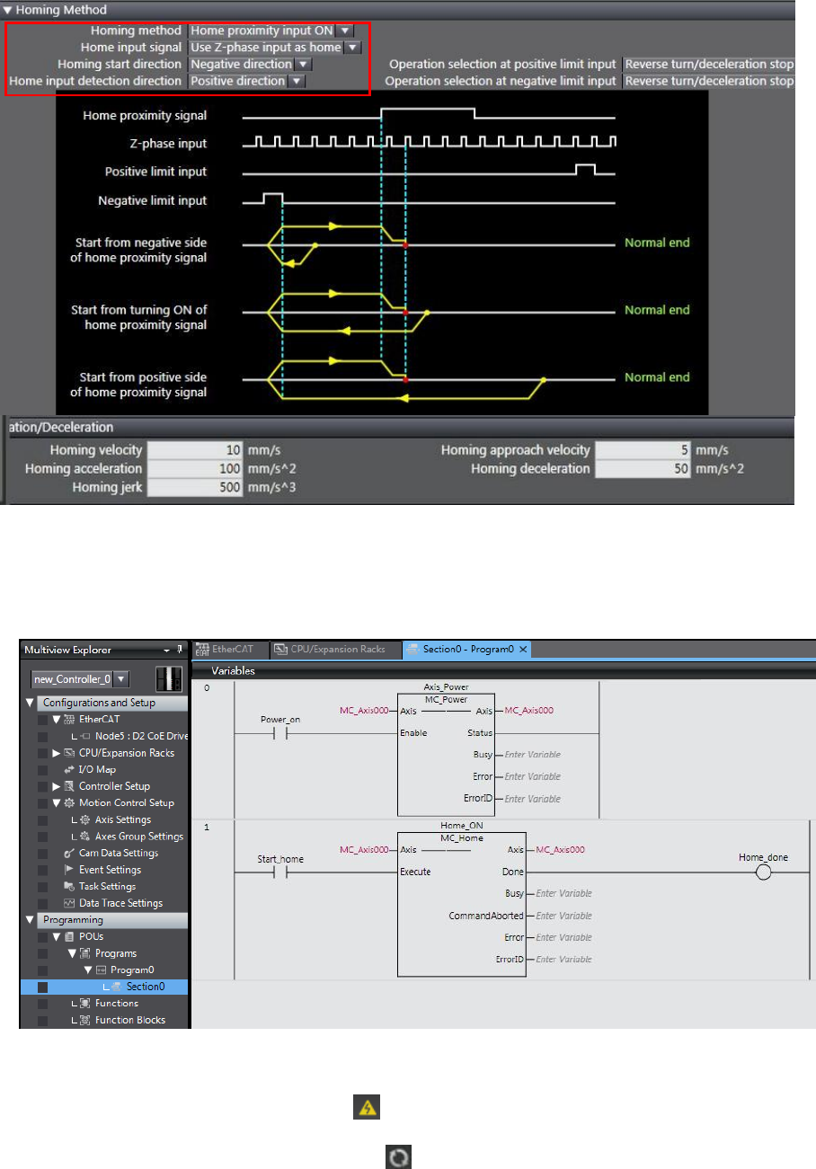
HIWIN CoE Drive User Guide v1.1 5. Setting Examples
HIWIN Mikrosystem Corp. 75
Fig. 5-48
(7) Open “POUs” in “Programming” at the left side of Sysmac Studio main window. Select
“Program0” in “Programs”. Use two function blocks of “MC_Power” and “MC_Home” to
code a simple homing program on “Section0”, as shown in Fig. 5-49.
Fig. 5-49
(8) Execute homing program.
a. Click the icon of “Online” ( ) at the toolbar of Sysmac Studio to let controller
connect with drive.
b. Click the icon of “Synchronize” ( ) at the toolbar of Sysmac Studio to compare the
program in Sysmac Studio with that in controller. Load program into controller.
c. After completing program loading, set “Power_on” on “Section0” page to be “True”
to enable motor.
d. Set “Start_home” on “Section0” page to be “True” to let motor execute homing.
e. The homing result is given in Fig. 5-50.
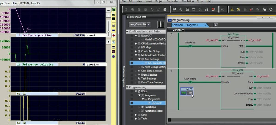
HIWIN CoE Drive User Guide v1.1 5. Setting Examples
HIWIN Mikrosystem Corp. 76
Fig. 5-50
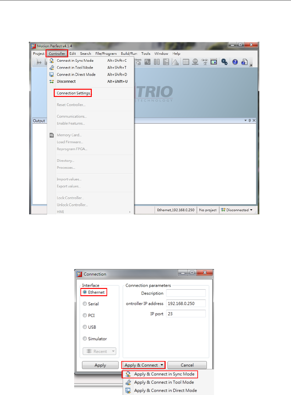
HIWIN CoE Drive User Guide v1.1 5. Setting Examples
HIWIN Mikrosystem Corp. 77
5.5. TRIO controller setting
Before communicating with HIWIN CoE drive, set its parameters by referring to Section 5.1 and
connect it to TRIO EtherCAT controller via network cable.
5.5.1. Communication setting
This subsection describes how to connect with HIWIN CoE drive via TRIO software – Motion
Perfect. In the following, take D2 CoE drive as an example.
(1) Open Motion Perfect and select “Connection settings” in “Controller”.
Fig. 5-51
(2) Set suitable parameters according to actual connection. In the following, take Ethernet
connection as an example. Select “Ethernet” in “Interface”, use default values in
“Connection parameters”, and choose “Apply & Connect in Sync Mode” in “Apply &
Connect”.
Fig. 5-52
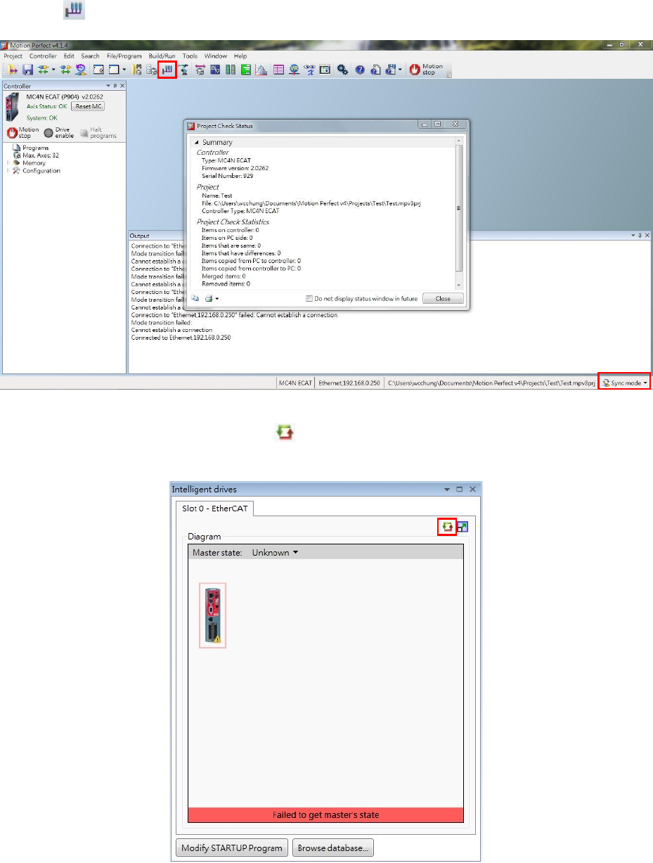
HIWIN CoE Drive User Guide v1.1 5. Setting Examples
HIWIN Mikrosystem Corp. 78
(3) After connecting with controller successfully, the information of TRIO controller is
shown in the left side of Motion Perfect main window. The current status is “Sync mode”
and is shown in the lower right corner. Click the icon of “Intelligent drives configuration”
() at the toolbar to open the window for EtherCAT connection setting.
Fig. 5-53
(4) Click the icon of “Re-initialize” ( ) on “Slot 0 - EtherCAT” tab to re-initialize EtherCAT
connection.
Fig. 5-54
a. If the icon of HIWIN drive is shown in “Diagram” and “Master state” is “Operational”,
it means that the communication between TRIO controller and HIWIN CoE drives is
built successfully.
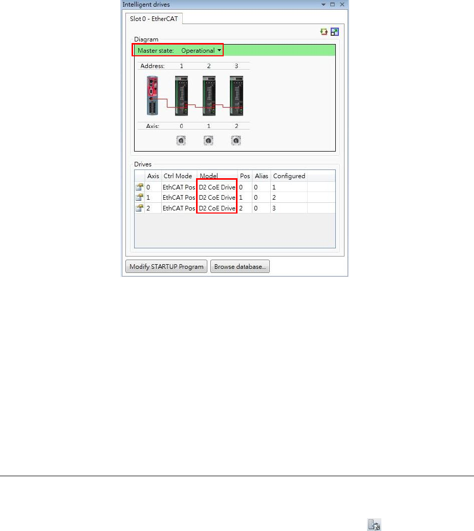
HIWIN CoE Drive User Guide v1.1 5. Setting Examples
HIWIN Mikrosystem Corp. 79
Fig. 5-55
b. If the icon of HIWIN drive does not show in “Diagram”, it may be caused by the
following two reasons.
(a) The EEPROM data of HIWIN drive does not match with the ESI version
supported by TRIO controller. Please write the EEPROM file supported by TRIO
controller in drive via TwinCAT.
(b) If the ESI or EEPROM file of HIWIN CoE drive is updated, the current firmware
of TRIO controller cannot distinguish it. Please update the firmware of TRIO
controller, or contact HIWIN engineer for assistance.
Note. TRIO software version above “MC4NE_20262” begins to support HIWIN COE
drives. ESI files corresponding to “MC4NE_20262” are D1COE_20150826.
xml, D1NCOE_20150826.xml, and D2COE_20150922.xml.
5.5.2. Motion parameter setting
This subsection describes how to set motion parameters for each axis via TRIO software –
Motion Perfect. In the following, take D2 CoE drive as an example.
(1) Open Motion Perfect and select the icon of “Axis Parameters” ( ) at the toolbar of
Motion Perfect main window.
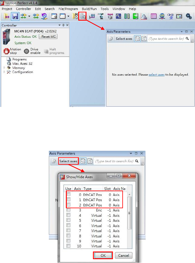
HIWIN CoE Drive User Guide v1.1 5. Setting Examples
HIWIN Mikrosystem Corp. 80
Fig. 5-56
(2) Click “Select axes” in the window of “Axis Parameters” to open the window of
“Show/Hide Axes”. Check the option of axis wanted to be shown. After that, press the
“OK” button.
Fig. 5-57
(3) Motion parameters can be modified in the window of “Axis Parameter”, e.g., speed,
acceleration, and so on. The definition of motion parameter can be obtained by
searching its name on “Trio BASIC help” located at “Help” of main window.
Note. The setting of “UNIT” is very important at the setting of axis parameter. Suppose
that 17-bit AC servo motor with the screw pitch of 10 mm is used. One
revolution of motor is equal to 131072 counts (= 10 mm). If “Unit” is set to be
131072, the motion parameter and distance will take 131072 (= 10 mm) as the
unit. For example, if the acceleration (ACCEL) is set to be 20, it means that the
acceleration is 20*10 = 200 mm/s2. Hence, please check this parameter
carefully to avoid an accident.
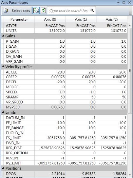
HIWIN CoE Drive User Guide v1.1 5. Setting Examples
HIWIN Mikrosystem Corp. 81
Fig. 5-58

HIWIN CoE Drive User Guide v1.1
HIWIN Mikrosystem Corp. 82
HIWIN CoE Drive User Guide
○C HIWIN Mikrosystem Corp.
