MT5000/4000系列与控制器连接说明 HMI And PLC Connecting Guide
User Manual:
Open the PDF directly: View PDF ![]() .
.
Page Count: 427 [warning: Documents this large are best viewed by clicking the View PDF Link!]
- MT5000/4000 Series HMI and PLC connecting guide
- 1 Serial Communication Pin definition
- 2 Printer Connecting Cable Diagram
- 3 Download Cable Diagram
- 4 Communication Settings and guide of HMI connecting with Controller
- 4.1 ABB Corporation
- 4.2 Allen-Bradley
- 4.3 ACS-Tech80 Motion Controller
- 4.4 ADAM
- 4.5 AysjNet
- 4.6 BACnet
- 4.7 Baldor NextMove ES (Motion Controller)
- 4.8 Barcode
- 4.9 Baumuller
- 4.10 Bosch Rexroth KVFC+ (Inverter)
- 4.11 Bosch Rexroth
- 4.12 Bosch Rexroth Ethernet
- 4.13 CANOpen Node Slave
- 4.14 Cimon
- 4.15 Danfoss Inverter
- 4.16 Delta Corporation
- 4.17 Delta (Temperature Controller)
- 4.18 ENDA
- 4.19 Emerson NetWork Power
- 4.20 Epower
- 4.21 Fatek Corporation
- 4.22 Fuji SPB
- 4.23 GE Fanuc Automation Inc.
- 4.24 HAIWELL
- 4.25 HanG
- 4.26 Hitachi Inverter
- 4.27 Hitachi IES Co., Ltd
- 4.28 Hollysys Corporation
- 4.29 HuaDA HD-JZ06
- 4.30 IDEC Corporation
- 4.31 Inovance Electric Corporation
- 4.32 Invt
- 4.33 KDN Corporation
- 4.34 Kinco Corporation
- 4.35 Kinco Inverter
- 4.36 Kinco EB-MOD2P-01(Kinco Bus Bridge)
- 4.37 Kinco Servo Series
- 4.38 Kinco Master & Kinco Slave(Master/Slave Protocol Connection)
- 4.39 Keyence Corporation
- 4.40 Koyo Corporation
- 4.41 KTC Srdlink
- 4.42 KYL Slave
- 4.43 LENZE Inverter
- 4.44 LS Industrial Systems(LG)
- 4.45 LUST
- 4.46 Memory map
- 4.47 MEGMEET
- 4.48 Mikom
- 4.49 Millenium3
- 4.50 Mitsubishi Electric Corporation
- 4.51 MKS controller
- 4.52 Modbus
- 4.53 MODROL
- 4.54 OE MAX
- 4.55 Omron Corporation
- 4.56 OMRON E5EZ-R3(Temperature Controller)
- 4.57 OPTO 22
- 4.58 Panasonic Electric Corporation
- 4.59 Parker Automation(Servo Controller)
- 4.60 PMAC Motion Controller
- 4.61 Power-one AURORA Wind Inverter
- 4.62 Profibus DP Slave
- 4.63 RF-IC (Card Reader)
- 4.64 RKC Instrument INC.
- 4.65 Saia-Burgess
- 4.66 Sailsors D9 (Temperature Controller)
- 4.67 Schneider Electric, Ltd.
- 4.68 SHIMADEN
- 4.69 SIEMENS
- 4.70 SIKO AG05 SIKONETZ5
- 4.71 Sinocon Sc1n
- 4.72 TAIAN
- 4.73 TMCM
- 4.74 Toledo DLoadCell
- 4.75 Toshiba
- 4.76 Trio motion controller
- 4.77 Unitronics
- 4.78 Universal ASCII Slave
- 4.79 Vigor Corporation
- 4.80 XINJE Controller
- 4.81 XiLin Inverter
- 4.82 Yamatake Corporation
- 4.83 Yaskawa Electric Corporation
- 4.84 Yokogawa Electric Corporation
- 4.85 YuDian AI
- 4.86 ZiGuang Ethernet
- 4.87 ZHIMEI CB920X

To be the partner of your success
CONTENTS
MT5000/4000 SERIES HMI AND PLC CONNECTING GUIDE....................................................... - 1 -
1 SERIAL COMMUNICATION PIN DEFINITION............................................................................................- 1 -
2 PRINTER CONNECTING CABLE DIAGRAM .............................................................................................- 3 -
2.1 Serial Interface Printer Cable ....................................................................................................... - 3 -
2.2 Recommend Optional printer ....................................................................................................... - 5 -
3 DOWNLOAD CABLE DIAGRAM..............................................................................................................- 6 -
3.1 Download by Serial Port .............................................................................................................. - 6 -
3.2 Download by USB ....................................................................................................................... - 6 -
3.3 Download by Network Ethernet................................................................................................... - 6 -
4 COMMUNICATION SETTINGS AND GUIDE OF HMI CONNECTING WITH CONTROLLER ............................- 8 -
4.1 ABB Corporation.......................................................................................................................... - 8 -
4.2 Allen-Bradley ............................................................................................................................. - 12 -
4.3 ACS-Tech80 Motion Controller ................................................................................................. - 24 -
4.4 ADAM........................................................................................................................................ - 26 -
4.5 AysjNet....................................................................................................................................... - 28 -
4.6 BACnet....................................................................................................................................... - 29 -
4.7 Baldor NextMove ES (Motion Controller)................................................................................. - 36 -
4.8 Barcode ...................................................................................................................................... - 38 -
4.9 Baumuller................................................................................................................................... - 39 -
4.10 Bosch Rexroth KVFC+ (Inverter)............................................................................................ - 40 -
4.11 Bosch Rexroth .......................................................................................................................... - 42 -
4.12 Bosch Rexroth Ethernet............................................................................................................ - 50 -
4.13 CANOpen Node Slave ............................................................................................................. - 56 -
4.14 Cimon....................................................................................................................................... - 62 -
4.15 Danfoss Inverter ....................................................................................................................... - 64 -
4.16 Delta Corporation..................................................................................................................... - 70 -
4.17 Delta (Temperature Controller) ................................................................................................ - 76 -
4.18 ENDA....................................................................................................................................... - 83 -
4.19 Emerson NetWork Power......................................................................................................... - 84 -
4.20 Epower ..................................................................................................................................... - 89 -
4.21 Fatek Corporation..................................................................................................................... - 91 -
4.22 Fuji SPB ................................................................................................................................... - 96 -
4.23 GE Fanuc Automation Inc........................................................................................................ - 98 -
4.24 HAIWELL.............................................................................................................................. - 108 -
4.25 HanG ...................................................................................................................................... - 109 -
4.26 Hitachi Inverter .......................................................................................................................- 111 -
4.27 Hitachi IES Co., Ltd............................................................................................................... - 112 -
4.28 Hollysys Corporation ............................................................................................................. - 120 -
4.29 HuaDA HD-JZ06.................................................................................................................... - 122 -
4.30 IDEC Corporation .................................................................................................................. - 124 -
4.31 Inovance Electric Corporation................................................................................................ - 126 -

To be the partner of your success
4.32 Invt ......................................................................................................................................... - 134 -
4.33 KDN Corporation................................................................................................................... - 137 -
4.34 Kinco Corporation.................................................................................................................. - 139 -
4.35 Kinco Inverter ........................................................................................................................ - 141 -
4.36 Kinco EB-MOD2P-01(Kinco Bus Bridge) ............................................................................ - 144 -
4.37 Kinco Servo Series ................................................................................................................. - 150 -
4.38 Kinco Master & Kinco Slave(Master/Slave Protocol Connection)........................................ - 153 -
4.39 Keyence Corporation.............................................................................................................. - 154 -
4.40 Koyo Corporation................................................................................................................... - 160 -
4.41 KTC Srdlink ........................................................................................................................... - 164 -
4.42 KYL Slave.............................................................................................................................. - 166 -
4.43 LENZE Inverter...................................................................................................................... - 168 -
4.44 LS Industrial Systems(LG)............................................................................................... - 170 -
4.45 LUST...................................................................................................................................... - 198 -
4.46 Memory map .......................................................................................................................... - 204 -
4.47 MEGMEET ............................................................................................................................ - 205 -
4.48 Mikom .................................................................................................................................... - 209 -
4.49 Millenium3............................................................................................................................. - 211 -
4.50 Mitsubishi Electric Corporation ............................................................................................. - 213 -
4.51 MKS controller....................................................................................................................... - 247 -
4.52 Modbus................................................................................................................................... - 249 -
4.53 MODROL............................................................................................................................... - 255 -
4.54 OE MAX ................................................................................................................................ - 257 -
4.55 Omron Corporation ................................................................................................................ - 258 -
4.56 OMRON E5EZ-R3(Temperature Controller)......................................................................... - 276 -
4.57 OPTO 22 ................................................................................................................................ - 278 -
4.58 Panasonic Electric Corporation .............................................................................................. - 281 -
4.59 Parker Automation(Servo Controller)............................................................................... - 290 -
4.60 PMAC Motion Controller ...................................................................................................... - 297 -
4.61 Power-one AURORA Wind Inverter ...................................................................................... - 299 -
4.62 Profibus DP Slave .................................................................................................................. - 301 -
4.63 RF-IC (Card Reader).............................................................................................................. - 305 -
4.64 RKC Instrument INC. ............................................................................................................ - 306 -
4.65 Saia-Burgess........................................................................................................................... - 309 -
4.66 Sailsors D9 (Temperature Controller) .................................................................................... - 311 -
4.67 Schneider Electric, Ltd. .......................................................................................................... - 312 -
4.68 SHIMADEN........................................................................................................................... - 321 -
4.69 SIEMENS............................................................................................................................... - 327 -
4.70 SIKO AG05 SIKONETZ5...................................................................................................... - 358 -
4.71 Sinocon Sc1n.......................................................................................................................... - 359 -
4.72 TAIAN.................................................................................................................................... - 361 -
4.73 TMCM.................................................................................................................................... - 363 -
4.74 Toledo DLoadCell .................................................................................................................. - 368 -
4.75 Toshiba ................................................................................................................................... - 369 -

To be the partner of your success
4.76 Trio motion controller ............................................................................................................ - 373 -
4.77 Unitronics............................................................................................................................... - 378 -
4.78 Universal ASCII Slave ........................................................................................................... - 382 -
4.79 Vigor Corporation................................................................................................................... - 383 -
4.80 XINJE Controller ................................................................................................................... - 386 -
4.81 XiLin Inverter......................................................................................................................... - 391 -
4.82 Yamatake Corporation............................................................................................................ - 392 -
4.83 Yaskawa Electric Corporation ................................................................................................ - 397 -
4.84 Yokogawa Electric Corporation ............................................................................................. - 408 -
4.85 YuDian AI............................................................................................................................... - 414 -
4.86 ZiGuang Ethernet ................................................................................................................... - 419 -
4.87 ZHIMEI CB920X................................................................................................................... - 422 -
1 Serial Communication Pin definition
- 1 -
MT5000/4000 Series HMI and PLC connecting guide
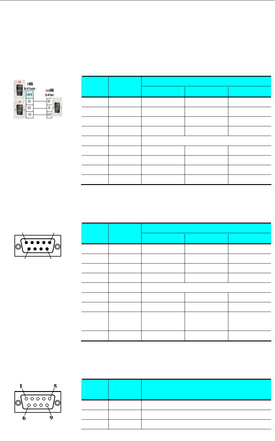
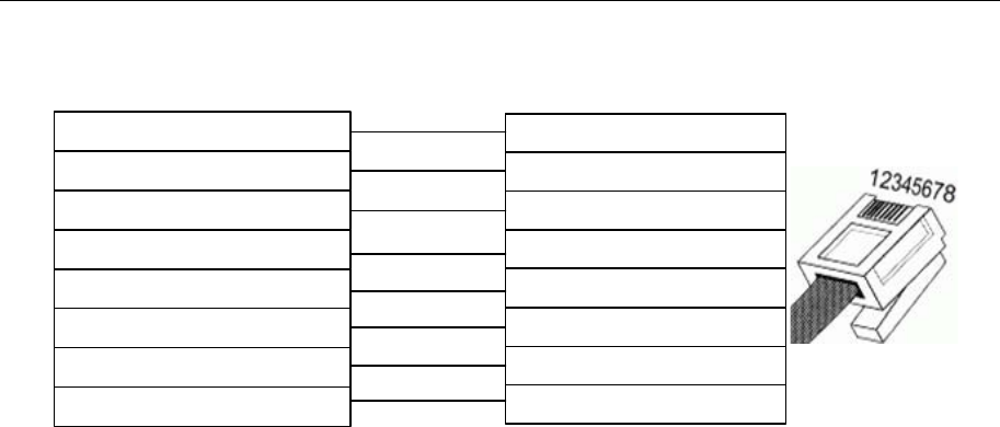
1 Serial Communication Pin definition
- Serial port COM0
COM0 is a 9-pin D-Sub male port, this port supports RS-232C/RS-485/RS-422A communication, the pin
definition as follows:
Function
Pin Signal RS-232C RS-485 RS-422A
1 RX-(B) -- RS485B Receive data
2 RXD Receive data -- --
3 TXD Transmit data -- --
4 TX- -- -- Transmit data
5 SG Signal ground
6 RX+(A) -- RS485A Receive data
7 NC -- -- --
8 NC -- -- --
9 TX+ -- -- Transmit data
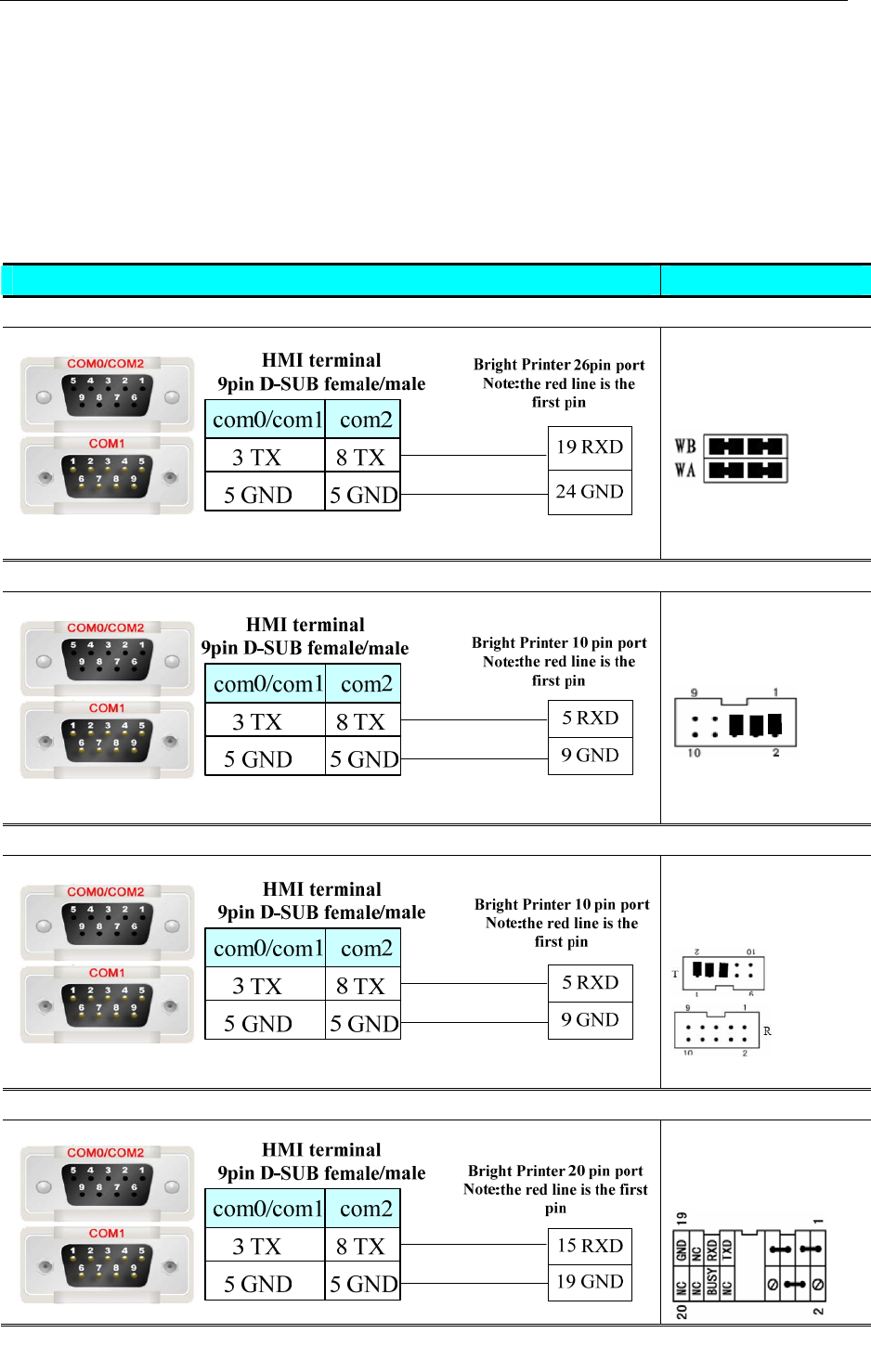
- Serial port COM1
COM1 is a 9-pin D-Sub female port, this port supports RS-232C/RS-485/RS-422A communication, and the
pin definition as follows:
51
96
Function
Pin Signal RS-232C RS-485 RS-422A
1 RX-(B) -- RS485B Receive data
2 RXD Receive data -- --
3 TXD Transmit data -- --
4 TX- -- -- Transmit data
5 SG Signal ground
6 RX+(A) -- RS485A Receive data
7 NC Clear transmit -- --
8 NC Request
transmit
-- --
9 TX+ -- -- Transmit data
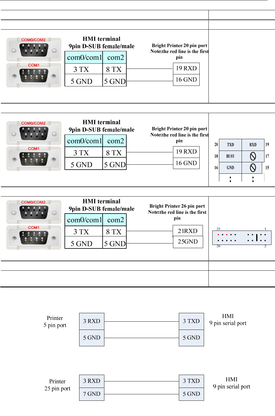
- Serial port COM2
The COM2 and COM0 use the same physical port, the 9-pin D-Sub male port. This COM port supports the
RS232 communication only. The pin definition as follows:
Function
Pin Signal RS-232C
1 NC --
2 NC --
3 NC --

1 Serial Communication Pin definition
- 2 -
4 NC --
5 SG Signal ground
6 NC --
7 RXD Receive data
8 TXD Transmit data
9 NC --
The COM2 can be used to download and upload HMI program, and connect to PLC via RS232 as
well.COM2.
2 Printer connectiong cable diagram
- 3 -
2 Printer Connecting Cable Diagram
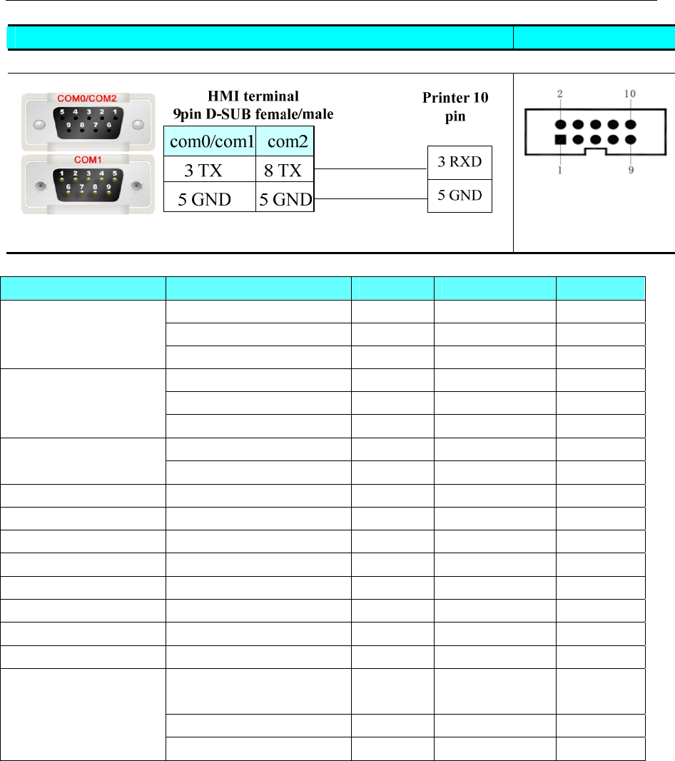
2.1 Serial Interface Printer Cable
2.1.1 Brightek thermal printer
Users choose the protocol of thermal printer according to the dot-matrix of printer.
16 dots: WH-A62R10 protocol
24 dots: WH-A93RG0-00E825 protocol
2.1.2 Serial Interface Printer Cable of Brightek printer
Printer Type Note
WH4008A31-053:
pulling up W1 short
circuit block by RS232
level
WH-A62R10、WH-E461RB01:Support printing of 190 dots width.
Serial port printing
mode via RS232 level,
short circuit as follows:
WH-A52Z20-30E125:Support printing of 240 dots width.
Serial port printing
mode via RS232 level,
short circuit as follows:
WH-A93RG0-00E825、WH-E393R101:support printing of 384 dots width
Serial port printing
mode via RS232 level,
short circuit as follows:
2 Printer connectiong cable diagram
- 4 -
WH-E173R90-00E11720GA:support printing of 192 dots width.
WH-E191RB0-00E1182055:support printing of 576 dots width (24).
Serial port printing
mode via RS232 level
WH-C13RA9-00E82B:support printing of 384 dots width, and with automatic cutting function
Serial port printing
mode via RS232 level,
short circuit as follows:
WH-M073R101
Use the built-in communication line Baud:115200
2.1.3 Siupo Printer cable
a. SP-E40004SK serial printer supports 240 dots width.
2.1.4 MY POS Printer cable
a. MY-POS80K serial printer which supports 240 dots width. 25 pin.
2.1.5 SPRT Printer cable
2 Printer connectiong cable diagram
- 5 -
打印机型号 备注
SP-RMDIIIDSH: support printing of 384 dots width
232 level
2.2 Recommend Optional printer
Printer Driver Printer model Interface Print Structure Print format
WH-A52Z20-30E125 serial Stylus micro printer 240 dots/line
WH-A52Z20-40E125 serial Stylus micro printer 240 dots/line
WH4008A31-053
WH-E202Z20-50E0022T55 serial Stylus micro printer 240 dots/line
WH-A62R10-41E725 Serial thermal 192 dots/line
WH-A93RG0-00E725 Serial thermal 192 dots/line
WH-A62R10
WH-E173R90-00E11720GA Serial thermal 192 dots/line
WH-A93RG0-00E825 Serial thermal 384 dots/line WH-A93RG0-00E825
WH-T2AR10-30E82B Serial Thermal POS 384 dots/line
WH-E191RB0-00E1182055 WH-E191RB0-00E1182055 Serial thermal 576 dots/line
WH-E393R101 WH-E393R101-00A00B2TBA Serial thermal
WH-E461RB01 WH-E461RB01-00A00B2UBA Serial thermal
WH-M073R101 WH-M073R101-00E00C20BA USB slave thermal
Siupo SP-M, D, E, F SP-E4004SK Serial Stylus micro printer 240 dots/line
SP-RMDIIIDSH SP-RMDIIIDSH_S13AS Serial thermal 384 dots/line
MY-POS80K MY-POS80K Serial thermal POS 240 dots/line
HP LaserJet P1108 HP LaserJet P1108 USB slave Laser A4
CANON PIXMA iP4980
CANON IP100
USB slave Ink-jet A4
EPSON ColorioPX-G5300 USB slave Ink-jet A4
Pictbridge
HP 8500A/8500A Plus USB slave Ink-jet A4

3 Download cable diagram
- 6 -
3 Download Cable Diagram
3.1 Download by Serial Port
The COM2 port on the back of the case can be used to connect PLC RS-232 devices and can also be used
to connect with the programming interface and setting interface of a PC.
3.2 Download by USB
3.3 Download by Network Ethernet
Connecting PC and HMI use cross-ruling; communicating with hub or switch use Cross-over cable or
cross-ruling.
A. cross-ruling cable diagram:
HMI Ethernet terminal
RJ45 Controller terminal
RJ45
3 RX+ (green,white)
4 BD4+(blue)
5 BD4- (blue,white)
1 TX+ (orange,white)
2 TX- (orange)
3 RX+ (green,white)
6 RX- (green)
1 TX+(orange,white)
4 BD4+ (blue)
5 BD4- (blue,white)
7 BD3+ (brown,white)
8 BD3- (brown)
6 RX- (green) 2 TX- (orange)
7 BD3+ (brown,white)
8 BD3- (brown)
B. cross-over cable diagram:
3 Download cable diagram
- 7 -
HMI Ethernet terminal
RJ45 Ethernet Hub or Switch
RJ45
1 RX+(orange,white)
4 BD4+ (bule)
5 BD4- (bule,white)
2 RX- (orange)
3 TX+ (green,white)
7 BD3(brown,white)
8 BD3- (brown)
6 TX- (green)
1 TX+ (orange,white)
2 TX- ( orange)
3 RX+ (green,white)
4 BD4+ (bule)
5 BD4- (bule,white)
6 RX- (green)
7 BD3+ (brown,white)
8 BD3- (brown)
4 Communication settings and guide of HMI connecting with controller
- 8 -
4 Communication Settings and guide of HMI connecting with Controller
Note:Do not hot plug!
4.1 ABB Corporation
◎Serial Communication
Series CPU Link Module Driver
RS232 on the CPU unit
ABB AC31 O7KR51-V3.6 RS485 ABB AC31 Modbus RTU
ABB AC500
PM571
PM581
PM591
RS232 on the CPU unit ABB AC500
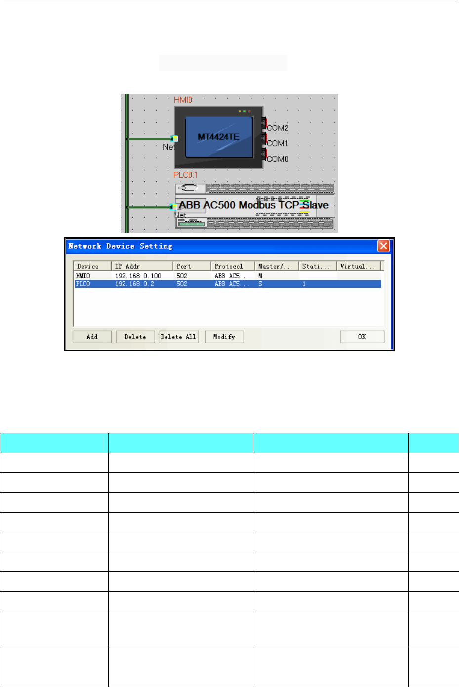
◎Network Communication
Series CPU Link Module Driver
ABB AC500 PM583 CPU Direct ABB AC500 Modbus TCP Slave
◎System configuration
Series CPU Link Module COMM Type Parameter Cable
RS232 on the CPU unit RS232 Setting Your owner cable
ABB AC31 O7KR51-V3.6 RS485 RS485-2 Setting Your owner cable
RS232 on the port 1 RS232 Setting Your owner cable
ABB AC500
PM571
PM581
PM591 RS232 on the port 2 RS232 Setting Your owner cable
◎Network Communication Settings
Series CPU Link Module Connect Type Parameter Cable
ABBCPU PM583 CPU Direct Ethernet Setting Your owner cable
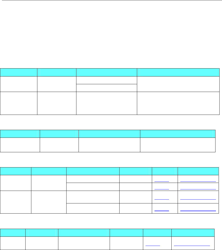
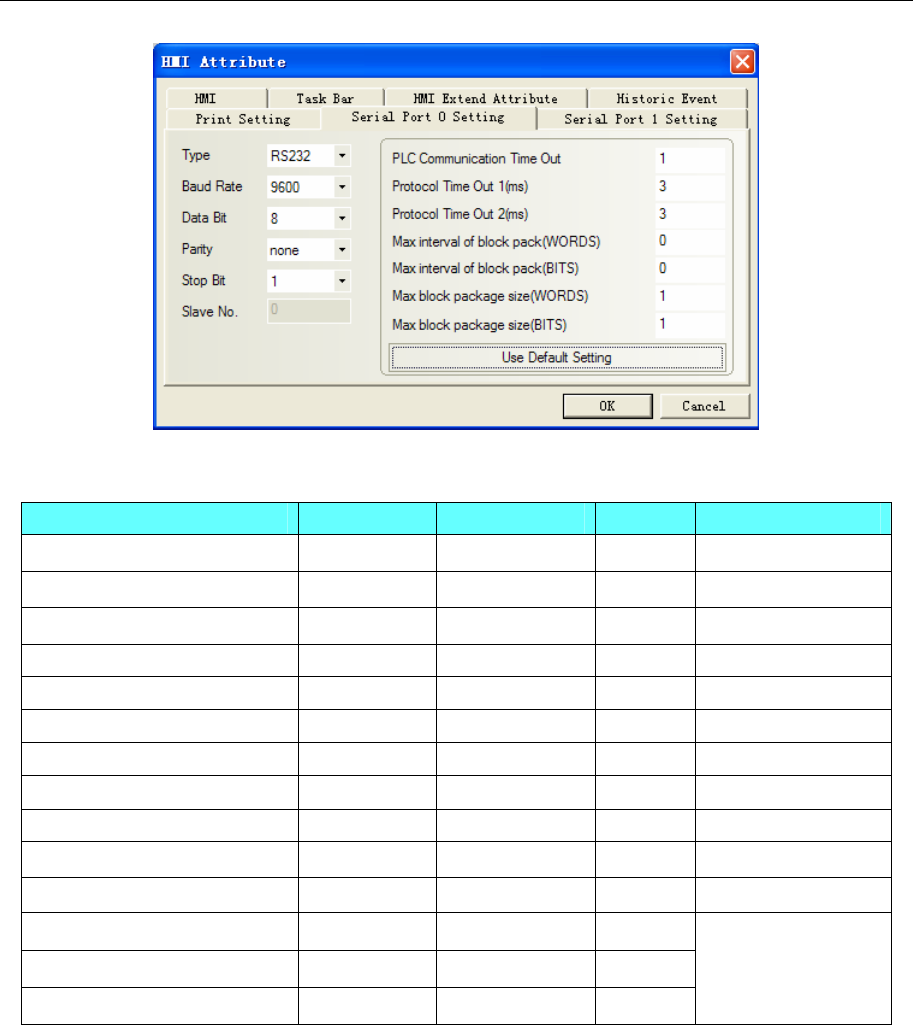
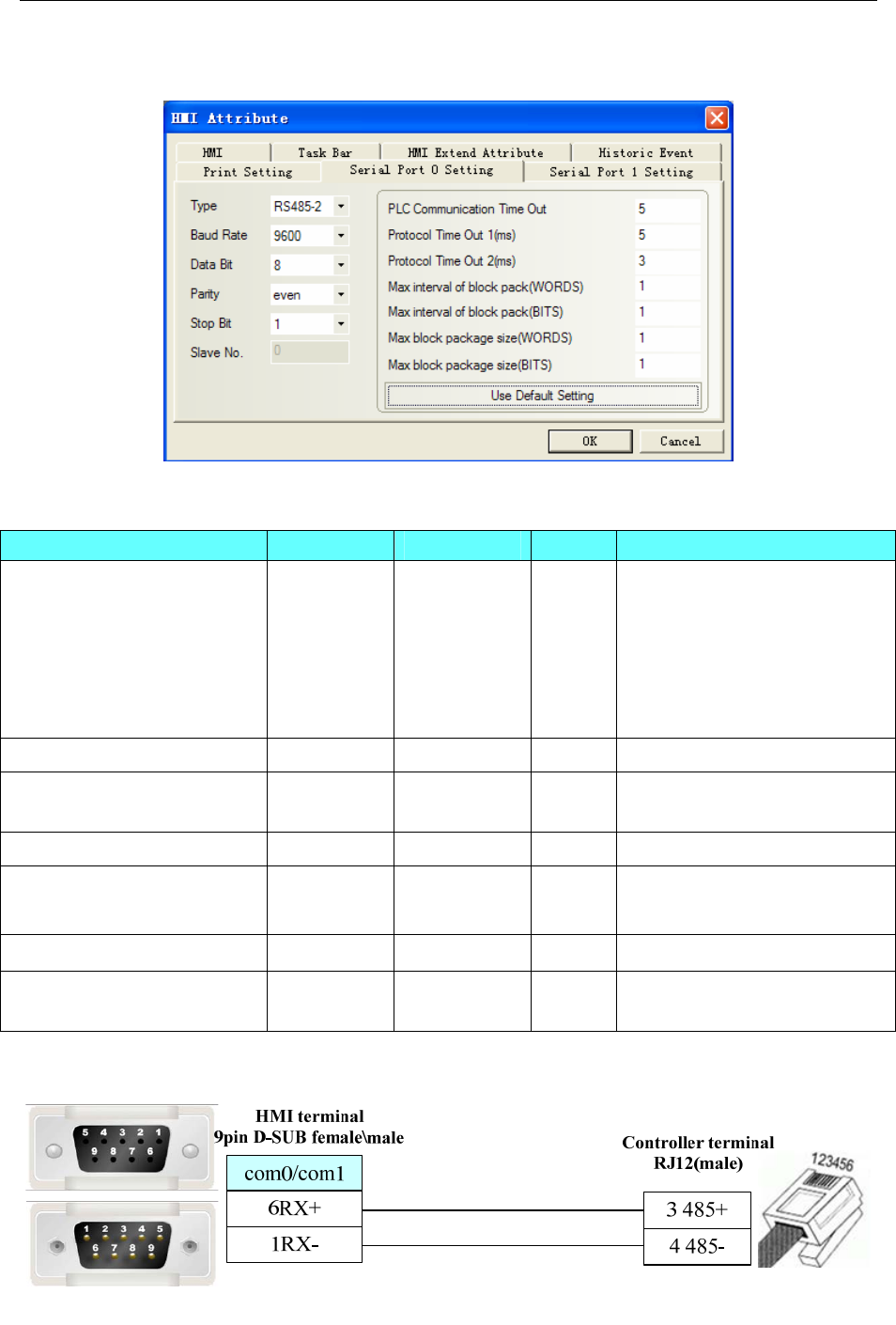
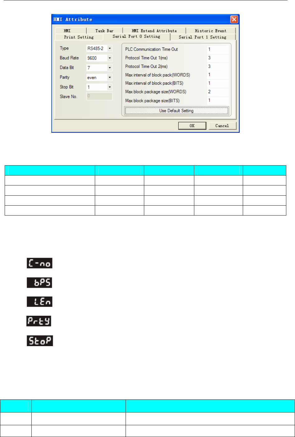
◎Serial Communication Settings
HMI Setting
ABB AC31 Modbus RTU protocol:
Default communication parameters 9600, 8, none, 1; station No. : 1
RS232
4 Communication settings and guide of HMI connecting with controller
- 9 -
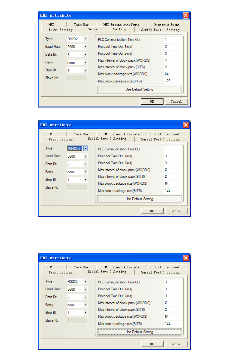
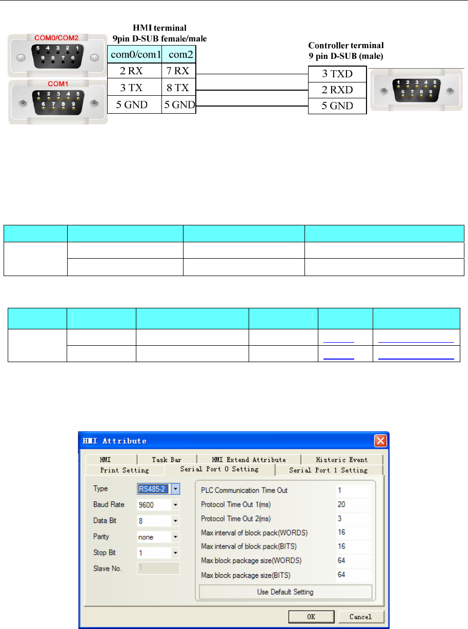
RS485-2
ABB AC500 protocol:
Default communication parameters 9600, 8, none, 1; station No. : 1
RS232
4 Communication settings and guide of HMI connecting with controller
- 10 -
PLC Settings
Related parameters settings refer to the communication equipment specifications。
Network Communication parameters Settings
HMI Settings
PLC 设置
IP setting can use control builder plus orpanel setting,specific reference to ABB help。
◎Supported Device
ABB AC31
Device Bit Address Word Address Format
Input bit I00.00-624.15 ------ DD.DD
Output bit O00.00-624.15 ------ DD.DD
Internal Relay M(0.0--99.15)U(233.00-255.15) ------ DDD.DD
Link Relay S000.00-624.15 ------ DDD.DD
Input Register ------ IW00.00-624.15 DD.DD
Output Register ------ OW00.00-624.15 DD.DD
Internal Register ------ MW(0.0--99.15)U(233.00-255.15) DDD.DD
Indirect Register ------ KW01.00-624.15 DD.DD
Internal Register
(Double words) ------ MD0.00-624.15 D.DD
Indirect Register
(Double words) ------ KD0.00-624.15 D.DD
4 Communication settings and guide of HMI connecting with controller
- 11 -
ABB AC500
Device Bit Address Word Address Format
PLC Register MB0.0—12499.7 ------ DDDD.O
Internal Register ------ MW0.0—3.01695 D.DDDDD
Internal Register (Double words) ------ MD0.0—6.01695 D.DDDDD
Note:
1)Select “MODBUS” mode in the ABB AC500 programming software;
2)If selecting “COM1 MODBUS”, serial communication setting must be “slave” in the 15th
“Operation mode”. Other parameters match the touch-screen.
3)Example: MB address: 0.0.1, please input 0.1 in the HMI.
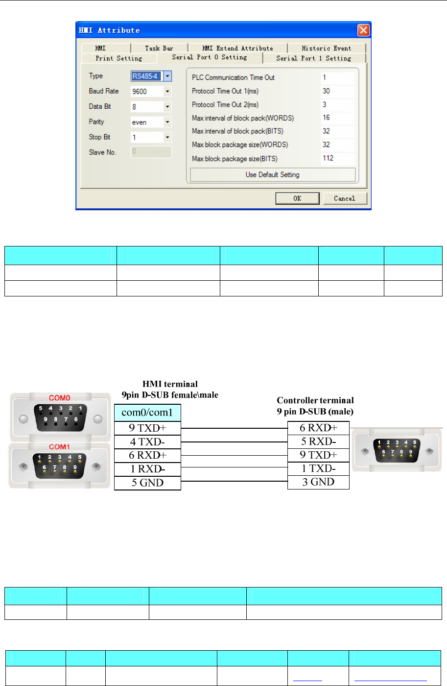
◎Cable Diagram
ABB AC31 RS232
ABB AC31 RS485-2
ABB AC500 port1 RS232
ABB AC500 port2 RS232
4 Communication settings and guide of HMI connecting with controller
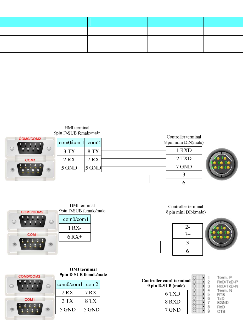
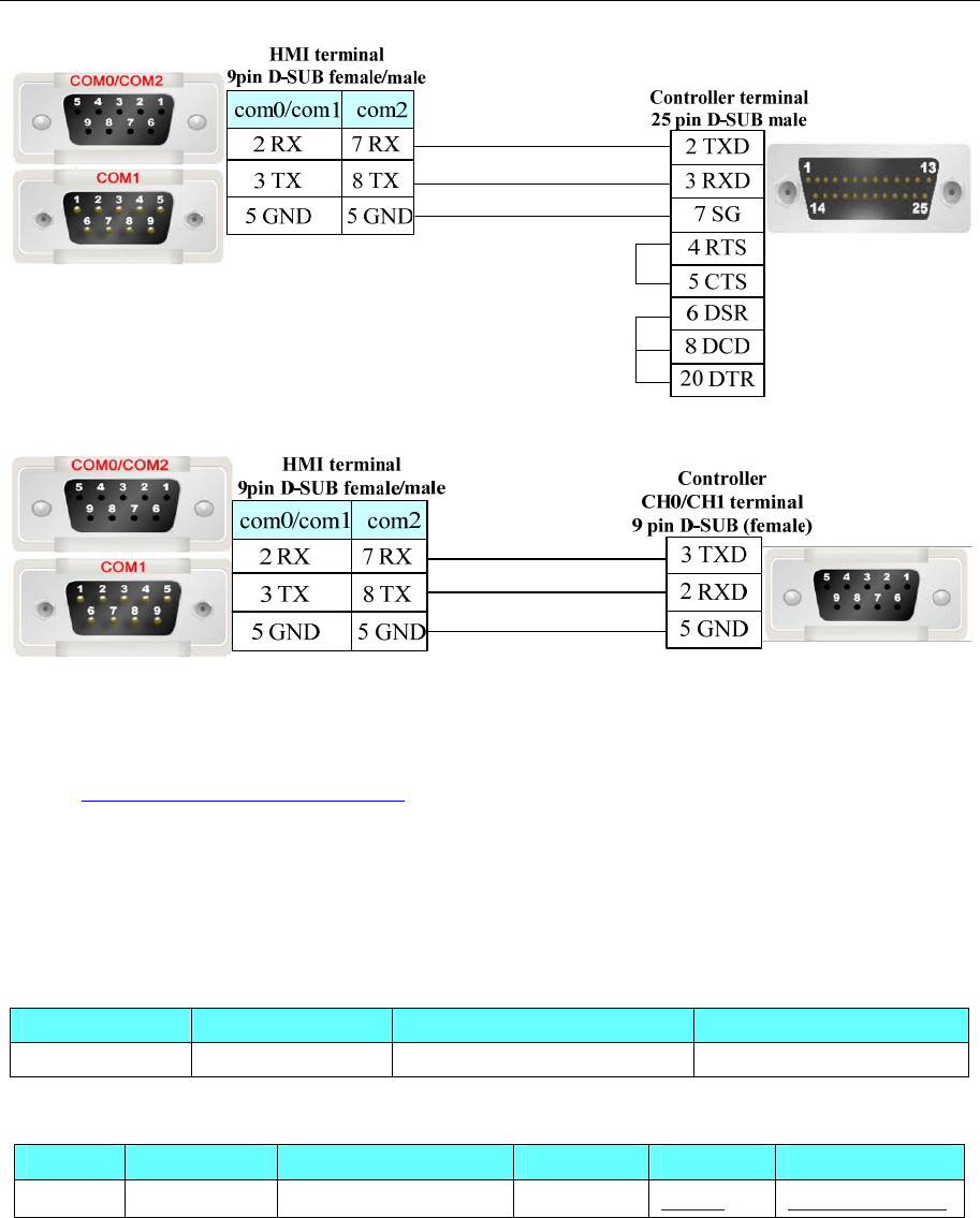
- 12 -
HMI terminal
9pin D-SUB female/male Controller com2 terminal
9 pin D-SUB (male)
2TXD
7RXD
5 GND
com2
3 TX
2 RX
5 GND
8 TX
7 RX
5 GND
com0/com1
4.2 Allen-Bradley
◎Serial Communication
Series CPU Link Module Driver
MicroLogix 1500 (1764-LRP) Channel 1
Channel 0 MicroLogix 1000
MicroLogix 1200
MicroLogix 1500
(1764-LSP,1764-LRP)
AIC+ Advanced
Interface Converter
1761-NET-AIC
Channel 0
MicroLogix
MicroLogix 1400
(1766-L32BWAA) Channel 2
Channel 0
1770-KF3
2760-RB
1775-KA
5130-RM
SLC500
SLC 5/03
SLC 5/04
SLC 5/05
1771-KGM
PLC-5
PLC-5/11
PLC-5/20
PLC-5/30
PLC-5/40
PLC-5/40L
PLC-5/60
PLC-5/60L
Channel 0
AB SLC500/PLC5/MicroLogix
Series(DF1)*1
CompactLogix
1769-L20
1769-L30
1769-L31
1769-L32E
1769-L35E
Channel 0
Channel 1
ControlLogix 1756-L61
1756-L63 CPU Direct
AB
CompactLogix/ControlLogix
Series(DF1)*2
*1 Suitable for the PLC that uses RSLinx500 program software
*2 Suitable for the PLC that uses RSLinx5000 program software

4 Communication settings and guide of HMI connecting with controller
- 13 -
◎Ethernet Communication (Direct Online Simulation disable)
Series CPU Link Module Driver
MicroLogix 1100
MicroLogix 1400 CPU Direct (channel 1)
MicroLogix
MicroLogix 1000
MicroLogix 1100
MicroLogix 1200
MicroLogix 1400
MicroLogix 1500
1761-NET-ENI
SLC5/05 CPU Direct (channel 1)
SLC500 SLC5/03
SLC5/04
SLC5/05
1761-NET-ENI
PLC-5 ALL CPUs that support the link I/F
on the right 1761-NET-ENI
AB
SLC500/PLC5/MicroLogix
Series Ethernet(TCP Slave)
*1
1769-L30ER
1769-L32E
1769-L35E
CPU Direct
CompactLogix
All CPUs which support the link I/F
on the right 1761-NET-ENI
AB
CompactLogix/ControlLogix
Series Ethernet(TCP Slave)
*2
*1 Suitable for the PLC that uses RSLinx500 program software
*2 Suitable for the PLC that uses RSLinx5000 program software
◎Serial System Communication
Series CPU Link Module COMM Type Parameter Cable
1500 (1764-LRP) Channel 1 RS232C Setting Your owner cable
Channel 0
MicroLogix 1000
MicroLogix 1200
MicroLogix 1500
AIC+ Advanced
Interface Converter
1761-NET-AIC
RS232C Setting Your owner cable
Channel 0 Your owner cable
MicroLogix
MicroLogix 1400 Channel 2 RS232C Setting Your owner cable
Channel 0
1770-KF3
2760-RB
1775-KA
5130-RM
SLC500
SLC 5/03
SLC 5/04
SLC 5/05
1771-KGM
RS232C Setting Your owner cable
PLC-5
PLC-5/11
PLC-5/20
PLC-5/30
PLC-5/40
Channel 0 RS232C Setting Your owner cable
4 Communication settings and guide of HMI connecting with controller
- 14 -
PLC-5/40L
PLC-5/60
PLC-5/60L
Channel 0
CompactLogix
1769-L20
1769-L30
1769-L31
1769-L32E
1769-L35E
Channel 1
RS232C Setting Your owner cable
ControlLogix 1756-L61 CPU Direct RS232C Setting Your owner cable
◎Ethernet System Communication
Series CPU Link Module Connect Type Parameter Cable
MicroLogix 1100
MicroLogix 1400
CPU Direct
(channel 1)
MicroLogix MicroLogix 1000
MicroLogix 1100
MicroLogix 1200
MicroLogix 1500
1761-NET-ENI
SLC5/05 CPU Direct(channel 1)
SLC500 SLC5/03
SLC5/04
SLC5/05
1761-NET-ENI
PLC-5 ALL CPUs that support
the link I/F on the right 1761-NET-ENI
Ethernet Setting Your owner cable
1769-L30ER
1769-L32E
1769-L35E
CPU Direct
CompactLogix
All CPUs which support
the link I/F on the right
1761-NET-ENI
Ethernet Setting Your owner cable
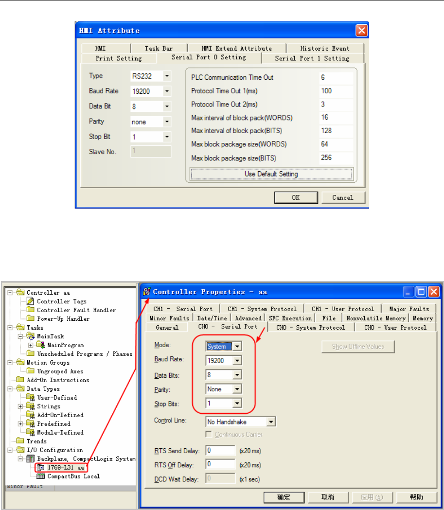
◎Serial Communication Setting
AB SLC500/PLC5/MicroLogix Series protocol
HMI Setting
Default communication parameters 19200, 8, none, 1; station No. : 0
4 Communication settings and guide of HMI connecting with controller
- 15 -
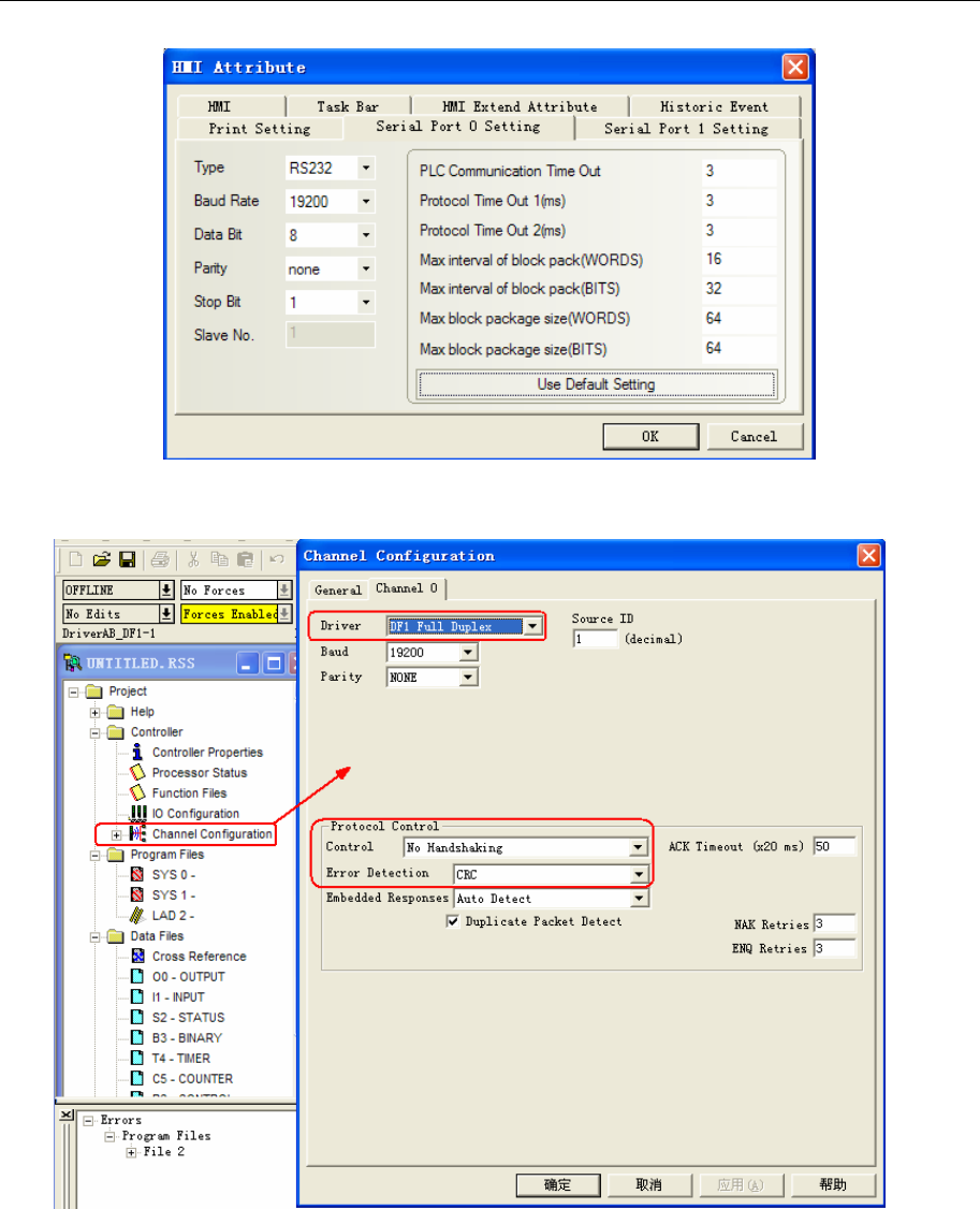
PLC Setting
RSLogix500 software setting
NOTE: Driver: DF1 Full Duplex; Error Detection: CRC.
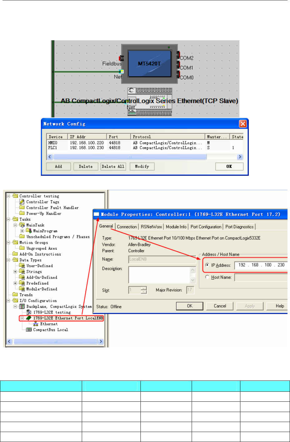
AB CompactLogix/ControlLogix Series protocol
HMI Setting
Default communication parameters 19200, 8, none, 1; station No. : 0
4 Communication settings and guide of HMI connecting with controller
- 16 -
PLC Setting
RSLogix5000 software setting
NOTE: Protocol: DF1 Point to Point; Error Detection: CRC; Enable Duplicate Detection: Disabled.
(1)Set the communication parameters: Controller properties
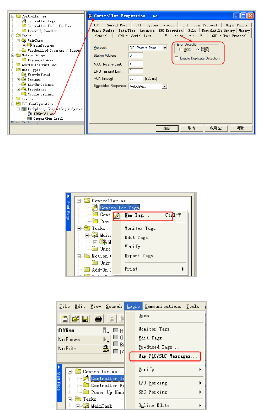
4 Communication settings and guide of HMI connecting with controller
- 17 -
NOTE: Define the new device in the RSLogix5000 before using the register in the HMI.
(2) Define Tags and Data type: Select “Controller Tags” right-click”New Tag”, set up tag:
NOTE:
1. The controller registers that HMI needs to visit should be defined in the RSLogix5000 in advance.
2. Controller Tags are suitable for all routines in controller, they are global, so the tag should be built in
Controller Tags
(3) Tag Name and File Number mapping: Select “Logic””Map PLC/SLC Messages”.(Note: the
software should be in offline mode)
4 Communication settings and guide of HMI connecting with controller
- 18 -
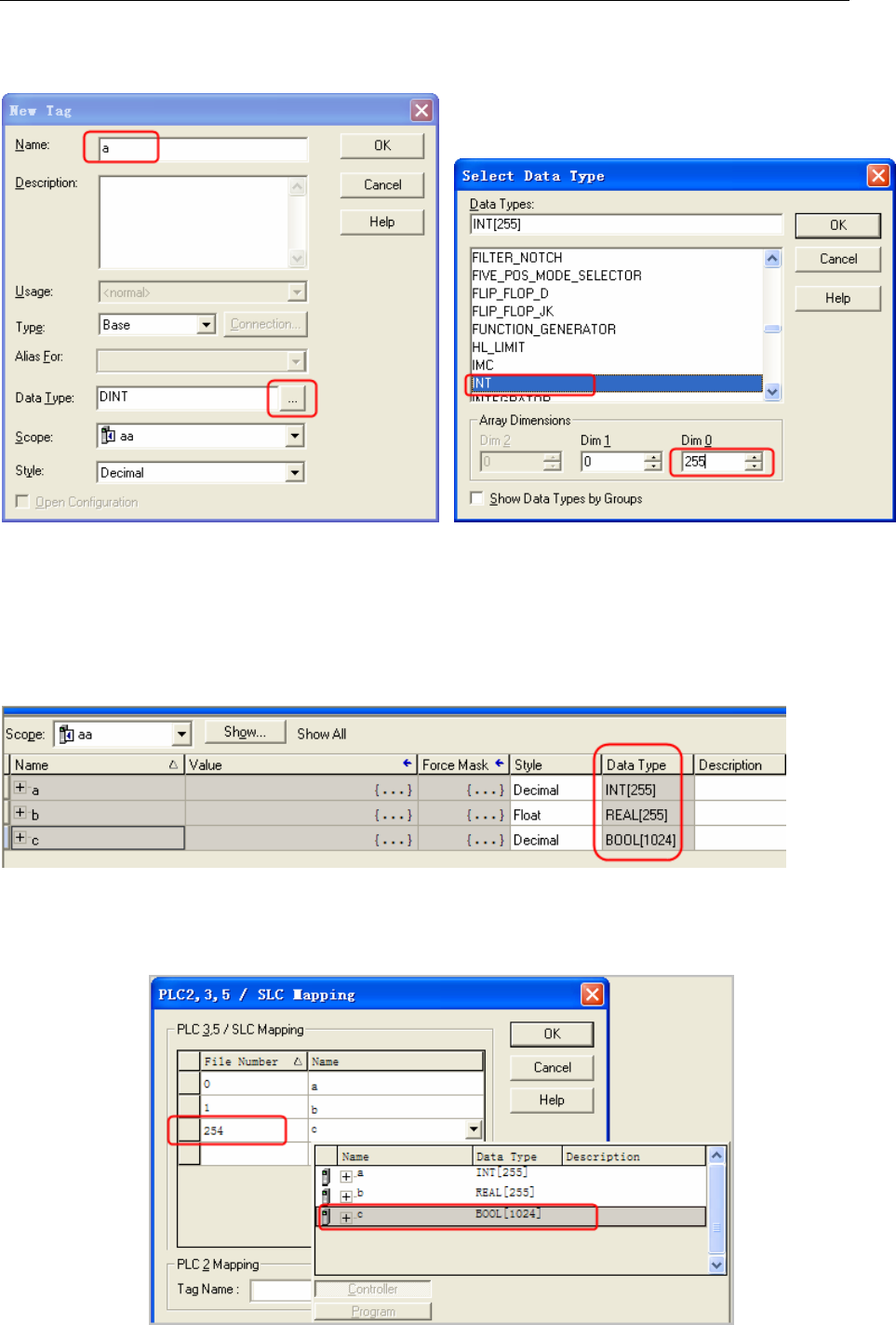
Example:
Build a new tag whose name is a, the Data Type is INT:
Note:
1. For the Data Type,the CompactLogix/ControlLogix supports the INT, BOOL, REAL data type only.
2. This driver does not support Multi-dimensional array, so you can define the range of Dim0 only.
3. In this driver, the INT range is 0~254; REAL range is 0~254, and the BOOL range is 0~999.
Besides, build two new tags whose Names are b and c, Data Type are REAL and BOOL.
The BOOL variable address range is 0~1024 in PLC, but this driver only supports 0~999. So the HMI can
only visit the BOOL register from to 999.
After the tags are defined, map the Name to the File Number:
4 Communication settings and guide of HMI connecting with controller
- 19 -
Note:
1. The File Number is unique, a same File Number cannot map to different Names
2. The range of File Number in this driver is 0~254.
The HMI mapping addresses are as follows:
Tag Name Data Type Support Range Mapping File
Number
Mapping HMI address
a INT[255] 0~254 0 INT 000000~000254
a BOOL 000.0~254.15 0 N_BOOL 000000.00~000254.15
b REAL[255] 0~254 1 REAL 001000~001254
c BOOL[1024] 0~999 254 B_BOOL 254000~254999
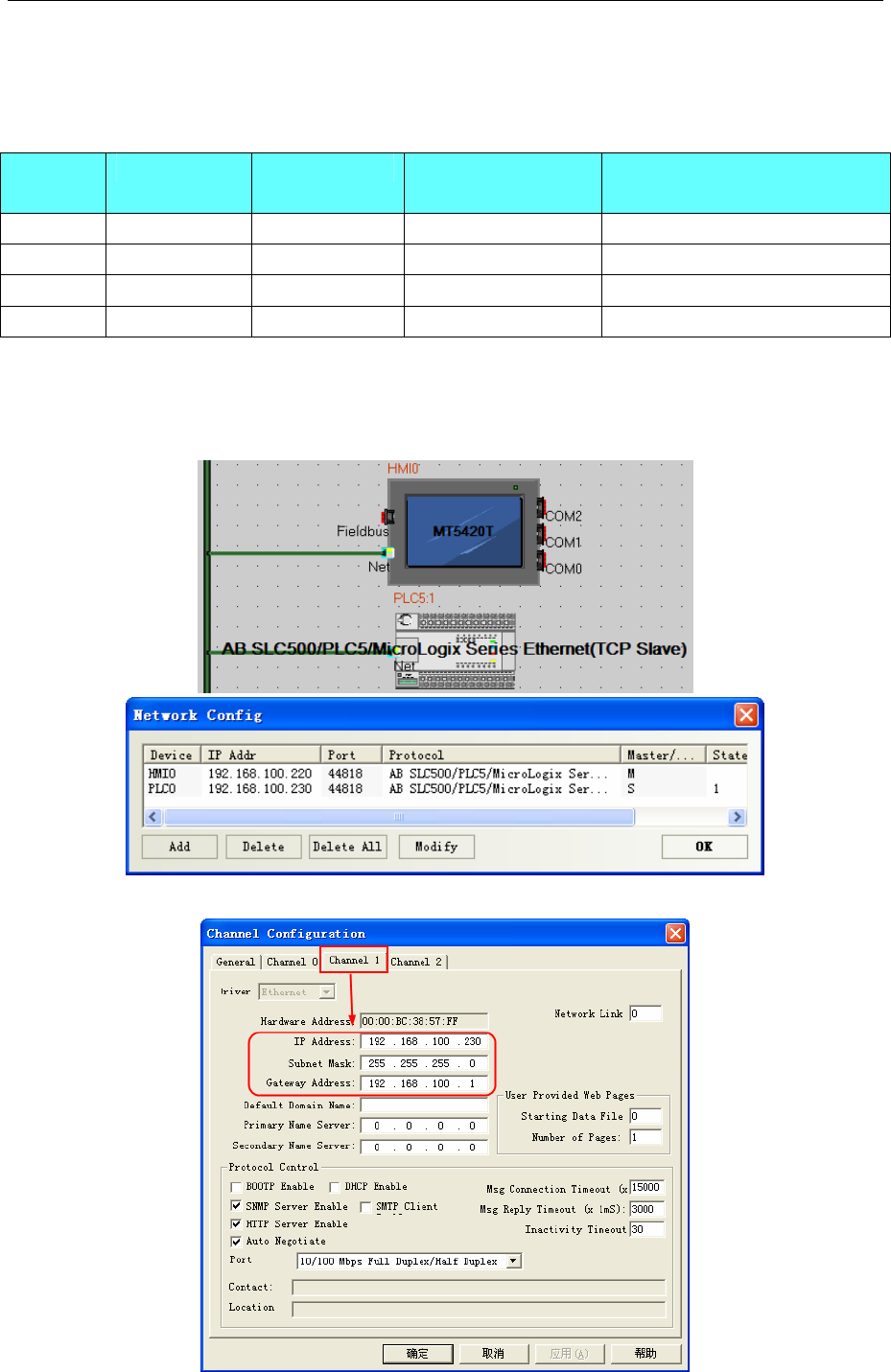
◎Ethernet Communication Setting
AB SLC500/PLC5/MicroLogix Series Ethernet(TCP Slave) protocol
HMI Setting
PLC Setting
4 Communication settings and guide of HMI connecting with controller
- 20 -
AB CompactLogix/ControlLogix Series Ethernet(TCP Slave) protocol
HMI Setting
PLC Setting
◎Supported Device
AB SLC500/PLC5/MicroLogix Series(DF1)
Device Bit Address Word Address Format Notes
Bit data file B3:0.0-255.15 ------ DDD.DD
Bit data file B10:0.0-255.15 ------ DDD.DD
Bit data file B11:0.0-255.15 ------ DDD.DD
Bit data file B12:0.0-255.15 ------ DDD.DD
Bit data file B13:0.0-255.15 ------ DDD.DD
4 Communication settings and guide of HMI connecting with controller
- 21 -
Output data file O0:0.0-255.15 ------ DD.DD
Input data file I1:0.0-255.15 ------ DD.DD
Integer data file ------ N15:0-255 DDD
Integer data file ------ N14:0-255 DDD
Integer data file ------ N13:0-255 DDD
Integer data file ------ N12:0-255 DDD
Integer data file ------ N11:0-255 DDD
Integer data file ------ N10:0-255 DDD
Integer data file ------ N7:0-255 DDD
Floating point data file ------ F8:0-255 DDD
Counter Accumulator Value ------ C5PV:0-255 DDD
Counter Preset Value ------ C5SV:0-255 DDD
Timer Accumulator Value ------ T4PV:0-255 DDD
Timer Preset Value ------ T4SV:0-255 DDD
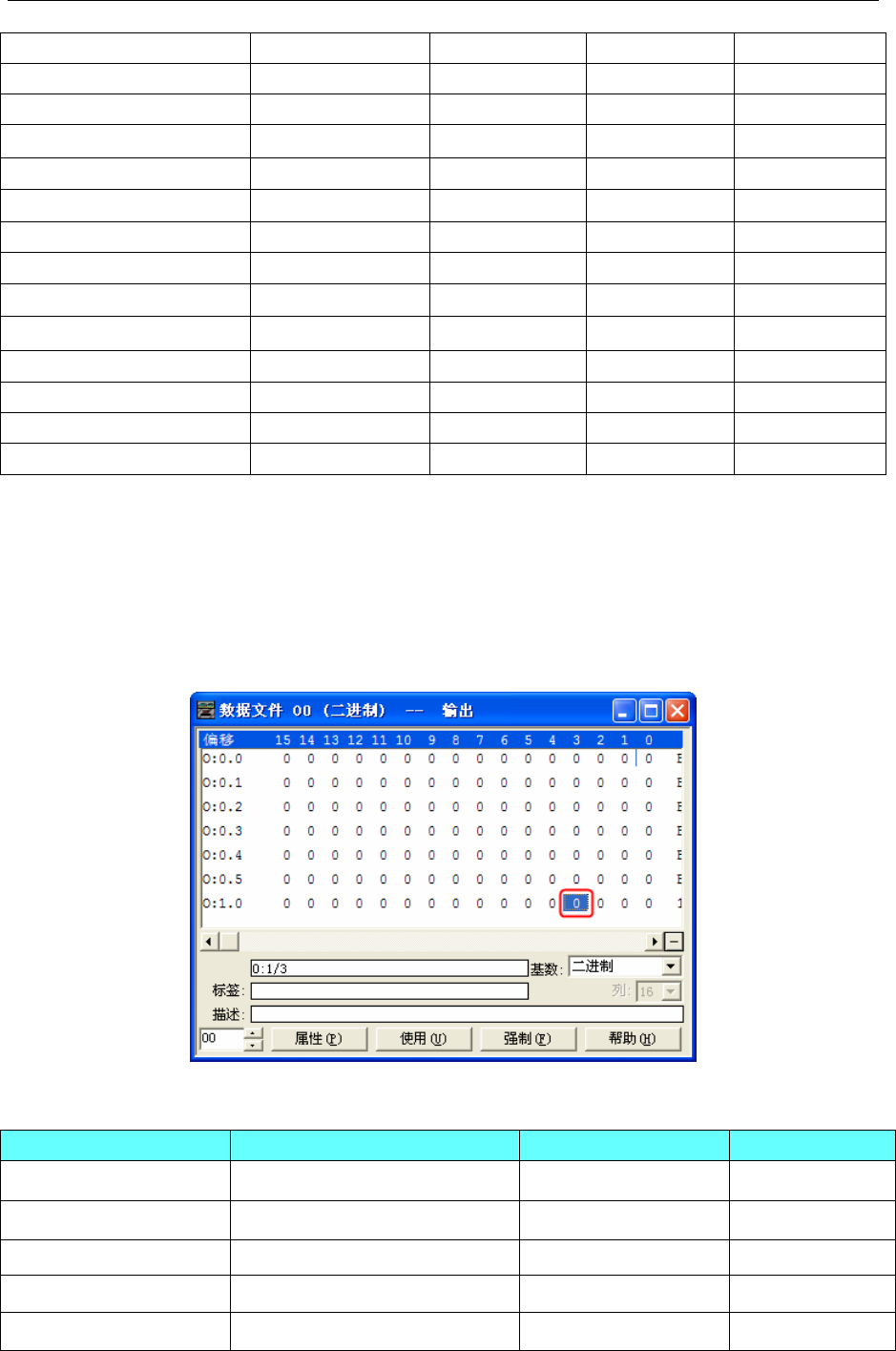
Note:
The format of I/O address is I/O e.s/b, and the e is slot number, s is variable number and b is bit number.
For example:
The PLC address is O0 0.0/11, mapping address in HMI is O0 0.11;
The PLC address is O0 0.1/8, mapping address in HMI is O0 1.8.
The I/O address in HMI is continuous when different AB CPU use the I/O modules.
Take Micrologix 1400 + output module 1762-OW16 for example, O0 1.3/3 maps the O0 6.3 in HMI.
AB CompactLogix/ControlLogix Series(DF1)
Device Bit Address Word Address Format
Integer data file bit level N_BOOL000000.00~254254.15 ------ DDDDDD.DD*1
Bit data file B_BOOL000000~254991 ------ DDDDDD*1
Floating point data file ------ REAL000000~254254 DDDDDD*1
Integer data file ------ INT000000~254254 DDDDDD*1
DInteger data file ------ DINT000000~254254 DDDDDD*1
4 Communication settings and guide of HMI connecting with controller
- 22 -
Note:
*1 Variable less than three address the need to fill the former 0
The correct format example as follow: file number is 112, variable address is 87.12, format is 112087.12.
2. Users can define the File Number.
AB SLC500/PLC5/MicroLogix Series Ethernet(TCP Slave)
Device Bit Address Word Address Format Notes
Bit data file B13:0.0-255.15 ------ DDD.DD
Bit data file B12:0.0-255.15 ------ DDD.DD
Bit data file B11:0.0-255.15 ------ DDD.DD
Bit data file B10:0.0-255.15 ------ DDD.DD
Bit data file B3:0.0-255.15 ------ DDD.DD
Bit data file Bf:n:0.0-255255.15 ------ DDDDDD.DD *1
Output bit data file O0:0.0-255.15 ------ DD.DD
Input bit data file I1:0.0-255.15 ------ DD.DD
Output data file ------ OW0:0-255 DDD
Input data file ------ IW1:0-255 DDD
Integer data file ------ N15:0-255 DDD
Integer data file ------ N14:0-255 DDD
Integer data file ------ N13:0-255 DDD
Integer data file ------ N12:0-255 DDD
Integer data file ------ N11:0-255 DDD
Integer data file ------ N10:0-255 DDD
Integer data file ------ N7:0-255 DDD
Integer data file ------ Nf:n:0-255255 DDDDDD *1
Floating point data file ------ F8:0-255 DDD
Floating point data file ------ Ff:n:0-255255 DDDDDD *1
Counter Accumulator Value ------ C5PV:0-255 DDD
Counter Preset Value ------ C5SV:0-255 DDD
Timer Accumulator Value ------ T4PV:0-255 DDD
Timer Preset Value ------ T4SV:0-255 DDD
Note:
*1 Variable less than three address the need to fill the former 0
The correct format example as follow:
Bf:n 113087.12, file number is 113, variable address is 87.12, and mapping address in PLC is B113: 87/12;
Ff:n 9002, file number 9, variable address 2, and mapping address in PLC is F9:2.
AB CompactLogix/ControlLogix Series Ethernet(TCP Slave)
Device Bit Address Word Address Format
Integer data file bit level N_BOOL000000.00~254255.15 ------ DDDDDD.DD*1
Bit data file B_BOOL000000~254999 ------ DDDDDD*1
Floating point data file ------ REAL000000~254255 DDDDDD*1
4 Communication settings and guide of HMI connecting with controller
- 23 -
Integer data file ------ INT000000~254255 DDDDDD*1
DInteger data file ------ DINT000000~254255 DDDDDD*1
NOTE:
1. Variable less than three address the need to fill the former 0
The correct format example as follow: file number is 112, variable address is 87.12, format is 112087.12.
2. Users can define the File Number.
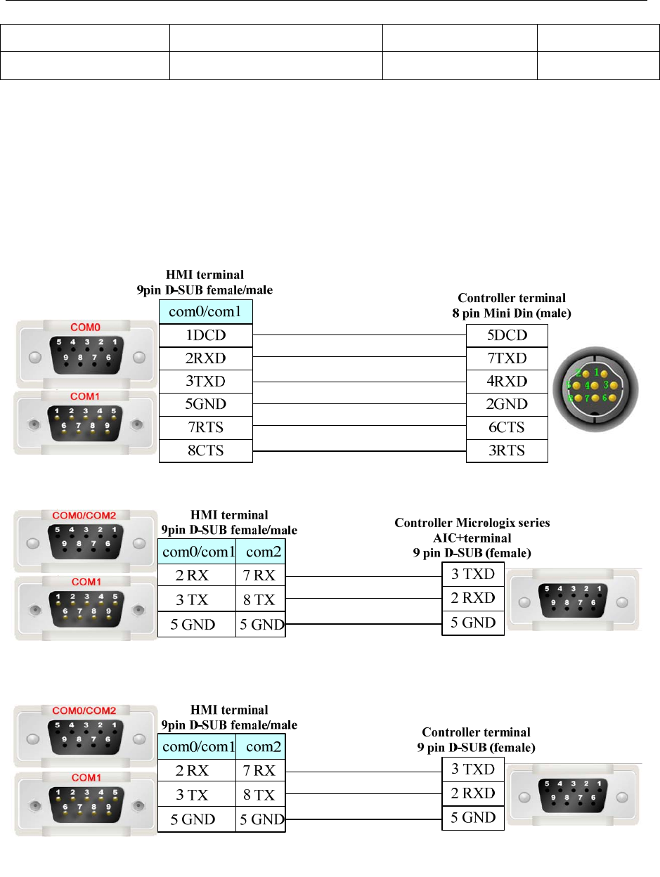
◎Cable Diagram
MicroLogix RS232 cable diagram
1. Cable made by AB Corporation
2. Communication module AIC+ (Part No. 1761-NET-AIC) RS232
SLC 5/03 RS232 cable diagram
PLC-5 RS232 cable diagram
4 Communication settings and guide of HMI connecting with controller
- 24 -
CompactLogix/ ControlLogix RS232 cable diagram
Ethernet cable
Connecting PC and HMI use cross-ruling; communicating with hub or switch use cross-over cable or
cross-ruling.
Refer to 3.3 Download by Network Ethernet for method of making connection cable.
4.3 ACS-Tech80 Motion Controller
◎Serial Communication
Series CPU Link Module Driver
SA2103 SB214SA RS232 on the CPU unit ACS-Tech80
◎System configuration
Series CPU Link Module COM Type Parameter Cable
SA2103 SB214SA RS232 on the CPU unit RS232 Setting Your owner cable
◎Communication Setting
RS232 communication
4 Communication settings and guide of HMI connecting with controller
- 25 -
◎Supported Device
Device Bit Address Word Address Format Notes
Linear Deceleration(LD) ------ LD 0~3 D R/W
Linear Acceleration(LA) ------ LA 0~3 D R/W
Linear Velocity(LV) ------ LV 0~3 D R/W
Next trgt Abs Pos(AP) ------ AP 0~3 D R/W
Next Motion Mode(MM) ------ MM 0~3 D R/W
Functions Avail.(FA.1) ------ FA.1 0~3 D Read Only
Array Offset(AO) ------ AO 0~3 D R/W
Array’s Upper Index(UI) ------ UI 0~3 D R/W
Array’s Low Index(LI) ------ LI 0~3 D R/W
Path Gen.mode(PG) ------ PG 0~3 D R/W
Motor enabled(MO) MO 0~3 ------ D Write Only
CLEAR CLEAR 0 ------ D
RESET RESET 0 ------
D
B B 0~3 ------
D
Write Only
Note:R: Readable,W: Writable。
Register instructions:
1. LD、LA、LV、AP、MM、FA.1、AO、UI、LI、PG
Main address:Axis parameter number(X、Y、Z、T)
2. MO、B(Operating instructions)
Main address:Axis parameter number(X、Y、Z、T)
3. CLEAR、RESET(Operating instructions)
◎Cable Diagram
RS232 communication cable
4 Communication settings and guide of HMI connecting with controller
- 26 -
4.4 ADAM
◎Serial Communication
Series CPU Link Module Driver
ADAM-4017 RS485 on the CPU unit ADAM-4017
ADAM ADMA-4015 RS485 on the CPU unit ADMA-4015
◎System configuration
Series CPU Link Module COMM Type Parameter Cable
ADAM-4017 RS485on the CPU unit RS485 Setting Your owner cable
ADAM ADMA-4015 RS485 on the CPU unit RS485 Setting Your owner cable
◎Communication Setting
HMI Setting
ADAM-4017 default communication: 9600, 8, none, 1; station: 255
Note:a. To allow the “Check Code”;
b. Direct online simulation disables.
ADAM-4015 default communication: 9600, 8, none, 1; station: 1
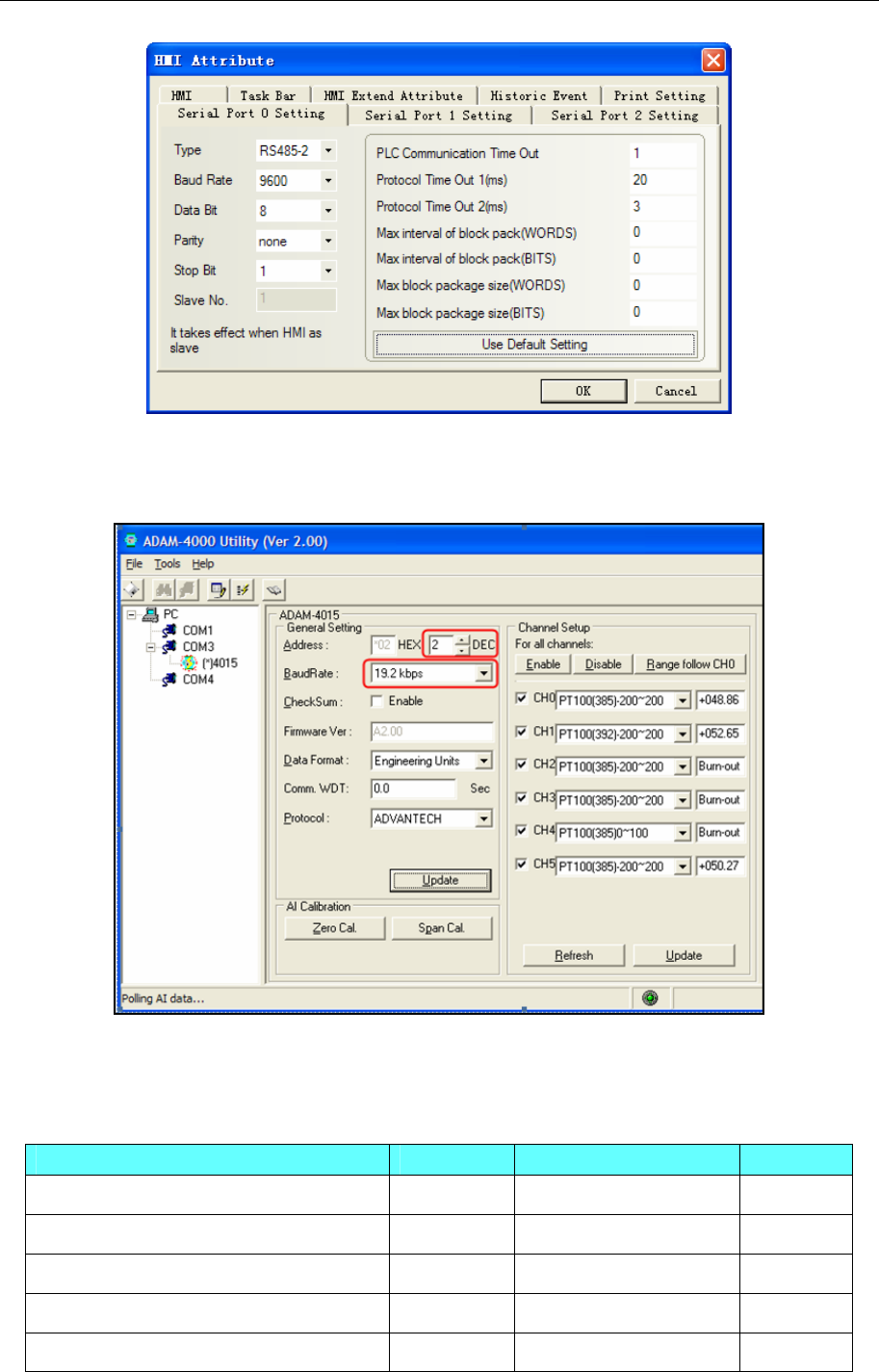
4 Communication settings and guide of HMI connecting with controller
- 27 -
Note: PLC station must match with the ADAM-4015 configuration.
PLC Setting
Connect “INIT” with “GND”, and reset the device, then set the communication of ADMA-4015.
Set OK, then Update.
◎Supported Device
ADAM-4017
Device Bit Address Word Address Format
Read Analog Input form Channel N ------ S_Channel 0-65535 DDDDD
Read Analog Input from all Channel ------ A_Channel 0-7 D
Configuration Status ------ Status 0-65535 DDDDD
Enable/disable Channels for Multiplexing ------ M_channel 0-65535 DDDDD
Read Channel Status ------ Channel_Status 0-65535 DDDDD
4 Communication settings and guide of HMI connecting with controller
- 28 -
Read Version ------ Version 0-65535 DDDDD
Read Module Name ------ Name 0-65535 DDDDD
Note:Order code refer to the ADAM-4107 manual
1、 “Data type” of S_Channel and A_Channel is signed integer. Decimal digits is 2 when the power
supply is 500mv or 150mv, other conditions is 3.
2、 “Data type” of other registers is HEXING
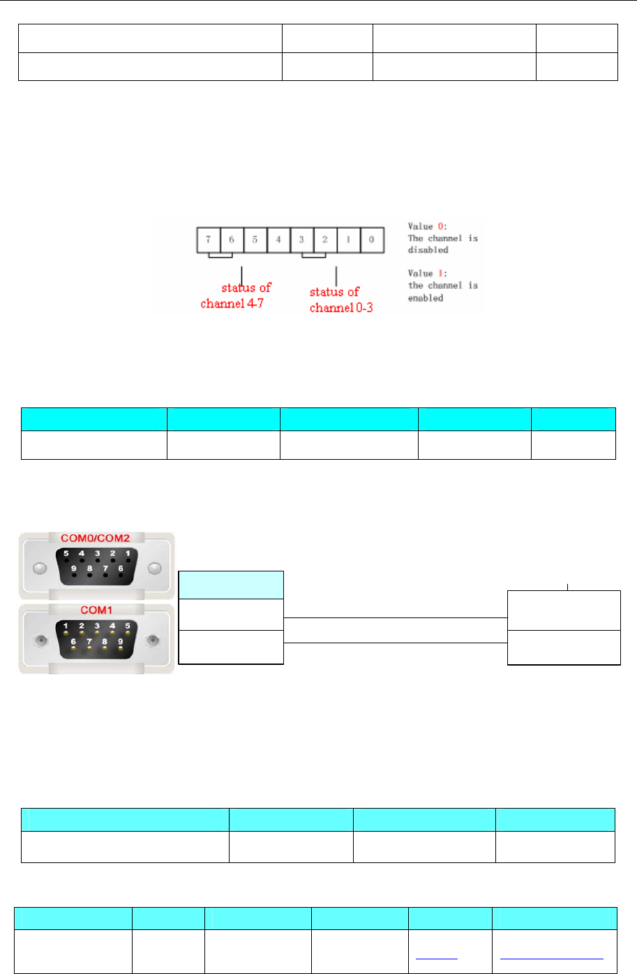
3、M_channel($AA5VV):At the same time allow multiplexing.
Enter the decimal value in the range of 0 to 255, mapping hexadecimal (00-FF)
255(FF):0-7 channel show.
127(7F):0-6 channel show, 7 Channel does not show.
ADAM-4015
Device Bit Address Word Address Format Notes
Channel ------ Channel 0-5 D Floating
Note: Channel 0-5 data type is floating.
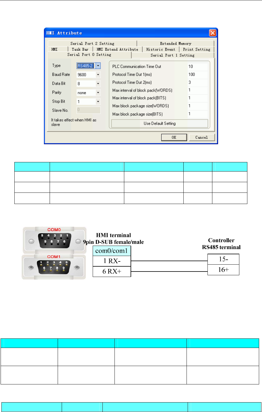
◎Cable Diagram
HMI terminal
9pin D-SUB female/male Controller
RS485 terminal
DATA-
DATA+
1 RX-
6 RX+
com0/com1
4.5 AysjNet
◎Serial Communication
Series CPU Link Module Driver
Compressor Controller KYK3-K RS485 on port AysjNet
◎System configuration
Series CPU Link Module COMM Type Parameter Cable
Compressor
Controller KYK3-K RS485 on port RS485 Setting Your owner cable
4 Communication settings and guide of HMI connecting with controller
- 29 -
◎Communication Setting
◎Supported Device
Device Bit Address Word Address Format Notes
control CTL (0~5)&128&150 ------ DDD Write only
set ------
SET (0~51)&128 DDD
state ------
STATUS 0.0~17.2 DD.D Read only
◎Cable Diagram
4.6 BACnet
◎Serial Communication
Series CPU Link Module Driver
BACnet MS/TP VLC-660R
Johnson FC BUS Port on CPU unit BACnet MS/TP
BACnet MS/TP
Extend
ALERTON
VLC-660R Port on CPU unit BACnet MS/TP Extend
◎Ethernet Communication
Series CPU Link Module Driver
4 Communication settings and guide of HMI connecting with controller
- 30 -
BACnet IP Ethernet interface on CPU BACnet IP
BACnet IP Slave Ethernet interface on CPU BACnet IP Slave
◎Serial System configuration
Series CPU Link Module COM Type Parameter Cable
BACnet MS/TP VLC-660R
Johnson FC BUS CPU Direct RS485 Setting Your owner cable
BACnet MS/TP
Extend
ALERTON
VLC-660R
Port on CPU
unit RS485-2 Setting Your owner cable
◎ Ethernet System configuration
Series CPU Link Module COMM Type Parameter Cable
BACnet IP Ethernet interface on CPU Ethernet Setting
BACnet IP Slave Ethernet interface on CPU Ethernet Setting
Your owner
cable
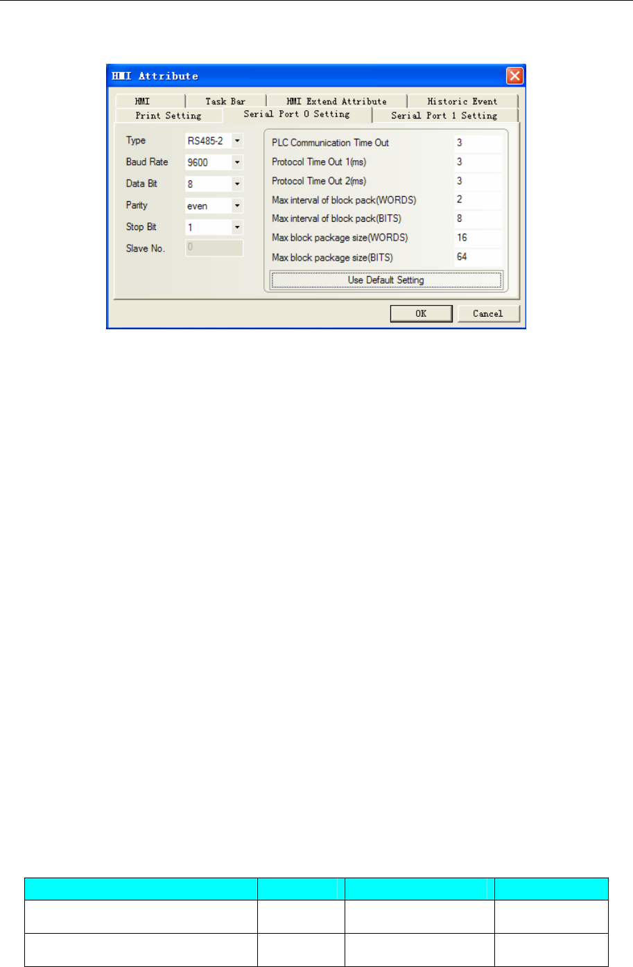
◎Serial Communication Setting
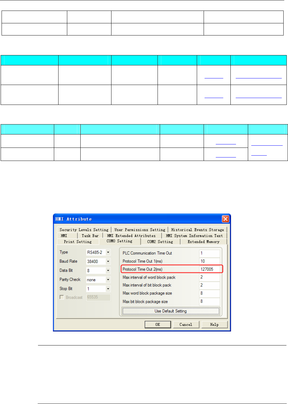
BACnet MS/TP protocol
HMI Setting
Default communication parameters 38400, 8, none, 1; station No. : 1
NOTE: MAX Master setting:
Protocol Time Out 2(ms)high three is MAX Master,default 127.
MAC address setting:
Protocol Time Out 2(ms)low three is HMI MAC address,Range is 0-127。And it must be
different from others which one in the token-ring。
PLC MAC address is setting in [PLC Attribute]-[Station No.],Range is 0~255.
4 Communication settings and guide of HMI connecting with controller
- 31 -
PLC Setting
Please refer to the communication equipment related documentation to set the parameter。
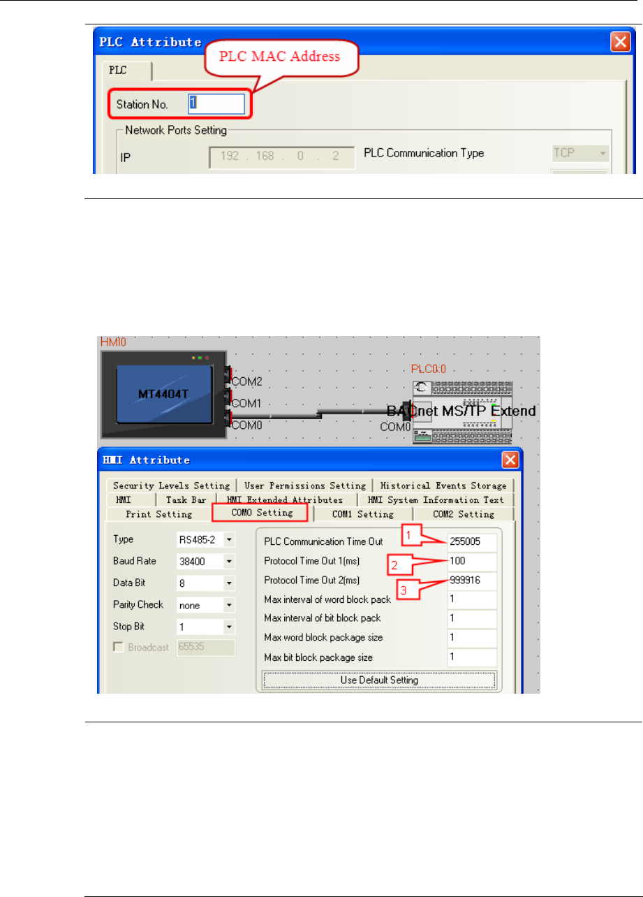
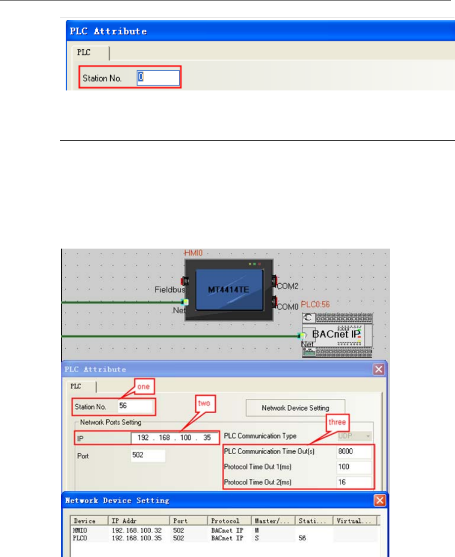
BACnet MS/TP Extend Protocol:
HMI Setting
Default communication:38400bps,8,none,1;station:1
Note: 1. Lable one:
a.PLC Communication Time Out:255 stands for HMI’s ID number;
b.005 stands for HMI’s MAC address,Range is 0~127。And it must be different from
others which one in the token-ring。
2. Lable three:
a.Protocol Time Out 2:16 stands for register read and writer priority,range is 1~16;
b.9999 stands for offset address;Range is 0~4194303;
c.PLC’s ID number=Offset address+The setting in [PLC Attribute]-[Station No.];
4 Communication settings and guide of HMI connecting with controller
- 32 -
3. Use this protocol , the hmi must be updated kernel and rootfs by the kinco HMIware
v2.2(build140805) or later.
4. This protocol only support new 4000 series and 5020 series HMI.
PLC Setting
Please refer to the communication equipment related documentation to set the parameter.
◎Network Communication Setting
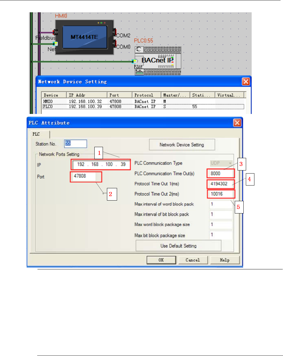
BACnet IP protocol
HMI Setting
4 Communication settings and guide of HMI connecting with controller
- 33 -
NOTE: 1. BACnet controller IP Address;
2. Port ID: 47808, This the standard communication port of BACnet protocol.
3. HMI ID: 8000, If there are more than two HMIs, user must set the different HMI ID for
each HMI.
4. Device ID: 4194302,the ID is the same as the actual device.
5. The protocol time out: 100;register read and writer priority :16 range(1~16);
6. Use this protocol, the HMI must be update kernel and rootfs by the kinco HMIware v2.2
(build141210) or later.
7. This protocol only supports new 4000 series and 5020 series HMI.
PLC Setting
Please refer to the communication equipment related documentation to set the parameter.
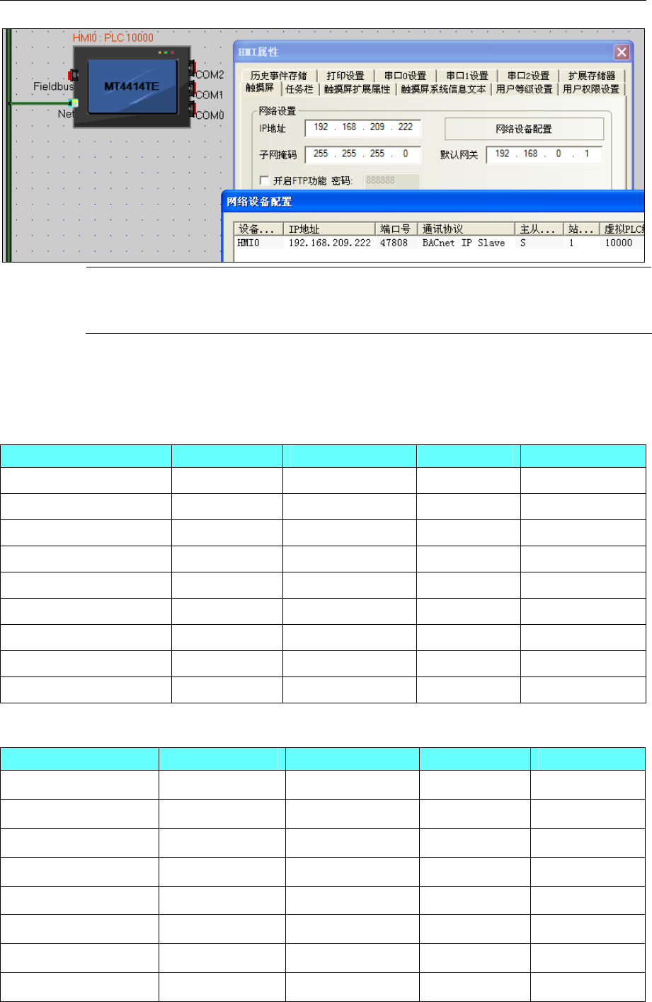
BACnet IP Slave protocol
HMI Setting
4 Communication settings and guide of HMI connecting with controller
- 34 -
NOTE: 1. Use this protocol, the HMI must be update kernel and rootfs by the kinco HMIware v2.2
(build150416) or later.
2. This protocol only supports new 4000 series and 5020 series HMI.
PLC Setting
Please refer to the communication equipment related documentation to set the parameter.
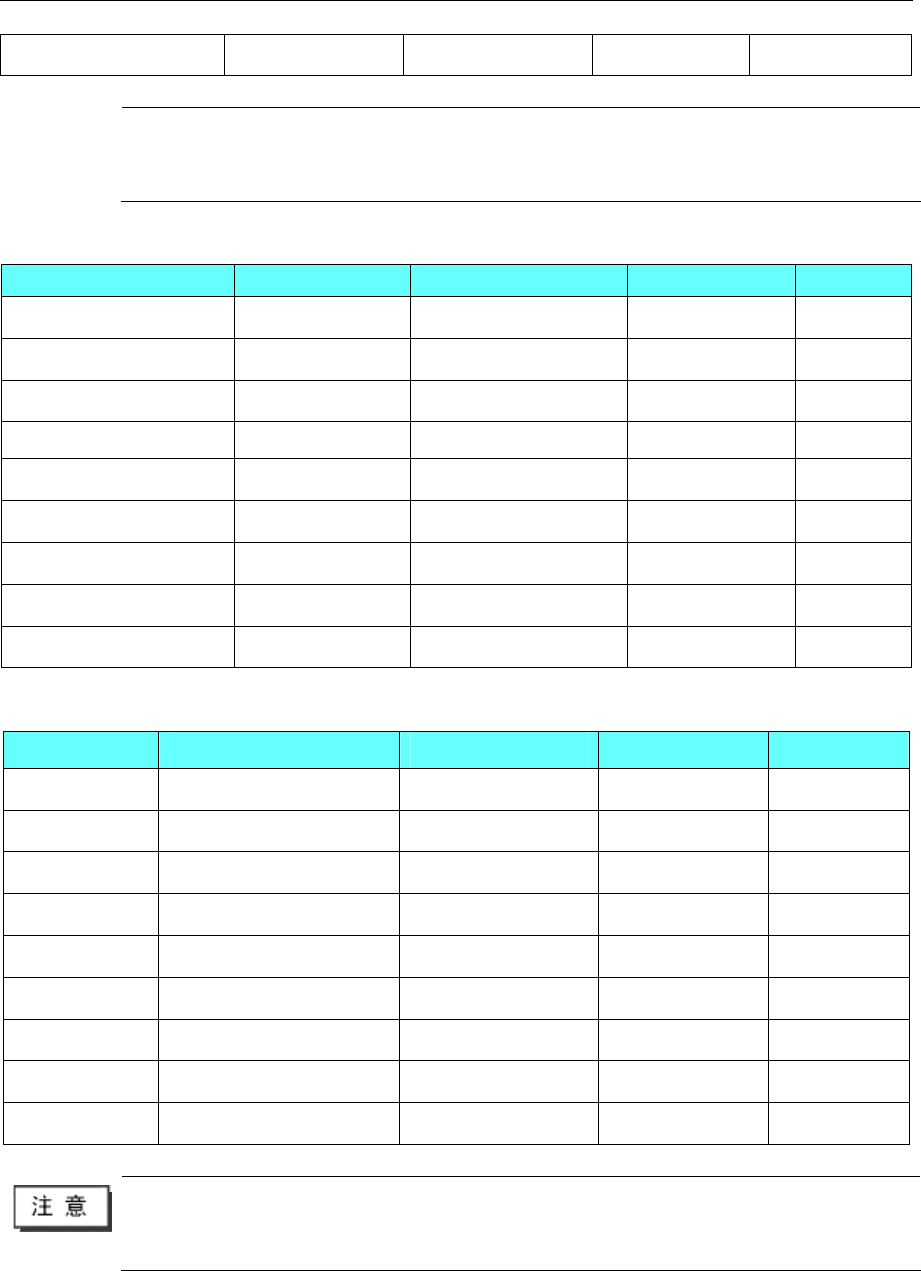
◎Supported Device
BACnet MS/TP Protocol
Device Bit Address Word Address Format Notes
Binary Input BI 0-65535 ------ DDDDD
Binary Output BO 0-65535 ------ DDDDD
Binary Value BV 0-65535 ------ DDDDD
Analog Input ------ AI 0-65535 DDDDD Float
Analog Output ------ AO 0-65535 DDDDD Float
Analog Value ------ AV 0-65535 DDDDD Float
------ MI 0-65535 DDDDD Float
------ MO 0-65535 DDDDD Float
------ MV 0-65535 DDDDD Float
BACnet MS/TP Extend Protocol
Device Bit Address Word Address Format Notes
AI ------ 0-65535 DDDDD Float
AO ------ 0-65535 DDDDD Float
AV ------ 0-65535 DDDDD Float
BI 0-65535 ------ DDDDD
BO 0-65535 ------ DDDDD
BV 0-65535 ------ DDDDD
MI ------ 0-65535 DDDDD
MO ------ 0-65535 DDDDD
4 Communication settings and guide of HMI connecting with controller
- 35 -
MV ------ 0-65535 DDDDD
Note 1. AI、AO、AV is float data;
2.This protocol does not support direct online simulation;
3. Bit register transfer is recommended to use a timer to achieve.
BACnet IP Protocol
Device Bit Address Word Address Format Notes
Binary Input BI 0-65535 ------ DDDDD
Binary Output BO 0-65535 ------ DDDDD
Binary Value BV 0-65535 ------ DDDDD
Analog Input ------ AI 0-65535 DDDDD Float
Analog Output ------ AO 0-65535 DDDDD Float
Analog Value ------ AV 0-65535 DDDDD Float
------ MI 0-65535 DDDDD
------ MO 0-65535 DDDDD
------ MV 0-65535 DDDDD
BACnet IP Slave Protocol
Device Bit Address Word Address Format Notes
BI RB 600.0-600.F ------ DDDDD
BO RB 610.0-610.F ------ DDDDD
BV RB 620.0-620.F ------ DDDDD
AI ------ RW 0-9 DDDDD Float
AO ------ RW 100-109 DDDDD Float
AV ------ RW 200-209 DDDDD Float
MI ------ RW 300-309 DDDDD
MO ------ RW 400-409 DDDDD
MV ------ RW 500-509 DDDDD
1.AI、AO、AV is float data;
2.This protocol does not support direct online simulation;
3. Bit register transfer is recommended to use a timer to achieve.
◎Cable Diagram
RS485-2
4 Communication settings and guide of HMI connecting with controller
- 36 -
Ethernet cable
Connecting PC and HMI use cross-ruling; communicating with hub or switch use cross-over cable or
cross-ruling.
Refer to 3.3 Download by Network Ethernet for method of making connection cable.
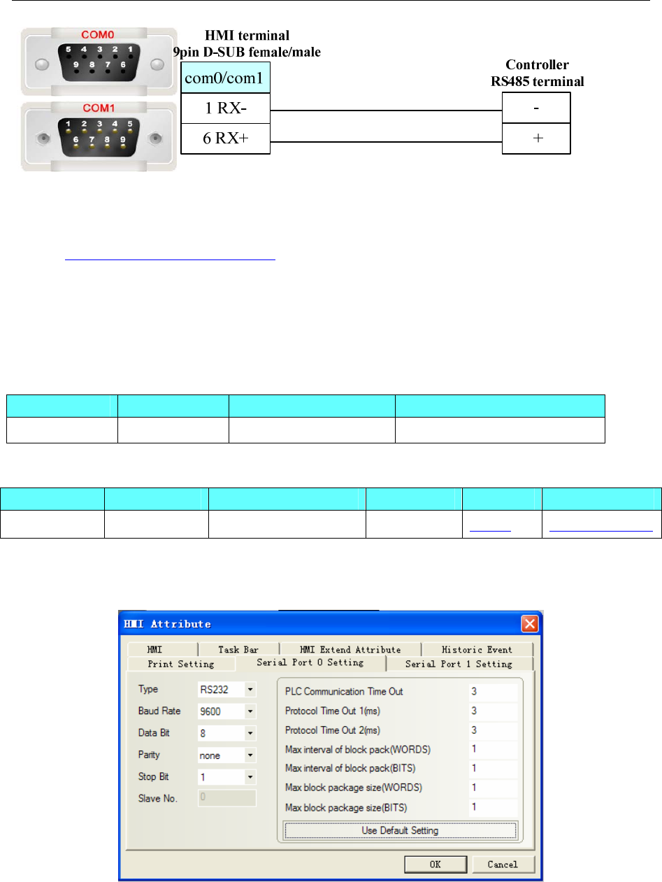
4.7 Baldor NextMove ES (Motion Controller)
◎Serial Communication
Series CPU Link Module Driver
NextMove ES NextMove ES RS232 on the CPU unit Baldor NextMove ES
◎System configuration
Series CPU Link Module COMM Type Parameter Cable
NextMove ES NextMove ES RS232 on the CPU unit RS232 Setting Your owner cable
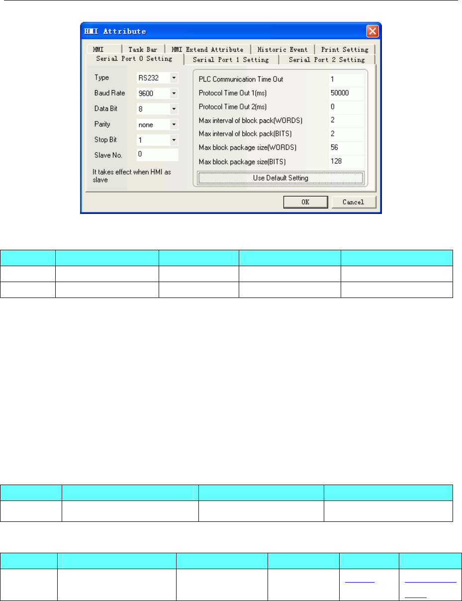
◎Communication Setting
HMI Setting
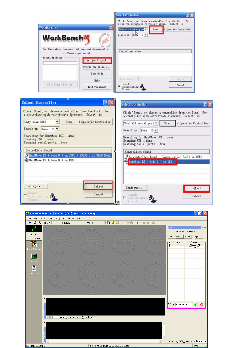
PLC Setting
Use the guide of the Workbench software
4 Communication settings and guide of HMI connecting with controller
- 37 -
◎Supported Device
4 Communication settings and guide of HMI connecting with controller
- 38 -
(Only data of comms can be monitored, some address greater than or equal to 100 are read only. Please
pay attention to matching the controller software configuration.)
Device Bit Address Word Address(Parameter symbol)Format Notes
Float --------- 1-255 DDD Float Data type
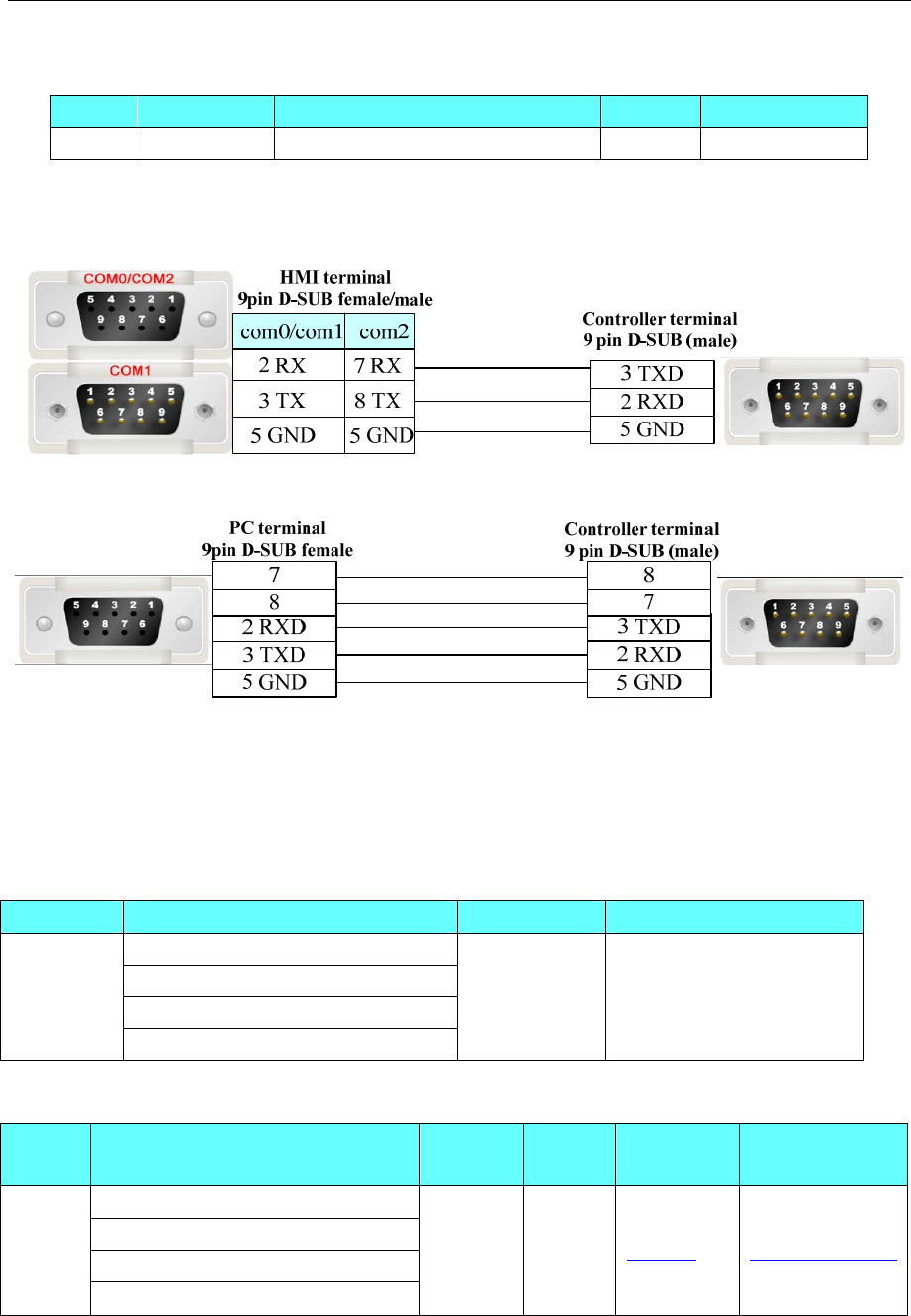
◎Cable Diagram
RS232 communication cable of HMI connecting to controller
RS232 programming cable(Also can use USB,Power is +5v/±12v)
4.8 Barcode
◎Serial Communication
Series CPU Link Module Driver
3800LTP-12E
MLJ-MS9590
SYMBOL LS4208-SR200007 ZZR
Barcode
Flashcode LS3042
RS232 Barcode
◎System configuration
Series CPU Link
Module
COMM
Type Parameter Cable
3800LTP-12E
MLJ-MS9590
SYMBOL LS4208-SR200007 ZZR
Barcode
Flashcode LS3042
RS232 RS232 Setting Your owner cable
◎Communication Setting
4 Communication settings and guide of HMI connecting with controller
- 39 -
◎Supported Device
Device Bit Address Word Address Format Notes
Word -------- LW 8900-8999 DDDD
Bit -------- LB 8999 DDDD
NOTE:
1. LW 8900-8999: the character after scanning, text and note book parts can display it.
2. LB 8999: the state of barcode is received or not. LB 8999=1 means the data is received.
◎Cable Diagram
Connect the scanner and the COM port of HMI directly.
4.9 Baumuller
◎Serial Communication
Series CPU Link Module Driver
Baumuller BM4413-ST0-02200-03 RS422 on the CPU unit Baumuller
◎System configuration
Series CPU Link Module COMM Type Parameter Cable
Baumuller BM4413-ST0-02200-03
RS422 on the CPU
unit
RS485 Setting Your owner
cable
◎Communication Setting
4 Communication settings and guide of HMI connecting with controller
- 40 -
◎Supported Device
Device Bit Address Word Address Format Notes
Bit type DB_BIT0.00-255.F ------ DDD.H
Word type ------ DB0-255 DDD
Example: DB2_BIT address please input 0.F in the EV5000 software.
DB2 address please input 11 in the EV5000 software.
◎Cable Diagram
RS485-4 communication cable
4.10 Bosch Rexroth KVFC+ (Inverter)
◎Serial Communication
Series CPU Link Module Driver
KVFC+ RS485 Bosch Rexroth KVFC+
◎System configuration
Series CPU Link Module COMM Type Parameter Cable
KVFC+ RS485 on the CPU unit RS485 Setting Your owner cable
4 Communication settings and guide of HMI connecting with controller
- 41 -
◎Communication Setting
◎Supported Device
Device Bit Address Word Address Format Notes
Start/Stop STW0~3
------ D
STW0 open, start.
STW0 close, stop.
STW1 close, positive rotation.
STW1 open, negative rotation.
STW2 REV inching turning.
STW3 FWD inching turning.
Set frequency ------ HSW 0 D
Basic Function Block ------ B 0~41 DD
B16 acceleration time.
B17 deceleration time.
Deviation alarm ------ E 0~41 DD
Programmable control
function array
------ P 0~37 DD
High function array ------ H 0~38 DD
D array ------ D 0~6 D
D0: output power.
D2: running current.
◎Cable Diagram
4 Communication settings and guide of HMI connecting with controller
- 42 -
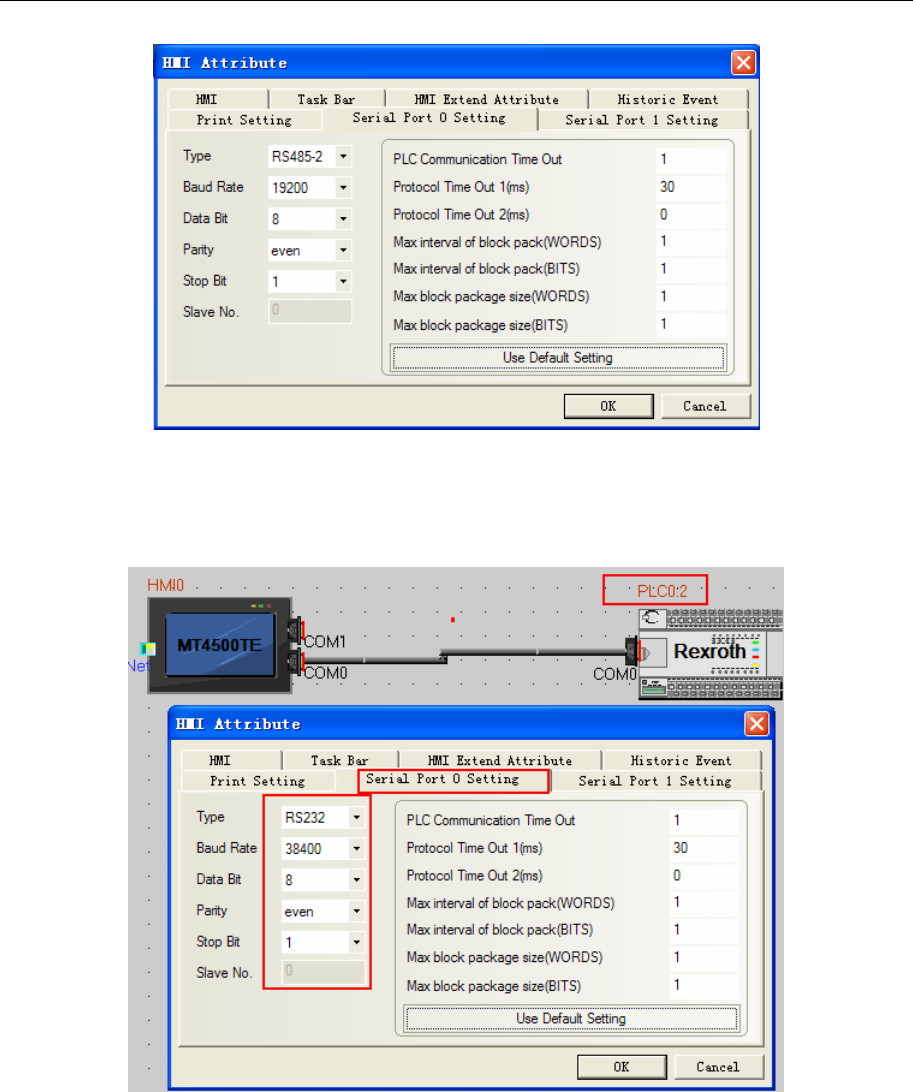
4.11 Bosch Rexroth
◎Serial Communication
Series CPU Link Module Driver
RS232 on the CPU unit
PPC-R PPC-R22.1 13VRS
RS485 on the port
L40 RS232 on the CPU unit
L L20 RS232 on the CPU unit
Bosch Rexroth
IndraDrive C HCS02 RS232 on the CPU unit Bosch Rexroth SIS
◎System configuration
Series CPU Link Module COMM Type Parameter Cable
RS232 on the CPU unit RS232C Setting Your owner cable
PPC-R PPC-R22.1 13VRS
RS485 on the port RS485 Setting Your owner cable
L L40
L20 RS232 on the CPU unit RS232C Setting Your owner cable
Indra
Drive
C
◎Communication Setting
PPC-R communication setting
RS232 communication: 19200, 8, even, 1; station number: 128
RS485 communication
4 Communication settings and guide of HMI connecting with controller
- 43 -
NOTE: To communicate with the touch screen, declare variable firstly in the Rexroth software.
L40 communication settings
Default communication: 38400, 8, 1, none; Station No.: 2
NOTE: To communicate with the touch screen, declare variable firstly in the Rexroth software.
L40 Hardware Settings
4 Communication settings and guide of HMI connecting with controller
- 44 -
PLC Setting
PPC-R software setting
PLC connects with PC via crossover ethernet cable. If using cross-connection ethernet cable, you must add
a HUB (we usually use a cross-connection line to access the Internet)
Hardware configuration:
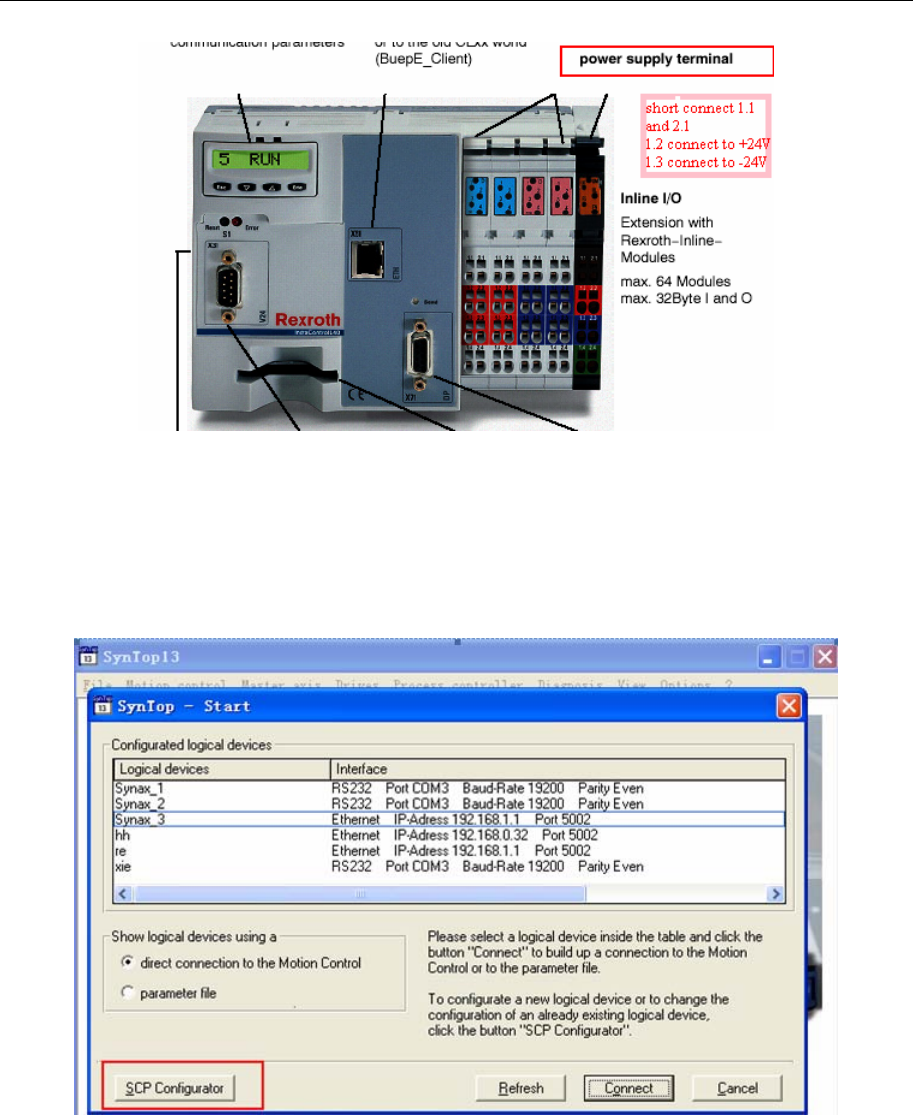
1. Click”scp configurator”--->”scanning ”or” add device”--->”next”, pay attention to the default
controller IP: 192.168.1.1. And set IP 192.168.1.1 in the software (PC and controller must be set up in
the same segment), ping IP address is OK, that configuration is successful. Save and close “scp
configurator”--->”refresh” to see logical devices created in configured logical devices”, double-click to
enter. All configurations will be successful.
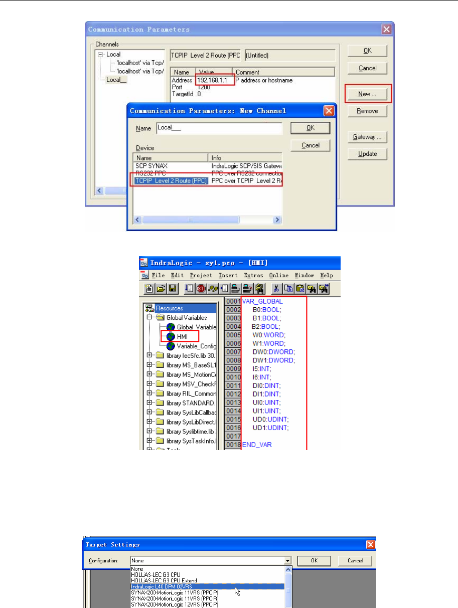
2. Open ”indralogic”--->”online/communication parameter”--->”new” and select ”TCP/IP” to
modify “value”, set IP address the same as controller: 192.168.1.1
4 Communication settings and guide of HMI connecting with controller
- 45 -
3. “Resource”--->“Global variables”--->declare variable in “HMI”
4. Click “online/login”
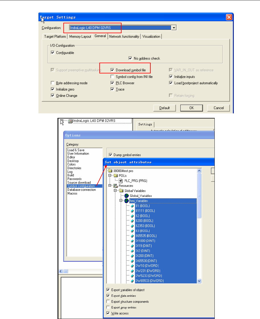
L40 software setting
1) The IndraLogic software connect with the Rexroth IndraControl L40 by ethernet cable(test: plc IP
address:192.168.100.103)
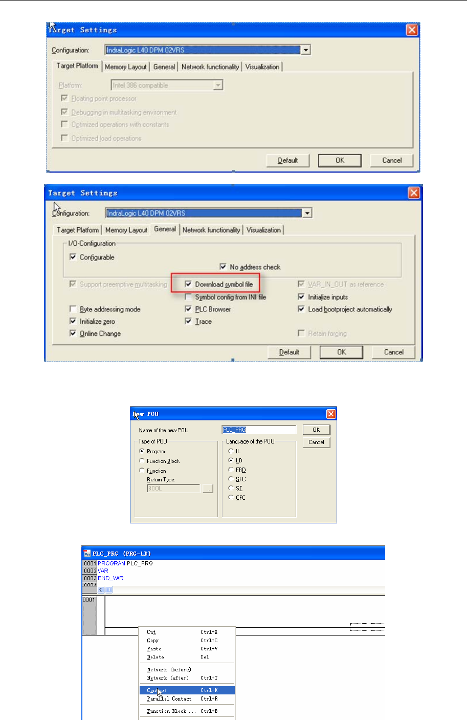
Open the IndraLogic software,create a new project:
Click “OK” and pop-up the window as follows:
4 Communication settings and guide of HMI connecting with controller
- 46 -
NOTE:Must select Download symbol file
Click “OK” and pop-up the window as follows:
And then edit program:
4 Communication settings and guide of HMI connecting with controller
- 47 -
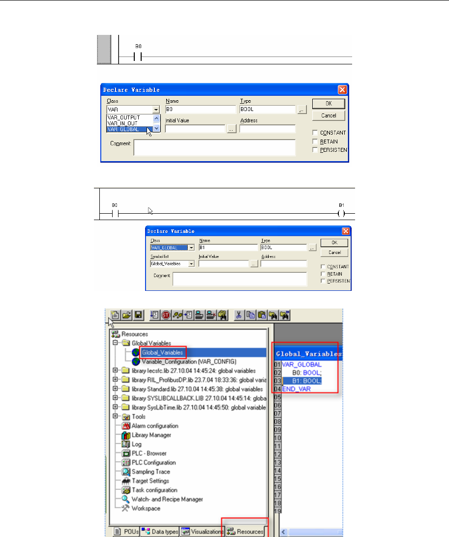
Input B0 and pop-up the dialog, configurations as follows, click “OK”:
And set up coil:
At the same time, you will find that there automatically generate two variables in the global variable:
Then setting as follows:
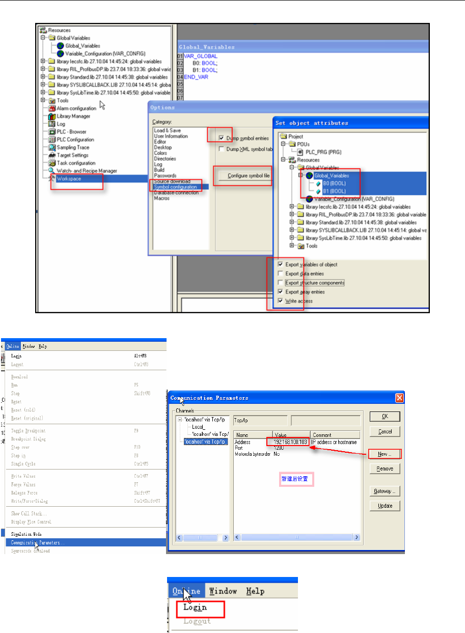
4 Communication settings and guide of HMI connecting with controller
- 48 -
Setting communication parameter:
Then click “Login”:
Communicating successfully, you can operate(“Online” menu to select “run” or others):
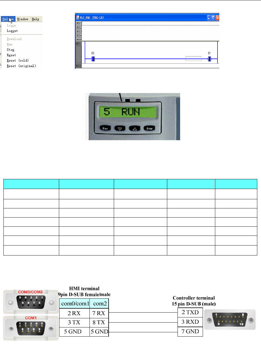
4 Communication settings and guide of HMI connecting with controller
- 49 -
NOTE:The PLC panel must be set up, press” Enter”, then press” ”, until showed up “ RS232”, and then △
press ”Enter” to enter “COM SERV” interfaces (not SERV, it must change to SERV)
In accordance with the above settings, the serial line access, EV5000 can be communicated with the
Rexroth Controller L40 by serial port.
◎Supported Device
Device Bit Address Word Address Format Notes
BYTE B0000-9999 ------ DDDD
WORD ------ W0-65535 DDDDD
INT ------ I0-65535 DDDDD
UINT ------ UI0-65535 DDDDD
DWORD ------ DW0-65535 DDDDD
DINT ------ DI0-65535 DDDDD
UDINT ------ UD0-65535 DDDDD
◎Cable Diagram
PPC-R RS232 communication cable
PPC-R RS485 communication cable
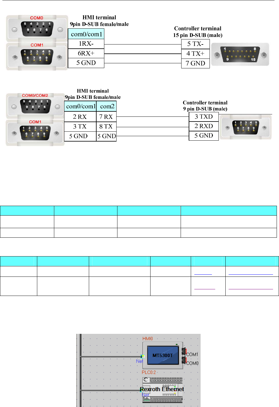
4 Communication settings and guide of HMI connecting with controller
- 50 -
L40 communication cable
4.12 Bosch Rexroth Ethernet
◎Network communication (indirect online and direct online simulation disable)
Series CPU Link Module Driver
IndraLogic IndraLogic L40 DPM ETH on the CPU unit Bosch Rexroth Ethernet
IndraMotion MLC IndraControl L25 ETH on the CPU unit Bosch Rexroth L25 Ethernet
◎System configuration
Series CPU Link Module COMM Type Parameter Cable
IndraLogic L40 DPM 02VRS ETH on the CPU unit ETH Setting Your owner cable
IndraMotio
n MLC IndraControl L25 ETH on the CPU unit ETH Setting Your owner cable
◎Communication Setting
L40
HMI Setting
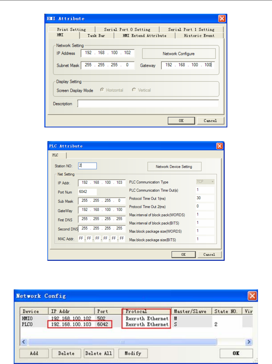
4 Communication settings and guide of HMI connecting with controller
- 51 -
PLC Attribute※ (station disable)
Network configuration※(Note: PLC port num. must be set 6042,HMI port num. is optional,default
is 6042. In addition, the screen and plc must be set in the same network segment, the gateway of the screen
is better to set with the actual use of the network gateway .)
NOTE: To communicate with the touch screen, declare variable firstly in the Rexroth software.
PLC Setting
PLC connect with PC by crossover network cable,if using cross-connection network cable, you must
add a HUB (we usually use a cross-connection line to access the Internet)
1. After L40 equipped with software driver successfully, to set as follows:
4 Communication settings and guide of HMI connecting with controller
- 52 -
At this time open “indralogic” -->“online/communication parameter” -->“new” and select “TCP/IP ”
to modify “value”,set IP address the same as controller: 192.168.100.103

4 Communication settings and guide of HMI connecting with controller
- 53 -
2. “Resource”--->“Global variables”--->declare variable in “HMI”
3. Click “online/login”
L25:
HMI Setting
4 Communication settings and guide of HMI connecting with controller
- 54 -
PLC Setting
1. Modify the IP in the controller.
2. Declare variable in controller programmer software.
3. Software setting
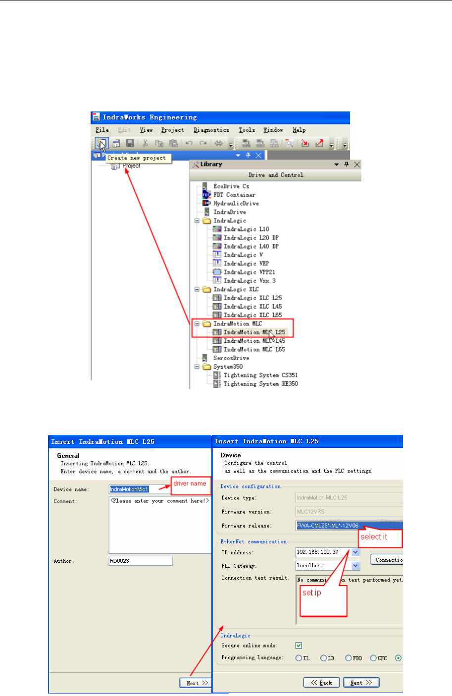
1)Create new project and select IndraMotion MLC L25(library→driver and control→IndraMotion MLC),
then drug the selected controller onto the project file.
2)IN Insert IndraMotion MLC L25 properties box, set the Firmware release
(FWA-CML25*-ML*-12V06)and IP address.
4 Communication settings and guide of HMI connecting with controller
- 55 -
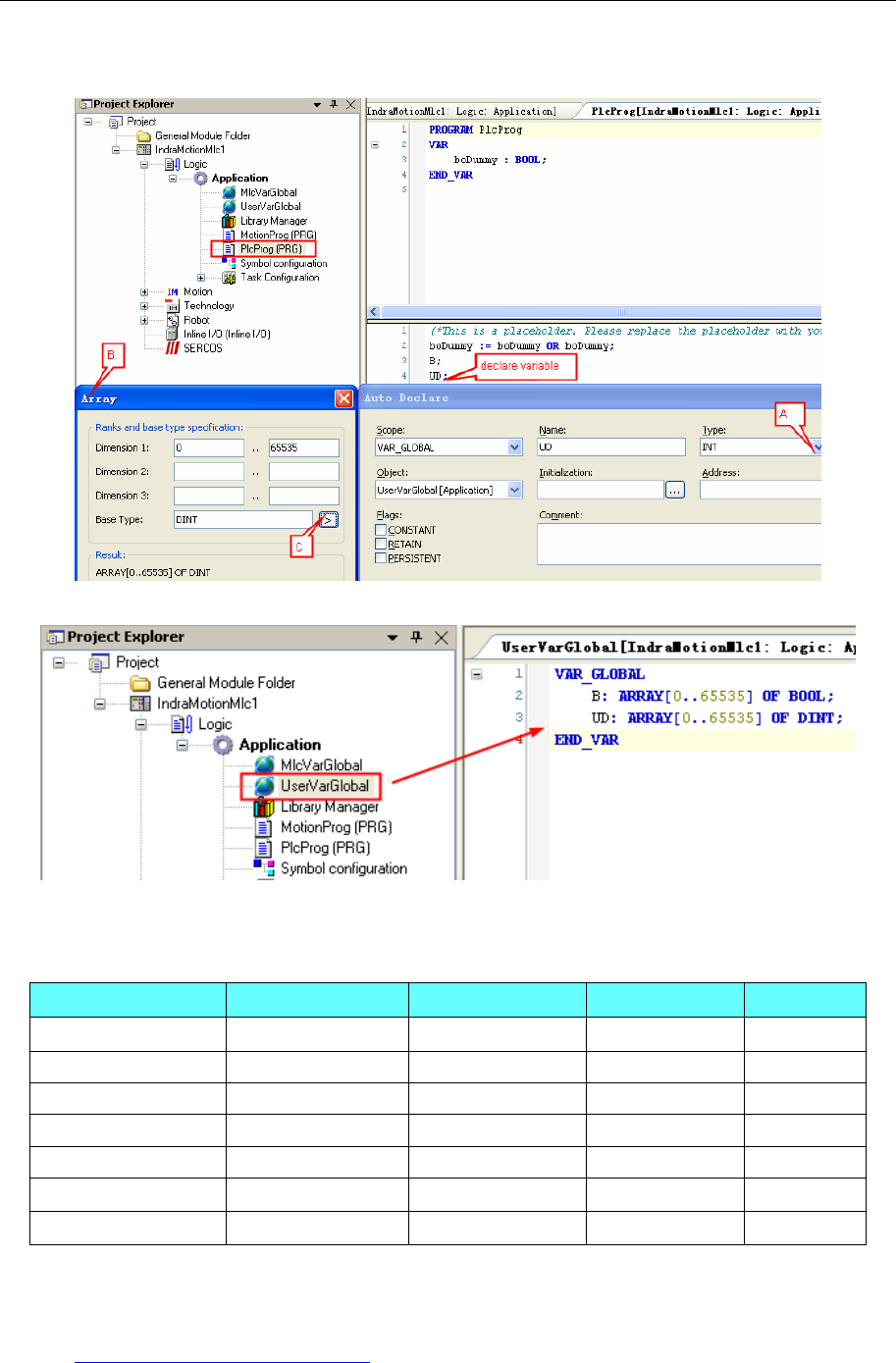
3)Declare variable
Declare variable UD in [Application]→[PlcProg(PRG)],and declare the variable type.
4) View the Declared variable in [Application]→[UserVarGlobal]
4. Click “online/login”
◎Supported Device
Device Bit Address Word Address Format Notes
BYTE B0000-9999 ------ DDDD
WORD ------ W0-65535 DDDDD
INT ------ I0-65535 DDDDD
UINT ------ UI0-65535 DDDDD
DWORD ------ DW0-65535 DDDDD
DINT ------ DI0-65535 DDDDD
UDINT ------ UD0-65535 DDDDD
◎Cable Diagram
Cross-connection or crossover network cable can be used as communication cable via the hub
Refer to 3.3 Download by Network Ethernet for method of making connection cable.
4 Communication settings and guide of HMI connecting with controller
- 56 -
4.13 CANOpen Node Slave
◎Serial Communication
Series CPU Link Module Driver
KINCO K4 CAN port on the External Device
Other company devices which support
CANOpen CANOpen port CANOpen Node Slave
◎System configuration
Series CPU Link Module Parameter Cable
KINCO K4 CAN port on the External Device Setting
Other company devices which
support CANOpen CAN port Setting
Your owner
cable
◎Communication Setting
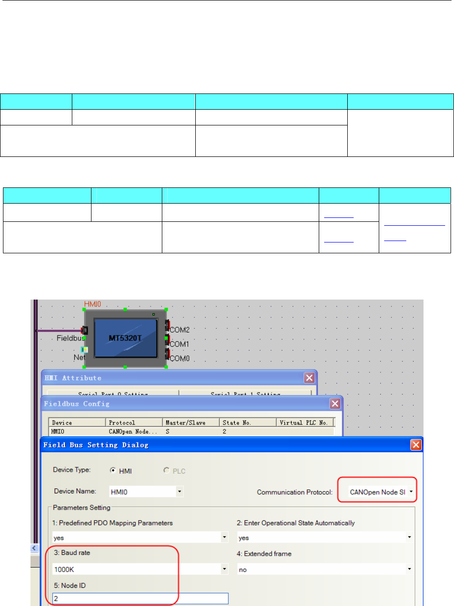
HMI Setting
NOTE: Baud Rate and Station No. must be the same as the setting in the controller.
Parameters Setting
1. Predefined PDO mapping parameters
a. Default is “yes”, that is an effective predefined PDO mapping parameters. HMI now use the following
PDO communication parameters and mapping
Receive PDO Mapping Send PDO Mapping
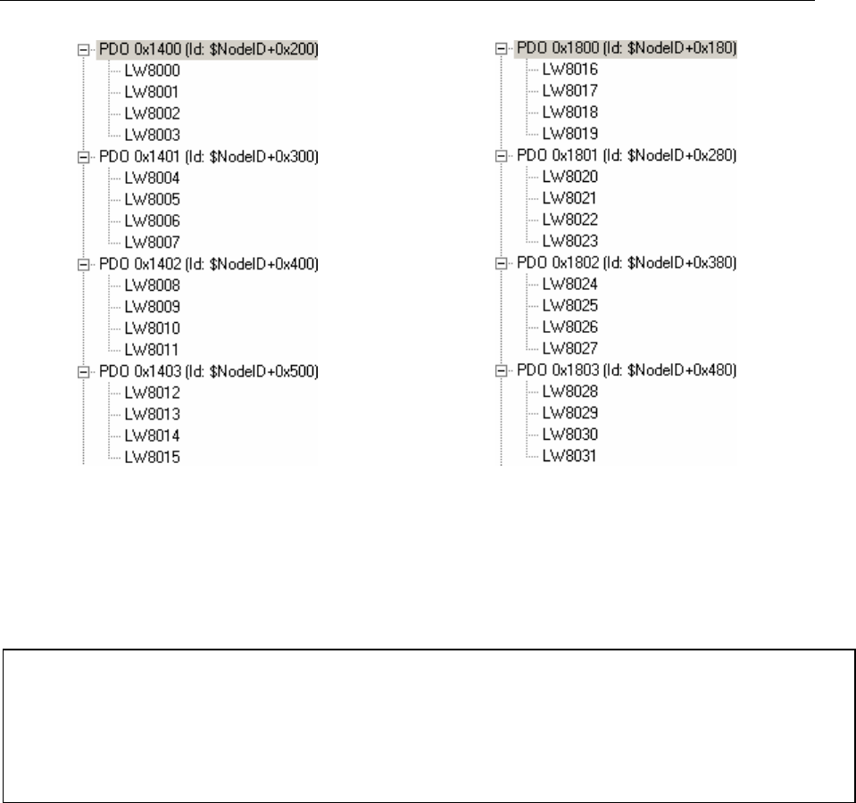
4 Communication settings and guide of HMI connecting with controller
- 57 -
Note: TX_PDO using the event-triggered mode, that is, only when its mapping variable changes, it sends
the PDO.
b. If the "No", the main station or other equipment necessary to configure the PDO communication
parameters and mapping (configure only in the pre-operational status). After configured, you can send a
save command via USB-CAN or controller to save the current configuration (restart still valid).
Command:
2. Enter operational state automatically
a. Default is "yes", that is, HMI enter the operational status (OPERATIONAL) automatically after
power-up, NMT Master is no need to re-send start instructions.
b. If the "No", then HMI enter the pre-operational status (PRE-OPERATIONAL) automatically after
power-up, only when the NMT Master sends start commands, system can entering the operational status
(OPERATIONAL)
Note: PDO is effective only in the operating conditions (OPERATIONAL).
3. Baudrate
CAN port baud rate must be the same as CAN bus.
4. Node ID
HMI in the CAN bus ID, the ID only for the use of CANopen protocol. When using all the PDO
(RX_PDO1 ~ RX_PDO64, TX_PDO1 ~ TX_PDO64), station number can not exceed 7, the bus station
number of other devices also can not exceed 7.
PLC setting
COB-ID DATA
Save the configuration information: 0x600 + NodeID 0x23 0x10 0x10 0x01 0x73 0x61 0x76 0x65
Restore to factory defaults: 0x600 + NodeID 0x23 0x11 0x10 0x01 0x6C 0x6F 0x61 0x64
Into the operating state: 0x00 0x01 NodeID
Into the pre-operational status: 0x00 0x80 NodeID
4 Communication settings and guide of HMI connecting with controller
- 58 -
Note: you can find MT5020.EDS in fieldbus file of EV5000 Installation Directory, or you can download
from www.kinco.cn.
Take MT6000 for example (we use MT6000 HMI to test, and use 3S CODESYS software to download
project)
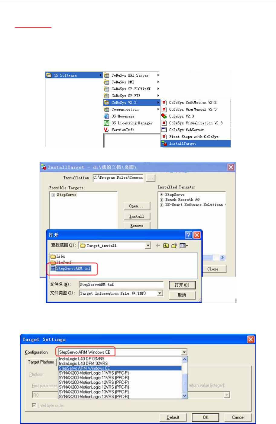
1. Setup
- Start Menu “3s Software”->“Codesys v2.3”->“installtarget”
- Click “open” choose “StepServoARM.tnf”, and then click “install”.
2. Copy “MT5020.EDS” to “C:\Program Files\Common Files\CAA -Targets\ StepServo\ PlcConf”
3. Configuration setting
a. run codesys software,make a new project
4 Communication settings and guide of HMI connecting with controller
- 59 -
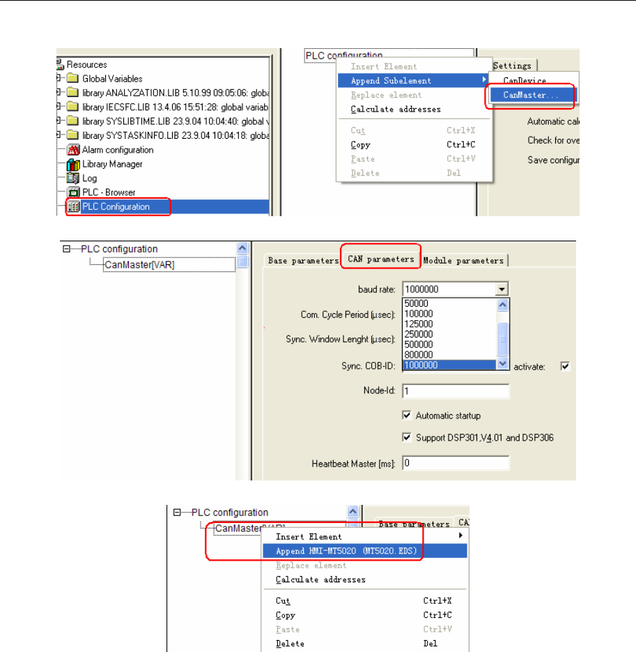
b. configuration setting,right click “PLC configuration” and choose “CanMaster”
c. set Baud Rate
d. choose “CanMaster” right click “Append HMI-MT5020”
e. Node ID: set slave station No.
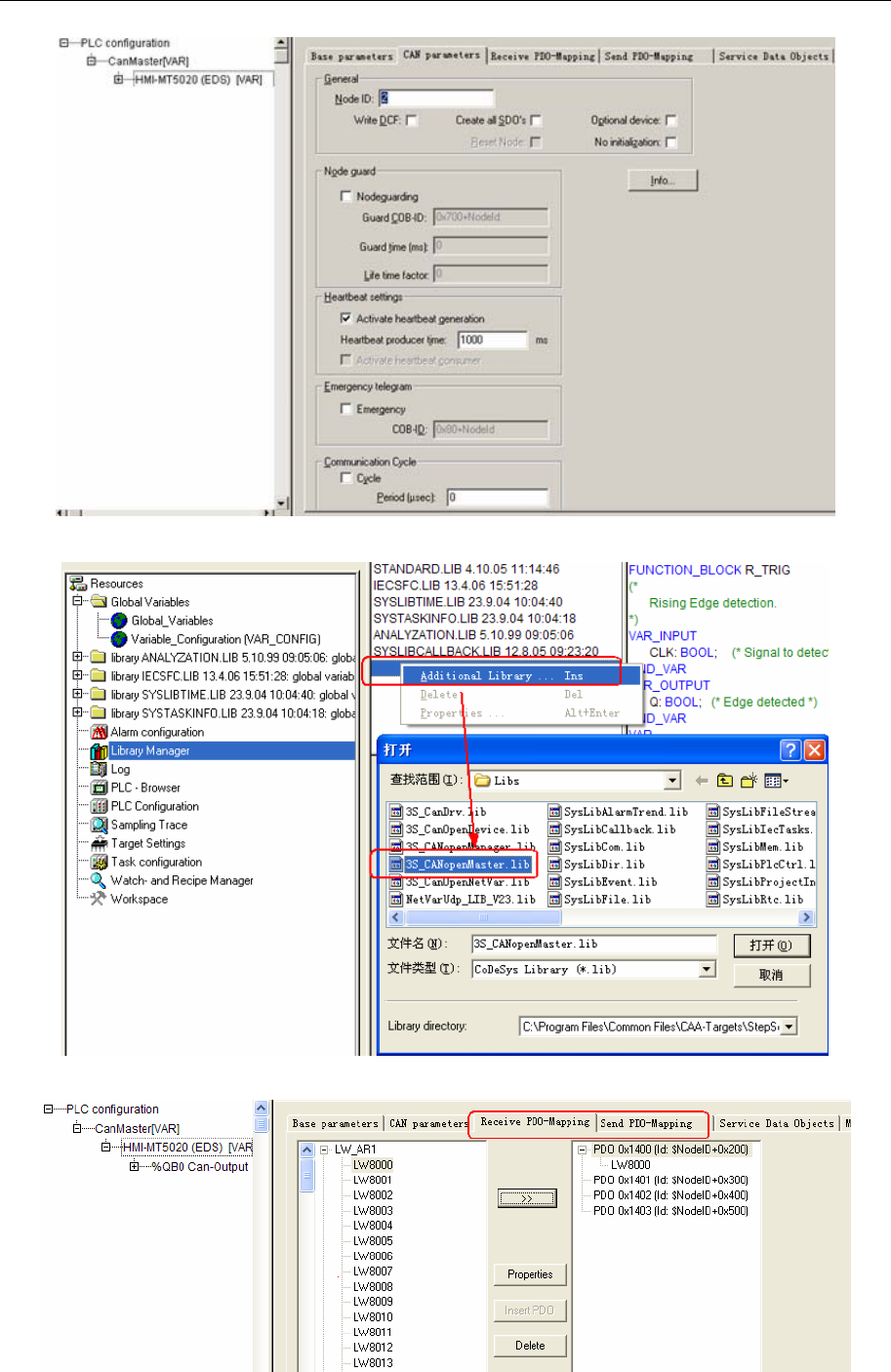
4 Communication settings and guide of HMI connecting with controller
- 60 -
f. in the “Library Manager” we import “3S_CANopenMaster.lib”
g. PDO read and write setting
4 Communication settings and guide of HMI connecting with controller
- 61 -
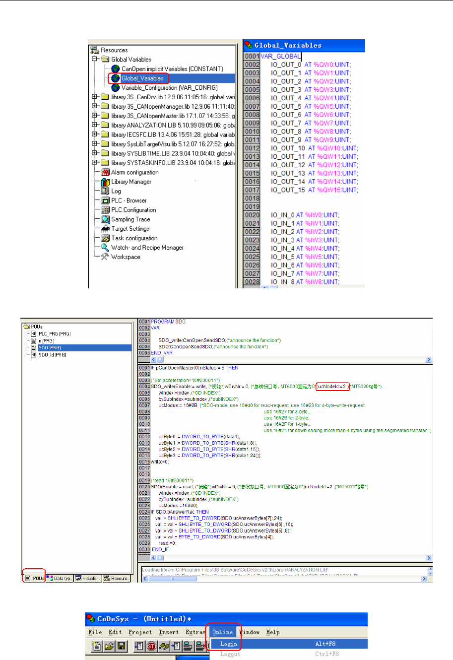
h. define Global Variable
i. SDO setting,this step need program
j. load the configuration into the PLC
◎Supported Device
4 Communication settings and guide of HMI connecting with controller
- 62 -
Device Bit Address Word Address Format Notes
————— LW8000~LW8999 DDDD
NOTE: We must make the setting of PD0, SD0 and LW the same as codesys
◎Cable Diagram
4.14 Cimon
◎Serial Communication
◎ System configuration
Series CPU Link Module COMM Type Parameter Cable
PLC-S Cimon
CM3-SP16MDRV
RS232 on the CPU
unit RS232/RS485 Setting Your owner cable
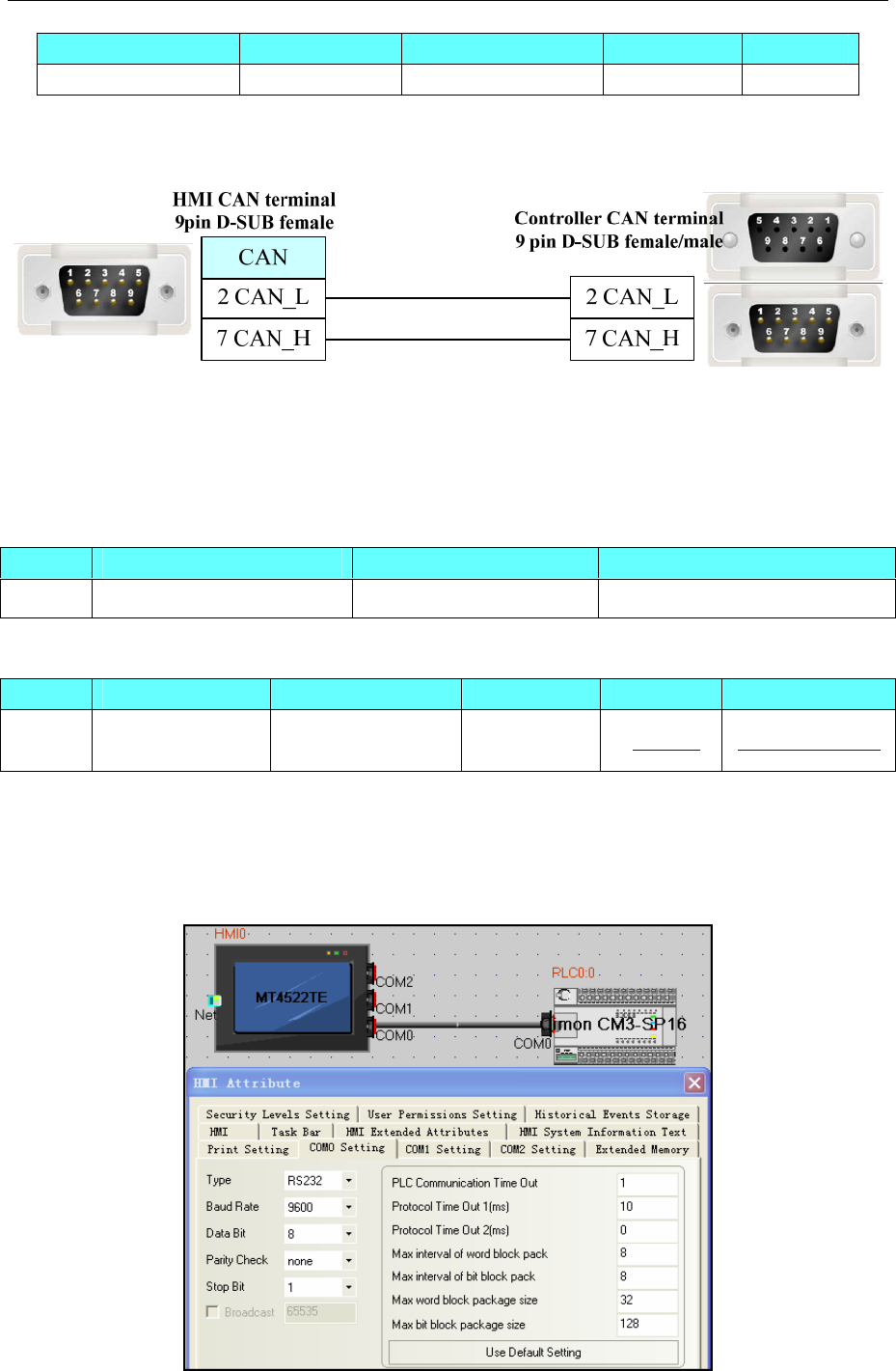
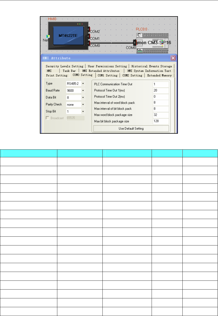
◎ Communication Setting
HMI setting
Default parameter:9600bps,8,none,1;station number:0
RS232
Series CPU Link Module Driver
PLC-S Cimon CM3-SP16MDRV RS232 on the CPU unit Cimon CM3-SP16
4 Communication settings and guide of HMI connecting with controller
- 63 -
RS485
◎ Supported Device
Device Bit Address Word Address Format Notes
Input X 0.0-63.F ------ DD.F
Output Y 0.0-63.F ------ DD.F
Sub Relay M 0.0-511.F ------ DDD.F
Link Relay L 0.0-255.F ------ DDD.F
Keep Relay K 0.0-255.F ------ DDD.F
Timer T 0-519 ------ DDD
Counter C 0-519
------ DDD
Special Relay F 0-2047 ------ DDDD
Z Register ------ Z 0-1029 DDDD
Timer ------ T 0-519 DDD
Counter ------ C 0-519 DDD
Data Device ------ D 0-9999 DDDD
Sub Relay ------ M 0-511 DDD
Output ------ Y 0-63 DD
Input ------ X 0-63 DD
Keep Relay ------ K 0-255 DDD
Link Relay ------ L 0-255 DDD
Step Control Relay ------ S 0-99 DD
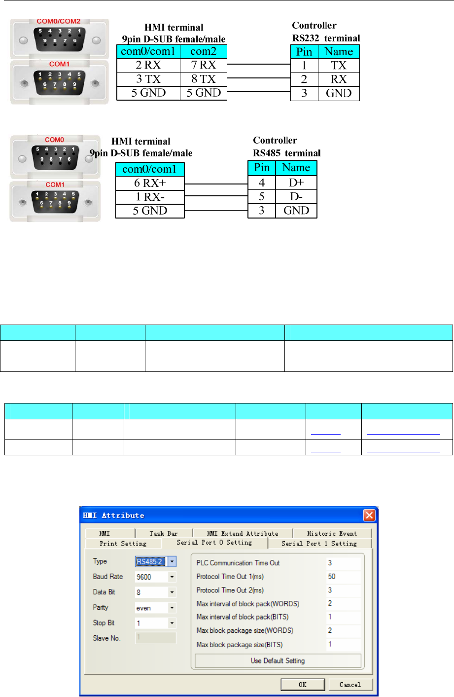
◎ Cable Diagram
RS232
4 Communication settings and guide of HMI connecting with controller
- 64 -
RS485
4.15 Danfoss Inverter
◎Serial Communication
Series CPU Link Module Driver
Danfoss FC-300 RS485 on the CPU unit Danfoss
Modbus RTU
◎System configuration
Series CPU Link Module COMM Type Parameter Cable
Danfoss FC-300 RS485 on the CPU unit RS485-2 Setting Your owner cable
Modbus RTU FC-300 RS485 on the CPU unit RS485-2 Setting Your owner cable
◎Communication Setting
Danfoss Protocol:
4 Communication settings and guide of HMI connecting with controller
- 65 -
Modbus RTU Protocol:
Note:Change the value of 8-30 to 2 on the Danfoss inverter for modbus protocol(Change the value of 8-30
to 0 for the Danfoss Protocol)
Inverter
8-3* FC Port Setting
8-30 protocol
*[0] FC (danfoss protocol)
[2] Modbus (modbus protocol)
8-31 address
1 – 247 * 1 (HMI station No.)
8-32 FC Port Baud Rate
[0] 2400 Baud
[1] 4800 Baud
*[2] 9600 Baud
8-33 FC Port Parity
*[0] even, 1 stop bit
[1] Odd, 1 stop bit
[2] None, 1 stop bit
[3] None, 2 stop bit
Inverter setting
Please refer to the manual of Danfoss inverter for details
◎Supported Device
Danfoss Protocol:
Device Bit Address Word Address Format
EEPROM Register(Double Word) ———— EPD0-7998.99999 DDDD.DDDDD
EEPROM Register ———— EPW0-7998.99999 DDDD.DDDDD
4 Communication settings and guide of HMI connecting with controller
- 66 -
RAM Register(Double Word) ———— RMD0-7998.99999 DDDD.DDDDD
RAM Register ———— RMW0-7998.99999 DDDD.DDDDD
Note:
1. D indicates decimal; the prefix of RMD\RMW\EPD\EPW is address parameter, the suffix is index
number.
2. Mapping of index address (adding radix point if having index address, index value follow radix point.
Otherwise there’s no radix point):
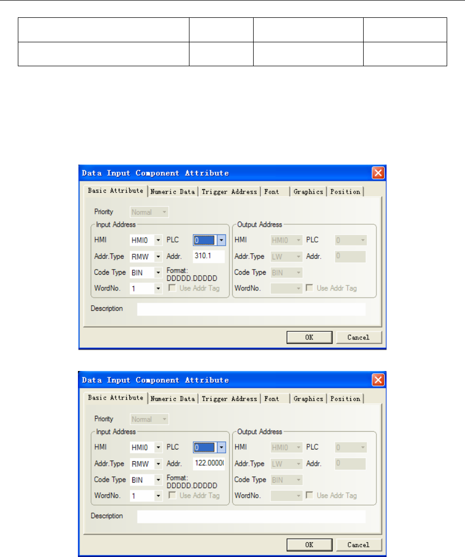
RMW310.1 is to 3-10, please clicking Menu, to find 3-10 to check.
3. If no index, radix point followed by default zero. As follows RMW122 to 1-22:
4. R/W of process word:
1) Address of EPD register is 8000, is for saving input command value of process word;
2) Address of EPD register is 8100, is for saving return value of process word;
3) Input command value and return value can be showed by RW register.
4)Start\Stop, Mapping of reference value to frequency:
Reason: RWD8000 is for inputting control word, it’s not able to input control word by itself, but
via sending RW1, RW0 to RWD8000 by timer.
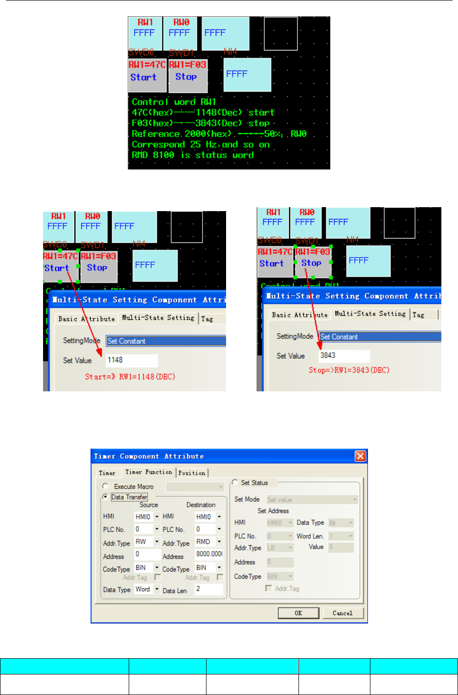
4 Communication settings and guide of HMI connecting with controller
- 67 -
Control word RW1: While RW1=0x47C or 1148, it means start.◆ While RW=0x0F03 or 3843, it
means stop.
Frequency of RW0 mapping : If input 2000 to RW0, frequency is 25HZ, and input 4000, frequency ◆
is 50HZ, and so on.
Timer, send value of RW1 and RW0 to RWD8000.◆
Modbus RTU Protocol:
Device Bit Address Word Address Format Notes
Output bit 0X1-65535 ------ DDDDD
4 Communication settings and guide of HMI connecting with controller
- 68 -
Input bit (read only) 1X1-65535 ------ DDDDD
Input Register (read only) ------ 3X1-65535 DDDDD
Output Register ------ 4X1-65535 DDDDD
Note:
Mapping of address (same as *10 relationships):
2-01 is to 4X2010
3-02 is to 4X3020
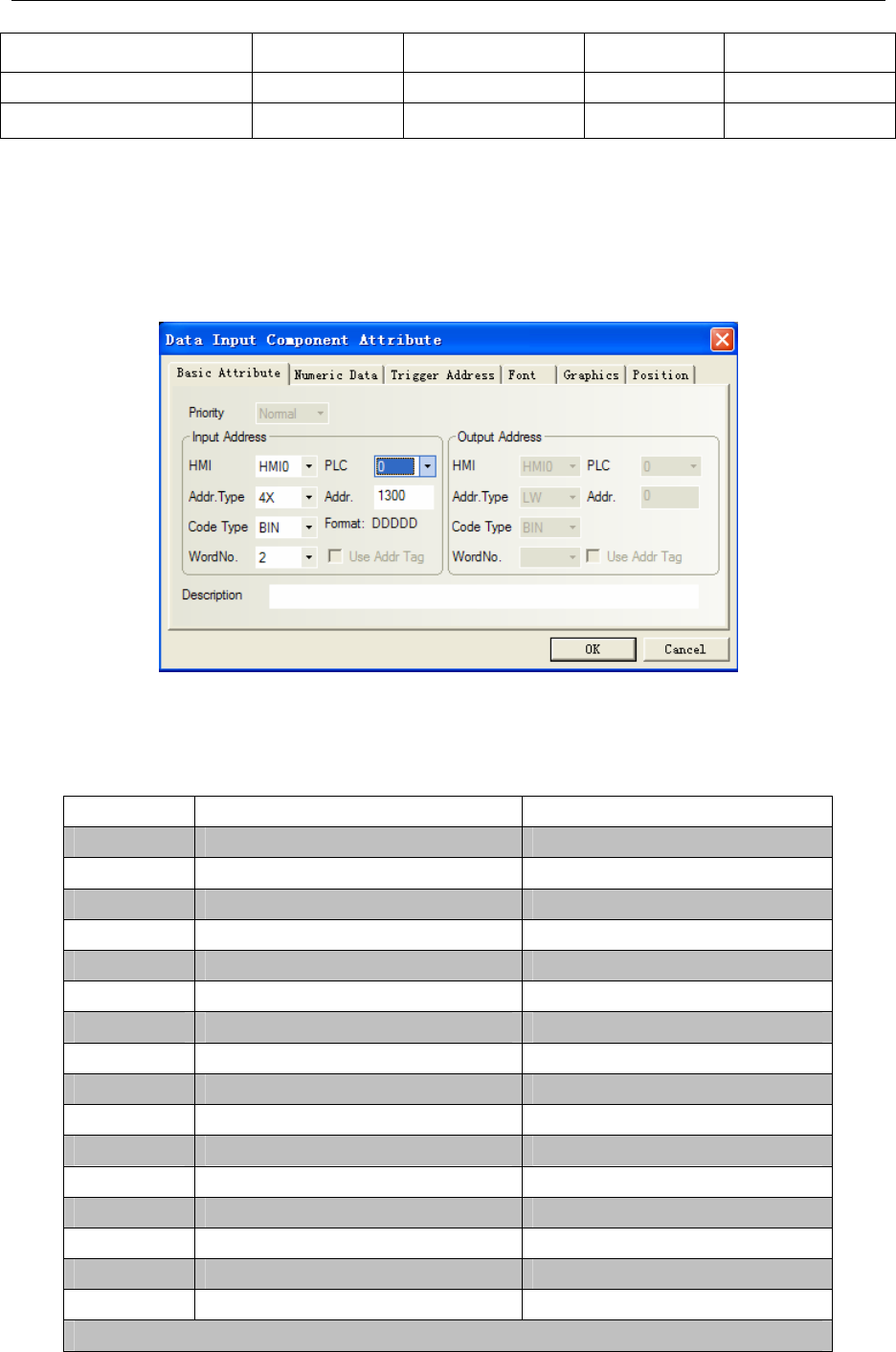
So address 4X1300 is to 1-30 as following picture, here is double word address. To get more
information, please refer to danfoss manual.
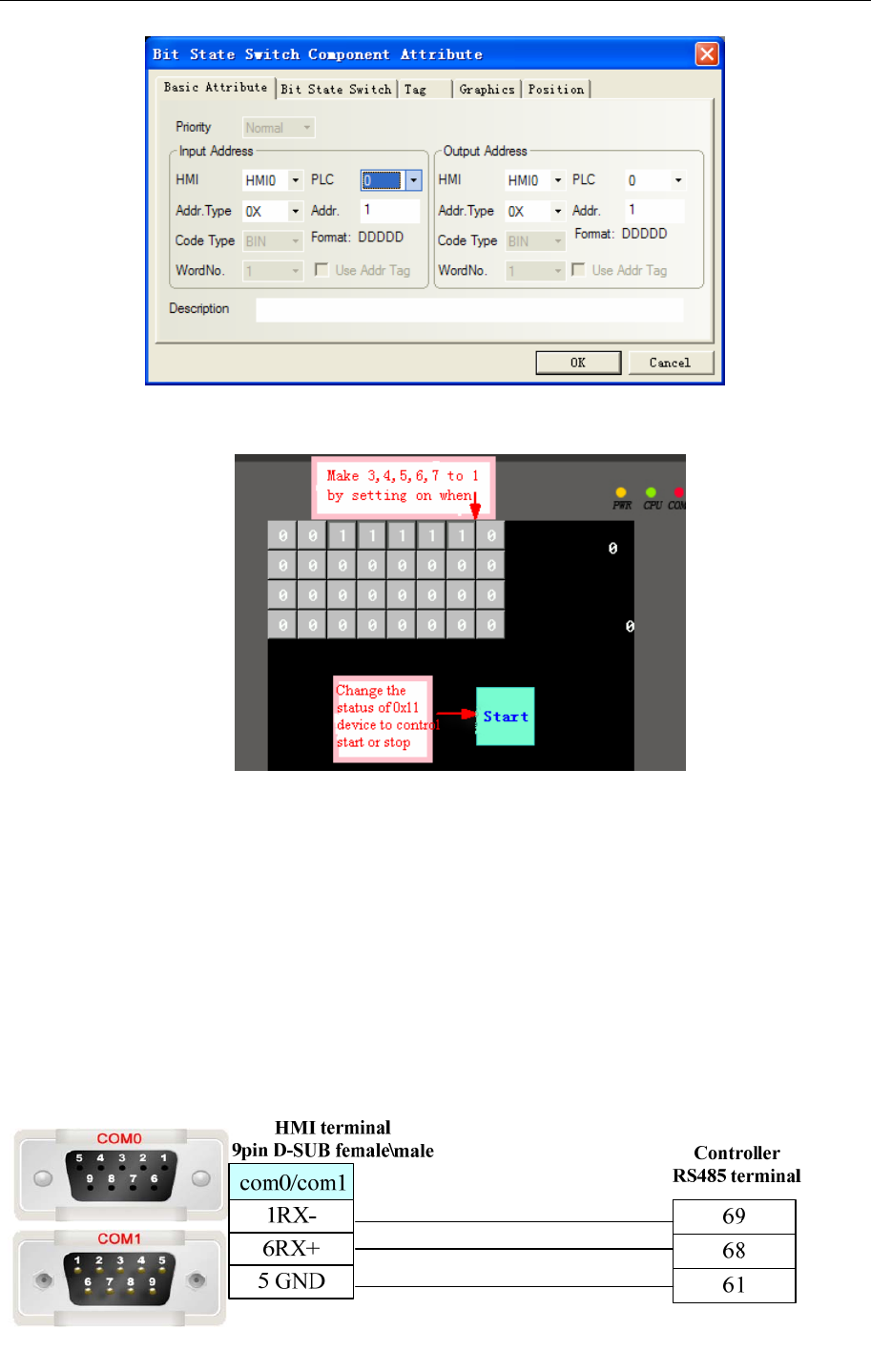
In addition, to get mapping address of startup, you should set bit of 3, 4, 5, 6,7,11 coil on:
0x047C=0000 0100 0111 1100
Set 0X 3, 0X 4, 0X 5, 0X 6, 0X 7, 0X 11 all to “1” (if random one of these registers is “0”,inverter will
stop.
loop 0 1
01 Preset reference value LSB
02 Preset reference value MSB
03 DC brake Do not DC brake
04 Inertial stop Do not Inertial stop
05 Quickly stop Do not Quickly stop
06 locking frequency Do not locking frequency
07 Acc/Dec stop start
08 Do not reset reset
09 Do not inching inching
10 Acc/Dec 1 Acc/Dec 2
11 valid data invalid data
12 Relay 1 close Relay 1 open
13 Relay 2 close Relay 2 open
14 Set LSB
15 Set MSB
16 Do not reverse reverse
Transducer controller word (FC structure)
4 Communication settings and guide of HMI connecting with controller
- 69 -
Set 0X 3,0X 4,0X 5,0X 6,0X 7 all to “1” via the method of setting on when window open; Change
the inverter status (start or stop) by control the status of 0X11.
0x2000=0010 0000 0000 0000(binary bit from the 17th to the 32nd), setting the 30th bit to “1” means
frequency is 25Hz, and “1” in the 29th bit means 12.5Hz, and so on. In short, the 0X17~0X32 is to control
frequency. The inverter will show the value after starting.
0X17~0X32 for controlling frequency,mapping as follows:
0x4000 ——50Hz
0x2000 ——25Hz
0x1000 ——12.5Hz (approximate)
0x800 ——6Hz
And so on, about 80 times
◎Cable Diagram
4 Communication settings and guide of HMI connecting with controller
- 70 -
4.16 Delta Corporation
◎Serial Communication
Series CPU Link Module Driver
RS232 on the CPU unit
DVP
DVP14SS11R2
DVP 24
DVP 32
DVP 60ES00
DVP-XXES01
RS485 on port
Delta DVP
◎Ethernet Communication
◎Serial System configuration
Series CPU Link Module COMM Type Parameter Cable
RS232 on the CPU unit RS232 Setting Your owner cable
DVP
DVP14SS11R2
DVP 24
DVP 32
DVP 60ES00
DVP-XXES01
RS485 on port RS485-2 Setting Your owner cable
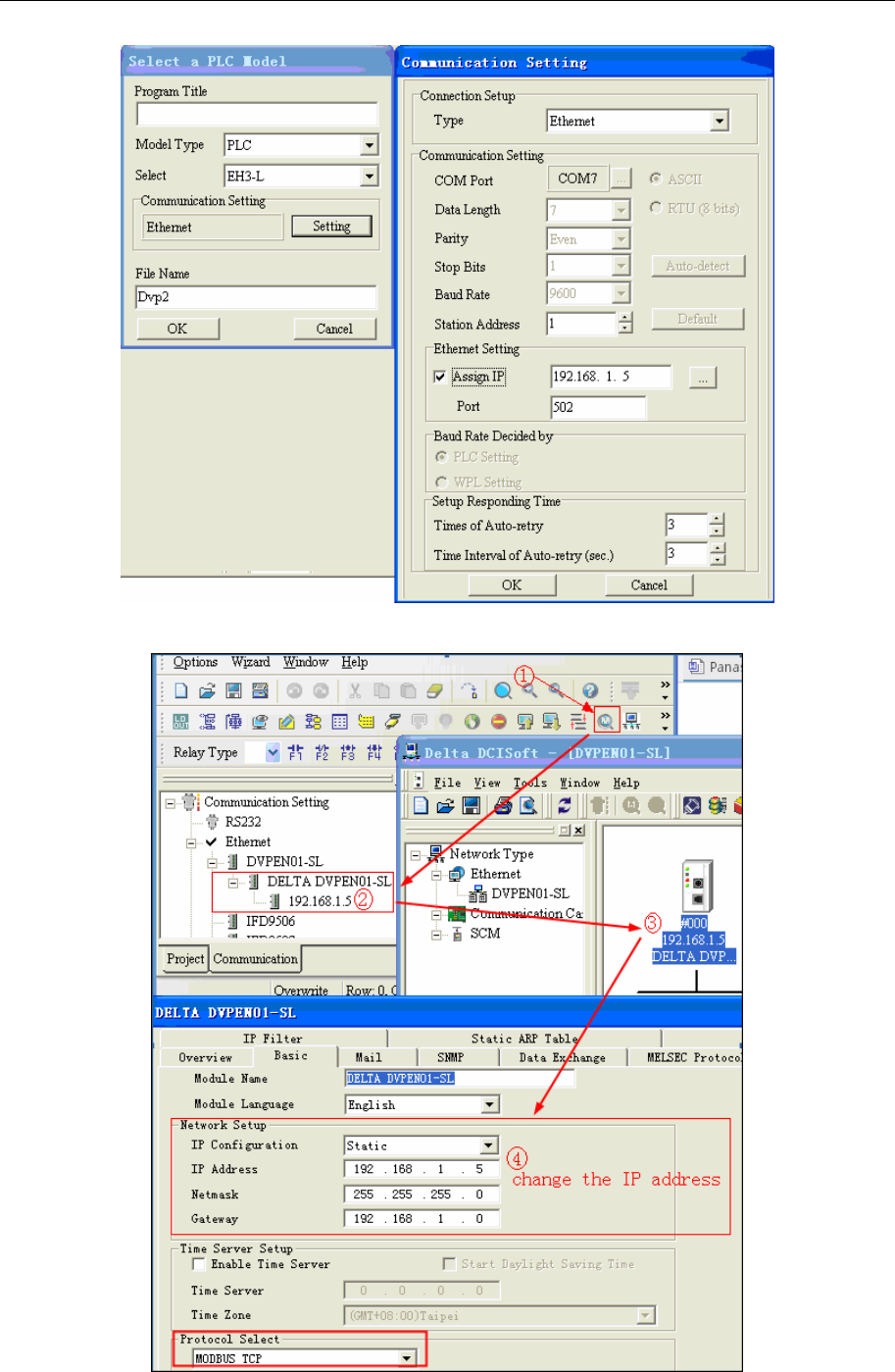
◎ Ethernet Communication Parameters and Cables Production
Series CPU Link Module COMM Type Parameter Cable
DVP DVP-32EH DVPEN01-SL Ethernet Setting Your owner cable
AS300 AS332T Ethernet interface on
CPU Ethernet Setting Your owner cable
◎Serial Communication Setting
DVP RS232 communication
Series CPU Link Module Driver
DVP DVP-32EH DVPEN01-SL Delta DVPEN01-SL Ethernet (TCP Slave)
AS300 AS332T Ethernet interface on CPU Delta AS300 Ethernet(TCP Slave)
4 Communication settings and guide of HMI connecting with controller
- 71 -
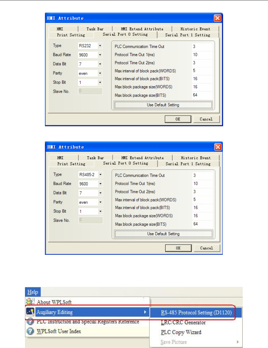
DVP RS485-2 communication
Note: RS485 communication, we should change the value of D1120 in the PLC Software.
PLC setting
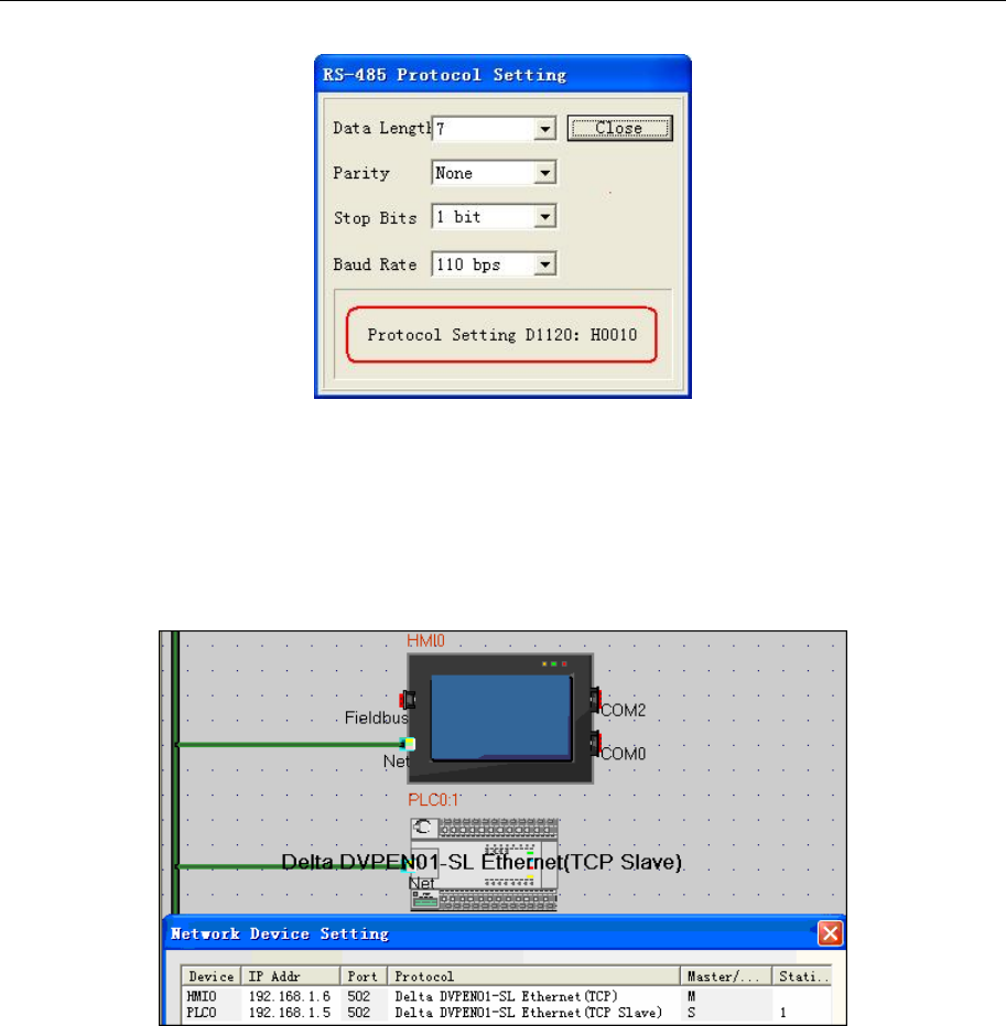
1. Wpl207->Auxiliary Editing->RS-485 Protocol Setting (D1120), you can set the value of D1120.
4 Communication settings and guide of HMI connecting with controller
- 72 -
2. PLC connection with the Wpl207, monitoring changes in the value of D1120. for example, 9600, 7, even,
1. and then D1120=86(HEX)
◎Ethernet Communication Parameters
Delta DVPEN01-SL Ethernet (TCP Slave)
HMI Setting
PLC Setting
1)Open the WPLSoft and bulid new project;
4 Communication settings and guide of HMI connecting with controller
- 73 -
2) Change the IP address
4 Communication settings and guide of HMI connecting with controller
- 74 -
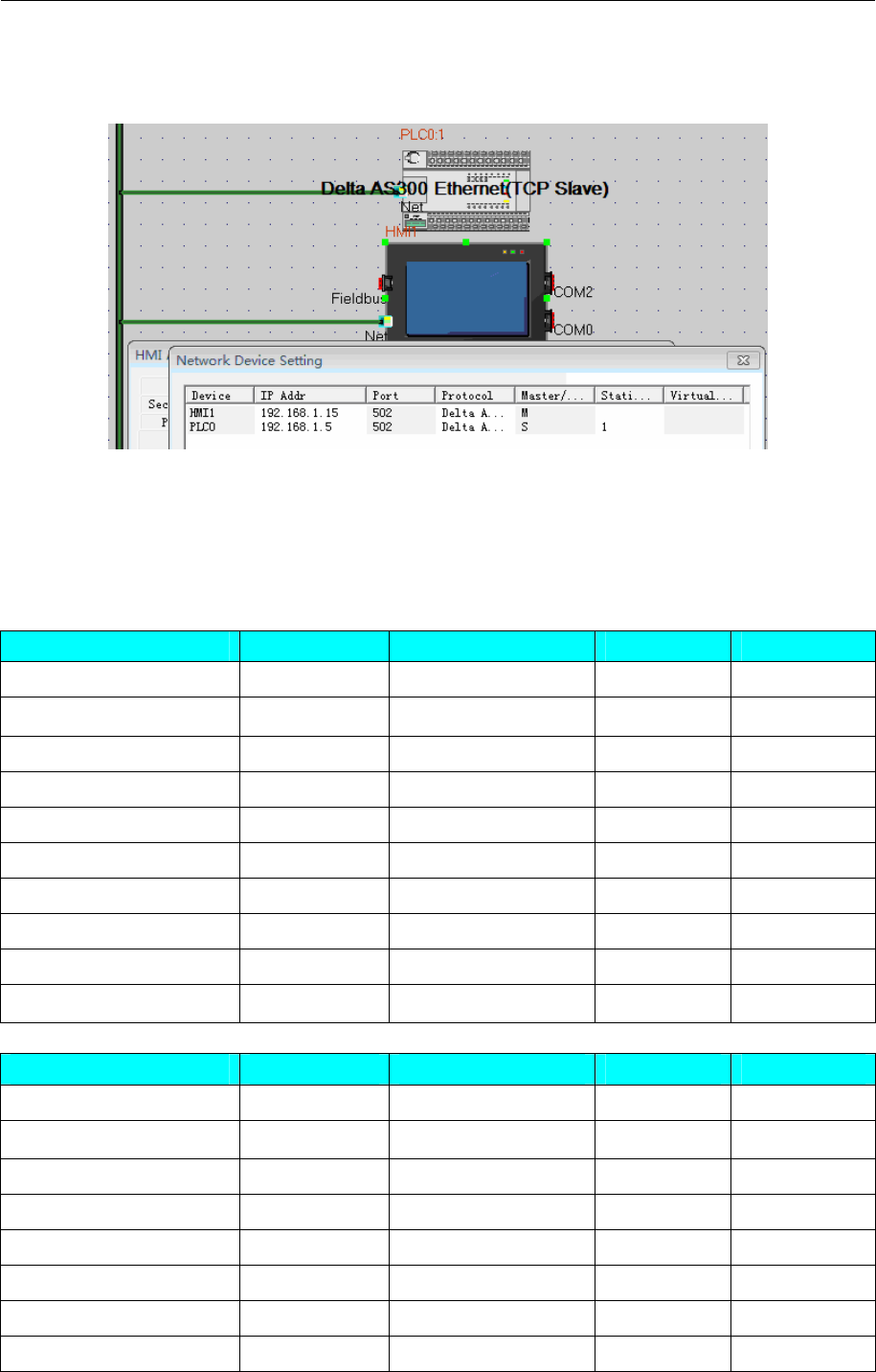
Delta AS300 Ethernet(TCP Slave)
HMI Setting
PLC Setting
1.Open ISPSoft,bulid new project and choose the right CPU type.
2.PLC parameter setting:
◎ Supported Device
Delta DVP
Device Bit Address Word Address Format Notes
Input X0-9999 ------ OOOO
Output Y0-9999 ------ OOOO
Auxiliary Relay M0-9999 ------ DDDD
Step Relay S0-9999 ------ DDDD
Timer Relay T0-9999 ------ DDDD
Counter Relay C0-9999 ------ DDDD
Timer ------ TV0-9999 DDDD
Counter ------ CV0-127 DDD
Double word counter ------ CV2 232-255 DDD
Data Register ------ D0-9999 DDDD
Delta DVPEN01-SL Ethernet
Device Bit Address Word Address Format Notes
Input X0-377 ------ OOO
Output Y0-377 ------ OOO
Auxiliary Relay M0-4095 ------ DDDD
Step Relay S0-1023 ------ DDDD
Timer Relay T0-255 ------ DDD
Counter Relay C0-255 ------ DDD
Timer ------ T0-255 DDD
Counter ------ C0-199 DDD
4 Communication settings and guide of HMI connecting with controller
- 75 -
Double word counter ------ C2 200-255 DDD
Data Register ------ D0-11999 DDDDD
Delta AS300 Ethernet(TCP Slave)
Device Bit Address Word Address Format
32-bit Counter HC_Bit 0-255 ------ DDD
Counter C_Bit 0-511 ------ DDD
Timer T_Bit 0--511 ------ DDD
Step point Relay S_Bit 0-2047 ------ DDDD
Special auxiliary sign SM_Bit 0-4095 ------ DDDD
Special auxiliary M_Bit 0-8191 ------ DDDD
Output Relay Y_Bit 0.00-63.15 ------ DD.DD
Input Relay X_Bit 0.00-63.15 ------ DD.DD
Data Register D_Bit 0.00-29999.15 ------ DDDDD.DD
32-bit Counter ------ HC_Word 0-255 DDD
Index Register ------ E_Word 0-9
D
Counter ------ C_Word 0--511
DDD
Timer ------ T_Word 0-511
DDD
Data Register ------ D_Word 0-29999 DDDDD
Special data Register ------ SR_Word 0-2047 DDDD
Output Relay ------ Y_Word 0-63
DD
Input Relay ------ X_Word 0-63
DD
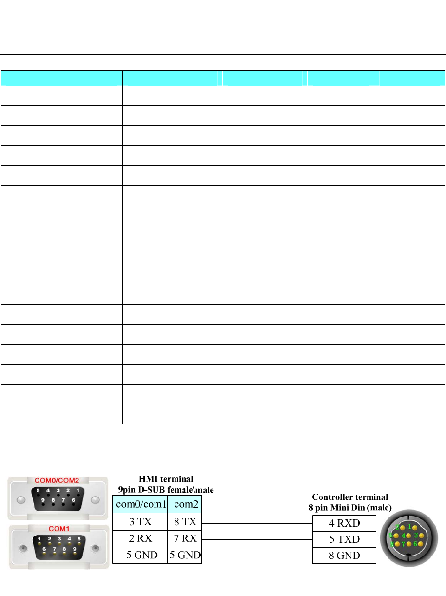
◎Cable Diagram
DVP RS232 communication cable
DVP RS485-2 communication cable
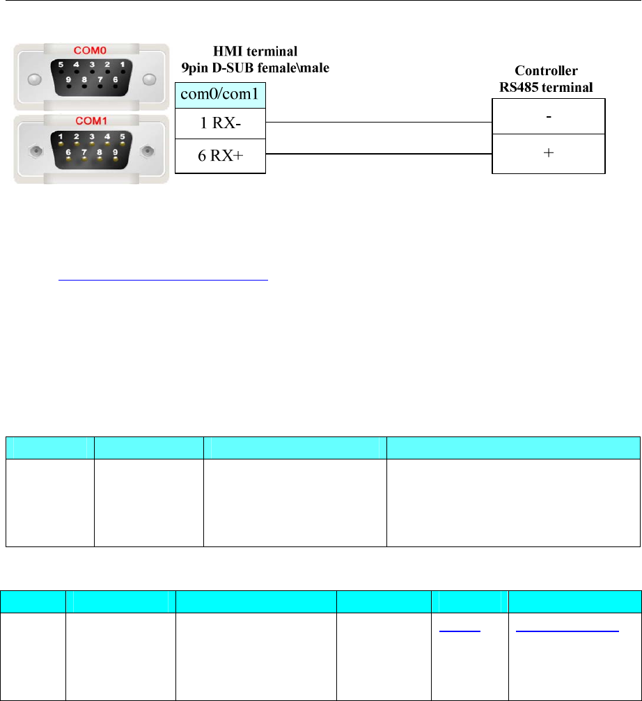
4 Communication settings and guide of HMI connecting with controller
- 76 -
Ethernet communication protocol cable
Cross-connection or crossover network cable can be used as communication cable via the hub
Refer to 3.3 Download by Network Ethernet for method of making connection cable.
4.17 Delta (Temperature Controller)
◎Serial Communication
Series CPU Link Module Driver
DVP
DTA4848
DTB9696VR
DTC1000
DTC2000
RS485 on the CPU unit Delta DTA/DTB/DTC
◎System configuration
Series CPU Link Module COMM Type Parameter Cable
DVP DTA4848
DTB9696VR
DTC1000
DTC2000
RS485 on port RS485-2 Setting Your owner cable
◎Communication Setting
RS485-2 communication
4 Communication settings and guide of HMI connecting with controller
- 77 -
NOTE: Only use 4X, not 3X in the ev5000 project.
◎Supported Device
Device Bit Address Word Address Format Notes
Output bit 0X1-FFFF ------ HHHH
Input bit (read only) 1X1-FFFF ------ HHHH
Input Register (read only) ------ 3X1-FFFF HHHH
Output Register ------ 4X1-FFFF HHHH
Controller Setting
1. Set the communication parameter
Setting communication parameter in “setting mode”
(1) (Station number) matching the station No. of the Ev5000
(2) (Baudrate)
(3) (Data bit)
(4) (Parity)
(5) (Stop bit)
Non-supported formats: 7, N, 1 or 8, O, 2 or 8, E, 2(Databit、Parity、Stopbit).
(6) Setting the parameter of CoSH
The data must be ON when executing write operation in touch-screen.
2. Communication parameters and notes
DTA4848:Address and Content of Word Register (corresponds to 4X in the HMI)
Address Content Explanations
4700H Process value (PV)
4701H Set point (SV)
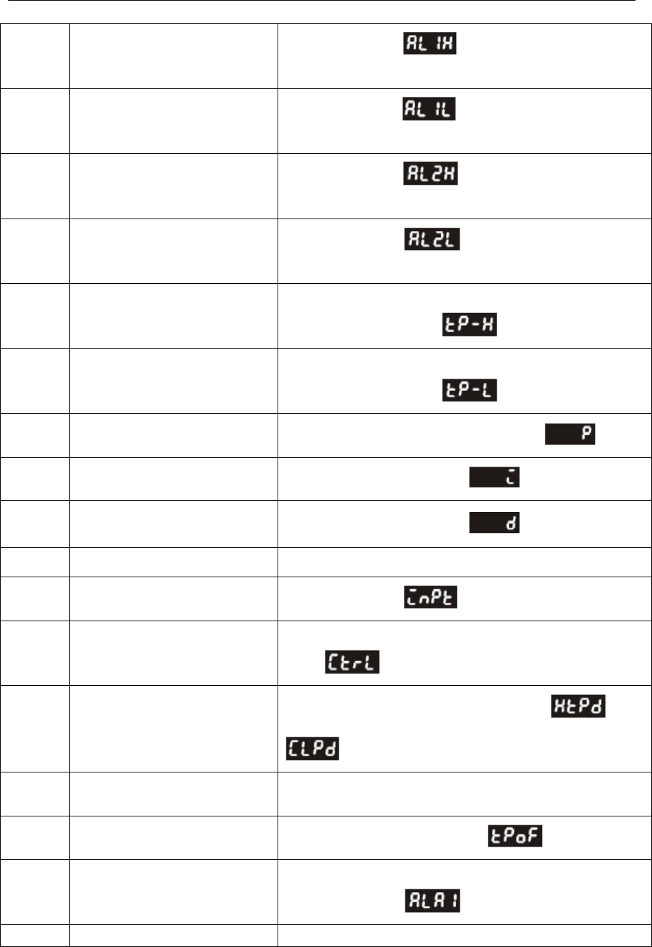
4 Communication settings and guide of HMI connecting with controller
- 78 -
4702H Upper-limit alarm 1 In the running mode , when ALA1 is 1 and
Upper-limit alarm is valid.
4703H Lower-limit alarm 1 In the running mode , when ALA1 is 1 and Lower
-limit alarm is valid.
4704H Upper-limit alarm 2 In the running mode , when ALA2 is 2 and
Upper-limit alarm is valid.
4705H Lower-limit alarm 2 In the running mode , when ALA2 is 2 and Lower
-limit alarm is valid.
4706H Upper-limit of temperature range
The data content should not be higher than the temperature
range. In the setting mode
4707H Lower-limit of temperature range
The data content should not be lower than the temperature
range. In the setting mode
4708H PB Proportional band 1 to 9999, unit is 0.1. In the adjusting mode
4709H Ti Integral time 0~9999. In the adjusting mode
470AH Td Derivative time 0~9999. In the adjusting mode
470BH Heating/Cooling hysteresis 0~9999
4710H Input temperature sensor type In the setting mode
4711H Control method
0: PID (default), 1: ON/OFF, 2: manual tuning. In the setting
mode
4712H Heating/Cooling control cycle
0 to 99 second, 0:0.5s, in the adjusting mode or
, when it is under the control of PID
4713H Proportional control offset error
value 0%~100%
4714H Temperature regulation value -99.9~99.9. in the adjusting mode
4715H Alarm 1 type
Please refer to the contents of the “Alarm Outputs” for detail.
In the setting mode
4716H Alarm 2 type Please refer to the contents of the “Alarm Outputs” for detail.
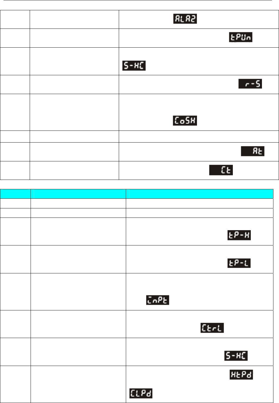
4 Communication settings and guide of HMI connecting with controller
- 79 -
In the setting mode
4717H Temperature unit display
selection oC : 1 (default), oF : 0. in the setting mode
4718H Heating/Cooling control
Selection
Heating: 0 (default), Cooling: 1. in the setting mode
4719H Control Run/Stop setting Run: 1 (default), Stop: 0. in the running mode
471AH Communication write-in
selection
Communication write in disabled: 0 (default),
Communication write in enabled: 1.
In the setting mode
471BH Software Version V1.00 indicates 0 x 100
4729H AT Setting OFF: 0 (default), ON: 1. in the adjusting mode
4733H CT monitor value Unit is 0.1A. in the running mode
DTB9696VR:Address and Content of Word Register (corresponds to 4X in the HMI)
Address Content Explanation
1000H Process value (PV) Measuring unit is 0.1, updated one time in 0.4 second
1001H Set point (SV) Unit is 0.1, oC or oF
1002H Upper-limit of temperature range
The data content should not be higher than the
temperature range. In the setting mode
1003H Lower-limit of temperature range
The data content should not be lower than the
temperature range. In the setting mode
1004H Input temperature sensor type
Please refer to the contents of the “Temperature Sensor
Type and Temperature Range” for detail. In the setting
mode
1005H Control method
0: PID, 1: ON/OFF, 2: manual tuning, 3: PID grogram
control. In the setting mode
1006H Heating/Cooling control selection
0: Heating, 1: Cooling, 2: Heating/Cooling, 3:
Cooling/Heating. In the setting mode
1007H 1st group of Heating/Cooling
control cycle
0 ~ 99, 0:0.5 sec. in the adjusting mode or
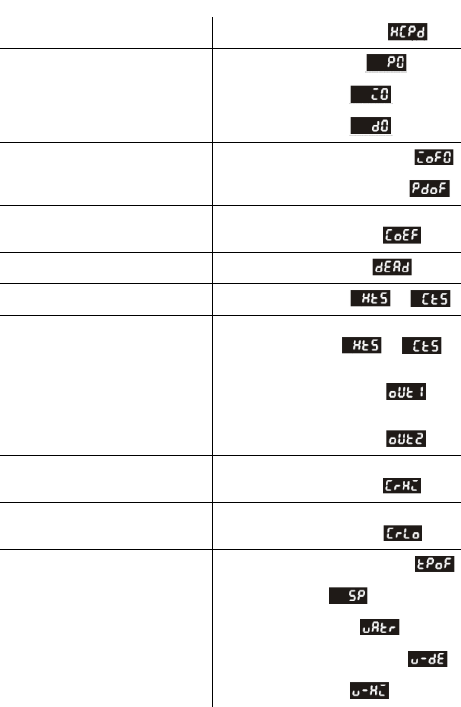
4 Communication settings and guide of HMI connecting with controller
- 80 -
1008H 2nd group of Heating/Cooling
control cycle 0 ~ 99, 0:0.5 sec. in the adjusting mode
1009H PB Proportional band 0.1 ~ 999.9. in the adjusting mode
100AH Ti Integral time 0~9999. in the adjusting mode
100BH Td Derivative time 0~9999. in the adjusting mode
100CH Integration default 0 ~ 100%, unit is 0.1%. in the adjusting mode
100DH Proportional control offset error
value, when Ti = 0 0 ~ 100%, unit is 0.1%. in the adjusting mode
100EH The setting of COEF when Dual
Loop output control are used
0.01 ~ 99.99, unit is 0.01 (setting when it is under the
control of PID ) in the adjusting mode
100FH The setting of Dead band when
Dual Loop output control are used -999 ~ 9,999. in the adjusting mode
1010H Hysteresis setting value of the 1st
output group 0~9999. in the adjusting mode or
1011H Hysteresis setting value of the 1st
output group
0~9999. (setting when Dual Loop output control are
used ) in the adjusting mode or
1012H Hysteresis setting value of the 1st
output group
Unit is 0.1%; write operation is valid under manual
tuning mode only. In the running mode
1013H Hysteresis setting value of the 2nd
output group
Unit is 0.1%; write operation is valid under manual
tuning mode only. In the running mode
1014H Upper-limit regulation of analog
linear output
1 Unit = 2.8uA (Current Output) = 1.3mV (Linear
Voltage Output) in the adjusting mode
1015H Lower-limit regulation of analog
linear output
1 Unit = 2.8uA (Current Output) = 1.3mV (Linear
Voltage Output) in the adjusting mode
1016H Temperature regulation value -99.9 ~ +99.9, unit: 0.1. in the adjusting mode
1017H Analog decimal setting 0~3. in the running mode
1018H Time for valve from full open to
full close 0.1~999.9. in the adjusting mode
1019H Dead Band setting of valve 0 ~ 100%; unit: 0.1%. in the adjusting mode
101AH Upper-limit of feedback signal set
by valve 0~1024. in the adjusting mode
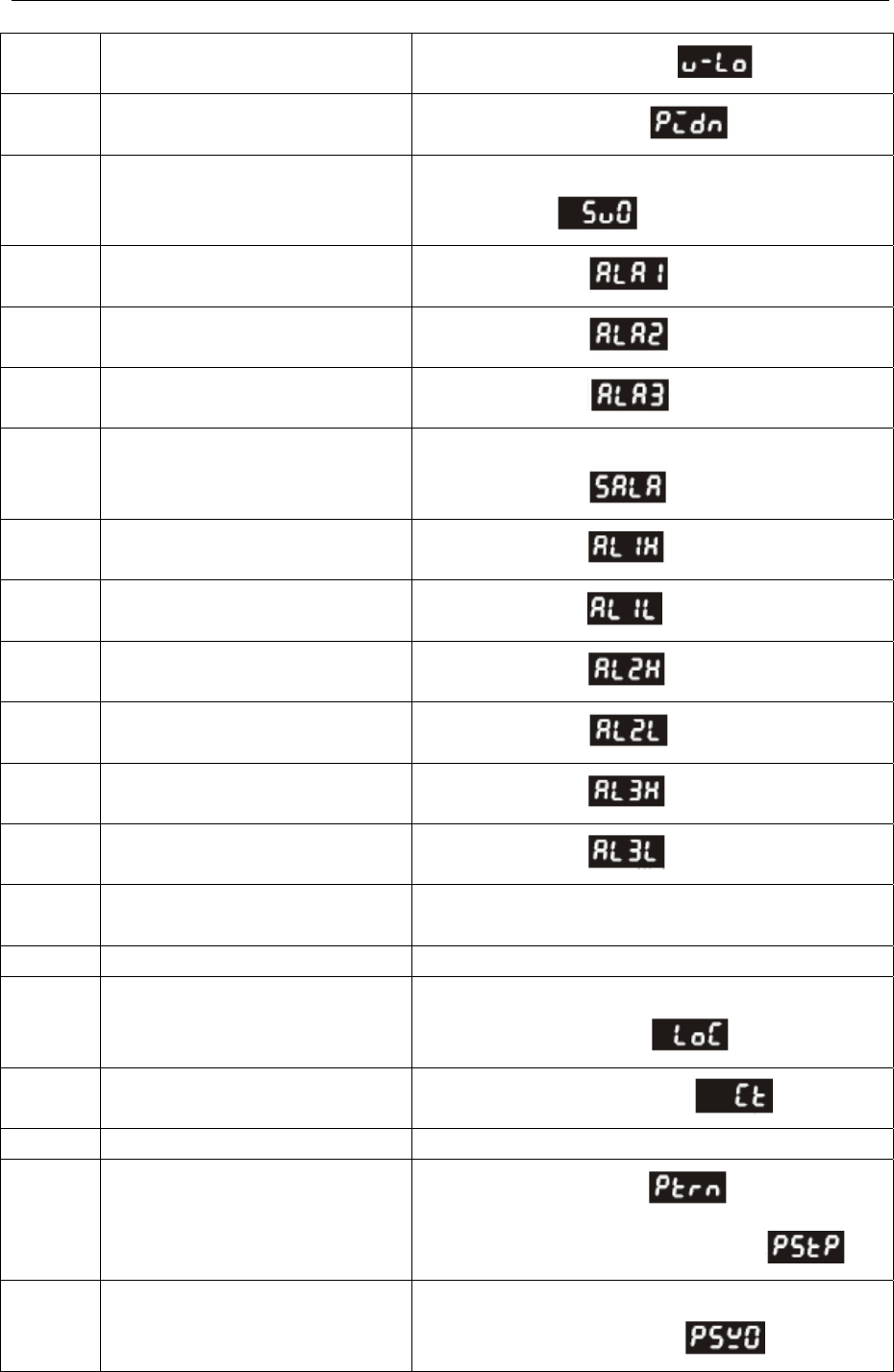
4 Communication settings and guide of HMI connecting with controller
- 81 -
101BH Lower-limit of feedback signal set
by valve 0~1024. in the adjusting mode
101CH PID parameter selection
0~4. in the adjusting mode
101DH SV value corresponded to PID
value
Only valid within available range, unit: 0.1 scale. in the
adjusting mode
1020H Alarm 1 type In the setting mode
1021H Alarm 2 type In the setting mode
1022H Alarm 3 type In the setting mode
1023H System alarm setting
0: None (default), 1~3: Set Alarm 1 to Alarm 3.
In the setting mode
1024H Upper-limit alarm 1 In the setting mode unit: 0.1
1025H Lower-limit alarm 1 In the setting mode
1026H Upper-limit alarm 2 In the setting mode
1027H Lower-limit alarm 2 In the setting mode
1028H Upper-limit alarm 3 In the setting mode
1029H Lower-limit alarm 3 In the setting mode
102AH Read LED status b0 : Alm3, b1: Alm2, b2: F, b3: ℃, b4: Alm1, b5:
OUT2, b6: OUT1, b7: AT
102BH Read pushbutton status b0: Set, b1: Select, b2: Up, b3: Down. 0 is to push
102CH Setting lock status
0: Normal, 1: All setting lock, 11: Lock others than SV
value. In the running mode
102DH CT read value Unit: 0.1A. In the running mode
102FH software version V1.00 indicates 0x100.
1030H Start pattern number
0 ~ 7. In the running mode (setting when it is
under the control of PID and the mode of )
1040H~
1047H
Actual step number setting inside
the correspond pattern
0 ~ 7 = N, indicate that this pattern is executed from step
0 to step N. in the setting mode
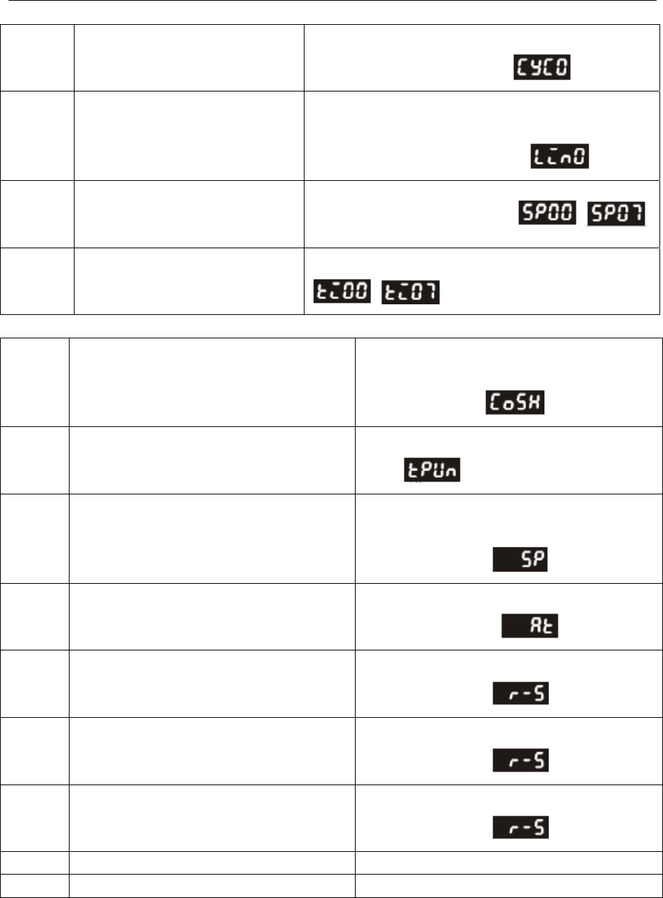
4 Communication settings and guide of HMI connecting with controller
- 82 -
1050H~
1057H
Cycle number for repeating the
execution of the correspond pattern
0 ~ 99 indicate that this pattern has been executed for 1
~ 100 times. In the setting mode
1060H~
1067H
Link pattern number setting of the
correspond pattern
0 ~ 8, 8 indicates the program end. 0~7 indicates the
next execution pattern number after executing the
current pattern. In the setting mode
2000H~
203FH
Pattern 0~7 temperature set point
setting(Pattern 0 temperature is set
to2000H ~ 2007H)
-999 ~ 9,999. in the setting mode ~
2080H~
20BFH
Pattern 0~7 execution time
setting(Pattern 0 time is set to
2080H~2087H)
Time 0 ~ 900 (1 minute per scale). in the setting mode
~
DTB9696VR:Address and Content of Bit Register (corresponds to 1X in the HMI)
0810H Communication write-in selection Communication write in disabled: 0 (default),
Communication write in enabled: 1.
In the setting mode
0811H Temperature unit display selection
oC/linear input (default): 1 , oF : 0. in the setting
mode
0812H Decimal point position selection
Except for the thermocouple B, S, R type, all the
other thermocouple type are valid. (0 or 1).
In the running mode
0813H AT setting
OFF: 0 (default), ON : 1.
In the adjusting mode
0814H Control RUN/STOP setting
0: STOP, 1: RUN (default).
In the running mode
0815H STOP setting for PID program control
0: RUN (default), 1: STOP.
In the running mode
0816H Temporarily STOP for PID program control
0: RUN (default), 1: Temporarily STOP.
In the running mode
0817H Valve feedback setting status 0: w/o feedback (default), 1: feedback function.
0818H Auto-tuning valve feedback status 0: Stop AT (default), 1: Start AT
3. Communication Parameters List
- Communication protocol: Modbus (ASCII); Available communication address: 1 to 255, 0 is
broadcast address
- Function code: 03H: read the contents of register (Max. 3 words).
06H: write 1 (one) word into register.
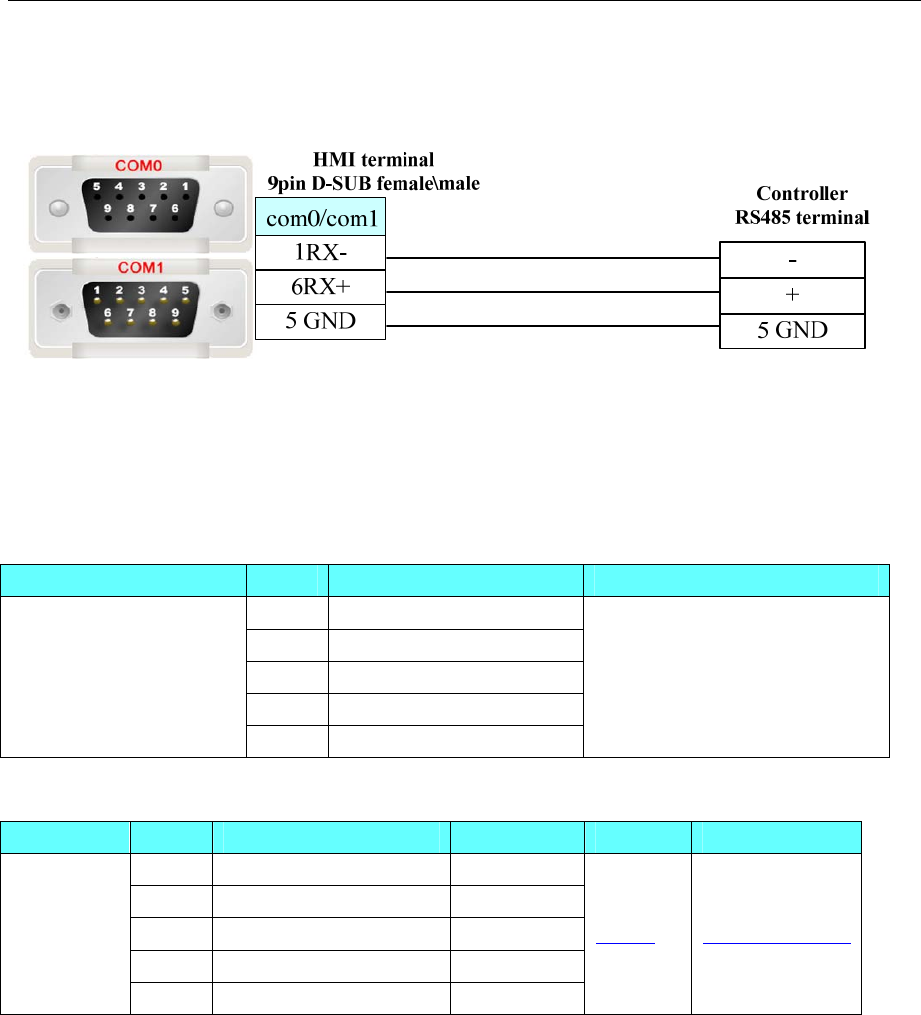
4 Communication settings and guide of HMI connecting with controller
- 83 -
◎Cable Diagram
DVP RS485-2 communication cable
4.18 ENDA
◎Serial Communication
Series CPU Link Module Driver
ELC RS485-2 on the CPU unit
ETC RS485-2 on the CPU unit
EUC RS485-2 on the CPU unit
EPC RS485-2 on the CPU unit
ENDA devices
EDP RS485-2 on the CPU unit
ENDA Controller/PLC Devices
◎System configuration
Series CPU Link Module COMM Type Parameter Cable
ELC RS485-2 on the CPU unit RS485
ETC RS485-2 on the CPU unit RS485
EUC RS485-2 on the CPU unit RS485
EPC RS485-2 on the CPU unit RS485
ENDA
devices
EDP RS485-2 on the CPU unit RS485
Setting Your owner cable
◎Communication Setting
ENDA Devices:Default communication:9600, 8, 1, none; station:1
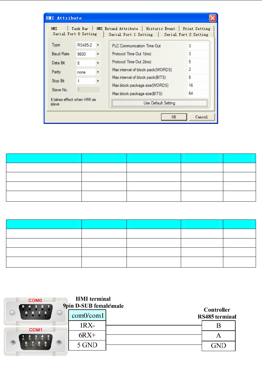
4 Communication settings and guide of HMI connecting with controller
- 84 -
◎Supported Device
ENDA PLC Devices
Device Bit Address Word Address Format Notes
Output Relay MB 0-65535 ------ DDDDD
Input Relay (read only) IP 0-65535 ------ DDDDD
Output Register ------ MW 0-65535 DDDDD
Input Register (read only) ------ IR 0-65535 DDDDD
ENDA Controller Devices
Device Bit Address Word Address Format Notes
Coils Coils 0-65535 ------ DDDDD
Discrete input (read only) DI 0-65535 ------ DDDDD
Holding Registers ------ HR 0-65535 DDDDD
Input Register (read only) ------ IR 0-65535 DDDDD
◎Cable Diagram
RS485 communication cable
4.19 Emerson NetWork Power
◎Serial Communication
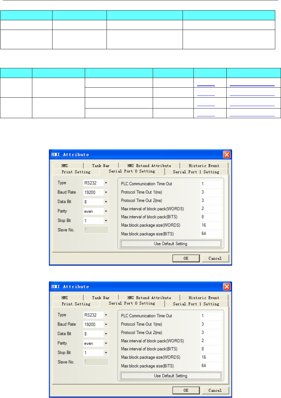
4 Communication settings and guide of HMI connecting with controller
- 85 -
Series CPU Link Module Driver
Emerson EC10 Ec10-1006BRA RS232 on the CPU unit Emerson EC10
Emerson EC20 Ec20-2012BRA
Ec20-3232BRA RS232 on the CPU unit Emerson EC20
◎System configuration
Series CPU Link Module COMM Type Parameter Cable
RS232 on the CPU unit RS232 Setting Your owner cable Emerson
EC10 EC10-1006BRA RS485 on port1 RS485-2 Setting Your owner cable
RS232 on the CPU unit RS232 Setting Your owner cable Emerson
EC20
EC20-2012BRA
EC20-3232BRA RS485 on port1 RS485-2 Setting Your owner cable
◎Communication Setting
Emerson EC10 RS232 communication
Emerson EC20 RS232 communication
Emerson EC10 RS485-2 communication
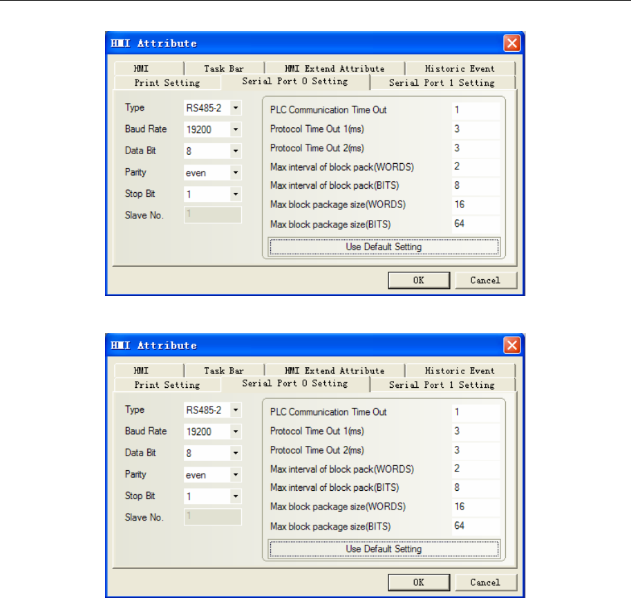
4 Communication settings and guide of HMI connecting with controller
- 86 -
Emerson EC20 RS485-2 communication
NOTE: Communication with port1, you must set the system configuration in the programming software
first.
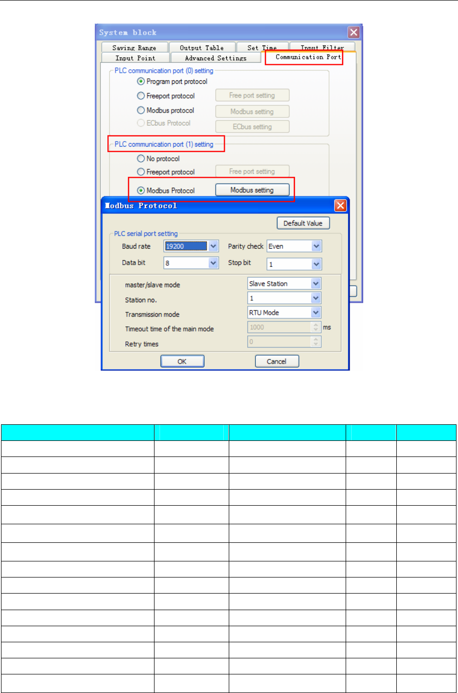
4 Communication settings and guide of HMI connecting with controller
- 87 -
◎Supported Device
Emerson EC10
Device Bit Address Word Address Format Notes
Input Relay X000-377 ------ OOO
Output Relay Y000-377 ------ OOO
Internal Relay M0000-1999 ------ DDDD
Special Relay SM000-255 ------ DDD
Step Relay S000-991 ------ DDD
Timer Relay T000-255 ------ DDD
Counter Relay C000-255 ------ DDD
Data register ------ D0000-7999 DDDD
Special Register ------ SD000-255 DDD
Index Register ------ Z00-15 DD
Timer ------ T000-255 DDD
Counter ------ C000-199 DDD
Counter(double word) ------ C_Double200-255 DDD
Data register(double word) ------ D_Double0000-7999 DDDD
Special Register(double word) ------ SD_Double000-127 DDD
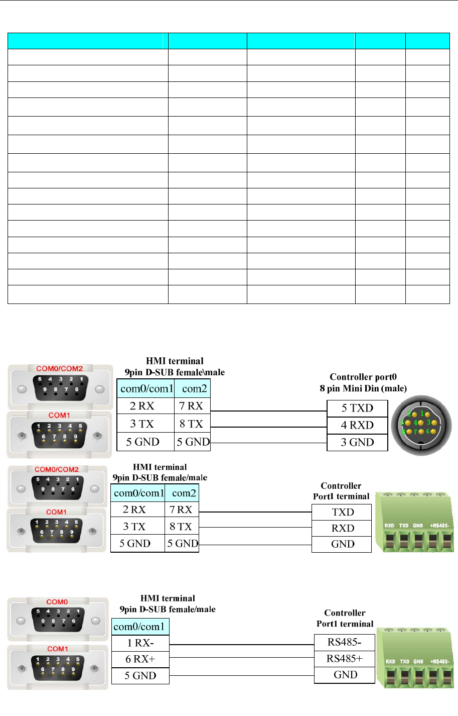
4 Communication settings and guide of HMI connecting with controller
- 88 -
Emerson EC20
Device Bit Address Word Address Format Notes
Input Relay X000-377 ------ OOO
Output Relay Y000-377 ------ OOO
Internal Relay M0000-1999 ------ DDDD
Special Relay SM000-255 ------ DDD
Step Relay S000-991 ------ DDD
Timer T000-255
------ DDD
Counter C000-255
------ DDD
Data register ------ D0000-7999 DDDD
Special Register ------ SD000-255 DDD
Index Register ------ Z00-15 DD
Timer ------ T000-255 DDD
Counter ------ C000-199 DDD
Counter(double word) ------ C_Double200-255 DDD
Data register(double word) ------ D_Double0000-7999 DDDD
Special Register(double word) ------ SD_Double000-125 DDD
◎Cable Diagram
Emerson RS232 communication
Emerson RS485-2 communication
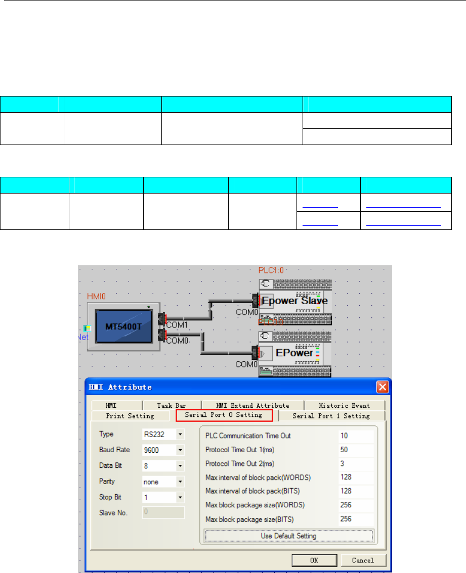
4 Communication settings and guide of HMI connecting with controller
- 89 -
4.20 Epower
◎Serial Communication
Series CPU Link Module Driver
EPower
Epower Epower CPU Direct Epower Slave
◎System configuration
Series CPU Link Module COMM Type Parameter Cable
Setting Your owner cable
Epower Epower CPU Direct RS232 Setting Your owner cable
◎Communication Setting
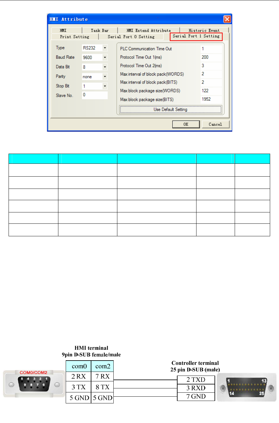
4 Communication settings and guide of HMI connecting with controller
- 90 -
◎Supported Device
Device Bit Address Word Address Format Notes
UPSSet UPSSet1-6 ------ DDDDD
UPSPanel UPSPanel0-9 ------ DDDDD
UPSData ------ UPSData0-70 DDDD
UPSDisp ------ UPSDisp0 DDDDD
UPSCommand ------ UPSCommand0-52 DDDDD
UPSText ------ UPSText0-1 DDDDD
Slave driver notes:
1. Transmit the device value to LW, LB by timer; refer to the addr table for details.
2. UPSCommand must use with UPSSet、macro;
3. UPSDisp must use with UPStexr、UPSPanel、macro.
Epower HMI project notes:
1. The project must have UPSData0 device, otherwise the data accuracy will be affected; Suggest to
put UPSData0 device in the public window.
2. LW.B indicates the bits of UPSData
◎Cable Diagram
COM0 connect to ups communication board
COM1 connect to King software or com debug tool
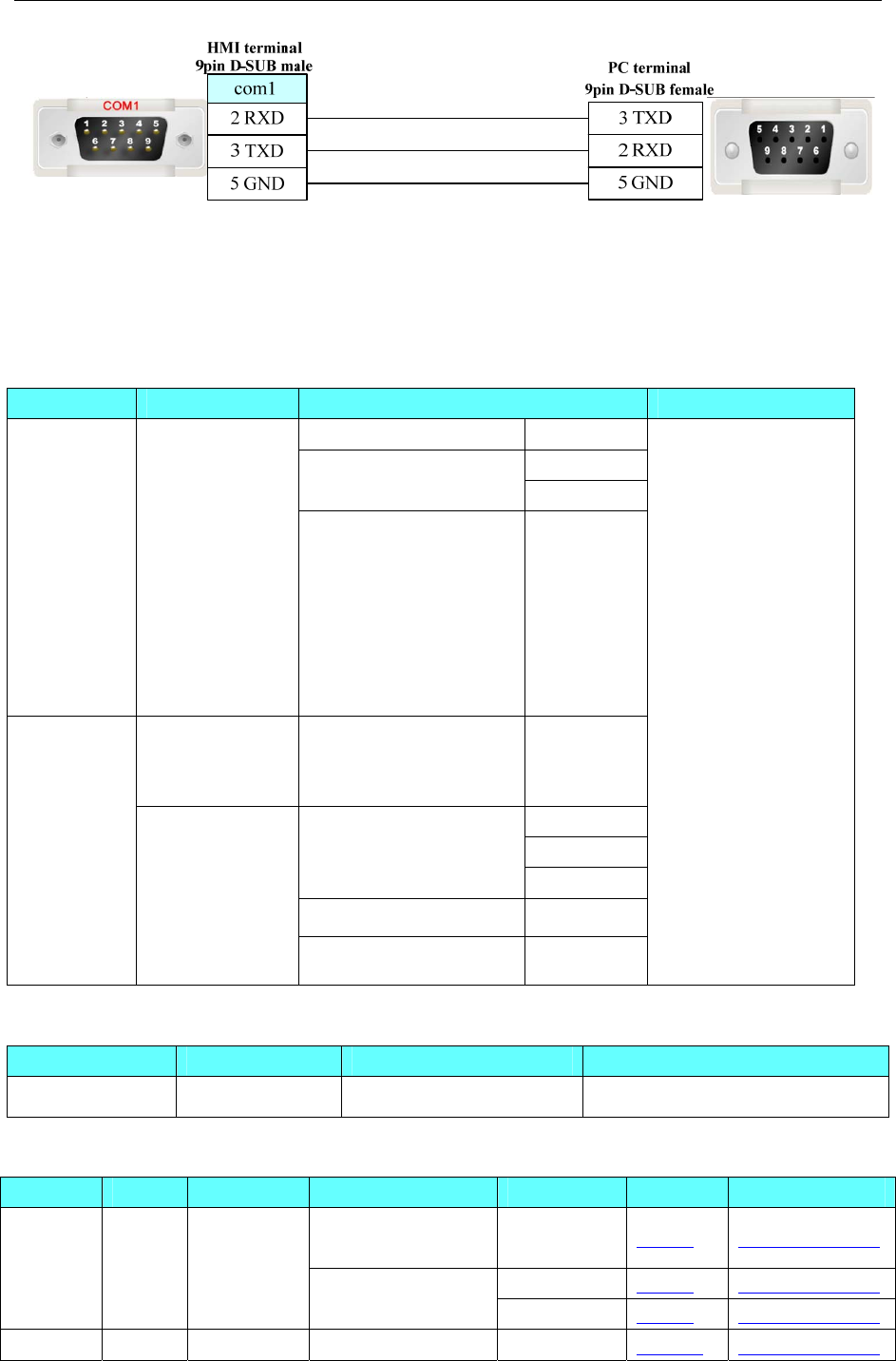
4 Communication settings and guide of HMI connecting with controller
- 91 -
4.21 Fatek Corporation
◎Serial Communication
c CPU Link Module Driver
RS232 on the CPU unit Port 0
Port 1
FBS-CB25-3 Port 2
FBs
FBs-10MA/MC
FBs-14MA/MC
FBs-20MA/MC
FBs-24MA/MC
FBs-32MA/MC
FBs-40MA/MC
FBs-60MA/MC
FBs-20MN
FBs-32MN
FBs-44MN
FBe-20MA
FBe-28MA
FBe-40MA
CPU unit Port 0
Port 0
Port 1
CPU unit
Port 2
FB-DTBR
FBe/FBn
FBe-20MC
FBe-28MC
FBe-40MC
FBn-19MCT
FBn-26MCT
FBn-36MCT FB-DTBR-E
FATEK FB
Modbus RTU
◎Network communication
Series CPU Link Module Driver
FBs FBs-20MAT FBs-CBE-3 FATEK FB Ethernet(TCP)
◎Serial System configuration
Driver Series CPU Link Module COMM Type Parameter Cable
RS232 on the CPU
unit RS232 Setting Your owner cable
RS232 Setting Your owner cable
FACON
FB
FB MA
FB MC FBs-20MAT
FBS-CB25-3 RS485 Setting Your owner cable
Modbus FB MA FBs-20MAT FBS-CB25-3 RS232 Setting Your owner cable
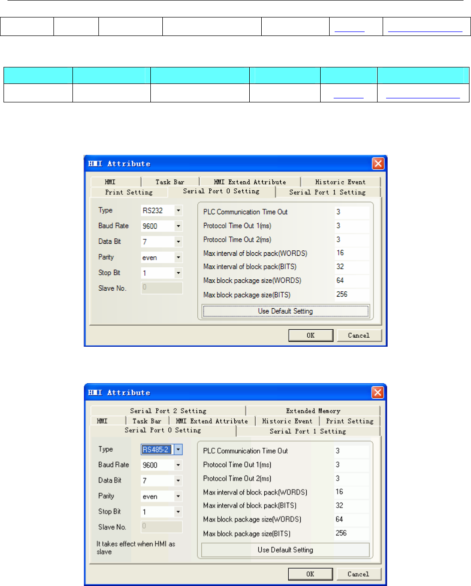
4 Communication settings and guide of HMI connecting with controller
- 92 -
RTU FB MC RS485 Setting Your owner cable
◎Network System configuration
Series CPU Link Module COMM Type Parameter Cable
FBs FBs-20MAT FBs-CBE-3 ETH Setting Your owner cable
◎Serial Communication Setting
FACON FB RS232 communication
FBS-CB25-3 module RS485 communication
FBS-CB25-3 module communication
Modbus RTU RS232 communication
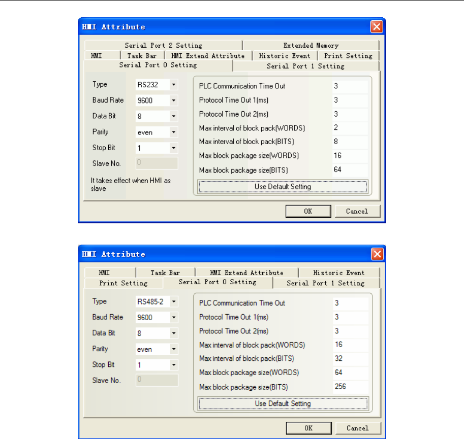
4 Communication settings and guide of HMI connecting with controller
- 93 -
Modbus RTU RS485-2 communication
Note: The detailed communication configuration must be the same as the PLC’s port setting.
◎Network Communication Setting
HMI Setting
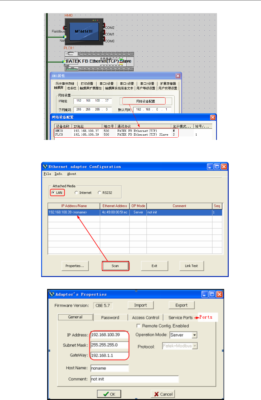
4 Communication settings and guide of HMI connecting with controller
- 94 -
PLC Setting
1、 In ether cfg software, click [scan] to search the PLC information.
2、 Click [Properties] to change the IP and ports.
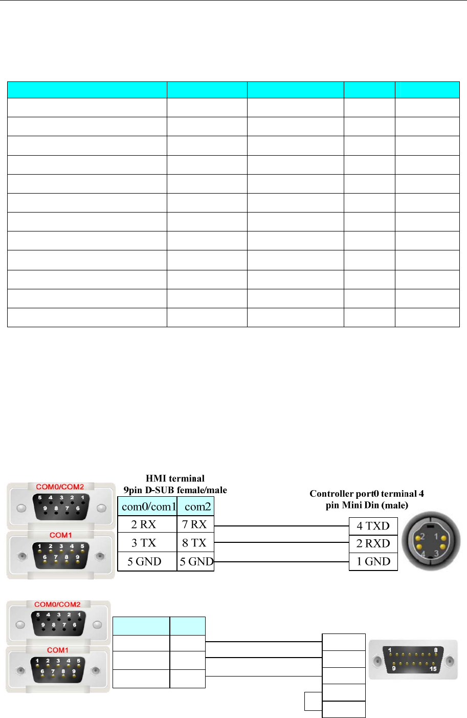
4 Communication settings and guide of HMI connecting with controller
- 95 -
3、 Click [ok] to save the settings.
◎Supported Device
Device Bit Address Word Address Format Notes
Input X0-9999 ------ DDDD
Output Y0-9999 ------ DDDD
Internal Relay M0-9999 ------ DDDD
Step Relay S0-9999 ------ DDDD
Timer Relay T0-9999 ------ DDDD
Counter Relay C0-9999 ------ DDDD
Data Register ------ R-L 0-3839 DDDD
Data Register ------ R-H 3840-9999 DDDD
Data Register ------ D0-9999 DDDD
Timer ------ T0-9999 DDDD
Counter ------ C0-199 DDD
Double word Counter Register ------ DRC200-255 DDD
Note:R-L register corresponds to the “R” register of the PLC, the address range 0~3839;
R-H register corresponds to the “R” register of the PLC, the address range 3840~9999;
DR register corresponds to the “D” register of the PLC;
TMR register corresponds to the “T” register of the PLC;
CTR register corresponds to the “C” register of the PLC;
DRC register corresponds to the “C(32)” register of the PLC,e.g.:DRC200==C200
◎Cable Diagram
FB RS232 communication cable
Controller terminal
15 pin D-SUB (male)
2 TXD
1 RXD
6 GND
HMI terminal
9pin D-SUB female/male
com2
3 TX
2 RX
5 GND
8 TX
7 RX
5 GND
com0/com1
3 RTS
4 CTS
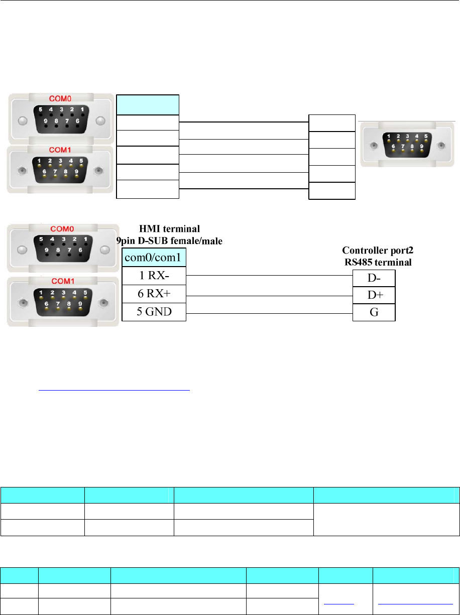
4 Communication settings and guide of HMI connecting with controller
- 96 -
FBS-CB25-3 module communication
RS232 communication cable
Controller port1 terminal
9 pin D-SUB (male)
HMI terminal
9pin D-SUB female/male
2RXD 2TXD
3RXD
5SG
3TXD
5GND
7CTS
8RTS
7RTS
8CTS
com0/com1
RS485 communication cable
Ethernet cable
Connecting PC and HMI use cross-ruling; communicating with hub or switch use cross-over cable or
cross-ruling.
Refer to 3.3 Download by Network Ethernet for method of making connection cable.
4.22 Fuji SPB
◎Serial Communication
Series CPU Link Module Driver
SPB NW0P20T-31 RS485 interface on the CPU
NB NB2U24R-11 RS485 interface on the CPU Fuji SPB
◎System configuration
Series CPU Link Module Ethernet Type Parameter Cable
SPB NW0P20
T
-31 RS485 interface on the CPU RS485-4
NB NB2U24R-11 RS485 interface on the CPU RS485-4 Setting Your owner cable
◎Communication Setting
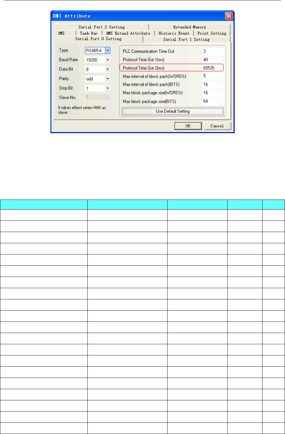
4 Communication settings and guide of HMI connecting with controller
- 97 -
NOTE:When PLC is protected by password, protocol time out 2 is 65535, and the register is read only. If
you want to make the register writable, you must let the protocol time out 2 equal the PLC password.
Example: PLC password is 1234, and then you make the protocol time out 2 to be 1234.
PLC password is 0010, and then you make the protocol time out 2 to be 10.
◎Supported Device
SPB
Device Bit Address Word Address Format Notes
Data register D 0~6FF.F ------ HHH.H
Special relay M_special 0~1FF ------ HHH
Counter contact C 0~FF ------ HH
Timer contact T 0~1FF ------ HHH
Keep relay L 0~FFF ------ HHH
Auxiliary relay M 0~FFF ------ HHH
Output relay Y 0~3FF ------ HHH
Input relay X 0~3FF ------ HHH
Timer contact ------ TW 0~3FF HHH
Counter contac ------ CW 0~FF HH
Data register ------ DW 0~6FF HHH
Special register ------ DW_special 0~1FF HHH
Link register(0 slot) ------ W0 0~7FF HH
Link register(1 slot) ------ W1 0~7FF HHH
Link register(2 slot) ------ W2 0~7FF HHH
Link register(3 slot) ------ W3 0~7FF HHH
Link register(4 slot) ------ W4 0~7FF HHH
Link register(5 slot) ------ W5 0~7FF HHH
Link register(6 slot) ------ W6 0~7FF HHH
Link register(7 slot) ------ W7 0~7FF HHH
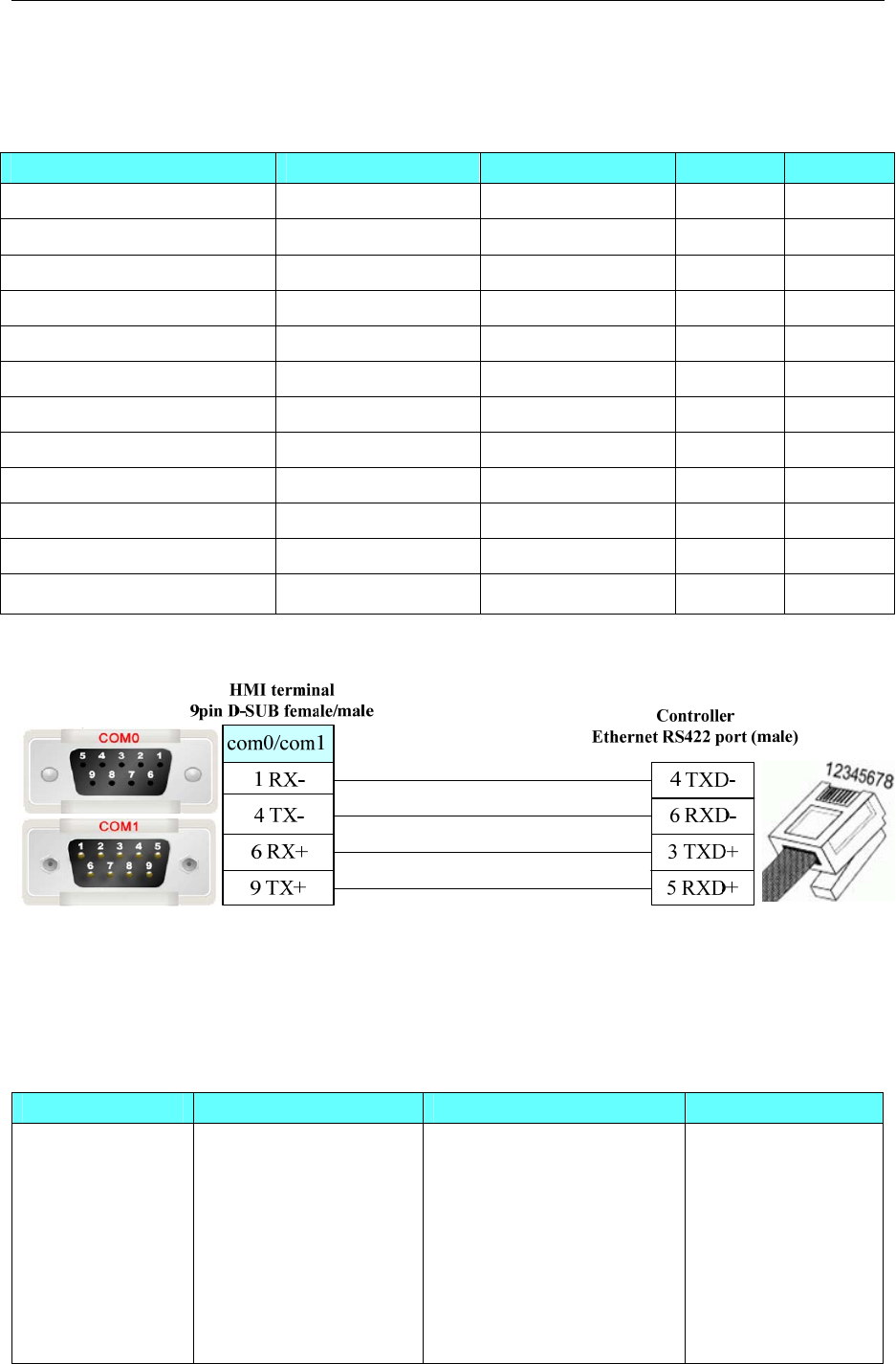
4 Communication settings and guide of HMI connecting with controller
- 98 -
Note:M_special address: 8000 in the PLC corresponds to 0 in the HMI.
DW_special address: 8000 in the PLC corresponds to 0 in the HMI.
NB
Device Bit Address Word Address Format Notes
Data register D 0~3F.F ------ HHH.H
Special relay M_special 0~1FF ------ HHH
Counter contact C 0~1F ------ HH
Timer contact T 0~1F ------ HHH
Keep relay L 0~1FF ------ HHH
Auxiliary relay M 0~3FF ------ HHH
Output relay Y 0~3F ------ HHH
Input relay X 0~3F ------ HHH Read only
Timer contact ------ TW 0~1F HHH
Counter contact ------ CW 0~1F HH
Data register ------ DW 0~3F HHH
Special register ------ DW_special 0~1FF HHH
◎Cable Diagram
4.23 GE Fanuc Automation Inc.
◎Serial Communication
Series CPU Link Module Driver
GE Fanuc Series
90-30
IC693CPU311
IC693CPU313
IC693CPU321
IC693CPU323
IC693CPU331
IC693CPU340
IC693CPU341
IC693CPU350
Serial Connector on Power
Supply
GE Fanuc Series
SNP
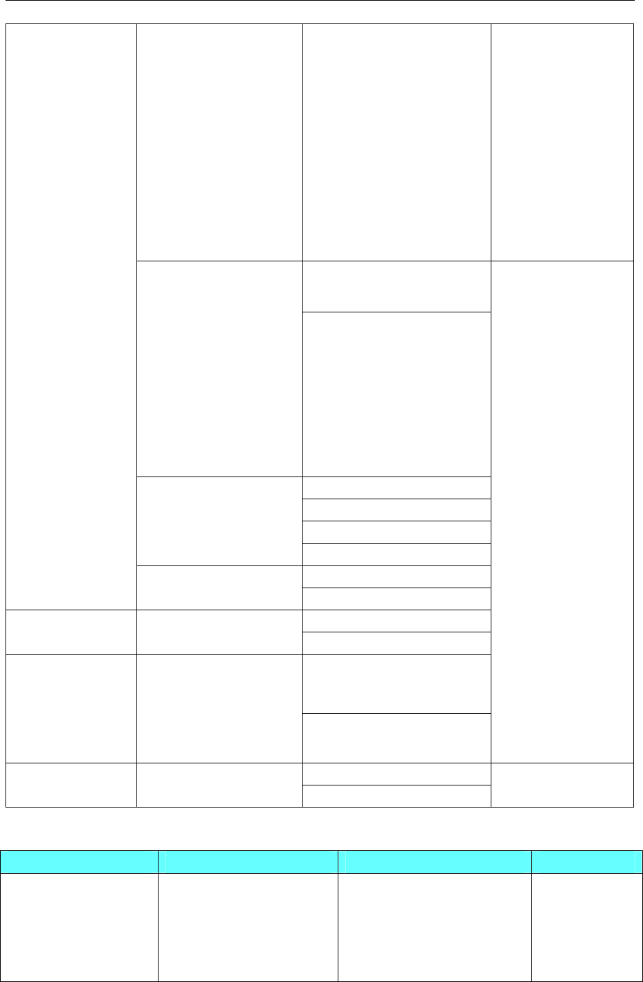
4 Communication settings and guide of HMI connecting with controller
- 99 -
IC693CPU351
IC693CPU352
IC693CPU360
IC693CPU363
IC693CPU364
IC693CPU374
IC693CSE311
IC693CSE313
IC693CSE323
IC693CSE331
IC693CSE340
Connector on Power Supply IC693CPU311
IC693CPU313
IC693CPU321
IC693CPU323
IC693CPU331
IC693CPU340
IC693CPU341
IC693CPU350
IC693CPU360
IC693CPU364
IC693CMM311
Connector on Power Supply
Port1 on CPU unit
Port2 on CPU unit
IC693CPU351
IC693CPU352
IC693CPU363
IC693CMM311
Port on Power Supply IC693CPU374
IC693CMM311
RS232 on port1 VersaMax Series CPU001/002/005
CPUE05 RS485 on port2
RS232 on port1 VersaMax Micro &
Nano Series
IC200UAL004/005/006
IC200UDD110/120/212
IC200UDR005/006/010
IC200UAA007
IC200UAR028
RS485 on port2
GE SNP-X
RS232 on port1 PACSystems RX3i IC695CPE310
IC695CPE320 RS485 on port2
GE Fanuc Series
SNP
◎Network communication
Series CPU Link Module Driver
Series90-30
CPU340
CPU341
CPU350
CPU351
CPU352
IC693CMM321
GE IP Ethernet
(TCP Slave)

4 Communication settings and guide of HMI connecting with controller
- 100 -
CPU360
CPU363
CSE311
CSE313
CSE323
CSE331
CSE340
CPU364
CPU374 Ethernet interface on CPU
PACSystem RX3i
IC695CPE305
IC695CPE310
IC695CPE 315
IC695CPE 320
IC695ETM001
VersMax Micro&Nano
IC200UDD020
IC200UDD040
IC200UDD064
IC200UDD120
IC200UDD164
IC200UDD220
IC200UDD240
IC200UDR020
IC200UDR040
IC200UDR064
IC200UDR120
IC200UDR140
IC200UDR164
IC200UDR440
IC200UEM001
VerMax CPUE05 Ethernet interface on CPU
Series 90-30
CPU311
CPU313
CPU323
CPU331
CPU340
CPU341
CPU350
CPU351
CPU352
CPU360
CPU363
CSE311
CSE313
CSE323
CSE331
CSE340
IC693CMM321
Modbus TCP
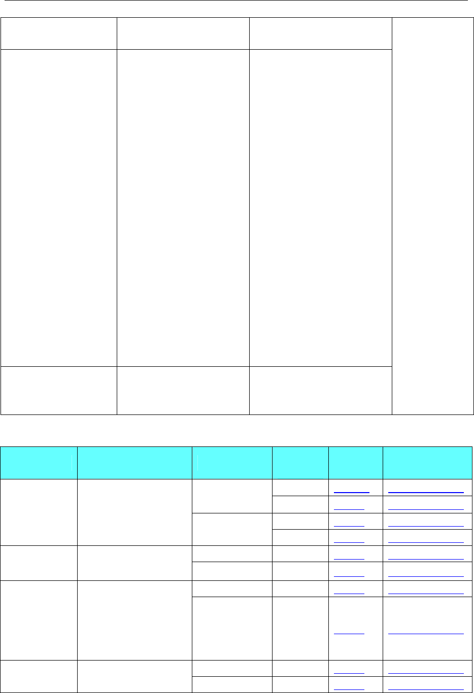
4 Communication settings and guide of HMI connecting with controller
- 101 -
CPU364
CPU374 Ethernet interface on CPU
Series 90-70
CPU731
CPU771
CPU772
CPU780
CPU781
CPU782
CPU788
CPU789
CPM790
CPM915
CPM925
CSE784
CSE924
CSE925
CPX772
CPX782
CPX928
CPX935
CGR772
CGR935
IC697CMM742 (Type2)
PACSystem RX7i
CPE010
CPE020
CRE020
Ethernet interface on CPU
◎Serial System configuration
Series CPU Link Module COMM
Type Parameter Cable
RS232 Setting Your owner cable
RS485 on the
CPU unit RS485-4 Setting Your owner cable
RS232 Setting Your owner cable
GE Fanuc
Series 90-30 IC693CPU374
IC693CMM311 RS485-4 Setting Your owner cable
RS232 on port1 RS232 Setting Your owner cable
VersaMax
Series
CPU001/002/005
CPUE05 RS485 on port2 RS485-4 Setting Your owner cable
RS232 on port1 RS232 Setting Your owner cable
VersaMax
Micro & Nano
Series
IC200UAL004/005/006
IC200UDD110/120/212
IC200UDR005/006/010
IC200UAA007
IC200UAR028
RS485 on port2 RS485-4 Setting Your owner cable
RS232 on port1 RS232 Setting Your owner cablePACSystems
RX3i
IC695CPE310
IC695CPE320 RS485 on port2 RS485-4 Setting Your owner cable
◎Network System configuration
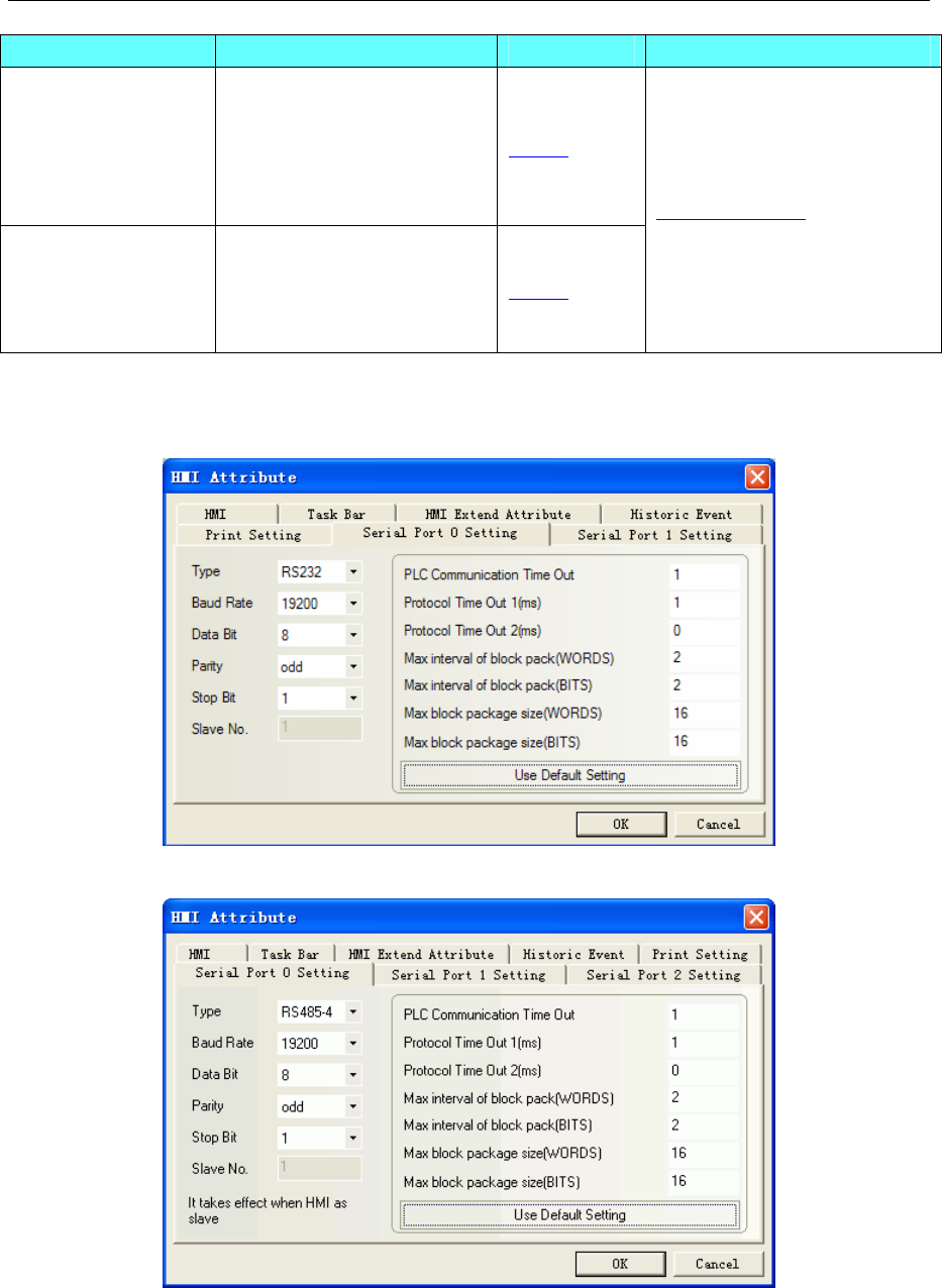
4 Communication settings and guide of HMI connecting with controller
- 102 -
Series Connect Type Parameter Cable
Series 90-30/
Versa ma x/
PACSystem RX3i/
Versa ma x
Mico&Nano
Ethernet
(GE IP Ethernet(TCP Slave)) Setting
Series 90-30/
PACSystem RX3i/
Versa ma x
Mico&Nano
Ethernet
(Modbus TCP Slave) Setting
Your owner cable
◎Serial Communication Setting
GE Fanuc Series SNP RS232 Communication
GE Fanuc Series SNP RS422 Communication
GE SNP-X Protocol RS232 Communication
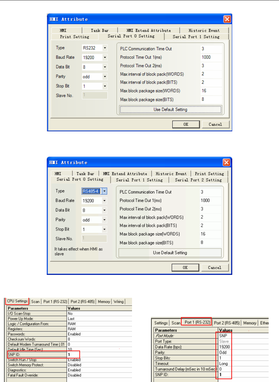
4 Communication settings and guide of HMI connecting with controller
- 103 -
GE SNP-X Protocol RS422 Communication
NOTE: Set matching communication parameter in the Programming software.
PLC Setting
RX3i 设置:
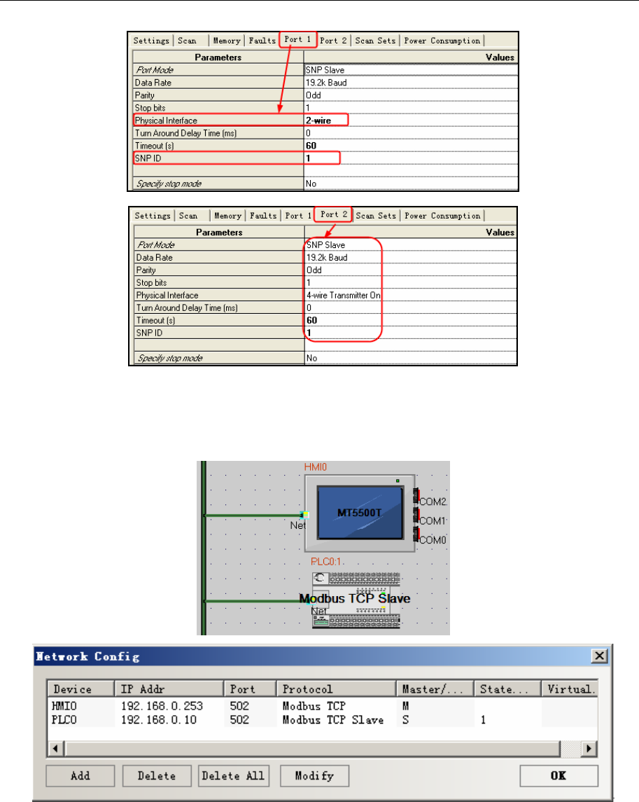
4 Communication settings and guide of HMI connecting with controller
- 104 -
◎Network Communication Setting
MODBUS TCP Protocol:
HMI:
PLC:
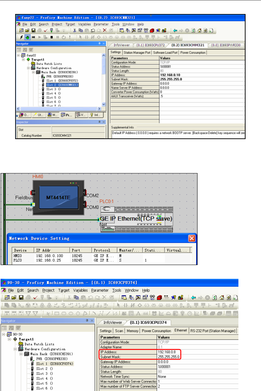
4 Communication settings and guide of HMI connecting with controller
- 105 -
GE IP Ethernet(TCP Slave)Protocol:
HMI:
PLC:
◎Supported Device
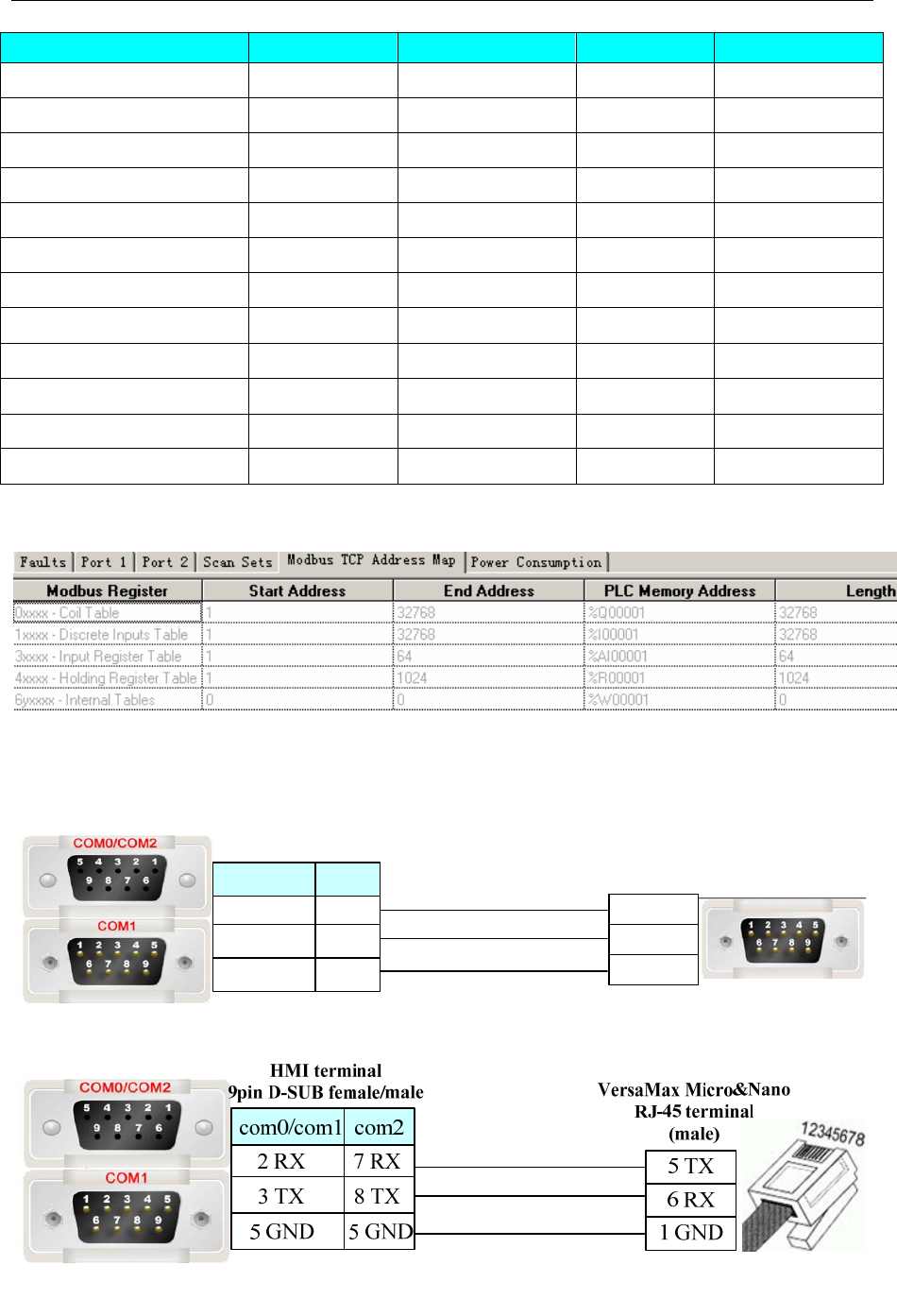
4 Communication settings and guide of HMI connecting with controller
- 106 -
Device Bit Address Word Address Format Notes
System SC01-32
------ DD
System SB01-32
------ DD
System SA01-32
------ DD
System S01-32
------ DD
Temporary T001-256
------ DDD
Internal M0001-4096
------ DDDD
Genius Global G0001-1280 ------ DDDD
Output Q0001-2048
------ DDDD
Input I001-256
------ DDD
Analog Output ------ AQ001-512 DDD
Analog Input ------ AI0001-2048 DDDD
Register ------
R0001-9999 DDDD
Address correspondence between modbus
◎Cable Diagram
90-30/VersaMax/RXi RS232 communication
Controller VersaMax terminal
9 pin D-SUB (male)
HMI terminal
9pin D-SUB female/male
2 TX
3 RX
5 GND
3 TX
2 RX
5 GND
8 TX
7 RX
com0/com1
5 GND
com2
VersaMax Micro & Nano Series RS232 communication
CMM311 RS232 communication
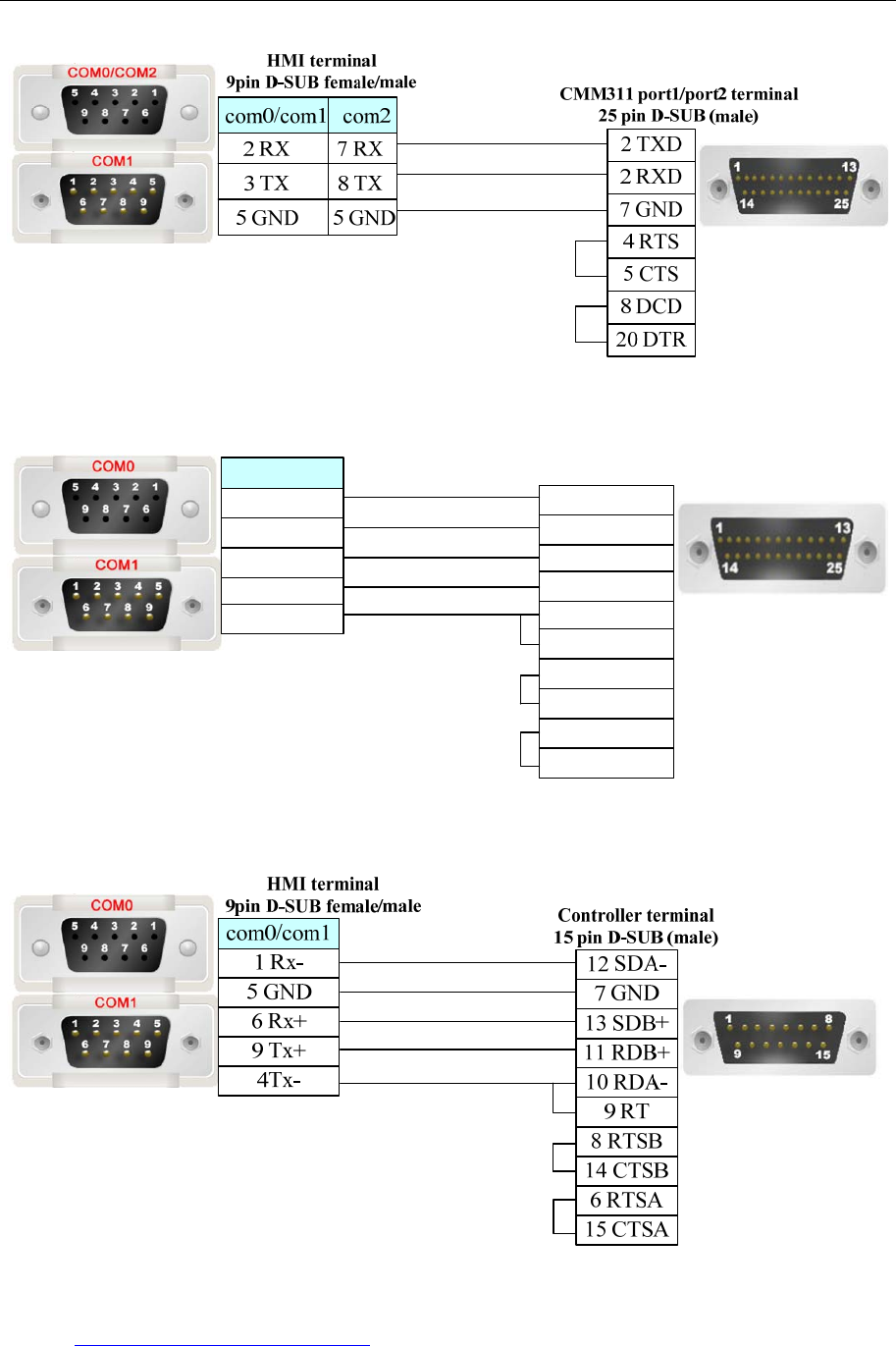
4 Communication settings and guide of HMI connecting with controller
- 107 -
CMM311 RS422 communication
HMI terminal
9pin D-SUB female/male
1 Rx-
9 Tx+
4Tx-
9 SDA
7 GND
21 SDB
5 GND
6 Rx+
25 RDB
13 RDA
11 CTSA
12 TER CTS
22 RTSB
23 CTSB
10 RTSA
CMM311 port2 terminal
25 pin D-SUB (male)
com0/com1
90-30/VersaMax RS422 communication
Ethernet communication protocol cable
Cross-connection or crossover network cable can be used as communication cable via the hub
Refer to 3.3 Download by Network Ethernet for method of making connection cable.
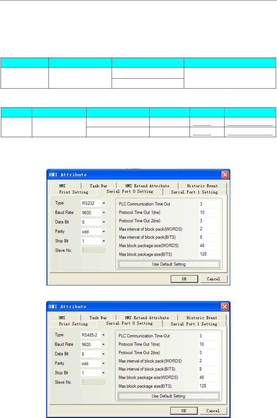
4 Communication settings and guide of HMI connecting with controller
- 108 -
4.24 HAIWELL
◎Serial Communication
Series CPU Link Module Driver
RS232 on com1
E/S HW-S16ZA220R RS485 on com2 Haiwell
◎System configuration
Series CPU Link Module COM Type Parameter Cable
RS232 on com1 RS232 Setting Your owner cable
E/S HW-S16ZA220R RS485 on com2 RS485 Setting Your owner cable
◎Communication Setting
Haiwell RS232 communication
Haiwell RS485 communication
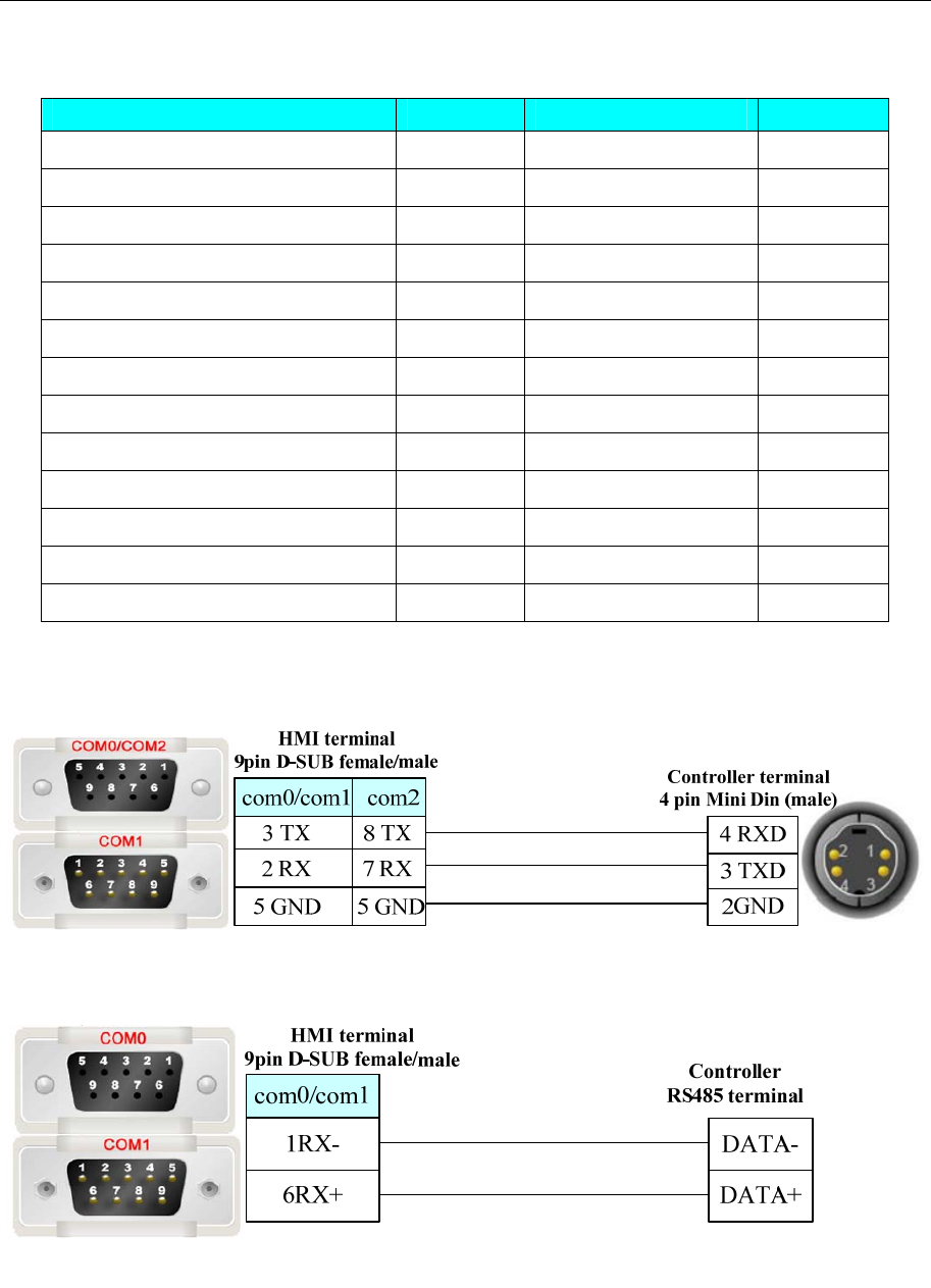
4 Communication settings and guide of HMI connecting with controller
- 109 -
◎Supported Device
Device Bit Address Word Address Format
Special memory Relay SM0–215 ------- DDD
Counter Relay C0–127
------- DDD
Timer Relay T0–127
------- DDD
Internal Relay M0–2047 ------- DDDD
Switch Output Y0–127 ------- DDD
Switch Input X0–127 ------- DDD
System register ------- SV0-139 DDD
Counter(Current Value) ------- CCV-16 0-47&80-127 DDD
Counter(Current Value double word) ------- CCV-32 48-79 DD
Timer(Current Value) ------- TCV0-127 DDD
Internal Register ------- V0-2047 DDDD
Analog Output ------- AQ0-31 DD
Analog Input ------- AI0-31 DD
◎Cable Diagram
Haiwell RS232 communication cable
Haiwell RS485 communication cable
4.25 HanG
◎Serial Communication
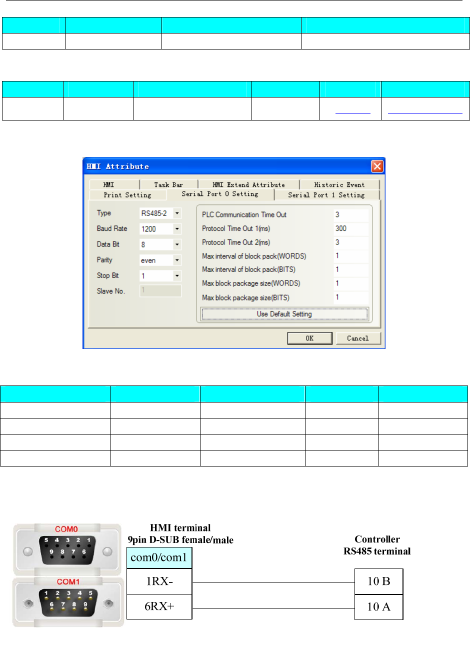
4 Communication settings and guide of HMI connecting with controller
- 110 -
Series CPU Link Module Driver
HanG DTS3338 RS485 on the CPU unit HanG
◎System configuration
Series CPU Link Module COMM Type Parameter Cable
HanG DTS3338 RS485 on the CPU unit RS485 Setting Your owner cable
◎Communication Setting
◎Supported Device
Device Bit Address Word Address Format Notes
Password ------ APAS 0 H
Meter Number ------ ANUM C032 HHHH
Init Meter ------ ASTR 0 H
Register value ------ AMVD 9010 HHHH
NOTE:Use text part to show meter number (ANUM). AMVD data type: signed integer
◎Cable Diagram
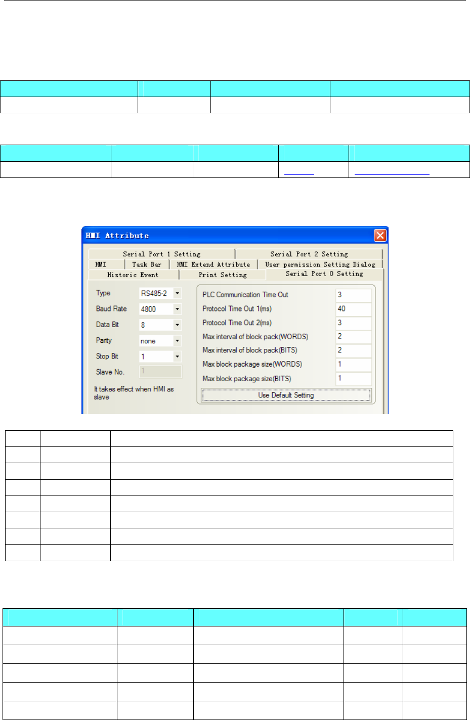
4 Communication settings and guide of HMI connecting with controller
- 111 -
4.26 Hitachi Inverter
◎Serial Communication
Series CPU Link Module Driver
Hitachi Inverter SJ300 RS485-2 Hitachi SJ300
◎System configuration
Series CPU Link Module Parameter Cable
Hitachi Inverter SJ300 RS485-2 Setting Your owner cable
◎Communication Setting
HMI default communication parameter: 4800, 7, none, 1; station: 1
Inverter internal setting
Code Name description
A001 Frequency set 00(VR)/01(Terminal)/02(operator)/03(RS485)/04(OPT 1)/05(OPT 2)
A002 Run set 01(Terminal)/02(operator)/03(RS485) /04(OPT 1)/05(OPT 2)
C71 Baudrate 02(close loop detect)/ 03(2400bps)/ 04(4800bps)/ 05(9600bps)/ 06(19200bps)
C72 Station set 1~32
C73 Data bit 7(7 bit)/8(8 bit)
C74 Parity 00(none)/01(even)/02(odd)
C75 Stop bit 1(bit)/2(bit)
NOTE:A001, A002 must be set 03(RS485)in order to communication with HMI.
◎Supported Device
Device Bit Address Word Address Format Notes
------ P Extend Func 0~50 DD
------ H Extend Func 0~512 DDD
------ F Func Date 0~65535 DDDDD
------ C Func Date 0~65535 DDDD
------
B Func Date 0~999 DDD
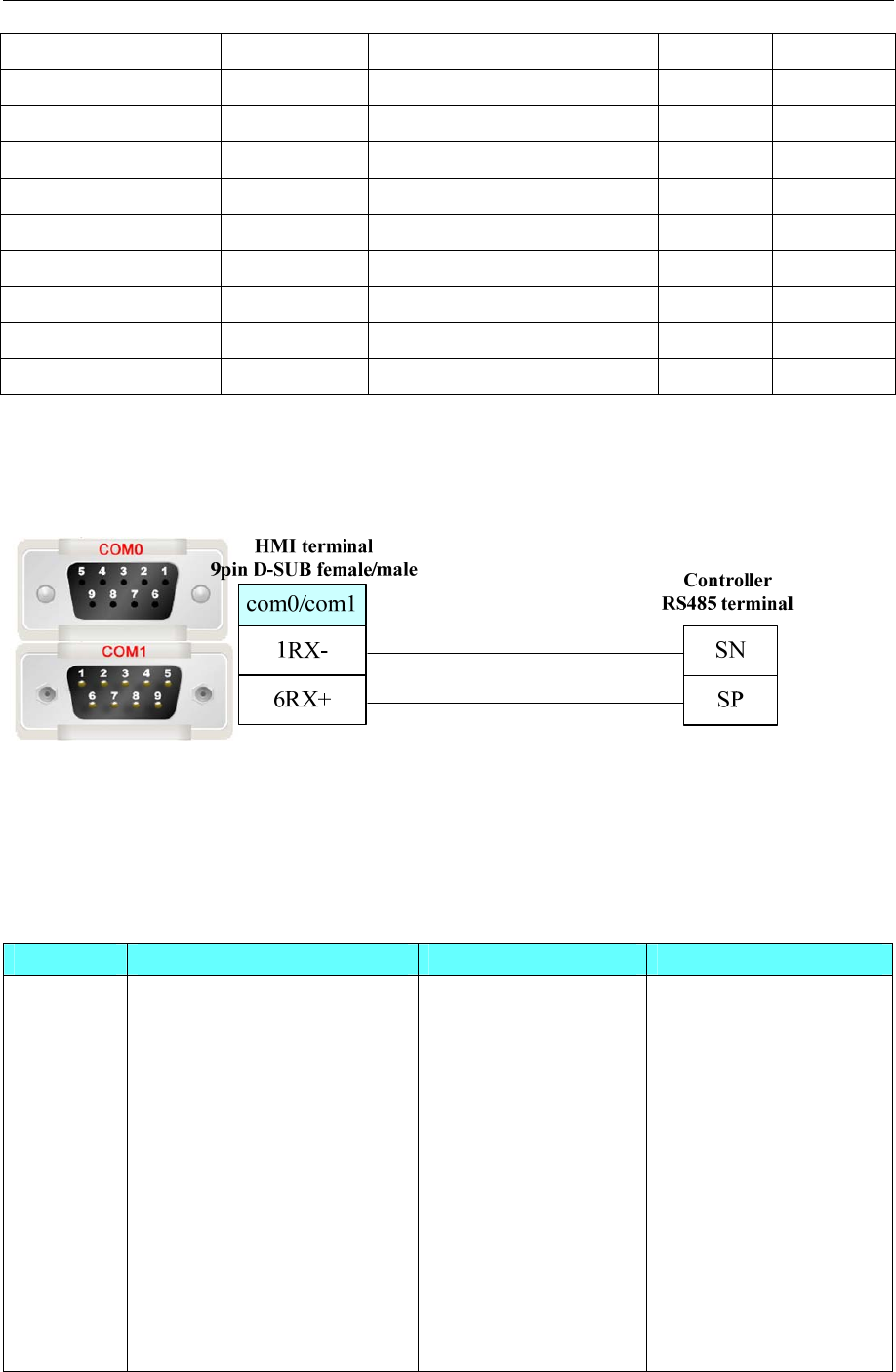
4 Communication settings and guide of HMI connecting with controller
- 112 -
------
A Func Date 0~999 DDD
FWD/REW/STOP
(00)FWD/REW/STOP 0 D Write only
FREQ SET ------ (01)FREQ SET 0 D Write only
TerminalPoint State (02)TerminalPoint State 0~7 D Write only
Surveillance Data ------ (03)Surveillance Data 0~12 DD Read only
Transducer State (04)Transducer State 0~3 D Read only
Trip Record ------ (05)Trip Record 0~54 DD Read only
Revert ------
(08)Revert 0 D Write only
Recount Motor Con ------ (0B)Recount Motor Cons 0 D Write only
Store EEPROM ------ Store EEPROM 0 D
NOTE:(02)Terminal Point State 0~7 use text part
◎Cable Diagram
RS485-2 communication cable
4.27 Hitachi IES Co., Ltd
◎Serial Communication
Series CPU Link Module Driver
H H-20
H-28
H-40
H-64
H-200(CPU-02H)
H-250(CPU21-02H)
H-252B(CPU22-02HB)
H-252C(CPU22-02HC)
H-300(CPU-03Ha)
H-302(CPU2-03H)
H-700(CPU-07Ha)
H-702(CPU2-07H)
port on CPU Hitachi

4 Communication settings and guide of HMI connecting with controller
- 113 -
H-2002(CPU2-20H)
H-4010(CPU3-40H)
H-1002(CPU2-10H)
H-300(CPU-03Ha)
H-302(CPU2-03H)
H-700(CPU-07Ha)
H-702(CPU2-07H)
H-2000(CPU-20Ha)
H-2002(CPU2-20H)
H-4010(CPU3-40H)
COMM-H
COMM-2H
H-1002(CPU2-10H) COMM-2H
EH-150(EH-CPU104)
EH-150(EH-CPU104A)
EH-150(EH-CPU208)
EH-150(EH-CPU208A)
EH-150(EH-CPU308)
EH-150(EH-CPU308A)
EH-150(EH-CPU316)
EH-150(EH-CPU316A)
EH-150(EH-CPU448)
EH-150(EH-CPU448A)
EH-150(EH-CPU516)
EH-150(EH-CPU548)
Serial port 1 on CPU
Serial port 2 on CPU
EH-150
EH-150(EH-CPU516)
EH-150(EH-CPU548)
Port 1 on EH-SIO
Port 2 on EH-SIO
MICRO-EH(EH-D10)
MICRO-EH(EH-A14)
MICRO-EH(EH-D14)
MICRO-EH(EH-A23)
MICRO-EH(EH-D23)
MICRO-EH(EH-A28)
MICRO-EH(EH-D28)
Port 1 on CPU
MICRO-EH(EH-A23)
MICRO-EH(EH-D23)
MICRO-EH(EH-A28)
MICRO-EH(EH-D28)
Port 2 on CPU
Port on CPU
MICRO-EH
MICRO-EH(EH-A64)
MICRO-EH(EH-D64)
MICRO-EH(EH-A40)
MICRO-EH(EH-D40)
MICRO-EH(EH-A20)
MICRO-EH(EH-D20)
EH-OB232
EH-OB485
◎Ethernet Communication
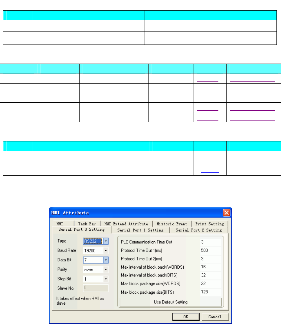
4 Communication settings and guide of HMI connecting with controller
- 114 -
Series CPU Link Module Driver
S10V LQP510-Z LQP520-Z HITACHI S10V Series Ethernet (TCP Slave)
EHV EHV-CPU32 Ethernet interface on CPU HITACHI EHV Series Ethernet (TCP Slave)
◎Serial System configuration
Series CPU Link Module COMM Type Parameter Cable
H H-20 RS232 on the CPU unit RS232 Setting Your owner cable
EH-150 EH-150(EH-
CPU104)
Serial port 1 on CPU
Serial port 2 on CPU
Port 1 on CPU RS232 Setting Your owner cable
MICRO-EH EH-A23DR Port 2 on CPU RS485 Setting Your owner cable
◎Ethernet System Communication
Series CPU Link Module Connect Type Parameter Cable
S10V LQP510-Z LQP520-Z Ethernet Setting
EHV EHV-CPU32 Ethernet interface on CPU Ethernet Setting
Your owner cable
◎Serial Communication Setting
RS232 communication
RS422 communication
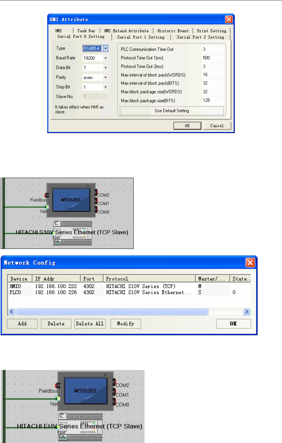
4 Communication settings and guide of HMI connecting with controller
- 115 -
Ethernet Communication Setting
HITACHI S10V Series Ethernet (TCP Slave)
HMI Setting
HITACHI EHV Series Ethernet (TCP Slave)
HMI Setting
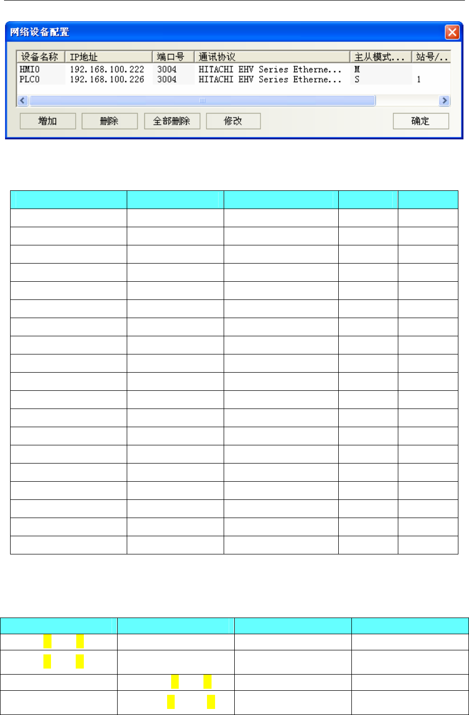
4 Communication settings and guide of HMI connecting with controller
- 116 -
◎Supported Device
Hitachi EH-A23DR
Device Bit Address Word Address Format Notes
External In
p
ut X 00.000-5A.095 ------ HHH.DDD Read Only
External Out
p
ut Y 00.000-5A.095 ------ HHH.DDD
Remote In
p
ut X 100.000-9FF.095 ------ HHH.DDD Read Only
Remote Out
p
ut Y 100.000-9FF.095 ------ HHH.DDD
Internal Out
p
ut R 0000-FFFF ------ HHHH
Data Area M 0000-FFFF ------ HHHH
Fi
r
st CPU Link L 00000-03FFF ------ HHHHH
Second CPU Link L 10000-FFFFF ------ HHHHH
On Dela
y
Time
r
TD 00000-65535 ------ DDDDD
External In
p
ut ------ WX 000.00-05A.09 HHH.DD Read Only
External Out
p
ut ------ WY 000.00-05A.09 HHH.DD
Remote In
p
ut ------ WX 100.00-9FF.09 HHH.DD Read Only
Remote Out
p
ut ------ WY 100.00-9FF.09 HHH.DD
Word Internal Out
p
ut ------ WR 0000-C3FF HHHH
S
p
ecial Word Out
p
ut ------ WRF 000-FFFF HHHH
Data Area ------ WM 0000- FFFF HHHH
First CPU Link ------ WL 0000-03FF HHHH
Second CPU Link ------ WL 1000-FFFF HHHH
Timer Counte
r
------ TC 00000-65535 DDDDD
Note:X0.015 in the HMI match x15 in the PLC,Y1.000 in the HMI match Y100,WX0.09 in the HMI
match WX9 in the Plicate effective address is deleted radix point and the first zero behind radix point.
The list of address correspondence
Bit Address Word Address PLC address Notes
X 00.000-00.047 ------ X 0000-0047
Y 01.000-01.031 ------ Y 0100-0131
------ WX 000.00-000.03 WX 0000-0003
------ WY 001.00-Y001.01 WY 0010-0011

4 Communication settings and guide of HMI connecting with controller
- 117 -
Note: The range of X, Y, WX, WY is according to the I/O assign. Make sure the I/O address before using
the register.
Note:
1. Communication setting
EH series, only port1 supports procedure 2.Switch DIP and change special Internal Input (WR) value to
select procedure.
EH150 series,only EHCPU***A/448/516/548 support procedure 2.
EH PLC connect with PC only by procedure 1.
2. CPU related actions
EH150
DIP 5 must be set on.
If DIP 5 is on, which procedure (1 or2) to use by judging the value of the WR F037.The highest bit of
WR F037 must be on, so that the other bits can be written in. The data keep on, when turn on the power
again.
o By entering 0x8000, turn on the power again and value of the address is 0x0000.After settings,
communication with procedure 1.
o By entering 0xC000, turn on the power again and value of the address is 0x4000.After settings,
communication with procedure 2.
The transmission speed of port 1 will be set with DIP 3, 4 switches
o 3 on, 4 off is 19200 bps
The transmission speed of port 2 will be set with DIP 6, PHL switches.
o 6 off, PHL on is 19200 bps
MicroEH
The transmission speed will be set with DIP switches
o SW1 on is 19200 bps
Which procedure(1 or2) to use by judging the value of the WR F01A.Different with EH150, The
highest bit of WR F01A is optional, The data will reset when turn on the power again. If the value of R
7F6 is set on, the data of WR F01A will be stored in Flash memory.
o 0x0000 for procedure 1.
o 0x8000 for procedure 2.
Note: if procedure 2 is set and written in Flash memory, external device (only supports procedure 1) or
ladder editor will not connect with it.
S10V
Device Bit Address Word Address Format Notes
S S 0-BFF ------ HHH
Z Z 0-3FF ------ HHH
E E 0-FFF ------ HHH
V V 0-FFF ------ HHH
P P 0-7F ------ HH
N N 0-FF
------ HH
CCC CCC 0-FF
------ HH
CR CR 0-FF
------ HH
CD CD 0-FF
------ HH

4 Communication settings and guide of HMI connecting with controller
- 118 -
CU CU 0-FF
------ HH
UUU UUU 0-FF
------ HH
UU UU 0-FF
------ HH
TTT TTT 0-1FF
------ HHH
TT TT 0-1FF
------ HHH
K K 0-FFF
------ HHH
M M 0-FFF
------ HHH
R R 0-FFF
------ HHH
G G 0-FFF
------ HHH
Q Q 0-FFF
------ HHH
Y Y 0-FFF
------ HHH
J J 0-FFF
------ HHH
X X 0-FFF
------ HHH
OW ------ OW 0-FFF
HHH
IW ------ IW 0-FFF HHH
DW ------ DW 0-FFF HHH
FW ------ FW 0-BFF HHH
SW ------ SW 0-BF HH
ZW ------ ZW 0-3F HH
EW ------ EW 0-FF
HH
VW ------ VW 0-FF HH
PW ------ PW 0-8 H
NW ------ NW 0-F H
CW ------ CW 0-F H
UW ------ UW 0-F H
TW ------
TW 0-1F HH
KW ------ KW 0-FF HH
MW ------ MW 0-FF HH
RW ------ RW 0-FF HH
GW ------ GW 0-FF HH
QW ------ QW 0-FF HH
YW ------ YW 0-FF HH
JW ------ JW 0-FF HH
XW ------ XW 0-FF HH
CC ------ CC 0-FF HH
CS ------ CS 0-FF HH
UC ------ UC 0-FF HH
US ------ US 0-FF HH
TC ------ TC 1FF HHH
TS ------ TS 0-1FF HHH
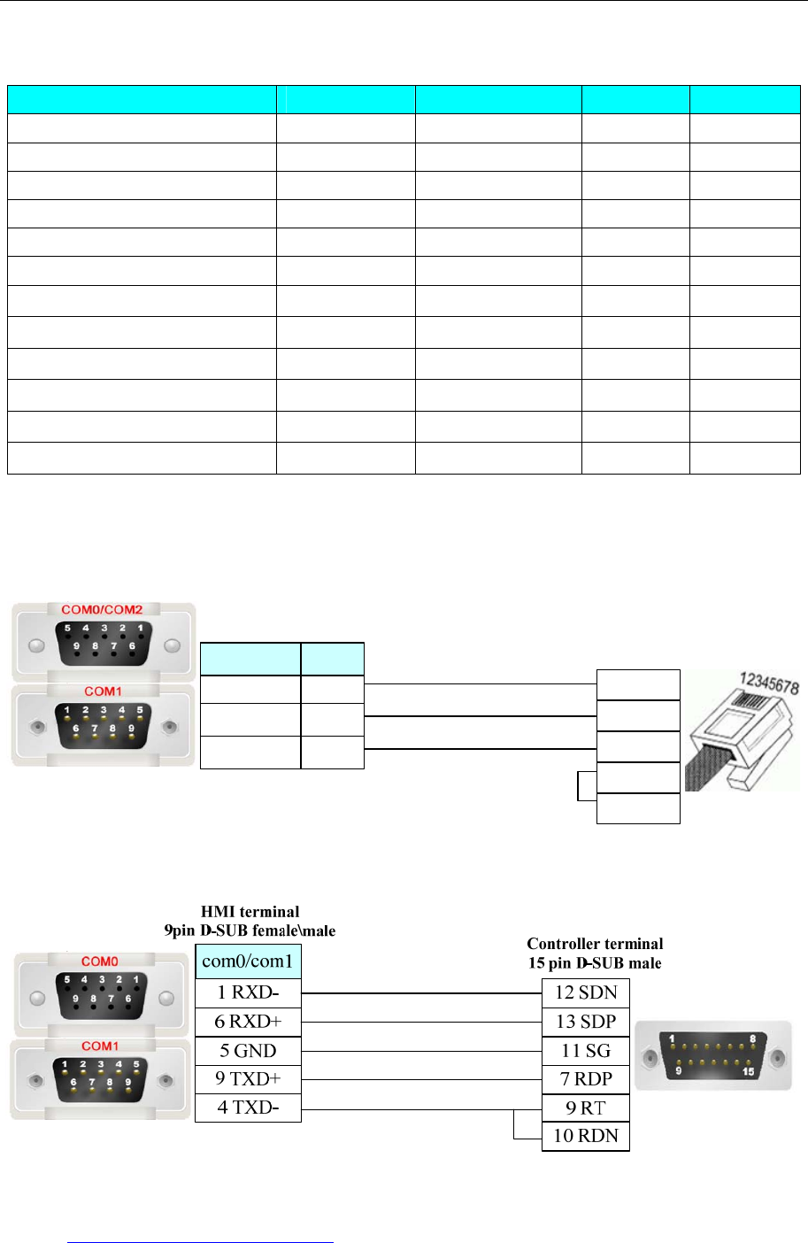
4 Communication settings and guide of HMI connecting with controller
- 119 -
HITACHI EHV Series Ethernet (TCP Slave)
Device Bit Address Word Address Format Notes
Timer T 0-65535 ------ DDDDD
Internal output(shared Bit/Word) M 0-FFFFF ------ HHHHH
Link area No.n(n is 0 to 7) L 0-73FFF ------ HHHHH
Internal output R 0-FFFF ------ HHHH
External output Y 0-65535 ------ DDDDD
External input X 0-65535 ------ DDDDD
Timer progress value ------ TC 0-65535 DDDDD
Internal output ------ WM 0-FFFF HHHH
Link area No.n(n is 0 to 7) ------ WL 0-FFFF HHHH
Internal output ------ WR 0-FFFF HHHH
External output ------ WY 0-65535 DDDDD
External input ------ WX 0-65535 DDDDD
◎Cable Diagram
Hitachi EH-A23DR RS232 communication cable
HMI terminal
9pin D-SUB female/male
com2
3 TX
2 RX
5 GND
8 TX
7 RX
5 GND
com0/com1
Controller
RJ-45 terminal
1 SG
5 SD
6 RD
7 DSR
2 VCC
Hitachi EH-A23DR RS422 communication cable
Ethernet Cable
Cross-connection or crossover network cable can be used as communication cable via the hub
Refer to 4.3 Download by Network Ethernet for method of making connection cable.
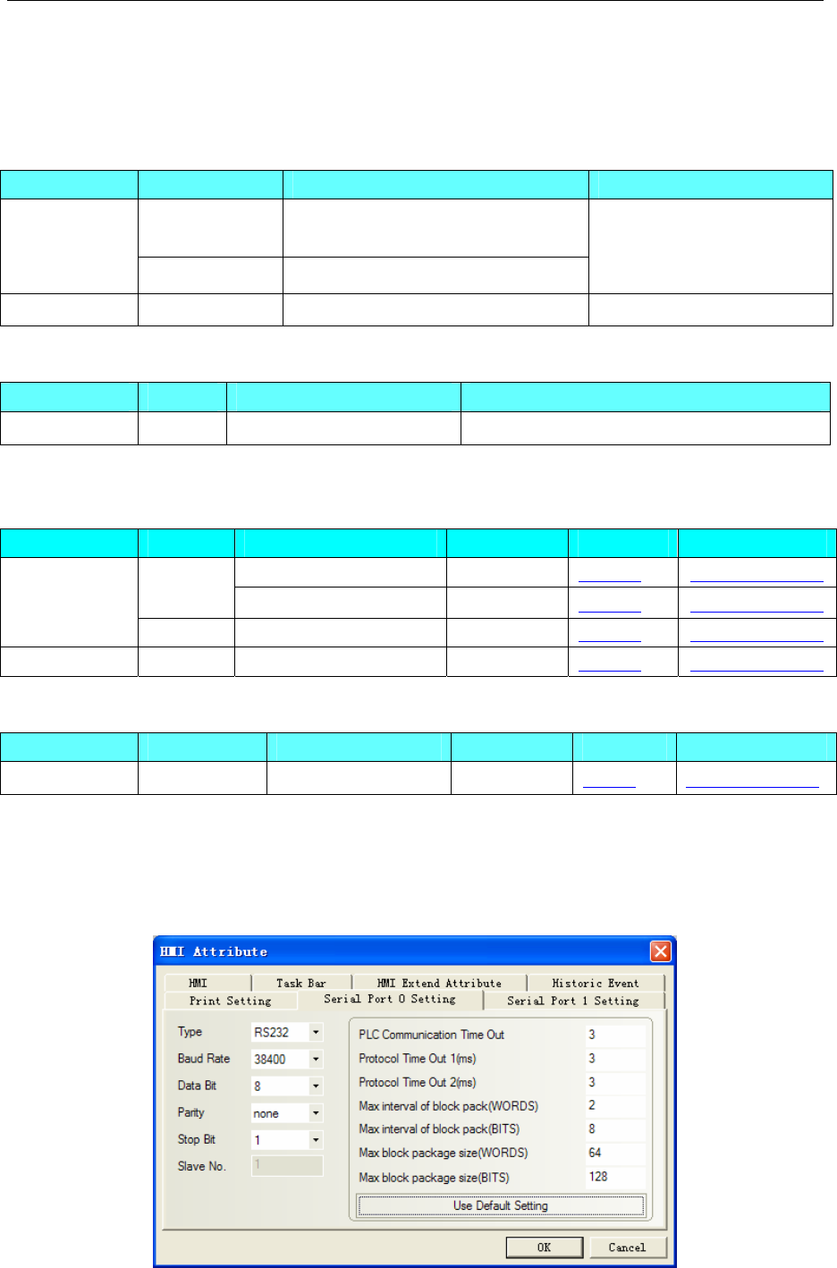
4 Communication settings and guide of HMI connecting with controller
- 120 -
4.28 Hollysys Corporation
◎Serial Communication
Series CPU Link Module Driver
LM3109 Serial port0 on CPU 485
Serial port1 on CPU 232
Hollysys LM
LM3107 RS232 on CPU
Hollysys LM Modbus
RTU
Hollysys LK RS232 on CPU Hollysys LK Modbus RTU
◎Ethernet Communication
Series CPU Link Module Driver
Hollysys LK LK210 Ethernet interface on CPU Hollysys LK Modbus TCP Slave*1
*1 Support dual redundancy
◎Serial System Configuration
Series CPU Link Module COMM Type Parameter Cable
RS232 on the CPU unit RS232 Setting Your owner cable
LM3109 RS485on the CPU unit RS485 Setting Your owner cable
Hollysys LM
LM3107 RS232 on the CPU unit RS232 Setting Your owner cable
Hollysys LK RS232 on the CPU unit RS232 Setting Your owner cable
◎Ethernet System Configuration
Series CPU Link Module COMM Type Parameter Cable
Hollysys LK LK210 ETH on the CPU unit ETH Setting Your owner cable
◎Serial Communication Setting
HMI Setting
Default communication parameters:38400,8,none,1;station:51
RS232
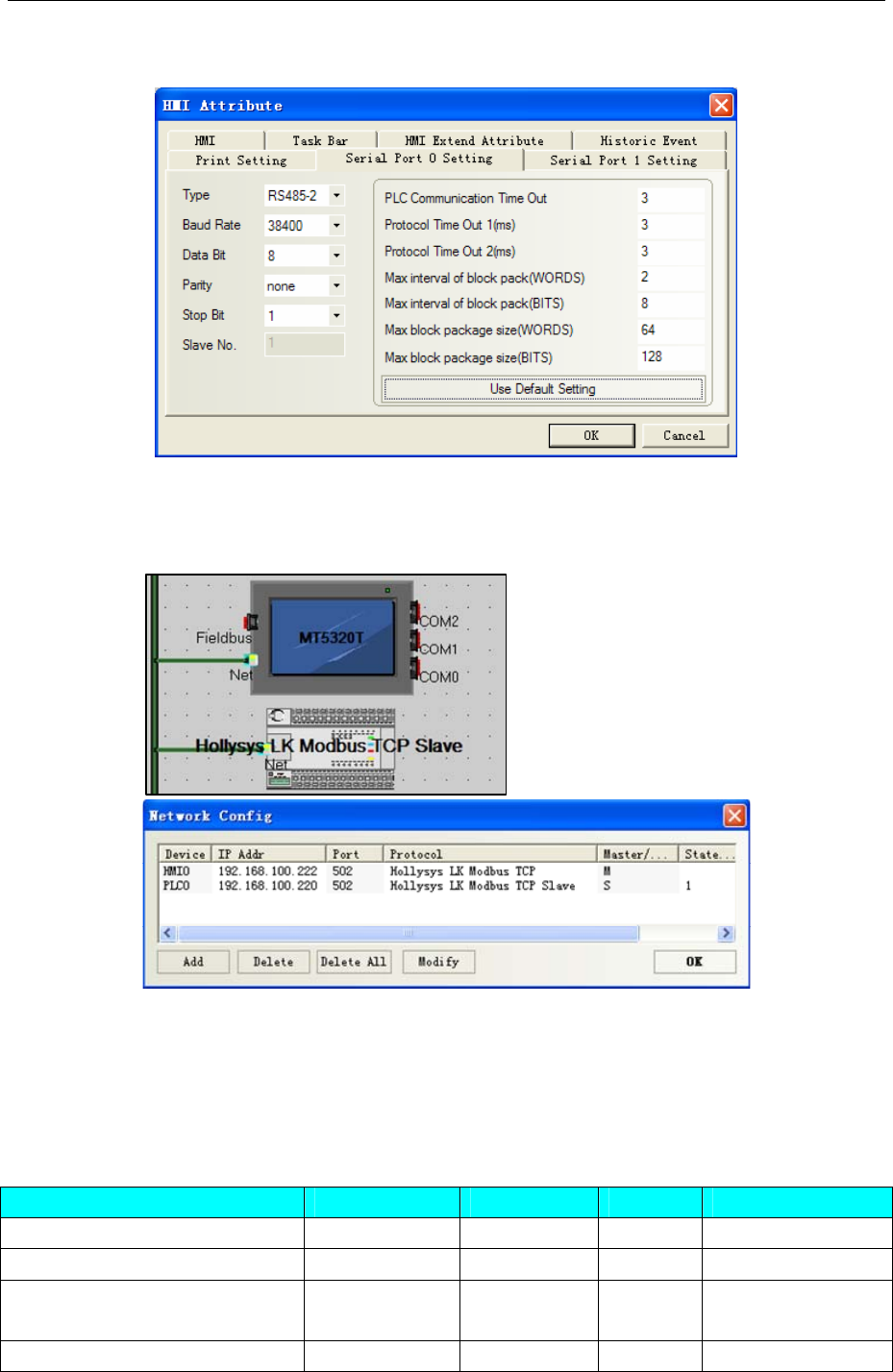
4 Communication settings and guide of HMI connecting with controller
- 121 -
RS485-2
◎Ethernet Communication Setting
HMI Setting
Note:In the dual redundancy system, just set one of IP addresses in Network Device Setting
PLC Setting
Must set the PLC station in PLC program software.
◎Supported Device
LM
Device Bit Address Word Address Format Notes
Discrete inputs and image Relay I0.0-2.7 ------ D.O
Discrete outputs and image Relay Q0.0-1.7 ------ D.O
Internal memory Relay M100.0-7816.7 ------ DDDD.O M0-99 are occupied
by system diagnosis.
Analog inputs ------ IW0 D address must be an
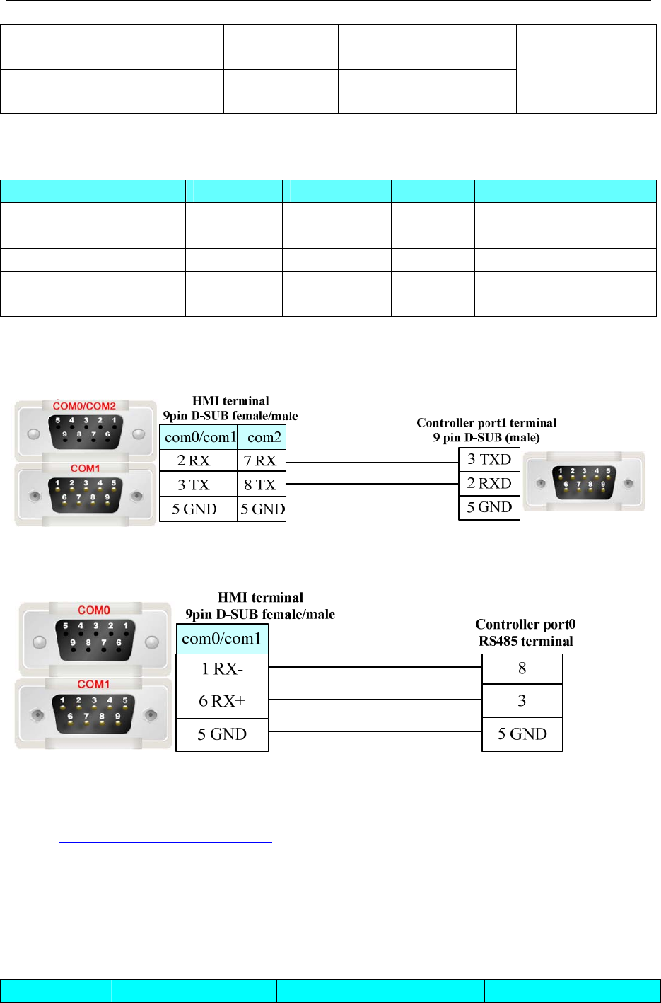
4 Communication settings and guide of HMI connecting with controller
- 122 -
Analog outputs ------ QW0 D
Internal register ------ MW0-8190 DDDD
Internal register(double word) ------ MD0-8188 DDDD
even number;
IW,QW address
range to 30 by
adding a module
Note: I,IW register read only
LK
Device Bit Address Word Address Format Notes
Outputs Relay 0X 1-65535 ------ DDDDD
Inputs Relay 1X 1-65535 ------ DDDDD
Analog inputs ------ 3X 1-65535 DDDDD
Data Register ------ 4X 1-65335 DDDDD
Data Register(DWord) ------ 5X 1-65535 DDDDD
◎Cable Diagram
Hollysys LM RS232 communication cable
Hollysys LM RS485 communication cable
Ethernet Cable
Cross-connection or crossover network cable can be used as communication cable via the hub
Refer to 3.3 Download by Network Ethernet for method of making connection cable.
4.29 HuaDA HD-JZ06
◎Serial Communication
Series CPU Link Module Driver
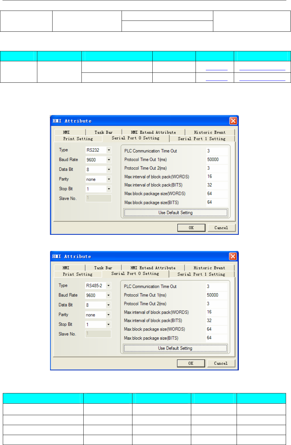
4 Communication settings and guide of HMI connecting with controller
- 123 -
RS232 on the CPU unit
HD HD-JZ06 RS485 on the CPU unit
HuaDA HD-JZ06\ HuaDA
HD SLAVE
◎System configuration
Series CPU Link Module COMM Type Parameter Cable
RS232 on the CPU unit RS232 Setting Your owner cable
HD HD-JZ06
RS485 on the CPU unit RS485 Setting Your owner cable
◎Communication Setting
RS232 communication
RS485 communication
◎Supported Device
Device Bit Address Word Address Format Notes
HMI Internal Relay LB 0-4095 ------ DDDD
MCU Register VB 0-4095 ------ DDDD
HMI Internal register ------ LW 0-4094 DDDD
MCU Register ------ VW 0-4094 DDDD
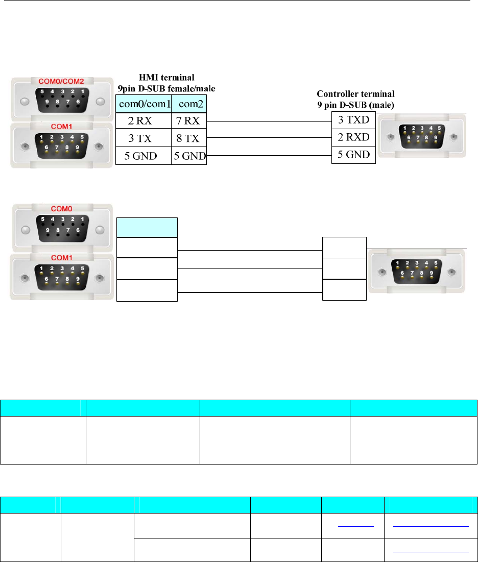
4 Communication settings and guide of HMI connecting with controller
- 124 -
◎Cable Diagram
RS232 Port
RS485 Port
HMI terminal
9pin D-SUB female/male
1 RX-
6 RX+
5 GND
com0/com1 Controller terminal
9 pin D-SUB (male)
7 B-
6 A+
5 GND
4.30 IDEC Corporation
◎Serial Communication
Series CPU Link Module Driver
MICRO SMART
FC4A-C10R2
FC5A-C24R2
FT1A-H48SA
RS232 on the CPU unit IDEC MicroSmart
◎System configuration
Series CPU Link Module COMM Type Parameter Cable
RS232 on the CPU unit RS232 Setting Your owner cableMICRO
SMART
FC4A-C10R2
FC5A-C24R2
FT1A-H48SA RS485 on the CPU unit RS485 Setting Your owner cable
◎Communication Setting
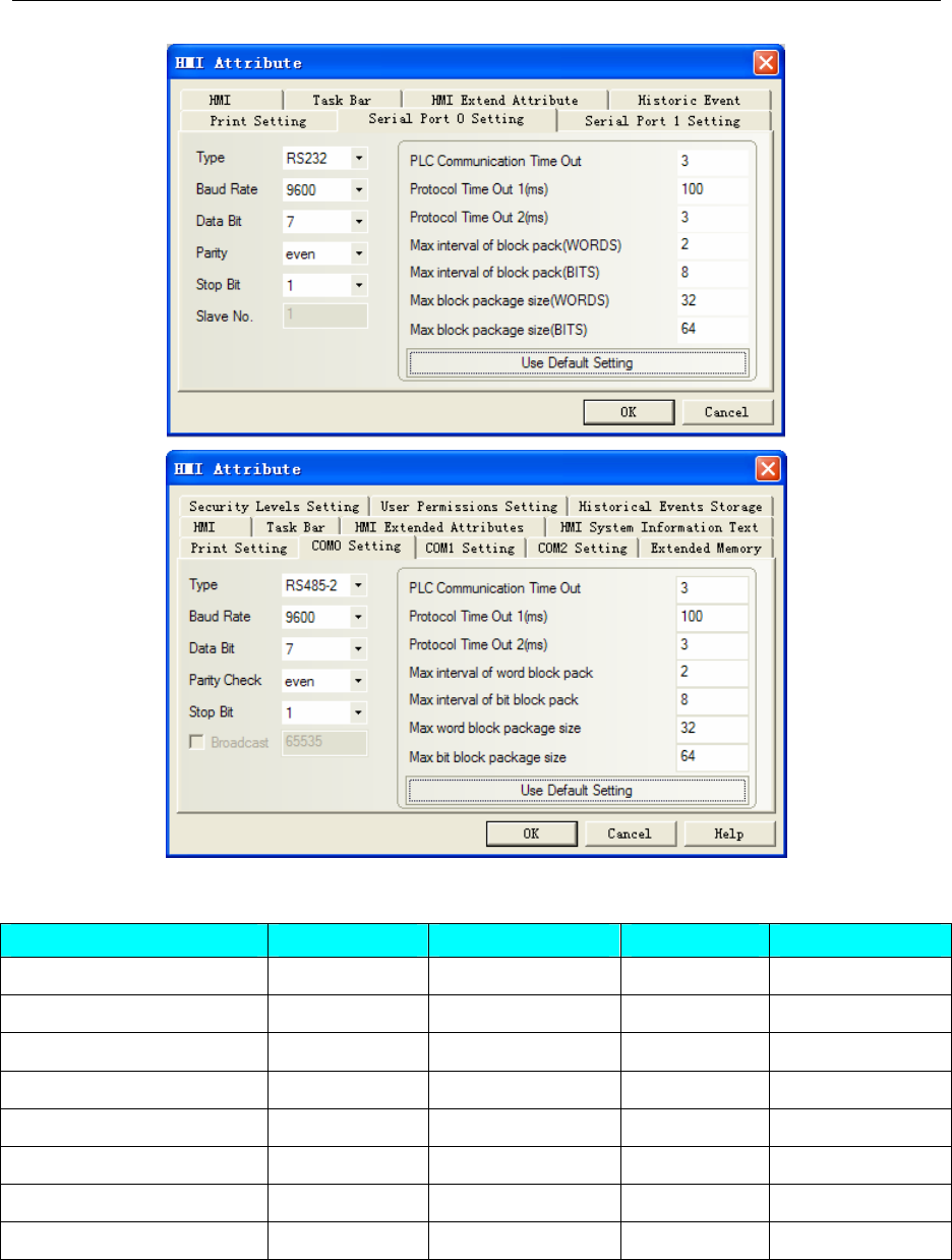
4 Communication settings and guide of HMI connecting with controller
- 125 -
◎Supported Device
Device Bit Address Word Address Format Notes
Internal Relay M0.0-127.7 ------ DDD.O
Output Q0.0-30.7
------ DD.O
Input I0.0-30.7
------ DD.O
Data Register ------ D0-8199 DDDD
Counter(Current Value) ------ C_CV0-99 DD
Counter(Preset Value) ------ C_SV0-99 DD
Timer(Current Value) ------ T_CV0-99 DD
Timer( Preset Value) T_SV0-99 DD
Note: M address: 121 in the plc correspond to 12.1 in the EV5000.
Q\I address: 1277 in the plc corresponds to 127.7 in the EV5000.
◎Cable Diagram
Idec RS232 communication cable
FC4A
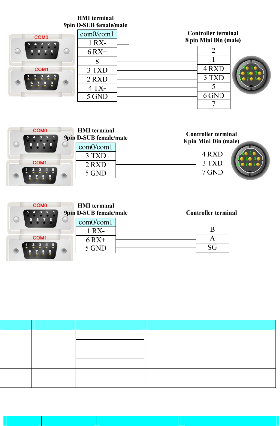
4 Communication settings and guide of HMI connecting with controller
- 126 -
FC5A
RS485
4.31 Inovance Electric Corporation
◎Serial Communication
Series CPU Link Module Driver
CPU direct
COM1
Inovance H2u(don’t support multi station)
CPU direct
H2U H2U-3624MR
COM1 Modbus RTU*1
H3U H3U-1616MT
-XP CPU direct Inovance H3u (don’t support multi station)
NOTE: *1 Support multi-station
◎Ethernet Communication
Series CPU Link Module Driver
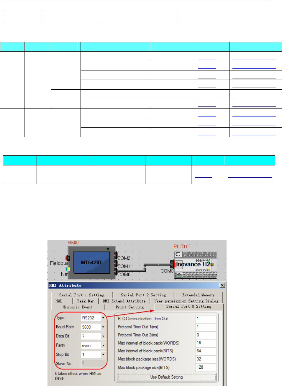
4 Communication settings and guide of HMI connecting with controller
- 127 -
Inovance H3U-1616MT-XP Ethernet interface on CPU Inovance H3u Ethernet(TCP Slave)
◎Serial System configuration
Series CPU Driver Link Module COMM Type Parameter Cable
RS232 on the CPU unit RS232 Setting Your owner cable
RS422 on the CPU unit RS485-4 Setting Your owner cable
RS485 on the CPU unit RS485-2 Setting Your owner cable
Inovance
H2u
RS485 on the com1 RS485-2 Setting Your owner cable
RS485 on the CPU unit RS485-2 Setting Your owner cable
H2U 3624M
R
Modbus
RTU RS485 on the com1 RS485-2 Setting Your owner cable
RS232 on the CPU unit RS232 Setting Your owner cable
RS422 on the CPU unit RS485-4 Setting Your owner cable
H3U 1616MT-XP
RS485 on the com1 RS485-2 Setting Your owner cable
◎Ethernet System configuration
Series CPU Link Module Connect Type Parameter Cable
Inovance H3U-1616MT-XP
Ethernet interface
on CPU Ethernet Setting Your owner cable
◎Serial Communication Setting
Inovance H2u protocol
HMI Setting
HMI monitor protocol communication: 9600, 7, even, 1; station: 0
RS232
RS422
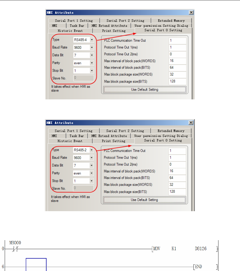
4 Communication settings and guide of HMI connecting with controller
- 128 -
RS485
PLC Setting
You should put off JP0, if communication on the COM0, RS485.
You should set D8126=01h, if communication on the COM1, RS485.
Modbus RTU protocol
HMI Setting
RS485 communication parameter: PLC COM0 port is controlled by D8110; COM1 port is controlled by
D8120.
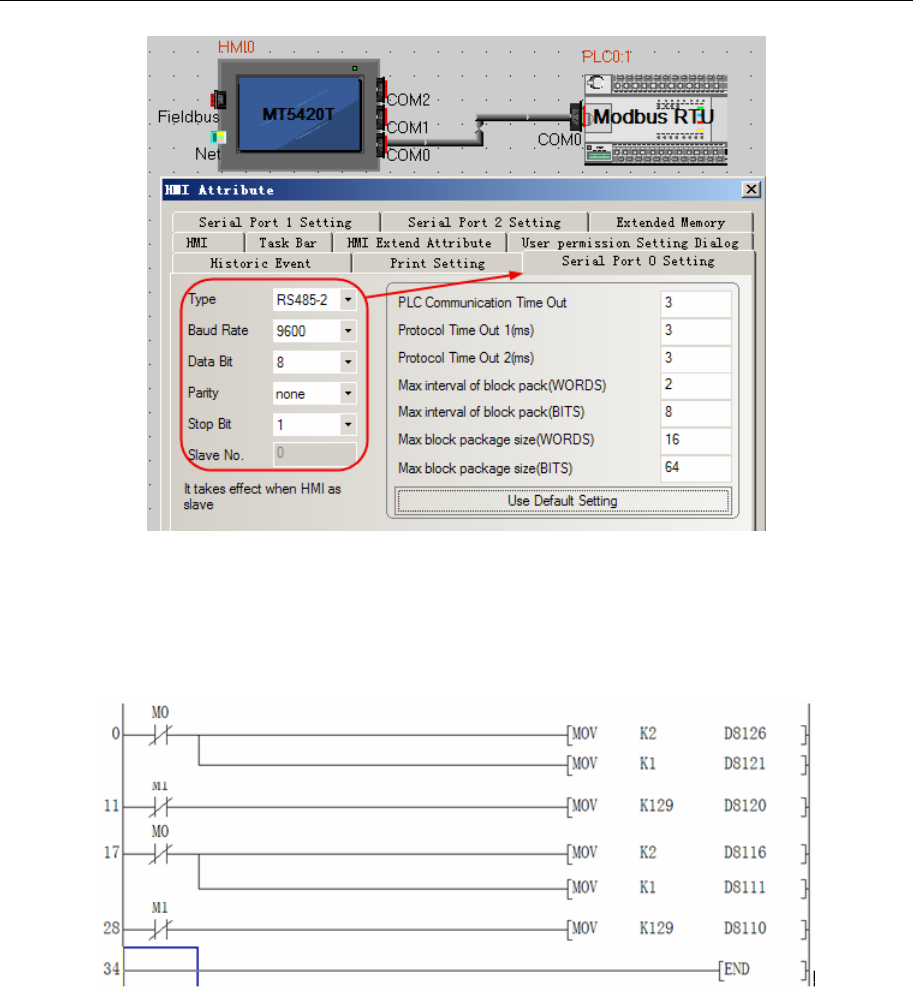
4 Communication settings and guide of HMI connecting with controller
- 129 -
PLC setting
COM0 setting: D8116=02h, modbus-RTU slave protocol; D8111=1, station: 1; D8110=81h,
communication parameter: 9600, 8, none, 1.
COM1 setting: D8126=02h, modbus-RTU slave protocol; D8121=1, station: 1; D8120=81h,
communication parameter: 9600, 8, none, 1.
Inovance H3u protocol
HMI Setting
Default parameter:9600bps,7,even,1;station NO.:0
RS232
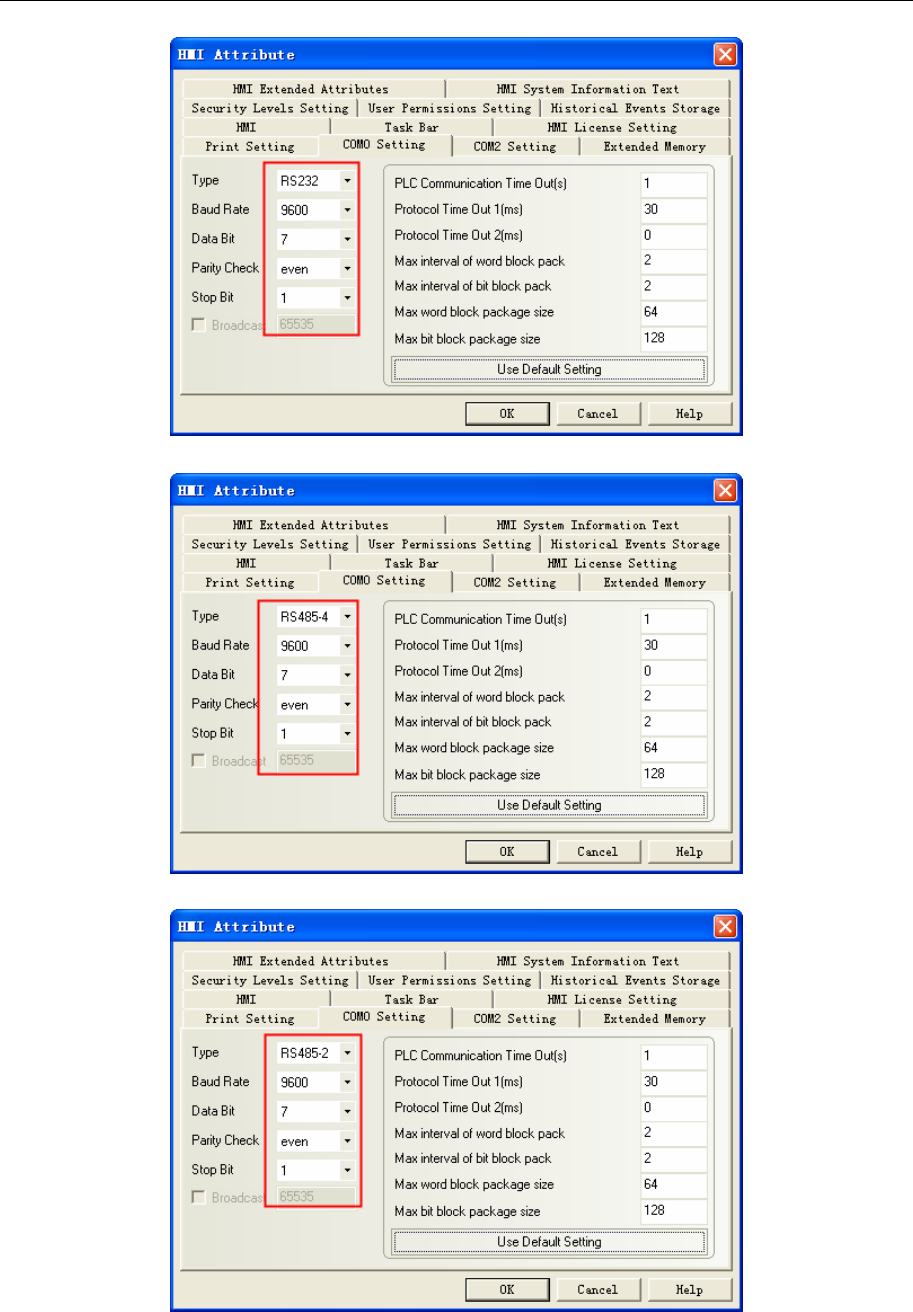
4 Communication settings and guide of HMI connecting with controller
- 130 -
RS422
RS485-2
PLC Setting
PLC COM0
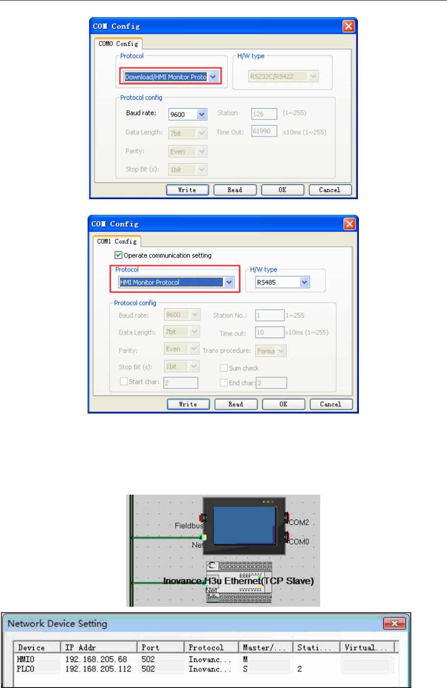
4 Communication settings and guide of HMI connecting with controller
- 131 -
PLC COM1
Note:COM1 parameter only support 9600bps;
◎Ethernet Communication Setting
HMI Setting
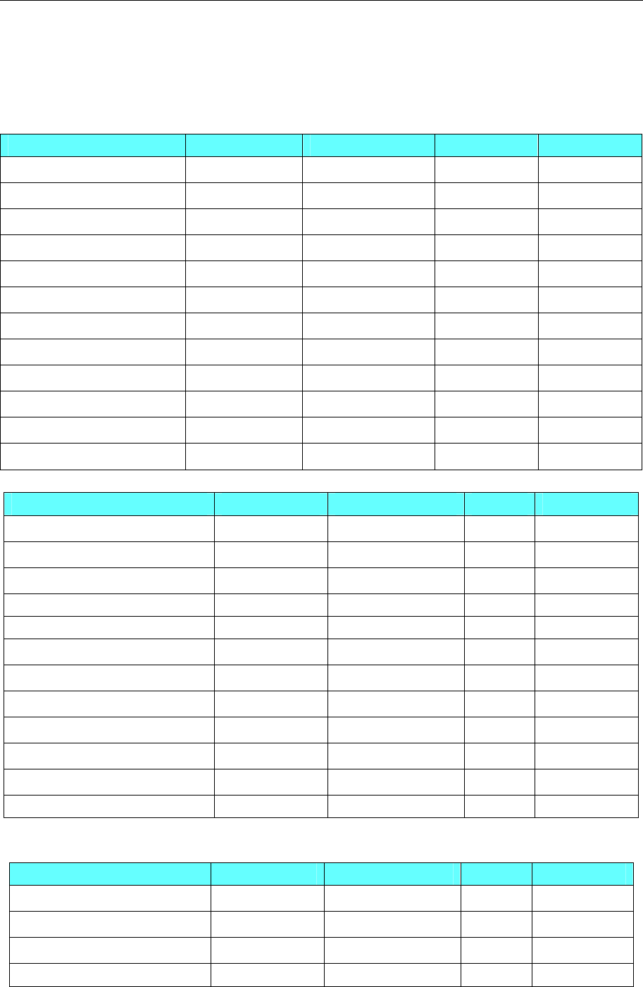
4 Communication settings and guide of HMI connecting with controller
- 132 -
PLC Setting
Set a right IP address.
◎ Supported Device
Inovance H2u
Device Bit Address Word Address Format Notes
Input Relay X 000-177 ------ OOO
Output Relay Y 000-177 ------ OOO
Auxiliary Relay M 0000-1535 ------ DDDD
Timer Relay T_bit 000-255 ------ DDD
Counter Relay C_bit 000-255 ------ DDD
Data Register Relay SM 8000-8255 ------ DDDD
Status Relay S 000-999 ------ DDD
Timer ------ T 000-255 DDD
Counter ------ C 000-199 DDD
Data register ------ D 0000-7999 DDDD
Special Data Register ------ SD 8000-8255 DDDD
Counter Memory(DWord) ------ C_dword 200-255 DDD
Inovance H3u Ethernet(TCP Slave)
Device Bit Address Word Address Format Notes
Input Relay X0-377 ------ OOO
Output Relay Y0-377 ------ OOO
Auxiliary Relay M0-8511 ------ DDDD
Data Register Relay SM0-1023 ------ DDD
Status Relay S 0-4095 ------ DDDD
Timer Relay T 0-511 DDD
Counter Relay C 0-255 DDD
Timer ------ T0-511 DDD
Counter ------ C0-199 DDD
Data register ------ D0-8511 DDDD
Special Data Register ------ SD0-1023 DDDD
R Register ------ R 0-32767 DDDDD
Inovance H3u
Device Bit Address Word Address Format Notes
Input Relay X 0-377 ------ OOO
Output Relay Y 0-377 ------ OOO
Auxiliary Relay M 0-8511 ------ DDDD
Data Register Relay SM 0-1023 ------ DDDD
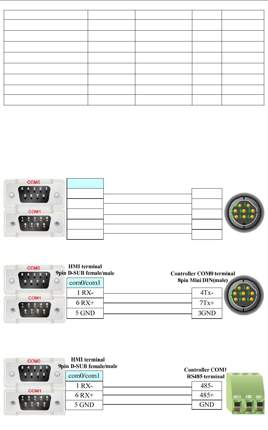
4 Communication settings and guide of HMI connecting with controller
- 133 -
Status Relay S 0-4095 ------ DDDD
Timer Relay T_bit 0-511 DDD
Counter Relay C_bit 0-255 DDD
Timer ------ T 0-511 DDD
Counter ------ C 0-199 DDD
Data register C_dword 200-255 DDD
Special Data Register ------ D 0-8511 DDDD
R Register ------ SD 0-1023 DDDD
Input Relay ------ R 0-32767 DDDDD
◎Cable Diagram
COM0 port communication cable
RS232
Please uses the programming cable: SC-09
RS422
com0/com1
HMI terminal
9pin D-SUB female/male
1 RX-
6 RX+
5 GND
4Tx-
7Tx+
3GND
1Rx-
2Rx+
4 TX-
9 TX+
Controller COM0 terminal
8pin Mini DIN(male)
RS485
NOTE: Put off JP0 by RS485.
COM1 port communication cable
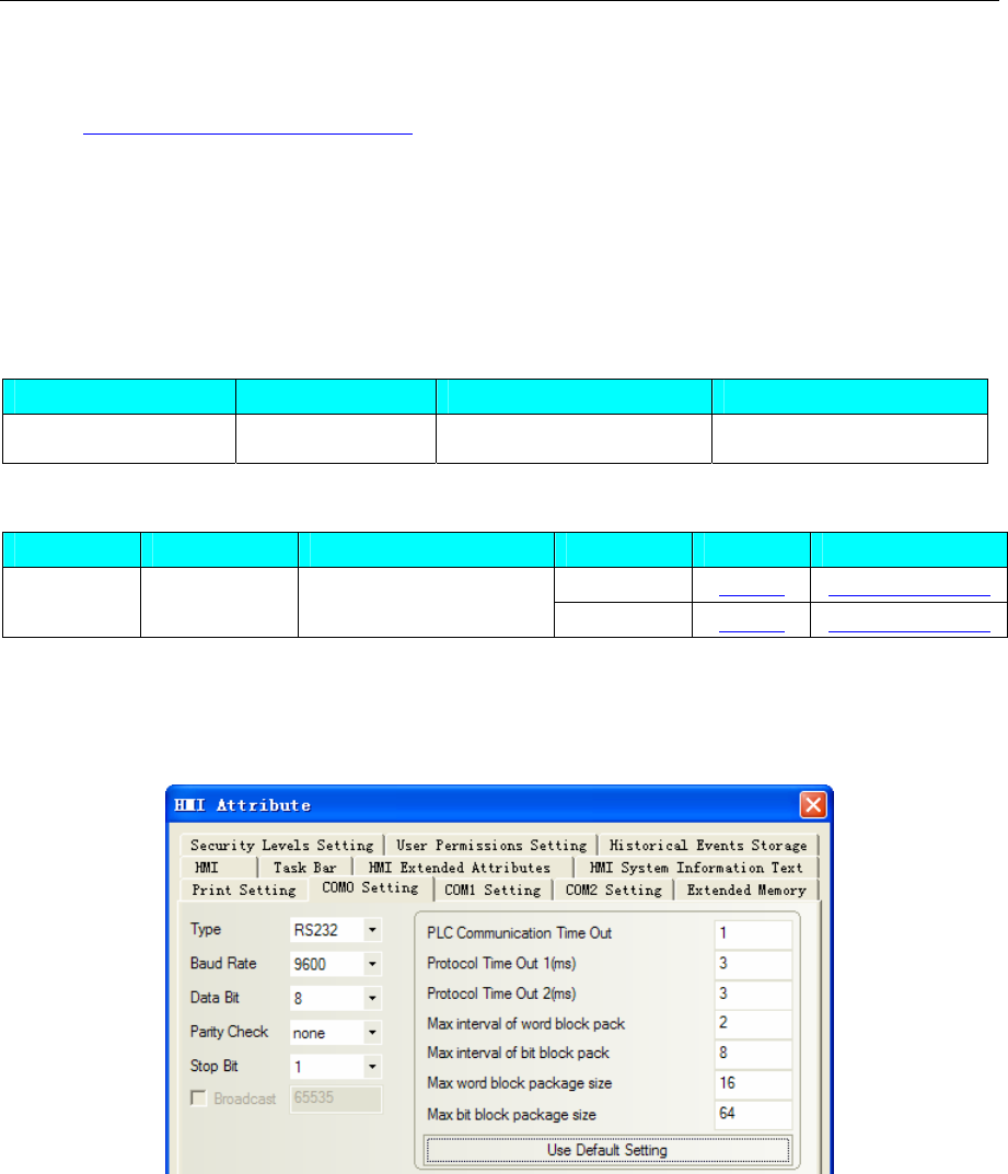
4 Communication settings and guide of HMI connecting with controller
- 134 -
Ethernet communication protocol cable
Cross-connection or crossover network cable can be used as communication cable via the hub
Refer to 3.3 Download by Network Ethernet for method of making connection cable.
4.32 Invt
◎Serial Communication
Series CPU Link Module Driver
INVT IVC1 RS232 on the CPU unit Invt IVC1
◎System configuration
Series CPU Link Module COM Type Parameter Cable
RS232 Setting Your owner cable
INVT IVC1 RS232 on the CPU unit RS485 Setting Your owner cable
◎Communication Setting
HMI Setting
RS232 default communication: 9600, 8, none, 1; station number: 1
RS485-2 default communication: 9600, 8, none, 1; station number: 1
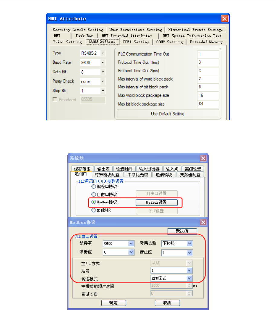
4 Communication settings and guide of HMI connecting with controller
- 135 -
PLC Setting
1. The PLC has two ports: port0 and port1, port1 support RS232 and RS485
2. Port0 configuration as follow:
Port1 configuration as follow:
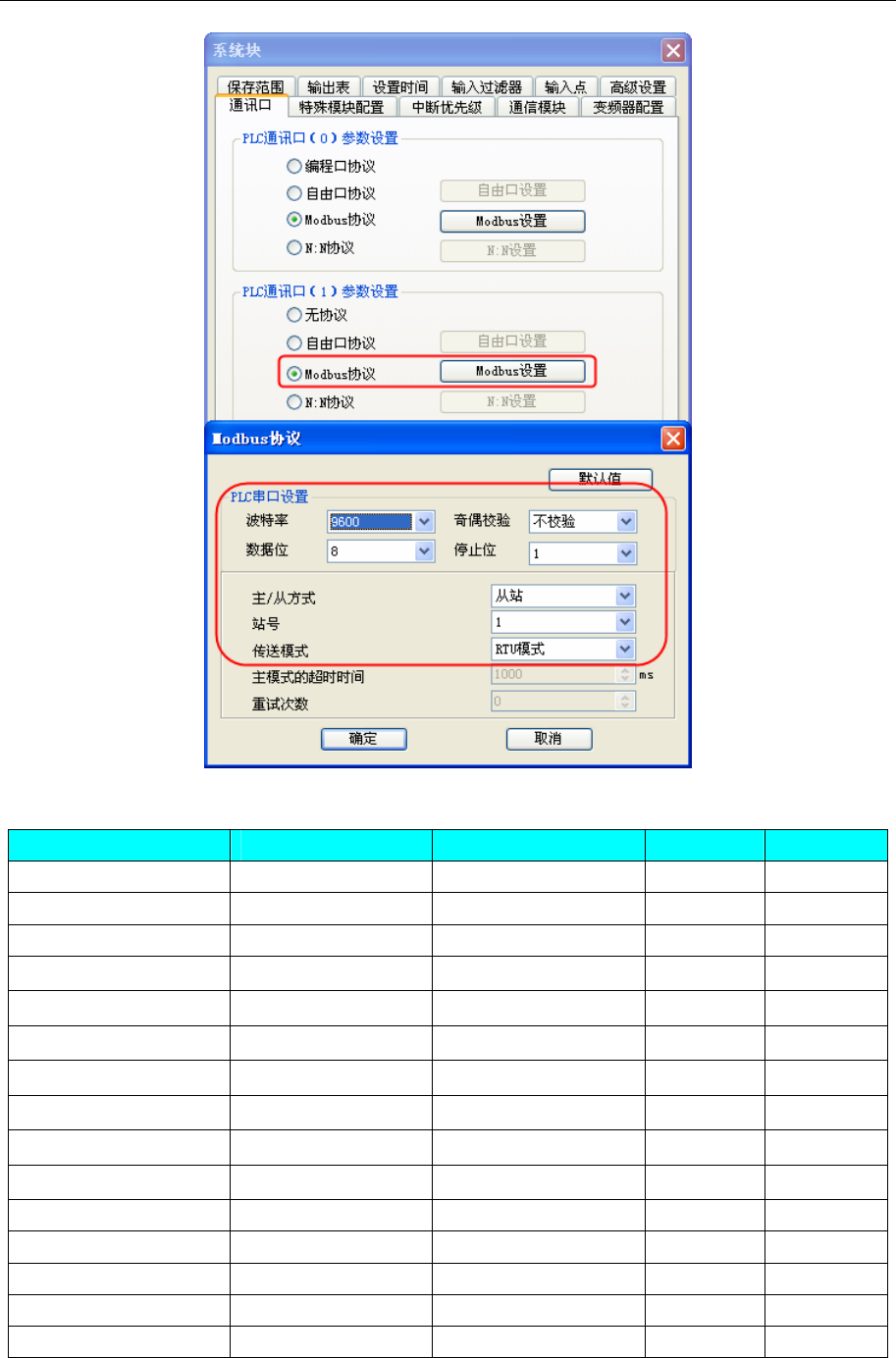
4 Communication settings and guide of HMI connecting with controller
- 136 -
◎Supported Device
Device Bit Address Word Address Format Notes
C_bit C_bit 0-255 ------ DDD
T_bit T_bit 0- 255 ------ DDD
S S 0-1023 ------ DDDD
SM SM 0-255
------ DDD
M M 0-2047
------ DDDD
Y Y 0-177
------ OOO
X X 0-177
------ OOO
SD_double ------
SD_double 0-127 DDD
D_double ------
D_double 0-7999 DDD
C_double ------
C_double 200-255 DDD
C_word ------ C_word 0-199 DDD
T_word ------ T_word 0-255 DDD
Z ------ Z 0-15 DD
SD ------ SD 0-255 DDD
D ------ D 0-7999 DDDD
◎Cable Diagram
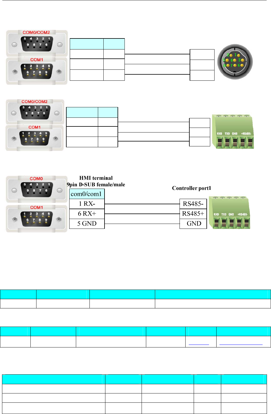
4 Communication settings and guide of HMI connecting with controller
- 137 -
RS232 communication cable
HMI terminal
9pin D-SUB female/male Controller port0
8 pin Mini Din (male)
5 TXD
4 RXD
3 GND
com2
3 TX
2 RX
5 GND
8 TX
7 RX
5 GND
com0/com1
HMI terminal
9pin D-SUB female/male
com2
3 TX
2 RX
5 GND
8 TX
7 RX
5 GND
com0/com1
TXD
RXD
GND
Controller port1
RS485-2 communication cable
4.33 KDN Corporation
◎Serial Communication
Series CPU Link Module Driver
KDN-K3 KDN-K304-14AR RS232 on the CPU unit KDN-K3
◎System configuration
Series CPU Link Module COMM Type Parameter Cable
KDN-K3 K304-14AR RS232 on the CPU unit RS232 Setting Your owner cable
◎Supported Device
KDN-K3
Device Bit Address Word Address Format Notes
Discrete inputs and image Relay I0.0-7.7 ------ D.O
Discrete outputs and image Relay Q0.0-7.7 ------ D.O
Internal memory Relay M0.0-31.7 ------ DD.O
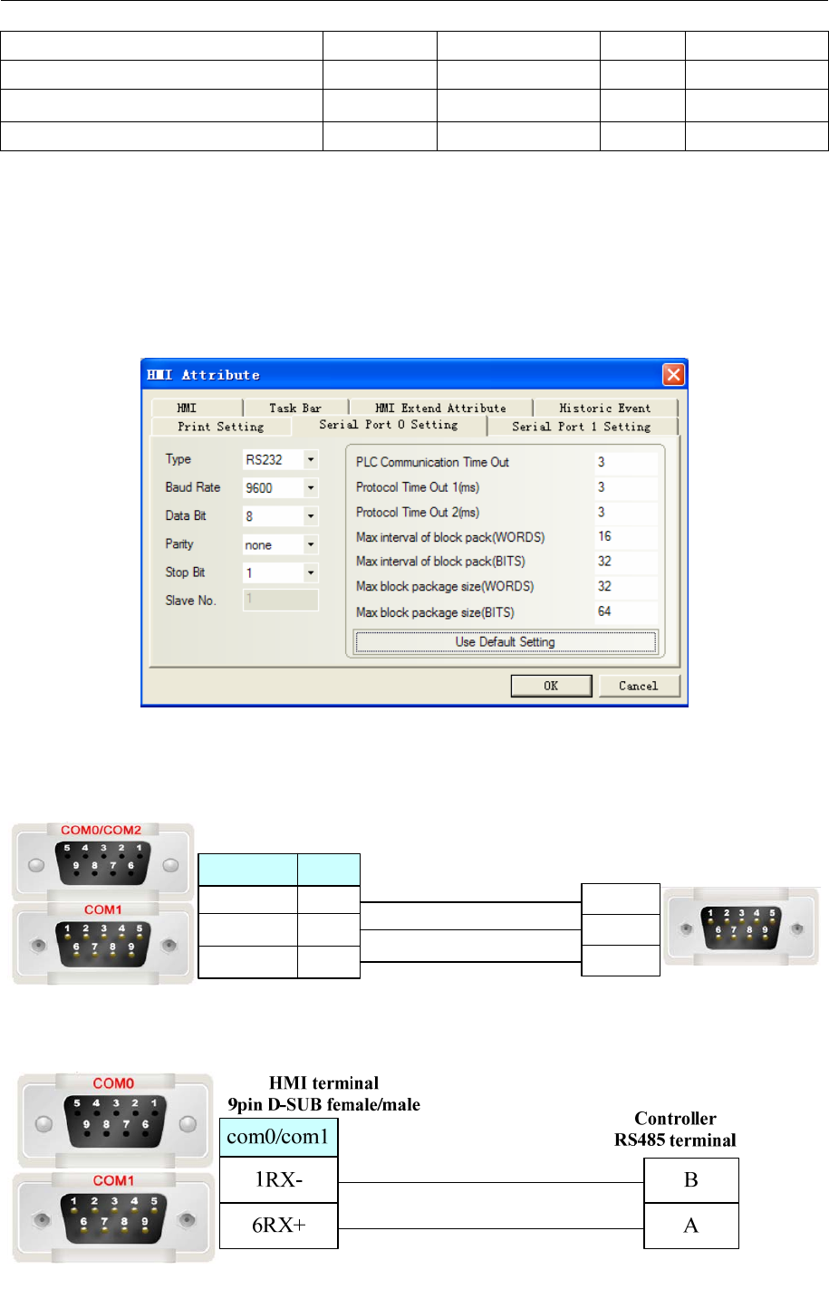
4 Communication settings and guide of HMI connecting with controller
- 138 -
Analog inputs ------ AIW0-30 DD
Analog outputs ------ AQW0-30 DD
Internal register ------ VW0-4094 DDDD
Internal register(double word) ------ VD0-4092 DDDD
NOTE:
1) AIW, AQW, VW, VD address must be an even number.
2) AIW and I device read only.
3) The single floating VR of PLC corresponds with the VD of the Ev5000 (choose single floating).
◎Communication Setting
KDN-K3 RS232 communication
◎Cable Diagram
RS232 communication cable
Controller terminal
9 pin D-SUB (male)
com2
3 TX
2 RX
5 GND
8 TX
7 RX
5 GND
com0/com1
HMI terminal
9pin D-SUB female/male
3 TXD
2 RXD
5 GND
RS485 communication cable
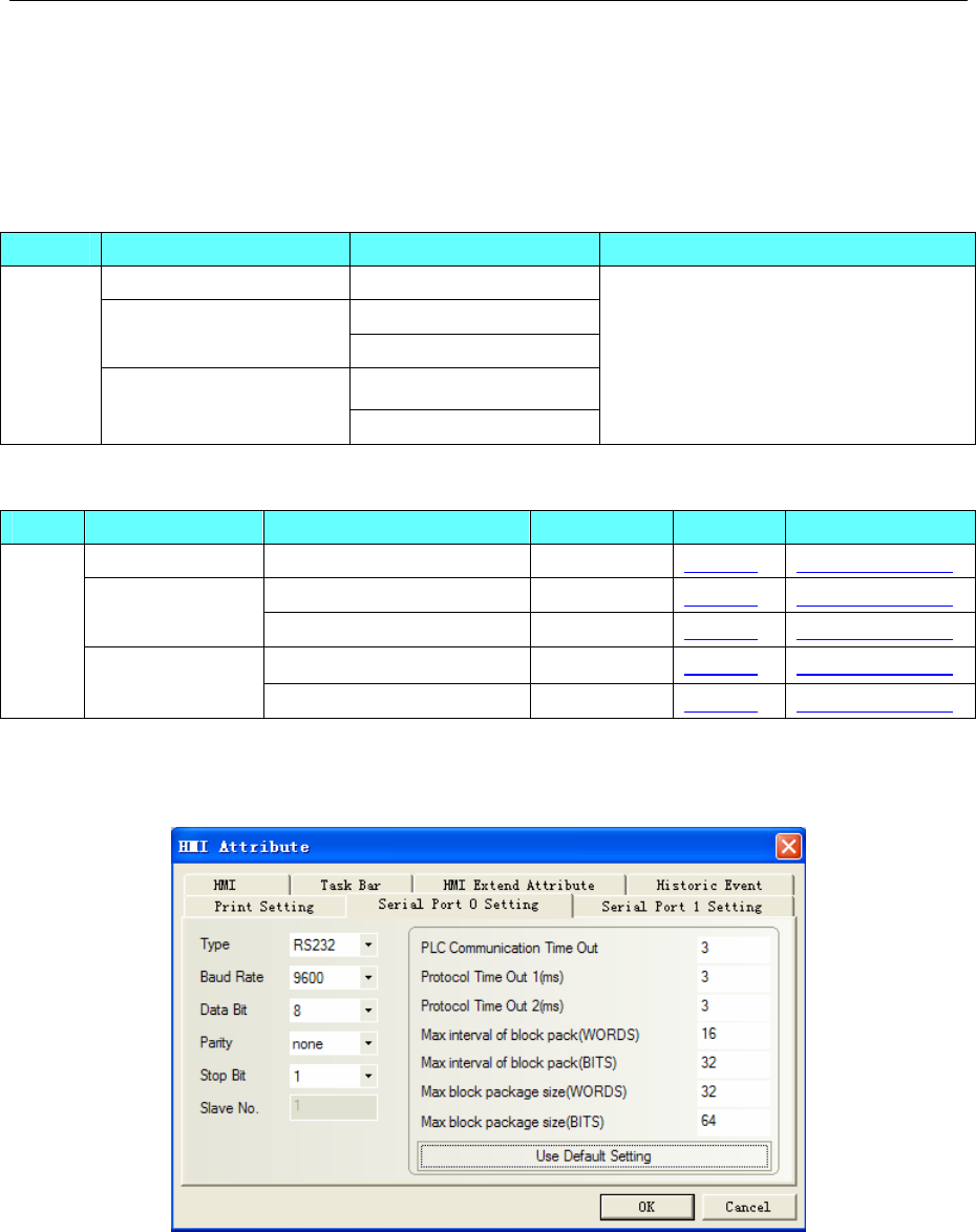
4 Communication settings and guide of HMI connecting with controller
- 139 -
4.34 Kinco Corporation
◎Serial Communication
Series CPU Link Module Driver
K2 Series RS485 on the CPU port
RS232 on the CPU unit
K3 Series RS485 on the CPU port
RS232 on the CPU unit
Kinco
K5 Series
RS485 on the CPU port
Kinco PLC Series
◎System configuration
Series CPU Link Module COMM Type Parameter Cable
K2 Series RS485 on the port RS485 Setting Your owner cable
RS232 on the CPU unit RS232 Setting Your owner cable K3 Series
RS485 on the port RS485 Setting Your owner cable
RS232 on the CPU unit RS232 Setting Your owner cable
Kinco
K5 Series
RS485 on the port RS485 Setting Your owner cable
◎Communication Setting
RS232 communication
RS485 communication
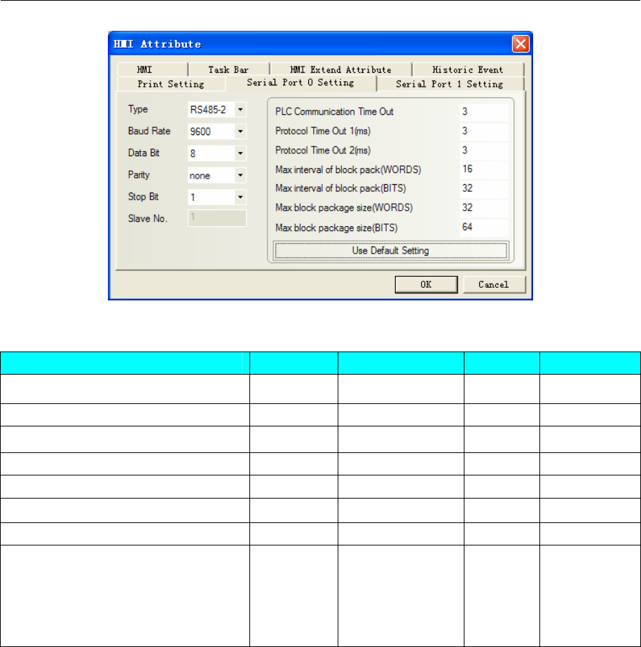
4 Communication settings and guide of HMI connecting with controller
- 140 -
◎Supported Device
Device Bit Address Word Address Format Notes
Discrete inputs and image Relay I0.0-31.7 ------ D.O
Discrete outputs and image Relay Q0.0-31.7 ------ D.O
Internal memory Relay M0.0-31.7 ------ DD.O
Analog inputs ------ AIW0-62 DD
Analog outputs ------ AQW0-62 DD
Internal register ------ VW0-4094 DDDD
Internal register(double word) ------ VD0-4092 DDDD
ERR --------
ERR 0~127*1
ERR 128~255*2
ERR 256~383*3
ERR 384~511*4
DDDDD
NOTE:
1) AIW, AQW, VW, VD address must be an even number.
2) AIW and I device read only.
3) The single floating VR of PLC corresponds with the VD of the Ev5000 (choose single floating).
*1 ERR0~127 indicate the recent 128 common errors. ERR0 is the latest error, ERR1 is the later
error, and so on.
*2 ERR128~255 indicate the recent 128 serious errors. ERR128 is the latest error, ERR129 is the
later error, and so on.
*3 ERR256~383 indicate the last 128 common errors the last time PLC is powered on. ERR256 is
the last error, ERR257 is the previous error, and so on.
*4 ERR384~511 indicate the last 128 serious errors the last time PLC is powered on. ERR 384 is the
last error, ERR385 is the previous error, and so on.
◎Cable Diagram
RS232 communication cable
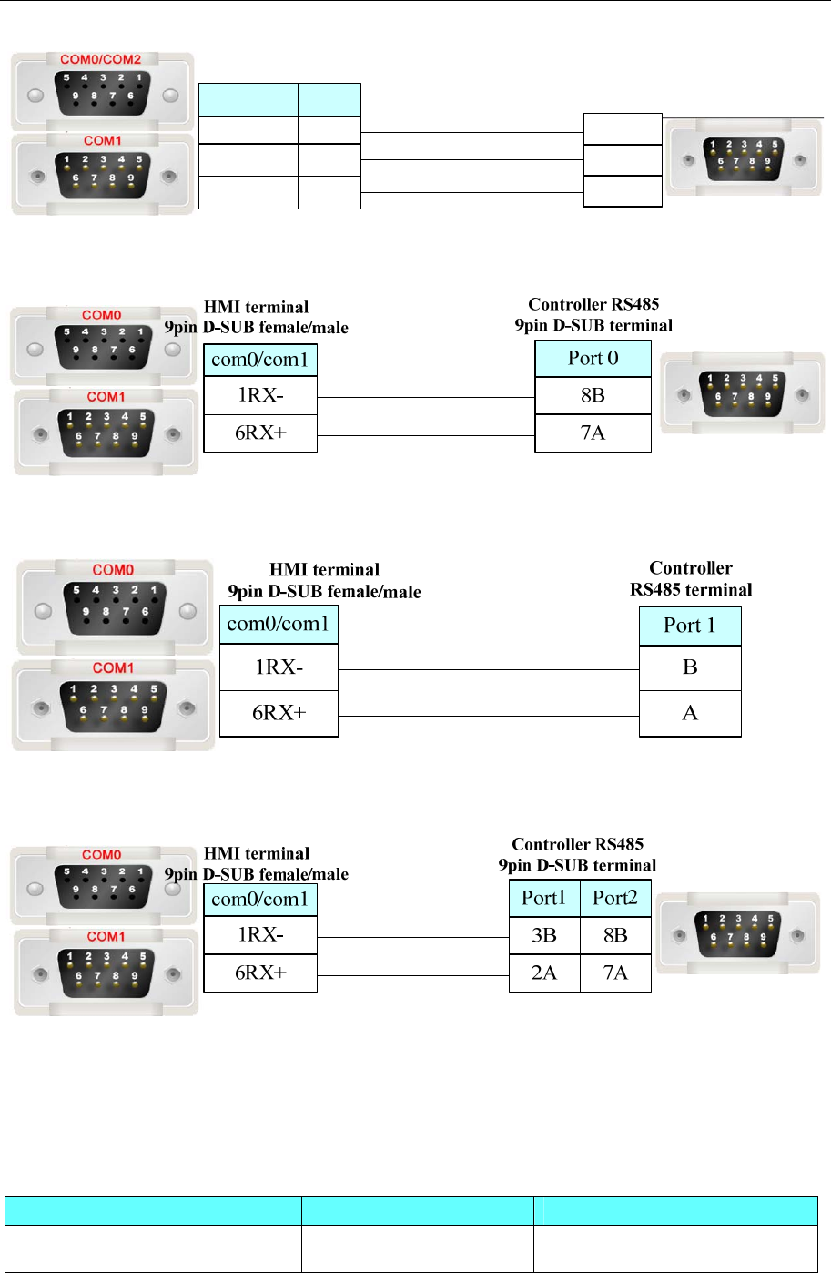
4 Communication settings and guide of HMI connecting with controller
- 141 -
Controller terminal
9 pin D-SUB (male)
com2
3 TX
2 RX
5 GND
8 TX
7 RX
5 GND
com0/com1
HMI terminal
9pin D-SUB female/male
3 TXD
2 RXD
5 GND
CPU304/CPU304EX/CPU306
RS485 communication cable
CPU306EX /308/504
RS485 communication cable
CPU506EA
RS485 communication cable
4.35 Kinco Inverter
◎Serial Communication
Series CPU Link Module Driver
FV100 FV100-2S-00156 RS485 on the CPU unit Kinco Inverter
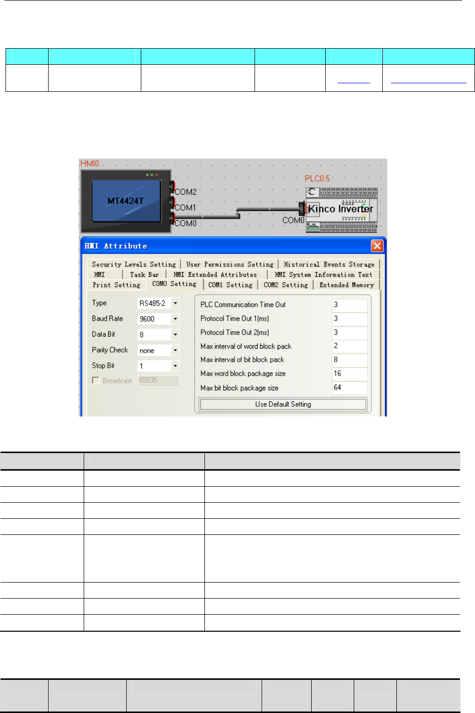
4 Communication settings and guide of HMI connecting with controller
- 142 -
◎ Serial Communication Parameters and Cables Production
Series CPU Link Module COMM Type Parameter Cable
FV100 FV100-2S-00156 RS485 on the CPU unit RS485-2 Setting Your owner cable
◎Serial Communication Parameters
HMI Setting
Default communication:9600bps,8,even,1;station:5
PLC Setting
A. Inverter operation panel menu
Key Name Function
MENU Programming / Exit key Enter or exit the programming status
ENTER Function / Data key Enter the submenu or confirm data
∧ Increase key Incremental data or function code
∨ Decrease key Decreasing the data or function code
SHIFT Shift key In edit mode, you can choose to modify the bit setting
data; in other states, you can switch the display status
parameters
M Multifunction key The key functions are set by b4.01
RUN Run key In the operation panel mode, press this key to run
STOP/RST Stop / Reset key Shutdown or fault reset
B.Inverter function code parameters
b3:Communication parameters
Function
Code
Name Range Minimum
unit
Factory
setting
Change machine
setting range
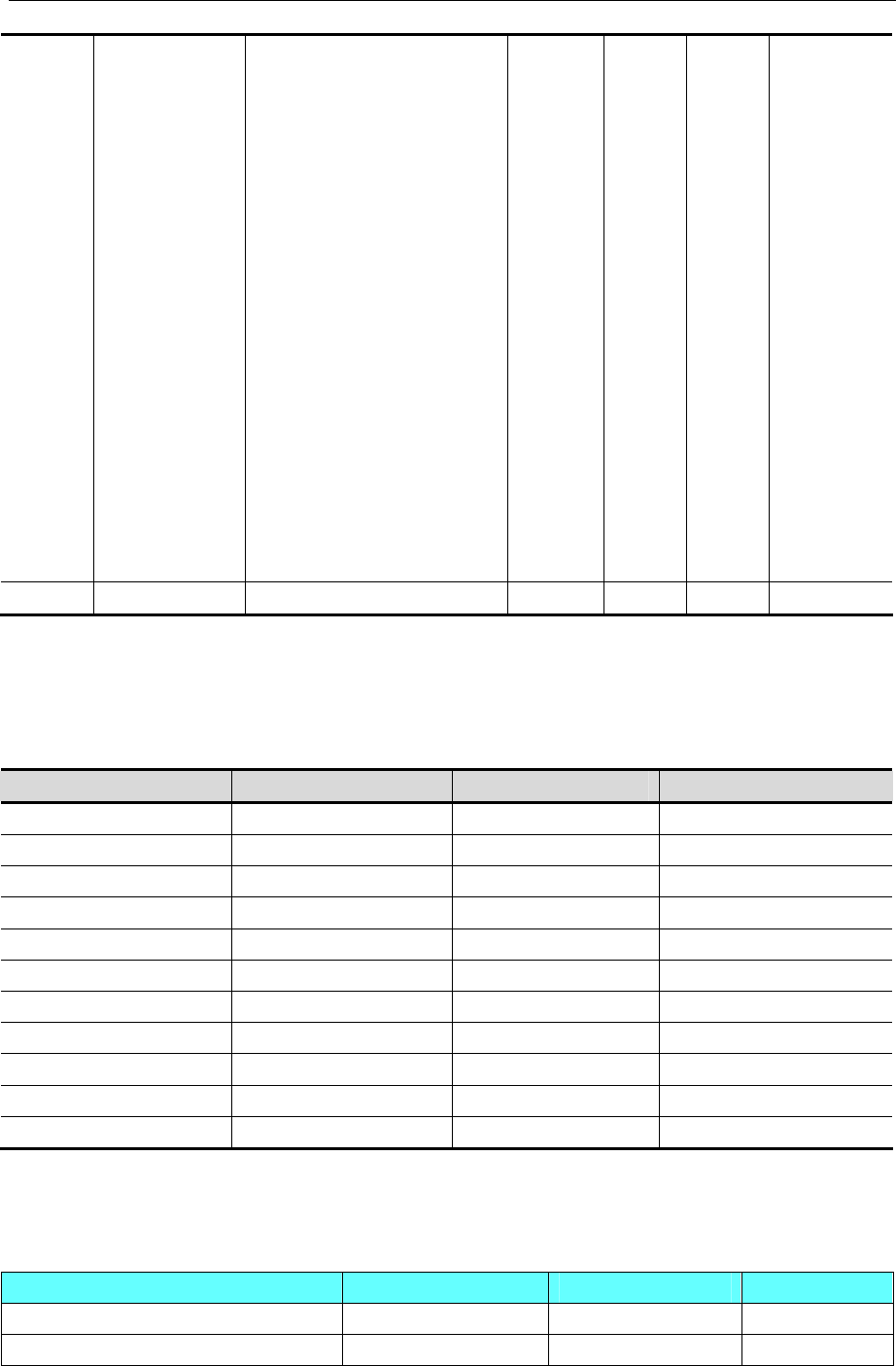
4 Communication settings and guide of HMI connecting with controller
- 143 -
b3.00 Communication
Configuration
LED ones:Baud Rate Selection
0:4800BPS
1:9600BPS
2:19200BPS
3:38400BPS
4:115200BPS
5:125000BPS
LED tens:Data Format
0:1-8-2-N,RTU
1:1-8-1-E,RTU
2:1-8-1-O,RTU
3:1-7-2-N,ASCII
4:1-7-1-E,ASCII
5:1-7-1-O,ASCII
LED hundreds:Connection mode
0:Direct Cable Connection
(232/485)
1:MODEM(232)
1 001 X 0~155H
b3.01 Machine Address
0~127,0:Broadcast address 1 5 X 0~127
X:Operation can not be changed
C.Function code parameters of the inverter, control parameters and status parameters are mapped to
Modbus read and write registers; inverter control parameters and status parameters are virtual inverter
function code group; Function code group and its high byte register address map
correspondence shown in the following table
Inverter parameter group Mapped address high byte Inverter parameter group Mapped address high byte
A0 0x00 B2 0x0C
A1 0x01 B3 0x0D
A2 0x02 B4 0x0E
A3 0x03 C0 0x14
A4 0x04 C1 0x15
A5 0x05 D0 0x1E
A6 0x06 D1 0x1F
A7 0x07 D2 0x20
A8 0x08 U0 0x5A
B0 0x0A Control parameters group 0x32
B1 0x0B Status parameter group 0x33
Note:With function code parameter A3.02 example, the register address A3.02 to 0x0302, converted to
decimal number 770, so the HMI set the address to 770 + 1 = 771 (decimal)
◎Supported Device
Device Bit Address Word Address Format
Internal system / external output node 0X 1-65535 ------ DDDDD
Internal system / external input node 1X 1-65535 ------ DDDDD
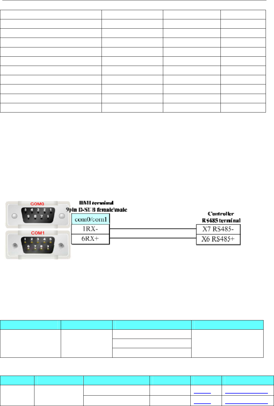
4 Communication settings and guide of HMI connecting with controller
- 144 -
Analog input data node 3X_bit 0.01-65535.15 ------ DDDDD.DD
Data Node 4X_bit 0.01-65535.15 ------ DDDDD.DD
4X single write data node 6X_bit 0.01-65535.15 ------ DDDDD.DD
Analog Input Data Register ------ 3X 1-65535 DDDDD
Data register ------ 4X 1-65535 DDDDD
Data register ------ 5X 1-65535 DDDDD
4X single write register ------ 6X 1-65535 DDDDD
Data register ------ 41X 1-65535 DDDDD
Data register ------ 43X-DINV 1-65535 DDDDD
Data register ------ 4X-DINV 1-65535 DDDDD
Data register ------ 3X-DINV 1-65535 DDDDD
Notes:1.5X :Anti-byte;4X-DINV,3X-DINV: word high and low bit-reversed;
2.41X:Rewrite a single 16-length inverter function code parameter or control parameters,
parameter values after the drive is powered down to save;
3.43X-DINV:Rewrite multiple inverter function code parameter or control parameters, parameter
values after the drive is powered down to save;
◎Cables Production
RS485-2 communication cable
4.36 Kinco EB-MOD2P-01(Kinco Bus Bridge)
◎Serial Communication
Series CPU Link Module Driver
RS232 on the CPU unit
RS485 on the CPU unit
FieldBus Bridge EB-MOD2P-01
RS422 on the CPU unit
Kinco EB-MOD2P-01
Modbus RTU
◎System configuration
Series CPU Link Module COMM Type Parameter Cable
RS232 on the CPU unit RS232 Setting Your owner cable
FieldBus
Bridge
EB-MOD2P-01
RS422 on the CPU unit RS422 Setting Your owner cable
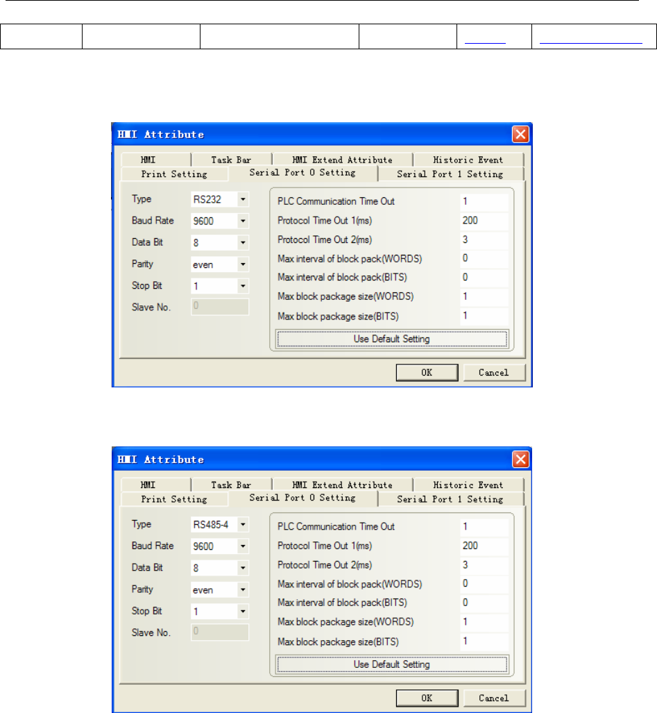
4 Communication settings and guide of HMI connecting with controller
- 145 -
RS485 on the CPU unit RS485 Setting Your owner cable
◎Communication Setting
EB-MOD2P-01 RS232 communication
NOTE: Communication parameter must the same as the controller panel.
EB-MOD2P-01 RS485-4 communication
EB-MOD2P-01 RS485-2 communication
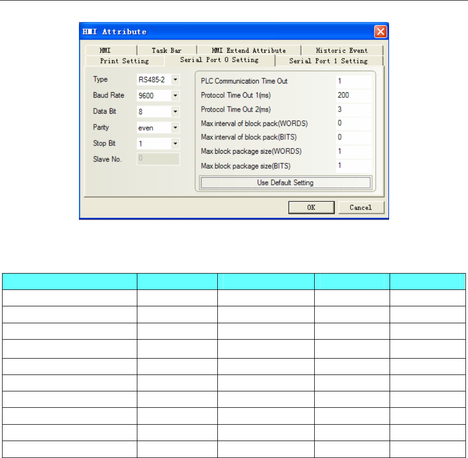
4 Communication settings and guide of HMI connecting with controller
- 146 -
◎Supported Device
EB-MOD2P-01
Device Bit Address Word Address Format Notes
Internal/External Output bit 0X1-60 ------ DDDDD
Internal/External Input bit 1X1-60 ------ DDDDD
Data Register bit 3X_bit1-60 ------ DDDDD
Data Register bit 4X_bit1-60 ------ DDDDD
Simulate Input Register bit ------ 3X1-60 DDDDD
Data Register ------ 4X1-60 DDDDD
Data Register ------ 5X1-60 DDDDD
Data Register ------ 6X1-60 DDDDD
Data Register ------ 3X-DINV 1-60 DDDDD
Data Register ------ 4X-DINV 1-60 DDDDD
NOTE:The correspondence between the device of EV5000 and the s7-300 software, as follows:
4X-DINV------------PID
e.g.:4X-DINV1------------PID256 4X-DINV3------------PID260
3X-DINV------------PQD
e.g.:3X-DINV1------------PQD256 3X-DINV3------------PQD260
4X -------------------PIW
e.g.:4X1 --------------------PIW256 4X2--------------------PIW258
3X--------------------PQW
e.g.:3X1---------------------PQW256 3X2---------------------PQW258
0X--------------------I
e.g.:0X1--------------------I0.0 0X9--------------------I1.0
1X--------------------Q
e.g.:1X1--------------------Q0.0 1X9--------------------Q1.0
4X_BIT -------------------PIW(binary)
e.g.:4X_BIT1.0~~1.15-------------------PIW256(binary)
3X_BIT--------------------PQW(binary)
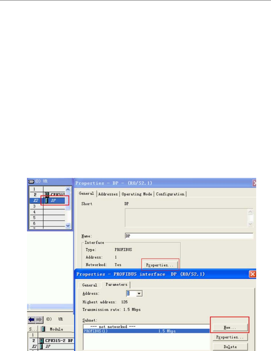
4 Communication settings and guide of HMI connecting with controller
- 147 -
e.g. :3X_BIT1.0~~1.15--------------------PQW256(binary)
PLC software setting
Setup the GSD in the S7-300 software
Procedure :
(1).Close all stations in “HW Config”.
(2).And select “option”-->”setup GSD”.
(3). In the “installation *.GSD file” dialog box, select Source: folders contain *. GSD file, or the
STEP 7 project contain *. GSD file
(4).Select one or more files from *.GSD file list, and then click on "install" button.
Copy the icon (. BMP file) to the relevant path, such as BRIDGE product:Bitmap_Device =
"EVIEW", that copy the "EVIEW" BMP file to the relevant path: c:\siemens\step7\s7data\nsbmp or
c:\siemens\cpbv51\bitmaps
After installation, you can find the appropriate symbol in "PROFIBUS DP\GATWAY".
Project configuration
(1)Use the guide to set up projects in the s7-300 software.
(2)Double click “DP” of "HW Config"->attribute->new
(3)After press “ok”, and then give a connection as follows:
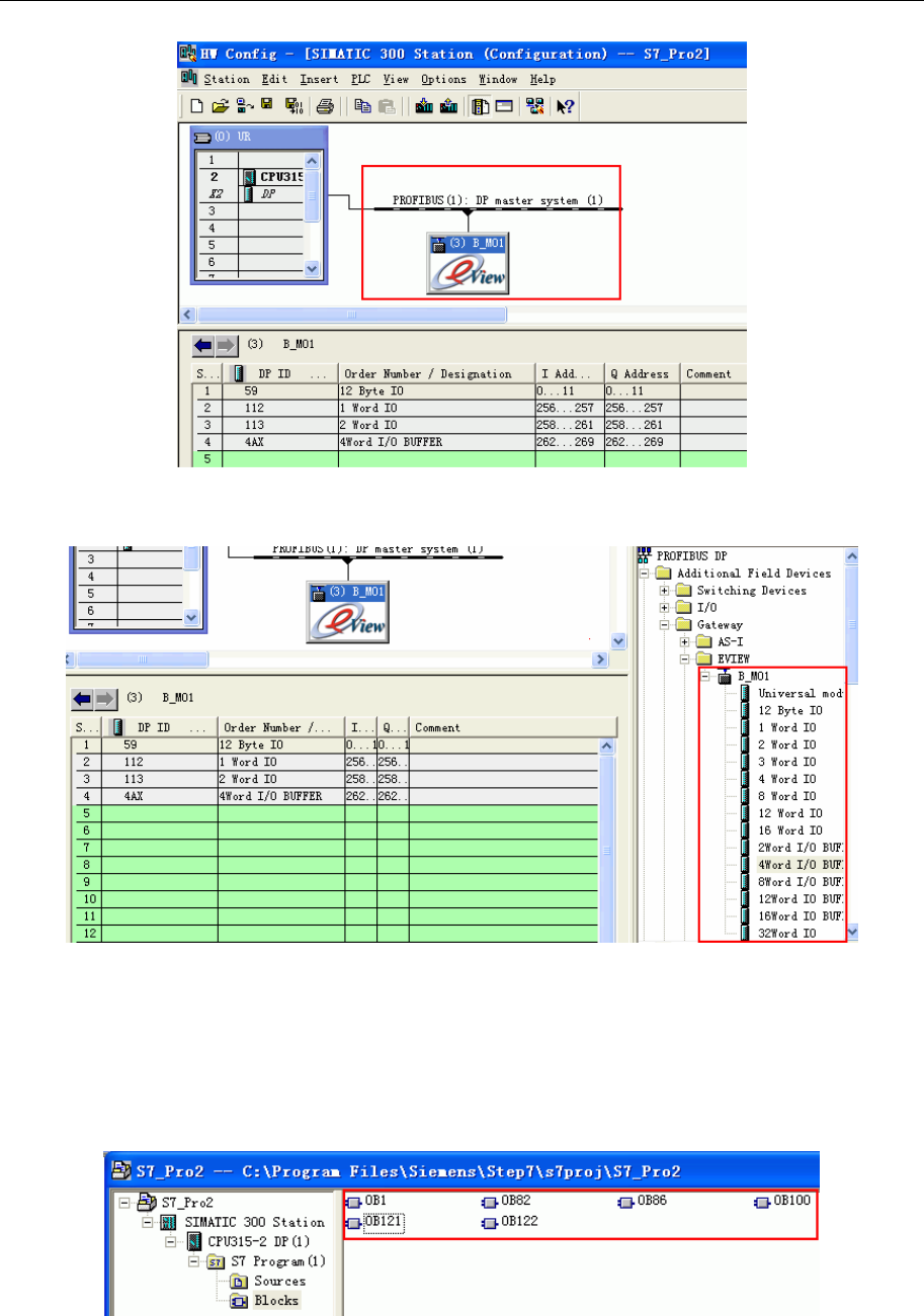
4 Communication settings and guide of HMI connecting with controller
- 148 -
NOTE: the address of DP can’t be the same as MPI’s. Double click the address number to change.
(4)Double click “GATEWAY"->"eview"->"B_MO1"to extend device.
NOTE: for project configuration of BRIDGE, you must configure DI/D0 resource of 12 bytes firstly.
AI/AO is optional.
(5)Must Use OB82,OB86,OB100,OB121,OB122 in the ladder program of the external device, otherwise
you need to manually operate the RUN switch of the external device as “RUN,STOP,RUN” in this order
upon restart the display or PLC. When you use those special OB block, the communication will be
automatically recovered even if you restart the display or PLC.
(6)Save and compile, and download to module, then the light of profibus is on.
(7)After configuration, and then you can program.
Bus Bridge setting:
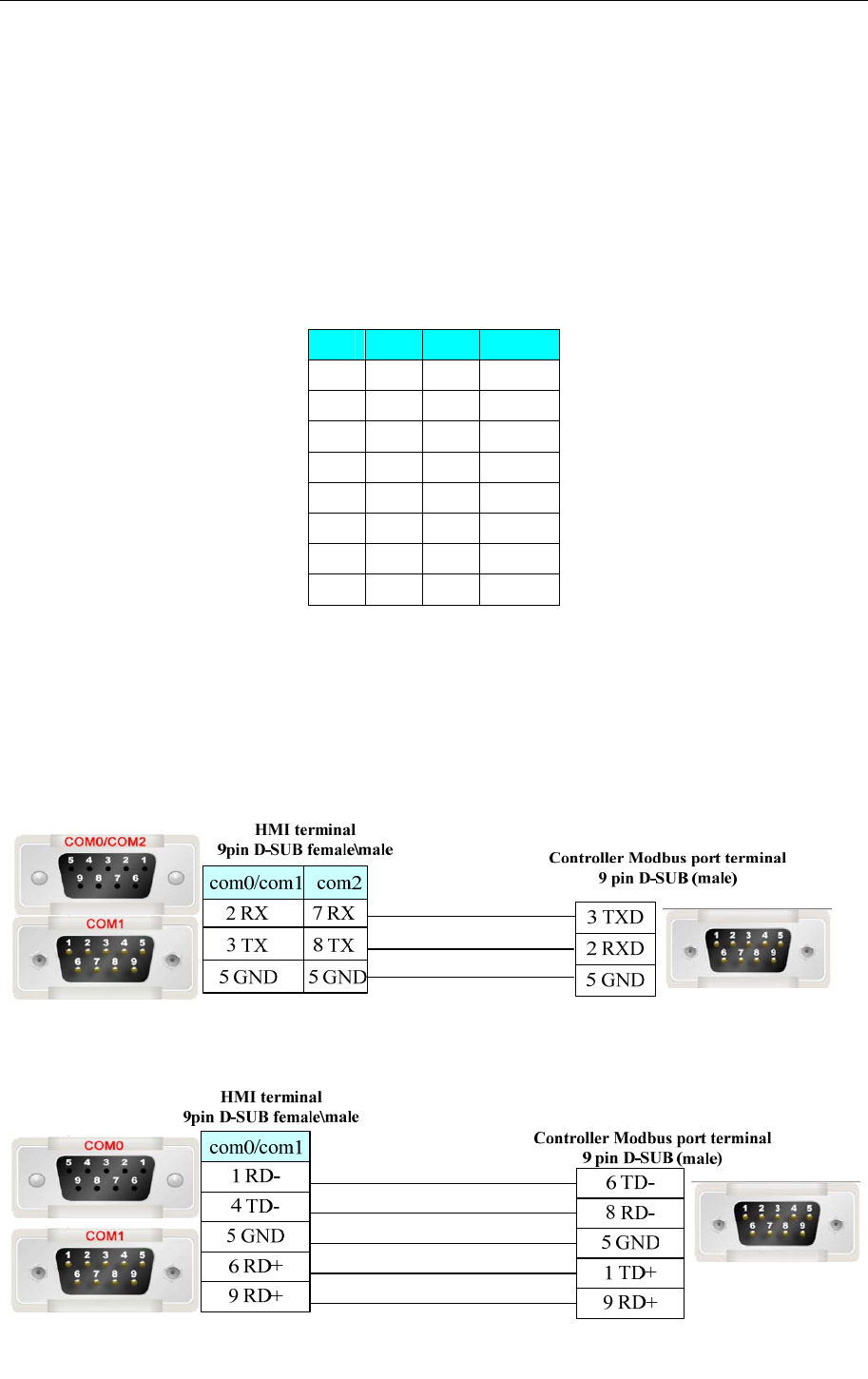
4 Communication settings and guide of HMI connecting with controller
- 149 -
(1) Setting ID of Profibus by switching 8-bit Dip(DIP1 is lowest bit, DIP8 is highest bit),range is from 3
to 125;
ID must be the same as its configuration in Siemens software. As above picture for example, setting is “3”,
that the switch DIP1 and DIP2 on the panel of profibus are set ON, others are OFF.
(2)Profibus support baudrate as follows: 9.6Kbit/s, 19.2Kbit/s, 45.45Kbit/s, 93.75Kbit/s, 187.5Kbit/s,
0.5Mbit/s, 1.5Mbit/s, 3Mbit/s, 6Mbit/, 12Mbit/s,and interface is automatically adaptive.
(3)A cable (purple),connect DP interface of s7-300 and bus bridge of profibus. Two sides have active
terminal resistors; Switch on the s7-300 PLC is off, on the busbridge is on.
(4)Setting baudrate of modbus by switching DIP1-3 of modbus ID port, support 8 kinds of
baudrate .Setting as follows:
1 2 3 Baud
OFF OFF OFF 1200
ON OFF OFF 2400
OFF ON OFF 4800
ON ON OFF 9600
OFF OFF ON 19200
ON OFF ON 38400
OFF ON ON 57600
ON ON ON 115200
(5)Setting station number of modbus by switching DIP4-8 of modbus ID port ,support 1 to 30 kinds of
station number(DIP4 is lowest bit,DIP8 is highest bit, if DIP4 is on and DIP5~8 is off, it means station
number is 00001,that is No. 1 station).
◎Cable Diagram
RS232 communication cable
RS485-4 communication cable
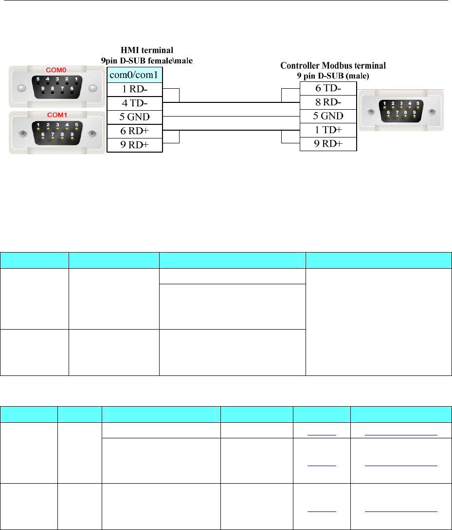
4 Communication settings and guide of HMI connecting with controller
- 150 -
RS485-2 communication cable
4.37 Kinco Servo Series
◎Serial Communication
Series CPU Link Module Driver
RS232 on the CPU unit
ED
ED100
ED430
ED620
ED630
RS485 on port
CD
CD420
CD430
CD620
RS232 on the CPU unit
Kinco Servo Series
◎System configuration
Series CPU Link Module COMM Type Parameter Cable
RS232 on the CPU unit RS232 Setting Your owner cable
ED
ED100
ED430
ED620
ED630
RS485 on port RS485-2 Setting Your owner cable
CD
CD420
CD430
CD620
RS232 on the CPU unit RS232 Setting Your owner cable
◎Communication Setting
Default communication: 9600, 8, none, 1; staion: 1
RS232 communication
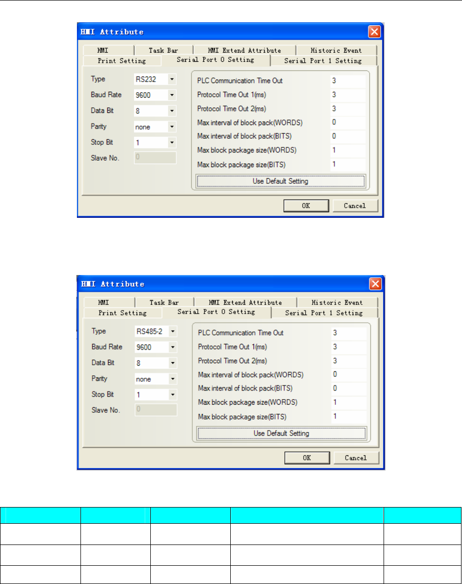
4 Communication settings and guide of HMI connecting with controller
- 151 -
NOTE: If the servo controller to modify the station number, the servo power needed to restart, the station
number to take effect, otherwise the communication is incorrect.
RS485 communication
◎Supported Device
Device Bit Address Word Address Range Notes
word ———— 20 Refer to the kinco manual
word ———— 10 Refer to the kinco manual
word ———— 8 Refer to the kinco manual
NOTE: Use the touch screen, pay attention to the rules addressing. The specific reference to the following
description.
Touch-screen type of address: according to the number of bits to the servo. Can only be 20, 10, 8.
Address of the touch screen: master address, and sub address
For example, kinco servo drive manual on page 117, the address 2509, sub-address 06, median 20,
addressing the touch screen as shown:
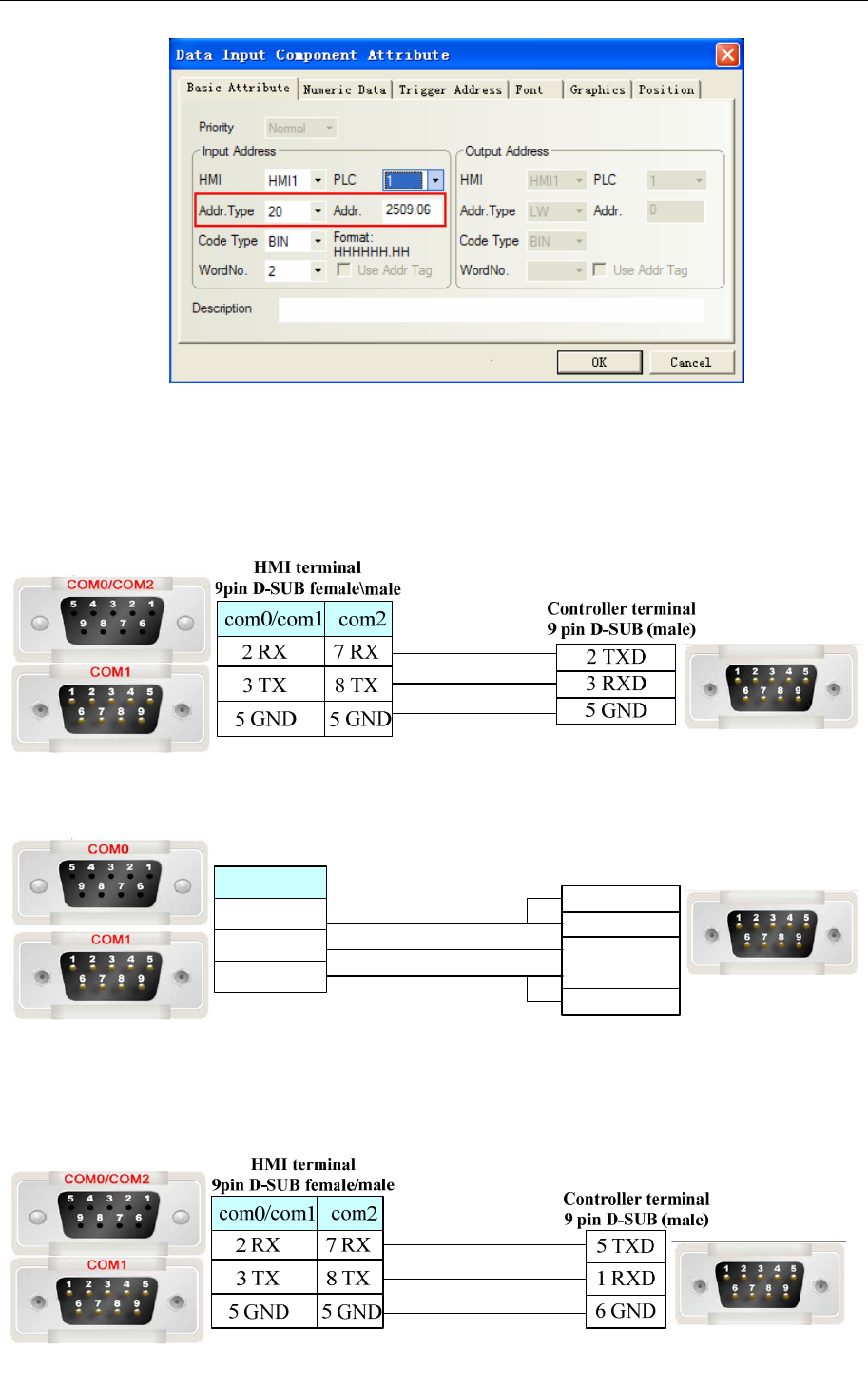
4 Communication settings and guide of HMI connecting with controller
- 152 -
◎Cable Diagram
ED Series
RS232 communication cable
RS485 communication cable
HMI terminal
9pin D-SUB female\male Controller terminal
9 pin D-SUB (male)
8Tx-
5 GND
2Rx+
7Rx-
3Tx+
com0/com1
1 RX-
5 GND
6 RX+
CD Series
RS232 communication cable
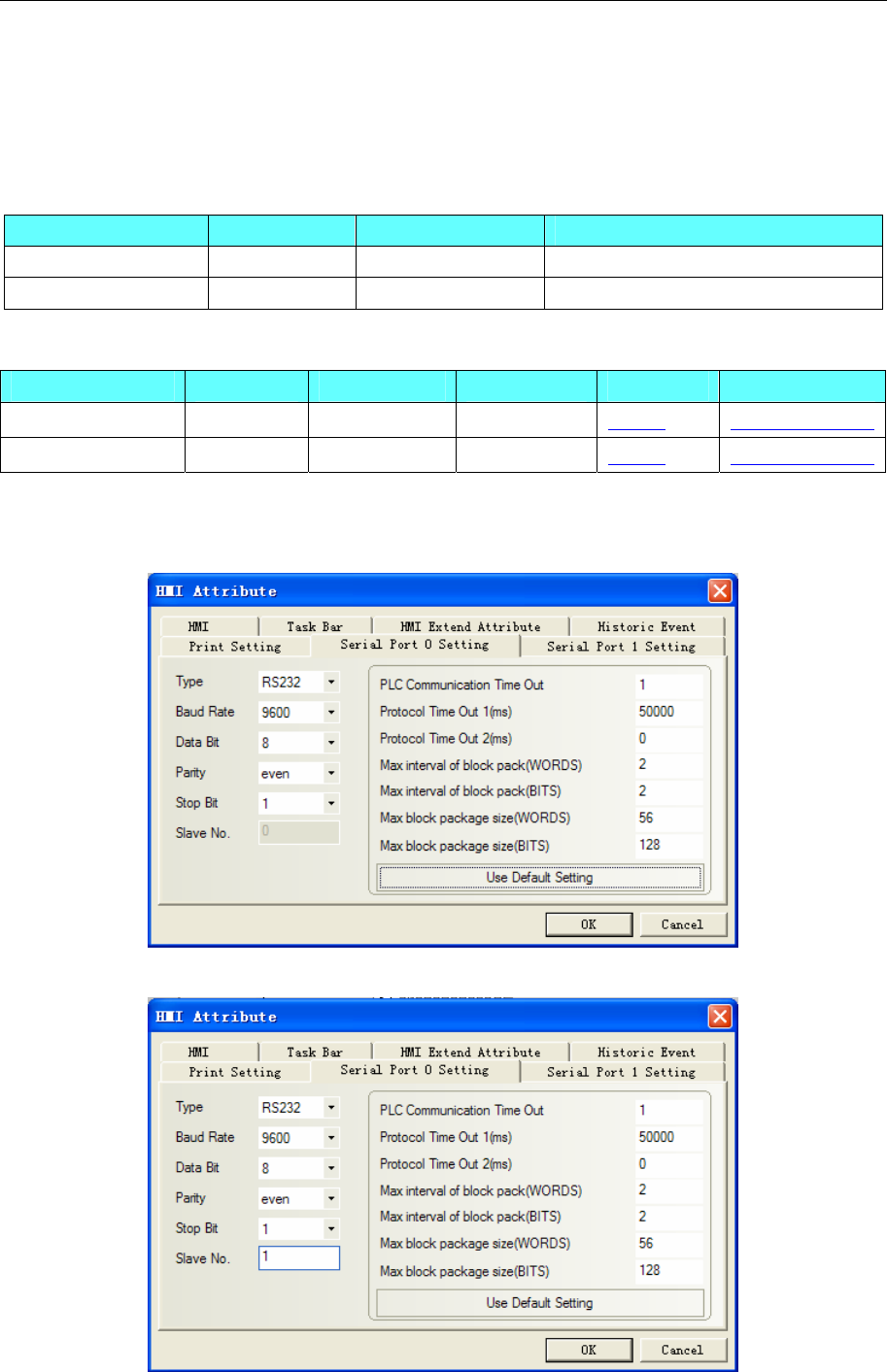
4 Communication settings and guide of HMI connecting with controller
- 153 -
4.38 Kinco Master & Kinco Slave(Master/Slave Protocol Connection)
◎Serial Communication
Series CPU Link Module Driver
Kinco Master Kinco Master
Kinco Slave Kinco Slave
◎System configuration
Series CPU Link Module COMM Type Parameter Cable
Kinco Master Setting Your owner cable
Kinco Slave Setting Your owner cable
◎Communication Setting
Kinco Master
Kinco Slave
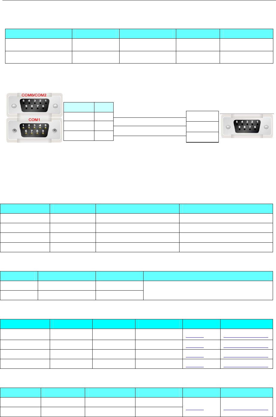
4 Communication settings and guide of HMI connecting with controller
- 154 -
◎Supported Device
Device Bit Address Word Address Format Notes
B0 - 8999 ------ DDDD
------ W0 - 8999 DDDD
◎Cable Diagram
HMI terminal
9pin D-SUB female/male Controller terminal
9pin D-SUB female
3TXD
2RXD
5 GND
com2
3 TX
2 RX
5 GND
8 TX
7 RX
5 GND
com0/com1
4.39 Keyence Corporation
◎Serial Communication
Series CPU Link Module Driver
KV-16DT KV-16DT CPU Direct Keyence KV-16DT
KV-1000 KV-1000 CPU Direct Keyence KV-1000
KV-3000 KV-3000 CPU Direct Keyence KV-3000
KV-Nano Series KV-N60AT CPU Direct Keyence KV-N60AT/7000
◎Network communication
Series CPU Link Module Driver
KV-5000 KV-5000 CPU Direct
KV-7000 KV-7500 CPU Direct
Keyence KV-5000/7000 EtherNet Slave
◎Serial System configuration
Series CPU Link Module COMM Type Parameter Cable
KV-16DT KV-16DT CPU Direct RS232 Setting Your owner cable
KV-1000 KV-1000 CPU Direct RS232 Setting Your owner cable
KV-3000 KV-3000 CPU Direct RS232 Setting Your owner cable
KV-Nano Series KV-N60AT CPU Direct RS232 Setting Your owner cable
◎Network System configuration
Series CPU Link Module Connect Type Parameter Cable
KV-5000 KV-5000 CPU Direct Ethernet
KV-7000 KV-7500 CPU Direct Ethernet Setting Your owner cable
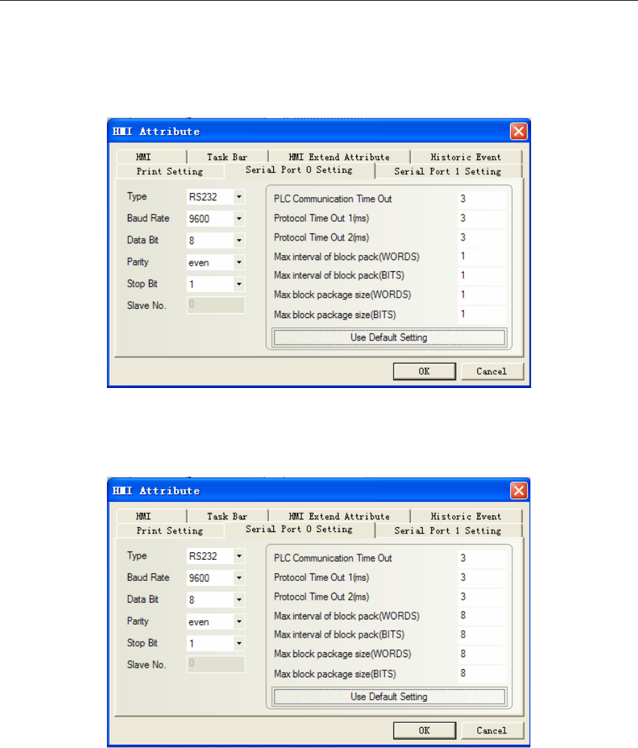
4 Communication settings and guide of HMI connecting with controller
- 155 -
◎Serial Communication Setting
Keyence KV-16DT protocol
Default communication: 9600, 8, 1, even; station: 0
Keyence KV-1000 protocol
Default communication: 9600, 8, 1, even; station: 0
Keyence KV-3000 protocol
Default communication: 9600, 8, 1, even; station: 0(Don’t support station No.)
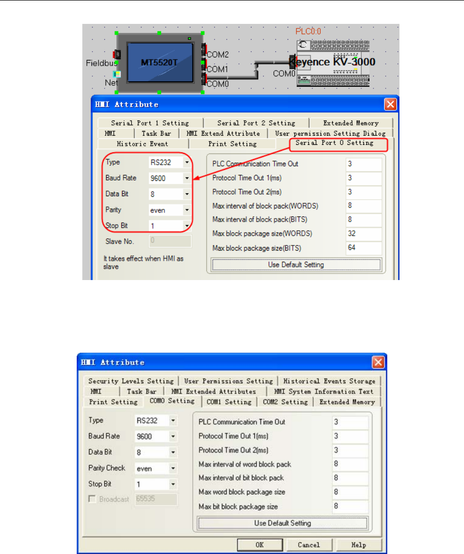
4 Communication settings and guide of HMI connecting with controller
- 156 -
Keyence KV-N60AT protocol
Default communication parameters, 9600bps, 8,even, 1,;station NO:0
RS232
PLC setting
1. In the [Confirm unit setting information] dialog box click [Yes], and the [Unit Editor] window will
display. On the [Select unit] tab, from the displayed list of units select “KV-N60”, then drag &drop to the
unit placement area. Configure the setup items as follows.
Operation Mode: KV STUDIO mode; Baud Rate: 9600 bps.
Note: 1. Timer and counter register must be programmed in the KV STUDIO software before it be used in
the HMI.
2. If the communication is slower, you can change the baud rate and the Protocol time out 1(ms)
◎Network Communication Setting
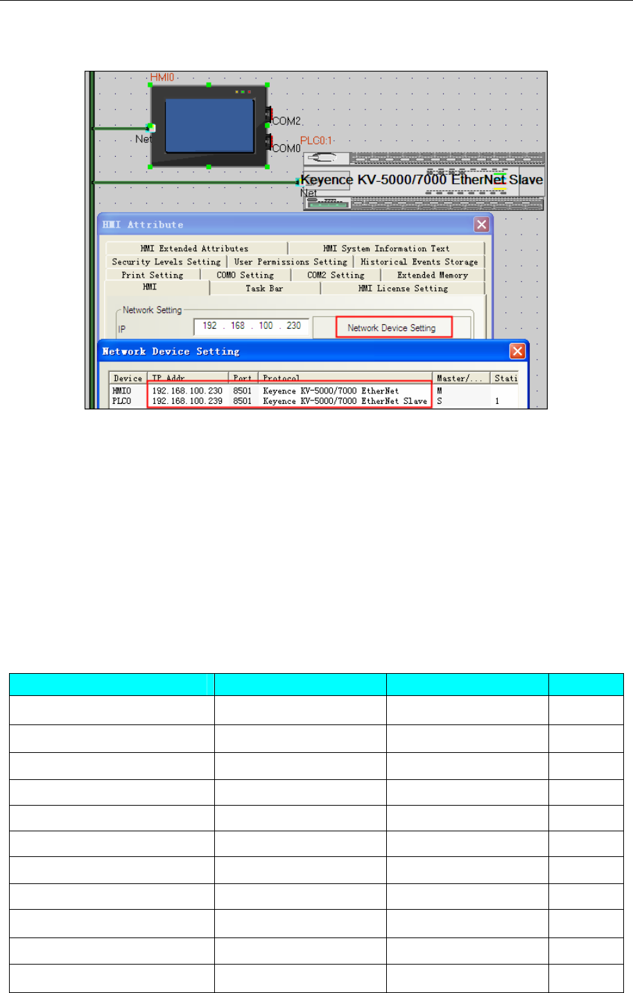
4 Communication settings and guide of HMI connecting with controller
- 157 -
Keyence KV-5000/7000 EtherNet Slave protocol
HMI Setting
PLC configuration
1. "Editor" window, click [Configure unit] in the "[0] KV-5000 R30000" to modify the IP address of
the PLC, PLC and PC in the same segment, modify the IP address of the test shown, click [confirm] to save
the modifications
2. Switch to the "Monitor" window to see the changes of the figure will pop up window, Click [PLC
transfer -> Monitor mode (T)], pop-up "transmission program [communication goals: KV-5000 path:
USB]", Click [implementation], content writing, once again view the "[0] KV-5000 R30000" in the PLC's
IP address in the "Monitor" window [unit configuration], This indicates that the address has been modified
over.
◎Supported Device
KV-16DT
Device Bit Address Word Address Format
Counter Relay Counter_contact0- 59915 ------ DDDDD
Timer Relay Timer_contact0- 65535 ------ DDDDD
High speed counter CTH_contact0- 511 ------ DDD
High speed counter Comparator CTC_contact0- 511 ------ DDD
Relay Relay0- 32766 ------
DDDDD
Counter current ------ Counter_current0- 3915 DDDD
Counter preset ------ Counter_preset0- 65535 DDDDD
Timer current ------ Timer_current0- 65534 DDDDD
Timer preset ------ Timer_preset0- 11998 DDDDD
High speed counter ------ CTH_current0- 65534 DDDDD
High speed counter ------ CTH_preset0- 32766 DDDDD
4 Communication settings and guide of HMI connecting with controller
- 158 -
High speed counter Comparator ------ CTC_current0-65534 DDDDD
High speed counter Comparator ------ CTC_preset0- 32766 DDDDD
Data memory ------ DM0- 32766 DDDDD
Temporary data memory ------ TM0- 32766 DDDDD
Note: Non-supported batch transfer of bits or words for this protocol.
KV-1000
Device Bit Address Word Address Format Notes
Relay R0-59915
------ DDDDD
Control Relay CR0-3915 ------ DDDD
Internal auxiliary relay MR0-65535 ------ DDDDD
Latch Relay LR0-65535 ------ DDDDD
Data Memory ------ DM0-65534 DDDDD
Control Memory ------ CM0-11998 DDDDD
Temporary data memory ------ TM0-511 DDD
Extended Data memory ------ EM0-65534 DDDDD
Extended Data memory ------ FM0-32766 DDDDD
KV-3000
Device Bit Address Word Address Format Notes
Relay R0-999.15 ------ DDD.DD
Control Relay CR0-39.15 ------ DD.DD
Internal auxiliary relay MR0-999.15 ------ DDD.DD
Latch Relay LR0-999.15 ------ DDD.DD
Data Memory ------ DM0-65534 DDDDD
Control Memory ------ CM0-5999 DDDD
Temporary data memory ------ TM0-511 DDD
Extended Data memory ------ EM0-65534 DDDDD
Extended Data memory ------ FM0-32767 DDDDD
Note: PLC bit address without a decimal point in the distinction, in fact, the last two addresses
corresponding to the fractional part, makes a distinction between the touch screen.
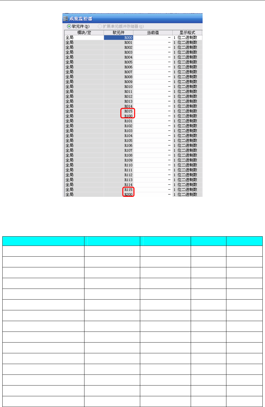
4 Communication settings and guide of HMI connecting with controller
- 159 -
Example, PLC which corresponds to R009, the touch screen address is R0.09; PLC which corresponds to
R015, the touch screen address is R0.15.
KV-5000/7000
Device Bit Address Word Address Format Notes
Relay R0-999.15 ------ DDD.DD
Control Relay CR0-79.15 ------ DD.DD
Internal auxiliary relay MR0-999.15 ------ DDD.DD
Latch Relay LR0-999.15 ------ DDD.DD
Timer T0~3999 ------ DDDD
Counter C0~3999 ------ DDDD
Timer(Setting Value) ------ TS0~3999 DDDD
Timer(Current Value) ------ TC0~3999 DDDD
Counter(Setting Value) ------ CS0~3999 DDDD
Counter(Current Value) ------ CC0~3999 DDDD
Data Memory ------ DM0-65534 DDDDD
Control Memory ------ CM0-5999 DDDD
Temporary data memory ------ TM0-511 DDD
Extended Data memory ------ EM0-65534 DDDDD
Extended Data memory ------ FM0-32767 DDDDD
Note: PLC bit address without a decimal point in the distinction, in fact, the last two addresses
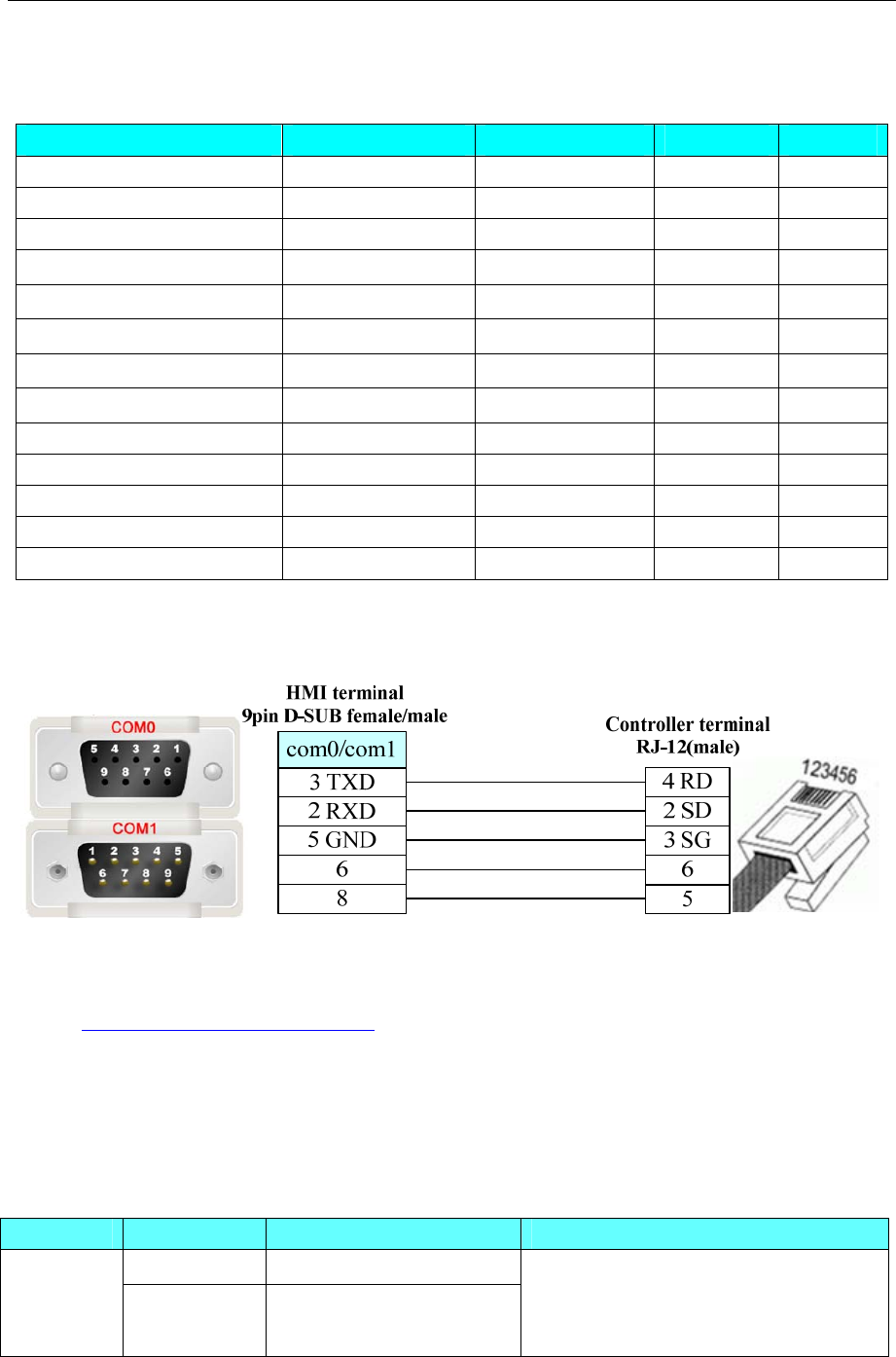
4 Communication settings and guide of HMI connecting with controller
- 160 -
corresponding to the fractional part, makes a distinction between the touch screen.
KV-N60AT
Device Bit Address Word Address Format Notes
Relay R0-599.15 ------ DDD.DD
Control Relay CR0-89.15 ------ DD.DD
Internal auxiliary relay MR0-599.15 ------ DDD.DD
Latch Relay LR0-199.15 ------ DDD.DD
Link Relay B0-1FFF ------ HHHH
Work Relay VB0-1FFF ------- HHHH
Counter ------
C0-255 DDD
Timer ------
T0-511 DDD
Data Memory ------ DM0-32767 DDDDD
Control Memory ------ CM0-8999 DDDD
Temporary data memory ------ TM0-511 DDD
Link register ------ W0-3FFF HHHH
Working memory ------ VW0-9999 DDDDD
◎Cable Diagram
KV Series RS232 communication cable
Ethernet communication protocol cable
Cross-connection or crossover network cable can be used as communication cable via the hub
Refer to 3.3 Download by Network Ethernet for method of making connection cable.
4.40 Koyo Corporation
◎Serial Communication
Series CPU Link Module Driver
SM24-T RS232 on the CPU unit
KOYO
DIRECT DL06
DL105 RS232 on the port1
Koyo Direct
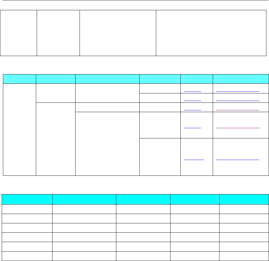
4 Communication settings and guide of HMI connecting with controller
- 161 -
DL230
DL240
DL250
DL350
DL450
RS232\RS422 on the port2
◎System configuration
Series CPU Link Module COMM Type Parameter Cable
RS232 Setting Your owner cable
SM24-T RS232 on the CPU unit RS485-2 Setting Your owner cable
RS232 on the port1 RS232 Setting Your owner cable
RS232 Setting Your owner cable
KOYO
DIRECT
DL05
DL06
DL105
DL230
DL240
DL250
DL350
DL450
RS232 on the port2
RS485-4 Setting Your owner cable
◎Supported Device
Device Bit Address Word Address Format Notes
Input I(X)0-477 ------ OOO
Output Q(Y)0-477 ------ OOO
variable M(C)0-377 ------ OOO
Timer Status T(T)0-177 ------ OOO
Counter Status C(CT)0-177 ------ OOO
Data Register ------ R(V)0-7777 OOOO
PLC software setting
1. The security password function must be disabled.
2. The COM port must adopt K sequence protocol.
3. Set the switch of the CPU with working mode setting switch to the TERM state.
◎Communication Setting
KOYO series RS232 communication setting
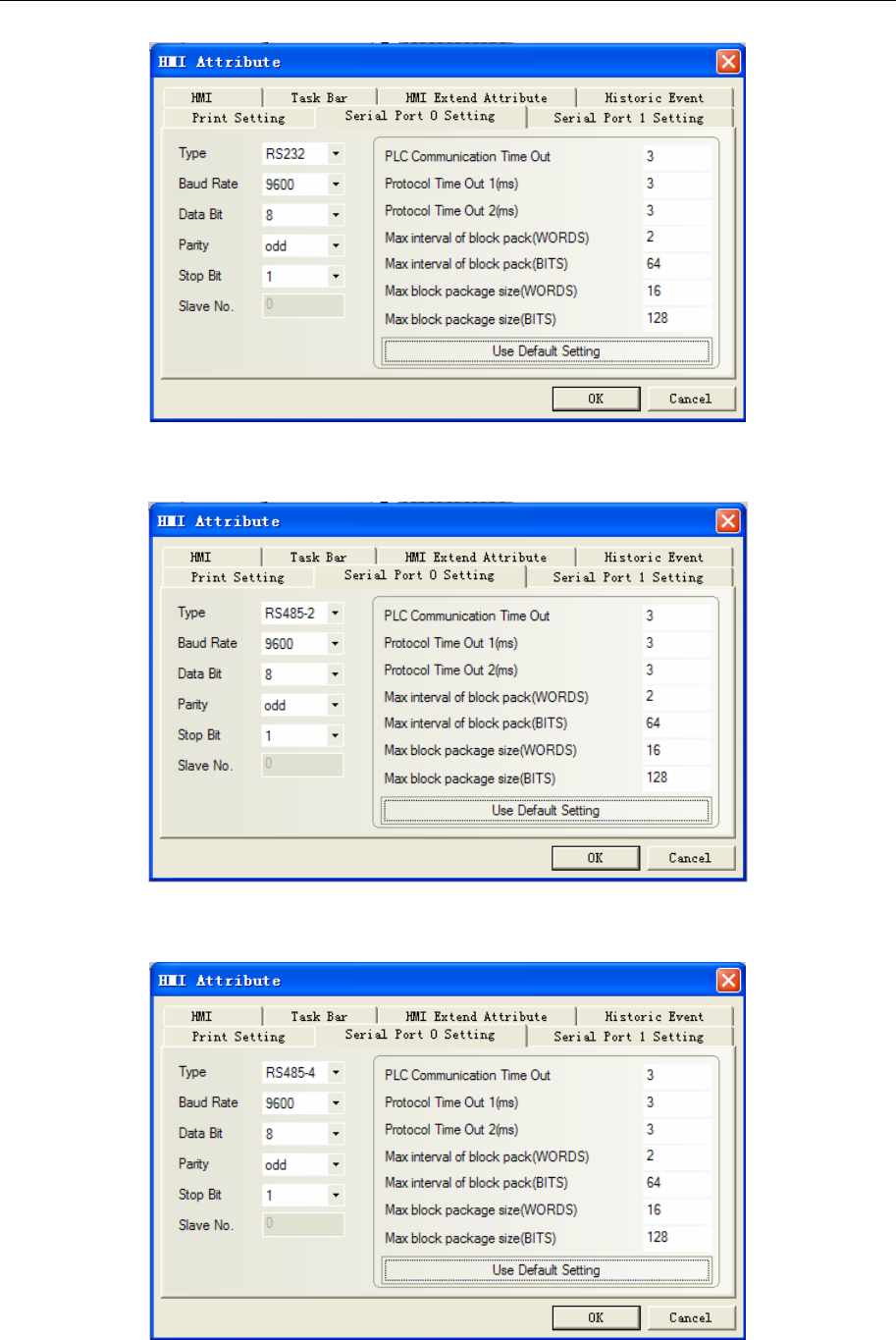
4 Communication settings and guide of HMI connecting with controller
- 162 -
KOYO series RS485 communication setting
KOYO DL06 series RS422 communication setting
◎Cable Diagram
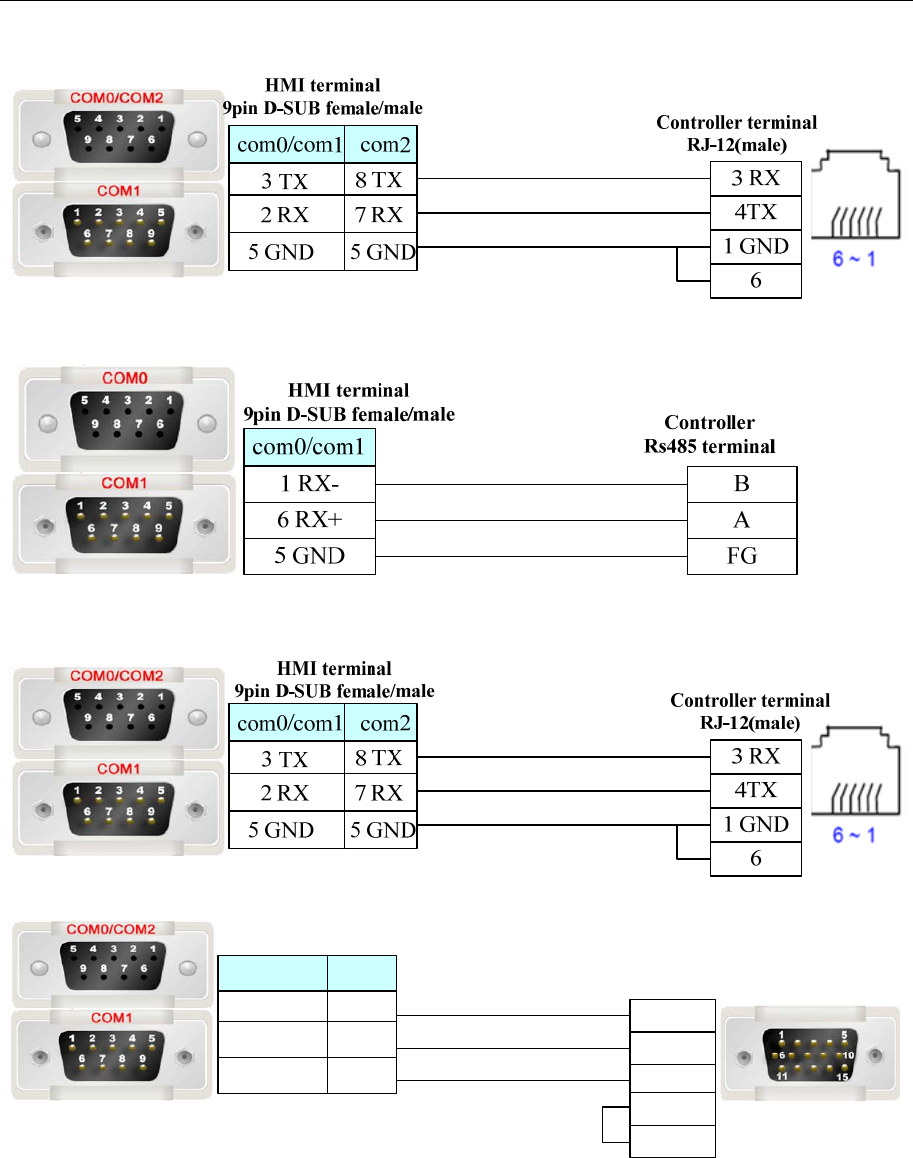
4 Communication settings and guide of HMI connecting with controller
- 163 -
KOYO SM24-T series RS232 communication cable
KOYO SM24-T series RS485 communication cable
KOYO DL06 series RS232 communication cable
Controller PORT2
15 pin SVGA terminal
(male)
3 RX
2 TX
7 GND
4 RTS
5 CTS
HMI terminal
9pin D-SUB female/male
com2
3 TX
2 RX
5 GND
8 TX
7 RX
5 GND
com0/com1
KOYO DL06 series RS422 communication cable
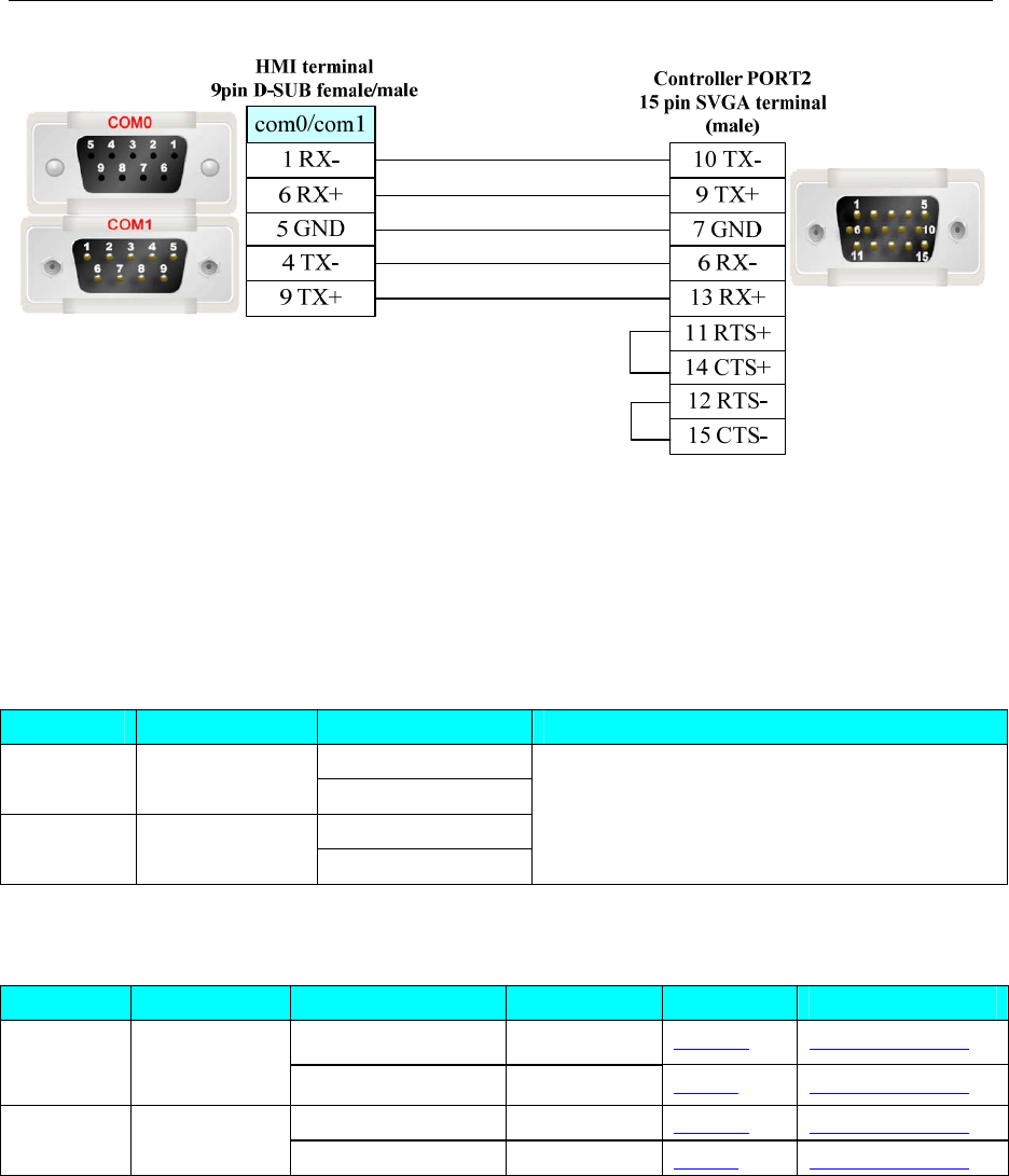
4 Communication settings and guide of HMI connecting with controller
- 164 -
4.41 KTC Srdlink
◎Serial Communication
Series CPU Link Module Driver
RS232 on CPU unit
SRD SRD2211 RS485 on CPU unit
RS232 on CPU unit
COM COM2023 RS485 on CPU unit
KTC SRDLINK
◎System configuration
Series CPU Link Module COMM Type Parameter Cable
RS232 on CPU unit RS232 Setting Your owner cable
SRD SRD2211
RS485 on CPU unit RS485-2 Setting Your owner cable
RS232 on CPU unit RS232 Setting Your owner cable
COM COM2023
RS485 on CPU unit RS485-2 Setting Your owner cable
◎Communication Setting
KTC RS232 communication
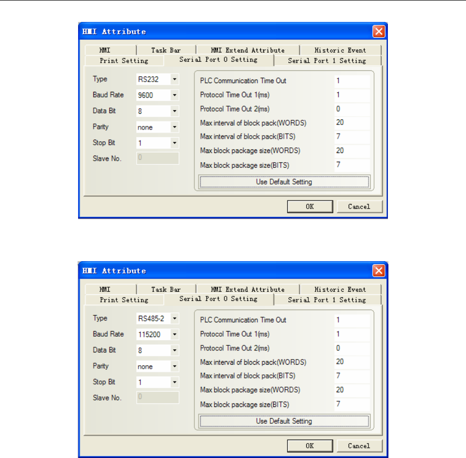
4 Communication settings and guide of HMI connecting with controller
- 165 -
KTC RS485-2 communication
NOTE: Must modify communication parameter in the programming software.
◎Supported Device
Please refer to the PLC manual for details.
◎Cable Diagram
KTC RS232 communication cable
Direct connect (cable by KTC Corporation)
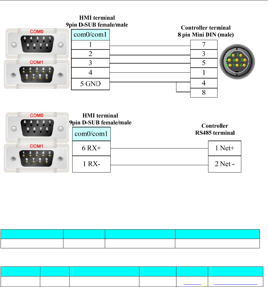
4 Communication settings and guide of HMI connecting with controller
- 166 -
KTC RS485 communication cable
4.42 KYL Slave
◎Serial Communication
Series CPU Link Module Driver
KYL Slave KYL RS232 on the CPU unit KYL Slave
◎System configuration
Series CPU Link Module COM Type Parameter Cable
KYL Slave KYL RS232 on the CPU unit RS232 Setting Your owner cable
◎Communication Setting
RS232
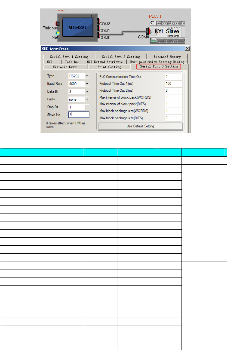
4 Communication settings and guide of HMI connecting with controller
- 167 -
◎Supported Device
Device Bit Address Word Address Format Notes
Group close instruction LB0 ------ DD
Remote valve open operation LB1 ------ DD
Remote valve close operation LB2 ------ DD
Remote valve address set operation LB3 ------ DD
Set gain cunrrent state LB4 ------ DD
flase valve open LB8 ------ DD
flase valve close LB9 ------ DD
valve open feedback LB10 ------ DD
valve close feedback LB11 ------ DD
valve uncap alarm LB12 ------ DD
valve hypopiesis alarm LB13 ------ DD
Show current valve state LB14 ------ DD
Show valve state LB15 ------ DD
Station:1; LB
address
Group close instruction LB17 ------ DD
Remote valve open operation LB18 ------ DD
Remote valve close operation LB19 ------ DD
Remote valve address set operation LB20 ------ DD
Set gain cunrrent state LB24 ------ DD
flase valve open LB25 ------ DD
flase valve close LB26 ------ DD
valve open feedback LB27 ------ DD
valve close feedback LB28 ------ DD
valve uncap alarm LB29 ------ DD
valve hypopiesis alarm LB30 ------ DD
Staion:2, LB
address(LB is on
the base of
1station+16)
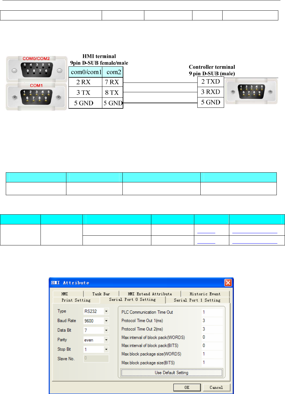
4 Communication settings and guide of HMI connecting with controller
- 168 -
Show current valve state LB31 ------ DD
◎Cable Diagram
RS232
4.43 LENZE Inverter
◎Serial Communication
Series CPU Link Module Driver
Lenze Lecom A/B EVF9323-EV RS232 on the CPU unit Lenze Lecom_AB
◎System configuration
Series CPU Link Module COM Type Parameter Cable
RS232 on the CPU unit RS232 Setting Your owner cable Lenze
Lecom A/B EVF9323-EV RS485 on the CPU unit RS485 Setting Your owner cable
◎Communication Setting
Lecom AB RS232 communication
Lecom AB RS485 communication
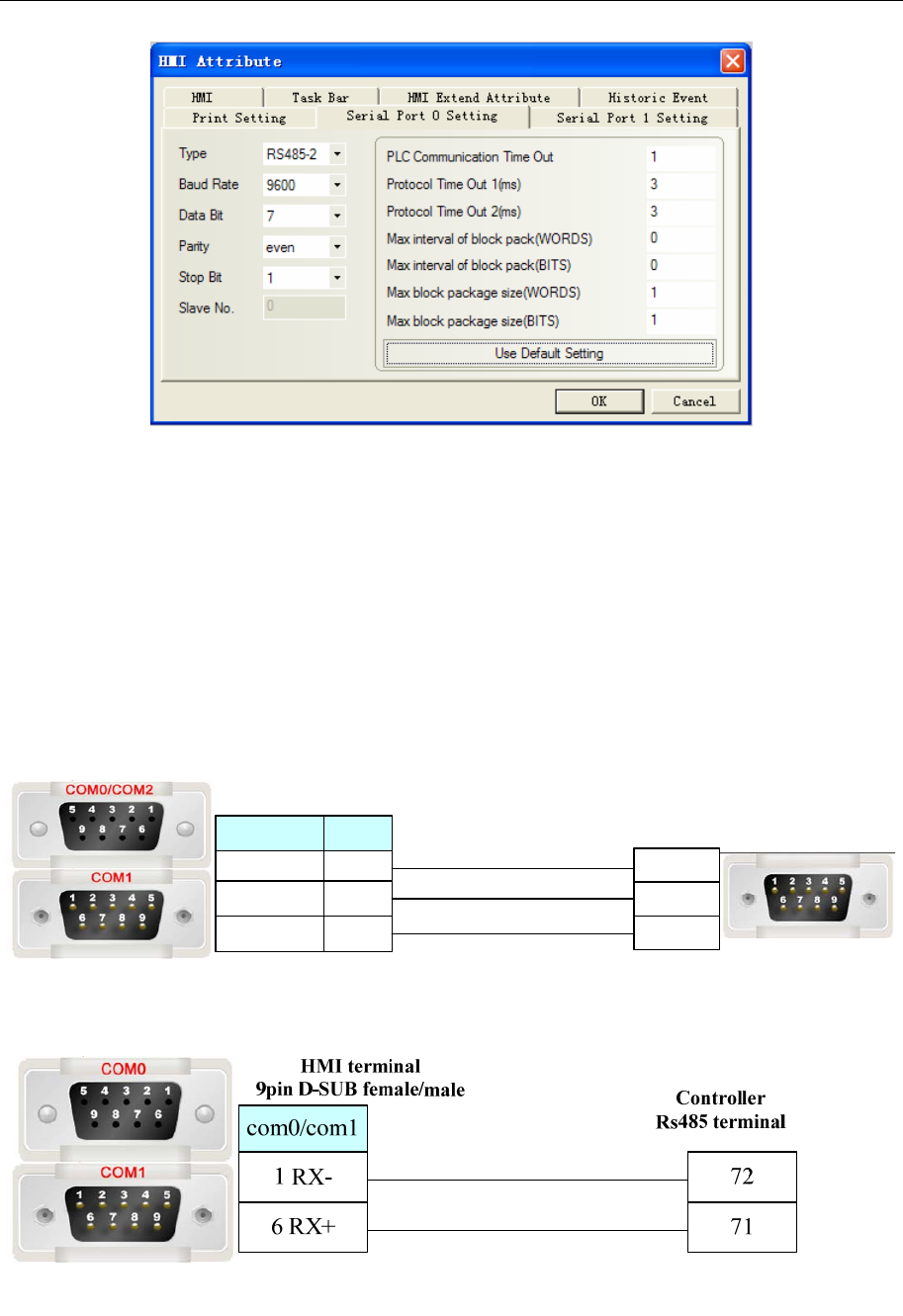
4 Communication settings and guide of HMI connecting with controller
- 169 -
◎Supported Device
Refer to the PLC software for details;Global drive control
Note:code_H: Data type is HEX
code_F: Data type is Floating
code_D: Data type is Decimal
◎Cable Diagram
Lecom AB RS232 communication cable
Controller terminal
9 pin D-SUB (male)
com2
3 TX
2 RX
5 GND
8 TX
7 RX
5 GND
com0/com1
HMI terminal
9pin D-SUB female/male
3 TXD
2 RXD
5 GND
Lecom AB RS485 communication cable
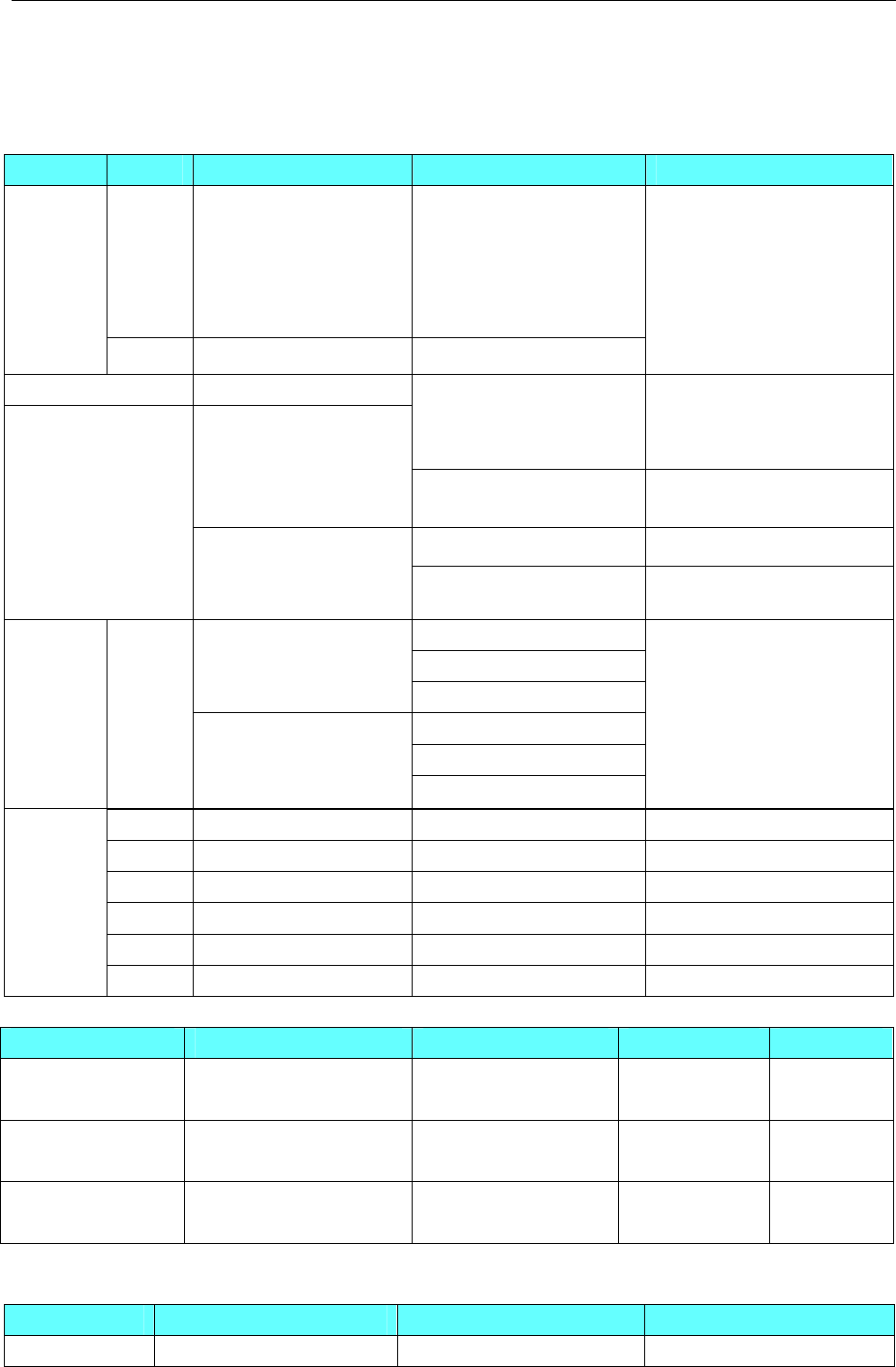
4 Communication settings and guide of HMI connecting with controller
- 170 -
4.44 LS Industrial Systems(LG)
◎Serial Communication
Series Type CPU Link Module Driver
K120S
K7M-DR10UE
K7M-DR20U
K7M-DT30U
K7M-DT40U
K7M-DT60U
Port1 on CPU unit
Port2 on CPU unit
Master-K
K200S K3P-07AS RS232 on the CPU unit
LS Master-K CPU Direct
LS Master-K Cnet
LS Master-K Modbus RTU
XGT XGK-CPUH
RS232 on the CPU unit LS XBC/XGK CPU Direct
XBC-DN64H
XBC-DR32H
XBC-DR40EB
XBC-DN30S Built-in RS-232C/RS-485 LS XBC/XGK Cnet
RS232 on the CPU unit LS XEC CPU Direct
XGB
XEC-DN20SU
XEC-DR32H
XEC-DN32UA Built-in RS-232C/RS-485 LS XEC CPU Cnet
RS232 on the CPU unit
G6L-CUEB
GM6
G6L-CUEC
RS232 on the CPU unit
G7L-CUEB
GLOFA GM
GM7
G7L-CUEC
LS GLOFA Cnet
iG5A SV008iG5A-2 RS485-2on the CPU unit LS iG5A
iG5 SV004IG5-1 RS485 on the CPU unit LS iG5
C100 LV0002C100-2N RS485-2on the CPU unit LS C100 Series Inverter
iGxA SV008IGXA-4 RS485-2on the CPU unit LS iGxA Series Inverter
iS7 SV0550-0750iS7-4 RS485-2on the CPU unit LS iS7 Series Inverter
Inverter
S100 LV0004S100-4EONNS RS485-2on the CPU unit LS S100 Series Inverter
The difference of LS Master-K CPU Direct、LS Master-K Cnet、LS Master-K Modbus RTU
Protocol PLC Setting Communication Mode Multi-station Baud(bps)
LS Master-K Cnet Switch the DIP2 to be
ON, DIP1 to be OFF
RS232/RS485 support 9600/19200
/38400
LS Master-K
MODBUS RTU
Switch the DIP2 to be
ON, DIP1 to be OFF
RS232/RS485 support 9600/19200
/38400
LS Master-K CPU
Direct
Switch the DIP1 and
DIP2 to be OFF
RS232 non-support 38400
◎Ethernet communication
Series CPU Link Module Driver
GLOFA GM6-CPUA G6L-EUTP LS GLOFA FEnet
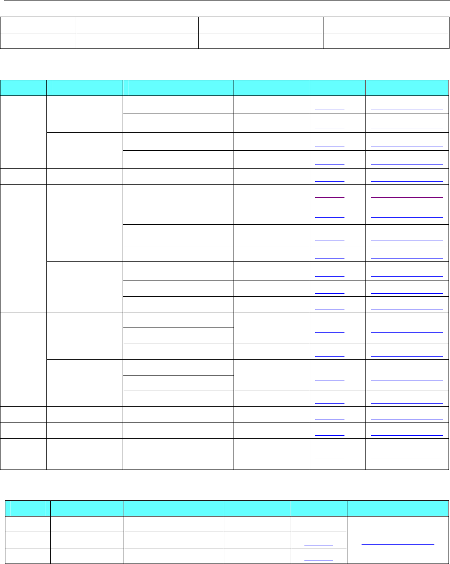
4 Communication settings and guide of HMI connecting with controller
- 171 -
XGT XGK-CPUE XGL-EFMT LS XGT Ethernet
XGB XBC-DR60SU XBL-EMTA LS XBC FEnet Slave
◎Serial System Configuration
Series CPU Link Module COMM Type Parameter Cable
Port1 on CPU unit RS232 Setting Your owner cable
K7M-DR10UE Port2 on CPU unit RS485-2 Setting Your owner cable
Port1 on CPU unit RS232 Setting Your owner cable
K120S
K7M-DR20U Port2 on CPU unit RS485-2 Setting Your owner cable
K200S K3P-07AS RS232 on the CPU unit RS232 Setting Your owner cable
XGT XGK-CPUH RS232 on the CPU unit RS232 Setting Your owner cable
RS232 on the CPU unit RS232 Setting Your owner cable
Built-in RS-232C RS232 Setting Your owner cable
XBC-DN64H
XBC-DR32H
XBC-DR40EB
XBC-DN30S Built-in RS-485 RS485-2 Setting Your owner cable
RS232 on the CPU unit RS232 Setting Your owner cable
Built-in RS-232C RS232 Setting Your owner cable
XGB
XEC-DN20SU
XEC-DR32H
XEC-DN32UA Built-in RS-485 RS485-2 Setting Your owner cable
RS232 on the CPU unit
G6L-CUEB RS232 Setting Your owner cable
GM6
G6L-CUEC RS422/RS485 Setting Your owner cable
RS232 on the CPU unit
G7L-CUEB RS232 Setting Your owner cable
GLOFA
GM7
G7L-CUEC RS422/RS485 Setting Your owner cable
iG5A SV008iG5A-2 on the CPU unit RS485-2 Setting Your owner cable
iG5 SV004IG5-1 R485 on the CPU unit RS485-2 Setting Your owner cable
C100 LV0002C100-2
N on the CPU unit RS485-2 Setting Your owner cable
◎Ethernet System Configuration
Series CPU Link Module COMM Type Parameter Cable
GLOFA GM6-CPUA ETH on the CPU unit ETH Setting
XGT XGK-CPUE XGL-EFMT ETH Setting
XGB XBC-DR60SU XBL-EMTA ETH Setting
Your owner cable
◎Serial Communication Setting
LS Master-K Cnet protocol
Default communication: 38400, 8, none , 1; station:1
HMI Setting
RS232 communication
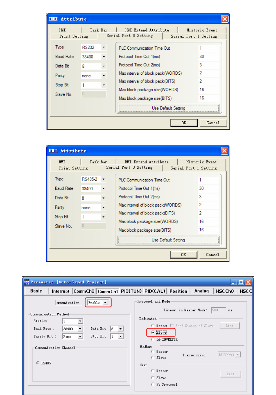
4 Communication settings and guide of HMI connecting with controller
- 172 -
RS485 communication
PLC setting
If click “Connect+Write+Run+Monitor Start”, it will give a “Cannot Change PLC Mode”. Need to let the
run light go out by manual control, and then download. After download, let the run light keep on.
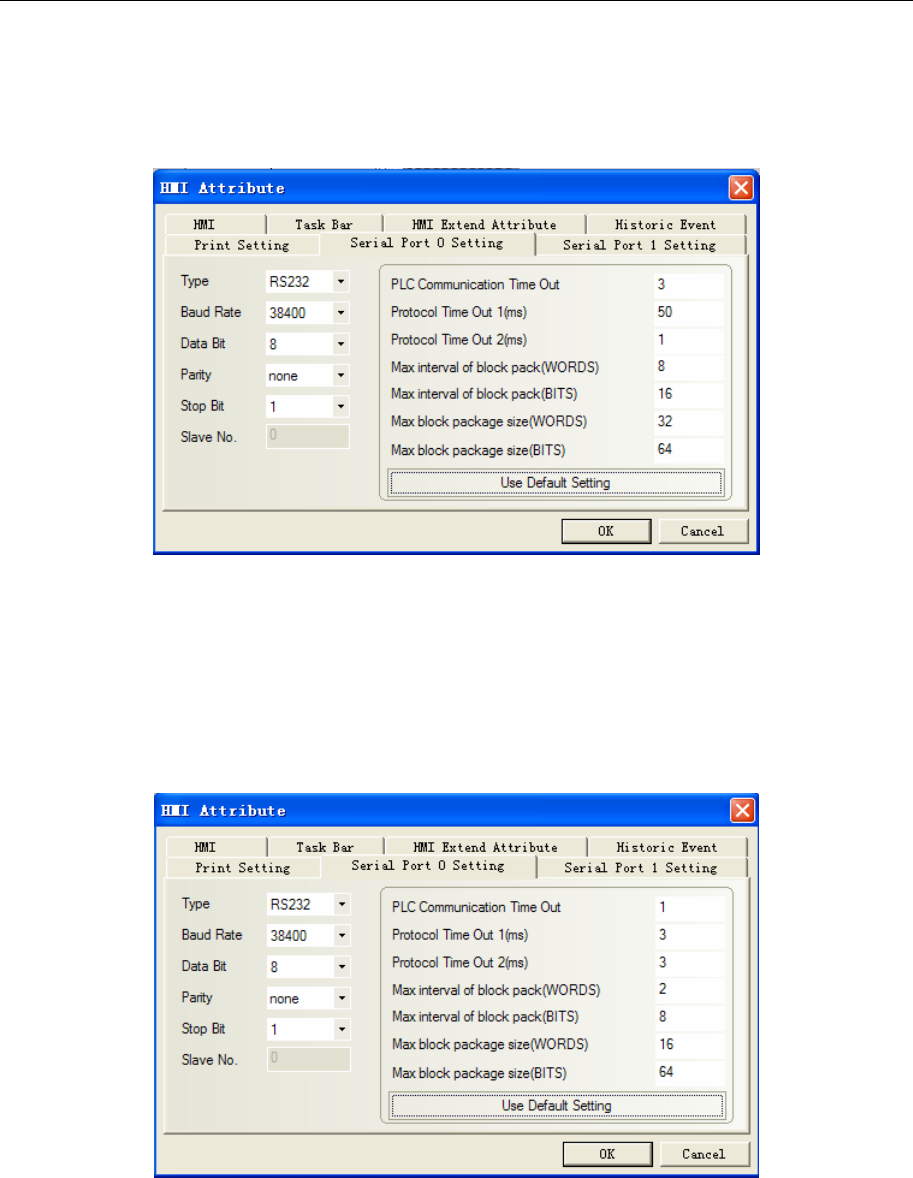
4 Communication settings and guide of HMI connecting with controller
- 173 -
LS Master-K CPU Direct protocol
HMI Setting
Default communication: 38400, 8, none , 1; station:1
RS232 communication
NOTE: Only support 38400 baud rate for the protocol
LS Master-K Modbus RTU protocol
HMI Setting
Default communication: 38400, 8, none , 1; station:1
RS232 communication
PLC Setting
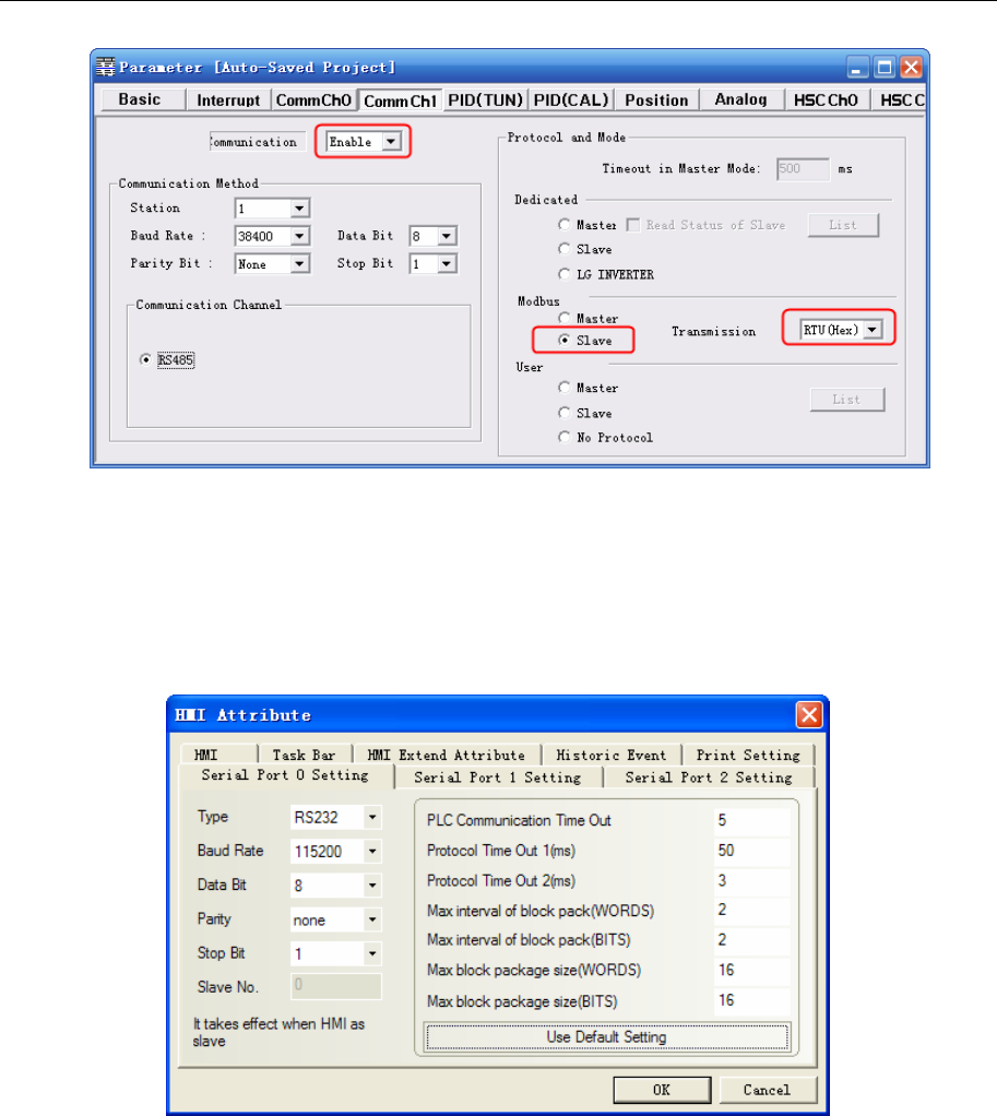
4 Communication settings and guide of HMI connecting with controller
- 174 -
If click “Connect+Write+Run+Monitor Start”, it will give a “Cannot Change PLC Mode”. Need to let the
run light go out by manual control, and then download. After download, let the run light keep on.
LS XBC/XGK CPU Direct protocol
Default communication: 115200, 8, none, 1; station: 0
RS232 communication
NOTE: Only support 115200 baud rate for the protocol; station number disable.
LS XBC/XGK Cnet protocol
Default communication: 9600, 8, none, 1; station: 0
HMI Setting
RS232 communication
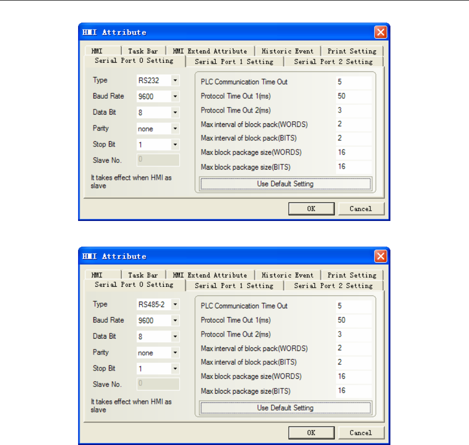
4 Communication settings and guide of HMI connecting with controller
- 175 -
RS485-2 communication
PLC Setting
1. “Tools”---“Network Manager” set communication
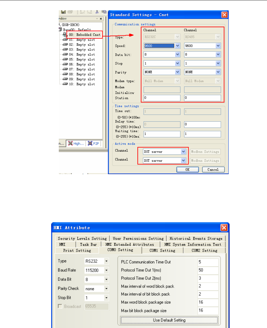
4 Communication settings and guide of HMI connecting with controller
- 176 -
2. Communicating in the OPR mode
LS XEC CPU Direct
HMI Setting
Default communication parameters: 115200bps, 8, 1, none; PLC station No.:0
NOTE:Only support 115200 baud rate for the protocol; station number disable.
LS XEC Cnet protocol
HMI Setting
Default communication parameters: 9600bps, 8, 1, none; PLC station No.:0
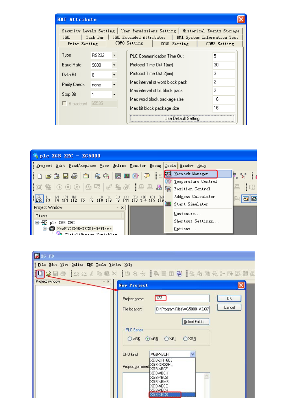
4 Communication settings and guide of HMI connecting with controller
- 177 -
PLC Setting
1.PLC parameter settings:[Tools]-[Network Manager].
2. In the pop-up window “XG-PD”, creat a new file, select the correct CPU kind.
3.Double click the [ 00:Embedded Cnet], in the pop-up window “Standard Settings-Cnet” to set
communication.
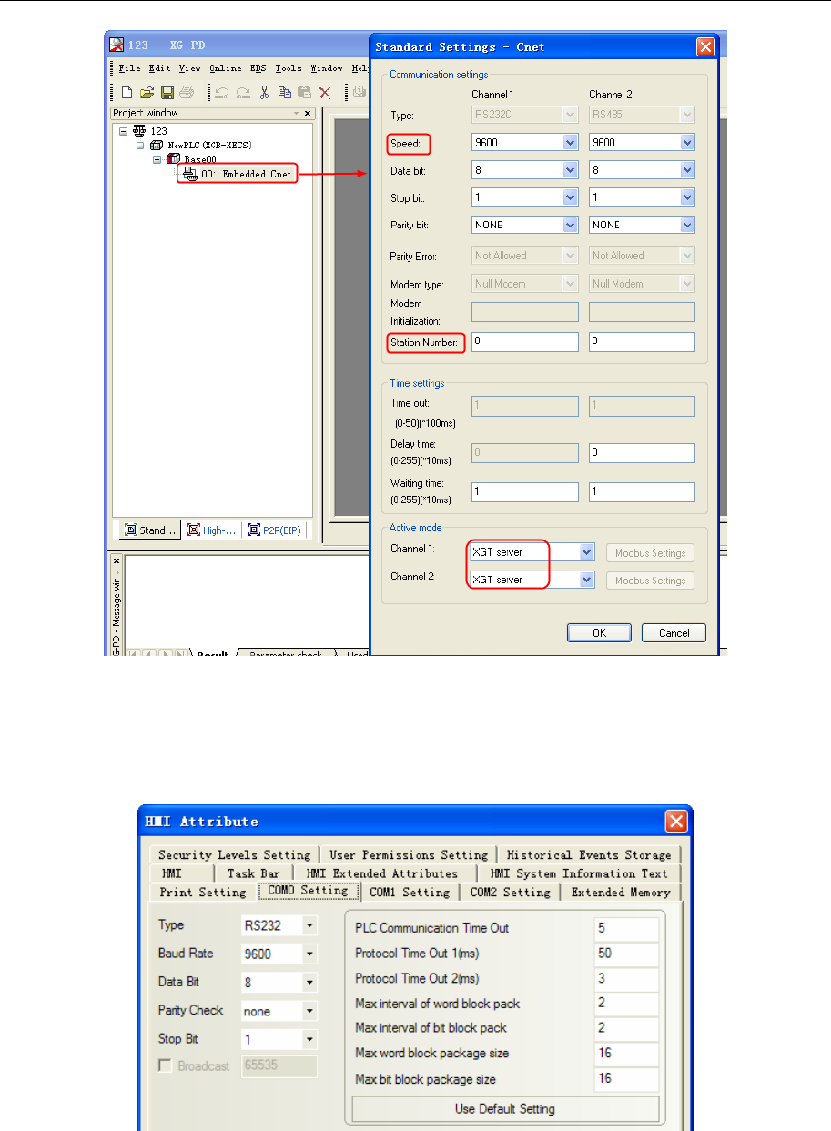
4 Communication settings and guide of HMI connecting with controller
- 178 -
LS GLOFA Cnet protocol
Default communication: 9600, 8, none, 1; station: 0
HMI Setting
RS232 communication
RS485-4 communication
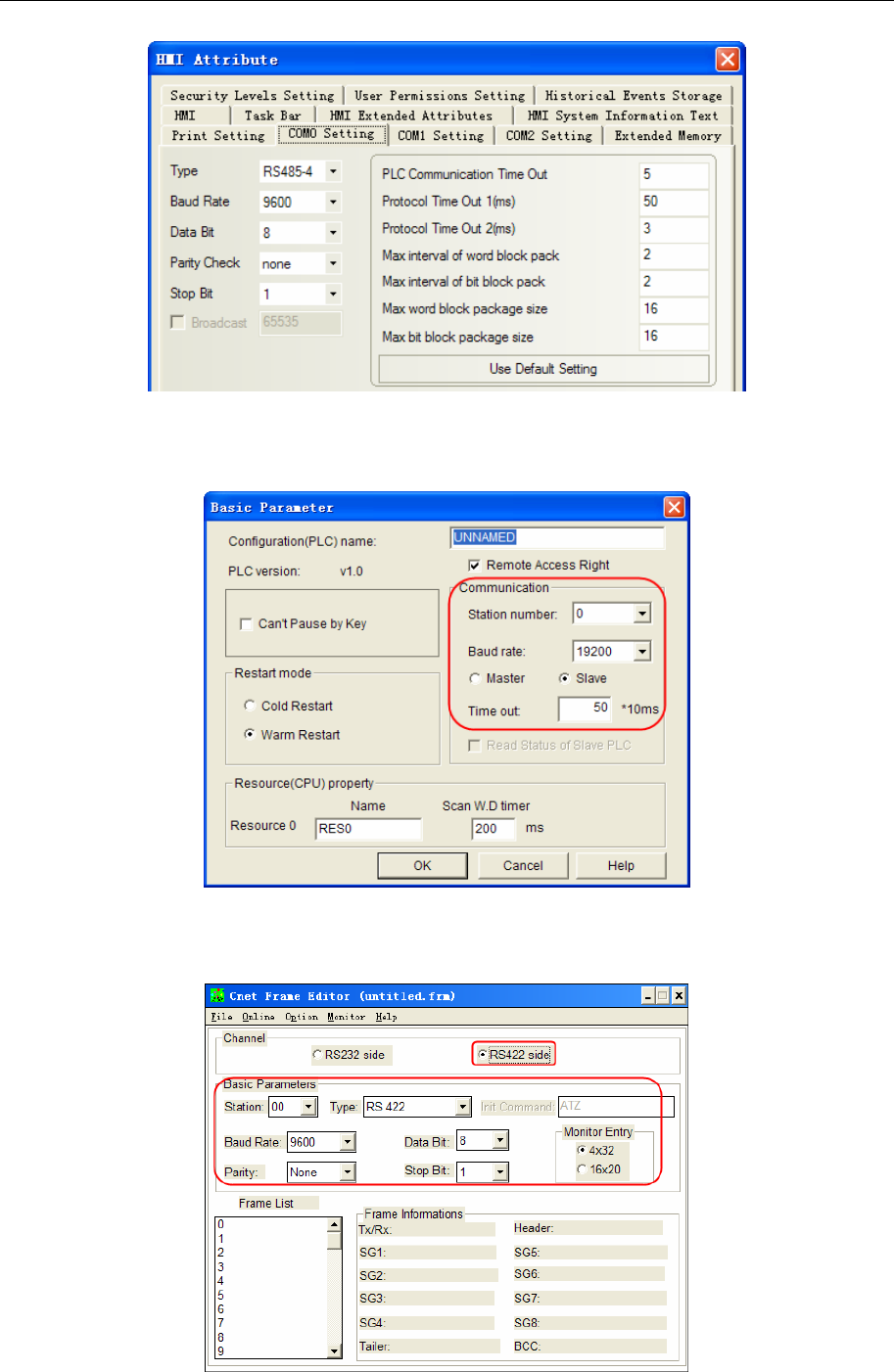
4 Communication settings and guide of HMI connecting with controller
- 179 -
PLC Setting
1. Set the parameters of CPU module
Open GMWIN, “Parameters””Basic Parameters” set “Communication”:
2. Set the parameters of module
Take G6L-CUEC for example,
Open GMWIN, select ”Tool””Cnet Frame Editor”,
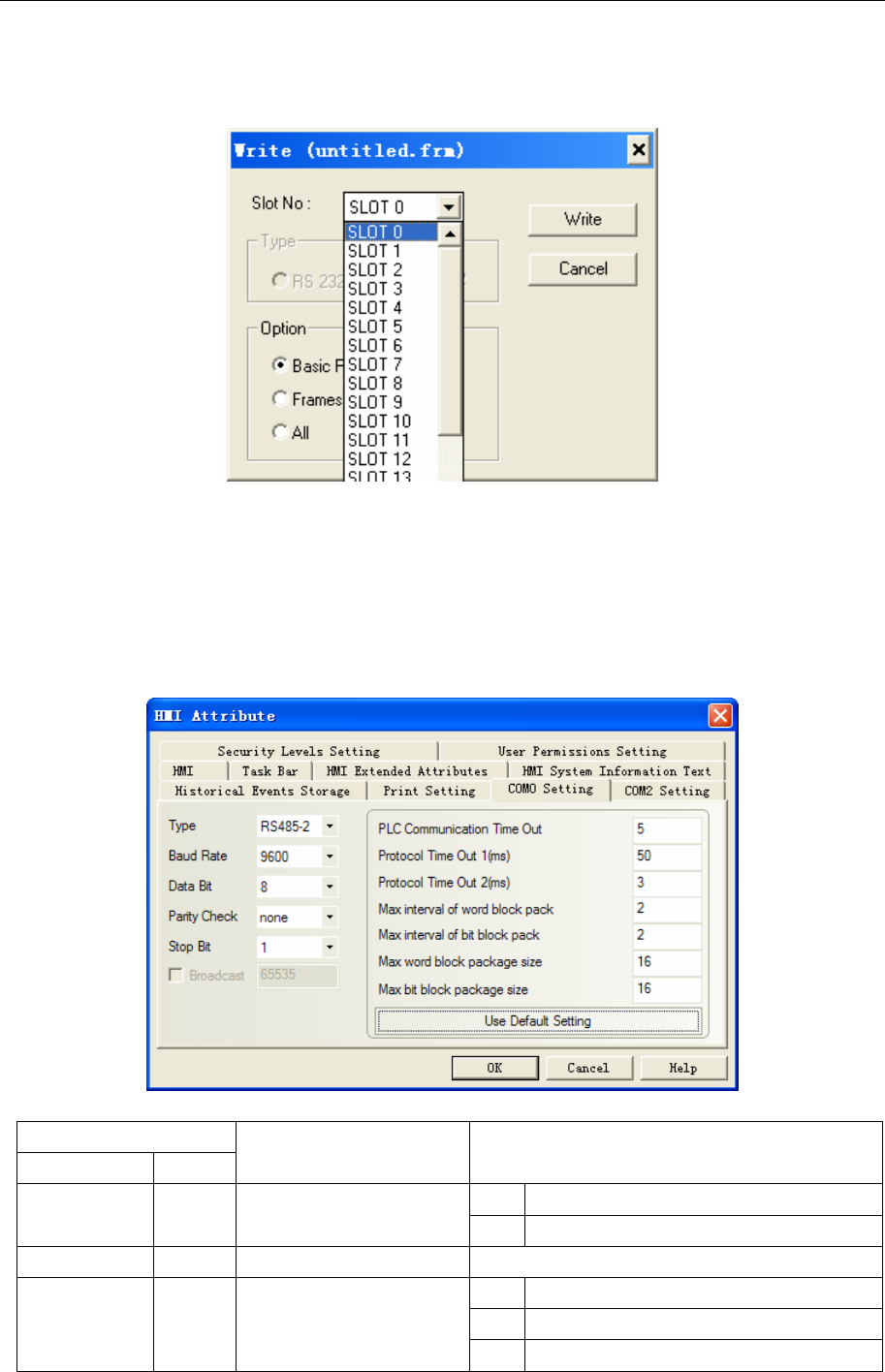
4 Communication settings and guide of HMI connecting with controller
- 180 -
As G6L-CUEC is RS422/485 module, the channel should be selected “RS422 side”. After set the
parameters, click ”Online””Connect”, and then click ”Online””Write” after the communication is built,
pay attention to choose the correct Slot No..
The Slot No. is the I/O slot position where the communication module is. For example, G6L-CUEC is
plugged in the I/O 1, the Slot No. should be selected SLOT 1.
NOTE: Be sure to put the switch of the module to 9 (ON-LINE) position when communicating.
LS ig5A Protocol
HMI Setting
Default communication: 9600bps,8,none,1;PLC station:1
PLC Setting
Settings
paneldisplay AddrParameterdirections
0 Modbus RTU I59 A43BProtocol
1 LS BUS
I60 A43CStation1-250
0 1200[bps]
1 2400[bps]
I61 A43DBaudRate
2 4800[bps]
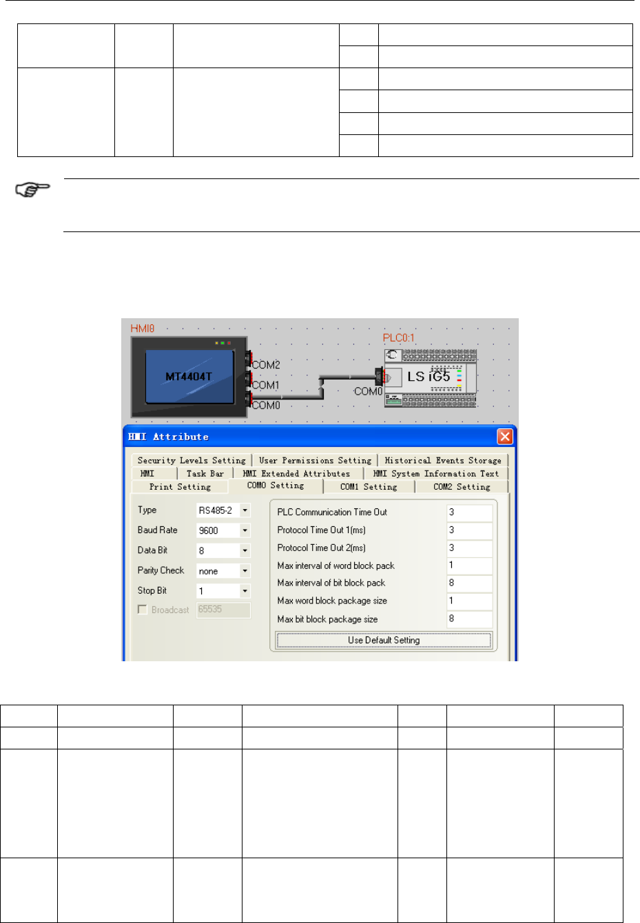
4 Communication settings and guide of HMI connecting with controller
- 181 -
3 9600[bps]
4 19200[bps]
0 none,stop bit:1
1 none,stop bit:2
2 even,stop bit:1
I65 A441ParityCheck
3 odd,stop bit:1
The controller also supports the standard Modbus RTU protocol , set the agreement with
LS ig5A.
LS Ig5 Protocol
HMI Setting
Default communication:9600bps,8,none,1;station:1
PLC Setting
Setting in operation panel:
Code Name Display Range Unit Factory setting Change
I/O-46 Inverter No. I46 1 to 32 1 1 yes
I/O-47 Baud rate I47 0:1200bps
1:2400bps
2:4800bps
3:9600bps
4:19200bps
- 3:9600bps yes
I/O-50 Communication
protocol
I50 0:LS-BUS
1-6:MODBUS ASCII
7-9:MODBUS-RTU
7 yes
Note: Setting communication protocol in operation panel(0:LS-BUS),when use inverter
LS C100 Series Inverter Protocol
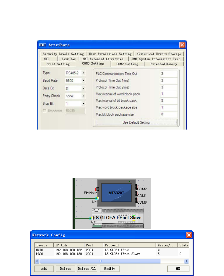
4 Communication settings and guide of HMI connecting with controller
- 182 -
HMI Setting
Default communication:9600bps, 8,non,1;station:1
(Attention, parity check :non ,no modification)
RS485
◎Ethernet Communication Setting
LS GLOFA FEnet protocol
GM6-CPU Setting
HMI Setting
PLC Setting
1. Modify the parameters of PLC: “Tools””Enet Frame Editor”, set the type as “FENET”:
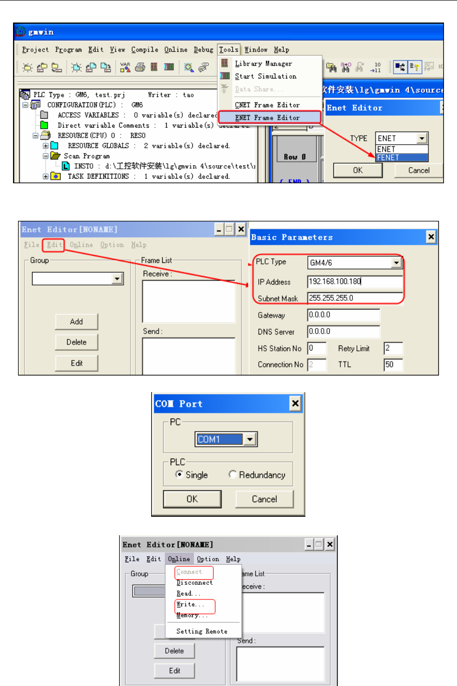
4 Communication settings and guide of HMI connecting with controller
- 183 -
NOTE: Modify the IP address only via serial communication, and in the offline.
2. On the “Enet Editor” and select “Edit”, set the PLC series and IP address
3. On the “Option” and select “COM Port”, set the serial port of PC
4. Download: “Online””Connect””Write”
XGK-CPUE Setting
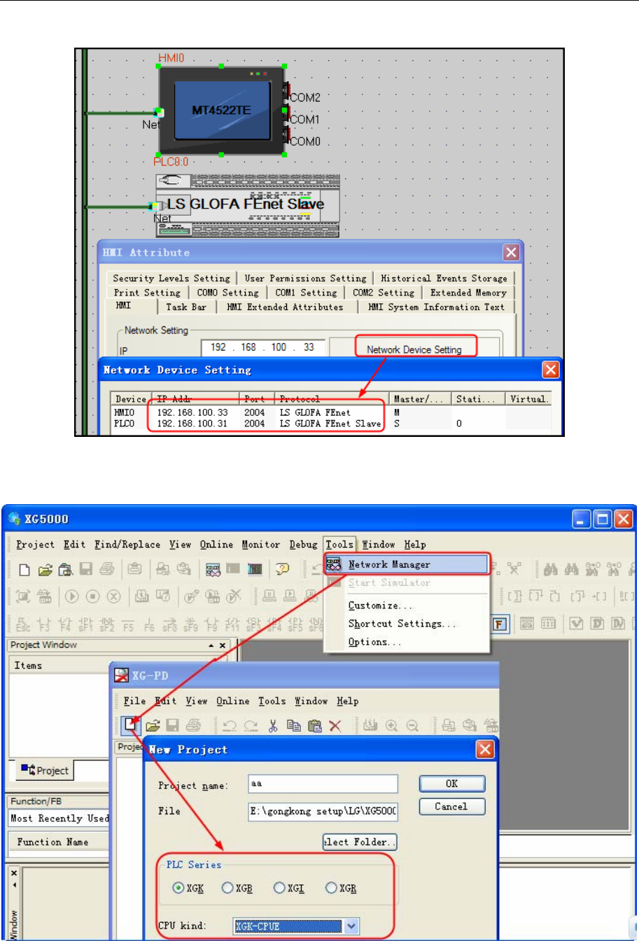
4 Communication settings and guide of HMI connecting with controller
- 184 -
HMI setting
PLC setting
1. PLC parameter settings: [Tools] - [ network management ] , in the pop-up window XG-PD ,
create a new file , select the correct CPU kind .
2. Double click the [ base 00 ], in the pop-up window [communication module Settings], select
the category FEnet .
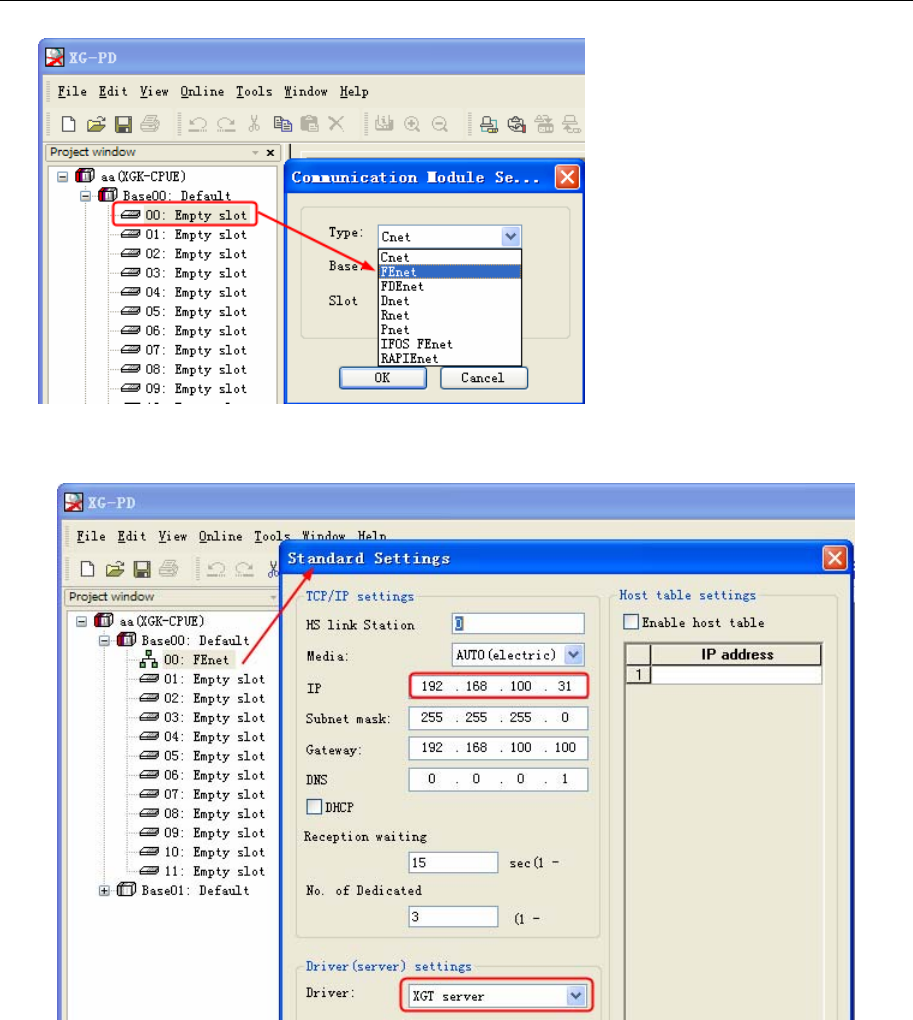
4 Communication settings and guide of HMI connecting with controller
- 185 -
3. Double click the FEnet, in the pop-up window [ Standard Settings] to set the IP address and
drive .
LS XBC FEnet Slave
HMI Setting
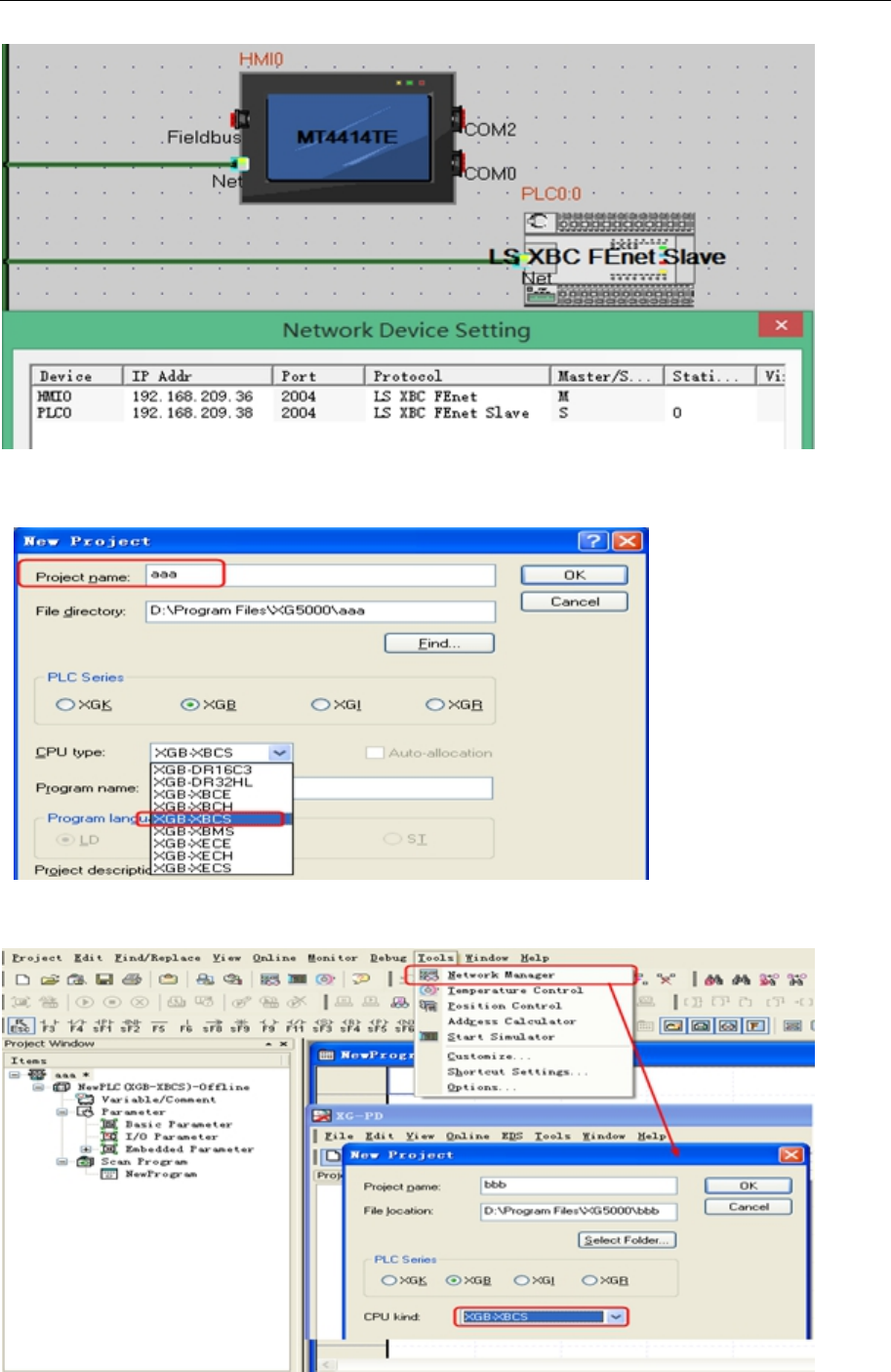
4 Communication settings and guide of HMI connecting with controller
- 186 -
PLC Setting
1.Open XG5000,new project aaa,choosing the right CPU ;
2.PLC parameter setting(IP setting):
A.【Tools】→【Network Manager】,new project bbb in XG-PD,choosing the right CPU;
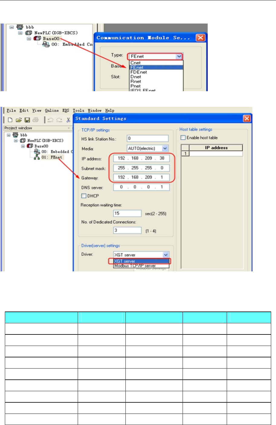
4 Communication settings and guide of HMI connecting with controller
- 187 -
B.Right click【Base00】→【Add Communication Module】,Select FEnet;
C.Setting IP and Driver in【Standard Settings】;
3.Setting OK,writer parameters to PLC;
◎Supported Device
LS Master-K CPU Direct
Device Bit Address Word Address Format Notes
I/O Relay P 0.0-255.F ------ DDD.H
Auxiliary Relay M 0.0-255.F ------ DDD.H
Link Relay L 0.0-255.F ------ DDD.H
Keep Relay K 0.0-255.F ------ DDD.H
Special Relay F 0.0-255.F ------ DDD.H
Counter C 0-255 ------ DDD
Timer T 0-255 ------ DDD
I/O Relay ------ P 0-255 DDD
Auxiliary Relay ------ M 0-255
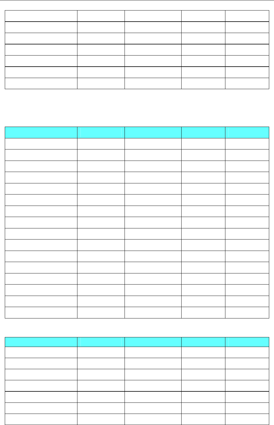
4 Communication settings and guide of HMI connecting with controller
- 188 -
Link Relay ------ L 0-255
Keep Relay ------ K 0-255
Special Relay ------ F 0-255
S ------ S 0-255
Timer ------ T 0-255 DDDD
Counter ------ C 0-256 DDDD
Data Register ------ D 0-9999 DDDD
NOTE:F address: 01 in the PLC corresponds to 0.1 in the HMI;
F address: 2A in the PLC corresponds to 2.A in the HMI.
Other register addresses, and so on.
LS Master K-cnet
Device Bit Address Word Address Format Notes
I/O Relay P 0.0-255.F ------ DDD.H
Auxiliary Relay M 0.0-255.F ------ DDD.H
Link Relay L 0.0-255.F ------ DDD.H
Keep Relay K 0.0-255.F ------ DDD.H
Special Relay F 0.0-255.F ------ DDD.H
Counter C 0-255 ------ DDD
Timer T 0-255 ------ DDD
I/O Relay ------ P 0-255 DDD
Auxiliary Relay ------ M 0-255 DDD
Link Relay ------ L 0-255 DDD
Keep Relay ------ K 0-255 DDD
Special Relay ------ F 0-255 DDD
S ------ S 0-255 DDD
Timer ------ T 0-255 DDDD
Counter ------ C 0-256 DDDD
Data Register ------ D 0-9999 DDDD
LS Modbus RTU
Device Bit Address Word Address Format Notes
I/O Relay P 0.0-1023.F ------ DDD.H
Auxiliary Relay M 0.0-1023.F ------ DDD.H
Link Relay L 0.0-2047.F ------ DDD.H
Keep Relay K 0.0-4095.F ------ DDD.H
Special Relay F 0.0-1023.F ------ DDD.H
Timer ------ T 0-255 DDD
Counter ------ C 0-255 DDD
4 Communication settings and guide of HMI connecting with controller
- 189 -
Data Register ------ D 0-9999 DDDD
LS XGT_Cnet
Device Bit Address Word Address Format
File Relay R_bit 0.0-10239.F ------ DDDDD.H
Data Relay D_bit 0.0-10239.F ------ DDDDD.H
Communication Relay N_bit 0.0-5119.F ------ DDDD.H
Link Relay L_bit 0.0-2047.F ------ DDDD.H
Index Relay Z_bit 0.0-624.F ------ DDD.H
Counter Contact Relay C_bit 0-9999 ------ DDDD
Timer Contact Relay T_bit 0-9999 ------ DDDD
Special Relay F_bit 0.0-1023.F ------ DDDD.H
Keep Relay K_bit 0.0-4095.F ------ DDDD.H
Auxiliary Relay M_bit 0.0-1023.F ------ DDDD.H
I/O Relay P_bit 0.0-1023.F ------ DDDD.H
File Register ------ R_word 0-10239 DDDDD
Data Register ------ D_ word 0-10239 DDDDD
Communication Register ------ N_ word 0-9999 DDDD
Link Register ------ L_ word 0-9999 DDDD
Step Control Register ------ S_ word 0-9999 DDDD
Index Register ------ Z_ word 0-9999 DDDD
Counter ------ C_ word 0-9999 DDDD
Timer ------ T_ word 0-9999 DDDD
Special Register ------ F_ word 0-9999 DDDD
Keep Register ------ K_ word 0-9999 DDDD
Auxiliary Register ------ M_ word 0-9999 DDDD
I/O Register ------ P_ word 0-9999 DDDD
NOTE: Register T_bit and C_bit can not communicate batch
LS XBC/XGK CPU Direct
Device Bit Address Word Address Format
File Relay R_bit 0.0-10239.F ------ DDDDD.H
Data Relay D_bit 0.0-10239.F ------ DDDDD.H
Communication Relay N_bit 0.0-5119.F ------ DDDD.H
Link Relay L_bit 0.0-2047.F ------ DDDD.H
Index Relay Z_bit 0.0-624.F ------ DDD.H
ZR_bit 0.0-10239.F ------ DDDDD.H
4 Communication settings and guide of HMI connecting with controller
- 190 -
Counter Contact Relay C_bit 0-9999 ------ DDDD
Timer Contact Relay T_bit 0-9999 ------ DDDD
Special Relay F_bit 0.0-1023.F ------ DDDD.H
Keep Relay K_bit 0.0-4095.F ------ DDDD.H
Auxiliary Relay M_bit 0.0-1023.F ------ DDDD.H
I/O Relay P_bit 0.0-1023.F ------ DDDD.H
File Register ------ R 0-10239 DDDDD
Data Register ------ D 0-10239 DDDDD
Communication Register ------ N 0-9999 DDDD
Link Register ------ L 0-9999 DDDD
Step Control Register ------ S 0-9999 DDDD
Index Register ------ Z 0-9999 DDDD
------ ZR 0-10239 DDDDD
Counter Set Value ------ C_ SV 0-9999 DDDD
Timer Set Value ------ T_ SV 0-9999 DDDD
Counter Current Value ------ C_ CV 0-9999 DDDD
Timer Current Value ------ T_ CV 0-9999 DDDD
Special Register ------ F 0-9999 DDDD
Keep Register ------ K 0-9999 DDDD
Auxiliary Register ------ M 0-9999 DDDD
I/O Register ------ P 0-9999 DDDD
LS XBC/XGK CPU Direct
Device Bit Address Word Address Format
A_Bit 0.0-8191.F
------- DDDD.H
Special Relay F_Bit 0.0-1023.F ------- DDDD.H
W_Bit 0.0-10239.F ------- DDDDD.H Same area with R
File Relay R_Bit 0.0-10239.F ------- DDDDD.H
Special module Relay U_Bit 0.0-511.F ------- DDD.H
Keep Relay K_Bit 0.0-4095.F ------- DDDD.H
Link Relay L_Bit 0.0-2047.F ------- DDDD.H
Auxiliary Relay M_Bit 0.0-4095.F ------- DDDD.H
Output Relay Q_Bit 0.0-1023.F ------- DDDD.H
Input Relay I_Bit 0.0-1023.F ------- DDDD.H
-------
A 0-8191 DDDD
Special Register ------- F 0-1023 DDDD
-------
W 0-10239 DDDDD
File Register ------- R 0-10239 DDDDD
Special module Register ------- U 0-511 DDD
Keep Register ------- K 0-4095 DDDD
4 Communication settings and guide of HMI connecting with controller
- 191 -
Link Register ------- L 0-2047 DDDD
Auxiliary Reguster ------- M 0-4095 DDDD
Output Register ------- Q 0-1023 DDDD
Input Register ------- I 0-1023 DDDD
LS XEC CPU Direct
Device Bit Address Word Address Format
A_Bit 0-262143
------- DDDDDD
Special Relay F_Bit 0-16383 ------- DDDDD
W_Bit 0-163839
------- DDDDDD Same area with R
File Relay R_Bit 0-163839 ------- DDDDDD
Communication Relay N_Bit 0-81919 ------- DDDDD
Special module Relay U_Bit 0-8191 ------- DDDD
Keep Relay K_Bit 0-65535 ------- DDDDD
Link Relay L_Bit 0-32767 ------- DDDDD
Auxiliary Relay M_Bit 0-131071 ------- DDDDDD
Output Relay Q_Bit 0-16383 ------- DDDDD
Input Relay I_Bit 0-16383 ------- DDDDD
-------
A 0-16383 DDDDD
Special Register ------- F 0-1023 DDDD
-------
W 0-10239 DDDDD
File Register ------- R 0-10239 DDDDD
Communication Register ------- N 0-5119 DDDD
Special module Register ------- U 0-511 DDD
Keep Register ------- K 0-4095 DDDD
Link Register ------- L 0-2047 DDDD
Auxiliary Reguster ------- M 0-8191 DDDD
Output Register ------- Q 0-1023 DDDD
Input Register ------- I 0-1023 DDDD
LS XEC Cnet
Device Bit Address Word Address Format
A_Bit 0-524287
------- DDDDDD
Special Relay F_Bit 0-32767 ------- DDDDD
W_Bit 0-524287
------- DDDDDD Same area with R
File Relay R_Bit 0-262143 ------- DDDDDD
Special module Relay U_Bit 0-15511 ------- DDDDD
Keep Relay K_Bit 0-131071 ------- DDDDD
4 Communication settings and guide of HMI connecting with controller
- 192 -
Link Relay L_Bit 0-65535 ------- DDDDD
Auxiliary Relay M_Bit 0-262143 ------- DDDDDD
Communication Relay N_Bit 0-163839 ------- DDDDD
Output Relay Q_Bit 0-151563 ------- DDDDDD
Input Relay I_Bit 0-151563 ------- DDDDDD
-------
A 0-32767 DDDDD
Special Register ------- F 0-2047 DDDD
-------
W 0-32767 DDDDD
File Register ------- R 0-16383 DDDDD
Special module Register ------- U 0-1531 DDDD
Keep Register ------- K 0-8191 DDDD
Communication Register ------- N 0-10239 DDDD
Link Register ------- L 0-4095 DDDD
Auxiliary Reguster ------- M 0-16383 DDDD
Output Register ------- Q 0-15153 DDDDD
Input Register ------- I 0-15153 DDDDD
1. The address format of %UX is D.DD.DDD (0.0.0-0.15.511) in the PLC, it correspond to
DDDDD (0-15511) in the HMI. And the %UX 0.m.n in the PLC is U_Bit m*512+n in the
HMI.
For example,
Internal address: %UX 0.1.0 in the PLC correspond to U_Bit 512 in the HMI
Internal address: %UX 0.15.511 in the PLC correspond to U_Bit 8191 in the HMI
Similarly, the %UW 0.0.0-0.15.511 in the PLC correspond to U_Word 0-1531 in the HMI.
The %UW 0.m.n in the PLC is U_Word m*32+n.
For example,
Internal address: %UW 0.1.0 in the PLC correspond to U_Word 32 in the HMI
Internal address: %UW 0.15.31 in the PLC correspond to U_Word 511 in the HMI
2. The address format of %QX/IX is DD.DD.DD (0.0.0-15.15.63) in the PLC, it correspond to
DDDDDD (0-151563) in the HMI. And the %QX/IX a.b.c in the PLC is Q_Bit/I_Bit
a*1024+b*64+c in the HMI.
For example,
Internal address: %QX/IX 0.1.0 in the PLC correspond to Q_Bit/I_Bit 64 in the HMI
Internal address: %QX/IX 15.15.63 in the PLC correspond to Q_Bit/I_Bit 16383 in the HMI
Similarly, the %QW/IW 0.0.0-15.15.3 in the PLC correspond to Q_Word/I_Word 0-15153 in
the HMI. The %QW/IW a.b.c in the PLC is Q_Word/I_Word a*64+b*4+c.
For example,
Internal address: %QW/IW 0.1.0 in the PLC correspond to Q_Word/I_Word 4 in the HMI
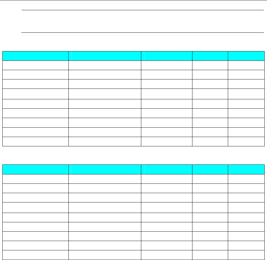
4 Communication settings and guide of HMI connecting with controller
- 193 -
Internal address: %QW/IW 15.15.63 in the PLC correspond to Q_Word/I_Word 1023 in the
HMI
LS GLOFA Cnet
Device Bit Address Word Address Format Notes
Buffer Memory(Bit) MX0-32767 ------ DDDDD
Output(Bit) QX0-1763 ------ DDDD
Input(Bit) IX0-1763 ------ DDDD
Buffer Memory(Dword) ------ MD0-16368 DDDDD
Output(Dword) ------ QD0.0-17.1 DD.D
Input(Dword) ------ ID0.0-17.1 DD.D
Buffer Memory(Word) ------ MW0-32767 DDDDD
Output(Word) ------ QW0.0-17.3 DD.D
Input(Word) ------ IW0.0-17.3 DD.D
LS GLOFA FEnet
Device Bit Address Word Address Format Notes
Buffer Memory(Bit) MX0-131056 ------ DDDDD
Output(Bit) QX0-1763 ------ DDDD
Input(Bit) IX0-1763 ------ DDDD
Buffer Memory(Dword) ------ MD0-4095 DDDD
Output(Dword) ------ QD0.0-17.1 DD.D
Input(Dword) ------ ID0.0-17.1 DD.D
Buffer Memory(Word) ------ MW0-8191 DDDD
Output(Word) ------ QW0.0-17.3 DD.D
Input(Word) ------ IW0.0-17.3 DD.D
NOTE:
1. The address format of %QX\IX is DD.D.DD (00.0.00~63.7.63) in the PLC, it correspond to DD D DD
(0~63763) in the HMI; Note that put 0 before the address if the address is less than two bits.
For example,
Internal address : %QX\IX 0.3.1 in the PLC correspond to QX\IX 301 in the HMI;
Internal address : %QX\IX 1.4.63 in the PLC correspond to QX\IX 1463 in the HMI;
2. The address format of %QD\ID is D.D.D (0.0.0~1.7.1) in the PLC, it correspond to D D.D (0.0~17.1) in
the HMI;
For example,
Internal address : %QD\ID 0.3.1 in the PLC correspond to QD\ID 3.1 in the HMI;
Internal address : %QD\ID 1.5.1 in the PLC correspond to QD\ID 15.1 in the HMI;
3. The address format of %QW\IW is D.D.D (0.0.0~1.7.3) in the PLC, it correspond to D D.D (0.0~17.3) in
the HMI;
For example,
Internal address : %QW\IW 0.3.1 in the PLC correspond to QW\IW 3.1 in the HMI;
Internal address : %QW\IW 1.5.3 in the PLC correspond to QW\IW 15.3 in the HMI;
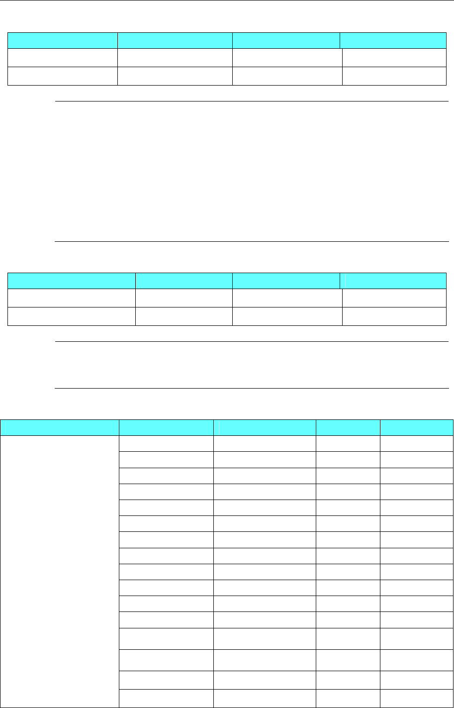
4 Communication settings and guide of HMI connecting with controller
- 194 -
LS iG5A protocol
Device Bit Address Word Address Format
Bits AB 0.0-65535.F
------- DDDDD
Words -------
AW 0-65535 DDDDD
NOTE:
1、The representation of address is hexadecimal in the Inverter User's Manual , used in
the project must be converted to decimal.Such as universal domain address
0000 corresponds to AW0,The address of the function list A100 corresponds
AW41216.
2、Register more than eight consecutive addresses will not be properly read.
3、Some address may affect the surrounding register read, should used separately:
H8andH10,H42andH44,do not show put together
H20,H30,H36,H37,H42,H50,H51,H52,H70,H90
F30,F37,F60,I27,I57
MODUS RTU protocol(support LS iG5A)
Device Bit Address Word Address Format
Read Holding Registers ------- 3X 1-65535
DDDDD
Read Input Registers ------- 4X 1-65535
DDDDD
NOTE:
Inverter address converted to decimal, the address of the function list A100
corresponds AW41216.
Modbus address starting from 1, the general field of 0000 address is inaccessible.
LS C100 Series Inverter protocol
Device Bit Address Word Address Format Notes
------ Fbr 0 D
------ rEF 0 D
------ Fra 0 D
------ drv2 0 D
------ drC 0 D
------ nOn 0 D
------ vOL 0 D
------ dCL 0 D
------ rPM 0 D
------ CUr 0 D
------ St3 0 D
------ St2 0 D
------ St1 0 D
------ Frq 0 D
------ drv 0 D
Driver
------ dEC 0 D
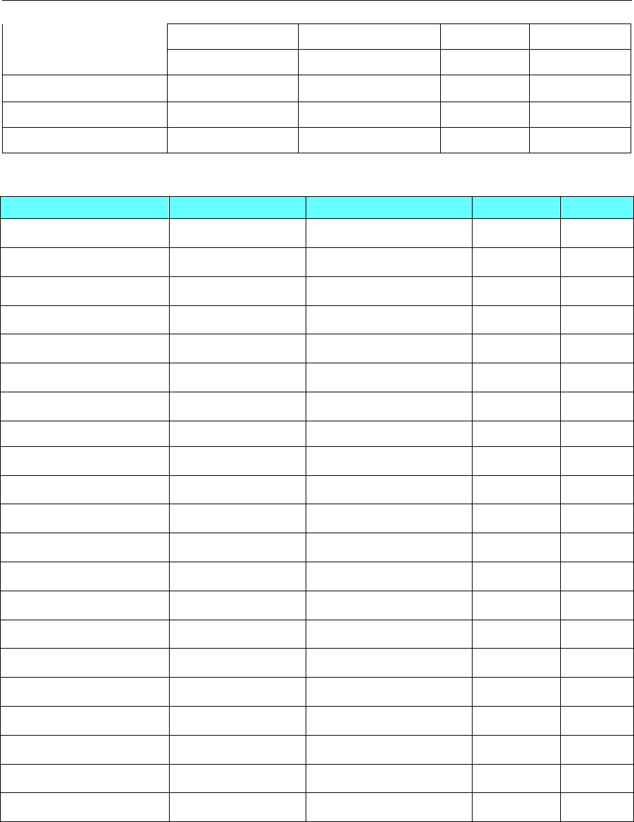
4 Communication settings and guide of HMI connecting with controller
- 195 -
------ ACC 0 D
------ DRIVER_0 0 D
I/O ------ I 0-87 DD
Funcation 1 ------ F0-72 DD
Funcation 2 ------ H0-95 DD
LS XBC FEnet Slave protocol
Device Bit Address Word Address Format Notes
I/O Relay P_Bit 0.0-2047.F ------ DDDD.H
Link Relay L_Bit 0.0-11263.F ------ DDDDD.H
Counter Contact Relay C_Bit 0-2047 ------ DDDD
Timer Contact Relay T_Bit 0-2047 ------ DDDD
Special Relay F_Bit 0.0-2047.F ------ DDDD.H
Keep Relay K_Bit 0.0-4095.F ------ DDDD.H
Auxiliary Relay M_Bit 0-8191.F ------ DDDD.H
Analog Data ------ U_Word 0.00-127.31 DDD.DD
------ ZR_Word 0-65535 DDDDD
File Register ------ R_Word 0-32767 DDDDD
Data Register ------ D_Word 0-32767 DDDDD
Communication Register ------ N_Word 0-21503 DDDDD
Counter Register ------ C_Word 0-2047 DDDD
Timer Register ------ T_Word 0-2047 DDDD
Link Register ------ L_Word 0-11263 DDDDD
Step Control Register ------ S_Word 0-127 DDD
Index Register ------ Z_Word 0-127 DDD
Special Register ------ F_Word 0-2047 DDDD
Keep Register ------ K_Word 0-4095 DDDD
Auxiliary Register ------ M_Word 0-2047 DDDD
I/O Register ------ P_Word 0-2047 DDDD
◎Cable Diagram
LS Master-K Cnet/ LS Master-K Modbus RTU protocol
RS232 communication cable
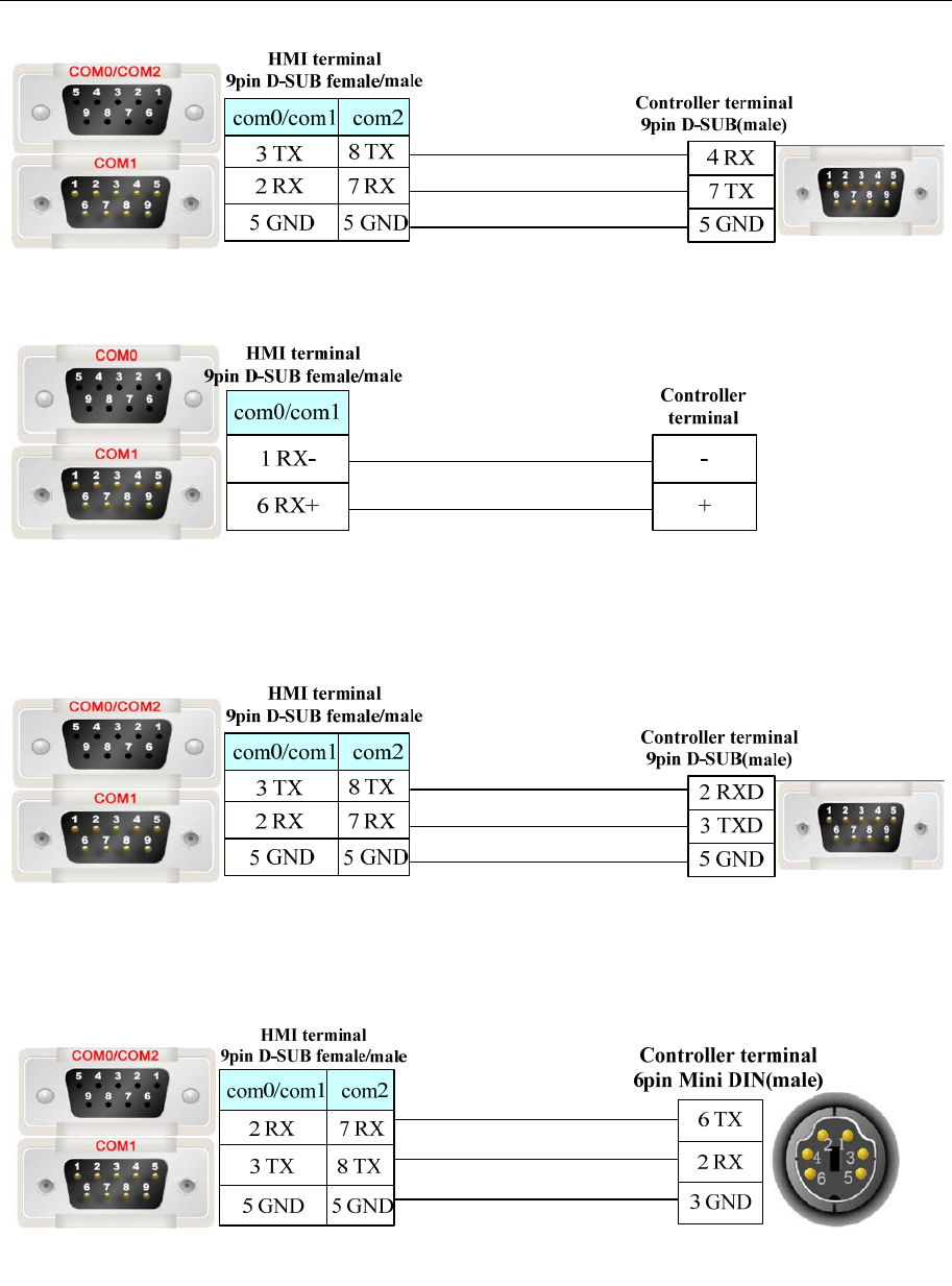
4 Communication settings and guide of HMI connecting with controller
- 196 -
RS485-2 communication cable
LS Master-K CPU Direct protocol
RS232 communication cable
LS XBC/XGK/XEC CPU Direct protocol
RS232 communication cable
LS XBC/XGK/XEC Cnet protocol
RS232 programming cable
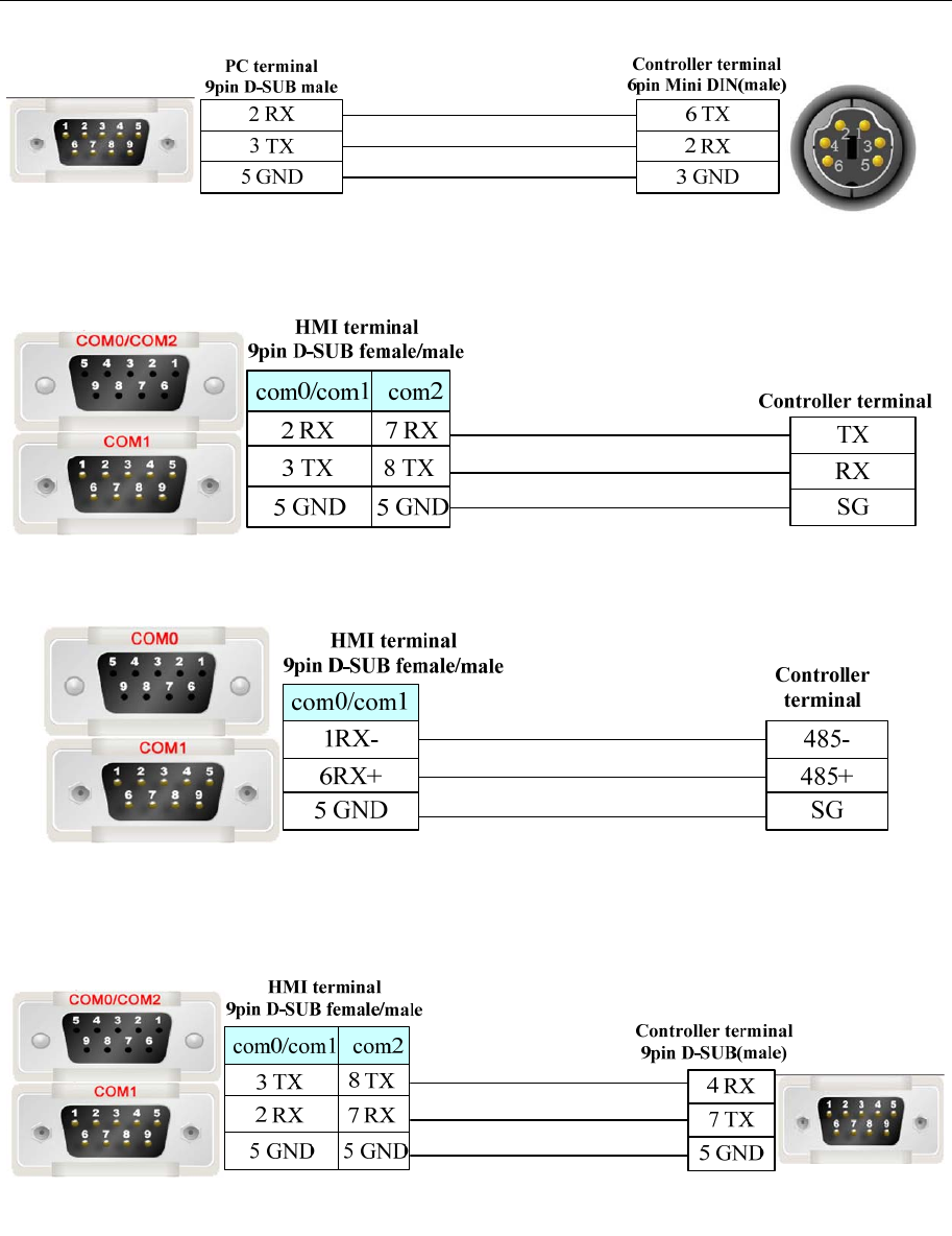
4 Communication settings and guide of HMI connecting with controller
- 197 -
RS232 communication cable
RS485 communication cable
LS GLOFA Cnet protocol
RS232 communication cable
RS422 communication cable
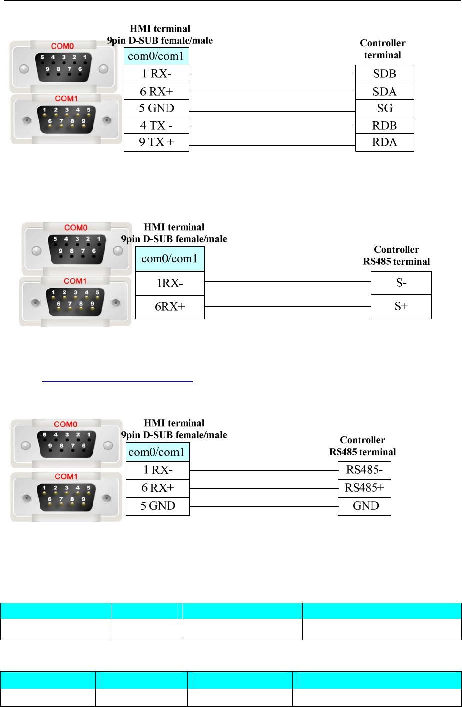
4 Communication settings and guide of HMI connecting with controller
- 198 -
NOTE: Be sure to put the switch of the module to 9 (ON-LINE) position when communicating.
LS iG5A protocol
Ethernet Cable
Cross-connection or crossover network cable can be used as communication cable via the hub
Refer to 3.3 Download by Network Ethernet for method of making connection cable.
LS C100 Series Inverter protocol
4.45 LUST
◎Serial Communication
Series CPU Link Module Driver
CDE34.008 CDE34.008 RS232 on the CPU unit LustBus
◎Network communication (direct online simulation disable)
Series CPU Link Module Driver
ServoOne junior Lust ETH on the CPU Lust Ethernet Slave
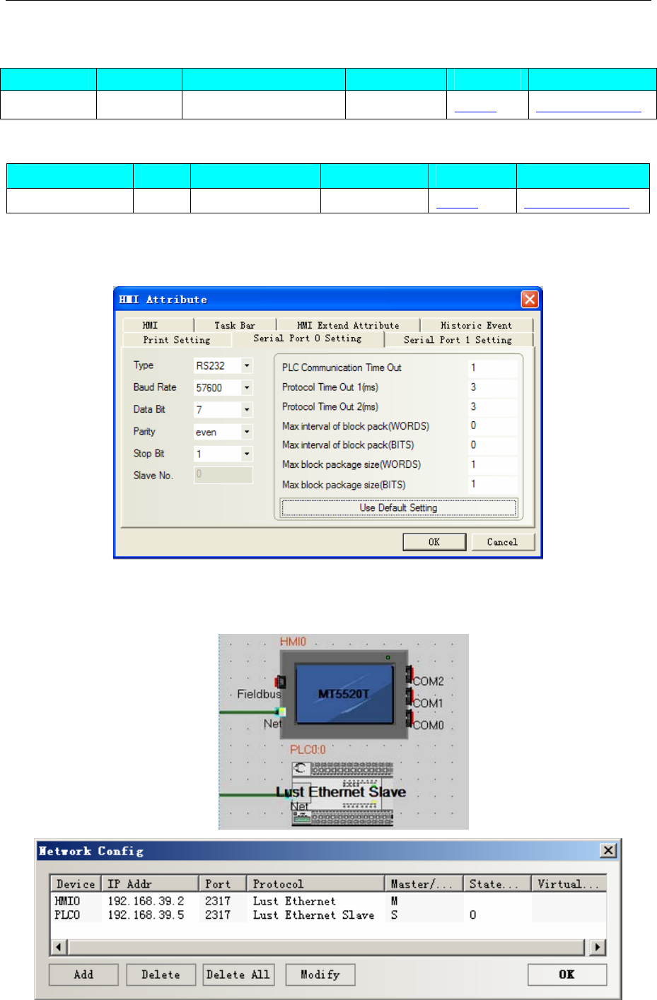
4 Communication settings and guide of HMI connecting with controller
- 199 -
◎Serial System configuration
Series CPU Link Module COM Type Parameter Cable
CDE34.008 CDE34.008 RS232 on the CPU unit RS232 Setting Your owner cable
◎Network System configuration
Series CPU Link Module COMM Type Parameter Cable
ServoOne junior Lust ETH on the CPU ETH Setting Your owner cable
◎Serial Communication Setting
Lustbus RS232 default communication: 57600, 7, even, 1; station: 1
◎Network Communication Setting
HMI Setting
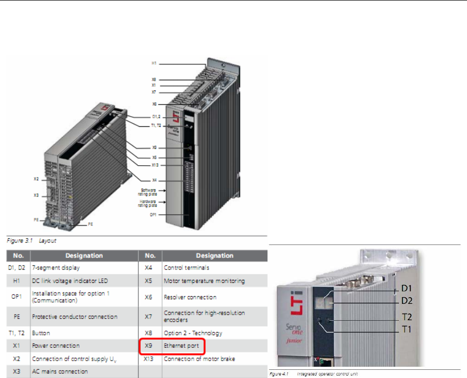
4 Communication settings and guide of HMI connecting with controller
- 200 -
The way to change IP of Servo drive system
Plug the 24-volt power supply on the X2, plug the network cable on the X9.
Refer to the map, press the T1 or T2 to modify the IP
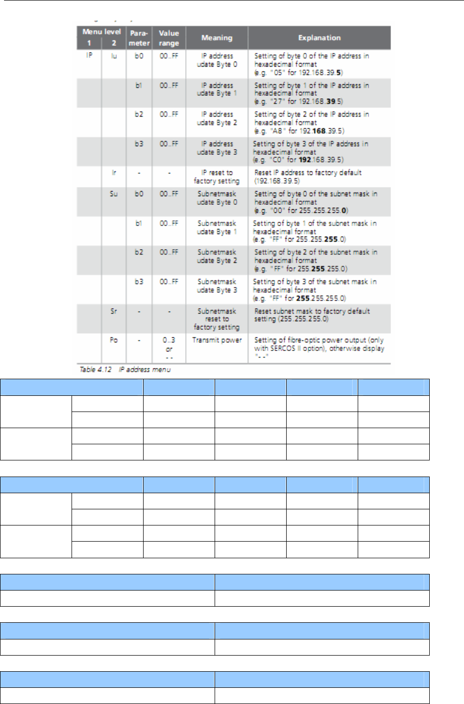
4 Communication settings and guide of HMI connecting with controller
- 201 -
Parameter b3 b2 b1 b0
int 192 168 39 5
Initial IP hex C0 A8 27 05
int 192 168 100 240
Modified IP hex C0 A8 64 F0
Parameter b3 b2 b1 b0
int 192 168 39 5
Initial IP hex C0 A8 27 05
int 192 168 100 240
Modified IP hex C0 A8 64 F0
The following description of specific processes, after the servo power
D1 D2
5. 1.
Press key T1 of about 1s
D1 D2
P R
Press key T1 of about 1s
D1 D2
I P
Press key T2 of about 1s
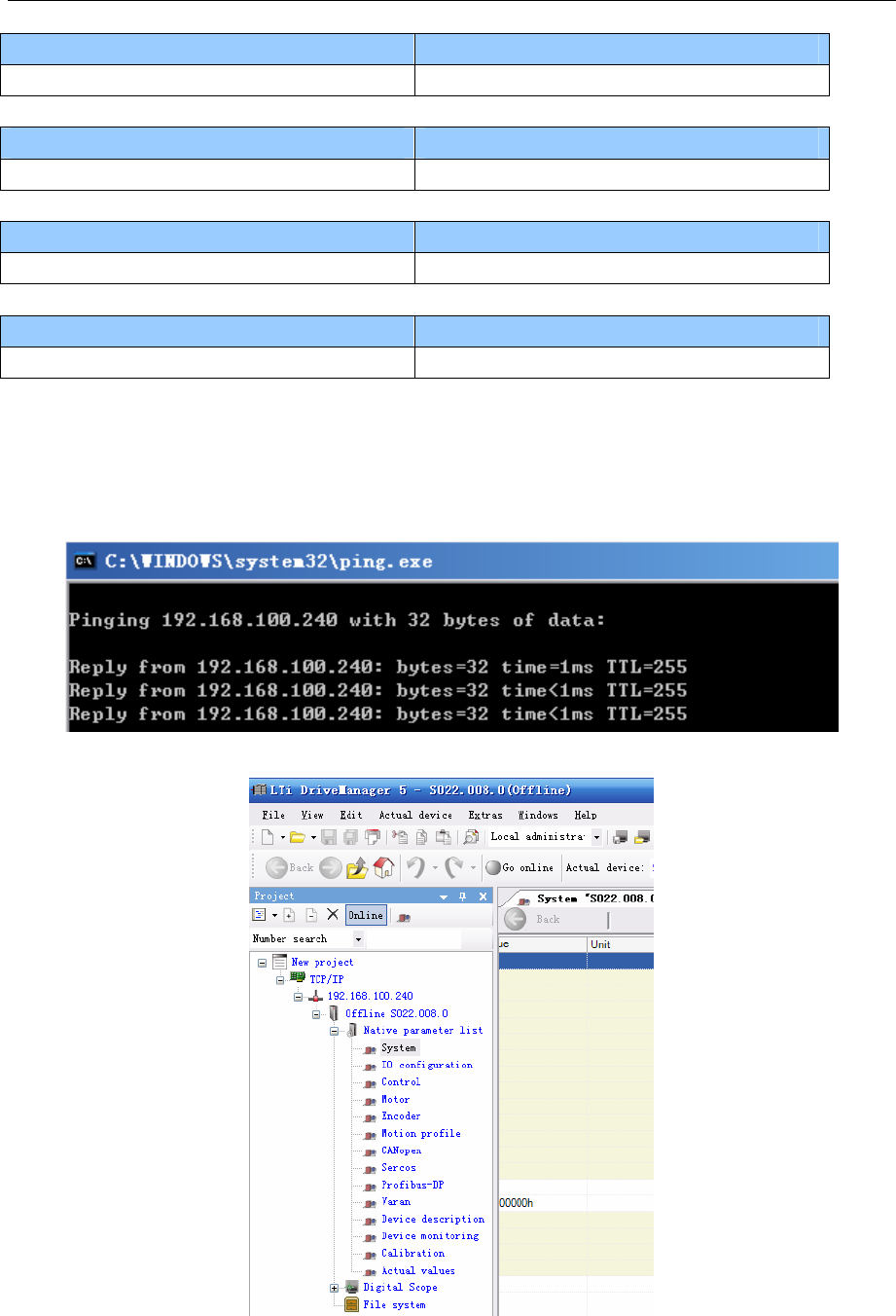
4 Communication settings and guide of HMI connecting with controller
- 202 -
D1 D2
l u
Press key T2 of about 1s
D1 D2
b 0
Press key T2 of about 1s
D1 D2
b 0
1s at about T2 button to display the value of d0, the initial value is 05
D1 D2
0 5
Press T1, respectively, and T2, you can adjust the value of b0, After release, while at T1 and T2 key until
the display or can be, Then press and T1 and T2, also show b0, then press the key T1 of about 1s,can switch
to b2, empathy can be modified the value of b2, b3, b4, modify the good, the same press T1 and T2 until
display “or” (where press T1 and T2 at the same time is the key to save and exit).
Well, after the change, restart the power, and then ping.
After the software is connected
◎Supported Device
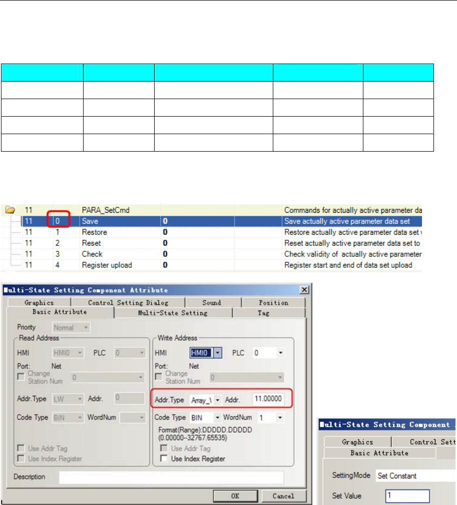
4 Communication settings and guide of HMI connecting with controller
- 203 -
CDE34.008
Refer to the Controller software for details: DriveManager for c-line drives
ServoOne junior
Device Bit Address Word Address Format Notes
Array_DWord32 ———— 0.00000-32767.65535 DDDDD.DDDDD
Array_DWord16 ———— 0.00000-32767.65535 DDDDD.DDDDD
DWord32 ———— 0-32767 DDDDD
Word16 ———— 0-32767 DDDDD
Note: Array_DWord32/Array_DWord16 the address format is the primary address + decimal point +
sub-address, such as the address for the save as shown below, the main address is 11, sub-address is 0, the
data type is int16, then the touch screen corresponding to the address is Array_DWord16 11.00000.
The primary address is 11, sub-address is 1, the data type is int16, then the touch screen corresponding to
the address is Array_DWord16 11.00001. In addition, INT8 address, select Word16, but also through the
conversion can be displayed, as should show -3, while the display 253, which can be done in the macro
data conversion, so 253-256 = -3, that is in need of special address type conversion .
◎Cable Diagram
Lustbus RS232 communication cable
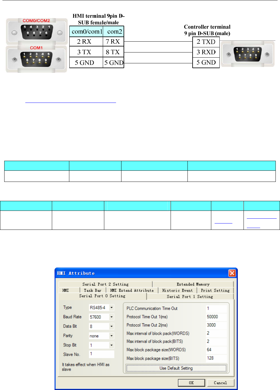
4 Communication settings and guide of HMI connecting with controller
- 204 -
Ethernet communication protocol cable
Cross-connection or crossover network cable can be used as communication cable via the hub
Refer to 3.3 Download by Network Ethernet for method of making connection cable.
4.46 Memory map
◎Serial Communication
Series CPU Link Module Driver
BMS005A-MC11 BMS005A-MC11 RS422 on the CPU unit MemoryMap(Master-Slave)
◎System configuration
Series CPU Link Module COMM Type Parameter Cable
BMS005A-MC11 BMS005A-MC11 RS422 on the CPU unit RS422 Setting Your owner
cable
◎Communication Setting
HMI Setting
Default communication: 57600, 8, none, 1; station: 1
PLC Setting
Please refer to the manual of PLC for the configuration.
◎Supported Device
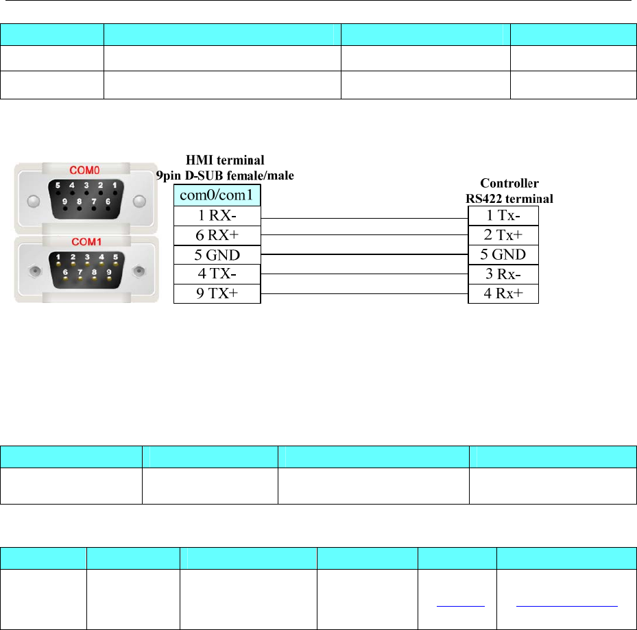
4 Communication settings and guide of HMI connecting with controller
- 205 -
Device Bit Address Word Address Format
LW.B 8000.0-8999.15 -------- DDDD.DD
-------- LW8000-8999 DDDD
◎Cable Diagram
4.47 MEGMEET
◎Serial Communication
◎ Serial Communication Parameters and Cables Production
Series CPU Link Module COMM Type Parameter Cable
MEGMEET
MC280
MC280-1616
BTA4
RS232 on the CPU
unit RS232/RS485 Setting Your owner cable
◎ Serial Communication Parameters
HMI Setting
Default communication:9600bps, 8,even,1;station:1
RS232
Series CPU Link Module Driver
MEGMEET MC280 MC280-1616BTA4 RS232 on the CPU unit MEGMEET MC Series
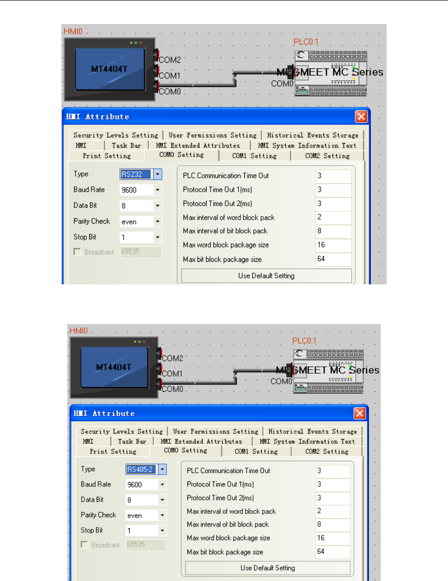
4 Communication settings and guide of HMI connecting with controller
- 206 -
RS485
PLC Setting
1.Open X_builder,New project,select PLC type(MC280)
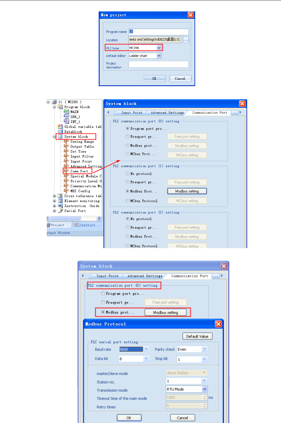
4 Communication settings and guide of HMI connecting with controller
- 207 -
2.Open System block→Comm Port,set comm port(support Modbus)
(1)Port0 setting(RS232)
(2)Port1andPort2 setting(RS485)
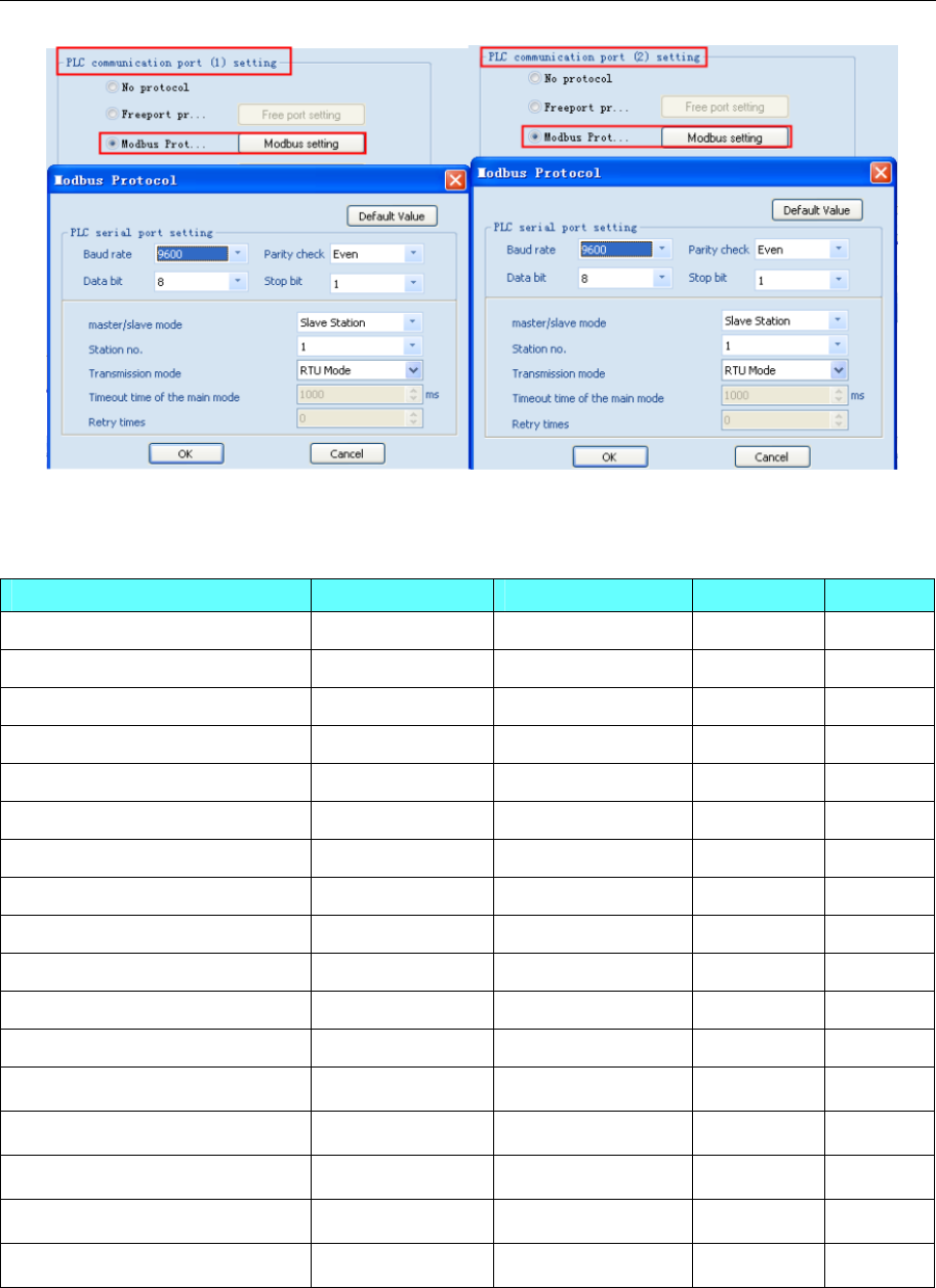
4 Communication settings and guide of HMI connecting with controller
- 208 -
Notes:Using X_builder,Main routine cannot be empty
◎ Supported Device
Device Bit Address Word Address Format Notes
Input Relay X 0-377 ------ OOO R
Output Relay Y 0-377 ------ OOO
Internal Relay M 0-10239 ------ DDDDD
Special Relay SM 0-511 ------ DDD
Step Relay S 0-4095 ------ DDDD
Timer Relay T_BIT 0-511 ------ DDD
Counter Relay C_BIT 0-306 ------ DDD
Data register ------ D 0-7999 DDDD
Special Register ------ SD 0-511 DDD
Index Register ------ Z 0-15 DD
Timer ------
T_Word 0-511 DDD
Counter ------
C_Word 0-199 DDD
Counter(double word) ------ C_DWord 200-306 DDD
------
R 0-32767 DDDDD
------ R_DWord 0-32767 DDDDD
Special Register(double word) ------ SD_DWord 0-511 DDD
Data register(double word) ------ D_DWord 0-7999 DDDD
◎ Cables Production
RS232
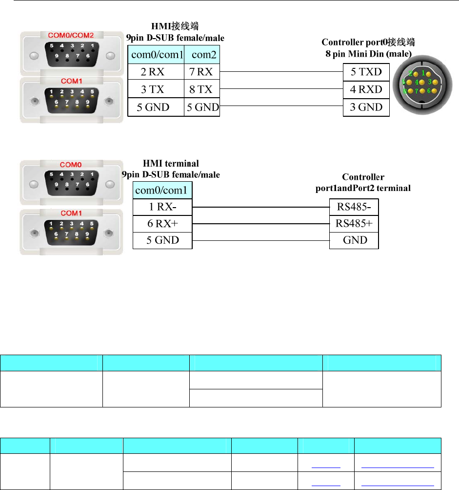
4 Communication settings and guide of HMI connecting with controller
- 209 -
RS485
4.48 Mikom
◎Serial Communication
Series CPU Link Module Driver
RS232 on the CPU unit
MX2H MX2H-3232M RS485 on port Mikom MXxh
◎System configuration
Series CPU Link Module COMM Type Parameter Cable
Port 0 RS232 Setting Your owner cable
MX2H MX2H-3232M Port 1 RS485-2 Setting Your owner cable
◎Communication Setting
HMI Setting
Default communication parameters 19200, 7, 1, even;Station:1
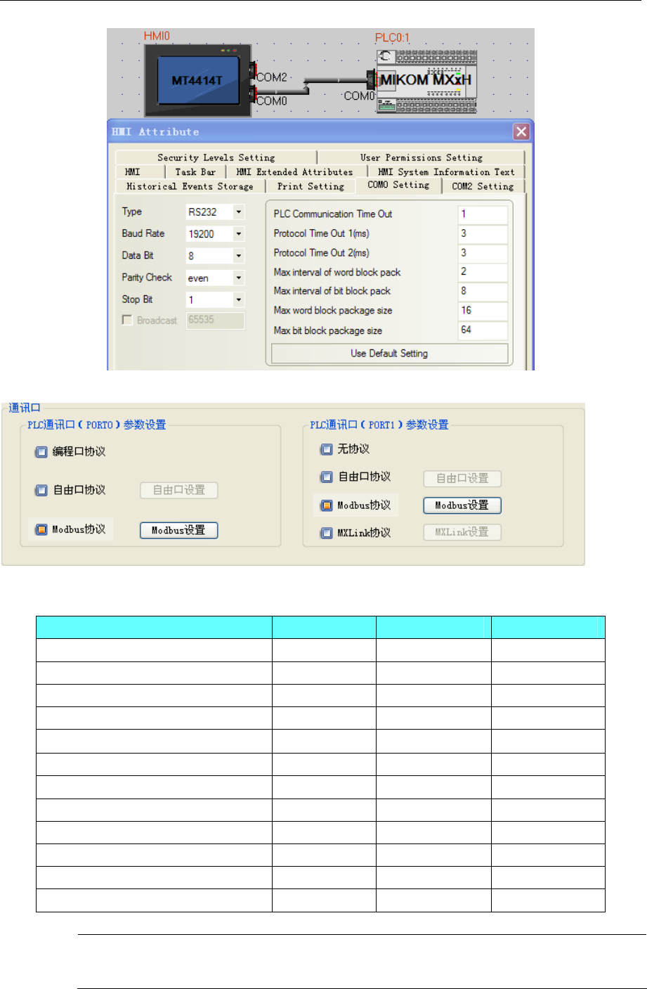
4 Communication settings and guide of HMI connecting with controller
- 210 -
PLC Setting
◎Supported Device
Device Bit Address Word Address Format
Input Relay X 0-777 OOO
Output Relay Y 0-777 OOO
Counter C_bit 0-511 DDD
Timer T_bit 0-511 DDD
Status Relay S 0-1535 DDDD
Special Relay SM 0-511 DDD
Internal Relay M 0-4095 DDDD
Data register D 0-7999 DDDD
Special Register(double word) SD 0-511 DDD
Index Register Z 0-255 DDD
Timer T_word 0-255 DDD
Counter C_word 0-199 DDD
NOTE: The PLC MODBUS protocol does not support double-word data type, so the protocol
does not support the bulk of the word read and write .
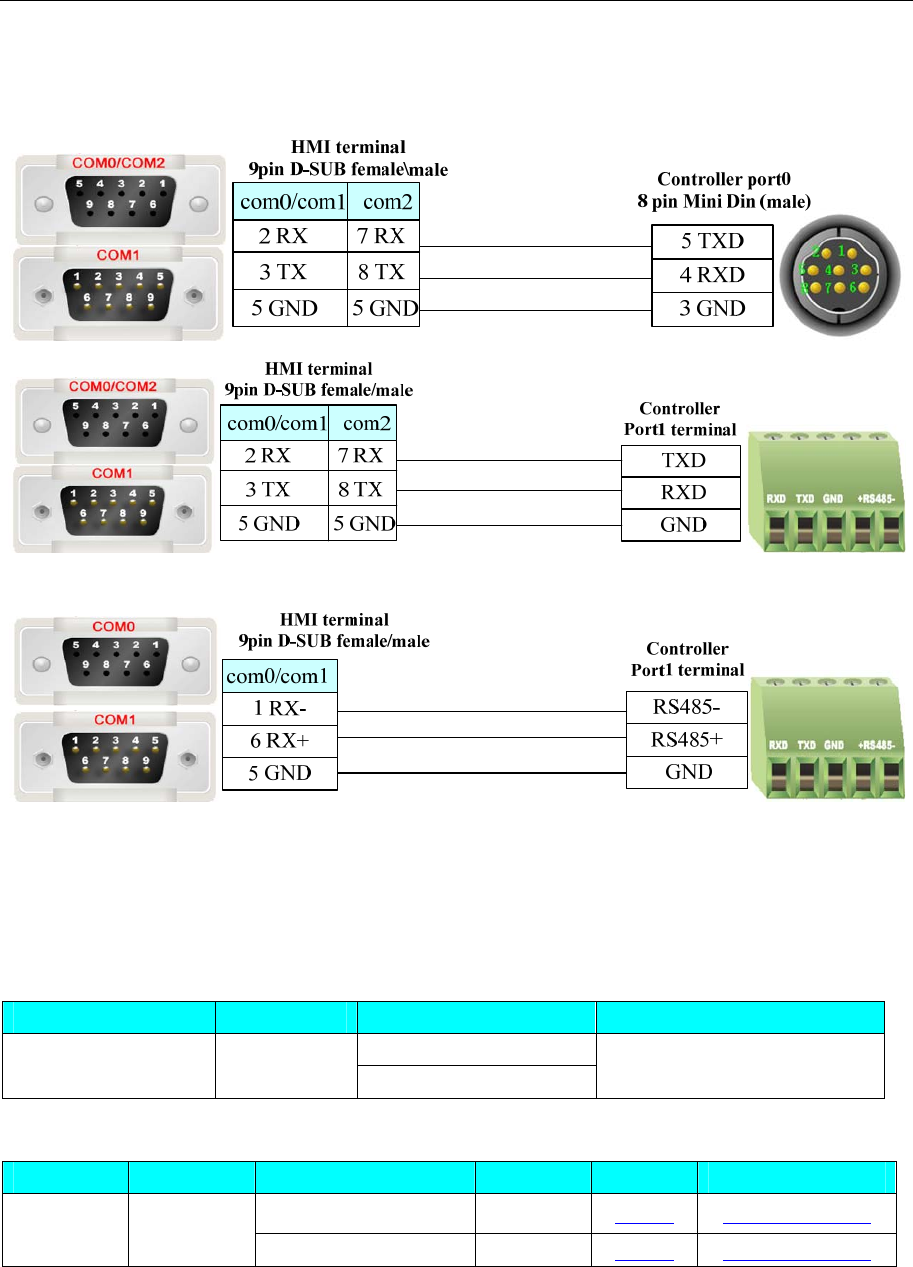
4 Communication settings and guide of HMI connecting with controller
- 211 -
◎Cable Diagram
RS232 Communication
RS485-2 Communication
4.49 Millenium3
◎Serial Communication
Series CPU Link Module Driver
RS232 on the CPU unit
Millenium 3 Millenium 3 RS485 on the CPU unit Millenium 3
◎System configuration
Series CPU Link Module COM Type Parameter Cable
RS232 on the CPU unit RS232 Setting Your owner cable
Millenium 3 Millenium 3
RS485 on the CPU unit RS485-2 Setting Your owner cable
◎Communication Setting
HMI Setting
Default communication parameters 115200, 7, 1, even;Station:1
RS232 Communication:
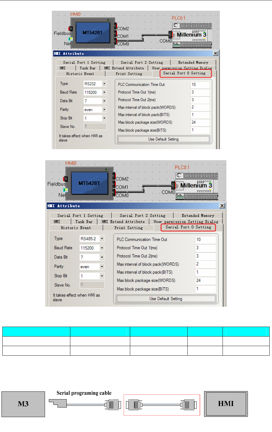
4 Communication settings and guide of HMI connecting with controller
- 212 -
RS485-2 Communication:
◎Supported Device
Device Bit Address Word Address Format Notes
Register ------ Register 0~23 DD Write only
Register ------ Register 24~47 DD Read only
◎Cable Diagram
RS232
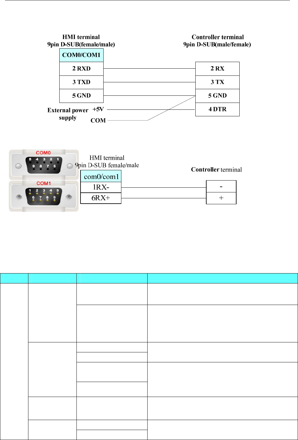
4 Communication settings and guide of HMI connecting with controller
- 213 -
Users need to make the communication cable for M3 and HMI (region of red marquee as shown above)
M3 communicate with COM0/COM1 of HMI, the cable connection is as follow:
NOTE: Provide 5V DC high level for the pin 4 of M3 9-pin D-Sub.
RS485-2
4.50 Mitsubishi Electric Corporation
◎Serial Communication
Series CPU Link Module Driver
CPU Direct
FX□□-422-BD*3 Mitsubishi FX1S*2
FX0S
FX1S
FX0N
FX1N
FX2
FX3S
FX□□-485-BD *3
FX□□-485-ADP*3
Mitsubishi FX1S*2
Mitsubishi FX-485ADP/485BD/232BD
(Multi-station) *1
CPU Direct
FX□□-422-BD*3 Mitsubishi FX 2N/3G*2
FX□□-485-BD*3
FX□□-485-ADP*3
FX1NC
FX2N
FX2NC
FX3SA FX□□-232-BD*3
Mitsubishi FX2N/3G*2
Mitsubishi FX-485ADP/485BD/232BD
(Multi-station) *1
FX2N-10GM
FX2N-20GM CPU Direct Mitsubishi FX2N_10GM/20GM
CPU Direct
FXCPU
FX3U
FX3UC FX□□-422-BD*3 Mitsubishi FX3U*2

4 Communication settings and guide of HMI connecting with controller
- 214 -
FX□□-485-BD*3
FX□□-485-ADP*3
FX□□-232-BD*3
Mitsubishi FX3U*2
Mitsubishi FX-485ADP/485BD/232BD
(Multi-station) *1
FX5U-32M RS422 on the CPU unit Mitsubishi FX5U
FX3G
FX3GE CPU Direct Mitsubishi FX2N/3G*2
RS232 on the CPU unit Mitsubishi Q00J (CPU Port)
Q00jCPU
QJ71C24
QJ71C24-R2
QJ71C24N
QJ71C24N-R2
QJ71C24N-R4
1. Mitsubishi Q_QnA (Link Port)
2. Mitsubishi Melsec Q
RS232 on the CPU unit
Q00CPU
Q01CPU
QJ71C24
QJ71C24-R2
QJ71C24N
QJ71C24N-R2
QJ71C24N-R4
1. Mitsubishi Q_QnA (Link Port)
2. Mitsubishi Melsec Q
Q01UCPU
Q03UDCPU
Q06UDHCPU
RS232 on the CPU unit Mitsubishi Q series (CPU Port)
RS232 on the CPU unit Mitsubishi Q series (CPU Port)
Mitsubishi Q06Hv2*4
Q02CPU
Q02HCPU
Q25HCPU
QJ71C24
QJ71C24-R2
QJ71C24N
QJ71C24N-R2
QJ71C24N-R4
1. Mitsubishi Q_QnA (Link Port)
2. Mitsubishi Melsec Q
Q12HCPU RS232 on the CPU unit Mitsubishi Q06Hv2*4
Q00UJCPU RS232 on the CPU unit Mitsubishi Q_QnA (Link Port)
Q02UCPU RS232 on the CPU unit Mitsubishi Melsec Q
QCPU
Q06HCPU RS232 on the CPU unit Mitsubishi Q06H
Mitsubishi Q06Hv2*4
L02CPU LJ71C24-CM
LCPU L02SCPU RS232 on the CPU unit Mitsubishi Q_QnA (Link Port)
NOTE: 1. *1 The protocol support multi-station
2. *2 The protocol don’t support multi-station
3. *3 □□means the module that is suitable for the PLC
4. *4 The protocol support to modify the device points, only to support Q06HCPU and
Q02HCPU.

4 Communication settings and guide of HMI connecting with controller
- 215 -
◎Network Communication (Direct online simulation disable)
Series CPU Link Module Driver
FX3GE-24M Ethernet port on CPU unit
FX3U-32M FX3U-ENET-L
Mitsubishi FX Series Ethernet(TCP
Slave)
FXCPU
FX5U-32MT/ES Ethernet port on CPU uni Mitsubishi FX5U Series Ethernet(TCP
Slave)
Q00CPU
Q00JCPU
Q01CPU
Q02CPU
Q02HCPU
Q06HCPU
Q12HCPU
Q25HCPU
Q03UDECPU
Q04UDEHCPU
Q06UDEHCPU
Q13UDEHCPU
Q26UDEHCPU
QJ71E71
QJ71E71-B2
QJ71E71-B5
QJ71E71-100
QCPU
Q02UCPU
Q03UDCPU
Q04UDHCPU
Q06UDHCPU
Q13UDHCPU
Q26UDHCPU
QJ71E71
QJ71E71-B2
QJ71E71-B5
QJ71E71-100
Mitsubishi QJ71E71 EtherNet Slave
LCPU L02CPU
L26CPU-BT Ethernet port on CPU unit
QCPU
Q03UDECPU
Q04UDEHCPU
Q26UDV CPU
Ethernet port on CPU unit
Mitsubishi QnA 3EBin Ethernet(TCP
Slave)
◎ Serial System configuration
Series CPU Link Module COMM
Type Parameter Cable
RS232 Setting Your owner cable RS485 on the CPU unit
FX□□-422-BD RS485-4 Setting Your owner cable
FX0S
FX1S
FX0N
FX1N
FX2
FX3S
FX□□-485-BD
FX□□-485-ADP RS485-4 Setting Your owner cable
RS232 Setting Your owner cable RS485 on the CPU unit
FX□□-422-BD RS485-4 Setting Your owner cable
FXCPU
FX1NC
FX2N
FX2NC FX□□-485-BD RS485-4 Setting Your owner cable
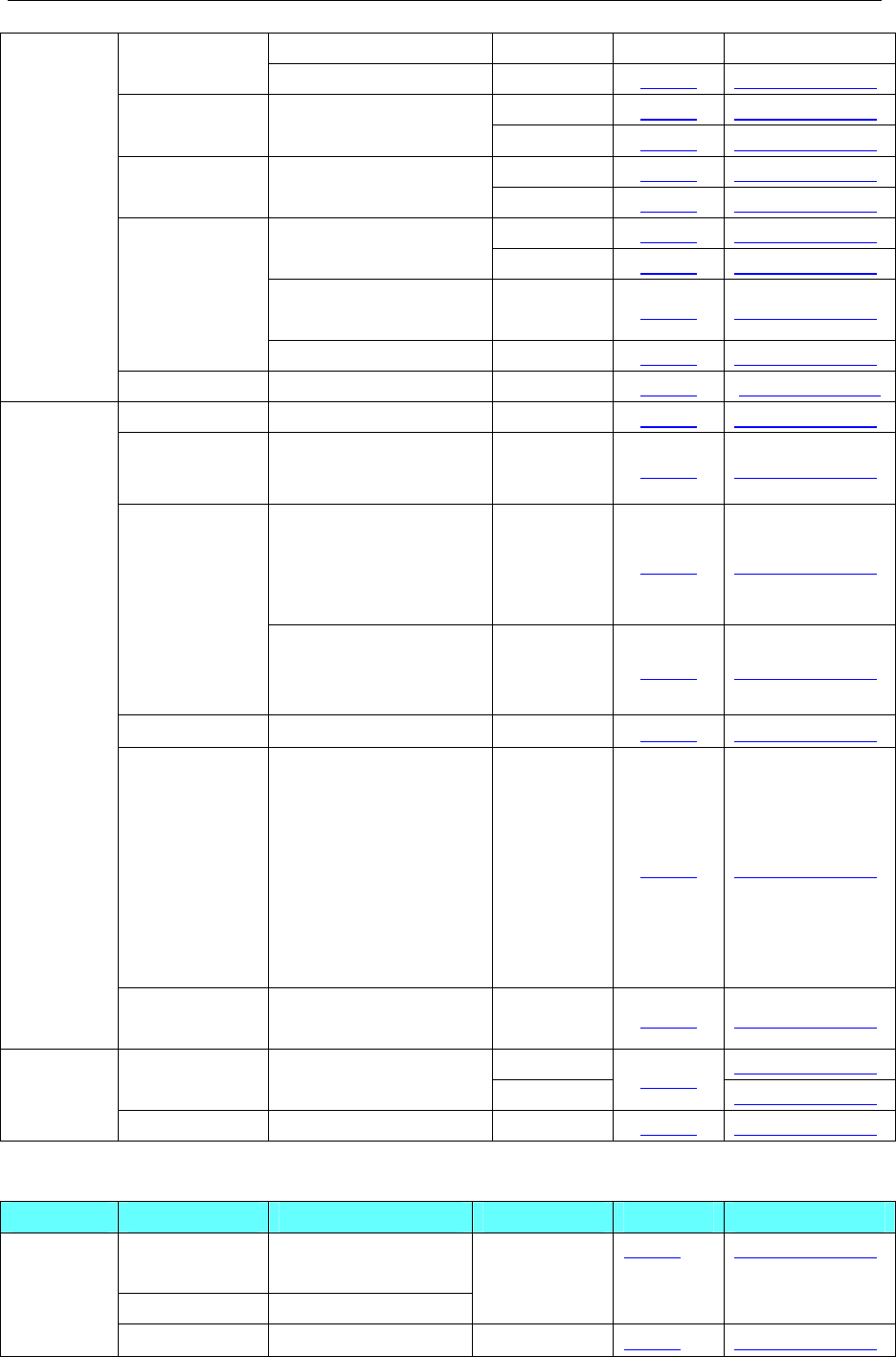
4 Communication settings and guide of HMI connecting with controller
- 216 -
FX□□-485-ADP FX3SA
FX□□-232-BD RS232 Setting Your owner cable
RS232 Setting Your owner cable FX2N-10GM
FX2N-20GM RS485 on the CPU unit RS485-4 Setting Your owner cable
RS232 Setting Your owner cable FX3G
FX3GE
RS485 on the CPU unit
RS485-4 Setting Your owner cable
RS232 Setting Your owner cable RS485 on the CPU unit
FX□□-422-BD RS485-4 Setting Your owner cable
FX□□-485-BD
FX□□-485-ADP RS485-4 Setting Your owner cable
FX3UC
FX3U
FX□□-232-BD RS232 Setting Your owner cable
FX5U RS485 on the CPU unit RS485-4 Setting Your owner cable
Q00jCPU RS232 on the CPU unit RS232 Setting Your owner cable
Q00CPU
Q01CPU RS232 on the CPU unit RS232 Setting Your owner cable
QJ71C24
QJ71C24-R2
QJ71C24N
QJ71C24N-R2
RS232 Setting Your owner cable
Q00jCPU
Q00CPU
Q01CPU
Q02CPU
Q02HCPU
Q03UDCPU
Q25HCPU
QJ71C24
QJ71C24N
QJ71C24N-R4
RS485-4 Setting Your owner cable
Q00UJCPU RS232 on the CPU unit RS232 Setting Your owner cable
Q02CPU
Q02HCPU
Q01UCPU
Q02UCPU
Q03UDCPU
Q06HCPU
Q06UDHPU
Q25HCPU
RS232 on the CPU unit RS232 Setting Your owner cable
Melsec Q
Q06HCPU
Q12HCPU RS232 on the CPU unit RS232 Setting Your owner cable
RS232 Your owner cable
L02CPU LJ71C24-CM RS485-4 Setting Your owner cable
LCPU
L02SCPU RS232 on the CPU unit RS232 Setting Your owner cable
◎Network System configuration
Series CPU Link Module Connect Type Parameter Cable
FX3GE-24M Ethernet port on CPU
unit
FX3U-32M FX3U-ENET-L
Ethernet Setting Your owner cable FXCPU
FX5U-32MT/E Ethernet port on CPU Ethernet Setting Your owner cable
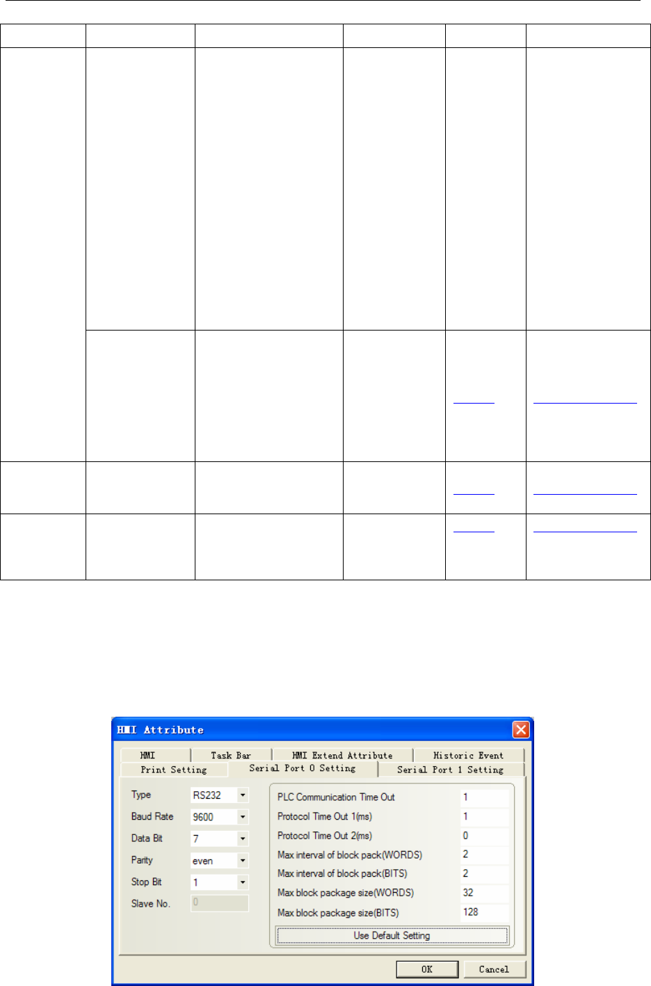
4 Communication settings and guide of HMI connecting with controller
- 217 -
S unit
Q00CPU
Q00JCPU
Q01CPU
Q02CPU
Q02HCPU
Q06HCPU
Q12HCPU
Q25HCPU
Q03UDECPU
Q04UDEHCPU
Q06UDEHCPU
Q13UDEHCPU
Q26UDEHCPU
QJ71E71
QJ71E71-B2
QJ71E71-B5
QJ71E71-100
Ethernet
Melsec Q
Q02UCPU
Q03UDCPU
Q04UDHCPU
Q06UDHCPU
Q13UDHCPU
Q26UDHCPU
QJ71E71
QJ71E71-B2
QJ71E71-B5
QJ71E71-100
Ethernet Setting Your owner cable
MELSEC L L02CPU
L26CPU-BT
Ethernet port on CPU
unit Ethernet Setting Your owner cable
QCPU Q26UDV CPU
Q04UDEHCPU
Q03UDECPU
Ethernet port on CPU
unit
Ethernet Setting Your owner cable
◎Serial Communication Setting
Mitsubishi FX1S、Mitsubishi FX0N/1N/2N/3G、Mitsubishi FX3U protocol
HMI Setting
Default communication: 9600, 7, even, 1; station: 0
RS232 communication
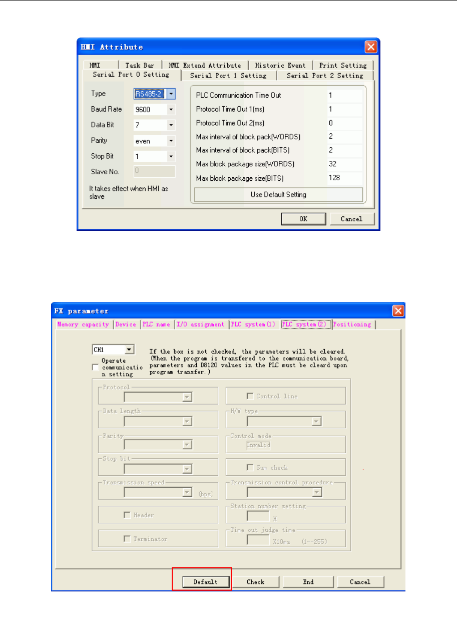
4 Communication settings and guide of HMI connecting with controller
- 218 -
RS422 communication
HMI Setting
When using the Mitsubishi FX1S、Mitsubishi FX0N/1N/2N/3G、Mitsubishi FX3U protocol, PLC
configuration is as follow:
Don’t select “Operate communication setting”, and click “default”
NOTE:
1. If you do not use the multi-station when using communication module, you can choose the protocol of
Mitsubishi FX1S、Mitsubishi FX0N/1N/2N/3G、Mitsubishi FX3U etc. according to the PLC model
2. Make sure that the value of D8120 is 0 when using the communication module
Mitsubishi FX-485ADP/485BD/232BD (Multi-station) protocol
HMI Setting
Default communication: 19200, 7, even, 2; station: 0
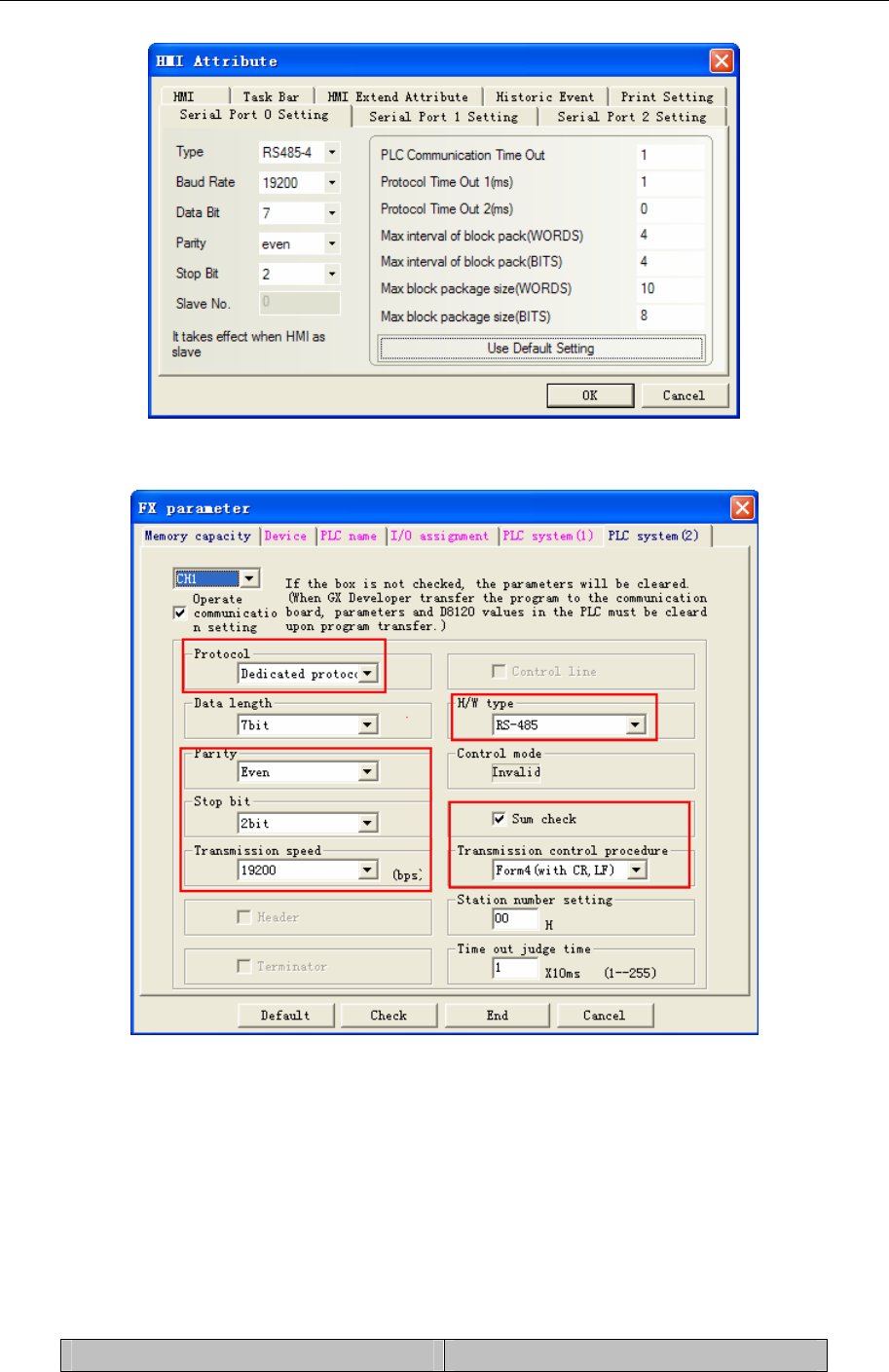
4 Communication settings and guide of HMI connecting with controller
- 219 -
PLC Setting
Select the “Operate communication setting”
NOTE:
1. FX0N series don’t support the “Operate communication setting”, but the communication parameters can
be modified by setting the value of D8120、D8121、D8129
2. If series of PLC is FX3U/3UC, you must select “CH1”
3. Select the “Dedicated protocol” and check “Sum check” option, Transmission control procedure must be
Form4
4. If you use the FX□□-232-BD module, set H/W type to Regular/RS-232C; if you use the FX□□
-485-BD/FX□□-485-ADP module, set H/W type to RS-485
The communication parameters can be modified by setting the value of D8120/D8121/D8129
Special register Description
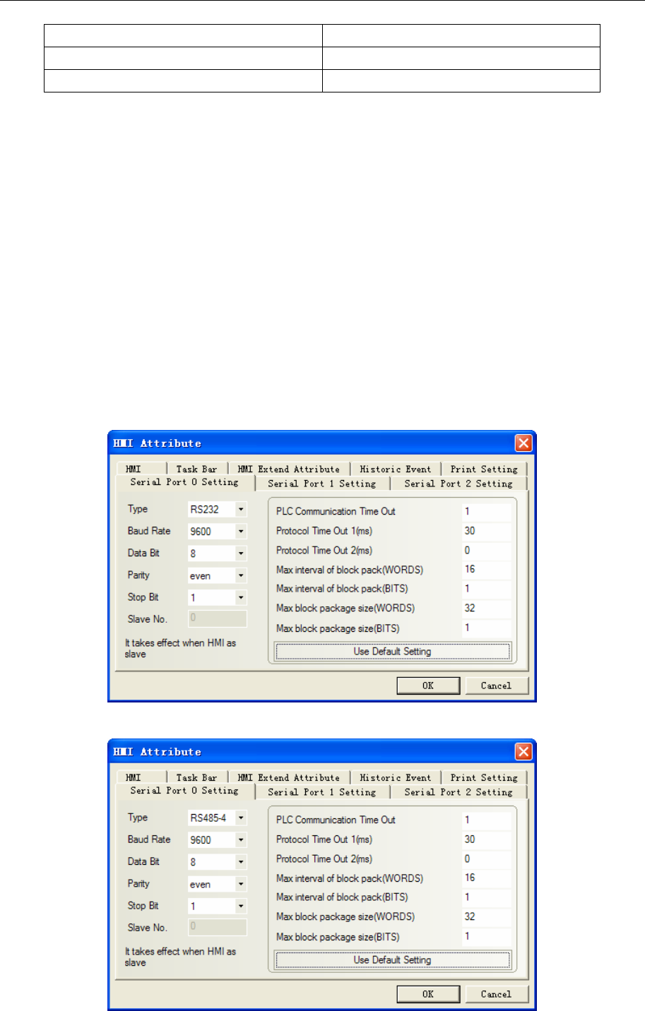
4 Communication settings and guide of HMI connecting with controller
- 220 -
D8120 Communication format
D8121 Station number
D8129 Overtime
For example
The communication parameters of PLC as follow:
Communication format: 9600bps, 7, even, 2;
Station No.:1;
H/W type: RS485;
Time out: 1
Set the value of D8120/D8121/D8129:
D8120=0xE08E;
D8121=1;
D8129=1;
NOTE: Restart the PLC after setting the value of D8120.
FX2N-10G/20GM protocol
Default communication: 9600, 8, even, 1; station: 0
RS232 communication
RS422 communication
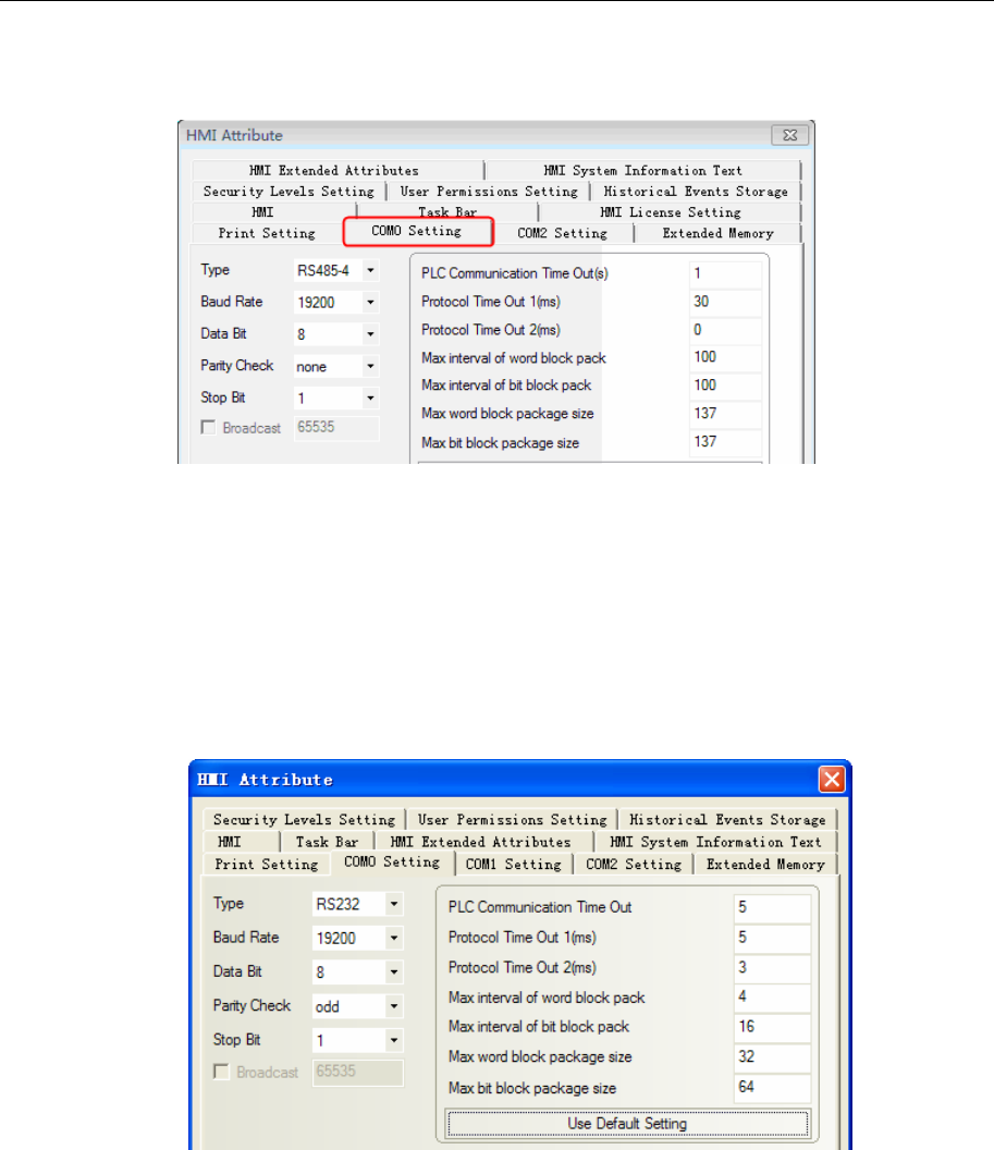
4 Communication settings and guide of HMI connecting with controller
- 221 -
Mitsubishi FX5U protocol
HMI Setting
PLC Setting
PLC Setting:Set the same parameters as the HMI dose.
Mitsubishi Q00J (CPU Port) protocol
HMI Setting
Default parameters: 19200, 8, odd, 1; Station No.: 0(Non-support station number, only one HMI connect to
one PLC)
RS232 communication
NOTE:
1、 If communication baudrate is error, HMI automatically set PLC baudrate for the HMI baudrate. It
is not necessary to consider whether the PLC communications baudrate being true.
2、 This drives support password protection model Q00J.
Mitsubishi Q series (CPU Port) protocol
HMI Setting
Default parameters :115200, 8, odd, 1 ; Station No. : 0(Non-support station number, only one HMI connect
to one PLC)
RS232 communication
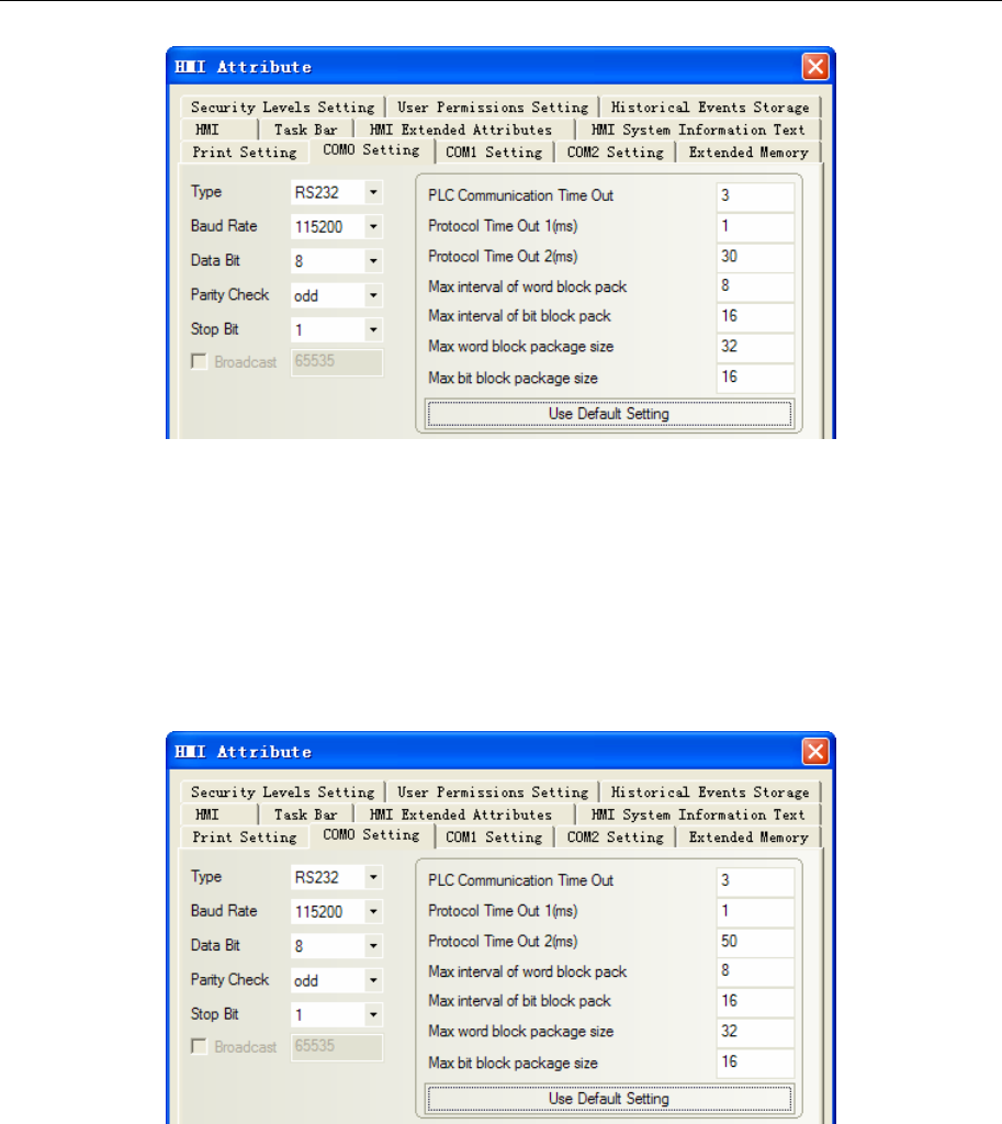
4 Communication settings and guide of HMI connecting with controller
- 222 -
NOTE: If communication baudrate is error, HMI automatically set PLC baudrate for the HMI baudrate. It
is not necessary to consider whether the PLC communications baudrate being true.
Mitsubishi Q06H 、Mitsubishi Q06Hv2 protocol
HMI Setting
Default parameters :115200, 8, odd, 1 ; Station No. : 0(Non-support station number, only one HMI connect
to one PLC)
RS232 communication
NOTE: If communication baudrate is error, HMI automatically set PLC baudrate for the HMI baudrate. It
is not necessary to consider whether the PLC communications baudrate being true.
Mitsubishi Q_QnA (Link Port) & Mitsubishi Melsec Q protocol
HMI Setting
Default parameters :9600, 8, odd, 1 ; Station No. : 0
RS232 communication
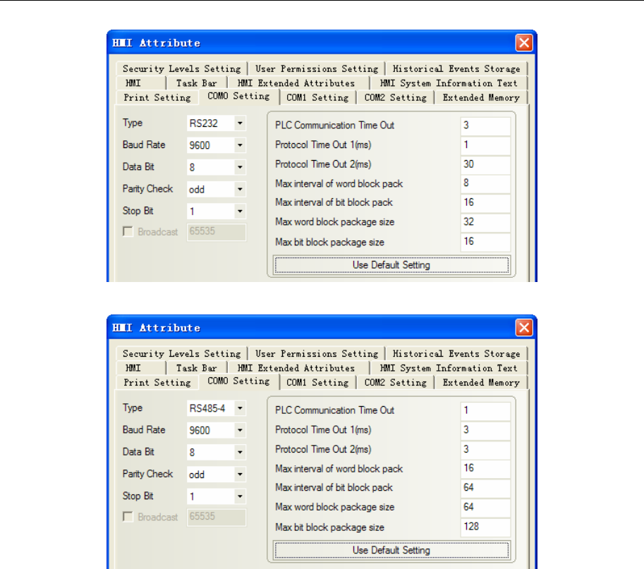
4 Communication settings and guide of HMI connecting with controller
- 223 -
RS422 communication
The differences of Mitsubishi Q_QnA (Link Port)、Mitsubishi Melsec Q:
1. Mitsubishi Q_QnA (Link Port) protocol advantage is communication speed
2. Mitsubishi Melsec Q protocol advantages is that it support RS232 and RS485 communication modules,
disadvantage is that communication is slow.
HMI Setting
1. CPU port communication
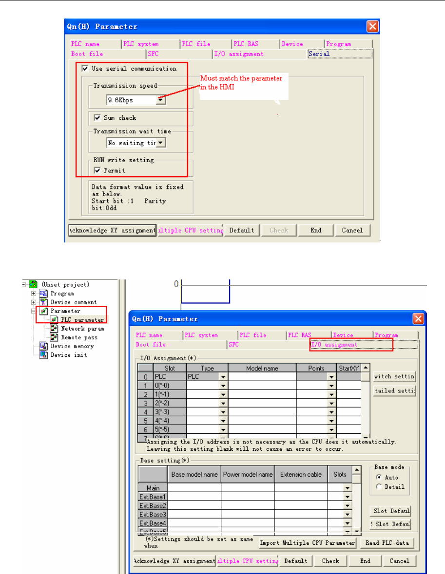
4 Communication settings and guide of HMI connecting with controller
- 224 -
2. C24 module communication
a. “Parameter” double-click “PLC parameter”, select “I/O assignment”.
b. Click “type” to select “intelligent”
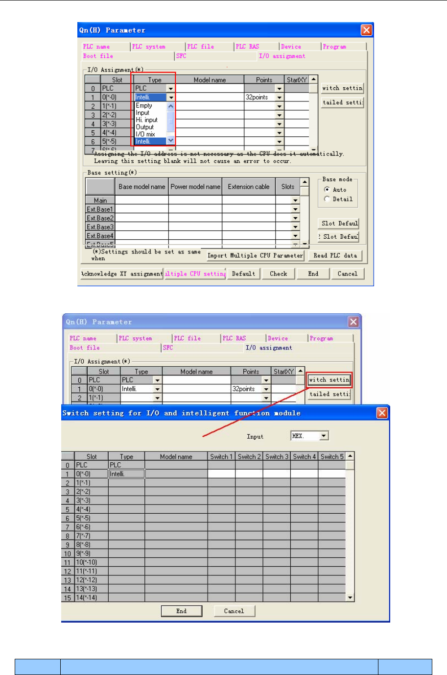
4 Communication settings and guide of HMI connecting with controller
- 225 -
c. Click “switch setting” and set
Setting the intelligent function unit switch
switch content example
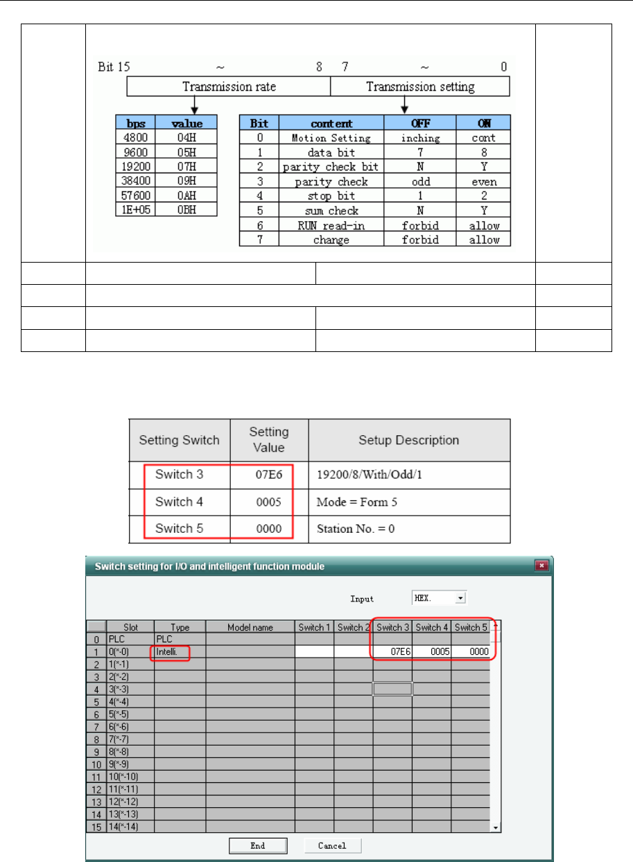
4 Communication settings and guide of HMI connecting with controller
- 226 -
Switch1 CH1:transmission rate, transmission setting
0BEEH
115Kbps
8 bit
1 bit
even
Switch2 CH1:communication protocol MC protocol type5 binary 0005H
Switch3 CH2:transmission rate, transmission setting (the same as switch 1) 0BEEH
Switch4 CH2:communication protocol MC protocol type5 binary 0005H
Switch5 Station No. setting 0~31 0000H
If the communication parameters of CH2 485 is 19200/8/odd/1, station:0, set as follows “switch setting”
in “PLC parameters” and “I/O assignment”.
If the communcation parameters of CH1 232 is 19200/8/odd/1, station:0, set as follows “switch setting” in
“PLC parameters” and “I/O assignment”.
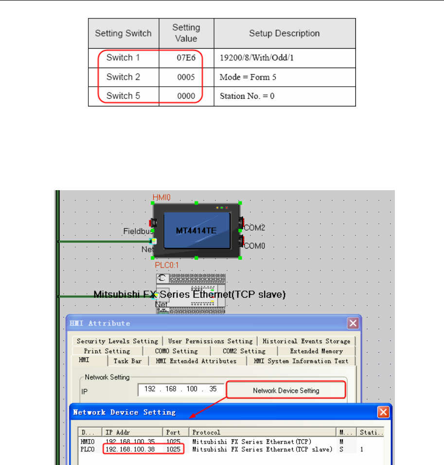
4 Communication settings and guide of HMI connecting with controller
- 227 -
NOTE: After setting the switches, reset the PLC or turn the power off and then back on again.
◎Network Communication Setting
Mitsubishi FX Series Ethernet(TCP Slave) protocol
HMI Setting
NOTE:Data fomat of PORT number is decimalism
PLC Setting
FX3GE-24M
1. Double click“PLC Parameters”,select“Built-in Ethernet Port Settings”,the parameters
configuration as follow:
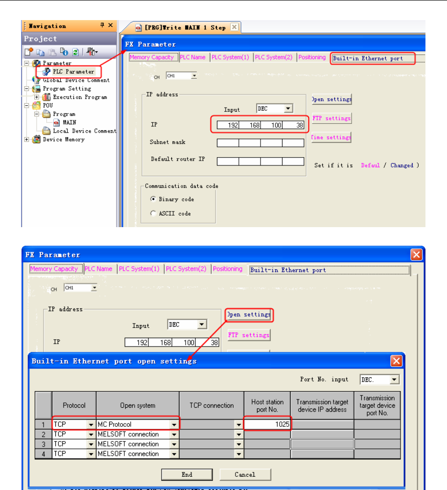
4 Communication settings and guide of HMI connecting with controller
- 228 -
2. Click “Open Setting”, the parameters configuration as follow:
NOTE: Data fomat of PORT number is decimalism
FX3U-ENET-L
1. Open“FX3U-ENET-L Configuration Tool”,the parameters configuration as follow:
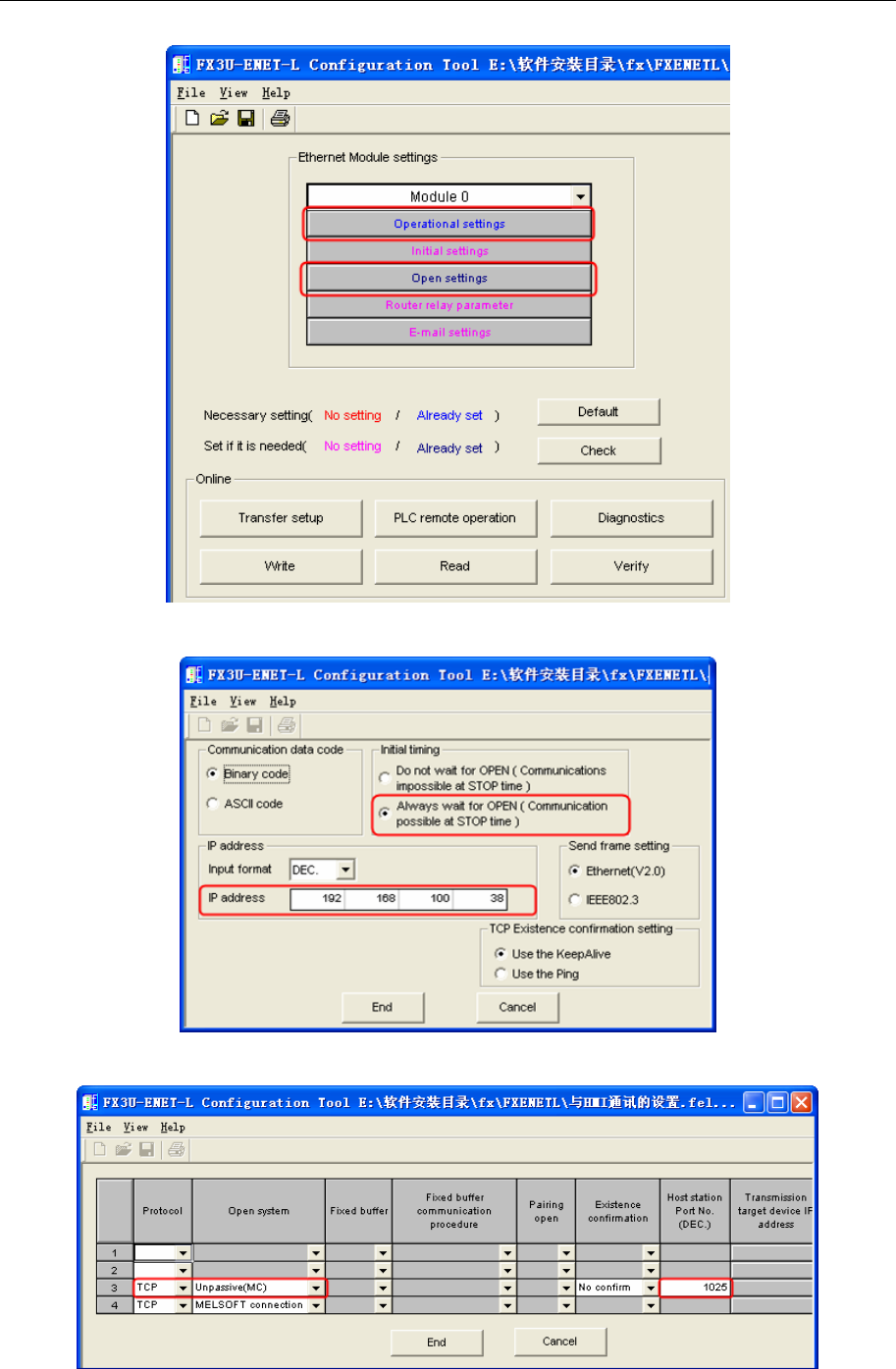
4 Communication settings and guide of HMI connecting with controller
- 229 -
3. Click“Operational settings”,the parameters configuration as follow:
4. Click“Open settings”,the parameters configuration as follow:
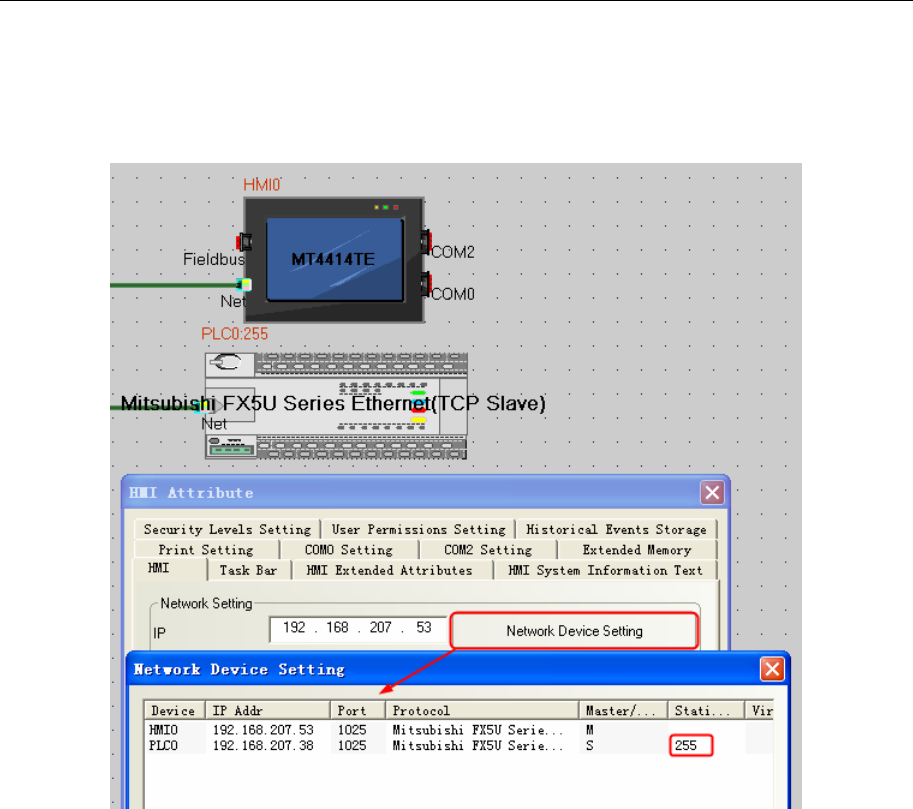
4 Communication settings and guide of HMI connecting with controller
- 230 -
NOTE: Data fomat of PORT number is decimalism
Mitsubishi FX5U Series Ethernet(TCP Slave) protocol
HMI Setting
NOTE: 1.Data fomat of PORT number is decimalism
2.PLC station must be 255
PLC Setting
1. Click”Parameter”‐‐‐‐“FX5UCPU”‐‐‐‐“ModuleParameter”‐‐‐‐“EthernetPort”
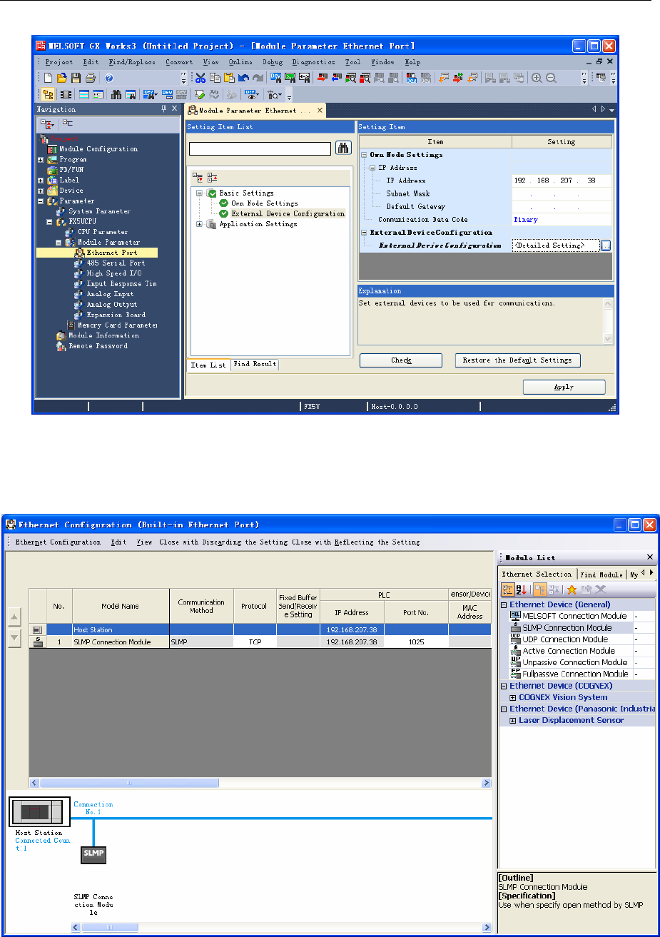
4 Communication settings and guide of HMI connecting with controller
- 231 -
2. Inthe“EthernetPort”SettingItemList‐‐‐“ExternalDeviceConfiguration”,click“DetailedSetting”.
3. PopuptheEthernetDevice(General)list,choose“SLMPConnectionModule”,andsetTCPProtocol,
PortNo.:1025,thenClosewithReflectingtheSetting.
NOTE: 1.Data fomat of PORT number is decimalism
Mitsubishi QJ71E71 EtherNet protocol
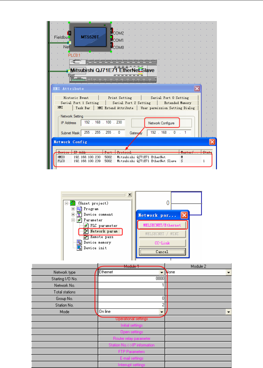
4 Communication settings and guide of HMI connecting with controller
- 232 -
HMI Setting
PLC Setting
1. Network parameters
[network type] select "Ethernet"; [start I/O] is a hexadecimal number increments & H10, you can select "0";
[network number] range is 1-239, generally set at the network level, only a layer of the network, so set to
"1"; [Group number] range is 0-32, select "0"; [station number] range 1-64, 1 occupied by the computer
side, can be set to 2-64, the example is set to "2" ; [Model] Select "online". Next, click [operation], set the
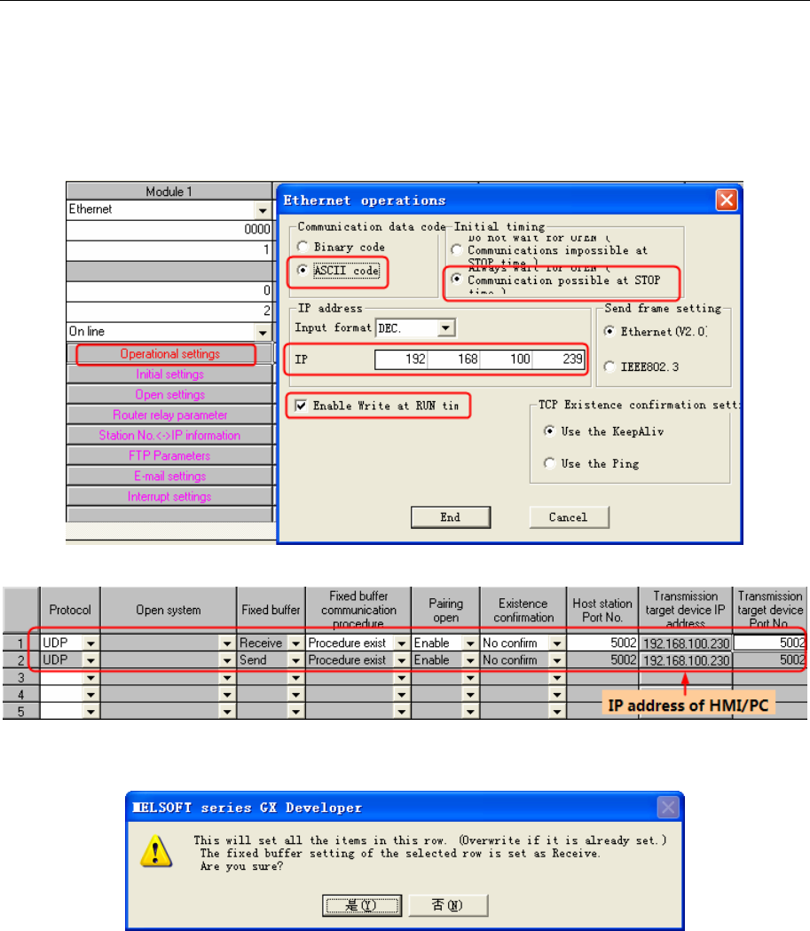
4 Communication settings and guide of HMI connecting with controller
- 233 -
IP address of the dialog box pops up, in part by the network to determine the first three, the fourth part of
the free use of the network number. One thing to note is that the figure of [the initial time setting] to choose
"Always wait to open" (stop when communication), or Ethernet port is not open external device. Click [end
set] button to save the settings.
2. Operational settings
3. Open settings
In line 1 [protocol] selection "UDP" protocol; and that [open in pairs] option select "pairs", system will be
prompted to
selection is confirmed, the parameters of line 2 will be self-generated, so as to form a two-way
communication. PLC's port and PC port range is & H401 - & HFFFF, the example is set to & H1000, PC's
IP address is your computer's IP. Click [End set] to save, and form an Ethernet module and host two-way
communication channel.
4. Just write to set the PLC in the main menu selection [online]->"PLC write", the "PLC/network
parameters" in the content downloaded to the PLC, the correct execution, the writing on the work of the
Ethernet parameters completed.
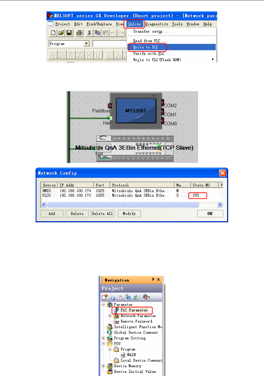
4 Communication settings and guide of HMI connecting with controller
- 234 -
Mitsubishi QnA 3EBin Ethernet(TCP Slave) protocol
L02:
HMI Setting
NOTE:
1. PLC station number must be 255
2. Data format of Port number is decimalism
PLC Setting
Double click “PLC parameters”, select “Built-in Ethernet Port Settings”
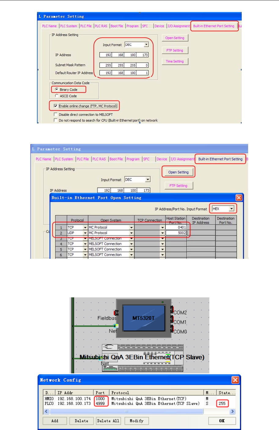
4 Communication settings and guide of HMI connecting with controller
- 235 -
Click “Open Setting”, the parameters configuration as follow:
NOTE: Host Station Port No. will be set by the selected format.
Q03UDE CPU :
HMI Setting
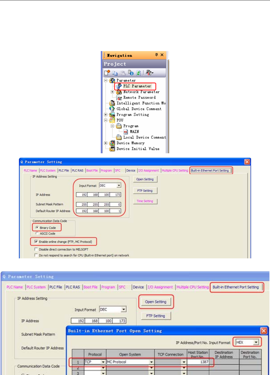
4 Communication settings and guide of HMI connecting with controller
- 236 -
NOTE:
1. PLC station number must be 255
2. Data format of Port number is decimalism
PLC Setting
Click “Open Setting”, the parameters configuration as follow:
NOTE: Host Station Port No. will be set by the selected format.
◎Supported Device
FX1S
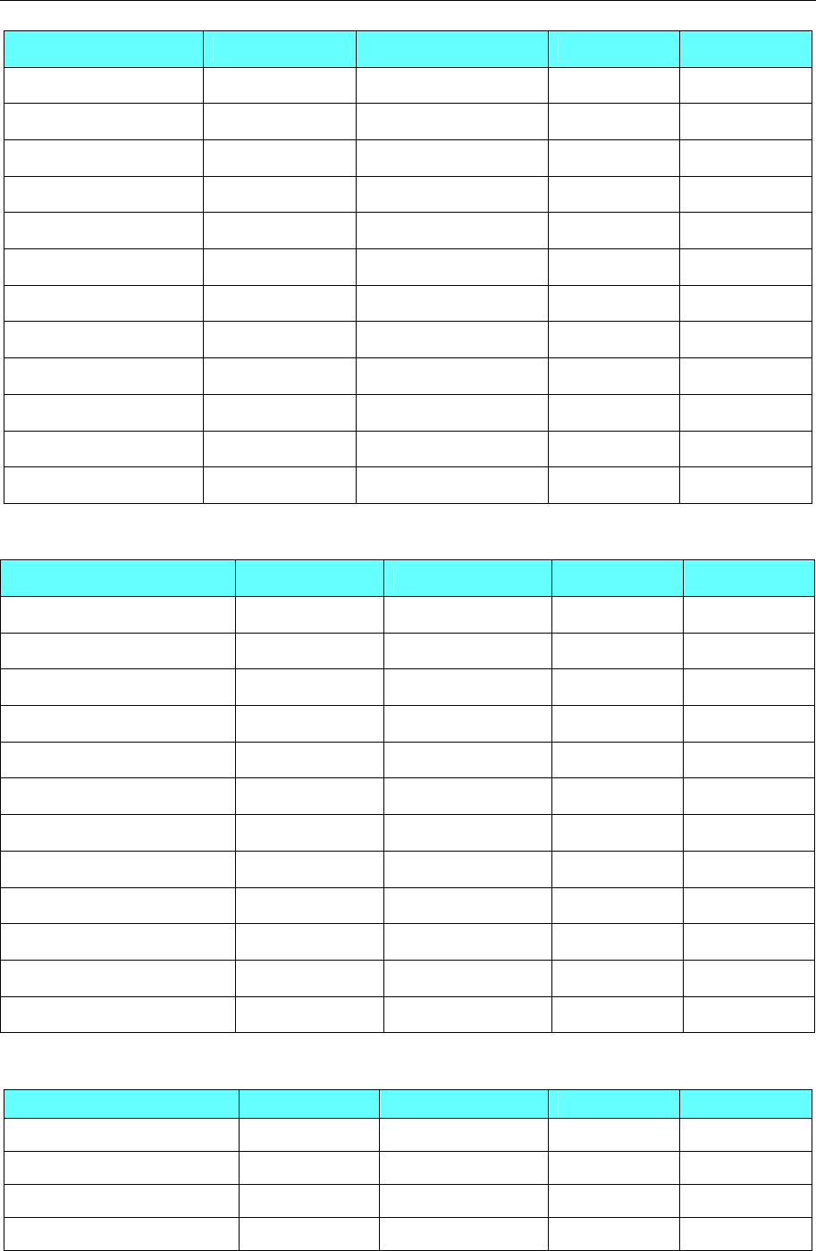
4 Communication settings and guide of HMI connecting with controller
- 237 -
Device Bit Address Word Address Format Notes
Input Relay X 00-764 ------ OOO
Output Relay Y 00-764 ------ OOO
Internal Relay M 000-7999 ------ DDDD
Timer Contact T 00-511 ------ DDD
Counter Contact C 00-255 ------ DDD
Data Contact D_bit 0.0-7999.F ------ DDDD.H
State S 000-4095
------ DDDD
Timer Value ------ T_word 00-511 DDD
Counter Value ------ C_word 00-199 DDD
Data Register ------ D_word 000-17999 DDDDD
Special Data Register ------ SD_word 8000-8255 DDDD
Counter Value ------ C_dword 235-255 DDD 32 bit device
FX0N/FX1N/2N/3G
Device Bit Address Word Address Format Notes
Input Relay X 000-377 ------ OOO
Output Relay Y 000-377 ------ OOO
Internal Relay M 0000-3071 ------ DDDD
Timer Contact T_bit 000-255 ------ DDD
Counter Contact C_bit 000-199 ------ DDD
Special Internal Relay SM 8000-8255 ------ DDDD
State S 000-999
------ DDD
Timer Value ------ T_word 000-255 DDD
Counter Value ------ C_word 000-199 DDD
Data Register ------ D 0000-7999 DDDD
Special Data Register ------ SD 8000-8255 DDDD
Counter Value ------ C_dword 200-255 DDD 32 bit device
FX2N-10GM/20GM
Device Bit Address Word Address Format Notes
Input Relay X 00-571 ------ OO *1
Output Relay Y 00-571 ------ OO *1
Internal Relay M 000-7999 ------ DDD *1
Special Internal Relay SM9000-9999 ------ DDDD *1
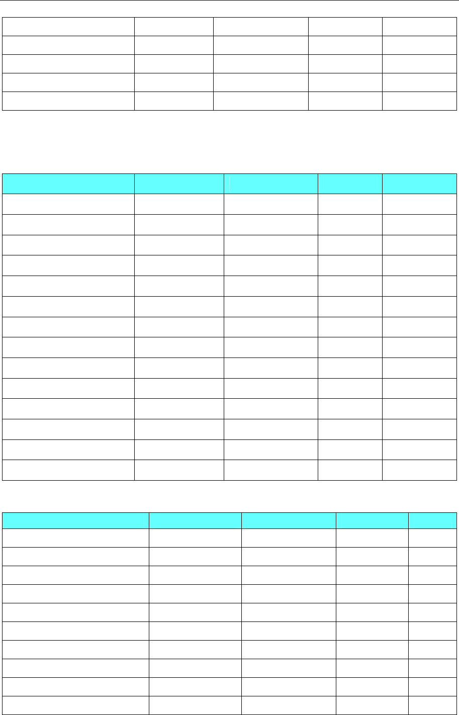
4 Communication settings and guide of HMI connecting with controller
- 238 -
Data Register ------ D 0-7999 DDDD *2
Special Data Register ------ SD 9000-9999 DDDD *2
Special Data Register ------ FD 4000-4550 DDDD *2
Current Position(System) ------ CP_unit 0-1 D
Current Position(Pulse) ------ CP_puls 0-1 D
NOTE:
*1 Don’t support batch
*2 Support batch
FX3UC
Device Bit Address Word Address Format Notes
Input Relay X000-764 ------ OOO
Output Relay Y000-764 ------ OOO
Timer Contact T_bit 000-511 ------ DDD
Counter Contact C_bit 000-255 ------ DDD
Data Contact D_bit0.0-7999.F ------ DDDD.H
State S0000-4095
------ DDDD
Internal Relay M0000-7999 ------ DDDD
Special Internal Relay SM8000-8511 ------ DDDD
Timer Value ------ T_word 000-511 DDD
Counter Value ------ C_word 000-199 DDD
Data Register ------ D_word 0-17999 DDDDD
Extension Register ------ R0000-32767 DDDDD
Special Data Register ------ SD8000-9999 DDDD
Counter Value ------ C_dword200-255 DDD 32 bit device
FX Series Ethernet
Device Bit Address Word Address Format Notes
State S 0-4095 ------ DDDD
Data Contact D_bit0.0-7999.F ------ DDDD.H
Special Internal Relay SM8000-8511 ------ DDDD
Counter Contact C_bit0-255 ------ DDDD
Timer Contact T_bit0-511 ------ DDDD
Internal Relay M 0-7679 ------ DDDD
Output Relay Y 0-377 ------ DDDD
Input Relay X 0-377 ------ DDDD
Extension Register ------ R 0-32767 DDDDD
Special Data Register ------ SD 8000-8511 DDDD

4 Communication settings and guide of HMI connecting with controller
- 239 -
Data Register ------ D_word0-7999 DDDD
Timer Value ------ T_word0-511 DDD
Counter Value ------ C_word0-199 DDD
Counter Value ------ C_dword200-255 DDD
FX5u
Device Bit Address Word Address Format
Retentive TimerValve(contact) SS 0-15 ------ DD
Counter Valve(contact) CS 0-255 ------ DDD
Counter Valve(coil) CC 0-255 ------ DDD
Timer Valve(contact) TS 0-511 ------ DDD
Timer Valve(coil) TC 0-511 ------ DDD
Specia Link Relay SB 0-FF ------ HH
Link Relay B 0-FF ------ HH
State Relay S 0-4095 ------ DDDD
Annunciator Relay F 0-127 ------ DDD
Latch relay L 0-7679 ------ DDDD
Specia Internal Relay SM 0-9999 ------ DDDD
Internal Relay M 0-7679 ------ DDDD
Output Relay Y 0-1777 ------ OOOO
Input Relay X 0-1777 ------ OOOO
Long Counter Valve(contact) LCS 0-63 ------ DD
Long Counter Valve(coil) LCC 0-63 ------ DD
16 Bit Index Register ------ Z 0-19 DD
Retentive TimerValve ------ SN 0-15
DD
Counter Valve ------ CN 0--255
DDD
Timer Valve ------ TN 0-511
DDD
Specia Link Register ------ SW 0-1FF
HHH
Link Register ------ W 0-1FF
HHH
File Register ------ R 0-32767
DDDDD
Specia Date Register ------ SD 0-11999
DDDDD
Date Register D 0-7999
DDDD
32 Bit Index Register LZ 0-1
D
Long Counter Valve LCN 0-63
DD Double
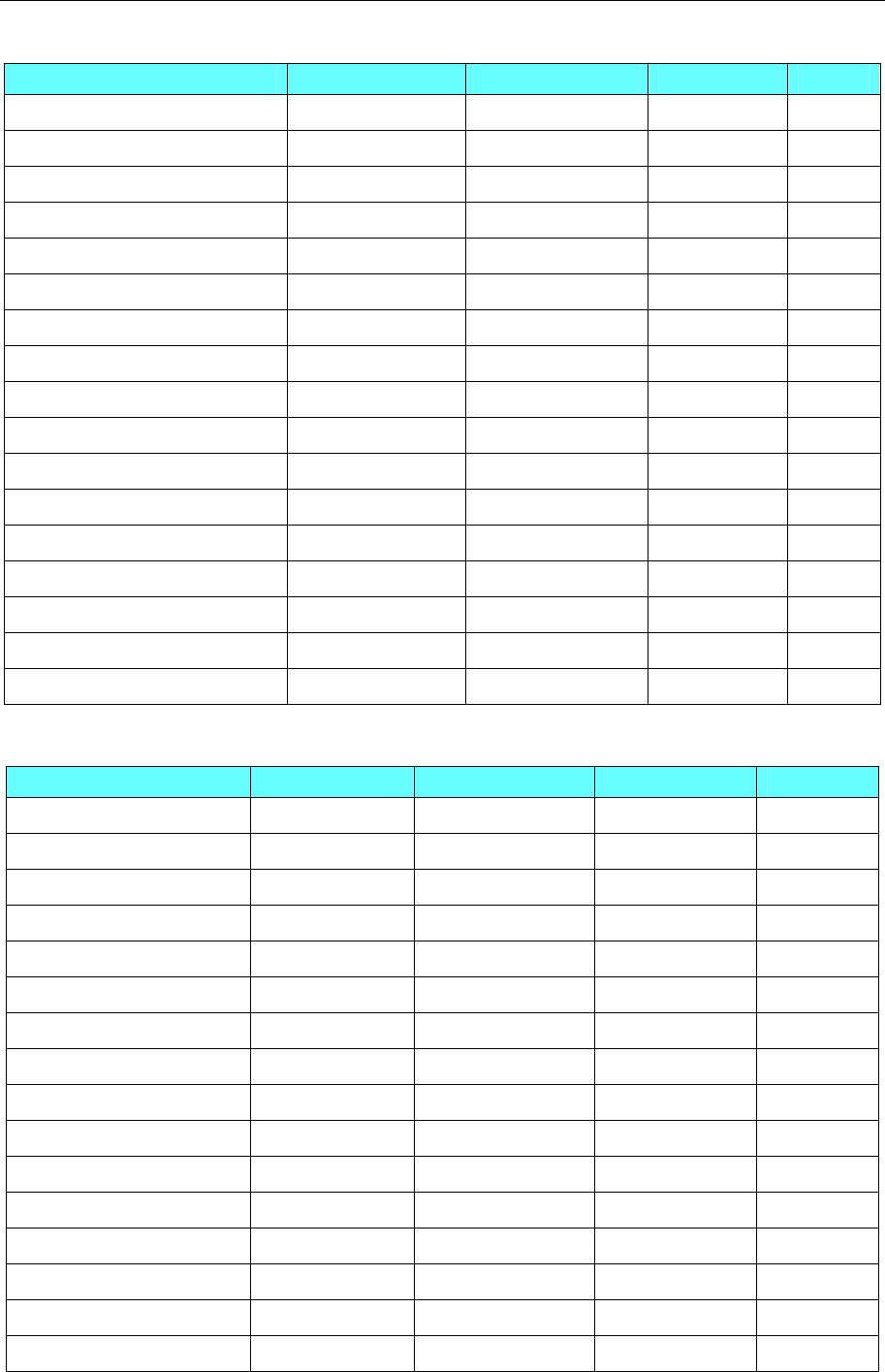
4 Communication settings and guide of HMI connecting with controller
- 240 -
FX5u Series Ethernet
Device Bit Address Word Address Format Notes
State S 0-4095 ------ DDDD
Special Link Relay SB0-FF ------ HH
Link Relay B0-FF ------ HH
Annunciator F0-127 ------ DDD
Latch Relay LO-7679 ------ DDDD
Special Internal Relay SM0-9999 ------ DDDD
Internal Relay M0-7679 ------ DDDD
Output Relay Y 0-1777 ------ OOOO
Input Relay X 0-1777 ------ OOOO
File Register ------ R 0-32767 DDDDD
Counter Value ------ CN0-255 DDD
Retentive Timer Value ------ SN0-15 DD
Timer Value ------ TN0-511 DDD
Special Link Register ------ SW0-1FF HHH
Link Register ------ W0-1FFF HHH
Special Data Register ------ SD0-11999 DDDDD
Data Register ------ D0-7999 DDDD
Q00jCPU
Device Bit Address Word Address Format Notes
Counter Coil CC0-1023 ------ DDDD
Counter Contact CS0-1023 ------ DDDD
Timer Coil TC0-2047 ------ DDDD
Timer Contact TS0-2047 ------ DDDD
Special Link Relay SB000-7FFF ------ HHHH
Link Relay B0000-7FFF ------ HHHH
Step Relay S0000-1FFF ------ HHHH
Edge Relay V0000-32767 ------ DDDDD
Annunciator F0000-32767 ------ DDDDD
Latch Relay L0000-32767 ------ DDDDD
Special Internal Relay SM0000-2047 ------ DDDD
Internal Relay M0000-32767 ------ DDDDD
Output Relay Y0000-1FFF ------ HHHH
Input Relay X0000-1FFF ------ HHHH
File Register ------ R000-32767 DDDDD
Special Link Register ------ SW0-7FF HHH

4 Communication settings and guide of HMI connecting with controller
- 241 -
Link Register ------ W000-291F HHHH
Special Data Register ------ SD0-2047 DDDD
Data Register ------ D0-25983 DDDDD
Counter Value ------ CN0-25983 DDDDD
Retentive Timer Value ------ SN0-2047 DDDD
Timer Value ------ TN0-25983 DDDDD
Melsec Q
Device Bit Address Word Address Format Notes
Direct output DY 0-7FF HHHH
Direct input DX 0-7FF HHHH
Step Relay S 0-2047 ------ DDDD
Special Link Relay SB 0-7FFF HHHH
Counter Coil CC 0-511 ------ DDDD
Counter Contact CS 0-511 ------ DDDD
Step Coil SC 0-511 ------ DDDD
Step Contact SS 0-511 ------ DDDD
Timer Coil TC 0-511 ------ DDDD
Timer Contact TS 0-511 ------ DDDD
Link Relay B 0-7FF HHHH
Edge Relay V 0-1023 ------ DDDD
Annunciator F 0-1023 ------ DDDD
Latch Relay L 0-2047 ------ DDDD
Internal Relay M 0-8191 ------ DDDD
Output Relay Y 0-7FF ------ HHHH
Input Relay X 0-7FF ------ HHHH
File Register ------ ZR 0-65535 DDDDDD
File Register ------ R 0-32767 DDDDD
Index Register ------ Z 0-9 DD
Counter Value ------ CN 0-511 DDDD
Retentive Timer Value SN 0-511 DDDD
Timer Value ------ TN 0-511 DDDD
Special Link Register ------ SW 0-3FF HHH
Link Register ------ W 0-1FFF HHHH
Special Data Register ------ SD 0-2047 DDDD
Data Register ------ D 0-11135 DDDDD
Q Series CPU port
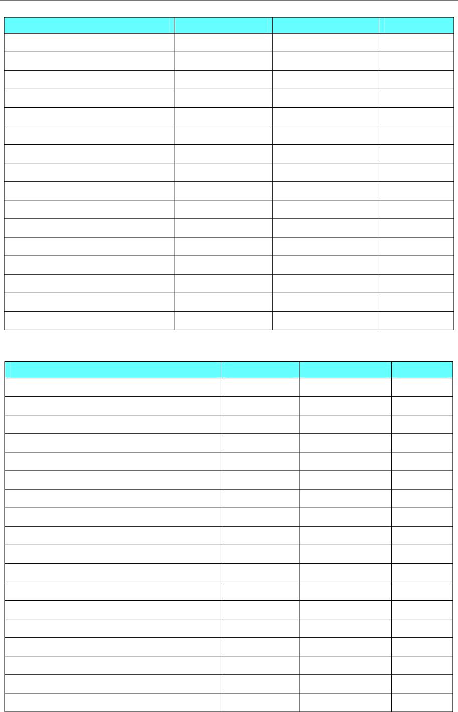
4 Communication settings and guide of HMI connecting with controller
- 242 -
Device Bit Address Word Address Format
Special Link Relay SB 00000- 7FFF ------ HHHH
Link Relay B 00000- 7FFF ------ HHHH
Edge relay V 00000-32767 ------ DDDDD
Annunciator F 00000-32767 ------ DDDDD
Latch relay L 00000-32767 ------ DDDDD
Special Internal Relay SM 0000-2047 ------ DDDD
Internal Relay M 00000-32767 ------ DDDDD
Output Relay Y 0000-1FFF ------ HHHH
Input Relay X 0000-1FFF ------ HHHH
Link Register ------ W 00000- 291F HHHH
Timer Value ------ TN 00000-23087 DDDDD
Counter Value ------ CN 00000-23087 DDDDD
File Register ------ R 00000-32767 DDDDD
Special Link Register ------ SW 0000- 7FF HHH
Data Register ------ D 00000-25983 DDDDD
Special Data Register ------ SD 0000-2047 DDDD
Q_QnA(link port)
Device Bit Address Word Address Format
Special Link Relay SB000-7FFF ------ HHHH
Link Relay B0000-7FFF ------ HHHH
Edge Relay V0000-32767 ------ DDDDD
Annunciator F0000-32767 ------ DDDDD
Latch Relay L0000-32767 ------ DDDDD
Special Internal Relay SM0000-2047 ------ DDDD
Internal Relay M0000-32767 ------ DDDDD
Output Relay Y0000-1FFF ------ HHHH
Input Relay X0000-1FFF ------ HHHH
Link Register ------ W0000-291F HHHH
Timer Value ------ TN0-23087 DDDDD
Retentive Timer Value ------ SN0-23087 DDDDD
Counter Value ------ CN0-23087 DDDDD
File Register(Block switching is not necessary) ------ ZR00000-65535 DDDDD
File Register ------ R00000-32767 DDDDD
Special Link Register ------ SW000-7FF HHH
Data Register ------ D00000-25983 DDDDD
Special Data Register ------ SD0000-2047 DDDD
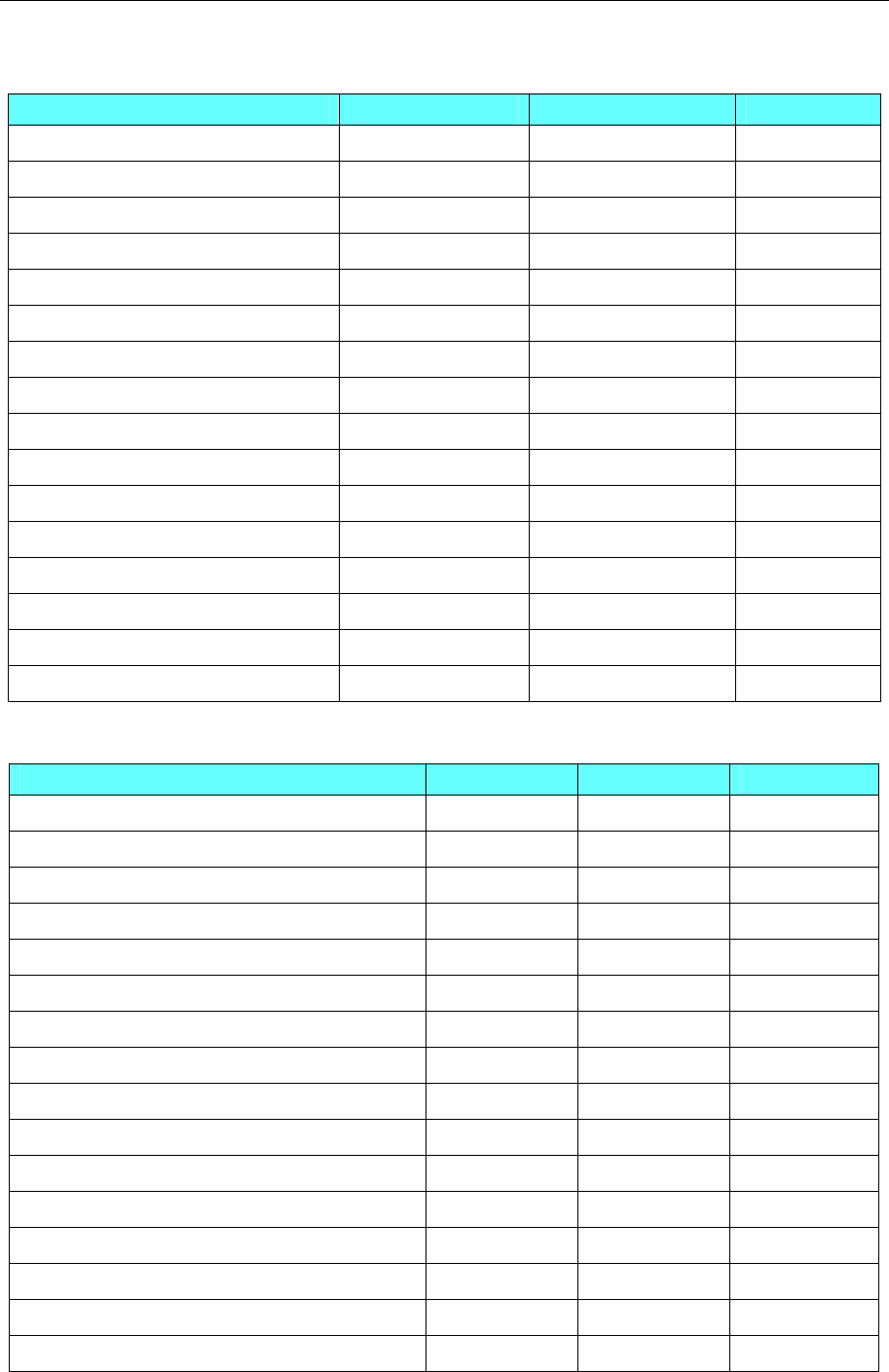
4 Communication settings and guide of HMI connecting with controller
- 243 -
Q06
Device Bit Address Word Address Format
Special Link Relay SB 0000- 7FFF ------ HHHH
Link Relay B 0000- 7FFF ------ HHHH
Edge relay V 00000-32767 ------ DDDDD
Annunciator F 00000-32767 ------ DDDDD
Latch relay L 00000-32767 ------ DDDDD
Special Internal Relay SM 0000-2047 ------ DDDD
Internal Relay M 00000-32767 ------ DDDDD
Output Relay Y 0000-1FFF ------ HHHH
Input Relay X 0000-1FFF ------ HHHH
Link Register ------ W 00000- 291F HHHH
Timer Value ------ TN 00000-23087 DDDDD
Counter Value ------ CN 00000-23087 DDDDD
File Register ------ R 00000-32767 DDDDD
Special Link Register ------ SW 0000- 7FF HHH
Data Register ------ D 00000-25983 DDDDD
Special Data Register ------ SD 0000-2047 DDDD
Mitsubishi QJ71E71 EtherNet Slave
Device Bit Address Word Address Format
Step Relay S 000-8191 ------ DDDD
Special Link Relay SB 000-7FFF ------ HHHH
Counter Coil CC 0-23087 ------ DDDDD
Counter Contact CS 0-23087 ------ DDDDD
Step Coil SC 0-23087 ------ DDDDD
Step Contact SS 0-23087 ------ DDDDD
Timer Coil TC 0-23087 ------ DDDDD
Timer Contact TS 0-23087 ------ DDDDD
Link Relay B 0000-1FFF ------ HHHH
Edge Relay V 0-32767 ------ DDDDD
Annunciator F 0-32767 ------ DDDDD
Latch Relay L 0-32767 ------ DDDDD
Special Internal Relay SM 0-2047 ------ DDDD
Internal Relay M 0-32767 ------ DDDD
Output Relay Y 0-1FFF ------ HHHH
Input Relay X 0-1FFF ------ HHHH

4 Communication settings and guide of HMI connecting with controller
- 244 -
Link Register ------ W 0-291F HHHH
Timer Value ------ TN 0-23087 DDDD
Counter Value ------ CN 0-23087 DDDDD
Retentive Timer Value SN 0-23087 DDDDD
File Register ------ R 0-32767 DDDDD
File Register(Block switching is not necessary) ------ ZR 0-1042431 DDDDDDD
Special Link Register ------ SW 0-7FF HHH
Data Register ------ D 0-25983 DDDDD
Special Data Register ------ SD 0-2047 DDDD
Mitsubishi QnA 3EBin Ethernet(TCP Slave)
Device Bit Address Word Address Format Notes
Direct output DY 0-1FFF HHHH
Direct input DX 0-1FFF HHHH
Step Relay S 0-8191 ------ DDDD
Special Link Relay SB 0-7FFF SB 0-1FFF HHHH
Counter Coil CC 0-1023 ------ DDDD
Counter Contact CS 0-1023 ------ DDDD
Step Coil SC 0-2047 ------ DDDD
Step Contact SS 0-2047 ------ DDDD
Timer Coil TC 0-2047 ------ DDDD
Timer Contact TS 0-2047 ------ DDDD
Link Relay B 0-1FFF B 0-1FFF HHHH
Edge Relay V 0-2047 ------ DDDD
Annunciator F 0-2047 ------ DDDD
Latch Relay L 0-8191 ------ DDDD
Special Internal Relay SM 0-2047 ------ DDDD
Internal Relay M 0-8191 ------ DDDD
Output Relay Y 0-1FFF Y 0-1FFF HHHH
Input Relay X 0-1FFF X 0-1FFF HHHH
File Register ------ ZR 0-393216 DDDDDD
File Register ------ R 0-32767 DDDDD
Index Register ------ Z 0-19 DD
Counter Value ------ CN 0-1023 DDDD
Retentive Timer Value SN 0-2047 DDDD
Timer Value ------ TN 0-2047 DDDD
Special Link Register ------ SW 0-7FF HHH
Link Register W 0-1FFF HHHH

4 Communication settings and guide of HMI connecting with controller
- 245 -
Special Data Register ------ SD 0-2047 DDDD
Data Register ------ D 0-45055 DDDDD
Q03UDE
Device Bit Address Word Address Format Notes
Direct output DY 0-1FFF HHHH
Direct input DX 0-1FFF HHHH
Step Relay S 0-8191 ------ DDDD
Special Link Relay SB 0-7FF SB 0-7F0 HHHH
Counter Coil CC 0-1023 ------ DDDD
Counter Contact CS 0-1023 ------ DDDD
Step Coil SC 0-2047 ------ DDDD
Step Contact SS 0-2047 ------ DDDD
Timer Coil TC 0-2047 ------ DDDD
Timer Contact TS 0-2047 ------ DDDD
Link Relay B 0-1FFF B 0-1FF0 HHHH
Edge Relay V 0-2047 ------ DDDD
Annunciator F 0-2047 ------ DDDD
Latch Relay L 0-8191 ------ DDDD
Special Internal Relay SM 0-2047 ------ DDDD
Internal Relay M 0-8191 ------ DDDD
Output Relay Y 0-1FFF Y 0-1FF0 HHHH
Input Relay X 0-1FFF X 0-1FF0 HHHH
File Register ------ ZR 0-32767 DDDDDD
File Register ------ R 0-32767 DDDDD
Index Register ------ Z 0-19 DD
Counter Value ------ CN 0-1023 DDDD
Retentive Timer Value ------ SN 0-2047 DDDD
Timer Value ------ TN 0-2047 DDDD
Special Link Register ------ SW 0-7FF HHH
Link Register ------ W 0-1FFF HHHH
Special Data Register ------ SD 0-2047 DDDD
Data Register ------ D 0-12287 DDDDD
◎Cable Diagram
FX Series RS232 Cable
1. CPU port communication
Please use the FX series SC - 09 serial programming cable communication, can also be made simple
programming cable
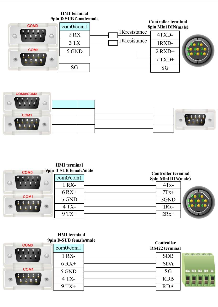
4 Communication settings and guide of HMI connecting with controller
- 246 -
2. FX□□-232-BD communication
Controller terminal
9 pin D-SUB (male)
com2
3 TX
2 RX
5 GND
8 TX
7 RX
5 GND
com0/com1
HMI terminal
9pin D-SUB female/male
3 TXD
2 RXD
5 GND
FX Series RS422 Cable
1. CPU port / FX□□-422-BD communication
2. FX□□-485-BD communication
Q Series RS232 Cable
1. CPU port communication
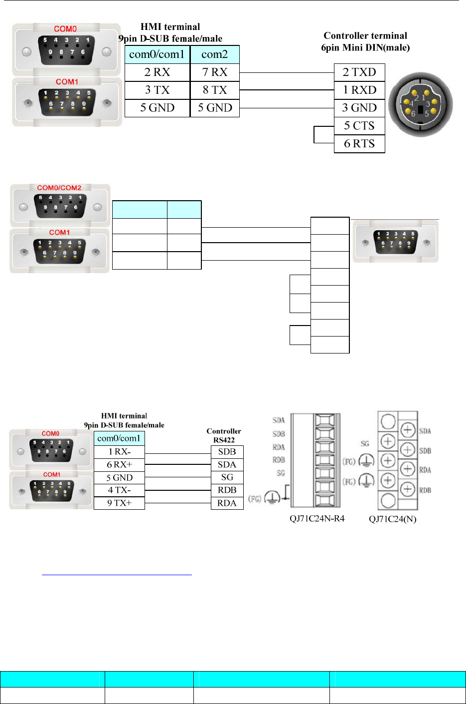
4 Communication settings and guide of HMI connecting with controller
- 247 -
2. C24 module communication
Controller terminal
9 pin D-SUB (male)
com2
3 TX
2 RX
5 GND
8 TX
7 RX
5 GND
com0/com1
HMI terminal
9pin D-SUB female/male
3 TXD
2 RXD
5 GND
1 DCD
4 DTR
6 DSR
7 RTS
8 CTS
Q Series RS485/422 Cable
C24 module communication
Ethernet communication protocol cable
Cross-connection or crossover network cable can be used as communication cable via the hub
Refer to 3.3 Download by Network Ethernet for method of making connection cable.
4.51 MKS controller
◎Serial Communication
Series CPU Link Module Driver
BY125 BY125 RS232 on the CPU unit MKS
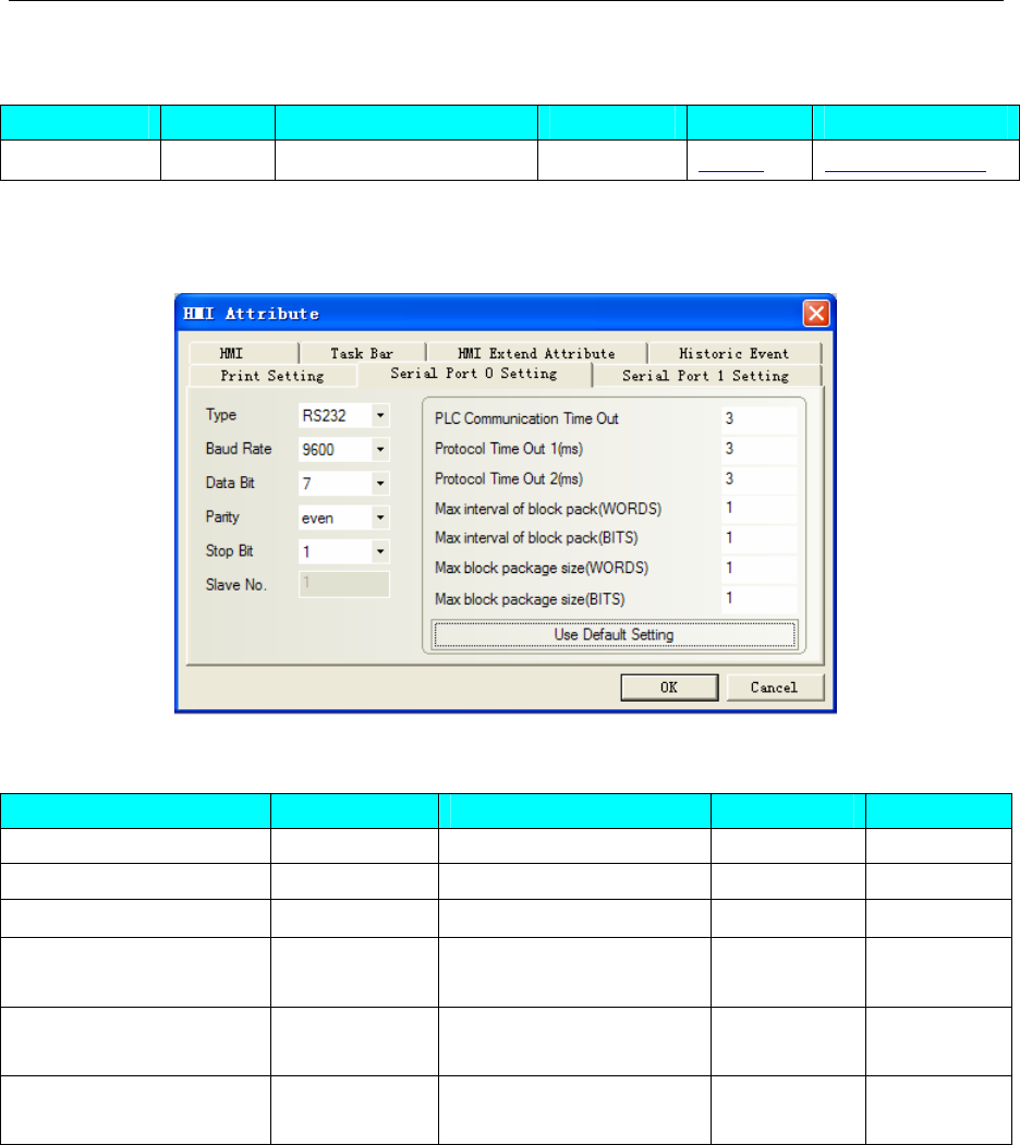
4 Communication settings and guide of HMI connecting with controller
- 248 -
◎System configuration
Series CPU Link Module COMM Type Parameter Cable
BY125 BY125 RS232 on the CPU unit RS232 Setting Your owner cable
◎Communication Setting
Default communication: 9600, 7, even, 1; station: 11
◎Supported Device
Device Bit Address Word Address Format Notes
Relay CB 00-FF ------ HH
Register ------ CD00-FF HH
External Register ------ ERCD 0000.00-FFFF.FF HHHH.HH
Internal data processing
control address bit ------ M1 0~9 H Read only
Internal data processing
control address bit ------ M2 0~9 H Read only
Internal data processing
control address bit ------ M3 0~9 H Read only
NOTE:
1)ERCD is Extended register, the four position before radix point are C1,C2,C3,C4.The two
positions after radix point are S1, S2.
2)Parameter code corresponding with CD are C1,C2;
3)Parameter code corresponding with CB set to “1”;Eg:”Bit State Setting” part, addr type CB67, set
the state to “1”.
4) M1 correspond to parameter ":"; M2 correspond to parameter";"; M3 correspond to parameter"<";
◎Cable Diagram
MKS controller RS232 communication cable
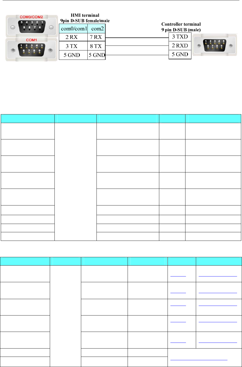
4 Communication settings and guide of HMI connecting with controller
- 249 -
4.52 Modbus
◎Serial Communication
Series CPU Link Module SIO type Driver
Modbus RTU RS232/485 on the CPU
unit Modbus RTU
Modbus RTU Extend RS232/485 on the CPU
unit Modbus RTU Extend
Modbus RTU Slave RS232/485 on the CPU
unit Modbus RTU Slave
Modbus RTU MT500
compatible
RS232/485 on the CPU
unit Modbus RTU MT500
compatible
Modbus ASCII RS232/485 on the CPU
unit Modbus ASCII
Modbus TCP Ethernet Modbus TCP
Modbus TCP Slave Ethernet Modbus TCP Slave
Modbus UDP Ethernet Modbus UDP
Modbus UDP Slave
MODBUS
Compatible
External Device
Ethernet Modbus UDP Slave
◎System configuration
Series CPU Link Module COMM Type Parameter Cable
Modbus RTU RS232/485 on the
CPU unit RS232/RS485 Setting Your owner cable
Modbus RTU
Extend
RS232/485 on the
CPU unit RS232/RS485 Setting Your owner cable
Modbus RTU Slave RS232/485 on the
CPU unit
RS232/RS485 Setting Your owner cable
Modbus RTU
MT500 compatible
RS232/485 on the
CPU unit
RS232/RS485 Setting Your owner cable
Modbus ASCII RS232/485 on the
CPU unit RS232/RS485 Setting Your owner cable
Modbus TCP Ethernet
Modbus TCP Slave
MODBUS
Compatible
External
Device
Ethernet
Connection Configuration
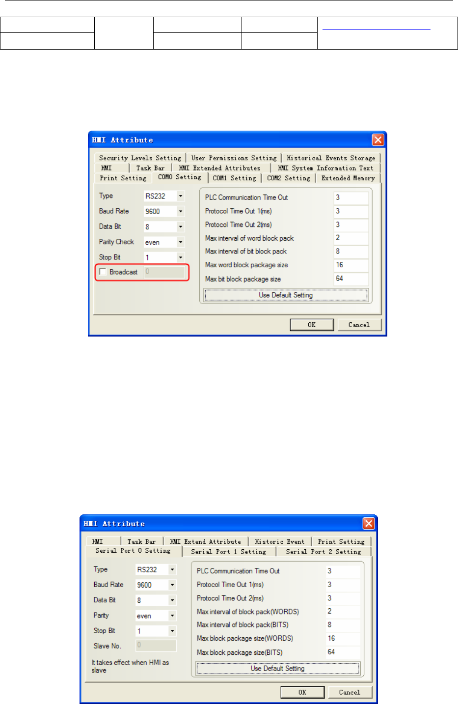
4 Communication settings and guide of HMI connecting with controller
- 250 -
Modbus UDP Ethernet
Modbus UDP Slave Ethernet
Connection Configuration
◎Communication Setting
Modbus RTU protocol
RS232 communication
Default communication parameters: 9600, 8, even, 1; station: 1
NOTE:
1. Modbus RTU protocol supports broadcasting station number, but the radio function only supports write
operations, with a reading of properties for the components, can not use the radio function;
2. Radio features are used in two ways: First, write-only properties with components (Bit state setting
device, "switch" method, except); multi-state setting device, "add value", "sub value", "JOG++", "JOG--"
method excluded); Second, the use of macros, the macro programming, on the radio station to write the
address number.
Modbus RTU Extend protocol
RS232 communication
Default communication parameters: 9600, 8, even, 1; station: 1
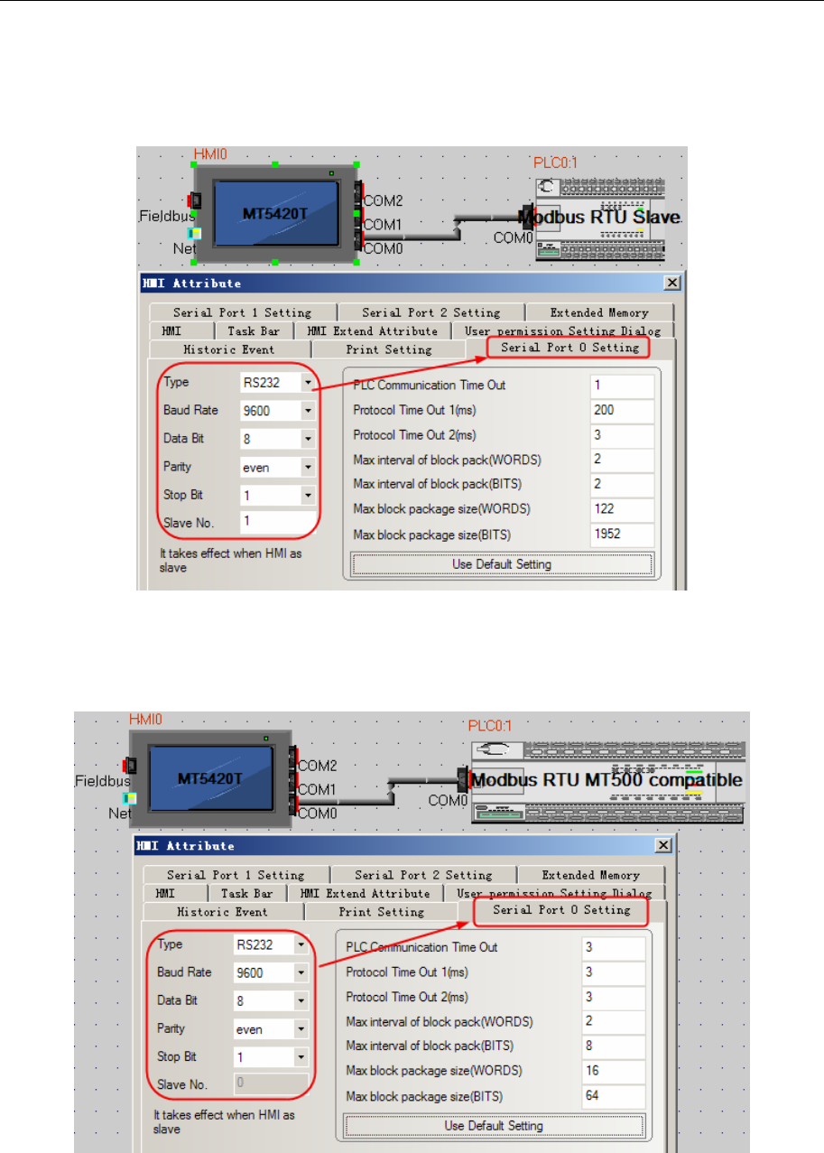
4 Communication settings and guide of HMI connecting with controller
- 251 -
Modbus RTU Slave protocol
RS232 communication
Default communication parameters: 9600, 8, even, 1; station: 1
Modbus RTU MT500 compatible protocol
RS232 communication
Default communication parameters: 9600, 8, even, 1; station: 1
Modbus ASCII protocol
RS232 communication
Default communication parameters: 9600, 8, even, 1; station: 1
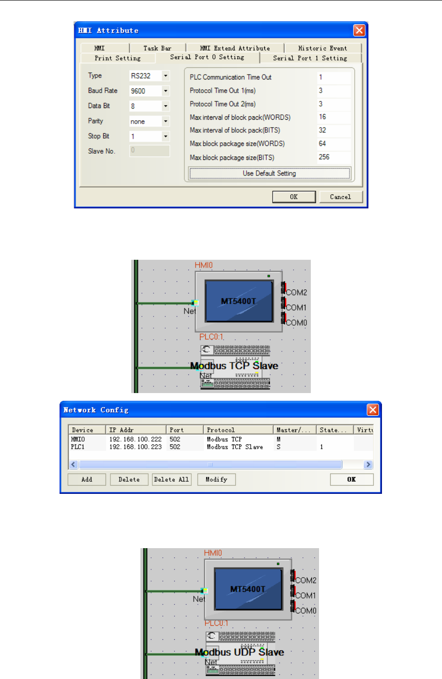
4 Communication settings and guide of HMI connecting with controller
- 252 -
Modbus TCP protocol
Network configuration
Modbus UDP protocol
Network configuration
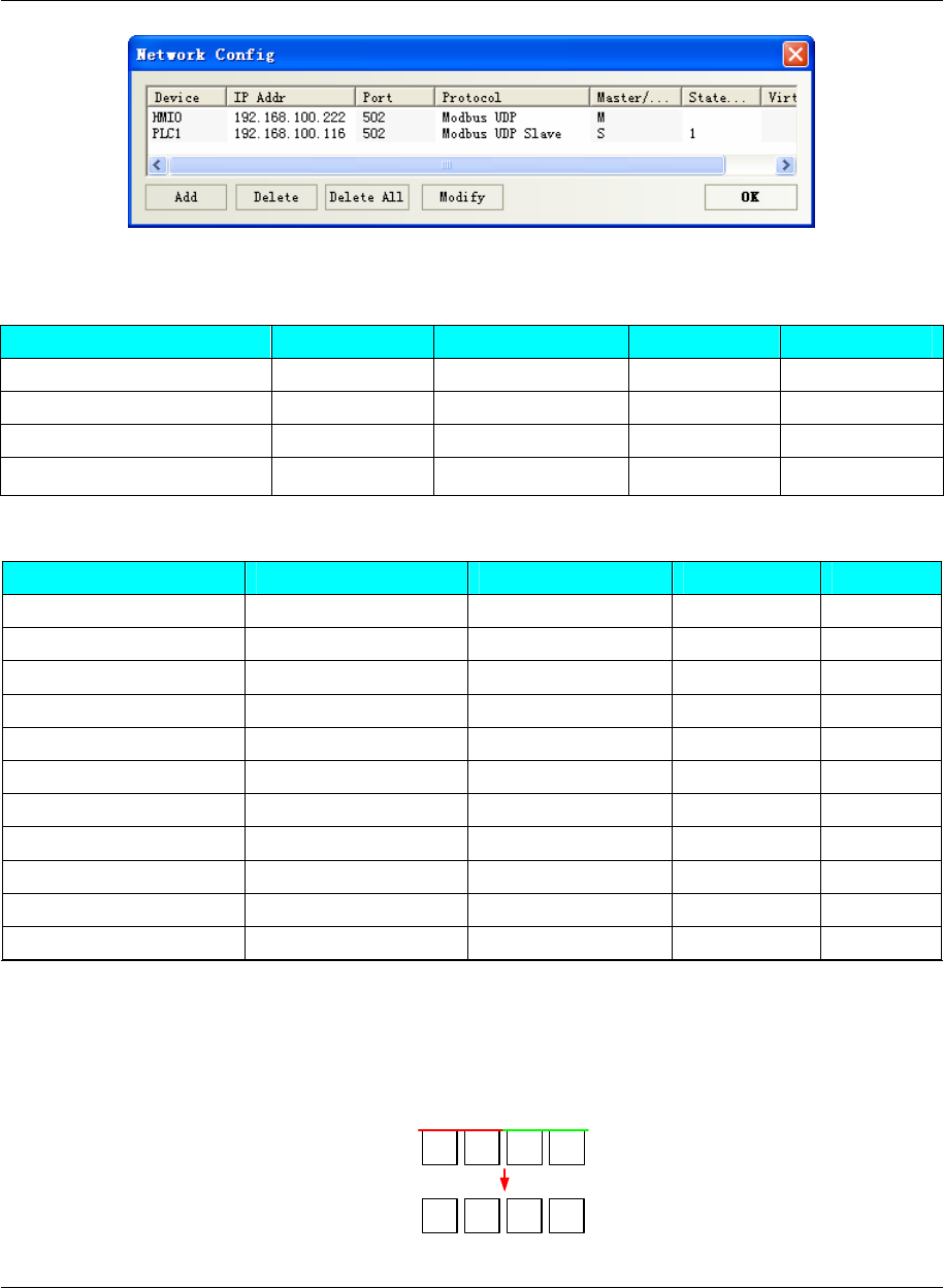
4 Communication settings and guide of HMI connecting with controller
- 253 -
◎Supported Device
Modbus RTU
Device Bit Address Word Address Format Notes
Output Relay 0X1-65535 ------ DDDDD
Input Relay (read only) 1X1-65535 ------ DDDDD
Input Register (read only) ------ 3X1-65535 DDDDD
Output Register ------ 4X1-65535 DDDDD
Modbus RTU Extend
Device Bit Address Word Address Format Notes
Output Relay 0X1-65535 ------ DDDDD
Input Relay 1X1-65535 ------ DDDDD read only
Input Relay 3X_bit 1.00-65535.15 ------ DDDDD read only
Output Relay 4X_bit 1.00-65535.15 ------ DDDDD
4X Single Write Relay 6X_bit 1.00-65535.15 ------ DDDDD.DD
Input Register ------ 3X1-65535 DDDDD read only
Output Register ------ 4X1-65535 DDDDD
4X Byte Swap ------ 5X1-65535 DDDDD
4X single word write ------ 6X1-65535 DDDDD
4X double word swap 4X-DINV 1-65535 DDDDD
3X double word swap 3X-DINV 1-65535 DDDDD
NOTE:
1. 5X is the byte register; 4X-DINV, 3X-DINV is the word high and low-bit register. The relation of them
as follow:
Word:
1234
4X(1word) H
HL
3412
5X(1word) H
byte swap
Dword:
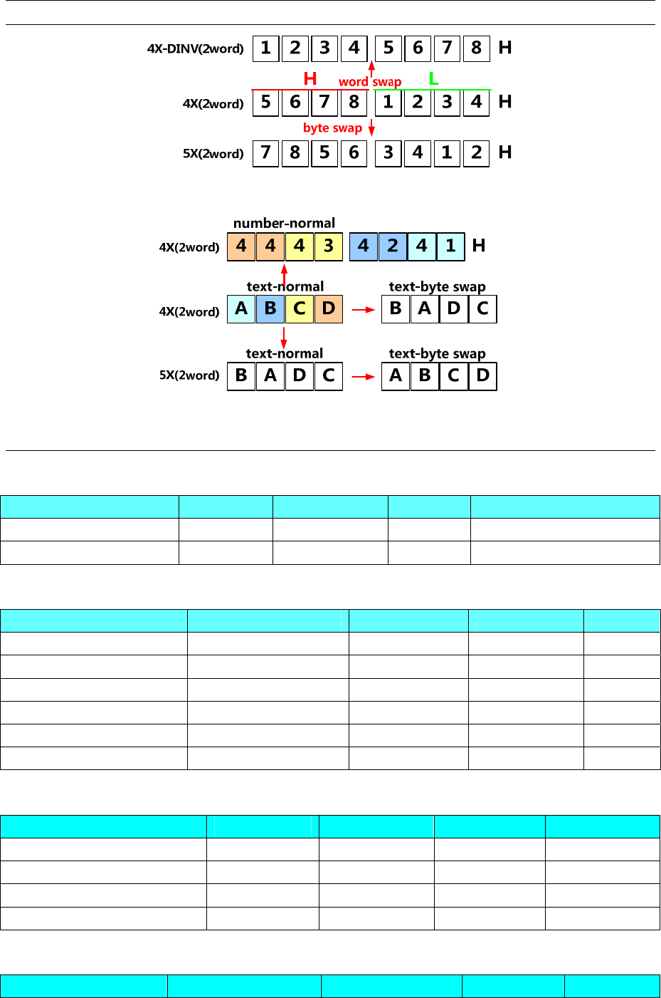
4 Communication settings and guide of HMI connecting with controller
- 254 -
Text:
2. Not use the odd and even address in the same window by 4X-DINV,only odd address or even address in
the same window.
Modbus RTU Slave
Device Bit Address Word Address Format Notes
Output Relay LB 0-9999 ------ DDDDD Mapping to 0X 1~9999
Data Register ------ LW 0-65535 DDDDD Mapping to 4X 1~9999
Modbus RTU MT500 compatible
Device Bit Address Word Address Format Notes
Output Relay 0X 1-65535 ------ DDDDD
Input Relay 1X 1-65535 ------ DDDDD read only
Input Relay 3X_bit 1.00-65535.15 ------ DDDDD.DD read only
Output Relay 4X_bit 1.00-65535.15 ------ DDDDD.DD
Input Register ------ 3X 1-65535 DDDDD read only
Output Register ------ 4X 1-65535 DDDDD
Modbus ASCII
Device Bit Address Word Address Format Notes
Output Relay 0X1-65535 ------ DDDDD
Input Relay (read only) 1X1-65535 ------ DDDDD
Input Register (read only) ------ 3X1-65535 DDDDD
Output Register ------ 4X1-65535 DDDDD
Modbus TCP Slave
Device Bit Address Word Address Format Notes
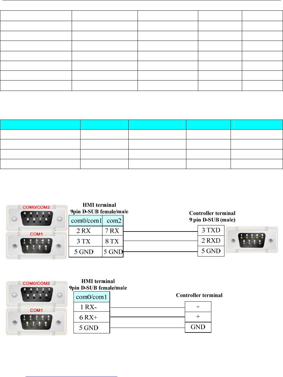
4 Communication settings and guide of HMI connecting with controller
- 255 -
Output Relay 0X 1-65535 ------ DDDDD
Input Relay 1X 1-65535 ------ DDDDD read only
Input Relay 3X_bit 1.00-65535.15 ------ DDDDD.DD read only
Data relay 4X_bit 1.00-65535.15 ------ DDDDD.DD
Input Register ------ 3X 1-65535 DDDDD read only
Output Register ------ 4X 1-65535 DDDDD
Data Register ------ 4X-DINV 1-65535 DDDDD
Data Register ------ 3X-DINV 1-65535 DDDDD
NOTE: 4X-DINV, 3X-DINV is the word high and low-bit counter.
Modbus UDP Slave
Device Bit Address Word Address Format Notes
Output Relay 0X1-65535 ------ DDDDD
Input Relay 1X1-65535 ------ DDDDD read only
Input Register ------ 3X1-65535 DDDDD read only
Output Register ------ 4X1-65535 DDDDD
◎Cable Diagram
RS232 communication cable
RS485 communication cable
Ethernet communication cable
Cross-connection or crossover network cable can be used as communication cable via the hub
Refer to 3.3 Download by Network Ethernet for method of making connection cable.
4.53 MODROL
Serial Communication
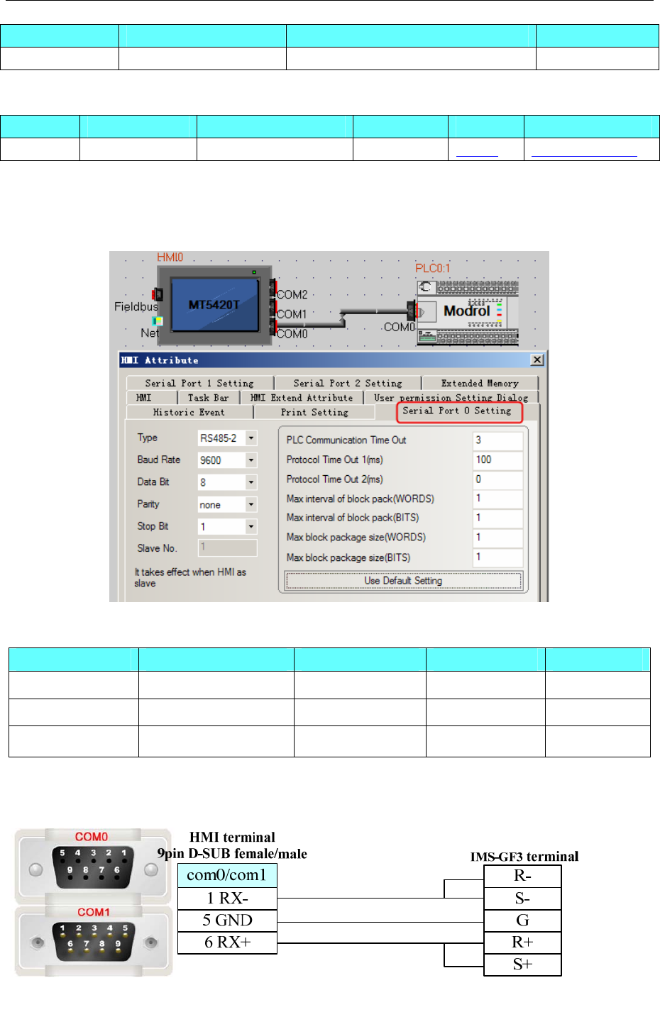
4 Communication settings and guide of HMI connecting with controller
- 256 -
Series CPU Link Module Driver
MODROL IMS-GF3-4011E RS485 on the CPU unit MODROL
System configuration
Series CPU Link Module COMM Type Parameter Cable
MODROL IMS-GF3-4011E RS485 on the CPU unit RS485 Setting Your owner cable
Communication Setting
HMI Setting
Default communication: 9600, 8, none, 1; station: 1
Supported Device
Device Bit Address Word Address Format Notes
------ D_1 0-9999 DDDD One byte
------ D_2 0-9999 DDDD Two byte
------ D_3 0-9999 DDDD Three byte
Cable Diagram
MODROL RS485
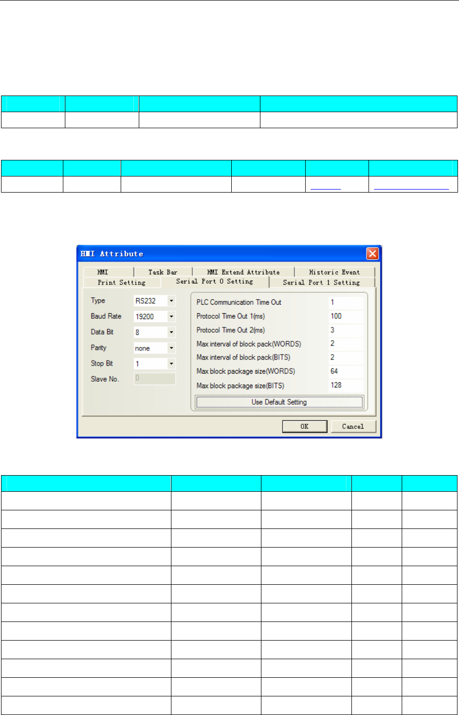
4 Communication settings and guide of HMI connecting with controller
- 257 -
4.54 OE MAX
◎Serial Communication
Series CPU Link Module Driver
NX7 NX7 RS232 on the CPU unit OE MAX NX7
◎System configuration
Series CPU Link Module COMM Type Parameter Cable
NX7 NX7 RS232 on the CPU unit RS232 Setting Your owner cable
◎Communication Setting
Default communication: 19200, 8, none, 1; station: 1
◎Supported Device
Device Bit Address Word Address Format Notes
Input/Output Relay R 0.0–127.15 ------ DDD.DD
General Relay L 0.0–63.15 ------ DD.DD
General Relay M 0.0–127.15 ------ DDD.DD
Keep Relay K 0.0–127.15 ------ DDD.DD
Timer Relay TC 0–255 ------ DDD
Special Relay F 0.0–15.15 ------ DD.DD
Internal HSC ------ R_word 0-127 DDD
General Register ------ L_word 0-63 DD
General Register ------ M_word 0-127 DDD
Keep Register ------ K_word 0-127 DDD
General Register ------ F_word 0-15 DD
Timer/Counter Register ------ SV_word 0-255 DDD
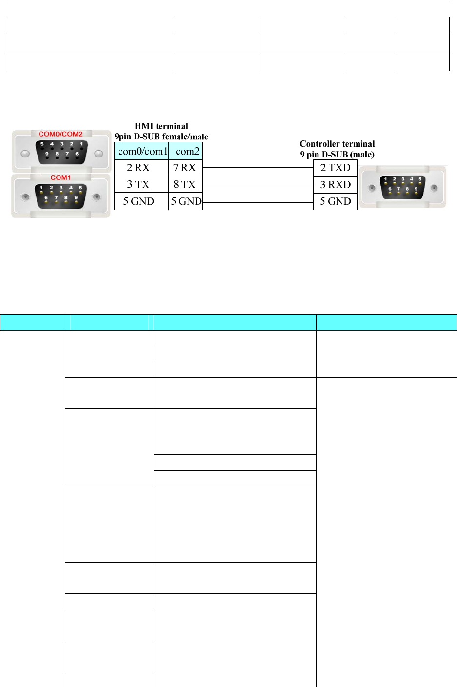
4 Communication settings and guide of HMI connecting with controller
- 258 -
Timer/Counter Register ------ PV_word 0-255 DDD
General Register ------ W_word 0-2047 DDDD
Special Register ------ SR_word 0-511 DDD
◎Cable Diagram
Oemax RS232 communication cable
4.55 Omron Corporation
◎Serial Communication
Series CPU Link Module Driver
RS232 on the CPU unit
CP1W-CIF01
CP1H
CP1L
CP1E CP1W-CIF11/CIF12
OMRON C Series Host Link
OMRON CP Series Host Link
C200H C200H-LK202
C120-LK201-V1
C200H-LK201
C200H-LK202
C120-LK201-V1
Link I/F on the CPU unit
C200HS
Peripheral port on the CPU unit
C500
C500F
C1000H
C2000
C2000H
C120-LK201-V1
C120-LK202-V1
C500-LK201-V1
C500-LK203
C1000HF C500-LK201-V1
C500-LK203
C20H/28H/40H Link I/F on the CPU unit
C20PF/28PF
C40PF/60PF
C120-LK201-V1
C120-LK202-V1
C120
C120F
C120-LK201-V1
C120-LK202-V1
SYSMAC C
CQM1-CPU11 Peripheral port on the CPU unit
OMRON C Series Host Link

4 Communication settings and guide of HMI connecting with controller
- 259 -
RS232C port on the CPU unit CQM1-CPU21
CQM1-CPU41
CQM1-CPU42
CQM1-CPU43
CQM1-CPU44
CQM1-CPU41-V1
CQM1-CPU42-V1
CQM1-CPU43-V1
CQM1-CPU44-V1
Peripheral port on the CPU unit
Peripheral port on the CPU unit
Peripheral port on
the CPM2C-CIF01
RS232C port on the CPM2C-CIF01
RS232C port on the CPM2C-CIF11
CPM2C
Terminal block on
the CPM2C-CIF11
Peripheral port on the CPU unit CQM1H-CPU11
CQM1H-CPU21 RS232 on the CPU unit
Peripheral port on the CPU unit
RS232 on the CPU unit
RS232C port on
the CQM1H-SCB41
CQM1H-CPU51
CQM1H-CPU61
RS422A/485 port on
the CQM1H-SCB41
OMRON C Series Host Link CPM1
CPM1A
CPM1A-V1
CPM2AH
RS232 on the CPU unit
OMRON CPM Series Host
Link
SYSMAC
CJ2
CJ2M-CPU13 RS232 on the CPU unit
RS232 on the CPU unit
Peripheral port on the CPU unit
SYSMAC
CJ
CJ1G-CPU45
CJ1G-CPU44
CJ1G-CPU45H
CJ1G-CPU44H
CJ1G-CPU43H
CJ1G-CPU42H
CJ1M-CPU23
CJ1M-CPU22
CJ1M-CPU21
CJ1M-CPU13
CJ1M-CPU12
CJ1M-CPU11
CJ1H-CPU66H
CJ1H-CPU65H
CJ1W-SCU41
OMRON CJ/CS Series Host
Link
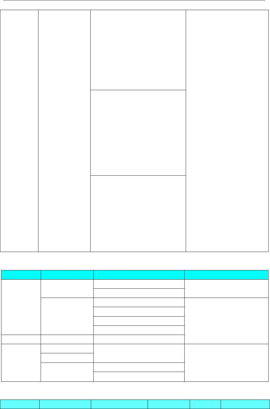
4 Communication settings and guide of HMI connecting with controller
- 260 -
RS232 on the CPU unit
Peripheral port on the CPU unit
SYSMAC
CS
CS1G-CPU45
CS1G-CPU44
CS1G-CPU43
CS1G-CPU42
CS1G-CPU45H
CS1G-CPU44H
CS1G-CPU43H
CS1G-CPU42H
CS1G-CPU45-V1
CS1G-CPU44-V1
CS1G-CPU43-V1
CS1G-CPU42-V1
CS1H-CPU67
CS1H-CPU66
CS1H-CPU65
CS1H-CPU64
CS1H-CPU63
CS1H-CPU67H
CS1H-CPU66H
CS1H-CPU65H
CS1H-CPU64H
CS1H-CPU63H
CS1H-CPU67-V1
CS1H-CPU66-V1
CS1H-CPU65-V1
CS1H-CPU64-V1
CS1H-CPU63-V1
CS1W-SCU21
CS1W-SCB21
CS1W-SCB41
OMRON CJ/CS Series Host
Link
◎Network Communication
Series CPU Link Module Driver
EtherNet/IP port on CPU Unit CJ2M-CPU35
CJ1W-ETN21
OMRON CJ Series
Ethernet(TCP Slave)
EtherNet/IP port on CPU Unit
CS1W-ETN21/EIP21
CJ1W-ETN21/EIP21
SYSMAC
CJ/CS
CJ2M-CPU3*
CS1H
CS1G
CJ2H-***-EIP
SYSMAC NJ NJ*01 EtherNet/IP port on CPU Unit
Omron CJ/CS/NJ/NX Series
Ethernet(UDP Slave)
CP1L-EM
CP1L-EL
EtherNet/IP port on CPU Unit
EtherNet/IP port on CPU Unit
SYSMAC C CP1H
CP1L CP1W-CIF41
OMRON CP Series Ethernet
(UDP Slave)
◎Serial System configuration
Series CPU Link Module COMM Type Parameter Cable

4 Communication settings and guide of HMI connecting with controller
- 261 -
RS232 on the CPU
unit
CP1W-CIF01
RS232 Setting Your owner cable
CP1H
CP1L
CP1E CP1W-CIF11/CIF12 RS485-4 Setting Your owner cable
Setting
SYSMAC C
CPM2AH RS232 on the CPU
unit RS232 Setting Your owner cable
SYSMAC
CJ2 CJ2M-CPU13 RS232 on the CPU
unit RS232 Setting Your owner cable
RS232 on the CPU
unit RS232 Setting Your owner cable
Peripheral port on
the CPU unit*1
RS232 Setting Your owner cable
RS232 Setting Your owner cable
SYSMAC CJ
CJ1G-CPU45
CJ1G-CPU44
CJ1G-CPU45H
CJ1G-CPU44H
CJ1G-CPU43H
CJ1G-CPU42H
CJ1M-CPU23
CJ1M-CPU22
CJ1M-CPU21
CJ1M-CPU13
CJ1M-CPU12
CJ1M-CPU11
CJ1H-CPU66H
CJ1H-CPU65H
CJ1W-SCU41
RS485-4 Setting Your owner cable
RS232 on the CPU
unit RS232 Setting Your owner cable
Peripheral port on
the CPU unit*1
RS232 Setting Your owner cable
CS1W-SCU21 RS232 Setting
CS1W-SCB21 RS232 Setting
SYSMAC
CS
CS1G-CPU45
CS1G-CPU44
CS1G-CPU43
CS1G-CPU42
CS1G-CPU45H
CS1G-CPU44H
CS1G-CPU43H
CS1G-CPU42H
CS1G-CPU45-V1
CS1G-CPU44-V1
CS1G-CPU43-V1
CS1G-CPU42-V1
CS1H-CPU67
CS1H-CPU66
CS1H-CPU65
CS1H-CPU64
CS1H-CPU63 CS1W-SCB41 RS232 Setting
Your owner cable
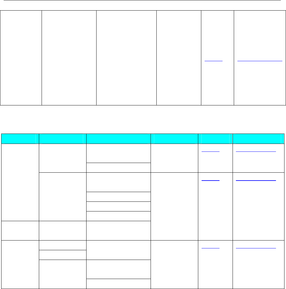
4 Communication settings and guide of HMI connecting with controller
- 262 -
CS1H-CPU67H
CS1H-CPU66H
CS1H-CPU65H
CS1H-CPU64H
CS1H-CPU63H
CS1H-CPU67-V1
CS1H-CPU66-V1
CS1H-CPU65-V1
CS1H-CPU64-V1
CS1H-CPU63-V1
RS485-4 Setting Your owner cable
*1 Must set the switch DIP 4 to be on
◎Network System configuration
Series CPU Link Module Connect Type Parameter Cable
EtherNet/IP port on
CPU Unit
CJ2M-CPU35
CJ1W-ETN21
Ethernet(TCP
Slave)
Setting Your own cable
EtherNet/IP port on
CPU Unit
CS1W-ETN21/EIP21
CJ1W-ETN21/EIP21
SYSMAC
CJ/CS
CJ2M-CPU3*
CS1H
CS1G
CJ2H-***-EIP
SYSMAC
NJ
NJ*01 EtherNet/IP port on
CPU Unit
Ethernet(UDP
Slave)
Setting Your own cable
CP1L-EM
CP1L-EL
EtherNet/IP port on
CPU Unit
EtherNet/IP port on
CPU Unit
SYSMAC
C CP1H
CP1L
CP1W-CIF41
Ethernet(UDP
Slave)
Setting Your own cable
◎Serial Communication Setting
OMRON CP Series Host Link protocol
HMI Setting
Default communication: 9600, 7, even, 2; station: 0
RS232 communication
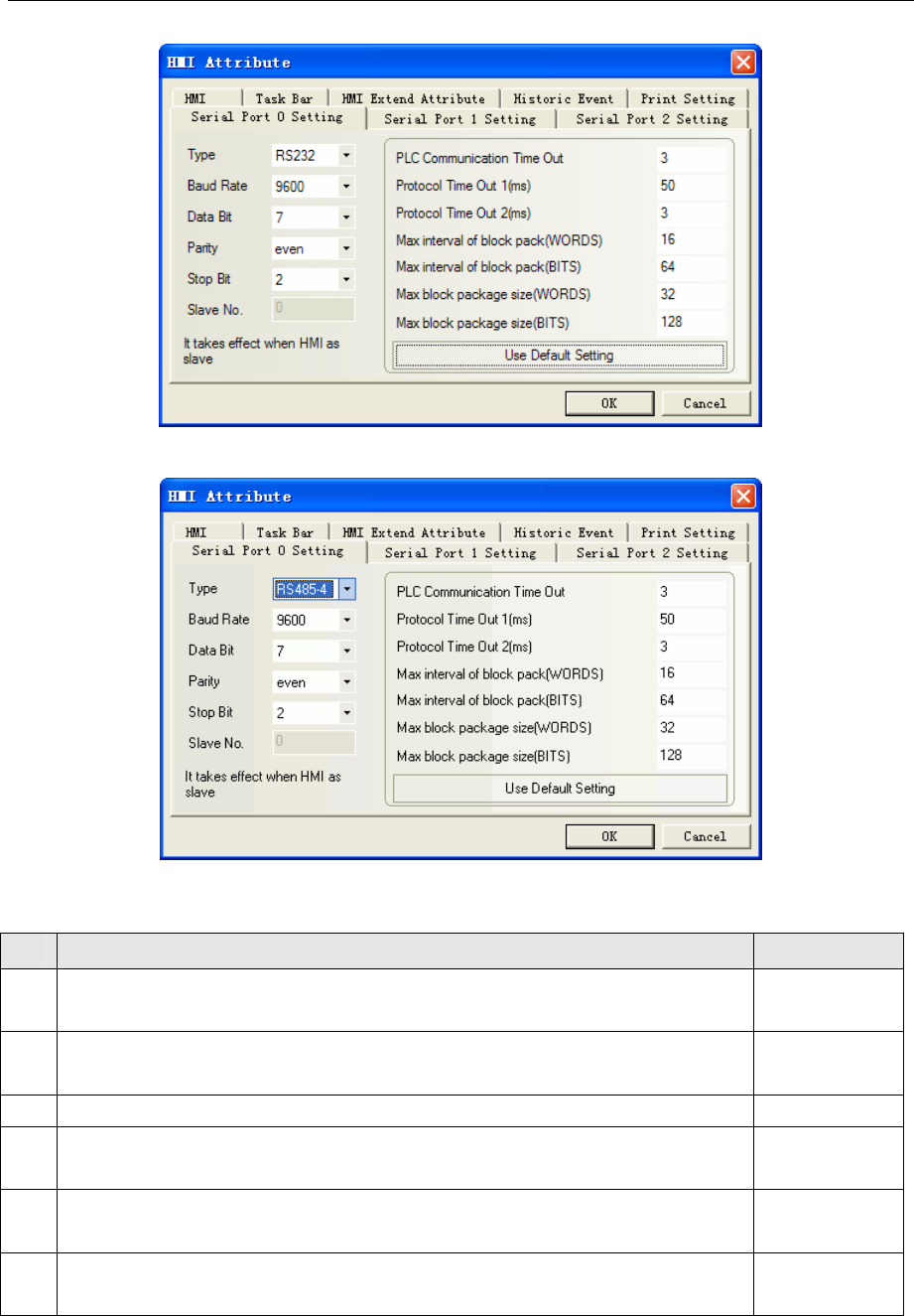
4 Communication settings and guide of HMI connecting with controller
- 263 -
RS422 communication
NOTE:Make sure that the switch DIP1~6 of PLC must be OFF when using OMRON CP Series Host Link
protocol.
NO. Setup contents default status
1 ON: write enable
OFF:write disable
OFF
2 ON: program automaticlly transmit from card to PLC when power up
OFF: program can’t automaticlly transmit from card to PLC when power up
OFF
3 OFF: OFF(default) OFF
4 ON: communication port1,Toolbus(default)
OFF:Port 1 communications settings according to the PLC system CPU setting
OFF
5 ON: communication port2,Toolbus(default)
OFF:Port 2 communications settings according to the PLC system CPU setting
OFF
6 ON: customer use ( A395.12 = ON)
OFF: customer use ( A395.12 = OFF)
OFF
OMRON C Series Host Link protocol
Default communication: 19200, 7, even, 2; station: 0
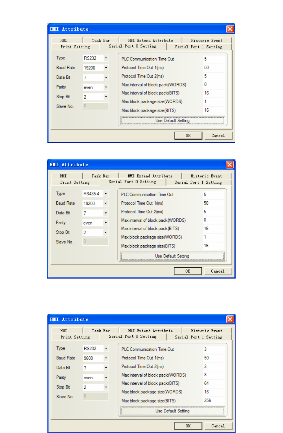
4 Communication settings and guide of HMI connecting with controller
- 264 -
RS232 communication
RS422 communication
OMRON CPM Series Host Link protocol
Default communication: 9600, 7, even, 2; station: 0
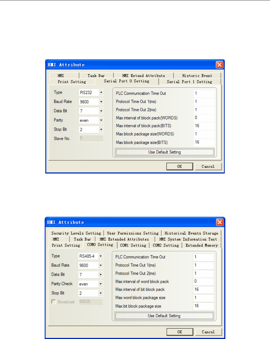
4 Communication settings and guide of HMI connecting with controller
- 265 -
NOTE: Select custom communication parameters (non-standard communication parameters), the switch of
PLC must be OFF.
OMRON CJ/CS Series Host Link protocol
RS232 Default communication: 9600, 7, even, 2; station: 0
NOTE:1.CJ1M switch DIP: SW1, SW2, SW3, SW5, SW8 must be off, but SW4, SW6, SW7 are optional.
2. CJ1M switches DIP 1~8 are OFF (default).
RS485-4 Default communication: 9600, 7, even, 2; station: 0
◎Network Communication Setting
OMRON CJ Series Ethernet(TCP Slave)
HMI Setting
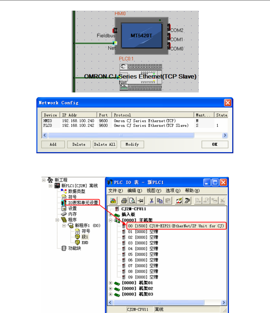
4 Communication settings and guide of HMI connecting with controller
- 266 -
PLC Setting
1. Double-click the IO table and the unit set, find the Ethernet communication module
2. Double-click the Ethernet communication module, set the parameters
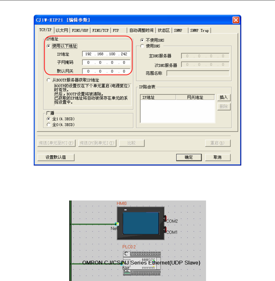
4 Communication settings and guide of HMI connecting with controller
- 267 -
OMRON CJ/CS/NJ Series Ethernet(UDP Slave)
HMI Setting
Attention: HMI and PLC must be set in the same network,while the node ID should be different.
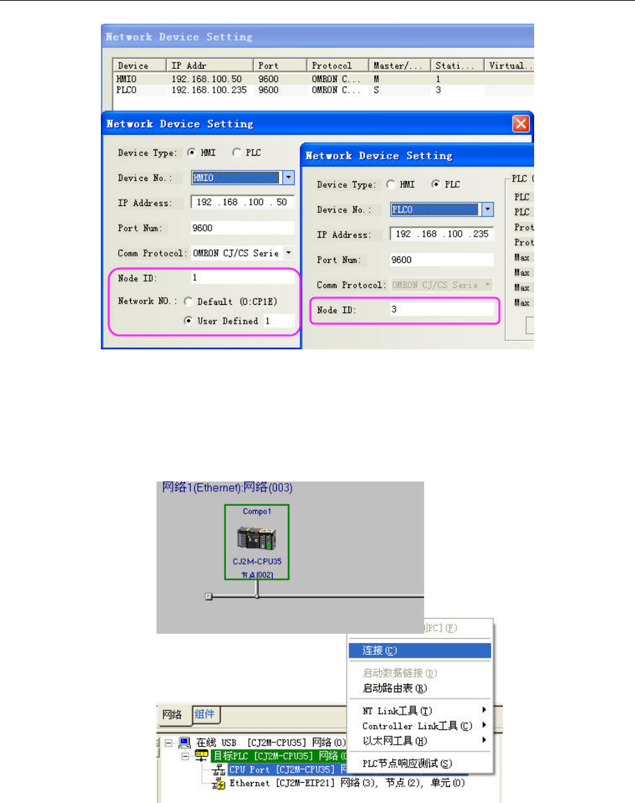
4 Communication settings and guide of HMI connecting with controller
- 268 -
PLC Setting
Please use CX-Integrator to modify
1. Choose the right type to get the PLC and its software connected
2. Set the PLC into programming mode
3. Read the data and show the connected device
4. Double click the device to modify the related parameter,for example IP Address
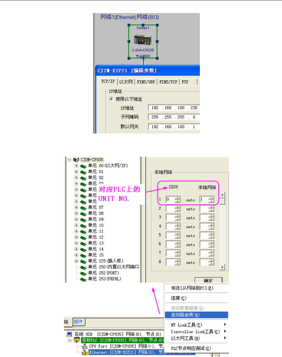
4 Communication settings and guide of HMI connecting with controller
- 269 -
5. Set the Network number and Node ID
(1)Network number
(2)You can change the Node ID by the switch on the device(NODE No.)
OMRON CP Series Ethernet(UDP Slave)
HMI Setting
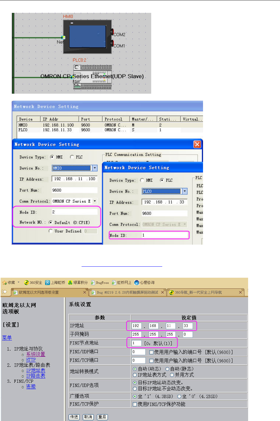
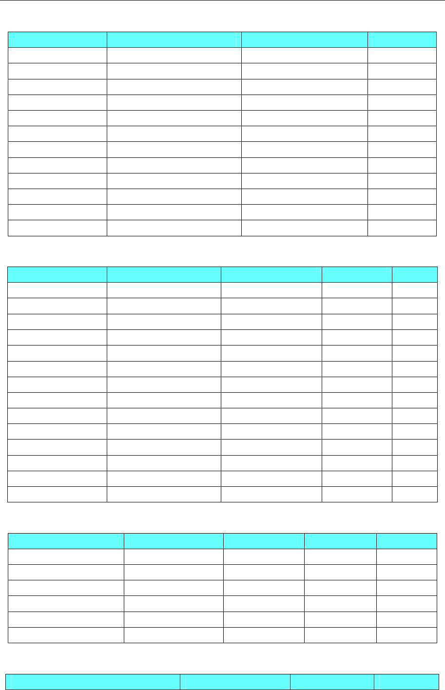
4 Communication settings and guide of HMI connecting with controller
- 271 -
Omron C Series Host Link
Device Bit Address Word Address Format
Hold Relay HR_bit 00.00-99.15 ------ DD.DD
Data Relay DM_bit 0000.00-6655.15 ------ DDDD.DD
Link Relay LR_bit 00.00-63.15 ------ DD.DD
Auxiliary Relay AR_bit 00.00-959.15 ------ DD.DD
Channel I/O CIO_IR_bit 000.00-511.15 ------ DDD.DD
Counter Relay ------ CNT_word 000-511 DDD
Timer Relay ------ TIM_word 000-511 DDD
Hold Register ------ HR_word 00-99 DD
Data Register ------ DM_word 0000-6655 DDDD
Link Register ------ LR_word 00-63 DD
Auxiliary Register ------ AR_word 000-959 DDD
Channel I/O Register ------ CIO_IR_word 000-511 DDD
OMRON CP Series Host Link
Device Bit Address Word Address Format Notes
Work Relay W_bit 0.00-511.15 ------ DDD.DD
Hold Relay H_bit 0.00-1535.15 ------ DDDD.DD
Data Relay D_bit 0.00-32767.15 ------ DDDDD.DD
Counter Relay C flag 0.00-4095.15 ------ DDDD.DD
Timer Relay T flag 0.00-4095.15 ------ DDDD.DD
Auxiliary Relay A_bit 0.00-959.15 ------ DDD.DD
Channel I/O CIO_bit 0.00-6143.15 ------ DDDD.DD
Work Register ------ W_word 0-511 DDD
Hold Register ------ H_word 0-1535 DDDD
Data Register ------ D_word 0-32767 DDDDD
Counter Register ------ C_word 0-4095 DDDD
Timer Register ------ T_word 0-4095 DDDD
Auxiliary Register ------ A_word 0-959 DDD
Channel I/O Register ------ CIO_word 0-6143 DDDD
OMRON CPM Series Host Link
Device Bit Address Word Address Format Notes
Hold Relay HR 0.00-4095.15 ------ DDDD.DD
Link Relay LR 0.00-4095.15 ------ DDDD.DD
Auxiliary Relay AR 0.00-4095.15 ------ DDDD.DD
Internal Relay IR 0.00-4095.15 ------ DDDD.DD
Timer/Counter Register ------ TC 0-255 DDD
Data Register ------ DM 0-9999 DDDD
OMRON CJ/CS Series Host Link
Device Bit Address Word Address Format
4 Communication settings and guide of HMI connecting with controller
- 272 -
Channel I/O CIO 0000.00-6143.15 ------ DDDD.DD
Internal Auxiliary Relay WR 000.00-511.15 ------ DDD.DD
Special Auxiliary Relay AR 000.00-959.15 ------ DDD.DD
Latch Relay HR 000.00-511.15 ------ DDD.DD
Timer (Timer Up Flag) TIM 0000-4095 ------ DDDD
Counter (Counter Up Flag) CNT 0000-4095 ------ DDDD
Data Memory DM 00000.00-32767.15 ------ DDDDD.DD
Extension Data Memory Relay(E0-EC) E0 0.00-EC 32767.15 ------ DDDDD.DD
Extension Data Memory(E0-EC) ------ E0 0-EC 32767 DDDDD
Channel I/O ------ CIO 0000-6143 DDDD
Internal Auxiliary Relay ------ WR 000-511 DDD
Special Auxiliary Relay ------ AR 000-959 DDD
Latch Relay ------ HR 000-511 DDD
Timer (current Value) ------ TIM 0000-4095 DDDD
Counter (Current Value) ------ CNT 0000-4095 DDDD
Data Memory ------ DM 00000-32767 DDDDD
Index Register ------ IR 00-15 DD
Data Register ------ DR 00-15 DD
OMRON CJ Series Ethernet (TCP Slave)
Device Bit Address Word Address Format
Channel IO CIO 0.00-6143.15 ------ DDDD.DD
Internal Auxiliary Relay W 0.00-511.15 ------ DDD.DD
Special Auxiliary Relay A 0.0-959.15 ------ DDD.DD
Latch Relay H 0.0-511.15 ------ DDD.DD
Timer Up Flag T 0-4095 ------ DDDD
Count Up Flag C 0-4095 ------ DDDD
TKB TKB 0-31 ------ DD
Channel IO ------ CIO 0-6142 DDDD
Internal Auxiliary Relay ------ W 0-511 DDD
Special Auxiliary Relay ------ A 0-959 DDD
Latch Relay ------ H 0-511 DDD
Timer Current Value ------ T 0-4095 DDDD
Counter Current Value ------ C 0-4095 DDDD
Extension Data Memory(E0-E18) ------ E0-E18 0-32767 DDDDD
EM ------ EM 0-32767 DDDDD
Index Register ------ IR 0-15 DD
Data Register ------ DR 0-15 DD
OMRON CJ/CS/NJ Series Ethernet (UDP Slave)
Device Bit Address Word Address Format
CIO_bit ------ Channel IO
0.00-6143.15 CIO_FORCE ------
DDDD.DD

4 Communication settings and guide of HMI connecting with controller
- 273 -
CIO_FORCE_RELEASE ------
CIO_RELEASE_STATUS ------
W_bit ------
W_FORCE ------
W_FORCE_RELEASE ------
Internal Auxiliary Relay
0.00-511.15
W_RELEASE_STATUS ------
DDD.DD
H_bit ------
H_FORCE ------
H_FORCE_RELEASE ------
Latch Relay
0.0-1535.15
H_RELEASE_STATUS ------
DDDD.DD
T_FLAG ------
T_FORCE ------
T_FORCE_RELEASE ------
Timer Up Flag
0-4095
T_RELEASE_STATUS ------
DDDD
C_FLAG ------
C_FORCE ------
C_FORCE_RELEASE ------
Count Up Flag
0-4095
C_RELEASE_STATUS ------
DDDD
Special Auxiliary Relay A 0.0-11535.15 ------ DDDDD.DD
E(0-9)_bit ------ DDDDD.DD
E(A-F)_bit ------ DDDDD.DD
Extension Data Memory
0.00-32767.15 E(10-18)_bit ------- DDDDD.DD
Data Memory D_bit 0.00-32767.15 ------ DDDDD.DD
TKB TK_FLAG 0-127 ------ DDD
Channel IO ------ CIO 0-6143 DDDD
Internal Auxiliary Relay ------ W 0-511 DDD
Latch Relay ------ H 0-1535 DDDD
Timer Current Value ------ T 0-4095 DDDD
Counter Current Value ------ C 0-4095 DDDD
Special Auxiliary Relay ------ A 0-11535 DDDDD
Extension Data Memory
------
E0-E9 0-32767
EA-EF 0-32767
E10-E18 0-32767
EM 0-32767
DDDDD
Data Memory ------ D 0-32767 DDDDD
TK ------ TK0-127 DDD
Index Register ------ IR 0-15 DD
Data Register ------ DR 0-15 DD
OMRON CP Series Ethernet (UDP Slave)
Device Bit Address Word Address Format
Channel IO CIO_bit ------ DDDD.DD

4 Communication settings and guide of HMI connecting with controller
- 274 -
CIO_FORCE ------
CIO_FORCE_RELEASE ------
0.00-6143.15
CIO_RELEASE_STATUS ------
W_bit ------
W_FORCE ------
W_FORCE_RELEASE ------
Internal Auxiliary Relay
0.00-511.15
W_RELEASE_STATUS ------
DDD.DD
H_bit ------
H_FORCE ------
H_FORCE_RELEASE ------
Latch Relay
0.0-1535.15
H_RELEASE_STATUS ------
DDDD.DD
T_FLAG ------
T_FORCE ------
T_FORCE_RELEASE ------
Timer Up Flag
0-4095
T_RELEASE_STATUS ------
DDDD
C_FLAG ------
C_FORCE ------
C_FORCE_RELEASE ------
Count Up Flag
0-4095
C_RELEASE_STATUS ------
DDDD
Special Auxiliary Relay A 0.0-959.15 ------ DDDDD.DD
Data Memory D_bit 0.00-32767.15 ------ DDDDD.DD
TKB TK_FLAG 0-31 ------ DDD
Channel IO ------ CIO 0-6143 DDDD
Internal Auxiliary Relay ------ W 0-511 DDD
Latch Relay ------ H 0-1535 DDDD
Timer Current Value ------ T 0-4095 DDDD
Counter Current Value ------ C 0-4095 DDDD
Special Auxiliary Relay ------ A 0-959 DDDDD
Data Memory ------ D 00000-32767 DDDDD
TK ------ TK0-31 DDD
Index Register ------ IR 0-15 DD
Data Register ------ DR 0-15 DD
◎Cable Diagram
RS232 Communication Cable
1. RS232 on the CPU unit or CP1W-CIF01\CS1W-SCU21\CS1W-SCB21 etc. module
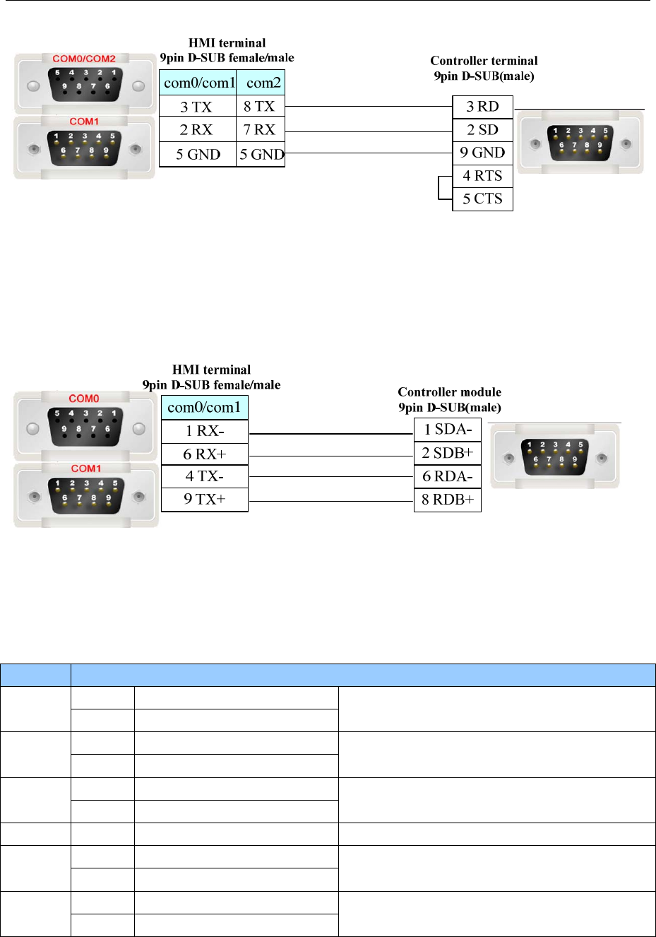
4 Communication settings and guide of HMI connecting with controller
- 275 -
2. Peripheral port on the CPU unit(OMRON CJ\CS series)
When connecting the peripheral port on the CPU by the conversion adapter, set DIP4 to on.
RS422 Communication Cable
1. CJ1W-SCU41\ CJ1W-SCB41 module
2. CP1W-CIF11/CP1W-CIF12 module
NOTE:CP1W-CIF11 is without photoelectricity isolation, the maximum communication distance is 50
m. CP1W-CIF12 is with photoelectricity isolation, the maximum communication distance is 500 m. Other
parameters specification and DIP switch settings are the same.
DIP CONTENT
ON Yes(Both sides) 1
OFF No
Terminal resistance selection
ON 2-wires(RS485) 2
OFF 4-wires(RS422A)
2、3 must be the same.
ON 2-wires(RS485) 3
OFF 4-wires(RS422A)
4 ----- ----- N/A
ON With RS control 5
OFF Without RS control(Receive)
Set ON when loop back is forbidden.
ON With RS control 6
OFF Without RS control(Send)
If connecting to multiple devices, set ON when
using RS422A, it must set as ON.
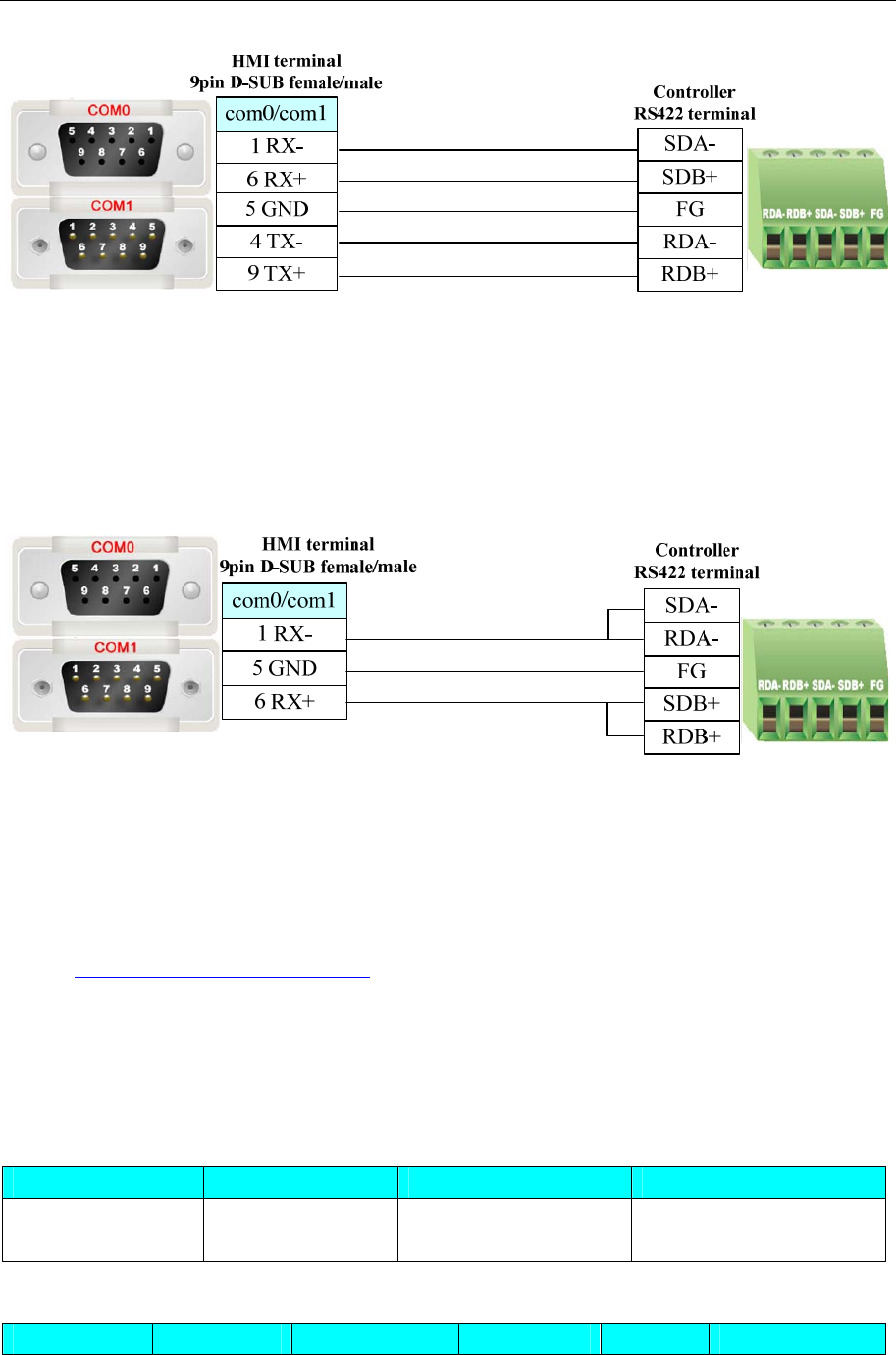
4 Communication settings and guide of HMI connecting with controller
- 276 -
NOTE: When PLC uses CP1W-CIF11 or CP1W-CIF12 module for communication, if it uses 1:1 and
RS422 communication, it need to set all the DIP Switch SW1~6 as OFF. If it uses 1:N and RS422
communication, it need to set DIP Switch SW1~5 as OFF and SW6 as ON.
RS485 communication cable
CP1W-CIF11/CIF12 module
NOTE: When PLC uses CP1W-CIF11 or CP1W-CIF12 module and RS485 communication, please make
sure the DIP Switch SW1 of CP1W-CIF11 or CP1W-CIF12 as OFF, and set SW2,SW3,SW5,SW6 as
ON.SW4 can be set as ON or OFF.
Ethernet communication protocol cable
Cross-connection or crossover network cable can be used as communication cable via the hub
Refer to 3.3 Download by Network Ethernet for method of making connection cable.
4.56 OMRON E5EZ-R3(Temperature Controller)
◎Serial Communication
Series CPU Link Module Driver
OMRON E5EZ-R3 E5EZ-R3
E5EZ-C3MT
RS485 on the CPU unit Omron E5EZ-R3
◎System configuration
Series CPU Link Module COMM Type Parameter Cable
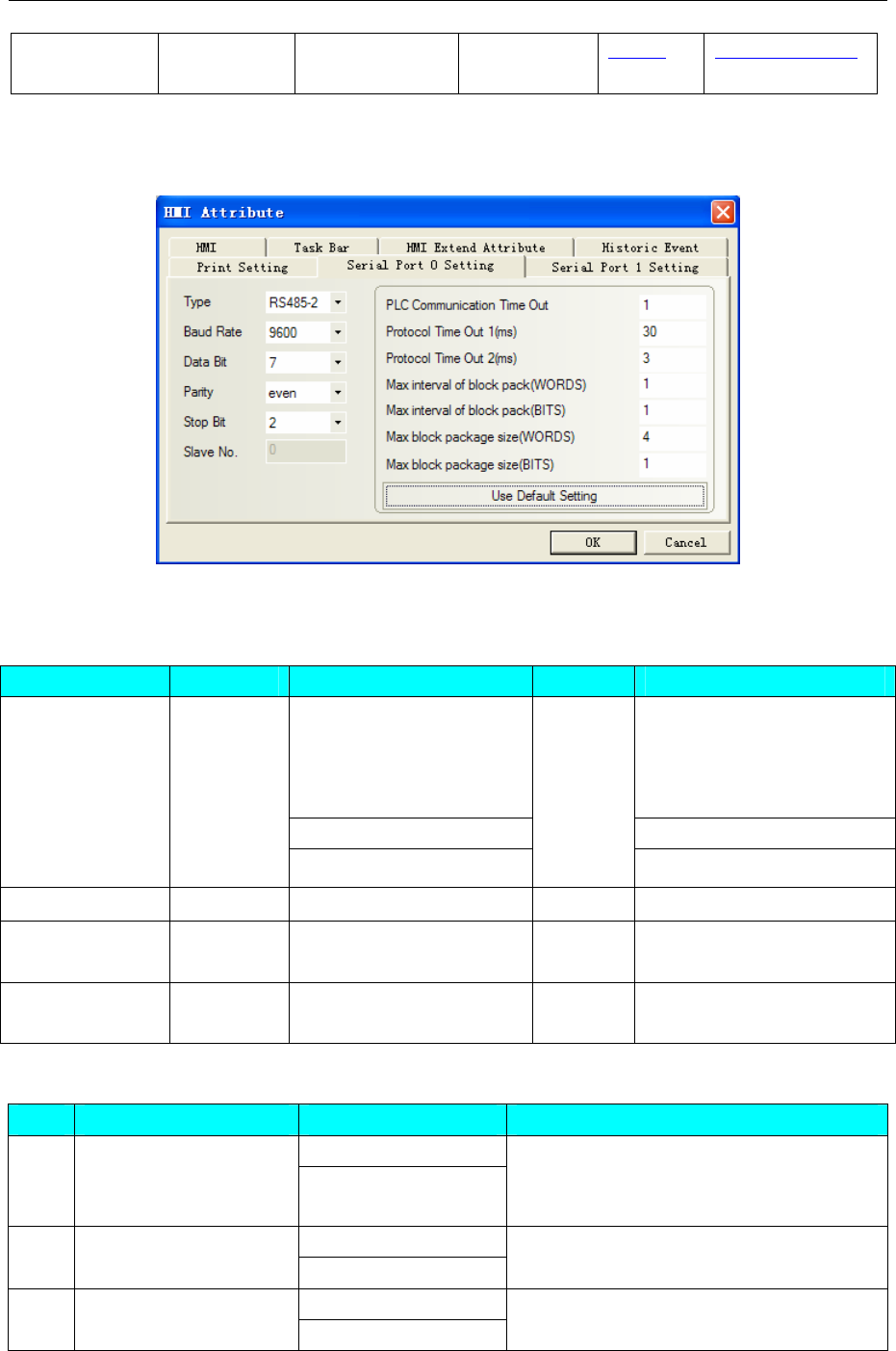
4 Communication settings and guide of HMI connecting with controller
- 277 -
OMRON
E5EZ-R3
OMRON
E5EZ-R3
RS485 on the
CPU unit
RS485-2 Setting Your owner cable
◎Communication Setting
Default communication: 9600, 7, even, 2; station: 0
◎Supported Device
OMRON E5EZ-R3
Device Bit Address Word Address Format Notes
0.0 — 0.A (C0 read only) Main addr indicates variable
type 0(C0),1(C1),2(C3)
subaddress indicates address
of variable type
1.0 — 1.2D (C1)
Variable ------
2.0 — 2.5B (C3)
DDD.HH
Action Command ------ 0-8 H
State 0-31 ------ DD Show the bit value of 0001
(state)in C0
Abnormal Input 0 ------ D The 6th value of C0
0001(state) Abnormal Input
NOTE: H indicates hexadecimal
Action Command address and other informations
Addr command content Notes
00:OFF(disable)
0 Communication write
01:ON (enable)
Before writing data, "Communication
write" command is "01” ON (enable)",
otherwise it writes disable
00:Run
1 Run/Stop 01:Stop
00:Setting value 0 2 Multi-segment SP
01:Setting value 1
Must set the value of variable(addr:3.1A )to
1(ON) for writing correctly, otherwise it
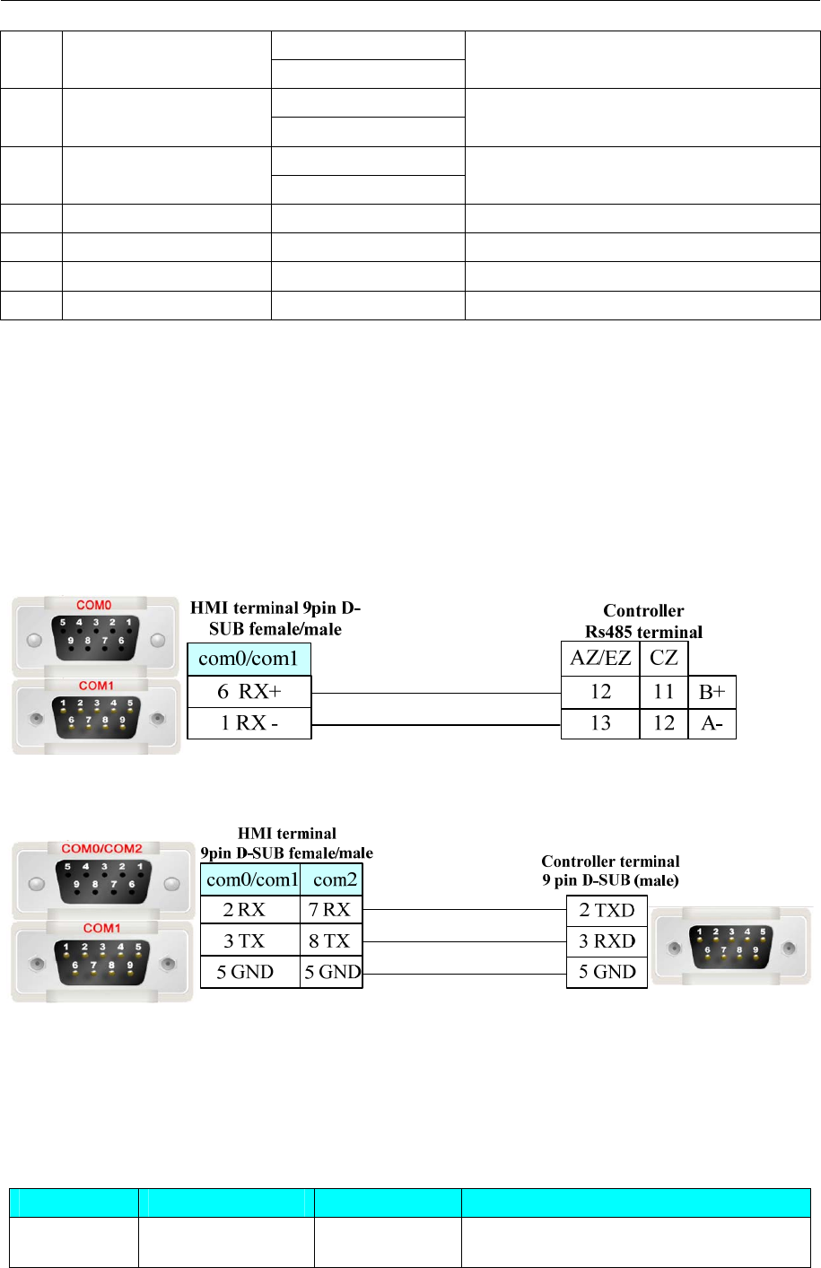
4 Communication settings and guide of HMI connecting with controller
- 278 -
02:Setting value 2
03:Setting value 3
can’t write-in.
00:stop
3 AT execute/stop 01:AT execute
00:save
4 write-in mode 01:RAM
5 RAM storage 00
6 Soft reset 00
7 Setting area1 shift 00
8 Protection value shift 00
Please refer to the communication protocol for details.
NOTE:
• Make sure the setting value be the same as the plc’s station No.
• Must be the same as the station No. of HMI
• Before writing data, "Communication write" command must is "01” ON (enable)", otherwise it
writes disable
◎Cable Diagram
RS485-2 communication cable
RS232 communication, need to use RS-232 to RS-422/485 converter
4.57 OPTO 22
◎Ethernet Communication (nonsupport Direct Online Simulation)
Series CPU Link Module Driver
OPTO 22
SNAP-UP1-ADS Ethernet OPTO 22 SNAP Ethernet(TCP)
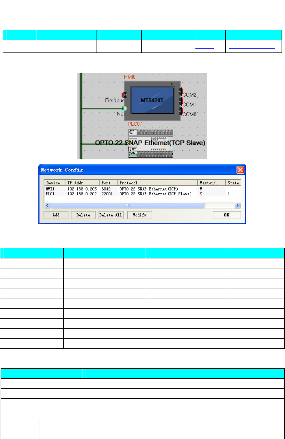
4 Communication settings and guide of HMI connecting with controller
- 279 -
◎System configuration
Series CPU Link Module Connect Type Parameter Cable
OPTO 22 SNAP-UP1-ADS Ethernet Ethernet Setting Your owner cable
◎Communication Setting
◎Supported Device
Device Bit Address Word Address Format
Bit Table B0-65535 —— DDDDD
Bit Table BT0.000-65535.255 —— DDDDD.DDD
Integer 32 —— N32 0-65535 DDDDD
Float —— FN0-65535 DDDDD
UP Timer —— UTN0-65535 DDDDD
Down Timer —— DTN0-65535 DDDDD
PID parameter —— PIDSN0.00-32.06 DDDDD.DD
Integer 32 Table —— NT0.000-65535.255 DDDDD.DDD
Float Table —— FT0.000-65535.255 DDDDD.DDD
Editing Macro, please refer to the type table:
Register Type
N32 Double
FN Float
DTN Float
UTN Float
Input Float PID
SetPoint Float
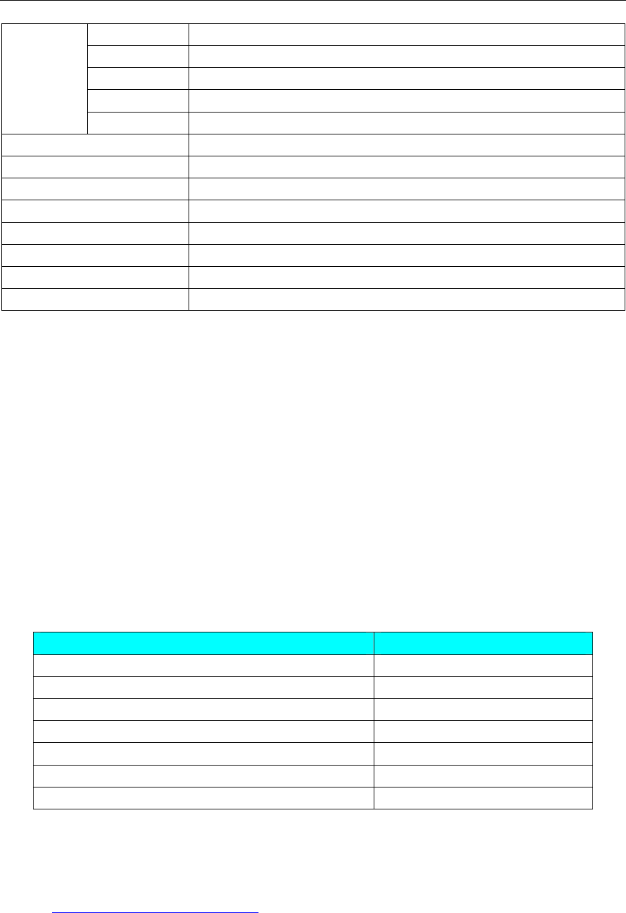
4 Communication settings and guide of HMI connecting with controller
- 280 -
Output Float
Gain Float
Tune I Float
Tune D Float
Mode Double
IN BIT
QN BIT
PIN Float
PQN Float
NT Double
FT Float
B BIT(the attribute of B is the same as N32 in the PLC software)
BT BIT(the attribute of BT is the same as NT in the PLC software)
NOTE:
1、 The configuration in OPTO 22 software must be the same as the configuration in EV5000
software:
true:e.g.: define Float in the OPTO 22 software,F1
Select FN device in the EV5000 software, address: 1.
Communicate correctly
error:e.g.: define Float in the OPTO 22 software,F0001
Select FN device in the EV5000 software, address: 1.
Communicate error
2、 PIDSN correspondence
If it set up PID1 in the OPTO 22 software, it can show the values of Input, SetPoint, Output, Gain,
Tune I, Tune D, and Mode.
In the Ev5000 software, PIDSN format DDDDD.DD, Address can be written in 1.**.( the main address
in front of decimal point corresponding to the OPTO 22 of PID1 1 ,sub-addr refer to the table. the table
as follows:
Sub Address(Example PID1,1 is sub address)Corresponding Value
1.00 Input
1.01 SetPoint
1.02 Output
1.03 Gain
1.04 Tune I
1.05 Tune D
1.06 Mode
◎Cable Diagram
Ethernet communication cable
Cross-connection or crossover network cable can be used as communication cable via the hub
Refer to 3.3 Download by Network Ethernet for method of making connection cable.
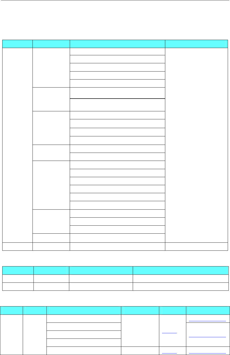
4 Communication settings and guide of HMI connecting with controller
- 281 -
4.58 Panasonic Electric Corporation
◎Serial Communication
Series CPU Link Module Driver
Tool port on the Control unit
AFPG801
AFPG802
AFPG803
FP
AFPG806
Tool port on the Control unit FP0
FP1
FP-M RS232C port on the Control unit
Tool port on the Control unit
RS232C port on the Control unit
AFP2462
FP2
FP2SH
AFP2465+(AFP2803,AFP2804, FP2805)
Tool port on the Control unit FP3
AFP3462
Tool port on the Control unit
AFPE224300
AFPE224302
AFPE224305
AFPE214322
FP-e
AFPE214325
Tool port on the Control unit
RS232C port on the Control unit
FP10SH
FP10S
AFP3462
FP
FP-X RS232C port on the Control unit
Panasonic FP
FP7 CPS3E RS232 on the CPU unit Panasonic FP7
◎Network Communication
Series CPU Link Module Driver
FP FP-X Ethernet interface on CPU Panasonic FP Ethernet(TCP Slave)
FP7 CPS3E Ethernet interface on CPU Panasonic FP7 Ethernet(TCP slave)
◎ Serial System configuration
Series CPU Link Module COMM Type Parameter Cable
Tool port on the Control unit Your owner cable
AFPG801
AFPG802
AFPG806
RS232C Setting Your owner cable
FP FP
AFPG803 RS485(2 wire) Setting Your owner cable
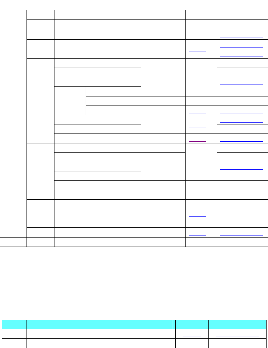
4 Communication settings and guide of HMI connecting with controller
- 282 -
AFPG806
Tool port on the Control unit Your owner cable
FP0 RS232C port on the Control unit RS232C Setting Your owner cable
Tool port on the Control unit Your owner cableFP1
FP-M RS232C port on the Control unit RS232C Setting Your owner cable
Tool port on the Control unit Your owner cable
RS232C port on the Control unit
AFP2462
AFP2803
RS232C Setting Your owner cable
AFP2804 RS422(4 wire) Setting Your owner cable
FP2
FP2SH
AFP2465
AFP2805 RS485(2 wire) Setting Your owner cable
Tool port on the Control unit Your owner cable
AFP3462 RS232C Setting Your owner cable
FP3
AFP3463 RS422(4 wire) Setting Your owner cable
Tool port on the Control unit RS232C Your owner cable
AFPE224300
AFPE214325
AFPE224305
RS232C Setting Your owner cable
AFPE224302
FP-e
AFPE214322 RS485(2 wire) Setting Your owner cable
Tool port on the Control unit Your owner cable
RS232C port on the Control unit
FP10SH
FP10S AFP3462
RS232C Setting Your owner cable
FP-X RS232C port on the Control unit RS232C Setting Your owner cable
FP7 CPS3E RS232 on the CPU unit RS232 Setting Your owner cable
NOTE:
1. Only FP0 (C10CRM/C10CRS/C14CRM/C14CRS/C16T/C16CP/C32CT/C32CP) has RS232C port.
2. Only FP1 (C24/C40/C56/C72) has RS232C port.
3. Only FP1(C20R/C20T/C32T)has RS232C port.
4. AFP245 is the communication Package of FP2/FP2SH. AFP2803, AFP2084 and AFP2085 are the
communications module of AFP2465.
◎ Network System configuration
Series CPU Link Module COMM Type Parameter Cable
FP FP-X Ethernet interface on CPU Ethernet Setting Your owner cable
FP7 CPS3E Ethernet interface on CPU Ethernet 5Setting Your owner cable
◎ Serial Communication Setting
Panasonic FP protocol:
RS232 communication
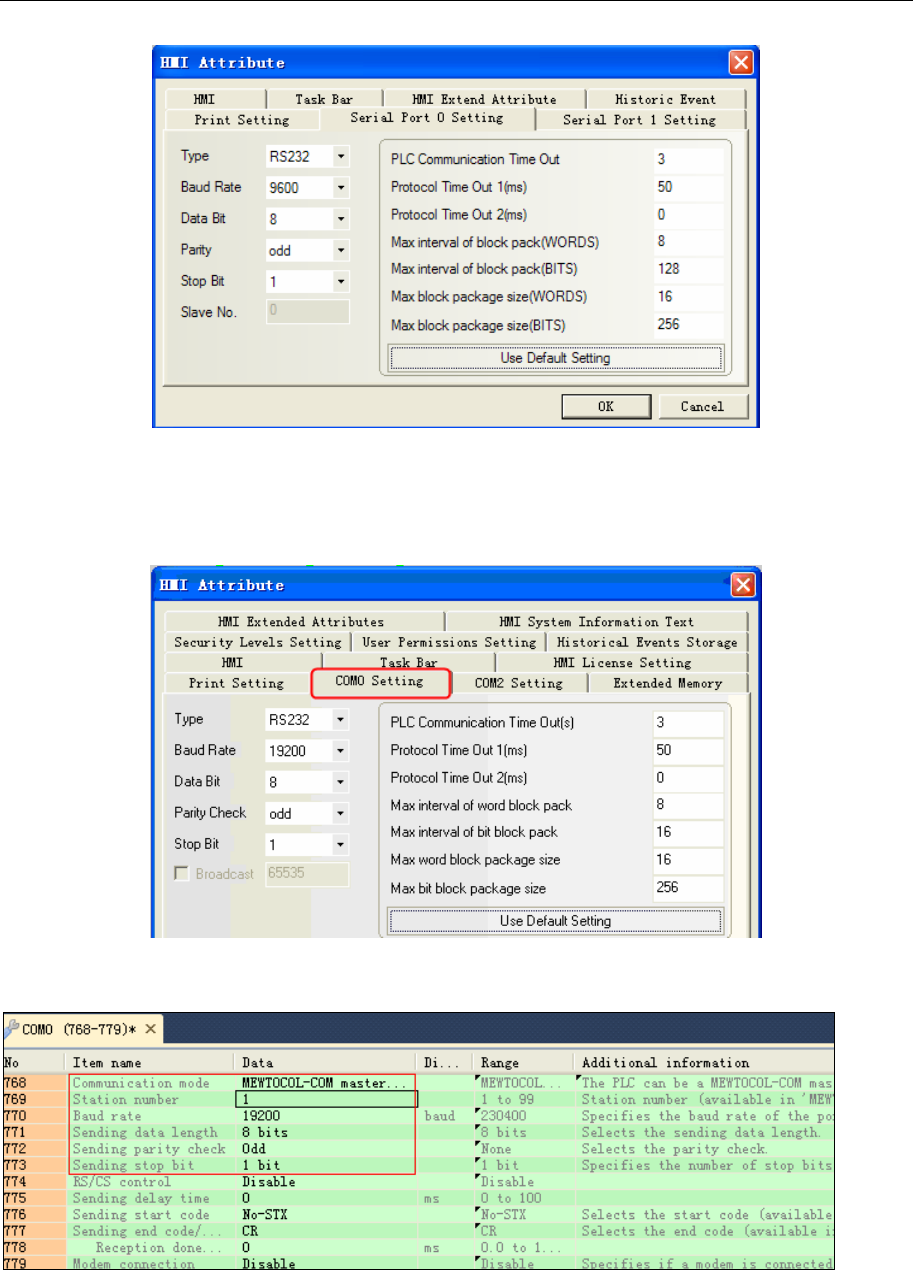
4 Communication settings and guide of HMI connecting with controller
- 283 -
Panasonic FP7 protocol:
HMI Setting
Default communication parameters: 19200, 8, odd, 1; station: 1
PLC Setting
communication parameters setting:
◎Network Communication Setting
Panasonic FP Ethernet (TCP Slave) protocol
HMI Setting
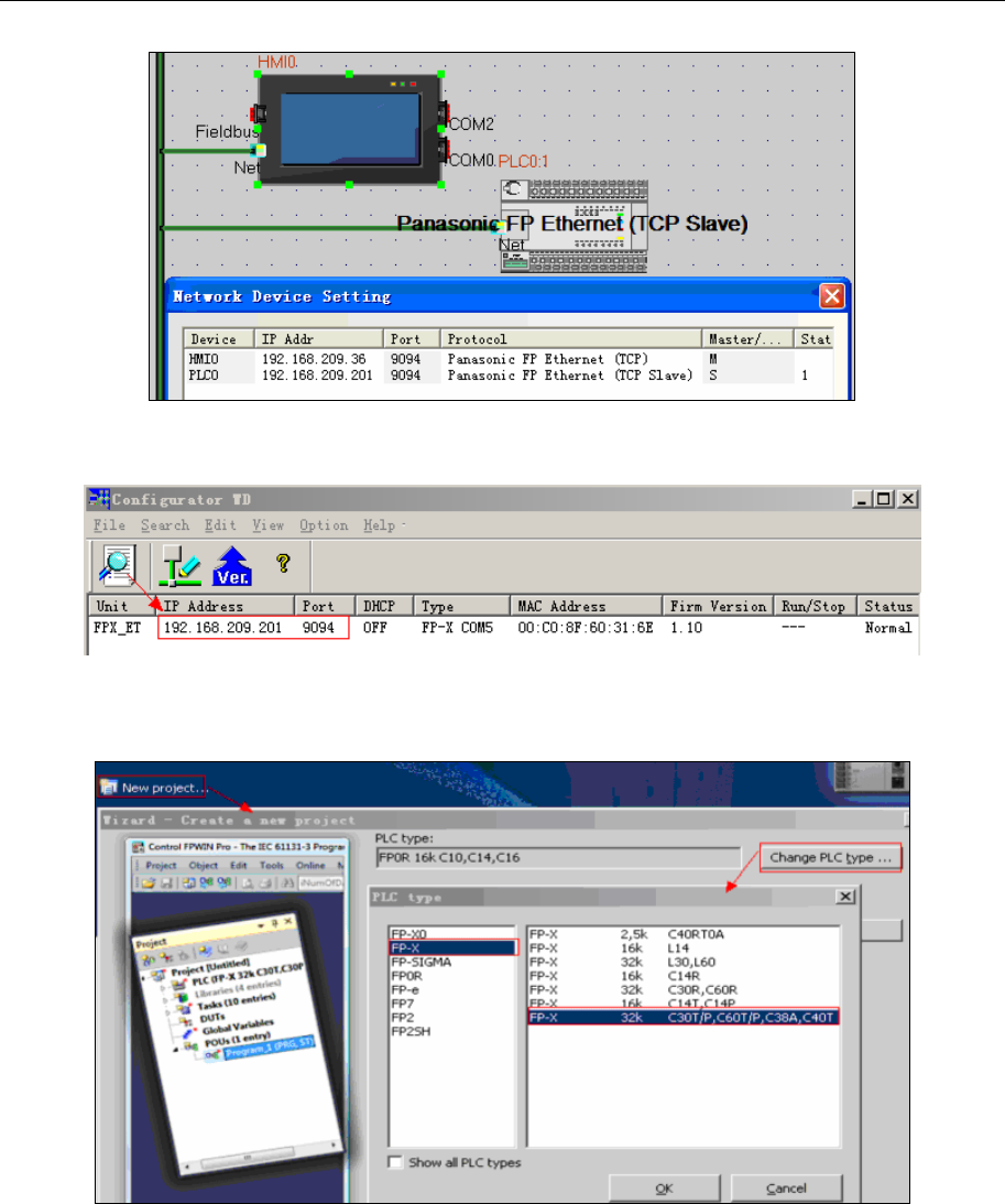
4 Communication settings and guide of HMI connecting with controller
- 284 -
PLC Setting
1. Open the Configurator WD and search the online PLC.
NOTE: Configurator WD can configure PLC parameters (IP Address, Port ......).
2. Software Setting
1)Open the Control FPWIN Pro 7,build new project and select PLC type(FP-X C40T);
2) Communication setting: [Online] →[Communication parameters... ] →Communications
settings(Destination Parameters must be the same as the testing PLC Parameters )
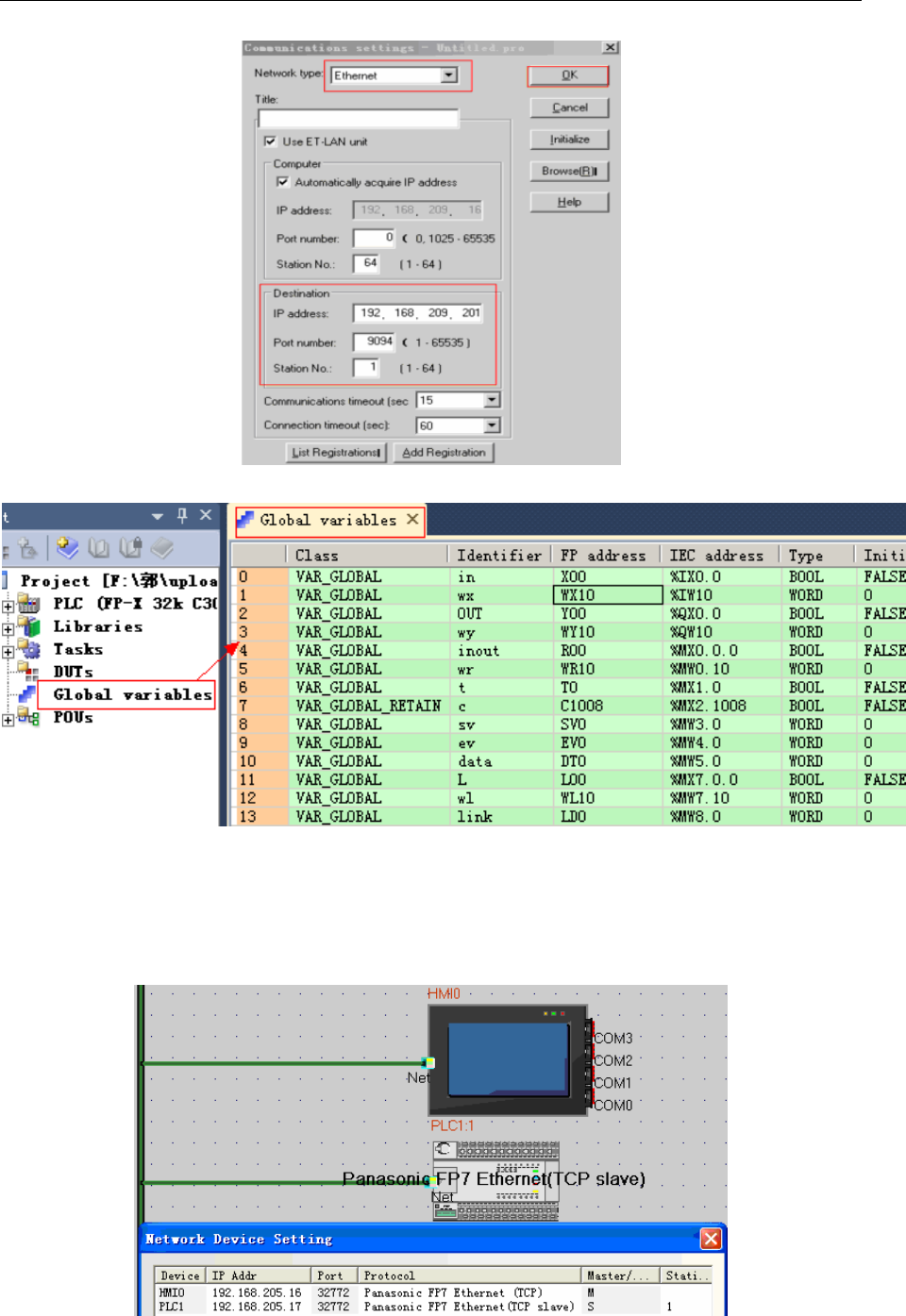
4 Communication settings and guide of HMI connecting with controller
- 285 -
3) VAR_EXTERNAL declaration
NOTE: VAR_EXTERNAL must be declared; otherwise you will get some compile errors.
4) Download to the PLC
Panasonic FP7 Ethernet (TCP Slave) protocol
HMI Settings
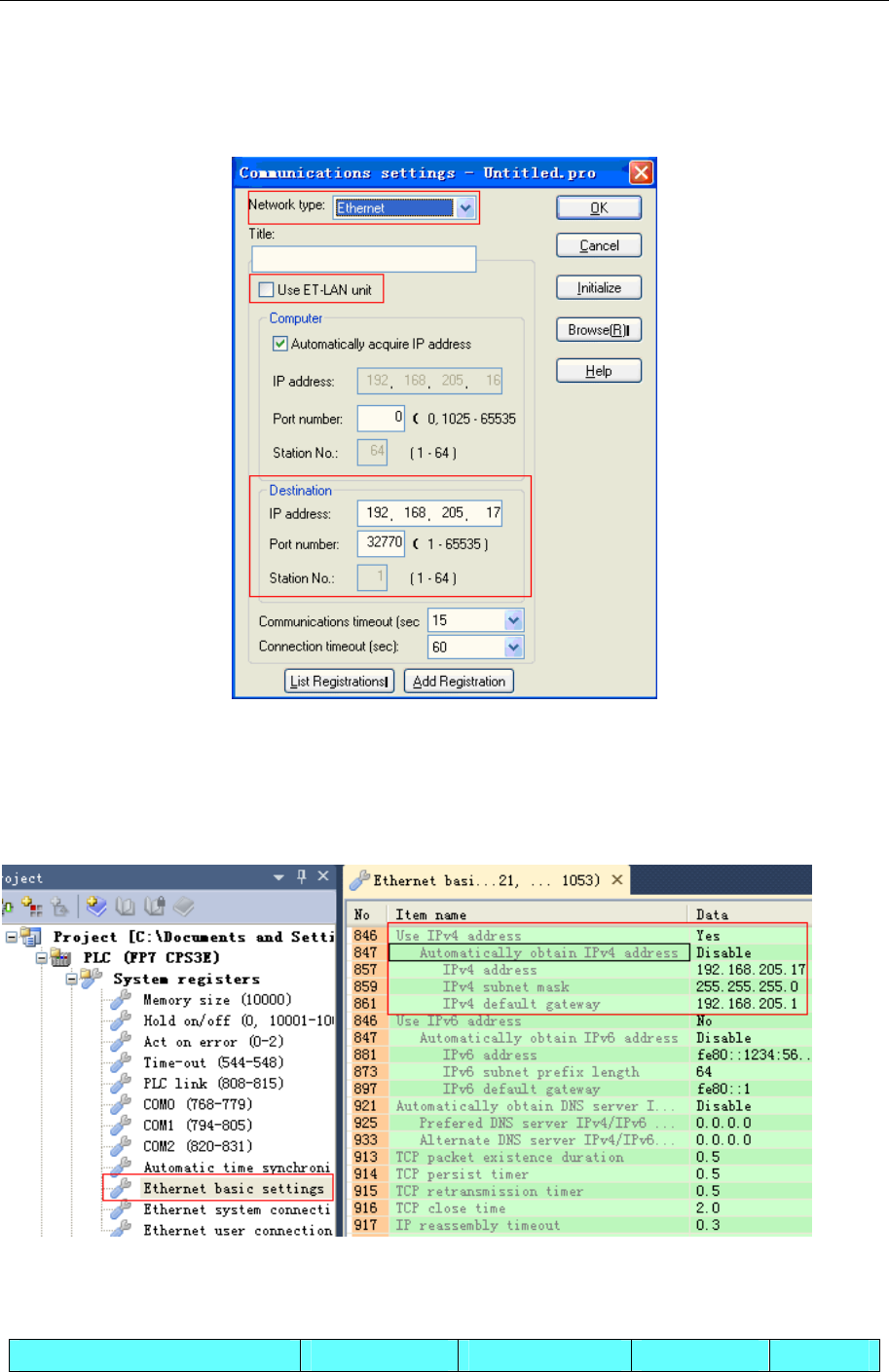
4 Communication settings and guide of HMI connecting with controller
- 286 -
NOTE:
This protocol supports one HMI to one PLC communication.
PLC Settings
1、communications settings
NOTE:
a. The range of the destination’s port number is 32769~32772.
b. The destination’s port number cannot be the same as the network device setting’s port of HMI
setting.
2、changed the IP address
◎Supported Device
FP Series
Device Bit Address Word Address Format Notes
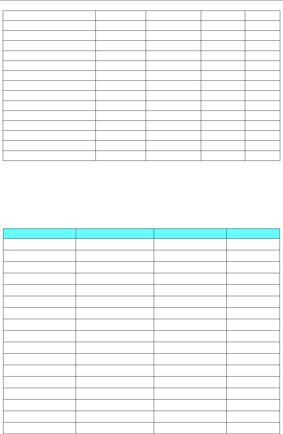
4 Communication settings and guide of HMI connecting with controller
- 287 -
Output Relay X0.0~9999.F ------ DDDD.H
Input Relay Y0.0~9999.F ------ DDDD.H
Timer T0~9999 ------ DDDD
Counter C0~9999 ------ DDDD
Link Relay L0.0~32767.F ------ DDDDD.H
Internal Auxiliary/Relay R0.0~32767.F ------ DDD.H
T/C Elapsed Value ------ EV0~32767 DDDDD
T/C Setting Value ------ SV0~9999 DDDD
Data Register ------ DT0~99999 DDDDD
Input Word ------ WX0~9999 DDDD
Output Word ------ WY0~9999 DDDD
Internal Auxiliary/Relay ------ WR0~32767 DDDDD
Link Data Register ------ LD0~99999 DDDDD
Link Relay ------ WL0~32767 DDDDD
File Register ------ FL0~99999 DDDDD
NOTE:
1. Example: X address: 01 in the PLC corresponds to 0.1 in the EV5000; X address: 1F in the PLC
corresponds to 1.F in the EV5000.Y\R register address, and so on.
2. EV registers in the range of addresses on the touch screen can be set to 32767, but only supports the
9999 agreement.
FP7 Series
Device Bit Address Word Address Format
Input Relay X 0.0-32767.f ------ DDDDD.H
Output Relay Y0.0-32767.f ------ DDDDD.H
Internal Auxiliary/Relay R0.0-32767.f ------ DDDDD.H
Link Relay L0.0-32767.f ------ DDDDD.H
Timer T0-4095 ------ DDDD
Counter C0-1023 ------ DDDD
Input word ------ WX0-511 DDD
Output word ------ WY0-511 DDD
Internal Auxiliary/Relay ------ WR0-32767 DDDDD
Link Relay ------ WL0-32767 DDDDD
File register ------ FL0-99999 DDDDD
Link Data register ------ LD0-99999 DDDDD
Data register ------ DT0-9829 DDDD
T Setting Value ------ TS0-4095 DDDD
T Elapsed Value ------ TE0-4095 DDDD
C Setting Value ------ CS0-1023 DDDD
C Elapsed Value ------ CE0-1023 DDDD
NOTE:
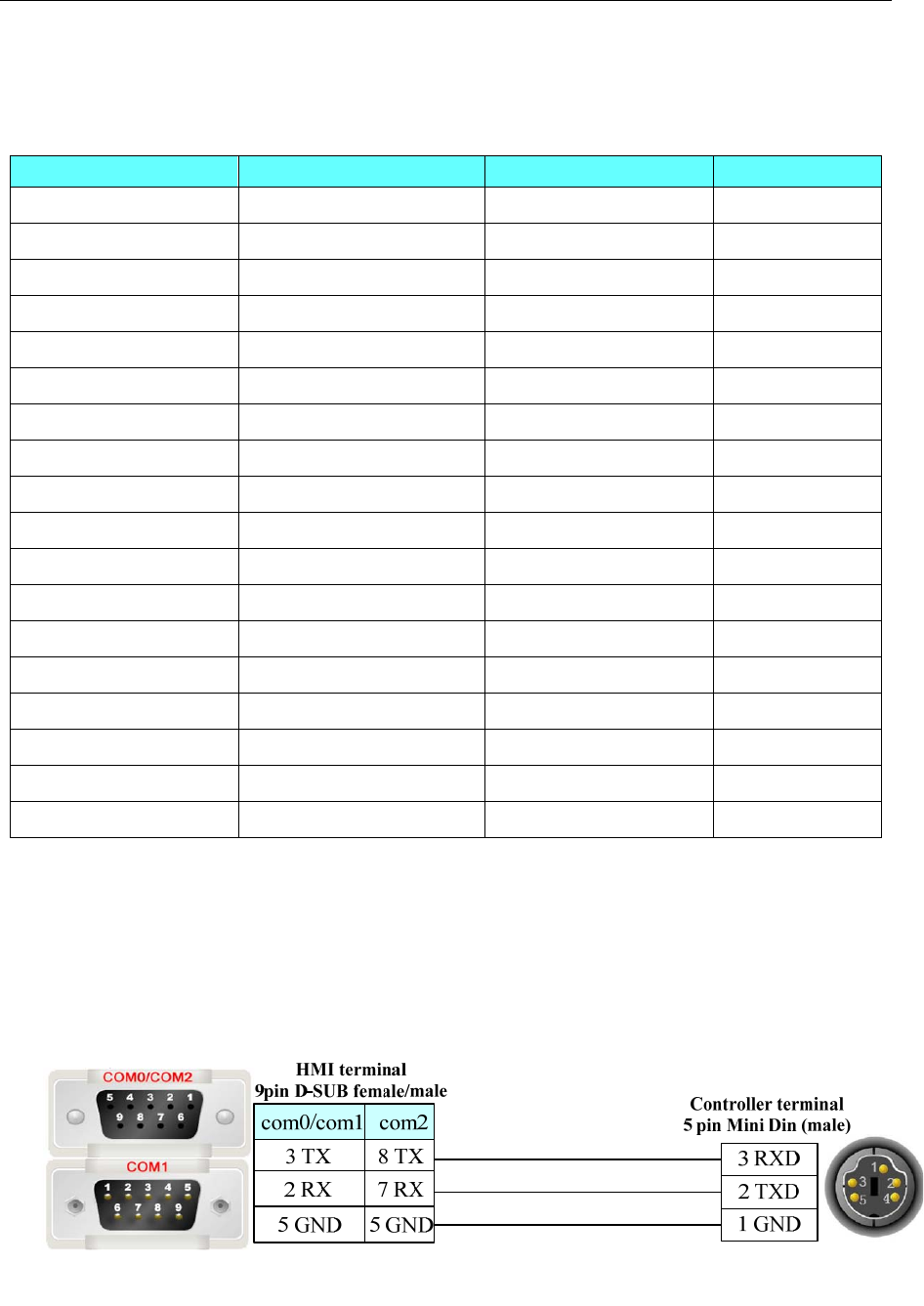
4 Communication settings and guide of HMI connecting with controller
- 288 -
Example: X address:01 in the PLC corresponds to 0.1 in the HMI;X address;1F in the PLC corresponds to
1.F in the HMI.R\Y\L register address,and so on.
FP7 Ethernet(TCP Slave)
Device Bit Address Word Address Format
Input Relay X 0.0-511.f ------ DDD.H
Output Relay Y0.0-511.f ------ DDD.H
Internal Auxiliary/Relay R0.0-2047.f ------ DDDD.H
Link Relay L0.0-1023.f ------ DDDD.H
Timer T0-4095 ------ DDDD
Counter C0-1023 ------ DDDD
Error alarm relay E0-4095 ------ DDDD
Input word ------ WX0-511 DDD
Output word ------ WY0-511 DDD
Internal Auxiliary/Relay ------ WR0-2047 DDDD
Link Relay ------ WL0-1023 DDDD
File register ------ FL0-99999 DDDDD
Link Data register ------ LD0-16383 DDDDD
Data register ------ DT0-999423 DDDDDD
T Setting Value ------ TS0-4095 DDDD
T Elapsed Value ------ TE0-4095 DDDD
C Setting Value ------ CS0-1023 DDDD
C Elapsed Value ------ CE0-1023 DDDD
NOTE:
Example: X address:01 in the PLC corresponds to 0.1 in the HMI;X address;1F in the PLC
corresponds to 1.F in the HMI.R\Y\L register address,and so on.
◎Cable Diagram
RS232 communication
Tool port:
CPU port:
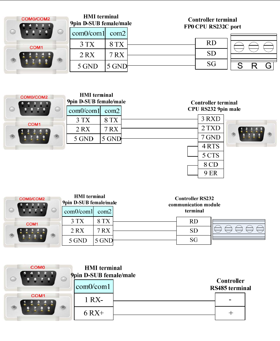
4 Communication settings and guide of HMI connecting with controller
- 289 -
COM port:
Communication module:
RS485 communication
RS422 communication
FP3 RS422 programming port:
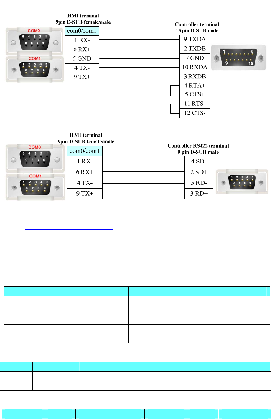
4 Communication settings and guide of HMI connecting with controller
- 290 -
Another module RS422 communication:
Ethernet communication protocol cable
Cross-connection or crossover network cable can be used as communication cable via the hub
Refer to 3.3 Download by Network Ethernet for method of making connection cable.
4.59 Parker Automation(Servo Controller)
◎Serial Communication
Series CPU Link Module Driver
RS232 on CPU unit
Parker Compax3 Compax3 RS485 on CPU unit Parker Compax3
Parker SLVD Series SLVD 15NS RS485 on the CPU unit Parker SLVD Series
Parker 6k 6K4 RS232 on the CPU unit Parker 6k
ACR9040 ACR9040-P3-B RS232 on the CPU unit Parker ACR9000
◎Ethernet Communication
Series CPU Link Module Driver
ACR9040 ACR9040-P3-B Ethernet interface on CPU Parker ACR9000 Series Ethernet (TCP
Slave)
◎System configuration
Series CPU Link Module COMM Type Parameter Cable
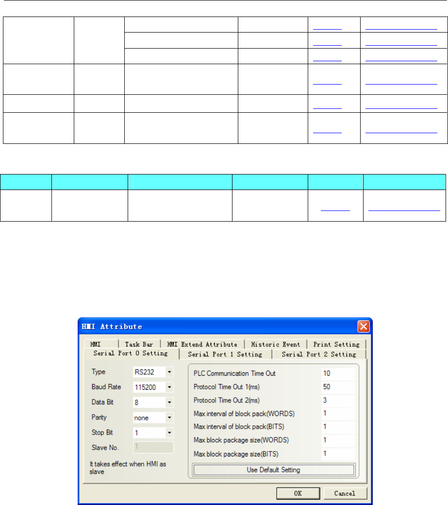
4 Communication settings and guide of HMI connecting with controller
- 291 -
RS232 on CPU unit RS232 Setting Your owner cable
RS485 on CPU unit RS485-2 Setting Your owner cable
Parker
Compax3 Compax3
RS422 on CPU unit RS485-4 Setting Your owner cable
Parker SLVD
Series
SLVD
Series RS485 on the CPU unit RS485 Setting Your owner cable
Parker 6k 6K4 RS232 on the CPU unit RS232 Setting Your owner cable
ACR9040 ACR904
0-P3-B RS232 on the CPU unit RS232 Setting Your owner cable
◎Ethernet System configuration
Series CPU Link Module Connect Type Parameter Cable
ACR9040 ACR9040-P3-B Ethernet interface on
CPU Ethernet Setting Your owner cable
◎Communication Setting
Parker Compax3 protocol
HMI Setting
Default communication parameters: 115200, 8, none, 1; station: 1
RS232 Communication
RS485-2 Communication
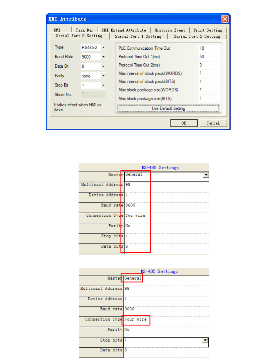
4 Communication settings and guide of HMI connecting with controller
- 292 -
PLC Setting
NOTE: RS-485 Settings can be made in the C3 Servo Manager under “RS485 settings”
RS485-2 setting:
RS485-4 setting:
Parker SLVD Series protocol
Default communication parameters: 9600, 8, 1, even; station: 0
RS422 communication
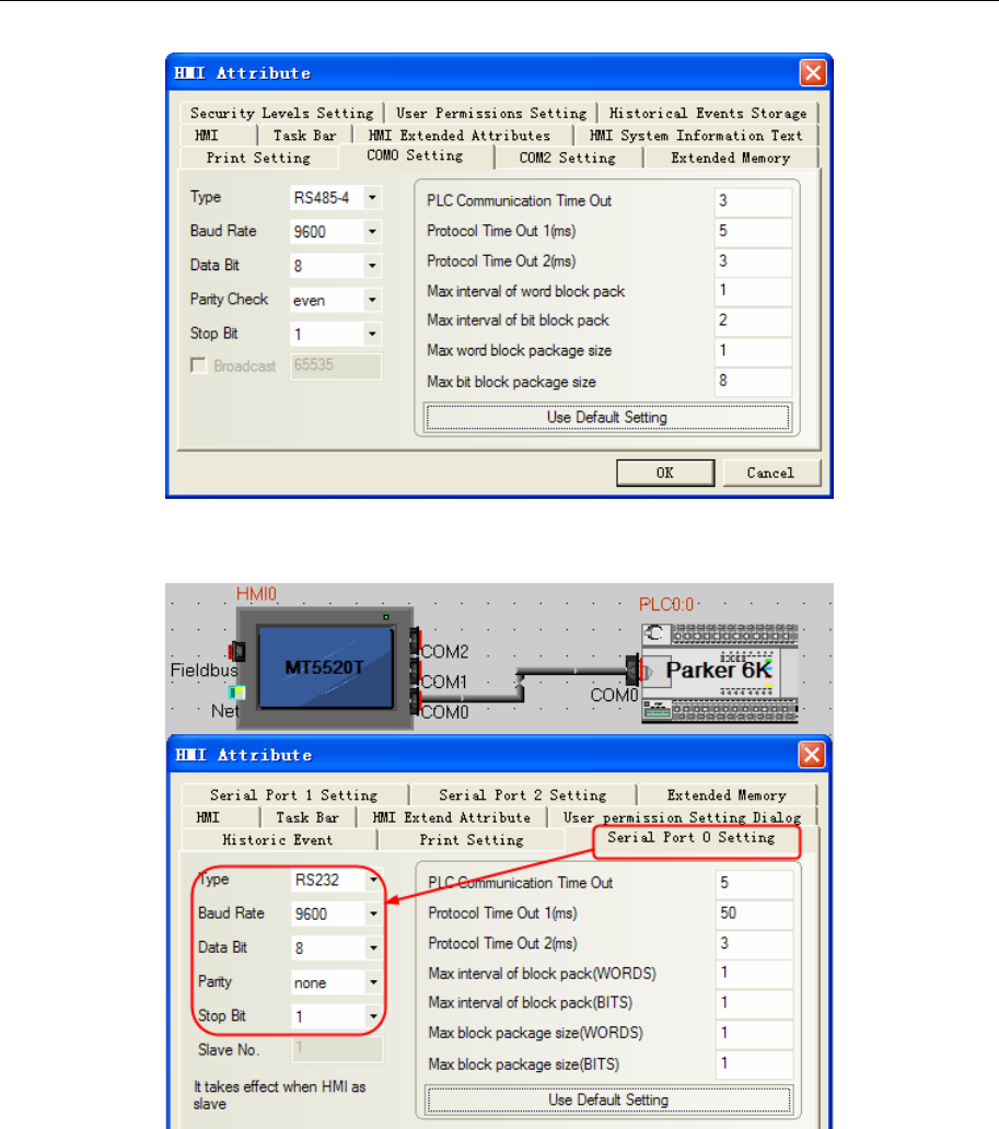
4 Communication settings and guide of HMI connecting with controller
- 293 -
Parker 6K protocol
Default communication parameters: 9600, 8, 1, none; station: 0
NOTE: Don’t support RS485 communication mode
Parker ACR9000 protocol
Default communication parameters: 38400bps, 8, none, 1;station NO.:0
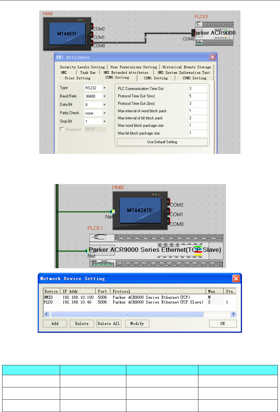
4 Communication settings and guide of HMI connecting with controller
- 294 -
Parker ACR9000 Series Ethernet (TCP Slave)
HMI Setting
◎Supported Device
Parker Compax3
Device Bit Address Word Address Format
R_Bit 0.0-9999999.31 ------ DDDDDDD.DD
------ R_Float 0.0-9999.511 DDDD.DDD
------ R_Int 0.0-9999.511 DDDD.DDD
NOTE: R_Bit device is the bit format of R_Int device. The address of R_Bit device is DDDDDDD.DD,
the first seven position indicate the address of R_Int, the last two positon indicate 32-bit
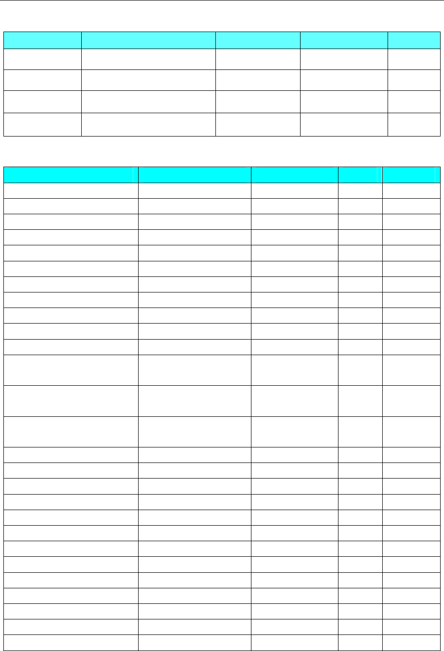
4 Communication settings and guide of HMI connecting with controller
- 295 -
SLVD Series
Device Bit Address Word Address Format Note
Pr_Bit 0-9999.15 ------ DDDD.DD
Pr_Byte ------ 0-9999 DDDD
Pr_Word ------ 0-9999 DDDD
Pr_DWord ------ 0-9999 DDDD
6k Series
Device Bit Address Word Address Format Notes
Bit in register VARB_bit 1.00~125.31 ------ DDD Read only
KILL 0 ------
S 0 ------
C 0 ------
PS 0 ------
HALT 0 ------
RUN 0 ------
TAS_Bit 1.01-2.32 ------
TSS_Bit 1-32 ------
TIN_Bit 1.01-3.32 ------
TOUT_Bit 1.01-3.32 ------
The 32-bit hexadecimal value
in register ------ VARB 1~125 DDD Read only
The integer number value in
register ------ VAR_Int 1~225 DDDD
The real number value in
register ------ VAR_Float 1~225 DDD
------ VAR 1~255 DDD
------ VARS 1~255 DDD
------ A 1~255 DDD
------ AD 1~255 DDD
------ V 1~255 DDD
------ DRIVE 1~255 DDD
------ TAS 1~2 D
------ TPC 1~255 DDD
------ TPE 1~255 DDD
------ TER 0 D
------ TSS 0 D
------ TIN 1~3 D
------ TOUT 1~3 D
NOTE: VARB configuration software need to use hexadecimal data type, integer-bit to 8 bits.
ACR9000
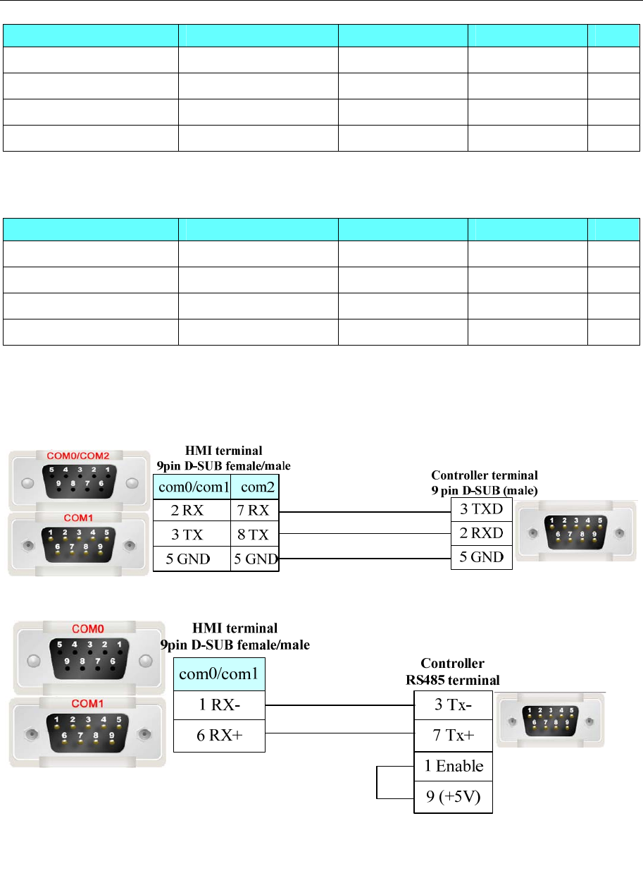
4 Communication settings and guide of HMI connecting with controller
- 296 -
Device Bit Address Word Address Format Notes
P_low16bit 0.0~99999.f ------ DDDDD.FF
P_high16bit 0.0~99999.f ------ DDDDD.FF
P_int32 ------ 0~99999 DDDDD
P_float ------ 0~99999 DDDDD
Parker ACR9000 Series Ethernet (TCP Slave)
Device Bit Address Word Address Format Notes
P_low16bit 0.0~99999.f ------ DDDDD.FF
P_high16bit 0.0~99999.f ------ DDDDD.FF
P_int32 ------ 0~99999 DDDDD
P_float ------ 0~99999 DDDDD
◎Cable Diagram
Parker Compax3 Series
RS232 Communication Cable
RS485-2 Communication Cable
RS485-4 Communication Cable
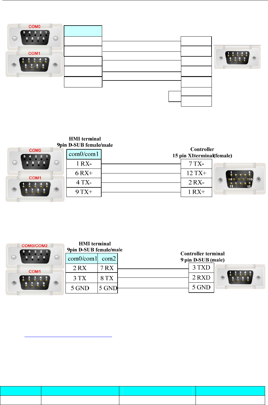
4 Communication settings and guide of HMI connecting with controller
- 297 -
com0/com1
HMI terminal
9pin D-SUB female/male
1 RX-
6 RX+
3 Tx-
7 Tx+
1 Enable
9 (+5V)
Controller
RS485 terminal
4 Tx-
9 TX+
8 Rx-
2 Rx+
5 GND 5 GND
SLVD Series
RS485-2 Communication Cable
6k/9000 Series
RS232 Communication Cable
Ethernet communication protocol cable
Cross-connection or crossover network cable can be used as communication cable via the hub
Refer to 3.3 Download by Network Ethernet for method of making connection cable.
4.60 PMAC Motion Controller
◎Serial Communication
Series CPU Link Module Driver
PC/104 PC/104 RS232 on the CPU unit PMAC series
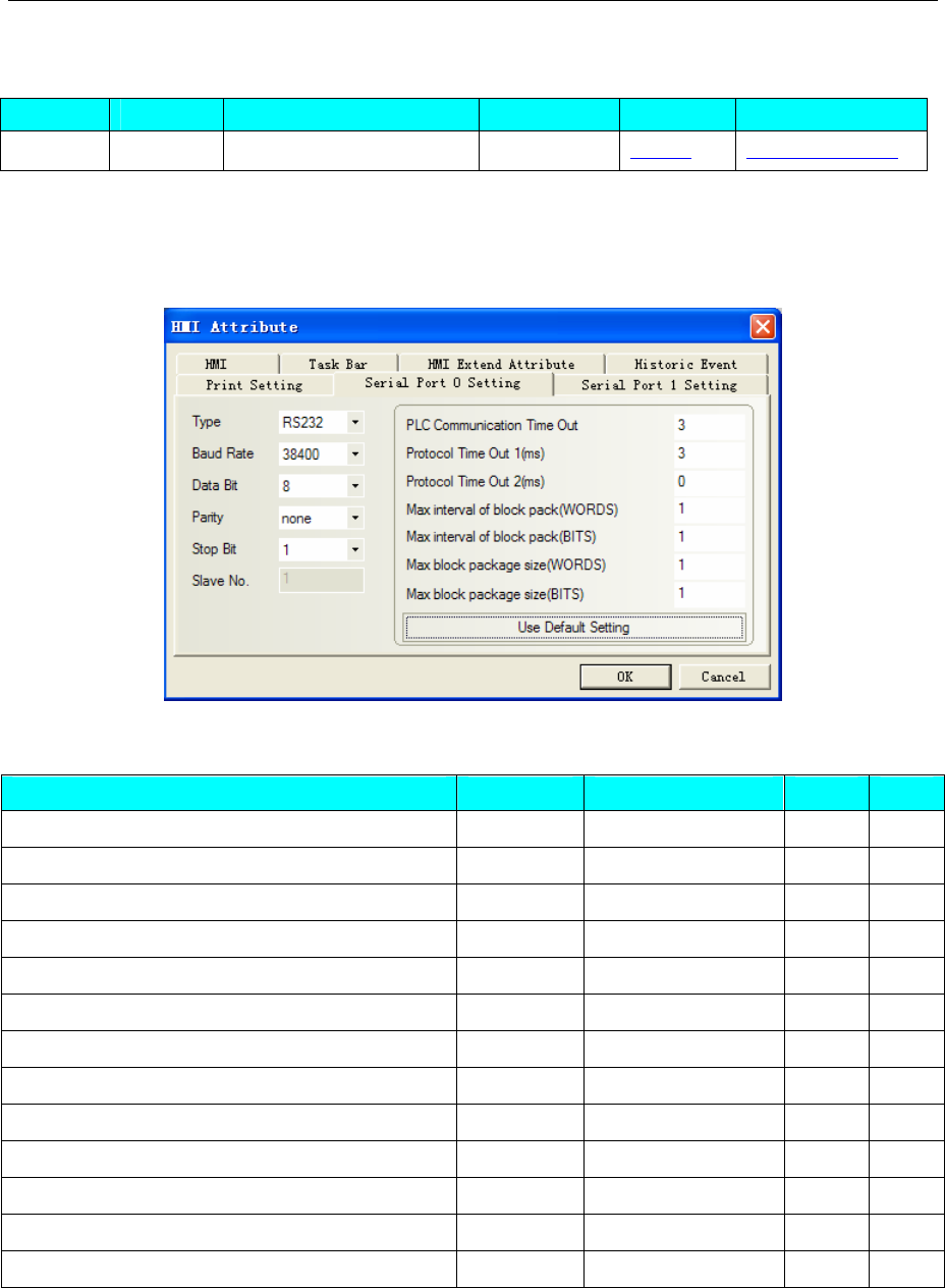
4 Communication settings and guide of HMI connecting with controller
- 298 -
◎System configuration
Series CPU Link Module COMM Type Parameter Cable
PC/104 PC/104 RS232 on the CPU unit RS232 Setting Your owner cable
◎Communication Setting
HMI Setting
Default communication parameters: 38400bps, 8, none, 1; station: 0
◎Supported Device
Device Bit Address Word Address Format Notes
I variable ------ I0-9999 DDDD R/W
M variable ------ M 0-9999 DDDD R/W
P variable ------
P
0-9999 DDDD R/W
Q variable ------ Q 0-9999 DDDD R/W
I variable Float ------ I
_
float 0-9999 DDDD R/W
P variable Float ------ P
_
float 0-9999 DDDD R/W
Q variable Float ------ Q
_
float 0-9999 DDDD R/W
re
p
ort
p
osition of moto
r
------ POS 0 D R
re
p
ort velocit
y
of moto
r
------ VEL 0 D R
re
p
ort followin
g
error of moto
r
------ FER 0 D R
common manual and
p
ro
g
rammin
g
command ------ ORD/JOG* 0-9999 DDDD W
Run current
p
ro
g
ra
m
------ RUN 0-9999 DDDD W
Halt
p
ro
g
ra
m
------ HLT 0-9999 DDDD W
NOTE:Some addresses in I variable devices are on with hex number, when single float number on, all bits
which can’t be transformed into hex numbers will be “0”
PMAC common manual commands
(0) ORD/JOG 0000: j+::continual positive rotation command
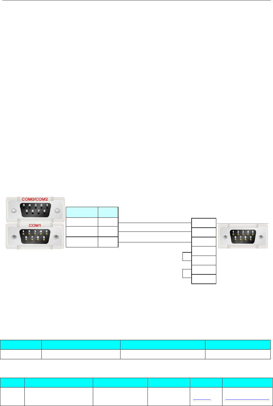
4 Communication settings and guide of HMI connecting with controller
- 299 -
(1) ORD/JOG 0010: j- :continual reverse rotation command
(2) ORD/JOG 0020: j/ :stop command
(3) ORD/JOG 0030: j=constant
(4) ORD/JOG 0040: j:constant
(5) ORD/JOG 0050: j ^
(6) ORD/JOG 0060: # n
(7) ORD/JOG 0070: home(hm):manual reset zero commands
(8) ORD/JOG 0080: homez(hmz):manual reset zero position commands
PMAC common programming commands
(0) ORD/JOG 0100:& n
(1) ORD/JOG 0110:B m R
(2) ORD/JOG 0120:B m S
(3) ORD/JOG 0130:A(ctrl A):Stop movement program
(4) ORD/JOG 0140:K(ctrl K):Stop movement program and close enable signal
(5) ORD/JOG 0150: Enable PLC n:Enable PLC, n indicates prog no. of PLC, range 0-31
(6) ORD/JOG 0160: Disable PLC n:Disable PLC, n indicates prog no. of PLC, range 0-31
◎Cable Diagram
RS232 Communication Cable
Controller terminal
9pin D-SUB(male)
3 TXD
5 RXD
9 GND
2 DTR
7 DSR
4 CTS
6 RTS
com2
3 TX
2 RX
5 GND
8 TX
7 RX
5 GND
com0/com1
HMI terminal
9pin D-SUB female/male
4.61 Power-one AURORA Wind Inverter
◎Serial Communication
Series CPU Link Module Driver
AURORA PVI-6000-OUTD-US-W RS485 on the port Aurora PV
◎System configuration
Series CPU Link Module COMM Type Parameter Cable
AURO
RA PVI-6000-OUTD-US-W RS485 on the port RS485 Setting Your owner cable
◎Communication Setting
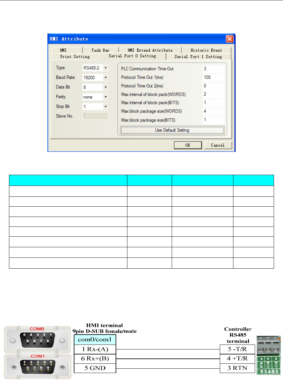
4 Communication settings and guide of HMI connecting with controller
- 300 -
HMI Setting
Default communication parameters: 19200, 8, none, 1; station: 2
◎Supported Device
Device Bit Address Word Address Format
Time Register(double word) ------ Time 0-9999.7 DDDDD.0
Energy Register(double word) ------ Energy 0-9999.7 DDDDD.0
Status variable Register(double word) ------ Measure 0-9999.7 DDDDD.0
Hardware version(double word) ------ Fireware 0-9999.7 DDDDD.0
Software version(double word) ------ Version 0-9999 DDDD
Device sequence No.(double word) ------ SN 0-9999 DDDD
Device ID(double word) ------ PN 0-9999 DDDD
Device work status ------ State 0-9999 DDDD
◎Cable Diagram
NOTE: AURORA Wind Inverter supports two connection modes, please refer to the manual of power-one
Corporation for details.
1. Connect with RS485 port
2. Connect with RJ12
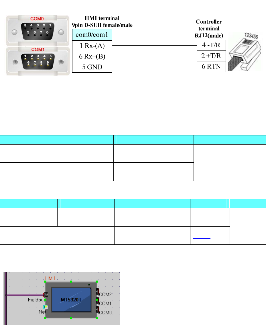
4 Communication settings and guide of HMI connecting with controller
- 301 -
4.62 Profibus DP Slave
◎Serial Communication
Series CPU Link Module Driver
SIMATIC
S7-300/400
ALL CPUs that have
the DP port
PROFIBUS DP port on the
External Device
Other company devices which support
PROFIBUS DP Master
PROFIBUS DP port Profibus DP Slave
◎System configuration
Series CPU Link Module Parameter SIP Type
SIMATIC
S7-300/400
ALL CPUs that have
the DP port
PROFIBUS DP port on the
External Device Setting
Other company devices which support
PROFIBUS DP Master PROFIBUS DP port Setting
Profibus
◎Communication Setting
HMI Setting
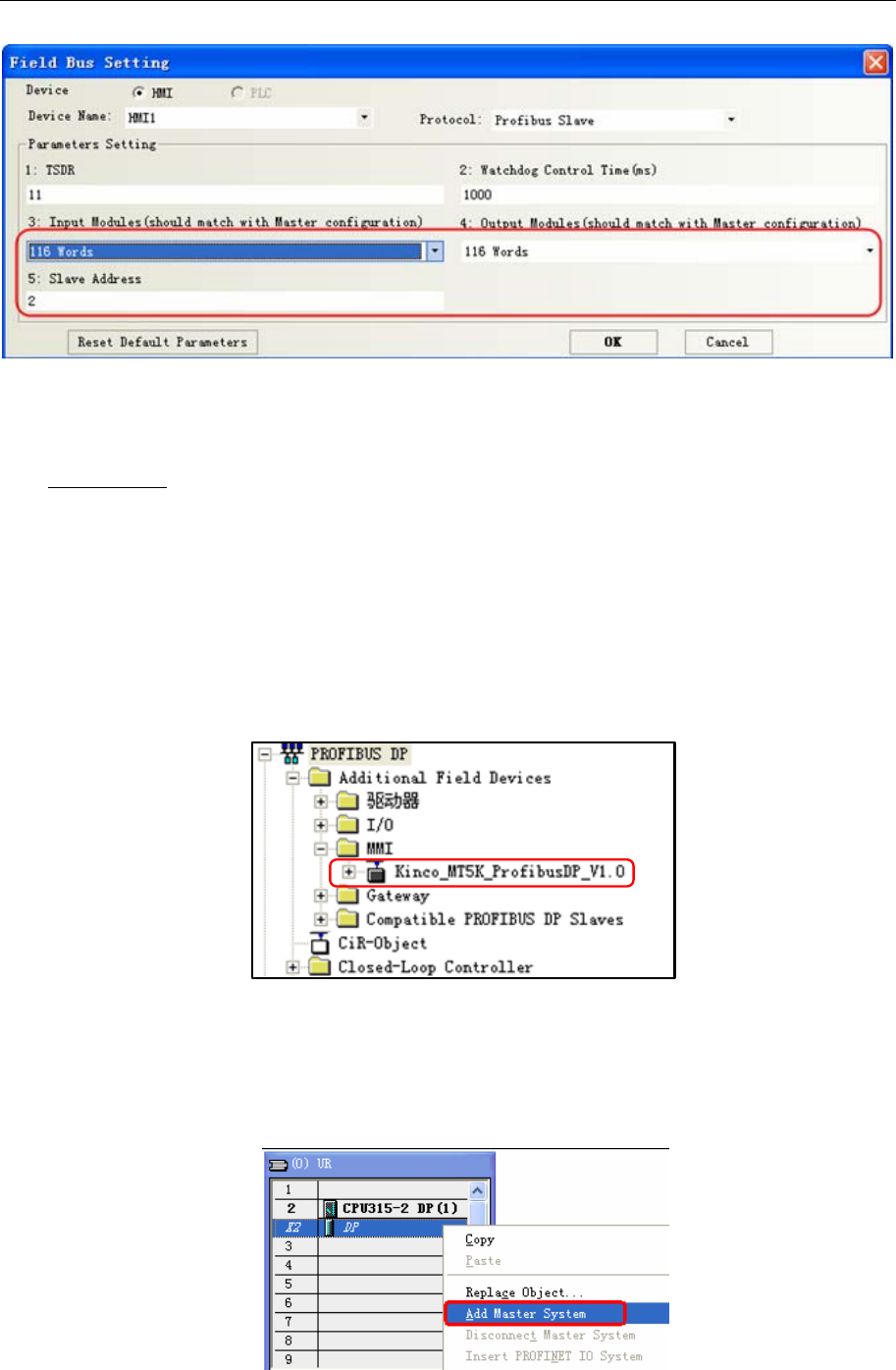
4 Communication settings and guide of HMI connecting with controller
- 302 -
NOTE:Input and Output Modules should match with Master Configuration.
PLC Setting
NOTE: you can find kinco.gsd in the fieldbus file of EV5000 Installation Directory, or you can download
from www.kinco.cn.
1. Setup kinco.gsd file
Setup GSD file in the s7-300 software.
Process:
(1). Closed all the station in HW Config
(2).choose “option” > “install GSD file”.
(3).Find out the folder of eview.gsd.
(4).Choose eview.gsd, and then click the install button.
You can find the ico in PROFIBUS DP\MMI, after installing
2. configuration setting
(1) Make a new project in s7-300 through the guide
(2) We must use OB82,OB86,OB100,OB121 and OB122 in BLOCK, or system will go wrong when PLC
is power-up.
(3) Double click HW Config, choose “DP” and right click “add master station”.
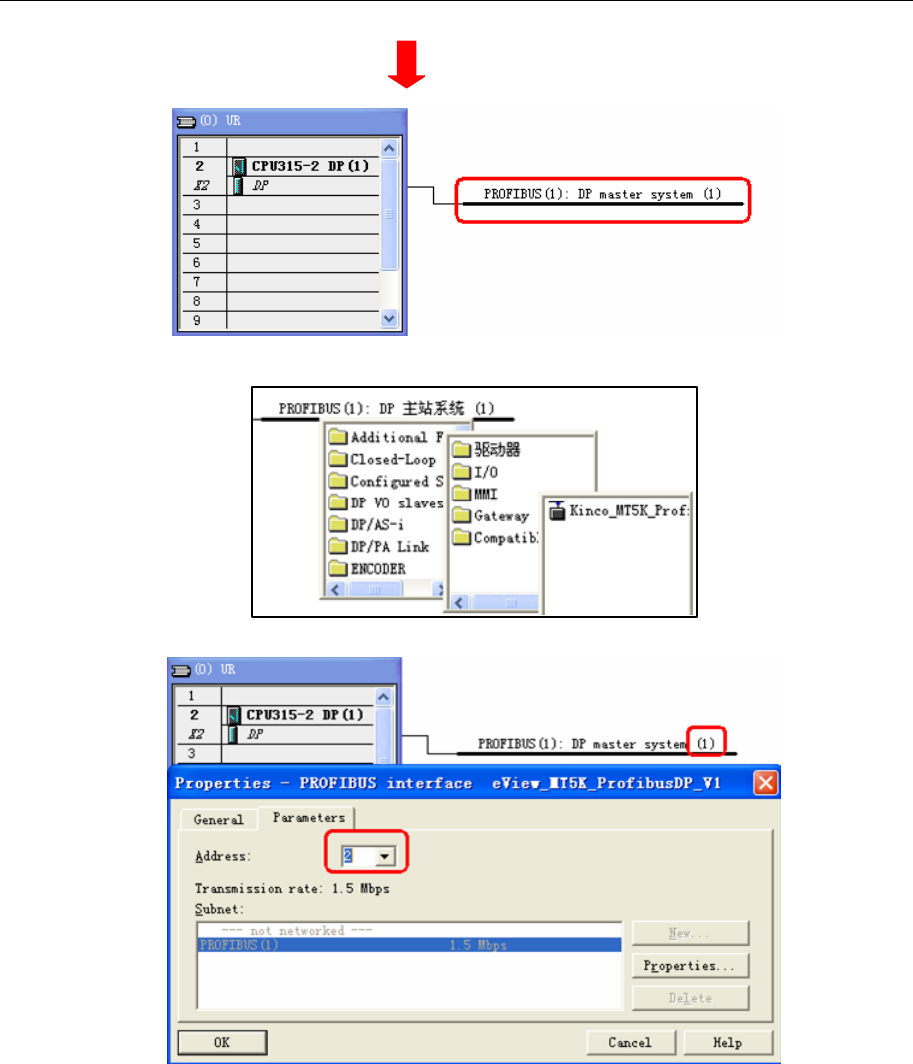
4 Communication settings and guide of HMI connecting with controller
- 303 -
(4) Right click,choose “Insert Object”
Click “Kinco_MT5K_ProfibusDP_V1.0”,set address.
NOTE: the address No. of DP master station and slave can not be same.
(5) Input and output setting
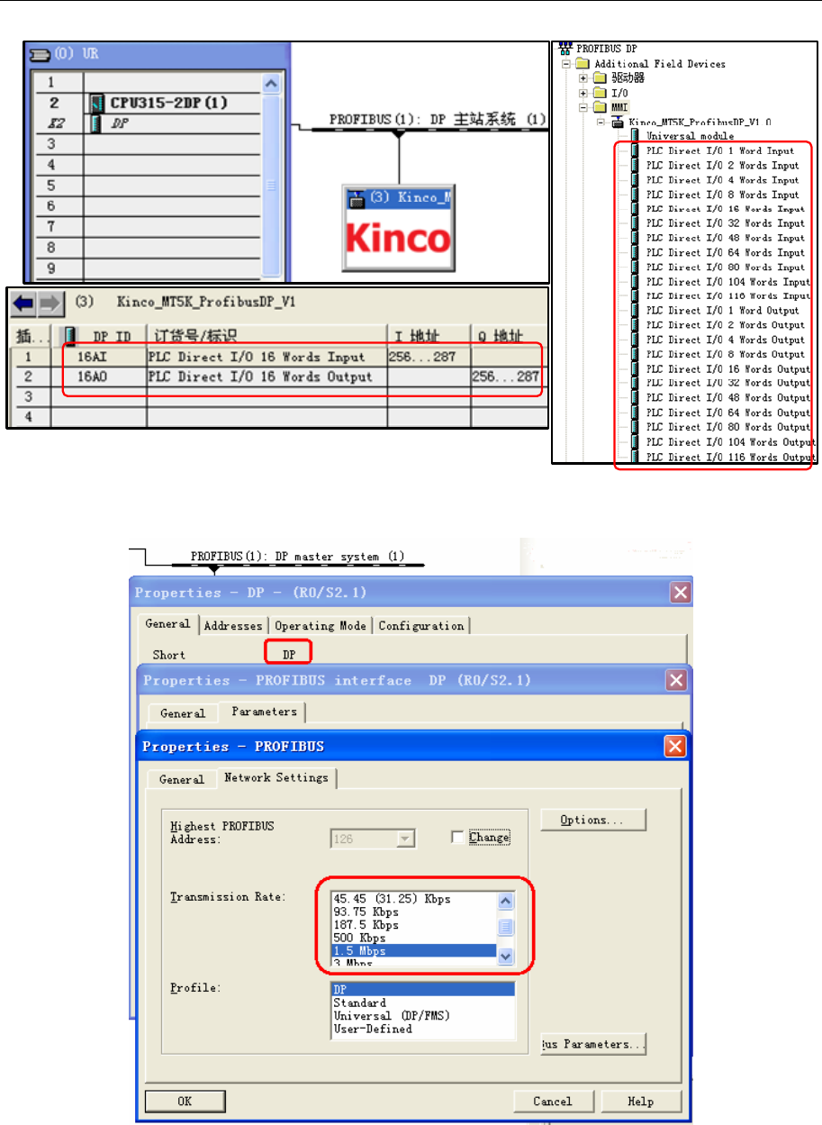
4 Communication settings and guide of HMI connecting with controller
- 304 -
(6) Profibus DP Slave has adaption function,you can change the transmission rate of DP master station,
maximum is 12Mbps.
(7) Double click slave ico, then set User_Prm_Data (0) =01
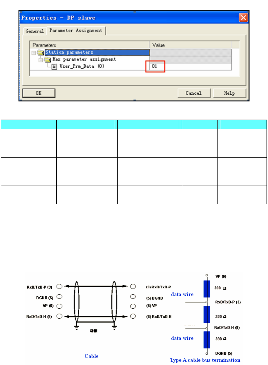
4 Communication settings and guide of HMI connecting with controller
- 305 -
◎Supported Device
Device Bit Address Word Address Format Notes
Direct I/O Input LW.B8500.0~8615.F ———— DDDD.H
Direct I/O Output LW.B8000.0~8115.F ———— DDDD.H
Direct I/O Input ———— LW8500~8615 DDDD correspond PIW
Direct I/O Output ———— LW8000~8115 DDDD correspond PQW
Direct I/O Input ———— LW8500~8615(Data
width is dword) DDDD correspond PID
Direct I/O Output ———— LW8000~8115(Data
width is dword) DDDD correspond PQD
NOTE: When use either PID or PQD, you must set User_Prm_Data (0) =1 if HMI communication with the
DP port of Siemens; Other company devices which support PROFIBUS DP Master, default
User_Prm_Data (0) =0.
◎Cable Diagram
A-type violet cable
4.63 RF-IC (Card Reader)
◎Serial Communication
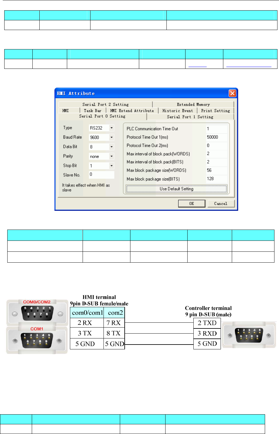
4 Communication settings and guide of HMI connecting with controller
- 306 -
Series CPU Link Module Driver
RF-IC RF-IC RS232 on the CPU unit RF-IC
◎System configuration
Series CPU Link Module COMM Type Parameter Cable
RF-IC RF-IC RS232 on the CPU unit RS232 Setting Your owner cable
◎Communication Setting
◎Supported Device
Device Bit Address Word Address Format Notes
Bit LB 8999 ------ DDDD
------ LW 8900 DDDD
NOTE: LB8999 means bar code has received or not. LB8999=1 means data has received.
◎Cable Diagram
4.64 RKC Instrument INC.
◎Serial Communication
Series CPU Link Module Driver
RKC CH CH402WK02-VV*AN-5N CPU direct RKC CH402
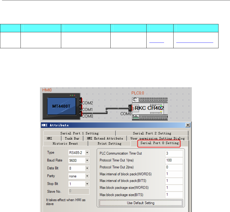
4 Communication settings and guide of HMI connecting with controller
- 307 -
◎System configuration
Series CPU Link Module COMM Type Parameter Cable
RKC
CH
CH402WK02-V
V*AN-5N RS485 the CPU unit RS485 Setting Your owner cable
◎Communication Setting
HMI Setting
Default communication: 9600, 8, none, 1; station: 1
RS485 communication
PLC Setting
Press “SET” key and “﹤R/S” key at one time,then press the SET key and select parameters:
Add Address *1
bPS Baudrate *2
bIT data instruction *3
InT transmission delay *4
*1: Two bits ASCII code. Example 23, instrument number must 23(32H 33H)
*2: Baudrate controlled by code as below; default value: 2
0:2400 bps
1:4800 bps
2:9600 bps
3:19200 bps
*3: data instruction controlled by code as below; default value: 0
ID Data bit parity stop bit
0 8 none 1
1 8 none 2
2 7 odd 1
3 7 odd 2
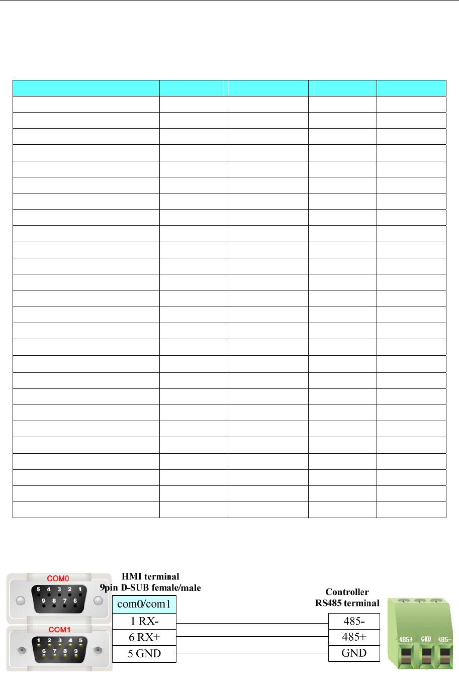
4 Communication settings and guide of HMI connecting with controller
- 308 -
4 7 even 1
5 7 even 2
◎Supported Device
Device Bit Address Word Address Format Notes
Alarm 1 status AA: 0 ------ D Read only
Burnout B1: 0 ------ D Read only
PID control/Autotuning G1: 0 ------ D R/W
Alarm 2 status AB: 0 ------ D Read only
RUN/STOP transfer SR: 0 ------ D R/W
Self-tuning G2:0 ------ D R/W
Measured value ------ M1: 0 D Read only
Current transfomer input1 ------ M2: 0 D Read only
Current transfomer input2 ------ M3: 0 D Read only
Error code ------ ER: 0 D Read only
Set value(SV1) ------ S1: 0 D R/W
Alarm 1 setting ------ A1: 0 D R/W
Alarm 2 setting ------ A2: 0 D R/W
Heater break alarm 1 setting ------ A3: 0 D R/W
Heater break alarm 2 setting ------ A4: 0 D R/W
Control loop break alarm ------ A5: 0 D R/W
Heat-side proportional band ------ P1: 0 D R/W
Integral time ------ I1: 0 D R/W
Derivative time ------ D1: 0 D R/W
Anti-reset windup ------ W1: 0 D R/W
Cool-side proportional band ------ P2: 0 D R/W
Overlap/deadband ------ V1: 0 D R/W
Heat-side proportioning cycle ------ T0: 0 D R/W
Cool-side proportioning cycle ------ T1: 0 D R/W
PV bias ------ PB: 0 D R/W
Set data lock function ------ LK: 0 D R/W
◎Cable Diagram
RS485 Communication Cable
CAN bus Communication Cable
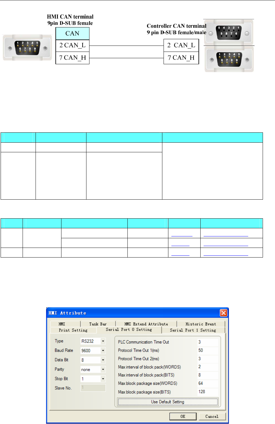
4 Communication settings and guide of HMI connecting with controller
- 309 -
4.65 Saia-Burgess
◎Serial Communication
Series CPU Link Module Driver
PCS PCS1.C8 RS232 on the CPU unit
PCD
PCD2.M110
PCD2.M120
PCD2.M150
PCD2.M170
PCD2.M480
RS232 on the CPU unit Saia SBus
◎Systems Configuration
Series CPU Link Module COMM Type Parameter Cable
RS232 on the CPU unit RS232 Setting Your owner cable
PCS PCS1.C8 RS485 on the CPU unit RS485-4 Setting Your owner cable
PCD PCD2.M110 RS232 on the CPU unit RS232 Setting Your owner cable
◎Communication Setting
HMI Setting
Default communication: 9600, 8, none, 1; station: 80
RS232 communication
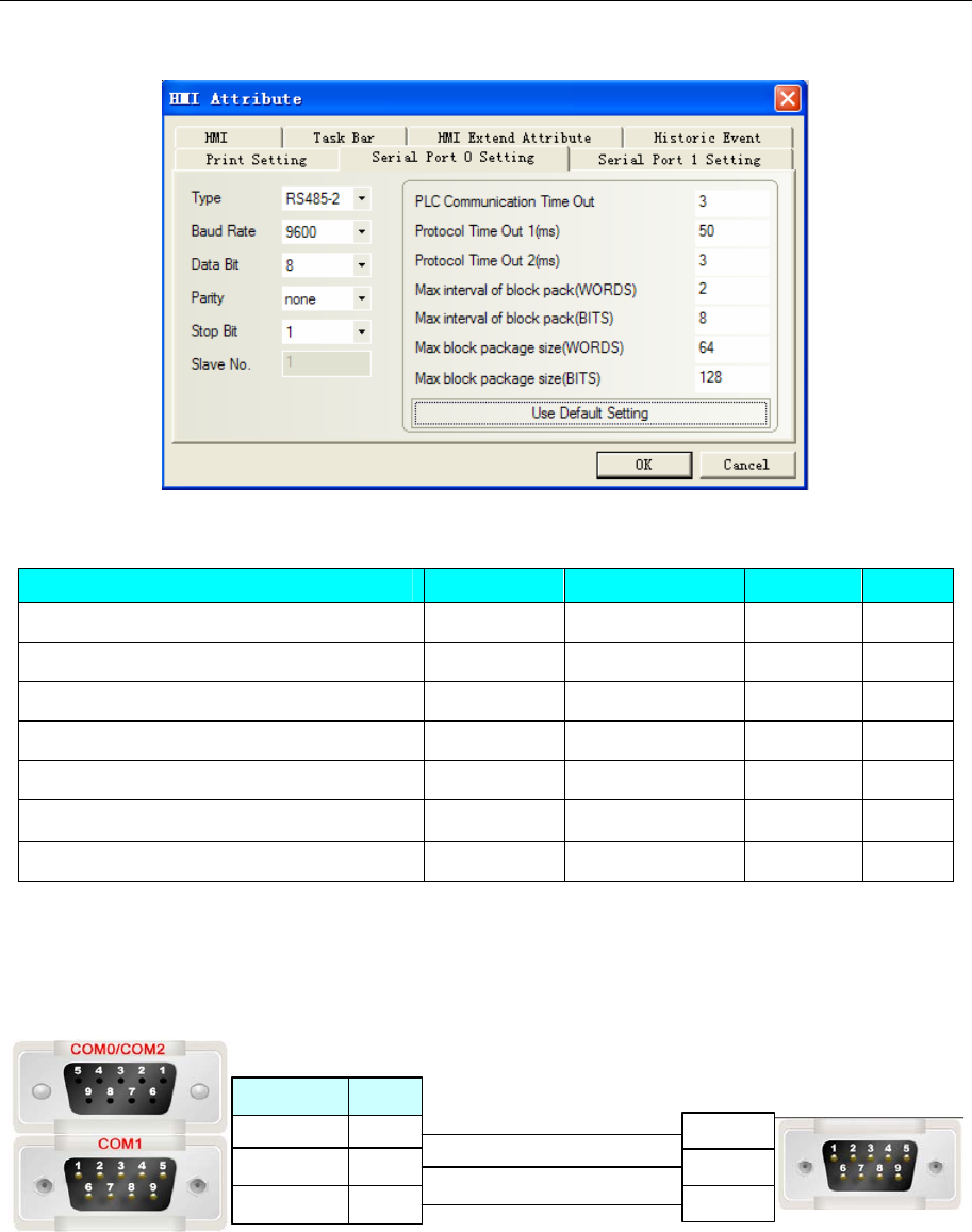
4 Communication settings and guide of HMI connecting with controller
- 310 -
RS485 communication
◎Supported Device
Device Bit Address Word Address Format Notes
Input I0-8091 ------ DDDDD
Output O0-8091 ------ DDDDD
Flag F0-8091 ------ DDDD
Timer ------ T0-1599 DDDD
Counter ------ C0-1599 DDDD
Register ------ R0-4095 DDDD
Register(support single float point) ------ R_Float0-4095 DDDD
◎Cable Diagram
PCS1.C8
RS232 communication cable
Controller terminal
9 pin D-SUB (male)
com2
3 TX
2 RX
5 GND
8 TX
7 RX
5 GND
com0/com1
HMI terminal
9pin D-SUB female/male
3 TXD
2 RXD
5 GND
RS485 communication cable
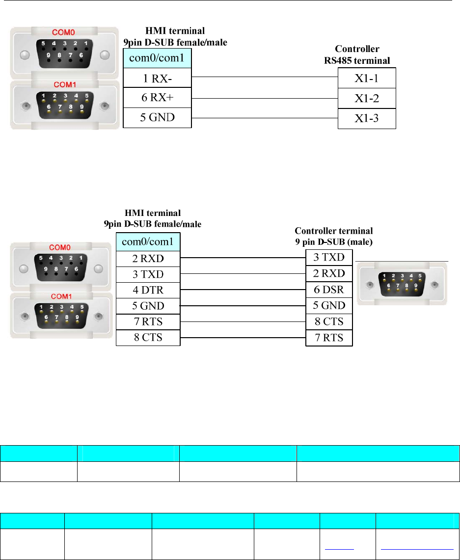
4 Communication settings and guide of HMI connecting with controller
- 311 -
PCD2.M110
RS232 communication cable
4.66 Sailsors D9 (Temperature Controller)
◎Serial Communication
Series CPU Link Module Driver
Sailsors D9 Swp-T16-80-08-N RS232 on the CPU unit Sailsors D9
◎System configuration
Series CPU Link Module COM Type Parameter Cable
Sailsors D9 Swp-T16-80-08-N RS485 on the CPU
unit RS485 Setting Your owner cable
◎Communication Setting
HMI Setting
Default communication parameters: 9600, 8, none, 1; station: 80
RS485 communication
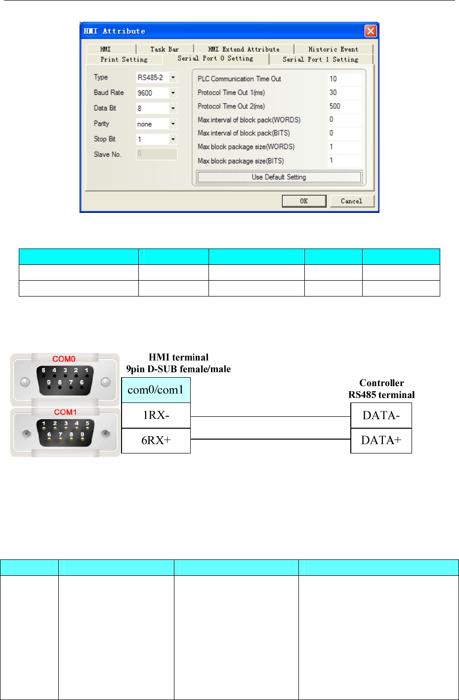
4 Communication settings and guide of HMI connecting with controller
- 312 -
◎Supported Device
Device Bit Address Word Address Format Notes
Channel Sample Value ------ CH 0~16 DD
Channel Indexing ------ SN 1~16 DD
◎Cable Diagram
RS485 communication cable
4.67 Schneider Electric, Ltd.
◎Serial Communication
Series CPU Link Module Driver
Micro TSX3705001
TSX 37 05 028DR1
TSX 37 08 056DR1
TSX 37 10 128DT1
TSX 37 10 128DR1
TSX 37 10 128DTK1
TSX 37 10 164DTK1
TSX 37 10 028AR1
TER port on the CPU
Schneider Modicon Uni-TelWay
Modbus RTU

4 Communication settings and guide of HMI connecting with controller
- 313 -
TSX 37 10 028DR1
TSX 37 21 101
TSX 37 22 101
TSX 37 21 001
TSX 37 22 001
Premium TSX P57 103M
TSX P57 153M
TSX P57 203M
TSX P57 253M
TSX P57 303M
TSX P57 353M
TSX P57 453M
TER port on the CPU
Nano TSX 07 3L 28
TSX 07 30 10
TSX 07 31 16
TSX 07 31 24
TSX 07 32 28
TSX 07 33 28
Programming port on CPU
Twido TWD LCAA 10DRF
TWD LCAA 16DRF
TWD LCAA 24DRF
TWD LMDA 20DTK
TWD LMDA 20DUK
TWD LMDA 20DRT
TWD LMDA 40DTK
TWD LMDA 40DUK
RS485 on the CPU unit Schneider Twido Modbus RTU
◎System configuration
Series CPU Link
Module Driver COMM
Type Parameter Cable
RS232 Setting Your owner cableModicon
TSX
TSX3705001
TSX3705001
TSX 37 05 028DR1
TSX 37 08 056DR1
TSX 37 10 128DT1
TSX 37 10 128DR1
TSX 37 10 128DTK1
TSX 37 10 164DTK1
TSX 37 10 028AR1
TSX 37 10 028DR1
TSX 37 21 101
TSX 37 22 101
TSX 37 21 001
TSX 37 22 001
RS485 on
the CPU unit
Schneider
Modicon
Uni-TelWay RS485-2 Setting Your owner cable
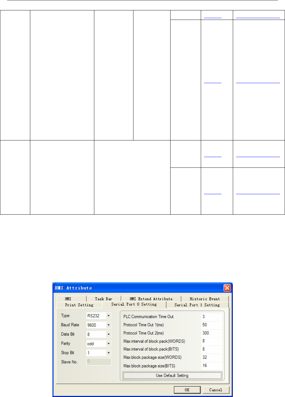
4 Communication settings and guide of HMI connecting with controller
- 314 -
RS232 Setting Your owner cableTSX3705001
TSX3705001
TSX 37 05 028DR1
TSX 37 08 056DR1
TSX 37 10 128DT1
TSX 37 10 128DR1
TSX 37 10 128DTK1
TSX 37 10 164DTK1
TSX 37 10 028AR1
TSX 37 10 028DR1
TSX 37 21 101
TSX 37 22 101
TSX 37 21 001
TSX 37 22 001
RS485 on
the CPU unit
Modbus
RTU RS485-2 Setting Your owner cable
RS232 Setting Your owner cable
Twido
TWD LCAA 10DRF
TWD LCAA 16DRF
TWD LCAA 24DRF
TWD LMDA 20DTK
TWD LMDA 20DUK
TWD LMDA 20DRT
TWD LMDA 40DTK
TWD LMDA 40DUK
RS485 on the CPU unit
RS485-2 Setting Your owner cable
◎Communication Setting
HMI Setting
Schneider Modicon Uni-TelWay protocol
Default communication:9600, 8, odd, 1; station:1
RS232 communication
NOTE: Cable by Schneider Electric Industries, Rotary switch setting: 2(TER Direct)
RS485 communication
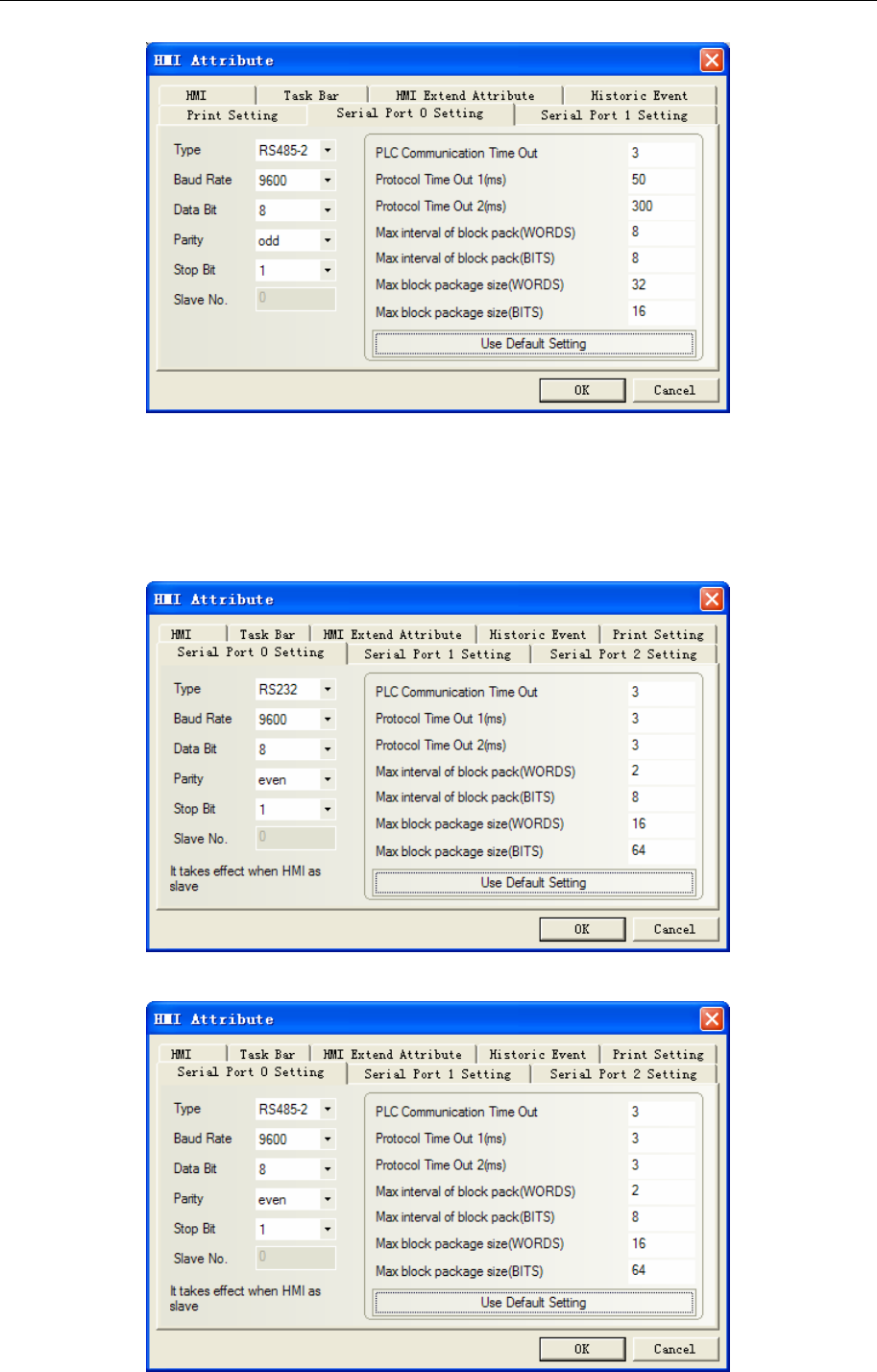
4 Communication settings and guide of HMI connecting with controller
- 315 -
Modbus RTU protocol
Default communication:9600, 8, even, 1; station: 1
RS232 communication
NOTE: Cable by Schneider Electric Industries, Rotary switch setting: 3(OTHER Direct)
RS485 communication
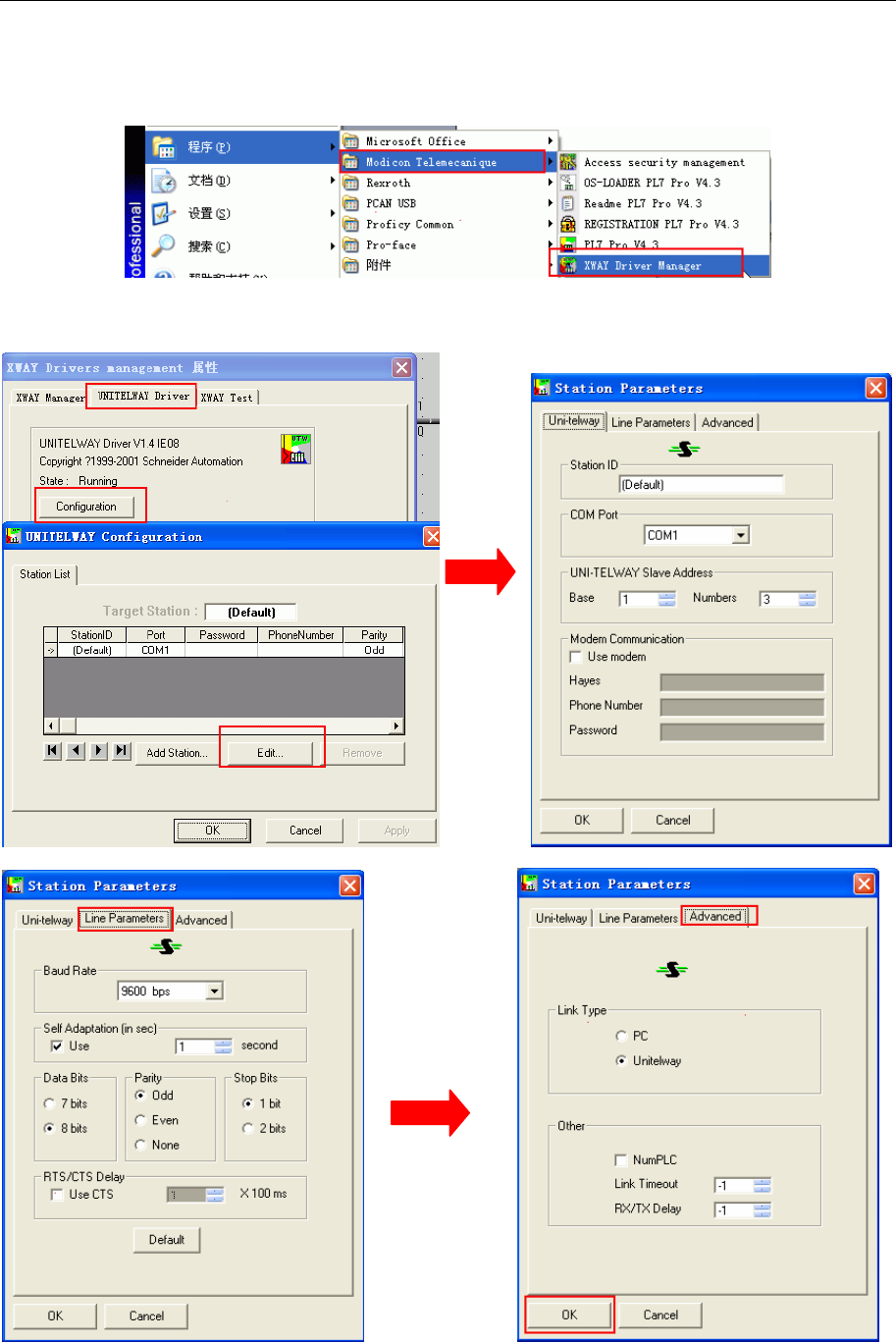
4 Communication settings and guide of HMI connecting with controller
- 316 -
PLC Setting
PL7 software setting
1. Start menu“modicum telemecanique” “XWAY Driver Manager” to set communication parameter
2. Pop-up to select “UNITELWAY Driver””Configuration””Edit” to modify communication
parameter
3. Press ”OK” and pop up the following tips
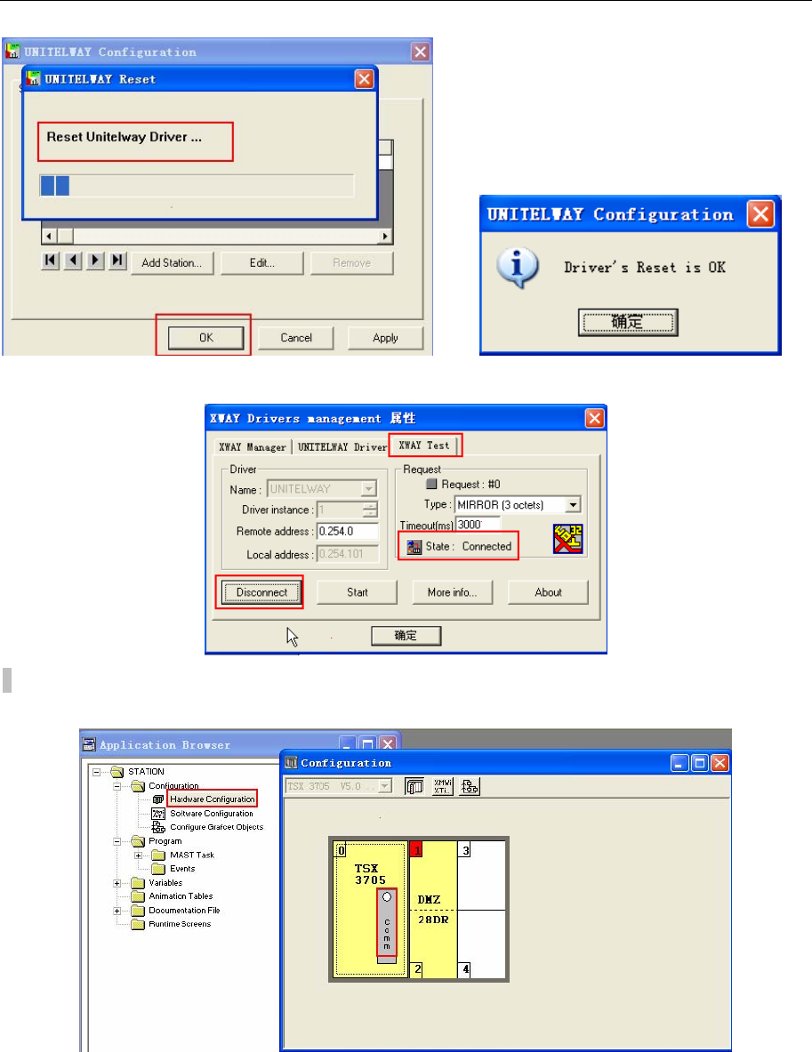
4 Communication settings and guide of HMI connecting with controller
- 317 -
4. And then click ”XWAY Test””Connect”, if the connection is successful, it will clue “Connected”
5. Open the PL7 software”Create new project” click “Hardware configuration”double-click pop-up
window “Comm”
Unitel-way protocol setting as follow:
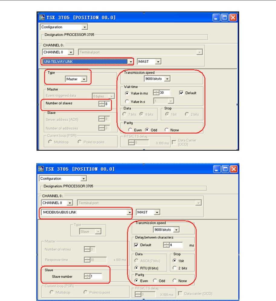
4 Communication settings and guide of HMI connecting with controller
- 318 -
Modbus RTU protocol setting as follow:
6. Setting up the configuration and download the project to the PLC
Schneider Twido Modbus RTU protocol
Default communication: 19200, 8, none, 1; station: 1
NOTE: Cable by Schneider Electric Industries, Rotary switch setting: 2(TER Direct).
RS232 communication
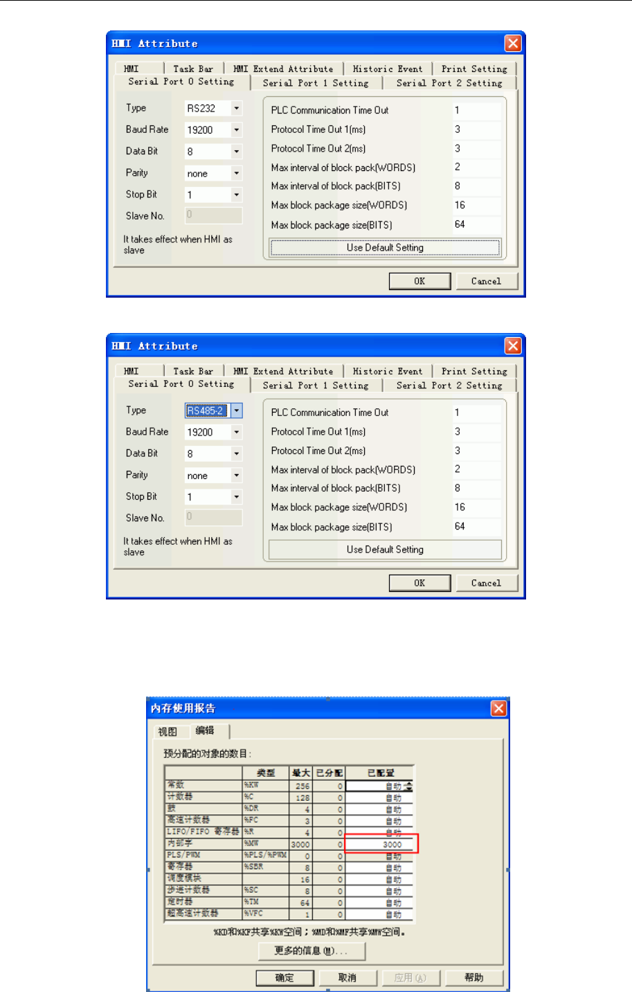
4 Communication settings and guide of HMI connecting with controller
- 319 -
RS485 communication
PLC Setting
1. Specify a large number for the internal word in the “Controller Memory Use Edit” and load the
configuration into the PLC to open the memory area for the words. If set the internal word 3000, you can
use address of MW before 3000.
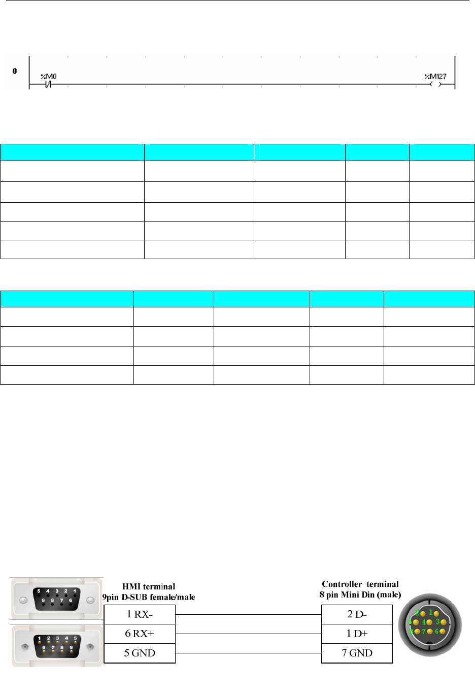
4 Communication settings and guide of HMI connecting with controller
- 320 -
2. You must program a coil with maximum address to open the memory area for the Bits. If you
program a coil with 127 addresses, then the address before 127 can be used.
◎Supported Device
Modicon TSX
Device Bit Address Word Address Format Notes
Internal Relay S00000-32767 ------ DDDDD
Auxiliary Relay M00000-32767 ------ DDDDD
Data Register Relay MW.B0000-9999.F ------ DDDD.H
Data register ------ MW0000-7999 DDDD
Data register double word ------ MD0000-7999 DDDD
Twido
Device Bit Address Word Address Format Notes
Output Relay 0X 1-9999 ------ DDDD
Input Relay (read only) 1X 1-9999 ------ DDDD
Input Register (read only) ------ 3X 1-9999 DDDD
Output Register ------ 4X 1-9999 DDDD
NOTE:
The M register in the software of TWIDO corresponds to 0X in the ev5000 software; MW corresponds
to 4X.The HMI’s address must plus 1 to correspond with the address of PLC.
e.g.: M0 corresponds to 0X1.
Don’t use 1X, 3X device, because there is no correspondence with the PLC.
◎Cable Diagram
Uni-TelWay protocol
RS232 communication cable
Cable recommended by Schneider Electric Industries, Rotary switch setting: 2(TER Direct)(Add a direct
line)
RS485 communication cable
Modicon modbus protocol
RS232 communication cable
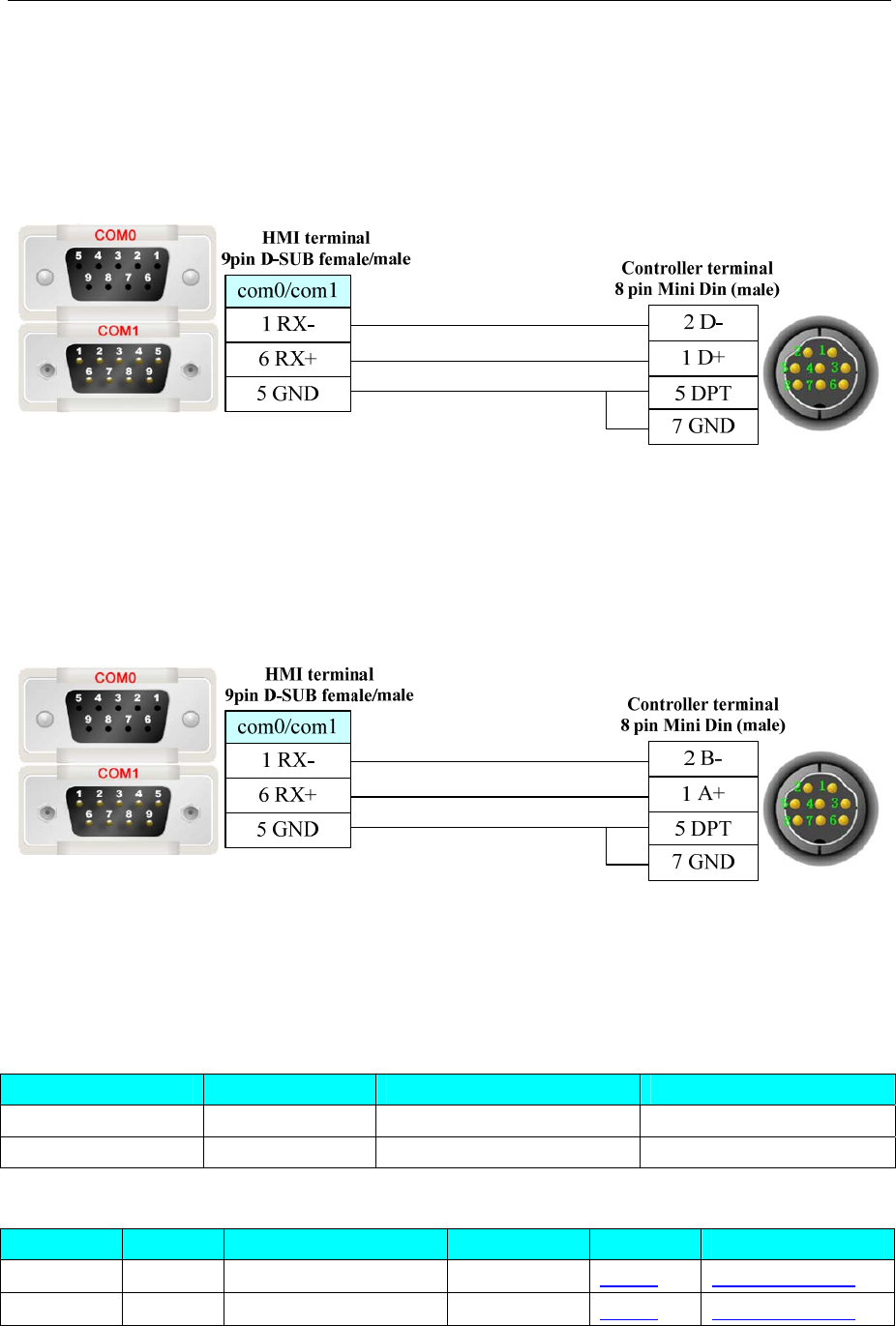
4 Communication settings and guide of HMI connecting with controller
- 321 -
PLC software setting: “Hardware Configuration”double click “Ccom” to select “MODBUS/BUS
LINK”; others are default parameters.
Cable recommended by Schneider Electric Industries, Rotary switch setting: 3 (OTHER Direct)
RS485 communication cable
PLC software setting: “Hardware Configuration”double click “Ccom” to select “ MODBUS/BUS
LINK”; Others are default parameters.
Schneider Twido Modbus RTU protocol
RS232 communication cable
Cable recommended by Schneider Electric Industries
RS485 communication cable
4.68 SHIMADEN
◎Serial Communication
Series CPU Link Module Driver
FP23 FP23 RS485 on the CPU unit SHIMADEN FP23
MR13 FP23 RS485 on the CPU unit SHIMADEN MR13
◎System configuration
Series CPU Link Module COMM Type Parameter Cable
FP23 FP23
RS485 on the CPU unit RS485 Setting Your owner cable
MR13 MR13
RS485 on the CPU unit RS485 Setting Your owner cable
◎Communication Setting
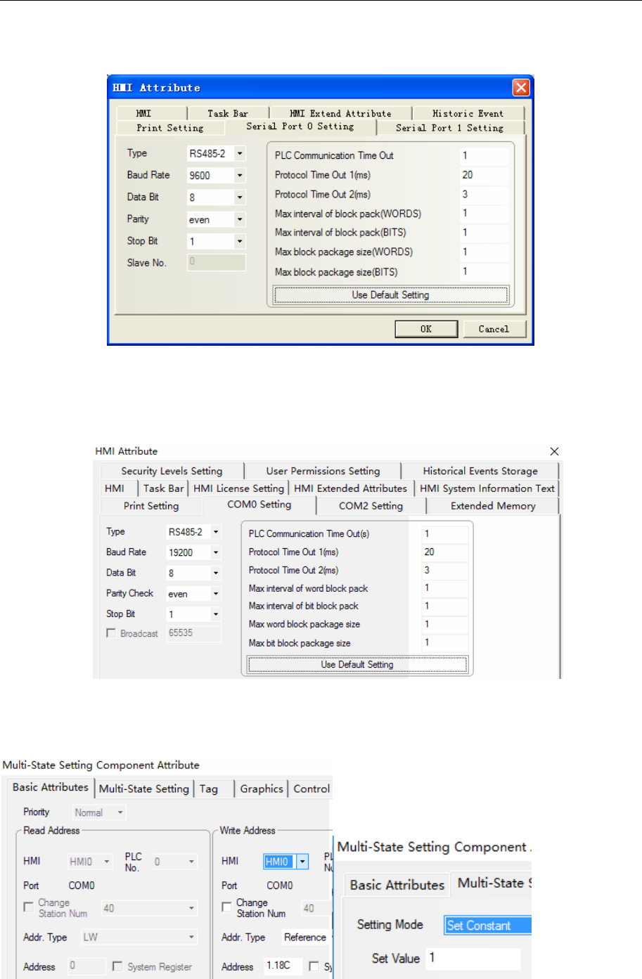
4 Communication settings and guide of HMI connecting with controller
- 322 -
SHIMADEN FP23
Default communication parameters: 9600, 8, even, 1; station: 1
SHIMADEN MR13
HMI Settings
Default communication parameters of HMI
NOTE: When communicating with COM mode, you should first put the 18C address 1, and then open the
COM communication mode to communicate successfully. The bool element address is set to 1.18C, as
shown in the following figure:

4 Communication settings and guide of HMI connecting with controller
- 323 -
PLC Settings
Please refer to relevant instructions of communication equipment for related parameter settings.
◎ Supported Device
FP23
Device Bit Address Word Address Format
State instructions(Write Only) Ctrl_Write 184-252 ------ HHH
Sequence code(Read Only) ------ Array Code 0-3 H
Basic parameter value(Read Only) ------ Basic_Read 00-42 HH
OUT1_W,OUT2_W(Write Only) ------ Out_Write 0-1 H
PV1,PV2(Read Only) ------ PV_Read 0-1 H
Reference(Read & Write) ------ Reference 300-952 HHH
Basic_Read operatable address
PLC addr
(HEX) Parameter R/W Parameters mean
00H PV_W Read Measurements
01H SV_W Read Setting value
02H OUT1_W Read Output1 value
03H OUT2_W Read Output2 value
04H EXE_FLG Read Execute_flag(no execute=0)
05H EV_FLG Read Event_flag(no event output 0000)
06H Reserve Read value:0000H
07H EXE_PID Read Execute_PID No.
09H HB_W Read Heater break alarm
0AH HL_W Read Heater loop alarm
0BH DI_FLG Read DI status flag
10H UNIT Read Measurement unit
11H RANGE Read Measuring range
12H CJ Read Cold junction compensation 0=Internal 1=External
13H DP Read Decimal position, 0=none 1=0.1 2=0.01 3=0.001 4=0.0001
14H SC_L Read PV lower limit side scaling
15H SC_H Read PV higher limit side scaling
16H DPFLG Read 0=show 1=cancel
20H E_PRG Read Execute flag of program
21H E_PTN Read Execution step No. of step loop
22H Reserve Read Reserve
23H E_RPT Read Curve repeat time
24H E_STP Read Execution count of step loop
25H E_TIM Read Step time
26H E_PID Read PID No. execution
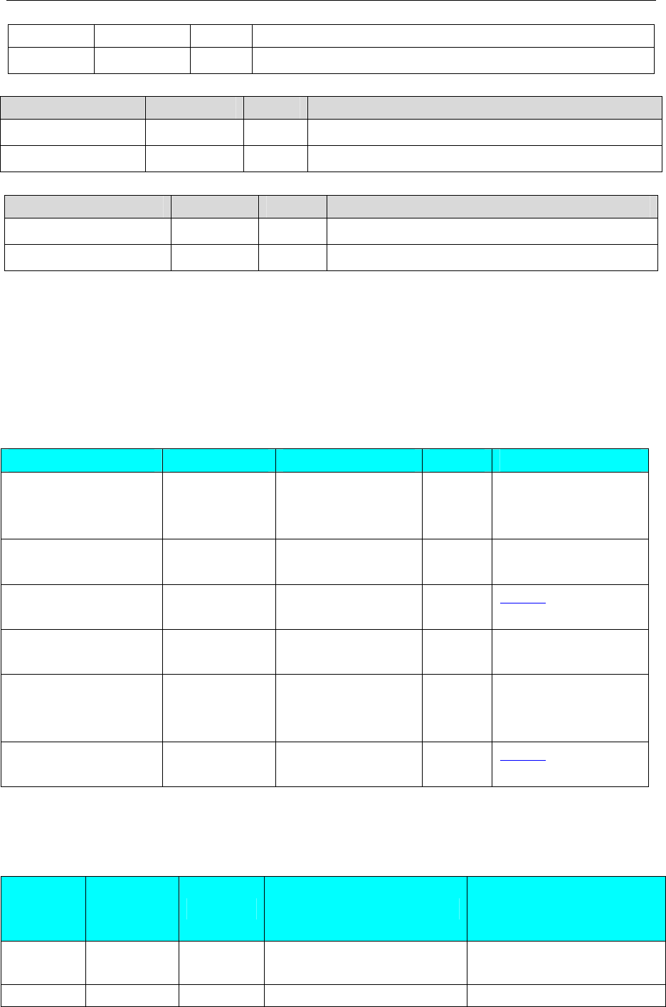
4 Communication settings and guide of HMI connecting with controller
- 324 -
29H E_STPRPT Read Number of steps
42H POSI Read Seven switches(feedback 0-100)
Ctrl_Write operatable address example
PLC addr(HEX) Parameter R/W Parameters mean
184H AT write Execution automatically adjustment 0:OFF1:ON
18CH COM write Communication Protocol:0: LOC 1: COM
Reference operatable address example
PLC Addr(HEX) Parameter R/W Parameters mean
300H FIX_SV R/W
FIX mode SV: in the limit range of SV
460H PB21 R/W ratio coefficient:0.0 to 999.9%(0.0=OFF)
About device address details, please refer to the FP23 communication protocol.
Show: H indicates HEX
Note: 1、Setting the parameters of ADDR address, the settings must be the same as the corresponding PLC
station.
2、When Connecting multiple instruments, for distinguishing instruments, each instrument must be
set different ADDR value.
MR13
Device Bit Address Word Address Format Notes
State instructions(Write
Only)
Ctrl_Write
1.184-3.252
------- HHH
Sequence code(Read
Only)
------- Array
Code1.000-3.003
D.HHH
Basic parameter value
(Read Only)
------- Basic_Read
1.000-3.042
D.HHH settings
OUT1_W,OUT2_W(W
rite Only)
------- Out_Write
1.000-3.001
D.HHH
PV1,PV2(Read Only) ------- PV_Read
1.000-3.002
D.HHH PV1(1.0;2.0;3.0)
PV2(1.1;2.1;3.1)
PV3(1.2;2.2;3.2)
Reference (Read &
Write)
------- Reference
1.100-3.952
D.HHH settings
(Example: In address 1.184, “1” is the channel address, “2” is the control address, and the communication mode is chosen
as the public address, regardless of the channel. The address is set to 1.184(AT mode)and1.18C(COM mode) by default.)
Basic_Read 可操作地址
Examples: Address “1.2” ,”1” is the channel address, and “2” is the control address
PLC
Address
(HEX)
Parameter Read/Write Meanings of Parameter Remark /Example for 3
channel address
01H SV_W Read Setting values 1.1;2.1;3.1(setting values of
three channels)
02H OUT_W Read Limits of output control 1.2;2.2;3.2

4 Communication settings and guide of HMI connecting with controller
- 325 -
04H EXE_FLG Read Execution flag Non execution =0
05H EV_FLG Read Event output flag bit Non event output=0000
06H Retain Read The value is fixed to 0000H
07H EXE_PID Read The current executed PID
number
09H HB_W Read Heater disconnection alarm
value
0AH HL_W Read Undercurrent alarm value
0BH DI_FLG Read DI switch status flag bit
10H UNIT Read 0=℃;1=℉;2=% 3=K;
4=NONE
11H RANGE Read Measuring range
12H CJ Read Cold junction compensation 0=Internal;1=External
13H DP Read Position of decimal point 0=None;1=0.1;2=0.01......
14H SC_L Read Lower limit of measuring
range
15H SC_H Read Higher limit of measuring
range
16H DPFLG Read Digital decimal place 0=Display ; 1=Cancel
20H E_PRG Read Program execution tagging
21H E_PTN Read The currently executed curve
number
22H Retain Read Retain
23H E_RPT Read Curve repeat number
24H E_STP Read Current executed step of the
curve
25H E_TIM Read The remaining time of the
current executed step
26H E_PID Read The current executed PID
number
29H E_STPRPT Read Program execution steps
42H POSI Read Seven switching quantities
Ctrl_Write:Operable address examples
PLC Address
(HEX)
Parameter
Read/Write
Remark /Example for 3
channel address
184H AT Write Self-tuning function,
0=OFF;1=0N
18CH COM Write COM function:0=Local;
1=COM
(Example: In address 1.184, “1” is the channel address, “2” is the control address, and the communication
mode is chosen as the public address, regardless of the channel. The address is set to 1.184(AT
mode)and1.18C(COM mode) by default.
Reference:Operable address examples
PLC Address Parameter Read/Write 备注/地址
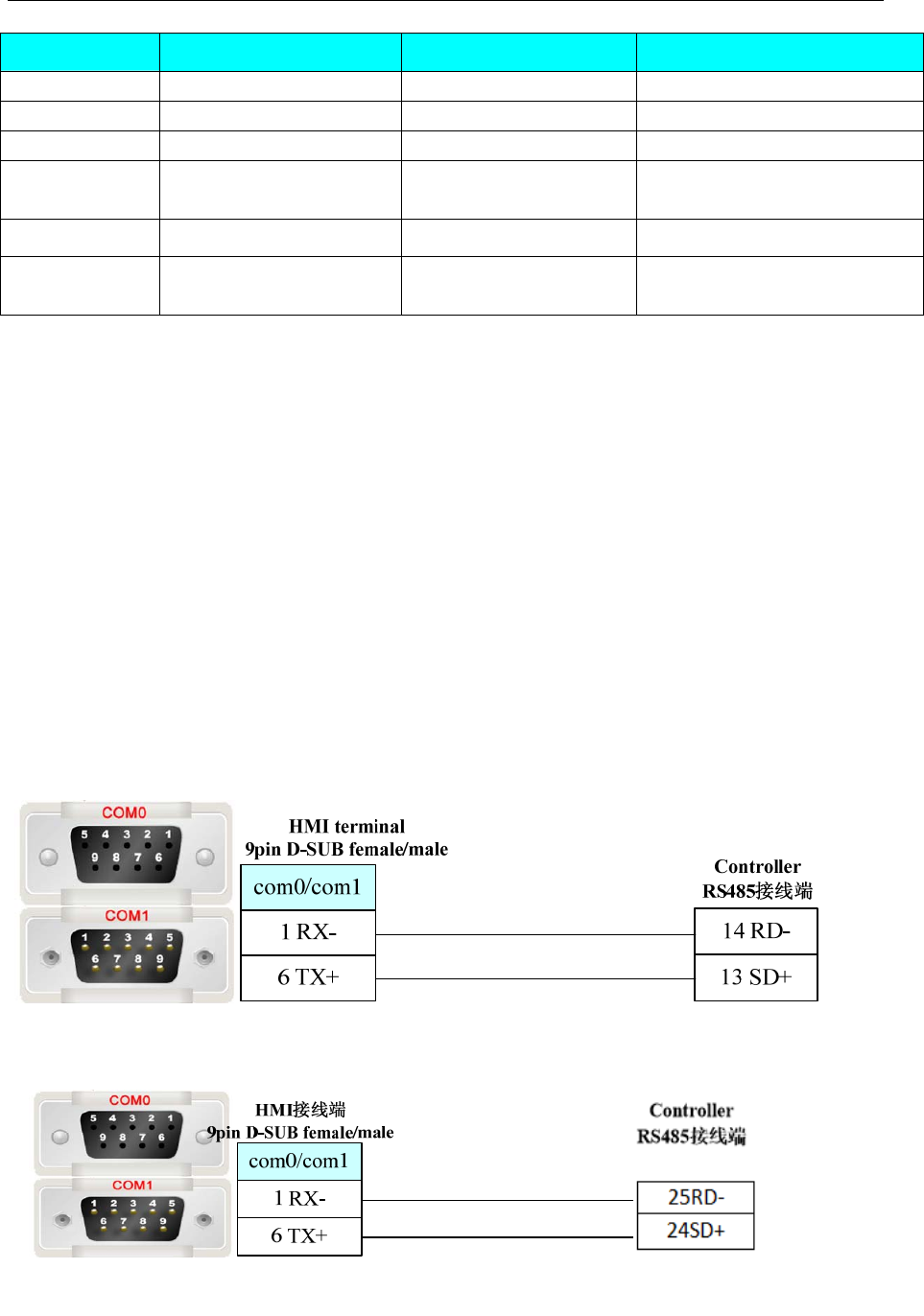
4 Communication settings and guide of HMI connecting with controller
- 326 -
(HEX)
100H PV(Measuring values ) Read Example: 1.100;2.100;3.100
101H E_SV(Setting values) Read Example: 1.101;2.101;3.101
184H AT(Self tuning) Write 0:Stop;1:Execute
18CH COM(Communication
state )
Write 0:Local communication
1:COM Communication
... ... ... ...
8C2 The ninth step number
of PID
Read/Write 1.8C2,2.8C2,3.8C2
Example: In address 1.184, “1” is the channel address, “2” is the control address, and the communication
mode is chosen as the public address, regardless of the channel. The address is set to 1.184(AT
mode)and1.18C(COM mode) by default.
For other parameters, refer to 《mr13 communication protocol 》, at the sixth section of the communication
data address table.
Notice:
1.When you set the parameter address of communication,the setting value must be the same as the
station number of the corresponding PLC.
2.In the case of connecting multiple meters, a different parameter address value is required for each
instrument to distinguish between different instruments.
◎ Cable Diagram
FP23
FP23 programmable PID regulator of 8 point and 10 point must be shorted or communications
failure
RS485 communication cable
MR13
RS485-2:Communication cable

4 Communication settings and guide of HMI connecting with controller
- 327 -
4.69 SIEMENS
◎Serial Communication
Series CPU Link Module Driver
S7-200
CPU212
CPU214
CPU215
CPU216
CPU221
CPU222
CPU224
CPU226
CPU224 XP CN
CPU226 XP CN
RS485 on the CPU unit
S7-200 SMART CR40
SR20 RS485 on the CPU unit
SIEMENS S7-200
S7-300
CPU312IFM
CPU313
CPU313C
CPU314
CPU314IFM
CPU315
CPU315-2 DP
CPU316
CPU316-2 DP
CPU318-2
MPI port on the CPU unit
S7-400
CPU412-1
CPU412-2 DP
CPU412-3H
CPU413-1
CPU413-2 DP
CPU414-1
CPU414-2 DP
CPU414-3 DP
CPU416-1
CPU416-2 DP
CPU416-3 DP
CPU417-4
MPI port on the CPU unit
SIEMENS S7-300/400 (PC
Adapter Direct)
SIEMENS S7-300/400 (MPI
Direct) *1
S7-300
CPU312IFM
CPU313
CPU313C
CPU314
MPI port on the CPU unit SIEMENS MPI*2

4 Communication settings and guide of HMI connecting with controller
- 328 -
CPU314IFM
CPU315
CPU315-2 DP
CPU316
CPU316-2 DP
CPU318-2
NOTE 1. *1 :The protocol is suitable for the MT5020 series with MPI extended port. This
protocol supports multi HMI to multi PLC communication
2. *
2 : The protocol is suitable for the MT4000 series HMI in 2013 November factory.
This protocol supports one HMI to one PLC communication
◎ Ethernet Communication (Direct online simulation disable)
Series CPU Link Module Driver
SIMATIC S7-200
CPU222
CPU224
CPU224 XP
CPU226
CP 243-1 IT
CP 243-1
SIEMENS S7-200
Ethernet (TCP Slave)
SMART S7-200 CR40
SR20 Ethernet interface on CPU
SIEMENS S7-200
SMART Ethernet (TCP
Slave)
SIMATIC S7-1200 CPU1214C CPU
SIMATIC S7-1500 CPU1511-1 PN CPU
SIEMENS S7-1200 /1500
Ethernet (TCP Slave)
CPU315-2DP CP 343-1 IT
CP 343-1
SIMATIC S7-300 CPU315-2 PN/DP
CPU317-2 PN/DP
CPU319-3 PN/DP
Ethernet interface on CPU SIEMENS S7-300
Ethernet (TCP Slave)
SIMATIC S7-400
CPU412-1
CPU412-2 DP
CPU412-3H
CPU413-1
CPU413-2 DP
CPU414-1
CPU414-2 DP
CPU414-3 DP
CPU416-1
CPU416-2 DP
CPU416-3 DP
CPU417-4
CPU414-3 PN/DP
CPU416-3 PN/DP
CP 443-1 IT
CP 443-1
SIEMENS S7-400
Ethernet
(TCP Slave)

4 Communication settings and guide of HMI connecting with controller
- 329 -
CPU414-3 PN/DP
CPU416-3 PN/DP
Ethernet interface
on CPU
SIEMENS LOGO! 6ED1
052-1MD00-0AB8 Ethernet interface on CPU SIEMENS LOGO!
Ethernet(TCP Slave)
◎BUS Communication
Please refer to 4.59 Profibus DP Slave.
◎Serial System configuration
Series CPU Link Module COMM Type Parameter Cable
RS232 Setting Your owner cable
S7-200
CPU222
CPU224
CPU226
CPU224 XP CN
CPU226 XP CN
RS485 on the CPU unit
RS485-2 Setting Your owner cable
S7-200
SMART
CR40
SR20 RS485 on the CPU unit RS485-2 Setting Your owner cable
RS232
S7-300/400
(PC Adapter
Direct)
protocol
Setting Your owner cable
RS485
S7-300/400
(MPI Direct)
protocol
Setting Your owner cable
S7-300 CPU312IFM
CPU313
CPU313C
CPU314
CPU314IFM
CPU315
CPU315-2 DP
CPU316
CPU316-2 DP
CPU318-2
MPI port on the CPU unit
RS485
SIEMENS
MPI protocol
Setting Your owner cable
RS232
S7-300/400
(PC Adapter
Direct)
protocol
Setting Your owner cableS7-400 CPU412-1
CPU412-2 DP
CPU412-3H
CPU413-1
CPU413-2 DP
CPU414-1
CPU414-2 DP
CPU414-3 DP
CPU416-1
CPU416-2 DP
CPU416-3 DP
CPU417-4
MPI port on the CPU unit
RS485
S7-300/400
(MPI Direct)
protocol
Setting Your owner cable
◎Ethernet System configuration
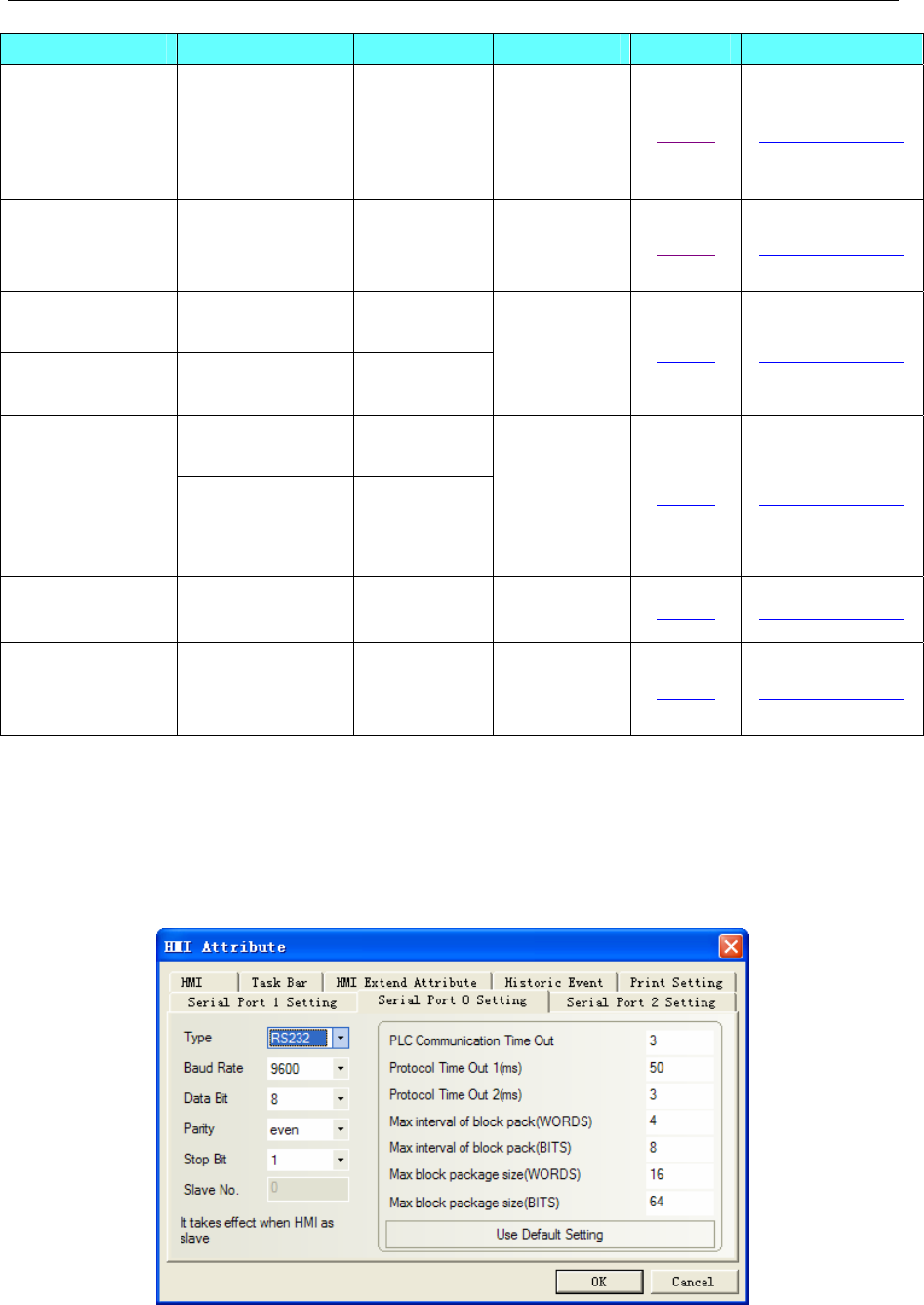
4 Communication settings and guide of HMI connecting with controller
- 330 -
Series CPU Link Module Connect Type Parameter Cable
SIMATIC S7-200
CPU222
CPU224
CPU224 XP
CPU226
CP 243-1 IT
CP 243-1 Ethernet Setting Your owner cable
SIMATIC S7-200
SMART
CR40
SR20
Ethernet
interface on
CPU
Ethernet Setting Your owner cable
SIMATIC
S7-1200 CPU1214C CPU
SIMATIC
S7-1500 CPU1511-1 PN CPU
Ethernet Setting Your owner cable
CPU315-2DP CP 343-1 IT
CP 343-1
SIMATIC S7-300 CPU315-2 PN/DP
CPU317-2 PN/DP
CPU319-3 PN/DP
Ethernet
interface on
CPU
Ethernet Setting Your owner cable
SIMATIC S7-400 CPU412-3H CP 443-1 IT
CP 443-1 Ethernet Setting Your owner cable
SIEMENS
LOGO!
6ED1
052-1MD00-0AB
8
Ethernet
interface on
CPU
Ethernet 6Setting Your owner cable
◎Serial Communication Setting
SIEMENS S7-200 protocol
Default communication parameters: 9600, 8, 1, even; station No.: 2.
NOTE: HMI Baudrate can reach to187.5k, but don’t support online simulate for187.5K.
RS232 communication
RS485 communication
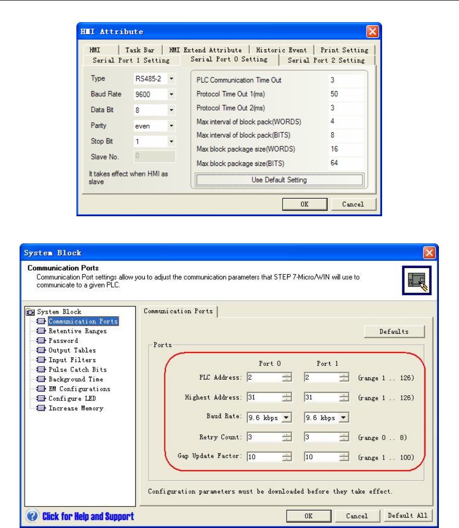
4 Communication settings and guide of HMI connecting with controller
- 331 -
PLC Setting
SIEMENS S7-300/400 (PC Adapter Direct) protocol
HMI Setting
Default communication parameters: 19200bps, 8, 2, odd; station:2
RS232 communication
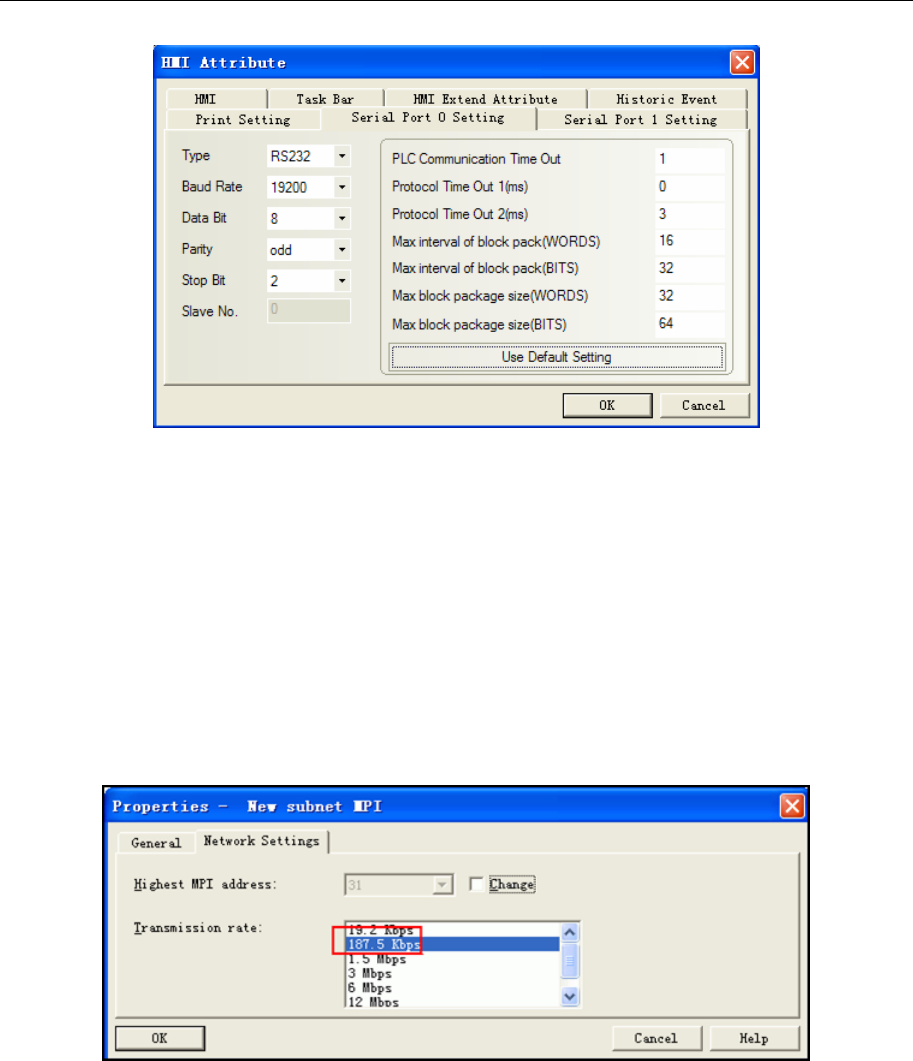
4 Communication settings and guide of HMI connecting with controller
- 332 -
NOTE:
1. If you use MT5-S7-300 adapter to communicate, the baudrate of PLC must be 187.5K, and HMI must be
19.2K
2. If we use PC adapter, PLC station No. is not necessary, so the communication is one-to-one.
3. DB block must be created, otherwise the relevant registers can not write (DB.DBX, DB.DBW, DB.DBD).
DBm.DBW, DBm.DBD address start must be an even number.
PLC Setting
1. Production of the adapter with KINCO, MPI transmission rate must be set 187.5K. 19.2K general users
of the transmission rate, if the S7-300 MPI-side transmission rate is 19.2K, you need to change it into the
Siemens adapter 187.5K (where changes in the hardware properties)
2. MPI address must be 2.
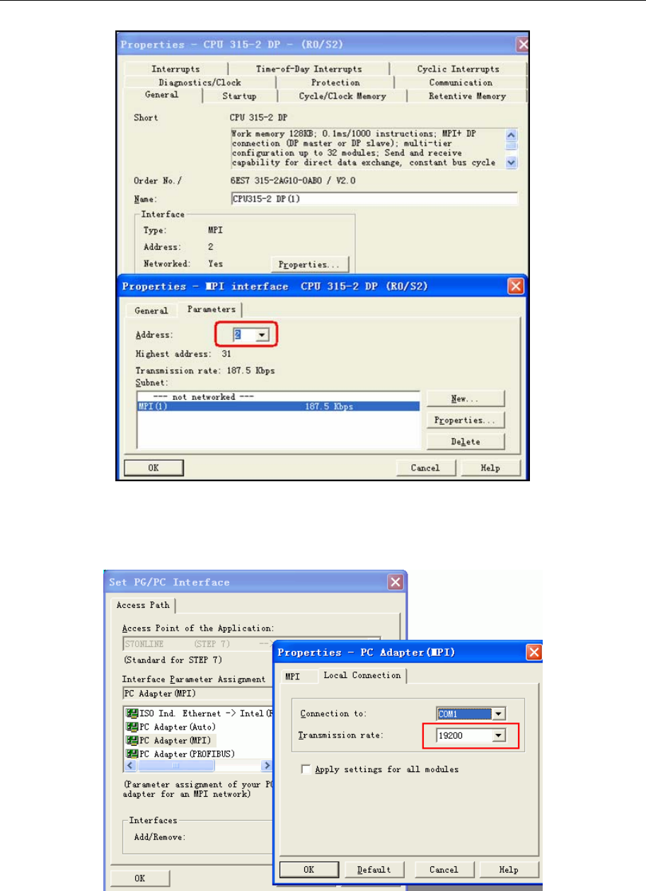
4 Communication settings and guide of HMI connecting with controller
- 333 -
3. After the software change, downloaded to PLC, make sure the transmission rate of MPI is 187.5K, and
then in the options set PG / PC interface, select PC Adapter (MPI), MPI-side of the transfer rate will be
changed to 187.5K.
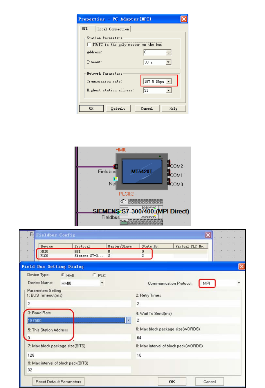
4 Communication settings and guide of HMI connecting with controller
- 334 -
SIEMENS S7-300/400 (MPI Direct) protocol
HMI Setting
NOTE:
1. This protocol is suitable for MT5020 series with MPI extended port.
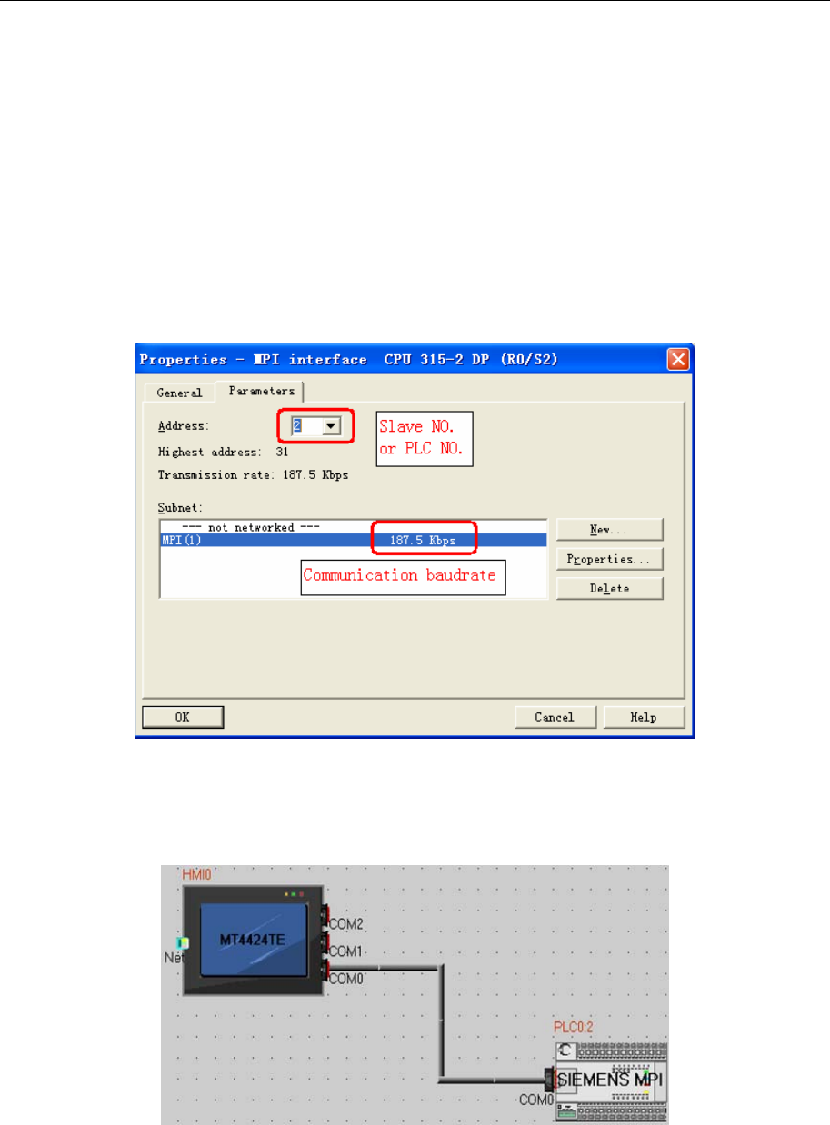
4 Communication settings and guide of HMI connecting with controller
- 335 -
2. This protocol supports multi-station communication, and the MPI is RS485 port, so we can use this
protocol to communicate between many HMI and PLC, and then we must set the master station number.
3. HMI station No. can be 0~15, PLC station No. must be 0~15, the station No. of HMI and PLC can not be
the same number.
4. PLC baud rate can be 187.5K or 19.2K.
5. You must set DB first, or register cannot write(DB.DBX, DB.DBW, DB.DBD. The initial address of
DBm.DBW and DBm.DBD must be even number.
6. This protocol doesn’t support direct simulation and indirect simulation.
PLC Setting
1. PLC station No. can be 0~15.
2. MPI baud rate can be 19.2k or 187.5k.
SIEMENS MPI Direct protocol
HMI setting
Default parameter:19200bps, 8, none, 1; station number:2
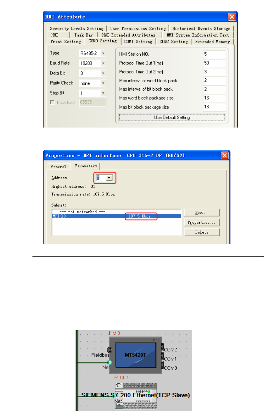
4 Communication settings and guide of HMI connecting with controller
- 336 -
PLC setting
PLC station No. can be 2-15, MPI baud rate can be 19.2k or 187.5k
NOTE:
1. You should set DB block first, otherwise the registers as DB.DBX,DB.DBW and
DB.DBD cannot write.
2. This protocol supports one HMI to one PLC communication
◎Ethernet Communication Setting
SIEMENS S7-200 Ethernet (TCP Slave) protocol
HMI Setting
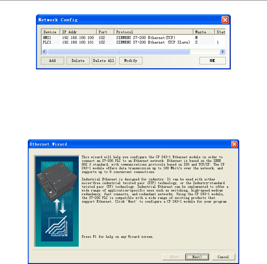
4 Communication settings and guide of HMI connecting with controller
- 337 -
PLC Setting
The settings for the CP 243-1 are defined in STEP 7 Micro/WIN via the Ethernet Wizard. For
assistance with all the information go to STEP 7 Micro/WIN Online Help via F1.
1. Starting the Ethernet Wizard
- Open STEP 7 Micro/WIN
- Start the Ethernet Wizard via “Tools >Ethernet Wizard….”
- Click on “Next”
2. Specifying module position
If your PC is connected to the S7-200, click the “Read modules” button to determine the position of
the CP 243-1 module automatically. Otherwise, the module position can also be entered manually.
Important:
The panel can only establish a connection with a Cp243-1 if the module is configured to “position 0”.
- Check if the CP is connected in the module position “ZERO” and change the module position if
necessary.
- Identify or enter the module position “ZERO”.
- Click on “Next”.
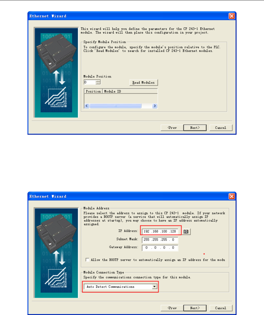
4 Communication settings and guide of HMI connecting with controller
- 338 -
3. Specifying IP address
3.0 Define an IP address for the CP 243-1.
Caution:The IP address for this application may not be taken automatically from a server because the
panel requires a fixed reference partner (CP 243-1) for the Ethernet communication.
Note: The communication connection type for this module can be defined by the “Automatic Setting”.
4.0 Click on “Next” to continue.
4. Parameterizing PtP connection
5.0 Specify the command byte for the module and the number of point-to-point connections with the
CP 243-1 .
6.0 Click on “Next”.
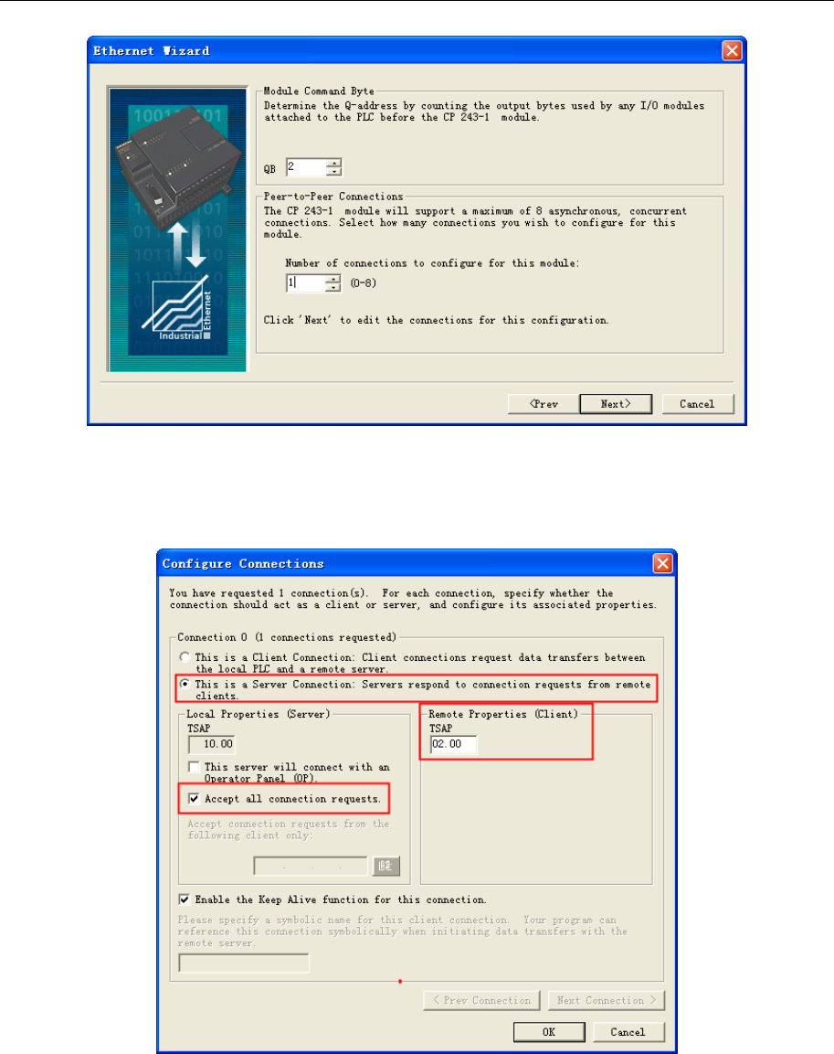
4 Communication settings and guide of HMI connecting with controller
- 339 -
5. Configuration connection
7.0 The configuration for connecting the CP 243-1 to the panel must be defined as in Fig..
8.0 Click OK to confirm the entries.
Warning: The TSAP must always be specified in four-digit format, with a leading zero (02.00).
6. Using CRC protection
Set the CRC protection the way you want it. It is advisable to work without CRC protection first of all. The
“Keep Alive Interval” can be specified with the default time.
9.0 Activate the CRC protection and change the time of the “Keep Alive Interval” if required.
10.0 Click on “Next”.
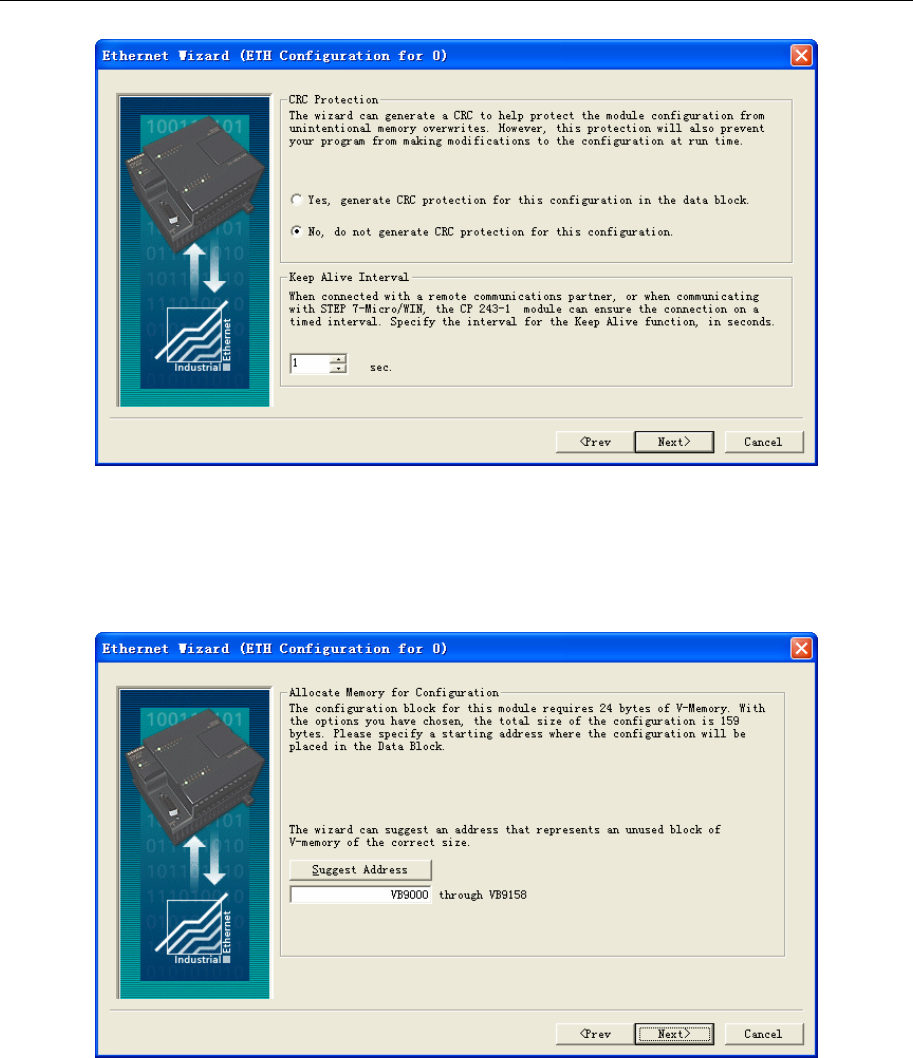
4 Communication settings and guide of HMI connecting with controller
- 340 -
7. Assigning memory
11.0 Specify a memory area for the configuration of the CP 243-1.
Recommend: If you click on Suggest address, the Wizard can identify a variable memory area.
Note: The register used in the panel must be out of the memory area for the configuration.
12.0 Click on “Next”.
8. Creating project components
If you click on “Close”, the Ethernet Wizard generates the project components for the set configuration.
Among other things, subprograms and the variable memory are created in the data block.
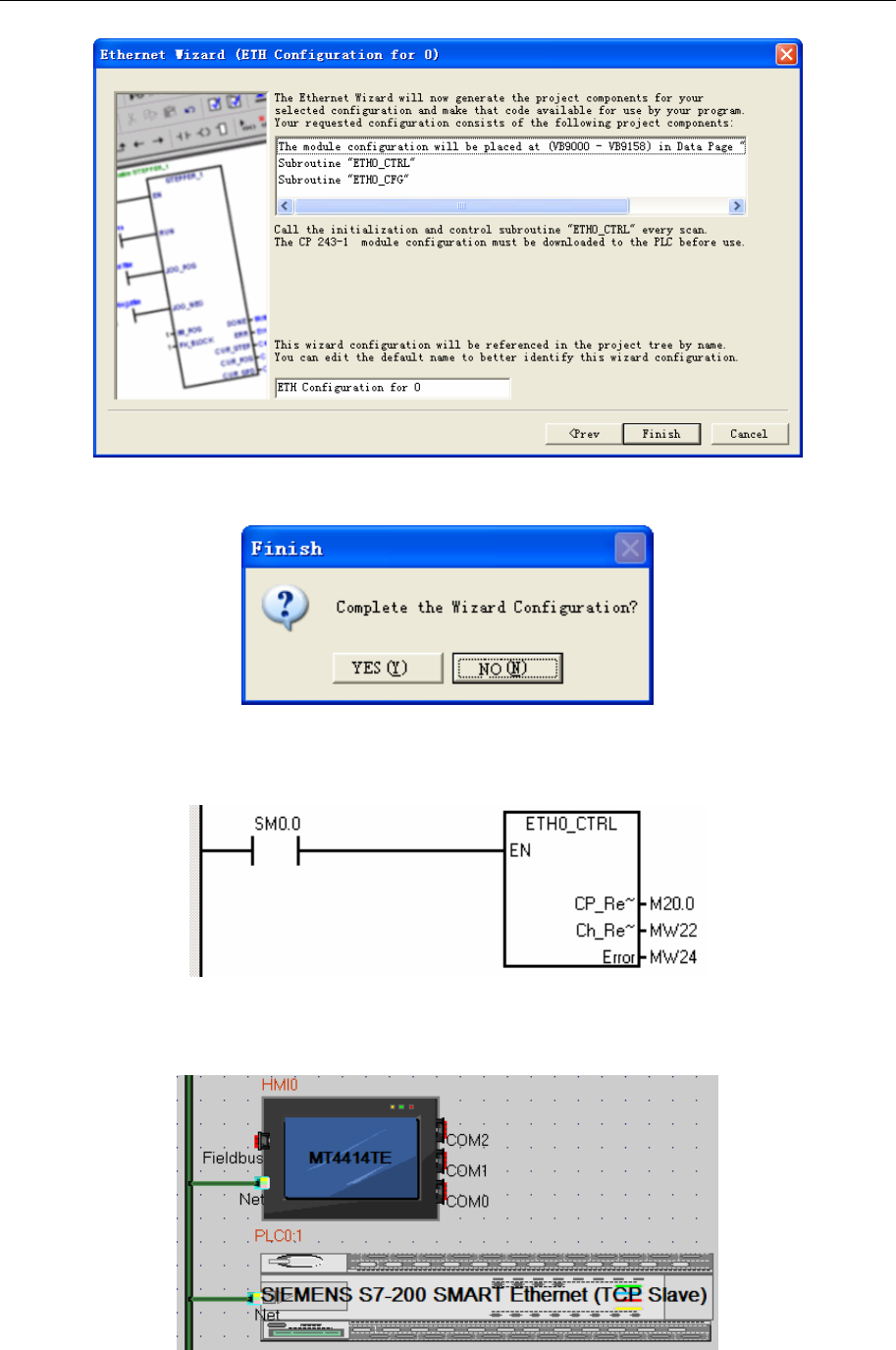
4 Communication settings and guide of HMI connecting with controller
- 341 -
9. Confirm message
13.0 Click “Yes” to confirm the message that appears.
10. Call ETH0_CTRL
14.0 In your STEP 7 Micro/WIN program, you must call the ETH0_CTRL subroutine in each cycle.
15.0 Finally, load the entire configuration into the S7-200.
SIEMENS S7-200 SMART Ethernet (TCP Slave) protocol
HMI Setting
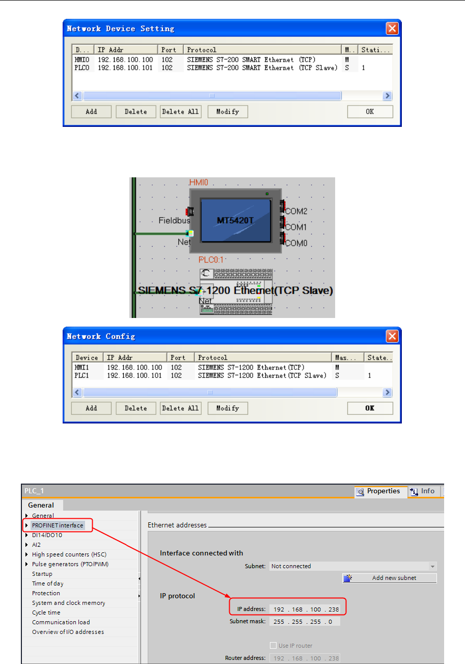
4 Communication settings and guide of HMI connecting with controller
- 342 -
SIEMENS S7-1200 Ethernet(TCP Slave) protocol
HMI Setting
PLC Setting
1. Modify the IP address
a. Setting IP in “General”“Profinet interface”
b. After configuration, download device. Download in the first time, select the “Extended download to
device”, in the dialog to select show all accessible devices.
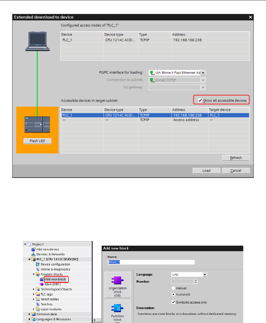
4 Communication settings and guide of HMI connecting with controller
- 343 -
c. Select the device, press “Load”.
2. Build the data block
Portal10:
Data block must be created, otherwise the relevant registers can not write (DB.DBX, DB.DBW, DB.DBD).
Double-click “Add new block”
For example, add new block “DB10”, setting as follow
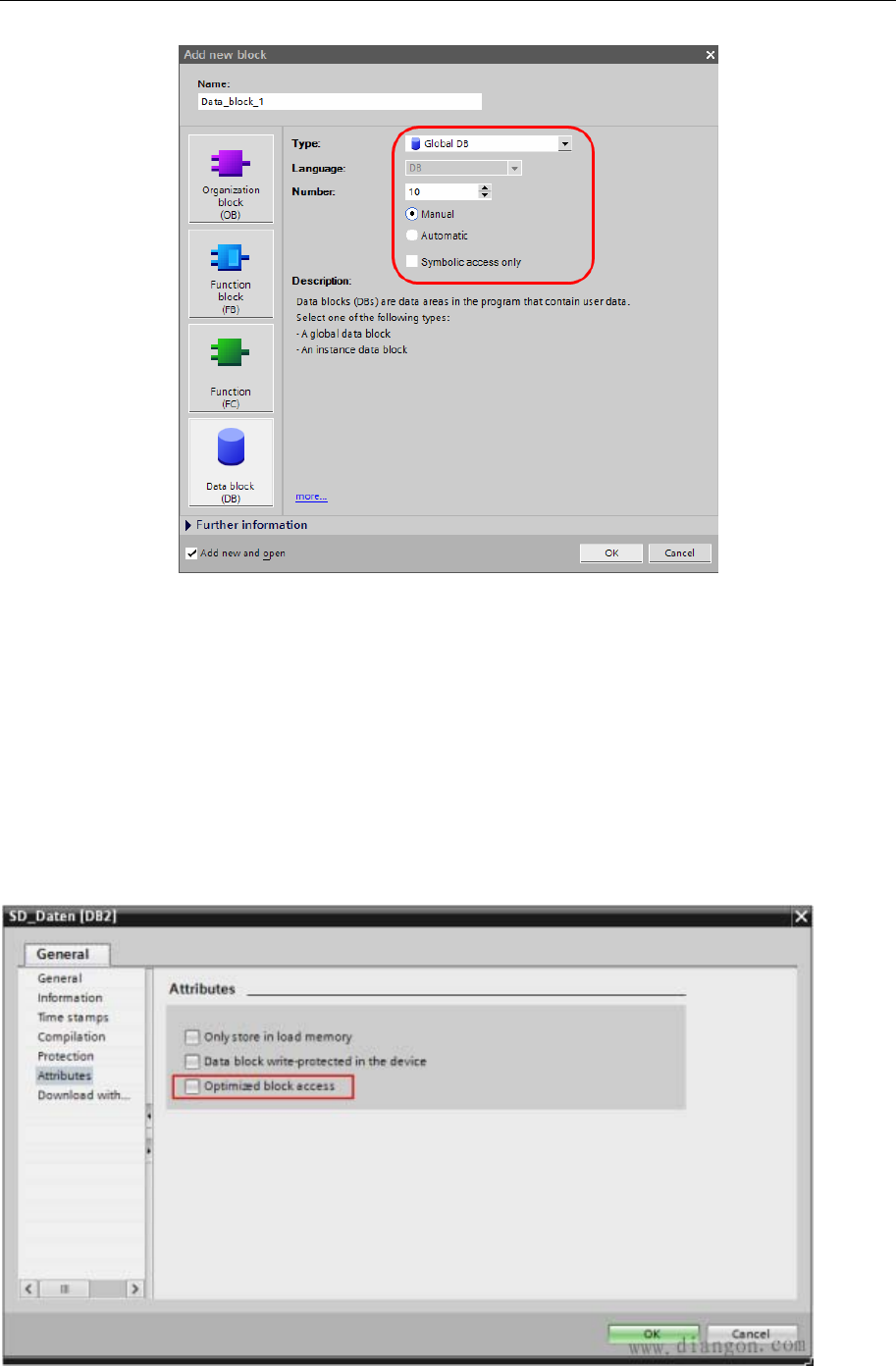
4 Communication settings and guide of HMI connecting with controller
- 344 -
NOTE:
1. Make sure the data type of PLC same as the HMI when defining the data block. For example, if the data
type of PLC is REAL, then the data type of number input/display component must be float in HMI.
2. Make sure that the data block defined in PLC should be more than the data block used in HMI. For
example, if DB5.DBW32 is used in HMI, user can’t define the data block up to DB5.DBW32, but up to
DB5.DBW34 or more.
Portal13:
1. Must disable “Optimized block access” in the DB block properties-[general]-[Attributes].
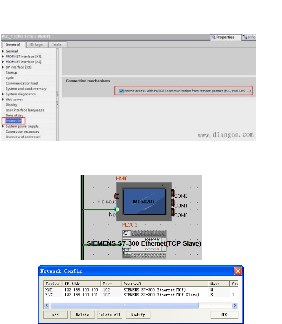
4 Communication settings and guide of HMI connecting with controller
- 345 -
2. Must enable “Permit access with PUT/GET communication from remote partner (PLC, HMI,
OPC, …)” in the CPU properties-[General]-[Protection].
SIEMENS S7-300 Ethernet(TCP Slave) protocol
HMI Setting
PLC Setting
1. In “HW configuration” insert CP300 industrial Ethernet.
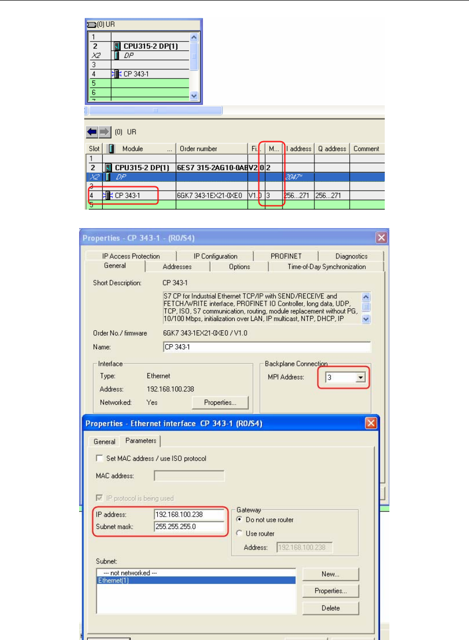
4 Communication settings and guide of HMI connecting with controller
- 346 -
2. Set IP address in the Properties of CP343-1.
3. After HW configuration, download.
SIEMENS S7-400 Ethernet(TCP Slave) protocol
HMI Setting
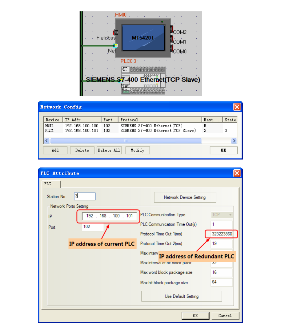
4 Communication settings and guide of HMI connecting with controller
- 347 -
NOTE: Dual redundant parameters configuration of S7-400 Ethernet communication
16.0 The station No. is composed of two parts: track No. and slot No., and station No. is a byte, the track
No. is the high 4 bits, and the slot No. is the low 4 bits. For example, the station No. is 0x03 in hex,
that is to say, the track No. is 0 and CPU slot No. is 3.
17.0 Protocol timeout 1 stands for IP address of redundancy PLC. For example, if the IP address is
192.168.100.240, corresponding to the hex value 0xC0A864F8, then transfer this value to decimal, it is
3232261368.
18.0 Protocol timeout 2 stands for tack No. and Slot No. of redundant PLC, for example, if the Protocol
timeout 2 is 19, corresponding to the 0x13 in hex, that is to say the track No. is 1 and slot No. is 3.
19.0 When configuring PLC in HMI program, just need to configure one PLC but not two.
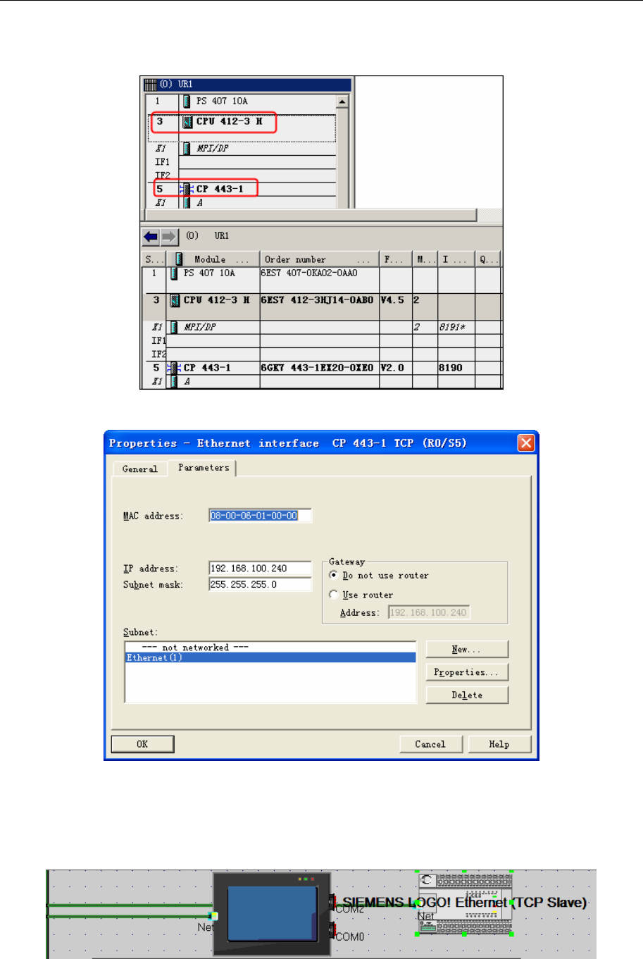
4 Communication settings and guide of HMI connecting with controller
- 348 -
PLC Setting
1. In the hardware configuration, insert CP400 Ethernet module CP443-1:
2. Open the Properties of CP443-1, set the IP address. No need to set MAC address.
3. Download after finishing hardware configuration
SIEMENS LOGO! Ethernet(TCP Slave)
HMI Setting
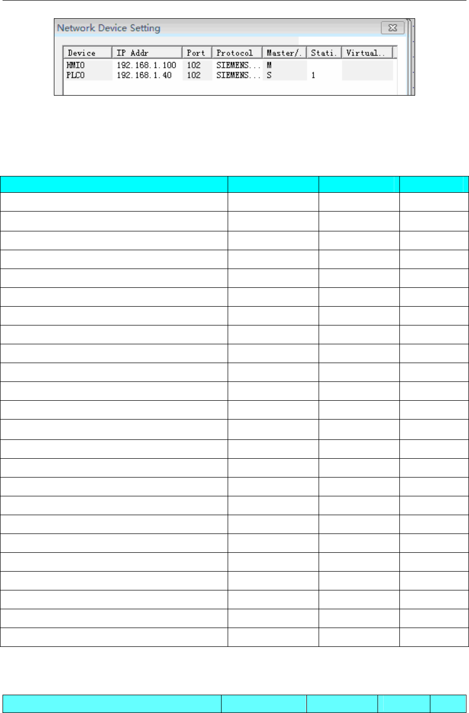
4 Communication settings and guide of HMI connecting with controller
- 349 -
PLC Setting
Set the same parameters as the HMI dose.
◎Supported Device
S7-200
Device Bit Address Word Address Format
SCR S.B 0.0-31.7 ------ DDD.O
Special memory Relay SM.B 0.0-549.7 ------ DDDD.O
Counter Relay Cnt 0-255 ------ DDD.O
Timer Relay Tim 0-255 ------ DDD.O
V Relay V.B 0.0-10238.7 ------ DDDDD.O
Internal Memory Relay M.B 0.0-31.7 ------ DDDDD.O
Discrete outputs and image Relay Q.B 0.0-15.7 ------ DDDDD.O
Discrete inputs and image Relay I.B 0.0-15.7 ------ DDDDD.O
Analog Outputs ------ AQW 0-62 DD
Analog Inputs ------ AIW 0-62 DD
SCR double word ------ SD 0-28 DD
SCR ------ SW 0-30 DD
Special memory double word ------ SMD 0-546 DDD
Special memory ------ SMW 0-548 DDD
Internal memory double word ------ MD 0-28 DD
Internal memory ------ MW 0-30 DD
Discrete outputs and image register double word ------ QD 0-12 DD
Discrete outputs and image register ------ QW 0-14 DD
Discrete inputs and image register double word ------ ID 0-12 DD
Discrete inputs and image register ------ IW 0-14 DD
Timer(Current Value) ------ Cnt 0-255 DDD
Counter(Current Value) ------ Tim 0-255 DDD
V memory double word ------ VD 0-10236 DDDDD
V memory ------ VW 0-10238 DDDDD
NOTE:VW、VD address must be an even number
SIEMENS S7-200 Ethernet(TCP Slave)
Device Bit Address Word Address Format Notes
4 Communication settings and guide of HMI connecting with controller
- 350 -
V Relay V.B 0.0-20479.7 ------ DDDD.O
Internal Memory Relay M.B 0.0-31.7 ------ DD.O
Discrete outputs and image Relay Q.B 0.0-31.7 ------ DD.O
Discrete inputs and image Relay I.B 0.0-31.7 ------ DD.O
Special memory Relay SM.B 0.0-1535.7 ------ DDDD.O
SCR S.B 0.0-31.7
------ DD.O
Internal memory double word ------ MD 0-28 DD
Internal memory ------ MW 0-30 DD
Discrete outputs and image register double word ------ QD 0-28 DD
Discrete outputs and image register ------ QW 0-30 DD
Discrete inputs and image register double word ------ ID 0-28 DD
Discrete inputs and image register ------ IW 0-30 DD
V memory double word ------ VD 0-20478 DDDD
V memory ------ VW 0-20476 DDDD
SIEMENS S7-200 SMART Ethernet(TCP Slave)
Device Bit Address Word
Address Format Notes
V Relay V.B 0.0-20479.7 ------ DDDD.O
Internal Memory Relay M.B 0.0-31.7 ------ DD.O
Discrete outputs and image Relay Q.B 0.0-31.7 ------ DD.O
Discrete inputs and image Relay I.B 0.0-31.7 ------ DD.O
Special memory Relay SM.B 0.0-1535.7 ------ DDDD.O
SCR S.B 0.0-31.7 ------ DD.O
Internal memory double word C.FLAG 0-255 ------ DDD
Internal memory T.FLAG 0-255 ------ DDD
Discrete outputs and image
register double word ------ MD 0-28 DD
Discrete outputs and image
register ------ MW 0-30 DD
Discrete inputs and image register
double word ------ QD 0-28 DD
Discrete inputs and image register ------ QW 0-30 DD
V memory double word ------ ID 0-28 DD
V memory ------ IW 0-30 DD
V Relay ------ Cnt 0-255 DDD
Internal Memory Relay ------ Tim 0-255 DDD
Discrete outputs and image Relay ------ VD 0-20478 DDDD
Discrete inputs and image Relay ------ VW 0-20476 DDDD
4 Communication settings and guide of HMI connecting with controller
- 351 -
SIEMENS S7-300/400 (PC Adapter Direct)
Device Bit Address Word Address Format Notes
External Input node I 0.0~511.7 ------ DDDD.O
External Output node Q 0.0~511.7 ------ DDDD.O
Internal assistant node M 0.0~4095.7 ------ DDDD.O
Data Register Relay node
DBm.DBX
0~65535.7 ------ DDDDD.O m:10~60
Data Register Relay ------ DBm.DBW 0-65534 DDDDD m:10~60
Data Register Relay (32 bit) ------ DBm.DBD 0-65532 DDDDD m:10~60
Internal Relay ------ MW 0~2046 DDDD
Internal Relay (32 bit) ------ MD 0~2044 DDDD
External Output Relay ------ QW 0~126 DDD
External Output Relay (32 bit) ------ QD 0~124 DDD
External Input Relay ------ IW 0~126 DDD
External Input Relay (32 bit) ------ ID 0~124 DDD
NOTE:
1. The initial address of DBm.DBW and DBm.DBD must be even number.
2. Make sure that the data block defined in PLC should be more than the data block used in HMI. For
example, if DB5.DBW32 is used in HMI, user can’t define the data block up to DB5.DBW32, but up to
DB5.DBW34 or more.
SIEMENS S7-300/400 (MPI Direct)& SIEMENS MPI
Device Bit Address Word Address Format Notes
External Input node I 0.0~255.7 ------ DDDD.O
External Output node Q 0.0~255.7 ------ DDDD.O
Internal assistant node M 0.0~8191.7 ------ DDDD.O
Data Register Relay node DBm.DBX 0.0~65533.7 ------ DDDDD.O m:1~60
Data Register Relay node DBn.DBX
100000.0~409665535.7
------ DDDDD.O n:1~4096
Counter ------ C 0~2047 DDD
Timer ------ T 0~2047 DDD
*1
Internal Relay ------ MW 0~8190 DDDD
External Output Relay ------ QW 0~254 DDD
External Input Relay ------ IW 0~254 DDD
Internal Relay ------ MD 0~8188 DDDD
External Output Relay ------ QD 0~252 DDD
External Input Relay ------ ID 0~252 DDD
Data Register Relay ------ DBm.DBW 0~65532 DDDDD m:1~60
Data Register Relay (32 ------ DBm.DBD 0~65532 DDDDD m:1~60
4 Communication settings and guide of HMI connecting with controller
- 352 -
bit)
Data Register Relay ------ DBn_DBW
100000-409665534
DDDDDDDDD n:1~4096
Data Register Relay (32
bit)
------ DBn_DBD
100000-409665532
DDDDDDDDD n:1~4096
NOTE:
1. DBn_DBX, DBn_DBW, DBn_DBD is a custom block. First four data formats for data block number, the
address after the five, less than five former address zeros. To DB20.DBX23.4 example, EV5000 software
addresses to DBn_DBX: 2000023.4
2. The initial address of DBm.DBW, DBm.DBD must be an even number.
3. *1 T/C registers are read only.
4. Make sure that the data block defined in PLC should be more than the data block used in HMI. For
example, if DB5.DBW32 is used in HMI, user can’t define the data block up to DB5.DBW32, but up to
DB5.DBW34 or more.
SIEMENS S7-1200 Ethernet(TCP Slave)
Device Bit Address Word Address Format Notes
External Input node I 0.0~127.7 ------ DDDD.O
External Output node Q 0.0~127.7 ------ DDDD.O
Internal assistant node M 0.0~2047.7 ------ DDDD.O
Data Register Relay node
DBn_DBX
100000.0~25565535.7 ------ DDDDDDDD.O
Data Register Relay node DBm_DBX
0.0~65535.7 ------ DDDDD.O m:1~10
Data Register Relay ------ DBn_DBW
100000-25565534 DDDDDDDD n:1~255
Data Register Relay (32 bit) ------ DBn_DBD
100000-25565532 DDDDDDDD n:1~255
Data Register Relay ------ DBm_DBW
0-65534 DDDDD
Data Register Relay (32 bit) ------ DBm_DBD
0-65532 DDDDD
m:1~10
Internal Relay ------ MW 0~2046 DDDD
Internal Relay (32 bit) ------ MD 0~2044 DDDD
External Output Relay ------ QW 0~126 DDD
External Output Relay (32
bit) ------ QD 0~124 DDD
External Input Relay ------ IW 0~126 DDD
External Input Relay (32 bit) ------ ID 0~124 DDD
NOTE:
1. EV5000 in the DB register corresponds to the definition of S7-1200 software, the absolute address of DB,
rather than the global symbol DB.

4 Communication settings and guide of HMI connecting with controller
- 353 -
2. DBn_DBX, DBn_DBW, DBn_DBD is a custom block. First three data formats for data block number,
the address after the five, less than five former address zeros. To DB20.DBX23.4 example, EV5000
software addresses to DBn_DBX: 2000023.4
3. The initial address of DBm.DBW, DBm.DBD must be an even number.
4. Make sure that the data block defined in PLC should be more than the data block used in HMI. For
example, if DB5.DBW32 is used in HMI, user can’t define the data block up to DB5.DBW32, but up to
DB5.DBW34 or more.
SIEMENS S7-300 Ethernet(TCP Slave)
Device Bit Address Word Address Format Notes
External Input node I 0.0~2047.7 ------ DDDD.O
External Output node Q 0.0~2047.7 ------ DDDD.O
Internal assistant node M 0.0~2047.7 ------ DDDD.O
Data Register Relay node
DBn_DBX
100000.0~25565535.7 ------ DDDDDDDD.O
Data Register Relay node DBm_DBX
0.0~65535.7 ------ DDDDD.O m:1~10
Data Register Relay ------ DBn_DBW
100000-25565534 DDDDDDDD n:1~255
Data Register Relay (32 bit) ------ DBn_DBD
100000-25565532 DDDDDDDD n:1~255
Data Register Relay ------ DBm_DBW
0-65534 DDDDD
Data Register Relay (32 bit) ------ DBm_DBD
0-65532 DDDDD
m:1~10
Internal Relay ------ MW 0~2046 DDDD
Internal Relay (32 bit) ------ MD 0~2044 DDDD
External Output Relay ------ QW 0~2046 DDD
External Output Relay (32 bit) ------ QD 0~2044 DDD
External Input Relay ------ IW 0~2046 DDD
External Input Relay (32 bit) ------ ID 0~2044 DDD
NOTE:
1. DBn_DBX, DBn_DBW, DBn_DBD is a custom block. First three data formats for data block number,
the address after the five, less than five former address zeros. To DB20.DBX23.4 example, EV5000
software addresses to DBn_DBX: 2000023.4
2. The initial address of DBm.DBW, DBm.DBD must be an even number.
3. The data type of MB, IB, QB registers can’t be set to signed int.
4. Make sure that the data block defined in PLC should be more than the data block used in HMI. For
example, if DB5.DBW32 is used in HMI, user can’t define the data block up to DB5.DBW32, but up to
DB5.DBW34 or more.
SIEMENS S7-400 Ethernet(TCP Slave)
Device Bit Address Word Address Format Notes
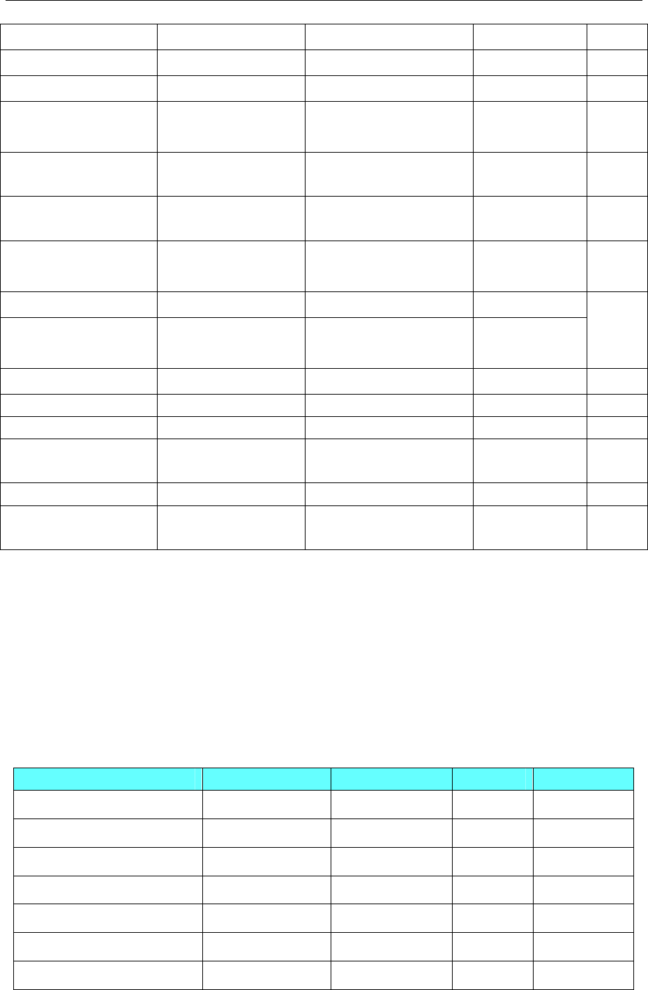
4 Communication settings and guide of HMI connecting with controller
- 354 -
External Input node I 0.0~255.7 ------ DDD.O
External Output node Q 0.0~255.7 ------ DDD.O
Internal assistant node M 0.0~8191.7 ------ DDDD.O
Data Register Relay
node
DBn_DBX
100000.0~25565535.7 ------ DDDDDDDD.O
Data Register Relay
node
DBm_DBX
0.0~65535.7 ------ DDDDD.O m:1~10
Data Register Relay ------ DBn_DBW
100000-25565534 DDDDDDDD
Data Register Relay (32
bit)
------ DBn_DBD
100000-25565532 DDDDDDDD
Data Register Relay ------ DBm_DBW 0-65534 DDDDD
Data Register Relay (32
bit)
------ DBm_DBD 0-65532 DDDDD
m:1~10
Internal Relay ------ MW 0~8190 DDDD
Internal Relay (32 bit) ------ MD 0~8188 DDDD
External Output Relay ------ QW 0~254 DDD
External Output Relay
(32 bit) ------ QD 0~252 DDD
External Input Relay ------ IW 0~254 DDD
External Input Relay
(32 bit) ------ ID 0~252 DDD
NOTE:
1. DBn_DBX, DBn_DBW, DBn_DBD is a custom block. First three data formats for data block number,
the address after the five, less than five former address zeros. To DB20.DBX23.4 example, EV5000
software addresses to DBn_DBX: 2000023.4
2. The initial address of DBm.DBW, DBm.DBD must be an even number.
3. Make sure that the data block defined in PLC should be more than the data block used in HMI. For
example, if DB5.DBW32 is used in HMI, user can’t define the data block up to DB5.DBW32, but up to
DB5.DBW34 or more.
SIEMENS LOGO! Ethernet(TCP Slave)
Device Bit Address Word Address Format Notes
Input I_Bit 1-64 ------ DD Read Only
Output Q_Bit 1-64 ------ DD
Flag Bit M_Bit 1-112 ------ DDD
Network Input NI_Bit 1-128 ------ DDD
Network Output NQ_Bit 1-128 ------ DDD
V Relay V_Bit 0.0-1469.7 ------ DDDDo
Analog Input ------ AI_Word 1-16
DD
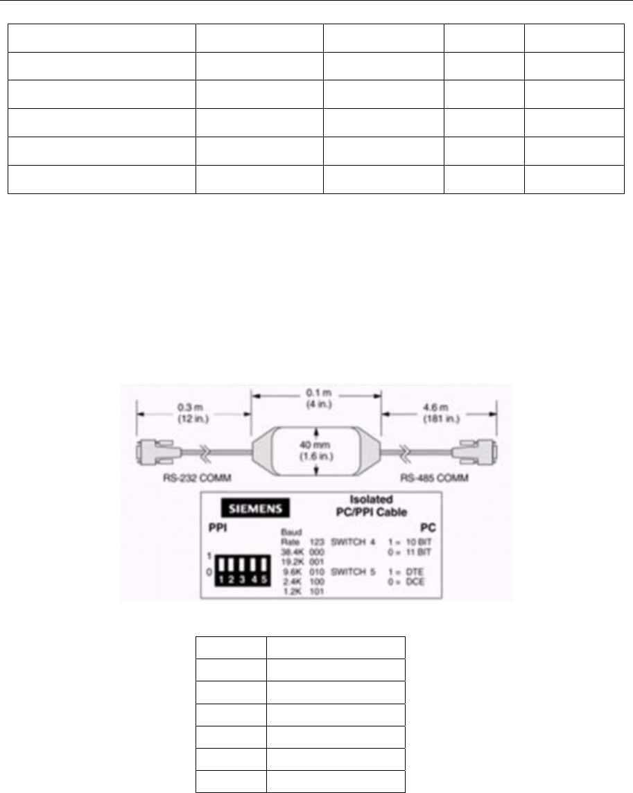
4 Communication settings and guide of HMI connecting with controller
- 355 -
Analog Output ------ AQ_Word 1-16
DD
Analog Mark ------ AM_Word 1-16
DD
Network Analog Input ------ NAI_Word 1-64 DD
Network Analog Onput ------ NAQ_Word 1-32 DD
V memory ------ VW_Word
DDDD
V memory double word ------ VD_Word 0-1466 DDDD
NOTE:VD、VW address must be an even number
◎Cable Diagram
SIEMENS S7-200 protocol
RS232 communication
Siemens models using standard serial PC / PPI cable . Cable Baud Rate DIP switch settings are as
follows:
1 ) with 5 DIP switch cable
PC/PPI Cable switch to select the baud rate
Baud SWITCH(1=on)
38400 000
19200 001
9600 010
4800 011
2400 100
1200 101
2)with 8 DIP switch cable
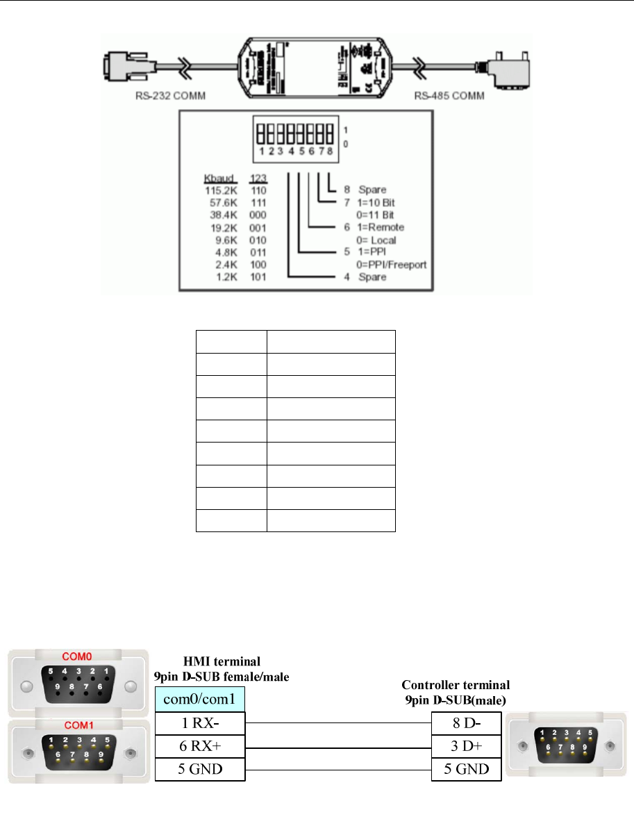
4 Communication settings and guide of HMI connecting with controller
- 356 -
PC/PPI Cable switch to select the baud rate
Baud SWITCH(1=on)
115200 110
57600 111
38400 000
19200 001
9600 010
4800 011
2400 100
1200 101
Note: The switch 5 is set to 0 , the selected item Freeport;the switch 6,7,8 is set to 0.
PC / PPI cable on the baud rate DIP switch settings, you must set the baud rate with the PLC and
PC SET PG / PC Interface match the settings , Siemens S7-200 PLC baud rate can be programmed
via STEP7-Micro/WIN software settings.
RS485 communication
SIEMENS S7-300/400 (PC Adapter Direct) protocol
RS232 communication
MT5-S7-300 PC Adapter communication cable
Need to add a communication cable in adapter RS232 terminal
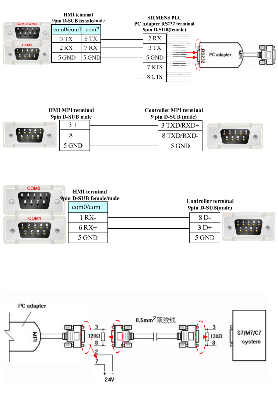
4 Communication settings and guide of HMI connecting with controller
- 357 -
SIEMENS S7-300/400 (MPI Direct) protocol
RS485 communication
SIEMENS MPI protocol
RS485-2 communication
Long distance communication with MPI adapter:
The cable length must be 600m or less in the 187.5k ,the 7 pin and 2 pin must connect with 24V power in
the port of RS485, the 8 pin and 3 pin must connect with 120Ωterminal resistance.
Ethernet communication protocol cable
Cross-connection or crossover network cable can be used as communication cable via the hub
Refer to 3.3 Download by Network Ethernet for method of making connection cable.
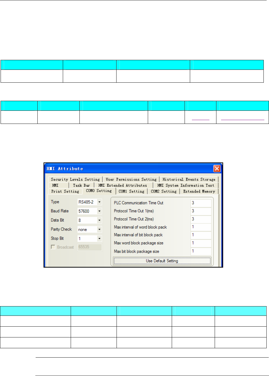
4 Communication settings and guide of HMI connecting with controller
- 358 -
4.70 SIKO AG05 SIKONETZ5
◎Serial Communication
Series CPU Link Module Driver
Siko AG05 AG05 Port on CPU unit SIKO AG05 SIKONETZ5
◎Serial System configuration
Series CPU Link Module COM Type Parameter Cable
Siko AG05 AG05 CPU Direct RS485-2 Setting Your owner cable
◎Communication Setting
HMI Setting
Default parameter:57600bps,8,none,1,station:1
PLC Setting
Please reference to controller manual.
◎Supported Device
Device Bit Address Word Address Format Notes
Parameter No. ------ ID 0-FF HH
SW ------ SW 0-0 D
CW ------ CW 0-0 D
Note Direct online simulation disable
◎Cable Diagram
RS485-2
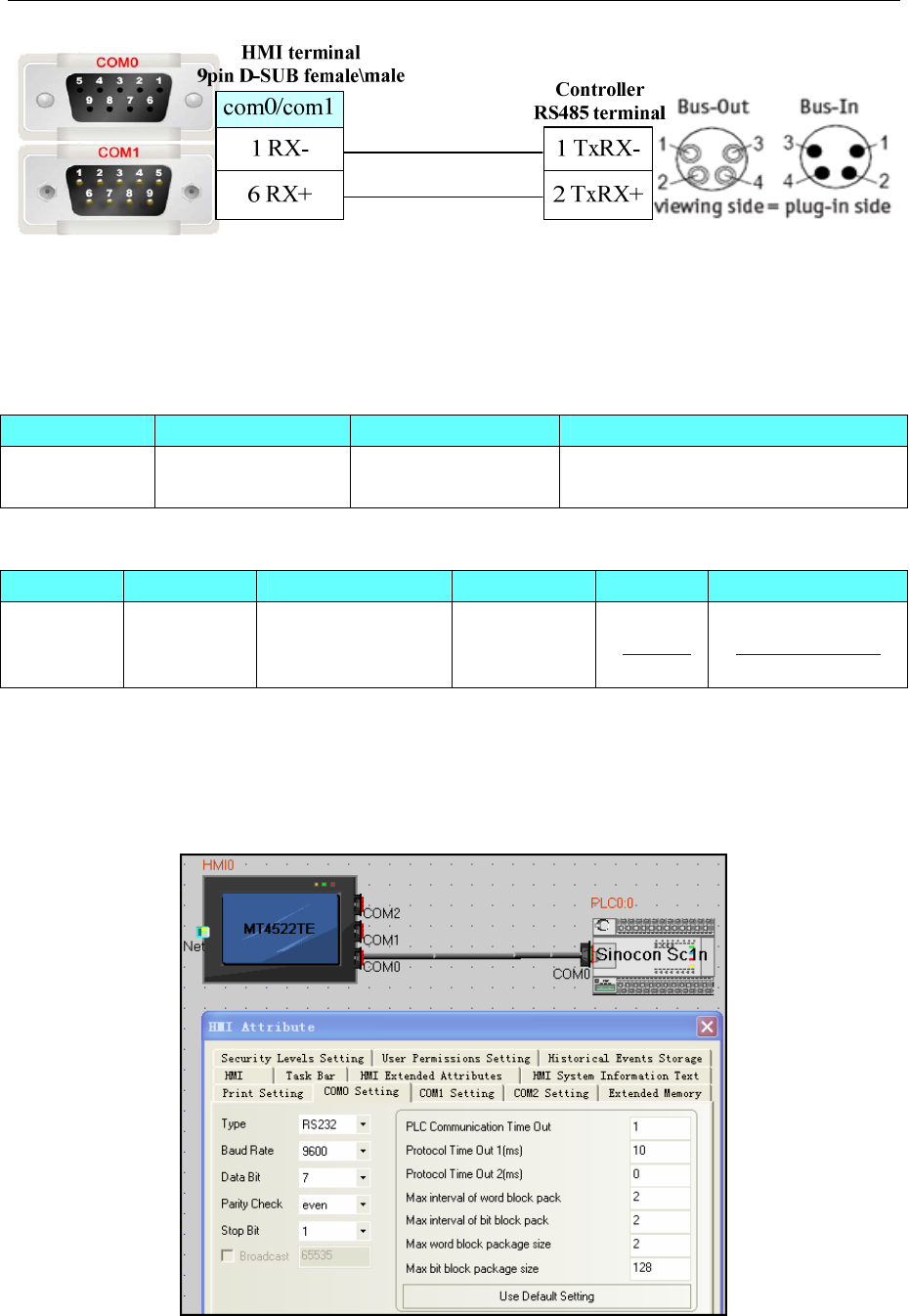
4 Communication settings and guide of HMI connecting with controller
- 359 -
4.71 Sinocon Sc1n
◎Serial Communication
◎ System configuration
Series CPU Link Module COMM Type Parameter Cable
SC1N SC1N-30T-2
AD2DA
RS232 on the CPU
unit RS232/RS485 Setting Your owner cable
◎ Communication Setting
HMI setting
Default parameter:9600bps,7,even,1,station:1
RS232
RS485
Series CPU Link Module Driver
SC1N SC1N-30T-2AD2DA
RS232 on the CPU
unit Sinocon Sc1n
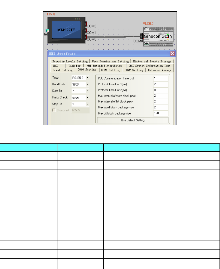
4 Communication settings and guide of HMI connecting with controller
- 360 -
◎ Supported Device
Device Bit Address Word Address Format Notes
Input Relay X 000-177 ------ OOO
Output Relay Y 000-177 ------ OOO
Data Contact D_bit 0.0-5998.F ------ DDDD.F
Internal Relay M 0000-1535 ------ DDDD
Timer Contact T 000-255 ------ DDD
Counter Contact C 000-255 ------ DDD
Special Internal Relay SM 8000-8255 ------ DDDD
State S 000-999
------ DDD
Timer Value ------ T_word 000-255 DDD
Counter Value ------ C_word 000-199 DDD
Data Register ------ D_word 0000-5998 DDDD
Special Data Register ------ SD_word 8000-8255 DDDD
Counter Value ------ C_dword 200-255 DDD 32 bit device
◎ Cable Diagram
RS232
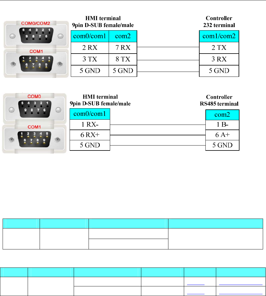
4 Communication settings and guide of HMI connecting with controller
- 361 -
RS485
4.72 TAIAN
◎Serial Communication
Series CPU Link Module Driver
RS232 on the CPU unit
Taian TOP3-30HR-A
RS485 on the CPU unit Taian
◎System configuration
Series CPU Link Module COMM Type Parameter Cable
RS232 on the CPU unit RS232 Setting Your owner cable
Taian TOP3-30HR-A
RS485 on the CPU unit RS485 Setting Your owner cable
◎Communication Setting
HMI Setting
Default communication: 19200, 8, none, 1; station: 1
RS232 communication
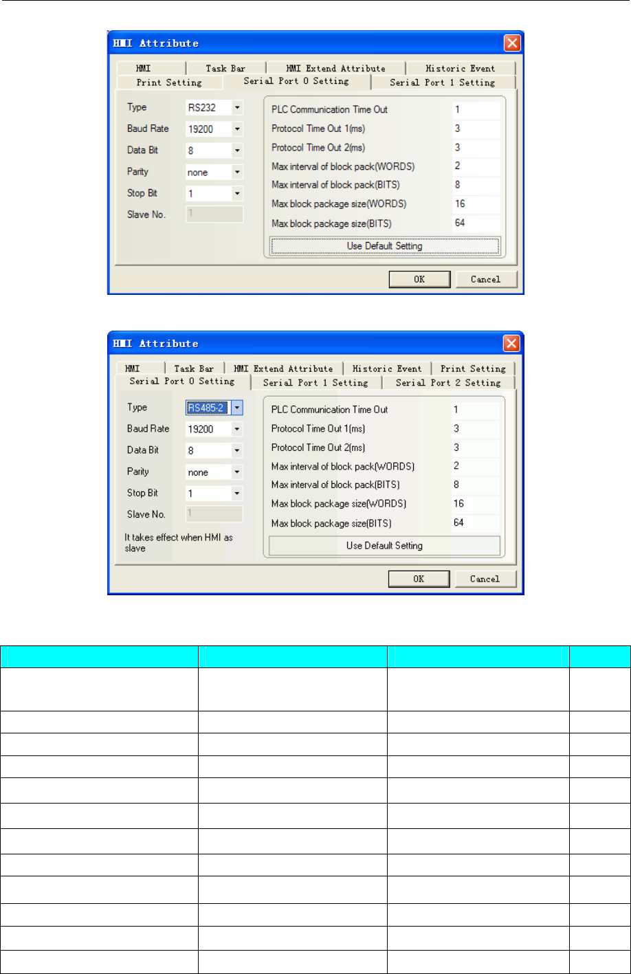
4 Communication settings and guide of HMI connecting with controller
- 362 -
RS485 communication
◎Supported Device
Device Bit Address Word Address Format
Input Relay(receive external
switch signal) X0-377 ------ OOO
Output Relay Y0-377 ------ OOO
Auxiliary Relay M(0-7679)& (8000-8511)------ DDDD
Step Relay S0-4096 ------ DDDD
Timer Relay T0-511 ------ DDD
Counter Relay C0-255 ------ DDD
Data Register ------ D0-8511 DDDD
Data Register ------ Z0-15 DD
Data Register ------ V0-15 DD
Timer(Current value) ------ T_Current_Word 0-511 DDD
Counter(Current value) ------ C_Current_Word 0-199 DDD
Counter ------ C_Current_Double 200-255 DDD
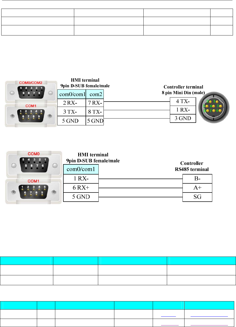
4 Communication settings and guide of HMI connecting with controller
- 363 -
Timer(Preset value) ------ T_Preset_Word 0-511 DDD
Counter(Preset value) ------ C_Preset_Word 0-199 DDD
Counter ------ C_Preset_Double 200-255 DDD
NOTE:Z, V is the turn of the write and read out. When testing a single word, max interval of word block
pack and max word block package size are changed to 1.
◎Cable Diagram
RS232 communication cable
RS485 communication cable
4.73 TMCM
◎Serial Communication
Series CPU Link Module Driver
TMCM_303 RS232 on the CPU unit TMCM_303
TMCM-6110 TMCM-6110 RS485 on the CPU unit TMCM_6110
◎System configuration
Series CPU Link Module COMM Type Parameter Cable
TMCM_303 RS232 on the CPU unit RS232 Setting Your owner cable
TMCM-6110 RS485 on the CPU unit RS485 Setting Your owner cable
◎Communication Setting
TMCM_303:
HMI Setting
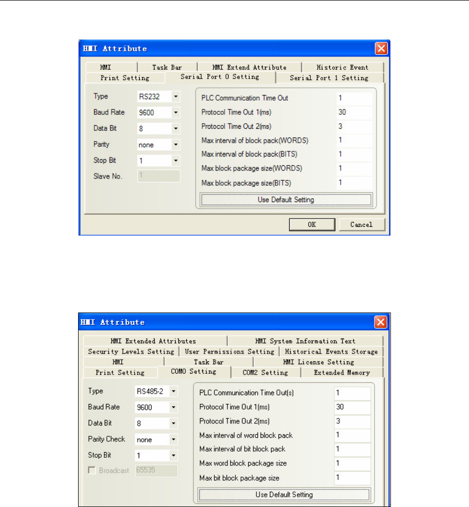
4 Communication settings and guide of HMI connecting with controller
- 364 -
Default communication: 9600, 8, none, 1; station: 1
TMCM_6110:
HMI Setting
Default communication parameters: 9600, 8, none, 1; station: 1
PLC Setting
communication parameters setting:
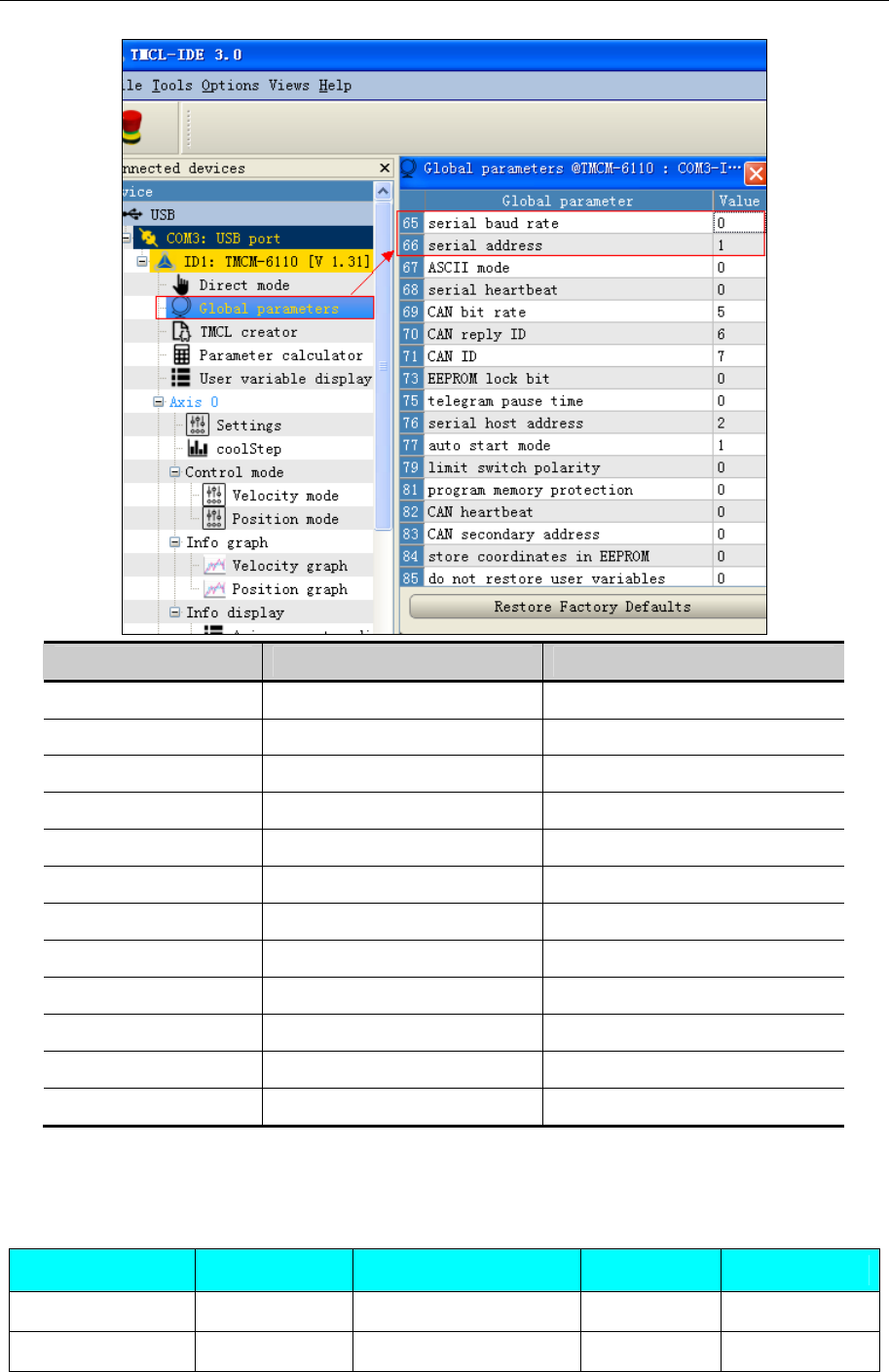
4 Communication settings and guide of HMI connecting with controller
- 365 -
Serial baud rate value Serial baud rate
0 9600 baud Default
1 14400 baud
2 19200 baud
3 28800 baud
4 38400 baud
5 57600 baud
6 76800 baud Not supported by Windows!
7 115200 baud
8 230400 baud
9 250000 baud Not supported by Windows!
10 500000 baud Not supported by Windows!
11 1000000 baud Not supported by Windows!
◎Supported Device
Please refer to TMCL Reference Manual for device details
TMCM_303
Device Bit Address Word Address Format Notes
ROR ------ 0-2 D Write Only
ROL ------ 0-2 D Write Only
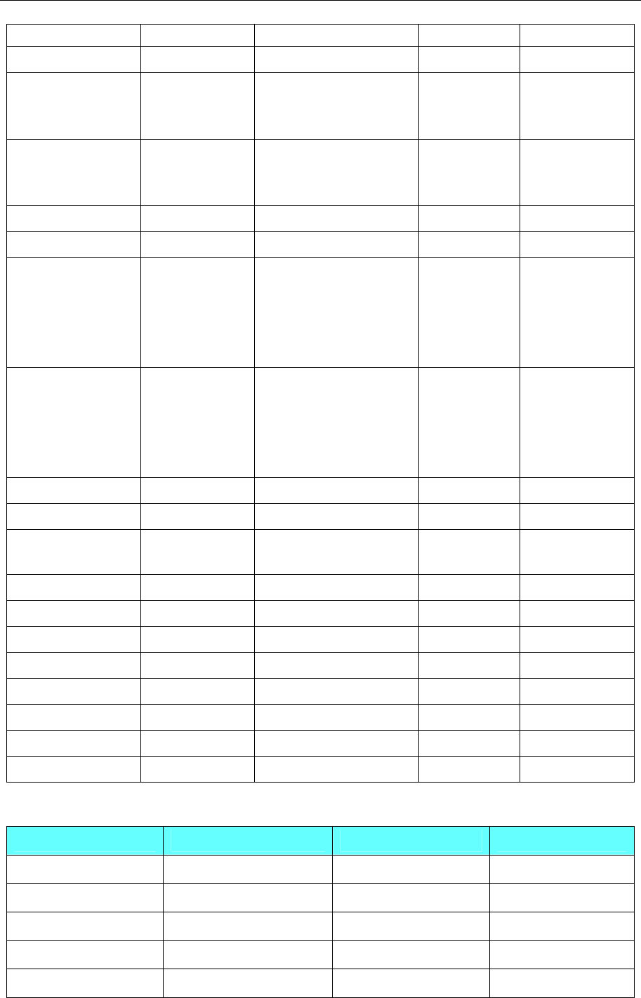
4 Communication settings and guide of HMI connecting with controller
- 366 -
MST 0-2 ------ D Write Only
MVP ------ 0.0-2.7 DD.D Write Only
SAP
0.008-0.013
1.008-1.013
2.008-2.013
0.0-2.213 DDDD.DDD Write Only
GAP
0.008-0.013
1.008-1.013
2.008-2.013
0.0-2.213 DDDD.DDD Read Only
STAP 0.0-2.213 ------ DDDD.DDD Write Only
RSAP 0.0-2.213 ------ DDDD.DDD Write Only
SGP 0.077
0.129
0.0-0.038
0.64-0.81
0.128-0.132
1.0-1.11
2.0-2.19
DDDD.DDD Write Only
GGP 0.077
0.129
0.0-0.038
0.64-0.81
0.128-0.132
1.0-1.11
2.0-2.19
DDDD.DDD Read Only
RFS ------ DWord 0.0-2.2 DD.D Write Only
SIO 0-7 ------ D Write Only
GIO 0.0-0.10
2.0-2.07 1.0-1.7 DDD.DD Read Only
CALC ------ 0-9 D Write Only
COMP ------ 0 D Write Only
JC ------ 0-9 DD Write Only
JA ------ 0 D Write Only
CSUB ------ 0 D Write Only
RSUB 0 ------ D Write Only
WAIT ------ 0.0-4.7 DD.D Write Only
STOP 0 ------ D Write Only
TMCM_6110
Device Bit Address Word Address Format
STOP 0-0 ------ D
RSUB 0-0 ------ D
SIO 0-7 ------ D
RSGP 0.000-255.255 ------ DDD.DDD
STGP 0.000-255.255 ------ DDD.DDD
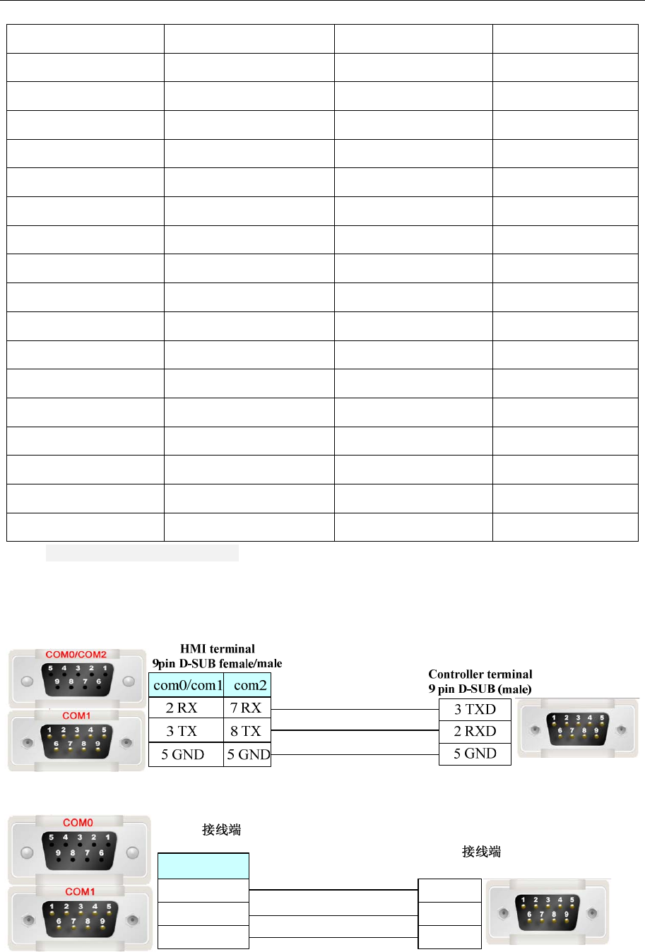
4 Communication settings and guide of HMI connecting with controller
- 367 -
RSAP 0.000-255.255 ------ DDD.DDD
STAP 0.000-255.255 ------ DDD.DDD
MST 0-5 ------ D
WAI T ------ 0.000-4.255 D.DDD
CSUB ------ 0-0 D
JA ------ 0-0 D
JC ------ 0-12 DD
COMP ------ 0-0 D
CALC ------ 0-9 D
GIO ------ 0.000-255.255 DDD.DDD
RFS ------ 0.000-2.255 D.DDD
GGP ------ 0.000-255.255 DDD.DDD
SGP ------ 0.000-255.255 DDD.DDD
GAP ------ 0.000-255.255 DDD.DDD
SAP ------ 0.000-255.255 DDD.DDD
MVP ------ 0.000-2.255 D.DDD
ROL ------ 0-5 D
ROR ------ 0-5 D
NOTE:The address format of registers is [type].[motor].c
◎Cable Diagram
RS232 Communication Cable
RS485 Communication Cable
HMI
9pin D-SUB female/male Controller
9pin D-SUB(male)
1 RX-
6 RX+
5 GND
8 D-
3 D+
5 GND
com0/com1
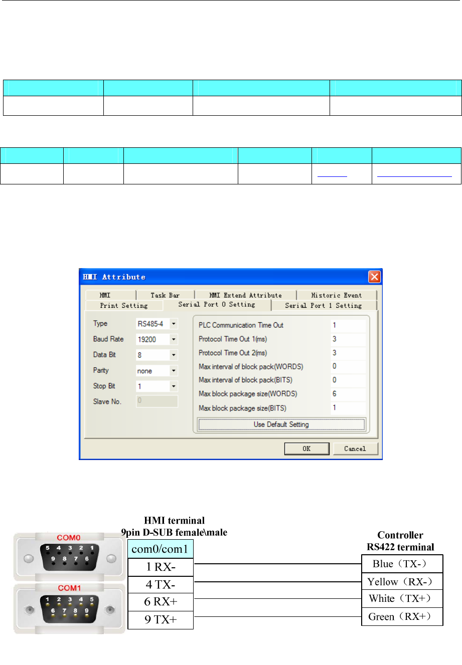
4 Communication settings and guide of HMI connecting with controller
- 368 -
4.74 Toledo DLoadCell
◎Serial Communication
Series CPU Link Module Driver
D3CellTM D3CellTM RS422 on the CPU unit DLoadCell
◎System configuration
Series CPU Link Module COMM Type Parameter Cable
D3CellTM D3CellTM RS485 on the CPU unit RS422 Setting Your owner cable
◎Supported Device
For detailed device, please refer to the PLC manual.
◎Communication Setting
◎Cable Diagram
RS485 Communication Cable
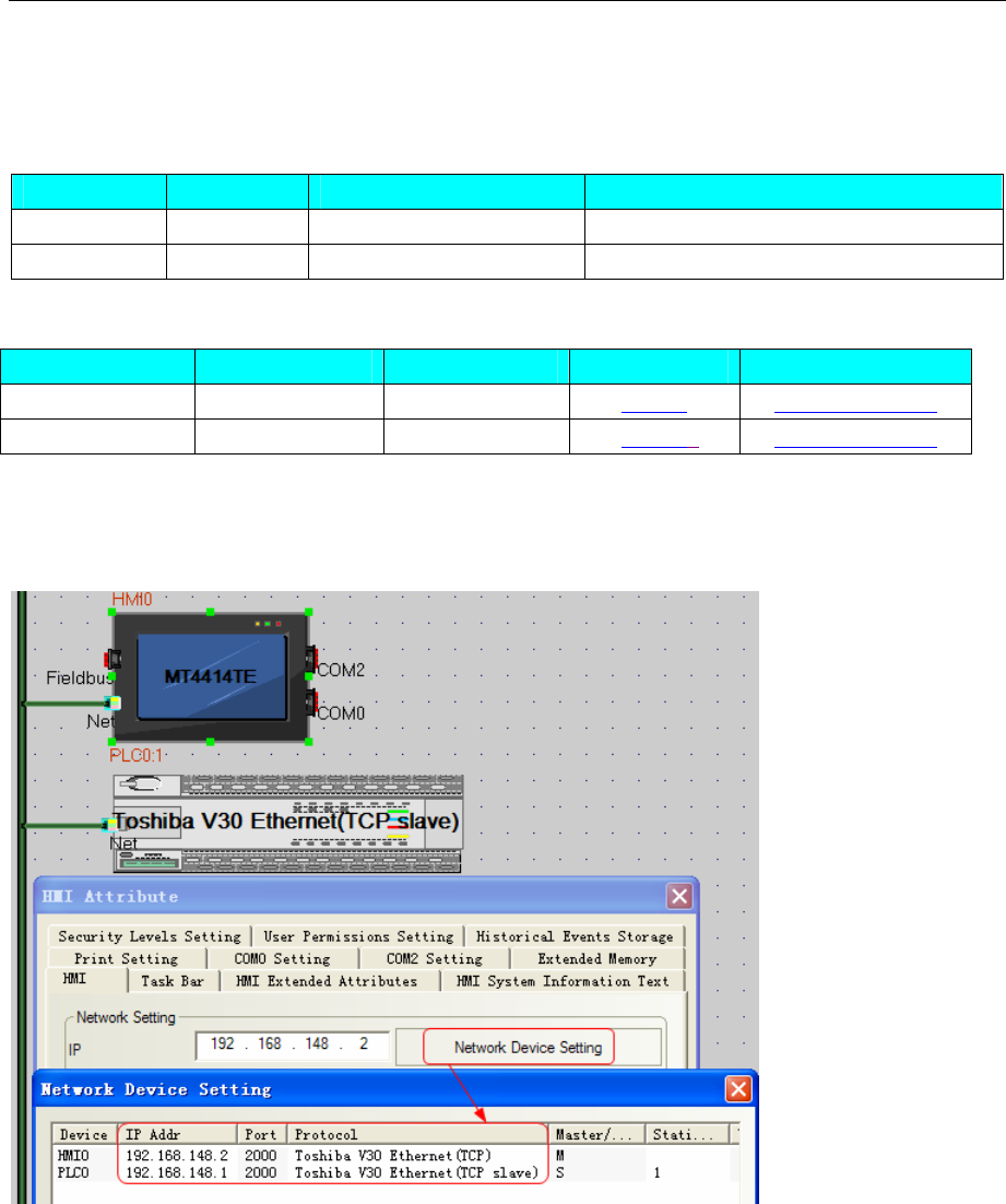
4 Communication settings and guide of HMI connecting with controller
- 369 -
4.75 Toshiba
◎Network Communication
Series CPU Link Module Driver
V30 TCXMAIN1 Ethernet interface on CPU Toshiba V30 Ethernet (TCP Slave)
V-series S2PU72A Ethernet interface on CPU Toshiba S2PU72A Ethernet(TCP Slave)
◎Network System configuration
Series CPU Connect Type Parameter Cable
ToShiBaV30 TCXMAIN1 Ethernet Setting Your owner cable
V-series S2PU72A Ethernet 6Setting Your owner cable
◎Network Communication Setting
HMI setting
TCXMAIN1:
S2PU72A:
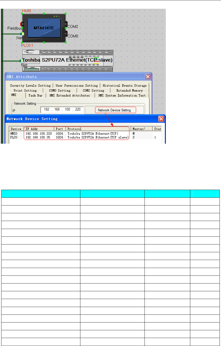
4 Communication settings and guide of HMI connecting with controller
- 370 -
PLC setting
Please refer to the communication equipment related documentation to set the parameter。
◎Supported Device
TCXMAIN1:
Device Bit Address Word Address Format
0x00000000-0x0000FFFF R00_B 0.00-FFFF.1F ------ HHHH.HH
0x01000000-0x0100FFFF R01_B 0.00-FFFF.1F ------ HHHH.HH
0x02000000-0x02000FFF R02_B 0.00-FFF.1F ------ HHH.HH
0x03000000-0x03000FFF R03_B 0.00-FFF.1F ------ HHH.HH
0x04000000-0x04000FFF R04_B 0.00-FFF.1F ------ HHH.HH
0x05000000-0x05000FFF R05_B 0.00-FFF.1F ------ HHH.HH
0x06000000-0x06000FFF R06_B 0.00-FFF.1F ------ HHH.HH
0x07000000-0x07000FFF R07_B 0.00-FFF.1F ------ HHH.HH
0x08000000-0x0800FFFF R08_B 0.00-FFFF.1F ------ HHHH.HH
0x09000000-0x09000FFF R09_B 0.00-FFF.1F ------ HHH.HH
0x0A000000-0x0A000FFF R0A_B 0.00-FFF.1F ------ HHH.HH
0x0B000000-0x0B00FFFF R0B_B 0.00-FFFF.1F ------ HHHH.HH
0x0C000000-0x0C00FFFF R0C_B 0.00-FFFF.1F ------ HHHH.HH
0x0D000000-0x0D000FFF R0D_B 0.00-FFF.1F ------ HHH.HH
0x0E000000-0x0E000FFF R0E_B 0.00-FFF.1F ------ HHH.HH
0x0F000000-0x0F000FFF R0F_B 0.00-FFF.1F ------ HHH.HH
0x10000000-0x10000FFF R10_B 0.00-FFF.1F ------ HHH.HH
0x11000000-0x11000FFF R11_B 0.00-FFF.1F ------ HHH.HH
0x12000000-0x1200FFFF R12_B 0.00-FFFF.1F ------ HHHH.HH

4 Communication settings and guide of HMI connecting with controller
- 371 -
0x13000000-0x13000FFF R13_B 0.00-FFF.1F ------ HHH.HH
0x14000000-0x14000FFF R14_B 0.00-FFF.1F ------ HHH.HH
0x15000000-0x15000FFF R15_B 0.00-FFF.1F ------ HHH.HH
0x17000000-0x17007FFF R17_B 0.00-7FFF.1F ------ HHHH.HH
0x41000000-0x4100FFFF R41_B 0.00-FFFF.1F ------ HHHH.HH
0x51000000-0x5100FFFF R51_B 0.00-FFFF.1F ------ HHHH.HH
0x52000000-0x520000FF R52_B 0.00-FF.1F ------ HH.HH
0x61000000-0x6107FFFF R61_B 0.00-7FFF.1F ------ HHHH.HH
0x62000000-0x62003FFF R62_B 0.00-3FFF.1F ------ HHHH.HH
0x63000000-0x63003FFF R63_B 0.00-3FFF.1F ------ HHHH.HH
0x64000000-0x64003FFF R64_B 0.00-3FFF.1F ------ HHHH.HH
0x65000000-0x65003FFF R65_B 0.00-3FFF.1F ------ HHHH.HH
0x66000000-0x66003FFF R66_B 0.00-3FFF.1F ------ HHHH.HH
0x67000000-0x67003FFF R67_B 0.00-3FFF.1F ------ HHHH.HH
0x68000000-0x68003FFF R68_B 0.00-3FFF.1F ------ HHHH.HH
0x69000000-0x69003FFF R69_B 0.00-3FFF.1F ------ HHHH.HH
0x6A000000-0x6A003FFF R6A_B 0.00-3FFF.1F ------
HHHH.HH
0x6B000000-0x6B003FFF R6B_B 0.00-3FFF.1F ------ HHHH.HH
0x6C000000-0x6C003FFF R6C_B 0.00-3FFF.1F ------ HHHH.HH
0x6D000000-0x6D003FFF R6D_B 0.00-3FFF.1F ------
HHHH.HH
0x6E000000-0x6E003FFF R6E_B 0.00-3FFF.1F ------ HHHH.HH
0x6F000000-0x6F000FFF R6F_B 0.00-FFF.1F ------
HHH.HH
0x00000000-0x0000FFFF ------ R00 0-FFFF
HHHH
0x01000000-0x0100FFFF ------ R01 0-FFFF
HHHH
0x02000000-0x02000FFF ------ R02 0-FFF
HHH
0x03000000-0x03000FFF ------ R03 0-FFF
HHH
0x04000000-0x04000FFF ------ R04 0-FFF
HHH
0x05000000-0x05000FFF ------ R05 0-FFF
HHH
0x06000000-0x06000FFF ------ R06 0-FFF
HHH
0x07000000-0x07000FFF ------ R07 0-FFF
HHH
0x08000000-0x0800FFFF ------ R08 0-FFFF
HHHH
0x09000000-0x09000FFF ------ R09 0-FFF
HHH
0x0A000000-0x0A000FFF ------ R0A 0-FFF
HHH
0x0B000000-0x0B00FFFF ------ R0B 0-FFFF
HHHH
0x0C000000-0x0C00FFFF ------ R0C 0-FFFF
HHHH
0x0D000000-0x0D000FFF ------ R0D 0-FFF
HHH
0x0E000000-0x0E000FFF ------ R0E 0-FFF
HHH
0x0F000000-0x0F000FFF ------ R0F 0-FFF
HHH
0x10000000-0x10000FFF ------ R10 0-FFF
HHH
0x11000000-0x11000FFF ------ R11 0-FFF
HHH
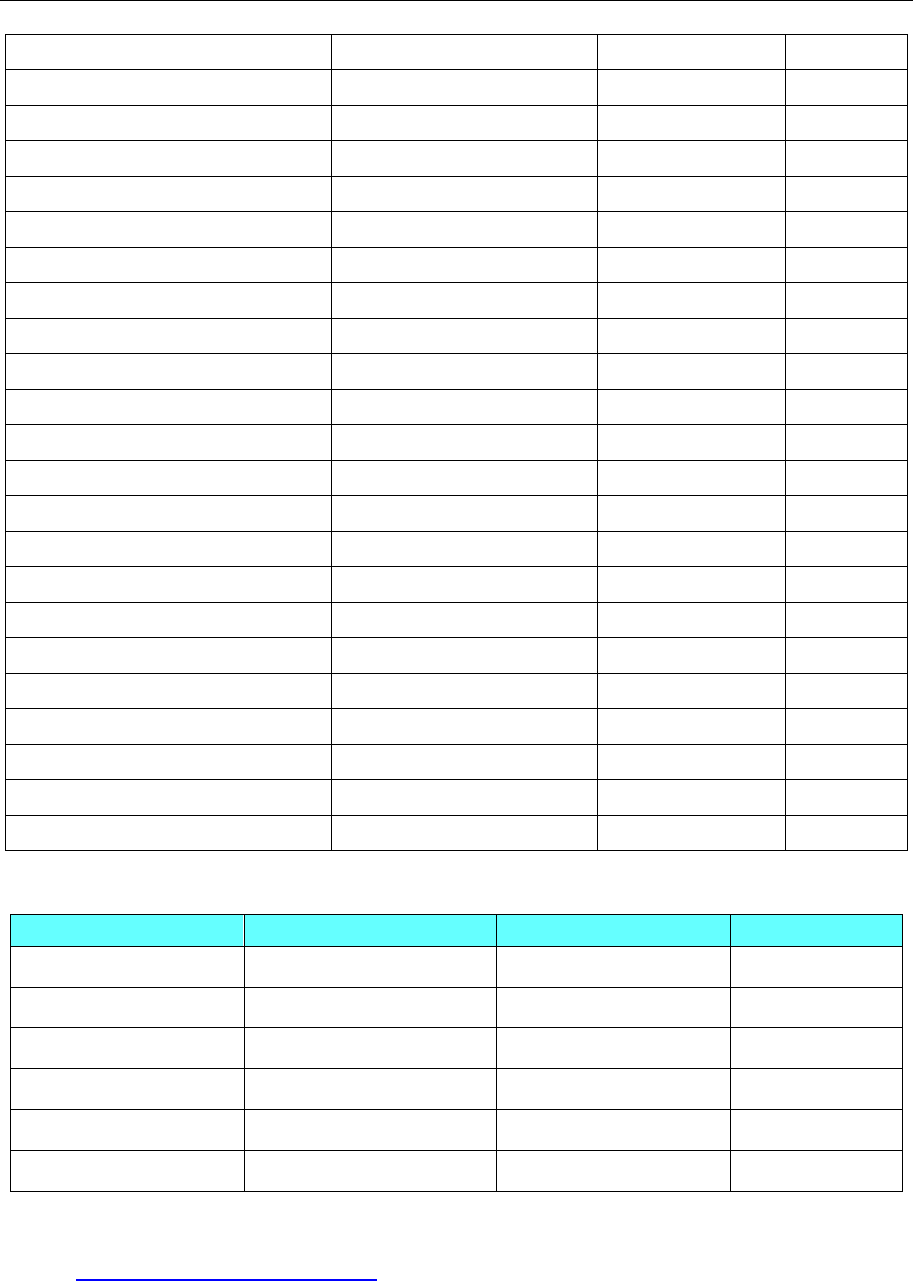
4 Communication settings and guide of HMI connecting with controller
- 372 -
0x12000000-0x1200FFFF ------ R12 0-FFFF
HHHH
0x13000000-0x13000FFF ------ R13 0-FFF
HHH
0x14000000-0x14000FFF ------ R14 0-FFF
HHH
0x15000000-0x15000FFF ------ R15 0-FFF
HHH
0x17000000-0x17007FFF ------ R17 0-7FFF
HHHH
0x41000000-0x4100FFFF ------ R41 0-FFFF
HHHH
0x51000000-0x5100FFFF ------ R51 0-FFFF
HHHH
0x52000000-0x520000FF ------ R52 0-FF
HH
0x61000000-0x6107FFFF ------ R61 0-7FFF
HHHH
0x62000000-0x62003FFF ------ R62 0-3FFF
HHHH
0x63000000-0x63003FFF ------ R63 0-3FFF
HHHH
0x64000000-0x64003FFF ------ R64 0-3FFF
HHHH
0x65000000-0x65003FFF ------ R65 0-3FFF
HHHH
0x66000000-0x66003FFF ------ R66 0-3FFF
HHHH
0x67000000-0x67003FFF ------ R67 0-3FFF
HHHH
0x68000000-0x68003FFF ------ R68 0-3FFF
HHHH
0x69000000-0x69003FFF ------ R69 0-3FFF
HHHH
0x6A000000-0x6A003FFF ------ R6A 0-3FFF
HHHH
0x6B000000-0x6B003FFF ------ R6B 0-3FFF
HHHH
0x6C000000-0x6C003FFF ------ R6C 0-3FFF
HHHH
0x6D000000-0x6D003FFF ------ R6D 0-3FFF
HHHH
0x6E000000-0x6E003FFF ------ R6E 0-3FFF
HHHH
0x6F000000-0x6F000FFF ------ R6F 0-FFF
HHH
S2PU72A:
Device Bit Address Word Address Format
XX 0.0-3071.F ------ DDDD.F
RR 0.0-4095.F ------ DDDD.F
SS 0.0-511.F ------ DDD.F
X_WORD ------ 0-3071 DDDD
R_WORD ------ 0-4095 DDDD
S_WORD ------ 0-511 DDD
◎Cable Diagram
Refer to 3.3 Download by Network Ethernet
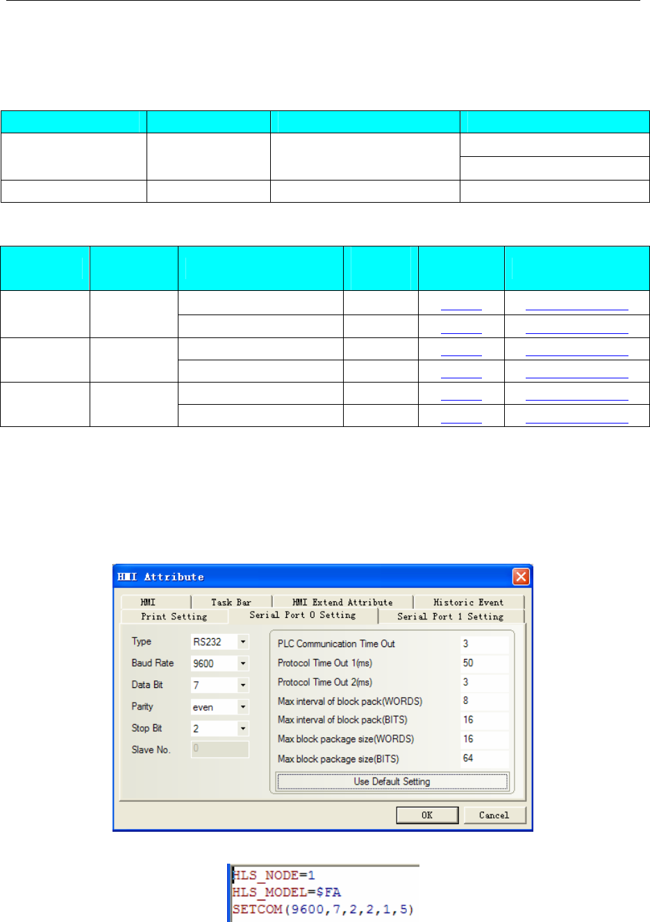
4 Communication settings and guide of HMI connecting with controller
- 373 -
4.76 Trio motion controller
◎Serial Communication
Series CPU Link Module Driver
TRIO
Euro Euro 205x RS232 on the CPU unit Modbus RTU Extend
MC MC405 RS232 on the CPU unit Trio (mode7)
◎System configuration
Series CPU Link Module COMM
Type Parameter Cable
RS232 on the CPU unit RS232 Setting Your owner cable
TRIO Euro 205x
RS485 on the CPU unit RS485-4 Setting Your owner cable
RS232 on the CPU unit RS232 Setting Your owner cable Modbus
RTU Extend Euro 205x RS485 on the CPU unit RS485-4 Setting Your owner cable
RS232 on the CPU unit RS232 Setting Your owner cable Trio
(mode7) MC405 RS485 on the CPU unit RS485-4 Setting Your owner cable
◎Communication Setting
TRIO protocol
HMI Setting
Default communication: 9600, 7, even, 2; station: 1
RS232 communication
Controller internal setting:
RS485-4 communication
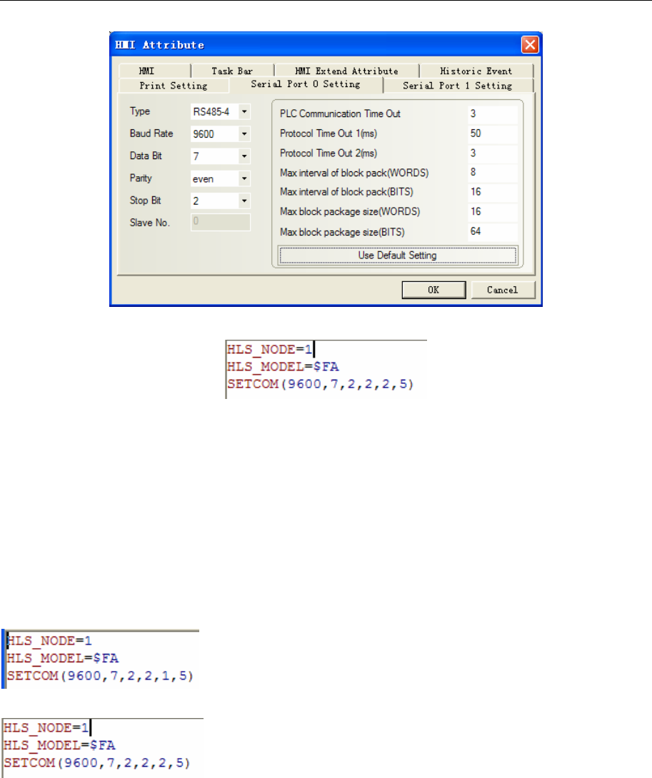
4 Communication settings and guide of HMI connecting with controller
- 374 -
Controller internal setting:
PLC Setting
Select the HOST LINK protocol in the PLC program software
1. Define HOST LINK slave node
HLS_NODE=1
2. Define HOST LINK slave model
HLS_MODEL=$FA
3. Set up HOST LINK slave for port2.
Trio controller setting: SETCOM(baudrate, databits, stopbits, parity, port, 5)
SETCOM(9600,7,2,2,2,5)
RS232 communication
RS485-4 communication
Modbus RTU Extend protocol
HMI Setting
Default communication: 9600, 8, even, 1; station: 1
RS232 communication
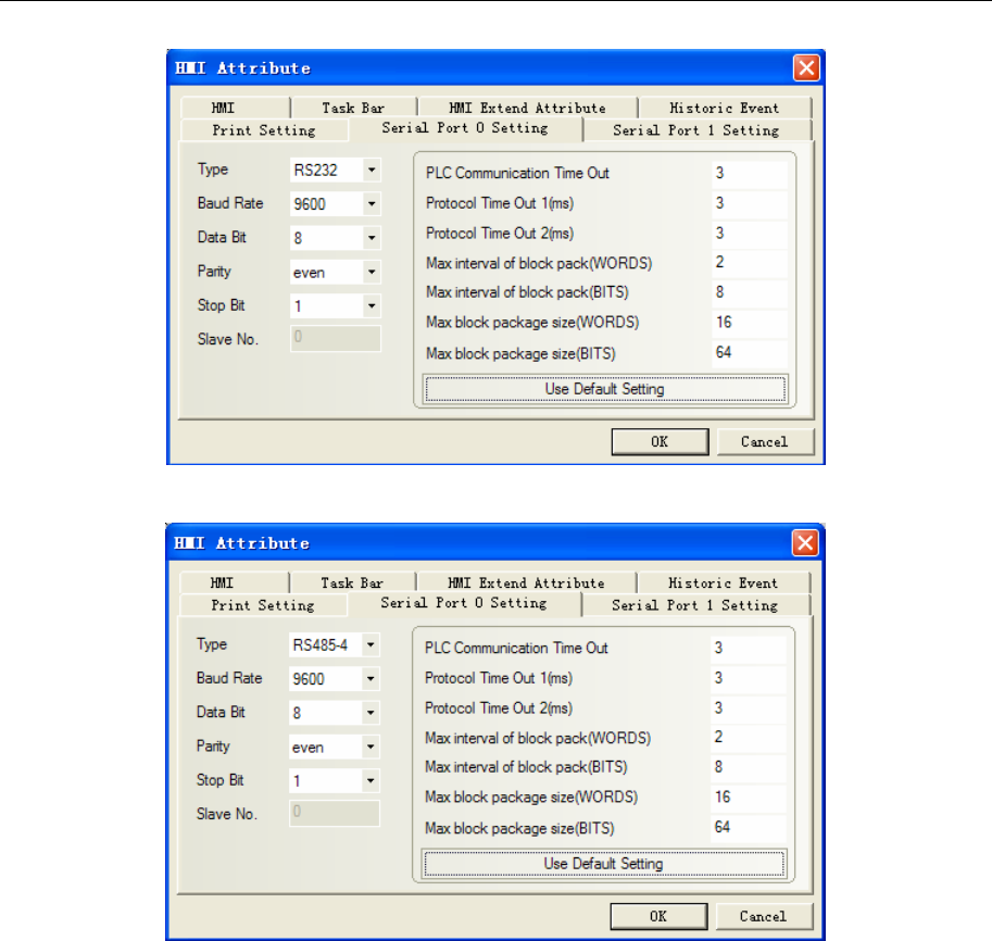
4 Communication settings and guide of HMI connecting with controller
- 375 -
RS485-4 communication
PLC Setting
Modbus Protocol:
ADDRESS=1
SETCOM(9600,8,1,2,1,4)
Trio(mode7) protocol
HMI Setting
Default communication: 9600, 8, even, 1; station: 1
RS232 communication
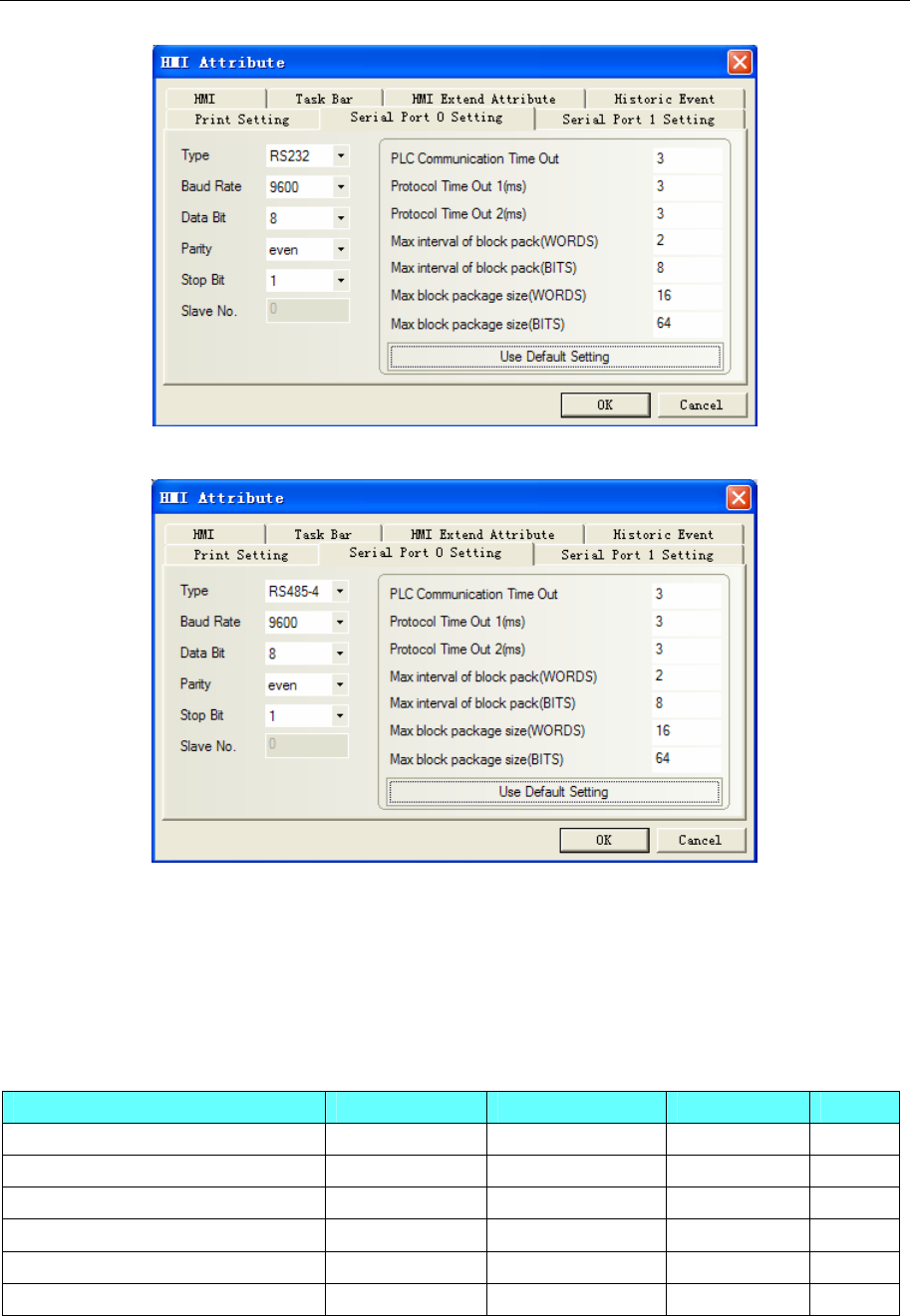
4 Communication settings and guide of HMI connecting with controller
- 376 -
RS485-4 communication
PLC Setting
Modbus Protocol:
ADDRESS=1
SETCOM(9600,8,1,2,1,7)
◎Supported Device
TRIO
Device Bit Address Word Address Format Notes
I/O and Internal Auxiliary Relay IR 0.0-4095.15 ---------- DDDD.DD
Link Relay LR 0.0-4095.15 ---------- DDDD.DD
Assistant Relay AR 0.0-4095.15 ---------- DDDD.DD
Holding Relay HR 0.0-4095.15 ---------- DDDD.DD
Data Memory ---------- DM 0-30000 DDDDD
Timer/Counter ---------- TC 0-255 DDD
NOTE:Address correspondence: IRn.m-->the m Trio VR (n); DMn->Table (n). Example IR1.02
corresponds to the 2nd bit of VR1.
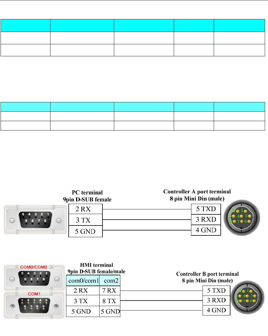
4 Communication settings and guide of HMI connecting with controller
- 377 -
Modbus RTU Extend
Device Bit Address Word Address Format Notes
Data register bit 4X_bit 0.0-1023.15 ---------- DDDD.DD
Data register ---------- 4X 0-1023 DDDDD
NOTE:Address correspondence: 4x corresponds to VR; 4x_bit corresponds to VR’s bit. Address difference
between one position, e.g. 4x (501) corresponds to VR (500); 4x_bit (67.1) corresponds to the first bit of
VR (66).
Trio (mode 7)
Device Bit Address Word Address Format Notes
VR 0-4095 DDDD
Data register ---------- Table 0-32767 DDDDD
NOTE: In this communication, users should choose data type as float.
◎Cable Diagram
NOTE: In the controller, A port is programming port, B port is communication port
Programming Cable
RS232 Communication Cable
RS422 Communication Cable
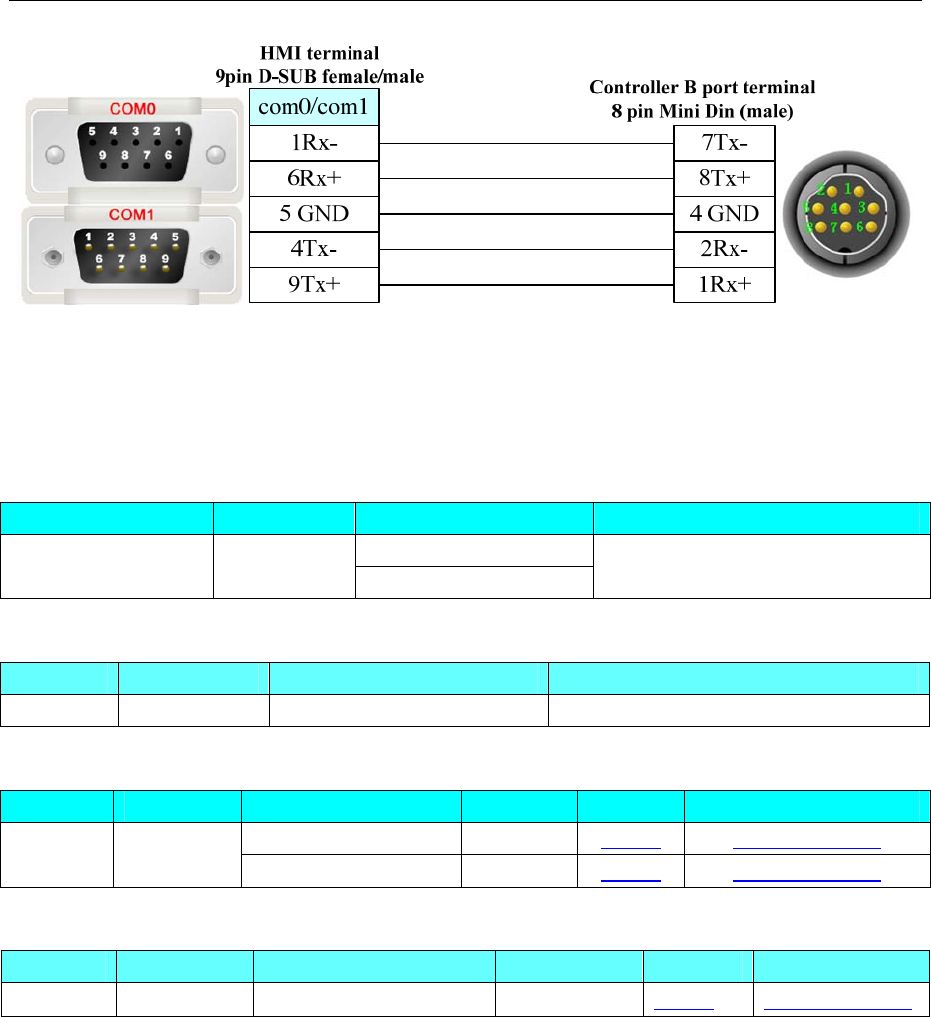
4 Communication settings and guide of HMI connecting with controller
- 378 -
4.77 Unitronics
◎Serial Communication
Series CPU Link Module Driver
RS232 on the CPU unit
Vision 130 V130-33-B1 RS485 on the CPU unit Unitronics
◎Network Communication
Series CPU Link Module Driver
Vision 130 V130-33-B1 Ethernet I/F on CPU Unit Unitronics Ethernet(TCP Slave)
◎Serial System configuration
Series CPU Link Module COM Type Parameter Cable
RS232 on the CPU unit RS232 Setting Your owner cable
Vision 130 V130-33-B1 RS485 on the CPU unit RS485-2 Setting Your owner cable
◎Network System configuration
Series CPU Link Module Connect Type Parameter Cable
Vision 130 V130-33-B1 Ethernet I/F on CPU Unit Ethernet Setting Your owner cable
◎Serial Communication Setting
HMI Setting
RS232 default communication: 57600, 8, 1, none; station: 1
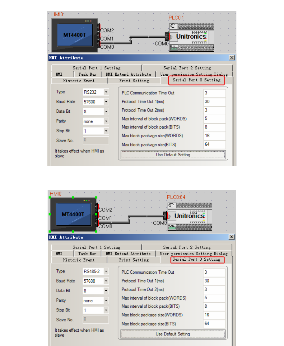
4 Communication settings and guide of HMI connecting with controller
- 379 -
RS485 default communication: 57600, 8, 1, none; station: 64
PLC Setting
1. COM Initialize in the program software by RS485 communication.
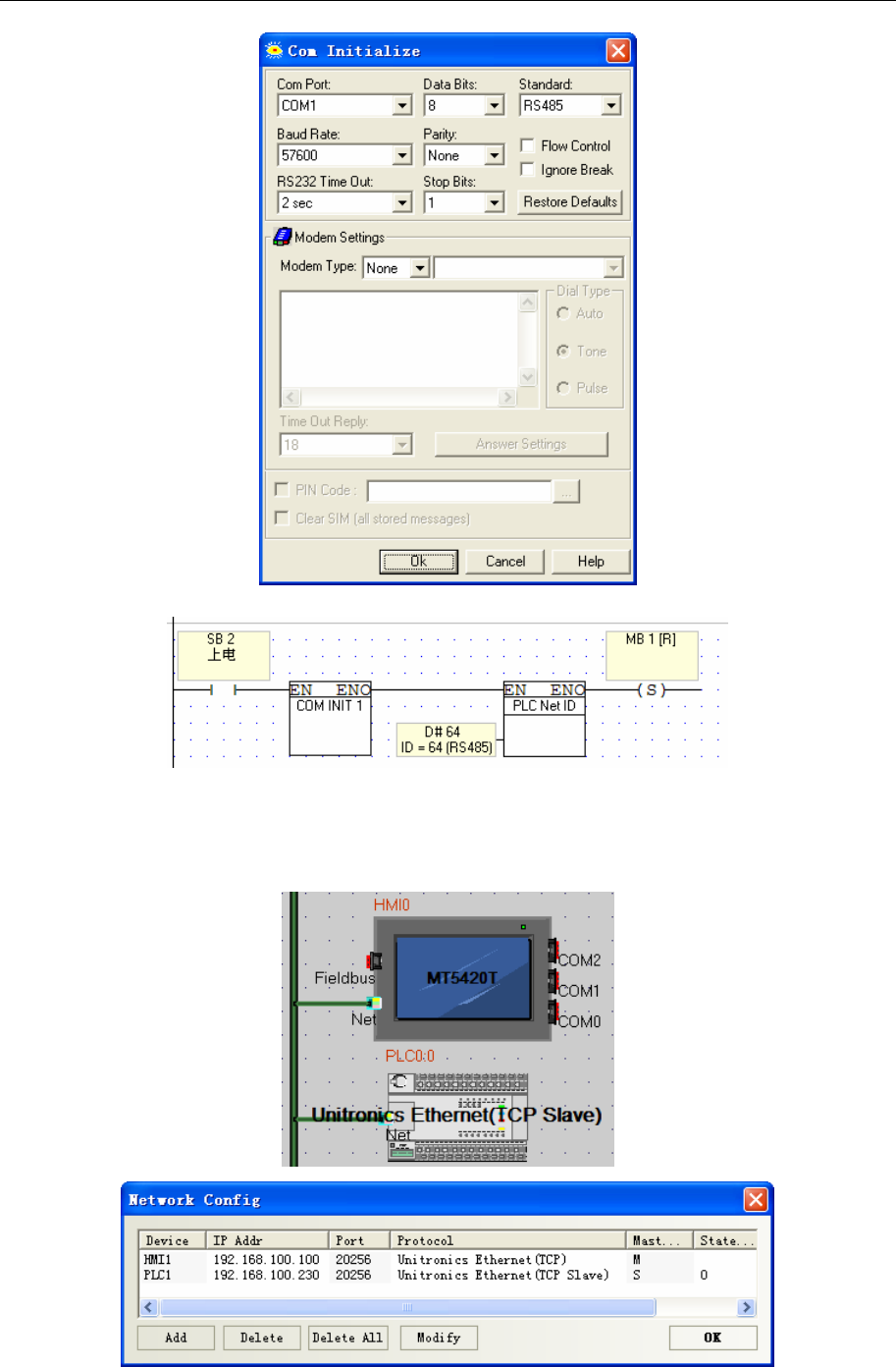
4 Communication settings and guide of HMI connecting with controller
- 380 -
2. Initialize ID, and program as below, download to controller.
3. Change the jumper position and choose RS485 communication.
◎Network Communication Setting
HMI Setting
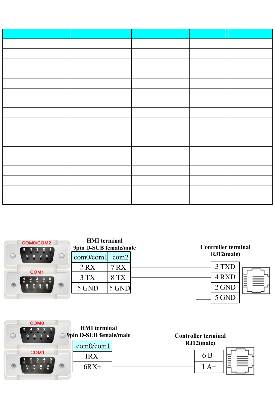
4 Communication settings and guide of HMI connecting with controller
- 381 -
◎Supported Device
Device Bit Address Word Address Format Notes
Inputs I 0~999 ------ DDD Read only
Outputs O 0~999 ------ DDD
Memory Bits MB 0~8191 ------ DDDD
System Bits SB 0~999 ------ DDD
Timers T 0~383 ------ DDD Read only
Counters C 0~31 ------ DD Read only
Memory Integer ------ MI 0~4095 DDDD
Memory Longer ------ ML 0~511 DDD
Double Word ------ DW 0~255 DDD
Memory Float ------ MF 0~63 DD
System Integer ------ SI 0~999 DDD
System Longer ------ SL 0~199 DDD
System Double Word ------ SDW 0~199 DDD
Timers Preset ------ T_C 0~383 DDD Read only
Timers Current ------ T_P 0~383 DDD Read only
Counters Preset ------ C_C 0~31 DD Read only
Counters Current ------ C_P 0~31 DD Read only
◎Cable Diagram
RS232 communication cable
RS485-2 communication cable
PLC RJ12 pins are defined as follow:
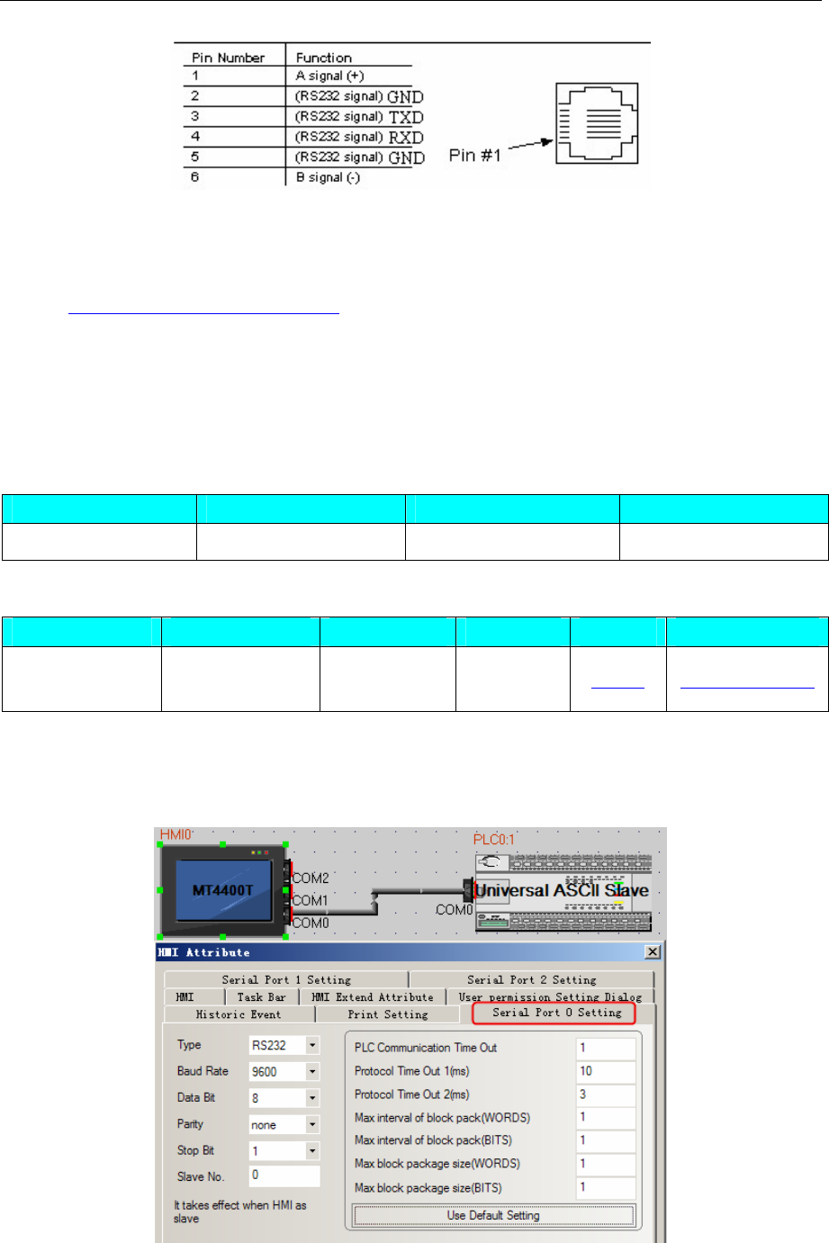
4 Communication settings and guide of HMI connecting with controller
- 382 -
Ethernet communication protocol cable
Cross-connection or crossover network cable can be used as communication cable via the hub
Refer to 3.3 Download by Network Ethernet for method of making connection cable.
4.78 Universal ASCII Slave
◎Serial Communication
Series CPU Link Module Driver
Universal ASCII Slave Universal ASCII Slave RS232 on the CPU unit Universal ASCII Slave
◎System configuration
Series CPU Link Module COM Type Parameter Cable
Universal ASCII
Slave
Universal ASCII
Slave
RS232 on the
CPU unit RS232 Setting Your owner cable
◎Communication Setting
HMI Setting
Default communication: 57600, 8, 1, none; station: 1
◎Supported Device
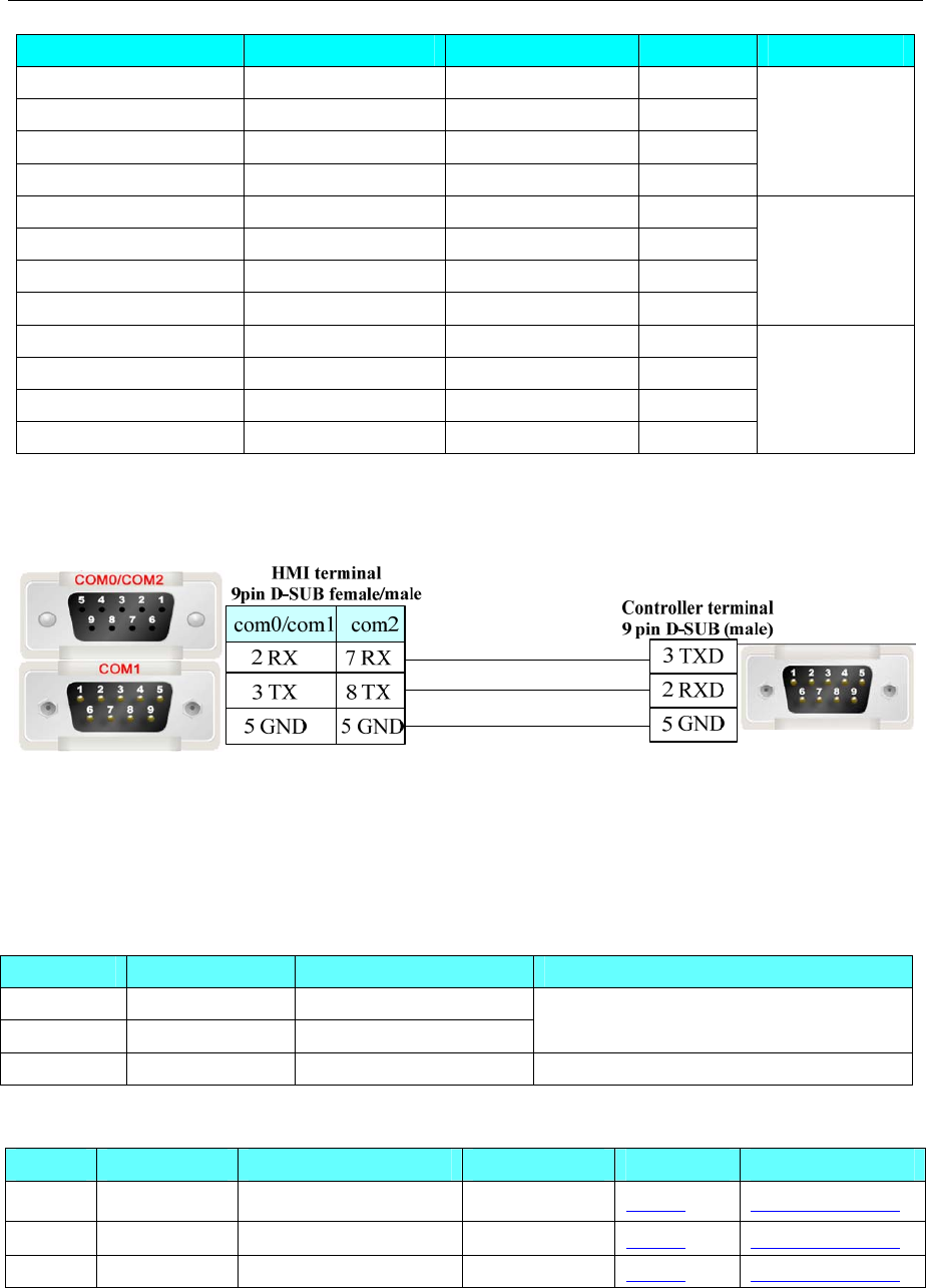
4 Communication settings and guide of HMI connecting with controller
- 383 -
Device Bit Address Word Address Format Notes
send LB 0 ------ D
clear LB1 ------ D
Send data buffer ------ LW 0~99 DD
Receive data buffer ------ LW 100~199 DDD
Correspond to
COM0
send LB2 ------ D
clear LB3 ------ D
Send data buffer ------ LW 200~299 DD
Receive data buffer ------ LW 300~399 DDD
Correspond to
COM1
send LB 4 ------ D
clear LB5 ------ D
Send data buffer ------ LW400~499 DD
Receive data buffer ------ LW 500~599 DDD
Correspond to
COM2
◎Cable Diagram
RS232 communication cable
4.79 Vigor Corporation
◎Serial Communication
Series CPU Link Module Driver
VH VH-14MR RS232 on the CPU unit
VB0 VB0-14MR RS232 on the CPU unit Vigor
VS1 VS1-10MT-D RS485 CP1 Vigor VS
◎System configuration
Series CPU Link Module COMM Type Parameter Cable
VH VH-14MR RS232 on the CPU unit RS232 Setting Your owner cable
VB0 VB0-14MR RS232 on the CPU unit RS232 Setting Your owner cable
VS1 VS1-10MT-D RS485 CP1 RS485 Setting Your owner cable
◎Communication Setting
Vigor Protocol:
Default communication: 19200, 7, even, 1; station: 0
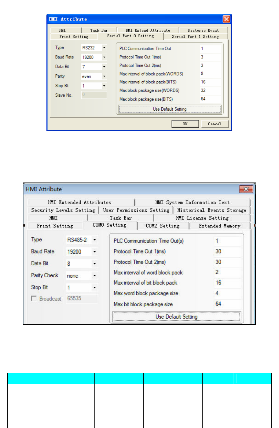
4 Communication settings and guide of HMI connecting with controller
- 384 -
NOTE:CP1* baudrate 19200bps.
*:CP1 programming port is USB(RS232).
Vigor VS Protocol:
RS485:Default parameter:19200,8,1,None;Station No:0
PLC Setting
Set the same parameters as the HMI does.
◎ Supported Device
Vigor Protocol
Device Bit Address Word Address Format Notes
In
p
ut Rela
y
X0-255 ------ OOO
Out
p
ut Rela
y
Y0-255 ------ OOO
Internal Rela
y
M0-5119 ------ DDDD
S
p
ecial Rela
y
SM 9000-9255 ------ DDDD
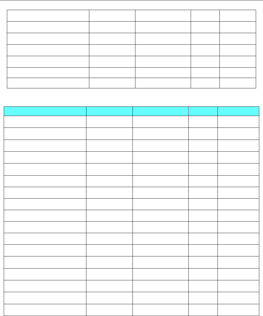
4 Communication settings and guide of HMI connecting with controller
- 385 -
Timer Relay T_bit 0-255 ------ DDD
Counter Relay C_bit 0-255 ------ DDD
Timer ------ T_word 0-255 DDD
Counter ------ C_word 0-199 DDD
Counter double word ------ C_dword 200-255 DDD
Data Re
g
iste
r
------ D0-8191 DDDD
S
p
ecial Data Re
g
iste
r
------ SD 9000-9255 DDDD
Vigor VS Protocol
Device Bit Address Word Address Format Notes
Input Relay X 0-377 ------ OOO
Output Relay Y 0-377 ------ OOO
Internal Relay M 0-8191 ------ DDDD
Special Relay SM 0-511 ------ DDD
Data Register D (bit) D_BIT 0.0-8999.F ------ DDDD.H
Data Register R (bit) R_BIT ------ DDDDD.
Step Relay S 0-4095 ------ DDDD
Timer Coil T_XQ 0-511 DDD
Timer Contact T_JD 0-511 DDD
Counter Coil C_XQ 0-255 DDD
Counter Contact C_JD 0-255 DDD
Timer ------ T_WORD 0-511 DDD
Counter ------ C_WORD 0-199 DDD
Counter(32 bit) ------ C_DWORD 200-255 DDD
Data Register D ------ D_WORD 0-8999 DDDD
Special Data Register ------ SD_WORD 0-511 DDDD
Data Register R ------ R_WORD 0-25999 DDDDD
◎Cable Diagram
VH-14MR RS232 communication cable
1. Communication via USB programming port
Connection with HMI by programming cable of Vigor
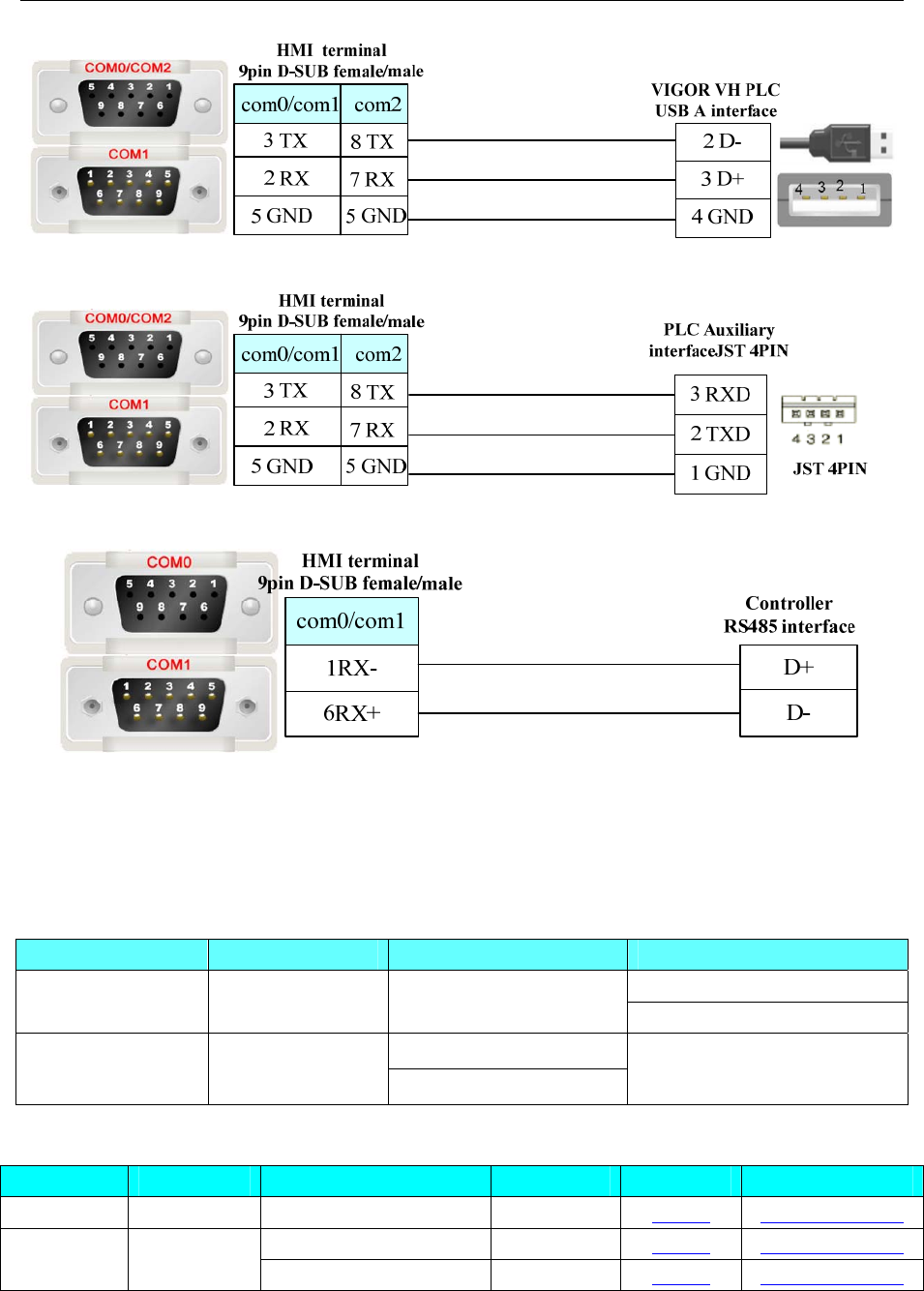
4 Communication settings and guide of HMI connecting with controller
- 386 -
2. Communication via auxiliary interface of programming device:
3.RS485-2 communication cable
4.80 XINJE Controller
◎Serial Communication
Series CPU Link Module Driver
Modbus RTU
XINJE XC XC3-32R-E RS232 on the CPU unit XINJE XC Series
RS232 on the Port 1
XINJE XDM XDM-60T10-E RS485 on the Port 2 XINJIE XDM Series
◎System configuration
Series CPU Link Module COM Type Parameter Cable
XINJE XC XC3-32R-E RS232 on the CPU unit RS232 Setting Your owner cable
RS232 on the Port 1 RS232 Setting Your owner cable XINJE
XDM
XDM-60T10
-E RS485 on the Port 2 RS485-2 Setting Your owner cable
◎Communication Setting
XINJE XC Series protocol
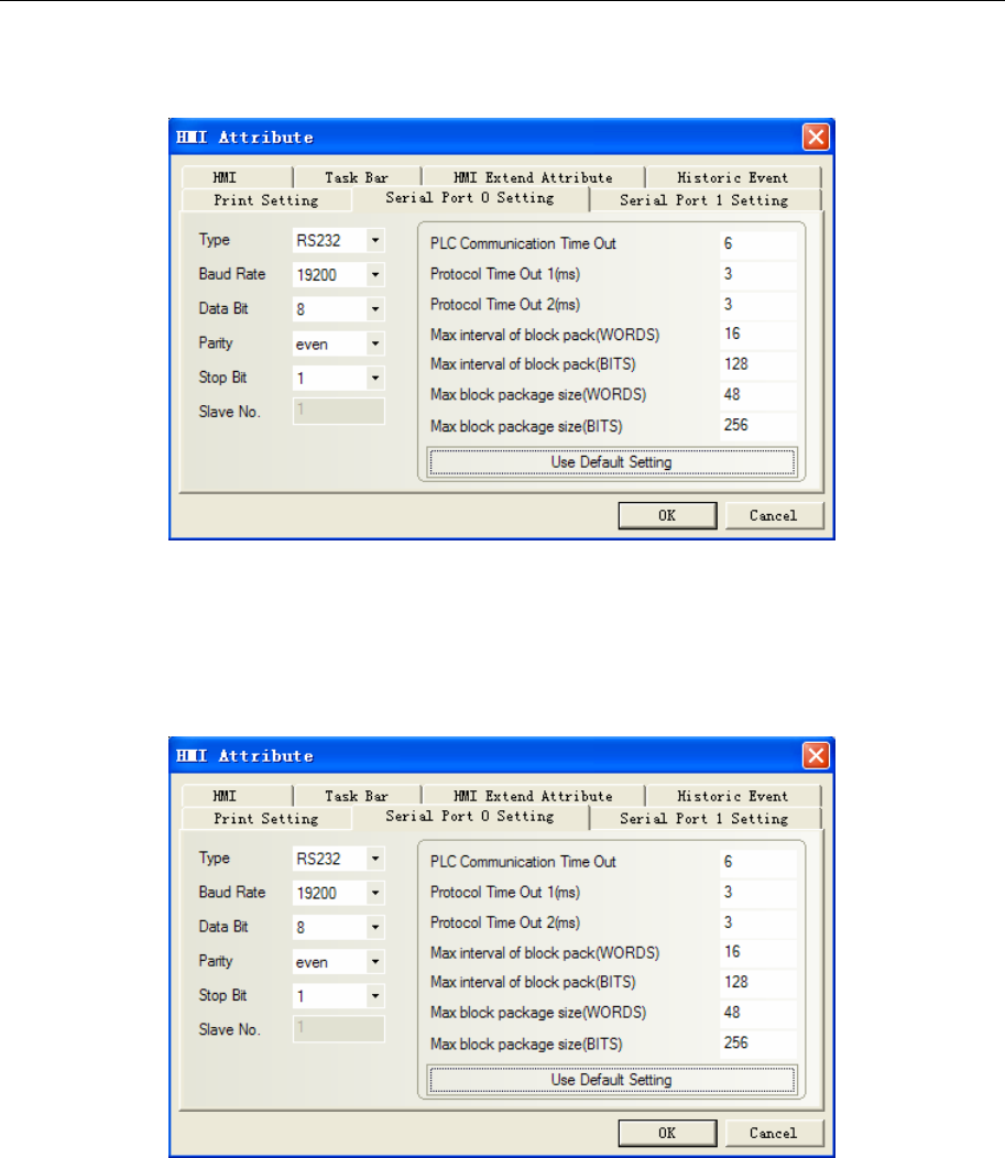
4 Communication settings and guide of HMI connecting with controller
- 387 -
HMI Setting
Default communication: 19200, 8, even, 1; station: 1
XINJE XDM Series protocol
HMI Setting
Default communication: 19200, 8, even, 1; station: 1
RS232
RS485
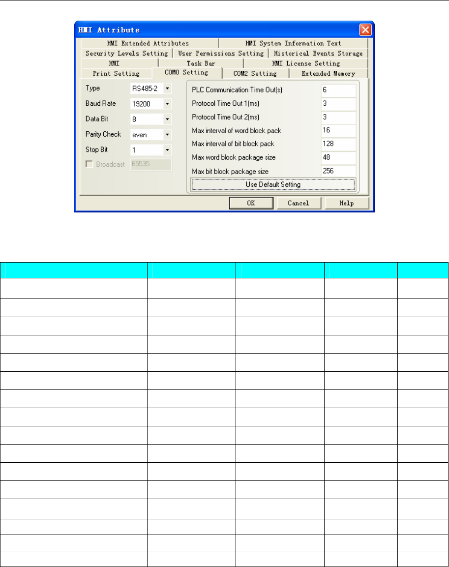
4 Communication settings and guide of HMI connecting with controller
- 388 -
◎ Supported Device
XINJE XC Series
Device Bit Address Word Address Format Notes
Internal Relay M0~M7999 ------ DDDDD
Input Relay X0.0~X51.1 ------ OOOOOO.O
Output Relay Y0.0~Y51.1 ------ OOOOOO.O
State Relay S0~S1023 ------ DDDDD
Special Relay M8000~M8511 ------ DDDDD
Timer Relay T0~T618 ------ DDDDD
Counter Relay C0~C634 ------ DDDDD
Data register ------ D0~D7999 DDDDD
Timer ------ TD0~TD618 DDDDD
Counter ------ CD0~CD634 DDDDD
Special Data Register ------ D8000~D8511 DDDDD
FlashROM Register ------ FD0~FD5000 DDDDD
Special FlashROM Register ------ FD8000~FD8511 DDDDD
Internal extend register ------ ED 0~36863 DDDDD
Input register ------ ID 0~9999 DDDD
Output Register ------ QD 0~9999 DDDD
NOTE:
1. O indicates OCT, D indicates HEX.
2. Example: X\Y address: 1 in the controller corresponds with 0.1 in the HMIWare; X\Y address: 17 in the
controller correspond with 1.7 in the HMIWare.
MODBUS RTU protocol
Register address in programmable controller correspond with address in modbus protocol, as follows:
Coil Area:
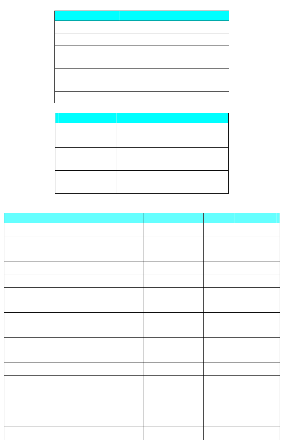
4 Communication settings and guide of HMI connecting with controller
- 389 -
bits Addr MODBUS addr(Decimal K)
M0~M7999 0X 1~0X 8000
X0~X511 0X 16385~0X 16714
Y0~Y511 0X 18433~0X 18762
S0~S1023 0X 20481~0X 21504
M8000~M8511 0X 24577~0X 25088
T0~T618 0X 25601~0X 26219
C0~C634 0X 27649~0X 28283
Register Area:
words Addr MODBUS addr(Decimal K)
D0~D7999 4X 1~4X8000
TD0~TD618 4X 12289~4X12907
CD0~CD634 4X 14337~4X 14971
D8000~D8511 4X 16385~4X 16896
FD0~FD1535 4X 18433~4X19968
FD8000~FD8511 4X 26625~4X 27136
XINJE XDM Series
Device Bit Address Word Address Format Notes
Counter HSC 0-39 ------ DD
Counter HC 0-1023 ------ DDDD
Timer task HT 0-1023 ------ DDDD
State relay HS 0-999 ------ DDD
Auxiliary relay HM 0-6143 ------ DDDD
Order function block SEM 0-127 ------ DDD
Timer task ET 0-39 ------ DD
Counter C 0-4095 ------ DDDD
Timer task T 0-4095 ------ DDDD
Auxiliary relay SM 0-4095 ------ DDDD
State relay S 0-7999 ------ DDDD
Output relay Y3 0-77 ------ OO
Output relay Y2 0-277 ------ OOO
Output relay Y1 0-1777 ------ OOOO
Output relay Y 0-77 ------ OO
Input relay X3 0-77 ------ OO
Input relay X2 0-277 ------ OOO
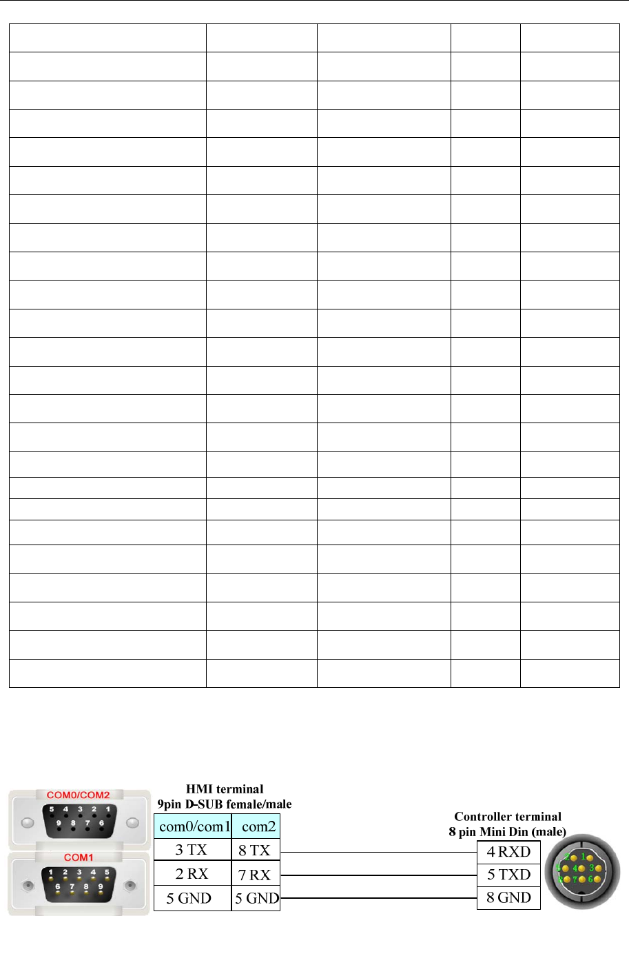
4 Communication settings and guide of HMI connecting with controller
- 390 -
Input relay X1 0-1777 ------ OOOO
Input relay X 0-77 ------ OO
Auxiliary relay M 0-20479 ------ DDDDD
Confidentiality register ------ FS 0-47 DD
Flash register ------ SFD 0-4095 DDDD
Flash register ------ FD 0-8191 DDDD
Counter ------ HSCD 0-39 DD
Counter ------ HCD 0-1023 DDDD
Timer task ------ HTD 0-1023 DDDD
Dater register ------ HSD 0-1023 DDDD
Dater register ------ HD 0-6143 DDDDD
Counter ------ ETD 0-39 DD
Timer task ------ CD 0-4095 DDDD
Timer task ------ TD 0-4095 DDDD
Dater register ------ SD 0-4095 DDDD
Functional module ------ QD3 0-99 DD
Functional module ------ QD2 0-299 DDD
Functional module ------ QD1 0-1599 DDDD
Functional module ------ QD 0-99 DD
Functional module ------ ID3 0-99 DD
Functional module ------ ID2 0-299 DDD
Functional module ------ ID1 0-1599 DDDD
Functional module ------ ID 0-99 DD
Dater register ------ D 0-20479 DDDDD
◎Cable Diagram
RS232 Communication
RS485 Communication
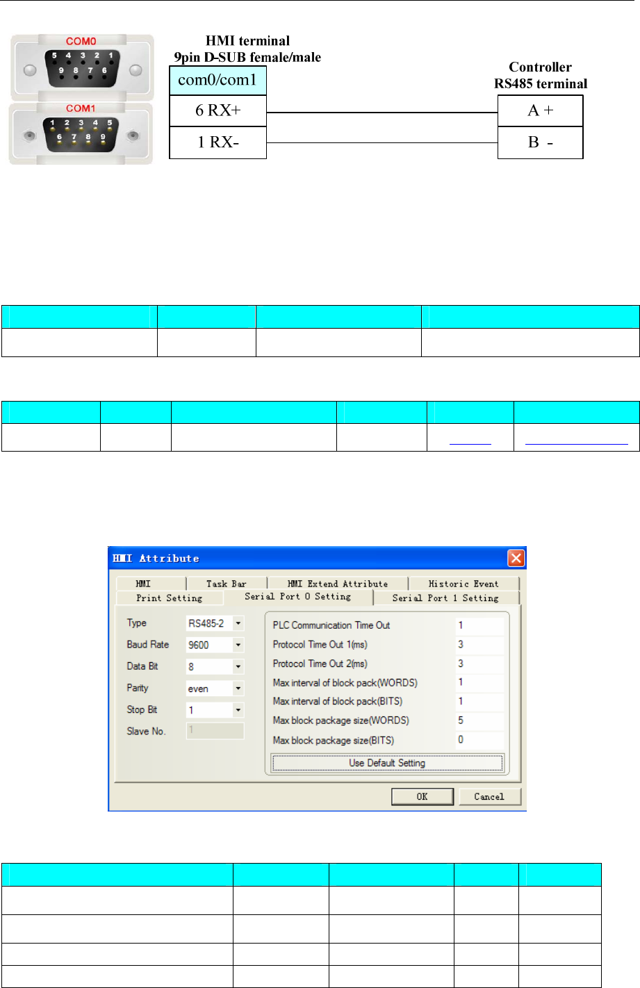
4 Communication settings and guide of HMI connecting with controller
- 391 -
4.81 XiLin Inverter
◎Serial Communication
Series CPU Link Module Driver
XiLin EH600 RS485-2 on the CPU unit XiLin EH600
◎System configuration
Series CPU Link Module COM Type Parameter Cable
XiLin EH600 RS485-2 on the CPU unit RS485-2 Setting Your owner cable
◎Communication Setting
HMI Setting
Default Communication: 9600, 8, even, 1; station: 1
◎Supported Device
Device Bit Address Word Address Format Notes
Addr communication parameter ------ Addr HHHH
A FWD ------ A 0 D
B REV ------ B 0 D
C FJOG ------ C 0 D
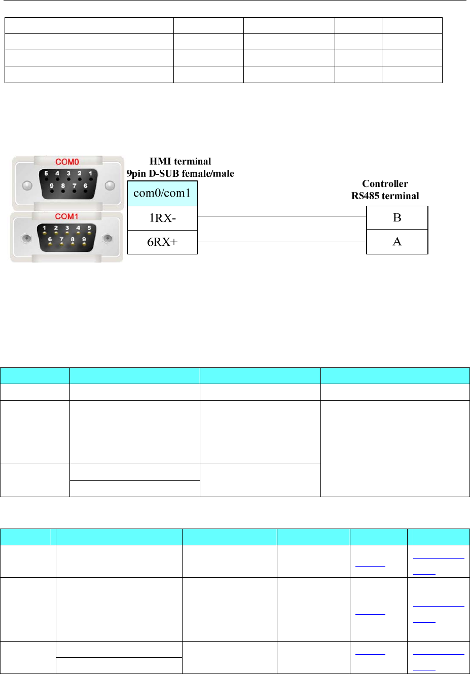
4 Communication settings and guide of HMI connecting with controller
- 392 -
D RJOG ------ D 0 D
E Free halt ------ E0 D
F Slow down ------ F 0 D
G Reset failures ------ G 0 D
PLC Setting
Please refer to XILIN frequency converter manual for details about device address.
◎Cable Diagram
4.82 Yamatake Corporation
◎Serial Communication
Series CPU Link Module Driver
DCP30 P30A2 RS485 on the CPU unit Yamatake DCP30
SDC35/36
C352
C354
C362
C364
RS485 on the CPU unit
DMC10D
DMC DMC10S RS485 on the CPU unit
Yamatake SDC/DMC
◎System configuration
Series CPU Link Module COMM Type Parameter Cable
DCP30 P30A2 RS485 on the CPU
unit RS485 Setting Your owner
cable
SDC35/36
C352
C354
C362
C364
RS485 on the CPU
unit RS485 Setting Your owner
cable
DMC10D DMC
DMC10S
RS485 on the CPU
unit
RS485 Setting Your owner
cable
◎Communication Setting
HMI Setting
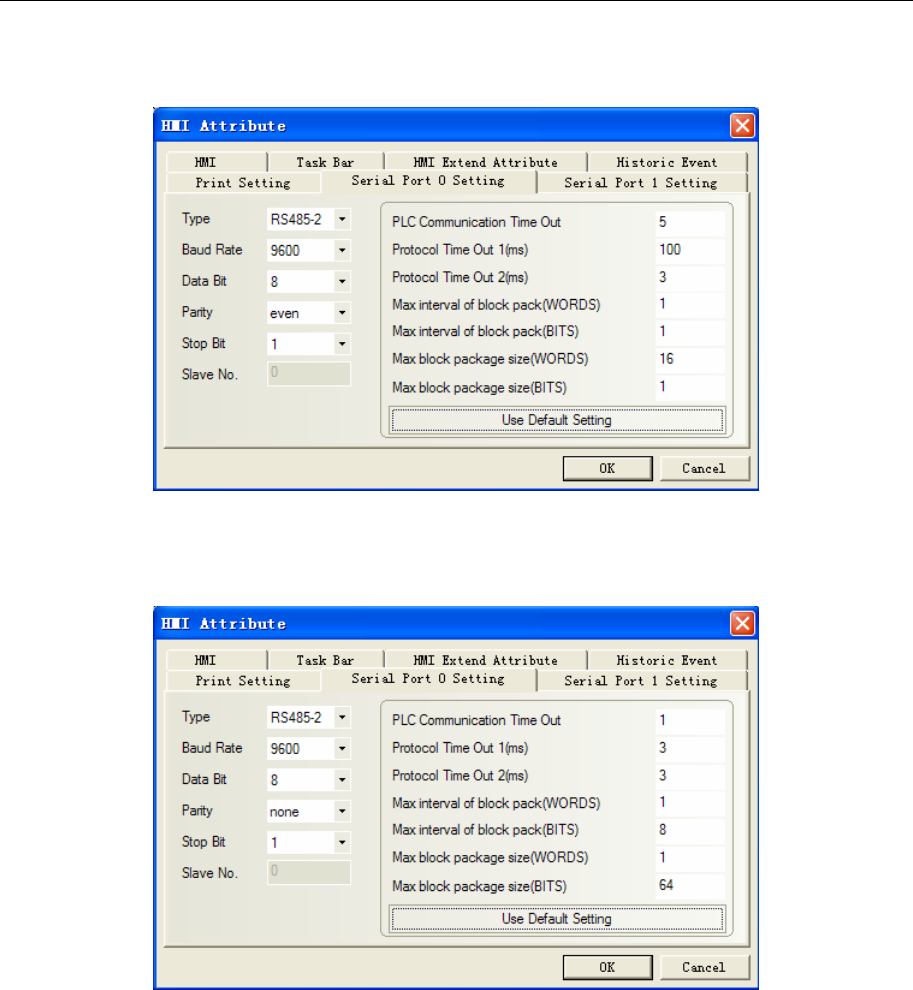
4 Communication settings and guide of HMI connecting with controller
- 393 -
Yamatake DCP30 protocol
Default communication: 9600, 8, even, 1; station: 1
Yamatake SDC/DMC protocol
SDC
Default communication: 9600, 8, none, 1; station: 1
DMC
Default communication: 19200, 8, even, 1; station: 6
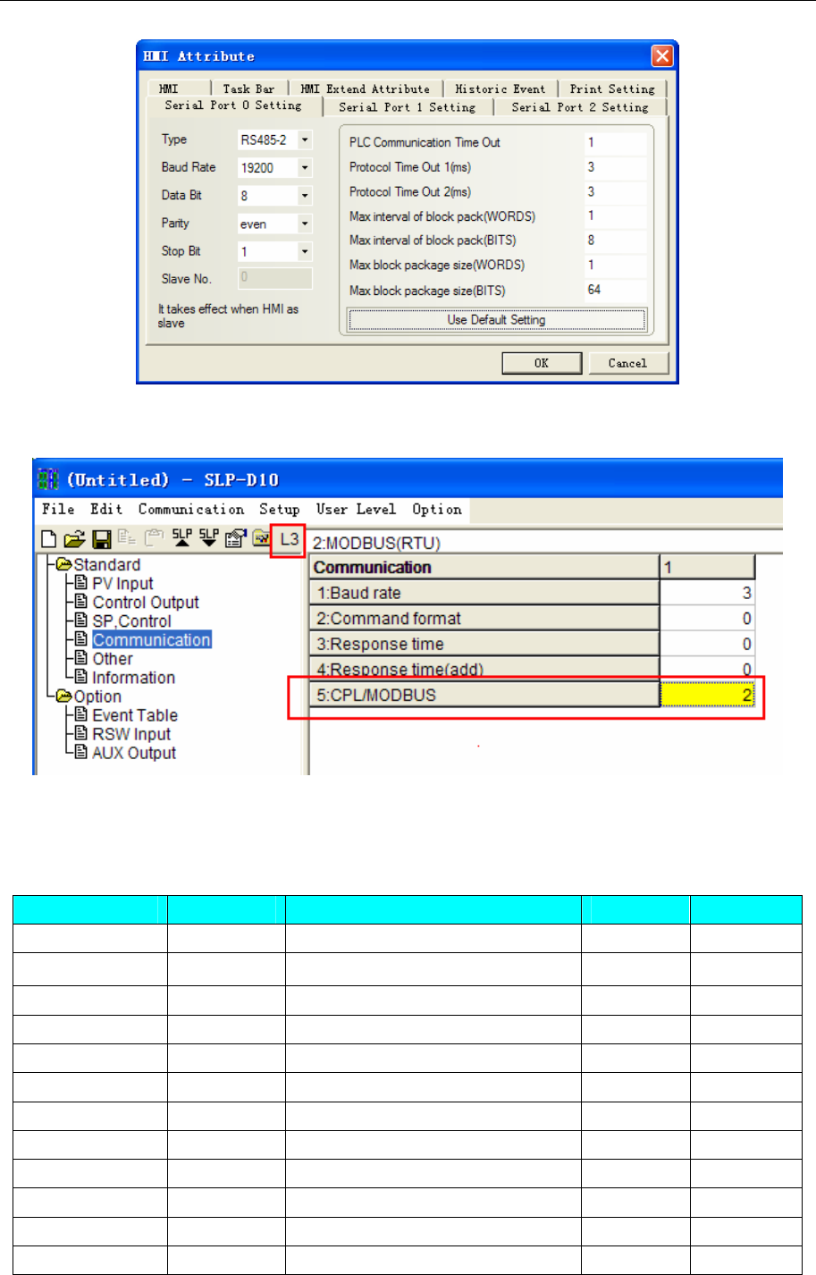
4 Communication settings and guide of HMI connecting with controller
- 394 -
PLC Setting
1. Set modbus RTU in the SLP-D10, and then download.
2. Station match with the switch on the device.
◎Supported Device
DCP30
Device Bit Address Word Address(Parameter code) Format Notes
RUN Status ------ 1-26 DDD
PARA ------ 1-33 DDD
EU ------ 1-13 DDD
PID ------ 1-80 DDD
SET ------ 1-99 DDD
TBL ------ 1-22 DDD
CNST ------ 1-26 DDD
FO_R 1-19 ------ DDD
FO_W 1-19 ------ DDD
FC 1-19 ------ DDD
FD 1-19 ------ DDD
FBR1_R ------ 1.0-30.22 DDD.DD

4 Communication settings and guide of HMI connecting with controller
- 395 -
FBR2_R ------ 1.0-30.22 DDD.DD
FBR3_R ------ 1.0-30.22 DDD.DD
FBR4_R ------ 1.0-30.22 DDD.DD
FBR5_R ------ 1.0-30.22 DDD.DD
FBR6_R ------ 1.0-30.22 DDD.DD
FBR7_R ------ 1.0-30.22 DDD.DD
FBR8_R ------ 1.0-30.22 DDD.DD
FBR9_R ------ 1.0-30.22 DDD.DD
FBR10_R ------ 1.0-30.22 DDD.DD
FBR11_R ------ 1.0-30.22 DDD.DD
FBR12_R ------ 1.0-30.22 DDD.DD
FBR13_R ------ 1.0-30.22 DDD.DD
FBR14_R ------ 1.0-30.22 DDD.DD
FBR15_R ------ 1.0-30.22 DDD.DD
FBR16_R ------ 1.0-30.22 DDD.DD
FBR17_R ------ 1.0-30.22 DDD.DD
FBR18_R ------ 1.0-30.22 DDD.DD
FBR19_R ------ 1.0-30.22 DDD.DD
Please refer to the communication protocol for details.
NOTE:
1、SET C85 ----- Transmission rate,data type
0:9600,even,stopbit 1;
1:9600,none,stopbit 2;
2:4800,even,stopbit 1;
3:4800,none,stopbit 2.
2、SET C84 -----setting station No. The value of C84 must be the same as the PLC’s station No.
When connecting multiple instruments, for distinguishing instruments, each instrument must be set
C84 value with a different parameter. .
3、Must press “FUNC+PARA” to set the parameter;
4、PROG. have 19 numbers and SEG have 30 numbers, press DOWN key (sub) and PROG key (add) to
change program number;
5、Press “FUNC+PROG” to change the program.----every program must be set firstly and then
communicate will be ok, or else “PLC Response Error” will print;
6、After “RUN/HLD” light on, many parameters can’t be modified(e.g. SET) In order to reset, press
“ PROG+RUN/HOLD” .
Modify the parameter at the state of “DISP”, not at the state of “INPUT”;
7、On the temperature controller, time parameters show number with sexagesimal.
(Example it shows 2222 on the screen, but on the controller panel shows 37.02-----37.00*60+2=2222)
8、PROG’s address setting:
FBR1_R indicates prog 1. (e.g. PROG 1) format: DDD.DD. Main address DDD indicates seg No,
subaddress DD indicates parameter value, the correspondence as follows
(Example:FBR1_R address 11.10 indicates PROG 1,SEG 1,T1 2nd )
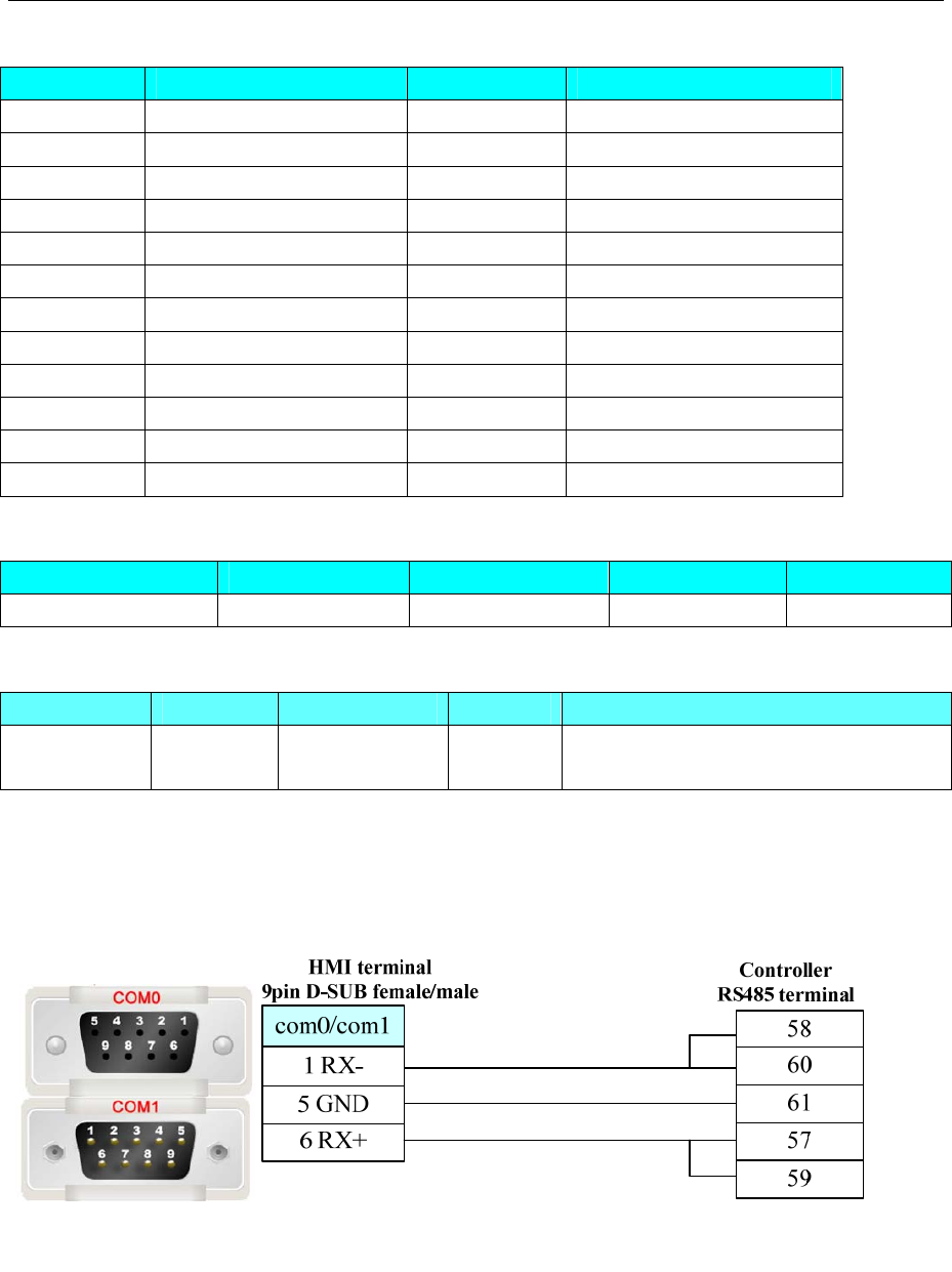
4 Communication settings and guide of HMI connecting with controller
- 396 -
Sub addr DD correspond to temperature controller:
Sub Addr Parameter Sub Addr Parameter
.0 SP .12 T2 2nd
.1 TM .13 T3 1st
.2 None(Skip) .14 T3 2nd
.3 EV1 .15 T4 1st
.4 Blank .16 T4 2nd
.5 EV2 .17 T5 1st
.6 Blank .18 T5 2nd
.7 EV3 .19 PID
.8 Blank .20 None(Skip)
.9 T1 1st .21 9.5.
.10 T1 2nd .22 9.5.to
.11 T2 1st
SDC36(Please refer to the manual of yamatake SDC36 for details)
Device Bit Address Word Address Format Notes
Data Register ———— 4X 0-65535 DDDDD
DMC(Please refer to the manual of DMC-SPL for details, in 10-8 communication parameters)
Device Bit Address Word Address Format Notes
Data Register ———— 4X 1002-65535 DDDDD Address add 1 to the list of
communication parameters
Example: CH1 PV is according to 4X1005 in the HMIWare.
◎Cable Diagram
DCP 30 series
RS485 communication cable
RS232 communication cable
Need to use RS-232 to RS-422/485 converter
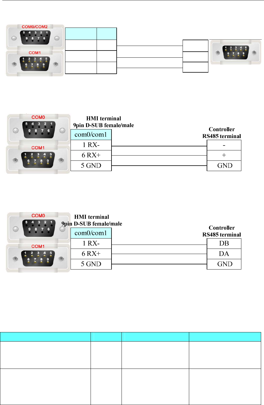
4 Communication settings and guide of HMI connecting with controller
- 397 -
Commutator terminal
9 pin D-SUB male
2 TX
3 RX
5 GND
com2
3 TX
2 RX
5 GND
8 TX
7 RX
5 GND
com0/com1
HMI terminal
9pin D-SUB female/male
SDC36 series
RS485 communication cable
DMC series
RS485 communication cable
4.83 Yaskawa Electric Corporation
◎Serial Communication
Series CPU Link Module Driver
V(Inverter)
CIMR-JT
2A0001B
AA
RS485 on the CPU unit Yaskawa AH Modbus RTU
MP(Motion Controller)
MP2200
MP2300
MP2310
MP2300S
RS232 on the CPU unit Yaskawa MP2300
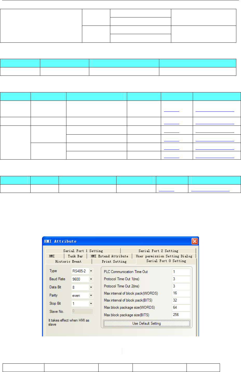
4 Communication settings and guide of HMI connecting with controller
- 398 -
RS232 on the CPU unit
SGDM RS422 on the CPU unit Yaskawa SGDM
RS232 on the CPU unit
∑/∑ PlusⅡⅡ (Servo Controller)
SGDV RS422 on the CPU unit Yaskawa SGDV
◎Network communication (support indirect online and direct online)
Series CPU Link Module Driver
MP series MP2400 ETH on the CPU unit Yaskawa Ethernet(UDP Slave)
◎Serial System configuration
Series CPU Link Module COM Type Parameter Cable
V CIMR-JT2A
0001BAA RS485 on the CPU unit RS485-2 Setting Your owner cable
MP MP2300 RS232 on the CPU unit RS232 Setting Your owner cable
RS232 on the CPU unit RS232 Setting Your owner cable
SGDM RS422 on the CPU unit RS485-4 Setting Your owner cable
RS232 on the CPU unit RS232 Setting Your owner cable
∑Ⅱ/∑Ⅱ
Plus SGDV RS422 on the CPU unit RS485-4 Setting Your owner cable
◎Network System configuration
Series CPU Link Module COMM Type Parameter Cable
MP series MP2400 ETH on the CPU unit ETH Setting Your owner cable
◎Serial Communication Setting
HMI Setting
Yaskawa AH Modbus RTU protocol
Default communication: 9600, 8, even, 1; station: 1
PLC Setting
20.0 change the inverter panel button ”up” or “down”, adjustment to the parameter mode
21.0 then adjust to H5-01 by the button ”up” or “down”,according to the required parameter set
No. Name Scope Parameter description Setting
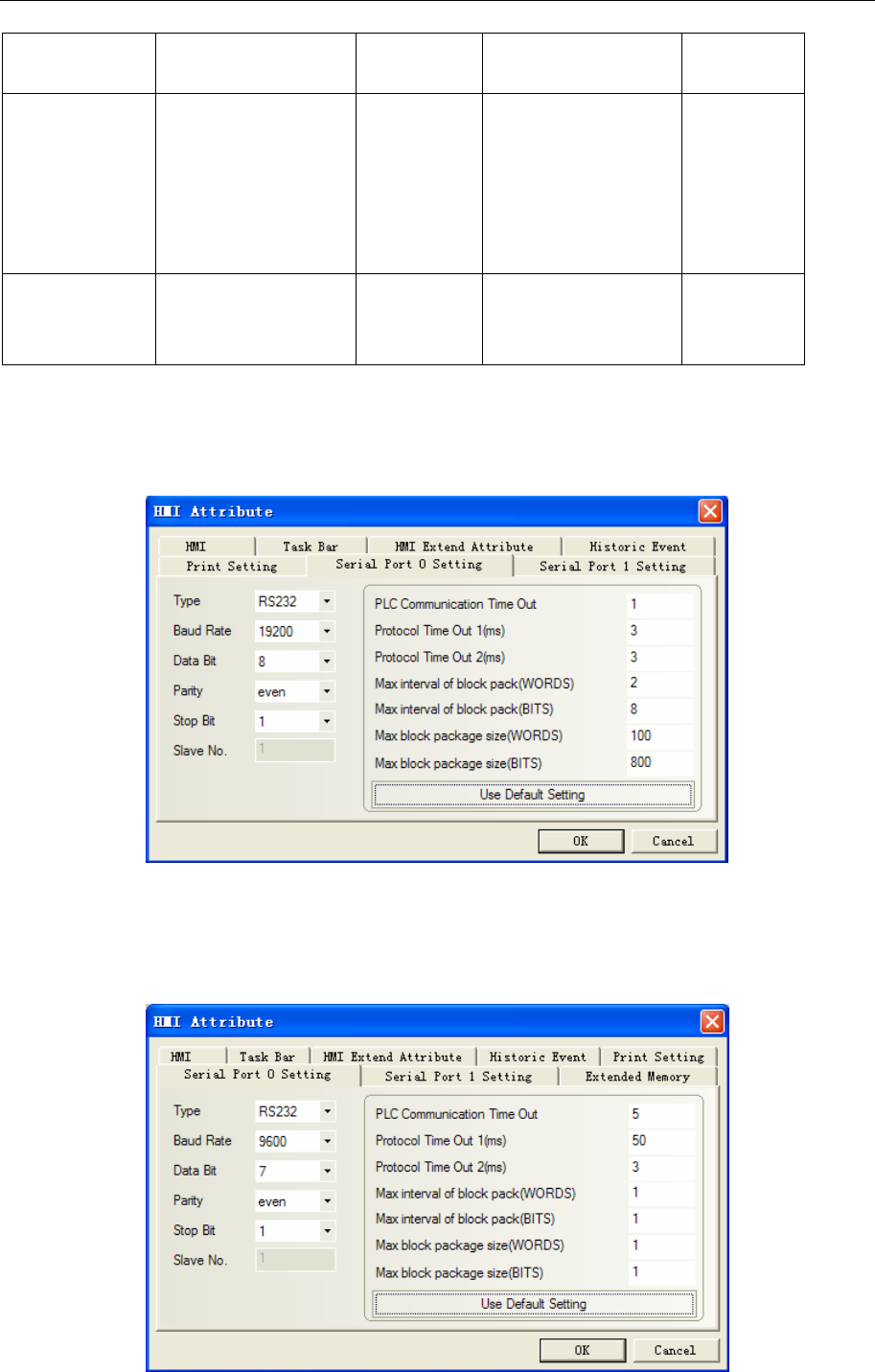
4 Communication settings and guide of HMI connecting with controller
- 399 -
H5-01 Secondary station
address
0~FFH Secondary station
number
1F
H5-02 The choice of the
communication speed
0~5 0:1200bps
1:2400bps
2:4800bps
3:9600bps
4:19200bps
5:38400bps
3
H5-03 The choice of the
communication check
0~2 0:no check
1:even check
2:odd check
0
NOTE: the inverter should be restarted to be effective。
Yaskawa MP2300 protocol
Default communication: 19200, 8, even, 1; station: 1
Yaskawa SGDM protocol
Default communication: 9600, 7, even, 1; station: 0
RS232 communication
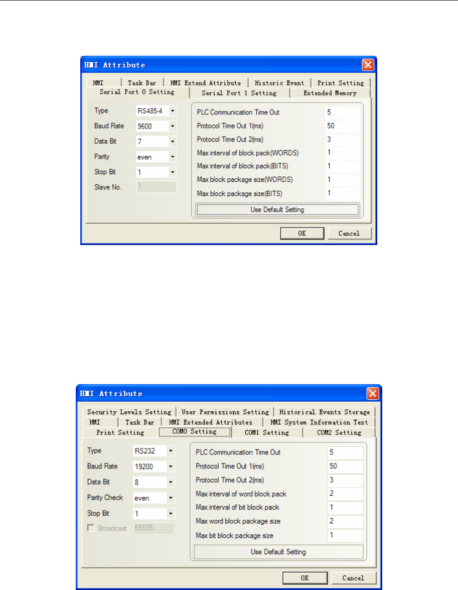
4 Communication settings and guide of HMI connecting with controller
- 400 -
RS485-4 communication
PLC Setting
Related parameters Settings refer to the communication equipment description。
Yaskawa SGDV protocol
RS232 communication
HMI Setting
Default communication: 19200, 8, even, 1; station: 0
NOTE:Set max word block package size as 2
RS485-4 communication
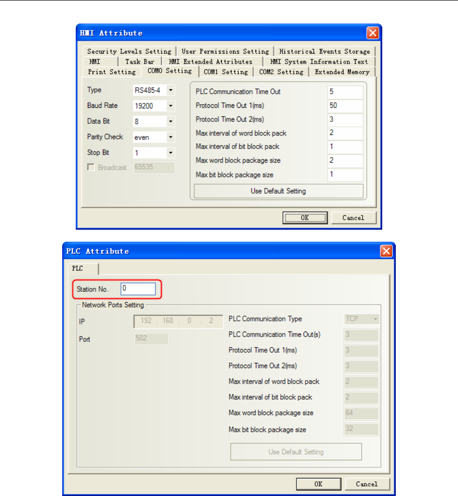
4 Communication settings and guide of HMI connecting with controller
- 401 -
NOTE: Station No. is a decimal number corresponding to axis address of servo controller.
PLC Setting
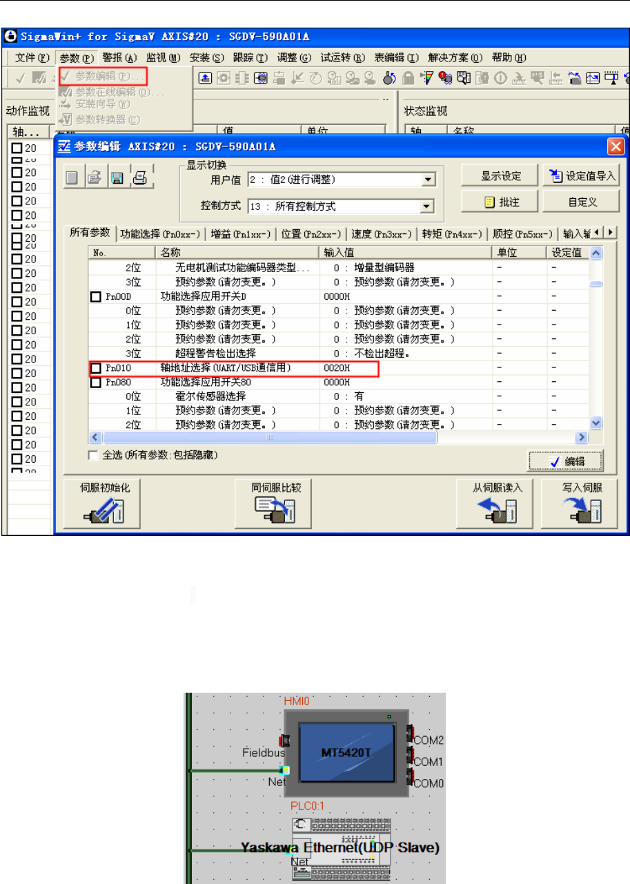
4 Communication settings and guide of HMI connecting with controller
- 402 -
NOTE:
1. axis address 0020H is the station number of PLC,here is hexadecimal,HMI is the decimal system;
2.if you change the axis address, Parameters will be displayed unless you restart
◎Network Communication Setting
Yaskawa Ethernet(UDP Slave) protocol
HMI Setting
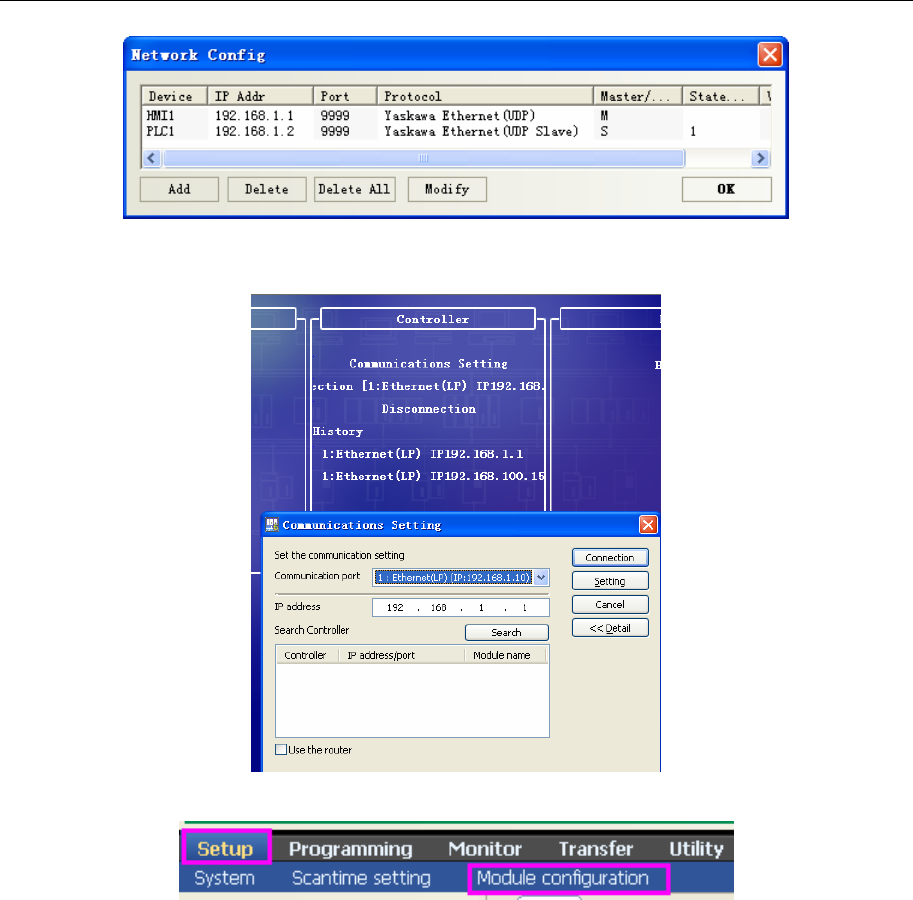
4 Communication settings and guide of HMI connecting with controller
- 403 -
PLC Setting
1. Set the IP,connect with the MPE720 software
2. How to set the IP
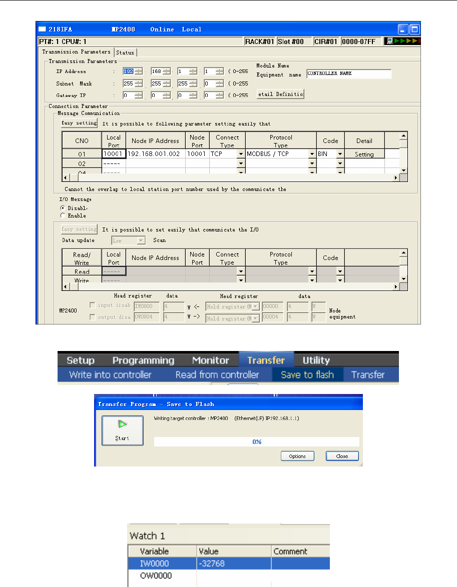
4 Communication settings and guide of HMI connecting with controller
- 404 -
Change, save, and save to flash:
Restart the controller and the set is ok.
If online, then you can monitoring the data:
Monitor single data:
Monitor the Register:
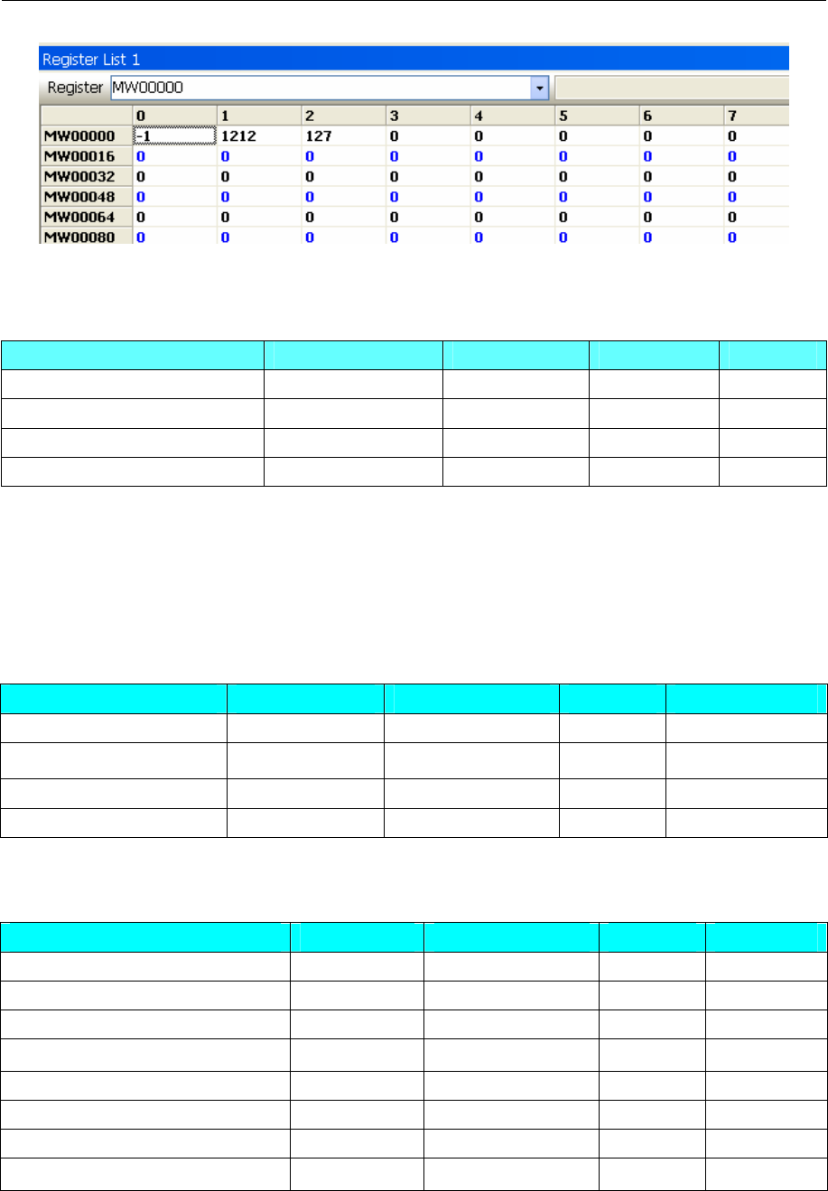
4 Communication settings and guide of HMI connecting with controller
- 405 -
◎Supported Device
V inverter
Device Bit Address Word Address Format Notes
Internal/external output node 0X1-65535 ------ DDDDD
Internal/external input node 1X1-65535 ------ DDDDD
Simulant input data register ------ 3X1-65535 DDDDD
data register ------ 4X1-65535 DDDDD
NOTE:
1 this drive can not provide write batch of word part;
2 Address correspondence: MEMOBUS+1=4X
Eg: b1-01(requency instruction selection),MEMOBUS register address is 080 H;the corresponding
screen is 4X 385
MP2300
Device Bit Address Word Address Format Notes
Coil MB0.0-4095.F ------ DDDD.H
Input Relay IB 0.0-FFF.F ------ HHHH.H
Hold Register ------ MW 0-65534 DDDDD
Input Register ------ IW 0-7FFF HHHH
NOTE:IB0.0-0.F are occupied by the system; IW0 is occupied by the system.
SGDM
Device Bit Address Word Address Format Notes
Function Selection Basic Switches ------ Pn000 ~ Pn003 HHH
Speed Loop Gain and so on ------ Pn100 ~ Pn118 HHH
Position Control Reference ------ Pn200 ~ Pn205 HHH
Speed Control Reference ------ Pn300 ~ Pn308 HHH
Torque Control Reference ------ Pn400 ~ Pn407 HHH
Sequence Reference ------ Pn500 ~ Pn510 HHH
Other ------ Pn600 ~ Pn601 HHH
Monitor mode ------ Un000 ~ Un00D HHH
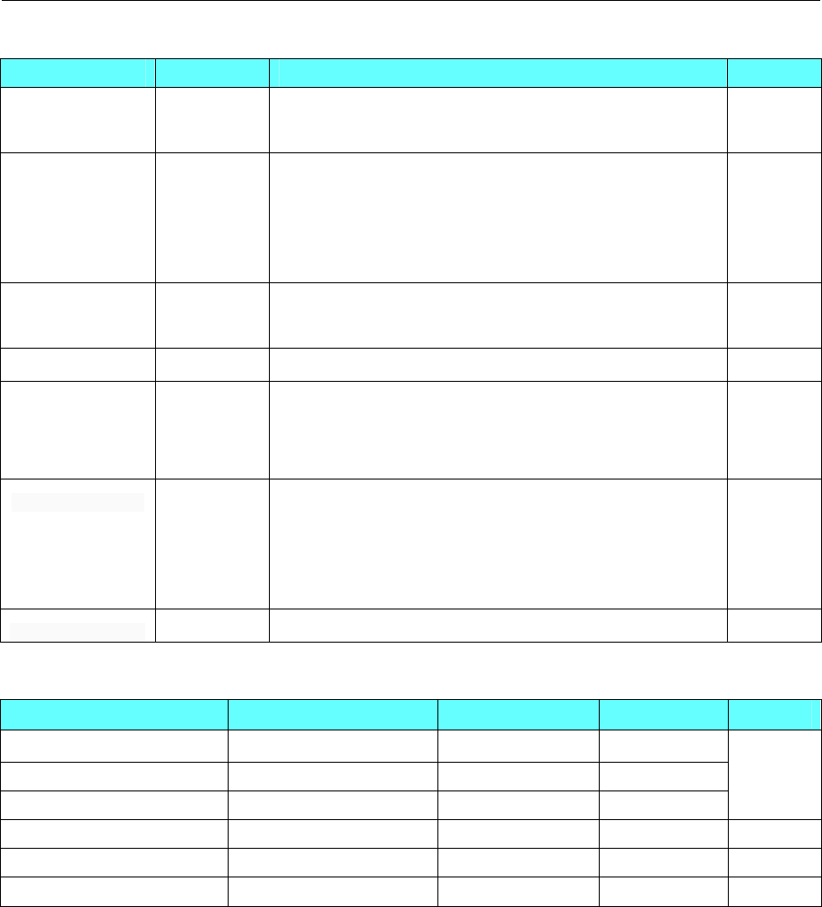
4 Communication settings and guide of HMI connecting with controller
- 406 -
SGDV
Device Bit Address Word Address Format
Function
Selection ------------
(Pn000~Pn002)&(Pn006~Pn009)
(Pn00B~Pn00D)& Pn010 & Pn080 HHH
Gain ------------
(Pn100~Pn106)&(Pn109~Pn10F)& Pn11F
(Pn121~Pn125)&(Pn131~Pn132)& (Pn135~Pn136)
(Pn139 & Pn13D)&(Pn140~Pn14B)
Pn14F &(Pn160~Pn165)&Pn170 & Pn190
HHH
Position ------------ Pn200 & Pn205 & Pn207 &Pn20A & Pn20E
Pn210 & Pn212 &(Pn216~Pn218)& Pn22A & Pn281 HHH
Speed ------------ (Pn300~Pn307)&(Pn310~Pn312)& Pn324 HHH
Touque
------------
(Pn400~Pn410)& Pn412 & Pn415 &(Pn423~Pn425)
Pn456 & Pn460 &(Pn481~Pn482)&(Pn486~Pn488)
Pn490 &(Pn493~Pn495)& Pn498
HHH
Sequential Control
------------
(Pn501~Pn503)&(Pn506~Pn509)& Pn51B
Pn51E & Pn520 & Pn522 & Pn524 & Pn526
(Pn528~Pn52C)&(Pn52F~Pn531)&(Pn533~Pn536)
(Pn550~Pn553)&(Pn560~Pn561)&(Pn600~Pn601)
HHH
Input/Output signal ------------ (Pn50A~Pn513)&(Pn515~Pn517) HHH
UDP
Device Bit Address Word Address Format Notes
Input register node IB0000.0-FFFF.F ------ HHHHH.H
Output register node OB0000.0-FFFF.F ------ HHHHH.H
holding register node MB00000.0-65534.F ------ DDDDD.H
Input register ------ IW0000-FFFF HHHH
Output register ------ OW0000-FFFF HHHH
Holding register ------ MW00000-65534 DDDDD
NOTE:In the HMIWare, bit address format is HHHH.H, but there is no point in the controller. E.g.: In the
EV5000 software, the bit address is MB65534.F, but there is no point in the controller, and it is MB65534F.
We set the I\O address as large as enough, and we found the big address can’t be written, but it is the same
effect with the monitoring.
◎Cable Diagram
V series inverter
RS485-2 communication cable
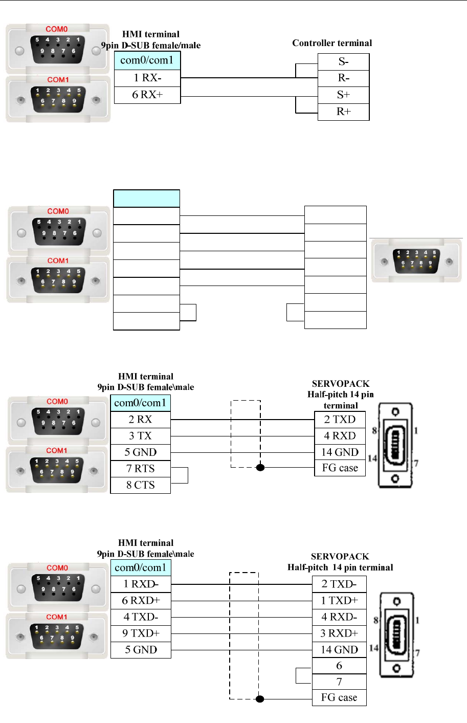
4 Communication settings and guide of HMI connecting with controller
- 407 -
MP2300
RS232 communication cable
com0/com1
HMI terminal
9pin D-SUB female/male Controller terminal
9 pin D-SUB (male)
1 FG
2 SD(TXD)
3 RD(RXD)
4 RS(RTS)
5 CS(CTS)
7 SG(GND)
9 ER(DTR)
1 FG
2 RD(RXD)
3 SD(TXD)
5 SG(GND)
6 DR(DSR)
7 RS(RTS)
8 CS(CTS)
SGDM/SGDV
RS232 communication cable
RS422 communication cable

4 Communication settings and guide of HMI connecting with controller
- 408 -
Ethernet communication protocol cable
Cross-connection or crossover network cable can be used as communication cable via the hub
Refer to 3.3 Download by Network Ethernet for method of making connection cable.
4.84 Yokogawa Electric Corporation
◎Serial Communication
Series CPU Link Module Driver
F3SP21-0N
F3SP25-2N
F3SP28-3N
F3SP35-5N
F3SP38-6N
F3SP53-4H
F3SP58-6H
F3SP28-3S
F3SP38-6S
F3SP53-4S
F3SP58-6S
F3SP59-7S
CPU Direct
F3LC11-1N
F3LC11-1F
F3LC11-2F
F3LC12-1F
FA-M3
F3SP20-0N
F3SP21-0N
F3SP25-2N
F3SP28-3N
F3SP30-0N
F3SP35-5N
F3SP38-6N
F3SP53-4H
F3SP58-6H
F3SP36-3N
F3SP28-3S
F3SP38-6S
F3SP53-4S
F3SP58-6S
F3SP59-7S
F3SP66-4S
F3SP67-6S
F3LC11-2N
Yokogawa FA-M3
◎Network Communication(direct online simulation disable)
Series CPU Link Module Driver

4 Communication settings and guide of HMI connecting with controller
- 409 -
F3SP21-0N
F3SP25-2N
F3SP28-3N
F3SP35-5N
F3SP38-6N
F3SP53-4H
F3LE01-5T
F3LE11-0T
F3SP58-6H
F3SP28-3S
F3SP38-6S
F3SP53-4S
F3SP58-6S
F3SP59-7S
F3LE01-5T
F3LE11-0T
FA-M3
F3SP66-4S
F3SP67-6S Ethernet I/F on CPU Unit
Yokogawa FA-M3
Ethernet(TCP Slave)
◎Serial System configuration
Series CPU Link Module COM Type Parameter Cable
RS232 on the CPU
unit RS232 Setting Your owner cable
FA-M3
F3SP21-0N
F3SP25-2N
F3SP28-3N
F3SP35-5N
F3SP38-6N
F3SP53-4H
F3SP58-6H
F3SP28-3S
F3SP38-6S
F3SP53-4S
F3SP58-6S
F3SP59-7S
F3SP20-0N
F3SP21-0N
F3SP25-2N
F3SP28-3N
F3SP30-0N
F3SP35-5N
RS422/485(4Wire)
port on F3LCLL-2F
RS422 Setting Your owner cable
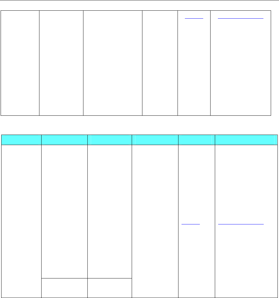
4 Communication settings and guide of HMI connecting with controller
- 410 -
F3SP38-6N
F3SP53-4H
F3SP58-6H
F3SP36-3N
F3SP28-3S
F3SP38-6S
F3SP53-4S
F3SP58-6S
F3SP59-7S
F3SP66-4S
F3SP67-6S
RS422/485(2Wire)
port on F3LCLL-2F
RS485 Setting Your owner cable
◎Network System configuration
Series CPU Link Module Connect Type Parameter Cable
F3SP21-0N
F3SP25-2N
F3SP28-3N
F3SP35-5N
F3SP38-6N
F3SP53-4H
F3LE01-5T
F3LE11-0T
F3SP58-6H
F3SP28-3S
F3SP38-6S
F3SP53-4S
F3SP58-6S
F3SP59-7S
F3LE01-5T
F3LE11-0T
FA-M3
F3SP66-4S
F3SP67-6S
Ethernet I/F
on CPU Unit
Ethernet Setting Your owner cable
◎Serial Communication Setting
HMI Setting
RS232 default communication: 9600, 8, 1, even; station: 0 (station number disable)
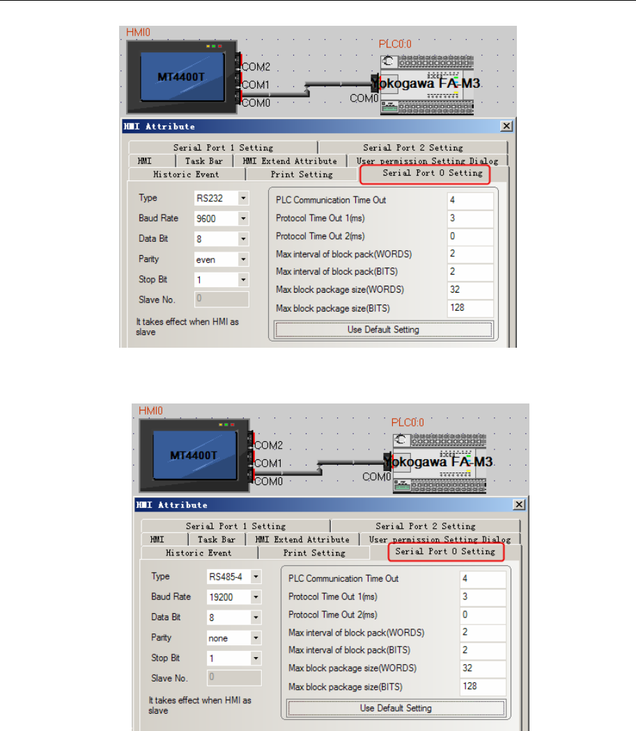
4 Communication settings and guide of HMI connecting with controller
- 411 -
RS485-4 default communication: 19200, 8, 1, none; station: 1
RS485-2 default communication: 19200, 8, 1, none; station: 1
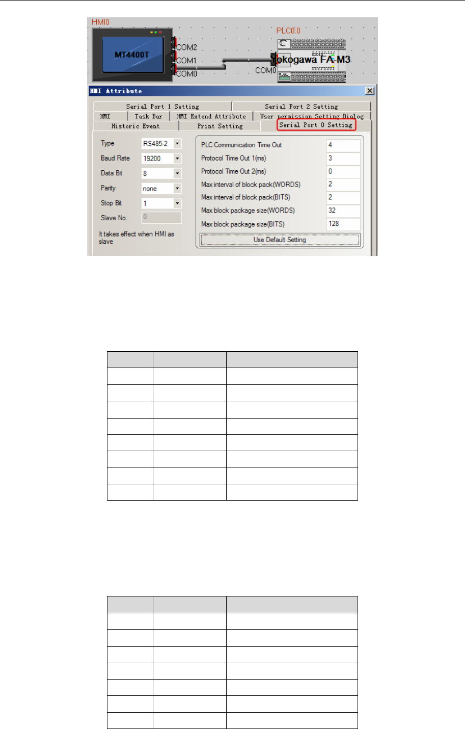
4 Communication settings and guide of HMI connecting with controller
- 412 -
PLC Setting
RS485-4 communication configuration
Set the 485 communication module on the right as below.
1. Transmission Speed Setting Switch: SW1=7
2. Data Code Setting Switch: SW2
Bit Settings Setup Description
1 ON Data Length
2 OFF Parity Bit
3 OFF --
4 OFF Stop Bit
5 OFF Exist Sum Check
6 ON Exist Terminator
7 OFF Protect
8 OFF Always OFF
3. Station No. setting 1
4. Set the termination resistance switch of only the module which terminates the connection to 4- WIRE
RS485-2 communication configuration
Set the 485 communication module on the right as below.
1. Transmission Speed Setting Switch: SW1=7
2. Data Code Setting Switch: SW2
Bit Settings Setup Description
1 ON Data Length
2 OFF Parity Bit
3 OFF --
4 OFF Stop Bit
5 OFF Exist Sum Check
6 ON Exist Terminator
7 OFF Protect
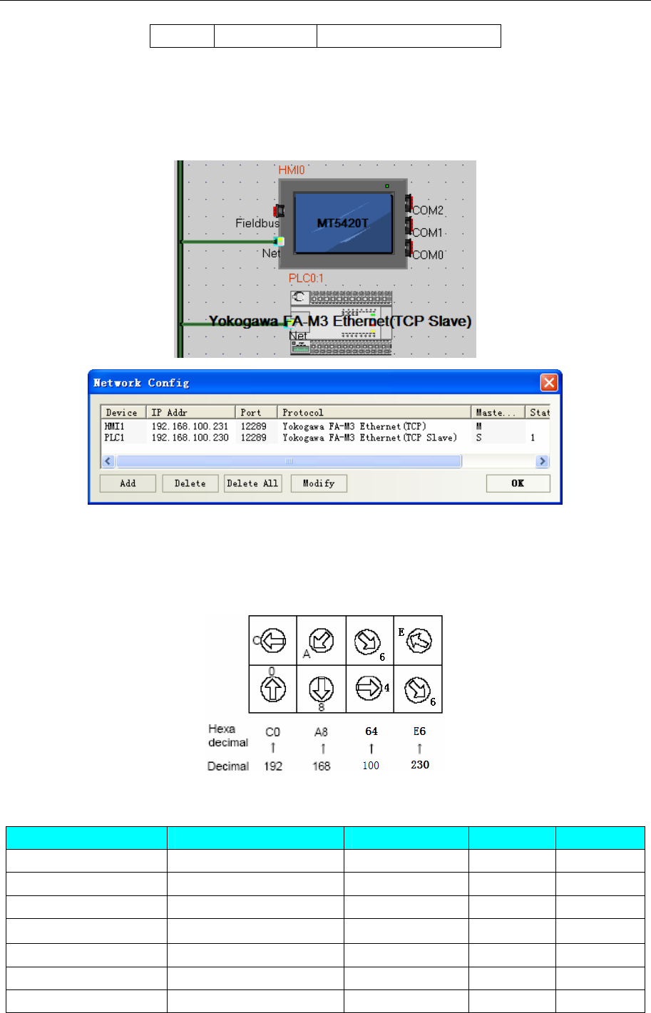
4 Communication settings and guide of HMI connecting with controller
- 413 -
8 OFF Always OFF
3. Station No. setting 1
4. Set the termination resistance switch of only the module which terminates the connection to 2- WIRE.
◎Network Communication Setting
HMI Setting
PLC setting
Use the swicthes on the right side of Ethernet module for setting the External Device.
1. Set all condition setup switch off.
2. Set IP Address: 192.168.100.230.
◎Supported Device
Device Bit Address Word Address Format Notes
Link Relay L 1~256 ------ DDD
Special Relay M 1~256 ------ DDD
Internal Relay I 1~256 ------ DDDD
Output Relay Y (233~264)&(333~364)------ DDD
Input Relay X (201~232)&( 301~332)------ DDD Read only
Special Register ------ Z_word 1~256 DDDD
Link Register ------ W_word 1~256 DDD
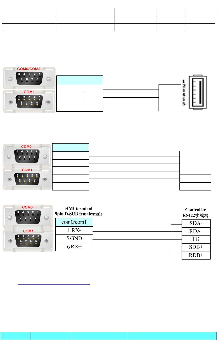
4 Communication settings and guide of HMI connecting with controller
- 414 -
Index Register ------ V_word 1~64 DD
File Register ------ B_word 1~256 DD
Data Register ------ D_word 1~256 DDD
◎Cable Diagram
RS232 communication cable
Yokogawa programming cable
Controller terminal
6 pin
com2
3 TX
2 RX
5 GND
8 TX
7 RX
5 GND
com0/com1
HMI terminal
9pin D-SUB female/male
1 TXD
2 RXD
5 GND
RS485-4 communication cable
HMI terminal
9pin D-SUB female/male
1 RX-
6 RX+
5 GND
SDA-
SDB+
FG
RDA-
RDB+
4 TX-
9 TX+
Controller
RS422 terminal
com0/com1
RS485-2 communication cable
Ethernet communication protocol cable
Cross-connection or crossover network cable can be used as communication cable via the hub
Refer to 3.3 Download by Network Ethernet for method of making connection cable.
4.85 YuDian AI
◎Serial Communication
Series CPU Link Module Driver
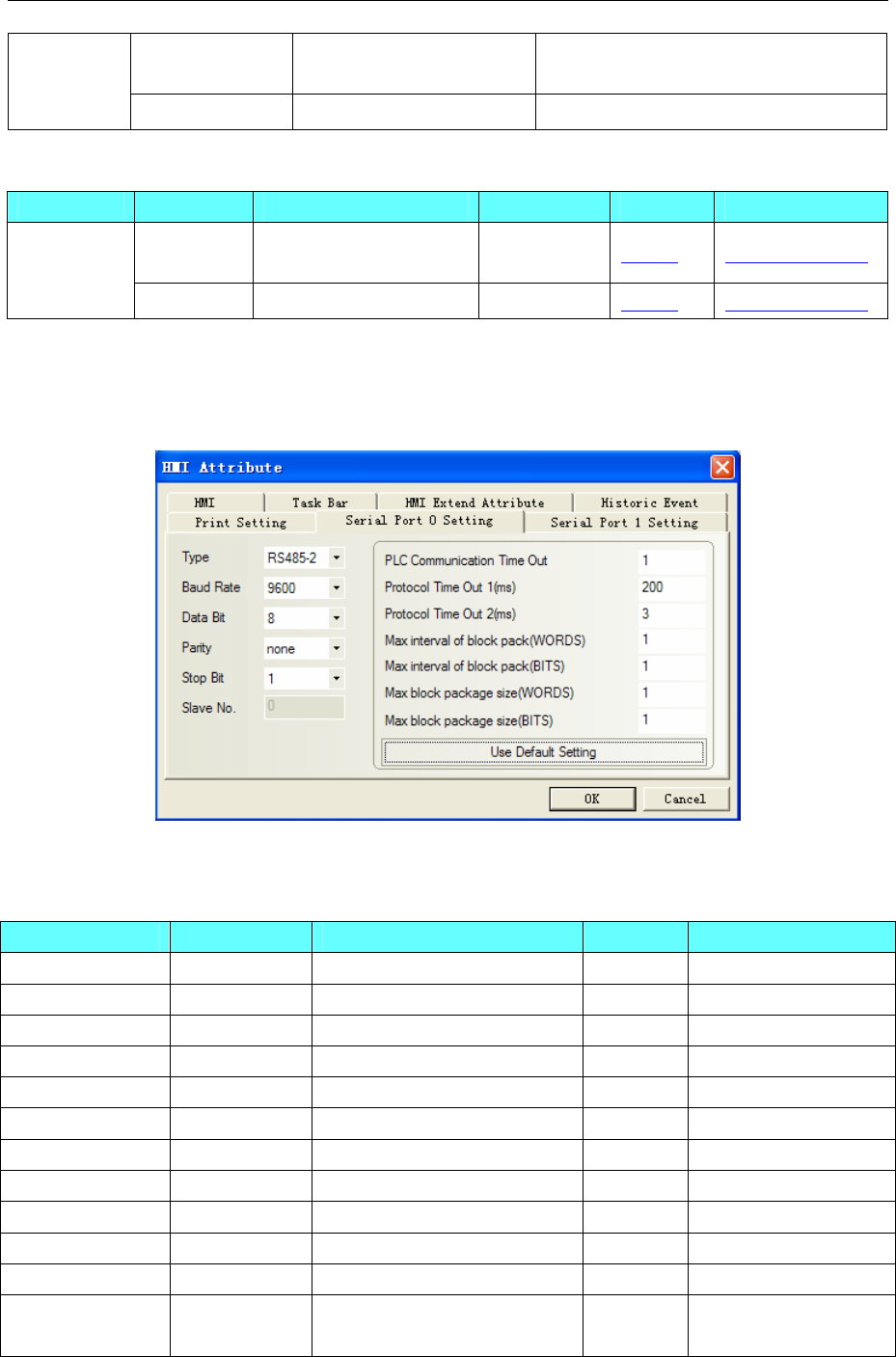
4 Communication settings and guide of HMI connecting with controller
- 415 -
AI-518
AI-701 RS485 on the CPU unit YuDian AI Single_Loop
AI
AI-7048 RS485 on the CPU unit YuDian AI 4_Loop
◎System configuration
Series CPU Link Module COMM Type Parameter Cable
AI-518
AI-701 RS485 on the CPU unit RS485 Setting Your owner cable
AI
AI-7048 RS485 on the CPU unit RS485 Setting Your owner cable
◎Communication Setting
HMI Setting
Default communication: 9600, 8, none, 1; station: 1
◎Supported Device
YuDian AI Single_Loop
Device Bit Address Word Address(参数代号) Format Notes
HiAL 0 ------ D Read only
LoAL 0 ------ D Read only
dHAL 0 ------ D Read only
dLAL 0 ------ D Read only
orAL 0 ------ D Read only
AL1 0 ------ D Read only
AL2 0 ------
D Read only
PV ------ 0 D Read only
MV ------ 0 D
SV ------ 0 D
ALARM ------ 0 D Read only
Reference ------ 86 DD
Address correspond to
AI parameters code
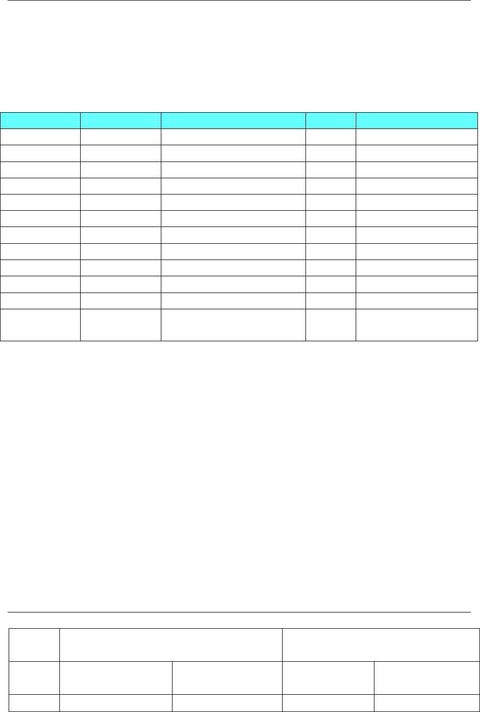
4 Communication settings and guide of HMI connecting with controller
- 416 -
NOTE:
1、When setting the parameter of ADDR, it match the PLC Station Number .
2、If connecting many devices, you should set different ADDR values.
YuDian AI 4_Loop
AI-7048
Device Bit Address Word Address(参数代号) Format Notes
HiAL 0.0-3.0 ------ D.D Read only
LoAL 0.0-3.0 ------ D.D Read only
dHAL 0.0-3.0 ------ D.D Read only
dLAL 0.0-3.0 ------ D.D Read only
orAL 0.0-3.0 ------ D.D Read only
AL1 0.0-3.0 ------ D.D Read only
AL2 0.0-3.0 ------
D.D Read only
PV ------ 0.0-3.0 D.D Read only
MV ------ 0.0-3.0 D.D
SV ------ 0.0-3.0 D.D
ALARM ------ 0.0-3.0 D.D Read only
Reference ------ 0.0-3.086 D.DDD Address correspond to AI
parameters code
NOTE:
1、When setting the parameter of ADDR, it match the PLC Station Number.
2、If connecting many devices, you should set different ADDR values.
3、AI-7048 has 4 loops, so it occupies 4 address, For instance, Addr=5,address 5~8 were used by this
controller, other controller can’t use address 5~8.
EXAMPLE
Take HIAL for example, look up table and then know that HIAL parameters code is 1, so HIAL for 4
channels correspond to address in HMI should be Reference0.01,Reference1.01,Reference2.01,
Reference3.01.
If station number is 2, Reference0.01 is HIAL address of channel 2(station No. 2 + main address 0),
Reference1.01 is HIAL address of channel 2(station No. 2 + main address 1), and so on.
Thereinto the setting of station number is very important, it denotes start address of the controller (viz.
instrument address in instrument parameter), and main address just denotes 4 channels. When main address
is 0, it denotes channel (station number+0)
TABLE
Table 1
Parameter
Code Adjustor Inspection instrument
DEC AI-518/708/808/518P/70
8P/808P AI-519/719/719P AI-501/701 AI-702M/704M/706M
0 SV /SteP SV /SteP N/A N/A

4 Communication settings and guide of HMI connecting with controller
- 417 -
1 HIAL HIAL HIAL HIAL
2 LoAL LoAL LoAL LoAL
3 dHAL HdAL HdAL N/A
4 dLAL LdAL LdAL N/A
5 dF CHYS AHYS dF
6 Ctrl Ctrl N/A N/A
7 M5 P N/A N/A
8 P I N/A N/A
9 t d N/A N/A
10 CtI CtI N/A N/A
11 Sn InP InP Sn
12 dIP dPt dPt dIP
13 dIL SCL SCL dIL
14 dIH SCH SCH dIH
15 ALP AOP AOP ALP
16 Sc Scb Scb Sc
17 OP1 OPt OPt OPn
18 oPL OPL N/A oPL
19 oPH OPH N/A oPH
20 CF AF N/A Cn
21
Feature codes/Program
control words(Run:0
Pause:4 Stop:12)
Feature codes/Program
control words(Run:0
Pause:4 Stop:12)
Feature codes(the
same to SV, and it
can be modified)
Feature codes
22 Add.(R/W) Add.(R/W) Add.(R/W) Add.(R/W)
23 dL FILt FILt dL
24 run A-M N/A nonc
25 Loc Loc Loc Loc
26 C01(set the MV when
writing AI-808)
C01(set the MV when
writing AI-519/719)
27 t01 t01
28 C02 C02
29 t02 t02
30 C03 C03
31 t03 t03
32 C04 C04
33 t04 t04
34 C05 C05
35 t05 t05
36 C06 C06
37 t06 t06
38 C07 C07
39 t07 t07

4 Communication settings and guide of HMI connecting with controller
- 418 -
40 C08 C08
41 t08 t08
42 C09 C09
43-85 t09-C30 t09-C30
86 Run time of current
program
Run time of current
program
Table 2
Parameter Code Flow totalizer AI-301M 4 loop PID
adjustor
DEC HEX (AI-708H/Y/808H) Frequency
measurement/switching value AI-7048
0 00H SV SV SP
1 01H FHIA HIAL HIAL
2 02H FloA LoAL LoAL
3 03H SPE dHAL
4 04H Act dLAL
5 05H Sn dF AHYS
6 06H FSc CtrL At
7 07H PdIH M5 P
8 08H CSc P I
9 09H CdIH t d
10 0AH Cut CtI
11 0BH FdIH Frd InP
12 0CH FdIP dIP dPt
13 0DH PA dIL SCL
14 0EH Po dIH SCH
15 0FH Co ALP AOP
16 10H Frd switch state Scb
17 11H CF oP1
18 12H bC OPL
19 13H IoL OPH OPH
20 14H FoH CF AF
21 15H Feature codes Feature codes Feature codes
22 16H Add.(R/W) Add.(R/W) Add.(R/W)
23 17H IoH dL FILt
24 18H FdL run Nonc
25 19H Loc Loc Loc
26 1AH N/A MV Cn
27 1BH FdF
28 1CH CHIA
29 1DH CLoA
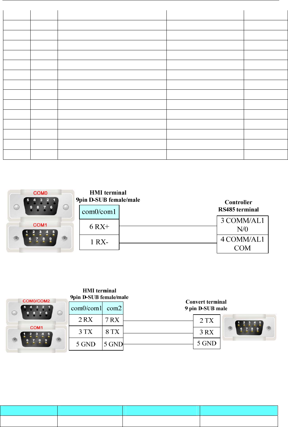
4 Communication settings and guide of HMI connecting with controller
- 419 -
30 1EH PHIA
31 1FH PLoA
32 20H ALP
33 21H FSb
34 22H CdIP
35 23H PdIP
36 24H PSc
37 25H CLn
38 26H FLJH
39 27H FLJL
40 28H EJH
41 29H EJL
42 2AH Mass accumulation value of zero position
43-85 2BH-55H
86 56H
◎Cable Diagram
RS485 communication cable
RS232 communication cable
Need to use RS-232 to RS-422/485 converter
4.86 ZiGuang Ethernet
◎Network Communication
Series CPU Link Module Driver
ZiGuang Ethernet UNIS-600C Ethernet ZiGuang Ethernet Slave
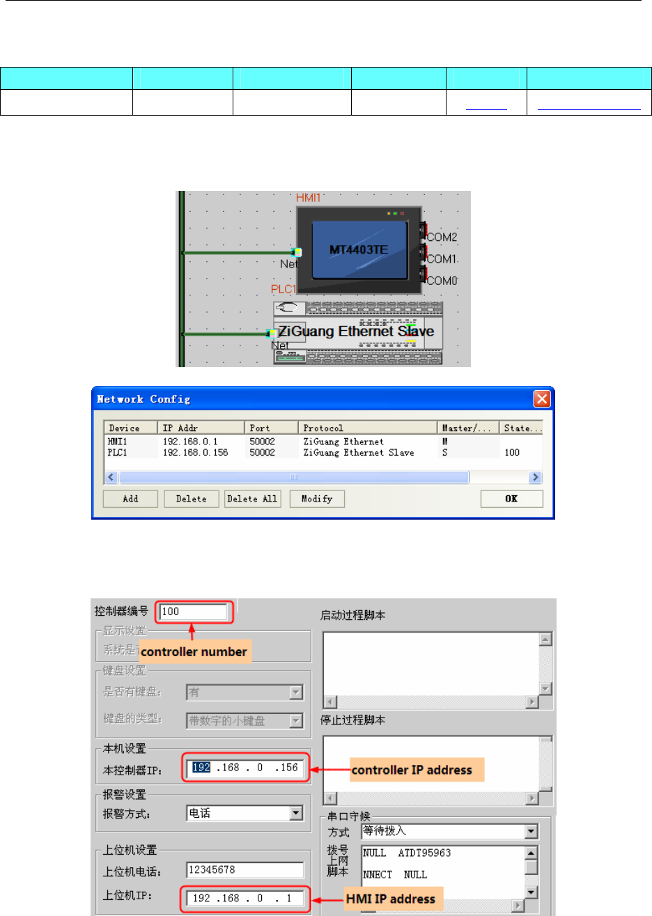
4 Communication settings and guide of HMI connecting with controller
- 420 -
◎Network System configuration
Series CPU Link Module COMM Type Parameter Cable
ZiGuang Ethernet UNIS-600C Ethernet Ethernet Setting Your owner cable
◎Ethernet Communication Setting
HMI Setting
PLC Setting
1. Settings in the software as follows:
(1) System basic configuration: Set the controller number, IP address, and the PC IP address.
(2) Configuration of data tag: set the parameters according to the actual I/O card. The PLC register address
should be the same as the ID number of the data tag.
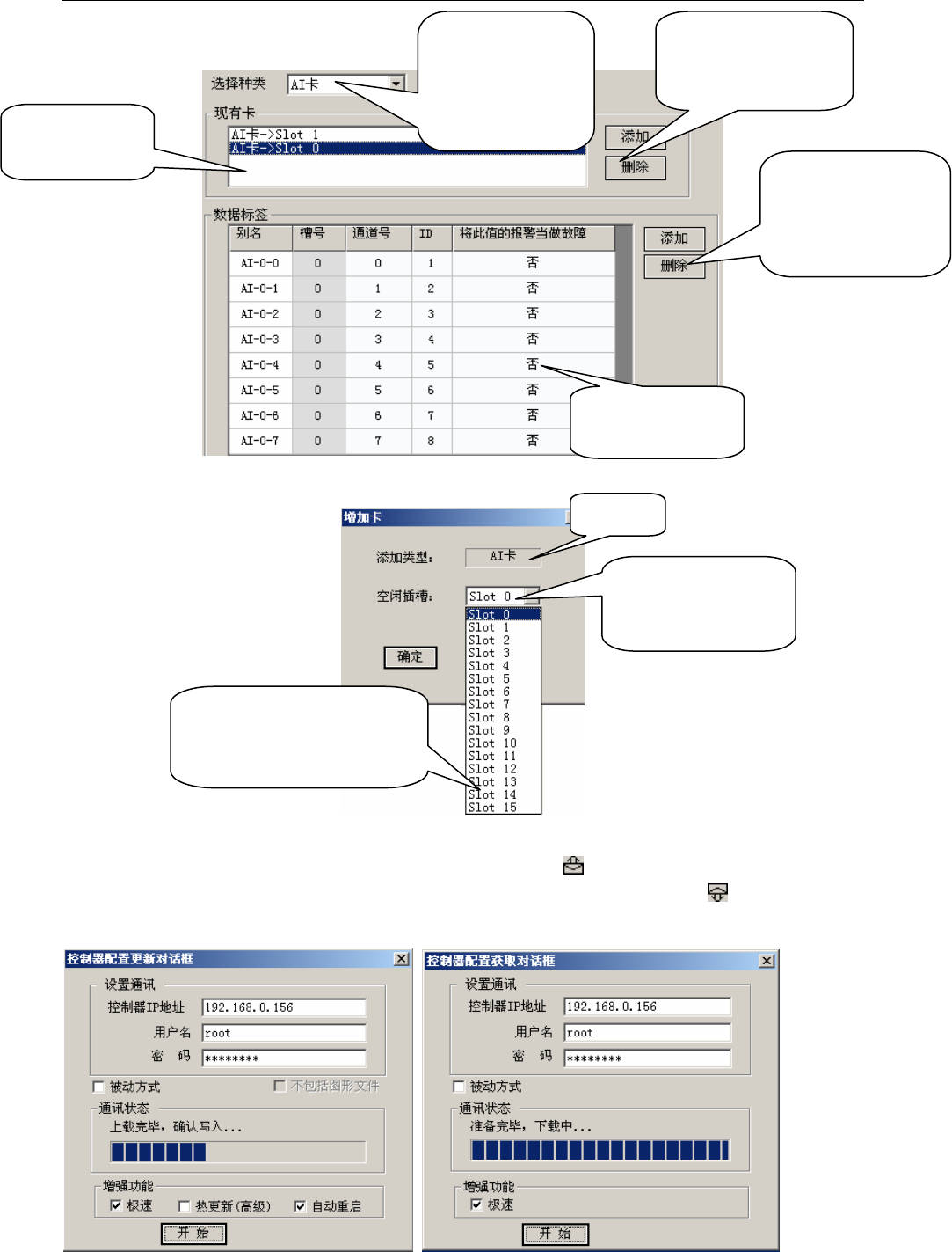
4 Communication settings and guide of HMI connecting with controller
- 421 -
(3)Update and get configuration: After finish the system basic configuration and data tag configuration,
choose the Update Configuration in the Tool menu or click the icon to update the configurations in
the controller. Choose the Get Configuration in the Tool menu or click the icon to get the
configuration in the controller.
Use this box to
choose the IO card
that needs to be
added or deleted.
Use these two buttons to
add or delete current
card.
Use these two buttons
to add or delete the
channels of added
card.
This box displays
data tag of added
This box displays
current card list.
Card type
Choose the slot(free) of
card that needs to be
adde
d
The controller only has 8 slots in
actual, the slot 8-15 is the
system simulation slots.
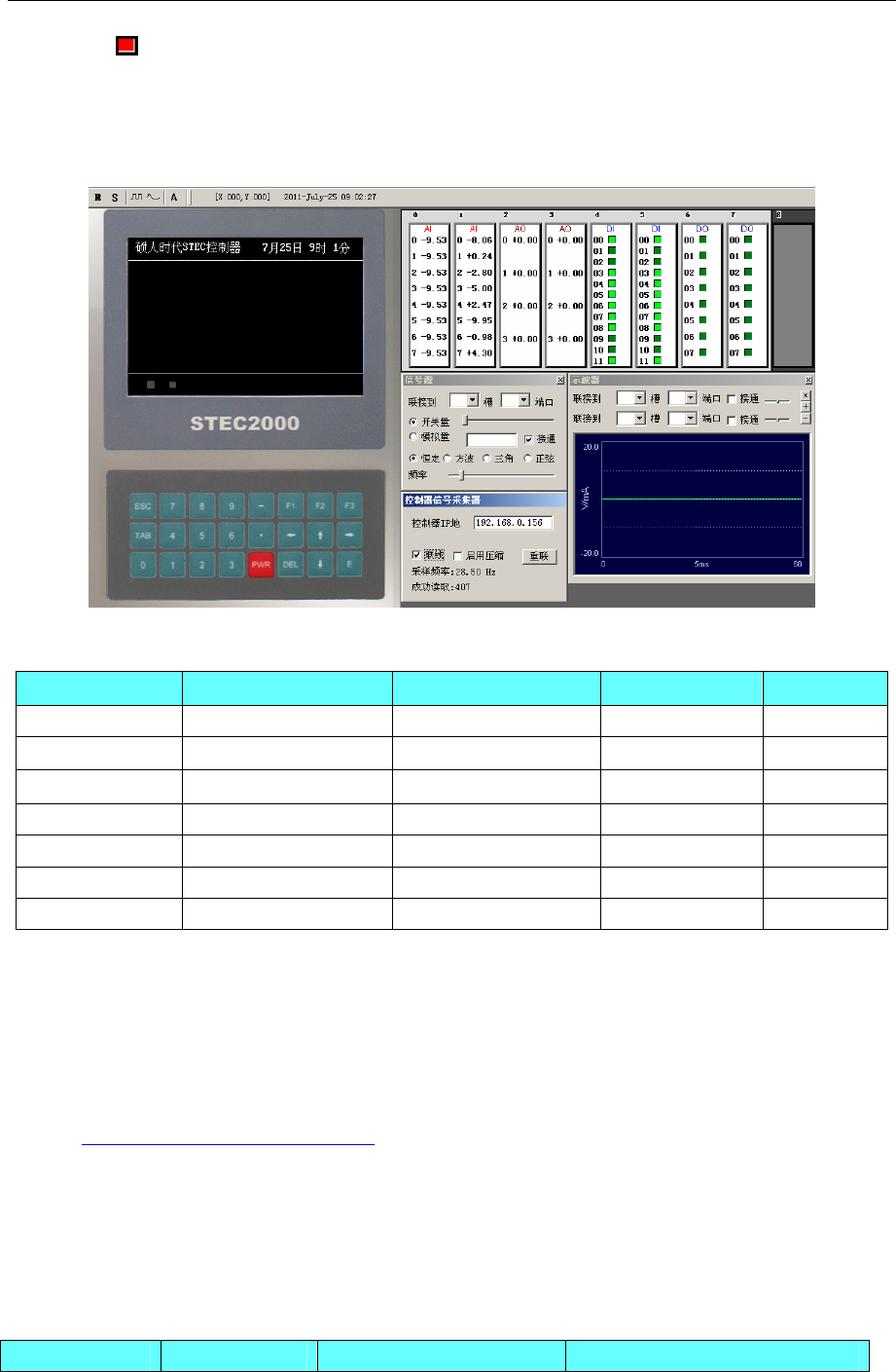
4 Communication settings and guide of HMI connecting with controller
- 422 -
(4)Click icon after updating controller configuration, then it will pop upWinEmu window, real-time
control of script debugging window and none-real time control of script debugging window.
WinEmu window monitors the internal data of controller, real-time control of script debugging window and
none-real time control of script debugging window provide environment for customer secondary
development.
◎Supported Device
Device Bit Address Word Address Format Notes
Bool_Read Bool_Read 0-65535 ------ DDDDD Read only
Bool_Write Bool_Write 0-65535 ------ DDDDD Write only
Float_Read ------
Float_Read 0-65535 DDDDD Read only
Int_Read ------ Int_Read 0-65535 DDDDD Read only
Float_Write ------ Float_Write 0-65535 DDDDD Write only
Int_Write ------ Int_Write 0-65535 DDDDD Write only
------ Time 0-2 D
NOTE: The name and address of registers in HMI must be same as register in Ziguang controller when
defining in HMI.
◎Cable Diagram
Ethernet communication protocol cable
Cross-connection or crossover network cable can be used as communication cable via the hub
Refer to 3.3 Download by Network Ethernet for method of making connection cable.
4.87 ZHIMEI CB920X
◎Serial Communication
Series CPU Link Module Driver
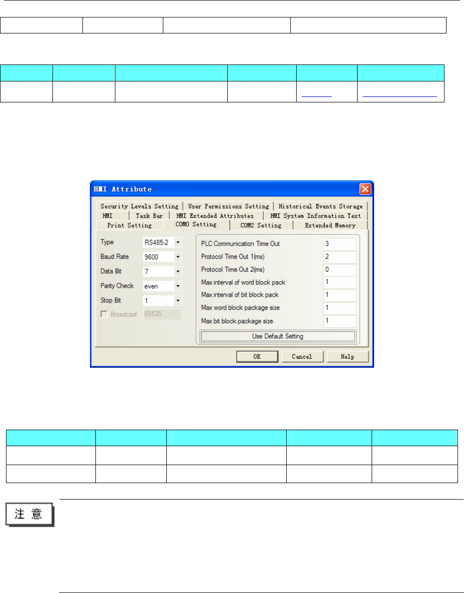
4 Communication settings and guide of HMI connecting with controller
- 423 -
CB920X CB920X-10 RS485 on the CPU unit ZHIMEI CB920X
◎System configuration
Series CPU Link Module Connect Type Parameter Cable
CB920X CB920X-10 RS485 on the CPU unit RS485-2 Setting Your owner cable
◎Communication Setting
HMI 设置
Default communication: 9600, 7, even, 1; station: 1
RS485-2
PLC 设置
Please refer to the manual of controller.
◎Supported Device
Device Bit Address Word Address Format Notes
------ FUNC1-FUNC42 DD
------ READ0 D
1. The controller station can set 1~99, don’t support station 0.
2. The FUNC parameter cannot be arbitrarily set, please refer to the controller manual. If the
settings in the HMI value is not in the allowed range, it will retain a valid value
3.FUNC registers, when in use, select "Hex data type".
4.Weighing register READ is read-only register, and only 0 address is effective. When in use,
select the text display component, 4 words.
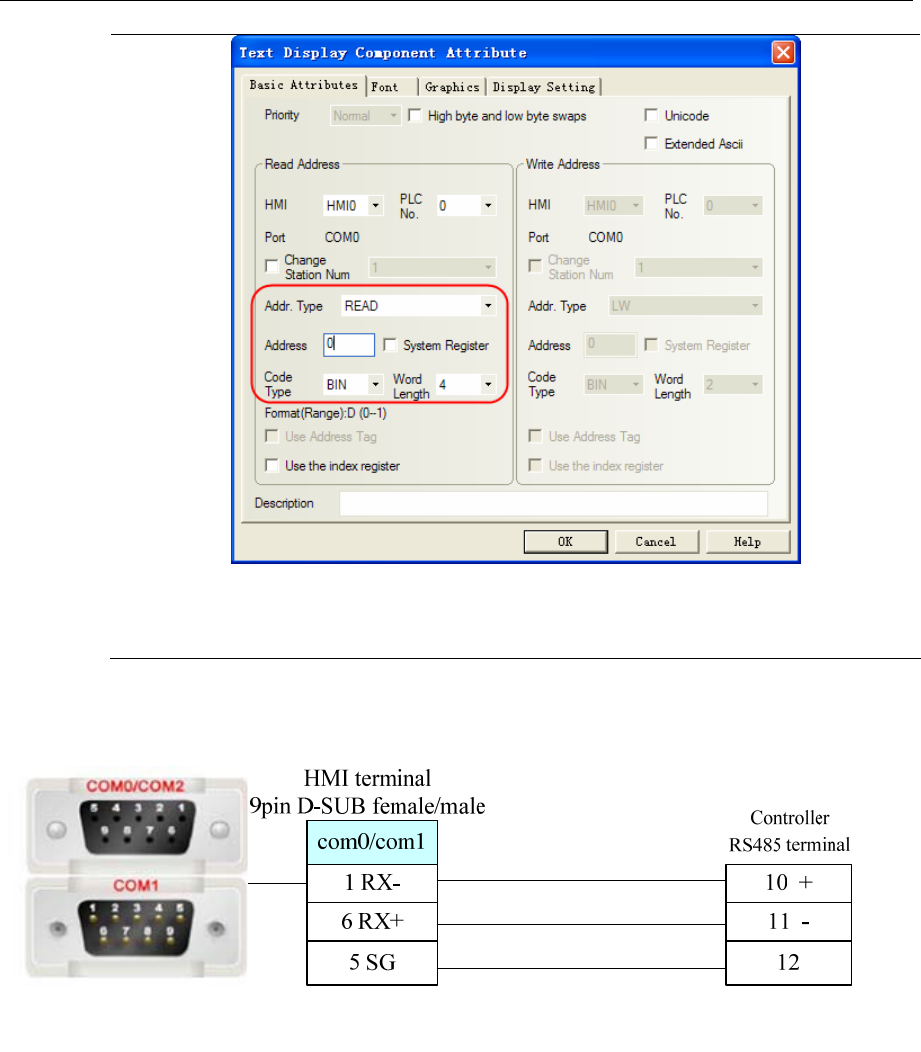
4 Communication settings and guide of HMI connecting with controller
- 424 -
5.Suggest place the FUNC and READ registers in the different configuration window,
because the FUNC is the functional setting register, when in a functional setting condition,
the RS485 interface will always send instructions, and you cannot read the weight register.
◎Cable Diagram
RS485-2
