044822_1 HP 8444A Tracking Generator User Manual
User Manual: HP 8444A Tracking Generator User Manual
Open the PDF directly: View PDF ![]() .
.
Page Count: 122 [warning: Documents this large are best viewed by clicking the View PDF Link!]
- TOC
- LAST CHANGE
- LOI
- LOT
- SECTIONS
- TABLES
- FIGURES
- FIGURE 1-1
- FIGURE 1-2
- FIGURE 2-1
- FIGURE 3-1
- FIGURE 3-2
- FIGURE 3-3
- FIGURE 3-4
- FIGURE 3-5
- FIGURE 3-6
- FIGURE 3-7
- FIGURE 3-8
- FIGURE 3-9
- FIGURE 3-10
- FIGURE 4-1
- FIGURE 4-2
- FIGURE 4-3
- FIGURE 4-4
- FIGURE 4-5
- FIGURE 4-6
- FIGURE 4-7
- FIGURE 4-8
- FIGURE 5-1
- FIGURE 5-2
- FIGURE 5-3
- FIGURE 5-4
- FIGURE 5-5
- FIGURE 5-6
- FIGURE 5-7
- FIGURE 5-8
- FIGURE 7-1
- FIGURE 7-2
- FIGURE 7-3
- FIGURE 8-1
- FIGURE 8-2
- FIGURE 8-3
- FIGURE 8-4
- FIGURE 8-5
- FIGURE 8-6
- FIGURE 8-7
- FIGURE 8-7A
- FIGURE 8-8
- FIGURE 8-9
- FIGURE 8-10
- FIGURE 8-11
- FIGURE 8-12
- FIGURE 8-13
- FIGURE 8-14
- FIGURE 8-15
- FIGURE 8-16
- FIGURE 8-17
- FIGURE 8-18
- FIGURE 8-19
- FIGURE D-1
- FIGURE D-2
- FIGURE D-3
- APPENDICES
- PAGES
- PAGE 1-0
- PAGE 0-1
- PAGE 1-1
- PAGE 1-2
- PAGE 1-3
- PAGE 1-4
- PAGE 1-5
- PAGE 1-7
- PAGE 2-1
- PAGE 2-2
- PAGE 3-1
- PAGE 3-2
- PAGE 3-3
- PAGE 3-4
- PAGE 3-6
- PAGE 3-8
- PAGE 3-9
- PAGE 3-10
- PAGE 4-1
- PAGE 4-2
- PAGE 4-3
- PAGE 4-5
- PAGE 4-7
- PAGE 4-8
- PAGE 4-9
- PAGE 4-11
- PAGE 4-13
- PAGE 4-15
- PAGE 4-16
- PAGE 5-1
- PAGE 5-2
- PAGE 5-3
- PAGE 5-4
- PAGE 5-5
- PAGE 5-6
- PAGE 5-8
- PAGE 5-9
- PAGE 5-10
- PAGE 5-11
- PAGE 5-13
- PAGE 5-15
- PAGE 6-1
- PAGE 6-2
- PAGE 6-3
- PAGE 6-4
- PAGE 6-5
- PAGE 6-6
- PAGE 6-7
- PAGE 6-8
- PAGE 6-9
- PAGE 6-11
- PAGE 7-1
- PAGE 7-2
- PAGE 7-5
- PAGE 7-6
- PAGE 8-1
- PAGE 8-2
- PAGE 8-3
- PAGE 8-4
- PAGE 8-5
- PAGE 8-6
- PAGE 8-7
- PAGE 8-9
- PAGE 8-10
- PAGE 8-11
- PAGE 8-12
- PAGE 8-13
- PAGE 8-14
- PAGE 8-15
- PAGE 8-16
- PAGE 8-17
- PAGE 8-19
- PAGE 8-20
- PAGE 8-21
- PAGE B-1
- PAGE C-1
- PAGE D-1
- PAGE D-4
- PAGE D-6
- PAGE D-7
- PAGE D-8
- PAGE E-1
- PAGE F-1
- PAGE F-2
- PAGE F-3
- PAGE G-1
- PAGE G-2
- PAGE H-1
- PAGE H-3
- PAGE H-5
- PAGE I-1

TM 11-6625-2866-14&P
TECHNICAL MANUAL
OPERATOR'S, ORGANIZATIONAL, DIRECT SUPPORT,
AND GENERAL SUPPORT
MAINTENANCE MANUAL
(INCLUDING REPAIR PARTS AND SPECIAL TOOLS LISTS)
FOR
GENERATOR, TRACKING SG-1125/U
(HEWLETT-PACKARD MODEL 8444A)
(NSN 6625-00-185-4802)
HEADQUARTERS, DEPARTMENT OF THE ARMY
29 FEBRUARY 1980
TM 11-6625-2866-14&P
C 1
CHANGE HEADQUARTERS
DEPARTMENT OF THE ARMY
No. 1 WASHINGTON, DC, 28 August 1980
Operator's, Organizational, Direct Support, and General Support
Maintenance Manual
(Including Repair Parts and Special Tools Lists)
For
GENERATOR, TRACKING SG-1125/U
(HEWLETT-PACKARD MODEL 8444A)
(NSN 6625-00-185-4802)
TM 11-6625-2866-14&P, 29 February 1980, is changed as follows:
1. Remove old pages and insert new pages as indicated below:
Remove Insert
None ..............................................................................6-9 through 6-11/(6-12 blank)
F-1 .................................................................................F-1 through F-3/(F-4 blank)
G-1 ................................................................................G-1 and G-2
None ..............................................................................H-3 through H-5/(H-6 blank)
2. File this sheet in front of the manual for reference purposes.
}
By Order of the Secretary of the Army:
E. C. MEYER
General, United States Army
Official: Chief of Staff
J. C. PENNINGTON
Major General, United States Army
The Adjutant General
Distribution:
Active Army:
HISA (Ft Monmouth) (21) USAICS (3)
USAINSCOM (2) MAAG (1)
COE (1) USARMIS (1)
TSG (1) USAERDAA (1)
USAARENBD (1) USAERDAW (1)
DARCOM (1) Fort Gordon (10)
TRADOC (2) Fort Carson (5)
OS Maj Comd (4) Army Dep (1) except
TECOM (2) LBAD (14)
USACC (4) SAAD (30)
MDW (1) TOAD (14)
Armies (2) SHAD (3)
Corps (2) Fort Gillem (10)
Svc Colleges (1) USA Dep (1)
USASIGS (5) Sig Sec USA Dep (1)
USAADS (2) Fort Richardson (CERCOM Ofc) (2)
USAFAS (2) Units org under fol TOE:
USAARMS (2) (2 copies each unit)
USAIS (2) 29-207
USAES (2) 29-610
ARNG: None
USAR: None
For explanation of abbreviations used, see AR 310-50.

This manual contains copyright material reproduced by permission of the Hewlett-Packard Company.
TM 11-6625-2866-14&P
TECHNICAL MANUAL HEADQUARTERS
DEPARTMENT OF THE ARMY
No. 11-6625-2866-14&P WASHINGTON, DC,
29 February 1980
OPERATOR'S, ORGANIZATIONAL, DIRECT
SUPPORT, AND GENERAL SUPPORT
MAINTENANCE MANUAL
(INCLUDING REPAIR PARTS AND SPECIAL TOOLS LISTS)
FOR
GENERATOR, TRACKING SG-1 125/U
(HEWLETT-PACKARD MODEL 8444A)
(NSN 6625-00-185-4802)
REPORTING ERRORS AND RECOMMENDING IMPROVEMENTS
You can improve this manual by recommending improvements using DA Form 2028-2 (Test) located in
the
back of the manual. Simply tear out the self-addressed form, fill it out as shown on the sample, fold it where
shown, and drop it in the mail. If there are no blank DA Forms 2028-2 (Test) in the back of your manual, use
the standard DA Form 2028 (Recommended Changes to Publications and Blank Forms) and forward to the
Commander, US Army Communications and Electronics Materiel Readiness Command, ATTN: DRSEL-ME-
MQ, Fort Monmouth, NJ 07703.
In either case a reply will be furnished direct to you.
This manual is an authentication of the manufacturer's commercial literature which, through usage, has been found to
cover the data required to operate and maintain this equipment. Since the manual was not prepared in accordance with
military specifications, the format has not been structured to consider levels of maintenance.
}
i
TM 11-6625-2866-14&P
TABLE OF CONTENTS
Section Page
0. INTRODUCTION .....................................0-1
I. GENERAL INFORMATION........................1-1
1-1.Introduction......................................1-1
1-5.Safety Considerations......................1-1
1-16.Instruments Covered by Manual.......1-2
1-18.Description ......................................1-2
1-21.8554B RF Section Modifications.......1-4
1-23.Accessories Supplied.......................1-4
1-25.Operating Accessories......................1-4
1-27.Warranty..........................................1-4
1-29.Recommended Test Equipment.......1-4
II. INSTALLATION.........................................2-1
2-1.Initial Inspection...............................2-1
2-2.Mechanical Check............................2-1
2-4.Electrical Check ..............................2-1
2-6.Claims for Damage. .......................2-1
2-9.Preparation for Use. .......................2-1
2-10.Power Requirements........................2-1
2-13.Power Cable.....................................2-1
2-16.Operating Environment....................2-1
2-18.Installation Connections....................2-2
2-21.Storage and Shipment......................2-2
2-22.Original Packaging ..........................2-2
2-26.Other Packaging Materials...............2-2
III. OPERATION ...........................................3-1
3-1.Introduction......................................3-1
3-3.Panel Features.................................3-1
3-5.Operator's Checks............................3-1
3-7.Operating Instructions......................3-1
3-9.Controls, Indicators and Connectors.3-1
3-11. Operating Techniques......................3-1
3-13.Crystal Filter Measurement...............3-8
3-15.Bandpass Filter Measurement..........3-8
3-17.Low-Pass Filter Measurement..........3-8
3-19.Swept Return Loss Measurement.....3-9
3-21.Amplifier Gain and Bandwidth
Measurement.............................3-9
3-23.Precision Frequency Measurements .3-9
IV. PERFORMANCE TESTS..........................4-1
4-1.introduction .....................................4-1
4-3.Equipment Required.........................4-1
4-5.Front Panel Checks..........................4-1
4-7.Preset Adjustments (8554B/8552B
Section Page
141T/84, 44A System............................
4-9.Preset Adjustments (8555A/8552B/
141T/8444A System)........................4-2
4-11.Performance Tests...........................4-2
4-16.Output Level.....................................4-3
4-17.Frequency Stability ..........................4-5
4-18.System Flatness ..............................4-9
4-19.-Frequency Accuracy......................4-11
4-20.Harmonic Distortion........................4-13
V. ADJUSTMENTS .5....................................5-1
5-1.Introduction......................................5-1
5-4.Equipment Required.........................5-1
5-6.Factory Selected Components..........5-1
5-8.Power Supply, Check and Adjustment 5-1
5-9.1.55 GHz Oscillator Power Level,
Frequency Check & Adjustment.......5-4
5-10.1.55 GHz Oscillator Residual
FM Check . .....................................5-6
5-11.First Converter Check and
Adjustment ......................................5-9
5-12.Automatic Level Control (ALC)
Check and Adjustment ..................5-11
5-13.Level Control Calibration Check
and Adjustment .............................5-13
VI. REPLACEABLE PARTS............................6-1
6-1.Introduction......................................6-1
6-3.Abbreviations...................................6-1
6-5.Replaceable Parts List......................6-1
6-7.Ordering Information........................6-1
VII. MANUAL CHANGES.................................7-1
7-1.Introduction......................................7-1
7-5.Manual Change Instructions ............7-1
VIII.SERVICE ..................................................8-1
8-1.Introduction......................................8-1
8-3.Principles of Operation ....................8-1
8-5.Recommended Test Equipment ......8-1
8-7.Troubleshooting................................8-1
8-11.Repair ............................................8-1
8-20.General Service Hints......................8-2
8-23.General Service Information.............8-4
8-28.Operational Amplifiers......................8-5
8-31.Electrical Maintenance.....................8-6
ii
TM 11-6625-2866-14&P
Contents LIST OF ILLUSTRATIONS
Figure Page
1-1. Model 8444A Tracking Generator and
Accessories . .......................................1-0
1-2. Instrument Identification ..............................1-2
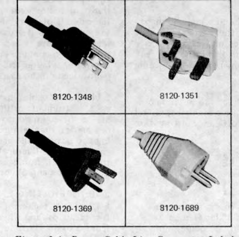
2-1. Power Cable Line Connector Labels. . ........2-2
3-1. Model 8444A Tracking Generator Front Panel
Controls, Indicators and Connectors ......3-2
3-2. Model 8444A Tracking Generator Rear Panel
Controls and Connectors ......................3-3
3-3. Tracking Generator Operation with 8554B
Spectrum Analyzer ...............................3-4
3-4. Tracking Generator Operation with 8555A
Spectrum Analyzer ...............................3-6
3-5. 20 MHz. Crystal Filter CRT Display..............3-8
3-6. 50 MHz. Bandpass Filter CRT Display ........3-8
3-7. 23 MHz Low-Pass Gilter CRT Display..........3-9
3-8. Swept Return Loss Measurement
CRT Display..........................................3-9
3-9. Amplifier Gain and Bandwidth CRT Display. 3-9
3-10. Precision Frequency Measurement
CRT Display..........................................3-10
4-1. Output Level & Flatness Test Setup.4-3
4-2. Residual FM Test Setup ..............................4-7
4-3. Demodulation Sensitivity Measurement.......4-8
4-4. System Flatness Test Setup .......................4-9
4-5. Frequency Accuracy Test Setup ..................4-11
4-6. Harmonic Distortion Test Setup ...................4-13
4-7. Typical Harmonic Distortion CRT Display
0 to 100 MHz.........................................4-15
4-8. Typical Harmonic Distortion CRT Display
0 to 500 MHz ........................................4-15
5-1. Power Supply Check and Adjustment
Test Setup ............................................5-2
5-2. 1.55 GHz LO Power Level and Frequency
Check and Adjustment Test Setup ........5-4
5-3. 1.55 GHz LO Residual FM Check Test Setup.....5-6
5-4. Demodulation Sensitivity Measurement .....5-8
5-5. First Converter Check and Adjustment Test
Setup.....................................................5-9
5-6. First Converter Passband CRT Display........5-10
5-7. Automatic Level Control (ALC) Check and
Adjustment Test Setup.................................5-11
5-8. Level Control Calibration Check and Adjust-
ment Test Setup....................................5-13
7-1. 1.55 GiHz LO Power Level and Check and
Adjustment Test Setup ..........................7-2
Figure Page
7-2. First Converter Circuits, Schematic Diagram ..7-5
7-3. A7 1.55 GHz Oscillator Assembly,
Illustrated Parts Breakdown ................7-6
8-1. Transistor Operation. ..............................8-5
8-2. Examples of Diode and Transistor Marking
Methods .............................................8-6
8-3. Operational Amplifier Equivalent Circuit . .8-7
8-4. Major Assembly Locations. . ..................8-9
8-5. Adjustment and Test Point Locations........8-9
8-6. Tracking Generator Spectrum Analyzer,
Simplified Block Diagram . ...............8-10
8-7. Tracking Generator Block Diagram with
Spectrum Analyzer Interconnections...8-11
8-7A. Troubleshooting Tree . ...........................8-12
8-8. Tracking Generator Troubleshooting
Block Diagram. . ..............................8-13
8-9. Mixer Diode Forming Dimensions in Inches . ..8-14
8-10. Modulator/Oscillator Driver Assy A2
Component Locations . ....................8-15
8-11. Amplifier and Pin Diode Modulator Assy
A4A1 Component Locations . ...........8-15
8-12. First Converter Circuits
Schematic Diagram............................8-15
8-13. J1 RF Output Connector, Exploded View..8-16
8-14. A2 Modulator/Oscillator Driver Assy,
Component Location ........................8-17
8-15. Second Converter Circuits,
Schematic Diagram ..........................8-17
8-16. Al Power Supply Assy, Component Location...8-19
8-17. Power Supply and Input Circuit,
Schematic Diagram............................8-19
8-18. A5 First Converter Assembly
Illustrated Parts Breakdown ................8-20
8-19. A71.55GHz Oscillator Assembly
Illustrated Parts Breakdown ................8-21
D-1. 500 MHz LO Mounting Location and Output
Port for the 8444A, Option 058 ...........D-6
D-2. Location of 500 MHz LO OUTPUT BNC
Connector Added on Rear Panel of
the 8444A, Option 058........................D-7
D-3. A9 500 MHz Oscillator Assembly, Schematic..D-8
iii
TM 11-6625-2866-14&P
Contents LIST OF TABLES
Table Page
1-1. System Specifications...............................1-3
1-2. Accessories Supplied................................1-4
1-3. Test Equipment and Accessories . ..........1-5
1-4. Operating Accessories ............................1-7
4-1. Performance Test Record . .....................4-16
5-1. Check and Adjustment Test Card ............5-15
6-1. Reference Designations and Abbreviations. ....6-2
6-2. Replaceable Parts ....................................6-4
6-3. Code List of Manufacturers.......................6-8
6-4. Part Number-National
Stock Number Cross
Reference Index .......................................6-9
Table Page
7-1. Manual Changes by Serial Number...........7-1
8-1. Factory Selected Components..................8-2
8-2. Adjustable Components . .......................8-2
8-3. Schematic Diagram Notes . ....................8-3
8-4. Etched Circuit Soldering Equipment..........8-4
D-1. 8444A System Specifications With Option 058 D-1
D-2. Replaceable Parts ....................................D-4
APPENDIXES
A. SERVICE NOTE-P-09602038,
P-5086-6025 ............................................A-1
B. SERVICE NOTE-P-08444-60019..............B-1
C. SERVICE NOTE-8444A-1 ........................C-1
D. MODEL 8444A TRACKING GEN-
ERATOR, OPTION 058 ...........................D-1
E. REFERENCES ........................................E-1
F. COMPONENTS OF END ITEM
LIST .........................................................F-1
G. ADDITIONAL AUTHORIZA-
TION LIST ...............................................G-1
H. MAINTENANCE ALLOCATION ................H-1
I. REPAIR PARTS AND SPECIAL
TOOLS LISTS .........................................I-1
iv

TM 11-6625-2866-14&P
Figure 1-1. Model 8444A Tracking Generator and Accessories
1-0
TM 11-6625-2866-14&P
SECTION 0
INTRODUCTION
0-1. SCOPE
This manual describes Generator, Tracking SG-1125/U
(Hewlett Packard Model 8444A) and provides
instructions for operation and maintenance.
0-2. INDEXES OF PUBLICATIONS
a. DA Pam 310-4. Refer to the latest issue of DA
Pam 310-4 to determine whether there are new editions,
changes, or additional publications pertaining to the
equipment.
b. DA Pam 310-7. Refer to DA Pam 310-7 to
determine whether there are modification work orders
(MWO's) pertaining to the equipment.
0-3. MAINTENANCE FORMS, RECORDS, AND
REPORTS
a. Reports of Maintenance and Unsatisfactory
Equipment. Department of the Army forms and
procedures used for equipment maintenance will be
those described by TM 38-750, The Army Maintenance
Management System.
b. Report of Packaging and Handling Deficiencies.
Fill out and forward DD Form 6 (Packaging
Improvement Report) as prescribed in AR 700-
58/NAVSUPINST 4030.29/AFR 71-13/MCO
P4030.29A, and DLAR 4145.8.
c. Discrepancy in Shipment Report (DISREP) (SF
361). Fill out and forward Discrepancy in Shipment
Report (DISREP) (SF 361) as prescribed in AR 55-
38/NAVSUPINST 4610.33B/AFR 75-18/MCO
P4610.19C and DLAR 4500.15.
0-4. REPORTING EQUIPMENT IMPROVEMENT
RECOMMENDATIONS (EIR)
EIR can and must be submitted by anyone who is aware
of an unsatisfactory condition with the equipment design
or use. It is not necessary to show a new design or list a
better way to perform a procedure; just simply tell why
the design is unfavorable or why a procedure is difficult.
EIR may be submitted on SF 368 (Quality Deficiency
Report). Mail direct to Commander, US Army
Communications and Electronics Materiel Readiness
Command, ATTN: DRSEL-ME-MQ, Fort Monmouth, NJ
07703. A reply will be furnished to you.
0-5. ADMINISTRATIVE STORAGE
Administrative storage of equipment issued to and used
by Army activities shall be in accordance with paragraph
.2-16.
0-6. DESTRUCTION OF ARMY ELECTRONICS
MATERIEL
Destruction of Army electronics materiel to prevent
enemy use shall be in accordance with TM 750-244-2.
0-1

Model 8444A TM 11-6625-2866-14&P
General Information
SECTION I
GENERAL INFORMATION
1-1. INTRODUCTION
1-2. This manual contains all information required to
install, operate, test, adjust and service the Hewlett-
Packard Model 8444A Tracking Generator. This section
covers instrument identification, description, options,
accessories, specifications and other basic information.
1-3. Figure 1-1 shows the Hewlett-Packard Model
8444A Tracking Generator with accessories supplied.
1-4. The various sections in this manual provide
information as follows:
SECTION II, INSTALLATION, provides
information relative to incoming inspection, power
requirements, mounting, packing and shipping,
etc.
SECTION III, OPERATION, provides information
relative to operating the instrument.
SECTION IV, PERFORMANCE TESTS, provides
information required to ascertain that the
instrument is performing in accordance with
published specifications.
SECTION V, ADJUSTMENTS, provides
information required to properly adjust and align
the instrument after repairs are made.
SECTION VI, REPLACEABLE PARTS, provides
ordering information for all replaceable parts and
assemblies.
SECTION VII, MANUAL CHANGES, normally will
contain no relevant information in the original
issue of a manual. This section is reserved to
provide back-dated and up-dated information in
manual revisions or reprints.
SECTION VIII, SERVICE, includes all information
required to service the instrument.
1-5. SAFETY CONSIDERATIONS
1-6. General
1-7. This is an International Electrotechnical
Commission Safety Class I instrument. This instrument
has been designed and tested according to IEC
Publication 348, "Safety Requirements for Electronic
Measuring Apparatus, " and has been supplied in safe
condition.
1-8. Operation
1-9. BEFORE APPLYING POWER, make sure the
instrument's ac input is set for the available ac line
voltage, that the correct fuse is installed, and that all
normal safety precautions have been taken.
1-10. Service
1-11. Although the instrument has been designed in
accordance with international safety standards, the
information, cautions, and warnings in this manual must
be followed to ensure safe operation and to keep the
instrument safe. Service and adjustments should be
performed only by qualified service personnel.
1-12. Adjustment or repair of the opened instrument
with the ac power connected should be avoided as much
as possible and, when inevitable, should be performed
only by a skilled person who knows the hazard involved.
1-13. Capacitors inside the instrument may still be
charged even though the instrument has been
disconnected from its source of supply.
1-14. Make sure only fuses of the required current
rating and type (normal blow, time delay, etc.) are used
for replacement. Do not use repaired fuses or short
circuit the fuse holders.
1-15. Whenever it is likely that the protection has been
impaired, make the instrument inoperative and secure it
against any unintended operation.
WARNING
If this instrument is to be energized through an
autotransformer (for voltage reduction), make sure
the common terminal is connected to the earthed
pole of the power source.
BEFORE SWITCHING ON THE INSTRUMENT,
the protective earth terminals of the instrument
must be connected to the protective conductor of
the mains power cord. The mains plug shall only
be inserted in a socket outlet provided with
1-1
Model 8444A TM 11-6625-2866-14&P
General Information
protective earth contact. The protection must not be
negated by using an extension cord (power cable)
without a protective grounding conductor.
Interruption of the protective (grounding) conductor,
inside or outside the instrument, or disconnection of
the protective earth terminal is likely to make this
instrument dangerous. Intentional interruption of the
earth ground is prohibited.
Servicing this instrument often requires that you
work with the instrument's protective covers
removed and with ac power connected. Be very
careful; the energy at many points in the instrument
may, if contacted, cause personal injury.
With the ac power cable connected, the ac line
voltage is present at the terminals of the power line
module and at the LINE power switch. Be very
careful. Bodily contact with this voltage can be
fatal.
CAUTIONS
BEFORE SWITCHING ON THIS INSTRUMENT,
make sure instrument's ac input is set to the voltage
of the ac power source.
BEFORE SWITCHING ON THIS INSTRUMENT,
make sure that all devices connected to the
instrument are connected to the protective earth
ground.
BEFORE SWITCHING ON THIS INSTRUMENT,
make sure the line power (mains) plug is connected
to a threeconductor line power outlet that has a
protective (earth) ground. (Grounding one
conductor of a two-conductor outlet is not sufficient.
BEFORE SWITCHING ON THIS INSTRUMENT,
make sure the ac line fuse is of the required current
rating and type (normal-blow, time-delay, etc.).
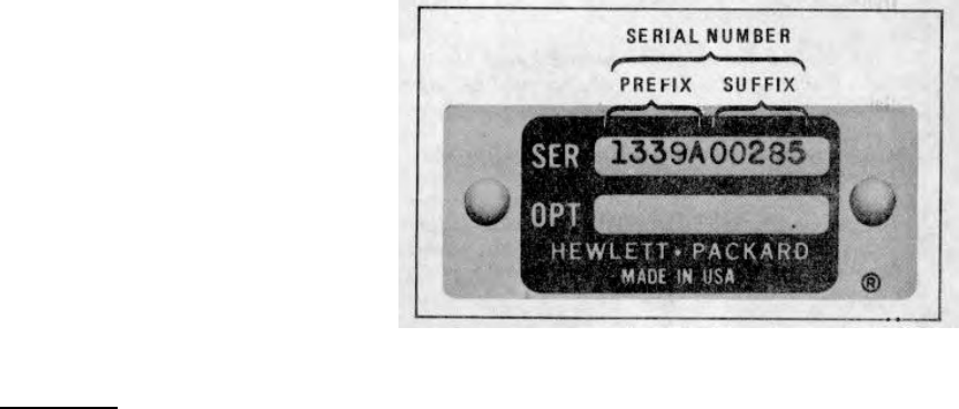
1-16. INSTRUMENTS COVERED BY MANUAL
1-17. Hewlett-Packard instruments carry a serial
number (see Figure 1-2) on the back panel. When 1-2
the serial number prefix on the instrument serial number
plate of your instrument is the same as one of the prefix
numbers on the inside title page of this manual, the
manual applies directly to the instrument. When the
instrument serial number prefix is not listed on the inside
title page of initial issue, manual change sheets and
manual up-dating information is provided. Later editions
or revisions to the manual will contain the required
change information in Section VII.
Figure 1-2. Instrument Identification
1-18. DESCRIPTION
1-19. The Model 8444A Tracking Generator is designed
to complement both Model 8554B and Model 8555A
Spectrum Analyzer RF Sections. The Tracking
Generator covers the frequency range of 500 kHz to
1250 MHz when used with the 8554B RF Section and
from 10 MHz to 1.3 GHz when used with the 8555A RF
Section. The Tracking Generator/Spectrum Analyzer
functions as a system to perform frequency response
measurements. Additionally, the system can be used as
a signal generator or sweeper to supply a test signal to
other devices. An auxilliary output is provided for
precision frequency measurements by an external
frequency counter.
1-20. The Tracking Generator converts the first and
third local oscillator (LO) signals from the Spectrum
Analyzer RF Section, to a signal that tracks the
frequency tuning of the RF Section. With the Spectrum
Analyzer operating in ZERO SCAN WIDTH, the
Tracking Generator is a CW signal generator, tuned to
the frequency of the analyzer.
In FULL or PER DIVISION SCAN WIDTH the Tracking
Generator functions as a sweep oscillator which tracks
the analyzer tuning. Additionally, a
1-2

Model 8444A TM 11-6625-2866-14&P
General Information
Table 1-1. System Specifications
These system specifications describe the performance available from the
spectrum analyzer-tracking generator system in various types of
applications. In all cases it is assumed that the spectrum analyzer is
equipped with either an 8554B or 8555A Tuning Section, 8552A or 8552B
IF Section, 140T or 141T Display Section.
SWEPT FREQUENCY RESPONSE MEASUREMENTS The tracking
generator is used as a signal source to measure the frequency response
of a device.
Dynamic Range: > 90 dB from spectrum analyzer 1 dB gain
compression point to average noise level (approximately -10 dBm to
-100 dBm). Spurious responses not displayed.
Gain Compression: For -10 dBm signal level at the input mixer, gain
compression < 1 dB.
Average Noise Level: > -102 dBm with 10 kHz IF bandwidth.
Absolute Amplitude Calibration Range:
Spectrum Analyzer: Log: From -122 dBm to +10 dBm, 10 dB/div
on a 70 dB display or 2 dB/div on a 16 dB display (8552A has 10
dB/div only).
Linear: From 0.1 pV/div to 100 mV/div (8555A), 20 mV/div (8554B)
in a 1, 2 sequence on an 8division display.
Tracking Generator (Drive Level to Test Device): 0 to -10 dBm
continuously variable. 0 dBm calibrated to +0.5 dB at 30 MHz.
Frequency Range: 500 kHz to 1250 MHz with 8554B and 10 MHz
to 1300 MHz with 8555A.
Scan Width (Determined by Spectrum Analyzer Controls):
Per Division: With 8555A, 16 calibrated scan widths from a 2
kHz/div to 200 MHz/div in a 2, 5, 10 sequence. With 8554B, 15
calibrated scan widths from a 2 kHz/div to 100 MHz/div in 2, 5, 10
sequence.
Full Scan: 0--1250 MHz with 8554B; 0-1300 MHz with 8555A.
Zero Scan: Analyzer is fixed tuned receiver.
Frequency Resolution: 1 kHz.
Stability:
Residual FM (peak to peak):
Tuning Section Stabilized Unstabilized
8554B/8555A 200 Hz 10 kHz
Amplitude Accuracy:
System Frequency Response: +1.5 dB.
Tracking Generator Calibration: 0 dBm at 30 MHz to +0.5 dB.
SWEEP/CW GENERATOR
The tracking generator-spectrum analyzer system can be used to supply
test signals for other devices as a sweeper.
Frequency: Controlled by spectrum analyzer. Range is 500 kHz to 1250
MHz with the 8554B and 10 MHz to 1300 MHz with the 8555A.
Frequency Accuracy: +10 MHz (8554B), +15 MHz (8555A) using
spectrum analyzer tuning dial. Can be substantially improved using
external counter output.
Spectral Purity:
Residual FM (peak-to-peak):
Tuning Section Stabilized Unstabilized
8554B/8555A 200 Hz 10 kHz
Harmonic Distortion: 25 dB below output
level.
Nonharmonic (spurious) Signals: >40 dB below
output level.
Flatness: +/- 0.5 dB.
Long Term Stability: Drift typically less than 30 kHz/hour when
stabilized after 2-hour warmup.
Sweep Width: 20 kHz to 1250 MHz (8554B) or 1300 MHz (8555A).
Sweep Rates: Selected by Scan Time per Division on spectrum
analyzer. 16 internal scan rates from 0.1 msec/div to 10 sec/div in a
1, 2, 5 sequence. Manual Scan is available with the external sweep
voltage from the 8444A or by a front panel control of the 8552B IF
Section.
PRECISION FREQUENCY MEASUREMENTS
An external counter output is provided on the 8444A for precision
frequency measurements. The frequency of unknown signals as well as
the frequency of any point on a frequency response curve can be
measured. The use of the HP 5300A/5303A Counter is suggested for
frequency measurements to 500 MHz and the HP 5245L/5254C Counter
for measurements to 1300 MHz.
Frequency Accuracy:
For unknown signals +10 kHz. (Tracking drift typically 5 kHz/10
min after 2-hour warmup.)
For points on frequency response curve. Counter
accuracy ±Residual FM.
Counter Mode of Operation:
Manual Scan: Scan determined either by front panel control of
8552B IF Section or by external scan signal provided by
the 8444A.
Zero Scan: Analyzer is fixed tuned receiver. Counter reads
center frequency to accuracy of tracking drift.
Counter Output Level: 0.1 V rms.
GENERAL SPECIFICATIONS
Temperature Range: Operation, 0 to 550C, storage -40°C to 75 C.
Power: 115V and 230V, 48 to 440 Hz, 12 watts max.
1-3

Model 8444A TM 11-6625-2866-14&P
General Information
MANUAL SCAN control on the Tracking Generator
allows manual tuning of the Spectrum Analyzer/Tracking
Generator System. The amplitude of the Tracking
Generator output is adjustable over a 0 to -10 dBm
range by a front panel vernier control. The output level
is calibrated at 30 MHz to 0 +/- 0.5 dBm and maintained
by an automatic level control circuit. Refer to Table 1-1
for system performance specifications.
1-21. 8554L RF SECTION MODIFICATIONS
1-22. Hewlett-Packard Model 8554L Spectrum Analyzer
RF Section with serial prefixes 1101A and below require
modification for Tracking Generator compatibility. The
modification consists of adding two cables to the RF
Section. The cables provide front panel access to the
first and third LO outputs. The modification kit, HP Part
Number 08554-60056, containing all necessary parts
and information is available from any Hewlett-Packard
Sales and Service Office. (A list of Sales and Service
offices is contained in the back of this manual.) Service
Note 8554L-6 containing the modification procedure is
included with the modification kit. After modification,
the Service Note should be filed with the 8554L Service
Manual.
1-23. ACCESSORIES SUPPLIED
1-24. Accessories supplied with the Tracking Generator
are listed in Table 1-2. RF cables, supplied with the
Tracking Generator, allow operation with either the
8554B or 8555A Spectrum Analyzer RF Sections. The
power cable, supplied with the instrument, is selected at
time of shipment. Cable selection is based on shipping
destination. Figure 2-1 illustrates the different power
cable connectors that are currently available.
1-25. OPERATING ACCESSORIES
1-26. In addition to the accessories supplied with the
Tracking Generator, a Spectrum Analyzer System is
required to complete the Tracking Generator Spectrum
Analyzer System. The Tracking Generator is
compatible with either the 8554B/8552( )/140-series
Spectrum Analyzer System or the 8555A/8552( )/140-
series Spectrum Analyzer System. Refer to paragraph
1-11 for modifications to early model Spectrum Analyzer
Systems. For precision frequency measurements a
frequency counter is required for use with the Tracking
Generator/Spectrum Analyzer System. Operating
accessories are listed in Table 1-4.
1-27. WARRANTY
1-28. The Hewlett-Packard Model 8444A Tracking
Generator is warranted and certified as indicated on the
inner front cover of this manual. For further information
contact the nearest Hewlett Packard Sales and Service
office; addresses are provided at the back of this
manual.
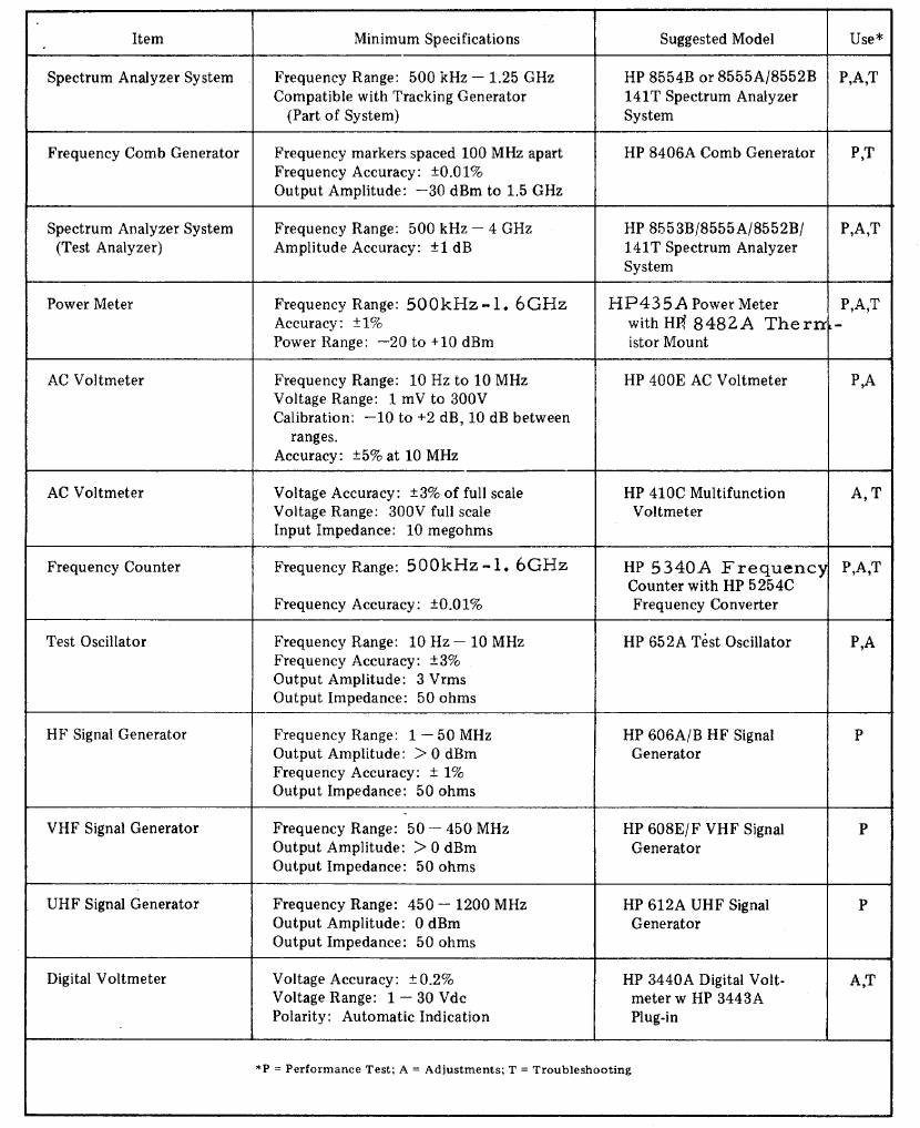
1-29. RECOMMENDED TEST EQUIPMENT
1-30. Table 1-3 lists the test equipment and accessories
required to check, adjust, and repair the Tracking
Generator. If substitute equipment is used, it must meet
the Minimum Specifications listed in Table 1-3.
Table 1-2. Accessories Supplied
HP Part Number Name Description
8120-1348* Line Power Cable 71 feet, 3 wire AC Line Cord
08444-60017 Interconnect Cable Coaxial cable for interconnection between AUX "A" connector
on Display Section and THIRD LO INPUT on Tracking Generator.
For use with 8555A Spectrum Analyzer System.
08444-60018 Interconnect Cable 18-inch low leakage coaxial cable with BNC connectors. Three
(3) each supplied. Two required for 8555A Spectrum Analyzer
System. Three required for 8554B Spectrum Analyzer System.
Connects FIRST LO to FIRST LO, THIRD LO to THIRD LO
and SCAN OUTPUT to SCAN IN/OUT.
*See paragraph 2-15 and Figure 2-1.
1-4
Model 8444A TM 11-6625-2866-14&P
General Information
Table 1-3. Test Equipment and Accessories (1 of 3)
1-5
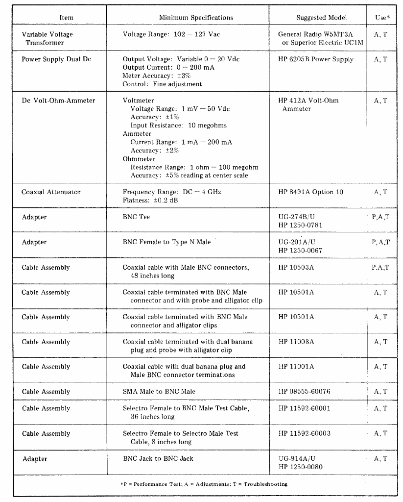
Model 8444A TM 11-6625-2866-14&P
General Information
Table 1-3. Test Equipment and Accessories (2 of 3)
1-6
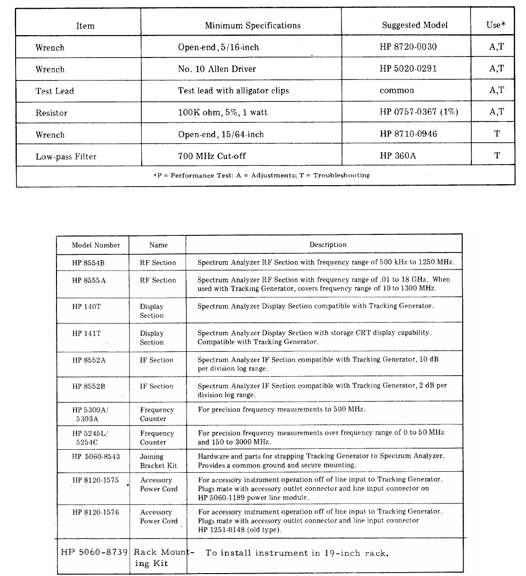
Model 8444A TM 11-6625-2866-14&P
General Information
Table 1-3. Test Equipment and Accessories (3 of 3)
Table 1-4. Operating Accessories
1-7/(1-8)

Model 8444A TM 11-6625-2866-14&P
Installation
SECTION II
INSTALLATION
2-1. INITIAL INSPECTION
2-2. Mechanical Check
2-3. Check the shipping carton for evidence of damage
immediately after receipt. If there is any visible damage
to the carton, request the carrier's agent be present
when the instrument is unpacked. Inspect the
instrument for physical damage such as bent or broken
parts and dents or scratches. If damage is found refer
to paragraph 2-6 for recommended claim procedures. If
the instrument appears to be undamaged, perform the
electrical check (see paragraph 2-4). The packaging
material should be retained for possible future use.
2-4. Electrical Check
2-5. The electrical check consists of following the
performance test procedures listed in Section IV. These
procedures allow the operator to determine that the
instrument is, or is not, operating within the
specifications listed in Table 1-1. The initial
performance and accuracy of the instrument are
certified as stated on the inside front cover of this
manual. If the instrument does not operate as specified,
refer to paragraph 2-6 for the recommended claim
procedure.
2-6. CLAIMS FOR DAMAGE
2-7. If physical damage is found when the instrument is
unpacked, notify the carrier and the nearest Hewlett-
Packard Sales and Service office immediately. The
Sales and Service office will arrange for repair or
replacement without waiting for a claim to be settled
with the carrier.
2-8. The warranty statement for the instrument is on the
inside front cover of this manual. Contact the nearest
Sales and Service office for information about warranty
claims.
2-9. PREPARATION FOR USE
CAUTION
Before applying power, check the power selector
switch on the Tracking Generator input power
module (rear panel) for proper position (115 or
230 volts).
2-10. Power Requirements
2-11. The Tracking Generator can be operated from a
48to 440-hertz input line that supplies either 115or 230-
volt (+10% in each case) power. Consumed power is
normally less than 15 watts.
2-12. The 115/230 power selector switch on the rear
panel line power module must be set to agree with the
available line voltage. The selector switch is located
below the fuse holder and fuse extractor lever. An
arrow on the selector switch points to callouts listing the
line input voltage and fuse amperage rating. To change
the position of the selector switch it is necessary to
remove the power cable, slide the protective cover to
the left and lift the fuse extractor before the switch can
be changed. With the fuse extractor extended, press
down and toward the desired direction. Replace fuse
with a fuse of the amperage rating for the selected
position. See Section VI for replacement HP Part
Numbers. The instrument is normally shipped with fuse
installed for 115-volt operation.
2-13. Power Cable
2-14. To protect operating personnel, the National
Electrical Manufacturers Association (NEMA) and the
International Electrotechnical Commission (IEC)
recommends that the instrument panel and cabinet be
grounded. The Tracking Generator is equipped with a
three-conductor power cable; the third conductor is the
ground conductor and when the cable is plugged into an
appropriate receptacle, the instrument is grounded. To
preserve the protection feature when operating the
instrument from a two-contact outlet, use a three-prong
to two-prong adapter and connect the green or green/
yellow lead on the adapter to ground.
2-15. Power cables are selected for shipment with each
instrument; with a line connector plug to match the
standard power cord for the country of destination on the
purchase order. A label indicating the power cable
inside is affixed to the packing case. Figure 2-1
indicates the connector plugs and the HP part numbers
for the various available power cables and plugs.
2-16. OPERATING ENVIRONMENT
2-17. The Tracking Generator does not require forced
air cooling when operating at temperatures from 0 to
55°C (32 to 131°F). When operating the instrument,
choose a location which will provide at
2-1
Model 8444A TM 11-6625-2866-14&P
Installation
least three inches of clearance around the rear and both
sides. Normal air circulation will maintain a reasonable
temperature within the instrument.
2-18. INSTALLATION CONNECTIONS
2-19. A rack mounting kit is supplied for rack
installation. Additionally, a joining bracket kit
(accessory) can be provided to secure the Tracking
Generator to the Spectrum Analyzer. Installation
instructions are supplied with both joining bracket and
rack mounting kits.
2-20. Electrical connections are provided by three
coaxial cables and two line power cords. Coaxial cables
connect Spectrum Analyzer FIRST LO OUTPUT to
Tracking Generator FIRST LO INPUT, THIRD LO
OUTPUT to THIRD LO INPUT and SCAN OUTPUT to
SCAN IN/OUT. Double shielded coaxial cables are
provided for connection between local oscillator input
and output connectors. Refer to Table 1-2 for
description and HP part number of cables supplied with
the Tracking Generator.
2-21. STORAGE AND SHIPMENT
2-22. Original Packaging
2-23. The same containers and materials used in
factory packaging can be obtained through the Hewlett-
Packard Sales and Service offices listed at the rear of
this manual.
2-24. If the instrument is being returned to Hewlett-
Packard for servicing, attach a tag indicating service
required, return address, instrument model number and
full serial number. Mark the container FRAGILE to
assure careful handling.
2-25. In any correspondence refer to the instrument by
model number and full serial number.
2-26. Other Packaging Materials
2-27. The following general instructions should be
followed when repackaging with commercially available
materials:
a. Wrap the instrument in heavy paper or plastic.
(If shipping to a Hewlett-Packard Service office or
center attach a tag indicating the type of service
required, return address, model number and full serial
number.)
b. Use a strong shipping container. A double-wall
carton made of 350 pound test material is adequate.
c. Use enough shock-absorbing material (three to
four inch layer) around all sides of the instrument to
provide firm cushion and prevent movement inside the
container. Protect the control panel with cardboard.
d. Seal the shipping container securely.
e. Mark the shipping container FRAGILE to assure
careful handling.
Figure 2-1. Power Cable Line Connector Labels
2-2
Model 8444A TM 11-6625-2866-14&P
Operation
SECTION III
OPERATION
3-1. INTRODUCTION
3-2. This section provides complete operation
instructions for the HP Model 8444A Tracking
Generator. Front and rear panel controls, connectors
and indicators for the Tracking Generator are identified
and described in Figures 3-1 and 3-2. Operational
connections and adjustments for the Tracking Generator
and an 8554B Spectrum Analyzer System are detailed
in Figure 3-3. Operational connections and adjustments
for the Tracking Generator and an 8555A Spectrum
Analyzer System are detailed in Figure 3-4. Additional
operating information is contained in Figures 3-5
through 3-10.
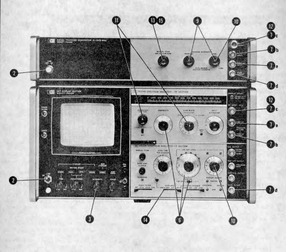
3-3. PANEL FEATURES
3-4. Front and rear panel features of the Tracking
Generator are described in Figures 3-1 and 3-2. Front
and rear panel views of the Tracking Generator
connected to the HP 8554B/8552/141T Spectrum
Analyzer are shown in Figure 3-3. Front and rear panel
views of the Tracking Generator connected to the HP
8555A/8552/141T Spectrum Analyzer are shown in
Figure 3-4. For a detailed description of the Spectrum
Analyzer controls, connectors and indicators refer to the
appropriate operating and service manuals for those
instruments. Interconnection wiring between the
Tracking Generator and the Spectrum Analyzer is
contained in Section VIII (Service Sheet 1) of this
manual.
3-5. OPERATOR'S CHECKS
3-6. Upon receipt of the instrument, or when the
Tracking Generator is to be used with a different
Spectrum Analyzer, perform the operational adjustment
procedures listed in Figure 3-3 or 3-4.
3-7. OPERATING INSTRUCTIONS
3-8. General operating instructions are contained in
Figures 3-3 and 3-4. These instructions will familiarize
the operator with basic operating functions of the
Tracking Generator in use with Spectrum Analyzers.
Additional operating techniques and information is
contained in Figures 3-5 through 3-10.
3-9. CONTROLS, INDICATORS AND CONNECTORS
3-10. Front and rear panel controls, indicators and
connectors are identified and briefly described in
Figures 3-1 and 3-2. Operational adjustment
procedures are given in Figures 3-3 and 3-4. Additional
information, to assist the user during instrument
operation, is given in the following paragraphs.
3-11. OPERATING TECHNIQUES
3-12. The following information is provided to acquaint
the user with Tracking Generator/ SpectrumAnalyzer
operation. When a device is placed in the signal path
between the Tracking Generator and the Spectrum
Analyzer, the analyzer detects and displays the
frequency response of the device under test. The
Spectrum Analyzer tuning and scan width settings
determine the Tracking Generator output frequency and
the resultant CRT display. The type of device, control
settings, and typical display is provided for each of the
following measurements.
a. Crystal Filter Measurement, Para. 3-13.
b. Bandpass Filter Measurement, Para. 3-15.
c. Low-Pass Filter Measurement, Para. 3-17.
d. Swept Return Loss Measurement, , Para. 3-19.
e. Amplifier Gain and Bandwidth Measurement,
Para. 3-21.
f. Precision Frequency Measurement, Para. 3-23.
3-1
Model 8444A TM 11-6625-2866-14&P
Operation
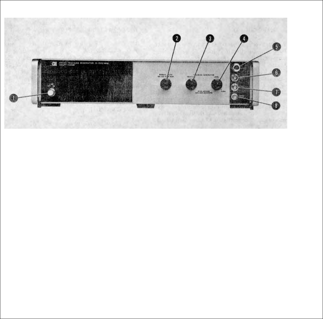
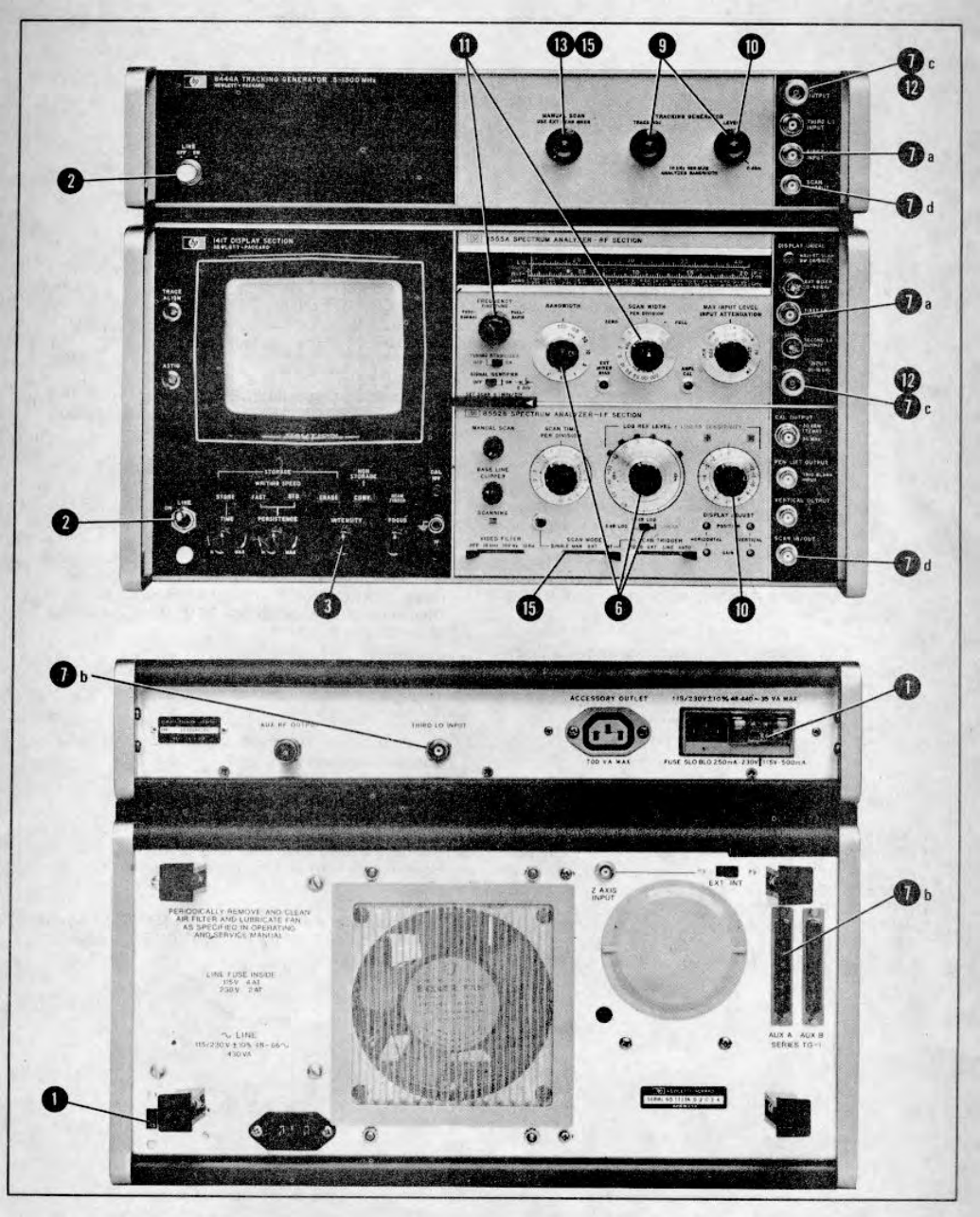
FRONT PANEL
1. LINE - ON/OFF. Controls primary power to Tracking
Generator. Light glows when switch is energized.
Type A1H bulb. For access to bulb, switch to OFF
and pull button straight out.
2. MANUAL SCAN. Provides manual tuning of
Spectrum Analyzer. Controls voltage level at SCAN
OUTPUT (8) below. Scan trace on CRT determined
by position of MANUAL SCAN control. For MANUAL
SCAN operation, connect cable between Tracking
Generator SCAN OUTPUT and Spectrum Analyzer
SCAN IN/OUT. Set Spectrum Analyzer SCAN
MODE switch to EXT. Vary MANUAL SCAN control
to tune analyzer through selected SCAN WIDTH.
3. TRACK ADJ. Adjusts frequency of 1.55 GHz
oscillator in Tracking Generator so that the RF
OUTPUT (5) tracks the frequency tuning of the
Spectrum Analyzer. Control adjusted for maximum
amplitude indication of trace on CRT display. Ten
turn control provides adjustment of frequency over a
range of approximately 4 MHz.
4. LEVEL. Adjusts Tracking Generator RF OUTPUT
(5) level over range of 0 to -10 dBm. Level
calibrated
for 0 dBm at 30 MHz with accuracy of +0.5 dB. Set
LEVEL control to 0 dBm for calibrated CRT display
on Spectrum Analyzer.
5. RF OUTPUT. Type N Connector - Tracking
Generator RF output connector. Frequency adjusted
to track tuning of Spectrum Analyzer by TRACK ADJ
(3). Output level adjusted by LEVEL (4).
6. THIRD LO INPUT. Type BNC connector Input for
Spectrum Analyzer third LO (500 MHz). Normally
used with 8554B RF Section. Parallel with rear panel
THIRD LO INPUT which is normally used with 8555A
RF Section.
7. FIRST LO INPUT. Type BNC connector-Input for
Spectrum Analyzer first LO (2.05 - 3.3 GHz with
8554L RF Section) - (2.05 - 4.1 GHz with 8555A RF
Section).
8. SCAN OUTPUT. Type BNC connector. Manual
tune voltage to Spectrum Analyzer (0 to 10 Vdc).
Voltage level controlled by position of MANUAL
SCAN (2).
Figure 3-1. Model 8444A Tracking Generator Front Panel Controls, Indicators and Connectors
3-2
Model 8444A TM 11-6625-2866-14&P
Operation
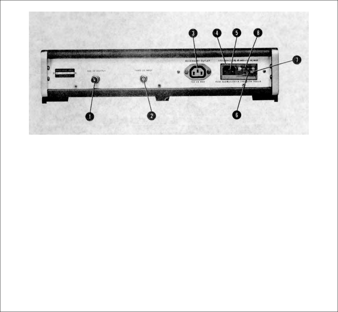
REAR PANEL
1. AUX RF OUTPUT. Type BNC connector Tracking
Generator auxiliary RF output. Same frequency as
signal out front panel RF OUTPUT connector. For
use with external frequency counter during precision
frequency measurements. Terminate in 50 ohms.
2. THIRD LO INPUT. Type BNC connector Input for
Spectrum Analyzer third LO (500 MHz). Normally
used with 8555A RF Section. Parallel with front
panel THIRD LO INPUT which is normally used with
8554B RF Section.
3. ACCESSORY OUTLET. Line power outlet.
Connected to power line module input. Provides ac
outlet for use by accessory equipment.
Note
See Table 14 for HP part numbers of
interconnecting power cords.
4. Line power module. 115/230V, 48-440 Hz.
5. Line input. Connects to external ac power source.
Supplies ac power to ACCESSORY OUTLET when
connected to external power source.
6. 115/230V Switch. Line voltage slide switch; controls
power supply input connections. Check that switch is
set for nominal voltage of ac line. To change setting:
remove power cord from line input (5) , slide
protective cover aside, extract fuse with FUSE PULL
(7) and slide switch to desired position. Replace fuse
with a fuse of the value indicated for the desired
switch position.
7. Fuse extractor and switch lock. Prevents line switch
from being actuated until fuse is extracted.
8. Line input fuse. Rating of fuse to be used is marked
near line voltage slide switch setting corresponding to
nominal ac supply voltage.
Figure 3-2. Model 8444A Tracking Generator Rear Panel Controls and Connectors
3-3
Model 8444A TM 11-6625-2866-14&P
Operation
Figure 3-3. Tracking Generator Operation with 8554B Spectrum Analyzer (1 of 2)-,
3-4

Model 8444A TM 11-6625-2866- 14&P
Operation
OPERATING PROCEDURE
WITH AN 8554B
1. Check that the 115/230V switch is set to correspond
with the available line voltage. Refer to Figure 3-2,
steps 4 through 8, for switch and fuse information.
2. Apply power to Tracking Generator and Spectrum
Analyzer.
3. Turn Spectrum Analyzer INTENSITY control fully
CCW.
4. Allow instruments to warm up for at least 30 minutes.
5. Perform Spectrum Analyzer "Calibration Procedure".
Refer to 8554B RF Section Operating Manual.
6. Set Spectrum Analyzer LOG/LINEAR control to
LOG, LOG REF LEVEL to 0 dBm, and
BANDWIDTH to 300 kHz.
7. Make the following interconnections between
Tracking Generator and Spectrum Analyzer:
a. FIRST LO INPUT to FIRST LO OUTPUT.
b. THIRD LO INPUT to THIRD LO OUTPUT.
c. RF OUTPUT to RF INPUT.
d. SCAN OUTPUT to SCAN IN/OUT.
8. Check that the Spectrum Analyzer controls are set as
follows:
INTENSITY ..................................12 o'clock (approx.)
FREQUENCY .............................................. 30 MHz
BANDWIDTH ................................................ 300 kHz
SCAN WIDTH PER DIVISION ...................... 50 kHz
INPUT ATTENUATION ................................... 10 dB
TUNING STABILIZER .......................................... On
BASE LINE CLIPPER ..................................... CCW
SCAN TIME PER DIVISION ........ 5 MILLISECONDS
LOG/LINEAR ................................................... LOG
LOG REF LEVEL ............................................ O dBm
LOG REF LEVEL Vernier ......................................... 0
VIDEO FILTER .................................................. OFF
SCAN MODE ....................................................... INT
SCAN TRIGGER ............................................. LINE
9. Set Tracking Generator LEVEL control to 0 dBm and
adjust TRACK ADJ for maximum signal amplitude
indication on CRT display.
10. Adjust Spectrum Analyzer Vernier control or
Tracking Generator LEVEL control to position signal
on CRT LOG REF level graticule line. (System
calibrated at 30 MHz with an amplitude accuracy of
+/- 0.5 dB.)
11. Set Spectrum Analyzer to scan desired frequency
range. (FREQUENCY control adjusted to center of
frequency of interest, SCAN WIDTH set for desired
coverage.)
12. Insert device to be tested between Tracking
Generator RF OUTPUT and Spectrum Analyzer RF
INPUT.
13. Rotate Tracking Generator MANUAL SCAN control
fully counterclockwise.
14. Set Spectrum Analyzer SCAN MODE switch to
EXT.
15. Rotate Tracking Generator MANUAL SCAN control
clockwise to tune system through selected
frequency range.
16. For automatic scanning, set SCAN MODE switch to
INT and SCAN TIME PER DIVISION to desired
scan time.
Figure 3-3. Tracking Generator Operation with 8554B Spectrum Analyzer (2 of 2)
3-5
Model 8444A TM 11-6625-2866-14&P
Operation
Figure 3-4. Tracking Generator Operation with 8555A Spectrum Analyzer (1 of 2)
3-6

Model 8444A TM 11-6625-2866-14&P
Operation
OPERATING PROCEDURE
WITH AN 8555A
1. Check that the 115/230 switch is set to correspond
with the available line voltage. Refer to Figure 3-2,
steps 4 through 8, for switch and fuse information.
2. Apply power to Tracking Generator and Spectrum
Analyzer.
3. Turn Spectrum Analyzer INTENSITY control fully
CCW.
4. Allow instruments to warm up for at least 30 minutes.
5. Perform Spectrum Analyzer Operational Adjustments
(30 MHz Calibration). Refer to 8555A RF Section
Operating and Service Manual.
6. Set Spectrum Analyzer LOG/LINEAR control to
LOG, LOG REF LEVEL to 0 dBm, and
BANDWIDTH to 300 kHz.
7. Make the following interconnections between
Tracking Generator and Spectrum Analyzer:
a. FIRST LO INPUT to FIRST LO OUTPUT.
b. THIRD LO INPUT to THIRD LO OUTPUT (rear
panel connections).
c. RF OUTPUT to INPUT.
d. SCAN OUTPUT to SCAN IN/OUT.
8. Check that the Spectrum Analyzer controls are set as
follows:
INTENSITY ................................ 12 o'clock (approx.)
BAND ............................................n=l- (2.05 GHz IF)
FREQUENCY .............................................. 30 MHz
BANDWIDTH .............................................. 300 kHz
SCAN WIDTH PER DIVISION .................... 100 kHz
INPUT ATTENUATION ..................................... 20 dB
TUNING STABILIZER ..........................................ON
SIGNAL IDENTIFIER ........................................ OFF
BASE LINE CLIPPER ..................................... CCW
SCAN TIME PER DIVISION ...... 10 MILLISECONDS
LOG/LINEAR ................................................... LOG
LOG REF LEVEL ......................................... O dBm
LOG REF LEVEL Vernier ......................................... 0
VIDEO FILTER ................................................... OFF
SCAN MODE ..................................................... INT
SCAN TRIGGER ............................... LINE or AUTO
9. Set Tracking Generator LEVEL control to 0 dBm and
adjust TRACK ADJ for maximum signal amplitude
indication on CRT display.
10. Adjust Spectrum Analyzer Vernier control or
Tracking Generator LEVEL control to position signal
on CRT LOG REF level graticule line. (System
calibrated at 30 MHz with an amplitude accuracy of
10.5 dB.)
11. Set Spectrum Analyzer to scan desired frequency
range. (FREQUENCY control adjusted to center of
frequency of interest, SCAN WIDTH set for desired
coverage.)
12. Insert device to be tested between Tracking
Generator RF OUTPUT and Spectrum Analyzer RF
INPUT.
13. Rotate Tracking Generator MANUAL SCAN control
fully counterclockwise.
14. Set Spectrum Analyzer SCAN MODE switch to
EXT.
15. Rotate Tracking Generator MANUAL SCAN control
clockwise to tune system through selected
frequency range.
16. For automatic scanning, set SCAN MODE switch to
INT and SCAN TIME PER DIVISION to desired
scan time.
Figure 3-4. Tracking Generator Operation with 8555A Spectrum Analyzer (2 of 2)
3-7
Model 8444A TM 11-6625-2866 -14&P
Operation
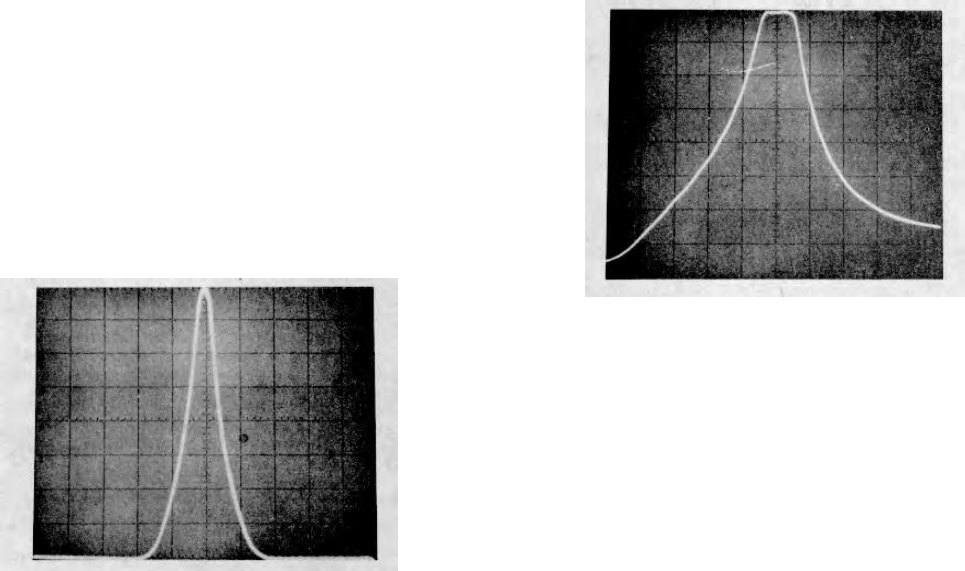
3-13. Crystal Filter Measurement
3-14. Figure 3-5 illustrates the CRT display for a 20
MHz crystal filter. Filter characteristics: 2-kHz passband
with bandwidth at the 60-dB points less than 10 kHz.
a. Spectrum Analyzer (8555A) control settings:
FREQUENCY.................................................20 MHz
BANDWIDTH.....................................................3 kHz
SCAN WIDTH PER DIVISION ..........................5 kHz
INPUT ATTENUATION .................................. 10 dB
SCAN TIME PER DIVISION ......20 MILLISECONDS
LOG REF LEVEL .............................................OdBm
VIDEO FILTER ............................................. 100 Hz
SCAN MODE ........................................................INT
SCAN TRIGGER ............................................ AUTO
LOG/LINEAR .................................................... LOG
b. Tracking Generator control settings:
TRACK ADJ .......................................................Peak
LEVEL ........................................................... OdBm
Figure 3-5. 20 MHz Crystal Filter CRT Display
3-15. Bandpass Filter Measurement
3-16. Figure 3-6 illustrates the CRT display for a
50 MHz bandpass filter. Filter characteristics: 50
MHz, 4-pole bandpass filter; adjusted for band-
width of approximately 5 MHz at the 3 dB points.
Bandwidth at 60 dB points is approximately 32
MHz.
a. Spectrum Analyzer (8555A) control settings:
FREQUENCY....................................................50 MHz
BANDWIDTH......................................................10 kHz
SCAN WIDTH PER DIVISION ............................5 MHz
INPUT ATTENUATION .......................................10 dB
SCAN TIME PER DIVISION ...................0.5 SECONDS
LOG REF LEVEL ................................................0 dBm
VIDEO FILTER ....................................................10 Hz
SCAN MODE ...........................................................INT
SCAN TRIGGER ..................................................AUTO
LOG/LINEAR .........................................................LOG
b. Tracking Generator control settings:
TRACK ADJ ..........................................................Peak
LEVEL ...............................................................O dBm
Figure 3-6. 50 MHz Bandpass Filter CRT Display
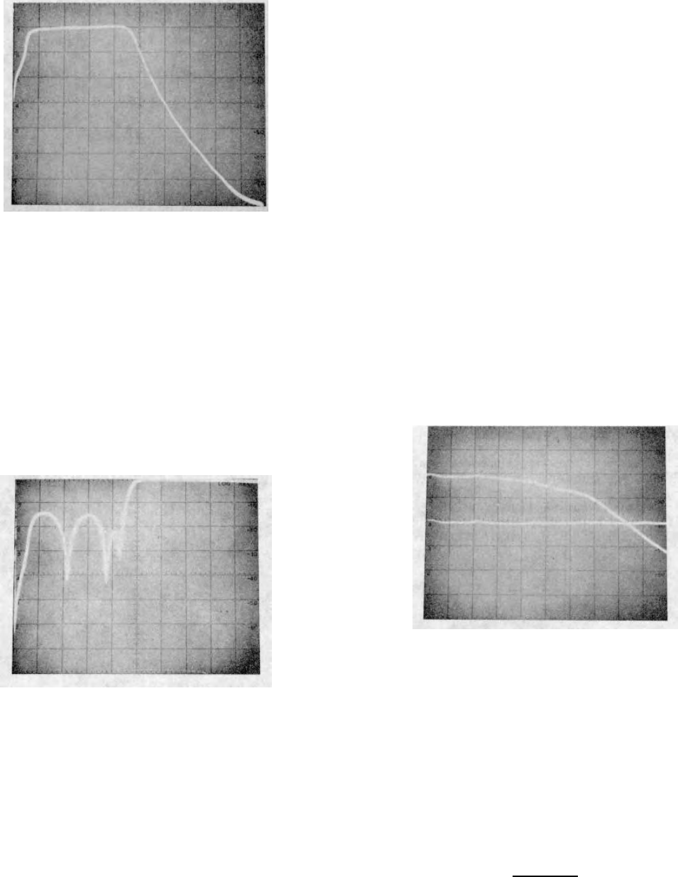
3-17. Low-Pass Filter Measurement
3-18. Figure 3-7 illustrates the CRT display for a 23
MHz low-pass filter. Filter characteristics: 3 dB point at
approximately 23 MHz, 60 dB point at approximately 42
MHz.
a. Spectrum Analyzer (8555A) control settings:
FREQUENCY ..................................................25 MHz
SCAN WIDTH PER DIVISION ............................5 MHz
BANDWIDTH ...................................................100 kHz
INPUT ATTENUATION ........................................10 dB
SCAN TIME PER DIVISION ...................0.1 SECONDS
LOG/LINEAR .........................................................LOG
LOG REF LEVEL .........................................(+) 10 dBm
LOG REF LEVEL Vernier ......................................-3 dB
VIDEO FILTER ....................................................10 Hz
SCAN MODE ...........................................................INT
SCAN TRIGGER ..................................................AUTO
b. Tracking Generator control settings:
TRACK ADJ ..........................................................Peak
LEVEL ................................................................OdBm
3-8
Model 8444A TM 11-6625-2866-14&P
Operation
Figure 3-7. 23 MHz Low-Pass Filter CRT Display
3-19. Swept Return Loss Measurement
3-20. Figure 3-8 illustrates the CRT display for a wept
return loss or reflection coefficient measurement. A
directional bridge (HP 8721A) was used to separate the
incident from the reflected signal. The filter under test is
the same 23-MHz Low-Pass (paragraph 3-18). Control
settings same as paragraph 3-18 except analyzer gain
adjusted so that the top graticule line represents 0 dB
return loss or total reflection (e.g. a short or open
circuit). Return loss is greater than 15 dB (p0.18, SWR
1.44) over the filter range of 0 to 23 MHz.
Figure 3-8. Swept Return Loss Measurement
CR T Display
3-21. Amplifier Gain and Bandwidth Measurement
3-22. Figure 3-9 illustrates the CRT display for a .1 to
400 MHz amplifier with gain of approximately 19 dB. A
reference level is first established by connecting the
Tracking Generator output to the Spectrum Analyzer
(through a 30 dB attenuator) and scanning over the
range of interest. The amplifier is then connected
between the Tracking Generator and the Spectrum
Analyzer and the same
frequency range scanned. The Spectrum Analyzer
(8554B) set to full scan (0-1250) provides a CRT display
indication as follows: 3-dB bandwidth approximately 500
MHz (level at +1 graticule line) and zero gain point of
approximately 1025 MHz.
a. 30 dB Coaxial Attenuator installed at Tracking
Generator RF OUTPUT.
b. Spectrum Analyzer(8554B) control settings:
BANDWIDTH.....................................................300 kHz
SCAN WIDTH............................................0--1250 MHz
INPUT ATTENUATION .......................................10 dB
SCAN TIME PER DIVISION 10 MILLISECONDS
LOG/LINEAR .........................................................LOG
LOG REF LEVEL ............................................+10 dBm
VIDEO FILTER ......................................................OFF
SCAN MODE ...........................................................INT
SCAN TRIGGER ..................................................AUTO
c. Tracking Generator control settings:
TRACK ADJ...........................................................Peak
LEVEL ................................................................0 dBm
Figure 3-9. Amplifier Gain and Bandwidth
CRT Display
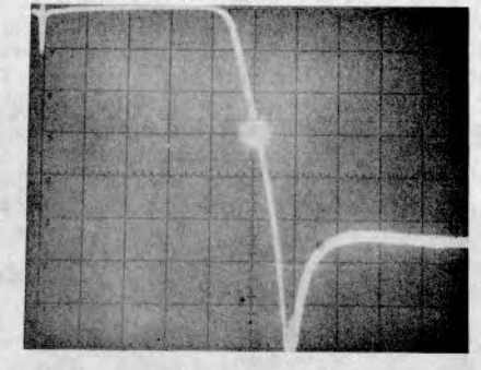
3-23. Precision Frequency Measurements
3-24. An external frequency counter may be used with
the Tracking Generator/Spectrum Analyzer System for
frequency measurements at any point on the CRT
display. With the counter connected to the Tracking
Generator AUX RF OUTPUT jack (rear panel) and the
system operated in the MANUAL SCAN mode; the scan
can be stopped at any point for frequency
measurement.
CAUTION
Do not leave System stopped in MANUAL SCAN
with high INTENSITY. Damage to the display
CRT can result.
3-9
Model 8444A TM 11-6625-2866-14&P
Operation
Figure 3-10 illustrates frequency measurement at the 30
dB point on a low-pass filter.
a. Spectrum Analyzer (8554B) control settings:
FREQUENCY ................................................... 50 MHz
BANDWIDTH ....................................................300 kHz
SCAN WIDTH PER DIVISION .......................... 10 MHz
INPUT ATTENUATION ......................................... 10dB
SCAN TIME PER DIVISION ........... 10 MILLISECONDS
LOG REF LEVEL ................................................ 0 dBm
LOG/LINEAR .........................................................LOG
VIDEO FILTER ...................................................... OFF
SCAN MODE ...........................................................INT
SCAN TRIGGER ..................................................AUTO
b. Tracking Generator control settings:
TRACK ADJ .......................................................... Peak
LEVEL ................................................................ 0 dBm
MANUAL SCAN ....................................................CCW
c. Connect unit under test between Tracking
Generator RF OUTPUT and Spectrum Analyzer
RF INPUT.
d. Connect Tracking Generator AUX RF OUTPUT
to Frequency Counter input.
e. Connect. Tracking Generator SCAN OUTPUT to
Spectrum Analyzer SCAN IN/OUT.
f. Connect Tracking Generator FIRST LO INPUT to
Spectrum Analyzer FIRST LO OUTPUT and THIRD LO
INPUT to THIRD LO OUTPUT.
g. Note point of interest on CRT display.
h. Set Spectrum Analyzer SCAN MODE to EXT
and rotate Tracking Generator MANUAL SCAN control
clockwise to point of interest.
i. Note and record frequency.
j. Set Spectrum Analyzer SCAN MODE to INT.
Note
The CRT trace (dot) can be moved in either
direction by the Tracking Generator MANUAL
SCAN control. For best' frequency accuracy,
approach frequency measurement point while
tuning the MANUAL SCAN control in the
clockwise
direction.
Figure 3-10. Precision Frequency Measurement CRT
Display
3-10
Model 8444A TM 11-6625-2866-14&P
Performance Tests
SECTION IV
PERFORMANCE TESTS
4-1. INTRODUCTION
4-2. This section contains preset adjustment procedures
and performance tests for the Model 8444A Tracking
Generator and Model 8554L or 8555A/ 8552B/141T
Spectrum Analyzer System. Preset adjustments for the
8444A/8554B/8552B/141T system are given in
paragraph 4-7. Preset adjustments for the
8444A/8555A/8552B/141T are given in paragraph 4-9.
Perform the preset adjustment procedures for the
appropriate system prior to accomplishing the
performance tests. Procedures for verifying that the
instruments meet specifications are given in paragraphs
4-16 through 4-20.
4-3. EQUIPMENT REQUIRED
4-4. Test equipment and accessories for performance
(P), adjustment (A) and troubleshooting (T) are listed in
Table 1-3. Critical specifications and/ or required
features for the test equipment and accessories are
contained in the table. Each performance test lists the
required test equipment and contains an illustrated test
equipment setup.
4-5. FRONT PANEL CHECKS
4-6. Before proceeding to the performance tests, the
instruments must be adjusted and all controls set as
specified in the preset adjustment procedures for the
appropriate system (8554B/8555A). The instruments
should perform as called out in the preset adjustment
procedures before going on to the performance tests.
4-7. Preset Adjustments (8554B/8552B/141T/ 8444A
System)
4-8. Procedure:
a. Apply power to Tracking Generator and
Spectrum Analyzer.
b. Turn Spectrum Analyzer INTENSITY control fully
CCW.
c. Allow instruments to warm up for at least 30
minutes.
d. Perform Spectrum Analyzer 30 MHz calibration
procedure. Refer to 8554B RF Section Operating
Manual.
e. Connect Spectrum Analyzer FIRST LO OUTPUT
to Tracking Generator FIRST LO
INPUT.
f. Connect Spectrum Analyzer THIRD LO OUTPUT
to Tracking Generator THIRD LO INPUT.
g. Connect Tracking Generator RF OUTPUT to
Spectrum Analyzer RF INPUT.
h. Connect Tracking Generator SCAN OUTPUT to
Spectrum Analyzer SCAN IN/OUT.
i. Set Spectrum Analyzer controls as follows:
INTENSITY .....................................12 o'clock (approx.)
FREQUENCY ................................................... 30 MHz
BANDWIDTH ....................................................300 kHz
SCAN WIDTH ........................................PER DIVISION
SCAN WIDTH PER DIVISION ...........................200 kHz
INPUT ATTENUATION ........................................ 20 dB
TUNING STABILIZER ...............................................On
BASE LINE CLIPPER ...........................................CCW
SCAN TIME PER DIVISION ........... 10 MILLISECONDS
LOG/LINEAR ...............................................10 dB LOG
LOG REF LEVEL ................................................ OdBm
LOG REF LEVEL Vernier ............................................ 0
VIDEO FILTER ...................................................... OFF
SCAN MODE ...........................................................INT
SCAN TRIGGER .....................................LINE or AUTO
j. Set Tracking Generator controls as follows:
MANUALSCAN ....................................................CCW
LEVEL ................................................................ OdBm
k. Adjust TRACK ADJ control for maximum
amplitude of trace on CRT display.
l. If trace is not within +0.5 dB of LOG REF level
graticule line repeat Spectrum Analyzer calibration
procedure.
m. Reconnect Tracking Generator RF OUTPUT to
Spectrum Analyzer RF INPUT and adjust TRACK ADJ
for maximum signal amplitude.
n. Rotate LEVEL control fully counterclockwise (-10
dBm) and note signal level on CRT display.
-10 to --12 dBm
4-1

Model 8444A TM 11-6625-2866-14&P
Performance Tests
o. If the signal level is off more than ±0.5 dB at the 0
dBm point or not within -10 to -12 dBm with the I, L, VEL
control fully counterclockwise, refer to paragraph 4-16,
Output Level Performance Check, a:1 -13 for LEVEL
control calibration procedure.
4-9. Preset Adjustments (8555A/8552B/141T/ 8444A
System)
4-10. Procedure:
a. Apply power to Tracking Generator and
Spectrum Analyzer.
b. Turn Spectrum Analyzer INTENSITY , control
fully CCW.
c. Allow instruments to warm up for at least 30
minutes.
d. Per, form Spectrum Analyzer Operational
Adjustments (30 MHz Calibration). Refer to o55t5 A
RF' Section Operating and Service Manual.
e. Connect Spectrum Analyzer FIRST LO
OUTPUT'l1, -. Tracking Generator FIRST LO INPUIT.
f. Connect Spectrum Analyzer THIRD LO OUTPUT
to Tracking Generator THIRD LO INPUT (rear panel
connections).
g. Connect Tracking Generator RF OUTPUT to
Spectrum .Analyzer INPUT.
h. Connect '[racking Generator SCAN OUTPUT to
PUT to Spectrum Analyzer SCAN IN/OUT.
i. Set Spectrum Analyzer controls as follows:
INTENSIT' ......................................12 o'clock (approx.)
BAND.................................................n=1-(2.05 GHz IF)
FREQUENCY ................................................... 30 MHz
BANDWIDTH ...................................................300 kHz
SCAN WIDTH ........................................PER DIVISION
SCAN WIDTH PER DIVISION .........................100 kHz
INPUT ATTENUATION ........................................ 20dB
TUNING STABILIZER .............................................. ON
SIGNAL IDIENTIFIER ............................................ OFF
BASE LINE CLIPPER ...........................................CCW
SCAN TIME PER DIVISION .......... 10 MILLISECONDS
LOG /LlNEAR ..............................................10 dB LOG
LOG REF LEVEL ................................................ 0 dBm
LOG REF LEVEL Vernier ............................................ 0
VIDEO FILTER ...................................................... OFF
SCAN MODE ............................................................INT
SCAN TRIGGER ....................................LINE or AUTO
j. Set Tracking Generator controls as follows:
MANUAL SCAN CCW
LEVEL ...................................................................dBm
k. Adjust TRACK ADJ control for maximum
aptitude of trace on CRT display.
l. If trace is not within +0.5 dB of LOG REF level
graticule line repeat Spectrum Analyzer calibration
procedure.
m. Reconnect Tracking Generator RF OUTPUT to
Spectrum Analyzer INPUT and adjust TRACK ADJ for
maximum signal amplitude.
n. Rotate LEVEL control fully counterclockwise (-10
dBm) and note signal level on CRT display.
-10 to -12 dBm
o. If the signal level is off more than +0.5 dB at the
0 dBm point or not within -10 to -12 dBm with the
LEVEL control fully counterclockwise, refer to paragraph
4-16, Output Level Performance Check, and 5-13 for
LEVEL control calibration procedure.
4-11. PERFORMANCE TESTS
4-12. The performance tests, given in this section, are
suitable for incoming inspection, troubleshooting, and/or
preventive maintenance. During any performance test,
all shields and connecting hardware must be in place.
The tests are designed to verify published
specifications. Perform the tests in the order given, and
record data on test card (Table 4-1) and/or in the data
spaces provided in each test.
4-13. The tests are arranged in the following order:
Paragraph Test Description
4-16 Output Level and flatness
4-17 Frequency Stability
4-18 System Flatness
4-19. Frequency Accuracy
4-20 Distortion
4-14. Each test is arranged so that the specification is
written as it appears in the Table of Specifications
(Table 1-1) in Section I. Next, a description of the test
and any special instructions or problem areas are
included. Each test that requires test equipment has a
test setup drawing and a list of required equipment.
Each procedure gives control settings required for that
particular test.
4-2
TM 11-6625-2866-14&P
Model 8444A Performance Tests
4-15. Required minimum specifications for test
specifications listed in order to performance-test
equipment are detailed in Table 1-3 in Section I. If the
Tracking Generator. substitute test equipment is used, it
must meet the
PERFORMANCE TESTS
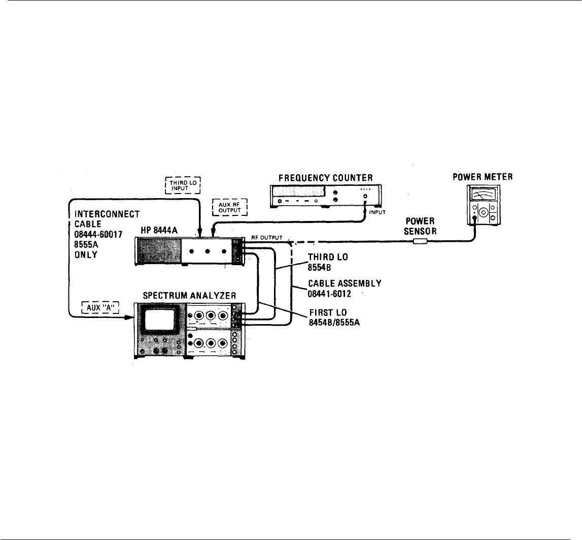
4-16. Output Level
SPECIFICATION: Tracking Generator (Drive Level to Test Device): 0 to -10 dBm continuously variable.
0 dBm calibrated to +0.5 dB. Flatness: +0.5 dB.
DESCRIPTION: With the Tracking Generator connected to the Spectrum Analyzer, the Tracking Generator output level
is first checked at 30 MHz (Spectrum Analyzer amplitude calibration point) with a power meter. With Tracking Generator
LEVEL control set at 0 dBm, the power meter indication should be 0 dBm +0.5 dB. With LEVEL control set fully
counterclockwise, the power meter indication should be -10 dBm to -12 dBm.
The flatness of the Tracking Generator output is checked using a power meter from 10 MHz to 1.3 GHz if used with the
8555A, and 500 kHz to 1.25 GHz if used with the 8554B. The overall maximum power variation in each case must not
exceed I dB (+0.5 dB).
Figure 4-1. Output Level and Flatness Test Setup
EQUIPMENT:
Spectrum Analyzer .................................................................................... HP 8554B or 8555A/8552B/141T
Power Meter .............................................................................................. HP 435A
Power Sensor ............................................................................................ HP 8482A
Frequency Counter .................................................................................... HP 5340A
Adapter, Type N Male to BNC Female ...................................................... HP 1250-0780
Interconnect Cable (8555A THIRD LO) ..................................................... HP 08444-60017
Interconnect Cable (two required) .............................................................. HP 08444-60018
Cable Assembly (RF) ................................................................................ HP 08441-6012
4-3

TM 11-6625-2866-14&P
Model 8444A
PERFORMANCE TESTS
4-16. OUTPUT LEVEL AND FLATNESS (Cont'd)
PROCEDURE:
1. Perform preset adjustment procedures, paragraph 4-7 for 8554B/8552B/141T Spectrum Analyzer System or
paragraph 4-9 for 8555A/8552B/141T Spectrum Analyzer System.
2. Connect test setup as shown in Figure 4-1 and set controls as follows:
Power Meter
RANGE .................................................................................... O dBm
LINE .......................................................................................... ON
CAL FACTOR ............................................................................ See Power Sensor
Frequency Counter
RANGE ..................................................................................... 10 Hz-18 GHz
LINE .......................................................................................... ON
RESOLUTION Hz ...................................................................... 100
Tracking Generator
MANUAL SCAN ......................................................................... Fully Counterclockwise
LEVEL........................................................................................ O dBm
3. Set Spectrum Analyzer TUNING STABILIZER to OFF and set SCAN WIDTH to ZERO. Adjust FREQUENCY for
indication of 30 MHz ± 100 kHz on Frequency Counter.
4. Tune Tracking Generator TRACK ADJ for maximum signal amplitude on Spectrum Analyzer.
5. Connect Power Sensor to 435A POWER REF OUTPUT and ZERO Power Meter. Set rear-panel POWER REF
switch to ON (up). Set CAL ADJ for proper 435A indication. Remove Power Sensor and return POWER REF
switch to OFF.
6. Disconnect cable at Tracking Generator RF OUTPUT and connect Power Sensor to RF OUTPUT connector.
Disconnect FIRST LO cable and ZERO Power Meter. Reconnect FIRST LO cable. Measure and record power
level. MAX. ACTUAL MIN.
+0.5 dBm ___dBm ____-0.5 dBm
7. Set Tracking Generator LEVEL control fully counterclockwise. Measure and record power level.
MAX. ACTUAL MIN.
-10dBm ___dBm ____-12 dBm
8. Adjust Tracking Generator LEVEL control to set a -I dBm reference level on power meter.
9. With Spectrum Analyzer FREQUENCY control, slowly tune the Spectrum Analyzer and Tracking Generator
between 10 MHz and 1.3 GHz if using 8555A RF Section, or between 500 kHz and 1.25 GHz if using 85S4B RF
Section.
10. Note and record the maximum overall power deviation. MAX. ACTUAL
1 dB
(±0.5 dB) ____dB
4-4

TM 11-6625-2866-14&P
Model 8444A Performance Tests
PERFORMANCE TESTS
This space intentionally left blank.
4-17. Frequency Stability
SPECIFICATION: Stability: Residual FM (peak-to-peak):
Tuning Section Stabilized Unstablized
8554B/8555A 200 Hz 10 kHz
DESCRIPTION: The stability of the Spectrum Analyzer/Tracking Generator System is checked using a HP
141T/8553B/8552B Spectrum Analyzer System which has less than 20 Hz peak-to-peak residual FM. The Spectrum
Analyzer in the system must be within residual FM specification limits. Refer to appropriate RF Section Operating and
Service Manual. There are no adjustments in the Tracking Generator for residual FM.
Refer to paragraph 5-10 if residual FM is excessive.
4-5/4-6
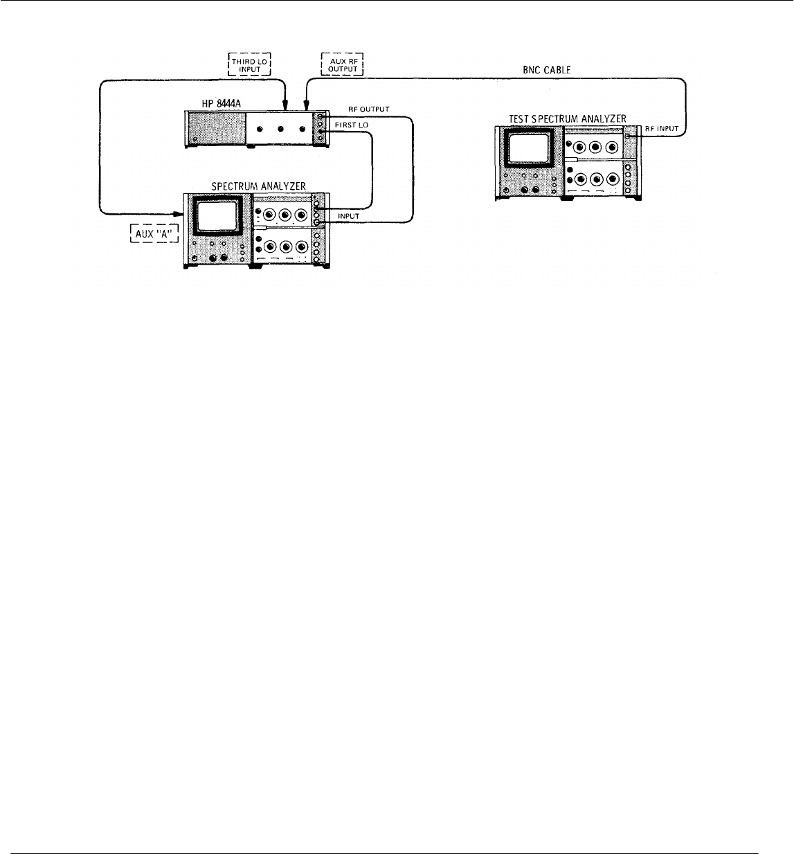
TM 11-6625-2866-14&P
Model 8444A Performance Tests
PERFORMANCE TESTS
4-17. Frequency Stability (cont'd)
Figure 4-2. Residual FM Test Setup
EQUIPMENT:
Spectrum Analyzer ................................................................... .................HP 8554B or 8555A/8552B/141T
Test Spectrum Analyzer . ......................................................... .................HP 8553B/8552B/141T
BNC Cable ................................................................................ .................HP 10503A
PROCEDURE:
1. Perform preset adjustment procedures, paragraph 4-7, for 8554B/8552B/141T Spectrum Analyzer System or
paragraph 4-9 for 8555A/8552B/141T Spectrum Analyzer System.
2. Connect test setup as indicated in Figure 4-2 and make the following control settings:
SPECTRUM ANALYZER (Tracking Generator/Spectrum Analyzer System) See paragraph
4-7 or 4-9.
SPECTRUM ANALYZER (8553B/8552B/141T "Test Analyzer")
POWER ................................................................................................. ON
RANGE MHz .......................................................................................... 0-110
FREQUENCY. ........................................................................................ 50 MHz
BANDWIDTH.......................................................................................... 30 kHz
SCAN WIDTH......................................................................................... PER DIVISION
SCAN WIDTH PER DIVISION ................................................................ 1 MHz
NPUT ATTENUATION............................................................................ 10 dB,
UNING STABILIZER............................................................................... ON
CAN TIME PER DIVISION...................................................................... 20 MILLISECONDS
LOG/LINEAR .......................................................................................... 10 dB LOG
OG REF LEVEL...................................................................................... +10 dBm
IDEO FILTER.......................................................................................... 10 kHz
CAN MODE ............................................................................................ INT
CAN TRIGGER....................................................................................... AUTO
3. Set Tracking Generator/Spectrum Analyzer System FREQUENCY to 50 MHz and SCAN WIDTH to
ZERO.
4-7

TM 11-6625-2866-14&P
Model 8444A Performance Tests
PERFORMANCE TESTS
4-17. Frequency Stability (cont'd)
4. Connect Tracking Generator AUX RF OUTPUT to Test Analyzer RF INPUT.
5. Adjust Test Analyzer FREQUENCY control to center signal on CRT Display.
6. Reduce Test Analyzer BANDWIDTH to 1 kHz and SCAN WIDTH PER DIVISION to 2 kHz while keeping signal
centered on CRT display.
7. Set Test Analyzer INPUT ATTENUATION to 30 dB, LOG/LINEAR to LINEAR, and LINEAR SENSITIVITY to
20.mV/DIV.
8. Adjust Test Analyzer LINEAR SENSITIVITY Vernier control for a full eight division display.
9. Refer to Figure 4-3. Tune Test Analyzer FINE TUNE so that the upward slope of the display intersects the
CENTER FREQUENCY graticule line one division from the top.
NOTE
The linear portion of the analyzer IF filter skirt is used to slope detect low-order residual FM.
The analyzer is stabilized, and the detected FM is displayed in the time domain.
10. Note where the slope intersects the middle horizontal
graticule line: Horizontal Displacement: ____ divisions
11. Use the horizontal displacement to calculate demodulation
sensitivity.
a. Convert the horizontal displacement (divisions) into Hertz.
Example: (2 kHz SCAN WIDTH) x (0.2
div) = 400 Hz.
Figure 4-3. Demodulation Sensitivity
Measurement
b. Calculate demodulation sensitivity by dividing the vertical displacement in divisions into the horizontal
displacement in Hz:
400 Hz
Example: = 133 Hz/div
3 divisions
12. Turn SCAN WIDTH to ZERO scan. Set FINE TUNE for a response level within the calibrated three division
range (one division from the top to the center horizontal graticule line).
13. Measure the peak-to-peak deviation, and multiply it by the demodulation sensitivity obtained in step lib above.
14. Example: 1.2 div p-p signal deviation x 133 Hz/div = 159.6 Hz Residual FM.
______________Hz peak-to-peak
4-8
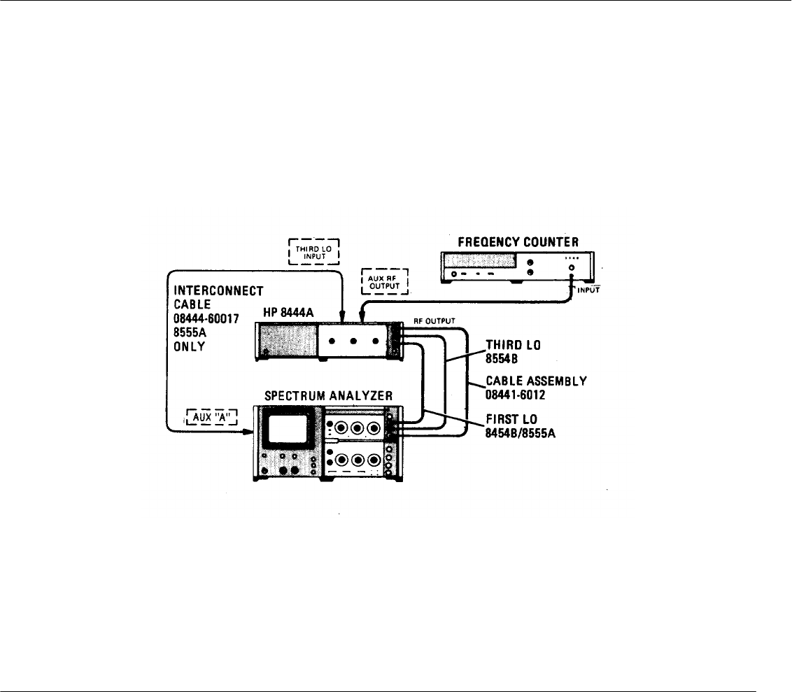
TM 11-6625-2866-14&P
Model 8444A
PERFORMANCE TESTS
4-18. SYSTEM FLATNESS
SPECIFICATION:
Amplitude Accuracy: System Frequency Response: 1.50 dB.
DESCRIPTION:
The Tracking Generator output is checked with the Spectrum Analyzer using either an 8555A or an 8554B RF Section. A
convenient reference level is set in the 2 dB LOG mode. The overall power deviation is measured from 10 MHz to 1.3
GHz if 8555A RF Section is used, or 500 kHz to 1.25 GHz if 8554B RF Section is used.
Figure 4-4. System Flatness Test Setup
EQUIPMENT:
Spectrum Analyzer ..........................................................................HP 8554B or 8555A/8552B/141T
Frequency Counter ..........................................................................HP 5340A
Adapter, Type N Male to BNC Female ............................................HP 1250-0780
Interconnect Cable (8555A THIRD LO) ...........................................HP 08444-60017
Interconnect Cable (two required) ....................................................HP 08444-60018
Cable Assembly ..............................................................................HP 08441-6012
4-9

TM 11-6625-2866-14&P
Model 8444A
PERFORMANCE TESTS
4-18. SYSTEM FLATNESS (Cont'd)
PROCEDURE:
1. Perform preset adjustment procedures, paragraph 4-7 for 8554B/8552B/141T Spectrum Analyzer System or
paragraph 4-9 for 8555A/8552B/141T Spectrum Analyzer System.
2. Connect test setup as shown in Figure 44 and set controls as follows:
Frequency Counter
RANGE ...................................................................................................... 10 Hz-18 GHz
LINE............................................................................................................. ON
RESOLUTION Hz ....................................................................................... 100
Tracking Generator
MANUAL SCAN .......................................................................................... Fully Counterclockwise
LEVEL ......................................................................................................... 0 dBm
3. Set Spectrum Analyzer SCAN WIDTH to ZERO and adjust FREQUENCY for indication of 30 MHz + 100 kHz on
frequency counter.
4. Set Spectrum Analyzer LOG REF LEVEL to (+)' 10 dBm and LOG/LINEAR to 2 dB LOG.
5. Adjust Tracking Generator TRACK ADJ for maximum signal indication on CRT display.
6. Adjust Spectrum Analyzer LOG REF LEVEL vernier control to position trace on -20 LOG REF graticule line.
7. With Spectrum Analyzer FREQUENCY control, slowly tune the Spectrum Analyzer and Tracking Generator
between 10 MHz and 1.3 GHz if using 8555A RF Section, or between 500 kHz and 1.25 GHz if using 8554B RF
Section.
8. Note and record the maximum overall power deviation (one minor division on center vertical graticule line equals
0.4 dB). MAX. ACTUAL
3 dB
(±1.5 dB) ____dB
4-10
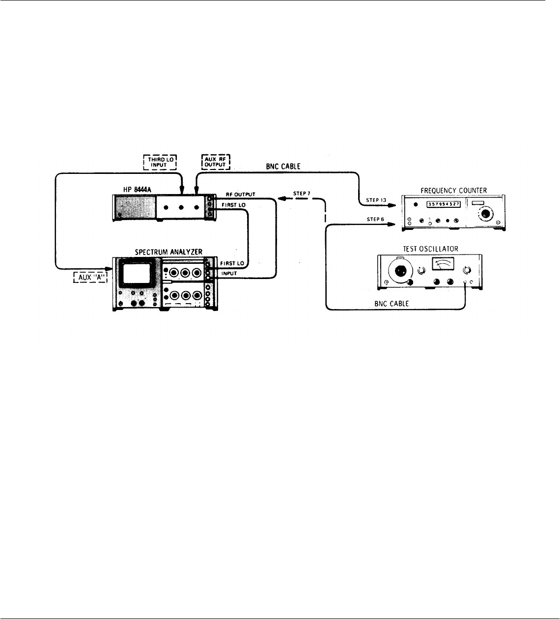
TM 11-6625-2866-14&P
Model 8444A Performance Tests
PER FORMANCE TESTS
4-19. Frequency Accuracy
SPECIFICATION: Frequency Accuracy: +15 MHz using Spectrum Analyzer slide rule dial. Precision frequency
measurements: Frequency Accuracy: +10 kHz for unknown signals (using Tracking Generator AUX RF OUTPUT and
an external frequency counter.
DESCRIPTION: The accuracy of the slide rule dial is determined by the RF Section calibration. Refer to dial accuracy
performance test in the appropriated RF Section Operating and Service manual. For precision frequency
measurements, frequency accuracy is checked by tuning the Spectrum Analyzer and Tracking Generator to a known
frequency and measuring the Tracking Generator output with an external counter. The slide rule dial can be visually
checked for an accuracy of +15 MHz.
Figure 4-5. Frequency Accuracy Test Setup
EQUIPMENT: Spectrum Analyzer.................................................................................. HP 8554B/8555A/8552A/141T
Frequency Counter.................................................................................. HP 5340A
Test Oscillator......................................................................................... HP 652A
HF Signal Generator ............................................................................... HP 606A/B
VHF Signal Generator............................................................................. HP 608E/F
UHF Signal Generator............................................................................. HP 612A
Cable Assembly . ................................................................................. HP 10503A
PROCEDURE:
1. Perform preset adjustment procedures, paragraph 4-7, for 8554B/8552B/141T Spectrum Analyzer System or
paragraph 4-9 for 8555A/8552B/141T Spectrum Analyzer System.
2. Connect test setup as indicated in Figure 4-5 and make the following control settings: Spectrum Analyzer
See paragraph 4-7 or 4-9.
Frequency Counter
SAMPLE RATE ...................................................................................... 12 o'clock
SENSITIVITY ......................................................................................... 1 (VOLTS RMS)
TIME BASE ........................................................................................... 10 ms
FUNCTION ............................................................................................ FREQUENCY
4-11

TM 11-6625-2866-14&P
Model 8444A Performance Tests
PERFORMANCE TESTS
4-19. Frequency Accuracy (cont'd)
Tracking Generator
TRACK ADJ ........................................................................................ Max signal amplitude
LEVEL ................................................................................................. O dBm
MANUAL SCAN .................................................................................. CCW
Test Oscillator FREQUENCY ...................................................................................... 500 kHz (8554B); 10 MHz
(8555A) OUTPUT ATTENUATOR .................................................................... OdBm
3. Allow instruments to warm up and stabilize for at least 2 hours.
4. Set Spectrum Analyze SCAN WIDTH PER DIVISION to 5 MHz, BANDWIDTH to 30 kHz, center FINE
TUNE control and set FREQUENCY to 0 MHz. Note
During all adjustments of FREQUENCY control approach dial setting in a clockwise direction.
5. Check displacement of LO feed thru signal from CRT CENTER FREQUENCY graticule line.
≤ 3 Div
6. Connect Test Oscillator 50o output to Frequency Counter and adjust oscillator frequency for an indication of 500
kHz (8554B) or 10 MHz (8555A).
7. Disconnect cable between Tracking Generator RF OUTPUT and Spectrum Analyzer INPUT.
8. Connect Test Oscillator to Spectrum Analyzer INPUT and tune Spectrum Analyzer to Test Oscillator frequency.
9. Reduce Spectrum Analyzer SCAN WIDTH PER DIVISION to 5 kHz and BANDWIDTH to 1 kHz keeping signal
centered on CRT display with FREQUENCY and FINE TUNE controls.
10. Set SCAN WIDTH to ZERO and tune FINE TUNE for maximum signal amplitude.
11. Disconnect Test Oscillator from Spectrum Analyzer and connect Tracking Generator OUTPUT to Spectrum
Analyzer INPUT.
12. Adjust Tracking Generator TRACK ADJ for maximum signal amplitude on CRT display.
13. Connect Tracking Generator AUX RF OUTPUT to Frequency Counter. Measure and record frequency.
8554B 500 +10 kHz____________
8555A10MHz+10kHz____________
14. Repeat steps 6 through 13 at selected frequencies using appropriate signal generator in place of test oscillator.
4-12
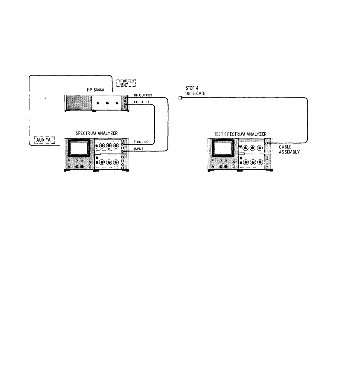
TM 11-6625-2866-14&P
Model 8444A Performance Tests
PERFORMANCE TESTS
4-20. Harmonic Distortion
SPECIFICATION: Harmonic Distortion: 25 dB below output level. Nonharmonic (spurious) signals: >40 dB below
output level.
DESCRIPTION: With the Tracking Generator and Spectrum Analyzer operating as a system, the RF OUTPUT from the
Tracking Generator is observed using a separate spectrum analyzer. The output signal is checked for signal level of
both harmonic and spurious signals.
Figure 4-6. Harmonic Distortion Test Setup
EQUIPMENT: Spectrum Analyzer .......................................................................HP 8554B or 8555A/8552B/141T
Test Spectrum Analyzer . .............................................................HP 8553B/8552B/141T
RF Section ....................................................................................HP 8554B or 8555A
BNC Cable ....................................................................................HP 10503A
Adapter ..........................................................................................UG-201A/U
PROCEDURE:
1. Perform preset adjustment procedures, paragraph 4-7, for 8554B/8552/141T Spectrum Analyzer System or
paragraph 4-9 for 8555A/8552/141T Spectrum Analyzer System.
2. Connect test setup as indicated in Figure 4-6 and make the following control settings:
Tracking Generator/Spectrum Analyzer System
See paragraph 4-7 or 4-9.
Spectrum Analyzer (8553B/8552B/141T "Test Analyzer")
FREQUENCY ................................................................................50 MHz
BANDWIDTH.................................................................................300 kHz
SCAN WIDTH ...............................................................................PER DIVISION
SCAN WIDTH PER DIVISION ......................................................0 MHz
INPUT ATTENUATION .................................................................20 dB
BASE LINE CLIPPER ...................................................................10 o'clock
VIDEO FILTER .............................................................................OFF
SCAN TIME PER DIVISION ..........................................................2 MILLISECONDS
LOG/LINEAR ................................................................................10 dB LOG
4-13

TM 11-6625-2866-14&P
Model 8444A Performance Tests
PERFORMANCE TESTS
4-20. Harmonic Distortion (cont'd)
LOG REF LEVEL ........................................................................................ 0 dBm
LOG REF LEVEL Vernier............................................................................. 0
SCAN MODE ............................................................................................... INT
SCAN TRIGGER . ..................................................................................... LINE
Tracking Generator/Spectrum Analyzer System
Tracking Generator
TRACK ADJ ............................................................................................... Max signal level
LEVEL ......................................................................................................... 0 dBm
Spectrum Analyzer
BAND* ....................................................................................................... n=1 - (2.05 GHz IF)
FREQUENCY .............................................................................................. 50 MHz
TUNING STABILIZER ................................................................................. OFF
SIGNAL IDENTIFIER* . ............................................................................. OFF
BANDWIDTH............................................................................................... 300 kHz
SCAN WIDTH.............................................................................................. PER DIVISION
SCAN WIDTH PER DIVISION .................................................................... 10 MHz
INPUT ATTENUATION................................................................................ 20 dB
BASE LINE CLIPPER .................................................................................. 9 o'clock
SCAN TIME PER DIVISION ........................................................................ 0.5 SECONDS
LOG/LINEAR ............................................................................................. 10 dB LOG
LOG REF LEVEL Vernier ........................................................................... 0
VIDEO FILTER ........................................................................................... OFF
SCAN MODE .............................................................................................. INT
SCAN TRIGGER . ...................................................................................... LINE
*8555A RF Section only
3. Disconnect the cable between Tracking Generator RF OUTPUT and Spectrum Analyzer INPUT.
4. Connect cable between Tracking Generator RF OUTPUT and the INPUT of the "Test Analyzer".
5. Observe the "Test Analyzer" display for harmonic and spurious signals. A typical display is shown in Figure 4-7.
The Tracking Generator fundamental signal is shown between the -2 and -1 graticule lines. The second
harmonic is shown between the +1 and +2 lines with the third harmonic shown between the +4 and +5 lines. The
amplitude of the second harmonic is approximately 36 dB below the fundamental. The third harmonic is down
approximately 50 dB. A spurious signal with an amplitude of approximately -58 dBm is shown between the -4
and -3 graticule lines.
6. Change the Tracking Generator/Spectrum Analyzer System controls as follows:
Tracking Generator
LEVEL ......................................................................................................... -10 dBm (CCW)
Spectrum Analyzer
FREQUENCY . .......................................................................................... 250 MHz
SCAN WIDTH PER DIVISION ..................................................................... 50 MHz
SCAN TIME PER DIVISION......................................................................... 1 SECOND
7. Replace the "Test Analyzer'* RF Section with either an 8554B or 8555A RF Section.
4-14
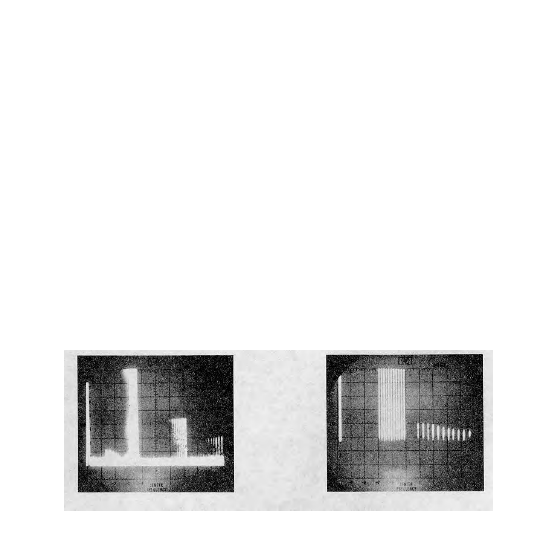
TM 11-6625-2866-14&P
Model 8444A Performance Tests
PERFORMANCE TESTS
4-20. Harmonic Distortion (cont'd)
8. Set "Test Analyzer" controls as follows:
FREQUENCY ............................................................................................. 250 MHz
BANDWIDTH .............................................................................................. 300 kHz
SCAN WIDTH ............................................................................................. PER DIVISION
SCAN WIDTH PER DIVISION ................................................................... 50 MHz
INPUT ATTENUATION ............................................................................... 20 dB
BASE LINE CLIPPER ................................................................................. 12 o'clock
VIDEO FILTER ........................................................................................... OFF
SCAN TIME PER DIVISION......................................................................... 10 MILLISECONDS
LOG/LINEAR ............................................................................................... 10 dB LOG
LOG REF LEVEL ........................................................................................ 10 dBm
LOG REF LEVEL Vernier ............................................................................ 0
SCAN MODE ............................................................................................. INT
SCAN TRIGGER . ..................................................................................... LINE
9. Observe the "Test Analyzer" display for harmonic and spurious signals.
10. Figure 4-8 illustrates a typical display of the LO feedthru, fundamental and second harmonic signals.
11. Repeat the above procedure at frequency of interest.
12. Note and record maximum amplitude level of harmonic and spurious signals.
Harmonics ≤ -25 dBm
Spurious ≤ - 40 dBm
Figure 4-7. Typical Harmonic Distortion Figure 4-8. Typical Harmonic Distortion
CRT Display 0 to 1 00 MHz CRT Display 0 to 500 MHz
4-15
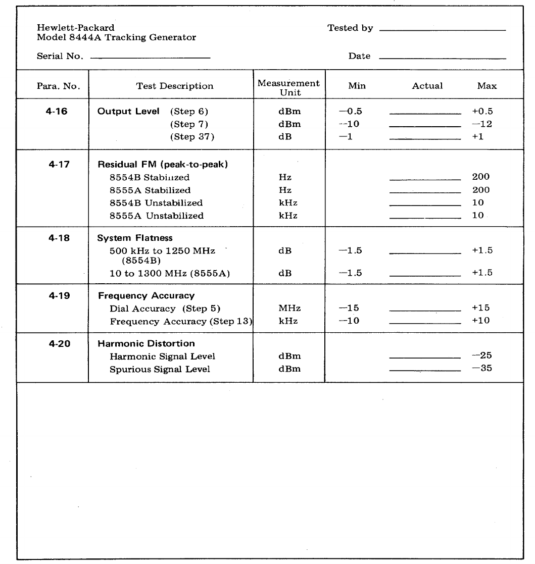
TM 11-6625-2866-14&P
Model 8444A Performance Tests
Table 4-1. Performance Test Record
4-16

TM 11-6625-2866-14&P
Model 8444A Adjustments
SECTION V
ADJUSTMENTS
5-1. INTRODUCTION
5-2. This section describes adjustments required to
return the Tracking Generator to peak operating
condition after repairs are made. Included in this
section are test setups, and check and adjustment
procedures. A test card for recording data is included at
the back of this section. Adjustment and test point
location illustrations are contained in Figures 8-4 and 8-
5.
5-3. The adjustment procedures are arranged in
numerical order. For best results, this order should be
followed. Record data, taken during adjustments, in the
spaces provided and/or in the data test card at the end
of this section. Comparison of initial data with data
taken during periodic adjustments assists in preventive
maintenance and troubleshooting.
Note
Control settings are called out for a HP
8555A Spectrum Analyzer RF Section.
If the RF Section used is a HP 8554B
disregard BAND and SIGNAL
IDENTIFIER control settings.
Otherwise, the Spectrum Analyzer
control settings apply to either
instrument.
5-4. EQUIPMENT REQUIRED
5-5. Each check and adjustment procedure contains
a list of test equipment required for that particular test.
Table 1-3 contains a tabular list of test equipment and
accessories required. In addition, the table contains the
required minimum specifications and a suggested
manufacturers model number.
5-6. FACTORY SELECTED COMPONENTS
5-7. Factory selected components are designated by
an asterisk (*) on the schematic diagrams in Section VIII
of this manual. Table 8-1 contains a list of factory
selected components by reference designation, basis of
selection, and schematic diagram location on which the
component is illustrated.
5-1
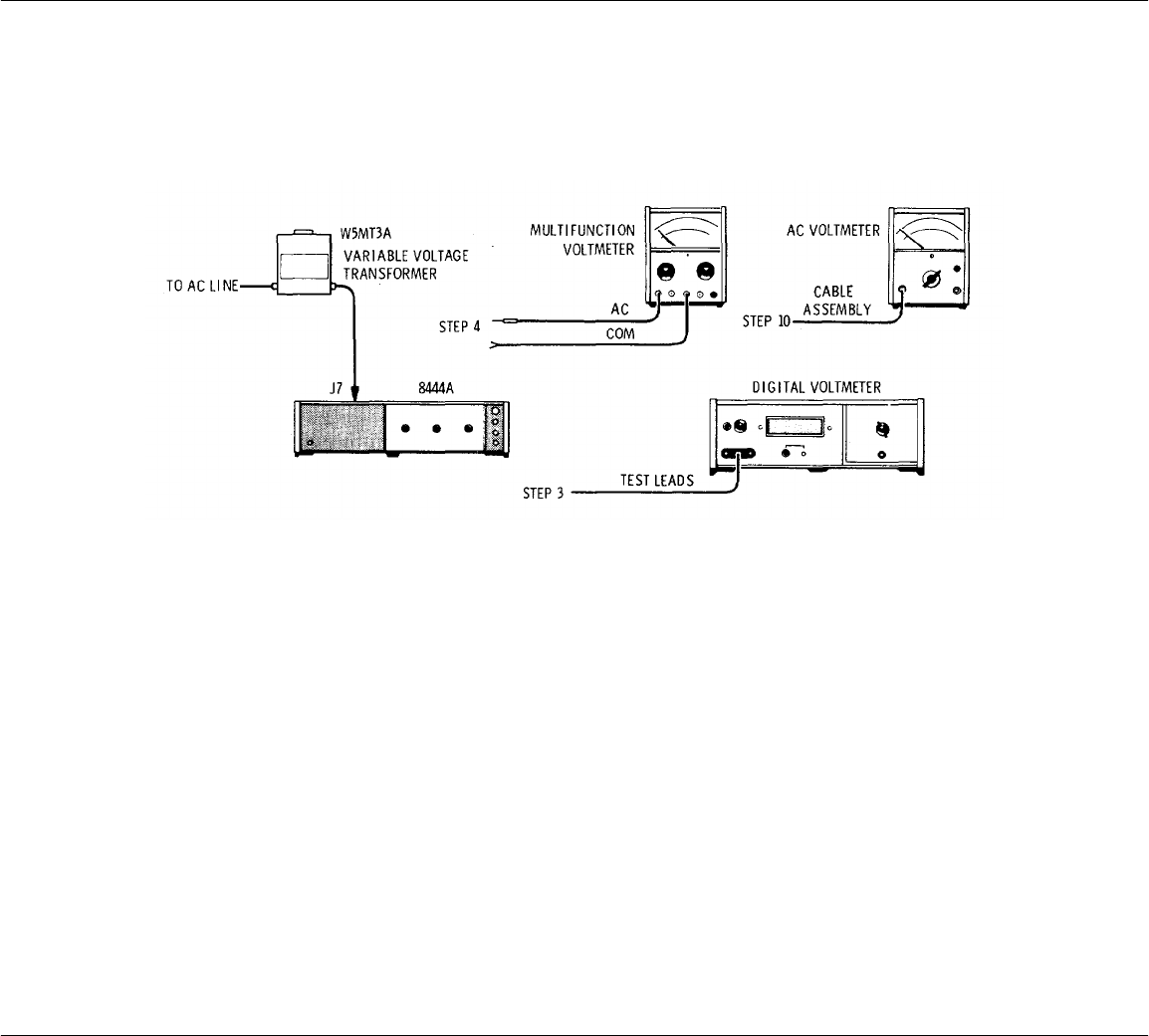
TM 11-6625-2866-14&P
Model 8444A Adjustments
ADJUSTMENTS
5-8. Power Supply, Check and Adjustment
REFERENCE: Service Sheet 5.
DESCRIPTION: Power supplies in the Tracking Generator provide regulated output of +20 and -10 volts. The +20 volt
supply is adjustable and provides the reference for the -10 volt supply. These checks verify proper operation of the
power supplies.
Figure 5-1. Power Supply Check and Adjustment Test Setup
EQUIPMENT: Digital Voltmeter with 3443A Plug-in ........................................................... HP 3440A
AC Voltmeter (Multifunction Voltmeter) ....................................................... HP 410C
Variable Voltage Transformer ..................................................................... General Radio W5MT3A
AC Voltmeter .............................................................................................. HP 400E
Cable Assy (terminated with probe and alligator clip) .................................. HP 10501A
Cable Assy (dual banana plug to probe and alligator clip) ............................ HP 11003A
PROCEDURE:
1. Connect test setup as indicated in Figure 5-1.
2. Remove top cover and right side cover from Tracking Generator.
3. Connect digital voltmeter test leads to AlTP1 and chassis ground.
4. Remove shield from power line module and connect ac voltmeter (HP 410C) across the outside terminals of the
ACCESSORY OUTLET connector J6. (The outside terminals of J6 are connected by the 98 and 908 color coded
wires to the power line module.)
5-2

TM 11-6625-2866-14&P
Model 8444A Adjustments
ADJUSTMENTS
5. Apply power to the Tracking Generator. Measure and record the +20 volt output. Vary the input ac line voltage
from 103.5 to 126.5 volts. The +20 volt regulated output should not vary more than 20 mV.
AC Input +20 Vdc Output
103.5V _____________
115V _____________
126.5V _____________
6. Set ac line voltage to 115 volts. Adjust AlR14 for +20.00 Vdc +20 mV at test point A1TP1.
7. Disconnect ac voltmeter from connector J6.
8. Connect digital voltmeter to A7C3 and chassis ground (-10 volt test point).
9. Measure and record voltage level. Voltage level should be -10.0 +0.5 volts.
-10.0 Vdc Output ______________
10. Set HP 400E AC Voltmeter RANGE to .001 VOLTS full scale and measure ac ripple on +20 and -10 volt sense
lines. Ripple should be less than 200 pV. Measure and record ac ripple between power supply sense lines and
chassis ground.
+20 Volt Output XA1 pin 6________
-10 Volt Output A7C3____________
11. Remove input line power and replace cover over power line module.
12. Replace right side cover and top cover.
13. If the dc supplies are out of tolerance, refer to Service Sheet 5 for trouble isolation procedure.
5-3
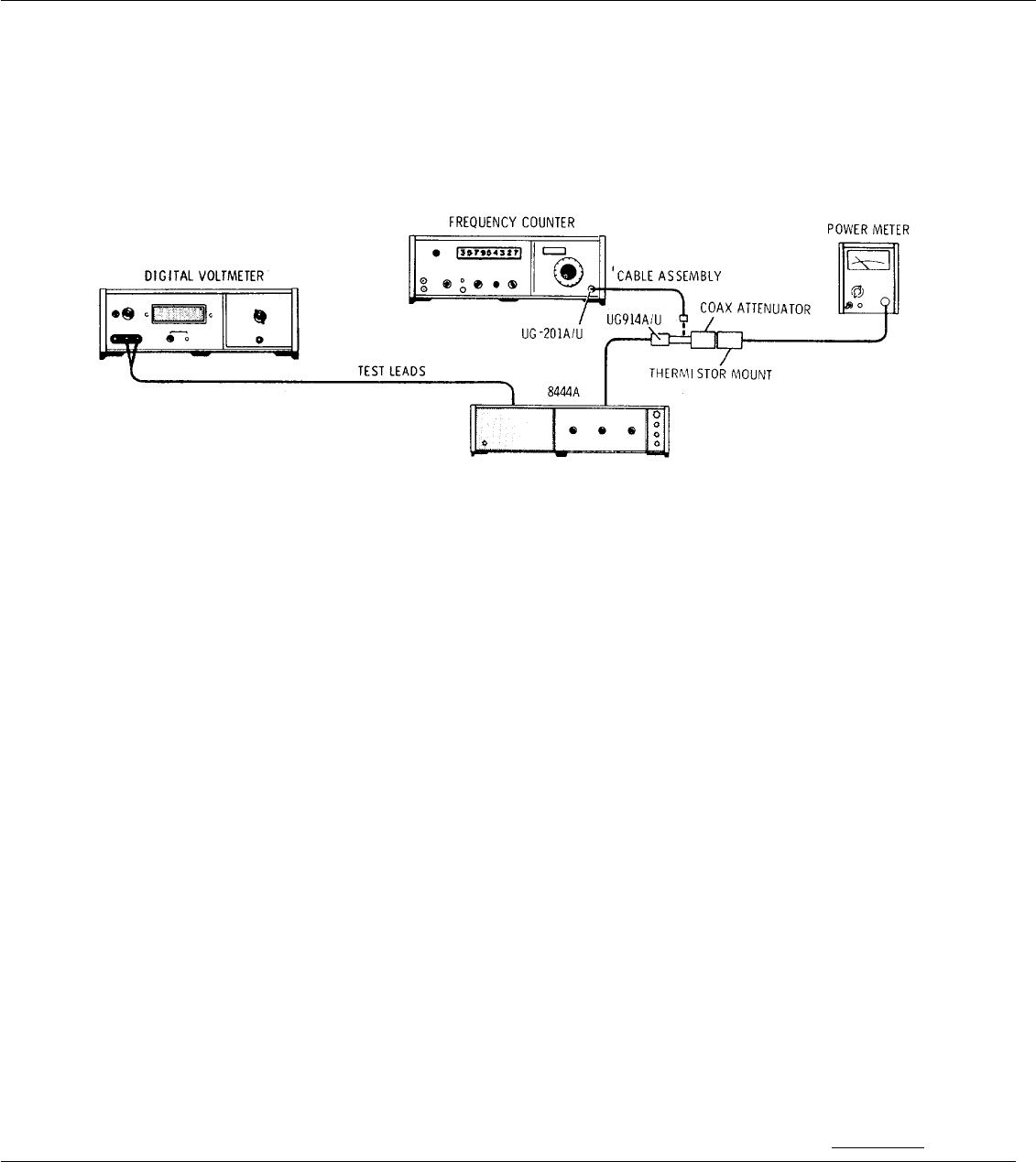
TM 11-6625-2866-14&P
Model 8444A Adjustments
ADJUSTMENTS
5-9. 1.55 GHz Oscillator Power Level, Frequency Check and Adjustment
REFERENCE: Service Sheet 3.
DESCRIPTION: The 1.55 GHz local oscillator is checked for power output level and frequency tuning range. Oscillator
frequency is determined primarily by the LO cavity, with tuning range determined by the drive voltage from the oscillator
driver. The oscillator is checked first for power level and then for frequency and tuning range.
Figure 5-2. 1.55 GHz LO Power Level and Frequency Check and Adjustment Test Setup
EQUIPMENT: Power Meter with HP 8478B Thermistor Mount............................................HP 432A
Frequency Counter with HP 5254C Plug-in ................................................HP 5245L
Digital Voltmeter with HP 3443A Plug-in .....................................................HP 3440A
Test Leads (dual banana plug to probe and alligator clip) ...........................HP 11003A
Cable Assy, SMA male to BNC male ...........................................................HP 08555-60076
Cable Assy, male BNC connectors ..............................................................HP 10503A
Coaxial Attenuator, Option 010 ...................................................................HP 8491A
Adapter BNC barrel (HP Part Number 1250-0080) .....................................UG 914A/U
Adapter (BNC to Type N) ............................................................................UG 201A/U
PROCEDURE:
1. Perform Power Supply Check and Adjustment, paragraph 5-8.
2. Apply power to Tracking Generator and allow 1 hour for instrument to warm up and stabilize.
3. Disconnect Cable W8 at Isolator AT3 J2 (see Figures 8-4 and 8-12).
4. With test setup as indicated in Figure 5-2, connect Power Meter to Isolator AT3 J2 via 08555-60076 cable, .10
dB attenuator and UG 914A/U adapter.
5. Rotate TRACK ADJ control throughout its tuning range while noting power level indicated on Power Meter.
6. Minimum power output must be greater than +5 dBm.
>+5 dBm
5-4

TM 11-6625-2866-14&P
Model 8444A Adjustments
ADJUSTMENTS
5-9. 1.55 GHz Oscillator Power Level, Frequency Check and Adjustment (cont'd)
7. Connect Frequency Counter to Isolator AT3 J2 via 08555-60076 cable, UG 914A/U adapter and BNC to BNC
cable.
8. Rotate TRACK ADJ control fully counterclockwise and record oscillator frequency.
1, 548, 000 ±500 kHz _____
9. Rotate TRACK ADJ control fully clockwise and record oscillator frequency
1, 552, 000 +500 kHz ______
10. Record frequency tuning range (frequency recorded in step 9 minus frequency recorded in step 8).
4, 000 ±500 kHz __________
11. If data recorded in steps 8, 9, and 10 is within tolerance no adjustment is required.
12. If data recorded in steps 8, 9, or 10 is not within tolerance proceed with step 13.
13. Connect Digital Voltmeter to test point A2TP5.
14. Set TRACK ADJ control fully clockwise. Set "MAX" TUNE potentiometer A2R26 and "MIN" TUNE potentiometer
A2R27 fully counterclockwise. Measure voltage at A2TP5. Voltage should be +1 *0.1 Vdc.
+0.9_________+1.1 Vdc
15. Measure and record oscillator frequency.
16. Adjust "MAX" TUNE potentiometer A2R26 to increase oscillator frequency 4, 000 +50 kHz above frequency
recorded in step 15. Record oscillator frequency.
17. Set TRACK ADJ control to center of tuning range recorded in steps 15 and 16 above. Record oscillator
frequency.
18. If frequency recorded in step 17 is not within +500 kHz of 1.550 GHz adjust A7ADJ 1 to tune oscillator frequency
to 1.550 GHz±100 kHz.
19. If oscillator frequency is adjusted, repeat steps 15 through 18.
20. Disconnect Power Meter and connect W8 Cable to Isolator AT3 J2.
21. Replace right side panel cover.
5-5

TM 11-6625-2866-14&P
Model 8444A Adjustments
ADJUSTMENTS
5-10. 1.55 GHz Oscillator Residual FM Check
REFERENCE: Service Sheet 3.
DESCRIPTION: The 1.55 GHz oscillator is checked for residual FM by mixing the oscillator output with a stable signal
source and observing the resultant output on a calibrated spectrum analyzer display. The second converter in Tracking
Generator is used to mix the oscillator output with the 1500 MHz comb signal from a Frequency Comb Generator. The
mixer output is displayed using a HP 141T/8553B/8552B Spectrum Analyzer System which has less than 20 Hz peak-to-
peak residual FM. There are no adjustments for oscillator residual FM. Perform power supply check for excessive ripple
if residual FM is excessive.
Figure 5-3. 1.55 GHz LO Residual FM Check Test Setup
EQUIPMENT: Spectrum Analyzer System ........................................................................HP 141T/8553B/8552B
Frequency Comb Generator ........................................................................HP 8406A
Cable Assy, Selectro male to Selectro female ............................................HP 11592-60003
Cable Assy, Selectro female to BNC male (2 each)......................................HP 11592-60001
Adapter (BNC to Type N) ............................................................................UG 201A/U
PROCEDURE:
1. Perform Power Supply Check and Adjustment, paragraph 5-8.
2. Perform 1.55 GHz Oscillator Power Level, Frequency Check and Adjustment, paragraph 5-9.
3. Apply power to Spectrum Analyzer System, Frequency Comb Generator and Tracking Generator. Allow at least
one (1) hour for equipment stabilization.
4. Disconnect Cable W4 at Mixer Assy A6 and Cable W8 at First Converter A5J2 (see Figures 8-4 and 8-12).
Connect 11592-60003 cable between W8 and A6 J1.
5. Disconnect Cable W9 from A6 J2 and connect 11592-60001 cable between A6 J2 and Frequency Comb
Generator.
6. Disconnect Cable W10 from A6 J3 and connect 11592-60001 cable between A6 J3 and Spectrum Analyzer RF
input.
7. Set instrument controls as follows:
5-6

TM 11-6625-2866-14&P
Model 8444A Adjustments
ADJUSTMENTS
5-10. 1.55 GHz Oscillator Residual FM Check (cont'd)
Tracking Generator
LINE OFF/ON .............................................................................................. .ON
TRACK ADJ................................................................................................. Centered
Frequency Comb Generator
COMB FREQUENCY - MHz ....................................................................... 100 MHz
OUTPUT AMPLITUDE ............................................................................... Maximum (CW)
Spectrum Analyzer
POWER ...................................................................................................... ON
RANGE MHz ............................................................................................... 0-110
FREQUENCY ............................................................................................. 50 MHz
BANDWIDTH . .......................................................................................... 30 kHz
SCAN WIDTH ............................................................................................. PER DIVISION
SCAN WIDTH PER DIVISION ................................................................... 1 MHz
INPUT ATTENUATION................................................................................ 0 dB
TUNING STABILIZER.................................................................................. ON
SCAN TIME PER DIVISION ....................................................................... 20 MILLISECONDS
LOG/LINEAR .............................................................................................. 10 dB LOG
LOG REF LEVEL ........................................................................................ +10 dBm
VIDEO FILTER . ........................................................................................ 10 kHz
SCAN MODE ............................................................................................. INT
SCAN TRIGGER . ..................................................................................... AUTO
8. Rotate Tracking Generator TRACK ADJ control while observing CRT display.
NOTE
With the 1.55 GHz oscillator tuned to 1550 MHz both the 1500 and 1600 MHz comb signals will
produce a response at 50 MHz.
9. Adjust the TRACK ADJ control until the responses are separated by 2 MHz (2 divisions) on the display.
10. Adjust Spectrum Analzyer FREQUENCY control to center largest response on CRT display.
11. Reduce BANDWIDTH to 1 kHz and SCAN WIDTH PER DIVISION to 2 kHz while keeping signal centered on
CRT display.
12. Switch Spectrum Analyzer LOG/LINEAR to LINEAR and adjust sensitivity controls for a full eight division display.
13. Refer to Figure 5-4. Tune FINE TUNE so that the upward slope of the display intersects the CENTER
FREQUENCY graticule line one division from the top.
NOTE
The linear portion of the analyzer IF filter skirt is used to slope detect low-order residual FM. The
analyzer is stabilized, and the detected FM is displayed in the time domain.
5-7
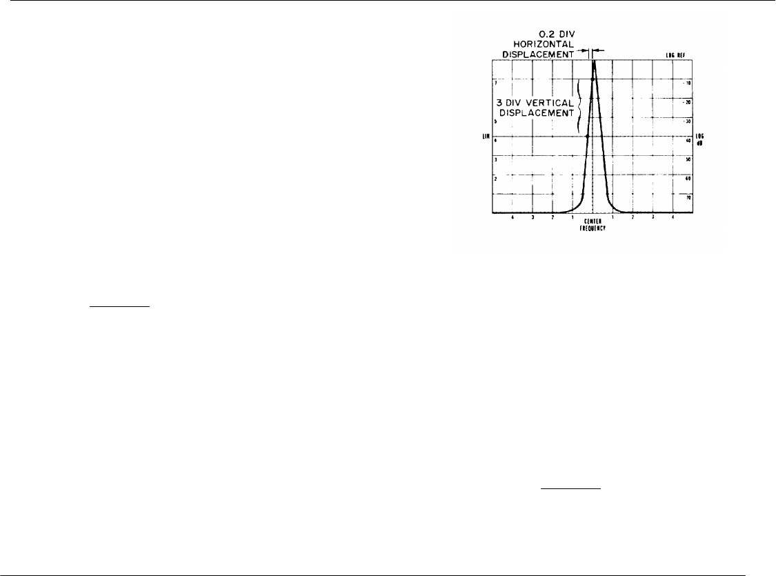
TM 11-6625-2866-14&P
Model 8444A Adjustments
ADJUSTMENTS
5-10. 1.55 GHz Oscillator Residual FM Check (cont'd)
14. Note where the slope intersects the middle horizontal
graticule line: Horizontal Displacement: ___________
divisions
15. Use the horizontal displacement to calculate demodulation
sensitivity.
a. Convert the horizontal displacement(divisions) into Hertz.
Example: (2 kHz SCAN WIDTH) x (0.2
div) = 400 Hz.
b. Calculate demodulation sensitivity by dividing the vertical
displacement in divisions into the horizontal displacement in Hz:
400 H z/di Figure 5-4. Demodulation Sensitivity
Example: = 133 Hz/div Measurement
3 divisions
16. Turn SCAN WIDTH to ZERO scan. Set FINE TUNE for a response level within the calibrated three division
range (one division from the top to the center horizontal graticule line).
17. Measure the peak-to-peak deviation, and multiply it by the demodulation sensitivity obtained in step 15b above.
Example: 0.5 div p-p signal deviation x 133 Hz/div = 66.5 Residual FM.
Hz peak-to-peak
18. Install cables removed in steps 4 through 6.
5-8
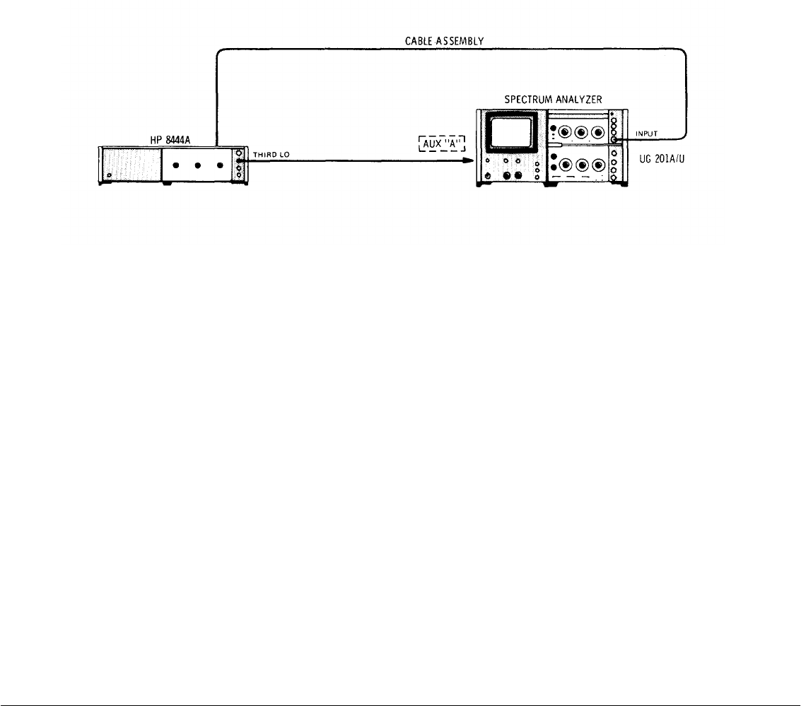
TM 11-6625-2866-14&P
Model 8444A Adjustments
ADJUSTMENTS
5-11. First Converter Check and Adjustment
REFERENCE: Service Sheet 3.
DESCRIPTION: The 1.55 GHz oscillator cavity and the two 2.05 GHz IF bandpass cavities in the first converter are
adjusted for maximum output signal level. A 8555A Spectrum Analyzer System (8555A/ 8552/140) should be used
during the adjustment procedure. In addition to providing the third LO input signal the output signal can be displayed
during the adjustment. With the analyzer operating in the linear mode, the cavities are alternately adjusted for maximum
indication on the CRT. When only the 8554L Spectrum Analyzer System is available, the output can be monitored using
a power meter such as the HP 432B.
Figure 5-5. First Converter Check and Adjustment Test Setup
EQUIPMENT: Spectrum Analyzer....................................................................................... HP 8555A/8552/141T
Cable Assembly ......................................................................................... HP 11592-60001
Adapter ....................................................................................................... UG 201A/U
Wrench ........................................................................................................ 5/16 inch
Allen Driver ................................................................................................. No.10
PROCEDURE:
1. Perform 1.55 GHz Oscillator Power Level, Frequency Check and Adjustment, paragraph 5-9.
2. With test setup as indicated in Figure 5-5, set controls as follows:
Tracking Generator
LINE ............................................................................................................ ON
TRACK ADJ ................................................................................................ Centered
LEVEL ......................................................................................................... 0 dBm
Spectrum Analyzer
BAND........................................................................................................... n=1 - (2.05 GHz IF)
FREQUENCY .............................................................................................. 500 MHz
BANDWIDTH . .......................................................................................... 100 kHz
SCAN WIDTH PER DIVISION .................................................................... 5 MHz
INPUT ATTENUATION .............................................................................. 20 dB
SCAN TIME PER DIVISION ....................................................................... 20 MILLISECONDS
LOG REF LEVEL ........................................................................................ (+) 10 dBm
LOG/LINEAR .............................................................................................. 10 dB LOG
5-9
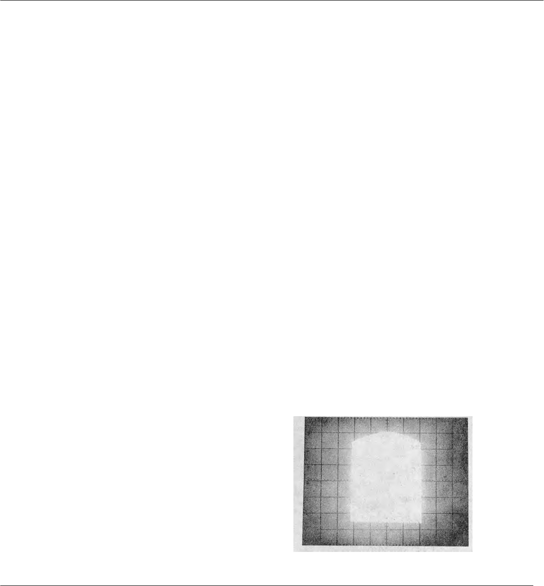
TM 11-6625-2866-14&P
Model 8444A Adjustments
ADJUSTMENTS
VIDEO FILTER ............................................................................................ 10 kHz
SCAN MODE. ............................................................................................ INT
SCAN TRIGGER ......................................................................................... AUTO
3. Disconnect W6 cable at RF OUT of 500 MHz Amplifier Assembly A4.
4. Connect 11592-60001 cable between A4 RF OUT and Spectrum Analyzer INPUT using UG 201A/U adapter.
5. Record 500 MHz signal level. ≅0 dBm _______
6. Disconnect 11592-60001 cable from A4 RF OUT connector.
7. Install W6 cable removed in step 3 above.
8. Disconnect W9 cable at A5 J3 and connect 11592-60001 cable between A5 J3 and Spectrum Analyzer INPUT.
9. Select Spectrum Analyzer n=1- (550 MHz IF) BAND and adjust FREQUENCY control for dial indication of 2050
MHz.
10. Set Spectrum Analyzer LOG/LINEAR switch to LINEAR and adjust LINEAR SENSITIVITY controls to position
signal peak between the 5 and 7 LIN graticule lines.
11. Adjust A5 ADJ 1 (1.55 GHz oscillator cavity) for peak signal indication on CRT display.
12. Alternately adjust A5 ADJ 2 and ADJ 3 (2.05 GHz IF bandpass cavities) for peak signal indication on CRT
display.
13. Repeat steps 11 and 12 above.
14. Set Spectrum Analyzer SCAN PER DIVISION to 1 MHz.
15. Tune Tracking Generator TRACK ADJ through its tuning range while observing the CRT display.
16. The passband should be similar to that displayed in Figure 5-6. If not, set TRACK ADJ to center of passband
and repeat steps 11 through 15.
17. Set Spectrum Analyzer LOG/LINEAR switch
to LOG, measure and record first converter
output signal level.
≥-7 dBm _______
18. Install W9 cable between A5 J3 and A6 J2.
Figure 5-6. First Converter Passband
CR T Display
5-10

TM 11-6625-2866-14&P
Model 8444A Adjustments
ADJUSTMENTS
5-12. Automatic Level Control (ALC) Check and Adjustment
REFERENCE: Service Sheet 3.
DESCRIPTION:
The modulator driver functions as an operational amplifier in the ALC loop. A 10 kHz signal is applied to the operational
amplifier and the loop gain is adjusted while maintaining 0 dB output level. A limiter in the amplifier circuit is adjusted to
prevent a large swing in the driver output when the analyzer sweeps through zero frequency. Perform Level Control
Calibration, paragraph 513, after ALC loop adjustment.
Figure 5-7. Automatic Level Control (ALC) Check and Adjustment Test Setup
EQUIPMENT: Spectrum Analyzer ..................................................................................... HP 8555A/8552/141T
Power Meter ................................................................................................ HP 432A
Thermistor Mount ........................................................................................ HP 8478B
AC Voltmeter .............................................................................................. HP 400E
DC Voltmeter (RF Millivoltmeter) ................................................................. HP 412A
Test Oscillator ............................................................................................. HP 652A
Test Lead with alligator clips ........................................................................
Cable Assembly ........................................................................................... HP 10501A* (2)
Resistor........................................................................................................ (100K ohm 5%, 1 watt)
*Terminated with alligator clips
PROCEDURE:
1. Perform Spectrum Analyzer calibration procedure; refer to appropriate operation and service manual.
2. Connect test setup as indicated in Figure 5-7 and set controls as follows:
Spectrum Analyzer
BAND........................................................................................................... n=1 - (2.05 GHz IF)
FREQUENCY .............................................................................................. 30 MHz
BAND........................................................................................................... 100 kHz
SCAN .......................................................................................................... ZERO
5-11

TM 11-6625-2866-14&P
Model 8444A Adjustments
ADJUSTMENTS
5-12. Automatic Level Control (ALC) Check and Adjustment (cont'd)
INPUT ATTENUATION........................................................................ 10 dB
TUNING STABLIZER .......................................................................... ON
SIGNAL IDENTIFIER........................................................................... OFF
BASE LINE CLIPPER ......................................................................... Max CCW
SCAN TIME PER DIVISION ................................................................ 10 MILLISECONDS
LOG REF LEVEL ................................................................................ +10 dBm
LOG/LINEAR ...................................................................................... LOG
VIDEO FILTER ................................................................................... OFF
SCAN MODE ..................................................................................... INT
SCAN TRIGGER . ............................................................................. AUTO
Tracking Generator
LINE .................................................................................................... ON
TRACK ADJ ....................................................................................... Peak signal indication on CRT
LEVEL ............................................................................................... 0 dBm
3. Allow instruments to warm up and stabilize for at least 30 minutes.
4. Adjust TRACK ADJ for maximum signal indication on CRT display.
5. Disconnect cable between Tracking Generator RF OUTPUT and Spectrum Analyzer INPUT.
6. Connect Thermistor Mount and Power Meter to Tracking Generator RF OUTPUT.
7. Connect test lead jumper between A2TP1 and A2TP2.
8. Adjust A2R17 "NULL ADJ" for output level of 0 1.0 dBm indication on Power Meter.
9. Remove jumper between A2TP1 and A2TP2.
10. Adjust A2R41 "O dBm LEVEL" for output level of 0 +0.5 dBm indication on Power Meter.
11. Adjust Test Oscillator for 10 kHz output.
12. Connect Test Oscillator output through 100K ohm resistor to A2TP4.
13. Connect AC Voltmeter to A2TP1.
14. Adjust Test Oscillator output amplitude for an indication of -7 dB (.001 VOLTS RANGE) on AC Voltmeter.
15. Connect AC Voltmeter to A2TP2.
16. Adjust A2R7 "GAIN ADJ" for an indication of -10 dB (.001 VOLTS RANGE) on AC Voltmeter.
17. Adjust A2R17 "NULL ADJ" for Tracking Generator output of 0 dBm.
18. Repeat steps 16 and 17 until both levels are obtained.
19. Disconnect AC Voltmeter and Test Oscillator.
20. Repeat steps 7 through 10 above.
21. Connect DC Voltmeter across A2TP1 and A2TP3, COM to A2TP1 and VOLTS to A2TP3.
5-12
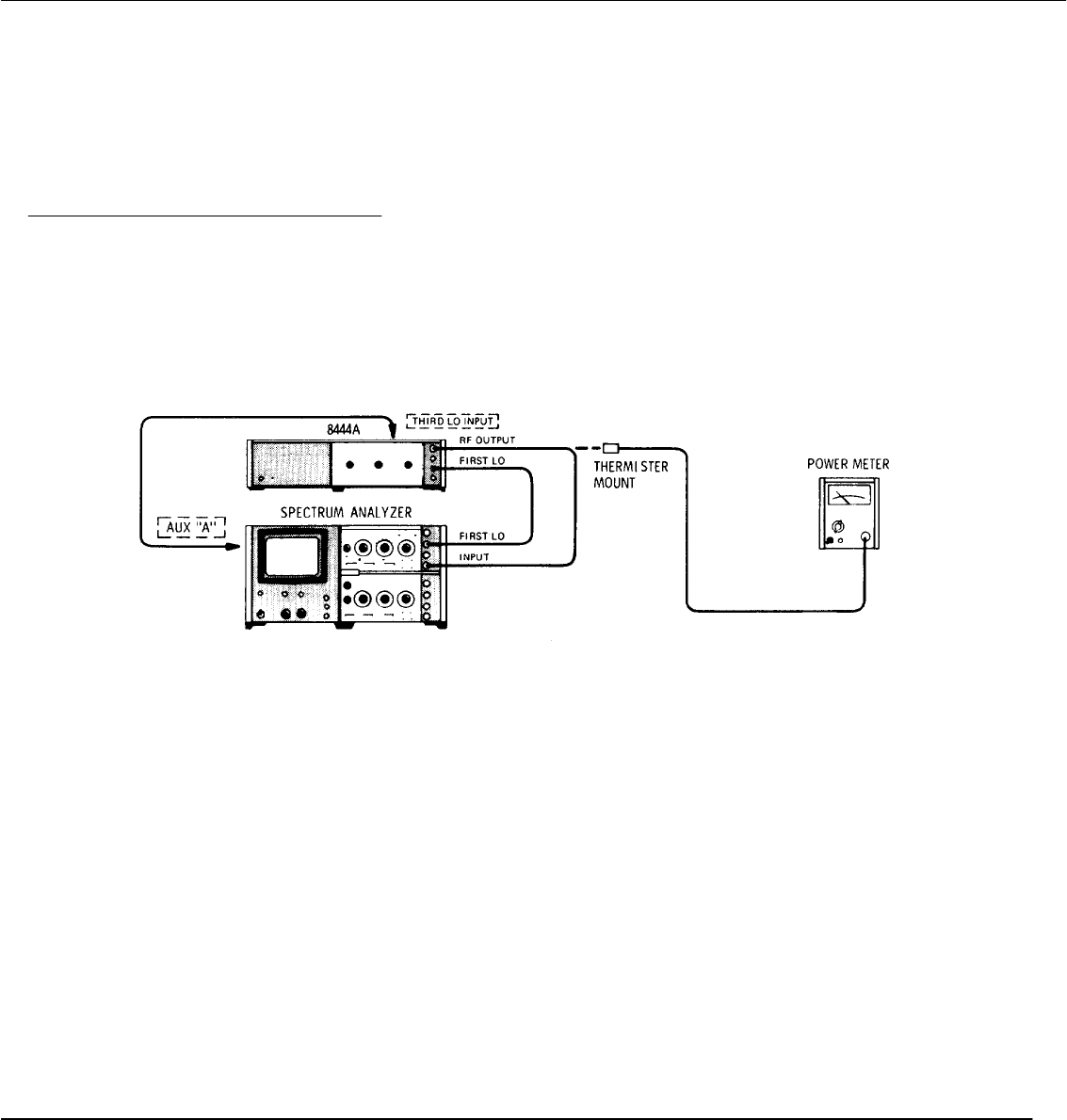
TM 11-6625-2866-14&P
Model 8444A Adjustments
ADJUSTMENTS
5-12. Automatic Level Control (ALC) Check and Adjustment (cont'd)
22. Adjust A2R6 "LIMIT SET" for an indication of +0.3 Vdc on DC Voltmeter.
23. Disconnect DC Voltmeter.
24. Perform Level Control Calibration, paragraph 5-13.
5-13. Level Control Calibration Check and Adjustment
REFERENCE: Service Sheet 4.
DESCRIPTION: The level control circuitry is adjusted to provide a 10 dB tuning range of the front panel LEVEL control.
The level control circuitry provides the voltage level to the reference diode in the ALC detector. Perform Automatic
Level Control Check and Adjustment, paragraph 512, before calibrating the level control.
Figure 5-8. Level Control Calibration Check and Adjustment Test Setup
EQUIPMENT: Spectrum Analyzer ..................................................................................... HP 8555A/8552B/141T
Power Meter ................................................................................................ HP 432A
Thermistor Mount ........................................................................................ HP 8478B
PROCEDURE:
1. Connect test setup as indicated in Figure 5-8 and set controls as follows:
Spectrum Analyzer
BAND........................................................................................................... n=1 - (2.05 GHz IF)
FREQUENCY .............................................................................................. 30 MHz
BANDWIDTH............................................................................................... 100 kHz
SCAN WIDTH . .......................................................................................... ZERO
INPUT ATTENUATION ............................................................................... 20 dB
TUNING STABILIZER ................................................................................. ON
SIGNAL IDENTIFIER . .............................................................................. OFF
BASE LINE CLIPPER ................................................................................. Max CCW
SCAN TIME PER DIVISION......................................................................... 10 MILLISECONDS
LOG REF LEVEL ........................................................................................ +10 dBm
LOG/LINEAR .............................................................................................. LOG
5-13

TM 11-6625-2866-14&P
Model 8444A Adjustments
ADJUSTMENTS
5-13. Level Control Calibration Check and Adjustment (cont'd)
VIDEO FILTER ................................................................................... OFF
SCAN MODE ...................................................................................... INT
SCAN TRIGGER.................................................................................. AUTO
Tracking Generator
LINE..................................................................................................... ON
TRACK ADJ......................................................................................... Peak signal indication on CRT
LEVEL ................................................................................................. OdBm
2. Adjust TRACK ADJ for maximum signal indication on CRT display.
3. Disconnect cable between Tracking Generator RF OUTPUT and Spectrum Analyzer INPUT.
4. Connect Thermistor Mount and Power Meter to Tracking Generator RF OUTPUT.
5. Adjust A2R41 "O dBm LEVEL" for an indication of 0 ±0.5 dBm on Power Meter.
6. Set Tracking Generator LEVEL control fully counterclockwise.
7. Adjust A2R40 "'-10 dBm LEVEL" for an indication of -10 to -12 dBm on Power Meter.
8. Set Tracking Generator LEVEL control to 0 dBm.
9. Repeat steps 5 through 7 until Power Meter indicates 0 dBm with LEVEL control fully clockwise.
10. Disconnect Power Meter and Thermistor Mount from Tracking Generator RF OUTPUT.
11. Connect cable between Tracking Generator RF OUTPUT and Spectrum Analyzer INPUT.
12. Set Tracking Generator TRACK ADJ for maximum signal level on Spectrum Analyzer CRT display.
13. Note and record signal level at 30 MHz. 0 +0.5 dBm
5-14
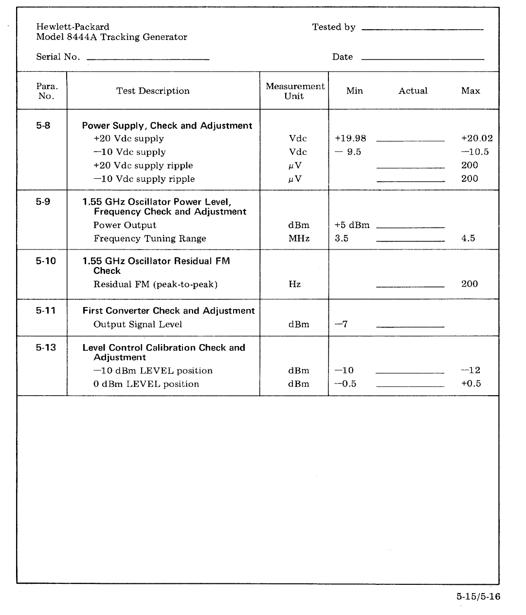
TM 11-6625-2866-14&P
Model 8444A Replaceable Parts
SECTION VI
REPLACEABLE PARTS
6-1. INTRODUCTION
6-2. This section contains information for ordering
parts. Table 6-1 lists abbreviations used in the parts list
and throughout the manual. Table 6-2 lists all
replaceable parts in reference designator order. Table
6-3 contains names and addresses that correspond to
the manufacturer's code numbers.
6-3. ABBREVIATIONS
6-4. Table 6-1 gives a list of abbreviations used in
the parts list, schematics, and throughout the manual.
In some cases, two forms of the abbreviations are
given:
one is in capital letters, while the other is partial or no
capitals. This occurs because in the parts list,
abbreviations are all capitalized. However, in the
schematics and other parts of the manual, other
abbreviation forms are used with both lower case and
upper case letters.
6-5. REPLACEABLE PARTS LIST
6-6. Table 6-2 is a list of replaceable parts and is
organized as follows:
a. Electrical assemblies and their components
in alpha-numerical order by reference designation.
b. Chassis-mounted parts in alpha-numeric
order by reference designation.
c. Miscellaneous parts.
The information given for each part consists of the
following:
a. The Hewlett-Packard part number.
b. The total quantity (Qty) used in the
instrument.
c. The description of the part.
d. The typical manufacturer of the part in a five-
digit code.
e. Manufacturer code number for the part.
The total quantity for each part is given only once - at
the first appearance of the part number in the list.
6-7. ORDERING INFORMATION
6-8. To order a part listed in the replaceable parts
table, note the Hewlett-Packard part number and then
Cross-Reference that part number to the National Stock
Number listed in table 6-5. Then order through normal
ordering channel 1 s.
6-9. If the part number does not have a National
Stock Number, then order through normal ordering
channels using the Hewlett-Packard part number.
6-10. Refer to table 6-4 for part number to NSN cross-
reference.
6-1
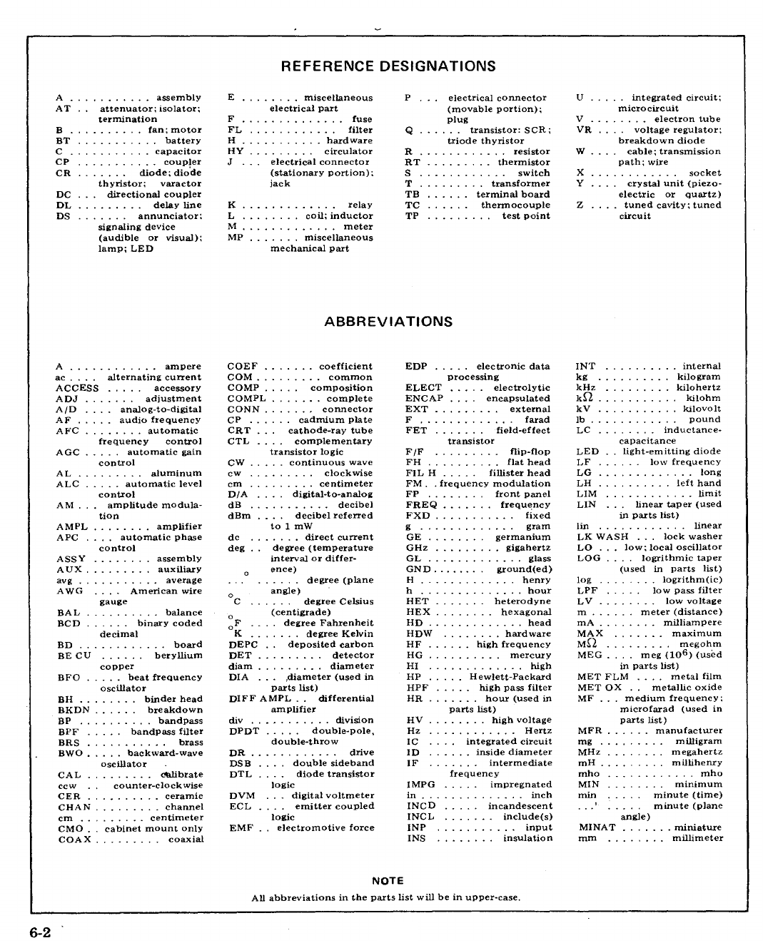
TM 11-6625-2866-14&P
Model 8444A Replaceable Parts
Table 6-1. Reference Designations and Abbreviations
6-2
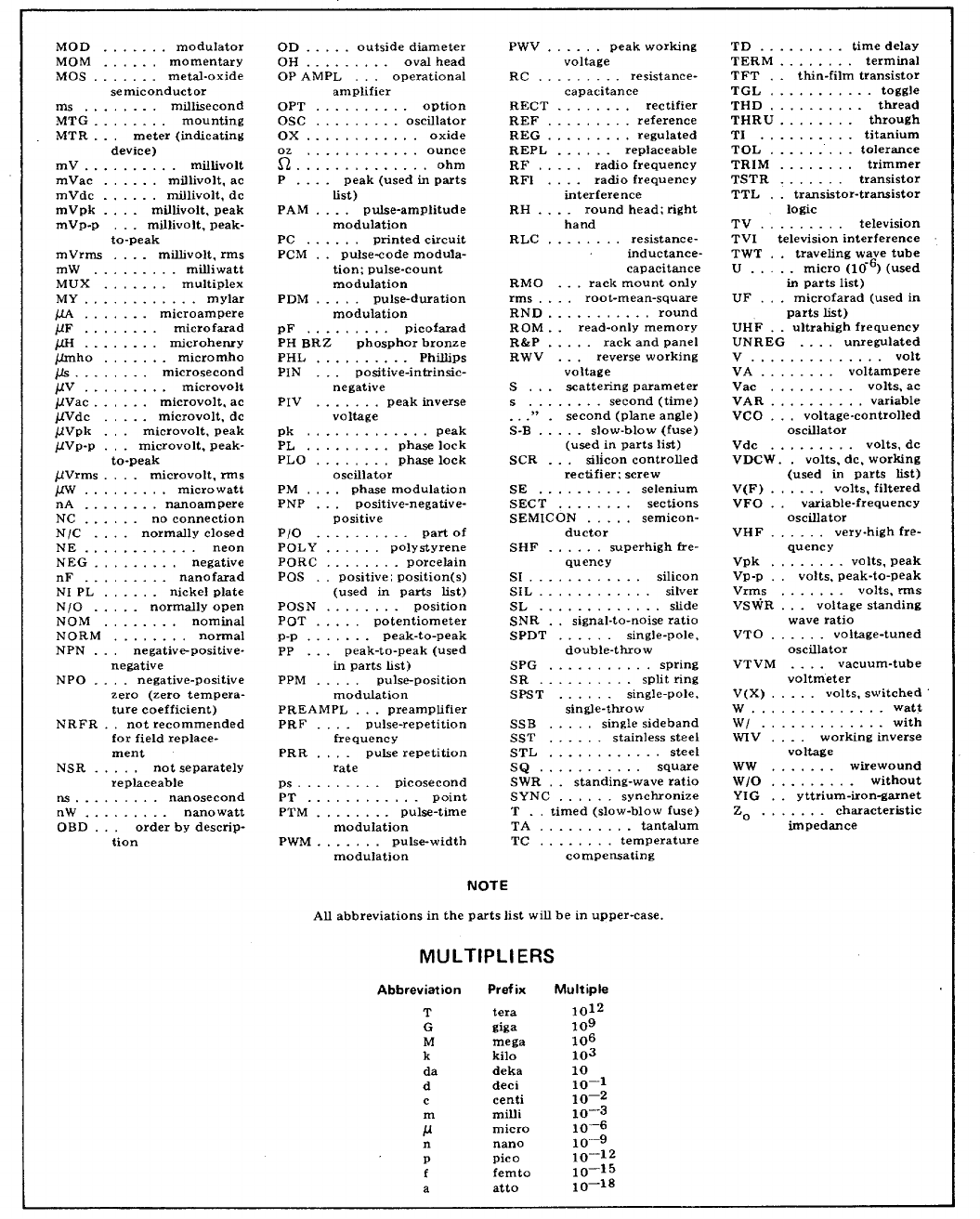
TM 11 -6625-2866-14&P
Model 8444A Replaceable Parts
Table 6-1. Reference Designations and Abbreviations (Cont’d)
6-3

TM 11 -6625-2866-14&P
Model 8444A Replaceable Parts
Table 6-2. Replaceable Parts
Reference HP Part Number Qty Description Mfr Mfr Part Number
Designation Code
A1 08444-60001 1BOARD ASSY:POWER SUPPLY 28480 08444-60001
A1C1 0160-3460 2C:FXD CER 0.05 UF +80-20Z 100VDCW 56289 C023El06 L503LS22-CDM
A1C2 0180-0116 4C:FXD ELECT 6.8 UF 10 35VDCW 56289 1500685X903582-DYS
A1C3 0160-2199 2C:FXO M1CA 30 PF 5% 300VDCW 28480 0160-2199
A1C4 0180-0228 3C:FXD ELECT 22 UF 105 15VDCW 56289 150D0226X9015B2-DYS
A1C5 0180-0116 C:FXD ELECT 6.8 UF 10% 35VDCW 56289 1500685X903582-DYS
A1C6 0160-3460 C:FXD CER 0.05 UF +80-203 100VDCW 56289 C023El101OL503ZS22-CDM
A1C7 0160-2199 C:FXD 11CA 30 PF 5% 300VDCW 28480 0160-2199
A1C8 0180-0228 C:FXD ELECT 22 UF 10 15VDCW 56289 1500226X901582-DYS
A1C9 0180-0116 C:FXD ELECT 6.8 UF 10% 35VDCW 56289 1500685X903582-DYS
A1CR1 1901-0159 8DIODE:SILICON 0.75A 400PIV 04713 SR1358-4
A1CR2 1901-0159DIODE:SILICON 0.75A 400PIV 04713 SR1358-4
A1CR3 1901-0159 DIODE:SILICON 0.75A 400PIV 04713 SR1358-4
A1CR4 1901-0159 DIODE:SILICON 0.75A 400PIV 04713 SR1358-4
A1CR5 1901-0040 5DIODE:SILICON 30MA 30WV 07263 FDG1088
A1CR6 1901-0200 2DIODE:SILICON 100 PIV 3A 02735 1N4998
A1CR7 1901-0200 DIODE:SILICON 100 PIV 3A 02735 1N4998
A1CR8 1902-3182 1DIODE BREAKDOWN:SILICON 12.1V 5% 28480 1902-3182
A1CR9 1902-3256 1DIODE:BREAKOOWN SILICON 23.78 5% 28480 1902-3256
A1CR10 1884-0012 1RECTIFIER:SILICON CONTROLLED 2N3528 02735 2N3528
A1CR11 1902-0761 1DIODE:BREAKDOWN 5.9 TO 6.5V 12954 1N821
A1CR12 1901-0159 DIODE:SILICON 0.75A 400PIV 04713 SR1358-4
A1CR13 1901-0156 DIODE:SILICON 0.75A 400IV 04713 SR1358-4
A1CR13 1901-0159 DIODE:SILICON 0.75A 400PIV 04713 SR1358-4
A1CR14 1901-0159 D1ODE:SILICON 0.75A 400PIV 04713 SR1358-4
A1CR15 1901-0159 DIODE:SILICON 0.75A 400PIV 04713 SR1358-4
AiCR16 1901-0040 DIODE:SILICON 30MA 30WV 07263 FDG1088
A1F1 2110-0012 2FUSE:0.5 AMP 250V 75915 312.500
A1F2 2110-0012 FUSE:0.5 AMP 250V 75915 312.500
A1MP1 2110-0269 4CL1P:FUSE 0.250" DIA 91506 6008-32CN
A1MP2 2110-0269 CL1P:FUSE 0.250” DIA 91506 6008-32CN
A1MP3 2110-0269 CLIP:FUSE 0.250" D1A 91506 6008-32CN
A1MP4 2110-0269 CLIP:FUSE 0.250" D1A 91506 6008-32CN
A1Q1 1853-0020 7TSTR:SI PNP[SELECTED FROM 2N37021 28480 1853-0020
A1Q2 1853-0012 2TSTR:SI PNP 80131 2N2904A
A1Q3 1854-0039 2TSTR:SI NPN 80131 2N3053
A1Q4 1854-0071 3TSTR:SI NPN(SELECTED FROM 2N3704) 28480 1854-0071
A1Q5 1853-0020 TSTR:SI PNP(SELECTED FROM 2N3702) 28480 1853-0020
A1Q6 1854-0039 TSTR:SI NPN 80131 2N3053
A1Q7 1854-0071 TSTR:SI NPN(SELECTED FROM 2N3704) 28480 1854-0071
A1R1 0698-3160 2R:FXD MET FLM 31.6K OHM 1% 1/8W 28480 0698-3160
A1R2 0698-3445 2R:FXD MET FLM 348 OHM 1X 1/8W 28480 0698-3445
A1R3 0757-0440 4R:FXD MET FLM 7.50K OHM 1t 1/8W 28480 0757-0440
A1R4 0811-1666 2R:FXD MWW 1.0 OHM 5% 2W 28480 0811-1666
A1R5 0698-3441 4R:FXD MET FLM 215 OHM 12 1/8W 28490 0698-3441
A1R6 0157-0440 R:FXD MET FLM 7.50K OHM 1% 1/8W 28480 0757-0440
A1R7 0757-0280 5R:FXD MET FLM 1K OHM 1% 1/8W 28480 0757-0280
A1R8 0757-0401 3R:FXD MET FLM 100 OHM 1% 1/8W 28480 0757-0401
1AR9 0757-0438 3R:FXD MET FLM 5.11K OHM 1% 1/8W 28480 0757-0438
A1R10 0683-0275 2R:FXD COMP 2.7 OHM 52 1/4W 01121 CB 27G5
A1R11 0757-0280 R:FXD MET FLM LK OHM 1% 1/8W 28480 0757-0280
ALR12 0757-0278 1R:FXD MET FLM 1.78K OHM 1% 1/8W 28480 0757-0278
A1R13 0757-0289 1R:FXD MET FLM 13.3K OHM 3 1/81W 28480 0757-0289
A1R14 2100-1758 3R:VAR WW 1K OHM 53 TYPE V 1W 28480 2100-1758
A1R15 0757-0200 1R:FXO MET FLM 5.62K OHM 1% 1/8W 28480 0757-0200
A1RL16 0811-1666 R:FXD WW 1.0 OHM 5% 2W 28480 0811-1666
A1R17 0698-3441 R:FXD MET FLM 215 OHM 1% 1/8W 28480 0698-3441
A1R18 0757-0440 R:FXD MET FLM 7.50K OHM 1% 1/8W 28480 0757-0440
1AR19 0757-0280 R:FXD MET FLM 1K OHM 1% 1/8W 28480 0757-0280
A1R20 0757-0440 R:FXD MET FLM 7.50K OHM 1% 1/8W 28480 0757-0440
A1R21 0698-0084 3R:FXD MET ELM 2.15K OHM 1% 1/8W 28480 0698-0084
A1R23 0698-0084 R:FXD MET FLM 2.15K OHM 1% 1/8W 28480 0698-0084
A1R22 0698-0084 R:FXD MET FLM 2.15K OHM 1% 1/8W 28480 0698-0084
A1R24 0683-0275 R:FXD COMP 2.7 OHM 5% 1/4W 01121 CB 27G5
A1TB1 08444-20001 1BOARD:BLANK PC 28480 08444-20001
A1TP1 0360-1514 12 TERMINAL PIN:SQUARE 28480 0360-1514
A1TP2 0360-1514 TERMINAL PIN:SQUARE 28480 0360-1514
A1TP3 0360-1514 TERMINAL PIN:SQUARE 28480 0360-1514
A1TP4 0360-1514 TERMINAL PIN:SOUARE 28480 0360-1514
A1TP5 0360-1514 TERMINAL PIN:SQUARE 28480 0360-1514
A1LT6 0360-1514 TERMINAL PIN:SQUARE 28480 0360-1514
A1U1 1820-0223 3INTEGRATED CIRCUIT:OPERATIONAL AMPL. 28480 1820-0223
A1U2 1820-0223 INTEGRATED CIRCUIT:OPERATIONAL AMPL. 28480 1820-0223
A2 08444-60002 1BOARD ASSY:DRIVER 28480 08444-60002
A2C1 0180-0116 C:FXO ELECT 6.8 UF 10% 35VDCW 56289 150D685X903582-DYS
A2C2 0180-2205 1C:FXD ELECT 0.33 UF 10% 35VDCW 56289 1500334X9035A2-DYS
6-4

TM 11 -6625-2866-14&P
Model 8444A Replaceable Parts
Table 6-2. Replaceable Parts
Reference HP Part Number Qty Description Mfr Mfr Part Number
Designation Code
A2C3 0180-0228 C:FXD ELECT 22 UF 10% 15VDCW 56289 1500226X901582-DYS
A2C4 0180-1746 1C:FXD ELECT 15 UF 10% 20VDCW 28480 0180-1746
A2C5 0180-0374 2C:FXD TANT. 10 UF 10% 20VDCW 56289 1500106X902082-DYS
A2C6 0160-2208 1C:FXD MICA 330 PF 5% 300VDCW 28480 0160-2208
A2C7 0180-0374 C:FXD TANT. 10 UF 10% 20VDCW 56289 1500106X902082-DYS
A2C8 0160-0300 1C:FXD MY 0.0027 UF 10% 200VDCW 56289 292P27292-PTS
A2CR1 1901-0040 DIODE:SILICON 30HA 30WV 07263 FDG1088
A2CR2 1901-0040 DIOOE:SILICON 30MA 30WV 07263 FDG1088
A2CR3 1901-0040 DIODE:SILICON 30MA 30WV 07263 FDG1088
A2Q1 1854-0221 1TSTR:SI NPN(REPL.BY 2N4044} 28480 1854-0221
A2Q2 1853-0020 TSTR:SI PNP(SELECTED FROM 2N3702) 28480 1853-0020
A2Q3 1853-0020 TSTR:SI PNP(SELECTED FROM 2N3702) 28480 1853-0020
A2Q4 1853-0020 TSTR:SI PNP(SELECTED FROM 2N3702) 28480 1853-0020
A2Q5 1853-0020 TSTR:SI PNP(SELECTED FROM 2N3702) 28480 1853-0020
A2Q6 1854-0071 TSTR:SI NPN(SELECTED FROM 2N3704) 28480 1854-0071
A2Q7 1853-0020 TSTR:SI PNP(SELECTED FROM 2N3702) 28480 1853-0020
A2Q8 1853-0012 TSTR:SI PNP 80131 2N2904A
A2R1 0757-0346 3R:FXD MET FLM 10 OHM 1% 1/8W 28480 0757-0346
A2R2 0698-3454 2R:FXD MET FLM 215K OHM 1% 1/8W 28480 0698-3454
A2R3 0757-0280 R:FXD MET FLM 1K OHM 1% 1/8W 28480 0757-0280
A2R4 0757-0280 R:FXO MET FLM 1K OHM 1% 1/8W 28480 0757-0280
A2R5 0757-0438 R:FXO MET FLM 5.11K OHM 1% 1/8W 28480 0757-0438
A2R6 2100-1760 3R:VAR WW 5K OHM 5% TYPE V 1W 28480 2100-1760
A2R7 2100-1760 R:VAR WW 5K OHM 5% TYPE V 1W 28480 2100-1760
A2R8 0698-3444 1R:FXD MET ELM 316 OHM 1% 1/8W 28480 0698-3444
A2R9 0698-3156 1R:FXD MET FLM 14.7K OHM 1% 1/8W 28480 0698-3156
A2R10 0757-0346 R:FXD MET FLM 10 OHM 1% 1/8W 28480 0757-0346
A2R11 0698-3154 1R:FXD MET FLM 4.22K OHM 1% I/8W 28480 0698-3154
A2R12 0757-0346 R:FXD MET FLM 10 OHM 1% 1/8W 28480 0757-0346
A2R13 0698-3454 R:FXD MET FLM 215K OHM 1% 1/8W 28480 0698-3454
A2R14 0757-0424 2R:FXD MET FLM 1.10K OHM 1% 1/8W 28480 0757-0424
A2R15 0698-3437 1R:FXD MET FLM 133 OHM 1% 18W 28480 0698-3437
A2R16 0757-0817 1R:FXD MET FLM 750 OHM 1% 1/2W 28480 0757-0817
A2R17 2100-1758 R:VAR WW IK OHH 5t TYPE V 1W 28480 2100-1758
A2R18 0698-3445 R:FXD MET ELM 348 OHM 1% 18W 28480 0698-3445
A2R19 0757-0401 R:FXD MET FLM 100 OHM 1% 1/8W 28480 0757-0401
A2R20 0757-0416 1R:FXD MET FLM 511 OHM 1% 1/8W 28480 0757-0416
A2R21 0698-3450 1R:FXD MET FLM 42.2K OHM 1% 1/18W 28480 0698-3450
A2R22 0757-0401 R:FXD MET FLM 100 OHM 1% 1/8W 28480 0757-0401
A2R23 0757-1094 1R:FXD MET ELM 1.47K OHM 1% 1/8W 28480 0757-1094
A2R24 0757-0424 R:FXD MET FLM 1.10K OHM 1% 1/8W 28480 0757-0424
A2R25 0698-3441 R:FXD MET FLM 215 OHM 1% 1/8W 28480 0698-3441
A2R26 2100-2522 1R:VAR CERMET 10K OHM 10% LIN 1/2W 28480 2100-2522
A2R27 2100-1758 R:VAR WW 1K OHM 5% TYPE V 1W 28480 2100-1758
A2R28 0757-0442 4R:FXD MET FLM 10.OK OHM 1% 1/8W 28480 0757-0442
A2R29 0757-0465 R:FXD MET FLM 100K OHM 1% 1/8W 28480 0757-0465
A2R30 0757-0288 2R:FXD MET FLM 9.09K OHM 1% 1/8W 28480 0757-0288
A2R31 0757-0442 R:FXD MET FLM 10.0K OHM 1% 1/8W 28480 0757-0442
A2R32 0757-0438 R:FXD MET FLM 5.11K OHM I% 1/8W 28480 0757-0438
A2R33 0698-3441 R:FXD MET FLM 215 OHM i1%1/8W 28480 0698-3441
A2R34 0757-0442 R:FXD MET FLM 10.OK OHM 1% 1/8W 28480 0757-0442
A2R35 0698-3399 1R:FXD MET FLM 133 OHM 1% 1/2W 28480 0698-3399
A2R36 0757-0439 R:FXD MET FLM 6.81K OHM 1% 1/8W 28480 0757-0439
A2R37 0757-0421 1R:FXD MET ELM 825 OHM 1% 1/8W 28480 0757-0421
A2838 0698-3438 1R:FXD MET FLM 147 OHM 1% 1/8W 28480 0698-3438
A2R39 0757-0288 R:FXD MET FLM 9.09K OHM 1% 1/8W 28480 0757-0288
A2R40 2100-2522 1R:VAR WW 10K OHM 10% TYPE V 1W 19701 ET50X103
A2R41 2100-1760 R:VAR WW 5K OHM 5% TYPE V 1W 28480 2100-1760
A2R42 0698-3151 1R:FXD MET FLM 2.87K OHM 1% 1/8W 28480 0698-3151
A2TB1 08444-20002 1BOARD:BLANK PC 28480 08444-20002
A2TP1 0360-1514 TERMINAL PIN:SQUARE 28480 0360-1514
A2TP2 0360-1514 TERMINAL PIN:SQUARE 28480 0360-1514
A2TP3 0360-1514 TERMINAL PIN:SQUARE 28480 0360-1514
A2TP4 0360-1514 TERMINAL PIN:SQUARE 28480 0360-1514
A2TP5 0360-1514 TERMINAL PIN:SQUARE 28480 0360-1514
A2TP6 0360-1514 TERMINAL PIN:SQUARE 28480 0360-1514
A2UI 1820-0223 INTEGRATED CIRCUIT:OPERATIONAL AMPL. 28480 1820-0223
A3 5086-7025 1AMPLIFIER DETECTOR 28480 0960-2038
A3 NOT FIELD REPAIRABLE
A4 AMPLIFIER ASSY:500 MHZ
A4C1 0160-2357 2C:FXD CER FEED-THRU 1000 PF +80-20% 28480 0160-2357
A4C2 0160-2357 C:FXD CER FEED-THRU 1000 PF +80-20% 28480 0160-2357
A4C3 0160-2152 1C:FXD CER 10 PF 20% 500VDCW 28480 0160-2152
A4J1 1250-1220 2CONNECTOR:RF 50 OHM SCREW-ON TYPE 98291 50-051-0109
A4J2 1250-1220 CONNECTOR:RF 50 OHM SCREW-ON TYPE 98291 50-051-0109
6-5

TM 11 -6625-2866-14&P
Model 8444A Replaceable Parts
Table 6-2. Replaceable Parts
Reference HP Part Number Qty Description Mfr Mfr Part Number
Designation Code
A4MP1 08444-00006 1COVER:500 MHZ AMPLIFIER 28480 08444-00006
A4MH2 08444-20011 1HOUSING:500 MHZ AMPLIFIER 28480 08444-20011
A4A1 08444-60005 1BOARD ASSY:500 MHZ AMPLIFIER 28480 08444-60005
A4A1C1 0160-2266 11 C:FXD CER 24 PF 5% 500VDCW 72982 301-000-COGO-240J
A4A1C2 0160-3456 C:FXD CER 1000 PF 10% 250 VDCW 28480 0160-3456
A4A1C3 0160-2266 C:FXD CER 24 PF 5% 500VDCW 72982 301-000-COGO-240J
A4A1C4 0160-2266 C:FXD CER 24 PF 5t 500VDCW 72982 301-000-COGO-240J
A4A1C5 0160-2266 C:FXD CER 24 PF 5% 500VDCW 72982 301-000-COGO-240J
A4A1C6 0160-2266 C:FXD CER 24 PF 5% 500VDCW 72982 301-000-COGO-240J
A4A1C7 0160-2266 C:FXO CER 24 PF 5% 500VDCW 72982 301-000-COGO-240J
A4A1C8 0160-2266 C:FXD CER 24 PF 500VDCW 72982 301-000-COGO-240J
A4A1C9 0160-2266 C:FXD CER 24 PF 500VDCW72982 301-000-COGO-240J
A4A1C10 0160-2266 C:FXD CER 24 PF 500VDCW 72982 301-000-COGO-240J
A4A1C11 0160-2266 C:FXD CER 24 PF 500VDCW 72982 301-000-CG000-240J
A4A1CR1 1901-0639 2DIOOE:PIN 1MHZ TO 1GHZ 28480 1901-0639
A4A1CR2 1901-0639 DIODE:PIN 1MHZ TO 1GHZ 28480 1901-0639
A4A1L1 9100-2252 4COIL/CHOKE 0.27 UH 10% 28480 9100-2252
A441L2 9100-2252 COIL/CHOKE 0.27 UH 10% 28480 9100-2252
A4A1L3 9100-2252 COIL/CHOKE 0.27 UH 10% 28480 9100-2252
A4A1L4 9100-2252 COIL/CHOKE 0.27 UH 10% 28480 9100-2252
A4A1Q1 1854-0345 3TSTR:SI NPN 80131 2N5179
A4A1Q2 1854-0345 TSTR:SI NPN 80131 2N5179
A4A1Q3 1854-0345 TSTR:SI NPN 80131 2N5179
A4A1R1 0698-7197 1R:FXD FLM 23.7 OHM 2% 1/8W 28480 0698-7197
A4A1R2 0698-7236 9R:FXD FLM 1K OHM 2% 1/8W 28480 0698-7236
A4A1R3 0698-7236 R:FXD FLM 1K OHM 2% 1/8W 28480 0698-7236
A4A1R4 0698-7236 R:FXD FLM IK OHM 2% 1/8W 28480 0698-7236
A4A1R5 0698-7236 R:FXD FLM 1K OHM 2% 1/8W 28480 0698-7236
A4A1R6 0698-7236 R:FXD FLM 1K OHM 2% 1/8W 28480 0698-7236
A4A1R7 0698-7236 R:FXD FLM 1K OHM 2% 1/8W 28480 0698-7236
A4A1R8 0698-7236 R:FXD FLM 1K OHM 2% 1/8W 28480 0698-7236
A4A1R9 0698-7236 R:FXD FLM 1K OHM 2% 1/8W 28480 0698-7236
A4A1R10 0698-7236 R:FXD FLM 1K OHM 22 1/8W 28480 0698-7236
A4A1R11 0693-7214 1R:FXD FLM 121 OHM 2% 1/8W 28480 0698-7214
A4A1TB1 08444-20005 1BOARD:BLANK PC 28480 08444-20005
A5 08444-60011 1CONVERTER ASSY:FIRST 28480 08444-60011
A5J1 1250-0829 5CONNECTOR:RF 50-OHM SCREW ON TYPE 98291 50-045-4610
A5J2 1250-0829 CONNECTOR:KF 50-OHM SCREW ON TYPE 98291 50-045-4610
A5J3 1250-0829 CONNECTOR:RF 50-OHM SCREW ON TYPE 98291 50-045-4610
A5MP1 08555-00033 2INPUT-OUTPUT LOOP 28480 08555-00033
A5MP2 0516-0005 2SCREW:PAN HD SLOT DR 0-80 X 0.188" LG 00000 080
A5MP3 2200-0111 14 SCREW:PAN HD POLI DR 4-40 X 0.500" LG 00000 OBD
A5MP4 08555-20035 1CAVITY BLOCK:SECOND CONVERTER 28480 08555-20035
A5MP5 08444-20012 1COVER:FIRST CONVERTER 28480 08444-20012
A5MP6 2200-0172 2SCREW:FLAT HD POZI DR 4-40 X 0.875" LG 00000 OBD
A5MP7 08444-20007 1CENTER-POST 28480 08444-20007
A5MP8 2740-0001 3NUT:HEX 10-32 THREAD 00000 O8D
A5MP9 3030-0151 4SCREW:SOCKET CAP 4-40 THREAD 28480 3030-0151
A5MP10 3030-0397 3SCREW:SET 10-32 UNF-2A THREAD 00000 OBD
A5A1 08444-60012 1MIXER ASSY:FIRST 28480 08444-60012
A5A1C1 0160-2327 1C:FXO CER 1000 PF 20% 100VDCW 96733 B104BX102M
A5A1C2 0160-3861 1C FXD 18 PF + -5% 250 VDCW 72982 2930-000-3903
A5A1C3 0160-3860 1C:FXD MICA 39 PF 5% 250VDCW 72982 2930-000-390J
A5A1CR1 1901-0633 1DIODE:HOT CARRIER 28480 1901-0633
A5A1J1 1250-0829 CONNECTOR:RF 50-OHM SCREW ON TYPE 98291 50-045-4610
A5A1L1 9100-2254 1COIL/CHOKE .39 UH 10% 28480 9100-2254
A5A1MP1 0520-0128 4SCREW:PAN HD POZI DR 2-56 X 0.250" LG 00000 OBD
A5A1MP2 1251-1556 1CONNECTOR:SINGLE CONTACT 00779 2-330808-8
A5A1MP3 08555-00031 1LID:RESONATOR HOUSING 28480 08555-00031
A5A5MP4 085'5-20036 1RESONATOR HOUSING 28480 08555-20016
A5A1R1 0698-7233 1R:FXD FLM 750 OHM 2% 1/8W 28480 0698-7233
A6 08444-60004 1MIXER ASSY:OUTPUT 28480 08444-60004
A6 NOT RECOMMENDEOD FOR FIELD REPAIR
A7 08444-60019 1 OSCILLATOR ASSY:1.55 GHZ
A7 ·NOT RECOMMENDED FOR FIELD REPAIR 28480 08444-60019
A7CI 0163-3827* 1C:FXD PRC 1 PF 500VDCW 84411 663UW22354W2
A7C2 0160-0345 2C:FXD CEP FEED-THRU 1000 PF 500VDCW 01121 FB2B-102W
A7C3 0160-0345 C:FXD CER FEED-THRU 1000 PP 500VDCW 01121 FB28-102W
A7C4 0160-2437 1C FXD CER 5000 PF +80 -20%
A7CR1 0122-0245 2C:VOLTAGE VAR. 6.8 PF 10% 60VDCW 04713 1N5139
A7J1 1250-0829 CONNECTOR:KF 5-OHM SCREW ON TYPE 98291 50-045-4610
A7L1 1460-0103 1SPRING:COMPRESSION 0.120" OD 00000 O8D
A7Q1 1854-0292 1TSTR:SI NPN 28480 1854-0292
A7R1 0698-7230 1R:FXD FLM 562 OHM 2% 1/8'W 28480 0698-7230
A7R2 0757-0418 1R:FXD MET FLM 619 OHM 1% 1/8W 28480 0757-0418
A8 5060- 1189 POWER LINE MODULE. NON-FILTERED 28480 5060-1189
6-6

TM 11 -6625-2866-14&P
Model 8444A Replaceable Parts
Table 6-2. Replaceable Parts
Reference HP Part Number Qty Description Mfr Mfr Part Number
Designation Code
CHASSIS PARTS
AT1 0960-0084 2ISOLATOR:2-PORT 2-4 GHZ 28480 0960-0084
AT2 0960-0084 ISOLATOR:2-PORT 2-4 GHZ 28480 0960-0084
AT3 0960-0168 1ISOLATOR:2-PORT 1.54-1.56 GHZ 28480 0960-0168
AT4 11593A 1TERMINATION:50 OHM 28480 11593A
C1 0180-2181 2C:FXD ELECT 1300 UF +75-10% 50VDCW 56289 3601320050AA2A-DQ8
C1 1210-0013 2BRACKET:MOUNTING FOR 1-3/8 OD 56289 4586-87A
C2 0180-2181 C:FXD ELECT 1300 UF +75-10% 50VDCW 56289 3601320050A02A-DQB
C2 1210-0013 BRACKET:MOUNTING FOR 1-3/8 OD 56289 4586-87A
C3 0160-0155 1C:FXD MY 0.0033 UF 10% 200VDCW 28080 0160-0155
CP1 1250-0838 1CONNECTOR:RF ADAPTER TEE 98291 50-085-0000
F1 2110-0202 1FUSE:0.50A 250V SLOW-BLOW 75915 313.500S
F1 (FOR 115V OPERATION)
F1 2110-02011 FUSE:0.25A 250V SLO-BLO 71400 MDL-1/4
FL1 (FOR 230V OPERATION)
FL1 0960-0167 1FILTER:TUBULAR BANDPASS 2.0-3.4 GHZ 28480 0960-0167
J1MPI 1250-0914 1BODY:RF CONNECTOR 02660 131-150
J1MP2 1250-0915 1CONTACT:RF CONNECTOR 02660 131-149
J1MP3 5040-0306 1INSULATOR 28480 5040-0306
J1M4 08555-20093 1CONTACT:JACK 28480 08555-20093
J1MP5 08555-20094 1BODY:BULKHEAD 28480 08555-20094
J1MP6 2190-0444 1WASHER:LOCK 00000 O8D
J1MP7 2950-0132 1NUT:HEX 7/16-28 00000 O8D
J1MP8 08761-2027 1INSULATOR 28480 08761-2027
J4 1250-0118 1CONNECTOR:BNC 24931 28JR 128-1
J6 1251-2996 1CONNECTOR:AC POWER 28480 1251-2996
Q1 1854-0063 2TSTR:SI NPN 80131 2N3055
Q1 1200-0043 2INSULATOR:TSTR MOUNTING(TO-3) 71785 293011
Q2 1854-0063 TSTR:SI NPN 80131 2N3055
Q2 1200-0043 INSULATOR:TSTR MOUNTING(TO-3) 71785 293011
R1 2100-2730 1R:VAR CERMET 5000 OHM 20% LIN 2W 28480 2100-2730
R1 0370-0133 3KNOB:SKIRTED FOR 0.250" DIA SHAFT 28480 0370-0133
R2 2100-2886 1R:VAR WW 5K OHM 5% LIN 2W 28480 2100-2886
R2 0370-0133 KNOB:SKIRTED FOR 0.250" DIA SHAFT 28480 0370-0133
R3 2100-2728 1R:VAR CERNET 1K OHM 20% LIN 2W 28480 2100-2728
R3 0370-0133 KNOB:SKIRTED FOR 0.250" DIA SHAFT 28480 0370-0133
R4 0698-3449 1R:FXD MET FLM 28.7K OHM 1% 1/8W 28480 0698-3449
R5 0757-3438 1R FXD MET FLM 5.11 OHM 1% 1/8W 28080 0757-0438
S1 3101-1248 1SWITCH:PUSHBUTTON SPDT ILLUMINATED 87034 53-55480-121/A1H
S1DS1 2140-0244 1LAMP:GLOW MINIATURE 95V 87034 A1H
W1 08444-20018 1CABLE ASSY:FIRST LO INPUT 28480 08444-20018
W2 08444-20024 2CABLE ASSY:FILTER 28480 08444-20024
W3 08444-20024 CABLE ASSY:FILTER 28480 08444-20024
W4 08444-20020 1CABLE ASSY:MIXER ISOLATOR 28480 08444-20020
W5 08444-60015 1CABLE ASSY:THIRD LO INPUT 28480 08444-60015
W6 08444-60014 1CABLE ASSY:FIRST CONVERTER 28480 08444-60014
w7 08444-20017 1CABLE ASSY:OSCILLATOR 28480 08444-20017
W8 08444-20026 1CABLE ASSY:FIRST ISOLATOR 28480 08444-20026
W9 09444-20027 1CABLE ASSY:FIRST C OUTPUT 28480 08444-20027
W10 08444-20021 1CABLE ASS¥:MIXER-CIRCUIT 28480 08444-20021
W11 08444-20019 1CABLE ASSY:RF OUTPUT(AUXILIARY) 28480 0844O 20019
W12 08444-20023 1CABLE ASSY:RF OUTPUT 28480 08444-20023
W13 08444-60016 1CABLE ASSY:THIRD LO INPUT 28480 08444-60016
W14 08444-60018 3CABLE ASSY:RF INTERCONNECT 28480 08444-60018
W15 0R444-60018 CABLE ASSY:RF INTERCONNECT 28480 08444-60018
W16 08444-60018 CABLE ASSY:RF INTERCONNECT 28480 08444-60018
W17 08444-60017 1CABLE ASSY:INTERCONNECTING 28480 08444-60017
W18 8120-1348 1CABLE:LINE POWER 28480 8120-1348
XA1 1251-0159 1CONNECTOR:PC EDGE 2 X 15 CONTACT 71785 251-15-30-261
XA2 1251-0135 1CONNECTOR:PC EDGE 15 CONTACT 95354 91-6915-1500-00
XFI 1400-0011 2CLIP:FUSE 75915 #125002
XF1 1400-0011 CLIP:FUSE 75915 #125002
XQ1 1200-0041 2SOCKET:TRANSISTOR 71785 133-32-10-013
XQ2 1200-0041 SOCKET:TRANSISTOR 71785 133-32-10-013
08444-60013 1WIRING HARNESS 28480 08444-60013
T1 9100-3308 1TRANSFORMER: POWER 115-230 VAC 28480 9100-3308
48-440 HZ
6-7

TM 11 -6625-2866-14&P
Model 8444A Replaceable Parts
Table 6-2. Replaceable Parts
Reference HP Part Number Qty Description Mfr Mfr Part Number
Designation Code
MECHANICAL PARTS
MP1 1490-0030 1STAND:TILT 28480 1490-0030-
MP2 5000-0050 2TRIM:SIDES 28480 5000-0050
MP3 5000-0730 2COVER:SIDE 3 X 16( BLUE GRAY) 28480 5000-0730
MP3 5000-8593 2COVER:SIDE 3 X 16(OLIVE GRAY) 28480 5000-8593
MP4 5020-0900 1TRIM:PANEL( LIGHT GRAY) 28480 5020-0900
MP4 5020-6850 1TRIM:PANEL( MINT GRAY) 28480 5020-6850
MP5 5020-0901 1TRIM:PANEL( LIGHT GRAY) 28480 5020-0901
MP5 5020-6851 1TRIM:PANEL(MINT GRAY) 28480 5020-6851
MP6 5040-0170 4GUIDE:PLUG-IN PC BOARD 28480 5040-0170
MP7 50b0-0730 2FRAME ASSY:3 X 16 28480 5060-0730
MP8 5060-0740 1COVER AS5Y:TOP 16L(BLUE GRAY) 28480 5060-0740
MP8 5060-8589 ICOVER ASSY:TOP 16L(OLIVE GRAY) 28480 5060-8589
MP9 5060-0752 1COVER ASSY:BOTTOM 16L(BLUE GRAY) 28480 5060-0752
MP9 5060-8713 1COVER:BOTTOM 28480 5060-8713
MP10 5060-0767 5FOOT ASSY:FM 28480 5060-0767
MP11 5060-0774 1RACK MOUNTING KIT:3H (LIGHT GRAY) 28480 5060-0774
MP11 5060-8739 1KIT:RACK MOUNT 3H (MINT GRAY) 28480 5060-8739
MP12 08443-40002 1TRIM STRIP(LIGHT GRAY) 28480 08443-40002
MP12 08443-40005 1TRIM STRIP(MINT GRAY) 28480 08443-40005
MP13 08444-00001 1PANEL:FRONT(BLACK/LIGHT GRAY) 28480 08444-00001
MP13 08444-00013 1PANEL:FRONT(OLIVE BLACK/MINT GRAY) 28480 08444-00013
MP14 08444-00002 1PLATE:CONNECTOR 28480 08444-00002
MP14 08444-00015 1PLATE:CONNECTOR(OLIVE BLACK) 28480 08444-00015
MP15 09444-00003 1DECK:MAIN 28480 08444-00003
MP16 08444-00004 IPANEL:REAR 28480 08444-00004
MP17 09444-00007 1GUARD 28480 08444-00007
MP18 08445-00008 4CLAMP:FRONT PANEL TRIM 28480 08445-00008
Table 6-3. Code List of Manufacturers
MFR ZIP
NO. MANUFACTURER NAME ADDRESS CODE
00000 U.S.A. COMMON ANY SUPLIER OF U.S.A.
00779 AMP INC.(AIRCRAFT MARINE PROD.) HARRISBURG, PA. 17101
01121 ALLEN BRADLEY CO. MILWAUKEE, WIS. 53204
03553 AMPHENOL CORP. BRDADVIEW, ILL. 60153
02735 RCA SOLID STATE & RECEIVING TUBE DIV. SOMERVILLE, N.J. 08876
04713 MOTOROLA SEMICONDUCTOR PROD. INC. PHOENIX, ARIZ. 85008
07203 FAIRCHILD CAMEPA & INST. CORP. SEMICONDUCTOR DIV. MOUNTAIN VIEW, CALIF. 94040
12954 DICKSON ELECTRONIC CORP. SCOTTSDALE, ARIZ. 85252
24931 SPECIALTY CONNECTOR CO. INC. INDIANAPOLIS, IND. 46227
28480 HEWLETT-PACKARD COMPANY PALO ALTO, CALIF. 94304
56289 SPRAGUE ELECTRIC CO. N. ADAMS, MASS. 01247
71400 BUSSMANN MFG. DIV. MC GRAW-EDISON CO. ST. LOUIS, MO. 63017
71785 CINCH MFG. CO. DIV TRW INC. ELK GROVE VILLAGE, ILL.
72982 ERIE TECHNOLOGICAL PROD. INC. ERIE, PA. 16512
75915 LITTELFUSE INC. DES PLAINES, ILL. 60016
80131 ELECTRONIC INDUSTRIES ASSOCIATION WASHINGTON D.C. 20006
87034 MARCOAK INDUSTRIES ANAHEIM, CALIF. 92803
91506 AUGAT INC. ATTLEBORO, MASS. 02703
95354 METHODE MFG. CO. ROLLING MEADOWS, ILL. 60008
96733 SAN FERNANDO ELECT. MFG. CO. SAN FERNANDO, CALIF. 91341
98291 SEALECTRO CORP. MAMAPONECK, N.Y. 0544
6-8

TM 11-6625-2866-14&P
Table 6-4.
PART NUMBER - NATIONAL STOCK NUMBER CROSS REFERENCE INDEX
NATIONAL NATIONAL
PART STOCK PART STOCK
NUMBER FSCM NUMBER NUMBER FSCM NUMBER
A1H 87034 6240-00-951-3376 0698-3160 28480 5905-00-974-6078
B104BX102M 96733 5910-00-244-7171 0698-3399 28480 5905-00-405-2867
FDG1088 07263 5961-00-928-7939 0698-3437 28480 5905-00-402-7080
SR1358-4 04713 5961-00-496-7363 0698-3438 28480 5905-00-974-6080
0121-0414 28480 5910-00-402-1910 0698-3441 28480 5905-00-974-6076
0160-0155 28480 5910-00-719-4370 0698-3444 28480 5905-00-974-6079
0160-0300 28480 5910-00-058-7916 0698-3445 28480 5905-00-493-4289
0160-0345 28480 5910-00-803-4398 0698-3447 28480 5905-00-828-0404
0160-2055 28480 5910-00-211-1611 0698-3449 28480 5905-00-828-0397
0160-2152 28480 5910-00-410-9365 0698-3450 28480 5905-00-826-3262
0160-2199 28480 5910-00-244-7164 0698-3454 28480 5905-00-974-6077
0160-2208 28480 5910-00-430-5685 0698-7200 28480 5905-00-161-8936
0160-2266 28480 5910-00-430-5754 0698-7233 28480 5905-00-160-5437
0160-2327 28480 5910-00-244-7171 0757-0200 28480 5905-00-891-4224
0160-2357 28480 5910-00-451-3194 0757-0278 28480 5905-00-110-0851
0160-2437 28480 5910-00-431-3956 0757-0280 28480 5905-00-853-8190
0160-3456 28480 5910-01-014-2874 0757-0288 28480 5905-00-193-4318
0160-3460 28480 5910-00-008-4458 0757-0289 28480 5905-00-998-1908
0180-0049 28480 5910-00-781-9398 0757-0346 28480 5905-00-998-1906
0180-0116 28480 5910-00-809-4701 0757-0401 28480 5905-00-981-7529
0180-0228 28480 5910-00-719-9907 0757-0416 28480 5905-00-998-1795
0180-0374 28480 5910-00-931-7050 0757-0418 28480 5905-00-412-4037
0180-1746 28480 5910-00-430-6036 0757-0421 28480 5905-00-891-4219
0360-1514 28480 5940-00-150-4513 0757-0424 28480 5905-00-493-0736
0370-0133 28480 5355-00-917-1039 0757-0438 28480 5905-00-929-2529
0698-0082 28480 5905-00-974-6075 0757-0439 28480 5905-00-990-0303
0698-0083 28480 5905-00-407-0052 0757-0442 28480 5905-00-998-1792
0698-0084 28480 5905-00-974-6073 0757-0465 28480 5905-00-904-4412
0698-3151 28480 5905-00-246-8634 0757-0817 28480 5905-00-909-1778
0698-3154 28480 5905-00-891-4215 0757-1094 28480 5905-00-917-0580
0698-3155 28480 5905-00-976-3418 0811-1666 28480 5905-00-402-7082
0698-3156 28480 5905-00-974-6084 08554-00007 28480 5950-00-774-7261
Change 1 6-9

TM 11-6625-2866-14&P
TABLE 6-4
PART NUMBER - NATIONAL STOCK NUMBER CROSS REFERENCE INDEX
NATIONAL NATIONAL
PART STOCK PART STOCK
NUMBER FSCM NUMBER NUMBER FSCM NUMBER
08555-20093 28480 5999-00-008-8444 1902-3182 28480 5961-00-229-1966
0960-0084 28480 5985-00-787-2899 1902-3256 28480 5961-00-412-0957
1N4998 02735 5961-00-994-0520 2-330808-8 00779 5935-00-965-9612
1N5139 04713 5961-00-499-7905 2N2904A 80131 5961-00-913-5195
11593A 28480 5905-00-890-3393 2N3053 80131 5961-00-985-9073
1200-0041 28480 5935-00-971-9712 2N3055 80131 5961-00-985-9074
1200-0043 28480 5970-00-805-7166 2N3528 02735 5961-00-945-3380
1250-0118 28480 5935-00-897-9351 2N5179 80131 5961-00-401-0507
1250-0829 28480 5935-00-428-2944 2100-1758 28480 5905-00-228-5989
1250-0838 28480 5985-00-972-3149 2100-1760 28480 5905-00-229-1971
1250-0914 28480 5935-00-434-3040 2100-1775 28480 5905-00-228-5990
1251-0135 28480 5935-00-972-9464 2100-2522 28480 5905-00-476-5797
1251-0159 28480 5935-00-867-0119 2100-2728 28480 5905-00-161-9093
1251-1556 28480 5999-00-165-0403 2100-2730 28480 5905-00-532-2926
131-149 02660 5999-00-479-8176 2110-0012 28480 5920-00-898-0400
131-150 02660 5935-00-434-3040 2110-0201 28480 5920-00-280-9534
133-32-10-013 71785 5935-00-885-8598 2110-0269 28480 5999-00-333-9620
1400-0011 28480 5999-00-999-6875
1490-0030 28480 6625-00-760-9521 2140-0244 28480 6240-00-951-3376
1820-0223 28480 5962-00-614-5251 251-15-30-261 71785 5935-00-867-0119
1853-0020 28480 5961-00-904-2540 3101-1248 28480 5930-00-476-9679
1854-0063 28480 5961-00-985-9074 3101-1395 28480 5930-00-164-0850
1854-0071 28480 5961-00-137-4608 50-045-4610 98291 5935-00-428-2944
1854-0221 28480 5961-00-836-1887 50-051-0109 98291 5935-00-858-8794
1854-0292 28480 5961-00-476-5731 50-085-0000 98291 5985-00-972-3149
1854-0345 28480 5961-00-401-0507 5000-0050 28480 6625-01-014-8071
1854-0404 28480 5961-00-408-9807 5040-0170 28480 6625-00-911-7214
1901-0040 28480 5961-00-965-5917 5040-0306 28480 5970-00-470-7622
1901-0159 28480 5961-00-496-7363 5060-0767 28480 6625-00-903-0348
1901-0200 28480 5961-00-994-0520 5060-1189 28480 6625-00-434-3251
1901-0633 28480 5961-00-408-9813 8120-1348 28480 6150-01-004-8773
1901-0639 28480 5961-00-787-3394
Change 10 6-10

TM 11-6625-2866-14&P
TABLE 6-4
PART NUMBER - NATIONAL STOCK NUMBER CROSS REFERENCE INDEX
NATIONAL NATIONAL
PART STOCK PART STOCK
NUMBER FSCM NUMBER NUMBER FSCM NUMBER
91-6915-1500-00 95354 5935-00-972-9464
9100-2252 28480 5950-00-430-6904
9100-2254 28480 5950-00-008-4471
Change 1 6-11/(6-12 blank)

TM 11-6625-2866-14&P
Model 8444A Manual Changes
SECTION VII
MANUAL CHANGES
7-1. INTRODUCTION
7-2. This section contains information for adapting
this manual to instruments for which the content does
not apply directly.
7-3. To adapt this manual to your instrument, refer
to Table 7-1 and make all of the manualchanges listed
opposite your instrument serial number
Perform these changes in the sequence listed.
7-4. If your instrument serial number is not listed on
the title page of this manual, or in Table 7-1 below, it
may be documented in a yellow MANUAL CHANGES
supplement. For additional important information about
serial number coverage, refer to INSTRUMENTS
COVERED BY MANUAL in Section I.
Table 7-1. Manual Changes by Serial Number
Serial Prefix or No. Make Manual Changes
1215A A
1208A A, B
1147A A, B, C
7-5. MANUAL CHANGE INSTRUCTIONS
CHANGE A
Page 1-2, Table 1-1:
Change "Nonharmonic (Spurious) Signals" under Spectral Purity to >40 dB below output level.
Page 4-13, Paragraph 4-20:
Change "Nonharmonic (Spurious) Signals" in Specification to read:
>40 dB below output level.
Page 4-15, Paragraph 4-20, Step 12:
Change spurious to <--40 dBm.
Page 4-16, Table 4-1:
Change -35 to -40 for paragraph 4-20, Spurious Signal Level.
CHANGE B
Page 1-2, Table 1-1, change Spectral Purity: Harmonic Distortion specification to read:
Harmonic Distortion: 25 dB below output level.
Page 4-13, Paragraph 4-'20, Harmonic Distortion, change SPECIFICATION to read:
Harmonic Distortion: 25 dB below output level. Nonharmonic (spurious) signals: >40 dB below output level.
Page 4-15, Paragraph 4-20, change to read:
12. Note and record maximum amplitude level of harmonic and spurious signals. Harmonics <--25 dBm
Spurious <--40 dBm
7-1
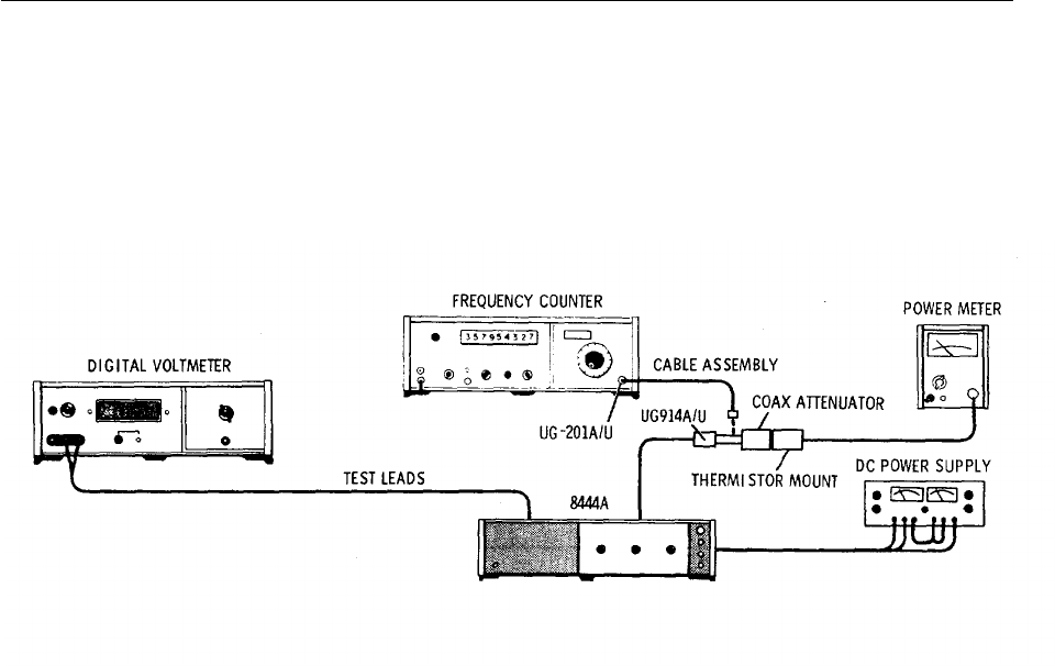
TM 11-6625-2866-14&P
Model 8444A Manual Changes
CHANGE C
Pages 5-3 through 5-6, Paragraph 5-9 and Figure 5-2, change to read as follows:
5-9.1.55 GHz Oscillator Power Level, Frequency Check and Adjustment
REFERENCE: Service Sheet 3.
DESCRIPTION: The 1.55 GHz local oscillator is checked for power output level and frequency tuning range.
Oscillator frequency is determined primarily by the LO cavity, with tuning range and power output level
determined by the drive voltage from the oscillator driver. The oscillator is checked first for power level and then
for frequency and tuning range. After any adjustments are made the previous checks are repeated.
Figure 7-1. 1.55 GHz LO Power Level and Frequency Check and Adjustment Test Setup
(Manual Figure 5-2)
EQUIPMENT:
Power Meter with HP 8478B Thermistor Mount.........................HP 432A
Frequency Counter with HP 5254C Plug-in..............................HP 5245L
Digital Voltmeter with HP 3443A Plug-in.................................HP 3440A
Power Supply..........................................................................HP 6205B
Test Leads (dual banana plug to probe and alligator clip).......HP 11003A
Cable Assy, SMA male to BNC male.............................HP 08555-60076
Cable Assy, male BNC connectors.........................................HP 10503A
Coaxial Attenuator, Option 010...............................................HP 8491A
Adapter BNC barrel (HP Part Number 1250-0080)................UG 914A/U
Adapter (BNC to Type N)......................................................UG 201A/U
PROCEDURE:
1. Perform Power Supply Check and Adjustment, paragraph 5-8.
2. Apply power to Tracking Generator and allow 1 hour for instrument to warm up and stabilize.
3. Disconnect Cable W8 at Isolator AT3 J2 (see Figures 8-4 and 8-12).
4. With test setup as indicated in Figure 5-2, connect Power Meter to Isolator AT3 J2 via 08555-60076
cable, 10 dB attenuator and UG 914A/U adapter.
5. Rotate TRACK ADJ control throughout its tuning range while noting power level indicated on Power
Meter.
7-2

TM 11-6625-2866-14&P
Model 8444A Manual Changes
5-9. 1.55 GHz Oscillator Power Level, Frequency Check and Adjustment (cont'd)
6. Record minimum power output. >+5 dBm
7. Connect Frequency Counter to Isolator AT3 J2 via 08555-60076 cable, UG 914A/1J adapter and BNC to
BNC cable.
8. Rotate TRACK ADJ control fully counterclockwise and record oscillator frequency. 1,548,000+500 kHz
9. Rotate TRACK ADJ control fully clockwise and record oscillator frequency. 1,552,000+500 kHz
10. Record frequency tuning range (frequency recorded in step 9 minus frequency recorded in step 8).
4,000+500 kHz
11. If data recorded in steps 6, 8, 9, and 10 is within tolerance no adjustment is required.
12. If power level recorded in step 6 is less than +5 dBm proceed to step 23.
13. If data recorded in steps 8, 9, or 10 is not within tolerance proceed with step 14.
14. Connect Digital Voltmeter to test point A2TP5.
15. Set TRACK ADJ -control fully clockwise. Set "MAX" TUNE potentiometer A2R26 fully counterclockwise.
16. Adjust "MIN" TUNE potentiometer A2R27 to set voltage at test point A2I'P5 to level indicated on
oscillator label. (See steps 23 through 30 for method of obtaining voltage level.)
17. Measure and record oscillator frequency.
18. Adjust "MAX" TUNE potentiometer to increase oscillator frequency 4, 000+50 kHz above frequency
recorded in step 17. Record oscillator frequency.
19. Set TRACK ADJ control to center of tuning range recorded in steps 17 and 18 above. Record oscillator
frequency.
20. If frequency recorded in step 19 is not within +500 kHz of 1.550 GHz adjust A7ADJ 1 to tune oscillator
frequency to 1.550 GHz +100 kHz.
21. If oscillator frequency is adjusted, repeat steps 15 through 20.
22. Repeat steps 4 through 11 above.
23. If power level recorded in step 6 is less than +5 dBm connect Power Meter as indicated in step 4.
Remove right side panel cover. Unsolder and remove power wires from A7C2 and A7C3.
24. Adjust Power Supply for -10 and +10 volts. Connect -10 volts to A7C3 and +10 volts to A7C2. Connect
Power Supply ground to solder lug near A7 Oscillator Assembly.
7-3

TM 11-6625-2866-14&P
Model 8444A Manual Changes
5-9. 1.55 GHz Oscillator Power Level, Frequency Check and Adjustment (cont'd)
25. Adjust Power Supply negative voltage for maximum oscillator power level as indicated on Power Meter.
Record power level. >+7 dBm
26. If power level is less than +7 dBm replace Oscillator Assembly A7.
27. If power level is greater than +7 dBm reduce negative voltage from Power Supply to -10 volts.
a. If output level drops 2 dB go to step 30.
b. If output level drops less than 2 dB go to step 28.
c.If output level drops more than 2 dB go to step 29.
28. Increase Power Supply positive voltage approximately 0.5 volts and repeat steps 25 through 27.
29. Decrease Power Supply positive voltage approximately 0.5 volts and repeat steps 25 through 27.
30. Record positive voltage obtained in steps 24, 28 or 29 on label on top of oscillator assembly.
31. Repeat steps 14 through 22.
32. Disconnect Power Meter and connect W8 Cable to Isolator AT3 J2.
33. Replace right side panel cover.
Pages 6-3 through 6-5, Table 6-2, change to read as follows:
A2R29 0698-0465 R:FXD MET FLM 31.6 OHM 1% 1/8W.
A2R36 0757-0442 R: FXD MET FLM 10K OHM 1% 1/8W.
A4A1C2 0160-2266 C:FXD CER 24PF 5% 500 VDCW,
72982, 301-000-COGO-240J
A7 08444-60003 OSCILLATOR ASSY: 1.55 GHz NOT
RECOMMENDED FOR FIELD REPAIR.
A7 C10160-3549 C:FXD PORC 0.5-0.1 PF 500 VDCW,
28480, 0160-3549.
Delete A7C4
A7 R10698-7205 R:FXD MET FLM 51.1 OHM 2% 1/8W.
Delete C3
Delete R5
Page 8-15, Figure 8-12, Service Sheet 3:
Replace with Figure 7-2.
Page 8-21, Figure 8-19:
Replace with Figure 7-3.
7-4
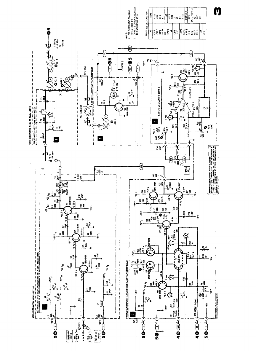
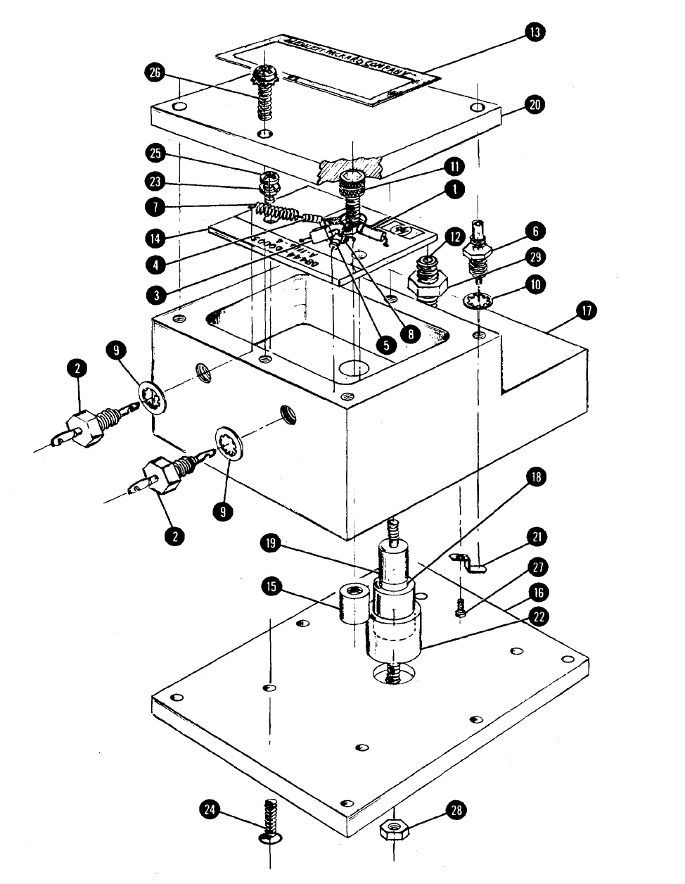
TM 11-6625-2866-14&P
Model 8444A Manual Changes
Figure 7-3. A 7 1.55 GHz Oscillator Assembly, Illustrated Parts Breakdown, Manual Figure 8-19 (1 of 2) (for Change C)
7-6

TM 11-6625-2866-14&P
Model 8444A Manual Changes
7-6. MANUAL CHANGE SUPPLEMENT
This supplement contains important information for adapting the manual to instruments containing improvements made
after the printing of the manual.
To use this supplement:
Make all appropriate serial number related changes indicated in the tables below.
Serial Prefix or Number Make Manual Changes Serial Prefix or Number Make Manual
Changes
1601A, 1630A 1
CHANGE 1
Page 6-6, Table 6-2:
Change A8 HP Part Number to 0960-0444.
Page 6-7, Table 6-2:
Change SI HP Part Number to 3101-1395.
Page 8-19, Figure 8-17, Service Sheet 5:
Replace ON/OFF switch S1 and POWER LINE MODULE A8, wiring diagram and schematic, with Figure 1 of this
MANUAL CHANGES.
7-7
TM 11-6625-2866-14&P
Model 8444A Service
SECTION VIII
SERVICE
8-1. INTRODUCTION
8-2. This section provides instructions for trouble-
shooting and repair of the HP Model 8444A Tracking
Generator.
8-3. PRINCIPLES OF OPERATION
8-4. Information relative to the principles of
operation appears on the foldout pages opposing the
Block Diagram, Service Sheet 1. Theory of operation
appears on the foldout pages facing each of the foldout
schematic diagrams. The schematic diagram circuits
are referenced in the theory of operation test by block
numbers.
8-5. RECOMMENDED TEST EQUIPMENT
8-6. Test equipment and accessories required to
maintain the Tracking Generator are listed in Table 1-3.
If the equipment listed is not available, equipment that
meets the required specifications may be substituted.
8-7. TROUBLESHOOTING
8-8. Troubleshooting procedures are divided into two
maintenance levels in this manual. The first, a
troubleshooting tree, is designed to isolate the
malfunction to the defective circuit.
8-9. The second maintenance level provides circuit
analysis and test procedures to aid in isolating faults to a
defective component. Circuit descriptions and test
procedures for the second maintenance level are
located on the pages facing the schematic diagrams.
The test procedures are referenced to the schematic
diagrams by block numbers.
8-10. After the cause of a malfunction has been found
and remedied in any circuit containing adjustable
components, the applicable procedure specified in
Section V of this manual should be performed. After
repairs and/or adjustments have been made, the
applicable procedure specified in Section IV of this
manual should be performed.
8-11. REPAIR
8-12. Factory Repaired Exchange Modules. The
LSI microcircuit, Amplifier and ALC Detector Assy A3, is
available as a factory repaired exchange module. The
factory repaired module is available at a considerable
savings in cost over the new module.
8-13 This exchange module should be ordered from
the nearest Hewlett-Packard Sales and Service office
using the part number in the replaceable parts table in
Section VI of this manual. Virtually all orders for
replacement parts received by HP offices are shipped
the same day received --either from the local office or
from a Service Center.
8-14. Factory Selected Components. Some
component values are selected at the time of final
checkout at the factory. Usually these values are not
extremely critical; they are selected to provide optimum
compatibility with associated components. These
components, which are identified on the schematics with
an asterisk, are listed in Table 84. The recommended
procedure for replacing a factory-selected component is
as follows:
a. Try the original value, then perform the test
specified in Section. V of this manual for the circuit
being repaired.
b. If the specified test cannot be satisfactorily
performed, try the typical value shown in the parts list
and repeat the test.
c. If the test results are still not satisfactory,
substitute various values until the desired result is
obtained.
8-15. Adjustable Components. Adjustable
components, other than front panel operating controls,
are listed in Table 8-2 Adjustment procedures for these
components are contained in Section V of this manual.
8-16. Servicing Aids on Printed Circuit Boards.
Servicing aids on printed circuit boards include test
points, transistor designations, adjustment callouts and
assembly part numbers with alpha-numerical revision
information.
8-17. Part Location Aids. The location of chassis
mounted parts and major assemblies are shown in
Figures 8-4 and 8-5.
8-18. The location of individual components mounted
on printed circuit boards or assemblies are shown on the
appropriate Service Sheet. The part reference
designator is the assembly designation plus the part
designation. (Example: A1Rl is R1 on the Al
assembly.) For specific component description and
ordering information refer to the replaceable parts table
in Section VI.
8-1
TM 11-6625-2866-14&P
Model 8444A Service
Table 8- 1. Factory Selected Components
Designation Service Sheet Circuit Purpose
A2R8 3ALC Differential Amplifier Center GAIN ADJ control
A4AlR11 3PIN Diode Modulator Set range of Modulator
Table 8-2. Adjustable Components
Designation Circuit Purpose
R1 +20 volt circuit MANUAL SCAN control
R2 Oscillator driver TRACK ADJ control
R3 ALC reference driver LEVEL control
AlR14 +20 volt power supply Sets +20 volt supply level and reference
level to -10 volt supply.
A2R6 PIN diode driver Sets limiting level of PIN diode driver
A2R7 PIN diode driver Sets gain of differential amplifier in PIN
diode driver circuit.
A2R17 PIN diode driver Sets PIN diode driver circuit for null.
A2R26 1.55 GHz oscillator driver Set frequency tuning range of 1.55 GHz
oscillator.
A2R27 1.55 GHz oscillator driver Sets oscillator power level.
A2R40 ALC reference diode circuit -10 dBm adjustment for LEVEL control.
A2R41 ALC reference diode circuit 0 dBm adjustment for LEVEL control.
A5ADJ 1 First converter Adjusts center frequency of 1.55 GHz cavity.
A5ADJ 2/3 First converter Adjusts center frequency of 2.05 GHz cavities.
A7 ADJ 1 1.55 oscillator Adjusts center frequency of 1.55 GHz
oscillator cavity.
8-19. Diagram Notes. Table 8-3, Schematic Diagram
Notes, provides information relative to symbols and
values shown on schematic diagrams.
8-20. GENERAL SERVICE HINTS
8-21. The etched circuit boards used in Hewlett
Packard equipment are the plated-through type
consisting of metallic conductors bonded to both sides
of an insulating material. The circuit boards can be
either a single layer or multi-layer board. The metallic
conductors are extended through the component holes
or interconnect holes by a plating process. Soldering
can be performed on either side of the board with
equally good results. Table 8-4 lists recommended tools
and materials for use in
repairing etched circuit boards. Following are
recommendations and precautions pertinent to etched
circuit repair work.
a. Avoid unnecessary component substitution;
it can result in damage to the circuit board and/or
adjacent components.
b. Do not use a high power soldering iron on
etched circuit boards. Excessive heat may lift a
conductor or damage the board.
c. Use a suction device or wooden toothpick
to remove solder from component mounting holes.
8-2
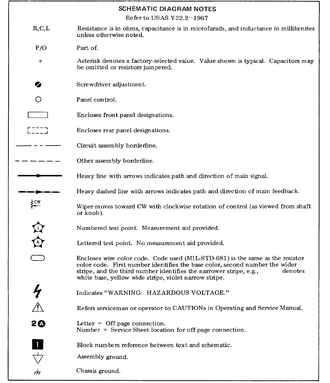
TM 11-6625-2866-14&P
Model 8444A Service
Table 8-3. Schematic Diagram Notes
8-3
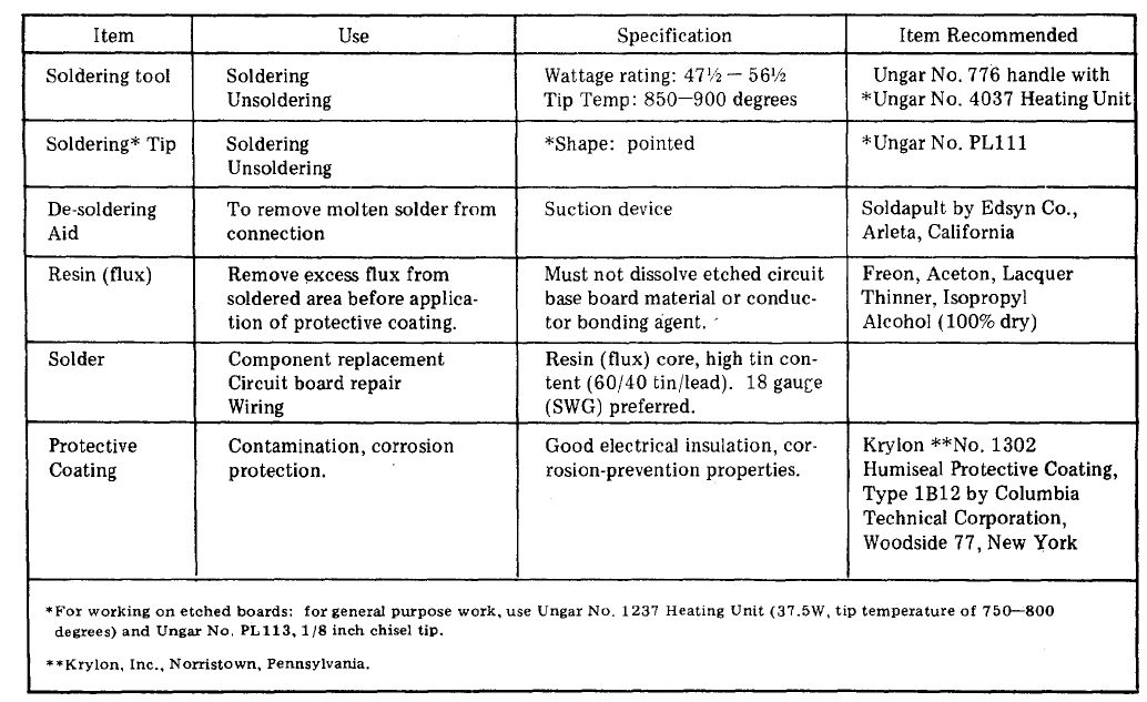
TM 11-6625-2866-14&P
Model 8444A Service
CAUTION
Do not use a sharp object such as an
an awl or twist drill for this purpose.
Sharp objects may damage the
plated-through conductor.
d. After soldering, remove excess flux from
the soldered areas and apply a protective coating to
prevent contamination and corrosion.
8-22. Component Replacement. The following
procedures are recommended when component
replacement is necessary:
a. Remove defective component from board.
b. If component was unsoldered, remove
solder from mounting holes with a suction device or a
wooden toothpick.
c. Shape leads of replacement component to
match mounting hole spacing.
d. Insert component leads into mounting holes
and position component as original was positioned. Do
not force leads into mounting holes: sharp lead ends
may damage the plated through conductor.
NOTE
Although not recommended when
both sides of the circuit board are
accessible, axial lead components
such as resistors and tubular
capacitors, can be replaced without
unsoldering. Clip leads near body of
defective component, remove
component and straighten leads left
in board. Wrap leads of replacement
component one turn around original
leads. Solder wrapped connection
and clip off excess lead.
8-23. GENERAL SERVICE INFORMATION
8-24. Transistors and diodes are used throughout the
RF Section in circuit configurations such as delay
circuits, trigger circuits, switches, oscillators and various
types of amplifiers. Basic transistor operation is shown
on the following pages.
8-25. Transistor In-Circuit Testing. The common
causes of transistor failure are internal short circuits and
open circuits. In transistor circuit testing, the most
important consideration is the transistor base-to-emitter
junction. The base emitter junction in a transistor is
comparable to the control grid-cathode
Table 8-4. Etched Circuit Soldering Equipment
8-4
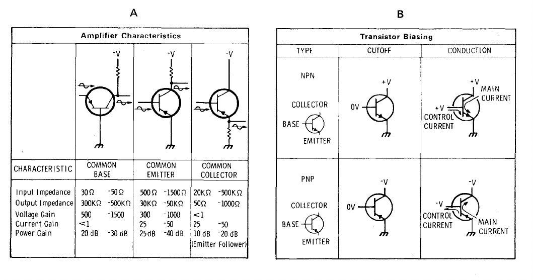
TM 11-6625-2866-14&P
Model 8444A Service
cathode relationship in a vacuum tube. The base
emitter junction is essentially a solid-state diode; for the
transistor to conduct, this diode must be forward biased.
As with simple diodes, the forward-bias polarity is
determined by the materials forming the junction.
Transistor symbols on schematic diagrams reveal the
bias polarity required to forward-bias the base-emitter
junction. The B part of Figure shows transistor symbols
with the terminals labeled. The other two columns
compare the biasing required to cause conduction and
cutoff in NPN and PNP transistors. If the transistor
base-emitter junction is forward biased, the transistor
conducts. However, if the base-emitter junction is
reverse-biased, the transistor is cut off (open). The
voltage drop across a forward-biased, emitter base
junction varies with transistor collector current. For
example, a germanium transistor has a typical forward-
bias, base-emitter voltage of 0.2-0.3 volt when collector
current is 1-10 mA, and 0.4-0.5 volt when collector
current is 10-100 mA. In contrast, forward-bias voltage
for silicon transistor is about twice that for germanium
types; about 0.5-0.6 volt when collector current is low,
and about 0.8-0.9 volt when collector current is high.
8-26. Figure 8-1, Part A, shows simplified versions of
the three basic transistor circuits and gives the
characteristics of each. When examining a transistor
stage, first determine if the emitter-base junction is
biased for conduction (forward-biased) by measuring the
voltage difference between emitter and base. When
using an electronic voltmeter, do
not measure directly between emitter and base; there
may be sufficient loop current between the voltmeter
leads to damage the transistor. Instead, measure each
voltage separately with respect to a common point (e.g.,
chassis). If the emitter-base junction is forward-biased,
check for amplifier action by short-circuiting base to
emitter while observing collector voltage. The short
circuit eliminates base-emitter bias and should cause
the transistor to stop conducting (cut off). Collector
voltage should then change and approach the supply
voltage. Any difference is due to leakage current
through the transistor and, in general, the smaller this
current the better the transistor. If the collector voltage
does not change, the transistor has either an emitter-
collector short circuit or emitter base open circuit.
8-27. Transistor and Diode Markings. Figure 8-2
illustrates examples of diode and transistor marking
methods. In addition, the emitter lead for bipolar
transistors is identified on the printed circuit boards.
8-28. OPERATIONAL AMPLIFIERS
8-29 Operational amplifiers are used to provide such
functions as summing amplifiers, offset amplifiers,
buffers and power supplies. The particular function is
determined by the external circuit connections.
Equivalent circuit and logic diagrams for type 741
operational amplifiers are contained in Figure 8-3,
Circuit A is a non-inverting buffer amplifier with a gain of
1. Circuit B is a non
Figure 8-1. Transistor Operation
8-5
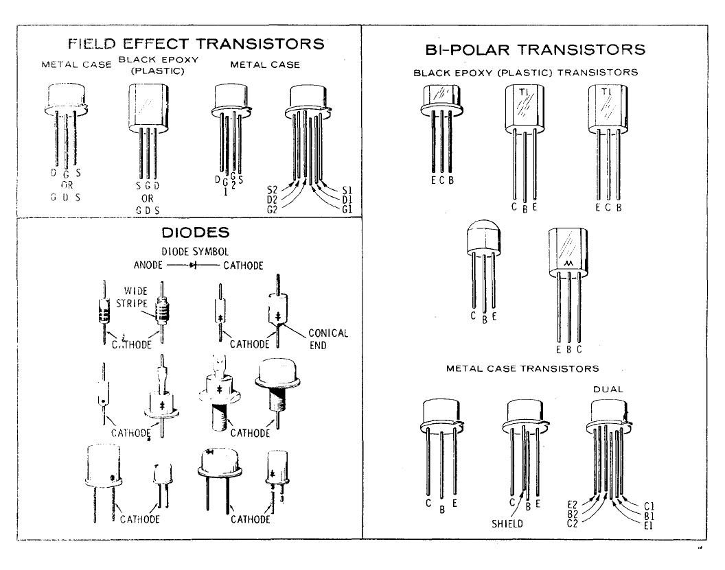
TM 11-6625-2866-14&P
Model 8444A Service
inverting amplifier with gain determined by the
resistance of R1 and R2. Circuit C is an inverting
amplifier with gain determined by R1 and R2, with the
input impedance determined by R2. Circuit D contains
the functional circuitry and pin connection information
along with an operational amplifier review.
Note
In Circuit D it is assumed that the
amplifier has high gain, low output
impedance and high input
impedance.
8-30. 0perational Amplifier Troubleshooting
Procedure. Measure and record the voltage level at
both the (inverting) terminal pin 2 and the +
(noninverting) terminal pin 3. The level should not differ
by more than m 10 mV. If the voltage level is not within
m 10 mV, check the external circuitry and components.
If the external circuitry (input signal, operating voltages,
feedback resistors) is normal, replace the operational
amplifier.
8-31. ELECTRICAL MAINTENANCE
8-32. Perform the electrical checks and adjustments
once every six months and after repair or component
replacement.
Figure 8-2. Examples of Diode and Transistor Marking Methods
8-6
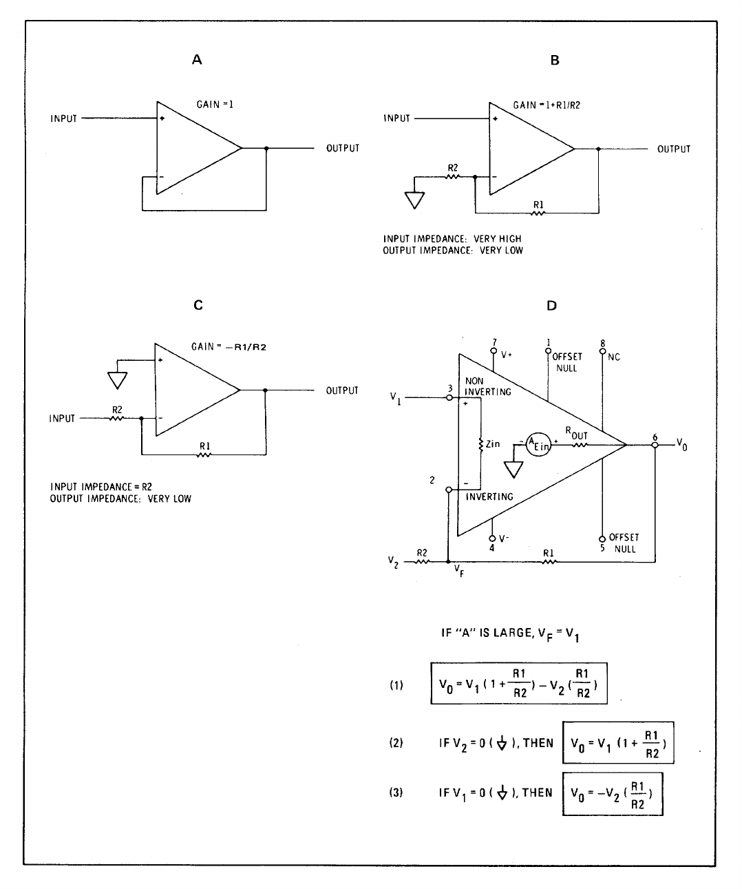
TM 11-6625-2866-14&P
Model 8444A Service
Figure 8-3. Operational Amplifier Equivalent Circuit
8-7/8-8
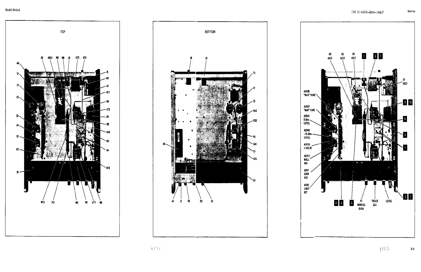
TM 11-6625-286614&P
Figure 8-4. Major Assembly Locations (1 Figure 8-4. Major Assembly Locations Figure 8-5. Adjustment and Test Point
8-9
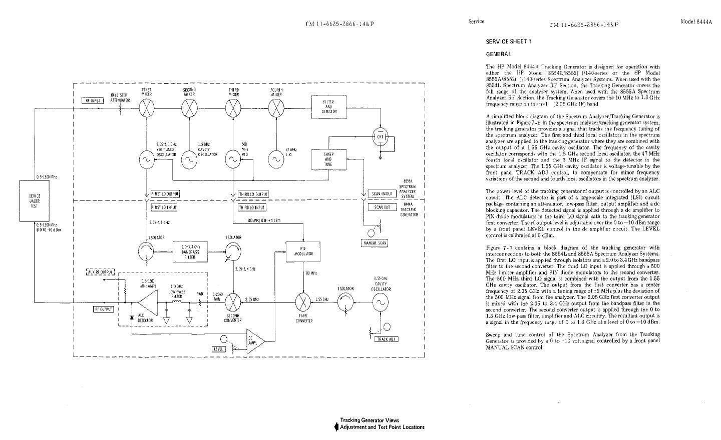
TM 11-6625-286614&P
Figure 8-6.Tracking Generator Spectrum Analyzer, Simplified Block Diagram
8-10
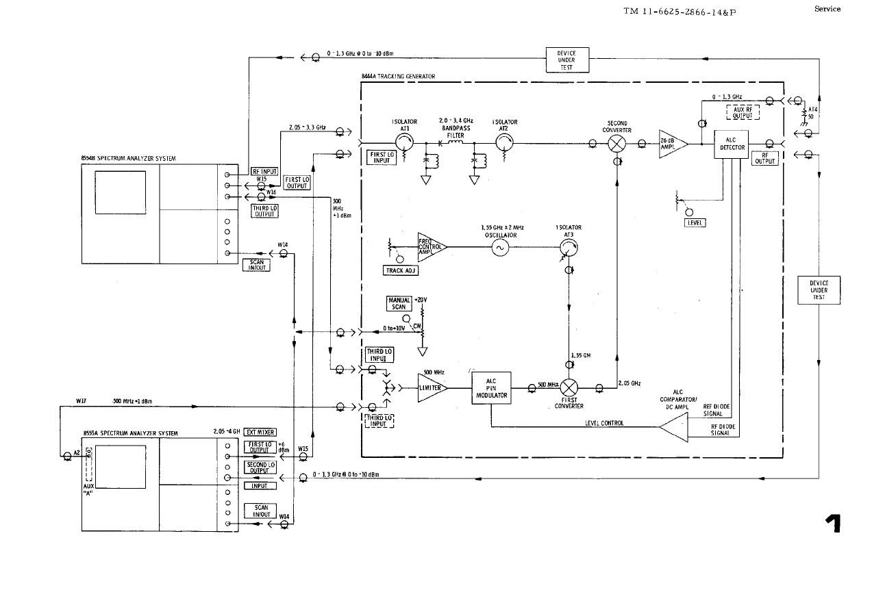
TM 11-6625-286614&P
Figure 8-7.Tracking Generator, Block diagram with Spectrum Analyzer Interconnections
8-11
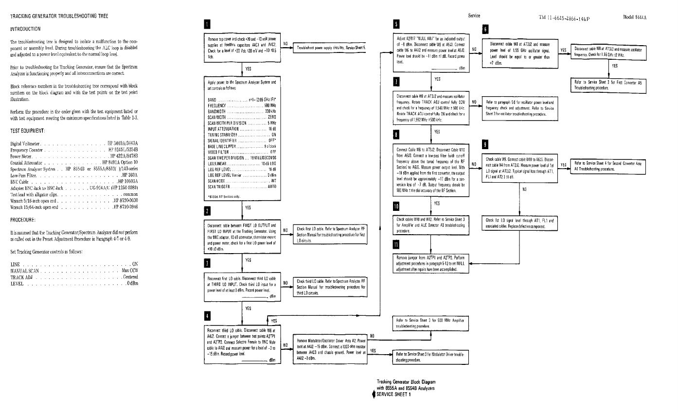
TM 11-6625-286614&P
Figure 8-7A.Troubleshooting Tree
8-12
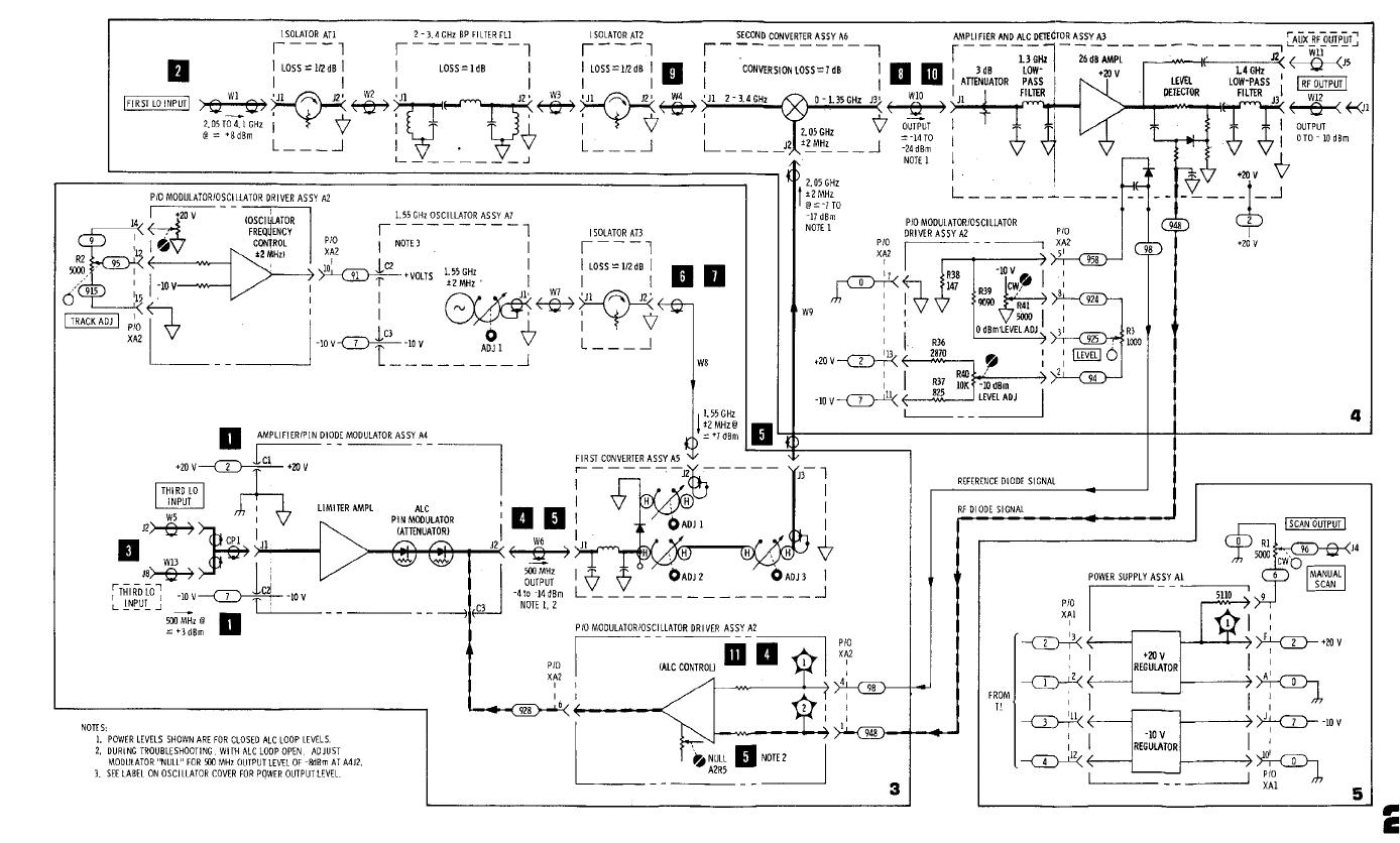
TM 11-6625-286614&P
Figure 8-8.Tracking Generator Troubleshooting Block Diagram
8-13
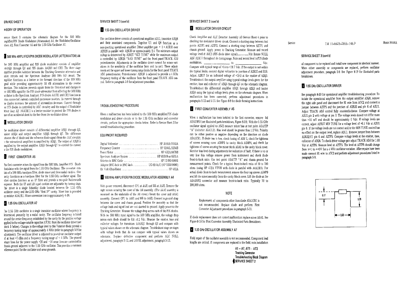
TM 11-6625-286614&P
Figure 8-9. Mixer Diode Forming
Dimensions in Inches
8-14
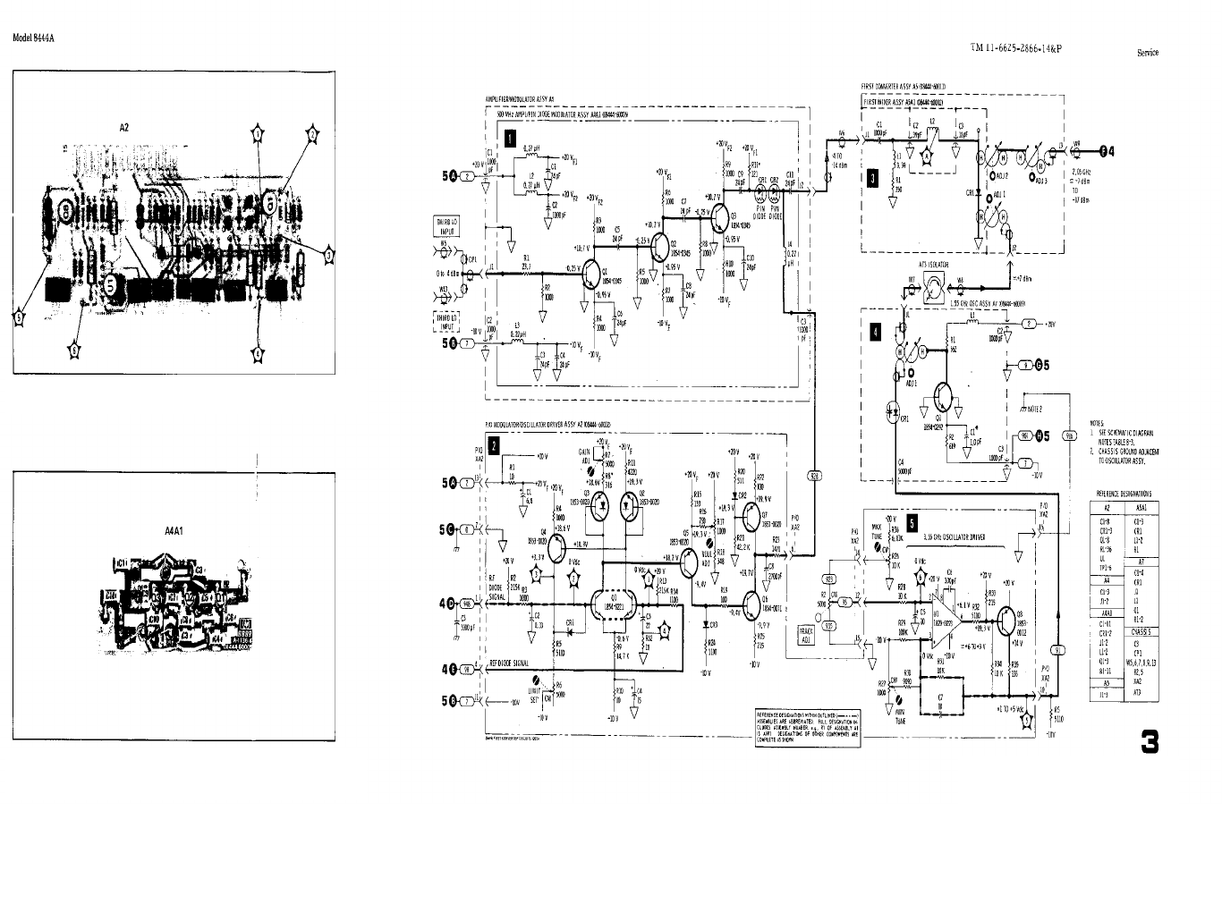
TM 11-8520-759-35
Figure 8-12. First Converter Circuits, Schematic Diagram
Figure 8-10. Modulator/Oscillator Driver
Assy A2 Component Locations
Figure 8-11. Amplifier and Pin Diode
Modulator Assy A4A1 Component Locations
8-15
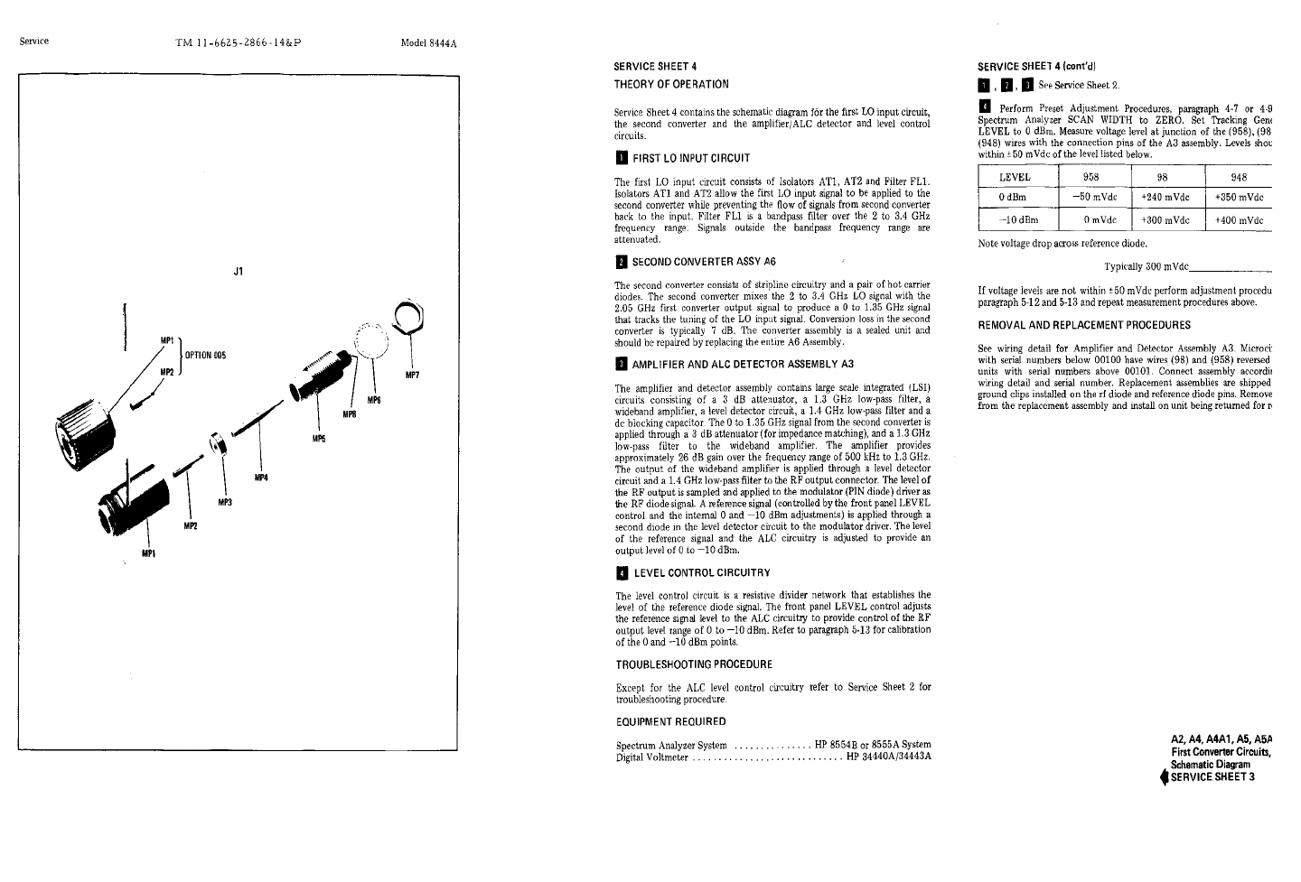
TM 11-6625-286614&P
Figure 8-13. J1 RF Output Connector, Exploded View
8-16
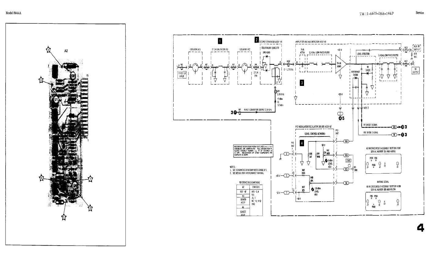
TM 11-6625-286614&P
Figure 8-14. A2 Modulator/Oscillator Driver Assy, Component Location
Figure 8-15. Second Converter Circuit, Schematic Diagram
8-17
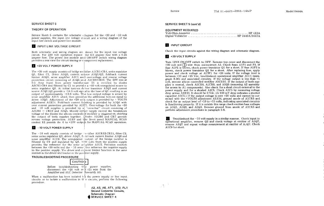
TM 11-6625-286614&P
8-18
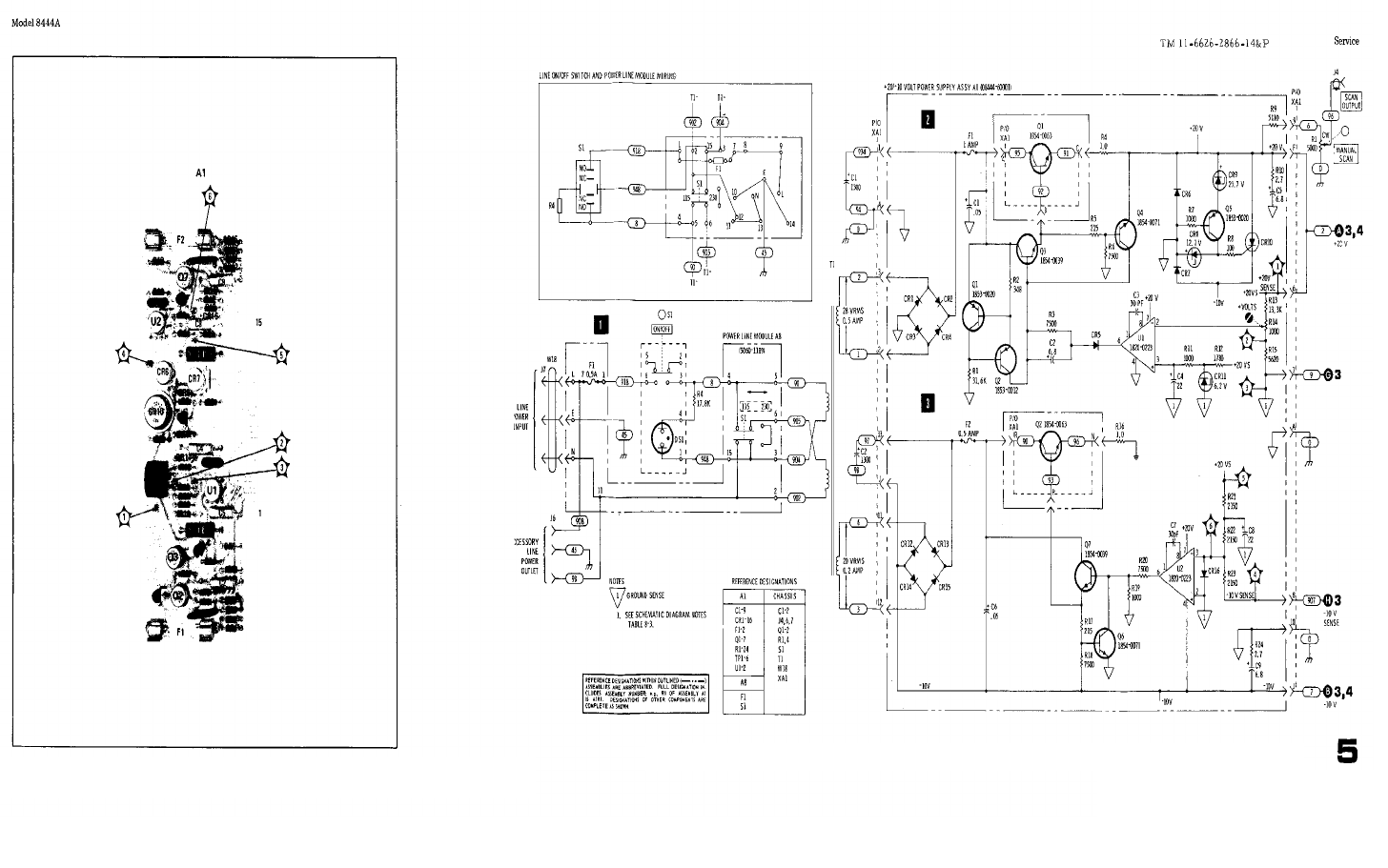
TM 11-6625-286614&P
Figure 8-16. A1 Power Supply Assy, Component Location Figure 8-17. Power Supply and Input Circuit, Schematic Diagram
8-19
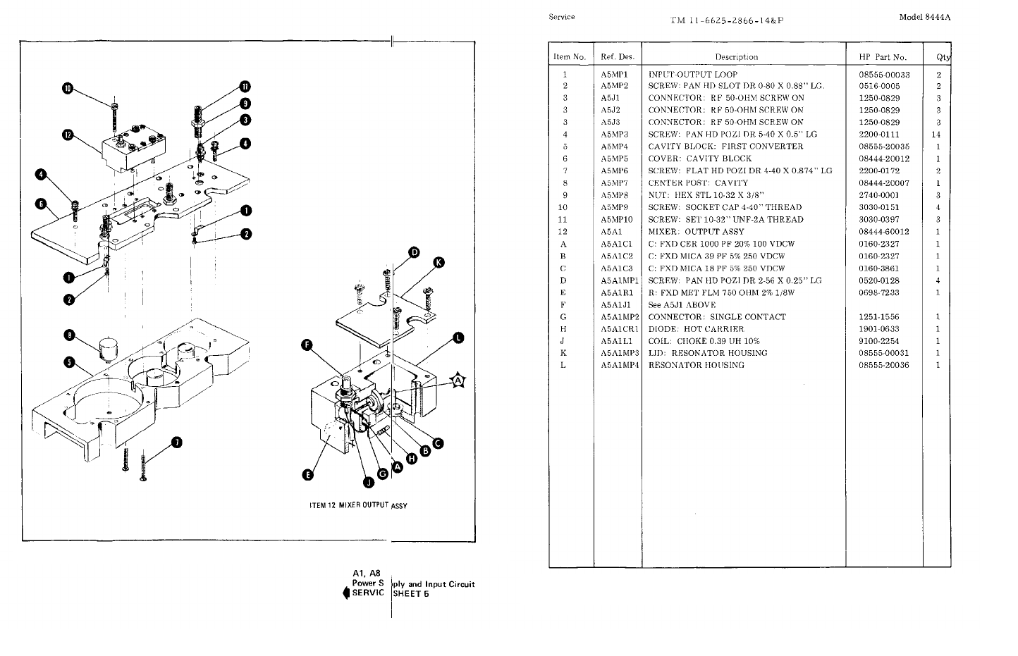
TM 11-6625-286614&P
Figure 8-18. A5 First Converter Assembly, Illustrated Parts Breakdown (1 of 2)
Figure 8-18. A5 First Converter Assembly, Illustrated Parts Breakdown (2 of 2)
8-20
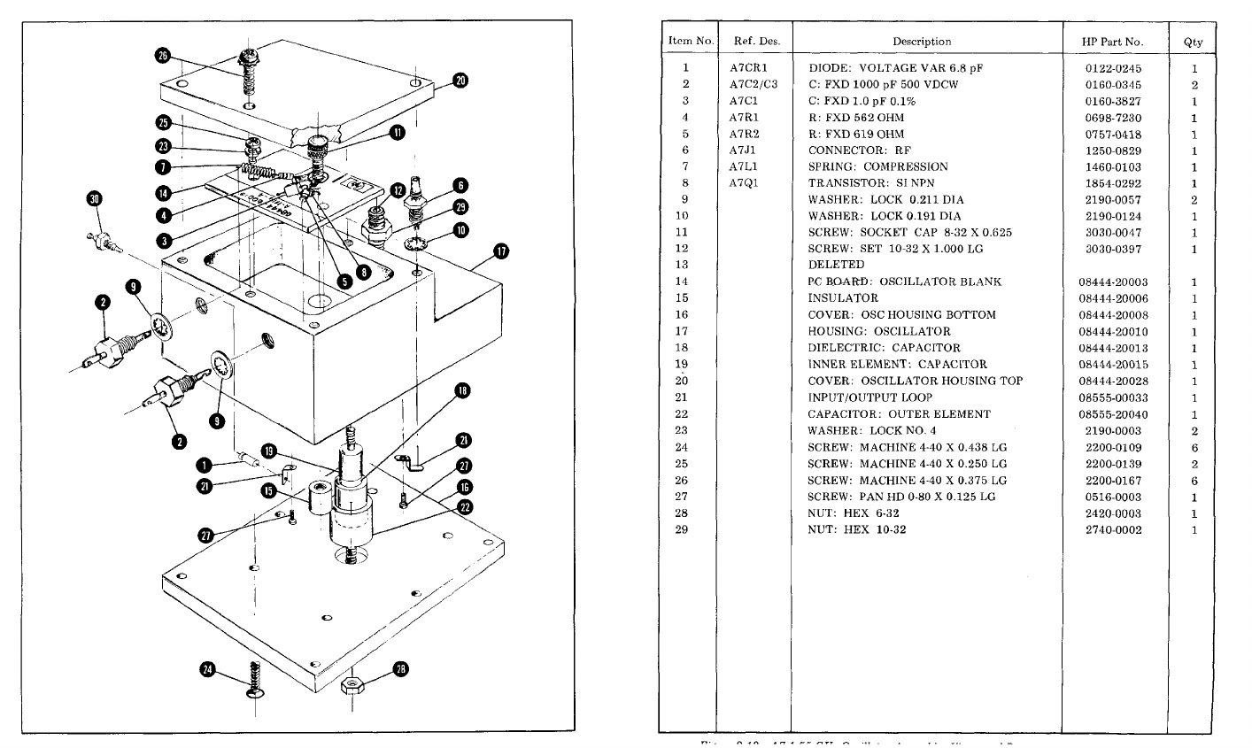
Figure 8-19. A7 1.55 GHz Oscillator Assembly, Illustrated Parts
Breakdown (2 of 2)
Figure 8-19. A7 1.55 GHz Oscillator Assembly, Illustrated Parts
Breakdown (1 of 2) 8-21
TM 11-6625-2866-14&P
Model 8444A Appendix A
APPENDIX A
SERVICE NOTE - P-0960-2038, P-5086-6025
HP MODEL 8444A TRACKING GENERATOR
Serials Prefixed 1147A and Below
REQUIRED MODIFICATION WHEN REPLACING A3
When replacing the A3 Amplifier Detector Assembly in the HP Model 8444A, serials prefixed 1147A and below, a capacitor C3, 3300 pF, HP Part No. 0160-
0155, is a required addition for proper instrument operation. The capacitor is electrically connected between the RF Diode Signal line and ground. For easiest
installation, connect the capacitor between connector pins XA2-1 and XA2-7. Pin 1 is located nearest the instrument front panel.
APPENDIX B
SERVICE NOTE - P-08444-60019
HP MODEL 8444A TRACKING GENERATOR
Serials Prefixed 1147A and Below
REPLACEMENT FOR A7 08444-60003
The HP Part No. 08444-60019 assembly is the
recommended replacement for the old 08444-60003 A7
assembly. Since the old and new A7 assemblies are not
directly interchangeable, minor modifications are
required when installing the new A7. The additional
parts required for the modification are:
(one each)
HP 0757-0438 5.11K, 1%, 1/8 W Resistor
HP 0757-0439 6.81K, 1%, 1/8 W Resistor
HP 0757-0465 1OOK, 1%, 1/8 W Resistor
HP 8150-0449 30" Red No. 24 AWG Wire
MODIFICATIONS
1. A7 hookup (refer to Figures 8-12 and 8-19):
a. Connect the wht-brn wire to new A7C4.
b. Add red wire; connect between +20V (XA1-
6) and A7C2.
c. Connect violet and wht-blk-violet wires to
A7C3.
2. Component changes:
a. Add R5, 5.11K, 0757-0438 between
connector pins XA2-10 and unused XA2-
12; then short pins XA2-12 and XA2-11 (-
10V) together.
b. Replace A2R29 with 100K, 0757-0465.
c. Replace A2R36 with 6.81K, 0757-0439.
CALIBRATION
To calibrate the new A7 assembly, follow the 1.55 GHz
Oscillator Power Level, Frequency Check and
Adjustment procedure, pages 5-3 to 5-5.
A/B-1/2
TM 11-6625-2866-14&P
Model 8444A Appendix C
APPENDIX C
SERVICE NOTE - 8444A-1
HP MODEL 8444A TRACKING GENERATOR
Serials Prefixed 1147A and Below
IMPROVED POWER SUPPLY STABILITY
The +20V power supply stability can be improved by changing A4A1C2 from 24 pF to 1000 pF, HP Part No. 0160-3456.
The new value eliminates any oscillation tendencies and is a recommended modification for all instruments with serials
listed above.
C-1/2

TM 11-6625-2866-14&P
Model 8444A Appendix D
APPENDIX D
MODEL 8444A TRACKING GENERATOR, OPTION 058
D-1. INTRODUCTION
D-2. This appendix explains the use of an 8444A Tracking Generator with an 8558B/180 Spectrum Analyzer system
when Option 058 circuitry is added to the 8444A. The Tracking Generator is designed to generate a CW tracking signal
for an 8555A/8552/140 Spectrum Analyzer system when operating in the range of 0.5 to 1300 MHz. With Option 058
circuits added, a 0.5 to 1300 MHz CW tracking signal can also be generated by an 8444A when it is coupled to an
8558B/180 Spectrum Analyzer system.
D-3. DESCRIPTION
D-4. To provide a tracking signal for an 8555A/8552/140 Spectrum Analyzer, an 8444A Tracking Generator must be
fed a 2.05 to 4.1 GHz tuned oscillator signal from the 8555A First LO, plus a 500 MHz signal from the 8555A Third LO.
When mixed with the internal 1.55 GHz oscillator in the 8444A, a 0.5 to 1300 MHz tracking signal output is produced.
D-5. To develop a 0.5 to 1300 MHz tracking signal for an 8558B/180 Spectrum Analyzer/Display system, a 2.05 to
3.55 GHz First LO is available from the 8558B, but no 500 MHz LO is used in this instrument. Option 058 consists of a
500 MHz oscillator for the 8444A. This 500 MHz signal is brought out on a separate BNC connector on the rear panel of
the 8444A, directly above the THIRD LO INPUT BNC connector. When the 8444A is used with an 8558B/180 Spectrum
Analyzer system, the two rear panel BNC connectors are interconnected with a short BNC cable. With the First LO from
the 8558/B plus its own 500 MHz LO signal, the 8444A can provide a 0.5 to 1300 MHz tracking signal for the 8558B
Spectrum Analyzer system.
D-6. MANUAL CHANGES TO INCORPORATE OPTION 058
D-7. Section I.
D-8. 8444A System Specifications with Option 058 added are listed in Table D-1.
Table D-1. 8444A System Specifications with Option 058
SPECIFICATIONS
These specifications apply to the 8444A Option 058 when used with the 8558B Spectrum Analyzer ONLY. Specifications
of the 8444A Option 058 when used with the 8554B and 8555A Spectrum Analyzers can be found in Table 1-1 of the
8444A manual.
Swept Frequency Response Measurements Absolute Amplitude Calibration Range
Dynamic Range: <90 dB from Spectrum Analyzer 1 dB Spectrum Analyzer:
gain compression point to average noise level (approxi-
mately --10 dBm to -100 dBm). Log: From -117 dBm to +30 dBm, 10 dB/div on a
70 dB display or 1 dB/div on an 8 dB display.
Average Noise Level: -107 dBm with 10 kHz Resolution Linear: From 2.2 µV (-100 dBm) to 7.1V (+30
bandwidth. dBm), full scale in 10 dB steps.
D-1

TM 11-6625-2866-14&P
Model 8444A Appendix D
Table D-1. (Continued)
Frequency Range: 500 kHz to 1300 MHz
Scan Width: (Determined by Spectrum Analyzer Controls):
Per Division:14 Calibrated Scan Widths from a
5 kHz/div to 100 MHz/div in a 2, 5, 10 sequence.
"O” Scan: Analyzer is a fixed tuned receiver.
Frequency Resolution: 3 kHz.
Stability:
Residual FM (peak-to-peak): 1 kHz for time <0.1
sec.
Amplitude Accuracy:
System Frequency Response: +1.50 dB (0.5 dB
for 8444A-058, +10 dB for 8558B).
SWEEP/CW GENERATOR
Frequency: Controlled by Spectrum Analyzer. Range
500 kHz to 1300 MHz. Scan widths are determined
by Spectrum Analyzer controls.
Frequency Accuracy: Same as the 8558B. Can be improved
using an external counter.
Flatness: +0.5 dB.
Spectral Purity:
Residual FM (peak-to-peak): 1 kHz for time <0.1
sec. Harmonic Distortion:25 dB below output
level/(typical).
Nonharmonic (spurious) Signals: 35 dB below
output level.
Long Term Stability: Drift typically less than 30 kHz/10 min.
(20 kHz for 8558B, 10 kHz for 8444A) when
stabilized after 2-hour warm-up
Sweep Width: 50 kHz to 1000 MHz.
Sweep Rates: Selected by Sweep Time per Division on
Spectrum Analyzer. 16 internal scan rates from 0.1 m
Sec/div to 10 sec/div in a 1, 2, 5 sequence. Manual
Sweep is available with a front panel control of the
8558B. Auto Sweep is automatically controlled by
FREQ SPAN/DIV, RESOLUTION BW, and VIDEO
FILTER settings
PRECISION FREQUENCY MEASUREMENTS
An external counter output is provided on the 8444A for
precision frequency measurements. The frequency of
unknown signals as well as the frequency of any point on a
frequency response curve can be measured. The use of the
5300A/5303A Counter is suggested for frequency
measurements to 500 MHz and the 5245L/5254C Counter for
measurements to 1300 MHz
Frequency Accuracy (Tracking Generator Output): For
unknown signals, typically less than +3 kHz frequency
error after tracking adjustment with 10 kHz BW (Tracking
drift typically 10 kHz/10 min. after 2-hour warmup.)
For points on frequency response curve, counter accuracy +
Residual FM (1 kHz peak-to-peak for time <0.1 sec)
Counter Mode of Operation:
Manual Scan: Scan determined by front panel
control of 8558B
"O" Scan: Analyzer is a fixed-tuned receiver.
Counter reads center frequency to accuracy of
tracking drift
Counter Output Level: Nominally 0.1 Vrms
NOTE
All above changes in specifications
apply to use with an 8558B only
D-9. SECTION III OPERATION
D-10. Add the following 8444A Option 058 Tracking Generator Operation information when using the 8558B Spectrum
Analyzer.
1. Check that the 115/230V switch is set to correspond with the available line voltage. Refer to Figure 3-2,
steps 4 through 8, for switch and fuse information.
2. Apply power to Tracking Generator and Spectrum Analyzer.
3. Turn Spectrum Analyzer INTENSITY control fully CCW.
4. Allow instruments to warm up for at least 30 minutes.
5. Perform Spectrum Analyzer "Operation Check." Refer to 8558B Spectrum Analyzer Operating Manual.
D-2
TM 11-6625-2866-14&P
Model 8444A Appendix D
6. Set Spectrum Analyzer LOG/LINEAR control to LOG, and BANDWIDTH to 300 kHz.
7. Set OPTIMUM INPUT dBm to 0, and REF LEVEL dBm to 0 dBm.
8. Make the following interconnections between tracking Generator and Spectrum Analyzer.
a. 8558B FIRST LO OUTPUT to 8444A FIRST LO INPUT.
b. 8558B RF OUTPUT to the 8444A RF INPUT.
c. Jumper 500 MHz OUTPUT to THIRD LO INPUT (Rear Panel 8444A-058).
9. Check that the Spectrum Analyzer controls are set as follows:
INTENSITY ............................................................12 o'clock (approx.)
FREQUENCY MHz................................................................... 30 MHz
RESOLUTION BW ...................................................................300 kHz
FREQ SPAN/DIV....................................................................... 50 kHz
BASE LINE CLIPPER...................................................................CCW
SWEEP TIME/DIV................................................... 5 MILLISECONDS
dB/DIV-LIN ........................................................................... 10 dB/DIV
OPTIMUM INPUT dBm ...................................................................... 0
REF LEVEL dBm......................................................................... 0dBm
REF LEVEL FINE............................................................................... 0
VIDEO FILTER........................................................................2 o'clock
SWEEP TRIGGER........................................................................LINE
10. Set Tracking Generator LEVEL control to 0 dBm and adjust TRACK ADJ for maximum signal amplitude
indication on CRT display.
11. Adjust Spectrum Analyzer REF LEVEL FINE control or Tracking Generator LEVEL control to position signal
on CRT LOG REF level graticule line. (System calibrated at 30 MHz with an amplitude accuracy of +0.5
dB.)
12. Set Spectrum Analyzer to scan desired frequency range.
13. Insert device to be tested between Tracking Generator RF OUTPUT and Spectrum Analyzer RF INPUT.
14. Set Spectrum Analyzer Sweep Time to MAN.
15. Rotate Spectrum Analyzer MANUAL SWEEP control clockwise to tune system through selected frequency
range.
16. For automatic scanning, set SCAN MODE switch to INT and SWEEP TIME/DIV to desired scan time.
D-11. SECTION IV, PERFORMANCE TESTS
D-12. Add the following: Proper operation of the SPECIAL 500 MHz Oscillator after a one-hour warmn-up may be
checked in the following manner:
1. Connect the 500 MHz OUTPUT (Third LO OUTPUT, Figure D-2) on the rear panel of the 8444A to a 432A
Power Meter.
2. Adjust "L.O. PWR" on Oscillator Assembly (A9) to set oscillator output power to +4 dBm + .5 dB.
3. Disconnect oscillator output from power meter and connect to 5254C Frequency Counter.
4. Adjust "FREQ ADJ" on Oscillator to set frequency to 500 MHz + 200 kHz.
D-3

TM 11-6625-2866-14&P
Model 8444A Appendix D
5. Check power output again and re-adjust if necessary.
6. Repeat steps 2 through 5 until the two test limits are both met.
D-13. SECTION VI, REPLACEABLE PARTS
Page 6-4, Table 6-2:
Add the following parts:
Table D-2. Replaceable Parts
Reference HP Part Mfr
Designation Number Qty Description Code Mfr Part Number
A9 0844460024 1 500 MHz OSCILLATOR ASSEMBLY 28480 08444-60024
A9C1 01602357 2 C;FXD 100OPF +80 -20% 500WVDC CER 28480 0160-2357
A9C2 0160-2357 C;FXD 10OO0PF +80 -20% 500WVDC CER 28480 0160-2357
A9J1 1250-0828 1CONNECTOR: 50 OHM 28480 1250-0828
A9L1 0855400015 1 COUPLING: LO OUTPUT 28480 08554-00015
A9R1 06987200 1 R;FXD 31.6 OHM 2%.05W 24546 C3-1/8-TOO-31 R6-G
A9A1 0844460020 1 OSCILLATOR ASSEMBLY: 500 MHz 28480 08444-60020
A9AIC1 0160-2247 1C:FXD 3.9PF f.25PF 50OWVDC CER 28480 0160-2247
A9A1C2 0121-0414 1C:VAR TRMR 1.9 - 8.5PF; AIR 74970 189-253-5 MODIFIED
A9A1L1 0855400007 1 INDUCTOR: 500 MHz OSC. 28480 08554-00007
A9A1Q1 1854-0323 2TRANSISTOR: NPN 28480 1854-0323
A9A1Q2 1854-0323 TRANSISTOR: NPN 28480 1854-0323
A9A1R1 06983447 1 R: FXD 422 OHM 1% 1/8W 16299 C4-1/8-TO-422R-F
A9A1R2 0757-0280 2R: FXD 1K OHM 1% 1/8W 24546 C4-1/8-TO-1001-F
A9A1R3 0757-0280 R: FXD 1K OHM 1% 1/8W 24546 C4-1/8-TO-1001-F
A9A2 0844460031 1 POWER SUPPLY FILTER ASSEMBLY 28480 08444-60031
A9A2C1 0160-2055 2C: FXD.01 U F +80 -20% 10WVDC CER 28480 0160-2055
A9A2C2 0160-2055 C: FXD .O1U F +80 -20% 1OOWVDC CER 28480 0160-2055
A9A2C3 0180-00492 C: FXD 20UF +75 -10% 50WV DC AL 56289 300206G050CC2
A9A2C4 01800049 C: FXD 20UF +75 -10% 50WVDC AL 56289 300206G050CC2
A9A2CR1 1901-00402 DIODE: SWITCHING 2NS 30V 50MA 28480 1901-0040
A9A2CR2 1901-0040 DIODE: SWITCHING 2NS 30V 50MA 28480 1901-0040
A9A2Q1 185404042 TRANSISTOR: NPN 28480 1854-0404
A9A2Q2 1854-0404 TRANSISTOR: NPN 28480 1854-0404
A9A2R1 2100-1775 1R:VAR 5K OHM 5% WW 28480 2100-1775
A9A2R2 06983155 2 R:FXD 4.64K OHM 1% 1/8W 16299 C4-1/8TO-4641-F
A9A2R3 06983155 R: FXD 4.64K OHM 1% 1/8% 16299 C4-1/8-TO-4641-F
A9A2R4 06980083 1 R: FXD 1.96K OHM 1% 1/8W 16299 C4-1/8-TO-1961-F
A9A2R5 06980082 1 R: FXD 464 OHM 1% 1/8W 16299 C4-1/8-TO-4640-F
W19 08444-60025 1CABLE: COAX; 500 MHz OUTPUT 28480 0844460025
D-4
TM 11-6625-2866-14&P
Model 8444A Appendix D
D-14. SECTION VIII, SERVICE
D-15. Description of Option 058: A two-transistor, 500-MHz fixed-tuned local oscillator with power supply processing
circuits, Assembly A9, is added to the Main Deck of an 8444A. The 500 MHz LO Output is brought out through a BNC
connector on the rear panel directly above the BNC connector serving as the output of the THIRD LO INPUT. Power
supply voltages for the A9 500 MHz Oscillator Assembly are taken from the PC connector XA1 on the bottom of the
8444A Main Deck.
D-16. Figure D-1 is a top view of the 8444A including the Option 058 500 MHz A9 Oscillator Assembly with its BNC
connector on the rear panel.
D-17. Figure D-2 shows the rear panel of an 8444A Option 058 with the added 500 MHz OUTPUT BNC connector
above the THIRD LO INPUT connector.
D-18. Figure D-3 is a schematic diagram of the 500 MHz Oscillator used with Option 058, a capacitance multiplier used
as additional filter for the 8444A +20V power supply, and an adjustable current regulator for the -10V 8444A power
supply.
D-5
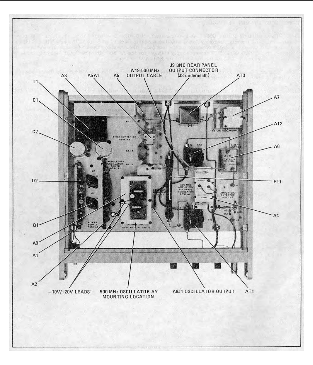
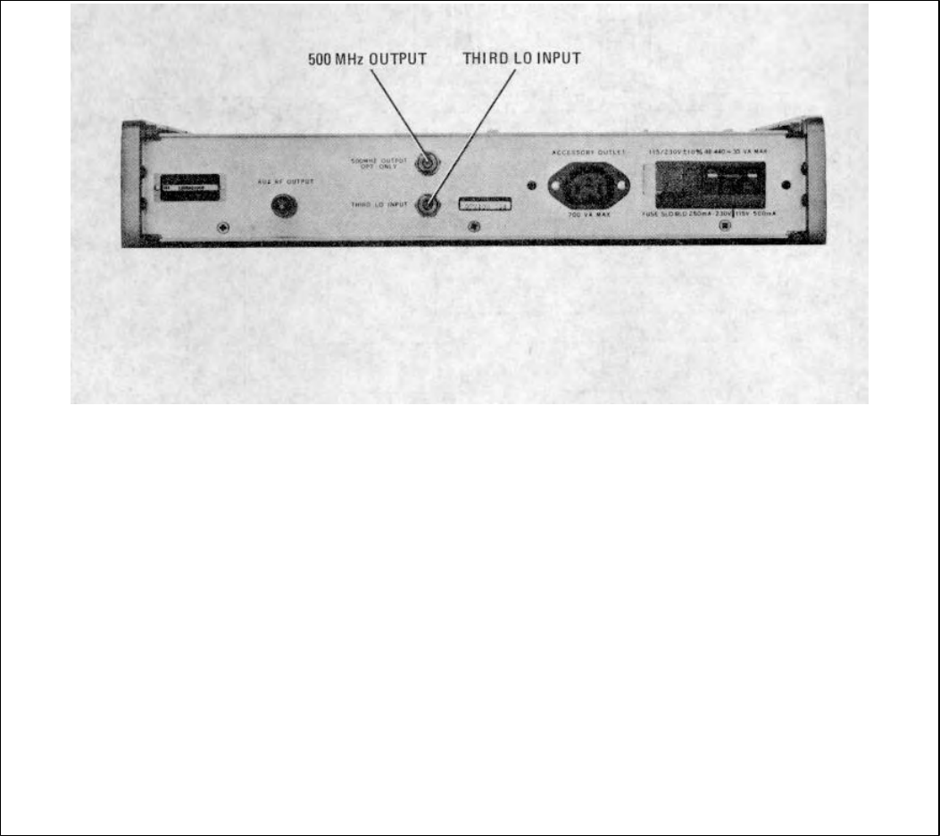
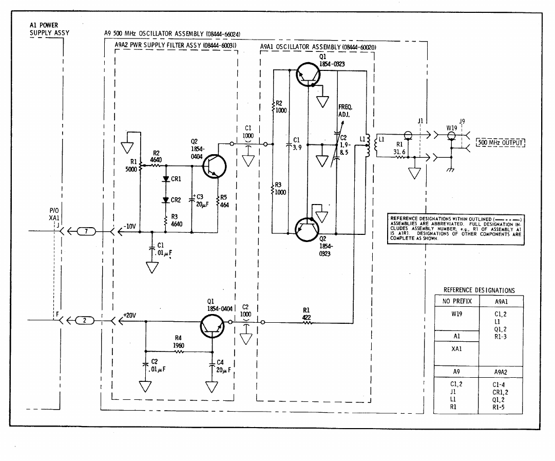

TM 11-6625-2886-14&P
APPENDIX E
REFERENCES
DA Pam 310-4 Index of Technical Manuals, Technical Bulletins, Supply Manuals (Types 7, 8, and 9),
Supply Bulletins, and Lubrication Orders.
DA Pam 310-7 US Army Equipment Index of Modification Work Orders.
TB 43-0118 Field Instructions for Painting and Preserving Electronics Command Equipment
Including Camouflage Pattern Painting of Electrical Equipment Shelters.
TM 38-750 The Army Maintenance Management System (TAMMS).
TM 750-244-2 Procedures for Destruction of Electronics Materiel to Prevent Enemy Use (Electronics
Command).
E-1

TM 11-6625-2866-14&P
APPENDIX F
COMPONENTS OF END ITEM LIST
Section I. INTRODUCTION
F-1. Scope
This appendix lists integral components of and basic
issue items for the SG-1 125/U to help you inventory
items required for safe and efficient operation.
F-2. General
This Components of End Item List is divided into the
following sections:
a. Section II. Integral Components of the End
Item. These items, when assembled, comprise the
SG1125/U and must accompany it whenever it is
transferred or turned in. The illustrations will help you
identify these items.
b. Section III Basic Issue Items. These are
the minimum essential items required to place the SG-
1125/U in operation, to operate it, and to perform
emergency repairs. Although shipped separately
packed they must accompany the SG-1125/U during
operation and whenever it is transferred between
accountable officers. The illustrations will assist you
with hard-to-identify items. This manual is your
authority to requisition replacement BII, based on
TOFEMTOE authorization of the end item.
F-3. Explanation of Columns
a. Illustration. This column is divided as
follows: (1) Figure number. Indicates the figure
number of the illustration on which the item is shown.
(2) Item number. The number used to
identify item called out in the illustration.
b. National Stock Number. Indicates the
National stock number assigned to the item and which
will be used for requisitioning
c. Description. Indicates the Federal item
name and, if required, a minimum description to identify
the item. The part number indicates the primary
number used by the manufacturer, which controls the
design and characteristics of the item by means of its
engineering drawings, specifications, standards, and
inspection requirements to identify an item or range of
items. Following the part number, the Federal Supply
Code for Manufactures (SCM) is shown in parentheses.
d. Location. The physical location of each
item listed is given in this column. The lists are
designed to inventory all items in one area of the major
item before moving on to an adjacent area.
e. Usable on Code. Not applicable.
f. Quantity Required (Qty Reqd). This
column lists the quantity of each item required for a
complete major item.
g. Quantity. This column is left blank for use
during an inventory. Under the Rcvd column, list the
quantity you actually receive on your major item. The
Date columns are for your use when you inventory the
major item.
(Next printed page F-2)
F-1

TM 11-6625-2866-14&P
SECTION II INTEGRAL COMPONENTS OF END ITEM
(1) (2) (3) (4) (5) (6) (7)
ILLUSTRATION NATIONAL DESCRIPTION LOCATION USUABLE QTY QUANTITY
(A) (B) STOCK ON REQD
FIG. ITEM NUMBER PART NUMBER CAGE CODE RCVD DATE
6625-00-185-4802 GENERATOR, TRACKING
SG-1125/U (HP 8444A)
Change 1 F-2

TM 11-6625-2866-14&P
SECTION III BASIC ISSUE ITEMS GENERATOR TRACKING SG-1125/U
(1) (2) (3) (4) (5) (6) (7)
ILLUSTRATION NATIONAL DESCRIPTION LOCATION USUABLE QTY QUANTITY
(A) (B) STOCK ON REQD
FIG. ITEM NUMBER PART NUMBER CAGE CODE RCVD DATE
AC POWER CABLE
8120-1348
RACK MOUNTING KIT
5060-8739
INTERCONNECT CABLE
08444-60017
INTERCONNECT CABLES (3)
08444-60018
OPERATING AND SERVICE MANUAL
08444-90012
Change 1 F-3/(F-4 blank)

TM 11-6625-2866-14&P
APPENDIX G
ADDITIONAL AUTHORIZATION LIST
Section I. INTRODUCTION
G-1. Scope
This appendix lists additional items you are authorized
for the support of the SG-1 125/U.
G-2. General
This list identifies items that do not have to accompany
the SG1125/U and that do not have to be turned in with
it. These items are all authorized to you by CIA, MTOE,
TDA, or JTA.
G-3. Explanation of Listing
National stock numbers, descriptions, and quantities are
provided to help you identify and request the additional
items you require to support this equipment. The items
are listed in alphabetical sequence by item name under
the type document i.e., CTA, MTOE, TDA, or ITA) which
authorizes the item(s) to you.
(Next printed page is G-2)
G-1

TM 11-6625-2866-14&P
SECTION II ADDITIONAL AUTHORIZATION LIST
(1) (2) (3) (4)
NATIONAL DESCRIPTION UNIT QTY
STOCK OF AUTH
NUMBER MEAS
USABLE ON
PART NUMBER AND FSCM CODE
JOINING BRACKET KIT HP 5060-8543
ACCESSORY POWER CORD
HP 8120-1575
ACCESSORY POWER CORD
HP 8120-1576
Change 1 G-2
TM 11-6825-2866-14&P
APPENDIX H
MAINTENANCE ALLOCATION
Section I. INTRODUCTION
H-1. General
This appendix provides a summary of the maintenance
operations for SG-1125/U. It authorizes categories of
maintenance for specific maintenance functions on
repairable items and components and the tools and
equipment required to perform each function. This
appendix may be used as an aid in planning
maintenance operations.
H-2. Maintenance Function
Maintenance functions will be limited to and defined as
follows: a. Inspect. To determine the serviceability of
an item by comparing its physical, mechanical, and/or
electrical characteristics with established standards
through examination.
b. Test. To verify serviceability and to detect
incipient failure by measuring the mechanical or
electrical characteristics of an item and comparing those
characteristics with prescribed standards.
c. Service. Operations required periodically to
keep an item in proper operating condition, i.e., to clean
(decontaminate), to preserve, to drain, to paint, or to
replenish fuel, lubricants, hydraulic fluids, or
compressed air supplies.
d. Adjust. To maintain, within prescribed limits,
by bringing into proper or exact position, or by setting
the operating characteristics to the specified
parameters.
e. Align. To adjust specified variable elements
of an item to bring about optimum or desired
performance.
f. Calibrate. To determine and cause
corrections to be made or to be adjusted on instruments
or test measuring and diagnostic equipments used in
precision measurement. Consists of comparisons of two
instruments, one of which is a certified standard of
known accuracy, to detect and adjust any discrepancy in
the accuracy of the instrument being compared.
g. Install. The act of emplacing, seating, or
fixing into position an item, part, module (component or
assembly) in a manner to allow the proper functioning of
the equipment or system.
h. Replace. The act of substituting a
serviceable like type part, subassembly, or module
(component or assembly) for an unserviceable
counterpart.
i. Repair. The application of maintenance
services (inspect, test, service, adjust, align, calibrate,
replace) or other maintenance actions (welding,
grinding, riveting, straightening, facing, remaching, or
resurfacing) to restore serviceability to an item by
correcting specific damage, fault, malfunction, or failure
in a part, subassembly, module (component or
assembly), end item, or system.
j. Overhaul. That maintenance effort
(service/action) necessary to restore an item to a
completely serviceable/operations condition as
prescribed by maintenance standards (i.e., DMWR) in
appropriate technical publications. Overhaul is normally
the highest degree of maintenance performed by the
Army. Overhaul does not normally return an item to like
new condition.
k. Rebuild. Consists of those services/actions
necessary for the restoration of unserviceable
equipment to a like new condition in accordance with
original manufacturing standards. Rebuild is the highest
degree of materiel maintenance applied to Army
equipment. The rebuild operation includes the act of
returning to zero those age measurements (hours,
miles, etc.) considered in classifying Army
equipments/components.
H-3. Column Entries
a. Column 1, Group Number. Column 1 lists
group numbers, the purpose of which is to identify
components, assemblies, subassemblies, and modules
with the next higher assembly.
b. Column 2, Component/Assembly. Column 2
contains the noun names of components, assemblies,
subassemblies, and modules for which maintenance is
authorized.
c. Column 3, Maintenance Functions. Column
3 lists the functions to be performed on the item listed in
column 2. When items are listed without maintenance
functions, it is solely for purpose of having the group
numbers in the MAC and RPSTL coincide.
d. Column 4, Maintenance Category. Column
4 specifies, by the listing of a "work time" figure in the
appropriate subcolumn(s), the lowest level of
maintenance authorized to perform the function listed in
column 3. This figure represents the active time
required to perform that maintenance function at the
indicated category of maintenance. If the number or
complexity of the tasks within the listed maintenance
function vary at different maintenance categories,
appropriate "work time" figures will be shown for each
category. The number of taskhours specified by the
"work time" figure represents the average time required
to restore an item (assembly, subassembly, component,
module, end item or system) to a serviceable condition
under typical field operating conditions. This time
includes preparation time, troubleshooting time, and
quality assurance/quality control time in addition to the
time required to perform the specific tasks identified for
the maintenance functions authorized in the
maintenance allocation chart. Subcolumns of column 4
are as follows:
C -- Operator/Crew
O -- Organizational
F-- Direct Support
H-1
TM 11-6625-2866-14&P
H-General Support
D-Depot
e. Column 5, Tools and Equipment. Column 5
specifies by code, those common tool sets (not
individual tools) and special tools, test, and support
equipment required to perform the designated function.
f. Column 6, Remarks. Column 6 contains an
alphabetic code which leads to the remark in section IV,
Remarks, which is pertinent to the item opposite the
particular code.
H-4. Tool and Test Equipment Requirements
(Sec III)
a. Tool or Test Equipment Reference Code.
The numbers in this column coincide with the numbers
used in the tools and equipment column of the MAC.
The numbers indicate the applicable tool or test
equipment for the maintenance functions.
b. Maintenance Category. The codes in this
column indicate the maintenance category allocated the
tool or test equipment.
c. Nomenclature. This column lists the noun
name and nomenclature of the tools and test equipment
required to perform the maintenance functions.
d. National/NATO Stock Number. This column
lists the National/NATO stock number of the specific
tool or test equipment.
e. Tool Number. This column lists the
manufacturer's part number of the tool followed by the
Federal Supply Code for manufacturers (5-digit) in
parentheses.
H-5. Remarks (Sec IV)
a. Reference Code. This code refers to the
appropriate item in section II, column 6.
b. Remarks. This column provides the required
explanatory information necessary to clarify items
appearing in section II.
(Next printed page is H-3)
H-2

TM 11-6625-2866-14&P
SECTION II. TOOL AND TEST EQUIPMENT REQUIREMENTS
FOR
GENERATOR TRACKING SG-1125/U
(1) (2) (3) (4) (5) (6)
GROUP MAINTENANCE MAINTENANCE CATEGORY TOOLS AND
NUMBER COMPONENT ASSEMBLY FUNCTION COFH D EQUIPMENT REMARKS
00 GENERATOR TRACKING SG-1125/U Inspect 0.2 A
Test 3.0 1 thru 17
Adjust 1.5 1 thru 13,
17 thru 21
Repair 1.0 2.0 1 thru 13,
17 thru 21
Overhaul 3.0 1 thru 21
01 POWER SUPPLY BOARD ASSEMBLY A2 Inspect 0.2
Test 1.0 10,11,17,
18
Adjust 0.2 20, 21
Replace 0.5 20, 21
Repair 0.5 20, 21
Overhaul 0.1 20, 21
02 DRIVER BOARD ASSEMBLY A2 Inspect 0.2
Test 1 thru 3,
8 thru 13
17
Adjust 0.5 20, 21
Replace 0.5 20, 21
Repair 1.0 20, 21
overhaul 1.5 20, 21
03 AMPLIFIER AND DETECTOR ASSEMBLY Test 0.5 1 thru 3,
A3 17
Replace 0.5 20, 21
04 AMPLIFIER ASSEMBLY A4 Inspect 0.3
Test 0.5 1 thru 3,
8 thru 12
17
Replace 0.5 20, 21
Repair 1.0 20, 21
Overhaul 1.0 20, 21
05 FIRST CONVERTER ASSEMBLY A5 Inspect 0.1
Test 1.0 1 thru 3,
8 thru 12
17
Adjust 0.5 20, 21
Replace 0.5 20, 21
0501 FIRST MIXER ASSEMBLY A5A1 Repair 0.5 20, 21 B
Replace 0.5 20, 21
06 SECOND CONVERTER ASSEMBLY A6 Inspect 0.2
Test 0.5 1 thru 3
8 thru 12
17
0.5 20, 21
07 OSCILLATOR ASSEMBLY A7 Inspect 0.2
Adjust 0.5 20, 21
Replace 0.5 20, 2
Change 1 H-3

TM 11-6625-2866-14&P
SECTION III TOOL AND TEST EQUIPMENT REQUIREMENTS
FOR
GENERATOR TRACKING SG-1125/U
(1) (2 ) (3) (4) (5)
TOOL OR TEST
EQUIPMENT MAINTENANCE NATIONAL/NATO TOOL
REF CODE LEVEL NOMENCLATURE STOCK NUMBER NUMBER
1H, D ANALYZER SPECTRUM IP-1216(P)/GR 6625-00-424-4370
2H, D PLUG-IN UNIT SPECTRUM ANALYZER 6625-00-140-0156
PL-1406/U
3H, D PLUG-IN UNIT ELECTRONIC TEST 6625-00-431-9339
EQUIPMENT PL-1388/U
4H, D GENERATOR SIGNAL SG-1129/U 6625-00-937-3525
5H, D ANALYZER SPECTRUM IP-1216(P)/GR 6625-00-424-4370
6H, D PLUG-IN UNIT ELECTRONIC TEST 6625-00-432-5055
EQUIPMENT PL-1399/U
7H, D PLUG-IN UNIT ELECTRONIC TEST 6625-00-431-9339
EQUIPMENT PL-1388/U
8H, D POWER METER, HEWLETT PACKARD 436A 6625-01-033-5050
9H, D POWER SENSOR, HEWLETT 6625-01-015-4412
PACKARD 8482A
10 H, D VOLTMETER IS-185 6625-00-405-6608
11 H, D MULTIMETER, ME-303A/U 6625-00-969-4105
12 H, D COUNTER ELECTRONIC TD-1225(V)1/U 6625-00-498-8946
13 H, D GENERATOR SIGNAL AN/USM-205A 6625-01-007-4796
14 H, D GENERATOR SIGNAL AN/GRM-SOC 6625-00-003-3238
15 H, D GENERATOR SIGNAL AN/USM-44B 6625-00-126-5708
16 H, D GENERATOR SIGNAL SG-340A/G 6625-00-542-1292
17 H, D VOLTMETER DIGITAL AN/GSM-64B 6625-00-022-7894
18 H, D TRANSFORMER, VARIABLE 5950-00-235-2086
POWER CN-16/U
19 H, D POWER SUPPLY, DUAL DC- HP 6205B 6625-00-437-4861
20 H, D TOOL KIT TK-1OO/G 5180-00-605-0079
21 H, 0 COMMON TOOLS NECESSARY TO THE PERFORMANCE OF THIS MAINTENANCE
FUNCTION ARE AVAILABLE TO MAINTENANCE PERSONNEL FOR THE MAINTEN-
ANCE CATEGORY LISTED.
Change 1 H-4

TM 11-6625-2866-14&P
SECTION IV. REMARKS
GENERATOR TRACKING SG-1125/U
REFERENCE CODE REMARKS
AVISUAL
BREPAIR BY REPLACEMENT OF DIODE ASA1CR1
* U.S. GOVERNMENT PRINTING OFFICE: 1980-765-016/1104
H-5/(H-6 blank)

PIN 044822-001