HP Color LaserJet Enterprise CM4540 MFP Series Service Manual ENWW Laser Jet
User Manual: HP Color LaserJet Enterprise CM4540 MFP shared.swissparts.ch - /Manuals/HP/LaserJet/Color Laserjet/
Open the PDF directly: View PDF ![]() .
.
Page Count: 878 [warning: Documents this large are best viewed by clicking the View PDF Link!]
- Theory of operation
- Basic operation
- Engine-control system
- Laser/scanner system
- Image-formation system
- Pickup, feed, and delivery system
- Jam detection
- Optional paper feeders
- Document feeder/scanner assembly
- 3-bin stapling mailbox
- Removal and replacement
- Introduction
- Removal and replacement strategy
- Electrostatic discharge
- Required tools
- Before performing service
- After performing service
- Post-service test
- Parts removal order
- Customer self repair (CSR) components
- Control panel
- Print cartridges
- Toner-collection unit
- Formatter PCA
- Fax card
- Hard drive
- Tray
- Fuser
- Feed and separation rollers (Trays 2-5)
- Pickup roller (Tray 1)
- Reinstalling the pickup roller (Tray 1)
- Secondary transfer roller
- Intermediate transfer belt (ITB)
- Standard output bin
- Output bin bezel
- ASY-TRY-F-BASE-SP (document feeder tray extender)
- ASY-CVR-FE-PICK-SP (pickup roller cover)
- ASY-ROL-FE-FEED-SP (pickup roller)
- ASY-HLD-REV-PAD-SP (pickup roller pad) and ASY-SP-REV-SPR (spring)
- External panels, covers, and doors
- Document feeder
- ASY-LVR-FE-EMP-SP (paper present flag)
- Document feeder
- ASY-CVR-FE-FEED-SP (document feeder jam-access cover)
- ASY-TRY-SP (tray assembly)
- ASY-FRM-RE-FEED-SP (internal assembly)
- ASY-PBA-RELAY-SB (document feeder PCA)
- ASM-IF-SP (document feeder cable)
- ASY-HNG-L-SP (document feeder left hinge)
- ASY-HNG-R-SP (document feeder right hinge)
- ASY-FAN-SP (document feeder fan)
- ASY-MOT-FE-SP (motor)
- ASY-MOT-RE-SP (document feeder motor)
- ASY-DFSENS-SP (document feeder open sensor)
- ASY-GIDREV-SPR-SP (document feeder jam access plate)
- ASY-BASE_SB (base assembly)
- Scanner
- Scanner filter cover and scanner filter
- Scanner assembly
- Scissor hinge assemblies
- S-ASSY-CP-ADAPTER (CP adapter assembly)
- S-PBA-SCB (SCB)
- S-ASM-USB (USB control panel cable)
- S-HNG-LIFT-R (scanner release assembly)
- S-ASSY-UPPER-UNIT (tub top)
- S-PBA-TYUKEI (interconnect board) and S-SNS-EY3A1061–2 (size sensor)
- S-ASSY-INV (inverter)
- S-FAN-MFB-30E-05A-006 (inverter fan)
- ASSY-CRG-UNIT-IR4068 (optical assembly)
- S-ASSY-MOTOR-UNIT (motor assembly)
- S-FAN-D06037600G-001 (scanner fan)
- Internal assemblies
- IPTU
- Cassette feed guide
- Secondary transfer assembly
- Separation pad (Tray 1)
- Registration density (RD) sensor assembly
- Registration assembly
- Residual-toner-feed motor
- Residual-toner duct and feed assembly
- Cartridge fan and environmental sensor
- Toner-collection sensor and scanner-thermistor assembly
- Delivery fan
- Intermediate cover and duplexing gear cover
- Delivery assembly
- Duplex-drive assembly
- Power-supply fan
- Image scanner power supply unit (PSU)
- Interconnect board (ICB)
- DC controller PCA only
- Low-voltage power supply (LVPS)
- DC controller PCA and tray
- High-voltage power supply lower (HVPS-D)
- Developing-disengagement motor
- Exhaust fan and fan duct
- Pickup motor
- Lifter-drive assembly
- Lifter base assembly
- Tray-pickup drive assembly
- Tray-pickup assembly
- Laser/scanner assembly (Y/M)
- Laser/scanner assembly (C/Bk)
- High-voltage power supply upper (HVPS-T)
- Yellow, magenta, cyan, and black drum motors
- Fuser motor
- ITB motor
- Main-drive assembly
- Optional paper feeder assemblies (1 x 500-sheet and 3 x 500-sheet)
- Front door (optional paper feeder)
- Rear cover (optional paper feeder)
- Right-front cover (optional paper feeder)
- Right door (optional paper feeder)
- Left cover (optional paper feeder)
- Right cover (optional paper feeder)
- Rear-right cover (optional paper feeder)
- Pickup assembly (optional paper feeder)
- Lifter assembly (optional paper feeder)
- Lifter-drive assembly (optional paper feeder)
- Pickup motor assembly (optional paper feeder)
- Controller PCA (optional paper feeder)
- Optional 500-sheet paper feeder assembly
- Rear cover (500-sheet paper feeder)
- Right-front cover (500-sheet paper feeder)
- Left cover (500-sheet paper feeder)
- Right cover (500-sheet paper feeder)
- Front cover (500-sheet paper feeder)
- Pickup assembly (500-sheet paper feeder)
- Lifter assembly (500-sheet paper feeder)
- Lifter-drive assembly (500-sheet paper feeder)
- Pickup motor assembly (500-sheet paper feeder)
- Controller PCA (500-sheet paper feeder)
- Stapling mailbox
- Stapling mailbox front cover
- Stapling mailbox rear cover
- Stapling mailbox door
- Holder connector
- Top cover
- Output bin 3
- Stapling mailbox PCA
- Stapler assembly
- Stamp solenoid
- Output bin sensor PCA
- Stacking panel
- Jogger assembly
- Flapper guide assembly
- Flapper assembly
- MBM output bin assembly
- Output bin 3 drive assembly
- Output bin solenoid
- Solve problems
- Solve problems checklist
- Administration Menu Map
- Troubleshooting process
- Tools for troubleshooting
- Component diagnostics
- LED diagnostics
- Engine diagnostics
- Paper-path test
- Manual sensor test
- Tray/Bin manual sensor test
- Tray 1 paper sensor
- Tray 2 paper sensor
- Tray 2 paper surface 1 and 2 sensors
- Tray 2 paper size switches
- Tray 3 paper sensor
- Tray 3 feed sensor
- Tray 3 paper surface 1 and 2 sensors
- Tray 3 paper size switches
- Tray 4 paper sensor
- Tray 4 feed sensor
- Tray 4 paper surface 1 and 2 sensors
- Tray 4 paper size switches
- Tray 5 paper sensor
- Tray 5 feed sensor
- Tray 5 paper surface 1 and 2 sensors
- Tray 5 paper size switches
- 5V laser and 24V interlock and logic switches (and power switch)
- New ITB sensor
- Tray 3, 4, and 5 right door switch
- Paper-path sensors test
- Print/stop test
- Scanner tests
- Component tests
- Diagrams
- Internal print-quality test pages
- Print-quality troubleshooting tools
- Control panel menus
- Interpret control-panel messages
- Control-panel message types
- Control-panel messages
- Clear All Blocked Numbers
- Clear Event Log
- Replace Supplies
- Cleaning Page
- 10.00.70 Printing past very low
- 10.0X.90 Replace <Supply>
- 10.0X.Y0 Supply memory error
- 10.XX.69 <Supply> very low To continue, touch “OK”
- 10.YY.60 <color> cartridge low
- 11.00.YY Internal clock error To continue, touch “OK”
- 13.WX.EE Door open jam
- 13.WX.FF Jam
- 13.WX.YZ Fuser Area Jam
- 13.WX.YZ Fuser wrap jam
- 13.WX.YZ Jam below control panel Clear jam, then touch "OK"
- 13.WX.YZ Jam in left cover
- 13.WX.YZ Jam in lower bin area
- 13.WX.YZ Jam in top cover area
- 13.WX.YZ Jam in Tray 1 Clear jam, then touch "OK"
- 13.WX.YZ Jam in Tray <X>
- 13.WX.YZ Jam inside lower right door
- 13.WX.YZ Jam inside output accessory bridge
- 13.WX.YZ Jam inside right door
- 13.WX.YZ Jams inside lower right door
- 13.WX.YZ Jams inside right door
- 13.WX.YZ Staple jam inside left cover
- 20.00.00 Insufficient memory: <Device> To continue, touch “OK”
- 21.00.00 Page Too Complex To continue, touch “OK”
- 30.01.YY Scanner Failure
- 30.01.YY Scanner Failure
- 30.01.YY Scanner Failure
- 30.01.YY Scanner Failure
- 30.01.YY Scanner Failure
- 30.01.YY Scanner Failure
- 30.01.YY Scanner Failure
- 30.01.YY Scanner Failure
- 30.01.YY Scanner Failure
- 30.01.YY Scanner Failure
- 30.01.YY Scanner Failure
- 30.01.YY Scanner Failure
- 30.01.YY Scanner Failure
- 30.01.YY Scanner Failure
- 30.01.YY Scanner Failure
- 30.01.YY Scanner Failure
- 30.01.YY Scanner Failure
- 30.01.YY Scanner Failure
- 30.01.YY Scanner Failure
- 31.01.02 Jam in document feeder
- 31.01.03 Document feeder pick error
- 40.00.01 USB I/O buffer overflow To continue, touch “OK”
- 40.00.02 Embedded I/O buffer overflow To continue, touch “OK”
- 40.00.03 EIO <X> buffer overflow To continue, touch “OK”
- 40.00.04 EIO <X> bad transmission To continue, touch “OK”
- 40.00.05 Embedded I/O bad transmission To continue, touch “OK”
- 41.02.00 Error To continue, touch “OK”
- 41.03.YZ Unexpected size in tray <X>
- 41.05.YZ Unexpected type in tray <X>
- 41.07.YZ Error To continue, touch “OK”
- 42.XX.YY Error
- 44.01.XX Error
- 44.03.XX Error
- 44.10.XX Error
- 44.34.XX Error
- 44.92.XX Error
- 47.00.XX Error
- 47.01.XX Error
- 47.02.XX Error
- 47.03.XX Error
- 47.04.XX Error
- 47.06.XX Error
- 47.WX.YZ Printer Calibration Failed To continue, touch “OK”
- 48.01.XX Error
- 48.03.XX Error
- 48.05.XX Error
- 49.21.49 The device has a detection problem
- 49.XX.YY Error To continue turn off then on
- 50.WX.YZ Fuser Error To continue turn off then on
- 50.WX.YZ Fuser Error To continue turn off then on
- 50.WX.YZ Fuser Error To continue turn off then on
- 50.WX.YZ Fuser Error To continue turn off then on
- 50.WX.YZ Fuser Error To continue turn off then on
- 50.WX.YZ Fuser Error To continue turn off then on
- 50.WX.YZ Fuser Error To continue turn off then on
- 50.WX.YZ Fuser Error To continue turn off then on
- 50.WX.YZ Fuser Error To continue turn off then on
- 51.00.YY Error To continue turn off then on
- 52.00.00 Error To continue turn off then on
- 52.20.00 Error To continue turn off then on
- 53.10.0X Unsupported DIMM
- 54.XX.YY Error
- 54.XX.YY Error
- 54.XX.YY Error
- 54.XX.YY Error
- 54.XX.YY Error
- 54.XX.YY Error
- 54.XX.YY Error
- 54.XX.YY Error
- 55.00.05 Engine Firmware RFU Error To continue turn off then on
- 55.00.YY DC Controller Error To continue turn off then on
- 55.00.YY DC Controller Error To continue turn off then on
- 56.00.01 Illegal Input Printer Error To continue turn off then on
- 56.00.YY Error To continue turn off then on
- 58.00.04 Error To continue turn off then on
- 59.00.B0 Cleaning motor error Replace Toner Collection Unit
- 59.00.YY Error To continue turn off then on
- 59.0X.50 Error To continue turn off then on
- 59.0X.60 Error To continue turn off then on
- 60.00.0Y Tray <Y> lifting error
- 62.00.00 No system To continue turn off then on
- 65.80.A1 Output accessory disconnected
- 66.80.YY <Output device> failure
- 69.11.YY Error To continue, touch “OK”
- 70.00.00 Error To continue turn off then on
- 79.XX.YY Error To continue turn off then on
- 80.0X.YY Embedded JetDirect Error To continue turn off then on
- 80.YYYY EIO Error To continue turn off then on
- 98.00.0X Corrupt data in X volume
- 99.00.01 Upgrade not performed file is corrupt
- 99.00.02 Upgrade not performed timeout during receive
- 99.00.03 Upgrade not performed error writing to disk
- 99.00.04 Upgrade not performed timeout during receive
- 99.00.05 Upgrade not performed timeout during receive
- 99.00.06 Upgrade not performed error reading upgrade
- 99.00.07 Upgrade not performed error reading upgrade
- 99.00.08 Upgrade not performed error reading upgrade
- 99.00.09 Upgrade canceled by user
- 99.00.10 Upgrade canceled by user
- 99.00.11 Upgrade canceled by user
- 99.00.12 Upgrade not performed the file is invalid
- 99.00.13 Upgrade not performed the file is invalid
- 99.00.14 Upgrade not performed the file is invalid
- 99.09.60 Unsupported disk
- 99.09.61 Unsupported disk
- 99.09.62 Unknown disk
- 99.09.63 Incorrect disk
- 99.09.64 Disk malfunction
- 99.09.65 Disk data error
- 99.09.66 No disk installed
- 99.09.67 Disk is not bootable please download firmware
- 99.09.68 Expecting secondary disk
- <binname> full Remove all paper from bin
- <X> destinations received 1 copy
- Accept bad signature?
- Authentication required
- Authentication required to use this feature
- Bad optional tray connection
- Calibrating...
- Calibration reset pending
- Card slot device failure To clear touch “OK”
- Card slot file system is full
- Card slot is write protected
- Card slot not initialized
- Cartridge ship mode
- Checking engine
- Checking output device
- Checking paper path
- Chosen personality not available To continue, touch “OK”
- Cleaning disk <X>% complete Do not power off
- Cleaning...
- Clearing activity log
- Clearing paper path
- Clearing paper path
- Close front door
- Close lower right door
- Close right door
- Close top cover
- Close upper right door
- Code CRC error Send full RFU on <X> port
- Color RFU failed Send full RFU on <X> port
- Communication Lost
- Connect output accessory
- Cooling device
- Data received
- Data received To print last page press “OK”
- Digital send communication error
- Digital send communication error
- Document feeder bin full
- Document feeder kit low
- Document feeder kit very low To continue, touch “OK”
- Document feeder top cover open
- EIO <X> disk initializing
- EIO <X> disk not functional
- EIO <X> disk spinning up
- EIO device failure
- EIO device failure To clear touch “OK”
- EIO file operation failed
- EIO file system is full
- EIO is write protected
- EIO not initialized
- Event log is empty
- Expected drive missing
- External device initializing
- Fax is disabled – ignoring call
- Finisher low on finishing agent
- Finishing process not functional
- Flatbed cover open
- Fuser Kit Low
- Fuser Kit Very Low To continue, touch “OK”
- Gateways failed
- Gateways OK
- Genuine HP cartridge installed
- Genuine HP supply installed
- HP Secure drive disabled
- Incompatible <Supply>
- Incompatible Supplies
- Initializing scanner... Please wait
- Initializing...
- Install <color> cartridge
- Install Fuser Unit
- Install Supplies
- Install Transfer Unit
- Internal disk device failure To clear touch “OK”
- Internal disk file operation failed
- Internal disk file system is full
- Internal disk is write protected
- Internal disk not found
- Internal disk not functional
- Internal disk not initialized
- Internal disk spinning up
- Job not stapled due to mixed sizes
- Load Tray 1 [Type] [Size]
- Load Tray 1 [Type] [Size] To continue, touch “OK”
- Load Tray 1 [Type] [Size] To use another tray, touch "Options"
- Load Tray <X>: [Type], [Size]
- Load Tray <X>: [Type], [Size] To use another tray, touch "Options"
- Loading program <XX> Do not power off
- Manually feed output stack Then touch "OK" to print second side
- Manually feed: <Type><Size>
- Manually feed: <Type><Size> To continue, touch “OK”
- Manually feed: <Type><Size> To use another tray, press “OK”
- Moving solenoid To exit press
- Moving solenoid and motor To exit press
- Output Bin Full
- Paperless Mode
- Paused… Press to Resume
- Performing Color Band Test…
- Performing Paper Path Test…
- Please wait… Canceling test
- Printing CMYK samples…
- Printing Color Usage Log...
- Printing Demo Page...
- Printing Diagnostics Page...
- Printing PQ Troubleshooting…
- Printing Registration Page…
- Printing RGB samples…
- Printing stopped To continue, touch “OK”
- Printing…engine test
- Processing...
- Processing... copy <X> of <Y>
- Processing... from tray <X>
- RAM disk device failure To clear touch “OK”
- RAM disk file operation failed To clear touch “OK”
- RAM disk file system is full To clear touch “OK”
- RAM disk is write protected To clear touch “OK”
- RAM disk not initialized
- Ready
- Reattach output bin
- Receiving Upgrade
- Remove all print cartridges To exit press
- Remove at least one print cartridge To exit press
- Remove shipping sheet
- Remove USB accessory
- Replace DIMM <X> MEM test failure
- Replace Fuser Kit
- Replace staple cartridge
- Replace Toner Collection Unit
- Replace Transfer Kit
- Resend external accessory firmware
- Resend Upgrade
- Restoring factory settings
- Restricted from printing in color
- RFU Load Error Send full RFU on <X> port
- ROM disk device failed To clear touch “OK”
- ROM disk file operation failed To clear touch “OK”
- ROM disk file system is full To clear touch “OK”
- ROM disk is write protected To clear touch “OK”
- ROM disk not initialized
- Rotating <color> Motor To exit press
- Rotating <color> Motor To exit press
- Rotating Motor
- Rotating Motor To exit press
- Sanitizing disk <X>% complete Do not power off
- Size mismatch in Tray <X>
- Sleep mode on
- Staple Cartridge low
- Staple Cartridge very low
- Staple Cartridge very low To continue, touch “OK”
- Supplies in wrong position
- Supplies low
- Supplies very low To continue, touch “OK”
- The Device Fan Has Failed
- Toner collection unit almost full
- Too many jobs in queue
- Too many pages in job to staple
- Transfer Kit low
- Transfer Kit very low To continue, touch “OK”
- Tray <x> empty
- Tray <X> empty: [Type], [Size]
- Tray <X> open
- Tray <X> overfilled Remove excess paper
- Tray <X> overfilled To use another tray, press “OK”
- Troubleshooting To exit press
- Type Mismatch Tray
- Unable to Install
- Unsupported drive installed
- Unsupported supply in use
- Unsupported supply installed
- Unsupported tray configuration
- Unsupported USB accessory detected Remove USB accessory
- Upgrade complete To continue turn off then on
- Upper bin full
- USB accessory needs too much power Remove USB Accessory and Turn Off then On
- USB accessory not functional
- USB hubs are not fully supported Some operations may not work properly
- USB is write protected To clear touch “OK”
- USB needs too much power
- USB not initialized
- USB storage accessory removed Clearing any associated data
- USB storage device failure To clear touch “OK”
- USB storage file operation failed To clear touch “OK”
- USB storage file system is full
- Used supply in use
- Used supply installed
- Waiting for tray <X> to lift
- Windows Login Required to Use this Feature
- Wrong cartridge in <color> slot
- Event log messages
- Component diagnostics
- Clear jams
- Prevent jams
- Jam locations
- Clear jams in the document feeder
- Clear paper jams in the stapler/stacker assembly
- Clear staple jams
- Clear jams in the output bin area
- Clear jams from under the scanner assembly
- Clear jams in the right door
- Clear jams in Tray 1
- Clear jams in Trays 2, 3, 4, or 5
- Clear jams in the lower-right door (Trays 3, 4, or 5)
- Jam causes and solutions
- Change jam recovery
- Paper does not feed automatically
- Product feeds multiple sheets
- Use manual print modes
- Solve image-quality problems
- Clean the product
- Solve performance problems
- Solve connectivity problems
- Service mode functions
- Preboot menu options
- Solve fax problems
- Product updates
- Parts and diagrams
- Order parts, accessories, and supplies
- Part numbers
- Screws
- How to use the parts lists and diagrams
- External covers, panels, and doors
- Right door assembly
- Front door assembly
- Internal components
- Internal components (1 of 7)
- Internal components (2 of 7)
- Internal components (3 of 7)
- Internal components (4 of 7)
- Internal components (5 of 7)
- Internal components (6 of 7)
- Internal components (7 of 7)
- Cassettes 2-5
- Paper pickup assembly
- Tray 1 paper pickup assembly
- Registration assembly
- Secondary transfer assembly
- Intermediate paper transfer unit (IPTU)
- Delivery assembly
- Fuser assembly
- PCAs
- Stapling mailbox
- 500-sheet paper feeder
- 1x500 and 3x500 paper feeders
- Document feeder/scanner
- Document feeder/scanner assemblies
- Scanner inverter assembly
- Scanner assembly (1 of 6)
- Scanner assembly (2 of 6)
- Scanner assembly (3 of 6)
- Scanner assembly (4 of 6)
- Scanner assembly (5 of 6)
- Scanner assembly (6 of 6)
- Document feeder assembly (1 of 5)
- Document feeder assembly (2 of 5)
- Document feeder assembly (3 of 5)
- Document feeder assembly (4 of 5)
- Document feeder assembly (5 of 5)
- Alphabetical parts list
- Numerical parts list
- Service and support
- Hewlett-Packard limited warranty statement
- HP's Premium Protection Warranty: LaserJet print cartridge limited warranty statement
- Color LaserJet Fuser Kit, Transfer Kit, and Roller Kit Limited Warranty Statement
- Data stored on the print cartridge
- End User License Agreement
- OpenSSL
- Customer self-repair warranty service
- Customer support
- Product specifications
- Regulatory information
- FCC regulations
- Environmental product stewardship program
- Protecting the environment
- Ozone production
- Power consumption
- Paper use
- Plastics
- HP LaserJet print supplies
- Return and recycling instructions
- Paper
- Material restrictions
- Disposal of waste equipment by users in private households in the European Union
- Chemical substances
- Material Safety Data Sheet (MSDS)
- For more information
- Declaration of Conformity
- Declaration of Conformity (fax models)
- Certificate of volatility
- Safety statements
- Laser safety
- Canadian DOC regulations
- VCCI statement (Japan)
- Power cord instructions
- Power cord statement (Japan)
- EMC statement (China)
- EMC statement (Korea)
- EMI statement (Taiwan)
- Laser statement for Finland
- GS statement (Germany)
- Substances Table (China)
- Restriction on Hazardous Substances statement (Turkey)
- Additional statements for telecom (fax) products
- Index
COLOR LASERJET ENTERPRISE CM4540
MFP SERIES
Service Manual

HP Color LaserJet Enterprise CM4540
MFP Series
Service Manual
Copyright and License
© 2010 Copyright Hewlett-Packard
Development Company, L.P.
Reproduction, adaptation, or translation
without prior written permission is
prohibited, except as allowed under the
copyright laws.
The information contained herein is subject
to change without notice.
The only warranties for HP products and
services are set forth in the express warranty
statements accompanying such products and
services. Nothing herein should be
construed as constituting an additional
warranty. HP shall not be liable for technical
or editorial errors or omissions contained
herein.
Part number: CC419-90987
Edition 1, 10/2010
Trademark Credits
Adobe
®
, Acrobat
®
, and PostScript
®
are
trademarks of Adobe Systems Incorporated.
Corel® is a trademark or registered
trademark of Corel Corporation or Corel
Corporation Limited.
Intel® Core™ is a trademark of Intel
Corporation in the U.S. and other countries.
Java™ is a US trademark of Sun
Microsystems, Inc.
Microsoft®, Windows®, Windows® XP,
and Windows Vista® are U.S. registered
trademarks of Microsoft Corporation.
PANTONE® is Pantone, Inc's check-
standard trademark for color.
UNIX
®
is a registered trademark of The
Open Group.
ENERGY STAR
®
and the ENERGY STAR
®
mark are registered U.S. marks.

Conventions used in this guide
TIP: Tips provide helpful hints or shortcuts.
NOTE: Notes provide important information to explain a concept or to complete a task.
CAUTION: Cautions indicate procedures that you should follow to avoid losing data or damaging
the product.
WARNING! Warnings alert you to specific procedures that you should follow to avoid personal
injury, catastrophic loss of data, or extensive damage to the product.
ENWW iii
iv Conventions used in this guide ENWW

Table of contents
1 Theory of operation .......................................................................................................... 1
Basic operation ........................................................................................................................ 2
Sequence of operation ............................................................................................... 4
Engine-control system ................................................................................................................ 5
DC controller ............................................................................................................ 6
Solenoids .................................................................................................. 6
Clutches .................................................................................................... 7
Switches ................................................................................................... 7
Sensors ..................................................................................................... 8
Motors ...................................................................................................... 9
Fans ...................................................................................................................... 10
High-voltage power supply ....................................................................................... 12
Low-voltage power supply ........................................................................................ 14
Overcurrent/overvoltage protection ............................................................ 15
Safety ..................................................................................................... 15
Voltage detection ..................................................................................... 15
Sleep (powersave) mode ........................................................................... 15
Low-voltage power supply failure ............................................................... 16
Fuser control ........................................................................................................... 16
Fuser temperature control .......................................................................... 17
Fuser sleeve temperature protection ............................................................ 17
Failure detection ...................................................................................... 19
Fuser unit identification ............................................................................. 19
Fuser unit life detection ............................................................................. 20
Laser/scanner system ............................................................................................................. 21
Laser/scanner failure ............................................................................................... 22
Protective-glass cleaners ........................................................................................... 22
Image-formation system ........................................................................................................... 24
Image-formation process .......................................................................................... 26
Step 1: Pre-exposure ................................................................................. 27
Step 2: Primary charging .......................................................................... 27
Step 3: Laser-beam exposure ..................................................................... 28
ENWW v
Step 4: Development ................................................................................ 28
Step 5: Primary transfer ............................................................................ 29
Step 6: Secondary transfer ........................................................................ 29
Step 7: Separation ................................................................................... 30
Step 8: Fusing ......................................................................................... 30
Step 9: ITB cleaning ................................................................................. 31
Step 10: Drum cleaning ............................................................................ 31
Print cartridge ......................................................................................................... 31
Developing-roller engagement and disengagement ..................................................... 33
Intermediate transfer belt (ITB) unit ............................................................................. 34
Primary-transfer-roller engagement and disengagement ................................. 35
ITB cleaning ............................................................................................ 37
Calibration ............................................................................................................. 37
Color-misregistration control ...................................................................... 38
Image-stabilization control ......................................................................... 39
Pickup, feed, and delivery system ............................................................................................. 40
Pickup-and-feed unit ................................................................................................ 44
Cassette pickup ........................................................................................ 44
Cassette-presence detection ........................................................ 45
Cassette lift operation and cassette paper-presence detection ......... 46
Cassette multiple-feed prevention ................................................. 47
Multipurpose tray pickup ........................................................................... 47
Paper feed .............................................................................................. 48
Skew-feed prevention ................................................................. 50
Paper detection ......................................................................... 50
Feed speed control .................................................................... 51
Fusing and delivery unit ........................................................................................... 52
Loop control ............................................................................................ 52
Pressure-roller pressurization control ........................................................... 54
Duplexing unit ........................................................................................................ 55
Duplexing reverse and feed control ............................................................ 55
Duplex print operation .............................................................................. 56
Jam detection ........................................................................................................................ 58
Optional paper feeders .......................................................................................................... 61
Motor control .......................................................................................................... 63
Paper-feeder pickup and feed operation .................................................................... 64
Paper-size detection and cassette-presence detection ................................................... 66
Paper-feeder cassette lift operation ............................................................................ 67
Paper feeder jam detection ....................................................................................... 68
Document feeder/scanner assembly ......................................................................................... 70
Scanner subsystem .................................................................................................. 70
vi ENWW
Document feeder/scanner motor and fan control ......................................................... 71
Legal detection sensor sequence ............................................................................... 72
Fan timing sequence ................................................................................................ 72
Optical assembly operation ...................................................................................... 73
Image data path ..................................................................................................... 73
Document feeder/scanner paper path and sensors ...................................................... 74
Document feeder pick mechanism ............................................................................. 75
3-bin stapling mailbox ............................................................................................................ 76
Motor control .......................................................................................................... 78
Failure detection ..................................................................................................... 79
Delivery operation ................................................................................................... 80
Staple operation ...................................................................................... 81
Stapler .................................................................................................... 86
Output bin 3 lift operation ......................................................................... 87
Stacker mode ......................................................................................................... 88
Mailbox/job separator mode ................................................................................... 89
Jam Detection ......................................................................................................... 90
Automatic Delivery .................................................................................................. 91
2 Removal and replacement .............................................................................................. 93
Introduction ........................................................................................................................... 94
Removal and replacement strategy ........................................................................................... 94
Electrostatic discharge ............................................................................................................ 95
Required tools ........................................................................................................................ 95
Before performing service ....................................................................................................... 96
After performing service .......................................................................................................... 96
Post-service test ...................................................................................................................... 97
Print-quality test ....................................................................................................... 97
Parts removal order ................................................................................................................ 98
Customer self repair (CSR) components ................................................................................... 100
Control panel ....................................................................................................... 100
Print cartridges ...................................................................................................... 103
Toner-collection unit ............................................................................................... 104
Formatter PCA ...................................................................................................... 106
Fax card .............................................................................................................. 107
Remove the fax card ............................................................................... 107
Hard drive ........................................................................................................... 108
Remove the hard drive ............................................................................ 108
Tray .................................................................................................................... 111
Fuser ................................................................................................................... 112
Feed and separation rollers (Trays 2-5) .................................................................... 113
ENWW vii
Pickup roller (Tray 1) ............................................................................................. 114
Reinstalling the pickup roller (Tray 1) ....................................................................... 117
Secondary transfer roller ........................................................................................ 118
Reinstall the transfer roller ....................................................................... 119
Intermediate transfer belt (ITB) ................................................................................. 120
Standard output bin ............................................................................................... 123
Output bin bezel ................................................................................................... 124
Remove the output bin bezel .................................................................... 124
ASY-TRY-F-BASE-SP (document feeder tray extender) .................................................. 124
ASY-CVR-FE-PICK-SP (pickup roller cover) ................................................................. 125
ASY-ROL-FE-FEED-SP (pickup roller) .......................................................................... 125
ASY-HLD-REV-PAD-SP (pickup roller pad) and ASY-SP-REV-SPR (spring) ......................... 126
External panels, covers, and doors ......................................................................................... 127
Identification and location ...................................................................................... 127
S-CVR-REAR (scanner rear cover) ............................................................................. 128
ASY-CVR-F-SP (document feeder front cover) ............................................................. 129
ASY-CVR-F-R-SP (document feeder rear cover) ........................................................... 131
S-CVR-LEFT (scanner left cover) ................................................................................ 133
Fan cover ............................................................................................................. 134
Remove the fan cover ............................................................................. 135
Lower-left cover ..................................................................................................... 136
Left cover ............................................................................................................. 137
Remove the left cover .............................................................................. 137
Right-front cover .................................................................................................... 138
Remove the right-front cover ..................................................................... 138
Reinstall the power button ........................................................ 139
Front-door assembly .............................................................................................. 140
Remove the front-door assembly ............................................................... 140
Right-rear cover .................................................................................................... 143
Remove the right-rear cover ..................................................................... 143
Rear cover ........................................................................................................... 144
Remove the rear cover ............................................................................ 144
Right-door assembly .............................................................................................. 145
Document feeder .................................................................................................................. 150
ASY-LVR-FE-EMP-SP (paper present flag) ................................................................... 150
Document feeder ................................................................................................... 151
Remove the document feeder ................................................................... 151
Reinstall the document feeder ................................................................... 152
ASY-CVR-FE-FEED-SP (document feeder jam-access cover) ........................................... 153
Remove the ASY-CVR-FE-FEED-SP (document feeder jam-access cover) ........... 153
ASY-TRY-SP (tray assembly) .................................................................................... 155
viii ENWW
Remove the ASY-TRY-SP (tray assembly) .................................................... 155
ASY-FRM-RE-FEED-SP (internal assembly) .................................................................. 157
Remove ASY-FRM-RE-FEED-SP (internal assembly) ....................................... 157
ASY-PBA-RELAY-SB (document feeder PCA) ............................................................... 159
Remove the ASY-PBA-RELAY-SB (document feeder PCA) ............................... 159
ASM-IF-SP (document feeder cable) ......................................................................... 160
Remove the ASM-IF-SP (document feeder cable) ......................................... 161
ASY-HNG-L-SP (document feeder left hinge) .............................................................. 162
Remove the ASY-HNG-L-SP (document feeder left hinge) .............................. 162
ASY-HNG-R-SP (document feeder right hinge) ........................................................... 163
Remove the ASY-HNG-R-SP (document feeder right hinge) ........................... 163
ASY-FAN-SP (document feeder fan) ......................................................................... 164
Remove the ASY-FAN-SP (document feeder fan) ......................................... 164
ASY-MOT-FE-SP (motor) .......................................................................................... 165
Remove the ASY-MOT-FE-SP (motor) .......................................................... 165
ASY-MOT-RE-SP (document feeder motor) ................................................................. 166
Remove the ASY-MOT-RE-SP (motor) ......................................................... 166
ASY-DFSENS-SP (document feeder open sensor) ........................................................ 167
Remove the ASY-DFSENS-SP (document feeder open sensor) ........................ 167
ASY-GIDREV-SPR-SP (document feeder jam access plate) ............................................ 168
Remove the ASY-GIDREV-SPR-SP (document feeder jam access plate) ............ 168
ASY-BASE_SB (base assembly) ............................................................................... 169
Remove the ASY-BASE_SB (base assembly) ............................................... 169
Scanner .............................................................................................................................. 170
Scanner filter cover and scanner filter ...................................................................... 170
Scanner assembly ................................................................................................. 171
Remove the scanner ................................................................................ 171
Scissor hinge assemblies ........................................................................................ 174
S-ASSY-CP-ADAPTER (CP adapter assembly) ............................................................. 176
Remove the S-ASSY-CP-ADAPTER (CP adapter assembly) ............................. 176
S-PBA-SCB (SCB) ................................................................................................... 179
Remove the S-PBA-SCB (SCB) ................................................................... 179
S-ASM-USB (USB control panel cable) ...................................................................... 181
Remove the S-ASM-USB (USB control panel cable) ...................................... 181
S-HNG-LIFT-R (scanner release assembly) ................................................................. 183
Remove the S-HNG-LIFT-R (scanner release assembly) ................................. 183
S-ASSY-UPPER-UNIT (tub top) .................................................................................. 184
Remove the S-ASSY-UPPER-UNIT (tub top) .................................................. 184
S-PBA-TYUKEI (interconnect board) and S-SNS-EY3A1061–2 (size sensor) ................... 185
Remove the S-PBA-TYUKEI (interconnect board) and S-SNS-EY3A1061–2
(size sensor) .......................................................................................... 185
ENWW ix
S-ASSY-INV (inverter) ............................................................................................. 188
Remove the S-ASSY-INV (inverter) ............................................................. 188
S-FAN-MFB-30E-05A-006 (inverter fan) .................................................................... 190
Remove the S-FAN-MFB-30E-05A-006 (inverter fan) .................................... 190
ASSY-CRG-UNIT-IR4068 (optical assembly) .............................................................. 191
Remove the ASSY-CRG-UNIT-IR4068 (optical assembly) .............................. 191
S-ASSY-MOTOR-UNIT (motor assembly) ................................................................... 195
Remove the S-ASSY-MOTOR-UNIT (motor assembly) ................................... 195
S-FAN-D06037600G-001 (scanner fan) .................................................................. 197
Remove the S-FAN-D06037600G-001 (scanner fan) .................................. 197
Internal assemblies ............................................................................................................... 199
IPTU .................................................................................................................... 199
Remove the IPTU .................................................................................... 199
Cassette feed guide ............................................................................................... 202
Secondary transfer assembly .................................................................................. 204
Reinstall the secondary transfer assembly .................................................. 205
Separation pad (Tray 1) ......................................................................................... 206
Remove the separation pad (Tray 1) ......................................................... 206
Registration density (RD) sensor assembly ................................................................. 209
Remove the RD sensor assembly ............................................................... 209
Registration assembly ............................................................................................ 213
Remove the registration assembly ............................................................. 214
Residual-toner-feed motor ....................................................................................... 218
Remove the residual-toner-feed motor ........................................................ 218
Residual-toner duct and feed assembly ..................................................................... 219
Remove the residual-toner duct and feed assembly ..................................... 219
Cartridge fan and environmental sensor ................................................................... 222
Remove the cartridge fan and environmental sensor ................................... 222
Toner-collection sensor and scanner-thermistor assembly ............................................ 226
Remove the toner-collection sensor and scanner-thermistor assembly ............. 226
Delivery fan .......................................................................................................... 228
Remove the delivery fan .......................................................................... 228
Intermediate cover and duplexing gear cover ........................................................... 229
Remove the Intermediate cover and duplexing gear cover ........................... 229
Delivery assembly ................................................................................................. 231
Remove the delivery assembly .................................................................. 231
Reinstall the delivery assembly .................................................. 234
Duplex-drive assembly ........................................................................................... 235
Remove the duplex-drive assembly ........................................................... 235
Power-supply fan ................................................................................................... 236
Remove the power-supply fan .................................................................. 236
xENWW
Image scanner power supply unit (PSU) ................................................................... 237
Remove the image scanner supply unit (PSU) and fan ................................. 238
Interconnect board (ICB) ........................................................................................ 239
Remove the ICB ...................................................................................... 239
DC controller PCA only .......................................................................................... 241
Remove the DC controller PCA only .......................................................... 241
Low-voltage power supply (LVPS) ............................................................................. 243
Remove the low-voltage power supply ....................................................... 243
DC controller PCA and tray .................................................................................... 248
Remove the DC controller PCA and tray .................................................... 248
High-voltage power supply lower (HVPS-D) .............................................................. 250
Remove the high-voltage power supply lower ............................................. 250
Reinstall the high-voltage power supply lower ............................. 254
Developing-disengagement motor ........................................................................... 255
Remove the developing-disengagement motor ............................................ 255
Exhaust fan and fan duct ........................................................................................ 256
Remove the exhaust fan and fan duct ........................................................ 256
Reinstall the exhaust fan and fan duct ....................................................... 258
Pickup motor ........................................................................................................ 259
Remove the pickup motor ........................................................................ 259
Lifter-drive assembly .............................................................................................. 260
Remove the lifter-drive assembly ............................................................... 261
Lifter base assembly .............................................................................................. 263
Remove the lifter base assembly ............................................................... 263
Reinstall the lifter base assembly .............................................................. 264
Tray-pickup drive assembly ..................................................................................... 266
Remove the tray-pickup drive assembly ..................................................... 266
Tray-pickup assembly ............................................................................................. 268
Remove the tray-pickup assembly ............................................................. 269
Laser/scanner assembly (Y/M) ............................................................................... 275
Remove the laser/scanner assembly (Y/M) ................................................ 276
Laser/scanner assembly (C/Bk) .............................................................................. 279
Remove the laser/scanner assembly (C/Bk) ............................................... 280
Reinstall the protective glass cleaner (PGC) actuators ................... 283
High-voltage power supply upper (HVPS-T) ............................................................... 286
Remove the high-voltage power supply upper ............................................ 286
Reinstall the high-voltage power supply upper ............................. 288
Yellow, magenta, cyan, and black drum motors ........................................................ 289
Remove the yellow, magenta, cyan, and black drum motors ........................ 289
Fuser motor .......................................................................................................... 290
Remove the fuser motor ........................................................................... 291
ENWW xi
ITB motor ............................................................................................................. 292
Remove the ITB motor ............................................................................. 292
Main-drive assembly .............................................................................................. 293
Remove the main-drive assembly .............................................................. 294
Reinstall the main-drive assembly ............................................... 298
Optional paper feeder assemblies (1 x 500-sheet and 3 x 500-sheet) ........................................ 303
Front door (optional paper feeder) .......................................................................... 303
Rear cover (optional paper feeder) .......................................................................... 305
Right-front cover (optional paper feeder) .................................................................. 306
Right door (optional paper feeder) .......................................................................... 307
Left cover (optional paper feeder) ............................................................................ 309
Remove the left cover (optional paper feeder) ............................................ 309
Right cover (optional paper feeder) ......................................................................... 311
Remove the right cover (optional paper feeder) .......................................... 311
Rear-right cover (optional paper feeder) ................................................................... 312
Remove the rear-right cover (optional paper feeder) ................................... 312
Pickup assembly (optional paper feeder) .................................................................. 313
Remove the pickup assembly (optional paper feeder) .................................. 313
Lifter assembly (optional paper feeder) ..................................................................... 316
Remove the lifter assembly (optional paper feeder) ..................................... 316
Lifter-drive assembly (optional paper feeder) ............................................................. 317
Remove the lifter-drive assembly (optional paper feeder) ............................. 317
Pickup motor assembly (optional paper feeder) ......................................................... 318
Remove the pickup motor (optional paper feeder) assembly ......................... 318
Controller PCA (optional paper feeder) .................................................................... 319
Remove the controller PCA (optional paper feeder) ..................................... 319
Optional 500-sheet paper feeder assembly ............................................................................. 321
Rear cover (500-sheet paper feeder) ....................................................................... 321
Right-front cover (500-sheet paper feeder) ................................................................ 321
Left cover (500-sheet paper feeder) ......................................................................... 322
Remove the left cover (500-sheet paper feeder) .......................................... 322
Right cover (500-sheet paper feeder) ....................................................................... 323
Remove the right cover (500-sheet paper feeder) ........................................ 323
Front cover (500-sheet paper feeder) ....................................................................... 324
Pickup assembly (500-sheet paper feeder) ................................................................ 325
Remove the pickup assembly (500-sheet paper feeder) ............................... 325
Lifter assembly (500-sheet paper feeder) .................................................................. 328
Remove the lifter assembly (500-sheet paper feeder) ................................... 328
Reinstall the lifter assembly ...................................................................... 329
Reinstall the lifter assembly ....................................................... 329
Lifter-drive assembly (500-sheet paper feeder) .......................................................... 330
xii ENWW
Remove the lifter-drive assembly (500-sheet paper feeder) ........................... 330
Pickup motor assembly (500-sheet paper feeder) ....................................................... 331
Remove the pickup motor (500-sheet paper feeder) assembly ...................... 331
Controller PCA (500-sheet paper feeder) .................................................................. 332
Remove the controller PCA (500-sheet paper feeder) .................................. 332
Stapling mailbox .................................................................................................................. 333
Stapling mailbox front cover ................................................................................... 333
Stapling mailbox rear cover ................................................................................... 334
Stapling mailbox door ........................................................................................... 335
Holder connector .................................................................................................. 335
Remove the holder connector ................................................................... 336
Top cover ............................................................................................................. 337
Remove the top cover ............................................................................. 337
Output bin 3 ......................................................................................................... 338
Stapling mailbox PCA ............................................................................................ 340
Stapler assembly ................................................................................................... 343
Remove the stapler assembly ................................................................... 343
Stamp solenoid ..................................................................................................... 344
Remove the stamp solenoid ..................................................................... 344
Output bin sensor PCA .......................................................................................... 346
Remove the output bin sensor PCA ........................................................... 346
Stacking panel ...................................................................................................... 348
Remove the stacking panel ...................................................................... 348
Jogger assembly ................................................................................................... 350
Remove the jogger assembly ................................................................... 350
Flapper guide assembly ......................................................................................... 352
Remove the flapper guide assembly .......................................................... 353
Flapper assembly .................................................................................................. 354
Remove the flapper assembly ................................................................... 355
MBM output bin assembly ...................................................................................... 356
Remove the MBM output bin assembly ...................................................... 356
Output bin 3 drive assembly ................................................................................... 358
Remove the output bin drive assembly ....................................................... 358
Output bin solenoid ............................................................................................... 361
Remove the output bin solenoid ................................................................ 361
3 Solve problems ............................................................................................................. 363
Solve problems checklist ....................................................................................................... 364
Administration Menu Map ..................................................................................................... 366
Troubleshooting process ........................................................................................................ 367
Determine the problem source ................................................................................. 367
ENWW xiii
Pre-troubleshooting checklist .................................................................... 367
Troubleshooting flowchart ....................................................................... 369
Power subsystem ................................................................................................... 370
Power-on checks .................................................................................... 370
Power-on troubleshooting overview ............................................ 370
Control-panel checks ............................................................................................. 372
Scanning subsystem .............................................................................................. 373
Tools for troubleshooting ....................................................................................................... 374
Component diagnostics .......................................................................................... 374
LED diagnostics ...................................................................................... 374
LED indicators ......................................................................... 374
Engine diagnostics ................................................................................. 375
Defeating interlocks ................................................................. 375
Disable cartridge check ........................................................... 376
Engine-test button .................................................................... 376
Paper-path test ....................................................................................... 378
Manual sensor test ................................................................................. 378
Front-door switch ..................................................................... 380
Right-door switch ..................................................................... 381
Registration sensor .................................................................. 382
Fuser loop 1 and 2 sensors ...................................................... 383
Fuser output sensor .................................................................. 384
Duplexer refeed sensor ............................................................ 386
IPTU-bin-full sensor ................................................................... 387
Developer alienation sensor ...................................................... 388
Fuser pressure-release sensor .................................................... 389
ITB alienation sensor ................................................................ 390
IPTU feed sensor ..................................................................... 392
Scanner open sensor ............................................................... 392
Tray/Bin manual sensor test .................................................................... 393
Tray 1 paper sensor ................................................................ 395
Tray 2 paper sensor ................................................................ 396
Tray 2 paper surface 1 and 2 sensors ....................................... 397
Tray 2 paper size switches ....................................................... 398
Tray 3 paper sensor ................................................................ 399
Tray 3 feed sensor ................................................................... 399
Tray 3 paper surface 1 and 2 sensors ....................................... 400
Tray 3 paper size switches ....................................................... 401
Tray 4 paper sensor ................................................................ 401
Tray 4 feed sensor ................................................................... 402
Tray 4 paper surface 1 and 2 sensors ....................................... 402
xiv ENWW
Tray 4 paper size switches ....................................................... 403
Tray 5 paper sensor ................................................................ 403
Tray 5 feed sensor ................................................................... 404
Tray 5 paper surface 1 and 2 sensors ....................................... 404
Tray 5 paper size switches ....................................................... 405
5V laser and 24V interlock and logic switches (and power switch) 406
New ITB sensor ....................................................................... 410
Tray 3, 4, and 5 right door switch ............................................. 412
Paper-path sensors test ............................................................................ 413
Print/stop test ........................................................................................ 414
Scanner tests ......................................................................................... 414
Scanner tests .......................................................................... 414
Scanner sensor tests ................................................................. 415
Document feeder paper present sensor ...................................... 416
Document feeder Y (length) sensor ............................................. 416
Document feeder jam cover sensor ............................................ 417
Flatbed Y (length) sensor .......................................................... 418
Flatbed cover angle sensor ....................................................... 419
Flatbed cover sensor ................................................................ 420
Document feeder registration sensor .......................................... 421
Document feeder exit sensor ..................................................... 421
Document feeder read sensor ................................................... 422
Component tests ..................................................................................... 422
Control-panel tests ................................................................... 422
Component test (special-mode test) ............................................ 422
Stapler/stacker ....................................................................... 424
Diagrams ............................................................................................................. 426
Block diagrams ...................................................................................... 426
Plug/jack locations ................................................................................. 430
Location of connectors ............................................................................ 432
DC controller connector locations .............................................. 432
Controller PCA (1 x 500-sheet and 3 x 500-sheet optional paper
feeders) .................................................................................. 434
Stapler/stacker PCA ................................................................ 435
IPTU PCA ............................................................................... 436
Locations of major components ................................................................ 437
General timing chart ............................................................................... 451
Circuit diagrams .................................................................................... 452
Internal print-quality test pages ................................................................................ 458
Print-quality-troubleshooting pages ............................................................ 458
Diagnostics page ................................................................................... 461
ENWW xv
Cleaning page ....................................................................................... 462
Configuration pages ............................................................................... 462
Configuration page ................................................................. 462
HP embedded Jetdirect page .................................................... 464
Embedded protocol page ......................................................... 465
Finding important information on the configuration pages ............ 466
Color-band test ...................................................................................... 466
Print-quality troubleshooting tools ............................................................................ 467
Repetitive defects ruler ............................................................................ 467
Calibrate the product .............................................................................. 468
Control panel menus .............................................................................................. 469
Navigate the Administration menu ........................................................... 469
Interpret control-panel messages ............................................................................. 470
Control-panel message types ................................................................... 470
Control-panel messages .......................................................................... 470
Clear All Blocked Numbers ...................................................... 470
Clear Event Log ....................................................................... 470
Replace Supplies ..................................................................... 471
Cleaning Page ........................................................................ 471
10.00.70 Printing past very low ............................................... 471
10.0X.90 Replace <Supply> .................................................... 472
10.0X.Y0 Supply memory error ................................................ 472
10.XX.69 <Supply> very low To continue, touch “OK” ................ 473
10.YY.60 <color> cartridge low ............................................... 473
11.00.YY Internal clock error To continue, touch “OK” ................ 474
13.WX.EE Door open jam ........................................................ 474
13.WX.FF Jam ........................................................................ 474
13.WX.YZ Fuser Area Jam ....................................................... 475
13.WX.YZ Fuser wrap jam ....................................................... 476
13.WX.YZ Jam below control panel Clear jam, then touch "OK" . . 476
13.WX.YZ Jam in left cover ...................................................... 477
13.WX.YZ Jam in lower bin area .............................................. 478
13.WX.YZ Jam in top cover area .............................................. 478
13.WX.YZ Jam in Tray 1 Clear jam, then touch "OK" ................. 478
13.WX.YZ Jam in Tray <X> ...................................................... 478
13.WX.YZ Jam inside lower right door ...................................... 479
13.WX.YZ Jam inside output accessory bridge ........................... 479
13.WX.YZ Jam inside right door ............................................... 480
13.WX.YZ Jams inside lower right door ..................................... 480
13.WX.YZ Jams inside right door .............................................. 481
13.WX.YZ Staple jam inside left cover ...................................... 482
xvi ENWW
20.00.00 Insufficient memory: <Device> To continue, touch
“OK” ..................................................................................... 482
21.00.00 Page Too Complex To continue, touch “OK” ............... 483
30.01.YY Scanner Failure ........................................................ 483
30.01.YY Scanner Failure ........................................................ 483
30.01.YY Scanner Failure ........................................................ 483
30.01.YY Scanner Failure ........................................................ 484
30.01.YY Scanner Failure ........................................................ 484
30.01.YY Scanner Failure ........................................................ 484
30.01.YY Scanner Failure ........................................................ 485
30.01.YY Scanner Failure ........................................................ 485
30.01.YY Scanner Failure ........................................................ 485
30.01.YY Scanner Failure ........................................................ 485
30.01.YY Scanner Failure ........................................................ 486
30.01.YY Scanner Failure ........................................................ 486
30.01.YY Scanner Failure ........................................................ 486
30.01.YY Scanner Failure ........................................................ 487
30.01.YY Scanner Failure ........................................................ 487
30.01.YY Scanner Failure ........................................................ 487
30.01.YY Scanner Failure ........................................................ 488
30.01.YY Scanner Failure ........................................................ 488
30.01.YY Scanner Failure ........................................................ 488
31.01.02 Jam in document feeder ............................................ 489
31.01.03 Document feeder pick error ....................................... 489
40.00.01 USB I/O buffer overflow To continue, touch “OK” ........ 490
40.00.02 Embedded I/O buffer overflow To continue, touch
“OK” ..................................................................................... 490
40.00.03 EIO <X> buffer overflow To continue, touch “OK” ........ 490
40.00.04 EIO <X> bad transmission To continue, touch “OK” ..... 490
40.00.05 Embedded I/O bad transmission To continue, touch
“OK” ..................................................................................... 491
41.02.00 Error To continue, touch “OK” ................................... 491
41.03.YZ Unexpected size in tray <X> ...................................... 491
41.05.YZ Unexpected type in tray <X> ..................................... 492
41.07.YZ Error To continue, touch “OK” .................................... 493
42.XX.YY Error ....................................................................... 494
44.01.XX Error ....................................................................... 494
44.03.XX Error ....................................................................... 494
44.10.XX Error ....................................................................... 495
44.34.XX Error ....................................................................... 495
44.92.XX Error ....................................................................... 495
ENWW xvii
47.00.XX Error ....................................................................... 495
47.01.XX Error ....................................................................... 496
47.02.XX Error ....................................................................... 496
47.03.XX Error ....................................................................... 496
47.04.XX Error ....................................................................... 497
47.06.XX Error ....................................................................... 497
47.WX.YZ Printer Calibration Failed To continue, touch “OK” ...... 497
48.01.XX Error ....................................................................... 498
48.03.XX Error ....................................................................... 498
48.05.XX Error ....................................................................... 499
49.21.49 The device has a detection problem ............................ 499
49.XX.YY Error To continue turn off then on ................................ 499
50.WX.YZ Fuser Error To continue turn off then on ...................... 500
50.WX.YZ Fuser Error To continue turn off then on ...................... 501
50.WX.YZ Fuser Error To continue turn off then on ...................... 501
50.WX.YZ Fuser Error To continue turn off then on ...................... 502
50.WX.YZ Fuser Error To continue turn off then on ...................... 502
50.WX.YZ Fuser Error To continue turn off then on ...................... 503
50.WX.YZ Fuser Error To continue turn off then on ...................... 504
50.WX.YZ Fuser Error To continue turn off then on ...................... 504
50.WX.YZ Fuser Error To continue turn off then on ...................... 505
51.00.YY Error To continue turn off then on ................................ 505
52.00.00 Error To continue turn off then on ............................... 506
52.20.00 Error To continue turn off then on ............................... 506
53.10.0X Unsupported DIMM .................................................. 507
54.XX.YY Error ....................................................................... 507
54.XX.YY Error ....................................................................... 507
54.XX.YY Error ....................................................................... 507
54.XX.YY Error ....................................................................... 508
54.XX.YY Error ....................................................................... 508
54.XX.YY Error ....................................................................... 509
54.XX.YY Error ....................................................................... 509
54.XX.YY Error ....................................................................... 510
55.00.05 Engine Firmware RFU Error To continue turn off then
on ......................................................................................... 510
55.00.YY DC Controller Error To continue turn off then on ........... 510
55.00.YY DC Controller Error To continue turn off then on ........... 511
56.00.01 Illegal Input Printer Error To continue turn off then on .... 511
56.00.YY Error To continue turn off then on ................................ 511
58.00.04 Error To continue turn off then on ............................... 512
59.00.B0 Cleaning motor error Replace Toner Collection Unit ...... 512
xviii ENWW
59.00.YY Error To continue turn off then on ................................ 512
59.0X.50 Error To continue turn off then on ................................ 513
59.0X.60 Error To continue turn off then on ................................ 514
60.00.0Y Tray <Y> lifting error ................................................ 514
62.00.00 No system To continue turn off then on ........................ 515
65.80.A1 Output accessory disconnected .................................. 515
66.80.YY <Output device> failure ............................................ 515
69.11.YY Error To continue, touch “OK” .................................... 516
70.00.00 Error To continue turn off then on ............................... 516
79.XX.YY Error To continue turn off then on ................................ 516
80.0X.YY Embedded JetDirect Error To continue turn off then on ... 517
80.YYYY EIO Error To continue turn off then on .......................... 517
98.00.0X Corrupt data in X volume ........................................... 517
99.00.01 Upgrade not performed file is corrupt ......................... 518
99.00.02 Upgrade not performed timeout during receive ............ 518
99.00.03 Upgrade not performed error writing to disk ................ 519
99.00.04 Upgrade not performed timeout during receive ............ 519
99.00.05 Upgrade not performed timeout during receive ............ 519
99.00.06 Upgrade not performed error reading upgrade ............ 520
99.00.07 Upgrade not performed error reading upgrade ............ 520
99.00.08 Upgrade not performed error reading upgrade ............ 520
99.00.09 Upgrade canceled by user ........................................ 521
99.00.10 Upgrade canceled by user ........................................ 521
99.00.11 Upgrade canceled by user ........................................ 521
99.00.12 Upgrade not performed the file is invalid .................... 521
99.00.13 Upgrade not performed the file is invalid .................... 522
99.00.14 Upgrade not performed the file is invalid .................... 522
99.09.60 Unsupported disk ..................................................... 522
99.09.61 Unsupported disk ..................................................... 523
99.09.62 Unknown disk .......................................................... 523
99.09.63 Incorrect disk ........................................................... 523
99.09.64 Disk malfunction ....................................................... 523
99.09.65 Disk data error ......................................................... 524
99.09.66 No disk installed ...................................................... 524
99.09.67 Disk is not bootable please download firmware ........... 524
99.09.68 Expecting secondary disk .......................................... 525
<binname> full Remove all paper from bin ................................. 525
<X> destinations received 1 copy .............................................. 525
Accept bad signature? ............................................................. 525
Authentication required ............................................................ 526
Authentication required to use this feature .................................. 526
ENWW xix
Bad optional tray connection .................................................... 526
Calibrating... .......................................................................... 526
Calibration reset pending ......................................................... 526
Card slot device failure To clear touch “OK” .............................. 527
Card slot file system is full ........................................................ 527
Card slot is write protected ....................................................... 527
Card slot not initialized ............................................................ 527
Cartridge ship mode ................................................................ 527
Checking engine ..................................................................... 528
Checking output device ............................................................ 528
Checking paper path ............................................................... 528
Chosen personality not available To continue, touch “OK” ........... 528
Cleaning disk <X>% complete Do not power off ......................... 528
Cleaning... ............................................................................. 529
Clearing activity log ................................................................ 529
Clearing paper path ................................................................ 529
Clearing paper path ................................................................ 529
Close front door ...................................................................... 529
Close lower right door ............................................................. 530
Close right door ...................................................................... 530
Close top cover ....................................................................... 530
Close upper right door ............................................................. 530
Code CRC error Send full RFU on <X> port ................................ 531
Color RFU failed Send full RFU on <X> port ................................ 531
Communication Lost ................................................................. 531
Connect output accessory ......................................................... 531
Cooling device ....................................................................... 532
Data received ......................................................................... 532
Data received To print last page press “OK” .............................. 532
Digital send communication error .............................................. 532
Digital send communication error .............................................. 533
Document feeder bin full .......................................................... 533
Document feeder kit low ........................................................... 533
Document feeder kit very low To continue, touch “OK” ................ 533
Document feeder top cover open ............................................... 533
EIO <X> disk initializing .......................................................... 534
EIO <X> disk not functional ...................................................... 534
EIO <X> disk spinning up ......................................................... 534
EIO device failure ................................................................... 534
EIO device failure To clear touch “OK” ...................................... 535
EIO file operation failed ........................................................... 535
xx ENWW
EIO file system is full ................................................................ 535
EIO is write protected .............................................................. 535
EIO not initialized ................................................................... 535
Event log is empty ................................................................... 536
Expected drive missing ............................................................. 536
External device initializing ........................................................ 536
Fax is disabled – ignoring call .................................................. 536
Finisher low on finishing agent .................................................. 536
Finishing process not functional ................................................. 537
Flatbed cover open .................................................................. 537
Fuser Kit Low .......................................................................... 537
Fuser Kit Very Low To continue, touch “OK” ............................... 537
Gateways failed ...................................................................... 538
Gateways OK ......................................................................... 538
Genuine HP cartridge installed .................................................. 538
Genuine HP supply installed ..................................................... 538
HP Secure drive disabled ......................................................... 539
Incompatible <Supply> ............................................................ 539
Incompatible Supplies .............................................................. 540
Initializing scanner... Please wait .............................................. 540
Initializing... ........................................................................... 540
Install <color> cartridge ........................................................... 540
Install Fuser Unit ...................................................................... 541
Install Supplies ........................................................................ 541
Install Transfer Unit .................................................................. 541
Internal disk device failure To clear touch “OK” .......................... 542
Internal disk file operation failed ............................................... 542
Internal disk file system is full .................................................... 542
Internal disk is write protected ................................................... 542
Internal disk not found ............................................................. 543
Internal disk not functional ........................................................ 543
Internal disk not initialized ........................................................ 543
Internal disk spinning up .......................................................... 543
Job not stapled due to mixed sizes ............................................ 544
Load Tray 1 [Type] [Size] ......................................................... 544
Load Tray 1 [Type] [Size] To continue, touch “OK” ...................... 544
Load Tray 1 [Type] [Size] To use another tray, touch "Options" .... 544
Load Tray <X>: [Type], [Size] ................................................... 544
Load Tray <X>: [Type], [Size] To use another tray, touch
"Options" ............................................................................... 545
Loading program <XX> Do not power off ................................... 545
ENWW xxi
Manually feed output stack Then touch "OK" to print second side . 545
Manually feed: <Type><Size> .................................................. 546
Manually feed: <Type><Size> To continue, touch “OK” .............. 546
Manually feed: <Type><Size> To use another tray, press “OK” .... 546
Moving solenoid To exit press ................................................... 547
Moving solenoid and motor To exit press ................................... 547
Output Bin Full ........................................................................ 547
Paperless Mode ...................................................................... 547
Paused… Press to Resume ........................................................ 548
Performing Color Band Test… ................................................... 548
Performing Paper Path Test… .................................................... 548
Please wait… Canceling test ..................................................... 548
Printing CMYK samples… ......................................................... 548
Printing Color Usage Log... ...................................................... 549
Printing Demo Page... .............................................................. 549
Printing Diagnostics Page... ...................................................... 549
Printing PQ Troubleshooting… .................................................. 549
Printing Registration Page… ..................................................... 549
Printing RGB samples… ........................................................... 550
Printing stopped To continue, touch “OK” ................................... 550
Printing…engine test ................................................................ 550
Processing... ........................................................................... 550
Processing... copy <X> of <Y> .................................................. 550
Processing... from tray <X> ...................................................... 551
RAM disk device failure To clear touch “OK” .............................. 551
RAM disk file operation failed To clear touch “OK” ..................... 551
RAM disk file system is full To clear touch “OK” .......................... 551
RAM disk is write protected To clear touch “OK” ........................ 551
RAM disk not initialized ........................................................... 551
Ready .................................................................................... 552
Reattach output bin .................................................................. 552
Receiving Upgrade .................................................................. 552
Remove all print cartridges To exit press ..................................... 552
Remove at least one print cartridge To exit press ......................... 552
Remove shipping sheet ............................................................. 553
Remove USB accessory ............................................................ 553
Replace DIMM <X> MEM test failure ......................................... 553
Replace Fuser Kit ..................................................................... 553
Replace staple cartridge ........................................................... 554
Replace Toner Collection Unit ................................................... 554
Replace Transfer Kit ................................................................. 554
xxii ENWW
Resend external accessory firmware .......................................... 555
Resend Upgrade ..................................................................... 555
Restoring factory settings .......................................................... 555
Restricted from printing in color ................................................. 555
RFU Load Error Send full RFU on <X> port .................................. 556
ROM disk device failed To clear touch “OK” .............................. 556
ROM disk file operation failed To clear touch “OK” ..................... 556
ROM disk file system is full To clear touch “OK” .......................... 556
ROM disk is write protected To clear touch “OK” ........................ 556
ROM disk not initialized ........................................................... 557
Rotating <color> Motor To exit press ......................................... 557
Rotating <color> Motor To exit press ......................................... 557
Rotating Motor ........................................................................ 557
Rotating Motor To exit press ..................................................... 557
Sanitizing disk <X>% complete Do not power off ........................ 558
Size mismatch in Tray <X> ....................................................... 558
Sleep mode on ....................................................................... 558
Staple Cartridge low ............................................................... 558
Staple Cartridge very low ......................................................... 558
Staple Cartridge very low To continue, touch “OK” ..................... 559
Supplies in wrong position ....................................................... 559
Supplies low ........................................................................... 559
Supplies very low To continue, touch “OK” ................................. 559
The Device Fan Has Failed ....................................................... 560
Toner collection unit almost full .................................................. 560
Too many jobs in queue ........................................................... 560
Too many pages in job to staple ............................................... 560
Transfer Kit low ....................................................................... 561
Transfer Kit very low To continue, touch “OK” ............................. 561
Tray <x> empty ....................................................................... 561
Tray <X> empty: [Type], [Size] ................................................. 561
Tray <X> open ........................................................................ 562
Tray <X> overfilled Remove excess paper .................................. 562
Tray <X> overfilled To use another tray, press “OK” .................... 562
Troubleshooting To exit press .................................................... 562
Type Mismatch Tray ................................................................ 563
Unable to Install ...................................................................... 563
Unsupported drive installed ...................................................... 563
Unsupported supply in use ........................................................ 564
Unsupported supply installed .................................................... 564
Unsupported tray configuration ................................................. 564
ENWW xxiii
Unsupported USB accessory detected Remove USB accessory ....... 564
Upgrade complete To continue turn off then on ........................... 565
Upper bin full ......................................................................... 565
USB accessory needs too much power Remove USB Accessory
and Turn Off then On .............................................................. 565
USB accessory not functional .................................................... 565
USB hubs are not fully supported Some operations may not work
properly ................................................................................. 566
USB is write protected To clear touch “OK” ................................ 566
USB needs too much power ...................................................... 566
USB not initialized ................................................................... 566
USB storage accessory removed Clearing any associated data ..... 566
USB storage device failure To clear touch “OK” .......................... 566
USB storage file operation failed To clear touch “OK” ................. 567
USB storage file system is full .................................................... 567
Used supply in use .................................................................. 567
Used supply installed ............................................................... 567
Waiting for tray <X> to lift ....................................................... 568
Windows Login Required to Use this Feature .............................. 568
Wrong cartridge in <color> slot ................................................ 568
Event log messages ............................................................................................... 570
Print an event log ................................................................................... 570
Show an event log ................................................................................. 570
Sample event log ................................................................................... 571
Clear the event log ................................................................................. 571
Event log message table .......................................................................... 572
Clear jams .......................................................................................................................... 581
Prevent jams ......................................................................................................... 581
Jam locations ........................................................................................................ 582
Clear jams in the document feeder .......................................................................... 584
Clear paper jams in the stapler/stacker assembly ..................................................... 585
Clear staple jams .................................................................................................. 587
Clear jams in the output bin area ............................................................................ 589
Clear jams from under the scanner assembly ............................................................ 589
Clear jams in the right door .................................................................................... 591
Clear jams in Tray 1 .............................................................................................. 594
Clear jams in Trays 2, 3, 4, or 5 ............................................................................ 596
Clear jams in the lower-right door (Trays 3, 4, or 5) .................................................. 597
Jam causes and solutions ....................................................................................... 598
Jams in the fuser and transfer area ........................................................... 598
Jams in the duplex area .......................................................................... 600
xxiv ENWW
Jams in Tray 1, Tray 2 and internal paper path .......................................... 602
Jams in Tray 3, 4, and 5 ......................................................................... 603
Change jam recovery ............................................................................................ 608
Paper does not feed automatically .......................................................................................... 609
Product feeds multiple sheets ................................................................................................. 610
Use manual print modes ....................................................................................................... 611
Solve image-quality problems ................................................................................................ 614
Print quality examples ............................................................................................ 614
Clean the product ................................................................................................................ 620
Clean the paper path ............................................................................................ 620
Clean the scanner glass ......................................................................................... 620
Clean the fuser ..................................................................................................... 622
Solve performance problems ................................................................................................. 623
Solve connectivity problems ................................................................................................... 624
Solve direct-connect problems ................................................................................. 624
Solve network problems ......................................................................................... 624
Service mode functions ......................................................................................................... 625
Service menu ........................................................................................................ 625
Product resets ....................................................................................................... 629
Restore factory settings ............................................................................ 629
Preboot menu options ........................................................................................................... 631
Solve fax problems ............................................................................................................... 638
Is your fax set up correctly? .................................................................................... 638
What type of phone line are you using? .................................................... 638
Are you using a surge-protection device? .................................................. 638
Are you using a phone company voice-messaging service or an answering
machine? .............................................................................................. 639
Does your phone line have a call-waiting feature? ...................................... 639
Check fax accessory status ..................................................................................... 639
Fax feature is not operating .................................................................................... 640
General fax problems ............................................................................................ 640
Problems with receiving faxes ................................................................................. 641
Problems with sending faxes ................................................................................... 642
Error codes .......................................................................................................... 643
Fax error messages ............................................................................................... 643
Send-fax messages ................................................................................. 645
Receive-fax messages ............................................................................. 647
Fax reports ........................................................................................................... 648
Fax activity log ...................................................................................... 648
Billing code report .................................................................................. 649
Blocked fax list report ............................................................................. 649
ENWW xxv
Speed dial list report .............................................................................. 649
Fax call report ....................................................................................... 649
Clear the fax activity log ......................................................................... 649
Service settings ..................................................................................................... 650
Settings in the Troubleshooting menu ........................................................ 650
Settings in the Resets menu ...................................................................... 650
Firmware upgrades ............................................................................................... 650
Product updates ................................................................................................................... 651
Determine the installed revision of firmware .............................................................. 651
Perform a firmware upgrade ................................................................................... 651
Use the HP Embedded Web Server .......................................................... 651
Use a USB storage device with the preboot menu ....................................... 652
Use a USB storage device with the Device Maintenance menu ..................... 653
4 Parts and diagrams ...................................................................................................... 655
Order parts, accessories, and supplies ................................................................................... 656
Part numbers ....................................................................................................................... 657
Accessories .......................................................................................................... 657
Supplies and maintenance kits ................................................................................ 657
Cables and interfaces ............................................................................................ 658
Customer self repair (CSR) parts .............................................................................. 659
Service kits ........................................................................................................... 661
Unique components ............................................................................................... 663
Screws ................................................................................................................................ 664
How to use the parts lists and diagrams .................................................................................. 665
External covers, panels, and doors ......................................................................................... 666
Right door assembly ............................................................................................................. 668
Front door assembly ............................................................................................................. 670
Internal components ............................................................................................................. 672
Internal components (1 of 7) ................................................................................... 672
Internal components (2 of 7) ................................................................................... 674
Internal components (3 of 7) ................................................................................... 676
Internal components (4 of 7) ................................................................................... 678
Internal components (5 of 7) ................................................................................... 680
Internal components (6 of 7) ................................................................................... 682
Internal components (7 of 7) ................................................................................... 684
Cassettes 2-5 ........................................................................................................ 686
Paper pickup assembly .......................................................................................... 688
Tray 1 paper pickup assembly ................................................................................ 690
Registration assembly ............................................................................................ 692
Secondary transfer assembly .................................................................................. 694
xxvi ENWW
Intermediate paper transfer unit (IPTU) ..................................................................... 696
Delivery assembly ................................................................................................. 698
Fuser assembly ..................................................................................................... 700
PCAs ................................................................................................................... 702
Stapling mailbox .................................................................................................................. 704
External covers, panels, and doors (SSMBM) ............................................................ 705
Top door assembly (SSMBM) .................................................................................. 707
Main body (SSMBM; 1 of 2) .................................................................................. 709
Main body (SSMBM; 2 of 2) .................................................................................. 711
PCAs (SSMBM) ..................................................................................................... 713
500-sheet paper feeder ........................................................................................................ 716
External covers, panels, and doors (1x500-SPF) ........................................................ 717
Main body (1x500-SPF) ......................................................................................... 719
1x500 and 3x500 paper feeders .......................................................................................... 722
Paper feeders ....................................................................................................... 722
External covers, panels, and doors (1x500PF and 3x500PF) ...................................... 724
Main body (1x500PF) ........................................................................................... 726
Main body (3x500PF) ........................................................................................... 728
Document feeder/scanner ..................................................................................................... 730
Document feeder/scanner assemblies ...................................................................... 730
Scanner inverter assembly ...................................................................................... 732
Scanner assembly (1 of 6) ...................................................................................... 734
Scanner assembly (2 of 6) ...................................................................................... 736
Scanner assembly (3 of 6) ...................................................................................... 738
Scanner assembly (4 of 6) ...................................................................................... 740
Scanner assembly (5 of 6) ...................................................................................... 742
Scanner assembly (6 of 6) ...................................................................................... 744
Document feeder assembly (1 of 5) ......................................................................... 746
Document feeder assembly (2 of 5) ......................................................................... 748
Document feeder assembly (3 of 5) ......................................................................... 750
Document feeder assembly (4 of 5) ......................................................................... 752
Document feeder assembly (5 of 5) ......................................................................... 754
Alphabetical parts list ........................................................................................................... 756
Numerical parts list .............................................................................................................. 769
Appendix A Service and support ..................................................................................... 783
Hewlett-Packard limited warranty statement ............................................................................. 784
HP's Premium Protection Warranty: LaserJet print cartridge limited warranty statement .................. 785
Color LaserJet Fuser Kit, Transfer Kit, and Roller Kit Limited Warranty Statement ........................... 786
Data stored on the print cartridge ........................................................................................... 787
End User License Agreement .................................................................................................. 788
ENWW xxvii
OpenSSL ............................................................................................................................. 790
Customer self-repair warranty service ..................................................................................... 791
Customer support ................................................................................................................. 792
Appendix B Product specifications ................................................................................... 793
Physical specifications .......................................................................................................... 794
Electrical specifications ......................................................................................................... 794
Acoustic specifications .......................................................................................................... 794
Environmental specifications .................................................................................................. 795
Skew specifications .............................................................................................................. 795
Appendix C Regulatory information ................................................................................. 797
FCC regulations ................................................................................................................... 798
Environmental product stewardship program ........................................................................... 799
Protecting the environment ...................................................................................... 799
Ozone production ................................................................................................. 799
Power consumption ............................................................................................... 799
Paper use ............................................................................................................. 799
Plastics ................................................................................................................. 799
HP LaserJet print supplies ....................................................................................... 799
Return and recycling instructions ............................................................................. 800
United States and Puerto Rico .................................................................. 800
Multiple returns (more than one cartridge) .................................. 800
Single returns .......................................................................... 800
Shipping ................................................................................ 800
Non-U.S. returns .................................................................................... 801
Paper .................................................................................................................. 801
Material restrictions ............................................................................................... 801
Disposal of waste equipment by users in private households in the European Union ...... 802
Chemical substances ............................................................................................. 802
Material Safety Data Sheet (MSDS) ......................................................................... 802
For more information ............................................................................................. 802
Declaration of Conformity ..................................................................................................... 803
Declaration of Conformity (fax models) ................................................................................... 805
Certificate of volatility ........................................................................................................... 807
Types of memory ................................................................................................... 807
Volatile memory ..................................................................................... 807
Non-volatile memory .............................................................................. 807
Hard-disk-drive memory .......................................................................... 807
Safety statements ................................................................................................................. 808
Laser safety .......................................................................................................... 808
xxviii ENWW
Canadian DOC regulations .................................................................................... 808
VCCI statement (Japan) .......................................................................................... 808
Power cord instructions .......................................................................................... 808
Power cord statement (Japan) ................................................................................. 808
EMC statement (China) .......................................................................................... 809
EMC statement (Korea) .......................................................................................... 809
EMI statement (Taiwan) .......................................................................................... 809
Laser statement for Finland ..................................................................................... 809
GS statement (Germany) ........................................................................................ 810
Substances Table (China) ....................................................................................... 810
Restriction on Hazardous Substances statement (Turkey) ............................................. 810
Additional statements for telecom (fax) products ....................................................................... 811
EU Statement for Telecom Operation ....................................................................... 811
New Zealand Telecom Statements ........................................................................... 811
Additional FCC statement for telecom products (US) .................................................. 811
Telephone Consumer Protection Act (US) .................................................................. 812
Industry Canada CS-03 requirements ...................................................................... 812
Japan Telecom Mark ............................................................................................. 813
Index ............................................................................................................................... 815
ENWW xxix
xxx ENWW

List of tables
Table 1-1 Sequence of operation ............................................................................................................ 4
Table 1-2 Solenoids .............................................................................................................................. 6
Table 1-3 Switches ................................................................................................................................ 7
Table 1-4 Sensors ................................................................................................................................. 8
Table 1-5 Motors .................................................................................................................................. 9
Table 1-6 Fans ................................................................................................................................... 10
Table 1-7 High-voltage power supply circuits ......................................................................................... 12
Table 1-8 Converted DC voltages ......................................................................................................... 15
Table 1-9 Fuser components ................................................................................................................. 16
Table 1-10 Primary-transfer-roller engagement states ............................................................................... 35
Table 1-11 Image-stabilization controls .................................................................................................. 39
Table 1-12 Print mode and feed speed .................................................................................................. 51
Table 1-13 Paper sizes ........................................................................................................................ 56
Table 1-14 Jams that the product detects ............................................................................................... 59
Table 1-15 Electrical components for the paper feeder ............................................................................ 63
Table 1-16 Pickup feed components (1 x 500-sheet paper feeder) ............................................................ 64
Table 1-17 Electrical components for the 3-bin stapling mailbox ............................................................... 77
Table 1-18 Delivery components (3-bin stapling mailbox) ........................................................................ 80
Table 3-1 Pre-troubleshooting checklist ................................................................................................ 367
Table 3-2 Troubleshooting flowchart .................................................................................................... 369
Table 3-3 Manual sensor diagnostic tests ............................................................................................. 378
Table 3-4 Tray/bin manual sensor test ................................................................................................. 393
Table 3-5 Paper-path sensors diagnostic tests ....................................................................................... 413
Table 3-6 Component test details ........................................................................................................ 423
Table 3-7 Formatter PCA ................................................................................................................... 431
Table 3-8 DC controller connectors ..................................................................................................... 432
Table 3-9 Controller PCA connectors ................................................................................................... 434
Table 3-10 Important information on the configuration pages ................................................................. 466
Table 3-11 Paper path sensor locations ............................................................................................... 583
Table 3-12 Causes and solutions for fuser delivery delay jams ............................................................... 598
Table 3-13 Causes and solutions for wrapping jams ............................................................................. 598
Table 3-14 Causes and solutions for fuser delivery stationary jams .......................................................... 598
ENWW xxxi
Table 3-15 Causes and solutions for residual media jams ...................................................................... 599
Table 3-16 Causes and solutions for pickup delay jams 2 ...................................................................... 599
Table 3-17 Causes and solutions for pickup stationary jams ................................................................... 600
Table 3-18 Causes and solutions for duplexing reverse jams .................................................................. 600
Table 3-19 Causes and solutions for duplex repick jams ........................................................................ 600
Table 3-20 Causes and solutions for residual media jams ...................................................................... 601
Table 3-21 Causes and solutions for pickup delay jam 1: tray pickup ..................................................... 602
Table 3-22 Causes and solutions for pickup stationary jams ................................................................... 603
Table 3-23 Causes and solutions for pickup delay and pickup stationary jams ......................................... 603
Table 3-24 Causes and solutions for residual media jams ...................................................................... 604
Table 3-25 Causes and solutions for IPTU delivery delay jams ................................................................ 605
Table 3-26 Causes and solutions for IPTU stationary jams ...................................................................... 605
Table 3-27 Causes and solutions for stapler/stacker feed delay jams ...................................................... 606
Table 3-28 Causes and solutions for stapler/stacker stationary jams ....................................................... 606
Table 3-29 Causes and solutions for stapler/stacker residual paper jams ................................................ 607
Table 3-30 MP modes under the Adjust Paper Types sub menu ............................................................... 611
Table 3-31 MP modes under the Optimize submenu ............................................................................. 612
Table 3-32 Preboot menu options (1 of 6) ............................................................................................ 631
Table 3-33 Preboot menu options (2 of 6) ............................................................................................ 633
Table 3-34 Preboot menu options (3 of 6) ............................................................................................ 634
Table 3-35 Preboot menu options (4 of 6) ............................................................................................ 635
Table 3-36 Preboot menu options (5 of 6) ............................................................................................ 636
Table 3-37 Preboot menu options (6 of 6) ............................................................................................ 637
Table 3-38 Send-fax messages ........................................................................................................... 645
Table 3-39 Receive-fax messages ........................................................................................................ 647
Table 4-1 Service kits ........................................................................................................................ 661
Table 4-2 110 V and 220 V unique components .................................................................................. 663
Table 4-3 Common fasteners ............................................................................................................. 664
Table 4-4 External covers, panels, and doors; ...................................................................................... 667
Table 4-5 Right door assembly ........................................................................................................... 669
Table 4-6 Front door assembly ........................................................................................................... 671
Table 4-7 Internal components (1 of 7) ................................................................................................ 673
Table 4-8 Internal components (2 of 7) ................................................................................................ 675
Table 4-9 Internal components (3 of 7) ................................................................................................ 677
Table 4-10 Internal components (4 of 7) .............................................................................................. 679
Table 4-11 Internal components (5 of 7) .............................................................................................. 681
Table 4-12 Internal components 6 of 7 ................................................................................................ 683
Table 4-13 Internal components 7 of 7 ................................................................................................ 685
Table 4-14 Cassette .......................................................................................................................... 687
Table 4-15 Paper pickup assembly ..................................................................................................... 689
Table 4-16 Tray 1 paper pickup assembly ........................................................................................... 691
xxxii ENWW
Table 4-17 Registration assembly ........................................................................................................ 693
Table 4-18 Secondary transfer assembly ............................................................................................. 695
Table 4-19 Intermediate paper transfer unit (IPTU) ................................................................................. 697
Table 4-20 Delivery assembly ............................................................................................................. 699
Table 4-21 Fuser assembly ................................................................................................................. 701
Table 4-22 PCAs .............................................................................................................................. 703
Table 4-23 External covers, panels, and doors (SSMBM) ....................................................................... 706
Table 4-24 Top door assembly (SSMBM) ............................................................................................. 708
Table 4-25 Main body (SSMBM; 1 of 2) ............................................................................................. 710
Table 4-26 Main body (SSMBM; 2 of 2) ............................................................................................. 712
Table 4-27 PCAs (SSMBM) ................................................................................................................ 714
Table 4-28 Paper feeders .................................................................................................................. 718
Table 4-29 Main body (1x500-SPF) .................................................................................................... 720
Table 4-30 Paper feeders .................................................................................................................. 723
Table 4-31 External covers, panels, and doors (1x500PF and 3x500PF) ................................................. 725
Table 4-32 Main body (1x500PF) ....................................................................................................... 727
Table 4-33 Main body (3x500PF) ....................................................................................................... 729
Table 4-34 Document feeder/scanner assemblies ................................................................................. 731
Table 4-35 Scanner inverter assembly ................................................................................................. 733
Table 4-36 Scanner assembly (1 of 6) ................................................................................................. 735
Table 4-37 Scanner assembly (2 of 6) ................................................................................................. 737
Table 4-38 Scanner assembly (3 of 6) ................................................................................................. 739
Table 4-39 Scanner assembly (4 of 6) ................................................................................................. 741
Table 4-40 Scanner assembly (5 of 6) ................................................................................................. 743
Table 4-41 Scanner assembly (6 of 6) ................................................................................................. 745
Table 4-42 Document feeder assembly (1 of 5) ..................................................................................... 747
Table 4-43 Document feeder assembly (2 of 5) ..................................................................................... 749
Table 4-44 Document feeder assembly (3 of 5) ..................................................................................... 751
Table 4-45 Document feeder assembly (4 of 5) ..................................................................................... 753
Table 4-46 Document feeder assembly (5 of 5) ..................................................................................... 755
Table 4-47 Alphabetical parts list ....................................................................................................... 756
Table 4-48 Numerical parts list ........................................................................................................... 769
Table B-1 Product dimensions ............................................................................................................. 794
Table B-2 Power requirements ............................................................................................................ 794
Table B-3 Power consumption (average, in watts)
1246
............................................................................. 794
Table B-4 HP Color LaserJet Enterprise CM4540 MFP Series
13
................................................................ 794
Table B-5 Media registration and image placement accuracy ................................................................. 795
ENWW xxxiii
xxxiv ENWW

List of figures
Figure 1-1 Relationship between the main product systems ......................................................................... 2
Figure 1-2 System block diagram ............................................................................................................ 3
Figure 1-3 Engine-control system ............................................................................................................. 5
Figure 1-4 DC controller block diagram ................................................................................................... 6
Figure 1-5 High-voltage power supply circuits ........................................................................................ 12
Figure 1-6 Low-voltage power-supply circuit ........................................................................................... 14
Figure 1-7 Fuser components ................................................................................................................ 16
Figure 1-8 Fuser temperature-control circuit ............................................................................................ 17
Figure 1-9 Laser/scanner system ........................................................................................................... 21
Figure 1-10 Protective-glass cleaners (PGCs) .......................................................................................... 23
Figure 1-11 Image-formation system ...................................................................................................... 24
Figure 1-12 Image-formation drive system .............................................................................................. 25
Figure 1-13 Image-formation process .................................................................................................... 26
Figure 1-14 Pre-exposure ..................................................................................................................... 27
Figure 1-15 Primary charging ............................................................................................................... 27
Figure 1-16 Laser-beam exposure ......................................................................................................... 28
Figure 1-17 Development ..................................................................................................................... 28
Figure 1-18 Primary transfer ................................................................................................................. 29
Figure 1-19 Secondary transfer ............................................................................................................ 29
Figure 1-20 Separation ....................................................................................................................... 30
Figure 1-21 Fusing .............................................................................................................................. 30
Figure 1-22 ITB cleaning ...................................................................................................................... 31
Figure 1-23 Drum cleaning .................................................................................................................. 31
Figure 1-24 Print-cartridge system ......................................................................................................... 32
Figure 1-25 Developing-roller engagement and disengagement control ..................................................... 33
Figure 1-26 ITB unit ............................................................................................................................. 34
Figure 1-27 Three states of primary-transfer-roller engagement and disengagement ..................................... 36
Figure 1-28 ITB cleaning process .......................................................................................................... 37
Figure 1-29 Toner patterns for calibration .............................................................................................. 38
Figure 1-30 Paper path ....................................................................................................................... 40
Figure 1-31 Switches and sensors for the pickup, feed, and delivery system ............................................... 41
Figure 1-32 Motors and solenoids for the pickup, feed, and delivery system .............................................. 42
ENWW xxxv
Figure 1-33 Three main units of the pickup, feed, and delivery system ....................................................... 43
Figure 1-34 Pickup-and-feed unit ........................................................................................................... 44
Figure 1-35 Cassette-pickup mechanism ................................................................................................ 45
Figure 1-36 Cassette lift mechanism ...................................................................................................... 46
Figure 1-37 Multiple-feed prevention ..................................................................................................... 47
Figure 1-38 Multipurpose tray pickup mechanism ................................................................................... 48
Figure 1-39 Paper-feed mechanism ....................................................................................................... 49
Figure 1-40 Skew-feed prevention ......................................................................................................... 50
Figure 1-41 Fuser and delivery unit ....................................................................................................... 52
Figure 1-42 Loop-control mechanism ..................................................................................................... 53
Figure 1-43 Pressure-roller pressurization control .................................................................................... 54
Figure 1-44 Duplexing unit ................................................................................................................... 55
Figure 1-45 Duplex reverse and feed control .......................................................................................... 56
Figure 1-46 Jam detection sensors ........................................................................................................ 58
Figure 1-47 1 x 500 optional paper feeder ........................................................................................... 61
Figure 1-48 3 x 500-sheet optional paper feeder .................................................................................... 62
Figure 1-49 Signals for the paper feeder ............................................................................................... 62
Figure 1-50 Paper-feeder pickup and feed operation ............................................................................... 64
Figure 1-51 Paper-feeder cassette lift ..................................................................................................... 67
Figure 1-52 Jam detection (1 x 500-sheet paper feeder) .......................................................................... 68
Figure 1-53 Jam detection (3 x 500-sheet paper feeder) .......................................................................... 69
Figure 1-54 Scanner subsystem ............................................................................................................ 70
Figure 1-55 Optical assembly operation ................................................................................................ 73
Figure 1-56 Image data path ............................................................................................................... 73
Figure 1-57 Document feeder/scanner paper path and sensors ................................................................ 74
Figure 1-58 3-bin stapling mailbox ....................................................................................................... 76
Figure 1-59 Signals for the 3-bin stapling mailbox .................................................................................. 76
Figure 1-60 3-bin stapling mailbox delivery operation ............................................................................. 80
Figure 1-61 3-bin stapling mailbox stapler operation (1 of 4) ................................................................... 82
Figure 1-62 3-bin stapling mailbox stapler operation (2 of 4) ................................................................... 83
Figure 1-63 3-bin stapling mailbox stapler operation (3 of 4) ................................................................... 84
Figure 1-64 3-bin stapling mailbox stapler operation (4 of 4) ................................................................... 85
Figure 1-65 3-bin stapling mailbox sensors for the stapler ........................................................................ 86
Figure 1-66 3-bin stapling mailbox sensors for output bin 3 lift operation ................................................... 87
Figure 1-67 3-bin stapling mailbox sensors for stacker mode .................................................................... 88
Figure 1-68 3-bin stapling mailbox sensors for mailbox/jam separation .................................................... 89
Figure 1-69 3-bin stapling mailbox sensors for jam detection ................................................................... 90
Figure 2-1 Phillips and pozidrive screwdriver comparison ........................................................................ 95
Figure 2-2 Parts removal order (1 of 2) .................................................................................................. 98
Figure 2-3 Parts removal order (2 of 2) .................................................................................................. 99
Figure 2-4 Remove the control panel (1 of 3) ........................................................................................ 100
xxxvi ENWW
Figure 2-5 Remove the control panel (2 of 3) ........................................................................................ 100
Figure 2-6 Remove the control panel (3 of 3) ........................................................................................ 101
Figure 2-7 Incorrect installation of the control panel .............................................................................. 102
Figure 2-8 Correct installation of the control panel ................................................................................ 102
Figure 2-9 Remove the print cartridge (1 of 2) ...................................................................................... 103
Figure 2-10 Remove the print cartridge (2 of 2) .................................................................................... 103
Figure 2-11 Remove the toner-collection unit (1 of 4) ............................................................................. 104
Figure 2-12 Remove the toner-collection unit (2 of 4) ............................................................................. 104
Figure 2-13 Remove the toner-collection unit (3 of 4) ............................................................................. 105
Figure 2-14 Remove the toner-collection unit (4 of 4) ............................................................................. 105
Figure 2-15 Remove the formatter ....................................................................................................... 106
Figure 2-16 Remove the fax card ........................................................................................................ 107
Figure 2-17 Remove the hard drive (1 of 3) .......................................................................................... 108
Figure 2-18 Remove the hard drive (2 of 3) .......................................................................................... 109
Figure 2-19 Remove the hard drive (3 of 3) .......................................................................................... 109
Figure 2-20 Remove the tray (1 of 2) ................................................................................................... 111
Figure 2-21 Remove the tray (2 of 2) ................................................................................................... 111
Figure 2-22 Remove the fuser (1 of 2) ................................................................................................. 112
Figure 2-23 Remove the fuser (2 of 2) ................................................................................................. 112
Figure 2-24 Remove the Pickup and feed rollers (Trays 2-5) .................................................................... 113
Figure 2-25 Remove the pickup roller (Tray 1) (1 of 5) ........................................................................... 114
Figure 2-26 Remove the pickup roller (Tray 1) (2 of 5) ........................................................................... 114
Figure 2-27 Remove the pickup roller (Tray 1) (3 of 5) ........................................................................... 115
Figure 2-28 Remove the pickup roller (Tray 1) (4 of 5) ........................................................................... 115
Figure 2-29 Remove the pickup roller (Tray 1) (5 of 5) ........................................................................... 116
Figure 2-30 Incorrect position of cover ................................................................................................ 117
Figure 2-31 Correct position of cover .................................................................................................. 117
Figure 2-32 Remove the transfer roller (1 of 3) ..................................................................................... 118
Figure 2-33 Remove the transfer roller (2 of 3) ..................................................................................... 118
Figure 2-34 Remove the transfer roller (3 of 3) ..................................................................................... 119
Figure 2-35 Reinstall the transfer roller ................................................................................................. 119
Figure 2-36 Remove the intermediate transfer belt (1 of 4) ..................................................................... 120
Figure 2-37 Remove the intermediate transfer belt (2 of 4) ..................................................................... 120
Figure 2-38 Remove the intermediate transfer belt (3 of 4) ..................................................................... 121
Figure 2-39 Remove the intermediate transfer belt (4 of 4) ..................................................................... 122
Figure 2-40 Remove the standard output bin ........................................................................................ 123
Figure 2-41 Remove output bin bezel .................................................................................................. 124
Figure 2-42 Remove the document feeder tray extender ......................................................................... 124
Figure 2-43 Remove the ASY-CVR-FE-PICK-SP (pickup roller cover) .......................................................... 125
Figure 2-44 Remove the ASY-CVR-FE-PICK-SP (pickup roller cover) .......................................................... 125
Figure 2-45 Remove the ASY-CVR-FE-PICK-SP (pickup roller cover) .......................................................... 126
ENWW xxxvii
Figure 2-46 Remove the ASY-CVR-FE-PICK-SP (pickup roller cover) .......................................................... 126
Figure 2-47 External panels, covers, and doors; identification and location ............................................. 127
Figure 2-48 Remove S-CVR-REAR (scanner rear cover) (1 of 2) ............................................................... 128
Figure 2-49 Remove S-CVR-REAR (scanner rear cover) (2 of 2) ............................................................... 128
Figure 2-50 Remove ASY-CVR-F-SP (document feeder front cover) (1 of 4) ................................................ 129
Figure 2-51 Remove ASY-CVR-F-SP (document feeder front cover) (2 of 4) ................................................ 129
Figure 2-52 Remove ASY-CVR-F-SP (document feeder front cover) (3 of 4) ................................................ 130
Figure 2-53 Remove ASY-CVR-F-SP (document feeder front cover) (4 of 4) ................................................ 130
Figure 2-54 Remove the ASY-CVR-F-R-SP (document feeder rear cover) (1 of 5) ......................................... 131
Figure 2-55 Remove the ASY-CVR-F-R-SP (document feeder rear cover) (2 of 5) ......................................... 131
Figure 2-56 Remove the ASY-CVR-F-R-SP (document feeder rear cover) (3 of 5) ......................................... 132
Figure 2-57 Remove the ASY-CVR-F-R-SP (document feeder rear cover) (4 of 5) ......................................... 132
Figure 2-58 Remove the ASY-CVR-F-R-SP (document feeder rear cover) (5 of 5) ......................................... 133
Figure 2-59 Remove S-CVR-LEFT (scanner left cover) (1 of 2) .................................................................. 133
Figure 2-60 Remove S-CVR-LEFT (scanner left cover) (2 of 2) .................................................................. 134
Figure 2-61 Remove upper left cover ................................................................................................... 135
Figure 2-62 Remove the lower-left cover .............................................................................................. 136
Figure 2-63 Remove the left cover ....................................................................................................... 137
Figure 2-64 Remove the right-front cover (1 of 2) .................................................................................. 138
Figure 2-65 Remove the right-front cover (2 of 2) .................................................................................. 138
Figure 2-66 Reinstall the power button ................................................................................................. 139
Figure 2-67 Remove the front-door assembly (1 of 5) ............................................................................. 140
Figure 2-68 Remove the front-door assembly (2 of 5) ............................................................................. 141
Figure 2-69 Remove the front-door assembly (3 of 5) ............................................................................. 141
Figure 2-70 Remove the front-door assembly (4 of 5) ............................................................................. 142
Figure 2-71 Remove the front-door assembly (5 of 5) ............................................................................. 142
Figure 2-72 Remove the right-rear cover .............................................................................................. 143
Figure 2-73 Remove the rear cover ..................................................................................................... 144
Figure 2-74 Remove the right-door assembly (1 of 9) ............................................................................. 145
Figure 2-75 Remove the right-door assembly (2 of 9) ............................................................................. 145
Figure 2-76 Remove the right-door assembly (3 of 9) ............................................................................. 146
Figure 2-77 Remove the right-door assembly (4 of 9) ............................................................................. 146
Figure 2-78 Remove the right-door assembly (5 of 9) ............................................................................. 147
Figure 2-79 Remove the right-door assembly (6 of 9) ............................................................................. 147
Figure 2-80 Remove the right-door assembly (7 of 9) ............................................................................. 148
Figure 2-81 Remove the right-door assembly (8 of 9) ............................................................................. 148
Figure 2-82 Remove the right-door assembly (9 of 9) ............................................................................. 149
Figure 2-83 Remove the ASY-LVR-FE-EMP-SP (paper present flag) (1 of 2) ................................................. 150
Figure 2-84 Remove the ASY-LVR-FE-EMP-SP (paper present flag) (2 of 2) ................................................. 150
Figure 2-85 Remove the document feeder (1 of 3) ................................................................................. 151
Figure 2-86 Remove the document feeder (2 of 3) ................................................................................. 151
xxxviii ENWW
Figure 2-87 Remove the document feeder (3 of 3) ................................................................................. 152
Figure 2-88 Reinstall the document feeder ............................................................................................ 152
Figure 2-89 Remove the ASY-CVR-FE-FEED-SP (document feeder jam-access cover) (1 of 2) ........................ 153
Figure 2-90 Remove the ASY-CVR-FE-FEED-SP (document feeder jam-access cover) (2 of 2) ........................ 154
Figure 2-91 Remove the ASY-TRY-SP (tray assembly) (1 of 2) .................................................................. 155
Figure 2-92 Remove the ASY-TRY-SP (tray assembly) (2 of 2) .................................................................. 156
Figure 2-93 Remove the ASY-FRM-RE-FEED-SP (internal assembly) (1 of 3) ................................................ 157
Figure 2-94 Remove the ASY-FRM-RE-FEED-SP (internal assembly) (2 of 3) ................................................ 158
Figure 2-95 Remove the ASY-FRM-RE-FEED-SP (internal assembly) (3 of 3) ................................................ 158
Figure 2-96 Remove the ASY-PBA-RELAY-SB (document feeder PCA) ........................................................ 159
Figure 2-97 Remove the ASM-IF-SP (document feeder cable) (1 of 2) ....................................................... 161
Figure 2-98 Remove the ASM-IF-SP (document feeder cable) (2 of 2) ....................................................... 161
Figure 2-99 Remove the ASY-HNG-L-SP (document feeder left hinge) ....................................................... 162
Figure 2-100 Remove the ASY-HNG-L-SP (document feeder right hinge) ................................................... 163
Figure 2-101 Remove the ASY-FAN-SP (document feeder fan) ................................................................ 164
Figure 2-102 Remove the ASY-MOT-FE-SP (motor) ................................................................................. 165
Figure 2-103 Remove the ASY-MOT-RE-SP (motor) ................................................................................. 166
Figure 2-104 Remove the ASY-DFSENS-SP (document feeder open sensor) ............................................... 167
Figure 2-105 Remove the ASY-GIDREV-SPR-SP (document feeder jam access plate) ................................... 168
Figure 2-106 Remove the ASY-BASE_SB (base assembly) ....................................................................... 169
Figure 2-107 Remove the scanner filter (1 of 2) .................................................................................... 170
Figure 2-108 Remove the scanner filter (2 of 2) .................................................................................... 170
Figure 2-109 Remove the scanner assembly (1 of 6) ............................................................................. 171
Figure 2-110 Remove the scanner assembly (2 of 6) ............................................................................. 172
Figure 2-111 Remove the scanner assembly (3 of 6) ............................................................................. 172
Figure 2-112 Remove the scanner assembly (4 of 6) ............................................................................. 173
Figure 2-113 Remove the scanner assembly (5 of 6) ............................................................................. 173
Figure 2-114 Remove the scanner assembly (6 of 6) ............................................................................. 174
Figure 2-115 Remove the scissor hinge assembly (1 of 3) ...................................................................... 174
Figure 2-116 Remove the scissor hinge assembly (2 of 3) ...................................................................... 175
Figure 2-117 Remove the scissor hinge assembly (3 of 3) ...................................................................... 175
Figure 2-118 Remove the S-ASSY-CP-ADAPTER (CP adapter assembly) (1 of 4) ........................................ 176
Figure 2-119 Remove the S-ASSY-CP-ADAPTER (CP adapter assembly) (2 of 4) ........................................ 177
Figure 2-120 Remove the S-ASSY-CP-ADAPTER (CP adapter assembly) (3 of 4) ........................................ 178
Figure 2-121 Remove the S-ASSY-CP-ADAPTER (CP adapter assembly) (4 of 4) ........................................ 178
Figure 2-122 Remove the S-PBA-SCB (SCB) (1 of 2) .............................................................................. 179
Figure 2-123 Remove the S-PBA-SCB (SCB) (2 of 2) .............................................................................. 180
Figure 2-124 Remove the S-ASM-USB (USB control panel cable) (1 of 2) ................................................. 181
Figure 2-125 Remove the S-ASM-USB (USB control panel cable) (2 of 2) ................................................. 182
Figure 2-126 Remove the S-HNG-LIFT-R (scanner release assembly) ......................................................... 183
Figure 2-127 Remove tub top ............................................................................................................. 184
ENWW xxxix
Figure 2-128 Remove the S-PBA-TYUKEI (interconnect board) and S-SNS-EY3A1061–2 (size sensor) (1 of
4) ..................................................................................................................................................... 185
Figure 2-129 Remove the S-PBA-TYUKEI (interconnect board) and S-SNS-EY3A1061–2 (size sensor) (2 of 4) 186
Figure 2-130 Remove the S-PBA-TYUKEI (interconnect board) and S-SNS-EY3A1061–2 (size sensor) (3 of 4) 186
Figure 2-131 Remove the S-PBA-TYUKEI (interconnect board) and S-SNS-EY3A1061–2 (size sensor) (4 of 4) 187
Figure 2-132 Remove the S-ASSY-INV (inverter) (1 of 2) ........................................................................ 188
Figure 2-133 Remove the S-ASSY-INV (inverter) (2 of 2) ........................................................................ 189
Figure 2-134 Remove the S-FAN-MFB-30E-05A-006 (inverter fan) ........................................................... 190
Figure 2-135 Remove the ASSY-CRG-UNIT-IR4068 (optical assembly) (1 of 6) ......................................... 191
Figure 2-136 Remove the ASSY-CRG-UNIT-IR4068 (optical assembly) (2 of 6) ......................................... 192
Figure 2-137 Remove the ASSY-CRG-UNIT-IR4068 (optical assembly) (3 of 6) ......................................... 192
Figure 2-138 Remove the ASSY-CRG-UNIT-IR4068 (optical assembly) (4 of 6) ......................................... 193
Figure 2-139 Remove the ASSY-CRG-UNIT-IR4068 (optical assembly) (5 of 6) ......................................... 193
Figure 2-140 Remove the ASSY-CRG-UNIT-IR4068 (optical assembly) (6 of 6) ......................................... 194
Figure 2-141 Remove the S-ASSY-MOTOR-UNIT (motor assembly) (1 of 3) ............................................... 195
Figure 2-142 Remove the S-ASSY-MOTOR-UNIT (motor assembly) (2 of 3) ............................................... 196
Figure 2-143 Remove the S-ASSY-MOTOR-UNIT (motor assembly) (3 of 3) ............................................... 196
Figure 2-144 Remove the S-FAN-D06037600G-001 (scanner fan) (1 of 2) .............................................. 197
Figure 2-145 Remove the S-FAN-D06037600G-001 (scanner fan) (2 of 2) .............................................. 198
Figure 2-146 Remove the IPTU (1 of 5) ................................................................................................ 199
Figure 2-147 Remove the IPTU (2 of 5) ................................................................................................ 200
Figure 2-148 Remove the IPTU (3 of 5) ................................................................................................ 200
Figure 2-149 Remove the IPTU (4 of 5) ................................................................................................ 201
Figure 2-150 Remove the IPTU (5 of 5) ................................................................................................ 201
Figure 2-151 Remove the cassette feed guide (1 of 3) ........................................................................... 202
Figure 2-152 Remove the cassette feed guide (2 of 3) ........................................................................... 203
Figure 2-153 Remove the cassette feed guide (3 of 3) ........................................................................... 203
Figure 2-154 Remove the secondary transfer assembly (1 of 3) .............................................................. 204
Figure 2-155 Remove the secondary transfer assembly (2 of 3) .............................................................. 204
Figure 2-156 Remove the secondary transfer assembly (3 of 3) .............................................................. 205
Figure 2-157 Reinstall the secondary transfer assembly ......................................................................... 205
Figure 2-158 Remove the separation pad (1 of 6) ................................................................................. 206
Figure 2-159 Remove the separation pad (2 of 6) ................................................................................. 206
Figure 2-160 Remove the separation pad (3 of 6) ................................................................................. 207
Figure 2-161 Remove the separation pad (4 of 6) ................................................................................. 207
Figure 2-162 Remove the separation pad (5 of 6) ................................................................................. 208
Figure 2-163 Remove the separation pad (6 of 6) ................................................................................. 208
Figure 2-164 Remove the RD sensor assembly (1 of 7) .......................................................................... 209
Figure 2-165 Remove the RD sensor assembly (2 of 7) .......................................................................... 209
Figure 2-166 Remove the RD sensor assembly (3 of 7) .......................................................................... 210
Figure 2-167 Remove the RD sensor assembly (4 of 7) .......................................................................... 210
xl ENWW
Figure 2-168 Remove the RD sensor assembly (5 of 7) .......................................................................... 211
Figure 2-169 Remove the RD sensor assembly (6 of 7) .......................................................................... 211
Figure 2-170 Remove the RD sensor assembly (7 of 7) .......................................................................... 212
Figure 2-171 Remove the registration assembly (1 of 8) ........................................................................ 214
Figure 2-172 Remove the registration assembly (2 of 8) ........................................................................ 214
Figure 2-173 Remove the registration assembly (3 of 8) ........................................................................ 215
Figure 2-174 Remove the registration assembly (4 of 8) ........................................................................ 215
Figure 2-175 Remove the registration assembly (5 of 8) ........................................................................ 216
Figure 2-176 Remove the registration assembly (6 of 8) ........................................................................ 216
Figure 2-177 Remove the registration assembly (7 of 8) ........................................................................ 217
Figure 2-178 Remove the registration assembly (8 of 8) ........................................................................ 217
Figure 2-179 Remove the residual-toner-feed motor ............................................................................... 218
Figure 2-180 Remove the residual-toner duct and feed assembly (1 of 4) ................................................. 219
Figure 2-181 Remove the residual-toner duct and feed assembly (2 of 4) ................................................. 220
Figure 2-182 Remove the residual-toner duct and feed assembly (3 of 4) ................................................. 220
Figure 2-183 Remove the residual-toner duct and feed assembly (4 of 4) ................................................. 221
Figure 2-184 Remove the cartridge fan and environmental sensor (1 of 7) ............................................... 222
Figure 2-185 Remove the cartridge fan and environmental sensor (2 of 7) ............................................... 223
Figure 2-186 Remove the cartridge fan and environmental sensor (3 of 7) ............................................... 223
Figure 2-187 Remove the cartridge fan and environmental sensor (4 of 7) ............................................... 224
Figure 2-188 Remove the cartridge fan and environmental sensor (5 of 7) ............................................... 224
Figure 2-189 Remove the cartridge fan and environmental sensor (6 of 7) ............................................... 225
Figure 2-190 Remove the cartridge fan and environmental sensor (7 of 7) ............................................... 225
Figure 2-191 Remove the toner-collection sensor and scanner-thermistor assembly (1 of 3) ......................... 226
Figure 2-192 Remove the toner-collection sensor and scanner-thermistor assembly (2 of 3) ......................... 227
Figure 2-193 Remove the toner-collection sensor and scanner-thermistor assembly (3 of 3) ......................... 227
Figure 2-194 Remove the delivery fan ................................................................................................. 228
Figure 2-195 Remove the intermediate cover and duplexing gear cover (1 of 2) ....................................... 229
Figure 2-196 Remove the intermediate cover and duplexing gear cover (2 of 2) ....................................... 230
Figure 2-197 Remove the delivery assembly (1 of 4) ............................................................................. 231
Figure 2-198 Remove the delivery assembly (2 of 4) ............................................................................. 232
Figure 2-199 Remove the delivery assembly (3 of 4) ............................................................................. 232
Figure 2-200 Remove the delivery assembly (4 of 4) ............................................................................. 233
Figure 2-201 Reinstall the delivery assembly ........................................................................................ 234
Figure 2-202 Remove the duplex-drive assembly ................................................................................... 235
Figure 2-203 Remove the power-supply fan (1 of 2) .............................................................................. 236
Figure 2-204 Remove the power-supply fan (2 of 2) .............................................................................. 237
Figure 2-205 Remove the image scanner supply unit (PSU) and fan (1 of 2) ............................................. 238
Figure 2-206 Remove the image scanner supply unit (PSU) and fan (2 of 2) ............................................. 238
Figure 2-207 Remove the ICB (1 of 2) ................................................................................................. 239
Figure 2-208 Remove the ICB (2 of 2) ................................................................................................. 240
ENWW xli
Figure 2-209 Remove the DC controller PCA only ................................................................................. 242
Figure 2-210 Remove the low-voltage power supply (1 of 8) .................................................................. 243
Figure 2-211 Remove the low-voltage power supply (2 of 8) .................................................................. 244
Figure 2-212 Remove the low-voltage power supply (3 of 8) .................................................................. 244
Figure 2-213 Remove the low-voltage power supply (4 of 8) .................................................................. 245
Figure 2-214 Remove the low-voltage power supply (5 of 8) .................................................................. 245
Figure 2-215 Remove the low-voltage power supply (6 of 8) .................................................................. 246
Figure 2-216 Remove the low-voltage power supply (7 of 8) .................................................................. 246
Figure 2-217 Remove the low-voltage power supply (8 of 8) .................................................................. 247
Figure 2-218 Remove the DC controller PCA and tray (1 of 3) ............................................................... 248
Figure 2-219 Remove the DC controller PCA and tray (2 of 3) ............................................................... 249
Figure 2-220 Remove the DC controller PCA and tray (3 of 3) ............................................................... 249
Figure 2-221 Remove the high-voltage power supply lower (1 of 7) ........................................................ 250
Figure 2-222 Remove the high-voltage power supply lower (2 of 7) ........................................................ 251
Figure 2-223 Remove the high-voltage power supply lower (3 of 7) ........................................................ 252
Figure 2-224 Remove the high-voltage power supply lower (4 of 7) ........................................................ 252
Figure 2-225 Remove the high-voltage power supply lower (5 of 7) ........................................................ 253
Figure 2-226 Remove the high-voltage power supply lower (6 of 7) ........................................................ 253
Figure 2-227 Remove the high-voltage power supply lower (7 of 7) ........................................................ 254
Figure 2-228 Reinstall the high-voltage power supply lower ................................................................... 254
Figure 2-229 Remove the developing-disengagement motor ................................................................... 255
Figure 2-230 Remove the exhaust fan and fan duct (1 of 3) ................................................................... 256
Figure 2-231 Remove the exhaust fan and fan duct (2 of 3) ................................................................... 257
Figure 2-232 Remove the exhaust fan and fan duct (3 of 3) ................................................................... 257
Figure 2-233 Reinstall the exhaust fan and fan duct .............................................................................. 258
Figure 2-234 Remove the pickup motor ............................................................................................... 259
Figure 2-235 Remove the lifter-drive assembly (1 of 3) .......................................................................... 261
Figure 2-236 Remove the lifter-drive assembly (2 of 3) .......................................................................... 261
Figure 2-237 Remove the lifter-drive assembly (3 of 3) .......................................................................... 262
Figure 2-238 Remove the lifter base assembly (1 of 2) .......................................................................... 263
Figure 2-239 Remove the lifter base assembly (2 of 2) .......................................................................... 264
Figure 2-240 Reinstall the lifter base assembly (1 of 2) .......................................................................... 264
Figure 2-241 Reinstall the lifter base assembly (2 of 2) .......................................................................... 265
Figure 2-242 Remove the tray-pickup drive assembly (1 of 3) ................................................................. 266
Figure 2-243 Remove the tray-pickup drive assembly (2 of 3) ................................................................. 267
Figure 2-244 Remove the tray-pickup drive assembly (3 of 3) ................................................................. 267
Figure 2-245 Remove the tray-pickup assembly (1 of 11) ....................................................................... 269
Figure 2-246 Remove the tray-pickup assembly (2 of 11) ....................................................................... 269
Figure 2-247 Remove the tray-pickup assembly (3 of 11) ....................................................................... 270
Figure 2-248 Remove the tray-pickup assembly (4 of 11) ....................................................................... 270
Figure 2-249 Remove the tray-pickup assembly (5 of 11) ....................................................................... 271
xlii ENWW
Figure 2-250 Remove the tray-pickup assembly (6 of 11) ....................................................................... 271
Figure 2-251 Remove the tray-pickup assembly (7 of 11) ....................................................................... 272
Figure 2-252 Remove the tray-pickup assembly (8 of 11) ....................................................................... 272
Figure 2-253 Remove the tray-pickup assembly (9 of 11) ....................................................................... 273
Figure 2-254 Remove the tray-pickup assembly (10 of 11) ..................................................................... 273
Figure 2-255 Remove the tray-pickup assembly (11 of 11) ..................................................................... 274
Figure 2-256 Remove the laser/scanner assembly (Y/M) (1 of 5) ........................................................... 276
Figure 2-257 Remove the laser/scanner assembly (Y/M) (2 of 5) ........................................................... 276
Figure 2-258 Remove the laser/scanner assembly (Y/M) (3 of 5) ........................................................... 277
Figure 2-259 Remove the laser/scanner assembly (Y/M) (4 of 5). .......................................................... 278
Figure 2-260 Remove the laser/scanner assembly (Y/M) (5 of 5) ........................................................... 278
Figure 2-261 Remove the laser/scanner assembly (C/Bk) (1 of 5) .......................................................... 280
Figure 2-262 Remove the laser/scanner assembly (C/Bk) (2 of 5) .......................................................... 281
Figure 2-263 Remove the laser/scanner assembly (C/Bk) (3 of 5) .......................................................... 281
Figure 2-264 Remove the laser/scanner assembly (C/Bk) (4 of 5) .......................................................... 282
Figure 2-265 Remove the laser/scanner assembly (C/Bk) (5 of 5) .......................................................... 283
Figure 2-266 Reinstall the PGC actuators (1 of 5) ................................................................................. 283
Figure 2-267 Reinstall the PGC actuators (2 of 5) ................................................................................. 284
Figure 2-268 Reinstall the PGC actuators (3 of 5) ................................................................................. 284
Figure 2-269 Reinstall the PGC actuators (4 of 5) ................................................................................. 285
Figure 2-270 Reinstall the PGC actuators (5 of 5) ................................................................................. 285
Figure 2-271 Remove the high-voltage power supply upper (2 of 2) ........................................................ 286
Figure 2-272 Remove the high-voltage power supply upper (1 of 2) ........................................................ 287
Figure 2-273 Reinstall the high-voltage power supply upper ................................................................... 288
Figure 2-274 Remove the yellow, magenta, cyan, and black drum motors ............................................... 289
Figure 2-275 Remove the fuser motor .................................................................................................. 291
Figure 2-276 Remove the ITB motor (1 of 2) ......................................................................................... 292
Figure 2-277 Remove the main-drive assembly (1 of 7) .......................................................................... 294
Figure 2-278 Remove the main-drive assembly (2 of 7) .......................................................................... 294
Figure 2-279 Remove the main-drive assembly (3 of 7) .......................................................................... 295
Figure 2-280 Remove the main-drive assembly (4 of 7) .......................................................................... 295
Figure 2-281 Remove the main-drive assembly (5 of 7) .......................................................................... 296
Figure 2-282 Remove the main-drive assembly (6 of 7) .......................................................................... 296
Figure 2-283 Remove the main-drive assembly (7 of 7) .......................................................................... 297
Figure 2-284 Reinstall the main-drive assembly (1 of 7) ......................................................................... 298
Figure 2-285 Reinstall the main-drive assembly (2 of 7) ......................................................................... 298
Figure 2-286 Reinstall the main-drive assembly (3 of 7) ......................................................................... 299
Figure 2-287 Reinstall the main-drive assembly (4 of 7) ......................................................................... 300
Figure 2-288 Reinstall the main-drive assembly (5 of 7) ......................................................................... 301
Figure 2-289 Reinstall the main-drive assembly (6 of 7) ......................................................................... 301
Figure 2-290 Reinstall the main-drive assembly (7 of 7) ......................................................................... 302
ENWW xliii
Figure 2-291 Remove the front door (optional paper feeder) (1 of 2) ....................................................... 303
Figure 2-292 Remove the front door (optional paper feeder) (2 of 2) ....................................................... 304
Figure 2-293 Remove the rear cover (optional paper feeder) .................................................................. 305
Figure 2-294 Remove the right-front cover (optional paper feeder) .......................................................... 306
Figure 2-295 Remove the right door (optional paper feeder) (1 of 3) ...................................................... 307
Figure 2-296 Remove the right door (optional paper feeder) (2 of 3) ...................................................... 307
Figure 2-297 Remove the right door (optional paper feeder) (3 of 3) ...................................................... 308
Figure 2-298 Remove the left cover (optional paper feeder) (1 of 3) ........................................................ 309
Figure 2-299 Remove the left cover (optional paper feeder) (2 of 3) ........................................................ 310
Figure 2-300 Remove the left cover (optional paper feeder) (3 of 3) ........................................................ 310
Figure 2-301 Remove the right cover (optional paper feeder) ................................................................. 311
Figure 2-302 Remove the rear-right cover (optional paper feeder) ........................................................... 312
Figure 2-303 Remove the pickup assembly (optional paper feeder) (1 of 5) ............................................. 313
Figure 2-304 Remove the pickup assembly (optional paper feeder) (2 of 5) ............................................. 314
Figure 2-305 Remove the pickup assembly (optional paper feeder) (3 of 5) ............................................. 314
Figure 2-306 Remove the pickup assembly (optional paper feeder) (4 of 5) ............................................. 315
Figure 2-307 Remove the pickup assembly (optional paper feeder) (5 of 5) ............................................. 315
Figure 2-308 Remove the lifter assembly (optional paper feeder) (1 of 2) ................................................. 316
Figure 2-309 Remove the lifter assembly (optional paper feeder) (2 of 2) ................................................. 316
Figure 2-310 Remove the lifter-drive assembly (optional paper feeder) (1 of 2) ......................................... 317
Figure 2-311 Remove the lifter-drive assembly (optional paper feeder) (2 of 2) ......................................... 317
Figure 2-312 Remove the pickup motor assembly (optional paper feeder) (1 of 2) .................................... 318
Figure 2-313 Remove the pickup motor assembly (optional paper feeder) (2 of 2) .................................... 318
Figure 2-314 Remove the controller PCA (optional paper feeder) (1 of 2) ................................................ 319
Figure 2-315 Remove the controller PCA (optional paper feeder) (2 of 2) ................................................ 320
Figure 2-316 Remove the rear cover (500-sheet paper feeder) ............................................................... 321
Figure 2-317 Remove the right-front cover (500-sheet paper feeder) ........................................................ 321
Figure 2-318 Remove the left cover (500-sheet paper feeder) (1 of 2) ..................................................... 322
Figure 2-319 Remove the left cover (500-sheet paper feeder) (2 of 2) ..................................................... 322
Figure 2-320 Remove the right cover (500-sheet paper feeder) (1 of 2) ................................................... 323
Figure 2-321 Remove the right cover (500-sheet paper feeder) (2 of 2) ................................................... 323
Figure 2-322 Remove the rear-right cover (500-sheet paper feeder) ........................................................ 324
Figure 2-323 Remove the pickup assembly (500-sheet paper feeder) (1 of 5) ........................................... 325
Figure 2-324 Remove the pickup assembly (500-sheet paper feeder) (2 of 5) ........................................... 326
Figure 2-325 Remove the pickup assembly (500-sheet paper feeder) (3 of 5) ........................................... 326
Figure 2-326 Remove the pickup assembly (500-sheet paper feeder) (4 of 5) ........................................... 327
Figure 2-327 Remove the pickup assembly (500-sheet paper feeder) (5 of 5) ........................................... 327
Figure 2-328 Remove the lifter assembly (500-sheet paper feeder) (1 of 2) .............................................. 328
Figure 2-329 Remove the lifter assembly (500-sheet paper feeder) (2 of 2) .............................................. 328
Figure 2-330 Reinstall the lifter assembly (500-sheet paper feeder) ......................................................... 329
Figure 2-331 Remove the lifter-drive assembly (500-sheet paper feeder) (1 of 2) ...................................... 330
xliv ENWW
Figure 2-332 Remove the lifter-drive assembly (500-sheet paper feeder) (2 of 2) ...................................... 330
Figure 2-333 Remove the pickup motor assembly (500-sheet paper feeder) ............................................. 331
Figure 2-334 Remove the controller PCA (500-sheet paper feeder) ......................................................... 332
Figure 2-335 Remove the stapling mailbox front cover .......................................................................... 333
Figure 2-336 Remove the stapling mailbox rear cover ........................................................................... 334
Figure 2-337 Remove the stapling mailbox door ................................................................................... 335
Figure 2-338 Remove the holder connector .......................................................................................... 336
Figure 2-339 Remove the top cover ..................................................................................................... 337
Figure 2-340 Remove the output bin (1 of 3) ........................................................................................ 338
Figure 2-341 Remove the output bin (2 of 3) ........................................................................................ 338
Figure 2-342 Remove the output bin (3 of 3) ........................................................................................ 339
Figure 2-343 Remove the stapling mailbox PCA (1 of 5) ........................................................................ 340
Figure 2-344 Remove the stapling mailbox PCA (2 of 5) ........................................................................ 340
Figure 2-345 Remove the stapling mailbox PCA (3 of 5) ........................................................................ 341
Figure 2-346 Remove the stapling mailbox PCA (4 of 5) ........................................................................ 341
Figure 2-347 Remove the stapling mailbox PCA (5 of 5) ........................................................................ 342
Figure 2-348 Remove the stapler assembly .......................................................................................... 343
Figure 2-349 Remove the stamp solenoid (1 of 2) ................................................................................. 344
Figure 2-350 Remove the stamp solenoid (2 of 2) ................................................................................. 345
Figure 2-351 Remove the output bin sensor PCA (1 of 2) ....................................................................... 346
Figure 2-352 Remove the output bin sensor PCA (2 of 2) ....................................................................... 347
Figure 2-353 Remove the output bin 3 drive assembly (1 of 3) ............................................................... 348
Figure 2-354 Remove the output bin 3 drive assembly (2 of 3) ............................................................... 349
Figure 2-355 Remove the output bin 3 drive assembly (3 of 3) ............................................................... 349
Figure 2-356 Remove the jogger assembly (1 of 3) ............................................................................... 350
Figure 2-357 Remove the jogger assembly (2 of 3) ............................................................................... 351
Figure 2-358 Remove the jogger assembly (3 of 3) ............................................................................... 351
Figure 2-359 Remove the flapper guide assembly (1 of 2) ..................................................................... 353
Figure 2-360 Remove the flapper guide assembly (2 of 2) ..................................................................... 353
Figure 2-361 Remove the flapper guide assembly (1 of 2) ..................................................................... 355
Figure 2-362 Remove the flapper guide assembly (2 of 2) ..................................................................... 355
Figure 2-363 Remove the MBM output bin assembly (1 of 3) .................................................................. 356
Figure 2-364 Remove the MBM output bin assembly (2 of 3) .................................................................. 357
Figure 2-365 Remove the MBM output bin assembly (3 of 3) .................................................................. 357
Figure 2-366 Remove the output bin 3 drive assembly (1 of 4) ............................................................... 358
Figure 2-367 Remove the output bin 3 drive assembly (2 of 4) ............................................................... 359
Figure 2-368 Remove the output bin 3 drive assembly (3 of 4) ............................................................... 359
Figure 2-369 Remove the output bin 3 drive assembly (4 of 4) ............................................................... 360
Figure 2-370 Remove the output bin solenoid ....................................................................................... 361
Figure 3-1 Diagnostic test (1 of 2) ....................................................................................................... 375
Figure 3-2 Diagnostic test (2 of 2) ....................................................................................................... 376
ENWW xlv
Figure 3-3 Engine-test button .............................................................................................................. 377
Figure 3-4 Manual sensor test ............................................................................................................. 379
Figure 3-5 Test the front-door switch .................................................................................................... 380
Figure 3-6 Test the right door switch .................................................................................................... 381
Figure 3-7 Test the TOP sensor (1 of 2) ................................................................................................ 382
Figure 3-8 Test the TOP sensor (2 of 2) ................................................................................................ 382
Figure 3-9 Fuser loop 1 and 2 sensors location .................................................................................... 383
Figure 3-10 Test the loop sensors ........................................................................................................ 383
Figure 3-11 Fuser output sensor flag location ....................................................................................... 384
Figure 3-12 Test the fuser output sensor (1 of 2) .................................................................................... 384
Figure 3-13 Test the fuser output sensor (2 of 2) .................................................................................... 385
Figure 3-14 Test the duplexer refeed sensor ......................................................................................... 386
Figure 3-15 Test the IPTU-bin-full sensor ............................................................................................... 387
Figure 3-16 Developer alienation sensor connector J87 ......................................................................... 388
Figure 3-17 Test the fuser pressure-release sensor ................................................................................. 389
Figure 3-18 Test the ITB alienation sensor (1 of 4) ................................................................................. 390
Figure 3-19 Test the ITB alienation sensor (2 of 4) ................................................................................. 390
Figure 3-20 Test the ITB alienation sensor (3 of 4) ................................................................................. 391
Figure 3-21 Test the ITB alienation sensor (4 of 4) ................................................................................. 391
Figure 3-22 IPTU feed sensor test ........................................................................................................ 392
Figure 3-23 Tray/Bin sensor test ......................................................................................................... 394
Figure 3-24 Test the Tray 1 paper sensor ............................................................................................. 395
Figure 3-25 Tray 2 paper sensor location ............................................................................................ 396
Figure 3-26 Test the Tray 2 paper-present sensor .................................................................................. 396
Figure 3-27 Tray 2 paper surface 1 and 2 sensors location ................................................................... 397
Figure 3-28 Tray 2 paper surface 1 and 2 ........................................................................................... 397
Figure 3-29 Test the Tray 2 paper size switches .................................................................................... 398
Figure 3-30 Tray 3 paper sensor location ............................................................................................ 399
Figure 3-31 Tray 3 feed sensor location .............................................................................................. 399
Figure 3-32 Test the Tray 3 feed sensor ............................................................................................... 400
Figure 3-33 Tray 3 paper surface 1 and 2 sensors location ................................................................... 400
Figure 3-34 Tray 3 paper size switches location ................................................................................... 401
Figure 3-35 Tray 4 paper sensor location ............................................................................................ 401
Figure 3-36 Tray 4 feed sensor location .............................................................................................. 402
Figure 3-37 Tray 4 paper surface 1 and 2 sensors location ................................................................... 402
Figure 3-38 Tray 4 paper size switches location ................................................................................... 403
Figure 3-39 Tray 5 paper sensor location ............................................................................................ 403
Figure 3-40 Tray 5 feed sensor location .............................................................................................. 404
Figure 3-41 Tray 5 paper surface 1 and 2 sensors location ................................................................... 404
Figure 3-42 Tray 5 paper size switches location ................................................................................... 405
Figure 3-43 Test the new ITB sensor .................................................................................................... 410
xlvi ENWW
Figure 3-44 Test the new ITB sensor .................................................................................................... 411
Figure 3-45 Test the right door switch .................................................................................................. 412
Figure 3-46 Paper path sensors .......................................................................................................... 413
Figure 3-47 Document feeder paper present sensor test ......................................................................... 416
Figure 3-48 Document feeder jam cover sensor test ............................................................................... 417
Figure 3-49 Flatbed cover sensor test .................................................................................................. 420
Figure 3-50 Product cross section ........................................................................................................ 426
Figure 3-51 Optional paper feeder (1 x 500-sheet) ............................................................................... 427
Figure 3-52 Optional paper feeder (3 x 500-sheet) ............................................................................... 428
Figure 3-53 Stapler/stacker ............................................................................................................... 429
Figure 3-54 Formatter PCA ................................................................................................................ 431
Figure 3-55 DC controller connector locations ...................................................................................... 432
Figure 3-56 Controller PCA connectors ................................................................................................ 434
Figure 3-57 External panels, covers, and doors; identification and location ............................................. 437
Figure 3-58 Major component locations (1 of 4) ................................................................................... 438
Figure 3-59 Major component locations (2 of 4) ................................................................................... 439
Figure 3-60 Major component locations (3 of 4) ................................................................................... 440
Figure 3-61 Major component locations (4 of 4) ................................................................................... 441
Figure 3-62 Motors, fans, and rollers component locations .................................................................... 442
Figure 3-63 PCA component locations ................................................................................................. 443
Figure 3-64 Stapler/stacker component locations (1 of 3) ...................................................................... 444
Figure 3-65 Stapler/stacker component locations (2 of 3) ...................................................................... 445
Figure 3-66 Stapler/stacker component locations (3 of 3) ...................................................................... 446
Figure 3-67 Optional paper feeder (1 x 500-sheet) component locations (1 of 2) ..................................... 447
Figure 3-68 Optional paper feeder (1 x 500-sheet) component locations (2 of 2) ..................................... 448
Figure 3-69 Optional paper feeder (3 x 500-sheet) component locations (1 of 2) ..................................... 449
Figure 3-70 Optional paper feeder (3 x 500-sheet) component locations (2 of 2) ..................................... 450
Figure 3-71 General timing chart ........................................................................................................ 451
Figure 3-72 General circuit diagram (1 of 2) ....................................................................................... 452
Figure 3-73 General circuit diagram (2 of 2) ....................................................................................... 453
Figure 3-74 Paper feeder circuit diagram (1 X 500-sheet) ...................................................................... 454
Figure 3-75 Paper feeder circuit diagram (3 X 500-sheet) ...................................................................... 455
Figure 3-76 IPTU circuit diagram ........................................................................................................ 456
Figure 3-77 Stapler/stacker circuit diagram ......................................................................................... 457
Figure 3-78 Print-quality troubleshooting procedure ............................................................................... 458
Figure 3-79 Yellow print-quality troubleshooting page ........................................................................... 459
Figure 3-80 Yellow comparison page .................................................................................................. 459
Figure 3-81 Black print-quality troubleshooting page ............................................................................. 460
Figure 3-82 Configuration page ......................................................................................................... 463
Figure 3-83 HP embedded Jetdirect page ............................................................................................ 464
Figure 3-84 Embedded protocol page ................................................................................................. 465
ENWW xlvii
Figure 3-85 Repetitive defects ruler ..................................................................................................... 467
Figure 3-86 Sample event log ............................................................................................................ 571
Figure 3-87 Jam locations .................................................................................................................. 582
Figure 3-88 Paper path sensor locations .............................................................................................. 583
Figure 4-1 External covers, panels, and doors ...................................................................................... 666
Figure 4-2 Right door assembly .......................................................................................................... 668
Figure 4-3 Front door assembly .......................................................................................................... 670
Figure 4-4 Internal components 1 of 7 ................................................................................................. 672
Figure 4-5 Internal components 2 of 7 ................................................................................................. 674
Figure 4-6 Internal components 3 of 7 ................................................................................................. 676
Figure 4-7 Internal components 4 of 7 ................................................................................................. 678
Figure 4-8 Internal components 5 of 7 ................................................................................................. 680
Figure 4-9 Internal components 6 of 7 ................................................................................................. 682
Figure 4-10 Internal components 7 of 7 ............................................................................................... 684
Figure 4-11 Cassettes 2-5 .................................................................................................................. 686
Figure 4-12 Paper pickup assembly .................................................................................................... 688
Figure 4-13 Tray 1 paper pickup assembly .......................................................................................... 690
Figure 4-14 Registration assembly ....................................................................................................... 692
Figure 4-15 Secondary transfer assembly ............................................................................................ 694
Figure 4-16 Intermediate paper transfer unit (IPTU) ................................................................................ 696
Figure 4-17 Delivery assembly ............................................................................................................ 698
Figure 4-18 Fuser assembly ................................................................................................................ 700
Figure 4-19 PCAs ............................................................................................................................. 702
Figure 4-20 Stapling mailbox ............................................................................................................. 704
Figure 4-21 External covers, panels, and doors (SSMBM) ...................................................................... 705
Figure 4-22 Top door assembly (SSMBM) ............................................................................................ 707
Figure 4-23 Main body (SSMBM; 1 of 2) ............................................................................................ 709
Figure 4-24 Main body (SSMBM; 2 of 2) ............................................................................................ 711
Figure 4-25 PCAs (SSMBM) ............................................................................................................... 713
Figure 4-26 500-sheet paper feeder .................................................................................................... 716
Figure 4-27 External covers, panels, and doors (1x500-SPF) .................................................................. 717
Figure 4-28 Main body (1x500-SPF) ................................................................................................... 719
Figure 4-29 Paper feeders ................................................................................................................. 722
Figure 4-30 Paper feeder external covers, panels, and doors (1x500PF and 3x500PF) ............................. 724
Figure 4-31 Main body (1x500PF) ...................................................................................................... 726
Figure 4-32 Main body (3x500PF) ...................................................................................................... 728
Figure 4-33 Document feeder/scanner assemblies ................................................................................ 730
Figure 4-34 Scanner inverter assembly ................................................................................................ 732
Figure 4-35 Scanner assembly (1 of 6) ................................................................................................ 734
Figure 4-36 Scanner assembly (2 of 6) ................................................................................................ 736
Figure 4-37 Scanner assembly (3 of 6) ................................................................................................ 738
xlviii ENWW
Figure 4-38 Scanner assembly (4 of 6) ................................................................................................ 740
Figure 4-39 Scanner assembly (5 of 6) ................................................................................................ 742
Figure 4-40 Scanner assembly (6 of 6) ................................................................................................ 744
Figure 4-41 Document feeder assembly (1 of 5) .................................................................................... 746
Figure 4-42 Document feeder assembly (2 of 5) .................................................................................... 748
Figure 4-43 Document feeder assembly (3 of 5) .................................................................................... 750
Figure 4-44 Document feeder assembly (4 of 5) .................................................................................... 752
Figure 4-45 Document feeder assembly (5 of 5) .................................................................................... 754
ENWW xlix
lENWW


Basic operation
The product routes all high-level processes through the formatter, which stores font information,
processes the print image, and communicates with the host computer.
The basic product operation comprises the following systems:
●The engine-control system, which includes the power supply and the DC controller printed circuit
assembly (PCA)
●The laser/scanner system, which forms the latent image on the photosensitive drum
●The image-formation system, which transfers a toner image onto the paper
●The media feed system, which uses a system of rollers and belts to transport the paper through the
product
●Option (optional paper feeder)
Figure 1-1 Relationship between the main product systems
Laser/scanner system
Image-formation system
Media-feed system
Option
Engine control system
The interconnect board (ICB) provides connections from the formatter to the following components:
●DC controller (DCC)
●Scan control board (SCB)
●Control panel, USB walkup port, USB hardware integration pocket through a USB cable
The formatter receives +12 volts from the low voltage power supply (LVPS).
2 Chapter 1 Theory of operation ENWW
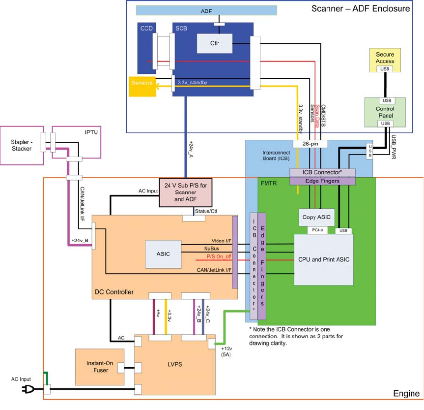
The document feeder/scanner receives 24 volts from the scanner power supply, which is powered by
an AC line from the LVPS.
The intermediate paper transport unit (IPTU) receives +24 volts and 3.3 volts from the DCC.
The Stapler/Stacker receives +24 volts and the JetLink control lines for communications from the DCC.
Figure 1-2 System block diagram
ENWW Basic operation 3

Sequence of operation
The DC controller PCA controls the operating sequence, as described in the following table.
Table 1-1 Sequence of operation
Period Duration Description
Waiting From the time the power is turned on,
the door is closed, or when the product
exits Sleep mode until the product is
ready for printing
●Heats the fuser sleeve in the fuser
●Pressurizes the pressure roller in the
fuser
●Detects the print cartridges
●Moves the ITB and developing unit
to the home position
●Cleans the ITB and secondary
transfer roller
Standby From the end of the waiting sequence or
the last rotation until the formatter
receives a print command or until the
product is turned off
●The product is in the Ready state.
●The product enters Sleep mode if
the sleep command is received
from the formatter.
●The product calibrates if it is time
for an automatic calibration.
Initial rotation From the time the formatter receives a
print command until the paper enters the
paper path
●Activates the high-voltage power
supply
●Prepares each laser/scanner unit
●Warms the fuser to the correct
temperature
Printing From the time the first sheet of paper
enters the paper path until the last sheet
has passed through the fuser
●Forms the image on the
photosensitive drums
●Transfers the toner to the paper
●Fuses the toner image onto the
paper
Last rotation From the time the last sheet of paper
exits the fuser until the motors stop
rotating
●Moves the last printed sheet into
the output bin
●Stops the high-voltage power
supply
●Stops each laser/scanner unit
●If another print command is
received, the product enters the
initial rotation period when the last
rotation is complete.
4 Chapter 1 Theory of operation ENWW

Engine-control system
The engine-control system receives commands from the formatter and interacts with the other main
systems to coordinate all product functions. The engine-control system consists of the following
components:
●DC controller
●Low-voltage power supply
●High-voltage power supply
●Fuser control
Figure 1-3 Engine-control system
MEDIA FEED SYSTEM
ENGINE CONTROL SYSTEM
DC controller
LASER SCANNER SYSTEM
IMAGE-FORMATION SYSTEM
Formatter
High-voltage power supply
Low-voltage power supply
OPTION
Fuser control
ENWW Engine-control system 5
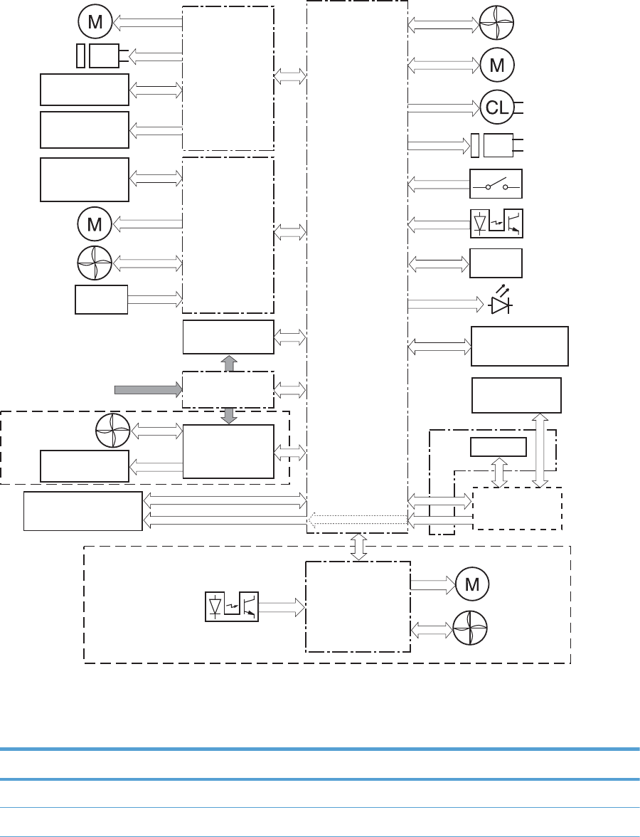
DC controller
The DC controller controls the operational sequence of the product.
Figure 1-4 DC controller block diagram
Fixing unit
High-voltage
power supply T
ITB unit
AC input Low-voltage
power supply
Motor
Solenoid
Photointerrupter
DC controller
Laser scanner unit Formatter
Switch
Fan
Option
Sensor
Cartridge
(Y/M/C/K)
High-voltage
power supply D
Secondary
transfer roller
Motor
Fan
Clutch
LED
Motor
Solenoid
Operation panel
Photointerrupter IPTU controller
Fan
Motor
Sensor
Sub power
supply unit
Fan
Image Scanner
NVRAM
ICB
Solenoids
Table 1-2 Solenoids
Component abbreviation Component name
SL1 Primary transfer roller disengagement solenoid
SL2 Duplex reverse solenoid
6 Chapter 1 Theory of operation ENWW

Table 1-2 Solenoids (continued)
Component abbreviation Component name
SL3 Multipurpose-tray pickup solenoid
SL4 Cassette pickup solenoid
Clutches
Component abbreviation Component name
CL1 Duplex re-pickup clutch
Switches
Table 1-3 Switches
Component abbreviation Component name
SW1 5V interlock switch
SW2 24V interlock switch
SW3 Power switch
SW4 Cassette media size switch
SW5 Front door switch
SW6 Right door switch
Test print switch
ENWW Engine-control system 7

Sensors
Table 1-4 Sensors
Component abbreviation Component name
SR1 Yellow drum home position sensor
SR2 Magenta drum home position sensor
SR3 Cyan drum home position sensor
SR4 Black drum home position sensor
SR5 Fuser delivery sensor
SR7 Fuser pressure release sensor
SR8 MP-tray-media-presence sensor
SR9 Primary-transfer-roller disengagement sensor
SR10 New ITB sensor
SR11 Developer alienation sensor
SR14 Loop sensor 1
SR15 Loop sensor 2
SR20 Top of page (TOP) sensor
SR21 Media sensor
SR22 Duplex re-pickup sensor
SR23 Tray 2 paper surface 1 sensor
SR24 Tray 2 paper surface 2 sensor
SR25 Tray 2 paper present sensor
SR26 IPTU media full sensor
SR27 IPTU media feed sensor
SR28 Image scanner unit open sensor
RD sensor
Environment sensor (temperature and humidity)
Yellow toner-level sensor
Magenta toner-level sensor
Cyan toner-level sensor
Black toner-level sensor
Residual toner full sensor
TH4 Laser scanner temperature sensor
8 Chapter 1 Theory of operation ENWW

Motors
The product has 13 motors. The motors drive the components in the paper-feed and image-formation
systems.
Table 1-5 Motors
Abbreviation Name Purpose Failure detection
M1 ITB motor Drives the ITB and residual
toner feed screw
Yes
M2 Fuser motor Drives the fuser sleeve,
pressure roller, fuser pressure
roller, and primary transfer
roller disengagement
Yes
M3 Y drum motor Drives the photosensitive
drum (yellow), developing
roller (yellow), and primary
charging roller (yellow)
Yes
M4 M drum motor Drives the photosensitive
drum (magenta), developing
roller (magenta), and primary
charging roller (magenta)
Yes
M5 C drum motor Drives the photosensitive
drum (cyan), developing
roller (cyan), and primary
charging roller (cyan)
Yes
M6 Bk drum motor Drives the photosensitive
drum (black), developing
roller (black), and primary
charging roller (black)
Yes
M7 Lifter motor Drives the lifter for the
cassette
Yes
M8 Cyan/black scanner motor Drives the scanner mirror in
the cyan/black laser scanner
Yes
M9 Yellow/magenta scanner
motor
Drives the scanner mirror in
the yellow/magenta laser
scanner
Yes
M10 Developing disengagement
motor
Drives the developing unit
disengagement
No
M11 Duplex reverse motor Drives the duplex reverse
roller and duplex feed roller
No
M12 Residual toner-feed motor Drives the residual toner feed
screw
Yes
ENWW Engine-control system 9

Table 1-5 Motors (continued)
Abbreviation Name Purpose Failure detection
M13 Pickup motor Drives the cassette pickup
roller, MP tray pickup roller,
feed roller, and cassette
separation roller
No
M14 IPTU feed motor Drive the IPTU feed rollers
and IPTU delivery roller
No
The DC controller determines if a motor has failed and notifies the formatter when it encounters the
following conditions:
The DC controller detects a failure by monitoring a motor:
●Startup failure: the motor does not reach a specified speed within a specified time from when the
motor starts.
●Rotational failure: the rotational speed of the motor is not in the specified range for a specified
time after the motor reaches a specified speed.
●Lock detection (for the residual toner feed motor): the value of the motor drive signal voltage is not
in the specified range for a specified time.
The DC controller detects a failure by monitoring a part related to the motor:
●Developing disengagement motor: A specified signal is not detected from the developing
disengagement sensor during a developing assembly operation.
●Lifter motor: The cassette media stack surface sensor does not detect the media surface within a
specified time period after the lifter motor starts.
●Scanner motor: The scanner motor does not reach a specified speed within a specified period
after the scanner assembly starts.
●A specified beam-detect (BD) interval is not detected during a print operation.
Fans
The product has eight fans for preventing the temperature from rising in the product.
Table 1-6 Fans
Abbreviation Name Cooling area Type Speed
FM1 Power supply fan Around the power
supply unit
Intake Full/half
FM2 Cartridge fan Around the cartridges Intake Full/half
10 Chapter 1 Theory of operation ENWW

Table 1-6 Fans (continued)
Abbreviation Name Cooling area Type Speed
FM3 Exhaust fan 2 Around the delivery
assembly
Exhaust Full/half
FM4 Exhaust fan 1 Around the cartridge Exhaust Full/half
FM5 Sub power supply fan Around the sub power
supply
Intake Full
FM6 IPTU fan 1 Around the IPTU media
feed unit and the
product delivery
assembly
Intake Full
FM7 IPTU fan 2 Around the product
delivery assembly
Exhaust Full
FMx Formatter fan Formatter area
The DC controller determines if there is a fan failure and notifies the formatter if the fan locks for a
specified time from when the fan starts.
ENWW Engine-control system 11
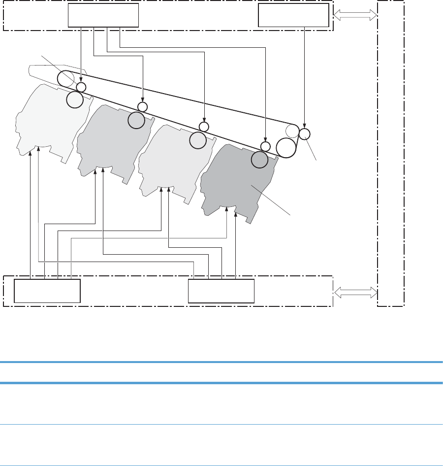
High-voltage power supply
The DC controller controls the high-voltage power supply to generate biases. The high-voltage power
supply delivers the high-voltage biases to the following components used to transfer toner during the
image-formation process:
●Primary-charging roller (in the cartridge)
●Developing roller (in the cartridge)
●Primary-transfer roller
●Secondary-transfer roller
Figure 1-5 High-voltage power supply circuits
Primary transfer roller
Print cartridge
Secondary transfer roller
ITB
DC controller
Secondary transfer
bias circuit
Primary charging
bias circuit
High-voltage power supply D
Primary transfer
bias circuit
Developing bias
circuit
High-voltage power supply T
The high-voltage power supply contains several separate circuits.
Table 1-7 High-voltage power supply circuits
Circuit Description
Primary-charging-bias generation The primary charging bias negatively charges the surface of the photosensitive
drum to prepare for image formation. The primary-charging-bias circuit in the high-
voltage power supply generates the biases for each color.
Developing-bias generation The developing bias adheres toner to an electrostatic latent image formed on the
photosensitive drum. The developing-bias circuit in the high-voltage power supply
generates the biases for each color.
12 Chapter 1 Theory of operation ENWW

Table 1-7 High-voltage power supply circuits (continued)
Circuit Description
Primary-transfer-bias generation The primary transfer bias transfers the toner from each photosensitive drum onto the
ITB. The primary transfer bias circuit in the high-voltage power supply generates the
biases for each color.
Secondary-transfer-bias generation The secondary transfer bias transfers the toner image from the ITB onto the paper.
The secondary transfer bias circuit in the high-voltage power supply generates the
bias. The reversed bias transfers residual toner on the secondary transfer roller back
to the ITB. The residual toner on the ITB is deposited in the toner collection box.
ENWW Engine-control system 13
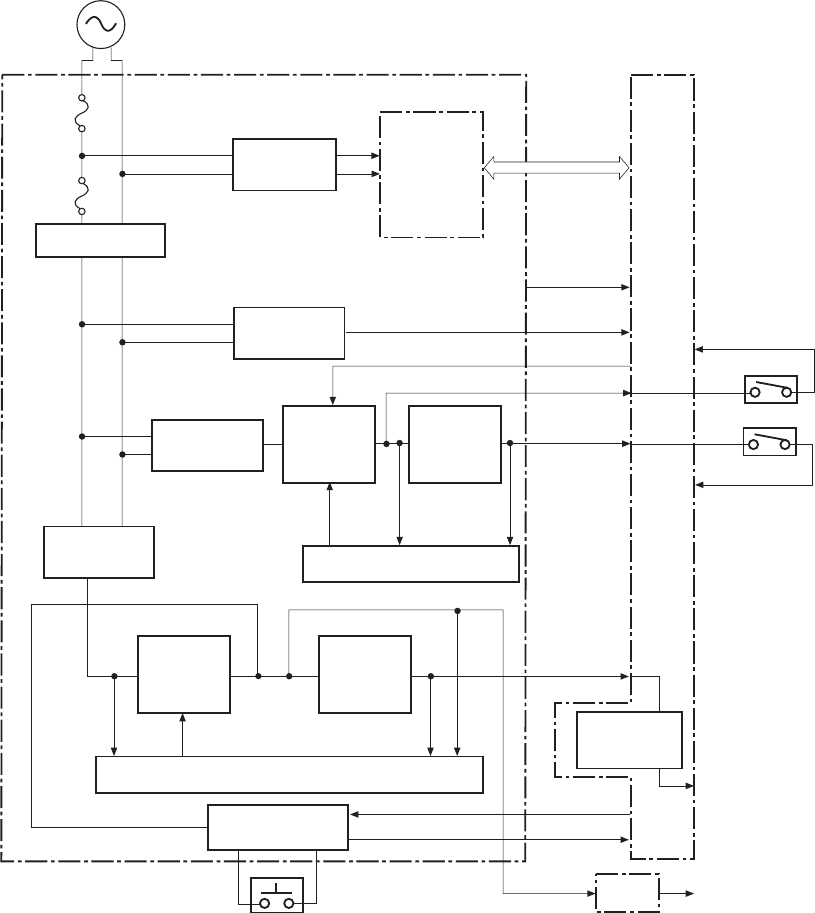
Low-voltage power supply
The low-voltage power-supply circuit converts the AC power from the wall receptacle into the DC
voltage that the product components use. The product has two low-voltage power-supplies for 110 Volt
or 220 Volt input.
Figure 1-6 Low-voltage power-supply circuit
+3.3V
24RMT
+24VA
+12VA
SW1
+5VC
+24VB
SW2
PWROFF
PWRSWON
ZEROX
PSTYP100
+3.3VS
+5VB
ICB
Fuse
Formatter
+3.3V
generation
circuit
Power switch
Remote switch
control circuit
+24V
generation
circuit
+5V
generation
circuit
Protection circuit
Rectifying
circuit
Zerocross
circuit
Low-voltage power supply
AC input
Fuse
Noise filter
Noise filter
Rectifying
circuit
+12V
generation
circuit
Protection circuit
Switching
circuit
DC controller
Fuser control
circuit
The low-voltage power supply converts the AC power into three DC voltages, which it then subdivides,
as described in the following table.
14 Chapter 1 Theory of operation ENWW

Table 1-8 Converted DC voltages
Main DC voltage Sub-voltage Behavior
+24 V +24 VA Constantly supplied
+24 VB Interrupted when the front door or right
door open
+5 V +5 VB Constantly supplied
+5 VC Interrupted when the front door or right
door open
+3.3 V 3.3 V Constantly supplied
3.3 VS Stopped during Sleep (powersave)
mode
Overcurrent/overvoltage protection
The low-voltage power supply stops supplying the DC voltage to the product components whenever it
detects excessive current or abnormal voltage from the power source. If DC voltage is not being
supplied from the low-voltage power supply, the protective function might be running. In this case, turn
the power off and unplug the power cord. Do not turn the power switch on until the root cause is found.
The DC controller notifies the formatter of a low-voltage power supply failure when the protective
function is activated. In addition, the low-voltage power supply circuit and the fuser control unit have a
fuse to protect against overcurrent. If overcurrent flows into the AC line, the fuse blows to stop AC
power.
Safety
For personal safety, the product interrupts 24 VB power to the fuser, high-voltage power supply, and
motors, in addition to +5 VC to the laser scanners when the front or right door is opened. The power
switch is on the dc line so that the ac power flows even if the power switch is turned off. Unplug the
power cord before disassembling the product.
Voltage detection
The product detects the power supply voltage that is connected to the product. The DC controller
monitors the POWER SUPPLY VOLTAGE (PSTYP100) signal and detects power supply voltage, whether
100 V or 200 V, to control the fuser operation.
Sleep (powersave) mode
Sleep mode conserves energy by stopping the power to several components when the product is idle. If
the DC controller detects voltage that is too high when the product is in Sleep mode, it determines that
the low-voltage power supply has failed, and it notifies the formatter.
ENWW Engine-control system 15
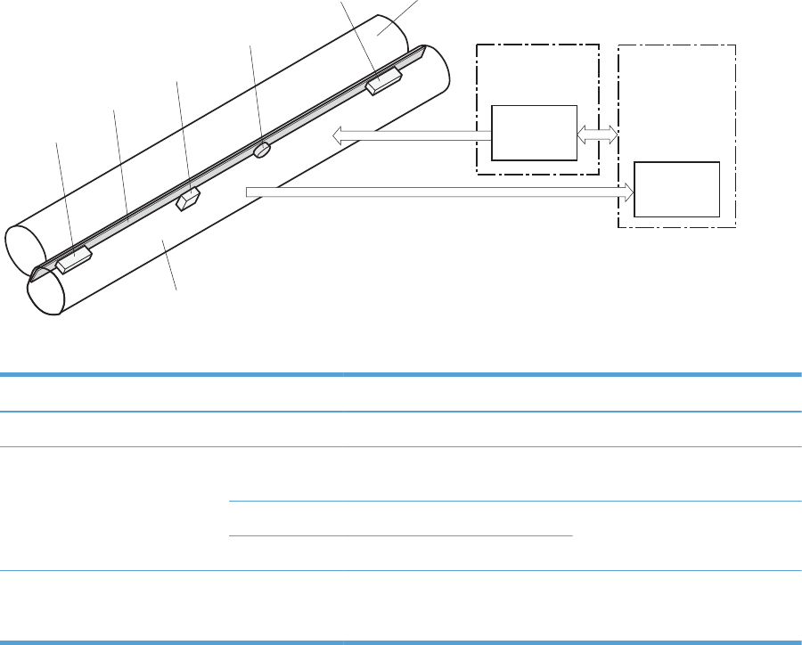
Low-voltage power supply failure
The DC controller determines a low-voltage power supply failure and notifies the formatter when the
low-voltage power supply does not supply +24 V.
Fuser control
The fuser heater-control circuit and the fuser heater safety circuit control the fuser temperature according
to commands from the DC controller.
Figure 1-7 Fuser components
H1
TH2
TH1
TP1
TH3
FUSER TEMPERATURE signal
Pressure roller
FUSER HEATER
CONTROL signal
Fuser sleeve
Fuser heater
control circuit
Fuser heater
safety circuit
DC controller
Low-voltage power
supply unit
Table 1-9 Fuser components
Type of component Abbreviation Name Function
Heaters H1 Fuser heater Heats the fuser sleeve.
Thermistors
(Contact type)
TH1 Main thermistor Detects the center temperature of
the fuser sleeve.
TH2 Sub thermistor 1 Detects the temperature at one
end of the fuser heater.
TH3 Sub thermistor 2
Thermoswitches
(Contact type)
TP1 For the fuser heater Opens in the event of high
temperature fault
16 Chapter 1 Theory of operation ENWW
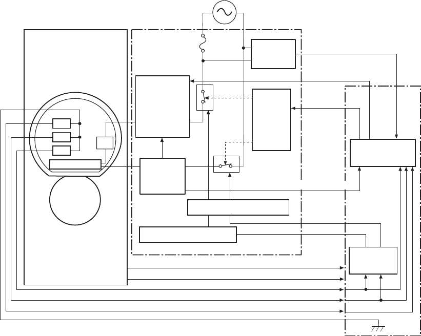
Fuser temperature control
The fuser temperature control maintains the target surface temperature of the fuser sleeve.
Figure 1-8 Fuser temperature-control circuit
FSRTH3
FSRTH2
FSRTH1
FSRD1
TP1
/RLD
TH3
TH2
TH1
CPU
H1
FSRSAFE1
FSRSAFE2
FSR_CURRMS
/ZEROX
/FSRSNS
/FSRNEW
Fuser sleeve unit
Fuser heater
safety circuit
DC controller
Fuser
Zerocross
circuit
Relay
control
circuit
Fuser control circuit
Pressure
roller
Fuse
Relay
Relay
Fuser heater
control circuit
Current
detection
circuit
Low-voltage power supply
Fuser heater safety circuit
Fuser heater safety circuit
H1: Fuser heater
TP1: Thermoswitch
TH1: Main thermistor
TH2: Sub thermistor 1
TH3: Sub thermistor 2
Fuser sleeve temperature protection
The fuser heater controls the temperature of the fuser sleeve. The DC controller detects the center area
temperature by monitoring the main thermistor. The DC controller controls the FIXING HEATER
CONTROL (FSRD1) signal, so that the fuser sleeve remains at the targeted temperature.
●Protective function: The protective function detects rising temperatures in the fuser and
interrupts power to the fuser heater. The following four protective components prevent the fuser
sleeve and pressure roller from excessive rising temperature:
◦DC controller
◦Fuser heater safety circuit
ENWW Engine-control system 17

◦Current detection circuit
◦Thermoswitch
●DC controller: The DC controller monitors the detected temperature of the main thermistor and
sub thermistors. The DC controller deactivates the FIXING HEATER CONTROL signal and releases
the relay to interrupt power supply to the fuser heater under the following conditions:
◦TH1: 230° C (446° F) or higher
◦TH2: 285° C (545° F) or higher
◦TH3: 285° C (545° F) or higher
●Fuser-heater safety circuit: The fuser heater safety circuit monitors the detected temperature
of the sub thermistors. The fuser heater safety circuit releases the relay to interrupt power supply to
the fuser heater under the following conditions:
◦TH2: 290° C (554° F) or higher
◦TH3: 290° C (554° F) or higher
●Current-detection protection circuit: The current detection circuit monitors the current flowing
through the fuser heater control circuit. The current detection circuit deactivates the fuser heater
control circuit to interrupt power supply to the fuser heater when it detects the current higher than a
specified value.
●Thermoswitch: If the temperature in the heaters is abnormally high, and the temperature in the
thermoswitches exceeds a specified value, the contact to the thermoswitch breaks. Following are
the thresholds for each thermoswitch:
◦TP1: 270° C (518° F) or higher
NOTE: When the thermoswitches reach this temperature, the temperature on the fuser rollers is about
320° C (608° F).
18 Chapter 1 Theory of operation ENWW
Failure detection
The DC controller determines a fuser unit failure, deactivates the FIXING HEATER CONTROL signal,
releases the relay to interrupt power supply to the fuser heater, and notifies the formatter of a failure
status when it encounters any of following conditions:
●Abnormally high temperatures: Temperatures are too high for any of the following
components, at any time:
◦TH1: 230° C (446° F) or higher
◦TH2: 285° C (545° F) or higher
◦TH3: 285° C (545° F) or higher
●Abnormally low temperatures: Temperatures are too low at any of the following
components after the product has initialized.
◦TH1: 120° C (248° F) or lower
◦TP2 or TP3: 100° C (212° F) or lower
●Abnormal temperature rise: The DC controller determines an abnormal temperature rise if
the detected temperature of TH1 does not rise 2° C within a specified time after the fuser motor is
turned on, or if the detected temperature of the thermistors does not rise to a specified temperature
for a specified time after the fuser motor is turned on.
●Thermistor open: The DC controller determines a thermistor open if:
◦The detected temperature of TH1 is kept at 12° C (53° F) or lower for a specified time after
the fuser motor is turned on.
◦The detected temperature of TH2 is kept at 4° C (39° F) or lower for a specified time.
◦The detected temperature of TH3 is kept at 4° C (39° F) or lower for a specified time.
●Drive-circuit failure: The DC controller determines a drive-circuit failure:
◦If the detected power supply frequency is out of a specified range when the product is turned
on or during the standby period
◦If the current detection circuit detects a current value that is out of a specified range
●Fuser discrepancy: The DC controller determines a fuser type mismatch when it detects an
unexpected power supply voltage.
Fuser unit identification
The product detects the type and presence of the fuser. The DC controller detects whether the fuser is
installed and its type by monitoring the FIXING UNIT IDENTIFICATION (FSRSNS) signal when the
product is turned on or when the right door is closed. The DC controller determines a low-voltage
power supply failure and notifies the formatter when it fails to detect the type or presence of the fuser.
ENWW Engine-control system 19

NOTE: This product detects if the correct fuser for the product is installed. The fuser from a different
product (for example, the HP Color LaserJet CP 3525 Series printer) can be installed in this product, but
it will not correctly function.
Fuser unit life detection
The product detects the remaining life of a fuser. The DC controller recognizes a new fuser from the
NEW FIXING UNIT (/FSRNEW) signal. The DC controller determines a fuser's end of life and then
notifies the formatter when a specified number of pages has been printed after the fuser was replaced.
NOTE: The product detects a new fuser using a fusible link that breaks down after 100 pages of
printing. If a new fuser is installed for troubleshooting purposes, be sure to remove it before printing
100 pages.
20 Chapter 1 Theory of operation ENWW
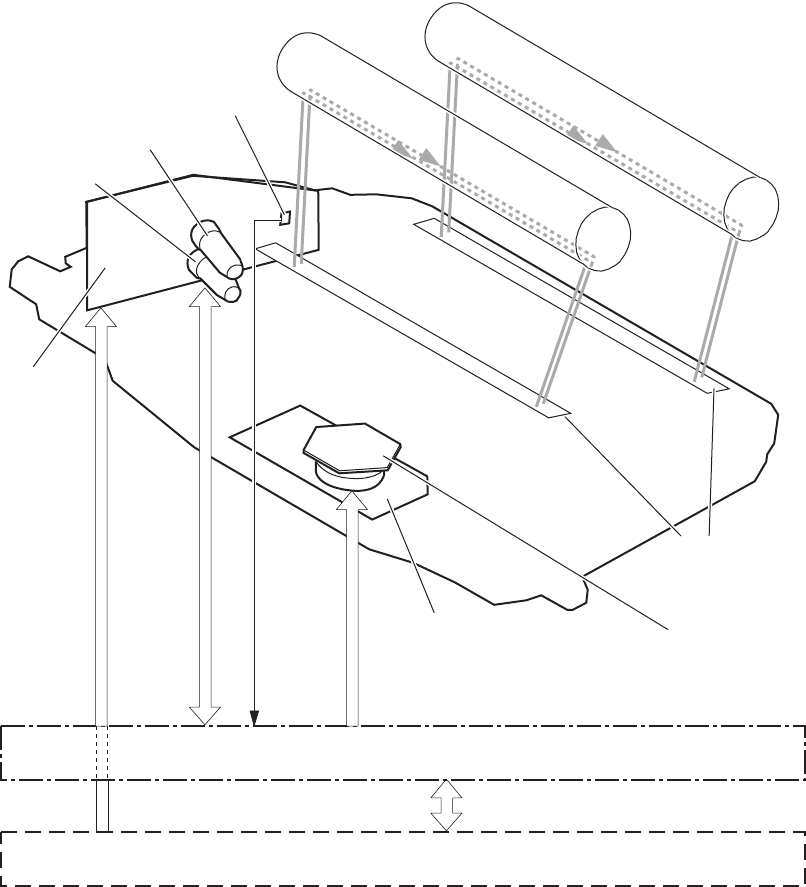
Laser/scanner system
The laser/scanner system forms the latent electrostatic image on the photosensitive drums according to
the VIDEO signals sent from the formatter. The product has two laser/scanners: one for yellow and
magenta and the other for cyan and black.
The main components of the laser/scanner system are the laser unit and the scanner motor unit, which
are controlled by the signals sent from the DC controller.
Figure 1-9 Laser/scanner system
DC controller
Formatter
Scanner mirror
Scanner motor unit
SCANNER MOTOR
CONTROL signal
VIDEO signal
LASER CONTROL signal
BDI signal
BD sensor
Laser unit
Photosensitive drum (M)
Photosensitive drum (Y)
Yellow laser
Magenta laser
Protective glass
ENWW Laser/scanner system 21

Laser/scanner failure
The DC controller determines that a laser/scanner has failed when any of the following conditions
occurs:
●Laser failure: The detected laser intensity does not match a specified value when the product
initializes.
●Scanner motor startup failure: The scanner motor does not reach a specified rotation within
a specified period from when the laser scanner starts driving.
●Scanner-motor abnormal rotation: When a specified BD interval is not detected during a
print operation, a BD error is determined. If the BD interval does not recover within a specified
period after the BD error occurs, the product determines a scanner motor abnormal rotation.
The laser/scanner system does not have a mechanical laser shutter. For safety reason, the product has
a interlock switch. The interlock switch is turned off to interrupt +5 V power supply to the laser/scanner
system, when the front or right door is open.
Protective-glass cleaners
Each laser/scanner has two openings which allow the laser beam to pass to the surface of the
photosensitive drum. These openings are covered by protective glass. When the protective glass gets
dirty (for example, by paper dust or toner) a protective-glass cleaner (PGC) cleans them.
NOTE: When a glass is dirty, streaks appear on the printed page in the process direction.
The PGC is a cleaning pad which slides along the laser shutter. With the front door open, the laser
shutter is positioned over the glass. As a print cartridge is inserted, the cleaning pad is pushed down
and wipes the glass. When the front door is closed after cartridge insertion, the laser shutter (and PGC)
move away from the glass which allows the laser beam to pass through the glass.
When the front door is opened, the laser shutter and PGC move back into position over the glass.
When the cartridge is pulled out, the cleaning pad is returned to its starting position at the front of the
cartridge opening.
22 Chapter 1 Theory of operation ENWW
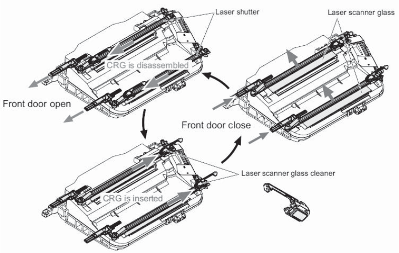
Figure 1-10 Protective-glass cleaners (PGCs)
ENWW Laser/scanner system 23
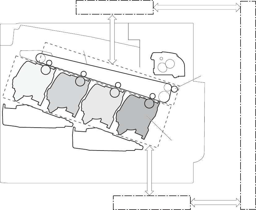
Image-formation system
The image-formation system creates the printed image on the paper. The system consists of the
following components:
●Print cartridges
●ITB
●Secondary transfer roller
●Fuser
●Laser /scanner units
The DC controller controls the laser scanner unit and each of the high-voltage power supplies to form
the toner image on the photosensitive drum surface, according to the VIDEO signals. The toner image is
then transferred to the print-media and fused.
Figure 1-11 Image-formation system
Print cartridge
Laser scanner unit
Fuser
ITB
Secondary
transfer roller
High-voltage power supply D
DC controller
High-voltage power supply T
Laser scanner unit
24 Chapter 1 Theory of operation ENWW
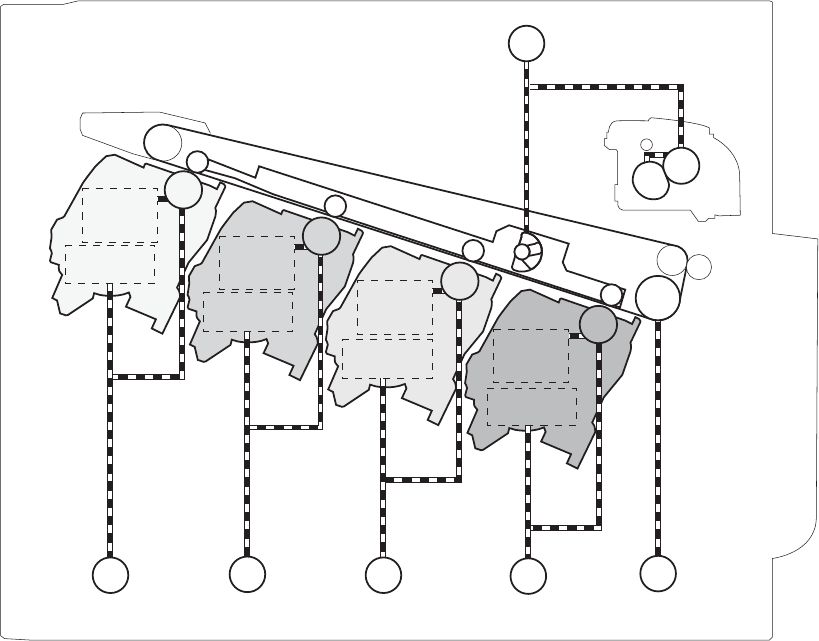
Figure 1-12 Image-formation drive system
Fuser motor
M2
ITB motor
M1
M3
Developing
roller
Y drum motor
M4
M drum motor
M5
C drum motor
M6
Bk drum motor
Primary
charging
roller
Developing
roller
Primary
charging
roller
Developing
roller
Primary
charging
roller
Developing
roller
Primary
charging
roller
ENWW Image-formation system 25

Image-formation process
The image-formation system consists of ten steps divided into six functional blocks.
Figure 1-13 Image-formation process
Cartridge
Laser scanner unit
Fusing unit
ITB
Secondary
transfer roller
High-voltage power supply D
DC controller
High-voltage power supply T
Laser scanner unit
Functional block Steps Description
Latent image formation 1. Pre-exposure
2. Primary charging
3. Laser-beam exposure
An invisible latent image forms on the
surface of the photosensitive drums.
Development 4. Development Toner adheres to the electrostatic latent
image on the photosensitive drums.
Transfer 5. Primary transfer
6. Secondary transfer
7. Separation
The toner image transfers to the ITB and
later to the paper.
Fusing 8. Fusing The toner fuses to the paper to make a
permanent image.
26 Chapter 1 Theory of operation ENWW
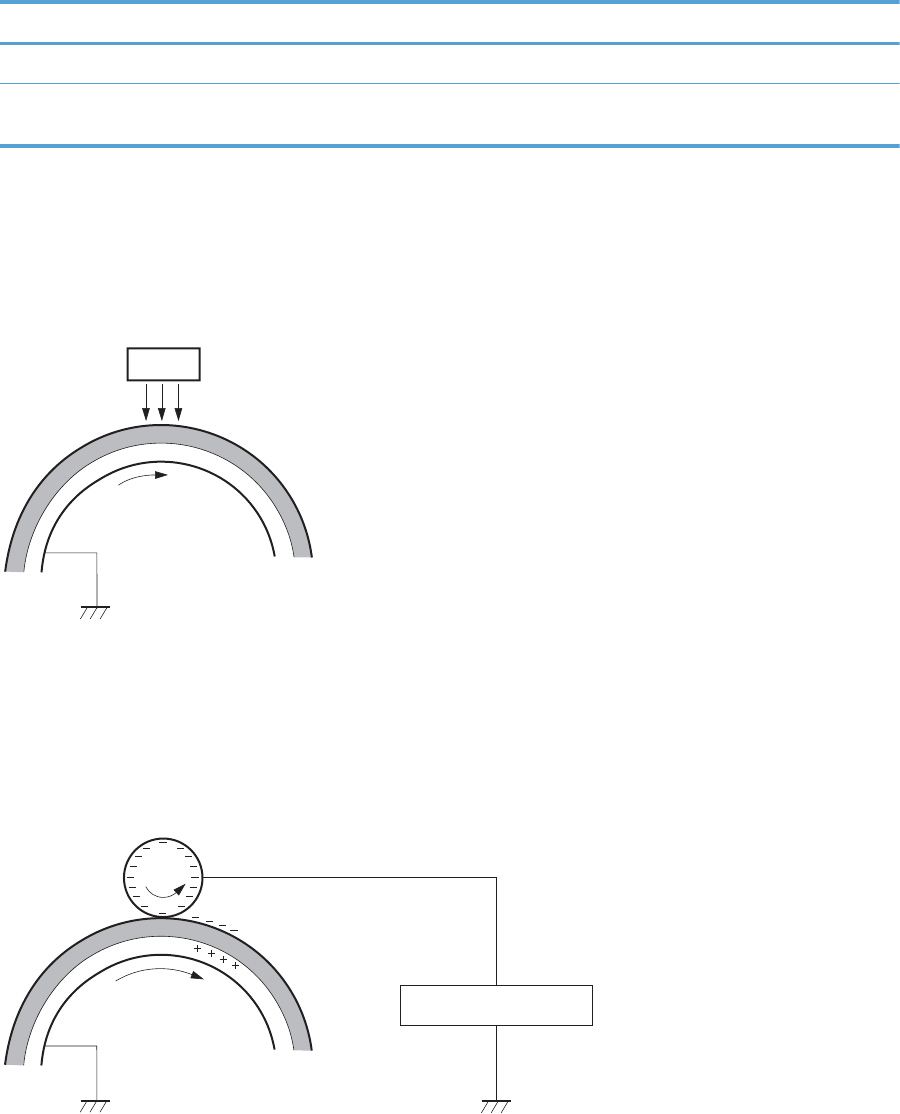
Functional block Steps Description
ITB cleaning 9. ITB cleaning Residual toner is removed from the ITB.
Drum cleaning 10. Drum cleaning Residual toner is removed from the
photosensitive drums.
Step 1: Pre-exposure
Light from the pre-exposure LED strikes the surface of the photosensitive drum to remove any residual
electrical charges from the drum surface.
Figure 1-14 Pre-exposure
Photosensitive drum
LED
Step 2: Primary charging
The primary-charging roller contacts the photosensitive drum and charges the drum with negative
potential.
Figure 1-15 Primary charging
Primary charging roller
Primary charging bias
Photosensitive drum
ENWW Image-formation system 27
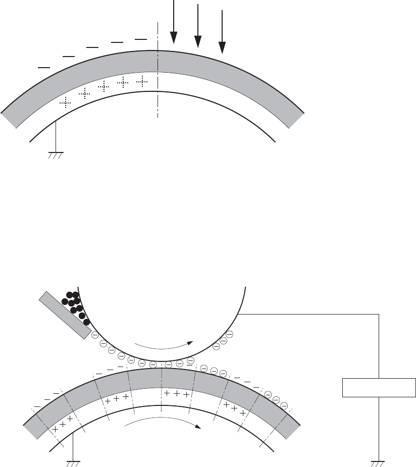
Step 3: Laser-beam exposure
The laser beam strikes the surface of the photosensitive drum in the areas where the image will form.
The negative charge neutralizes in those areas, which are then ready to accept toner.
Figure 1-16 Laser-beam exposure
Laser beam
Step 4: Development
Toner acquires a negative charge as the developing cylinder contacts the developing blade. Because
the negatively charged surface of the photosensitive drums have been neutralized where they have
been struck by the laser beam, the toner adheres to those areas on the drums. The latent image
becomes visible on the surface of each drum.
Figure 1-17 Development
Developing bias
Photosensitive drum
Developing roller
Developing blade
28 Chapter 1 Theory of operation ENWW
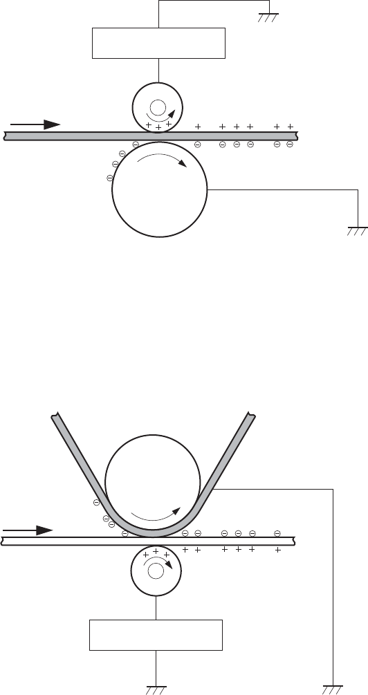
Step 5: Primary transfer
The positively charged primary-transfer rollers contact the ITB, giving the ITB a positive charge. The ITB
attracts the negatively charged toner from the surface of each photosensitive drum, and the complete
toner image transfers onto the ITB.
Figure 1-18 Primary transfer
ITB
Primary transfer bias
Primary transfer roller
Photosensitive
drum
Step 6: Secondary transfer
The paper acquires a positive charge from the secondary-transfer roller, and so it attracts the negatively
charged toner from the surface of the ITB. The complete toner image transfers onto the paper.
Figure 1-19 Secondary transfer
ITB
Secondary transfer bias
Secondary transfer roller
Paper
Secondary transfer
opposed roller
ENWW Image-formation system 29
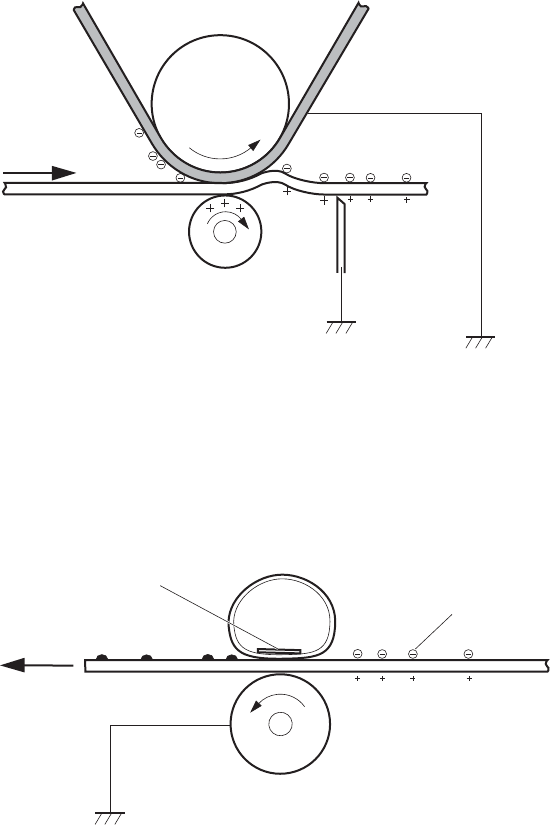
Step 7: Separation
The stiffness of the paper causes it to separate from the ITB as the ITB bends. The static-charge
eliminator removes excess charge from the paper to make sure that the toner fuses correctly.
Figure 1-20 Separation
ITB
Secondary transfer roller
Paper
Secondary transfer
opposed roller
Static charge
eliminator
Step 8: Fusing
To create the permanent image, the paper passes through heated, pressurized rollers to melt the toner
onto the page.
Figure 1-21 Fusing
Paper
Pressure roller
Fuser sleeve
Fuser heater
Toner
30 Chapter 1 Theory of operation ENWW
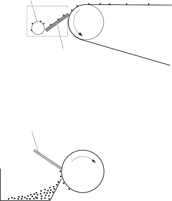
Step 9: ITB cleaning
The cleaning blade scrapes the residual toner off the surface of the ITB. The residual toner feed screw
deposits residual toner in the toner collection box.
Figure 1-22 ITB cleaning
ITB
Cleaning blade
Residual toner feed screw
Step 10: Drum cleaning
The cleaning blade scrapes the residual toner off the surface of the photosensitive drum, and toner is
deposited in the toner collection box in the cartridge.
Figure 1-23 Drum cleaning
Cleaning blade
Photosensitive
drum
CRG toner collection box
Print cartridge
Each print cartridge is filled with toner and consists of the following components:
●Photosensitive drum
●Developing unit
●Developing roller
●Primary-charging roller
ENWW Image-formation system 31
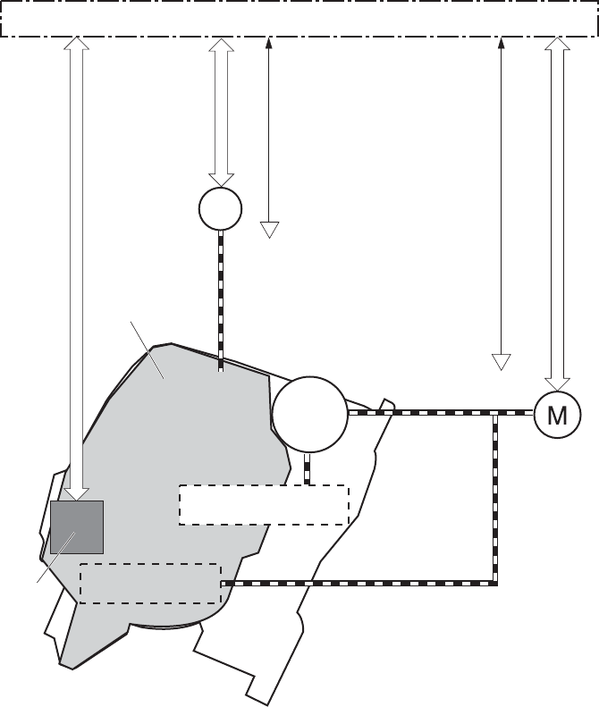
The DC controller rotates the drum motor to drive the photosensitive drum, developing roller, and the
primary-charging roller.
Figure 1-24 Print-cartridge system
Primary charging roller
SR1/SR2/SR3/SR4:
Drum home position sensor
SR11:
Developing disengagement sensor
DC controller
Developing
disengagement
motor
Memory
tag
M3/M4/M5/M6:
Drum motor
Developing roller
Developing unit
M10
The DC controller rotates the drum motor to drive the photosensitive drum, developing unit, and primary
charging roller.
The memory tag is a non-volatile memory chip that stores information about the usage for the print
cartridge. The product reads and writes the data in the memory tag.
32 Chapter 1 Theory of operation ENWW
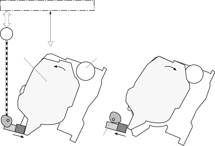
The DC controller determines a memory tag error and notifies the formatter when it fails to either read
from or write to the memory tag.
●Cartridge presence detection: The DC controller detects the presence of the cartridges by
monitoring the memory tag. The DC controller notifies the formatter when a cartridge is missing or
installed in the incorrect slot.
●Toner level detection: The DC controller detects the remaining toner in a cartridge by the optical
detection method and then notifies the formatter of the remaining toner level.
●Cartridge life detection: The DC controller detects the cartridge life by monitoring the total
operating time or remaining toner level of the print cartridge. The DC controller determines a
cartridge end of life and notifies the formatter when total operating time of the cartridge reaches a
specified time or the cartridge runs out of toner.
Developing-roller engagement and disengagement
The product can print in full-color mode or in black-only mode. To print in black-only mode, the product
disengages the developing rollers in the cyan, magenta, and yellow print cartridges which maximizes
the life of the cartridges.
Figure 1-25 Developing-roller engagement and disengagement control
Developing unit is disengaged
Developing
disengagement
motor
Photosensitive drum
Developing unit
Developing disengagement cam
SR11
Developing disengagement sensor
DC controller
M10
Developing unit is engaged
ENWW Image-formation system 33
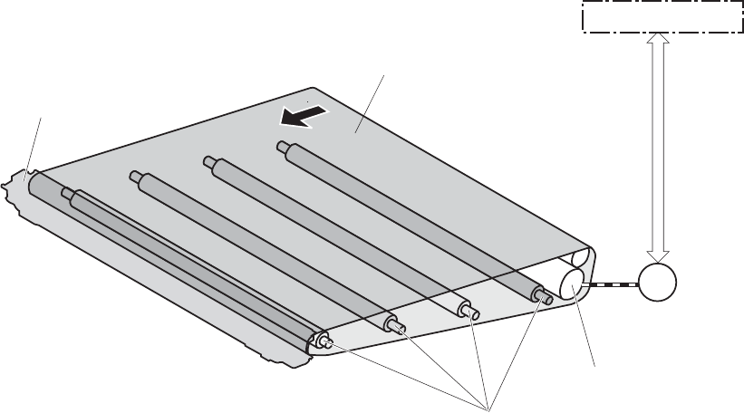
The developing-roller engagement and disengagement control operates as follows: When the product is
turned on and when each print job is completed, all four of the developing units are disengaged from
the photosensitive drums.
●The drive of the developing disengagement motor rotates the developing disengagement cam.
●As the cam rotates, the developing unit engages with or separates from the photosensitive drum.
When the print mode is full color, the developing units engage with the drums. When the print mode is
black-only, only the black developing units engages with the drum.
The DC controller determines a developing disengagement motor failure and notifies the formatter when
it does not detect a specified signal from the developing disengagement sensor during the developing
unit engagement and disengagement operation.
Intermediate transfer belt (ITB) unit
The ITB unit accepts the toner images from the photosensitive drums and transfers the completed image
to the paper. The ITB unit has the following main components:
●ITB
●ITB drive roller
●ITB-drive roller
●Primary-transfer roller
●ITB cleaner
The ITB motor drives the ITB drive roller, which rotates the ITB. The motion of the ITB causes the primary
transfer rollers to rotate. The ITB cleaner cleans the ITB surface.
Figure 1-26 ITB unit
Primary transfer roller
ITB drive roller
ITB
ITB cleaner
M1
DC controller
ITB motor
34 Chapter 1 Theory of operation ENWW

Primary-transfer-roller engagement and disengagement
The sequence of the primary-transfer-roller engagement and disengagement control is as follows:
1. The fuser motor turns on the primary-transfer disengagement solenoid and rotates the primary-
transfer-roller disengagement cam.
2. As the cam rotates, the Y/M/C primary-transfer-roller slide plate or the Bk primary-transfer-roller
slide plate moves to the right or left, which causes the primary-transfer roller to move up or down.
3. The ITB engages with or separates from the photosensitive drum depending on the movement of
the primary-transfer rollers.
Depending on the requirements of the print job, the primary-transfer rollers engage with the ITB so it
can receive toner from the photosensitive drums. The primary-transfer roller has three engagement
states.
Table 1-10 Primary-transfer-roller engagement states
All rollers disengaged The ITB is disengaged from all the four photosensitive drums. This state is the home
position for the ITB unit.
All rollers engaged The ITB is engaged with all four photosensitive drums. The state for full-color
printing.
Black roller engaged The ITB is engaged with only the black photosensitive drum. The state for black-
color mode printing .
The DC controller determines a primary-transfer-roller disengagement failure and notifies the formatter
when it does not detect a signal from the primary-transfer disengagement sensor even though the
primary-transfer disengagement solenoid is turned on.
If the DC controller does not receive the expected signal from the ITB home-position sensor when the
primary-transfer-roller engages or disengages, but the primary-transfer-roller disengagement motor is
rotating, the DC controller determines that the primary-transfer-disengagement mechanism has failed,
and notifies the formatter.
The DC controller detects whether the ITB unit is new by monitoring the new ITB unit sensor. The DC
controller determines the ITB unit is at end of life and notifies the formatter when a specified number of
pages are printed after the ITB unit is replaced. If swapping ITB units between two products for
troubleshooting purposes, be sure to return the ITB units to their original products to maintain the correct
life count.
NOTE: A new ITB has a flag that causes the ITB life counter to be reset. When an ITB is installed in
the product, it cannot be removed and used again as a new ITB.
The DC controller detects the presence of an ITB unit by monitoring the primary-transfer-roller
disengagement sensor. The DC controller turns on the primary-transfer disengagement solenoid for
specified times during an initial rotation period when the following events occur:
●The product is turned on.
●The product exits sleep mode.
●The door is closed.
ENWW Image-formation system 35
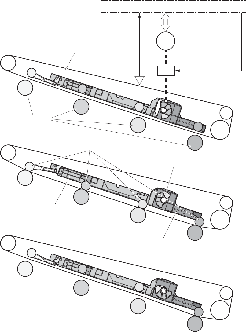
The DC controller determines the absences of an ITB unit and notifies the formatter when it does not
detect a specified signal from the new primary transfer-roller disengagement sensor.
Figure 1-27 Three states of primary-transfer-roller engagement and disengagement
M2
SL1
ITB
DC controller
Fuser motor
Primary transfer
disengagement solenoid
SR9:
Primary transfer
disengagement sensor
Primary transfer roller disengagement cam
Bk primary transfer roller slide plate
YMC primary transfer roller slide plate
<Only black is engaged>
<All colors are engaged>
<All colors are disengaged>
Primary transfer roller
Photosensitive drum
36 Chapter 1 Theory of operation ENWW
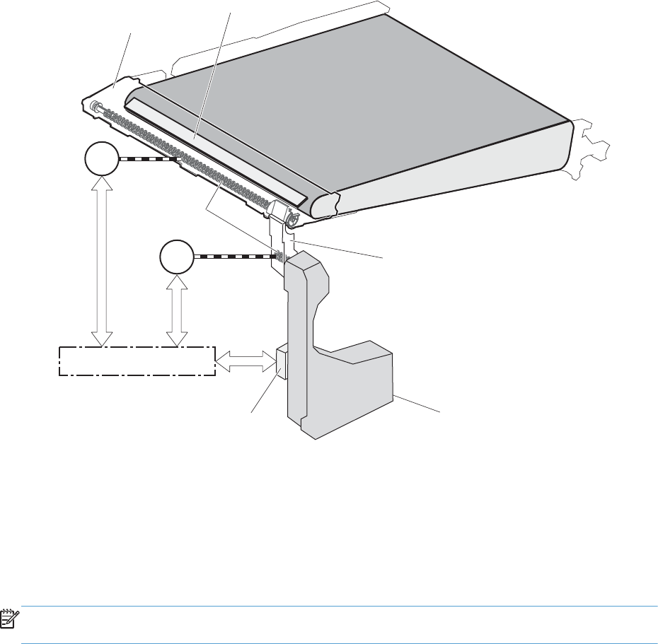
ITB cleaning
The cleaning blade in the ITB cleaner scrapes the residual toner off the ITB surface. The residual toner
feed screw deposits the residual toner to the residual toner feed unit. The ITB motor and the residual
toner feed motor drive the screw. The DC control detects whether the toner collection box is full, using
the residual-toner full sensor, and then notifies the formatter.
Figure 1-28 ITB cleaning process
ITB
DC controller
ITB cleaner
Cleaning blade
Residual toner
feed screw
Residual toner full sensor Toner collection box
Residual toner feed unit
ITB motor
Residual toner
feed motor
M12
M1
Calibration
The product calibrates itself to maintain excellent print quality. Calibration corrects color-misregistration
and color-density variation.
During calibration, the product places a specific pattern of toner on the surface of the ITB. Sensors at
the end of the ITB read the toner pattern to determine if adjustments are necessary.
NOTE: The product performs a drum-speed adjustment (DSA) during the full calibration operation.
The DSA compensates for variations between each drum and the speed of the ITB surface.
ENWW Image-formation system 37
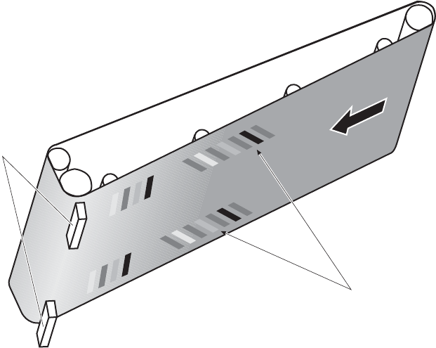
Color-misregistration control
Internal variations in the laser/scanners can cause the toner images to become misaligned. The color-
misregistration control corrects the following problems:
●Horizontal scanning start position
●Horizontal scanning magnification
●Vertical scanning start position
The DC controller forms a pattern of toner on the surface of the ITB and measures a misaligned length
with the RD sensor.
Figure 1-29 Toner patterns for calibration
ITB
RD sensor
Pattern of toner
The DC controller signals the formatter to perform the color-misregistration control when one of the
following events occur:
●A cartridge or the ITB is replaced.
●A specified number of pages have printed.
●The formatter sends a command.
The DC controller determines an RD sensor failure and notifies the formatter if it detects data from the
RD sensor that is not in a specified range, when the product is turned on or when the color-
misregistration control starts.
38 Chapter 1 Theory of operation ENWW

Image-stabilization control
NOTE: The product contains a thermal sensor, located within the TCU level detection sensor, which
monitors the temperature in the cartridge area and uses this information to make adjustments during
CPR control.
Environmental changes or deterioration of the photosensitive drums and toner can cause variations in
the image density. The image-stabilization control reduces these fluctuations.
Table 1-11 Image-stabilization controls
Image density control (DMAX) This control corrects variations in image density related to deterioration of the
photosensitive drum or the toner. The DC controller adjusts the high-voltage biases
to correct the problem under the following conditions:
The image-stabilization control calibrates each high-voltage bias to stabilize the
fluctuations in image density caused by deterioration of the photosensitive drums or
toner or because of environmental changes. The DC controller determines the
product's environment based on the surrounding temperature and humidity data
from the environment sensor. The DC controller calibrates the biases according to
the detected environment and usage condition of the print cartridge to obtain an
appropriate image. The DC controller determines an environment sensor failure and
notifies the formatter when it detects environmental data from the environment
sensor with out of specified value. The DC controller commands the formatter to
control the image density under the following conditions
●The temperature of the main thermistor is too low when the product is turned
on.
●A print cartridge or the ITB is replaced.
●A specified number of pages have printed.
●After a specific period of the completion of a previous DMAX
●The environment changes for a specified condition after a previous DMAX.
Image halftone control (DHALF) The formatter performs this control to calibrate the halftone, based on the halftone-
density measurements, under the following conditions:
●The formatter sends a command.
●DMAX is completed.
The DC controller determines an RD sensor failure and notifies the formatter if it
detects data from the RD sensor out of a specified range.
The DC controller determines a RD sensor failure and notifies the formatter if it detects an out-of-
specified-data value from the RD sensor when the product is turned on or when the color misregistration
control starts.
ENWW Image-formation system 39
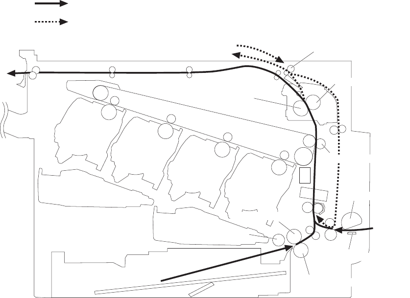
Pickup, feed, and delivery system
The pickup, feed, and delivery system uses a series of rollers to move the paper through the product.
Figure 1-30 Paper path
Duplex media path
Simplex media path
Fixing sleeve
Pressure roller
Duplex reverse roller
Cassette pickup roller
Cassette separation roller
MP tray pickup roller
MP tray separation pad
Secondary transfer roller
Cassette feed roller
40 Chapter 1 Theory of operation ENWW
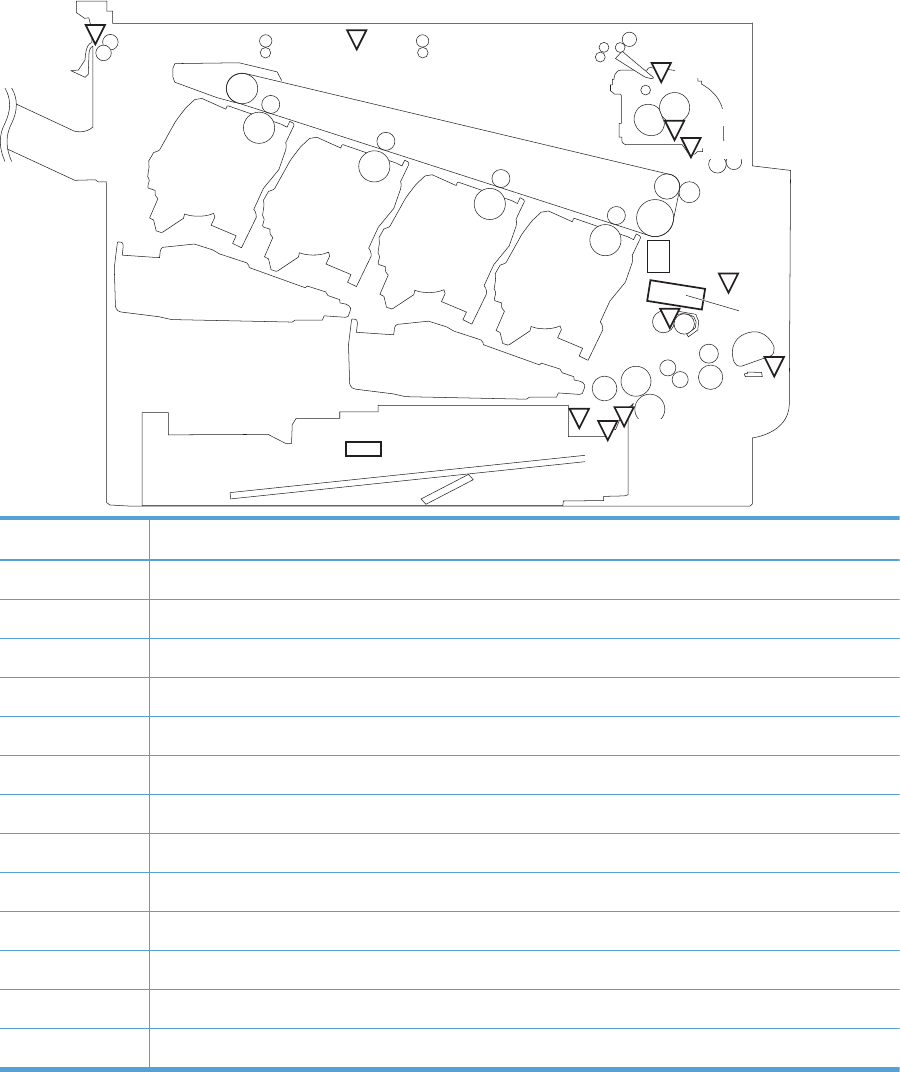
Figure 1-31 Switches and sensors for the pickup, feed, and delivery system
SW4 SR25
SR24
SR23
SR22
SR20
SR14
SR15
SR5
SR27
SR8
SR26
SR21
Abbreviation Component
SR5 Fuser delivery sensor
SR8 MP tray media presence sensor
SR14 Loop sensor 1
SR15 Loop sensor 2
SR20 Top of page (TOP) sensor
SR21 Media sensor
SR22 Duplex re-pickup sensor
SR23 Cassette-media stack-surface sensor 1
SR24 Cassette-media stack-surface sensor 2
SR25 Cassette presence sensor
SR26 IPTU media full sensor
SR27 IPTU media feed sensor
SW4 Cassette media size switch
ENWW Pickup, feed, and delivery system 41
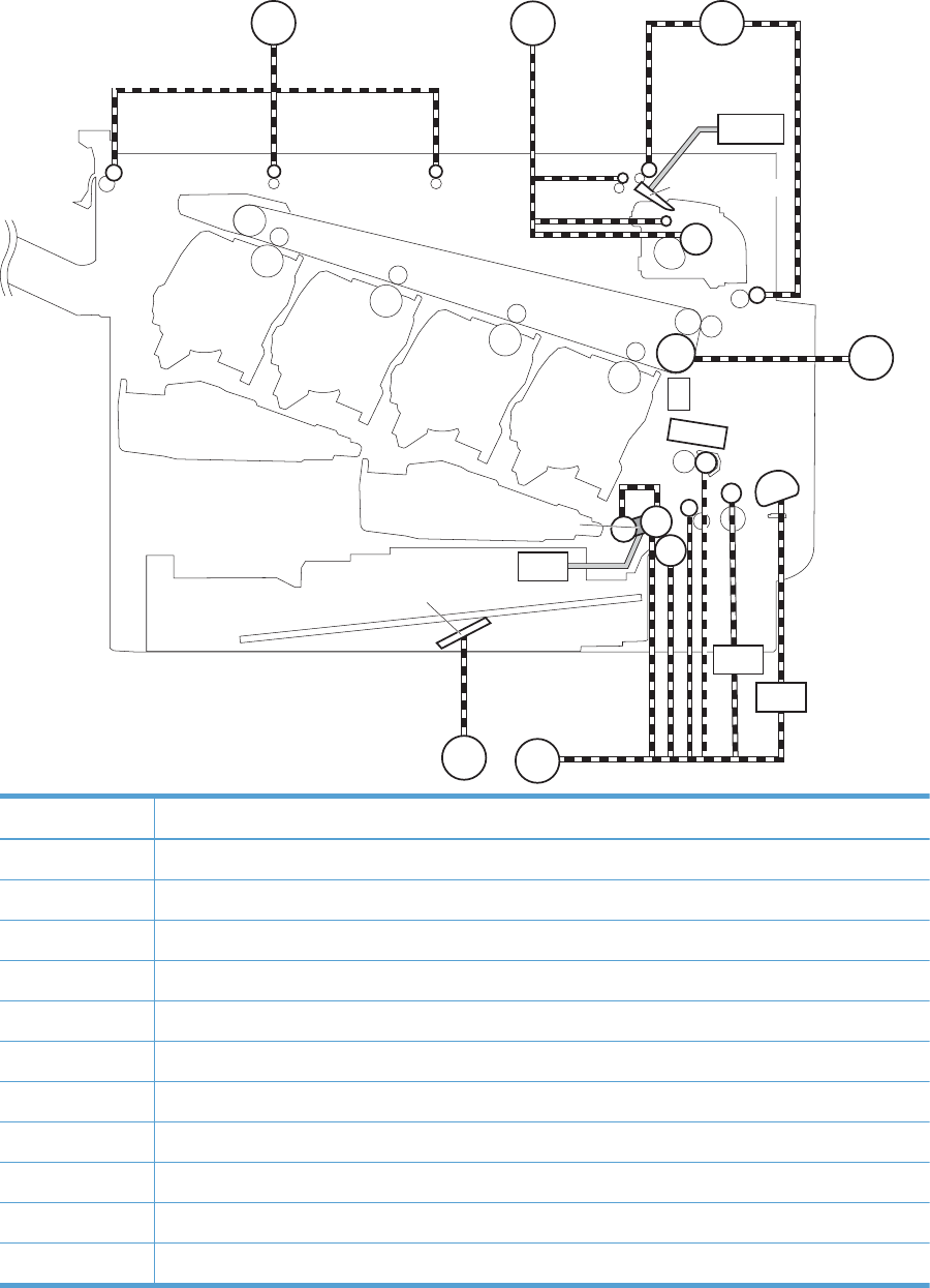
Figure 1-32 Motors and solenoids for the pickup, feed, and delivery system
SL4
SL3
CL1
M2 M11
M1
M13
M7
SL2
M14
Duplex flapper
Lifter
Pickup arm
Abbreviation Component
M1 ITB motor
M2 Fuser motor
M7 Lifter motor
M11 Duplex reverse motor
M13 Pickup motor
M14 IPTU feed motor
CL1 Duplex re-pickup clutch
SL2 Duplex reverse solenoid
SL3 Multipurpose tray pickup solenoid
SL4 Cassette pickup solenoid
CL1 Duplex re-pick clutch
42 Chapter 1 Theory of operation ENWW
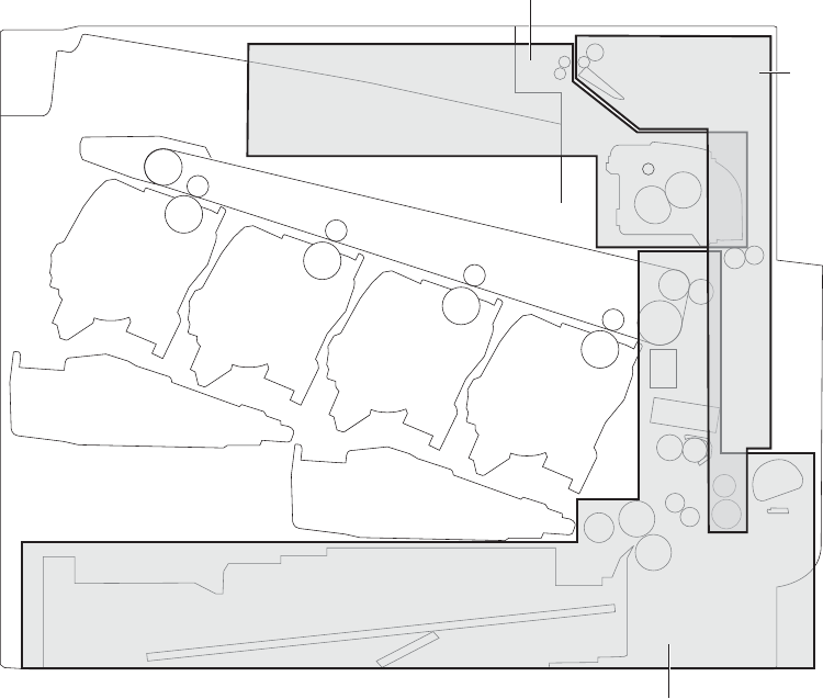
The pickup, feed, and delivery system is divided into the following three blocks:
●Pickup-and-feed block: From each pickup source to the fuser inlet
●Fuser-and-delivery block: From the fuser to the delivery destination
●Duplex block: From the duplex reverse unit to duplex re-pickup unit (for duplex models only)
Figure 1-33 Three main units of the pickup, feed, and delivery system
Pickup-and-feed block
Duplex block
Fusing-and-delivery block
ENWW Pickup, feed, and delivery system 43
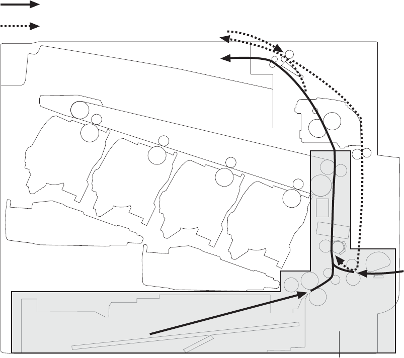
Pickup-and-feed unit
The pickup-and-feed unit picks an individual sheet of paper from the multipurpose tray or the cassettes,
carries it through the secondary-transfer unit, and feeds it into the fuser.
Figure 1-34 Pickup-and-feed unit
Pickup-and-feed block
Duplex media path
Simplex media path
Cassette pickup
The sequence of steps for the cassette-tray pickup operation is the following:
1. The product is turned on or the cassette is inserted.
2. The cassette lift-up operation raises the lifting plate so paper can be picked up.
3. The pickup motor rotates when a print command is received from the formatter.
4. The cassette pickup roller, cassette feed roller, and cassette separation roller rotate.
5. The cassette pickup solenoid turns on at a specified time.
6. The cassette pickup cam rotates.
44 Chapter 1 Theory of operation ENWW
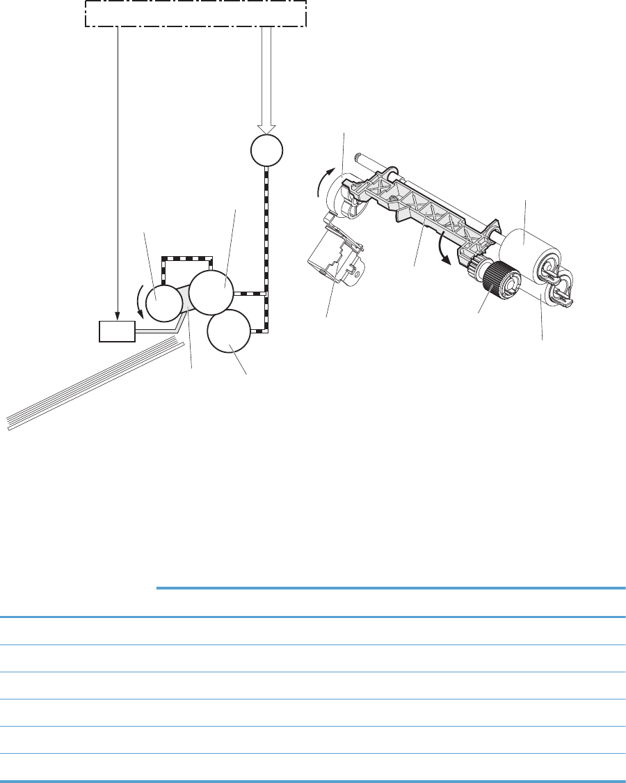
7. As the pickup arm lowers, the cassette pickup roller touches the surface of the paper stack.
8. One sheet of paper feeds into the product.
Figure 1-35 Cassette-pickup mechanism
M13
SL1
DC controller
Cassette separation roller
Cassette feed roller
Cassette pickup cam
Pickup arm
Cassette pickup roller
Pickup motor
Cassette pickup solenoid
Cassette pickup roller
Cassette feed roller
Pickup arm
Cassette pickup solenoid
Cassette separation roller
Cassette-presence detection
The product detects the size of the paper loaded in the cassette and the presence of the cassette by
monitoring the cassette media size switch. The DC controller notifies the formatter when it determines
the absence of the cassette.
Paper size Cassette media size switch
Top switch Center switch Bottom switch
Universal ON ON ON
A5 OFF OFF ON
B5 OFF ON ON
Executive ON OFF ON
Letter OFF ON OFF
A4 ON OFF OFF
ENWW Pickup, feed, and delivery system 45
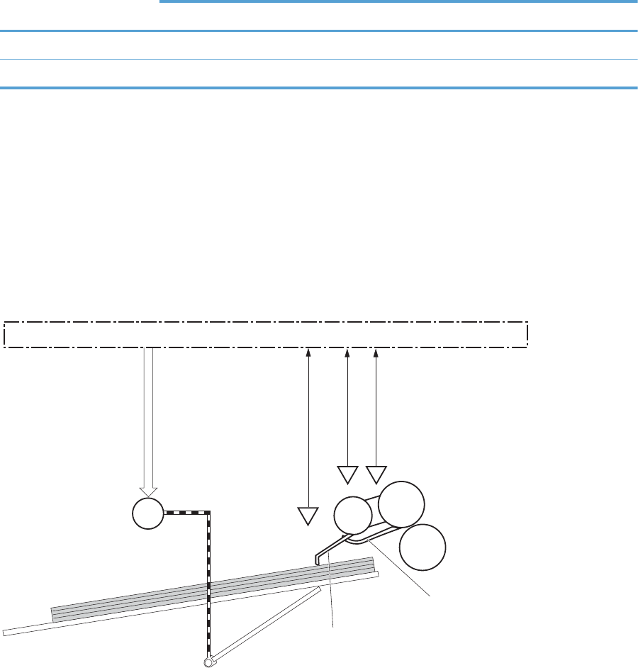
Paper size Cassette media size switch
Top switch Center switch Bottom switch
LegalONONOFF
Cassette absence OFF OFF OFF
Cassette lift operation and cassette paper-presence detection
The product keeps the paper stack surface at the correct pickup position. The cassette lift-up operation
is performed under the following conditions:
●The product is turned on
●The cassette is inserted
●The paper stack surface in the cassette lowers
Figure 1-36 Cassette lift mechanism
Lifter motor
Lifter
SR1
SR23
Cassette media presence sensor lever
Cassette media stack surface sensor lever
Lifting plate
DC controller
Cassette media
presence sensor
Cassette media stack surface sensor 1
Cassette media stack surface sensor 2
SR24
M7
The operational sequence of the cassette lift-up is as follows:
1. The lifter motor rotates and the lifter moves up.
2. When the cassette-media stack surface sensor 2 detects the stack surface of media, the lifter motor
stops.
3. The lifter motor rotates again to lift the lifter when the cassette-media stack surface sensor 1 detects
the stack surface and then lowers during printing.
When a cassette-media stack surface sensors does not detect the stack surface within a specified time
period after the lifter motor starts rotating, the DC controller determines a lifter motor failure and notifies
the formatter
46 Chapter 1 Theory of operation ENWW
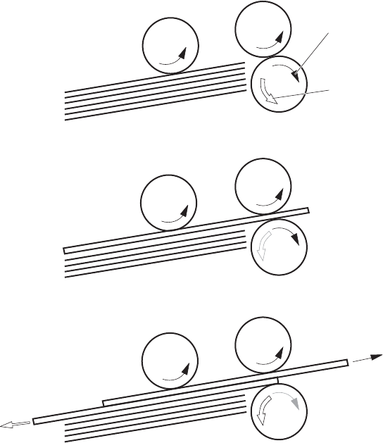
Cassette multiple-feed prevention
In the cassette, a separation roller prevents multiple sheets of paper from entering the paper path. The
cassette pickup roller drives the separation roller through a sheet of paper.
The rotation of the cassette feed roller through the sheet drives the cassette separation roller. Because it
is equipped with a torque limiter, only one sheet is fed into the product.
The low friction force between the sheets weakens the driving force from the cassette feed roller.
Therefore, the separation roller is driven by its own driving force and holds back any multiple-fed sheets
from the cassette.
Figure 1-37 Multiple-feed prevention
Cassette separation roller
follows the cassette feed roller
Driving force from
the pickup motor
Normal-feed
Multiple-feed
Print-media
Cassette pickup roller
Cassette separation roller
Cassette feed roller
Multipurpose tray pickup
The product picks up one sheet of paper from the MP tray.
The sequence of steps for the multipurpose tray pickup operation as follows:
1. The pickup motor reverses when a print command is received from the formatter.
2. When the DC controller turns on the MP tray pickup solenoid, the MP tray pickup roller rotates
and the lifting plate lifts.
ENWW Pickup, feed, and delivery system 47
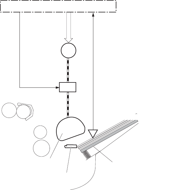
3. As the lifting plate rises, the paper is picked up.
4. The multipurpose tray separation pad removes any multiple-fed sheets, and one sheet is fed into
the product.
The MP-tray media-presence sensor (SR8) detects whether paper is present in the MP tray.
Figure 1-38 Multipurpose tray pickup mechanism
Lifting plate
MP tray pickup roller
MP tray separation pad
SL2
SR8
M13
Pickup motor
MP tray pickup solenoid
MP tray media presence sensor
DC controller
Paper feed
After the pickup operation, the paper feeds through the product and into the fuser.
1. The paper picked up from the cassette is fed to the registration unit as the pickup motor rotates.
The paper picked up from the multipurpose tray is fed to the registration unit as the pickup motor
rotates. The duplex model has the duplex feed clutch. The driving force of the pickup motor is
transmitted to the duplex re-pickup roller by turning on the clutch.
2. The registration shutter corrects the skew-feed.
3. When the TOP sensor detects the leading edge of paper, the DC controller stops the paper so that
the media sensor detects the type of paper.
4. The DC controller controls the rotational speed of the pickup motor to align the paper with the
leading edge of the toner image on the ITB.
48 Chapter 1 Theory of operation ENWW

5. The ITB motor rotates the ITB.
6. The toner image on the ITB is transferred onto the paper, and the paper is fed to the fuser.
The DC controller notifies the formatter of a paper size mismatch error when the paper length detected
by the TOP sensor does not match the paper size specified by the formatter.
Figure 1-39 Paper-feed mechanism
TOP sensor
Registration shutter
Pickup motor
SR20
Media sensor
M13
CL1
M1
ITB motor
ITB
Registration front feed roller
Duplex re-pickup roller
Duplex re-pickup clutch
DC controller
ENWW Pickup, feed, and delivery system 49
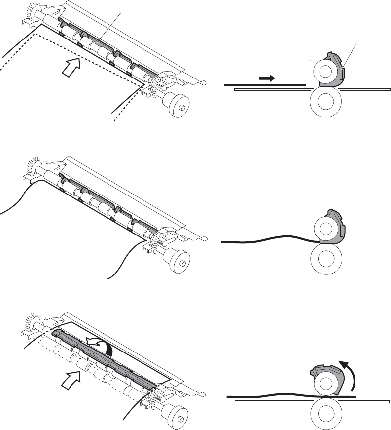
Skew-feed prevention
The product can straighten the paper without slowing the feed operation.
1. The leading edge of paper strikes the registration shutter, and the leading edge is aligned with the
shutter.
2. As the feed rollers keep pushing the paper, the paper warps.
3. When the force is great enough, the registration shutter opens, and the paper passes through and
straightens
Figure 1-40 Skew-feed prevention
Registration shutter
Paper
Registration shutter
Paper
Paper detection
The product detects the type of paper by monitoring the media sensor. The media sensor detects the
glossiness of paper by the reflected light and the thickness of paper by transmitted light. The DC
50 Chapter 1 Theory of operation ENWW

controller identifies the type of paper (for example, plain paper, light paper, heavy paper, glossy
paper, glossy film, or overhead transparency) and switches to the correct print mode. The DC controller
determines a media mismatch error and notifies the formatter under the following condition:
Simplex printing
●The specified print mode is overhead transparency (OHT), but the media sensor detects another
paper type.
●The specified print mode is not auto or OHT, but the media sensor detects OHT.
Duplex printing
●The media sensor detects OHT.
The DC controller flashes the media sensor during the initial rotation period under the following
conditions:
●The product is turned on
●The product exits Sleep mode
When the light intensity is not a specified value, the DC controller determines a media-sensor failure
and notifies the formatter.
Feed speed control
For the best print quality, the product adjusts the feed speed depending on the paper type.
Table 1-12 Print mode and feed speed
Print mode Feed speed Media sensor detection
Normal 1/1 Yes
Heavy media 1 3/4
Heavy media 2 1/2 Yes
Heavy media 3 1/3 Yes
Light media 1 1/1 Yes
Glossy media 1 1/3 Yes
Glossy media 2 1/3 Yes
Glossy media 3 1/4 Yes
Glossy film 1/4 Yes
Envelope 1/2 No
OHT 1/4 Yes
Label 1/2 No
Designated media 1 1/2 No
ENWW Pickup, feed, and delivery system 51
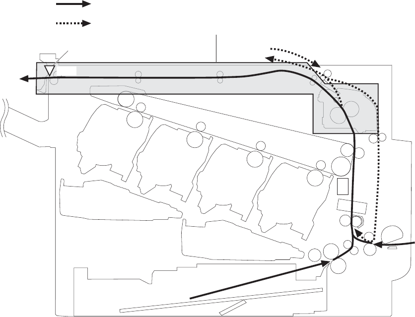
Fusing and delivery unit
The fusing and delivery unit fuses the toner onto the paper and delivers the printed page into the output
bin. The following controls ensure optimum print quality:
The face-down tray media full sensor on the output bin detects whether the tray is full of printed pages.
The DC controller notifies the formatter when the sensor is on for a specified time.
Figure 1-41 Fuser and delivery unit
Duplex media path
Simplex media path
SR26
Fusing-and-delivery block
IPTU media full sensor
Loop control
The loop control stabilizes the paper feed operation before the paper enters the fuser. If the pressure
roller rotate slower than the secondary transfer roller, the paper loop increases and an image defect or
paper crease occurs. If the pressure roller rotate faster than the secondary transfer roller, the paper
loop decreases and a vertical scanning magnification failure occurs because the pressure roller pulls
the paper.
To prevent these problems, loop sensor 1 and loop sensor 2 detect the paper loop before the paper
enters the fuser. The DC controller adjusts the rotational speed of the fuser motor according to the
output signals from the loop sensors and maintains the paper loop. Loop sensor 1 is for light media,
52 Chapter 1 Theory of operation ENWW
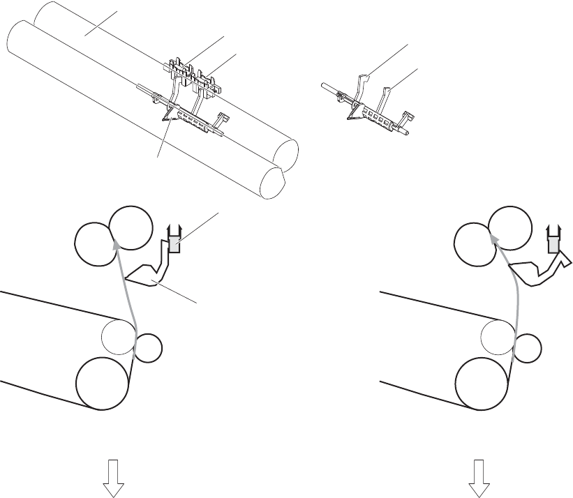
and loop sensor 2 is for heavy media. The DC controller slows the fuser motor when the sensor is off
and speeds up the sensor when the sensor is on.
Figure 1-42 Loop-control mechanism
Pressure roller
The pressure roller rotates faster
than the secondary transfer roller
Loop sensor: OFF
SR14: Loop sensor 1
SR15: Loop sensor 2
Sensor flag
ITB
Loop sensor 1,2
Secondary transfer rollerr
Pressure roller
For light media
For heavy media
Sensor flag
Sensor flag
Loop sensor: ON
The pressure roller rotates slower
than the secondary transfer roller
ENWW Pickup, feed, and delivery system 53
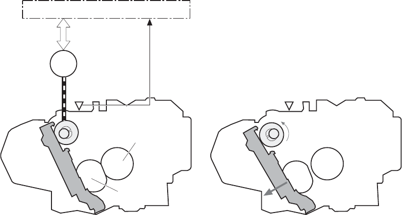
Pressure-roller pressurization control
To prevent excessive wear on the pressure roller and help with jam-clearing procedures, the pressure
roller pressurizes only during printing and standby. The DC controller reverses the fuser motor. The
fuser motor rotates the fuser pressure-release cam.
Figure 1-43 Pressure-roller pressurization control
SR7 SR7
M2
Pressure roller
DC controller
Fuser pressure release cam
Fuser motor
Pressurized Depressurized
Fuser sleeve
The pressure roller depressurizes under the following conditions:
●The product is turned off
●Any failure occurs
●During powersave mode
●When a paper jam is detected
If the DC controller does not sense the fuser pressure-release sensor for a specified period after it
reverses the fuser motor, it notifies the formatter that a fuser pressure-release mechanism failure has
occurred.
54 Chapter 1 Theory of operation ENWW
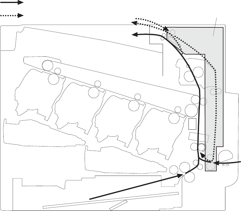
Duplexing unit
The duplexing unit reverses the paper and feeds it through the paper path to print the second side.
Figure 1-44 Duplexing unit
Duplex block
Duplex media path
Simplex media path
Duplexing reverse and feed control
The duplex reverse control reverses the paper after the first side is printed and feeds it to the duplex re-
pickup position to print the second side of the page.
1. At a specified time after the first side of a page is printed, the duplex reverse motor rotates, and
the duplex reverse solenoid is turned on.
2. The duplex flapper moves, and the paper is fed to the duplex reverse unit.
3. After a specified period of time, the duplex reverse motor is reversed, and the paper is fed to the
duplex feed unit.
4. The duplex reverse motor and the pickup motor move the paper to the duplex re-pickup position.
ENWW Pickup, feed, and delivery system 55
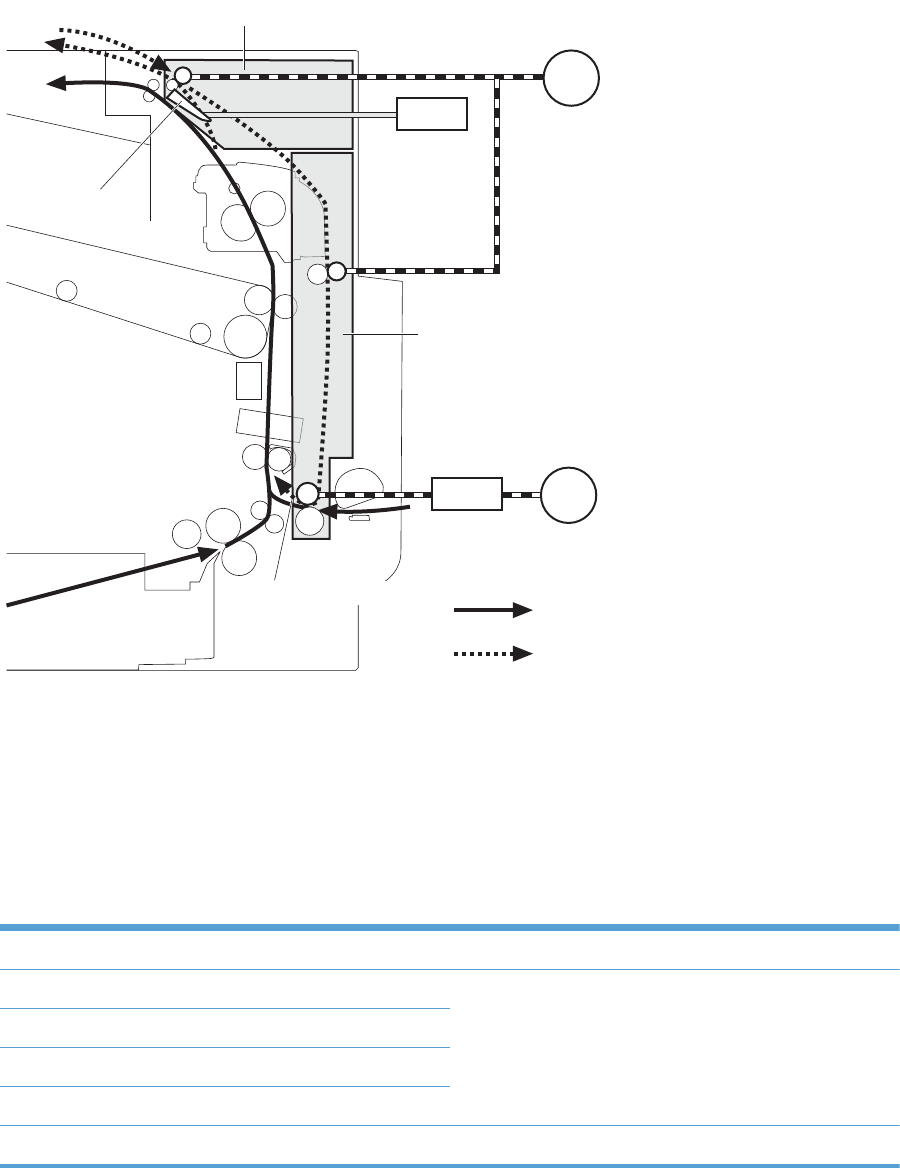
5. The duplex reverse motor and the duplex feed clutch stop, and the paper feed operation pauses.
6. After a specified period of time, the duplex reverse motor rotates, and the duplex feed clutch is
turned on. The paper is then picked up again.
Figure 1-45 Duplex reverse and feed control
Duplex media path
Simplex media path
Duplex feed unit
Duplex re-pickup position
Duplex reverse unit
Duplex reverse motor
Duplex reverse
solenoid
M13
CL1
Pickup motor
Duplex re-pickup
clutch
SL2
M11
Duplex flapper
Duplex print operation
The product has the following two duplex-media-feed modes depending on the paper sizes:
●One-sheet mode: Prints one sheet that is printed on two sides in one duplex print operation
●Two-sheet mode: Prints two sheets that are printed on two-sides in one duplex print operation
Table 1-13 Paper sizes
Paper size Duplex media feed mode
A4 One-sheet operation
Two-sheet operation
Letter
B5
Executive
Legal One-sheet operation
56 Chapter 1 Theory of operation ENWW
The formatter specifies the duplex-media-feed mode for each two-sided print job. Duplex printable
media size (A4, Letter, B5, Legal and Executive) and designated print mode (Auto, Normal, Heavy
media 1, Heavy media 2 (120 g/m2 or lighter), Glossy media 1, Glossy media 2, Glossy media 3,
Glossy film, Designated media 1, and Designated media 2) must be specified.
ENWW Pickup, feed, and delivery system 57

Jam detection
The product uses the following sensors to detect the paper as it moves through the paper path and to
report to the DC controller if the paper has jammed.
●Fuser delivery sensor (SR5)
●Top of page (TOP) sensor (SR20)
●Loop sensor 1 (SR14)
●Loop sensor 2 (SR15)
●Duplex re-pickup sensor (SR22)
●IPTU media full sensor (SR26)
NOTE: SR26 sensor is not used on products that have a stapling mailbox is installed.
●IPTU media feed sensor (SR27)
Figure 1-46 Jam detection sensors
SR22
SR20
SR14
SR15
SR5
SR27
SR26
Duplex media path
Simplex media path
The product determines that a jam has occurred if one of these sensors detects paper at an
inappropriate time. The DC controller stops the print operation and notifies the formatter.
58 Chapter 1 Theory of operation ENWW

Table 1-14 Jams that the product detects
Jam Description
Pickup delay jam The TOP sensor does not detect the leading edge of the paper within a
specified time (including two retries) after the pickup operation from the
cassette, multipurpose tray, or optional paper feeder starts.
Pickup stationary jam The TOP sensor does not detect the trailing edge of the paper within a
specified time from when it detects the leading edge.
Fuser delivery delay
jam
The fuser delivery sensor does not detect the leading edge of the paper
within a specified period after the TOP sensor detects the leading edge.
Fuser delivery
stationary jam
The fuser delivery sensor does not detect the trailing edge of the paper
within a specified period after it detects the leading edge.
Wrapping jam After detecting the leading edge of the paper, the fuser delivery sensor
detects the absence of paper, and it has not yet detected the trailing edge.
Residual paper jam One of the following sensors detects paper presence during the
initialization sequence:
●Fuser delivery sensor
●Loop sensor 1
●Loop sensor 2
One of the following sensors detects paper presence during the an
automatic delivery operation:
●Fuser delivery sensor
●TOP sensor
●Loop sensor 1
●Loop sensor 2
●Duplex re-pickup sensor
●IPTU media feed sensor
Door open jam A door is open while paper is moving through the product.
Duplexing re-pickup
jam 1
The duplex re-pickup sensor does not detect the leading edge of the paper
within a specified period after the media reverse operation starts in the
duplex reverse unit.
Duplexing re-pickup
jam 2
The TOP sensor does not detect the leading edge of the paper within a
specified period after the paper is re-picked.
IPTU delivery delay jam
1
The IPTU media feed sensor does not detect the leading edge of paper
within a specified time period after the fusing delivery sensor detects the
leading edge.
IPTU delivery delay jam
2
The IPTU media full sensor does not detect the leading edge of paper
within a specified period after the IPTU media feed sensor detects the
leading edge.
ENWW Jam detection 59

Table 1-14 Jams that the product detects (continued)
Jam Description
IPTU delivery stationary
jam 1
The IPTU media feed sensor does not detect the trailing edge of paper
within a specified period after it detects the leading edge.
IPTU delivery stationary
jam 2
The IPTU media feed sensor detects a paper absence yet it does not detect
the trailing edge of paper after it detects the leading edge.
Automatic delivery: The product automatically clears paper if the TOP sensor, duplex re-pickup sensor,
IPTU media feed sensor, or PD media feed sensors detect residual paper during initialization.
60 Chapter 1 Theory of operation ENWW
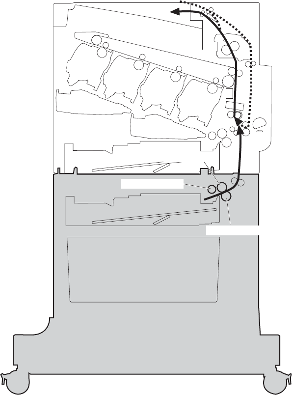
Optional paper feeders
Three types of optional paper feeders are available for the product:
●1 x 500 sheet paper feeder
●1 x 500 sheet paper feeder and cabinet
●3 x 500 paper feeder and stand
The operational sequence of the paper feeders is controlled by the paper feeder controller.
Figure 1-47 1 x 500 optional paper feeder
PD separation roller
PD feed roller
PD pickup roller
ENWW Optional paper feeders 61
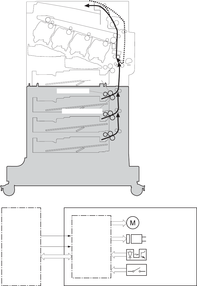
Figure 1-48 3 x 500-sheet optional paper feeder
PD feed roller
PD pickup roller
PD separation roller
Figure 1-49 Signals for the paper feeder
Paper deck
controller
Motor
Solenoid
Photointerrupter
DC controller
Switch
+24V
Paper deck
+3.3V
The input trays contain several motors, solenoids, sensors, and switches, as described in the following
table.
62 Chapter 1 Theory of operation ENWW

Table 1-15 Electrical components for the paper feeder
Component
type
Abbreviation Component name
Motors M1 PD lifter motor 1
M2 PD pickup motor
M3 PD lifter motor 2 (3 x 500-sheet paper feeder only)
M4 PD lifter motor 3 (3 x 500-sheet paper feeder only)
Solenoids SL1 PD pickup solenoid 1
SL2 PD pickup solenoid 2 (3 x 500-sheet paper feeder only)
SL3 PD pickup solenoid 3 (3 x 500-sheet paper feeder only)
Sensors SR1 Tray 3 paper surface sensor 1
SR2 Tray 3 paper surface sensor 2
SR3 Tray 3 paper present presence sensor
SR4 Tray 3 feed sensor
SR5 Tray 4 paper surface sensor 1 (3 x 500-sheet paper feeder only)
SR6 Tray 4 paper present sensor (3 x 500-sheet paper feeder only)
SR7 Tray 4 feed sensor (3 x 500-sheet paper feeder only)
SR8 Tray 4 paper surface sensor 2 (3 x 500-sheet paper feeder only)
SR9 Tray 5 paper surface sensor 1 (3 x 500-sheet paper feeder only)
SR10 Tray 5 feed sensor (3 x 500-sheet paper feeder only)
SR11 Tray 5 paper present sensor (3 x 500-sheet paper feeder only)
SR12 Tray 5 paper surface sensor 2 (3 x 500-sheet paper feeder only)
Switches SW1 PD right door switch
SW2 PD media size switch 1 (3 x 500-sheet paper feeder only)
SW3 PD media size switch 2 (3 x 500-sheet paper feeder only)
SW4 PD media size switch 3 (3 x 500-sheet paper feeder only)
Motor control
The 1 x 500-sheet paper feeder has two motors, and the 3 x 500-sheet paper feeder has four motors
for feeding paper.
Component Drives Failure
detection
PD lifter motor 1 M1 Lifter of the upper cassette No
ENWW Optional paper feeders 63
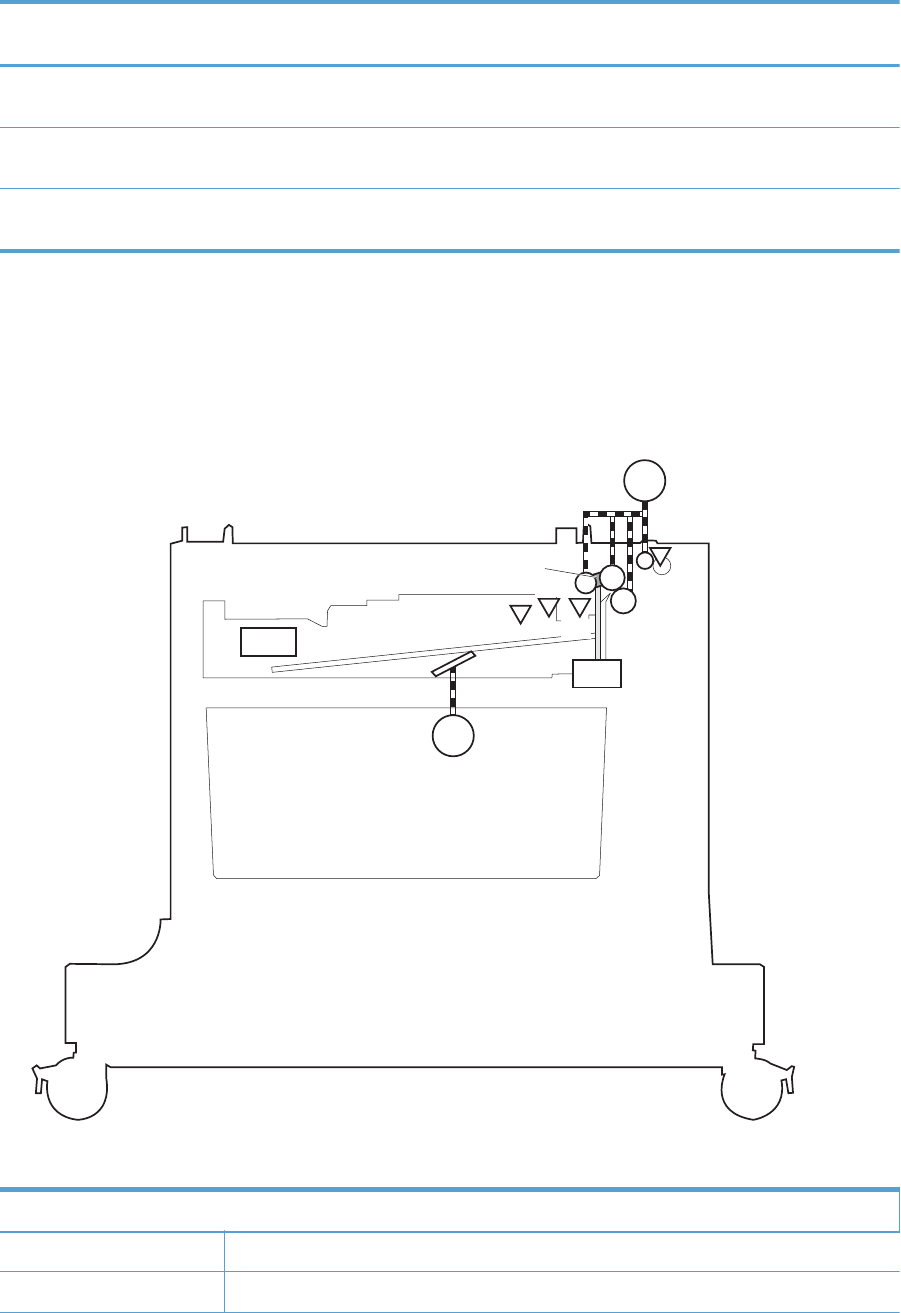
Component Drives Failure
detection
PD lifter motor 2 (3 x 500-sheet paper
feeder only)
M3 Lifter of the middle cassette No
PD lifter motor 3 (3 x 500-sheet paper
feeder only)
M4 Lifter of the lower cassette No
PD pickup motor M2 PD pickup roller, PD feed roller, and PD
separation roller
No
Paper-feeder pickup and feed operation
The paper feeder picks up one sheet from the paper-feeder cassette and feeds it to the product.
Figure 1-50 Paper-feeder pickup and feed operation
SL1
SR4
SW2
M2
M1
Pickup arm
SR3 SR1
SR2
Table 1-16 Pickup feed components (1 x 500-sheet paper feeder)
Component
M1 PD lifter motor 1
M2 PD pickup motor
64 Chapter 1 Theory of operation ENWW
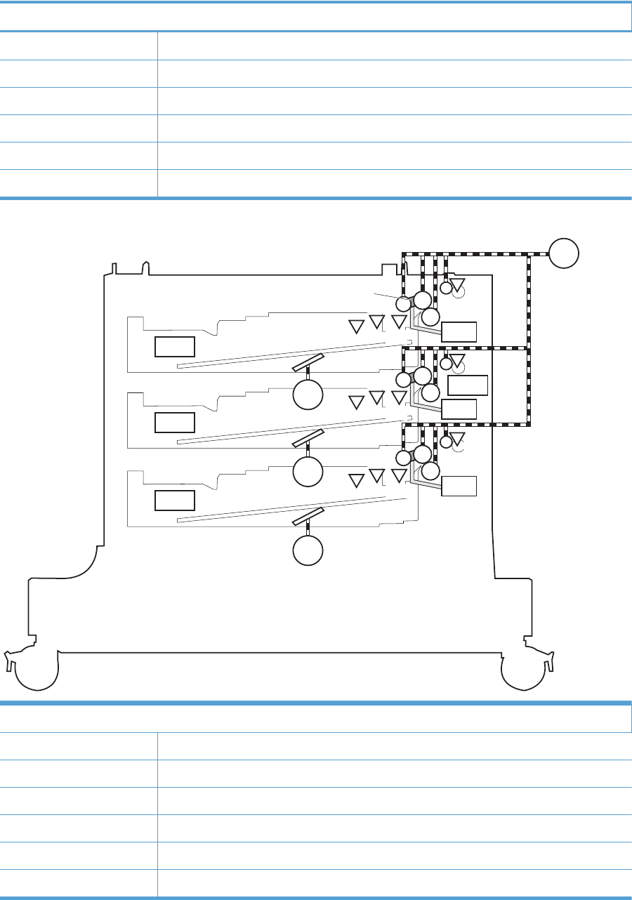
Table 1-16 Pickup feed components (1 x 500-sheet paper feeder) (continued)
Component
SL1 PD pickup solenoid 1
SR1 Tray 3 paper surface sensor 1
SR2 Tray 3 paper surface sensor 2
SR3 Tray 3 paper presence sensor
SR4 Tray 3 paper present sensor
SW2 Tray 3 paper size switches
SL1
SL2
SL3
SR4
SW2
M2
M1
Pickup arm
SR3 SR1
SR2
SR7
SW3
M3
SR6 SR5
SR8
SR10
SW4
M4
SR11 SR12
SR9
SW1
Components
M1 PD lifter motor 1
M2 PD pickup motor
M3 PD lifter motor 2 (3 x 500-sheet paper feeder only)
M4 PD lifter motor 3 (3 x 500-sheet paper feeder only)
SL1 PD pickup solenoid 1
SL2 PD pickup solenoid 2
ENWW Optional paper feeders 65

SL3 PD pickup solenoid 3
SR1 Tray 3 paper surface sensor 1
SR2 Tray 3 paper surface sensor 2
SR3 Tray 3 paper presence sensor
SR4 Tray 3 paper presence sensor
SR5 Tray 4 paper surface sensor 1 (3 x 500-sheet paper feeder only)
SR6 Tray 4 paper surface sensor 2 (3 x 500-sheet paper feeder only)
SR7 Tray 4 feed sensor (3 x 500-sheet paper feeder only)
SR8 Tray 4 media-stack-surface sensor (3 x 500-sheet paper feeder only)
SR9 Tray 5 paper surface sensor 1 (3 x 500-sheet paper feeder only)
SR10 Tray 5 feed sensor (3 x 500-sheet paper feeder only)
SR11 Tray 5 paper present sensor (3 x 500-sheet paper feeder only)
SR12 Tray 5 media-stack-surface sensor (3 x 500-sheet paper feeder only)
SW1 Tray 3, 4, and 5 right door switch
SW2 Tray 3 paper size switches (3 x 500-sheet paper feeder only)
SW3 Tray 4 paper size switches (3 x 500-sheet paper feeder only)
SW4 Tray 5 paper size switches (3 x 500-sheet paper feeder only)
Paper-size detection and cassette-presence detection
The paper feeder detects the size of paper loaded in the paper feeder and the presence of the cassette
using the PD media size switch.
Paper size Paper-feeder cassette media-size switch settings
Top switch Center switch Bottom switch
Universal On On On
A5 Off Off On
B5 Off On On
Executive On Off On
Letter Off On Off
A4 On Off Off
Legal On On Off
No cassette Off Off Off
66 Chapter 1 Theory of operation ENWW
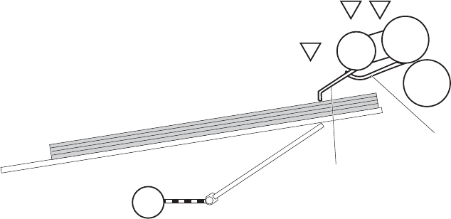
Paper-feeder cassette lift operation
The paper feeder keeps the paper stack surface at the correct pickup position. The cassette lift
operation occurs under the following conditions:
●The product is turned on.
●The cassette is inserted.
●The paper stack surface of the cassette lowers.
The sequence occurs as follows:
1. The PD lifter motor rotates and the lifter moves up.
2. When the tray media-stack-surface sensor detects the stack surface of the paper, the PD lifter motor
stops.
3. The PD lifter motor rotates again to lift the lifter when the PD cassette media-stack-surface sensor
detects the stack surface, and then lowers during printing.
If a tray media-stack-surface sensor does not detect a stack surface within a specified period after the
PD lifter motor starts rotating, the paper feeder driver determines that the PD lifter motor has failed and
through the DC controller notifies the formatter.
Figure 1-51 Paper-feeder cassette lift
PD lifter motor
Lifter
SR3/SR6/SR11
SR1/SR5/SR12
PD cassette media presence sensor lever
PD cassette media stack surface sensor lever
Lifting plate
PD cassette media presence sensor
SR2/SR8/SR9
M
PD cassette media stack surface sensor 1
M1/M3/M4
PD cassette media stack surface sensor 2
The paper-feeder driver notifies the formatter if either of the paper-feeder media-stack surface sensors
fails to detect the stack surface within a specified period from when a lift-up operation starts.
ENWW Optional paper feeders 67
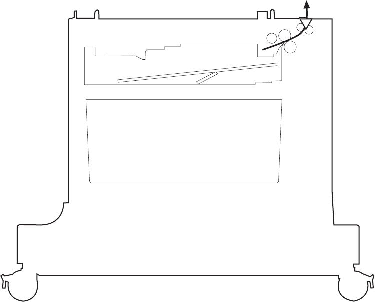
Paper feeder jam detection
The 1 x 500-sheet paper feeder uses the Tray 3 paper presence sensor (SR4) to detect the presence of
paper and to check whether paper has jammed.
Figure 1-52 Jam detection (1 x 500-sheet paper feeder)
SR4
The 1 x 500-sheet paper feeder detects the following jams:
●1 x 500-sheet PD pickup delay jam: Tray 3 feed sensor does not detect the leading edge of paper
within a specified time (including two retries) after the pickup operation starts.
●1 x 500-sheet PD pickup stationary jam: Tray 3 feed sensor does not detect the trailing edge of
paper within a specified time after the sensor detects the leading edge.
●1 x 500-sheet PD residual paper jam: Tray 3 feed sensor detects the presence of paper for a
specified time during an automatic delivery operation.
The 3 x 500-sheet paper feeder uses the following sensors to detect the presence of paper and to check
whether paper has jammed.
●Tray 3 paper presence sensor (SR4)
●Tray 4 feed sensor (SR7)
●Tray 5 feed sensor (SR10)
68 Chapter 1 Theory of operation ENWW
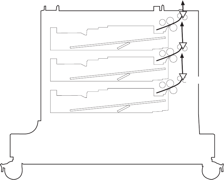
Figure 1-53 Jam detection (3 x 500-sheet paper feeder)
SR4
SR7
SR10
The 3 x 500-sheet paper feeder detects the following jams:
●3 x 500-sheet PD pickup delay jam: One of the tray feed sensors does not detect the leading edge
of paper within a specified time (including two retries) after the pickup operation starts.
●3 x 500-sheet PD pickup delay jam 2: Tray 3 feed sensor does not detect the leading edge of
paper within a specified time (including two retries) after the pickup operation starts.
●3 x 500-sheet PD pickup stationary jam 1: Tray 4 or 5 feed sensors do not detect the trailing edge
of paper within a specified time after the sensor detects the leading edge.
●3 x 500-sheet PD pickup stationary jam 2: Tray 3 feed sensor does not detect the trailing edge of
paper within a specified time after the sensor detects the leading edge.
●3 x 500-sheet PD residual paper jam: Tray 3, 4, or 5 feed sensors detect the presence of paper
for a specified time during an automatic delivery operation.
●3 x 500-sheet PD door open jam: The door is open during paper feed operation.
ENWW Optional paper feeders 69
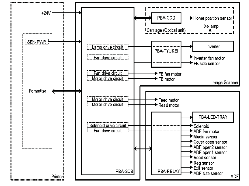
Document feeder/scanner assembly
The document feeder/scanner assembly consists of a document feeder and flatbed scanner. The
document feeder can feed 50 pages of letter or A4 size paper at speeds up to 57 images per minute in
simplex and 24 images per minute in duplex. The document feeder features legal size detection and
customer replaceable feed and separation rollers and pads. The flatbed scanner also includes legal
detection and does not require a scanner lock for transport. The sensors and motors in both the
document feeder and flatbed scanner are controlled and monitored by the SCB that is located on the
rear of the flatbed scanner. The copy process board (CPB) is integrated on the formatter. Image data is
sent to the formatter through the scanner cable connected to the interconnect board (ICB).
Scanner subsystem
Figure 1-54 Scanner subsystem
The scan control board (SCB), located on the rear of the scanner, provides control of both the scanner
and document feeder components. The scanner power supply—located on the rear of the printer above
the DCC—provides a +24v current. The formatter supplies a 3.3v current to keep sensors energized
while the +24v current is turned off during Sleep. The optical unit contains a Xenon lamp that is driven
by a fan-cooled inverter power supply.
70 Chapter 1 Theory of operation ENWW

The relay PCA in the document feeder provides connections only to the various components such as
fans, motors, and sensors. The control and monitoring of these components takes place on the SCB.
Document feeder/scanner motor and fan control
Component Purpose Type Rotation Timing Failure
detection
Carriage motor Drives the carriage Step motor Clockwise Initializing No
Clockwise Scanning mono No
Clockwise Scanning color No
Counterclockwise Return No
Feed motor Drives the pick,
separation, and
registration rollers
Step motor Counterclockwise Separation No
Clockwise Feeding No
Clockwise Scanning mono
(600 x 300)
No
Clockwise Scanning mono
(600 x 600)
No
Clockwise Scanning color
(600 x 300)
No
Clockwise Scanning color
(600 x 600)
No
Read motor Drives the feed
and delivery rollers
Step motor Counterclockwise Scanning mono
(600 x 300)
No
Counterclockwise Scanning mono
(600 x 600)
No
Counterclockwise Scanning color
(600 x 300)
No
Counterclockwise Scanning color
(600 x 600)
No
Clockwise Switch back for
duplex scanning
No
Scanner fan Cools the lamp
and CCD
DC motor Clockwise Turns on when
lamp is on
Yes
Document feeder
fan
Cools the motor
and solenoid
DC motor Clockwise Feeding originals Yes
Inverter fan Cools the inverter DC motor Clockwise Turns on when
lamp is on
Yes
ENWW Document feeder/scanner assembly 71
Legal detection sensor sequence
The legal detection status displays in the following circumstances:
●Document feeder legal detection:
◦When the document feeder legal sensor is turned on.
●Flatbed legal detection:
◦When the flatbed legal sensor is turned on while the flatbed angle sensor is opened.
◦When the flatbed angle sensor is closed but the flatbed legal sensor is turned on.
Fan timing sequence
Fan activated timing
Fans are activated as follows:
●The image scanner fan is activated when the carriage motor or lamp is turned on.
●The document feeder fan is activated when the feed motor or read motor is activated.
●The inverter fan is activated when the carriage motor or lamp is activated.
Fan lock failure detection
The scanner, document feeder, and inverter fans have the following failure detection features:
●The fan is turned on. After 5 seconds, the scanner controller begins observing the fan lock signal.
●The fan fails in an error condition. After 5 seconds, the lock condition is detected.
●The scanner completes the job even if the scanner recognizes errors during the job.
●After completing the job, the scanner shifts to the error status and transfers the failure information
to the formatter.
72 Chapter 1 Theory of operation ENWW
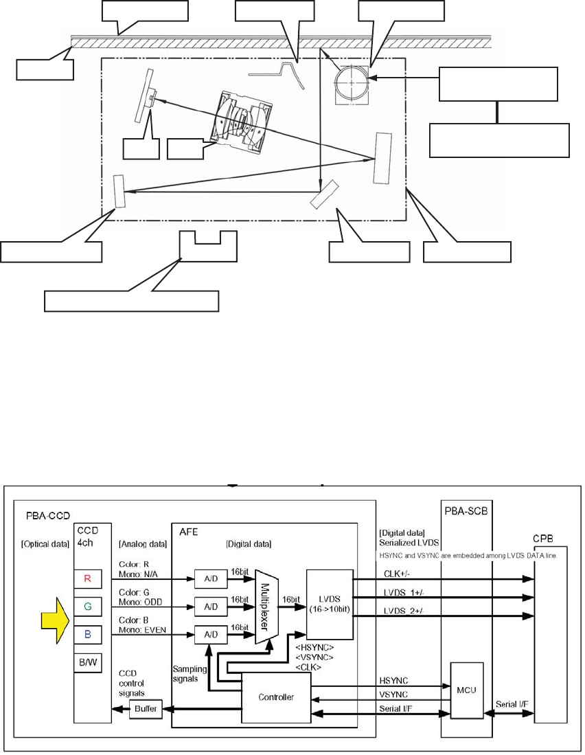
Optical assembly operation
Figure 1-55 Optical assembly operation
Document
Glass
Second mirror First mirror Third mirror
Carriage home position sensor
Inverter circuit
CPU
Scanner controller
CCD Lens
Reflector Scanner lamp
The optical assembly contains the lamp, mirrors, lens, and charge-coupled device (CCD). As the optical
assembly moves across the original, the lens focuses the reflected image onto the CCD. The optical
assembly home position is detected by the carriage home position sensor. During document feeder
copying, the optical assembly remains near the home position and the product moves the paper across
the document feeder glass strip.
Image data path
Figure 1-56 Image data path
The product transfers the analog data produced by the CCD/image sensor to the analog front end
(AFE), which is a PCA that converts this information to digital form. The digital data exits the scanner
assembly and then passes through the scan control board (SCB) to the copy processor board (CPB),
which is located on the formatter.
ENWW Document feeder/scanner assembly 73
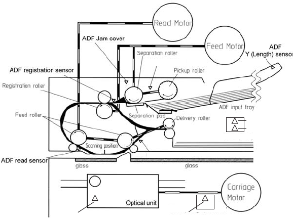
Document feeder/scanner paper path and sensors
Figure 1-57 Document feeder/scanner paper path and sensors
ADF paper present
ADF sensor
Delivery Tray
Carriage Home Position sensor FB Y (length) sensor
FB cover angle sensor
FB cover sensor
Jam detection sequence
1. A jam error occurs in the document feeder.
2. The feed and read motors stop immediately.
3. The error bit of the scanner status is set. The status information is sent to the CPB.
4. Document feeder operation is terminated.
5. The error bit is held until the jam is cleared.
Clearing a jam
1. Open the jam-access cover and then remove the paper.
2. After the jam-access cover is closed, the error bit is cleared if the sensors detect no media.
Document feeder jam detection
1. After initialization or after the jam-access cover is opened and then closed, the registration sensor,
read sensor, or exit sensor are checked for residual paper.
2. The paper did not reach the registration sensor within the standard time. After feeding paper from
the input tray, paper is transferred. The motor is stopped if the registration sensor does not detect
paper. The motor reverses and attempts to refeed the paper. A pick error occurs if the registration
sensor continues to fail to detect paper after the refeed attempt. If there is paper ahead of jammed
paper in the paper path, the pick error occurs after the preceding paper is scanned and ejected.
3. Document feeder sensors detect errors in the following situations:
74 Chapter 1 Theory of operation ENWW

Sensor Description
Registration sensor A jam is detected when the registration sensor does not
detected the leading edge of paper when turning paper
over during the duplexing process.
A jam is detected when the registration sensor does not
detected the trailing edge of paper.
Read sensor A jam is detected when the read sensor does not detected
the leading edge of paper.
A jam is detected when the read sensor does not detected
the trailing edge of paper.
Exit sensor A jam is detected when the exit sensor does not detected
the leading edge of paper.
A jam is detected when the exit sensor does not detect the
trailing edge of paper.
4. Jam-access cover open jam: A jam error occurs if the jam cover is opened while paper is being
fed through the document feeder.
5. Document feeder open jam: A jam error occurs if the document feeder is open while a paper is
being fed through the document feeder.
Document feeder pick mechanism
1. The pickup-roller picks up a page from the input tray.
2. If multiple pages are picked up, the separation roller and separation pad separates them to
prevent feeding of multiple pages.
3. After the page reaches the registration sensor, the pickup and separation rollers stop and
registration and read rollers start.
ENWW Document feeder/scanner assembly 75
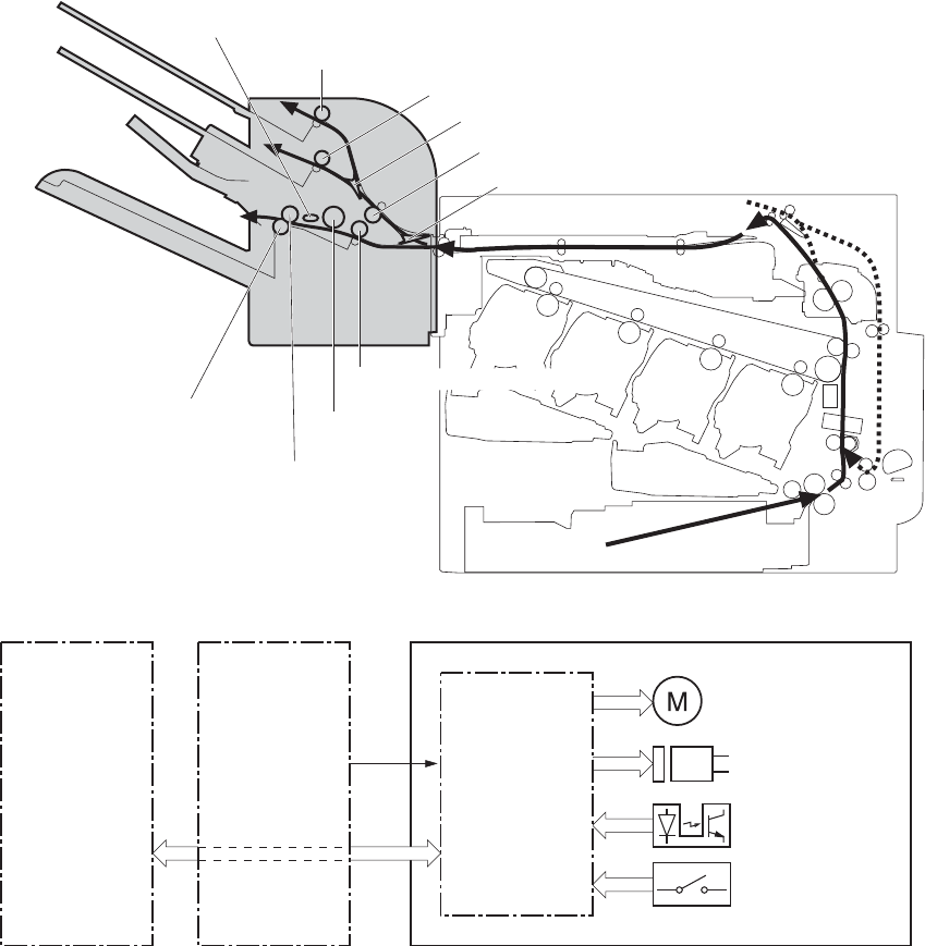
3-bin stapling mailbox
The 3-bin stapling mailbox installs on the delivery assembly and delivers paper to the output bin. The 3-
bin stapling mailbox has two modes:
●Stacker mode
●Mailbox/job separator mode
Stapling is available for both modes.
Figure 1-58 3-bin stapling mailbox
Output bin 1 delivery roller
Output bin 2 delivery roller
Output bin flapper
Stapler/Stacker feed roller 1
Inlet flapper
Alignment roller
Output bin 3 upper delivery roller
Stapler/Stacker feed roller 2
Stamp
Output bin 3 lower delivery roller
Figure 1-59 Signals for the 3-bin stapling mailbox
Stapler/Stacker
controller
Motor
Solenoid
Photointerrupter
DC controller
Switch
+24V
Stapler/Stacker
Formatter
The 3-bin stapling mailbox contains several motors, solenoids, sensors, and switches.
76 Chapter 1 Theory of operation ENWW

Table 1-17 Electrical components for the 3-bin stapling mailbox
Component
type
Abbreviation Component name
Motors M1 Stapler motor
M3 Jogger motor
M4 Paddle motor
M5 Stapler/Stacker feed motor
M6 Stapler/Stacker lifter motor
Solenoids SL1 Stamp solenoid
SL2 Inlet solenoid
SL3 Output bin solenoid
Sensors SR1 Output bin 3 delivery sensor
SR2 Stapler/Stacker media feed sensor 1
SR3 Output bin 3 media full sensor
SR4 Alignment roller sensor
SR5 Stapler/Stacker media feed sensor 2
SR6 Jogger sensor
SR7 Output bin 3 upper delivery roller sensor
PS2501 Output bin 1 media presence sensor
PS2502 Output bin 2 media full sensor
PS2503 Output bin 2 media presence sensor
PS2504 Output bin 1 media full sensor
PS2601 Output bin 3 higher limit sensor
PS2602 Output bin 3 lower limit sensor
Stapler sensor
Staple presence sensor
Staple ready sensor
Switches SW1 Stapler/Stacker door switch
ENWW 3-bin stapling mailbox 77
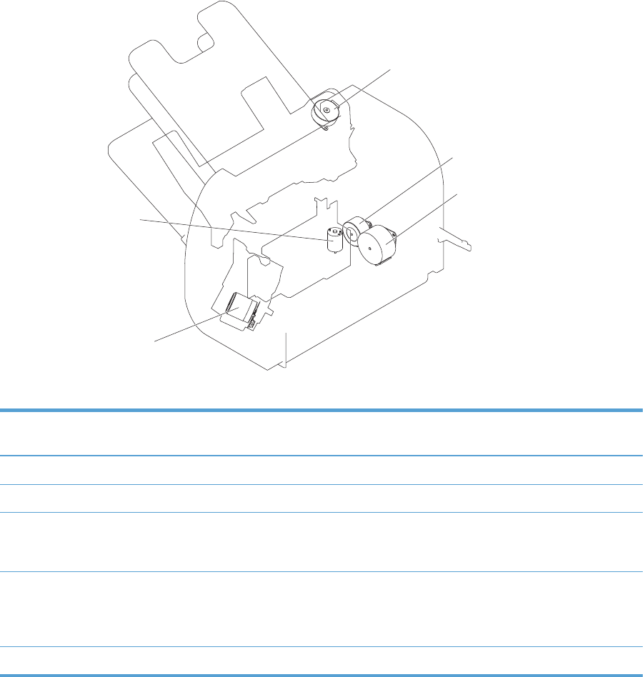
Motor control
Stapler/Stacker lifter motor
Stapler motor
Jogger motor
Paddle motor
Stapler/Stacker feed motor
The 3-bin stapling mailbox has five motors for paper feed, paper delivery, and staple operation.
Component Drives Failure
detection
Stapler motor M1 Stapler Yes (type 2)
1
Jogger motor M3 Jogger guide Yes (type 2)
Paddle motor M4 Alignment roller, disengagement of the
alignment roller, and disengagement of
the output bin 3 lower delivery roller
Yes (type 2)
Stapler/Stacker feed motor M5 Stapler/Stacker feed roller, Stapler/
Stacker delivery roller, output bin 3
upper delivery roller, and the output bin
3 lower delivery roller
No
When the motor
fails a jam occurs.
Stapler/Stacker lifter motor M6 Output bin 3 Yes (type 2)
1
There are two methods for detecting motor failure. Type 1 detects failure by monitoring the motor. Type 2 detects failure by
monitoring a related part of the motor.
78 Chapter 1 Theory of operation ENWW
Failure detection
The controller detects a motor failure by monitoring a part related to the motor. If the controller
determines a motor failure or motor-related part failure, it notifies the formatter when it encounters the
following conditions:
●Stapler motor: The stapler sensor is not sensed for a specified period of time after the stapler motor
starts rotating.
●Jogger motor: The jogger sensor is not sensed for a specified period of time after the jogger motor
starts rotating.
●Paddle motor: The output bin 3 upper delivery roller sensor is not sensed for a specified period of
time after the paddle motor is rotated. The alignment roller sensor is not sensed for a specified
period of time after the paddle motor is reversed.
●Stapler/Stacker lifter motor: The output bin 3 higher limit sensor or output bin 3 media full sensor
is not sensed for a specified period of time after the stapler/stacker lifter motor is rotated. The
output bin 3 higher limit sensor, output bin 3 lower limit sensor, or output bin 3 media full sensor is
not sensed for a specified period from when the stapler/stacker lifter motor is reversed.
ENWW 3-bin stapling mailbox 79
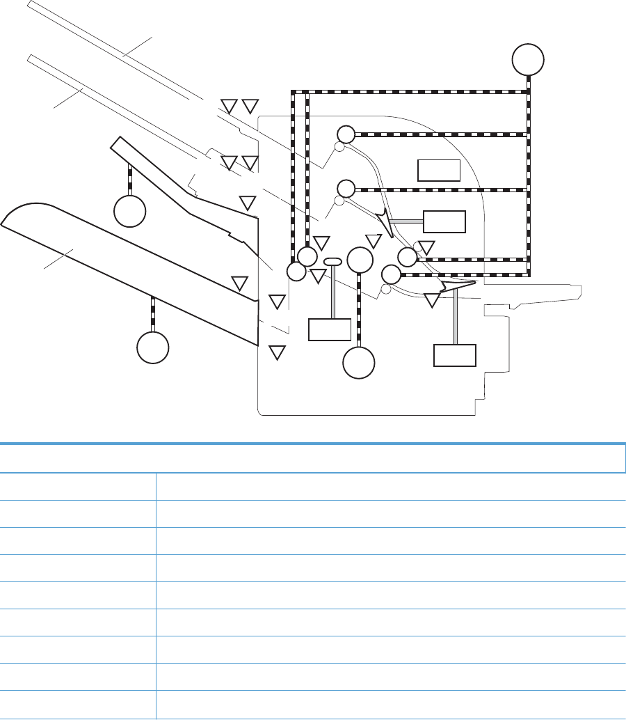
Delivery operation
The 3-bin stapling mailbox has two modes.
●Stacker mode: The printed page is delivered to output bin 3 first and then delivered to the
subsequent output bins.
●Mailbox/job separator mode: The printed page is delivered to the specified output bin for each
print job.
Figure 1-60 3-bin stapling mailbox delivery operation
SL3
SL2
SL1
SR2
SR1
SR5
SW1
M5
M6
M3
M4
SR4
PS2502
PS2503
PS2504
PS2501
SR3
PS2601
PS2602
SR7
SR6
Output bin 1
Output bin 2
Output bin 3
Table 1-18 Delivery components (3-bin stapling mailbox)
Component
M1 Stapler motor
M3 Jogger motor
M4 Paddle motor
M5 Stapler/Stacker feed motor
M6 Stapler/Stacker lifter motor
SL1 Stamp solenoid
SL2 Inlet solenoid
SL3 Output bin solenoid
SR1 Output bin 3 delivery sensor
80 Chapter 1 Theory of operation ENWW

Table 1-18 Delivery components (3-bin stapling mailbox) (continued)
Component
SR2 Stapler/Stacker media feed sensor 1
SR3 Output bin 3 media full sensor
SR4 Alignment roller sensor
SR5 Stapler/Stacker media feed sensor 2
SR6 Jogger sensor
SR7 Output bin 3 upper delivery roller sensor
PS2501 Output bin 1 media presence sensor
PS2502 Output bin 2 media full sensor
PS2503 Output bin 2 media presence sensor
PS2504 Output bin 1 media full sensor
PS2601 Output bin 3 higher limit sensor
PS2602 Output bin 3 lower limit sensor
Stapler sensor
Staple presence sensor
Staple ready sensor
SW1 Stapler/Stacker door switch
Staple operation
The staple operation staples 2 to 30 sheets of printed pages together into one set and then delivers it to
the output bin 3. This staple operation is available for both stacker mode and mailbox/job separator
mode.
The staple sequence is as follows:
1. The stapler/stacker controller rotates the paddle motor to disengage the output bin 3 upper
delivery roller from the output bin 3 lower delivery roller.
ENWW 3-bin stapling mailbox 81
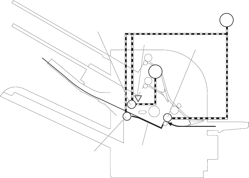
2. The printed page from the product is fed to the staple tray.
Figure 1-61 3-bin stapling mailbox stapler operation (1 of 4)
Output bin 3 upper delivery roller
Staple tray
Stapler/Stacker feed roller 2
Output bin 3 lower delivery roller
M4
M5
Stapler/Stacker feed motor
Paddle motor
SR7
Output bin 3 delivery roller sensor
The controller determines an output bin 3 upper delivery roller failure and notifies the formatter
through the DC controller when it does not detect the output bin 3 upper delivery roller sensor for
a specified period after the paddle motor starts rotating.
82 Chapter 1 Theory of operation ENWW
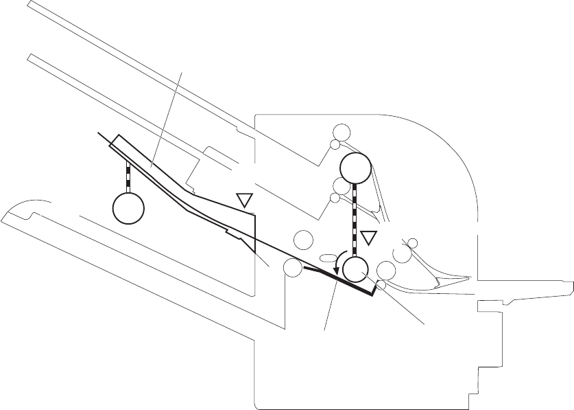
3. The printed page on the staple tray is aligned. For horizontal alignment, the jogger motor rotates
and moves the jogger guide. For vertical alignment, the paddle motor is reversed and the
alignment roller pushes the page.
Figure 1-62 3-bin stapling mailbox stapler operation (2 of 4)
M4
M3
SR4
SR6
Alignment roller
Paddle motor
Alignment roller sensor
Jogger sensor
Jogger guide
Jogger motor
Staple tray
The controller determines a paddle motor failure and notifies the formatter through the DC
controller when it does not detect the alignment roller sensor for a specified period after the
paddle motor starts rotating.
4. After alignment, the stamp solenoid is driven and the stamp holds the page.
5. Step 1 to 4 repeat for a specified number of pages.
ENWW 3-bin stapling mailbox 83
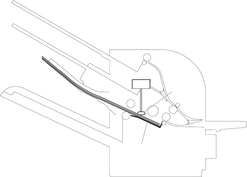
6. After all of the pages are aligned, the pages are stapled together while being held with the stamp.
Figure 1-63 3-bin stapling mailbox stapler operation (3 of 4)
SL1
Stamp
Stamp solenoid
Staple tray
7. The paddle motor rotates, and the output bin 3 upper delivery roller touches the stapled pages.
8. The stapler/stacker feed motor rotates to rotate the output bin 3 upper delivery roller and the
output bin 3 lower delivery roller. Accordingly, the set of printed-pages is delivered to output bin
3.
84 Chapter 1 Theory of operation ENWW
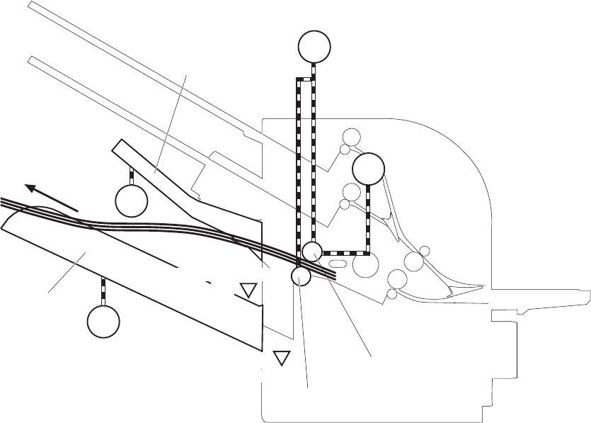
9. The stapler/stacker feed motor starts rotating while the jogger motor is reversed and the jogger
guide moves to its home position.
Figure 1-64 3-bin stapling mailbox stapler operation (4 of 4)
Paddle motor
Output bin 3 upper delivery roller
Output bin 3 lower delivery roller
M4
Stapler/Stacker feed motor
M5
Output bin 3 SR3
Output bin 3 media full sensor
M3
Jogger guide
Jogger motor
M6
PS2602
Stapler/Stacker lifter motor
Output bin 3 lower limit sensor
The output bin 3 media full sensor on output bin 3 detects whether the bin is full. The stapler/
stacker controller determines that the media stack surface is high and reverses the stapler/stacker
lifter motor to lower output bin 3 when the output bin 3 media full sensor is on for a specified
period. If the output bin 3 lower limit sensor is turned on at this time, the stapler/stacker controller
determines an output bin 3 media full and notifies the formatter through the DC controller.
The stapler/stacker controller determines a jogger motor failure and notifies the formatter through
the DC controller when it does not detect the jogger sensor for a specified period after the jogger
motor starts rotating.
ENWW 3-bin stapling mailbox 85
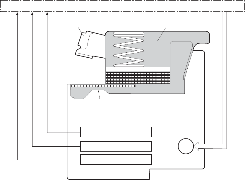
Stapler
The stapler consists of the staple cartridge and the stapler assembly. The staple cartridge holds up to
5,000 staples. The staple presence sensor detects the presence of staple. The staple ready sensor
detects whether the stapler is in the correct position to staple. The staple assembly is equipped with the
stapler motor. When the stapler/stacker controller rotates the stapler motor, the staple arm lowers and
staple operation begins. The stapler sensor detects the position of the staple arm.
Figure 1-65 3-bin stapling mailbox sensors for the stapler
M1
Staple cartridge
Staple
Staple unit
Staple arm
Stapler motor
Stapler sensor
Staple presence sensor
Staple ready sensor
Stapler/Stacker controller
The stapler/stacker controller determines a stapler motor failure and notifies the formatter through the
DC controller when it does not detect the stapler sensor for a specified period after the stapler motor
starts rotating. The stapler/stacker controller determines a stapler jam and notifies the formatter through
the DC controller if it senses the stapler sensor after a specified period of time from when the stapler
motor starts rotating and then if the stapler sensor recovers within a specified period of time from when
the stapler motor is reversed.
86 Chapter 1 Theory of operation ENWW
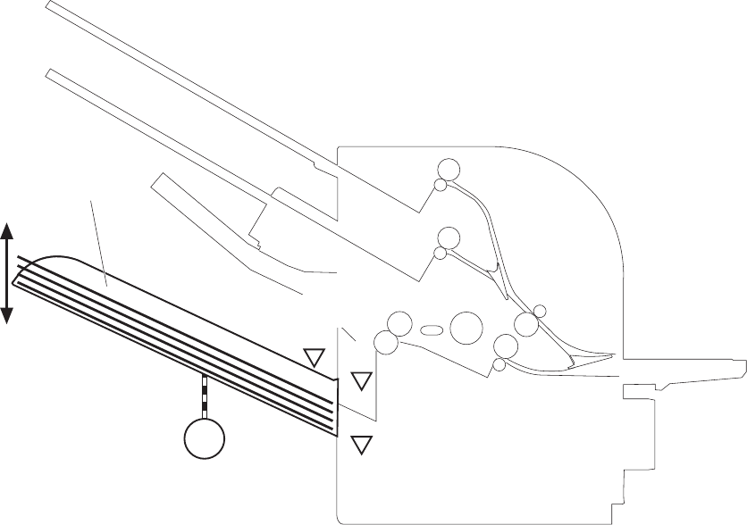
Output bin 3 lift operation
Figure 1-66 3-bin stapling mailbox sensors for output bin 3 lift operation
M6
SR3
PS2601
PS2602
Stapler/Stacker lifter motor
Output bin 3 higher limit sensor
Output bin 3 lower limit sensor
Output bin 3
media full sensor
Output bin 3
The operational sequence of the output bin 3 lift operation is as follows:
1. The stapler/stacker lifter motor rotates if both the output bin 3 higher limit sensor and the output
bin 3 media full sensor are off when the product is turned on until following conditions occur:
●The output bin 3 higher limit sensor detects the output bin 3.
●The output bin 3 media full sensor detects paper.
The stapler/stacker lifter motor is reversed if either the output bin 3 higher limit sensor or the
output bin 3 media full sensor is on, or if both sensors are on when the product is turned on to
lower the output bin 3 to a specified level.
2. When the printed pages are stacked on the output bin 3, and the output bin 3 media full sensor
detects the paper, the stapler/stacker lifter motor is reversed to lower the output bin 3 to a
specified level.
3. The stapler/stacker controller notifies the formatter through the DC controller when the output bin 3
media full sensor detects paper. The output bin 3 lowers to the position of the output bin 3 lower
limit sensor.
ENWW 3-bin stapling mailbox 87
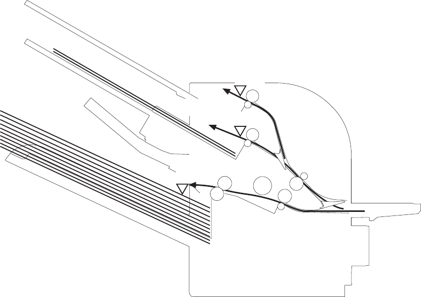
The stapler/stacker controller determines a stapler/stacker lifter motor failure. The controller notifies the
formatter through the DC controller when it encounters the following conditions after the stapler/stacker
lifter motor starts rotating:
●Output bin 3 does not reach the output bin 3 higher limit sensor within a specified period of time.
●The output bin 3 media full sensor does not detect paper
.
The stapler/stacker controller determines a stapler/stacker lifter motor failure. The controller notifies the
formatter through the DC controller when the following sensor is not sensed after the stapler/stacker
lifter motor is reversed:
●Output bin 3 higher limit sensor
●Output bin 3 lower limit sensor
●Output bin 3 media full sensor
Stacker mode
Stacker mode does not designate an output bin. It delivers the printed page to the output bin 3 first and
then to the next bin up.
When the output bin 3 media full sensor detects that output bin 3 is full, the 3-bin stapling mailbox
delivers to output bin 2. When the output bin 2 media full sensor detects that the output bin 2 is full, the
3-bin stapling mailbox delivers to output bin 1.
Figure 1-67 3-bin stapling mailbox sensors for stacker mode
PS2502
PS2504
SR3
Output bin 1 media full sensor
Output bin 2
media full sensor
Output bin 3
media full sensor
88 Chapter 1 Theory of operation ENWW
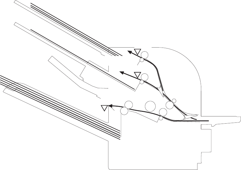
The stapler/stacker controller determines a if the 3-bin stapling mailbox is full and notifies the formatter
through the DC controller when it encounters the following condition:
●The output bin 1 media full is detected.
●The staple operation is designated when the output bin 3 is full of paper.
Mailbox/job separator mode
The mailbox/job separator mode delivers the printed page to the designated bin for each print job.
Figure 1-68 3-bin stapling mailbox sensors for mailbox/jam separation
PS2502
PS2504
SR3
Output bin 1 media full sensor
Output bin 2
media full sensor
Output bin 3
media full sensor
The stapler/stacker controller determines if the 3-bin stapling mailbox is full and notifies the formatter
through the DC controller when it encounters the following condition:
●The designated output bin media full is detected.
●The staple operation is designated when output bin 3 is full of paper.
ENWW 3-bin stapling mailbox 89
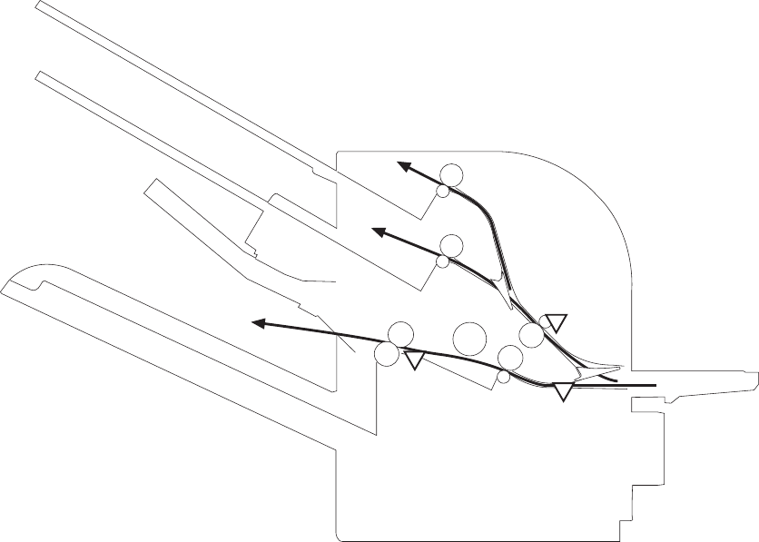
Jam Detection
The 3-bin stapling mailbox uses the following sensors to detect the presence of paper and to check
whether paper is being fed correctly or has jammed:
●Output bin 3 delivery sensor (SR1)
●Stapler/stacker media feed sensor 1 (SR2)
●Stapler/stacker media feed sensor 2 (SR5)
Figure 1-69 3-bin stapling mailbox sensors for jam detection
SR2
SR1
SR5
The stapler/stacker detects the following jams:
●Stapler/Stacker feed delay jam 1: The stapler/stacker media feed sensor 1 does not detect the
leading edge of paper within a specified period of time after the fixing delivery sensor in the
product detects the leading edge.
●Stapler/Stacker feed delay jam 2: The stapler/stacker media feed sensor 2 does not detect the
leading edge of paper within a specified period of time after the fixing delivery sensor in the
product detects the leading edge.
●Stapler/Stacker feed stationary jam 1: The stapler/stacker media feed sensor 1 does not detect
the trailing edge of paper within a specified period of time after it detects the leading edge.
●Stapler/Stacker feed stationary jam 2: The stapler/stacker media feed sensor 2 does not detect
the trailing edge of paper within a specified period of time after it detects the leading edge.
90 Chapter 1 Theory of operation ENWW
●Stapler/Stacker feed stationary jam 3: The output bin 3 delivery sensor does not detect the trailing
edge of paper within a specified period of time from when the stapler/stacker feed motor starts
rotating after a staple operation.
●Stapler/Stacker residual paper jam: Any one of the following sensors detects a presence of paper
for a specified period of time during an automatic delivery operation:
◦Output bin 3 delivery sensor
◦Stapler/Stacker media feed sensor 1
◦Stapler/Stacker media feed sensor 2
Automatic Delivery
The stapler/stacker automatically clears the paper if any one of the following sensors detects the
residual paper during the initial sequence after the stapler/stacker is turned on or after the door is
closed.
●Output bin 3 delivery sensor
●Stapler/Stacker media feed sensor 1
●Stapler/Stacker media feed sensor 2
ENWW 3-bin stapling mailbox 91
92 Chapter 1 Theory of operation ENWW

2 Removal and replacement
●Introduction
●Removal and replacement strategy
●Electrostatic discharge
●Required tools
●Before performing service
●After performing service
●Post-service test
●Parts removal order
●Customer self repair (CSR) components
●External panels, covers, and doors
●Document feeder
●Scanner
●Internal assemblies
●Optional paper feeder assemblies (1 x 500-sheet and 3 x 500-sheet)
●Optional 500-sheet paper feeder assembly
●Stapling mailbox
ENWW 93

Introduction
This chapter describes the removal and replacement of field-replaceable units (FRUs) only.
Replacing FRUs is generally the reverse of removal. Occasionally, notes and tips are included to
provide directions for difficult or critical replacement procedures.
HP does not support repairing individual subassemblies or troubleshooting to the component level.
Note the length, diameter, color, type, and location of each screw. Be sure to return each screw to its
original location during reassembly.
Incorrectly routed or loose wire harnesses can interfere with other internal components and can become
damaged or broken. Frayed or pinched harness wires can be difficult to find. When replacing wire
harnesses, always use the provided wire loops, lance points, or wire-harness guides and retainers.
Removal and replacement strategy
WARNING! Turn the product off, wait 5 seconds, and then remove the power cord before
attempting to service the product. If this warning is not followed, severe injury can result, in addition to
damage to the product. The power must be on for certain functional checks during troubleshooting.
However, disconnect the power supply during parts removal.
Never operate or service the product with the protective cover removed from the laser/scanner
assembly. The reflected beam, although invisible, can damage your eyes.
The sheet-metal parts can have sharp edges. Be careful when handling sheet-metal parts.
CAUTION: Do not bend or fold the flat flexible cables (FFCs) during removal or installation. Also, do
not straighten pre-folds in the FFCs. You must fully seat all FFCs in their connectors. Failure to fully seat
an FFC into a connector can cause a short circuit in a PCA.
NOTE: To install a self-tapping screw, first turn it counterclockwise to align it with the existing thread
pattern, and then carefully turn it clockwise to tighten. Do not overtighten. If a self-tapping screw-hole
becomes stripped, repair the screw-hole or replace the affected assembly.
TIP: For clarity, some photos in this chapter show components removed that would not be removed to
service the product. If necessary, remove the components listed at the beginning of a procedure before
proceeding to service the product.
94 Chapter 2 Removal and replacement ENWW
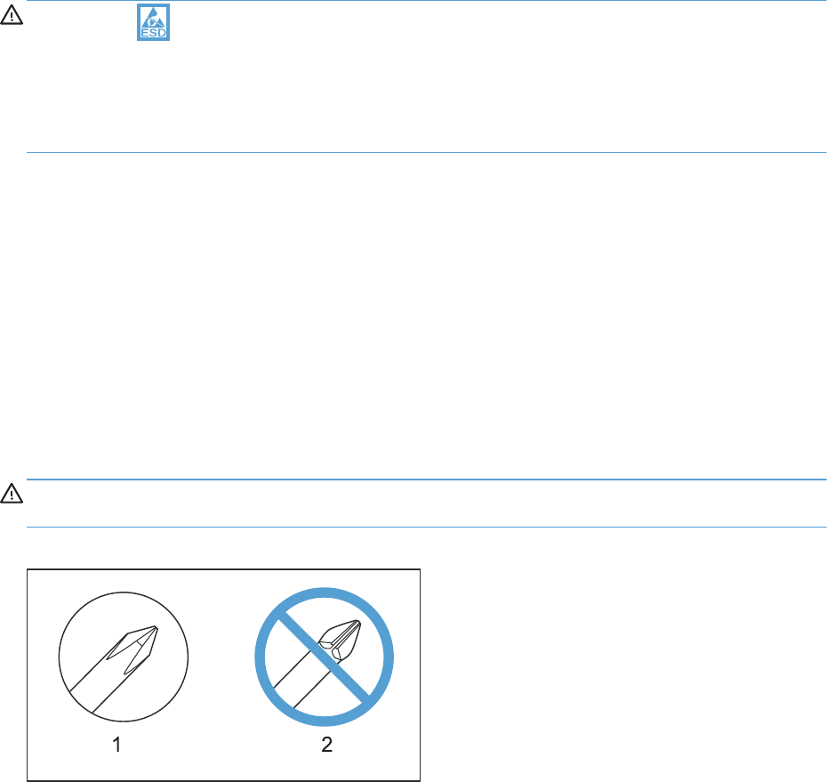
Electrostatic discharge
CAUTION: Some parts are sensitive to electrostatic discharge (ESD). Look for the ESD reminder
when removing product parts. Always perform service work at an ESD-protected workstation or mat, or
use an ESD strap. If an ESD workstation, mat, or strap is not available, ground yourself by touching the
sheet-metal chassis before touching an ESD-sensitive part.
Protect the ESD-sensitive parts by placing them in ESD pouches when they are out of the product.
Required tools
●#2 Phillips screwdriver with a magnetic tip and a 152-mm (6-inch) shaft length
●Small flat blade screwdriver
●Needle-nose pliers
●ESD mat or ESD strap (if one is available)
●Penlight (optional)
●USB thumbdrive
CAUTION: Always use a Phillips screwdriver (callout 1). Do not use a pozidrive screwdriver
(callout 2) or any motorized screwdriver. These can damage screws or screw threads.
Figure 2-1 Phillips and pozidrive screwdriver comparison
ENWW Electrostatic discharge 95

Before performing service
●Remove all media from the product.
●Turn off the power using the power switch.
●Unplug the power cable and interface cable or cables.
●Place the product on an ESD workstation or mat, or use an ESD strap (if one is available). If an
ESD workstation, mat, or strap is not available, ground yourself by touching the sheet-metal
chassis before touching an ESD-sensitive part.
●Remove the print cartridges. See Print cartridges on page 103.
●Remove the tray cassette or cassettes. See Tray on page 111.
After performing service
●Plug in the power cable.
●Reinstall the print cartridges.
●Reinstall the tray cassette or cassettes.
●If the optional paper feeder was installed, place the product on the feeder.
WARNING! The product is heavy. Do not try to separate the product from the optional paper
feeder by yourself. Three people are required to lift the product off of the feeder.
96 Chapter 2 Removal and replacement ENWW
Post-service test
Perform the following test to verify that the repair or replacement was successful.
Print-quality test
1. Verify that you have completed the necessary reassembly steps.
2. Make sure that the tray contains clean, unmarked paper.
3. Attach the power cord and interface cable or interface cables, and then turn on the product.
4. Verify that the expected startup sounds occur.
5. Print a configuration page, and then verify that the expected printing sounds occur.
6. Print a demo page, and then verify that the print quality is as expected.
7. Send a print job from the host computer, and then verify that the output meets expectations.
8. If necessary, restore any customer-specified settings.
9. Clean the outside of the product with a damp cloth.
ENWW Post-service test 97

Parts removal order
Figure 2-2 Parts removal order (1 of 2)
Standard output bin
Output bin bezel
S-CVR-REAR (scanner rear cover)
ASY-CBR-F-SP (ADF front cover)
ASY-CBR-F-R-SP (ADF rear cover)
S-CVR-LEFT (scanner left cover)
Fan cover
Cassette feed guide
IPTU
Registration density (RD) sensor
ADF
Scanner
Left cover
Lower left cover
Separation pad (Tray 1)
Delivery fan
Delivery assy
Duplex-drive assy
Power-supply (PS) fan
Exhaust fan and fan duct
Tray-pickup assy
Laser Scanner (Y/M)
Drum motors
Fuser motor
ITB motor
Main drive
Residual-toner duct
and feed assembly
Residual-toner-feed motor
Cartridge fan
Toner-collection sensor
Image scanner power
supply unit (PSU)
Interconnect board (ICB)
DC controller (DCC)
Low-voltage power supply (LVPS)
High-voltage power supply
(HVPS)-lower
Developing-disengagement motor
Pickup motor
Lifter base assembly
Tray-pickup drive assembly
Laser scanner (C/Bk)
Standard output bin Output bin bezel Fan cover Lower-left cover Left cover
Toner-collection unit ITB Standard output bin Output bin bezel S-CVR-REAR Fan cover
Roller cover
Control panel S-CVR-REAR ADF
Standard output bin Output bin bezel
Right-front cover
ADF Scanner assemblyStandard output bin
Standard output bin Fan coverOutput bin bezel
Fan cover Lower-left cover
Standard output bin Scanner assemblyADFS-CVR-REAROutput bin bezel
Pickup roller Right door assembly
ITB Secondary transfer
assembly
ITB Secondary transfer
assembly
ITB Standard output bin Output bin bezel S-CVR-REAR
Toner-collection unit Standard output bin Output bin bezel Lower-left cover Fan cover Left cover
Standard output bin Output bin bezel S-CVR-REAR Fan cover ADF Scanner
assembly
Fuser ITB Standard output bin Output bin bezel S-CVR-REAR Fan cover
Fuser ITB Standard output bin Output bin bezel S-CVR-REAR Fan cover
Standard output bin Output bin bezel S-CVR-REAR Lower-left cover Left cover ADF
S-CVR-REAR Lower-left cover Fan cover Rear cover ADF Scanner
assembly
Formatter S-CVR-REAR Fan cover Lower-left cover Rear cover ADF
Standard output bin Output bin bezel S-CVR-REAR Lower-left cover Fan cover Rear cover
Formatter S-CVR-REAR Lower-left cover Fan cover Rear cover ADF
Formatter S-CVR-REAR Fan cover Lower-left cover Left cover Rear cover
High-voltage power supply
(HVPS)-upper
Formatter S-CVR-REAR Fan cover Lower-left cover Left cover Rear cover
Formatter S-CVR-REAR Fan cover Lower-left cover Left cover Rear cover
Formatter S-CVR-REAR Fan cover Lower-left cover Left cover Rear cover
Formatter S-CVR-REAR Fan cover Lower-left cover Left cover Rear cover
Formatter S-CVR-REAR Fan cover Lower-left cover Left cover Rear cover
Lifter-drive assembly Formatter ITB S-CVR-REAR Fan cover Lower-left cover Left cover
Formatter S-CVR-REAR Fan cover Lower-left cover Left cover Rear cover
Formatter ITB S-CVR-REAR Lower-left cover Left cover Rear cover
TCU ITB S-CVR-REAR Fan cover Lower-left cover Left cover
TCU ITB S-CVR-REAR Fan cover Lower-left cover Left cover
Formatter S-CVR-REAR Fan cover Lower-left cover Left cover Rear cover
Formatter S-CVR-REAR Fan cover Lower-left cover Left cover Rear cover
Formatter S-CVR-REAR Fan cover Lower-left cover Left cover Rear cover
Formatter S-CVR-REAR Fan cover Lower-left cover Left cover Rear cover
98 Chapter 2 Removal and replacement ENWW

Figure 2-3 Parts removal order (2 of 2)
IPTU
IPTU Delivery Fan
Image scanner (PSU)
Image scanner (PSU)
Image scanner (PSU)
Image scanner (PSU)
Scanner assy
Scanner assy
Scanner assy
Scanner assy
ICB LVPS
ICB LVPS
ICB LVPS
ICB LVPS
DCC HVPS-lower
DCC HVPS-upper
DCC HVPS-upper
DCC HVPS-upper
HVPS-upper Drum motorsExhaust fan
and duct
ADF Scanner IPTU Delivery fan
ADF
ScannerADF
Scanner assy
Scanner assy Image scanner power
supply unit (PSU)
ADF Scanner Image scanner (PSU) ICB
Scanner assy Image scanner (PSU)
ADF
ADF ICB DCC and tray
Scanner assy
Scanner assy
Image scanner (PSU)
Image scanner (PSU)
ICB LVPS HVPS-lowerScanner assy
Scanner assy
Scanner assy HVPS-lower
Secondary transfer
assembly
Registration
assembly
ICB LVPS HVPS-lower
Exhaust fan
and fan duct
Exhaust fan
and fan duct
Laser/scanner
assy (Y/M)
LVPS
LVPS
ICB
ICB
HVPS-lower
HVPS-lower
Toner collection
sensor and scanner-
thermistor assembly
Image scanner (PSU)
ICB LVPS HVPS-lower
HVPS-lower
Scanner Image scanner (PSU)
ICB LVPSImage scanner (PSU)
ADF ICB LVPSScanner assembly
Scanner
Scanner
ICB LVPSImage scanner (PSU)
ADF
ADF
ADF
ADF
Rear cover
ADF
ADF
Rear cover ADF Scanner assembly Cartridge fan
and environ-
mental sensor
ADF Scanner assembly Toner collection
sensor and scanner-
thermistor assembly
Rear cover
ADF
ADF
ADF
ADF
Residual-toner
feed motor
IPTU Delivery Fan
Scanner IPTU Delivery Fan
Delivery Assembly
ICB LVPS
ENWW Parts removal order 99
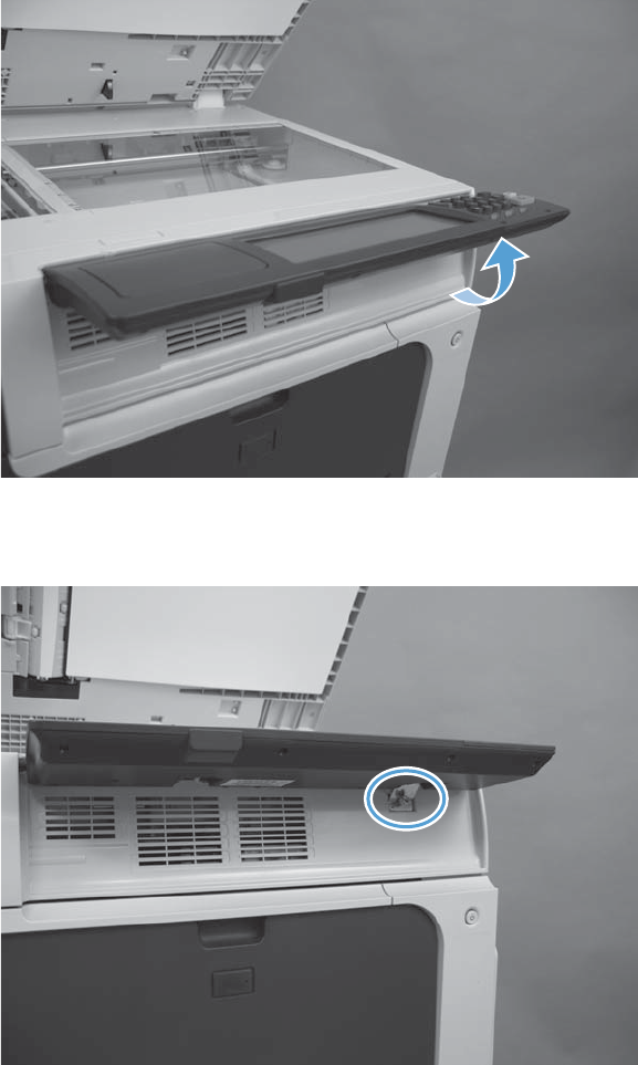
Customer self repair (CSR) components
Control panel
1. Lift the control panel.
Figure 2-4 Remove the control panel (1 of 3)
2. Remove one screw.
Figure 2-5 Remove the control panel (2 of 3)
100 Chapter 2 Removal and replacement ENWW
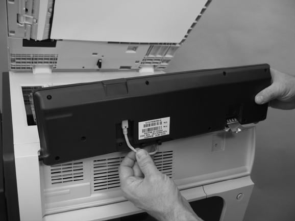
3. Disconnect one connector, and then move the control panel to the right to remove.
Figure 2-6 Remove the control panel (3 of 3)
ENWW Customer self repair (CSR) components 101
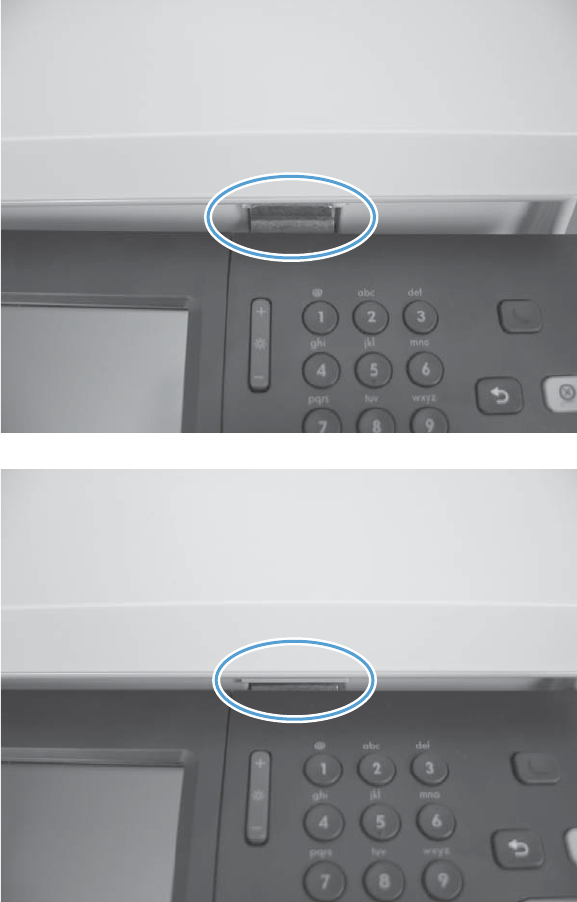
4. When reinstalling the control panel, make sure the bracket fits correctly on the product.
Figure 2-7 Incorrect installation of the control panel
Figure 2-8 Correct installation of the control panel
102 Chapter 2 Removal and replacement ENWW
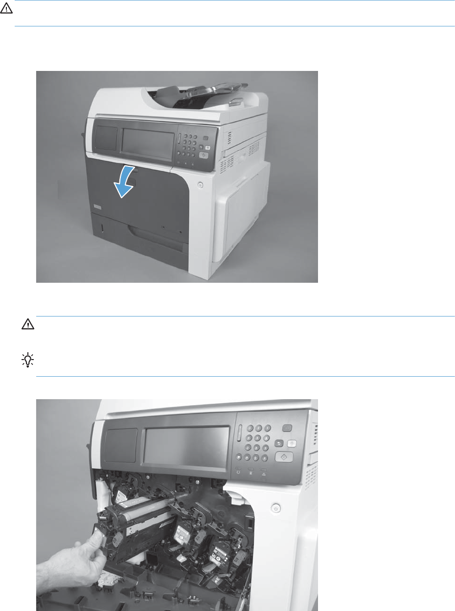
Print cartridges
CAUTION: If toner gets on your clothing, wipe it off with a dry cloth and wash clothing in cold
water. Hot water sets toner into fabric.
1. Open the front door. Make sure that the door is completely open.
Figure 2-9 Remove the print cartridge (1 of 2)
2. Grasp the print-cartridge handle and pull out to remove.
CAUTION: Do not touch the green roller. Doing so can damage the cartridge. Do not expose
the cartridge to strong light. Cover the cartridge with a sheet of paper to protect it from light.
Reinstallation tip Align the print cartridge with its slot and insert the print cartridge until it
clicks into place.
Figure 2-10 Remove the print cartridge (2 of 2)
ENWW Customer self repair (CSR) components 103
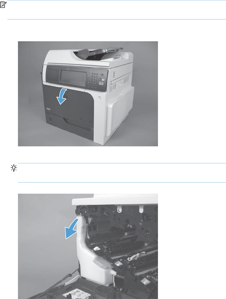
Toner-collection unit
NOTE: The toner-collection unit is designed for a single use. Do not try to empty the toner-collection
unit and reuse it. Doing so could cause toner to spill inside the product and result in reduced print
quality. For recycling information, see the product user guide.
1. Open the front door. Make sure that the door is completely open.
Figure 2-11 Remove the toner-collection unit (1 of 4)
2. Grasp the top of the toner-collection unit and remove it from the product.
Reinstallation tip Insert the bottom of the replacement unit into the product first and then push
the top of the unit until it clicks into place. If the toner-collection unit is installed incorrectly, the front
door will not close completely.
Figure 2-12 Remove the toner-collection unit (2 of 4)
104 Chapter 2 Removal and replacement ENWW
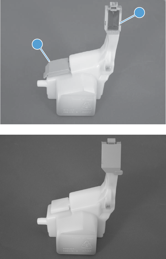
3. To prevent toner spills, place the blue cap (callout 1) over the blue opening at the top of the unit
(callout 2).
Figure 2-13 Remove the toner-collection unit (3 of 4)
1
2
Figure 2-14 Remove the toner-collection unit (4 of 4)
ENWW Customer self repair (CSR) components 105
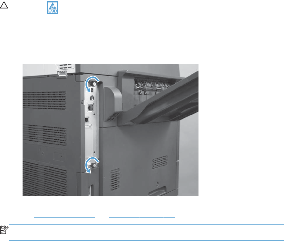
Formatter PCA
CAUTION: ESD sensitive component.
1. Turn the product off and disconnect the power and interface cable or interface cables.
2. Unscrew the formatter thumb screws, and then firmly pull the formatter from the product. Place the
formatter on a clean, flat, grounded surface.
Figure 2-15 Remove the formatter
3. Remove the hard drive and fax card from the existing formatter and reinstall on the new formatter.
See Fax card on page 107 and Hard drive on page 108.
NOTE: When reinstalling the formatter, push firmly on the right side to make sure the formatter is
seated.
106 Chapter 2 Removal and replacement ENWW
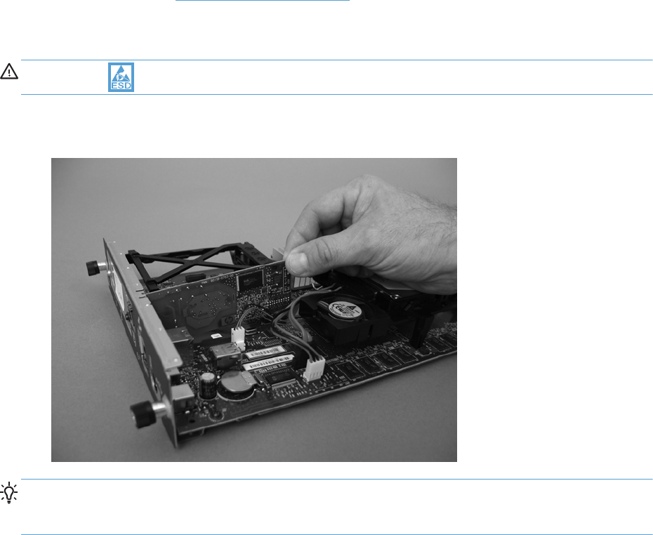
Fax card
Before proceeding, remove the following components:
●Formatter PCA. See Formatter PCA on page 106.
Remove the fax card
CAUTION: ESD sensitive component.
▲Lift the inside edge of the fax card and then remove.
Figure 2-16 Remove the fax card
Reinstallation tip Make sure that the fax card is installed correctly. If it is installed incorrectly, it
can cause the formatter PCA to not connect properly when it is reinstalled. If this occurs, the product
displays a 30.01.YY Scanner Failure error message (error log message 30.01.42).
ENWW Customer self repair (CSR) components 107
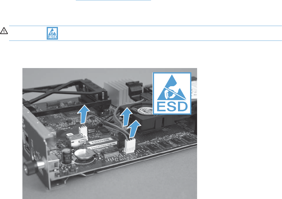
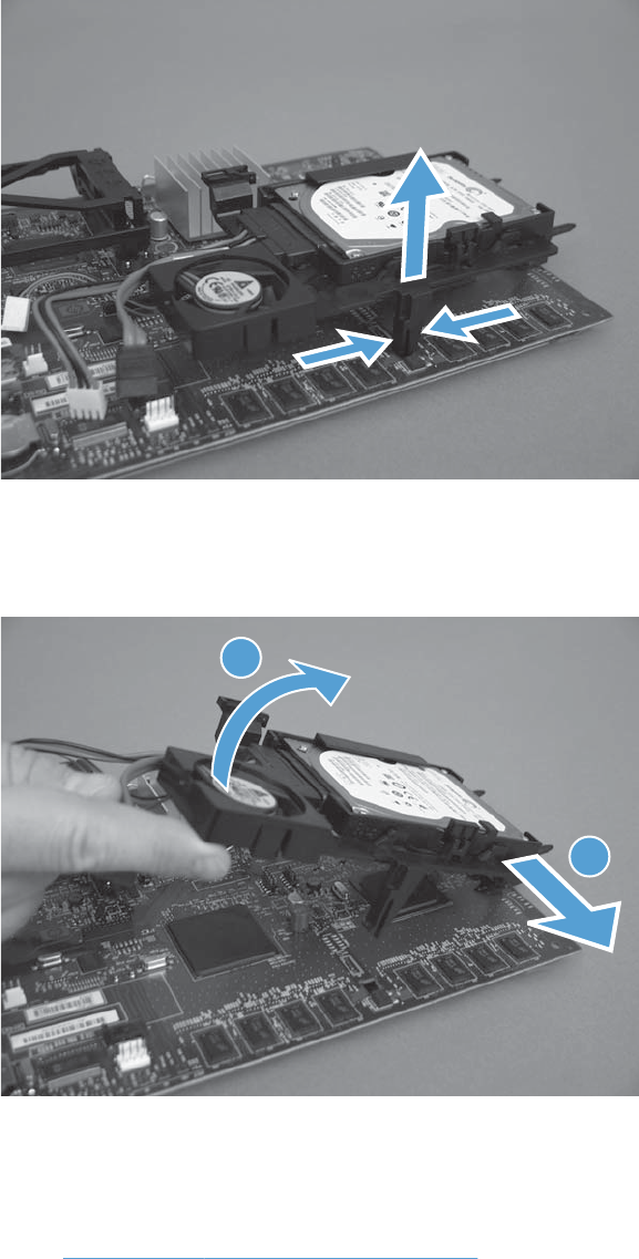
2. Release one tab.
Figure 2-18 Remove the hard drive (2 of 3)
3. Rotate the hard drive assembly away from the formatter until the slots in the hinges are aligned
with the elongated hinge pins, and then slide the hard drive assembly off the hinge pins.
Figure 2-19 Remove the hard drive (3 of 3)
1
2
4. Upgrade the firmware to the new hard drive.
Upgrade the firmware
1. Go to www.hp.com/go/cljcm4540mfp_firmware and follow the onscreen steps to download the
most recent firmware upgrade files for your product.
2. Copy the firmware update file to a portable USB flash memory storage device (thumb drive).
ENWW Customer self repair (CSR) components 109

3. Reinstall the formatter with the new hard drive and reconnect the power cord and network
connection.
4. Turn the product on.
5. Press and hold the Stop button when all of the LEDs illuminate solid.
6. Press the 9 button to highlight the Administrator menu, and then press the 6 button.
7. Press the 9 button to highlight the Download menu, and then press the 6 button.
8. Insert the portable USB storage device with the firmware update file on it.
NOTE: If the error message No USB Thumbdrive Files Found appears on the control-panel
display, you might need to connect the storage device to the external USB connection on the
formatter.
9. Press the 9 button to highlight the USB Thumbdrive menu, and then press the 6 button.
10. Press the 9 button to highlight the firmware update file, and then press the 6 button.
NOTE: The upgrade process can take up to 10 minutes to complete.
TIP: If there is more than one firmware update file on the storage device, make sure that you
select the correct file for this product.
11. When the message Complete appears on the control-panel display, press the 5 button three
times.
12. When the message Continue appears on the control-panel display, press the 6 button. The product
will initialize.
13. When the upgrade process is complete, print a configuration page and verify that the upgrade
firmware version was installed.
110 Chapter 2 Removal and replacement ENWW
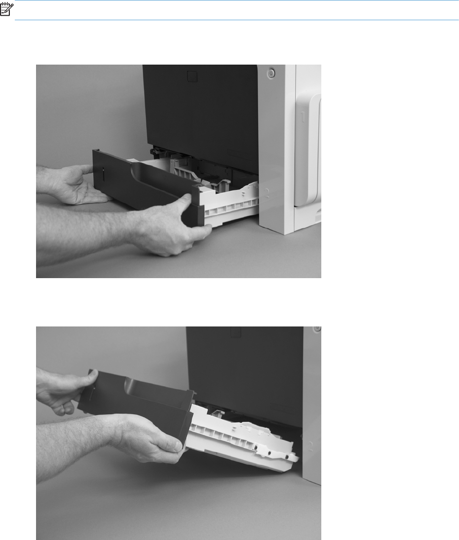
Tray
NOTE: Use this procedure to remove Tray 2 and the optional Trays 3, 4, and 5.
1. Pull the tray straight out of the product until it stops.
Figure 2-20 Remove the tray (1 of 2)
2. Push the tray in slightly, carefully lift up to release it, and then remove the tray.
Figure 2-21 Remove the tray (2 of 2)
ENWW Customer self repair (CSR) components 111

Fuser
CAUTION: The fuser might be hot. Allow enough time after turning off the product power for the
fuser to cool.
NOTE: The product detects a new fuser using a fusible link that blows after 100 pages have been
printed. If a new fuser is installed for troubleshooting purposes, be sure to remove it before printing
100 pages.
1. Open the right-door assembly.
Figure 2-22 Remove the fuser (1 of 2)
2. Grasp the handles and squeeze the blue release levers.
Pull the fuser straight out of the product to remove it.
Figure 2-23 Remove the fuser (2 of 2)
112 Chapter 2 Removal and replacement ENWW
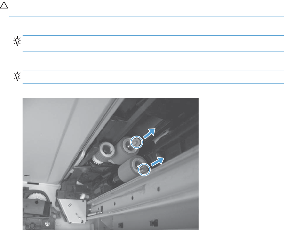
Feed and separation rollers (Trays 2-5)
CAUTION: Do not touch the spongy roller surface unless you are replacing the roller. Skin oils on the
roller can cause paper pickup problems.
1. Locate the feed and separation rollers for the tray.
TIP: You do not have to separate the product from the feeder to remove these rollers. Remove
the cassette, and then reach up into the cavity to remove the rollers.
2. Release two tabs, and then remove the rollers.
Reinstallation tip When you reinstall the rollers, make sure that the rollers snap into place.
Figure 2-24 Remove the Pickup and feed rollers (Trays 2-5)
ENWW Customer self repair (CSR) components 113
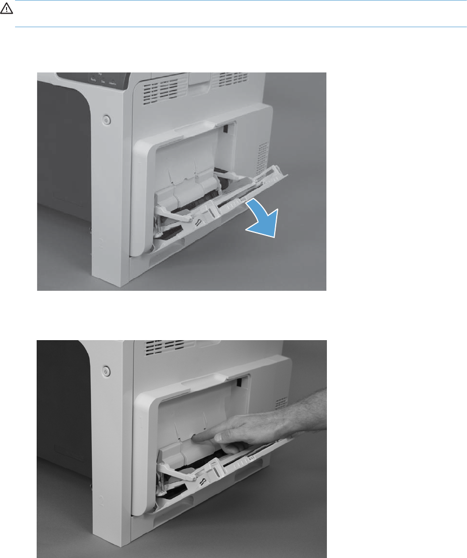
Pickup roller (Tray 1)
CAUTION: Do not touch the spongy roller surface unless you are replacing the roller. Skin oils on the
roller can cause paper pickup problems.
1. Open Tray 1.
Figure 2-25 Remove the pickup roller (Tray 1) (1 of 5)
2. Push the top edge of the cover to release the tabs.
Figure 2-26 Remove the pickup roller (Tray 1) (2 of 5)
114 Chapter 2 Removal and replacement ENWW
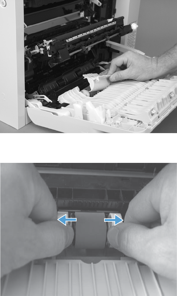
3. Open the right-door assembly, and then remove the cover.
Figure 2-27 Remove the pickup roller (Tray 1) (3 of 5)
4. Release the two blue tabs.
Figure 2-28 Remove the pickup roller (Tray 1) (4 of 5)
ENWW Customer self repair (CSR) components 115
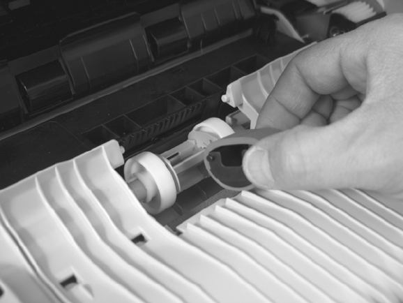
5. Rotate the roller body away from the product to remove it.
Figure 2-29 Remove the pickup roller (Tray 1) (5 of 5)
116 Chapter 2 Removal and replacement ENWW
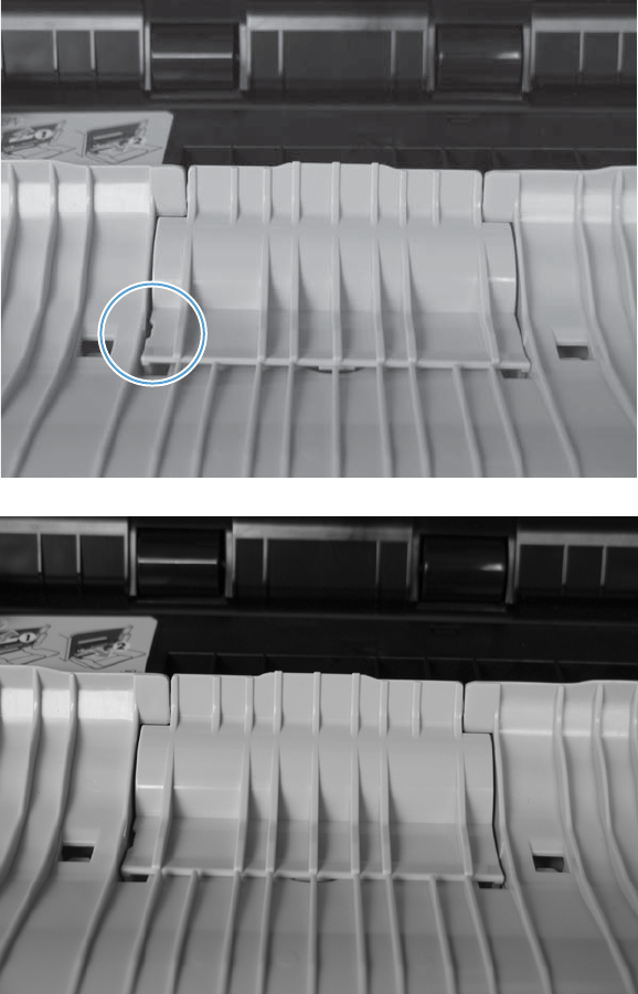
Reinstalling the pickup roller (Tray 1)
▲When reinstalling the pickup roller, make sure the roller cover is installed correctly. Incorrect
installation can cause paper to jam.
Figure 2-30 Incorrect position of cover
Figure 2-31 Correct position of cover
ENWW Customer self repair (CSR) components 117

Secondary transfer roller
CAUTION: Do not touch the spongy roller surface unless you are replacing the roller. Skin oils on the
roller can cause image quality problems.
1. Open the right-door assembly.
Figure 2-32 Remove the transfer roller (1 of 3)
2. Use the blue lever to lower the secondary transfer assembly.
Figure 2-33 Remove the transfer roller (2 of 3)
118 Chapter 2 Removal and replacement ENWW
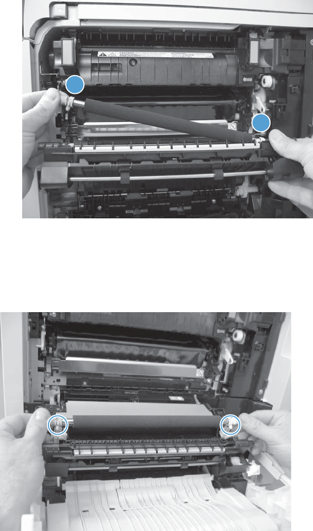
3. Grasp the roller shaft collars, and lift the transfer roller off of the product.
Figure 2-34 Remove the transfer roller (3 of 3)
1
2
Reinstall the transfer roller
When you reinstall the transfer roller, make sure that the pins on the shaft collars align with the holes in
the mounting assembly. After installing the new transfer roller, remove the protective cover.
Figure 2-35 Reinstall the transfer roller
ENWW Customer self repair (CSR) components 119
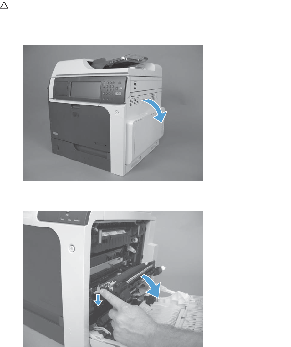
Intermediate transfer belt (ITB)
CAUTION: Do not touch the black-plastic belt. Skin oils and fingerprints on the belt can cause print-
quality problems. Always place the ITB on a flat surface in a safe and protected location.
1. Open the right-door assembly.
Figure 2-36 Remove the intermediate transfer belt (1 of 4)
2. Use the blue lever to lower the secondary transfer assembly.
Figure 2-37 Remove the intermediate transfer belt (2 of 4)
120 Chapter 2 Removal and replacement ENWW
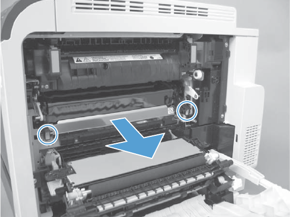
3. Grasp the small handles on the ITB and then pull the ITB out of the product until two large handles
expand along the right- and left-side of the ITB.
Figure 2-38 Remove the intermediate transfer belt (3 of 4)
ENWW Customer self repair (CSR) components 121
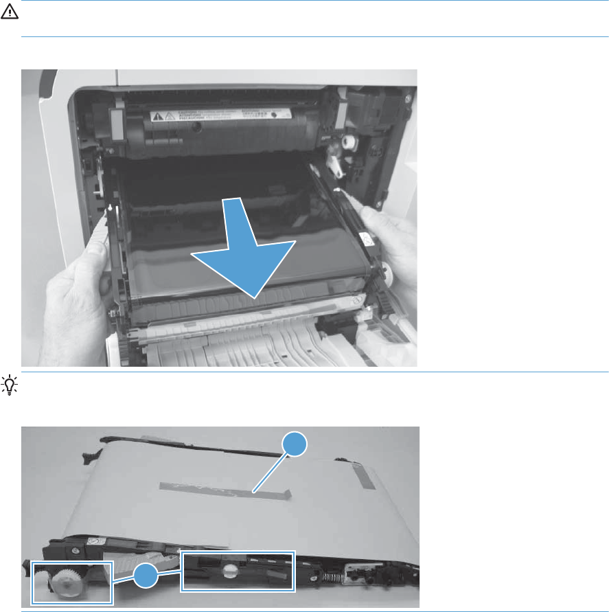
4. Grasp the large handles on the ITB and then pull the ITB straight out of the product to remove it.
CAUTION: The ITB is a sensitive component. Be careful when handling the ITB so that it is not
damaged. Always place the ITB in a safe and protected location.
Figure 2-39 Remove the intermediate transfer belt (4 of 4)
Reinstallation tip If you are installing a replacement ITB, make sure that you remove the
packing tape (callout 1) and the protective cover sheet (callout 2).
1
2
122 Chapter 2 Removal and replacement ENWW
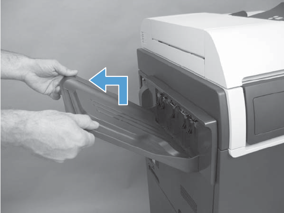
Standard output bin
▲Lift and pull the output bin to remove.
Figure 2-40 Remove the standard output bin
ENWW Customer self repair (CSR) components 123
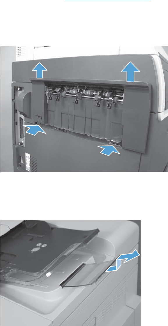
Output bin bezel
Before proceeding, remove the following components:
●Standard output bin. See Standard output bin on page 123
Remove the output bin bezel
▲Release two latches, and then slide the bezel up to remove.
Figure 2-41 Remove output bin bezel
ASY-TRY-F-BASE-SP (document feeder tray extender)
▲Pull the tray extender out, lift, and then remove.
Figure 2-42 Remove the document feeder tray extender
124 Chapter 2 Removal and replacement ENWW
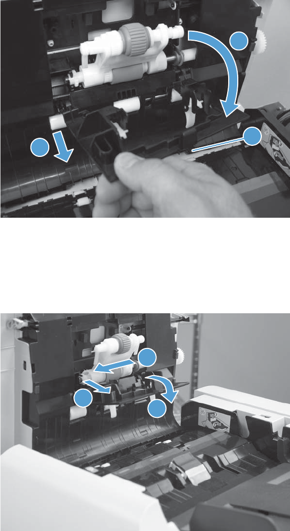
ASY-CVR-FE-PICK-SP (pickup roller cover)
1. Open the jam access cover.
2. Release the cover latch (callout 1). Lower the cover (callout 2) and then pull (callout 3) the cover to
remove.
Figure 2-43 Remove the ASY-CVR-FE-PICK-SP (pickup roller cover)
3
2
1
ASY-ROL-FE-FEED-SP (pickup roller)
▲Open the jam access cover (callout 1). Release the left side of the roller (callout 2) and remove
(callout 3).
Figure 2-44 Remove the ASY-CVR-FE-PICK-SP (pickup roller cover)
2
3
1
ENWW Customer self repair (CSR) components 125
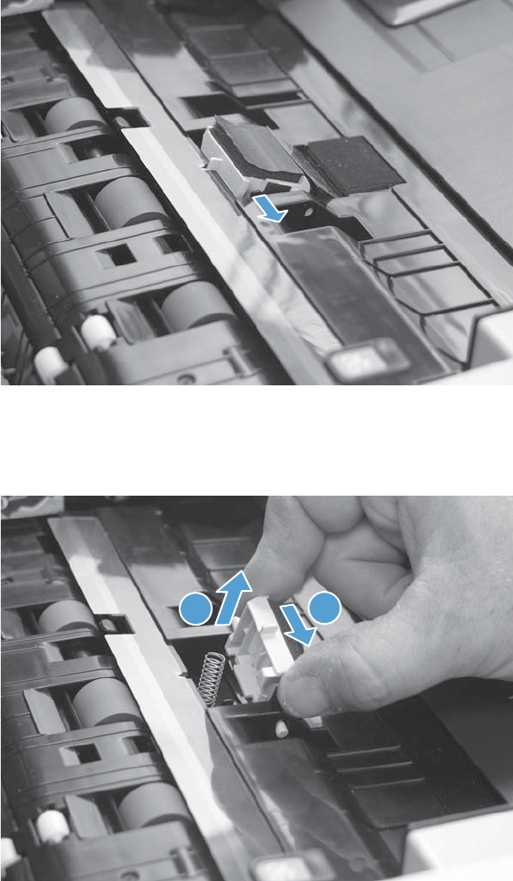
ASY-HLD-REV-PAD-SP (pickup roller pad) and ASY-SP-REV-SPR
(spring)
1. Open the jam access cover.
2. Release one tab.
Figure 2-45 Remove the ASY-CVR-FE-PICK-SP (pickup roller cover)
3. Slide the pad (callout 1) and then lift back edge to remove (callout 2). Remove the spring if
necessary.
Figure 2-46 Remove the ASY-CVR-FE-PICK-SP (pickup roller cover)
21
126 Chapter 2 Removal and replacement ENWW
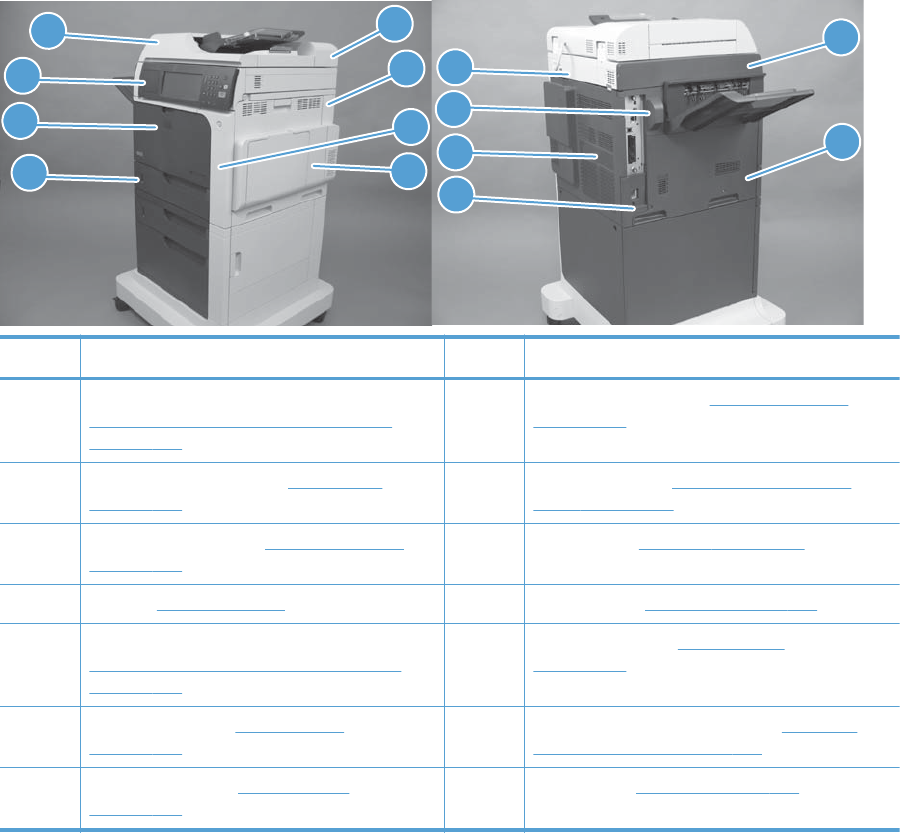
External panels, covers, and doors
Identification and location
Figure 2-47 External panels, covers, and doors; identification and location
5
6
1
2
3
4
7
8
13
14
12
11
9
10
Item Description Item Description
1 ASY-CVR-F-SP (document feeder front cover) (see
ASY-CVR-F-SP (document feeder front cover)
on page 129)
8 Right-door assembly (see Right-door assembly
on page 145)
2 Control-panel assembly (see Control panel
on page 100).
9 Rear top cover (see S-CVR-REAR (scanner rear
cover) on page 128
3 Front-door assembly (see Front-door assembly
on page 140)
10 Fan cover (see Fan cover on page 134)
4Tray (see Tray on page 111) 11 Rear cover (see Rear cover on page 144)
5 ASY-CVR-F-R-SP (document feeder rear cover) (see
ASY-CVR-F-R-SP (document feeder rear cover)
on page 131)
12 Lower-left cover (see Lower-left cover
on page 136)
6 Right-rear cover (see Right-rear cover
on page 143)
13 S-CVR-LEFT (scanner left cover) (see S-CVR-LEFT
(scanner left cover) on page 133)
7 Right-front cover (see Right-front cover
on page 138)
14 Left cover (see Left cover on page 137)
ENWW External panels, covers, and doors 127
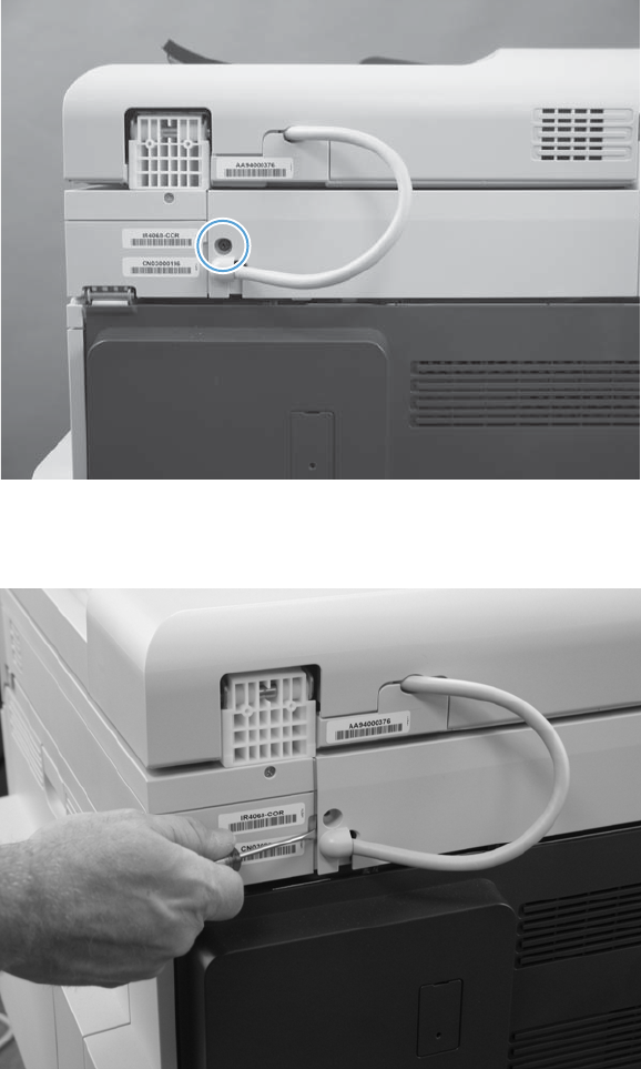
S-CVR-REAR (scanner rear cover)
1. Remove one screw.
Figure 2-48 Remove S-CVR-REAR (scanner rear cover) (1 of 2)
2. Release one tab, and then remove the scanner cover.
Figure 2-49 Remove S-CVR-REAR (scanner rear cover) (2 of 2)
128 Chapter 2 Removal and replacement ENWW
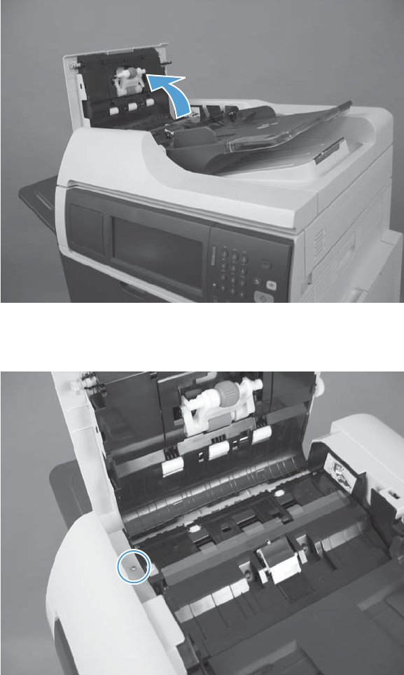
ASY-CVR-F-SP (document feeder front cover)
1. Lift the jam cover.
Figure 2-50 Remove ASY-CVR-F-SP (document feeder front cover) (1 of 4)
2. Remove one screw.
Figure 2-51 Remove ASY-CVR-F-SP (document feeder front cover) (2 of 4)
ENWW External panels, covers, and doors 129
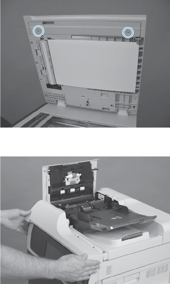
3. Open the document feeder and then remove two screws.
Figure 2-52 Remove ASY-CVR-F-SP (document feeder front cover) (3 of 4)
4. Close the document feeder and then remove the document feeder front cover.
Figure 2-53 Remove ASY-CVR-F-SP (document feeder front cover) (4 of 4)
130 Chapter 2 Removal and replacement ENWW
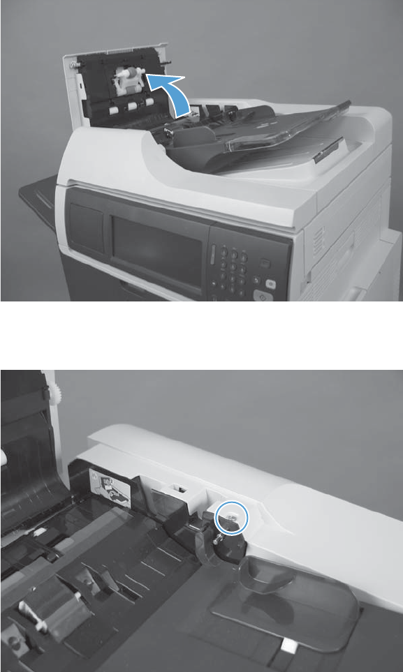
ASY-CVR-F-R-SP (document feeder rear cover)
1. Open the jam cover.
Figure 2-54 Remove the ASY-CVR-F-R-SP (document feeder rear cover) (1 of 5)
2. Remove one screw.
Figure 2-55 Remove the ASY-CVR-F-R-SP (document feeder rear cover) (2 of 5)
ENWW External panels, covers, and doors 131
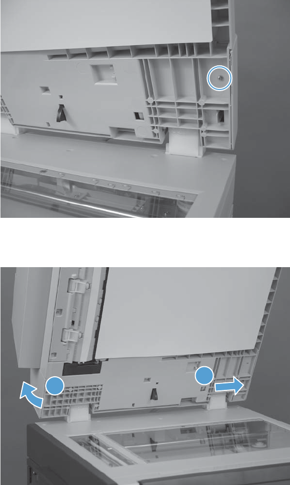
3. Open the document feeder and then remove one screw.
Figure 2-56 Remove the ASY-CVR-F-R-SP (document feeder rear cover) (3 of 5)
4. Release one tab (callout 1) and then lift the document feeder rear cover (callout 2).
Figure 2-57 Remove the ASY-CVR-F-R-SP (document feeder rear cover) (4 of 5)
1
2
132 Chapter 2 Removal and replacement ENWW

5. Remove the document feeder rear cover.
Figure 2-58 Remove the ASY-CVR-F-R-SP (document feeder rear cover) (5 of 5)
S-CVR-LEFT (scanner left cover)
1. Remove one screw.
Figure 2-59 Remove S-CVR-LEFT (scanner left cover) (1 of 2)
ENWW External panels, covers, and doors 133
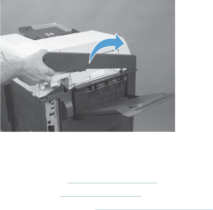
2. Lift the scanner left cover to remove.
Figure 2-60 Remove S-CVR-LEFT (scanner left cover) (2 of 2)
Fan cover
Before proceeding, remove the following components:
●Standard output bin. See Standard output bin on page 123.
●Output bin bezel. See Output bin bezel on page 124.
●S-CVR-LEFT (scanner left cover). See S-CVR-LEFT (scanner left cover) on page 133.
134 Chapter 2 Removal and replacement ENWW
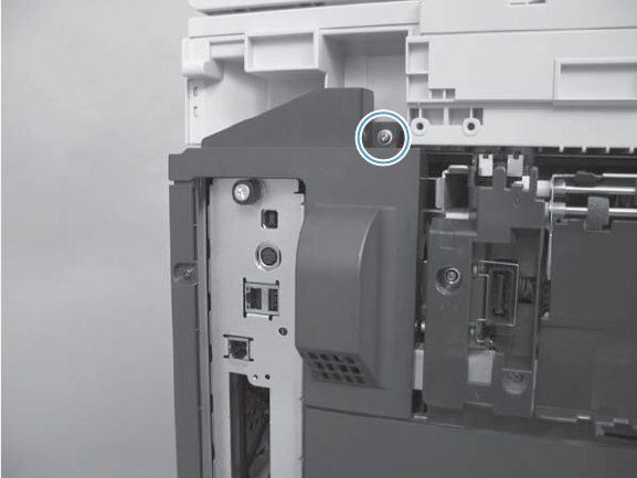
Remove the fan cover
▲Remove one screw and then remove the fan cover.
Figure 2-61 Remove upper left cover
ENWW External panels, covers, and doors 135
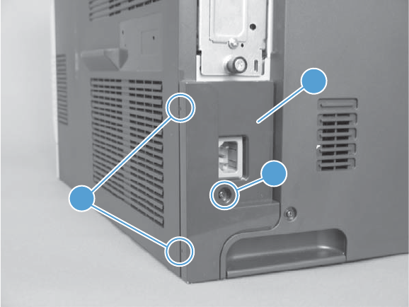
Lower-left cover
▲Remove one screw (callout 1), release two tabs (callout 2), and then remove the lower-left cover
(callout 3).
Figure 2-62 Remove the lower-left cover
1
3
2
136 Chapter 2 Removal and replacement ENWW
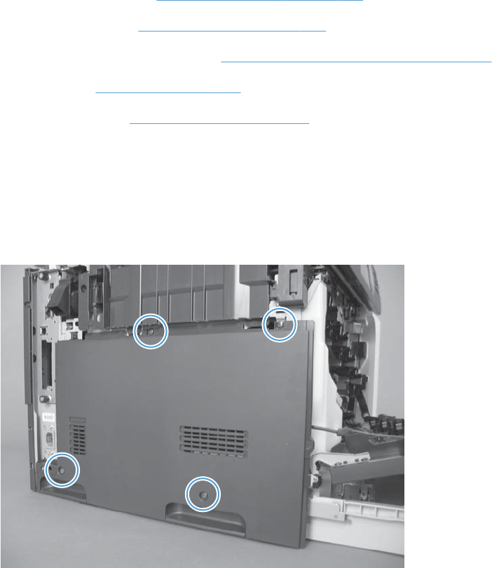
Left cover
Before proceeding, remove the following components:
●Standard output bin. See Standard output bin on page 123.
●Output bin bezel. See Output bin bezel on page 124.
●S-CVR-LEFT (scanner left cover). See S-CVR-LEFT (scanner left cover) on page 133.
●Fan cover. See Fan cover on page 134.
●Lower-left cover. See Lower-left cover on page 136.
Remove the left cover
1. Open the front-door assembly. Open or remove Tray 2.
2. Remove four screws, and then remove the left cover.
Figure 2-63 Remove the left cover
ENWW External panels, covers, and doors 137
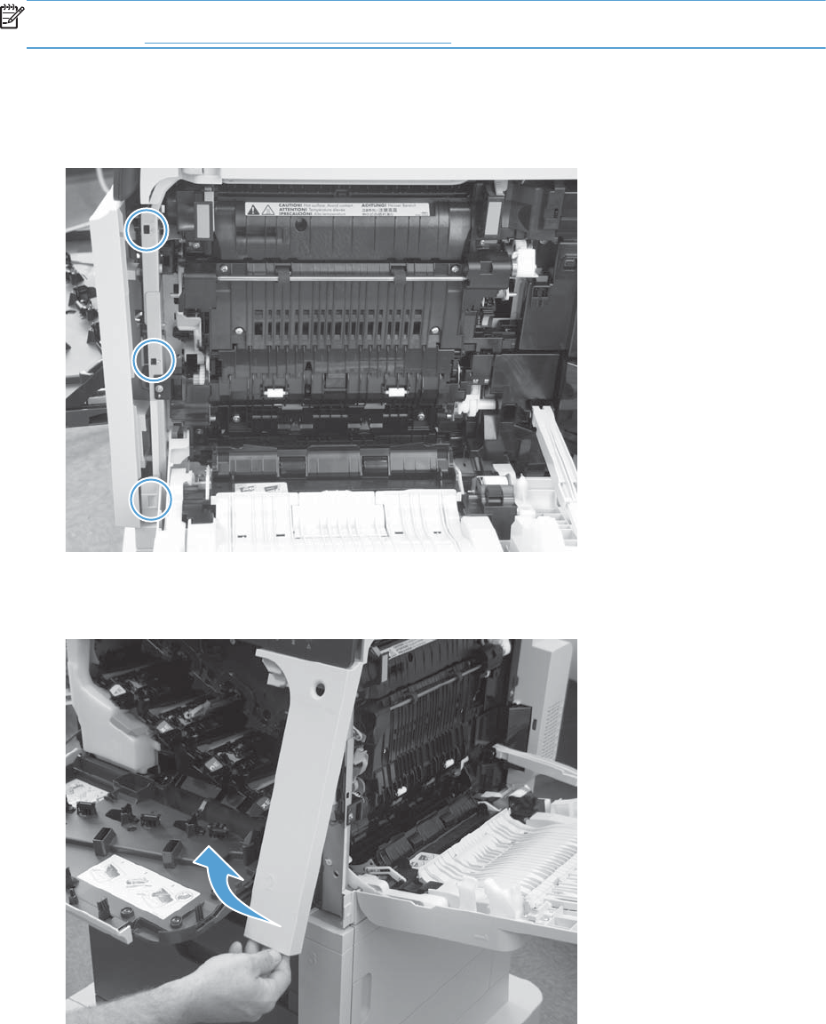
Right-front cover
Remove the right-front cover
NOTE: Be careful. When removing the cover, do not dislodge the power button. If the button is
dislodged, see Reinstall the power button on page 139 to reinstall it.
1. Open the right-door and front door assemblies.
2. Release three tabs.
Figure 2-64 Remove the right-front cover (1 of 2)
3. Lift the right-front cover to remove
Figure 2-65 Remove the right-front cover (2 of 2)
138 Chapter 2 Removal and replacement ENWW
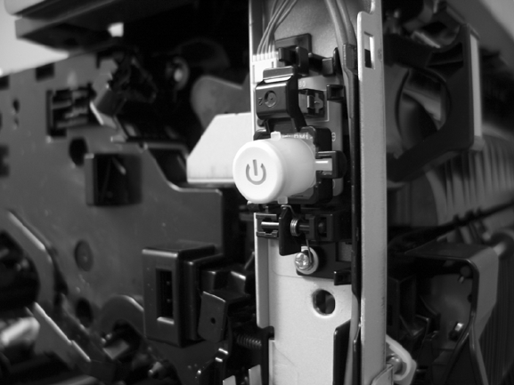
Reinstall the power button
Snap the power button into the holders on the cover. Make sure that the spring is correctly installed.
Figure 2-66 Reinstall the power button
ENWW External panels, covers, and doors 139
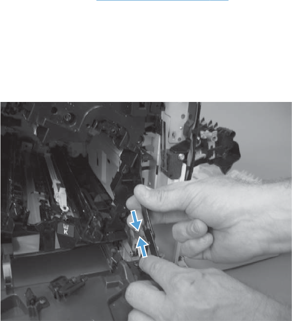
Front-door assembly
Before proceeding, remove the following components:
●Right-front cover. See Right-front cover on page 138
Remove the front-door assembly
1. Open the front-door assembly.
2. Release the right link arm by pushing the two segments together and then releasing.
Figure 2-67 Remove the front-door assembly (1 of 5)
140 Chapter 2 Removal and replacement ENWW
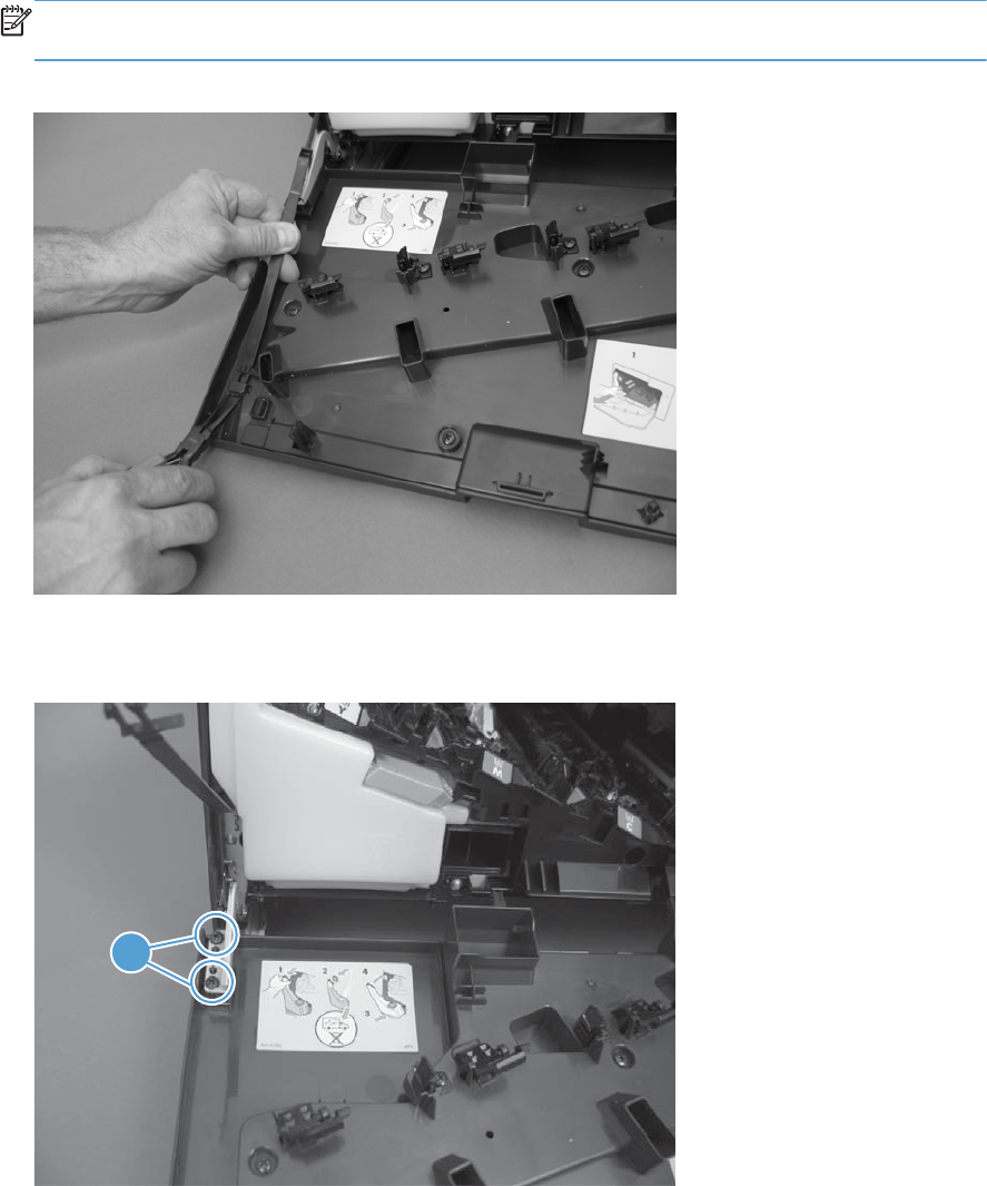
3. Squeeze the tab on the left link arm using needle nose pliers to release it from the front door
assembly.
NOTE: Hold the link arm firmly when releasing to prevent it from snapping against the front of
the product.
Figure 2-68 Remove the front-door assembly (2 of 5)
4. Remove two screws (callout 1).
Figure 2-69 Remove the front-door assembly (3 of 5)
1
ENWW External panels, covers, and doors 141
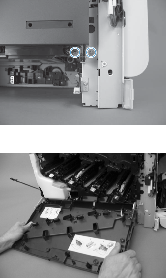
5. Remove two screws.
Figure 2-70 Remove the front-door assembly (4 of 5)
6. Remove the front-door assembly.
Figure 2-71 Remove the front-door assembly (5 of 5)
142 Chapter 2 Removal and replacement ENWW
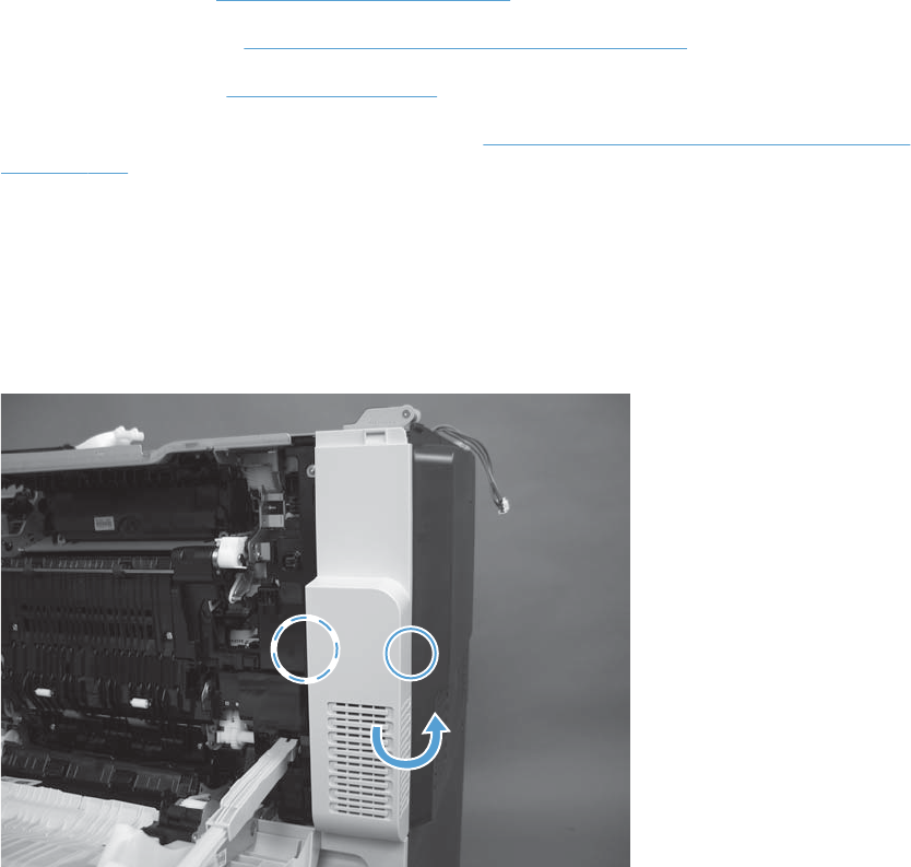
Right-rear cover
Before proceeding, remove the following components:
●Document feeder. See Document feeder on page 151.
●Standard output bin. See S-CVR-REAR (scanner rear cover) on page 128.
●Scanner assembly. See Scanner on page 170.
●Intermediate cover and duplexing gear cover. See Intermediate cover and duplexing gear cover
on page 229.
Remove the right-rear cover
1. Open the right-door assembly.
2. Release two tabs and rotate the cover to remove.
Figure 2-72 Remove the right-rear cover
ENWW External panels, covers, and doors 143
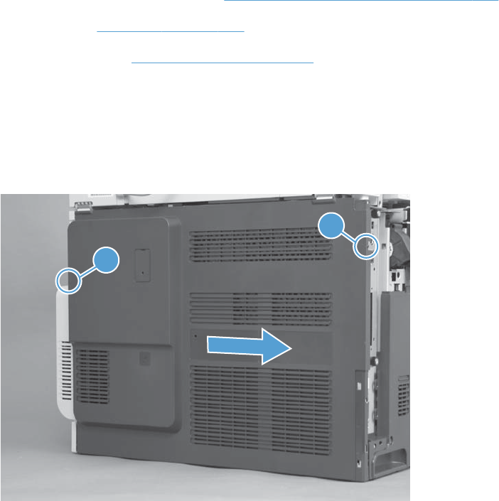
Rear cover
Before proceeding, remove the following components:
●S-CVR-LEFT (scanner left cover). See S-CVR-LEFT (scanner left cover) on page 133.
●Fan cover. See Fan cover on page 134.
●Lower-left cover. See Lower-left cover on page 136.
Remove the rear cover
▲Remove one screws (callout 1), release one tab (callout 2), and then slide the cover to the right to
remove.
Figure 2-73 Remove the rear cover
2
1
144 Chapter 2 Removal and replacement ENWW
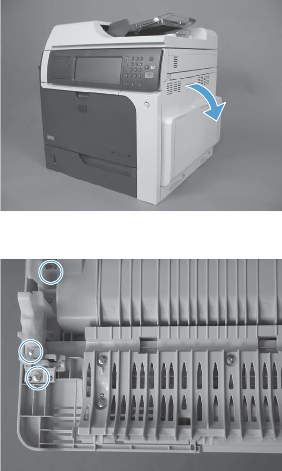
Right-door assembly
1. Open the right-door assembly.
Figure 2-74 Remove the right-door assembly (1 of 9)
2. Remove three screws.
Figure 2-75 Remove the right-door assembly (2 of 9)
ENWW External panels, covers, and doors 145
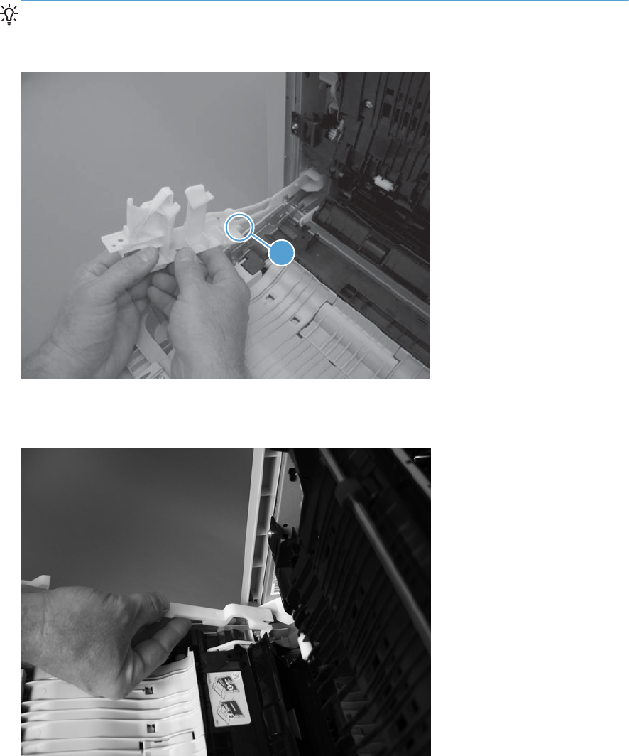
3. Remove the hinge assembly.
Reinstallation tip When the hinge is reinstalled, make sure that the tab (callout 1) is correctly
positioned on the door.
Figure 2-76 Remove the right-door assembly (3 of 9)
1
4. Remove the hinge cover.
Figure 2-77 Remove the right-door assembly (4 of 9)
146 Chapter 2 Removal and replacement ENWW
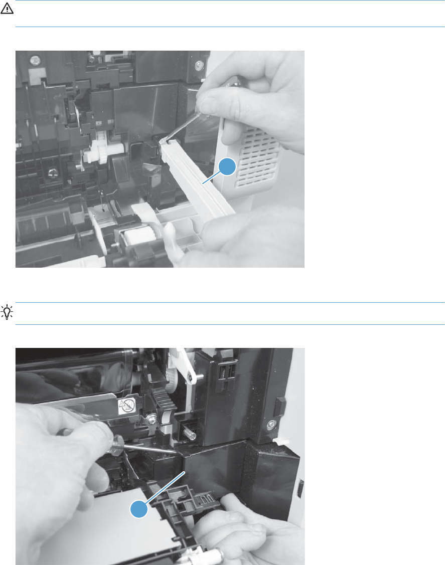
5. Release one pin, and then release the link arm (callout 1).
CAUTION: The link arm is spring loaded. Hold the arm securely (as shown) to prevent the
spring from abruptly retracting.
Figure 2-78 Remove the right-door assembly (5 of 9)
1
6. Release one tab, and then remove the cover (callout 1).
TIP: Lift up on the secondary transfer assembly to make removing the cover easier.
Figure 2-79 Remove the right-door assembly (6 of 9)
1
ENWW External panels, covers, and doors 147
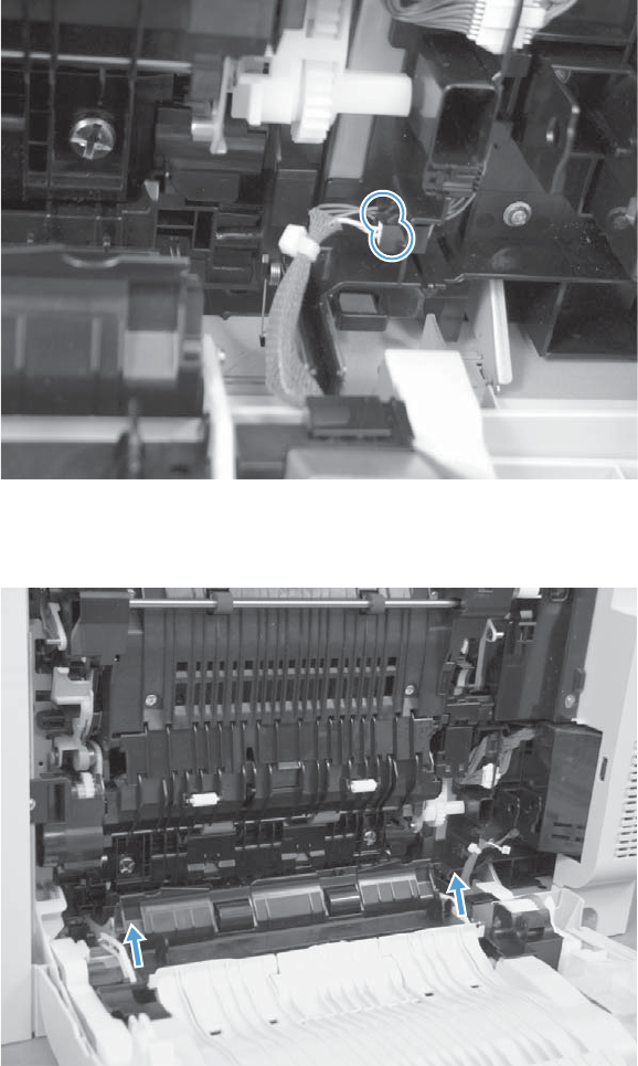
7. Disconnect two connectors.
Figure 2-80 Remove the right-door assembly (7 of 9)
8. Lift two link arms to release.
Figure 2-81 Remove the right-door assembly (8 of 9)
148 Chapter 2 Removal and replacement ENWW
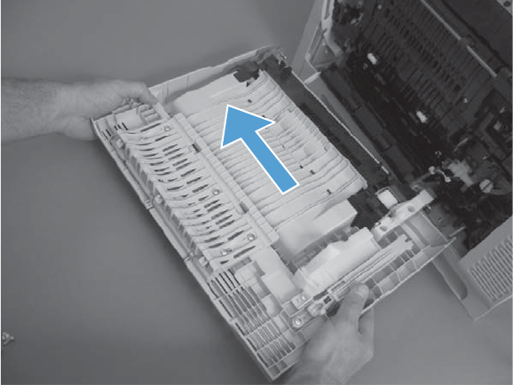
9. Slide the right-door assembly toward the front of the product and remove.
Figure 2-82 Remove the right-door assembly (9 of 9)
ENWW External panels, covers, and doors 149
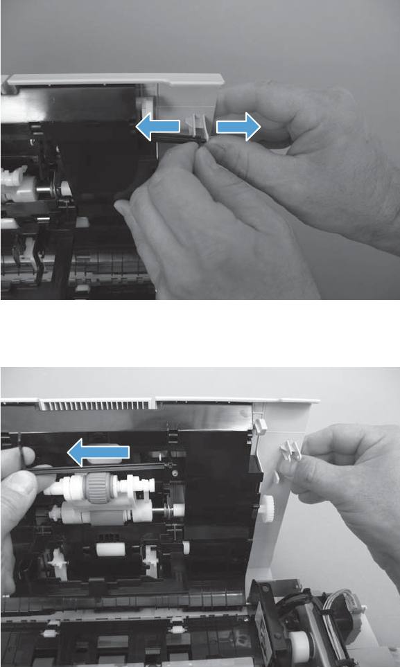
Document feeder
ASY-LVR-FE-EMP-SP (paper present flag)
1. Open the jam access cover.
2. Release the flag from the hinge.
Figure 2-83 Remove the ASY-LVR-FE-EMP-SP (paper present flag) (1 of 2)
3. Pull the flag to release and remove.
Figure 2-84 Remove the ASY-LVR-FE-EMP-SP (paper present flag) (2 of 2)
150 Chapter 2 Removal and replacement ENWW
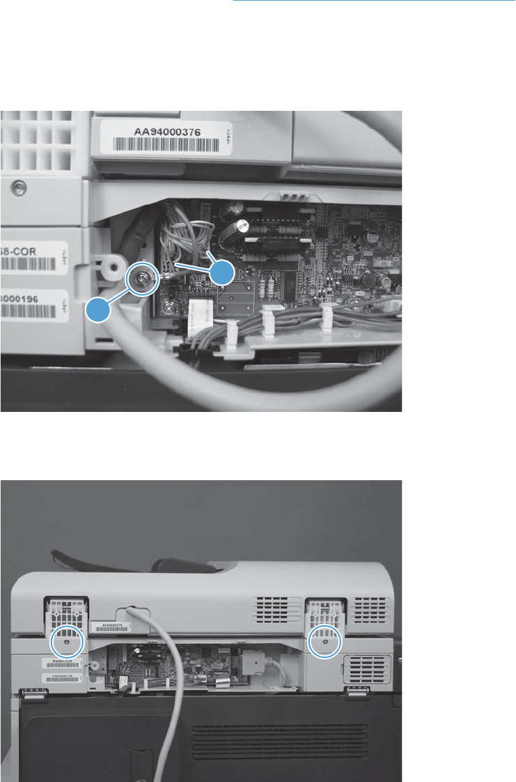
Document feeder
Before proceeding, remove the following components
●S-CVR-REAR (scanner rear cover). See S-CVR-REAR (scanner rear cover) on page 128.
Remove the document feeder
1. Remove one screw (callout 1) and disconnect two connectors (callout 2).
Figure 2-85 Remove the document feeder (1 of 3)
1
1
1
2
2. Remove two screws.
Figure 2-86 Remove the document feeder (2 of 3)
ENWW Document feeder 151
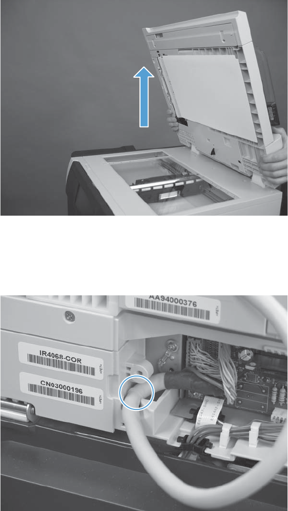
3. From the rear of the product, lift the document feeder to remove.
Figure 2-87 Remove the document feeder (3 of 3)
Reinstall the document feeder
▲Make sure the cable retainer is installed inside the cavity.
Figure 2-88 Reinstall the document feeder
152 Chapter 2 Removal and replacement ENWW
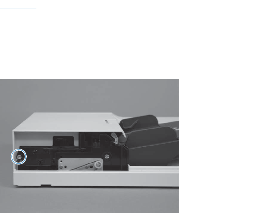
ASY-CVR-FE-FEED-SP (document feeder jam-access cover)
Before proceeding, remove the following components:
●ASY-CVR-F-SP (document feeder front cover). See ASY-CVR-F-SP (document feeder front cover)
on page 129.
●ASY-CVR-F-R-SP (document feeder rear cover). See ASY-CVR-F-R-SP (document feeder rear cover)
on page 131.
Remove the ASY-CVR-FE-FEED-SP (document feeder jam-access cover)
1. Remove one stepped screw.
Figure 2-89 Remove the ASY-CVR-FE-FEED-SP (document feeder jam-access cover) (1 of 2)
ENWW Document feeder 153
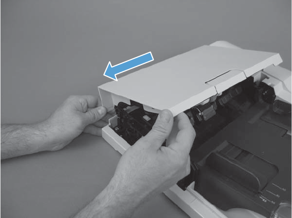
2. Lift the cover slightly, and then pull the cover toward the front of the product to remove.
Figure 2-90 Remove the ASY-CVR-FE-FEED-SP (document feeder jam-access cover) (2 of 2)
154 Chapter 2 Removal and replacement ENWW
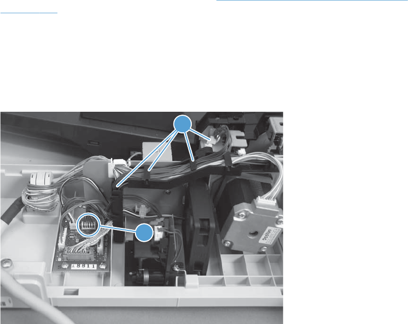
ASY-TRY-SP (tray assembly)
Before proceeding, remove the following components
●ASY-CVR-F-R-SP (document feeder rear cover). See ASY-CVR-F-R-SP (document feeder rear cover)
on page 131.
Remove the ASY-TRY-SP (tray assembly)
1. Open the jam-access cover.
2. Disconnect one connector (callout 1) and release the cable from the cable guides (callout 2).
Figure 2-91 Remove the ASY-TRY-SP (tray assembly) (1 of 2)
11
2
ENWW Document feeder 155
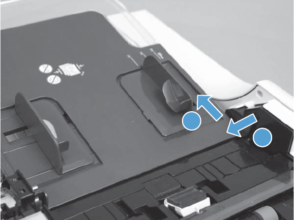
3. Release the pin from the hinge (callout 1) and then remove the tray assembly (callout 2).
Figure 2-92 Remove the ASY-TRY-SP (tray assembly) (2 of 2)
11
2
156 Chapter 2 Removal and replacement ENWW
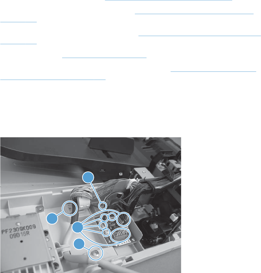
ASY-FRM-RE-FEED-SP (internal assembly)
Before proceeding, remove the following components
●S-CVR-REAR (scanner rear cover). See S-CVR-REAR (scanner rear cover) on page 128.
●ASY-CVR-F-SP (document feeder front cover). See ASY-CVR-F-SP (document feeder front cover)
on page 129.
●ASY-CVR-F-R-SP (document feeder rear cover). See ASY-CVR-F-R-SP (document feeder rear cover)
on page 131.
●Document feeder. See Document feeder on page 151.
●ASY-CVR-FE-FEED-SP (document feeder jam-access cover). See ASY-CVR-FE-FEED-SP (document
feeder jam-access cover) on page 153.
Remove ASY-FRM-RE-FEED-SP (internal assembly)
1. Remove one screw (callout 1), release one clamp (callout 2), and then disconnect six connectors
(callout 3).
Figure 2-93 Remove the ASY-FRM-RE-FEED-SP (internal assembly) (1 of 3)
1
1
14
1
2
3
ENWW Document feeder 157
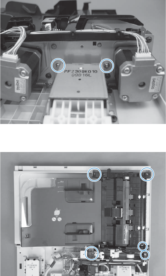
2. Remove two screws.
Figure 2-94 Remove the ASY-FRM-RE-FEED-SP (internal assembly) (2 of 3)
3. Remove five screws, and then remove the assembly.
Figure 2-95 Remove the ASY-FRM-RE-FEED-SP (internal assembly) (3 of 3)
158 Chapter 2 Removal and replacement ENWW
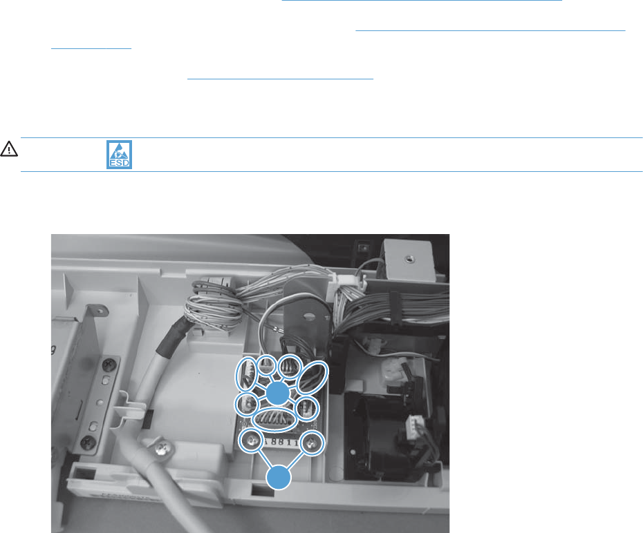
ASY-PBA-RELAY-SB (document feeder PCA)
Before proceeding, remove the following components
●S-CVR-REAR (scanner rear cover). See S-CVR-REAR (scanner rear cover) on page 128.
●ASY-CVR-F-R-SP (document feeder rear cover). See ASY-CVR-F-R-SP (document feeder rear cover)
on page 131.
●Document feeder. See Document feeder on page 151.
Remove the ASY-PBA-RELAY-SB (document feeder PCA)
CAUTION: ESD-sensitive part.
▲Disconnect seven connectors (callout 1), remove two screws (callout 2), and then remove the PCA.
Figure 2-96 Remove the ASY-PBA-RELAY-SB (document feeder PCA)
11
2
ENWW Document feeder 159

ASM-IF-SP (document feeder cable)
Before proceeding, remove the following components
●S-CVR-REAR (scanner rear cover) S-CVR-REAR (scanner rear cover) on page 128
●ASY-CVR-F-R-SP (document feeder rear cover). See ASY-CVR-F-R-SP (document feeder rear cover)
on page 131.
●Document feeder. See Document feeder on page 151.
160 Chapter 2 Removal and replacement ENWW
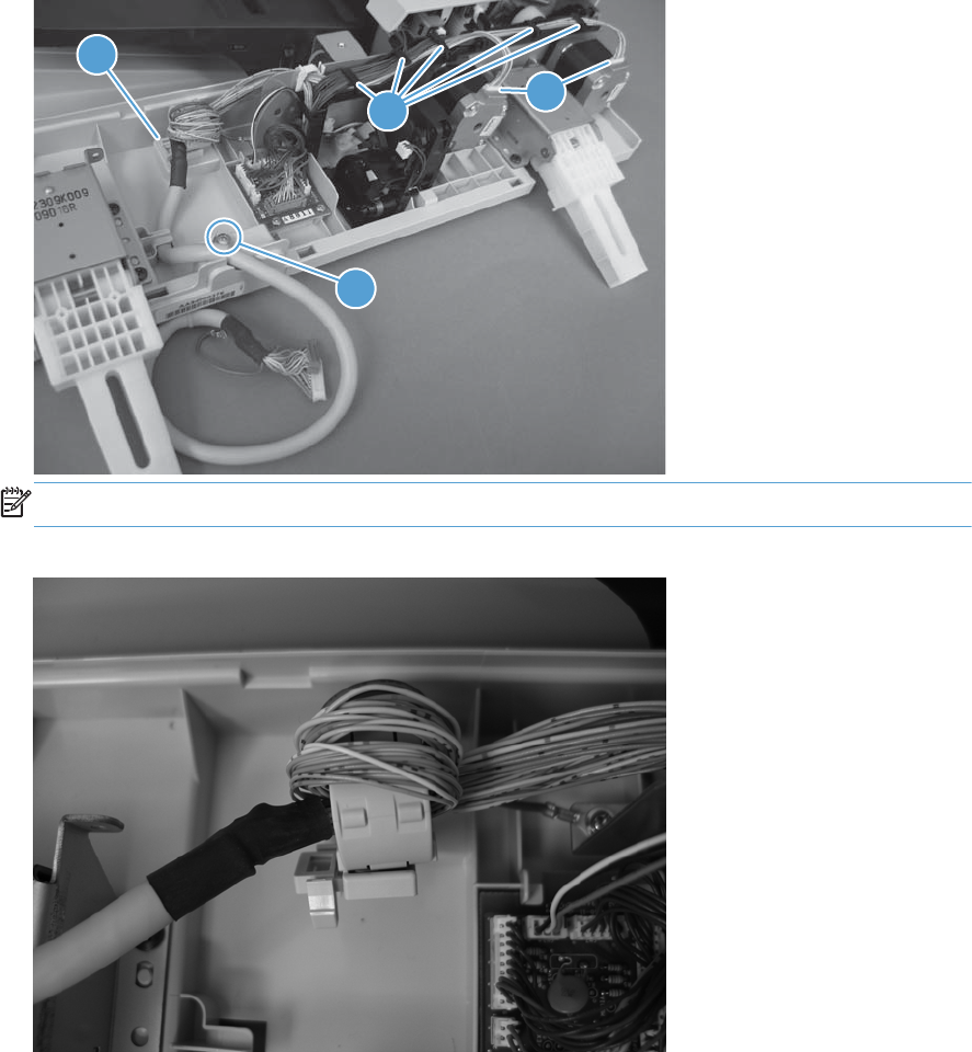
Remove the ASM-IF-SP (document feeder cable)
▲Remove one screw (callout 1), release the cable guides (callout 2), disconnect two connectors
(callout 3), release one tab (callout 4). Remove the document feeder cable.
Figure 2-97 Remove the ASM-IF-SP (document feeder cable) (1 of 2)
1
3
2
4
NOTE: When reinstalling the cable, make sure to correctly wrap the cable in the toroid.
Figure 2-98 Remove the ASM-IF-SP (document feeder cable) (2 of 2)
ENWW Document feeder 161
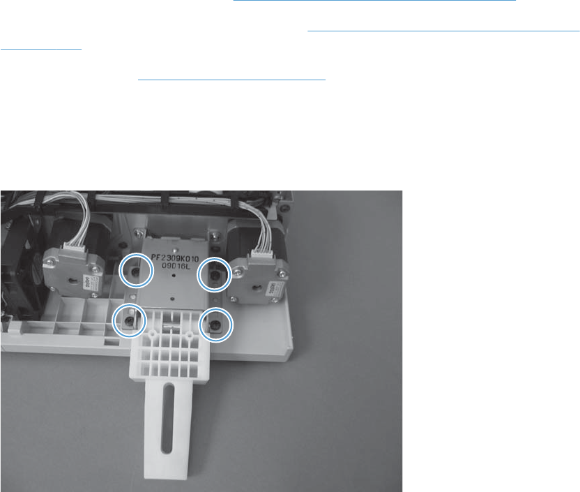
ASY-HNG-L-SP (document feeder left hinge)
Before proceeding, remove the following components
●S-CVR-REAR (scanner rear cover). See S-CVR-REAR (scanner rear cover) on page 128.
●ASY-CVR-F-R-SP (document feeder rear cover). See ASY-CVR-F-R-SP (document feeder rear cover)
on page 131.
●Document feeder. See Document feeder on page 151.
Remove the ASY-HNG-L-SP (document feeder left hinge)
▲Remove four screws and then remove the hinge.
Figure 2-99 Remove the ASY-HNG-L-SP (document feeder left hinge)
162 Chapter 2 Removal and replacement ENWW
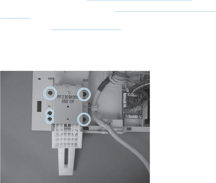
ASY-HNG-R-SP (document feeder right hinge)
Before proceeding, remove the following components
●S-CVR-REAR (scanner rear cover). See S-CVR-REAR (scanner rear cover) on page 128.
●ASY-CVR-F-R-SP (document feeder rear cover). See ASY-CVR-F-R-SP (document feeder rear cover)
on page 131.
●Document feeder. See Document feeder on page 151.
Remove the ASY-HNG-R-SP (document feeder right hinge)
▲Remove five screws and then remove the hinge.
Figure 2-100 Remove the ASY-HNG-L-SP (document feeder right hinge)
ENWW Document feeder 163
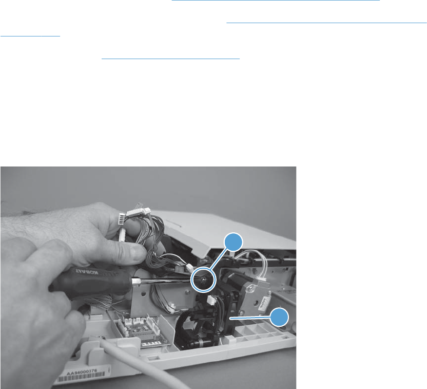
ASY-FAN-SP (document feeder fan)
Before proceeding, remove the following components
●S-CVR-REAR (scanner rear cover). See S-CVR-REAR (scanner rear cover) on page 128.
●ASY-CVR-F-R-SP (document feeder rear cover). See ASY-CVR-F-R-SP (document feeder rear cover)
on page 131.
●Document feeder. See Document feeder on page 151.
Remove the ASY-FAN-SP (document feeder fan)
▲Disconnect all connectors from the document feeder PCA and lift the cable guide to provide access
to the screw (callout 1). Remove one screw (callout 1), and then remove the document feeder fan
(callout 2).
Figure 2-101 Remove the ASY-FAN-SP (document feeder fan)
11
2
164 Chapter 2 Removal and replacement ENWW
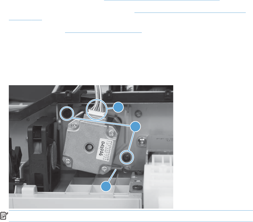
ASY-MOT-FE-SP (motor)
Before proceeding, remove the following components
●S-CVR-REAR (scanner rear cover). See S-CVR-REAR (scanner rear cover) on page 128.
●ASY-CVR-F-R-SP (document feeder rear cover). See ASY-CVR-F-R-SP (document feeder rear cover)
on page 131.
●Document feeder. See Document feeder on page 151.
Remove the ASY-MOT-FE-SP (motor)
▲Remove two screws (callout 1), disconnect one connector (callout 2), release one spring (callout
3), and then remove the motor.
Figure 2-102 Remove the ASY-MOT-FE-SP (motor)
1
1
1
2
3
NOTE: When reassembling, reattach the spring before reinstalling screws.
ENWW Document feeder 165
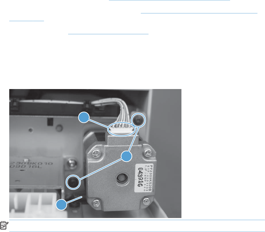
ASY-MOT-RE-SP (document feeder motor)
Before proceeding, remove the following components
●S-CVR-REAR (scanner rear cover). See S-CVR-REAR (scanner rear cover) on page 128.
●ASY-CVR-F-R-SP (document feeder rear cover). See ASY-CVR-F-R-SP (document feeder rear cover)
on page 131.
●Document feeder. See Document feeder on page 151.
Remove the ASY-MOT-RE-SP (motor)
▲Remove two screws (callout 1), disconnect one connector (callout 2), release one spring (callout
3), and then remove the motor.
Figure 2-103 Remove the ASY-MOT-RE-SP (motor)
11
3
2
NOTE: When reassembling, reattach the spring before reinstalling screws.
166 Chapter 2 Removal and replacement ENWW
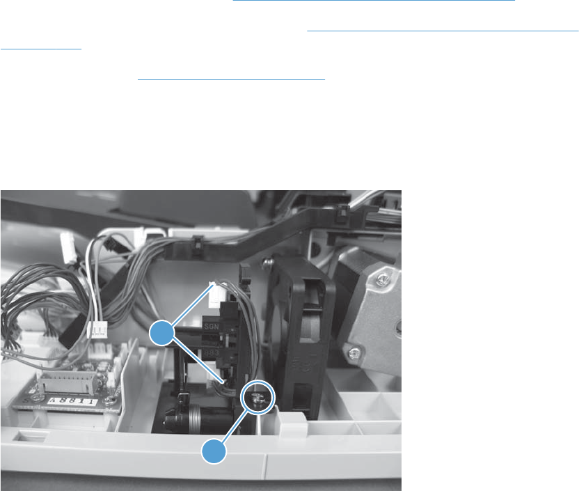
ASY-DFSENS-SP (document feeder open sensor)
Before proceeding, remove the following components
●S-CVR-REAR (scanner rear cover). See S-CVR-REAR (scanner rear cover) on page 128.
●ASY-CVR-F-R-SP (document feeder rear cover). See ASY-CVR-F-R-SP (document feeder rear cover)
on page 131.
●Document feeder. See Document feeder on page 151.
Remove the ASY-DFSENS-SP (document feeder open sensor)
▲Remove one screw (callout 1), disconnect two connectors (callout 2), and then remove the sensor.
Figure 2-104 Remove the ASY-DFSENS-SP (document feeder open sensor)
1
2
ENWW Document feeder 167
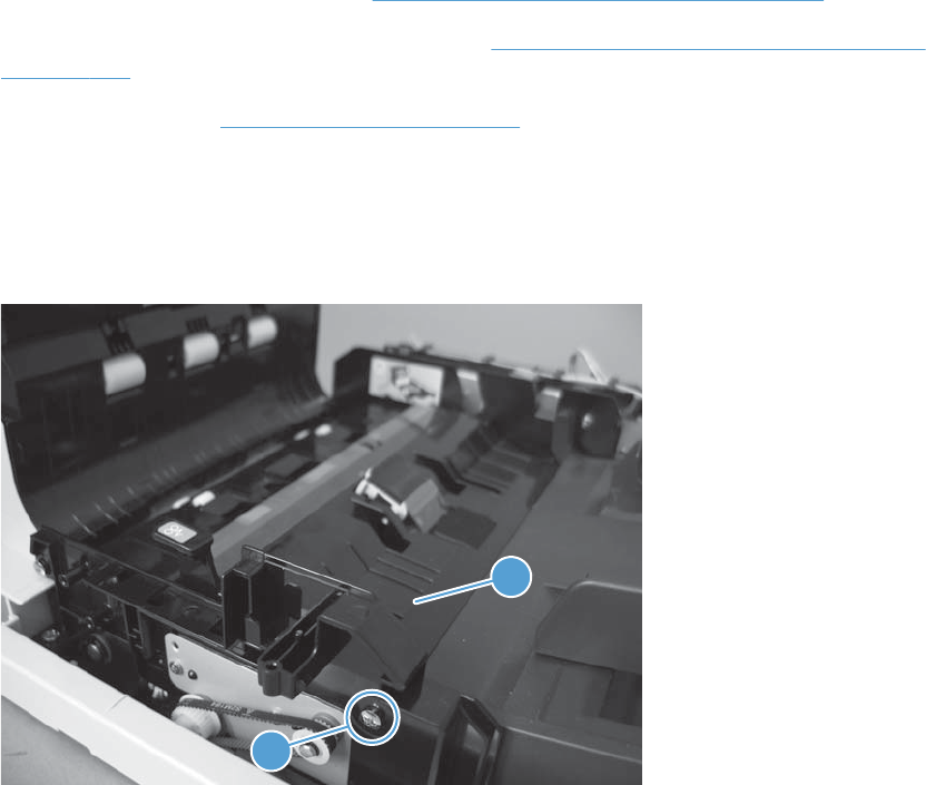
ASY-GIDREV-SPR-SP (document feeder jam access plate)
Before proceeding, remove the following components
●S-CVR-REAR (scanner rear cover). See S-CVR-REAR (scanner rear cover) on page 128.
●ASY-CVR-F-R-SP (document feeder rear cover). See ASY-CVR-F-R-SP (document feeder rear cover)
on page 131.
●Document feeder. See Document feeder on page 151.
Remove the ASY-GIDREV-SPR-SP (document feeder jam access plate)
▲Remove one stepped screw (callout 1) and then remove the jam access plate (callout 2).
Figure 2-105 Remove the ASY-GIDREV-SPR-SP (document feeder jam access plate)
1
2
168 Chapter 2 Removal and replacement ENWW
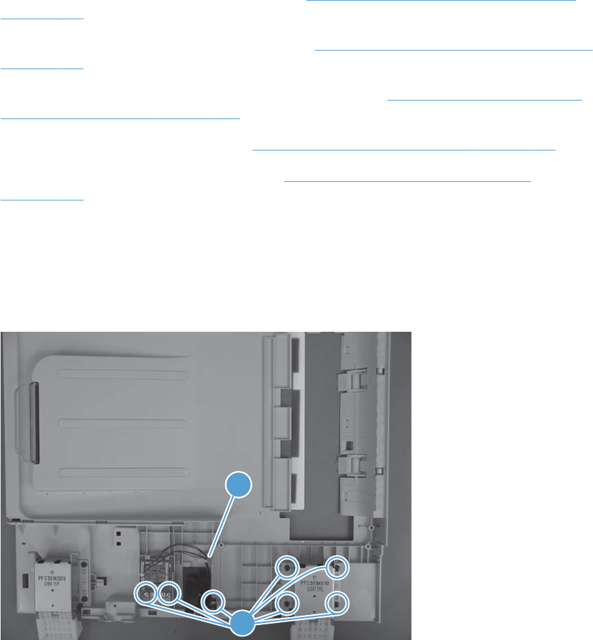
ASY-BASE_SB (base assembly)
Before proceeding, remove the following components
●ASY-CVR-F-SP (document feeder front cover). See ASY-CVR-F-SP (document feeder front cover)
on page 129.
●ASY-CVR-F-R-SP (document feeder rear cover). See ASY-CVR-F-R-SP (document feeder rear cover)
on page 131.
●ASY-CVR-FE-FEED-SP (document feeder jam-access cover). See ASY-CVR-FE-FEED-SP (document
feeder jam-access cover) on page 153.
●ASY-FAN-SP (document feeder fan). See ASY-FAN-SP (document feeder fan) on page 164.
●ASY-FRM-RE-FEED-SP (internal assembly). See ASY-FRM-RE-FEED-SP (internal assembly)
on page 157.
Remove the ASY-BASE_SB (base assembly)
▲Remove seven screws (callout 1) and then release one cable clamp (callout 2). Remove the right
hinge, document feeder PCA, and document feeder open sensor from the base assembly.
Figure 2-106 Remove the ASY-BASE_SB (base assembly)
12
1
ENWW Document feeder 169
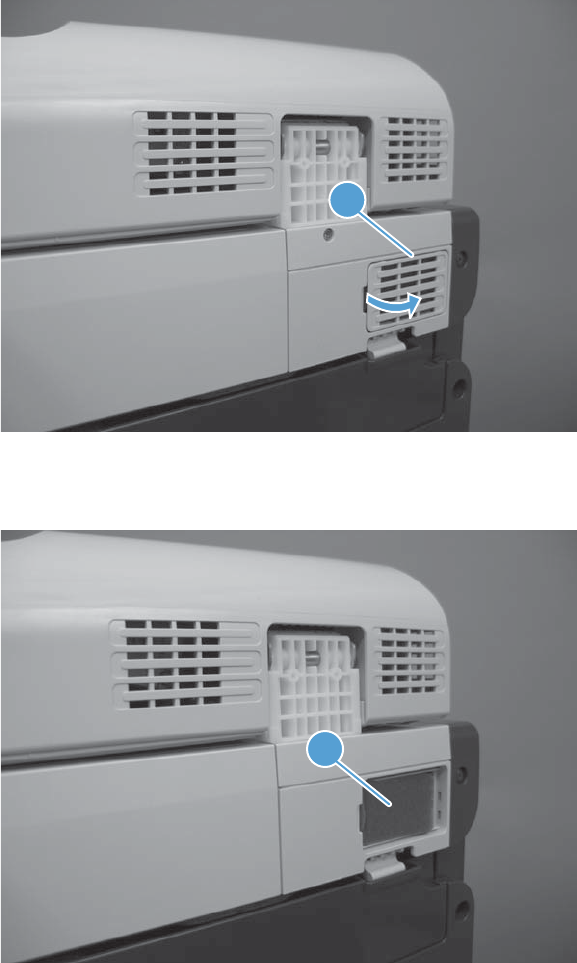
Scanner
Scanner filter cover and scanner filter
1. Remove the scanner-filter cover (callout 1).
Figure 2-107 Remove the scanner filter (1 of 2)
1
2. Remove the filter (callout 1).
Figure 2-108 Remove the scanner filter (2 of 2)
1
170 Chapter 2 Removal and replacement ENWW
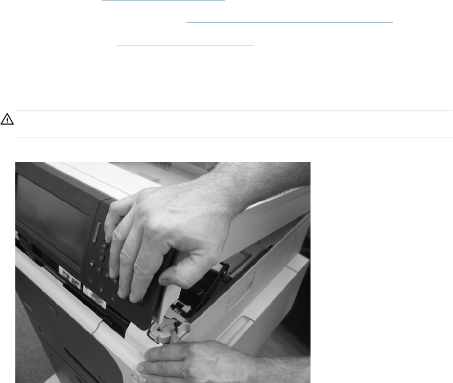
Scanner assembly
Before proceeding, remove the following components
●Control panel. See Control panel on page 100.
●S-CVR-REAR (scanner rear cover). See S-CVR-REAR (scanner rear cover) on page 128.
●Document feeder. See Document feeder on page 151.
Remove the scanner
1. Carefully open the scanner.
WARNING! When the document feeder is removed from the product, the scanner opens with
force. Press down on the scanner with one hand when releasing the scanner latch.
Figure 2-109 Remove the scanner assembly (1 of 6)
ENWW Scanner 171
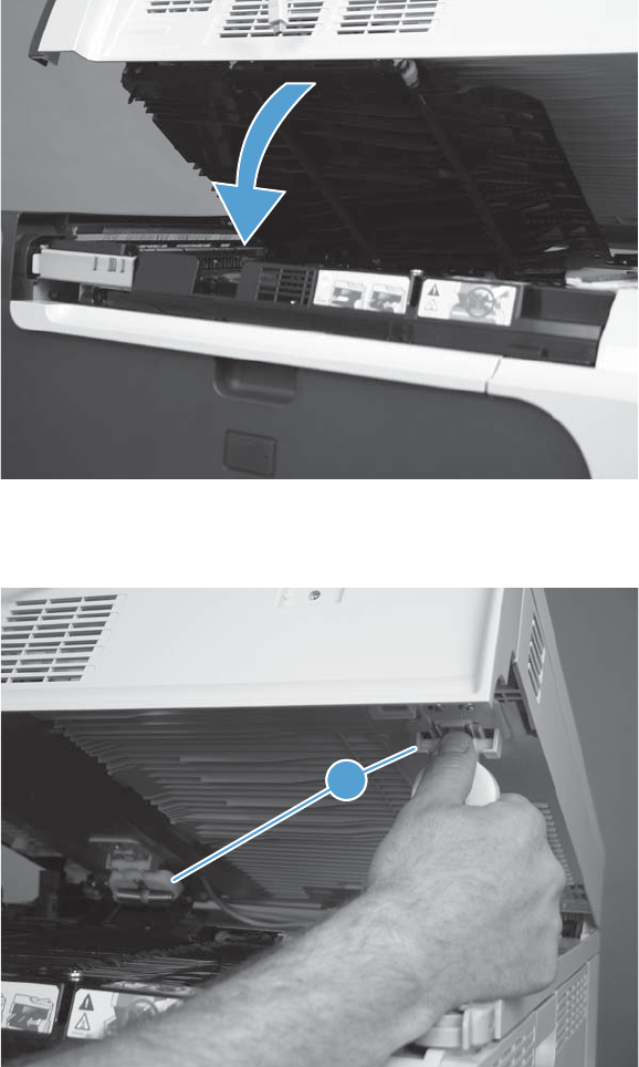
2. Lower the jam access cover.
Figure 2-110 Remove the scanner assembly (2 of 6)
3. Release two scissor hinges (callout 1).
Figure 2-111 Remove the scanner assembly (3 of 6)
11
172 Chapter 2 Removal and replacement ENWW
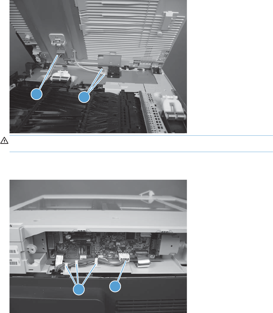
4. Disconnect two connectors (callout 1) and release the safety cable (callout 2).
Figure 2-112 Remove the scanner assembly (4 of 6)
1
11
2
WARNING! The scanner is no longer secured to the product. To prevent the scanner from
falling from the product, firmly grasp the scanner when opening.
5. Disconnect one connector (callout 1), and then release the cable from the cable guides (callout 2).
Figure 2-113 Remove the scanner assembly (5 of 6)
1
11
2
ENWW Scanner 173
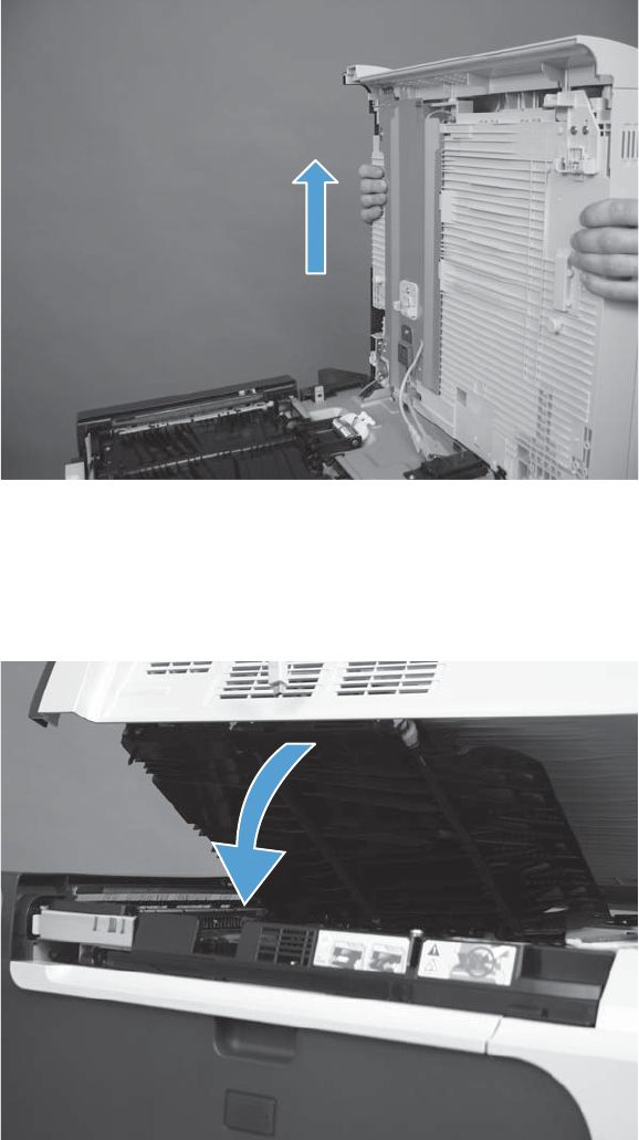
6. From the rear of the product, lift the scanner to remove.
Figure 2-114 Remove the scanner assembly (6 of 6)
Scissor hinge assemblies
1. Open the scanner and then lower the jam access cover.
Figure 2-115 Remove the scissor hinge assembly (1 of 3)
174 Chapter 2 Removal and replacement ENWW
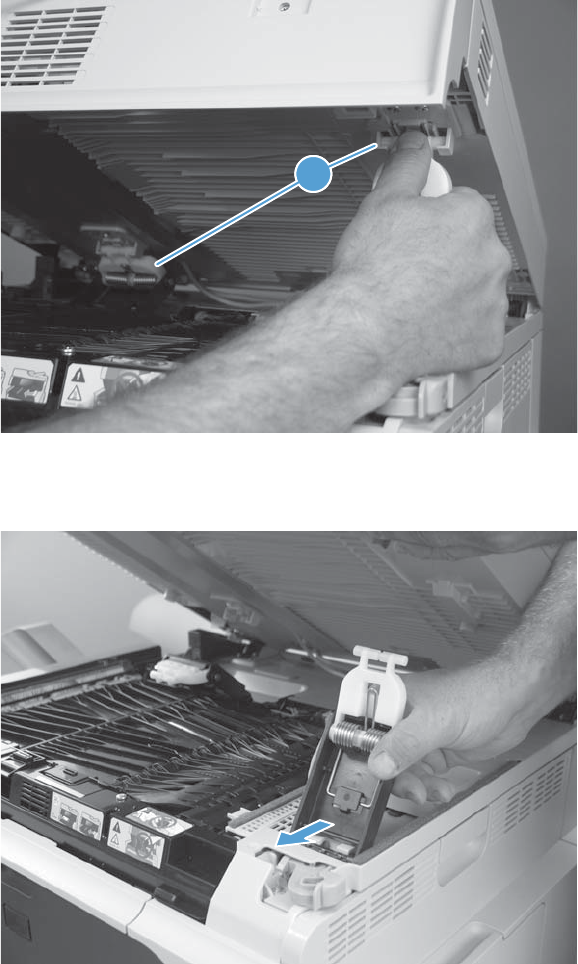
2. Release the top of the two scissor hinges (callout 1).
Figure 2-116 Remove the scissor hinge assembly (2 of 3)
11
3. Release the bottom of the two scissor hinges and remove.
Figure 2-117 Remove the scissor hinge assembly (3 of 3)
ENWW Scanner 175
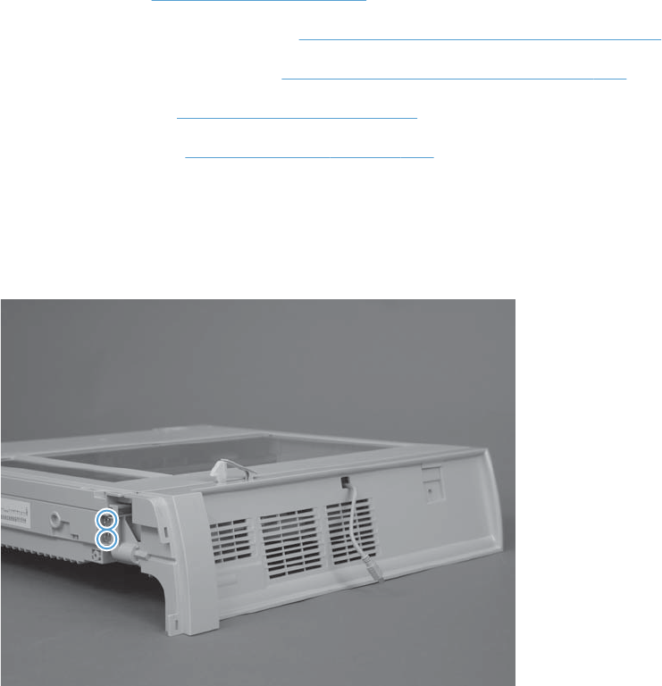
S-ASSY-CP-ADAPTER (CP adapter assembly)
Before proceeding, remove the following components
●Control panel. See Control panel on page 100.
●S-CVR-REAR (scanner rear cover). See S-CVR-REAR (scanner rear cover) on page 128.
●S-CVR-LEFT (scanner left cover). See S-CVR-LEFT (scanner left cover) on page 133
●Document feeder. See Document feeder on page 151.
●Scanner assembly. See Scanner assembly on page 171.
Remove the S-ASSY-CP-ADAPTER (CP adapter assembly)
1. Remove two screws.
Figure 2-118 Remove the S-ASSY-CP-ADAPTER (CP adapter assembly) (1 of 4)
176 Chapter 2 Removal and replacement ENWW
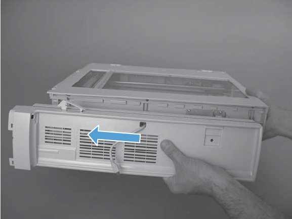
2. Slide the CP adapter assembly to the left to release.
Figure 2-119 Remove the S-ASSY-CP-ADAPTER (CP adapter assembly) (2 of 4)
ENWW Scanner 177
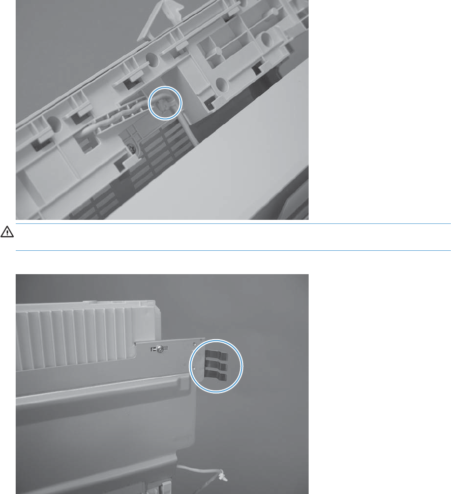
3. Squeeze the retainer to release the cable from the back of the CP adapter assembly.
Figure 2-120 Remove the S-ASSY-CP-ADAPTER (CP adapter assembly) (3 of 4)
CAUTION: After removing the CP adapter assembly from the scanner, be careful not to
damage the ground spring.
Figure 2-121 Remove the S-ASSY-CP-ADAPTER (CP adapter assembly) (4 of 4)
178 Chapter 2 Removal and replacement ENWW
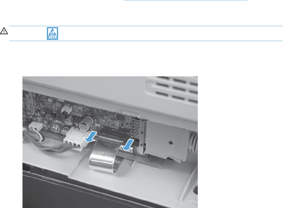
S-PBA-SCB (SCB)
Before proceeding, remove the following components
●S-CVR-REAR (scanner rear cover). See S-CVR-REAR (scanner rear cover) on page 128.
Remove the S-PBA-SCB (SCB)
CAUTION: ESD-sensitive part.
1. Carefully unlatch the top of the zero insertion force (ZIF) connector to release the flat flexible cable
(FFC). Disconnect the FFC.
Figure 2-122 Remove the S-PBA-SCB (SCB) (1 of 2)
ENWW Scanner 179
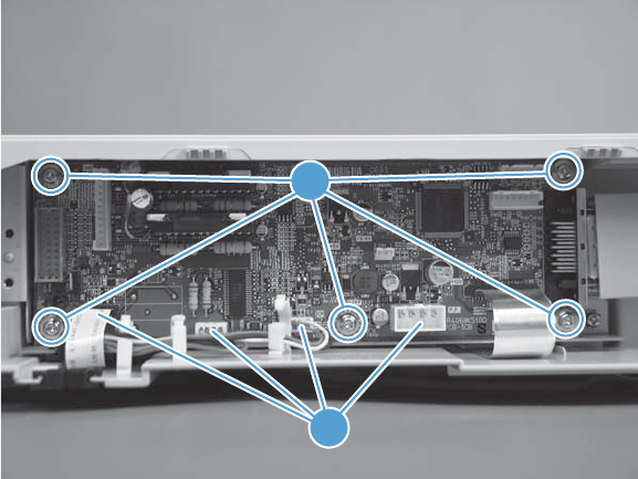
2. Remove five screws (callout 1), disconnect four connectors (callout 2), and then remove the SCB.
Figure 2-123 Remove the S-PBA-SCB (SCB) (2 of 2)
1
2
180 Chapter 2 Removal and replacement ENWW
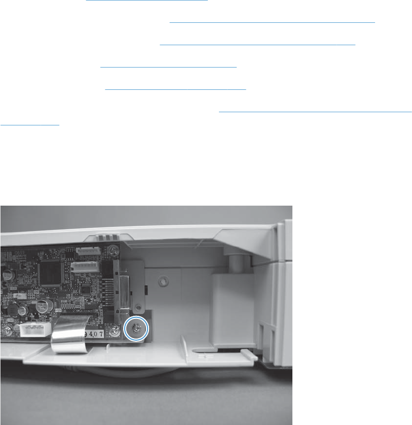
S-ASM-USB (USB control panel cable)
Before proceeding, remove the following components
●Control panel. See Control panel on page 100.
●S-CVR-REAR (scanner rear cover). See S-CVR-REAR (scanner rear cover) on page 128.
●S-CVR-LEFT (scanner left cover). See S-CVR-LEFT (scanner left cover) on page 133.
●Document feeder. See Document feeder on page 151.
●Scanner assembly. See Scanner assembly on page 171.
●S-ASSY-CP-ADAPTER (CP adapter assembly). See S-ASSY-CP-ADAPTER (CP adapter assembly)
on page 176
Remove the S-ASM-USB (USB control panel cable)
1. Remove one screw.
Figure 2-124 Remove the S-ASM-USB (USB control panel cable) (1 of 2)
ENWW Scanner 181
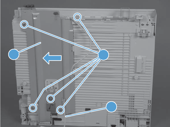
2. Remove five screws (callout 1), and then slide the lift plate (callout 2) and remove. Remove the
cable (callout 3).
Figure 2-125 Remove the S-ASM-USB (USB control panel cable) (2 of 2)
1
2
3
182 Chapter 2 Removal and replacement ENWW
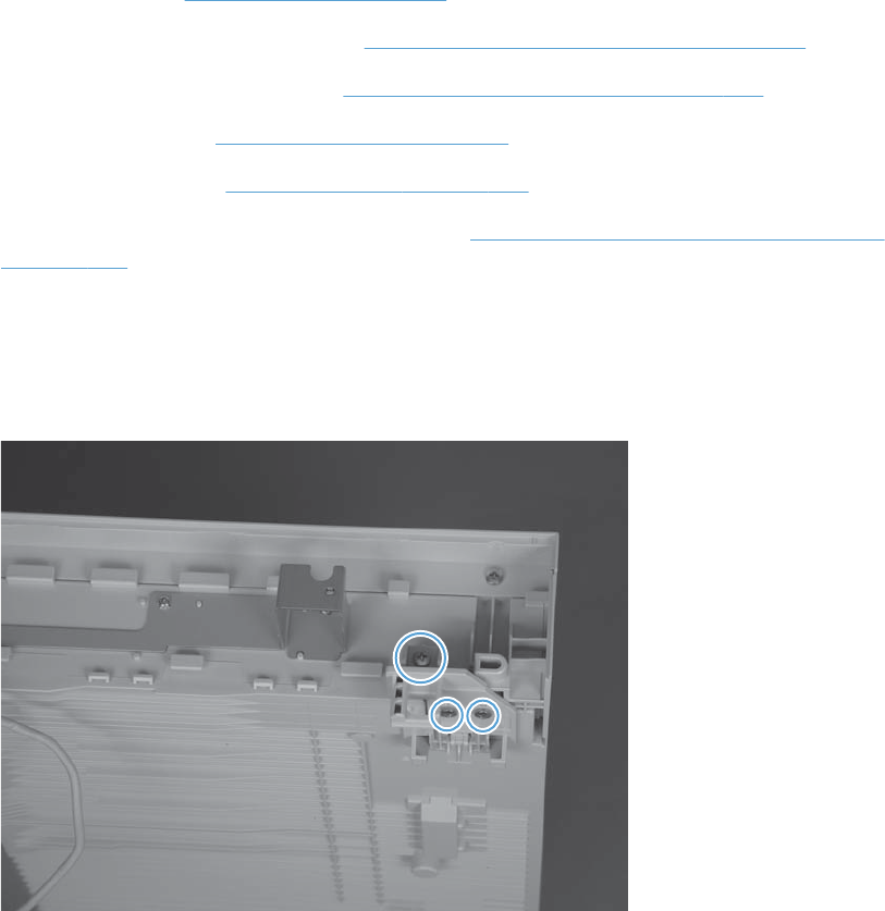
S-HNG-LIFT-R (scanner release assembly)
Before proceeding, remove the following components
●Control panel. See Control panel on page 100.
●S-CVR-REAR (scanner rear cover). See S-CVR-REAR (scanner rear cover) on page 128.
●S-CVR-LEFT (scanner left cover). See S-CVR-LEFT (scanner left cover) on page 133.
●Document feeder. See Document feeder on page 151.
●Scanner assembly. See Scanner assembly on page 171.
●S-ASSY-CP-ADAPTER (CP adapter assembly). See S-ASSY-CP-ADAPTER (CP adapter assembly)
on page 176.
Remove the S-HNG-LIFT-R (scanner release assembly)
▲Remove three screws, and then remove the scanner release assembly.
Figure 2-126 Remove the S-HNG-LIFT-R (scanner release assembly)
ENWW Scanner 183
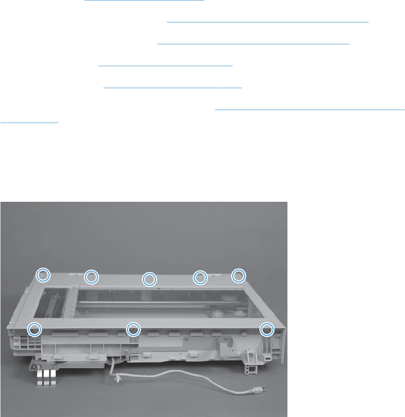
S-ASSY-UPPER-UNIT (tub top)
Before proceeding, remove the following components
●Control panel. See Control panel on page 100.
●S-CVR-REAR (scanner rear cover). See S-CVR-REAR (scanner rear cover) on page 128.
●S-CVR-LEFT (scanner left cover). See S-CVR-LEFT (scanner left cover) on page 133.
●Document feeder. See Document feeder on page 151.
●Scanner assembly. See Scanner assembly on page 171.
●S-ASSY-CP-ADAPTER (CP adapter assembly). See S-ASSY-CP-ADAPTER (CP adapter assembly)
on page 176.
Remove the S-ASSY-UPPER-UNIT (tub top)
▲Remove eight screws and then remove the tub top.
Figure 2-127 Remove tub top
184 Chapter 2 Removal and replacement ENWW
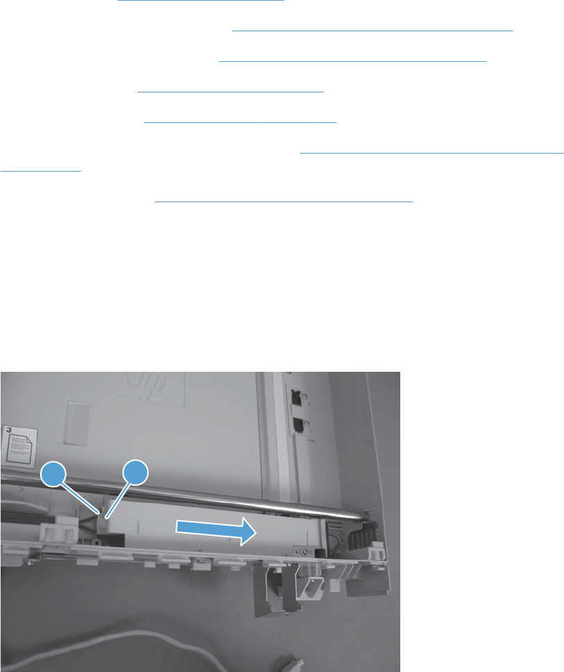
S-PBA-TYUKEI (interconnect board) and S-SNS-EY3A1061–2 (size
sensor)
Before proceeding, remove the following components
●Control panel. See Control panel on page 100.
●S-CVR-REAR (scanner rear cover). See S-CVR-REAR (scanner rear cover) on page 128.
●S-CVR-LEFT (scanner left cover). See S-CVR-LEFT (scanner left cover) on page 133.
●Document feeder. See Document feeder on page 151.
●Scanner assembly. See Scanner assembly on page 171.
●S-ASSY-CP-ADAPTER (CP adapter assembly). See S-ASSY-CP-ADAPTER (CP adapter assembly)
on page 176.
●S-ASSY-UPPER-UNIT. See S-ASSY-UPPER-UNIT (tub top) on page 184.
Remove the S-PBA-TYUKEI (interconnect board) and S-SNS-EY3A1061–2 (size
sensor)
1. Disconnect one connector (callout 1), release one tab (callout 2), and then slide the inverter cover
to the right to remove.
Figure 2-128 Remove the S-PBA-TYUKEI (interconnect board) and S-SNS-EY3A1061–2 (size
sensor) (1 of 4)
12
2. Move the carriage to the center of the scanner.
ENWW Scanner 185
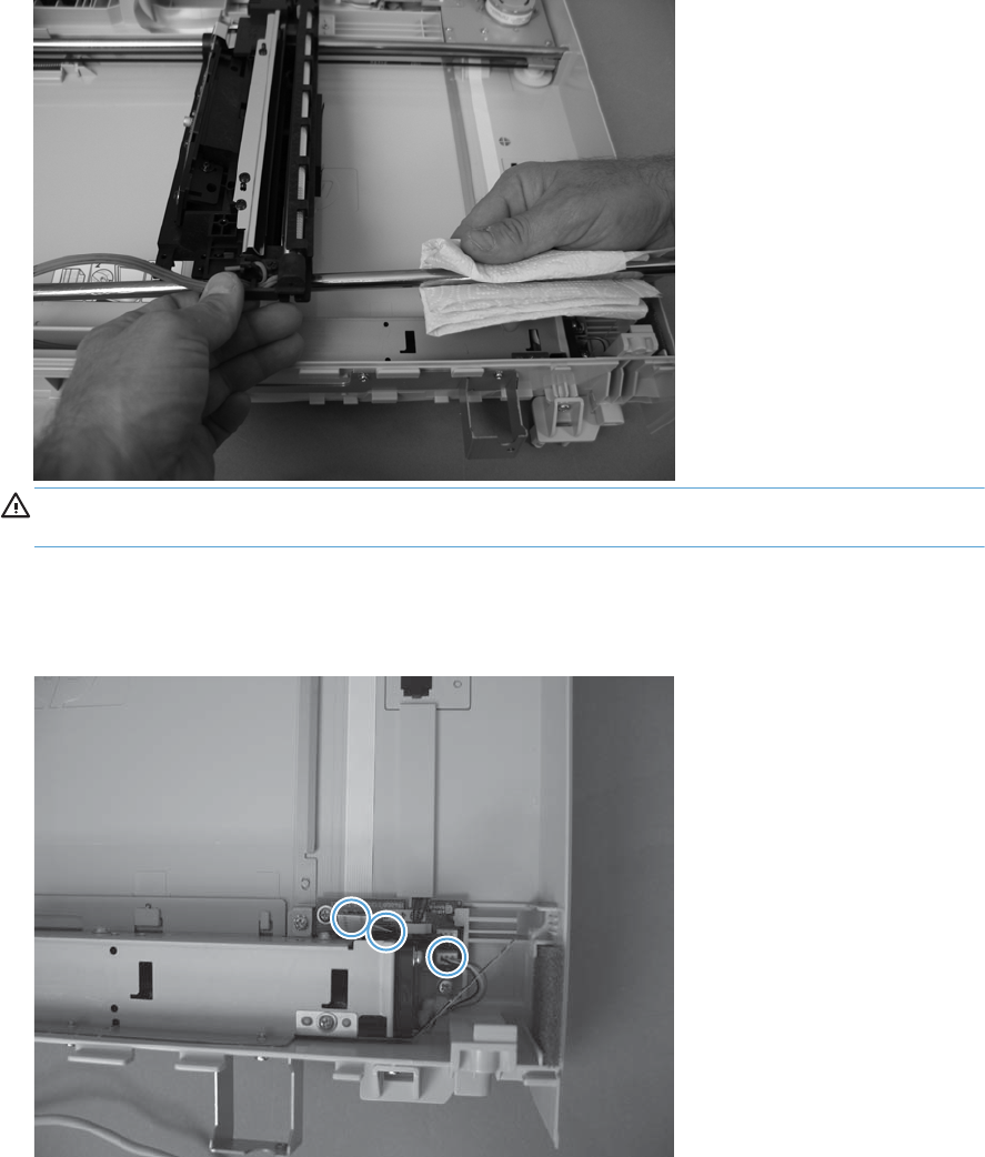
3. Remove the front side shaft.
Figure 2-129 Remove the S-PBA-TYUKEI (interconnect board) and S-SNS-EY3A1061–2 (size
sensor) (2 of 4)
CAUTION: Grease is applied to the shaft. Avoid removing the grease from the shaft. Keep the
grease away from other parts of the product.
4. Disconnect two FFCs and one connector.
Figure 2-130 Remove the S-PBA-TYUKEI (interconnect board) and S-SNS-EY3A1061–2 (size
sensor) (3 of 4)
186 Chapter 2 Removal and replacement ENWW
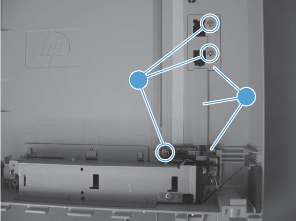
5. Remove three screws (callout 1) and the interconnect board and size sensor (callout 2).
Figure 2-131 Remove the S-PBA-TYUKEI (interconnect board) and S-SNS-EY3A1061–2 (size
sensor) (4 of 4)
1
2
ENWW Scanner 187
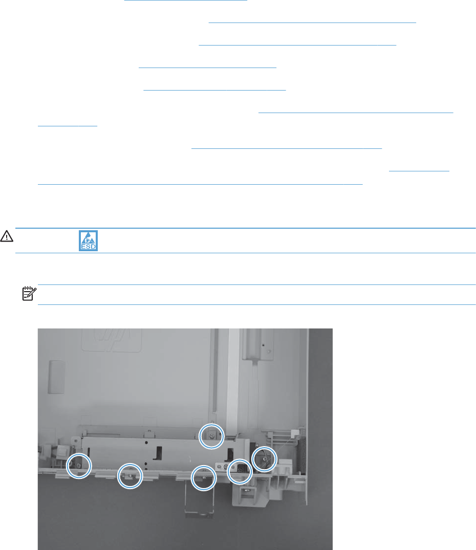
S-ASSY-INV (inverter)
●Control panel. See Control panel on page 100.
●S-CVR-REAR (scanner rear cover). See S-CVR-REAR (scanner rear cover) on page 128.
●S-CVR-LEFT (scanner left cover). See S-CVR-LEFT (scanner left cover) on page 133.
●Document feeder. See Document feeder on page 151.
●Scanner assembly. See Scanner assembly on page 171.
●S-ASSY-CP-ADAPTER (CP adapter assembly). See S-ASSY-CP-ADAPTER (CP adapter assembly)
on page 176.
●S-ASSY-UPPER-UNIT (tub top). See S-ASSY-UPPER-UNIT (tub top) on page 184.
●S-PBA-TYUKEI (interconnect board) and S-SNS-EY3A1061–2 (size sensor). See S-PBA-TYUKEI
(interconnect board) and S-SNS-EY3A1061–2 (size sensor) on page 185.
Remove the S-ASSY-INV (inverter)
CAUTION: ESD-sensitive part.
1. Remove six screws.
NOTE: Make sure to note the locations of each screw type.
Figure 2-132 Remove the S-ASSY-INV (inverter) (1 of 2)
188 Chapter 2 Removal and replacement ENWW
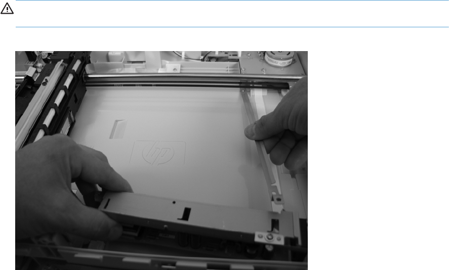
2. Carefully lift the grounding plate and then remove the inverter.
CAUTION: Do not deform the grounding plate. Deforming the grounding plate can cause the
optical carriage to malfunction.
Figure 2-133 Remove the S-ASSY-INV (inverter) (2 of 2)
ENWW Scanner 189
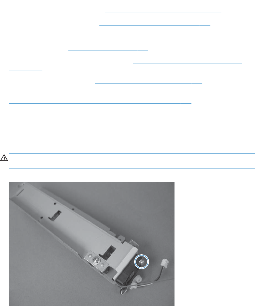
S-FAN-MFB-30E-05A-006 (inverter fan)
Before proceeding, remove the following components
●Control panel. See Control panel on page 100.
●S-CVR-REAR (scanner rear cover). See S-CVR-REAR (scanner rear cover) on page 128.
●S-CVR-LEFT (scanner left cover). See S-CVR-LEFT (scanner left cover) on page 133.
●Document feeder. See Document feeder on page 151.
●Scanner assembly. See Scanner assembly on page 171.
●S-ASSY-CP-ADAPTER (CP adapter assembly). See S-ASSY-CP-ADAPTER (CP adapter assembly)
on page 176.
●S-ASSY-UPPER-UNIT (tub top). See S-ASSY-UPPER-UNIT (tub top) on page 184.
●S-PBA-TYUKEI (interconnect board) and S-SNS-EY3A1061–2 (size sensor). See S-PBA-TYUKEI
(interconnect board) and S-SNS-EY3A1061–2 (size sensor) on page 185.
●S-ASSY-INV (inverter). See S-ASSY-INV (inverter) on page 188.
Remove the S-FAN-MFB-30E-05A-006 (inverter fan)
▲Remove one screw, and then remove the inverter fan.
CAUTION: Check the arrows embossed on the fan frame that indicate air flow direction. When
the fan is reinstalled, the air must flow in the correct direction.
Figure 2-134 Remove the S-FAN-MFB-30E-05A-006 (inverter fan)
190 Chapter 2 Removal and replacement ENWW
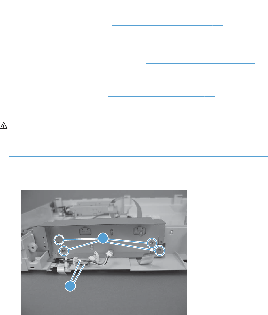
ASSY-CRG-UNIT-IR4068 (optical assembly)
●Control panel. See Control panel on page 100.
●S-CVR-REAR (scanner rear cover). See S-CVR-REAR (scanner rear cover) on page 128.
●S-CVR-LEFT (scanner left cover). See S-CVR-LEFT (scanner left cover) on page 133.
●Document feeder. See Document feeder on page 151.
●Scanner assembly. See Scanner assembly on page 171.
●S-ASSY-CP-ADAPTER (CP adapter assembly). See S-ASSY-CP-ADAPTER (CP adapter assembly)
on page 176.
●S-PBA-SCB (SCB). See S-PBA-SCB (SCB) on page 179.
●S-ASSY-UPPER-UNIT (tub top). See S-ASSY-UPPER-UNIT (tub top) on page 184.
Remove the ASSY-CRG-UNIT-IR4068 (optical assembly)
CAUTION: If removing both shafts, be sure to return each shaft in its original position. The front shaft
has oil applied and rear shaft has grease applied.
CAUTION: Avoid removing the grease and oil from the shafts. Keep the grease and oil away from
other parts of the product.
1. Remove four screws (callout 1), release two cables (callout 2) from the cable guides, and then
remove the sheet metal box.
Figure 2-135 Remove the ASSY-CRG-UNIT-IR4068 (optical assembly) (1 of 6)
1
2
ENWW Scanner 191
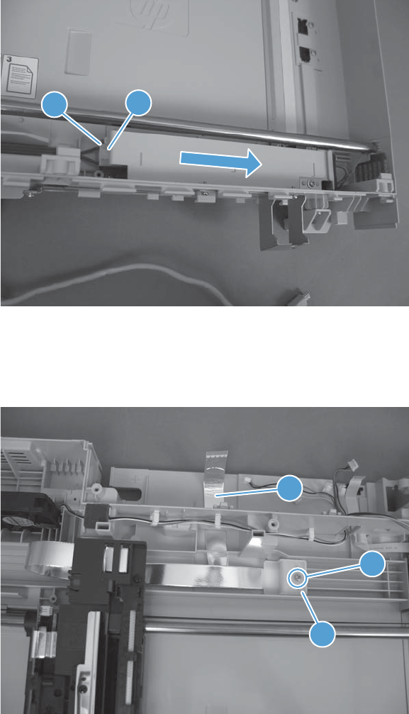
2. Disconnect one connector (callout 1), release one tab (callout 2), and then slide the inverter cover
to the right to remove.
Figure 2-136 Remove the ASSY-CRG-UNIT-IR4068 (optical assembly) (2 of 6)
12
3. Move the carriage to the center of the scanner.
4. Remove one screw (callout 1) and restraint (callout 2). Release the FFC (callout 3) from the tape.
Figure 2-137 Remove the ASSY-CRG-UNIT-IR4068 (optical assembly) (3 of 6)
3
1
2
192 Chapter 2 Removal and replacement ENWW
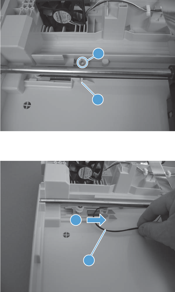
5. Remove one screw (callout 1), and then remove the stop (callout 2).
Figure 2-138 Remove the ASSY-CRG-UNIT-IR4068 (optical assembly) (4 of 6)
1
2
6. Compress the spring until it locks (callout 1), and then remove the belt (callout 2) from the pulley.
Figure 2-139 Remove the ASSY-CRG-UNIT-IR4068 (optical assembly) (5 of 6)
1
2
ENWW Scanner 193
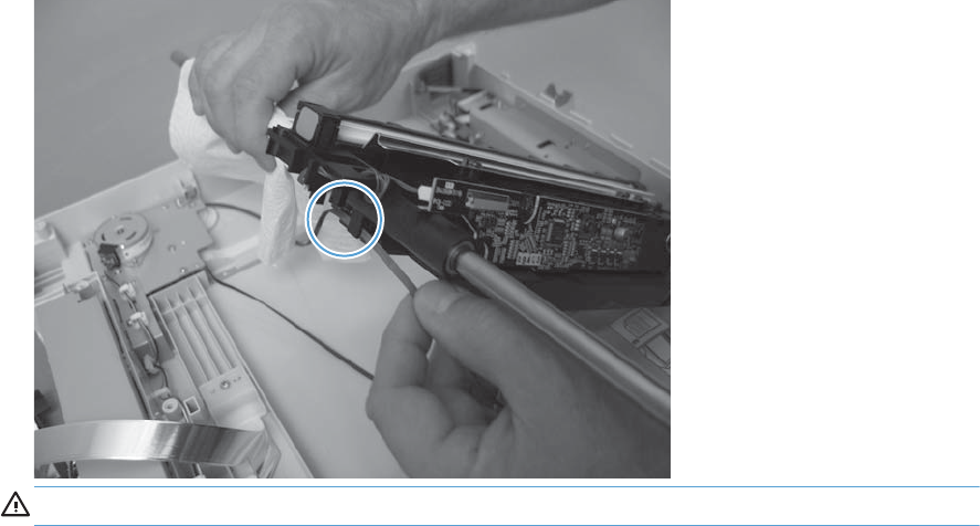
7. Release the belt from the optical assembly and then remove the assembly.
Figure 2-140 Remove the ASSY-CRG-UNIT-IR4068 (optical assembly) (6 of 6)
CAUTION: Oil is applied to the shaft. Keep oil away from other parts of the product.
194 Chapter 2 Removal and replacement ENWW
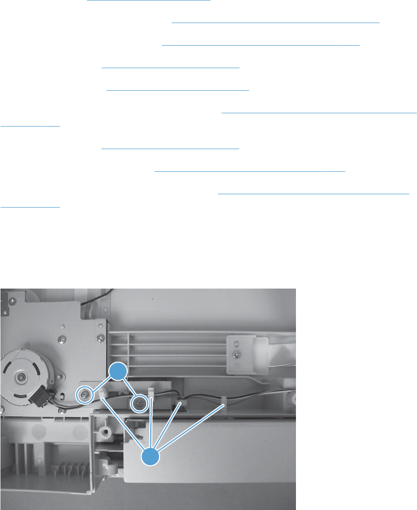
S-ASSY-MOTOR-UNIT (motor assembly)
●Control panel. See Control panel on page 100.
●S-CVR-REAR (scanner rear cover). See S-CVR-REAR (scanner rear cover) on page 128.
●S-CVR-LEFT (scanner left cover). See S-CVR-LEFT (scanner left cover) on page 133.
●Document feeder. See Document feeder on page 151.
●Scanner assembly. See Scanner assembly on page 171.
●S-ASSY-CP-ADAPTER (CP adapter assembly). See S-ASSY-CP-ADAPTER (CP adapter assembly)
on page 176.
●S-PBA-SCB (SCB). See S-PBA-SCB (SCB) on page 179
●S-ASSY-UPPER-UNIT (tub top). See S-ASSY-UPPER-UNIT (tub top) on page 184.
●ASSY-CRG-UNIT-IR4068 (optical assembly). See ASSY-CRG-UNIT-IR4068 (optical assembly)
on page 191.
Remove the S-ASSY-MOTOR-UNIT (motor assembly)
1. Remove two screws (callout 1) and then release the cables from the cable guides (callout 2).
Figure 2-141 Remove the S-ASSY-MOTOR-UNIT (motor assembly) (1 of 3)
1
2
ENWW Scanner 195
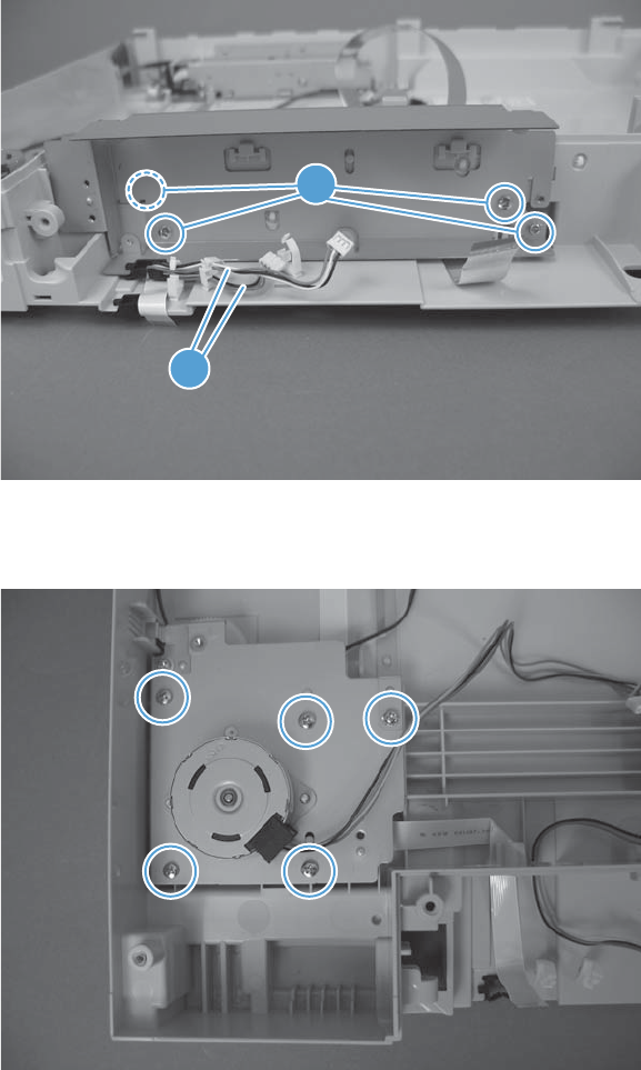
2. Remove three screws (callout 1), release two cables (callout 2) from the cable guides, and then
remove the sheet metal box.
Figure 2-142 Remove the S-ASSY-MOTOR-UNIT (motor assembly) (2 of 3)
1
2
3. Remove five screws, and then remove the motor assembly.
Figure 2-143 Remove the S-ASSY-MOTOR-UNIT (motor assembly) (3 of 3)
196 Chapter 2 Removal and replacement ENWW
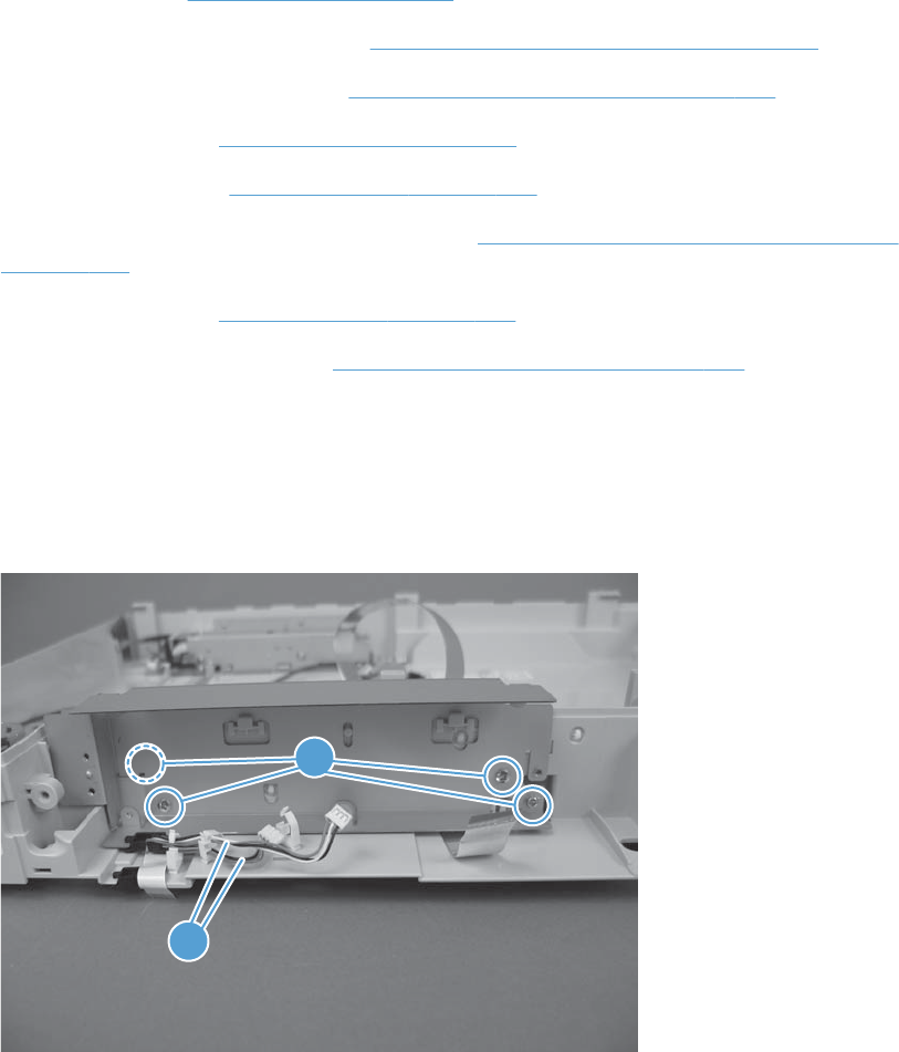
S-FAN-D06037600G-001 (scanner fan)
●Control panel. See Control panel on page 100.
●S-CVR-REAR (scanner rear cover). See S-CVR-REAR (scanner rear cover) on page 128.
●S-CVR-LEFT (scanner left cover). See S-CVR-LEFT (scanner left cover) on page 133.
●Document feeder. See Document feeder on page 151.
●Scanner assembly. See Scanner assembly on page 171.
●S-ASSY-CP-ADAPTER (CP adapter assembly). See S-ASSY-CP-ADAPTER (CP adapter assembly)
on page 176.
●S-PBA-SCB (SCB). See S-PBA-SCB (SCB) on page 179
●S-ASSY-UPPER-UNIT (tub top). See S-ASSY-UPPER-UNIT (tub top) on page 184.
Remove the S-FAN-D06037600G-001 (scanner fan)
1. Remove four screws (callout 1), release two cables (callout 2) from the cable guides, and then
remove the sheet metal box.
Figure 2-144 Remove the S-FAN-D06037600G-001 (scanner fan) (1 of 2)
1
2
ENWW Scanner 197
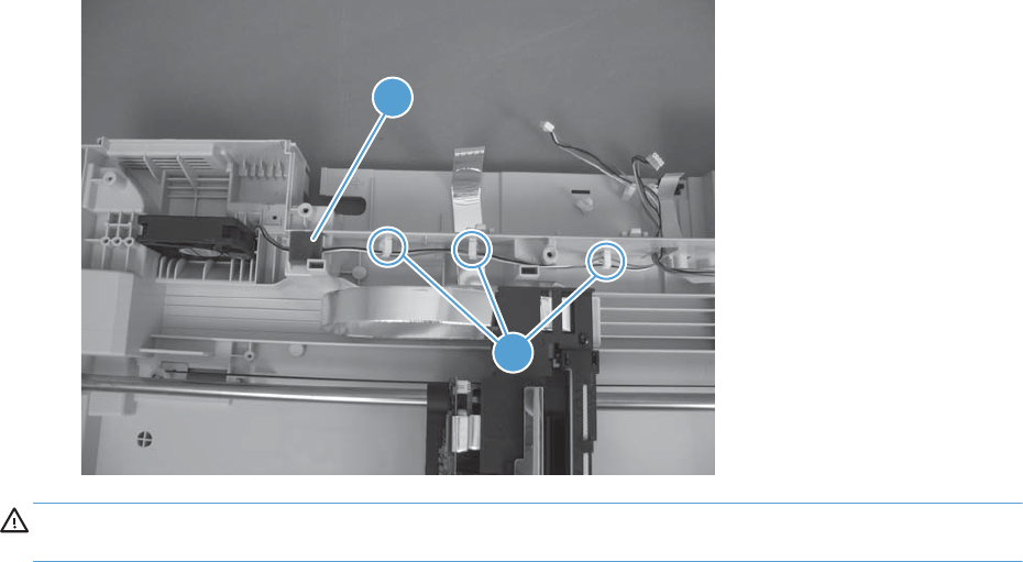
2. Remove the foam (callout 1), release the cable from the cable guides (callout 2), and then remove
the fan.
Figure 2-145 Remove the S-FAN-D06037600G-001 (scanner fan) (2 of 2)
2
1
CAUTION: When the fan is reinstalled, the air must flow into the product. Check the arrows
embossed on the fan frame that indicate air flow direction.
198 Chapter 2 Removal and replacement ENWW
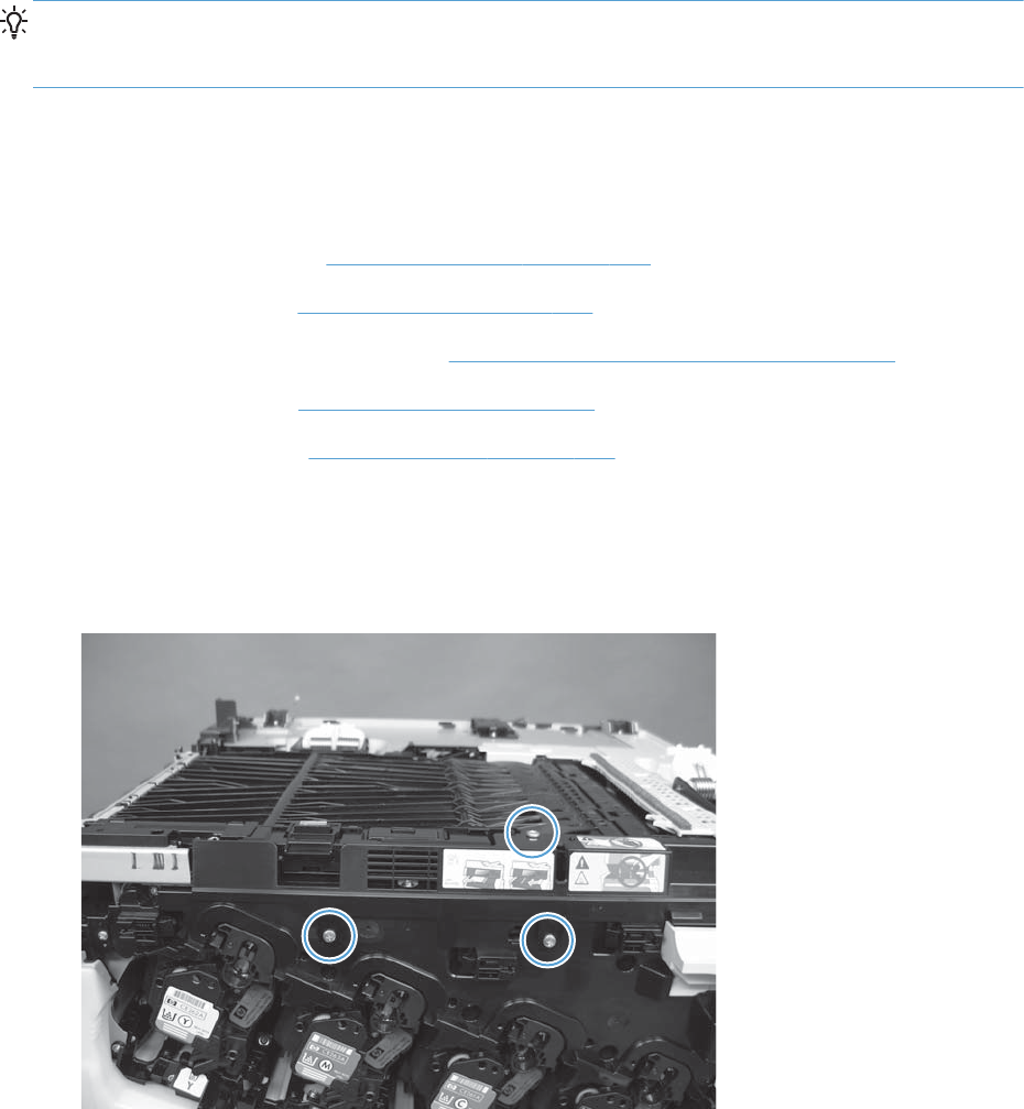
Internal assemblies
TIP: For clarity, some photos in this chapter show components removed that would not be removed to
service the product. If necessary, remove the components listed at the beginning of a procedure before
proceeding to service the product.
IPTU
Before proceeding, remove the following components
●Standard output bin. See Standard output bin on page 123.
●Output bin bezel. See Output bin bezel on page 124.
●S-CVR-REAR (scanner rear cover). See S-CVR-REAR (scanner rear cover) on page 128.
●Document feeder. See Document feeder on page 151.
●Scanner assembly. See Scanner assembly on page 171.
Remove the IPTU
1. Open the front door and then remove three screws.
Figure 2-146 Remove the IPTU (1 of 5)
ENWW Internal assemblies 199
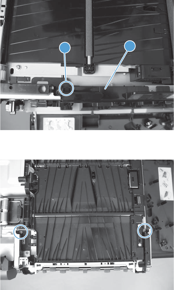
2. Lift the cover up on the right side to clear the pin, lift the paper path, rotate the cover on left side to
release one tab (callout 1), and then remove the inner cover (callout 2).
Figure 2-147 Remove the IPTU (2 of 5)
11
12
3. Remove two screws.
Figure 2-148 Remove the IPTU (3 of 5)
200 Chapter 2 Removal and replacement ENWW
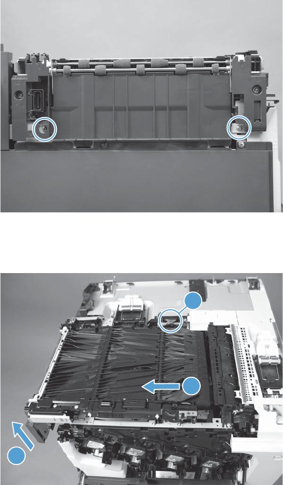
4. Remove two screws.
Figure 2-149 Remove the IPTU (4 of 5)
5. Disconnect one connector (callout 1) and then lift (callout 2) and slide the IPTU (callout 3) to
remove.
Figure 2-150 Remove the IPTU (5 of 5)
2
1
3
ENWW Internal assemblies 201
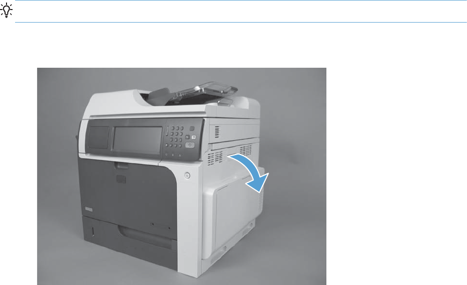
Cassette feed guide
TIP: If a page is jammed in the product, you might be able to access it by removing this guide.
1. Open the right-door assembly.
Figure 2-151 Remove the cassette feed guide (1 of 3)
202 Chapter 2 Removal and replacement ENWW
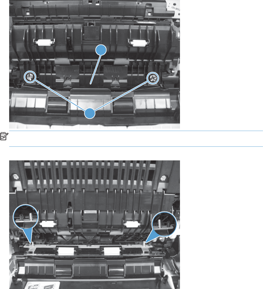
2. Remove two screws (callout 1), and then remove the cassette feed guide (callout 2).
Figure 2-152 Remove the cassette feed guide (2 of 3)
1
2
NOTE: When reinstalling the cassette feed guide, make sure to correctly align each screw and
pin with the corresponding hole and that the guide fits secure against the chassis.
Figure 2-153 Remove the cassette feed guide (3 of 3)
ENWW Internal assemblies 203
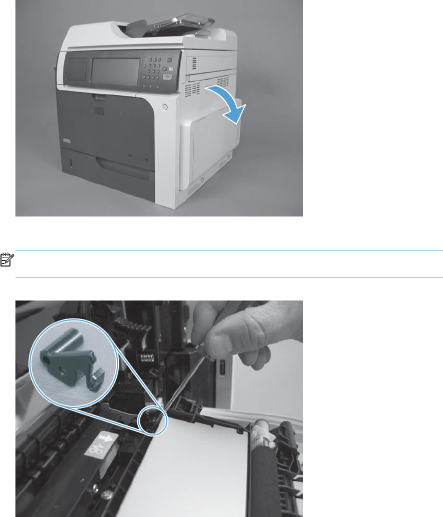
Secondary transfer assembly
The secondary transfer assembly includes the transfer roller.
1. Open the right-door assembly.
Figure 2-154 Remove the secondary transfer assembly (1 of 3)
2. Release one tab and carefully remove the stopper.
NOTE: You might have to slightly lift up on the corner of the assembly to release the stopper pin
from the hole in the chassis.
Figure 2-155 Remove the secondary transfer assembly (2 of 3)
204 Chapter 2 Removal and replacement ENWW
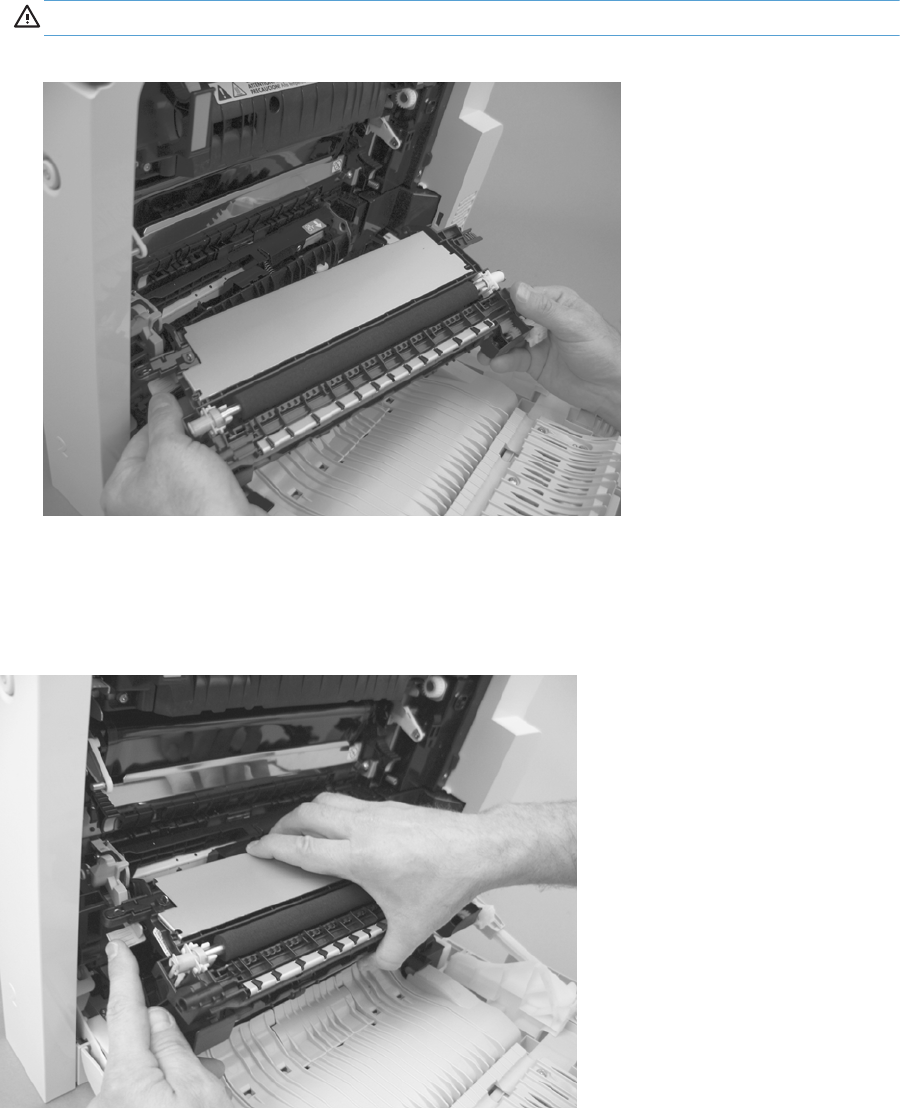
3. Remove the secondary transfer assembly.
CAUTION: Do not damage the blue release lever when removing the assembly.
Figure 2-156 Remove the secondary transfer assembly (3 of 3)
Reinstall the secondary transfer assembly
Press and hold the blue release lever when you reinstall the assembly.
Figure 2-157 Reinstall the secondary transfer assembly
ENWW Internal assemblies 205
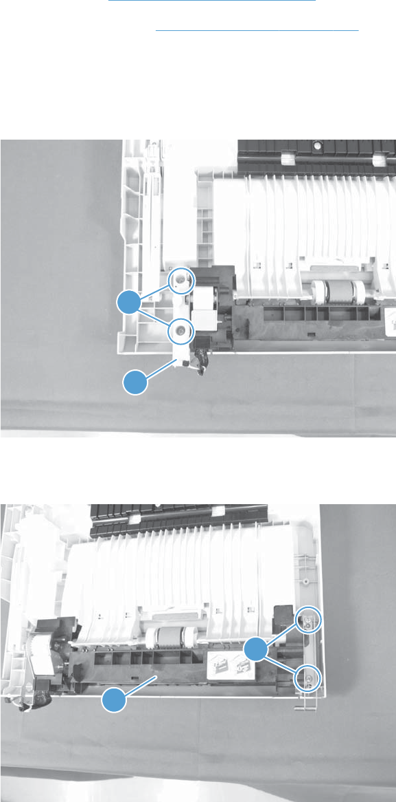
Separation pad (Tray 1)
Before proceeding, remove the following components:
●Pickup roller. See Pickup roller (Tray 1) on page 114.
●Right door assembly. See Right-door assembly on page 145.
Remove the separation pad (Tray 1)
1. Remove two screws (callout 1) and the cover (callout 2).
Figure 2-158 Remove the separation pad (1 of 6)
2
1
2. Remove two screws (callout 1) and separate Tray 1 (callout 2) from the door assembly.
Figure 2-159 Remove the separation pad (2 of 6)
2
1
206 Chapter 2 Removal and replacement ENWW
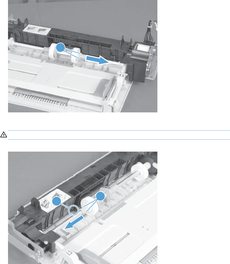
3. Release two tabs (callout 1) and slide the locking cap and sub roller toward the edge of the tray.
Figure 2-160 Remove the separation pad (3 of 6)
1
4. Release two tabs (callout 1) and slide the locking cap and sub roller toward the edge of the tray.
CAUTION: Do not damage the flag (callout 2).
Figure 2-161 Remove the separation pad (4 of 6)
1
2
ENWW Internal assemblies 207
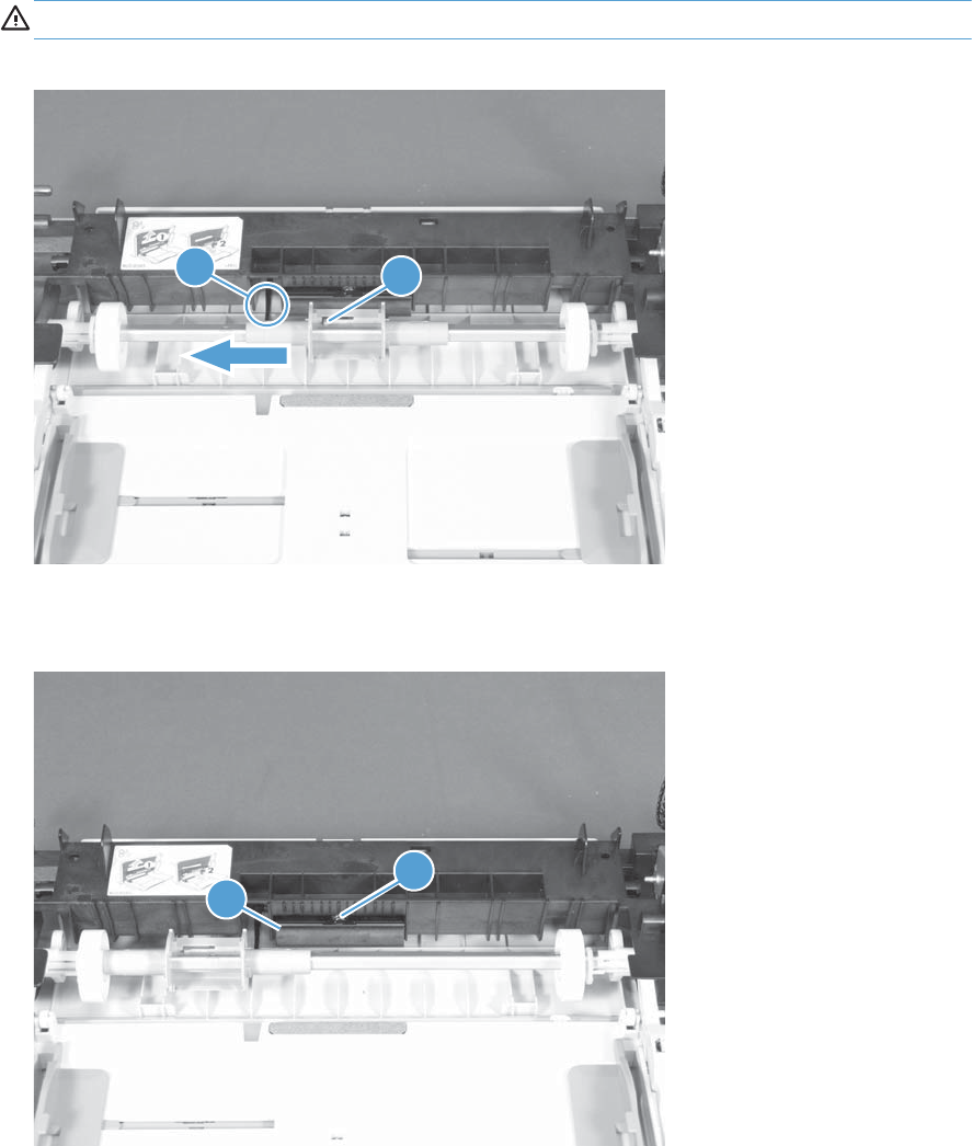
5. Release one tab (callout 1) and slide the pickup-roller holder toward the edge of the tray.
CAUTION: Do not damage the flag (callout 2).
Figure 2-162 Remove the separation pad (5 of 6)
1
2
6. Release one tab (callout 1) and remove the separation pad.
Figure 2-163 Remove the separation pad (6 of 6)
1
2
208 Chapter 2 Removal and replacement ENWW
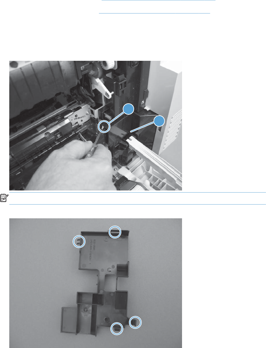
Registration density (RD) sensor assembly
Before proceeding, remove the following components:
●Intermediate transfer belt (ITB). See Intermediate transfer belt (ITB) on page 120.
●Secondary transfer assembly. See Secondary transfer assembly on page 204.
Remove the RD sensor assembly
1. Release one tab (callout 1), and then remove the cover (callout 2).
Figure 2-164 Remove the RD sensor assembly (1 of 7)
1
2
NOTE: When reinstalling the cover, make sure that the tabs are seated correctly.
Figure 2-165 Remove the RD sensor assembly (2 of 7)
ENWW Internal assemblies 209
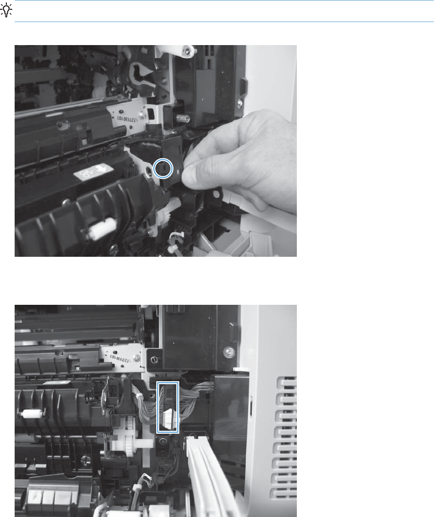
2. Release one tab, and then remove the wire-harness cover.
TIP: Open the front door to make it easier to remove the cover.
Figure 2-166 Remove the RD sensor assembly (3 of 7)
3. Disconnect three connectors.
Figure 2-167 Remove the RD sensor assembly (4 of 7)
210 Chapter 2 Removal and replacement ENWW
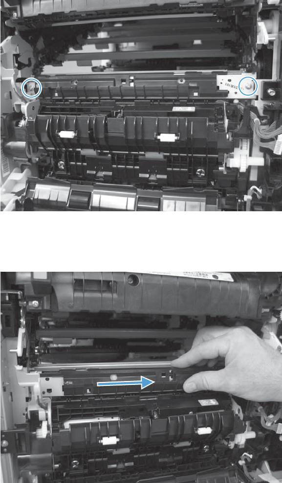
4. Remove two screws.
Figure 2-168 Remove the RD sensor assembly (5 of 7)
5. Slide the shutter toward the back side of the product. Keep the shutter in this position for the
following step.
Figure 2-169 Remove the RD sensor assembly (6 of 7)
ENWW Internal assemblies 211
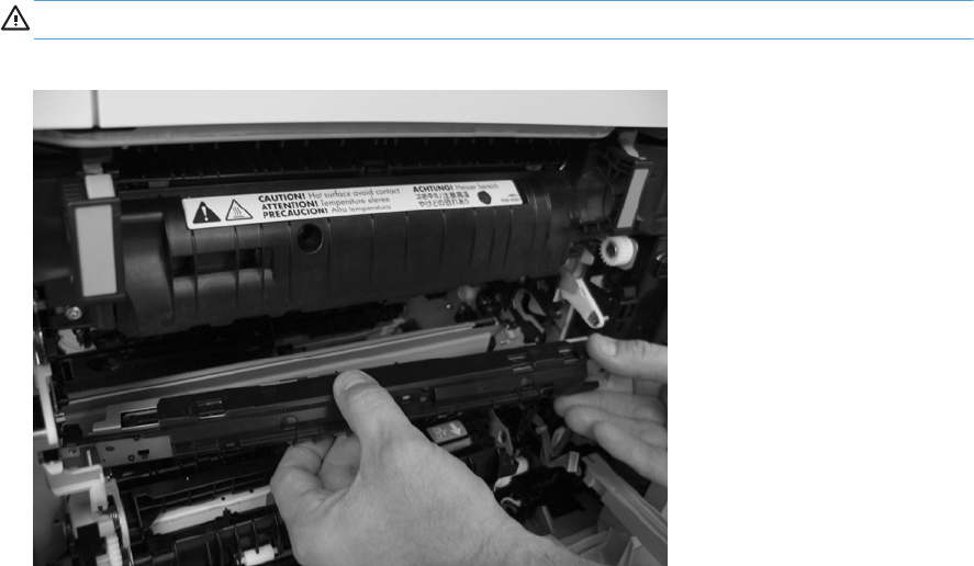
6. Carefully remove the assembly from the product.
CAUTION: Do not damage the shutter as it passes through the chassis.
Figure 2-170 Remove the RD sensor assembly (7 of 7)
212 Chapter 2 Removal and replacement ENWW

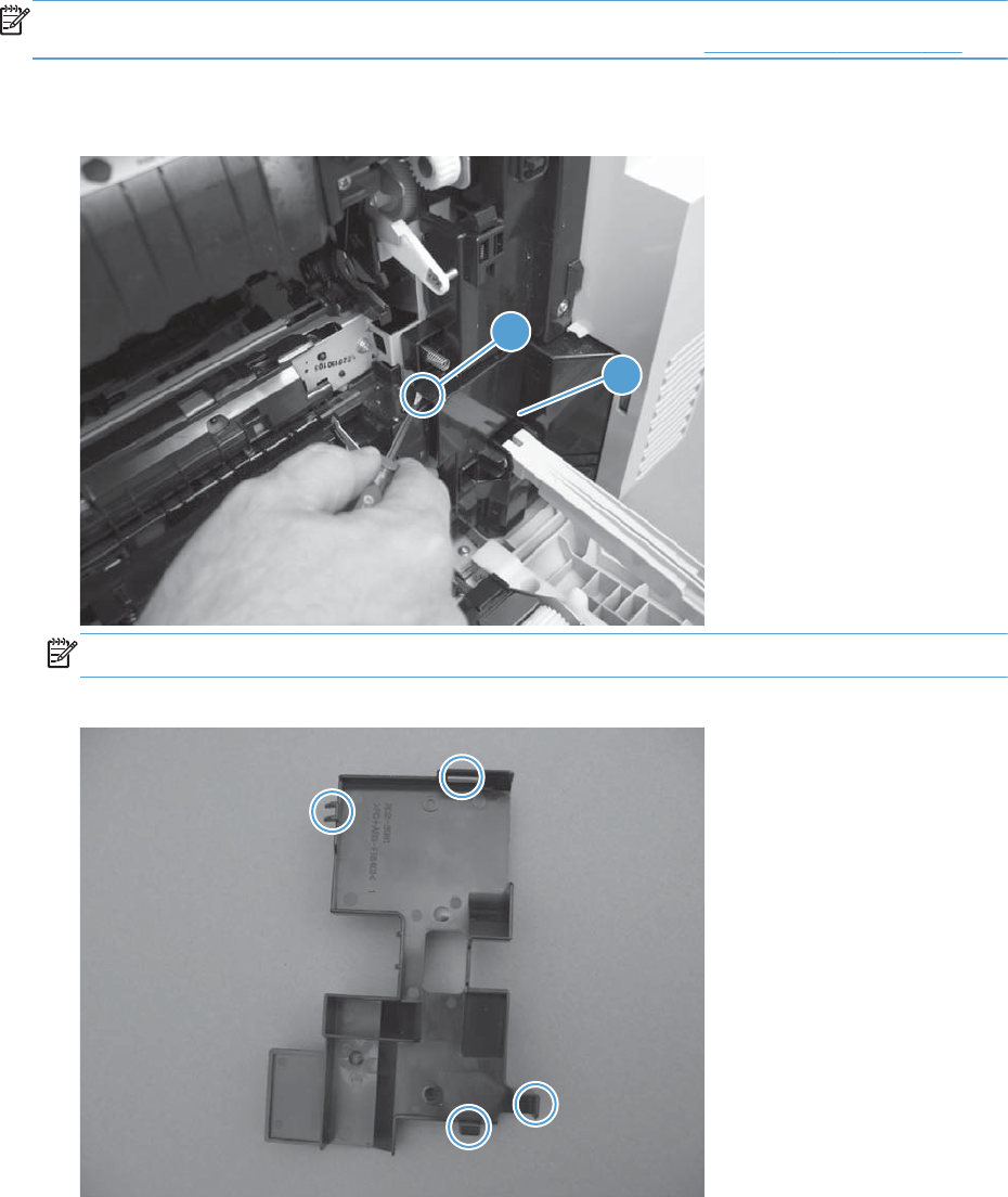
Remove the registration assembly
NOTE: If a replacement registration assembly is installed, you must use the control-panel menus to
reset the registration-roller count and input the media sensor value. See Service menu on page 625.
1. Release one tab (callout 1), and then remove the cover (callout 2).
Figure 2-171 Remove the registration assembly (1 of 8)
1
2
NOTE: When reinstalling the cover, be sure that the tabs are seated correctly.
Figure 2-172 Remove the registration assembly (2 of 8)
214 Chapter 2 Removal and replacement ENWW
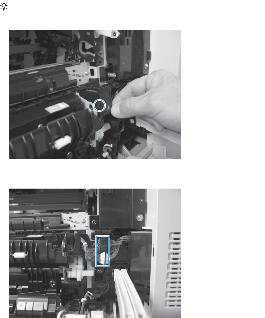
2. Release one tab, and then remove the wire-harness cover.
TIP: To make the cover easier to remove, open the front-door assembly to close the RD-sensor
shutter.
Figure 2-173 Remove the registration assembly (3 of 8)
3. Disconnect two connectors.
Figure 2-174 Remove the registration assembly (4 of 8)
ENWW Internal assemblies 215
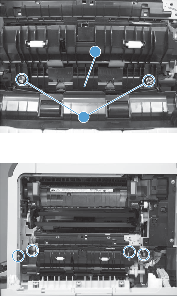
4. Remove two screws (callout 1), and then remove the cassette feed guide (callout 2).
Figure 2-175 Remove the registration assembly (5 of 8)
1
2
5. Remove four screws.
Figure 2-176 Remove the registration assembly (6 of 8)
216 Chapter 2 Removal and replacement ENWW
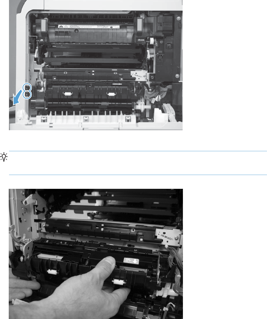
6. Release two pins and the front of the assembly.
Figure 2-177 Remove the registration assembly (7 of 8)
7. Remove the assembly from the product.
Reinstallation tip When you reinstall the registration assembly, make sure that it is correctly
positioned in the product. The tabs on the assembly must fit into the slots in the product chassis
and the assembly fits securely up against the product chassis.
Figure 2-178 Remove the registration assembly (8 of 8)
ENWW Internal assemblies 217
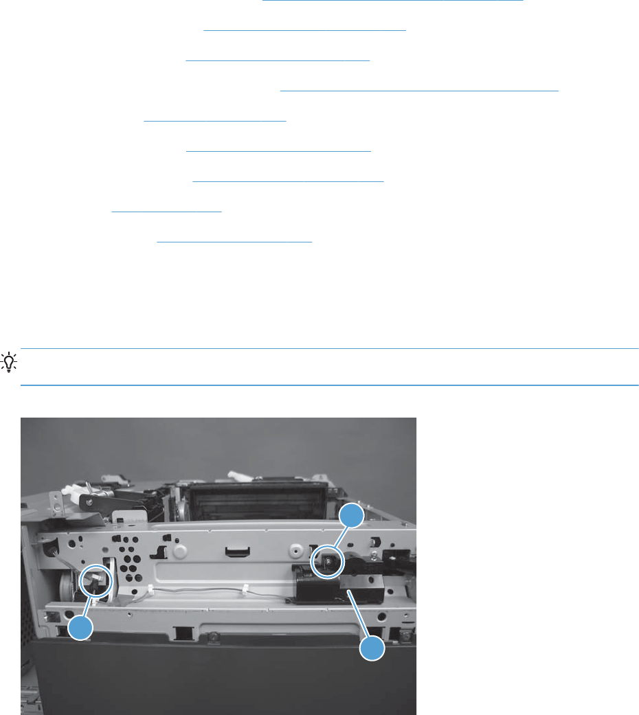
Residual-toner-feed motor
Before proceeding, remove the following components:
●Intermediate transfer belt (ITB). See Intermediate transfer belt (ITB) on page 120.
●Standard output bin. See Standard output bin on page 123.
●Output bin bezel. See Output bin bezel on page 124.
●S-CVR-REAR (scanner rear cover). See S-CVR-REAR (scanner rear cover) on page 128.
●Fan cover. See Fan cover on page 134.
●Document feeder. See Document feeder on page 151.
●Scanner assembly. See Scanner assembly on page 171.
●IPTU. See IPTU on page 199.
●Delivery fan. See Delivery fan on page 228.
Remove the residual-toner-feed motor
Remove one screw (callout 1), disconnect one connector (callout 2), and them remove the residual-
toner-feed motor (callout 3).
Reinstallation tip When the motor (callout 3) is reinstalled, make sure that the keyed shaft on the
product and motor component are correctly aligned and engaged.
Figure 2-179 Remove the residual-toner-feed motor
2
1
3
218 Chapter 2 Removal and replacement ENWW

Residual-toner duct and feed assembly
Before proceeding, remove the following components:
●Toner-collection unit. See Toner-collection unit on page 104.
●Intermediate transfer belt (ITB). See Intermediate transfer belt (ITB) on page 120.
●Standard output bin. See Standard output bin on page 123.
●Output bin bezel. See Output bin bezel on page 124.
●S-CVR-REAR (scanner rear cover). See S-CVR-REAR (scanner rear cover) on page 128.
●Fan cover. See Fan cover on page 134.
●Document feeder. See Document feeder on page 151.
●Scanner assembly. See Scanner assembly on page 171.
●IPTU. See IPTU on page 199.
●Residual-toner-feed motor. See Residual-toner-feed motor on page 218.
●Delivery fan. See Delivery fan on page 228.
Remove the residual-toner duct and feed assembly
1. Remove one screw.
Figure 2-180 Remove the residual-toner duct and feed assembly (1 of 4)
ENWW Internal assemblies 219
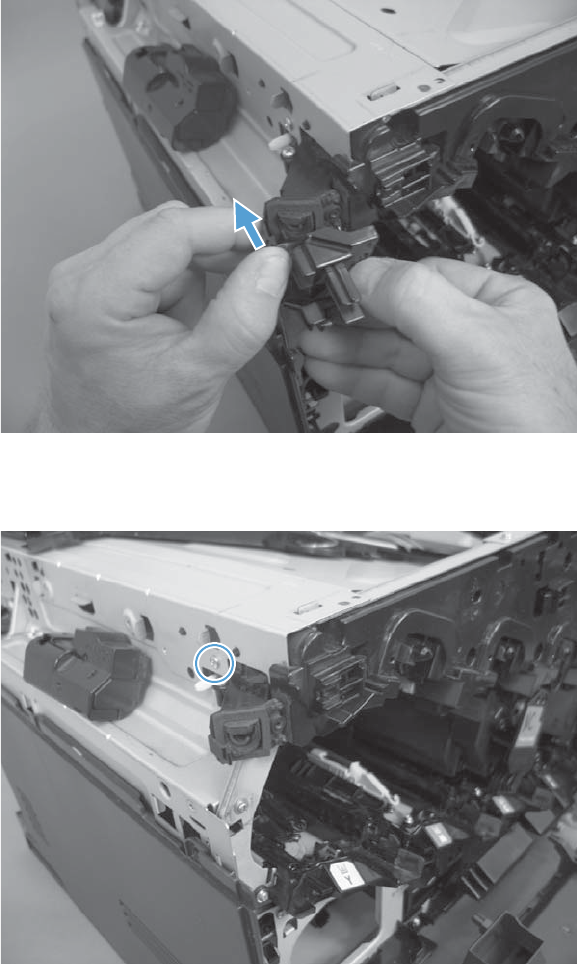
2. Release one tab, and then remove the waste toner duct.
Figure 2-181 Remove the residual-toner duct and feed assembly (2 of 4)
3. Remove one screw.
Figure 2-182 Remove the residual-toner duct and feed assembly (3 of 4)
220 Chapter 2 Removal and replacement ENWW
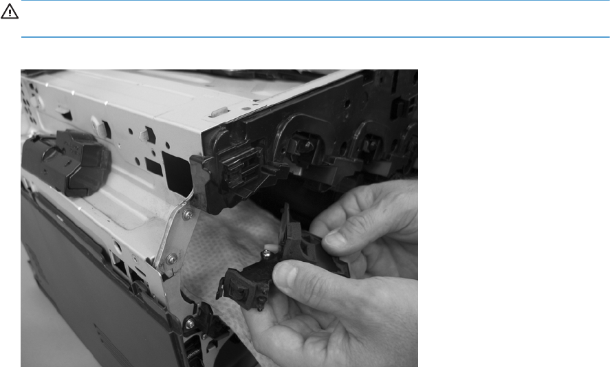
4. Push the residual-toner feed assembly into the product and then remove through the print cartridge
cavity.
CAUTION: The waste toner feed assembly contains toner. Place a cloth below the work area to
catch any spilled toner.
Figure 2-183 Remove the residual-toner duct and feed assembly (4 of 4)
ENWW Internal assemblies 221
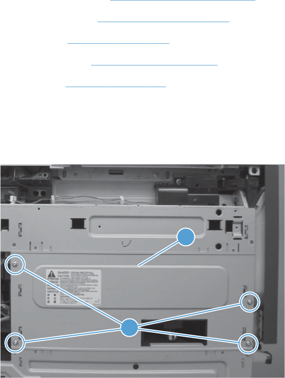
Cartridge fan and environmental sensor
Before proceeding, remove the following components:
●Standard output bin. See Standard output bin on page 123.
●Output bin bezel. See Output bin bezel on page 124.
●Fan cover. See Fan cover on page 134.
●Lower-left cover. See Lower-left cover on page 136.
●Left cover. See Left cover on page 137.
Remove the cartridge fan and environmental sensor
1. Remove four screws (callout 1), and then remove the sheet-metal plate (callout 2).
Figure 2-184 Remove the cartridge fan and environmental sensor (1 of 7)
1
2
222 Chapter 2 Removal and replacement ENWW
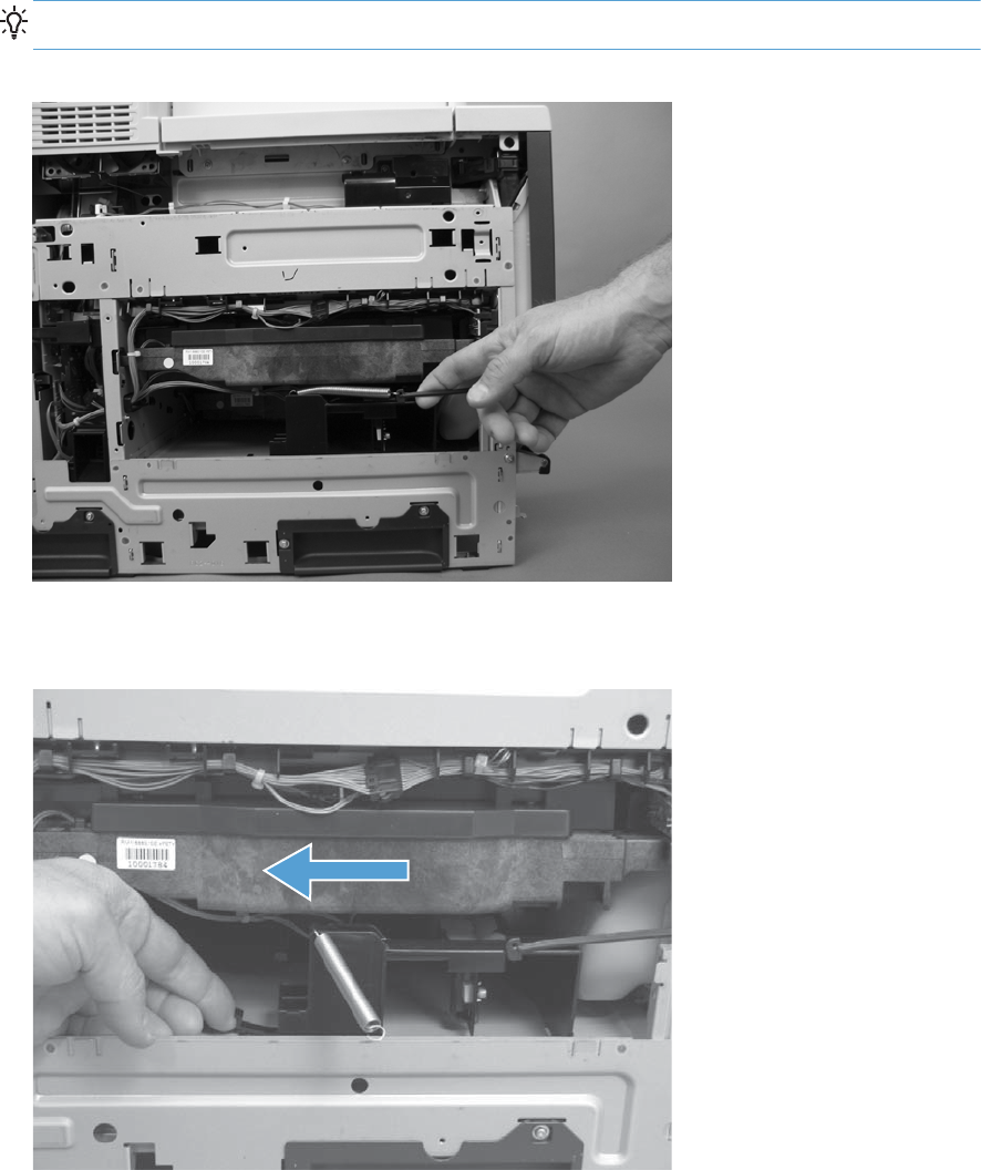
2. Release one spring.
TIP: Close the front-door assembly to reduce tension in the spring.
Figure 2-185 Remove the cartridge fan and environmental sensor (2 of 7)
3. Release one tab and then slide the fan assembly toward the back of the product.
Figure 2-186 Remove the cartridge fan and environmental sensor (3 of 7)
ENWW Internal assemblies 223
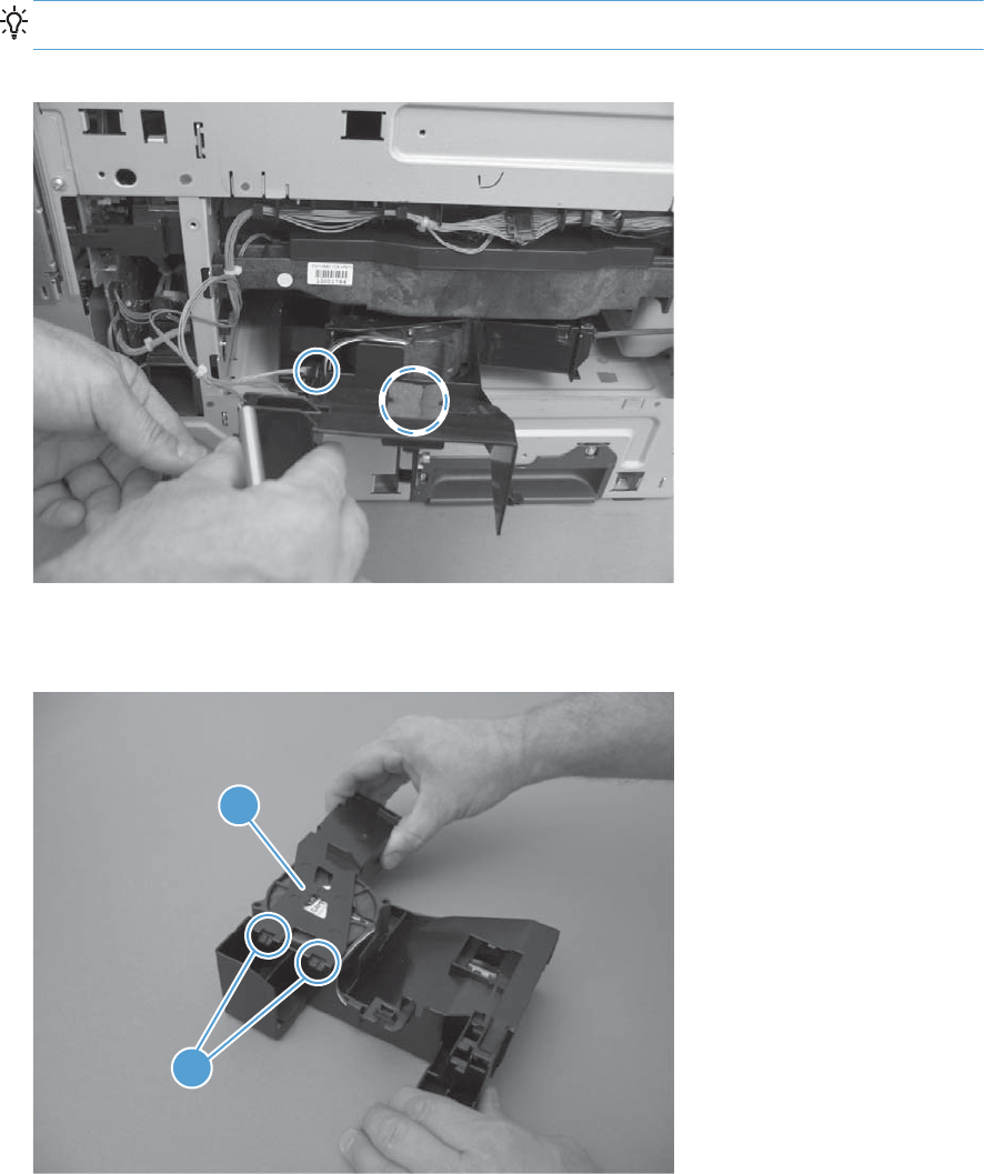
4. Pull the fan assembly out of the product, and then disconnect two connectors.
TIP: One connector is below the sponge.
Figure 2-187 Remove the cartridge fan and environmental sensor (4 of 7)
5. Release two tabs (callout 1), and then remove the cover (callout 2).
Figure 2-188 Remove the cartridge fan and environmental sensor (5 of 7)
1
2
224 Chapter 2 Removal and replacement ENWW
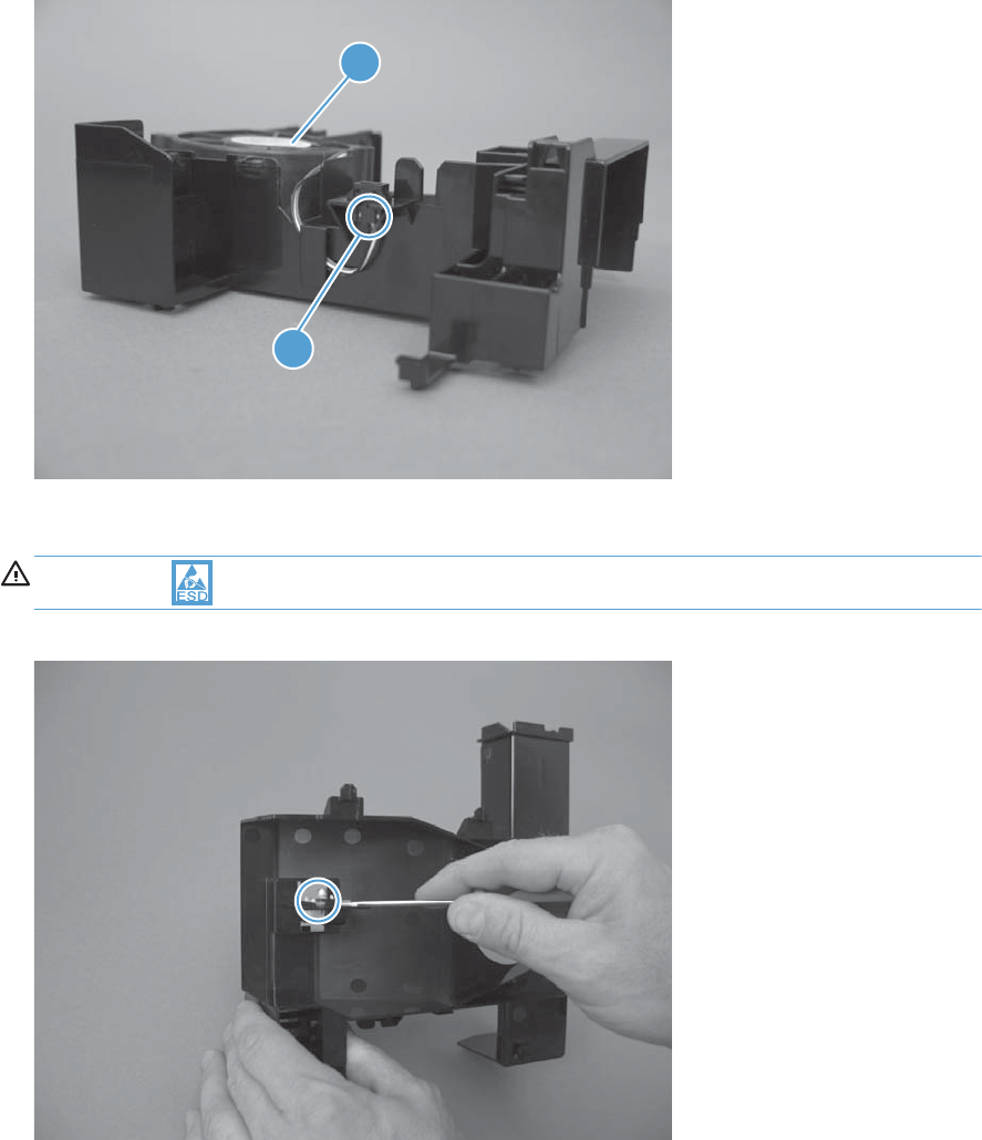
6. Disconnect one connector (callout 1), and then remove the fan (callout 2).
Figure 2-189 Remove the cartridge fan and environmental sensor (6 of 7)
1
2
7. Carefully release one tab, and then remove the environmental sensor.
CAUTION: ESD-sensitive part.
Figure 2-190 Remove the cartridge fan and environmental sensor (7 of 7)
ENWW Internal assemblies 225
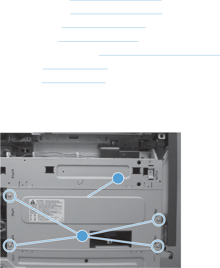
Toner-collection sensor and scanner-thermistor assembly
Before proceeding, remove the following components:
●Toner-collection unit. See Toner-collection unit on page 104.
●Standard output bin. See Standard output bin on page 123.
●Output bin bezel. See Output bin bezel on page 124.
●Lower-left cover. See Lower-left cover on page 136.
●S-CVR-LEFT (scanner left cover). See S-CVR-LEFT (scanner left cover) on page 133.
●Fan cover. See Fan cover on page 134.
●Left cover. See Left cover on page 137.
Remove the toner-collection sensor and scanner-thermistor assembly
1. Remove four screws (callout 1), and then remove the sheet-metal plate (callout 2).
Figure 2-191 Remove the toner-collection sensor and scanner-thermistor assembly (1 of 3)
1
2
226 Chapter 2 Removal and replacement ENWW
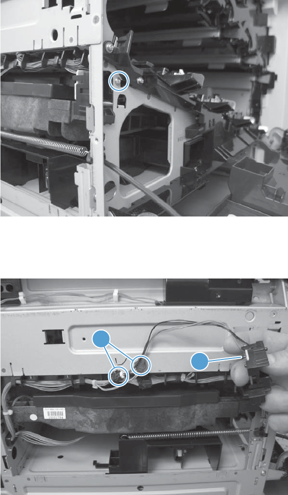
2. Open the front-door assembly, and then remove one screw.
Figure 2-192 Remove the toner-collection sensor and scanner-thermistor assembly (2 of 3)
3. Disconnect two connectors (callout 1), and then remove the toner-collection sensor and scanner-
thermistor assembly (callout 2).
Figure 2-193 Remove the toner-collection sensor and scanner-thermistor assembly (3 of 3)
1
2
ENWW Internal assemblies 227
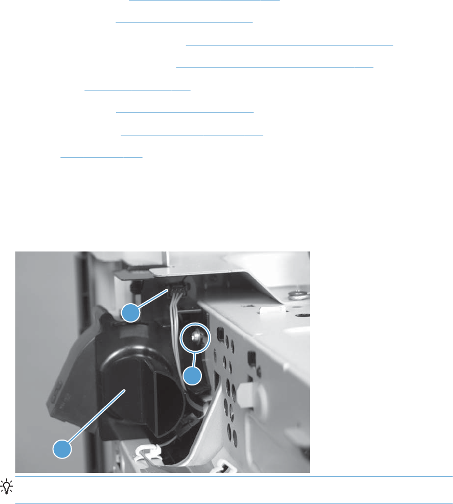
Delivery fan
Before proceeding, remove the following components:
●Standard output bin. See Standard output bin on page 123.
●Output bin bezel. See Output bin bezel on page 124.
●S-CVR-REAR (scanner rear cover). See S-CVR-REAR (scanner rear cover) on page 128.
●S-CVR-LEFT (scanner left cover). See S-CVR-LEFT (scanner left cover) on page 133.
●Fan cover. See Fan cover on page 134.
●Document feeder. See Document feeder on page 151.
●Scanner assembly. See Scanner assembly on page 171.
●IPTU. See IPTU on page 199.
Remove the delivery fan
▲Remove one screw (callout 1), disconnect one connector (callout 2) and then remove the fan
(callout 3).
Figure 2-194 Remove the delivery fan
2
1
3
TIP: When the fan is reinstalled, the air must flow into the product. Check the arrows embossed
on the fan frame that indicate air flow direction.
228 Chapter 2 Removal and replacement ENWW
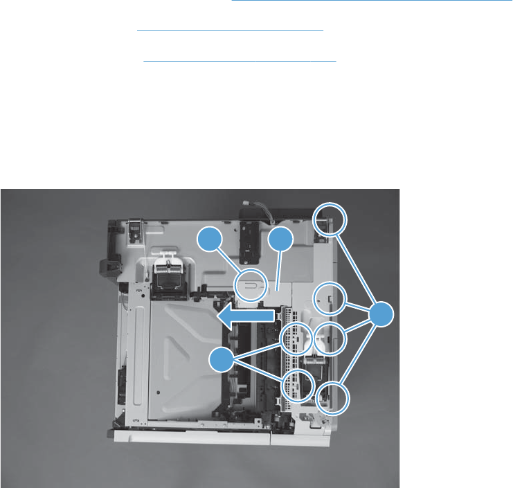
Intermediate cover and duplexing gear cover
Before proceeding, remove the following components:
●S-CVR-REAR (scanner rear cover). See S-CVR-REAR (scanner rear cover) on page 128.
●Document feeder. See Document feeder on page 151.
●Scanner assembly. See Scanner assembly on page 171.
Remove the Intermediate cover and duplexing gear cover
1. Open the right door. Release one pry points (callout 1). Slide the duplexing gear cover (callout 2)
to the left to remove. Release two pry points (callout 3) and then release four pry points (callout 4).
Figure 2-195 Remove the intermediate cover and duplexing gear cover (1 of 2)
1 2
3
4
ENWW Internal assemblies 229
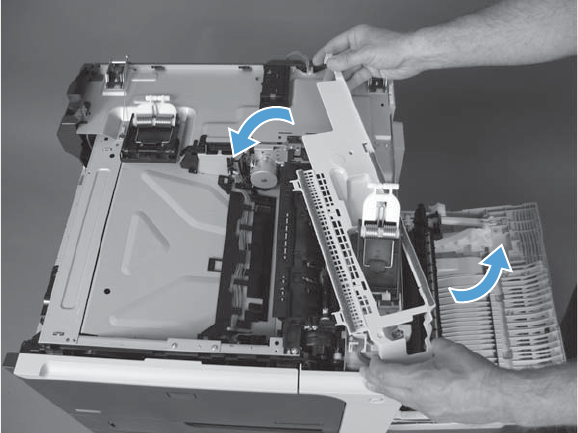
2. Rotate the intermediate cover and remove.
Figure 2-196 Remove the intermediate cover and duplexing gear cover (2 of 2)
230 Chapter 2 Removal and replacement ENWW

Delivery assembly
Before proceeding, remove the following components:
●Fuser. See Fuser on page 112.
●Intermediate transfer belt (ITB). See Intermediate transfer belt (ITB) on page 120.
●Standard output bin. See Standard output bin on page 123.
●Output bin bezel. See Output bin bezel on page 124.
●S-CVR-REAR (scanner rear cover). See S-CVR-REAR (scanner rear cover) on page 128.
●S-CVR-LEFT (scanner left cover). See S-CVR-LEFT (scanner left cover) on page 133.
●Fan cover. See Fan cover on page 134.
●Document feeder. See Document feeder on page 151.
●Scanner assembly. See Scanner assembly on page 171.
●IPTU. See IPTU on page 199.
●Intermediate cover and duplexing gear cover. See Intermediate cover and duplexing gear cover
on page 229.
Remove the delivery assembly
1. Remove two screws.
Figure 2-197 Remove the delivery assembly (1 of 4)
ENWW Internal assemblies 231
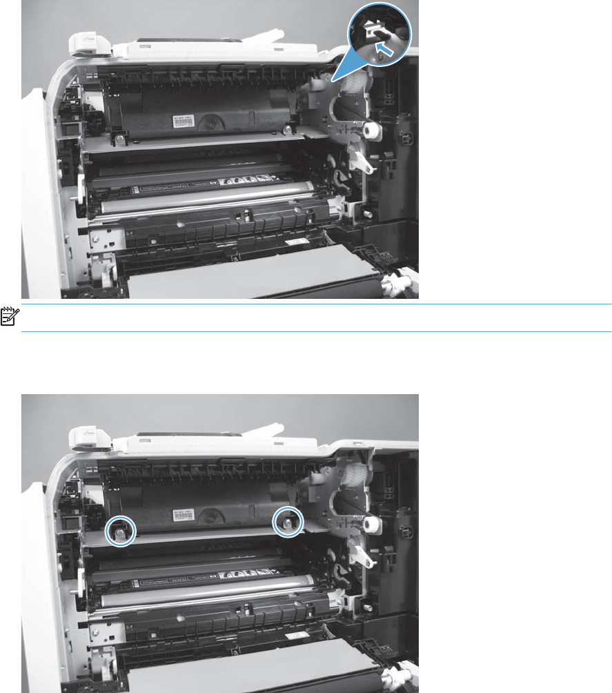
2. Pull one tab out, and then push the tab down to release the bushing.
Figure 2-198 Remove the delivery assembly (2 of 4)
NOTE: When reinstalling, make sure the tab is correctly installed and flush against the chassis.
3. Remove two screws.
Figure 2-199 Remove the delivery assembly (3 of 4)
232 Chapter 2 Removal and replacement ENWW
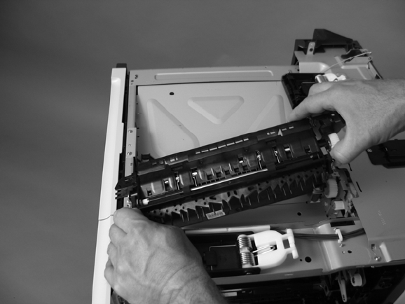
4. Remove the assembly.
Figure 2-200 Remove the delivery assembly (4 of 4)
ENWW Internal assemblies 233

Reinstall the delivery assembly
▲Make sure that the solenoid plunger is correctly installed on the replacement assembly.
Figure 2-201 Reinstall the delivery assembly
234 Chapter 2 Removal and replacement ENWW

Duplex-drive assembly
Before proceeding, remove the following components:
●Fuser. See Fuser on page 112.
●Intermediate transfer belt (ITB). See Intermediate transfer belt (ITB) on page 120.
●Standard output bin. See Standard output bin on page 123.
●Output bin bezel. See Output bin bezel on page 124.
●S-CVR-REAR (scanner rear cover). See S-CVR-REAR (scanner rear cover) on page 128.
●S-CVR-LEFT (scanner left cover). See S-CVR-LEFT (scanner left cover) on page 133.
●Fan cover. See Fan cover on page 134.
●Document feeder. See Document feeder on page 151.
●Scanner assembly. See Scanner assembly on page 171.
●IPTU. See IPTU on page 199.
●Delivery assembly. See Delivery assembly on page 231.
Remove the duplex-drive assembly
▲Disconnect one connector (callout 1), remove three screws (callout 2), and then remove the
assembly (callout 3).
Figure 2-202 Remove the duplex-drive assembly
2
1
3
ENWW Internal assemblies 235
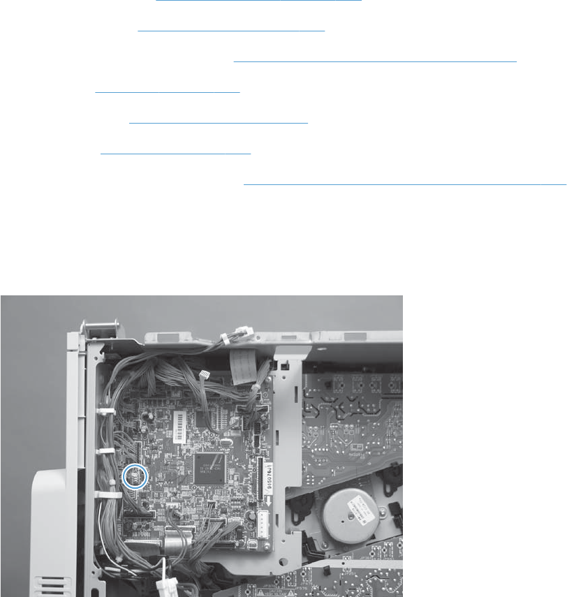
Power-supply fan
Before proceeding, remove the following components:
●Standard output bin. See Standard output bin on page 123.
●Output bin bezel. See Output bin bezel on page 124.
●S-CVR-REAR (scanner rear cover). See S-CVR-REAR (scanner rear cover) on page 128.
●Fan cover. See Fan cover on page 134.
●Lower-left cover. See Lower-left cover on page 136.
●Rear cover. See Rear cover on page 144.
●Image scanning power supply unit. See Image scanner power supply unit (PSU) on page 237.
Remove the power-supply fan
1. Release the fan cable from the DC controller.
Figure 2-203 Remove the power-supply fan (1 of 2)
236 Chapter 2 Removal and replacement ENWW
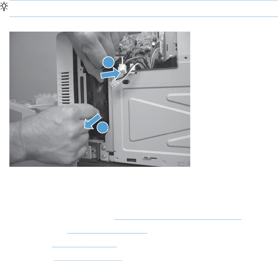
2. Release one tab (callout 1), and then remove the fan (callout 2) from the fan duct.
Reinstallation tip When the fan is reinstalled, the air must flow into the product. Check the
arrows embossed on the fan frame that indicate air flow direction.
Figure 2-204 Remove the power-supply fan (2 of 2)
11
2
Image scanner power supply unit (PSU)
Before proceeding, remove the following components
●S-CVR-REAR (scanner rear cover). See S-CVR-REAR (scanner rear cover) on page 128.
●Lower-left cover. See Lower-left cover on page 136.
●Fan cover. See Fan cover on page 134.
●Rear cover. See Rear cover on page 144.
ENWW Internal assemblies 237
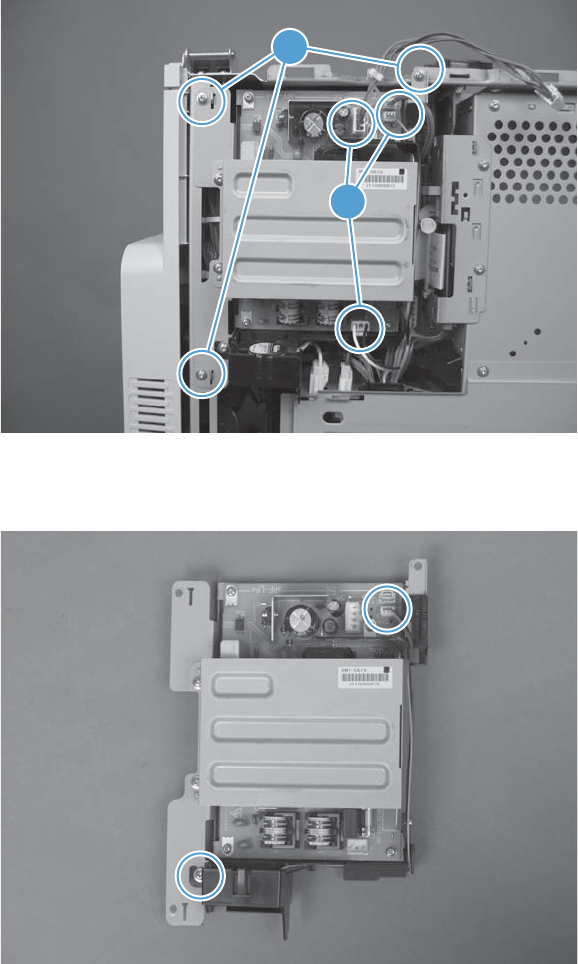
Remove the image scanner supply unit (PSU) and fan
1. Disconnect three connectors (callout 1), remove three screws (callout 2), and then remove the
image scanner supply unit (PSU).
Figure 2-205 Remove the image scanner supply unit (PSU) and fan (1 of 2)
2
1
2. Remove one screw, disconnect one connector, and then remove the fan.
Figure 2-206 Remove the image scanner supply unit (PSU) and fan (2 of 2)
238 Chapter 2 Removal and replacement ENWW
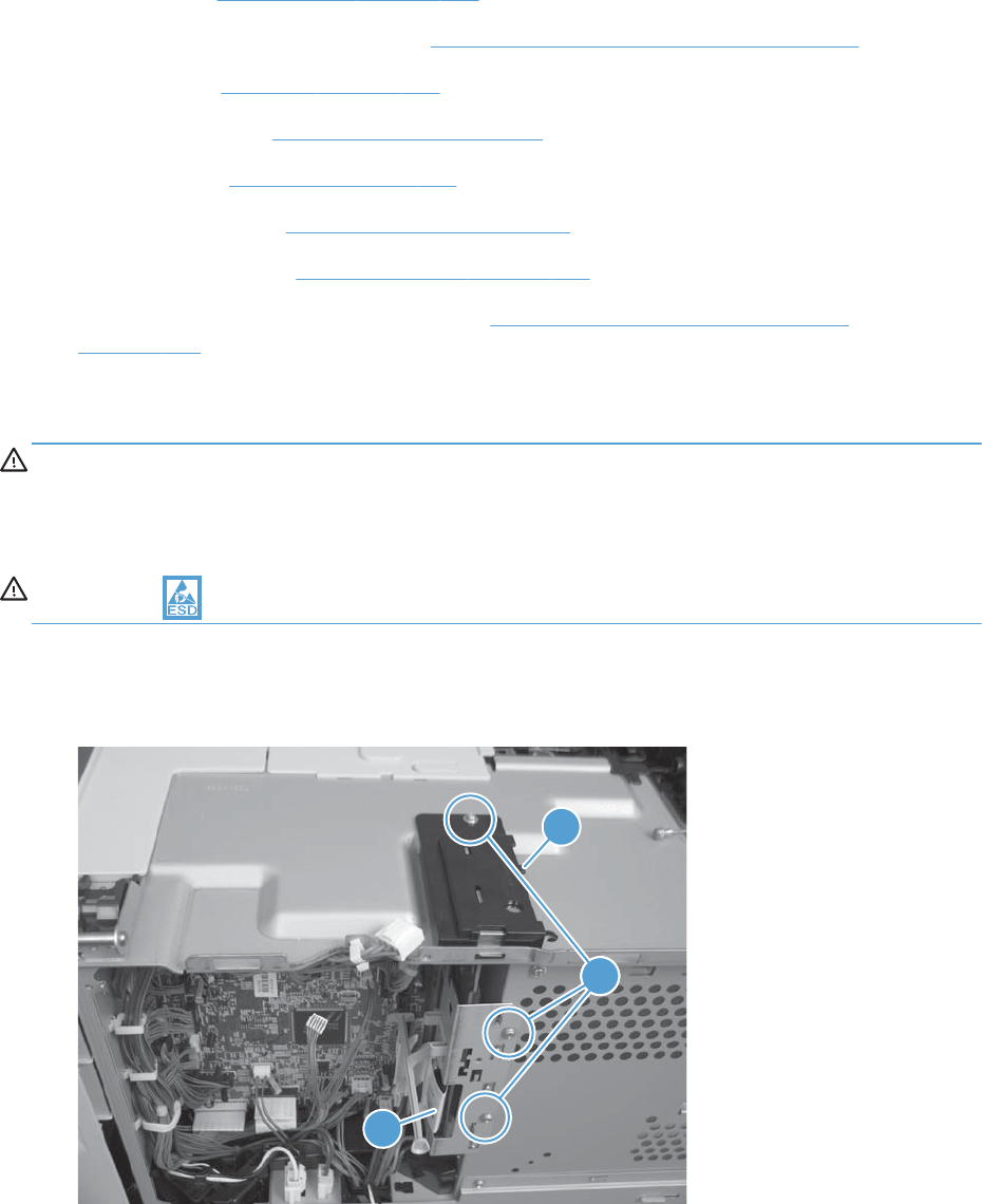
Interconnect board (ICB)
Before proceeding, remove the following components:
●Formatter. See Formatter PCA on page 106.
●S-CVR-REAR (scanner rear cover). See S-CVR-REAR (scanner rear cover) on page 128.
●Fan cover. See Fan cover on page 134.
●Lower-left cover. See Lower-left cover on page 136.
●Rear cover. See Rear cover on page 144.
●Document feeder. See Document feeder on page 151.
●Scanner assembly. See Scanner assembly on page 171.
●Image scanner power supply unit (PSU). See Image scanner power supply unit (PSU)
on page 237.
Remove the ICB
WARNING! Do not remove the ICB from a product and then install it into a different product.
Failure to follow this warning will result in severe damage to that product and cause it to be unusable.
HP recommends that if you remove and replace the ICB, you should destroy the discarded ICB so that it
can not accidentally be installed in a different product.
CAUTION: ESD-sensitive part.
1. Remove three screws (callout 1), disconnect one FFC (callout 2), and remove the small cover
(callout 3).
Figure 2-207 Remove the ICB (1 of 2)
11
2
3
ENWW Internal assemblies 239
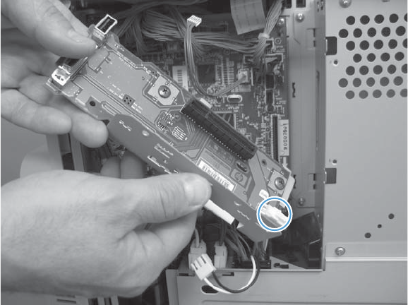
2. Carefully rotate and slide the ICB up and away from the chassis, disconnect one connector, and
then remove the ICB.
Figure 2-208 Remove the ICB (2 of 2)
240 Chapter 2 Removal and replacement ENWW

DC controller PCA only
NOTE: Use the following procedure to replace only the DC controller PCA. To access components
behind the DC controller, remove the PCA and the sheet-metal backing tray. See DC controller PCA
and tray on page 248.
Before proceeding, remove the following components:
●Standard output bin. See Standard output bin on page 123.
●Output bin bezel. See Output bin bezel on page 124.
●S-CVR-REAR (scanner rear cover). See S-CVR-REAR (scanner rear cover) on page 128.
●Lower-left cover. See Lower-left cover on page 136.
●Fan cover. See Fan cover on page 134.
●Rear cover. See Rear cover on page 144.
●Document feeder. See Document feeder on page 151.
●Scanner assembly. See Scanner assembly on page 171.
●Image scanner power supply unit (PSU). See Image scanner power supply unit (PSU)
on page 237.
●Interconnect board (ICB). See Interconnect board (ICB) on page 239.
Remove the DC controller PCA only
CAUTION: ESD-sensitive part.
NOTE: To locate DC controller connector locations, see DC controller connector locations
on page 432. There are 34 connectors in all.
ENWW Internal assemblies 241
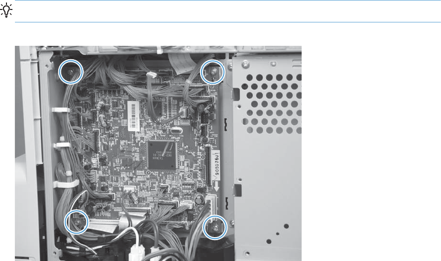
▲Disconnect all the connectors. Remove four screws and then remove the DC controller PCA
Reinstallation tip The connector locations J101 and J102 are not used.
Figure 2-209 Remove the DC controller PCA only
242 Chapter 2 Removal and replacement ENWW
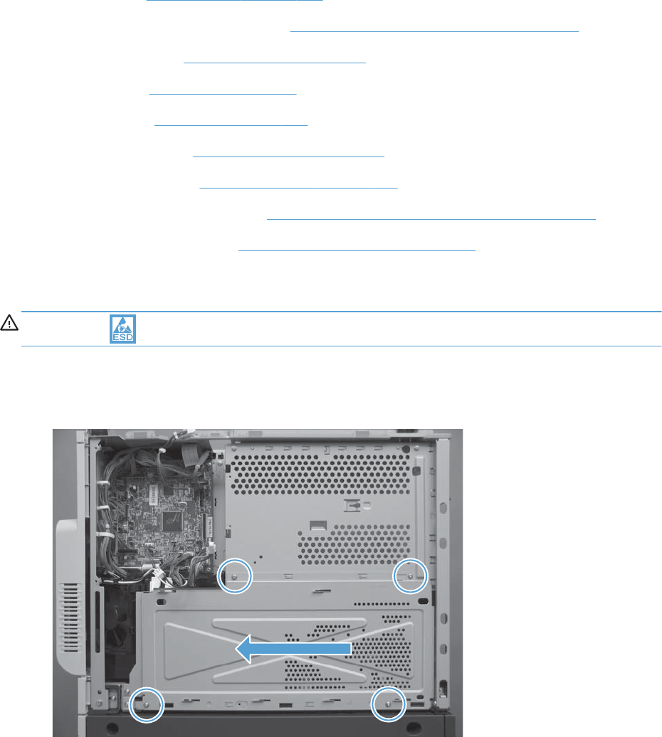
Low-voltage power supply (LVPS)
Before proceeding, remove the following components:
●Formatter. See Formatter PCA on page 106.
●S-CVR-REAR (scanner rear cover). See S-CVR-REAR (scanner rear cover) on page 128.
●Lower-left cover. See Lower-left cover on page 136.
●Fan cover. See Fan cover on page 134.
●Rear cover. See Rear cover on page 144.
●Document feeder. See Document feeder on page 151.
●Scanner assembly. See Scanner assembly on page 171.
●Image scanner power supply. See Image scanner power supply unit (PSU) on page 237.
●Interconnect board (ICB). See Interconnect board (ICB) on page 239.
Remove the low-voltage power supply
CAUTION: ESD-sensitive part.
1. Remove four screws, and then slide the sheet-metal plate toward the back of the product to
remove.
Figure 2-210 Remove the low-voltage power supply (1 of 8)
ENWW Internal assemblies 243
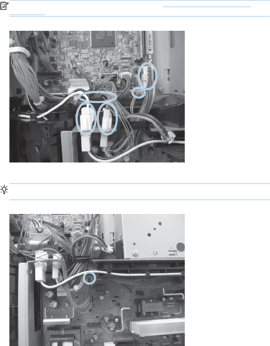
2. Disconnect five connectors, and then release the wire harnesses from the guides as necessary.
NOTE: To locate DC controller connector locations, see DC controller connector locations
on page 432.
Figure 2-211 Remove the low-voltage power supply (2 of 8)
3. Disconnect one connector, and then release the wire harness from the guide.
Reinstallation tip Make sure that you reconnect this connector when the power supply is
reinstalled.
Figure 2-212 Remove the low-voltage power supply (3 of 8)
244 Chapter 2 Removal and replacement ENWW
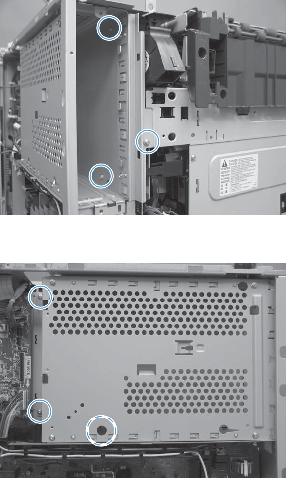
4. Remove three screws.
Figure 2-213 Remove the low-voltage power supply (4 of 8)
5. Remove three screws.
Figure 2-214 Remove the low-voltage power supply (5 of 8)
ENWW Internal assemblies 245

6. Slide the end of the formatter cage away from the product (callout 1) and the slide the cage out of
the product (callout 2).
Figure 2-215 Remove the low-voltage power supply (6 of 8)
11 2
7. Remove two screws.
Figure 2-216 Remove the low-voltage power supply (7 of 8)
246 Chapter 2 Removal and replacement ENWW
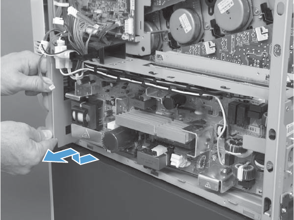
8. Slide and then lift the end of low-voltage power supply until it is free of the product. Remove the
low-voltage power supply.
Figure 2-217 Remove the low-voltage power supply (8 of 8)
ENWW Internal assemblies 247
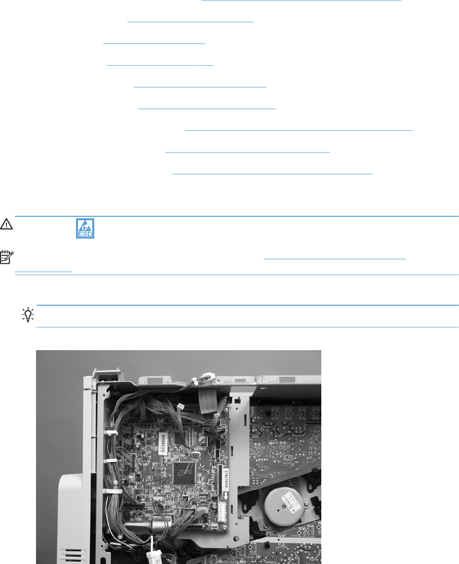
DC controller PCA and tray
Before proceeding, remove the following components:
●S-CVR-REAR (scanner rear cover). See S-CVR-REAR (scanner rear cover) on page 128.
●Lower-left cover. See Lower-left cover on page 136.
●Fan cover. See Fan cover on page 134.
●Rear cover. See Rear cover on page 144.
●Document feeder. See Document feeder on page 151.
●Scanner assembly. See Scanner assembly on page 171.
●Image scanner power supply. See Image scanner power supply unit (PSU) on page 237.
●Interconnect board (ICB). See Interconnect board (ICB) on page 239.
●Low-voltage power supply. See Low-voltage power supply (LVPS) on page 243.
Remove the DC controller PCA and tray
CAUTION: ESD-sensitive part.
NOTE: To locate DC controller connector locations, see DC controller connector locations
on page 432.
1. Disconnect all the connectors. There are 34 connectors in all.
Reinstallation tip The connector locations J101 and J102 are not used.
Figure 2-218 Remove the DC controller PCA and tray (1 of 3)
248 Chapter 2 Removal and replacement ENWW
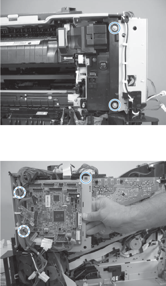
2. Remove two screws.
Figure 2-219 Remove the DC controller PCA and tray (2 of 3)
3. Disengage three tabs (two along the left edge of the PCA and one at the top-right corner of the
PCA).
Figure 2-220 Remove the DC controller PCA and tray (3 of 3)
ENWW Internal assemblies 249
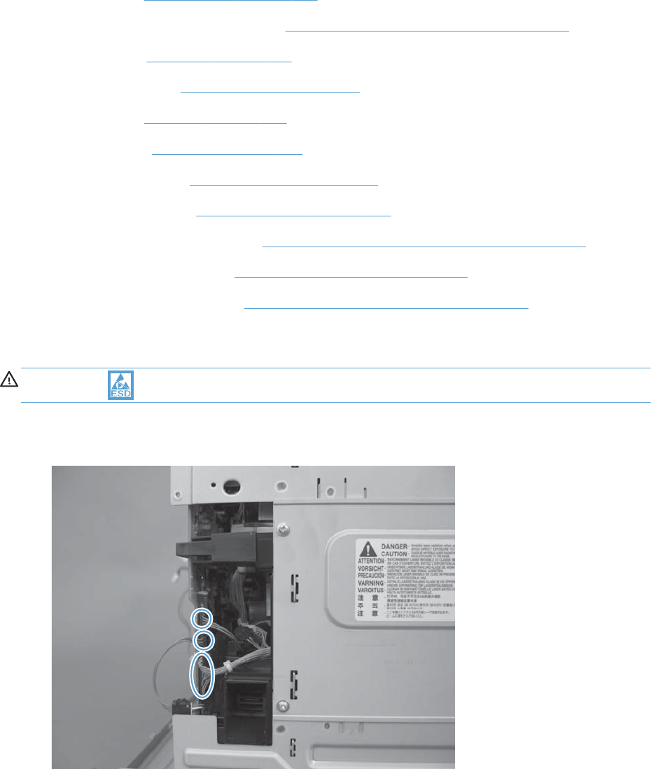
High-voltage power supply lower (HVPS-D)
Before proceeding, remove the following components:
●Formatter. See Formatter PCA on page 106.
●S-CVR-REAR (scanner rear cover). See S-CVR-REAR (scanner rear cover) on page 128.
●Fan cover. See Fan cover on page 134.
●Lower-left cover. See Lower-left cover on page 136.
●Left cover. See Left cover on page 137.
●Rear cover. See Rear cover on page 144.
●Document feeder. See Document feeder on page 151.
●Scanner assembly. See Scanner assembly on page 171.
●Image scanner power supply. See Image scanner power supply unit (PSU) on page 237.
●Interconnect board (ICB). See Interconnect board (ICB) on page 239.
●Low-voltage power supply. See Low-voltage power supply (LVPS) on page 243.
Remove the high-voltage power supply lower
CAUTION: ESD-sensitive part.
1. Disconnect three connectors.
Figure 2-221 Remove the high-voltage power supply lower (1 of 7)
250 Chapter 2 Removal and replacement ENWW
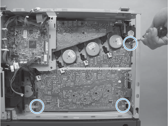
2. Remove three screws.
Figure 2-222 Remove the high-voltage power supply lower (2 of 7)
ENWW Internal assemblies 251
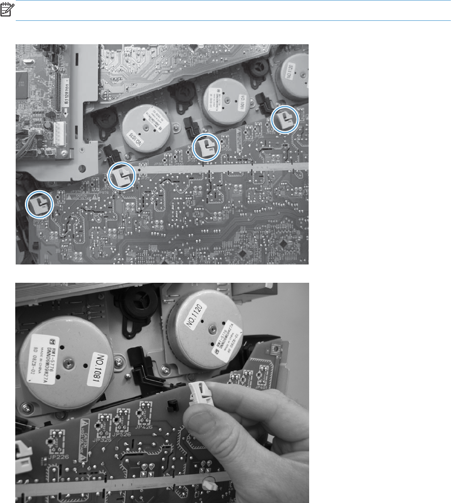
3. Release four locking clips.
NOTE: Squeeze each locking clip to remove.
Figure 2-223 Remove the high-voltage power supply lower (3 of 7)
Figure 2-224 Remove the high-voltage power supply lower (4 of 7)
252 Chapter 2 Removal and replacement ENWW
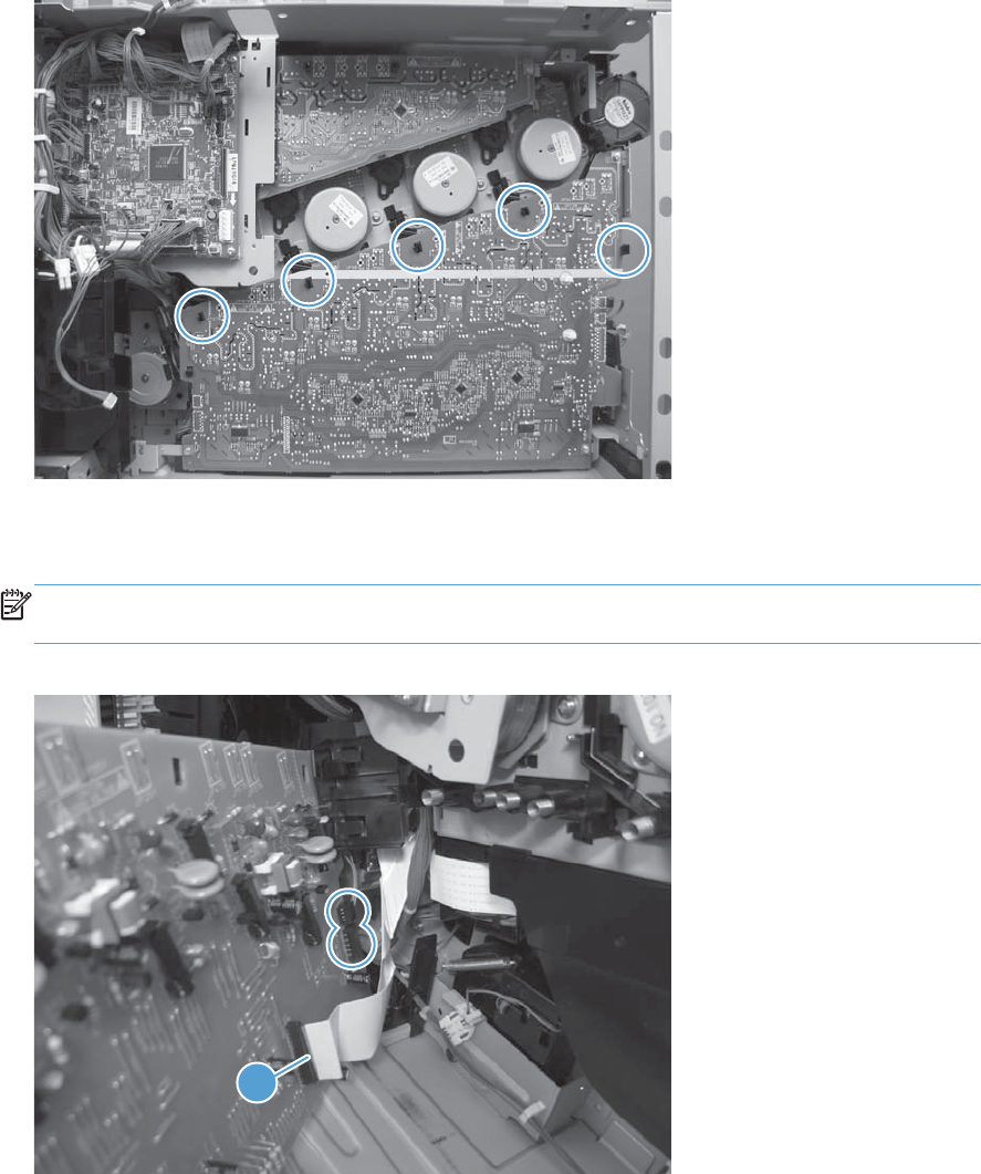
4. Release five tabs.
Figure 2-225 Remove the high-voltage power supply lower (5 of 7)
5. Rotate the top of the power supply away from the chassis, and then disconnect two connectors on
the back of the power supply.
NOTE: Do not disconnect the FFC (callout 1). The FFC and the FFC wiring guide are supplied
with the replacement assembly.
Figure 2-226 Remove the high-voltage power supply lower (6 of 7)
1
ENWW Internal assemblies 253
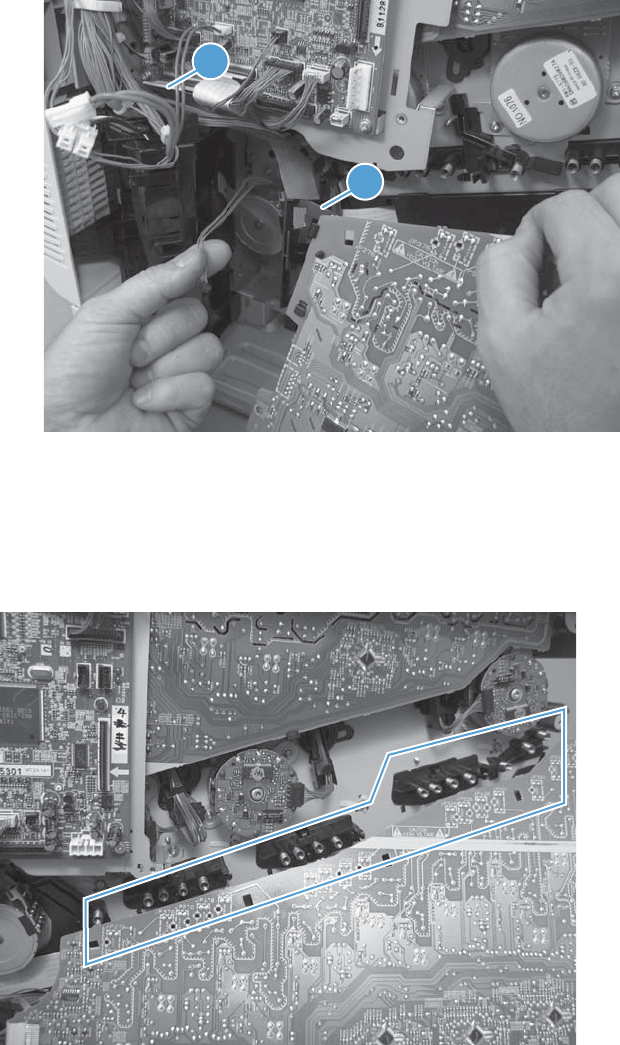
6. Disconnect one FFC (callout 1). Release only the wire harnesses from the guide (callout 2) and
then remove the power supply.
Figure 2-227 Remove the high-voltage power supply lower (7 of 7)
1
2
Reinstall the high-voltage power supply lower
When you reinstall the power supply, look through the holes in the PCA and make sure that the high-
voltage contact springs are correctly seated against the PCA.
Figure 2-228 Reinstall the high-voltage power supply lower
254 Chapter 2 Removal and replacement ENWW
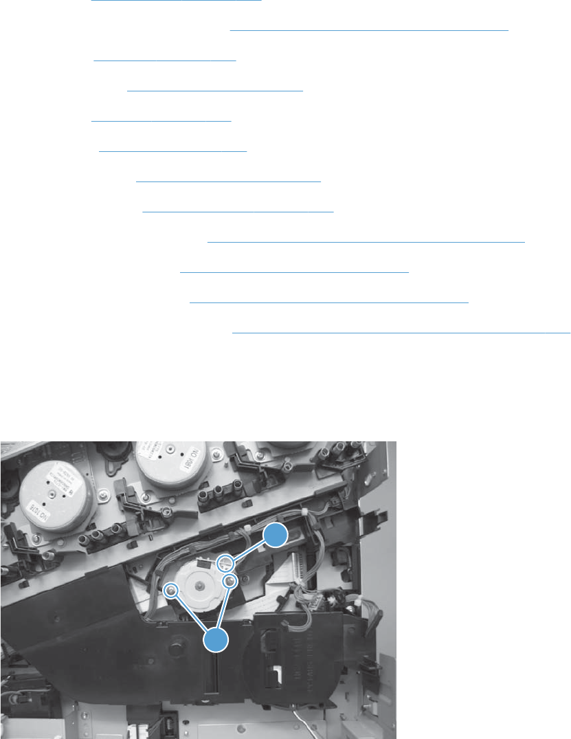
Developing-disengagement motor
Before proceeding, remove the following components:
●Formatter. See Formatter PCA on page 106.
●S-CVR-REAR (scanner rear cover). See S-CVR-REAR (scanner rear cover) on page 128.
●Fan cover. See Fan cover on page 134.
●Lower-left cover. See Lower-left cover on page 136.
●Left cover. See Left cover on page 137.
●Rear cover. See Rear cover on page 144.
●Document feeder. See Document feeder on page 151.
●Scanner assembly. See Scanner assembly on page 171.
●Image scanner power supply. See Image scanner power supply unit (PSU) on page 237.
●Interconnect board (ICB). See Interconnect board (ICB) on page 239.
●Low-voltage power supply. See Low-voltage power supply (LVPS) on page 243.
●High-voltage power supply lower. See High-voltage power supply lower (HVPS-D) on page 250.
Remove the developing-disengagement motor
▲Remove two screws (callout 1), disconnect one connector (callout 2), and remove the motor.
Figure 2-229 Remove the developing-disengagement motor
1
2
ENWW Internal assemblies 255

Exhaust fan and fan duct
Before proceeding, remove the following components:
●Formatter. See Formatter PCA on page 106.
●S-CVR-REAR (scanner rear cover). See S-CVR-REAR (scanner rear cover) on page 128.
●Fan cover. See Fan cover on page 134.
●Lower-left cover. See Lower-left cover on page 136.
●Left cover. See Left cover on page 137.
●Rear cover. See Rear cover on page 144.
●Document feeder. See Document feeder on page 151.
●Scanner assembly. See Scanner assembly on page 171.
●Image scanner power supply. See Image scanner power supply unit (PSU) on page 237.
●Interconnect board (ICB). See Interconnect board (ICB) on page 239.
●Low-voltage power supply. See Low-voltage power supply (LVPS) on page 243.
●High-voltage power supply lower. See High-voltage power supply lower (HVPS-D) on page 250.
Remove the exhaust fan and fan duct
1. Remove two screws (callout 1), disconnect two connectors (callout 2), and then remove the exhaust
fan and duct (callout 3) from the product.
Figure 2-230 Remove the exhaust fan and fan duct (1 of 3)
1
2
3
256 Chapter 2 Removal and replacement ENWW
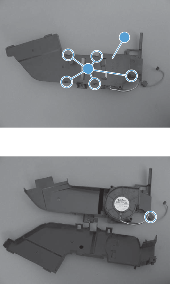
2. Release five tabs (callout 1) and remove the cover (callout 2).
Figure 2-231 Remove the exhaust fan and fan duct (2 of 3)
1
2
3. Disconnect one connector, and then remove the fan from the duct.
Figure 2-232 Remove the exhaust fan and fan duct (3 of 3)
ENWW Internal assemblies 257
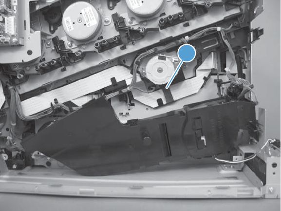
Reinstall the exhaust fan and fan duct
Be sure that the toroid (callout 1) is correctly aligned in the FFC cable guide before attempting to
reinstall the exhaust fan and duct.
Figure 2-233 Reinstall the exhaust fan and fan duct
1
258 Chapter 2 Removal and replacement ENWW

Pickup motor
Before proceeding, remove the following components:
●Formatter. See Formatter PCA on page 106.
●S-CVR-REAR (scanner rear cover). See S-CVR-REAR (scanner rear cover) on page 128.
●Fan cover. See Fan cover on page 134.
●Lower-left cover. See Lower-left cover on page 136.
●Left cover. See Left cover on page 137.
●Rear cover. See Rear cover on page 144.
●Document feeder. See Document feeder on page 151.
●Scanner assembly. See Scanner assembly on page 171.
●Image scanner power supply. See Image scanner power supply unit (PSU) on page 237.
●Interconnect board (ICB). See Interconnect board (ICB) on page 239.
●Low-voltage power supply. See Low-voltage power supply (LVPS) on page 243.
Remove the pickup motor
Remove two screws (callout 1), disconnect one connector (callout 2), and then remove the motor
(callout 3).
Figure 2-234 Remove the pickup motor
11
2
3
ENWW Internal assemblies 259

Lifter-drive assembly
Before proceeding, remove the following components:
●Formatter. See Formatter PCA on page 106.
●Intermediate transfer belt (ITB). See Intermediate transfer belt (ITB) on page 120.
●S-CVR-REAR (scanner rear cover). See S-CVR-REAR (scanner rear cover) on page 128.
●Lower-left cover. See Lower-left cover on page 136.
●Fan cover. See Fan cover on page 134.
●Left cover. See Left cover on page 137.
●Rear cover. See Rear cover on page 144.
●Document feeder. See Document feeder on page 151..
●Scanner assembly. See Scanner assembly on page 171.
●Interconnect board (ICB). See Interconnect board (ICB) on page 239.
●Low-voltage power supply. See Low-voltage power supply (LVPS) on page 243.
●High-voltage power supply lower. See High-voltage power supply lower (HVPS-D) on page 250.
260 Chapter 2 Removal and replacement ENWW
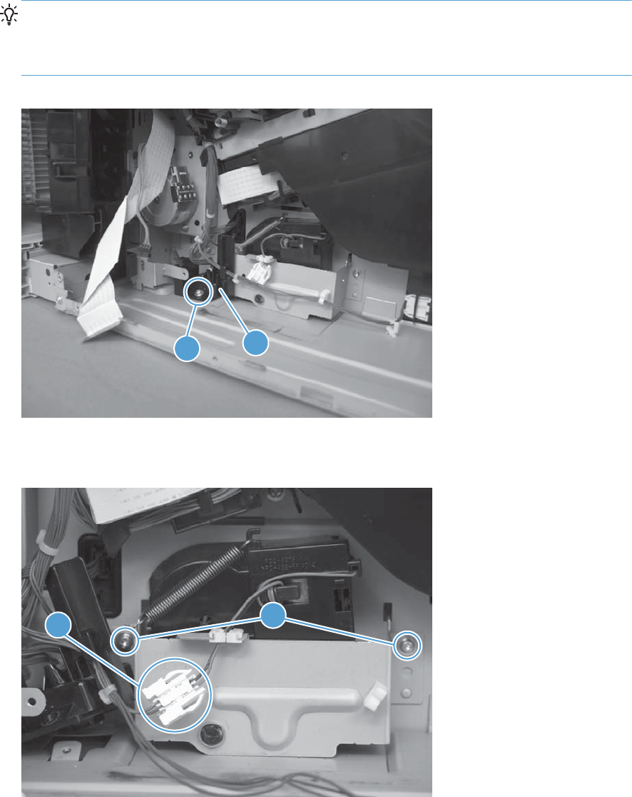
Remove the lifter-drive assembly
1. Remove one screw (callout 1), and then move the accessory-tray connector (callout 2) to access
the screw behind it.
Reinstallation tip If the product is installed on the optional paper feeder, you must slightly
separate the product and the feeder assembly to install this connector. Open the right door on the
feeder. Use the blue handle to release the product-accessory lock, and then lift up on the edge of
the product to create a slight gap between the product and the accessory.
Figure 2-235 Remove the lifter-drive assembly (1 of 3)
12
2. Disconnect one connector (callout 1), and then remove two screws (callout 2).
Figure 2-236 Remove the lifter-drive assembly (2 of 3)
2
1
ENWW Internal assemblies 261
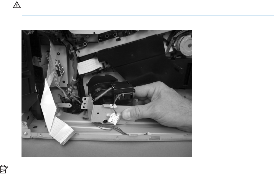
3. Remove the lifter-drive assembly from the product.
CAUTION: The spring on the assembly is not captive. Do not lose the spring when the assembly
is removed.
Figure 2-237 Remove the lifter-drive assembly (3 of 3)
NOTE: Make sure that the lifter-drive assembly moves up and down easily after reinstalling.
262 Chapter 2 Removal and replacement ENWW
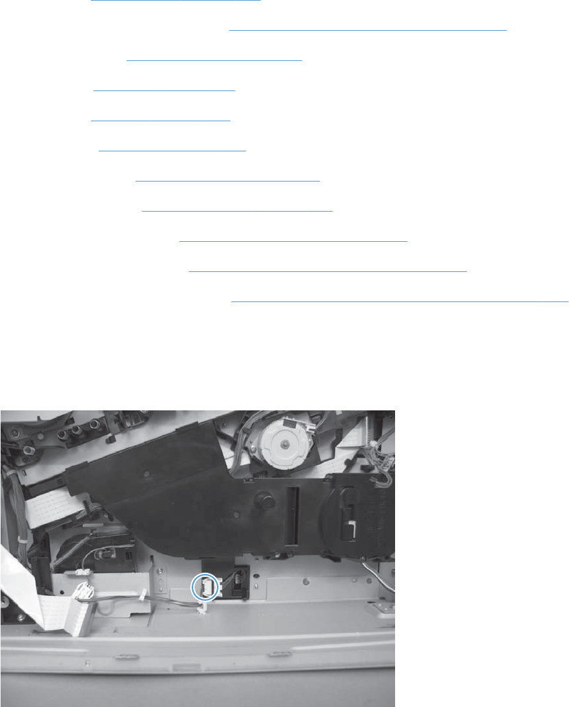
Lifter base assembly
Before proceeding, remove the following components:
●Formatter. See Formatter PCA on page 106
●S-CVR-REAR (scanner rear cover). See S-CVR-REAR (scanner rear cover) on page 128.
●Lower-left cover. See Lower-left cover on page 136.
●Fan cover. See Fan cover on page 134.
●Left cover. See Left cover on page 137.
●Rear cover. See Rear cover on page 144.
●Document feeder. See Document feeder on page 151.
●Scanner assembly. See Scanner assembly on page 171.
●Interconnect board (ICB). See Interconnect board (ICB) on page 239.
●Low-voltage power supply. See Low-voltage power supply (LVPS) on page 243.
●High-voltage power supply lower. See High-voltage power supply lower (HVPS-D) on page 250.
Remove the lifter base assembly
1. Disconnect one connector.
Figure 2-238 Remove the lifter base assembly (1 of 2)
ENWW Internal assemblies 263
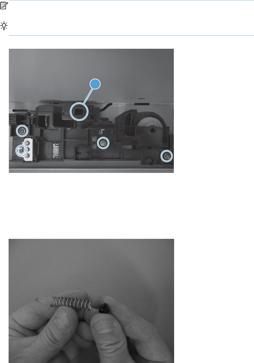
2. From inside the Tray 2 cavity, remove four screws, and then remove the lifter base assembly.
NOTE: Pull the assembly straight from the product without tipping to prevent the spring from
falling from the assembly.
Reinstallation tip If the tray does not completely close when reinstalled, push on the lever in
the opening (callout 1) with a flat blade screwdriver to reset the spring in the closing mechanism.
Figure 2-239 Remove the lifter base assembly (2 of 2)
1
Reinstall the lifter base assembly
If the spring falls from the lifter base assembly, reinstall it in the lifter before reinstalling the lifter base
assembly.
1. Make sure the black rubber end is seated on the spring.
Figure 2-240 Reinstall the lifter base assembly (1 of 2)
264 Chapter 2 Removal and replacement ENWW
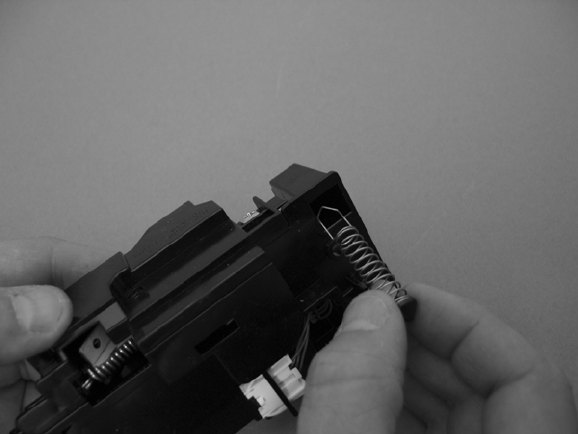
2. Place the spring in the lifter before installing the assembly on the product.
Figure 2-241 Reinstall the lifter base assembly (2 of 2)
ENWW Internal assemblies 265
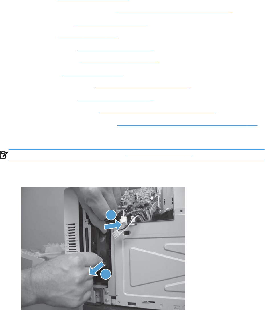
Tray-pickup drive assembly
Before proceeding, remove the following components:
●Formatter. See Formatter PCA on page 106.
●S-CVR-REAR (scanner rear cover). See S-CVR-REAR (scanner rear cover) on page 128.
●Lower-left cover. See Lower-left cover on page 136.
●Left cover. See Left cover on page 137.
●Document feeder. See Document feeder on page 151.
●Scanner assembly. See Scanner assembly on page 171.
●Rear cover. See Rear cover on page 144.
●Interconnect board (ICB). See Interconnect board (ICB) on page 239.
●Power-supply fan. See Power-supply fan on page 236.
●Low-voltage power supply. See Low-voltage power supply (LVPS) on page 243.
●High-voltage power supply lower. See High-voltage power supply lower (HVPS-D) on page 250.
Remove the tray-pickup drive assembly
NOTE: To remove the pickup motor only, see Pickup motor on page 259.
1. Release one tab (callout 1), and then remove the power-supply fan (callout 2).
Figure 2-242 Remove the tray-pickup drive assembly (1 of 3)
11
2
266 Chapter 2 Removal and replacement ENWW
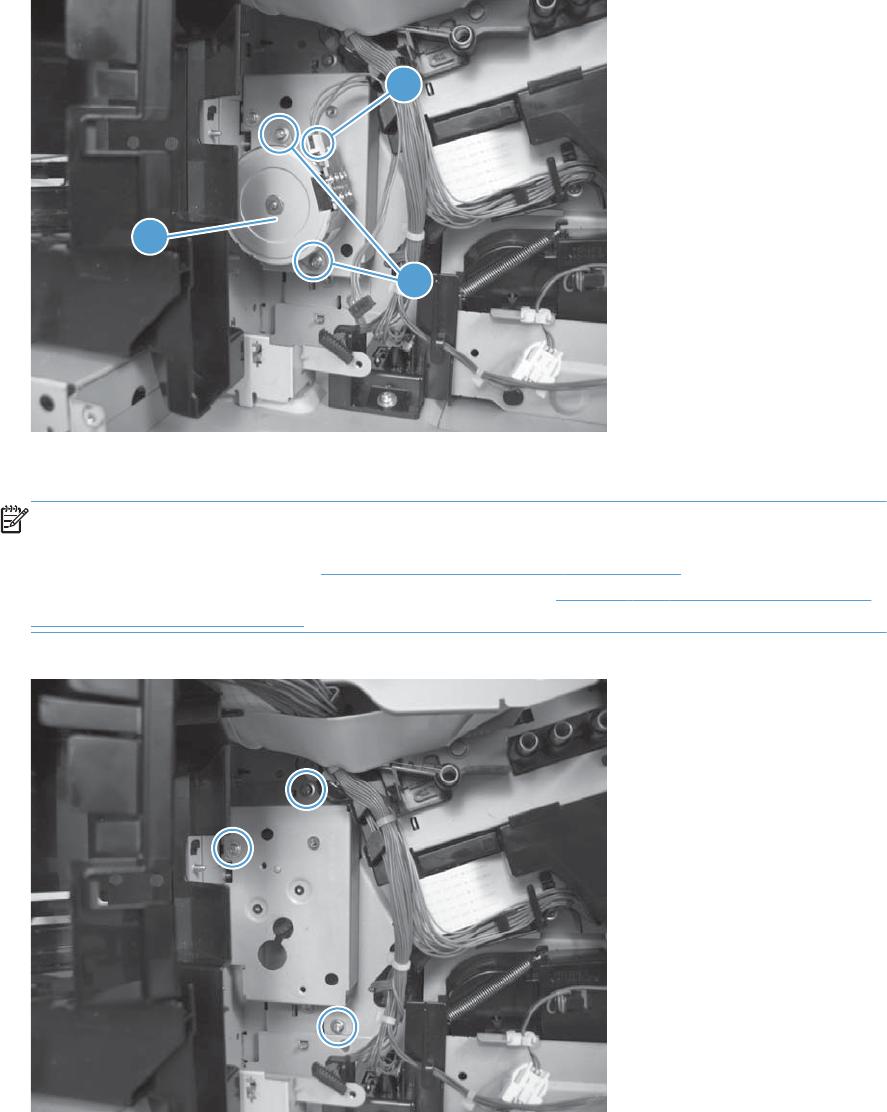
2. Remove two screws (callout 1), disconnect one connector (callout 2), and then remove the pickup
motor (callout 35).
Figure 2-243 Remove the tray-pickup drive assembly (2 of 3)
1
2
3
3. Remove three screws, and then remove the tray-pickup drive assembly.
NOTE: The cams on the main-drive assembly can prevent the tray-pickup drive assembly from
releasing from the product. If you cannot remove the assembly, remove the DC controller and tray
to provide additional space. See DC controller PCA and tray on page 248. You might also need
to remove the wire guide from the main-drive assembly. See Figure 2-280 Remove the main-drive
assembly (4 of 7) on page 295.
Figure 2-244 Remove the tray-pickup drive assembly (3 of 3)
ENWW Internal assemblies 267

Tray-pickup assembly
Before proceeding, remove the following components:
●Formatter. See Formatter PCA on page 106.
●Intermediate transfer belt (ITB). See Intermediate transfer belt (ITB) on page 120.
●S-CVR-REAR (scanner rear cover). See S-CVR-REAR (scanner rear cover) on page 128.
●Lower-left cover. See Lower-left cover on page 136.
●Left cover. See Left cover on page 137.
●Right-rear cover. See Right-rear cover on page 143.
●Rear cover. See Rear cover on page 144.
●Document feeder. See Document feeder on page 151.
●Scanner assembly. See Scanner assembly on page 171.
●Secondary transfer assembly. See Secondary transfer assembly on page 204.
●Registration assembly. See Registration assembly on page 213.
●Interconnect board (ICB). See Interconnect board (ICB) on page 239.
●Low-voltage power supply. See Low-voltage power supply (LVPS) on page 243.
●High-voltage power supply lower. See High-voltage power supply lower (HVPS-D) on page 250.
268 Chapter 2 Removal and replacement ENWW
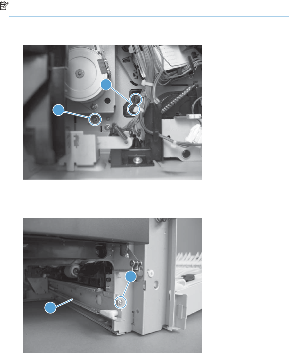
Remove the tray-pickup assembly
NOTE: This task requires that you remove three feed guides on the right side of the product before
you can remove the tray-pickup assembly.
1. Remove one screw (callout 1), and then disconnect two connectors (callout 2).
Figure 2-245 Remove the tray-pickup assembly (1 of 11)
1
2
2. From the front of the product, remove one screw (callout 1), and then remove one tray rail
(callout 2).
Figure 2-246 Remove the tray-pickup assembly (2 of 11)
1
2
ENWW Internal assemblies 269
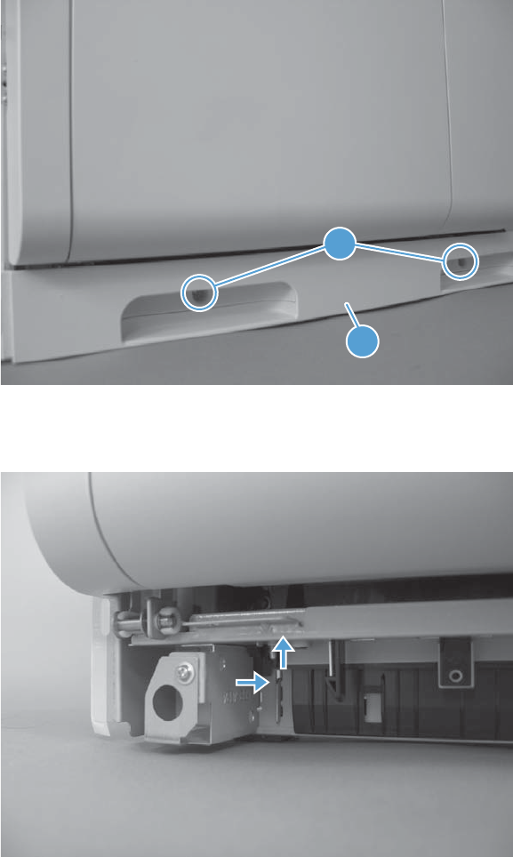
3. From the right side of the product, remove two screws (callout 1) and one cover (callout 2).
Figure 2-247 Remove the tray-pickup assembly (3 of 11)
1
2
4. Close the right-door assembly. Push in and then push up on the stopper to release.
Figure 2-248 Remove the tray-pickup assembly (4 of 11)
270 Chapter 2 Removal and replacement ENWW
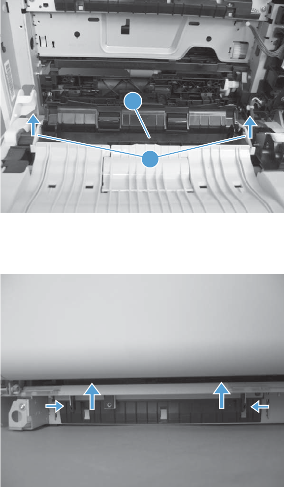
5. Open the right-door assembly. Lift the two link arms (callout 1) to release from the product, and
then remove the paper guide (callout 2).
Figure 2-249 Remove the tray-pickup assembly (5 of 11)
1
2
6. Close the right-door assembly. Push the two tabs toward each other, and then push up to release
the feed guide.
Figure 2-250 Remove the tray-pickup assembly (6 of 11)
ENWW Internal assemblies 271
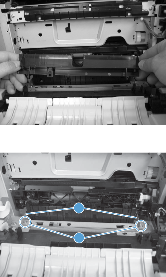
7. Open the right-door assembly, and then remove the feed guide.
Figure 2-251 Remove the tray-pickup assembly (7 of 11)
8. Remove two screws (callout 1), and then remove two brackets (callout 2).
Figure 2-252 Remove the tray-pickup assembly (8 of 11)
1
2
272 Chapter 2 Removal and replacement ENWW
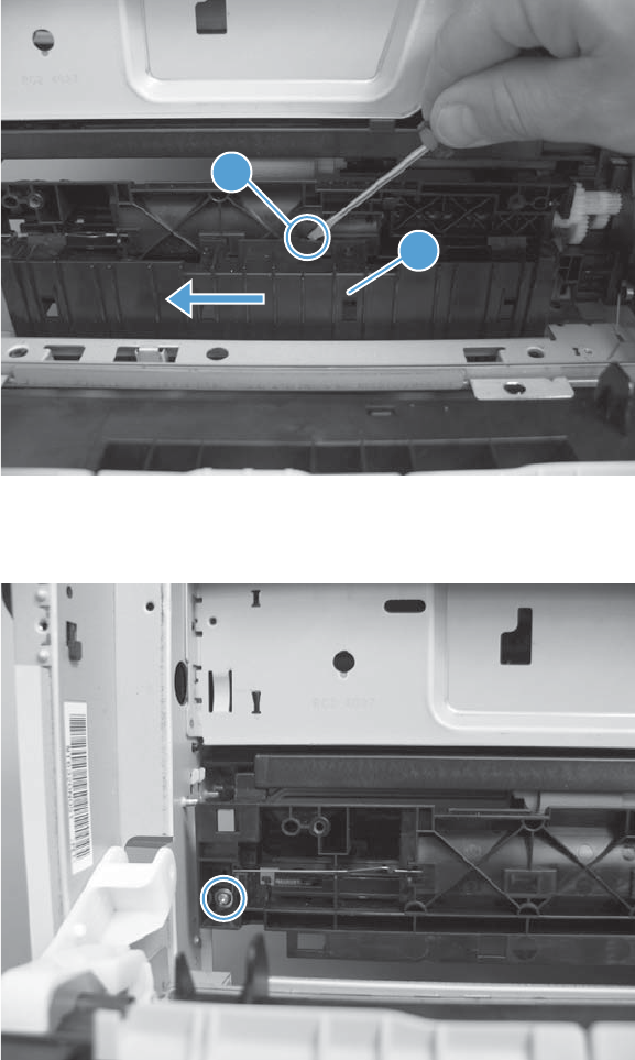
9. Release one tab (callout 1), and then slide the feed guide (callout 2) toward the front of the
product to remove.
Figure 2-253 Remove the tray-pickup assembly (9 of 11)
1
2
10. Remove one screw.
Figure 2-254 Remove the tray-pickup assembly (10 of 11)
ENWW Internal assemblies 273
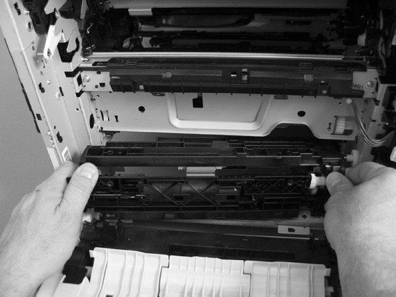
11. Remove the tray-pickup assembly.
Figure 2-255 Remove the tray-pickup assembly (11 of 11)
274 Chapter 2 Removal and replacement ENWW

Laser/scanner assembly (Y/M)
Before proceeding, remove the following components:
●Toner collection unit. See Toner-collection unit on page 104.
●Intermediate transfer belt (ITB). See Intermediate transfer belt (ITB) on page 120.
●S-CVR-REAR (scanner rear cover). See S-CVR-REAR (scanner rear cover) on page 128.
●Lower-left cover. See Lower-left cover on page 136.
●Left cover. See Left cover on page 137.
●Rear cover. See Rear cover on page 144.
●Document feeder. See Document feeder on page 151.
●Scanner assembly. See Scanner assembly on page 171.
●Cartridge fan and environmental sensor. See Cartridge fan and environmental sensor
on page 222.
●Toner collection sensor and scanner-thermistor assembly. See Toner-collection sensor and scanner-
thermistor assembly on page 226.
●Interconnect board (ICB). See Interconnect board (ICB) on page 239.
●Low-voltage power supply. See Low-voltage power supply (LVPS) on page 243.
●High-voltage power supply lower. See High-voltage power supply lower (HVPS-D) on page 250.
●Exhaust fan and fan duct. See Exhaust fan and fan duct on page 256.
ENWW Internal assemblies 275
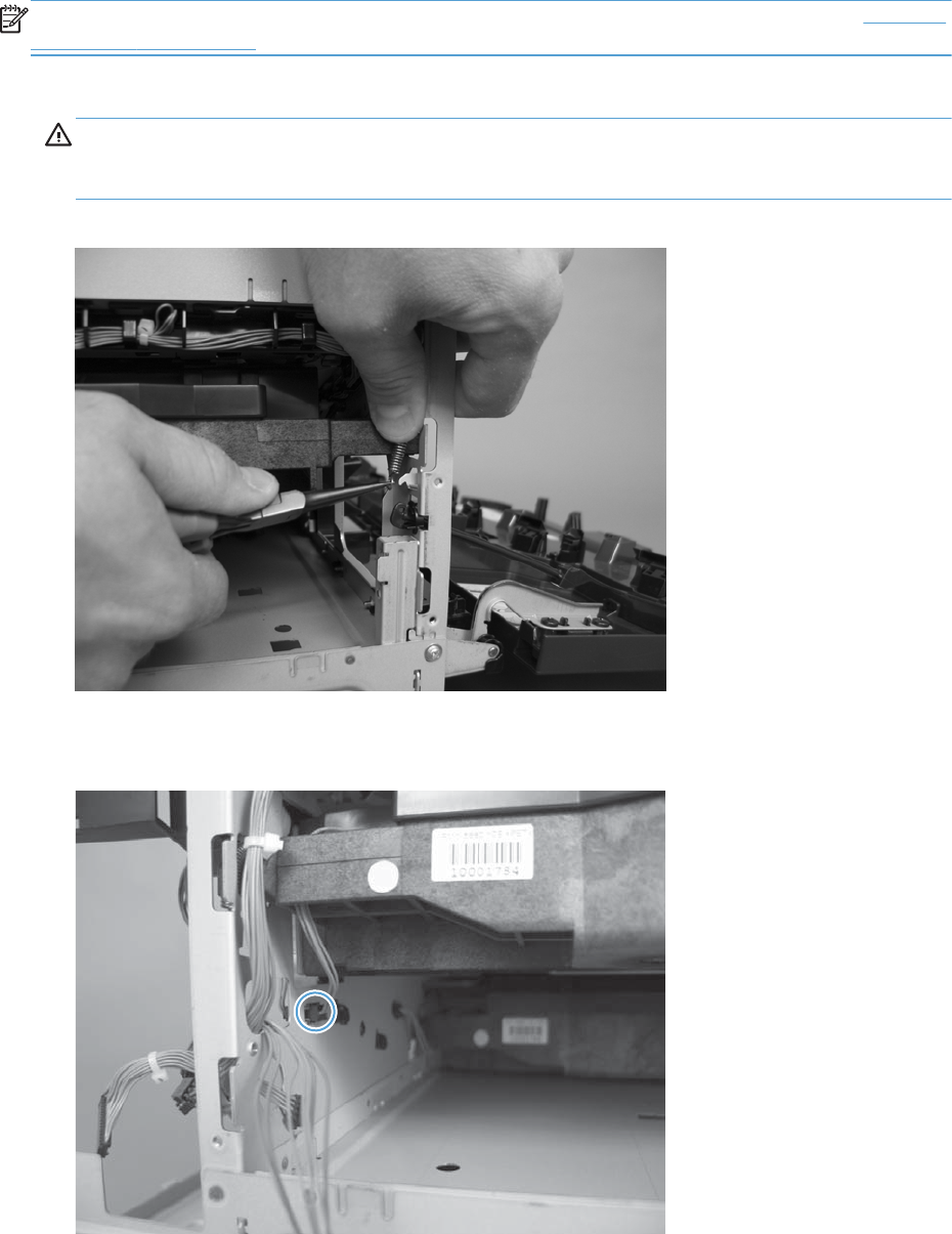
Remove the laser/scanner assembly (Y/M)
NOTE: After installing a new laser/scanner assembly, be sure to calibrate the product. See Calibrate
the product on page 468.
1. Release one spring.
CAUTION: The spring is not captive. Do not lose the spring when it is removed. Use a pair of
needle-nose pliers to safely retain the spring when it is removed. Do not use a flat blade
screwdriver to remove the spring; the spring could forcibly leave the product and strike you.
Figure 2-256 Remove the laser/scanner assembly (Y/M) (1 of 5)
2. Disconnect one connector.
Figure 2-257 Remove the laser/scanner assembly (Y/M) (2 of 5)
276 Chapter 2 Removal and replacement ENWW
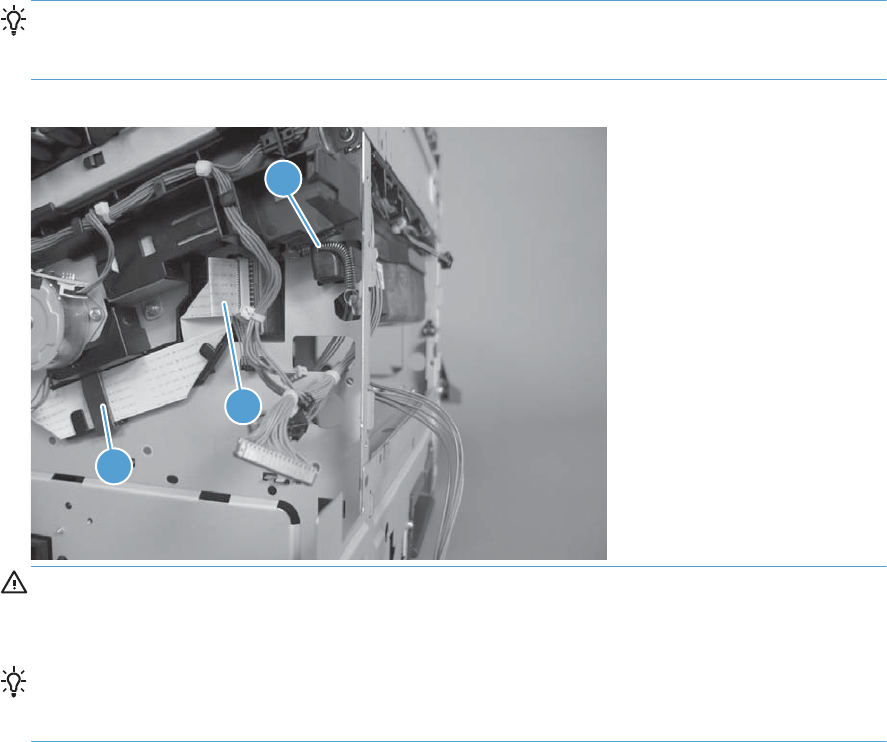
3. Release one spring (callout 1), and then disconnect one FFC (callout 2).
Reinstallation tip When reinstalled, the toroid (callout 3) must be correctly positioned on the
wire guide (in the provided slots) so that the fan duct will fully seat in the product when it is
reinstalled.
Figure 2-258 Remove the laser/scanner assembly (Y/M) (3 of 5)
1
2
3
CAUTION: The spring is not captive. Do not lose the spring when it is removed. Use a pair of
needle-nose pliers to safely retain the spring when it is removed. Do not use a flat blade
screwdriver to remove the spring; the spring could forcibly leave the product and strike you.
Reinstallation tip When you reinstall the spring, make sure that the laser/scanner fits tightly
up against the product chassis, and make sure that the FFC is fully seated in the connector. The
locator tabs on the front and rear of the scanner must be firmly seated in the slots in the chassis.
ENWW Internal assemblies 277
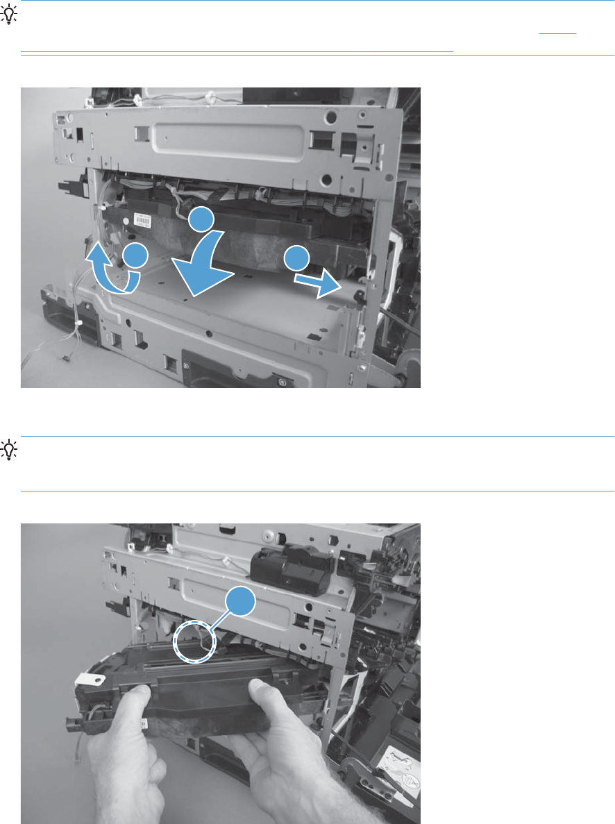
4. Rotate the front of the laser/scanner assembly down (callout 1), and then slide it toward the right
(callout 2). Lower the left corner, and then rotate the left corner out of the product (callout 3).
Reinstallation tip When the scanner is reinstalled, make sure that the tab on the front of the
laser/scanner is inserted in the alignment hole in the product chassis. See callout 1 in Figure
2-260 Remove the laser/scanner assembly (Y/M) (5 of 5) on page 278
Figure 2-259 Remove the laser/scanner assembly (Y/M) (4 of 5).
1
32
5. Pull the laser/scanner assembly out of the product to remove it.
Reinstallation tip When the scanner is removed, locate the alignment tab (callout 1) on the
front of the laser/scanner. The tab must be inserted in the alignment hole in the product chassis
when the assembly is reinstalled.
Figure 2-260 Remove the laser/scanner assembly (Y/M) (5 of 5)
1
278 Chapter 2 Removal and replacement ENWW

Laser/scanner assembly (C/Bk)
Before proceeding, remove the following components:
●Toner collection unit. See Toner-collection unit on page 104.
●Intermediate transfer belt (ITB). See Intermediate transfer belt (ITB) on page 120.
●S-CVR-REAR (scanner rear cover). See S-CVR-REAR (scanner rear cover) on page 128.
●Lower-left cover. See Lower-left cover on page 136.
●Left cover. See Left cover on page 137.
●Document feeder. See Document feeder on page 151.
●Rear cover. See Rear cover on page 144.
●Scanner assembly. See Scanner assembly on page 171.
●Cartridge fan and environmental sensor. See Cartridge fan and environmental sensor
on page 222.
●Toner collection sensor and scanner-thermistor assembly. See Toner-collection sensor and scanner-
thermistor assembly on page 226.
●Interconnect board (ICB). See Interconnect board (ICB) on page 239.
●Low-voltage power supply. See Low-voltage power supply (LVPS) on page 243.
●High-voltage power supply lower. See High-voltage power supply lower (HVPS-D) on page 250.
●Exhaust fan and fan duct. See Exhaust fan and fan duct on page 256.
●Laser/scanner assembly (Y/M). See Laser/scanner assembly (Y/M) on page 275.
ENWW Internal assemblies 279
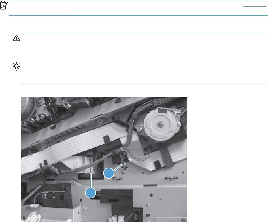
Remove the laser/scanner assembly (C/Bk)
NOTE: After installing a new laser/scanner assembly, be sure to calibrate the product. See Calibrate
the product on page 468.
1. Release one spring (callout 1), and then disconnect one FFC (callout 2).
CAUTION: The spring is not captive. Do not lose the spring when it is removed. Use a pair of
needle-nose pliers to safely retain the spring when it is removed. Do not use a flat blade
screwdriver to remove the spring; the spring could forcibly leave the product and strike you.
Reinstallation tip When you reinstall the spring, make sure that the laser/scanner fits tightly
up against the product chassis, and make sure that the FFC is fully seated in the connector. The
locator tabs on the front of the scanner must be firmly seated in the slots in the chassis.
Figure 2-261 Remove the laser/scanner assembly (C/Bk) (1 of 5)
2
1
280 Chapter 2 Removal and replacement ENWW
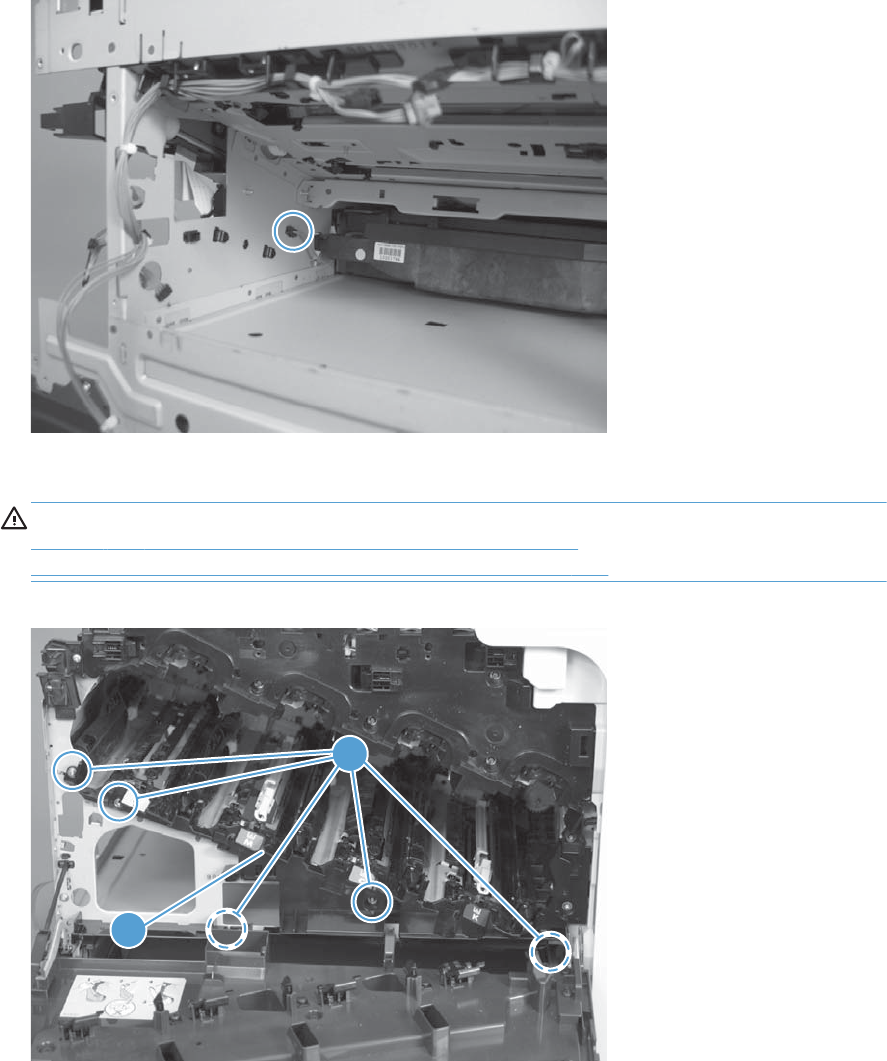
2. Disconnect one connector.
Figure 2-262 Remove the laser/scanner assembly (C/Bk) (2 of 5)
3. Remove five screws (callout 1), and then remove the cover (callout 2).
CAUTION: Be careful. The PGC actuators are easily dislodged when the cover is removed. See
Figure 2-266 Reinstall the PGC actuators (1 of 5) on page 283. To reinstall the actuators, see
Reinstall the protective glass cleaner (PGC) actuators on page 283.
Figure 2-263 Remove the laser/scanner assembly (C/Bk) (3 of 5)
2
1
ENWW Internal assemblies 281
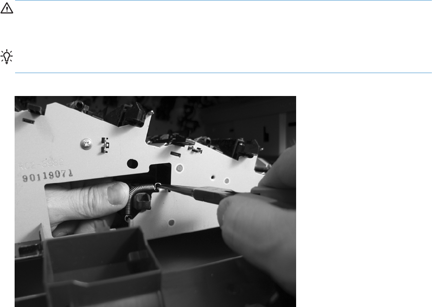
4. Release one spring.
CAUTION: The spring is not captive. Do not lose the spring when it is removed. Use a pair of
needle-nose pliers to safely retain the spring when it is removed. Do not use a flat blade
screwdriver to remove the spring; the spring could forcibly leave the product and strike you.
Reinstallation tip When you reinstall the spring, make sure that the laser/scanner fits tightly
up against the product chassis.
Figure 2-264 Remove the laser/scanner assembly (C/Bk) (4 of 5)
282 Chapter 2 Removal and replacement ENWW
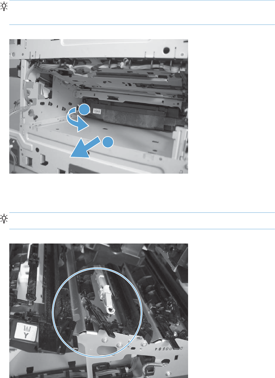
5. Rotate the corner of the assembly away from the product until you can see the PCA, and then
remove the assembly from the product.
Reinstallation tip When the laser/scanner is correctly positioned in the chassis, the plastic
parts which protrude at the front and rear of the product will be firmly seated against the locator
tabs on the chassis. Verify that the assembly is correctly seated, and then install the spring.
Figure 2-265 Remove the laser/scanner assembly (C/Bk) (5 of 5)
1
2
Reinstall the protective glass cleaner (PGC) actuators
1. The following figure shows a dislodged PGC actuator.
TIP: If the actuator and spring are only slightly dislodged, you might be able to easily push them
back into place.
Figure 2-266 Reinstall the PGC actuators (1 of 5)
ENWW Internal assemblies 283
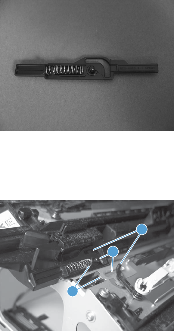
2. Remove the actuator and spring from the product. Install the spring on the actuator.
Figure 2-267 Reinstall the PGC actuators (2 of 5)
3. Before proceeding, take note of the following:
●Callout 1: The pin on the actuator will be installed into the slot in the chassis.
●Callout 2: The pin on the pivot arm will be installed into the slot on the actuator.
●Callout 3: The end of the spring will be installed onto the tab on the chassis.
Figure 2-268 Reinstall the PGC actuators (3 of 5)
3
1
2
284 Chapter 2 Removal and replacement ENWW
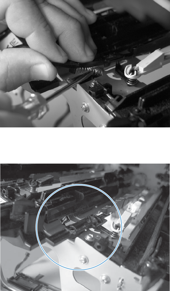
4. Place the end of the actuator into the PGC rod, and then use a small flat blade screw driver to
fasten the end of the spring on the tab on the chassis.
Figure 2-269 Reinstall the PGC actuators (4 of 5)
5. Push down on the actuator to seat it into place. Verify that the actuators is correctly installed. The
PGC actuator must freely move when you push in on the actuator.
Figure 2-270 Reinstall the PGC actuators (5 of 5)
ENWW Internal assemblies 285
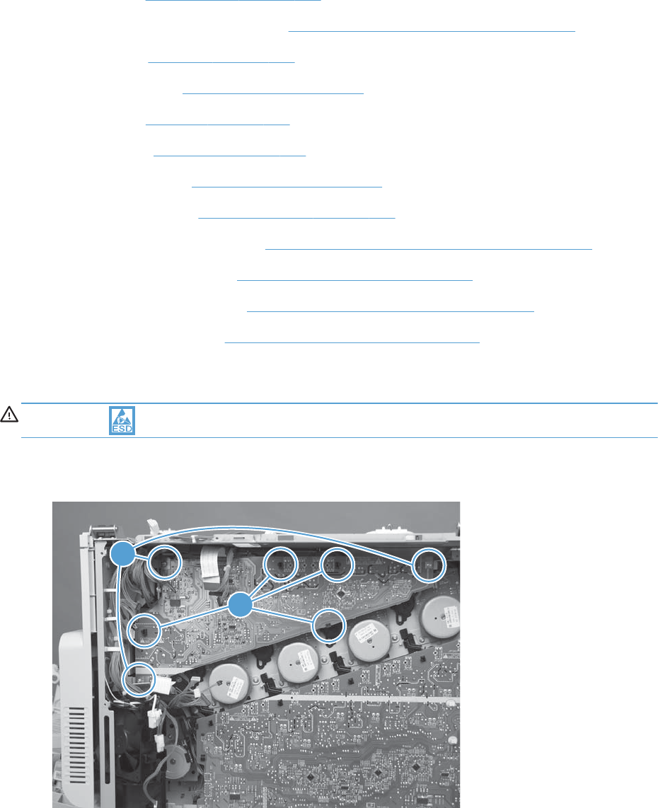
High-voltage power supply upper (HVPS-T)
Before proceeding, remove the following components:
●Formatter. See Formatter PCA on page 106.
●S-CVR-REAR (scanner rear cover). See S-CVR-REAR (scanner rear cover) on page 128.
●Fan cover. See Fan cover on page 134.
●Lower-left cover. See Lower-left cover on page 136.
●Left cover. See Left cover on page 137.
●Rear cover. See Rear cover on page 144.
●Document feeder. See Document feeder on page 151.
●Scanner assembly. See Scanner assembly on page 171.
●Image scanner power supply. See Image scanner power supply unit (PSU) on page 237.
●Interconnect board (ICB). See Interconnect board (ICB) on page 239.
●Low-voltage power supply. See Low-voltage power supply (LVPS) on page 243.
●DC controller and tray. See DC controller PCA and tray on page 248.
Remove the high-voltage power supply upper
CAUTION: ESD-sensitive part.
1. Remove three screws (callout 1), and then release four tabs (callout 2).
Figure 2-271 Remove the high-voltage power supply upper (2 of 2)
11
2
286 Chapter 2 Removal and replacement ENWW
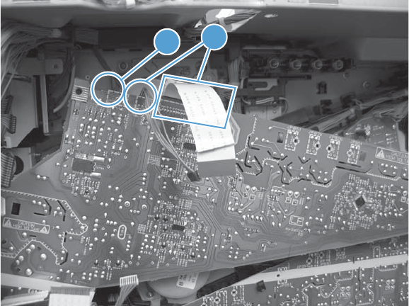
2. Disconnect one connector (callout 1) and then remove the power supply.Do not disconnect two
connectors (callout 2)
Figure 2-272 Remove the high-voltage power supply upper (1 of 2)
11 2
ENWW Internal assemblies 287
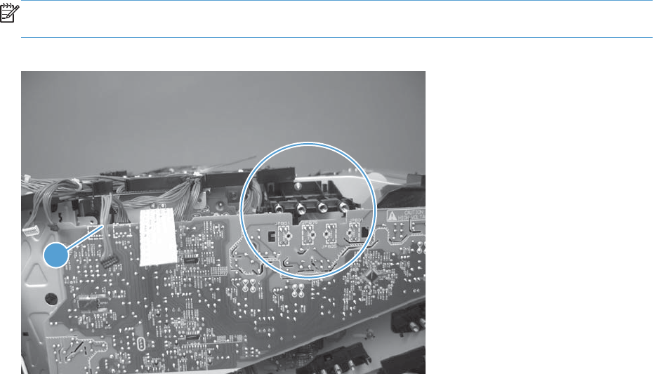
Reinstall the high-voltage power supply upper
When you reinstall the power supply, look through the holes in the PCA and make sure that the high-
voltage contact springs are correctly seated against the PCA.
NOTE: For a replacement power supply, remove one wire harness (callout 1) and then install it on
the replacement power supply.
Figure 2-273 Reinstall the high-voltage power supply upper
1
288 Chapter 2 Removal and replacement ENWW
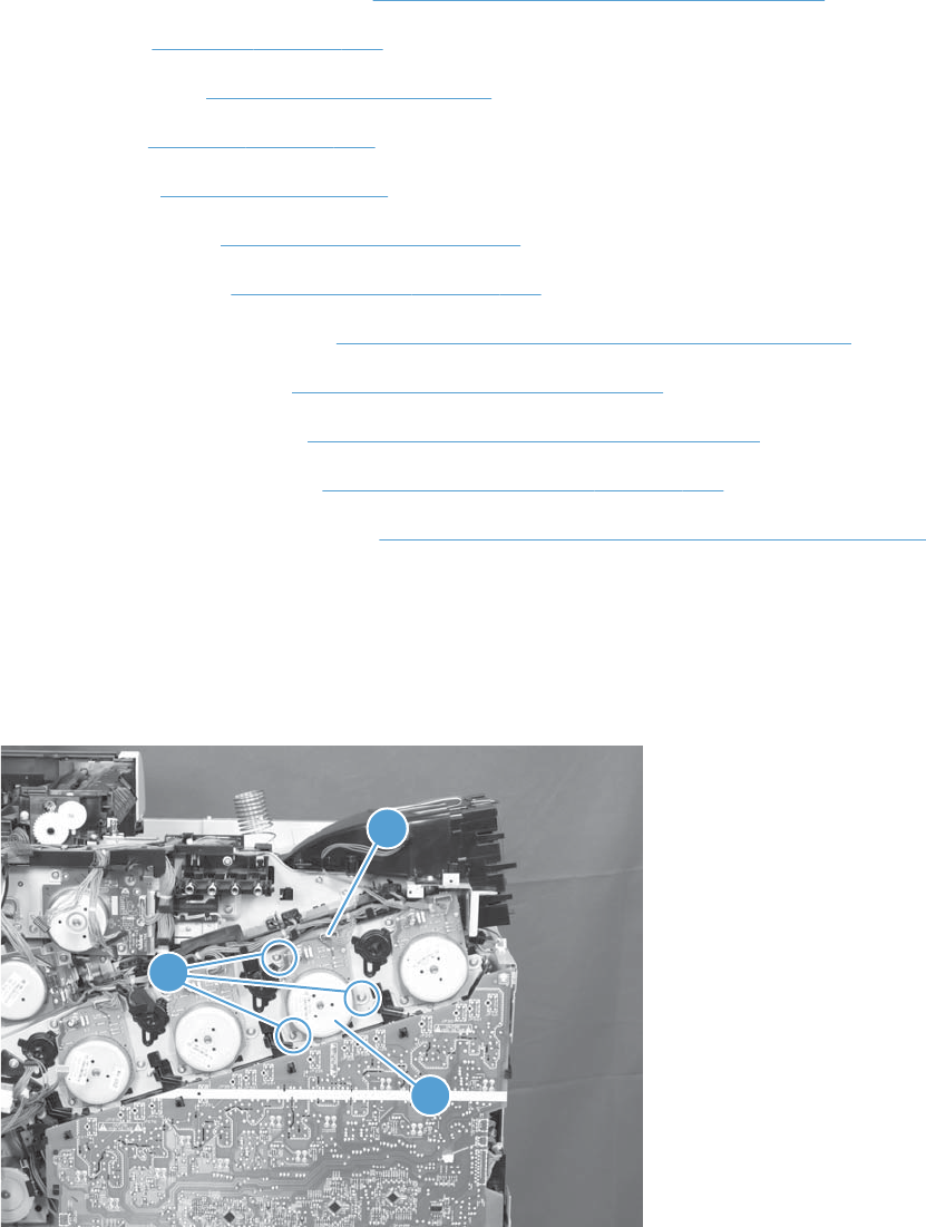
Yellow, magenta, cyan, and black drum motors
Before proceeding, remove the following components:
●S-CVR-REAR (scanner rear cover). See S-CVR-REAR (scanner rear cover) on page 128.
●Fan cover. See Fan cover on page 134.
●Lower-left cover. See Lower-left cover on page 136.
●Left cover. See Left cover on page 137.
●Rear cover. See Left cover on page 137.
●Document feeder. See Document feeder on page 151.
●Scanner assembly. See Scanner assembly on page 171.
●Image scanner power supply. See Image scanner power supply unit (PSU) on page 237.
●Interconnect board (ICB). See Interconnect board (ICB) on page 239.
●Low-voltage power supply. See Low-voltage power supply (LVPS) on page 243.
●DC controller PCA and tray. See DC controller PCA and tray on page 248.
●High-voltage power supply upper. See High-voltage power supply upper (HVPS-T) on page 286.
Remove the yellow, magenta, cyan, and black drum motors
▲For each motor, remove three screws (callout 1), disconnect one connector (callout 2), and then
remove the motor (callout 3)
Figure 2-274 Remove the yellow, magenta, cyan, and black drum motors
1
2
3
ENWW Internal assemblies 289

Fuser motor
Before proceeding, remove the following components:
●Formatter. See Formatter PCA on page 106.
●S-CVR-REAR (scanner rear cover). See S-CVR-REAR (scanner rear cover) on page 128.
●Lower-left cover. See Lower-left cover on page 136.
●Fan cover. See Fan cover on page 134.
●Left cover. See Left cover on page 137.
●Rear cover. See Rear cover on page 144.
●Document feeder. See Document feeder on page 151.
●Image scanner power supply unit (PSU). See Image scanner power supply unit (PSU)
on page 237.
●Scanner assembly. See Scanner assembly on page 171.
●Interconnect board (ICB). See Interconnect board (ICB) on page 239.
●Low-voltage power supply. See Low-voltage power supply (LVPS) on page 243.
●DC controller PCA. See DC controller PCA and tray on page 248.
●High-voltage power supply upper. See High-voltage power supply upper (HVPS-T) on page 286.
290 Chapter 2 Removal and replacement ENWW
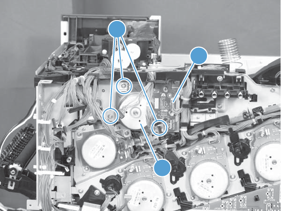
Remove the fuser motor
Remove three screws (callout 1), disconnect one connector (callout 2), and then remove the motor
(callout 3).
Figure 2-275 Remove the fuser motor
1
2
3
ENWW Internal assemblies 291
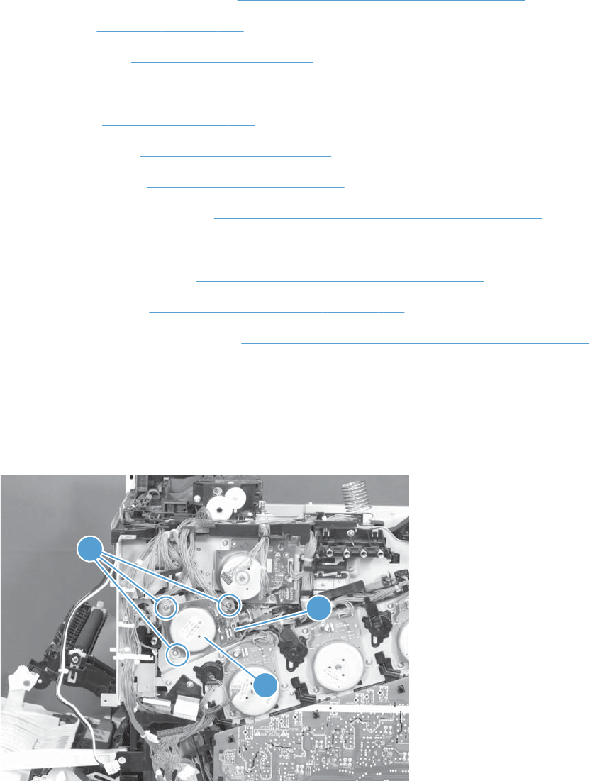
ITB motor
Before proceeding, remove the following components:
●S-CVR-REAR (scanner rear cover). See S-CVR-REAR (scanner rear cover) on page 128.
●Fan cover. See Fan cover on page 134.
●Lower-left cover. See Lower-left cover on page 136.
●Left cover. See Left cover on page 137.
●Rear cover. See Rear cover on page 144.
●Document feeder. See Document feeder on page 151.
●Scanner assembly. See Scanner assembly on page 171.
●Image scanner power supply. See Image scanner power supply unit (PSU) on page 237.
●Interconnect board (ICB). See Interconnect board (ICB) on page 239.
●Low-voltage power supply. See Low-voltage power supply (LVPS) on page 243.
●DC controller PCA. See DC controller PCA and tray on page 248.
●High-voltage power supply upper. See High-voltage power supply upper (HVPS-T) on page 286.
Remove the ITB motor
▲Remove three screws (callout 1), disconnect one connector (callout 2), and then remove the motor
(callout 3).
Figure 2-276 Remove the ITB motor (1 of 2)
1
2
3
292 Chapter 2 Removal and replacement ENWW

Main-drive assembly
NOTE: Removing the main-drive assembly typically requires more than 2 hours to complete.
Before proceeding, remove the following components:
●Formatter. See Formatter PCA on page 106.
●Intermediate transfer belt (ITB). See Intermediate transfer belt (ITB) on page 120.
●S-CVR-REAR (scanner rear cover). See S-CVR-REAR (scanner rear cover) on page 128.
●Fan cover. See Fan cover on page 134.
●Lower-left cover. See Lower-left cover on page 136.
●Left cover. See Left cover on page 137.
●Rear cover. See Rear cover on page 144.
●Document feeder. See Document feeder on page 151.
●Scanner assembly. See Scanner assembly on page 171.
●Image scanner power supply. See Image scanner power supply unit (PSU) on page 237.
●Interconnect board (ICB). See Interconnect board (ICB) on page 239.
●Low-voltage power supply. See Low-voltage power supply (LVPS) on page 243.
●DC controller PCA. See DC controller PCA and tray on page 248.
●High-voltage power supply lower. See High-voltage power supply lower (HVPS-D) on page 250.
●Exhaust fan and fan duct. See Exhaust fan and fan duct on page 256.
●High-voltage power supply upper. See High-voltage power supply upper (HVPS-T) on page 286.
●Yellow, magenta, cyan, and black drum motors. See Remove the yellow, magenta, cyan, and
black drum motors on page 289.
ENWW Internal assemblies 293
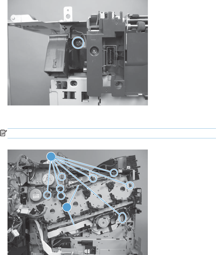
Remove the main-drive assembly
1. Remove one screw and then release the fan from the chassis.
Figure 2-277 Remove the main-drive assembly (1 of 7)
2. Remove eight connectors (callout 1), and then release the wire harnesses from the guides
(callout 2).
NOTE: Leave the wire harnesses with the product.
Figure 2-278 Remove the main-drive assembly (2 of 7)
1
2
294 Chapter 2 Removal and replacement ENWW
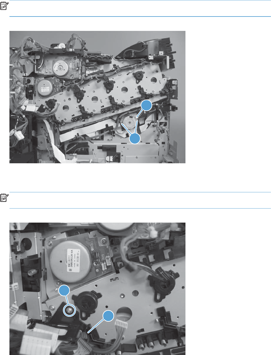
3. Remove two screws (callout 1), disconnect one connector (callout 2), and then remove the
developing-disengagement motor.
NOTE: When the motor is reinstalled, make sure the motor PCA is positioned at the top of the
assembly.
Figure 2-279 Remove the main-drive assembly (3 of 7)
2
1
4. Remove one screw (callout 1), and then remove the wire guide from the main-drive assembly
(callout 2).
NOTE: Leave the wire harnesses connected to the wire guide and attached to the product for
easier reinstallation.
Figure 2-280 Remove the main-drive assembly (4 of 7)
1
2
ENWW Internal assemblies 295
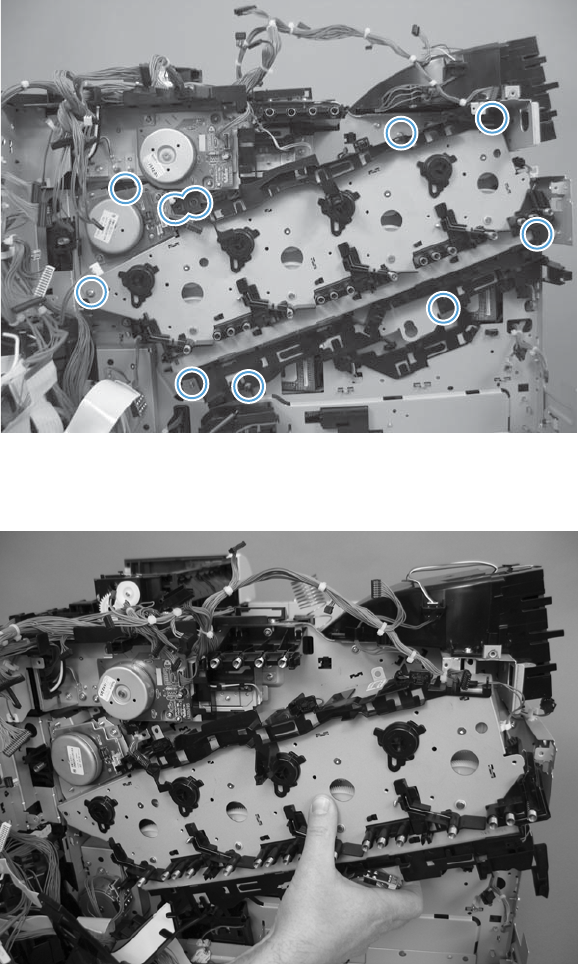
5. Remove 10 screws.
Figure 2-281 Remove the main-drive assembly (5 of 7)
1
6. Separate the main-drive assembly from the product.
Figure 2-282 Remove the main-drive assembly (6 of 7)
296 Chapter 2 Removal and replacement ENWW
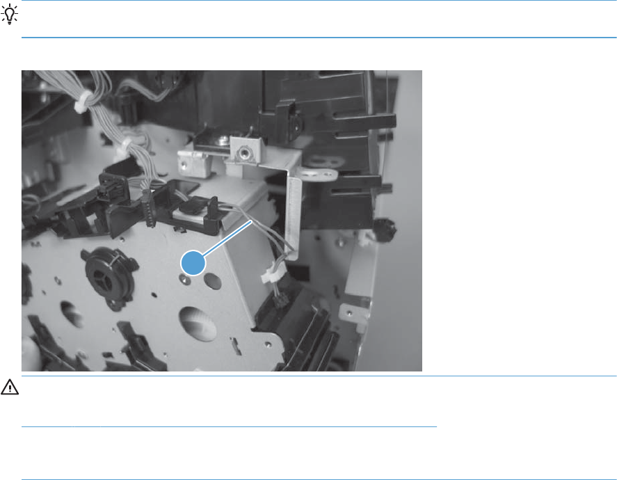
7. Release the wire harness (callout 1) from the guides, and then remove the main-drive assembly
from the product.
Reinstallation tip It might be easier to pass this harness over the edge of the assembly chassis
after the main-drive assembly is reinstalled.
Figure 2-283 Remove the main-drive assembly (7 of 7)
1
CAUTION: Be careful when you remove the assembly. The cams on the backside of the
assembly can be dislodged. If the cams become dislodged, install them on the shafts as shown in
Figure 2-284 Reinstall the main-drive assembly (1 of 7) on page 298.
The black cam must be installed on the shaft furthest away from the developing-disengagement
motor. The white cams are interchangeable.
ENWW Internal assemblies 297
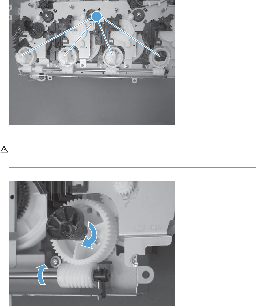
Reinstall the main-drive assembly
1. Locate the cams (callout 1) on the back side of the assembly.
Figure 2-284 Reinstall the main-drive assembly (1 of 7)
1
2. Slowly rotate the shaft near the black cam.
WARNING! Do not touch the plastic gears or cams. You must not wipe away any of the grease
that is applied to these components. Always rotate the gears and cams by rotating the metal drive
shaft.
Figure 2-285 Reinstall the main-drive assembly (2 of 7)
298 Chapter 2 Removal and replacement ENWW
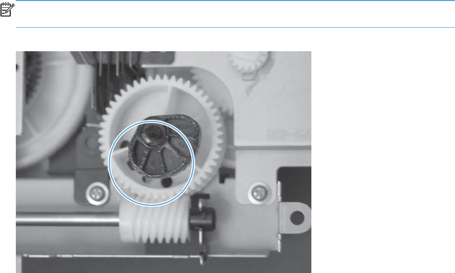
3. Continue to rotate the shaft until the holes in the black-cam gear align as shown below.
When correctly aligned, the bottom-most hole in the gear is aligned with a hole in the sheet-metal
chassis.
NOTE: The holes in the other cam gears have a different alignment. You must make sure that the
holes in the black-cam gear are correctly aligned.
Figure 2-286 Reinstall the main-drive assembly (3 of 7)
ENWW Internal assemblies 299
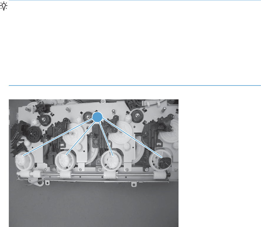
4. Verify that the cams (callout 1) align correctly.
TIP: The second cam in from the right (the white cam to the left of the black cam), should have
the second hole aligned with the hole in the sheet-metal chassis.
The third cam in from the right, should have the third hole aligned with the hole in the sheet-metal
chassis.
The fourth cam in from the right (the cam nearest the developing-disengagement motor), should
have the fourth hole aligned with the hole in the sheet-metal chassis.
If the second, third, or fourth cams do not correctly align, do the following. Hold the long drive
shaft, gently tilt the cam and gear away from the shaft to allow clearance to rotate the gear until
the correct hole in the gear aligns with the hole in the chassis.
Figure 2-287 Reinstall the main-drive assembly (4 of 7)
1
300 Chapter 2 Removal and replacement ENWW
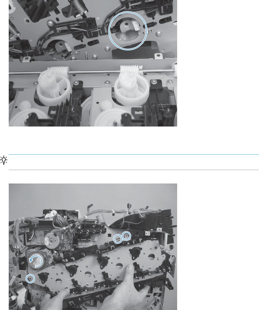
5. When the cams align correctly, they easily fit into the holes in the chassis.
Figure 2-288 Reinstall the main-drive assembly (5 of 7)
6. When placing the assembly on the chassis, align the holes in the assembly with the holes in the
chassis.
Reinstallation tip If the upper-left corner of the assembly is difficult to seat, you might need to
rotate the ITB motor to align the gear shaft with the hole in the chassis.
Figure 2-289 Reinstall the main-drive assembly (6 of 7)
ENWW Internal assemblies 301
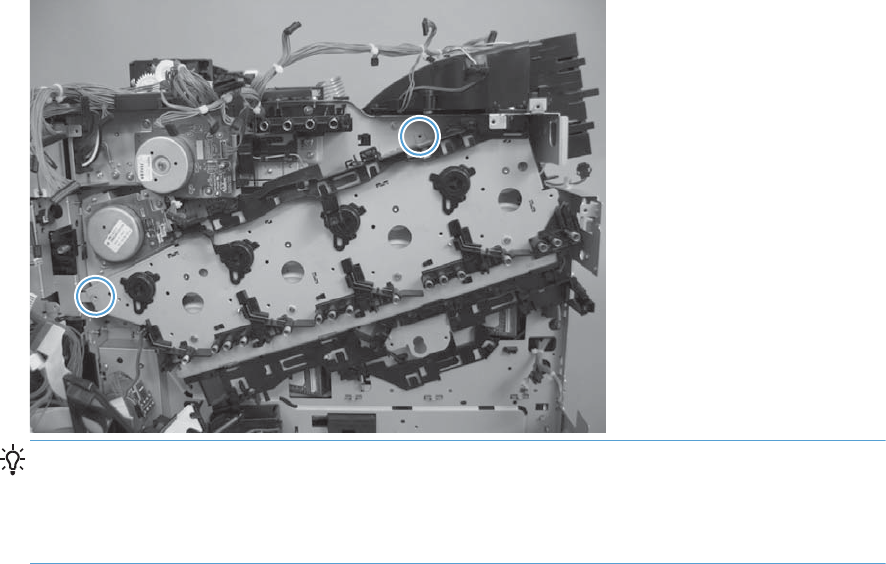
7. When the assembly is correctly installed, the tabs are flat against the chassis.
Figure 2-290 Reinstall the main-drive assembly (7 of 7)
TIP: After reassembling the product, use the Diagnostics menu to print a Color Band Test page.
If the test page shows one or more color planes are not printing (usually in the upper left corner of
the page), the cam or cams for the missing color plane are not correctly aligned. Repeat the
reinstall the main-drive assembly procedure.
302 Chapter 2 Removal and replacement ENWW
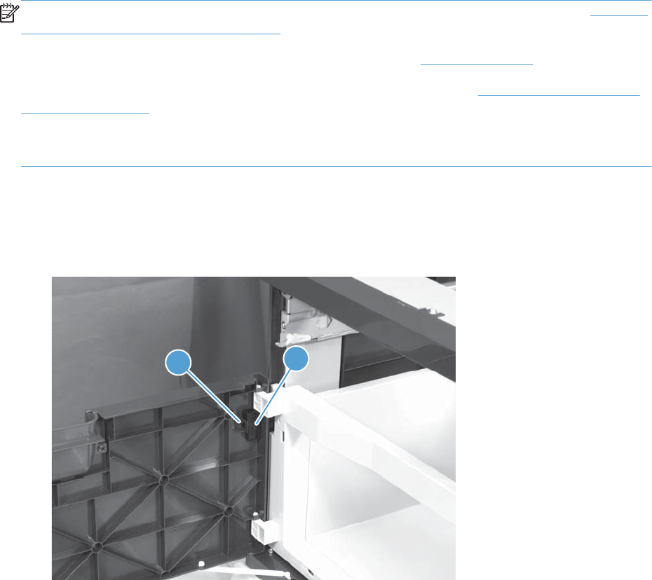
Optional paper feeder assemblies (1 x 500-sheet
and 3 x 500-sheet)
NOTE: For information about removing the Tray 3, 4, or 5 feed and separation rollers, see Feed and
separation rollers (Trays 2-5) on page 113.
For information about removing the Tray 3, 4, or 5 cassettes, see Tray on page 111.
For information about removing the right door (optional paper feeder), see Right door (optional paper
feeder) on page 307
The following procedures apply to both the 1 x 500-sheet optional paper feeder and the 3 x 500-sheet
optional paper unless specifically noted.
Front door (optional paper feeder)
1. Release one tab (callout 1), and then remove the stopper (callout 2).
Figure 2-291 Remove the front door (optional paper feeder) (1 of 2)
12
ENWW Optional paper feeder assemblies (1 x 500-sheet and 3 x 500-sheet) 303
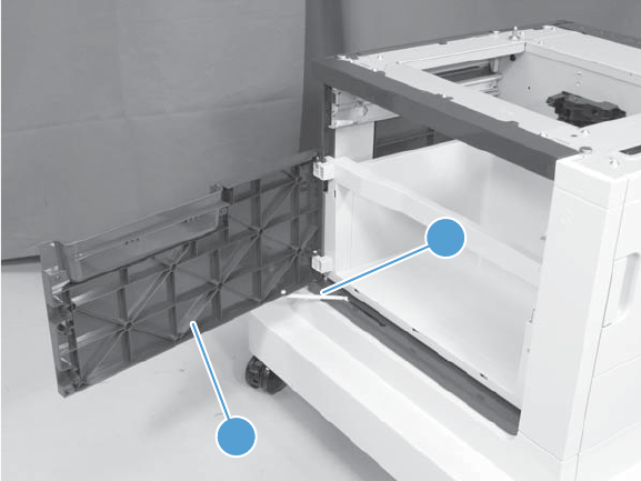
2. Release the link arm (callout 1), and then remove the front door (callout 2).
Figure 2-292 Remove the front door (optional paper feeder) (2 of 2)
1
2
304 Chapter 2 Removal and replacement ENWW
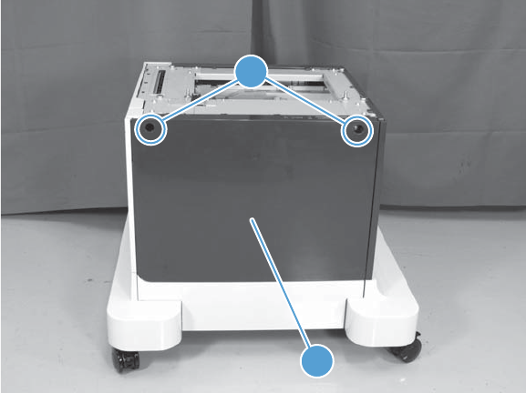
Rear cover (optional paper feeder)
▲Remove two screws (callout 1), and then remove the rear cover (callout 2).
Figure 2-293 Remove the rear cover (optional paper feeder)
1
2
ENWW Optional paper feeder assemblies (1 x 500-sheet and 3 x 500-sheet) 305
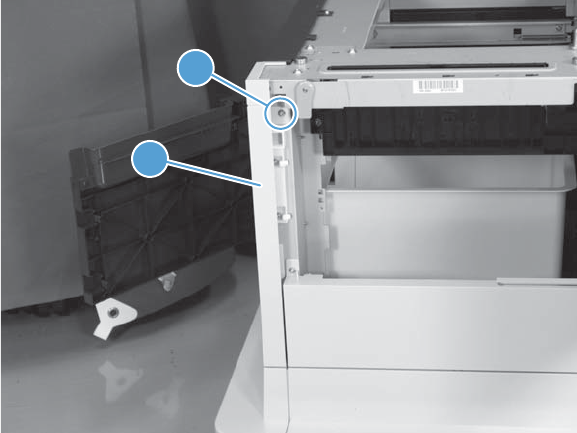
Right-front cover (optional paper feeder)
▲Open the front and right doors, remove one screw (callout 1), and then lift the right-front cover
(callout 2) to remove.
Figure 2-294 Remove the right-front cover (optional paper feeder)
1
2
306 Chapter 2 Removal and replacement ENWW
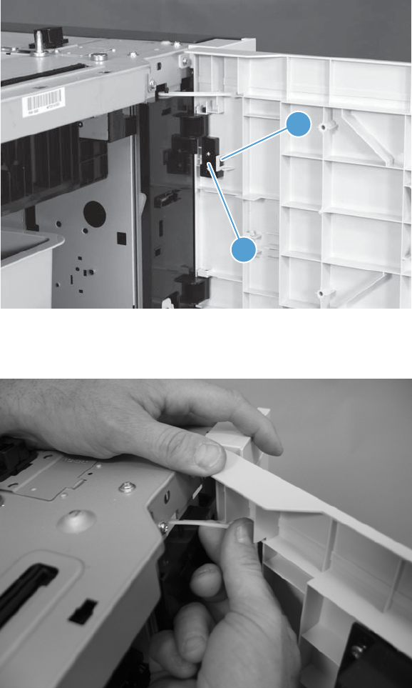
Right door (optional paper feeder)
1. Open the right door, release one tab (callout 1), and then remove the stopper (callout 2)
Figure 2-295 Remove the right door (optional paper feeder) (1 of 3)
2
1
2. Close the right door slightly, and then release the upper link arm.
Figure 2-296 Remove the right door (optional paper feeder) (2 of 3)
ENWW Optional paper feeder assemblies (1 x 500-sheet and 3 x 500-sheet) 307
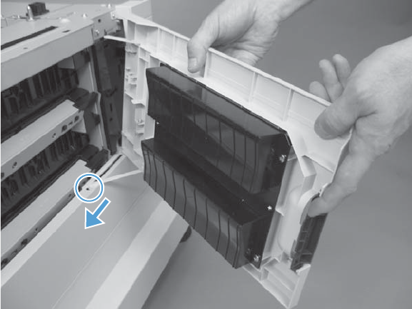
3. Slide the door to release the lower link arm, and then remove the right door.
Figure 2-297 Remove the right door (optional paper feeder) (3 of 3)
308 Chapter 2 Removal and replacement ENWW
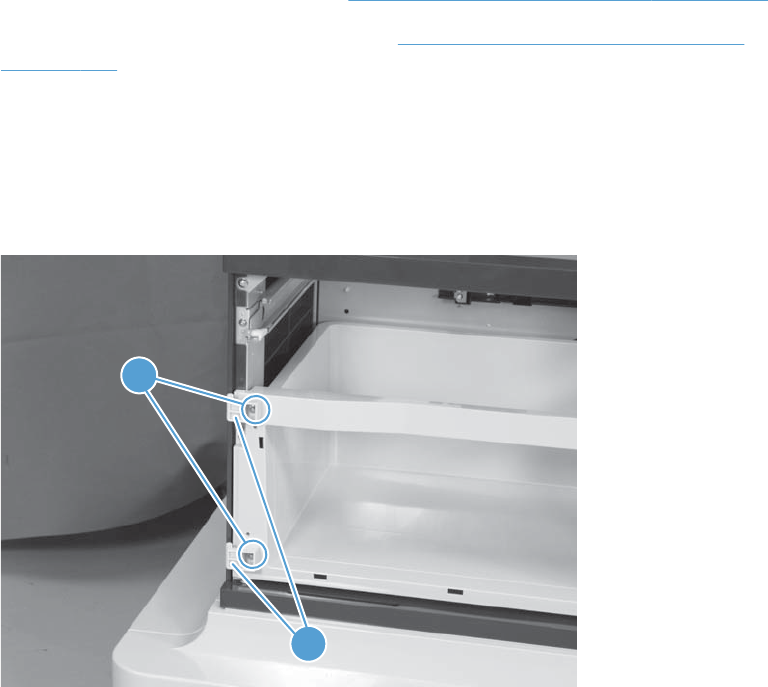
Left cover (optional paper feeder)
Before proceeding, remove the following components:
●Front door (optional paper feeder). See Front door (optional paper feeder) on page 303.
●Right-front cover (optional paper feeder). See Right-front cover (optional paper feeder)
on page 306.
Remove the left cover (optional paper feeder)
1. 1 x 500 paper feeder only: Remove two screws (callout 1), and then remove two bushings
(callout 2).
Figure 2-298 Remove the left cover (optional paper feeder) (1 of 3)
1
2
ENWW Optional paper feeder assemblies (1 x 500-sheet and 3 x 500-sheet) 309
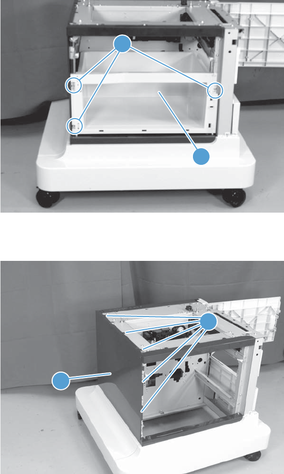
2. 1 x 500 paper feeder only: Remove three screws (callout 1), and then remove the storage
box (callout 2).
Figure 2-299 Remove the left cover (optional paper feeder) (2 of 3)
1
2
3. Release five tabs (callout 1), and then remove the left cover (callout 2).
Figure 2-300 Remove the left cover (optional paper feeder) (3 of 3)
1
2
310 Chapter 2 Removal and replacement ENWW
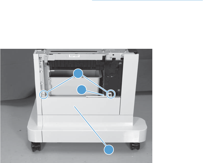
Right cover (optional paper feeder)
Before proceeding, remove the following components:
●Right door (optional paper feeder). See Right door (optional paper feeder) on page 307.
Remove the right cover (optional paper feeder)
▲Remove two screws (callout 1), release one tab (callout 2), and then remove the right cover
(callout 3).
Figure 2-301 Remove the right cover (optional paper feeder)
2
3
1
ENWW Optional paper feeder assemblies (1 x 500-sheet and 3 x 500-sheet) 311
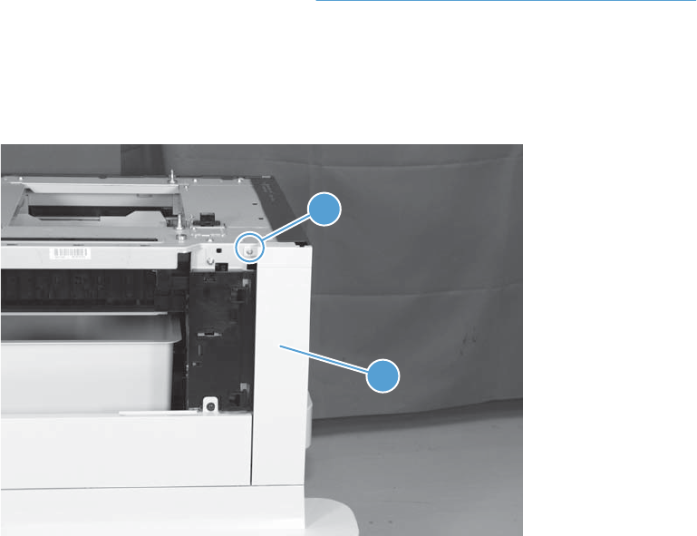
Rear-right cover (optional paper feeder)
Before proceeding, remove the following components:
●Right door (optional paper feeder). See Right door (optional paper feeder) on page 307.
Remove the rear-right cover (optional paper feeder)
▲Remove one screw (callout 1), and then lift the rear-right cover (callout 2) to remove.
Figure 2-302 Remove the rear-right cover (optional paper feeder)
2
1
312 Chapter 2 Removal and replacement ENWW
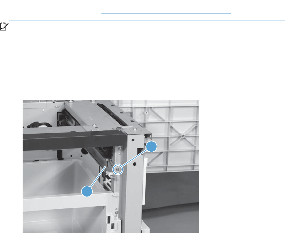
Pickup assembly (optional paper feeder)
Before proceeding, remove the following components:
●Paper feeder right front cover. See Right-front cover (optional paper feeder) on page 306.
●Paper feeder rear cover. See Rear cover (optional paper feeder) on page 305.
NOTE: The following procedure shows steps for removing the pickup assembly for Tray 3. 3 x 500-
sheet optional paper feeder only: The steps for removing the pickup assemblies for Tray 4 and
Tray 5 are the same unless noted. You must remove the pickup assemblies in sequence beginning with
the pickup assembly for Tray 5.
Remove the pickup assembly (optional paper feeder)
1. Remove one screw (callout 1), and then remove the tray rail (callout 2).
Figure 2-303 Remove the pickup assembly (optional paper feeder) (1 of 5)
1
2
ENWW Optional paper feeder assemblies (1 x 500-sheet and 3 x 500-sheet) 313
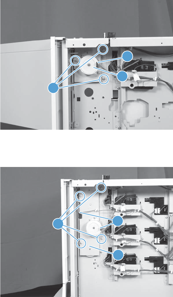
2. 1 x 500-sheet optional paper feeder only: Remove three screws (callout 1), disconnect
one connector (callout 2), and then remove the motor assembly (callout 3).
Figure 2-304 Remove the pickup assembly (optional paper feeder) (2 of 5)
2
1
3
3. 3 x 500-sheet optional paper feeder only: Remove four screws (callout 1), disconnect two
connector (callout 2), and then remove the motor assembly (callout 3).
Figure 2-305 Remove the pickup assembly (optional paper feeder) (3 of 5)
12
3
314 Chapter 2 Removal and replacement ENWW

4. Remove one screw (callout 1), and then disconnect three connectors (callout 2).
Figure 2-306 Remove the pickup assembly (optional paper feeder) (4 of 5)
1
2
5. Remove one screw (callout 1), and then remove the pickup assembly (callout 2).
Figure 2-307 Remove the pickup assembly (optional paper feeder) (5 of 5)
1
2
ENWW Optional paper feeder assemblies (1 x 500-sheet and 3 x 500-sheet) 315
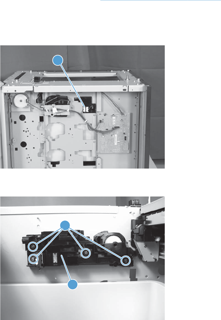
Lifter assembly (optional paper feeder)
Before proceeding, remove the following components:
●Rear cover (optional paper feeder). See Rear cover (optional paper feeder) on page 305.
Remove the lifter assembly (optional paper feeder)
1. Disconnect one connector (callout 1).
Figure 2-308 Remove the lifter assembly (optional paper feeder) (1 of 2)
1
2. Remove four screws (callout 1), and then remove the lifter assembly (callout 2).
Figure 2-309 Remove the lifter assembly (optional paper feeder) (2 of 2)
1
2
316 Chapter 2 Removal and replacement ENWW
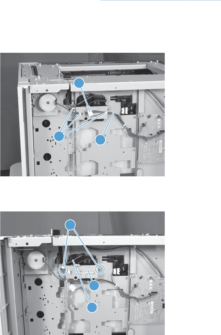
Lifter-drive assembly (optional paper feeder)
Before proceeding, remove the following components:
●Rear cover (optional paper feeder). See Rear cover (optional paper feeder) on page 305.
Remove the lifter-drive assembly (optional paper feeder)
1. Disconnect one connector (callout 1), and then release the wire harnesses (callout 3) from the
guides (callout 2).
Figure 2-310 Remove the lifter-drive assembly (optional paper feeder) (1 of 2)
2
1
3
2. Remove two screws (callout 1), and then remove the sheet-metal plate (callout 2). Remove one
spring (callout 3), and then remove the lifter drive assembly.
Figure 2-311 Remove the lifter-drive assembly (optional paper feeder) (2 of 2)
1
2
3
ENWW Optional paper feeder assemblies (1 x 500-sheet and 3 x 500-sheet) 317
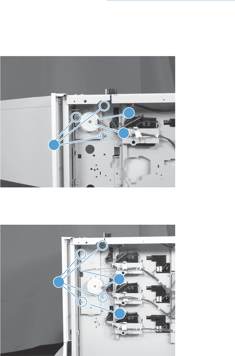
Pickup motor assembly (optional paper feeder)
Before proceeding, remove the following components:
●Rear cover (optional paper feeder). See Rear cover (optional paper feeder) on page 305.
Remove the pickup motor (optional paper feeder) assembly
1. 1 x 500-sheet optional paper feeder only: Remove three screws (callout 1), disconnect
one connector (callout 2), and then remove the motor assembly (callout 3).
Figure 2-312 Remove the pickup motor assembly (optional paper feeder) (1 of 2)
2
1
3
2. 3 x 500-sheet optional paper feeder only: Remove four screws (callout 1), disconnect two
connector (callout 2), and then remove the motor assembly (callout 3).
Figure 2-313 Remove the pickup motor assembly (optional paper feeder) (2 of 2)
12
3
318 Chapter 2 Removal and replacement ENWW
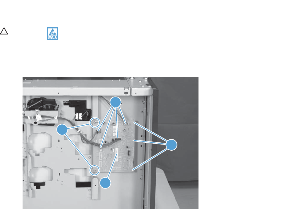
Controller PCA (optional paper feeder)
Before proceeding, remove the following components:
●Rear cover (optional paper feeder). See Rear cover (optional paper feeder) on page 305.
Remove the controller PCA (optional paper feeder)
CAUTION: ESD-sensitive part.
1. 1 x 500-sheet optional paper feeder only: Disconnect four connector (callout 2), and then
remove two screws (callout 1). Release three tabs (callout 3), and then remove the PCA (callout 4).
Figure 2-314 Remove the controller PCA (optional paper feeder) (1 of 2)
4
1
2
3
ENWW Optional paper feeder assemblies (1 x 500-sheet and 3 x 500-sheet) 319
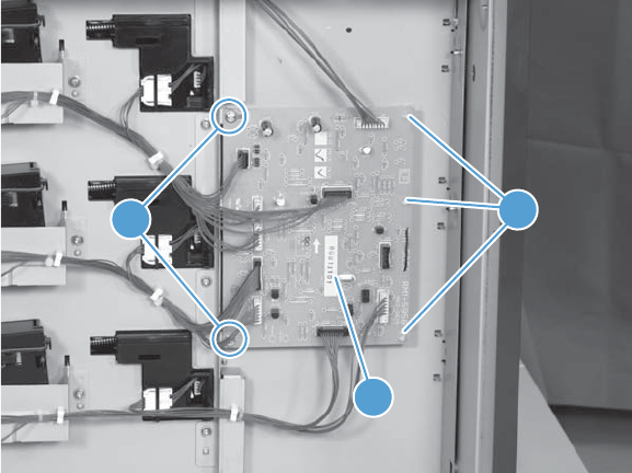
2. 3 x 500-sheet optional paper feeder only: Disconnect all connectors, and then remove
two screws (callout 1). Release three tabs (callout 2), and then remove the PCA (callout 3).
Figure 2-315 Remove the controller PCA (optional paper feeder) (2 of 2)
12
3
320 Chapter 2 Removal and replacement ENWW
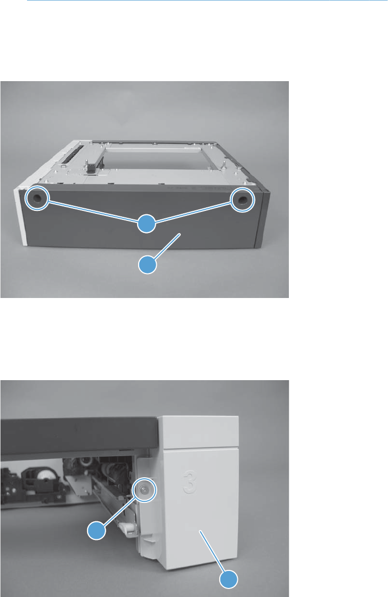
Optional 500-sheet paper feeder assembly
For information about removing the optional paper feeder assemblies (1 x 500-sheet and 3 x 500-
sheet), see Optional paper feeder assemblies (1 x 500-sheet and 3 x 500-sheet) on page 303
Rear cover (500-sheet paper feeder)
▲Remove two screws (callout 1), and then remove the rear cover (callout 2).
Figure 2-316 Remove the rear cover (500-sheet paper feeder)
1
2
1
Right-front cover (500-sheet paper feeder)
▲Remove one screw (callout 1), and then lift the right-front cover (callout 2) to remove.
Figure 2-317 Remove the right-front cover (500-sheet paper feeder)
11
2
ENWW Optional 500-sheet paper feeder assembly 321
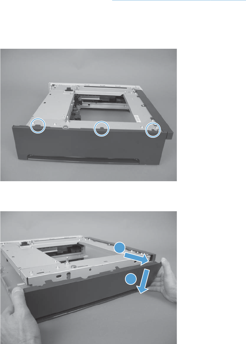
Left cover (500-sheet paper feeder)
Before proceeding, remove the following components:
●Rear cover (500-sheet paper feeder). See Rear cover (500-sheet paper feeder) on page 321.
Remove the left cover (500-sheet paper feeder)
1. Release three tabs.
Figure 2-318 Remove the left cover (500-sheet paper feeder) (1 of 2)
2. Pull the top of the cover out (callout 1), and then press down (callout 2) to remove the cover.
Figure 2-319 Remove the left cover (500-sheet paper feeder) (2 of 2)
1
2
322 Chapter 2 Removal and replacement ENWW
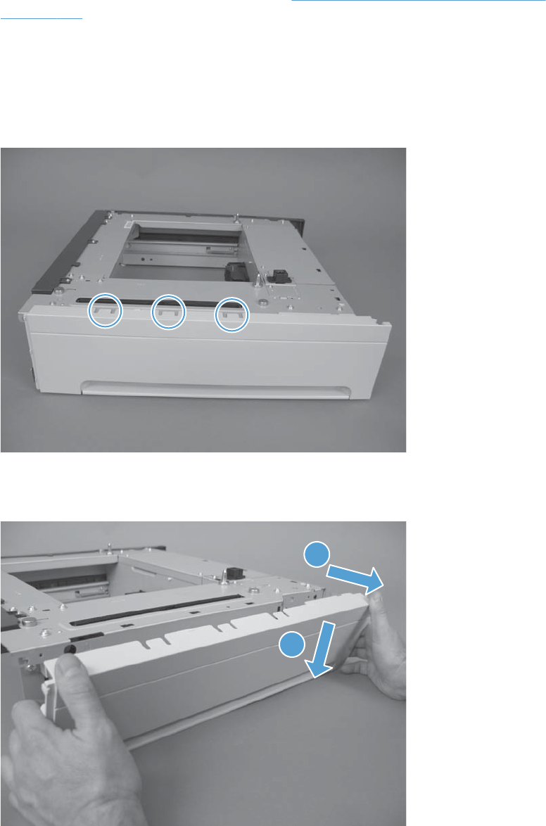
Right cover (500-sheet paper feeder)
Before proceeding, remove the following components:
●Right front cover (500-sheet paper feeder). See Right-front cover (500-sheet paper feeder)
on page 321.
Remove the right cover (500-sheet paper feeder)
1. Remove two screws (callout 1), release one tab (callout 2), and then remove the right cover
(callout 3).
Figure 2-320 Remove the right cover (500-sheet paper feeder) (1 of 2)
2. Pull the top of the cover out (callout 1), and then press down (callout 2) to remove the cover.
Figure 2-321 Remove the right cover (500-sheet paper feeder) (2 of 2)
1
2
ENWW Optional 500-sheet paper feeder assembly 323
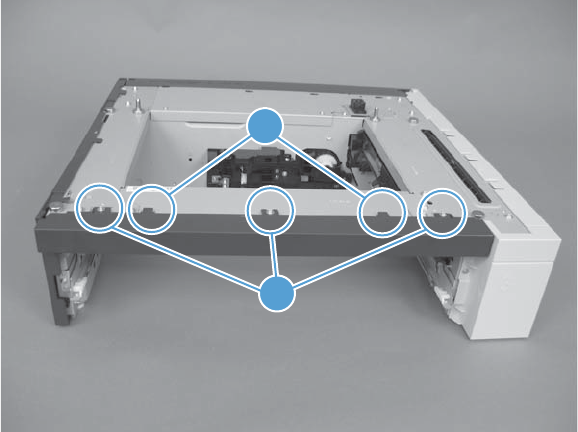
Front cover (500-sheet paper feeder)
▲Remove three screws (callout 1), release two tabs (callout 2), and then remove the front cover.
Figure 2-322 Remove the rear-right cover (500-sheet paper feeder)
1
2
324 Chapter 2 Removal and replacement ENWW
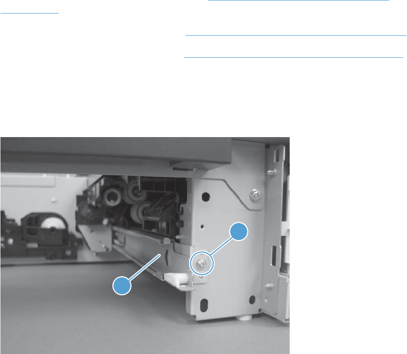
Pickup assembly (500-sheet paper feeder)
Before proceeding, remove the following components:
●Right front cover (500-sheet paper feeder). See Right-front cover (500-sheet paper feeder)
on page 321.
●Right cover (500-sheet paper feeder). See Right cover (500-sheet paper feeder) on page 323
●Rear cover (500-sheet paper feeder). See Rear cover (500-sheet paper feeder) on page 321.
Remove the pickup assembly (500-sheet paper feeder)
1. Remove one screw (callout 1), and then remove the tray rail (callout 2).
Figure 2-323 Remove the pickup assembly (500-sheet paper feeder) (1 of 5)
2
1
ENWW Optional 500-sheet paper feeder assembly 325
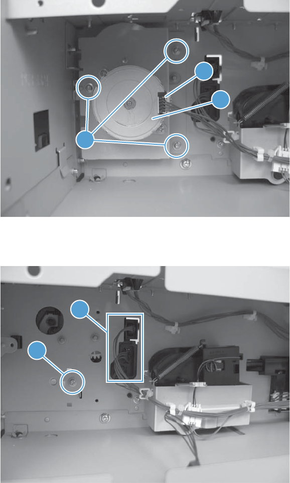
2. Remove three screws (callout 1), disconnect one connector (callout 2), and then remove the motor
assembly (callout 3).
Figure 2-324 Remove the pickup assembly (500-sheet paper feeder) (2 of 5)
3
2
1
3. Remove one screw (callout 1), and then disconnect three connectors (callout 2).
Figure 2-325 Remove the pickup assembly (500-sheet paper feeder) (3 of 5)
2
1
326 Chapter 2 Removal and replacement ENWW
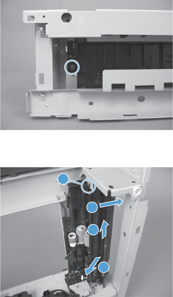
4. Remove one screw.
Figure 2-326 Remove the pickup assembly (500-sheet paper feeder) (4 of 5)
5. Move the top of the assembly to the right (callout 1) until the post (callout 4) is free of the hole. Lift
the assembly (callout 2), and then pull the bottom of the assembly (callout 3) to remove.
Figure 2-327 Remove the pickup assembly (500-sheet paper feeder) (5 of 5)
1
2
3
4
ENWW Optional 500-sheet paper feeder assembly 327
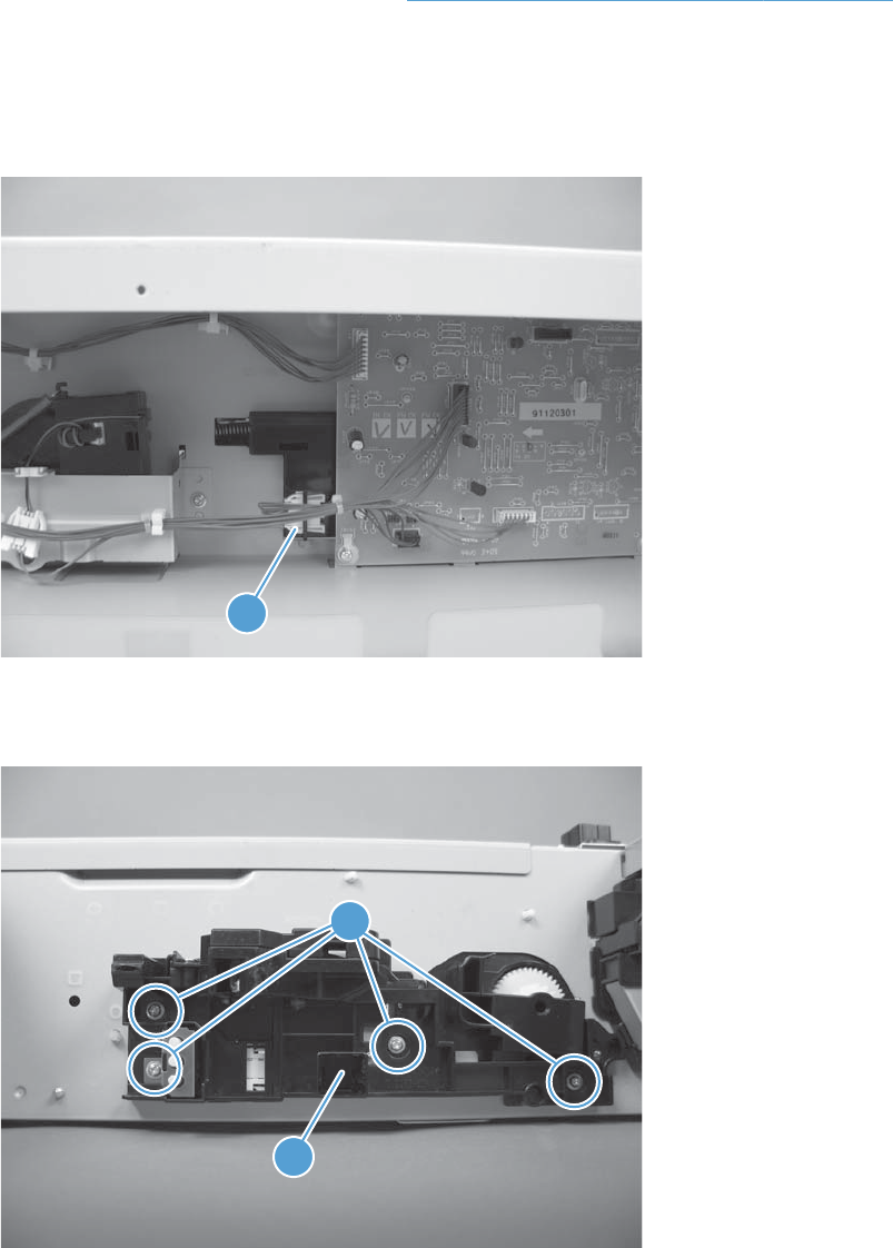
Lifter assembly (500-sheet paper feeder)
Before proceeding, remove the following components:
●Rear cover (500-sheet paper feeder). See Rear cover (500-sheet paper feeder) on page 321.
Remove the lifter assembly (500-sheet paper feeder)
1. Disconnect one connector (callout 1).
Figure 2-328 Remove the lifter assembly (500-sheet paper feeder) (1 of 2)
1
2. Remove four screws (callout 1), and then remove the lifter assembly (callout 2).
Figure 2-329 Remove the lifter assembly (500-sheet paper feeder) (2 of 2)
1
2
1
328 Chapter 2 Removal and replacement ENWW
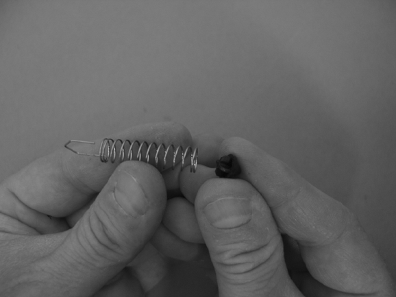
Reinstall the lifter assembly
If the spring falls from the lifter assembly, reinstall it in the lifter before reinstalling the lifter assembly.
Reinstall the lifter assembly
▲Place the spring in the lifter before installing the assembly on the product.
Figure 2-330 Reinstall the lifter assembly (500-sheet paper feeder)
ENWW Optional 500-sheet paper feeder assembly 329
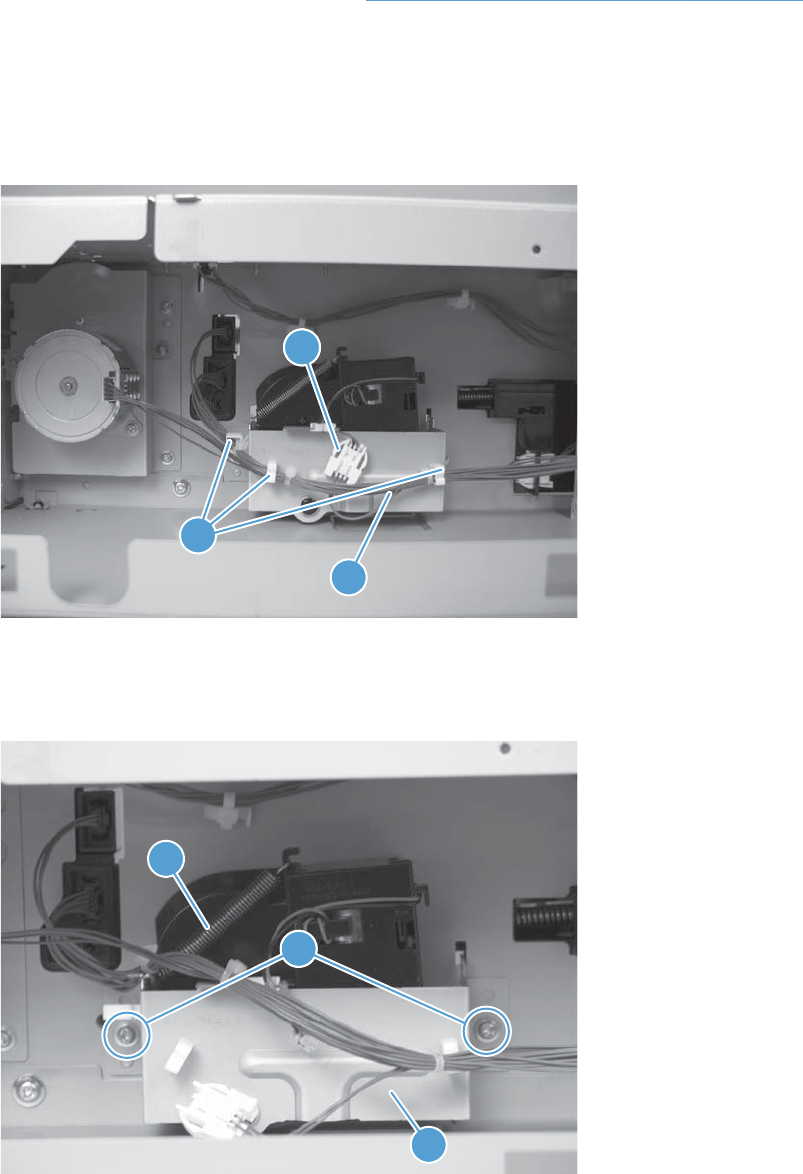
Lifter-drive assembly (500-sheet paper feeder)
Before proceeding, remove the following components:
●Rear cover (500-sheet paper feeder). See Rear cover (500-sheet paper feeder) on page 321.
Remove the lifter-drive assembly (500-sheet paper feeder)
1. Disconnect one connector (callout 1), and then release the wire harnesses (callout 3) from the
guides (callout 2).
Figure 2-331 Remove the lifter-drive assembly (500-sheet paper feeder) (1 of 2)
11
2
3
2. Remove two screws (callout 1), and then remove the sheet-metal plate (callout 2). Remove one
spring (callout 3), and then remove the lifter drive assembly.
Figure 2-332 Remove the lifter-drive assembly (500-sheet paper feeder) (2 of 2)
1
3
1
2
330 Chapter 2 Removal and replacement ENWW
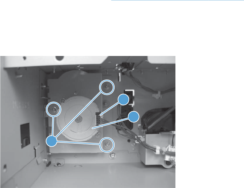
Pickup motor assembly (500-sheet paper feeder)
Before proceeding, remove the following components:
●Rear cover (500-sheet paper feeder). See Rear cover (500-sheet paper feeder) on page 321.
Remove the pickup motor (500-sheet paper feeder) assembly
▲Remove three screws (callout 1), disconnect one connector (callout 2), and then remove the motor
assembly (callout 3).
Figure 2-333 Remove the pickup motor assembly (500-sheet paper feeder)
3
2
1
ENWW Optional 500-sheet paper feeder assembly 331
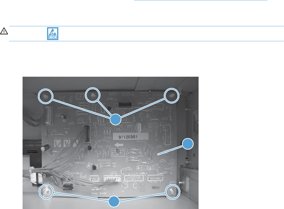
Controller PCA (500-sheet paper feeder)
Before proceeding, remove the following components:
●Rear cover (500-sheet paper feeder). See Rear cover (500-sheet paper feeder) on page 321.
Remove the controller PCA (500-sheet paper feeder)
CAUTION: ESD-sensitive part.
▲Disconnect all connectors, and then remove two screws (callout 1). Release three tabs (callout 2),
and then remove the PCA (callout 3).
Figure 2-334 Remove the controller PCA (500-sheet paper feeder)
11
3
2
332 Chapter 2 Removal and replacement ENWW
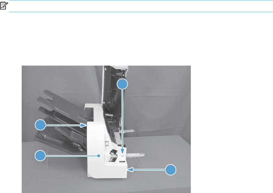
Stapling mailbox
This section provides stapling mailbox removal and replacement procedures.
NOTE: The stapling mailbox is also referred to as the SSMBM.
Stapling mailbox front cover
▲Open the stapling mailbox door, remove one screw (callout 1), release two tabs (callout 2), and
then remove the front cover (callout 3).
Figure 2-335 Remove the stapling mailbox front cover
1
2
2
3
ENWW Stapling mailbox 333
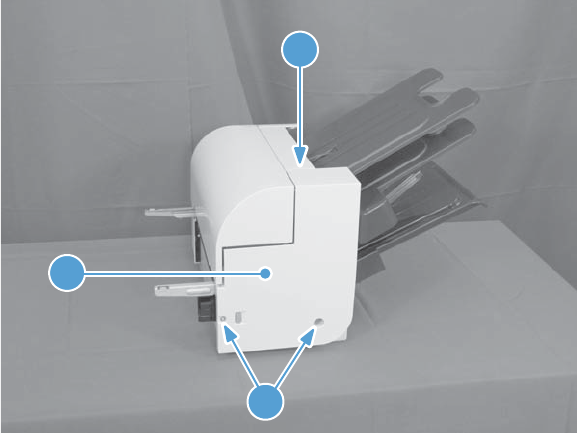
Stapling mailbox rear cover
▲Remove two screws (callout 1), release one tab (callout 2), and then remove the rear cover (callout
3).
Figure 2-336 Remove the stapling mailbox rear cover
1
2
3
334 Chapter 2 Removal and replacement ENWW

Stapling mailbox door
1. Remove the following components or assemblies:
●Stapling mailbox rear cover. See Stapling mailbox rear cover on page 334.
2. Remove three screws (callout 1), and then remove the stapling mailbox door (callout 2).
Figure 2-337 Remove the stapling mailbox door
1
2
Holder connector
Before proceeding, remove the following components:
●Stapling mailbox rear cover. See Stapling mailbox rear cover on page 334.
ENWW Stapling mailbox 335
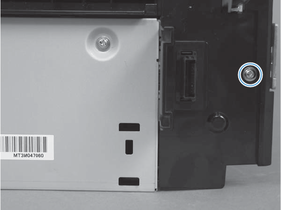
Remove the holder connector
▲Remove one screw, and then remove the holder connector.
Figure 2-338 Remove the holder connector
336 Chapter 2 Removal and replacement ENWW
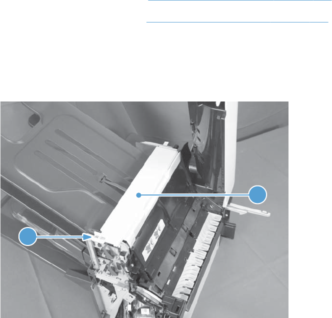
Top cover
Before proceeding, remove the following components:
●Stapling mailbox front cover. See Stapling mailbox front cover on page 333.
●Stapling mailbox rear cover. See Stapling mailbox rear cover on page 334.
Remove the top cover
▲Remove one screw (callout 1), and then remove the top cover (callout 2).
Figure 2-339 Remove the top cover
2
1
ENWW Stapling mailbox 337
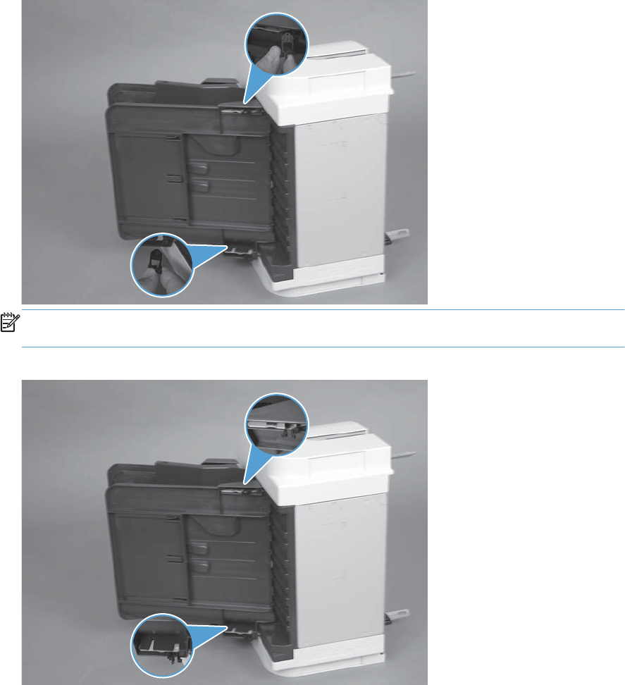
Output bin 3
1. Squeeze and pull two stoppers to remove from the output bin.
Figure 2-340 Remove the output bin (1 of 3)
NOTE: When reinstalling the output bin, make sure the two stoppers are installed in the correct
position.
Figure 2-341 Remove the output bin (2 of 3)
338 Chapter 2 Removal and replacement ENWW
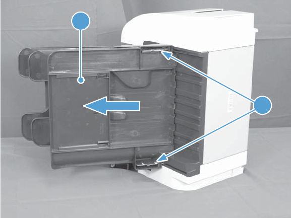
2. Release two tabs (callout 1) and slide the output bin (callout 2) to remove.
Figure 2-342 Remove the output bin (3 of 3)
1
2
ENWW Stapling mailbox 339
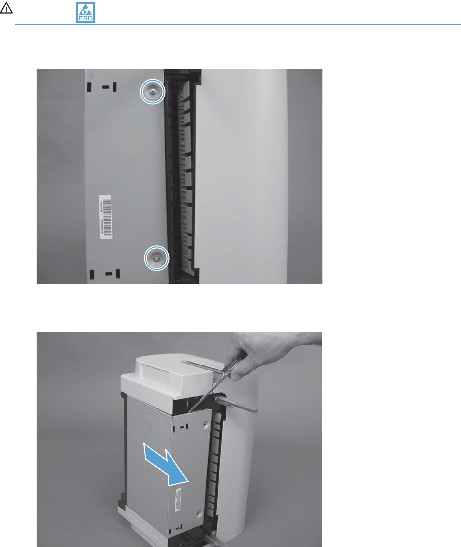
Stapling mailbox PCA
CAUTION: ESD-sensitive part.
1. Remove two screws.
Figure 2-343 Remove the stapling mailbox PCA (1 of 5)
2. Remove the PCA cover.
Figure 2-344 Remove the stapling mailbox PCA (2 of 5)
340 Chapter 2 Removal and replacement ENWW
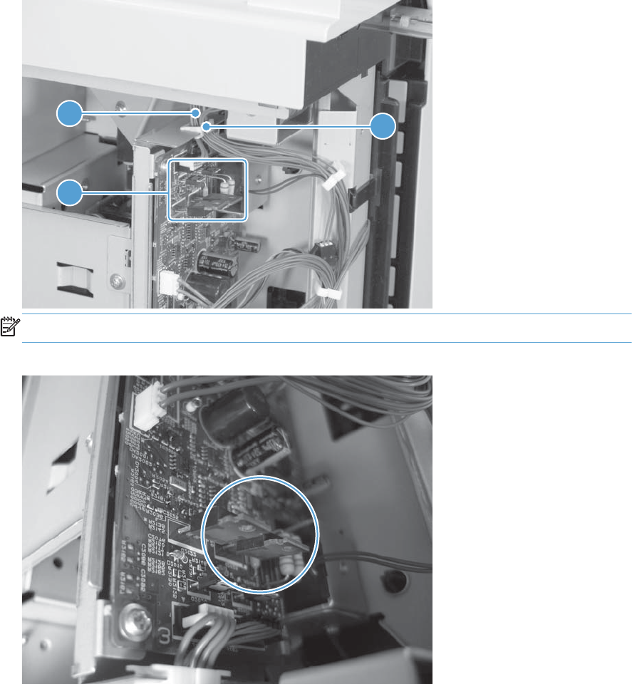
3. Release the cables (callout 2) from the cable guide (callout 1).
Figure 2-345 Remove the stapling mailbox PCA (3 of 5)
1
2
3
NOTE: Be careful not to damage components (callout 3) on the PCA.
Figure 2-346 Remove the stapling mailbox PCA (4 of 5)
ENWW Stapling mailbox 341
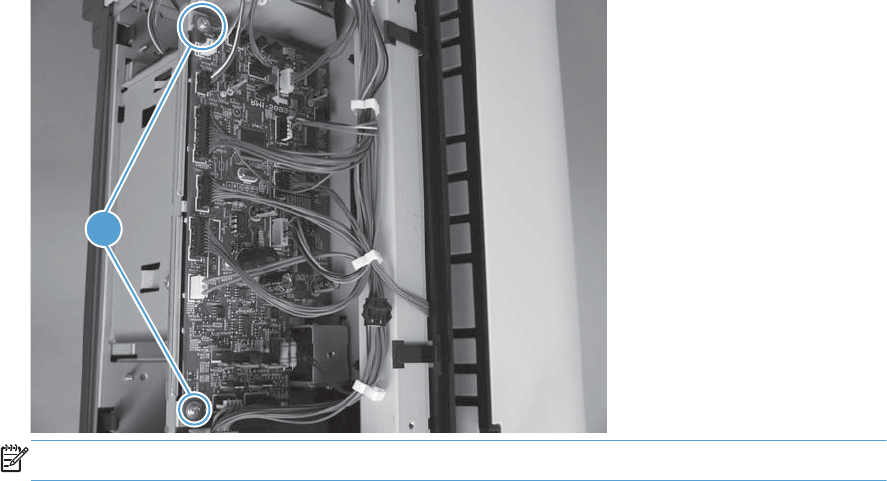
4. Remove two screws (callout 1), disconnect all connectors from the PCA, and then remove the PCA.
Figure 2-347 Remove the stapling mailbox PCA (5 of 5)
1
NOTE: There is no connection for J460.
342 Chapter 2 Removal and replacement ENWW
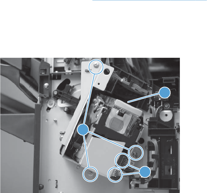
Stapler assembly
Before proceeding, remove the following components:
●Stapling mailbox front cover. See Stapling mailbox front cover on page 333.
Remove the stapler assembly
▲Remove three screws (callout 1), disconnect two connectors (callout 2), and then remove the
stapler assembly (callout 3).
Figure 2-348 Remove the stapler assembly
2
3
1
ENWW Stapling mailbox 343
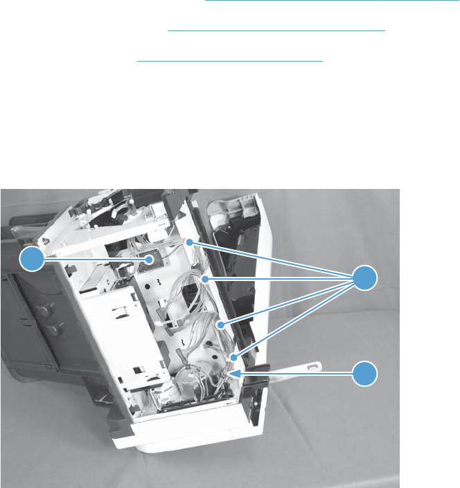
Stamp solenoid
Before proceeding, remove the following components:
●Stapling mailbox front cover. See Stapling mailbox front cover on page 333.
●Stapling mailbox PCA. See Stapling mailbox PCA on page 340.
●Stapler assembly. See Stapler assembly on page 343.
Remove the stamp solenoid
1. Disconnect one connector (callout 1), and then release the cables (callout 3) from the cable guides
(callout 2).
Figure 2-349 Remove the stamp solenoid (1 of 2)
1
2
3
344 Chapter 2 Removal and replacement ENWW
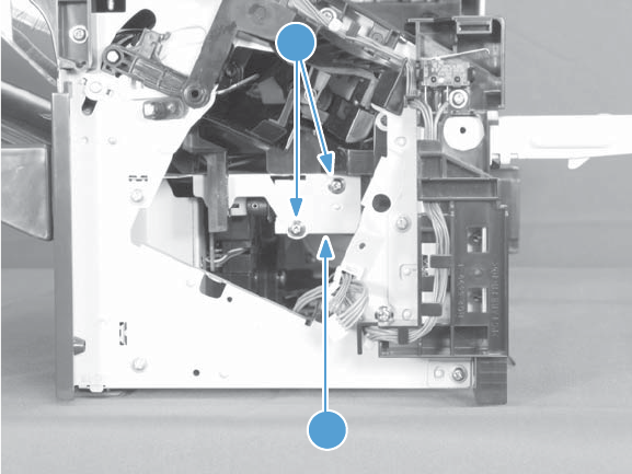
2. Remove two screws (callout 1), and then remove the stamp solenoid (callout 2).
Figure 2-350 Remove the stamp solenoid (2 of 2)
2
1
ENWW Stapling mailbox 345
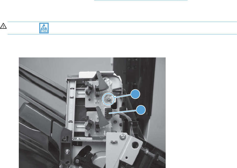
Output bin sensor PCA
Before proceeding, remove the following components:
●Stapling mailbox front cover. See Stapling mailbox front cover on page 333.
Remove the output bin sensor PCA
CAUTION: ESD-sensitive part.
1. Remove one screw (callout 1) and disconnect one connector (callout 2).
Figure 2-351 Remove the output bin sensor PCA (1 of 2)
2
1
346 Chapter 2 Removal and replacement ENWW
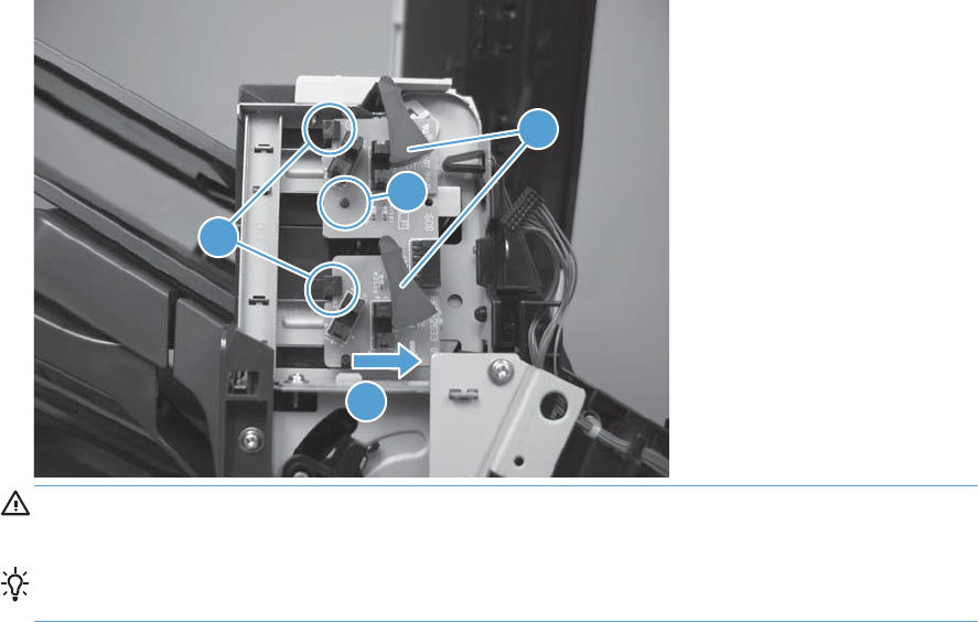
2. Release two tabs (callout 1), clear one post (callout 2), and slide the PCA to remove (callout 3).
Figure 2-352 Remove the output bin sensor PCA (2 of 2)
2
4
3
1
CAUTION: Be careful not to damage the flags (callout 4) when removing and installing the
PCA.
TIP: When reinstalling, make sure the PCA is seated correctly with the tabs (callout 1) and post
(callout 2).
ENWW Stapling mailbox 347
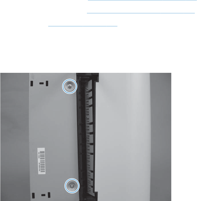
Stacking panel
Before proceeding, remove the following components:
●Stapling mailbox front cover. See Stapling mailbox front cover on page 333.
●Stapling mailbox rear cover. See Stapling mailbox rear cover on page 334.
●Output bin 3. See Output bin 3 on page 338.
Remove the stacking panel
1. Remove two screws
Figure 2-353 Remove the output bin 3 drive assembly (1 of 3)
348 Chapter 2 Removal and replacement ENWW
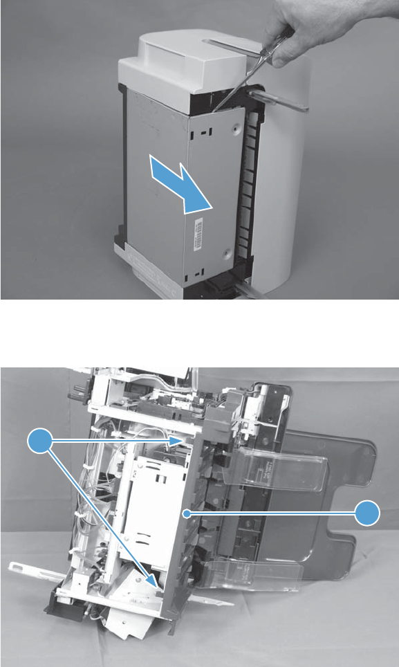
2. Remove the PCA cover.
Figure 2-354 Remove the output bin 3 drive assembly (2 of 3)
3. Release two tabs (callout 1) and them remove the stacking panel (callout 2).
Figure 2-355 Remove the output bin 3 drive assembly (3 of 3)
1
2
ENWW Stapling mailbox 349
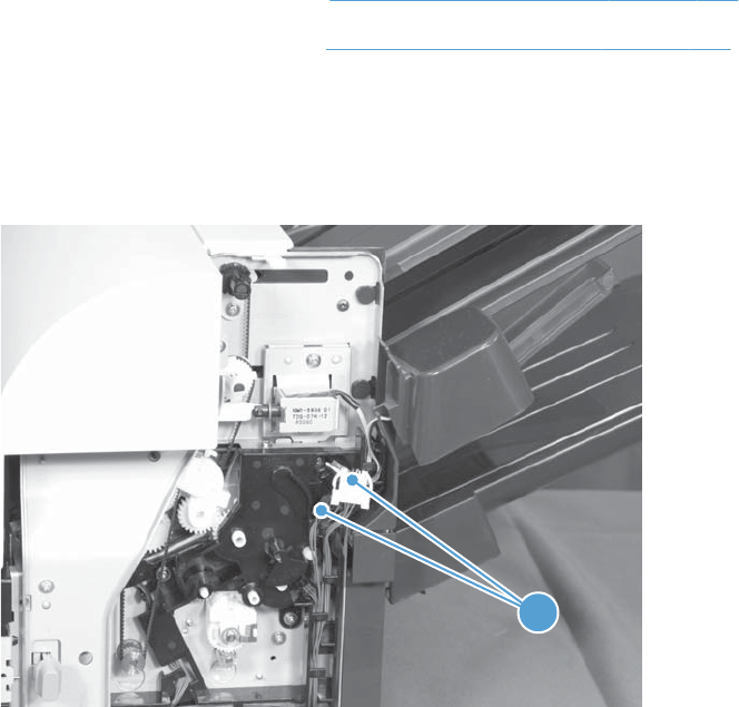
Jogger assembly
Before proceeding, remove the following components:
Before proceeding, remove the following components:
●Stapling mailbox front cover. See Stapling mailbox front cover on page 333.
●Stapling mailbox rear cover. See Stapling mailbox rear cover on page 334.
Remove the jogger assembly
1. Disconnect two connectors (callout 1).
Figure 2-356 Remove the jogger assembly (1 of 3)
1
350 Chapter 2 Removal and replacement ENWW
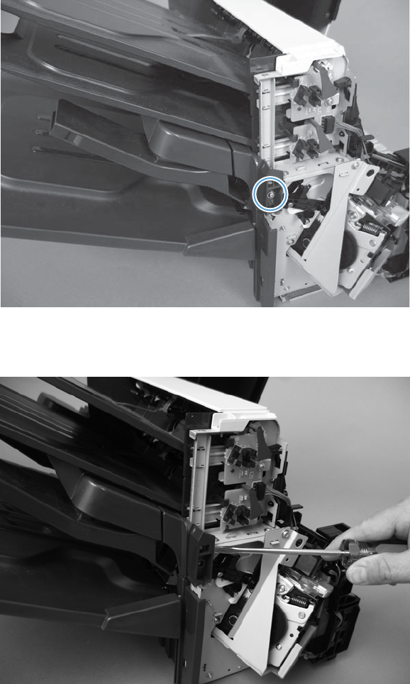
2. Remove one screw.
Figure 2-357 Remove the jogger assembly (2 of 3)
3. Disengage pin and remove the jogger assembly.
Figure 2-358 Remove the jogger assembly (3 of 3)
ENWW Stapling mailbox 351

Flapper guide assembly
Before proceeding, remove the following components:
●Stapling mailbox front cover. See Stapling mailbox front cover on page 333.
●Stapling mailbox rear cover. See Stapling mailbox rear cover on page 334.
●Stapling mailbox door. See Stapling mailbox door on page 335.
●Top cover. See Top cover on page 337.
●Jogger assembly. See Jogger assembly on page 350.
352 Chapter 2 Removal and replacement ENWW
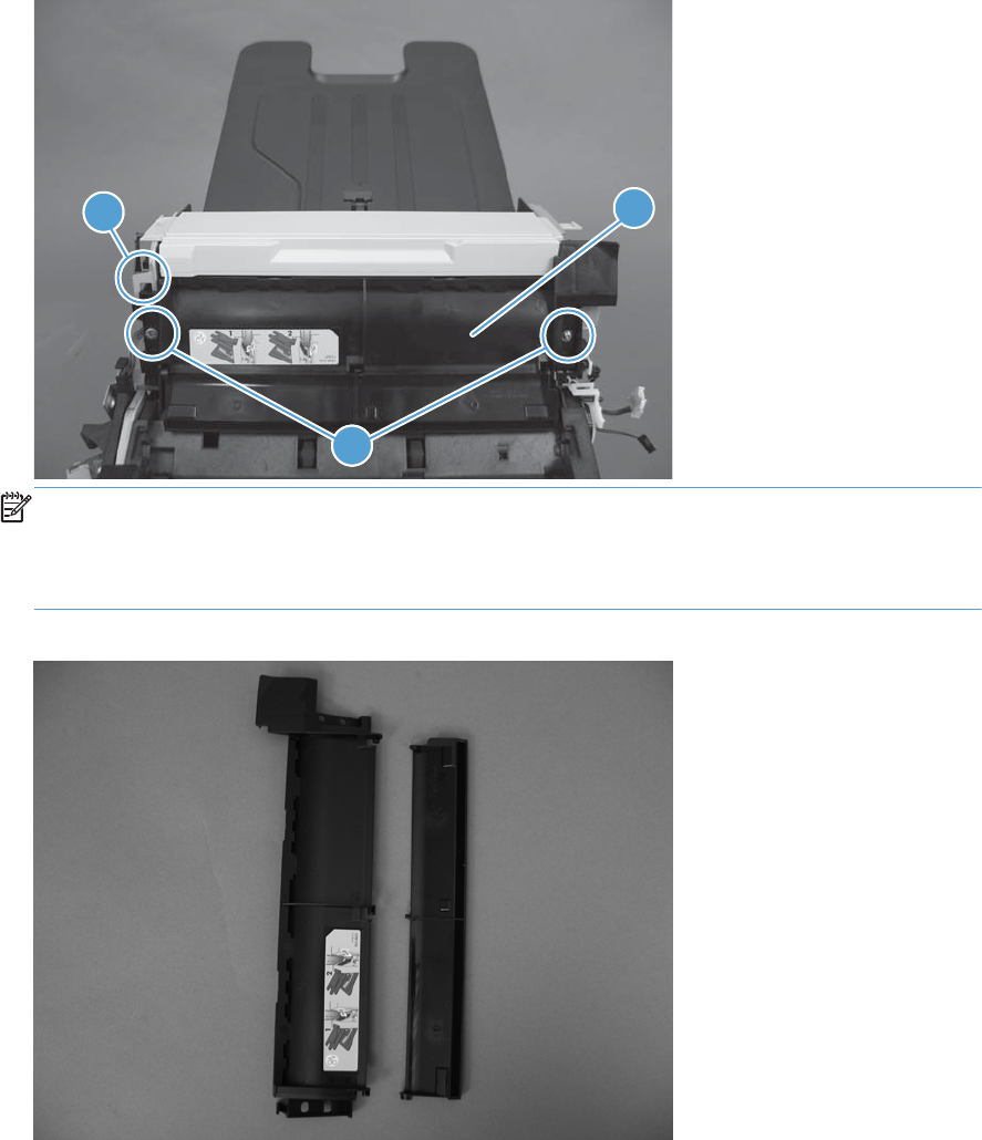
Remove the flapper guide assembly
▲Remove two screws (callout 1), release one tab (callout 2), and then remove the flapper guide
assembly (callout 3).
Figure 2-359 Remove the flapper guide assembly (1 of 2)
1
11
23
NOTE: Make sure to reinstall the stepped screw on the left side of the assembly.
NOTE: When reinstalling the assembly, makes sure to correctly reattach the two pieces of the
assembly.
Figure 2-360 Remove the flapper guide assembly (2 of 2)
ENWW Stapling mailbox 353

Flapper assembly
Before proceeding, remove the following components:
●Stapling mailbox front cover. See Stapling mailbox front cover on page 333.
●Stapling mailbox rear cover. See Stapling mailbox rear cover on page 334.
●Stapling mailbox door. See Stapling mailbox door on page 335.
●Top cover. See Top cover on page 337.
●Jogger assembly. See Jogger assembly on page 350.
●Flapper guide assembly. See Flapper guide assembly on page 352.
354 Chapter 2 Removal and replacement ENWW
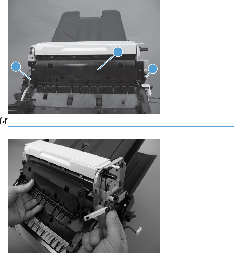
Remove the flapper assembly
▲Remove one tab (callout 1), release the solenoid arm (callout 2), and then remove the flapper
assembly (callout 3).
Figure 2-361 Remove the flapper guide assembly (1 of 2)
1
1
1
3
2
NOTE: When reinstalling the assembly, makes sure to correctly reattach the solenoid and arm.
Figure 2-362 Remove the flapper guide assembly (2 of 2)
ENWW Stapling mailbox 355
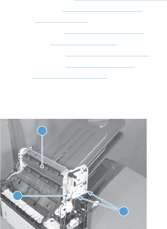
MBM output bin assembly
Before proceeding, remove the following components:
●Stapling mailbox rear cover. See Stapling mailbox rear cover on page 334.
●Stapling mailbox door. See Stapling mailbox door on page 335.
●Top cover. See Top cover on page 337.
●Output bin sensor PCA. See Output bin sensor PCA on page 346.
●Jogger assembly. See Jogger assembly on page 350.
●Flapper guide assembly. See Flapper guide assembly on page 352.
●Flapper guide assembly. See Flapper assembly on page 354.
●Solenoid. See Output bin solenoid on page 361.
Remove the MBM output bin assembly
1. Remove two screws (callout 1).
Figure 2-363 Remove the MBM output bin assembly (1 of 3)
1
2
3
356 Chapter 2 Removal and replacement ENWW
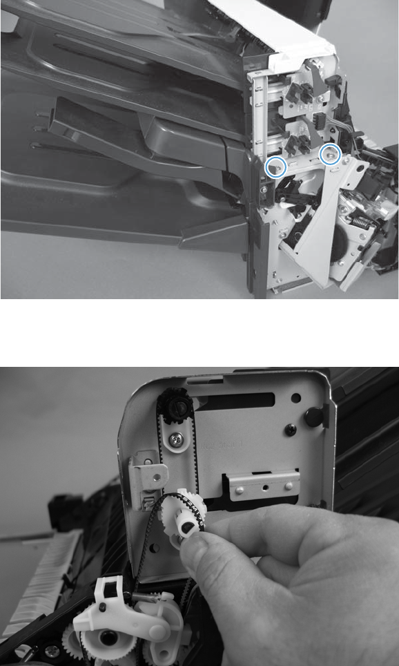
2. Remove two screws.
Figure 2-364 Remove the MBM output bin assembly (2 of 3)
3. Remove the belt and then the assembly.
Figure 2-365 Remove the MBM output bin assembly (3 of 3)
ENWW Stapling mailbox 357
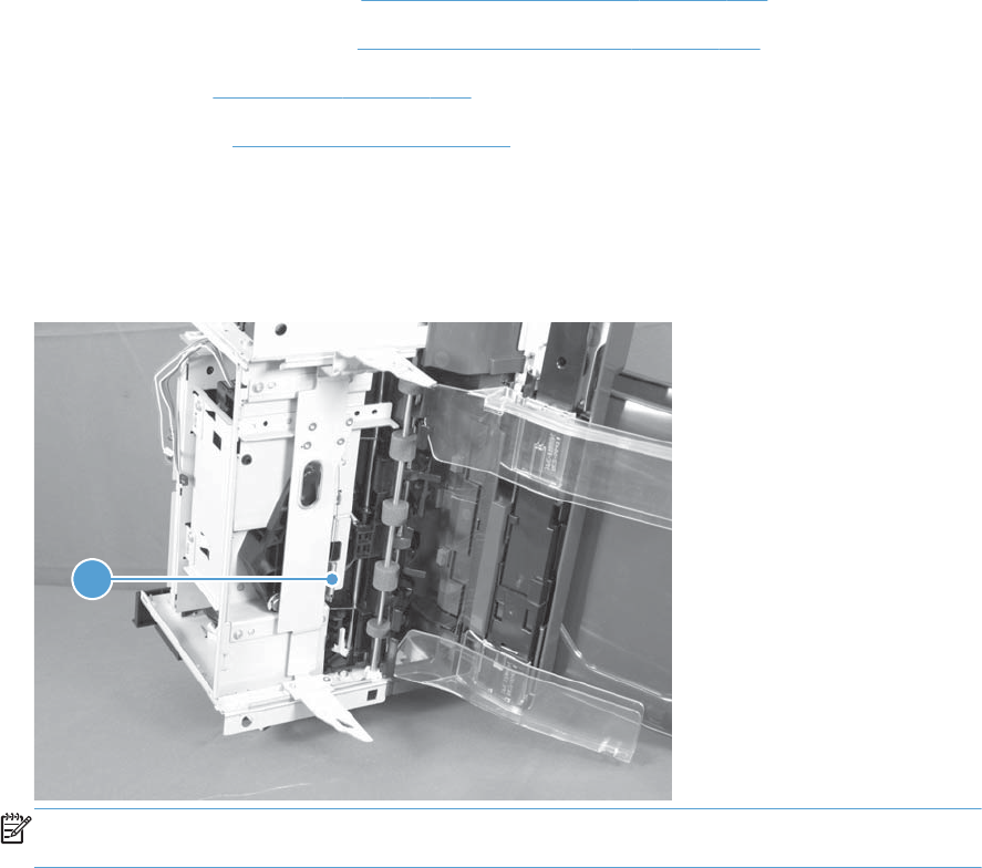
Output bin 3 drive assembly
Before proceeding, remove the following components:
●Stapling mailbox front cover. See Stapling mailbox front cover on page 333.
●Stapling mailbox rear cover. See Stapling mailbox rear cover on page 334.
●Output bin 3. See Output bin 3 on page 338.
●Stacking panel. See Stacking panel on page 348.
Remove the output bin drive assembly
1. Release one spring (callout 1).
Figure 2-366 Remove the output bin 3 drive assembly (1 of 4)
1
NOTE: If you cannot reach the spring, lower the tray support until you have clearance as shown
in the next step.
358 Chapter 2 Removal and replacement ENWW
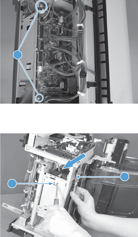
2. Disconnect two connectors.
Figure 2-367 Remove the output bin 3 drive assembly (2 of 4)
1
3. Using a screwdriver to disengage the gear (callout 1) and then slide the tray support (callout 2) to
remove it.
Figure 2-368 Remove the output bin 3 drive assembly (3 of 4)
1
2
ENWW Stapling mailbox 359
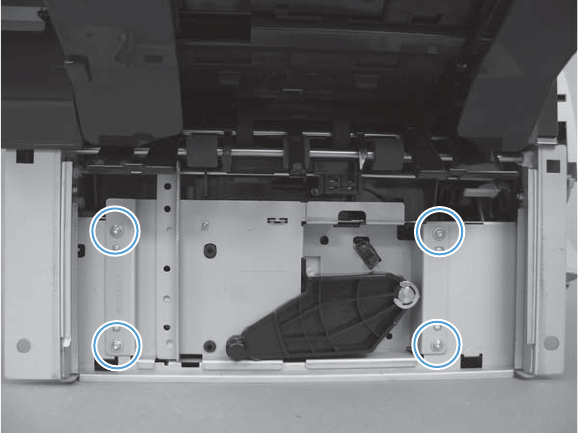
4. Remove four screws and then remove the output bin 3 drive assembly.
Figure 2-369 Remove the output bin 3 drive assembly (4 of 4)
360 Chapter 2 Removal and replacement ENWW
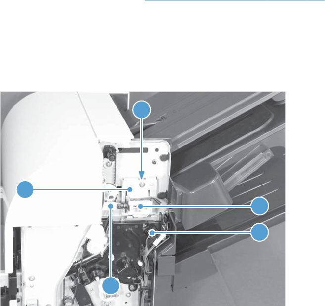
Output bin solenoid
Before proceeding, remove the following components:
●Stapling mailbox rear cover. See Stapling mailbox rear cover on page 334.
Remove the output bin solenoid
▲Disconnect one connector (callout 1), remove one screw (callout 2), disconnect the solenoid arm
(callout 3), and then remove the solenoid (callout 4) and bracket (callout 5).
Figure 2-370 Remove the output bin solenoid
1
4
2
5
3
ENWW Stapling mailbox 361
362 Chapter 2 Removal and replacement ENWW

3 Solve problems
To use the information in this chapter, you need to have a basic understanding of the HP LaserJet
printing process. Explanations of each mechanical assembly, the printer systems, and the basic theory
of operation are contained in the English-only service manual. Do not perform any of these
troubleshooting processes unless you understand the function of each product component.
●Solve problems checklist
●Administration Menu Map
●Troubleshooting process
●Tools for troubleshooting
●Clear jams
●Paper does not feed automatically
●Product feeds multiple sheets
●Use manual print modes
●Solve image-quality problems
●Clean the product
●Solve performance problems
●Solve connectivity problems
●Service mode functions
●Preboot menu options
●Solve fax problems
●Product updates
ENWW 363

Solve problems checklist
1. Make sure that the product control panel is lit and that the product is in Ready state. If the product
is not on, complete these steps:
a. Check the power-cable connections.
b. Check that the power is turned on.
c. Make sure that the line voltage is correct for the product power configuration. (See the label
that is on the back of the product for voltage requirements.) If you are using a power strip
and its voltage is not within specifications, plug the product directly into the wall. If it is
already plugged into the wall, try a different outlet.
d. If none of these measures restores power, see Power subsystem on page 370.
2. Check the cabling.
a. Check the cable connection between the product and the computer or network port. Make
sure that the connection is secure.
b. Make sure that the cable itself is not faulty by using a different cable, if possible.
c. Check the network connection. See Solve connectivity problems on page 624.
3. Check to see if any messages appear on the control-panel display. If any error messages appear,
see Control-panel messages on page 470.
4. Ensure that the paper that you are using meets specifications.
5. Print a configuration page. See Configuration pages on page 462. If the product is connected to
a network, an HP Jetdirect page also prints.
a. If the pages do not print, check that at least one tray contains paper.
b. If the page jams in the product, see Clear jams on page 581.
6. If the configuration page prints, check the following items:
a. If the page does not print correctly, the problem is with the product hardware.
b. If the page prints correctly, then the product hardware is working. The problem is with the
computer you are using, with the printer driver, or with the program.
7. Select one of the following options:
Windows: Click Start, click Settings, and then click Printers or Printers and Faxes.
Double-click the name of the product.
-or-
Mac OS X: Open the Printer Setup Utility and double-click the line for the product.
364 Chapter 3 Solve problems ENWW
8. Verify that you have installed the printer driver for this product. Check the program to make sure
that you are using the printer driver for this product.
9. Print a short document from a different program that has worked in the past. If this solution works,
then the problem is with the program you are using. If this solution does not work (the document
does not print), complete these steps:
a. Try printing the job from another computer that has the product software installed.
b. If you connected the product to the network, connect the product directly to a computer with
a USB cable. Redirect the product to the correct port, or reinstall the software, selecting the
new connection type that you are using.
ENWW Solve problems checklist 365
Administration Menu Map
The Administration Menu Map report presents the entire structure of the Administration menu so you
can identify how to navigate to any option.
1. From the Home screen, scroll to and touch the Administration button.
2. Open the following menus:
●Reports
●Configuration/Status Pages
●Administration Menu Map
3. Touch the Print button to print the report.
366 Chapter 3 Solve problems ENWW

Troubleshooting process
Determine the problem source
When the product malfunctions or encounters an unexpected situation, the product control panel alerts
you to the situation. This section contains a pre-troubleshooting checklist to filter out many possible
causes of the problem. A troubleshooting flowchart helps you diagnose the root cause of the problem.
The remainder of this chapter provides steps for correcting problems.
●Use the pre-troubleshooting checklist to evaluate the source of the problem and to reduce the
number of steps that are required to fix the problem.
●Use the troubleshooting flowchart to pinpoint the root cause of hardware malfunctions. The
flowchart guides you to the section of this chapter that contains steps for correcting the
malfunction.
Before beginning any troubleshooting procedure, check the following issues:
●Are supply items within their rated life?
●Does the configuration page reveal any configuration errors?
NOTE: The customer is responsible for checking supplies and for using supplies that are in good
condition.
Pre-troubleshooting checklist
The list below describes basic questions to ask the customer to help quickly define the problem or
problems.
Table 3-1 Pre-troubleshooting checklist
Environment ●Is the product installed on a solid, level surface?
●Is the product exposed to particle matter or dust?
●Is the power-supply voltage within ± 10 volts of the
specified power source?
●Is the power supply plug inserted in the product and
directly to the wall outlet (not a power strip)?
●Is the operating environment within the specified
parameters, as listed in chapter 1 of this manual?
●Is the product exposed to ammonia gas, such as that
produced by diazo copiers or office cleaning materials?
●Is the product exposed to direct sunlight?
ENWW Troubleshooting process 367

Table 3-1 Pre-troubleshooting checklist (continued)
Media ●Does the customer use only supported media?
●Is the media in good condition (contains no curls, folds,
and so forth)?
●Is the media stored correctly and within environmental
limits?
Input trays ●Is the amount of media in the tray within specifications?
●Is the media correctly placed in the tray?
●Are the paper guides aligned with the stack?
●Is the paper tray correctly installed in the product?
Print cartridges ●Is each print cartridge installed correctly?
●Are original HP print cartridges installed?
●Are the cartridges damaged?
ITB and fuser ●Are the ITB and fuser correctly installed?
●Is the ITB or fuser damaged?
Covers ●Are the right and front doors closed?
Condensation ●Does condensation occur following a temperature
change (particularly in winter following cold storage)? If
so, wipe the affected area dry or leave the product on
for 10 to 20 minutes.
●Was a print cartridge installed soon after being moved
from a cold to a warm room? If so, allow the product to
sit at room temperature for one to two hours.
Miscellaneous ●Check for and remove any non-HP components (print
cartridges, memory modules, and EIO cards) from the
product.
●Remove the product from the network, and make sure
that the failure is with the product before beginning
troubleshooting.
●For any print-quality issues, calibrate the product. See
Calibrate the product on page 468.
368 Chapter 3 Solve problems ENWW

Troubleshooting flowchart
This flowchart highlights the general processes that you can follow to quickly isolate and solve product
hardware problems.
Each row depicts a major troubleshooting step. A “yes” answer to a question allows you to proceed to
the next major step. A “no” answer indicates that additional testing is needed. Proceed to the
appropriate section in this chapter, and follow the instructions there. After completing the instructions,
proceed to the next major step in this troubleshooting flowchart.
Table 3-2 Troubleshooting flowchart
1
Power on
Is the product on and does a readable
message display?
Follow the power-on troubleshooting checks. See Power subsystem
on page 370.
After the control-panel display is functional, go to step 2.
Yes No
2
Control panel
messages
Does the message Ready display on the
control panel?
If an error message appears, see Control-panel messages
on page 470.
After the errors have been corrected, go to step 3.
Yes No
3
Event log
Open the Troubleshooting menu and print an
event log to see the history of errors with this
product.
Does the event log print?
If the event log does not print, see Print an event log
on page 570.
If paper jams inside the product, see Clear jams on page 581.
If error messages appear on the control-panel display when you try
to print an event log, see Control-panel messages on page 470.
After successfully printing and evaluating the event log, go to
step 4.
Yes No
4
Information
pages
Open the Information menu and print the
configuration pages to verify that all of the
accessories are installed.
Are all the accessories installed?
If accessories that are installed are not listed on the configuration
page, remove the accessory and reinstall it.
After evaluating the configuration pages, go to step 5.
Yes No
5
Image quality
Does the print quality meet the customer's
requirements?
Compare the images with the sample defects in the image defect
tables. See Print quality examples on page 614.
After the print quality is acceptable, go to step 6.
Yes No
6
Interface
Can the customer print successfully from the
host computer?
Verify that all I/O cables are connected correctly and that a valid
IP address is listed on the Jetdirect configuration page.
If error messages display on the control panel, see Control-panel
messages on page 470.
When the customer can print from the host computer, this is the
end of the troubleshooting process.
Yes. This is the end of
the troubleshooting
process.
No
ENWW Troubleshooting process 369

Power subsystem
Power-on checks
The basic product functions should start up when the product is plugged into an electrical outlet and the
power switch is pushed to the on position. If the product does not start, use the information in this
section to isolate and solve the problem.
Power-on troubleshooting overview
Turn on the product power. If the control panel display remains blank, random patterns display, or
asterisks remain on the control panel display, perform power-on checks to find the cause of the
problem.
During normal operation, the main cooling fan begins to spin briefly after the product power is turned
on. Place your hand over the holes in the left-side cover, near the formatter. If the fan is operating, you
will feel air passing out of the product. You can also lean close to the product and hear the fans
operating.
After the fans are operating, the engine initializes (unless the right or front cover is open, a jam
condition is sensed, or the paper-path sensors are damaged). You should be able to visually and
audibly determine if the engine has initialized.
If the fans turn on and the engine initializes correctly, the next troubleshooting step is to isolate print
engine, formatter, and control panel problems. Perform an engine test (see Engine-test button
on page 376). If the formatter is damaged, it might interfere with the engine test. If the engine-test
page does not print, try removing the formatter and then performing the engine test again. If the engine
test is then successful, the problem is almost certainly with the formatter, the control panel, or the cable
that connects them.
If the control panel is blank when you turn on the product, check the following items.
1. Make sure that the product is plugged directly into an active electrical outlet (not a power strip)
that delivers the correct voltage.
2. Make sure that the power switch is in the on position.
3. Make sure that the fan runs briefly, which indicates that the power supply is operational.
4. Make sure that the control panel USB cable is connected.
5. Make sure that the formatter is seated and operating correctly. Turn off the product and remove
the formatter. Reinstall the formatter, and then verify that the heartbeat LED is flashing.
6. Remove any HP Jetdirect or other EIO cards, and then try to turn the product on again.
NOTE: If the control panel display is blank, but the main cooling fan runs briefly after the product
power is turned on, try printing an engine-test page to determine whether the problem is with the
control-panel display, formatter, or other product components. See Engine-test button on page 376.
370 Chapter 3 Solve problems ENWW

Power-on timing (approximate)
●0 seconds: Power button initiates power-on sequence
●2 seconds: Blank control panel screen
●8 seconds: HP circle logo (without trademark symbol) appears
●15 seconds: Fans reach full speed
●18 seconds: HP logo (with trademark symbol) and progress bar appear; stage 1 of 8 begins
●21 seconds: Stage 2 of 8 begins; warning not to unplug product appears
●40 seconds: Stage 4 of 8 begins
●42 seconds: Stage 6 of 8 begins
●43 seconds: Stage 7 of 8 begins
●44 seconds: Document feeder and scanner initialize
●45 seconds: Stage 8 of 8 begins
●50 seconds: HP logo and activity indicator, with “Checking Hardware” message
●58 seconds: HP logo and activity indicator, with “Checking Data” message
●1:02 minutes: HP logo and activity indicator, with “Initializing” message
●1:55 minutes: Stapling mailbox initializes
●1:58 minutes: Product engine initializes
●2:30 minutes: Fans slow down
●3:05 minutes: Home screen displays
●3:10 minutes: Control panel enters Ready state
NOTE: If the product does not enter the Ready state within 5 minutes, turn off the product and then
restart it.
ENWW Troubleshooting process 371

Control-panel checks
The product includes a diagnostic test mode for the control panel. This mode allows you to troubleshoot
issues with the touchscreen, keypad, LEDs and speaker.
Start diagnostic mode
1. Press and hold the asterisk button (*) and the plus sign (+) key at the same time.
2. Press the Start button to initiate diagnostic mode.
Many of the diagnostic tests are for factory use only. You can use the following tests:
●Calibrate: calibrates the touchscreen
●Touch Grid: verifies that all areas respond to a touch
●Keyboard LED: tests the functionality of keys and LEDs
●Sound: tests the speaker
●Panel Reset: reboots the control panel
If the touchscreen does not function, use the keypad to navigate:
●Press the 3 button to move up.
●Press the 5 button to move left.
●Press the 6 button to move right.
●Press the 9 button to move down.
Exit diagnostic mode
▲Do one of the following:
●Press and hold the asterisk key (*) and the minus key (-) at the same time.
●Touch the Panel Reset button.
●Touch the Stop button.
372 Chapter 3 Solve problems ENWW

Scanning subsystem
Calibrate the scanner
Use this procedure to properly position the copied image on the page.
TIP: This adjustment might be required after the scanner or document feeder are replaced.
1. Touch the Device Maintenance button.
2. Touch the Calibrate/Cleaning button.
3. Touch the Calibrate Scanner button, and then follow the instructions provided on the screen.
ENWW Troubleshooting process 373
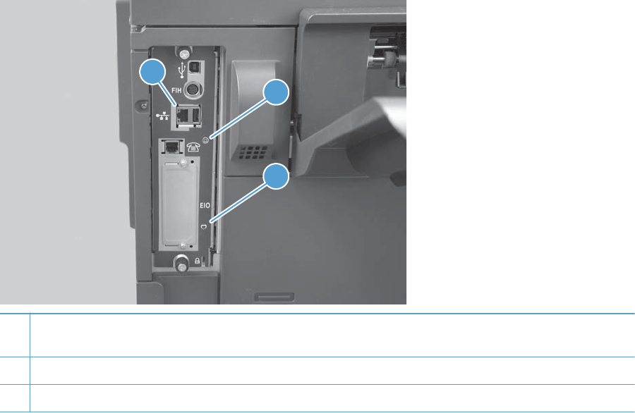
Tools for troubleshooting
The section describes the tools that can help you solve problems with your device.
Component diagnostics
LED diagnostics
LED, engine, and individual diagnostics can identify and troubleshoot product problems.
LED indicators
Three LEDs on the formatter indicate that the product is functioning correctly.
1
2
3
1Formatter connectivity LED (lit when formatter is correctly seated and scanner cable is properly connected at ICB and
SCB)
2HP Jetdirect LEDs
3Heartbeat LED
HP Jetdirect LEDs
The embedded HP Jetdirect print server has two LEDs. The yellow LED indicates network activity, and
the green LED indicates the link status. A blinking yellow LED indicates network traffic. If the green LED
is off, a link has failed.
For link failures, check all the network cable connections. In addition, you can try to manually configure
the link settings on the embedded print server by using the product control-panel menus.
1. From the Home screen, scroll to and touch the Administration button.
2. Touch the Network Settings button, and then touch the Embedded Jetdirect button.
374 Chapter 3 Solve problems ENWW
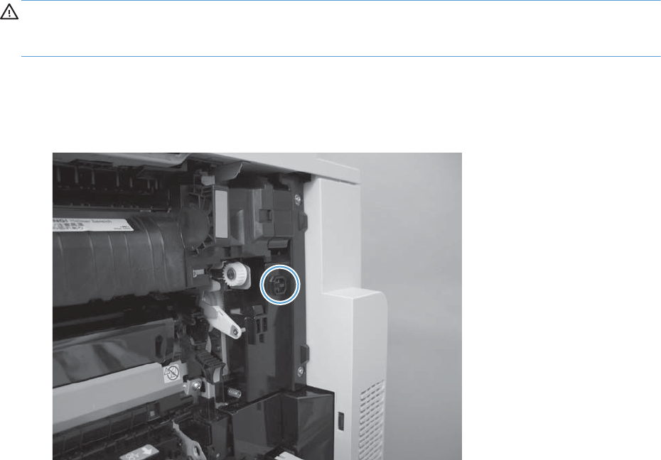
3. Touch the Link Speed button.
4. Select the appropriate link speed, and then touch the Save button.
Formatter heartbeat LED
The heartbeat LED indicates that the formatter is functioning correctly. While the product is initializing
after you turn it on, the LED blinks rapidly, and then turns off. When the product has finished the
initialization sequence, the heartbeat LED pulses on and off.
Engine diagnostics
This section provides an overview of the engine diagnostics that are available in the HP Color LaserJet
Enterprise CM4540 MFP Series product. The product contains extensive internal diagnostics that help
in troubleshooting print quality, paper path, noise, component, and timing issues.
Defeating interlocks
Different tests can be used to isolate different types of issues. For component or noise isolation, you can
run the diagnostic test when the front and right doors are open. To operate the product with the doors
open, the door switch levers must be depressed to simulate a closed-door position.
WARNING! Be careful when performing printer diagnostics to avoid risk of injury. Only trained
service personnel should open and run the diagnostics with the covers removed or the doors open.
Never touch any of the power supplies when the printer is turned on.
1. Open the right and front doors.
2. Use a piece of tape to defeat the right door logic switch.
Figure 3-1 Diagnostic test (1 of 2)
ENWW Tools for troubleshooting 375
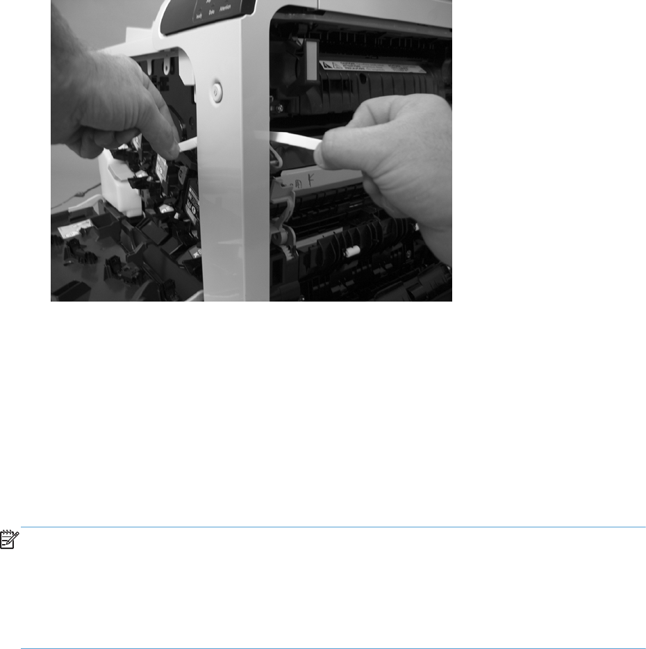
3. Insert a folded piece of paper into each slot to defeat the front and right door interlock switches.
Figure 3-2 Diagnostic test (2 of 2)
4. Fold a stiff piece of paper, for example a business card or index card, into a 10 mm (.375 in)
strip with a bend at the end, and insert the strip into the opening at the front of the product to
defeat the front door logic switch.
Disable cartridge check
Use this diagnostic test to print internal pages or send an external job to the product when one or more
print cartridges are removed or exchanged. Consumable supply errors are ignored while the product is
in this mode. When the product is in this mode, you can navigate the menus and print internal pages or
send an external print job to the product. This test can be used isolate problems, such as noise, and to
isolate print-quality problems that are related to individual print cartridges.
NOTE: Color cartridges are not keyed and can be interchanged. The black print cartridge is keyed
and cannot fit into any other position. An error will display on the control panel if a print cartridge is
installed in the wrong position. The Supplies Status menu will explain which print cartridge is
misplaced.
NOTE: Do not remove or exchange print cartridges until after you start the disable cartridge check
diagnostic.
1. From the Home screen, scroll to and touch the Administration button.
2. Touch the Troubleshooting button, and then touch the Diagnostic Tests button.
3. Touch the Disable Cartridge Check button.
To exit this diagnostic, touch the Exit Troubleshooting button.
Engine-test button
To verify that the product engine is functioning, print an engine test page. Use a small pointed object to
depress the test-page switch located on the rear of the product. The test page should have a series of
376 Chapter 3 Solve problems ENWW
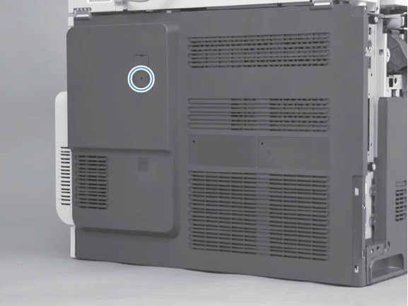
horizontal lines in the primary colors (CYMK). The test page can use only Tray 2 as the paper source,
so make sure that paper is loaded in Tray 2.
Figure 3-3 Engine-test button
The test functions differently depending on the presence of the formatter or stapler/stacker.
Engine test with the formatter and the stapler/stacker removed
1. Turn on the product, wait 30 seconds, and then press the test button.
2. Wait for the product to initialize (approximately 30 more seconds), and then press the test button
a second time to print the test page.
Engine test with the formatter installed and the stapler/stacker removed
1. Turn on the product, and then wait for the product to enter the Ready state.
2. Press the test button to print the test page.
Engine test with the stapler/stacker installed and the formatter removed
1. Turn on the product, wait for the engine and fans to initialize (approximately 40 seconds), and
then press the test button.
2. Wait for the stapler/stacker to initialize (approximately 40 more seconds), and then press the test
button again to print the test page.
Engine test with the formatter and the stapler/stacker installed
1. Turn on the product, and then wait for the product to enter the Ready state, and then press the test
button.
2. Because the stapler/stacker rollers will be stopped, the test page will jam at the stapler/stacker
entrance. Open the top cover of the stapler/stacker, and then remove the jammed engine test
page.
ENWW Tools for troubleshooting 377

Paper-path test
This diagnostic test generates one or more test pages that you can use to isolate the cause of jams.
To isolate a problem, specify which input tray to use, specify whether to use the duplex path, and
specify the number of copies to print. Multiple copies can be printed to help isolate intermittent
problems. The following options become available after you start the diagnostic feature:
●Print Test Page. Run the paper-path test from the default settings: Tray 2, no duplex, and one copy.
To specify other settings, scroll down the menu and select the setting, and then scroll back up and
select Print Test Page to start the test.
●Source. Select Tray 1, Tray 2, or the optional trays.
●Duplex. Enable or disable 2-sided printing.
●Copies. Set the number of copies to be printed; the choices are 1,10, 50, 100, or 500.
1. From the Home screen, scroll to and touch the Administration button.
2. Touch the Troubleshooting button, and then touch the Diagnostic Tests button.
3. Touch the Paper Path Test button.
4. Select the paper-path test options for the test you want to run.
Manual sensor test
1. From the Home screen, scroll to and touch the Administration button.
2. Touch the Troubleshooting button, and then touch the Diagnostic Tests button.
3. Touch the Manual Sensor Test button.
4. Select from the list of sensors.
NOTE: When a sensor is selected, a graphic appears on the control-panel display that identifies
the location of the sensor.
Table 3-3 Manual sensor diagnostic tests
Sensor or switch name Sensor or switch number Sensor or switch test
Front door switch SW5 See Front-door switch on page 380.
Right door switch SW6 See Right-door switch on page 381.
Registration sensor SR20 See Registration sensor on page 382.
Fuser loop 1 sensor SR14 See Fuser loop 1 and 2 sensors
on page 383.
Fuser loop 2 sensor SR15
Fuser pressure release sensor SR7 See Fuser pressure-release sensor
on page 389.
Fuser output sensor SR5 See Fuser output sensor on page 384.
378 Chapter 3 Solve problems ENWW
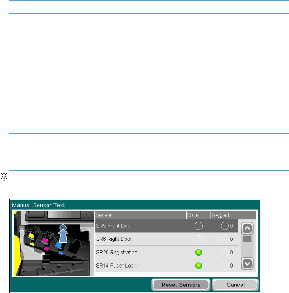
Table 3-3 Manual sensor diagnostic tests (continued)
Sensor or switch name Sensor or switch number Sensor or switch test
Duplexer refeed sensor SR22 See Duplexer refeed sensor
on page 386.
Developer alienation sensor
NOTE: The Developer alienation
sensor can not be manually actuated.
See Developer alienation sensor
on page 388 for information about
testing this sensor.
SR11 See Developer alienation sensor
on page 388.
ITB alienation sensor SR9 See ITB alienation sensor on page 390.
IPTU feed sensor SR27 See IPTU feed sensor on page 392.
IPTU bin full sensor SR26 See IPTU-bin-full sensor on page 387.
Scanner open sensor SR28 See Scanner open sensor on page 392.
When performing these tests, watch the control panel for the corresponding sensor to change from
green to clear or clear to green. It can take a few seconds to change.
TIP: The Toggled column indicates how many times a sensor changed state.
Figure 3-4 Manual sensor test
ENWW Tools for troubleshooting 379
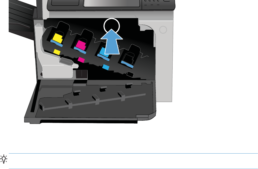
Front-door switch
1. Open the front-door assembly to disengage the front-door switch.
Figure 3-5 Test the front-door switch
2
2. Close the front-door assembly, and then check the control panel on the product for sensor
response.
TIP: You can leave the front door open and use a slender blade screw driver or pencil to
activate the switch.
3. If there is no response, replace the front-door switch.
380 Chapter 3 Solve problems ENWW
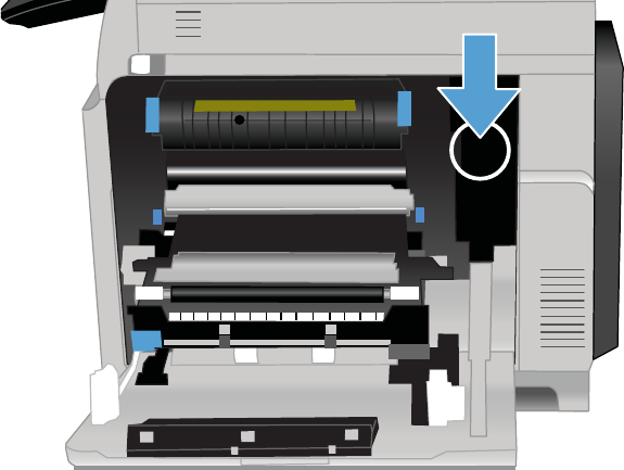
Right-door switch
1. Open the right-door assembly to disengage the right-door switch.
Figure 3-6 Test the right door switch
2. Close the right-door assembly, or use your finger to depress the switch flag, and check the control
panel on the product for sensor response.
3. If there is no response, replace the right-door switch.
ENWW Tools for troubleshooting 381
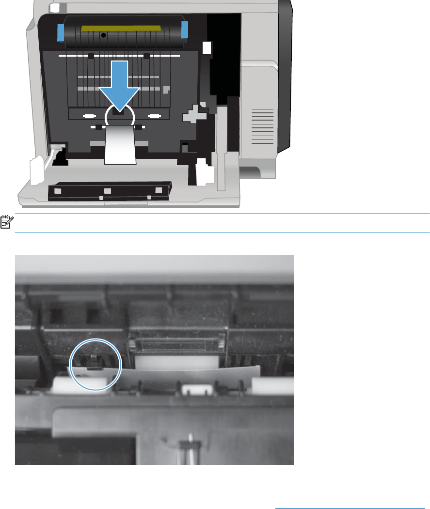
Registration sensor
1. Open the right door.
2. Insert a piece of paper to activate the registration sensor.
Figure 3-7 Test the TOP sensor (1 of 2)
NOTE: Open the registration shutter to verify the paper activates the sensor.
Figure 3-8 Test the TOP sensor (2 of 2)
3. Check the control-panel display for sensor response.
4. If there is no response, replace the registration assembly. See Registration assembly on page 213.
382 Chapter 3 Solve problems ENWW
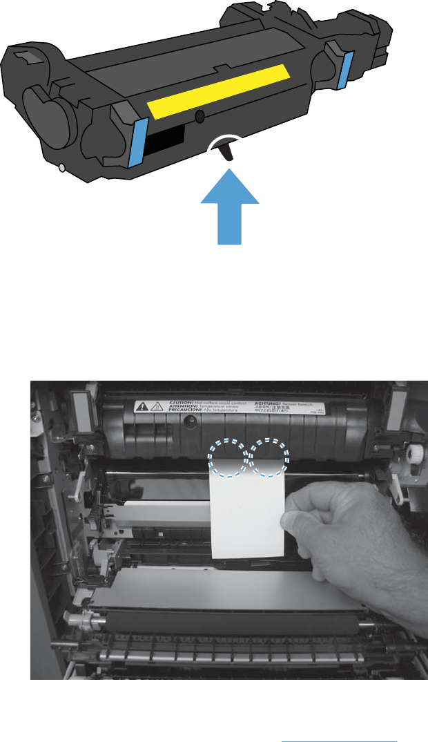
Fuser loop 1 and 2 sensors
Figure 3-9 Fuser loop 1 and 2 sensors location
1. Open the right door.
2. Lower the secondary transfer assembly.
3. Slowly insert a piece of paper at the entrance of the fuser to activate the fuser loop sensors
underneath the fuser.
Figure 3-10 Test the loop sensors
4. Check the control-panel display for a sensor response.
5. If there is no response, replace fuser. See Fuser on page 112.
ENWW Tools for troubleshooting 383
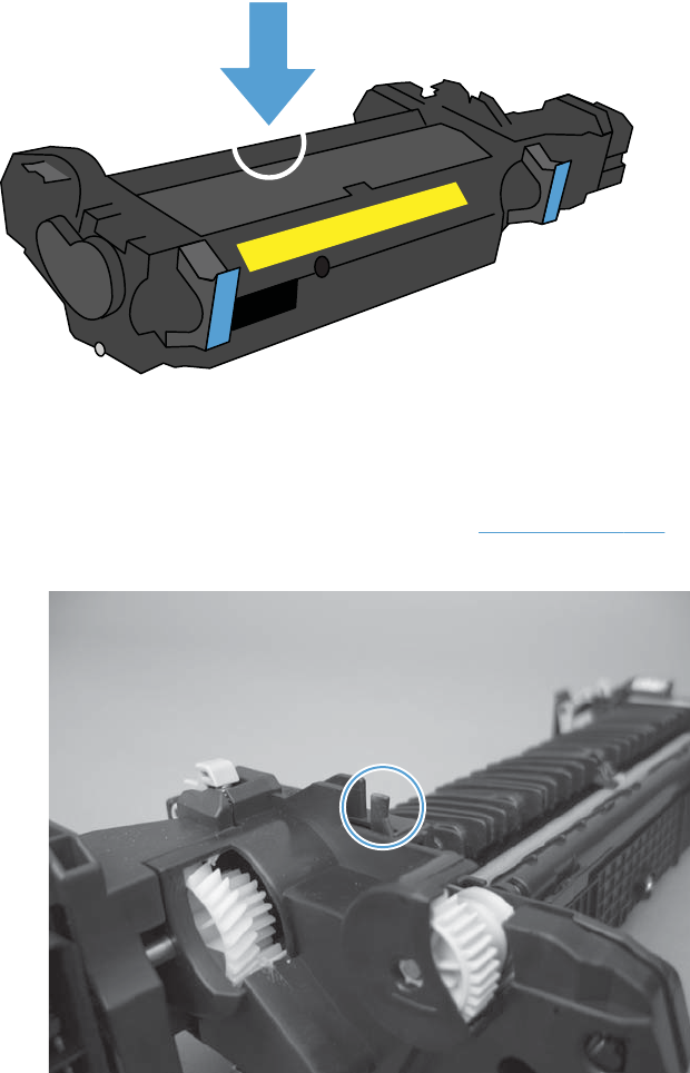
Fuser output sensor
Figure 3-11 Fuser output sensor flag location
1. Open the right-door assembly.
2. Lower the secondary transfer assembly.
3. Remove the fuser, and then verify that the sensor flag on the fuser moves freely. If the sensor flag
does not move freely, replace the fuser. See Fuser on page 112.
Figure 3-12 Test the fuser output sensor (1 of 2)
384 Chapter 3 Solve problems ENWW
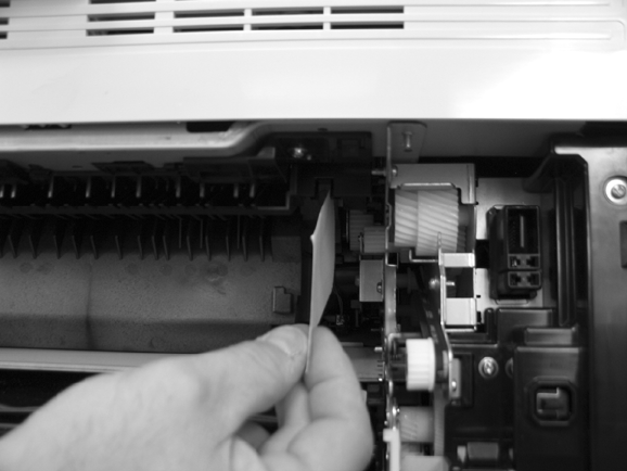
4. Insert a piece of paper to activate the fuser output sensor.
Figure 3-13 Test the fuser output sensor (2 of 2)
5. Check the control-panel display for a sensor response.
6. If there is no response, replace the fuser output sensor.
ENWW Tools for troubleshooting 385
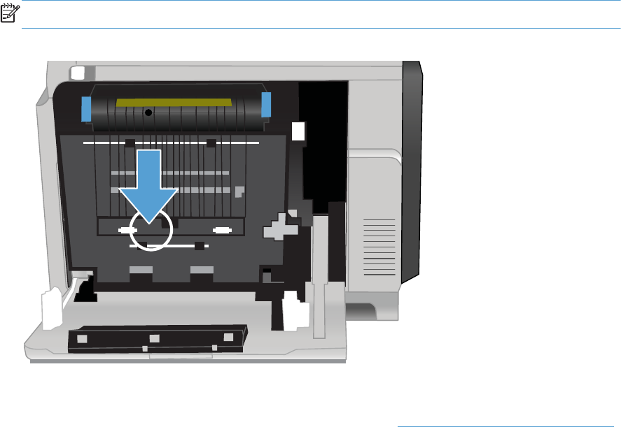
Duplexer refeed sensor
1. Open the right door.
2. Lift the secondary-transfer assembly.
3. Press the flag to activate the sensor.
NOTE: The sensor and sensor flag are located on the back side of the registration assembly.
Figure 3-14 Test the duplexer refeed sensor
4. Check the control-panel display for sensor response.
5. If there is no response, replace the registration assembly. See Registration assembly on page 213.
386 Chapter 3 Solve problems ENWW
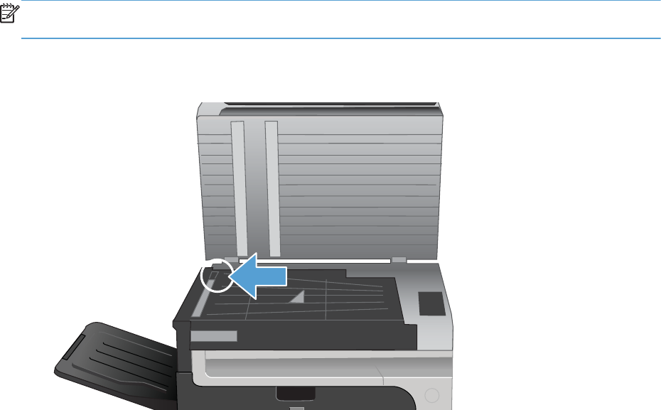
IPTU-bin-full sensor
NOTE: The IPTU-bin-full sensor is used only when the output tray is present. If the optional stapler/
stacker is installed, the IPTU-bin-full sensor is not used.
1. Lift the scanner.
Figure 3-15 Test the IPTU-bin-full sensor
2. Move the IPTU-bin-full sensor flag in the output tray to activate the sensor.
3. Check the control-panel display for sensor response. If the test fails, replace the IPTU.
ENWW Tools for troubleshooting 387
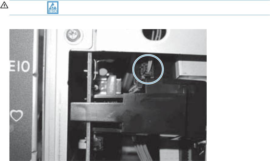
Developer alienation sensor
This sensor is located inside the main-drive assembly and cannot be accessed for direct manual testing.
To test this sensor, do the following.
1. Access the manual-sensor test menu and select sensor test SR11.
2. Locate the in-line connector J87. Disconnect, and the reconnect the connector. The sensor indicator
on the control-panel display should indicate that the sensor changed state. If it does not, check the
connector J112 on the DC controller PCA.
CAUTION: ESD sensitive component.
Figure 3-16 Developer alienation sensor connector J87
3. Check the control-panel display for sensor response.
388 Chapter 3 Solve problems ENWW
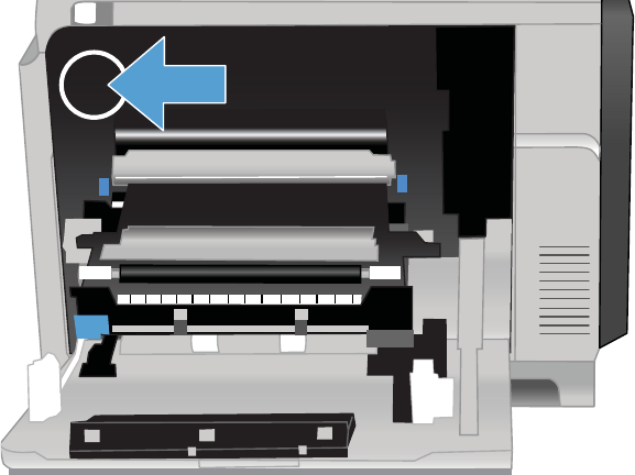
Fuser pressure-release sensor
1. Open the right-door assembly.
2. Lower the secondary transfer assembly.
3. Remove the fuser.
4. Insert a piece of paper to activate the fuser pressure-release sensor.
Figure 3-17 Test the fuser pressure-release sensor
5. Check the control-panel display for sensor response.
6. If there is no response, replace fuser pressure-release sensor.
ENWW Tools for troubleshooting 389
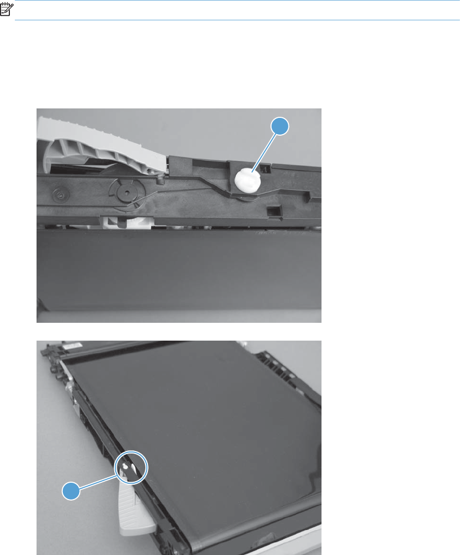
ITB alienation sensor
NOTE: The document feeder, scanner, and IPTU have been removed for clarity.
1. Open the right-door assembly.
2. Lower the secondary transfer assembly, and then remove the fuser and ITB.
3. Rotate the gear (callout 1) to move the flag (callout 2). If the flag does not move, replace the ITB.
Figure 3-18 Test the ITB alienation sensor (1 of 4)
1
Figure 3-19 Test the ITB alienation sensor (2 of 4)
2
390 Chapter 3 Solve problems ENWW
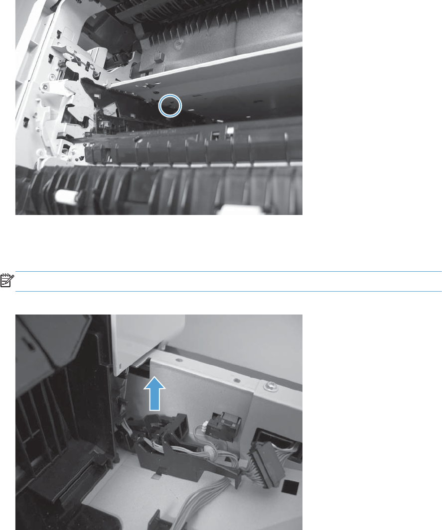
4. From inside the ITB cavity, press up on the primary-transfer-roller-disengagement flag to activate
the sensor.
Figure 3-20 Test the ITB alienation sensor (3 of 4)
5. Check the control-panel display for sensor response.
6. If there is no response, verify that the flag is moving.
NOTE: Figure shows the sensor with the IPTU removed.
Figure 3-21 Test the ITB alienation sensor (4 of 4)
7. If the flag moves correctly, replace the sensor.
ENWW Tools for troubleshooting 391
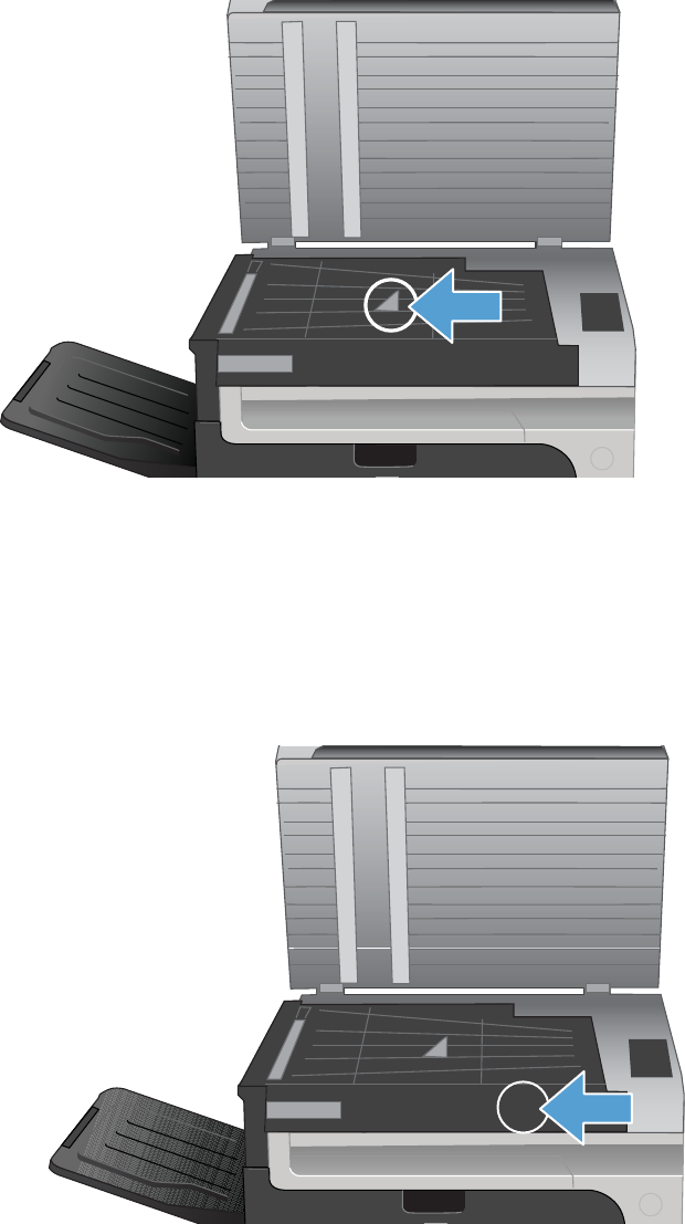
IPTU feed sensor
Figure 3-22 IPTU feed sensor test
1. Lift the scanner.
2. Activate the sensor.
3. Check the control-panel display for sensor response. If the test fails, replace the IPTU.
Scanner open sensor
1. Open the scanner and locate the sensor.
2. Use a folded piece of paper to actuate the sensor and watch the control-panel display for a
response.
3. If the test fails, replace the IPTU.
392 Chapter 3 Solve problems ENWW

Tray/Bin manual sensor test
Use this test to test paper-path sensors and the paper-size switches manually. The following illustrations
and table show the locations of these sensors.
1. Scroll to and touch the Administration button.
2. Touch the Troubleshooting button, and then touch the Diagnostic Tests button.
3. Touch the Tray/Bin Manual Sensor Test button.
4. Select from the list of sensors.
Table 3-4 Tray/bin manual sensor test
Sensor or switch name Sensor or switch number Sensor or switch test
Tray 1 paper sensor SR8 See Tray 1 paper sensor on page 395.
Tray 2 paper sensor SR25 See Tray 2 paper sensor on page 396.
Tray 2 paper surface sensor SR24 See Tray 2 paper surface 1 and 2
sensors on page 397.
Tray 2 paper size switches SW4 See Tray 2 paper size switches
on page 398.
Tray 3 paper sensor SR3 (paper feeder) See Tray 3 paper sensor on page 399.
Tray 3 feed sensor SR4 (paper feeder) See Tray 3 feed sensor on page 399.
Tray 3 paper surface sensors SR2 (paper feeder) See Tray 3 paper surface 1 and 2
sensors on page 400.
Tray 3 paper size 1 sensor SW2 (paper feeder) See Tray 3 paper size switches
on page 401.
Tray 3 paper size 2 sensor
Tray 3 paper size 3 sensor
Tray 4 paper sensor SR6 (paper feeder) See Tray 4 paper sensor on page 401.
Tray 4 feed sensor SR7 (paper feeder) See Tray 4 feed sensor on page 402.
Tray 4 paper surface sensors SR8 (paper feeder) See Tray 4 paper surface 1 and 2
sensors on page 402.
Tray 4 paper size 1 sensor SW3 (paper feeder) See Tray 4 paper size switches
on page 403.
Tray 4 paper size 2 sensor
Tray 4 paper size 3 sensor
Tray 5 paper sensor SR11 (paper feeder) See Tray 5 paper sensor on page 403.
Tray 5 feed sensor SR10 (paper feeder) See Tray 5 feed sensor on page 404.
Tray 5 paper surface sensor SR9 and SR12 (paper feeder) See Tray 5 paper surface 1 and 2
sensors on page 404.
ENWW Tools for troubleshooting 393
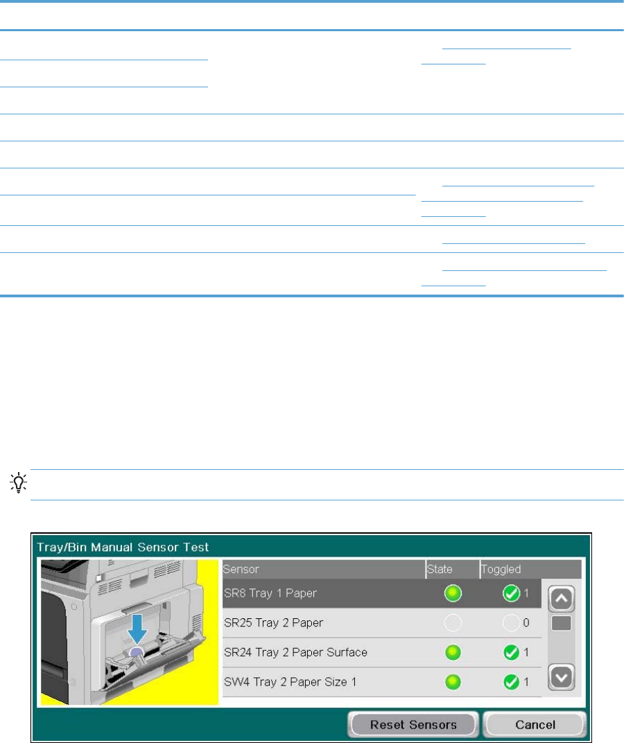
Table 3-4 Tray/bin manual sensor test (continued)
Sensor or switch name Sensor or switch number Sensor or switch test
Tray 5 paper size 1 sensor SW4 (paper feeder) See Tray 5 paper size switches
on page 405.
Tray 5 paper size 2
Tray 5 paper size 3
Output bin full sensor SR1
The following items cannot be tested using the manual sensor test.
5 V laser and 24 V interlock switches SW1 and SW2 See 5V laser and 24V interlock and
logic switches (and power switch)
on page 406.
Power switch SW3
New ITB sensor SR10 See New ITB sensor on page 410.
Tray 3, 4, and 5 right door switch SW1 (paper feeder) See Tray 3, 4, and 5 right door switch
on page 412.
To perform these tests, do the following:
●Remove the appropriate tray.
●Test each switch or sensor individually.
●Watch the control panel for the corresponding sensor to change from green to clear or clear to
green. It can take a few seconds to change.
TIP: The Toggled column indicates how many times a sensor changed state.
Figure 3-23 Tray/Bin sensor test
394 Chapter 3 Solve problems ENWW
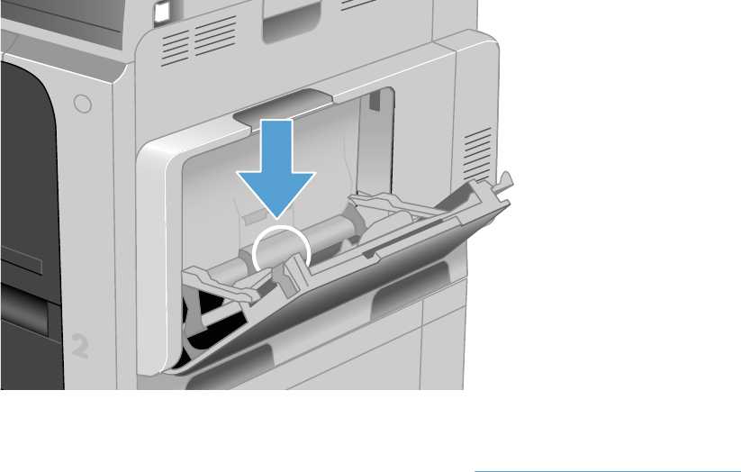
Tray 1 paper sensor
1. Open Tray 1.
2. Toggle the Tray 1 paper-present sensor flag.
Figure 3-24 Test the Tray 1 paper sensor
3. Check the control-panel display for sensor response.
4. If there is no response, replace the right door assembly. See Right-door assembly on page 145.
ENWW Tools for troubleshooting 395
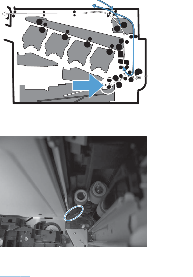
Tray 2 paper sensor
1. Remove Tray 2 and locate the sensor.
Figure 3-25 Tray 2 paper sensor location
2. Toggle the Tray 2 paper-present sensor flag.
Figure 3-26 Test the Tray 2 paper-present sensor
3. Check the control-panel display for sensor response.
4. If there is no response, replace the cassette-pickup assembly. See Tray-pickup assembly
on page 268.
396 Chapter 3 Solve problems ENWW
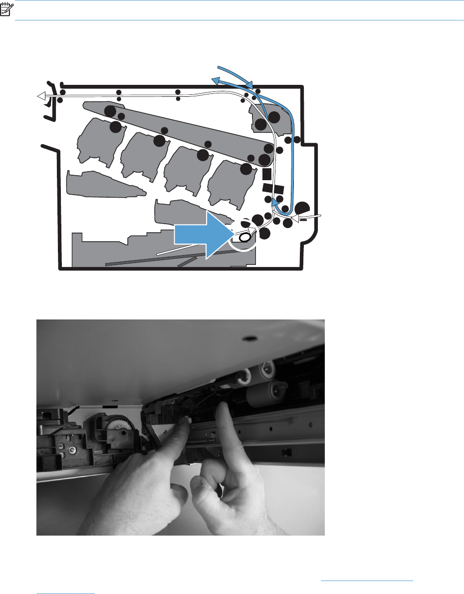
Tray 2 paper surface 1 and 2 sensors
NOTE: Only paper surface sensor 2 can be tested.
1. Remove the tray and locate the sensor flag.
Figure 3-27 Tray 2 paper surface 1 and 2 sensors location
2. In the tray cavity, press the tray-closed tab to release the flag, and then toggle the flag.
Figure 3-28 Tray 2 paper surface 1 and 2
3. Check the control-panel display for sensor response.
4. If there is no response, replace the cassette-pickup assembly. See Tray-pickup assembly
on page 268.
ENWW Tools for troubleshooting 397
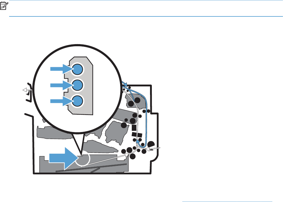
Tray 2 paper size switches
NOTE: These three switches also detect cassette presence. If these switches fail, the message Tray
<X> open could appear on the control-panel display.
1. Remove the tray. From inside the tray cavity, push any of the three switches.
Figure 3-29 Test the Tray 2 paper size switches
2. Check the control-panel display for sensor response.
3. If there is no response, replace the lifter base assembly. See Lifter base assembly on page 263.
398 Chapter 3 Solve problems ENWW
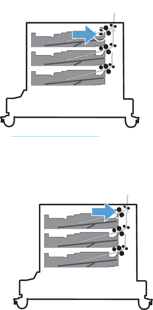
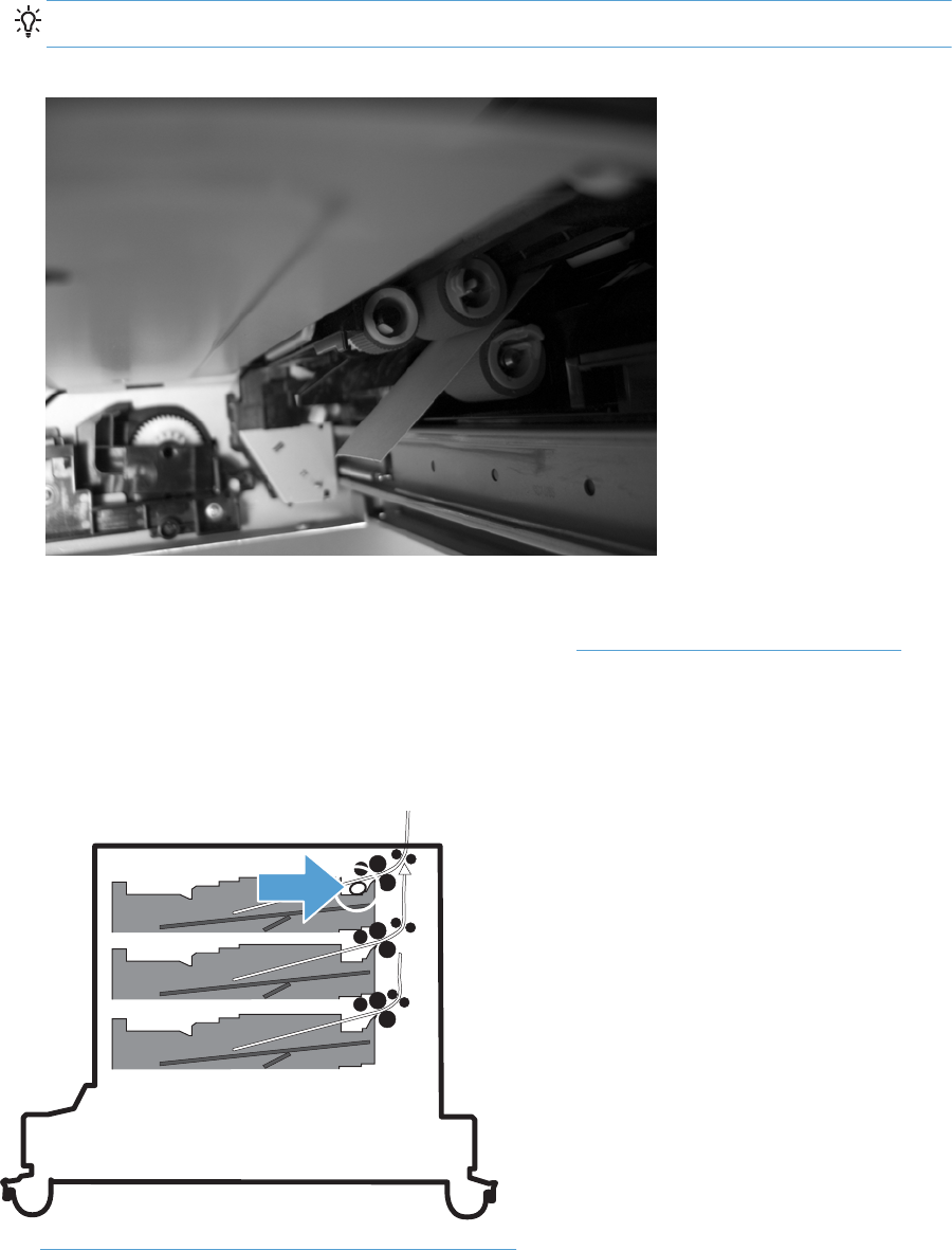
2. Insert a piece of paper between the rollers to activate the feed sensor.
TIP: Use stiff paper when performing this test (for example a business card or index card).
Figure 3-32 Test the Tray 3 feed sensor
3. Check the control-panel display for sensor response.
4. If no response, replace the cassette-pickup assembly. See Tray-pickup assembly on page 268.
Tray 3 paper surface 1 and 2 sensors
Figure 3-33 Tray 3 paper surface 1 and 2 sensors location
See Tray 2 paper surface 1 and 2 sensors on page 397.
400 Chapter 3 Solve problems ENWW
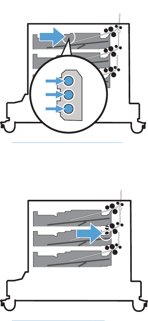
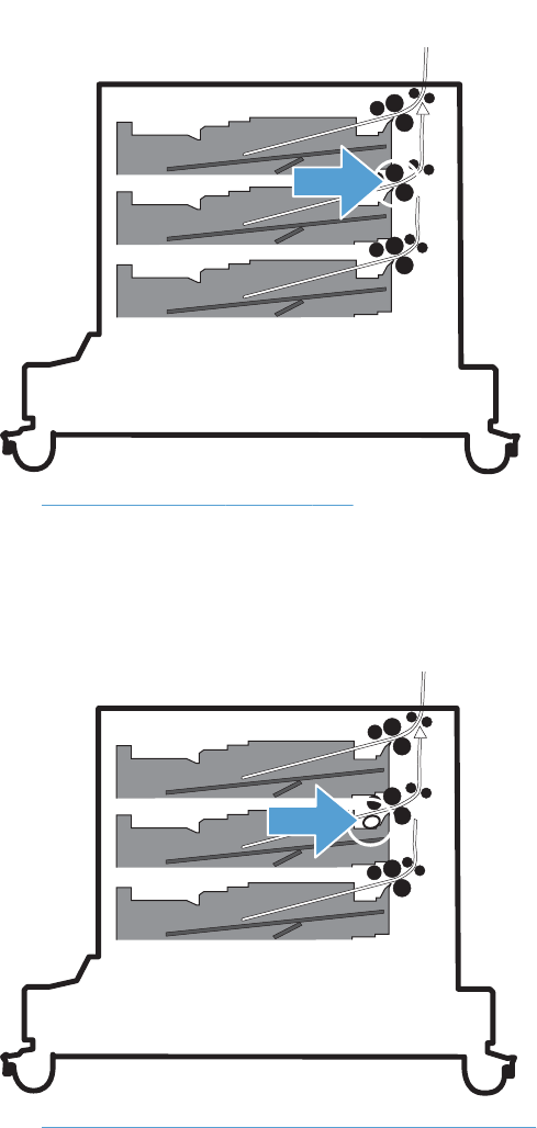
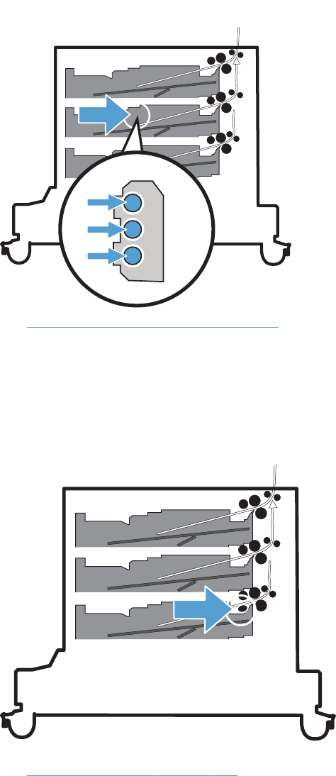
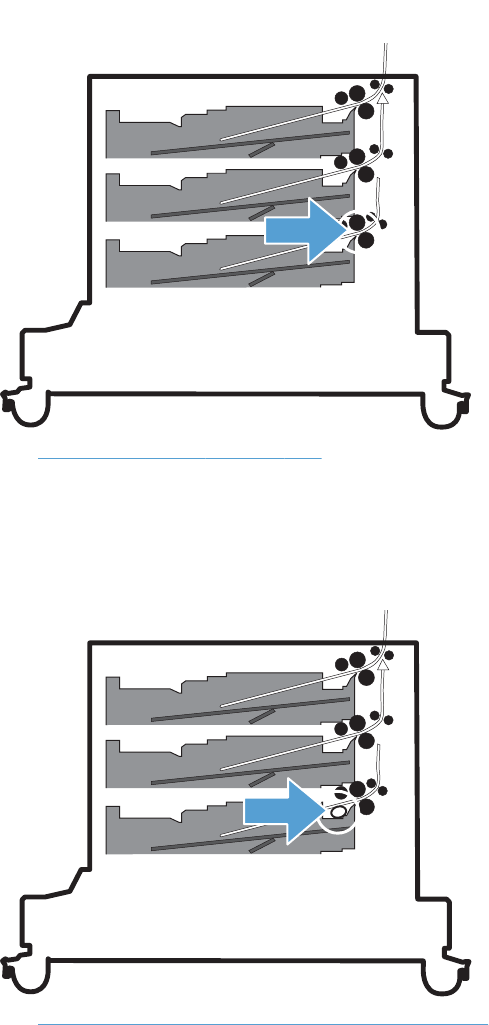
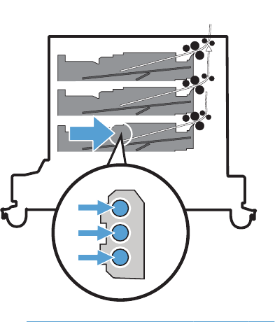
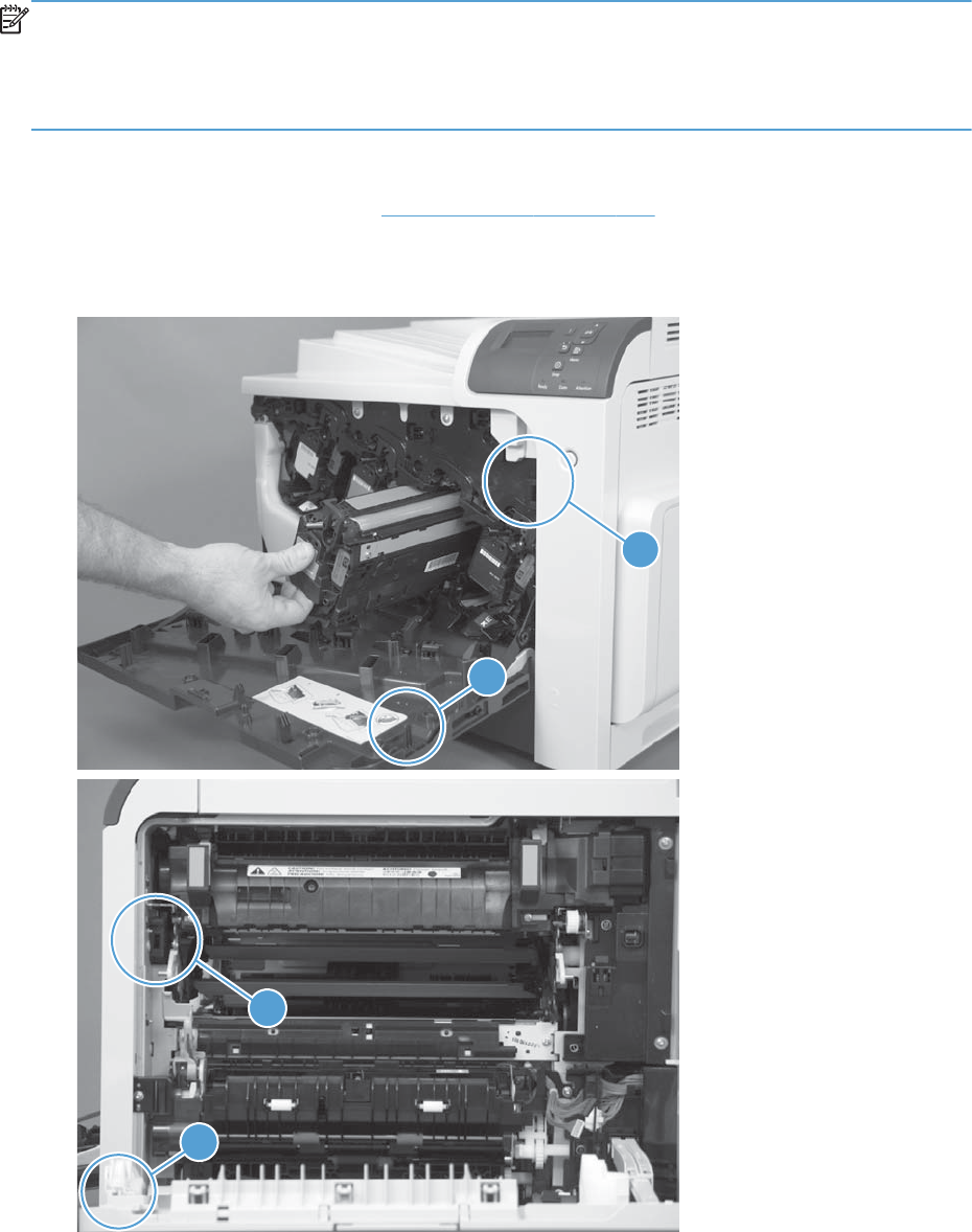
5V laser and 24V interlock and logic switches (and power switch)
Location and testing
NOTE: When a door is opened, the 5V interlock switch prevents the lasers from operating (no
power). When a door is opened, the 24V interlock switch prevents the motors and high-voltage power
supply from operating (no power).
The front and right door each have a logic switch that indicates when a door is open.
1. Press the power switch to turn the product off then on to test the switch function.
2. Remove the right-front cover. See Right-front cover on page 138.
3. Locate the link arms (callout 1) on the front and right doors (and access ports in the covers; callout
2) that actuate the front- and right-door interlock switchs (behind the right-front cover).
2
1
2
1
406 Chapter 3 Solve problems ENWW
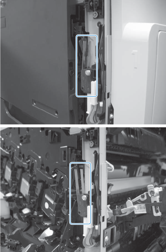
4. Open and close the doors to make sure that the interlock switches are correctly functioning. The
following figures show the interlock switch positions with the front and right doors closed and
open.
Defeating
●Front-door interlock switch
◦Fold a stiff piece of paper, for example a business card or index card, into a 10 mm (.
375 in) strip, and then wedge the strip into the opening at the front of the product.
ENWW Tools for troubleshooting 407
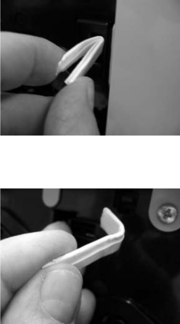
●Front-door logic switch
◦Fold a stiff piece of paper, for example a business card or index card, into a 10 mm (.
375 in) strip with a bend at the end, and insert the strip into the opening at the front of the
product.
●Right-door interlock switch
◦Fold a stiff piece of paper, for example a business card or index card, into a 10 mm (.
375 in) strip, and then insert the strip into the opening at the right of the product.
408 Chapter 3 Solve problems ENWW
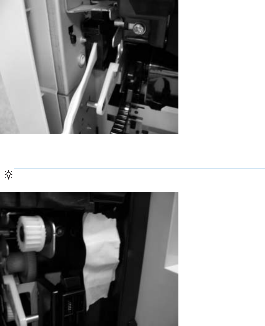
●Right-door logic switch
◦Use masking tape to keep the switch flag depressed.
TIP: You might have to use two pieces of tape to overcome the tension return spring on the
flag.
ENWW Tools for troubleshooting 409

New ITB sensor
NOTE: This sensor cannot be tested, but you can inspect the sensor, actuator, and the flag on the ITB
for damage.
1. Remove the existing ITB.
2. Inspect the new ITB sensor. Press the actuator on the sensor toward the black print cartridge to
verify that the actuator moves.
Figure 3-43 Test the new ITB sensor
410 Chapter 3 Solve problems ENWW
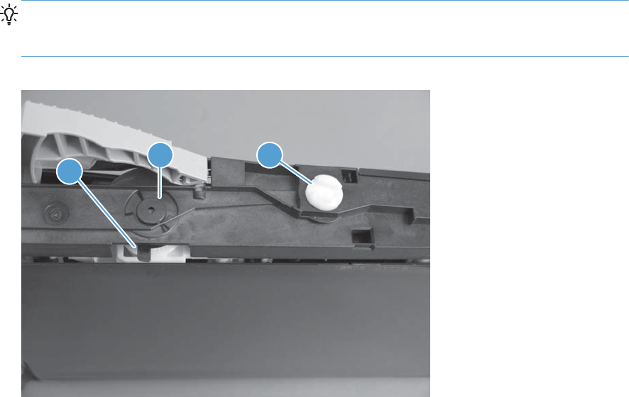
3. On the new ITB, locate and inspect the new ITB flag (callout 1).
TIP: The new ITB flag is only present prior to installation. To see the flag on a previously installed
ITB, insert the end of a paperclip in the hole just below the handle (callout 2) and then rotate the
ITB alienation gear (callout 3).
Figure 3-44 Test the new ITB sensor
2
1
3
ENWW Tools for troubleshooting 411
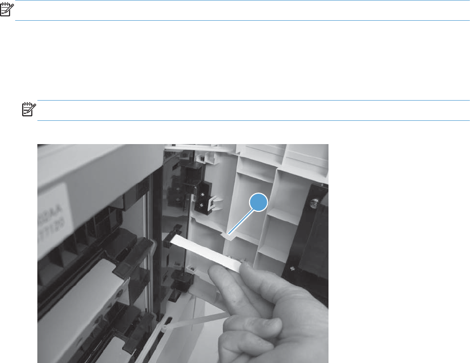
Tray 3, 4, and 5 right door switch
NOTE: There is no manual sensor test for this sensor.
1. Open the paper feeder right door. Check the control-panel display for the Close lower right
door message. If the message does not display, open the door and inspect the flag for damage
(callout 1).
2. Insert a piece of paper to activate the sensor. If there is no response, replace the switch.
NOTE: Make sure that the door flag (callout 1) is not damaged or missing.
Figure 3-45 Test the right door switch
1
412 Chapter 3 Solve problems ENWW
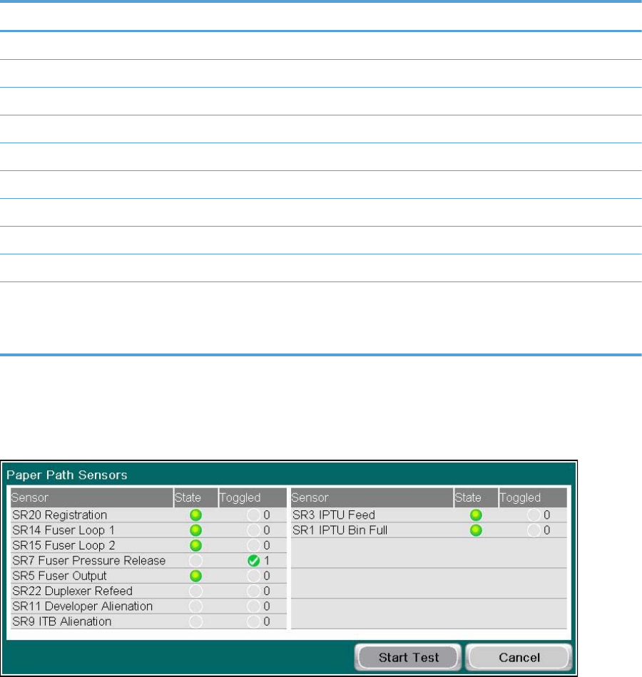
Paper-path sensors test
This test displays the status of each paper-path sensor and allows viewing of sensor status while printing
internal pages.
1. From the Home screen, scroll to and touch the Administration button.
2. Touch the Troubleshooting button, and then touch the Diagnostic Tests button.
3. Touch the Paper Path Sensors button.
4. Touch the Start Test button and observe the sensors change state as the test page prints.
Table 3-5 Paper-path sensors diagnostic tests
Sensor name Sensor number
Registration sensor SR20
Fuser loop 1 sensor SR14
Fuser loop 2 sensor SR15
Fuser pressure release sensor SR7
Fuser output sensor SR5
Duplexer refeed sensor SR22
Developer alienation SR11
ITB alienation sensor SR9
IPTU feed sensor SR27
IPTU bin full sensor
NOTE: The IPTU bin full sensor is only active if the stapler/
stacker is removed.
SR26
When performing these tests, watch the control panel for the corresponding sensor to change from
green to clear or clear to green. It can take a few seconds to change.
Figure 3-46 Paper path sensors
ENWW Tools for troubleshooting 413

Print/stop test
Use this diagnostic test to isolate the cause of problems such as image-formation defects and jams
within the engine. During this test you can stop the paper anywhere along the product paper path. The
test can be programmed to stop printing internal pages or an external print job when the paper
reaches a certain position. The test can also be programmed to stop from 0 to 60,000 ms. If the timer
is set to a value that is greater than the job-print time, you can recover the product in one of two ways.
1. From the Home screen, scroll to and touch the Administration button.
2. Touch the Troubleshooting button.
3. Touch the Diagnostic Tests button.
4. Scroll to and touch the Print/Stop Test button.
5. Enter a range, and then touch the OK button.
●After the print job is completed press OK button to return to the Troubleshooting menu before the
timer times out.
●After the timer times out, touch the Stop button. Activate the door switch to restart the engine and
return it to a normal state.
NOTE: Do not try to perform a print/stop test while the product is calibrating, because you be
required to power-cycle the product. If a jam message displays on the control panel during testing,
activate the door switch.
Scanner tests
This test activates individual document feeder and scanner parts independently to isolate problems.
Scanner tests
1. From the Home screen, scroll to and touch the Administration button.
2. Touch the Troubleshooting button, and then touch the Diagnostic Tests button.
3. Touch the Scanner Tests button.
4. Select the document feeder or scanner component test option you want to run, and then touch the
OK button.
5. Press the Stop button to stop the test.
Component Actions
Document feeder LED indicator This test turns the green input tray (on the document feeder) on
and off. If the test fails, replace the document feeder. See
Document feeder on page 151. If the problem continues,
replace the SCB. See S-PBA-SCB (SCB) on page 179.
414 Chapter 3 Solve problems ENWW

Component Actions
Document feeder input motor This test runs the motor in either the forward or reverse
direction. If you do not hear noise when the motor is
activated, replace the document feeder. See Document feeder
on page 151. If the problem continues, replace the SCB. See
S-PBA-SCB (SCB) on page 179.
Document feeder read motor This test runs the motor in either the forward or reverse
direction. If you do not hear noise when the motor is
activated, replace the document feeder. See Document feeder
on page 151. If the problem continues, replace the SCB. See
S-PBA-SCB (SCB) on page 179.
Lower lamp This test turns the lamp, inverter fan, and the scanner fan. If
the flatbed lamp and fans fail to turn on, replace the scanner.
See Scanner assembly on page 171. If the problem continues,
replace the SCB. See S-PBA-SCB (SCB) on page 179.
Flatbed Motor This test moves the optics to the right, and then back to the
home position. If the scanner optics fail to move, replace the
scanner. See Scanner assembly on page 171. If the problem
continues, replace the SCB. See S-PBA-SCB (SCB)
on page 179.
Scanner sensor tests
1. From the Home screen, scroll to and touch the Administration button.
2. Touch the Troubleshooting button, and then touch the Diagnostic Tests button.
3. Touch the Scanner Tests button.
4. Touch the Sensors button, and then touch the OK button.
5. Select from the list of sensors.
Sensor or switch name Sensor or switch test
Document feeder paper present sensor SeeDocument feeder paper present sensor on page 416.
Document feeder Y (length) sensor See Document feeder Y (length) sensor on page 416.
Document feeder jam cover sensor See Document feeder jam cover sensor on page 417.
Flatbed Y (length) sensor See Flatbed Y (length) sensor on page 418.
Flatbed cover angle sensor See Flatbed cover angle sensor on page 419.
Flatbed cover sensor See Flatbed cover sensor on page 420.
ENWW Tools for troubleshooting 415
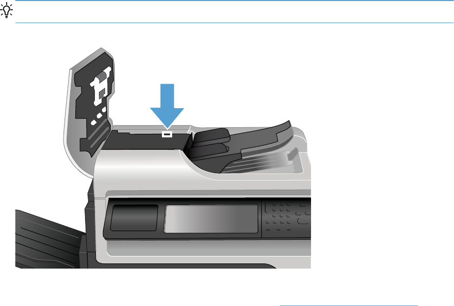
Document feeder paper present sensor
1. Open the jam-access cover and locate the document feeder paper present sensor.
TIP: To help locate the sensor, find the black paper present flag on the rear of the cover.
Figure 3-47 Document feeder paper present sensor test
2. Use a folded piece of paper to toggle the sensor and watch the control-panel display for a
response. If the test fails, replace the document feeder. See Document feeder on page 151.
Document feeder Y (length) sensor
1. Locate the sensor on the input tray.
416 Chapter 3 Solve problems ENWW
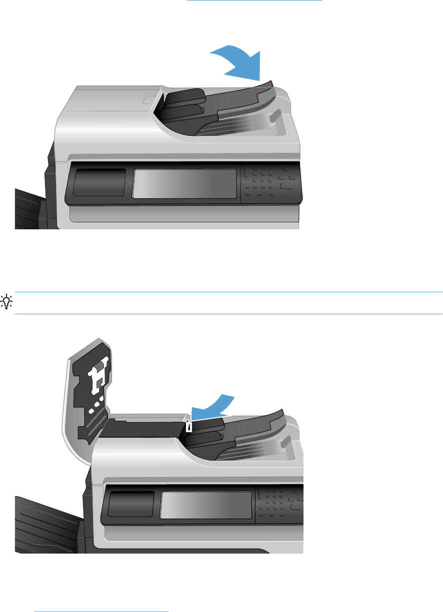
2. Place a finger over the sensor, and then watch the control-panel display for a response. If the test
fails, replace the document feeder. See Document feeder on page 151.
Document feeder jam cover sensor
1. Open the jam-access cover and locate the sensor.
TIP: To help locate the sensor, find the white sensor flag on the top of the cover.
Figure 3-48 Document feeder jam cover sensor test
2. Use a folded piece of paper to actuate the sensor.
3. Check the control-panel display for sensor response. If the test fails, replace the document feeder.
See Document feeder on page 151.
ENWW Tools for troubleshooting 417
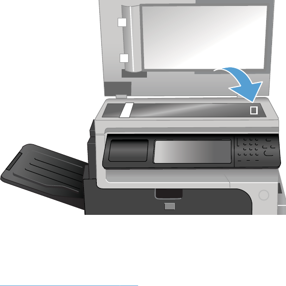
Flatbed Y (length) sensor
1. Lift the scanner and locate the sensor.
1
2. Block the sensor by placing a piece of paper on the glass and watch the control-panel display for
a response.
3. Check the control-panel display for sensor response. If the test fails, replace the scanner. See
Scanner assembly on page 171.
418 Chapter 3 Solve problems ENWW
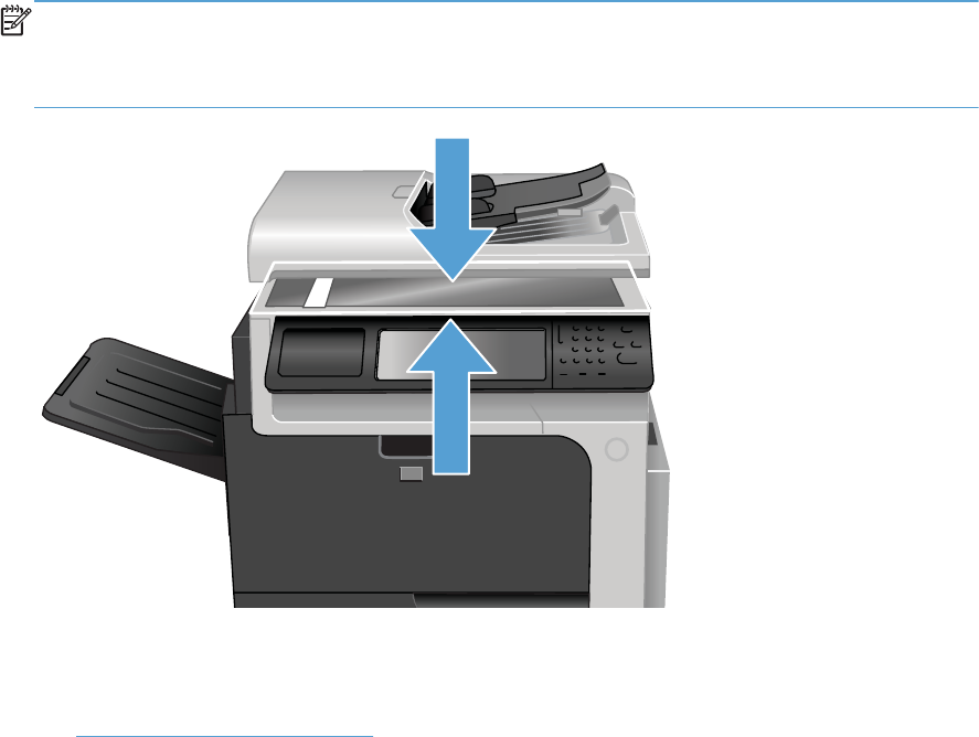
Flatbed cover angle sensor
1. Lift the scanner and locate the sensor.
NOTE: The flatbed cover angle and the flatbed cover open sensors use the same sensor
assembly.
The sensor changes state when the scanner is raised approximately 50 mm (2 in).
1
2
2. Actuate the sensor by closing and then slowly opening the scanner.
3. Check the control-panel display for sensor response. If the test fails, replace the document feeder.
See Document feeder on page 151.
ENWW Tools for troubleshooting 419
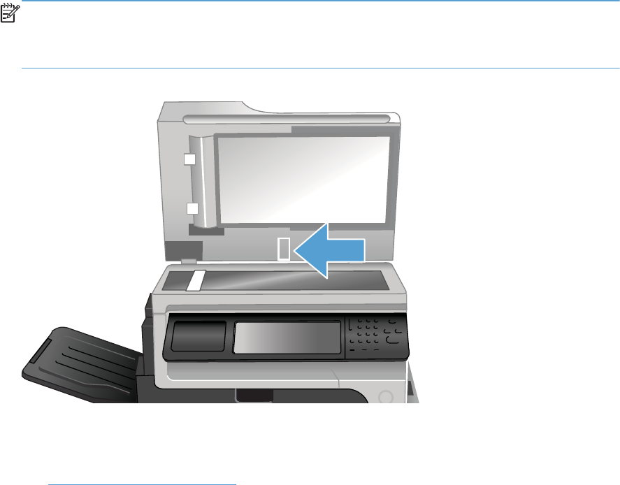
Flatbed cover sensor
1. Open the scanner and locate the sensor.
NOTE: The flatbed cover angle and the flatbed cover open sensors use the same sensor
assembly.
The sensor changes state when the scanner is raised approximately 150 mm (6 in).
Figure 3-49 Flatbed cover sensor test
2. Actuate the sensor and watch the control-panel display for a response.
3. Check the control-panel display for sensor response. If the test fails, replace the document feeder.
See Document feeder on page 151.
420 Chapter 3 Solve problems ENWW
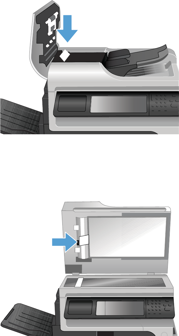
Document feeder registration sensor
1. Lift the document feeder and locate the sensor.
2. Actuate the sensor by inserting a stiff piece of paper, like a business card, into the paper path.
3. Check the control-panel display for sensor response.
Document feeder exit sensor
1. Lift the document feeder and locate the sensor.
2. Actuate the sensor by inserting a stiff piece of paper, like a business card, into the paper path.
3. Check the control-panel display for sensor response.
ENWW Tools for troubleshooting 421

Document feeder read sensor
1. Lift the document feeder and locate the sensor.
2. Actuate the sensor by inserting a stiff piece of paper, like a business card, into the paper path.
3. Check the control-panel display for sensor response.
Component tests
Control-panel tests
Open the following menus:
●Administration
●Troubleshooting
●Diagnostic Tests
Available control-panel tests
●LEDs: test the LEDs on the control panel.
●Display: sequence through display tests.
●Buttons: tests the key pad and other buttons.
●Touchscreen: tests the control-panel touchscreen.
For more control-panel diagnostics, see Control-panel checks on page 372.
Component test (special-mode test)
This test activates individual parts independently to isolate problems.
422 Chapter 3 Solve problems ENWW

Each component test can be performed once or repeatedly. If you select Continuous from the drop-
down menu as the repeat option, the test cycles the component on and off. This process continues for
two minutes, and then the test terminates.
NOTE: The front or side door interlocks must be defeated to run the component tests. Some tests may
require that the ITB and print cartridges be removed. The control panel display prompts you to remove
some or all cartridges during certain tests.
1. From the Home screen, scroll to and touch the Administration button.
2. Touch the Troubleshooting button, and then touch the Diagnostic Tests button.
3. Touch the Component Test button.
4. Select the component you want to test, and then touch the OK button.
Table 3-6 Component test details
Component test Motor or solenoid number Comments
Transfer Motors M1
M3
M4
M5
M6
Activates four drum motors and the ITB
motor (M1).
Belt Only M1 Activates the ITB motor.
Cartridge Motors M3: yellow
M4: magenta
M5: cyan
M6: black
Activates each drum motor sequentially
(K, C, M, Y).
Fuser Motor M2 Activate the fuser motor at a specified
speed for 10 seconds.
Fuser Pressure Release Motor M2 reverse Reverses the fuser motor and
pressurizes or depressurizes the fuser.
Alienation Motor M10 Activates CMYK developer alienation
in the following sequence: All colors
engaged, all colors alienated, K-only
engaged, and K alienated.
ITB Contact/Alienation M2
SL1
Activates the fuser motor and primary
transfer solenoid to cycle through the
ITB alienation stages.
TCU Motor M12 Activates the motor at a specified
speed for 10 seconds.
ENWW Tools for troubleshooting 423

Table 3-6 Component test details (continued)
Component test Motor or solenoid number Comments
Tray <X> Pickup Motor Tray 2: M13
Tray 3: M2
Tray 4: M2
Tray 5: M2
Tray 2: Activates the pickup motor in
reverse for 10 seconds.
Trays 3-5: Activates the motor in the
paper-feeder assembly and drives the
separation roller for each tray in
reverse.
Tray <X> Pickup Solenoid Tray 1: SL3
Tray 2: SL4
Tray 3: SL1
Tray 4: SL2
Tray 5: SL3
Activates the solenoid for 10 seconds.
Duplexer Pickup Motor M11: Duplex reverse motor Activates the motor at a specified
speed for 10 seconds.
Black Laser Scanner M8 Activates the black/cyan scanner
motor for 10 seconds.
Cyan Laser Scanner M8 Activates the black/cyan scanner
motor for 10 seconds.
Magenta Laser Scanner M9 Activates the yellow/magenta scanner
motor for 10 seconds.
Yellow Laser Scanner M9 Activates the yellow/magenta scanner
motor for 10 seconds.
Repeat Allows you to specify whether or not
the product repeats the test sequences.
Stapler/stacker
There are no component or sensor tests for the stapler/stacker. The stapler/stacker initializes when the
product power is turned on.
Stapler/stacker initialization:
●The jogger moves out toward the front of the stapler/stacker, and then moves back.
●The bin-3 flapper raises up, and then down.
The product power must be turned off before the stapler/stacker is removed or installed. If the stapler/
stacker is removed when the product power is on, the following messages appear on the control-panel
display.
424 Chapter 3 Solve problems ENWW

Stapler/stacker error messages:
●65.80.A1 Output accessory disconnected
This error message appears if the stapler/stacker is removed while the product power is on and
the product is at the Ready state. Turn the power off, reinstall the stapler/stacker, and then turn the
power on again.
●49.21.49 The device has a detection problem. Turn off the device…
This error message appears if the stapler/stacker is removed while the product power is on and
the product in the Sleep state. Turn the power off, reinstall the stapler/stacker, and then turn the
power on again.
●Staple Cartridge very low
This error message appears if the staple cartridge in the stapler/stacker is very low on staples.
This error message also displays if the top cover of the stapler/staker is closed and a staple
cartridge is not installed. If a staple cartridge is not installed, printed pages are delived to the
output bin without being stapled.
If the stapler/stacker is defective, the product configure the product to operate without it until a
replacement is obtained.
1. Turn the power off.
2. Remove the defective stapler/stacker.
3. Install the output bezel and output bin.
NOTE: The output bin full sensor is only activated when the product power is on and the
stapler/stacker is not installed. You must install the output bezel. The output bin full sensor flag is
part of the bezel.
4. Turn the power on.
ENWW Tools for troubleshooting 425
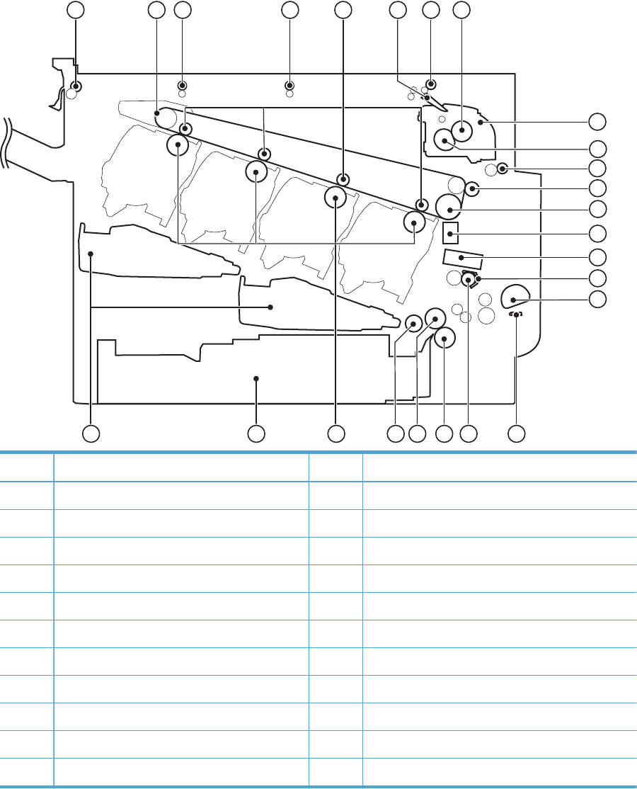
Diagrams
Block diagrams
Figure 3-50 Product cross section
11
12
13
17
18
25
23678
9
10
2024
14 5
14
15
16
19
212223
Item Description Item Description
1 ITB delivery roller 14 RD sensor
2 ITB 15 Media sensor
3 IPTU feed roller 2 16 Registration shutter
4 IPTUB feed roller 1 17 MP tray pickup roller
5 Primary transfer roller 18 MP tray separation pad
6 Duplex flapper 19 Registration roller
7 Duplex reverse roller 20 Cassette separation roller
8 Pressure roller 21 Cassette feed roller
9 Fuser 22 Cassette pickup roller
10 Fuser sleeve 23 Photosensitive drum
11 Duplex feed roller 24 Cassette
426 Chapter 3 Solve problems ENWW
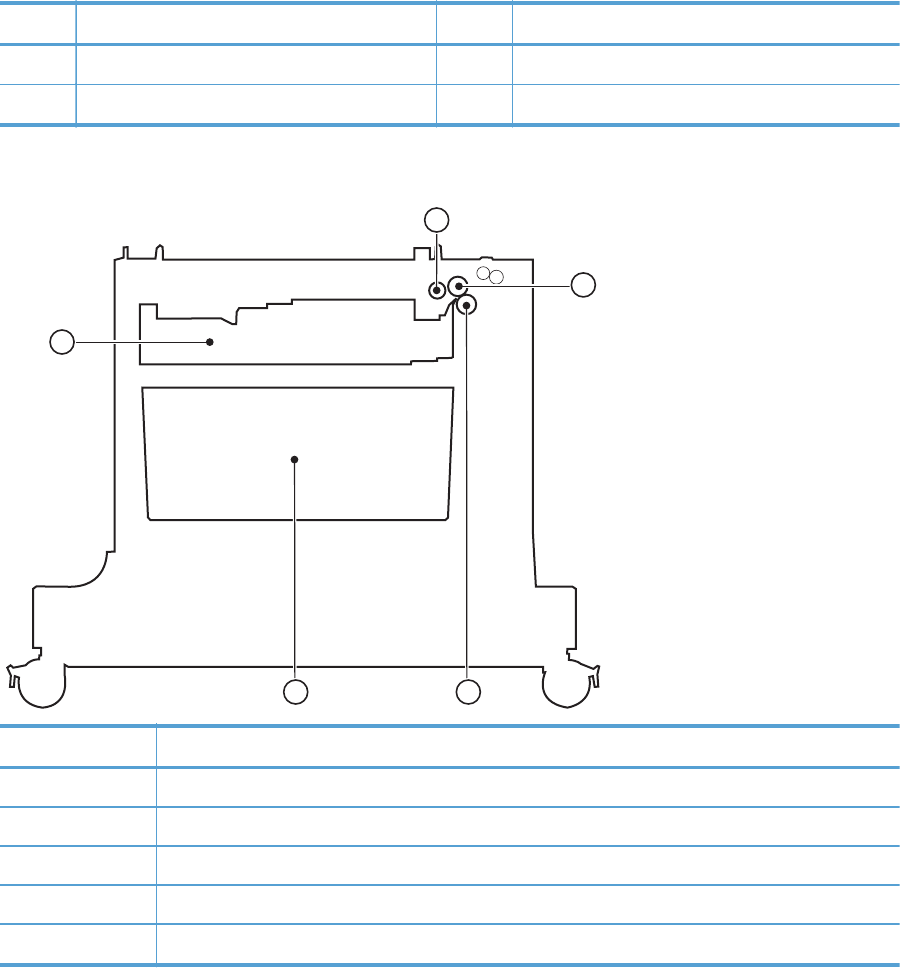
Item Description Item Description
12 Secondary transfer roller 25 Laser/scanner assembly
13 ITB drive roller
Figure 3-51 Optional paper feeder (1 x 500-sheet)
1
2
3
4
5
Item Description
1 Pickup roller
2 Feed roller
3 Separation roller
4 Storage space
5 Cassette
ENWW Tools for troubleshooting 427
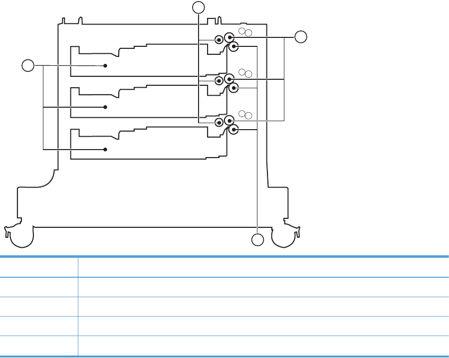
Figure 3-52 Optional paper feeder (3 x 500-sheet)
1
2
3
4
Item Description
1 Pickup roller
2 Feed roller
3 Separation roller
4 Cassette
428 Chapter 3 Solve problems ENWW
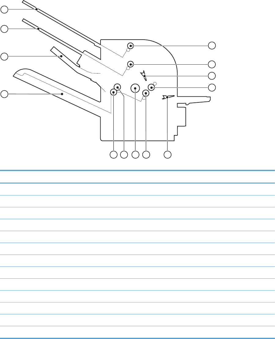
Figure 3-53 Stapler/stacker
1
2
3
4
5
6
11
13
7
8
10
9
12
Item Description
1 Output bin 1 delivery roller
2 Output bin 2 delivery roller
3 Output bin flapper
4 Stapler/stacker feed roller 1
5 Inlet flapper
6 Stapler/stacker feed roller 2
7 Alignment roller
8 Output bin 3 upper delivery roller
9 Output bin 3 lower delivery roller
10 Output bin 3
11 Jogger guide
12 Output bin 2
13 Output bin 1
ENWW Tools for troubleshooting 429
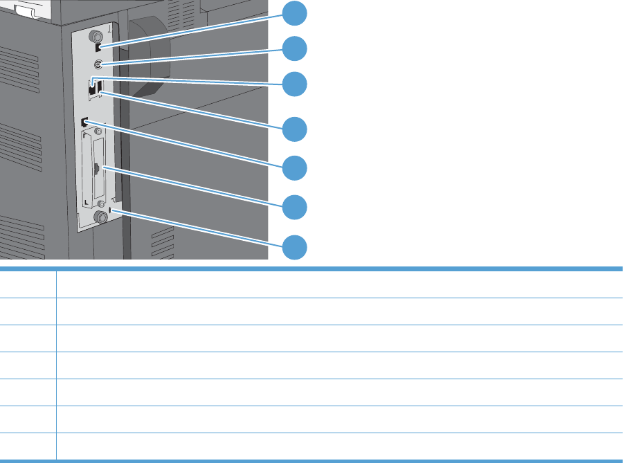
Plug/jack locations
1
2
4
5
6
7
3
1 Hi-speed USB 2.0 printing port
2 Foreign interface harness for connecting third-party devices
3 Local area network (LAN) Ethernet (RJ-45) network port
4 USB port for connecting external USB devices
5 Fax port (RJ-11)
6 EIO interface expansion slot
7 Slot for a cable-type security lock
430 Chapter 3 Solve problems ENWW
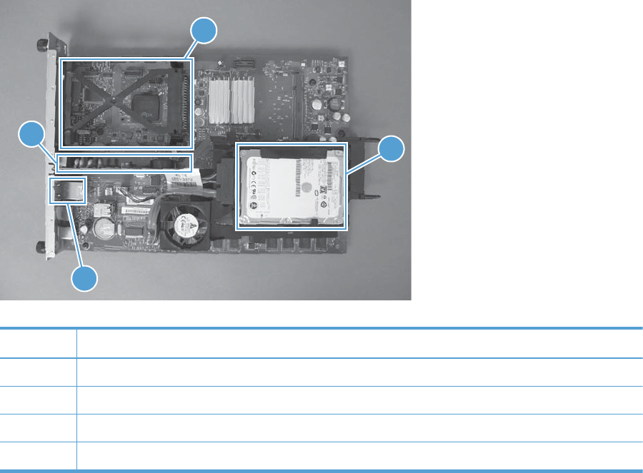
Figure 3-54 Formatter PCA
1
1
2
4
1
3
Table 3-7 Formatter PCA
Item Description
1Fax card
2 Internal hard drive
3USB ports
4 EIO slot
ENWW Tools for troubleshooting 431
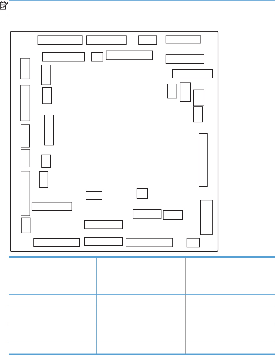
Location of connectors
DC controller connector locations
NOTE: The DC controller has 34 connectors: Six are for FFCs, 26 are for wire harnesses, and two
are not used.
Figure 3-55 DC controller connector locations
J130
J160
J123
J127
J162
J145
J131
J147
J115
J103
J114
J152
J110
J111
J112
J150
J126
J161
J105
J101
J120
J116
J113
J106
J129
J140 J128
J155
J121
J102
J107
J108
J151
J154
J148
J153
J101: not used J115: SL4, SL23, SL24, SL25, and
HVPS lower
J145: top of page (TOP) sensor (SR20)
Top of page (TOP) sensor (SR20),
duplex re-pickup sensor (SR22), and
duplex re-pickup clutch (CL1)
J102: not used J116: HVPS upper (FFC) J147: right-door switch (SW6)
J103: laser scanner temperature sensor
(TH4)
J120: yellow drum motor (M3) and
magenta drum motor (M4)
J148: MP-tray-media-presence sensor
(SR8) and MP-tray pickup solenoid (SL3)
J105: interconnect board (ICB) (FFC) J121: cyan drum motor (M5) and black
drum position (M6)
J150: LVPS
J106: IPTU J123: fuser motor (M2) J151: LVPS
432 Chapter 3 Solve problems ENWW

J107: Tray 3, 4, and 5 lifter motors
(M7), and cassette paper size switch
(SW4)
J126: memory tag connector J152: 5V interlock switch (SW1)
J108: environmental sensor J127: pre-exposure LEDs (rear), fuser
delivery sensor (SR5), New ITB sensor
(SR10)
J153: power supply fan (FM1)
J110: YM laser (FFC) J128: Delivery tray media full sensor
(SR6), Fuser pressure release sensor
(SR7), and pre-exposure LEDs (front)
(SR9)
J154: image scanner power supply unit
(PSU)
J111: CK laser (FFC) J129: front-door switch (SW5) J155: Residual toner-feed motor (M12)
and delivery fan (FM3)
J112: cyan/black scanner motor (M8),
yellow/magenta scanner motor (M9),
and developing disengagement sensor
(SR11)
J130: registration density (RD) sensors
(front and rear)
J160: fuser
J113: 24 v to high-voltage power
supply (HVPS) upper (FFC)
J131: media sensors J161: LVPS
J114: HVPS lower (FFC) J140: ITB motor (M1), yellow drum
home-position sensor (SR1), magenta
drum home-position sensor (SR2), cyan
drum home-position sensor (SR3), black
drum home-position sensor (SR4), and
primary transfer roller disengagement
solenoid (SL1)
J162: fuser
ENWW Tools for troubleshooting 433
Controller PCA (1 x 500-sheet and 3 x 500-sheet optional paper feeders)
Figure 3-56 Controller PCA connectors
J404
J409
J407
J403
J402
J401
J410
J408
J406
J405
Table 3-9 Controller PCA connectors
J401: not used
J402: lifter motor 3 signal
J403: cassette media presence 3
J404: right door open sensor
J405: lifter motor 2 signal
J406: cassette media presence 2
J407: lifter motor 1 signal
J408: cassette media presence 1
J409: pickup motor
J410: communication (command)
434 Chapter 3 Solve problems ENWW
Stapler/stacker PCA
J464
J450
J460
J465
J463
J467
J452
J453
J454
J455
J456
J462
J459
J458
J466
J451
J461
ENWW Tools for troubleshooting 435
IPTU PCA
J555
J550
J551
J552
J554
J553
436 Chapter 3 Solve problems ENWW
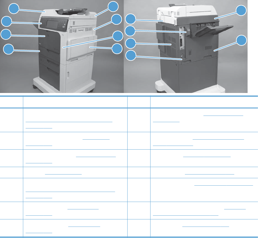
Locations of major components
Figure 3-57 External panels, covers, and doors; identification and location
5
6
1
2
3
4
7
8
13
14
12
11
9
10
Item Description Item Description
1 ASY-CVR-F-SP (document feeder front cover) (see
ASY-CVR-F-SP (document feeder front cover)
on page 129)
8 Right-door assembly (see Right-door assembly
on page 145)
2 Control-panel assembly (see Control panel
on page 100).
9 Rear top cover (see S-CVR-REAR (scanner rear
cover) on page 128
3 Front-door assembly (see Front-door assembly
on page 140)
10 Fan cover (see Fan cover on page 134)
4Tray (see Tray on page 111) 11 Rear cover (see Rear cover on page 144)
5 ASY-CVR-F-R-SP (document feeder rear cover) (see
ASY-CVR-F-R-SP (document feeder rear cover)
on page 131)
12 Lower-left cover (see Lower-left cover on page 136)
6 Right-rear cover (see Right-rear cover
on page 143)
13 S-CVR-LEFT (scanner left cover) (see S-CVR-LEFT
(scanner left cover) on page 133)
7 Right-front cover (see Right-front cover
on page 138)
14 Left cover (see Left cover on page 137)
ENWW Tools for troubleshooting 437
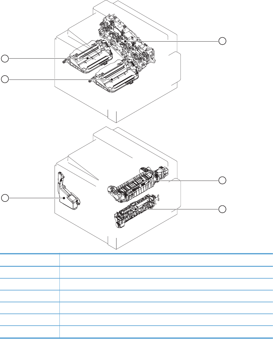
Figure 3-58 Major component locations (1 of 4)
1
5
6
2
3
4
Item Description
1 Main drive assembly
2 Fuser
3 Registration assembly
4 Toner collection unit
5 Laser/scanner assembly (C/Bk)
6 Laser/scanner assembly (Y/M)
438 Chapter 3 Solve problems ENWW
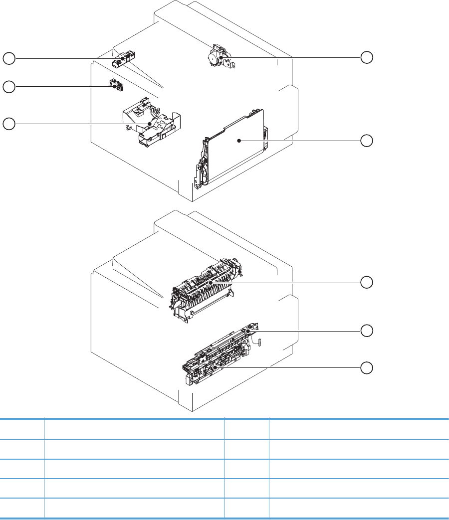
Figure 3-59 Major component locations (2 of 4)
1
2
3
4
5
6
7
8
Item Description Item Description
1 Duplex-drive assembly 5 Tray-pickup assembly
2 MP tray assembly 6 Cartridge fan
3 Delivery assembly 7 Residual toner full sensor
4 RD sensor assembly 8 Residual-toner-feed motor
ENWW Tools for troubleshooting 439
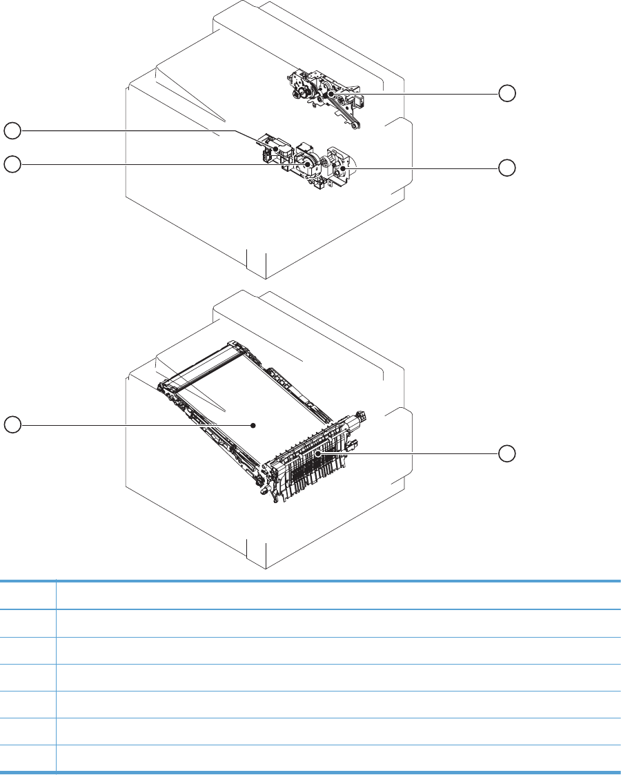
Figure 3-60 Major component locations (3 of 4)
1
2
3
4
5
6
Item Description
1 Fuser-drive assembly
2 Tray-pickup drive assembly
3 Secondary transfer assembly
4ITB
5 Lifter-drive assembly
6 Lifter base assembly
440 Chapter 3 Solve problems ENWW

Figure 3-61 Major component locations (4 of 4)
1
2
3
7
4
5
6
8
9
item Description
1Exhaust fan
2 ICB assembly
3 Sub power supply assembly
4 Power supply fan
5 Rear right frame
6 Delivery assembly
ENWW Tools for troubleshooting 441
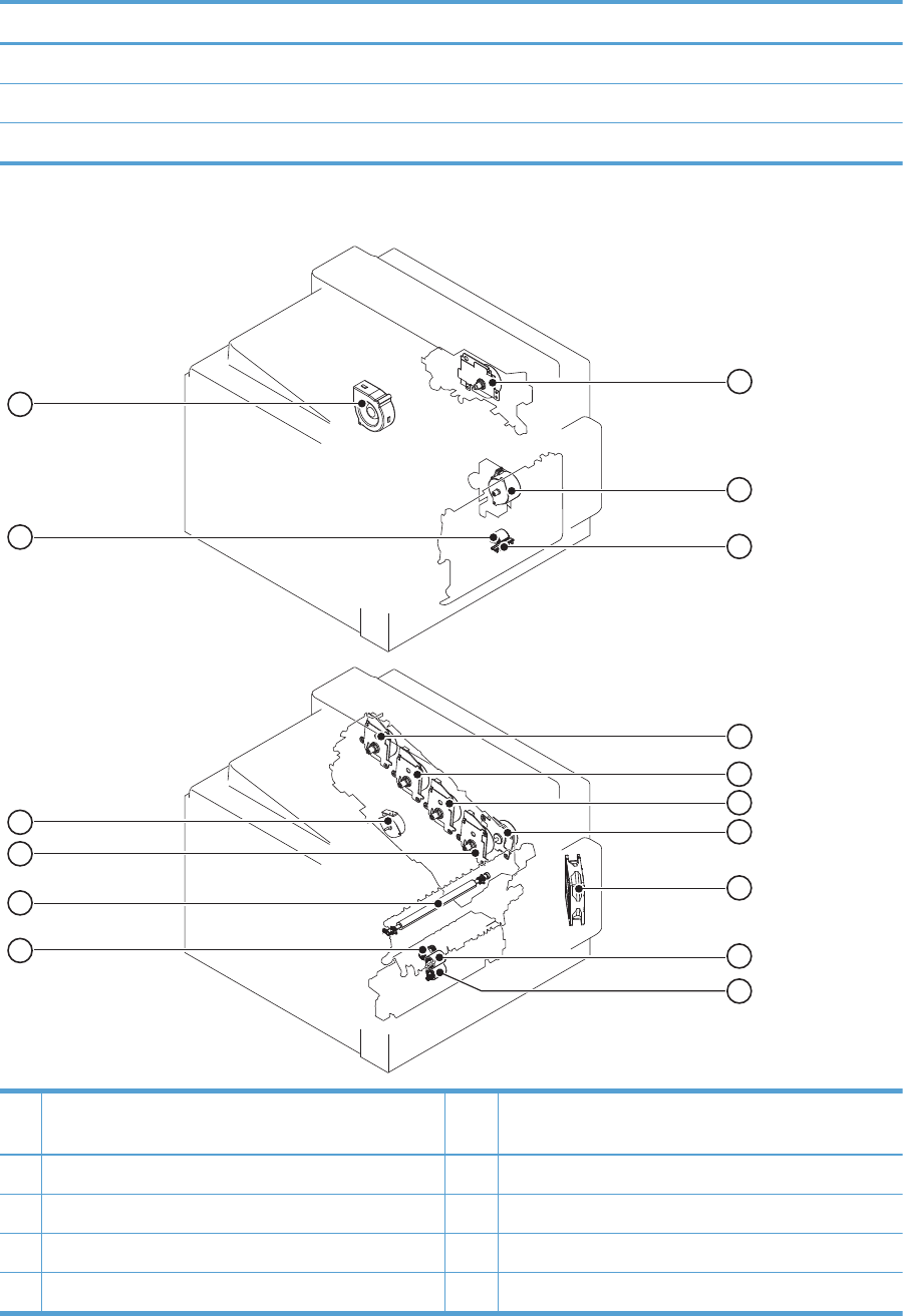
item Description
7 Left rear frame
8 Low voltage assembly
9 IPTU
Figure 3-62 Motors, fans, and rollers component locations
1
2
3
4
5
6
7
8
9
10
11
12
16
13
14
15
Ite
m
Description Ite
m
Description
1 Fuser motor 9 Tray 2 feed roller
2 Pickup motor 10 Tray 2 separation roller
3 Tray 1 separation pad 11 Tray 2 pickup roller
4 Yellow drum motor 12 Secondary transfer roller
442 Chapter 3 Solve problems ENWW
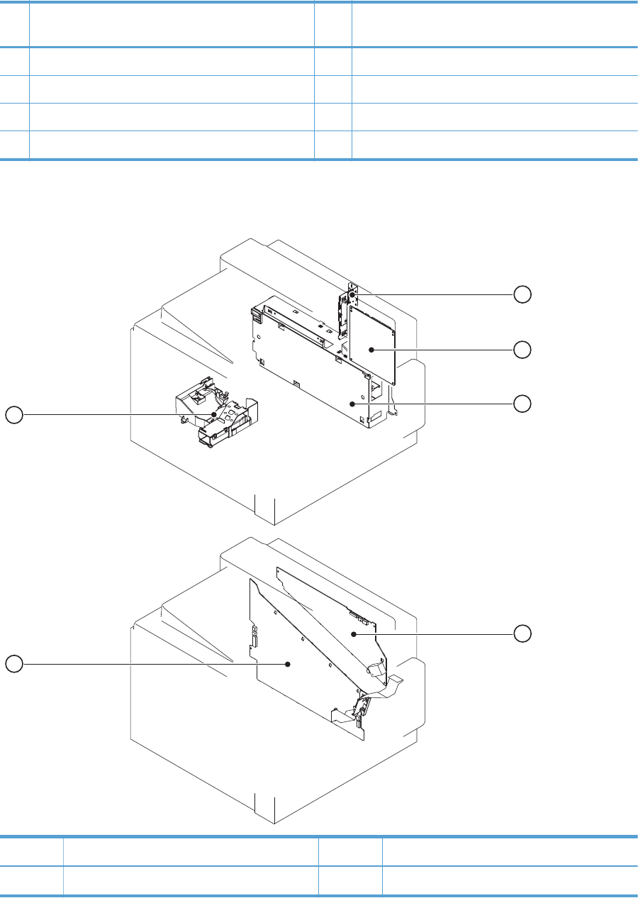
Ite
m
Description Ite
m
Description
5 Magenta drum motor 13 Black drum motor
6 Cyan drum motor 14 Developing-disengagement motor
7 ITB motor 15 Tray 1 pickup roller
8 Power supply fan 16 Exhaust fan
Figure 3-63 PCA component locations
1
2
3
4
5
6
Item Description Item Description
1 Interconnect board (ICB) 4 High-voltage power supply upper (HVPS-T)
ENWW Tools for troubleshooting 443
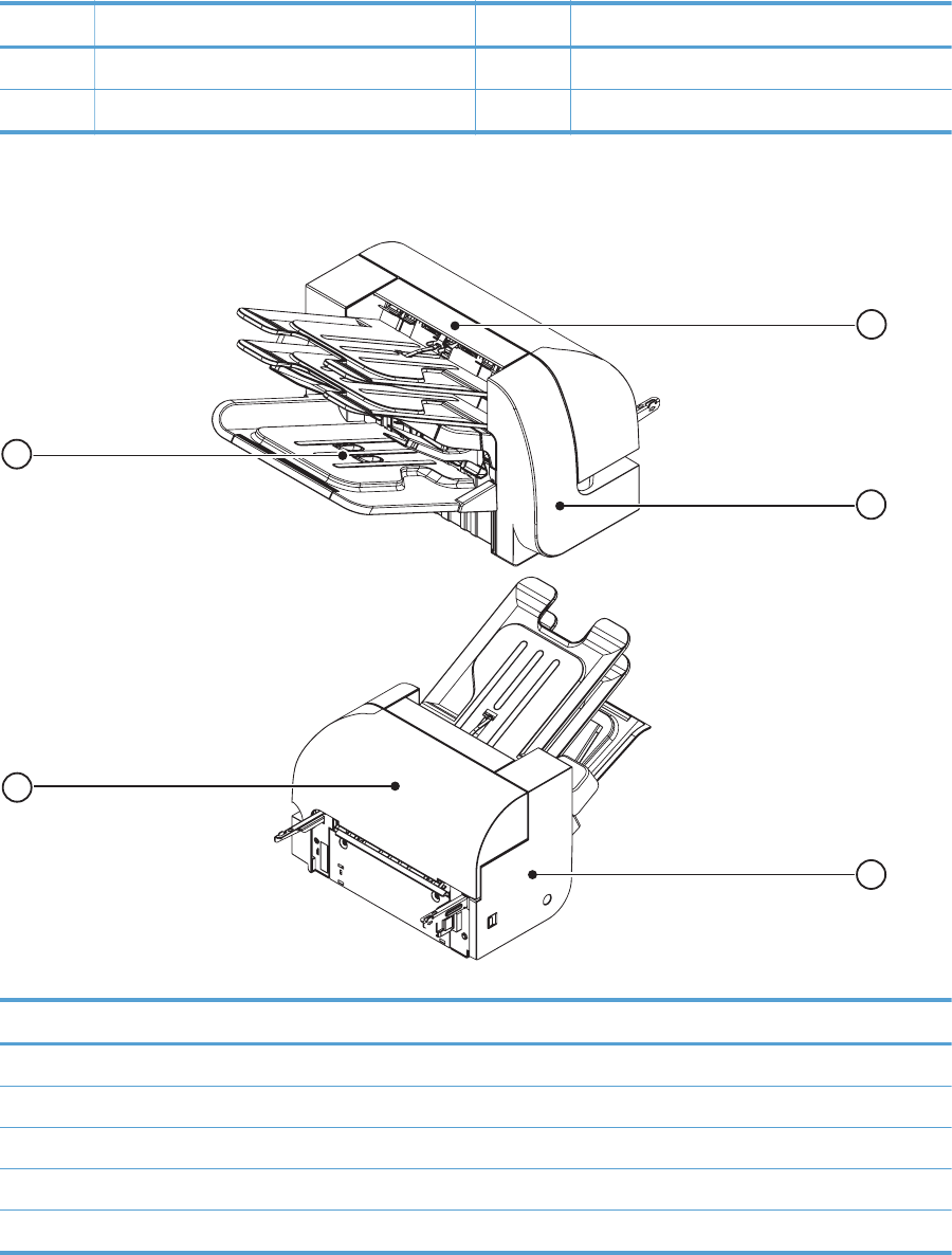
Item Description Item Description
2 DC controller PCA 5 High-voltage power supply lower (HVPS-D)
3 Low-voltage power supply 6 Environment sensor PCA
Figure 3-64 Stapler/stacker component locations (1 of 3)
1
2
3
5
4
item Description
1Top cover
2Front cover
3Rear cover
4 Stapler/stacker door
5 Output bin 3
444 Chapter 3 Solve problems ENWW
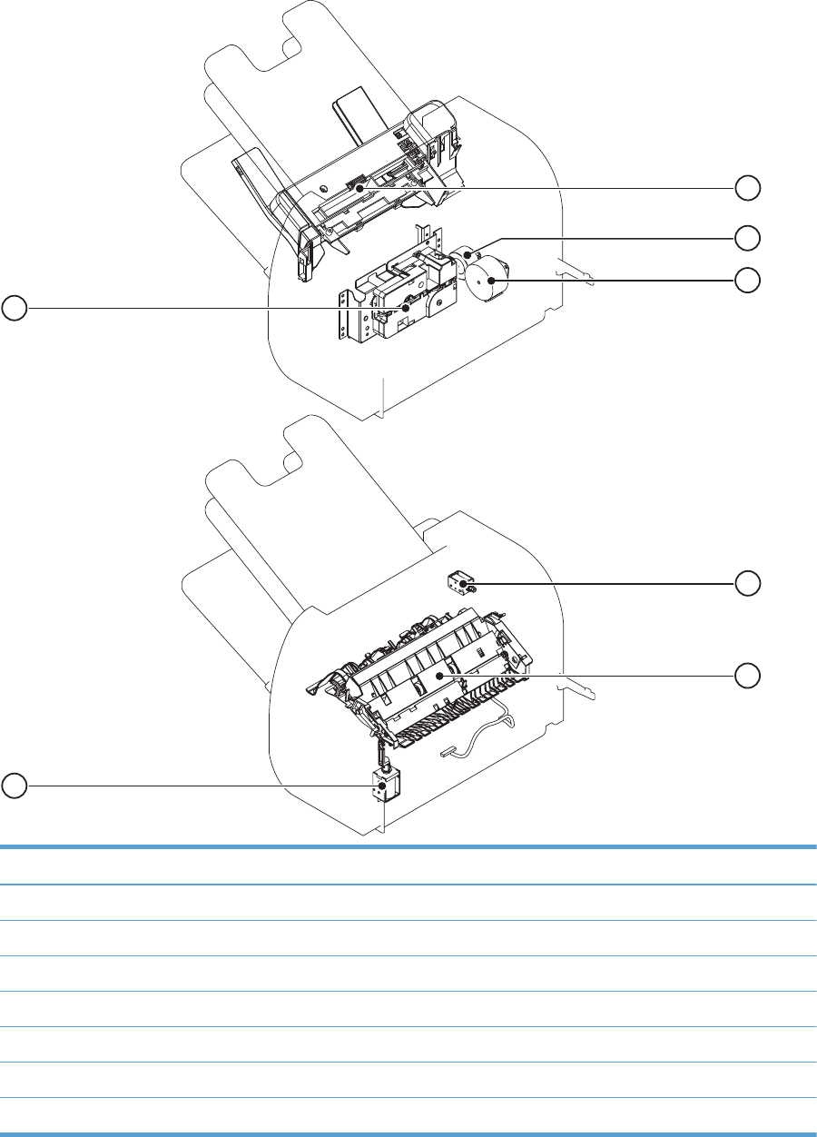
Figure 3-65 Stapler/stacker component locations (2 of 3)
1
2
3
6
4
5
7
item Description
1 Jogger assembly
2 Paddle motor
3 Stapler/stacker feed motor
4 Output bin solenoid
5 Stage top unit
6Inlet solenoid
7 Output bin 3 driver assembly
ENWW Tools for troubleshooting 445
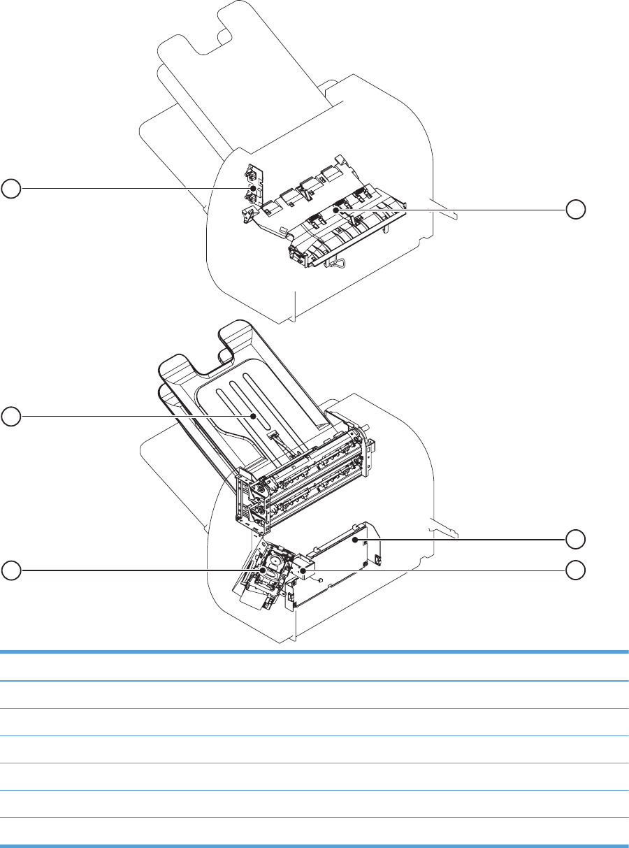
Figure 3-66 Stapler/stacker component locations (3 of 3)
1
2
3
6
4
5
item Description
1 Stage assembly
2 Stapler/stacker PCA
3Stamp solenoid
4 Stapler assembly
5 Output bin
6 Output bin sensor
446 Chapter 3 Solve problems ENWW
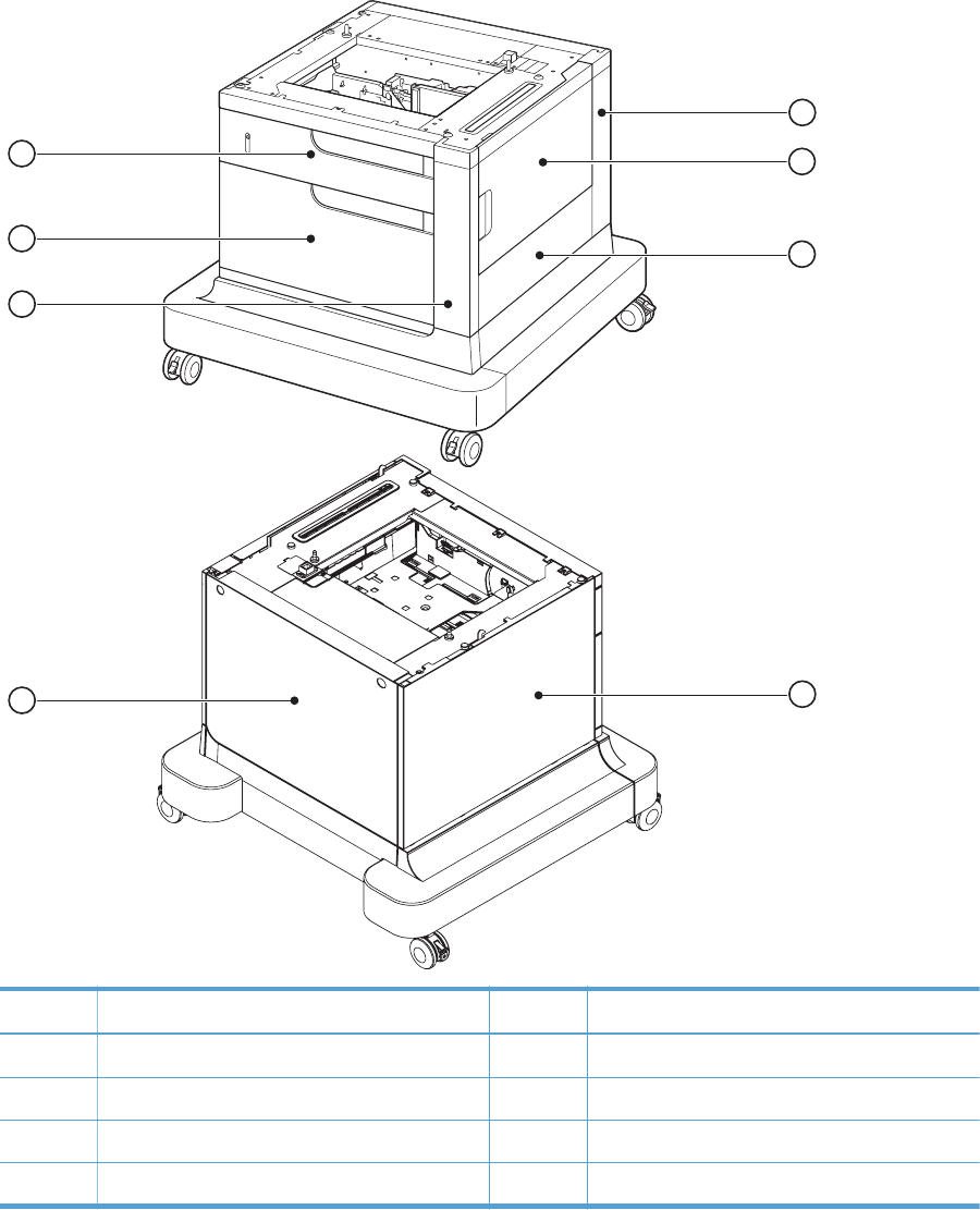
Figure 3-67 Optional paper feeder (1 x 500-sheet) component locations (1 of 2)
1
2
3
5
6
8
4
7
Item Description Item Description
1 Rear-right cover 5 Rear cover
2 Right door 6 Right front cover
3 Right cover 7 Front door
4Left cover 8Tray 3
ENWW Tools for troubleshooting 447
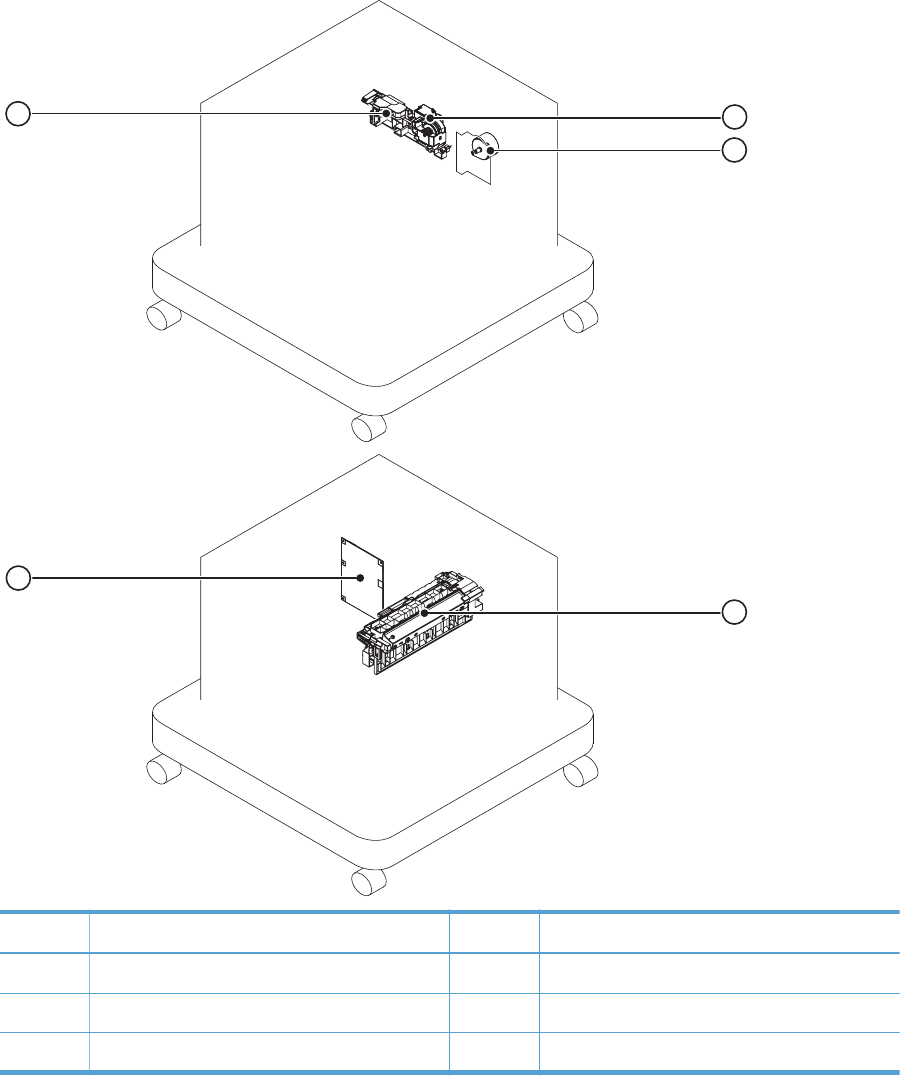
Figure 3-68 Optional paper feeder (1 x 500-sheet) component locations (2 of 2)
1
2
3
5
4
Item Description Item Description
1 Lifter-drive assembly 4 Controller PCA
2 Pickup motor 5 Lifter base assembly
3 Pickup assembly
448 Chapter 3 Solve problems ENWW
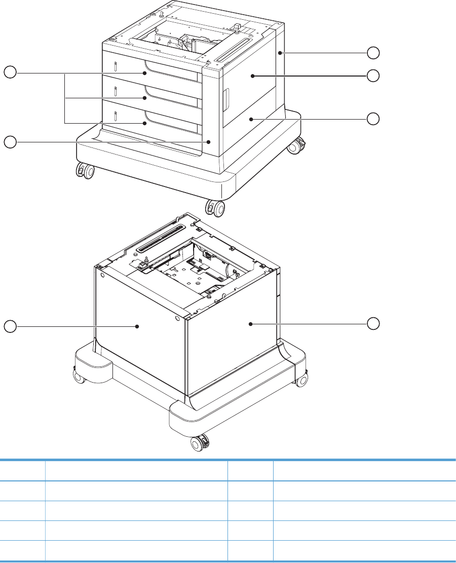
Figure 3-69 Optional paper feeder (3 x 500-sheet) component locations (1 of 2)
1
2
3
5
6
4
7
Item Description Item Description
1 Rear right cover 5 Rear cover
2 Right door 6 Right front cover
3 Right cover 7 Trays 3, 4, and 5
4Left cover
ENWW Tools for troubleshooting 449
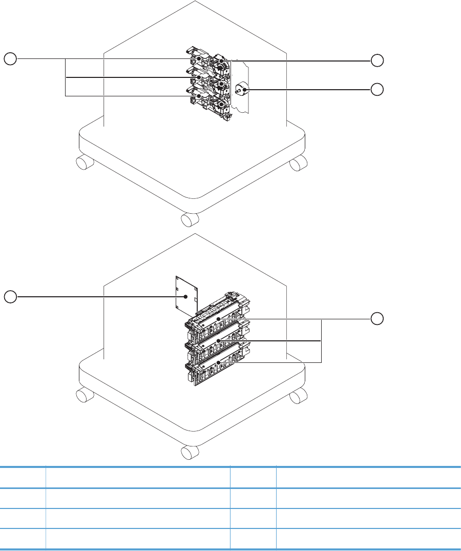
Figure 3-70 Optional paper feeder (3 x 500-sheet) component locations (2 of 2)
1
2
3
5
4
Item Description Item Description
1 Lifter-drive assembly (Trays 3, 4, and 5) 4 Controller PCA
2 Pickup motor 5 Lifter base assembly (Trays 3, 4, and 5)
3 Pickup assembly (Trays 3, 4, and 5)
450 Chapter 3 Solve problems ENWW

General timing chart
Figure 3-71 General timing chart
STBY STBY
Operation PRINTINTR LSTR
1Cassette pickup solenoid
2TOP sensor
3Fixing delivery sensor
Print command
9 C drum motor
10 K drum motor
Y drum motor7
5Scanner motor
8 M drum motor
6TOP signal
4Fixing motor
11 ITB motor
13 Primary charging bias Y
16 Primary charging bias K
14 Primary charging bias M
Primary charging bias C
12 Pickup motor
17 Developing bias Y
15
Developing bias M
19 Developing bias C
Primary transfer bias C
24 Primary transfer bias K
21
22 Primary transfer bias M
20 Developing bias K
18
25 Secondary transfer bias
23
Primary transfer bias Y
ENWW Tools for troubleshooting 451
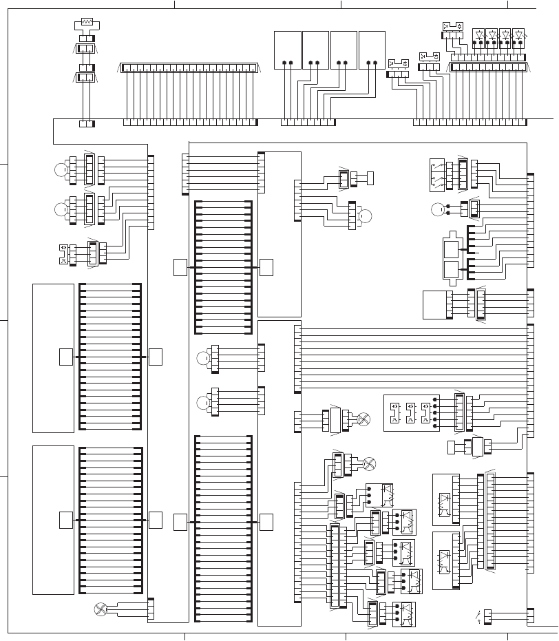
Circuit diagrams
Figure 3-72 General circuit diagram (1 of 2)
64
5
TAG (Bk) TAG (C) TAG (M) TAG (Y)
SL
SL
23
M
M
MM
29
29
21
21
M
23 23
23
M
A4 B5
+5VB
+5VB
SGND
+3.3V
DUP_SL
+5V
+5V
+5V
+5V
RD-SNS
1TR1S
1TR2S
HVTCLK
2TRS
2TRCNT
DUPSL
DEVHP
SGND
3.3VS
PGND
24VA
PGND
24VA
/VDO12O
LD1CTRL2
LD1CTRL1
LD1CTRL0
LD2CTRL2
LD2CTRL1
LD2CTRL0
LD3CTRL2
LD3CTRL1
LD3CTRL0
LD4CTRL2
LD4CTRL1
LD4CTRL0
LD4PDOUT
LD3PDOUT
24VB
VSS4
VIN
PGND
PGND
3.3V
I2CSD A
SGND
FAN1PWM
FAN1LK
PGND
24VB
24VB
PGND
SGND
SGND
SGND
/VDO2 2
VDO22
VDO21
SGND
SGND
/VDO42
VDO42
SGND
24VA
24VA
PGND
PGND
DUPMPHA
DUPMI0A
DUPMI1A
DUPMPHB
DUPMI0B
DUPMI1B
ENV-SNS
VIN
VSS3
VSS1
VSS2
VIN
CSTSL
24VB
GND
+24V
GND
RT4_S
GND
RT3_S
GND
RT2_S
GND
RT1_S
CSTSIZE1
LD1PDOUT
LD2PDOUT
L_LOW_PWR
DEVMI0A
FAN2LK
DEVMI0B
FEEDMI0B
FEEDMPHB
FEEDMI1B
FEEDMIDWN
FEEDMI1A
FEEDMI0A
FEEDMPHA
WTSSNS
TONLED
/HVRESET
HVDALD
HVDACLK
HVTCLK
HVTDATA1
DSRSR
DSRDR
3.3VS
SGND
3.3VS
SGND
3.3VS
SGND
OPT_EX Z
+24V A
GND
CAN_H
CAN_L
GND
JLPWRON
GND
+24V A
+24V A
+24V A
+24V A
GND
GND
GND
IPTUCLK
I2CSCK
CSTSIZE0
GND
FAN2LK
SGND
/SCN1ACC
/SCN1DEC
/SCN2ACC
/SCN2DEC
DUPM_A
DUPM_/A
DUPM_B
DUPM_/B
+24V
+5V
+24VB
DEVMOUT0B
FEEDMOUT0A
FEEDMOUT1A
FEEDMOUT1B
FEEDMOUT0B
HVDATA 2
PREEXP4
PREEXP3
PREEXP2
PREEXP1
RD-SNS
+3.3V
DEVMPHB
DEVMPHA
24VB
PGND
2TRCLK
1TR3S
1TR4S
DSFSR
DSFDR
RDSFLED
SGND
+5VB
+5VB
RDSRLED
VIN
RDSRGAIN1
SGND
SGND
FAN5LK
RDSFGAIN1
RDSFGAIN0
+5VB
+5VB
5VB
5VC
5VC
VDO31
/VDO31
VDO32
/VDO32
5VC
5VC
FPRESS
PAPFULL
TONER EM P
TCU FULL SNS
RDSRGAIN0
TO IPTU & SS
PGND
+24VA
SGND
3.3V
INPOPIN
INPOPOT
LUON
+24VB
CSTSIZE2
SGND
INPOPTMG
INPOPCLK
/BD21
VDO12O
VDO11O
/VDO11O
/VDO41
VDO41
L_LOW_PWR
/BD41
/VDO21
DUPMIDWN
3.3VS
5VB
CSTPEND
CSTPS2
CSTPS1
PSNS_PCB
FAN2PWM
ITBHPSNS
IPTUSTS
/HVRESET2
HVDALD2
HVDACLK2
RTS1SNS
RTS2SNS
RTS3SNS
RTS4SNS
/2TRNCNT
/DEV2CNT
/DEV3CNT
/DEV4CNT
/DEV1CNT
SGND
RDOORSNS
DEVMOUT1B
DEVMOUT1A
DEVMOUT0A
FAN5LK
WTSSNS
WTSLEDD
IPTUCMD
SCN_TH
GND
14 13 12 11 10 9 8 2345617
J83L
J83DH
7165432891011121314
J83D
15 14 13 12 11 10 9 8 2345617
J130
21
J81D
12
TH4
J81DH
21
J81L
12
J82D
12
J103
J79H
123
J79D
123
J264
54321
J58D
321
J79L
J59H
10 9 8 2345617
J251
321
J46
11 10 9 8 2345617
J60L
J85DH
12345678
J511
1234567
J510
123
FM4
4321
J72D
J72LH
J87LH
SW4
J56DH
7165432891011121314
J107
J55DB
J55D
J55DA
M7
17 16 15 14 13 12 11 10 9 8 2345617
J128
7165432891011
J60D
J60DH
12
J147
321
J42
123
J87L
12345678
J126
J2DH
J1DH
321
J1D
12 11 10 9 8 234576
J68L
123
J2D
J3DH
123
J4D
J4DH
321
J3L
LED5
LED6
LED7
LED8
123
J4L
123
J66L
J57LH
12
J56D
4321
J34
1234
J57L
321
J3D
J65DH
J67DH
4321
J67L
1234
J67D
1234
J108
4321
J36
J110
J501J503
1234
J39
21
J43
J68DH
M13
4321
J37
123456
J202
12
J69D
J69DH
12 11 10 2345617
J68D
J200
J116
14
J250
J114
J58LH
17 16 15 14 13 12 11 10 9 8 2345617
J115
12345
J58L
678214359101112131415161718
J263
4321
J57D
654321
J201
SR9
SR6
321
J47
123
J19
321
J2L
321
J1L
123
FM2
SR7
J71LH
4321
J71L
SR11
123
J87D
197165432 8 9 101112131415161718 20
J85D
20 18 17 16 15 14 13 12 11 10 9 8 234561719
J106
J66DH
321
J66D
21
J56L
321
J65L
123
J65D
1234
J71D
1234
J72L
4321
J41
M9
M8
1234
J40
M11
12
J69L
M10
4321
J38
12
J59L
21
J59D
1
1234
J260
1234
J261
321
FM1
29
1
2
1
123456
J113
17
SR23
SR25
J111
11 10 9 8 2345617
J112
SR24
21
SL4
4
2
3
5
6
7
8
9
10
11
12
13
14
15
16
17
18
19
20
21 21
20
19
18
17
16
15
14
13
12
11
10
9
8
7
6
5
3
2
1
4
4
1
2
3
5
6
7
8
9
10
11
12
13
14
15
16
17
18
19
20
21
22
23
4
1
2
3
5
6
7
8
9
10
11
12
13
14
15
16
17
18
19
20
21
22
23
4
1
2
3
5
6
7
8
9
10
11
12
13
14
15
16
18
19
20
21
22
23
4
1
2
3
5
6
7
8
9
10
11
12
13
14
15
16
17
18
19
20
21
22
23
4
1
2
3
5
6
7
8
9
10
11
12
13
15
16
17
18
19
20
21
22
23
24
25
26
27
28
29
28
27
26
25
24
23
22
21
20
19
18
17
16
15
14
13
12
11
10
9
8
7
6
5
3
4
123
J153
21
SL2
3
2
1
4
5
3
2
4
1
2
SW6
12
J82L
J82DH
DC Controller PCA
Laser Scanner Unit (Y/M)
Laser Scanner Unit (C/Bk)
HVT-T
HVT-D
1
452 Chapter 3 Solve problems ENWW
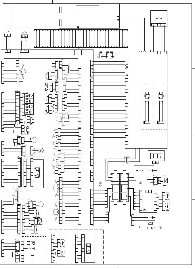
Figure 3-73 General circuit diagram (2 of 2)
A
332
B
C
D
MM
TP
M
35
CL
B7 A5
B7A5
SL
M
M
M
M
SL
MEDIA-SNS
HEATER1
NL
+5VB
+5VB
+5VB
+5VB
+24VB
SGND
PGND
+24VA
LED_ON
PREEXP1
MEDIA-SNS
PREEXP4
PREEXP3
PREEXP2
PGND
PGND
+24VA
+24VA
+24VA
+24VA
PGND
PGND
+24VA
+24VA
PGND
PGND
+24VB
+24VB
PGND
PGND
3.3VS
SGND
3.3VS
SGND
DRMHP3
DRMHP1
MPTSL
SGND
3.3VS
FSRSNS
SGND
FSRTH1
FSRTH2
SGND
3.3VS
3.3VS
PGND
/VD021
VD021
/VD022
VD022
/VDO41
VDO41
/VDO42
VDO42
/VDO31
VDO31
/VDO32
VDO32
CLEO
24VB
FSRSAFE2
FSRSAFE1
24RMT
TO P I
3.3VS
SGND
DRMHP4
N.C.
MD0
MD2
P80
P81
+3.3V
IOTR
SGND
IOTT
/FSRNEW
+12V
PGND
+24VB
PGND
PWRSWON
PWRON
GND
+12V
/BD3O
/BD4O
/BD2O
/BD1O
CAN_H
CAN_L
JLPWRON
SGND
AWAKE
SGND
/TOPO
/VCRST
SGND
VDO12I
VDO11I
ENGON
SGND
CLEI
/VDOEN
/VDO12I
/VDO11I
/FSMACC
/FSMDEC
/FSMFG
FSMFR
+24VB +24VA
+24VA
PGND
3.3VS
24VB
SGND
SW_LED
/BMFG
/BMDEC
/BMACC
24VB
3.3V
NPTRLED
REFEEDS
SGND
3.3VS
MPTPEND
SGND
FSLP2
FSLP1
FSRTH3
SGND
SGND
FDOORSNS
SGND
PGND
3.3VS
SGND
ITBLKSNS
CHK24V
/FSRMSTOP
INL_CURRMS
PWROFF
FSR_CURRMS
/RLD
ZEROX
FSRD1
SGND
PWRSWON
3.3VF
3.3VF
SGND
SGND
PFCRMT
PSTYP100
FAN3LK
FAN3PWM
5VB
5VC
5VB
5VB
+24VA
+24VA
PGND
PGND
/DRM3ACC
/DRM3DEC
/DRM3FG
DRMHP2
SGND
1TRSL
+24VB
SGND
NPLED
POUTSNS
100V 200V
/DRM2FG
/DRM2DEC
/DRM2ACC
DRMFR
/DRM1FG
/DRM1DEC
/DRM1ACC
DRMFR
N.C.
DRMFR
/DRM4FG
/DRM4DEC
/DRM4ACC
DRMKFR
LN
TCK
HEATERC
ACLACH
NPLED
3.3VS
RMCL
WTMSNS
NPSL_DATA
NPSL_EN
NPLED
NPSTART
/NPRST
5VA
NPSD_OUT
NPSD_RD
SGND
NPCLK
PGND
CHK24V
SR8
SL3
J52DH
12
J52D
J74DH
10 9 8 2345617
J74D
J77DH
1234
J64D
J64DH
10 9 8 2345617
J77D
14 13 12 11 10 9 8 2345617
J127
M4
J63DH
21
J63D
123
J48
J62DH
SR10
SR5
21
J63L
321
CT-3J62L
123
FM3
321
CT-3J62D
12345
J155
CT-5
65432187910
J74LS
71654328910
J27S
6543217910
J77LS
654321
J92D
21
TH3
M1
12345
J14
21
J20S
123
J23S
21
J604
3
1
2
IL101
2
1
3
IL201
LED 1
7165432891011
J78L
321
J44
123456
J603
21
SW3
19 7 1654328910111213141516171820
J601
TB401
21
SW2
21
J61M
21
J61F
21
FT1
12
J129
M12
12 11 10 9 8 2345617
J145
123456
J148
71654328910
J131
J53DH
123
J94D
SR4
J78DH
11 10 9 8 2345617
J78D
321
J31
321
J93D
J92LH
19 7 16543289101112131415161718
J140
J54DH
12
J54D
87654321
J123
12345678
J13
17 16 15 14 13 12 11 10 9 8 2345617
J121
87654321
J18
16 15 14 13 12 11 10 9 8 2345617
J120
M3
87654321
J15
12345678
J17
12345678
J16
321
J75D
123456
J92L
321
J93L
J93LH J94LH
123
J94L
J75DH
21
J52L
321
J28
SR1
123
J29
12
SL1
SR3
TB1TB2
123
J75L
12
SW1
21
FT2
SR22
321
J21
71654328910
J74L
21
J351
12
J51D
21
J25M
21
J25F
SOLD30
SOLD31
21
SW5
12
J45
4321
J607
1234
J161
J50LA
J50LB
4123
J50L
J50DA
J50DB
216543
J151
20 18 17 16 15 14 13 12 11 10 9 8 234561719
J150
21
J20
SR20
123
J23
CL1
54321
J84
J105
21
H1
12345
J160
1234567
J162
21
J54L
P1
7
1234567
J350
1234
J101
12345
J102
123
J22
P2 Control
Panel USB
J3 Scanner
26PIN
Formatter A1
21
231
J152
21
J53D
71654328910
J27
71654328910
J77L
35
34
33
32
31
30
29
28
27
26
25
24
23
22
21
20
19
18
17
16
15
14
13
12
11
10
9
8
7
6
5
4
3
2
35
34
33
4123
J50D
21
J51L
12
J53L
M2
21
J12
12
TP1
J51DH
J11
123456
J352
J10
SR15
SR14
21
TH2
12
TH1
TB201
TB202
TB501
TB502
21
FU1
SR2
1
LED 2
LED 3
LED 4
4
1
2
3
5
6
7
8
9
10
11
12
13
14
15
16
17
18
19
20
21
22
23
24
25
26
27
28
29
30
31
32
4
1
2
3
5
6
7
5
3
2
1
4
6
5
3
2
4
4
1
2
3
5
1
123
J32
M6
M5
TB402
TB403
TB404
TB405
TB406
12
J604A
SR20
321 321
Power Supply Unit
Inter Connect Board Power SW
Control
Panel
Registration Unit
(Duplex model)
Registration Unit (Simplex model)
J2
1
ENWW Tools for troubleshooting 453

Figure 3-74 Paper feeder circuit diagram (1 X 500-sheet)
A
65 4 3 21
B
C
D
SL
M
M
B5 A4
DCC I/F
GND
T3_PSNS
T3_PLVL_P
T3_PLVL_A
GND
T3_PATHS
+24V
T3_PICK_SL
HRD_TMG
+3.3V
GND
+24V
GND
CLK
STS
CMD
GND
T3_SIZE2
T3_SIZE1
T3_SIZE3
T3_LIFT_MTR
+24V
AOUT1
AOUT2
BOUT2
BOUT1
+3.3U
+3.3U
J11LH
12345
J11L
J18LH
1234
J17D
J17LH
J10LA
J10L
J10LB
12345678
J410
5
J15DH
12
J15D
54321
J11D
123
J13D
1234
J409
1234567
J407
21
J18D
12
J18L
SR4
4321
J17L
J13LH
12345678
J401
10982345617
J408
321
J12
SR1 SR3
4321
J16
21
J15L
SW2
M2
4321
J14
M1
12
SL1
SR2
321
J13L
4
1
2
3
4
1
2
3
1x500 PD Controller PCA
454 Chapter 3 Solve problems ENWW
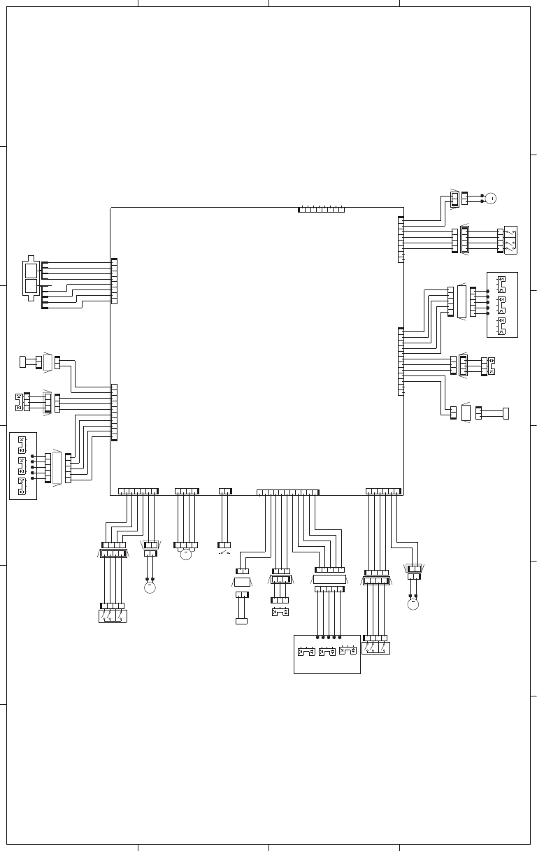
Figure 3-75 Paper feeder circuit diagram (3 X 500-sheet)
A
65 4 3 2 1
B
C
D
SL
M
M
M
SL
A4B5
M
SL
J24DH
DCC I/F
+24V
GND
GND
GND
T3_PSNS
T3_PLVL_P
T3_PLVL_A
GND
T3_PATHS
+24V
T3_PICK_SL
J150DH
T3_SIZE1
T3_SIZE2
GND
T3_SIZE3
+24V
T3_LIFT_MTR
AOUT2
BOUT1
BOUT2
AOUT1
J19
T4_PICK_SL
+24V
T4_PATHS
GND
T4_PLVL_A
T4_PLVL_P
T4_PSNS
GND
T4_SIZE1
T4_SIZE2
GND
T4_SIZE3
T4_LIFT_MTR
+24V
GND
T5_PSNS
T5_PLVL_P
T5_PLVL_A
GND
T5_PATHS
T5_PICK_SL
+24V
+24V
T5_LIFT_MTR
T5_SIZE3
GND
T5_SIZE2
T5_SIZE1
CMD
STS
CLK
HRD_TMG
+3.3V
+3.3U
+3.3U
+3.3U
+3.3U
+3.3U
+3.3U
J25LH
J17LH
+3.3V
DOPEN
J11LH
J31LH
12345
J31L
J21LH
SR8
SR3
J18LH
J13LH
4321
J17L
J20LH
J30LH
J35LH
4321
J35L
21
J34L
12345678
J402
54321
J21L
1110982345617
J406
J22LH
321
J22D
123
J22L
123
J23
SR7
12
J20D
21
J20L
21
SL2
12345
J21D
4321
J14
12
M1
12
J24L
21
J24D
4321
J36
4321
J25D
1234
J25L
12
J30L
J10LB
J10L
12345678
J410
J10LA
10982345617
J408
5
4
21
J404
1234
J17D
12
J18L
1234
J35D
54321
J11D
1
21
J15L
12
J15D
21
J30D
21
J18D
123
J13D
J34DH
12
J34D
54321
J31D
123
J32D
SW1
123456
J405
321
J33
J32LH
321
J32L
12 11 10 9 8 2345617
J403
SR9
12
SL1
1234567
J407
12345678
J401
12345
J11L
321
J12
SR1
4321
J16
SW2
M2
1234
J409
SR4
SR2
321
J13L
M3
SW3
1234
J26
M4
SW4
SR6
SR5
12
SL3
SR12
SR11
SR10
4
1
2
3
2
3
3x500 PD Controller PCA
ENWW Tools for troubleshooting 455
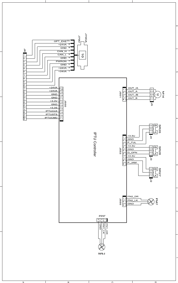
Figure 3-76 IPTU circuit diagram
PCA
456 Chapter 3 Solve problems ENWW
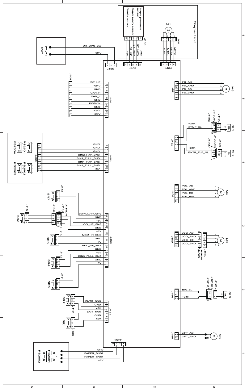
Figure 3-77 Stapler/stacker circuit diagram
Stapler/stacker Controller PCA
ENWW Tools for troubleshooting 457

Internal print-quality test pages
Print-quality-troubleshooting pages
Use the built-in print-quality-troubleshooting pages to help diagnose and solve print-quality problems.
1. Scroll to and touch the Administration button.
2. Scroll to and touch the Troubleshooting button.
3. Touch the Print Quality Pages button.
4. Touch the Print PQ Troubleshooting Pages button.
5. Touch the Print button.
The product returns to the Ready state after printing the print-quality-troubleshooting pages. Follow the
instructions on the pages that print out.
Figure 3-78 Print-quality troubleshooting procedure
HP Color LaserJet CM4540 MFP
Print Quality Troubleshooting
Page 1
458 Chapter 3 Solve problems ENWW
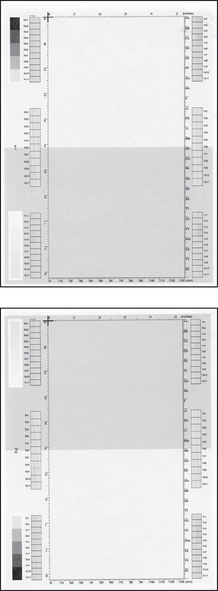
Figure 3-79 Yellow print-quality troubleshooting page
Yellow
Green
Figure 3-80 Yellow comparison page
Green
Yellow
Yellow cannot be easily seen unless combined with cyan, so half of each page is yellow and the other
half is an amplified version of yellow problems (green half). Compare the yellow on page one with the
corresponding green on page two for defects. You can also check the cyan page for defects.
ENWW Tools for troubleshooting 459
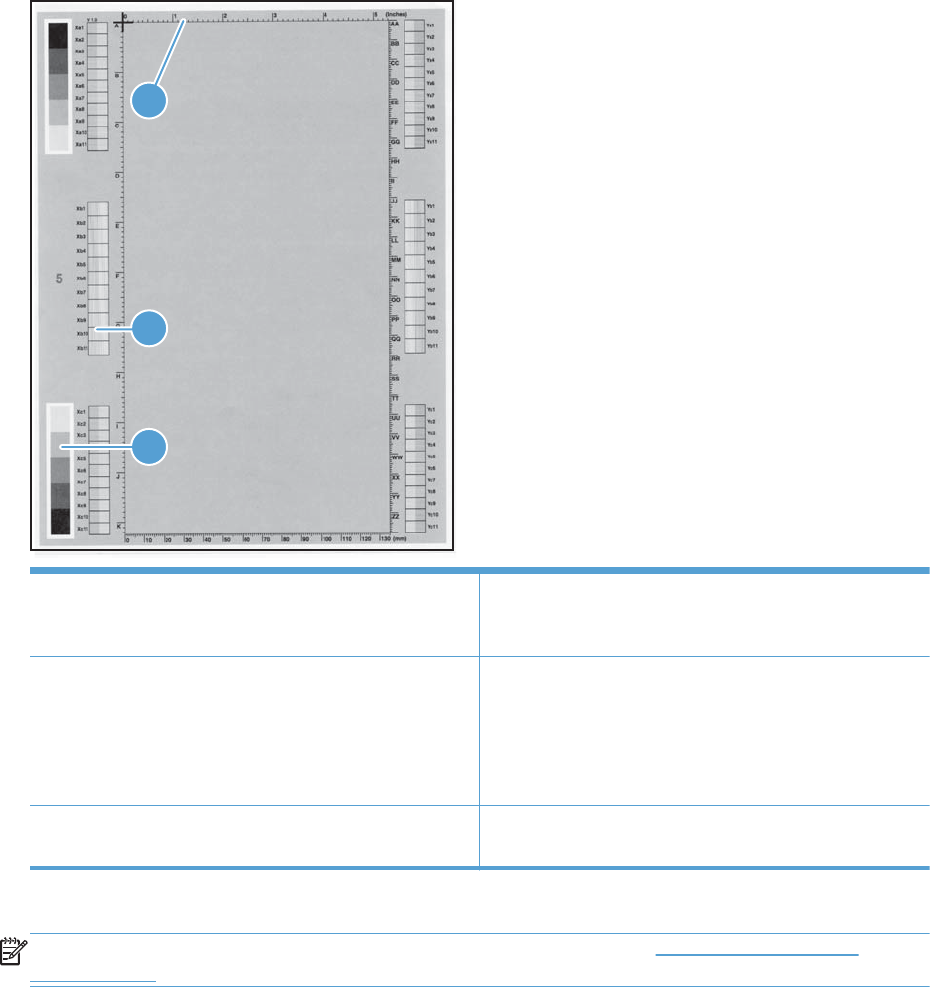
Figure 3-81 Black print-quality troubleshooting page
1
3
2
1. Grids The grids are in inches and millimeters. They are label with
letters and numbers so that defects can be described by
position and by distance between repeats.
2. Color plane registration (CPR) bars After printing, the box with no extra color in each area on
each page shows how far off the CPR of that color is. Each
page has two process direction areas and three scan
direction areas that are labeled x and y and 1–11. The page
should be fed by the long edge. Each square from the center
equals 42 microns.
3. Color ramp patches Used to detect offset for the OPC or developer in the image
drum or offset in the fuser.
NOTE: To get further assistance in print quality troubleshooting, go to www.hp.com/support/
cljcm4540mfp and select PQ Troubleshooting Tools.
460 Chapter 3 Solve problems ENWW
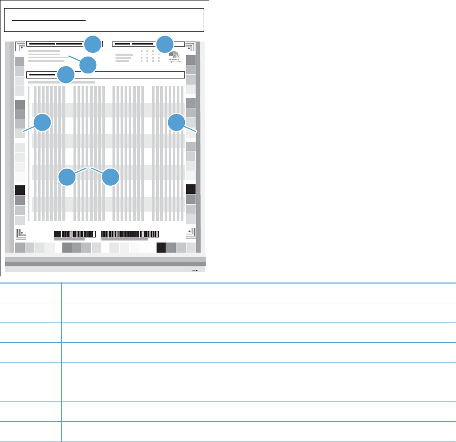
Diagnostics page
Use the diagnostics page to evaluate problems with color plane registration, EP parameters, and print
quality.
1. Scroll to and touch the Administration button.
2. Scroll to and touch the Troubleshooting button.
3. Touch the Print Quality Pages button.
4. Touch the Diagnostics Page button.
5. Touch the Print button.
DD MMM YYYY XX:XX
HP Color LaserJet CM4540 MFP
Diagnostics Page Page 1
1 3
24
5 6
87
1Calibration information
2Parameters
3Color density
4Color plane registration
5Primary colors
6Secondary colors
7Temperature values (22M)
8Humidity values (22N)
ENWW Tools for troubleshooting 461

Cleaning page
Use the cleaning page to remove paper dust and toner that accumulates on the pressure roller or heat
sleeve.
Create and use the cleaning page
1. Scroll to and touch the Administration button.
2. Scroll to and touch the Calibrate/Cleaning button.
3. Touch the Process Cleaning Page button.
Configuration pages
Depending on the model, up to three pages print. In addition to the main configuration page, an
embedded Jetdirect configuration page prints.
Configuration page
Use the configuration page to view current product settings, to help troubleshoot product problems, or
to verify installation of optional accessories, such as memory (DIMMs), paper trays, and printer
languages.
1. Scroll to and touch the Administration button.
2. Open the following menus:
●Reports
●Configuration/Status Pages
●Configuration Page
3. Touch the Print button to print the report, or touch the View button to view the report on the screen.
The report consists of several pages.
NOTE: The product IP address or host name is listed on the Jetdirect Page.
NOTE: If the product is configured with EIO cards (for example, an HP Jetdirect Print Server) or an
optional hard-disk drive, an additional configuration page will print that provides information about
those devices.
462 Chapter 3 Solve problems ENWW
Figure 3-82 Configuration page
HP Color LaserJet CM4540 MFP
Configuration Page
Page 1
2
3
14
5
6
7
8
1Printer information
2Installed personalities and options
3Color density
4Calibration information
5Memory
6Event log
7Security
NOTE: The support key is intended for factory use only.
8Paper trays and options
ENWW Tools for troubleshooting 463

HP embedded Jetdirect page
The second configuration page is the HP embedded Jetdirect page, which contains the following
information:
Figure 3-83 HP embedded Jetdirect page
HP Color LaserJet CM4540 MFP
Jetdirect Page
Page 1
2
3
14
5
6
1HP Jetdirect Configuration indicates the product status, model number, hardware firmware version, port select, port
configuration, auto negotiation, manufacturing identification, and manufactured date.
2Security Settings information
3Network Statistics indicates the total packets received, unicast packets received, bad packets received, framing
errors received, total packets transmitted, unsendable packets, transmit collisions, and transmit late collisions.
4TCP/IP information, including the IP address
5IPv4 information
6IPv6 information
Always make sure the status line under the HP Jetdirect configuration lines indicates "I/O Card Ready".
464 Chapter 3 Solve problems ENWW
Embedded protocol page
The embedded protocol page contains the following information:
Figure 3-84 Embedded protocol page
HP Color LaserJet CM4540 MFP
Embedded Protocol Page
Page 1
2
1
4
3
1 IPX/SPX
2 Novell/NetWare
3 AppleTalk
4DLC/LLC
ENWW Tools for troubleshooting 465

Finding important information on the configuration pages
Certain information, such as the firmware date codes, the IP address, and the e-mail gateways, is
especially helpful while servicing the product. This information is on the various configuration pages.
Table 3-10 Important information on the configuration pages
Type of information Specific information Configuration page
Firmware date codes
When you use the remote firmware upgrade
procedure, all of these firmware components
are upgraded.
DC controller Look on the main configuration page,
under “Device Information.”
Firmware datecode Look on the main configuration page,
under “Device Information.”
Embedded Jetdirect firmware version Look on the embedded Jetdirect page,
under “HP Jetdirect Configuration.”
Accessories and internal storage
All optional devices that are installed on the
product should be listed on the main
configuration page.
In addition, separate pages print for the
optional paper handling devices and the fax
accessory. These pages list more-detailed
information for those devices.
External disk (optional) Look on the main configuration page,
under “Installed Personalities and
Options.” Shows model and capacity.
Embedded HP Jetdirect Look on the main configuration page,
under “Installed Personalities and
Options.” Shows model and ID.
Total RAM Look on the main configuration page,
under “Memory.”
Duplex unit Look on the main configuration page,
under “Paper Trays and Options.”
Additional 500-sheet feeders Additional 500-sheet feeders Look on the main configuration page,
under “Paper Trays and Options.”
Engine cycles and event logs
Total page counts and maintenance kit
counts are important for ongoing product
maintenance.
The configuration page lists only the three
most recent errors. To see a list of the 50
most recent errors, print an event log from
the Diagnostics menu.
Engine cycles Look on the main configuration page,
under “Device Information.”
Pages since last maintenance (print engine
maintenance count)
Pages since last maintenance (print
engine maintenance count)
Look on the main configuration page,
under “Device Information.”
Event-log information Event-log information Look on the main configuration page,
under “Event log.”
Color-band test
The color-band test page shows bands of colors that can indicate whether or not the product is
producing colors correctly.
1. Scroll to and touch the Administration button.
2. Touch the Troubleshooting button.
466 Chapter 3 Solve problems ENWW

3. Touch the Print Quality Pages button.
4. Touch the Color Band Test button.
5. Touch the Print Test Page button.
6. Touch the Print button.
Print-quality troubleshooting tools
Repetitive defects ruler
If defects repeat at regular intervals on the page, use this ruler to identify the cause of the defect. Place
the top of the ruler at the first defect. The marking that is beside the next occurrence of the defect
indicates which component needs to be replaced.
Figure 3-85 Repetitive defects ruler
0 mm
27 mm
32 mm
44 mm
55 mm
48 mm
51 mm
63 mm
76 m m
80 mm
96 mm
101 mm
Distance between defects Product components that cause the defect
27 mm Print cartridge
32 mm Print cartridge
44 mm Transfer unit
48 mm Print cartridge
51 mm Transfer roller
ENWW Tools for troubleshooting 467

Distance between defects Product components that cause the defect
55 mm Print engine
63 mm Transfer unit
76 mm Print cartridge
76 mm Fuser
80 mm Fuser
96 mm Print engine
101 mm Print engine
Calibrate the product
Calibration is a product function that optimizes print quality. If you experience any image-quality
problems, calibrate the product.
1. From Home screen, scroll to and touch the Device Maintenance button.
2. Touch the Calibrate/Cleaning button.
3. Touch the Full Calibration or the Quick Calibration button, and then touch the Start button.
●Full Calibration: takes about three minutes and performs color plane registration, drum speed
adjustment, and Dmax and Dhalf adjustments. UseFull Calibration if colors are misaligned or
appear blurry. Full Calibration runs automatically after a new transfer belt is installed. Full
Calibration must be run manually after a laser scanner is replaced.
●Quick Calibration: takes approximately 1 minute and performs Dmax and Dhalf calibrations.
Use Quick Calibration if colors are wrong, highlights are missing, or if colors are too dark or
too light.
Calibrate the scanner to compensate for offsets in the scanner imaging system (carriage head) for
document feeder and flatbed scans. Because of mechanical tolerances, the scanner's carriage head
might not read the position of the image accurately. During the calibration procedure, scanner offset
values are calculated and stored. The offset values are then used when producing scans so that the
correct portion of the document is captured.
Scanner calibration should be carried out only if you notice offset problems with the scanned images.
The scanner is calibrated before it leaves the factory. It needs to be calibrated again only rarely.
Before calibrating the scanner, print the calibration target.
1. Place letter- or A4-size paper in Tray 1, and adjust the side guides.
2. From Home screen, scroll to and touch the Device Maintenance button.
3. Touch the Calibrate/Cleaning button.
4. Touch the Calibrate Scanner button.
5. Follow the steps displayed on the control panel to calibrate the scanner.
468 Chapter 3 Solve problems ENWW

Control panel menus
Navigate the Administration menu
From the Home screen, touch the Administration button to open the menu structure. You might need to
scroll to the bottom of the Home screen to see this feature.
The Administration menu has several sub-menus, which are listed on the left side of the screen. Touch
the name of a menu to expand the structure. A plus sign (+) next to a menu name means that it contains
sub-menus. Continue opening the structure until you reach the option that you want to configure. To
return to the previous level, touch the Back button.
To exit the Administration menu, touch the Home button in the upper-left corner of the screen.
CAUTION: This product includes a Backup/Restore menu. Data backup and restoration is the
responsibility of the customer/administrator of the product. Service personnel should not back up or
restore customer data under any circumstances.
NOTE: You can perform basic product setup by using the Administration menu. Use the HP
Embedded Web Server for more advanced product setup. To open the HP Embedded Web Server,
enter the product IP address or host name in the address bar of a Web browser.
ENWW Tools for troubleshooting 469

Interpret control-panel messages
Control-panel message types
Four types of control-panel messages can indicate the status of or problems with the product.
Message type Description
Status messages Status messages reflect the current state of the product. They inform you of normal product operation
and require no interaction to clear them. They change as the state of the product changes. Whenever
the product is ready, not busy, and has no pending warning messages, the status message Ready
appears if the product is online.
Warning messages Warning messages inform you of data and print errors. These messages typically alternate with the
Ready or status messages and remain until you touch the OK button. Some warning messages are
clearable. If the Clearable Warnings setting is set to Job on the product Device Behavior menu, the
next print job clears these messages.
Error messages Error messages communicate that some action must be performed, such as adding paper or clearing
a jam.
Some error messages are auto-continuable. If the Auto-Continue setting is set on the menus, the
product will continue normal operation after an auto-continuable error message appears for 10
seconds.
NOTE: Pressing any button during the 10-second auto-continuable error message overrides the
auto-continue feature, and the button function takes precedence. For example, pressing the Stop
button pauses printing and offers the option to cancel the print job.
Critical-error messages Critical error messages inform you of a product failure. Some of these messages can be cleared by
turning the product off and then on. These messages are not affected by the Auto-Continue setting. If
a critical error persists, service is required.
Control-panel messages
Clear All Blocked Numbers
Description
This message is displayed while the list of blocked numbers is cleared. The product exits the menus
when finished.
Recommended action
No action is necessary.
Clear Event Log
Description
This message is displayed while the event log is cleared. The product exits the menus when the event
log has been cleared.
470 Chapter 3 Solve problems ENWW

Recommended action
No action is necessary.
Replace Supplies
Description
At least two supplies on the product have reached the At very low condition and the user has set the
Very Low Settings menu item to Stop.
Recommended action
Press the OK button to see which supplies need to be replaced. Or, configure the product to continue
printing by using the Manage Supplies menu.
Cleaning Page
Description
The product is generating a fuser cleaning page.
Recommended action
No action is necessary.
10.00.70 Printing past very low
Event log error message
10.00.70
Description
The product indicates when at least one cartridge is past very low.
NOTE: Ignore product calibration failures which occur in the event log after this message. The
calibration patterns that are written to the ITB might be missing becuase of a very low cartridge.
You do not need to replace the print cartridge at this time unless print quality is no longer acceptable.
HP recommends that the customer have a replacement supply available to install when print quality is
no longer acceptable.
The product can be configured to stop when the supply level is very low. The supply might still be able
to produce acceptable print quality.
NOTE: When an HP supply has reached its approximated end of life, the HP Premium Protection
Warranty on that supply ends.
Recommended action
If print quality is no longer acceptable, replace the indicated print cartridge.
ENWW Tools for troubleshooting 471

10.0X.90 Replace <Supply>
Description
The product displays this error when there is a toner replenishment malfunction for a specific print
cartridge.
Recommended action
1. Open the front door.
2. Remove the old print cartridge.
3. Remove the orange cover and install the new cartridge.
CAUTION: Do not touch the shiny green drum.
4. Close the front door.
10.0X.Y0 Supply memory error
Event log error message
10.0X.Y0
Description
The product is unable to read the print cartridge data. The print cartridge is present but defective.
When this error occurs, a question mark appears on the gas gauge of the supply or supplies with the
error.
If multiple supplies have this error, a 10.0X.Y0 error for the first supply detected with the error will be
shown. After the user resolves the error that corresponds to the first supply, another 10.0X.Y0 error
displays for the next supply. This continues for all supplies memory errors.
Memory error
◦10.00.00 (event code): Black print cartridge
◦10.01.00 (event code): Cyan print cartridge
◦10.02.00 (event code): Magenta print cartridge
◦10.03.00 (event code): Yellow print cartridge
E-label missing
◦10.00.10 (event code): Black print cartridge
◦10.01.10 (event code): Cyan print cartridge
◦10.02.10 (event code): Magenta print cartridge
◦10.03.10 (event code): Yellow print cartridge
472 Chapter 3 Solve problems ENWW

Recommended action
1. Open the front door and remove the print cartridge, and then reinsert it.
2. Close the front door. If the message reappears, turn the product off and then on.
3. If the error persists, replace the print cartridge.
10.XX.69 <Supply> very low To continue, touch “OK”
Event log error message
10.XX.69
Description
The product indicates when a supply level is very low. Actual print cartridge life might vary. Consider
having a replacement print cartridge available to install when print quality is no longer acceptable. You
do not need to replace the print cartridge at this time unless the print quality is no longer acceptable.
NOTE: After an HP supply has reached the very low threshold, the HP Premium Protection Warranty
for that supply has ended.
◦10.00.69 (event code): Black print cartridge very low
◦10.01.69 (event code): Cyan print cartridge very low
◦10.02.69 (event code): Magenta print cartridge very low
◦10.03.690 (event code): Yellow print cartridge very low
Recommended action
If print quality is no longer acceptable, replace the print cartridge.
10.YY.60 <color> cartridge low
Event log error message
10.YY.60
Description
The product indicates when a supply level is low. Actual print cartridge life might vary. You do not
need to replace the print cartridge at this time unless print quality is no longer acceptable.
◦10.00.60 (event code): Black print cartridge
◦10.01.60 (event code): Cyan print cartridge
◦10.02.60 (event code): Magenta print cartridge
◦10.03.60 (event code): Yellow print cartridge
ENWW Tools for troubleshooting 473

Recommended action
If print quality is no longer acceptable, replace the print cartridge. Consider purchasing a replacement
cartridge so it is available when the installed cartridge has reached the end of its estimated life.
11.00.YY Internal clock error To continue, touch “OK”
Event log error message
11.00.YY
Description
The product real-time clock has experienced an error.
◦XX = 01: Clock battery failed
◦XX = 02: Real-time clock failed
Recommended action
Whenever the product is turned off and then turned on again, set the time and date at the control
panel. See the user guide for more information.
13.WX.EE Door open jam
Event log error message
13.WX.EE
Description
This error occurs when a door is opened during printing.
◦13.AA.EE: Lower right door
◦13.BA.EE: Right door
◦13.EA.EE: Scanner cover
NOTE: This jam can occur if the scanner cover is not securely latched. The sensor is located on
the front of the IPTU, and the flag is located on the bottom of the scanner.
◦13.8A.EE: Stapler/stacker
◦13.FF.EE: Multiple doors
Recommended action
Clear the jam and firmly close the door when finished. For instructions on clearing the jam, see Clear
jams on page 581.
13.WX.FF Jam
Event log error message
13.WX.FF
474 Chapter 3 Solve problems ENWW

Description
This error indicated paper in the path at power on or after a door is closed.
◦13.A3.FF: Tray 3 feed sensor
◦13.A4.FF: Tray 4 feed sensor
◦13.A5.FF: Tray 5 feed sensor
◦13.B2.FF: Registration sensor
◦13.B9.FF: Fuser output sensor
◦13.D3.FF: Duplex re-feed sensor
◦13.E2.FF: IPTU feed sensor
◦13.E5.FF: IPTU bin full sensor
◦13.AF.FF: Multiple feed sensors
◦13.BF.FF: Registration and fuser output sensor
◦13.EF.FF: IPTU feed and output sensors
◦13.FF.FF: multiple sensors across areas
Recommended action
Clear the jam. For instructions on clearing the jam, see Clear jams on page 581.
13.WX.YZ Fuser Area Jam
Event log error message
13.B9.DZ or 13.B9.DD
Description
The product has experienced a jam in the fuser output sensor area.
◦13.B2.AZ: Z = source tray 1–5
This jam occurs when picking from tray <Z>, SR20 sensor triggered, but the fuser output SR5 is
not triggered.
◦13.B2.AD:
This jam occurs when picking from duplexer, SR20 sensor triggered, but the fuser output SR5 is
not triggered.
◦13.B9.AZ: Z Fuser Mode
This jam occurs when the paper stays at fuser output SR5.
ENWW Tools for troubleshooting 475

Recommended action
CAUTION: The fuser can be hot while the product is in use. Use caution. Wait for the fuser to cool
before handling it.
For instructions on clearing the jam, see Clear jams in the right door on page 591.
13.WX.YZ Fuser wrap jam
Event log error message
13.B9.CZ
Description
Media in the product is wrapping around the fuser.
The paper triggered fuser output SR5 and then un-triggered it unexpectedly.
Recommended action
CAUTION: The fuser can be hot while the product is in use. Use caution. Wait for the fuser to cool
before handling it.
For instructions on clearing the jam, see Clear jams in the right door on page 591.
13.WX.YZ Jam below control panel Clear jam, then touch "OK"
Event log error message
13.B2.9Z or 13.E2.DZ or 13.E5.DZ or 13.E5.AZ or 13.E2.CZ
Description
A jam has occurred in the area below the product's control panel.
◦13.B2.9Z: Jam at duplex switchback
The paper has stopped in the duplex switchback area on top of the IPTU.
◦13.E2.DZ: Late to IPTU feed jam
The paper has triggered the fuser output SR5 but IPTU feed SR27 has not been triggered.
◦13.E5.DZ: Late to IPTU feed jam
The paper IPTU feed SR27 has IPTU bin full SR26 has not been triggered.
◦13.E5.AZ: Stopped at IPTU feed jam
The paper stays at IPTU feed SR27.
◦13.E2.CZ: IPTU wrap jam
This jam occurs when the paper leaves the IPTU feed SR27 before the designated amount of time
after it has reached the IPTU feed SR27.
476 Chapter 3 Solve problems ENWW
Recommended action
1. Open the top cover below the control panel.
2. Remove all paper found, and then close the top cover.
13.WX.YZ Jam in left cover
Event log error message
13.80.AZ or 13.80.DZ or 13.80.FZ or 13.85.AZ or 13.85.DZ or 13.85.FZ
Description
A jam has occurred below the product's left cover.
◦13.80.AZ: Stopped at stapler/stacker jam
This jam occurs when the paper stops at the stapler/stacker lower bin on the way to destination
bin 'Z'.
◦13.80.DZ: Late to stapler/stacker jam
This jam occurs when the paper is late to the stapler/stacker lower bin on the way to destination
bin 'Z'.
◦13.80.FZ: Power on or residual stapler/stacker jam
This jam occurs when the product is turned on with paper in the lower bin on the way to
destination bin 'Z' (power on jam). This jam can also occur if the stapler/stacker cover is closed
with paper still at the sensor (residual jam).
◦13.85.AZ: Stopped at stapler/stacker jam
This jam occurs when the paper stops at the stapler/stacker upper bin on the way to destination
bin 'Z'.
◦13.85.DZ: Late to stapler/stacker jam
This jam occurs when the paper stops at the stapler/stacker upper bin on the way to destination
bin 'Z'.
◦13.85.FZ: Power on jam at stapler/stacker
This jam occurs when the paper stops at the stapler/stacker upper bin on the way to destination
bin 'Z'.
Recommended action
1. Open the left cover.
2. Remove all paper found, and then close the left cover.
ENWW Tools for troubleshooting 477

13.WX.YZ Jam in lower bin area
Event log error message
13.84.A3
Description
A jam has occurred below the product's lower bin area.
Recommended action
1. Remove all paper from lower bin.
2. Open the left cover.
3. Remove all paper found, and then close the left cover.
13.WX.YZ Jam in top cover area
Description
A jam has occurred in the top cover of the product.
Recommended action
1. Open the top cover.
2. Remove all paper found, and then close the top cover.
13.WX.YZ Jam in Tray 1 Clear jam, then touch "OK"
Description
The product has a jam in Tray 1.
Recommended action
For instructions on clearing the jam, see Clear jams in Tray 1 on page 594.
13.WX.YZ Jam in Tray <X>
Event log error message
13.WX.YZ
478 Chapter 3 Solve problems ENWW
Description
The product has a page jammed in tray <X>.
◦13.B2.D2: Misfeed jam from Tray 2
This jam occurs when the paper does not reach the SR20 feed sensor in a designated amount of
time from the start of paper pick-up at printing from Tray 2 and duplex printing.
◦13.A3.D3: Misfeed jam from Tray 3
This jam occurs when the paper does not reach the SR4 feed sensor of the tray in a designated
amount of time after the start of paper pickup.
◦13.A4.D4: Misfeed from Tray 4
This jam occurs when the paper does not reach the SR7 feed sensor in a designated amount of
time.
◦13.A5.D5: Misfeed from Tray 5
This jam occurs when the paper does not reach the SR10 feed sensor in a designated amount of
time.
◦13.B2.16: Misfeed jam from Tray 1
This jam occurs when the paper does not reach the SR20 feed sensor in a designated amount of
time after the start of paper pickup.
◦13.B2.D1: Misfeed jam from Tray 1
This jam occurs when the paper does not reach the feed sensor of each tray in a designated
amount of time after the start of paper pickup.
Recommended action
Clear the jam.
13.WX.YZ Jam inside lower right door
Description
The product has a jam accessible from the lower right door.
Recommended action
1. Open the lower right door.
2. Remove all paper found and close the right door.
13.WX.YZ Jam inside output accessory bridge
Description
A jam has occurred inside the output accessory bridge.
ENWW Tools for troubleshooting 479

Recommended action
Remove the output accessory, clear the jam, and then reinstall the output accessory.
13.WX.YZ Jam inside right door
Event log error message
13.B2.D3 or 13.D3.DZ or 13.B2.DD or 13.E2.DZ
Description
The product has a jam accessible from the right door.
◦13.B2.D3:
This jam occurs when the paper is picked from Tray 3 and SR4 is triggered, but SR20 is not
triggered. Paper might also be in the fuser area.
◦13.D3.DZ: Late to duplex re-feed jam
This jam occurs when the paper is coming from the duplexer, and the fuser output SR5 is
triggered, but the duplex re-feed SR22 is not triggered. Paper might also be in the fuser area.
◦13.B2.DD: Late to registration jam, from duplexer
This jam occurs when the paper is coming from the duplexer, and the duplex refeed SR22 is
triggered, but the SR20 sensor is not triggered. Paper might also be in the fuser area.
◦13.E2.DZ: Late to IPTU feed jam
This jam occurs when the fuser output SR5 is triggered, but the IPTU feed SR27 sensor is not
triggered. Paper might also be in the fuser area.
Recommended action
For instructions on clearing the jam, see Clear jams in the right door on page 591.
CAUTION: The fuser can be hot while the product is in use. Use caution. Wait for the fuser to cool
before handling it.
13.WX.YZ Jams inside lower right door
Event log error message
13.B2.DX or 13.A3.DX or 13.A4.A4 or 13.A5.A5 or 13.A3.A4 or 13.A3.A5
480 Chapter 3 Solve problems ENWW

Description
The product has experienced a jam accessible from the lower right door.
◦13.B2.D4: Late to registration jam, from tray 4
This jam occurs when the product is picking from Tray 4 and SR7 is triggered, but SR20 sensor is
not triggered.
◦13.B2.D5: Late to registration jam, from tray 5
This jam occurs when the product is picking from Tray 5 and SR10 is triggered, but SR20 sensor is
not triggered.
◦13.A3.D4: Late to tray path jam, from tray 4
This jam occurs when the product is picking from Tray 4 and SR7 is triggered, but SR4 sensor is
not triggered.
◦13.A3.D5: Late to tray path jam, from tray 5
This jam occurs when the product is picking from Tray 5 and SR10 is triggered, but SR4 sensor is
not triggered.
◦13.A4.A4: Stopped at tray path jam, from tray 4
This jam occurs when the product is picking from Tray 4 and paper stays at SR7.
◦13.A5.A5: Stopped at tray path jam, from tray 5
This jam occurs when the product is picking from Tray 5 and paper stays at SR10.
◦13.A3.A4: Stopped at tray path jam, from tray 4
This jam occurs when the product is picking from Tray 4 and paper stays at SR4.
◦13.A3.A5: Stopped at tray path jam, from tray 5
This jam occurs when the product is picking from Tray 5 and paper stays at SR4.
Recommended action
For instructions on clearing the jam, see Clear jams in the lower-right door (Trays 3, 4, or 5)
on page 597.
13.WX.YZ Jams inside right door
Event log error message
13.B2.AZ or 13.B2.AD
ENWW Tools for troubleshooting 481

Description
Paper stopped at the registration jam, from the tray indicated.
◦13.B2.AZ: Z = source tray 1–5
The product is picking from the indicated tray, and the paper stays at SR20. Paper might also be
in the fuser area.
◦13.B2.AD:
The product is picking from the duplexer, and the paper stays at SR20. Paper might also be in the
fuser area.
Recommended action
For instructions on clearing the jam, see Clear jams in the right door on page 591.
CAUTION: The fuser can be hot while the product is in use. Use caution. Wait for the fuser to cool
before handling it.
13.WX.YZ Staple jam inside left cover
Event log error message
13.89.33
Description
A jam has occurred in the staple cartridge.
Recommended action
1. Open the left cover.
2. Replace the staple cartridge.
3. Close left cover.
20.00.00 Insufficient memory: <Device> To continue, touch “OK”
Event log error message
20.00.00
Description
The product does not have enough memory to print the page.
The product received more data than can fit in the available memory. You might have tried to transfer
too many macros, soft fonts, or complex graphics.
Recommended action
Touch the OK button to print the transferred data. Some data might be lost. Reduce the page
complexity or add product memory.
482 Chapter 3 Solve problems ENWW
21.00.00 Page Too Complex To continue, touch “OK”
Event log error message
21.00.00
Description
The product displays this message to indicate that the page decompression process was too slow for
the product.
Recommended action
Touch the OK button to continue. There may be some data loss on the page that was being formatted
when the error occurred.
30.01.YY Scanner Failure
Event log error message
30.01.06
Description
The product experienced a scanner fan error.
Recommended action
Turn the product off, then on again. If the message remains, turn the product off, check the fan, and
reconnect any loose cables.
If the error persists, replace the fan or the scanner control board.
30.01.YY Scanner Failure
Event log error message
30.01.08
Description
The scanner failed to return to home position.
Recommended action
Turn the product off, then on again.
Observe the movement of the optics assembly.
If the error persists, replace the optics assembly, scanner motor, or entire scanner.
30.01.YY Scanner Failure
Event log error message
30.01.14
ENWW Tools for troubleshooting 483
Description
The scanner experienced a scanner control board EEPROM error.
Recommended action
Turn the product off, then on again.
If the error persists, replace the scanner control board.
30.01.YY Scanner Failure
Event log error message
30.01.15
Description
The scanner failed to be initialized due to an internal error.
Recommended action
Turn the product off, then on again.
If the error persists, replace the scanner.
30.01.YY Scanner Failure
Event log error message
30.01.18
Description
The scanner experienced an error with the internal optical sensor.
Recommended action
Turn the product off, then on again.
If the error persists, replace the optics or entire scanner unit.
30.01.YY Scanner Failure
Event log error message
30.01.19
Description
The scanner experienced an error with the internal lamp sensor.
Recommended action
Turn the product off, then on again.
If the error persists, replace the optics or entire scanner unit.
484 Chapter 3 Solve problems ENWW
30.01.YY Scanner Failure
Event log error message
30.01.23
Description
The scanner experienced an error during the scanner calibration process.
Recommended action
Turn the product off, then on again.
After the product warms up, repeat the calibration process.
30.01.YY Scanner Failure
Event log error message
30.01.41
Description
The product experienced an internal communication error involving the copy processor board (CPB).
The CPB is part of the formatter.
Recommended action
Turn the product off, then on again.
If the error persists, turn the product off, remove the formatter, and then reinstall the formatter.
If the error persists, replace the formatter.
30.01.YY Scanner Failure
Event log error message
30.01.36
Description
The product experienced an error during the scanner firmware upgrade.
Recommended action
Resend the scanner firmware upgrade.
If the error persists, replace the scanner control board.
30.01.YY Scanner Failure
Event log error message
30.01.42
ENWW Tools for troubleshooting 485
Description
The product experienced an internal communication error.
Recommended action
Turn the product off, then on again. If the message remains, turn the product off, and then check the
cables connecting the scanner control board.
If this error occurs after a formatter, fax card or hard disk has been replaced, check that the formatter is
fully seated and the "smiley face" is illuminated. Check the fax card for proper seating on the formatter.
If it is not properly seated, it can prevent the formatter from seating properly.
If the error persists, replace the scanner control board.
30.01.YY Scanner Failure
Event log error message
30.01.43
Description
There was a scan memory error.
Recommended action
Turn the product off, then on again. If the message remains, turn the product off, remove the formatter,
and then reinstall the formatter.
If the error persists, replace the formatter.
30.01.YY Scanner Failure
Event log error message
30.01.44
Description
The product experienced an internal communication error.
Recommended action
Turn the product off, then on again. If the message remains, turn the product off, check the scanner
cable, remove the formatter, and then reinstall the formatter.
If the error persists, replace the scanner control board or formatter.
30.01.YY Scanner Failure
Event log error message
30.01.45
486 Chapter 3 Solve problems ENWW

Description
The product experienced an internal communication error involving the CPB.
Recommended action
Turn the product off, then on again. If the message remains, turn the product off, remove the formatter,
and then reinstall the formatter.
If the error persists, replace the formatter.
30.01.YY Scanner Failure
Event log error message
30.01.46
Description
The product experienced an internal communication error involving the CPB.
Recommended action
Turn the product off, then on again. If the message remains, turn the product off, remove the formatter,
and then reinstall the formatter.
If the error persists, replace the formatter.
30.01.YY Scanner Failure
Event log error message
30.01.48
Description
The scanner control board (SCB) has lost 24v power.
Recommended action
Turn the product off, then on again. If the message remains, check the 24v cable connections at the
SCB and the scanner power supply. This error also can occur if the scanner power supply fan fails.
If the error persists, replace the scanner power supply or the scanner power supply fan.
30.01.YY Scanner Failure
Event log error message
30.01.49
Description
The product experienced a scanner inverter fan error.
NOTE: The scanner inverter power supply is located inside the scanner.
ENWW Tools for troubleshooting 487
Recommended action
Turn the product off, then on again.
If the error persists, replace the scanner or the scanner control board (SCB).
30.01.YY Scanner Failure
Event log error message
30.01.50
Description
The product experienced a scanner control board error.
Recommended action
Turn the product off, then on again.
If the error persists, replace the scanner control board.
30.01.YY Scanner Failure
Event log error message
30.01.10
Description
The product experienced a document feeder fan error.
Recommended action
Turn the product off, then on again. If the message remains, turn the product off, check the fan and
cables, and then turn the product on again.
If the error persists, replace the document feeder fan or document feeder.
30.01.YY Scanner Failure
Event log error message
30.01.47
Description
The product experienced a document feeder error.
Recommended action
Turn the product off, then on again. If the message remains, turn the product off, check the document
feeder cables, and then turn the product on again.
If the error persists, replace the document feeder.
488 Chapter 3 Solve problems ENWW
31.01.02 Jam in document feeder
Event log error message
31.01.02
Description
Originals are jammed inside the document feeder top cover.
Recommended action
1. Open the document feeder top cover.
2. Remove all media found.
3. Remove the remaining pages from the document feeder input tray.
4. Close the document feeder top cover.
5. Place the jammed page on top of any remaining pages, and reinsert them into the document
feeder.
6. Align the paper guides with both edges on the paper.
7. Press the Start button to continue.
If the message remains, check the read and exit sensors.
If the error persists, replace the document feeder.
31.01.03 Document feeder pick error
Event log error message
31.01.03
Description
This message displays when the document feeder cannot pick up media.
Recommended action
1. Open the document feeder top cover.
2. Remove all media found.
3. Remove the remaining pages from the document feeder input tray.
4. Close the document feeder top cover.
5. Place the jammed page on top of any remaining pages, and reinsert them into the document
feeder.
6. Align the paper guides with both edges on the paper.
7. Press the Start button to continue.
ENWW Tools for troubleshooting 489
If message remains, check the paper guides, check and clean the rollers and separation pad, and test
the registration sensor.
If the error persists, replace pickup roller assembly, separation pad, or document feeder.
40.00.01 USB I/O buffer overflow To continue, touch “OK”
Description
The USB buffer overflowed during a busy state.
Recommended action
Touch the OK button to print the transferred data. Some data might be lost.
Check the host configuration.
40.00.02 Embedded I/O buffer overflow To continue, touch “OK”
Description
Too much data was sent to the embedded HP Jetdirect print server. An incorrect communications
protocol might be in use.
Recommended action
Press the OK button to print the transferred data. Some data might be lost.
Check the host configuration.
40.00.03 EIO <X> buffer overflow To continue, touch “OK”
Description
The product displays this message when the EIO card in the indicated slot has overflowed its I/O buffer
during a busy state.
Recommended action
Touch the OK button to continue.
40.00.04 EIO <X> bad transmission To continue, touch “OK”
Description
The product displays this message when a connection with the card in the indicated slot has been
abnormally broken.
Recommended action
Touch the OK button to continue.
490 Chapter 3 Solve problems ENWW
40.00.05 Embedded I/O bad transmission To continue, touch “OK”
Description
The product experienced a temporary printing error. The connection between the product and the EIO
card in the specified slot has been broken.
Recommended action
Touch the OK button to clear the error message and continue printing.
41.02.00 Error To continue, touch “OK”
Event log error message
41.02.00
Description
The product experienced an error in the laser/scanner assembly.
Recommended action
Turn the product off and then on.
If the error persists, replace the laser/scanner assembly.
41.03.YZ Unexpected size in tray <X>
Event log error message
41.03.YZ
Description
The product detected a different paper size than expected.
◦Y = 0: Size mismatch. Detected media is longer or shorter than expected.
◦Y = A: Size mismatch. Detected media too long.
◦Y = B: Size mismatch. Detected media too short.
◦Z = 1: Source is Tray 1
◦Z = 2: Source is Tray 2
◦Z = 3: Source is Tray 3
◦Z = 4: Source is Tray 4
◦Z = 5: Source is Tray 5
◦Z = 6: Source is Tray 6
ENWW Tools for troubleshooting 491
Recommended action
Make sure that the tray is loaded with the correct paper size and that the sliding paper guides are
correctly adjusted.
Use the manual/tray bin sensor test to verify that the cassette media switch is correctly functioning.
If the error persists, replace the lifter assembly.
41.05.YZ Unexpected type in tray <X>
Event log error message
41.05.YZ
Description
The product detected a different paper type than expected.
◦Y = 0: (expected type) Unknown
◦Y = 1: (expected type) Normal media
◦Y = 3: (expected type) LBP OHT Y = 4 (expected type) Glossy media
◦Y = 5: (expected type) Gloss film
◦Y = 6: (expected type) Non-assured OHT
◦Y = 7: (expected type) Heavy media
◦Y = 8: (expected type) Light media
◦Y = 9: (expected type) Rough media
◦Y = A: (expected type) Extra heavy glossy media (glossy media 3)
◦Y = B: (expected type) Heavy glossy media (glossy media 2)
◦Y = C: (expected type) Heavy media 3
◦Y = D: (expected type) Heavy media 2
◦Z = 1: (detected type) Normal media
◦Z = 3: (detected type) LBP OHT
◦Z = 4: (detected type) Glossy media
◦Z = 5: (detected type) Gloss film
◦Z = 6: (detected type) Non-assured OHT
◦Z = 7: (detected type) Heavy media
◦Z = 8: (detected type) Light media
◦Z = 9: (detected type) Rough media
492 Chapter 3 Solve problems ENWW
◦Z = A: (detected type) Extra heavy glossy media (glossy media 3)
◦Z = B: (detected type) Heavy glossy media (glossy media 2)
◦Z = C: (detected type) Heavy media 3
◦Z = D: (detected type) Heavy media 2
Recommended action
Load the tray with the size and type of paper indicated, or use another tray if available.
If this message appears and the tray is loaded with the correct paper type, check the print driver
settings to make sure that they match the tray type settings.
Clean the media sensor.
If the error persists, replace the paper pickup assembly.
41.07.YZ Error To continue, touch “OK”
Event log error message
41.07.YZ
Description
A media transportation error has occurred.
◦Y = 0: Photo media 1, Photo media 2, Photo media 3, Designated media 2, Designated media 3,
or N/ A, typed or AutoSense
◦Y = 1: AutoSense (Normal): special case distinguished from typed Normal
◦Y = 2: Normal: typed (not AutoSense)
◦Y = 3: Light media 1, 2, or 3: typed or AutoSense
◦Y = 4: Heavy media 1: typed or AutoSense
◦Y = 5: Heavy media 2: typed or AutoSense
◦Y = 6: Heavy media 3: typed or AutoSense
◦Y = 7: Glossy media 1: typed or AutoSense
◦Y = 8: Glossy media 2: typed or AutoSense
◦Y = 9: Glossy media 3: typed or AutoSense
◦Y = A: Glossy film: typed or AutoSense
◦Y = B: OHT: typed or AutoSense
◦Y = C: Label
◦Y = D: Envelope 1, Envelope 2, or Envelope 3
ENWW Tools for troubleshooting 493
◦Y = E: Rough (designated media 1): typed or AutoSense
◦Z = 1: Tray 1
◦Z = 2: Tray 2
◦Z = 3: Tray 3
◦Z = 4: Tray 4
◦Z = 5: Tray 5
◦Z = 6: Tray 6
◦Z = D: Duplexer
Recommended action
Turn the product off and then on. If the error persists, replace the DC controller PCA.
42.XX.YY Error
Event log error message
42.XX.YY
Description
An internal system failure error has occurred.
Recommended action
Turn the product off, and then on and retry.
If the error persists, clear the firmware image from the active partition using the Partial Clean item in the
preboot menu.
44.01.XX Error
Event log error message
44.01.XX
Description
A digital send error has occurred.
Recommended action
Try to send the job again.
44.03.XX Error
Event log error message
44.03.XX
494 Chapter 3 Solve problems ENWW
Description
A digital send error has occurred.
Recommended action
Try to send the job again.
44.10.XX Error
Event log error message
44.10.XX
Description
A send to e-mail error has occurred.
Recommended action
No action required.
44.34.XX Error
Event log error message
44.34.XX
Description
A fax error has occurred.
Recommended action
Try to send the job again. See the fax troubleshooting sections in the service manual.
44.92.XX Error
Event log error message
44.92.XX
Description
A fax error has occurred.
Recommended action
Try to send the job again. See the fax troubleshooting sections in the service manual.
47.00.XX Error
Event log error message
47.00.XX
ENWW Tools for troubleshooting 495
Description
A back channel internal error has occurred.
Recommended action
Turn the product off, and then on. Resend the job.
If the error persists, execute the Partial Clean item in the preboot menu.
47.01.XX Error
Event log error message
47.01.XX
Description
An image transformer internal error has occurred.
Recommended action
Turn the product off, and then on. Resend the job.
If the error persists, execute the Partial Clean item in the preboot menu.
47.02.XX Error
Event log error message
47.02.XX
Description
A job parser internal error has occurred.
Recommended action
Turn the product off, and then on. Resend the job.
If the error persists, execute the Partial Clean item in the preboot menu.
47.03.XX Error
Event log error message
47.03.XX
Description
A print job internal error has occurred.
Recommended action
Turn the product off, and then on. Resend the job.
If the error persists, execute the Partial Clean item in the preboot menu.
496 Chapter 3 Solve problems ENWW
47.04.XX Error
Event log error message
47.04.XX
Description
A print spooler 9100 internal error has occurred.
Recommended action
Turn the product off, and then on. Resend the job.
If the error persists, execute the Partial Clean item in the preboot menu.
47.06.XX Error
Event log error message
47.06.XX
Description
A print app internal error has occurred.
Recommended action
Turn the product off, and then on. Resend the job.
If the error persists, execute the Partial Clean item in the preboot menu.
47.WX.YZ Printer Calibration Failed To continue, touch “OK”
Event log error message
47.WX.YZ
Description
The product is unable to access or implement one of the image pattern files.
Y = calibration type, Z = event
◦47.FC.00: Color plane registration (CPR) image not found at system initialization
◦47.FC.01: CPR Store Image failure
◦47.FC.02: CPR Image not found
◦47.FC.03: CPR Print engine execution failure
◦47.FC.10: Consecutive Dmax Dhalf Image not found at system initialization
◦47.FC.11: Consecutive Dmax Dhalf Store image failure
◦47.FC.12: Consecutive Dmax Dhalf Image not found
ENWW Tools for troubleshooting 497
◦47.FC.13: Consecutive Dmax Dhalf Print engine execution failure
◦47.FC.20: Error Diffusion Image not found at system initialization
◦47.FC.21: Error Diffusion Store image failure
◦47.FC.22: Error Diffusion Image not found
◦47.FC.23: Error Diffusion Print engine execution failure
◦47.FC.30: Drum Speed Adjustment Image not found at system initialization
◦47.FC.31: Drum Speed Adjustment Store image failure
◦47.FC.32: Drum Speed Adjustment Image not found
◦47.FC.33: Drum Speed Adjustment Print engine execution failure
◦47.FC.40: Pulse Width Modulation Image not found at system initialization
◦47.FC.41: Pulse Width Modulation Store image failure
◦47.FC.42: Pulse Width Modulation Image not found
◦47.FC.43: Pulse Width Modulation Print engine execution failure
Recommended action
Turn the product off and then on.
If the error persists, reload the firmware.
48.01.XX Error
Event log error message
48.01.XX
Description
A job framework internal error has occurred.
Recommended action
No action necessary.
48.03.XX Error
Event log error message
48.03.XX
Description
A job framework internal error has occurred.
498 Chapter 3 Solve problems ENWW
Recommended action
No action necessary.
48.05.XX Error
Event log error message
48.05.XX
Description
A job framework internal error has occurred.
Recommended action
No action necessary.
49.21.49 The device has a detection problem
Event log error message
49.21.49
Description
This error occurs as the product comes out of sleep mode if the optional stapler/stacker is removed
when the product is in sleep mode.
Recommended action
Turn the product off, install the stapler/stacker, and then turn the product on.
49.XX.YY Error To continue turn off then on
Event log error message
49.XX.YY
Description
A firmware error has occurred. This error can be caused by corrupted print jobs, software applications
issues, non-product specific printer drivers, poor-quality USB or network cables, bad network
connections or incorrect configurations, invalid firmware operations, or unsupported accessories.
ENWW Tools for troubleshooting 499
Recommended action
1. Turn the product off, then on.
2. If the error returns, check the following:
●The error might be caused by a network connectivity problem, such as a bad interface cable,
a bad USB port, or an invalid network configuration setting.
●The error might be caused by the print job, such as an invalid printer driver, a problem with
the software application, or a problem with the file you are printing.
●Upgrading the product firmware might help resolve the error. See the product user guide for
more information.
50.WX.YZ Fuser Error To continue turn off then on
Event log error message
50.1X.YZ or 50.2X.YZ
Description
The product experienced a fuser error.
◦X = fuser mode
◦Y = previous printer sleep state
◦Z = next printer sleep state
Recommended action
Low fuser temperature and fuser warm-up failure
1. Remove the fuser, and then reinstall the fuser. Make sure that there is no residual paper in the
fuser. Make sure that the product is not located in front of a vent or window where cool air may
interfere with the ability of the fuser to heat up.
2. Check the product power source. Make sure that the power source meets product requirements.
Make sure that this is the only device using the circuit.
3. Replace the fuser.
4. Check the connector (J50) between the fuser and the printer. If it is damaged, replace the fuser
drive assembly or fuser.
5. If the error persists, replace the low-voltage power supply.
6. If this product has been previously serviced, check the connectors (J160 and J162) on the DC
controller PCA and the connector (J25) on the power line between the low-voltage power supply
assembly and the fuser.
500 Chapter 3 Solve problems ENWW
50.WX.YZ Fuser Error To continue turn off then on
Event log error message
50.3X.YZ
Description
The product experienced a fuser error.
◦X = fuser mode
◦Y = previous printer sleep state
◦Z = next printer sleep state
Recommended action
High fuser temperature
1. Remove the fuser, and then reinstall the fuser.
2. Check the paper type setting using the product menus and in the printer driver. Make sure that
they match and are correct for the type of media being used.
3. Replace the fuser.
4. If the error persists, replace the low-voltage power supply.
5. If this product has been previously serviced, check the connectors (J160 and J162) on the DC
controller PCA.
50.WX.YZ Fuser Error To continue turn off then on
Event log error message
50.4X.YZ
Description
The product experienced a fuser error.
◦X = fuser mode
◦Y = previous printer sleep state
◦Z = next printer sleep state
ENWW Tools for troubleshooting 501

Recommended action
Drive circuit fault
1. Check the power source. Make sure that the power source meets product requirements.
NOTE: If the power source does not meet the power frequency requirement of 43 to 67Hz, the
fuser temperature control does not work properly and causes this error.
2. If the error persists, replace the low-voltage power supply.
3. If this product has been previously serviced, check the connectors (J160 and J162) on the DC
controller PCA.
50.WX.YZ Fuser Error To continue turn off then on
Event log error message
50.4X.YZ
Description
The product experienced a fuser error.
◦X = fuser mode
◦Y = previous printer sleep state
◦Z = next printer sleep state
Recommended action
1. Check the power source. Make sure that the power source meets product requirements.
2. Reconnect the connector (J150) on the DC controller PCA.
3. If the error persists, replace the low-voltage power supply.
50.WX.YZ Fuser Error To continue turn off then on
Event log error message
50.7X.YZ
Description
The product experienced a fuser error.
◦X = fuser mode
◦Y = previous printer sleep state
◦Z = next printer sleep state
502 Chapter 3 Solve problems ENWW
Recommended action
Fuser pressure-release mechanism failure
1. Remove the fuser, and then reinstall the fuser. Make sure that there is no residual paper in the
fuser.
2. Check the fuser pressure-release sensor flag. If it is damaged, replace the fuser.
3. Use the sensor test in the manual sensor test to verify that the fuser pressure-release sensor (SR7) is
properly functioning. If it is not, replace the sensor.
4. Use the fuser pressure-release drive test in the component test to verify that the fuser motor (M2) is
properly functioning. If it is not, replace the fuser motor.
5. If this product has been previously serviced, check the connector (J128) on the DC controller PCA.
50.WX.YZ Fuser Error To continue turn off then on
Event log error message
50.8X.YZ
Description
The product experienced a fuser error.
◦X = fuser mode
◦Y = previous printer sleep state
◦Z = next printer sleep state
Recommended action
Low fuser temperature 2
1. Remove the fuser, and then reinstall the fuser. Make sure that there is no residual paper in the
fuser. Make sure that the product is not located in front of a vent or window where cool air may
interfere with the ability of the fuser to heat up.
2. Check the product power source. Make sure that the power source meets product requirements.
Make sure that this is the only device using the circuit.
3. Replace the fuser.
4. If the error persists, replace the low-voltage power supply.
5. Check the connector (J50) between the fuser and the product. If it is damaged, replace the fuser
drive assembly or fuser.
6. If this product has been previously serviced, check the connectors (J160 and J162) on the DC
controller PCA and the connectors (J25) on the power line between the low-voltage power supply
assembly and the fuser.
ENWW Tools for troubleshooting 503
50.WX.YZ Fuser Error To continue turn off then on
Event log error message
50.9X.YZ
Description
The product experienced a fuser error.
◦X = fuser mode
◦Y = previous printer sleep state
◦Z = next printer sleep state
Recommended action
High fuser temperature 2
1. Remove the fuser, and then reinstall the fuser.
2. Check the paper type setting using the product menus and in the printer driver. Make sure that
they match and are correct for the type of media being used.
3. Replace the fuser.
4. If this product has been previously serviced, check the connectors (J160 and J162) on the DC
controller PCA.
50.WX.YZ Fuser Error To continue turn off then on
Event log error message
50.AX.YZ
Description
The product experienced a fuser error.
◦X = fuser mode
◦Y = previous printer sleep state
◦Z = next printer sleep state
Recommended action
Low fuser temperature 3
1. Remove the fuser, and then reinstall the fuser. Make sure that there is no residual paper in the
fuser. Make sure that the product is not located in front of a vent or window where cool air may
interfere with the ability of the fuser to heat up.
2. Check the product power source. Make sure that the power source meets product requirements.
Make sure that this is the only device using the circuit.
3. Replace the fuser.
504 Chapter 3 Solve problems ENWW
4. Check the connector (J50) between the fuser and the product. If it is damaged, replace the fuser
drive assembly or fuser.
5. If this product has been previously serviced, check the connectors (J160 and J162) on the DC
controller PCA and the connector (J25) on the power line between the low-voltage power supply
assembly and the fuser.
50.WX.YZ Fuser Error To continue turn off then on
Event log error message
50.BX.YZ
Description
The product experienced a fuser error.
◦X = fuser mode
◦Y = previous printer sleep state
◦Z = next printer sleep state
Recommended action
High fuser temperature 3
1. Remove the fuser, and then reinstall the fuser.
2. Check the paper type setting using the product menus and in the printer driver. Make sure that
they match and are correct for the type of media being used.
3. Replace the fuser.
4. Check the connector (J50) between the fuser and the product. If it is damaged, replace the fuser
drive assembly or fuser.
5. If this product has been previously serviced, check the connectors (J160 and J162) on the DC
controller PCA.
51.00.YY Error To continue turn off then on
Event log error message
51.00.YY
Description
An error with the laser/scanner assembly has occurred in the product.
◦YY = 00: Laser malfunction
◦YY = 19: Laser malfunction
◦YY = 20: Black laser/scanner error
◦YY = 21: Cyan laser/scanner error
ENWW Tools for troubleshooting 505

◦YY = 22: Magenta laser/scanner error
◦YY = 23: Yellow laser/scanner error
Recommended action
Turn the product off, then on.
If the error persists, check the flat flexible cable connection at the laser scanner and DC controller.
If the error persists, check the motor connection at the laser scanner assembly.
If the error persists, replace the laser/scanner assembly.
52.00.00 Error To continue turn off then on
Description
The laser/scanner experienced a startup error.
Recommended action
1. Perform the laser/scanner component tests in the Troubleshooting menu.
2. Depending on the test results, perform one of the following steps:
●If the cyan or black component tests showed a startup failure, reconnect the connectors of the
cyan/black scanner motor (J41 and J72) and the DC controller PCA (J111).
●If the yellow or magenta component tests showed a startup failure, reconnect the connectors
of the yellow/magenta scanner motor (J40 and J71) and the DC controller PCA (J110).
3. Replace the cyan/black laser scanner unit or the yellow/magenta laser scanner unit. See Laser/
scanner assembly (C/Bk) on page 279 or Laser/scanner assembly (Y/M) on page 275.
52.20.00 Error To continue turn off then on
Description
The laser/scanner experienced a rotational error.
Recommended action
1. Perform the laser/scanner component tests in the Troubleshooting menu.
2. Depending on the test results, perform one of the following steps:
●If the cyan or black component tests showed a rotational failure, reconnect the connectors of
the cyan/black scanner motor (J41 and J72) and the DC controller PCA (J111).
●If the yellow or magenta component tests showed a rotational failure, reconnect the
connectors of the yellow/magenta scanner motor (J40 and J71) and the DC controller PCA
(J110).
3. Replace the cyan and black laser-scanner assembly or the yellow and magenta laser-scanner
assembly. See Laser/scanner assembly (C/Bk) on page 279 or Laser/scanner assembly (Y/M)
on page 275.
506 Chapter 3 Solve problems ENWW
53.10.0X Unsupported DIMM
Description
An unsupported DIMM is installed.
Recommended action
Turn the product off, and then replace the DIMM that caused the error.
54.XX.YY Error
Event log error message
54.00.03
Description
The product experienced a sensor error.
Recommended action
Environmental sensor failure
1. Turn the product off and then on.
2. If the error persists, replace the environment sensor assembly.
3. If the environment sensor or cartridge fan assembly has been removed or replaced, check the
sensor connector (J36), the inline connector (J67), and the connector (J108) on the DC controller
PCA.
54.XX.YY Error
Event log error message
54.00.06
Description
The product experienced a sensor error.
Recommended action
Registration density sensor failure
1. Open and close the front door to clean the RD sensor assembly.
2. Open the right door and check the RD sensors for toner or paper dust.
3. If the error persists, replace the registration density sensor assembly.
54.XX.YY Error
Event log error message
54.00.35
ENWW Tools for troubleshooting 507
Description
The product experienced a sensor error.
Recommended action
Drum speed adjustment abnormal warning
1. Turn the product off and then on.
54.XX.YY Error
Event log error message
54.01.05
Description
The product experienced a sensor error.
Recommended action
Media sensor is out of calibration range
1. Turn the product off and then on.
2. If the error persists, replace the registration assembly.
54.XX.YY Error
Event log error message
54.0X.07
Description
The product experienced a sensor error.
◦X = 5: Black
◦X = 6: Cyan
◦X = 7: Magenta
◦X = 8: Yellow
Recommended action
Drum home position sensor failure
1. Turn the product off and then on.
2. If the error persists, replace the main drive assembly.
3. If the product has had parts removed or replaced, check all the connectors on the main drive
assembly, and check the connector (J140) on the DC controller PCA.
508 Chapter 3 Solve problems ENWW
54.XX.YY Error
Event log error message
54.0X.0B or 54.0X.0C
Description
The product experienced a sensor error.
◦X = 0: Black
◦X = 1: Cyan
◦X = 2: Magenta
◦X = 3: Yellow
Recommended action
Density sensor out of range error or Dhalf calibration failure
1. Check the supplies status page to make sure that the print cartridges are not past their useful life.
2. Check the ITB for damage.
3. Make sure that the CPR sensor is not contaminated with toner or paper dust. Clean the sensor with
compressed air and a soft brush.
4. If the error persists, replace the density detect assembly.
54.XX.YY Error
Event log error message
54.0X.0D or 54.0X.0E
Description
The product experienced a sensor error.
◦X = 0: Black
◦X = 1: Cyan
◦X = 2: Magenta
◦X = 3: Yellow
Recommended action
Optical memory element abnormal or CPR sensor out of range
1. Check the supplies status page to make sure that the print cartridges are not past their estimated
useful life.
2. Check the ITB for damage.
ENWW Tools for troubleshooting 509
3. Make sure the CPR sensor is not contaminated with toner or paper dust. Clean the sensor with
compressed air and a soft brush.
4. If the error persists, replace the density detect sensor assembly.
54.XX.YY Error
Event log error message
54.0X.1E or 54.1X.1E or 54.2X.1E
Description
The product experienced a sensor error.
◦X = 0: Black
◦X = 1: Cyan
◦X = 2: Magenta
◦X = 3: Yellow
Recommended action
Halftone calibration error
1. Check the supplies status page to make sure that the print cartridges are not past their estimated
useful life.
2. Check the ITB for damage.
3. Make sure the CPR sensor is not contaminated with toner or paper dust. Clean the sensor with
compressed air and a soft brush.
4. If the error persists, replace the density detect sensor assembly.
55.00.05 Engine Firmware RFU Error To continue turn off then on
Event log error message
55.00.05
Description
The firmware upgrade failed.
Recommended action
Turn the product off and then on.
55.00.YY DC Controller Error To continue turn off then on
Event log error message
55.00.YY
510 Chapter 3 Solve problems ENWW

Description
The communication link between the formatter and DC controller was lost.
◦55.00.01: DC controller memory error.
◦55.00.03: DC controller no engine response.
◦55.00.04: DC controller communications timeout.
Recommended action
Turn the product off and then on.
If the error persists, replace the DC controller.
55.00.YY DC Controller Error To continue turn off then on
Description
The DC controller experienced a communication error.
Recommended action
1. Turn the product off and then on.
2. Perform an engine test.
3. Verify that the connectors on the DC controller are seated correctly.
4. Replace the DC controller. See DC controller PCA and tray on page 248.
56.00.01 Illegal Input Printer Error To continue turn off then on
Description
The product experienced an illegal input.
Recommended action
1. Turn the product off and then on.
2. Remove any third-party hardware.
56.00.YY Error To continue turn off then on
Event log error message
56.00.01
Description
The product experienced a communication error with the optional paper trays.
Recommended action
Turn the product off, then on.
ENWW Tools for troubleshooting 511
If the error persists, remove the optional paper trays and check the connector on the bottom of the
engine and the connector on top of the input tray for damage. If a connector is damaged, replace the
connector.
58.00.04 Error To continue turn off then on
Event log error message
58.00.04
Description
The product experienced a low voltage power supply unit malfunction.
Recommended action
Turn the product off, then on. If the error persists, replace the low voltage power supply.
59.00.B0 Cleaning motor error Replace Toner Collection Unit
Description
The cleaning motor is stuck, the waste toner chute is clogged, or the TCU is full.
Recommended action
If the TCU is full, replace the TCU. If the TCU is not full, remove the TCU motor and check the rotation of
the waste toner auger. Replace the TCU motor or the auger.
59.00.YY Error To continue turn off then on
Event log error message
59.00.YY
Description
The product experienced a printing error.
Recommended action
59.00.00: Paper path malfunction
◦Turn the product off and then on.
59.00.30 or 59.00.40: Fuser motor (M2) start up error or fuser motor (M2) rotational error
◦Use the fuser motor (M2) drive test in the component test to verify that the fuser motor is properly
functioning. If it is not, replace the fuser motor assembly.
◦If the product has been serviced, check the connectors at the fuser motor assembly and the DC
controller. See the circuit diagram for details.
If the error occurred the first time the product was turned on, or after a fuser replacement, check
the fuser bearings for damage.
512 Chapter 3 Solve problems ENWW
59.00.90 or 59.00.A0: ITB motor (M1) start up error or ITB motor (M1) abnormal rotational
error
◦Remove the ITB and check for damage.
◦Use the ITB motor (M1) drive test in the component test to verify that the ITB motor is properly
functioning. If it is not, replace the ITB motor assembly.
◦If the product has been serviced, check the connectors at the ITB motor assembly and the DC
controller. See the circuit diagram for details.
59.00.C0: Developer alienation motor (M10) error
◦Use the developer engagement and disengagement drive test in the component test to verify that
the disengagement mechanisms are properly functioning. If they are not, replace the developer
alienation motor.
◦Use the manual sensor test to verify that the developer disengagement sensor (SR11) is properly
functioning. The sensor is located inside the main drive assembly and cannot be reached for
testing. Disconnect the connector (J112) at the DC controller while in manual sensor test mode to
verify the sensor operation. If it is not operating, replace the main drive assembly.
◦If the product has been serviced, check the intermediate connector (J87) of the developing
disengagement sensor, the connector (J112) on the DC controller PCA, the connector (J38) of the
developing disengagement motor, and the connector (J261) on the high-voltage power supply D
PCA.
59.00.F0: T1 alienation mechanism failure
◦Make sure that the ITB is correctly installed.
◦Use the T1 roller alienation sensor (SR9) test in the manual sensor test to verify that the sensor is
properly functioning. If it is not, replace the sensor assembly.
◦Use the T1 roller engagement and disengagement drive test in the component test to verify that the
T1 roller disengagement mechanism is properly functioning. If it is not, remove the ITB and
manually actuate the alienation mechanism. If it fails, replace the ITB. If the ITB is working
correctly, replace the fuser drive assembly.
◦If the product has been serviced, check the connector (J128) on the DC controller PCA.
59.0X.50 Error To continue turn off then on
Event log error message
59.0X.50
Description
The product experienced a drum motor startup error.
◦X= 5: Black
◦X = 6: Cyan
ENWW Tools for troubleshooting 513
◦X = 7: Magenta
◦X = 8: Yellow
Recommended action
Each cartridge slot has a drum motor. Use the disable cartridge check and run the drum motor
component test with the print cartridge removed. If the test passes, replace the print cartridge. If the test
fails, replace the drum motor. If the product has been serviced, check the connector at the drum motor
assembly and the DC controller. See the circuit diagram for details.
59.0X.60 Error To continue turn off then on
Event log error message
59.0X.60
Description
The product experienced a drum motor rotation error.
◦X= 5: Black
◦X = 6: Cyan
◦X = 7: Magenta
◦X = 8: Yellow
Recommended action
Each cartridge slot has a drum motor. Use the disable cartridge check and run the drum motor
component test with the print cartridge removed. If the test passes, replace the print cartridge. If the test
fails, replace the drum motor. If the product has been serviced, check the connector at the drum motor
assembly and the DC controller. See the circuit diagram for details.
60.00.0Y Tray <Y> lifting error
Event log error message
60.00.0Y
Description
The indicated tray has not lifted into the paper feed position.
Recommended action
◦Remove the tray and manually rotate the gear on the rear of the tray to make sure that the lift
mechanism is working.
◦With the tray removed, pressing any of the paper size switches will cause the tray lift motor to run.
If the motor does not work, replace the lifter assembly.
514 Chapter 3 Solve problems ENWW
◦Use the manual sensor test to make sure that the paper surface sensor for the tray is working. If
not, replace the paper pickup assembly.
◦If the product has been serviced, check the connections for the motor and the sensor. See the
circuit diagram for details.
62.00.00 No system To continue turn off then on
Event log error message
62.00.00
Description
The product experienced an internal system failure.
Recommended action
Turn the product off, then on.
If the error persists, reload the firmware. If the error still persists, perform a firmware upgrade.
If the firmware upgrade does not resolve the problem, replace the hard disk.
65.80.A1 Output accessory disconnected
Description
The product displays this message when the stapler/stacker connection has been interrupted with no
media in the accessory.
Recommended action
1. Turn the product off.
2. Make sure that the stapler/stacker is clear of all packing material and other obstructions.
3. Check the stapler/stacker connection and make sure that it is properly connected.
4. Turn the product on.
66.80.YY <Output device> failure
Event log error message
66.80.YY
Description
The stapler/stacker controller on the product has detected a failure.
◦YY = 01: Y-align failure
◦YY = 02: Jogger failure
◦YY = 03: Stapler failure
ENWW Tools for troubleshooting 515
◦YY = 21: Lift up failure
◦YY = 22: Lift down failure
◦YY = 23: Left sensor failure
◦YY = 33: Output roller failure
Recommended action
1. Turn the product off.
2. Disconnect and then reconnect the stapler/stacker.
3. Turn the product on.
4. If the error persists, replace the stapler/stacker.
69.11.YY Error To continue, touch “OK”
Event log error message
69.11.YY
Description
This message displays to indicate an error during a duplex (2-sided printing) operation.
Recommended action
Turn the product off and then on.
70.00.00 Error To continue turn off then on
Event log error message
70.00.00
Description
The product experienced a DC controller failure.
Recommended action
Turn the product off, then on.
If the error persists, replace the DC controller.
79.XX.YY Error To continue turn off then on
Event log error message
79.XX.YY
516 Chapter 3 Solve problems ENWW
Description
This error can be caused by corrupted print jobs, software application issues, non-product-specific
printer drivers, poor-quality USB or network cables, bad network connections, incorrect configurations,
invalid firmware operations, or unsupported accessories.
Recommended action
1. Turn the product off, then on
2. If the error persists, check the following items:
●The error might be caused by a network connectivity problem, such as a bad interface cable,
a bad USB port, or an invalid network configuration setting.
●The error might be caused by the print job, such as an invalid printer driver, a problem with
the software application, or a problem with the file that you are printing.
●A firmware upgrade might help resolve the error.
80.0X.YY Embedded JetDirect Error To continue turn off then on
Event log error message
80.0X.YY
Description
The product experienced an embedded HP JetDirect print server critical error.
Recommended action
Turn the product off, then on.
If the error persists, replace the formatter.
80.YYYY EIO Error To continue turn off then on
Event log error message
81.WX.YY
Description
An external I/O card has failed on the product.
Recommended action
Turn the product off and then on.
If the error persists, replace the EIO card.
98.00.0X Corrupt data in X volume
Event log error message
98.00.0X
ENWW Tools for troubleshooting 517
Description
The product has experienced a data corruption in the volume indicated by the error message.
◦98.00.01 Corrupt data in firmware volume
◦98.00.02 Corrupt data in solutions volume
◦98.00.03 Corrupt data in configuration volume
◦98.00.04 Corrupt data in job data volume
Recommended action
98.00.01 or 98.00.02 or 98.00.03
◦Turn the product off and then on.
◦Use the Clean Disk item in the preboot menu.
◦Reload the firmware.
98.00.04
◦Turn the product off and then on.
◦Rerun the file erase function.
99.00.01 Upgrade not performed file is corrupt
Event log error message
99.00.01
Description
A remote firmware upgrade (RFU) failed.
The product experienced an error in the firmware image (bad image).
Recommended action
Download the RFU file and attempt the upgrade again.
99.00.02 Upgrade not performed timeout during receive
Event log error message
99.00.02
Description
A remote firmware upgrade (RFU) failed.
The product experienced an I/O timeout when reading the file header number and size.
518 Chapter 3 Solve problems ENWW
Recommended action
The most common cause is an issue with the network environment. Make sure that there is a good
network connection to the product, and then attempt the upgrade again, or perform the upgrade by
using the walk-up USB port on the product control panel.
99.00.03 Upgrade not performed error writing to disk
Event log error message
99.00.03
Description
A remote firmware upgrade (RFU) failed.
The product encountered a disk error. May indicate a problem or a hard disk failure. It might be
necessary to check the connection to the hard disk or replace the hard disk.
Recommended action
Download the RFU file, and then attempt the upgrade again.
If the error persists, perform the Clean Disk process. You will then need to upload the firmware file from
the preboot menu.
If the error persists, replace the hard disk.
99.00.04 Upgrade not performed timeout during receive
Event log error message
99.00.04
Description
A remote firmware upgrade (RFU) failed.
The product experienced an I/O timeout when reading the rest of the header.
Recommended action
The most common cause is an issue with the network environment. Make sure that there is a good
network connection to the product, and then attempt the upgrade again, or perform the upgrade by
using the walk-up USB port on the product control panel.
99.00.05 Upgrade not performed timeout during receive
Event log error message
99.00.05
Description
A remote firmware upgrade (RFU) failed.
The product experienced an I/O timeout when reading image data.
ENWW Tools for troubleshooting 519
Recommended action
The most common cause is an issue with the network environment. Make sure that there is a good
network connection to the product, and then attempt the upgrade again, or perform the upgrade by
using the walk-up USB port on the product control panel.
99.00.06 Upgrade not performed error reading upgrade
Event log error message
99.00.06
Description
A remote firmware upgrade (RFU) failed.
The product experienced an error when reading header number and size.
Recommended action
Download the RFU file, and then attempt the upgrade again.
If the error persists, replace the hard disk.
99.00.07 Upgrade not performed error reading upgrade
Event log error message
99.00.07
Description
A remote firmware upgrade (RFU) failed.
The product experienced an error when reading the rest of the header.
Recommended action
Download the RFU file, and then attempt the upgrade again.
If the error persists, replace the hard disk.
99.00.08 Upgrade not performed error reading upgrade
Event log error message
99.00.08
Description
A remote firmware upgrade (RFU) failed.
The product experienced an error when reading image data.
Recommended action
Download the RFU file, and then attempt the upgrade again.
520 Chapter 3 Solve problems ENWW
If the error persists, replace the hard disk.
99.00.09 Upgrade canceled by user
Event log error message
99.00.09
Description
A remote firmware upgrade (RFU) failed.
The RFU process was canceled by the user.
Recommended action
Attempt the upgrade again.
99.00.10 Upgrade canceled by user
Event log error message
99.00.10
Description
A remote firmware upgrade (RFU) failed.
The user canceled the job when the upgrade process was reading the header number and size.
Recommended action
Attempt the upgrade again.
99.00.11 Upgrade canceled by user
Event log error message
99.00.11
Description
A remote firmware upgrade (RFU) failed.
The user canceled the job when the upgrade process was reading the rest of the header.
Recommended action
Attempt the upgrade again.
99.00.12 Upgrade not performed the file is invalid
Event log error message
99.00.12
ENWW Tools for troubleshooting 521
Description
A remote firmware upgrade (RFU) failed.
The header number is 1, but the header size does not match the version 1 size.
Recommended action
Download the RFU file again. Make sure that you download the file for the correct product model.
Attempt the upgrade again.
99.00.13 Upgrade not performed the file is invalid
Event log error message
99.00.13
Description
A remote firmware upgrade (RFU) failed.
Header number is 2 but header size doesn’t match version 2 size.
Recommended action
Download the RFU file again. Make sure that you download the file for the correct product model.
Attempt the upgrade again.
99.00.14 Upgrade not performed the file is invalid
Event log error message
99.00.14
Description
A remote firmware upgrade (RFU) failed.
The file is invalid.
Recommended action
Download the RFU file again. Make sure that you download the file for the correct product model.
Attempt the upgrade again.
99.09.60 Unsupported disk
Event log error message
99.09.60
Description
This message is a preboot menu error.
The hard disk currently installed is not recognized or supported by the product.
522 Chapter 3 Solve problems ENWW
Recommended action
Install the correct hard disk for this product.
99.09.61 Unsupported disk
Event log error message
99.09.61
Description
This message is a preboot menu error.
The hard disk is installed in a product configured for an encrypted hard disk.
Recommended action
Open the preboot menu, and then select the Lock Disk item to lock the disk.
99.09.62 Unknown disk
Event log error message
99.09.62
Description
This message is a preboot menu error.
The installed disk was previously locked in another product.
Recommended action
Install a new disk or use the preboot menu to unlock this disk. If the disk is to be reused in a different
product, execute the Clean Disk procedure from the preboot menu, and then reload the firmware and
lock the disk.
99.09.63 Incorrect disk
Event log error message
99.09.63
Description
A new or blank disk has been installed in a product which previously had an encrypted disk.
Recommended action
Follow the procedure to load firmware on a new hard disk, and then lock it to this product.
99.09.64 Disk malfunction
Event log error message
99.09.64
ENWW Tools for troubleshooting 523

Description
The product experienced a fatal hard disk failure.
Recommended action
Replace the hard disk drive.
99.09.65 Disk data error
Event log error message
99.09.65
Description
The product experienced disk data corruption.
Recommended action
Execute the Clean Disk procedure from the preboot menu, and then attempt the firmware upgrade
again.
99.09.66 No disk installed
Event log error message
99.09.66
Description
A disk drive is not installed in the product.
Recommended action
Install a compatible hard disk drive.
99.09.67 Disk is not bootable please download firmware
Event log error message
99.09.67
Description
The product has a non-secure disk (solid state disk) installed as the boot disk, and it has been replaced
with a new service part. A new firmware image needs to be uploaded to the product.
Recommended action
1. Press any key to continue to the main preboot menu.
2. Press the Help button to see the help text for the error.
3. Select the Administrator menu.
524 Chapter 3 Solve problems ENWW

NOTE: If there is a password assigned to the administrator, a prompt to enter the password
displays.
4. Select the Download item.
5. The user can now upload a new firmware file to the product.
99.09.68 Expecting secondary disk
Event log error message
99.09.68
Description
The product is searching for a secondary disk.
Recommended action
Reinstall the secondary encrypted storage device.
<binname> full Remove all paper from bin
Description
The specified output bin on the product is full but is not currently needed for a job.
Recommended action
Remove all paper from the bin.
NOTE: The bin full sensor flag is part of the output bin bezel and is used only when the output bin is
installed. If the stapler/stacker is installed, the bin full sensor is not used by the product.
Check the bin full flag for proper movement.
Replace the stapler/stacker.
<X> destinations received 1 copy
Description
A digital send job was sent to the number of destinations indicated.
Recommended action
No action is necessary.
Accept bad signature?
Event log error message
99.00.28
Description
The product is performing a remote firmware upgrade, and the code signature is invalid.
ENWW Tools for troubleshooting 525
Recommended action
Download the RFU file again. Make sure that you download the file for the correct product model.
Attempt the firmware upgrade again.
Authentication required
Description
Authentication is enabled for this feature or destination. A user name and password are required.
Recommended action
Type the user name and password, or contact the network administrator.
Authentication required to use this feature
Description
A user name and password are required.
Recommended action
Type the user name and password, or contact the network administrator.
Bad optional tray connection
Description
The optional tray is not connected properly.
Recommended action
1. Turn the product off.
2. Remove and reinstall the optional tray.
3. Turn the product on.
Calibrating...
Description
This message displays during the execution of a calibration. Inline engines perform calibrations on
power-on, waking from sleep, at page-count limits (sometimes restricted to job boundaries), and
environmental changes.
Recommended action
Touch the Hide button to remove this message.
Calibration reset pending
Description
A calibration reset will occur when all jobs are processed.
526 Chapter 3 Solve problems ENWW

Recommended action
To begin the reset sooner, cancel all jobs by pressing the Stop button.
Card slot device failure To clear touch “OK”
Description
The specified device failed.
Recommended action
Touch the OK button to clear the message.
Card slot file system is full
Description
The file system on a card installed in the card slot is full.
Recommended action
Touch the OK button to clear the message.
Card slot is write protected
Description
The card slot device is protected, and no new files can be written to it.
Recommended action
Touch the OK button to clear the message.
Card slot not initialized
Description
The card slot file system must be initialized before it can be used.
Recommended action
Use the embedded Web server or HP Web Jetadmin to initialize the component.
Cartridge ship mode
Description
Manufacturing use only - should not be seen in field.
Recommended action
Contact HP support for steps to resolve this condition.
ENWW Tools for troubleshooting 527
Checking engine
Description
The product is checking the engine.
Recommended action
No action is necessary.
Checking output device
Description
The product is checking the stapler/stacker.
Recommended action
No action is necessary.
Checking paper path
Description
The engine is checking the rollers for possible paper jams.
Recommended action
No action is necessary.
Chosen personality not available To continue, touch “OK”
Description
A print job requested a product language (personality) that is not available for this product. The job will
not print and will be cleared from memory.
Recommended action
Print the job by using a printer driver for a different printer language, or add the requested language to
the product (if possible). To see a list of available personalities, print a configuration page.
Cleaning disk <X>% complete Do not power off
Description
A storage device is being sanitized or cleaned.
Recommended action
Do not turn off the product. The product's functions are unavailable. The product will automatically
restart when finished.
528 Chapter 3 Solve problems ENWW
Cleaning...
Description
A two-step cleaning page is being processed (after having been created) on the product. Products with
duplexers that create and process the cleaning page in one step also display this message.
Recommended action
No action is necessary.
Clearing activity log
Description
This message is displayed while the activity log is cleared. The product exits the menus when the log
has been cleared.
Recommended action
No action is necessary.
Clearing paper path
Description
The product jammed or was turned on and paper was detected where it should not be. It is attempting
to eject these pages automatically.
Recommended action
No action is necessary.
Clearing paper path
Description
The product is attempting to eject jammed paper.
Recommended action
No action is necessary.
Close front door
Description
The front door of the product is open.
Recommended action
Close the front door.
Run the switch test in the sensor monitor mode to verify that the front-door switch is functioning properly.
Check the sensor flag on the front-door assembly. If it is damaged, replace the front-door assembly.
ENWW Tools for troubleshooting 529
If this product has been previously serviced, reconnect the connector (J708) on the 24V interlock switch
and the connector (J121) on the DC controller PCA.
Close lower right door
Description
The optional paper feeder right door is open.
Recommended action
Close the door.
If the error persists, run the manual tray/bin sensor test SW1 right door opening/closing sensor. If the
sensor fails, replace the right door switch.
If the error persists, check the right door sensor flag. If it is damaged, replace the right door.
Close right door
Description
A door on the right side of the product is open.
Recommended action
Close the right door.
If the error persists, run the manual sensor test SP15 right door opening/closing sensor. If the sensor
fails, replace the right door switch.
If the error persists, check the right door sensor flag. If it is damaged, replace the right door.
If this product has been previously serviced, reconnect the connector (J708) on the 24V interlock switch
and the connector (J181) on the DC controller PCA.
Close top cover
Description
The scanner is open. Check the latch behind the control panel.
Recommended action
Use the sensors test to check the sensor located on the front of the IPTU.
Check the sensor flag located on the bottom of the scanner.
Close upper right door
Description
The upper right door is open.
530 Chapter 3 Solve problems ENWW
Recommended action
Close the upper right door.
If the error persists, run the manual sensor test SP15 right door opening/closing sensor. If the sensor
fails, replace the right door switch.
If the error persists, check the right door sensor flag. If it is damaged, replace the right door.
If this product has been previously serviced, reconnect the connector (J708) on the 24V interlock switch
and the connector (J181) on the DC controller PCA.
Code CRC error Send full RFU on <X> port
Description
The product displays this message before the firmware is loaded at startup when an error has occurred
during a firmware upgrade.
Recommended action
Resend the upgrade using either a network cable or the walk-up USB port.
Color RFU failed Send full RFU on <X> port
Description
The product displays this message before the firmware is loaded at startup when an error has occurred
during a firmware upgrade.
Recommended action
Resend the upgrade using either a network port or the walk-up USB port.
Communication Lost
Description
The control panel cannot communicate with the formatter.
Recommended action
◦Check the control panel USB connection.
◦Remove the formatter and then reinstall the formatter to make sure that it is seated correctly.
Connect output accessory
Description
The product has no output accessory connected and cannot print.
ENWW Tools for troubleshooting 531

Recommended action
1. Turn the product off.
2. Connect an output accessory and reconnect any loose external accessory cables.
3. Turn the product on.
NOTE: To continue without an output accessory, turn the product off, remove the output accessory
bridge, and then turn on the product.
Cooling device
Description
This product recently experienced a period of heavy use. In order to maintain a supported operating
temperature, the product cycles through intervals of printing and pausing.
Recommended action
No action is necessary.
Data received
Description
The product is waiting for more data to continue the print job. To print the remaining data, touch the
Clear button. To close the dialog and wait for the command to print the last page, touch the OK button.
Recommended action
No action is necessary.
Data received To print last page press “OK”
Description
The product is waiting for the command to print the last page.
Recommended action
Touch the OK button to print the last page.
Digital send communication error
Description
A digital send job failed and cannot be delivered.
Recommended action
Touch the Hide button to remove this message.
532 Chapter 3 Solve problems ENWW

Digital send communication error
Description
A digital send job failed and cannot be delivered.
Recommended action
Try to send the job again.
Document feeder bin full
Description
Too many pages are in the document feeder.
Recommended action
Remove excess media from document feeder output bin.
Document feeder kit low
Event log error message
10.39.60
Description
The product indicates when a supply level is low.
Recommended action
Replace the document feeder kit.
Document feeder kit very low To continue, touch “OK”
Event log error message
10.39.70
Description
The product indicates when a supply level is very low.
NOTE: After an HP supply has reached the very low threshold, the HP Premium Protection Warranty
for that supply has ended.
Recommended action
Replace the document feeder kit.
Document feeder top cover open
Description
The document feeder jam access cover is open.
ENWW Tools for troubleshooting 533
Recommended action
Close the cover.
EIO <X> disk initializing
Description
The specified EIO disk device is initializing.
Recommended action
No action is necessary.
EIO <X> disk not functional
Event log error message
82.0X.YY
Description
The EIO disk in the indicated slot is not working correctly.
◦X = 1: Slot 1
◦X = 2: Slot 2
Recommended action
Turn the product off and then on. If the message remains, turn the product off, and remove and reseat
the EIO disk.
EIO <X> disk spinning up
Description
The EIO disk product in the indicated slot is spinning up. Jobs that require disk access must wait.
◦X = 1: Slot 1
◦X = 2: Slot 2
Recommended action
No action is necessary.
EIO device failure
Description
The EIO device file system must be initialized before it can be used.
Recommended action
Initialize the EIO file system.
534 Chapter 3 Solve problems ENWW
EIO device failure To clear touch “OK”
Description
The specified device failed.
Recommended action
Touch the OK button to clear the message.
EIO file operation failed
Description
A PJL file system command attempted to perform an illogical operation, such as downloading a file to a
directory that does not exist.
Recommended action
Touch the OK button to clear the message.
EIO file system is full
Description
A PJL file system command attempted to write data to the disk but was unsuccessful due to the disk
being full.
Recommended action
Touch the OK button to clear the message.
EIO is write protected
Description
The device is protected and no new files can be written to it.
Recommended action
Touch the OK button to clear the message.
EIO not initialized
Description
The EIO disk file system must be initialized before it can be used.
Recommended action
Use the HP Embedded Web Server or HP Web Jetadmin to initialize the component.
ENWW Tools for troubleshooting 535
Event log is empty
Description
This message displays when the user has attempted to view an empty event log by selecting Show
Event Log from the control panel.
Recommended action
Touch the Hide button to remove this message.
Expected drive missing
Description
The product cannot find the encrypted hard drive during power on.
Recommended action
Insert the encrypted hard drive.
External device initializing
Description
An external accessory is initializing.
Recommended action
No action is necessary.
Fax is disabled – ignoring call
Description
The product received a call, but the fax feature was not configured with the required settings (country/
region, date/time, company name, fax number, etc.).
Recommended action
Configure the fax with the required settings from the Administration menu on the control panel.
Finisher low on finishing agent
Description
A finishing device on the product is low on its supply material (glue, staples, etc.).
Recommended action
Refill the product finishing device supply.
536 Chapter 3 Solve problems ENWW

Finishing process not functional
Description
The finishing device indicates it cannot perform the requested finishing action (like stapling or binding).
Recommended action
The job proceeds without the finishing action being performed.
Flatbed cover open
Description
The scanner cover has been opened to access the glass.
Recommended action
Close the scanner cover.
Fuser Kit Low
Event log error message
10.23.60
Description
The product indicates when a supply level is low.
Recommended action
Replace the fuser kit.
NOTE: After replacing the fuser kit, reset the fuser page counter by selecting the New Fuser Kit item
in the Reset Supplies sub-menu.
Fuser Kit Very Low To continue, touch “OK”
Event log error message
10.23.70
Description
The product indicates when a supply level is very low.
NOTE: After an HP supply has reached the very low threshold, the HP Premium Protection Warranty
for that supply has ended.
Recommended action
Replace the fuser kit.
NOTE: After replacing the fuser kit, reset the fuser page counter by selecting the New Fuser Kit item
in the Reset Supplies sub-menu.
ENWW Tools for troubleshooting 537
Gateways failed
Description
The gateway configuration is incorrect.
Recommended action
Check the gateway configuration and correct it if necessary.
Gateways OK
Description
This message appears when gateway test results are satisfactory.
Recommended action
No action is necessary.
Genuine HP cartridge installed
Description
A new HP cartridge has been installed. This message appears for approximately 6 seconds before the
product returns to the Ready state.
Recommended action
No action is necessary.
Genuine HP supply installed
Event log error message
10.XX.40
Description
The product displays this message when a new cartridge has been installed and all cartridges and
drums are Genuine HP
◦10.00.40 (event code): Black print cartridge
◦10.10.40 (event code): Cyan print cartridge
◦10.02.40 (event code): Magenta print cartridge
◦10.03.40 (event code): Yellow print cartridge
Recommended action
Touch the Hide button to remove this message.
538 Chapter 3 Solve problems ENWW

HP Secure drive disabled
Description
The HP high-performance hard disk is disabled, or the product does not recognize the hard disk.
After an encrypted hard disk is paired with a specific product, it cannot be used in another product
unless it is reinitialized.
NOTE: After the encrypted hard disk is paired to the product, all other hard disks are disabled.
Recommended action
Use the embedded Web server to configure the hard disk.
1. Open the embedded Web server by typing the product IP address into a Web browser.
2. Click the Digital Sending tab.
3. Select the Security link from the left navigation menu, and open the Hard Disk and Mass
Storage Security Settings section.
4. The following options are available:
●Disk Init: This option does not affect the disk encryption status.
●NVram Init: This option does not affect the disk encryption status.
●Disable Hard Disk Encryption and Reboot: This option completely erases the hard
disk including all stored jobs, digital-send settings, and authentication settings. All pre-loaded
fonts, after-market fonts, and other programs must be reloaded.
●Reinitialize Hard Disk: This option has the same effect as the Disable Hard Disk
Encryption and Reboot, but it does not restart the product.
Incompatible <Supply>
Event log error message
10.YY.35
Description
A supply has been installed that is intended for another product and printing is not allowed.
◦10.00.35 (event code): Black print cartridge
◦10.10.35 (event code): Cyan print cartridge
◦10.02.35 (event code): Magenta print cartridge
◦10.03.35 (event code): Yellow print cartridge
◦10.23.35 (event code): Fuser kit
ENWW Tools for troubleshooting 539
Recommended action
Replace the incompatible supply.
Incompatible Supplies
Description
Print cartridges or other supply items are installed that were not designed for this product. The product
cannot print with these supplies installed.
Event codes are supply specific.
Recommended action
Touch the OK button to identify the incompatible supplies.
Replace the supplies with those that are designed for this product.
Initializing scanner... Please wait
Description
The product is waiting for the scanner to initialize.
Recommended action
No action is necessary. Wait until the Ready message appears on the display.
Initializing...
Description
The product is starting.
Recommended action
No action is necessary. Wait until the Ready message appears on the display.
Install <color> cartridge
Event log error message
10.YY.15
Description
A supply is either not installed or not correctly installed in the product.
◦10.00.15 (event code): Black cartridge
◦10.01.15 (event code): Cyan cartridge
◦10.02.15 (event code): Magenta cartridge
◦10.03.15 (event code): Yellow cartridge
540 Chapter 3 Solve problems ENWW

Recommended action
Replace or reinstall the print cartridge correctly to continue printing.
Install Fuser Unit
Event log error message
10.23.15
Description
The fuser is either not installed or not correctly installed in the product.
Recommended action
CAUTION: The fuser can be hot while the product is in use. Use caution. Wait for the fuser to cool
before handling it.
Reseat the fuser.
Install Supplies
Event log error message
10.YY.15
Description
More than one supply is missing or is installed incorrectly.
◦10.00.15 (event code): Black print cartridge
◦10.01.15 (event code): Cyan print cartridge
◦10.02.15 (event code): Magenta print cartridge
◦10.03.15 (event code): Yellow print cartridge
◦10.23.15 (event code): Fuser kit
◦10.31.15 (event code): Toner collection unit
Recommended action
Touch the OK button to identify which supplies need to be replaced.
Touch the OK button a second time for more information about the specific supply.
Insert the supply item or make sure the installed supply item is fully seated.
Install Transfer Unit
Event log error message
10.22.15
ENWW Tools for troubleshooting 541
Description
The transfer unit has been removed or installed incorrectly.
Recommended action
Install the transfer unit. If already installed, remove and replace it.
If the product could not find the ITB contact alienation home position, check the ITB alienation sensor
(SR9).
Run the ITB contact alienation test to verify that the ITB alienation mechanism is functioning properly. If it
is not, replace the fuser drive assembly.
If the product has been serviced, reconnect the connector (J128) on the DC controller PCA.
Internal disk device failure To clear touch “OK”
Description
The internal disk failed.
Recommended action
Touch the OK button to clear the message.
Internal disk file operation failed
Description
A PJL file system command attempted to perform an illogical operation, such as downloading a file to a
nonexistent directory.
Recommended action
Touch the OK button to clear the message.
Internal disk file system is full
Description
A PJL file system command attempted to write data to the internal disk but was unsuccessful due to the
disk being full.
Recommended action
Touch the OK button to clear the message.
Internal disk is write protected
Description
The internal disk is protected and no new files can be written to it.
542 Chapter 3 Solve problems ENWW
Recommended action
Touch the OK button to clear the message.
Internal disk not found
Description
The product cannot find the hard drive.
Recommended action
Check the hard drive cable connections.
Internal disk not functional
Event log error message
82.0X.YY
Description
The product internal disk is not working correctly
Recommended action
Turn off the product, and then remove and reinstall the disk. Turn on the product.
If the error persists, replace the internal hard drive.
Internal disk not initialized
Description
The internal disk file system must be initialized before it can be used.
Recommended action
Initialize the internal file system.
Internal disk spinning up
Description
The internal disk is spinning up its platter. The message usually shows for approximately 15 seconds
when the product comes out of power-save mode. Jobs can still print, but jobs that require disk access,
such as stored jobs, must wait.
Recommended action
No action is necessary.
ENWW Tools for troubleshooting 543
Job not stapled due to mixed sizes
Description
This message displays when the job to staple has more than one paper size with different paper width.
Recommended action
Media of different widths cannot be stapled. Use the same width pages for stapled jobs.
Load Tray 1 [Type] [Size]
Description
Tray 1 is not loaded, but there is not another tray available for the user to use instead.
Recommended action
Load the tray with the requested paper.
Load Tray 1 [Type] [Size] To continue, touch “OK”
Description
Tray 1 is empty.
Recommended action
Load Tray 1 with the requested paper. Or, if paper is already in Tray 1, touch the OK button to print.
If paper is in another tray, remove the paper and insert it in Tray 1, and then touch the OK button.
Load Tray 1 [Type] [Size] To use another tray, touch "Options"
Description
This message occurs when Tray 1 is not loaded, but another tray is available for use instead.
Recommended action
Load the tray with the requested paper, or touch the Options button to select another tray.
Load Tray <X>: [Type], [Size]
Description
This message appears even though there is media loaded in the tray.
Recommended action
Use the cassette media present sensor test in the tray/bin manual sensor test to verify that the sensor is
correctly functioning.
Make sure that the sensor flag on the media presence sensor is not damaged and moves freely.
544 Chapter 3 Solve problems ENWW
Reconnect the corresponding connector:
◦MP tray: connector (J736) on the MP tray media out sensor and the connector (J152) on the DC
controller PCA.
◦Printer cassette: connectors (J739 and J742) on the cassette media out sensor and the connector
(J151) on the DC controller PCA.
◦1 X 500-sheet paper feeder cassette: connector (J702D) on the paper feeder cassette media out
sensor and the connector (J2003) on the paper feeder controller PCA.
◦Paper deck cassette 1: connector (J702D) on the paper deck cassette 1 media out sensor and
connector (J2003) on the paper deck controller PCA 1
◦Paper deck cassette 2: connector (J802D) on the paper deck cassette 2 media out sensor and
connector (J2003B) on the paper deck controller PCA 2.
◦Paper deck cassette 3: connector (J902D) on the paper deck cassette 3 media out sensor and
connector (J2003C) on the paper deck controller PCA 3.
Load Tray <X>: [Type], [Size] To use another tray, touch "Options"
Description
This message appears when the indicated tray is selected but is not loaded, and other paper trays are
available for use. It also appears when the tray is configured for a different paper type or size than the
print job requires.
Recommended action
Load the correct paper in the tray.
If prompted, confirm the size and type of paper loaded.
Otherwise, touch the OK button to select another tray.
Loading program <XX> Do not power off
Description
Programs and fonts can be stored on the product’s file system and are loaded into RAM when the
product is turned on. The number XX specifies a sequence number indicating the current program being
loaded.
Recommended action
No action is necessary. Do not turn the product off.
Manually feed output stack Then touch "OK" to print second side
Description
The first side of a manual duplex job printed and the product is waiting for the user to insert the output
stack to complete the second side. For the normal Manually Feed message, printing continues
ENWW Tools for troubleshooting 545

automatically when the paper is reinserted. With this message, printing stops until the user touches the
OK button, which allows time for straightening the output stack.
Recommended action
The even-numbered pages of the two-sided document have printed. Follow the next steps to print the
odd-numbered pages.
1. Maintaining the same orientation, remove the document from the output bin. Do not discard blank
pages.
2. Flip the document over so the printed side is up.
3. Load Tray 1 with the face-up document.
4. To continue printing, touch the OK button.
Manually feed: <Type><Size>
Description
This message appears when the manual feed setting is selected and all trays are empty
Recommended action
Load tray with requested paper.
If paper is already in tray, touch the Help button to clear the message, and then touch the OK button
to print.
To use another tray, clear paper from Tray 1, touch the Help button to clear the message, and then
touch the OK button.
Manually feed: <Type><Size> To continue, touch “OK”
Description
This message occurs when the job specified is manual feed and Tray 1 is loaded.
Recommended action
Load Tray 1 with requested paper. If paper is already in Tray 1, touch the OK button to print. To use
another tray, clear paper from Tray 1, and then touch the OK button.
Manually feed: <Type><Size> To use another tray, press “OK”
Description
This message appears when the manual feed setting is selected, Tray 1 is not loaded, and other trays
are available.
Recommended action
Load tray with requested paper.
546 Chapter 3 Solve problems ENWW

If paper is already in tray, touch the Help button to clear the message, and then touch the OK button
to print.
To use another tray, clear paper from Tray 1, touch the Help button to clear the message, and then
touch the OK button.
To override the message, touch the OK button to use the type and size of paper that is available in the
tray.
Moving solenoid To exit press
Description
The solenoid is moving as part of a component test.
Recommended action
To exit, touch the Stop button.
Moving solenoid and motor To exit press
Description
The solenoid and a motor are moving as part of a component test.
Recommended action
To exit, touch the Stop button.
Output Bin Full
Description
The output bin is full and must be emptied for printing to continue.
Recommended action
Empty the bin to continue printing.
Paperless Mode
Description
This is a test mode used in manufacturing and should not be seen on a normally operating product.
Recommended action
Contact HP support for steps to resolve this condition.
ENWW Tools for troubleshooting 547

Paused… Press to Resume
Description
This message displays when the product is paused and shows the job queue. The product is paused,
and there are no error messages pending at the display. The I/O continues receiving data until memory
is full.
Recommended action
Press the Stop button.
Performing Color Band Test…
Description
The color-band test is being performed.
Recommended action
No action is necessary.
Performing Paper Path Test…
Description
The product is performing a paper-path test.
Recommended action
No action is necessary.
Please wait… Canceling test
Description
The product is performing an ITB contact, alienation drive, or fuser pressure release test.
Recommended action
No action is necessary.
Printing CMYK samples…
Description
The CMYK-samples page is being generated. The product will return to the Ready state when the page
is complete.
Recommended action
No action is necessary.
548 Chapter 3 Solve problems ENWW
Printing Color Usage Log...
Description
The color-usage-log page is being generated. The product will return to the Ready state when the page
is complete.
Recommended action
No action is necessary.
Printing Demo Page...
Description
The demo page is being generated. The product will return to the Ready state when the page is
complete.
Recommended action
No action is necessary.
Printing Diagnostics Page...
Description
The diagnostics page is being generated. The product will return to the Ready state when the page is
complete.
Recommended action
No action is necessary.
Printing PQ Troubleshooting…
Description
The print-quality troubleshooting test is being generated. The product will return to the Ready state when
the test completes.
Recommended action
No action is necessary.
Printing Registration Page…
Description
The product is printing the registration page that is used to adjust image placement.
Recommended action
No action is necessary.
ENWW Tools for troubleshooting 549
Printing RGB samples…
Description
The print-quality troubleshooting test is being generated. The product will return to the Ready state when
the test completes.
Recommended action
No action is necessary.
Printing stopped To continue, touch “OK”
Description
The product displays this message when a print/stop test is run and the time expires.
Recommended action
Touch the OK button to continue.
Printing…engine test
Description
This message displays while the engine test page is being printed. This page is triggered by pressing
the test button on the formatter.
Recommended action
No action is necessary.
Processing...
Description
The product is processing the current job but has not begun to pick up pages yet.
When paper motion begins, this message will be replaced by a message that indicates which tray the
job is being printed from.
Recommended action
No action is necessary.
Processing... copy <X> of <Y>
Description
The product is currently processing or printing collated copies. The message indicates that copy X of Y
total copies is currently being processed.
Recommended action
No action is necessary.
550 Chapter 3 Solve problems ENWW
Processing... from tray <X>
Description
The product is processing a job from the tray indicated.
Recommended action
No action is necessary.
RAM disk device failure To clear touch “OK”
Description
The specified device failed.
Recommended action
Touch the OK button to clear the message.
RAM disk file operation failed To clear touch “OK”
Description
A PJL file system command was received that attempted to perform an illogical operation, such as
downloading a file to a non-existent directory.
Recommended action
Touch the OK button to clear the message.
RAM disk file system is full To clear touch “OK”
Description
The disk is full.
Recommended action
Touch the OK button to clear the message.
RAM disk is write protected To clear touch “OK”
Description
The device is protected and no new files can be written to it.
Recommended action
Touch the OK button to clear the message.
RAM disk not initialized
Description
The RAM disk file system must be initialized before it can be used.
ENWW Tools for troubleshooting 551

Recommended action
Initialize the RAM disk file system.
Ready
Description
The product is online and ready for data. No status or product attendance messages are pending at the
display.
Recommended action
No action is necessary.
Reattach output bin
Description
This message displays when the standard output bin is detached at power-up or optional output bin
(stapler/stacker) and does not have the Jetlink cable attached at power-up.
Recommended action
Touch the Hide button to remove this message.
Receiving Upgrade
Description
The product is receiving a firmware update.
Recommended action
Do not turn the product off until the product returns to the Ready state.
Remove all print cartridges To exit press
Description
The product is testing the transfer unit assembly.
Recommended action
To perform the test, remove all the print cartridges. To cancel the test, press the Stop button.
Remove at least one print cartridge To exit press
Description
The product is testing the print-cartridge motor .
Recommended action
To perform the test, remove at least one print cartridge. To cancel the test, press the Stop button.
552 Chapter 3 Solve problems ENWW

Remove shipping sheet
Description
The product displays this message if the user attempts to use the product without removing the transfer
unit shipping sheet.
Recommended action
1. Open the front door.
2. Remove the shipping sheet.
3. Close the front door.
Remove USB accessory
Description
This message displays when an unsupported host USB device is inserted into a host USB port in the
product.
Recommended action
Remove the USB accessory.
Replace DIMM <X> MEM test failure
Description
The listed DIMM is not functioning properly and must be replaced.
Recommended action
Replace the DIMM.
Replace Fuser Kit
Event log error message
10.23.70
Description
The product indicates when the fuser kit is at its estimated end of life. The actual life remaining might be
different than the estimation. Have a replacement fuser kit available to install when print quality is no
longer acceptable.
The fuser kit does not need to be replaced now unless the print quality is no longer acceptable.
NOTE: After the fuser kit reaches its approximated end of life, the HP Premium Protection Warranty
on that fuser kit ends.
Recommended action
Replace the fuser kit.
ENWW Tools for troubleshooting 553

WARNING! The fuser can be hot while the product is in use. Use caution. Wait for the fuser to cool
before handling it.
Open the right door.
Grasp the blue handles on both sides of the fuser and pull straight out to remove it.
Install the new fuser.
Close the right door.
Replace staple cartridge
Description
The staple cartridge is empty.
Recommended action
Replace the staple cartridge located in the stapler/stacker
1. Open the left cover.
2. Remove the staple cartridge.
3. Install a new staple cartridge.
4. Close the left cover.
Replace Toner Collection Unit
Event log error message
10.31.70
Description
The product indicates when a toner collection unit is at its estimated end of life.
NOTE: After a toner collection unit has reached its end of life, the HP Premium Protection Warranty
on that toner collection unit ends.
Recommended action
Replace the toner collection unit.
If you wish to have the toner collection unit operate past its estimated capacity, configure the product to
continue printing by using the Manage Supplies menu.
NOTE: This is not a recommended option because of the risk of overfilling the toner collection unit,
which could result in the need to service the product.
Replace Transfer Kit
Event log error message
10.22.70
554 Chapter 3 Solve problems ENWW

Description
The product indicates when a transfer kit is at its estimated end of life. The actual life remaining might
be different than the estimation. Have a replacement transfer kit available to install when print quality is
no longer acceptable.
The transfer kit does not need to be replaced now unless the print quality is no longer acceptable.
NOTE: After a transfer kit has reached its approximated end of life, the HP Premium Protection
Warranty on that transfer kit ends.
Recommended action
Replace the transfer kit. Instructions are included with the transfer kit.
Resend external accessory firmware
Description
An external accessory requires a firmware upgrade. Printing can continue, but jams may occur if the
job uses the external accessory.
Recommended action
Perform a firmware upgrade.
Resend Upgrade
Description
A firmware upgrade did not complete successfully.
Recommended action
Upgrade the firmware again.
Restoring factory settings
Description
The product is restoring the data for the external paper accessory. Either a Restore Factory Settings
reset is selected, or a device number is selected under Restore accessory data for accessory.
Recommended action
No action is necessary.
Restricted from printing in color
Description
The print job is being forced to print in black either because the product is set to print only in black or
because the user ID and application ID do not have color printing permissions.
ENWW Tools for troubleshooting 555
Recommended action
To enable color printing for the product, change the Restrict Color setting in the Manage Supplies
menu.
RFU Load Error Send full RFU on <X> port
Description
The product displays this message before the firmware is loaded at startup when an error has occurred
during a firmware upgrade.
Recommended action
Resend the firmware upgrade.
ROM disk device failed To clear touch “OK”
Description
The specified device failed.
Recommended action
Touch the OK button to clear the message.
ROM disk file operation failed To clear touch “OK”
Description
A PJL file system command was received that attempted to perform an illogical operation, such as
downloading a file to a non-existent directory.
Recommended action
Touch the OK button to clear the message.
ROM disk file system is full To clear touch “OK”
Description
The disk is full.
Recommended action
Touch the OK button to clear the message.
ROM disk is write protected To clear touch “OK”
Description
The device is protected and no new files can be written to it.
Recommended action
Touch the OK button to clear the message.
556 Chapter 3 Solve problems ENWW

ROM disk not initialized
Description
The ROM disk file system must be initialized before it can be used.
Recommended action
Initialize the ROM disk file system.
Rotating <color> Motor To exit press
Description
This message displays during the execution of a component test and the component that is moving is a
group of motors representing a color function.
Recommended action
Touch the Hide button to remove this message.
Rotating <color> Motor To exit press
Description
A component test is in progress; the component selected is the indicated cartridge motor.
Recommended action
Press the Stop button when ready to stop the test.
Rotating Motor
Description
This message displays during the execution of a component test and the component that is moving is a
single motor.
Recommended action
Touch the Hide button to remove this message.
Rotating Motor To exit press
Description
The product is executing a component test and the component selected is a motor.
Recommended action
Press the Stop button when ready to stop the test.
ENWW Tools for troubleshooting 557
Sanitizing disk <X>% complete Do not power off
Description
The hard disk is being cleaned.
Recommended action
Contact the network administrator.
Size mismatch in Tray <X>
Description
The media in the listed tray does not match the size specified for that tray.
Recommended action
1. Load the correct paper.
2. Verify that the paper is positioned correctly.
3. Close the tray and verify that the control panel lists the correct paper size and type. Reconfigure
the size and type if necessary.
Sleep mode on
Description
The product is in power-save mode.
Recommended action
The product exits power-save mode when a control-panel button is touched, an error condition occurs,
or printable data is received.
Staple Cartridge low
Description
The product indicates when a supply level is low.
Recommended action
Replace the staple cartridge.
Staple Cartridge very low
Description
The staple cartridge is at its estimated end of life.
Recommended action
1. Open the left cover.
2. Remove the staple cartridge.
558 Chapter 3 Solve problems ENWW

3. Insert a new staple cartridge.
4. Close the left cover.
Staple Cartridge very low To continue, touch “OK”
Description
The product indicates when a supply level is very low.
NOTE: After an HP supply has reached the very low threshold, the HP Premium Protection Warranty
for that supply has ended.
Recommended action
Replace the staple cartridge.
Supplies in wrong position
Description
The product displays this message when two or more cartridges are installed in the wrong slots and the
cover is closed.
Recommended action
Install the correct color cartridge in each slot.
From left to right, the print cartridges should be installed in the following order:
◦Yellow
◦Magenta
◦Cyan
◦Black
Supplies low
Description
Multiple supplies on the product have reached the User Defined Low threshold.
Recommended action
Replace the supply when print quality is no longer acceptable.
Supplies very low To continue, touch “OK”
Description
More than one color supply on the product has reached the At very low condition and the user has set
the Very Low Settings menu item to Continue or Prompt to continue after the user pressed OK when
prompted.
ENWW Tools for troubleshooting 559
Recommended action
Replace the supply when print quality is no longer acceptable.
To continue printing in color, either replace the supply or reconfigure the product by using the Manage
Supplies menu on the control panel.
The Device Fan Has Failed
Description
The formatter fan has failed.
Recommended action
Check the cabling to the formatter fan.
If the error persists, replace the formatter fan.
Toner collection unit almost full
Event log error message
10.31.60
Description
Toner collection unit bottle is almost full.
Recommended action
Replace the toner collection unit.
Too many jobs in queue
Description
This message displays when the user selects a USB file to print, and 100 files are already in the print
queue.
Recommended action
To select another file, touch the OK button.
Too many pages in job to staple
Description
The stapler/stacker received too many pages to staple.
The pages are ejected, unstapled.
Recommended action
Reduce the amount of pages to be stapled.
560 Chapter 3 Solve problems ENWW

Transfer Kit low
Event log error message
10.22.60
Description
The product indicates when a supply level is low.
Recommended action
Replace the ITB kit.
NOTE: After replacing the ITB kit, reset the ITB page counter by selecting the New Transfer Kit item in
the Reset Supplies sub-menu.
Transfer Kit very low To continue, touch “OK”
Event log error message
10.22.70
Description
The product indicates when a supply level is very low.
NOTE: After an HP supply has reached the very low threshold, the HP Premium Protection Warranty
for that supply has ended.
Recommended action
Replace the ITB kit.
NOTE: After replacing the ITB kit, reset the ITB page counter by selecting the New Transfer Kit item in
the Reset Supplies sub-menu.
Tray <x> empty
Description
The indicated tray is empty.
Recommended action
Load paper in the indicated tray.
Tray <X> empty: [Type], [Size]
Description
The specified tray is empty and needs to be loaded, but the current job does not need this tray to print.
Recommended action
Refill the tray at a convenient time.
ENWW Tools for troubleshooting 561

Tray <X> open
Description
The specified tray is open or not closed completely; the tray is not required to print and is not blocking
the paper path of a tray required for printing.
Recommended action
Close the tray.
NOTE: If this message appears and the lifter-base assembly was removed or replaced, make sure
that the connector on the assembly is correctly connected and fully seated.
Use the manual tray/bin sensor test to test the end/width switches (SW2 ,3 - SW82, 83 - SW92, 93).
If they do not respond, replace the lift drive assembly.
Tray <X> overfilled Remove excess paper
Description
A tray in the product is overfilled with print media. Printing can continue from a different tray.
Recommended action
Remove enough paper so that the paper stack does not exceed the limit for the tray.
NOTE: If this message appears and the paper-pickup assembly was removed or replaced, make sure
that the connector at the back of the assembly is correctly connected and fully seated.
Tray <X> overfilled To use another tray, press “OK”
Description
Too much media was loaded into the indicated tray.
Recommended action
Remove enough paper so that the paper stack does not exceed the limit for the tray or touch the OK
button to use another tray.
NOTE: If this message appears and the paper-pickup assembly was removed or replaced, make sure
that the connector at the back of the assembly is correctly connected and fully seated.
Troubleshooting To exit press
Description
The product is in the troubleshooting process.
Recommended action
Press the Stop button to exit.
562 Chapter 3 Solve problems ENWW
Type Mismatch Tray
Description
The specified tray contains a media type that does not match the configured type.
Recommended action
The specified tray will not be used until this condition is addressed. Printing can continue from other
trays.
1. Load the correct paper in the specified tray.
2. Verify the paper type configuration.
Unable to Install
Description
The product displays this message when one of the following conditions occurs during a firmware
upgrade.
◦A file I/O error occurs when there is an interruption while reading the firmware upgrade file.
◦A firmware installation is already in progress, possibly by a remote service application.
◦A firmware installation is pending.
◦An internal system failure has occurred while doing firmware upgrades
◦An unknown error occurs while doing firmware upgrades.
◦The memory is full when the user is doing firmware upgrades
◦The firmware upgrade file does not support this product.
◦The upgrade file is invalid or corrupted while doing firmware upgrades
Recommended action
Refer to the walk-up help for each of these error conditions for specific instructions on resolving the
error.
Unsupported drive installed
Description
The product has a non-HP encrypted drive that has been encrypted by another device. This drive is
unusable by the product.
Recommended action
Replace the unsupported drive.
ENWW Tools for troubleshooting 563
Unsupported supply in use
Event log error message
10.XX.41
Description
The product has one or more HP genuine supplies, designed for a different product, in use.
◦10.00.41 (event code): Black print cartridge
◦10.10.41 (event code): Cyan print cartridge
◦10.02.41 (event code): Magenta print cartridge
◦10.03.41 (event code): Yellow print cartridge
Recommended action
Turn off the product, and then replace the supply with a supply designed for the product.
Unsupported supply installed
Event log error message
10.XX.41
Description
The product has one or more HP genuine supplies, designed for a different product, installed. The
product will either shut down or slow down unless the user acknowledges the condition.
Recommended action
Touch the OK button to continue.
Unsupported tray configuration
Description
The product has too many optional trays installed.
Recommended action
Remove the unsupported trays from the product, and then restart the product.
Unsupported USB accessory detected Remove USB accessory
Event log error message
40.00.04
Description
The USB accessory is not recognized and cannot be used by this product.
564 Chapter 3 Solve problems ENWW
Recommended action
Turn off the product, remove the USB accessory, and then turn on the product. To clear this message,
touch the Hide button.
Upgrade complete To continue turn off then on
Description
The firmware upgrade is complete.
Recommended action
Turn the product off and then on.
Upper bin full
Description
The upper bin of the stapler/stacker is full.
Recommended action
Remove pages from the upper bin.
Check the bin full flag for proper movement. Replace the stapler/stacker, if needed.
USB accessory needs too much power Remove USB Accessory and Turn Off then On
Description
Recommended action
Remove the USB accessory, and then restart the product.
Use a USB accessory that uses less power or that contains its own power supply.
USB accessory not functional
Event log error message
40.XX.05
Description
A USB accessory is not working correctly.
Recommended action
1. Turn off the product.
2. Disconnect the USB accessory, and then replace it with a new USB accessory.
ENWW Tools for troubleshooting 565
USB hubs are not fully supported Some operations may not work properly
Description
Some USB hubs require more power than the product has available.
Recommended action
1. Remove the USB hub.
USB is write protected To clear touch “OK”
Description
The device is protected and no new files can be written to it.
Recommended action
Touch the OK button to clear the message.
USB needs too much power
Description
Power requirements for the USB accessory attached to this product are beyond supported limits.
Recommended action
Detach the accessory, and then turn the product off and then on. Try a similar accessory that has its
own power supply or requires less power.
USB not initialized
Description
The USB device file system must be initialized before it can be used.
Recommended action
Use the embedded Web server or HP Web Jetadmin to initialize the component.
USB storage accessory removed Clearing any associated data
Description
This message displays for six seconds after removal of the USB storage accessory.
Recommended action
Touch the Hide button to remove this message.
USB storage device failure To clear touch “OK”
Description
The specified device failed.
566 Chapter 3 Solve problems ENWW

Recommended action
Touch the OK button to clear the message.
USB storage file operation failed To clear touch “OK”
Description
A PJL file system command was received that attempted to perform an illogical operation, such as
downloading a file to a non-existent directory.
Recommended action
Touch the OK button to clear the message.
USB storage file system is full
Description
The file system on a USB device installed in the product is full.
Recommended action
Touch the OK button to clear the message.
Used supply in use
Event log error message
10.XX.33 or 10.XX.34
Description
One or more used supplies have been installed.
Recommended action
1. Install new supplies.
2. If you believe you purchased a genuine HP supply, go to www.hp.com/go/anticounterfeit. Any
repair required as a result of using used cartridges is not covered under warranty. Supply status
and features depending on supply status are not available.
Used supply installed
Event log error message
10.XX.34
ENWW Tools for troubleshooting 567

Description
The product displays this message when a used supply (a remanufactured or refilled genuine HP or
non-HP product) has been installed.
◦10.00.34 (event code): Black print cartridge
◦10.01.34 (event code): Cyan print cartridge
◦10.02.34 (event code): Magenta print cartridge
◦10.03.34 (event code): Yellow print cartridge
Recommended action
The print cartridge has been previously used. Touch the OK button to continue.
NOTE: If you believe you purchased a genuine HP supply, go to www.hp.com/go/anticounterfeit.
Waiting for tray <X> to lift
Description
The tray specified is in the process of lifting the paper to the top of the tray for proper feeding.
Recommended action
No action is necessary.
Windows Login Required to Use this Feature
Description
A Windows login is required.
Recommended action
Enter a Windows login.
Wrong cartridge in <color> slot
Event log error message
10.YY.25
Description
The product displays this message when a cartridge is installed in the wrong slot.
The indicated cartridge is installed in the wrong position:
◦10.00.25 (event code): Black print cartridge
◦10.01.25 (event code): Cyan print cartridge
568 Chapter 3 Solve problems ENWW
◦10.02.25 (event code): Magenta print cartridge
◦10.03.25 (event code): Yellow print cartridge
Recommended action
From left to right, the print cartridges should be installed in this order:
◦Yellow
◦Magenta
◦Cyan
◦Black
Reinstall the print cartridges in the correct slots.
ENWW Tools for troubleshooting 569

Event log messages
This section describes messages that only appear in the event log. For additional numeric messages,
see the control-panel message section in this manual. See Interpret control-panel messages
on page 470.
Print an event log
Print the event log
1. Touch the Administration button.
2. Scroll to and touch the Troubleshooting button.
3. Touch the Event Log button, and then touch the Print button.
Show an event log
View the event log from the control panel
1. Touch the Administration button.
2. Scroll to and touch the Troubleshooting button.
3. Touch the Event Log button.
570 Chapter 3 Solve problems ENWW

Sample event log
Figure 3-86 Sample event log
HP Color LaserJet CM4540 MFP
Event Log
Page 1
1
234 5 6 7 8
1Product information
2Event number
3Date and time
4Engine cycles
5Event log code
6Firmware version number
7Description of personality
Clear the event log
Use the Service menu to clear the event log.
1. Touch the Device Maintenance button.
2. Scroll to and touch the Service button.
3. Touch the Clear Event Log button.
ENWW Tools for troubleshooting 571

Event log message table
Event log message Description Comments
10.00.00 Black print cartridge Memory tag is present but is defective.
This condition prevents accurate
authentication.
10.01.00 Cyan print cartridge Memory tag is present but is defective.
This condition prevents accurate
authentication.
10.02.00 Magenta print cartridge Memory tag is present but is defective.
This condition prevents accurate
authentication.
10.03.00 Yellow print cartridge Memory tag is present but is defective.
This condition prevents accurate
authentication.
10.00.10 Black print cartridge Memory tag is missing but is defective.
This condition prevents accurate
authentication.
10.01.10 Cyan print cartridge Memory tag is missing but is defective.
This condition prevents accurate
authentication.
10.02.10 Magenta print cartridge Memory tag is missing but is defective.
This condition prevents accurate
authentication.
10.03.10 Yellow print cartridge Memory tag is missing but is defective.
This condition prevents accurate
authentication.
10.00.34 Black print cartridge
10.01.34 Cyan print cartridge
10.02.34 Magenta print cartridge
10.03.34 Yellow print cartridge
10.00.40 Black print cartridge Genuine HP supplies installed.
10.01.40 Cyan print cartridge Genuine HP supplies installed.
10.02.40 Magenta print cartridge Genuine HP supplies installed.
10.03.40 Yellow print cartridge Genuine HP supplies installed.
10.00.41 Black print cartridge Unsupported supply in use.
10.01.41 Cyan print cartridge Unsupported supply in use.
10.02.41 Magenta print cartridge Unsupported supply in use.
10.03.41 Yellow print cartridge Unsupported supply in use.
10.00.70 Black print cartridge Supply is printing beyond very low.
10.01.70 Cyan print cartridge Supply is printing beyond very low.
572 Chapter 3 Solve problems ENWW

Event log message Description Comments
10.02.70 Magenta print cartridge Supply is printing beyond very low.
10.03.70 Yellow print cartridge Supply is printing beyond very low.
10.00.90 Black print cartridge Print cartridge replacement issue.
10.01.90 Cyan print cartridge Print cartridge replacement issue.
10.02.90 Magenta print cartridge Print cartridge replacement issue.
10.03.90 Yellow print cartridge Print cartridge replacement issue.
10.22.50 The transfer kit life was set above the
replacement threshold.
10.23.50 The fuser kit life was set above the
replacement threshold.
10.23.70 Printing past very low.
10.39.50 New document feeder kit The document feeder kit has been reset.
10.99.31 Non-HP supply in use A non-HP supply has been installed.
11.00.01 Internal clock error Replace clock battery.
11.00.02 Internal clock error
13.80.AZ ●Z=1 Output bin 1
●Z=2 Output bin 2
●X=3 Output bin 3
Jam in the stapler/stacker.
13.80.DZ ●Z=1 Output bin 1
●Z=2 Output bin 2
●Z=3 Output bin 3
Paper is late arriving to the stapler/
stacker.
13.80.FZ ●Z=1 Output bin 1
●Z=2 Output bin 2
●Z=3 Output bin 3
Jam in the stapler/stacker.
13.81.AZ ●Z=1 Output bin 1
●Z=2 Output bin 2
●Z=3 Output bin 3
Paper stopped at the stapler/stacker
upper bin path.
13.81.DZ ●Z=1 Output bin 1
●Z=2 Output bin 2
●Z=3 Output bin 3
Paper is late arriving to the stapler/
stacker and is jammed.
13.81.FZ ●Z=1 Output bin 1
●Z=2 Output bin 2
●Z=3 Output bin 3
Jam in the stapler/stacker upper bin
path.
ENWW Tools for troubleshooting 573

Event log message Description Comments
13.83.A3 Paper stopped at stapler/stacker lower
bin path and is jammed.
Density sensor has failed.
13.89.33 Media sensor is out of range. Staple jam in the stapler/stacker
13.A3.A3 Paper stopped at tray 3 path and is
jammed.
13.A3.A4 Paper stopped at tray 4 path and is
jammed.
Rotary motor error
13.A3.A5 Paper stopped at tray 5 path and is
jammed.
13.A3.D3 Paper did not feed from tray 3.
13.A3.D4 Late to tray path jam, from tray 4
13.A3.D5 Late to tray path jam, from tray 5
13.A3.FF Power on or residual jam
13.A4.A4 Stopped at tray path jam, from tray 4
13.A4.FF Power on or residual jam
13.A5.A5 Stopped at tray path jam, from tray 5
13.A5.D5 Misfeed jam, from tray 5
13.A5.FF Power on or residual jam
13.AF.FF Power on or residual jam.
13.B2.9Z Page at duplex switchback jam, DCC NVRAM was restored from the
formatter.
13.B2.AD Stopped at registration jam, from
duplexer
13.B2.AZ Stopped at registration jam, from tray
●Z=1 Tray 1
●Z=2 Tray 2
●Z=3 Tray 3
●Z=4 Tray 4
●Z=5 Tray 5
13.B2.D1 Late to registration jam, from tray 1
13.B2.D2 Late to registration jam, from tray 3
13.B2.D3 New registration roller
13.B2.D4 Late to registration jam, from tray 4
13.B2.D5 Late to registration jam, from tray 5
13.B2.DD Late to registration jam, from duplexer
574 Chapter 3 Solve problems ENWW

Event log message Description Comments
13.B2.FF Power on or residual jam
13.B9.AZ Stopped at fuser jam,
13.B9.CZ Fuser wrap jam,
13.B9.DD Late to fuser jam, from duplexer
13.B9.DZ Late to fuser jam, from tray
●Z=1 Tray 1
●Z=2 Tray 2
●Z=3 Tray 3
●Z=4 Tray 4
●Z=5 Tray 5
13.B9.FF Power on or residual jam
13.BF.FF Power on or residual jam
13.C2.CZ IPTU wrap jam,
13.C2.DZ Late to IPTU feed jam
13.C5.AZ Stopped at IPTU feed jam,
13.C5.DZ Late to IPTU bin full jam,
13.D3.FF Duplex re-feed sensor
13.D3.DZ Late to duplex re-feed jam,
13.E2.FF IPTU feed sensor
13.E5.FF IPTU bin full sensor Power on or residual jam
13.EF.FF IPTU feed and output sensors Power on or residual jam
13.FF.FF Multiple sensors Power on or residual jam
13.WX.EE ●WX=AA Lower right door
●WX=BA Right door
●WX=EA IPTU door
●WX=8A Stapler/stacker
●WX=FF Multiple doors
Door open jam
30.01.06 Scanner fan error, power off/on Scanner fan error. Power off/on is
required.
30.01.14 Scanner error, power off/on, check SCB SCB EEPROM error. Power off/on is
required. Condition 2 does not require
checking the lock
ENWW Tools for troubleshooting 575

Event log message Description Comments
30.01.15 Scanner error, power off/on Scanner internal error. Can’t be
initialized. Power off/on is required.
Condition 2 does not require checking
the lock.
30.01.18 Scanner error, power off/on Scanner lamp error. Power off/on is
required. Condition 2 does not require
checking the lock.
30.01.19 Scanner lamp error, power off/on. Scanner lamp error. Power off/on is
required. Condition 2 does not require
checking the lock.
30.01.30 HP image ASIC error HP Image ASIC error. Power off/on is
required. DC FIFO overrun. Condition 2
does not require checking the lock.
30.01.32 HP image ASIC error HP Image ASIC error. Power off/on is
required. Corrupt scan. Condition 2
does not require checking the lock.
30.01.36 Upgrade failed, must resend upgrade. SCB upgrade error. Power off/on is
required. Condition 2 does not require
checking the lock
30.01.41 Scanner error, power off/on CPB general error. No details to know
where the system crash is. Power off/on
is required. SD detects error with
communication with CPB.
30.01.42 Scanner error, power off/on, check
cables
Scanner cable disconnected. Power off/
on is required. Condition 3 require user
to check the cable.
30.01.43 Scan memory failure, check formatter. CPB memory failure. Needs to replace
formatter. Power off/on is required.
Condition 2.
30.01.44 Power off/on, check SCP/CPB
connection
SCB communication error. Power off/on
is required. Condition 2.
30.01.45 Scanner error, power off/on, check
formatter
CPB assertion failure. Event log will have
filename (only first and last characters of
a filename) and line number. Power off/
on is required. Condition 2.
30.01.46 Scanner error, power off/on Formatter can’t find ONYX ASIC. Power
off/on is required. Condition 2.
30.01.48 Scanner error, power off/on Scanner power is not connected. Power
off/on is required. Condition 2.
30.01.49 Scanner inverter fan error, power off/on Scanner inverter fan error. Power off/on
is required. Condition 2.
30.01.50 Scanner Control Board error, power off/
on
Scanner flash read/write problem.
Power off/on is required.
576 Chapter 3 Solve problems ENWW

Event log message Description Comments
31.01.02 Jam in document feeder The document feeder is jammed or the
sensor failed. Refer to “Jam in document
feeder” message.
31.01.03 Document feeder pick error An document feeder pick failure
occurred. Refer to the “document feeder
pick error” VHS message.
31.01.10 Document feeder fan error, power off/on Scanner document feeder fan error.
Power off/on is required
31.01.47 Document feeder not detected The document feeder is not connected.
User can still use FB to scan. (warning
message only)
40.00.04 USB accessory error
40.XX.05 USB storage accessory removed
41.02.0Y Beam detected misprint error
41.03.YZ General misprint error Size mismatch or multifeed detected.
41.05.YZ General misprint error Type mismatch or multifeed detected.
41.07.YZ Media transportation error
50.1X.YZ Low temperature error
50.2X.YZ Fuser warm up error
50.3X.YZ High temperature error
50.4X.YZ Fuser PS driving circuit failure
50.7X.YZ Pressure release failure.
50.8X.YZ Low temperature error
50.9X.YZ High temperature error
50.AX.YZ Low temperature error
50.BX.YZ High temperature error
51.00.19 Black laser error
51.00.20 Black laser scanner failure
51.00.21 Cyan laser scanner failure
51.00.22 Magenta laser scanner failure
51.00.23 Yellow laser scanner failure
52.00.00 Scanner startup error
52.20.00 Scanner rotation error
52.00.03 Abnormal humidity environmental sensor
54.00.04 Abnormal engine temperature sensor 1
ENWW Tools for troubleshooting 577

Event log message Description Comments
54.00.06 Density sensor out of range
54.00.35 Abnormal drum speed adjustment
54.01.05 Media sensor out of range Media sensor 1 error
54.0X.07 ●X=5 Black
●X=6 Cyan
●X=7 Magenta
●X=8 Yellow
Imaging drum phase sensor out of range
54.0X.0B
●X=1 Black
●X=2 Cyan
●X=3 Magenta
Density out of range
54.0X.0C Halftone calibration errors
●X=1 Black
●X=2 Cyan
●X=3 Magenta
Abnormal density measurement
54.0X.0E ●X=1 Black
●X=2 Cyan
●X=3 Magenta
●X=4 Yellow
CPR sensor out of range
54.0X.1E Halftone calibration error
●X=1 Black
●X=2 Cyan
●X=3 Magenta
●X=4 Yellow
Halftone data out of range.
54.1X.1E ●X=1 Black
●X=2 Cyan
●X=3 Magenta
●X=4 Yellow
Halftone calibration error
54.20.1E Halftone calibration error Halftone bad internal data
54.21.1E Halftone calibration error Halftone bad internal data
54.22.1E Halftone calibration error Halftone memory allocation
54.23.1E Halftone calibration error Halftone has no default tables.
578 Chapter 3 Solve problems ENWW

Event log message Description Comments
54.24.1E Halftone calibration error Halftone has bad parameters.
55.00.01 DC controller memory error.
55.01.06 DC controller NVRAM abnormal read/
write
NVRAM memory data error warning.
55.02.06 DC controller NVRAM not accessible NVRAM memory access error warning.
56.00.01 Selected paper input unavailable
58.00.04 Lower voltage power supply assemble
failure
59.00.B0 TCU auger motor error
59.00.YY ●YY=00 Paper path
●YY=30 Fuser motor startup error
●YY=40 Fuser motor rotational error
●YY=90 ETB/ITB motor startup error
●YY=A0 ETB/ITB motor rotated
abnormally
59.0X.50 ●X=5 Black image drum
●X=6 Cyan image drum
●X=7 Magenta image drum
●X=8 Yellow image drum
Motor startup error
59.0X.60 ●X=5 Black image drum
●X=6 Cyan image drum
●X=7 Magenta image drum
●X=8 Yellow image drum
Motor rotation error
60.00.0Y ●Y=2 Tray 2
●Y=3 Tray 3
●Y=4 Tray 4
●Y=5 Tray 5
Lifting motor failure
61.00.01 Color table error The color table is not able to read a
table from the disk and the component
reverts to the version in RAM. The file
could be corrupt, missing, or the disk
has failed.
67.XX.00
74.00.00 New registration roller
82.73.45 Disk successfully cleaned.
ENWW Tools for troubleshooting 579

Event log message Description Comments
82.73.46 Cleaning disk failure Check the disk hardware.
82.73.47 Could not verify disks.
99.00.01 The upgrade was not performed. The file
is corrupt.
A corrupted file was received. Do not
replace hardware.
99.00.02 The upgrade was not performed. Error
encountered when receiving.
I/O error encountered when reading the
header number and size. Error indicates
a problem with the network environment,
not the product. Do not replace
hardware.
99.00.03 The upgrade was not performed. Error
encountered when writing to the disk.
Check the connection to the hard disk or
replace it.
99.00.04 The upgrade was not performed. I/O error encountered when reading the
header.
99.00.06 The upgrade was not performed. Error encountered when reading the
header number and size.
99.00.07 The upgrade was not performed. Error encountered when reading the
header.
99.00.14 The upgrade was not performed. The file is invalid.
580 Chapter 3 Solve problems ENWW
Clear jams
Prevent jams
Follow these guidelines to prevent paper from jamming in the product:
●Use only paper that meets HP specifications.
●Store paper in the original packaging in a controlled environment.
●Use paper that has not been previously printed on or copied and that is free from cuts, nicks,
tears, or wrinkles.
●Make sure the tray is loaded correctly, the paper guides are aligned against the stack of paper,
and that the paper stack does not exceed the stack height mark in the tray.
●Remove the paper, flex it, rotate it 180°, or flip it over. Reload the paper into the input tray.
●Wait until pages completely settle in the output bin before removing them.
●If you are using perforated or embossed paper, feed single sheets from Tray 1.
ENWW Clear jams 581
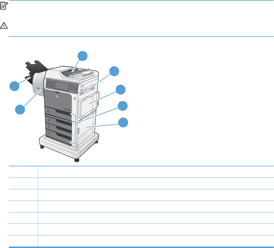
Jam locations
Use this illustration to identify locations of jams. In addition, instructions appear on the control panel to
direct you to the location of jammed paper and how to clear it.
NOTE: Internal areas of the product that might need to be opened to clear jams have green handles
or green labels.
WARNING! To avoid electrical shock, remove any necklaces, bracelets, or other metal items before
reaching into the inside of the product.
Figure 3-87 Jam locations
1
2
3
5
6
7
4
1 Document feeder
2 Right door
3Tray 1 area
4 Tray 2, and optional Trays 3, 4, and 5
5 Lower-right door
6 Stapler/stacker
7 Output bins
The following illustration shows the paper path sensors that determine when the product is experiencing
a paper jam.
582 Chapter 3 Solve problems ENWW
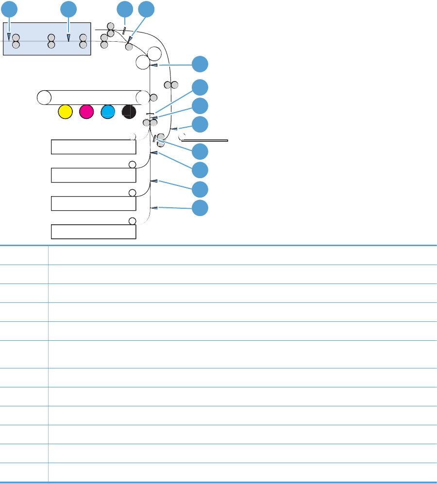
Figure 3-88 Paper path sensor locations
IPTU
Tray1
Tray2
Tray3 (Option Feeder1)
Tray4 (Option Feeder2)
Tray5 (Option Feeder3)
1 2 3 4
5
8
9
10
11
12
6
7
1 SR26: IPTU bin full sensor
2 SR27: IPTU feed sensor
3 Duplex media waiting position 1
4 SR5: Fuser output sensor
5 SR14, 15: Fuser loop sensor
6 Registration stop position
7 SR20: Registration sensor
8 SR22: Duplex refeed sensor
9 Duplex media waiting position 2
10 SR4: Tray 3 feed sensor
11 SR7: Tray 4 feed sensor
12 SR10: Tray 5 feed sensor
ENWW Clear jams 583
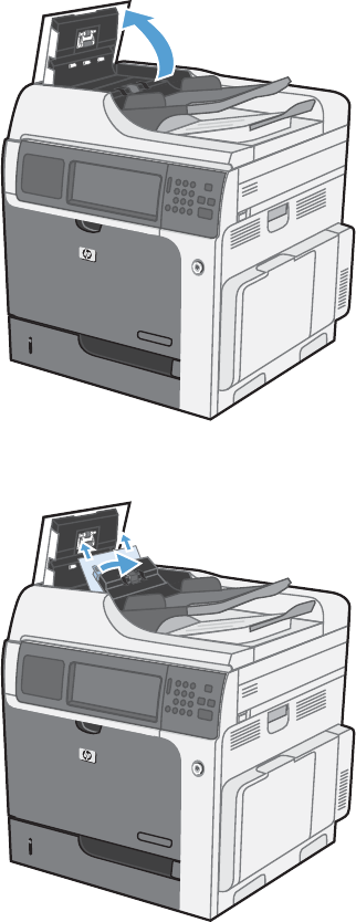
Clear jams in the document feeder
1. Open the document feeder cover.
2. Lift the jam-access door, and remove any jammed paper.
584 Chapter 3 Solve problems ENWW
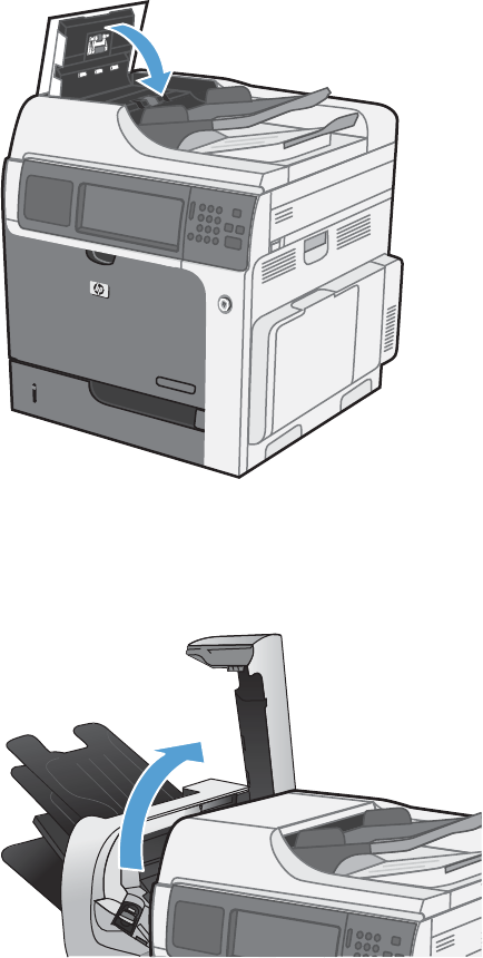
3. Close the document feeder cover.
Clear paper jams in the stapler/stacker assembly
1. Lift the gray latch on the front of the stapler/stacker, and open the stapler cover.
ENWW Clear jams 585
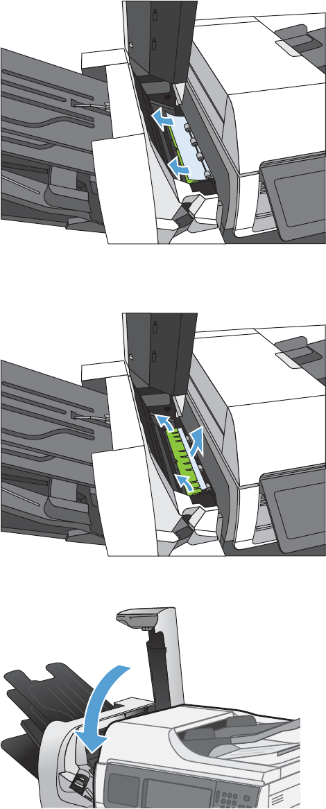
2. If jammed paper is visible underneath the paper guide, pull it straight out.
3. Lift the green jam-access door. If jammed paper is visible under the jam-access door, pull it straight
out,
4. Close the stapler cover.
586 Chapter 3 Solve problems ENWW
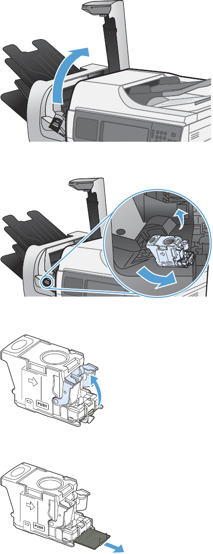
Clear staple jams
1. Lift the gray latch on the front of the stapler, and open the stapler cover.
2. Lift the green tab on the staple cartridge up, and then pull the staple cartridge straight out.
3. Lift up on the small lever at the back of the staple cartridge.
4. Remove the jammed staples.
ENWW Clear jams 587
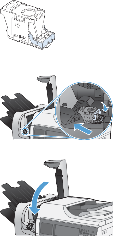
5. Close the lever at the back of the staple cartridge. Be sure that it snaps into place.
6. Insert the staple cartridge into the stapler and push down on the green handle until it snaps into
place.
7. Close the stapler cover.
588 Chapter 3 Solve problems ENWW
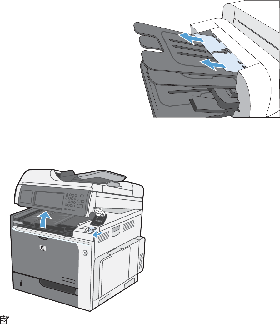
Clear jams in the output bin area
1. If paper is visible from the output bin, grasp
the leading edge and remove it.
Clear jams from under the scanner assembly
1. Pull the scanner latch forward, and then lift the scanner assembly up.
NOTE: Lift the jam-access cover if it has fallen.
ENWW Clear jams 589
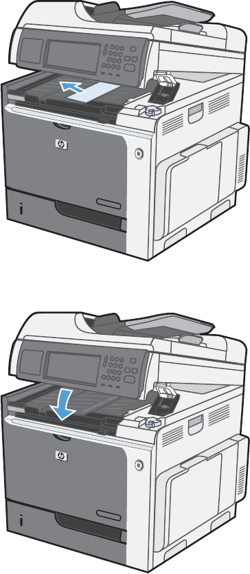
2. Remove any jammed sheets that are under the scanner assembly.
3. Close the scanner assembly.
590 Chapter 3 Solve problems ENWW
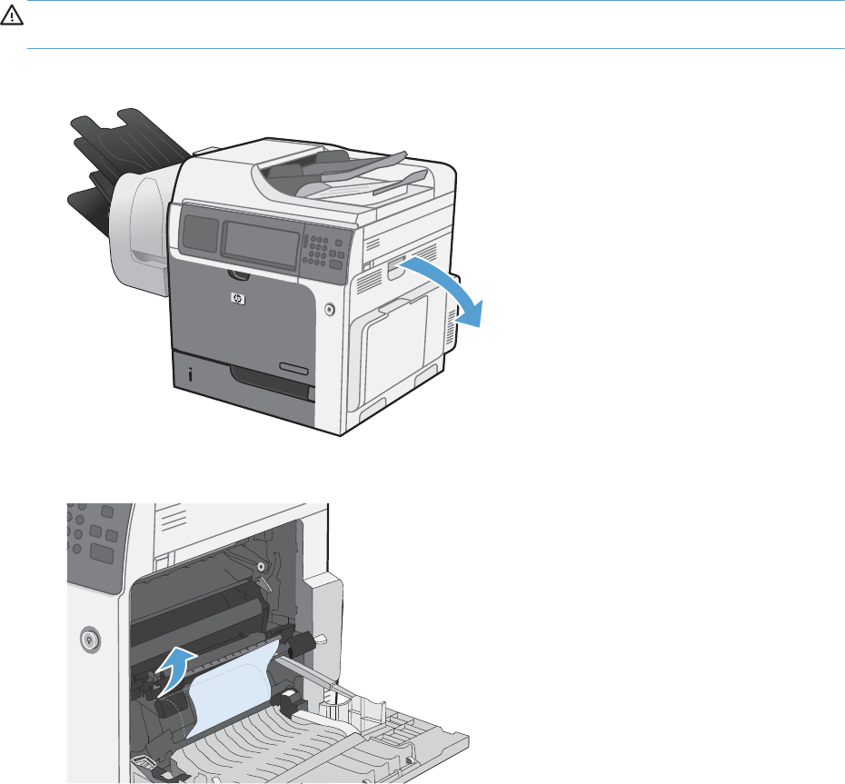
Clear jams in the right door
CAUTION: The fuser can be hot while the product is in use. Use caution. Wait for the fuser to cool
before handling it.
1. Open the right door.
2. Gently pull the paper out of the pickup area.
ENWW Clear jams 591
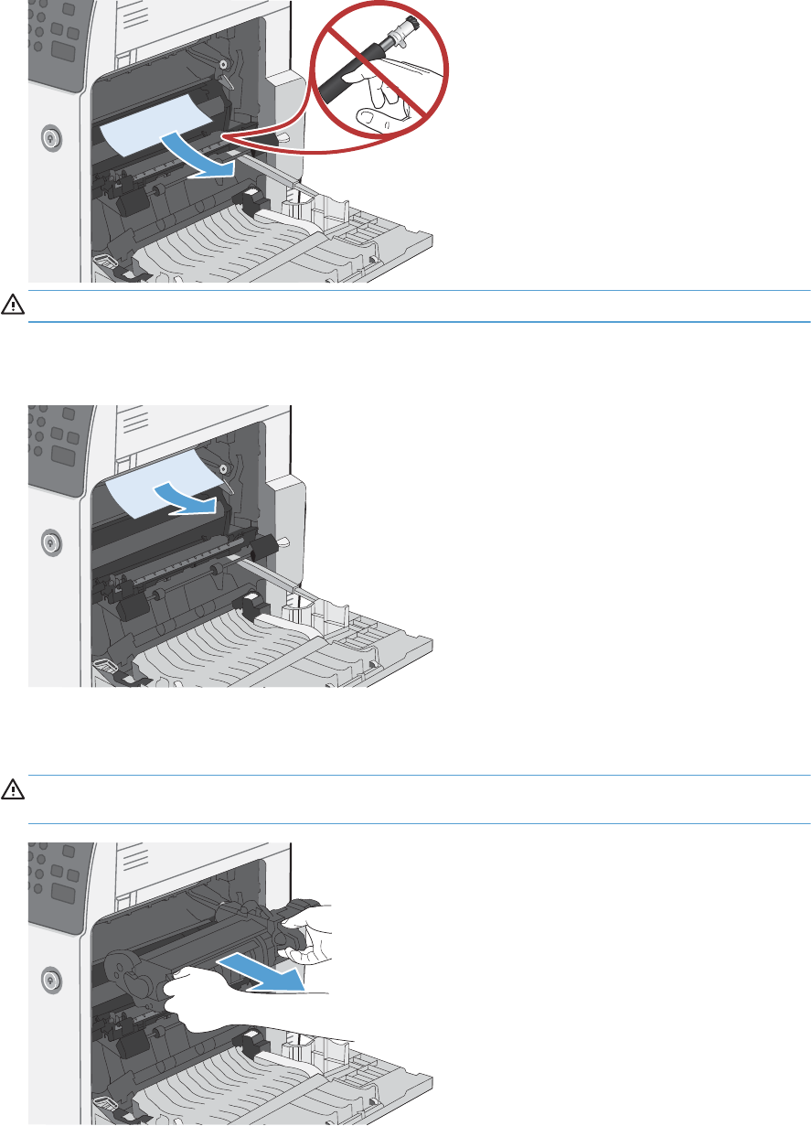
3. If paper is visible entering the bottom of the fuser, gently pull downward to remove it.
CAUTION: Do not touch the rollers on the transfer roller. Contaminants can affect print quality.
4. If paper is jammed as it enters the output bin, remove the fuser and gently pull the paper
downward to remove it.
5. Paper could be jammed inside the fuser where it would not be visible. Grasp the fuser handles, lift
up slightly, and then pull straight out to remove the fuser.
CAUTION: The fuser can be hot while the product is in use. Use caution. Wait for the fuser to
cool before handling it.
592 Chapter 3 Solve problems ENWW
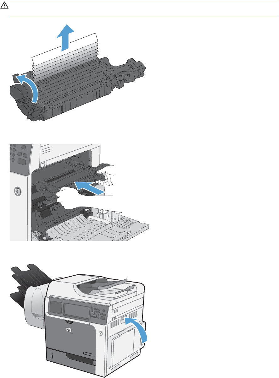
6. Open the jam-access door. If paper is jammed inside the fuser, gently pull it straight up to remove
it. If the paper tears, remove all paper fragments.
CAUTION: Even if the body of the fuser has cooled, the rollers that are inside could still be hot.
Do not touch the fuser rollers until they have cooled.
7. Close the jam-access door, and push the fuser completely into the product.
8. Close the right door.
ENWW Clear jams 593
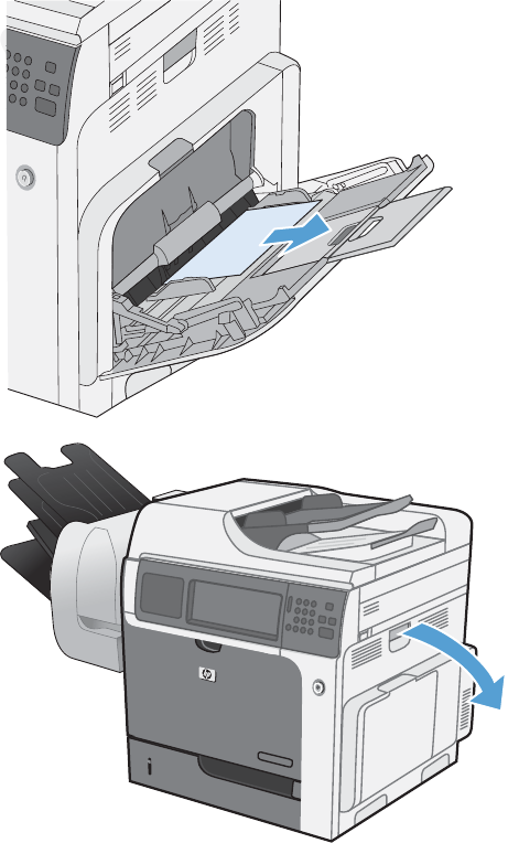
Clear jams in Tray 1
1. If jammed paper is visible in Tray 1, clear the
jam by gently pulling the paper straight out.
Touch the OK button to clear the message.
2. If you cannot remove the paper, or if no
jammed paper is visible in Tray 1, close Tray
1 and open the right door.
594 Chapter 3 Solve problems ENWW
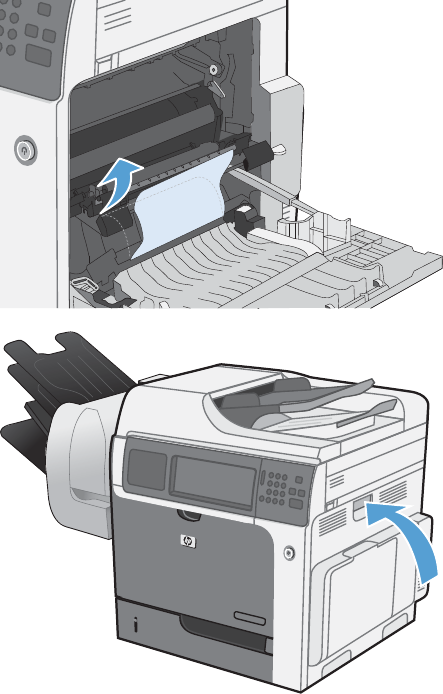
3. Gently pull the paper out of the pick up area.
4. Close the right door.
ENWW Clear jams 595
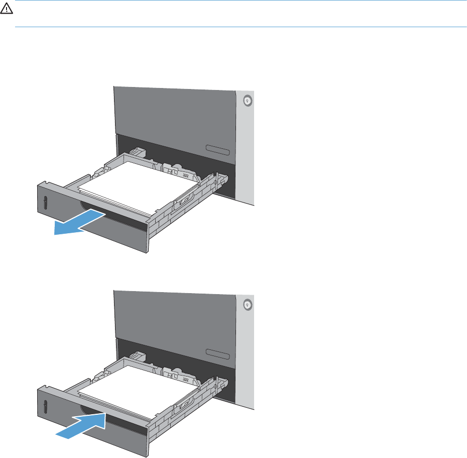
Clear jams in Trays 2, 3, 4, or 5
CAUTION: Opening a tray when paper is jammed can cause the paper to tear and leave pieces of
paper in the tray, which might cause another jam. Be sure to clear jams before opening the tray.
1. Open the tray and make sure that the paper is stacked correctly. Remove any jammed or
damaged sheets of paper. To access jammed paper from the tray cavity, remove the tray from the
product.
2. Close the tray.
596 Chapter 3 Solve problems ENWW
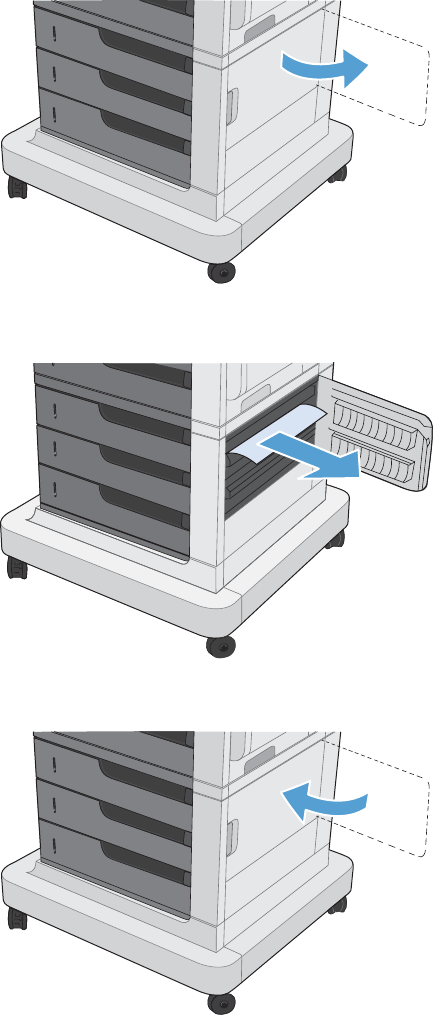
Clear jams in the lower-right door (Trays 3, 4, or 5)
1. Open the lower-right door.
2. If paper is visible, gently pull the jammed paper up or down to remove it.
3. Close the lower-right door.
ENWW Clear jams 597

Jam causes and solutions
Jams in the fuser and transfer area
Table 3-12 Causes and solutions for fuser delivery delay jams
Cause Solution
The fuser-delivery-sensor flag is damaged. Replace the fuser. See Fuser on page 112.
Poor contact with the fuser-delivery connector. Reconnect the connectors of the fuser-delivery sensor (J48) and the DC
controller PCA (J127).
The fuser-delivery sensor (SR5) is defective. Check the fuser-delivery sensor (SR5) with the manual sensor test. See Manual
sensor test on page 378. If the sensor is defective, replace the sensor.
Table 3-13 Causes and solutions for wrapping jams
Cause Solution
The fuser roller or pressure roller is dirty. Create and use a cleaning page. See Cleaning page on page 462.
The guide of the fuser delivery unit is dirty. Clean the guide.
The fuser roller or the pressure roller is worn
or deformed.
Replace the fuser. See Fuser on page 112.
The lever for the output bin full sensor on the
face-down tray is set incorrectly or is
damaged.
Set the lever correctly. If the lever is damaged, replace the delivery assembly.
See Delivery assembly on page 231.
The spring on the lever for the output bin full
sensor on the face-down tray is unhooked.
Reattached the spring.
Table 3-14 Causes and solutions for fuser delivery stationary jams
Cause Solution
The fuser roller or pressure roller is worn or
deformed.
Replace the fuser. See Fuser on page 112.
The fuser-delivery roller is deformed.
The gear of the fuser-delivery roller is
damaged.
The fuser-delivery sensor flag is stuck or
broken.
Check the flag to make sure it moves correctly. See Manual sensor test
on page 378 for information. If the flag is damaged, replace the fuser. See
Fuser on page 112.
Poor contact of the fuser-delivery sensor
connector.
Reconnect connector (J48) of the fuser-delivery sensor and connector (J127) on
the DC controller PCA.
The fuser delivery sensor (SR5) is defective. Run the sensor test in the sensor monitor mode to verify that the fuser delivery
sensor is functioning properly. If it is not, replace the fuser delivery sensor
(SR5).
598 Chapter 3 Solve problems ENWW

Table 3-15 Causes and solutions for residual media jams
Cause Solution
The sensor detecting a residual media jam is
not working.
One of the four sensors is reporting a residual jam. Test each sensor using the
manual sensor test. See Manual sensor test on page 378 for information. If the
sensor does not respond, replace the component indicated:
●TOP sensor (SR20): Replace the registration assembly. See Registration
assembly on page 213.
●Fuser delivery sensor (SR5): Replace the sensor.
●Loop sensor 1 or 2 (SR14 and SR15): Replace the fuser. See Fuser
on page 112.
●Duplex re-pickup sensor (SR22): Replace the registration assembly. See
Registration assembly on page 213.
If service was recently performed on the
product, a sensor connector might be
disconnected.
Run the manual sensor tests to verify which sensor detects the media. See
Manual sensor test on page 378 for information. Reconnect the corresponding
sensor connector:
●TOP sensor: Connector (J74) and (J145) on the DC controller PCA
●Fuser delivery sensor: Connector (J48) and connector (J127) on the DC
controller PCA
●Loop sensor 1 or 2: Connector (J162) on the DC controller PCA
●Duplex re-pickup sensor: Intermediate connector (J74) and connector
(J145) on the DC controller PCA.
Table 3-16 Causes and solutions for pickup delay jams 2
Cause Solution
Poor contact of the pickup motor drive
connector.
Reconnect the connector (J37) of the pickup motor and connector (J260) of the
DC controller PCA .
The pickup motor is defective. Execute the pickup-motor driving test in the actuator-drive mode. If the motor is
defective, replace the pickup motor. See Pickup motor on page 259.
The pickup roller is worn or deformed. Replace the pickup roller. See Feed and separation rollers (Trays 2-5)
on page 113.
The tray 2 separation roller is worn or
deformed.
Replace the separation roller. See Feed and separation rollers (Trays 2-5)
on page 113.
Poor contact of the TOP sensor connector. Reconnect the intermediate connector (J74) of the TOP sensor and connector
(J145) on the DC controller PCA.
The TOP sensor (SR20) is defective. Run the manual sensor test to verify that the TOP sensor is functioning properly.
See Manual sensor test on page 378 for information. If it is not, replace the
registration assembly. See Registration assembly on page 213.
Poor contact of the pickup solenoid drive
connector.
Reconnect the connector (J59) of the pickup solenoid and (J115) on the DC
controller PCA.
ENWW Clear jams 599

Table 3-16 Causes and solutions for pickup delay jams 2 (continued)
Cause Solution
The pickup solenoid is defective. Run the solenoid drive test in the actuator drive mode to verify that the pickup
solenoid is functioning properly. If it is not, replace the tray-pickup drive
assembly. See Tray-pickup drive assembly on page 266.
The pickup motor is defective. Run the pickup motor drive test in the actuator drive mode to verify that the
pickup motor is functioning properly. If it is not, replace the pickup motor. See
Pickup motor on page 259.
Table 3-17 Causes and solutions for pickup stationary jams
Cause Solution
Multiple-feed of media If the tray 2 pickup roller or separation roller are worn or deformed, replace
any defective parts. If the tray 1 pickup roller or separation pad are worn or
deformed, replace any defective parts.
The TOP sensor lever is set incorrectly or
damaged
Check the sensor lever to make sure it is set correctly. If it is damaged, replace
the registration assembly. See Registration assembly on page 213.
The spring of the TOP sensor lever is
unhooked.
Check the spring and place it in correct position.
Poor contact of the TOP sensor connector Reconnect intermediate connector (J74) of the TOP sensor and connector
(J145) on the DC controller PCA.
The TOP sensor is defective. Run the manual sensor test to verify that the TOP sensor (SR20) is functioning
properly. See Manual sensor test on page 378 for information. If it is not,
replace the registration assembly. See Registration assembly on page 213.
Jams in the duplex area
Table 3-18 Causes and solutions for duplexing reverse jams
Cause Solution
The duplex reverse roller is worn or deformed. Replace the delivery assembly. See Delivery assembly on page 231.
The duplex feed roller is worn or deformed. Replace the duplex feed unit.
Poor contact of the duplex reverse-motor
connector
Reconnect the connectors (J39) of the duplex reverse motor, connectors (J202
and J201) on the high-voltage power supply (upper) PCA, and connector
(J113) on the DC controller PCA.
The duplex reverse motor is defective. Replace the duplex drive assembly. See Duplex-drive assembly on page 235.
Table 3-19 Causes and solutions for duplex repick jams
Cause Solution
The duplex re-pickup sensor lever is set
incorrectly or damaged.
Check the sensor lever to make sure it is set correctly. If it is damaged, replace
the right door assembly. See Right-door assembly on page 145.
600 Chapter 3 Solve problems ENWW

Table 3-19 Causes and solutions for duplex repick jams (continued)
Cause Solution
The spring of the duplex re-pickup sensor
lever is unhooked.
Check the spring and place it in correct position.
Poor contact of the duplex re-pickup sensor
connector
Reconnect the intermediate connector (J74) and connector (J145) on the DC
controller PCA.
The duplex re-pickup sensor (SR22) is
defective.
Run the manual sensor test to verify that the duplex re-pickup sensor (SR22) is
functioning properly. See Manual sensor test on page 378 for information. If it
is not, replace the right-door assembly. See Right-door assembly on page 145.
Poor contact of the duplex reverse solenoid
connector
Reconnect the connector (J69) of the duplex reverse solenoid, connectors J202
and J201 on the high-voltage power supply (upper), and connector J113 on
the DC controller PCA.
The duplex reverse solenoid is defective. Replace the duplex-drive assembly. See Duplex-drive assembly on page 235.
The duplex flapper is damaged or
malfunctioning.
Replace the delivery assembly. See Delivery assembly on page 231.
Poor contact of the duplex reverse solenoid
connector
Reconnect the connector (J69) of the duplex reverse solenoid, connectors
(J202) and (J201) on the high-voltage power supply (upper), and connector
(J113) on the DC controller PCA.
The duplex reverse solenoid is defective. Replace the duplex-drive assembly. See Duplex-drive assembly on page 235.
The duplex flapper is damaged or
malfunctioning.
Replace the delivery assembly. See Delivery assembly on page 231.
The duplex repick roller is worn or damaged. Replace the registration assembly. See Registration assembly on page 213.
Poor contact of the duplex repick clutch
connector.
Reconnect the intermediate connector (J74) of the duplex repick clutch and
connector (J145) on the DC controller PCA.
The duplex repick clutch is defective. Run the solenoid drive test in actuator drive mode to verify that the duplex
repick clutch is functioning properly. If it is not, replace the registration
assembly. See Registration assembly on page 213.
Table 3-20 Causes and solutions for residual media jams
Cause Solution
Poor contact of the loop-sensor connector and
loop sensor 1 and 2.
Reconnect the connectors of the loop 1 sensor (1 and 2):
●Loop 1 (J11, J352, J350, J50) and the DC controller (J139)
●Loop 2 (J10, J352, J350, J50) and the DC controller (J139)
The loop sensor is defective. Run the manual sensor test. See Manual sensor test on page 378 for
information. If the sensor is defective, replace fuser. See Fuser on page 112.
The spring of the fuser-delivery-sensor lever is
unhooked.
Check the spring of the fuser and right door and place it in the correct
position.
The fuser-delivery sensor lever is damaged. Replace the sensor (SR5).
Poor contact of the fuser-delivery sensor
connector.
Reconnect the connectors of the fuser-delivery sensor (J46), intermediate (J95)
and the DC controller PCA (J123).
ENWW Clear jams 601

Table 3-20 Causes and solutions for residual media jams (continued)
Cause Solution
The fuser-delivery sensor is defective. Run the manual sensor test to make sure the fuser-delivery sensor is functioning
properly. See Manual sensor test on page 378 for information. If the sensor is
defective, replace the fuser. See Fuser on page 112.
The spring of the duplex repickup sensor lever
is unhooked.
Check the spring and place it in the correct position. The sensor is located in
the right door behind the cover close to the engine side.
The duplex pickup sensor lever is damaged. Replace the right door assembly. See Right-door assembly on page 145.
Poor contact of the duplexing media-reverse-
sensor connector
Reconnect the connectors of the duplexing media-reverse sensor (J8) and (J90)
and the duplexing driver PCA (J107).
The duplex repickup sensor (SR22) is
defective.
Run the manual sensor test to verify that the duplex repickup sensor is
functioning properly. See Manual sensor test on page 378 for information. If
the sensor is defective, replace the duplex repickup sensor.
NOTE: Even if jammed paper is visible in Tray 1, clear the jam from the inside of the product by
opening the right door.
Jams in Tray 1, Tray 2 and internal paper path
Table 3-21 Causes and solutions for pickup delay jam 1: tray pickup
Cause Solution
The tray 1 pick up roller or the tray 1
separation pad is worn or deformed.
Replace the tray 1 pickup roller and separation pad. See Pickup roller (Tray 1)
on page 114. Replace the right door. See Right-door assembly on page 145.
Poor contact of the tray 1 media-presence-
sensor connector
Reconnect the connectors of the tray media-feed sensor (J7), intermediate
(J85), and DC controller (J107).
Poor contact of the TOP sensor connector. Reconnect the intermediate connector (J74) of the TOP sensor and connector
(J145) on the DC controller PCA.
The TOP sensor is defective. Run the manual sensor test to verify that the TOP sensor is functioning
properly. If not, replace the registration assembly. See Registration assembly
on page 213.
Poor contact of the MP-pickup-solenoid drive
connector
Reconnect the connector of the tray pickup solenoid (J52) and the DC
controller PCA (J148).
The MP-pickup solenoid is defective. Execute the tray-pickup-solenoid driving test in the actuator-drive mode. If the
solenoid is defective, replace the right door assembly. See Right-door
assembly on page 145.
Poor contact of the pickup-motor drive
connector (M13)
Reconnect the connector (J37) and connector (J260) on the DC controller PCA.
The pickup motor is defective. Execute the pickup-motor driving test in the actuator-drive mode. If the motor is
defective, replace the pickup motor. See Pickup motor on page 259.
602 Chapter 3 Solve problems ENWW

Table 3-22 Causes and solutions for pickup stationary jams
Cause Solution
Multiple feed of media Replace any worn or deformed parts (tray separation pad, tray feed roller, MP
tray pickup roller or MP tray separation pad). If replacing the MP tray
separation pad, you must replace the right door assembly. See Right-door
assembly on page 145.
Check the separation pad and MP tray separation pad to see if they are firmly
seated and coupled with the torque limiter.
Replace the separation pad and feed roller for Tray 2 and Tray 3.
If the MP tray pickup roller if defective, replace the roller. See Pickup roller
(Tray 1) on page 114. If the MP tray separation pad is defective, replace the
right door assembly. See Right-door assembly on page 145.
The secondary transfer roller is not set
correctly.
Place the secondary-transfer-roller unit in the correct position.
The secondary-transfer roller is worn or
deformed.
Replace the secondary-transfer-roller assembly. See Secondary transfer
assembly on page 204.
Poor contact of the drum 3 drive connector Reconnect the connectors of the ITB motor (J42) and the DC controller PCA
(J121).
The drum motor 3 is defective. Execute the drum 3 driving test in the actuator-drive mode. If the motor is
defective, replace the ITB motor.
The ITB does not rotate smoothly. Replace the ITB. See Intermediate transfer belt (ITB) on page 120.
Jams in Tray 3, 4, and 5
Table 3-23 Causes and solutions for pickup delay and pickup stationary jams
Cause Solution
The paper-feeder pickup roller is worn or
deformed.
Replace the pickup roller. See Feed and separation rollers (Trays 2-5)
on page 113.
The paper-feeder separation roller is worn or
deformed.
Replace the separation roller. See Feed and separation rollers (Trays 2-5)
on page 113.
The paper-feeder feed roller is worn or
deformed.
Replace the feed roller. See Feed and separation rollers (Trays 2-5)
on page 113.
Poor contact of the paper-feeder media-feed
sensor connector (1, 2, or 3)
●Tray 3: Reconnect connectors (J408) and (J13)
●Tray 4: Reconnect connectors (J406) and (J22)
●Tray 5: Reconnect connectors (J403) and (J32)
A tray feed sensor is defective. Run the manual sensor test to verify that the paper-feeder media feed sensor is
functioning properly. See Tray/Bin manual sensor test on page 393 for
information. If it is not, replace the pickup assembly of the specific tray. See
Pickup assembly (optional paper feeder) on page 313.
ENWW Clear jams 603

Table 3-23 Causes and solutions for pickup delay and pickup stationary jams (continued)
Cause Solution
Poor contact of a paper-feeder pickup
solenoid drive connector (1, 2, or 3)
●Tray 3: Reconnect connectors (J408) and (J18)
●Tray 4: Reconnect connectors (J406) and (J20)
●Tray 5: Reconnect connectors (J403) and (J30)
The paper-feeder pickup solenoid is defective. Run the solenoid drive test in the actuator drive mode to verify that the paper-
feeder pickup solenoid is functioning properly. If it is not, replace the pickup
assembly of the specific tray. See Pickup assembly (optional paper feeder)
on page 313.
Poor contact of paper-feeder pickup motor
drive connector.
Reconnect the connector (J409) on the paper feeder driver PCA and connector
(J14).
The paper-feeder pickup motor is defective. Run the pickup motor drive test in the actuator drive mode to verify that the
paper-feeder pickup motor is functioning properly. If it is not, replace the
pickup assembly of the specific tray. See Pickup assembly (optional paper
feeder) on page 313.
Multiple feed of media If the tray 3 pickup roller, separation roller, or feed roller is worn or deformed,
replace any defective parts. See Feed and separation rollers (Trays 2-5)
on page 113.
The paper-feeder media-feed sensor lever is
set incorrectly or damaged.
Check the sensor lever to make sure it is set correctly. If it is damaged, replace
the paper-feeder assembly.
The spring of the paper-feeder media-feed
sensor lever is unhooked.
Check the spring and place it in correct position.
Poor contact of the paper-feeder media-feed
sensor connector.
Reconnect the connector (J406) on the connector PCA and connector (J22) of
the paper-feeder media feed sensor.
A tray feed sensor is defective. Run the manual sensor test to verify that the tray feed sensor is functioning
properly. See Tray/Bin manual sensor test on page 393 for information. If it is
not, replace the pickup assembly of the specific tray. See Pickup assembly
(optional paper feeder) on page 313.
Table 3-24 Causes and solutions for residual media jams
Cause Solution
The sensor that detects residual paper jams is
set incorrectly or damaged.
Run the manual sensor test to verify which sensor detects the paper. See Tray/
Bin manual sensor test on page 393 for information. Check the sensor lever to
make sure it is set correctly. If it is damaged, replace the corresponding
pickup assembly. See Pickup assembly (optional paper feeder) on page 313.
The spring of the sensor lever that detects
residual paper jams is unhooked.
Run the manual sensor test to verify which sensor detects the paper. See Tray/
Bin manual sensor test on page 393 for information. Check the spring of the
sensor lever to make sure it is set correctly.
604 Chapter 3 Solve problems ENWW

Table 3-24 Causes and solutions for residual media jams (continued)
Cause Solution
Poor contact exists in the sensor that detects
residual paper jams.
Run the manual sensor test to verify which sensor detects the paper. See Tray/
Bin manual sensor test on page 393 for information. Reconnect the following
corresponding sensor connectors:
●Tray 3: Reconnect connectors (J408) and (J13)
●Tray 4: Reconnect connectors (J406) and (J22)
●Tray 5: Reconnect connectors (J403) and (J32)
The sensor that detects residual paper jams is
defective.
Run the sensor test in the sensor monitor mode to verify which sensor detects
the paper. Replace media feed sensor 1, 2 or 3.
Table 3-25 Causes and solutions for IPTU delivery delay jams
Cause Solution
Poor contact exists in the IPTU media feed
sensor conector.
Reconnect the connector (J553) on the IPTU controller PCA.
The IPTU media feed sensor is defective. Run a manual sensor test to verify that the IPTU media feed sensor is
functioning properly. If it is not, replace the IPTU media feed sensor.
Poor contact exists in the IPTU feed motor
drive connector.
Reconnect the connector (J551) on the IPTU controller PCA and the connector
(J5) for the IPTU feed motor.
The IPTU feed motor is defective. Run a manual sensor test for the IPTU feed motor sensor to verify that the IPTU
feed motor is functioning properly. If it is not, replace the IPTU drive assembly.
Poor contact exists in the IPTU media full
sensor connector.
Reconnect the connector (J553) on the IPTU controller PCA.
The IPTU media full sensor is defective. Run a manual sensor test to verify that the IPTU media full sensor is functioning
properly. If it is not, replace the IPTU media full sensor.
Table 3-26 Causes and solutions for IPTU stationary jams
Cause Solution
The lever for the IPTU media feed sensor is set
incorrectly or damaged.
Check the sensor lever to make sure it is set correctly. If it is damaged, replace
the IPTU media feed sensor.
The spring of the IPTU media feed sensor lever
is unhooked
Put the spring in the correct position.
Poor contact exists in the IPTU media feed
sensor connector.
Reconnect the connector (J553) on the IPTU controller PCA.
The IPTU media feed sensor is defective. Run a manual sensor test to verify that the IPTU media feed sensor is
functioning properly. If it is not, replace the IPTU media feed sensor.
The lever for the IPTU media feed sensor is set
incorrectly or damaged.
Check the sensor lever to make sure it is set correctly. If it is damaged, replace
the IPTU media feed sensor.
The spring of the IPTU media feed sensor lever
is unhooked.
Place the spring in the correct position.
ENWW Clear jams 605

Table 3-26 Causes and solutions for IPTU stationary jams (continued)
Cause Solution
Poor contact exists in the IPTU media feed
sensor connector.
Reconnect the connector (J553) on the IPTU controller PCA.
The IPTU media feed sensor is defective. Run a manual sensor test to verify that the IPTU media feed sensor is
functioning properly. If it is not, replace the IPTU media feed sensor.
Paper is wrapped around the delivery roller in
the product.
Remove the wrapped paper.
Table 3-27 Causes and solutions for stapler/stacker feed delay jams
Cause Solution
Poor contact exists in the stapler/stacker
media feed sensor connector (SR1).
Reconnect the connector (J451) on the stapler/stacker controller PCA.
The stapler/stacker media feed sensor (SR1)
is defective.
Replace the stage unit.
Poor contact exists in the inlet solenoid drive
connector.
Reconnect the connector (J462) on the stapler/stacker controller PCA and the
connector (J120) of the inlet solenoid.
The inlet solenoid is defective. Replace the inlet solenoid.
Poor contact exists in the stapler/stacker
media feed sensor (SR5) connector.
Reconnect the connector (J453) on the stapler/stacker controller PCA.
The stapler/stacker media feed sensor (SR5)
is defective.
Replace the stage top unit.
Poor contact exists in the inlet solenoid drive
connector.
Reconnect the connector (J462) on the stapler/stacker controller PCA and the
connector (J120) of the inlet solenoid.
The inlet solenoid is defective. Replace the inlet solenoid.
Table 3-28 Causes and solutions for stapler/stacker stationary jams
Cause Solution
The lever for the stapler/stacker media feed
sensor (SR2) is set incorrectly or damaged
Check the sensor lever to make sure it is set correctly. If it is damaged, replace
the stage unit.
The spring of the stapler/stacker media feed
sensor (SR2) lever is unhooked.
Check the spring and place it in correct position.
Poor contact exists in the stapler/stacker
media feed sensor (SR1) connector.
Reconnect the connector (J451) on the stapler/stacker controller PCA.
The stapler/stacker media feed sensor (SR2)
is defective.
Replace the stage unit.
Poor contact exists in the stapler/stacker feed
motor drive connector.
Reconnect the connector (J461) on the stapler/stacker controller PCA.
The stapler/stacker feed motor is defective. Replace the stapler/stacker feed motor.
606 Chapter 3 Solve problems ENWW

Table 3-28 Causes and solutions for stapler/stacker stationary jams (continued)
Cause Solution
The lever for the stapler/stacker media feed
sensor (SR5) is set incorrectly or damaged.
Check the sensor lever to make sure it is set correctly. If it is damaged, replace
the stage top unit.
The spring of the stapler/stacker media feed
sensor (SR5) lever is unhooked.
Check the spring and place it in correct position.
Poor contact exists in the stapler/stacker
media feed sensor (SR5) connector.
Reconnect the connector (J453) on the stapler/stacker controller PCA.
The stapler/stacker media feed sensor (SR5)
is defective.
Replace the stage top unit.
Poor contact exists in the stapler/stacker feed
motor drive connector.
Reconnect the connector (J461) on the stapler/stacker controller PCA.
The stapler/stacker feed motor is defective. Replace the stapler/stacker feed motor.
The lever for the output bin 3 delivery sensor
(SR1) is set incorrectly or damaged.
Check the sensor lever to make sure it is set correctly. If it is damaged, replace
the stage unit.
The spring of the output bin 3 delivery sensor
(SR1) lever is unhooked.
Place the spring in the correct position.
Poor contact exists in the output bin 3 delivery
sensor (SR1) connector.
Reconnect the connector (J451) on the stapler/stacker controller PCA.
The output bin 3 delivery sensor (SR1) is
defective.
Replace the stage unit.
Table 3-29 Causes and solutions for stapler/stacker residual paper jams
Cause Solution
The stapler/stacker contains residual paper. Remove any residual paper.
The sensor detecting the stapler/stacker
residual paper jam is set incorrectly or
damaged.
Check the sensor lever to make sure it is set correctly. If it is damaged, replace
the following: Output bin 3 delivery sensor (SR1), stapler/stacker media feed
sensor (SR2), stapler/stacker media feed sensor (SR5), and stage top unit.
The spring of the sensor lever detecting the
stapler/stacker residual paper jam is
unhooked.
Check the spring of the sensor lever to make sure it is set correctly.
Poor connector contact exists in the sensor
detecting the stapler/stacker residual paper
jam.
Reconnect the following: Output bin 3 delivery sensor, connector (J451) on the
stapler/stacker controller PCA stapler/stacker media feed sensor (SR2),
connector (J451) on the stapler/stacker controller PCA stapler/stacker media
feed sensor (SR5), and connector (J453) on the stapler/stacker controller PCA.
The sensor detecting the stapler/stacker
residual paper jam is defective.
Replace the following: Output bin 3 delivery sensor (SR1), stapler/stacker
media feed sensor (SR2): stapler/stacker media feed sensor (SR5), and stage
top unit.
ENWW Clear jams 607

Change jam recovery
This product provides a jam recovery feature that reprints jammed pages.
1. From the Home screen, touch the Administration button.
2. Open the General Settings menu, and then open the Jam Recovery menu.
3. Select one of the following options:
●Automatic — The product attempts to reprint jammed pages when sufficient memory is
available. This is the default setting.
●Off — The product does not attempt to reprint jammed pages. Because no memory is used to
store the most recent pages, performance is optimal.
NOTE: When using this option, if the product runs out of paper and the job is being
printed on both sides, some pages can be lost.
●On — The product always reprints jammed pages. Additional memory is allocated to store
the last few pages printed. This might cause overall performance to suffer.
608 Chapter 3 Solve problems ENWW

Paper does not feed automatically
Paper does not feed automatically
Cause Solution
Manual feed is selected in the software program. Load Tray 1 with paper, or, if the paper is loaded, touch the
Start button.
The correct size paper is not loaded. Load the correct size paper.
The input tray is empty. Load paper into the input tray.
Paper from a previous jam has not been completely removed. Open the product and remove any paper in the paper path.
The paper size is not configured correctly for the input tray. Print a configuration page or use the control panel to
determine the paper size for which the tray is configured.
The guides in the tray are not against the paper. Verify that the paper guides are touching the paper.
The Manually Feed Prompt menu in the Manage Trays menu is
set to the Always setting. The product always prompts for
manual feed, even if the tray is loaded.
Load Tray 1 with paper, or, if the paper is loaded, touch the
Start button.
Or, change the manual-feed prompt setting to Unless
Loaded, so that the product prompts for manual feed only
when the tray is empty.
The Use Requested Tray menu in the Manage Trays menu is
set to the Exclusively setting, and the requested tray is empty.
The product will not use another tray.
Load the requested tray.
Or, change the setting to First. The product can use other trays
if no paper is loaded in the specified tray.
ENWW Paper does not feed automatically 609

Product feeds multiple sheets
Product feeds multiple sheets
Cause Solution
Print paper is sticking together. Remove paper, flex it, rotate it 180 degrees or flip it over,
and then reload it into the tray.
NOTE: Do not fan paper. Fanning can cause static
electricity, which can cause paper to stick together.
Paper does not meet the specifications for this product. Use only paper that meets HP paper specifications for this
product.
Trays are not properly adjusted. Make sure that the paper guides match the size of paper
being used.
610 Chapter 3 Solve problems ENWW

Use manual print modes
Try the following multi-purpose (MP) modes to see if they solve the image-quality problems. These
options can be found in the Adjust Paper Types and Optimize submenus under the Print Quality menu
on the control panel.
Table 3-30 MP modes under the Adjust Paper Types sub menu
Print Mode
●Auto Sense Mode
●Normal mode
●Light Mode
●Light Rough Mode
●Heavy Mode
●Extra Heavy Mode
●Card Stock Mode
●Heavy Glossy Mode
●X-Heavy Glossy Mode
●Card Glossy Mode
●Rough Mode
●Transparency Mode
●Transparency 2 Mode
●4 mm trans mode
●Tough Mode
●Label Mode
●Envelope Mode
NOTE: Not all print modes are available for all paper
types.
Resistance Mode Set to Up to resolve print-quality issues caused by poor
secondary transfer in low-humidity environments with resistive
or rough surface media.
Humidity Mode With glossy film, set to High when the product is in a high-
humidity environment and print-quality defects occur on HP
Tough Paper or Opaque film.
With transparencies, set to High when the product is in a
high-humidity environment and print-quality defects occur on
color transparencies on the first page of a print job.
With all other paper types, set to High when the product is in
a high-humidity environment and light density occurs on the
first page of a print job.
ENWW Use manual print modes 611

Table 3-30 MP modes under the Adjust Paper Types sub menu (continued)
Pre-Rotation Mode Set this feature to On if horizontal banding occurs on pages.
Fuser Temp Mode If you are seeing a faint image of the page repeated at the
bottom of the page or on the following page, first make sure
the Paper Type and Print Mode settings are correct for the
type of paper you are using. If you continue to see ghost
images on your print jobs, set the Fuser Temp feature to one of
the Alternate settings . Try the Alternate 1 setting first and see
if it solves the problem. If you continue to see the problem, try
Alternate 2 and then Alternate 3. Using the Alternate 2 and
Alternate 3 settings might cause an extra delay between jobs.
Paper Curl Mode Use in high-humidity and high-temperature environments. The
Reduced setting decreases fuser temperature and increases
the interpage gap.
Table 3-31 MP modes under the Optimize submenu
Normal Paper Set toSmooth when printing on smooth paper of normal
weight.
Heavy Paper Set to Smooth when printing on smooth, heavy media types.
Envelop Control Set to Reduced Temp if envelopes are sticking due to moisture
in the envelop adhesive.
Environment Set to Low Temp if the product is operating in a low-
temperature environment and you are having problems with
print quality such as blisters in the printed image.
Line Voltage Set to Low Voltage if the product is operating in a low-voltage
environment and you are having problems with print quality
such as blisters in the printed image.
Tray 1 Set the mode to Alternate if you are seeing marks on the back
side of the paper when printing from Tray 1. This sets the
product to initiate a clean sequence every time a job finishes
when the product is set for Any Size and Any Type for Tray 1.
Background Set to Alternate 1 when a background occurs all over the
page. Set to Alternate 2 when thin vertical lines appear on the
page. Set to Alternate 3 when the other alternatives do not
correct the problem.
Uniformity Control Set to Alternate 1 to improve uniformity on any paper type.
Set to Alternate 2 to improve uniformity on normal and light
paper types. Set to Alternate 3 when the other alternatives do
not correct the problem.
Tracking Control Improves color stability by adjusting the bias voltage. Make
sure this mode is set to On.
Registration Set to Alternate when color misregistration occurs.
612 Chapter 3 Solve problems ENWW

Table 3-31 MP modes under the Optimize submenu (continued)
Transfer Control Set to Alternate 1 to reduce primary transfer bias and to
resolve low density or blotchy images. Set to Alternate 2 to
resolve ghosting outlines that look like a finger or fingers. Set
to Alternate 3 when the other alternatives do not correct the
problem.
Process Cleaning Page Generates and processes a fuser cleaning page.
ENWW Use manual print modes 613

Solve image-quality problems
This section helps you define print-quality problems and what to do to correct them. Often print-quality
problems can be handled easily by making sure that the product is maintained, using paper that meets
HP specifications, or running a cleaning page.
Print quality examples
The following examples depict letter-size paper that has passed through the product short-edge first.
These examples illustrate problems that would affect all the pages that you print, whether you print in
color or in black only. The topics that follow list the typical cause and solution for each of these
examples.
Problem Sample Cause Solution
Print is light or faded on entire
page.
Poor contacts exist on the ITB
unit and the product
grounding unit.
Clean the grounding contacts. If the
problem remains after cleaning,
check the contacts for damage.
Replace any deformed or damaged
parts.
Poor secondary transfer
contacts exist on the
secondary transfer roller and
the ITB.
Clean the contacts. If the problem
remains after cleaning, check the
contacts for damage. Replace any
deformed or damaged parts.
Print is light or faded in a
particular color.
Poor primary transfer bias
contacts on the ITB unit and
product.
Clean the contacts of the color that
produces the light print. If the
problem remains after cleaning,
check the contacts for damage.
Replace any deformed or damaged
parts.
Poor primary charging bias
contacts with the print
cartridge and product.
Poor developing bias contacts
with the print cartridge and
product.
Image is too dark. The RD sensor is defective. Replace the RD sensor. See
Registration density (RD) sensor
assembly on page 209.
Page is blank. The high-voltage power-supply
lower is defective (no
developing bias output).
Replace the high-voltage power-
supply lower. See High-voltage
power supply lower (HVPS-D)
on page 250.
614 Chapter 3 Solve problems ENWW
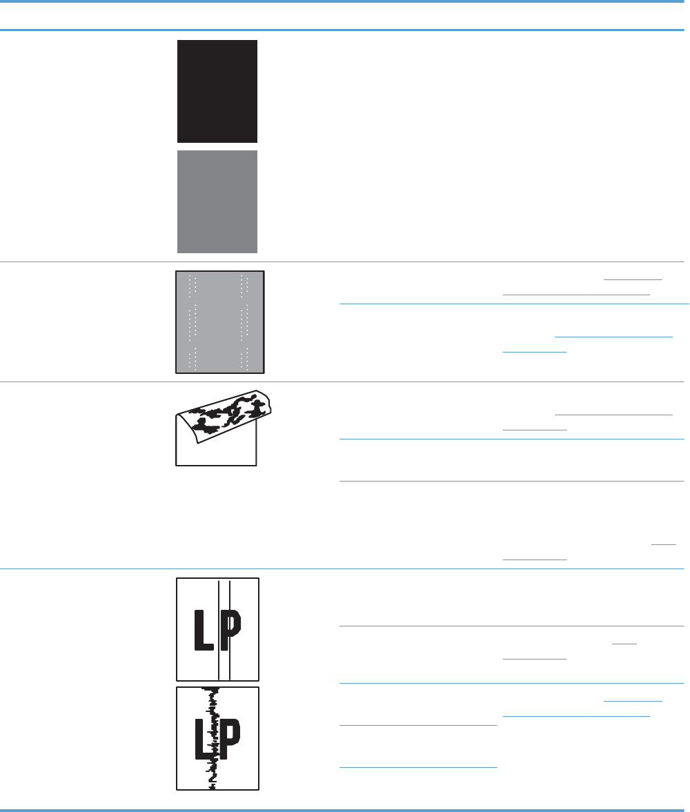
Problem Sample Cause Solution
The page is all black or a solid
color.
Poor contact exists in the
primary charging bias or
developing bias contacts
between the print cartridge
and the product.
Clean each contact of the color that
produces the all black or solid color.
If the problem remains after
cleaning, check the contacts for
damage. Replace any deformed or
damaged parts. Replace the
affected print cartridge.
White spots appear in an image The primary transfer roller is
deformed or has deteriorated.
Replace the ITB. See Intermediate
transfer belt (ITB) on page 120.
The secondary transfer roller
is deformed or has
deteriorated.
Replace the secondary-transfer-
roller. See Secondary transfer roller
on page 118.
The back of the page is dirty. The secondary transfer roller
is dirty.
Replace the secondary transfer
roller. See Secondary transfer roller
on page 118.
The fuser inlet guide or
separation guide is dirty.
Clean the dirty parts. If the dirt does
not come off, replace the guide.
The pressure roller is dirty. Run the cleaning page several times.
If the dirt does not come off, send a
fuser cleaning kit. If the issue
persists, replace the fuser. See Fuser
on page 112.
Vertical streaks or bands appear
on the page.
Scratches are present on the
circumference of the
photosensitive drum.
Replace the print cartridge of the
color that matches the defect.
Scratches are present on the
circumference of the fuser
roller.
Replace the fuser. See Fuser
on page 112.
Scratches are present on the
circumference of the ITB.
Replace the ITB. See Intermediate
transfer belt (ITB) on page 120.
The ITB drive roller is
deformed or has deteriorated.
The ITB cleaning mechanism is
malfunctioning.
ENWW Solve image-quality problems 615

Problem Sample Cause Solution
Vertical white lines appear in a
particular color.
The laser beam window is
dirty.
Remove the affected print cartridge
and reinstall it. The PGCs will clean
the glass.
Scratches are present on the
circumference of the
developing cylinder or
photosensitive drum.
White scratch down the page
could mean the scanner glass
needs to be cleaned.
Remove the affected print cartridge
and reinstall it. The PGCs will clean
the glass.
If the problem persists, replace the
affected print cartridge.
The laser/scanner-unit mirror
is dirty.
Replace the laser/scanner assembly.
See Laser/scanner assembly (Y/M)
on page 275 or Laser/scanner
assembly (C/Bk) on page 279.
Vertical white lines appear in all
colors.
Horizontal scratches on the
fuser roller.
Replace the fuser. See Fuser
on page 112.
Scratches are present on the
circumference of the ITB.
White scratch down the page
could mean the scanner glass
needs to be cleaned.
Remove the affected print cartridge
and reinstall it. The PGCs will clean
the glass.
Replace the ITB. See Intermediate
transfer belt (ITB) on page 120.
Horizontal lines appear on the
page.
Repetitive horizontal lines
appear.
Use the repetitive defects ruler to
identify the dirty roller. Clean the
roller. If the roller cannot be
cleaned, replace the fuser. See
Fuser on page 112.
Horizontal scratches are
present on the photosensitive
drum.
Replace the print cartridge of the
color that matches the defect.
Horizontal scratches are
present on the fuser roller.
Replace the fuser. See Fuser
on page 112.
A horizontal white line appears
on the page.
Repetitive horizontal white
lines appear.
Use the repetitive defects ruler to
identify the dirty roller. Clean the
roller. If the roller cannot be
cleaned, replace the roller.
Horizontal scratches are
present on the photosensitive
drum.
Replace the print cartridge of the
color that matches the defect.
Scratches are present on the
circumference of the ITB.
Replace the ITB. See Intermediate
transfer belt (ITB) on page 120.
616 Chapter 3 Solve problems ENWW
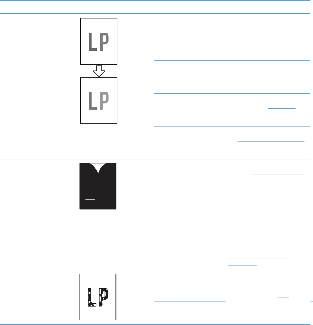
Problem Sample Cause Solution
Image in a particular color does
not print in the correct color.
Poor contact exists in the
primary charging bias or
developing bias contacts
between the print cartridge
and the product.
Clean each contact of the color that
produces the missing color. If the
problem remains after cleaning,
check the contacts for damage.
Replace any deformed or damaged
parts.
The print cartridge (primary
charging roller, developing
roller, or photosensitive drum)
is defective.
Replace the print cartridge of the
color that matches the defect.
The high-voltage power-supply
lower is defective (no primary
charging bias or developing
bias output).
Replace the high-voltage power-
supply lower. See High-voltage
power supply lower (HVPS-D)
on page 250.
The laser/scanner unit is
defective.
Replace the laser/scanner assembly.
See Laser/scanner assembly (Y/M)
on page 275 or Laser/scanner
assembly (C/Bk) on page 279.
Dropouts appear. The secondary transfer roller
is deformed or has
deteriorated.
Replace the secondary-transfer-
roller. See Secondary transfer roller
on page 118.
The primary charging roller,
developing roller, or
photosensitive drum is
deformed or has deteriorated.
Replace the print cartridge of the
color that matches the defect.
The fuser roller is deformed or
has deteriorated.
Replace the fuser.
The high-voltage power-supply
T PCA is defective (no transfer
bias output).
Replace the high-voltage power-
supply upper. See High-voltage
power supply upper (HVPS-T)
on page 286.
The toner is not fully fused to the
paper.
The fuser roller or pressure
roller is scarred or deformed.
Replace the fuser. See Fuser
on page 112.
The thermistor is defective. Replace the fuser. See Fuser
on page 112.
The fuser heater is defective.
ENWW Solve image-quality problems 617
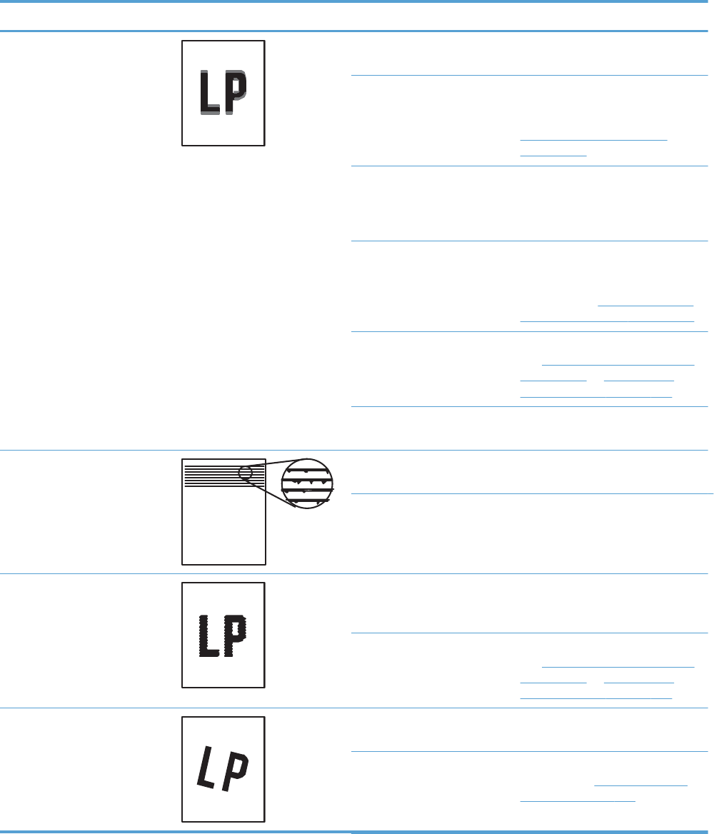
Problem Sample Cause Solution
Some color is misregistered. The product is incorrectly
calibrated.
Calibrate the product.
The ITB unit is defective. If the ITB does not rotate smoothly or
a cleaning malfunction occurs (ITB is
dirty), replace the ITB. See
Intermediate transfer belt (ITB)
on page 120.
The drive gear of the ITB
motor is worn or chipped.
Check each drive gear between the
ITB drive roller and the ITB motor. If
the gear is worn or chipped,
replace the drive unit.
The RD sensor is defective. Open and close the front door
several times to clean the RD sensor.
If the problem persists, replace the
RD sensor. See Registration density
(RD) sensor assembly on page 209.
The laser/scanner unit is
defective.
Replace the laser/scanner assembly.
See Laser/scanner assembly (Y/M)
on page 275 or Laser/scanner
assembly (C/Bk) on page 279.
The print cartridge is
defective.
Replace the print cartridge of the
affected color.
Toner smears appear on the
media.
The product has residual
media.
Remove the residual media.
The fuser inlet guide is dirty. Clean the fuser inlet guide.
The printed page contains
misformed characters.
The product is experiencing
page skew.
See the “Text or graphics are
skewed on the printed page” row in
this table.
The laser/scanner unit is
defective.
Replace the laser/scanner assembly.
See Laser/scanner assembly (Y/M)
on page 275 or Laser/scanner
assembly (C/Bk) on page 279.
Text or graphics are skewed on
the printed page.
The registration shutter spring
is unhooked.
Check the spring and place it in the
correct position.
The registration shutter spring
is deformed.
Replace the secondary transfer
assembly. See Secondary transfer
assembly on page 204.
618 Chapter 3 Solve problems ENWW

Problem Sample Cause Solution
The printed page contains
wrinkles or creases.
The roller or media feed guide
is dirty.
Clean any dirty components.
A feed roller is deformed or
has deteriorated.
Replace any deformed or
deteriorated rollers.
The paper feed guide is
damaged.
Replace the paper-feed-guide unit.
The front of the page is dirty. The photosensitive drum is
dirty.
Replace the print cartridge.
The fuser roller or pressure
roller is dirty.
Execute a Pressure roller clean
mode. If the dirt does not come off,
replace the fuser. See Fuser
on page 112.
NOTE: Cleaning the fuser with HP
tough paper provides better results
than with plain paper. You might
need to execute the cleaning
process several times to remove all
contaminates on the fuser.
Repetitive horizontal lines See repetitive image defect ruler.
Clean the indicated roller. If the
contaminate does not come off,
replace appropriate roller or
assembly.
Pages have flecks of toner Execute a cleaning page to clean
the contaminate off the fuser. The
cleaning page may need to be run
several time to clean the fuser. Do
not replace the fuser.
NOTE: Cleaning the fuser with HP
tough paper provides better results
than with plain paper. You might
need to execute the cleaning
process several times to remove all
contaminates on the fuser.
Pages have one or more skewed
color planes (can appear on the
right or left side of the page)
Remove and then reinstall the print
cartridge associated with the defect.
ENWW Solve image-quality problems 619
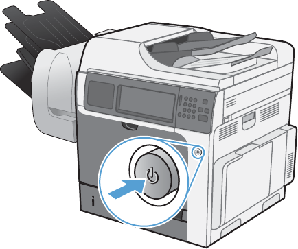
Clean the product
To clean the product exterior, use a soft, water-moistened cloth.
Clean the paper path
1. From the Home screen, touch the Device Maintenance button.
2. Open the following menus:
●Calibrate/Cleaning
●Cleaning Page
3. Touch the Print button to print the page.
4. The cleaning process can take several minutes. When it is finished, discard the printed page.
Clean the scanner glass
Over time, specks of debris might collect on the scanner glass and white plastic backing, which can
affect performance. Use the following procedure to clean the scanner glass and white plastic backing.
1. Use the power switch to turn off the product, and then unplug the power cord from the electrical
socket.
620 Chapter 3 Solve problems ENWW
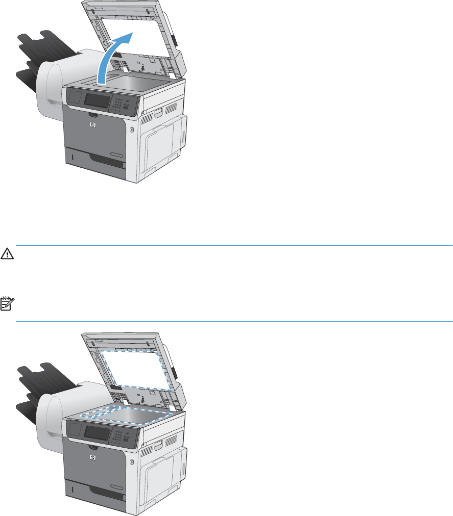
2. Open the scanner lid.
3. Clean the scanner glass and the white plastic backing with a soft cloth or sponge that has been
moistened with nonabrasive glass cleaner. Dry the glass and white plastic backing with a chamois
or a cellulose sponge to prevent spotting.
CAUTION: Do not use abrasives, acetone, benzene, ammonia, ethyl alcohol, or carbon
tetrachloride on any part of the product; these can damage the product. Do not place liquids
directly on the glass or platen. They might seep and damage the product.
NOTE: Carefully clean the small glass strip to the left of the scanner glass. Small marks on this
glass result in streaks on copies made from the document feeder.
ENWW Clean the product 621

4. Plug in the product, and then use the power switch to turn on the product.
Clean the fuser
1. Open Tray 1. Adjust the guides so that they are fully open, then load the appropriate size paper
into the tray so that it fills the space between the guides. Make sure that the guides are fully open,
and that you use the paper supplied in the fuser cleaning kit.
2. Touch the Device Maintenance button, and then touch the Calibrate/Cleaning button.
3. Touch the Cleaning Page button. The cleaning process can take up to 1.5 minutes.
4. Repeat the process 1 to 6 times until the paper comes out clean.
622 Chapter 3 Solve problems ENWW

Solve performance problems
Problem Cause Solution
Pages print but are totally blank. The document might contain blank
pages.
Check the document that you are
printing to see if content appears on all
of the pages.
The product might be malfunctioning. To check the product, print a
Configuration page.
All of the print cartridges might be very
low on toner.
Replace the print cartridges if a
Supplies very low message appears.
Pages print very slowly. Heavier paper types can slow the print
job.
Print on a different type of paper. Proper
fusing may require a slower print speed
to ensure the best print quality.
Complex pages can print slowly. Simplify the page.
Pages did not print. The product might not be pulling paper
correctly.
Make sure paper is loaded in the tray
correctly.
The paper is jamming in the product. Clear the jam.
The USB cable might be defective or
incorrectly connected.
●Disconnect the USB cable at both
ends and reconnect it.
●Try printing a job that has printed
in the past.
●Try using a different USB cable.
Other devices are running on your
computer.
The product might not share a USB port.
If you have an external hard drive or
network switchbox that is connected to
the same port as the product, the other
device might be interfering. To connect
and use the product, you must
disconnect the other device or you must
use two USB ports on the computer.
ENWW Solve performance problems 623

Solve connectivity problems
Solve direct-connect problems
If you have connected the product directly to a computer, check the cable.
●Verify that the cable is connected to the computer and to the product.
●Verify that the cable is not longer than 2 m (6.5 ft). Replace the cable if necessary.
●Verify that the cable is working correctly by connecting it to another product. Replace the cable if
necessary.
Solve network problems
Check the following items to verify that the product is communicating with the network. Before
beginning, print a configuration page. See Configuration pages on page 462.
Problem Solution
Poor physical connection Verify that the product is attached to the correct network port using a cable of the
correct length.
Verify that cable connections are secure.
Look at the network port connection on the back of the product, and verify that the
amber activity light and the green link-status light are lit.
If the problem continues, try a different cable or port on the hub.
The computer is unable to communicate
with the product.
Use the command prompt to ping the product from your computer. For example:
ping 192.168.45.39
Verify that the ping displays round-trip times, which indicates that it is working.
If the ping command failed, verify that the network hubs are on, and then verify that
the network settings, the product, and the computer are all configured for the same
network.
Incorrect link and duplex settings Hewlett-Packard recommends leaving this setting in automatic mode (the default
setting).
Incorrect IP address for the product on
the computer
Use the correct IP address. The IP address is listed on the configuration page.
If the IP address is correct, delete the product, and then add it again.
New software programs have caused
compatibility problems.
Verify that any new software programs are correctly installed and that they use the
correct printer driver.
Your computer or workstation is set up
incorrectly.
Check the network drivers, printer drivers, and the network redirection.
Verify that the operating system is configured correctly.
The protocol is disabled, or other
network settings are incorrect.
Review the configuration page to check the status of the protocol. Enable it if
necessary.
Reconfigure the network settings if necessary.
624 Chapter 3 Solve problems ENWW

Service mode functions
Service menu
The Service menu is PIN-protected for added security. Only authorized service people have access to
the Service menu. When you select Service from the list of menus, the product prompts you to type an
eight-digit personal identification number (PIN). The PIN for the HP Color LaserJet Enterprise CM4540
MFP Series is 11454010.
NOTE: The product automatically exits the Service menu after about one minute if no items are
selected or changed.
1. Scroll to and touch the Device Maintenance button.
2. Touch the Service button.
3. The drop-down menu shows the User Access Code list item. Select the Service Access Code list
item, and then touch the Access Code text box. The touchscreen numeric keypad appears.
4. Type the PIN (xxxxxx).
5. Touch the OK button to save the PIN or the Cancel button to exit the screen.
6. The PIN displays in the Service use only: text box as ********.
7. Touch the OK button to open the Service menu or the Cancel button to exit the screen.
The following menu items appear in the Service menu:
Menu item Sub-menu item Sub-menu
item
Description
Event Log Allows you to print or view the
product event log.
Clear Event Log Use this item to clear the product
event log.
Cycle Counts Total Engine Cycles
Mono Cycle Count The page count that is stored in
NVRAM and printed on the
configuration page represents the
number of pages that the formatter
has formatted (not including
engine-test prints).
Color Cycle Count The page count that is stored in
NVRAM and printed on the
configuration page represents the
number of pages that the formatter
has formatted (not including
engine-test prints).
Refurbish Cycle Count Use this item to record the page
count when the product was
refurbished.
ENWW Service mode functions 625

Menu item Sub-menu item Sub-menu
item
Description
Document Feeder Count: Set the total number of pages that
have been fed through the
document feeder.
Document Feeder Kit Interval Total number of pages since the
document feeder kit was replaced.
ADF Count Set the total pages fed through the
document feeder.
Flatbed Count Set the total pages scanned from
the flatbed.
ADF Simplex Count Set the total single-sided pages fed
through the document feeder.
ADF Duplex Count Set the total two-sided pages fed
through the document feeder.
Copy Scan Count Set the total copy pages that have
been scanned.
Send Scan Count Set the number of scanned pages
sent to e-mail.
Copy Pages Count Set the number of scanned pages
that have been printed.
Fax Scan Count
Scanner Settings Set the calibration values.
WARNING! Do not change
these values unless instructed to do
so.
Serial Number Set the serial number.
626 Chapter 3 Solve problems ENWW

Menu item Sub-menu item Sub-menu
item
Description
Service ID Use this item to show the date that
the product was first used on the
control panel. This eliminates the
need for users to keep paper
receipts for proof of warranty.
Restore the service ID
If you replace the formatter, the
date is lost. Use this menu item to
reset the date to the original date
that the product was first used. The
date format is YYDDD. Use the
following formula to calculate the
dates:
1. To calculate YY, subtract
1990 from the calendar year.
For instance, if the product
was first used in 2002,
calculate YY as follows: 2002
- 1990 = 12. YY = 12.
2. Subtract 1 from 10 (October
is the tenth month of the year):
10 - 1 = 9.
◦Multiply 9 by 30: 9 x 30
= 270 or add 17 to
ENWW Service mode functions 627

Menu item Sub-menu item Sub-menu
item
Description
270: 270 + 17 = 287.
Thus, DDD = 287.
Convert the service ID to an
actual date
You can use the product Service ID
number to determine whether the
product is still under warranty. Use
the following formula to convert the
Service ID into the installation date
as follows:
1. Add 1990 to YY to get the
actual year that the product
was installed.
2. Divide DDD by 30. If there is
a remainder, add 1 to the
result. This is the month.
3. The remainder from the
calculation in step 2 is the
date.
Using the Service ID 12287 as an
example, the date conversion is as
follows:
1. 12 + 1990 = 2002, so the
year is 2002.
2. 287 divided by 30 = 9 with a
remainder of 17. Since there
is a remainder, add 1 to 9 to
get 10, which represents
October.
3. The remainder in step 2 is 17,
so that is the date.
4. The complete date is 17-
October-2002.
NOTE: A six-day grace period is
built into the date system.
Cold Reset Paper When you perform a cold reset,
the paper size that is stored in
NVRAM is reset to the default
factory setting. If you replace a
formatter board in a country/
region that uses A4 as the
standard paper size, use this menu
to reset the default paper size to
A4. LETTER and A4 are the only
available values.
628 Chapter 3 Solve problems ENWW

Menu item Sub-menu item Sub-menu
item
Description
New Registration Roller Reset the counter for the
registration roller after replacing
the registration assembly.
Media Sensor Value After replacement of the
registration assembly, set the
media sensor values found on the
label of the new registration
assembly.
PTT Test Mode
Hook Operations
Generate Random Data
Generate DTMF Tone Burst
Generate DTMF Continuous Tone
Generate Pulse Burst
Generate Tone Dial Number
Generate Pulse Dial Number
Generate Single Modem Tone
Line Measurements
Fax Transmit Signal Loss
Product resets
Restore factory settings
Use the Resets menu to restore factory settings.
1. Scroll to and touch the Administration button, and then touch the General Settings button.
2. Touch the Restore Factory Settings button, and then touch an option. Touch the Select All button to
reset factory settings for all options.
3. Touch the Reset button to restore factory settings.
The values for each reset are as follows:
ENWW Service mode functions 629
Restore factory-set defaults values
●Calibration
◦Persisted calibration engine data
◦Engine color density data
◦LaserJet engine calibration data
●General
◦Display and sound settings for the control panel
◦Localization settings (for example, clock format and date format)
◦Error and warning log behavior
◦Default media settings
◦Sleep mode and delay setting
◦Internal backup file maximum size
◦Oxp installer solutions, tasks and pending tasks
◦Http job defaults
◦Clears the error, warning and info logs
◦Supported media types
◦Resets JetLink connected external devices
●Print
◦Print default job, stored job and quick set settings
◦Some print job usage data
◦Print system configuration settings
●Security
◦Default Authentication agent
◦Authentication agents
◦Policy agents
◦Color access control
630 Chapter 3 Solve problems ENWW

Preboot menu options
If an error occurs while the product is booting, an error message appears on the control-panel display.
The user can access the preboot menus. The error menu item will not be seen if an error did not occur.
Open the preboot menu
1. Turn the product on.
2. Press and hold the Stop button when the LED lights are illuminated solid.
3. Use the 3 button and the 9 button to highlight one of the menu items listed below, and then press
the 6 to open the selected item.
Table 3-32 Preboot menu options (1 of 6)
Menu option First level Second level Third level Description
Continue Selecting theContinue item exits the preboot menu and continues
the normal boot process.
If a selection is not made in the initial menu within 30 seconds,
the product returns to a normal boot (the same as selecting the
Continue item.
If the user navigates to another menu, the timeout does not
apply.
Sign In Enter the administrator PIN or service PIN if one is required to
open the preboot menu.
ENWW Preboot menu options 631

Table 3-32 Preboot menu options (1 of 6) (continued)
Menu option First level Second level Third level Description
Administrator This item navigates to the Administrator sub menus.
If authentication is required (and the user is not already signed
in) the Sign In prompt displays. The user is required to sign in.
Download This item initiates a preboot firmware download process. A USB
device interface or a network connection can be used to
download firmware.
Network See
Product updates on page 651.
USB See
Product updates on page 651.
Clean Disk This item reinitializes the disk and cleans all disk partitions.
CAUTION: Selecting the Clean Disk item removes all data.
A delete confirmation prompt is not provided.
The system is not bootable after this action—a firmware
download must be performed to return the system to a bootable
state.
Partial Clean This item reinitializes the disk (removing all data except the
firmware repository where the master firmware bundle is
downloaded and saved).
CAUTION: Selecting the Partial Clean item removes all data
except the firmware repository.
A delete confirmation prompt is not provided.
This allows user to reformat the disk by removing the firmware
image from the active directory without having to download new
firmware code (product remains bootable).
Change
Password
Select this item to set or change the administrator password.
Clear
Password
Select theClear Password item to remove a password from the
Administrator menu. Before the password is actually cleared, a
message will be shown asking to confirm that the password
should be cleared. Press the 6 button to confirm the action.
632 Chapter 3 Solve problems ENWW

Table 3-33 Preboot menu options (2 of 6)
Menu option First level Second
level
Third level Description
Administrator
continued
Manage Disk Clear Disk Select the Clear Disk item to enable an external device
for job storage. Job storage is normally enabled only for
the boot device. This item is disabled unless the
99.09.68 error is displayed.
Lock Disk Select the Lock Disk item to lock (mate) a new secure disk
to this product.
The secure disk already locked to this product will remain
accessible to this product. Use this function to have more
then one encrypted disk accessible by the product when
using them interchangeably.
The data stored on the secure disk locked to this product
always remains accessible to this product.
Leave
Unlocked
Select the Leave Unlocked item to use a new secure disk
in an unlocked mode for single service event. The secure
disk that is already locked to this product will remain
accessible to this product and uses the old disk's
encryption password with the new disk.
The secure disk that is already locked to this product
remains accessible to this product.
Clear
Password
Select the Clear Password item to continue using the non-
secure disk and clear the password associated with the
yet to be installed secure disk.
CAUTION: Data on the missing secure disk will be
permanently inaccessible.
Retain
Password
Select the Retain Password item to use the non-secure disk
for this session only, and then search for the missing
secure disk in future sessions.
Boot Device Secure Erase Select the Secure Erase item to erase all of the data on
the disk and unlock it, if required.
This process might take a long time.
NOTE: The system will be unusable until the system files
are reinstalled. The process is an ATA secure-erase
command one-pass overwrite. This process erases the
entire disk, including firmware. The disk remains an
encrypted disk.
Erase And
Unlock
Select the Erase And Unlock item to cryptographically
erase all data on disk and unlock the disk to allow access
to it from any product.
NOTE: The system will be unusable until the system files
are reinstalled. This process erases the crypto key. The
disk becomes a non-encrypted disk.
Get Status This item provides disk status information if any is
available.
ENWW Preboot menu options 633

Table 3-34 Preboot menu options (3 of 6)
Menu option First level Second
level
Third level Description
Administrator
continued
Manage Disk
continued
Internal
Device
Select the Internal Device item to erase the internal device
or view the status of the internal device.
Secure Erase Select the Secure Erase item to erase all of the data on
the disk and unlock it, if required.
This process might take a long time.
NOTE: The system will be unusable until the system files
are reinstalled. The process is an ATA secure-erase
command one-pass overwrite. This process erases the
entire disk, including firmware. The disk remains an
encrypted disk.
Erase And
Unlock
Select the Erase And Unlock item to cryptographically
erase all data on disk and unlock the disk to allow access
to it from any product.
NOTE: The system will be unusable until the system files
are reinstalled. This process erases the crypto key. The
disk becomes a non-encrypted disk.
Get Status This item provides disk status information if any is
available.
External
Device
Select the External Device item to erase the external
device or get status about the external device.
Secure Erase Select the Secure Erase item to erase all of the data on
the disk and unlock it if required.
This process might take a long time.
NOTE: The system will be unusable until the system files
are reinstalled. The process is an ATA secure-erase
command one-pass overwrite. This process erases the
entire disk, including firmware. The disk remains an
encrypted disk.
Erase And
Unlock
Select the Erase And Unlock item to cryptographically
erase all data on disk and unlock the disk to allow access
to it from any product.
NOTE: The system will be unusable until the system files
are reinstalled. This process erases the crypto key. The
disk becomes a non-encrypted disk..
Get Status This item provides disk status information if any is
available.
634 Chapter 3 Solve problems ENWW

Table 3-35 Preboot menu options (4 of 6)
Menu option First level Second
level
Third level Description
Administrator
continued
Configure
LAN
Select the Configure LAN item to set the network
settings for the preboot menu firmware upgrade.
The network can be configured to obtain the network
settings from a DHCP server or as static.
DHCP Use this item for automatic IP address acquisition from
the DHCP server.
Static Use this item to manually assign the network addresses.
IP Address Use this item to manually enter the IP addresses.
Subnet Mask Use this item to manually enter the subnet mask.
Default
Gateway
Use this item to manually enter the default gateway.
Save and
Exit
Select the Save and Exit item to save the manual
settings.
ENWW Preboot menu options 635

Table 3-36 Preboot menu options (5 of 6)
Menu option First level Second
level
Third level Description
Administrator
continued
Startup
Options
Select the Startup Options item to specify options that
can be set for the next time the product is turned on and
initializes to the Ready state.
Cold Reset Check the Cold Reset item to clear the IP address and all
customer settings (this item also returns all settings to
factory defaults).
NOTE: Items in the Service menu are not reset.
First Power Not currently functional: This item allows the product to
initialize as if it is the first time it has been turned on.
For example, the user is prompted to configure first-time
settings like date/time, language, and other settings.
Check this item so that it is enabled for the next time the
product power is turned on.
When the product power is turned on the next time, this
item is unchecked so that the pre-configured settings are
used during configuration, and the first-time setting
prompt is not used.
Skip Plugins This item allows the product to be started without loading
the third-party applications.
This means that files including Accessible Architecture on
the disk will not be available at boot-up. This is useful for
troubleshooting problems with the hard disk without
having to remove the hard disk. It also applies to flash
file system disks on DIMMs.
In this case, this function will cause the product to
configure the HP firmware first, followed by the third-
party applications.
NOTE: The files on the disk will be available after the
product enters the Ready state.
Skip Cal Select the Skip Cal item to initialize the product the next
time the power is turned on without calibrating.
Show Revision Not currently functional: Check the Show Revision item to
allow the product to initialize and show the firmware
version when the product reaches the Ready state.
Once the product power is turned on the next time, the
Show Revision item is unchecked so that the firmware
revision is not shown.
Lock Service CAUTION: Select the Lock Service item to lock the
Service menu access (both in the preboot menu and the
Device Maintenance menu).
Service personnel must have the administrator remove
the Lock Service setting before they can open the Service
menu.
636 Chapter 3 Solve problems ENWW

Table 3-37 Preboot menu options (6 of 6)
Menu
option
First level Second
level
Third
level
Description
Administrator
continued
Startup
Options
continued
Skip Disk
Scan
Check the Skip Disk Scan item to allow the
product to initialize without scanning the
disk.
If the product is crashing on step 4/8,
checking this item may allow the problem to
be isolated.
Once the product is turned on the next time,
the Skip Disk Scan item is unchecked and the
disk scan is not skipped.
Embedded
Jetdirect
Off
Check the Embedded Jetdirect Off item to
disable the embedded Jetdirect.
By default this item is unchecked so that
Jetdirect is always enabled.
Service
Tools
This item requires the service access code.
Reset
Password
Use this item to reset the administrator
password.
Subsystems For manufacturing use only. Do not change
these values.
ENWW Preboot menu options 637

Solve fax problems
Is your fax set up correctly?
Use the following checklist to help identify the cause of any fax related problems you are encountering:
●Are you using the phone cord supplied with the fax accessory? This fax accessory
has been tested with the supplied phone cord to meet RJ11 and functional specifications. Do not
substitute another phone cord; the analog-fax accessory requires an analog phone cord. It also
requires an analog phone connection.
●Is the fax/phone line connector seated in the socket on the fax accessory? Make
sure that the phone jack is well seated in the socket. The connector should be inserted into the
socket until it "clicks."
●Is the phone wall jack working properly? Verify that a dial tone exists by attaching a
phone to the wall jack. Can you hear a dial tone, and can you make a phone call?
What type of phone line are you using?
●Dedicated line: A standard fax/phone number assigned to receive or send faxes.
NOTE: The phone line should be for product fax use only and not shared with other types of
telephone devices. Examples include alarm systems that use the phone line for notifications to a
monitoring companies.
●PBX system: A business-environment phone system. Standard home phones and the fax
accessory use an analog phone signal. Some PBX systems are digital and might not be compatible
with the fax accessory. You need to have access to a standard analog phone line to be able to
send and receive faxes.
●Roll-over lines: A phone system feature where a new call "rolls over" to the next available line
when the first incoming line is busy. Try attaching the fax accessory to the first incoming phone
line. The fax accessory will answer the phone after it rings the number of times set in the rings-to-
answer setting.
NOTE: Roll-over lines can cause problems with the fax accessory's ability to receive faxes. Using roll-
over lines with this product is not recommended.
Are you using a surge-protection device?
A surge-protection device can be used between the wall jack and the fax accessory to protect the fax
accessory against electrical power passed through the phone lines. These devices can cause some fax
communication problems by degrading the quality of the phone signal. If you are having problems
sending or receiving faxes and are using one of these devices, connect the fax accessory directly to the
phone jack on the wall to determine whether the problem is with the surge-protection device.
638 Chapter 3 Solve problems ENWW

Are you using a phone company voice-messaging service or an answering
machine?
If the rings-to-answer setting for the messaging service is lower than the rings-to-answer setting for the
fax accessory, the messaging service answers the call, and the fax accessory is not able to receive
faxes. If the rings-to-answer setting for the fax accessory is lower than that of the messaging service, the
fax accessory answers all calls, and no calls are routed to the messaging service.
Does your phone line have a call-waiting feature?
If the fax telephone line has an activated call-waiting feature, a call-waiting notice can interrupt a fax
call in progress, which causes a communication error. Ensure that a call-waiting feature is not active on
the fax telephone line.
Check fax accessory status
If the analog-fax accessory does not appear to be functioning, print a Configuration Page report to
check the status.
1. From the Home screen, scroll to and touch the Administration button.
2. Open the following menus:
●Reports
●Configuration/Status Pages
●Configuration Page
3. Touch the Print button to print the report, or touch the View button to view the report on the screen.
The report consists of several pages.
NOTE: The product IP address or host name is listed on the Jetdirect Page.
On the fax accessory page of the configuration page, under the Hardware Information heading, check
the Modem Status. The following table identifies the status conditions and possible solutions.
Operational / Enabled
1
The analog-fax accessory is installed and ready.
Operational / Disabled
1
The fax accessory is installed and operational, however,
HP Digital Sending utility has either disabled the product fax
feature or has enabled LAN fax. When LAN fax is enabled,
the analog-fax feature is disabled. Only one fax feature, either
LAN fax or analog fax, can be enabled at a time.
Non-Operational / Enabled/Disabled
1
A firmware failure has been identified. The firmware should
be updated.
Damaged / Enabled/Disabled
1
Fax accessory has failed; reseat the fax accessory card and
check for bent pins. If the status is still DAMAGED, replace the
analog-fax accessory card.
1
ENABLED indicates that the analog fax accessory is enabled, turned on; DISABLED indicates that LAN fax is enabled (analog
fax is turned off).
ENWW Solve fax problems 639

Fax feature is not operating
The fax accessory is installed but the icon does not appear on the product main screen.
Cause Solution
HP MFP Digital Sending Software Configuration utility has
disabled the analog-fax feature.
Use the HP MFP Digital Sending Software Configuration utility
to enable the analog-fax feature.
The accessory is not operating correctly. Check the fax accessory status. If the status is
NON-OPERATIONAL, new firmware might need to be
installed.
If the status is DAMAGED and you just installed the card, try
reseating the card and check for bent pins.
If the status is DAMAGED and the card is installed correctly,
the card might need to be replaced.
Faulty formatter board. Contact your HP service representative for service.
The product is not displaying the fax menus.
Cause Solution
LAN fax is enabled. This is normal operation. When the HP Digital Sending
Software enables LAN fax, the analog fax is disabled and the
fax menu, which is used for the analog fax only, does not
open.
General fax problems
Problem Cause Solution
Fax failed to send. JBIG is enabled and receiving fax does
not have JBIG capability.
Set JBIG off.
An "Out of Memory" status message
appears on the status message bar.
The product storage disk is full. Delete some files from the disk, see the
product user guide for information about
managing the disk.
Print quality of a photo is poor or prints
as a gray box.
Wrong Page Content mode setting. Try setting the Optimize Text/Picture
option to Photograph.
Pressed the Cancel button on the
product keyboard to cancel a fax
transmission and the fax was still sent.
Cancellation takes place after making a
selection in the cancellation menu
(displayed after pressing red Stop
button) and acknowledging with OK.
Cancel faxes using the fax menu.
No fax address book button appears. The fax address book feature has not
been enabled.
Use the HP MFP Digital Sending
Software Configuration utility to enable
the fax address book feature.
640 Chapter 3 Solve problems ENWW

Problem Cause Solution
Not able to locate the Fax settings in
HP Web Jetadmin.
Fax settings in HP Web Jetadmin are
located under the device's status page
drop-down menu.
Select Digital Sending and Fax from
the drop-down menu.
The header is being appended to the
top of the page when I have overlay
enabled.
The fax will append the overlay header
to the top of a page when overlay is set,
when the fax has been forwarded.
This is normal operation.
Have a mix of names and numbers in
the recipients box.
This is normal for both names and
numbers to appear, depending on
where they are from, the fax address
book lists names, and all other
databases list numbers.
Normal, no action required.
My one page fax prints as two pages. The fax header is being appended to
the top of the fax, pushing text to a
second page.
If you want your one page fax to print
on one page, set the overlay header to
overlay mode or adjust the Fit to page
setting.
Document stops feeding in the middle of
faxing.
There might be a jam in the ADF. If there is a jam, see the product user
guide for instructions on clearing jams.
The volume for sounds coming from the
fax accessory is too high or too low.
The volume setting needs to be adjusted.
Problems with receiving faxes
Incoming fax calls are not being answered by the fax accessory (no fax detected).
Cause Solution
The rings-to-answer setting might not be set correctly. Check the rings-to-answer setting.
The phone cord might not be connected properly, or the
phone cord is not working.
Check the installation. Make sure you are using the phone
cord that came with the fax accessory.
The phone line might not be working. Disconnect the fax accessory from the phone jack, and
connect a phone. Try to make a phone call to ensure the
phone line is working.
A voice-messaging service might be interfering with the fax
accessory's ability to answer calls.
Do one of the following:
●Discontinue the messaging service.
●Get a phone line dedicated to fax calls.
●Decrease the rings-to-answer for the fax accessory to a
number less than the rings-to-answer for the voice mail.
Faxes are transmitting or being received very slowly.
Cause Solution
You might be sending or receiving a very complex fax, such
as one with many graphics.
Complex faxes take longer to be sent or received.
ENWW Solve fax problems 641

Faxes are transmitting or being received very slowly.
Cause Solution
The receiving fax machine might have a slow modem speed. The fax accessory only sends the fax at the fastest modem
speed the receiving fax machine can use.
The resolution at which the fax was sent or is being received
is very high. A higher resolution typically results in better
quality, but also requires a longer transmission time.
If you are receiving the fax, call and ask the sender to
decrease the resolution and resend the fax. If you are
sending, decrease the resolution and change the Optimize
Text/Picture option.
If there is a poor phone-line connection, the fax accessory and
the receiving fax machine slow down the transmission to
adjust for errors.
Cancel and resend the fax. Have the phone company check
the phone line.
Faxes are not printing on the product.
Cause Solution
There is no media in the media input tray. Load media. Any faxes received while the input tray is empty
are stored and will print after the tray has been refilled.
Schedule Printing of Faxes is set. If Schedule Printing of Faxes is enabled, faxes will not print
until it is disabled.
The product is either low on toner or has run out of toner. The product stops printing as soon as it is low on toner or runs
out of toner. Any faxes received are stored in memory and
print after the toner has been replaced. For other product
printing problems, see the product user guide.
Incoming call may be a voice call. Incoming voice calls usually show up in the call report as a
Communication Error (17) As these are voice calls and
not a fax error, no action is needed to be taken. Ensure that
those calling you have a voice number that is different from
the fax number.
The incoming fax was interrupted. Verify that the fax telephone line does not have an activated
call-waiting feature. A call-waiting notice can interrupt a fax
call in progress, which causes a communication error.
The Fax Printing Schedule feature is set to Always store faxes. Change the Fax Printing Schedule setting to Always print
faxes.
Problems with sending faxes
Problem Cause Solution
Faxes quit during sending. The fax machine to which you are
sending might be malfunctioning.
Try sending to another fax machine.
Your phone line might not be working. Disconnect the fax accessory from the
phone jack, and connect a phone. Try to
make a phone call to ensure the phone
line is working.
642 Chapter 3 Solve problems ENWW

Problem Cause Solution
Your phone line might be noisy or poor
quality
Try using a lower baud rate to improve
the reliability of transmission. See
maximum baud rate setting.
A call-waiting feature might be active Verify that the fax telephone line does
not have an activated call-waiting
feature. A call-waiting notice can
interrupt a fax call in progress, which
causes a communication error.
The fax accessory is receiving
faxes but is not sending them.
If the fax accessory is on a PBX system,
the PBX system might be generating a
dial tone the fax accessory cannot
detect.
Disable the detect dial tone setting.
There might be a poor phone
connection.
Try again later.
The fax machine to which you are
sending might be malfunctioning.
Try sending to another fax machine.
Your phone line might not be working. Disconnect the fax accessory from the
phone jack, and connect a phone. Try to
make a phone call to ensure the phone
line is working.
Outgoing fax calls keep dialing. The fax accessory automatically redials
a fax number if the Redial on Busy
option is set to on or if the Redial On No
Answer is set on.
This is normal operation. If you do not
want the fax to retry, set Redial on Busy
to 0 and set Redial On No Answer to 0.
Faxes you send are not arriving
at the receiving fax machine.
The receiving fax machine might be
turned off or might have an error
condition, such as being out of paper.
Call the recipient to make sure the fax
machine is turned on and ready to
receive faxes.
A fax might be in memory because it is
waiting to redial a busy number, or
there are other jobs ahead of it waiting
to be sent.
If a fax job is in memory for either of
these reasons, an entry for the job
appears in the fax log. Print the fax
activity log, and check the Result
column for jobs with a Pending
designation.
Error codes
If a fax problem occurs which prevents or interrupts sending or receiving of a fax, an error code is
generated that will help in determining the cause of the problem. Error codes show up in the fax activity
log, the fax call report, and the T.30 Protocol Trace. Print one of these three reports to obtain the error
code. A detailed description of the error codes and the appropriate action can be found at
www.hp.com by searching for HP LaserJet Analog Fax Accessory 500.
Fax error messages
When an analog fax is sent or received on an HP LaserJet product, any errors that occur during the fax
process will be displayed on the product control panel and entered into the fax reports. Fax errors can
occur for many reasons and often they are due to interruptions or noise on the telephone connection.
ENWW Solve fax problems 643
Any error that takes place during the fax process regardless of where it originates will be displayed by
the product.
If the fax process is interrupted or an error occurs during a fax transmission or reception, a two part
status/error description is generated by the fax subsystem on the product. Normal or successful faxes
also generate messages indicating success. The message information consists of a text description and
a numeric code (a few messages don’t include numeric codes). Only the text part of the message will
be displayed on the product control panel; however, both the text message and numeric code will be
listed in the fax activity report, fax call report, and the fax T.30 trace (these fax reports can be printed
out individually from the product control panel – under the Administration > Reports > Fax Reports and
Administration > Troubleshooting > Fax > Fax T.30 Trace menus). The numeric code is shown in
parentheses after the text part of the message in the reports. For example, if a communication error
occurred, the control panel display would show Fax Failed: Communication Error. The same error
would be shown in the Result field in the fax activity report as Communication Error (17). For this
example, the numeric code associated with this communication error is ‘17’.
The numeric code is generated by the fax modem. Usually a numeric code of (0) indicates a normal
modem response. Some messages will always display a numeric code of (0), whereas other messages
can have a range of numeric codes depending on the circumstances, and a few messages will have no
numeric code. Usually a numeric code of (0) indicates an error was not associated with the fax modem,
but occurred in another part of the fax subsystem or other product subsystem such as the printing
subsystem. Non-zero error codes give further detail into the particular action or process that the modem
is executing, and they don’t necessarily indicate that there is a problem with the modem.
In the tables that follow, the fax messages with the most common number codes are given with
recommended corrective action. Several messages that are normal or indicate a normal event are also
included in tables. For example, if a fax was not able to be sent to a busy number, a Fail Busy
message will be shown. Nothing is wrong with the fax subsystem; the message indicates the fax was
not completed due to a busy telephone number at the receiving end.
Persistent error messages with numeric codes different than those listed here require assistance of
customer support. A more detailed listing of the last fax call can be printed out before contacting
customer support to help identify the problem. The detailed fax listing is called a fax T.30 trace and
can be printed for the last fax, or it can be set to print whenever a fax error occurs. To print or
configure the fax T.30 trace, touch Administration, Troubleshooting, and then Fax T.30 Trace. You can
then print the report for the last fax or configure when to print the T.30 trace.
644 Chapter 3 Solve problems ENWW

Send-fax messages
Table 3-38 Send-fax messages
Message Error No. Description Action(s)
Cancelled 0 Fax was cancelled by user at
control panel of product.
None.
Success n/a Fax sent successfully. None.
Fail Busy 0 The receiving fax machine is
busy.
The fax will be retired
automatically (if configured),
otherwise try resending fax
later.
No Answer 0 The receiving fax machine is
not answering the call.
The receiving fax machine
may be disconnected or
turned off; contact the
receiver to check the
machine. Try resending.
Compression Error Any Fax may be corrupted or not
sent.
Try resending fax.
No Dial 0 No dial tone is detected
when sending the fax.
Verify the phone line is
active; set the sending fax to
"not" to detect a dial tone.
Modem Fail Any Unexpected or bad response
from the internal fax modem
to product.
Try resending fax; if the error
persists, contact service.
NOTE: This does not
necessarily indicate that the
modem hardware is bad.
Communication Error 17 or 36 Lost telephone connection
between sender and receiver.
May be due to voice calls.
Try resending the fax.
Communication Error Any besides 17 or 36 General communications
issue where the fax
transmission was interrupted
or did not proceed as
expected.
Try resending fax; if the error
persists, contact service.
Space Fail 0 Unable to read or write the
fax image file to disk; could
be corrupt product disk or no
space available on the
product's disk.
Try resending fax; if the error
persists, contact service.
Page Fail 0 Incompatible page width, or
page had too many bad
lines.
Try resending fax; if the error
persists, contact service.
Memory Error 0 Out of RAM memory on
product.
If error persists, may need to
add RAM to product.
Job Fail Any Fax failure; the fax job did
not complete.
Try resending fax; if the error
persists, contact service.
ENWW Solve fax problems 645

Table 3-38 Send-fax messages (continued)
Message Error No. Description Action(s)
Power Failure 0 A power failure occurred
during the fax transmission on
the sending fax product.
Try resending the fax.
No Fax Detected 17 or 36 No fax machine was detected
at receiving end. May be due
to voice calls.
Verify fax number and have
receiver verify fax machine is
on and connected; then try
resending fax.
646 Chapter 3 Solve problems ENWW

Receive-fax messages
Table 3-39 Receive-fax messages
Message Error No. Description Action(s)
Success n/a Fax received ok. None.
Blocked n/a Fax reception was blocked by
receiving fax machine using
blocked number feature.
None.
Modem Fail Any Unexpected or bad response
from the internal modem to
the product - example is
trying to send a fax just as
another fax is arriving.
Have fax resent; if the error
persists, contact service.
Communication Error 17, 36 Lost telephone connection or
interruption between sender/
receiver.
Have the sender resend the
fax (if the sending machine
does not automatically retry).
Communication Error Any besides 17 or 36 General communications
issue where the fax
transmission was interrupted
or did not proceed as
expected.
Have fax resent; if the error
persists, contact service.
Space Fail 0 Unable to read or write
image file to disk; could be
corrupt product disk or no
space on disk.
Have fax resent; if the error
persists, contact service.
Page Fail 0 Incompatible page width or
page had too many bad
lines.
Have fax resent; if the error
persists, contact service.
Memory Error 0 Out of RAM memory on
product.
If error persists, may need to
add additional RAM memory
to product.
Compression Error 0 Corrupted fax - the received
image file cannot be
decoded.
Have fax resent; enable ECM
(Error Correction Mode) if not
already.
Print Fail 0 Corrupted fax - the received
image file cannot be
decoded.
Have fax resent; enable ECM
(Error Correction Mode) if not
already.
Poll Invalid 0 The fax polling feature
attempted to retrieve a fax
from another machine but no
fax was available.
Contact the administrator of
the fax machine being polled
and verify a fax is available,
and then retry.
Job Fail Any Fax failure; this includes all
non-specific failures.
Have fax resent; if the error
persists, contact service.
Power Failure 0 A power failure occurred
during the fax reception.
Have the sender resend the
fax.
No Fax Detected 17, 36 A voice call was made to the
fax.
None
ENWW Solve fax problems 647
Fax reports
The following sections list the fax reports available on this product. These reports can be printed or
viewed on the product control panel.
The following fax reports are available on this product:
●Fax Activity Log
●Billing Codes Report
●Blocked Fax List
●Speed Dial List
●Fax Call Report
Use the following steps to print or view a fax report:
1. From the Home screen, scroll to and touch the Administration button.
2. Open the following menus:
●Reports
●Fax Reports
3. Touch the log or report to print or view.
4. Touch the Print or View button.
Fax activity log
The fax activity log includes the following information.
●The fax header information configured on the product.
●The job number of each fax job.
●Date and time of all faxes received, sent, or failed to send.
●The type of fax job; send or receive.
●Identification (phone number, if available)
●Duration (off-hook time)
●Number of pages
●Result (successfully sent, pending, or failed to send which includes error type and code)
The database stores the most recent 500 fax entries (older faxes are deleted from the log). The
database fax entries include any fax session as an entry. For example, a fax session could be a sent
fax, received fax, or firmware upgrades. Depending on the activity, there might be fewer than 500
entries in the report (unless you sent 500 faxes without receiving any faxes or other completing another
activity).
648 Chapter 3 Solve problems ENWW
If you want to use the log for record keeping purposes, you should print the log periodically (at least
every 500 faxes), and then clear it.
Billing code report
The billing code report is a list of the most recent 500 faxes that were successfully sent, listed by billing
code. The following information is provided in this report.
●Billing code number
●Date and time of all faxes that were successfully sent
●Identification number
●Duration (off hook time)
●Number of pages sent
●Result (success)
The database stores the most recent 500 faxes (older faxes are deleted from the database). If you want
to use the report for record keeping purposes, you should print the report periodically (at least every
500 faxes), and then clear it.
Blocked fax list report
The blocked fax list report contains the list of fax numbers that the product has been configured to not
receive faxes from.
Speed dial list report
A speed dial list report lists the fax numbers assigned to speed dial names.
Fax call report
The fax call report is a brief report that indicates the status of the last fax that was sent or received.
Clear the fax activity log
To clear the fax activity log, complete the following steps.
1. On the control panel, touch the Administration button.
2. Open the following menus:
●Fax Settings
●Clear fax activity log
3. Touch the Clear button to clear the fax activity log.
ENWW Solve fax problems 649

Service settings
These items in the control-panel menus can help with troubleshooting if the corrective action taken under
the Error Codes section is unsuccessful. They are intended to be used when an HP service
representative is assisting you.
Settings in the Troubleshooting menu
Open the Administration menu, and then select the Troubleshooting menu.
Troubleshooting menu settings Fax T.30 Trace: The T.30 trace is a printed report which produces a record of all the
communications between the sending and receiving fax machines for the last fax
transmission or reception. The report has many technical details which are usually
beyond the scope of most users. However the report contains detailed error codes and
other information that might be useful in troubleshooting a particular problem related to
sending or receiving a fax. The report contents might be requested by an HP service
representative when trying to determine the cause of a problem and will help to
determine the appropriate action.
Transmit Signal Loss: This selection compensates for phone line signal loss. It is not
recommended to modify this setting unless requested to do so by an HP service
representative as it might render the fax inoperable.
V34: This setting has two values, Normal and Off, that control the modem baud rate. The
Normal setting allows the modem to select any of the supported baud rates up to 33,600
bps. The Off setting sets the baud rate to 14,400 bps. This setting remains set, until
changed.
Speaker Mode: This service setting has two modes, Normal and Diagnostic. In Normal
mode, the modem speaker is turned on during dialing through the initial connection and
then shuts off. For Diagnostic mode, the speaker is turned on and remains on for all fax
communications until the setting is returned to Normal mode.
Settings in the Resets menu
Open the Administration menu, and then select the Resets menu.
Resets menu settings Restore Factory Telecom Settings or Restore Default Telecom Settings: This selection
resets menu changes back to their default settings. This includes the maximum baud
rate, ring-burst off time, V.34, speaker mode, and transmit signal loss.
Firmware upgrades
The firmware on the fax accessory can be updated. Fax firmware updates occur as part of an overall
product firmware update. See the product user guide for more information.
650 Chapter 3 Solve problems ENWW

Product updates
To download the most recent firmware upgrade for the product, go to www.hp.com/go/
cljcm4540mfp_firmware.
Determine the installed revision of firmware
Print a configuration page to determine the installed revision of firmware. See Configuration pages
on page 462.
On the configuration page, look in the section marked Device Information for the firmware datecode
and firmware revision.
Firmware datecode and firmware revision examples
●20100831 (firmware datecode)
●103067_104746 (firmware revision)
Perform a firmware upgrade
The firmware bundle is a xxxxxxx.bdl file. This file requires an interactive upgrade method. You
cannot upgrade the product using the traditional FTP, LPR or Port 9100 methods of upgrading. Use one
of the following methods to upgrade the product firmware.
Use the HP Embedded Web Server
1. Open an browser window.
2. Enter the product IP address in the URL line.
3. Click the Troubleshooting tab, and then click the Firmware Upgrade link.
NOTE: If you get a warning screen, follow the instructions for setting an administrator password
from the Security tab.
4. Browse to the location that the firmware upgrade file was downloaded to, and then select the
firmware file. Click the Install button to perform the upgrade.
NOTE: Do not close the browser window until the HP Embedded Web Server (EWS) displays
the confirmation page.
5. Click the Restart Now button on the EWS confirmation page, or turn the product off, and then
on again using the power switch.
ENWW Product updates 651

Use a USB storage device with the preboot menu
1. Copy the firmware update file to a portable USB flash memory storage device (thumb drive).
2. Turn the product on.
3. Press and hold the Stop button when all of the LEDs illuminate solid.
4. Press the 9 button to highlight the Administrator menu, and then press the 6 button.
5. Press the 9 button to highlight the Download menu, and then press the 6 button.
6. Insert the portable USB storage device with the firmware update file on it.
NOTE: If the error message No USB Thumbdrive Files Found appears on the control-panel
display, you might need to connect the storage device to the external USB connection on the
formatter.
7. Press the 9 button to highlight the USB Thumbdrive menu, and then press the 6 button.
8. Press the 9 button to highlight the firmware update file, and then press the 6 button.
NOTE: The upgrade process can take up to 10 minutes to complete.
TIP: If there is more than one firmware update file on the storage device, make sure that you
select the correct file for this product.
9. When the message Complete appears on the control-panel display, press the 5 button three
times.
10. When the message Continue appears on the control-panel display, press the 6 button. The product
will initialize.
11. When the upgrade process is complete, print a configuration page and verify that the upgrade
firmware version was installed.
652 Chapter 3 Solve problems ENWW

Use a USB storage device with the Device Maintenance menu
1. Copy the firmware update file to a portable USB flash memory storage device (thumbdrive).
2. Turn the product on, and then wait until it reaches the Ready state.
3. Touch the Device Maintenance button.
4. Touch the USB Firmware Upgrade menu.
5. Insert the portable USB storage device with the firmware upgrade file on it into the USB port on
the front of the product, and then press the OK button.
6. Touch the firmware update file, and then touch the Upgrade button.
TIP: If there is more than one firmware upgrade file on the storage device, make sure that you
select the correct file for this product.
7. When the product prompts you to confirm the upgrade, touch the Upgrade button.
When the upgrade is complete, the product will initialize.
NOTE: The upgrade process can take up to 10 minutes to complete.
8. When the upgrade process is complete, print a configuration page and verify that the upgrade
firmware version was installed.
ENWW Product updates 653
654 Chapter 3 Solve problems ENWW

4 Parts and diagrams
●Order parts, accessories, and supplies
●Part numbers
●Screws
●How to use the parts lists and diagrams
●External covers, panels, and doors
●Right door assembly
●Front door assembly
●Internal components
●Stapling mailbox
●500-sheet paper feeder
●1x500 and 3x500 paper feeders
●Document feeder/scanner
●Alphabetical parts list
●Numerical parts list
ENWW 655

Order parts, accessories, and supplies
You can obtain the following items directly from HP:
●Replacement parts: To order replacement parts in the U.S., go to partsurfer.hp.com. Outside
the United States, order parts by contacting your local authorized HP service center.
●Supplies and accessories: To order supplies in the U.S., go to www.hp.com/go/ljsupplies. To
order supplies worldwide, go to www.hp.com/ghp/buyonline.html. To order accessories, go to
www.hp.com/support/cljcm4540mfp.
656 Chapter 4 Parts and diagrams ENWW

Part numbers
The following list of accessories was current at the time of printing. Ordering information and
availability of the accessories might change during the life of the product.
Accessories
Product name Product number Part number
HP Color LaserJet 1x500 Paper Feeder
and stand
CC422A CC493-67902
HP Color LaserJet 3x500 Paper Feeder
and stand
CC423A CC493-67903
HP Color LaserJet Stapler Stacker Multi-
Bin Mail Box
CC424A CC424-67901
HP Color LaserJet 1x500 Paper Feeder CC425A CC425-67901
HP LaserJet MFP Analog 500 Fax
Accessory
CC487A CC456-60002
Supplies and maintenance kits
Product name
1
Product number Part number
HP Color LaserJet standard black print
cartridge (8.5K)
CE260A CE260-67901
HP Color LaserJet high capacity black
print cartridge (18K)
CE264X CE264-67901
HP Color LaserJet cyan print cartridge CF031A CF031-67901
HP Color LaserJet yellow print cartridge CF032A CF032-67901
HP Color LaserJet magenta print
cartridge
CF033A CF033-67901
Toner collection unit CE265A CC493-67913
Staple cartridge C8091A C8085-60541
Document feeder maintenance kit
Includes:
●Pickup roller/feed roller assembly
●Separation pad
●Instructions
CE248A CE248-67901
ENWW Part numbers 657

Product name
1
Product number Part number
Maintenance transfer kit
Includes:
●ITB
●Secondary transfer roller
●Tray 1 pickup roller
●8 paper feed and separation
rollers
●Instructions
CE249A CC493-67910
110V fuser kit
Includes:
●Fuser assembly, 110 v
●Instructions
CE246A CC493-67911
220V fuser kit
Includes:
●Fuser assembly, 220 v
●Instructions
CE247A CC493-67912
1
For more information, go to www.hp.com/go/learnaboutsupplies
Cables and interfaces
Product name Product number Part number
Enhanced I/O (EIO) card J7961G
658 Chapter 4 Parts and diagrams ENWW

Product name Product number Part number
USB cable 2 meter standard Q6264A
Power cord China 220V - 10A: 8121-0943
Taiwan 110V - 13A: 8121-0964
Korea 220V - 10A: 8121-0731
Japan 110V - 12A: 8121-1143
India 220V - 6A: 8121-0564
Asia Pacific 220V - 10A: 8121-0739
Austrailia/New Zealand 220V - 10A: 8121-0837
Israel 220V - 10A: 8121-1004
Denmark 220V - 10A: 8121-0733
South Africa 220V - 10A: 8121-0737
Switzerland 220V - 10A: 8121-0738
Brazil 110V - 10A: 8121-0734
Argentina 220V - 10A: 8121-0729
North America 110V - 13A: 8121-1141
Israel unique cord: 8120-8913
Switzerland unique cord: 8121-0844
Rest of world standard 2-wire RJ11: 8121-0811
Customer self repair (CSR) parts
Product name Part number
Document feeder roller cover (ASY-CVR-FE-PICK-SP) PF2309K132NI
Formatter assembly kit
Includes:
●Formatter PCA
●Formatter tray assembly (face plate)
●Screws
●EIO card guide
●Instructions
CE871-69001
ENWW Part numbers 659

Product name Part number
Internal hard-disk drive kit
Includes:
●Disk drive cradle
●Right plastic rail
●Left plastic rail
●Encrypted hard drive
●SATA combo power and data cable
●Formatter fan
●Instructions
CC419-67902
Fuser cleaning kit
Includes:
●50-sheets of HP tough paper
●Instructions
CC468-67919
Output bin bezel service kit
Includes:
●Output bin bezel
●Instructions
CC419-67904
Document feeder tray extender service kit
Includes:
●ASY-TRY-BASE-SP
●Instructions
CC419-67903
Control panel kit
Includes:
●Control panel
●Instructions
CC419-67901
Service manual (this manual) CC419-90987
660 Chapter 4 Parts and diagrams ENWW

Service kits
Table 4-1 Service kits
Product name Part number
Feed and separation roller kit (Trays 2–5)
Includes:
●One each, feed and separation rollers
●Instructions
CC493-67907
Secondary transfer (T2) roller kit
Includes:
●Roller
●Instructions
CC493-67908
Tray 1 roller kit
Includes:
●Pickup roller
●Instructions
CC493-67906
Repair transfer kit
Includes:
●ITB
●Secondary transfer roller
●Instructions
CC493-67909
Formatter fan 3160-4244
Duplex registration assembly kit
Includes:
●Registration assembly
●Instructions
CC493-67917
ENWW Part numbers 661

Table 4-1 Service kits (continued)
Product name Part number
Laser/scanner assembly kit
Includes:
●Laser/scanner assembly
●Instructions
CC493-67914
Secondary transfer assembly kit
Includes:
●Secondary transfer assembly
●Instructions
CC492-67901
662 Chapter 4 Parts and diagrams ENWW

Unique components
Use the following tables as a quick reference to identify component part numbers by product voltage.
Table 4-2 110 V and 220 V unique components
Item Part number
Fuser kit, 110 V CC493-67911
Fuser kit, 220 V CC493-67912
Low-voltage power supply, 110 V RM1-5763-000CN
Low-voltage power supply, 220 V RM1-5764-000CN
ENWW Part numbers 663

Screws
NOTE: The screw illustrations in the following table are for reference only. Screws might vary in size
and appearance from those shown in this table.
Table 4-3 Common fasteners
Example Description Size Part Number
Screw, D M3X8 XA9-1671-000CN
Screw, tapping, truss head M4X10 XB4-7401-005CN
Screw, step Not applicable RC3-0912-000CN
Screw, RS M3X8 XA9-1449-000CN
664 Chapter 4 Parts and diagrams ENWW

How to use the parts lists and diagrams
The figures in this chapter show the major subassemblies in the product and their component parts. A
parts list table follows each exploded view assembly diagram. Each table lists the item number, the
associated part number, and the description of each part. If a part is not listed in the table, then it is not
a field replacement unit (FRU).
CAUTION: Be sure to order the correct part. When looking for part numbers for electrical
components, pay careful attention to the voltage that is listed in the description column. Doing so will
ensure that the part number selected is for the correct all-in-one model.
NOTE: In this manual, the abbreviation “PCA” stands for “printed circuit-board assembly.”
Components described as a PCA might consist of a single circuit board or a circuit board plus other
parts, such as cables and sensors.
ENWW How to use the parts lists and diagrams 665
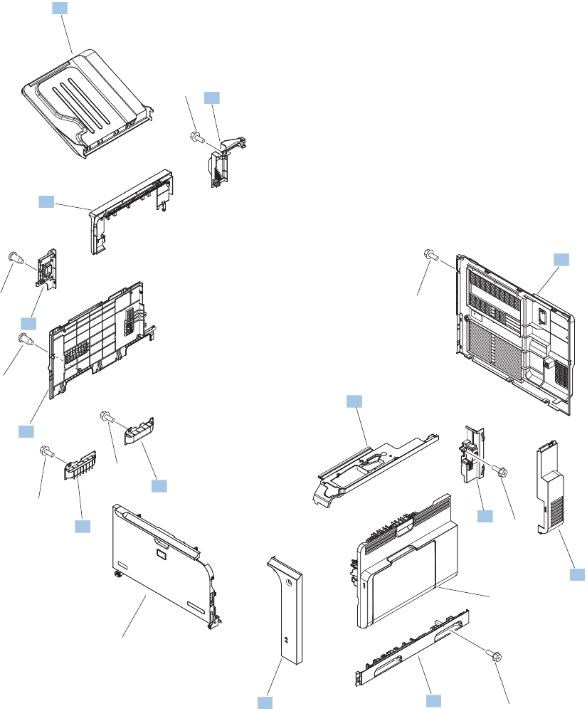
External covers, panels, and doors
Figure 4-1 External covers, panels, and doors
Right door
assembly
See figure 4-2
Front door
assembly
See figure 4-3
1
2
4
5
7
10
13
3
11
12
6
9
8
14
14
14
14
14
15
15
*A01
666 Chapter 4 Parts and diagrams ENWW

Table 4-4 External covers, panels, and doors;
Ref Description Part number Qty
1 Grip, left front RC2-4268-000CN 1
2 Grip, left rear RC2-4269-000CN 1
3 Rear cover assembly RM1-5613-000CN 1
4 Cover, right front RC2-4287-000CN 1
5 Cover, right rear RC2-4273-000CN 1
6 Cover, intermediate assembly RM1-5645-000CN 1
7 Cover, left lower RC2-4300-000CN 1
8 Cover, inner RM1-5520-000CN 1
9 Output bezel kit CC419-67904 1
10 Cover, left rear RC2-8213-000CN 1
11 Cover, fan RC2-4288-000CN 1
12 Output bin, left paper delivery assembly RM1-5632-000CN 1
13 Right handle cover assembly RM1-5507-000CN 1
ENWW External covers, panels, and doors 667
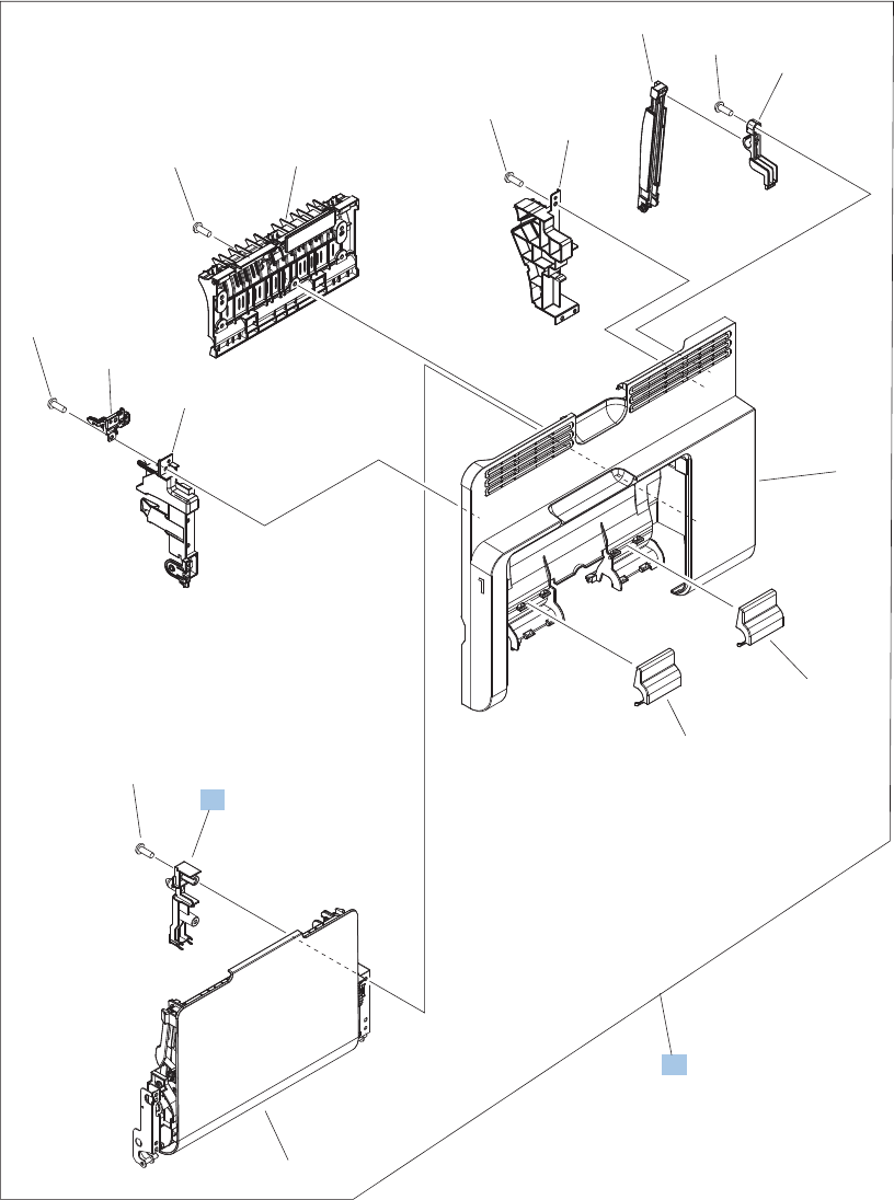
Right door assembly
Figure 4-2 Right door assembly
2
1
3
*A01
*A02
*A03
*A04
*A05
*A06
*A06
*A06
*A06
*A06
*A07
*A08
*A09
*A09
668 Chapter 4 Parts and diagrams ENWW

Table 4-5 Right door assembly
Ref Description Part number Qty
1 Right door assembly RM1-5509-000CN 1
3 Cover, M.P. crossmember R RC2-4747-000CN 1
ENWW Right door assembly 669
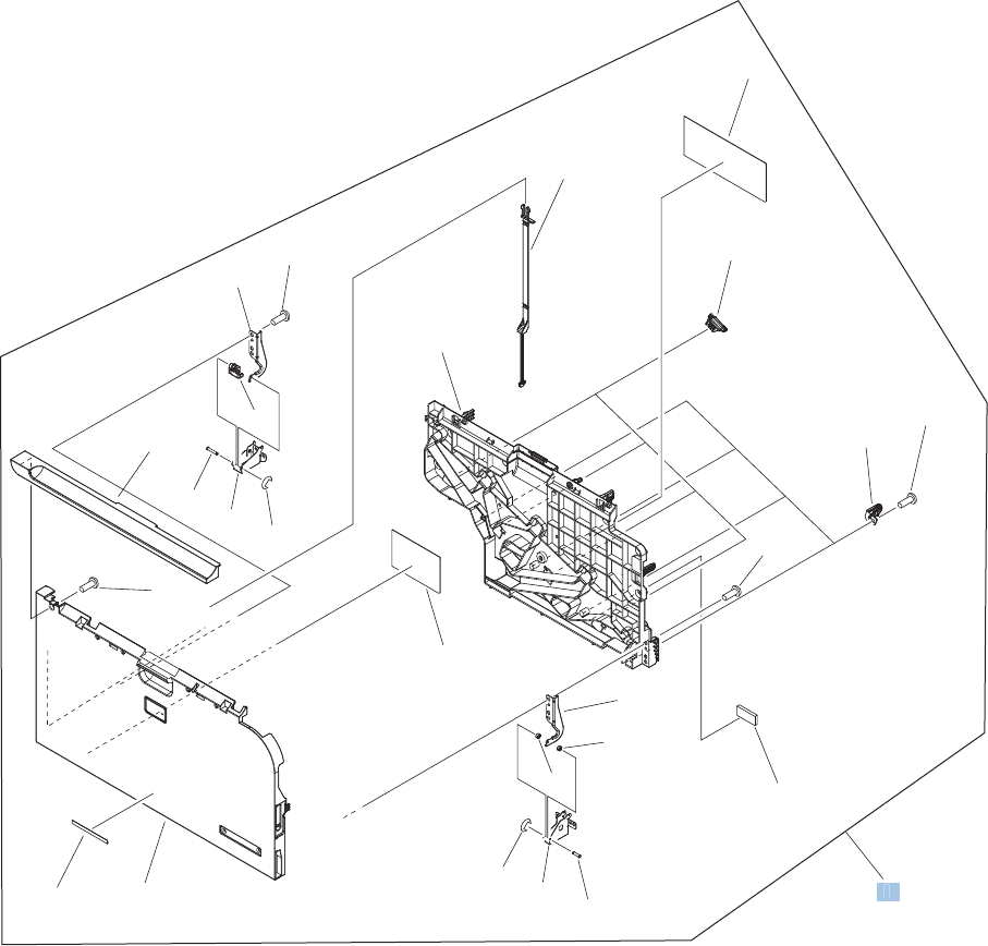
Front door assembly
Figure 4-3 Front door assembly
*A01
*A01
*A03
*A05
*A06
*A07
*A07
*A08
*A09
*A10
*A11
*A12
*A13
*A14
*A15
*A16
*A17
*A17
*A18
*A19 *A02
*A04
*A18
*A18
*A18
1
1
670 Chapter 4 Parts and diagrams ENWW

Table 4-6 Front door assembly
Ref Description Part number Qty
1 Front door assembly RM1-5612-000CN 1
ENWW Front door assembly 671
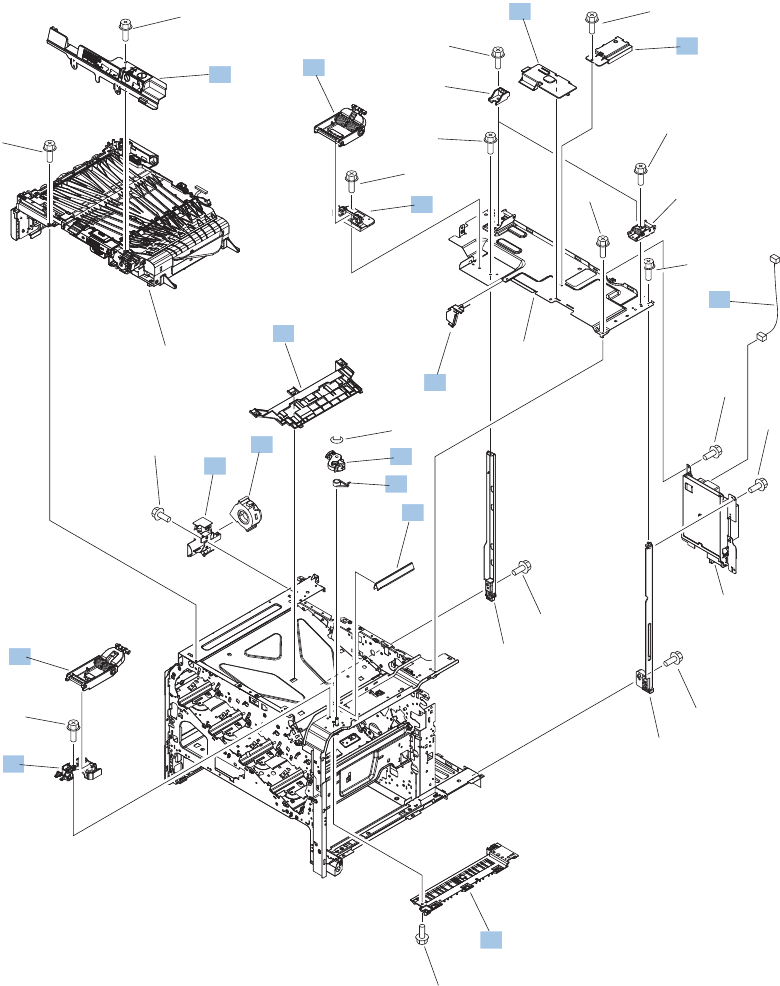
Internal components
Internal components (1 of 7)
Figure 4-4 Internal components 1 of 7
Intermediate paper
feed assembly
See Figure 4-16
PCAs
See Figure 4-19
(FM3)
(J62)
(J98)
(J2)
1
2
5
17
7
3
4
6
8
9
10
11
12
13
14
15
16
16
16
16
16
16
16 18
16
16
16
16
16
16
16
*A01
*A02
*A03
*A04
*A05
*A06
*A07
672 Chapter 4 Parts and diagrams ENWW

Table 4-7 Internal components (1 of 7)
Ref Description Part number Qty
1 Scissors hinge assembly, right RM1-5614-000CN 1
2 Scissors hinge assembly, left RM1-5616-000CN 1
3 Guide, interlock cable RC2-4632-000CN 1
4 Stand, scissors hinge, left RC2-4642-000CN 1
5 Image scanner CN cover assembly RM1-5646-000CN 1
6 Lever, release RC2-4644-000CN 1
7 Fan RK2-2575-000CN 1
8 Spring, torsion RC2-4645-000CN 1
9 Stand, scissors hinge, right RC2-4646-000CN 1
10 Cover, high voltage RC2-4662-000CN 1
11 Cover, duplexing gear RC2-4664-000CN 1
12 Guide, crossmember cable, upper RC2-8206-000CN 1
13 IPTU inner cover assembly RL1-2181-000CN 1
14 Holder, door handle, right RC2-4661-000CN 1
15 DC cable assembly RM1-5827-000CN 1
17 Holder, exhaust fan RC2-4665-000CN 1
ENWW Internal components 673
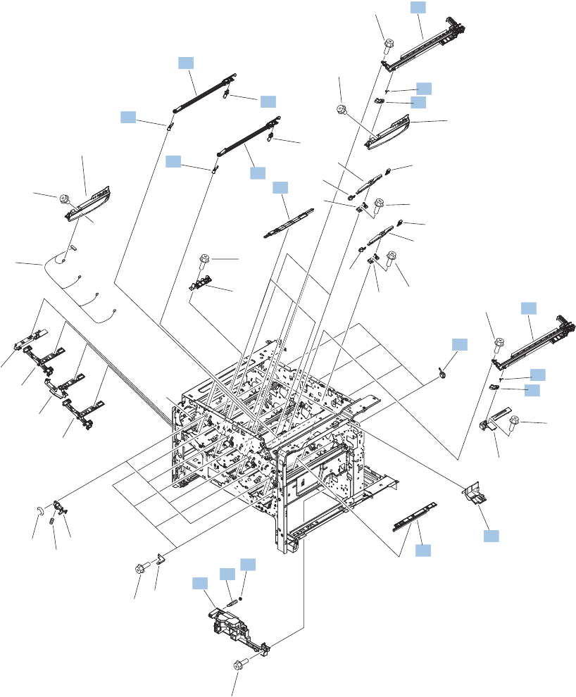
Internal components (2 of 7)
Figure 4-5 Internal components 2 of 7
A
A
PCAs
See Figure 4-19
(J1)
(J68)
(J2)
(J3)
(J4)
PCAs
See Figure 4-19
1
2
3
3
4
5
5
6
78
10
11
12
13
14
15
16
16
17
18
19
20
21
22
23
24
25
29 28
28
9
27
19
26
26
26
26
26
24
29
26
26
26
26
26
23
22
*A01
674 Chapter 4 Parts and diagrams ENWW

Table 4-8 Internal components (2 of 7)
Ref Description Part number Qty
1 Bushing RC2-9719-000CN 4
3 Lever, CRG. lock RC2-3986-000CN 4
4 Tray, waste toner catch RC2-4218-000CN 1
5 Spring, torsion RU6-2247-000CN 4
7 Spring, grounding RC2-4469-000CN 1
8 Bushing RC2-4470-000CN 1
12 Lifter base assembly RM1-5913-000CN 1
17 Cover RC2-4403-000CN 3
18 Cover RC2-5962-000CN 1
19 Crg. Guide lower assembly RM1-5486-000CN 4
20 Shutter assembly RM1-5488-000CN 2
21 Shutter assembly RM1-5489-000CN 2
22 Shutter arm assembly RM1-5585-000CN 4
23 Shutter arm assembly RM1-5586-000CN 4
ENWW Internal components 675
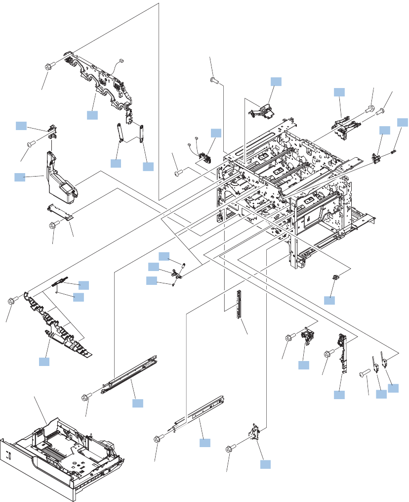
Internal components (3 of 7)
Figure 4-6 Internal components 3 of 7
Cassette
See Figure 4-11
(SW2)
(FT1)
(SW5)
(J45)
(SW3)
(J84)
(SW1)
(FT2)
(SR7)
(J46)
(J60)
(J66)
(J82)
12
4
5
6
7
8
9
10
11
12
13
14
3
16
21
22
15
17
18
20
19
23
19
24
25
25
25
25
25
25
25
25
25
*A01
*A04
*A04
*A04
*A03
*A05
676 Chapter 4 Parts and diagrams ENWW

Table 4-9 Internal components (3 of 7)
Ref Description Part number Qty
1 Hinge, front door RC2-4291-000CN 1
2 Hinge, front door RC2-4292-000CN 1
3 Cover RC2-4467-000CN 1
4 Holder, sensor RC2-4369-000CN 1
5 Lever, shutter RC2-4415-000CN 4
6 Spring, compression RU6-2316-000CN 4
7 Front inner cover upper assembly RM1-5495-000CN 1
8 Interlock assembly RM1-5496-000CN 1
9 Toner collection unit (TCU) kit (includes instructions and wipe) CC493-67913 1
10 Waste toner duct assembly RM1-5519-000CN 1
11 Power switch assembly RM1-5582-000CN 1
12 Front inner cover lower assembly RM1-5598-000CN 1
13 Cassette rail right assembly RM1-6195-000CN 1
14 Cassette rail left assembly RM1-6196-000CN 1
15 Lever, crg. pressure, front RC2-3983-020CN 4
17 Spring, tension RU6-2236-000CN 4
18 Spring, grounding RU6-2237-000CN 4
19 Switch WC4-5303-000CN 2
20 Waste toner detect assembly RM1-5545-000CN 1
21 Waste toner paper feed assembly RM1-5584-000CN 1
22 High voltage holder assembly RM1-6694-000CN 1
23 Switch, push WC2-5637-000CN 1
24 Photo interrupter WG8-5696-000CN 1
ENWW Internal components 677
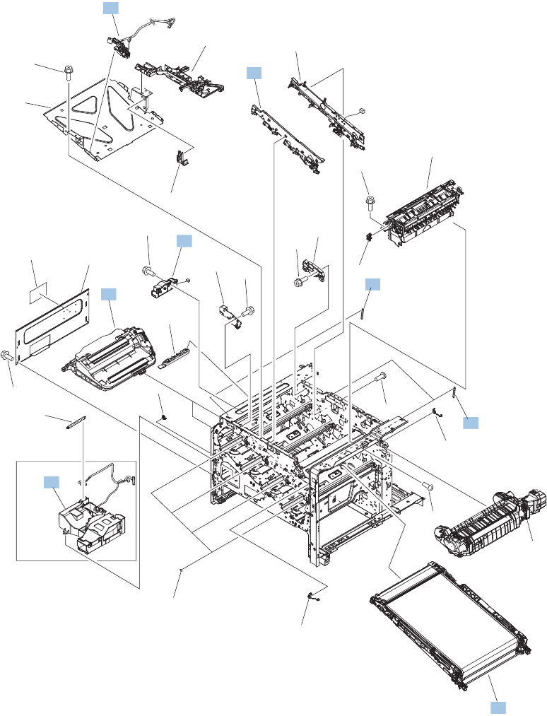
Internal components (4 of 7)
Figure 4-7 Internal components 4 of 7
Fuser assembly
See Figure 4-18
Delivery assembly
See Figure 4-17
(SR9)
(J19)
(SR6)
(J47)
(J78)
(J63)
(FM2)
(J65)
6
1
2
3
4
5
8
9
10
12
4
11
19
13
14
17
16
15
7
18
20
20
20
20
20
20
*A01
*A02
*A04
*A03
*A03
678 Chapter 4 Parts and diagrams ENWW

Table 4-10 Internal components (4 of 7)
Ref Description Part number Qty
4 Spring, tension RU6-2235-000CN 4
6 Cartridge fan assembly RM1-5589-000CN 1
8 Waste toner motor assembly RM1-5605-000CN 1
9 Laser scanner kit (includes instructions and one scanner
assembly)
CC493-67914 1
10 Position detect assembly RM1-5604-000CN 1
11 Front light guide assembly RM1-5492-000CN 1
12 Repair transfer kit (includes instructions, ITB, and secondary
transfer roller)
CC493-67909 1
ENWW Internal components 679
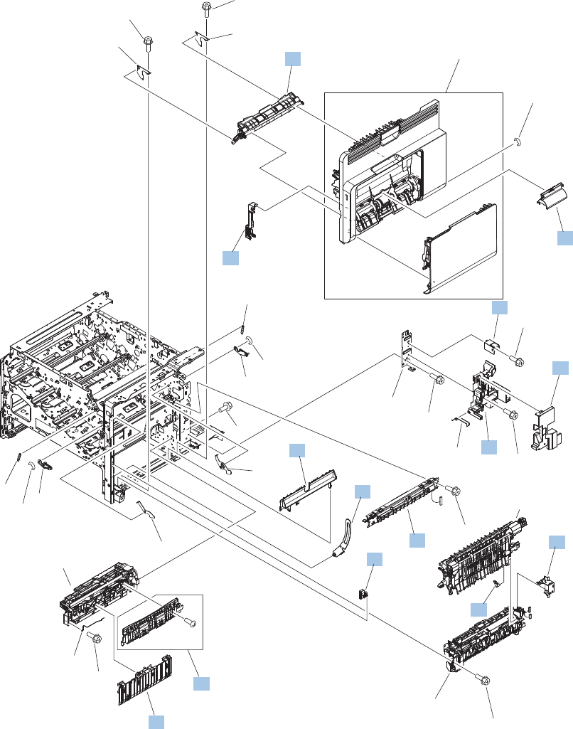
Internal components (5 of 7)
Figure 4-8 Internal components 5 of 7
Right door assembly
See Figure 4-2
Registration
assembly
See Figure 4-14
Secondary
transfer assembly
See Figure 4-15
Paper pickup
assembly
See Figure 4-12
(J83)
2
3
4
5
6
7
8
9
19
10
11
12
13 14
15
17
20
21
22
1
18
22
16
16
16
16
16
16
16
16
16
*A01
*A01
*A02
*A04
*A03
*A03
680 Chapter 4 Parts and diagrams ENWW

Table 4-11 Internal components (5 of 7)
Ref Description Part number Qty
2 Cover, inner RC2-3981-000CN 1
3 Shaft support (included in secondary transfer kit; see Figure 4–
15)
RC2-4162-000CN 1
4 Spacer RC2-4514-000CN 1
6 Guide RC2-4527-000CN 1
7 Link, right door RC2-4726-000CN 1
8 Guide, cassette option RC2-4741-000CN 1
9 Holder, duct cable RM1-5601-000CN 1
11 Cassette guide assembly (jam access) RM1-5504-000CN 1
12 Paper feed roller assembly RM1-5525-000CN 1
13 Density detect assembly RM1-5641-000CN 1
14 Cable cover assembly RM1-6695-000CN 1
15 Cover, roller RC2-4483-000CN 1
17 Cover, M.P. crossmember F RC2-9189-000CN 1
19 Arm, door link supporting, right RC2-4055-000CN 1
ENWW Internal components 681
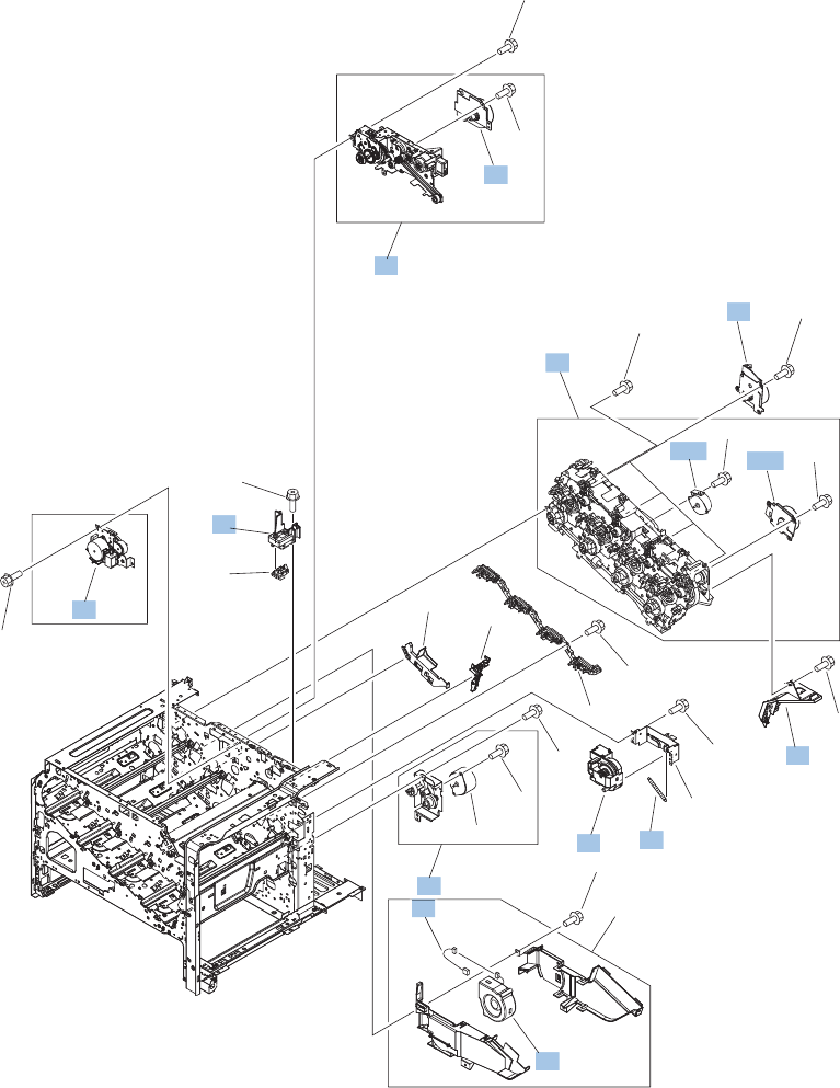
Internal components (6 of 7)
Figure 4-9 Internal components 6 of 7
(J79)
(FM4)
(J39)
(M11)
(J69)
(SL2)
(J37)
(M13)
(J14)
(M1)
(J38)
(M10)
(J13)
(M2)
(M3),(J18)
(M4),(J17)
(M5),(J16)
(M6),(J15)
(J79)
(J264)
1
2
4
5
6
7
8
9
10
10A
11
12
13
6A
10B
9A
3
15
15
15
15
15
15
15
15
15
15
15
15
15
14
16
*A01
*A02
*A03
682 Chapter 4 Parts and diagrams ENWW

Table 4-12 Internal components 6 of 7
Ref Description Part number Qty
2 Holder, paper pickup connector RC2-4044-000CN 1
3 Duplexing drive assembly RM1-4973-000CN 1
5 Spring, tension RU6-2468-000CN 1
6A Cartridge fan RK2-2418-000CN 1
7 Flexible flat cable assembly (includes two FFCs; DCC to laser/
scanner)
RM1-5498-000CN 1
8 Main DC motor assembly RM1-5521-000CN 4
9 Paper pickup drive assembly RM1-5549-000CN 1
10 Main drive kit (includes instructions) CC493-67915 1
10A ITB motor assembly RM1-5777-000CN 1
10B Developing disengaging motor RK2-2415-000CN 1
12 Fuser drive assembly, duplex RM1-5656-000CN 1
13 Lifter assembly RM1-5914-000CN 1
14 Fuser motor assembly RM1-4983-000CN 1
16 Cable, fan RM1-5821-000CN 1
ENWW Internal components 683
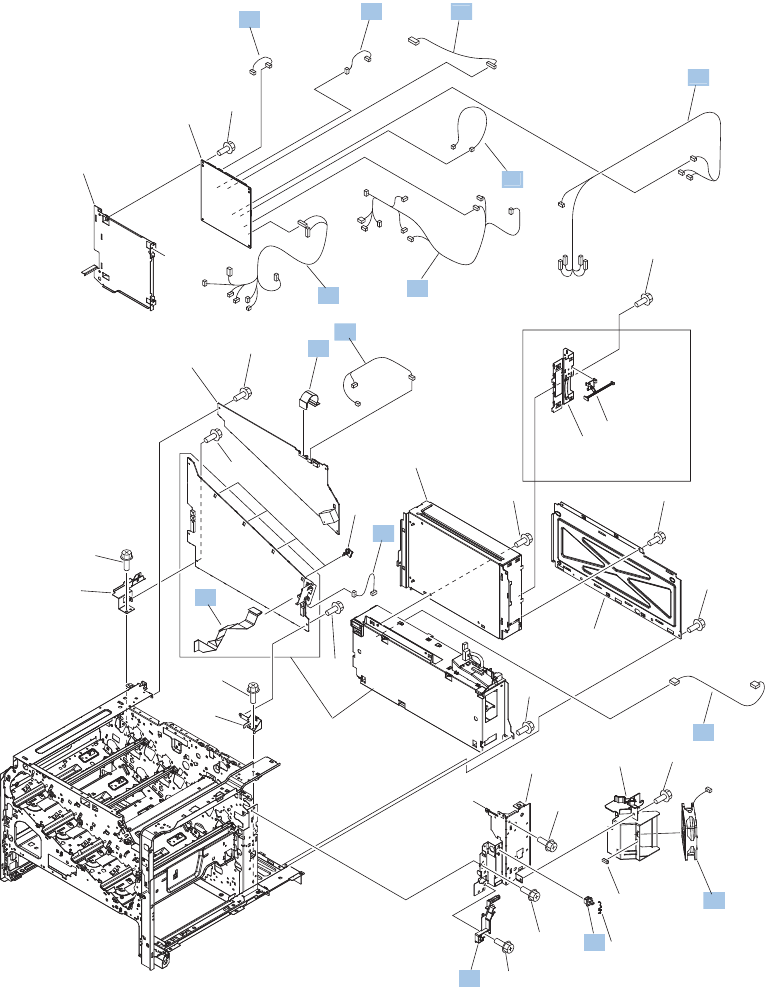
Internal components (7 of 7)
Figure 4-10 Internal components 7 of 7
A
A
PCAs
See Figure 4-19
(J84)
(J108)
(J103)
(J112)
(J261)
(J154)
(J113)
(J201)
(J4)
(J81)
(J71) (J67)
(J38)
(J87)
(J72)
(J115)
(J107)
(J251)
(J56)
(J85) (J106)
(J57)
(J55DA)
(J55DB) (J58)
(J59)
(J147)
(J43)
(FT2)
(FT1)
(J202)
(J39)
(J69)
(J152)
(J603)
(J61)
(J260)
(J37)
(J116)
(J200)
(J605)
(J1)
(J153)
(FM1)
(J43)
(SW6)
PCAs
See Figure 4-19
PCAs
See Figure 4-19
PCAs
See Figure 4-19
1
3
4
5
6
7
9
10
12
13
14
16
17
18
22
23
19
2
15
11
20
20
20
20
20
20
20
20
20
20
20
8
1
7
1
8
22
23
*A01
*A02
*A03
*A04
*A05
*A05
*A05
*A05
*A06
684 Chapter 4 Parts and diagrams ENWW

Table 4-13 Internal components 7 of 7
Ref Description Part number Qty
4 Fan RK2-2577-000CN 1
5 Cable, flexible flat, H.V.T. RK2-2603-000CN 1
7 Contact assembly RM1-5502-000CN 1
8 Cable, flat flexable (FFC) RK2-2604-000CN 1
9 H.V. power supply cable assembly RM1-5724-000CN 1
10 Lower main cable assembly RM1-5801-000CN 1
11 Switch, push WC2-5637-000CN 1
12 Sub controller cable assembly RM1-5826-000CN 1
13 Sub PS AD cable assembly RM1-5825-000CN 1
14 Connecting cable assembly RM1-5799-000CN 1
16 Duplexing cable assembly, duplex RM1-5803-000CN 1
17 Feed cable assembly RM1-5804-000CN 1
18 Switch cable assembly RM1-5807-000CN 1
22 Sensor cable assembly RM1-5815-000CN 1
23 Interlock switch cable assembly RM1-5832-000CN 1
ENWW Internal components 685
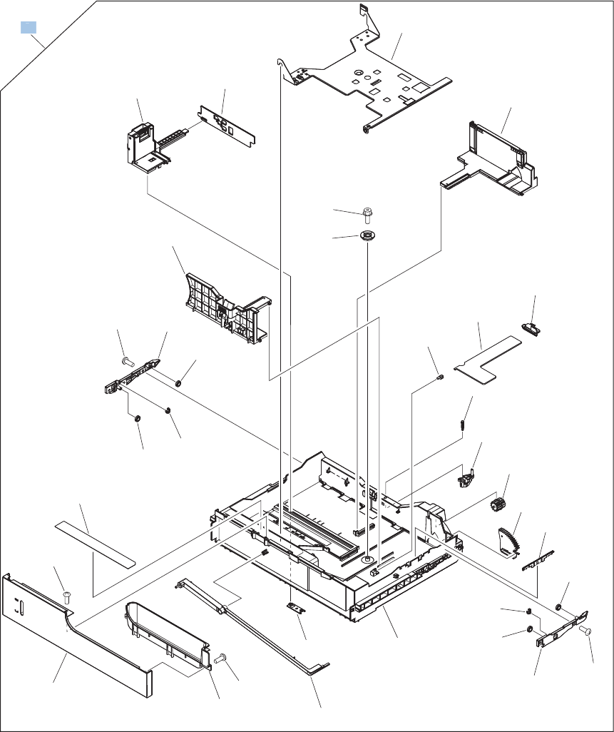
Cassettes 2-5
Figure 4-11 Cassettes 2-5
*A02
*A25
*A25
*A03
*A15
*A25
*A17
*A09
*A12
*A09
* A19
*A23
*A11
*A20
*A16
*A08
*A07
*A18
*A22
*A24
*A06
*A13
*A21
*A26
*A05
*A04
*A25
*A09
*A17
*A09
*A10
*A01
*A14
1
1
686 Chapter 4 Parts and diagrams ENWW

Table 4-14 Cassette
Ref Description Part number Qty
1 Cassette RM1-5928-000CN 1
ENWW Internal components 687
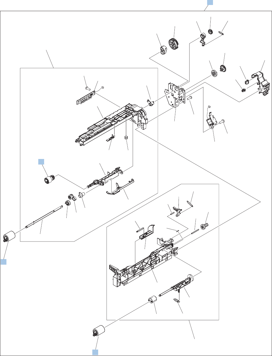
Paper pickup assembly
Figure 4-12 Paper pickup assembly
(SL4)
(J59)
(J58)
1
2
2
3
3
*A01
*A02
*A03
*A04
*A05
*A06
*A07
*A08
*A09
*A10
*A11
*A12
*A13
*A14
*A15
*A15
*A17
*A28
*A18
*A19
*A20
*A22
*A21
*A23
*A24
*A25
*A38
*A26
*A27
*A29
*A30
*A31
*A32
*A33
*A34
*A35
*A37
*A36
*A16
688 Chapter 4 Parts and diagrams ENWW

Table 4-15 Paper pickup assembly
Ref Description Part number Qty
1 Roller, paper pickup RL1-2099-000CN 1
2 Paper feed roller RM1-0037-020CN 2
3 Paper pickup assembly RM1-5919-000CN 1
ENWW Internal components 689
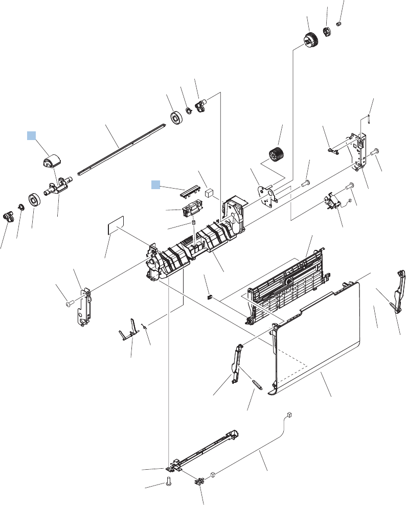
Tray 1 paper pickup assembly
Figure 4-13 Tray 1 paper pickup assembly
(SL3)
(J52)
(J75)
(J22)
(J22)
(SR8)
1
2
*A01
*A01
*A02
*A03
*A04
*A05
*A06
*A07 *A28
*A08
*A10
*A11
*A12
*A13
*A14
*A15
*A20
*A23
*A13
*A16
*A17
*A18
*A19
*A09
*A21
*A22
*A24
*A25
*A26
*A26
*A26
*A26
*A27
*A29
*A30
*A31 *A32
*A32
*A33
*A34
690 Chapter 4 Parts and diagrams ENWW

Table 4-16 Tray 1 paper pickup assembly
Ref Description Part number Qty
1 Pickup roller (Tray 1) kit (includes instructions CC493-67906 1
2 Separation pad (Tray 1) RL1-1937-000CN 1
ENWW Internal components 691
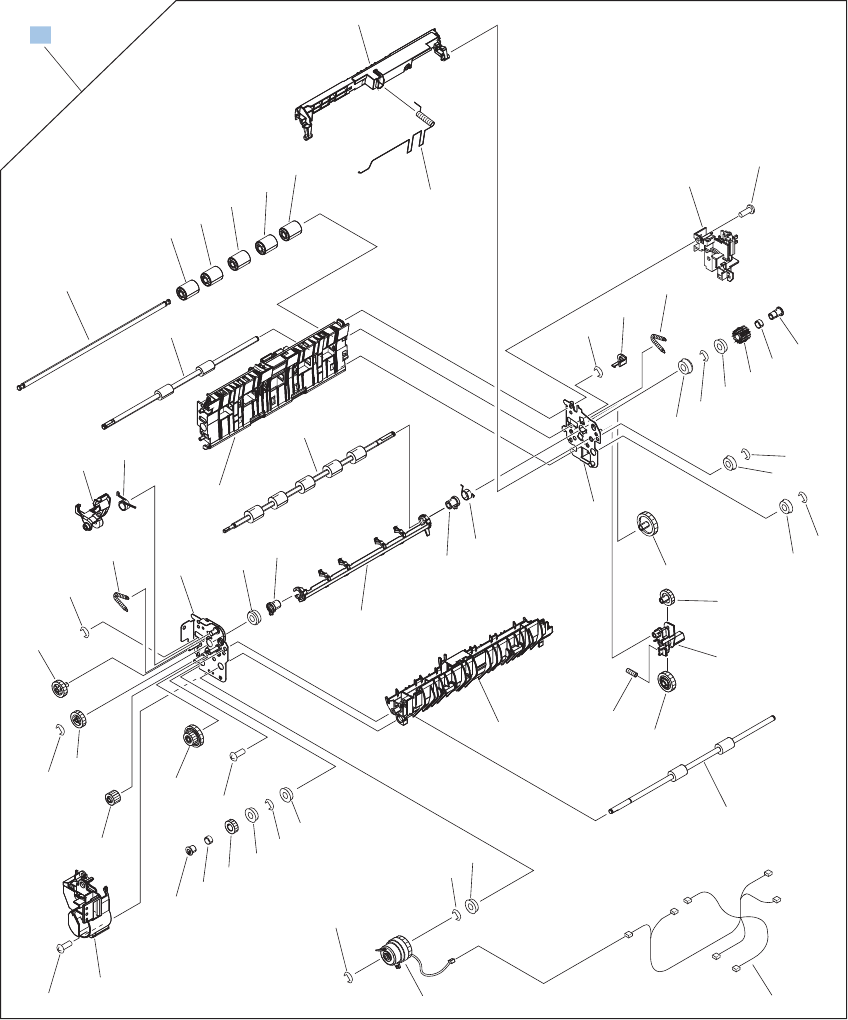
Registration assembly
Figure 4-14 Registration assembly
(J53)
(J23)
(J27)
(J74)
(J77)
(J21)
(J20)
(J53)
(CL1)
*A13
*A01
*A02
*A03
*A04
*A05
*A05
*A05
*A05
*A06
*A07
*A08
*A08
*A09
*A09
*A09
*A10
*A11
*A23
*A12
*A14
*A15
*A15
*A16
*A17
*A18
*A19
*A20
*A21
*A22
*A24
*A25
*A26
*A27
*A28
*A33
*A29
*A30
*A31
*A32
*A35
*A35
*A36
*A37
*A38
*A38
*A39
*A40
*A42
*A42
*A42
*A42
*A42
*A42
*A42
*A44
*A44
*A45
*A03
*A46
*A43
*A41
*A02
1
692 Chapter 4 Parts and diagrams ENWW

Table 4-17 Registration assembly
Ref Description Part number Qty
1 Duplex registration assembly kit (includes instructions) CC493-67917 1
ENWW Internal components 693
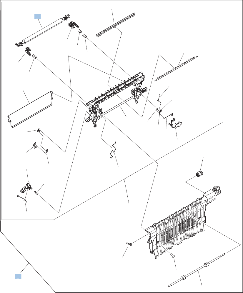
Secondary transfer assembly
Figure 4-15 Secondary transfer assembly
1
*A23
*A08
*A03
*A15
*A16
*A17
*A18
*A21
*A14
*A04
*A20
*A05
*A12
*A13
*A07
*A06
*A01
*A19
*A09
*A02
*A19
*A11
*A10
*A24
*A26
*A22
*A25
2
2
1
694 Chapter 4 Parts and diagrams ENWW

Table 4-18 Secondary transfer assembly
Ref Description Part number Qty
1 Secondary transfer roller assembly kit (includes instructions) CC493-67908 1
2 Secondary transfer assembly, duplex kit (includes instructions,
and shaft-support clip; RC2-4162-000CN)
CC492-67901 1
ENWW Internal components 695
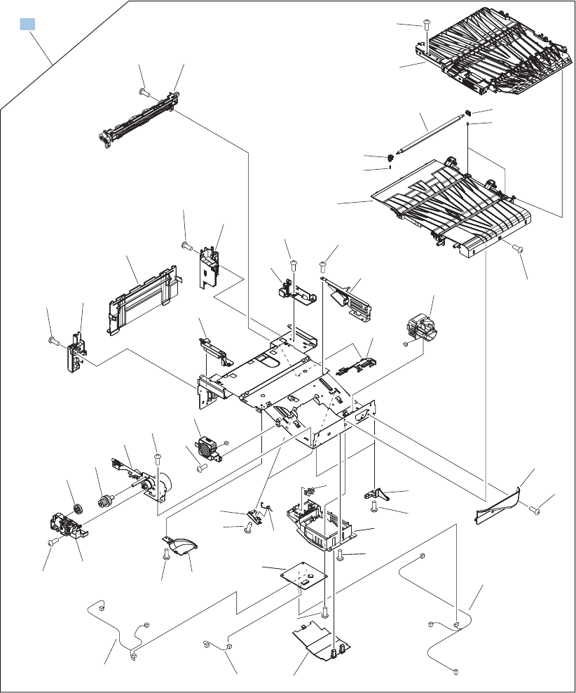
Intermediate paper transfer unit (IPTU)
Figure 4-16 Intermediate paper transfer unit (IPTU)
(J550)
(J70)
(J8)
(J5) (J551)
(J552)
(FM6)
(J5)
(M14)
(J555)
(FM7)
(J3)
(J2)
(J553)
(J4)
(J2)
(SR27)
1
1
1
2
3
4
5
6
7
9
8
10
11
PCAs
See Figure 4-19
12
*A02
*A03
*A03
*A04
*A05
*A06
*A07
*A08
*A09
*A10
*A11
*A12
*A12
*A13
*A17
*A18
*A19
*A20
*A21
*A15
*A14
*A01
*A14
*A14
*A14
*A14
*A14
*A14
*A14
*A14
*A14
*A14
*A14
*A22
*A16
*A14 *A14
696 Chapter 4 Parts and diagrams ENWW

Table 4-19 Intermediate paper transfer unit (IPTU)
Ref Description Part number Qty
1 Intermediate paper transfer unit (IPTU) RM1-5621-000CN 1
ENWW Internal components 697
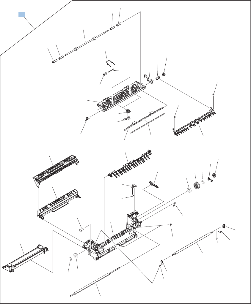
Delivery assembly
Figure 4-17 Delivery assembly
*A12
*A09
*A21
*A33
*A34
*A34
*A15
*A28
*A14
*A13 *A30
*A07 *A29
*A32
*A20
*A18
*A17
*A15
*A27
*A02
*A26
*A01
*A07
*A07
*A04
*A03
*A22 *A23
*A16
*A19
*A11
*A10
*A25
*A06
*A31
*A08
*A24
*A24
*A05
*A24
*A24
*A35
*A37
*A36
1
1
698 Chapter 4 Parts and diagrams ENWW

Table 4-20 Delivery assembly
Ref Description Part number Qty
1 Delivery assembly RM1-5615-000CN 1
ENWW Internal components 699
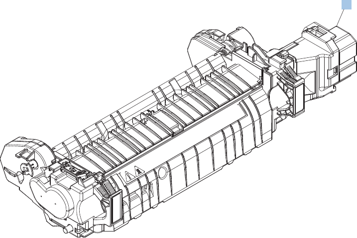
Fuser assembly
Figure 4-18 Fuser assembly
1
700 Chapter 4 Parts and diagrams ENWW

Table 4-21 Fuser assembly
Ref Description Part number Qty
1 Fuser 110 V assembly kit (includes instructions) CC493-67911 1
1 Fuser 220 V assembly kit (includes instructions) CC493-67912 1
ENWW Internal components 701
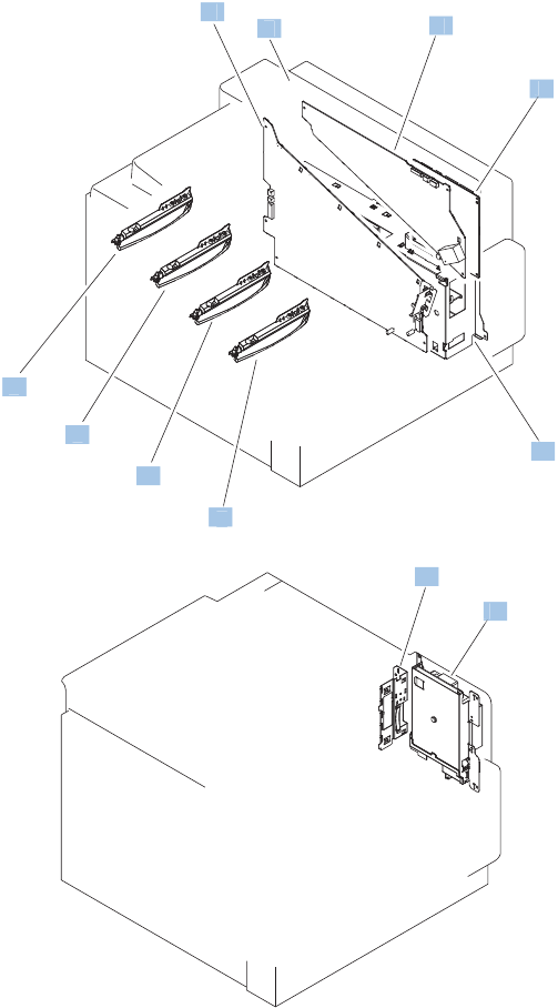
PCAs
Figure 4-19 PCAs
8
8
1
2
34
5
7
7
7
7
6
7
7
7
7
7
6
5
2
1
1
4
3
702 Chapter 4 Parts and diagrams ENWW

Table 4-22 PCAs
Ref Description Part number Qty
1 DC controller PCA assembly RM1-5758-000CN 1
2 Low voltage power supply PCA assembly, 110V RM1-5763-000CN 1
2 Low voltage power supply PCA assembly, 220V RM1-5764-000CN 1
3 High voltage power supply PCA, lower (includes FFC; DCC to
HVPS lower)
RM1-5779-000CN 1
4 High voltage power supply, upper RM1-5781-000CN 1
5 Image scanner power supply assembly RM1-5619-000CN 1
6 Inner connecting board (ICB) assembly RM1-5544-020CN 1
7 Toner remain PCA assembly RM1-5771-020CN 4
8 Formatter assembly kit (exchange; includes instructions) CE871-69001 1
ENWW Internal components 703
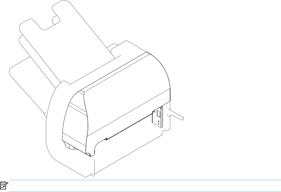
Stapling mailbox
The stapling mailbox is also referred to as the SSMBM.
Figure 4-20 Stapling mailbox
NOTE: Under warranty, replace the whole unit with customer self repair part number CC424-67901.
704 Chapter 4 Parts and diagrams ENWW
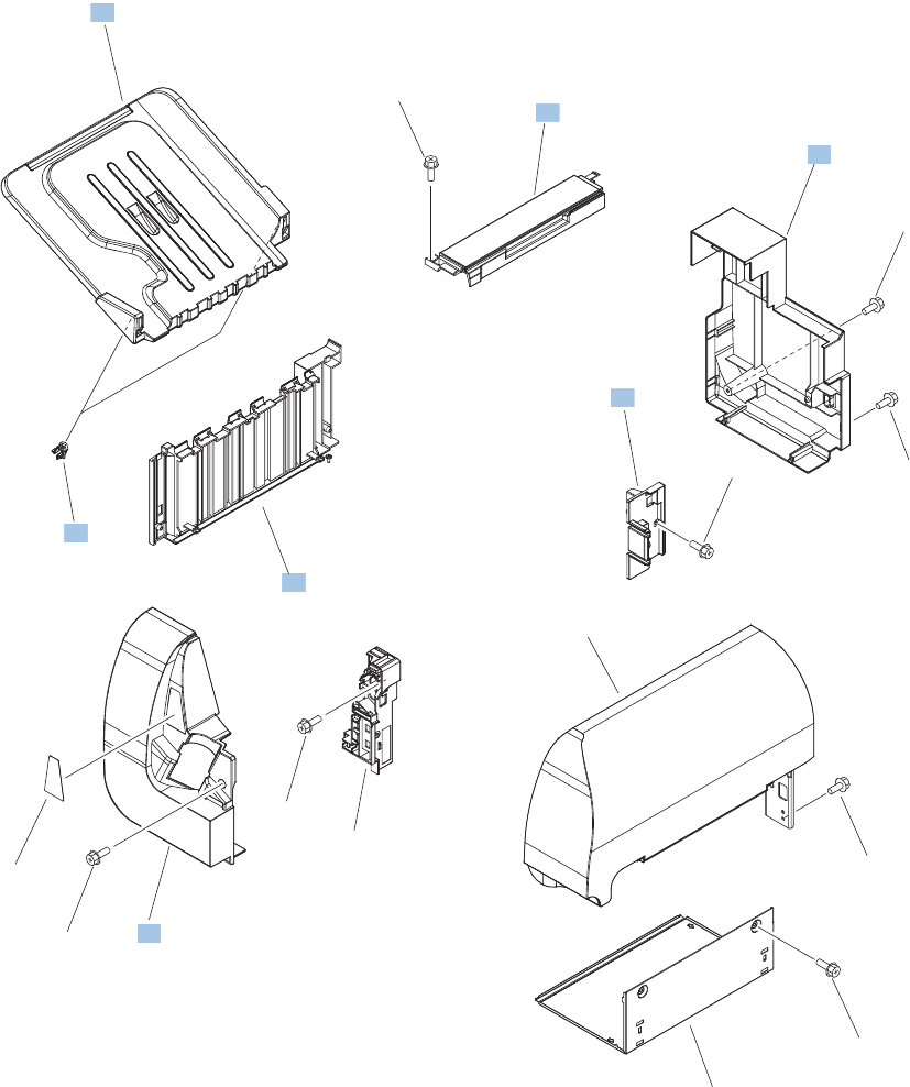
External covers, panels, and doors (SSMBM)
Figure 4-21 External covers, panels, and doors (SSMBM)
Top door assembly
See Figure 4-41
1
2
3
4
5
6
7
8
9
*A01
*A01
*A01
*A01
*A01
*A01
*A01
*A02
*A01
ENWW Stapling mailbox 705

Table 4-23 External covers, panels, and doors (SSMBM)
Ref Description Part number Qty
1 Cover, front (SSMBM) RC2-5571-000CN 1
2 Cover, rear (SSMBM) RC2-5572-000CN 1
4 Panel, stacking (SSMBM) RL1-1984-000CN 1
6 Holder, connector (SSMBM) RC2-5625-000CN 1
7 Top cover assembly (SSMBM) RM1-6669-000CN 1
8 Tray assembly (SSMBM) RM1-5161-000CN 1
9 Stopper, tray (SSMBM) RC2-5576-000CN 1
706 Chapter 4 Parts and diagrams ENWW
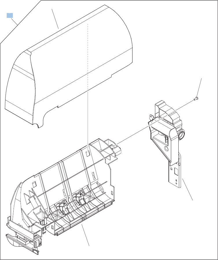
Top door assembly (SSMBM)
Figure 4-22 Top door assembly (SSMBM)
*A01
*A02
*A03
*A04
1
1
ENWW Stapling mailbox 707

Table 4-24 Top door assembly (SSMBM)
Ref Description Part number Qty
1 Top door assembly (SSMBM) RM1-5160-000CN 1
708 Chapter 4 Parts and diagrams ENWW
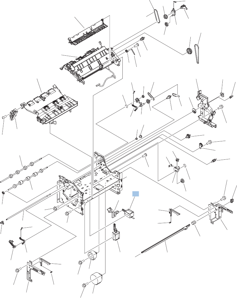
Main body (SSMBM; 1 of 2)
Figure 4-23 Main body (SSMBM; 1 of 2)
A
B
A
(J461)
(M5)
(J120)
(J453)
(J451)
(SL2)
(J119)
(SL1)
(J458)
(M4)
3
9
24
22
23
20
21
*A01
*A02
*A03
*A04
*A05
*A06
*A10
*A11
*A12
*A12
*A13
*A14
*A15
*A16
*A17
*A18 *A19
*A19
*A20
*A21
*A24
*A26
*A27
*A28
*A29
*A30
*A33
*A34
*A35
*A36
*A37
*A38
*A39
*A40
*A41
*A42
*A43
*A44
*A44
*A45
*A46
*A46
*A47
*A50
*A51
*A51
*A51
*A51
*A52
*A52
*A53
*A53
*A56
*A56
*A57
*A57
*A58
*A59
*A60
*A55
*A55
*A52
*A66
*A65
22
ENWW Stapling mailbox 709

Table 4-25 Main body (SSMBM; 1 of 2)
Ref Description Part number Qty
22 Stamp solenoid assembly (SSMBM) RM1-6664-000CN 1
710 Chapter 4 Parts and diagrams ENWW
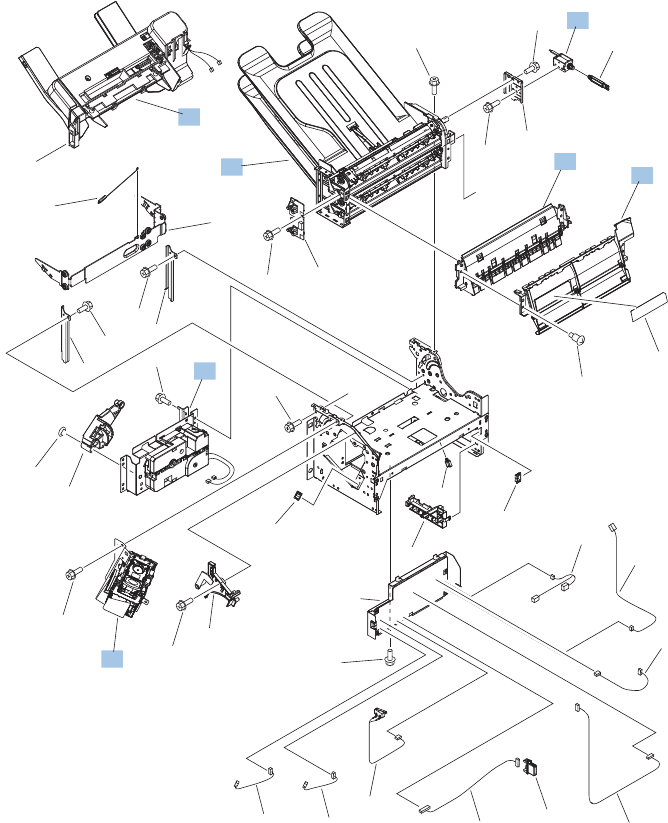
Main body (SSMBM; 2 of 2)
Figure 4-24 Main body (SSMBM; 2 of 2)
B
C
(J462)
(J120) (J119)
(J121)
(J456)
(J459)
(J466)
(J452)
(J490)
(J108)
(J450)
(J465)
(J114)
(J466)
(SW1)
(J106)
(J463)
(J105)
(J464)
(J454)
(J455)
(J121)
(SL3)
C
1
PCAs
See Figure 4-24
6
7
8
10
11
13
14
15
16
17
18 19
5
2
PCAs
See Figure 4-24
*A07
*A09
*A22
*A23
*A25
*A32
*A48
*A49
*A51
*A51
*A51
*A51
*A51
*A51
*A51 *A51
*A08
*A51
*A51
*A53
*A54
*A61
*A62
*A62
*A63
*A64
*A31
ENWW Stapling mailbox 711

Table 4-26 Main body (SSMBM; 2 of 2)
Ref Description Part number Qty
1 Flapper guide assembly (SSMBM) RM1-5153-000CN 1
6 Jog assembly (SSMBM) RM1-5155-000CN 1
7 Lift tray assembly (SSMBM) RM1-5156-000CN 1
8 MBM flapper assembly (SSMBM) RM1-5157-000CN 1
10 MBM bin assembly (SSMBM) RM1-6670-000CN 1
11 Stapler assembly (SSMBM) RM1-5166-000CN 1
13 Bin solenoid assembly (SSMBM) RM1-5896-000CN 1
712 Chapter 4 Parts and diagrams ENWW
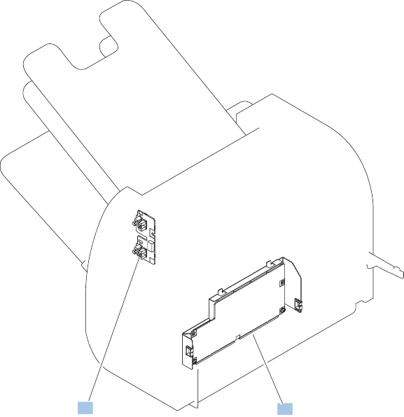
PCAs (SSMBM)
Figure 4-25 PCAs (SSMBM)
1
2
ENWW Stapling mailbox 713

Table 4-27 PCAs (SSMBM)
Ref Description Part number Qty
1 MBM driver PCA (SSMBM) RM1-5168-000CN 1
2 Bin sensor PCA (SSMBM) RM1-5894-000CN 1
714 Chapter 4 Parts and diagrams ENWW
ENWW Stapling mailbox 715
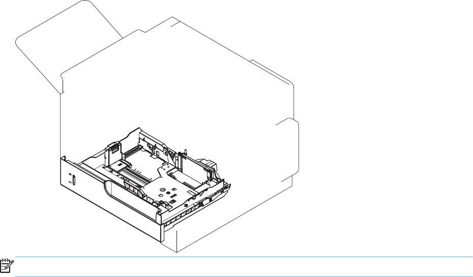
500-sheet paper feeder
The 500-sheet paper feeder is referred to as the 1x500-SPF.
Figure 4-26 500-sheet paper feeder
NOTE: Under warranty, replace the whole unit with customer self repair part number CC425-67901.
716 Chapter 4 Parts and diagrams ENWW
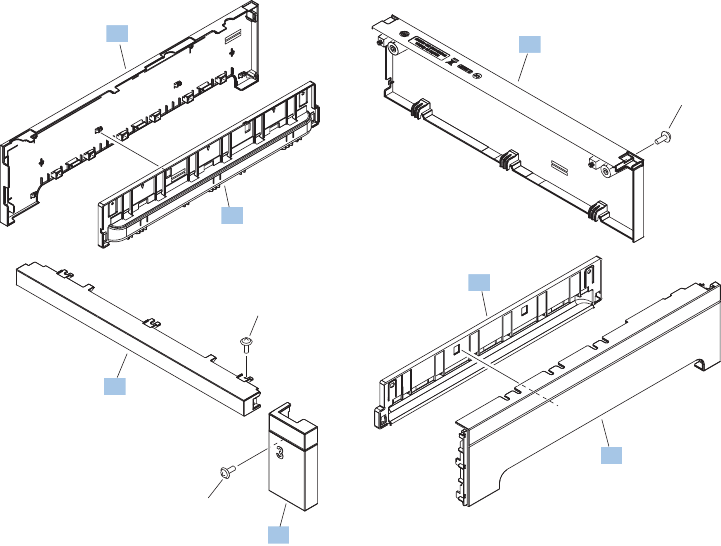
External covers, panels, and doors (1x500-SPF)
Figure 4-27 External covers, panels, and doors (1x500-SPF)
1
2
3
4
5
6
7
*A01
*A01
*A02
ENWW 500-sheet paper feeder 717

Table 4-28 Paper feeders
Ref Description Part number Qty
1 Cover, front upper (1x500-SPF) RC2-5395-000CN 1
2 Cover, left (1x500-SPF) RC3-1314-000CN 1
3 Cover, handle, left (1x500-SPF) RC3-1315-000CN 1
4 Cover, right (1x500-SPF) RC3-1316-000CN 1
5 Cover, handle, right (1x500-SPF) RC3-1317-000CN 1
6 Cover, right front (1x500-SPF) RC3-1318-000CN 1
7 Cover, rear (1x500-SPF) RC3-1319-000CN 1
718 Chapter 4 Parts and diagrams ENWW
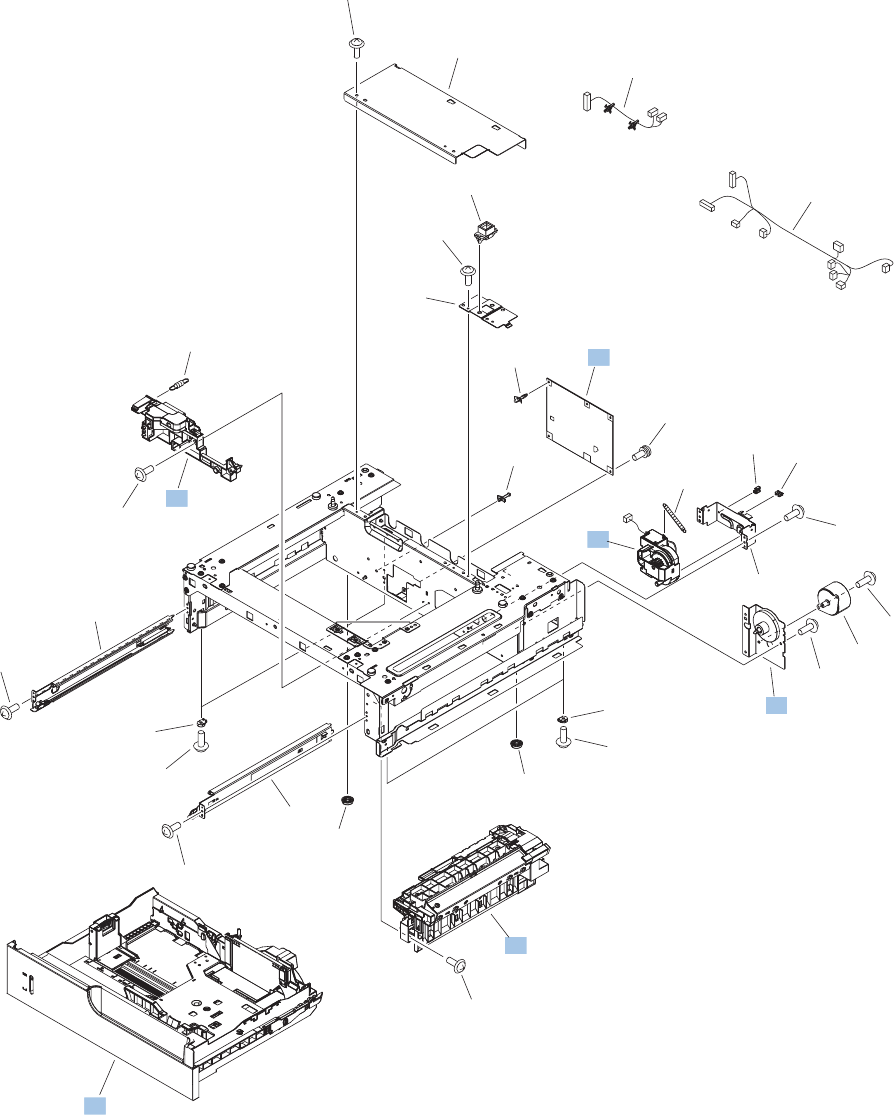
Main body (1x500-SPF)
Figure 4-28 Main body (1x500-SPF)
(M2)
(J14)
(J15L)
(J410)
(J10LB)
(J10LA)
(J10LB)
(J10LA)
(J408)
(J407)
(J409)
(J17D)
(J18D)
(J11D)
(J13D)
(J14)
(J15D)
1
2
3
4
5
6
7
8
9
10
11
12
*A02
*A10
*A02
*A02
*A02
*A02
*A02
*A03
*A04
*A05
*A06
*A07
*A08
*A08
*A09
*A11
*A12
*A13
*A01
*A10
*A02
*A02
*A02
*A02
*A02
ENWW 500-sheet paper feeder 719

Table 4-29 Main body (1x500-SPF)
Ref Description Part number Qty
3 Lifter base assembly (1x500-SPF) RM1-5913-000CN 1
4 Lifter assembly (1x500-SPF) RM1-5914-000CN 1
7 Paper pickup drive assembly (1x500-SPF) RM1-5934-000CN 1
8 Feeder PCA (1x500-SPF) RM1-5854-000CN 1
9 Paper pickup assembly (1x500-SPF) RM1-5929-000CN 1
10 Cassette (1x500-SPF) RM1-5928-000CN 1
720 Chapter 4 Parts and diagrams ENWW
ENWW 500-sheet paper feeder 721
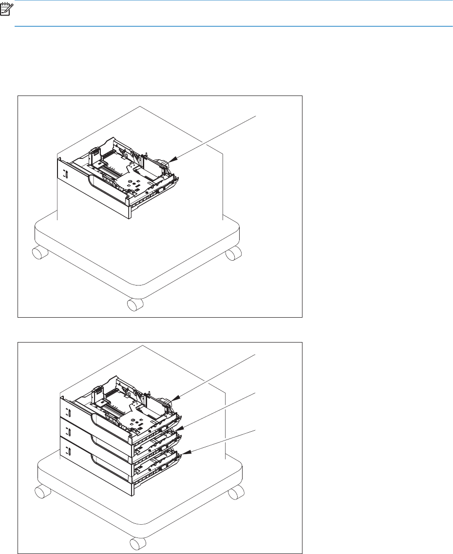
1x500 and 3x500 paper feeders
The 1x500 and 3x500 paper feeders are referred to as the 1x500PF and 3x500PF.
NOTE: Under warranty, replace the whole unit with customer self repair part number CC493-67902
(1x500) or CC493-67903 (3x500).
Paper feeders
Figure 4-29 Paper feeders
1x500PF
3x500PF
Cassette 3
Cassette 3
Cassette 4
Cassette 5
722 Chapter 4 Parts and diagrams ENWW

Table 4-30 Paper feeders
Ref Description Part number Qty
NA Cassette (1x500PF and 3x500PF) RM1-5928-000CN NA
ENWW 1x500 and 3x500 paper feeders 723
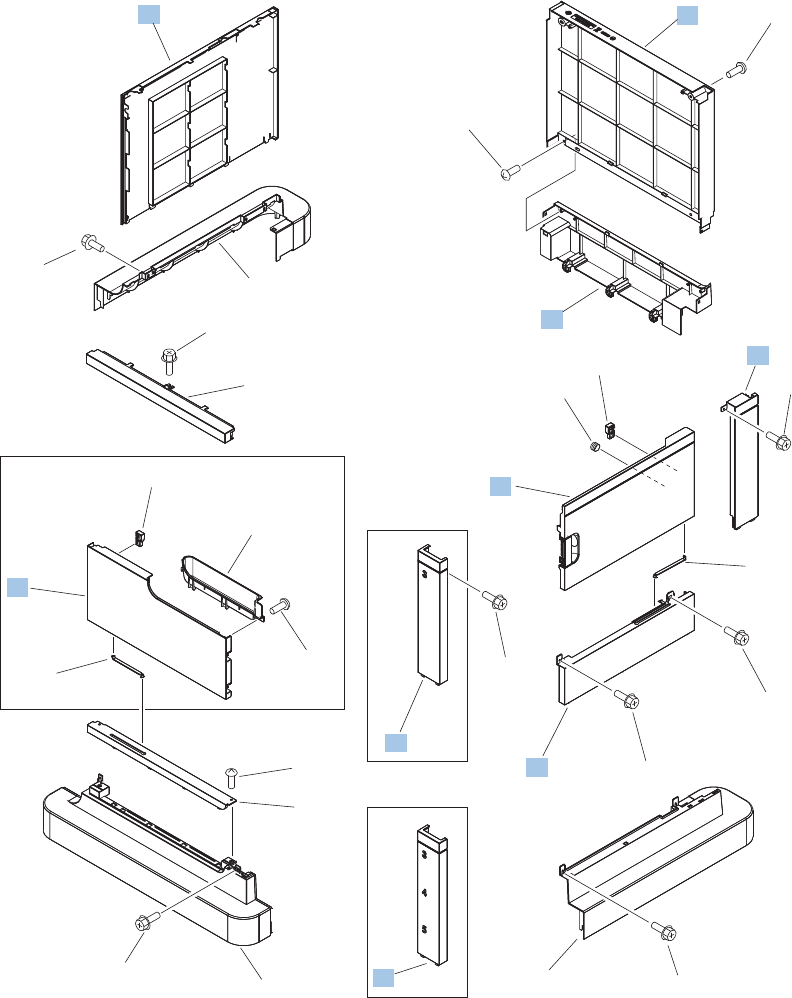
External covers, panels, and doors (1x500PF and 3x500PF)
Figure 4-30 Paper feeder external covers, panels, and doors (1x500PF and 3x500PF)
3x500PF
1x500PF
1x500PF
1
2
3
4
5
6
7
8
8
9
10
11
12
13
13
17
16
15
15
14
*A01
*A01
*A03
*A01
*A02
*A02
*A05
*A01
*A01
*A01
*A04
*A01
724 Chapter 4 Parts and diagrams ENWW

Table 4-31 External covers, panels, and doors (1x500PF and 3x500PF)
Ref Description Part number Qty
4 Cover, rear lower (1x500PF and 3x500PF) RC2-5378-000CN 1
5 Cover, rear (1x500PF and 3x500PF) RC2-5379-000CN 1
7 Cover, left (1x500PF and 3x500PF) RC2-5393-000CN 1
8 Cover, right front, (1x500PF) RC2-5356-000CN 1
8 Cover, right front, (3x500PF) RC2-5357-000CN 1
9 Cover, right rear (1x500PF and 3x500PF) RC2-5380-000CN 1
11 Cover, right center (1x500PF and 3x500PF) RC2-5394-000CN 1
14 Right door assembly (3x500PF) RM1-5937-000CN 1
14 Right door assembly (1x500PF) RM1-5936-000CN 1
16 Door, stock, (1x500PF) RC2-5377-000CN 1
ENWW 1x500 and 3x500 paper feeders 725
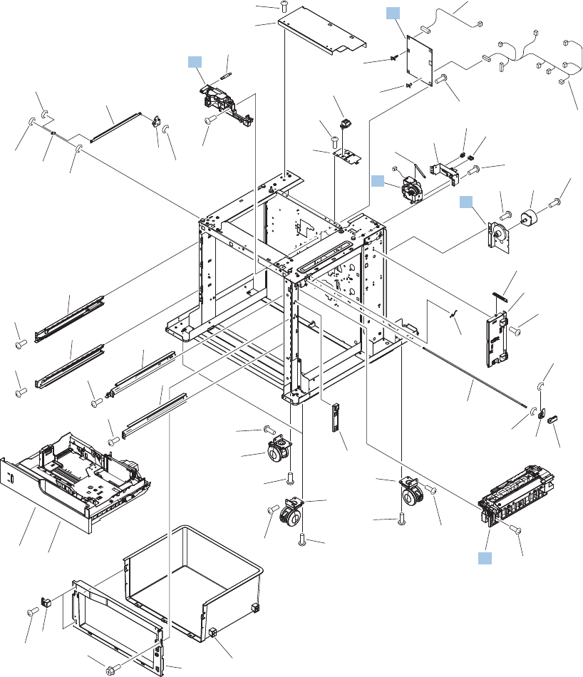
Main body (1x500PF)
Figure 4-31 Main body (1x500PF)
(J410)
(J10)
(J15)
(J14)
(M2)
Cassette
See Figure 4-11
(J408)
(J409)
(J407)
(J18)
(J14)
(J15)
(J13)
(J17)
(J11)
1
2
5
6
7
8
11
9
4
3
*A04
*A05
*A06
*A07
*A08
*A09
*A11
*A12
*A13
*A14
*A32
*A15*A33
*A17
*A16 *A16
*A16
*A16
*A16
*A16
*A16
*A16
*A16
*A16
*A16
*A16
*A19
*A19
*A20
*A21
*A22
*A23
*A24
*A28
*A25
*A27
*A27
*A27
*A28
*A26
*A28
*A29
*A29
*A29
*A19
*A18
*A10
*A31 *A30
*A16
*A01
*A01
*A01
*A02
*A03
726 Chapter 4 Parts and diagrams ENWW

Table 4-32 Main body (1x500PF)
Ref Description Part number Qty
3 Lifter base assembly (1x500PF) RM1-5913-000CN 1
4 Lifter assembly (1x500PF) RM1-5914-000CN 1
7 Paper pickup drive assembly (1x500PF) RM1-5934-000CN 1
8 Feeder PCA assembly (1x500PF) RM1-5854-000CN 1
9 Paper pickup assembly (1x500PF) RM1-5929-000CN 1
ENWW 1x500 and 3x500 paper feeders 727
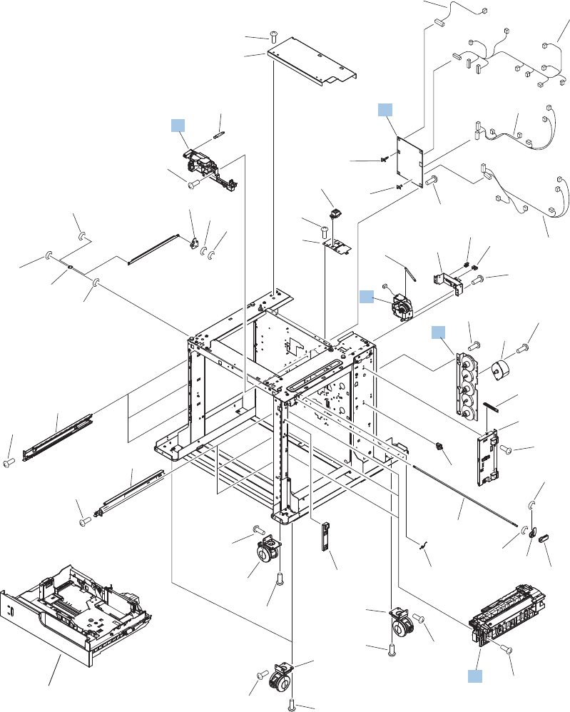
Main body (3x500PF)
Figure 4-32 Main body (3x500PF)
(J410)
(J10)
(J402)
(J403)
(J35)
(J34)
(J32)
(J30)
(J31)
(J21)
(J406)
(J405)
(J25)
(J15)
(J24)
(J34)
(J24)
(J22)
(J20)
Cassette
See Figure 4-11
(J14)
(M2)
(J409)
(J408)
(J404)
(J18) (J19)
(J14)
(J15)
(J13)
(J17)
(J11)
(J407)
7
8
9
1
2
3
4
5
6
10
11
13
*A02
*A03
*A04
*A05
*A06
*A07
*A09
*A10
*A11
*A16
*A15
*A15
*A15
*A15
*A15
*A15
*A15
*A15
*A15
*A18
*A18
*A19
*A20
*A21
*A22
*A23
*A08
*A24
*A25
*A01
*A01
*A01
*A25
*A25
*A08 *A17
*A08
*A17
*A17
*A17
*A13
*A18
*A12
*A26
*A14*A27
*A15
728 Chapter 4 Parts and diagrams ENWW

Table 4-33 Main body (3x500PF)
Ref Description Part number Qty
2 Lifter base assembly (3x500PF) RM1-5913-000CN 1
3 Lifter assembly (3x500PF) RM1-5914-000CN 1
6 Paper pickup drive assembly (3x500PF) RM1-5935-000CN 1
10 Feeder PCA assembly (3x500PF) RM1-5958-000CN 1
11 Paper pickup assembly (3x500PF) RM1-5929-000CN 3
ENWW 1x500 and 3x500 paper feeders 729
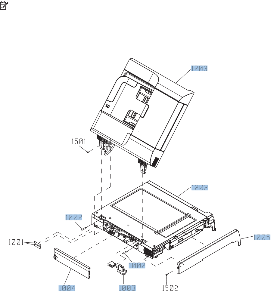
Document feeder/scanner
NOTE: Under warranty, replace the whole scanner assembly or document feeder with either
replacement part number IR4068-SVPNI (scanner assembly) or PF2309-SVPNI (document feeder
assembly).
Document feeder/scanner assemblies
Figure 4-33 Document feeder/scanner assemblies
730 Chapter 4 Parts and diagrams ENWW

Table 4-34 Document feeder/scanner assemblies
Ref Description Part number Qty
1002 S-SFT-STP-HNG (hinge screw) IR4068K319NI 2
1003 S-ASM-ICB-COR (scanner cable) IR4068K320NI 1
1004 S-CVR-REAR IR4068K321NI 1
1005 S-CVR-LEFT IR4068K322NI 1
1202 Scanner assembly (includes SCB and control panel adapter) IR4068-SVPNI 1
1203 Document feeder complete assembly PF2309-SVPNI 1
ENWW Document feeder/scanner 731
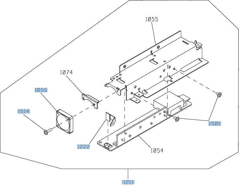
Scanner inverter assembly
Figure 4-34 Scanner inverter assembly
732 Chapter 4 Parts and diagrams ENWW

Table 4-35 Scanner inverter assembly
Ref Description Part number Qty
1211 Scanner inverter assembly IR4068K306NI 1
1222 S-K-CBP-INV-FFC IR4068K303NI 1
1501 ASY-030060NIT IR4068K341NI 9
1056 S-FAN-MFB30E-05A-006 IR4068K304NI 1
1514 ASY-030120FWWS IR4068K340NI 1
ENWW Document feeder/scanner 733
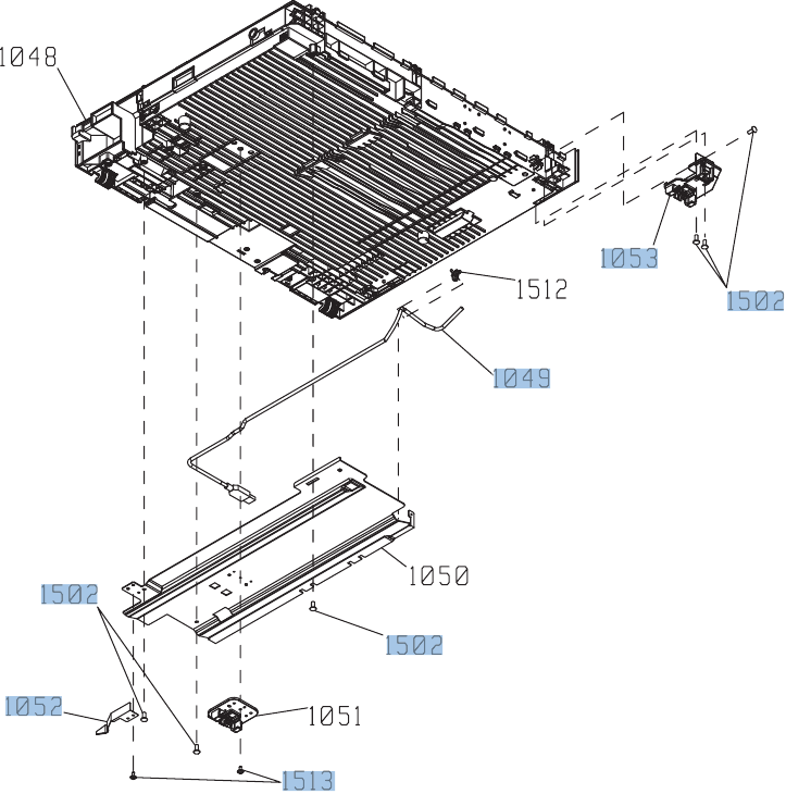
Scanner assembly (1 of 6)
Figure 4-35 Scanner assembly (1 of 6)
734 Chapter 4 Parts and diagrams ENWW

Table 4-36 Scanner assembly (1 of 6)
Ref Description Part number Qty
1049 S-ASM-USB (control panel USB cable) IR4068K301NI 1
1502 ASY-040100FNBB IR4068K342NI 16
1513 ASY-030080FNTP IR4068K334NI 2
1052 ASSY-SP-GUIDE-HINGE IR4068K126NI 4
1053 S-HNG-LIFT-R IR4068K302NI 1
ENWW Document feeder/scanner 735
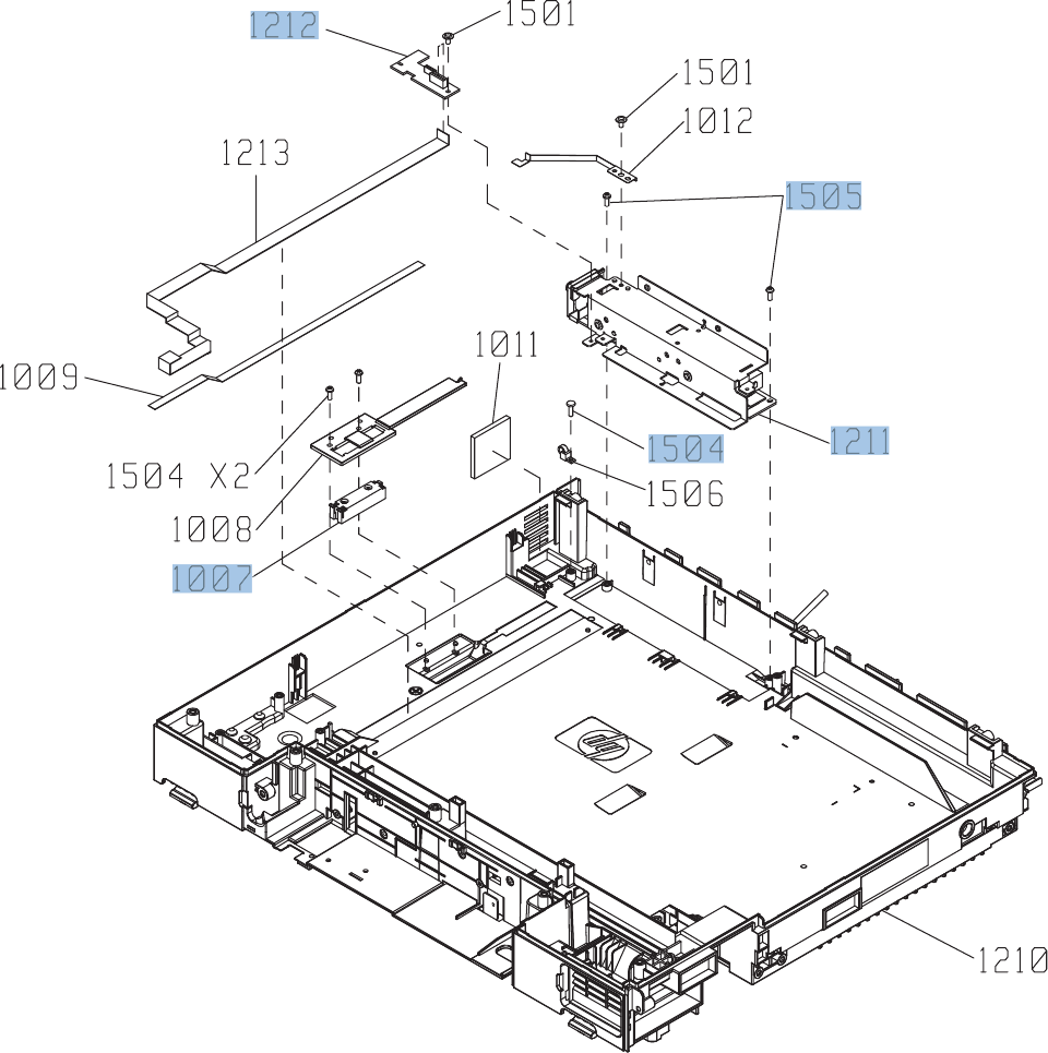
Scanner assembly (2 of 6)
Figure 4-36 Scanner assembly (2 of 6)
736 Chapter 4 Parts and diagrams ENWW

Table 4-37 Scanner assembly (2 of 6)
Ref Description Part number Qty
1007 S-SNS-EY3A-1061-2 IR4068K305NI 1
1504 ASY-NS-SCR00027 IR4068K344NI 22
1211 S-ASSY-INV IR4068K306NI 1
1212 S-PBA-TYUKEI IR4068K307NI 1
1505 ASY-NS-SCR00023B IR4068K338NI 2
ENWW Document feeder/scanner 737
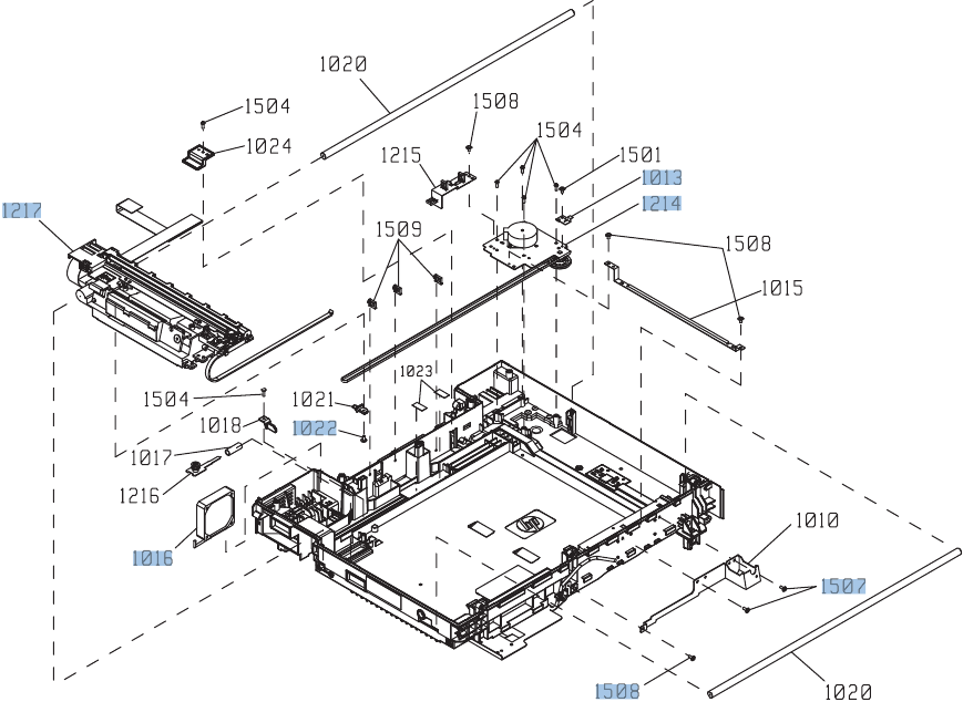
Scanner assembly (3 of 6)
Figure 4-37 Scanner assembly (3 of 6)
738 Chapter 4 Parts and diagrams ENWW

Table 4-38 Scanner assembly (3 of 6)
Ref Description Part number Qty
1507 ASY-030080FNTW IR4068K335NI 2
1508 ASY-030060FNTW IR4068K333NI 9
1214 S-ASSY-MOTOR-UNIT IR4068K309NI 1
1013 S-SP-GND-SFT-R IR4068K310NI 1
1016 S-FAN-D06037600G-01 IR4068K311NI 1
1217 ASSY-CRG-UNIT-IR4068 IR4068K200NI 1
1022 ASY-IR4041P021 IR4068K343NI 1
ENWW Document feeder/scanner 739
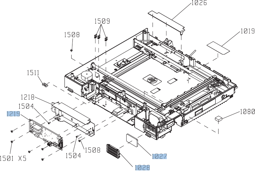
Scanner assembly (4 of 6)
Figure 4-38 Scanner assembly (4 of 6)
740 Chapter 4 Parts and diagrams ENWW

Table 4-39 Scanner assembly (4 of 6)
Ref Description Part number Qty
1219 Scan control board (SCB), S-PBA-SCB IR4068K312NI 1
1027 S-FLTR-IN IR4068K313NI 1
1028 S-CVR-FAN IR4068K314NI 1
ENWW Document feeder/scanner 741
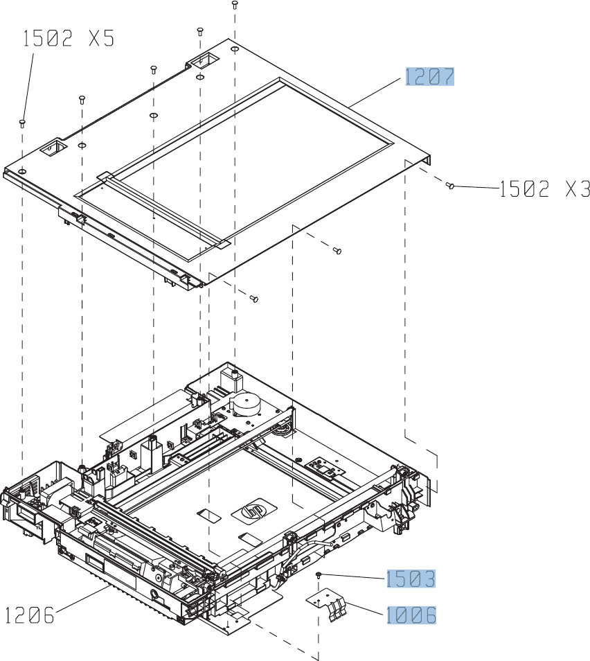
Scanner assembly (5 of 6)
Figure 4-39 Scanner assembly (5 of 6)
742 Chapter 4 Parts and diagrams ENWW

Table 4-40 Scanner assembly (5 of 6)
Ref Description Part number Qty
1207 S-ASSY-UPPER-UNIT (includes scanner glass) IR4068K315NI 1
1503 ASY-NS-SCR00017 IR4068K337NI 1
1006 S-SP-GND-PLT-LIFT-L IR4068K345NI 1
ENWW Document feeder/scanner 743
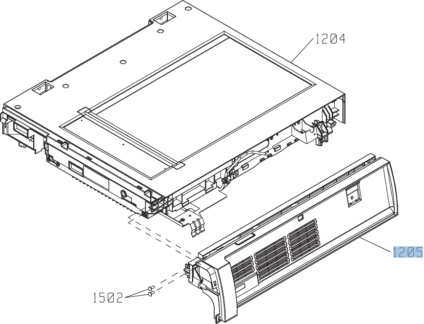
Scanner assembly (6 of 6)
Figure 4-40 Scanner assembly (6 of 6)
744 Chapter 4 Parts and diagrams ENWW

Table 4-41 Scanner assembly (6 of 6)
Ref Description Part number Qty
1205 S-ASSY-CP-ADAPTER IR4068K316NI 1
ENWW Document feeder/scanner 745
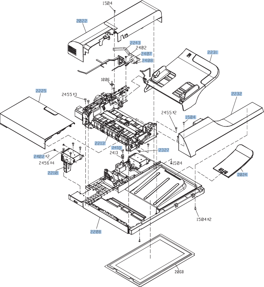
Document feeder assembly (1 of 5)
Figure 4-41 Document feeder assembly (1 of 5)
746 Chapter 4 Parts and diagrams ENWW

Table 4-42 Document feeder assembly (1 of 5)
Ref Description Part number Qty
2208 ASY-BASE-SP PF2309K102NI 1
2210 ASY-HNG-L-SP PF2309K104NI 1
2213 ASY-FRM-RE-FEED-SP PF2309K103NI 1
2225 ASY-CVR-FE-FEED-SP PF2309K105NI 1
2231 ASY-TRY-SP PF2309K106NI 1
2232 ASY-CVR-F-SP PF2309K107NI 1
2455 ASY-SCR04T100PLA-SP PF2309K108NI 10
2402 ASY-030060FNTP IR4068K332NI 3
2243 ASM-IF-SP PF2309K110NI 1
2407 ASY-TFT-152613N-SP PF2309K111NI 1
2408 ASY-TFB-2024RS PF2309K112NI 1
2327 ASY-SCR-5-4-DAN-SP PF2309K113NI 2
2022 ASY-CVR-F-R-SP PF2309K114NI 1
1504 ASY-SCR03T100PLA-SP PF2309K115NI 1
2024 ASY-TRY-F-BASE-SP CC419-67903 1
ENWW Document feeder/scanner 747
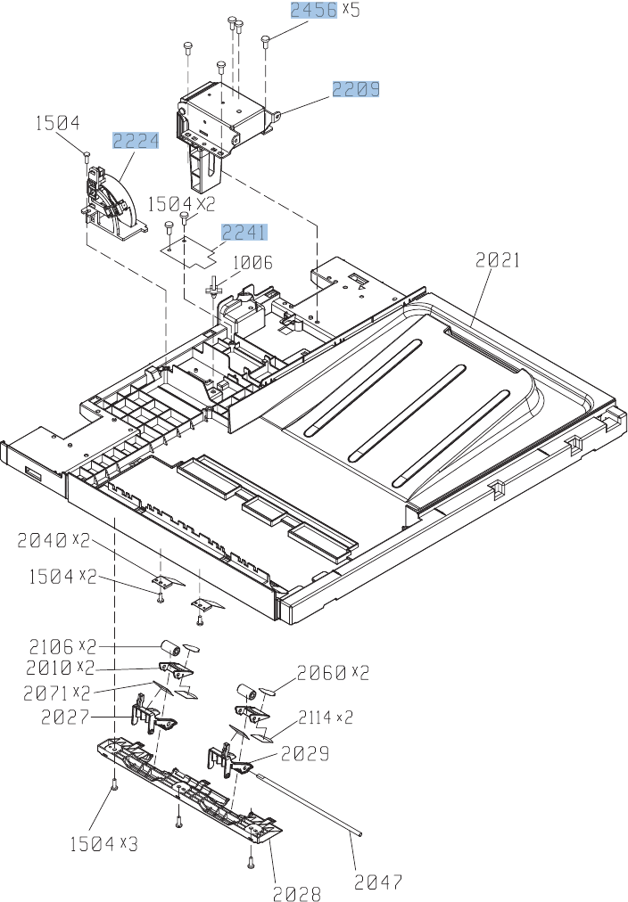
Document feeder assembly (2 of 5)
Figure 4-42 Document feeder assembly (2 of 5)
748 Chapter 4 Parts and diagrams ENWW

Table 4-43 Document feeder assembly (2 of 5)
Ref Description Part number Qty
2241 ASY-PBA-RELAY-SP PF2309K118NI 1
2209 ASY-HNG-R-SP PF2309K119NI 1
2456 ASY-NS-SCR00063 IR4068K339NI 5
2224 ASY-DFSENS-SP PF2309K121NI 1
ENWW Document feeder/scanner 749
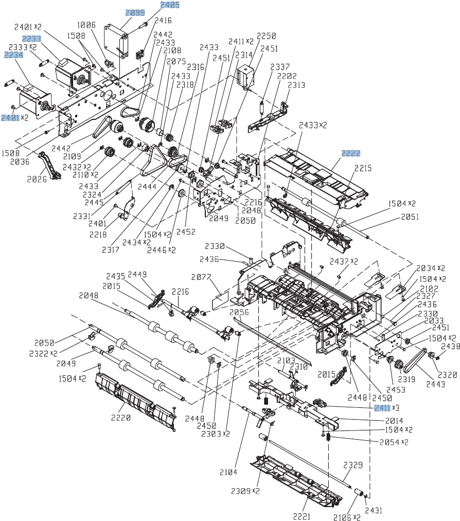
Document feeder assembly (3 of 5)
Figure 4-43 Document feeder assembly (3 of 5)
750 Chapter 4 Parts and diagrams ENWW

Table 4-44 Document feeder assembly (3 of 5)
Ref Description Part number Qty
2411 ASY-SG2481-NY-SP PF2309K122NI 5
2401 ASY-030060FDIT IR4068K331NI 5
2233 ASY-MOT-FE-SP PF2309K125NI 1
2234 ASY-MOT-RE-SP PF2309K126NI 1
2099 ASY-FAN-SP PF2309K127NI 1
2405 ASY-040200FNWS IR4068K336NI 1
2222 ASY-GIDREV-SPR-SP PF2309K129NI 1
ENWW Document feeder/scanner 751
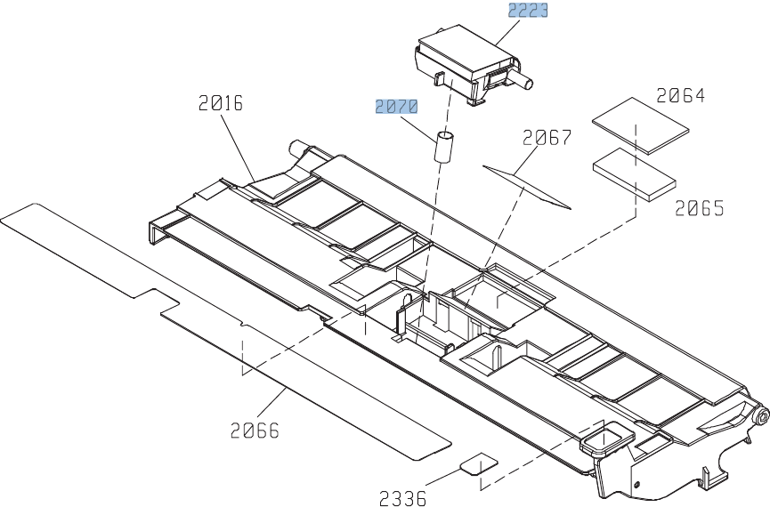
Document feeder assembly (4 of 5)
Figure 4-44 Document feeder assembly (4 of 5)
752 Chapter 4 Parts and diagrams ENWW

Table 4-45 Document feeder assembly (4 of 5)
Ref Description Part number Qty
2223 ASY-HLD-REV-PAD-SP PF2309K133NI 1
2070 ASY-SP-REV-SPR (spring) PF2309K135NI 1
NOTE: Kit CE248-67901 includes a separation pad, roller assembly, and instructions.
ENWW Document feeder/scanner 753
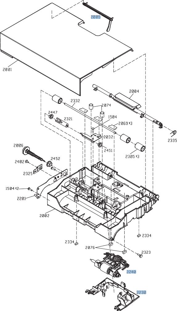
Document feeder assembly (5 of 5)
Figure 4-45 Document feeder assembly (5 of 5)
754 Chapter 4 Parts and diagrams ENWW

Table 4-46 Document feeder assembly (5 of 5)
Ref Description Part number Qty
2005 ASY-LVR-FE-EMP-SP PF2309K130NI 1
2240 ASY-ROL-FE-FEED-SP PF2309K131NI 1
2230 ASY-CVR-FE-PICK-SP PF2309K132NI 1
NOTE: Kit CE248-67901 includes a separation pad, roller assembly, and instructions.
ENWW Document feeder/scanner 755

Alphabetical parts list
Table 4-47 Alphabetical parts list
Description Part number Table and page
Arm, door link supporting, right RC2-4055-000CN Internal components (5 of 7)
on page 681
ASM-IF-SP PF2309K110NI Document feeder assembly (1
of 5) on page 747
ASSY-CRG-UNIT-IR4068 IR4068K200NI Scanner assembly (3 of 6)
on page 739
ASSY-SP-GUIDE-HINGE IR4068K126NI Scanner assembly (1 of 6)
on page 735
ASY-030060FDIT IR4068K331NI Document feeder assembly (3
of 5) on page 751
ASY-030060FNTP IR4068K332NI Document feeder assembly (1
of 5) on page 747
ASY-030060FNTW IR4068K333NI Scanner assembly (3 of 6)
on page 739
ASY-030060NIT IR4068K341NI Scanner inverter assembly
on page 733
ASY-030080FNTP IR4068K334NI Scanner assembly (1 of 6)
on page 735
ASY-030080FNTW IR4068K335NI Scanner assembly (3 of 6)
on page 739
ASY-030120FWWS IR4068K340NI Scanner inverter assembly
on page 733
ASY-040100FNBB IR4068K342NI Scanner assembly (1 of 6)
on page 735
ASY-040200FNWS IR4068K336NI Document feeder assembly (3
of 5) on page 751
ASY-BASE-SP PF2309K102NI Document feeder assembly (1
of 5) on page 747
ASY-CVR-F-R-SP PF2309K114NI Document feeder assembly (1
of 5) on page 747
ASY-CVR-F-SP PF2309K107NI Document feeder assembly (1
of 5) on page 747
ASY-CVR-FE-FEED-SP PF2309K105NI Document feeder assembly (1
of 5) on page 747
ASY-CVR-FE-PICK-SP PF2309K132NI Document feeder assembly (5
of 5) on page 755
ASY-DFSENS-SP PF2309K121NI Document feeder assembly (2
of 5) on page 749
756 Chapter 4 Parts and diagrams ENWW

Table 4-47 Alphabetical parts list (continued)
Description Part number Table and page
ASY-FAN-SP PF2309K127NI Document feeder assembly (3
of 5) on page 751
ASY-FRM-RE-FEED-SP PF2309K103NI Document feeder assembly (1
of 5) on page 747
ASY-GIDREV-SPR-SP PF2309K129NI Document feeder assembly (3
of 5) on page 751
ASY-HLD-REV-PAD-SP PF2309K133NI Document feeder assembly (4
of 5) on page 753
ASY-HNG-L-SP PF2309K104NI Document feeder assembly (1
of 5) on page 747
ASY-HNG-R-SP PF2309K119NI Document feeder assembly (2
of 5) on page 749
ASY-IR4041P021 IR4068K343NI Scanner assembly (3 of 6)
on page 739
ASY-LVR-FE-EMP-SP PF2309K130NI Document feeder assembly (5
of 5) on page 755
ASY-MOT-FE-SP PF2309K125NI Document feeder assembly (3
of 5) on page 751
ASY-MOT-RE-SP PF2309K126NI Document feeder assembly (3
of 5) on page 751
ASY-NS-SCR00017 IR4068K337NI Scanner assembly (5 of 6)
on page 743
ASY-NS-SCR00023B IR4068K338NI Scanner assembly (2 of 6)
on page 737
ASY-NS-SCR00027 IR4068K344NI Scanner assembly (2 of 6)
on page 737
ASY-NS-SCR00063 IR4068K339NI Document feeder assembly (2
of 5) on page 749
ASY-PBA-RELAY-SP PF2309K118NI Document feeder assembly (2
of 5) on page 749
ASY-ROL-FE-FEED-SP PF2309K131NI Document feeder assembly (5
of 5) on page 755
ASY-SCR-5-4-DAN-SP PF2309K113NI Document feeder assembly (1
of 5) on page 747
ASY-SCR03T100PLA-SP PF2309K115NI Document feeder assembly (1
of 5) on page 747
ASY-SCR04T100PLA-SP PF2309K108NI Document feeder assembly (1
of 5) on page 747
ASY-SG2481-NY-SP PF2309K122NI Document feeder assembly (3
of 5) on page 751
ENWW Alphabetical parts list 757

Table 4-47 Alphabetical parts list (continued)
Description Part number Table and page
ASY-SP-REV-SPR (spring) PF2309K135NI Document feeder assembly (4
of 5) on page 753
ASY-TFB-2024RS PF2309K112NI Document feeder assembly (1
of 5) on page 747
ASY-TFT-152613N-SP PF2309K111NI Document feeder assembly (1
of 5) on page 747
ASY-TRY-F-BASE-SP CC419-67903 Document feeder assembly (1
of 5) on page 747
ASY-TRY-SP PF2309K106NI Document feeder assembly (1
of 5) on page 747
Bin sensor PCA (SSMBM) RM1-5894-000CN PCAs (SSMBM) on page 714
Bin solenoid assembly (SSMBM) RM1-5896-000CN Main body (SSMBM; 2 of 2)
on page 712
Bushing RC2-9719-000CN Internal components (2 of 7)
on page 675
Bushing RC2-4470-000CN Internal components (2 of 7)
on page 675
Cable cover assembly RM1-6695-000CN Internal components (5 of 7)
on page 681
Cable, fan RM1-5821-000CN Internal components 6 of 7
on page 683
Cable, flat flexable (FFC) RK2-2604-000CN Internal components 7 of 7
on page 685
Cable, flexible flat, H.V.T. RK2-2603-000CN Internal components 7 of 7
on page 685
Cartridge fan RK2-2418-000CN Internal components 6 of 7
on page 683
Cartridge fan assembly RM1-5589-000CN Internal components (4 of 7)
on page 679
Cassette RM1-5928-000CN Cassette on page 687
Cassette (1x500-SPF) RM1-5928-000CN Main body (1x500-SPF)
on page 720
Cassette (1x500PF and 3x500PF) RM1-5928-000CN Paper feeders on page 723
Cassette guide assembly (jam access) RM1-5504-000CN Internal components (5 of 7)
on page 681
Cassette rail left assembly RM1-6196-000CN Internal components (3 of 7)
on page 677
Cassette rail right assembly RM1-6195-000CN Internal components (3 of 7)
on page 677
758 Chapter 4 Parts and diagrams ENWW

Table 4-47 Alphabetical parts list (continued)
Description Part number Table and page
Connecting cable assembly RM1-5799-000CN Internal components 7 of 7
on page 685
Contact assembly RM1-5502-000CN Internal components 7 of 7
on page 685
Cover RC2-4403-000CN Internal components (2 of 7)
on page 675
Cover RC2-5962-000CN Internal components (2 of 7)
on page 675
Cover RC2-4467-000CN Internal components (3 of 7)
on page 677
Cover, duplexing gear RC2-4664-000CN Internal components (1 of 7)
on page 673
Cover, fan RC2-4288-000CN External covers, panels, and
doors; on page 667
Cover, front (SSMBM) RC2-5571-000CN External covers, panels, and
doors (SSMBM) on page 706
Cover, front upper (1x500-SPF) RC2-5395-000CN Paper feeders on page 718
Cover, handle, left (1x500-SPF) RC3-1315-000CN Paper feeders on page 718
Cover, handle, right (1x500-SPF) RC3-1317-000CN Paper feeders on page 718
Cover, high voltage RC2-4662-000CN Internal components (1 of 7)
on page 673
Cover, inner RM1-5520-000CN External covers, panels, and
doors; on page 667
Cover, inner RC2-3981-000CN Internal components (5 of 7)
on page 681
Cover, intermediate assembly RM1-5645-000CN External covers, panels, and
doors; on page 667
Cover, left (1x500-SPF) RC3-1314-000CN Paper feeders on page 718
Cover, left (1x500PF and 3x500PF) RC2-5393-000CN External covers, panels, and
doors (1x500PF and 3x500PF)
on page 725
Cover, left lower RC2-4300-000CN External covers, panels, and
doors; on page 667
Cover, left rear RC2-8213-000CN External covers, panels, and
doors; on page 667
Cover, M.P. crossmember F RC2-9189-000CN Internal components (5 of 7)
on page 681
Cover, M.P. crossmember R RC2-4747-000CN Right door assembly
on page 669
ENWW Alphabetical parts list 759

Table 4-47 Alphabetical parts list (continued)
Description Part number Table and page
Cover, rear (1x500-SPF) RC3-1319-000CN Paper feeders on page 718
Cover, rear (1x500PF and 3x500PF) RC2-5379-000CN External covers, panels, and
doors (1x500PF and 3x500PF)
on page 725
Cover, rear (SSMBM) RC2-5572-000CN External covers, panels, and
doors (SSMBM) on page 706
Cover, rear lower (1x500PF and 3x500PF) RC2-5378-000CN External covers, panels, and
doors (1x500PF and 3x500PF)
on page 725
Cover, right (1x500-SPF) RC3-1316-000CN Paper feeders on page 718
Cover, right center (1x500PF and 3x500PF) RC2-5394-000CN External covers, panels, and
doors (1x500PF and 3x500PF)
on page 725
Cover, right front RC2-4287-000CN External covers, panels, and
doors; on page 667
Cover, right front (1x500-SPF) RC3-1318-000CN Paper feeders on page 718
Cover, right front, (1x500PF) RC2-5356-000CN External covers, panels, and
doors (1x500PF and 3x500PF)
on page 725
Cover, right front, (3x500PF) RC2-5357-000CN External covers, panels, and
doors (1x500PF and 3x500PF)
on page 725
Cover, right rear RC2-4273-000CN External covers, panels, and
doors; on page 667
Cover, right rear (1x500PF and 3x500PF) RC2-5380-000CN External covers, panels, and
doors (1x500PF and 3x500PF)
on page 725
Cover, roller RC2-4483-000CN Internal components (5 of 7)
on page 681
Crg. Guide lower assembly RM1-5486-000CN Internal components (2 of 7)
on page 675
DC cable assembly RM1-5827-000CN Internal components (1 of 7)
on page 673
DC controller PCA assembly RM1-5758-000CN PCAs on page 703
Delivery assembly RM1-5615-000CN Delivery assembly
on page 699
Density detect assembly RM1-5641-000CN Internal components (5 of 7)
on page 681
Developing disengaging motor RK2-2415-000CN Internal components 6 of 7
on page 683
760 Chapter 4 Parts and diagrams ENWW

Table 4-47 Alphabetical parts list (continued)
Description Part number Table and page
Document feeder complete assembly PF2309-SVPNI Document feeder/scanner
assemblies on page 731
Door, stock, (1x500PF) RC2-5377-000CN External covers, panels, and
doors (1x500PF and 3x500PF)
on page 725
Duplex registration assembly kit (includes instructions) CC493-67917 Registration assembly
on page 693
Duplexing cable assembly, duplex RM1-5803-000CN Internal components 7 of 7
on page 685
Duplexing drive assembly RM1-4973-000CN Internal components 6 of 7
on page 683
Fan RK2-2575-000CN Internal components (1 of 7)
on page 673
Fan RK2-2577-000CN Internal components 7 of 7
on page 685
Feed cable assembly RM1-5804-000CN Internal components 7 of 7
on page 685
Feeder PCA (1x500-SPF) RM1-5854-000CN Main body (1x500-SPF)
on page 720
Feeder PCA assembly (1x500PF) RM1-5854-000CN Main body (1x500PF)
on page 727
Feeder PCA assembly (3x500PF) RM1-5958-000CN Main body (3x500PF)
on page 729
Flapper guide assembly (SSMBM) RM1-5153-000CN Main body (SSMBM; 2 of 2)
on page 712
Flexible flat cable assembly (includes two FFCs; DCC to laser/
scanner)
RM1-5498-000CN Internal components 6 of 7
on page 683
Formatter assembly kit (exchange; includes instructions) CE871-69001 PCAs on page 703
Front door assembly RM1-5612-000CN Front door assembly
on page 671
Front inner cover lower assembly RM1-5598-000CN Internal components (3 of 7)
on page 677
Front inner cover upper assembly RM1-5495-000CN Internal components (3 of 7)
on page 677
Front light guide assembly RM1-5492-000CN Internal components (4 of 7)
on page 679
Fuser 110 V assembly kit (includes instructions) CC493-67911 Fuser assembly on page 701
Fuser 220 V assembly kit (includes instructions) CC493-67912 Fuser assembly on page 701
Fuser drive assembly, duplex RM1-5656-000CN Internal components 6 of 7
on page 683
ENWW Alphabetical parts list 761

Table 4-47 Alphabetical parts list (continued)
Description Part number Table and page
Fuser motor assembly RM1-4983-000CN Internal components 6 of 7
on page 683
Grip, left front RC2-4268-000CN External covers, panels, and
doors; on page 667
Grip, left rear RC2-4269-000CN External covers, panels, and
doors; on page 667
Guide RC2-4527-000CN Internal components (5 of 7)
on page 681
Guide, cassette option RC2-4741-000CN Internal components (5 of 7)
on page 681
Guide, crossmember cable, upper RC2-8206-000CN Internal components (1 of 7)
on page 673
Guide, interlock cable RC2-4632-000CN Internal components (1 of 7)
on page 673
H.V. power supply cable assembly RM1-5724-000CN Internal components 7 of 7
on page 685
High voltage holder assembly RM1-6694-000CN Internal components (3 of 7)
on page 677
High voltage power supply PCA, lower (includes FFC; DCC to
HVPS lower)
RM1-5779-000CN PCAs on page 703
High voltage power supply, upper RM1-5781-000CN PCAs on page 703
Hinge, front door RC2-4291-000CN Internal components (3 of 7)
on page 677
Hinge, front door RC2-4292-000CN Internal components (3 of 7)
on page 677
Holder, connector (SSMBM) RC2-5625-000CN External covers, panels, and
doors (SSMBM) on page 706
Holder, door handle, right RC2-4661-000CN Internal components (1 of 7)
on page 673
Holder, duct cable RM1-5601-000CN Internal components (5 of 7)
on page 681
Holder, exhaust fan RC2-4665-000CN Internal components (1 of 7)
on page 673
Holder, paper pickup connector RC2-4044-000CN Internal components 6 of 7
on page 683
Holder, sensor RC2-4369-000CN Internal components (3 of 7)
on page 677
Image scanner CN cover assembly RM1-5646-000CN Internal components (1 of 7)
on page 673
Image scanner power supply assembly RM1-5619-000CN PCAs on page 703
762 Chapter 4 Parts and diagrams ENWW

Table 4-47 Alphabetical parts list (continued)
Description Part number Table and page
Inner connecting board (ICB) assembly RM1-5544-020CN PCAs on page 703
Interlock assembly RM1-5496-000CN Internal components (3 of 7)
on page 677
Interlock switch cable assembly RM1-5832-000CN Internal components 7 of 7
on page 685
Intermediate paper transfer unit (IPTU) RM1-5621-000CN Intermediate paper transfer unit
(IPTU) on page 697
IPTU inner cover assembly RL1-2181-000CN Internal components (1 of 7)
on page 673
ITB motor assembly RM1-5777-000CN Internal components 6 of 7
on page 683
Jog assembly (SSMBM) RM1-5155-000CN Main body (SSMBM; 2 of 2)
on page 712
Laser scanner kit (includes instructions and one scanner
assembly)
CC493-67914 Internal components (4 of 7)
on page 679
Lever, CRG. lock RC2-3986-000CN Internal components (2 of 7)
on page 675
Lever, crg. pressure, front RC2-3983-020CN Internal components (3 of 7)
on page 677
Lever, release RC2-4644-000CN Internal components (1 of 7)
on page 673
Lever, shutter RC2-4415-000CN Internal components (3 of 7)
on page 677
Lift tray assembly (SSMBM) RM1-5156-000CN Main body (SSMBM; 2 of 2)
on page 712
Lifter assembly RM1-5914-000CN Internal components 6 of 7
on page 683
Lifter assembly (1x500-SPF) RM1-5914-000CN Main body (1x500-SPF)
on page 720
Lifter assembly (1x500PF) RM1-5914-000CN Main body (1x500PF)
on page 727
Lifter assembly (3x500PF) RM1-5914-000CN Main body (3x500PF)
on page 729
Lifter base assembly RM1-5913-000CN Internal components (2 of 7)
on page 675
Lifter base assembly (1x500-SPF) RM1-5913-000CN Main body (1x500-SPF)
on page 720
Lifter base assembly (1x500PF) RM1-5913-000CN Main body (1x500PF)
on page 727
ENWW Alphabetical parts list 763

Table 4-47 Alphabetical parts list (continued)
Description Part number Table and page
Lifter base assembly (3x500PF) RM1-5913-000CN Main body (3x500PF)
on page 729
Link, right door RC2-4726-000CN Internal components (5 of 7)
on page 681
Low voltage power supply PCA assembly, 110V RM1-5763-000CN PCAs on page 703
Low voltage power supply PCA assembly, 220V RM1-5764-000CN PCAs on page 703
Lower main cable assembly RM1-5801-000CN Internal components 7 of 7
on page 685
Main DC motor assembly RM1-5521-000CN Internal components 6 of 7
on page 683
Main drive kit (includes instructions) CC493-67915 Internal components 6 of 7
on page 683
MBM bin assembly (SSMBM) RM1-6670-000CN Main body (SSMBM; 2 of 2)
on page 712
MBM driver PCA (SSMBM) RM1-5168-000CN PCAs (SSMBM) on page 714
MBM flapper assembly (SSMBM) RM1-5157-000CN Main body (SSMBM; 2 of 2)
on page 712
Output bezel kit CC419-67904 External covers, panels, and
doors; on page 667
Output bin, left paper delivery assembly RM1-5632-000CN External covers, panels, and
doors; on page 667
Panel, stacking (SSMBM) RL1-1984-000CN External covers, panels, and
doors (SSMBM) on page 706
Paper feed roller RM1-0037-020CN Paper pickup assembly
on page 689
Paper feed roller assembly RM1-5525-000CN Internal components (5 of 7)
on page 681
Paper pickup assembly RM1-5919-000CN Paper pickup assembly
on page 689
Paper pickup assembly (1x500-SPF) RM1-5929-000CN Main body (1x500-SPF)
on page 720
Paper pickup assembly (1x500PF) RM1-5929-000CN Main body (1x500PF)
on page 727
Paper pickup assembly (3x500PF) RM1-5929-000CN Main body (3x500PF)
on page 729
Paper pickup drive assembly RM1-5549-000CN Internal components 6 of 7
on page 683
Paper pickup drive assembly (1x500-SPF) RM1-5934-000CN Main body (1x500-SPF)
on page 720
764 Chapter 4 Parts and diagrams ENWW

Table 4-47 Alphabetical parts list (continued)
Description Part number Table and page
Paper pickup drive assembly (1x500PF) RM1-5934-000CN Main body (1x500PF)
on page 727
Paper pickup drive assembly (3x500PF) RM1-5935-000CN Main body (3x500PF)
on page 729
Photo interrupter WG8-5696-000CN Internal components (3 of 7)
on page 677
Pickup roller (Tray 1) kit (includes instructions CC493-67906 Tray 1 paper pickup assembly
on page 691
Position detect assembly RM1-5604-000CN Internal components (4 of 7)
on page 679
Power switch assembly RM1-5582-000CN Internal components (3 of 7)
on page 677
Rear cover assembly RM1-5613-000CN External covers, panels, and
doors; on page 667
Repair transfer kit (includes instructions, ITB, and secondary
transfer roller)
CC493-67909 Internal components (4 of 7)
on page 679
Right door assembly RM1-5509-000CN Right door assembly
on page 669
Right door assembly (1x500PF) RM1-5936-000CN External covers, panels, and
doors (1x500PF and 3x500PF)
on page 725
Right door assembly (3x500PF) RM1-5937-000CN External covers, panels, and
doors (1x500PF and 3x500PF)
on page 725
Right handle cover assembly RM1-5507-000CN External covers, panels, and
doors; on page 667
Roller, paper pickup RL1-2099-000CN Paper pickup assembly
on page 689
S-ASM-ICB-COR (scanner cable) IR4068K320NI Document feeder/scanner
assemblies on page 731
S-ASM-USB (control panel USB cable) IR4068K301NI Scanner assembly (1 of 6)
on page 735
S-ASSY-CP-ADAPTER IR4068K316NI Scanner assembly (6 of 6)
on page 745
S-ASSY-INV IR4068K306NI Scanner assembly (2 of 6)
on page 737
S-ASSY-MOTOR-UNIT IR4068K309NI Scanner assembly (3 of 6)
on page 739
S-ASSY-UPPER-UNIT (includes scanner glass) IR4068K315NI Scanner assembly (5 of 6)
on page 743
ENWW Alphabetical parts list 765

Table 4-47 Alphabetical parts list (continued)
Description Part number Table and page
S-CVR-FAN IR4068K314NI Scanner assembly (4 of 6)
on page 741
S-CVR-LEFT IR4068K322NI Document feeder/scanner
assemblies on page 731
S-CVR-REAR IR4068K321NI Document feeder/scanner
assemblies on page 731
S-FAN-D06037600G-01 IR4068K311NI Scanner assembly (3 of 6)
on page 739
S-FAN-MFB30E-05A-006 IR4068K304NI Scanner inverter assembly
on page 733
S-FLTR-IN IR4068K313NI Scanner assembly (4 of 6)
on page 741
S-HNG-LIFT-R IR4068K302NI Scanner assembly (1 of 6)
on page 735
S-K-CBP-INV-FFC IR4068K303NI Scanner inverter assembly
on page 733
S-PBA-TYUKEI IR4068K307NI Scanner assembly (2 of 6)
on page 737
S-SFT-STP-HNG (hinge screw) IR4068K319NI Document feeder/scanner
assemblies on page 731
S-SNS-EY3A-1061-2 IR4068K305NI Scanner assembly (2 of 6)
on page 737
S-SP-GND-PLT-LIFT-L IR4068K345NI Scanner assembly (5 of 6)
on page 743
S-SP-GND-SFT-R IR4068K310NI Scanner assembly (3 of 6)
on page 739
Scan control board (SCB), S-PBA-SCB IR4068K312NI Scanner assembly (4 of 6)
on page 741
Scanner assembly (includes SCB and control panel adapter) IR4068-SVPNI Document feeder/scanner
assemblies on page 731
Scanner inverter assembly IR4068K306NI Scanner inverter assembly
on page 733
Scissors hinge assembly, left RM1-5616-000CN Internal components (1 of 7)
on page 673
Scissors hinge assembly, right RM1-5614-000CN Internal components (1 of 7)
on page 673
Secondary transfer assembly, duplex kit (includes instructions,
and shaft-support clip; RC2-4162-000CN)
CC492-67901 Secondary transfer assembly
on page 695
Secondary transfer roller assembly kit (includes instructions) CC493-67908 Secondary transfer assembly
on page 695
766 Chapter 4 Parts and diagrams ENWW

Table 4-47 Alphabetical parts list (continued)
Description Part number Table and page
Sensor cable assembly RM1-5815-000CN Internal components 7 of 7
on page 685
Separation pad (Tray 1) RL1-1937-000CN Tray 1 paper pickup assembly
on page 691
Shaft support (included in secondary transfer kit; see Figure 4–
15)
RC2-4162-000CN Internal components (5 of 7)
on page 681
Shutter arm assembly RM1-5585-000CN Internal components (2 of 7)
on page 675
Shutter arm assembly RM1-5586-000CN Internal components (2 of 7)
on page 675
Shutter assembly RM1-5488-000CN Internal components (2 of 7)
on page 675
Shutter assembly RM1-5489-000CN Internal components (2 of 7)
on page 675
Spacer RC2-4514-000CN Internal components (5 of 7)
on page 681
Spring, compression RU6-2316-000CN Internal components (3 of 7)
on page 677
Spring, grounding RC2-4469-000CN Internal components (2 of 7)
on page 675
Spring, grounding RU6-2237-000CN Internal components (3 of 7)
on page 677
Spring, tension RU6-2236-000CN Internal components (3 of 7)
on page 677
Spring, tension RU6-2235-000CN Internal components (4 of 7)
on page 679
Spring, tension RU6-2468-000CN Internal components 6 of 7
on page 683
Spring, torsion RC2-4645-000CN Internal components (1 of 7)
on page 673
Spring, torsion RU6-2247-000CN Internal components (2 of 7)
on page 675
Stamp solenoid assembly (SSMBM) RM1-6664-000CN Main body (SSMBM; 1 of 2)
on page 710
Stand, scissors hinge, left RC2-4642-000CN Internal components (1 of 7)
on page 673
Stand, scissors hinge, right RC2-4646-000CN Internal components (1 of 7)
on page 673
Stapler assembly (SSMBM) RM1-5166-000CN Main body (SSMBM; 2 of 2)
on page 712
ENWW Alphabetical parts list 767

Table 4-47 Alphabetical parts list (continued)
Description Part number Table and page
Stopper, tray (SSMBM) RC2-5576-000CN External covers, panels, and
doors (SSMBM) on page 706
Sub controller cable assembly RM1-5826-000CN Internal components 7 of 7
on page 685
Sub PS AD cable assembly RM1-5825-000CN Internal components 7 of 7
on page 685
Switch WC4-5303-000CN Internal components (3 of 7)
on page 677
Switch cable assembly RM1-5807-000CN Internal components 7 of 7
on page 685
Switch, push WC2-5637-000CN Internal components (3 of 7)
on page 677
Switch, push WC2-5637-000CN Internal components 7 of 7
on page 685
Toner collection unit (TCU) kit (includes instructions and wipe) CC493-67913 Internal components (3 of 7)
on page 677
Toner remain PCA assembly RM1-5771-020CN PCAs on page 703
Top cover assembly (SSMBM) RM1-6669-000CN External covers, panels, and
doors (SSMBM) on page 706
Top door assembly (SSMBM) RM1-5160-000CN Top door assembly (SSMBM)
on page 708
Tray assembly (SSMBM) RM1-5161-000CN External covers, panels, and
doors (SSMBM) on page 706
Tray, waste toner catch RC2-4218-000CN Internal components (2 of 7)
on page 675
Waste toner detect assembly RM1-5545-000CN Internal components (3 of 7)
on page 677
Waste toner duct assembly RM1-5519-000CN Internal components (3 of 7)
on page 677
Waste toner motor assembly RM1-5605-000CN Internal components (4 of 7)
on page 679
Waste toner paper feed assembly RM1-5584-000CN Internal components (3 of 7)
on page 677
768 Chapter 4 Parts and diagrams ENWW

Numerical parts list
Table 4-48 Numerical parts list
Part number Description Table and page
CC419-67903 ASY-TRY-F-BASE-SP Document feeder assembly (1
of 5) on page 747
CC419-67904 Output bezel kit External covers, panels, and
doors; on page 667
CC492-67901 Secondary transfer assembly, duplex kit (includes instructions,
and shaft-support clip; RC2-4162-000CN)
Secondary transfer assembly
on page 695
CC493-67906 Pickup roller (Tray 1) kit (includes instructions Tray 1 paper pickup assembly
on page 691
CC493-67908 Secondary transfer roller assembly kit (includes instructions) Secondary transfer assembly
on page 695
CC493-67909 Repair transfer kit (includes instructions, ITB, and secondary
transfer roller)
Internal components (4 of 7)
on page 679
CC493-67911 Fuser 110 V assembly kit (includes instructions) Fuser assembly on page 701
CC493-67912 Fuser 220 V assembly kit (includes instructions) Fuser assembly on page 701
CC493-67913 Toner collection unit (TCU) kit (includes instructions and wipe) Internal components (3 of 7)
on page 677
CC493-67914 Laser scanner kit (includes instructions and one scanner
assembly)
Internal components (4 of 7)
on page 679
CC493-67915 Main drive kit (includes instructions) Internal components 6 of 7
on page 683
CC493-67917 Duplex registration assembly kit (includes instructions) Registration assembly
on page 693
CE871-69001 Formatter assembly kit (exchange; includes instructions) PCAs on page 703
IR4068-SVPNI Scanner assembly (includes SCB and control panel adapter) Document feeder/scanner
assemblies on page 731
IR4068K126NI ASSY-SP-GUIDE-HINGE Scanner assembly (1 of 6)
on page 735
IR4068K200NI ASSY-CRG-UNIT-IR4068 Scanner assembly (3 of 6)
on page 739
IR4068K301NI S-ASM-USB (control panel USB cable) Scanner assembly (1 of 6)
on page 735
IR4068K302NI S-HNG-LIFT-R Scanner assembly (1 of 6)
on page 735
IR4068K303NI S-K-CBP-INV-FFC Scanner inverter assembly
on page 733
IR4068K304NI S-FAN-MFB30E-05A-006 Scanner inverter assembly
on page 733
ENWW Numerical parts list 769

Table 4-48 Numerical parts list (continued)
Part number Description Table and page
IR4068K305NI S-SNS-EY3A-1061-2 Scanner assembly (2 of 6)
on page 737
IR4068K306NI Scanner inverter assembly Scanner inverter assembly
on page 733
IR4068K306NI S-ASSY-INV Scanner assembly (2 of 6)
on page 737
IR4068K307NI S-PBA-TYUKEI Scanner assembly (2 of 6)
on page 737
IR4068K309NI S-ASSY-MOTOR-UNIT Scanner assembly (3 of 6)
on page 739
IR4068K310NI S-SP-GND-SFT-R Scanner assembly (3 of 6)
on page 739
IR4068K311NI S-FAN-D06037600G-01 Scanner assembly (3 of 6)
on page 739
IR4068K312NI Scan control board (SCB), S-PBA-SCB Scanner assembly (4 of 6)
on page 741
IR4068K313NI S-FLTR-IN Scanner assembly (4 of 6)
on page 741
IR4068K314NI S-CVR-FAN Scanner assembly (4 of 6)
on page 741
IR4068K315NI S-ASSY-UPPER-UNIT (includes scanner glass) Scanner assembly (5 of 6)
on page 743
IR4068K316NI S-ASSY-CP-ADAPTER Scanner assembly (6 of 6)
on page 745
IR4068K319NI S-SFT-STP-HNG (hinge screw) Document feeder/scanner
assemblies on page 731
IR4068K320NI S-ASM-ICB-COR (scanner cable) Document feeder/scanner
assemblies on page 731
IR4068K321NI S-CVR-REAR Document feeder/scanner
assemblies on page 731
IR4068K322NI S-CVR-LEFT Document feeder/scanner
assemblies on page 731
IR4068K331NI ASY-030060FDIT Document feeder assembly (3
of 5) on page 751
IR4068K332NI ASY-030060FNTP Document feeder assembly (1
of 5) on page 747
IR4068K333NI ASY-030060FNTW Scanner assembly (3 of 6)
on page 739
IR4068K334NI ASY-030080FNTP Scanner assembly (1 of 6)
on page 735
770 Chapter 4 Parts and diagrams ENWW

Table 4-48 Numerical parts list (continued)
Part number Description Table and page
IR4068K335NI ASY-030080FNTW Scanner assembly (3 of 6)
on page 739
IR4068K336NI ASY-040200FNWS Document feeder assembly (3
of 5) on page 751
IR4068K337NI ASY-NS-SCR00017 Scanner assembly (5 of 6)
on page 743
IR4068K338NI ASY-NS-SCR00023B Scanner assembly (2 of 6)
on page 737
IR4068K339NI ASY-NS-SCR00063 Document feeder assembly (2
of 5) on page 749
IR4068K340NI ASY-030120FWWS Scanner inverter assembly
on page 733
IR4068K341NI ASY-030060NIT Scanner inverter assembly
on page 733
IR4068K342NI ASY-040100FNBB Scanner assembly (1 of 6)
on page 735
IR4068K343NI ASY-IR4041P021 Scanner assembly (3 of 6)
on page 739
IR4068K344NI ASY-NS-SCR00027 Scanner assembly (2 of 6)
on page 737
IR4068K345NI S-SP-GND-PLT-LIFT-L Scanner assembly (5 of 6)
on page 743
PF2309-SVPNI Document feeder complete assembly Document feeder/scanner
assemblies on page 731
PF2309K102NI ASY-BASE-SP Document feeder assembly (1
of 5) on page 747
PF2309K103NI ASY-FRM-RE-FEED-SP Document feeder assembly (1
of 5) on page 747
PF2309K104NI ASY-HNG-L-SP Document feeder assembly (1
of 5) on page 747
PF2309K105NI ASY-CVR-FE-FEED-SP Document feeder assembly (1
of 5) on page 747
PF2309K106NI ASY-TRY-SP Document feeder assembly (1
of 5) on page 747
PF2309K107NI ASY-CVR-F-SP Document feeder assembly (1
of 5) on page 747
PF2309K108NI ASY-SCR04T100PLA-SP Document feeder assembly (1
of 5) on page 747
PF2309K110NI ASM-IF-SP Document feeder assembly (1
of 5) on page 747
ENWW Numerical parts list 771

Table 4-48 Numerical parts list (continued)
Part number Description Table and page
PF2309K111NI ASY-TFT-152613N-SP Document feeder assembly (1
of 5) on page 747
PF2309K112NI ASY-TFB-2024RS Document feeder assembly (1
of 5) on page 747
PF2309K113NI ASY-SCR-5-4-DAN-SP Document feeder assembly (1
of 5) on page 747
PF2309K114NI ASY-CVR-F-R-SP Document feeder assembly (1
of 5) on page 747
PF2309K115NI ASY-SCR03T100PLA-SP Document feeder assembly (1
of 5) on page 747
PF2309K118NI ASY-PBA-RELAY-SP Document feeder assembly (2
of 5) on page 749
PF2309K119NI ASY-HNG-R-SP Document feeder assembly (2
of 5) on page 749
PF2309K121NI ASY-DFSENS-SP Document feeder assembly (2
of 5) on page 749
PF2309K122NI ASY-SG2481-NY-SP Document feeder assembly (3
of 5) on page 751
PF2309K125NI ASY-MOT-FE-SP Document feeder assembly (3
of 5) on page 751
PF2309K126NI ASY-MOT-RE-SP Document feeder assembly (3
of 5) on page 751
PF2309K127NI ASY-FAN-SP Document feeder assembly (3
of 5) on page 751
PF2309K129NI ASY-GIDREV-SPR-SP Document feeder assembly (3
of 5) on page 751
PF2309K130NI ASY-LVR-FE-EMP-SP Document feeder assembly (5
of 5) on page 755
PF2309K131NI ASY-ROL-FE-FEED-SP Document feeder assembly (5
of 5) on page 755
PF2309K132NI ASY-CVR-FE-PICK-SP Document feeder assembly (5
of 5) on page 755
PF2309K133NI ASY-HLD-REV-PAD-SP Document feeder assembly (4
of 5) on page 753
PF2309K135NI ASY-SP-REV-SPR (spring) Document feeder assembly (4
of 5) on page 753
RC2-3981-000CN Cover, inner Internal components (5 of 7)
on page 681
RC2-3983-020CN Lever, crg. pressure, front Internal components (3 of 7)
on page 677
772 Chapter 4 Parts and diagrams ENWW

Table 4-48 Numerical parts list (continued)
Part number Description Table and page
RC2-3986-000CN Lever, CRG. lock Internal components (2 of 7)
on page 675
RC2-4044-000CN Holder, paper pickup connector Internal components 6 of 7
on page 683
RC2-4055-000CN Arm, door link supporting, right Internal components (5 of 7)
on page 681
RC2-4162-000CN Shaft support (included in secondary transfer kit; see Figure 4–
15)
Internal components (5 of 7)
on page 681
RC2-4218-000CN Tray, waste toner catch Internal components (2 of 7)
on page 675
RC2-4268-000CN Grip, left front External covers, panels, and
doors; on page 667
RC2-4269-000CN Grip, left rear External covers, panels, and
doors; on page 667
RC2-4273-000CN Cover, right rear External covers, panels, and
doors; on page 667
RC2-4287-000CN Cover, right front External covers, panels, and
doors; on page 667
RC2-4288-000CN Cover, fan External covers, panels, and
doors; on page 667
RC2-4291-000CN Hinge, front door Internal components (3 of 7)
on page 677
RC2-4292-000CN Hinge, front door Internal components (3 of 7)
on page 677
RC2-4300-000CN Cover, left lower External covers, panels, and
doors; on page 667
RC2-4369-000CN Holder, sensor Internal components (3 of 7)
on page 677
RC2-4403-000CN Cover Internal components (2 of 7)
on page 675
RC2-4415-000CN Lever, shutter Internal components (3 of 7)
on page 677
RC2-4467-000CN Cover Internal components (3 of 7)
on page 677
RC2-4469-000CN Spring, grounding Internal components (2 of 7)
on page 675
RC2-4470-000CN Bushing Internal components (2 of 7)
on page 675
RC2-4483-000CN Cover, roller Internal components (5 of 7)
on page 681
ENWW Numerical parts list 773

Table 4-48 Numerical parts list (continued)
Part number Description Table and page
RC2-4514-000CN Spacer Internal components (5 of 7)
on page 681
RC2-4527-000CN Guide Internal components (5 of 7)
on page 681
RC2-4632-000CN Guide, interlock cable Internal components (1 of 7)
on page 673
RC2-4642-000CN Stand, scissors hinge, left Internal components (1 of 7)
on page 673
RC2-4644-000CN Lever, release Internal components (1 of 7)
on page 673
RC2-4645-000CN Spring, torsion Internal components (1 of 7)
on page 673
RC2-4646-000CN Stand, scissors hinge, right Internal components (1 of 7)
on page 673
RC2-4661-000CN Holder, door handle, right Internal components (1 of 7)
on page 673
RC2-4662-000CN Cover, high voltage Internal components (1 of 7)
on page 673
RC2-4664-000CN Cover, duplexing gear Internal components (1 of 7)
on page 673
RC2-4665-000CN Holder, exhaust fan Internal components (1 of 7)
on page 673
RC2-4726-000CN Link, right door Internal components (5 of 7)
on page 681
RC2-4741-000CN Guide, cassette option Internal components (5 of 7)
on page 681
RC2-4747-000CN Cover, M.P. crossmember R Right door assembly
on page 669
RC2-5356-000CN Cover, right front, (1x500PF) External covers, panels, and
doors (1x500PF and 3x500PF)
on page 725
RC2-5357-000CN Cover, right front, (3x500PF) External covers, panels, and
doors (1x500PF and 3x500PF)
on page 725
RC2-5377-000CN Door, stock, (1x500PF) External covers, panels, and
doors (1x500PF and 3x500PF)
on page 725
RC2-5378-000CN Cover, rear lower (1x500PF and 3x500PF) External covers, panels, and
doors (1x500PF and 3x500PF)
on page 725
774 Chapter 4 Parts and diagrams ENWW

Table 4-48 Numerical parts list (continued)
Part number Description Table and page
RC2-5379-000CN Cover, rear (1x500PF and 3x500PF) External covers, panels, and
doors (1x500PF and 3x500PF)
on page 725
RC2-5380-000CN Cover, right rear (1x500PF and 3x500PF) External covers, panels, and
doors (1x500PF and 3x500PF)
on page 725
RC2-5393-000CN Cover, left (1x500PF and 3x500PF) External covers, panels, and
doors (1x500PF and 3x500PF)
on page 725
RC2-5394-000CN Cover, right center (1x500PF and 3x500PF) External covers, panels, and
doors (1x500PF and 3x500PF)
on page 725
RC2-5395-000CN Cover, front upper (1x500-SPF) Paper feeders on page 718
RC2-5571-000CN Cover, front (SSMBM) External covers, panels, and
doors (SSMBM) on page 706
RC2-5572-000CN Cover, rear (SSMBM) External covers, panels, and
doors (SSMBM) on page 706
RC2-5576-000CN Stopper, tray (SSMBM) External covers, panels, and
doors (SSMBM) on page 706
RC2-5625-000CN Holder, connector (SSMBM) External covers, panels, and
doors (SSMBM) on page 706
RC2-5962-000CN Cover Internal components (2 of 7)
on page 675
RC2-8206-000CN Guide, crossmember cable, upper Internal components (1 of 7)
on page 673
RC2-8213-000CN Cover, left rear External covers, panels, and
doors; on page 667
RC2-9189-000CN Cover, M.P. crossmember F Internal components (5 of 7)
on page 681
RC2-9719-000CN Bushing Internal components (2 of 7)
on page 675
RC3-1314-000CN Cover, left (1x500-SPF) Paper feeders on page 718
RC3-1315-000CN Cover, handle, left (1x500-SPF) Paper feeders on page 718
RC3-1316-000CN Cover, right (1x500-SPF) Paper feeders on page 718
RC3-1317-000CN Cover, handle, right (1x500-SPF) Paper feeders on page 718
RC3-1318-000CN Cover, right front (1x500-SPF) Paper feeders on page 718
RC3-1319-000CN Cover, rear (1x500-SPF) Paper feeders on page 718
RK2-2415-000CN Developing disengaging motor Internal components 6 of 7
on page 683
ENWW Numerical parts list 775

Table 4-48 Numerical parts list (continued)
Part number Description Table and page
RK2-2418-000CN Cartridge fan Internal components 6 of 7
on page 683
RK2-2575-000CN Fan Internal components (1 of 7)
on page 673
RK2-2577-000CN Fan Internal components 7 of 7
on page 685
RK2-2603-000CN Cable, flexible flat, H.V.T. Internal components 7 of 7
on page 685
RK2-2604-000CN Cable, flat flexable (FFC) Internal components 7 of 7
on page 685
RL1-1937-000CN Separation pad (Tray 1) Tray 1 paper pickup assembly
on page 691
RL1-1984-000CN Panel, stacking (SSMBM) External covers, panels, and
doors (SSMBM) on page 706
RL1-2099-000CN Roller, paper pickup Paper pickup assembly
on page 689
RL1-2181-000CN IPTU inner cover assembly Internal components (1 of 7)
on page 673
RM1-0037-020CN Paper feed roller Paper pickup assembly
on page 689
RM1-4973-000CN Duplexing drive assembly Internal components 6 of 7
on page 683
RM1-4983-000CN Fuser motor assembly Internal components 6 of 7
on page 683
RM1-5153-000CN Flapper guide assembly (SSMBM) Main body (SSMBM; 2 of 2)
on page 712
RM1-5155-000CN Jog assembly (SSMBM) Main body (SSMBM; 2 of 2)
on page 712
RM1-5156-000CN Lift tray assembly (SSMBM) Main body (SSMBM; 2 of 2)
on page 712
RM1-5157-000CN MBM flapper assembly (SSMBM) Main body (SSMBM; 2 of 2)
on page 712
RM1-5160-000CN Top door assembly (SSMBM) Top door assembly (SSMBM)
on page 708
RM1-5161-000CN Tray assembly (SSMBM) External covers, panels, and
doors (SSMBM) on page 706
RM1-5166-000CN Stapler assembly (SSMBM) Main body (SSMBM; 2 of 2)
on page 712
RM1-5168-000CN MBM driver PCA (SSMBM) PCAs (SSMBM) on page 714
776 Chapter 4 Parts and diagrams ENWW

Table 4-48 Numerical parts list (continued)
Part number Description Table and page
RM1-5486-000CN Crg. Guide lower assembly Internal components (2 of 7)
on page 675
RM1-5488-000CN Shutter assembly Internal components (2 of 7)
on page 675
RM1-5489-000CN Shutter assembly Internal components (2 of 7)
on page 675
RM1-5492-000CN Front light guide assembly Internal components (4 of 7)
on page 679
RM1-5495-000CN Front inner cover upper assembly Internal components (3 of 7)
on page 677
RM1-5496-000CN Interlock assembly Internal components (3 of 7)
on page 677
RM1-5498-000CN Flexible flat cable assembly (includes two FFCs; DCC to laser/
scanner)
Internal components 6 of 7
on page 683
RM1-5502-000CN Contact assembly Internal components 7 of 7
on page 685
RM1-5504-000CN Cassette guide assembly (jam access) Internal components (5 of 7)
on page 681
RM1-5507-000CN Right handle cover assembly External covers, panels, and
doors; on page 667
RM1-5509-000CN Right door assembly Right door assembly
on page 669
RM1-5519-000CN Waste toner duct assembly Internal components (3 of 7)
on page 677
RM1-5520-000CN Cover, inner External covers, panels, and
doors; on page 667
RM1-5521-000CN Main DC motor assembly Internal components 6 of 7
on page 683
RM1-5525-000CN Paper feed roller assembly Internal components (5 of 7)
on page 681
RM1-5544-020CN Inner connecting board (ICB) assembly PCAs on page 703
RM1-5545-000CN Waste toner detect assembly Internal components (3 of 7)
on page 677
RM1-5549-000CN Paper pickup drive assembly Internal components 6 of 7
on page 683
RM1-5582-000CN Power switch assembly Internal components (3 of 7)
on page 677
RM1-5584-000CN Waste toner paper feed assembly Internal components (3 of 7)
on page 677
ENWW Numerical parts list 777

Table 4-48 Numerical parts list (continued)
Part number Description Table and page
RM1-5585-000CN Shutter arm assembly Internal components (2 of 7)
on page 675
RM1-5586-000CN Shutter arm assembly Internal components (2 of 7)
on page 675
RM1-5589-000CN Cartridge fan assembly Internal components (4 of 7)
on page 679
RM1-5598-000CN Front inner cover lower assembly Internal components (3 of 7)
on page 677
RM1-5601-000CN Holder, duct cable Internal components (5 of 7)
on page 681
RM1-5604-000CN Position detect assembly Internal components (4 of 7)
on page 679
RM1-5605-000CN Waste toner motor assembly Internal components (4 of 7)
on page 679
RM1-5612-000CN Front door assembly Front door assembly
on page 671
RM1-5613-000CN Rear cover assembly External covers, panels, and
doors; on page 667
RM1-5614-000CN Scissors hinge assembly, right Internal components (1 of 7)
on page 673
RM1-5615-000CN Delivery assembly Delivery assembly
on page 699
RM1-5616-000CN Scissors hinge assembly, left Internal components (1 of 7)
on page 673
RM1-5619-000CN Image scanner power supply assembly PCAs on page 703
RM1-5621-000CN Intermediate paper transfer unit (IPTU) Intermediate paper transfer unit
(IPTU) on page 697
RM1-5632-000CN Output bin, left paper delivery assembly External covers, panels, and
doors; on page 667
RM1-5641-000CN Density detect assembly Internal components (5 of 7)
on page 681
RM1-5645-000CN Cover, intermediate assembly External covers, panels, and
doors; on page 667
RM1-5646-000CN Image scanner CN cover assembly Internal components (1 of 7)
on page 673
RM1-5656-000CN Fuser drive assembly, duplex Internal components 6 of 7
on page 683
RM1-5724-000CN H.V. power supply cable assembly Internal components 7 of 7
on page 685
RM1-5758-000CN DC controller PCA assembly PCAs on page 703
778 Chapter 4 Parts and diagrams ENWW

Table 4-48 Numerical parts list (continued)
Part number Description Table and page
RM1-5763-000CN Low voltage power supply PCA assembly, 110V PCAs on page 703
RM1-5764-000CN Low voltage power supply PCA assembly, 220V PCAs on page 703
RM1-5771-020CN Toner remain PCA assembly PCAs on page 703
RM1-5777-000CN ITB motor assembly Internal components 6 of 7
on page 683
RM1-5779-000CN High voltage power supply PCA, lower (includes FFC; DCC to
HVPS lower)
PCAs on page 703
RM1-5781-000CN High voltage power supply, upper PCAs on page 703
RM1-5799-000CN Connecting cable assembly Internal components 7 of 7
on page 685
RM1-5801-000CN Lower main cable assembly Internal components 7 of 7
on page 685
RM1-5803-000CN Duplexing cable assembly, duplex Internal components 7 of 7
on page 685
RM1-5804-000CN Feed cable assembly Internal components 7 of 7
on page 685
RM1-5807-000CN Switch cable assembly Internal components 7 of 7
on page 685
RM1-5815-000CN Sensor cable assembly Internal components 7 of 7
on page 685
RM1-5821-000CN Cable, fan Internal components 6 of 7
on page 683
RM1-5825-000CN Sub PS AD cable assembly Internal components 7 of 7
on page 685
RM1-5826-000CN Sub controller cable assembly Internal components 7 of 7
on page 685
RM1-5827-000CN DC cable assembly Internal components (1 of 7)
on page 673
RM1-5832-000CN Interlock switch cable assembly Internal components 7 of 7
on page 685
RM1-5854-000CN Feeder PCA (1x500-SPF) Main body (1x500-SPF)
on page 720
RM1-5854-000CN Feeder PCA assembly (1x500PF) Main body (1x500PF)
on page 727
RM1-5894-000CN Bin sensor PCA (SSMBM) PCAs (SSMBM) on page 714
RM1-5896-000CN Bin solenoid assembly (SSMBM) Main body (SSMBM; 2 of 2)
on page 712
RM1-5913-000CN Lifter base assembly Internal components (2 of 7)
on page 675
ENWW Numerical parts list 779

Table 4-48 Numerical parts list (continued)
Part number Description Table and page
RM1-5913-000CN Lifter base assembly (1x500-SPF) Main body (1x500-SPF)
on page 720
RM1-5913-000CN Lifter base assembly (1x500PF) Main body (1x500PF)
on page 727
RM1-5913-000CN Lifter base assembly (3x500PF) Main body (3x500PF)
on page 729
RM1-5914-000CN Lifter assembly Internal components 6 of 7
on page 683
RM1-5914-000CN Lifter assembly (1x500-SPF) Main body (1x500-SPF)
on page 720
RM1-5914-000CN Lifter assembly (1x500PF) Main body (1x500PF)
on page 727
RM1-5914-000CN Lifter assembly (3x500PF) Main body (3x500PF)
on page 729
RM1-5919-000CN Paper pickup assembly Paper pickup assembly
on page 689
RM1-5928-000CN Cassette Cassette on page 687
RM1-5928-000CN Cassette (1x500-SPF) Main body (1x500-SPF)
on page 720
RM1-5928-000CN Cassette (1x500PF and 3x500PF) Paper feeders on page 723
RM1-5929-000CN Paper pickup assembly (1x500-SPF) Main body (1x500-SPF)
on page 720
RM1-5929-000CN Paper pickup assembly (1x500PF) Main body (1x500PF)
on page 727
RM1-5929-000CN Paper pickup assembly (3x500PF) Main body (3x500PF)
on page 729
RM1-5934-000CN Paper pickup drive assembly (1x500-SPF) Main body (1x500-SPF)
on page 720
RM1-5934-000CN Paper pickup drive assembly (1x500PF) Main body (1x500PF)
on page 727
RM1-5935-000CN Paper pickup drive assembly (3x500PF) Main body (3x500PF)
on page 729
RM1-5936-000CN Right door assembly (1x500PF) External covers, panels, and
doors (1x500PF and 3x500PF)
on page 725
RM1-5937-000CN Right door assembly (3x500PF) External covers, panels, and
doors (1x500PF and 3x500PF)
on page 725
RM1-5958-000CN Feeder PCA assembly (3x500PF) Main body (3x500PF)
on page 729
780 Chapter 4 Parts and diagrams ENWW

Table 4-48 Numerical parts list (continued)
Part number Description Table and page
RM1-6195-000CN Cassette rail right assembly Internal components (3 of 7)
on page 677
RM1-6196-000CN Cassette rail left assembly Internal components (3 of 7)
on page 677
RM1-6664-000CN Stamp solenoid assembly (SSMBM) Main body (SSMBM; 1 of 2)
on page 710
RM1-6669-000CN Top cover assembly (SSMBM) External covers, panels, and
doors (SSMBM) on page 706
RM1-6670-000CN MBM bin assembly (SSMBM) Main body (SSMBM; 2 of 2)
on page 712
RM1-6694-000CN High voltage holder assembly Internal components (3 of 7)
on page 677
RM1-6695-000CN Cable cover assembly Internal components (5 of 7)
on page 681
RU6-2235-000CN Spring, tension Internal components (4 of 7)
on page 679
RU6-2236-000CN Spring, tension Internal components (3 of 7)
on page 677
RU6-2237-000CN Spring, grounding Internal components (3 of 7)
on page 677
RU6-2247-000CN Spring, torsion Internal components (2 of 7)
on page 675
RU6-2316-000CN Spring, compression Internal components (3 of 7)
on page 677
RU6-2468-000CN Spring, tension Internal components 6 of 7
on page 683
WC2-5637-000CN Switch, push Internal components (3 of 7)
on page 677
WC2-5637-000CN Switch, push Internal components 7 of 7
on page 685
WC4-5303-000CN Switch Internal components (3 of 7)
on page 677
WG8-5696-000CN Photo interrupter Internal components (3 of 7)
on page 677
ENWW Numerical parts list 781
782 Chapter 4 Parts and diagrams ENWW

A Service and support
●Hewlett-Packard limited warranty statement
●HP's Premium Protection Warranty: LaserJet print cartridge limited warranty statement
●Color LaserJet Fuser Kit, Transfer Kit, and Roller Kit Limited Warranty Statement
●Data stored on the print cartridge
●End User License Agreement
●OpenSSL
●Customer self-repair warranty service
●Customer support
ENWW 783

Hewlett-Packard limited warranty statement
HP PRODUCT DURATION OF LIMITED WARRANTY
HP Color LaserJet CM4540, CM4540f, CM4540fskm One-year on-site warranty
HP warrants to you, the end-user customer, that HP hardware and accessories will be free from defects
in materials and workmanship after the date of purchase, for the period specified above. If HP receives
notice of such defects during the warranty period, HP will, at its option, either repair or replace
products which prove to be defective. Replacement products may be either new or equivalent in
performance to new.
HP warrants to you that HP software will not fail to execute its programming instructions after the date
of purchase, for the period specified above, due to defects in material and workmanship when
properly installed and used. If HP receives notice of such defects during the warranty period, HP will
replace software which does not execute its programming instructions due to such defects.
HP does not warrant that the operation of HP products will be uninterrupted or error free. If HP is
unable, within a reasonable time, to repair or replace any product to a condition as warranted, you
will be entitled to a refund of the purchase price upon prompt return of the product.
HP products may contain remanufactured parts equivalent to new in performance or may have been
subject to incidental use.
Warranty does not apply to defects resulting from (a) improper or inadequate maintenance or
calibration, (b) software, interfacing, parts or supplies not supplied by HP, (c) unauthorized
modification or misuse, (d) operation outside of the published environmental specifications for the
product, or (e) improper site preparation or maintenance.
TO THE EXTENT ALLOWED BY LOCAL LAW, THE ABOVE WARRANTIES ARE EXCLUSIVE AND NO
OTHER WARRANTY OR CONDITION, WHETHER WRITTEN OR ORAL, IS EXPRESSED OR IMPLIED
AND HP SPECIFICALLY DISCLAIMS ANY IMPLIED WARRANTIES OR CONDITIONS OF
MERCHANTABILITY, SATISFACTORY QUALITY, AND FITNESS FOR A PARTICULAR PURPOSE. Some
countries/regions, states or provinces do not allow limitations on the duration of an implied warranty,
so the above limitation or exclusion might not apply to you. This warranty gives you specific legal rights
and you might also have other rights that vary from country/region to country/region, state to state, or
province to province.
HP's limited warranty is valid in any country/region or locality where HP has a support presence for
this product and where HP has marketed this product. The level of warranty service you receive may
vary according to local standards. HP will not alter form, fit or function of the product to make it
operate in a country/region for which it was never intended to function for legal or regulatory reasons.
TO THE EXTENT ALLOWED BY LOCAL LAW, THE REMEDIES IN THIS WARRANTY STATEMENT ARE
YOUR SOLE AND EXCLUSIVE REMEDIES. EXCEPT AS INDICATED ABOVE, IN NO EVENT WILL HP OR
ITS SUPPLIERS BE LIABLE FOR LOSS OF DATA OR FOR DIRECT, SPECIAL, INCIDENTAL,
CONSEQUENTIAL (INCLUDING LOST PROFIT OR DATA), OR OTHER DAMAGE, WHETHER BASED
IN CONTRACT, TORT, OR OTHERWISE. Some countries/regions, states or provinces do not allow the
exclusion or limitation of incidental or consequential damages, so the above limitation or exclusion may
not apply to you.
THE WARRANTY TERMS CONTAINED IN THIS STATEMENT, EXCEPT TO THE EXTENT LAWFULLY
PERMITTED, DO NOT EXCLUDE, RESTRICT OR MODIFY AND ARE IN ADDITION TO THE
MANDATORY STATUTORY RIGHTS APPLICABLE TO THE SALE OF THIS PRODUCT TO YOU.
784 Appendix A Service and support ENWW
HP's Premium Protection Warranty: LaserJet print
cartridge limited warranty statement
This HP product is warranted to be free from defects in materials and workmanship.
This warranty does not apply to products that (a) have been refilled, refurbished, remanufactured or
tampered with in any way, (b) experience problems resulting from misuse, improper storage, or
operation outside of the published environmental specifications for the printer product or (c) exhibit
wear from ordinary use.
To obtain warranty service, please return the product to place of purchase (with a written description of
the problem and print samples) or contact HP customer support. At HP's option, HP will either replace
products that prove to be defective or refund your purchase price.
TO THE EXTENT ALLOWED BY LOCAL LAW, THE ABOVE WARRANTY IS EXCLUSIVE AND NO
OTHER WARRANTY OR CONDITION, WHETHER WRITTEN OR ORAL, IS EXPRESSED OR IMPLIED
AND HP SPECIFICALLY DISCLAIMS ANY IMPLIED WARRANTIES OR CONDITIONS OF
MERCHANTABILITY, SATISFACTORY QUALITY, AND FITNESS FOR A PARTICULAR PURPOSE.
TO THE EXTENT ALLOWED BY LOCAL LAW, IN NO EVENT WILL HP OR ITS SUPPLIERS BE LIABLE
FOR DIRECT, SPECIAL, INCIDENTAL, CONSEQUENTIAL (INCLUDING LOST PROFIT OR DATA), OR
OTHER DAMAGE, WHETHER BASED IN CONTRACT, TORT, OR OTHERWISE.
THE WARRANTY TERMS CONTAINED IN THIS STATEMENT, EXCEPT TO THE EXTENT LAWFULLY
PERMITTED, DO NOT EXCLUDE, RESTRICT OR MODIFY AND ARE IN ADDITION TO THE
MANDATORY STATUTORY RIGHTS APPLICABLE TO THE SALE OF THIS PRODUCT TO YOU.
ENWW HP's Premium Protection Warranty: LaserJet print cartridge limited warranty statement 785
Color LaserJet Fuser Kit, Transfer Kit, and Roller Kit
Limited Warranty Statement
This HP product is warranted to be free from defects in materials and workmanship until the printer
provides a low-life indicator on the control panel.
This warranty does not apply to products that (a) have been refurbished, remanufactured or tampered
with in any way, (b) experience problems resulting from misuse, improper storage, or operation outside
of the published environmental specifications for the printer product or (c) exhibit wear from ordinary
use.
To obtain warranty service, please return the product to place of purchase (with a written description of
the problem) or contact HP customer support. At HP’s option, HP will either replace products that prove
to be defective or refund your purchase price.
TO THE EXTENT ALLOWED BY LOCAL LAW, THE ABOVE WARRANTY IS EXCLUSIVE AND NO
OTHER WARRANTY OR CONDITION, WHETHER WRITTEN OR ORAL, IS EXPRESSED OR IMPLIED
AND HP SPECIFICALLY DISCLAIMS ANY IMPLIED WARRANTIES OR CONDITIONS OF
MERCHANTABILITY, SATISFACTORY QUALITY, AND FITNESS FOR A PARTICULAR PURPOSE.
TO THE EXTENT ALLOWED BY LOCAL LAW, IN NO EVENT WILL HP OR ITS SUPPLIERS BE LIABLE
FOR DIRECT, SPECIAL, INCIDENTAL, CONSEQUENTIAL (INCLUDING LOST PROFIT OR DATA), OR
OTHER DAMAGE, WHETHER BASED IN CONTRACT, TORT, OR OTHERWISE.
THE WARRANTY TERMS CONTAINED IN THIS STATEMENT, EXCEPT TO THE EXTENT LAWFULLY
PERMITTED, DO NOT EXCLUDE, RESTRICT OR MODIFY AND ARE IN ADDITION TO THE
MANDATORY STATUTORY RIGHTS APPLICABLE TO THE SALE OF THIS PRODUCT TO YOU.
786 Appendix A Service and support ENWW

Data stored on the print cartridge
The HP print cartridges used with this product contain a memory chip that assists in the operation of the
product.
In addition, this memory chip collects a limited set of information about the usage of the product, which
might include the following: the date when the print cartridge was first installed, the date when the print
cartridge was last used, the number of pages printed using the print cartridge, the page coverage, the
printing modes used, any printing errors that might have occurred, and the product model. This
information helps HP design future products to meet our customers' printing needs.
The data collected from the print cartridge memory chip does not contain information that can be used
to identify a customer or user of the print cartridge or their product.
HP collects a sampling of the memory chips from print cartridges returned to HP's free return and
recycling program (HP Planet Partners: www.hp.com/recycle). The memory chips from this sampling
are read and studied in order to improve future HP products. HP partners who assist in recycling this
print cartridge might have access to this data, as well.
Any third party possessing the print cartridge might have access to the anonymous information on the
memory chip. If you prefer to not allow access to this information, you can render the chip inoperable.
However, after you render the memory chip inoperable, the memory chip cannot be used in an HP
product.
ENWW Data stored on the print cartridge 787
End User License Agreement
PLEASE READ CAREFULLY BEFORE USING THIS SOFTWARE PRODUCT: This End-User License
Agreement (“EULA”) is a contract between (a) you (either an individual or the entity you represent) and
(b) Hewlett-Packard Company (“HP”) that governs your use of the software product (“Software”). This
EULA does not apply if there is a separate license agreement between you and HP or its suppliers for
the Software, including a license agreement in online documentation. The term “Software” may include
(i) associated media, (ii) a user guide and other printed materials, and (iii) “online” or electronic
documentation (collectively “User Documentation”).
RIGHTS IN THE SOFTWARE ARE OFFERED ONLY ON THE CONDITION THAT YOU AGREE TO ALL
TERMS AND CONDITIONS OF THIS EULA. BY INSTALLING, COPYING, DOWNLOADING, OR
OTHERWISE USING THE SOFTWARE, YOU AGREE TO BE BOUND BY THIS EULA. IF YOU DO NOT
ACCEPT THIS EULA, DO NOT INSTALL, DOWNLOAD, OR OTHERWISE USE THE SOFTWARE. IF
YOU PURCHASED THE SOFTWARE BUT DO NOT AGREE TO THIS EULA, PLEASE RETURN THE
SOFTWARE TO YOUR PLACE OF PURCHASE WITHIN FOURTEEN DAYS FOR A REFUND OF THE
PURCHASE PRICE; IF THE SOFTWARE IS INSTALLED ON OR MADE AVAILABLE WITH ANOTHER
HP PRODUCT, YOU MAY RETURN THE ENTIRE UNUSED PRODUCT.
1. THIRD PARTY SOFTWARE. The Software may include, in addition to HP proprietary software (“HP
Software”), software under licenses from third parties (“Third Party Software” and “Third Party
License”). Any Third Party Software is licensed to you subject to the terms and conditions of the
corresponding Third Party License. Generally, the Third Party License is in a file such as
“license.txt” or a “readme” file. You should contact HP support if you cannot find a Third Party
License. If the Third Party Licenses include licenses that provide for the availability of source code
(such as the GNU General Public License) and the corresponding source code is not included with
the Software, then check the product support pages of HP's website (hp.com) to learn how to
obtain such source code.
2. LICENSE RIGHTS. You will have the following rights provided you comply with all terms and
conditions of this EULA:
a. Use. HP grants you a license to Use one copy of the HP Software. “Use” means installing,
copying, storing, loading, executing, displaying, or otherwise using the HP Software. You
may not modify the HP Software or disable any licensing or control feature of the
HP Software. If this Software is provided by HP for Use with an imaging or printing product
(for example, if the Software is a printer driver, firmware, or add-on), the HP Software may
only be used with such product (“HP Product”). Additional restrictions on Use may appear in
the User Documentation. You may not separate component parts of the HP Software for Use.
You do not have the right to distribute the HP Software.
b. Copying. Your right to copy means you may make archival or back-up copies of the
HP Software, provided each copy contains all the original HP Software’s proprietary notices
and is used only for back-up purposes.
3. UPGRADES. To Use HP Software provided by HP as an upgrade, update, or supplement
(collectively “Upgrade”), you must first be licensed for the original HP Software identified by HP as
eligible for the Upgrade. To the extent the Upgrade supersedes the original HP Software, you may
no longer use such HP Software. This EULA applies to each Upgrade unless HP provides other
terms with the Upgrade. In case of a conflict between this EULA and such other terms, the other
terms will prevail.
788 Appendix A Service and support ENWW
4. TRANSFER.
a. Third Party Transfer. The initial end user of the HP Software may make a one-time transfer of
the HP Software to another end user. Any transfer will include all component parts, media,
User Documentation, this EULA, and if applicable, the Certificate of Authenticity. The transfer
may not be an indirect transfer, such as a consignment. Prior to the transfer, the end user
receiving the transferred Software will agree to this EULA. Upon transfer of the HP Software,
your license is automatically terminated.
b. Restrictions. You may not rent, lease or lend the HP Software or Use the HP Software for
commercial timesharing or bureau use. You may not sublicense, assign or otherwise transfer
the HP Software except as expressly provided in this EULA.
5. PROPRIETARY RIGHTS. All intellectual property rights in the Software and User Documentation are
owned by HP or its suppliers and are protected by law, including applicable copyright, trade
secret, patent, and trademark laws. You will not remove any product identification, copyright
notice, or proprietary restriction from the Software.
6. LIMITATION ON REVERSE ENGINEERING. You may not reverse engineer, decompile, or
disassemble the HP Software, except and only to the extent that the right to do so is allowed under
applicable law.
7. CONSENT TO USE OF DATA. HP and its affiliates may collect and use technical information you
provide in relation to (i) your Use of the Software or the HP Product, or (ii) the provision of support
services related to the Software or the HP Product. All such information will be subject to HP’s
privacy policy. HP will not use such information in a form that personally identifies you except to
the extent necessary to enhance your Use or provide support services.
8. LIMITATION OF LIABILITY. Notwithstanding any damages that you might incur, the entire liability
of HP and its suppliers under this EULA and your exclusive remedy under this EULA will be limited
to the greater of the amount actually paid by you for the Product or U.S. $5.00. TO THE
MAXIMUM EXTENT PERMITTED BY APPLICABLE LAW, IN NO EVENT WILL HP OR ITS SUPPLIERS
BE LIABLE FOR ANY SPECIAL, INCIDENTAL, INDIRECT, OR CONSEQUENTIAL DAMAGES
(INCLUDING DAMAGES FOR LOST PROFITS, LOST DATA, BUSINESS INTERRUPTION,
PERSONAL INJURY, OR LOSS OF PRIVACY) RELATED IN ANY WAY TO THE USE OF OR
INABILITY TO USE THE SOFTWARE, EVEN IF HP OR ANY SUPPLIER HAS BEEN ADVISED OF THE
POSSIBILITY OF SUCH DAMAGES AND EVEN IF THE ABOVE REMEDY FAILS OF ITS ESSENTIAL
PURPOSE. Some states or other jurisdictions do not allow the exclusion or limitation of incidental
or consequential damages, so the above limitation or exclusion may not apply to you.
9. U.S. GOVERNMENT CUSTOMERS. Software was developed entirely at private expense. All
Software is commercial computer software within the meaning of the applicable acquisition
regulations. Accordingly, pursuant to US FAR 48 CFR 12.212 and DFAR 48 CFR 227.7202, use,
duplication and disclosure of the Software by or for the U.S. Government or a U.S. Government
subcontractor is subject solely to the terms and conditions set forth in this End User License
Agreement, except for provisions which are contrary to applicable mandatory federal laws.
10. COMPLIANCE WITH EXPORT LAWS. You will comply with all laws, rules, and regulations (i)
applicable to the export or import of the Software, or (ii) restricting the Use of the Software,
including any restrictions on nuclear, chemical, or biological weapons proliferation.
11. RESERVATION OF RIGHTS. HP and its suppliers reserve all rights not expressly granted to you in
this EULA.
© 2009 Hewlett-Packard Development Company, L.P.
Rev. 04/09
ENWW End User License Agreement 789
OpenSSL
This product includes software developed by the OpenSSL Project for use in the OpenSSL Toolkit
(http://www.openssl.org/)
THIS SOFTWARE IS PROVIDED BY THE OpenSSL PROJECT ``AS IS'' AND ANY EXPRESSED OR
IMPLIED WARRANTIES, INCLUDING, BUT NOT LIMITED TO, THE IMPLIED WARRANTIES OF
MERCHANTABILITY AND FITNESS FOR A PARTICULAR PURPOSE ARE DISCLAIMED. IN NO EVENT
SHALL THE OpenSSL PROJECT OR ITS CONTRIBUTORS BE LIABLE FOR ANY DIRECT, INDIRECT,
INCIDENTAL, SPECIAL, EXEMPLARY, OR CONSEQUENTIAL DAMAGES (INCLUDING, BUT NOT
LIMITED TO, PROCUREMENT OF SUBSTITUTE GOODS OR SERVICES;
LOSS OF USE, DATA, OR PROFITS; OR BUSINESS INTERRUPTION) HOWEVER CAUSED AND ON
ANY THEORY OF LIABILITY, WHETHER IN CONTRACT, STRICT LIABILITY, OR TORT (INCLUDING
NEGLIGENCE OR OTHERWISE) ARISING IN ANY WAY OUT OF THE USE OF THIS SOFTWARE,
EVEN IF ADVISED OF THE POSSIBILITY OF SUCH DAMAGE.
This product includes cryptographic software written by Eric Young (eay@cryptsoft.com). This product
includes software written by Tim Hudson (tjh@cryptsoft.com).
790 Appendix A Service and support ENWW
Customer self-repair warranty service
HP products are designed with many Customer Self Repair (CSR) parts to minimize repair time and
allow for greater flexibility in performing defective parts replacement. If during the diagnosis period,
HP identifies that the repair can be accomplished by the use of a CSR part, HP will ship that part
directly to you for replacement. There are two categories of CSR parts: 1) Parts for which customer self
repair is mandatory. If you request HP to replace these parts, you will be charged for the travel and
labor costs of this service. 2) Parts for which customer self repair is optional. These parts are also
designed for Customer Self Repair. If, however, you require that HP replace them for you, this may be
done at no additional charge under the type of warranty service designated for your product.
Based on availability and where geography permits, CSR parts will be shipped for next business day
delivery. Same-day or four-hour delivery may be offered at an additional charge where geography
permits. If assistance is required, you can call the HP Technical Support Center and a technician will
help you over the phone. HP specifies in the materials shipped with a replacement CSR part whether a
defective part must be returned to HP. In cases where it is required to return the defective part to HP,
you must ship the defective part back to HP within a defined period of time, normally five (5) business
days. The defective part must be returned with the associated documentation in the provided shipping
material. Failure to return the defective part may result in HP billing you for the replacement. With a
customer self repair, HP will pay all shipping and part return costs and determine the courier/carrier to
be used.
ENWW Customer self-repair warranty service 791

Customer support
Get telephone support for your country/region
Have the product name, serial number, date of purchase, and
problem description ready.
Country/region phone numbers are on the flyer that was in
the box with your product or at www.hp.com/support/.
Get 24-hour Internet support www.hp.com/support/cljcm4540mfp
Get support for products used with a Macintosh computer www.hp.com/go/macosx
Download software utilities, drivers, and electronic
information
www.hp.com/go/cljcm4540mfp_software
Order additional HP service or maintenance agreements www.hp.com/go/carepack
Register your product www.register.hp.com
792 Appendix A Service and support ENWW


Physical specifications
Table B-1 Product dimensions
Product Height Depth Width Weight
CM4540 MFP 575 mm (22.6 in) 623 mm (24.5 in) 905 mm (35.6 in) 54.8 kg (120.5 lb)
CM4540f MFP 1119 mm (44.1 in) 668 mm (26.3 in) 909 mm (35.8 in) 75.7 kg (166.5 lb)
CM4540fskm MFP 1119 mm (44.1 in) 668 mm (26.3 in) 1072 mm (42.2 in) 88.6 kg (195.0 lb)
Electrical specifications
WARNING! Power requirements are based on the country/region where the product is sold. Do not
convert operating voltages. This can damage the product and void the product warranty.
NOTE: This product has an Energy Star Typical Electricity Consumption (TEC) rating of 8.062 kw-hr/
week.
Table B-2 Power requirements
Specification 110-volt models 220-volt models
Power requirements 100 to 127 volts (± 10%)
50/60 Hz (± 2 Hz)
220 to 240 volts (± 10%)
50/60 Hz (± 2 Hz)
Rated current 8.5 Amps 4.5 Amps
Table B-3 Power consumption (average, in watts)
1246
Product model Printing Ready Sleep Off
CM4540 MFP model
CM4540f MFP model
780 W 91 W 21.5 W 0.3 W
1
Values subject to change. See www.hp.com/go/cljcm4540mfp_regulatory for current information.
2
Power numbers are the highest values measured using all standard voltages.
3
Default time from Ready mode to Sleep = 30 minutes.
4
Heat dissipation in Ready mode = 204.8 BTU/hour.
6
CM4540 MFP speed is 30 ppm Letter size.
Acoustic specifications
Table B-4 HP Color LaserJet Enterprise CM4540 MFP Series
13
Sound power level Declared per ISO 9296
Printing L
WAd
= 7.2 Bels (A) [69 dB(A)]
Ready L
WAd
= 5.4 Bels (A) [50 dB(A)]
794 Appendix B Product specifications ENWW

Table B-4 HP Color LaserJet Enterprise CM4540 MFP Series
13
(continued)
Sound power level Declared per ISO 9296
Sound pressure level - bystander position Declared per ISO 9296
Printing L
pAm
=54 dB (A)
Ready L
pAm
=39 dB (A)
1
Values are based on preliminary data. See www.hp.com/go/cljcm4540mfp_regulatory for current information.
3
Configuration tested: CM4540 MFP printer printing on A4-size paper in simplex mode
Environmental specifications
Environmental condition Recommended Allowed
Temperature (product and print
cartridge)
15° to 27°C (59° to 80.6°F) 10° to 30°C (50° to 86°F)
Relative humidity 30% to 70% relative humidity (RH) 10% to 80% RH
Altitude N/A 0 m (0 ft) to 3000 m (9842 ft)
Skew specifications
Table B-5 Media registration and image placement accuracy
Cut sheet simplex and automatic duplex
1
Envelopes
Skew - vertical ≤ 1.5 mm / 260 mm ≤ 3.3 mm / 220 mm
First line / leading edge position 5.0 mm ± 2.0 mm 10.0 mm ± 3.0 mm
Left margin accuracy 5.0 mm ± 2.0 mm 10 mm ± 2.5 mm
Parallelism ≤ 0.75% N/A
Image or text stretching - vertical ≤ 1.0 % N/A
Image or text stretching - horizontal ≤ 1.0 % N/A
Duplex registration - vertical, horizontal ≤ 2.0 mm N/A
1
Xerox 4200 (#20) should be used for measurement.
ENWW Environmental specifications 795
796 Appendix B Product specifications ENWW


FCC regulations
This equipment has been tested and found to comply with the limits for a Class A digital device,
pursuant to Part 15 of the FCC rules. These limits are designed to provide reasonable protection
against harmful interference in a residential installation. This equipment generates, uses, and can
radiate radio frequency energy, and if not installed and used in accordance with the instruction
manual, may cause harmful interference to radio communications. Operation of this equipment in a
residential area is likely to cause harmful interference in which case the user will be required to correct
the interference at his own expense.
NOTE: Any changes or modifications to the printer that are not expressly approved by HP could void
the user’s authority to operate this equipment.
Use of a shielded interface cable is required to comply with the Class A limits of Part 15 of FCC rules.
798 Appendix C Regulatory information ENWW

Environmental product stewardship program
Protecting the environment
Hewlett-Packard Company is committed to providing quality products in an environmentally sound
manner. This product has been designed with several attributes to minimize impacts on our
environment.
Ozone production
This product generates no appreciable ozone gas (O
3
).
Power consumption
Power usage drops significantly while in Ready and Sleep mode, which saves natural resources and
saves money without affecting the high performance of this product. To determine the ENERGY STAR®
qualification status for this product, see the Product Data Sheet or Specifications Sheet. Qualified
products are also listed at:
www.hp.com/go/energystar
Paper use
This product’s optional automatic duplex feature (two-sided printing) and N-up printing (multiple pages
printed on one page) capability can reduce paper usage and the resulting demands on natural
resources.
Plastics
Plastic parts over 25 grams are marked according to international standards that enhance the ability to
identify plastics for recycling purposes at the end of the product’s life.
HP LaserJet print supplies
It’s easy to return and recycle your HP LaserJet print cartridges after use—free of charge—with
HP Planet Partners. Multilingual program information and instructions are included in every new
HP LaserJet print cartridge and supplies package. You help reduce the toll on the environment further
when you return multiple cartridges together rather than separately.
HP is committed to providing inventive, high-quality products and services that are environmentally
sound, from product design and manufacturing to distribution, customer use and recycling. When you
participate in the HP Planet Partners program, we ensure your HP LaserJet print cartridges are recycled
properly, processing them to recover plastics and metals for new products and diverting millions of tons
of waste from landfills. Since this cartridge is being recycled and used in new materials, it will not be
returned to you. Thank you for being environmentally responsible!
NOTE: Use the return label to return original HP LaserJet print cartridges only. Please do not use this
label for HP inkjet cartridges, non-HP cartridges, refilled or remanufactured cartridges or warranty
returns. For information about recycling your HP inkjet cartridges please go to http://www.hp.com/
recycle.
ENWW Environmental product stewardship program 799

Return and recycling instructions
United States and Puerto Rico
The enclosed label in the HP LaserJet toner cartridge box is for the return and recycling of one or more
HP LaserJet print cartridges after use. Please follow the applicable instructions below.
Multiple returns (more than one cartridge)
1. Package each HP LaserJet print cartridge in its original box and bag.
2. Tape the boxes together using strapping or packaging tape. The package can weigh up to 31 kg
(70 lb).
3. Use a single pre-paid shipping label.
OR
1. Use your own suitable box, or request a free bulk collection box from www.hp.com/recycle or
1-800-340-2445 (holds up to 31 kg (70 lb) of HP LaserJet print cartridges).
2. Use a single pre-paid shipping label.
Single returns
1. Package the HP LaserJet print cartridge in its original bag and box.
2. Place the shipping label on the front of the box.
Shipping
For US and Puerto Rico HP LaserJet print cartridge recycling returns, use the pre-paid, pre-addressed
shipping label contained in the box. To use the UPS label, give the package to the UPS driver during
your next delivery or pick-up, or take it to an authorized UPS drop-off center. (Requested UPS Ground
pickup will be charged normal pick-up rates) For the location of your local UPS drop-off center, call
1-800-PICKUPS or visit www.ups.com.
If you are returning the package with the FedEx label, give the package to either the U.S. Postal Service
carrier or FedEx driver during your next pick-up or delivery. (Requested FedEx Ground pickup will be
charged normal pick-up rates). Or, you can drop off your packaged print cartridge(s) at any U.S. Post
Office or any FedEx shipping center or store. For the location of your nearest U.S. Post Office, please
call 1-800-ASK-USPS or visit www.usps.com. For the location of your nearest FedEx shipping center/
store, please call 1-800-GOFEDEX or visit www.fedex.com.
For more information, or to order additional labels or boxes for bulk returns, visit www.hp.com/recycle
or call 1-800-340-2445. Information subject to change without notice.
Residents of Alaska and Hawaii
Do not use the UPS label. Call 1-800-340-2445 for information and instructions. The U.S. Postal
Service provides no-cost cartridge return transportation services under an arrangement with HP for
Alaska and Hawaii.
800 Appendix C Regulatory information ENWW
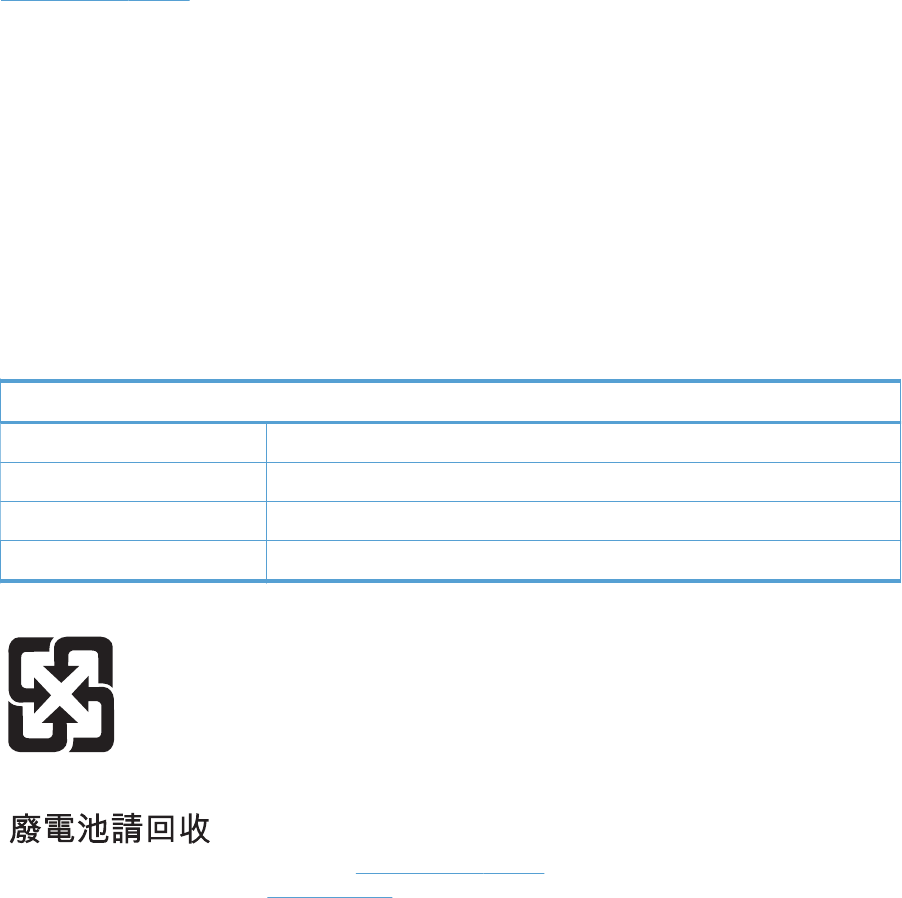
Non-U.S. returns
To participate in HP Planet Partners return and recycling program, just follow the simple directions in
the recycling guide (found inside the packaging of your new product supply item) or visit
www.hp.com/recycle. Select your country/region for information on how to return your HP LaserJet
printing supplies.
Paper
This product is capable of using recycled papers when the paper meets the guidelines outlined in the
HP LaserJet Printer Family Print Media Guide. This product is suitable for the use of recycled paper
according to EN12281:2002.
Material restrictions
This HP product does not contain added mercury.
This HP product contains a battery that might require special handling at end-of-life. The batteries
contained in or supplied by Hewlett-Packard for this product include the following:
HP Color LaserJet Enterprise CM4540 MFP Series
Type Carbon monofluoride lithium
Weight 0.8 g
Location On formatter board
User-removable No
For recycling information, you can go to www.hp.com/recycle, or contact your local authorities or the
Electronics Industries Alliance: www.eiae.org.
ENWW Environmental product stewardship program 801

Disposal of waste equipment by users in private households in the
European Union
This symbol on the product or on its packaging indicates that this product must not be disposed of with
your other household waste. Instead, it is your responsibility to dispose of your waste equipment by
handing it over to a designated collection point for the recycling of waste electrical and electronic
equipment. The separate collection and recycling of your waste equipment at the time of disposal will
help to conserve natural resources and ensure that it is recycled in a manner that protects human health
and the environment. For more information about where you can drop off your waste equipment for
recycling, please contact your local city office, your household waste disposal service or the shop
where you purchased the product.
Chemical substances
HP is committed to providing our customers with information about the chemical substances in our
products as needed to comply with legal requirements such as REACH (Regulation EC No 1907/2006
of the European Parliament and the Council). A chemical information report for this product can be
found at: www.hp.com/go/reach.
Material Safety Data Sheet (MSDS)
Material Safety Data Sheets (MSDS) for supplies containing chemical substances (for example, toner)
can be obtained by accessing the HP Web site at www.hp.com/go/msds or www.hp.com/hpinfo/
community/environment/productinfo/safety.
For more information
To obtain information about these environmental topics:
●Product environmental profile sheet for this and many related HP products
●HP’s commitment to the environment
●HP’s environmental management system
●HP’s end-of-life product return and recycling program
●Material Safety Data Sheets
Visit www.hp.com/go/environment or www.hp.com/hpinfo/globalcitizenship/environment.
802 Appendix C Regulatory information ENWW

Declaration of Conformity
Declaration of Conformity
according to ISO/IEC 17050-1 and EN 17050-1
Manufacturer's Name: Hewlett-Packard Company DoC#: BOISB-0806-01-rel.1.0
Manufacturer's Address: 11311 Chinden Boulevard
Boise, Idaho 83714-1021, USA
declares, that the product
Product Name: HP Color LaserJet Enterprise CM4540 MFP
Regulatory Model Number
2)
BOISB-0806-01
Including:
CC422A – 500-sheet paper feeder and cabinet
CC423A – 3x500-sheet paper feeder and stand
CC424A – 900-sheet 3-bin Stapling Mailbox
Product Options: ALL
Print Cartridges: CE260A, CE264X, CF031A, CF032A, CF033A
conforms to the following Product Specifications:
SAFETY: IEC 60950-1:2001 / EN60950-1: 2001 +A11
IEC 60825-1:1993 +A1 +A2 / EN 60825-1:1994 +A1 +A2 (Class 1 Laser/LED Product)
GB4943-2001
EMC: CISPR22:2005 +A1/ EN55022:2006 +A1 - Class A
1) ,3)
EN 61000-3-2:2006
EN 61000-3-3:1995 +A1 +A2
EN 55024:1998 +A1 +A2
FCC Title 47 CFR, Part 15 Class A
1) ,3)
/ ICES-003, Issue 4
GB9254-1998, GB17625.1-2003
ENERGY USE: Regulation (EC) No. 1275/2008:
ENERGY STAR® Qualified Imaging Equipment Typical Electricity Consumption (TEC) Test Procedure
Supplementary Information:
The product herewith complies with the requirements of the EMC Directive 2004/108/EC and the Low Voltage Directive 2006/95/EC, the
EuP Directive 2005/32/EC and carries the CE-Marking accordingly.
ENWW Declaration of Conformity 803

This Device complies with Part 15 of the FCC Rules. Operation is subject to the following two Conditions: (1) this device may not cause
harmful interference, and (2) this device must accept any interference received, including interference that may cause undesired operation.
1. The product was tested in a typical configuration with Hewlett-Packard Personal Computer Systems.
2. For regulatory purposes, this product is assigned a Regulatory model number. This number should not be confused with the product
name or the product number(s).
3. The product meets the requirements of EN55022 & CNS13438 Class A in which case the following applies: “Warning – This is a
class A product. In a domestic environment this product may cause radio interference in which case the user may be required to take
adequate measures.”
Boise, Idaho USA
July 6, 2010
For regulatory topics only:
European Contact: Your Local Hewlett-Packard Sales and Service Office or Hewlett-Packard GmbH, Department HQ-
TRE / Standards Europe, Herrenberger Strasse 140, D-71034, Böblingen (FAX: +49-7031-14-3143)
www.hp.com/go/certificates
USA Contact: Product Regulations Manager, Hewlett-Packard Company, PO Box 15, Mail Stop 160, Boise, Idaho
83707-0015 (Phone: 208-396-6000)
804 Appendix C Regulatory information ENWW

Declaration of Conformity (fax models)
Declaration of Conformity
according to ISO/IEC 17050-1 and EN 17050-1
Manufacturer's Name: Hewlett-Packard Company DoC#: BOISB-0806-02-rel.1.0
Manufacturer's Address: 11311 Chinden Boulevard
Boise, Idaho 83714-1021, USA
declares, that the product
Product Name: HP Color LaserJet Enterprise CM4540f MFP
HP Color LaserJet Enterprise CM4540fskm MFP
Regulatory Model Number
2)
BOISB-0806-02
Including:
CC422A – 500-sheet paper feeder and cabinet
CC423A – 3x500-sheet paper feeder and stand
CC424A – 900-sheet 3-bin Stapling Mailbox
BOISB-0703-00 – Fax Module
Product Options: ALL
Print Cartridges: CE260A, CE264X, CF031A, CF032A, CF033A
conforms to the following Product Specifications:
SAFETY: IEC 60950-1:2001 / EN60950-1: 2001 +A11
IEC 60825-1:1993 +A1 +A2 / EN 60825-1:1994 +A1 +A2 (Class 1 Laser/LED Product)
GB4943-2001
EMC: CISPR22:2005 +A1/ EN55022:2006 +A1 - Class A
1) ,3)
EN 61000-3-2:2006
EN 61000-3-3:1995 +A1 +A2
EN 55024:1998 +A1 +A2
FCC Title 47 CFR, Part 15 Class A
1) ,3)
/ ICES-003, Issue 4
GB9254-1998, GB17625.1-2003
TELECOM: ES 203 021; FCC Title 47 CFR, Part 68
4)
ENERGY USE: Regulation (EC) No. 1275/2008:
ENERGY STAR® Qualified Imaging Equipment Typical Electricity Consumption (TEC) Test Procedure
Supplementary Information:
The product herewith complies with the requirements of the EMC Directive 2004/108/EC and the Low Voltage Directive 2006/95/EC, the
R&TTE; Directive 1999/5/EC (Annex II), the EuP Directive 2005/32/EC and carries the CE-Marking accordingly.
ENWW Declaration of Conformity (fax models) 805

This Device complies with Part 15 of the FCC Rules. Operation is subject to the following two Conditions: (1) this device may not cause
harmful interference, and (2) this device must accept any interference received, including interference that may cause undesired operation.
1. The product was tested in a typical configuration with Hewlett-Packard Personal Computer Systems.
2. For regulatory purposes, this product is assigned a Regulatory model number. This number should not be confused with the product
name or the product number(s).
3. The product meets the requirements of EN55022 & CNS13438 Class A in which case the following applies: “Warning – This is a
class A product. In a domestic environment this product may cause radio interference in which case the user may be required to take
adequate measures.”
4. Telecom approvals and standards appropriate for the target countries/regions have been applied to this product, in addition to those
listed above.
5. This product uses an analog fax accessory module which Regulatory Model numbers are: BOISB-0903-00 (US-LIU) or BOISB-0903-01
(EURO LIU), as needed to meet technical regulatory requirements for the countries/regions this product will be sold.
6. 5. This product uses an analog fax accessory module which Regulatory Model number is: BOISB-0703-00 as needed to meet technical
regulatory requirements for the countries/regions this product will be sold.
Boise, Idaho USA
July 6, 2010
For regulatory topics only:
European Contact: Your Local Hewlett-Packard Sales and Service Office or Hewlett-Packard GmbH, Department HQ-
TRE / Standards Europe, Herrenberger Strasse 140, D-71034, Böblingen (FAX: +49-7031-14-3143)
www.hp.com/go/certificates
USA Contact: Product Regulations Manager, Hewlett-Packard Company, PO Box 15, Mail Stop 160, Boise, Idaho
83707-0015 (Phone: 208-396-6000)
806 Appendix C Regulatory information ENWW
Certificate of volatility
This is a statement regarding the volatility of customer data stored in memory. It also outlines how to
securely erase data from the product.
Types of memory
Volatile memory
The product utilizes volatile memory (a total of 1280 MB) to support the embedded OS and to store
customer data during the printing and copying process. When the product is powered off, this volatile
memory is erased.
Non-volatile memory
The product utilizes non-volatile memory (EEPROM) to store system control data and user preference
settings. No customer print or copy data is stored in non-volatile memory. This non-volatile memory can
be cleared and restored to factory defaults by performing a cold reset or restore factory settings
operation from the control panel.
Hard-disk-drive memory
The product contains an internal hard disk drive that may retain data after the product is powered off.
The product also may contain additional optional compact flash storage, or an external EIO hard disk.
Data stored in these devices may be from incoming/outgoing fax or e-mail files, stored copy or print
jobs, fax or e-mail address books, or third-party solutions. Some of this data can be erased from the
product control panel, but most must be erased using the Secure Disk Erase feature available from the
product BIOS Menu, the Embedded Web Server (EWS) for the product, and from HP Web Jetadmin.
Secure Storage Erase features comply with U.S. NIST Special Publication 800-88 “Guidelines for
Media Sanitization”.
ENWW Certificate of volatility 807
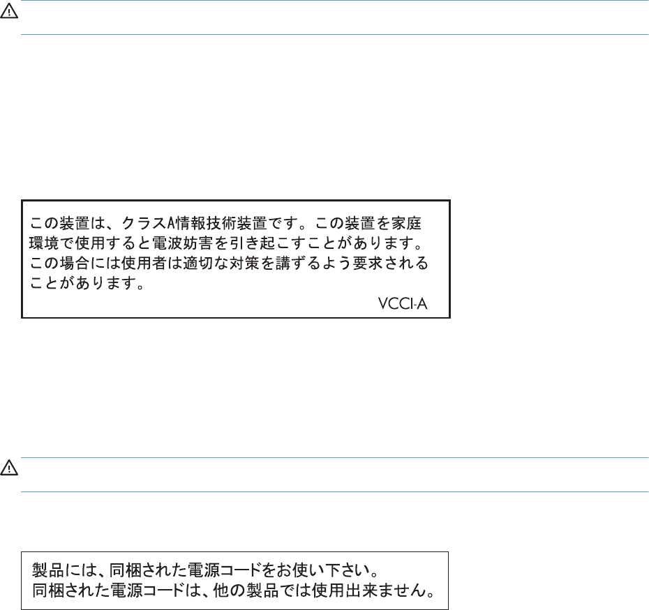
Safety statements
Laser safety
The Center for Devices and Radiological Health (CDRH) of the U.S. Food and Drug Administration has
implemented regulations for laser products manufactured since August 1, 1976. Compliance is
mandatory for products marketed in the United States. The device is certified as a “Class 1” laser
product under the U.S. Department of Health and Human Services (DHHS) Radiation Performance
Standard according to the Radiation Control for Health and Safety Act of 1968. Since radiation
emitted inside the device is completely confined within protective housings and external covers, the
laser beam cannot escape during any phase of normal user operation.
WARNING! Using controls, making adjustments, or performing procedures other than those
specified in this user guide may result in exposure to hazardous radiation.
Canadian DOC regulations
Complies with Canadian EMC Class A requirements.
« Conforme à la classe A des normes canadiennes de compatibilité électromagnétiques. « CEM ». »
VCCI statement (Japan)
Power cord instructions
Make sure your power source is adequate for the product voltage rating. The voltage rating is on the
product label. The product uses either 100-127 Vac or 220-240 Vac and 50/60 Hz.
Connect the power cord between the product and a grounded AC outlet.
CAUTION: To prevent damage to the product, use only the power cord that is provided with the
product.
Power cord statement (Japan)
808 Appendix C Regulatory information ENWW
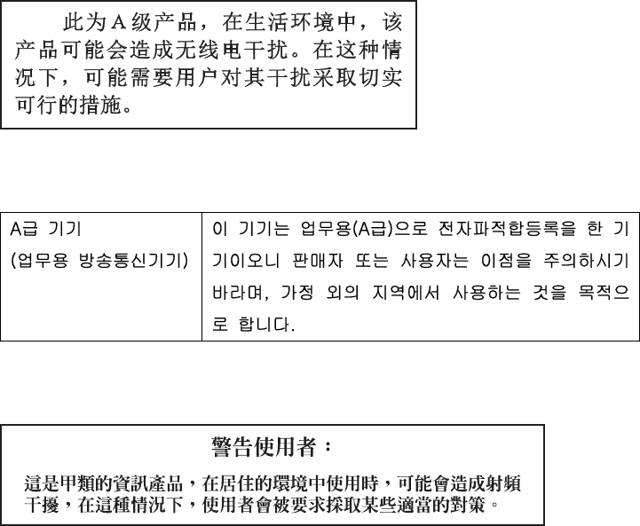
EMC statement (China)
EMC statement (Korea)
EMI statement (Taiwan)
Laser statement for Finland
Luokan 1 laserlaite
Klass 1 Laser Apparat
HP Color LaserJet CM4540, CM4540f, CM4540fskm, laserkirjoitin on käyttäjän kannalta turvallinen
luokan 1 laserlaite. Normaalissa käytössä kirjoittimen suojakotelointi estää lasersäteen pääsyn laitteen
ulkopuolelle. Laitteen turvallisuusluokka on määritetty standardin EN 60825-1 (2007) mukaisesti.
VAROITUS !
Laitteen käyttäminen muulla kuin käyttöohjeessa mainitulla tavalla saattaa altistaa käyttäjän
turvallisuusluokan 1 ylittävälle näkymättömälle lasersäteilylle.
VARNING !
Om apparaten används på annat sätt än i bruksanvisning specificerats, kan användaren utsättas för
osynlig laserstrålning, som överskrider gränsen för laserklass 1.
HUOLTO
HP Color LaserJet CM4540, CM4540f, CM4540fskm - kirjoittimen sisällä ei ole käyttäjän
huollettavissa olevia kohteita. Laitteen saa avata ja huoltaa ainoastaan sen huoltamiseen koulutettu
henkilö. Tällaiseksi huoltotoimenpiteeksi ei katsota väriainekasetin vaihtamista, paperiradan puhdistusta
tai muita käyttäjän käsikirjassa lueteltuja, käyttäjän tehtäväksi tarkoitettuja ylläpitotoimia, jotka voidaan
suorittaa ilman erikoistyökaluja.
ENWW Safety statements 809
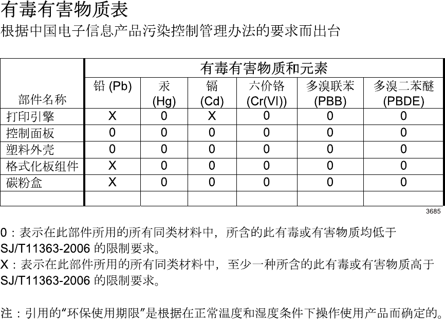
VARO !
Mikäli kirjoittimen suojakotelo avataan, olet alttiina näkymättömällelasersäteilylle laitteen ollessa
toiminnassa. Älä katso säteeseen.
VARNING !
Om laserprinterns skyddshölje öppnas då apparaten är i funktion, utsättas användaren för osynlig
laserstrålning. Betrakta ej strålen.
Tiedot laitteessa käytettävän laserdiodin säteilyominaisuuksista: Aallonpituus 775-795 nm Teho 5 m W
Luokan 3B laser.
GS statement (Germany)
Das Gerät ist nicht für die Benutzung im unmittelbaren Gesichtsfeld am Bildschirmarbeitsplatz
vorgesehen. Um störende Reflexionen am Bildschirmarbeitsplatz zu vermeiden, darf dieses Produkt
nicht im unmittelbaren Gesichtsfeld platziert werden.
Substances Table (China)
Restriction on Hazardous Substances statement (Turkey)
Türkiye Cumhuriyeti: EEE Yönetmeliğine Uygundur
810 Appendix C Regulatory information ENWW
Additional statements for telecom (fax) products
EU Statement for Telecom Operation
This product is intended to be connected to the analog Public Switched Telecommunication Networks
(PSTN) of European Economic Area (EEA) countries/regions.
It meets requirements of EU R&TTE Directive 1999/5/EC (Annex II) and carries appropriate CE
conformity marking.
For more details see Declaration of Conformity issued by the manufacturer in another section of this
manual.
However due to differences between individual national PSTNs the product may not guarantee
unconditional assurance of successful operation on every PSTN termination point. Network
compatibility depends on the correct setting being selected by the customer in preparation of its
connection to the PSTN. Please follow the instructions provided in the user manual.
If you experience network compatibility issues, please contact your equipment supplier or Hewlett-
Packard help desk in the country/region of operation.
Connecting to a PSTN termination point may be the subject of additional requirements set out by the
local PSTN operator.
New Zealand Telecom Statements
The grant of a Telepermit for any item of terminal equipment indicates only that Telecom has accepted
that the item complies with minimum conditions for connection to its network. It indicates no
endorsement of the product by Telecom, nor does it provide any sort of warranty. Above all, it provides
no assurance that any item will work correctly in all respects with another item of Telepermitted
equipment of a different make or model, nor does it imply that any product is compatible with all of
Telecom’s network services.
This equipment may not provide for the effective hand-over of a call to another device connected to the
same line.
This equipment shall not be set up to make automatic calls to the Telecom “111” Emergency Service.
This product has not been tested to ensure compatibility with the FaxAbility distinctive ring service for
New Zealand.
Additional FCC statement for telecom products (US)
This equipment complies with Part 68 of the FCC rules and the requirements adopted by the ACTA. On
the back of this equipment is a label that contains, among other information, a product identifier in the
format US:AAAEQ##TXXXX. If requested, this number must be provided to the telephone company.
The REN is used to determine the quantity of devices, which may be connected to the telephone line.
Excessive RENs on the telephone line may result in the devices not ringing in response to an incoming
call. In most, but not all, areas, the sum of the RENs should not exceed five (5.0). To be certain of the
number of devices that may be connected to the line, as determined by the total RENs, contact the
telephone company to determine the maximum REN for the calling area.
This equipment uses the following USOC jacks: RJ11C.
ENWW Additional statements for telecom (fax) products 811

An FCC-compliant telephone cord and modular plug is provided with this equipment. This equipment is
designed to be connected to the telephone network or premises wiring using a compatible modular
jack, which is Part 68 compliant. This equipment cannot be used on telephone company-provided coin
service. Connection to Party Line Service is subject to state tariffs.
If this equipment causes harm to the telephone network, the telephone company will notify you in
advance that temporary discontinuance of service may be required. If advance notice is not practical,
the telephone company will notify the customer as soon as possible. Also, you will be advised of your
right to file a complaint with the FCC if you believe it is necessary.
The telephone company may make changes in its facilities, equipment, operations, or procedures that
could affect the operation of the equipment. If this happens, the telephone company will provide
advance notice in order for you to make the necessary modifications in order to maintain uninterrupted
service.
If trouble is experienced with this equipment, please see the numbers in this manual for repair and (or)
warranty information. If the trouble is causing harm to the telephone network, the telephone company
may request you remove the equipment from the network until the problem is resolved.
The customer can do the following repairs: Replace any original equipment that came with the device.
This includes the print cartridge, the supports for trays and bins, the power cord, and the telephone
cord. It is recommended that the customer install an AC surge arrestor in the AC outlet to which this
device is connected. This is to avoid damage to the equipment caused by local lightning strikes and
other electrical surges.
Telephone Consumer Protection Act (US)
The Telephone Consumer Protection Act of 1991 makes it unlawful for any person to use a computer or
other electronic device, including fax machines, to send any message unless such message clearly
contains, in a margin at the top or bottom of each transmitted page or on the first page of the
transmission, the date and time it is sent and an identification of the business, other entity, or individual
sending the message and the telephone number of the sending machine or such business, or other
entity, or individual. (The telephone number provided cannot be a 900 number or any other number for
which charges exceed local or long distance transmission charges).
Industry Canada CS-03 requirements
Notice: The Industry Canada label identifies certified equipment. This certification means the
equipment meets certain telecommunications network protective, operational, and safety requirements
as prescribed in the appropriate Terminal Equipment Technical Requirement document(s). The
Department does not guarantee the equipment will operate to the user’s satisfaction. Before installing
this equipment, users should ensure that it is permissible for the equipment to be connected to the
facilities of the local telecommunications company. The equipment must also be installed using an
acceptable method of connection. The customer should be aware that compliance with the above
conditions may not prevent degradation of service in some situations. Repairs to certified equipment
should be coordinated by a representative designated by the supplier. Any repairs or alterations made
by the user to this equipment, or equipment malfunctions, may give the telecommunications company
cause to request the user to disconnect the equipment. Users should ensure for their own protection that
the electrical ground connections of the power utility, telephone lines, and internal metallic water pipe
system, if present, are connected together. This precaution can be particularly important in rural areas.
CAUTION: Users should not attempt to make such connections themselves, but should contact the
appropriate electric inspection authority, or electrician, as appropriate. The Ringer Equivalence
Number (REN) of this device is 0.0.
812 Appendix C Regulatory information ENWW

Notice: The Ringer Equivalence Number (REN) assigned to each terminal device provides an indication
of the maximum number of terminals allowed to be connected to a telephone interface. The termination
on an interface may consist of any combination of devices subject only to the requirement that the sum
of the Ringer Equivalence Number of all the devices does not exceed five (5.0). The standard
connecting arrangement code (telephone jack type) for equipment with direct connections to the
telephone network is CA11A.
Japan Telecom Mark
A08-0138004
ENWW Additional statements for telecom (fax) products 813
814 Appendix C Regulatory information ENWW

Index
Symbols/Numerics
1x500 and 3x 500 paper feeders
parts lists and diagrams 722
3-bin stapling mailbox
automatic delivery 91
delivery operation 80
electrical components 77
failure detection 79
jam detection 90
mailbox/job separator mode
89
motor control 78
optional, operations 76
output bin 3 lift operation 87
stacker mode 88
staple operation 81
stapler 86
500-sheet paper and heavy media
tray
specifications, physical 793
500-sheet paper feeder
parts lists and diagrams 716
A
AC to DC conversion 14
accessories
ordering 656
part numbers 657
screws 664
accessories installed, information
466
acoustic specifications 794
activity log 648
Administration menu, control
panel 469
after-service checklist 96
AppleTalk information 465
automatic delivery
3-bin stapling mailbox 91
B
bands, troubleshooting 615
batteries included 801
beam-detect (BD) failure 22
bias generation
high-voltage power supply 12
billing code report
printing 649
black-only printing mode
developing roller state 33
primary transfer roller state 35
blank pages
troubleshooting 623
blank pages, troubleshooting 614
blocked fax list report
printing 649
buffer overflow errors 490
C
cabinet/stand
specifications, physical 793
cable, USB
part number 659
troubleshooting 623
cables
part numbers 658
calibrate scanner 468
calibration
information, printed 461
call report 649
Canadian DOC regulations 808
cartridges
recycling 799
removing 103
warranty 785
cartridges, print
part numbers 657
cassette
lift operation 46, 67
paper-level detection 46
paper-presence detection 46
pickup assembly (500-sheet
paper feeder), removing 325
pickup assembly (optional
paper feeder), removing 313
pickup operations 44
presence detection 45, 66
Tray 2, removing 111
Tray 3, removing 111
See also trays
cautions iii
characters, troubleshooting 618
checklists
after-service 96
preservice 96
circuit diagrams
fuser temperature-control 17
general 452
high-voltage power supply 12
low-voltage power supply 14
cleaning
fuser 622
paper path 620
product 620
scanner glass 620
cleaning page
printing 462
clearing log/report data 649
clock
error message 474
clutches
DC controller 7
cold reset 628
color
calibration 37
diagnostic test 466
disengagement for black-only
printing 33
ENWW Index 815
misregistration control 38
page count, reset 625
primary transfer roller state 35
troubleshooting 461, 617
components
3-bin stapling mailbox 77
cover, locations 437
DC controller 6
diagnostic tests 422
diagrams of 426
duplexing unit 55
engine-control system 5
fuser 16
image formation, use during
24
intermediate transfer belt (ITB)
34
major, locations 438
motor, fan, and roller
locations 442
paper feeder 63
paper feeder (1 x 500-sheet)
447
paper feeder (3 x 500-sheet)
449
PCA locations 443
pickup, feed, and delivery 40
print cartridge 31
protection for 15, 17
stapler/stacker, locations 444
configuration page 374
configuration pages
information 466
printing 462
connectivity
solving problems 624
connectors
controller PCA (optional paper
feeder) 434
DC controller PCA 432
IPTU PCA 436
Stapler/stacker PCA 435
control panel
Administration menu 469
cleaning page, printing 620
messages, numerical list 470
messages, types of 470
removing 100
troubleshooting tests 422
controller (500-sheet paper feeder)
PCA (500-sheet paper feeder),
removing 332
controller (optional paper feeder)
PCA (optional paper feeder),
removing 319
PCA, connectors 434
conventions, document iii
cooling
areas and fans 10
copying
quality, troubleshooting 614
counts
color cycle 625
copy pages 626
copy scan 626
document feeder 626
document feeder duplex 626
document feeder simplex 626
flatbed cycle 626
mono cycle 625
page, reset 625
print engine maintenance 466
refurbish cycle 625
reset after replacing formatter
625
send scan 626
See also pages counts
covers
document feeder front cover,
removing 129
document feeder rear cover,
removing 131
document feeder tray extender,
removing 124
fan cover, removing 134
front cover (500-sheet paper
feeder), removing 324
front door (optional paper
feeder), removing 303
front-door assembly, removing
140
identification and location
127, 437
jam-access cover, removing
153
left cover (500-sheet paper
feeder), removing 322
left cover (optional paper
feeder), removing 309
left, removing 137
locations 437
Lower-left cover, removing 136
output bin bezel, removing
124
rear cover (500-sheet paper
feeder), removing 321
rear cover (optional paper
feeder), removing 305
rear, removing 144
rear-right cover (optional paper
feeder), removing 312
right cover (500-sheet paper
feeder), removing 323
right cover (optional paper
feeder), removing 311
right door (optional paper
feeder), removing 307
right-door assembly, removing
145
right-front cover (500-sheet
paper feeder), removing 321
right-front cover (optional paper
feeder), removing 306
right-front, removing 138
right-rear, removing 143
S-CVR-REAR (scanner rear
cover), removing 128
scanner left cover, removing
133
standard output bin, removing
123
creases, troubleshooting 619
crooked pages
troubleshooting 618
current-detection protection circuit
18
customer self repair, part
numbers 659
customer support
online 792
D
dark image, troubleshooting 614
date
codes for firmware 466
manufacture 464
product first used 627
DC controller
clutches 7
816 Index ENWW
components 6
fans 10
motors 9
PCA and tray, removing 248
PCA only, removing 241
PCA, connectors 432
sensors 8
solenoids 6
switches 7
temperature controls 17
voltage detection 15
DC motors 9
DC voltages converted from AC
14
defeating
front-door logic switch 408
front-door safety switch 407
interlocks 375
right-door logic switch 409
right-door safety switch 408
defects, repeating 467
delivery assembly
removing 231
delivery operation
3-bin stapling mailbox 80
demo page 374
density control 39
development process 28
diagnostics
component 422
control panel 422
engine 375
LED 374
page, printing 461
See also tests; troubleshooting
diagrams
components 426
disposal, end-of-life 801
DLC/LLC information 465
document conventions iii
document feeder
jam-access cover, removing
153
jams 584
removing and replacing 150
document feeder base assembly
removing and replacing 169
document feeder cable
removing and replacing 160
document feeder count
document feeder pages 626
document feeder fan
removing and replacing 164
document feeder internal assembly
removing and replacing 157
document feeder interval 626
document feeder jam access plate
removing and replacing 168
document feeder left hinge
removing and replacing 162
document feeder motor
removing and replacing 165,
166
document feeder open sensor
removing and replacing 167
document feeder PCA
removing and replacing 159
document feeder pick mechanism
document feeder/scanner 75
document feeder right hinge
removing and replacing 163
document feeder/scanner
fan control 71
fan timing sequence 72
image data path 73
jam detection 74
legal detection 72
motor control 71
optical assembly 73
paper path and sensors 74
parts lists and diagrams 730
pick mechanism 75
scanner subsystem 70
document feeder/scanner
assembly 70
doors. See covers
drive circuit
power-supply frequency range
19
drum cleaning 31
duplexer
specifications, physical 793
duplexing gear cover
removing 229
duplexing unit
components 55
duplex-drive assembly,
removing 235
jam causes 600
motors 9
print operation 56
See also pickup, feed, and
delivery
E
EIO cards
buffer overflow 490
part number 658
electrical specifications 794
electrostatic discharge (ESD) 95
embedded protocol page 465
end-of-life disposal 801
energy specifications 794
engine
diagnostics 375
test page 376
engine-control system
components 5
Enhanced I/O card
part number 658
environment, specifications 795
Environmental Product Stewardship
Program 799
error
codes 643
error messages
event log, listed numerically
572
numerical list 470
types of 470
ESD (electrostatic discharge) 95
European Union, waste disposal
802
event log
clear 571, 625
information 466
messages, listed numerically
572
sample 571
view or print 570
exhaust fans 10
F
faded print 614
failure detection
3-bin stapling mailbox 79
drive circuit 19
fuser 19
lasers and scanners 22
ENWW Index 817
low-voltage power supply 16
motors 9
See also jams
fan control
document feeder/scanner 71
fan timing sequence
document feeder/scanner 72
fans
cartridge, removing 222
DC controller 10
delivery, removing 228
exhaust 10
exhaust, removing 256
intake 10
locations 442
Power-supply fan, removing
236
scanner, removing 197
fax
feeding problems 640
FCC regulations 798
feed speed control 51
feed, paper. See pickup, feed, and
delivery
feeding problems 640
Finnish laser safety statement 809
firmware
date codes 466
version information 464
firmware upgrades 650
firmware, downloading new 651
flowcharts
troubleshooting 369
formatter
operations 2
PCA, removing 106
resets after replacing 625
formatter lights 374
fuser
components 16
control-circuit function 16
discrepancy detection 19
failure detection 19
identification 19
jam causes 598
jams 591
life detection 20
motor, removing 290
temperature control 17
See also fusing and delivery unit
fusing and delivery unit
operations 52
See also fuser; pickup, feed,
and delivery
fusing process 30
H
halftone control 39
hard drive
removing 108
hard drive, removing 108
heartbeat LED 375
heat control for fuser 17
heaters, fuser 16
high-voltage power supply
bias generation 12
circuits 12
operations 12
removing, lower 250
removing, upper 286
HP Customer Care 792
HP Jetdirect print server
configuration page 464
lights 374
humidity requirements 795
I
image data path
document feeder/scanner 73
image placement accuracy 795
image quality issues
examples and solutions 614
image stabilization controls 39
image-formation process
development process 28
drum cleaning 31
fusing process 30
ITB cleaning 31
laser-beam exposure 28
pre-exposure 27
primary charging 27
primary transfer process 29
secondary transfer process 29
separation process 30
steps 26
imaging drums
color drums disengagement
33
diagnostic test 376
initial rotation period 4
input trays
optional, operations 61
installation
date calculation 627
verify for optional accessories
462
intake fans 10
interconnect board (ICB)
removing 239
interface ports
locating 430
interlocks
defeating 375
intermediate cover
removing 229
intermediate transfer belt (ITB)
components 34
home position 35
operations 34
internal clock errors 474
inverter PCA, removing 188
IPTU
PCA, connectors 436
IPv4 information 464
IPv6 information 464
IPX/SPX information 465
ITB
motor, removing 292
ITB cleaning 31
J
jam detection
3-bin stapling mailbox 90
document feeder/scanner 74
jams
detection in paper feeder 68
detection sensors 58
diagnostic test for 378
document feeder 584
document feeder access cover,
removing 153
duplex area 600
fuser 591
fuser area 598
lower-right door 597
output area 585
output bin 589
preventing 581
recovery 608
right door 591
818 Index ENWW
scanner 589
stapler 585, 587
Tray 1 594
Tray 1 and Tray 2 602
Tray 3, 4, and 5 603
trays 596
types detected 59
Japanese VCCI statement 808
Jetdirect print server
lights 374
K
Korean EMC statement 809
L
laser safety statements 808, 809
laser-beam exposure 28
laser/scanner
assembly (C/Bk), removing
279
assembly (Y/M), removing
275
failure conditions 22
operations 21
protective-glass cleaners
(PGCs) 22
last rotation period 4
latent image formation 26
LEDs. See lights
left cover, removing 137
legal detection
document feeder/scanner 72
license, software 788
lifter assembly (500-sheet paper
feeder)
removing 328
lifter assembly (optional paper
feeder)
removing 316
lifter base assembly
removing 263
lifter-drive assembly
removing 260
lifter-drive assembly (500-sheet
paper feeder)
removing 330
lifter-drive assembly (optional paper
feeder)
removing 317
light print, troubleshooting 614
lights
formatter 374
troubleshooting with 374
lines, troubleshooting 615
log of events
clear 571
messages, listed numerically
572
sample 571
view or print 570
log/report
activity log 648
activity log, clearing 649
billing code report 649
blocked fax list report 649
fax call report 649
speed dial list report 649
loop control 52
loose toner, troubleshooting 617
low-voltage power supply
converted DC voltages 15
failure detection 16
operations 14
protection for components 15
removing 243
safety provided by 15
stops and interruptions 15
See also power supply
lower-right door
jams 597
M
Macintosh
support 792
mailbox/job separator mode
3-bin stapling mailbox 89
main-drive assembly
removing 293
manual print modes 611
material restrictions 801
Material Safety Data Sheet
(MSDS) 802
media registration accuracy 795
memory
information 462
insufficient 482
memory chip, print cartridge
description 787
menus, control panel
Administration 469
mercury-free product 801
messages
event log, listed numerically
572
numerical list 470
types of 470
model number 464
modem speed 641
motor control
3-bin stapling mailbox 78
document feeder/scanner 71
paper feeder 63
motors
3-bin stapling mailbox 77
DC controller 9
developing-disengagement,
removing 255
drum motor, removing 289
failure detection 9
fuser, removing 290
ITB, removing 292
locations 442
paper feeder 63
pickup (500-sheet paper
feeder), removing 331
pickup (optional paper feeder),
removing 318
pickup, removing 259
residual-toner-feed, removing
218
stepping 9
movement of paper through
product. See pickup, feed, and
delivery
multiple paper feed prevention 47
multipurpose tray. See trays
N
networks
HP embedded Jetdirect
configuration page 464
noise specifications 794
notes iii
Novell/NetWare information
465
O
online support 792
operating environment
specifications 795
ENWW Index 819
operation sequence 4
optical assembly
document feeder/scanner 73
optical unit
removing 191
ordering
part numbers for 657
supplies and accessories 656
output area
jams 585
output bin
jams 589
output bin 3 lift operation
3-bin stapling mailbox 87
overcurrent or overvoltage
protection 15
P
pages
blank 623
not printing 623
printing slowly 623
skewed 618
pages count
from product copy 626
from product copy scan count
626
from product document feeder
626
from product flatbed 626
from product refurbish date
625
from product send scan 626
reset 625
since last maintenance 466
See also counts
paper
cassette-presence detection
45, 66
default size reset 628
jam detection 68
level detection 46
movement sensors 58
presence detection 46
size detection 66
stop in path for testing 414
wrinkled 619
paper detection 50
paper feeder
cassette lift operation 67
component locations 447,
449
controller PCA 434
controller PCA, removing 319,
332
diagrams of 1 x 500-sheet
427
diagrams of 3 x 500-sheet
428
electrical components 63
feed operations 48
feed speed control 51
front cover, removing 324
front door, removing 303
jam detection 68
left cover, removing 309, 322
lifter assembly, removing 316,
328
lifter-drive assembly, removing
317, 330
motor control 63
multifeed prevention 47
optional 1 x 500-sheet 61
optional 3 x 500-sheet 61
paper detection 50
pickup and feed operation 64
pickup assembly, removing
313, 325
pickup motor assembly,
removing 318, 331
rear cover, removing 305,
321
rear-right cover, removing 312
right cover, removing 311,
323
right door, removing 307
right-front cover, removing
306, 321
skew feed prevention 50
See also pickup, feed, and
delivery
paper jams. See jams
paper path
diagnostic test 378
diagnostic test, manual 393
stop movement for testing 414
paper path and sensors
document feeder/scanner 74
paper present flag
removing and replacing 150
paper-path
test, sensors 413
parameters, EP, troubleshooting
461
part numbers
cables 658
fuser 663
print cartridges 657
registration unit 663
screws 664
service kits 661
staple cartridge 657
toner collection unit 657
parts 655
parts lists and diagrams
1x500 and 3x500 paper
feeders 722
cassettes 2–5 686
covers and doors (optional
stapler stacker multi-bin
mailbox) 705
covers, panels, and doors 666
delivery assembly 698
document feeder/scanner 730
front door assembly 670
fuser assembly 700
intermediate paper transfer unit
(IPTU) 696
internal components 672,
674, 676, 678, 684
paper pickup assembly 688
PCAs 702
registration assembly 692
right door assembly 668
scanner assembly 734
secondary transfer assembly
694
stapling mailbox 704
Tray 1 paper pickup assembly
690
using 665
password
Service menu PIN 625
PBX systems troubleshooting 642
PCA, locations 443
periods of the operation
sequence 4
phone lines troubleshooting 642
physical specifications 793
820 Index ENWW
pickup roller
removing and replacing 125
pickup roller cover
removing and replacing 125
pickup roller pad
removing and replacing 126
pickup roller spring
removing and replacing 126
pickup, feed, and delivery
components 40
multipurpose tray pickup 47
overview 40
paper-feed operations 48
paper-feeder pickup and feed
64
pickup-and-feed unit
operations 44
See also paper feeder; fusing
and delivery unit; duplexing
unit
pliers, required 95
port configuration information
464
ports
locating 430
post-service tests 97
power cord
part number 659
power specifications 794
power supply
frequency range for drive
circuit 19
troubleshooting 370
See also low-voltage power
supply; high-voltage power
supply
power-save mode. See sleep
settings
pre-exposure process 27
pre-troubleshooting checklist 367
preservice checklist 96
pressure-roller pressurization
control 54
primary charging process 27
print cartridges
components 31
diagnostic test 376
error conditions 33
memory chips 787
operations 32
part numbers 657
recycling 799
removing 103
warranty 785
print quality
built-in troubleshooting pages
458
color misregistration control
38
image stabilization controls 39
manual print modes 611
test 97
test pages 458
troubleshooting 614
Print Quality menu options 611
printing
modes, manual 611
period in operation sequence
4
process explained 24
stop for testing 414
troubleshooting 623
problem-solving
messages, types of 470
Q
quality. See print quality
R
recycling
HP printing supplies returns and
environmental program 800
registration assembly
removing 213
regulatory statements
environmental product
stewardship program 799
removing parts
cartridge fan 222
cassette feed guide 202
cautions for 94
checklists 96
control panel 100
controller PCA (500-sheet paper
feeder) 332
controller PCA (optional paper
feeder) 319
DC controller PCA and tray
248
DC controller PCA only 241
delivery assembly 231
delivery fan 228
developing-disengagement
motor 255
document feeder front cover
129
document feeder rear cover
131
document feeder tray
extender 124
drum motors 289
duplex-drive assembly 235
duplexing gear cover 229
environmental sensor 222
exhaust fan 256
fan cover 134
feed and separation rollers
113
formatter PCA 106
front cover (500-sheet paper
feeder) 324
front door (optional paper
feeder) 303
front-door assembly 140
fuser 112
fuser motor 290
hard drive 108
high-voltage power supply
lower 250
high-voltage power supply
upper 286
interconnect board (ICB) 239
intermediate cover 229
intermediate transfer belt 120
ITB motor 292
laser/scanner assembly (C/
Bk) 279
laser/scanner assembly (Y/
M) 275
left cover 137
left cover (500-sheet paper
feeder) 322
left cover (optional paper
feeder) 309
lifter assembly (500-sheet paper
feeder) 328
lifter assembly (optional paper
feeder) 316
lifter base assembly 263
lifter-drive assembly 260
ENWW Index 821
lifter-drive assembly (500-sheet
paper feeder) 330
lifter-drive assembly (optional
paper feeder) 317
low-voltage power supply 243
Lower-left cover 136
main-drive assembly 293
output bin bezel 124
pickup assembly (500-sheet
paper feeder) 325
pickup assembly (optional
paper feeder) 313
pickup motor 259
pickup motor (500-sheet paper
feeder) 331
pickup motor (optional paper
feeder) 318
pickup roller (Tray 1) 114
power-supply fan 236
print cartridges 103
rear cover 144
rear cover (500-sheet paper
feeder) 321
rear cover (optional paper
feeder) 305
rear-right cover (optional paper
feeder) 312
registration assembly 213
registration density (RD) sensor
assembly 209
residual-toner and feed
assembly 219
residual-toner-feed motor 218
right cover (500-sheet paper
feeder) 323
right cover (optional paper
feeder) 311
right door (optional paper
feeder) 307
right-door assembly 145
right-front cover 138
right-front cover (500-sheet
paper feeder) 321
right-front cover (optional paper
feeder) 306
right-rear cover 143
S-CVR-REAR (scanner rear
cover) 128
scanner left cover 133
secondary transfer assembly
204
secondary transfer roller 118
separation pad (Tray 1) 206
standard output bin 123
toner-collection sensor and
scanner-thermistor assembly
226
toner-collection unit 104
tools, required 95
tray cassette 111
tray-pickup assembly 268
tray-pickup drive assembly
266
repeating defects,
troubleshooting 467
replacing
parts 94
resolution
troubleshooting quality 614
restore factory settings 629
reverse and feed control,
duplexer 55
right door
jams 591
roller
feed and separation roller (Trays
2–5), removing 113
pickup roller (Tray 1),
removing 114
rollers
locations 442
secondary transfer roller,
removing 204
separation pad (Tray 1),
removing 206
ruler, repetitive defect 467
S
safety features
when front door is open 15
safety statements 808, 809
scanner
jams 589
removing and replacing 170
scanner assembly
parts lists and diagrams 734
scanner assembly, removing 171
scanner calibration 468
scanner fan, removing 197
scanner filter, replacing 170
scanner settings 626
scanner subsystem
document feeder/scanner 70
scanner-motor failure 22
screwdrivers, required 95
screws
part numbers 664
replacing 94
secondary transfer processes 29
secondary transfer roller,
removing 118
security settings information 464
security slot
locating430
sensor tests manual
5V laser and 24V interlock and
logic switches 406
developer alienation sensor
388
duplexer refeed sensor 386
front-door switch 380
fuser loop sensors 383
fuser output sensor 384
fuser pressure-release sensor
389
IPTU-bin-full sensor 387
ITB alienation sensor 390
new ITB sensor 410
right-door switch 381
TOP sensor 382
tray 1 paper sensor 395
tray 2 paper sensor (P) 396
tray 2 paper size switches
398
Tray 2 paper surface 1 and 2
sensors 397
tray 3 feed sensor 399
tray 3 paper 399
tray 3 paper size switches
401
tray 3 paper surface 1 and 2
400
tray 3, 4, and 5 right door
switch 412
tray 4 feed sensor 402
tray 4 paper 401
tray 4 paper size switches
403
822 Index ENWW
tray 4 paper surface 1 and 2
402
tray 5 feed sensor 404
tray 5 paper 403
tray 5 paper size switches
405
tray 5 paper surface 1 and 2
404
sensors
3-bin stapling mailbox 77
DC controller 8
diagnostic tests 413
environmental, removing 222
jam detection 58
paper feeder 63
registration density (RD) sensor
assembly, removing 209
tests, manual 378
toner-collection sensor,
removing 226
separation process 30
sequence of operation 4
serial number 626
service
tools, required 95
Service ID
convert to date 627
restore 627
Service menu options 625
service settings 650
settings
restore factory 629
skew-feed prevention 50
skewed pages
troubleshooting 618
Sleep mode
power specifications 794
sleep settings
voltage too high during 15
slow fax reception 641
slow fax transmission 642
smeared toner, troubleshooting
618
software
software license agreement
788
solenoids
3-bin stapling mailbox 77
DC controller 6
paper feeder 63
solve problems 363
solving
direct-connect problems 624
network problems 624
space requirements 793
specifications
acoustic 794
electrical 794
operating environment 795
physical 793
speed dial
list report 649
stacker mode
3-bin stapling mailbox 88
standby period 4
staple cartridge
part number 657
staple operation
3-bin stapling mailbox 81
stapler
3-bin stapling mailbox 86
jams 585, 587
stapler stacker multi bin mailbox
parts lists and diagrams 705
Stapler/stacker
PCA, connectors 435
stapler/stacker
diagram 429
specifications, physical 793
stapling mailbox
parts lists and diagrams 704
stapling mailbox, door
removing and replacing 335
stapling mailbox, flapper assembly
removing and replacing 354
stapling mailbox, flapper guide
assembly
removing and replacing 352
stapling mailbox, front cover
removing and replacing 333
stapling mailbox, holder connector
removing and replacing 335
stapling mailbox, jogger assembly
removing and replacing 350
stapling mailbox, MBM output bin
assembly
removing and replacing 356
stapling mailbox, output bin 3
removing and replacing 338
stapling mailbox, output bin 3 drive
assembly
removing and replacing 358
stapling mailbox, output bin sensor
PCA
removing and replacing 346
stapling mailbox, output bin
solenoid
removing and replacing 361
stapling mailbox, PCA
removing and replacing 340
stapling mailbox, rear cover
removing and replacing 334
stapling mailbox, stacking panel
removing and replacing 348
stapling mailbox, stamp solenoid
removing and replacing 344
stapling mailbox, stapler assembly
removing and replacing 343
stapling mailbox, top cover
removing and replacing 337
static precautions 95
status
messages, types of 470
status page 374
status, fax accessory page 639
stepping motors 9
stop printing for test 414
storage cabinet
specifications, physical 793
streaks, troubleshooting 615
subvoltage
low-voltage power supply
circuit 15
supplies
ordering 656
part numbers 657
recycling 799
toner collection unit part
number 657
support
online 792
switches
3-bin stapling mailbox 77
DC controller 7
paper feeder 63, 66
paper-size, diagnostic test 393
T
T.30 Trace report 650
ENWW Index 823
Taiwan EMI statement 809
TCP/IP information 464
technical support
online 792
temperature
control for fuser 17
thresholds for fuser
components 17, 19
temperature requirements 795
tests
color band 466
component tests list and
descriptions 423
disable cartridge check 376
engine 376
manual sensor 378
paper path 378
paper-path sensors 413
post-service 97
print-quality 97
print/stop 414
special-mode test 393
text, troubleshooting 618
thermistors
fuser 16, 17
open detection 19
thermopiles
fuser 17
thermoswitches
fuser 16, 17
thresholds
power-supply frequency, drive
circuit 19
temperature, fuser
components 17, 19
timing chart 451
tips iii
toner
image formation, use during
26
loose, troubleshooting 617
patterns for calibration 38
smeared, troubleshooting 618
toner cartridges. See print
cartridges
toner collection unit
part number 657
removing 104
tools, required 95
transfer processes 29
tray
pickup assembly, removing
268
pickup drive assembly,
removing 266
Tray 1
jams 594
tray assembly
removing and replacing 155
trays
jam causes 602, 603
jams 596
multipurpose, pickup
operation 47
removing 111
specifications, physical 793
See also cassette
troubleshooting
blank pages 623
checklist 364, 367
cleaning page for 462
color 461
configuration page 374
configuration pages for 462
control panel 422
control panel messages,
numerical 470
control-panel checks 372
demo page 374
direct-connect problems 624
EP parameters 461
event log 374
event log, use for 570
event-log messages, numerical
list 572
flowchart 369
jams in duplex area 600
jams in fuser area 598
jams in Tray 1 and Tray 2
602
jams in Tray 3, 4, and 5 603
lights, using 374
lines, printed pages 615
network problems 624
pages not printing 623
pages printing slowly 623
PBX systems 642
power 370
print quality issues 614
process 367
repeating defects 467
reports and tools 374
scanner calibration 373
scanning subsystem 373
skewed pages 618
slow fax reception 641
slow fax transmission 642
status page 374
text 618
toner smear 618
USB cables 623
wrinkles 619
See also diagnostics
U
updates, downloading product
651
USB port
troubleshooting 623
V
version, hardware firmware 464
vertical lines, troubleshooting 615
voltage detection
DC controller 15
voltage specifications 794
W
waiting period 4
warnings iii
warranty
customer self repair 791
license 788
print cartridges 785
product 784
warranty date information 627
Web sites
customer support 792
Macintosh customer support
792
Material Safety Data Sheet
(MSDS) 802
ordering supplies 656
white spots, troubleshooting 615
wrinkles, troubleshooting 619
824 Index ENWW

© 2010 Hewlett-Packard Development Company, L.P.
www.hp.com
*CC419-90987*
*CC419-90987*
CC419-90987
