HP Designjet 30 111
User Manual: HP Designjet 30-111 shared.swissparts.ch - /Manuals/HP/Plotter/
Open the PDF directly: View PDF ![]() .
.
Page Count: 180 [warning: Documents this large are best viewed by clicking the View PDF Link!]
- Test Prints
- System Error Codes
- System Maintenance Utility
- Utilities
- Calibrations
- Parts and Diagrams
- Cover Assemblies
- Cover Assemblies
- Printer Labels
- Right Hand Assemblies
- Left Hand Assemblies
- Scan-Axis Assemblies
- Top Paper Path Assemblies (1 of 2)
- Top Paper Path Assemblies (2 of 2)
- Rear Paper Path Assemblies
- Paper Feed Assemblies
- Cable Harnesses
- Ink Supplies and Accessories (1 of 2)
- Ink Supplies & Accessories (2 of 2)
- Rollfeed Components
- Printer Stand and Basket
- Removal and Installation
- Introduction
- Top Cover
- Front Cover (Applicability: 30, 30n, 50ps)
- Center Cover
- Right End Cover
- Left End Cover
- Ink Supply Station Cover (Applicability: 70, 100, 100plus, 110plus, 111)
- Ink Supply Station
- Electronics Module
- Power Supply Unit
- Service Station
- Front Panel
- Encoder Strip
- Carriage Motor
- Cleanout Assembly
- Ink Supply Tubes
- Carriage Assembly (Applicability: 70, 100+, 110+, 111)
- Carriage Assembly (Applicability: 30, 30nr, 90, 90r, 130, 130nr)
- Carriage Belt
- Starwheel Assembly (Applicability: 30, 30n)
- Starwheel Assembly
- Print Platen Assembly
- Output Separator (Applicability: 30, 30n)
- Ramp Motor Assembly
- Output Mechanism Assembly (Applicability: 30, 30n)
- Spittoon (If Installed in the Printer)
- Pivot Assembly
- Feed Roller Assembly (Applicability: 30, 30n)
- Feed Roller Assembly
- Pick Assembly (Applicability: 30, 30n)
- Pick Assembly
- Pinch Assembly (Applicability: 30, 30n)
- Lower Paper Guide (Applicability: 30, 30n)
- Inner Paper Guide (Applicability: 30, 30n)
- Inner Paper Guide
- OOPS Sensor
- Paper-Axis Motor Drive Assembly (Applicable only to 30, 30n)
- Paper-Axis Motor Assembly (Applicability: 90, 90r, 130, 130nr)
- Bypass Platen (Applicability: 90, 90r, 130, 130nr)
- Bypass Platen Actuator (Applicability: 90, 90r, 130, 130nr)
- Output Platen (HP Designjet 111 with Roll)
- Maintenance

HP Designjet Entry-Level Printers Service
Manual
Version: September 2010
For HP Internal Use Only
©Copyright Hewlett-Packard Company 2010
This document contains proprietary
information that is protected by copyright. All
rights are reserved. No part of this document
may be photocopied, reproduced, or
translated to another language without the
prior written consent of Hewlett-Packard
Company.
Edition, September 2010.

Notices
Warranty
The information contained in this
document is subject to change without
notice.
Hewlett-Packard makes no
warranty of any kind with regard to
this material, including, but not
limited to, the implied warranties of
merchantability and fitness for a
particular purpose.
Hewlett-Packard shall not be liable for
errors contained herein or for
incidental or consequential damages
in connection with the furnishing,
performance, or use of this material.
WARNING
The procedures described in this manual are
to be performed by HP-qualified service
personnel only.
Electrical Shock Hazard
Serious shock hazard leading to death or
injury may result if you do not take the
following precautions:
●Ensure that the ac power outlet (mains)
has a protective earth (ground)
terminal.
●Disconnect the Printer from the power
source prior to performing any
maintenance.
●Prevent water or any other liquids from
running onto electrical components or
circuits, or through openings in the
enclosure.
Electrostatic Discharge
Refer to the beginning of Chapter 4
Utilities on page 53 of this manual, for
precautions you should take to prevent
damage to the Printer circuits from
electrostatic discharge.
Safety Symbols
General definitions of safety symbols are
given immediately after the table of contents.
WARNING
The Warning symbol calls attention to a
procedure, practice, or the like, which,
if not correctly performed or adhered to,
could result in personal injury. Do not
proceed beyond a Warning symbol until
the indicated conditions are fully
understood and met.
CAUTION
The Caution symbol calls attention to
an operating procedure, practice, or the
like, which, if not correctly performed or
adhered to, could result in damage to or
destruction of part or all of the product.
Do not proceed beyond a Caution
symbol until the indicated conditions
are fully understood and met.
Content Management Department,
Barcelona Division,
Hewlett-Packard Espanola, S.A.
Avda. Graells, 501
08190 Sant Cugat del Valles
Spain
ENWW iii
iv Notices ENWW

Using this Manual
Purpose
This Service Manual contains information necessary to test, calibrate and service:
●HP Designjet 30 Printer (Model C7790D)
●HP Designjet 30n Printer (Model C7790E)
●HP Designjet 70 Printer (Model Q6655A)
●HP Designjet 90 Printer (Model Q6656A)
●HP Designjet 90r Printer (Model Q6656B)
●HP Designjet 100+ Printer (Model C7796C)
●HP Designjet 110+ Printer (Model C7796D)
●HP Designjet 110+nr Printer (Model C7796E)
●HP Designjet 130 Printer (Model C7791C)
●HP Designjet 130nr Printer (Model C7791D)
●HP Designjet 110+r Printer (Model C7796H)
●HP Designjet 130r Printer (Model C7791H)
●HP Designjet 111 Printer with Roll (Model CQ532A)
●HP Designjet 111 Printer with tray (Model CQ533A)
For information about using these printers, refer to the corresponding User and Quick Reference Guides.
Readership
The procedures described in this Service Manual are to be performed by HP Certified service personnel
only.
Part Numbers
Part Numbers for Printer options, accessories and service parts are located in Chapter 7 Removal
and Installation on page 95.
Conventions
A small arrow is used to indicate other parts of the Service Manual where you can find information
related to the topic you are consulting.
ENWW v
vi Using this Manual ENWW

Table of contents
1 Test Prints
Usage Report Page .............................................................................................................................. 2
Information Page .................................................................................................................................. 3
NVM Contents Page ............................................................................................................................. 5
2 System Error Codes
Introduction ........................................................................................................................................... 8
Errors and Warnings ............................................................................................................................ 9
System Error Codes ........................................................................................................................... 10
Warnings ............................................................................................................................................ 17
Startup track mode ............................................................................................................................. 25
Emergency Firmware Upgrade .......................................................................................................... 33
System Error Codes - Explanation ..................................................................................................... 34
3 System Maintenance Utility
Introduction ......................................................................................................................................... 38
Launching the System Maintenance Utility ........................................................................................ 38
System Maintenance Utility (Designjet 30, 30n, 70, 90, 90r, 110plus, 111, 130, 130nr) .................... 40
Main Menu - Printer Front Panel Replication ..................................................................... 40
Color Calibration ................................................................................................................ 40
Align Printheads ................................................................................................................. 45
Clean Printheads ............................................................................................................... 46
Check Image Quality ......................................................................................................... 47
Calibrate Paper Feed ......................................................................................................... 48
Get Printer Information ...................................................................................................... 50
Update Firmware ............................................................................................................... 51
Reset Jetdirect Network Card ............................................................................................ 52
4 Utilities
Utilities ................................................................................................................................................ 53
How to Access Restricted Access Utilities ......................................................................... 54
Enable/Disable Buzzer ...................................................................................................... 54
Transport Position .............................................................................................................. 54
Printhead Recovery ........................................................................................................... 55
Network Card Reset .......................................................................................................... 56
Set to Factory Defaults ...................................................................................................... 56
Hard EEPROM reset ......................................................................................................... 57
ENWW vii
Set Flag to Prime Tubes .................................................................................................... 57
5 Calibrations
PRS Adjustment ................................................................................................................................. 60
When Required .................................................................................................................. 60
Manual PRS Adjustment .................................................................................................................... 60
Factory Accuracy Calibration ............................................................................................................. 70
Parts replacement and associated calibrations .................................................................................. 72
6 Parts and Diagrams
Cover Assemblies .............................................................................................................................. 75
Cover Assemblies .............................................................................................................................. 76
Printer Labels ..................................................................................................................................... 78
Right Hand Assemblies ...................................................................................................................... 79
Left Hand Assemblies ........................................................................................................................ 81
Scan-Axis Assemblies ........................................................................................................................ 82
Top Paper Path Assemblies (1 of 2) .................................................................................................. 84
Top Paper Path Assemblies (2 of 2) .................................................................................................. 85
Rear Paper Path Assemblies ............................................................................................................. 87
Paper Feed Assemblies ..................................................................................................................... 88
Cable Harnesses ................................................................................................................................ 90
Ink Supplies and Accessories (1 of 2) ................................................................................................ 91
Ink Supplies & Accessories (2 of 2) .................................................................................................... 92
Rollfeed Components ......................................................................................................................... 93
Printer Stand and Basket ................................................................................................................... 94
7 Removal and Installation
Introduction ......................................................................................................................................... 96
Top Cover ........................................................................................................................................... 98
Front Cover (Applicability: 30, 30n, 50ps) .......................................................................................... 98
Center Cover ...................................................................................................................................... 99
Right End Cover ............................................................................................................................... 101
Left End Cover ................................................................................................................................. 103
Ink Supply Station Cover (Applicability: 70, 100, 100plus, 110plus, 111) ........................................ 105
Ink Supply Station ............................................................................................................................ 106
Electronics Module ........................................................................................................................... 109
Power Supply Unit ............................................................................................................................ 112
Service Station ................................................................................................................................. 114
Front Panel ....................................................................................................................................... 117
Encoder Strip .................................................................................................................................... 118
Carriage Motor ................................................................................................................................. 119
Cleanout Assembly .......................................................................................................................... 120
Ink Supply Tubes .............................................................................................................................. 121
Carriage Assembly (Applicability: 70, 100+, 110+, 111) .................................................................. 123
Carriage Assembly (Applicability: 30, 30nr, 90, 90r, 130, 130nr) ..................................................... 125
Carriage Belt .................................................................................................................................... 128
viii ENWW
Starwheel Assembly (Applicability: 30, 30n) .................................................................................... 129
Starwheel Assembly ......................................................................................................................... 130
Print Platen Assembly ...................................................................................................................... 131
Output Separator (Applicability: 30, 30n) ......................................................................................... 133
Ramp Motor Assembly ..................................................................................................................... 134
Output Mechanism Assembly (Applicability: 30, 30n) ...................................................................... 135
Spittoon (If Installed in the Printer) ................................................................................................... 137
Pivot Assembly ................................................................................................................................. 138
Feed Roller Assembly (Applicability: 30, 30n) .................................................................................. 139
Feed Roller Assembly ...................................................................................................................... 141
Pick Assembly (Applicability: 30, 30n) .............................................................................................. 145
Pick Assembly .................................................................................................................................. 146
Pinch Assembly (Applicability: 30, 30n) ........................................................................................... 152
Lower Paper Guide (Applicability: 30, 30n) ...................................................................................... 153
Inner Paper Guide (Applicability: 30, 30n) ........................................................................................ 154
Inner Paper Guide ............................................................................................................................ 155
OOPS Sensor ................................................................................................................................... 156
Paper-Axis Motor Drive Assembly (Applicable only to 30, 30n) ....................................................... 158
Paper-Axis Motor Assembly (Applicability: 90, 90r, 130, 130nr) ...................................................... 159
Bypass Platen (Applicability: 90, 90r, 130, 130nr) ............................................................................ 160
Bypass Platen Actuator (Applicability: 90, 90r, 130, 130nr) ............................................................. 163
Output Platen (HP Designjet 111 with Roll) ..................................................................................... 165
8 Maintenance
Maintenance ..................................................................................................................................... 168
Cleaning Information ........................................................................................................ 168
Lubrication Information .................................................................................................... 170
About this Edition ............................................................................................................. 170
What’s in this Service Manual .......................................................................................... 170
ENWW ix
xENWW

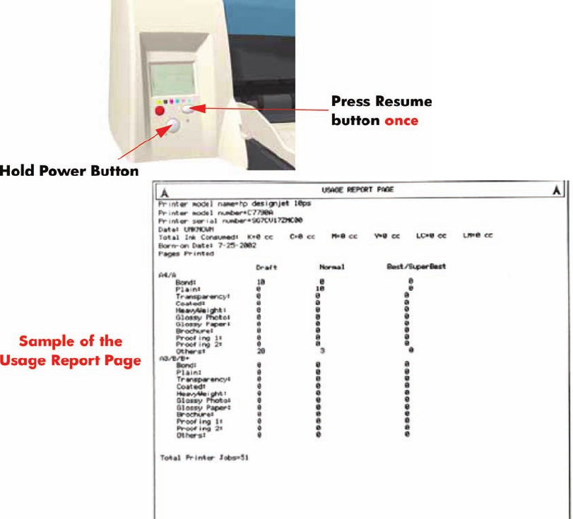
Usage Report Page
The Usage Report Page contains the following information:
●Printer Model Name.
●Printer Model Number.
●Printer Serial Number.
●Date of last print job received.
●Total ink consumed.
●Date of first print job received.
●Number of pages printer (media size/media type/print quality setting).
To print the Usage Report Page, hold the power button down and press the resume button once.
2 Chapter 1 Test Prints ENWW
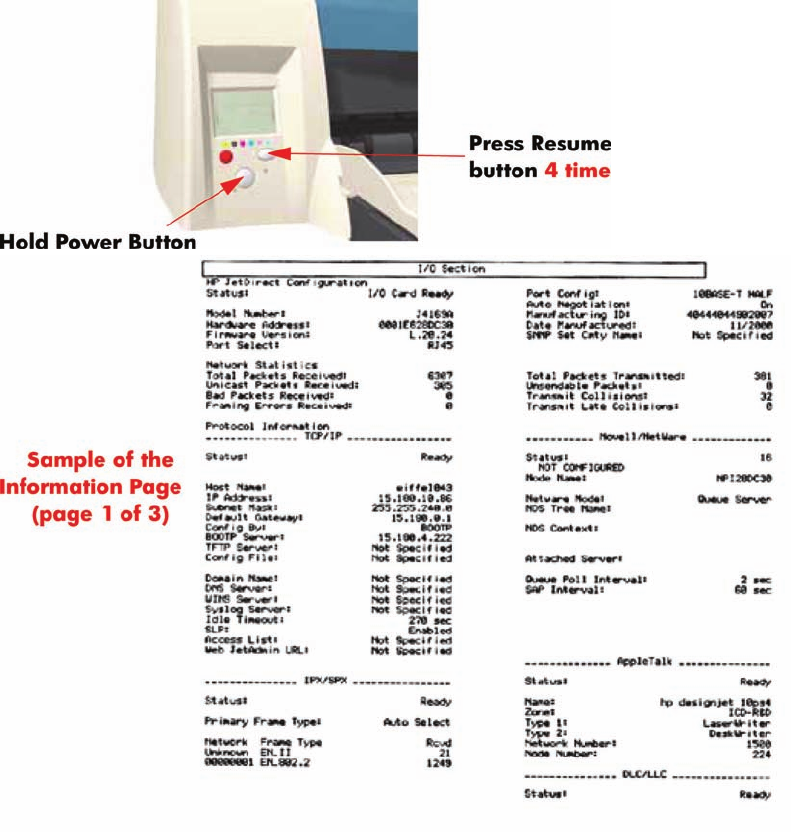
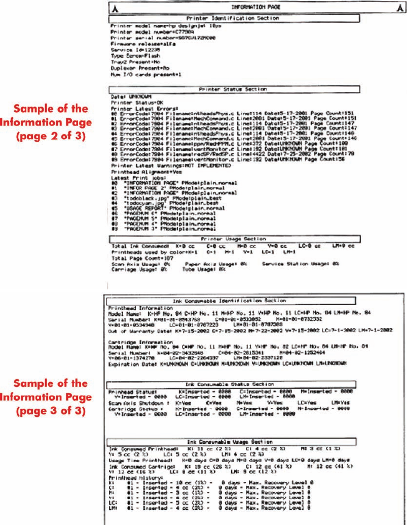
Information Page
The Information Page contains the following information:
●Printer Identification.
●Printer Status.
●Printer Usage.
●Ink Consumable Identification.
●Ink Consumable Status.
●Ink Consumable Usage.
●Network Card Information.
To print the Information Page, hold the power button down and press the resume button four times.
ENWW Information Page 3
4 Chapter 1 Test Prints ENWW
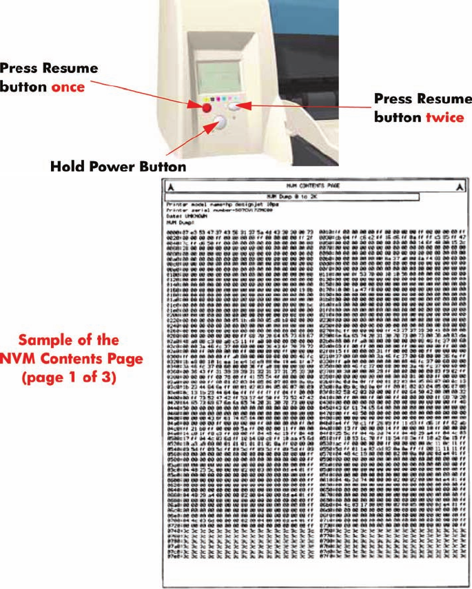
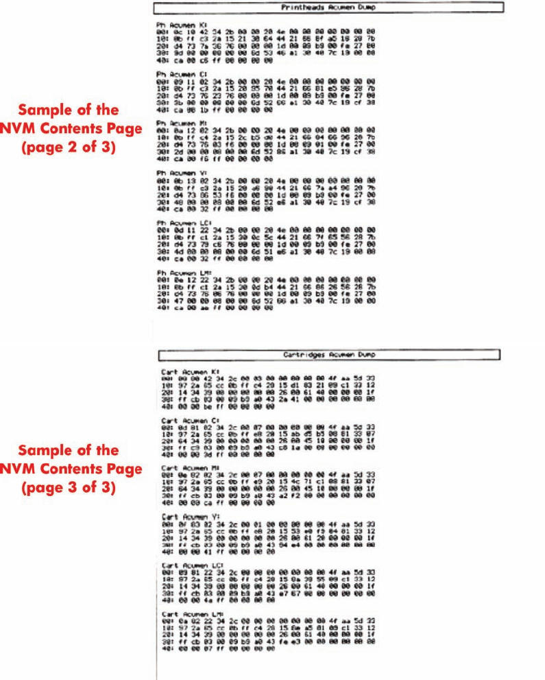
NVM Contents Page
The NVM Contents Page contains the following information:
●EEROM values dump containing all the values stored in the EEROM (Calibration, etc.)
●Printheads Acumen dump
●Cartridges Acumen dump.
To print the NVM Contents Page, hold the power button down and press the cancel button once and
the resume button twice.
ENWW NVM Contents Page 5
6 Chapter 1 Test Prints ENWW

Introduction
The following pages contain a list of system error codes and their respective descriptions and
recommended corrective actions. Only try one recommended action at a time and check if the error
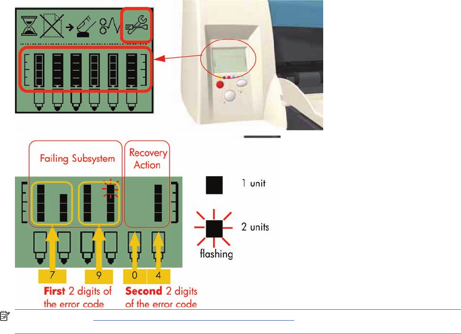
code has disappeared. Since the front panel can only display graphics, the error code needs to be
determined by counting the bars on the front panel (as shown below).
NOTE: Refer to System Error Codes - Explanation on page 34 for an explanation on the construction
of the Error Codes and Warnings.
8 Chapter 2 System Error Codes ENWW
Errors and Warnings
Error Codes will normally be displayed directly on the front panel (but can also be seen on the
Information Page) and will require some kind of intervention to resolve the problem. Warnings will
not be displayed on the front panel, but will instead only appear on the Information Page, therefore
allowing the user to continue operating the printer without the need of an intervention.
NOTE: You can also obtain report of the System Error and Warnings through the DesignJet System
Maintenance Tool.
ENWW Errors and Warnings 9
System Error Codes
NOTE: Applicable for 111 only: The printer has a MROM module and it is not possible to perform a
firmware upgrade, and in fact not required as the printer already has the latest version.
01:10
Cause Solution
Electronics Module failure. Replace the Electronics Module Electronics Module
on page 109.
01:12
Cause Solution
Electronics Module failed during the firmware upgrade OR the
Electronics Module failed during initialization.
Try the following:
●If the Electronics Module failed during the firmware
upgrade, first perform an emergency firmware upgrade
( Emergency Firmware Upgrade on page 33).
●If an emergency firmware upgrade is NOT possible or it
didn’t work, replace the Electronics Module
Electronics Module on page 109.
02:10
Cause Solution
Carriage failure. Replace the Carriage Assembly Carriage Assembly
(Applicability: 70, 100+, 110+, 111) on page 123.
04:13
Cause Solution
Generic Firmware Error (Network Card). Unplug the power cable from the printer and wait a few
seconds. Plug in the power cable again and check if the Error
Code has disappeared. If the error code continues, refer to the
Jetdirect Card Service Manual and Service Notes.
08:11
Cause Solution
Front Panel cannot be detected. Try the following:
●Check the connections and cables of the Font Panel,
check they have not been damaged and are correctly
connected, disconnect and reconnect the front panel.
●Replace the Front Panel if the problem persists Front
Panel on page 117.
10 Chapter 2 System Error Codes ENWW
11:10
Cause Solution
Trailing Cable Failure. Try the following:
●Replace the Carriage Assembly Carriage Assembly
(Applicability: 70, 100+, 110+, 111) on page 123.
●If the Error Code continues, replace the Electronics
Module Electronics Module on page 109.
NOTE: Only replace one component at a time and check if
the error has gone before replacing another component. Using
this procedure you will be able to determine exactly which
component failed.
11:11
Cause Solution
Trailing Cable is badly connected. Try the following:
●Reconnect the Trailing Cable correctly to the Electronics
Module.
●If the Error Code continues, replace the Carriage
Assembly Carriage Assembly (Applicability: 70, 100
+, 110+, 111) on page 123.
21:10
Cause Solution
Service Station failure. Replace the Service Station Assembly Service Station
on page 114.
22:10
Cause Solution
Ink Supply Station failure. Replace the Ink Supply Station Ink Supply Station
on page 106.
ENWW System Error Codes 11
35:01
Cause Solution
No Cleanout Assembly detected while loading media. Try the following:
●Remove the Cleanout Assembly and install it again
correctly.
●Replace the Cleanout Interconnect PCA.
●If the Error Code continues, replace the Cleanout
Assembly.
NOTE: Only replace one component at a time and check if
the error has gone before replacing another component. Using
this procedure you will be able to determine exactly which
component failed.
37:01
Cause Solution
Automatic roll motor shutdown. Try the following:
●If this error code was caused by a paper jam, unplug the
power cable from the printer and clear the blockage. Plug
in the power cable again and check if the Error Code has
disappeared.
●If there is no paper jam or if recovering the paper jam does
not resolve the problem, then replace the Automatic Roll
System (the error could be caused by anything that stalls
the motor).
37:10
Cause Solution
Automatic roll home position error. Replace the Automatic Roll System (the error could be caused
by anything that causes the home position not to be detected
or not to be the correct one - electrical sensors, internal
mechanical problems, etc.).
42:10
Cause Solution
Carriage Motor failure (short-circuit). Replace the Carriage Motor Assembly Carriage Motor
on page 119.
12 Chapter 2 System Error Codes ENWW

56:10
Cause Solution
Error during the calibration of the motor encoder system or a
problem finding the zero position on the Encoder Disc.
Try the following:
●Replace the Paper-Axis Motor Drive Assembly Paper-
Axis Motor Drive Assembly (Applicable only to 30, 30n)
on page 158.
●Replace the Encoder Disc.
NOTE: Make sure you recalibrate the Paper-Axis after
replacing the Paper-Axis Motor Drive Assembly or the Encoder
Disc.
Only replace one component at a time and check if the error
has gone before replacing another component. Using this
procedure you will be able to determine exactly which
component failed.
56:13
Cause Solution
Error during the calibration of the Line-feed Motor/Encoder
system.
Unplug the power cable from the printer and wait a few
seconds. Plug in the power cable again.
61:05
Cause Solution
Firmware Upgrade or Color Calibration was rejected because
the file was sent in the wrong format.
Upgrade the RIP software or the Designjet System
Maintenance Tool.
62:04, 63:04, 64:04 and 65:04
Cause Solution
I/O module error (62 = parallel; 63 = Network; 64 = USB). Try the following:
●Unplug the power cable from the printer and wait a few
seconds. Plug in the power cable again and check if the
Error Code has disappeared.
●If the Error Code reappears, upgrade the firmware.
71:03
Cause Solution
Generic Firmware Error (Out of memory). Try the following:
●Unplug the power cable from the printer and wait a few
seconds. Plug in the power cable again and check if the
Error Code has disappeared.
●If the Error Code reappears, check for a new Firmware
release.
ENWW System Error Codes 13
71:14
Cause Solution
Memory Management Error (Out of memory during firmware
upgrade).
Try the following:
●Unplug the power cable from the printer and wait a few
seconds. Plug in the power cable again and check if the
Error Code has disappeared.
●If the Error Code reappears, perform an emergency
firmware upgrade ( Emergency Firmware Upgrade
on page 33).
72:04
Cause Solution
Generic Firmware Error (expected). Try the following:
●Unplug the power cable from the printer and wait a few
seconds. Plug in the power cable again and check if the
Error Code has disappeared.
●If the Error Code reappears, check for a new Firmware
release.
●If possible, request the user to provide the following
information which can be found on the information
page:
◦Firmware Release.
◦Filename.
◦Line.
74:12
Cause Solution
Firmware Upgrade Error (Memory size check failed during
firmware upgrade).
Try the following:
●Perform the automatic troubleshooting procedure
(requires a special firmware upgrade file that must be
provided by the manufacturing division).
74:14
Cause Solution
The printer is unavailable to upgrade the firmware.. Try the following:
●Turn off and on the printer.
●Print the Service Page
●Check that the firmware is the latest available.:
◦Applicable for 110+,110+r,130,130r: If the
firmware version is D.05.04, this would indicate that
the printer has a MROM module and it is not possible
to perform a firmware upgrade, and in fact not
required as the printer already has the latest version.
14 Chapter 2 System Error Codes ENWW
74:14
Cause Solution
◦Applicable for 111 only: The printer has a MROM
module and it is not possible to perform a firmware
upgrade, and in fact not required as the printer
already has the latest version.
79:04
Cause Solution
Generic Firmware Error (unexpected). Try the following:
●Unplug the power cable from the printer and wait a few
seconds. Plug in the power cable again and check if the
Error Code has disappeared.
●If the Error Code reappears, check for a new Firmware
release.
●If possible, request the user to provide the following
information which can be found on the information
page:
◦Firmware Release.
◦Filename.
◦Line.
81:01
Cause Solution
Paper-Axis shutdown - usually a paper-jam caused by a
blockage of the Paper-axis System.
Try the following:
●If this error code was caused by a paper-jam, unplug the
power cable from the printer and clear the blockage. Plug
in the power cable again and check if the Error Code has
disappeared
●If this error code appeared but was NOT caused by a
paper jam, replace the Paper-Axis Motor Drive Assembly
Paper-Axis Motor Drive Assembly (Applicable only to
30, 30n) on page 158.
81:12
Cause Solution
Media Advance error. This error usually appears during the paper-advance
calibration - Retry the paper-advance calibration.
ENWW System Error Codes 15
83:10
Cause Solution
Sheet feeding failure. Try the following:
●Replace the Out-Of-paper Sensor.
●Replace the Electronics Module Electronics Module
on page 109.
85:10
Cause Solution
Paper-Axis Encoder error. Try the following:
●Make sure that the Encoder Sensor cable is connected
correctly.
●Replace the Paper-Axis Motor Drive Assembly Paper-
Axis Motor Drive Assembly (Applicable only to 30, 30n)
on page 158.
●Replace the Electronics Module Electronics Module
on page 109.
86:01
Cause Solution
Scan-axis shutdown - usually a paper-jam caused by a
blockage of the Scan-axis System.
Try the following:
●Check that there are no obstacles in the Scan-Axis which
stops the Carriage from moving freely.
●Too much friction in the Slider Rod, try lubricating the
Slider Rod.
●The Carriage is bumping into the Service Station. If the
Carriage is stuck at the right hand side of the Printer and
cannot be moved out to the center of the Print Platen it is
because the Service Station cannot uncap the
printheads. In this case replace the Service Station
Assembly Service Station on page 114.
●Check that the belt is correctly installed and not damaged.
●Check that the Turnaround Pulley is correctly installed.
●Replace the Carriage Motor Assembly Carriage
Motor on page 119.
16 Chapter 2 System Error Codes ENWW
86:11
Cause Solution
Scan-axis shutdown during initialization. Typically, this error
occurs when the printer detects an incorrect length.
Try the following:
●Unplug the power cable from the printer and wait a few
seconds. Plug in the power cable again and check if the
Error Code has disappeared.
●Check that the Paper-Axis Drive Motor Assembly is
correctly installed and that the bushing is correctly locked
into position.
●Check that the Carriage moves freely and DOES NOT
bump into the Service Station.
●If the Printheads are not installed, maybe the carriage
cover is not closed completely.
●If the Error Code continues, replace the Carriage
Assembly Carriage Assembly (Applicability: 70, 100+,
110+, 111) on page 123.
Warnings
01:11
Cause Solution
The Electronics Module is incorrectly positioned. Reseat the Electronics Module by Removing it from the Printer
Electronics Module on page 109 and installing it again in
the correct position.
01:12
Cause Solution
Electronics Module Error. The Electronics Module EEPROM is flagged as empty and
must be upgraded with the contents of the Carriage EEPROM,
but the Carriage is also flagged as empty. The backup is not
performed. This is the result of an error during the
manufacturing or the repair process. Therefore the Electronics
Module must be reconfigured.
02:10
Cause Solution
Carriage failure. Replace the Carriage Assembly Carriage Assembly
(Applicability: 70, 100+, 110+, 111) on page 123.
ENWW Warnings 17

270:00
Cause Solution
Black Color Calibration Failure - Black Color Calibration
cancelled.
Try the following:
●Clean the electrical contacts on the black printhead.
●If the error code continues, replace the black printhead.
271:00
Cause Solution
Cyan Color Calibration Failure - Cyan Color Calibration
cancelled.
Try the following:
●Clean the electrical contacts on the cyan printhead.
●If the error code continues, replace the cyan printhead.
272:00
Cause Solution
Magenta Color Calibration Failure - Magenta Color Calibration
cancelled.
Try the following:
●Clean the electrical contacts on the magenta printhead.
●If the error code continues, replace the magenta
printhead.
273:00
Cause Solution
Yellow Color Calibration Failure - Yellow Color Calibration
cancelled.
Try the following:
●Clean the electrical contacts on the yellow printhead.
●If the error code continues, replace the yellow printhead.
274:00 (Not applicable to HP DesignJet 70, 100, 100+, 110+)
Cause Solution
Light Cyan Color Calibration Failure - Light Cayan Color
Calibration cancelled.
Try the following:
●Clean the electrical contacts on the light cyan printhead.
●If the error code continues, replace the light cyan
printhead.
18 Chapter 2 System Error Codes ENWW
275:00 (Not applicable to HP DesignJet 70, 100, 100+, 110+)
Cause Solution
Light Magenta Color Calibration Failure - Light Magenta Color
Calibration cancelled.
Try the following:
●Clean the electrical contacts on the light magenta
printhead.
●If the error code continues, replace the light magenta
printhead.
35:01
Cause Solution
No Cleanout Assembly (or Duplexer, if installed) detected
while loading media.
Try the following:
●Remove the Cleanout Assembly ( Cleanout
Assembly on page 120) (or Duplexer, if installed) and
install it again correctly.
●Replace the Duplexer Interconnect PCA.
●If the Error Code continues, replace the Cleanout
Assembly Cleanout Assembly on page 120.
58:10
Cause Solution
Problem detected in the color sensor system. Replace the Carriage Assembly Carriage Assembly
(Applicability: 70, 100+, 110+, 111) on page 123.
61:05
Cause Solution
Language interpreting error. This is usually and error produced
while parsing a file. There is probably an incompatibility
between the driver and the firmware.
Upgrade the RIP software or the Designjet System
Maintenance Tool.
65:01
Cause Solution
Communication Failure. Try the following:
●Unplug the power cable from the printer and check the
cable connections (Parallel, USB and Network cables).
Plug in the power cable again and check if the Error Code
has disappeared.
ENWW Warnings 19
66:02:1 (Only applicable to HP DesignJet 30, 30n, 90, 90r, 130, 130nr)
Cause Solution
Horizontal clipping. May happen when the roll ends in the
middle of printing an image. Could also happen when multi-
pick occurs and two sheets are loaded together and they do
not completely overlap.
Make sure the image size is within the selected WIDTH of the
sheet.
66:02:2 (Only applicable to HP DesignJet 30, 30n, 90, 90r, 130, 130nr)
Cause Solution
Vertical clipping. May happen when the roll ends in the middle
of printing an image. Could also happen when multi-pick
occurs and two sheets are loaded together and they do not
completely overlap.
Make sure the image size is within the selected LENGTH of
the sheet.
71:14
Cause Solution
Out-of-memory while trying to process the firmware upgrade
file. Probably this is a firmware bug, because the firmware
should free up enough memory to perform the firmware
upgrade process correctly.
Perform an emergency firmware upgrade ( Emergency
Firmware Upgrade on page 33) .
74:12
Cause Solution
Firmware bug in the firmware upgrade process Try the following:
●Download the special file in order to update the bootlog.
●If possible, request the user to provide the following
information which can be found on the information
page:
◦Firmware Release.
◦Printer Serial Number.
74:14
Cause Solution
The printer is unavailable to upgrade the firmware.. Try the following:
●Turn off and on the printer.
●Print the Service Page
●Check that the firmware is the latest available.:
◦Applicable for 110+,110+r,130,130r: If the
firmware version is D.05.04, this would indicate that
the printer has a MROM module and it is not possible
20 Chapter 2 System Error Codes ENWW
74:14
Cause Solution
to perform a firmware upgrade, and in fact not
required as the printer already has the latest version.
◦Applicable for 111 only: The printer has a MROM
module and it is not possible to perform a firmware
upgrade, and in fact not required as the printer
already has the latest version.
81:01
Cause Solution
Paper-Axis shutdown - usually a paper-jam caused by a
blockage of the Paper-axis System.
Try the following:
●If this error code was caused by a paper-jam, unplug the
power cable from the printer and clear the blockage. Plug
in the power cable again and check if the Error Code has
disappeared.
●If this error code appeared but was NOT caused by a
paper jam, replace the Paper-Axis Motor Drive Assembly
Paper-Axis Motor Drive Assembly (Applicable only to
30, 30n) on page 158.
83:01:1 (Only applicable to HP DesignJet 30, 30n, 70, 100+, 110+, 111, 90, 90r,, 130, 130nr)
Cause Solution
The paper is rejected from the Bypass due to skew. When manually loading paper from the front of the paper, make
sure that it is loaded straight.
83:01:3 (Only applicable to HP DesignJet 70/100plus/110plus, 111 with Roll)
Cause Solution
The paper is rejected from the roll due to skew. When loading paper from the roll, make sure that it is loaded
straight.
94:02:1 (Only applicable to HP DesignJet 30, 30n, 90, 90r, 130, 130nr, 111)
Cause Solution
User selected Coated Paper and Best mode, but the Color
Calibration profile was obsolete or missing for Coated Paper
and the selected print quality setting.
Using the System Maintenance Tool, perform Color Calibration
for Coated Paper and the selected print quality setting.
94:02:3 (Only applicable to HP DesignJet 30, 30n, 90, 90r, 130, 130nr, 111)
Cause Solution
User selected Photo Paper and Best mode, but the Color
Calibration profile was obsolete or missing for Photo Paper and
the selected print quality setting.
Using the System Maintenance Tool, perform Color Calibration
for Photo Paper and the selected print quality setting.
ENWW Warnings 21

94:02:4 (Only applicable to HP DesignJet 30, 30n, 90, 90r, 130, 130nr)
Cause Solution
User selected Heavy-Weight Coated Paper and Best mode,
but the Color Calibration profile was obsolete or missing for
Heavy-Weight Coated Paper and the selected print quality
setting.
Using the System Maintenance Tool, perform Color Calibration
for Heavy- Weight Coated Paper and the selected print quality
setting.
94:02:5 (Only applicable to HP DesignJet 30, 30n, 90, 90r, 130, 130nr)
Cause Solution
User selected Proofing Semi-Gloss Paper and Best mode, but
the Color Calibration profile was obsolete or missing for
Proofing Semi-Gloss Paper and the selected print quality
setting
Using the System Maintenance Tool, perform Color Calibration
for Proofing Semi-Gloss Paper and the selected print quality
setting.
94:02:6 (Only applicable to HP DesignJet 30, 30n, 90, 90r, 130, 130nr)
Cause Solution
User selected Photo Matte Paper and Best mode, but the Color
Calibration profile was obsolete or missing for Photo Matte
Paper and the selected print quality setting.
Using the System Maintenance Tool, perform Color Calibration
for Photo Matte Paper and the selected print quality setting.
94:02:7 (Only applicable to HP DesignJet 30, 30n, 90, 90r, 130, 130nr)
Cause Solution
User selected Photo Satin Paper and Best mode, but the Color
Calibration profile was obsolete or missing for Photo Satin
Paper and the selected print quality setting.
Using the System Maintenance Tool, perform Color Calibration
for Photo Satin Paper and the selected print quality setting.
94:02:8 (Only applicable to HP DesignJet 30, 30n, 90, 90r, 130, 130nr)
Cause Solution
User selected Coated Paper and Max dpi, but the Color
Calibration profile was obsolete or missing for Coated Paper
and the selected print quality setting.
Using the System Maintenance Tool, perform Color Calibration
for Coated Paper and the selected print quality setting.
941:02:1 (Only applicable to HP DesignJet 30, 30n, 90, 90r, 130, 130nr)
Cause Solution
User selected Photo Paper and Max dpi, but the Color
Calibration profile was obsolete or missing for Photo Paper and
the selected print quality setting.
Using the System Maintenance Tool, perform Color Calibration
for Photo Paper and the selected print quality setting.
22 Chapter 2 System Error Codes ENWW

941:02:2 (Only applicable to HP DesignJet 30, 30n, 90, 90r, 130, 130nr)
Cause Solution
User selected Heavy-Weight Coated Paper and Max dpi, but
the Color Calibration profile was obsolete or missing for Heavy-
Weight Coated Paper and the selected print quality setting.
Using the System Maintenance Tool, perform Color Calibration
for Heavy- Weight Coated Paper and the selected print quality
setting.
941:02:3 (Only applicable to HP DesignJet 30, 30n, 90, 90r, 130, 130nr)
Cause Solution
User selected Proofing Semi-Gloss Paper and Max dpi mode,
but the Color Calibration profile was obsolete or missing for
Proofing Semi-Gloss Paper and the selected print quality
setting.
Using the System Maintenance Tool, perform Color Calibration
for Proofing Semi-Gloss Paper and the selected print quality
setting.
941:02:4 (Only applicable to HP DesignJet 30, 30n, 90, 90r, 130, 130nr)
Cause Solution
User selected Photo Matte Paper and Max dpi mode, but the
Color Calibration profile was obsolete or missing for Photo
Matte Paper and the selected print quality setting.
Using the System Maintenance Tool, perform Color Calibration
for Photo Matte Paper and the selected print quality setting.
941:02:5 (Only applicable to HP DesignJet 30, 30n, 90, 90r, 130, 130nr)
Cause Solution
User selected Photo Satin Paper and Max dpi mode, but the
Color Calibration profile was obsolete or missing for Photo
Satin Paper and the selected print quality setting.
Using the System Maintenance Tool, perform Color Calibration
for Photo Satin Paper and the selected print quality setting.
94:04
Cause Solution
Firmware Error (during color calibration). Try the following:
●Unplug the power cable from the printer and wait a few
seconds. Plug in the power cable again and check if the
Error Code has disappeared.
●If the Error Code reappears, check for a new Firmware
release.
94:08
Cause Solution
Color Calibration Warning - Color Calibration not cancelled but
Color Calibration values are likely to be incorrect.
Try the Color Calibration again, but this time using a different
type of media (preferably HP media).
ENWW Warnings 23
94:10
Cause Solution
Color Calibration Failure - Color Calibration cancelled. Try the following:
●Unplug the power cable from the printer and wait a few
seconds. Plug in the power cable again and try the Color
Calibration again.
●If this error code appears again, check the Color
Calibration print:
◦If the Color Calibration was printed correctly without
any print defects, then check that the media is
moving freely (backwards and forwards) while the
printer is scanning it.
◦If the Color Calibration was printed incorrectly, with
some print defects, replace the faulty Printhead of
the color where the defects were noticeable.
◦If the Error Code continues, replace the Carriage
Assembly Carriage Assembly (Applicability: 70,
100+, 110+, 111) on page 123.
95:00
Cause Solution
Printhead Alignment Failure - Printhead Alignment cancelled. Try the following:
●Clean the printhead indicated by the printer.
●If the error code continues, replace the faulty printhead.
95:02
Cause Solution
Printhead Alignment Failure - Printhead Alignment cancelled. Try the following:
●Unplug the power cable from the printer and wait a few
seconds. Plug in the power cable again and try the
Printhead Alignment again.
●If this error code appears again, check the Printhead
Alignment print:
◦If the Printhead Alignment was printed correctly
without any print defects, then check that the media
is moving freely (backwards and forwards) while the
printer is scanning it.
◦If the Printhead Alignment was printed incorrectly,
with some print defects, replace the faulty Printhead
of the color where the defects were noticeable.
95:04
Cause Solution
Firmware Error (during Printhead Alignment). Upgrade the printer to the latest firmware release.
24 Chapter 2 System Error Codes ENWW
Startup track mode
Introduction
The startup track mode is designed to enable you to identify a failing subsystems while the printer is
initializing. Startup track mode provides a specific indication of which particular subsystem is failing.
This mode is not intended for use by end-users.
Initializing the printer in Startup track mode
To initialize the printer in Startup track mode:
1. Hold the ’Continue’ button while connecting the printer to the power supply.
2. During the initialization of the printer, the front panel will display a range of code numbers in the
form of squares, these code numbers added together represent the various subsystems about to
be initialized.
3. Once the printer comes to initializing the failing subsystem, the front panel will hang, and all that
will be displayed is the failing subsystem.
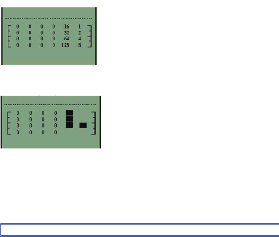
Interpreting the numbered code system
While the printer is initializing, the front panel will display a sequence of squares in the last two columns.
Each position in the last two columns represents a number, all the numbers represented are shown
below. To find the failing subsystem, add the numbers together that have a square and refer to the list
of numbers with their associated subsystems on Subsystem Code Description on page 25.
In the example below the printer is initializing and the front panel has stopped and is displaying squares
in positions 16, 32, 64, and 4. Add these four values together and you get 116, refer to the list on
Subsystem Code Description on page 25, and we can see the failing subsystem is the Trailing Cable.
If the display reaches 191, you will need to turn On the printer from the power button. If all the subsystems
pass the initialization, the printer will initialize normally and go to the ready status.
Subsystem Code Description
This is the list of the subsystems and their associated Startup Track Numbers. Many of the descriptions
of the Subsystems will not be immediately obvious, when this is the case contact the lfp help desk and
they can assist you.
Table 2-1 Subsystem code description
Startup track number: Associated Subsystem
ENWW Startup track mode 25

Startup Track 004: Calling EiffelMain
Startup Track 005: Initializing Classes
Startup Track 006: Initializing SM
Startup Track 007: Initializing Memory
Startup Track 008: Initializing MemoryVolatile
Startup Track 009: Initializing MemoryEndian
Startup Track 010: Initializing MemoryVolatileEndian
Startup Track 011: Initializing Impala
Startup Track 012: Initializing ColdFire
Startup Track 013: Initializing ImpalaInterruptController
Startup Track 014: Initializing MechProcTaskHiIntA
Startup Track 015: Initializing IsardInterruptA
Startup Track 016: Initializing Watchdog
Startup Track 017: Initializing Chronometer
Startup Track 018: Initializing EddTimer
Startup Track 019: Initializing IsardInterruptB
Startup Track 020: Initializing PciSlot2Interrupt
Startup Track 021: Initializing PciSlot3Interrupt
Startup Track 022: Initializing PciSlot4Interrupt
Startup Track 023: Initializing PciSlot5Interrupt
Startup Track 024: Initializing MagentaFireLow
Startup Track 025: Initializing BongoGpio
Startup Track 026: Initializing SecondTraySensor
Startup Track 027: Initializing CleanoutSensor
Startup Track 028: Initializing RearPathPaperSensor
Startup Track 029: Initializing BlackCartridgeSensor
Startup Track 030: Initializing CyanCartridgeSensor
Startup Track 031: Initializing MagentaCartridgeSensor
Startup Track 032: Initializing YellowCartridgeSensor
Startup Track 033: Initializing LightMagentaCartridgeSensor
Startup Track 034: Initializing LightCyanCartridgeSensor
Startup Track 035: Initializing SynergyReset
Startup Track 036: Initializing FrontPanelReset
Startup Track 037: Initializing PowerFan
Startup Track 038: Initializing FrontPanelInterrupt
Startup Track 039: Initializing CoverWindowSensor
Startup Track 040: Initializing nUSB_ENABLE
Startup Track 041: Initializing USB_CONNECT
Table 2-1 Subsystem code description (continued)
26 Chapter 2 System Error Codes ENWW

Startup Track 042: Initializing TrailingCable3Sensor
Startup Track 043: Initializing TrailingCable12Sensor
Startup Track 044: Initializing PrintheadSensor
Startup Track 045: Initializing BongoBrake
Startup Track 046: Initializing Dma
Startup Track 047: Initializing BongoEncoder
Startup Track 048: Initializing ServiceStationEncoder
Startup Track 049: Initializing SSPwm
Startup Track 050: Initializing PaperPwm
Startup Track 051: Initializing RampPwm
Startup Track 052: Initializing CarriagePwmForward
Startup Track 052: Initializing CarriagePwmForward
Startup Track 054: Initializing BomboPwm
Startup Track 055: Initializing EddPwm
Startup Track 056: Initializing ImpalaCarriagePosition
Startup Track 057: Initializing I2c0
Startup Track 058: Initializing I2c1
Startup Track 059: Initializing I2c2
Startup Track 060: Initializing I2c3
Startup Track 061: Initializing Darwin
Startup Track 062: Initializing PciCtrl
Startup Track 063: Initializing PciDma
Startup Track 064: Initializing MBandToPixel
Startup Track 065: Initializing PixelData
Startup Track 066: Initializing BlackCSData
Startup Track 067: Initializing CyanCSData
Startup Track 068: Initializing MagentaCSData
Startup Track 069: Initializing YellowCSData
Startup Track 070: Initializing LightCyanCSData
Startup Track 071: Initializing LightMagentaCSData
Startup Track 072: Initializing BlackPrintHead
Startup Track 073: Initializing CyanPrintHead
Startup Track 074: Initializing MagentaPrintHead
Startup Track 075: Initializing YellowPrintHead
Startup Track 076: Initializing LightCyanPrintHead
Startup Track 077: Initializing LightMagentaPrintHead
Startup Track 078: Initializing BlockBlack
Startup Track 079: Initializing BlockColor
Table 2-1 Subsystem code description (continued)
ENWW Startup track mode 27

Startup Track 080: Initializing ContoneToRaster
Startup Track 081: Initializing Enhancer
Startup Track 082: Initializing RasterToMband
Startup Track 083: Initializing MechProcA
Startup Track 084: Initializing MemoryUncached
Startup Track 085: Initializing Isard
Startup Track 086: Initializing IsardInterruptController
Startup Track 087: Initializing PaperInterrupt
Startup Track 088: Initializing IsardPMTimer
Startup Track 089: Initializing IsardKFort
Startup Track 090: Initializing IsardCarriagePosition
Startup Track 091: Initializing IsardPaperPosition
Startup Track 092: Initializing MediaPosition
Startup Track 093: Initializing PaperEncoderPosition
Startup Track 094: Initializing IsardMotorShortcut
Startup Track 095: Initializing Eridani
Startup Track 096: Initializing EddOn
Startup Track 097: Initializing ServiceStationLed
Startup Track 098: Initializing FetRegulator
Startup Track 099: Initializing EddOut
Startup Track 100: Initializing DuplexerConversor
Startup Track 101: Initializing EridaniConversorAuto
Startup Track 102: Initializing EridaniConversorAB
Startup Track 103: Initializing EridaniConversorAnA
Startup Track 104: Initializing EridaniConversorBnB
Startup Track 105: Initializing PaperDriver
Startup Track 106: Initializing ServiceStationDriver
Startup Track 107: Initializing RampDriver
Startup Track 108: Initializing DuplexerSensor
Startup Track 109: Initializing PaperMotorHw
Startup Track 110: Initializing CarriageMotorHw
Startup Track 111: Initializing ServiceStationMotorHw
Startup Track 112: Initializing BongoEncoderWindowHw
Startup Track 113: Initializing BongoMotorHw
Startup Track 114: Initializing RampMotorHw
Startup Track 115: Initializing FrontPanelHw
Startup Track 116: Initializing TrailingCable
Startup Track 117: Initializing CarriageBoardHw
Table 2-1 Subsystem code description (continued)
28 Chapter 2 System Error Codes ENWW

Startup Track 118: Initializing SynergyA
Startup Track 119: Initializing VPPA
Startup Track 120: Initializing VPPB
Startup Track 121: Initializing SynergyInternalRegulatorA
Startup Track 122: Initializing Led1Voltage
Startup Track 123: Initializing EndeavourA
Startup Track 124: Initializing EndeavourAcumenA
Startup Track 125: Initializing CLC_Channel0
Startup Track 126: Initializing CLC_Channel1
Startup Track 127: Initializing CLC_Channel2
Startup Track 128: Initializing EndeavourVRefConversor
Startup Track 129: Initializing CLC_ChannelDACConversor
Startup Track 130: Initializing IS_Channel3Conversor_A
Startup Track 131: Initializing CLC_Channel0Conversor
Startup Track 132: Initializing CLC_Channel1Conversor
Startup Track 133: Initializing CLC_Channel2Conversor
Startup Track 134: Initializing Led2Voltage
Startup Track 135: Initializing Black5V
Startup Track 136: Initializing Yellow5V
Startup Track 137: Initializing Magenta5V
Startup Track 138: Initializing Cyan5V
Startup Track 139: Initializing Black12V
Startup Track 140: Initializing Yellow12V
Startup Track 141: Initializing Magenta12V
Startup Track 142: Initializing Cyan12V
Startup Track 143: Initializing VPen_Current_Sense_A
Startup Track 144: Initializing VPen_OV_Latch_A
Startup Track 145: Initializing VPen_OV_Clear_Latch_A
Startup Track 146: Initializing VPen_UV_Latch_A
Startup Track 147: Initializing VPen_UV_Clear_Latch_A
Startup Track 148: Initializing VPen_OV_Present_A
Startup Track 149: Initializing VPen_UV_Present_A
Startup Track 150: Initializing EndeavourB
Startup Track 151: Initializing EndeavourAcumenB
Startup Track 152: Initializing IS_Channel3Conversor_B
Startup Track 153: Initializing Led3Voltage
Startup Track 154: Initializing LightMagenta5V
Startup Track 155: Initializing LightCyan5V
Table 2-1 Subsystem code description (continued)
ENWW Startup track mode 29

Startup Track 156: Initializing LightMagenta12V
Startup Track 157: Initializing LightCyan12V
Startup Track 158: Initializing VPen_Current_Sense_B
Startup Track 159: Initializing VPen_OV_Latch_B
Startup Track 160: Initializing VPen_OV_Clear_Latch_B
Startup Track 161: Initializing VPen_UV_Latch_B
Startup Track 162: Initializing VPen_UV_Clear_Latch_B
Startup Track 163: Initializing VPen_OV_Present_B
Startup Track 164: Initializing VPen_UV_Present_B
Startup Track 165: Initializing Eerom
Startup Track 166: Initializing EeromCarriage
Startup Track 167: Initializing PrintheadControl
Startup Track 168: Initializing BlackPrintheadAcumen
Startup Track 169: Initializing CyanPrintheadAcumen
Startup Track 170: Initializing MagentaPrintheadAcumen
Startup Track 171: Initializing YellowPrintheadAcumen
Startup Track 172: Initializing LightCyanPrintheadAcumen
Startup Track 173: Initializing LightMagentaPrintheadAcumen
Startup Track 174: Initializing BlackCartridgeAcumen
Startup Track 175: Initializing CyanCartridgeAcumen
Startup Track 176: Initializing MagentaCartridgeAcumen
Startup Track 177: Initializing YellowCartridgeAcumen
Startup Track 178: Initializing LightCyanCartridgeAcumen
Startup Track 179: Initializing LightMagentaCartridgeAcumen
Startup Track 180: Initializing ColorSensor
Startup Track 181: Initializing ColorSensorLed1
Startup Track 182: Initializing ColorSensorLed2
Startup Track 183: Initializing ColorSensorLed3
Startup Track 184: Initializing ColorSensorConverso
Startup Track 185: Initializing ColorSensorConversorB
Startup Track 186: Initializing ColorSensorConversorC
Startup Track 187: Initializing V5_V12_ISDetection
Startup Track 188: Initializing VPP_ISDetection
Startup Track 189: Initializing InterruptController
Startup Track 190: SM Initialized
Startup Track 191: Back from EiffelMain!!!
PRESS POWER BUTTON HERE!!
Startup Track 192: Initializing VPPA
Table 2-1 Subsystem code description (continued)
30 Chapter 2 System Error Codes ENWW

Startup Track 193: Initializing VPPB
Startup Track 194: Initializing SynergyInternalRegulatorA
Startup Track 195: Initializing Led1Voltage
Startup Track 196: Initializing EndeavourAcumenA
Startup Track 197: Initializing CLC_Channel0
Startup Track 198: Initializing CLC_Channel1
Startup Track 199: Initializing CLC_Channel2
Startup Track 200: Initializing EndeavourVRefConversor
Startup Track 201: Initializing CLC_ChannelDACConversor
Startup Track 202: Initializing IS_Channel3Conversor_A
Startup Track 203: Initializing CLC_Channel0Conversor
Startup Track 204: Initializing CLC_Channel1Conversor
Startup Track 205: Initializing CLC_Channel2Conversor
Startup Track 206: Initializing Led2Voltage
Startup Track 207: Initializing Black5V
Startup Track 208: Initializing Yellow5V
Startup Track 209: Initializing Magenta5V
Startup Track 210: Initializing Cyan5V
Startup Track 211: Initializing Black12V
Startup Track 212: Initializing Yellow12V
Startup Track 213: Initializing Magenta12V
Startup Track 214: Initializing Cyan12V
Startup Track 215: Initializing VPen_Current_Sense_A
Startup Track 216: Initializing VPen_OV_Latch_A
Startup Track 217: Initializing VPen_OV_Clear_Latch_A
Startup Track 218: Initializing VPen_UV_Latch_A
Startup Track 219: Initializing VPen_UV_Clear_Latch_A
Startup Track 220: Initializing VPen_OV_Present_A
Startup Track 221: Initializing VPen_UV_Present_A
Startup Track 222: Initializing EndeavourAcumenB
Startup Track 223: Initializing IS_Channel3Conversor_B
Startup Track 224: Initializing Led3Voltage
Startup Track 225: Initializing LightMagenta5V
Startup Track 226: Initializing LightCyan5V
Startup Track 227: Initializing LightMagenta12V
Startup Track 228: Initializing LightCyan12V
Startup Track 229: Initializing VPen_Current_Sense_B
Startup Track 230: Initializing VPen_OV_Latch_B
Table 2-1 Subsystem code description (continued)
ENWW Startup track mode 31

Startup Track 231: Initializing VPen_OV_Clear_Latch_B
Startup Track 232: Initializing VPen_UV_Latch_B
Startup Track 233: Initializing VPen_UV_Clear_Latch_B
Startup Track 234: Initializing VPen_OV_Present_B
Startup Track 235: Initializing VPen_UV_Present_B
Table 2-1 Subsystem code description (continued)
32 Chapter 2 System Error Codes ENWW
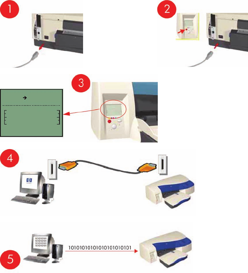
Emergency Firmware Upgrade
1. Unplug the power cord from the printer and wait a few seconds.
2. Press and hold the Cancel (red) button while plugging in the power cord.
3. The printer will initialize in emergency mode (the front panel will display just the arrow icon).
4. Connect the printer to the computer with a parallel cable.
5. Send the firmware file through the parallel port from the DOS command prompt. Type: copy /b
firmware_file lpt1: and then press ENTER.
ENWW Emergency Firmware Upgrade 33

System Error Codes - Explanation
System Error Codes explain which component/system is failing and what action should be taken to
resolve the problem.
System Error Codes are displayed directly on the front panel (but can also be seen on the Information
Page) and have been defined in the format XX.YZ.
Warnings will not be displayed on the front panel, but will instead only appear on the Information Page
and have been defined in the format XXn.YZ.m.
●XX: Service Part (2 digits).
●n: Service Part Index (if more than one used in the product) - Optional.
◦e.g. Identify the Ink Supply (color and number).
●Y: Who should perform the action (1 digit) - (User or Service Engineer).
●Z: Action to perform (1 digit).
●m: additional actions/information to consider (1 digit) - Optional.
◦e.g. Non-authorized ink was detected, PM was triggered or Printhead in/out of Warranty.
The following table explains the XX part of the System Error Code or Warning:
NOTE: Items denoting * (Asterisk) are not applicable to the printers.
Table 2-2 System error codes
Code Component/System
01 Main PCA/Electronics Module
02 Carriage/Carriage PCA
03 Power Supply Unit
04 Network Card
05 Formatter *
06 Hard Disk Drive *
07 Interconnect PCA
08 Front Panel
11 Trailing Cable
12 Carriage Flex Circuit
17 Interconnect Cable
21 Service Station
22 Ink Supply Station
23 Pressure System (APS) *
24 Ink Delivery Tubes
25 Spittoon *
26n Ink Cartridge (color n)
26n Printhead (color n)
31 Cutter
34 Chapter 2 System Error Codes ENWW

32 Take-up Reel *
33 Sheet Feeder
34 Dryer/Blower *
35 Cleanout Assembly
36 Duplexer
37 ARSS/Rollfeed
38 Output Tray
41 Paper-Axis Motor
42 Scan-Axis Motor
43 Vacuum Fan *
44 Aerosol fan *
51 Window Sensor
52 Drop Detector *
53 Media Sensor
54 Pinch-Arm Sensor
55 Line Sensor
56 Drive Roller Encoder Sensor
57 Ink Leak Detector *
58 Color Sensor *
59 Media Type Sensor *
61 Language Interpreting
62 Input/Output through Parallel Port
63 Input/Output through Network Card
64 Input/Output through USB Port
65 Input/Output (not know what port)
66 Print Job Configuration
71 Print Job Configuration
72 Generic Firmware
73 Motor Control Functions
74 Motor Control Functions 74 Firmware Upgrade
79 Firmware Crash
81 Media Advance
82 Media Cut *
83 Single-Sheet Feeding
84 Roll Feeding *
85 Media-Axis Encoder Reading
86 Carriage Movement
87 Scan-Axis Encoder Reading
Table 2-2 System error codes (continued)
ENWW System Error Codes - Explanation 35

91 Printhead Firing
92 Servicing
93 Ink Pumping
94 Ink Pumping
95 Printhead Alignment
96 Image Quality Troubleshooting
The following table explains the YZ part of the System Error Code or Warning:
Table 2-3 System error codes
Code Response Response
00 Replace
Possible for customer
to perform action
01 Reseat/Reconnect/Clean/Adjust (manually)
02 Calibrate/Adjust (using Automatic Process)
03 Power OFF
04 Upgrade System Firmware
05 Upgrade Driver
06 Add Accessory
07 Escalate
08 Send Plot Again
09 Wrong Part Installed
10 Replace
HP qualified
personnel assistance
required
11 Reseat/Reconnect/Clean/Adjust (manually)
12 Calibrate/Adjust (using Automatic Process)
13 Power OFF
14 Upgrade System Firmware
15 Upgrade Driver
16 Add Accessory
17 Escalate
18 Send Plot Again
19 Wrong Part Installed
Table 2-2 System error codes (continued)
36 Chapter 2 System Error Codes ENWW

Introduction
The System Maintenance Utility is designed to assist the customer with common maintenance tasks for
the printer and also to resolve common problems that they may encounter.
NOTE: Print jobs must not be sent to the printer while the system maintenance utility is in use.
Since the design of the System Maintenance Tool is different between the Designjet 120/120nr and
Designjet 130/130, this chapter will explain how to use the tool for each product separately:
Launching the System Maintenance Utility
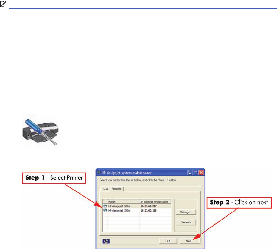
The procedures described here are applicable to the following printers: HP Designjet 30, 30n, 70, 90,
90r, 100+, 110+r, 110+nr, 111 with roll, 111 with tray, 130, 130r, 130nr:
There are two ways of launching the System Maintenance Utility.
From your computer’s desktop (Windows, Mac OS 9 and X)
1. Double click the hp designjet system maintenance icon on the desktop.
2. A printer selector window opens - select your printer from the list.
3. Click Next (in Windows) or Configure (in Mac OS).
From the Printer Driver (Windows, Mac OS X)
●In the Windows driver click the hp designjet system maintenance icon in the Services tab.
38 Chapter 3 System Maintenance Utility ENWW

●In Mac OS X, select the Printer in the Print Center or Print Setup Utility and click configure.
NOTE: When you finish using the System Maintenance Utility, you must click on exit on the left hand
column before closing the browser.
ENWW Launching the System Maintenance Utility 39
System Maintenance Utility (Designjet 30, 30n, 70, 90, 90r,
110plus, 111, 130, 130nr)
Main Menu - Printer Front Panel Replication
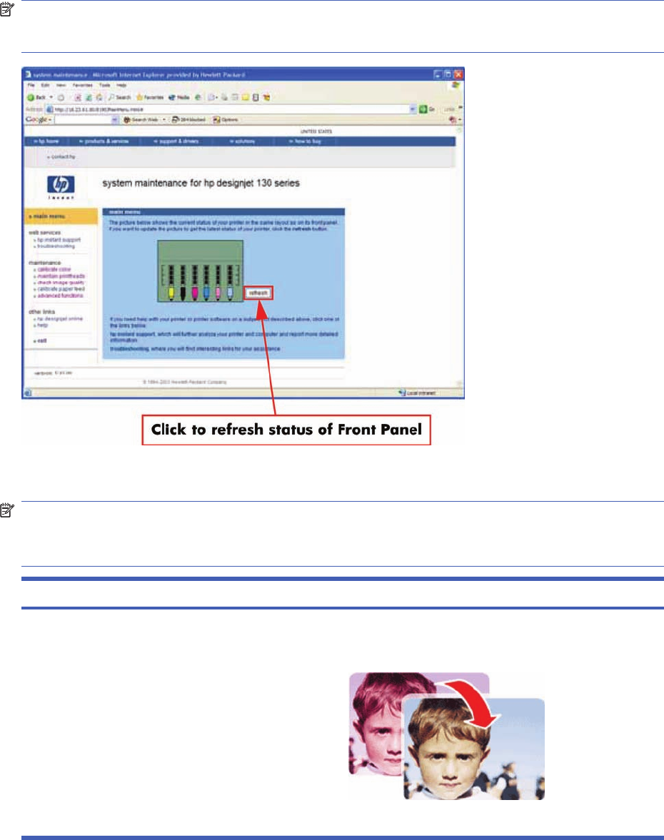
The main page of the System Maintenance Utility includes a replica of the Printer’s Front Panel showing
the status of the Printer.
NOTE: The replica Front Panel does not show the real-time status. It is a snapshot which can be
refreshed by pressing the refresh button either on the web browser toolbar or in the actual replica
window.
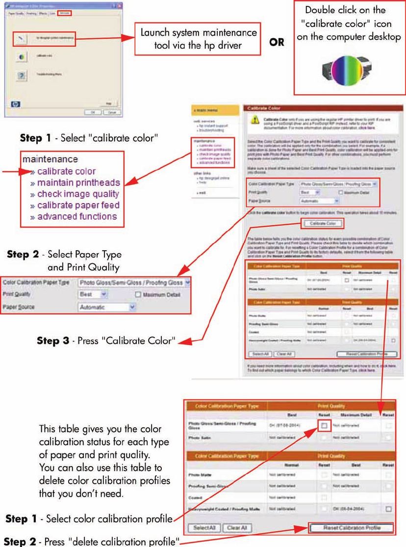
Color Calibration
NOTE: The Color Calibration is only available for the following printers: HP Designjets 30, 30n, 90,
90r, 130, 130nr. It is not available for the HP Designjets 70, 110plus, 111.
NOTE: The Color Calibration should ONLY be performed by the user when required.
Question Answer
Why calibrate color? Calibrate color performs a maintenance function to ensure
color consistency. If you calibrate correctly, the colors printed
on printers with different printheads will look very similar.
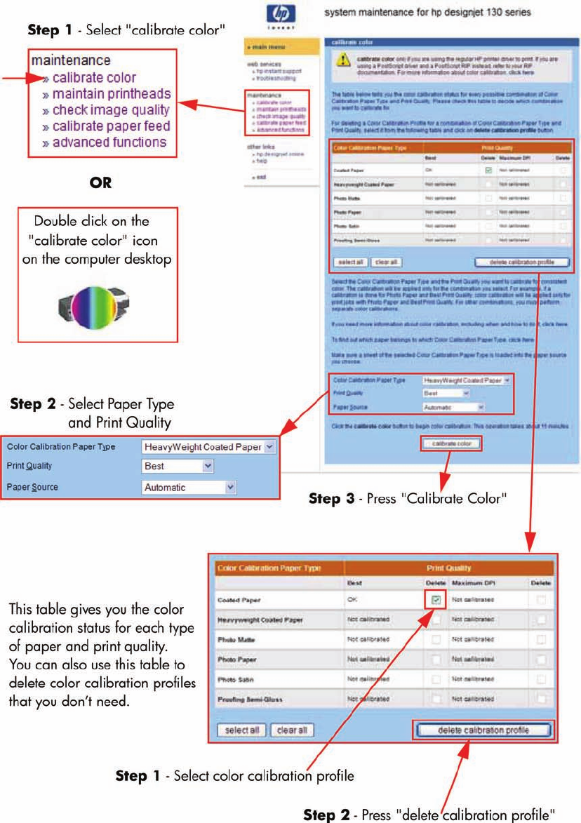
This picture shows an exaggerated example of how a printout
could look like before and after color calibration.
40 Chapter 3 System Maintenance Utility ENWW

Question Answer
When do I calibrate color? It is recommended that you calibrate color every time you
replace a printhead or when you perceive color degradation on
the printouts. There is no need to perform this operation each
time you print. The results of the color calibration will be applied
to all print jobs that follow, even if you power off the printer.
Perform color calibration if you print with the regular hp
designjet 120 printer driver, which was included with the printer
or which you downloaded from the Web. If you use a PostScript
driver such as Adobe PS or LaserWriter to print through a
PostScript RIP provided by HP or another third-party company,
the results of calibrate color will not be applied to your print
jobs. In this case, refer to your PostScript RIP documentation
for information on how to perform color calibration.
How do I calibrate color? You have to calibrate color for every Paper Type that requires
color consistency. For example, if you require consistent colors
on glossy paper and on heavy weight coated paper, you must
perform one color calibration for the former and another for the
latter Paper Type.
When you want to calibrate color, remember to select the Print
Quality option that you are going to use to print. For example,
if you want to print with the High Resolution option, select High
Resolution before performing the color calibration.
NOTE: If the Color calibration fails, print the information page
and check the list of warnings under the printer status section.
ENWW System Maintenance Utility (Designjet 30, 30n, 70, 90, 90r, 110plus, 111, 130, 130nr) 41
Performing the Color Calibration (HP DesignJet 30, 30n,130, 130nr)
▲The following shows how to perform the Color Calibration for the HP Designjet 30, 30n, 130, 130nr.
Performing the Color Calibration (HP DesignJet 90, 90r)
▲The following shows how to perform the Color Calibration for the HP Designjet 90 and 90r.
42 Chapter 3 System Maintenance Utility ENWW
ENWW System Maintenance Utility (Designjet 30, 30n, 70, 90, 90r, 110plus, 111, 130, 130nr) 43
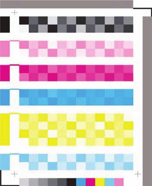
Sample of the Color Calibration Print:
▲Shown below is what the Color Calibration print looks like.
44 Chapter 3 System Maintenance Utility ENWW
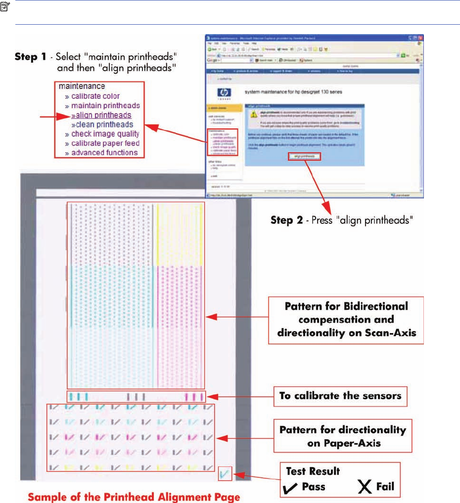
Align Printheads
Align printheads performs a maintenance function with the printheads. Proper alignment insures
correct registration between ink colors while printing. This is only recommended if you are experiencing
problems with print quality.
Before you continue, please verify that three sheets of paper are loaded in the default tray. If the
printhead alignment fails on the first attempt, the printer will retry the alignment twice.
NOTE: Do not power off the printer during this operation. The printer display will indicate busy until
the operation is finished.
ENWW System Maintenance Utility (Designjet 30, 30n, 70, 90, 90r, 110plus, 111, 130, 130nr) 45
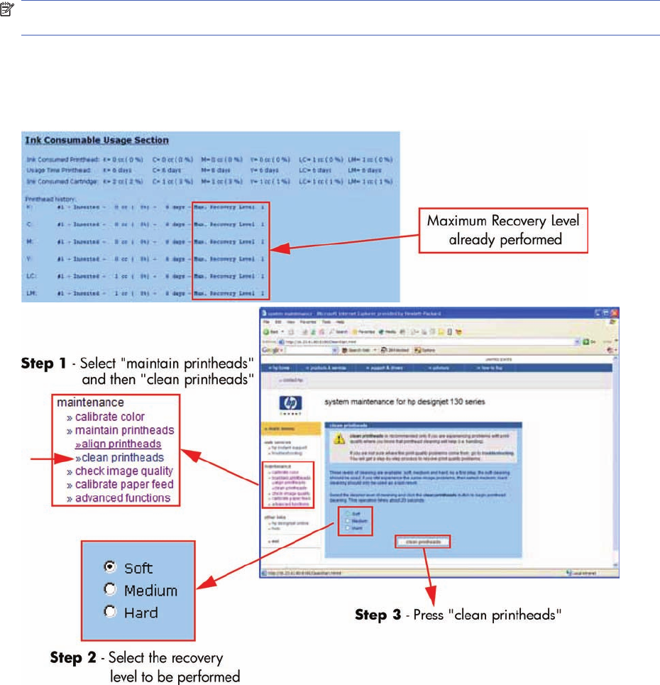
Clean Printheads
Clean printheads helps maintain proper operation of all nozzles in the printheads. This is only
recommended if you are experiencing problems with print quality such as banding.
Three levels of cleaning are available: soft, medium and hard. As a first step, the soft cleaning should
be used. If you still experience the same image problems, then select medium. Hard cleaning should
only be used as a last resort.
NOTE: Do not power off the printer during this operation. The printer display will indicate busy until
the operation is finished.
Before cleaning the printheads, first check the maximum recovery level already performed on the
printheads. If hard level (Recovery Level 3) has already been performed, then do not try performing
hard level again. The Maximum Recovery Level can be seen on the Printer Information page in the
"Printhead History" section.
46 Chapter 3 System Maintenance Utility ENWW
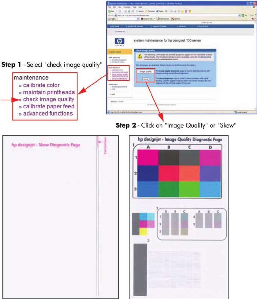
Check Image Quality
Check image quality provides two diagnostic pages for printing. The following test pages are available:
●Image Quality Diagnostic page.
●Skew Diagnostic page.
These commands only print the diagnostic pages and do not provide the actual analysis of the results.
ENWW System Maintenance Utility (Designjet 30, 30n, 70, 90, 90r, 110plus, 111, 130, 130nr) 47
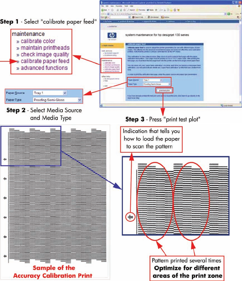
Calibrate Paper Feed
Calibrate paper feed is used to adjust the printer parameters for use with different types of print media.
This only affects the physical movement of paper and does not affect the color calibration profiles.
This calibration is a two-step process. Step one is to print a special test page with the paper calibration
test pattern. This page must be printed on A3 or 11x17 paper sizes. After printing the test page, you
must feed the test page back into the printer via the front single-sheet paper feed.
Once the Accuracy Calibration has been printed, rotate the page and reload it upside down (image
facing down).
48 Chapter 3 System Maintenance Utility ENWW
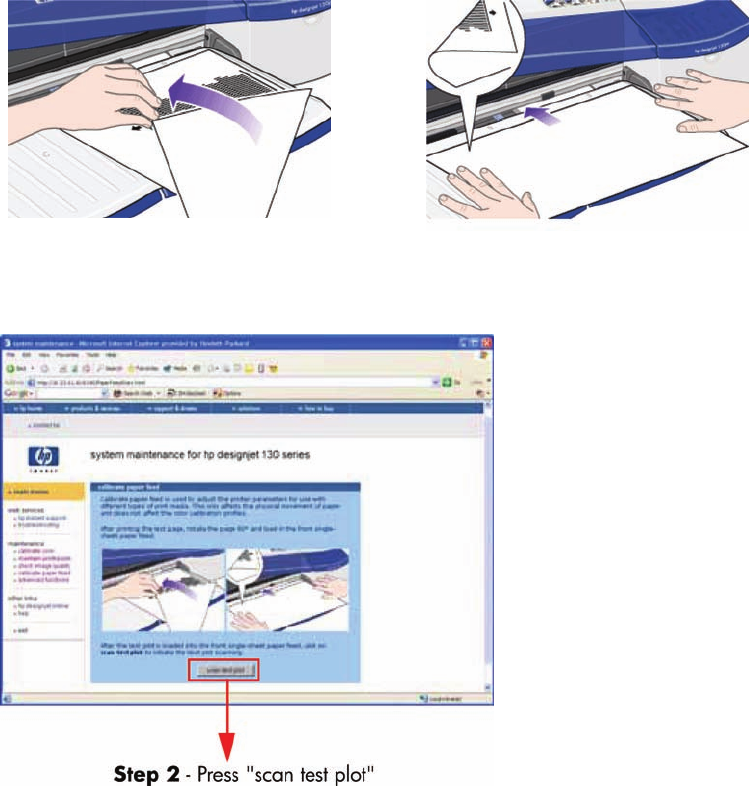
Step 1 - Rotate the page and reload it upside down (image facing down).
Step 2 - Press scan test plot.
ENWW System Maintenance Utility (Designjet 30, 30n, 70, 90, 90r, 110plus, 111, 130, 130nr) 49
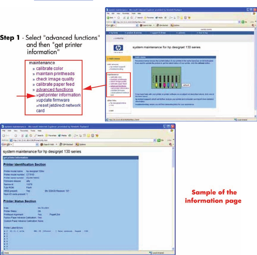
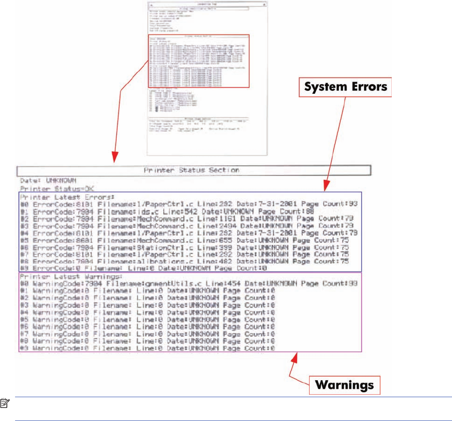
Get Printer Information
This option allows you to view all the information available on the Printer:
●Printer Identification.
●Printer Status.
●Printer Job Queue.
●Printer Errors and Warnings.
●Printer Usage.
●Ink Consumable Identification.
●Ink Consumable Status.
●Ink Consumable Usage.
●Network Card Information.
Refer to the Test Prints on page 1 chapter for explanations on each section.
50 Chapter 3 System Maintenance Utility ENWW
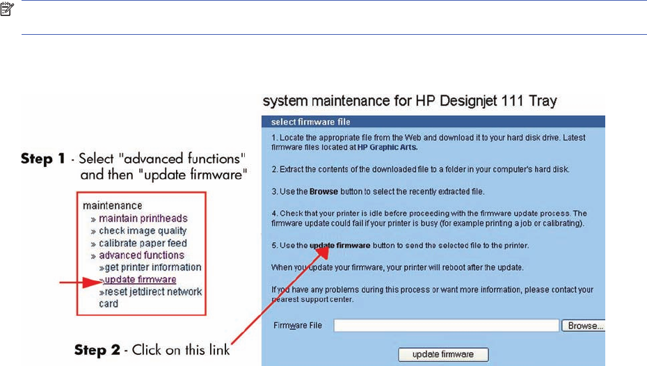
Update Firmware
Update firmware updates the built-in software of the printer.
NOTE: Do not power off the printer during this operation. The printer display will indicate busy until
the operation is finished.
The first steps will check to see if a newer version of the printer's software is available at hp.com. If there
is new software available, follow the on-screen instructions to upgrade the printer software.
ENWW System Maintenance Utility (Designjet 30, 30n, 70, 90, 90r, 110plus, 111, 130, 130nr) 51
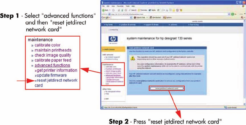
Reset Jetdirect Network Card
Use this function to reset the HP Jetdirect Network card configuration to the factory defaults. This should
only be used if the HP Jetdirect Network card is not responding and no other recovery method works.
Any user configuration information, for example the IP address, will be lost. In this case the system
maintenance utility will not be able to communicate with the printer using the network.
The HP Jetdirect Network card will need to be reconfigured, using WebJetAdmin for example, after this
reset.
52 Chapter 3 System Maintenance Utility ENWW

4 Utilities
Utilities
The following Utilities are available through the printer:
1. Enable/disable buzzer, refer Enable/Disable Buzzer on page 54.
This utility allows you to switch Off or On the internal buzzer.
2. Transport Position, refer Transport Position on page 54.
This utility allows you to put the printer in a stable condition before transporting it to another location.
3. Printhead Recovery, refer Printhead Recovery on page 55.
This utility helps maintain proper operation of all nozzles in the printheads. This is only
recommended if you are experiencing problems with print quality such as banding.
4. Network Card Reset, refer Network Card Reset on page 56.
Use this utility to reset the HP Jetdirect card configuration to the factory defaults. This should only
be used if the HP Jetdirect card is not responding and no other recovery method works.
5. Set to Factory Defaults, refer Set to Factory Defaults on page 56. RESTRICTED ACCESS
Use this utility to return to the default settings that were set in the factory.
6. Hard EEPROM reset, refer Hard EEPROM reset on page 57. RESTRICTED ACCESS
This utility allows you to reset the EEPROM inside the Printer.
7. Set Flag to Prime Tubes, refer Set Flag to Prime Tubes on page 57. RESTRICTED ACCESS
The purpose of this utility is to prime the Ink Supply Tubes after they have been replaced (or if a
situation arises where you need to force the priming).
ENWW Utilities 53
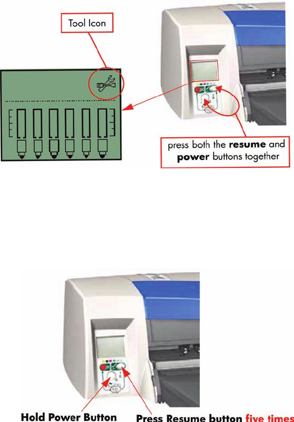
How to Access Restricted Access Utilities
Some of the Service Utilities are restricted to HP qualified personnel only. To access these restricted
service utilities, while the printer is switched OFF, press both the resume and power buttons together
until the Tool icon appears on the front panel.
Enable/Disable Buzzer
This utility allows you to switch Off or On the internal buzzer.
Switch Off or On the buzzer as follows:
1. Hold the power button down and press the cancel button five times.
2. Turn the Printer Off and then On again.
Transport Position
This utility allows you to put the printer in a stable condition before transporting it to another location.
Place the Printer in Transport Position as follows:
54 Chapter 4 Utilities ENWW
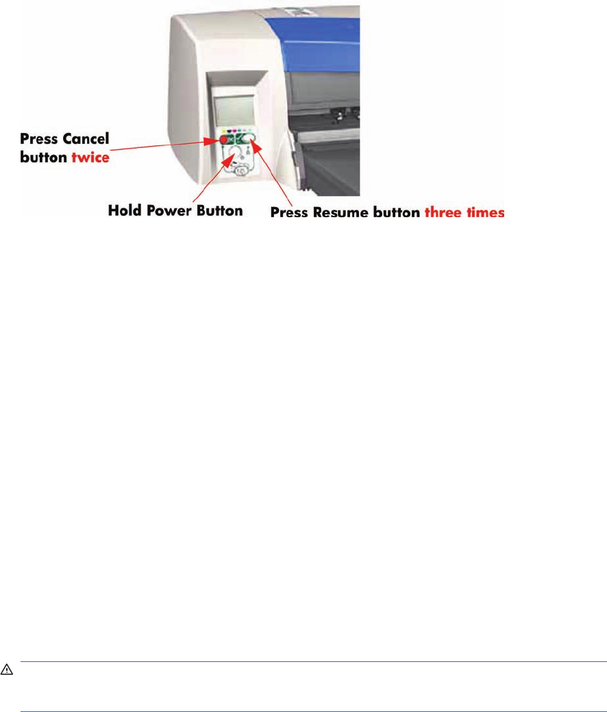
▲Hold the power button down and press the cancel button twice and the resume button three
times.
Printhead Recovery
This utility helps maintain proper operation of all nozzles in the printheads. This is only recommended
if you are experiencing problems with print quality such as banding.
Three levels of recovery are available: soft, medium and hard. As a first step, the soft recovery should
be used. If you still experience the same image problems, then select medium. Hard recovery should
only be used as a last resort.
Before recovering the printheads, first check the maximum recovery level already performed on the
printheads. If hard level (Recovery Level 3) has already been performed, then do not try performing
hard level again. The Maximum Recovery Level can be seen on the Printer Information page in the
"Printhead History" section.
Perform the Printhead Recover as follows:
▲Depending on the Recovery level, hold the power button down and then press:
●For level 1 (soft) - the cancel button twice.
●For level 2 (medium) - the cancel button twice and the resume button once.
●For level 3 (hard) - the cancel button twice and the resume button twice.
Some Light Magenta Printheads will show degradation after 150cc of usage. This results in certain
shift to green. If both of these conditions, 150cc and up and shift to green are apparent, then the
following Printhead Recovery has to be performed.
WARNING! This Printhead Recovery is quite strong and should only be executed when both of
the above conditions occur. Also, before performing the Light Magenta Printhead Recovery, make
sure that the Network, USB or Parallel cable is disconnected from the Printer.
●For Light Magenta Printhead degradation (standard recovery) - the cancel button twice and
the resume button five times.
A less aggressive recovery can be performed as well, currently it is not in use:
●For Light Magenta Printhead degradation (light recovery) - the cancel button twice and the
resume button four times.
ENWW Utilities 55
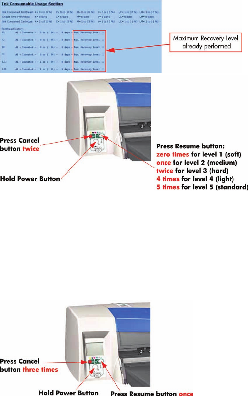
Network Card Reset
Use this utility to reset the HP Jetdirect card configuration to the factory defaults. This should only be
used if the HP Jetdirect card is not responding and no other recovery method works.
Any user configuration information, for example the IP address, will be lost. In this case the computer
will not be able to communicate with the printer using the network.
The HP Jetdirect card will need to be reconfigured, using WebJetAdmin for example, after this reset.
Reset the Network Card as follows:
▲Hold the power button down and press the cancel button three times and the resume button
once.
Set to Factory Defaults
Use this utility to return to the default settings that were set in the factory.
56 Chapter 4 Utilities ENWW
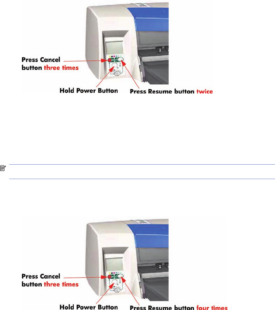
Return to Factory Defaults as follows:
▲Hold the power button down and press the cancel button three times and the resume button
twice.
Hard EEPROM reset
This utility allows you to reset the EEPROM inside the Printer. A hard EEPROM reset is ONLY
recommended when you need to install a used Electronics Module in a different Printer. This is because
there is a discrepancy between the values of the Carriage EEPROM and the Electronics Module EEROM
and since the values of the Electronics Module EEPROM are incorrect, a hard EEPROM reset will empty
the Electronics Module EEPROM. This will then force the Electronics Module EEPROM to collect the
values from the Carriage EEPROM when the Printer is next powered up.
NOTE: After a hard EEPROM reset, the Printer will act like a new Printer and try to prime the Ink
Supply Tubes when the Printer is next powered up.
Reset the EEPROM as follows:
▲Hold the power button down and press the cancel button three times and the resume button four
times.
Set Flag to Prime Tubes
The purpose of this utility is to prime the Ink Supply Tubes after they have been replaced (or if a situation
arises where you need to force the priming procedure).
Prime the Ink Supply Tubes as follows:
ENWW Utilities 57
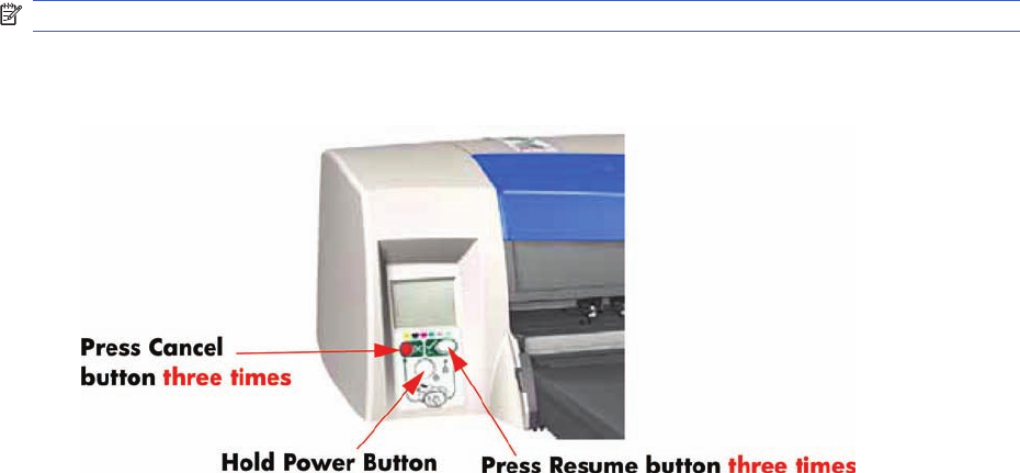
NOTE: Make sure that you install Printheads that haven’t had priming already done to them.
1. Hold the power button down and press the cancel button three times and the resume button three
times.
2. Switch Off the printer and then On again in order to start the priming of the Ink Supply Tubes.
58 Chapter 4 Utilities ENWW

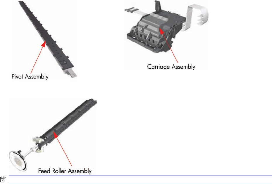
PRS Adjustment
When Required
It is very important that you perform the PRS Adjustment whenever:
●The Pivot Assembly is removed or replaced.
●The Feed Roller Assembly is removed or replaced.
●The Carriage Assembly is replaced (it is not necessary to perform the PRS Adjustment if the
carriage is reseated).
NOTE: B-size printers do not need Prs Adjustment.
Manual PRS Adjustment
The purpose of the Manual PRS Adjustment is to adjust the distance between the Carriage Assembly
and the Pivot Assembly. This adjustment is necessary in order to prevent problems like Printhead
crashes.
Perform the Manual PRS Adjustment as follows:
The Manual PRS Adjustment should be carried out using the Carriage Height Tool.
60 Chapter 5 Calibrations ENWW
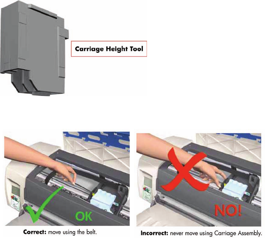
During the Manual PRS Adjustment procedure the Carriage Assembly has to be moved along
the length of the printer. Make sure that the Carriage Assembly is only ever moved by pulling
the belt and never by direct contact with the Carriage itself.
1. Turn On the Printer and open the Printhead Access Door.
Make sure that you turn ON the Printer, otherwise you will NOT be able to open the Carriage
Cover.
ENWW Manual PRS Adjustment 61
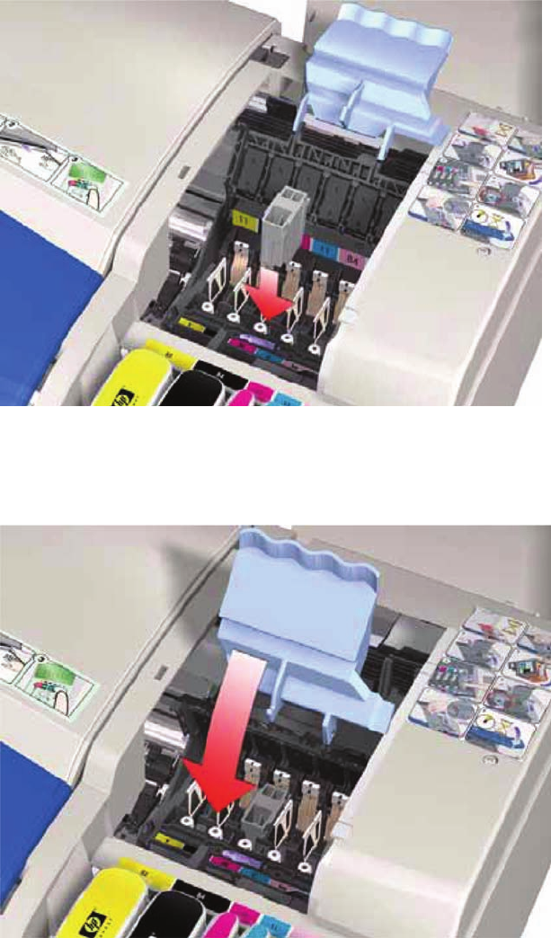
2. Open the Carriage Cover and install the Carriage Height Tool into the Magenta Stall - Make sure
ALL the other printheads are already removed from the Carriage Assembly.
3. Close the Carriage Cover and switch OFF the Printer.
Make sure that you turn OFF the Printer, otherwise you will NOT be able to manually move
the Carriage Assembly.
62 Chapter 5 Calibrations ENWW
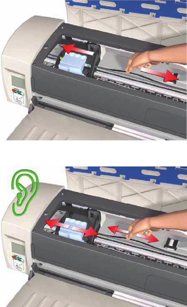
4. Move the Carriage Assembly to the left hand side of the Printer (to the position shown).
5. Using the belt, move the Carriage Assembly backwards and forwards over the Pivot Assembly (but
staying on the left hand side of the printer), carefully listening for a scraping sound.
ENWW Manual PRS Adjustment 63

6. If you hear a scraping sound, that means that the Pivot Assembly is too high and needs to be
lowered slightly. Lower the Pivot Assembly slightly by turning the T-8 screw 1/8
th
of a turn clockwise
and then check for a scraping sound again as shown previously in step 5.
Figure 5-1 Cross-Section - Lowering the Pivot Assembly
64 Chapter 5 Calibrations ENWW
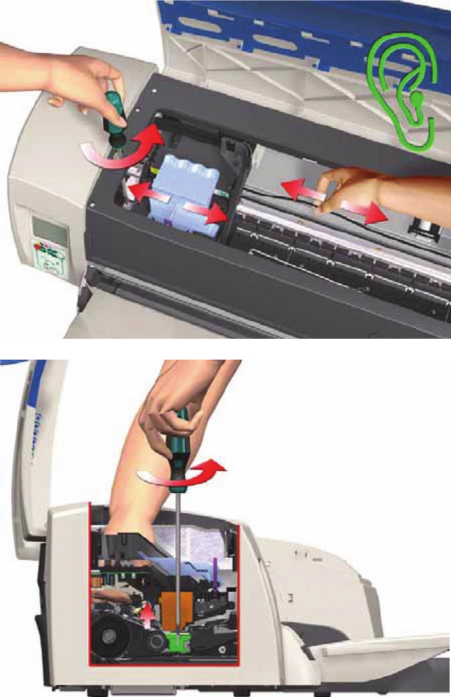
7. If you don’t hear a scraping sound, that means that the Pivot Assembly is too low and needs to be
raised slightly. Raise the Pivot Assembly slightly by turning the T-8 screw 1/8
th
of a turn anti-
clockwise and then check for a scraping sound again as shown previously in step 5.
Figure 5-2 Cross-Section - Raising the Pivot Assembly
ENWW Manual PRS Adjustment 65
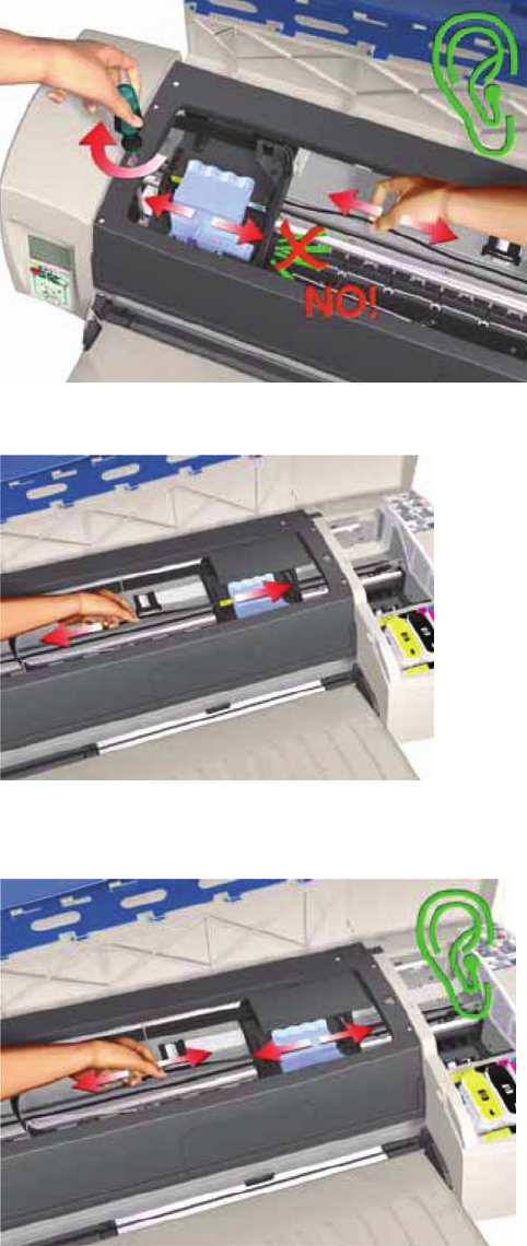
8. Repeat steps 5 to 7 until you reach a point where you will hear the scraping sound and by turning
the screw just 1/8
th
of a turn clockwise, the scraping sound will disappear.
9. Move the Carriage Assembly to the right hand side of the Printer (to the position shown).
10. Using the belt, move the Carriage Assembly backwards and forwards over the Pivot Assembly (but
staying on the right hand side of the printer), carefully listening for a scraping sound.
66 Chapter 5 Calibrations ENWW
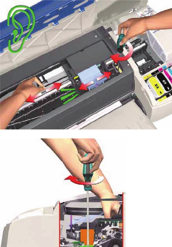
11. If you hear a scraping sound, that means that the Pivot Assembly is too high and needs to be
lowered slightly. Lower the Pivot Assembly slightly by turning the T-8 screw 1/8
th
of a turn clockwise
and then check for a scraping sound again as shown previously in step 10.
Figure 5-3 Cross-Section - Lowering the Pivot Assembly
ENWW Manual PRS Adjustment 67
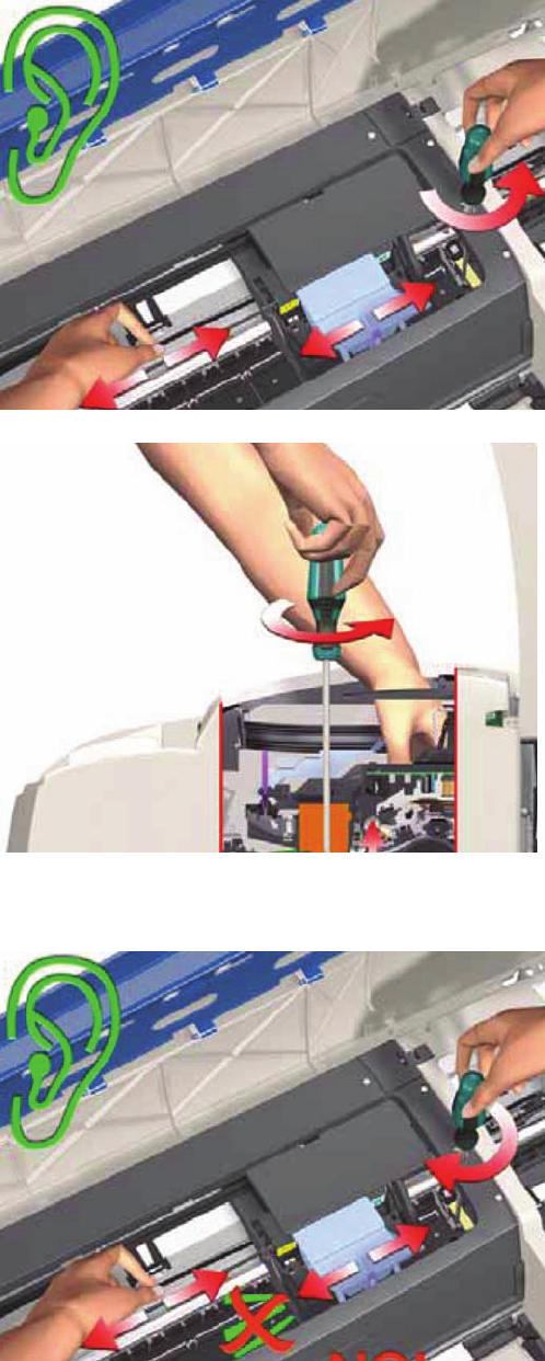
12. If you don’t hear a scraping sound, that means that the Pivot Assembly is too low and needs to be
raised slightly. Raise the Pivot Assembly slightly by turning the T-8 screw 1/8
th
of a turn anti-
clockwise and then check for a scraping sound again as shown previously in step 10.
Figure 5-4 Cross-Section - Raising the Pivot Assembly
13. Repeat steps 10 to 12 until you reach a point where you will hear the scraping sound and by turning
the screw just 1/8
th
of a turn clockwise, the scraping sound will disappear.
14. Move the Carriage Assembly along the length of the Printer, listening carefully for the scraping
sound.
68 Chapter 5 Calibrations ENWW
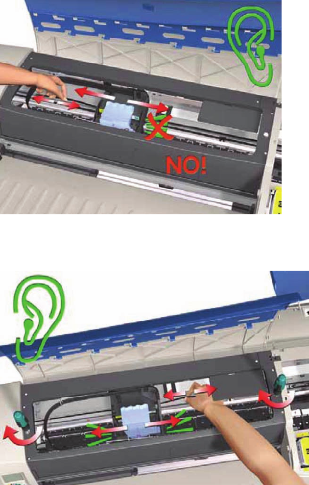
15. If you don’t hear the scraping sound, then the PRS Adjustment is correct, go to step 17.
16. If you hear the scraping sound, then you will need to lower the Pivot Assembly slightly by turning
the T-8 screw 1/8
th
of a turn clockwise on both the left and right hand side of the Pivot Assembly.
Check for a scraping sound again as shown previously in step 14.
ENWW Manual PRS Adjustment 69
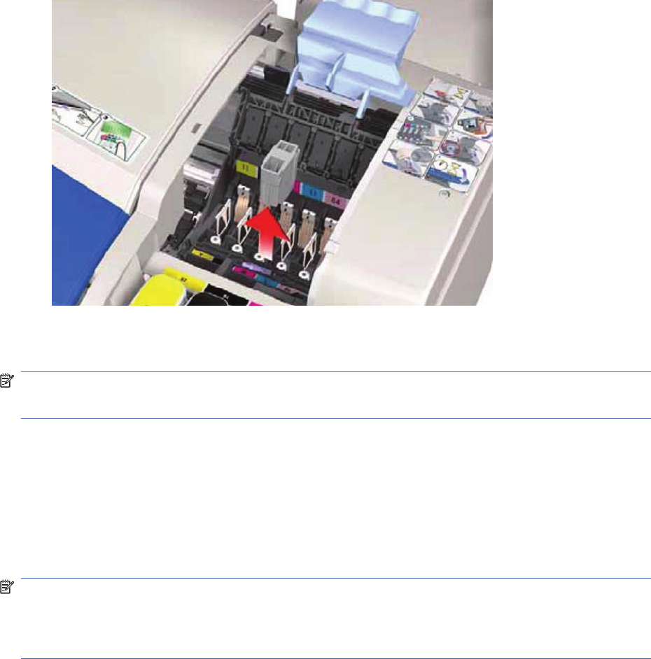
17. Remove the Carriage Height Tool.
Factory Accuracy Calibration
NOTE: The Accuracy Calibration should ONLY be performed by a qualified Service Engineer.
Restricted Access
The Factory Accuracy Calibration needs to be performed whenever:
●Banding is detected in printed images.
●The Feed Roller Assembly is disassembled or replaced.
●The Paper-Axis Motor Drive Assembly is disassembled or replaced.
●The Encoder Disc is removed or replaced.
NOTE: Ensure that you use HP Professional High-gloss Contract Proofing Paper (Q8662A) in order
to perform the Factory Accuracy Calibration.
NOTE: The B size printer (HP Designjet 30 Printer series) needs at least firmware B.05.XX to be able
to perform this calibration
Perform the Accuracy Calibration as follows:
1. Load HP Professional High-gloss Contract Proofing Paper (Q8662A) in to the input tray (HP
Designjet 111 with Roll: load the sheet via the front single-sheet paper feed).
70 Chapter 5 Calibrations ENWW
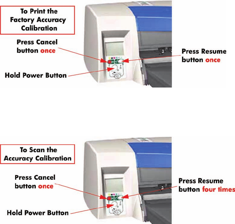
2. To manually print the Factory Accuracy Calibration, hold the power button down and press the
cancel button once and the resume button once.
3. Once the Accuracy Calibration has been printed, rotate the page and reload it upside down (image
facing down).
4. To scan the Accuracy Calibration, hold the power button down and press the cancel button once
and the resume button four times.
ENWW Factory Accuracy Calibration 71
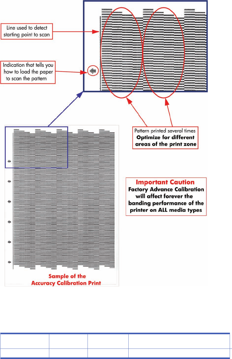
Parts replacement and associated calibrations
Following the removal and replacement of some components, it is important that calibrations are
performed immediately afterwards. Shown below is a table describing which parts require calibrations
when they are replaced, and the order in which you should perform the calibrations.
Description of service
part Media Advance
Calibration PRS Calibration PRS Calibration
Print Platen SV 1 2
72 Chapter 5 Calibrations ENWW

Pick Roller SV 1 2 3
Feed Roller 1 2 3
Inner Paper G SV 1 2 3
Carriage Belt SV 1
Lower Paper Guide Bits
SV
1 2 3
Bypass Platen 1 2 3
Bypass Actuator 1 2 3
Carriage SV 1 2
Tubes SV 1
Pivot SV 1 2
Electronics Module 1
Disk Encoder 1 2
ENWW Parts replacement and associated calibrations 73

6 Parts and Diagrams
●Cover Assemblies
●Cover Assemblies
●Printer Labels
●Right Hand Assemblies
●Left Hand Assemblies
●Scan-Axis Assemblies
●Top Paper Path Assemblies (1 of 2)
●Top Paper Path Assemblies (2 of 2)
●Rear Paper Path Assemblies
●Paper Feed Assemblies
●Cable Harnesses
●Ink Supplies and Accessories (1 of 2)
●Ink Supplies & Accessories (2 of 2)
●Rollfeed Components
●Printer Stand and Basket
74 Chapter 6 Parts and Diagrams ENWW
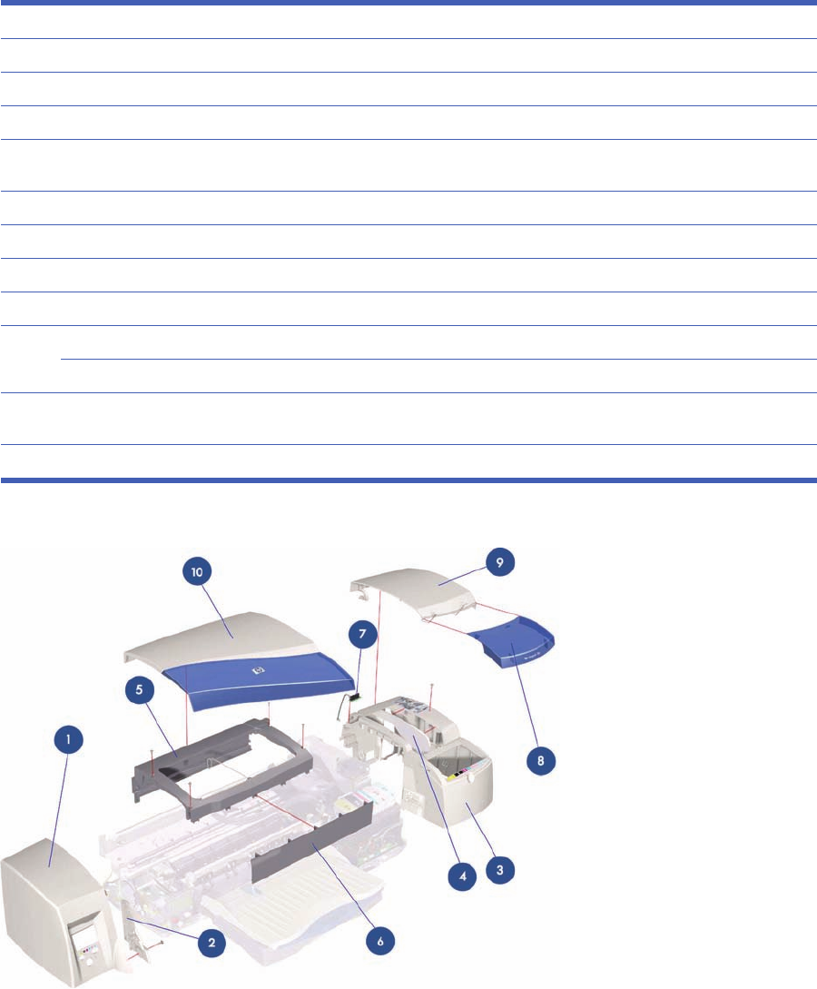
Cover Assemblies
Applicable Designjets: Only 30 series
Cover Assemblies
Ref HP Part Number Qty Description/Comments
1C7790-60447 1Left Cover (Includes Front Panel Label)
2Q1293-67003 1Left Trim
3C7790-60456 1Right Cover (includes Right Trim, Instruction Label, Ink Family Number Label
and Ink Color Label)
4Q1293-67000 1Filter Assembly
5C7790-60100 1Back Cover (Center Cover)
6C7790-60102 1Front Cover
7Q1292-67022 1Door Sensor Assembly
8C7790-60452 1Ink Cartridge Door 30
C7790-60453 1Ink Cartridge Door 30n
9C7790-60457 1Printhead Door Assembly (includes Ink Cartridge Door Hinge and Printhead
Door Label)
10 C7790-60443 1 Access Door Assembly
Figure 6-1 Cover Assemblies
ENWW Cover Assemblies 75

Cover Assemblies
Cover Assemblies
Reference HP Part Number Quantit
yDescription/Comments
1C7791-60300 1Left Cover (Includes Front Panel Label) (Applicable to 130 series)
C7796-60018 1Left Cover (Includes Front Panel Label) (Applicable to 110+ series)
Q6655-60091 1Left Cover (Includes Front Panel Label) (Applicable to 70)
C7791-60300 1Left Cover (Includes Front Panel Label) (Applicable to 90 series)
CQ532–67016 1Left Cover (Includes Front Panel Label) (Applicable to 111)
2Q1292-60271 1Right Cover (Applicable to 90 series, 130 series)
C7796-60064 1Right Cover (Applicable to 70, 110+ series)
CQ532–67004 1Right Cover CAD W/ Win Label S (Applicable to 111)
3Q1292-67009 1Filter Assembly
4Q1292-60258 1Back Cover (Center Cover) (Applicable to 130 series)
C7796-60223 1Back Cover (Applicable to 110+ series)
Q6655-60153 1Back Cover (Applicable to 70)
Q6656-60108 1Back Cover (Applicable to 90 series)
CQ532–67001 1Back Cover (Applicable to 111)
5Q1292-67022 1Door Sensor Assembly
6Q6655-60093 1Ink Cartridge Door (Applicable to 70)
Q6656-60064 1Ink Cartridge Door (Applicable to 90)
Q6656-60079 1Ink Cartridge Door (Applicable to 90r)
C7791-60294 1Ink Cartridge Door (Applicable to 130, 130r)
C7791-60295 1Ink Cartridge Door (Applicable to130nr)
C7796-60094 1Ink Cartridge Door (Applicable to100+)
C7796-60095 1Ink Cartridge Door (Applicable to 110+, 110r)
C7796-60106 1Ink Cartridge Door (Applicable to 110+nr)
CQ532–67005 1Ink Cartridge Door (Applicable to 111)
7C7790-60457 1Printhead Door Assembly (includes Ink Cartridge Door Hinge and
Printhead Door Label) (Applicable to 90 series, 130 series)
C7796-60021 1Printhead Door Assembly (includes Ink Cartridge Door Hinge and
Printhead Door Label) (Applicable to 70, 110+ series, 111)
8 C7791-60277 1Access Door Assembly (Applicable to 130 series)
C7796-60020 1Access Door Assembly (Applicable to 110+ series)
Q6655-60094 1Access Door Assembly (Applicable to 70)
Q6656-60065 1Access Door Assembly (Applicable to 90 series)
CQ532–67002 1Access Door Assembly (Applicable to 111)
76 Chapter 6 Parts and Diagrams ENWW
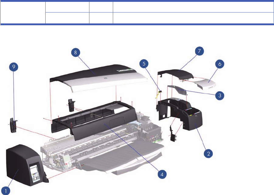
9C7796-67002 1Rear Trim Kit (Applicable to 70, 90 series, 110+ series, 130 series)
CQ532–67008 1Rear Trim Kit (Applicable 111)
Figure 6-2 Cover Assemblies
ENWW Cover Assemblies 77
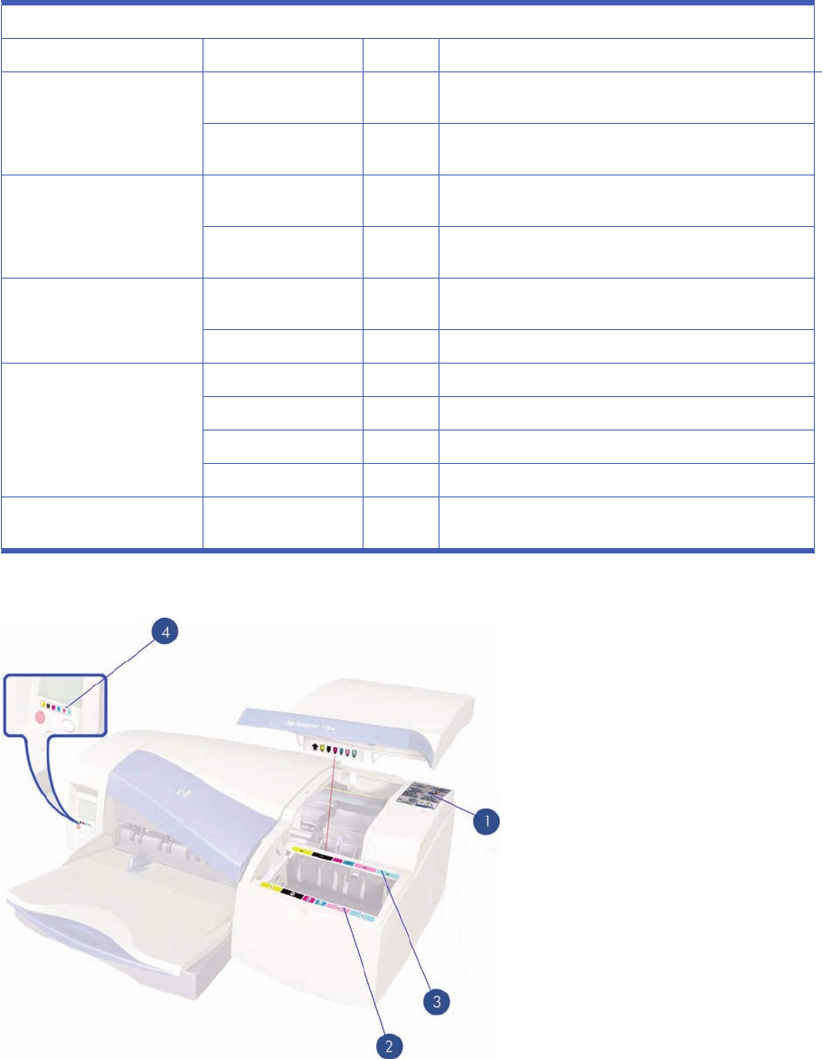
Printer Labels
Printer Labels
Reference on Drawing HP Part Number Quantity Description/Comments
1C7790-60450 1Printhead Access Instructions Label (Applicable to 30
series, 90 series, 130 series)
C7796-60041 1Printhead Access Instructions Label (Applicable to 70,
110+ series, 111)
2C8109-67002 Ink Cartridge Color Label (Applicable to 70, 110+ series,
111)
C7790-60201 Ink Cartridge Color Label (Applicable to 30 series, 90
series, 130 series)
3C7790-60449 1Ink Cartridge Family Label (Applicable to 30 series, 90
series, 130 series)
C8109-67003 1Ink Cartridge Family Label (Applicable to 70, 100+ series)
4Q6655-60096 1Front Panel Label (Applicable to 70)
C7790-60451 1Front Panel Label (Applicable to 30 series, 130 series)
C7796-60042 1Front Panel Label (Applicable to 110+ series)
CQ532–67003 1Front Panel (Applicable 111)
C7791-60228 1Load Rollfeed Label (Applicable to 90r, 130nr, 110+, 110
+nr, 120nr, 130nr)
Figure 6-3 Printer Labels
78 Chapter 6 Parts and Diagrams ENWW

Right Hand Assemblies
Right Hand Assemblies
Referen
ce HP Part Number Quantity Description/Comments
1Q1293-60049 1Ink Supply Station Assembly (Applicable to 30 series, 90 series, 130 series)
C7796-60209 Ink Supply Station Assembly (Applicable to 70, 110+ series)
CQ532–67007 1Ink Supply Station Assembly (Applicable to 111)
2Q1292-67007 1ISS Bottom Foam (Applicable to 30 series, 90 series, 130 series)
C8109-67022 1ISS Bottom Foam (Applicable to 70, 110+ series, 111)
3C7796-67001 1ISS Rear Foam (Applicable to 70, 110+ series)
Q1292-67011 1ISS Rear Foam (Applicable to 30 series, 90 series, 130 series)
4Q1293-67006 1Electronics Module Assembly (Applicable to 30 series)
Q6655-60166 Electronics Module Assembly (Applicable to 70)
Q6656-69116 1Electronics Module Assembly (Applicable to 90 series)
Q1292-67034 1Electronics Module Assembly (Applicable to 130 series)
C7796-69156 1Electronics Module Assembly (Applicable to 110+ series)
CQ532–67006 1Electronics Module Assembly (Applicable to 111)
5Q1292-67033 1Power Supply Unit
6 Q1293-60052 1Service Station Assembly (Applicable to 30 series)
Q1292-60206 1Service Station Assembly (Applicable to 90 series, 130 series)
C7796-60203 1Service Station Assembly (Applicable to 70, 110+ series, 111)
ENWW Right Hand Assemblies 79
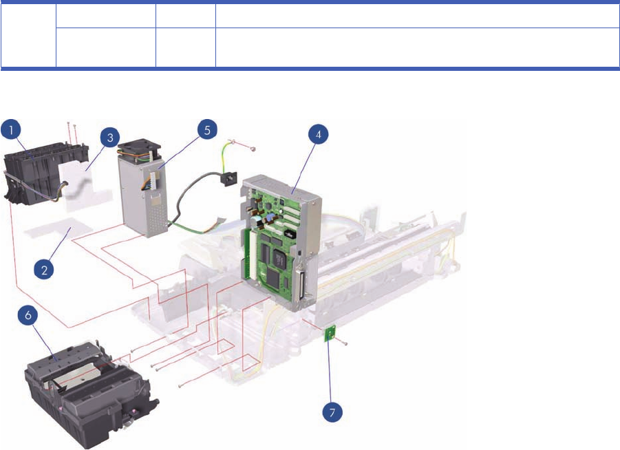
7 C8108-67031 1Cleanout Interconnect PCA (Applicable to 30 series)
Q1292-67020 1Cleanout Interconnect PCA (Applicable to 70, 90 series, 130 series, 110+ series,
111)
Figure 6-4 Right Hand Assemblies
80 Chapter 6 Parts and Diagrams ENWW
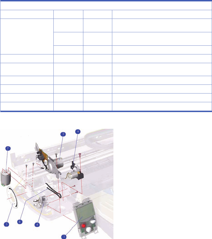
Left Hand Assemblies
Left Hand Assemblies
Reference on Drawing Part number Quantity Description/Comments
1Q1292-67021 1Front Panel Assembly (Includes Front Panel Cable)
(Applicable to 30 series, 70, 90 series, 130 series Printer)
C7796-67004 1Front Panel Assembly (Includes Front Panel Cable)
(Applicable to 110+ series)
CQ532–67009 1Front Panel Assembly (Applicable to 111)
2Q1292-60218 1LF Motor Assembly (Paper-Axis Motor)
3Q1292-60219 1Ramp Drive Assembly
4Q1293-60068 1Output Mechanism Support Assembly
5Q1292-67019 1Encoder Disc
7Q1292-60207 1Carriage Motor Assembly
8Q1292-67001 1Output Belt
Figure 6-5 Left Hand Assemblies
ENWW Left Hand Assemblies 81

Scan-Axis Assemblies
Scan-Axis Assemblies
Reference on Drawing HP Part Number Quantity Description/Comments
1Q1293-60046 1Carriage Assembly (Includes Trailing Cable)
(Applicable to 30 series)
Q1292-60202 1Carriage Assembly (Includes Trailing Cable)
(Applicable to 130 series)
Q6655-60121 1Carriage Assembly (Includes Trailing Cable)
(Applicable to 70)
Q6656-60094 1Carriage Assembly (Includes Trailing Cable)
(Applicable to 90 series)
C7796-60205 1Carriage Assembly (Includes Trailing Cable)
(Applicable to 110+ series, 111)
2Q1293-60065 1Tubes Assembly (Applicable to 30 series)
Q6655-60140 1Tubes Assembly (Applicable to 70)
Q6656-60103 1Tubes Assembly (Applicable to 90 series)
Q1292-60235 1Tubes Assembly (Applicable to 130 series)
C7796-60219 1Tubes Assembly (Applicable to 110+ series, 111)
3Q1293-67005 1Carriage Belt (Applicable to 30 series)
Q6655-67007 1Carriage Belt (Applicable to 70, 90 series)
Q1292-67026 1Carriage Belt (Applicable to 110+ series, series, 130
series, 111)
4Q6655-67006 1En coder Strip (Applicable to 70, 90 series)
Q1292-67003 1Encoder Strip (Applicable to 110+ series, 130 series)
5Q1292-60152 1Encoder Strip Holder
6Q1292-67005 1Tube Holder
7Q1292-67006 1Belt Tension Spring
8Q1293-67810 1Carriage Rod (Applicable to 30 series)
82 Chapter 6 Parts and Diagrams ENWW
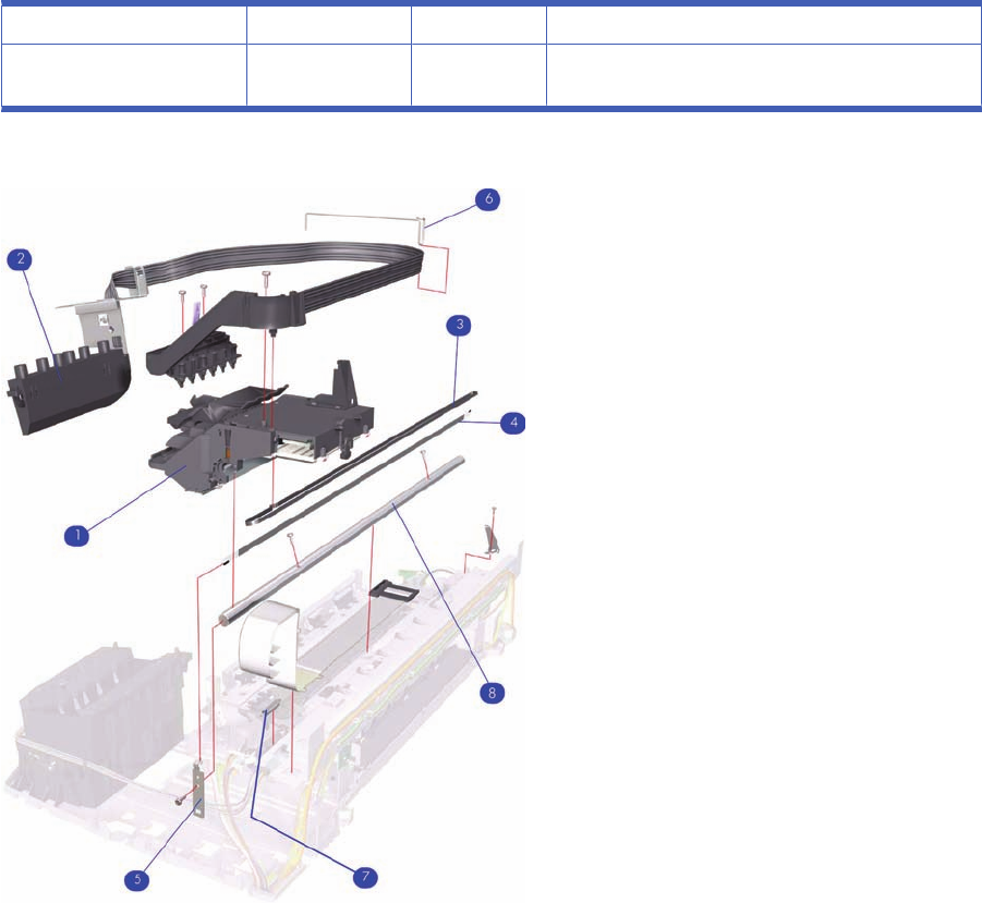
-C7790-60216 1Turnaround Assembly (Applicable to 30 series)
-C7791-60212 1Turnaround Assembly (Applicable to 70, 90 series, 110
+ series, 130 series)
Figure 6-6 Scan-Axis Assemblies
ENWW Scan-Axis Assemblies 83
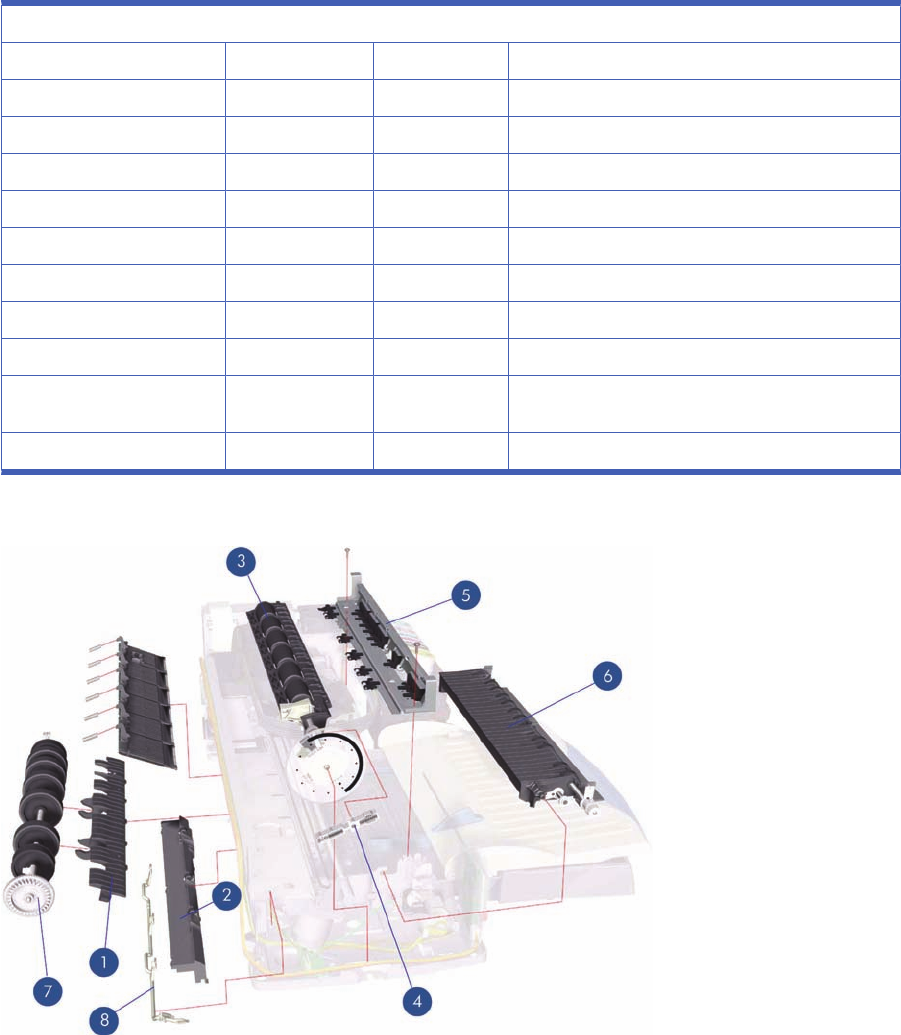
Top Paper Path Assemblies (1 of 2)
Applicable Designjets: 30 series
Top Paper Path Assemblies
Reference on Drawing HP Part Number Quantity Description/Comments
1C8108-67049 1Inner Paper Guide
2C8108-67043 1Lower Paper Guide
3Q1293-67809 1Feed Roller Assembly (Includes Encoder Disc)
4C8108-67035 1Pin Linkage Assembly
5C8108-67033 1Starwheel Assembly
6C8108-67041 1Print Platen (Includes Output Separator)
7C8108-67039 1Pick Roller Assembly
8C8108-67029 1Kicker Assembly
-C8108-67030 1Miscellaneous Plastic Parts (includes Plift Block, Pin
Caber, Pick Cam, FDRLR Idler Gear)
-Q1292-60150 1OPP Sensor Kit
Figure 6-7 Top Paper Path Assemblies
84 Chapter 6 Parts and Diagrams ENWW

Top Paper Path Assemblies (2 of 2)
Applicable Designjets: 70, 90 series, 110+ series, 130 series
Top Paper Path Assemblies
Reference on Drawing HP Part Number Quantity Description/Comments
1Q1292-60150 1OPP Sensor Kit
2Q6655-60122 1Feed Roller Assembly (Includes Encoder Disc and
Paper Axis Motor Assembly) (Applicable to 70, 90
series)
Q1292-60211 1Feed Roller Assembly (Includes Encoder Disc and
Paper Axis Motor Assembly) (Applicable to 110+
series, 130 series, 111)
3Q6655-60082 1Starwheel Assembly (Applicable to 70, 90 series)
C7791-60245 1Starwheel Assembly (Applicable to 110+ series,
130 series, 111)
4Q6655-60139 1Print Platen (Applicable to 70, 90 series)
Q1292-60227 1Print Platen (Applicable to 110+ series, 130 series,
111)
5C7791-60287 1Bypass Platen Kit (Applicable to 110+ series, 130
series, 111)
Q6655-60074 1Bypass Platen Kit (Applicable to 70, 90 series)
6C7796-60217 1Pivot Assembly (Applicable to 110+ series, 130
series, 111)
Q6656-60102 1Pivot Assembly (Applicable to 70, 90 series)
7Q1292-67017 1Pick Cam (Applicable to 70, 90 series, 110+ series,
130 series, 111)
ENWW Top Paper Path Assemblies (2 of 2) 85
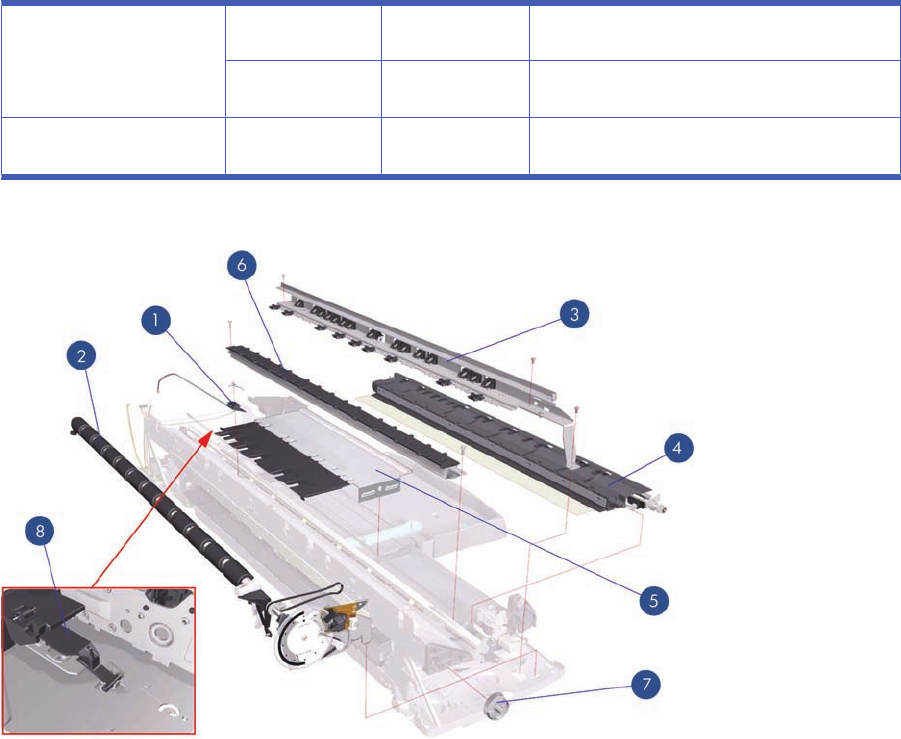
8C7791-60307 1Bypass Platen Actuator & Spring (Applicable to 110
+ series, 130 series, 111)
Q6655-67005 1Bypass Platen Actuator & Spring (Applicable to 70,
90 series)
-C8108-67030 1Misc Plastic Parts (includes Plift Block, Pin Caber,
Pick Cam, FDRLR Idler Gear)
Figure 6-8 Top Paper Path Assemblies
86 Chapter 6 Parts and Diagrams ENWW
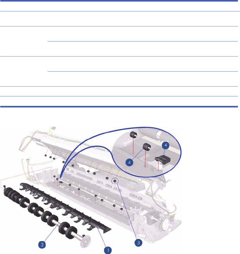
Rear Paper Path Assemblies
Rear Paper Path Assemblies
Reference on
Drawing HP Part
Number Quantity Description/Comments
1Q6655-67001 1Inner Paper Guide (Applicable to 70, 90
series)
Q1292-67023 1Inner Paper Guide (Applicable to 110+
series, 130 series, 111)
2Q1292-60210 1Pick Roller Assembly (Applicable to 110+
series, 130 series, 111)
Q6655-60123 1Pick Roller Assembly (Applicable only to
70, 90 series)
3Q1292-67015 1Upper Roller Kit
4 Q1292-67018 1 Lower Paper Guide Bits
Figure 6-9 Rear Paper Path Assemblies
ENWW Rear Paper Path Assemblies 87

Paper Feed Assemblies
Paper Feed Assemblies
Reference on Drawing HP Part Number Quantity Description/Comments
1C8108-67044 1Main Tray Assembly (Applicable to 30 series)
Q1292-60097 1Main Tray Assembly (Applicable to 70, 90, series,
110+ series, 130 series)
CQ532–67015 1Main Tray Assembly (Applicable to 111. with Tray)
2C7790-60448 1Output Tray Assembly (Applicable to 30 series)
Q6655-60101 1Output Tray Assembly (Applicable to 70)
Q6656-60072 1Output Tray Assembly (Applicable to 90, series)
C7791-60280 1Output Tray Assembly (Applicable to 130 series)
C7796-60063 1Output Tray Assembly (Applicable to 110+ series)
CQ532–67018 1Output Tray Assembly (Applicable to 111, With Tray)
3C8108-67050 1Drawer and Spring Cam
4 Q1293-60067 1Cleanout Assembly (Rear-Feed) (Applicable to 30
series)
Q1292-60283 1Cleanout Assembly (Rear-Feed) (Applicable to 110
+ series, 130 series)
Q6655-60159 1Cleanout Assembly (Rear-Feed) (Applicable to 70,
90 series)
CQ532–67011 1Cleanout Assembly (Applicable to 111)
88 Chapter 6 Parts and Diagrams ENWW
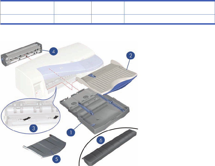
5C7791-60297 1Input tray Cover (Applicable to 70, 90 series, 110+
series, 130 series), 111 With Tray)
6CQ532–67013 1Output Platen (Applicable to 111, with Roll)
Figure 6-10 Paper Feed Assemblies
ENWW Paper Feed Assemblies 89
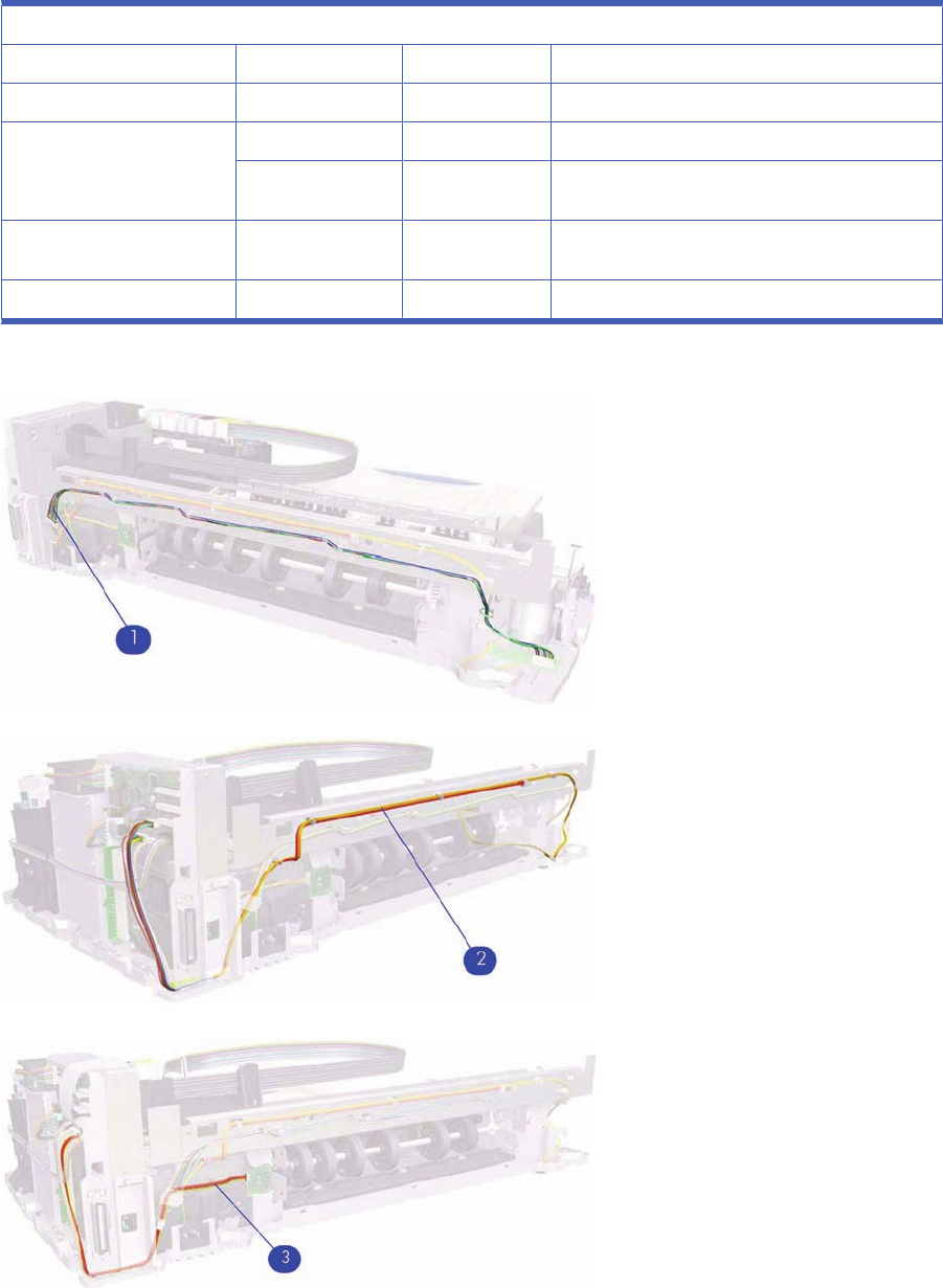
Cable Harnesses
Cable Harnesses
Reference on Drawing HP Part Number Quantity Description/Comments
1Q1292-67029 1Motor Harness (All products)
2Q1293-67002 1Encoder Harness (Applicable to 30 series)
Q1292-67014 1Encoder Harness (Applicable to 70, 90, seris, 110+
series, 130 series, 111)
3Q1292-67016 1Duplexer OOPS Harness (Applicable to 70, 90
series, 110+ series, 130 series, 111)
–Q1292-67010 1Front Panel Harness
Figure 6-11 Cable Harness
Figure 6-12 Cable Harness
Figure 6-13 Cable Harness
90 Chapter 6 Parts and Diagrams ENWW
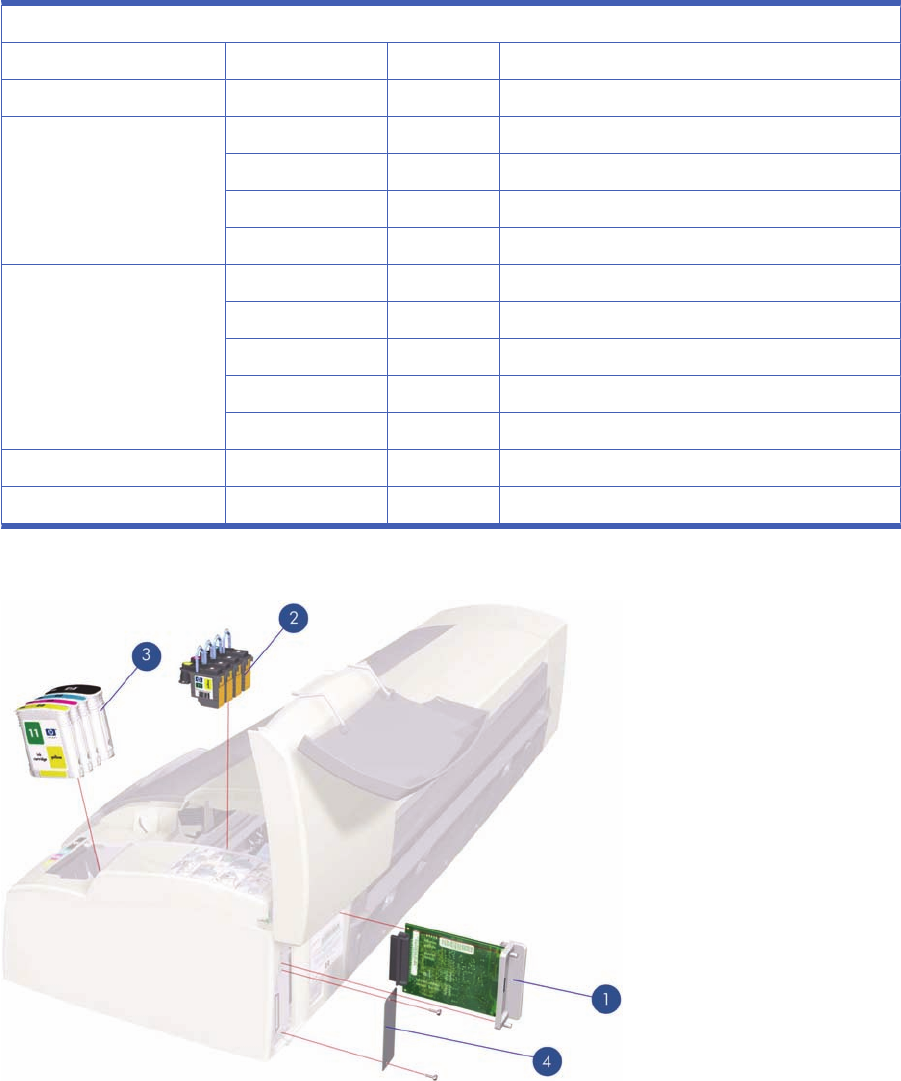
Ink Supplies and Accessories (1 of 2)
Applicable to Designjets: 110+ series, 70, 111
Ink Supplies and Accessories
Reference on Drawing HP Part Number Quantity Description/Comments
1J7934-69011 1Network Card
2C4810-60066 1Black Printhead
C4810-60067 1Cyan Printhead
C4812-60005 1Magenta Printhead
C4813-60004 1Yellow Printhead
3C4844-60053 1Black Ink Cartridge (Applicable to 70, 110+ series)
CH565A 1Black Ink Cartridge (Applicable to 111)
C4911-61002 1Cyan Ink Cartridge
C4912-61003 1Magenta Ink Cartridge
C4913-61003 1Yellow Ink Cartridge
4Q1292-67008 1Electronics End Cap
-C7790-60425 1USB Cable (5m)
Figure 6-14 Ink Supplies and Accessories
ENWW Ink Supplies and Accessories (1 of 2) 91
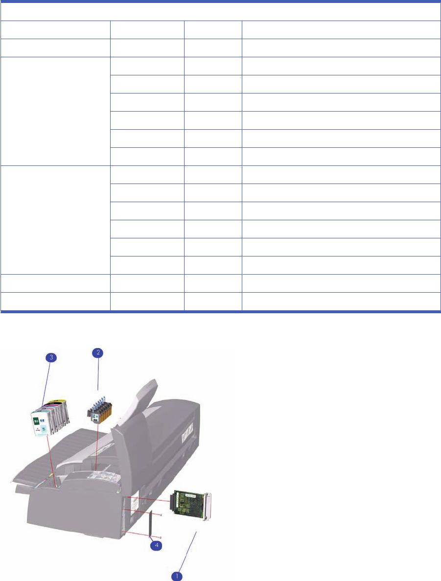
Ink Supplies & Accessories (2 of 2)
Applicable to Designjets: 30 series, 90 series, 130 series
Ink Supplies and Accessories
Reference on Drawing HP Part Number Quantity Description/Comments
1J7934-69011 1Network Card (Replacement)
2C5019-80008 1Black Printhead
C9420-88001 1Cyan Printhead
C9421-88001 1Magenta Printhead
C9422-88001 1Yellow Printhead
C9423-88001 1Light Cyan Printhead
C9424-88001 1Light Magenta Printhead
3C5016-80014 1Black Ink Cartridge
C9425-88001 1Cyan Ink Cartridge
C9426-88001 1Magenta Ink Cartridge
C9427-88001 1Yellow Ink Cartridge
C9428-88001 1Light Cyan Ink Cartridge
C9429-88001 1Light Magenta Ink Cartridge
4C7790-60217 1Electronics End Cap
-C7790-60425 11 USB Cable (5m)
Figure 6-15 Ink Supplies & Accessories
92 Chapter 6 Parts and Diagrams ENWW
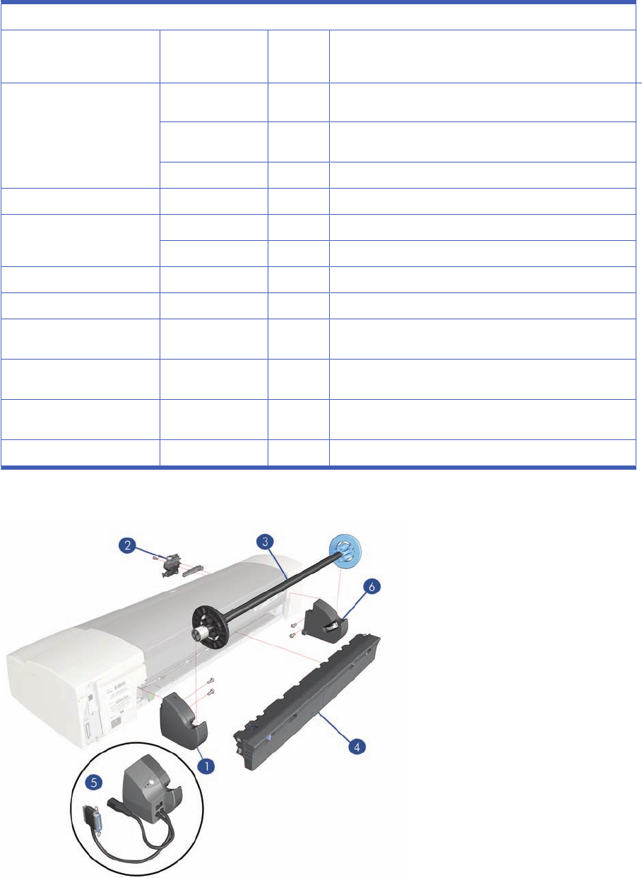
Rollfeed Components
Applicable to Designjets: 90r, 110+, 110+nr, 130nr, 111 with roll, 110+r, 130r, or as an accessory
Rollfeed Components
Reference on Drawing HP Part Number Qty Parts Description
1CQ532–67017 1Rollfeed Right Bracket (Applicable to 111)
C7791-60153 1Rollfeed Right Bracket (Applicable to 130nr, 130r, 110plus
nr, 110plus r)(without motor)
Q1292-60238 1Rollfeed Left & Right Bracket Kit (ROHS)
2Q1292-60064 1Cutter
3C7797-60008 1Spindle (130, 111, 110r, 110+
Q6655-60081 1Spindle (Applicable only to 70, 90, 90r)
4Q6655-60159 1Service cleanout C-Size packed (Applicable to 70, 90, 90r)
CQ532–67011 1Clean Out (Applicable to 111)
Q1292–60283 1CleanOut Manual Rollfeed (Applicable to 100+, 110plus,
130)
Q1247-60189 1Automatic Rollfeed Switching System Cleanout (Applicable
to 100, 110plus, 130)
5Q1247-60187 1Automatic Rollfeed Switching System bracket (Applicable to
100+nr, 130nr)
6CQ532–67019 1Rollfeed Left Bracket Kit (applicable 111)
Figure 6-16 Rollfeed Components
ENWW Rollfeed Components 93
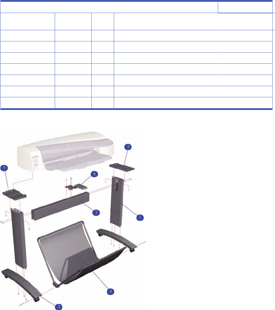
Printer Stand and Basket
Applicable Designjet 100+ series, 130 series
Printer Stand and Basket
Reference on
Drawing HP Part
Number Quantit
y
1Q1246-60007 2Legs Assembly
2Q1246-60008 1X-Brace Assembly
3Q1246-60009 2Foot Assembly
4Q1246-60010 1Basket Kit
5Q1246-60011 1Base Adaptor (Left and Right)
6Q1246-60012 1Input Tray Support
-Q1246-60013 1Hardware Kit
Figure 6-17 Printer Stand and Basket
94 Chapter 6 Parts and Diagrams ENWW

7 Removal and Installation
●Introduction
●Top Cover
●Front Cover (Applicability: 30, 30n, 50ps)
●Center Cover
●Right End Cover
●Left End Cover
●Ink Supply Station Cover (Applicability: 70, 100, 100plus, 110plus, 111)
●Ink Supply Station
●Electronics Module
●Power Supply Unit
●Service Station
●Front Panel
●Encoder Strip
●Carriage Motor
●Cleanout Assembly
●Ink Supply Tubes
●Carriage Assembly (Applicability: 70, 100+, 110+, 111)
●Carriage Assembly (Applicability: 30, 30nr, 90, 90r, 130, 130nr)
●Carriage Belt
●Starwheel Assembly (Applicability: 30, 30n)
●Starwheel Assembly
●Print Platen Assembly
●Output Separator (Applicability: 30, 30n)
●Ramp Motor Assembly
●Output Mechanism Assembly (Applicability: 30, 30n)
●Spittoon (If Installed in the Printer)
●Pivot Assembly
ENWW 95

●Feed Roller Assembly (Applicability: 30, 30n)
●Feed Roller Assembly
●Pick Assembly (Applicability: 30, 30n)
●Pick Assembly
●Pinch Assembly (Applicability: 30, 30n)
●Lower Paper Guide (Applicability: 30, 30n)
●Inner Paper Guide (Applicability: 30, 30n)
●Inner Paper Guide
●OOPS Sensor
●Paper-Axis Motor Drive Assembly (Applicable only to 30, 30n)
●Paper-Axis Motor Assembly (Applicability: 90, 90r, 130, 130nr)
●Bypass Platen (Applicability: 90, 90r, 130, 130nr)
●Bypass Platen Actuator (Applicability: 90, 90r, 130, 130nr)
●Output Platen (HP Designjet 111 with Roll)
Introduction
This chapter is a step by step guide to the removal and installation of the key components in the printer.
You may find it useful to tick off the steps as they are performed. Use the illustration at each procedure
to identify the parts referred to in the text. The procedures appear in order of removal. So the whole
machine can be stripped down by starting at the beginning of this chapter and working through the
subsequent procedures.
NOTE: Before using this chapter to remove and install a new component, always make sure that you
have performed the relevant service test from Chapter 4 titled Utilities on page 53. If the test passes
you will not need to replace the component.
Safety Precautions
Review WARNING and CAUTION symbols and instructions before you service the printer. Follow these
warnings and cautions for your protection and to avoid damaging the printer.
NOTE: Serious shock hazard leading to death or injury may result if you do not take the following
precautions:
Ensure that the ac power outlet (mains) has a protective earth (ground) terminal.
Switch the plotter off, and disconnect it from the power source prior to performing any maintenance.
Prevent water or other liquids from running onto electrical components or circuits, or through openings
in the module.
Electrostatic Discharge (ESD) Precautions
To prevent damage to the Printer circuits from high-voltage electrostatic discharge (ESD):
1. Do not wear clothing that is subject to static build-up.
2. Do not handle integrated circuits (ICs) in carpeted areas.
96 Chapter 7 Removal and Installation ENWW
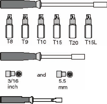
3. Do not remove an IC or a printed circuit assembly (PCA) from its conductive foam pad or conductive
packaging until you are ready to install it.
4. Ground (earth) your body while disassembling and working on the Printer.
5. After removing a cover from the Printer, attach an earthing (ground) lead between the PCA common
and earth ground. Touch all tools to earth ground to remove static charges before using them on
the Printer.
6. After removing any PCA from the Printer, place it on a conductive foam pad or into its conductive
packaging to prevent ESD damage to any ICs on the PCA.
Required Tools
The following tools are required to disassemble and repair the Printer.
Long Torx Screwdriver with the indicated attachments
Nut driver with the indicated attachments
Small flat-blade screwdriver
ENWW Introduction 97
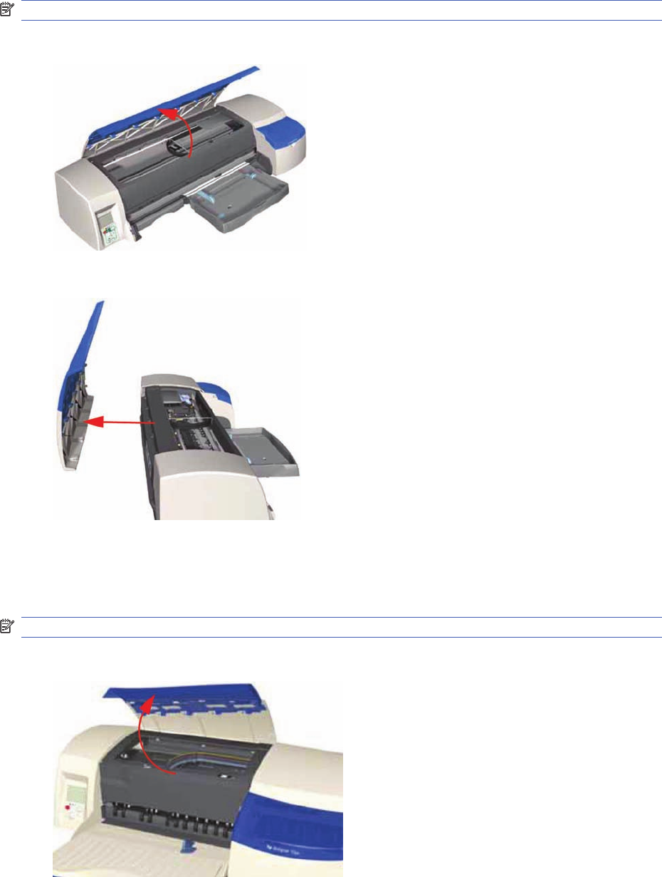
Top Cover
Removal
NOTE: Switch off the product and remove the power cable.
1. Open the Top Cover.
2. Release the clips that secure the Top Cover and remove from the Printer.
Front Cover (Applicability: 30, 30n, 50ps)
Removal
NOTE: Switch off the product and remove the power cable.
1. Open the Access Cover.
98 Chapter 7 Removal and Installation ENWW
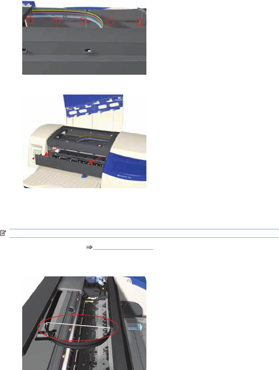
2. Release the clips (from the inside) that secure the Front Cover.
3. Remove the Front Cover from the Printer.
Center Cover
Removal
NOTE: Switch off the product and remove the power cable.
1. Remove the Top Cover Top Cover on page 98.
2. Release the Ink Supply Tubes from the Raceway Holder. Remove the Raceway Holder from the
Printer.
ENWW Center Cover 99
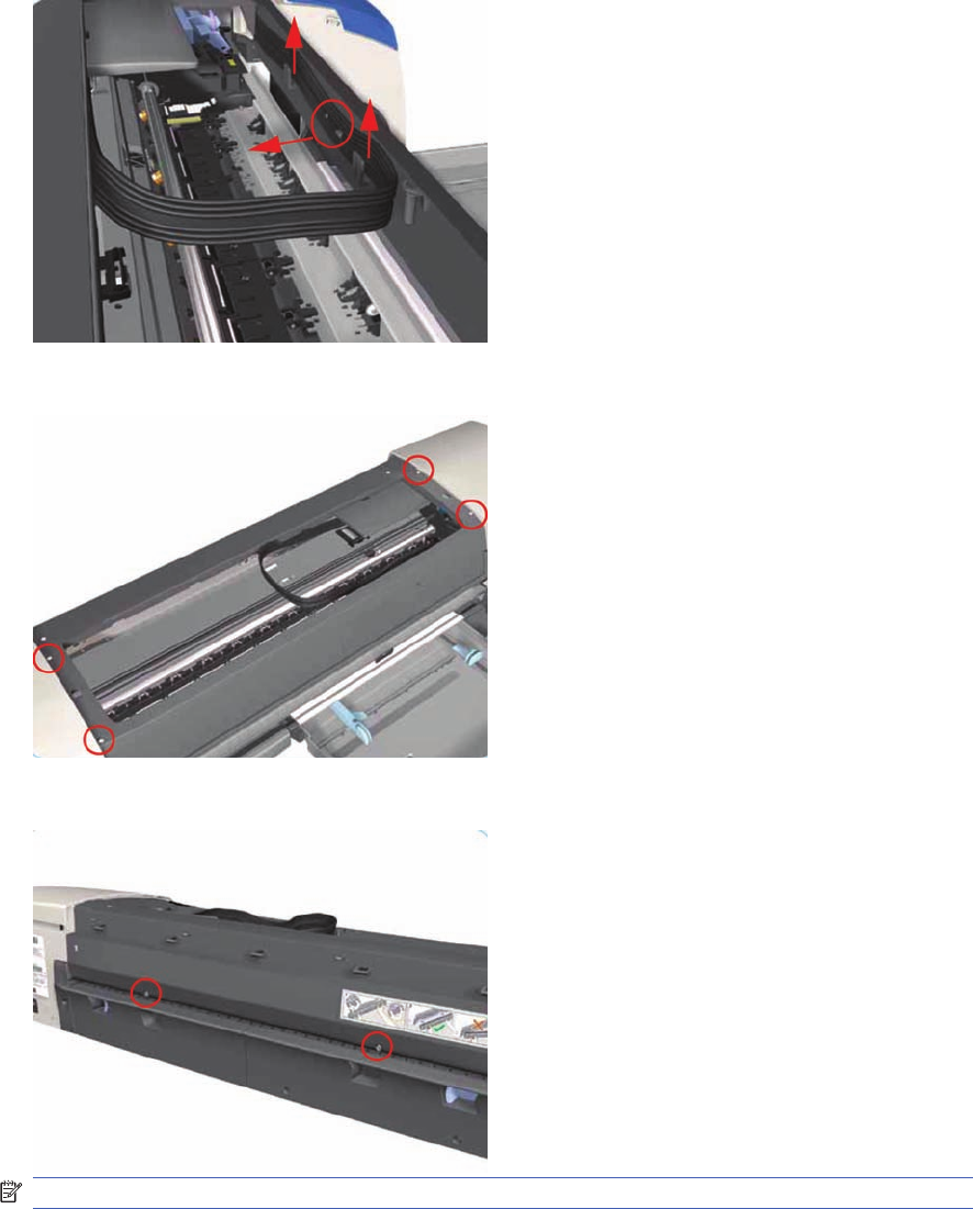
3. Release the Tubes from the retaining clips in the Center Cover.
4. Remove four T-10 screws that secure the Center Cover to the Printer.
5. Remove two T-10 screws that secure the Center Cover from the rear.
NOTE: Step 5 not applicable to 10ps,20ps, 30, 30n, 50ps
100 Chapter 7 Removal and Installation ENWW
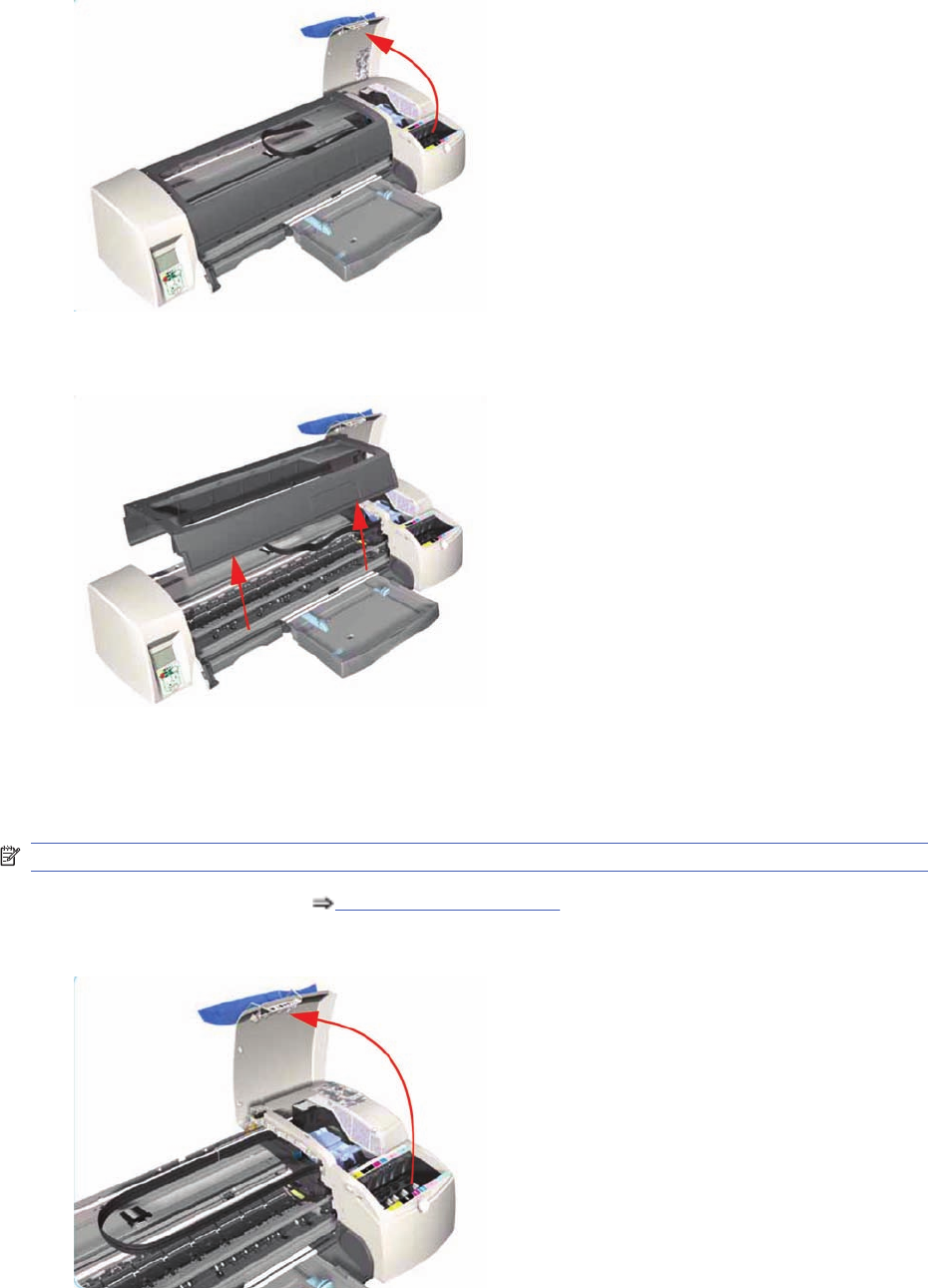
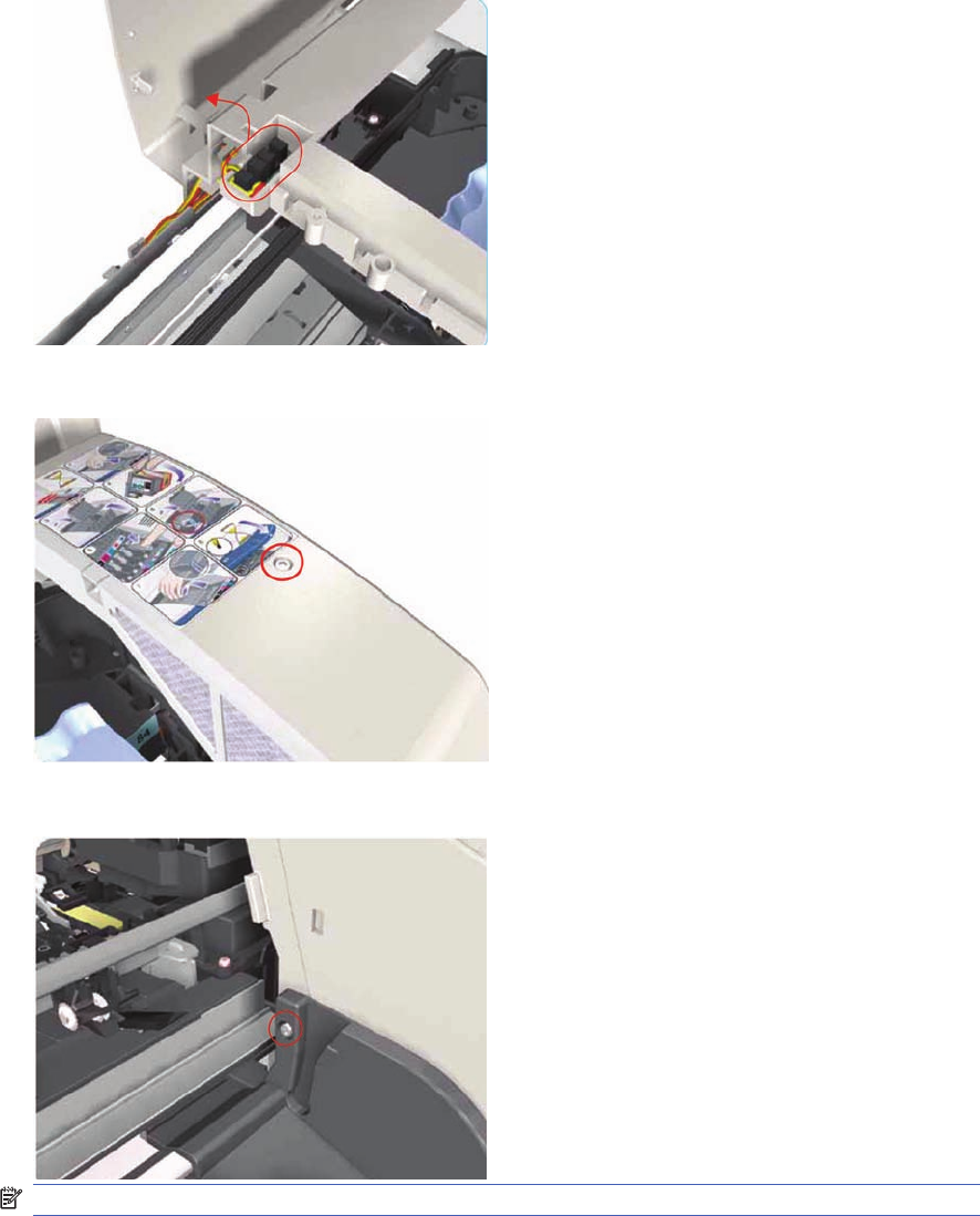
3. Release the Door Sensor from the Right End Cover.
4. Remove one T-10 screw that secures the Right End Cover to the Printer.
5. Remove one T-10 screw from the Right Side Bracket.
NOTE: Step 5 not applicable to 10ps,20ps, 30,30n,50ps
102 Chapter 7 Removal and Installation ENWW
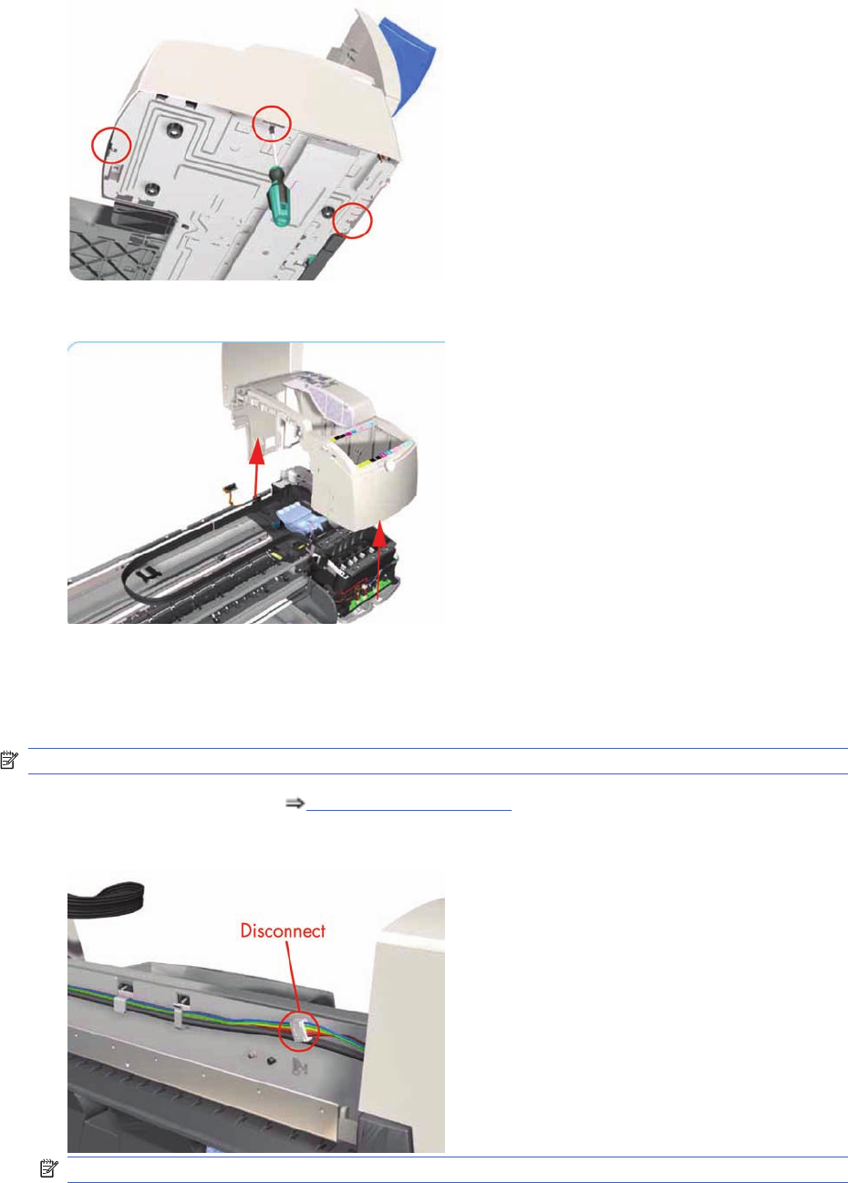
6. Release the clips that secure the Right End Cover to the Printer (use a flat-blade screwdriver if
necessary).
7. Remove the Right End Cover from the Printer.
Left End Cover
Removal
NOTE: Switch off the product and remove the power cable.
1. Remove the Center Cover Center Cover on page 99.
2. Disconnect the Front Panel cable from the rear of the Printer.
NOTE: Following steps 3, 4 and 5 not applicable to 10ps,20ps, 30, 30n, 50ps
ENWW Left End Cover 103
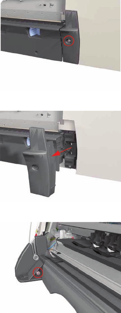
3. Remove one T-10 screw from the Rear Left Trim.
4. Remove the Rear Left Trim from the Printer.
5. Remove one T-10 screw from the Left Side Bracket.
104 Chapter 7 Removal and Installation ENWW
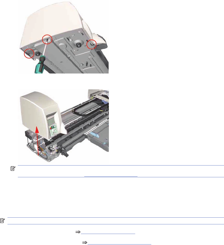
6. Release the clips that secure the Left End Cover to the Printer (use a flat-blade screwdriver if
necessary).
7. Remove the Left End Cover from the Printer.
NOTE: Before installing the Left End Cover, make sure you first check that the Front Panel Cable
is routed correctly as shown onFront Panel on page 117.
Ink Supply Station Cover (Applicability: 70, 100, 100plus,
110plus, 111)
Removal
NOTE: Switch off the product and remove the power cable.
1. Remove the Center Cover Center Cover on page 99.
2. Remove the Right End Cover Right End Cover on page 101.
ENWW Ink Supply Station Cover (Applicability: 70, 100, 100plus, 110plus, 111) 105
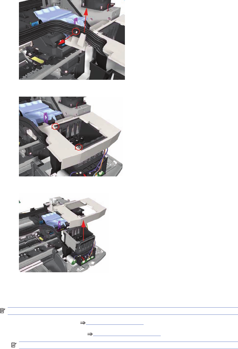
3. Release the Ink Tubs from the clip on the ISS Cover.
4. Remove two screws that secure the ISS Cover to the Ink Supply Station.
5. Remove the ISS Cover from the Printer.
Ink Supply Station
Removal
NOTE: Switch off the product and remove the power cable.
1. Remove the Center Cover Center Cover on page 99.
2. Remove the Right End Cover Right End Cover on page 101.
NOTE: Following step only applicable to Designjet 70, 100, 100+, 110+
106 Chapter 7 Removal and Installation ENWW
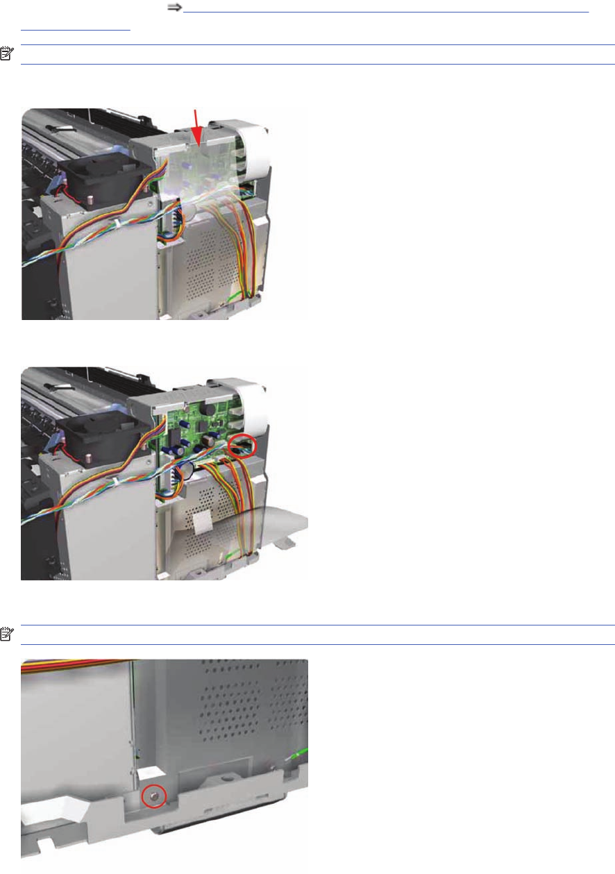
3. Remove the ISS Cover Ink Supply Station Cover (Applicability: 70, 100, 100plus, 110plus,
111) on page 105.
NOTE: Following step not applicable to Designjet 30, 30n
4. Release the Plastic Cover protecting the Electronics Module.
5. Disconnect the Ink Supply Station Cable from the Main PCA.
6. Remove one T-10 screw securing the Plastic Cover. Remove the Plastic Cover from the Printer.
NOTE: Step 6 only applicable to 70, 100, 100+, 100+
ENWW Ink Supply Station 107
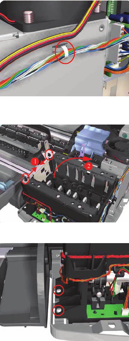
7. Cut the Plastic Tie that secures the Ink Supply Station Cable to the Power Supply Unit.
8. Release the Tubes Bracket from the Ink Supply Station by pushing the clips inwards and lifting up
the Bracket.
9. Remove two T-10 screws that secure the Ink Supply Station.
108 Chapter 7 Removal and Installation ENWW
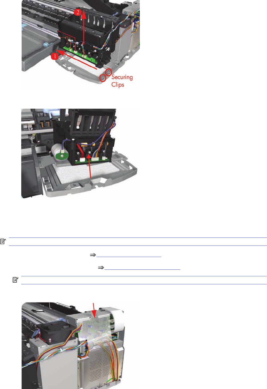
10. Move the Ink Supply Station to the left to release it from the securing clips.
11. Remove the Ink Supply Station from the Printer.
Electronics Module
Removal
NOTE: Switch off the product and remove the power cable.
1. Remove the Center Cover Center Cover on page 99.
2. Remove the Right End Cover Right End Cover on page 101.
NOTE: Following step not applicable to Designjet 30, 30n.
3. Release the Plastic Cover protecting the Electronics Module.
ENWW Electronics Module 109
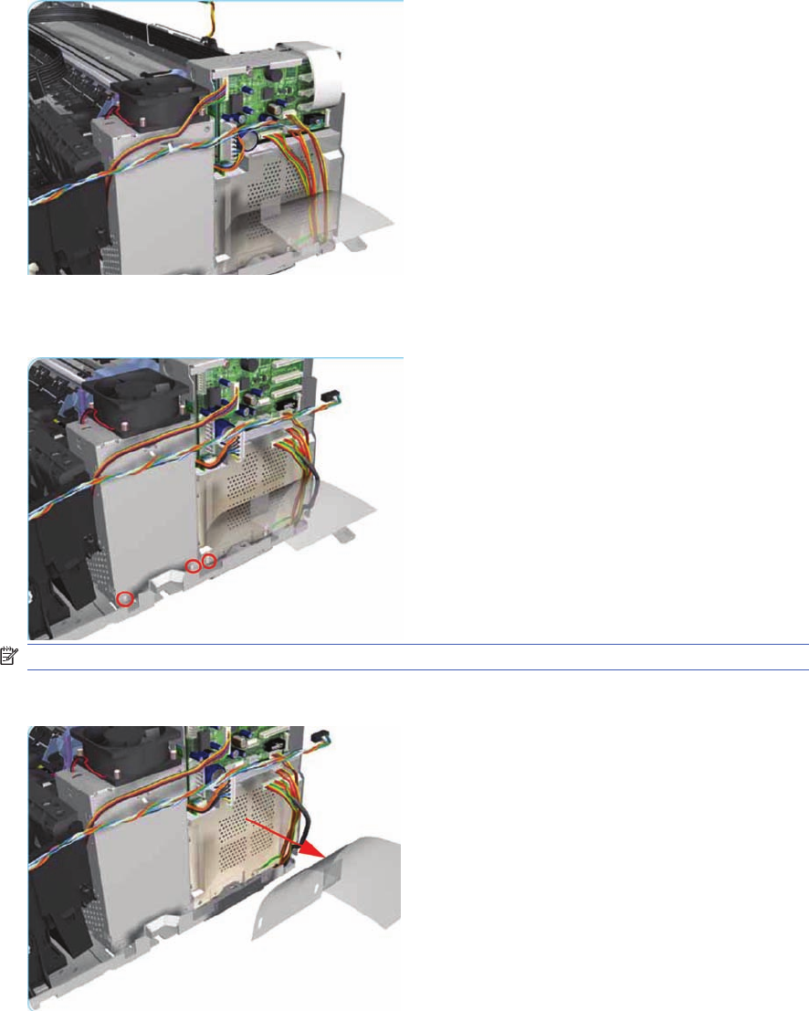
4. Disconnect ALL the cables from the Main PCA.
5. Remove three T-10 (Type B) screws that secure the Electronics Module and the Power Supply
Unit to the Printer.
NOTE: Following step not applicable to Designjet 30, 30n.
6. Remove the Plastic Cover from the Printer.
110 Chapter 7 Removal and Installation ENWW
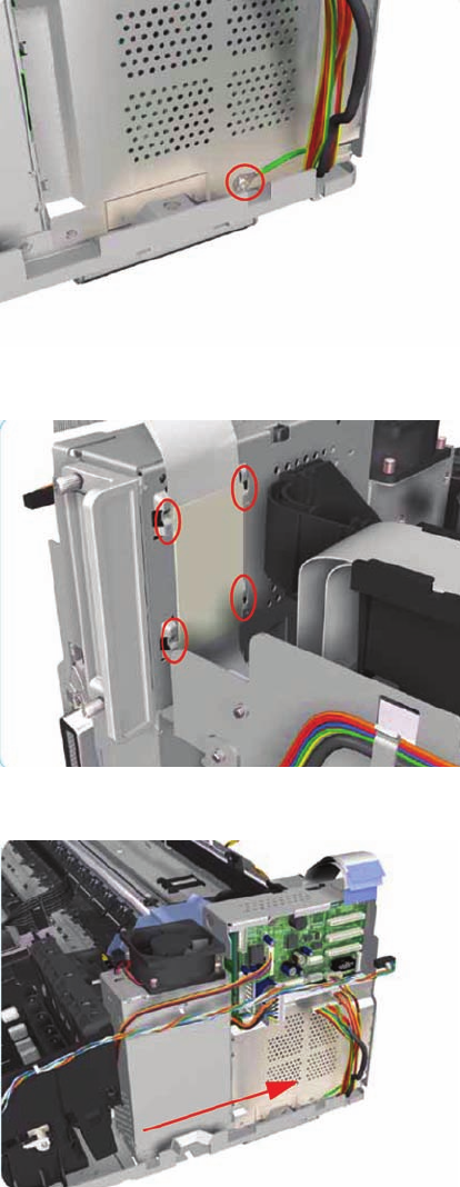
7. Remove one T-10 screw that secures the Electronics Module.
8. Release the plastic sheet that secures the Trailing Cable to the back of the Electronics Module.
9. Slide out the Electronics Module and the Power Supply Unit (as one assembly) to the right.
ENWW Electronics Module 111
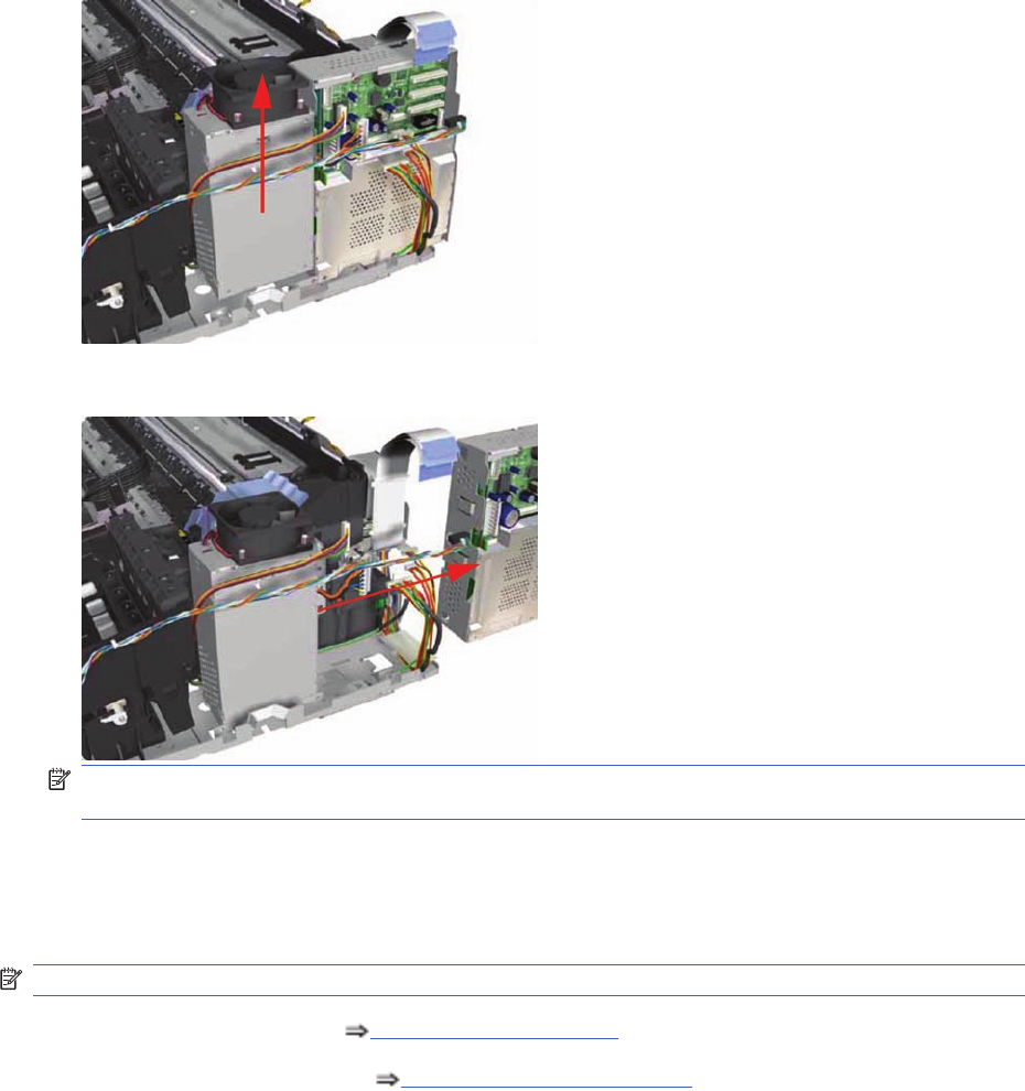
10. Slide the Power Supply Unit upwards to release it from the Electronics Module.
11. Remove the Electronics Module from the Printer.
NOTE: Check if the cable ties need to be cut before separating the Power Supply Unit and the
Electronics Module.
Power Supply Unit
Removal
NOTE: Switch off the product and remove the power cable.
1. Remove the Center Cover Center Cover on page 99.
2. Remove the Right End Cover Right End Cover on page 101.
112 Chapter 7 Removal and Installation ENWW
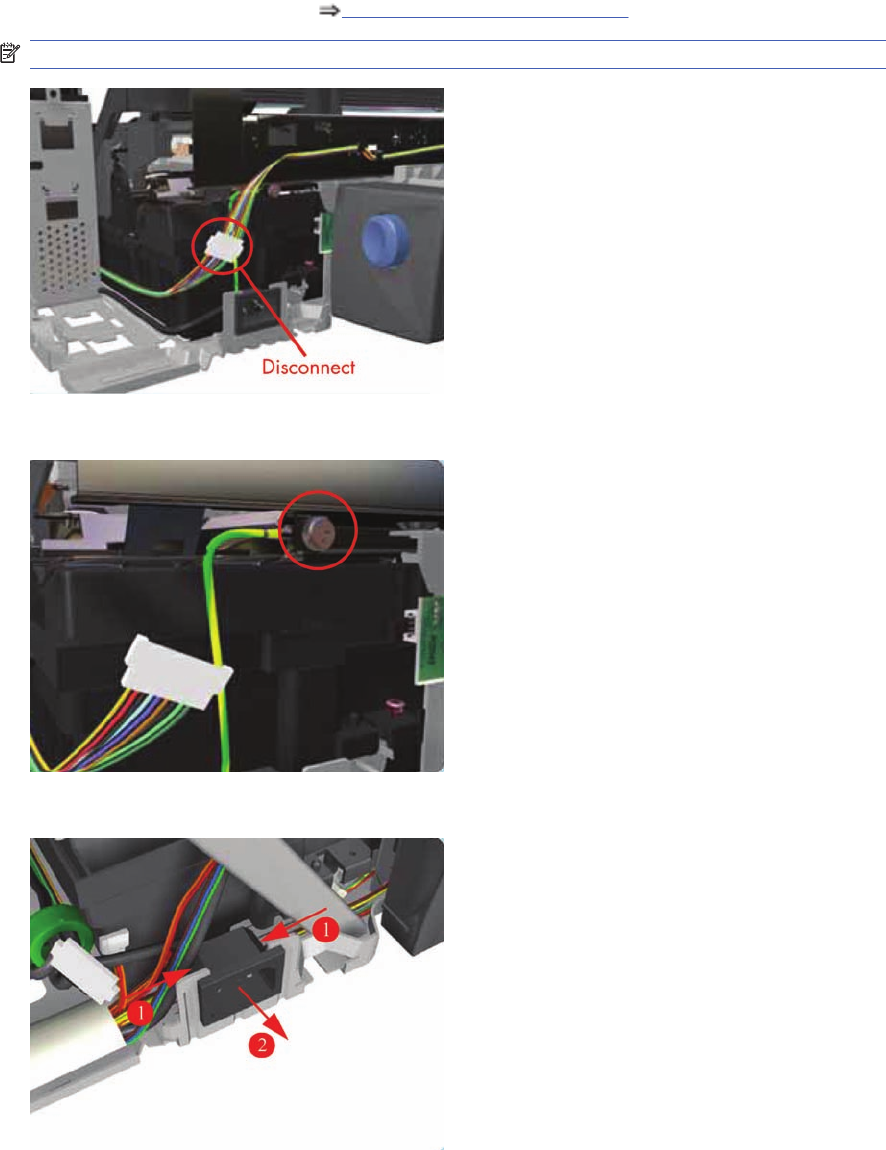
3. Remove the Electronics Module Electronics Module on page 109.
NOTE: Following two steps only applicable to Designjet 30, 30n.
4. Disconnect the Motor Harness Cable.
5. Remove one T-10 screw (Type A) that secures the Grounding Strip.
6. Press in the clips on either side and release the Power Socket.
ENWW Power Supply Unit 113
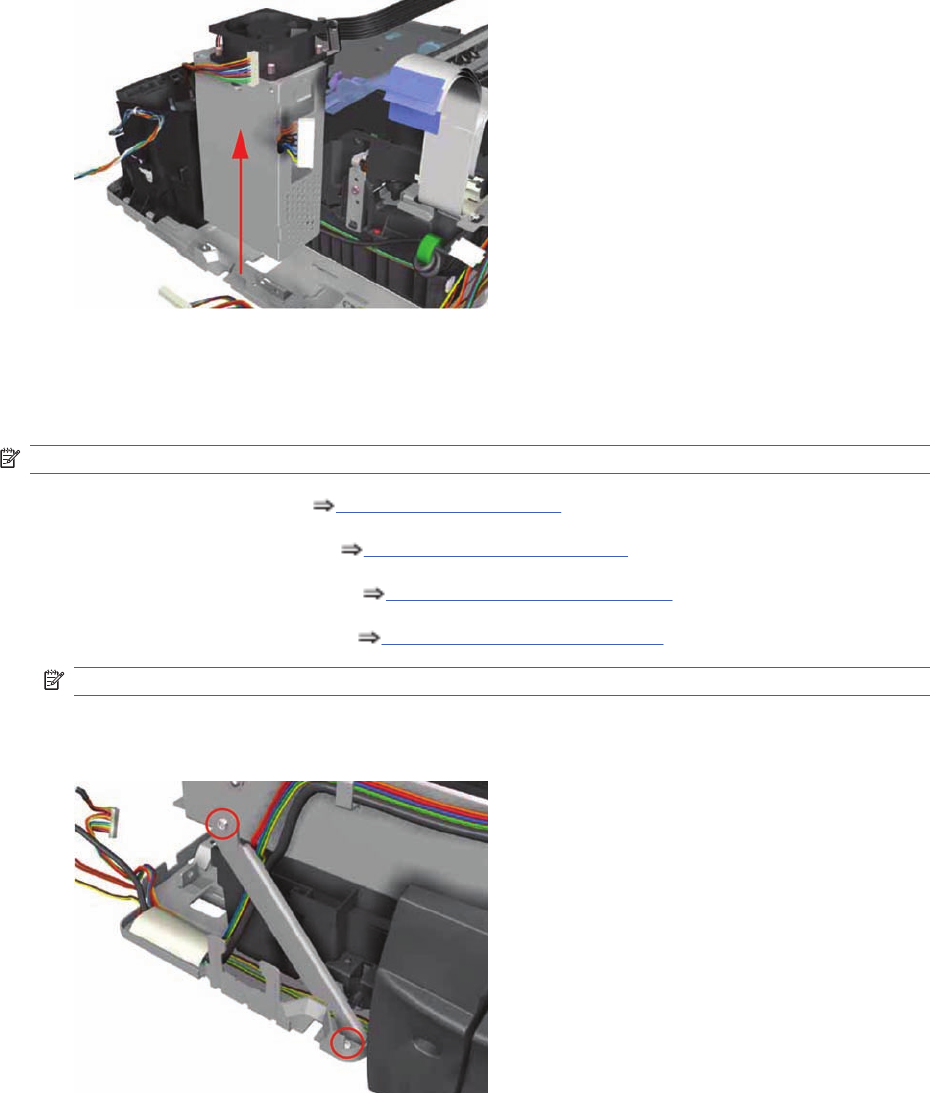
7. Remove the Power Supply from the Printer.
Service Station
Removal
NOTE: Switch off the product and remove the power cable.
1. Remove the Center Cover Center Cover on page 99.
2. Remove the Right End Cover Right End Cover on page 101.
3. Remove the Electronics Module Electronics Module on page 109.
4. Remove the Power Supply Unit Power Supply Unit on page 112.
NOTE: Following step is not applicable to Designjet 30, 30n.
5. Remove two screws that secure the Reinforcement Bracket. Remove the Reinforcement Bracket
from the Printer.
114 Chapter 7 Removal and Installation ENWW
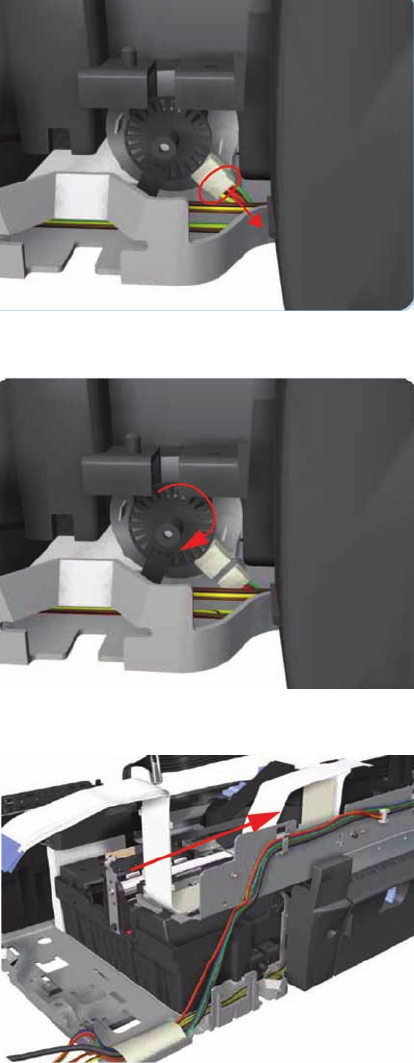
6. Disconnect the Service Station Cable.
7. Uncap the Carriage Assembly by turning the Service Station Motor clockwise.
8. Move the Carriage Assembly out of the Service Station.
ENWW Service Station 115
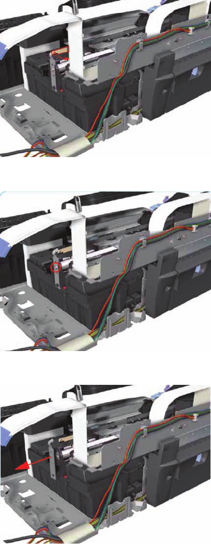
9. Release the Encoder Strip from the Encoder Strip Holder.
10. Remove one T-10 screw that secures the Encoder Strip Holder on the right hand side of the Printer.
11. Remove the Encoder Strip Holder from the Printer.
116 Chapter 7 Removal and Installation ENWW
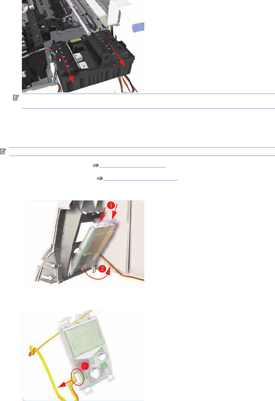
12. Slide the Service Station out of the Printer.
NOTE: If the Service Station is replaced, make sure that you check that the Pen to Rib Space
(PRS) is within specifications.
Front Panel
Removal
NOTE: Switch off the product and remove the power cable.
1. Remove the Center Cover Center Cover on page 99
2. Remove the Left End Cover Left End Cover on page 103.
3. Release the Front Panel from inside the Left Hand Cover.
4. Disconnect the cable from the Front Panel and remove from the Printer.
ENWW Front Panel 117
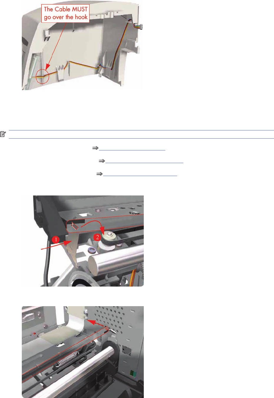
5. Important: When installing the Front Panel, make sure you route the cable as shown:
Encoder Strip
Removal
NOTE: Switch off the product and remove the power cable.
1. Remove the Center Cover Center Cover on page 99
2. Remove the Right End Cover Right End Cover on page 101.
3. Remove the Left End Cover Left End Cover on page 103.
4. Release the Encoder Strip from the left hand side of the Printer.
5. Release the Encoder Strip from the right hand side of the Printer.
118 Chapter 7 Removal and Installation ENWW
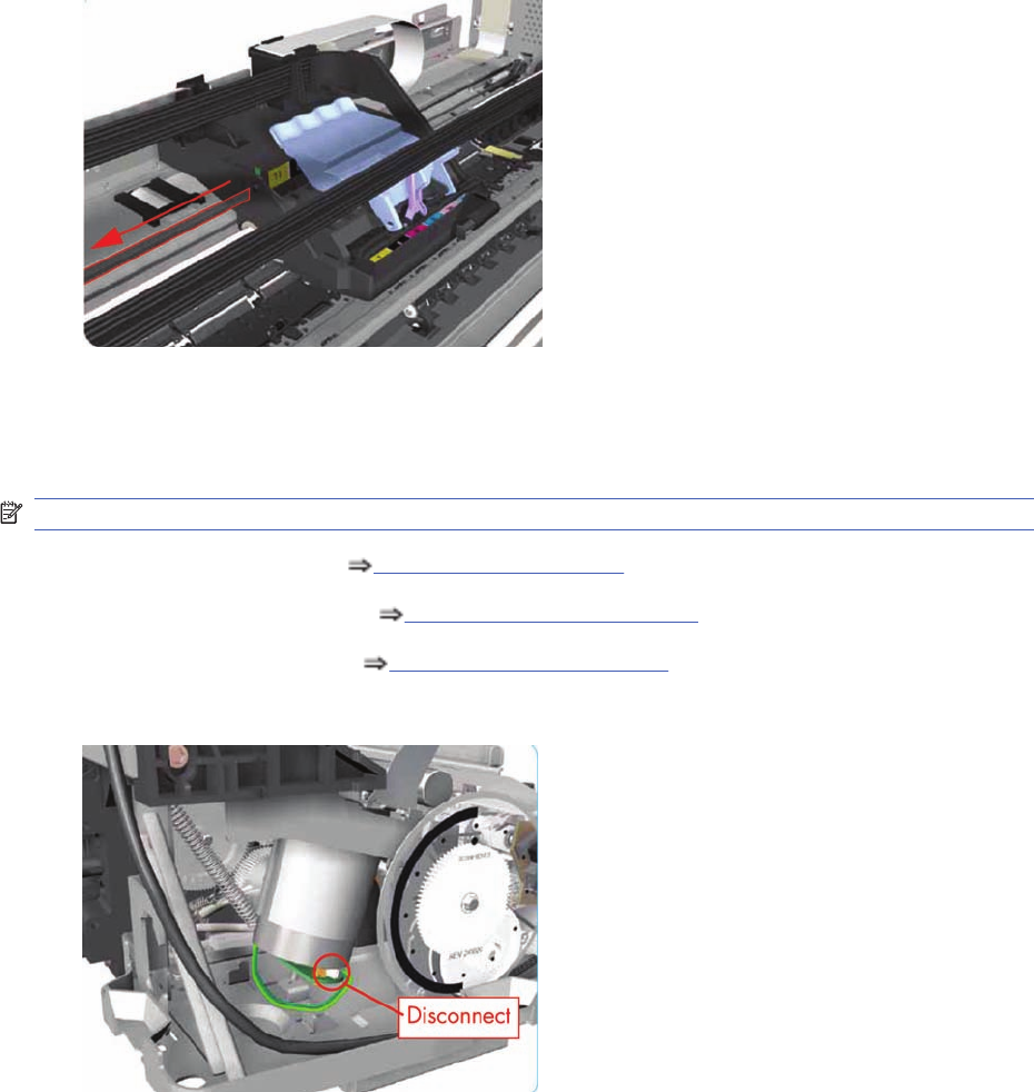
6. Gently slide out the Encoder Strip through the Carriage Assembly and remove from the Printer.
Carriage Motor
Removal
NOTE: Switch off the product and remove the power cable.
1. Remove the Center Cover Center Cover on page 99
2. Remove the Right End Cover Right End Cover on page 101.
3. Remove the Left End Cover Left End Cover on page 103.
4. Disconnect the cable from the Carriage Motor.
ENWW Carriage Motor 119
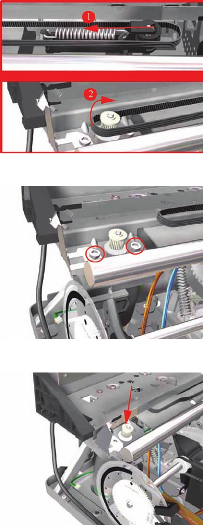
5. Release the Belt from the Carriage Motor by pushing in the Turnaround Assembly (right hand side
of the printer) and at the same time releasing the Belt from the Motor on the left hand side of the
printer.
6. Remove two T-10 screws that secure the Carriage Motor.
7. Remove the Carriage Motor from the Printer (needs to be removed from underneath).
Cleanout Assembly
Removal
120 Chapter 7 Removal and Installation ENWW
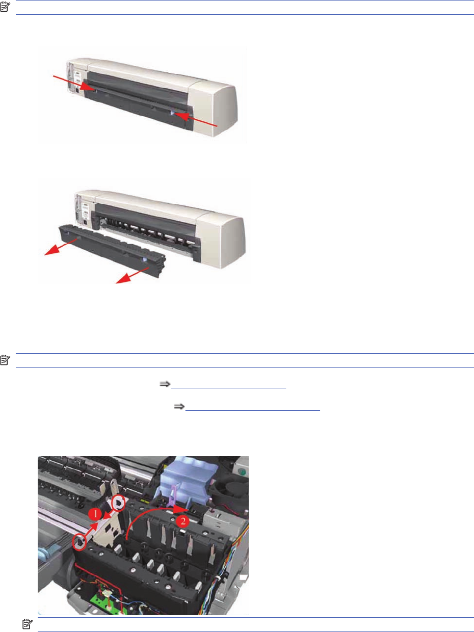
NOTE: Switch off the product and remove the power cable.
1. To release the Cleanout Assembly, push in the two buttons on either side.
2. Remove the Cleanout Assembly from the Printer.
Ink Supply Tubes
Removal
NOTE: Switch off the product and remove the power cable.
1. Remove the Center Cover Center Cover on page 99
2. Remove the Right End Cover Right End Cover on page 101.
3. Release the Tubes Bracket from the Ink Supply Station by pushing the clips inwards and lifting up
the Bracket.
NOTE: The following step is not applicable to 10, 20, 30, 30n, 50ps.
ENWW Ink Supply Tubes 121
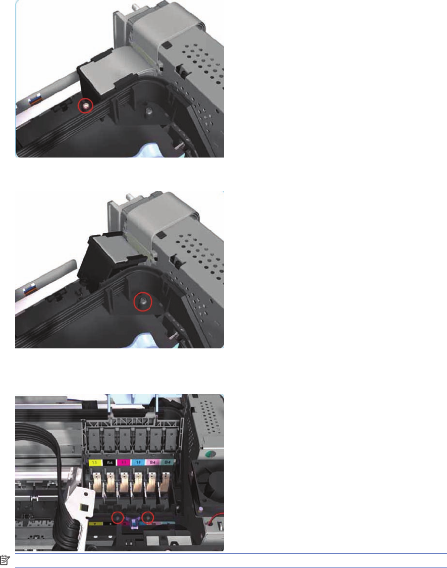
4. Remove one T-10 screw that secures the Trailing Cable Support to the Carriage Assembly.
Release the Trailing Cable Support from the Carriage Assembly.
5. Remove one T-10 screw that secures the Tube Crane to the Carriage Assembly.
6. Open the Printhead Cover and remove two T-8 screws that secure the Tube Crane to the Carriage
Assembly.
NOTE: The following step only applicable to 70, 100, 100+, 110plus
122 Chapter 7 Removal and Installation ENWW
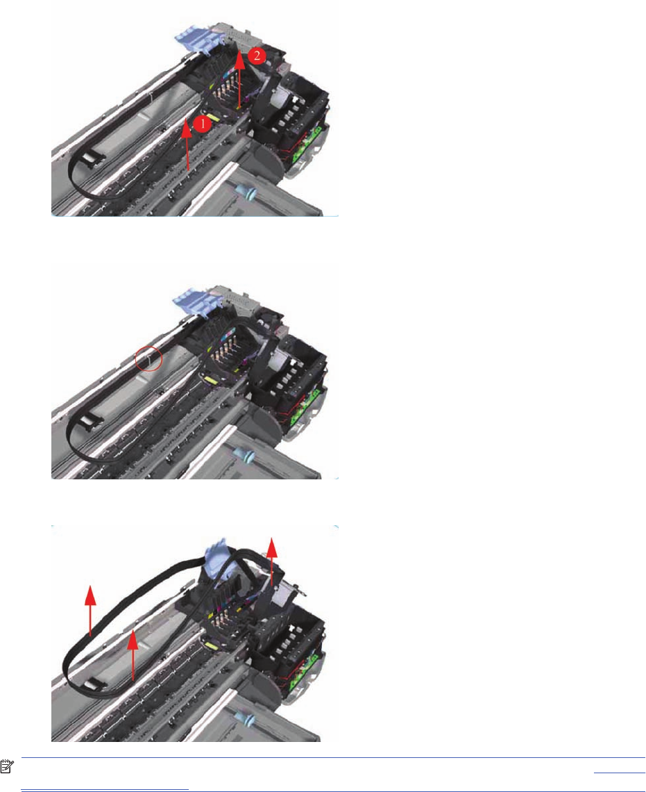
7. Lift up the Tube Crane (1) to release the PH Cover (2) from the Carriage Assembly and remove
from the Printer.
8. Release the Ink Supply Tubes from the Raceway Holder.
9. Release the Ink Supply Tubes and remove from the Printer.
NOTE: After installing NEW Ink Supply Tubes, make sure that you prime the tubes (Refer to "Set Flag
to Prime Tubes on page 57" in the "Utilities" Section).
Carriage Assembly (Applicability: 70, 100+, 110+, 111)
Removal
ENWW Carriage Assembly (Applicability: 70, 100+, 110+, 111) 123
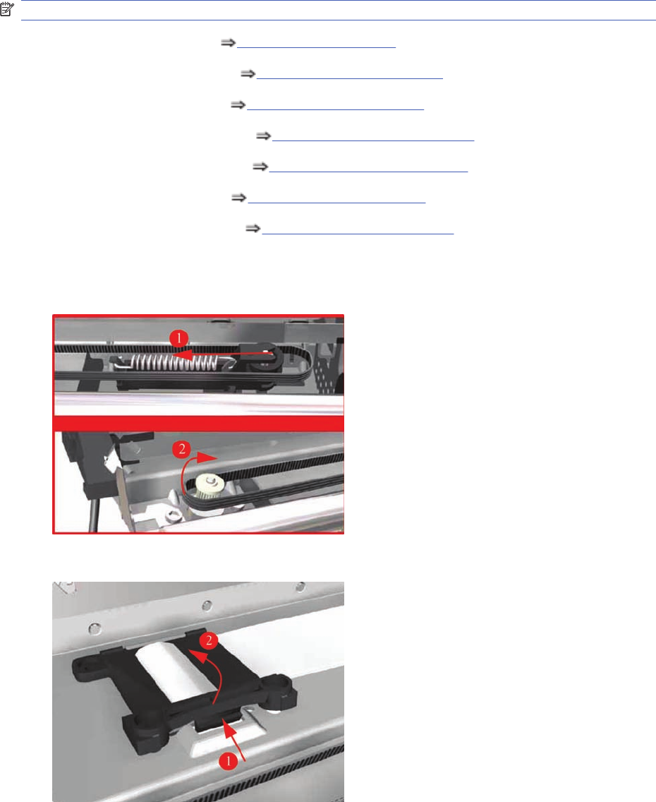
NOTE: Switch off the product and remove the power cable.
1. Remove the Center Cover Center Cover on page 99
2. Remove the Right End Cover Right End Cover on page 101.
3. Remove the Left End Cover Left End Cover on page 103.
4. Remove the Electronics Module Electronics Module on page 109.
5. Remove the Power Supply Unit Power Supply Unit on page 112.
6. Remove the Service Station Service Station on page 114.
7. Remove the Ink Supply Tubes Ink Supply Tubes on page 121.
8. Release the Belt from the Carriage Motor by pushing in the Turnaround Assembly (right hand side
of the printer) and at the same time releasing the Belt from the Motor on the left hand side of the
printer.
9. Release the Trailing Cable Clip from the Chassis.
124 Chapter 7 Removal and Installation ENWW
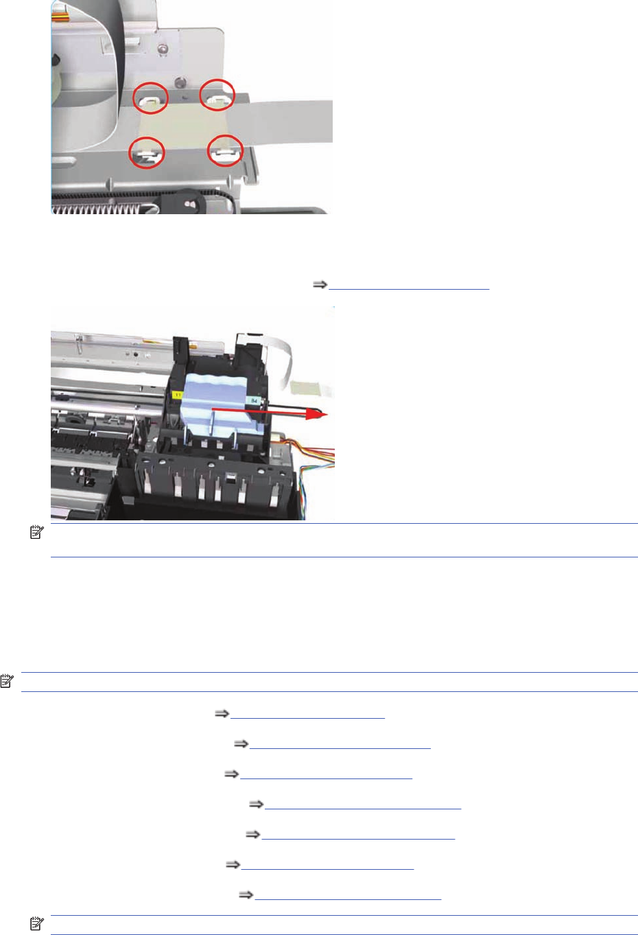
10. Release the Trailing Cable from the Chassis.
11. Slide the Carriage Assembly to the right and out of the Printer.
12. If the Carriage Assembly is to be replaced, make sure that you remove the belt (in order to install
it on the new carriage). To remove the belt Carriage Belt on page 128.
NOTE: If the Carriage is replaced by a new one, make sure that you perform the PRS Adjustment
procedure.
Carriage Assembly (Applicability: 30, 30nr, 90, 90r, 130,
130nr)
Removal
NOTE: Switch off the product and remove the power cable.
1. Remove the Center Cover Center Cover on page 99
2. Remove the Right End Cover Right End Cover on page 101.
3. Remove the Left End Cover Left End Cover on page 103.
4. Remove the Electronics Module Electronics Module on page 109.
5. Remove the Power Supply Unit Power Supply Unit on page 112.
6. Remove the Service Station Service Station on page 114.
7. Remove the Ink Supply Tubes Ink Supply Tubes on page 121.
NOTE: Following step only applicable to 90, 90r, 130, 130nr.
ENWW Carriage Assembly (Applicability: 30, 30nr, 90, 90r, 130, 130nr) 125
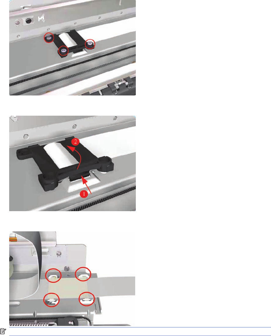
8. Remove three T-10 screws that secure the Trailing Cable Clip to the Chassis.
9. Release the Trailing Cable Clip from the Chassis.
10. Release the Trailing Cable from the Chassis.
NOTE: Following step only applicable to 90, 90r, 130, 130nr.
126 Chapter 7 Removal and Installation ENWW
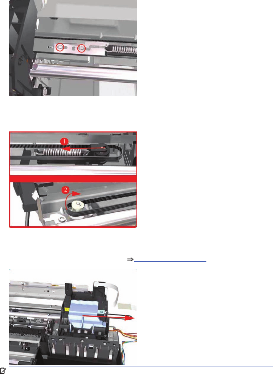
11. Remove two T-10 screws that secure the Turnaround Stopper. Remove the Turnaround Stopper
from the Printer.
12. Release the Belt from the Carriage Motor by pushing in the Turnaround Assembly (right hand side
of the printer) and at the same time releasing the Belt from the Motor on the left hand side of the
printer.
13. Slide the Carriage Assembly to the right and out of the Printer.
14. If the Carriage Assembly is to be replaced, make sure that you remove the belt (in order to install
it on the new carriage). To remove the belt Carriage Belt on page 128.
NOTE: If the Carriage is replaced by a new one, make sure that you perform the PRS Adjustment
procedure.
Installation of the Carriage Assembly - IMPORTANT (Only applicable to 90, 90r, 130, 130nr)
After re-installing the Carriage Assembly and Belt, take note of these steps for the correct installation
of the Turnaround Stopper. These steps must be followed in exactly the same sequence:
ENWW Carriage Assembly (Applicability: 30, 30nr, 90, 90r, 130, 130nr) 127
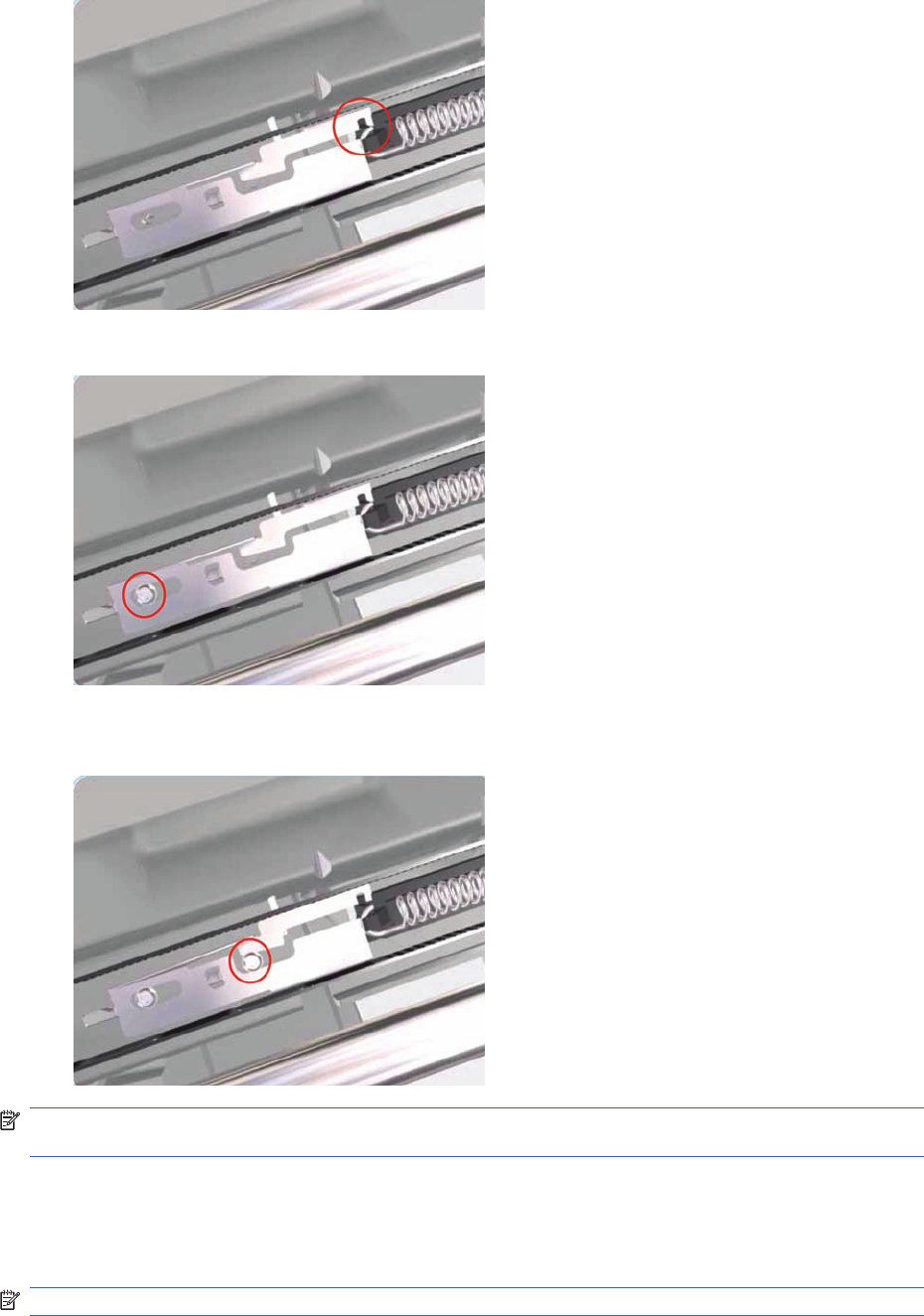
1. Place the Turnaround Stopper in to position and locate the slot in the Stopper on to the Turnaround
Assembly. This step is very important since it will determine the space between the Stopper and
the Turnaround Assembly.
2. Insert the first screw (left) and tighten it.
3. Insert the 2
nd
screw (right) and tighten it. As you tighten the screw you should notice that the slot
in the Stopper will rise away from the Turnaround Assembly.
NOTE: After the installation of the Carriage Assembly and the Turnaround Stopper, you must first
check that the Cutter cuts the media correctly (if the Printer has the Rollfeed and Cutter installed).
Carriage Belt
Removal
NOTE: Switch off the product and remove the power cable.
128 Chapter 7 Removal and Installation ENWW
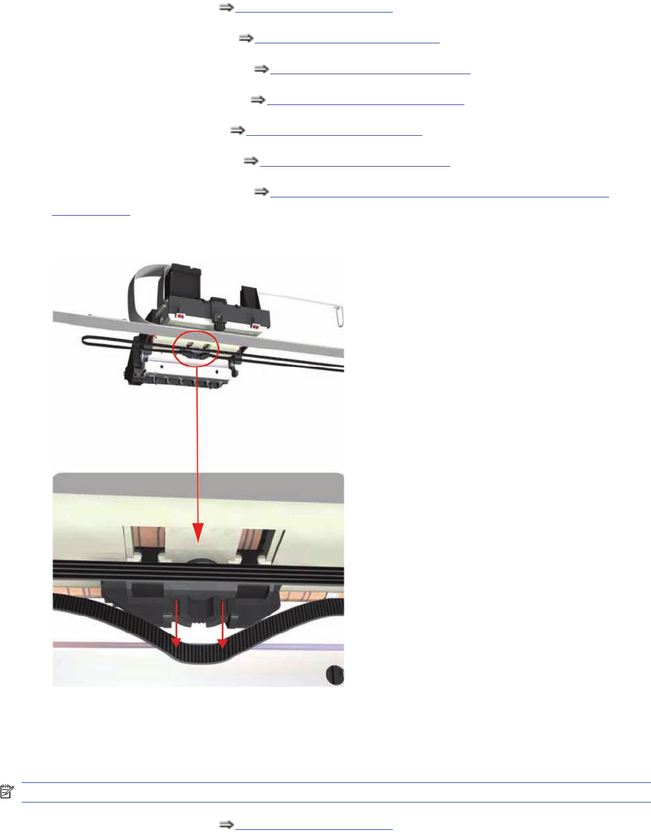
1. Remove the Center Cover Center Cover on page 99
2. Remove the Right End Cover Right End Cover on page 101.
3. Remove the Electronics Module Electronics Module on page 109.
4. Remove the Power Supply Unit Power Supply Unit on page 112.
5. Remove the Service Station Service Station on page 114.
6. Remove the Ink Supply Tubes Ink Supply Tubes on page 121.
7. Remove the Carriage Assembly Carriage Assembly (Applicability: 70, 100+, 110+, 111)
on page 123.
8. Release the Belt from the bottom of the Carriage Assembly.
Starwheel Assembly (Applicability: 30, 30n)
Removal
NOTE: Switch off the product and remove the power cable.
1. Remove the Center Cover Center Cover on page 99.
ENWW Starwheel Assembly (Applicability: 30, 30n) 129
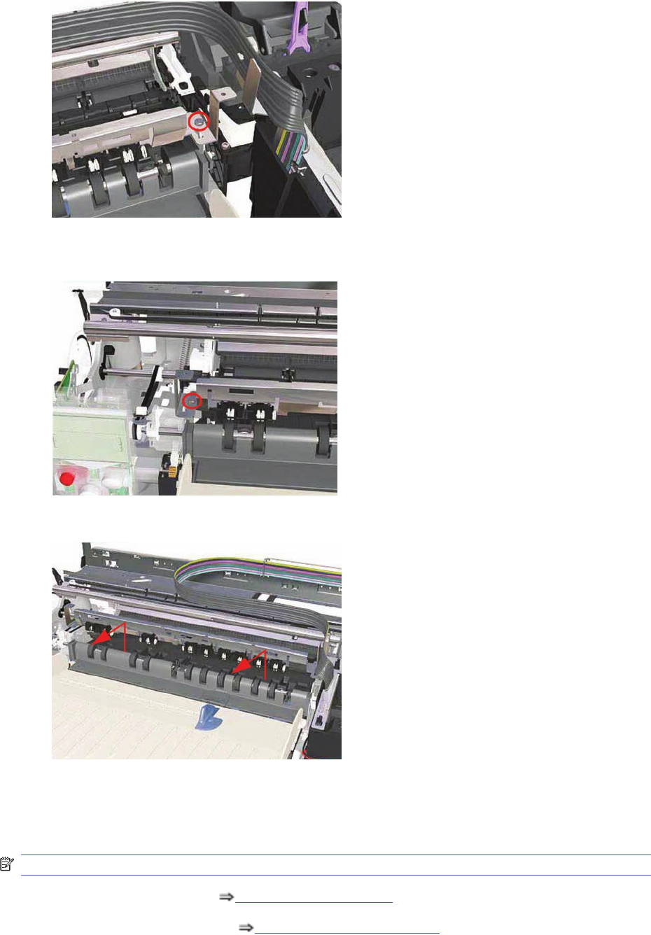
2. Remove one T-10 screw (Type A) that secures the Starwheel Assembly to the right hand side of
the printer.
3. Remove one T-10 screw (Type A) that secures the Starwheel Assembly to the left hand side of
the printer.
4. Remove the Starwheel Assembly.
Starwheel Assembly
Removal
NOTE: Switch off the product and remove the power cable.
1. Remove the Center Cover Center Cover on page 99.
2. Remove the Right End Cover Right End Cover on page 101.
130 Chapter 7 Removal and Installation ENWW
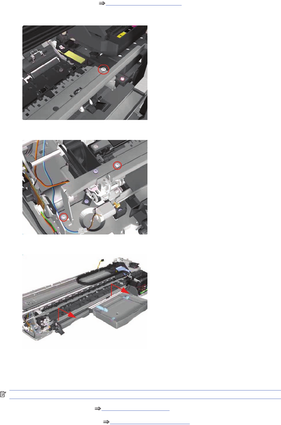
3. Remove the Left End Cover Left End Cover on page 103.
4. Remove one T-10 screw that secures the Starwheel Assembly to the right hand side of the printer.
5. Remove two T-10 screws that secure the Starwheel Assembly to the left hand side of the printer.
6. Remove the Starwheel Assembly.
Print Platen Assembly
Removal
NOTE: Switch off the product and remove the power cable.
1. Remove the Center Cover Center Cover on page 99.
2. Remove the Right End Cover Right End Cover on page 101.
ENWW Print Platen Assembly 131
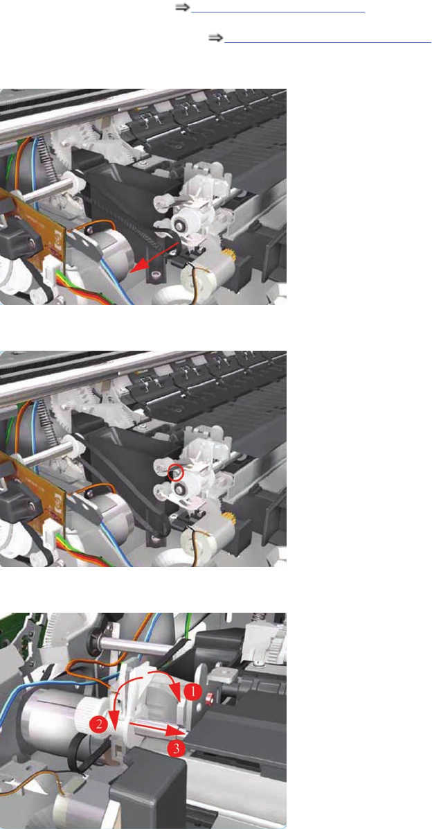
3. Remove the Left End Cover Left End Cover on page 103.
4. Remove the Starwheel Assembly Starwheel Assembly on page 130.
5. Release the Belt from the Print Platen Assembly.
6. Remove one T-10 screw that secures the Spring Idler. Remove the Spring Idler from the Printer.
7. Release the locking mechanism from the left hand side of the Printer.
132 Chapter 7 Removal and Installation ENWW
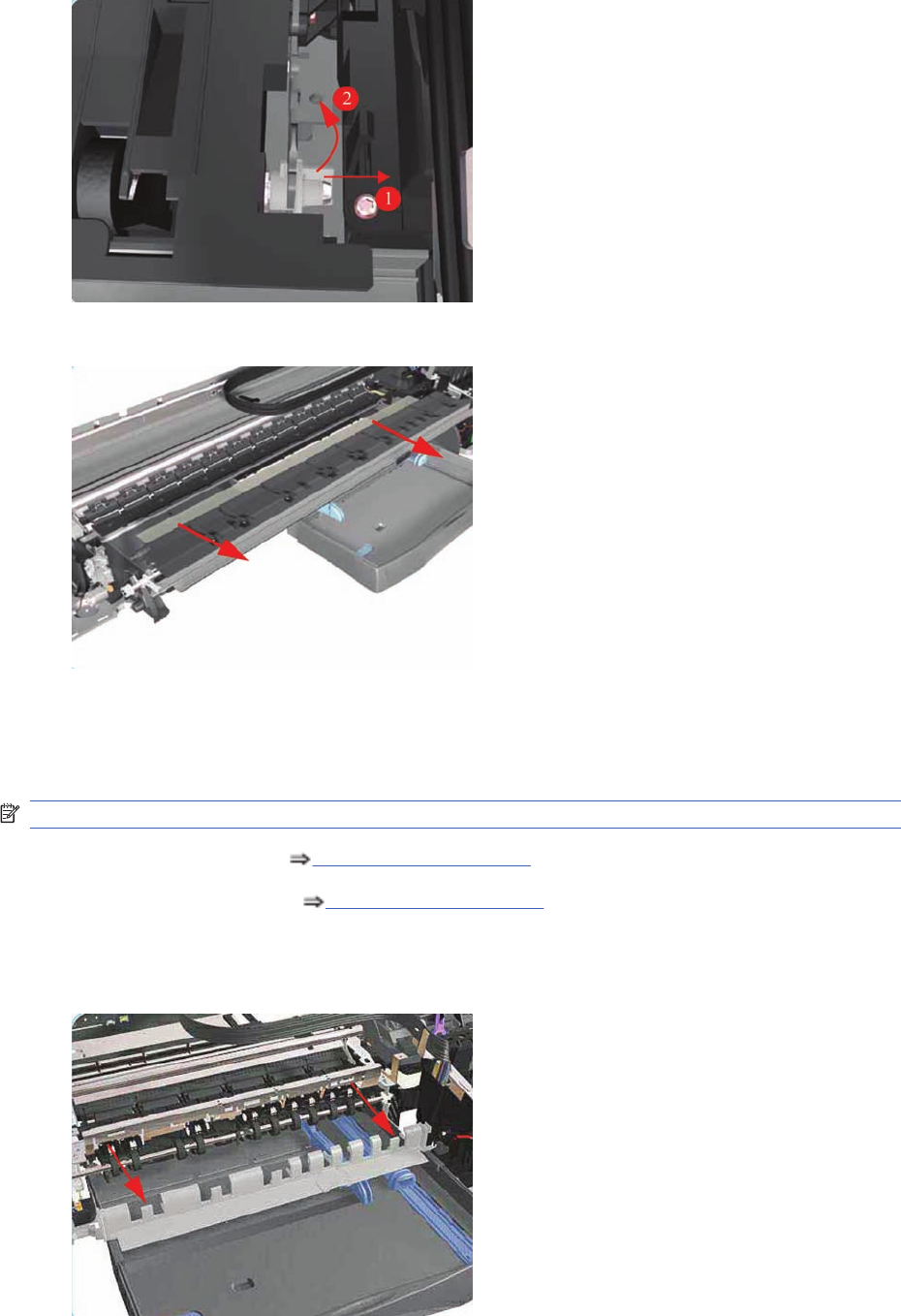
8. Release the locking mechanism from the right hand side of the Printer.
9. Slide out the complete Print Platen Assembly.
Output Separator (Applicability: 30, 30n)
Removal
NOTE: Switch off the product and remove the power cable.
1. Remove the Front Cover Center Cover on page 99.
2. Remove the Center Cover Center Cover on page 99.
3. Remove the Output Tray.
4. Unclip the Output Separator and remove from the Printer.
ENWW Output Separator (Applicability: 30, 30n) 133
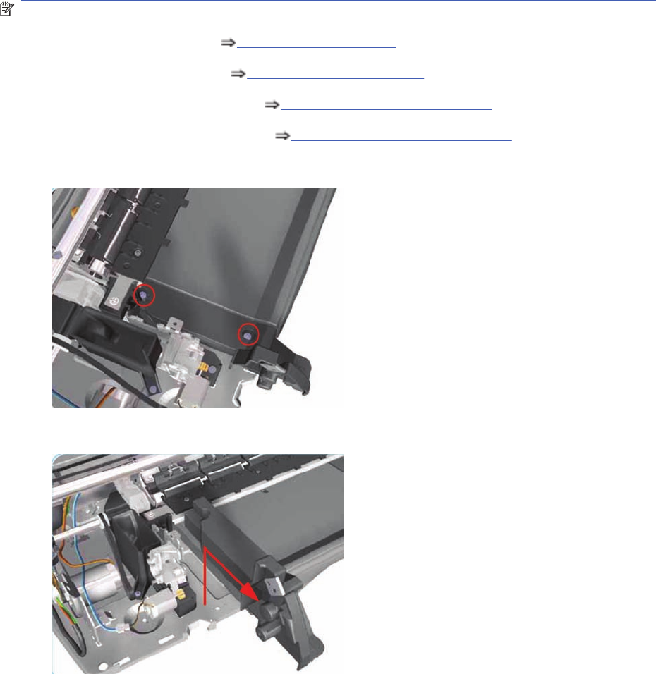
Ramp Motor Assembly
(Not applicable to 30, 30n)
Removal
NOTE: Switch off the product and remove the power cable.
1. Remove the Center Cover Center Cover on page 99.
2. Remove the Left End Cover Left End Cover on page 103.
3. Remove the Starwheel Assembly Starwheel Assembly on page 130.
4. Remove the Print Platen Assembly Print Platen Assembly on page 131.
5. Remove two T-10 screws that secure the Front Left Bracket.
6. Remove the Front Left Bracket from the Printer.
134 Chapter 7 Removal and Installation ENWW
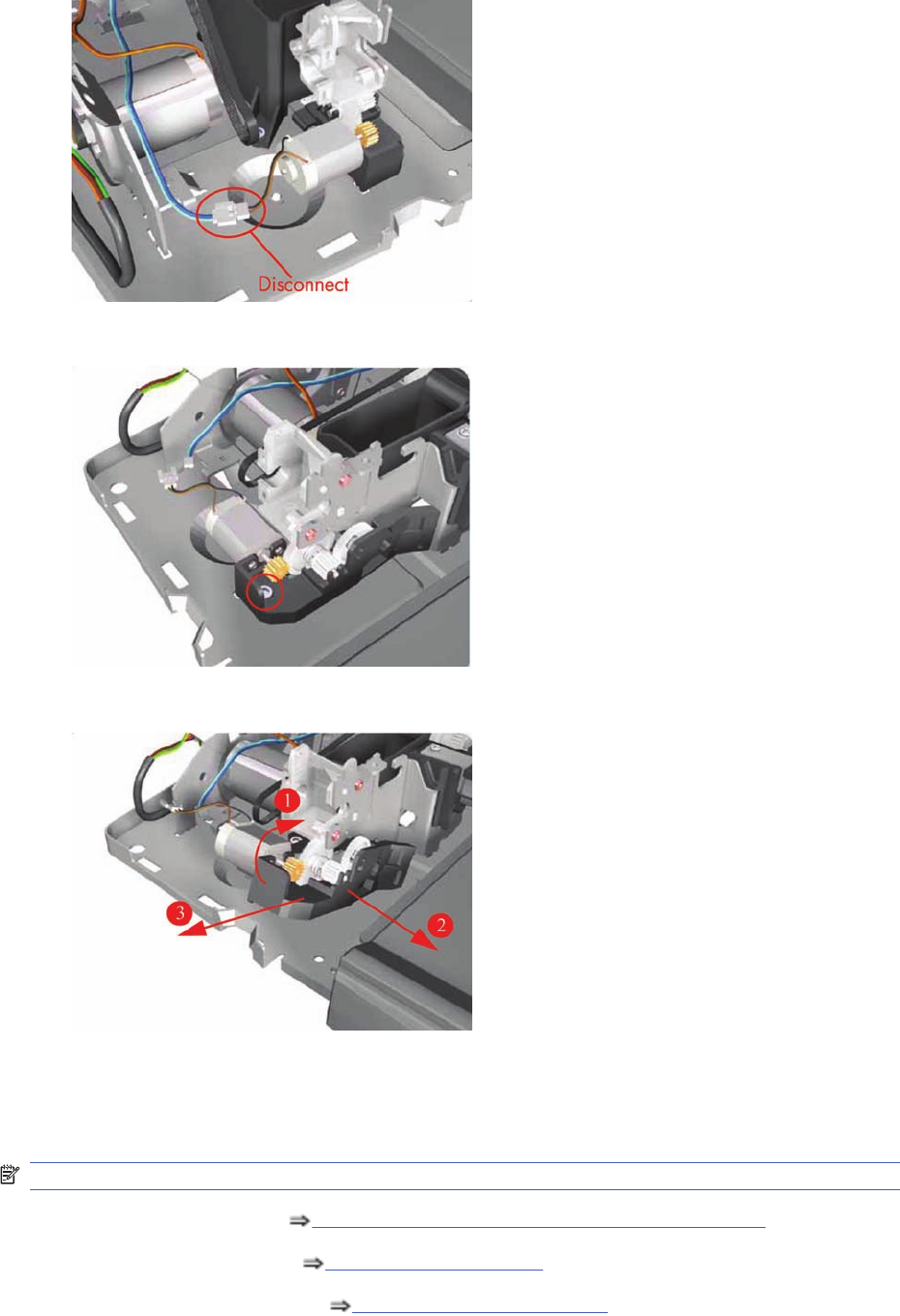
7. Disconnect the Ramp Motor cable.
8. Remove one T-10 screw from the Ramp Motor Assembly.
9. Remove one T-10 screw from the Ramp Motor Assembly.
Output Mechanism Assembly (Applicability: 30, 30n)
Removal
NOTE: Switch off the product and remove the power cable.
1. Remove the Front Cover Front Cover (Applicability: 30, 30n, 50ps) on page 98.
2. Remove the Center Cover Center Cover on page 99.
3. Remove the Right End Cover Right End Cover on page 101
ENWW Output Mechanism Assembly (Applicability: 30, 30n) 135
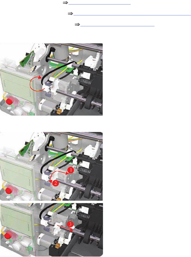
4. Remove the Left End Cover Left End Cover on page 103.
5. Remove the Output Separator Output Separator (Applicability: 30, 30n) on page 133.
6. Remove the Starwheel Assembly Starwheel Assembly on page 130.
7. Release the Belt from the Output Mechanism Assembly.
8. Release the locking mechanism from the left hand side of the Printer.
136 Chapter 7 Removal and Installation ENWW
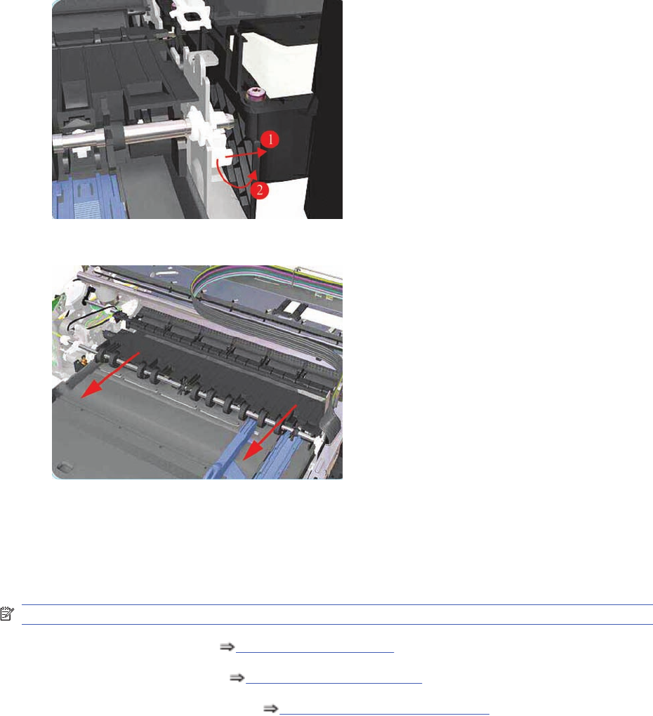
9. Release the locking mechanism from the right hand side of the Printer.
10. Slide out the complete Output Mechanism Assembly.
Spittoon (If Installed in the Printer)
(Not applicable to 30, 30n)
Removal
NOTE: Switch off the product and remove the power cable.
1. Remove the Center Cover Center Cover on page 99.
2. Remove the Left End Cover Left End Cover on page 103.
3. Remove the Starwheel Assembly Starwheel Assembly on page 130.
ENWW Spittoon (If Installed in the Printer) 137
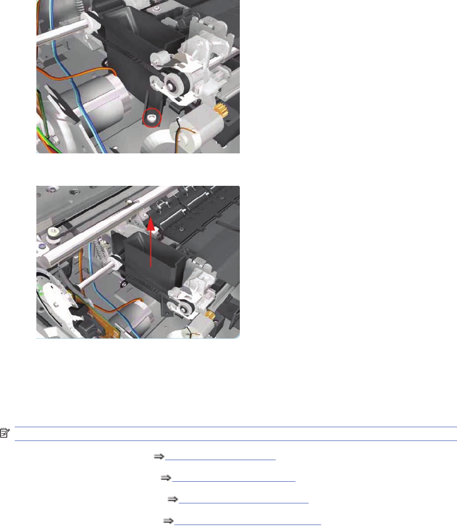
4. Remove one T-10 screw that secures the Spittoon.
5. Remove the Spittoon from the Printer.
Pivot Assembly
(Not applicable to 30, 30n)
Removal
NOTE: Switch off the product and remove the power cable.
1. Remove the Center Cover Center Cover on page 99.
2. Remove the Left End Cover Left End Cover on page 103.
3. Remove the Right End Cover Right End Cover on page 101.
4. Remove the Starwheel Assy Starwheel Assembly on page 130.
138 Chapter 7 Removal and Installation ENWW
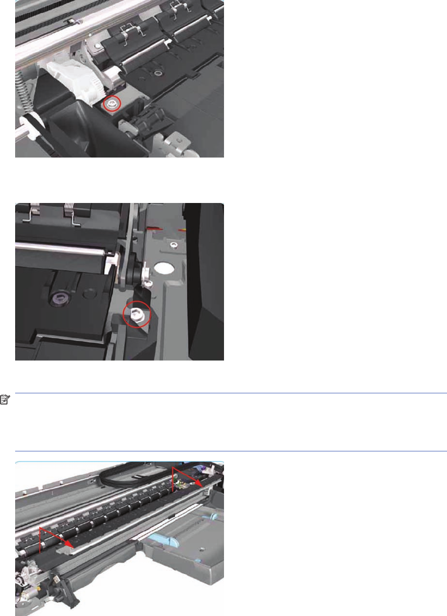
5. Remove one T-8 screw and washer that secure the Pivot Assembly on the left hand side of the
Printer.
6. Remove one T-8 screw and washer that secure the Pivot Assembly on the right hand side of the
Printer.
7. Remove the Pivot Assembly from the Printer.
NOTE: After removing or replacing the Pivot Assembly, make sure that you perform the PRS
Adjustment procedure.
Make sure you use NEW screws to install the Pivot Assembly when it has been removed or
replaced.
Feed Roller Assembly (Applicability: 30, 30n)
Removal
ENWW Feed Roller Assembly (Applicability: 30, 30n) 139
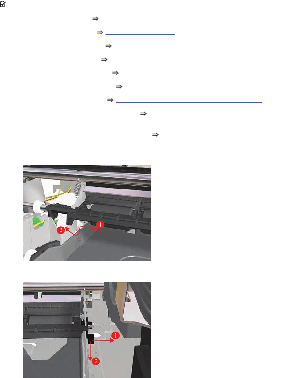
NOTE: Switch off the product and remove the power cable.
1. Remove the Front Cover Front Cover (Applicability: 30, 30n, 50ps) on page 98.
2. Remove the Center Cover Center Cover on page 99
3. Remove the Right End Cover Right End Cover on page 101.
4. Remove the Left End Cover Left End Cover on page 103.
5. Remove the Electronics Module Electronics Module on page 109.
6. Remove the Starwheel Assembly Starwheel Assembly on page 130.
7. Remove the Output Separator Output Separator (Applicability: 30, 30n) on page 133
8. Remove the Output Mechanism Assembly Output Mechanism Assembly (Applicability: 30,
30n) on page 135.
9. Remove the Paper-Axis Motor Drive Assembly Paper-Axis Motor Drive Assembly (Applicable
only to 30, 30n) on page 158.
10. Release the locking mechanism from the left hand side of the Printer.
11. Release the locking mechanism from the right hand side of the Printer.
140 Chapter 7 Removal and Installation ENWW
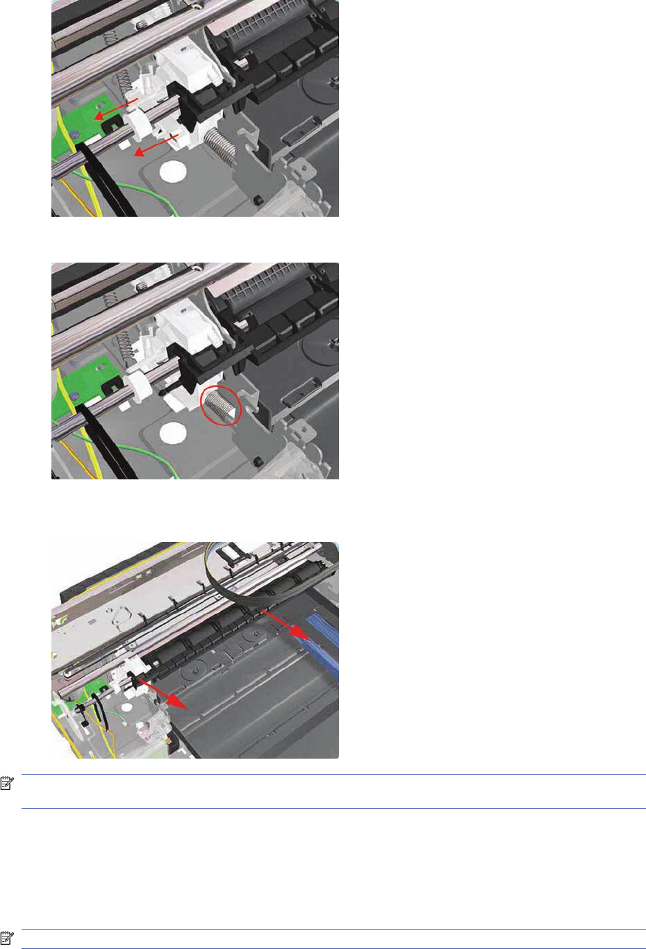
12. Release the Pin Caber and remove from the Printer.
13. Release the Spring.
14. Raise the locks so that they are aligned with the cutouts and lift out the Feed Roller Assembly from
the Printer.
NOTE: After removing or replacing the Feed Roller Assembly, make sure that you perform the PRS
Adjustment procedure and the Accuracy Calibration.
Feed Roller Assembly
(Not applicable to Designjets 30, 30n)
Removal
NOTE: Switch off the product and remove the power cable.
ENWW Feed Roller Assembly 141
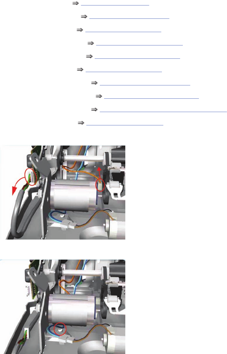
1. Remove the Center Cover Center Cover on page 99
2. Remove the Right End Cover Right End Cover on page 101.
3. Remove the Left End Cover Left End Cover on page 103.
4. Remove the Electronics Module Electronics Module on page 109.
5. Remove the Power Supply Unit Power Supply Unit on page 112.
6. Remove the Service Station Service Station on page 114.
7. Remove the Starwheel Assembly Starwheel Assembly on page 130.
8. Remove the Print Platen Assembly Print Platen Assembly on page 131.
9. Remove the Spittoon (if installed) Spittoon (If Installed in the Printer) on page 137.
10. Remove the Pivot Assembly Pivot Assembly on page 138.
11. Disconnect the Paper-Axis and Encoder cables.
12. Remove one T-10 screw that secures the Paper-Axis Motor Mount.
142 Chapter 7 Removal and Installation ENWW
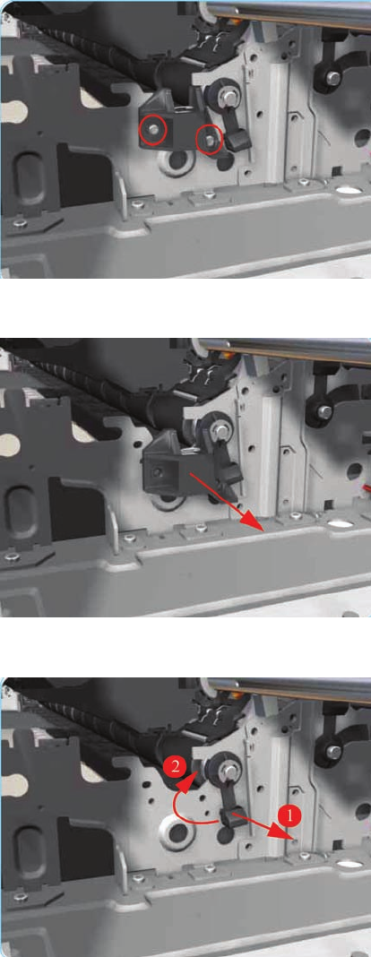
13. Remove two T-10 screws that secure the Pivot Assembly Support on the right hand side of the
Printer.
14. Remove the Pivot Assembly Support from the Printer.
15. Release the locking mechanism from the right hand side of the Printer.
ENWW Feed Roller Assembly 143
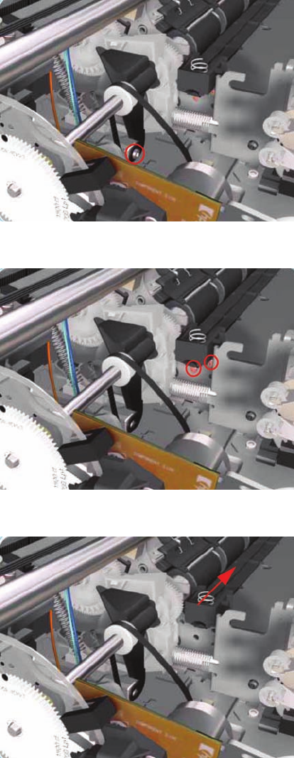
16. Remove one T-10 screw and nut that secures the Feed-Roller Support on the left hand side of the
Printer.
17. Remove two T-10 screws that secure the bracket on the left hand side of the Printer.
18. Remove the Bracket from the Printer.
144 Chapter 7 Removal and Installation ENWW
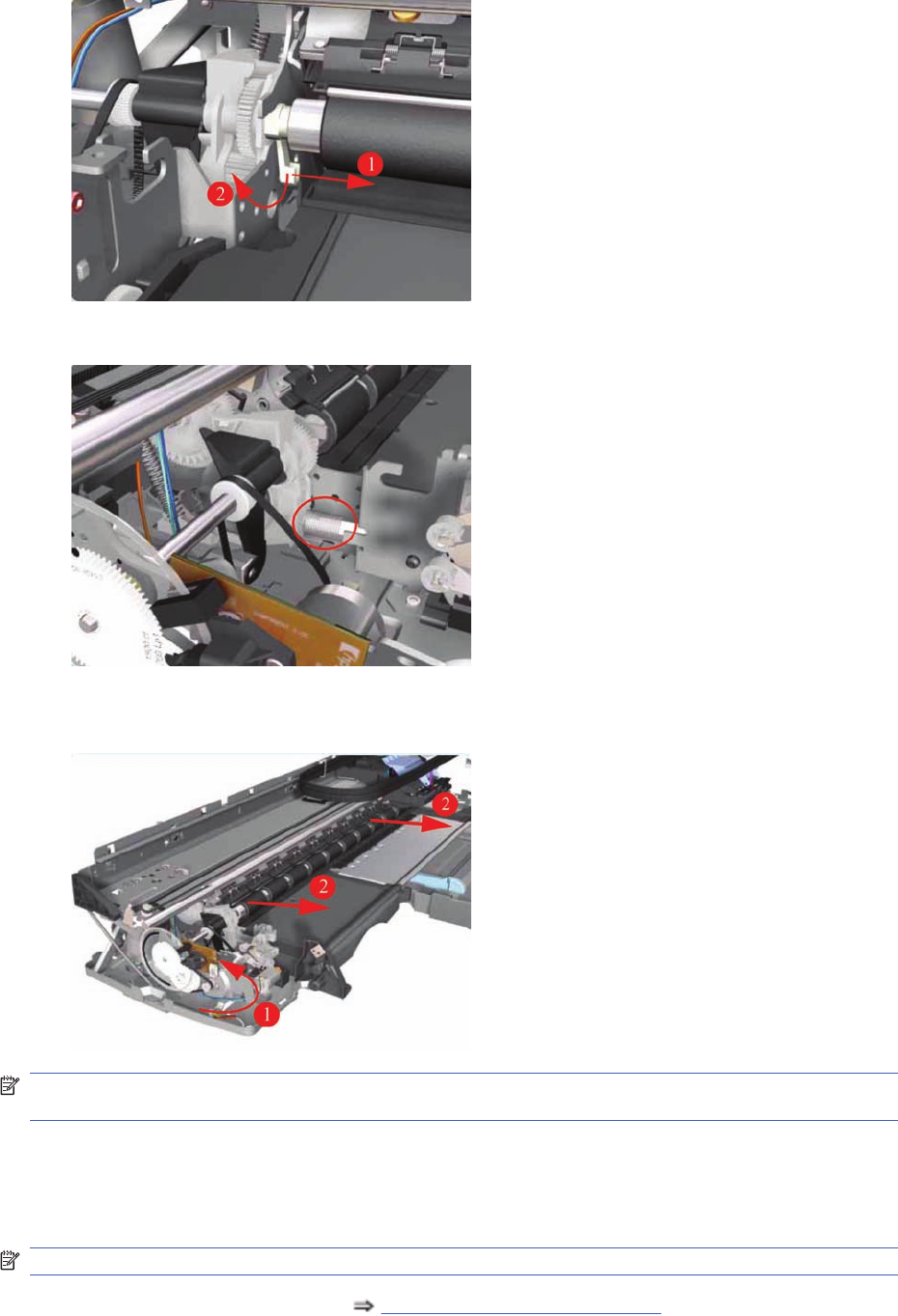
19. Release the locking mechanism from the left hand side of the Printer.
20. Release the Spring from the Bracket.
21. Raise the locks so that they are aligned with the cutouts and lift out the Feed Roller Assembly
(including the Paper-Axis Motor) from the Printer.
NOTE: After removing or replacing the Feed Roller Assembly, make sure that you perform the PRS
Adjustment procedure and the Accuracy Calibration.
Pick Assembly (Applicability: 30, 30n)
Removal
NOTE: Switch off the product and remove the power cable.
1. Remove the Cleanout Assembly Cleanout Assembly on page 120.
ENWW Pick Assembly (Applicability: 30, 30n) 145
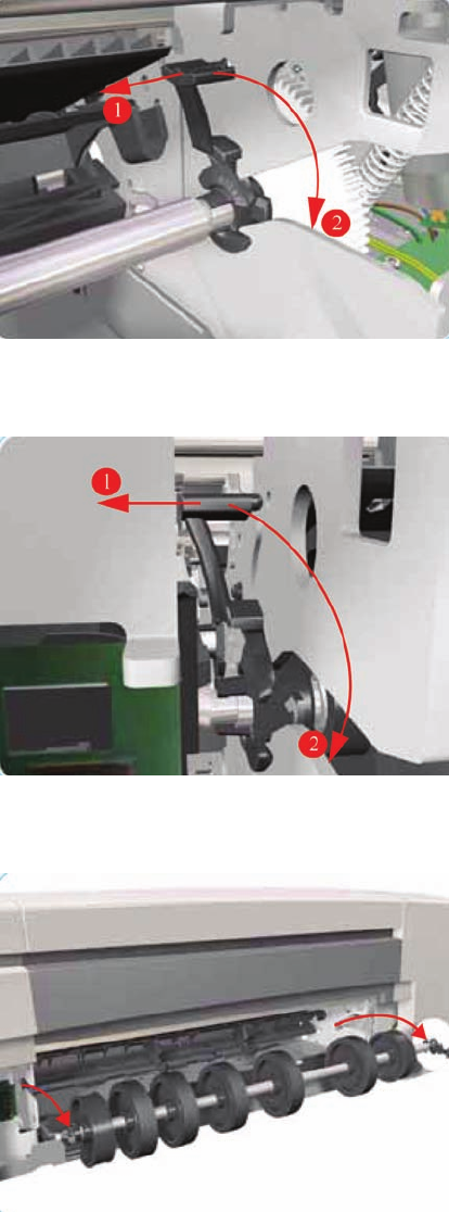
2. Release the locking mechanism that secures the Pick Assembly on the right hand side of the printer
(looking from the rear).
3. Release the locking mechanism that secures the Pick Assembly on the left hand side of the printer
(looking from the rear)
4. Raise the locks so that they are aligned with the cutouts and lift out the Pick Assembly from the
Printer.
Pick Assembly
(Not applicable to 30, 30n)
Removal
146 Chapter 7 Removal and Installation ENWW
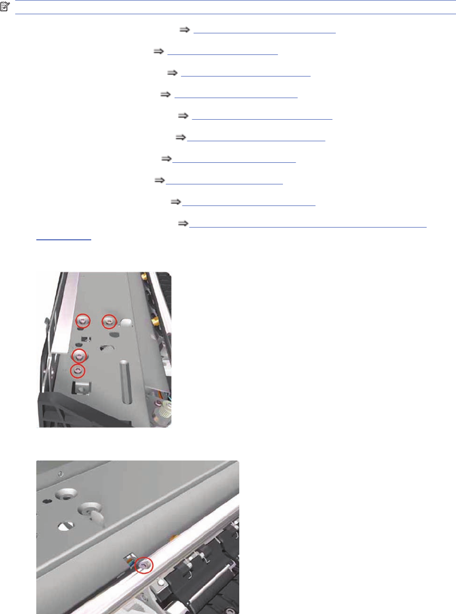
NOTE: Switch off the product and remove the power cable.
1. Remove the Cleanout Assembly Cleanout Assembly on page 120.
2. Remove the Center Cover Center Cover on page 99
3. Remove the Right End Cover Right End Cover on page 101.
4. Remove the Left End Cover Left End Cover on page 103.
5. Remove the Electronics Module Electronics Module on page 109.
6. Remove the Power Supply Unit Power Supply Unit on page 112.
7. Remove the Service Station Service Station on page 114.
8. Remove the Encoder Strip Encoder Strip on page 118.
9. Remove the Ink Supply Tubes Ink Supply Tubes on page 121.
10. Remove the Carriage Assembly Carriage Assembly (Applicability: 70, 100+, 110+, 111)
on page 123.
11. Remove four screws that secure the Hanger Assembly on the left hand side of the Printer.
12. Remove one screw that secures the Hanger Assembly on the left hand side of the Printer.
ENWW Pick Assembly 147
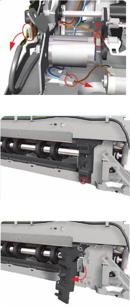
13. Disconnect the Paper-Axis, Encoder and Ramp Motor cables.
14. Remove one screw from the Rear Left Trim Bracket.
15. Remove the Rear Left Trim Bracket from the Printer.
148 Chapter 7 Removal and Installation ENWW
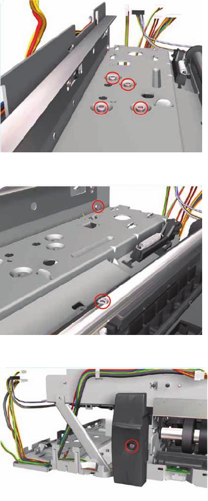
16. Remove four screws that secure the Hanger Assembly on the right hand side of the Printer.
17. Remove two screws that secure the Hanger Assembly on the right hand side of the Printer.
18. Remove one T-10 screw from the Rear Right Trim.
ENWW Pick Assembly 149
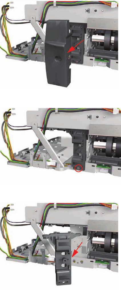
19. Remove the Rear Right Trim from the Printer.
20. Remove one screw from the Rear Right Trim Bracket.
21. Remove the Rear Right Trim Bracket from the Printer.
150 Chapter 7 Removal and Installation ENWW
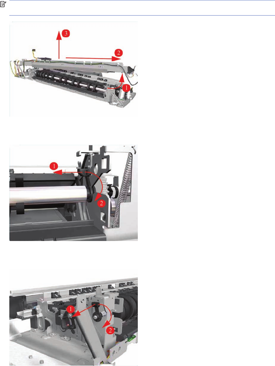
22. Remove the Hanger Assembly from the Printer.
NOTE: If there are any cables still attached between the Hanger Assembly and the Printer then
disconnect them before removing the Hanger Assembly.
23. Release the locking mechanism that secures the Pick Assembly on the right hand side of the printer
(looking from the rear).
24. Release the locking mechanism that secures the Pick Assembly on the right hand side of the printer
(looking from the rear).
ENWW Pick Assembly 151
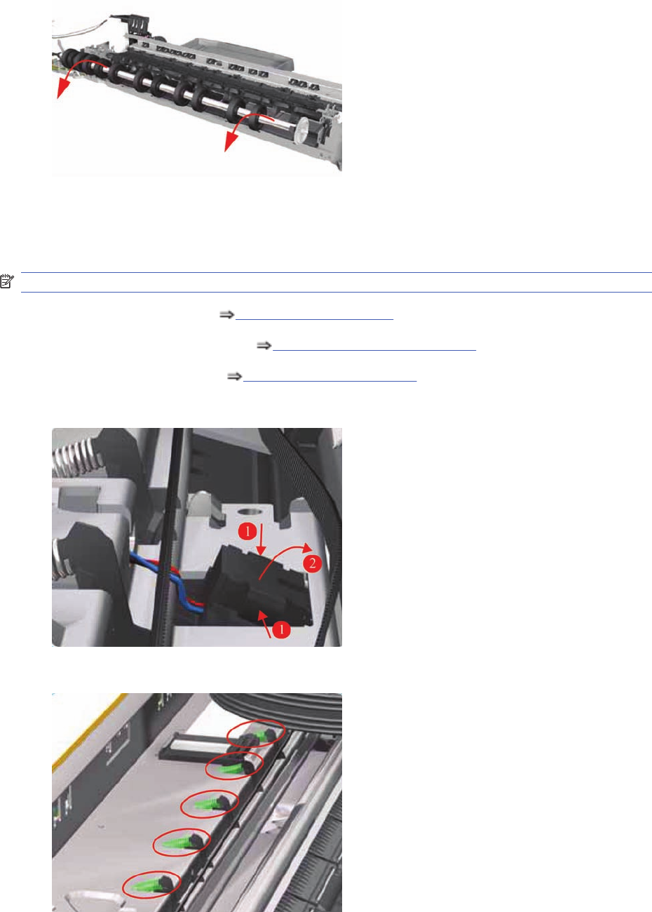
25. Raise the locks so that they are aligned with the cutouts and lift out the Pick Assembly from the
Printer.
Pinch Assembly (Applicability: 30, 30n)
Removal
NOTE: Switch off the product and remove the power cable.
1. Remove the Center Cover Center Cover on page 99.
2. Remove the Cleanout Assembly Cleanout Assembly on page 120.
3. Remove the Pick Assembly Pick Assembly on page 146.
4. Release the Out-of-Paper Sensor from the Pinch Assembly by pinching the tabs on either side.
5. Release ALL the Pinch Springs from the Pinch Assembly.
152 Chapter 7 Removal and Installation ENWW
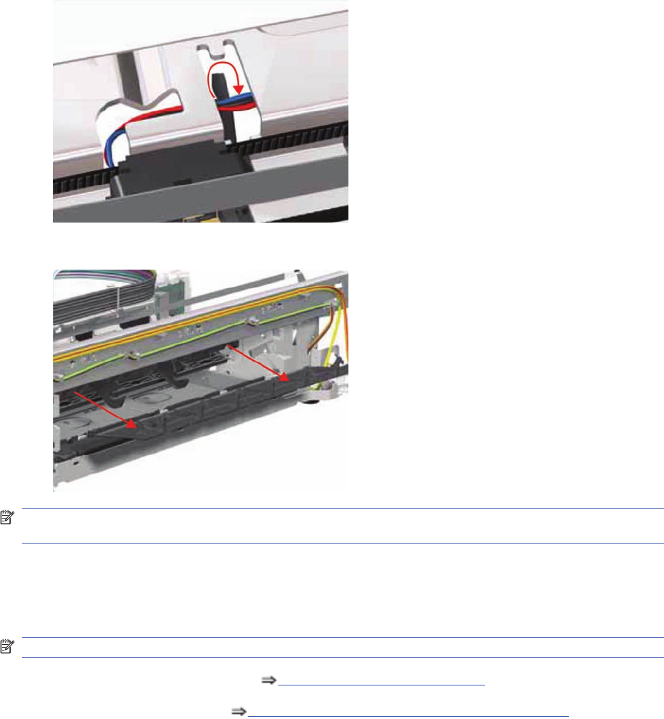
6. Release the Out-of-Paper Sensor cable that is looped underneath the Pinch Assembly.
7. Working from the rear, pull out the Pinch Assembly from the Printer.
NOTE: After removing or replacing the Pinch Assembly, make sure that you perform the PRS
Adjustment procedure.
Lower Paper Guide (Applicability: 30, 30n)
Removal
NOTE: Switch off the product and remove the power cable.
1. Remove the Cleanout Assembly Cleanout Assembly on page 120.
2. Remove the Pick Assembly Pick Assembly (Applicability: 30, 30n) on page 145.
ENWW Lower Paper Guide (Applicability: 30, 30n) 153
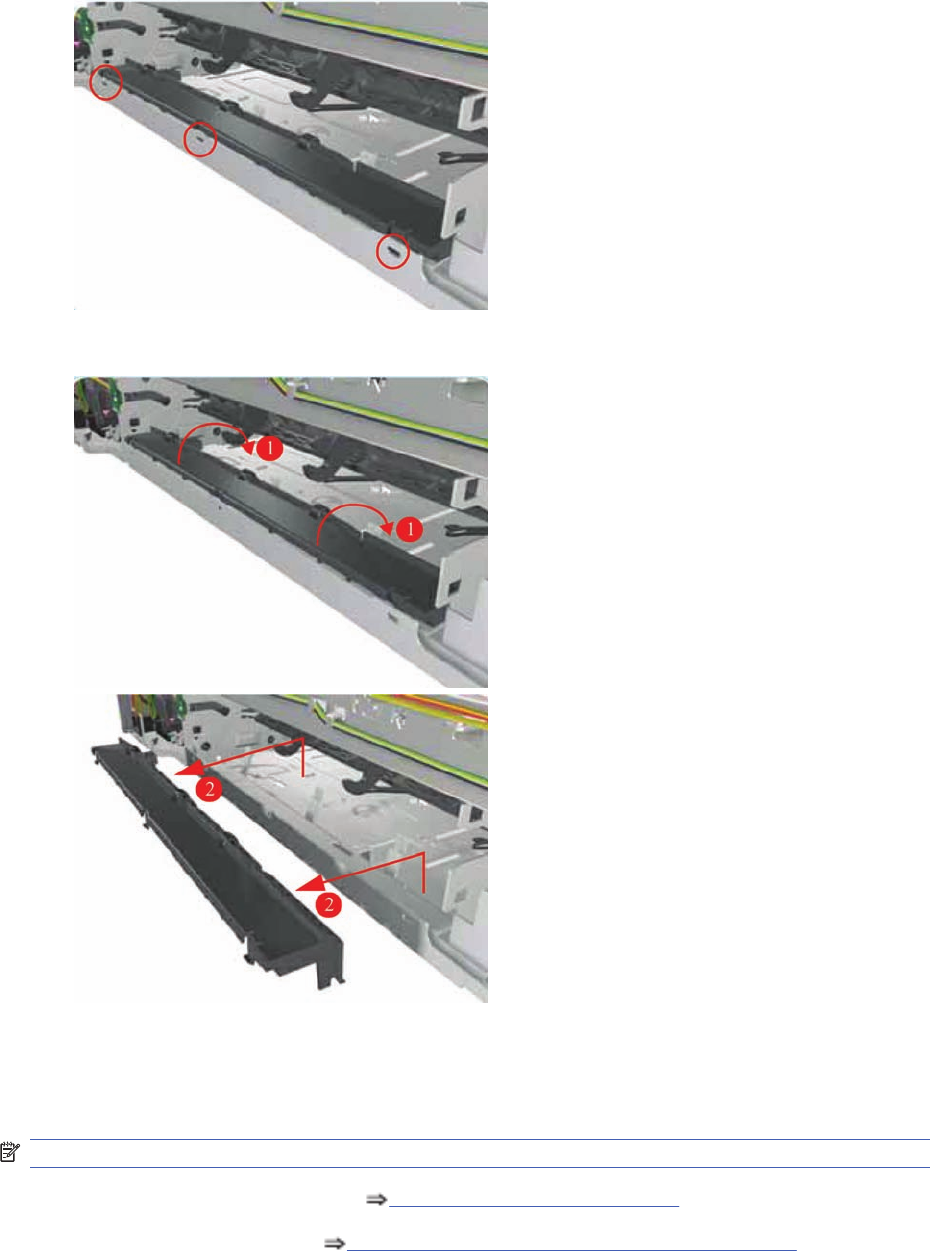
3. Release the tabs that secure the Lower Paper Guide (use a flat blade screwdriver to help you if
necessary).
4. Remove the Lower Paper Guide from the Printer.
Inner Paper Guide (Applicability: 30, 30n)
Removal
NOTE: Switch off the product and remove the power cable.
1. Remove the Cleanout Assembly Cleanout Assembly on page 120.
2. Remove the Pick Assembly Pick Assembly (Applicability: 30, 30n) on page 145.
154 Chapter 7 Removal and Installation ENWW
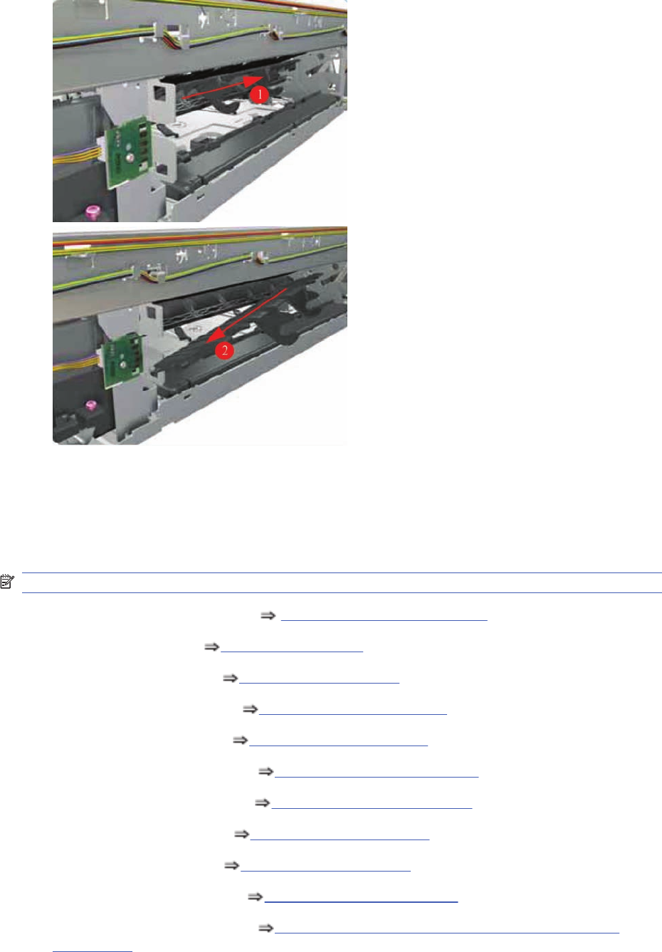
3. Release the locating pins on the left hand side (looking from the rear) by pushing the Inner Paper
Guide to the right and then removing it from the Printer.
Inner Paper Guide
Not applicable to 30, 30n
Removal
NOTE: Switch off the product and remove the power cable.
1. Remove the Cleanout Assembly Cleanout Assembly on page 120.
2. Remove the Top Cover Top Cover on page 98.
3. Remove the Center Cover Center Cover on page 99
4. Remove the Right End Cover Right End Cover on page 101.
5. Remove the Left End Cover Left End Cover on page 103.
6. Remove the Electronics Module Electronics Module on page 109.
7. Remove the Power Supply Unit Power Supply Unit on page 112.
8. Remove the Service Station Service Station on page 114.
9. Remove the Encoder Strip Encoder Strip on page 118.
10. Remove the Ink Supply Tubes Ink Supply Tubes on page 121.
11. Remove the Carriage Assembly Carriage Assembly (Applicability: 70, 100+, 110+, 111)
on page 123
ENWW Inner Paper Guide 155
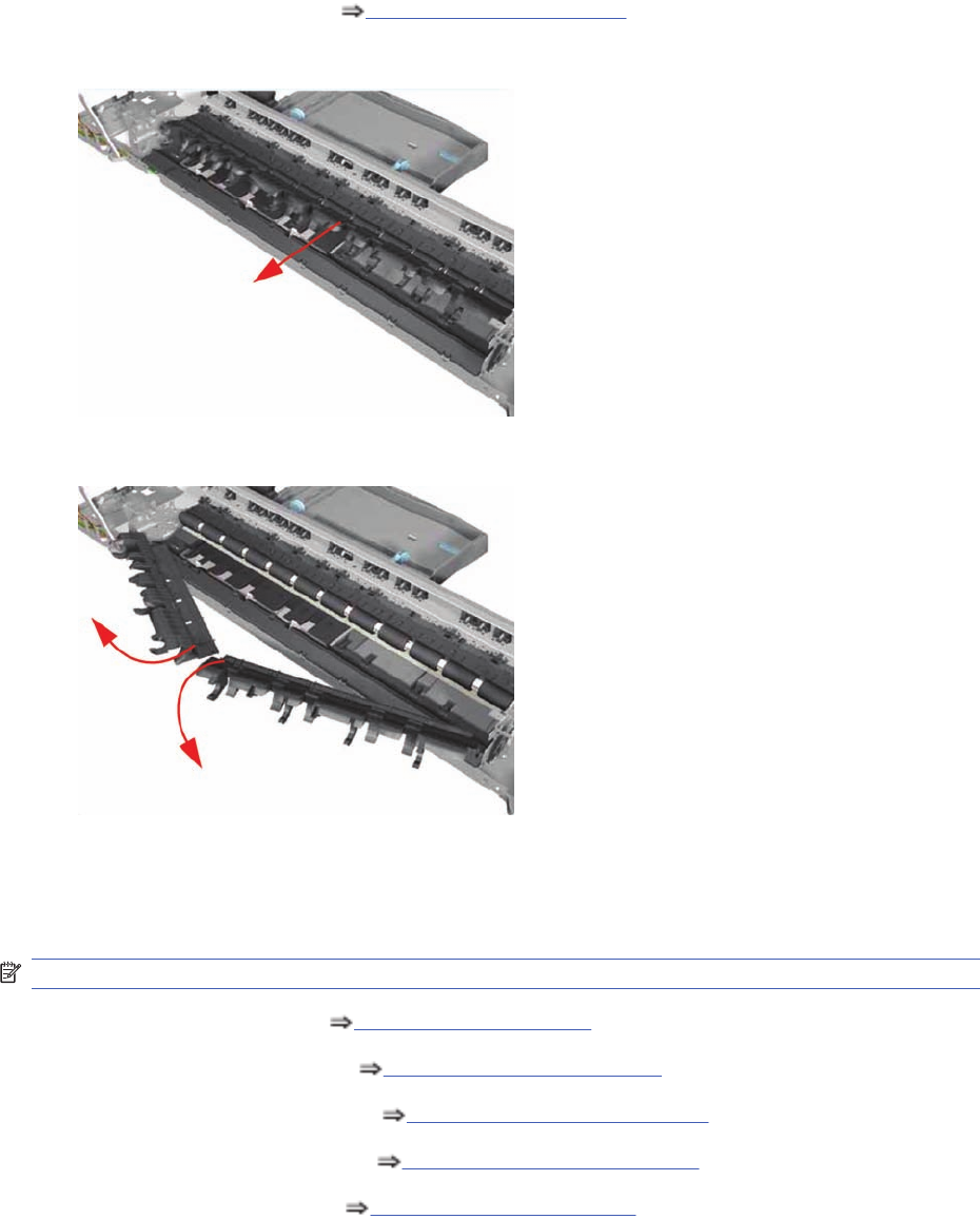
12. Remove the Pick Assembly Pick Assembly on page 146.
13. Pull the Inner Paper Guide from the middle to release it from the Printer.
14. Remove both pieces of the Inner Paper Guide from the Printer.
OOPS Sensor
Removal
NOTE: Switch off the product and remove the power cable.
1. Remove the Center Cover Center Cover on page 99.
2. Remove the Right End Cover Right End Cover on page 101.
3. Remove the Electronics Module Electronics Module on page 109.
4. Remove the Power Supply Unit Power Supply Unit on page 112.
5. Remove the Service Station Service Station on page 114.
156 Chapter 7 Removal and Installation ENWW
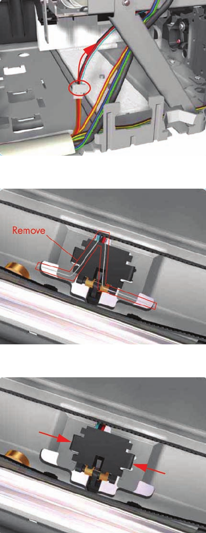
6. Disconnect the OOPS Sensor Cable.
7. Remove the Spring that secures the OOPS Sensor.
8. Press the OOPS Sensor clips inwards to release it.
ENWW OOPS Sensor 157
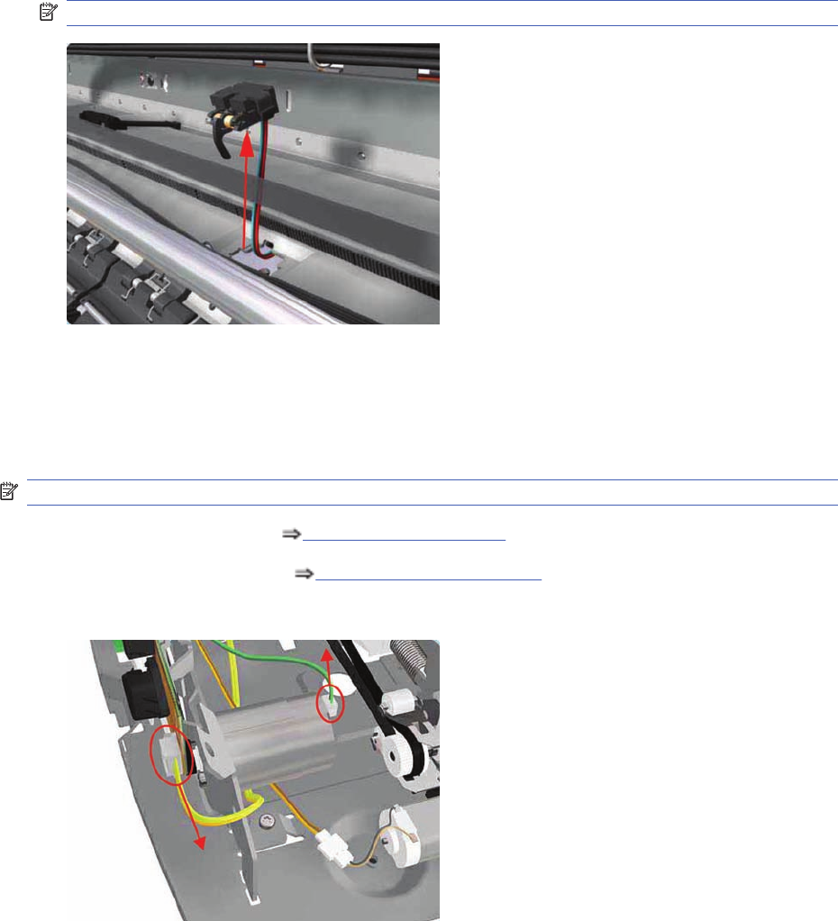
9. Remove the OOPS Sensor (including the cable) from the Printer.
NOTE: Check if any Cable Ties need to be cut before removing the OOPS Sensor.
Paper-Axis Motor Drive Assembly (Applicable only to 30,
30n)
Removal
NOTE: Switch off the product and remove the power cable.
1. Remove the Center Cover Center Cover on page 99.
2. Remove the Left End Cover Left End Cover on page 103.
3. Disconnect the Paper-Axis and Encoder cables.
158 Chapter 7 Removal and Installation ENWW
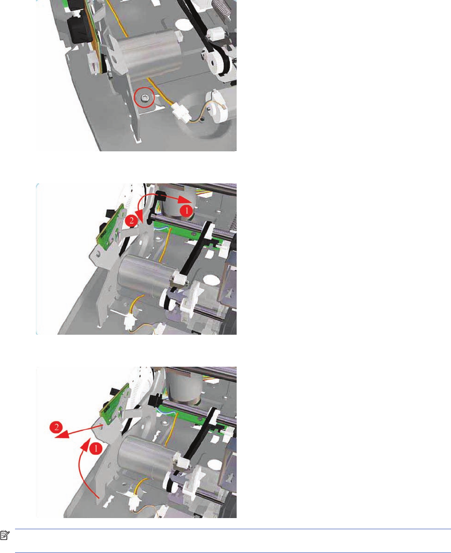
4. Remove one T-10 screw (Type A) that secures the Paper-Axis Motor Mount.
5. Release the locking mechanism that secures the Paper-Axis Motor Mount.
6. Remove the Paper-Axis Motor Assembly from the Printer.
NOTE: After removing or replacing the Paper-Axis Motor Assembly, make sure that you perform the
Accuracy Calibration.
Paper-Axis Motor Assembly (Applicability: 90, 90r, 130,
130nr)
Removal
ENWW Paper-Axis Motor Assembly (Applicability: 90, 90r, 130, 130nr) 159
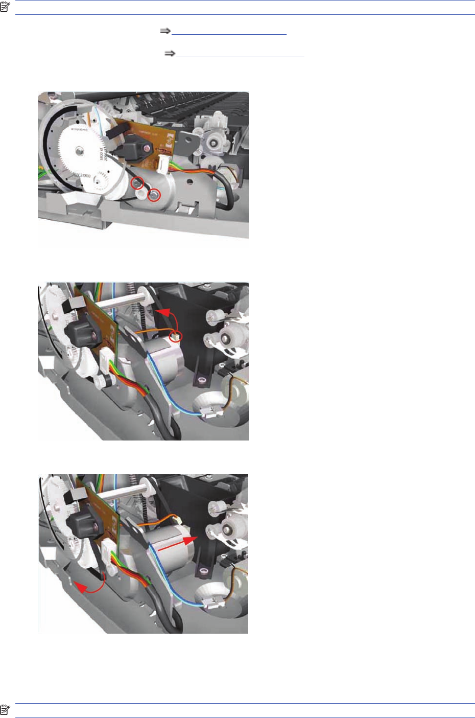
NOTE: Switch off the product and remove the power cable.
1. Remove the Center Cover Center Cover on page 99.
2. Remove the Left End Cover Left End Cover on page 103.
3. Remove two T-10 screws that secure the Paper-Axis Motor Assembly.
4. Disconnect the Paper-Axis Motor cable.
5. Disconnect the Paper-Axis Motor cable.
Bypass Platen (Applicability: 90, 90r, 130, 130nr)
Removal
NOTE: Switch off the product and remove the power cable.
160 Chapter 7 Removal and Installation ENWW
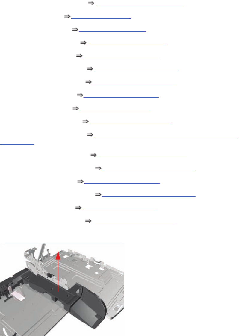
1. Remove the Cleanout Assembly Cleanout Assembly on page 120.
2. Remove the Top Cover Top Cover on page 98.
3. Remove the Center Cover Center Cover on page 99.
4. Remove the Right End Cover Right End Cover on page 101.
5. Remove the Left End Cover Left End Cover on page 103.
6. Remove the Electronics Module Electronics Module on page 109.
7. Remove the Power Supply Unit Power Supply Unit on page 112v.
8. Remove the Service Station Service Station on page 114.
9. Remove the Encoder Strip Encoder Strip on page 118.
10. Remove the Ink Supply Tubes Ink Supply Tubes on page 121.
11. Remove the Carriage Assembly Carriage Assembly (Applicability: 70, 100+, 110+, 111)
on page 123.
12. Remove the Starwheel Assembly Starwheel Assembly on page 130.
13. Remove the Print Platen Assembly Print Platen Assembly on page 131.
14. Remove the Pivot Assembly Pivot Assembly on page 138.
15. Remove the Feed Roller Assembly Feed Roller Assembly on page 141
16. Remove the Pick Assembly Pick Assembly on page 146.
17. Remove the Inner Paper Guide Inner Paper Guide on page 155.
18. Remove two T-10 screws that secure the Left Bracket to the Chassis.
ENWW Bypass Platen (Applicability: 90, 90r, 130, 130nr) 161
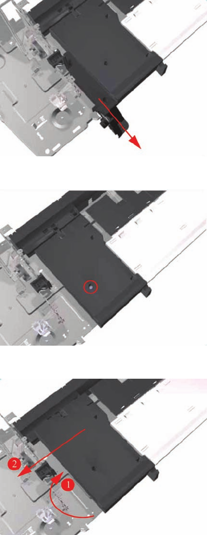
19. Slide the Left Bracket out of the Printer.
20. Remove one T-10 screw that secures the Side Guide to the Chassis.
21. Raise the Side Guide and then slide it out to the left.
162 Chapter 7 Removal and Installation ENWW
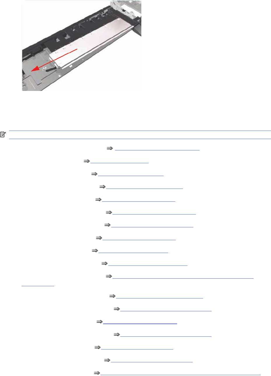
22. Slide the Bypass Platen to the left and remove from the Printer.
Bypass Platen Actuator (Applicability: 90, 90r, 130, 130nr)
Removal
NOTE: Switch off the product and remove the power cable.
1. Remove the Cleanout Assembly Cleanout Assembly on page 120.
2. Remove the Top Cover Top Cover on page 98.
3. Remove the Center Cover Center Cover on page 99.
4. Remove the Right End Cover Right End Cover on page 101.
5. Remove the Left End Cover Left End Cover on page 103.
6. Remove the Electronics Module Electronics Module on page 109.
7. Remove the Power Supply Unit Power Supply Unit on page 112.
8. Remove the Service Station Service Station on page 114.
9. Remove the Encoder Strip Encoder Strip on page 118.
10. Remove the Ink Supply Tubes Ink Supply Tubes on page 121.
11. Remove the Carriage Assembly Carriage Assembly (Applicability: 70, 100+, 110+, 111)
on page 123.
12. Remove the Starwheel Assembly Starwheel Assembly on page 130.
13. Remove the Print Platen Assembly Print Platen Assembly on page 131.
14. Remove the Pivot Assembly Pivot Assembly on page 138.
15. Remove the Feed Roller Assembly Feed Roller Assembly on page 141.
16. Remove the Pick Assembly Pick Assembly on page 146.
17. Remove the Inner Paper Guide Inner Paper Guide on page 155.
18. Remove the Bypass Platen Bypass Platen (Applicability: 90, 90r, 130, 130nr) on page 160.
ENWW Bypass Platen Actuator (Applicability: 90, 90r, 130, 130nr) 163
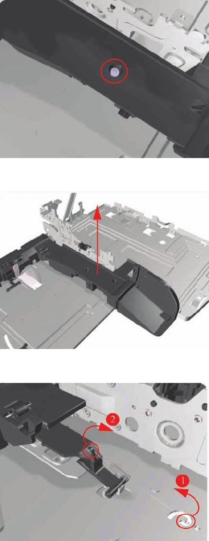
19. Remove one T-10 screw that secures the Right Bracket to the Chassis.
20. Lift the Right Bracket out of the Printer.
21. Release the Spring from the Bypass Platen Actuator.
164 Chapter 7 Removal and Installation ENWW
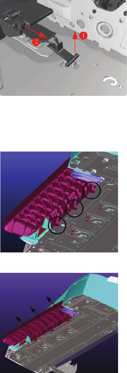
22. Remove the Bypass Platen Actuator from the Printer.
Output Platen (HP Designjet 111 with Roll)
Removal
1. From underneath the Output Tray, unclip the three retaining clips that hold the Output Tray in place.
2. Remove the Output Tray from the printer.
ENWW Output Platen (HP Designjet 111 with Roll) 165
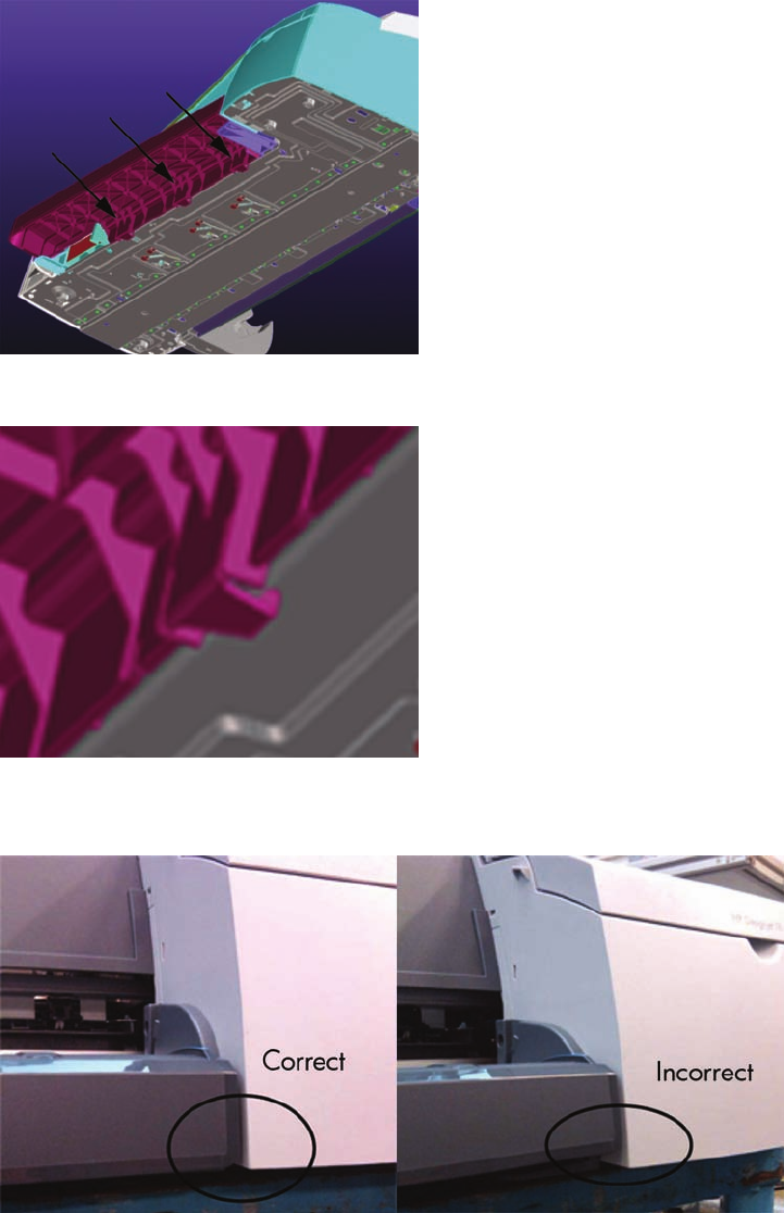
Installation
1. Insert the Output Tray into the front of the printer.
2. Ensure that each of the three clips located on the Output Tray are correctly latched to the printer
3. To check that the Output Tray is correctly installed, the underside of the Right Cover should be
horizontally aligned with the Output Tray.
166 Chapter 7 Removal and Installation ENWW

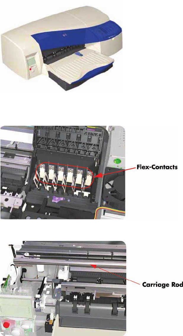
Maintenance
Cleaning Information
IMPORTANT - Do NOT clean the following: Pinch Rollers, Drive Belt, Service Station (unless
otherwise noted), Main PCA and other Electronic components such as Cables and Motors.
Case Parts: Use mild detergents such as PK 200 or Simple Green with water on a clean lint-free cloth.
Solvents and water on a clean lint-free cloth can be used to remove stubborn stains on external case
parts.
Paper Dust: It is recommended that vacuuming be used to remove paper dust from inside the printer.
Do NOT use compressed air.
Carriage Flex-Contacts: Use water on a clean lint-free cloth.
Carriage Rod: Cleaning is NOT recommended. If extremely dirty, wipe with a clean lint-free cloth. Do
NOT use water or solvents.
168 Chapter 8 Maintenance ENWW
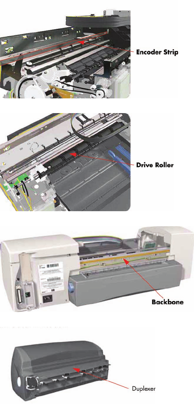
Encoder Strip: Wipe from left to right (viewed from front) with a clean lintfree cloth. Do NOT pull hard
on the Encoder Strip.
Drive Roller: Use water on a clean lint-free cloth. Do Not use solvents.
Backbone: Use water on a clean lint-free cloth. Dry carefully, parts left damp may rust.
Duplexer: Check for ink on connector to module. If ink is present, wipe clean with a clean lint-free cloth.
ENWW Maintenance 169
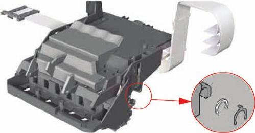
Lubrication Information
Lubrication: Cleaning the Carriage Rod is NOT recommended. If, however, the Carriage was wiped
clean, replace the felt washers on the Carriage Assembly. The felt washers are impregnated with oil to
provide the necessary lubrication for the Carriage Rod.
About this Edition
This is the 3
rd
edition of this Service Manual
1
st
edition March 2006
2
nd
edition August 2006
3
rd
edition March 2010
What’s in this Service Manual
This manual contains information necessary to test, calibrate and service:
HP Designjet 30 Printer (Model C7790D)
HP Designjet 30n Printer (Model C7790E)
HP Designjet 70 Printer (Model Q6655A)
HP Designjet 90 Printer (Model Q6656A)
HP Designjet 90r Printer (Model Q6656B)
HP Designjet 100+ Printer (Model C7796C)
HP Designjet 110 Printer (Model C7796B)
HP Designjet 110+ Printer (Model C7796D)
HP Designjet 110+nr Printer (Model C7796E)
HP Designjet 130 Printer (Model C7791C)
HP Designjet 130nr Printer (Model C7791D)
HP Designjet 111 Printer, With Roll (Model CQ532A)
HP Designjet 111 Printer, With Tray (Model CQ533A)
For information about using these printers, refer to the corresponding User Guide.
The procedures described in this manual are to be performed by HP-qualified Service Personnel only.
170 Chapter 8 Maintenance ENWW
