Boomer_SM HP Designjet L28500
User Manual: HP Designjet L28500 shared.swissparts.ch - /Manuals/HP/Plotter/
Open the PDF directly: View PDF ![]() .
.
Page Count: 628 [warning: Documents this large are best viewed by clicking the View PDF Link!]
- Using this manual
- 1 Printer systems
- Electrical system
- Description
- Components
- Circuit diagram
- E-box components
- Carriage Electronics
- Ink Supply Station (ISS) Electronics
- Vacuum Fan electronics
- Waste Management Electronics
- Heating System Electronics
- Electrical power system
- 380–415 V three-phase line-to-line configuration
- 200–240 V three-phase line-to-line configuration
- 200–240 V single-phase or bi-phase line-to-line configuration
- 110–130 V single-phase line-to-line configuration
- Power cable and Power Distribution Unit (PDU) requirements
- Main Switch
- Residual Circuit Current Breaker (RCCB)
- Sinewave converters
- Output circuit diagrams
- Substrate path
- Ink Delivery System (IDS)
- Scan Axis and Carriage
- Service Station and waste management
- Heating system
- Front Panel
- Electrical system
- 2 Troubleshooting
- Troubleshooting the printer
- Troubleshooting system error codes
- Performing a service test on a failed assembly
- Performing the necessary service calibrations
- The printer does not power on
- How to read the power switch LEDs
- How to read the Formatter LEDs
- How to read other LEDs
- Voltage check at installation
- Troubleshooting substrate jams or printhead crashes
- The printer continuously rejects printheads
- The cutter does not function
- Troubleshooting Carriage shutdowns
- Troubleshooting the drying and curing heaters
- Troubleshooting sensors
- How to troubleshoot the 79:04 system error
- Vacuum suction much lower at high altitudes
- Banding due to ink cartridge replacement while printing
- How to interpret the Service Information Pages
- How to obtain the printer log and the diagnostics package
- 3 System Error Codes
- Introduction
- System error codes and warnings—explanation
- Continuable and non-continuable error codes
- SE Code: 01.0:03 – Engine PCA electronics error
- SE Code: 01.0:10 – Engine PCA hardware failure
- SE Code: 01.1.03 – PrintMech PCA electronics error
- SE Code: 01.1.10 – PrintMech PCA hardware failure
- SE Code: 01.2:10 – ISS Pre-Driver PCA communication failure
- SE Code: 01.3:10 – ISS Pre-Driver PCA communication failure
- SE Code: 01.10:10 – PrintMech PCA is faulty
- SE Code: 01.11:10 – PrintMech PCA is faulty
- SE Code: 02:10 – Mechanical Carriage error
- SE Code: 02.1:10 – Problem with the Carriage PCA
- SE Code: 03:10 – Power distribution failure
- SE Code: 03.10:10 – Extra 24 V PSU failure
- SE Code: 05:10 – Formatter communication failure with ISS
- SE Code: 05.01:10 – Formatter CPU fan stopped or burnt out
- SE Code: 06.03 – Main NVM communication failure
- SE Code: 06.10 – Main NVM communication failure
- SE Code: 08.04 – The Front Panel watchdog timer has expired
- SE Code: 08:04.1 – ASSERT in Front Panel code
- SE Code: 08:08 – ASSERT in Front Panel code
- SE Code: 08:11 – A Front Panel application has died
- SE Code: 11:10 – Connection problem with the Trailing Cable
- SE Code: 14.31:10 – Pinch Power regulator V null and no fault
- SE Code: 14.32:01 – Pinch Power regulator V null and faulty
- SE Code: 14.33:01 – Pinch Power regulator V lower than 140
- SE Code: 14.34:01 – Pinch Power regulator V lower than 180
- SE Code: 14.35:01 – Pinch Power regulator V higher than Vmax
- SE Code: 14.36:11 – Pinch Power regulator V could not be read
- SE Code: 14.40:10 – Pinch Power regulator current not null
- SE Code: 14.41:10 – Pinch Power regulator current too high
- SE Code: 14.42:10 – Pinch Power regulator short-circuit
- SE Code: 14.43:11 – Pinch Power Regulator open circuit
- SE Code: 14.46:11 – Pinch Power regulator R out of range
- SE Code: 14.47:10 – Pinch Power regulator OverTemp
- SE Code: 14.48:10 – Pinch Power regulator overvoltage or short-circuit
- SE Code: 14.49:10 – Pinch sine-wave converter failure
- SE Code: 14.51:10 – Overdrive power regulator V null and no fault
- SE Code: 14.52:01 – Overdrive power regulator V null and fault
- SE Code: 14.53:01 – Overdrive power regulator V lower than 140
- SE Code: 14.54:01 – Overdrive power regulator V lower than 180
- SE Code: 14.55:01 – Overdrive power regulator V higher than Vmax
- SE Code: 14.56:11 – Overdrive power regulator V could not be read
- SE Code: 14.60:10 – Overdrive power regulator current not null
- SE Code: 14.61:10 – Overdrive power regulator current too high
- SE Code: 14.62:10 – Overdrive power regulator short-circuit
- SE Code: 14.63:11 – Overdrive power regulator open circuit
- SE Code: 14.66:11 – Overdrive power regulator R out of range
- SE Code: 14.67:10 – Overdrive power regulator OverTemp
- SE Code: 14.68:10 – Overdrive power regulator overvoltage or short-circuit
- SE Code: 14.69:10 – Overdrive sine-wave error
- SE Code: 14.71:10 – Curing power regulator V null and no fault
- SE Code: 14.72:01 – Curing power regulator V null and fault
- SE Code: 14.73:01 – Curing power regulator V lower than 140
- SE Code: 14.74:01 – Curing power regulator V lower than 180
- SE Code: 14.75:01 – Curing power regulator V higher than Vmax
- SE Code: 14.76:11 – Curing power regulator V could not be read
- SE Code: 14.80:10 – Curing power regulator current not null
- SE Code: 14.81:10 – Curing power regulator current too high
- SE Code: 14.82:10 – Curing power regulator short-circuit
- SE Code: 14.83:11 – Curing power regulator open circuit
- SE Code: 14.84:11 – Curing power regulator Rtotal is nominal1
- SE Code: 14.85:11 – Curing power regulator Rtotal is nominal2
- SE Code: 14.86:11 – Curing power regulator R out of range
- SE Code: 14.87:10 – Curing power regulator OverTemp
- SE Code: 14.88:10 – Curing power regulator overvoltage or short-circuit
- SE Code: 14.89:10 – Curing sine-wave converter failure
- SE Code: 15.01:00 – Drying system warn-up timed out
- SE Code: 15.02:00 – Drying system cool-down timed out
- SE Code: 15.03:00 – Drying system temperature too high
- SE Code: 15.04:00 – Drying system temperature too low
- SE Code: 15.05:00 – Problem with the drying system Temperature Sensor
- SE Code: 15.06:00 – Temperature error detected
- SE Code: 15.08:00 – Heating fans array not connected
- SE Code: 15.09:11 – Heating fan fault
- SE Code: 15.15:11 – Drying fan short-circuit
- SE Code: 15.20:01 – Minimum drying power has been automatically adjusted
- SE Code: 16.01:00 – Curing system warn-up timed out
- SE Code: 16.02:00 – Curing system cool-down timed out
- SE Code: 16.03:00 – Curing system temperature too high
- SE Code: 16.04:00 – Curing system temperature too low
- SE Code: 16.05:00 – Problem with the curing system Temperature Sensor
- SE Code: 16.06:00 – Temperature error detected
- SE Code: 16.08:00 – Curing fans array 1 not connected
- SE Code: 16.09:00 – Curing fan array 1 fault
- SE Code: 16.11:00 – Curing fans array 2 not connected
- SE Code: 16.20:11 – IR sensor curing fan not connected
- SE Code: 16.21:10 – Curing fan array 2 fault
- SE Code: 17.0:11 – PrintMech to Interconnect power cable disconnected
- SE Code: 17.1:11 – PrintMech to Interconnect data 1 cable disconnected
- SE Code: 17.2:11 – PrintMech to Interconnect data 2 cable disconnected
- SE Code: 17.3:11 – Engine PCA to PrintMech black 1 cable disconnected
- SE Code: 17.4:11 – Engine PCA to PrintMech blue 2 cable disconnected
- SE Code: 21:03 – Service Station electrical current limit
- SE Code: 21:13 – Problem with the Service Station
- SE Code: 21.2:10 – Problem with the Web Wipe motor
- SE Code: 21.3:10 – Electrical problem in the Web Wipe Motor
- SE Code: 21.4:03 – Electrical problem in the Web Wipe Motor
- SE Code: 21.5:03 – Web Wipe Assembly Drifting
- SE Code: 23:10 – Air Pressure System failure
- SE Code: 24:03 – Ink Supply Tubes purge failure
- SE Code: 24:10 – Ink cartridge broken bag
- SE Code: 24:11 – PrintMech PCA to ISS Top cable disconnected
- SE Code: 24.1:11 – ISS Top PCA to ISS Bottom PCA cable disconnected
- SE Code: 24.02:00 – Top Cover fans disconnected
- SE Code: 24.03:00 – Top Cover fans not working
- SE Code: 26:14 – A wrong ink cartridge has been detected
- SE Code: 26.0:01 – Contact failure with magenta ink cartridge
- SE Code: 26.1:01 – Contact failure with yellow ink cartridge
- SE Code: 26.2:01 – Contact failure with black ink cartridge
- SE Code: 26.3:01 – Contact failure with cyan ink cartridge
- SE Code: 26.4:01 – Contact failure with light magenta ink cartridge
- SE Code: 26.5:01 – Contact failure with light cyan ink cartridge
- SE Code: 27:01 – Calibration failed due to a printhead
- SE Code: 27:14 – A wrong printhead has been detected
- SE Code: 27.1:01 – Calibration failed due to printhead in slot 1
- SE Code: 27.2:01 – Calibration failed due to printhead in slot 2
- SE Code: 27.3:01 – Calibration failed due to printhead in slot 3
- SE Code: 27.4:01 – Calibration failed due to printhead in slot 4
- SE Code: 27.5:01 – Calibration failed due to printhead in slot 5
- SE Code: 27.6:01 – Calibration failed due to printhead in slot 6
- SE Code: 29:01 – Printhead Cleaning Cartridge incorrectly inserted
- SE Code: 32:01 – Take-Up Reel disconnected
- SE Code: 32:01.1 – Early Take-Up Reel substrate jam
- SE Code: 32:01.2 – Take-Up Reel substrate jam
- SE Code: 32:01.9 – Take-Up Reel substrate unexpectedly removed
- SE Code: 32:02 – Take-Up Reel disconnected at initialization
- SE Code: 41:03 – Media-Axis Motor electrical current limit
- SE Code: 42:03 – Scan-Axis Motor electrical current limit
- SE Code: 42:10 – Electrical fault in the Scan Axis area
- SE Code: 42.10:11 – Scan-Axis Motor cooling fan not connected
- SE Code: 42.11:10 – Scan-Axis Motor cooling fan fault
- SE Code: 43:11 – Vacuum Fan not connected
- SE Code: 43.2:11 – Vacuum Fan stopped
- SE Code: 43.3:10 – Vacuum Fan overcurrent
- SE Code: 43.4:10 – Vacuum Fan low performance
- SE Code: 43.11:11 – Vacuum Fan 2 or 3 not connected
- SE Code: 43.12:11 – Vacuum Fan 2 or 3 stopped
- SE Code: 43.13:10 – Vacuum Fan 2 or 3 overcurrent
- SE Code: 43.14:10 – Vacuum Fan 2 or 3 low performance
- SE Code: 44:10 – There is a problem with the Aerosol Fan
- SE Code: 44:11 – Aerosol Fan not connected
- SE Code: 44.1:01 – Waste Management cable not connected
- SE Code: 44.2:01 – Waste management switch open
- SE Code: 44.3:01 – Waste management cable short-circuited
- SE Code: 44.4:01 – Problem in the waste management feedback signal
- SE Code: 45:03 – Rewinder servo shutdown
- SE Code: 45:10 – Rewinder fault
- SE Code: 46:03 – Primer servo shutdown
- SE Code: 46:10 – Primer test distance failed
- SE Code: 50:14 – Firmware version mismatch
- SE Code: 50.1:10 – OMAS communication failure
- SE Code: 50.2:10 – OMAS Controller Card communication failure
- SE Code: 50.3:11 – Engine PCA to OMAS Controller cable not connected
- SE Code: 50.10:11 – TOMAS error
- SE Code: 52:01 – A problem with the Drop Detector
- SE Code: 52:10 – A problem with the On/Off switch in the Drop Detector
- SE Code: 53.1:10 – Media Sensor error
- SE Code: 53.1:11 – Media Sensor cable not connected
- SE Code: 54:10 – Media Lever Sensor error
- SE Code: 55:10 – Line Sensor communication failure
- SE Code: 56:01 – Incorrect readings from Substrate Encoder
- SE Code: 56:10 – Substrate Encoder calibration failed
- SE Code: 58:01 – Color Sensor shutter error
- SE Code: 58:10 – Color Sensor failure
- SE Code: 58.1:10 – Color Sensor Shutter Actuator failure
- SE Code: 58.2:10 – Color Sensor Shutter Deactivator failure
- SE Code: 59.1:09 – Two electrical parts have been replaced at the same time
- SE Code: 59.2:00 – An unsupported or reused part has been installed
- SE Code: 61:10 – Data lost due to I/O timeout
- SE Code: 63:05 – The job is reaching the printer too slowly
- SE Code: 65:04 – I/O problem though an unknown port
- SE Code: 74:01 – Error uploading firmware update file
- SE Code: 77:04 – Embedded Web Server internal software error
- SE Code: 78.1:04 – Substrate settings error
- SE Code: 78.2:01 – The back tension has been lost
- SE Code: 79:03 – Generic firmware error I
- SE Code: 79:04 – Generic firmware error II
- SE Code: 81:01 – Possible substrate jam
- SE Code: 81:03 – Problem with setting the encoder position
- SE Code: 82:01 – Substrate jam in the platen area
- SE Code: 85:03 – Drive Roller encoder problem
- SE Code: 86:01 – Possible substrate jam
- SE Code: 87:01 – Problem with the Scan Axis encoder sensor readings
- SE Code: 94:01 – Substrate unsuitable for color calibration
- SE Code: 94:02 – Color calibration error: inconsistent colors
- SE Code: 94:10 – Color Sensor contaminated by aerosol
- SE Code: 98:03 – Printhead nozzles out
- 4 Service Tests, Utilities & Calibrations
- Introduction
- Diagnostics - Self Test
- Service Tests
- Service Menu
- Entering the Service Utilities Menu
- 1. Service Tests and Utilities Menu
- 1.1 Boot Mode
- 1.1.1 Force Diagnostic Mode
- 1.1.2 Force Normal Mode
- 1.2 Electrical System
- 1.2.1 Set Date and Time
- 1.2.2 Enable/Disable Firewall
- 1.2.3. Enable/Disable Logs
- 1.2.4 Input/Output
- 1.2.5 Set Serial Number
- 1.2.6 Sleep Mode
- 1.2.7 Report Test Version
- 1.3 Substrate Path
- 1.3.1 Turn Drive Roller
- 1.3.2. Enable/Disable OMAS
- 1.3.3 OMAS Sensor Check
- 1.4 Ink System
- 1.4.1 Purge Tubes
- 1.5 Scan Axis
- 1.5.1 Force Drop Detection
- 1.6 Carriage
- 1.6.1. Color Sensor Shutter Diagnostic
- 1.6.2 Color Sensor Measurement Test
- 1.6.3 Color Sensor Check
- 1.6.4 Test Cutter
- 1.7 Service Station
- 1.7.1. Prime Pen X
- 1.8 Heating and Curing
- 1.8.1 Heating and Curing Temperature
- 1.8.2 Enable Heating and Curing
- 1.9 Show Test Messages
- 1.10 Force FW Upgrade
- 1.11 Hard Disk Recovery
- 2. Image Quality Plots
- 2.1 Print ALL Plots
- 2.2 Printhead Alignment
- 2.2.1 Test Plot
- 2.2.2 Advanced Test Plot
- 2.2.3 Automatic Printhead Alignment
- 2.2.4 Manual PH Alignment
- 2.2.4.1 Print Pattern
- 2.2.4.2 Manual Alignment Settings
- 2.3 Substrate Advance
- 2.3.1 Print Adjustment Plot
- 2.3.2 Reset Substrate Advance
- 2.4 Printhead Health
- 2.4.1 Print Test Plot
- 2.4.2 Advanced Test Plot
- 2.4.3 Only for Escalations
- 2.4.4 Clean All Printheads
- 2.4.5 Clean LC-C Printheads
- 2.4.6 Clean Y-MK Printheads
- 2.4.7 Clean LM-M Printheads
- 2.5 Geometry Check
- 2.6 Scan Axis Check
- 2.7 Vacuum Check
- 2.8 Side Registration Check
- 2.11 Others
- 3. Ink On Substrate Test
- 4. Reset Life Counters (NEVER DONE BY CUSTOMER)
- 5. Service Calibrations
- 5.1 Substrate Path
- 5.1.1 Substrate Advance Calibration
- 5.1.2 OMAS calibration
- 5.1.3 Reset Vacuum Calibration
- 5.1.4 Rewinder Calibration
- 5.2 Scan Axis
- 5.2.1 Scan Axis Calibration
- 5.2.2 Drop Detector Calibration
- 5.3 Carriage
- 5.3.1 Line Sensor Calib.
- 5.3.2 Primer Calibration
- 5.3.3 Color Sensor Shutter Calibration
- 5.3.4 Color Sensor Calibration
- 5 Print Quality
- RIP and front panel settings
- How to use the image quality plots
- 2.2.1 Printhead alignment test plot
- 2.4.1 Printhead health test plot
- 2.3.2 Print adjustment plot
- 2.4.2 Advanced printhead health test plot
- 2.2.2 Advanced alignment diagnostic print
- 2.4.3 Plot for escalation only
- 2.5 Geometry check
- 2.6 Scan axis check
- 2.7 Vacuum check
- Printing plot
- Modifying the vacuum level during plot printing
- Recommendations to modify the vacuum level during the plot
- Instructions to increase or decrease the vacuum level
- The substrate advance patterns
- Checking the main substrate advance pattern
- Comparing the secondary substrate advance pattern with the main one
- Other plot information
- 2.8 Misregistration check
- 3.1 Inks on substrate test
- Force drop detection
- Troubleshooting non-uniform curing
- Substrate advance issues
- 6 Ink Supplies
- What are ink supplies?
- Waste Management System
- General information about the ink supplies
- General precautions when handling ink supplies
- Priming the ink system
- When should you replace the ink supplies?
- Obtaining ink cartridge and printhead information
- Troubleshoot ink cartridge and printhead issues
- The front panel recommends replacing or reseating a printhead
- Warranty information for ink supplies
- 7 Parts and Diagrams
- Printer Support
- Front Covers
- Top & Back Covers
- Electronics Module
- Power Cabinet
- Right Cover
- Left Cover
- Right Hand Assemblies
- Waste Management System
- Left Hand Assemblies
- Vacuum Extra
- Carriage Assembly
- Dryer Assembly
- Curing Assemblies
- Curing Fans Assembly
- Scan-Axis Assemblies
- Drive Roller and Media-Axis Motor
- Substrate Path Assemblies
- Media Input (MI) and Pinchwheel Assembly
- Media Entry Assemblies
- Take-Up Reel Assembly
- Miscellaneous Parts
- 8 Removal & Installation
- Service part order
- Disassembly order
- Introduction
- Opening the Window
- Window
- Front Tube Shelf Beam
- Hinge Brakes
- Right Cover
- Right Trim, Media Lever, and Media Lever Sensor
- Left Cover
- Left Trim
- Left Curing Cover
- Right Curing Cover
- Rear Upper Cover
- Top Cover
- Right Connector Cover
- Power Box Cover
- Extra PSU 24 V
- Pre-Driver PCA
- Electronics Enclosure Extension Cover
- Heater Controller Box
- Window Lock Sensor Left
- Window Lock Sensor Right
- Top Cover Fans
- Rear Fans
- Front Panel
- Primer Assembly
- Primer Valves
- Primer Valve Cable
- Service Station
- Web Wipe Assembly
- Vacuum Fan
- Vacuum Fan Cable
- Vacuum Fans Extra
- Waste Ink System
- Waste Ink System Support
- Waste Ink Tube Guide
- Drop Detector, Funnel Transmission, Waste Ink Tube
- Ink Supply Tubes and Trailing Cable
- ISS to Cartridge Cables
- Cutter Assembly
- Ink Supply Station (ISS)
- Ink Supply Station PCAs (Top and Bottom)
- APS Assembly
- Encoder Strip
- Carriage PCA
- Carriage Flex Cables
- Oiler
- Carriage Assembly with Belt, Pulley, and Tensioner
- Media Jam Sensor and Carriage Reflector Assembly
- Belt Assembly
- Scan-Axis Motor
- Scan-Axis Motor Fan
- Media-Axis Motor
- OMAS: Optical Media Advance Sensor
- TOMAS: Temperature Optical Media Advance Sensor
- TOMAS Cable
- Interconnect PCA
- OMAS Controller Card
- OMAS Cable
- Engine PCA
- Formatter PCA
- Hard Disk Drive
- Power Supply Unit (PSU)
- Formatter Battery
- Circuit Breakers
- PrintMech PCA
- Electronics Enclosure
- Line Sensor Assembly
- Color Sensor Assembly
- Color Sensor Actuator Assembly
- Dryer Grill
- Dryer IR Temperature Sensor
- Dryer Protector
- Dryer Heater
- Curing Fans and Cover
- Curing IR Temperature Sensor & Fan
- Curing Module
- Curing Heaters
- Output Platen
- Curing Holders
- Print Platen
- Cartridge Tray
- Input Roller
- Media Input Profile
- Input Platen
- Output Roller
- Printhead Cleaning Cartridge Door
- Printhead Cleaning Cartridge Door Sensor
- Media Sensor
- Encoder Disc and Sensor
- Media Lever Linkage
- Pinchwheel Cam Arm
- Pinchwheel Assembly
- Individual Pinchwheel Rollers
- Drive Roller
- Rewinder Left-Hand Module
- Take-Up Reel Left-Hand Module
- Rewinder Right-Hand Module
- Take-Up Reel Right-Hand Module
- Take-Up Reel Diverter
- Take-Up Reel Sensor Module
- Tension Bar
- 9 Preventive Maintenance
- 10 Move, store, or repack the printer
- 11 Safety precautions

DESIGNJET L28500 Printer Series
July 2012
Customer Assurance
Customer Experience Section
Large Format Printing Division
Hewlett-Packard Espanola, S.L.
Cami de Can Graells, 1–21
08174 Sant Cugat del Vallès
Spain
For HP Internal Use Only
© 2012 Hewlett-Packard
Company
This document contains
proprietary information that is
protected by copyright. All
rights are reserved. No part of
this document may be
photocopied, reproduced, or
translated to another language
without the prior written
consent of Hewlett-Packard
Company.
2nd edition, July 2012
Warranty
The information contained in
this document is subject to
change without notice.
Hewlett-Packard makes
no warranty of any kind
with regard to this
material, including, but
not limited to, the implied
warranties of
merchantability and
fitness for a particular
purpose.
Hewlett-Packard shall not be
liable for errors contained
herein or for incidental or
consequential damages in
connection with the furnishing,
performance, or use of this
material.
WARNING
The procedures described in
this manual are to be
performed by HP-qualified
service personnel only.
Electrical Shock Hazard
Serious shock hazard leading
to death or injury may result if
you do not take the following
precautions:
- Ensure that the ac power
outlet (mains) has a protective
earth (ground) terminal.
- Disconnect the printer from the
power source before
performing any maintenance.
- Prevent water or any other
liquids from running onto
electrical components or
circuits, or through openings in
the enclosure.
Electrostatic Discharge
Refer to the beginning of
Chapter 4 of this manual, for
precautions you should take to
prevent damage to the printer
circuits from electrostatic
discharge.
Safety Symbols
General definitions of safety
symbols are given immediately
after the table of contents.
WARNING
The Warning symbol calls
attention to a procedure,
practice, or the like, which, if
not correctly performed or
adhered to, could result in
personal injury. Do not
proceed beyond a Warning
symbol until the indicated
conditions are fully understood
and met.
CAUTION
The Caution symbol calls
attention to an operating
procedure, practice, or the like,
which, if not correctly
performed or adhered to, could
result in damage to or
destruction of part or all of the
product. Do not proceed
beyond a Caution symbol until
the indicated conditions are
fully understood and met.
HP Designjet L28500 Printer Series
Service Manual
Table of Contents 1
Printer system 1-7
Troubleshooting 2-45
System error codes 3-89
Service test, utilities and calibrations 4-145
Print quality 5-207
Ink supplies 6-235
Service parts and diagrams 7-247
Removal and installation 8-271
Preventive maintenance 9-607
Move, repack, and store the printer 10-613
Safety precautions 11-625

Using this manual
Purpose
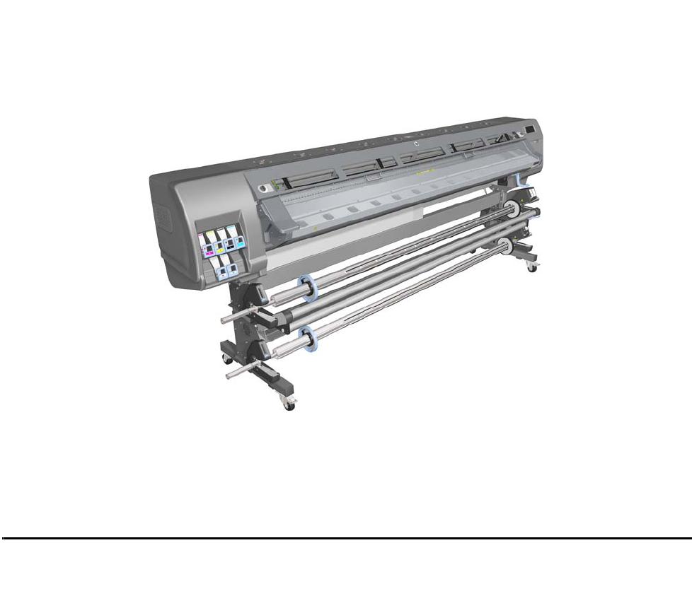
This Service Manual contains information necessary to test, calibrate, and service the HP Designjet
L28500 104-inch Printer (Model CQ871A).
For information about using the printer, see the User’s Guide.
Chapters
1 Printer systems
Use this chapter as a reference for technical information about the subsystems, components, and how they
work together.
Of particular importance are the diagrams included for each subsystem of the printer. They can be useful
for both troubleshooting and disassembly.
2 Troubleshooting
Whenever a printer is not functioning correctly due to a fault, use this chapter for step-by-step diagnosis
until you arrive at the solution, which may include replacing a part.
Troubleshooting always begins with a problem; so, when you enter the chapter, navigate to the proper
section and find the troubleshooting steps for your problem.
This chapter does not cover the procedures for the diagnostic tests you must perform while troubleshooting,
nor the replacement procedures you must complete to fix the problem.
3 System error codes
This chapter contains the system error codes which are displayed on the Front Panel and by the Embedded
Web Server. Each system error code shown in the chapter has a brief description and the steps required
to solve the error.
Most of the troubleshooting steps involve performing a test or a calibration, which can be found in the
following chapter. Before replacing any part that you suspect of causing the system error code, always
perform the test or calibration.
4 Tests, utilities, and calibrations
Use this chapter whenever you need to perform a diagnostic test, service utility, or service calibration. This
chapter is meant to provide procedures and relevant information, not troubleshooting information. For
troubleshooting information, see the Troubleshooting chapter.
These procedures are described in full, so that you know any relevant values for the test, as well as
information about what the printer is actually doing during the test.
The goal of diagnostic tests is to locate the root cause of the problem and the corresponding system error
code or message that will provide you with logical steps to resolution.
Some diagnostic tests or calibrations must be performed after removing a component.
5 Print quality
This chapter describes the print-quality diagnostic procedures. Further troubleshooting advice can be
found in the User’s Guide.

6 Ink supplies
This chapter describes and discusses the components of the ink supply system.
7 Parts and diagrams
The purpose of this chapter is to detail all of the available service parts of the printer. This information is
presented in tables, organized by subsystem, and includes the following:
•Official service part names
•Part numbers
•Illustrations of the service parts
Use this chapter whenever you need to order a service part.
8 Removal and installation
The purpose of this chapter is to provide procedures for removing and installing service parts. Each service
part has a removal procedure detailed in this chapter, and installation procedures and notes are included
as needed.
Useful information such as access notes and screw types (head sizes) are provided to help you work
efficiently.
9 Preventive maintenance
Maintenance alerts are displayed on the Front Panel and Embedded Web Server whenever maintenance
is required. While most of these alerts can be resolved by the customer, some require a service engineer.
Use the preventive maintenance chapter whenever you need to perform a preventive maintenance
procedure due to an alert the customer receives from the Front Panel or Embedded Web Server, or to get
reference information on life counters and maintenance that must be performed by the customer.
10 Move, store, or repack the printer
This chapter gives advice on moving, storing, and repacking the printer.
11 Safety precautions
This is an industrial printer that uses high voltages: service operations can be hazardous. The safety
chapter covers all the guidelines and checks you need to perform in order to service the printer.
You are expected to have appropriate technical training and experience necessary to be aware of
hazards to which you may be exposed in performing a task, and take appropriate measures to minimize
the risks to yourself and to other people.
Readership
The primary readers of this service manual are HP Service Engineers, although secondary readership may
include resellers. All procedures must be performed by HP Service Engineers or Authorized Service
Delivery Partners, except for those procedures clearly marked otherwise.

Printer Systems
Printer systems 7
1 Printer systems
•Electrical system .....................................................................................................8
•Substrate path ..................................................................................................... 25
•Ink Delivery System (IDS) ....................................................................................... 31
•Scan Axis and Carriage........................................................................................33
•Service Station and waste management .................................................................. 37
•Heating system ....................................................................................................40
•Front Panel ..........................................................................................................43

8Printer systems
Printer systems
Electrical system
Description
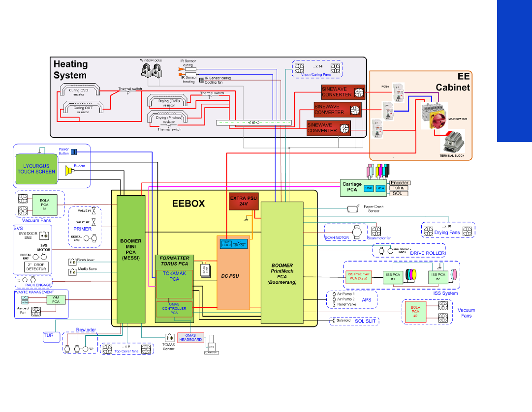
The electrical system controls all the printing systems and the heating systems inside the printer. Most parts
of the control electronics are placed inside the ’E-box’.
Components
The electronics can be divided into different functional subsystems and will be described accordingly.
There are 7 functional subsystems within the electronics, as shown below.
•Front Panel: The Front Panel in this printer includes a touchscreen, a power button, and a buzzer.
It is connected to three different boards on the EEbox: Formatter PCA (control), Engine PCA (power
button signal), and Mini Interconnect PCA (buzzer and power control).
•Substrate Path: Controls the substrate movement: Drive Roller and Rewinder motors, Take-Up
Reel, OMAS sensor, four Vacuum Fans (controlled by two Eola PCAs), pinch lever, and Media
Sensors.
•Scan Axis: Printhead firing control and sensors for color and substrate detection (Carriage PCA,
encoder, Tetris and SOL sensors, substrate crash sensor, and movement control using the scan motor
and its fan).
•Service Station: Printhead maintenance. It controls a motor, a drop detector, and some sensors,
including primer.
•Waste Management: Management of the waste ink and aerosol coming from the Service
Station.
•Ink Supply: Control of ink through two ISS PCAs and an intermediate PreDriver board as a buffer.
•Heating System: Dryer and Curing Resistor heater elements controlled by three sinewave
converters plus some Infrared (IR) sensors for Latex ink. The power input lines for the heating are
distributed to the rest of the printer through the EE Cabinet module.
Printer systems 9
Printer systems
Circuit diagram
E-box components
Description
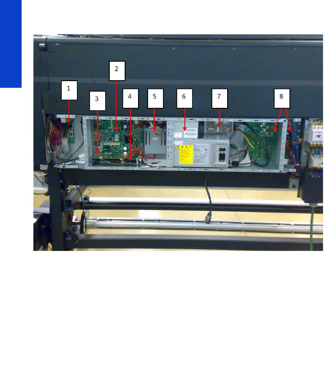
The E-box contains most of the electronics of the printer.
10 Printer systems
Printer systems
Components
1. Mini interconnect PCA [Messi]
2. Formatter PCA [Torus]
3. Engine PCA [Tokamak] (similar to what was known as Sausalito)
4. OMAS PCA
5. Hard Disk Drive (HDD)
6. Power Supply Unit (PSU)
7. Extra Power Supply 24 V
8. Printmech PCA [Boomerang]
Functionality
Mini interconnect PCA
The Mini PCA is just a interconnect board with only connectors that helps distribute the power and control
signals from the Printmech board to all the elements connected to the right side of the machine, including
the following:
•Take-Up Reel
•Vacuum Fans (passes through, the actual control is inside Printmech)
•Front Panel
•TOMAS (temperature sensor for the OMAS sensor)

Printer systems 11
Printer systems
•Valves and motors for primer, rack engage, SVS, and Waste Management
•Top fans
•Rewinder motor
Formatter PCA
The formatter is the motherboard of the printer, and is the same type of board as for a standard PC.
Engine PCA
This board is the main controller of the printer. It is responsible for all the processes performed in real-time
and is the ultimate controller of all electromechanical systems. The Engine PCA controls all substrate path
components (Drive Roller, Spindle Motors, OMAS, etc.) and all non-substrate path components (Carriage,
Scan Axis Motor, Dryer and Curing Heaters, Print Head Cleaning Assembly, Service Station, etc).
OMAS PCA
This board controls the Optical Media Advance Sensor used to measure the substrate advance.
Hard Disk Drive (HDD)
The HDD contains the firmware of the printer.
•The operating system.
•All calibration values, product number, serial number etc, are stored on the Hard Disk Drive. In order
to make sure that this information is not lost in the case of a failure of the HDD, a backup is made in
the ISS top board
Power Supply Unit (PSU)
This PSU delivers power to all the parts of the printer but the heater elements. The internal rails are: 5V_sb;
3V3, 5V, 12V, 24V, and 42V.
Extra Power Supply Unit (24 V)
This extra PSU supplies 24 V for some extra components such as drying fans and scan motor fan.
Printmech PCA [Boomerang]
The Printmech PCA is mainly used to control all the mechatronics of the printer. For routing reasons, only
the parts connected to the left side of the printer are connected to this board:
•Scan-Axis Motor
•Media-Axis Motor
•Ink valves
•Ink pressurizing pumps
•Dryer fans
•Curing fan
•Vacuum fans
•IR sensor
•IR Fan
•Sinewave converter control
•Media Jam Sensor
The remaining functionality implemented in the printmech PCA is sent to the right side of the printer
through the Mini Interconnect PCA and its 3 cables (power + data).
NOTE: In order to prevent any loss of calibration values, do not replace the following at the same
time:
•The Hard Disk Drive and the ISS Top Board
12 Printer systems
Printer systems
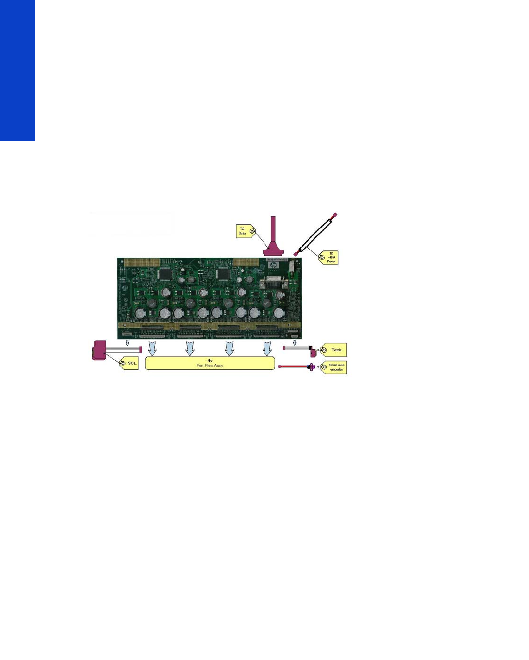
Carriage Electronics
The Carriage contains the electronics for controlling and firing the Printheads. It also contains electronics
for controlling the external sensors (SOL and Tetris) as well as the Scan Axis Encoder.
The electronics of the Carriage receives power and data from the Trailing Cables, which include both
power (+45V) and data (LVDS) cables. The power cable connects the Carriage with the Printmech board
and the data cable connects the Carriage with the Engine PCA.
Components
Carriage PCA
The Carriage PCA contains the electronics to control how and when the ink is dropped from every
Printhead, and receives information from the sensors.
SOL Spectrophotometer
The SOL is a color sensor located on the left side of the Carriage. A metal sheet protects the SOL from the
high temperatures produced by the Dryer Assembly. The main function of the SOL is to measure color
samples that have been printed on the loaded substrate and then are placed in the print platen zone.
Before taking any color measurement, the SOL must be initialized. The SOL initialization process takes
approximately 7 minutes. This process consists of three steps:
•Sensor switch on
•Sensor warm up
•Sensor calibration
When the initialization process has finished, the shutter opens automatically and the Carriage is moved
along the Scan Axis to place the SOL on top of each sample to take a color measurement. After the
measurements, the shutter is closed again and the sensor is switched off.
Tetris
Tetris is used to align the Printheads as well as to locate the substrate edges and measure its size. The
alignment procedure consists of a series of patterns first being printed, then scanned using the Tetris, and
finally an internal process is used to correct the timing of when and where the nozzles of the Printheads
fire, and detect any possible nozzle-out issues.
Scan axis encoder
The line encoder is located on the Carriage; it measures and counts the movements of the Scan Axis. An
optical, infrared wavelength encoder is used: the same type of encoder used in most of the HP large-format
printers. The Encoder signal is converted to LVDS logic levels and directly routed through the Data TC.
Printer systems 13
Printer systems
Printhead Flex
To connect the Carriage to the Printheads, a delicate flexible circuit with small golden dimples is used.
Printheads are inserted into unique slots and a spring-loaded mechanism pushes the electrical contacts of
the Printheads into the Printhead flex, which subsequently connects the Printhead to the Carriage
electronics. Printhead Flexes are the most delicate and sensitive part of the Carriage. If the Printheads are
inserted with too much force or they are misaligned, the insertion can easily damage them.
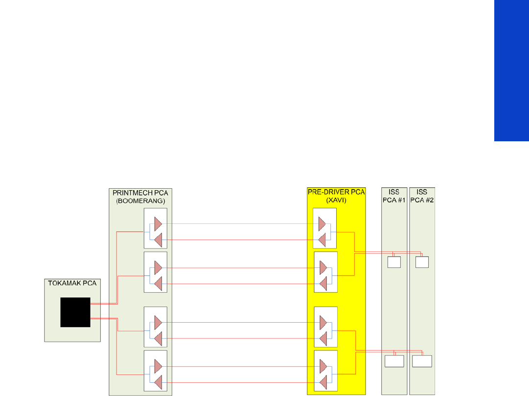
Ink Supply Station (ISS) Electronics
Description
There are two ISS PCAs (as in the DJ L25500/L26500 printers) plus a new extra board in between the
ISS PCAs and the PrintMech PCA, called the Pre-Driver PCA.
14 Printer systems
Printer systems
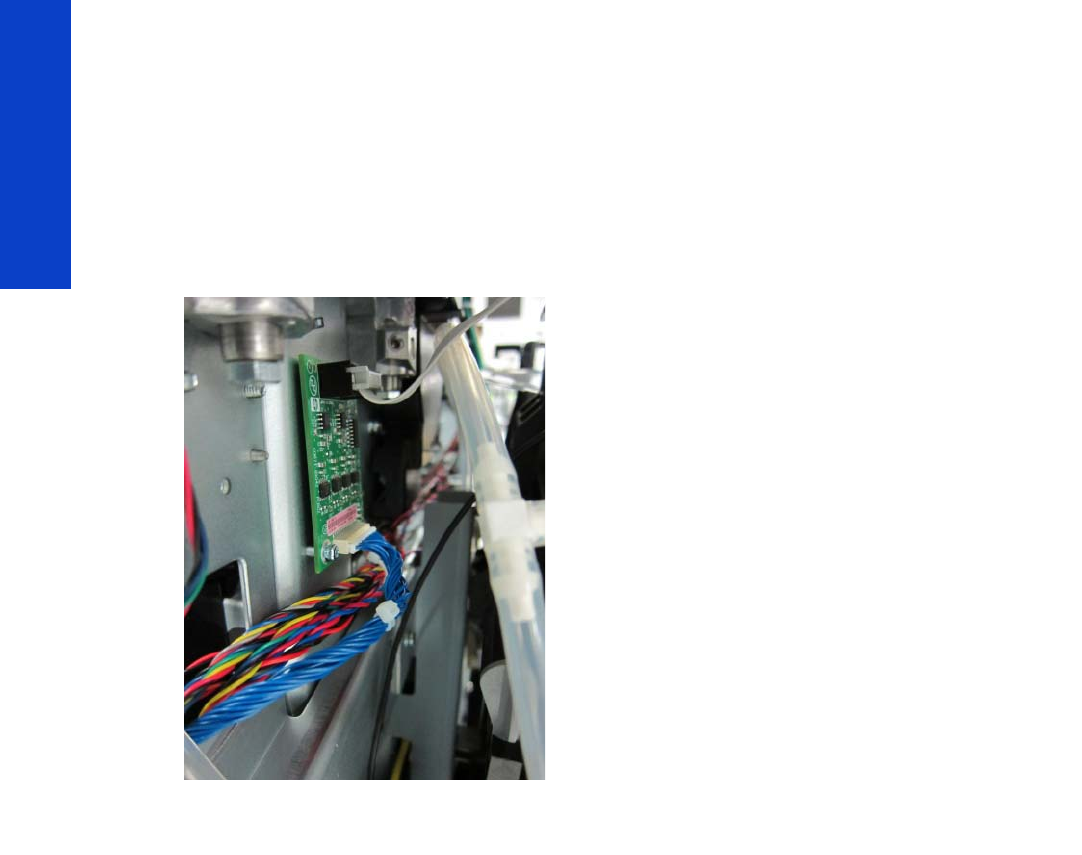
Components
PreDriver PCA
This board receives signals from the PrintMech PCA in differential mode and translates them to single-
ended ones.
It has two LEDS:
•Green LED: 5 V present coming from the PrintMech board (cable connected)
•Red LED: Overpressure or disconnected cable to the ISS PCA
See the Troubleshooting chapter (page 52) for more details, such as the location of the LEDs.
Top and Lower ISS PCAs
The ISS electronics are powered from a +12 V line coming from the PrintMech, and a linear regulator on
the ISS PCAs generates the +5 V used to power all the devices on the board.
The ISS PCAs are two electronic PCAs located at the rear of the Ink Supply Station. The ISS PCAs provide
the following:
•Pressure Ink Level Sense (PILS) measurement
•Ink supply presence detection
•Ink Cartridge broken bag detection
•Ink supply smart chip interface
•Air pressure measurement and air pump shutdown
•Humidity and temperature measurements
•System back-up EEPROM
Printer systems 15
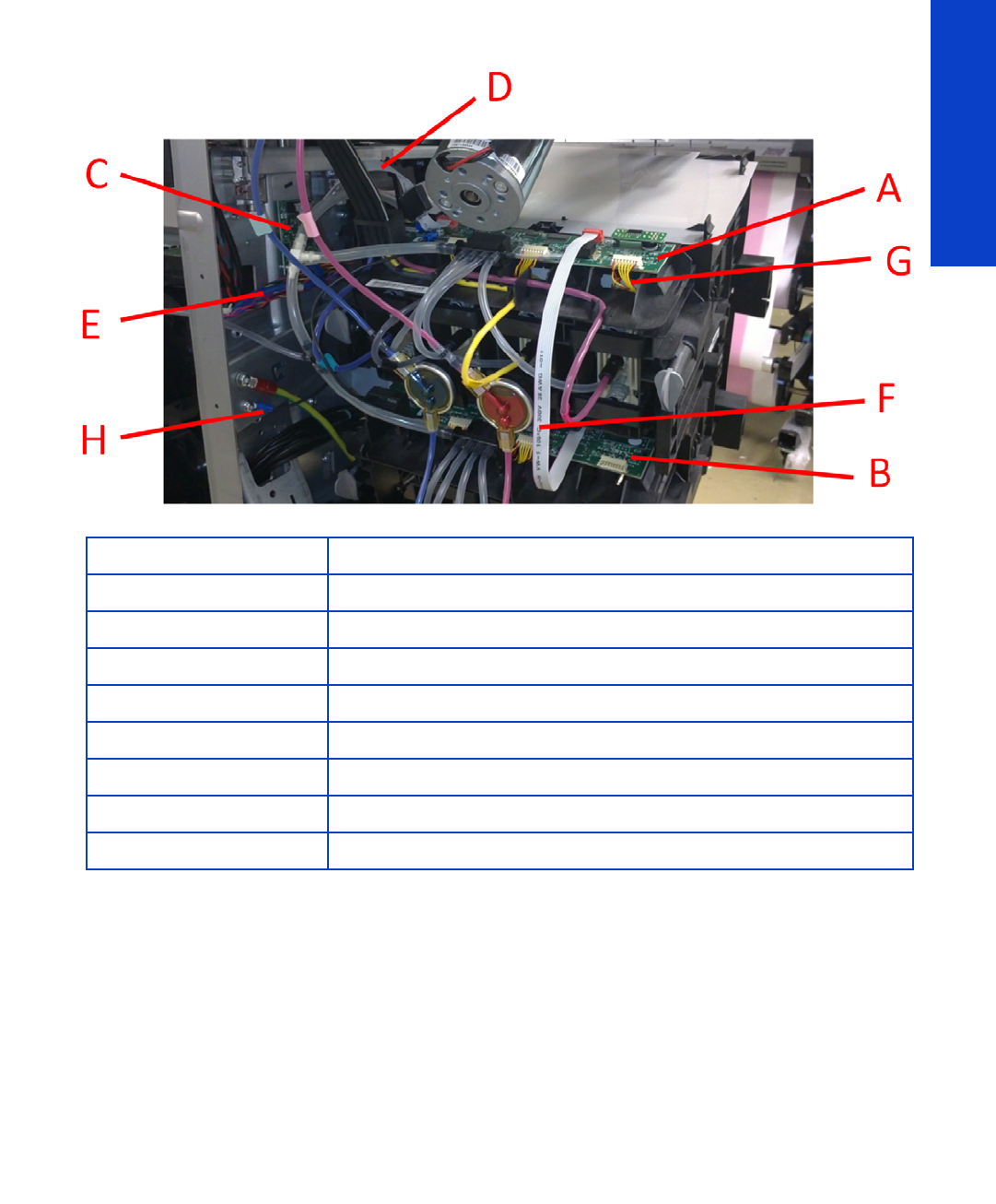
Printer systems
Below is a picture showing the connections and components located at the rear of the ISS.
Both top and lower ISS PCAs share the same PCB, the only difference between them is that the lower PCA
is a simplification of the top PCA: the top PCA contains these additional parts:
•EEPROM
•Connection from the PrintMech PCA
•Air pressure sensor
•Temperature and Humidity sensors
Both PCAs are connected through an 8-pin connector. The 2nd ISS connector is connected to the
PrintMech PCA in a daisy-chained connection, the 1st ISS board by means of this 8-pin connector.
Vacuum Fan electronics
Description
There are two Eola PCAs to control 4 different brushless blowers in order to generate the required vacuum
to hold the substrate. One of the Eola PCAs is connected to the Printmech PCA (left side of the printer) and
the other one to the Mini Interconnect PCA (right side).
Marking Description
AISS Top PCA
BISS Lower PCA
CPre-Driver PCA
D Cable: ISS Top PCA to Pre-Driver PCA
E Cable: Pre-Driver PCA to PrintMech PCA (blue)
F Cable: ISS Top PCA to ISS Lower PCA
G Cables (6): ISS PCAs (Top and Lower) to Ink Cartridges
H ISS grounding cable
16 Printer systems
Printer systems
Waste Management Electronics
Description
There is a small interconnect board (WM PCA) to connect the aerosol fan and two switches used in the
waste management system (as in the DJ L26500). This board is connected to the EEbox through the Mini
Interconnect PCA. There is an intermediate connector in the Ebox chassis to allow customers to connect
the cable during installation.
Heating System Electronics
Description
The heating system provides the power to the heater elements in order to dry and cure the jobs.
The amount of power used for heating requires a three-phase power system.
Components
•Terminal block
•Main Switch
•3 x RCBs
•3 x Sine wave converters
•Drying & curing resistors
•Thermal switches
•IR sensors (for curing and heating)
•IR sensor curing cooling fan
•2 x Window switches x Sine wave converters
•Curing and Drying fans
INPUT Circuit diagrams
The heating components form a high voltage system, so they are protected by their own enclosure (EE
cabinet) for safety.
Printer systems 17
Printer systems
A simplified block diagram of the input stage of the heater system (EE cabinet) is shown in the following
picture:
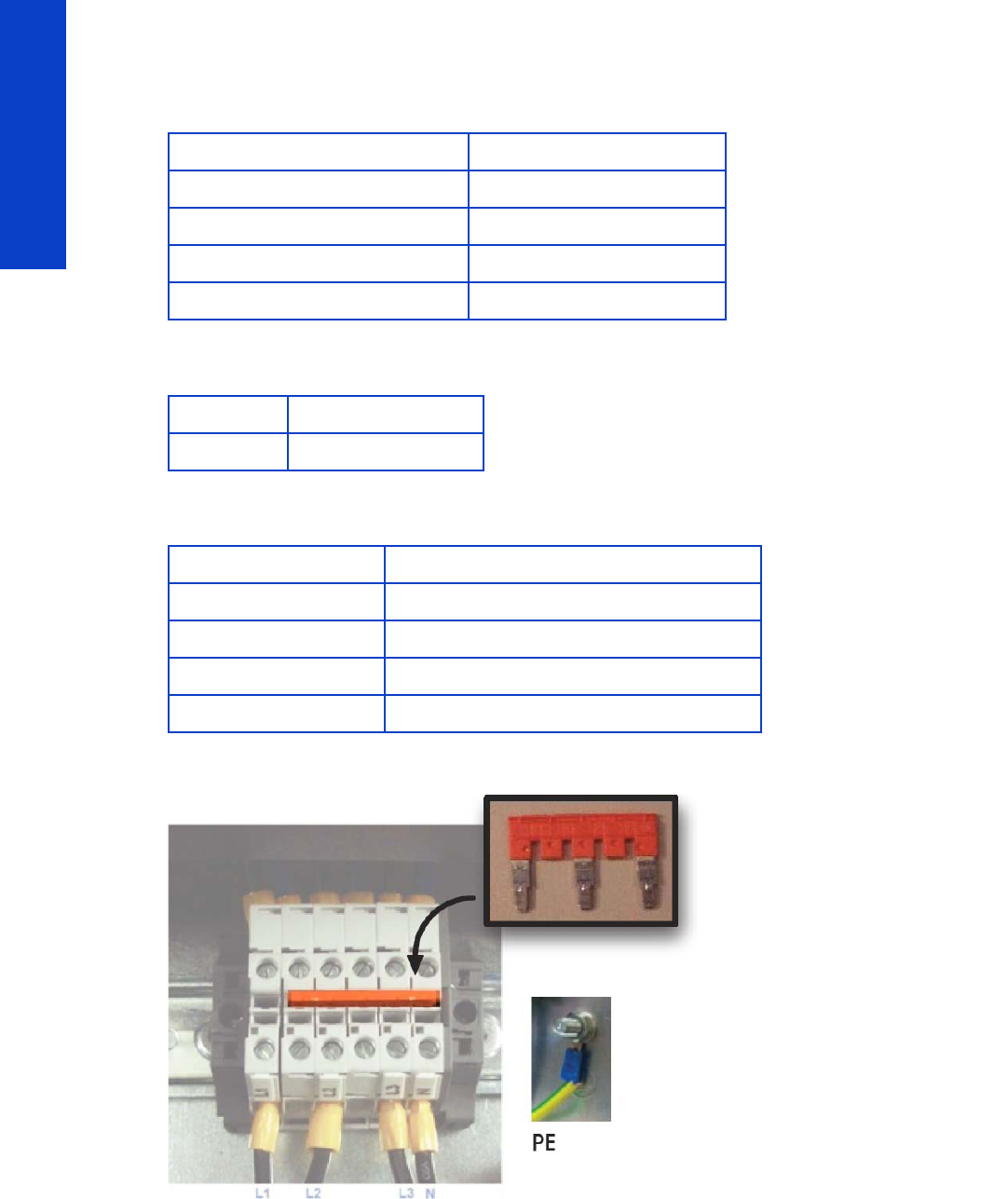
Terminal block
The terminal block is used to configure the printer depending on the customer's mains configuration. It has
some jumpers used to perform the configuration. The input power cables from the customer's installation
(not provided with the printer) are connected within this terminal block.
Electrical power system
The printer requires three-phase power, which provides a more efficient means of supplying large
electrical loads than single-phase power. There are two possible configurations depending on input
voltage range, as described below.
NOTE: An electrician is required for the setup and configuration of the building's electrical system
used to power the printer and also for printer installation. Make sure that your electrician is
appropriately certified according to local regulations and supplied with all the information regarding
the electrical configuration.
Remember that you are required to follow the local laws, regulations and standards that pertain to the
electrical installation of your printer.
18 Printer systems
Printer systems
380–415 V three-phase line-to-line configuration
Three-phase line specifications
Circuit-breaker specifications
AC power cable specifications
Jumper configuration
Number of power wires 5 (3 lines + 1 neutral + 1 PE)
Input voltage (line-to-line) 380–415 V (–10%+6%)
Input frequency 50/60 Hz
Power consumption 8 kW
Maximum load current (per phase) 24 A
Branch circuit-breaker
Three-phase 4 poles, 30–32 A
Three-phase line
Configuration 5 wires, L1/L2/L3/N/PE
Wire Strained Cu, minimum 4 mm² or 10 AWG
Terminals Lines: ferrule terminals, PE: M6 ring terminal
External diameter range 15–25 mm
Printer systems 19
Printer systems
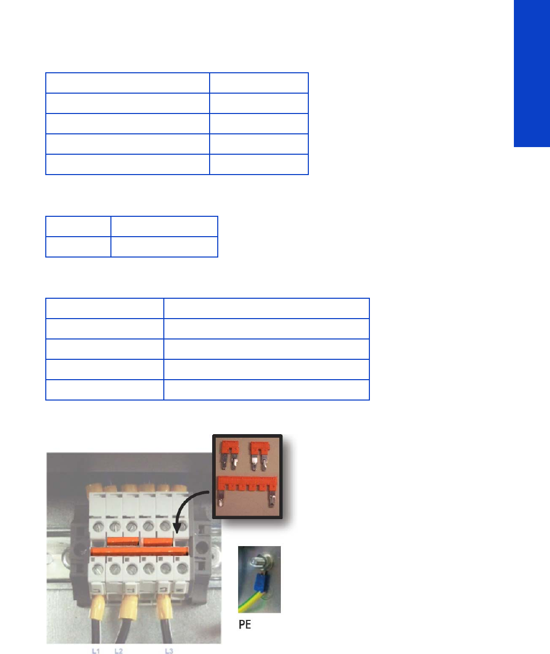
200–240 V three-phase line-to-line configuration
Three-phase line specifications
Circuit-breaker specifications
AC power cable specifications
Jumper configuration
Number of power wires 4 (3 lines + 1 PE)
Input voltage (line-to-line) 200–240 V (±10%)
Input frequency 50/60 Hz
Power consumption 8 kW
Maximum load current (per phase) 40 A
Branch circuit-breaker
Three-phase 3 poles, 50 A
Three-phase line
Configuration 4 wires, L1/L2/L3/PE
Wire Strained Cu, minimum 6 mm² or 8 AWG
Terminals Lines: ferrule terminals, PE: M6 ring terminal
External diameter range 15–25 mm

20 Printer systems
Printer systems
200–240 V single-phase or bi-phase line-to-line configuration
IMPORTANT: HP strongly recommends using three-phase power to connect the printer, as described in
the Site Preparation Guide and in the flier included in the printer’s box.
The following procedure in this document describes connection options that should be limited to locations
where three-phase power is not available. Compliance must be verified and approved by a certified
electrician according to local regulations.
The 200–240 V installation described in this chapter requires a line capable of delivering up to 10 kW,
which is the maximum consumed by the printer during the warm-up processes.
The power line needs to support 48 A, and the branch circuit breaker must be rated for 60–63 A.
If the customer cannot connect to a three-phase system, it is still possible to connect to a bi-phase or single-
phase installation if the following requirements are met and approved by an electrician.
Single- or bi-phase line specifications
Circuit-breaker specifications
AC power cable specifications
Number of power wires 3 (2 lines + 1 PE)
Input voltage (line-to-line) 200–240 V~ (±10%)
Input frequency 50/60 Hz
Power consumption 8 kW
Maximum load current (per phase) 48 A
Branch circuit-breaker
Single- or bi-phase 2 poles, 60/63 A
Single- or bi-phase line
Configuration 3 wires, L1/N/PE or L1/L2/PE
Wire Strained Cu, minimum 10 mm² or 6 AWG
Terminals Lines: ferrule terminals, PE: M6 ring terminal
External diameter range 14–25 mm
Printer systems 21
Printer systems
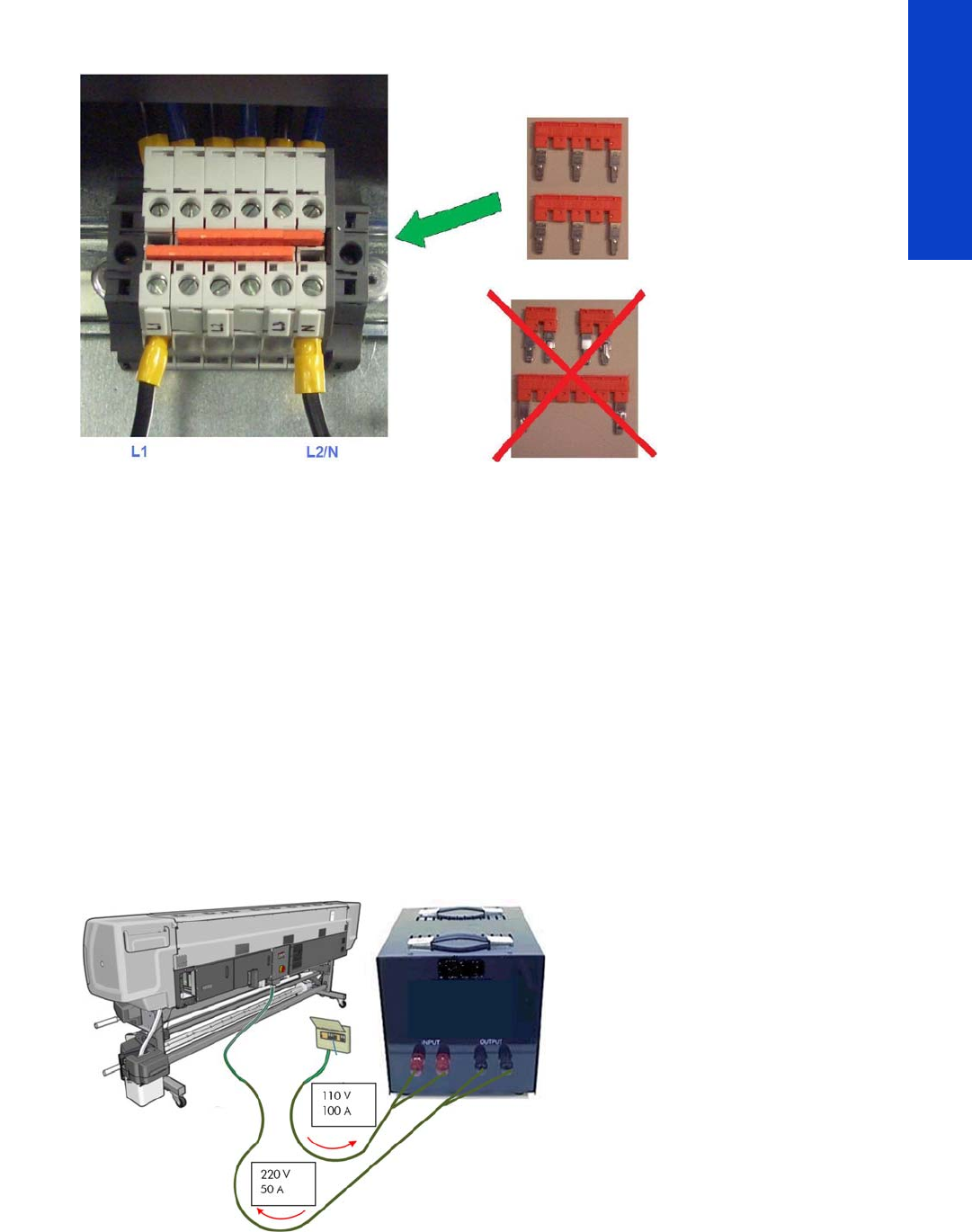
Jumper configuration
110–130 V single-phase line-to-line configuration
IMPORTANT: HP strongly recommends using three-phase power to connect the printer, as described in
the Site Preparation Guide and in the flier included in the printer’s box.
The following procedure in this document describes connection options that should be limited to locations
where three-phase power is not available. Compliance must be verified and approved by a certified
electrician according to local regulations.
The 110–130 V installation described in this chapter requires a line capable of delivering up to 11 kW
and a transformer for the appropriate power rating. 10 kW is the maximum consumed by the printer
during the warm-up processes, and a 10% power loss in the transformer is assumed.
The power line needs to support 100 A, and the branch circuit breaker must be rated appropriately.
If only single phase 110–130 V power is available, then a transformer is required. The proposed
specifications are:
•Input: 110–130 V, 100 A, 11 kW approximately, assuming 90% transformer efficiency
•Output: 200–240 V, 50 A, 10 kW
The setup of the printer connections in the output line of the transformer is the same as in the previous
section, “200–240 V single-phase or bi-phase line-to-line configuration”.
22 Printer systems
Printer systems
Power cable and Power Distribution Unit (PDU) requirements
These are the requirements for power cable and Power Distribution Unit described in the Site Preparation
Guide:
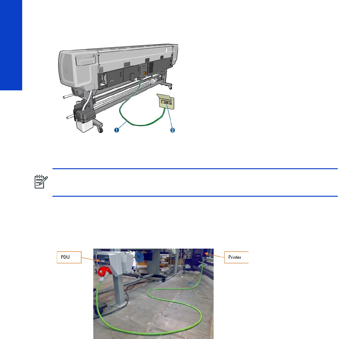
1. Three-phase power cable longer than 16 ft (5 m) (not supplied)
2. Power Distribution Unit (PDU) including three-phase branch circuit breaker
Power cable details and power cable length
The specified power cable length (16 ft, 5 m) in the Site Preparation Guide is not arbitrary. Since the
printer can be directly branched to the PDU and installed with its back against the wall, it is important to
have enough cable to enable proper service of the printer, if necessary. The picture below shows an
example of a printer with a proper power cable installation.
The printer can thus be separated from the wall to service the systems that are accessed from behind.
NOTE: The PDU must be rated to meet the power requirements of the printer, and should be in
accordance with the Electrical Code requirements of the local jurisdiction of the country where the
equipment is installed.

Printer systems 23
Printer systems
Power Distribution Unit
Find below an example of a compliant PDU in Western Europe: 380–415 VAC, 30–32 A per phase, 5
wires (3 lines, Neutral, and PE). In this example, the setup includes:
1. Three-phase Branch Circuit Breaker, as described in the Site Preparation Guide
2. Residual Current Circuit Breaker
3. Three-phase power plug
•The Residual Current Circuit Breaker (2) adds one level of safety to the operation of the printer.
•The power plug (3) is not required but convenient to service the printer if necessary, allowing the
service engineer to unplug and move the printer, to repair it safely.
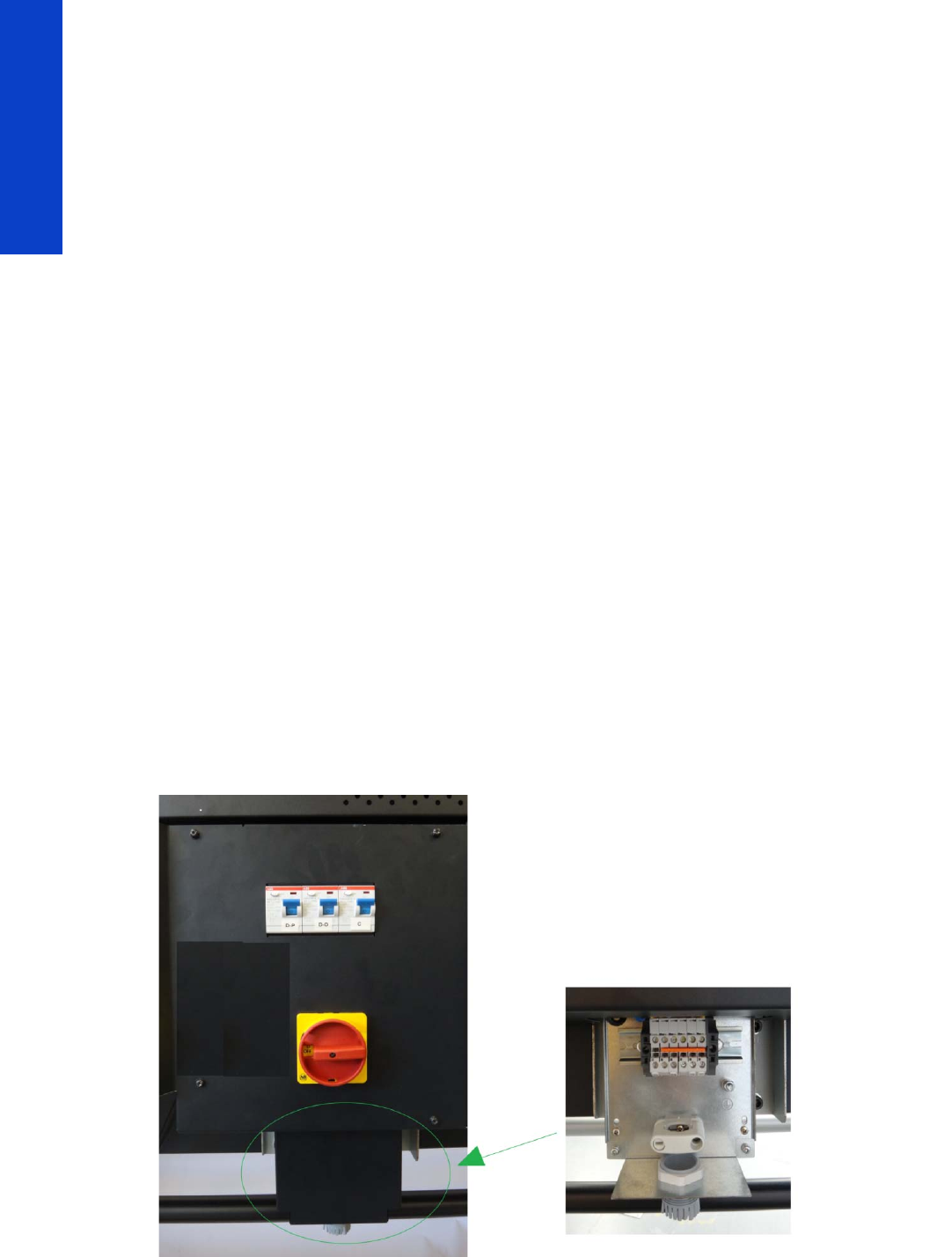
Main Switch
The Main Switch is used to switch the whole printer on or off, including all the printer electronics.
Residual Circuit Current Breaker (RCCB)
To protect the printer and the users, there are three Residual Circuit Current Breakers (RCCB), which are
connected between the main power switch and the Sine Wave Converter module. They detect a current
leak greater than 30 mA. Customers can reset the RCCB if a circuit blows, but a frequent reoccurrence
indicates an electrical failure in one or more of the heaters.
Sinewave converters
These three modules convert the input voltage from the mains to a voltage in the output that is controlled
by the EEbox depending the quantity of power required to each of the resistors connected to them.
Each converter has three cables: One power cable for the input, another one for the output power, and
finally the control cable. The control part of the converter that interfaces with the Printmech is powered at
24 V from the printmech PCA through the control cable and through both switches placed in the window
cover of the printer. This cover has to be closed to allow the converters to work.
Each converter has 3 LEDs: Status (off or fault), PWM (if power is being delivered to the output) and ACOK
(if Vin is in range).
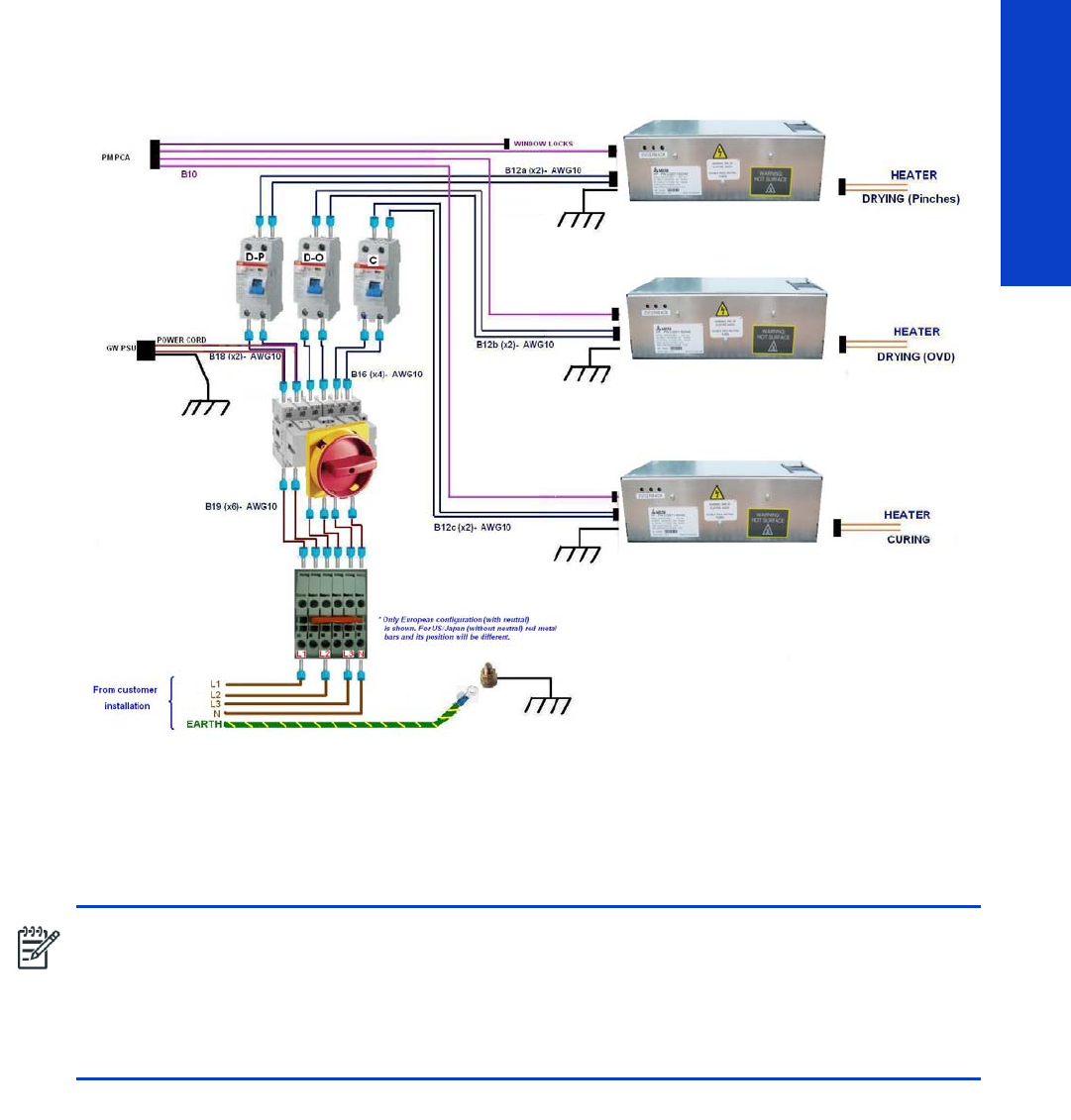
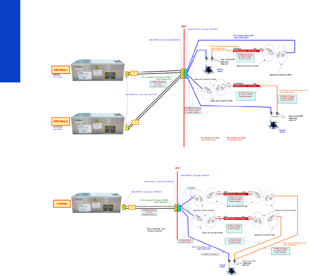
Output circuit diagrams
The following diagrams show the connections between the converters and the heating elements.
24 Printer systems
Printer systems
Drying
Curing
Printer systems 25
Printer systems
Substrate path
Description
The substrate path moves the substrate from the input spindle to the take-up reel, through the print path,
while the Carriage prints on the substrate. The objectives of the substrate path while advancing the
substrate are:
•Maintain an accurate advance
•Maintain a constant advance
•Keep the substrate flat
•Advance the substrate straight along the substrate axis
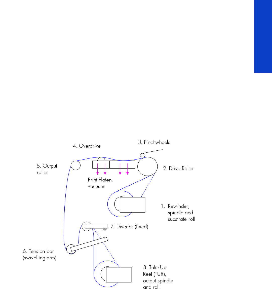
Substrate path workflow overview
The following steps describes the substrate path workflow.
1. The substrate is loaded onto the Input Spindle (1), which is driven by the rewinder mechanism to pro-
vide back tension to the substrate. The substrate is fed through the Input Platen, around the Drive Roller
(2), under the Pinchwheels (3), over the printzone and Overdrive (4), and finally it is either left free
or looped through the Tension Bar (6) and the Diverter (7) to be collected on the Take-Up Reel (8).
2. The Rewinder has a motor that primarily acts as a brake to maintain tension on the substrate. The
Rewinder may turn in either direction, depending on which is the printable side of the input substrate roll
and its winding direction.
3. The Drive Roller also has a motor, and is the primary component that advances the substrate. The sub-
strate is pressed to the drive roller by the pinchwheels, ensuring a smooth substrate advance. The motor
receives feedback from an encoder located at the left side of the roller, inside a protected enclosure on
the left of the left sideplate.
4. The surface of the substrate path where the substrate is printed is called the Print Platen. The Print Platen is
designed to give minimal resistance to the substrate advance, and includes suction holes that apply vac-
uum to the substrate.

26 Printer systems
Printer systems
5. The printer detects and controls the substrate advance. The OMAS sensor, located on a special cut-out
section of the Print Platen, is a sensor that is able to detect very small errors in the advance of the sub-
strate. These errors are communicated to the motors on the Drive Roller, and small correctional adjust-
ments are applied to the movement of the substrate.
In the same area, but not visible from outside the printer, is the TOMAS sensor that measures the
temperature in the area and helps OMAS to provide the drive motors with a high degree of accuracy.
6. The vacuum is calibrated according to the substrate type and print options used. It draws the substrate to
the Print Platen, making sure that the substrate is flat. The substrate is also under the dryer when it is in the
print zone.
7. The area of the platen in front of the print zone holds the Overdrive wheels. This area also has vacuum to
ensure traction over the wheels, which are connected to the Drive Roller through a set of gears. The Over-
drive wheels help to remove the substrate from the print zone during substrate advance.
8. After the platen, the substrate goes through the curing zone and finally leaves the printer, either to be col-
lected on the Take-Up Reel or to be cut.
9. When the Take-Up Reel is in use, the substrate must be threaded first under the swiveling Tension Bar and
rerouted to the output roll around the fixed Diverter roller. This system creates tension on the outgoing sub-
strate for proper winding. The Take-Up Reel can operate in both directions with the Rewinder, winding
with the printed face outside or inside. Weights on the Tension Bar arms may be slid forward in order to
create higher tension for textile substrates.
Startup, substrate load, substrate selection
During startup, the printer checks that the substrate path components are functioning correctly. When
shutting down, if a substrate is loaded, the printer remembers the substrate definition. This may be
modified through the front panel with the option ’Change loaded substrate’ from the substrate menu list.
During substrate loading the printer may ask the user two interactions:
1. To rewind manually the substrate: The printer automatically checks the direction of the loaded sub-
strate (printed face outwards or printed face inwards). If the ’curve’ of substrate is too large the
printer cannot detect it and the printer asks the user to rewind manually. Once the substrate is
rewound the printer can detect automatically
2. To align the substrate in order to avoid skew: the printer measures skew. If the skew is too large the
printer will ask the user to lift the pinchwheels (big blue lever on right hand side) and align the sub-
strate. The substrate must be aligned against itself (substrate edge must be aligned with input roll
edge).
NOTE: The OMAS sensor cannot see the fibers on some substrates, such as transparent
substrate or very dark or very reflective substrates. In these cases, the OMAS sensor
can be disabled. To disable the OMAS sensor
See page 182.
Printer systems 27
Printer systems
Components
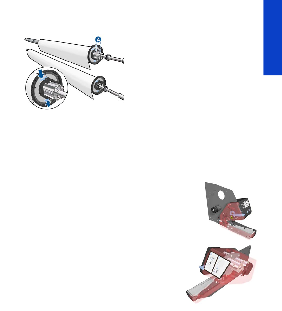
Spindle
The spindle can load 3” core rolls. It holds the core of the roll when its rubber bands are nipped between
the core of the roll and the aluminum extrusion.
The hub on the left side has two possible fixed positions: the end position allows loading maximum width
rolls, but there is a second position at 2.6 inches (65 mm) from the end that can be selected.
The right hub can be set along any length of the spindle so any length of roll can be loaded.
The right end of the spindle contains a gear which is used to transmit the movement from the rewinder to
the roll.
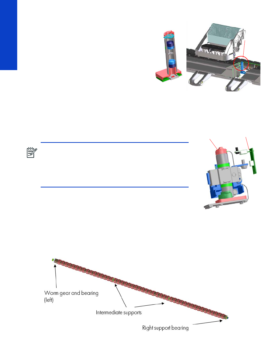
Spindle latch
The spindle latch prevents the substrate roll from slipping from its position when
printing. It is not necessary to close it when inserting the spindle, it closes
automatically. But the user must lift the small blue lever in order to release the
spindle and extract the roll of substrate.
Rewinder
The rewinder motor keeps a constant tension on the input substrate to
prevent skew problems. There is a motor and a transmission that gives
torque to the spindle in order to provide the necessary back tension.
Media sensor
The Input Platen has a lever that activates the media sensor whenever substrate is present. When the
substrate is inserted into the entry area, the sensor is activated and the drive roller starts turning to help
the loading process. The substrate load process has been triggered and the printer will provide instructions
through the front panel.
28 Printer systems
Printer systems
OMAS sensor (media advance sensor)
OMAS is located under the third platen slab from
the right, only the top window can be seen:
OMAS is composed of two parts: the sensor and
its optics located under the platen and a PCI
control board on the main electronics box. Both
are connected through a ribbon cable that runs
through the vacuum beam, by the right sideplate
and into the electronics box.
The optical sensor detects the surface of the back
of the substrate as it moves across the platen. The
sensor is able to evaluate the exact movement of
the substrate, and communicate any small
adjustments required by the system to move the substrate accurately.
The window of the OMAS sensor must be cleaned of dust and ink to work correctly. The cleaning
procedure is described in the User’s Guide, in the section ‘Clean the substrate-advance sensor window’.
During the substrate load, the printer detects that the substrate has
reached the print platen when the OMAS captures its image.
TOMAS
To compensate for temperature changes and mechanical expansion,
OMAS receives a temperature reading from TOMAS sensor.
Drive roller and motor
The drive roller and motor advance the substrate through the substrate path. The motor requires 42 V, and
is controlled by the Printmech PCA.
The drive roller receives the torque from the motor through a worm as in the Z6100 and other Designjets.
Because of the extension to 104 inches, the roller now has two intermediate supports.
Drive Roller Encoder Disc and Encoder PCA
The Drive Roller Encoder Disc and Encoder PCA provide the feedback system for the Drive Roller.
NOTE: The OMAS sensor cannot detect the surface of some
substrates, such as plastic or very dark ones. In these cases, the
OMAS sensor must be disabled, and instead the printer uses
feedback from the Driver Roller encoder to calculate the substrate
advance. To disable the OMAS sensor, locate the OMAS Sensor
selector from the print options menu of the RIP and set it to OFF. This
can also be done from the Service menu page 182.
OMAS
location
OMAS
OMAS sensor TOMAS sensor
location

Printer systems 29
Printer systems
•The Encoder disc is a round disc mounted to the left end of the Drive Roller.
•The Encoder PCA is mounted with a sensor that reads the encoder movements of the disc (the disc
turns with the drive roller).
Pinchwheels
The pinchwheels press the substrate against the Drive Roller to make sure that the Drive Roller can advance
the substrate correctly.
•The pinchwheels are activated with the blue lever at the right side of the substrate roll and usually do
not have to be lifted unless to correct skew during substrate load or to clear jams.
•The pinchwheel system has a sensor that detects if the system is up or down.
Vacuum Pump, Vacuum Tube Assembly, Vacuum Beam
The print zone is the area of the substrate path where the transmission of ink to the substrate occurs. The
main function of the system can be defined as providing the surface where the substrate is printed, keeping
it controlled during the process, playing a main roll on the final IQ of the plots and on the operational
reliability of the printer. The subsystem is composed of the print platen assembly (including the overdrive
wheels), which is the physical interface with the substrate, and the vacuum system which is the mechanical
system where the vacuum pressure used to control the substrate is generated and conduced.
The HP Designjet L28500 printer requires a hot print zone (with additional airflow) to allow the
evaporation of the majority of the water in the latex inks. This feature, plus the new substrates supported,
changes a little the main contributors of the cockle control and substrate expansion from former products
and also adds new issues such as the thermal marks. The platen gives a convenient shape to the heated
substrate, avoiding differential temperatures due to platen conductivity.
The main components are:
•OVD & Platen Assembly 104” including:
•12 DJ L26500 printer platen + 1 OMAS platen + 2 interplaten 60 + 1 platen right end + 1
platen left end
•Linear blade 104” + springs (same as DJ Z6100 or L26500)
•OVD shafts and wheels (same as DJ Z6100, with some new segments)
•Foams, foam fillings, and foam wall
•Magnets under the platen to hold Media Edge Holders
•ESD brushes
•OVD gears in brass
•Right Vacuum Fan Assembly with Eola Control Board (same as DJ Z6200 or T7100)
•Left Vacuum Fan Assembly with Eola Control Board (new)

30 Printer systems
Printer systems
Related tests, utilities, and calibrations
•Rewinder test page 154
•Drive Roller test page 155
•Substrate Path sensor test page 156
•Vacuum Test
•OMAS Test page 158
•Rewinder Motor polarity test
•Substrate path menu page 182
•Substrate advance adjustmentpage 190
Service parts
•Drive Roller page 265.
•Media Path Assemblies page 266.
•Center guide Pinchwheels Assemblies page 267.
•Media Entry Assemblies page 268.
•Take-up reel Assemblies page 269.
Removal and installation
•Rewinder page 351.
•Vacuum Fan page 356.
•OMAS page 432.
•TOMAS page 438.
•Output Platen page 524.
•Print Platen page 530.
•Input Roller page 542.
•Output Roller page 554.
•Media Sensor page 557.
•Pinchwheel Assemblypage 569.
•Center Guidepage 575.
•Driver Rollerpage 575.
•Rollfeed Modules page 582.
•Take-up reel page 582.
Printer systems 31
Printer systems
Ink Delivery System (IDS)
Ink Delivery System
The ink deliver system (IDS) is located in the left enclosure of the printer (inside the left covers) and delivers
a continuous supply of ink to the printheads. It can detect an ink leakage anywhere in the system, including
inside an Ink Cartridge. It also tracks and determines when an Ink cartridge needs replacing.
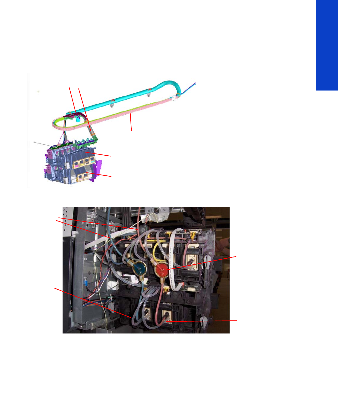
Rear of the Ink Supply Station
Ink Tubes
There are 6 ink tubes that deliver the inks to the printheads in the carriage and two additional tubes which
are used as a support structure. They are bundled together in a carrier and held on a shelf on the inside
of the top cover with clips.
Insulation Sleeve
The ink tubes are protected from the high temperatures of the Dryer Assembly by a heat resistant insulation
sleeve, which protects the main body of the tubes, that are static.
Upper and Lower Ink Supply Station (ISS)
The Ink Supply Station (ISS) is divided into the upper and lower sections. They have six slots for holding
the ink cartridges. Each slot has a unique shape (or lock out) which matches with an equal shape at the
end of the applicable ink cartridge. this arrangement avoids the incorrect insertion of an ink cartridge,
which would cause major damage to the ink system.
Insulation sleeve
Ink Tubes Carrier
Lower ISS: Lm, Lc
Top ISS: M, Y, K, C
On top of the ISS there is a thin
plastic sleeve to avoid the
substrate falling into the Ink
Supply Station when a
substrate crash occurs and
also to avoid the direct heat
radiation from the dryer
Air tubes
non-return valves
for the lower ISS
Spring loaded
Ink tubes

32 Printer systems
Printer systems
There are two places for additional slots but these are covered over.
The upper and lower ISS both contain PCAs, although the top PCA contains more functionality, such as
the pressure sensor, see page 13.
Non-return valves
The two non-return valves are only for the inks on the lower IDS.
This is to ensure that when the pump stops and the cartridges are
nearly empty, that the ink does not flow back to the cartridge.
If a cartridge is nearly empty, with no pressure from the pump, the
cartridge bag might increase, and air might enter the printhead.
With a valve, the ink can go only from the cartridge to the
printhead, and not the reverse!
Air Pressure System (APS)
The APS contains two air pumps which are used to force the ink through the tubes to the carriage
assembly. In the event of a broken bag in one of the Ink Cartridges, these tubes must be checked in case
any of the leaked ink has been forced into the air tubes.
Related tests, utilities, and calibrations
•Ink Delivery System tests: page 159.
Service parts
•Left hand assembly: page 257
Removal and installation
•Ink supply tubes and trailing cable: page 381
•ISS to Cartridge Cables: page 391
•Ink Supply Station: page 394
•Ink Supply Station PCAs: page 398
•APS Assembly: page 402.
•APS Assembly: page 402.

Printer systems 33
Printer systems
Scan Axis and Carriage
Scan Axis
The Scan Axis System is the part of the Scan Axis subsystem designed to move the carriage backwards
and forwards for printing and servicing. This subsystem moves the carriage with a motor, belt, and pulley
system. Furthermore the scan axis has features to open and close the Spectrophotometer shutter (SOL) and
to enable/disable the cutter.
Scan Axis Components
Scan Beam:
It is an extruded aluminum part. Its main function is to guide the carriage along the scan axis via two rods,
and it sets its limits of movement. Apart from this it positions and holds the Service Station, the Scan Axis
motor, the two brackets and the pinch wheels assembly. It also works as an air container to be blown to
the print zone coming from the rear and leaving through several pipes located over the substrate and
holds the rear fans.
PPS system
The PPS consists of some screws and pockets, it locates the scan beam in reference to the side plates in
order to have a correct distance between the printheads and the substrate. This distance is supposed to
be constant during the life of the machine and it is set to be as small as possible without taking the risk of
having the printheads touching the substrate.
Left Bracket
Left Bracket is an injected plastic part, and its main function is to set an end for the carriage movement. It
also closes the scan beam to avoid the air blown to the print zone leaking. It has several features to
enable/disable the cutter and the SOL shutter. The left bracket also houses the Substrate Jam Sensor,
which works with the reflector panel on the carriage assembly to detect substrate crashes. It also has some
parts to ensure that the encoder strip is held with tension.
Encoder Strip
The Encoder Strip contains positional data that the encoder sensor (located in the carriage) can read and
detect the position of the carriage. Since it is made of thin metal it is sharp and extreme caution is needed
when handling it. Unlike previous versions, do not clean the encoder strip as this will damage it.
Right Bracket
This part is the same in the left bracket, this metallic part closes the right hole of the scan beam extrusion.
It also holds the pulley assembly and the encoder strip.
Motor, pulley assembly and belt.
Their function is to transmit the position/speed to the carriage assembly.
Flat right bump
This plastic part defines the right end of the carriage movement. It is positioned and held by the scan
beam.
Carriage
The carriage is the subsystem of the printer that performs the printing on the substrate. It is moved across
the print path by the scan axis impelling system and with it the 6 printheads and several sensors, the
Spectrophotometer (SOL), the line sensor (Tetris), the scan axis sensor. The carriage houses an on-board
electronics system to send information to the 6 printheads though each of the interconnects, and it receives
information from the sensors. Some parts aid the ink to arrive at the printheads. It also holds in position
the cutter, used to cut some types of substrate.
34 Printer systems
Printer systems
Carriage Components
SOL Spectrophotometer
SOL is a color sensor and it is placed in the left side of the carriage, covered by a metal sheet that protects
it from the heater’s high temperatures. The main function of SOL is to measure color samples that have
been printed on the loaded substrate and are placed on the print platen zone.
Before taking any color measurement, SOL must be initialized. The SOL initialization process lasts for
about 7min. This process consists on 3 steps: sensor switch on, sensor warm up and sensor calibration.
When the initialization has been completed, the shutter is opened automatically and the carriage is
moved along the scan axis to place SOL on top of each sample to take a color measurement. After the
measurements, the shutter is closed again and the sensor is switched off.
SOL is used to make the linearization from the RIP.
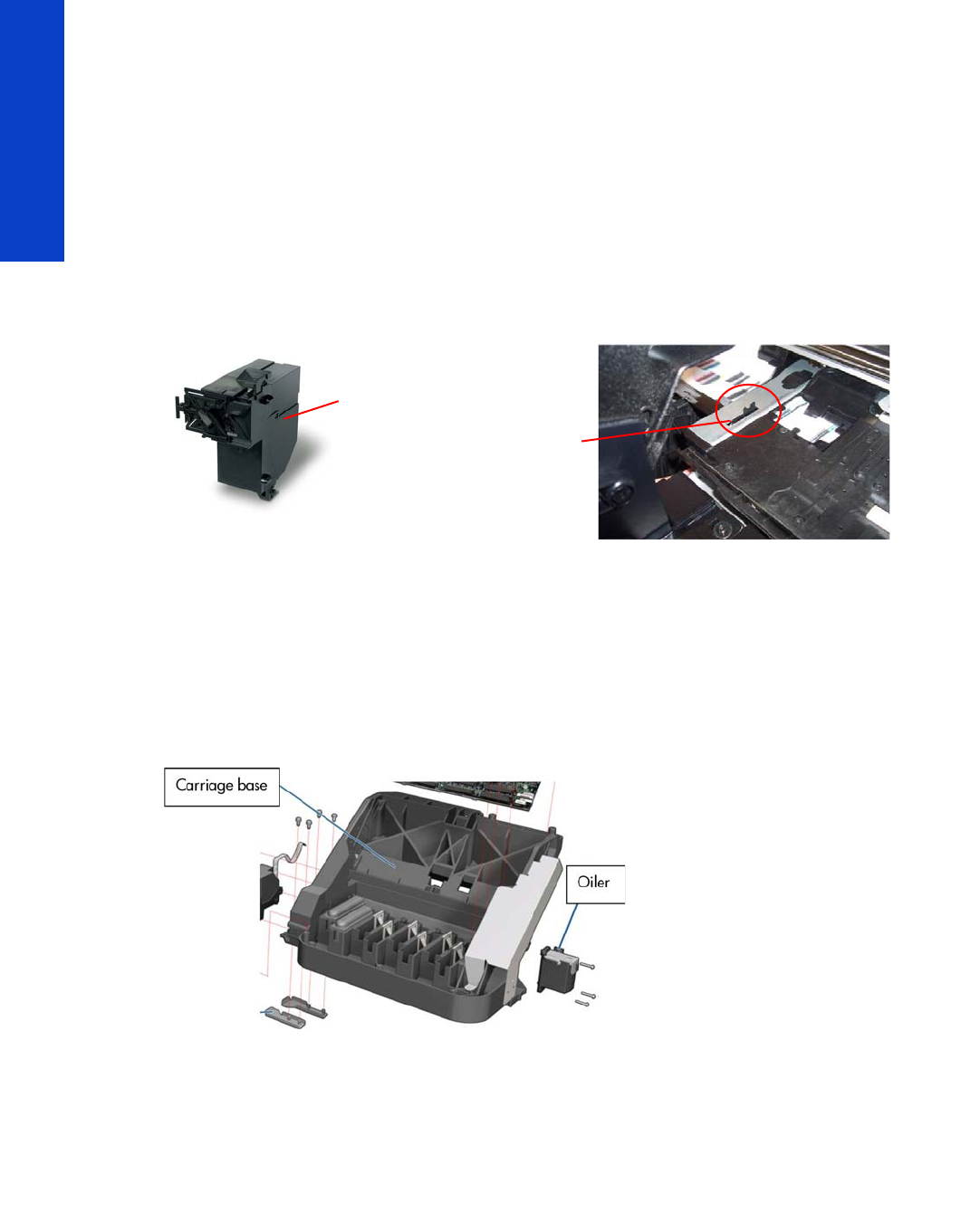
Carriage base
The main function of this plastic part is to located the printheads. Its position is enforced by the two rods
and the belt. It serves as a base where other parts are attached and it has some features to located other
components (capping station and all the next parts).
Oiler
The Oiler is a small system at the right-hand side of the carriage base that provides continuous lubrication
to the Slider Rod.
Latch assembly
This assembly holds down the printheads and helps to ensure that they do not move during operation.
Once the handle is opened it can rotate to allow the user to remove the printheads. It has some features
(holes) to allow the primer to pass though it and make contact with the printheads. Some parts help to
transmit force to the printheads to hold them in position and to transmit information of when the ink should
be dropped.
Sensors
The SOL, the Tetris and the encoder sensor sends information to the PCA board and is passed to the
printmech though the trailing cable. The SOL performs a color calibration, the line sensor calibrates the
printhead alignment and detects other features (e.g. the substrate) and the encoder sensor detects the
movement of the carriage in relation to the Encoder strip.
SOL
SOL actuator
used to open the
shutter

Printer systems 35
Printer systems
Carriage PCA,
This part contains the electronics to control how and when the ink is dropped in every printhead and
receives the information from the sensors.
PCA Cover
This part covers the PCA to avoid aerosol contamination and acts as an electronic enclosure.
X-bias springs
The X-bias springs are sheet metal parts that hold the printhead in position in the X axis.
Covering sheet and metal parts
These parts reflect part of the radiation that is received from the heater to avoid excess overheating and
problems with the sensors and the printheads. Bushings, are bronze parts that are attached to the carriage
base and slide over the rod
Felts, these parts help to lubricate the rod and they also avoid dirt going in between the carriage. They
block four degrees of freedom (Z and Y translation and rotation over the primary rod)
SOL protectors, these parts help to avoid the SOL shutter breaking after a substrate jam.
Plastic rear bushing: this blocks one degree of freedom (the X rotation over the primary rod). The dam
protector, are Mylar and stainless steel, and they stop the aerosol.
The plastic non-functioning printhead, is a plastic part which helps keep the carriage’s integrity when the
latch is applied over them. Also from a usability point of view, they avoid possible mistakes when inserting
the printheads and have a cosmetic function too.
The airflow deflector is a part that partially stops the air entering into the print zone, it is used to avoid
vapor concentration over the substrate that also causes “dpe” (drop placement error).
Media Jam reflector
This part is secured to the left ide of the carriage assembly and works with the Media Jam sensor which
is located on the Left end bracket. This is used to detect substrate jams.
Related tests, utilities, and calibrations
•Scan Axis Menu service tests: page 165.
•Carriage service tests page 169.
•Open/close SOLpage 206.
•Scan Axis Calibrations page 199.
•Carriage Calibrations page 201
Service parts
•Right hand Assemblies page 255
•Left hand Assemblies page 257
•Carriage Assembly page 258.
•Scan Axis Assemblies page 262.
•
Removal and installation
•Cutter Assembly page 392.
•Encoder Strip and Encoder sensor page 405.
•Carriage Assembly page 416.
•Belt Assembly page 425.
•Scan Axis Motor page 426.

Printer systems 37
Printer systems
Service Station and waste management
The main function of the Service Station is to maintain the Printheads in the Carriage assembly and to
manage the waste ink. The Service Station and waste management can be split into three subsystems:
•PHC servicing: Comprising cap, wiping, and priming functions
•Waste management: Contains ink spit/aerosol ink collection and the Aerosol Filter.
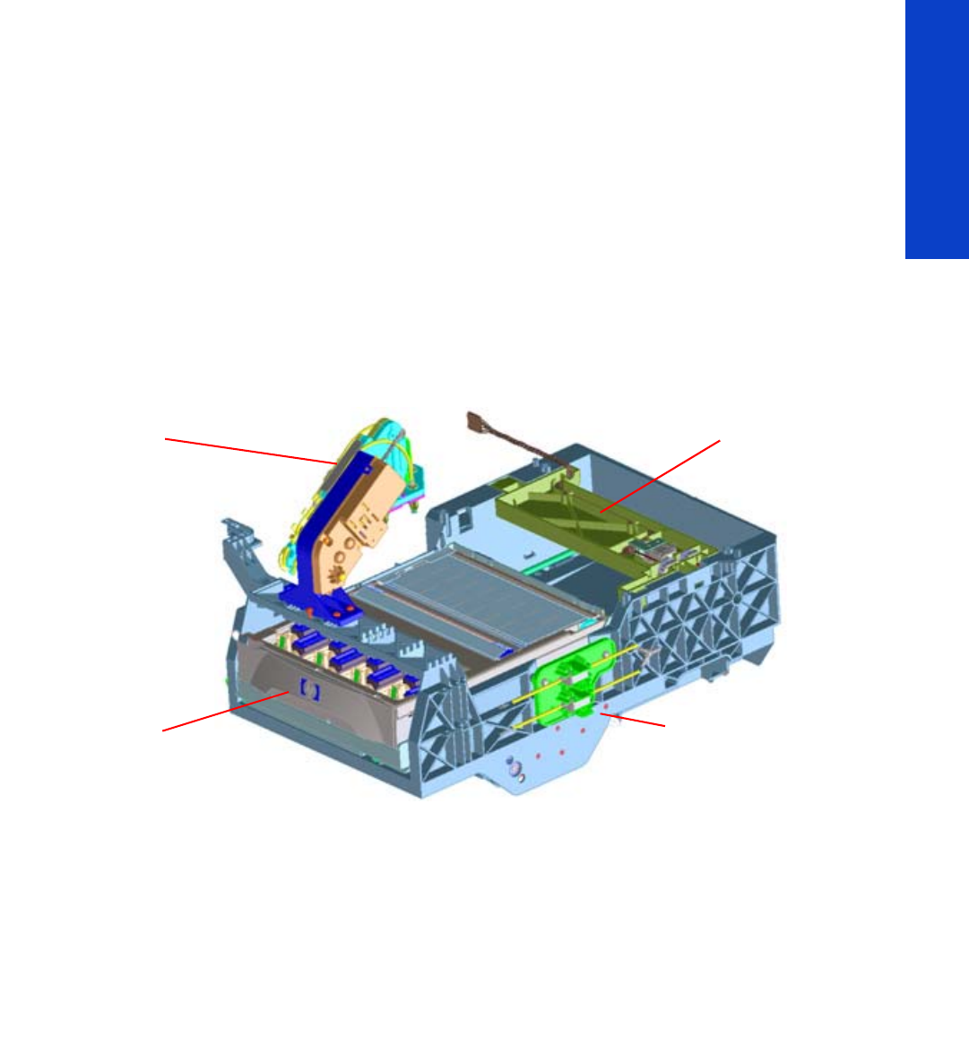
Components
SVS Mech
The SVS mechanics provide the movement for the Printhead Cleaning Cartridge, which integrates the
capping and wiping functions and the Web Wipe assembly, which provides the means with which to
advance the Web Wipe accurately.
Primer
The Primer executes the blow primer functionality to the Printheads. Air pressure to perform the prime
operation is drawn from the Ink Supplies, and prime pulse is controlled by solenoid valves.
Printhead Cleaning Cartridge
The Printhead Cleaning Cartridge is a customer consumable that holds the main components for wiping
and capping. It also contains some ink priming functionality.
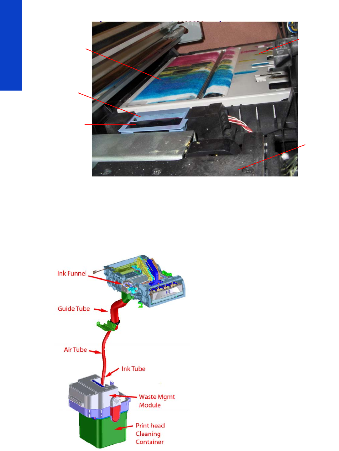
Drop detector
The drop detector is a sensor that analyzes the nozzle health of all the printheads. The drop detector has
a window where it is placed with the ink funnel. The ink funnel divides the window in two different parts,
the flying spittoon and the drop detector spittoon where nozzles are fired to check their status. The nozzles
out that are detected are compensated for by using other nozzles to keep a good print quality.
The drop detector has an infrared LED and a photodiode aligned in a beam light. This beam light can be
blocked by the ink funnel if it is not placed correctly.
Web Advance
Mechanism
Primer
Printhead Cleaning
Cartridge
SVS Mech
38 Printer systems
Printer systems
Web Wipe
The Web Wipe Advance mechanism engages/disengages the advance gear of the Printhead Cleaning
Cartridge. The actual advance is achieved by moving the Printhead Cleaning Cartridge once the gear
has been engaged by this mechanism.
Waste Collection Subsystem
As the Printhead Cleaning Cartridge does not have sufficient space to contain the amount of waste ink
that the printer generates, a separate subsystem provides the collection and storage for it.
Web Wipe
Printhead
Maintenance
Cartridge
Spittoon
Drop Detector
channel
Platen
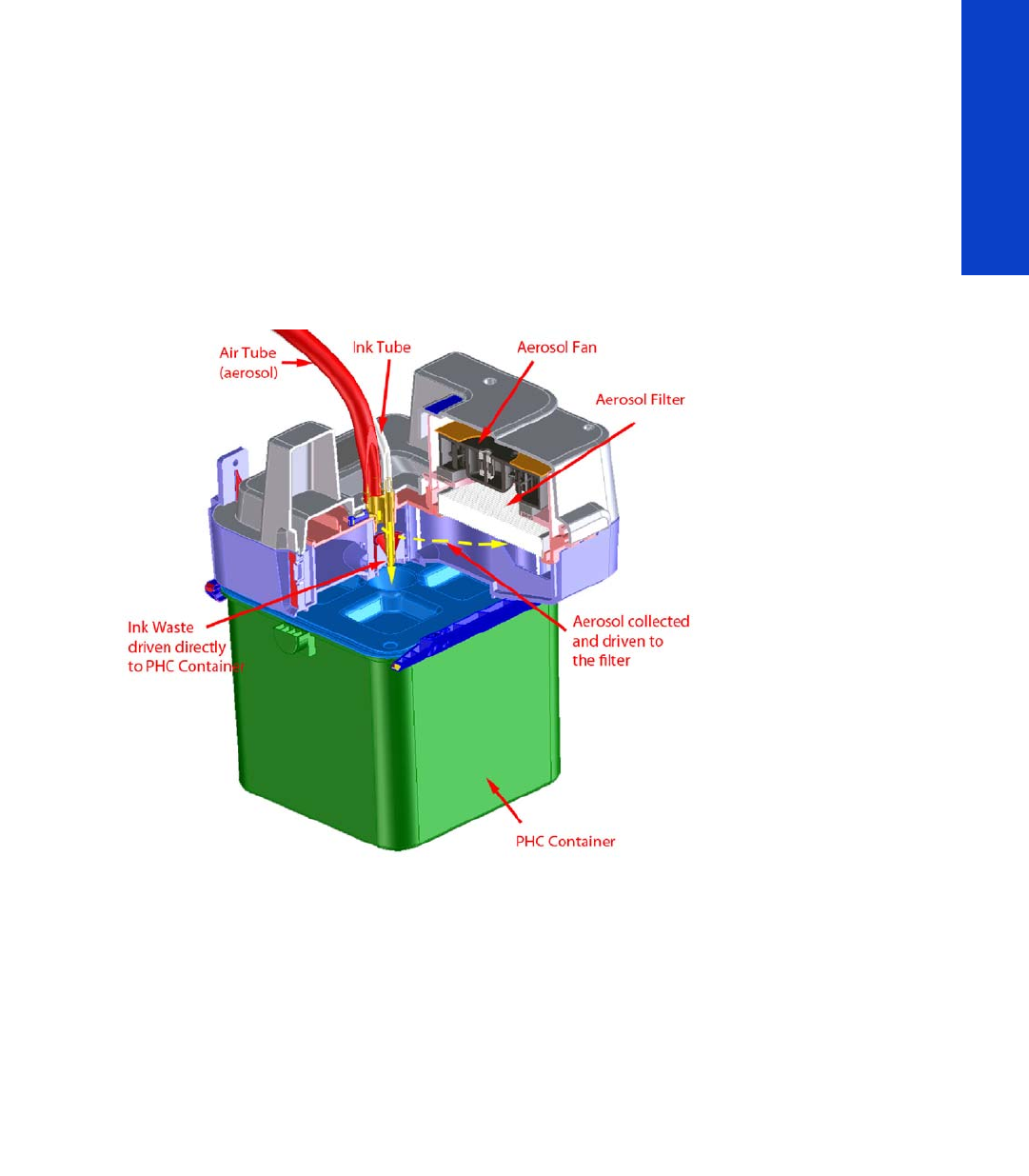
Printer systems 39
Printer systems
The main components of this subsystem are:
•Ink Funnel: It collects both the ink and aerosol waste during the spitting printhead servicing
operation.
•Tubes: Each type of waste (ink and aerosol) is driven downwards through its own tube, before
being processed in the Waste Management module. The tubes are fitted inside a guiding tube that
provides the proper routing.
•Waste Management Module: This external subsystem collects both types of waste coming from
the upper part of the system and stores each of them in its consumable. The liquid waste is collected
into a Container (the same container used in the L26500), while the aerosol is collected in a filter.
The ink waste falls down by gravity while the aerosol is sucked down by a centrifugal fan.
Related tests, utilities, and calibrations
•Service Station service tests page 170.
•Drop detector test page 170
•Force Drop Detector page 184
•Drop detection calibration page 201
•Service Station calibration page 187
Service parts
•Right Hand Assembliespage 255.
Removal and installation
•Primer Assembly page 345
•Primer Valves page 347
•Service Station page 351
•Web Wipe Motor Assembly page 354
•Waste Ink System page 369
•Drop Detector page 376
•Primer Assembly page 345
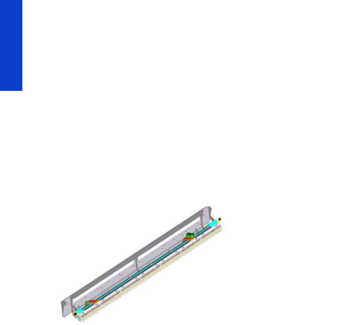
40 Printer systems
Printer systems
Heating system
The type of ink used in this printer (latex) requires heating in order for the ink to be cured. The heating
system applies this heat through a Dryer Assembly and a larger Curing Assembly. Temperatures are kept
at a target level depending on the type of substrate and amount of ink fired via a temperature sensor,
which feeds back information to the Heater Control assembly (Petisa) located at the rear of the printer.
Components
Heater Control
See Heating System Electronics for details page 16.
Dryer Module:
The Dryer module heats up the print zone to 40–55ºC while printing. The main objective is to evaporate
most of the water content of the ink and to provide the correct temperature for satisfactory print quality.
The two resistors in the dryer provide up to 6640 W during warm-up, reaching a working temperature of
650–700°C while printing.
Dryer Enclosure System
The main function of the dryer enclosure subsystem is to provide a thermal protection to the user when
accessing the dryer/printing area. The dryer enclosure subsystem includes all the parts and assemblies
that protect the user against the dryer, they are either attached to the dryer module, or attached to the
structure.
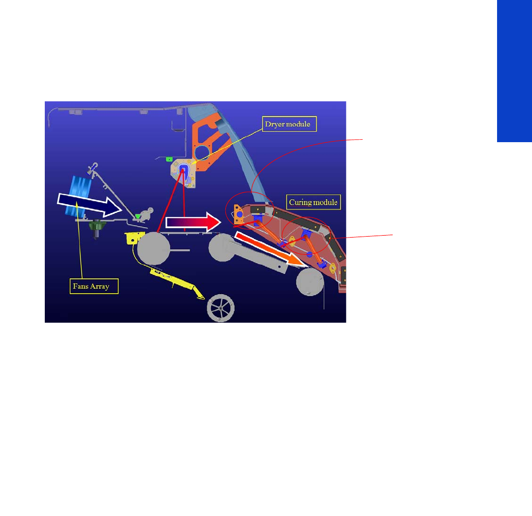
Printer systems 41
Printer systems
Curing Module
The Curing Module fixes the latex ink (cures) at typically around 80–120ºC, depending on the substrate
for satisfactory durability.
The two independent resistors provide a total 4250 W. The following cross section shows the heating
subsystems:
Dryer Fans and Curing Fans
The Dryer fans and Curing fans provide an airflow parallel to the substrate to reach a higher evaporation
rate at the print zone. The airflow wipes away the vapors from the substrate surface, improving radiation
efficiency.
The Top Cover fans blow air coming from outside of the printer to the ink tubes. This is because during
printing the heat coming from the dryer to keep the substrate warm also goes to the ink tubes causing an
increase of the ink temperature leading to short-term damage to the printheads.
The pipes that drive the air to the ink tubes are injected plastic parts. Three assemblies blow to the front
and rear and two to the rear.
Cables are formed by 4 wires, two supplying the voltage (12 V), one providing the PWM (5 V = 100%
of the voltage) and one containing a fault signal.
Metal Finger Guard
This is a metal guard designed to protect any fingers that may inadvertently enter the assembly.
Curing overdrive
Curing output
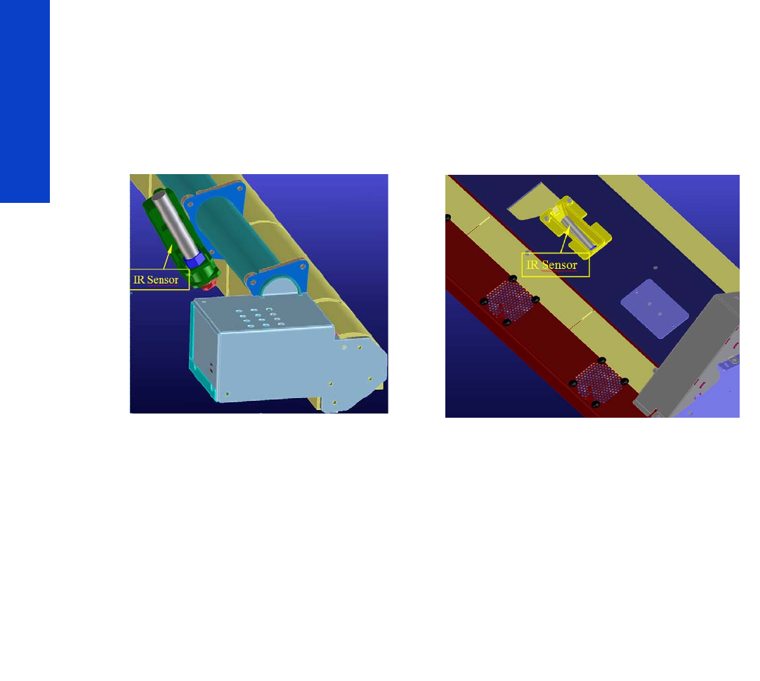
42 Printer systems
Printer systems
Dryer IR Sensor & Curing IR Sensor
There are two infrared sensors, one for each module, these sensors detect the temperature and feedback
the information to the Heater Control Assembly (Petisa), the power supplied to each module is then
adjusted according to target levels.
In the following picture a closer view of both sensors can be seen.
Thermal Switches
Each module has thermal switches, two in the drying module and one in the curing module. In the event
of too high a temperature, these will physically disconnect the current from the heaters.
Related tests, utilities, and calibrations
•Heating and Curing service tests page 171.
•Heating and Curing Temperature page 187.
Service parts
•Front Covers page 249.
•Dyer and Curing Modules page 261.
Removal and installation
•Heating Control Assembly page 463.
•Dryer (IR) Heater Sensor page 486.
•Dryer Heater Assembly page 494.
•Curing Temperature Sensor page 496.
•Curing Fans page 496.
•Curing Heaters page 512.
•Curing Module page 512.
Dryer Module: Curing Module:

Printer systems 43
Printer systems
Front Panel
See the User’s Guide for a description of the Front Panel and how to use it.

44 Printer systems
Printer systems

45
Troubleshooting
2 Troubleshooting
•Troubleshooting the printer................................................................................................ 46
• Printer education and training.................................................................................... 46
• Firmware update ...................................................................................................... 46
•Troubleshooting system error codes .................................................................................... 46
•Performing a service test on a failed assembly ......................................................................47
•Performing the necessary service calibrations .......................................................................47
•The printer does not power on............................................................................................47
•How to read the power switch LEDs ................................................................................... 48
•How to read the Formatter LEDs......................................................................................... 48
•How to read other LEDs.................................................................................................... 50
•Voltage check at installation.............................................................................................. 54
•Troubleshooting substrate jams or printhead crashes..............................................................56
•The printer continuously rejects printheads............................................................................59
•The cutter does not function................................................................................................59
•Troubleshooting Carriage shutdowns ...................................................................................59
• How to troubleshoot the 86:01 system error ................................................................. 60
•Troubleshooting the drying and curing heaters......................................................................63
•Troubleshooting sensors.................................................................................................... 68
• Cover Sensors...........................................................................................................68
• The Line Sensor.........................................................................................................68
• OMAS.....................................................................................................................68
•How to troubleshoot the 79:04 system error .........................................................................69
•Vacuum suction much lower at high altitudes ....................................................................... 77
•Banding due to ink cartridge replacement while printing .......................................................78
•How to interpret the Service Information Pages .....................................................................79
•How to obtain the printer log and the diagnostics package....................................................87

46 Chapter 2 Troubleshooting
Troubleshooting
Troubleshooting the printer
To troubleshoot print-quality issues, please turn to the Print Quality chapter page 207.
Printer education and training
Before any attempt is made to troubleshoot the printer, it is critical that you have the relevant training on
the HP Designjet L28500 Printer series. If you are not trained on this printer, please contact HP Education
or HP Training to enquire about becoming ‘HP Service Qualified’ for this printer.
Firmware update
The first step to take when trying to clear an error with the printer is to check that the firmware installed
in the printer is the latest available. Firmware updates often include fixes for common problems, and
simply updating the firmware can often resolve the problem. New firmware can be downloaded here:
http://www.hp.com/go/L28500/support/.
USB firmware update
If it is not possible to perform a firmware update using the Embedded Web Server (for instance, if the
printer has a System Error and the Embedded Web Server is inaccessible), it is still possible to do it using
a USB flash drive.
1. Turn off the printer.
2. Ensure that your USB flash drive contains a valid FMW firmware file and no other files.
3. Connect the USB flash drive to the USB host port on the Formatter.
4. Turn on the printer and follow the instructions on the front panel.
Troubleshooting system error codes
The System Error Codes chapter contains a list of system error codes and their respective descriptions and
recommended corrective actions page 89. Try one recommended action at a time and check whether
the error code has disappeared.
If you have an error code which is not documented in this Service Manual or you have an error which
you cannot resolve, then report the error to the HP Response Center or the nearest HP Support Office.
When reporting the error, have the following information ready:
•Model and Serial Number of the printer.
•Which firmware revision the printer is using (see note below).
•The complete error number.
•The Service Configuration Print.
•Which RIP the customer is using (name, version, driver version, etc).
•Which software application the customer is using (name, version, etc.).
NOTE: When reporting the System Error Code, make sure that you supply the full Error Code
and the firmware version. Without this information, HP Support Personnel cannot help you.
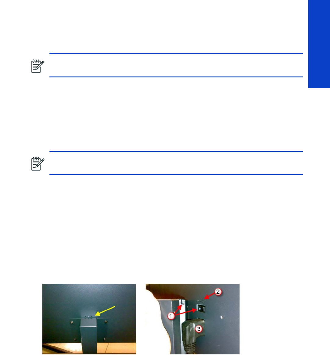
Performing a service test on a failed assembly 47
Troubleshooting
Performing a service test on a failed assembly
If possible, always perform a Service Test on the component/assembly that you are about to replace, just
to make sure that is the component/assembly that has failed.
For information on the Service Tests and how to use them see the Service Tests, Utilities & Calibrations
chapter page 145.
Performing the necessary service calibrations
Is the printer calibrated correctly after replacing a component? For information on the Service Calibrations
and how to use them refer to the Service Tests, Utilities & Calibrations chapter page 145.
The printer does not power on
To resolve printer power-up problems, try the following:
1. Check that power is reaching the printer. An easy first check is to press the "Test" button in the three
Ground Fault Interrupters: if they switch to the lower position (green) then power is reaching them but
is not necessarily reaching the printer.
2. Check that the Power Switch on the BACK of the printer is in the ON position.
3. Check to see if any of the LEDs on the Power Switch are On. If any of the LEDs are On, then see
“How to read the power switch LEDs” (page 48) for more information. If none of the LEDs are on,
check that the hidden plug is well connected and the hidden switch is in the on (I) position.
1. Hidden switch and switch pusher
2. PSU LEDs
3. Hidden power plug
4. Check the Circuit Breaker (Ground fault Interrupter) of the customer has not blown.
5. Check the status of the Formatter PCA’s troubleshooting LEDs. See “How to read the Formatter LEDs”
(page 48) for more information
NOTE: If the test on that component/assembly passes, you should NOT replace it.
NOTE: Remember that certain Calibrations are required even if an Assembly has been
disassembled to gain access to another Assembly or Component.
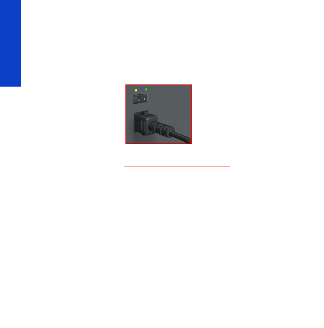
48 Chapter 2 Troubleshooting
Troubleshooting
6. Check that the Front-Panel Cable is correctly connected to the Electronics Module. Also make sure
that the Front-Panel cable is not damaged.
7. Replace the Power Supply Unit page 457
How to read the power switch LEDs
The LEDs located above the power switch (at the rear of the printer) indicate the status of power supply to
the printer.
1. When only the Amber LED is On:
• The printer has been switched off using the Power button beside the Front Panel.
• The Power Supply Unit delivers only 5 V standby power, which is needed to restart the printer
after the Power button is pressed (the Formatter starts the printer).
2. When the Blue LED is On: The Power Supply Unit delivers standard “ATX” power for the Electronics
Module PCAs (+12 V, +5 V, -5 V, -12 V, and so on). All the functions of the Electronics Module, such
as the Embedded Web Server, are fully operational.
3. When the Green LED is On: The Power Supply Unit delivers “analog” 24 V and 42 V power to
enable printing.
If you turn on the printer at the Front Panel, and the Blue LED does not come on, there is a problem. Turn
off the printer using the switch at the rear, then turn it on again using the same switch. If the Blue LED still
does not come on, replace the Power Supply Unit.
If the Blue LED comes on this time, you will probably see an error reported on the Front Panel as the printer
starts up. If no error is reported, but you continue to have problems when turning on the printer from the
front panel, see ‘How to read the Formatter LEDs’ below.
How to read the Formatter LEDs
The LEDs located on the Formatter can help to troubleshoot the printer. The LEDs can either be on or off;
different combinations can indicate different problems.
Amber is on the Left
Blue is in the center
Green is on the Right
Make sure you look directly at the LEDs
and not at an angle.
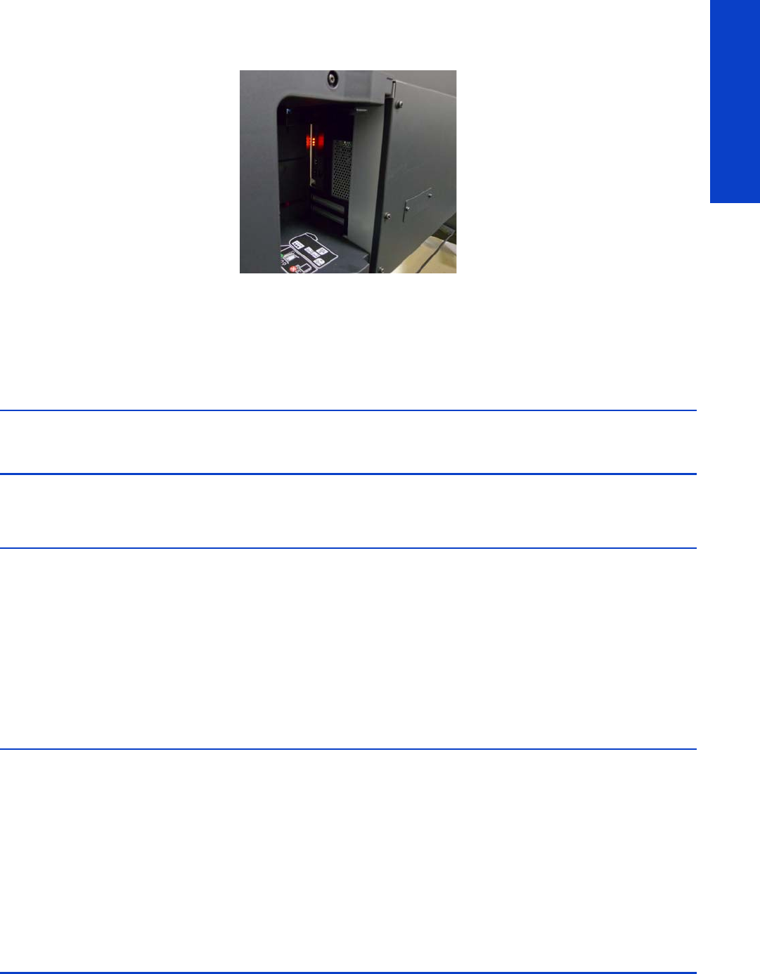
How to read the Formatter LEDs 49
Troubleshooting
The following image shows the three Formatter LEDs, which are numbered from the top down: number I
at the top, number II in the middle, number III at the bottom.
Use the following table to interpret the LEDs and find the source of the problem. Remember that you should
read these LEDs when you press the Power button.
Some combinations may require you to replace two or more components. In this case, always replace
one component at a time. Test the printer to see if the problem has disappeared (check the LEDs again).
If the same LED sequence continues, replace the next component indicated in the table.
Power
amber
LED
Power
blue
LED
Power
green
LED
Format-
ter I LED
Format-
ter II
LED
Format-
ter III
LED
Front
panel
status
Problem and
recommendations
Off Off Off Off Off Off Off
The printer is not receiving
electrical power. See “The
printer does not power on” on
page 47.
On Off Off Off Off Off Off
The Power key fails to turn on
the printer.
1. Turn off the printer using
the power switch at the
back of the printer. Wait
for 5 seconds and turn the
printer back on using the
same switch.
2. If the problem persists,
replace the Front Panel.
Off On Off Off Off Off Off
There is a power failure in the
Formatter.
1. Reseat the power connec-
tor in the Formatter.
2. Turn the printer on again.
3. If the problem persists,
replace the PSU.
4. If the problem persists, or
if the boot process starts,
replace the Formatter.

50 Chapter 2 Troubleshooting
Troubleshooting
How to read other LEDs
The printer electronics allow for many self-checks that will result in a definite system error when something
goes wrong. Therefore, it is not so important to know what the LEDs in other parts of the electronics mean.
However, they are explained here for reference.
Off On Off On Off Off Off
The Formatter BIOS is unable
to start. If an external Memory
Module is installed:
1. Reseat the Memory Mod-
ule.
2. Remove the Memory Mod-
ule and restart the printer.
3. If the printer is able to start
normally, replace the
Memory Module. If not,
replace the Formatter.
If an external Memory Module
is not installed, replace the
Formatter.
Off On Off Flashing Off Off Off
The Formatter BIOS cannot
detect the Hard Disk Drive.
1. Reseat the Hard Disk Drive
connectors.
2. Replace the Hard Disk
Drive.
Off On Off On Flashing Off Off
The operating system has
experienced a fatal error.
Replace the Hard Disk Drive.
Off On Off On On Off Off
There is a communication
failure in the Formatter.
1. Reseat the Formatter con-
nections to all other com-
ponents.
2. Replace the Formatter.
Off On Off On On Flashing Off
There is an initialization failure
in the Formatter. Replace the
Formatter.
Off On Off On On On Off
There is an initialization failure
in the Front Panel.
1. Reseat the Front Panel
cable.
2. Replace the Front Panel.
Power
amber
LED
Power
blue
LED
Power
green
LED
Format-
ter I LED
Format-
ter II
LED
Format-
ter III
LED
Front
panel
status
Problem and
recommendations
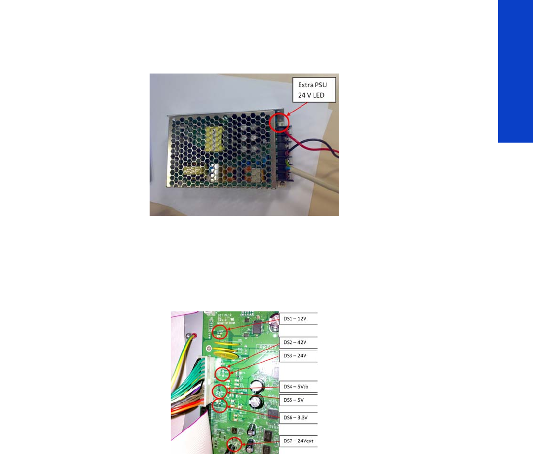
How to read other LEDs 51
Troubleshooting
Extra PSU 24 V
There is only one LED in the extra PSU. This LED indicates that the output 24 V voltage is being delivered
and it is on in normal operation.
If the LED is OFF, there could be a problem in the connections with the Power Supply Unit, in the Extra
PSU 24 V itself or in the Power Supply Unit.
PrintMech PCA
The LEDs in the PrintMech PCA are the following.
In normal operation all LEDs will be on.
If any of them are off, power from the corresponding voltage line is not reaching the PrintMech PCA. There
could be a problem with the cable connections from the other electronic boards to the PrintMech PCA, in
the Power Supply Unit, or in the PrintMech PCA itself. If none of these resolves the problem, you can also
replace the cables.
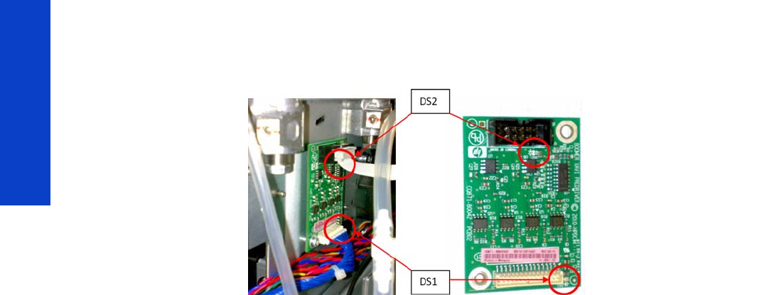
52 Chapter 2 Troubleshooting
Troubleshooting
Pre-Driver ISS PCA
The Pre-Driver ISS PCA is a new PCA connecting the PrintMech PCA to the Top ISS PCA. It has two LEDs.
DS1 (Green) – ON = OK. Pre-Driver and PrintMech are connected and 5 V are present.
DS1 (Green) – OFF = FAILURE. Pre-Driver and PrintMech are not connected and 5 V are present. The
problem could be in the connections to the PrintMech PCA, in the PrintMech PCA, or in the Pre-Driver PCA.
If none of these resolves the problem, you can also replace the cables from PrintMech PCA to Pre-Driver
PCA.
DS2 (Red) – ON = FAILURE. Top ISS PCA is not connected to Pre-driver PCA or an overpressure is detected
in the ISS PCA. There could be a problem with the connection from the Pre-Driver PCA to the ISS PCA, in
the Pre-Driver PCA, or in the ISS PCA. If none of these resolves the problem, you can also replace the
cables from Pre-Driver PCA to ISS PCA.
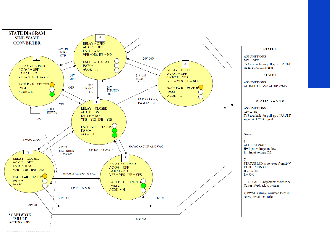
How to read other LEDs 53
Troubleshooting
Heater control modules (sine-wave converters)
State explanation
0 = OFF state
•Fault LED = Off
•PWM LED = Off
•AC OK LED = Off
1 = ON state: input voltage within range
•Fault LED = Off
•PWM LED = On
•AC OK LED = On
2 = Input voltage > 60 V AC and < 135 V AC (approximately)
•Fault LED = Off
•PWM LED = On
•AC OK LED = Off
3 = Input voltage < 60 V AC (approximately)
•Fault LED = On
•PWM LED = Off
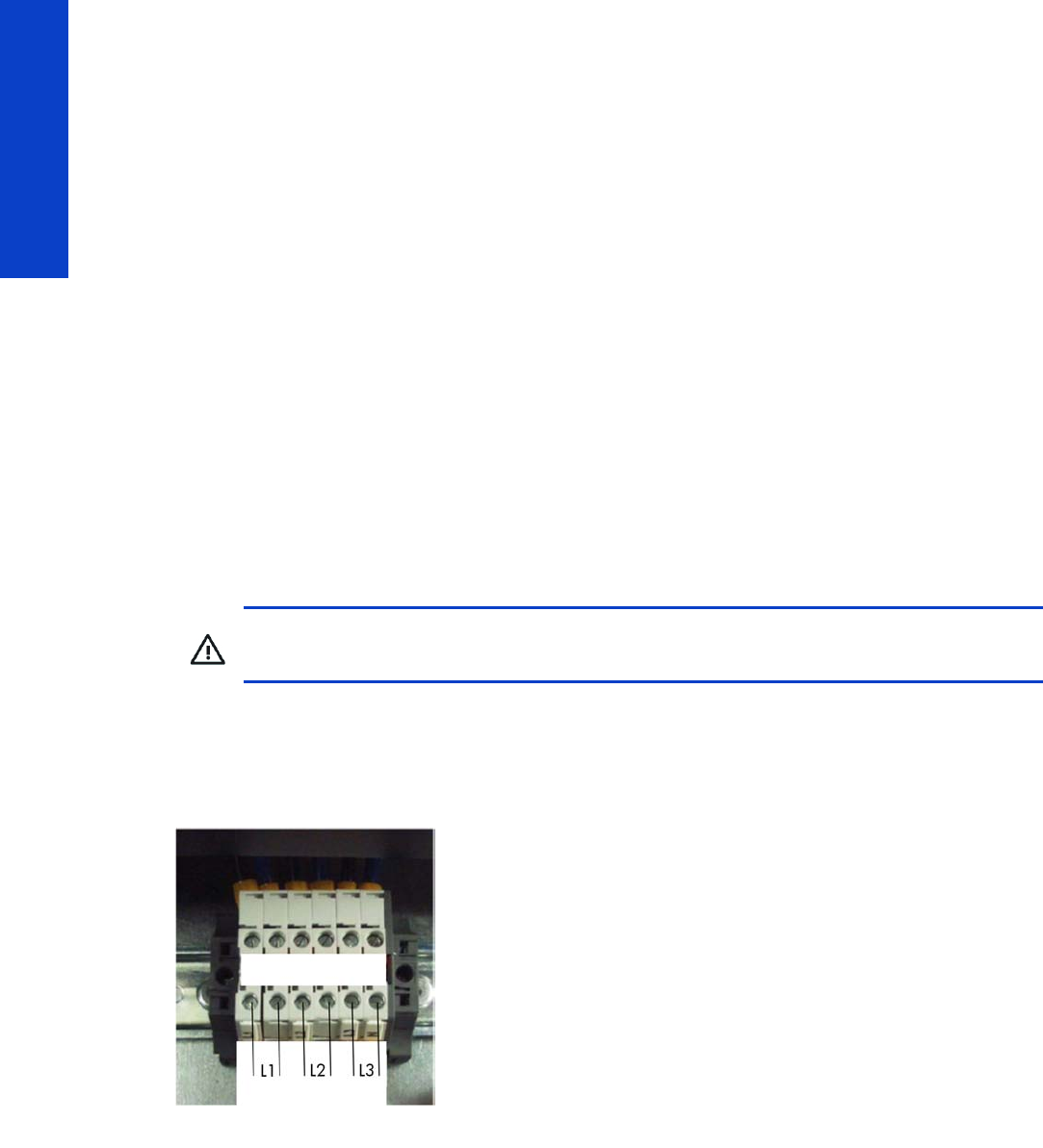
54 Chapter 2 Troubleshooting
Troubleshooting
•AC OK LED = Off
4 = Over Temperature Protection (OTP) state
•Fault LED = On
•PWM LED = Off
•AC OK LED = On
5 = Latched protection state
•Fault LED = On
•PWM LED = Off
•AC OK LED = Off
Voltage check at installation
This chapter describes how to check that the power cabinet has been set up properly and that the voltages
are appropriate to operate the printer.
Always refer to the Site Preparation Guide and Power Voltage Configuration information (printed
document in printer box). See also “Electrical power system” on page 17.
Before switching on the printer, the certified electrician setting up the power cabinet should check that the
voltages are appropriate to operate the printer.
The input voltage can be checked at the connection block of the power cabinet, between each pair of
connections for line 1 (L1), line 2 (L2), and line 3 (L3).
Correct voltage
Nominal input voltage range: 200–240 V (as described in the Site Preparation Guide and power setup
flier).
The following pictures show an example of the correct values to be measured.
WARNING! Risk of electrical hazard! The procedures described below must be performed
only by a certified electrician and always according to local regulations.
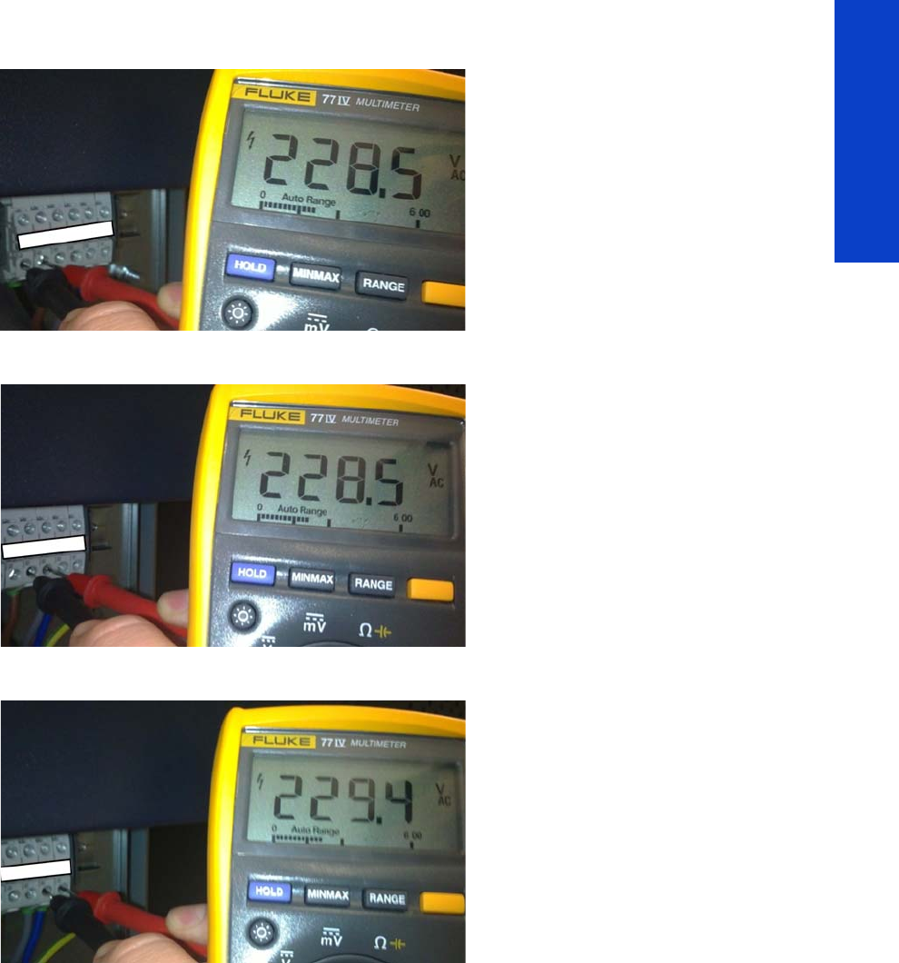
Voltage check at installation 55
Troubleshooting
Line 1 (L1)
Line 2 (L2)
Line 3 (L3)
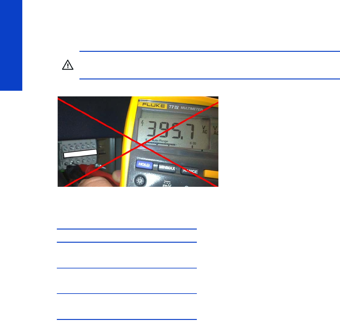
56 Chapter 2 Troubleshooting
Troubleshooting
Incorrect voltages
High voltages
Line 1 (L1) (example)
Lower voltages
Wrong connections resulting in nominal voltages lower than 200 V may produce system errors in the
printer. The printer will not be able to work.
Troubleshooting substrate jams or printhead crashes
The failure modes “substrate jam” and “head crash” are grouped together because in many cases a
substrate jam causes the substrate to lift up into the Carriage path and cause a Printhead crash, thus
causing many substrate jam failures to be detected as head crashes.
See the User’s Guide for instructions on how to respond to a substrate jam. Here are some additional tips.
•Always clear substrate jams from the front of the printer.
•Before loading, check the leading edge of the substrate for damage or excessive curling.
•If the substrate is self-adhesive, check that the backing (the liner) has not become detached. This is
quite common in Cast Self-Adhesive Vinyl printing materials.
•Check that the Add New Substrate procedure in the User´s Guide has been correctly followed for
the loaded substrate.
CAUTION: Wrong connections resulting in nominal voltages higher than 240 V will severely
damage the printer components, especially the Power Supply Unit (PSU) and Extra Power
Supply 24 V.
Voltage range (real) System error
140 - 180 V
Line 1 (L1) - 14.34:01
Line 2 (L2) - 14.54:01
Line 3 (L3) - 14.74:01
< 140 V
Line 1 (L1) - 14.33:01
Line 2 (L2) - 14.53:01
Line 3 (L3) - 14.73:01
No tension (0 V)
Line 1 (L1) - 14.32:01
Line 2 (L2) - 14.52:01
Line 3 (L3) - 14.72:01
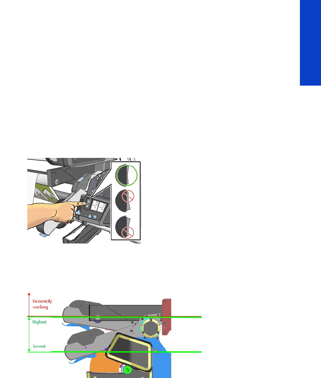
Troubleshooting substrate jams or printhead crashes 57
Troubleshooting
•Try loading the substrate manually.
•Try using the edge holders provided with the printer.
Take-up Reel usage tips
Correct usage of the Take-up Reel is very important to avoid substrate jams. In some cases, setting it up
wrongly can produce it to wind in the opposite direction than expected or even cause substrate jams at
the end of a job, while curing the final part of the printed image.
To avoid these issues, it is always recommended to follow all steps described in the User’s Guide chapter
“Handle the substrate” (under the heading “The take-up reel”), with the addition of the tips described in
this chapter.
Before loading the substrate onto the take-up reel (User’s Guide, step 2)
Maintain the winding-direction switch in the off position
Make sure to maintain the winding-direction switch in the off position until the substrate has been attached
to the take-up reel core and the tension bar has been lowered. This avoids unwanted movements when
routing the substrate to the take-up reel core, especially when loading it while printing.
After routing the substrate and attaching it to the core (User’s Guide, step 18)
Make sure the tension bar operates below the diverter
The tension bar’s working position is below the diverter. The following diagram shows the movement
range for it.
To ensure the correct working position, make sure there is enough substrate when unlocking and lowering
it for the tension bar to move low enough. If the substrate length is not enough, do the following:
•Loading the take-up reel before printing: move the substrate forward until the tension bar is low
enough. Then you can select the right winding direction. See the information below on selecting the
winding direction.
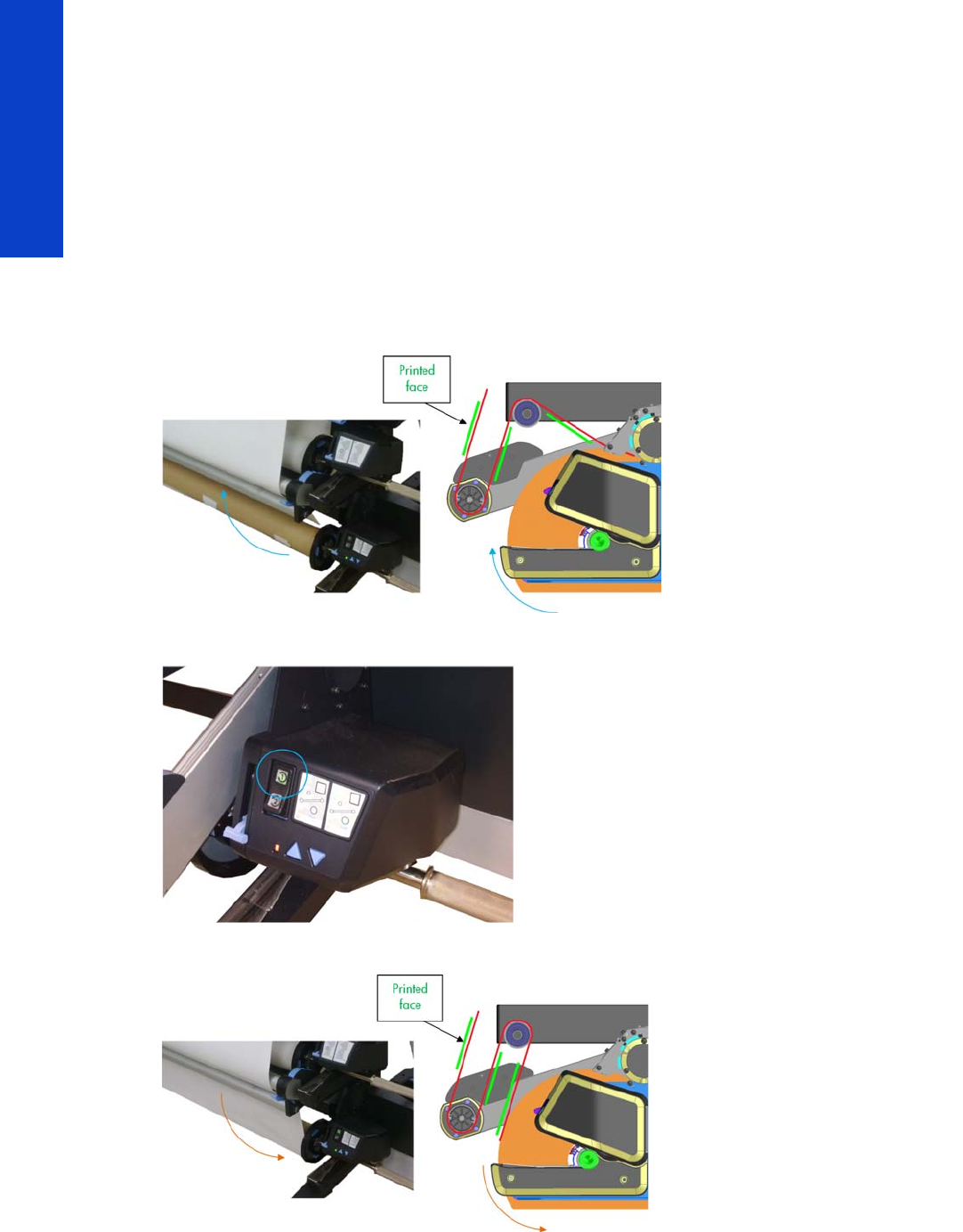
58 Chapter 2 Troubleshooting
Troubleshooting
•Loading the take-up reel while printing: keep printing and wait until the enough printed substrate has
come out so that the tension bar is low enough. Then, you can select the desired winding direction.
See the information below on selecting the winding direction.
If the tension bar is not low enough, it may seem to be working but it could cause problems:
•Winding in the wrong direction
•Substrate jams at the end of the job, while curing the print
Selecting the winding direction (User’s Guide, step 19)
To ensure correct winding, the correct winding direction must be selected according to how the substrate
has been attached to the take-up reel core. See the illustrations below.
Printed image face-in (setting 1)
Select setting 1 to roll the output with the printed image facing in.
Printed image face-out (setting 2)

The printer continuously rejects printheads 59
Troubleshooting
Select setting 2 to roll the output with the printed image facing out.
The printer continuously rejects printheads
To resolve printhead rejection problems, do the following:
1. Clean the flex contacts on the Printhead and in the Carriage Assembly using the Carriage
Interconnect Wiper (see the User’s Guide) and try again.
2. Swap the failed Printhead with a Printhead that is known to be working, and check if the error
follows the printhead:
• If the error follows the Printhead try to recover the Printhead by cleaning the contact again, if
that failed, replace the Printhead.
• If the error does not follow the Printhead, clean again the Carriage Interconnect and check for
damage, check the Carriage Interconnect if appropriate.
3. If all the Printheads are rejected (the status message on the Front Panel does not show “OK” for all
the Printheads), perform the Electronic Systems Test page 149.
The cutter does not function
Under certain circumstances the cutter will not cut the substrate. This is mainly when the take-up reel is
enabled, but there are other circumstances when the cutter will not cut.
•If the settings for the RIP have disabled the Cutter, but the customer has set the Front Panel settings to
cut, the customer could expect it to cut at the end of the job.
•If the customer presses the ‘Form Feed and Cut’ option, but the Cutter is disabled on the Front Panel.
•If the substrate being printed on cannot be physically cut because it is too thick.
The customer can enable and disable the cutter from the Front Panel (but remember this will be overridden
by the RIP). To enable the cutter from the Front Panel; select the substrate icon, then Substrate handling
options > Enable/Disable.
Troubleshooting Carriage shutdowns
Substrate path
To resolve substrate path problems, proceed as follows:
1. Open the Window and check for any visible obstacles restricting the movement of the Drive Roller.
Make sure that the mylar is not damaged. If there is a substrate jam, see the instructions in the User’s

60 Chapter 2 Troubleshooting
Troubleshooting
Guide; remember to clear substrate jams from the front of the printer. The Solve Substrate Jam
service test may help you page 158.
2. If this shutdown happens at the end of a roll of substrate, it could be because the substrate is stuck
firmly to the roll. Lift the Pinchwheels (using the Media Load Handles) and pull the substrate clear.
3. Replace spindle if broken.
4. Replace the Media-Axis Motor page 430.
How to troubleshoot the 86:01 system error
Possible causes of a system error 86:01
The HP Designjet L28500 will display a System Error 86:01 when there is a shutdown of the scan axis motor (the
carriage movement motor). A shutdown will occur when the motor cannot move the carriage or there is no feedback
from the encoder sensor by the time it has reached its maximum PWM (and shuts down to prevent further issues).
There are several different reasons that could lead to a shutdown:
•There is a physical obstruction in the path of the carriage (such as a substrate jam).
•Carriage stopper is not installed or is damaged.
•The friction between the carriage and the slider rod is too high and the carriage cannot begin
moving before the motor reaches its maximum PWM.
•The belt is not correctly transmitting motion to the carriage, which requires a higher motor PWM to
start it moving. This may occur if the belt is damaged, not correctly positioned or there is insufficient
tension.
•The ink tubes and trailing cable are not in the correct position. If this happens the tubes could
increase friction with the shelf during the carriage motion.
•The encoder strip or encoder sensor have failed, so the actual movement of the carriage is not
detected by the printer, causing an 86:01.
•The motor is defective and cannot generate enough motion or shuts down too early.
•One of the electronic boards or connections processing the carriage movement signal is defective,
so the printer cannot detect the actual movement, and causing an 86:01.
From the list above, it is possible to establish two main groups of causes for a system error 86:01:
•Mechanical: When the motors and electronics are working as expected, but still the carriage does
not move due to an obstacle or too high a friction.
•Electrical (or electromechanical): When the error is caused by one of the motors or electronic
components of the scan axis not working correctly (the scan axis motor, the encoder sensor, the
carriage PCA, etc.).
The first step in troubleshooting a 86:01system error is to determine to which of these two groups it belongs to, since
the troubleshooting process for both groups is significantly different.
Determining the type of system error 86:01
The following symptoms usually indicate that the system error 86:01 is caused by mechanical reasons:
•The system error is intermittent and occurs during printing.
•The performance of the printer is degrading (i.e. the system error is displayed increasingly frequent).
•The system error is preceded by a mechanical noise.

Troubleshooting Carriage shutdowns 61
Troubleshooting
If any of the previous conditions are occurring in the printer, apply the troubleshooting steps for mechanical 86:01
system errors.
Scan axis test
In case none of the above symptoms is occurring in the printer, perform the Scan axis test, refer to page 165.
Use the scan axis test to determine if the root cause of the system error 86:01 is mechanical or electrical. Once you
determine the type of 86:01, apply the troubleshooting steps described on page 61 (mechanical) or page 62
(electrical).
Following you have a summary of the steps of the Scan Axis test on how to interpret the results:
•Steps 1-4. Check the carriage PCA.
• If the results are correct continue the Scan axis test.
• If the results are not correct (the printer hangs, or the green LED is not ON or a system error is
displayed), the error is electrical, refer to page 62.
•Steps 5-8. Initialize scan axis, prepare PWM test, short carriage movements.
• If the results are correct continue the Scan axis test
• If the results are not correct (the printer hangs or a system error is displayed) the error is
electrical, refer to page 62.
•Steps 9-13. Short carriage movements, PWM test.
• If the carriage physically moves but the printer does not detect it, the error is Electrical, refer to
page 62.
• If the carriage does not physically move: check if the motor can move when not attached to the
carriage (to do so, you can reboot the printer in diagnostics boot mode, loosen the tensioner
and remove the belt from the motor pulley; repeat the Scan Axis test once more and check if
the pulley rotates or not):
- If the motor does not move, the error is electrical, refer to page 62.
- If the motor moves when not attached to the carriage the error is Mechanical, refer to
page 61.
• If the carriage moves the error is mechanical, refer to page 61. Take note of the values of the
PWM test. After performing the actions described below, the average PWM should show a
lower value .
How to troubleshoot mechanical 86:01 system errors
When the printer displays a system error 86:01 due to mechanical reasons, it is typically due to the belt not correctly
transmitting the movement of the motor to the carriage or the carriage having too high a friction with the slider rod
(which can be due to aerosol or dust accumulation). The procedure to troubleshoot and fix this type of issues includes
increasing the working margin in those areas that could be contributing to high friction or loss of belt traction.
Perform the following troubleshooting steps:
1. Check for mechanical interferences or encoder strip defects
Check that the error is not caused by a mechanical interference:
•The carriage stoppers not correctly positioned
•A broken carriage datum
•An object in the carriage path

62 Chapter 2 Troubleshooting
Troubleshooting
If you find any of these issues, correct it by correctly installing the stopper, removing the obstacle or replacing the
carriage.
The error can also be caused by a damaged or dirty encoder strip:
•Damaged: the small windows are broken. Replace the encoder strip.
•Dirty: ink/oil stains that block these small windows. Gently clean the ink/oil stains with a lint-free
cloth damped with a solvent.
•The cleansing must be very gentle in order not to break these small windows.
Remember that the metallic encoder strip is not affected by aerosol. If none of these issues is detected, proceed to
Procedure 2.
2. Correct potential causes of high friction or loss of belt traction
1. Clean the slider rod as described in the User’s Guide in order to remove remains of dust or aerosol.
2. Lubricate the scan axis as described in the User’s Guide.
3. Replace the oiler (CQ871-67086 Front Rod Oiler Right Assembly 104 SERV).
4. Check the belt, and replace belt and tensioner if worn or torn.
If these steps correct the issue, stop troubleshooting here. Only if the printer continues showing issues, move to
Procedure 3.
3. Clean or replace the carriage
If the printer is still showing issues at this point, it is possible that the carriage bushings are dirty or that they are worn
out, affecting the friction between the carriage and the rod. Disassemble the carriage and check the bushings. If they
are dirty, try to clean them and lubricate them. If the problem persists, replace the carriage (CQ871-67085 Carriage
w/o PCA, SOL, LS-104 SERV).
4. Increase cleaning and lubrication frequency
For heavy users (> 1500 m²/month) or in dusty or dirty environments, frequent cleaning and lubrication are needed.
Advise the customer to clean and lubricate, following the instructions in the User’s Guide, at least once a week even
if the printer does not ask for it.
How to troubleshoot electrical 86:01 system errors
If the root cause of the system error 86:01 is electrical, the troubleshooting process consists of determining and
replacing which electronic component is failing.
The “Scan axis test” described in the text above will point the following steps or the service part to be replaced at
each step of the diagnosis. Please follow the guidelines for part replacement.
Here is a list of the most important electrical systems involved in the Scan Axis movement:
•Scan Axis motor: Provides the movement (CQ871-67071 Scan Axis Motor 104 SERV).
•PrintMech PCA: Provides the power to the motor, following instructions from the Engine PCA
(CQ 871-67030 Printm ech PC A 104 SE RV ) .
•Encoder Strip and Sensor: Acquires the signal that provides the position and speed of the
carriage (CQ871-67012 Encoder strip and sensor 104 SERV). Sometimes the Encoder strip sensor is
not working due to a defective line sensor, if the problem is not fixed by replacing the encoder strip
and sensor, then change also the line sensor.
NOTE: Do not use Ethanol in California or other areas that restrict the volatile organic compound
(VOC) content of cleaning solvents. A regulatory compliant alternate should be used.
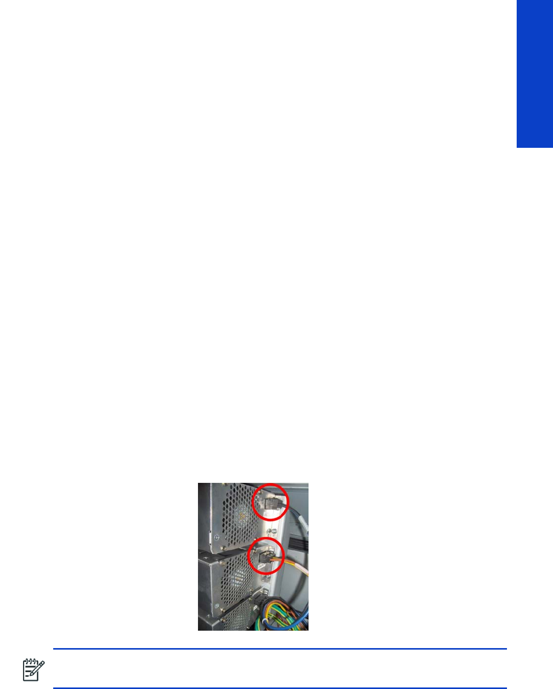
Troubleshooting the drying and curing heaters 63
Troubleshooting
•Carriage PCA: Provides power to the sensor, processes and passes the encoder signal to the
trailing cable (CQ109-67034 Carriage PCA SERV).
•Trailing Cable: Transfers the processed encoder signal to the Engine PCA (CQ871-67044 SRK
and TC 104 SERV).
•Engine PCA: Processes the encoder signal (servo), takes decisions, and sends instructions to the
Printmech PCA (CQ871-67002 Engine PCA 104 SERV).
All connections among these systems should be checked by disconnecting and reconnecting them to make sure they
are good, especially the Trailing Cable connections.
Troubleshooting the drying and curing heaters
Use this procedure if the resistors have failed. For this procedure you need a voltage-current tester like the
one shown in the pictures to measure resistances. If the printer has been printing, allow enough time
(about an hour) to cool down so that the resistance values will be correct when they are measured.
Important safety notice: Disconnect the printer from any electrical power source before opening the
electronics cover and checking these circuits.
Troubleshooting the drying heaters
1. The first check consists of running the Monitoring Sine-waves and Resistances diagnostic test
page 173. For this purpose, an input voltage is needed.
2. If any resistor is defective (current too high/low or resistance too low/high, respectively), exchange
dryer power connectors between upper and middle converters (cables labeled H1 and H2).
Run the Monitoring Sine-waves and Resistances diagnostic test again and check whether the defect
has moved to the other converter. If so, it means there is a problem from the connector onwards,
towards the resistor. Otherwise, it means there is a problem in the converter itself.
3. If the problem is not in the converter, remove the Electronics Enclosure Extension Cover to gain
access to the heaters’ connectors page 329.
4. Disconnect both dryer power connectors, which are the upper (labeled H1) and the middle (labeled
H2) ones.
NOTE: The colors and labels of the cables may be slightly different in the final product.
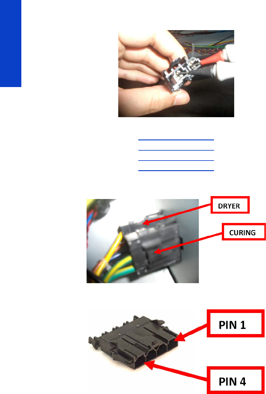
64 Chapter 2 Troubleshooting
Troubleshooting
5. Use a voltage current tester to measure between pins 1 and 2 on both connectors. As dryer resistors
are physically the same, expected resistance values are the same.
6. Check that the values are within specification:
7. Remove the Left Cover to gain access to the cable plate page 303. Then disconnect the dryer
power cables.
8. The dryer connector has 4 female pins. The illustration below shows the numbering of the connector
pins looking from the connection side and holding the clip down.
Maximum (ohm) 11.0
Nominal (ohm) 10.5
Minimum (ohm) 10.0
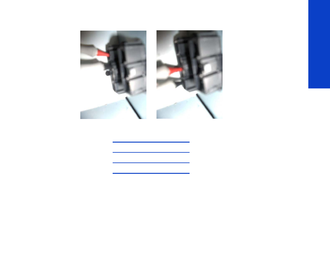
Troubleshooting the drying and curing heaters 65
Troubleshooting
9. Use a voltage tester to measure between pins 1 and 2 and between pins 3 and 4. As dryer resistors
are physically the same, expected resistance values are the same.
10. Check that the values are within specification:
If all the resistances are within specification, the fault is in the path from the Heater Controllers to the
connectors in the arc. It could be due to a failed cable or a wrong contact between pins 1-2 or 3-4 when
measuring.
1. Check the connectors and cables are not damaged, disconnect and reconnect them, test the pins
again.
2. Replace the Dryer Heater page 494.
3. Replace the left-side cabling.
Troubleshooting the curing heaters
1. The first check consists of running the Monitoring Sine-waves and Resistances diagnostic test
page 173. For this purpose, an input voltage is needed.
2. If any resistor is defective (current too high/low or resistance too low/high, respectively), exchange
the curing power connector (labeled H3) with any other converter.
Run the Monitoring Sine-waves and Resistances diagnostic test again and check whether the defect
has moved to the other converter. If so, it means there is a problem from the connector onwards,
towards the resistor. Otherwise, it means there is a problem in the converter itself.
3. If the problem is not in the converter, remove the Electronics Enclosure Extension Cover to gain
access to the heaters’ connectors page 329.
Maximum (ohm) 11.0
Nominal (ohm) 10.5
Minimum (ohm) 10.0
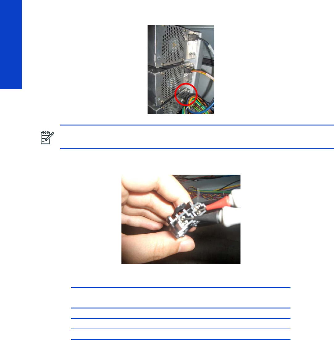
66 Chapter 2 Troubleshooting
Troubleshooting
4. Disconnect the curing power connector, which is the bottom one (labeled H3).
5. Use a voltage tester to measure between pins 1 and 2. Curing resistances are connected in parallel,
so the failing resistor can be identified from the value read.
6. Check that the values are within specification. If only one resistor is working, its resistance is higher:
NOTE: The colors and labels of the cables may be slightly different in the final product.
Both resistors
working
Overdrive (front)
resistor only
Output (rear)
resistor only
Maximum (ohm) 8.6 13.5 23.3
Nominal (ohm) 8.2 12.9 22.2
Minimum (ohm) 7.8 12.3 21.1
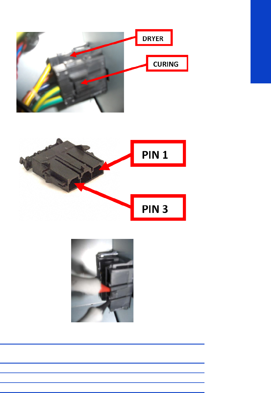
Troubleshooting the drying and curing heaters 67
Troubleshooting
7. Remove the Left Cover to gain access to the cable plate page 303. Then disconnect the curing
power cables.
8. The curing connector has 3 female pins. The illustration below shows the numbering of the connector
pins looking from the connection side and holding the clip down.
9. Use a voltage tester to measure between the pins 1 and 2.
10. Check that the values are within specification. If only one resistor is working, its resistance is higher:
If all the resistances are within specification, the fault is in the path from the Heater Controllers to the
connectors in the arc. It could be due to a failed cable or a wrong contact between pins 1-2 when
measuring.
Both resistors
working
Overdrive (front)
resistor only
Output (rear)
resistor only
Maximum (ohm) 8.6 13.5 23.3
Nominal (ohm) 8.2 12.9 22.2
Minimum (ohm) 7.8 12.3 21.1
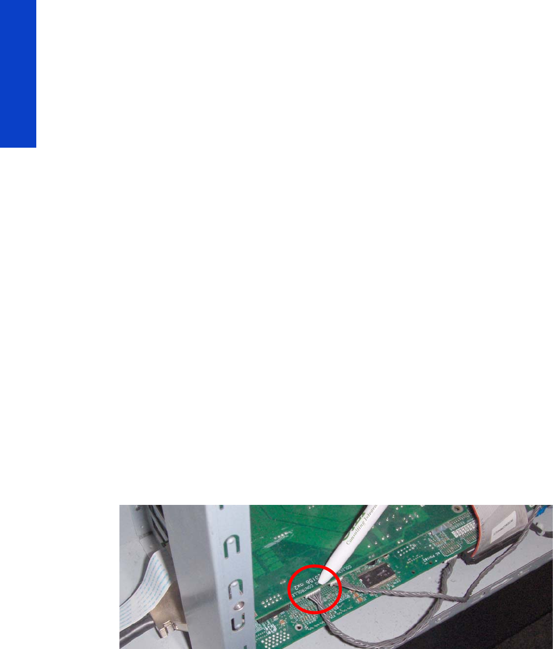
68 Chapter 2 Troubleshooting
Troubleshooting
1. Check that the connectors and cables are not damaged, disconnect and reconnect them, test the
pins again.
2. Replace the defective curing heater page 521.
3. Replace the left-side cabling.
Troubleshooting sensors
Cover Sensors
To resolve cover sensor problems, try the following:
1. Perform the Sensors Test page 174.
2. Check if the cable for the faulty sensor is not damaged and is connected correctly.
3. Replace the faulty Sensor.
The Line Sensor
If the line sensor cannot detect the substrate, try the following:
1. Check the type of substrate that is being used since the Line sensor may have problems detecting
transparent substrate or some types of Non-HP substrate. Try loading white HP substrate in to the
printer and check if the Line sensor detects it.
2. Excessive ink deposits on the Platen surface can fool the sensor by reflecting the light. Clean the Print
Platen.
3. The Line Sensor is not calibrated correctly. Perform the Line Sensor Calibration page 170.
4. The Line Sensor is damaged or faulty. Replace the Line Sensor page 473.
OMAS
A problem with the OMAS board may cause the printer to display a 50.2:10 service error, this can
be fixed by checking the following connections:
1. Check the CAN Cable is correctly connected.
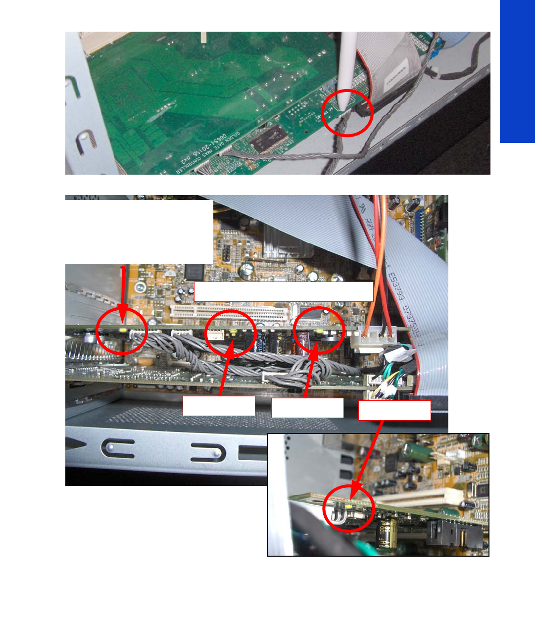
How to troubleshoot the 79:04 system error 69
Troubleshooting
2. Check the other end of the CAN cable is also correctly connected
3. Check the LEDs under the OMAS board.
How to troubleshoot the 79:04 system error
Introduction
The system error 79:04 is a generic firmware error, equivalent to a blue screen in Windows. It’s the system
error that the printer will display when an unknown exception occurs that cannot be linked to any specific
printer subsystem.
Since this is a generic error, it has many possible causes. This section covers the most likely causes of a
system error 79:04 and recommends the most efficient troubleshooting steps to resolve customer issues.
This LED only comes on for the first
20 seconds after the printer is
turned On. When the firmware has
successfully loaded into the
memory the LED will switch OFF.
These LEDs come On and stay On.
LED=3.3 volts LED=24 volts LED=5 volts

70 Chapter 2 Troubleshooting
Troubleshooting
One important point to mention is that, although 79:04 system errors can be caused by a hardware
malfunction, the vast majority of 79:04 system errors caused by software or firmware issues. In these cases
the issue can be solved only by determining the root cause and implementing a solution. The solution can
usually be applied by correctly configuring a selection, updating the printer’s firmware or software, or by
fixing an error in the code.
Possible causes
Since the 79:04 system error is a generic error, it has many possible causes. The majority can be
grouped, however, into the following groups.
Job-related SE 79:04
A specific print job that is not correctly formatted for the printer or that is not correctly processed by it can
trigger a 79:04 system error.
The incorrect format or processing can come from two sources:
• Incorrect commands in the job itself
• Incorrect job settings
Possible symptoms
A 79:04 error caused by a print job always has the same symptoms:
1. The job is received by the printer and starts to process.
2. In the middle of the processing, the printer stops and displays 79:04.
3. The printer restarts normally.
4. If the same job is sent again, it always produces a 79:04 system error.
This type of 79:04 system error is normally caused by jobs that have been generated by third-party
applications (RIPs, third-party drivers, files exported by an application to PS, PDF, HP-GL/2, RTL, … or
any other format supported by the printer). The HP Designjet L28500 processes only halftone PCL3GUI
files. Thus, there is little chance that this type of 79:04 system error will appear.
Solutions and workarounds
When a job consistently generates a 79:04 system error, it is either because of a issue in the printer’s
firmware or because of a defect in the job itself. In order to identify the cause and find out a solution,
these issues should always be immediately escalated to the GBU through the GCC.
However, there are some workarounds and short-term solutions that can be tested in order to get the
customer up and running in the shortest possible time:
1. Send the job using a variety of different settings, or maybe using a different media preset, in case
the original preset that generated the job is corrupted. The issue is often caused by a combination of
the job contents combined with some specific setting(s).
2. If step 1 did not resolve the issue, try updating the firmware, using a USB flash disk if the printer
does not start up, or the Embedded Web Server if it does.
Data-related SE 79:04
HP Designjet printers have hard disks and non-volatile memories that contain databases and files that can
be modified with user data. Some examples include:
•The database that stores the printer settings
•The database that stores accounting information

How to troubleshoot the 79:04 system error 71
Troubleshooting
Some of this information is accessed by the printer at start-up, and some accessed as needed. If any of it
contains characters or values that cannot be correctly processed by the printer, a 79:04 system error may
occur.
Possible symptoms
There are two different types of symptoms for data-related 79:04 system errors:
1. When corrupt data are accessed during start-up:
a. The printer displays a 79:04 error during the start-up process.
b. Switching the printer off and on again will not solve the issue. The printer continues displaying
the 79:04 error until the corrupt data have been cleared through a service procedure.
2. When corrupt data are accessed during normal printer operation:
a. The printer starts up normally.
b. When the data are accessed (for example while printing, or when changing some settings),
the printer displays a 79:04 system error.
c. The printer can restart normally.
d. When the data are accessed again (typically, under the same conditions as in step “b”), the
79:04 system error is displayed again.
Solutions and workarounds
Many times, data-related 79:04 errors are resolved by means of hardware intervention. Since data are
stored in physical components (RAM, EEROM and Hard Disk), replacing these components with new ones
that are empty usually solves the problem. However, there are quicker and more effective solutions to this
type of error:
1. Clear all information that has been introduced by the user using the standard tools available in the
printer:
a. Reset to factory defaults to clear the user’s configurations and calibrations.
b. Delete any non-standard substrate family in the printer, and any that have been installed as
OMES profiles through the EWS.
2. If step 1 did not resolve the issue, try updating the firmware, using a USB flash disk if the printer
does not start up, or the Embedded Web Server if it does.
3. If step 2 did not resolve the issue, you can use Service Tools to clear additional information that
could be causing the issue:
a. Start the printer in Diagnostics Boot Mode.
b. Perform an EEROM reset.
4. If step 3 did not resolve the issue, it is possible to clear the information on the Hard Disk and the
different EEROMs completely, leaving them in an equivalent state to a new part:
a. Access the Service Utilities Menu.
b. Select Disk Recovery.
c. Update the firmware in the printer to the latest official version as soon as the printer has
restarted.
Important note:
It is possible that the corrupt data came to be in the printer as a consequence of some activity in the
customer’s workflow; in which case, it is possible that the issue will recur. In this situation, it is very
important to understand the sequence of events in the customer’s workflow that led to the error occurring.
Once the error can be traced in the customer’s workflow, escalate the issue to the GBU through the GCC.
It may be possible to modify the printer’s firmware to avoid the issue in future.

72 Chapter 2 Troubleshooting
Troubleshooting
Network-related SE 79:04
Most HP Designjet printers have built-in networking capabilities. Network settings can be made manually,
but in the majority of cases they are obtained automatically from the printer. These settings include many
different fields, such as IP address and subnet mask, available gateways, and host and domain names.
Issues in the firmware can cause a value in one of these fields to be interpreted incorrectly, and this can
lead to a 79:04 system error.
Symptoms
There is no single set of symptoms that can absolutely pinpoint a network-related 79:04 system error.
However, the following guidelines can be applied:
•It can happen at start-up or when accessing the Network Configuration section of the Front Panel.
•In both cases, repeating the action with the LAN cable disconnected does not cause the 79:04 to
occur.
Solutions and workarounds
In most cases, this type of error is caused by an issue in the printer’s firmware. As soon as the conditions
in which the issue happens are understood, it should be escalated to the GBU through the GCC.
At the same time, the following short-term solutions and workarounds can help the customer to get up and
running in the shortest possible time:
1. Disconnect the network cable so that you can start the printer and change network settings.
2. In the Network Configuration menu in the Front Panel, disable any protocols that you are not using,
including IPv6, SNMP, and WebServices.
3. If step 2 does not work, try manual configuration:
a. Enter the correct subnet mask and an IP address in the valid range.
b. In the GateWay field, set the same value as in the IP address field.
c. Do not set a host name or a domain name.
4. If step 3 did not resolve the issue, try updating the firmware, using a USB flash disk if the printer
does not start up, or the Embedded Web Server if it does.
User-interaction-related SE 79:04
In some cases the printer may not react as expected when a certain set of conditions coincide. In these
cases, if the printer doesn’t know how to react, it may simply display a 79:04 system error and force a
restart. Some examples (not real) may help to illustrate this:
•A job is cancelled at the “Finishing print” stage.
•The Window is opened while the printer is checking the printheads.
These errors are likely to happen only in very specific corner cases that have not been identified during
the development or the qualification of the printer, so they do not usually impact the customer severely,
as they do not affect normal workflows.
Symptoms
The symptoms here are as numerous as the number of possible interactions between the user and the
printer. In any case, it’s possible to identify the steps that caused the error to occur and avoid them, as
the steps will always be the same with no variance.
Important: An major element in determining the error is what state the printer was in at the time the
error was displayed. For example, a user action while the printer is drying may produce an error, whereas
the same action while the printer is doing something else (or is idle) may not produce any error.

How to troubleshoot the 79:04 system error 73
Troubleshooting
Solutions and workarounds
First identify the steps that caused the error. Then proceed as follows:
1. Escalate the issue to the GBU through the GCC in order to have it corrected in the firmware.
2. Recommend to customers that they try to avoid those steps in order to avoid the error.
3. If the conditions that cause the error are in the customer’s regular workflow, try to identify a different
way of achieving the same result.
Random SE 79:04: Concurrence issues and memory leaks
Some 79:04 errors can happen randomly when the printer is being heavily used. However, it’s impossible
to find a single set of conditions that reproduce the problem. It just happens from time to time, without a
defined pattern.
These random 79:04 errors can have two different types of root causes:
•Memory leaks: Before a program is executed, it allocates the memory it will need. After the
execution is complete, the allocated memory is freed to be used by other programs. If the allocation
or the release of the memory are not correctly programmed, every time the program is executed
some memory will be incorrectly labeled (either as used or as free). This is known as a memory leak.
When a program with a memory leak is executed repeatedly, more and more memory becomes
unavailable to other programs (since it is not properly freed). When the leak becomes too big, the
printer is left out of memory to execute new processes and a 79:04 is triggered.
•Concurrence issues: There are certain resources that can be accessed by multiple programs or
by multiple executions of the same program (known as multiple threads). Access to these resources
must be correctly controlled to prevent unexpected behavior. Issues caused by an incorrect control of
these resources are concurrence issues.
Symptoms
This type of 79:04 error always occurs in heavy load conditions, so the symptoms will always follow this
pattern:
•A printer that is being heavily used (printing a project or in a reprographics environment) produces
79:04 errors randomly, forcing the user to restart.
•After restarting, the printer can be used without any issues for an extended period of time; but, if the
workload is consistently high, a random error will occur again.
•The error can never be associated with a specific file. The file that was being printed when the error
occurred the last time can be printed without issues after restart. And a file that has been printed
without issues several times can trigger the error in the future.
•The error is very dependant on the customer’s workflow. The most common user workflows have
been extensively tested both by HP and by our beta sites, so random 79:04 issues are highly
unlikely in these cases. These random issues tend to occur in very specific corner cases, and cannot
be reproduced unless the exact conditions of the workflow are replicated.
Workarounds and solutions
Random 79:04 errors are, by far, the most complex ones to diagnose and to fix. The only solutions
available in these cases are:
1. Identify the root cause (either in the files or in the firmware) and fix it in the code, which requires the
intervention of the GBU.
2. Test any options available to modify the customer’s workflow and see if any combination of them
solves the issue.
In both cases, a profound understanding of the customer’s workflow is necessary. In particular, the
information that is needed is:

74 Chapter 2 Troubleshooting
Troubleshooting
•Printer front-panel settings
•The RIP and its version number, the driver and its version number
•The media preset
•The application program, if any
•Some sample files that are representative of what the customer is using
•The operating system
•The method of connection to the printer
•A description of the normal flow when the issue occurs and the typical frequency of occurrence: for
example, once every hour when sending multiple several files without a pause, each of them with
multiple copies
With this information, the environment can be replicated in order to try to find workarounds. This is also
the information that will be needed at the GBU to investigate and fix the root cause of this issue once it is
escalated.
Hardware-related SE 79:04
Hardware is, by far, the least likely cause of a 79:04 system error. Replacing hardware components does
not normally fix the issue and increases the total time spent in finding a workable solution.
In some cases, a failure in a component in the printer’s electronics may cause a 79:04 system error, since
the printer’s electronics are involved in the execution of the firmware and the processing of jobs. It should
be noted, however, that hardware failures in the electronics tend to produce specific system errors that
point directly to the component that is failing.
Here are some specific hardware failures that could cause a 79:04 error.
•Defective clusters in the Hard Disk Drive. If these clusters are used to execute the firmware or to
process a job, they may produce a 79:04 error. It should be noted, however, that most 79:04 errors
that are resolved by a Hard Disk Drive replacement are, in fact, data-related 79:04 errors that could
have been solved more efficiently and quickly by following the steps in Section 3.
•Defective memory segments. If the RAM memory has some defective segments, a 79:04 may occur
when these segments are used.
•Intermittent defects in the electronic components that are involved in the processing of a job:
Carriage PCA, Trailing Cable, Formatter, and PrintMech. This is a highly unlikely cause, since
defects in these components will produce subsystem-specific errors.
Symptoms
There is no single set of symptoms behind hardware-related 79:04 system errors. These are the most usual
ones:
•79:04 error during start up. Restarting the printer may or may not solve the problem.
•79:04 error while processing or printing a job. Restarting the printer and printing the same job does
not always produce the error.
Solutions and workarounds
In the following procedure, perform each step as it appears in the list, and move on to the next step only
once you are sure the 79:04 error has not been cleared.
1. Restart the printer in Diagnostics Boot mode and execute the service tests to validate the functionality
of all the electronics components.
2. Perform the troubleshooting procedure for data-related system errors, as already described.
3. Replace the memory.

How to troubleshoot the 79:04 system error 75
Troubleshooting
4. Replace the Hard Disk Drive.
5. Escalate the issue before replacing any additional parts.
Troubleshooting based on symptoms
This section will describe which troubleshooting steps to perform for a 79:04 system error based on the
symptoms of the issue. Perform each step as it appears in the list and move on to the next step only once
you are sure the 79:04 error has not been cleared.
Front panel displays 79:04 at start-up
•Restart the printer. If the system error has been caused by a job in an incorrect format, restarting will
clear the error. If restarting the printer solves the issue, see job-related SE 79:04 page 70.
•Update the printer’s firmware. If the installed firmware is the latest version, re-install it. Since the
printer cannot start normally, you will need to update the firmware using a USB flash drive.
•Disconnect the network cable and restart the printer. If this solves the problem, see network-related
79:04 page 72.
1. Remove all cartridges, printheads, and printhead cleaning cartridge. Unload the substrate. Restart
the printer. If the printer can start normally, insert the consumables one by one until you isolate the
one that is causing the error. Do not insert any of the replaced consumables in another printer.
2. Restart the printer in Diagnostics Boot Mode and perform the electronics test. If an electronic
component is identified as faulty, replace it.
3. Restart the printer in Diagnostics Boot Mode and reset the EEROM. If this solves the issue, see data-
related 79:04 page 70.
4. If the printer has been used for some time and has suddenly started to show this behavior, replace
the Hard Disk Drive.
5. If the printer is new and the issue has been happening since it was first started, do not replace the
Hard Disk Drive.
6. If none of the previous steps solved the issue, escalate the issue with the following information:
• Printer information: serial number, part number, accessories
• Conditions in which the problem occurs and conditions prior to the first occurrence of the
problem
• The results of the above troubleshooting steps
• The system error detailed information (this can be obtained by pressing CANCEL + Down)
•The printer logs
Front panel displays 79:04 during printer operation – not while sending jobs
1. Restart the printer.
2. Update the printer’s firmware. If the installed firmware is the latest version, re-install it.
3. Reset the printer to factory defaults.
4. In order to narrow the scope of the issue, try the following:
a. Disable any unused network protocols.
b. Disable SNMP and WebServices.
c. Disable “Sleep mode” from the Service Utilities menu.
d. Delete any substrate families that you may have added to the printer.

76 Chapter 2 Troubleshooting
Troubleshooting
5. Restart the printer in Diagnostics Boot Mode and perform the electronics test. If an electronic
component is identified as faulty, replace it.
6. Restart the printer in Diagnostics Boot Mode and reset the EEROM. If this solves the issue, see data-
related 79:04 page 70.
7. Run the HDD Recovery service utility. If this solves the issue, see data-related 79:04 page 70.
8. Try to identify the combination of settings or actions that led to the system error and try to reach the
same result with a different combination. Escalate the issue to fix the original problem.
9. If none of the previous steps solved the issue, escalate it with the following information:
• Printer information: serial number, part number, accessories
• Conditions in which the problem occurs and conditions prior to the first occurrence of the
problem
• The result of the above troubleshooting steps
• The printer information pages (either printed and faxed or obtained through the Embedded
Web Server)
• The system error detailed information (it can be obtained by pressing CANCEL + Down)
•The printer logs
Front panel displays 79:04 while printing
A. While printing a single job
The error happens after a single job is sent. It’s easy to identify which job has produced the error, since
every time this same job is sent, the error is repeated.
1. Restart the printer.
2. Update the printer’s firmware. If the installed firmware is the latest version, re-install it. Send the job
using different print settings. The following ones can be helpful:
a. Try using a different media preset.
b. Try changing the print mode, or at least the number of passes.
3. Escalate the issue, providing the following information:
• Printer information: serial number, part number, accessories
• Conditions in which the problem occurs and conditions prior to the first occurrence of the
problem
• The result of the above troubleshooting steps
• The printer information pages (either printed and faxed or obtained through the Embedded
Web Server)
• The system error detailed information (it can be obtained by pressing CANCEL while the error
is being displayed)
•Workflow information:
-Operating system
- Application
- RIP and RIP version, driver and driver version
- Substrate family and media preset

Vacuum suction much lower at high altitudes 77
Troubleshooting
-Printer settings
- Connection method and settings
• The original file along with information on how to reproduce the issue
• A print to file that can reproduce the issue
•The printer logs
B. Random 79:04 during continuous printing
The error does not happen with a single job. It happens randomly during continuous printing, normally
while the printer is managing a heavy load (printing a project or in a reprographics environment).
This type of error is caused either by memory leaks or by concurrence issues in the printer’s firmware.
They normally happen in unusual environments in which memory leaks or concurrence issues may occur
without having been detected during qualification. These issues cause the printer to crash at a completely
random moment during printing, and are not associated with a specific job.
Troubleshooting these issues is normally quite complex.
1. Restart the printer. If the issue continues occurring randomly, continue troubleshooting.
2. Update the printer’s firmware. If the installed firmware is the latest version, re-install it.
3. Escalate the issue, providing the following information:
• Printer information: serial number, part number, accessories
• The printer information pages (either printed and faxed or obtained through the Embedded
Web Server)
• The system error detailed information (it can be obtained by pressing CANCEL while the error
is being displayed)
•Workflow information:
-Operating system
-Application
- RIP and RIP version, driver and driver version
- Substrate family and media preset
-Printer settings
- Connection method and settings
• Exact information on how to replicate the environment that reproduces the issue, including
some example files that can be sent to the printer to replicate a heavy load environment. These
files will need to be:
- Original application files, if the error occurs when printing from an application
-A print to file
•The printer logs
Vacuum suction much lower at high altitudes
At altitudes above 1,000 meters, the vacuum force holding down the substrate will be lower, therefore
the substrate will not be held in place sufficiently, causing:
•Ink smearing on the substrate

78 Chapter 2 Troubleshooting
Troubleshooting
•Printhead crashes against the substrate
•Roll loading problems (low probability)
The altitude range must be selected in the Front Panel for altitudes higher than 1,000 m.
At altitudes above 3,000 m the printer may not work correctly.
The level of suction applied to the substrate can be adjusted from the RIP.
Banding due to ink cartridge replacement while
printing
A user has removed the Ink Cartridge while the printer was printing, which has caused the printer to stop.
If the user does not replace the Ink Cartridge immediately, when the printer starts to print again, a band
will appear in the position where the printing restarted. This is because the wet ink interacts with the dried
ink on the substrate causing the band to appear. To solve the problem, try the following:
•Do not remove the Ink Cartridge while the printer is Printing. Only replace/remove Ink Cartridges in
between prints.
•If the Ink Cartridge was replaced due to the “Empty” status on the Front Panel, then advise the
customer to replace the Ink Cartridge when the “Very Low” status is showing on the Front Panel.

Banding due to ink cartridge replacement while printing 79
Troubleshooting
How to interpret the Service Information Pages
The Service Information Pages contain the following information:
•Current Information
•Usage Information
•Event Logs
•Calibration Status
•Connectivity Configuration
•All Pages
It is possible to print the Service Information Pages either through the Front Panel or through the Embedded
Web Server:
•Front Panel: Setup menu Internal Prints Service Information Prints.
•Embedded Web Server: Support tab Service SupportPrinter Information.
Even if the printer cannot print, the Information Pages are still accessible through the Embedded Web
Server.
Main characteristics
•Only available in English (except the current information page).
•From the Front Panel, you can choose to print ALL pages or just select the specific pages that are
needed. If ALL pages are printed, nesting is turned ON automatically (and turned OFF once all the
pages have been printed).
•Each page can be printed from the Web browser when using the Embedded Web Server.
•Each page can be sent by e-mail from the Web Browser when using the Embedded Web Server
(File Send Page by E-mail).
•You can see the same information through the Front Panel or the Embedded Web Server.
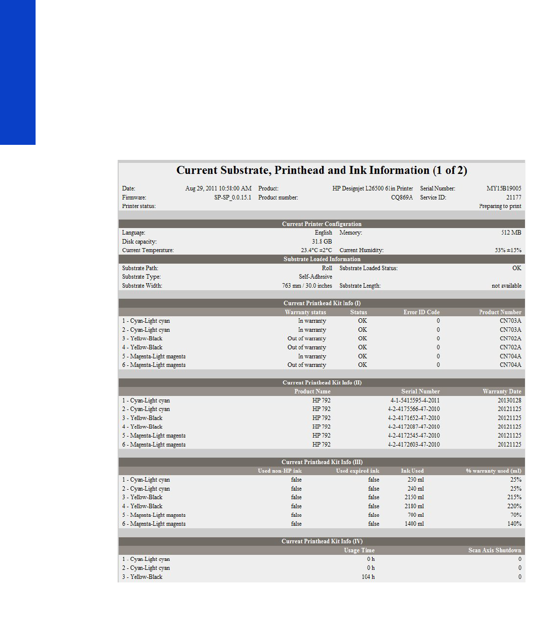
80 Chapter 2 Troubleshooting
Troubleshooting
Current information (1 of 2)
The first section, is generic information and is available in every tab, it displays information such as the
current level of firmware installed, the serial number of the printer etc.
This page is in two parts: The first part displays information on the following:
•Current Printer Configuration.
•Substrate Loaded Information.
•Current Printhead Kit Information.
Current information (2 of 2)
The second part displays information on the following:
•Current Ink Cartridge Information
•Printhead Cleaning Kit.
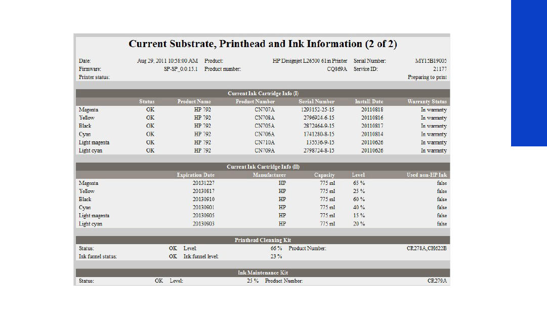
Banding due to ink cartridge replacement while printing 81
Troubleshooting
•Ink Maintenance
Printer usage information (1 of 3)
This page contains the following information:
•Printer Usage
•Usage per Printhead Slot
•Usage per Cartridge Slot
•Media Usage per Media Type
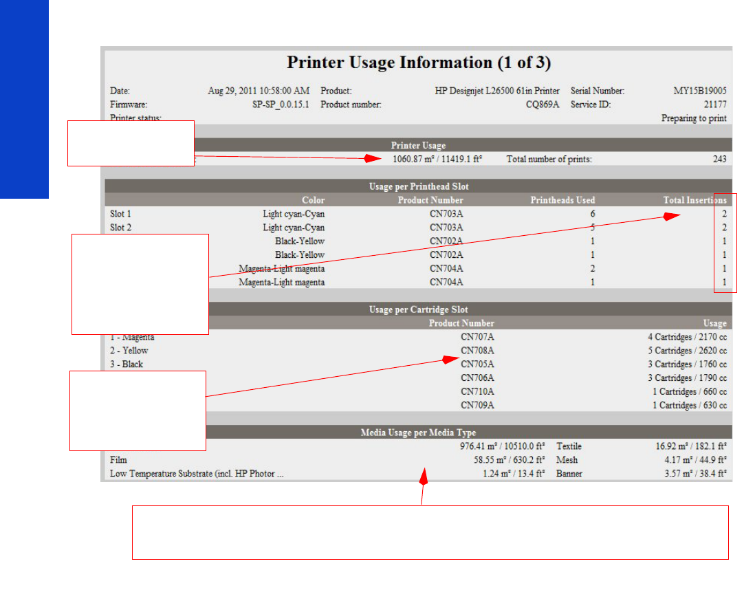
82 Chapter 2 Troubleshooting
Troubleshooting
Printer usage information (2 of 3)
•Component Usage
•Preventive Maintenance Usage
•Job Accounting I
•Job Accounting II
Printer Usage: The
total amount of substrate
used in the printer
Media Usage per Media Type: It is possible that the sum of the media used for each media type is lower that the total
amount of media used in the printer. This is because only the total media used in the printer is saved in the backup EEROM
which is located in the ISS PCA. When the Hard Disk Drive is replaced, the total media used per media type is reset to zero
(0), but the total media used is recovered from the backup EEROM.
Total Insertions: This is
linked to the current
printhead installed. When
the printhead is replaced, it
is reset to 1 (the initial
insertion of the current
printhead).
The Ink Cartridges This
section displays the ink
usage per cartridge.
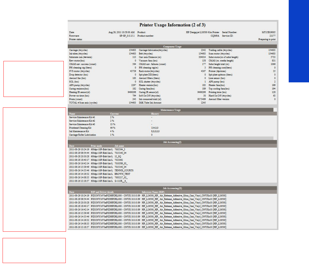
Banding due to ink cartridge replacement while printing 83
Troubleshooting
Printer usage information (3 of 3)
•Job Accounting III
•Job Accounting IV
•Job Accounting V
Component Usage: A
cycle is counted when the
Carriage makes one
movement to the left of the
printer and then returns to the
right will be reset to zero (0).
Maintenance Usage:
Once the value reaches
100%, the corresponding
Preventive Maintenance Kit
should be used. For further
details, refer to Chapter 9 -
Preventive Maintenance
The history data is the
information of the last 10
consumables. In the case of
the example, the customer
already changed:
one “Print Head Cleaning kit”
at 114% of usage
one “Ink Maintenance Kit” at
8% of usage
This history information may
help to understand the type of
use the customer has with the
consumables.
Job Accounting:
Tracks the usage information
for the purposes of
accountability
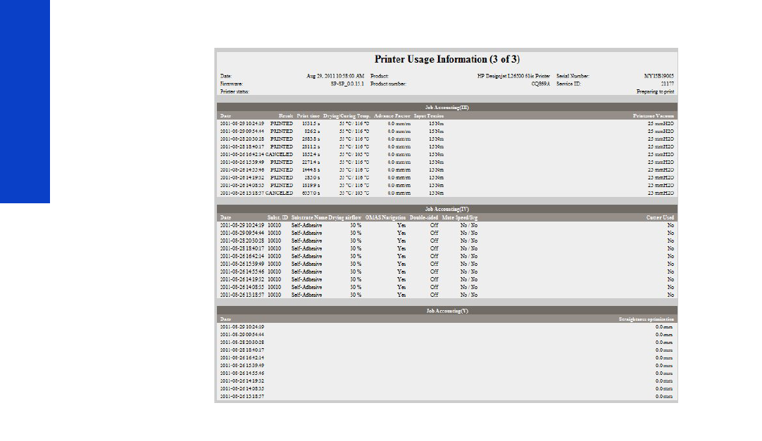
84 Chapter 2 Troubleshooting
Troubleshooting
Event logs
This page contains the following information:
•Last 20 System Error Codes (which prevented the printer from booting).
•Last 20 System Warnings (which did not prevent the printer from booting, but which required the
user to acknowledge the problem).
•Printhead Error log.
•GPIO Sensor Status.
In this section the printer is reporting the status of all the sensors. In that way we will know a lot about the
status of the printer at that moment (is the window open?, are all the printheads installed?, etc…)
This may help also to understand if the sensors are working. For example, you could get the information
with loaded substrate, check the status of the “MediaPresenceSensor”, remove the substrate from the
substrate path, get again the service plot information and check if the status has changed.
This may help in several circumstances for an advanced troubleshooting. For example:
We can know the milivolts of the pressure sensor at the moment of getting the service plot (without
measuring it directly). This may help to the R&D engineers to understand the real status of the
pressurization system.
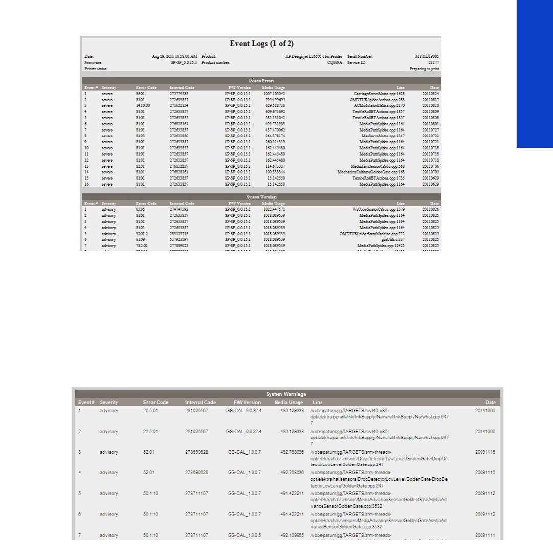
Banding due to ink cartridge replacement while printing 85
Troubleshooting
Same for the sensors inside the ink cartridges.
System/Warning error
•The Line and Internal Code do not provide much information, but are useful in the case of
escalating a problem to the division (different internal error codes can point to the same error code
(e.g. 01.10:10)).
•Media Usage (in square meters) and Date (from the printer’s Internal Clock (RTC)) help you to
understand if the printer has been used (media usage) and how much time has passed since the last
error.
Printhead error log
•Printheads ago: History of the last three Printheads used (’0’ represents the current Printhead used).
•Status:’0’ = Working,’1’ = No Printhead Detected,’2’ = Replace,’4’ = Reseat,’8’ = Remove.
•% Ink Used: Percentage of the Warranty life (1000cc).
•Error Code: Specific error code generated by the printer when the Printhead has been replaced.
•Max Recovery:
• 0: No manual Printhead recovery has been performed on the Printhead.
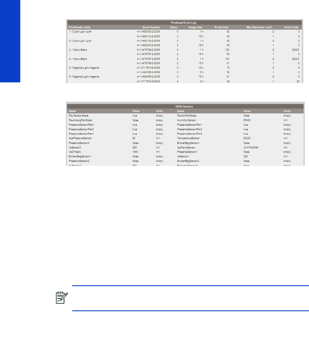
86 Chapter 2 Troubleshooting
Troubleshooting
• 1 or higher: At least one Printhead recovery has been performed.
GPIO log
Calibrations status
This page contains the following information:
•General Calibrations (performed by Service Engineers)
•Diagnostic Log
•Information about the internal NVM values
•For advanced troubleshooting (with the help of an R&D engineer), you can see whether if the line
sensor has “normal” calibration values or something is abnormal
General calibrations
•Printhead Alignment relates to the Printhead Alignment which changes to ‘pending’ when a
Printhead is replaced and the Printhead Alignment has not been performed.
•Drop Detector relates to the Drop Detector or Service Station calibration.
•Line Sensor relates to the Line Sensor Calibration.
Diagnostic log
This section displays the details of the Calibrations that have been performed on the printer, it also
contains useful information, such as if the particular calibration was successful or not.
NOTE: When a component is replaced, the corresponding calibration is NOT automatically
set to ‘NOT DONE‘. This is because the printer does not know that there is a new part
installed.

How to obtain the printer log and the diagnostics package 87
Troubleshooting
Connectivity configuration
This page contains full details of the current configuration of the printer.
How to obtain the printer log and the diagnostics
package
The printer keeps an internal log of its own actions. When a system error occurs, the product log may
help you to find the cause and the solution. By default, whenever it restarts, the printer deletes the current
log and starts a new one, to avoid using a lot of hard disk space.
You can obtain the printer log through the diagnostics package. There are two types of diagnostic
package:
•Diagnostic package (reduced level)
•Extended diagnostic package (full level)
And there are two ways of retrieving the information:

88 Chapter 2 Troubleshooting
Troubleshooting
•From the Front Panel with a USB flash drive (reduced level only)
•From the Embedded Web Server (reduced or full level)
When you have obtained the information, it should be attached to the customer case.
Front Panel method
This method works only if you have a standard USB flash drive. If you do not have a flash drive, use the
Embedded Web Server method. You are also recommended to use the Embedded Web Server if you
need the extended diagnostics package to solve a particularly difficult problem.
1. Take a standard USB flash drive, formatted as FAT32.
2. Create an empty file in the USB flash drive (right-click, New > Text Document) and name it
pdipu_enable.log. Then insert the USB flash drive into the printer.
3. The printer starts to copy the diagnostic package to the USB flash drive. Wait for one or two minutes.
You may hear several short beeps for each file copied to the USB flash drive.
4. When you hear one long beep, that means the entire diagnostics package and the printer log have
been copied to the USB flash drive. You can now remove the drive.
5. It will have created a folder with the name part number_serial number_time stamp, and in this folder
you’ll find one or more files with the extension trb. As the name of the folder contains the serial
number, you can reuse the flash drive for different products and the information will not be lost.
Embedded Web server method
1. You can access the Embedded Web Server by typing the IP address of the product in a Web
browser. In the Support tab, click Service support.
2. If the problem persists and is difficult to debug, try the extended diagnostics package. To enable the
extended diagnostics package, click Enable the extended diagnostics package. The printer
should be restarted after enabling or disabling the extended diagnostics package.
3. At any time after enabling the extended diagnostics package, you can download the package and
the printer log by clicking Download the extended diagnostics package.
4. When you have finishing using the extended diagnostics package, remember to disable it;
otherwise it could affect product performance or even cause undesirable side-effects.
Retrieving logs without the diagnostic package
This method is recommended only if you are unable to use the diagnostic package for some reason.
1. Enable the printer log by using the Enable/Disable Logs service test page 176.
2. After DO NOT REBOOT is displayed, retrieve at least the current printer log from the following URL:
http://<IP>/hp/device/3432/8828/tmp/, where <IP> is the IP address of the product. Click the
file once to select it, then right-click and select Save target as.
3. The printer.log file contains a log of printer activity since it was last restarted. Previous logs are
compressed and stored in .gz files whose names contain the date and time of the restart. You may
wish to download some of these files as well.
When you do not require permanent logging any more, remember to turn it off, to avoid filling up the
hard disk and degrading product performance. To disable permanent logging, use the Enable/Disable
Logs service test page 176.
NOTE: If the extended diagnostic package is available, it will be the only one visible from
the Embedded Web Server. In order to use the reduced diagnostic package from the
Embedded Web Server, you must disable the extended diagnostic package.

89
System Error Codes
3System Error Codes
•Introduction......................................................................................................................92
•System error codes and warnings—explanation....................................................................93
•Continuable and non-continuable error codes ......................................................................96
•01.0:03 – Engine PCA electronics error ........................................................................96
•01.0:10 – Engine PCA hardware failure........................................................................96
•01.1.03 – PrintMech PCA electronics error.....................................................................96
•01.1.10 – PrintMech PCA hardware failure.....................................................................96
•01.2:10 – ISS Pre-Driver PCA communication failure .......................................................96
•01.3:10 – ISS Pre-Driver PCA communication failure .......................................................97
•01.10:10 – PrintMech PCA is faulty...............................................................................97
•01.11:10 – PrintMech PCA is faulty................................................................................97
•02:10 – Mechanical Carriage error .............................................................................97
•02.1:10 – Problem with the Carriage PCA .....................................................................98
•03:10 – Power distribution failure.................................................................................98
•03.10:10 – Extra 24 V PSU failure................................................................................98
•05:10 – Formatter communication failure with ISS ..........................................................98
•05.01:10 – Formatter CPU fan stopped or burnt out........................................................99
•06.03 – Main NVM communication failure ..................................................................99
•06.10 – Main NVM communication failure ...................................................................99
•08.04 – The Front Panel watchdog timer has expired .....................................................99
•Replace the Formatter Þ Page 452. ..............................................................................99
•08:08 – ASSERT in Front Panel code..........................................................................100
•08:11 – A Front Panel application has died................................................................. 100
•11:10 – Connection problem with the Trailing Cable .....................................................100
•14.31:10 – Pinch Power regulator V null and no fault.....................................................100
•14.32:01 – Pinch Power regulator V null and faulty ...................................................... 101
•14.33:01 – Pinch Power regulator V lower than 140..................................................... 101
•14.34:01 – Pinch Power regulator V lower than 180..................................................... 101
•14.35:01 – Pinch Power regulator V higher than Vmax................................................. 101
•14.36:11 – Pinch Power regulator V could not be read .................................................. 101
•14.40:10 – Pinch Power regulator current not null......................................................... 102
•14.41:10 – Pinch Power regulator current too high ........................................................ 102
•14.42:10 – Pinch Power regulator short-circuit.............................................................. 102
•14.43:11 – Pinch Power Regulator open circuit............................................................. 102
•14.46:11 – Pinch Power regulator R out of range.......................................................... 103
•14.47:10 – Pinch Power regulator OverTemp................................................................ 103
•14.48:10 – Pinch Power regulator overvoltage or short-circuit......................................... 104
•14.49:10 – Pinch sine-wave converter failure ............................................................... 104
•14.51:10 – Overdrive power regulator V null and no fault.............................................. 104
•14.52:01 – Overdrive power regulator V null and fault................................................. 104
•14.53:01 – Overdrive power regulator V lower than 140..............................................105
•14.54:01 – Overdrive power regulator V lower than 180..............................................105
•14.55:01 – Overdrive power regulator V higher than Vmax .......................................... 105
•14.56:11 – Overdrive power regulator V could not be read ........................................... 105
•14.60:10 – Overdrive power regulator current not null.................................................. 105
•14.61:10 – Overdrive power regulator current too high .................................................106
•14.62:10 – Overdrive power regulator short-circuit ....................................................... 106
•14.63:11 – Overdrive power regulator open circuit....................................................... 106
•14.66:11 – Overdrive power regulator R out of range................................................... 107
•14.67:10 – Overdrive power regulator OverTemp......................................................... 107
•14.68:10 – Overdrive power regulator overvoltage or short-circuit.................................. 107
•14.69:10 – Overdrive sine-wave error.........................................................................108
•14.71:10 – Curing power regulator V null and no fault..................................................108
•14.72:01 – Curing power regulator V null and fault ..................................................... 108
•14.73:01 – Curing power regulator V lower than 140 .................................................. 108
•14.74:01 – Curing power regulator V lower than 180 ..................................................109
•14.75:01 – Curing power regulator V higher than Vmax ..............................................109
•14.76:11 – Curing power regulator V could not be read ............................................... 109
•14.80:10 – Curing power regulator current not null ...................................................... 109
•14.81:10 – Curing power regulator current too high...................................................... 109
•14.82:10 – Curing power regulator short-circuit ............................................................110

90 Chapter 3 System Error Codes
System Error Codes
•14.83:11 – Curing power regulator open circuit............................................................110
•14.84:11 – Curing power regulator Rtotal is nominal1 ................................................... 111
•14.85:11 – Curing power regulator Rtotal is nominal2 ................................................... 111
•14.86:11 – Curing power regulator R out of range ........................................................ 111
•14.87:10 – Curing power regulator OverTemp .............................................................. 111
•14.88:10 – Curing power regulator overvoltage or short-circuit .......................................112
•14.89:10 – Curing sine-wave converter failure.............................................................. 112
•15.01:00 – Drying system warn-up timed out................................................................112
•15.02:00 – Drying system cool-down timed out ............................................................ 113
•15.03:00 – Drying system temperature too high ........................................................... 113
•15.04:00 – Drying system temperature too low ............................................................ 113
•15.05:00 – Problem with the drying system Temperature Sensor .....................................114
•15.06:00 – Temperature error detected ....................................................................... 114
•15.08:00 – Heating fans array not connected.............................................................. 115
•15.09:11 – Heating fan fault ...................................................................................... 115
•15.15:11 – Drying fan short-circuit................................................................................115
•15.20:01 – Minimum drying power has been automatically adjusted .............................. 115
•15.15:11 – Drying fan short-circuit................................................................................115
•16.01:00 – Curing system warn-up timed out................................................................116
•16.02:00 – Curing system cool-down timed out ............................................................ 116
•16.03:00 – Curing system temperature too high ...........................................................116
•16.04:00 – Curing system temperature too low ............................................................117
•16.05:00 – Problem with the curing system Temperature Sensor .....................................118
•16.06:00 – Temperature error detected.......................................................................118
•16.08:00 – Curing fans array 1 not connected ............................................................119
•16.09:00 – Curing fan array 1 fault ........................................................................... 119
•16.11:00 – Curing fans array 2 not connected ..............................................................119
•16.20:11 – IR sensor curing fan not connected..............................................................119
•16.21:10 – Curing fan array 2 fault ............................................................................ 120
•17.0:11 – PrintMech to Interconnect power cable disconnected ...................................... 120
•17.1:11 – PrintMech to Interconnect data 1 cable disconnected....................................... 120
•17.2:11 – PrintMech to Interconnect data 2 cable disconnected...................................... 120
•17.3:11 – Engine PCA to PrintMech black 1 cable disconnected......................................121
•17.4:11 – Engine PCA to PrintMech blue 2 cable disconnected .......................................121
•21:03 – Service Station electrical current limit...............................................................121
•21:13 – Problem with the Service Station......................................................................121
•21.2:10 – Problem with the Web Wipe motor.............................................................. 122
•21.3:10 – Electrical problem in the Web Wipe Motor................................................... 122
•21.4:03 – Electrical problem in the Web Wipe Motor .................................................. 122
•21.5:03 – Web Wipe Assembly Drifting..................................................................... 122
•23:10 – Air Pressure System failure ............................................................................ 123
•24:03 – Ink Supply Tubes purge failure...................................................................... 123
•24:10 – Ink cartridge broken bag .............................................................................. 123
•24:11 – PrintMech PCA to ISS Top cable disconnected ................................................. 124
•24.1:11 – ISS Top PCA to ISS Bottom PCA cable disconnected ....................................... 124
•24.02:00 – Top Cover fans disconnected................................................................... 124
•24.03:00 – Top Cover fans not working..................................................................... 124
•26:14 – A wrong ink cartridge has been detected........................................................ 125
•26.0:01 – Contact failure with magenta ink cartridge .................................................. 125
•26.1:01 – Contact failure with yellow ink cartridge....................................................... 125
•26.2:01 – Contact failure with black ink cartridge ....................................................... 125
•26.3:01 – Contact failure with cyan ink cartridge ........................................................ 126
•26.4:01 – Contact failure with light magenta ink cartridge ........................................... 126
•26.5:01 – Contact failure with light cyan ink cartridge ................................................. 126
•27:01 – Calibration failed due to a printhead ............................................................. 127
•27:14 – A wrong printhead has been detected ............................................................ 127
•27:14 – A wrong printhead has been detected ............................................................ 127
•27.2:01 – Calibration failed due to printhead in slot 2 ................................................. 127
•27.3:01 – Calibration failed due to printhead in slot 3 ................................................. 127
•27.4:01 – Calibration failed due to printhead in slot 4 ................................................. 128
•27.5:01 – Calibration failed due to printhead in slot 5 ................................................. 128
•27.6:01 – Calibration failed due to printhead in slot 6 ................................................. 128
•29:01 – Printhead Cleaning Cartridge incorrectly inserted............................................ 128
•32:01 – Take-Up Reel disconnected ........................................................................... 128
•32:01.1 – Early Take-Up Reel substrate jam ................................................................. 129
•32:01.2 – Take-Up Reel substrate jam ........................................................................ 129
•32:01.9 – Take-Up Reel substrate unexpectedly removed............................................... 129
•32:02 – Take-Up Reel disconnected at initialization ..................................................... 129
•41:03 – Media-Axis Motor electrical current limit ......................................................... 129
•42:03 – Scan-Axis Motor electrical current limit........................................................... 130
•42:10 – Electrical fault in the Scan Axis area............................................................... 130

91
System Error Codes
•42.10:11 – Scan-Axis Motor cooling fan not connected ................................................. 130
•42.11:10 – Scan-Axis Motor cooling fan fault ............................................................... 130
•43:11 – Vacuum Fan not connected.............................................................................131
•43.2:11 – Vacuum Fan stopped ..................................................................................131
•43.3:10 – Vacuum Fan overcurrent..............................................................................131
•43.4:10 – Vacuum Fan low performance .....................................................................131
•43.11:11 – Vacuum Fan 2 or 3 not connected................................................................131
•43.12:11 – Vacuum Fan 2 or 3 stopped ...................................................................... 132
•43.13:10 – Vacuum Fan 2 or 3 overcurrent .................................................................. 132
•43.14:10 – Vacuum Fan 2 or 3 low performance ......................................................... 132
•44:10 – There is a problem with the Aerosol Fan ......................................................... 132
•44:11 – Aerosol Fan not connected ............................................................................ 132
•44.2:01 – Waste management switch open................................................................ 133
•44.3:01 – Waste management cable short-circuited .................................................... 133
•44.4:01 – Problem in the waste management feedback signal...................................... 134
•45:03 – Rewinder servo shutdown............................................................................. 134
•45:10 – Rewinder fault ............................................................................................. 134
•46:03 – Primer servo shutdown................................................................................. 135
•46:10 – Primer test distance failed ............................................................................. 135
•50:14 – Firmware version mismatch ........................................................................... 135
•50.1:10 – OMAS communication failure ..................................................................... 135
•50.2:10 – OMAS Controller Card communication failure.............................................. 135
•50.3:11 – Engine PCA to OMAS Controller cable not connected ................................... 136
•50.10:11 – TOMAS error .......................................................................................... 136
•52:01 – A problem with the Drop Detector ................................................................. 136
•52:10 – A problem with the On/Off switch in the Drop Detector.................................... 136
•53.1:10 – Media Sensor error .................................................................................... 137
•53.1:11 – Media Sensor cable not connected............................................................... 137
•54:10 – Media Lever Sensor error.............................................................................. 137
•55:10 – Line Sensor communication failure ................................................................. 137
•56:01 – Incorrect readings from Substrate Encoder ...................................................... 137
•56:10 – Substrate Encoder calibration failed ............................................................... 138
•58:01 – Color Sensor shutter error............................................................................. 138
•58:10 – Color Sensor failure ..................................................................................... 138
•58.1:10 – Color Sensor Shutter Actuator failure ............................................................ 138
•58.2:10 – Color Sensor Shutter Deactivator failure....................................................... 139
•59.1:09 – Two electrical parts have been replaced at the same time............................... 139
•59.2:00 – An unsupported or reused part has been installed ........................................ 139
•61:10 – Data lost due to I/O timeout .......................................................................... 139
•63:05 – The job is reaching the printer too slowly ....................................................... 139
•65:04 – I/O problem though an unknown port........................................................... 140
•65:04 – I/O problem though an unknown port........................................................... 140
•77:04 – Embedded Web Server internal software error................................................ 140
•78.1:04 – Substrate settings error............................................................................... 140
•78.2:01 – The back tension has been lost................................................................... 140
•79:03 – Generic firmware error I................................................................................141
•79:04 – Generic firmware error II...............................................................................141
•81:01 – Possible substrate jam....................................................................................141
•81:03 – Problem with setting the encoder position ....................................................... 142
•82:01 – Substrate jam in the platen area.................................................................... 142
•85:03 – Drive Roller encoder problem ....................................................................... 142
•86:01 – Possible substrate jam .................................................................................. 142
•87:01 – Problem with the Scan Axis encoder sensor readings ....................................... 142
•94:01 – Substrate unsuitable for color calibration ........................................................ 143
•94:02 – Color calibration error: inconsistent colors...................................................... 143
•94:10 – Color Sensor contaminated by aerosol ........................................................... 143
•98:03 – Printhead nozzles out .................................................................................. 143
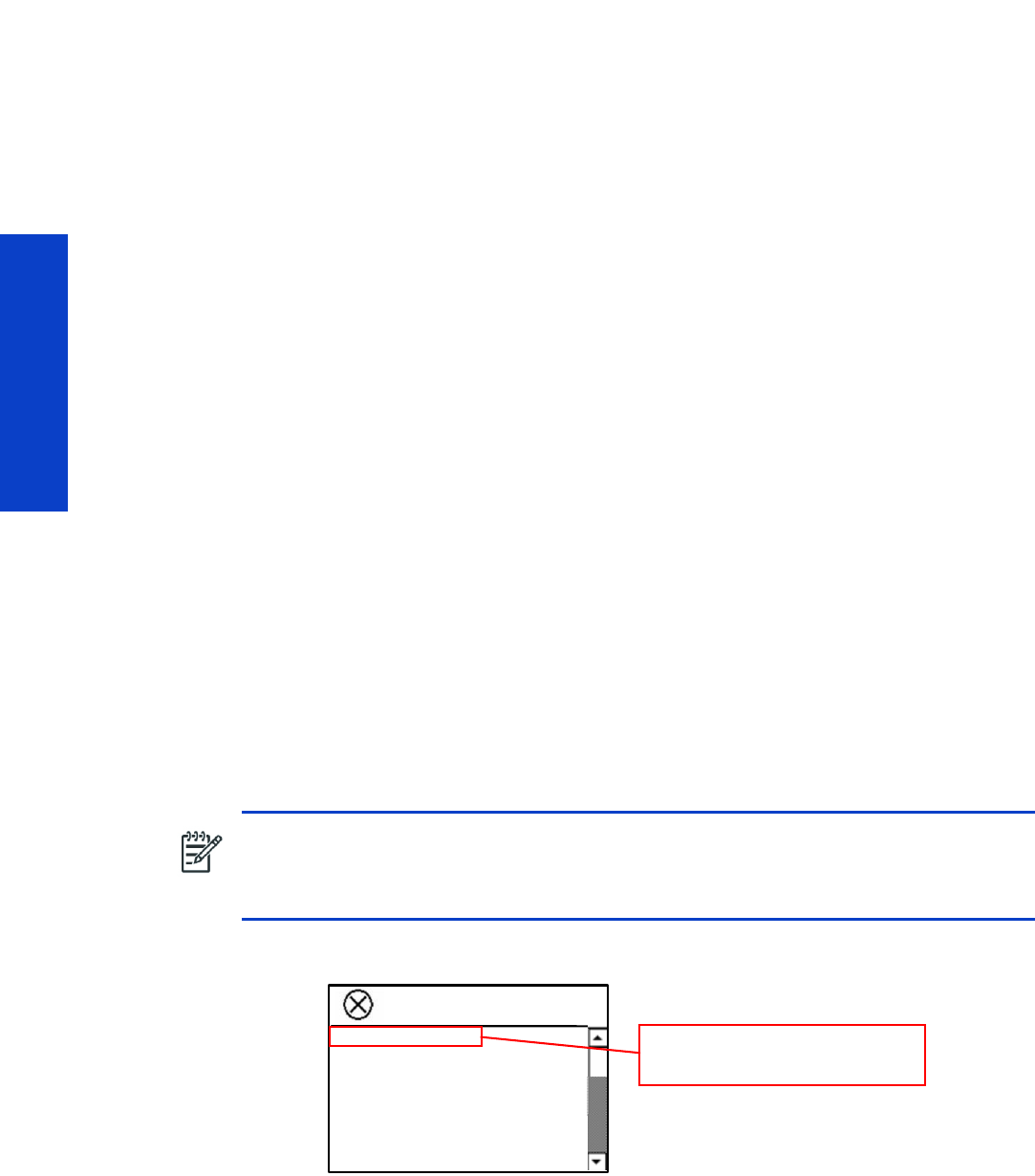
92 Chapter 3 System Error Codes
System Error Codes
Introduction
Firmware upgrade
The first step to take when trying to clear an error with the printer is to check that the firmware installed
in the printer is the latest available. Firmware updates often include fixes for some of the problems that
are found in the following pages, simply updating the firmware can often resolve the problem. The latest
firmware can be downloaded from the following url: www.hp.com/go/L28500/support
If the error with the printer does not allow you to upgrade the firmware using the normal process, try
upgrading the firmware using the emergency .plt file procedure.
What are system error codes?
System error codes are hexa-decimal based numbers generally caused by internal system errors. The
following pages contain a list of system error codes and their respective descriptions and recommended
corrective actions. Only try one recommended action at a time and check if the issue causing the error
code has been solved.
If you have an error code which is not documented in this Service Manual or you have an error which
you cannot resolve, then report the error to the HP Response Center or the nearest HP Support Office.
When reporting the error, have the following information ready:
•Model and serial number of the printer.
•Which firmware revision the printer is using (see note below). Check firmware in Setup Menu /
Information Menu / Show Printer Information.
•The complete error number (see note below).
•The Service Configuration Print.
•The Current configuration sheet.
•Which software application the customer is using (name, version, etc).
NOTE: When reporting the System Error Code, make sure that you supply the full Internal
Error Code and the firmware version. Without this information, HP Support Personnel cannot
help you. To view the Internal Error Code, hold the DOWN key and press the CANCEL key at
the same when the System Error Code is displayed on the Front Panel.
Code: 0x1901001
Severity: Error
Priority: 3000
Id: 0x101021a
Description:
STRING_POWER_OFF
File:
73:03
This is the Code that is required
when escalating a problem

System error codes and warnings—explanation 93
System Error Codes
System error codes and warnings—explanation
System Error Codes explain which component/system is failing and what action should be taken to
resolve the problem.
System Error Codes are displayed directly on the front panel (but can also be seen on the Information
Page) and have been defined in the format XX.YZ. or XX.n:YZ.m.
•XX: Service Part (2 digits).
•n: Service Part Index (if more than one used in the product) – Optional.
•e.g. Identify the Ink Supply (color and number).
•Y: Who should perform the action (1 digit) – (User or Service Engineer).
•Z: Action to perform (1 digit).
•m: additional actions/information to consider (1 digit) – Optional.
•e.g. Non-authorized ink was detected, PM was triggered or printhead in/out of Warranty.
The following table explains the XX part of the System Error Code or Warning:
Code Component/System
01.0 Engin e PCA
01.1 PrintMech PCA
01.2 ISS Top PCA
01.3 ISS Bottom PCA
01.10 PrintMech PCA sine-wave management
01.11 PrintMech PCA sine-wave management
02.1 Carriage PCA
03 Power Supply Unit
03.10 Extra 24 V PSU
05 Formatter
05.1 Formatter Fan
05.3 Formatter Memory
06 Hard Disk Drive
08 Front Panel
09 Vacuum
11 Trailing Cable
14 . 3 , 14 . 4 H e a t e r C o n t ro l D r y e r Pi n c h e s
14,5, 14.6 Heater Control Dryer Overdrive
14.7, 14.8 Heater Control Curing
15 D r y in g S ys tem
16 Cu ri ng Sys te m
17 O th e r c abl es
21 Se r vi ce Sta tion
23 Pressure System (APS)
24 Ink Delivery Tubes
26.n Ink cartridge (color n)
27.n Printhead (color n)
29 Printhead Cleaning Cartridge
31 C u t t e r

94 Chapter 3 System Error Codes
System Error Codes
The following table explains the YZ part of the System Error Code or Warning:
32 Take-Up Reel
41 M ed i a - Axi s Mot or
42 Scan-Axis Motor
43 Vacuum Fan
44 Aerosol Fan
45 Rewinder
46 Primer
50 OMAS
51 Window Sensor
51.1 PHC Access Door Sensor
52 Drop Detector
53 Media Sensor
54 Media Lever Sensor
55 Line Sensor
56 Drive Roller Encoder Sensor
58 Color Sensor
61 Language Interpreting
63 Input/Output through LAN Card
65 Input/Output (port unknown)
66 Print Job Configuration
71 Memory Management
74 Firmware Upgrade
77 Embedded Web Server
78 Media Settings
79 Assertion (Uncontrollable Firmware Error)
81 Media Advance
82 Media Jam Sensor
85 Media-Axis Encoder Reading
86 Carriage Movement
93 Ink Pumping
97 Automatic Media Advance Calibration
Code Recovery action Response
00 Replace
Possible for customer to perform action
01 Reseat/Reconnect/Clean/Adjust (manually)
02 Calibrate/Adjust (using automatic process)
03 Power off and restart the printer
04 Upgrade system firmware
05 Upgrade driver or computer software
06 Add accessory
07 Escalate
08 Send plot again
09 Wrong part installed
Code Component/System

System error codes and warnings—explanation 95
System Error Codes
10 Replace
HP qualified personnel assistance
required
11 Reseat/Reconnect/Clean/Adjust (manually)
12 Calibrate/Adjust (using automatic process)
13 Po we r o f f
14 Upgrade system firmware
15 Upgrade driver or computer software
16 Add accessory
17 E sc a l a t e
18 Send plot again
19 Wrong part installed
Code Recovery action Response

96 Chapter 3 System Error Codes
System Error Codes
Continuable and non-continuable error codes
Some of the error codes are continuable, which means you can press Enter on the front panel and
continue working with the printer. Non-continuable error codes do not allow you to continue working with
the printer, in this case power the printer off and on again and see whether the system error disappears.
If the error code reappears, then the printer requires an on-site visit in order to resolve the problem.
Important note: If the solution calls for a replacement part, replace one component at a time and check
if the error has been cleared before replacing another component. Using this procedure you will be able
to determine exactly which component has failed.
SE Code: 01.0:03 – Engine PCA electronics error
Problem description:
The Engine PCA has failed to respond.
Corrective action:
Switch the power off at the rear of the printer, wait briefly, then switch it back on again.
SE Code: 01.0:10 – Engine PCA hardware failure
Problem description:
Engine PCA hardware failure.
Corrective action:
1. Switch the power off at the rear of the printer, wait briefly, then switch it back on again.
2. Replace the Engine PCA Page 452.
SE Code: 01.1.03 – PrintMech PCA electronics error
Problem description:
The PrintMech PCA has failed to respond.
Corrective action:
Switch the power off at the rear of the printer, wait briefly, then switch it back on again.
SE Code: 01.1.10 – PrintMech PCA hardware failure
Problem description:
PrintMech PCA hardware failure.
Corrective action:
1. Switch the power off at the rear of the printer, wait briefly, then switch it back on again.
2. Replace the PrintMech PCA Page 467.
SE Code: 01.2:10 – ISS Pre-Driver PCA communication failure
Problem description:
The ISS Pre-Driver PCA has failed to respond.

Continuable and non-continuable error codes 97
System Error Codes
Corrective action:
1. Switch the power off at the rear of the printer, wait briefly, then switch it back on again.
2. Check that the connections of the ISS Pre-Driver PCA (Upper, Lower, and Adaptor) are correctly
connected and not damaged.
3. Check with another set of ink cartridges, to ensure the error is not with the ink cartridges.
4. Replace the ISS Pre-Driver PCA (Upper, Lower, and Adaptor) -->
Page 398
.
SE Code: 01.3:10 – ISS Pre-Driver PCA communication failure
Problem description:
The ISS Pre-Driver PCA has failed to respond.
Corrective action:
1. Switch the power off at the rear of the printer, wait briefly, then switch it back on again.
2. Check that the connections of the ISS Pre-Driver PCA (Upper, Lower, and Adaptor) are correctly
connected and not damaged.
3. Check with another set of ink cartridges, to ensure the error is not with the ink cartridges.
4. Replace the ISS Pre-Driver PCA (Upper, Lower, and Adaptor) -->
Page 398
.
SE Code: 01.10:10 – PrintMech PCA is faulty
Problem description:
The PrintMech PCA is not disabling sine-wave converters when requested.
Corrective action:
1. Switch the power off at the rear of the printer, wait briefly, then switch it back on again.
2. Replace the PrintMech PCA Page 467.
SE Code: 01.11:10 – PrintMech PCA is faulty
Problem description:
The PrintMech PCA is not enabling sine-wave converters when requested.
Corrective action:
1. Switch the power off at the rear of the printer, wait briefly, then switch it back on again.
2. Replace the PrintMech PCA Page 467.
SE Code: 02:10 – Mechanical Carriage error
Problem description:
Mechanical Carriage error.
Corrective action:
1. Switch the power off at the rear of the printer, wait briefly, then switch it back on again.
2. Replace the Carriage Assembly Page 416.

98 Chapter 3 System Error Codes
System Error Codes
SE Code: 02.1:10 – Problem with the Carriage PCA
Problem description:
The Carriage PCA has failed to respond.
Corrective action:
1. Switch the power off at the rear of the printer, wait briefly, then switch it back on again.
2. Check that the Trailing Cable is not damaged.
3. Check that the Trailing Cable is correctly connected to the Carriage PCA, Interconnect PCA, and
Engine PCA
.
4. Replace the Carriage PCA Page 408.
SE Code: 03:10 – Power distribution failure
Problem description:
The Power Supply Unit (PSU) may have failed.
Corrective action:
1. Switch the power off at the rear of the printer, wait briefly, then switch it back on again.
2. If the Power Supply Unit's blue LED is on, replace the PrintMech PCA Page 467.
3. Otherwise, replace the Power Supply Unit Page 457.
SE Code: 03.10:10 – Extra 24 V PSU failure
Problem description:
Extra 24 V PSU failure.
Corrective action:
1. Switch the power off at the rear of the printer.
2. Disconnect all drying fans (not the array, the fans one by one).
3. Switch the printer on.
4. If the error persists, check that Secondary PSU cables are properly connected to PrintMech PCA and
Main PSU.
5. If the error persists, replace the Extra 24 V PSU Page 323.
6. Connect the fans one by one until the error returns. Use the diagnostic test for the fans; it should
switch them all on.
7. Replace the drying fan that caused the error.
8. Make sure that you test all of them: more than one may be faulty.
SE Code: 05:10 – Formatter communication failure with ISS
Problem description:
The Formatter is not communicating with the Ink Supply Station.
Corrective action:
1. Switch the power off at the rear of the printer, wait briefly, then switch it back on again.

Continuable and non-continuable error codes 99
System Error Codes
2. Check that the Formatter to PrintMech PCA cable is correctly connected.
3. Replace the Formatter Page 452.
SE Code: 05.01:10 – Formatter CPU fan stopped or burnt out
Problem description:
Formatter CPU fan stopped or burnt out.
Corrective action:
1. Switch the power off at the rear of the printer, wait briefly, then switch it back on again.
2. Replace the Formatter Page 452.
SE Code: 06.03 – Main NVM communication failure
Problem description:
The Main NVM is not responding.
Corrective action:
1. Switch the power off at the rear of the printer, wait briefly, then switch it back on again.
2. Replace the Hard Disk Drive Page 454.
SE Code: 06.10 – Main NVM communication failure
Problem description:
The Main NVM is not responding.
Corrective action:
1. Switch the power off at the rear of the printer, wait briefly, then switch it back on again.
2. Replace the Hard Disk Drive Page 454.
SE Code: 08.04 – The Front Panel watchdog timer has expired
Problem description:
The Front Panel watchdog timer has expired.
Corrective action:
1. Switch the power off at the rear of the printer, wait briefly, then switch it back on again.
2. Check the main PSU LEDs to make sure that it is providing power as expected. See “The printer does
not power on” on page 47.
3. Upgrade the firmware.
4. Replace the Formatter Page 452.
SE Code: 08:04.1 – ASSERT in Front Panel code
Problem description:
ASSERT in Front Panel code.

100 Chapter 3 System Error Codes
System Error Codes
Corrective action:
1. Press Enter and continue.
2. Update the firmware.
SE Code: 08:08 – ASSERT in Front Panel code
Problem description:
ASSERT in Front Panel code.
Corrective action:
Switch the power off at the rear of the printer, wait briefly, then switch it back on again.
SE Code: 08:11 – A Front Panel application has died
Problem description:
A Front Panel application has died.
Corrective action:
1. Switch the power off at the rear of the printer, wait briefly, then switch it back on again.
2. Check the main PSU LEDs to make sure that it is providing power as expected. See “The printer does
not power on” on page 47.
3. Upgrade the firmware.
4. Replace the Formatter Page 452.
SE Code: 11:10 – Connection problem with the Trailing Cable
Problem description:
The Trailing Cable does not seem to be connected.
Corrective action:
1. Check that the Trailing Cable is not damaged.
2. Check that the Trailing Cable is correctly connected to the Carriage PCA, Interconnect PCA, and
Engine PCA.
3. Replace the Ink Supply Tubes and Trailing Cable Page 381.
SE Code: 14.31:10 – Pin ch Power regulator V null and no fault
Problem description:
Pinch Power regulator V null and no fault.
Corrective action:
1. Switch the power off at the rear of the printer, wait briefly, then switch it back on again.
2. Run the Monitoring Sine-waves and Resistances diagnostic test.
NOTE: If the Ink Supply Tubes are to be replaced, the ink cartridges need to be checked
beforehand to see if they are capable of purging the new tubes. If they are not, new ink
cartridges must also be sent with the parts to be replaced. To check the ink cartridges
Page 159.

Continuable and non-continuable error codes 101
System Error Codes
3. Replace the control cables to the sine-wave converter.
SE Code: 14.32:01 – Pinch Power regulator V null and faulty
Problem description:
Pinch Power regulator V null and faulty.
Corrective action:
1. Switch the power off at the rear of the printer, wait briefly, then switch it back on again.
2. Run the Monitoring Sine-waves and Resistances diagnostic test.
3. Check the Residual Current Circuit Breakers.
4. Check the input voltage.
SE Code: 14.33:01 – Pinch Power regulator V lower than 140
Problem description:
Pinch Power regulator V lower than 140.
Corrective action:
1. Switch the power off at the rear of the printer, wait briefly, then switch it back on again.
2. Check the input voltage.
3. Run the Monitoring Sine-waves and Resistances diagnostic test.
SE Code: 14.34:01 – Pinch Power regulator V lower than 180
Problem description:
Pinch Power regulator V lower than 180.
Corrective action:
1. Switch the power off at the rear of the printer, wait briefly, then switch it back on again.
2. Check the input voltage.
3. Run the Monitoring Sine-waves and Resistances diagnostic test.
SE Code: 14.35:01 – Pinch Power regulator V higher than Vmax
Problem description:
Pinch Power regulator V higher than Vmax.
Corrective action:
1. Switch the power off at the rear of the printer, wait briefly, then switch it back on again.
2. Check the input voltage.
3. Run the Monitoring Sine-waves and Resistances diagnostic test.
SE Code: 14.36:11 – Pinch Power regulator V could not be read
Problem description:
Pinch Power regulator V could not be read.

102 Chapter 3 System Error Codes
System Error Codes
Corrective action:
1. Switch the power off at the rear of the printer, wait briefly, then switch it back on again.
2. Check the input cables.
3. Replace the control cables to the sine-wave converters.
SE Code: 14.40:10 – Pinch Power regulator current not null
Problem description:
Pinch Power regulator current not null.
Corrective action:
1. Switch the power off at the rear of the printer, wait briefly, then switch it back on again.
2. Replace the sine-wave converter.
3. Run the Monitoring Sine-waves and Resistances diagnostic test.
SE Code: 14.41:10 – Pinch Power regulator current too high
Problem description:
Pinch Power regulator current too high.
Corrective action:
1. Switch the power off at the rear of the printer, wait briefly, then switch it back on again.
2. Run the Monitoring Sine-waves and Resistances diagnostic test.
3. Check heaters with a tester and replace heaters if necessary (short-circuit).
4. Replace the sine-wave converter.
SE Code: 14.42:10 – Pinch Power regulator short-circuit
Problem description:
Pinch Power regulator short-circuit.
Corrective action:
1. Switch the power off at the rear of the printer, wait briefly, then switch it back on again.
2. Run the Monitoring Sine-waves and Resistances diagnostic test.
3. Check heaters with a tester and replace heaters if necessary.
4. Replace the sine-wave converter.
SE Code: 14.43:11 – Pinch Power Regulator open circuit
Problem description:
Pinch Power Regulator open circuit.
If the error appears in the middle of a print and recovers after cooling down, it could be caused by an
abnormal increase in the drying module temperature leading one of the thermal switches to open. See
System Errors 15.03:00 and 15.20:01 for more information.

Continuable and non-continuable error codes 103
System Error Codes
Corrective action:
1. Switch the power off at the rear of the printer, wait briefly, then switch it back on again.
2. Run the Monitoring Sine-waves and Resistances diagnostic test.
3. Check cable connections and heaters with a tester.
4. Check the drying module:
•Ensure that the heaters do not touch the metal covers at the sides, close to the thermal switches.
•Remove the side covers. Ensure that the connections to the thermal switches are strong; tighten
the nuts if necessary. In addition, ensure the cables are not peeled or in bad condition.
5. Replace the drying heaters if any of the above applies.
Other possible causes:
•The room temperature is too high or is outside the operational specification of the printer. Make sure
there are no external sources of heat, such as strong lights, direct sunlight, or heaters.
•This system error may be caused by a setting in the RIP being used by the customer. If the ‘Minimum
Drying Power’ setting in the RIP is too high, this can cause the system error to be triggered. Set the
Minimum Drying Power to 0, and check whether the error remains.
•Check that there are no obstructions on any of the cooling fans: Dryer, Curing, Top Cover Fans, Rear
Fans.
•Check that all the fans are functioning correctly. Check that the cables of the fans are not damaged
and are connected. Replace any fans if required: Top cover fans Page 337. Drying Fans
Page 340. Curing Fans Page 496.
See System Errors 15.03:00 and 15.20:01 for more information.
SE Code: 14.46:11 – Pinch Power regulator R out of range
Problem description:
Pinch Power regulator R out of range.
Corrective action:
1. Switch the power off at the rear of the printer, wait briefly, then switch it back on again.
2. Run the Monitoring Sine-waves and Resistances diagnostic test.
3. Check cable connections.
4. Check heaters with a tester and replace heaters if necessary.
5. Replace the sine-wave converter.
SE Code: 14.47:10 – Pinch Power regulator OverTemp
Problem description:
Pinch Power regulator OverTemp.
Corrective action:
1. Switch the power off at the rear of the printer, wait briefly, then switch it back on again.
2. Run the Monitoring Sine-waves and Resistances diagnostic test.
3. Check cable connections.

104 Chapter 3 System Error Codes
System Error Codes
4. Check that the 3-phase configuration kit jumpers are fully inserted.
5. Check that the input voltage is within specifications.
6. Replace the sine-wave converter.
SE Code: 14.48:10 – Pinch Power regulator overvoltage or short-circuit
Problem description:
Pinch Power regulator overvoltage or short-circuit.
Corrective action:
1. Switch the power off at the rear of the printer, wait briefly, then switch it back on again.
2. Run the Monitoring Sine-waves and Resistances diagnostic test.
3. Check cable connections.
4. Check that the input voltage is within specifications.
5. Replace the sine-wave converter.
SE Code: 14.49:10 – Pinch sine-wave converter failure
Problem description:
Pinch sine-wave converter failure.
Corrective action:
1. Switch the power off at the rear of the printer, wait briefly, then switch it back on again.
2. Replace the sine-wave converter.
SE Code: 14.51:10 – Overdrive power regulator V null and no fault
Problem description:
Overdrive power regulator V null and no fault.
Corrective action:
1. Switch the power off at the rear of the printer, wait briefly, then switch it back on again.
2. Run the Monitoring Sine-waves and Resistances diagnostic test.
3. Replace the control cables to the sine-wave converter.
SE Code: 14.52:01 – Overdrive power regulator V null and fault
Problem description:
Overdrive power regulator V null and fault.
Corrective action:
1. Switch the power off at the rear of the printer, wait briefly, then switch it back on again.
2. Run the Monitoring Sine-waves and Resistances diagnostic test.
3. Check the Residual Current Circuit Breakers.
4. Check the input voltage.

Continuable and non-continuable error codes 105
System Error Codes
SE Code: 14.53:01 – Overdrive power regulator V lower than 140
Problem description:
Overdrive power regulator V lower than 140.
Corrective action:
1. Switch the power off at the rear of the printer, wait briefly, then switch it back on again.
2. Check the input voltage.
3. Run the Monitoring Sine-waves and Resistances diagnostic test.
SE Code: 14.54:01 – Overdrive power regulator V lower than 180
Problem description:
Overdrive power regulator V lower than 180.
Corrective action:
1. Switch the power off at the rear of the printer, wait briefly, then switch it back on again.
2. Check the input voltage.
3. Run the Monitoring Sine-waves and Resistances diagnostic test.
SE Code: 14.55:01 – Overdrive power regulator V higher than Vmax
Problem description:
Overdrive power regulator V higher than Vmax.
Corrective action:
1. Switch the power off at the rear of the printer, wait briefly, then switch it back on again.
2. Check the input voltage.
3. Run the Monitoring Sine-waves and Resistances diagnostic test.
SE Code: 14.56:11 – Overdrive power regulator V could not be read
Problem description:
Overdrive power regulator V could not be read.
Corrective action:
1. Switch the power off at the rear of the printer, wait briefly, then switch it back on again.
2. Check cable connections.
3. Replace the control cables to the sine-wave converter.
SE Code: 14.60:10 – Overdrive power regulator current not null
Problem description:
Overdrive power regulator current not null.
Corrective action:
1. Switch the power off at the rear of the printer, wait briefly, then switch it back on again.

106 Chapter 3 System Error Codes
System Error Codes
2. Replace the sine-wave converter.
3. Run the Monitoring Sine-waves and Resistances diagnostic test.
SE Code: 14.61:10 – Overdrive power regulator current too high
Problem description:
Overdrive power regulator current too high.
Corrective action:
1. Switch the power off at the rear of the printer, wait briefly, then switch it back on again.
2. Run the Monitoring Sine-waves and Resistances diagnostic test.
3. Check heaters with tester and replace heaters if necessary (short-circuit).
4. Replace the sine-wave converter.
SE Code: 14.62:10 – Overdrive power regulator short-circuit
Problem description:
Overdrive power regulator short-circuit.
Corrective action:
1. Switch the power off at the rear of the printer, wait briefly, then switch it back on again.
2. Run the Monitoring Sine-waves and Resistances diagnostic test.
3. Check heaters with tester and replace heaters if necessary.
4. Replace the sine-wave converter.
SE Code: 14.63:11 – Overdrive power regulator open circuit
Problem description:
Overdrive power regulator open circuit.
If the error appears in the middle of a print and recovers after cooling down, it could be caused by an
abnormal increase in the drying module temperature leading one of the thermal switches to open. See
System Errors 15.03:00 and 15.20:01 for more information.
Corrective action:
1. Switch the power off at the rear of the printer, wait briefly, then switch it back on again.
2. Run the Monitoring Sine-waves and Resistances diagnostic test.
3. Check cable connections and heaters with a tester.
4. Check the drying module:
•Ensure that the heaters do not touch the metal covers at the sides, close to the thermal switches.
•Remove the side covers. Ensure that the connections to the thermal switches are strong; tighten
the nuts if necessary. In addition, ensure the cables are not peeled or in bad condition.
5. Replace the drying heaters if any of the above applies.
Other possible causes:

Continuable and non-continuable error codes 107
System Error Codes
•The room temperature is too high or is outside the operational specification of the printer. Make sure
there are no external sources of heat, such as strong lights, direct sunlight, or heaters.
•This system error may be caused by a setting in the RIP being used by the customer. If the ‘Minimum
Drying Power’ setting in the RIP is too high, this can cause the system error to be triggered. Set the
Minimum Drying Power to 0, and check whether the error remains.
•Check that there are no obstructions on any of the cooling fans: Dryer, Curing, Top Cover Fans, Rear
Fans.
•Check that all the fans are functioning correctly. Check that the cables of the fans are undamaged
and connected. Replace any fans if required: Top Cover Fans Page 337. Drying Fans
Page 340. Curing Fans Page 496.
See System Errors 15.03:00 and 15.20:01 for more information.
SE Code: 14.66:11 – Overdrive power regulator R out of range
Problem description:
Overdrive power regulator R out of range.
Corrective action:
1. Switch the power off at the rear of the printer, wait briefly, then switch it back on again.
2. Run the Monitoring Sine-waves and Resistances diagnostic test.
3. Check cable connections.
4. Check heaters with tester and replace heaters if necessary.
5. Replace the sine-wave converter.
SE Code: 14.67:10 – Overdrive power regulator OverTemp
Problem description:
Overdrive power regulator OverTemp.
Corrective action:
1. Switch the power off at the rear of the printer, wait briefly, then switch it back on again.
2. Run the Monitoring Sine-waves and Resistances diagnostic test.
3. Check cable connections.
4. Check that the 3-phase configuration kit jumpers are fully inserted.
5. Check that the input voltage is within specifications.
6. Replace the sine-wave converter.
SE Code: 14.68:10 – Overdrive power regulator overvoltage or short-circuit
Problem description:
Overdrive power regulator overvoltage or short-circuit.
Corrective action:
1. Switch the power off at the rear of the printer, wait briefly, then switch it back on again.
2. Run the Monitoring Sine-waves and Resistances diagnostic test.

108 Chapter 3 System Error Codes
System Error Codes
3. Check cable connections.
4. Check that the input voltage is within specifications.
5. Replace the sine-wave converter.
SE Code: 14.69:10 – Overdrive sine-wave error
Problem description:
Overdrive power sine-wave error.
Corrective action:
1. Switch the power off at the rear of the printer, wait briefly, then switch it back on again.
2. Replace the sine-wave converter.
SE Code: 14.71:10 – Curing power regulator V null and no fault
Problem description:
Curing power regulator V null and no fault.
Corrective action:
1. Switch the power off at the rear of the printer, wait briefly, then switch it back on again.
2. Run the Monitoring Sine-waves and Resistances diagnostic test.
3. Replace the control cables to the sine-wave converter.
SE Code: 14.72:01 – Curing power regulator V null and fault
Problem description:
Curing power regulator V null and fault.
Corrective action:
1. Switch the power off at the rear of the printer, wait briefly, then switch it back on again.
2. Run the Monitoring Sine-waves and Resistances diagnostic test.
3. Check the Resident Current Circuit Breakers.
4. Check the input voltage.
SE Code: 14.73:01 – Curing power regulator V lower than 140
Problem description:
Curing power regulator V lower than 140.
Corrective action:
1. Switch the power off at the rear of the printer, wait briefly, then switch it back on again.
2. Check the input voltage.
3. Run the Monitoring Sine-waves and Resistances diagnostic test.

Continuable and non-continuable error codes 109
System Error Codes
SE Code: 14.74:01 – Curing power regulator V lower than 180
Problem description:
Curing power regulator V lower than 180.
Corrective action:
1. Switch the power off at the rear of the printer, wait briefly, then switch it back on again.
2. Check the input voltage.
3. Run the Monitoring Sine-waves and Resistances diagnostic test.
SE Code: 14.75:01 – Curing power regulator V higher than Vmax
Problem description:
Curing power regulator V higher than Vmax.
Corrective action:
1. Switch the power off at the rear of the printer, wait briefly, then switch it back on again.
2. Check the input voltage.
3. Run the Monitoring Sine-waves and Resistances diagnostic test.
SE Code: 14.76:11 – Curing power regulator V could not be read
Problem description:
Curing power regulator V could not be read.
Corrective action:
1. Switch the power off at the rear of the printer, wait briefly, then switch it back on again.
2. Check cable connections.
3. Replace the control cables to the sine-wave converter.
SE Code: 14.80:10 – Curing power regulator current not null
Problem description:
Curing power regulator current not null.
Corrective action:
1. Switch the power off at the rear of the printer, wait briefly, then switch it back on again.
2. Replace the sine-wave converter.
3. Run the Monitoring Sine-waves and Resistances diagnostic test.
SE Code: 14.81:10 – Curing power regulator current too high
Problem description:
Curing power regulator current too high.
Corrective action:
1. Switch the power off at the rear of the printer, wait briefly, then switch it back on again.

110 Chapter 3 System Error Codes
System Error Codes
2. Run the Monitoring Sine-waves and Resistances diagnostic test.
3. Check heaters with tester and replace heaters if necessary (short-circuit).
4. Replace the sine-wave converter.
SE Code: 14.82:10 – Curing power regulator short-circuit
Problem description:
Curing power regulator short-circuit.
Corrective action:
1. Switch the power off at the rear of the printer, wait briefly, then switch it back on again.
2. Run the Monitoring Sine-waves and Resistances diagnostic test.
3. Check heaters with tester and replace heaters if necessary.
4. Replace the sine-wave converter.
SE Code: 14.83:11 – Curing power regulator open circuit
Problem description:
Curing power regulator open circuit.
Corrective action:
1. Switch the power off at the rear of the printer, wait briefly, then switch it back on again.
2. Run Monitoring Sine-waves and Resistances diagnostic test.
3. Check the cable connections and heaters with a tester.
4. Check the curing module:
•Ensure that the heaters do not touch the metal covers at the sides, close to the thermal switches
•Remove the side covers. Ensure that the connections to the thermal switches are strong; tighten
the nuts if necessary. In addition, ensure the cables are not peeled or in bad condition.
5. Replace the curing heaters if any of the above applies.
Other possible causes:
•The room temperature is too high or is outside the operational specification of the printer. Make sure
there are no external sources of heat, such as strong lights, direct sunlight, or heaters.
•This system error may be caused by a setting in the RIP being used by the customer. If the ‘Minimum
Curing Power’ setting in the RIP is too high, this can cause the system error to be triggered. Set the
Minimum Curing Power to 0, and check whether the error remains.
•Check there are no obstructions on any of the cooling fans: Dryer, Curing, Top Cover Fans, Rear
Fans.
•Check that all the fans are functioning correctly. Check that the cables of the fans are undamaged
and connected. Replace any fans if required: Top Cover Fans Page 337. Drying Fans
Page 340. Curing Fans Page 496.
See System Errors 15.03:00 and 15.20:01 for more information.

Continuable and non-continuable error codes 111
System Error Codes
SE Code: 14.84:11 – Curing power regulator Rtotal is nominal1
Problem description:
Curing power regulator Rtotal is nominal1.
Corrective action:
1. Switch the power off at the rear of the printer, wait briefly, then switch it back on again.
2. Check intermediate heater connections to see if one of the resistors is disconnected.
3. Replace the curing heaters.
SE Code: 14.85:11 – Curing power regulator Rtotal is nominal2
Problem description:
Curing power regulator Rtotal is nominal2.
Corrective action:
1. Switch the power off at the rear of the printer, wait briefly, then switch it back on again.
2. Check intermediate heater connections to see if one of the resistors is disconnected.
3. Replace the curing heaters.
SE Code: 14.86:11 – Curing power regulator R out of range
Problem description:
Curing power regulator R out of range.
Corrective action:
1. Switch the power off at the rear of the printer, wait briefly, then switch it back on again.
2. Run Monitoring Sine-waves and Resistances diagnostic test.
3. Check cable connections.
4. Check heaters with tester and replace heaters if necessary.
5. Replace the sine-wave converter.
SE Code: 14.87:10 – Curing power regulator OverTemp
Problem description:
Curing power regulator OverTemp.
Corrective action:
1. Switch the power off at the rear of the printer, wait briefly, then switch it back on again.
2. Run the Monitoring Sine-waves and Resistances diagnostic test.
3. Check the cable connections.
4. Check that the 3-phase configuration kit jumpers are fully inserted.
5. Check that the input voltage is within specifications.
6. Replace the sine-wave converter.

112 Chapter 3 System Error Codes
System Error Codes
SE Code: 14.88:10 – Curing power regulator overvoltage or short-circuit
Problem description:
Curing power regulator overvoltage or short-circuit.
Corrective action:
1. Switch the power off at the rear of the printer, wait briefly, then switch it back on again.
2. Run the Monitoring Sine-waves and Resistances diagnostic test.
3. Check the cable connections.
4. Check that the input voltage is within specifications.
5. Replace the sine-wave converter.
SE Code: 14.89:10 – Curing sine-wave converter failure
Problem description:
Curing sine-wave converter failure.
Corrective action:
1. Switch the power off at the rear of the printer, wait briefly, then switch it back on again.
2. Replace the sine-wave converter.
SE Code: 15.01:00 – Drying system warn-up timed out
Problem description:
The drying system is unable to warm up in the pre-defined amount of time (to 45°C for standby and
normally 55°C or 60°C for printing).
Corrective action:
1. Check that the room temperature is within the printer's operating specifications; it should be higher
than 15°C for printer operation. If it is too low, increase the room temperature.
2. Check that the input voltage is within the printer’s operating specifications: see the Site Preparation
Guide.
3. Check whether the substrate loaded on the printer is too transparent or reflective for the IR sensor to
detect the surface temperature. You can check this by loading another type of substrate.
4. Check whether the Dryer IR sensor is dirty and requires cleaning. Observe all safety precautions
while working in the area of the heaters.
5. Check that the position of the IR sensor is correct. If it is pointing to a position other than the
substrate this will cause an error.
6. Perform the Heating IR sensor diagnostic check Page 172, to check the values being detected by
the IR sensor. Replace the Dryer IR sensor if required Page 486.
7. Replace the cables from the PrintMech PCA to the connection box.
8. Replace the PrintMech PCA Page 467.

Continuable and non-continuable error codes 113
System Error Codes
SE Code: 15.02:00 – Drying system cool-down timed out
Problem description:
The drying system is unable to cool down in the pre-defined amount of time.
Corrective action:
1. Check that the room temperature is within the printer’s operating specifications. If necessary, remove
external sources of heat, such as strong lights, direct sunlight, or heaters.
2. This system error can occur if the ‘Minimum Drying Power’ setting in the RIP is too high. Set the
Minimum Drying Power to 0, and check whether the error repeats.
3. Check there are no obstructions on any of the cooling fans: Dryer, Curing, Top Cover Fans, Rear
Fans.
4. Check that all the fans are functioning correctly. Check that the cables of the fans are undamaged
and connected. Replace any fans if required: Top Cover Fans Page 337. Drying Fans
Page 340. Curing Fans Page 496.
SE Code: 15.03:00 – Drying system temperature too high
Problem description:
The drying system has exceeded the upper temperature limit.
Corrective action:
1. Check that the room temperature is within the printer’s operating specifications. If necessary, remove
external sources of heat, such as strong lights, direct sunlight, or heaters.
2. This system error can occur if the ‘Minimum Drying Power’ setting in the RIP is too high. Set the
Minimum Drying Power to 0, and check whether the error repeats.
3. Check there are no obstructions on any of the cooling fans: Dryer, Curing, Top Cover Fans, Rear
Fans.
4. Check that all the fans are functioning correctly. Check that the cables of the fans are undamaged
and connected. Replace any fans if required: Top Cover Fans Page 337. Drying Fans
Page 340. Curing Fans Page 496.
SE Code: 15.04:00 – Drying system temperature too low
Problem description:
The drying system has fallen below the lower temperature limit (below 15°C).
Corrective action:
1. Check that the room temperature is within the printer's operating specifications; it should be higher
than 15°C for printer operation. If it is too low, increase the room temperature.
2. Check whether the Dryer IR sensor is dirty and requires cleaning. Observe all safety precautions
while working in the area of the heaters.
3. Check that the position of the IR sensor is correct. If it is pointing to a position other than the
substrate this will cause an error.
4. Perform the Heating IR sensor diagnostic check Page 172, to check the values being detected by
the IR sensor. Replace the Dryer IR sensor if required Page 486.
5. Replace the cables from the PrintMech PCA to the connection box.
6. Replace the PrintMech PCA Page 467.

114 Chapter 3 System Error Codes
System Error Codes
SE Code: 15.05:00 – Problem with the drying system Temperature Sensor
Problem description:
Signal error detected with the drying system Temperature Sensor.
Corrective action:
1. Check that the room temperature is within the printer’s operating specifications. If necessary, remove
external sources of heat, such as strong lights, direct sunlight, or heaters.
2. This system error can occur if the ‘Minimum Drying Power’ setting in the RIP is too high. Set the
Minimum Drying Power to 0, and check whether the error repeats.
3. Check there are no obstructions on any of the cooling fans: Dryer, Curing, Top Cover Fans, Rear
Fans.
4. Check that all the fans are functioning correctly. Check that the cables of the fans are undamaged
and connected. Replace any fans if required: Top Cover Fans Page 337. Drying Fans
Page 340. Curing Fans Page 496.
5. Check whether the Dryer IR sensor is dirty and requires cleaning. Observe all safety precautions
while working in the area of the heaters.
6. Check that the position of the IR sensor is correct. If it is pointing to a position other than the
substrate this will cause an error.
7. Perform the Heating IR sensor diagnostic check Page 172, to check the values being detected by
the IR sensor. Replace the Dryer IR sensor if required Page 486.
8. Replace the cables from the PrintMech PCA to the connection box.
9. Replace the PrintMech PCA Page 467.
SE Code: 15.06:00 – Temperature error detected
Problem description:
There is a mismatch between the temperature detected by the Drying IR Sensor and the amount of
electrical power the drying system is receiving.
Corrective action:
1. The ink density may be too high, check the User's Guide for the recommended ink density levels.
2. Check that the input voltage is within the printer’s operating specifications: see the Site Preparation
Guide.
3. Check whether the substrate loaded on the printer is too transparent or reflective for the IR sensor to
detect the surface temperature. You can check this by loading another type of substrate.
4. Check whether the Dryer IR sensor is dirty and requires cleaning. Observe all safety precautions
while working in the area of the heaters.
5. Check that the position of the IR sensor is correct. If it is pointing to a position other than the
substrate this will cause an error.
6. Perform the Heating IR sensor diagnostic check Page 172, to check the values being detected by
the IR sensor. Replace the Dryer IR sensor if required Page 486.
7. Replace the cables from the PrintMech PCA to the connection box.
8. Replace the PrintMech PCA Page 467.

Continuable and non-continuable error codes 115
System Error Codes
SE Code: 15.08:00 – Heating fans array not connected
Problem description:
Heating fans array not connected.
Corrective action:
Check the cable connections to the heating fans.
SE Code: 15.09:11 – Heating fan fault
Problem description:
Heating fan fault.
Corrective action:
1. Switch the power off at the rear of the printer, wait briefly, then switch it back on again.
2. Run the Diagnostic test and confirm which fans are rotating.
3. If none of the fans is working, replace the PrintMech PCA Page 467.
4. Replace the cable from the PrintMech PCA to the fans.
5. If at least one of the fans is working, ensure it is connected to the array cable.
6. Replace the non-rotating fans Page 340.
SE Code: 15.15:11 – Drying fan short-circuit
Problem description:
One or more drying fans have been short-circuited.
Corrective action:
1. Disconnect all drying fans except one from their own connectors.
2. Run the Fans diagnostic test Page 151.
3. If the error appears, the short-circuited fan is probably the connected one. Disconnect, connect
another one and continue to next step.
4. If the error does not appear, connect the fans one by one until it does. The failing fan is the last one
connected. Disconnect the failing fan and finish the test with all the fans in the array, just in case
there is more than one with the problem.
5. Replace the failing fans Page 340.
6. Replace the drying fans cable.
SE Code: 15.20:01 – Minimum drying power has been automatically adjusted
Problem description:
This error will appear only in the Service Plot. When the drying zone temperature increases in an
uncontrolled manner and for no apparent reason, the firmware will automatically adjust the minimum
drying power. When this happens, this error will be logged and visible in the Service Plot.
Corrective action:
1. Check that the room temperature is within the printer’s operating specifications. If necessary, remove
external sources of heat, such as strong lights, direct sunlight, or heaters.

116 Chapter 3 System Error Codes
System Error Codes
2. This system error can occur if the ‘Minimum Drying Power’ setting in the RIP is too high. Set the
Minimum Drying Power to 0, and check whether the error repeats.
3. Check there are no obstructions on any of the cooling fans: Dryer, Curing, Top Cover Fans, Rear
Fans.
4. Check that all the fans are functioning correctly. Check that the cables of the fans are undamaged
and connected. Replace any fans if required: Top Cover Fans Page 337. Drying Fans
Page 340. Curing Fans Page 496.
SE Code: 16.01:00 – Curing system warn-up timed out
Problem description:
The curing system is unable to warm up in the pre-defined amount of time (to 45°C for standby and
95°C to 115°C for printing).
Corrective action:
1. Check that the room temperature is within the printer's operating specifications; it should be higher
than 15°C for printer operation. If it is too low, increase the room temperature.
2. Check that the input voltage is within the printer’s operating specifications: see the Site Preparation
Guide.
3. Check whether the substrate loaded on the printer is too transparent or reflective for the IR sensor to
detect the surface temperature. You can check this by loading another type of substrate.
4. Check whether the Curing IR sensor is dirty and requires cleaning. Observe all safety precautions
while working in the area of the heaters.
5. Check for an obstacle blocking the IR sensor’s view. Ensure that the IR sensor is correctly installed on
the printer, with no interference in the infrared light path, and that it is pointing to the substrate.
6. Perform the Curing IR sensor diagnostic check Page 173, to check the values being detected by
the IR sensor. Replace the Curing IR sensor if required Page 506.
7. Replace the cables from the PrintMech PCA to the connection box.
8. Replace the PrintMech PCA Page 467.
SE Code: 16.02:00 – Curing system cool-down timed out
Problem description:
The curing system is unable to cool down in the pre-defined amount of time.
Corrective action:
1. Check that the room temperature is within the printer’s operating specifications. If necessary, remove
external sources of heat, such as strong lights, direct sunlight, or heaters.
2. Check there are no obstructions on any of the cooling fans: Dryer, Curing, Top Cover Fans, Rear
Fans.
3. Check that all the fans are functioning correctly. Check that the cables of the fans are undamaged
and connected. Replace any fans if required: Top Cover Fans Page 337. Drying Fans
Page 340. Curing Fans Page 496.
SE Code: 16.03:00 – Curing system temperature too high
Problem description:
The curing system has exceeded the upper temperature limit (150°C).
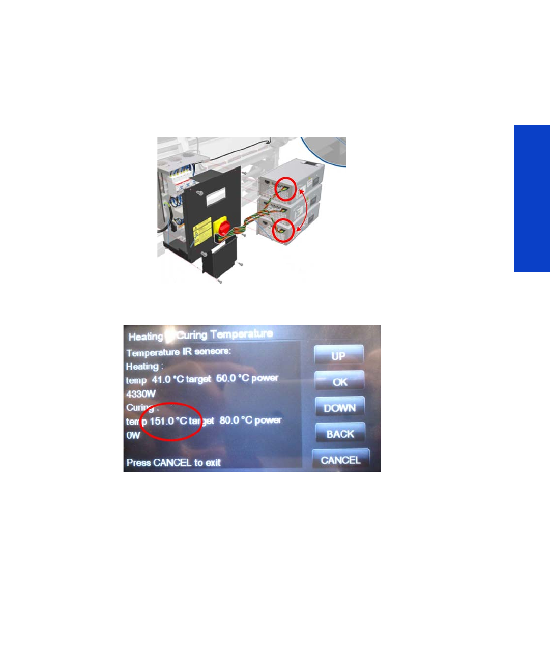
Continuable and non-continuable error codes 117
System Error Codes
Corrective action:
1. Check that the room temperature is within the printer’s operating specifications. If necessary, remove
external sources of heat, such as strong lights, direct sunlight, or heaters.
2. Check that the Curing IR Sensor Fan is turning and is correctly installed with the fan in the correct
orientation.
3. Check that the cables are connected and undamaged. In particular, check that the data cable
connections and the cable connections to the heaters are not swapped: a curing cable attached to
one of the drying heater control modules or vice versa. In the example below, the curing data cable
is swapped with the drying pinches data cable.
In this case, the printer will seem to work normally until the curing temperature reaches 150°C, as
shown in the picture below. At that point, the 16.03:00 system error will appear.
4. Perform the Curing IR sensor diagnostic check Page 173, to check the values being detected by
the IR sensor. Replace the Curing IR sensor if required Page 506.
5. Replace the cables from the PrintMech PCA to the connection box.
6. Replace the PrintMech PCA Page 467.
7. Check there are no obstructions on any of the cooling fans: Dryer, Curing, Top Cover Fans, Rear
Fans.
8. Check that all the fans are functioning correctly. Check that the cables of the fans are undamaged
and connected. Replace any fans if required: Top Cover Fans Page 337. Drying Fans
Page 340. Curing Fans Page 496.
SE Code: 16.04:00 – Curing system temperature too low
Problem description:
The curing system has fallen below the lower temperature limit (below 5°C).

118 Chapter 3 System Error Codes
System Error Codes
Corrective action:
1. Check that the room temperature is within the printer's operating specifications; it should be higher
than 15°C for printer operation. If it is too low, increase the room temperature.
2. Check whether the Curing IR sensor is dirty and requires cleaning. Observe all safety precautions
while working in the area of the heaters.
3. Check for an obstacle blocking the IR sensor’s view. Ensure that the IR sensor is correctly installed on
the printer, with no interference in the infrared light path, and that it is pointing to the substrate.
4. Perform the Curing IR sensor diagnostic check Page 173, to check the values being detected by
the IR sensor. Replace the Curing IR sensor if required Page 506.
5. Replace the cables from the PrintMech PCA to the connection box.
6. Replace the PrintMech PCA Page 467.
SE Code: 16.05:00 – Problem with the curing system Temperature Sensor
Problem description:
Signal error detected with the curing system Temperature Sensor.
Corrective action:
1. Check that the room temperature is within the printer’s operating specifications. If necessary, remove
external sources of heat, such as strong lights, direct sunlight, or heaters.
2. Check that the Curing IR Sensor Fan is turning and is correctly installed with the fan in the correct
orientation.
3. Check whether the Curing IR sensor is dirty and requires cleaning. Observe all safety precautions
while working in the area of the heaters.
4. Check that the cables are connected and undamaged.
5. Perform the Curing IR sensor diagnostic check Page 173, to check the values being detected by
the IR sensor. Replace the Curing IR sensor if required Page 506.
6. Replace the cables from the PrintMech PCA to the connection box.
7. Replace the PrintMech PCA Page 467.
8. Check there are no obstructions on any of the cooling fans: Dryer, Curing, Top Cover Fans, Rear
Fans.
9. Check that all the fans are functioning correctly. Check that the cables of the fans are undamaged
and connected. Replace any fans if required: Top Cover Fans Page 337. Drying Fans
Page 340. Curing Fans Page 496.
SE Code: 16.06:00 – Temperature error detected
Problem description:
There is a mismatch between the temperature detected by the Curing IR Sensor and the amount of
electrical power the curing system is receiving.
Corrective action:
1. The ink density may be too high, check the User's Guide for the recommended ink density levels.
2. Check that the input voltage is within the printer’s operating specifications: see the Site Preparation
Guide.

Continuable and non-continuable error codes 119
System Error Codes
3. Check whether the substrate loaded on the printer is too transparent or reflective for the IR sensor to
detect the surface temperature. You can check this by loading another type of substrate.
4. Check whether the Curing IR sensor is dirty and requires cleaning. Observe all safety precautions
while working in the area of the heaters.
5. Check for an obstacle blocking the IR sensor’s view. Ensure that the IR sensor is correctly installed on
the printer, with no interference in the infrared light path, and that it is pointing to the substrate.
6. Perform the Curing IR sensor diagnostic check Page 173, to check the values being detected by
the IR sensor. Replace the Curing IR sensor if required Page 506.
7. Replace the cables from the PrintMech PCA to the connection box.
8. Replace the PrintMech PCA Page 467.
SE Code: 16.08:00 – Curing fans array 1 not connected
Problem description:
The array 1 of curing system fans is not connected.
Corrective action:
Check the cable connections to the curing fans.
SE Code: 16.09:00 – Curing fan array 1 fault
Problem description:
Curing fan array 1 fault.
Corrective action:
1. Run the Diagnostic test and confirm which fans are rotating.
2. If none of the fans is working, replace the PrintMech PCA Page 467.
3. Replace the cable from the PrintMech to the fans.
4. If at least one of the fans is working, ensure it is connected to the array 1 cable.
5. Replace the non-rotating fans Page 496.
SE Code: 16.11:00 – Curing fans array 2 not connected
Problem description:
Curing fans array 2 not connected.
Corrective action:
Check the cable connections to the curing fans array 2.
SE Code: 16.20:11 – IR sensor curing fan not connected
Problem description:
IR sensor curing fan not connected.
Corrective action:
Check the cable connections to the IR sensor.

120 Chapter 3 System Error Codes
System Error Codes
SE Code: 16.21:10 – Curing fan array 2 fault
Problem description:
Curing fan array 2 fault.
Corrective action:
1. Switch the power off at the rear of the printer, wait briefly, then switch it back on again.
2. Run the diagnostic test and confirm which fans are rotating.
3. If none of the fans is working, replace the PrintMech PCA Page 467.
4. Replace the cable from the PrintMech PCA to the fans.
5. If at least one of the fans is working, ensure that it is connected to the array 2 cable.
6. Replace the non-rotating fans Page 496.
SE Code: 17.0:11 – PrintMech to Interconnect power cable disconnected
Problem description:
The PrintMech to Interconnect power cable does not seem to be connected.
Corrective action:
1. Check that the PrintMech to Interconnect power cable is not damaged.
2. Check that the PrintMech to Interconnect power cable is correctly connected to the PrintMech PCA
and the Interconnect PCA.
3. Replace the PrintMech to Interconnect power cable (which is included in the Electronics Module
Cable Kit).
SE Code: 17.1:11 – PrintMech to Interconnect data 1 cable disconnected
Problem description:
The PrintMech to Interconnect data 1 cable does not seem to be connected.
Corrective action:
1. Check that the PrintMech to Interconnect data 1 cable is not damaged.
2. Check that the PrintMech to Interconnect data 1 cable is correctly connected to the PrintMech PCA
and the Interconnect PCA.
3. Replace the PrintMech to Interconnect data 1 cable.
SE Code: 17.2:11 – PrintMech to Interconnect data 2 cable disconnected
Problem description:
The PrintMech to Interconnect data 2 cable does not seem to be connected.
Corrective action:
1. Check that the PrintMech to Interconnect data 2 cable is not damaged.
2. Check that the PrintMech to Interconnect data 2 cable is correctly connected to the PrintMech PCA
and the Interconnect PCA.
3. Replace the PrintMech to Interconnect data 2 cable.

Continuable and non-continuable error codes 121
System Error Codes
SE Code: 17.3:11 – Engine PCA to PrintMech black 1 cable disconnected
Problem description:
The Engine PCA to PrintMech black 1 cable does not seem to be connected.
Corrective action:
1. Check that the Engine PCA to PrintMech black 1 cable is not damaged.
2. Check that the Engine PCA to PrintMech black 1 cable is correctly connected to the Engine PCA and
the PrintMech PCA.
3. Replace the Engine PCA to PrintMech black 1 cable.
SE Code: 17.4:11 – Engine PCA to PrintMech blue 2 cable disconnected
Problem description:
The Engine PCA to PrintMech blue 2 cable does not seem to be connected.
Corrective action:
1. Check that the Engine PCA to PrintMech blue 2 cable is not damaged.
2. Check that the Engine PCA to PrintMech blue 2 cable is correctly connected to the Engine PCA and
the PrintMech PCA.
3. Replace the Engine PCA to PrintMech blue 2 cable.
SE Code: 21:03 – Service Station electrical current limit
Problem description:
Service Station electrical current limit.
Corrective action:
1. Switch the power off at the rear of the printer, wait briefly, then switch it back on again.
2. Make sure that the Service Station path is clear. Remove any visible obstacles restricting the
movement of the Service Station.
3. Replace the Service Station Page 351.
SE Code: 21:13 – Problem with the Service Station
Problem description:
Problem with the Service Station.
Corrective action:
1. Switch the power off at the rear of the printer, wait briefly, then switch it back on again.
2. Make sure that the Service Station path is clear. Remove any visible obstacles (such as screws or
plastic parts) restricting the movement of the Service Station.
3. Switch the power off at the rear of the printer, remove the Printhead Maintenance Cartridge, and
switch the printer on again.
4. If the error happens after printing for several hours and is cleared after power cycling, some small
damage to the Encoder can cause the print carriage to lose its position little by little. The same effect
could be produced by an ink or oil stain on the Encoder. Replace the Encoder Strip if it is damaged
Page 405.

122 Chapter 3 System Error Codes
System Error Codes
5. Replace the Service Station Page 351.
SE Code: 21.2:10 – Problem with the Web Wipe motor
Problem description:
Web Wipe Motor servo shut down.
Corrective action:
1. Switch the power off at the rear of the printer, manually pull the Printhead Maintenance Cartridge to
the front position and switch the printer on again.
2. Switch the power off at the rear of the printer and remove the Printhead Maintenance Cartridge.
Switch the printer on again. If the error is cleared, replace the Printhead Maintenance Cartridge.
3. Replace the Web Wipe Motor Page 354.
SE Code: 21.3:10 – Electrical problem in the Web Wipe Motor
Problem description:
Error detected in the area of the Web Wipe Assembly (Rack engage motor electrical).
Corrective action:
1. Switch the power off at the rear of the printer, manually pull the Printhead Maintenance Cartridge to
the front position and switch the printer on again.
2. Switch the power off at the rear of the printer and remove the Printhead Maintenance Cartridge.
Switch the printer on again. If the error is cleared, replace the Printhead Maintenance Cartridge.
3. Replace the Web Wipe Motor Page 354.
4. Replace the PrintMech PCA Page 467.
SE Code: 21.4:03 – Electrical problem in the Web Wipe Motor
Problem description:
Error detected in the area of the Web Wipe Assembly (Rack engage motor electrical).
Corrective action:
1. Switch the power off at the rear of the printer, manually pull the Printhead Maintenance Cartridge to
the front position and switch the printer on again.
2. Switch the power off at the rear of the printer and remove the Printhead Maintenance Cartridge.
Switch the printer on again. If the error is cleared, replace the Printhead Maintenance Cartridge.
3. Replace the Web Wipe Motor Page 354.
4. Replace the PrintMech PCA Page 467.
SE Code: 21.5:03 – Web Wipe Assembly Drifting
Problem description:
Error detected in the area of the Web Wipe Assembly (Rack engage drifting).
Corrective action:
1. Switch the power off at the rear of the printer, manually pull the Printhead Maintenance Cartridge to
the front position and switch the printer on again.

Continuable and non-continuable error codes 123
System Error Codes
2. Switch the power off at the rear of the printer and remove the Printhead Maintenance Cartridge.
Switch the printer on again. If the error is cleared, replace the Printhead Maintenance Cartridge.
3. Replace the Web Wipe Motor Page 354.
SE Code: 23:10 – Air Pressure System failure
Problem description:
The APS has received a request to depressurize, but the system has not depressurized within the expected
time (120 s).
Corrective action:
1. Switch the power off at the rear of the printer, wait briefly, then switch it back on again.
2. Check that the APS cable is not damaged and is correctly connected to the PrintMech PCA.
3. Check that the air tubes are properly connected and are not kinked or pinched.
4. Replace the APS Assembly
Page 402.
SE Code: 24:03 – Ink Supply Tubes purge failure
Problem description:
The Ink Supply Tubes purge process has failed or has been canceled by the customer.
Corrective action:
1. Switch the power off at the rear of the printer, wait briefly, then switch it back on again.
2. Ensure that the dummy printheads are correctly installed and purge the Ink Supply Tubes again.
3. Replace the Setup Printhead Kit.
SE Code: 24:10 – Ink cartridge broken bag
Problem description:
A broken bag has been detected in one of the ink cartridges. This error must be solved and the printer
checked and cleared of this error code before the printer can resume printing.
Corrective action:
1. The front panel message will indicate which ink cartridge has a broken bag. Remove the ink
cartridge and check for any ink leaking from the cartridge. In some extreme cases:
•Ink can leak from the damaged ink cartridge and contaminate the pressurized air system
or
•Air can get inside the Ink System causing bubbles in the Ink Tubes, which can damage the
printheads.
2. For this issue there is a specific menu selection to recover from the broken bag error. Perform the
“Bag Broken Recovery” Diagnostic procedure ( Page 160).
3. If the ISS Bottom PCA has been damaged by ink this must be replaced if it cannot be repaired
Page 398.

124 Chapter 3 System Error Codes
System Error Codes
SE Code: 24:11 – PrintMech PCA to ISS Top cable disconnected
Problem description:
The PrintMech PCA to ISS Top cable does not seem to be connected.
Corrective action:
1. Check that the PrintMech PCA to Pre-Driver PCA cable is not damaged.
2. Check the Pre-Driver PCA LEDs.
3. Check that the Pre-Driver PCA to IIS Top cable is correctly connected.
4. Replace the ISS Top PCA Page 398.
5. Replace the Pre-Driver PCA Page 327.
SE Code: 24.1:11 – ISS Top PCA to ISS Bottom PCA cable disconnected
Problem description:
The ISS Top PCA to ISS Bottom PCA cable does not seem to be connected.
Corrective action:
1. Check that the PrintMech PCA to Pre-Driver PCA cable is not damaged.
2. Check the Pre-Driver PCA LEDs.
3. Check that the Pre-Driver PCA to ISS Bottom PCA cable is correctly connected.
4. Replace the ISS Bottom PCA Page 398.
5. Replace the Pre-Driver PCA Page 327.
SE Code: 24.02:00 – Top Cover fans disconnected
Problem description:
The firmware has detected that there is no connection to the array of Top Cover fans.
Corrective action:
1. Perform the All Fans service test (Page 151) to confirm that none of the Top Cover fans is working.
2. Check the Top Cover fan cable, by the left arch, is connected to the PrintMech PCA at both ends,
and that it is not damaged.
3. If all the cables from the PrintMech PCA to the fans are connected, replace the PrintMech PCA
Page 467.
SE Code: 24.03:00 – Top Cover fans not working
Problem description:
The firmware has detected that one or more of the Top Cover fans are not working.
Corrective action:
1. Perform the All Fans service test (Page 151) to confirm that none of the Top Cover fans is working.
2. If none of the fans is working, this indicates a failure of the PrintMech PCA, or the cables from the
PrintMech PCA.
•Check the cables from the PrintMech PCA.

Continuable and non-continuable error codes 125
System Error Codes
•If all the cables from the PrintMech PCA to the fans are connected, replace the PrintMech PCA
Page 467.
3. If at least one of the fans is working, check whether the failed fans are connected to the array. If they
are connected, replace the failed fans Page 337.
4. If the error is not cleared, check all the cables from the failed fan to the PrintMech PCA.
SE Code: 26:14 – A wrong ink cartridge has been detected
Problem description:
A wrong ink cartridge has been detected.
Corrective action:
1. Switch the power off at the rear of the printer, wait briefly, then switch it back on again.
2. Remove the ink cartridges and check that they are the correct ones for this printer.
3. Check that the printer has the latest firmware version; if not, update the firmware to the latest version.
4. Replace the ink cartridges.
SE Code: 26.0:01 – Contact failure with magenta ink cartridge
Problem description:
Bad contact detected in ISS slot 0 floater.
Corrective action:
1. Remove the magenta ink cartridge and reinstall it into the printer.
2. Replace the magenta ink cartridge.
3. Check that the ISS to magenta ink cartridge cable is not damaged and is correctly connected to the
Ink Supply Tubes PCA.
4. Replace the ISS to magenta ink cartridge cable Page 391.
SE Code: 26.1:01 – Contact failure with yellow ink cartridge
Problem description:
Bad contact detected in ISS slot 1 floater.
Corrective action:
1. Remove the yellow ink cartridge and reinstall it into the printer.
2. Replace the yellow ink cartridge.
3. Check that the ISS to yellow ink cartridge cable is not damaged and is correctly connected to the Ink
Supply Tubes PCA.
4. Replace the ISS to yellow ink cartridge cable Page 391.
SE Code: 26.2:01 – Contact failure with black ink cartridge
Problem description:
Bad contact detected in ISS slot 2 floater.

126 Chapter 3 System Error Codes
System Error Codes
Corrective action:
1. Remove the black ink cartridge and reinstall it into the printer.
2. Replace the black ink cartridge.
3. Check that the ISS to black ink cartridge cable is not damaged and is correctly connected to the Ink
Supply Tubes PCA.
4. Replace the ISS to black ink cartridge cable Page 391.
SE Code: 26.3:01 – Contact failure with cyan ink cartridge
Problem description:
Bad contact detected in ISS slot 3 floater.
Corrective action:
1. Remove the cyan ink cartridge and reinstall it into the printer.
2. Replace the cyan ink cartridge.
3. Check that the ISS to cyan ink cartridge cable is not damaged and is correctly connected to the Ink
Supply Tubes PCA.
4. Replace the ISS to cyan ink cartridge cable Page 391.
SE Code: 26.4:01 – Contact failure with light magenta ink cartridge
Problem description:
Bad contact detected in ISS slot 4 floater.
Corrective action:
1. Remove the light magenta ink cartridge and reinstall it into the printer.
2. Replace the light magenta ink cartridge.
3. Check that the ISS to light magenta ink cartridge cable is not damaged and is correctly connected to
the Ink Supply Tubes PCA.
4. Replace the ISS to light magenta ink cartridge cable Page 391.
SE Code: 26.5:01 – Contact failure with light cyan ink cartridge
Problem description:
Bad contact detected in ISS slot 5 floater.
Corrective action:
1. Remove the light cyan ink cartridge and reinstall it into the printer.
2. Replace the light cyan ink cartridge.
3. Check that the ISS to light cyan ink cartridge cable is not damaged and is correctly connected to the
Ink Supply Tubes PCA.
4. Replace the ISS to light cyan ink cartridge cable Page 391.

Continuable and non-continuable error codes 127
System Error Codes
SE Code: 27:01 – Calibration failed due to a printhead
Problem description:
Calibration may have failed due to a high number of blocked nozzles in a printhead.
Corrective action:
Clean all printheads and check their status.
SE Code: 27:14 – A wrong printhead has been detected
Problem description:
A wrong printhead has been detected.
Corrective action:
1. Switch the power off at the rear of the printer, wait briefly, then switch it back on again.
2. Remove the printheads and check that they are the correct ones for this printer.
3. Check that the printer has the latest firmware version; if not, update the firmware to the latest version.
4. Replace the printheads.
SE Code: 27.1:01 – Calibration failed due to printhead in slot 1
Problem description:
Calibration failed to due to poor performance of the cyan/light cyan printhead in slot 1.
Corrective action:
This may impact your print quality. If it becomes unacceptable in the future, clean all printheads and check
their status.
SE Code: 27.2:01 – Calibration failed due to printhead in slot 2
Problem description:
Calibration failed to due to poor performance of the cyan/light cyan printhead in slot 2.
Corrective action:
This may impact your print quality. If it becomes unacceptable in the future, clean all printheads and check
their status.
SE Code: 27.3:01 – Calibration failed due to printhead in slot 3
Problem description:
Calibration failed to due to poor performance of the yellow/black printhead in slot 3.
Corrective action:
This may impact your print quality. If it becomes unacceptable in the future, clean all printheads and check
their status.

128 Chapter 3 System Error Codes
System Error Codes
SE Code: 27.4:01 – Calibration failed due to printhead in slot 4
Problem description:
Calibration failed to due to poor performance of the yellow/black printhead in slot 4.
Corrective action:
This may impact your print quality. If it becomes unacceptable in the future, clean all printheads and check
their status.
SE Code: 27.5:01 – Calibration failed due to printhead in slot 5
Problem description:
Calibration failed to due to poor performance of the light magenta/magenta printhead in slot 5.
Corrective action:
This may impact your print quality. If it becomes unacceptable in the future, clean all printheads and check
their status.
SE Code: 27.6:01 – Calibration failed due to printhead in slot 6
Problem description:
Calibration failed to due to poor performance of the light magenta/magenta printhead in slot 6.
Corrective action:
This may impact your print quality. If it becomes unacceptable in the future, clean all printheads and check
their status.
SE Code: 29:01 – Printhead Cleaning Cartridge incorrectly inserted
Problem description:
The Printhead Cleaning Cartridge is incorrectly installed.
Corrective action:
1. Reseat the Printhead Cleaning Cartridge.
2. Replace the Printhead Cleaning Cartridge if the error continues.
SE Code: 32:01 – Take-Up Reel disconnected
Problem description:
There is a cable connection problem with the Take-Up Reel.
Corrective action:
1. If you want to continue using the Take-Up Reel, you must turn off the printer and check that all Take-
Up Reel cables are connected (sensor cables, printer cable).
2. If not, cut the substrate and then manually unload it from the Take-Up Reel.

Continuable and non-continuable error codes 129
System Error Codes
SE Code: 32:01.1 – Early Take-Up Reel substrate jam
Problem description:
This system error happens when there is a small amount of substrate printed (less than 79 inches long),
and the Take Up Reel sensor detects that the tension bar is (incorrectly) at the bottom of its path, even
though the spindle motor has been rotating for more than 3 seconds.
The most likely cause of this error is that the user has forgotten to set the switch direction or tape the
substrate to the spindle core.
Corrective action:
1. Check that the substrate is attached to the Take-Up Reel.
2. Check that the winding direction switch is in the correct position.
3. If needed, use the Take-Up Reel arrow keys to wind the substrate before resuming printing.
4. To resume printing, press OK.
SE Code: 32:01.2 – Take-Up Reel substrate jam
Problem description:
The tension bar has stayed in one of its sensor trigger positions for more than 8 seconds.
Corrective action
1. Check that the substrate is attached to the Take-Up Reel.
2. Check that the winding direction switch is in the correct position.
3. Check that nothing is blocking the movement of the tension bar.
4. Ensure that the substrate is following the correct path along the tension bar and diverter bar.
SE Code: 32:01.9 – Take-Up Reel substrate unexpectedly removed
Problem description:
The Take-Up Reel has been disabled because the substrate was unexpectedly removed from it.
Corrective action
Remove all substrate from the printer and reinstall the Take-Up Reel.
SE Code: 32:02 – Take-Up Reel disconnected at initialization
Problem Description
This message is shown during initialization of the printer; it warns that the Take-Up Reel has been
disconnected while the printer was off. This error is also shown if the user tries to enable the Take-Up Reel
but it is not connected to the printer.
Corrective action:
Connect the Take-Up Reel to the printer and press OK to continue.
SE Code: 41:03 – Media-Axis Motor electrical current limit
Problem description:
Electrical current limit in the Media-Axis Motor.

130 Chapter 3 System Error Codes
System Error Codes
Corrective action:
1. Switch the power off at the rear of the printer, wait briefly, then switch it back on again.
2. Open the Window and check for any visible obstacles restricting the movement of the Drive Roller. If
there is a wrinkled mass of substrate inside the substrate path, lift the Pinchwheels (using the Media
Lever) and clear the obstruction.
3. Replace the Media-Axis Motor Page 430.
SE Code: 42:03 – Scan-Axis Motor electrical current limit
Problem description:
Electrical current limit in the Scan-Axis Motor.
Corrective action:
1. Switch the power off at the rear of the printer, wait briefly, then switch it back on again.
2. Open the Window and check for any visible obstacles restricting the movement of the Carriage. If
there is a wrinkled mass of substrate inside the printer, clear the substrate jam by following the
instructions in the User’s Guide.
3. Replace the Scan Axis Motor Page 426.
SE Code: 42:10 – Electrical fault in the Scan Axis area
Problem description:
Electrical fault in Carriage Motor or starting the Scan Axis or Homing Scan Axis.
Corrective action:
1. Switch the power off at the rear of the printer, wait briefly, then switch it back on again.
2. Replace the Scan Axis Motor Page 426.
SE Code: 42.10:11 – Scan-Axis Motor cooling fan not connected
Problem description:
The Scan-Axis Motor cooling fan is not connected.
Corrective action:
1. Perform the Scan Axis Service test.
2. Check that the Scan-Axis Motor fan cable is not damaged and is correctly connected to the
PrintMech PCA.
3. Replace the Scan-Axis Motor fan
Page 429
.
4. Replace the PrintMech PCA
Page 467
.
SE Code: 42.11:10 – Scan-Axis Motor cooling fan fault
Problem description:
Scan-Axis Motor cooling fan fault. It is connected, but when applying PWM it does not turn.
Corrective action:
1. Switch the power off at the rear of the printer, wait briefly, then switch it back on again.

Continuable and non-continuable error codes 131
System Error Codes
2. Replace the Scan-Axis Motor Fan
Page 429
.
SE Code: 43:11 – Vacuum Fan not connected
Problem description:
A Vacuum Fan does not seem to be connected.
Corrective action:
1. Check the cable connections between the Mini Interconnect PCA and Eolas SVS side.
2. Replace Eolas.
3. Replace the Mini Interconnect PCA.
SE Code: 43.2:11 – Vacuum Fan stopped
Problem description:
A Vacuum Fan has stopped.
Corrective action:
1. Check the cable connections between SVS side fans.
2. Replace the Vacuum Fan SVS side
Page 356
.
SE Code: 43.3:10 – Vacuum Fan overcurrent
Problem description:
Vacuum Fan overcurrent.
Corrective action:
1. Switch the power off at the rear of the printer, wait briefly, then switch it back on again.
2. Replace the Vacuum Fan SVS side
Page 356
.
SE Code: 43.4:10 – Vacuum Fan low performance
Problem description:
Vacuum Fan low performance.
Corrective action:
1. Switch the power off at the rear of the printer, wait briefly, then switch it back on again.
2. Replace the Vacuum Fan SVS side
Page 356
.
SE Code: 43.11:11 – Vacuum Fan 2 or 3 not connected
Problem description:
Vacuum Fan 2 or 3 is not connected.
Corrective action:
1. Check cable connections between the PrintMech PCA and Eolas IDS side.
2. Replace Eolas.
3. Replace the PrintMech PCA
Page 467
.

132 Chapter 3 System Error Codes
System Error Codes
SE Code: 43.12:11 – Vacuum Fan 2 or 3 stopped
Problem description:
Vacuum Fan 2 or 3 has stopped.
Corrective action:
1. Check the cable connections between Eolas and Vacuum Fans IDS side.
2. Replace the Vacuum Fans
Page 356
.
SE Code: 43.13:10 – Vacuum Fan 2 or 3 overcurrent
Problem description:
Vacuum Fan 2 or 3 overcurrent.
Corrective action:
1. Switch the power off at the rear of the printer, wait briefly, then switch it back on again.
2. Replace the Vacuum Fans IDS side
Page 356
.
SE Code: 43.14:10 – Vacuum Fan 2 or 3 low performance
Problem description:
Vacuum Fan 2 or 3 is not performing adequately.
Corrective action:
1. Switch the power off at the rear of the printer, wait briefly, then switch it back on again.
2. Replace the Vacuum Fans IDS side
Page 356
.
SE Code: 44:10 – There is a problem with the Aerosol Fan
Problem description:
There is no feedback signal from the Waste Management Aerosol Fan.
Corrective action:
1. Replace the Waste Management module (which can be done by the customer). This is the most
probable failure.
2. Check that the cable of the waste management system is correctly connected to the connector at the
EBOX (which can be done by the customer).
3. Check that the cable from the EBOX to the Interconnect PCA is correctly connected.
4. Check that the cables going from the Interconnect PCA to the PrintMech PCA are correctly
connected.
5. Replace the Interconnect PCA
Page 441.
6. Replace the PrintMech PCA
Page 467.
SE Code: 44:11 – Aerosol Fan not connected
Problem description:
The Aerosol Fan is disconnected.

Continuable and non-continuable error codes 133
System Error Codes
Corrective action:
Check the connections to the Aerosol Fan.
SE Code: 44.1:01 – Waste Management cable not connected
Problem description:
The waste management system cable is disconnected.
Corrective action:
1. Check the connections between the Waste Management PCA and the printer.
2. Check the connections to the Interconnect PCA.
3. Check that the cable of the waste management system is correctly connected to the connector at the
EBOX (this check can be done by the customer). This is the most probable cause.
4. Replace the Waste Management module (this part can be changed by the customer).
5. Check that the cable from the EBOX to the Interconnect PCA is correctly connected.
6. Check that the cables going from the Interconnect PCA to the PrintMech PCA are correctly
connected.
7. Replace the Interconnect PCA
Page 441.
8. Replace the PrintMech PCA
Page 467.
SE Code: 44.2:01 – Waste management switch open
Problem description:
At least one of the switches of the waste management sub-assembly is in open status.
Corrective action:
1. Check that the aerosol filter door is correctly closed (this can be done by the customer).
2. Check that the waste management ink tube is correctly inserted in the waste management sub-
assembly (this can be done by the customer).
3. Replace the Waste Management module (this part can be changed by the customer). This is the
most likely solution.
4. Check that the cable of the waste management system is correctly connected to the connector at the
EBOX (this check can be done by the customer).
5. Check that the cable from the EBOX to the Interconnect PCA is correctly connected.
6. Check that the cables going from the Interconnect PCA to the PrintMech PCA are correctly
connected.
7. Replace the Interconnect PCA
Page 441.
8. Replace the PrintMech PCA
Page 467.
SE Code: 44.3:01 – Waste management cable short-circuited
Problem description:
There is a short-circuit in the waste management system cable, and maybe also in the Interconnect PCA.

134 Chapter 3 System Error Codes
System Error Codes
Corrective action:
1. Replace the Waste Management module (this part can be changed by the customer). This is the
most likely solution.
2. Check that the cable of the waste management system is correctly connected to the connector at the
EBOX (this check can be done by the customer).
3. Check that the cable from the EBOX to the Interconnect PCA is correctly connected.
4. Check that the cables going from the Interconnect PCA to the PrintMech PCA are correctly
connected.
5. Replace the Interconnect PCA
Page 441.
6. Replace the PrintMech PCA
Page 467.
SE Code: 44.4:01 – Problem in the waste management feedback signal
Problem description:
There is a problem with the feedback signal from the waste management system.
Corrective action:
1. Check that the cable of the waste management system is correctly connected to the connector at the
EBOX (which can be done by the customer). This is the most probable failure.
2. Replace the Waste Management module (which can be done by the customer).
3. Check that the cable from the EBOX to the Interconnect PCA is correctly connected.
4. Check that the cables going from the Interconnect PCA to the PrintMech PCA are correctly
connected.
5. Replace the Interconnect PCA
Page 441.
6. Replace the PrintMech PCA
Page 467.
SE Code: 45:03 – Rewinder servo shutdown
Problem description:
The Rewinder servo has shut down.
Corrective action:
1. Switch the power off at the rear of the printer, wait briefly, then switch it back on again.
2. Open the Window and check for any visible obstacles restricting the movement of the Drive Roller. If
there is a wrinkled mass of substrate inside the substrate path, lift the Pinch Wheels and clear the
obstruction.
3. Replace the Rewinder Motor Module Page 351.
SE Code: 45:10 – Rewinder fault
Problem description:
Rewinder fault.
Corrective action:
1. Switch the power off at the rear of the printer, wait briefly, then switch it back on again.
2. Replace the Rewinder Motor Module Page 351.

Continuable and non-continuable error codes 135
System Error Codes
SE Code: 46:03 – Primer servo shutdown
Problem description:
The Primer servo has shut down.
Corrective action:
1. Check that the Primer Arm is not damaged and that there are no obstacles in its way.
2. Switch the power off at the rear of the printer, wait briefly, then switch it back on again.
3. Replace the Primer Assembly Page 345.
SE Code: 46:10 – Primer test distance failed
Problem description:
Primer test distance failed.
Corrective action:
1. Check that the Primer arm is not damaged and that there are no obstructions in the way.
2. Switch the power off at the rear of the printer, wait briefly, then switch it back on again.
3. Replace the Primer Assembly Page 345.
SE Code: 50:14 – Firmware version mismatch
Problem description:
Firmware version mismatch between the OMAS Controller Card and the Hard Disk Drive.
Corrective action:
1. Check that the printer has the latest Firmware version. If not, update the firmware to the latest
version.
2. Replace the OMAS Controller Card Page 442.
SE Code: 50.1:10 – OMAS communication failure
Problem description:
There has been a communication error with the Optical Media Advance Sensor (OMAS).
Corrective action:
1. Switch the power off at the rear of the printer, wait briefly, then switch it back on again.
2. Check that the printer has the latest firmware version. If not, update the firmware to the latest version.
3. Check that the OMAS Controller to OMAS Sensor cable is not damaged and is correctly connected
to the OMAS Controller Card and the OMAS Module.
4. Replace the OMAS Module Page 432.
SE Code: 50.2:10 – OMAS Controller Card communication failure
Problem description:
There has been a communication error with the OMAS Controller Card.

136 Chapter 3 System Error Codes
System Error Codes
Corrective action:
1. Switch the power off at the rear of the printer, wait briefly, then switch it back on again.
2. Check that the printer has the latest firmware version. If not, update the firmware to the latest version.
3. Replace the OMAS Controller Card Page 442.
SE Code: 50.3:11 – Engine PCA to OMAS Controller cable not connected
Problem description:
The Engine PCA to OMAS Controller cable does not seem to be connected.
Corrective action:
1. Check that the Engine PCA to OMAS Controller cable is not damaged.
2. Check that the Engine PCA to OMAS Controller cable is correctly connected to the Engine PCA and
to the OMAS Controller Card.
SE Code: 50.10:11 – TOMAS error
Problem description:
The TOMAS measurements are unstable.
Corrective action:
1. Check that TOMAS is correctly connected.
2. Replace TOMAS Page 438.
SE Code: 52:01 – A problem with the Drop Detector
Problem description:
Drop Detector fiber detected.
Corrective action:
1. Check that the Ink Funnel is correctly installed. Use the ‘Replace Ink Funnel’ process to access the
funnel.
2. Check that there are no obstructions in the funnel, such as substrate, which would block the detector
signal.
3. Replace the Drop Detector Page 376.
SE Code: 52:10 – A problem with the On/Off switch in the Drop Detector
Problem description:
Drop Detector switch On/Off failure.
Corrective action:
1. Switch the power off at the rear of the printer, wait briefly, then switch it back on again.
2. Check that the
Drop Detector cable is not damaged and is correctly connected to the Service Station
cable
.
3. Check that the
Service Station cable is not damaged and is correctly connected to the Interconnect
PCA
.

Continuable and non-continuable error codes 137
System Error Codes
4. Replace the Drop Detector Page 376.
5. R
eplace the Interconnect PCA
Page 441.
6. R
eplace the
Engine
PCA
Page 449.
SE Code: 53.1:10 – Media Sensor error
Problem description:
An error has been detected in the Media Sensor.
Corrective action:
1. Switch the power off at the rear of the printer, wait briefly, then switch it back on again.
2. Check that the
Media Sensor cable is not damaged and is connected correctly to the Interconnect
PCA
.
3. Replace the Media Sensor Page 557.
SE Code: 53.1:11 – Media Sensor cable not connected
Problem description:
The Media Sensor cable does not seem to be connected.
Corrective action:
Ensure that the
Media Sensor cable is not damaged and is connected correctly to the Interconnect PCA
.
SE Code: 54:10 – Media Lever Sensor error
Problem description:
An error has been detected in the Media Lever Sensor.
Corrective action:
1. Switch the power off at the rear of the printer, wait briefly, then switch it back on again.
2. Check that the
Media Lever Sensor cable is not damaged and is correctly connected to the
Interconnect PCA
.
3. Replace the Media Lever Sensor Page 299.
SE Code: 55:10 – Line Sensor communication failure
Problem description:
The printer cannot communicate with the Line Sensor.
Corrective action:
1. Switch the power off at the rear of the printer, wait briefly, then switch it back on again.
2. Replace the Line Sensor Page 473.
SE Code: 56:01 – Incorrect readings from Substrate Encoder
Problem description:
Incorrect readings from Substrate Encoder.

138 Chapter 3 System Error Codes
System Error Codes
Corrective action:
1. Switch the power off at the rear of the printer, wait briefly, then switch it back on again.
2. Perform Substrate Drive diagnostics.
3. Replace the Encoder Disc and Sensor Page 559.
SE Code: 56:10 – Substrate Encoder calibration failed
Problem description:
Substrate Encoder calibration has failed.
Corrective action:
1. Switch the power off at the rear of the printer, wait briefly, then switch it back on again.
2. Perform Substrate Drive diagnostics.
3. Replace the Encoder Disc and Sensor Page 559.
SE Code: 58:01 – Color Sensor shutter error
Problem description:
Color Sensor shutter error.
Corrective action:
Execute the Color Sensor Shutter Diagnostic Test.
SE Code: 58:10 – Color Sensor failure
Problem description:
Color Sensor failure.
Corrective action:
1. Check that the Color Sensor is installed in the Carriage.
2. Check that the Color Sensor is correctly installed and screwed into place.
3. Check that the Color Sensor cable is not damaged.
4. Check that the Color Sensor cable is correctly connected to the Carriage PCA.
5. If the system error persists, replace the Color Sensor.
6. Perform a Color Sensor basic test (CLC) to ensure that the replaced part is working correctly.
SE Code: 58.1:10 – Color Sensor Shutter Actuator failure
Problem description:
Color Sensor Shutter Actuator failure.
Corrective action:
1. Replace the Color Sensor Shutter Actuator Assembly.
2. Perform the Color Sensor Shutter Diagnostic Test to ensure that there is no other problem preventing
shutter operation.
3. Perform a Color Sensor basic test (CLC) to ensure that the replaced part is working correctly.

Continuable and non-continuable error codes 139
System Error Codes
SE Code: 58.2:10 – Color Sensor Shutter Deactivator failure
Problem description:
Color Sensor Shutter Deactivator failure.
Corrective action:
1. Check that the Shutter Deactivator is correctly screwed into place.
2. Perform the Color Sensor Shutter Diagnostic Test to ensure that there is no other problem preventing
shutter operation.
3. Perform a Color Sensor basic test (CLC) to ensure that the replaced part is working correctly.
SE Code: 59.1:09 – Two electrical parts have been replaced at the same time
Problem description:
Two electrical parts have been replaced at the same time.
Corrective action:
Replace one part at a time, and restart the printer before replacing another.
SE Code: 59.2:00 – An unsupported or reused part has been installed
Problem description:
An unsupported or reused part has been installed.
Corrective action:
Install only new parts recommended by HP for this printer.
SE Code: 61:10 – Data lost due to I/O timeout
Problem description:
A slow computer processing complex files can pause for longer than the default printer timeout, which
can be interpreted by the printer as an End Of Job, in which case some elements of the job may be lost.
Corrective action:
1. Increase the I/O timeout using the printer's front panel (see 'Communication failures between
computer and printer' in the User’s guide).
2. Send the job from a faster computer.
SE Code: 63:05 – The job is reaching the printer too slowly
Problem description:
The job is reaching the printer too slowly. The printer cancels the job if there are long pauses of more than
20 s.
Corrective action:
1. Make sure that a 1 Gigabit Ethernet card is correctly installed in the computer with the RIP.
2. Check the RIP for any error messages. Check that the computer with the RIP is working correctly and
has the minimum specification required by the RIP. Check that the hard disk is neither full nor
excessively fragmented.

140 Chapter 3 System Error Codes
System Error Codes
3. Check whether the option RIP while printing is enabled. This option can cause slow printing if the
computer is not sufficiently powerful.
4. Try reducing the resolution of the job or increasing the number of passes.
SE Code: 65:04 – I/O problem though an unknown port
Problem description:
Input/Output problem through an unknown port.
Corrective action:
1. Switch the power off at the rear of the printer, wait briefly, then switch it back on again.
2. Check that the LAN cable is connected.
3. Check that the printer has the latest firmware. If not, upgrade to the latest firmware.
4. Replace the Formatter PCA Page 452.
SE Code: 74:01 – Error uploading firmware update file
Problem description:
Error uploading firmware update file.
Corrective action:
1. Switch the power off at the rear of the printer, wait briefly, then switch it back on again.
2. Resend the firmware update file to the printer.
SE Code: 77:04 – Embedded Web Server internal software error
Problem description:
Embedded Web Server internal software error.
Corrective action:
1. Switch the power off at the rear of the printer, wait briefly, then switch it back on again.
2. Check that the printer has the latest firmware version. If not, update the firmware to the latest version.
SE Code: 78.1:04 – Substrate settings error
Problem description:
The printer has no media preset for this substrate.
Corrective action:
Check that the printer has the latest firmware version. If not, update the firmware to the latest version.
SE Code: 78.2:01 – The back tension has been lost
Problem description:
The printer has reached an end-of-roll condition: substrate moving, but input spindle not rotating.
Corrective action:
1. If the roll is not finished, unload and reload the substrate.

Continuable and non-continuable error codes 141
System Error Codes
2. Load a new roll.
3. Check that the substrate is not slipping on the spindle.
SE Code: 79:03 – Generic firmware error I
Problem description:
Generic Firmware error.
Corrective action:
1. Switch the power off at the rear of the printer, wait briefly, then switch it back on again.
2. Check that the printer has the latest firmware version. If not, update the firmware to the latest version.
3. Perform Hard Disk Recovery.
SE Code: 79:04 – Generic firmware error II
Problem description:
Generic Firmware error.
Corrective action:
1. Switch the power off at the rear of the printer, wait briefly, then switch it back on again.
2. Check that the printer has the latest firmware version. If not, update the firmware to the latest version.
3. Try using different selections in the RIP to print the image.
4. Perform Hard Disk Recovery.
5. For more detailed information on troubleshooting the 79:04 system error Page 87.
SE Code: 81:01 – Possible substrate jam
Problem description:
Media servo shutdown; possible substrate jam.
Corrective action:
1. If the substrate is nearing the end of the roll, check that the remaining substrate is firmly attached to
the core.
2. Open the Window, observing all safety precautions, and check for any visible obstacles restricting
the movement of the Drive Roller. If there is a wrinkled mass of substrate inside the substrate path, lift
the Pinchwheels (using the Media Lever) and clear the obstruction.
3. Check the performance of the Rewinder system as it may also cause a servo shutdown.
4. Check that the OMAS Controller Card to PrintMech PCA cable is not damaged.
5. Check that the OMAS Controller Card to PrintMech PCA cable is correctly connected to the OMAS
Controller Card and the PrintMech PCA.
6. Perform the Drive Roller service test Page 155.
7. Check whether the 5 V LED (D55) on the PrintMech PCA is off; this could be caused by a short-circuit
in the Curing IR Sensor Fan cable, usually due to being pinched by metallic parts. Check the cable;
if it is damaged, replace it.
8. Replace the Media Axis Motor Page 430.

142 Chapter 3 System Error Codes
System Error Codes
SE Code: 81:03 – Problem with setting the encoder position
Problem description:
It was impossible to stop the servo correctly before setting the encoder position.
Corrective action:
1. Open the Window observing all safety procedures and check for any visible obstacles restricting the
movement of the Drive Roller. If there is a wrinkled mass of substrate inside the substrate path, lift the
Pinchwheels (using the Media Lever) and clear the obstruction.
2. Perform the Substrate Path service test Page 154.
3. Replace the Media-Axis Motor Page 430.
SE Code: 82:01 – Substrate jam in the platen area
Problem description:
Substrate jam detected by the Media Jam Sensor in the Print Platen area.
Corrective action:
1. Open the window, observing all safety procedures, and clear the Print Platen of any obstruction.
Check especially around the area of the Media Jam Sensor, at the left end of the platen.
2. Check that the cable from the Media Jam Sensor is connected and undamaged.
3. Check that the reflector assembly on the side of the Carriage is not dirty or damaged. If it is dirty,
clean it; if it is damaged, replace the Media Jam Sensor and reflector.
SE Code: 85:03 – Drive Roller encoder problem
Problem description:
Problem finding the Drive Roller zero.
Corrective action:
1. Switch the power off at the rear of the printer, wait briefly, then switch it back on again.
2. Perform the Media Drive Diagnostic.
SE Code: 86:01 – Possible substrate jam
Problem description:
The Carriage servo has shut down; possible substrate jam.
Corrective action:
See Page 87.
SE Code: 87:01 – Problem with the Scan Axis encoder sensor readings
Problem description:
Problem with the Scan Axis encoder sensor readings.

Continuable and non-continuable error codes 143
System Error Codes
Corrective action:
1. Check whether the Encoder Strip is dirty. If necessary, clean it. Pay special attention to the area near
the Service Station. Follow the instructions on the front panel after selecting the Ink menu and then
Clean Encoder Strip.
2. Check whether the Encoder Strip is broken or damaged. If necessary, replace it.
3. Clean the Encoder Sensor.
4. Replace the Encoder Sensor.
5. Perform the Scan Axis diagnostic test to troubleshoot the problem further.
SE Code: 94:01 – Substrate unsuitable for color calibration
Problem description:
The substrate is not suitable for color calibration, being too dark, too colored, or transparent.
Corrective action:
•If accurate color is important, change to a different substrate type (preferably an HP substrate) that
satisfies the conditions for color calibration.
•If accurate color is not important, print without color calibration.
SE Code: 94:02 – Color calibration error: inconsistent colors
Problem description:
Color calibration error: some of the consistency checks on the Color Sensor measurements failed.
Corrective action:
1. Ensure that the substrate type selected corresponded to the substrate actually loaded.
2. Inspect the CLC printed target to detect any printing defect: banding, missing colors, etc. If an issue
is detected, run the Printing IQ Full Calibration procedure to fix any printing problems.
3. Check that color calibration is supported for this substrate type: translucent, plain, and heavily
colored substrates cannot be color-calibrated.
4. If the problem persists, try calibrating an HP Coated Paper (if available). If this calibration fails,
replace the Color Sensor.
SE Code: 94:10 – Color Sensor contaminated by aerosol
Problem description:
Color Sensor contaminated by aerosol.
Corrective action:
1. Replace the Color Sensor.
2. Perform the Color Sensor basic test (CLC) to ensure that the replaced part is working correctly.
SE Code: 98:03 – Printhead nozzles out
Problem description:
One or more printheads are malfunctioning.

144 Chapter 3 System Error Codes
System Error Codes
Corrective action:
Use the printhead status plot to find out which printheads are malfunctioning, and replace them.

145
Tests, Utilities & Calibrations
4 Service Tests, Utilities & Calibrations
Introduction.............................................................................................. 148
•Diagnostics - Self Test................................................................................... 148
•Service Tests ............................................................................................... 148
Service Tests ............................................................................................. 148
•Entering the Diagnostics Menu ...................................................................... 148
•1. Electrical System ...................................................................................... 149
•1.1 Electronics Control ......................................................................... 149
•1.2 All Fans ....................................................................................... 151
•1.3 Hard Disk Drive............................................................................. 152
•1.4 Hard Disk Recovery ....................................................................... 152
•1.5 File System Check.......................................................................... 152
•1.6 IO Information .............................................................................. 152
•1.7 Enable I/O Interfaces .................................................................... 153
•1.8 Unit information ............................................................................ 153
•1.9 SE 59.2:00 Recovery: Set SN and PN.............................................. 153
•1.9 SE 59.2:00 Recovery: Set SN and PN.............................................. 153
•1.10 EEROM reset ...............................................................................154
•2. Substrate Path .........................................................................................154
•2.1 Rewinder System ........................................................................... 154
•2.2 Drive Roller .................................................................................. 155
•2.3 Substrate Path Sensors ................................................................... 156
•2.4 OMAS Module............................................................................. 158
•2.5 Solve Substrate Jam....................................................................... 158
•3. Ink System .............................................................................................. 159
•3.1 Air Pressure System........................................................................ 159
•3.2 Check Ink Supplies........................................................................ 159
•3.3 Broken Bag Recovery Menu............................................................160
•3.3.1 Clean Air Tubes .................................................................160
•3.3.2 Recover Broken Bag........................................................... 161
•3.3.3 Refill Ink Tubes .................................................................. 162
•4. Scan Axis...............................................................................................165
•4.1 Scan Axis Test............................................................................... 165
•4.2 Scan Axis Cycles .......................................................................... 167
•5. Carriage ................................................................................................ 169
•5.1 Carriage PCA ............................................................................... 169
•5.2 Color Sensor ................................................................................ 169
•5.3 Line Sensor Check......................................................................... 170
•6. Service Station ........................................................................................ 170
•6.1 Shuttle Close Loop ......................................................................... 170
•6.2 Web Wipe Motor......................................................................... 170
•6.3 Primer ......................................................................................... 171
•7. Heating and Curing ................................................................................. 171
•7.1 Heating ........................................................................................ 171
•7.2 Curing ......................................................................................... 172
•7.3 Heating IR Sensor.......................................................................... 172
•7.4 Curing IR Sensor ........................................................................... 173
•7.5 Monitoring sine-waves and resistances ............................................. 173
•8. Covers ................................................................................................... 174
•8.1 Cover/Switch Sensor ..................................................................... 174

146 Chapter 4 Service Tests, Utilities & Calibrations
Tests, Utilities & Calibrations
•9. Diagnostic Utilities ................................................................................... 176
•9.1 Force Normal Boot ........................................................................ 176
•9.2 Force Diagnostic Boot.................................................................... 176
•9.3 Report Tests Version....................................................................... 176
•9.4 Enable/Disable Logs..................................................................... 176
Service Menu ............................................................................................ 178
•1. Service Tests and Utilities Menu ................................................................. 179
•1.1 Boot Mode ................................................................................... 179
•1.1.1 Force Diagnostic Mode........................................................ 179
•1.1.2 Force Normal Mode ........................................................... 179
•1.2 Electrical System ........................................................................... 180
•1.2.1 Set Date and Time.............................................................. 180
•1.2.2 Enable/Disable Firewall ..................................................... 180
•1.2.3. Enable/Disable Logs......................................................... 180
•1.2.4 Input/Output......................................................................181
•1.2.5 Set Serial Number ..............................................................181
•1.2.6 Sleep Mode.......................................................................181
•1.2.7 Report Test Version..............................................................181
•1.3 Substrate Path............................................................................... 182
•1.3.1 Turn Drive Roller................................................................. 182
•1.3.2. Enable/Disable OMAS ..................................................... 182
•1.3.3 OMAS Sensor Check ......................................................... 183
•1.4 Ink System.................................................................................... 183
•1.4.1 Purge Tubes....................................................................... 183
•1.5 Scan Axis .................................................................................... 184
•1.5.1 Force Drop Detection .......................................................... 184
•1.6 Carriage...................................................................................... 184
•1.6.1. Color Sensor Shutter Diagnostic........................................... 184
•1.6.2 Color Sensor Measurement Test........................................... 186
•1.6.3 Color Sensor Check ........................................................... 186
•1.6.4 Test Cutter ........................................................................ 186
•1.7 Service Station.............................................................................. 187
•1.7.1. Prime Pen X....................................................................... 187
•1.8 Heating and Curing ...................................................................... 187
•1.8.1 Heating and Curing Temperature ......................................... 187
•1.8.2 Enable Heating and Curing ................................................ 187
•1.9 Show Test Messages...................................................................... 187
•1.10 Force FW Upgrade ...................................................................... 188
•1.11 Hard Disk Recovery ...................................................................... 188
•2. Image Quality Plots ................................................................................. 188
•2.1 Print ALL Plots................................................................................ 188
•2.2 Printhead Alignment...................................................................... 189
•2.2.1 Test Plot ............................................................................ 189
•2.2.2 Advanced Test Plot ............................................................ 189
•2.2.3 Automatic Printhead Alignment ........................................... 189
•2.2.4 Manual PH Alignment........................................................ 189
•2.2.4.1 Print Pattern ......................................................... 189
•2.2.4.2 Manual Alignment Settings ................................... 189
•2.3 Substrate Advance........................................................................ 190
•2.3.1 Print Adjustment Plot........................................................... 190
•2.3.2 Reset Substrate Advance .................................................... 190
•2.4 Printhead Health........................................................................... 190
•2.4.1 Print Test Plot..................................................................... 190
•2.4.2 Advanced Test Plot ............................................................ 190

147
Tests, Utilities & Calibrations
•2.4.3 Only for Escalations...........................................................190
•2.4.4 Clean All Printheads ..........................................................190
•2.4.5 Clean LC-C Printheads........................................................ 191
•2.4.6 Clean Y-MK Printheads....................................................... 191
•2.4.7 Clean LM-M Printheads ...................................................... 191
•2.5 Geometry Check........................................................................... 191
•2.6 Scan Axis Check........................................................................... 191
•2.7 Vacuum Check ............................................................................. 191
•2.8 Side Registration Check ................................................................. 192
•2.11 Others ........................................................................................192
•3. Ink On Substrate Test ...............................................................................192
•3.1Print Test Plot at 6 passes.................................................................192
•3.2 Print Test Plot at 8 passes ............................................................... 192
•3.3 Print Test Plot at 10 passes..............................................................192
•3.4 Print Test Plot at 12 passes..............................................................192
•4. Reset Life Counters (NEVER DONE BY CUSTOMER) .....................................192
•4.1 Reset Maint. Kit Usage ................................................................... 193
•4.2 Reset Substrate Path ...................................................................... 193
•4.3 Reset ISS...................................................................................... 194
•4.4 Reset Scan Axis ............................................................................ 194
•4.5 Reset Carriage.............................................................................. 194
•4.6 Reset Service Station ..................................................................... 194
•4.7 Reset Heating & Curing ................................................................. 195
5. Service Calibrations .............................................................................. 195
•5.1 Substrate Path........................................................................................195
•5.1.1 Substrate Advance Calibration ......................................................195
•5.1.2 OMAS calibration....................................................................... 196
•5.1.3 Reset Vacuum Calibration.............................................................199
•5.1.4 Rewinder Calibration...................................................................199
•5.2 Scan Axis.............................................................................................199
•5.2.1 Scan Axis Calibration .................................................................199
•5.2.2 Drop Detector Calibration ...........................................................201
•5.3 Carriage ..............................................................................................201
•5.3.1 Line Sensor Calib........................................................................201
•5.3.2 Primer Calibration..................................................................... 203
•5.3.3 Color Sensor Shutter Calibration ................................................. 206
•5.3.4 Color Sensor Calibration............................................................ 206

148 Chapter 4 Service Tests, Utilities & Calibrations
Tests, Utilities & Calibrations
Introduction
This chapter explains how to use the Service Tests, Utilities and Calibration. Each part is shown step by
step in order that it is displayed on the Front Panel. If the Test, Utility or Calibration should fail and display
a system error, we explain where to go in the Service Manual to either troubleshoot the error or fix it
directly.
Diagnostics - Self Test
Whenever the printer is switched on, it automatically performs a series of internal self-tests and mechanical
initialization sequences. If any part fails during these tests, a system error is displayed and you should
consult “System error codes and warnings—explanation” on page 93.
Service Tests
Entering the Diagnostics Menu
1. Make sure the printer is switched off with the Power key beside the Front Panel, and not with the
power switch at the rear of the printer.
2. Press and release the Power key to switch on the printer.
3. Wait for about 10 seconds until the icons on the Front Panel appear, then press and release the
Cancel, Home, and Help icons one after another.
4. The icons on the Front Panel blink four times. Wait until the printer completes the initialization
sequence and shows the Diagnostics menu.
5. In the Diagnostics menu, you can scroll up and down by sliding your finger vertically. Select an
option by pressing it. In some cases a quick press may not be recognized by the printer; to select an
option, press it deliberately for about one second.
The Diagnostic Tests and Utilities work in a special mode that does not require full initialization of the
printer. Therefore, whenever you have finished a test, you must turn off the printer and turn it on again
before trying to print or before executing another test. Also turn off the printer if it hangs up during a test.
NOTE: If possible, always perform the related Service Test on a component that you are
about to replace, to confirm it has failed.
NOTE: Do not press the icons all at the same time: press each one in the order shown above
and release each icon before pressing the next one.

Service Tests 149
Tests, Utilities & Calibrations
1. Electrical System
1.1 E l e c t ro n i c s C o n t r o l
Description
The purpose of this test is to diagnose a failure in the operation of the:
•Components of the Electronics Module.
•Electronics Module to Carriage and ISS Communication.
Procedure
1. Go to Diagnostic test > 1. Electrical System > 1.1 Electronics Control, and press OK.
2. A message will display on the Front Panel asking whether you would like to check the Formatter.
Select Yes, and press OK to confirm your selection.
3. The printer will get the CPU information and display the information on the Front Panel. Press any key
to continue the test.
4. The printer will now get the CPU Fan Speed and display the information on the Front Panel. Press
any key to continue the test.
If the CPU Fan Speed is less than 2500, the Front Panel will display system error code 05.1:10
page 98.
5. The printer will now calculate the amount of memory installed and display the information on the
Front Panel. Press any key to continue the test.
A minimum of 256 megabytes of memory must be installed in the printer. If not, the Front Panel will
display system error code 05.3:10.
6. A message will display on the Front Panel asking whether you would like to check the printer
Configuration. Select Yes and press OK to confirm your selection.
7. The Printer will start the CDS and the following information will be displayed on the Front Panel:
•Starting CDS.
If there is a failure at this point, the Front Panel will display system error code 79:03 page 140.
8. The printer will then check the Serial Number and Part Number and display the information on the
Front Panel. Press any key to continue the test.
If the Serial Number does not have assigned a correct 10 character format or the Part number does
not have assigned a correct 6 character format, a fail message will display on the Front Panel. In this
case, re-enter the Service Tests submenu and use the diagnostic ‘Error 71:19 Recovery’ to set the
correct Serial Number (see page 153).
9. A message will display on the Front Panel asking whether you want to check the Engine PCA. Select
Yes and press OK. This action could take up to 10 minutes.
10. The Printer checks the Engine PCA and the following messages will be displayed on the Front Panel:
•Starting CDS
•Checking Engine PCA
•Starting Engine PCA
•Checking Impact memory
NOTE: This test does not test the Hard Disk Drive.

150 Chapter 4 Service Tests, Utilities & Calibrations
Tests, Utilities & Calibrations
•Checking Gauntlet memory
If there is a failure at this point, the Front Panel will display system error code 01.0:10 page 96.
11. A message will display on the Front Panel asking whether you would like to check the Power Supply.
Select Yes and press OK to confirm your selection.
12. The Printer will check various electrical subsystem, if there is an error at any time, use the information
on chapter 3 page 89to solve the issue.
13. A message will display on the Front Panel asking whether you would like to check the PrintMech.
Select Yes and press OK to confirm your selection.
14 . The Printer will check various electrical subsystem, if there is an error at any time, use the information
on chapter 3 page 89to solve the issue.
15. A message will display on the Front Panel stating that the delSol has been detected and asking
whether you would like to Continue. Press any key to continue.
16. A message will display on the Front Panel asking whether you would like to check the Interconnect.
Select Yes and press OK to confirm your selection.
17. The Printer will check the Interconnect PCA and the following messages will be displayed on the
Front Panel:
•Starting CDS
If there is a failure at this point, the Front Panel will display system error code 79:03 page 140.
•Getting unit config.
If the current Part Number is not in the correct 6 character format, the Front Panel will display a fail
message. In this case, re-enter in to the Service Tests submenu and use the diagnostic “14.2 Error
71:19 Recovery” to set the correct Serial Number (refer to page 153).
•Starting Tests GPIO
If there is a failure at this point, the Front Panel will display system error code 01.0:10 page 96.
•Checking GPIO channels
At this stage, the printer reads and checks the default GPIO values in the Interconnect PCA when all
the cables are connected and all the sensors give the default value or the current state. The results
will be displayed on the Front Panel and you can press any key to scroll through the information.
If any of the channels cannot be read, the Front Panel will display system error code 01.0:10
page 96.
18 . A message will display on the Front Panel asking whether you would like to check the Carriage
Communication. Select Yes and press OK to confirm your selection.
19. If you select Yes, the Front Panel asks whether the carriage supply LED has been switched on.
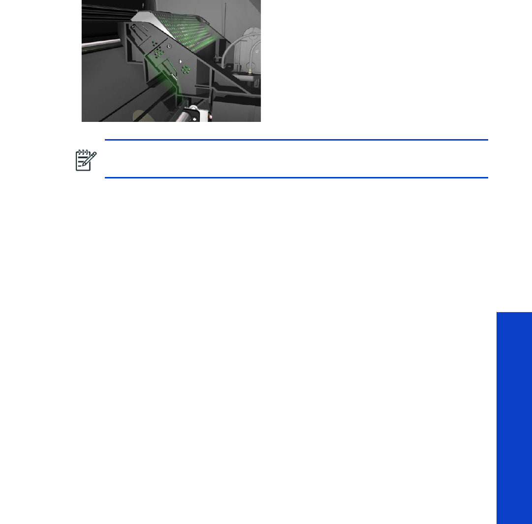
Service Tests 151
Tests, Utilities & Calibrations
20. Open the Window, move the carriage to the center and place your head as close as possible to the
platen in order to check if the Carriage power light is ON (a faint green light on the carriage PCA).
Select Yes or No by using the Up and Down keys and press OK to confirm your selection.
If you select Yes, then the Front Panel will display:
•Starting Carriage
If there is a failure at this point, the Front Panel will display system error code 02.1:10 see
page 97. Check also system error code 11 : 10 see page 100 or system error code 01.0:10 (refer
to page 96).
•Checking Carriage rev.
If there is a failure at this point, the Front Panel will display system error code 02.1:10 see
page 97. Check also system error code 11: 10 see page 100.
21. A message will display on the Front Panel asking whether you would like to check the ISS
Communication. Select Yes and press OK to confirm your selection.
22. If you select Yes, the printer will check the ISS Communication and the following information will be
displayed on the Front Panel:
•Starting Engine PCA.
If there is a failure at this point, the Front Panel will display system error code 01.0:10 page 96.
•Checking ISS PCA rev.
At this stage, the Front Panel displays the value for the ISS PCA revision and asking whether you
would like to continue. Press any key to continue.
1. 2 A l l F a n s
Description
This test checks the printer’s cooling fans.
•Curing Fans
•Dryer Fans (Top Cover Fans)
•Cover Fans
The test will switch on all the fans of the selected array, so a visual check can be made to verify if they
are working or not.
NOTE: The LED is very faint and it may not be obvious in a room with strong lighting.

152 Chapter 4 Service Tests, Utilities & Calibrations
Tests, Utilities & Calibrations
Procedure
1. Go to Diagnostic test > 1. Electrical System > 1.2 All fans, and press OK.
2. The printer initializes various subsystems required to perform the test and displays calibration values.
3. The printer that tests all fans are functioning correctly and displays results.
4. Check the fans are all rotating, if there are any that are not, stop the test, by pressing the Cancel key,
and perform the appropriate troubleshooting procedure.
1.3 Hard Disk Drive
Description
The hard disk drive service test checks the following:
•Protection status test (protected/not protected)
•Partition configuration test
•System file contents (sanity check for critical files)
Procedure
1. Go to Diagnostic test > 1. Electrical System > 1.3 Hard Disk Drive, and press OK.
2. The printer asks you if you want to perform this test, select Yes. Press OK to confirm your selection.
3. The printer checks the hard disk drive partitions for faults. The printer asks you if you want to perform
this test, select Yes.
4. The printer reads the current partition configuration of the hard disk drive and displays it on the Front
Panel.
5. Press any key to continue.
6. The printer performs a sanity check to verify hard disk consistency. The printer asks you if you want
to perform this test, select Yes.
7. The printer reads and displays the current file system contents of the formatted partitions of the hard
disk drive.
8. Press any key to shut down the system.
1.4 Hard Disk Recovery
1.5 File System Check
1. 6 I O I n fo rm a t i o n
Description
The IO information diagnostic test retrieves and displays information you may need when troubleshooting
a network problem. The following information is displayed:
•IP address
•Gateway address
•Subnet mask
Procedure
1. Go to Diagnostic test > 1. Electrical System > 1.6 IO Information, and press OK.
2. The printer will initialize and the Front Panel will display the following messages:

Service Tests 153
Tests, Utilities & Calibrations
•Getting IO Interface
•Getting Interface info
If there is a failure at this point, the Front Panel will display an error.
If no active interface is found, the Front Panel will display “No active interface found. Press any key
to finish”.
3. Once the IO information is obtained, it is displayed on the Front Panel. Press any key to exit.
4. Once the process is completed, OK will be displayed on the Front Panel.
1.7 Enable I/O Interfaces
The purpose of this test is to enable the printer's I/O interfaces (USB, Ethernet, Jetdirect) after they have
been disabled from the Embedded Web Server.
1. In the Diagnostics menu, scroll to Enable I/O interfaces and press OK.
2. Use the arrow keys if necessary to enable the I/O interfaces.
3. The front panel confirms the result of the operation. Press OK to restart the printer.
1.8 Unit information
Description
This option allows you to view the following Printer information:
•Firmware version.
•Serial Number.
•Part Number.
Procedure
1. Go to Diagnostic test > 1. Electrical System > 1.8 Unit Information, and press OK.
2. The Front Panel will display the various electrical subsystems being initialized in order to perform the
test, if there is a failure at this point the Front Panel will display a system error, troubleshoot the
system error using Chapter 3: System Error codes.
If the Serial Number does not have a correct 10 character format assigned or the Part number does
not have a correct 6 character format assigned, a fail message will display on the Front Panel. In this
case perform the diagnostic ‘71:19 Recovery’ to set the correct Serial Number (refer to page 153).
If there is a failure at this point, the Front Panel will display an error.
3. Once the Unit information is obtained, it is displayed on the Front Panel. Press any key to exit.
4. Once the process is completed, OK will be displayed on the Front Panel.
1.9 SE 59.2:00 Recovery: Set SN and PN
Description
The SE 59.2:00 Recovery diagnostic test is intended to be used to set the printer’s serial number and part
number in case both the Hard Disk Drive and the Ink Supply Tubes are replaced at the same time.
Procedure
1. Go to Diagnostic test > 1. Electrical System > 1.9 Set SN and PN, and press OK.
2. The front panel displays the printer’s serial number and part number, as stored in the Hard Disk
Drive and in the EEPROM. You can press UP or DOWN to change the values, OK to go to the next
number, or CANCEL to exit with no changes.

154 Chapter 4 Service Tests, Utilities & Calibrations
Tests, Utilities & Calibrations
3. When you have finished, the front panel displays the new serial number and part numbers for
confirmation. At this point, they are not saved. Double-check that the values displayed are what you
wanted to enter. If the values are not correct, press CANCEL to try again. If the values are correct,
press OK to confirm.
1.10 E E R O M r es e t
Description
This procedure can be used to restore the EEROM to the default manufacturing settings. This can under
certain circumstances correct the printer if there is a software conflict.
Procedure
1. Go to Diagnostic test > 1. Electrical System Menu > 1.10 EEROM reset, and press OK.
2. The front panel asks for confirmation. Use the Up and Down keys to select Yes, and press OK.
3. Press any key to finish the procedure.
1.11 EEROM restore
2. Substrate Path
2.1 Rewinder System
Description
The Rewinder System diagnostic test checks the following components and processes, any failures will be
displayed as a system error, which can then be used to troubleshoot and solve the problem.
•Rewinder Motor without substrate loaded (motors, encoder)
•Rewinder Motor with substrate loaded (friction)
Procedure
1. Go to Diagnostic test>2. Substrate path>3.1 Rewinder System.
2. The Front Panel will display the various electrical subsystems being initialized in order to perform the
test, if there is a failure at this point the Front Panel will display a system error, troubleshoot the
system error using Chapter 3: System Error codes.
3. When prompted by the Front Panel, remove the substrate and spindle from the printer.
4. Press any key to continue.
5. The printer will now test the Rewinder without the Spindle, moving in an open loop in one direction.
After the test, the Front Panel displays the amount of movement made.
6. Press any key to continue.
7. The printer will now test the Rewinder without the Spindle moving in a open loop in the opposite
direction.
8. The Front Panel displays an informative message. Press any key to continue.
9. The Front Panel asks you to feed substrate into the Rewinder.
Use tape to secure the lead edge of the substrate to the roll to stop the substrate from unwinding
during the test. Install the spindle into the printer. Press any key to continue.
10. The printer will now test the Rewinder with the Spindle, moving in an open loop in one direction.
After the test, the Front Panel displays the amount of movement made.
11. Press any key to continue.

Service Tests 155
Tests, Utilities & Calibrations
12. The printer will now test the Rewinder with the Spindle moving in a open loop in the opposite
direction. After the test, the Front Panel displays the amount of movement made.
13. Press the cancel key to repeat the test, or press OK to continue the test.
14 . Press OK to continue. The printer now tests the friction in the Rewinder with substrate loaded.
15. The results of the test are displayed on the front panel., press any key to finish the test.
2.2 Drive Roller
Description
The purpose of this test is to diagnose a failure in the operation of components related to the Drive Roller.
You must perform the Drive Roller test after:
•System Error Code 81:YX
•System Error Code 41:YX
•System Error Code 73:YX
Procedure
1. Go to Diagnostic test > 2. Substrate Path > 2.2 Drive Roller.
2. The Front Panel will display the various electrical subsystems being initialized in order to perform the
test, if there is a failure at this point the Front Panel will display a system error, troubleshoot the
system error using Chapter 3: System Error codes.
If there is no system error code displayed on the Front Panel but the printer hangs up and the last
message on the Front Panel is “Booting up the Carriage” this would indicate that the Carriage ASIC
could not be detected. Troubleshoot this problem using the system error 02.1:10 see page 96.
3. The printer will now check for the presence of the Color Meter (delSol) and report results.
4. The printer will program the duty cycle for the PWM test for the Paper Drive Movement and leave it
disabled and the following message will be displayed on the Front Panel:
•Prog slow PWM paper
If there is a failure at this point, the Front Panel will display system error code 01.0:10 page 96.
5. Before continuing, the Front Panel asks you to remove the substrate if it is still loaded. Make sure you
stay out of the Print Platen area if the Window is open.
6. The Printer will now test the Paper Drive moving in an open loop in one direction, and report the
amount of movement made. Press any key to continue the test.
Check that the movement made is more than 100 encoder units (in absolute value). If the movement
made is less than 100 encoder units, open the Window and check for any visible obstacles
restricting the movement of the Drive Roller or the Overdrive Assembly. In this case, press any key to
finish the test.
7. The printer will now test the Paper Drive moving in an open loop in the opposite direction and report
the amount of movement made. Press any key to continue the test.
NOTE: This part of the procedure may take a while to complete.
NOTE: If possible, always perform this test before replacing any component of the Media
Axis.

156 Chapter 4 Service Tests, Utilities & Calibrations
Tests, Utilities & Calibrations
Check that the movement made is more than 100 encoder units (in absolute value). If the
movement made is less than 100 encoder units then open the Window and check for any visible
obstacles restricting the movement of the Drive Roller or the Overdrive Assembly.
If the Encoder Units are less than 100, the printer will request you to follow these instructions:
a. Manually load a sheet of substrate into the printer (an A4 sheet).
b. The printer will test the Media Drive moving in an open loop.
c. Perform a visual check during the test. The Front Panel will ask you if the substrate moved or not:
–If the substrate moved, the Front Panel will display system error code 56:10 page 137.
–If the substrate did not move, the Front Panel will display system error code 41:10
page 130.
8. The Printer will now check the Paper Drive servo system and the following messages will be
displayed on the Front Panel:
•Starting Media Motor
•Starting Media Axis
•Calib. Analog Encoder
If there is a failure at this point, the Front Panel will display a system error code; for more information
on troubleshooting this error code, refer to page 89.
Once the Analog Encoder calibration is completed, the Front Panel will display the results.
Acceptable values are:
•Gain: between 0 and 5
•DGain between 0 and 15
•Offset: between -80 and 80
If the results are acceptable, press OK. If the results are unacceptable, then press the Back/
Cancel key and the Front Panel will display system error code 56:10 page 137.
•Starting Substrate Path.
•Homing and repeat. test.
If there is a failure at this point, the Front Panel will display a system error code, for more information
on troubleshooting this error code, refer to page 89.
9. The printer will now check the Substrate Drive PWM. Load substrate in to the printer and press any
key to continue the test.
10. When the PWM check is being performed, the following message will be displayed on the Front
Panel:
•PWM test with paper
11. Once the PWM check is done, the results will be displayed on the Front Panel. Press any key to finish
the test.
If there is a failure at this point, the Front Panel will display details of the problem.
12. Once the test is completed, OK will be displayed on the Front Panel and then you will be prompted
to press any key to shut down the printer.
13. Press any key to finish the test.
2.3 Substrate Path Sensors
Description
The purpose of this test is to verify the operation of the following Sensors:

Service Tests 157
Tests, Utilities & Calibrations
•Left and Right Window lock sensors.
•Media Lever.
•Maintenance Cartridge Door Sensor.
•Media Sensor.
•Media Jam Sensor
Procedure
1. Before starting, first make sure that:
•The Window is closed.
•The Maintenance Cartridge Door is closed.
•The Media Lever is in the lowered position.
•Paper is unloaded.
2. Go to Diagnostic test > 2. Substrate Path > 3.3 Substrate Path Sensors.
3. The printer will initialize the sensors.
4. The Front Panel will display the various electrical subsystems being initialized in order to perform the
test, if there is a failure at this point the Front Panel will display a system error, troubleshoot the
system error using Chapter 3: System Error codes.
5. Before starting to test the sensors, the Front Panel prompts the user to set the sensors to the test default
positions. Press any key to continue.
6. The Window Sensor will be tested first. When prompted by the Front Panel, open the Window and
press any key to continue.
7. The Front Panel reports the result of the test. Close the Window and press any key to continue.
If the Window Sensor fails the test, the Front Panel will display system error code 51:10
page 136.
8. The Maintenance Cartridge Door Sensor will be tested next. When prompted by the Front Panel,
open the Maintenance Cartridge Door Sensor and press any key to continue.
9. The Front Panel reports the result of the test. Press any key to continue.
If the Maintenance Cartridge Door Sensor fails the test, the Front Panel will display system error code
51.1:10 page 136.
10. The Media Lever Sensor will be tested next. When prompted by the Front Panel, raise the Paper
Lever and press any key to continue.
11. The Front Panel reports the result of the test. Lower the Paper Lever and press any key to continue.
If the
Paper Lever Sensor
fails the test, the Front Panel will display system error code
54:10
page 137
.
12. The Media Sensor will be tested next. When prompted by the Front Panel, raise the Media Lever,
load substrate, lower the Media Lever, and press any key to continue.
13. The Front Panel reports the result of the test. Raise the Media Lever, unload substrate, lower the
Media Lever, and press any key to continue.
If the
Paper Lever Sensor
fails the test, the system error
53:10
is displayed
page 137
14 . If there is an error with the Media Jam sensor, the system error 82:01 is displayed page 142.
15. The Front Panel reports the result of the test. Press any key to continue.

158 Chapter 4 Service Tests, Utilities & Calibrations
Tests, Utilities & Calibrations
16. The Front Panel asks you to cover the Media Jam reflector with your hand. Make sure the parts inside
the printer are not too hot. Cover the reflector on the left side of the carriage and at the same time
press any key to continue. This verifies that the light going to the sensor is from the reflector and not
from another light source.
If there is an error with the Media Jam sensor, the system error 82:01 is displayed page 142.
17. The Front Panel reports the result of the test. Press any key to continue.
18 . The carriage assembly moves along the Carriage path testing the Media Jam Sensor as it goes
along the scan axis. The Front Panel reports the result of the second test. Press any key to continue.
If there is an error with the Media Jam sensor, the system error 82:01 is display page 142.
19. The Front Panel reports the overall result of the tests. Press any key to finish.
2.4 OMAS Module
Description
The objective of this test is to check the communication of the OMAS system: OMAS controller PCA, the
CAN BUS, the OMAS flat cable, and the OMAS sensor.
Procedure
1. Go to Diagnostic test > 2. Substrate Path > 2.4 OMAS Module.
2. The Front Panel displays the OMAS firmware version located in the OMAS Controller PCA.
If the OMAS is unable to retrieve the firmware version, this would indicate an error with the OMAS
system, and system error 50.02:10 would be displayed page 135.
3. Press any key to continue.
The printer displays the OMAS sensor version number, which should be in the format YYWWDDDD
(year, week, day).
If the OMAS is not correctly connected the format of the version number will not be correct.
4. Press any key to finish the test.
2.5 Solve Substrate Jam
Description
We recommend using this test in case you cannot remove the substrate from the substrate path after a
substrate jam. This test allows you to move the media motor in both directions. It may help to “push” the
substrate in the direction you want while you are pulling the substrate to remove it.
Procedure
1. Go to Diagnostic test > 2. Substrate Path > 2.5 Solve Substrate Jam.
2. The front panel invites you to move the Drive Roller backwards and forwards to enable you to free
the jammed substrate.

Service Tests 159
Tests, Utilities & Calibrations
3. Ink System
3.1 Air Pressure System
Description
The purpose of this test is to verify the operation of the Air Pressure System (APS).
Procedure
1. Go to Diagnostic test > 3. Ink System > 3.1 Air Pressure System.
2. The Front Panel asks whether you want to perform the Air Pressure System diagnostic test, select Yes
and press OK.
3. The Front Panel asks you to insert all the Ink Cartridges. Insert all the Ink Cartridges and press any
key to continue.
4. The Front Panel displays the various electrical subsystems being initialized in order to perform the
procedure. If there is a failure at this point the Front Panel displays a system error; troubleshoot the
system error using Chapter 3: System Error codes
page 89.
5. The printer pressurizes and then depressurizes the APS.
6. If there is a failure starting the Pump, the Front Panel displays a system error code. For more
information on troubleshooting this error code, see the System Errors chapter
page 89.
7. Once the test is completed, OK is displayed on the Front Panel.
3.2 Check Ink Supplies
Description
The purpose of this test is to verify which Ink Cartridges are valid for the purge process and their current
available ink level. Some Ink Cartridges may not be able to be accessed (unable to read the Acumen) if
previously there had been a failure (faulty, broken bag, etc...).
Procedure
1. Go to Diagnostic test > 3. Ink System > 3.2 Check Ink Supplies.
2. The printer will start to initialize and the Front Panel will display the following messages:
•Starting Engine PCA.
If there is a failure at this point, the Front Panel will display system error code 01.0:10
page 96.
•Starting AcumenSupplies.
If there is a problem while reading the Acumen, the Front Panel will display one of the system error
codes:
•26.n:10 page 125
•
01.2:10
page 96
•
01.0:10
page 96
If there is a failure at this point, the Front Panel will display the message “Replace failing ink supplies
after running this utility”.
3. Once the Ink Supplies information is obtained, it is displayed. Press any key to exit.
If any part of the Acumen information is invalid, the Front Panel will display an error.
NOTE: Perform this test before replacing the APS (if possible), if this test passes, do not
replace the APS.
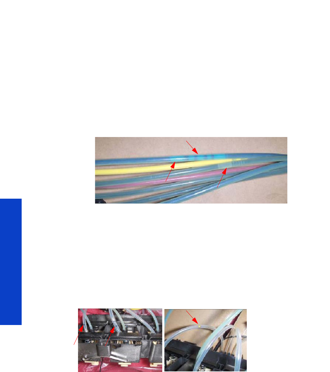
160 Chapter 4 Service Tests, Utilities & Calibrations
Tests, Utilities & Calibrations
4. Once the process is completed, OK will be displayed on the Front Panel.
3.3 Broken Bag Recovery Menu
Description
The purpose of the menus here is to recover the printer if a broken bag in an Ink Cartridge is
detected. A broken bag will stop the printer from functioning and will need to be fixed and cleared
of the error before the printer can continue printing normally. If ink leaks from the broken bag and
leaves the confines of the ink cartridge, this error is potentially damaging to various parts of the
printer.
In order to remove the printer from this system error status and recover the printer to working order
the test must be performed in the following order:
•3.3.1 Clean Air Tubes
•3.3.2 Recover Broken bag
•3.3.3 Refill Ink Tubes
The following procedures and menu selections enable the engineer to clear leaked ink from the
pressurized air system in the ISS and to remove air bubbles (caused by the broken bag) from the Ink
Tubes which can damage the Printheads.
To perform the following procedures the Broken Bag Fixing Tools kit is required (part number CH955-
67111).
3.3.1 Clean Air Tubes
Procedure
The procedures and menu selections must be performed if there is ink visible in the air tubes of the APS.
1. Remove the Left Cover and check if the tubes from the APS to the ISS are clean. If the tubes are clean
of ink this procedure does not need to be performed, go to page 162 and perform the Refill Ink
Tubes to clear any air bubbles from the ink tubes.
However if there are sections of tubing that have ink in them, like the examples indicated below with
the red arrows.
2. Remove all the Ink Cartridges and install the dummy Ink Cartridges from the Broken Bag Fixing Tools
kit.
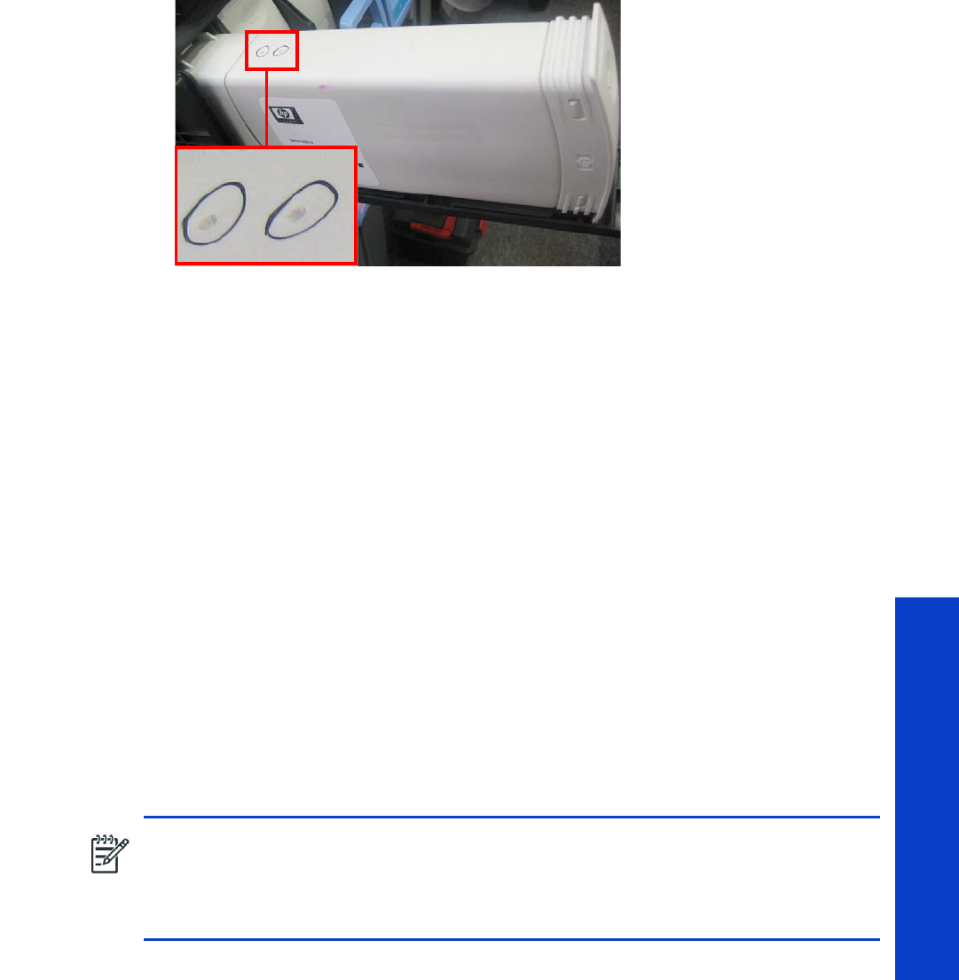
Service Tests 161
Tests, Utilities & Calibrations
3. One of the dummy Ink Cartridges has two holes at the top, this dummy Ink Cartridge must be
inserted into the color slot with the Broken Bag error.
4. Go to Diagnostic test > 3. Ink System Menu > 3.3 Broken Bag Recovery Menu > 3.3.1 Clean Air
Tubes, and press OK.
5. The Front Panel asks for confirmation. Select Yes and press OK.
6. The Front Panel asks whether the dummy cartridge is installed. Press OK to continue.
7. The Front Panel reports on the pumping of air through the tubes.
Air is now pumping through the air tubes system, pushing any ink that may be there from the Air
tubes into the Dummy Ink Cartridge with the two holes at the top. When this is finished, press any
key to continue.
8. The Front Panel asks whether you want to repeat the test with another cartridge.
9. Remove the dummy ink cartridge with the two holes and insert it into the other slots that may also
have ink in their air tubes, press OK to continue removing ink from the other air tubes.
When you are sure there is no more ink from the broken bag blocking any of the air tubes, select
Cancel.
3.3.2 Recover Broken Bag
Description
This option recovers the printer to a ready status after a broken bag has been detected in one of the Ink
Cartridges.
Procedure
1. Go to Diagnostic test > 3. Ink System Menu > 3.3 Broken Bag Recovery Menu > 3.3.2 Recover
Broken Bag, and press OK.
2. The Front Panel asks whether the tubes are clean. If the Air Tubes are clean of ink, select Yes and
press OK.
3. The Front Panel asks whether you want to remove the broken-bag condition. Select Yes and press
OK.
4. The Printer will now scan for a broken bag in the Ink Cartridges, and the Front Panel will display the
following messages:
NOTE: This option should only be selected if the following has been performed:
•The Ink Cartridge with the broken bag has been replaced with a new Ink
Cartridge.
•The Air Tubes have been cleaned of any ink.

162 Chapter 4 Service Tests, Utilities & Calibrations
Tests, Utilities & Calibrations
•Starting Gamut
•Starting TestGPIO
•Detecting Bag Broken
•Starting Acumen Supplies
•Getting ISS data
•Starting SuppliesCon....
5. When prompted by the Front Panel, press any key to finish the recovery procedure.
3.3.3 Refill Ink Tubes
Description
The procedures and menu selections must always be performed if a broken bag has been detected by the
printer. In this procedure the printer forces ink from the ink tube that had the broken bag, removing air
bubbles, into a syringe.
Procedure
1. Remove all the dummy Ink Cartridges and install the normal Ink Cartridges.
2. Go to Diagnostic test > 3. Ink System Menu > 3.3 Broken Bag Recovery Menu > 3.3.3 Refill Ink
Tubes, and press OK.
3. The Front Panel will display the various electrical subsystems being initialized in order to perform the
procedure. If there is a failure at this point the Front Panel will display a system error; troubleshoot
the system error using Chapter 3: System Error codes.
4. The Front Panel asks you to select the color of the Ink Cartridge that had the broken bag, and press
OK.
5. The Front Panel asks whether there is air in the ink tubes.
6. The Front Panel asks whether the new cartridges are installed.
7. When prompted by the Front Panel, open the Front Cover and Carriage Cover and press any key to
continue.
CAUTION: This procedure must only be performed after performing the Recover Broken Bag
procedure.
NOTE: It is important that the Ink Cartridge with the broken bag, is discarded and replaced
with a new Ink Cartridge. DO NOT reinstall the Ink Cartridge with the broken bag.
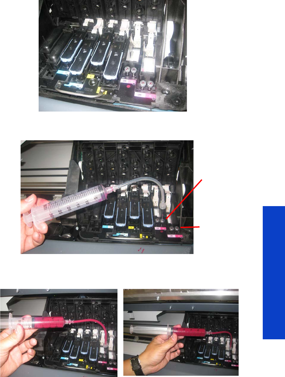
Service Tests 163
Tests, Utilities & Calibrations
8. When prompted by the Front Panel, remove the two Printheads of the color affected by the broken
bag error, in the example shown below it is Magenta. Press any key on the Front Panel to continue.
9. When prompted by the Front Panel, insert the needle connected to the syringe into the FI tower of the
color affected. Use the FI of the color which is to the rear of the Carriage, as shown. Press OK to
continue.
10. The Front Panel reports that the printer is pumping air.
Ink is now pumping through the ink tube, pushing any air bubbles from the Ink Tubes into the syringe.
The amount of ink pumped through the Ink Tube into the syringe is 33 cc + air.
11. After 2 minutes, the Front Panel asks whether the syringe has been filled. Press OK to continue.
12. The Front Panel displays several informational messages, press any key to continue.
Use this FI
Tower
Not this FI
Tower

164 Chapter 4 Service Tests, Utilities & Calibrations
Tests, Utilities & Calibrations
13. The Front Panel may ask whether you want to repeat the test with another cartridge. Press the OK
key to repeat the test, or the Cancel key to finish.
14 . When prompted by the Front Panel, remove the needle from the FI tower, and press any key to
continue.
15. When prompted by the Front Panel, reinstall the Printheads into the Carriage.
16. When prompted by the Front Panel, close the Carriage and close the Front Window.
NOTE: If you cannot clear the bubbles from the ink tubes, replace the complete SRK tubes
assembly
page 381.
TIP: Ink from the syringe can be emptied into the Printhead Cleaning Container.
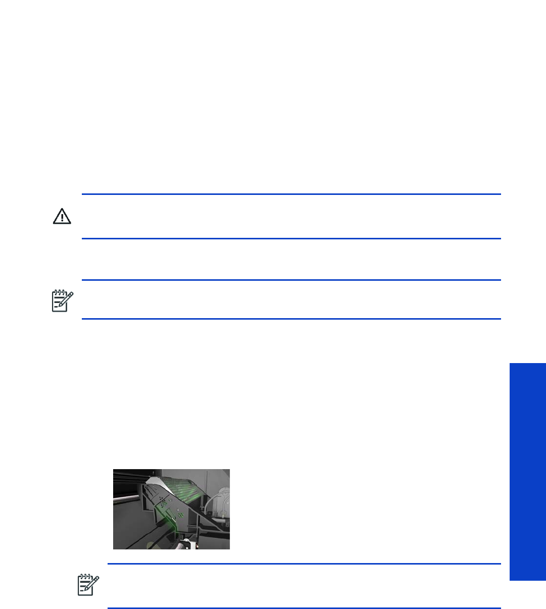
Service Tests 165
Tests, Utilities & Calibrations
4. Scan Axis
4.1 Scan Axis Test
Description
The purpose of this test is to diagnose a failure in the operation of components related to the Scan Axis.
Perform the Scan-Axis Test after:
•System Error Code 86:YX
•System Error Code 42:YX
•System Error Code 73:YX
•System Error Codes related to Scan-Axis shutdown or Carriage jam.
Procedure
1. Go to Diagnostic test > 5. Scan Axis Menu > 5.1 Scan Axis Test.
2. The Front Panel will display the various electrical subsystems being initialized in order to perform the
test. If there is a failure at this point the Front Panel will display a system error; troubleshoot the
system error using Chapter 3: System Error codes.
3. After initializing, the Front Panel asks whether the carriage supply LED has been switched on.
4. Open the Window, move the Carriage to the center of the platen, position your head as close as
possible to the platen in order to check if the Carriage power light is ON (a very dim green light on
the carriage PCA). Select Yes or No by using the Up and Down keys and press OK to confirm
your selection.
If you select No at this point, the Front Panel will display system error code 02.1:10 page 97.
Check also system error code 11 : 10 page 100.
If you select Yes, then the Front Panel will display:
•Booting up the Carriage
If there is a failure at this point, the Front Panel will display system error code 02.1:10 page 97.
Check also system error code 11 : 10 page 100, or system error code 01.1:10 page 96.
WARNING! All the cover sensors are disabled when in the service tests menu. If the
carriage is moving it will not stop if the window is opened, so be very careful not to put your
hands inside.
NOTE: Perform this test with the Printheads and the Tubes System installed so that the values
can be compared correctly.
NOTE: To be able to see the LED, you have to place your head very close to the Platen
but if you are not comfortable doing that you should remove the Right Cover before
starting the test.

166 Chapter 4 Service Tests, Utilities & Calibrations
Tests, Utilities & Calibrations
Unit Hangs Up - If no system error code is displayed on the Front Panel, but the printer hangs up
and the last message on the Front Panel is “Booting up the Carriage”, it means that the Carriage
ASIC could not be detected. Troubleshoot this problem in the same way as if system error code
02.1:10 had displayed page 97.
5. Once the Carriage is booted up, the Service Station will be prepared so that the Carriage can be
moved to a safe position. During this process, the following information will be displayed on the
Front Panel:
•Starting SVS Motor
If there is a failure at this point, the Front Panel will display system error code, for more information
on troubleshooting this error code, see page 89. In addition the Service Station Test can be
performed to try clear the SE, see page 170.
Unit Hangs Up - If no system error code is displayed on the Front Panel but the printer hangs up
and the last message on the Front Panel is “Starting SVS Motor” it means that the SVS Motor could
not be initialized. Troubleshoot this problem in the same way as if system error code 21:12 had
displayed.
6. The Printer will program the duty cycle for the PWM test for the Scan-Axis Movement and leave it
disabled and the following information will be displayed on the Front Panel:
•Preparing SVS
•Prog slow PWM scan
•Moving carriage middle
•Prog fast PWM scan
If there is a failure at this point, the Front Panel will display system error code 01.0:10 page 96.
7. The Carriage will be moved to the middle of the Print Platen. If there is a failure in moving the
Carriage, the Front Panel will display system error code 01.0:10 page 96.
8. The printer will now check that it can read the Encoder Strip. When prompted by the Front Panel,
open the Window and press the Up key to move the Carriage to the left and the Down key to
move the Carriage to the right. Make sure that you move the Carriage in both directions and check
that the Carriage actually moves when a key is pressed.
If there is a failure at this point, the Front Panel will display system error code 01.0:10 page 96.
If the Carriage only moves in one direction, troubleshoot the problem as system error code 01.1:10
page 96.
9. At the end of 10 Carriage movements, the Front Panel will display the maximum and minimum
length (in encoder units) of the 10 movements and the overall average.
If Carriage movement has not been detected or if Carriage movement was very short, the Front Panel
will ask you “Did the motor move?”. If the answer is Yes (the Carriage had moved) press OK. If the
answer is No (the Carriage had not moved) press the Back key.
If you select No (the Carriage had not moved), the Front Panel will display system error code 42:10
page 130. Check also system error code 01.1:10 page 96 or system error code 01.0:10
page 96.
If you select Yes (the Carriage had moved), the Front Panel will display a system error code. Check
also system error code 11: 10 page 100 or system error code 01.0:10 page 96.
If any max. or min. movement length is outside ±20% of the average, then this warning message
will be displayed on the Front Panel “Some movements out of avg. ±20% range: Intermittent
movements. PWM test needed”. This warning means that there is a mechanical problem in the
printer (Encoder Strip, friction, Carriage Belt, Slider Rod, etc...). Press any key to continue with the
PWM test.

Service Tests 167
Tests, Utilities & Calibrations
10. The Printer will now start to initialize the Scan-Axis servo and the Front Panel will display the
following information:
•Starting Carriage Motor
•Off/On Carriage Motor
•Doing a right side bump
•Doing a left side bump
•Exit bump position
If there is a failure at this point, the Front Panel will display system error code 86:01 see
page 142.
11. The Printer checks the complete length of the Scan Axis and displays the result on the Front Panel.
The length should be between 2570774 and 2580980.
If it is shorter, it means that there is an obstacle blocking the Scan-Axis path and the Front Panel will
display a system error code.
If the length is longer, it means that the carriage has a datum broken or the Carriage Stopper is not
installed.
12. The Printer will now check the Scan-Axis PWM and the following information will be displayed on
the Front Panel:
•Starting Scan Axis
•PWM test
If there is a failure at this point, the Front Panel will display a system error code.
13. The Printer will test the PWM and display the results on the Front Panel.
If some of the results are incorrect, the Front Panel will show “High Friction”. Depending on the results
received, proceed as follows.
•If PWM avg got is more than 32557 and PWM min diff got is less than 3100 then there is high
friction along the Scan Axis. In this case you should:
•Clean the Slider Rods and apply oil along the complete axis of the Slider Rods. After applying
the oil, perform the test again.
•Check that the Carriage Belt is installed correctly.
•If PWM min diff got is less than 3100 but PWM avg got is less than 32557 then there is a
problem in the Scan Axis. In this case you should:
•Check that the Encoder Strip has not been damaged and is clean page 61.
•Check that the Ink Supply Tubes and Trailing Cable are installed correctly.
If there is a failure processing the PWM results, the Front Panel will display system error code
86:01. In this case try repeating the test again.
14 . Once the test is completed, OK will be displayed on the Front Panel and then you will be prompted
to press any key to shut down the printer.
4.2 Scan Axis Cycles
Description
The Scan-Axis Cycles diagnostic test checks the following components and processes:
•Scan axis life status
Procedure
1. Go to Diagnostic tests > 4. Scan axis > 4.2 Scan axis cycles, and press OK.

168 Chapter 4 Service Tests, Utilities & Calibrations
Tests, Utilities & Calibrations
2. The printer retrieves scan-axis information and reports on the front panel the number of cycles
completed so far, the estimated lifespan of the scan axis in terms of cycles, and the percentage of
total lifespan completed.

Service Tests 169
Tests, Utilities & Calibrations
5. Carriage
5.1 Carriage PCA
Description
This test performs specific routines on the Carriage PCA to check for any problems. If a failure is detected,
the printer will display a system error code which can be used to troubleshoot the problem.
Procedure
1. Go to Diagnostic test > 5. Carriage > 5.1 Carriage PCA.
2. The Front Panel message is displayed.
5.2 Color Sensor
Description
The purpose of this test is to troubleshoot an error with the Color Sensor Test. The test checks the values
measured by the sensor and compares them to what is expected, if the values are different the test has
failed.
Procedure
1. Go to Diagnostic test > 5. Carriage > 5.2 Color Sensor Test.
2. The Front Panel will display the various electrical subsystems being initialized in order to perform the
test, if there is a failure at this point the Front Panel will display a system error, troubleshoot the
system error using Chapter 3: System Error codes.
If the SOL is disabled, the Front Panel will ask you if you want to enable the SOL, select Yes.
3. The Color Sensor information is read and the information is displayed on the Front Panel; press any
key to continue.
4. The printer will read the Red Reference and the Front Panel will display the following messages:
•Starting ColorSensor…
•Starting ColorSensing
•Reading SOL Status
•Reading Registers
•Performing Calibration…
•Reading Red Reference
5. When prompted by the Front Panel, raise the Media Lever, load substrate, lower the Media Lever,
and press any key to continue.
Be careful with the higher risk of a substrate jam during this procedure.
6. The Front Panel then displays the deltaE value, press any key to continue.
7. Once the test is completed, OK is displayed on the Front Panel.
NOTE: We do not recommend using this test to measure the paper white, as there is a high
risk of a jam occurring due to the vacuum being turned off, use the Color Sensor test shown
on page 184.
NOTE: If the customer reports color issues even through the test has passed, perform the
Color Spectrophotometer test on page 184.

170 Chapter 4 Service Tests, Utilities & Calibrations
Tests, Utilities & Calibrations
5.3 Line Sensor Check
Description
The test checks the communication between the Line sensor and the Line sensor NVM.
Procedure
1. Go to Diagnostic test>5. Carriage>5.3 Line Sensor Check.
2. The printer retrieves the Carriage Sensors PCA revision and displays it on the Front Panel. Press any
key to continue.
3. The printer checks that the Line Sensor NVM reads and writes correctly. To do this, the printer
temporarily writes a new serial number on the line sensor NVM then reads the new serial number to
verify that the change was made. The printer retrieves the line sensor serial and part numbers and
displays them on the Front Panel.
4. Press any key to finish the test.
6. Service Station
6.1 Shuttle Close Loop
Description
This test checks the connection and functionality of the shuttle and the Service station motor. The Service
Station shuttle is the moving tray on which the Printhead Cleaning Cartridge is held.
Procedure
1. Go to Diagnostic tests > 6. Service Station > 6.1 Shuttle Close Loop.
2. When prompted by the Front Panel, manually move the Service Station to the front.
3. The Front Panel asks you to confirm that you have moved the Service Station, press OK.
4. Push the Service Station back a little to the rear, but not all the way, press OK.
5. Pull the Service Station a little to towards the front of the printer, but not all the way, and press OK.
6. Move the Carriage Assembly to the middle of the Scan axis, and press OK.
7. If the Service Station has moved automatically to the front of the printer press OK.
8. The Front Panel displays the results of the test in encoder units.
9. When prompted by the Front Panel, close the Window and press any key to finish the test.
6.2 Web Wipe Motor
Description
The purpose of this test is to check the functionality of the Web Wipe Motor and the connection with the
PrintMech PCA. If a failure is found the appropriate system error is displayed, which can be used to
troubleshoot the issue.
Procedure
1. Go to Diagnostic tests > 7. Service station > 7.3 Web Wipe Motor.
2. The printer will now start to initialize the Web Wipe Motor test and the Front Panel will display the
following information:
•Starting Subsystems....
3. The following message is displayed, press OK to continue.

Service Tests 171
Tests, Utilities & Calibrations
•Checking the WebWipeMotor....
4. At the end of the test press OK to end the test and shut down the printer.
6.3 Primer
Description
The purpose of this test is to check the connection and functionality of the Primer assembly. The test involves
selecting a Printhead to prime a specified Printhead.
Procedure
1. Go to Diagnostic tests > 6. Service station > 6.3 Primer Test.
2. The Front Panel will display the various electrical subsystems being initialized in order to perform the
test, if there is a failure at this point the Front Panel will display a system error, troubleshoot the
system error using Chapter 3: System Error codes.
3. The Front Panel asks you to select the printhead number (0 to 5) by using the Up and Down keys
and press OK to confirm your selection.
4. The printer will prime the selected printhead and the Front Panel will display the following messages:
•Setting pens operational
•Preparing fluid manager
•Priming...
•Terminating fluid manager
•Allowing pens not operational
If there is a failure at this point, the Front Panel will display the corresponding error message (Error:
Setting Pens operational or Error: Allowing pens not operational).
5. Once the test is completed, OK will be displayed on the Front Panel.
7. Heating and Curing
7.1 H eating
Description
The Heating diagnostic test checks the following components and processes:
•The heating portion of the PrintMech PCA
•The drying heater controllers
•The connection between the drying heater controllers and the drying resistors connection
•The drying resistors
Procedure
1. Go to Diagnostic tests > 7. Heating and curing > 7.1 Heating, and press OK.
2. The printer initializes subsystems and checks whether substrate is loaded, which is needed to ensure
a proper temperature closed loop. Press OK when substrate is loaded.
0: C-Lc
1: C - Lc
2: Y-B
3: Y-B
4: M- Lm
5: m-Lm

172 Chapter 4 Service Tests, Utilities & Calibrations
Tests, Utilities & Calibrations
3. The printer checks that the temperature is stable. Then the front panel asks you to open the window.
Press OK to continue.
4. The front panel asks you to put your hand underneath the heating IR sensor to check that the
temperature reading shown on the front panel changes appropriately. Press OK to continue.
5. Close and lock the window.
6. The heating subsystem powers up the resistors for half an hour so that they can reach the target
temperature. To stop the process early, press Cancel.
7. When the half hour has passed, the test finishes.
7.2 C u ring
Description
The Curing diagnostic test checks the following components and processes:
•The curing portion of the PrintMech PCA
•The curing heater controller
•The connection between the curing heater controller and the curing resistors
•The curing resistors
Procedure
1. Go to Diagnostic tests > 7. Heating and curing > 7.2 Curing, and press OK.
2. The printer initializes subsystems and checks whether substrate is loaded, which is needed to ensure
a proper temperature closed loop. Press OK when substrate is loaded.
3. The printer checks that the temperature is stable. Then the front panel asks you to open the window.
Press OK to continue.
4. The front panel asks you to put your hand underneath the curing IR sensor to check that the
temperature reading shown on the front panel changes appropriately. Press OK to continue.
5. Close and lock the window.
6. The curing subsystem powers up the resistors for half an hour so that they can reach the target
temperature. To stop the process early, press CANCEL.
7. When the half hour has passed, the test finishes.
7.3 H e atin g I R Se nsor
Description
This test checks the connection and functionality of the Dryer IR Temperature Sensor.
Procedure
1. Go to Diagnostic tests > 7. Heating and curing > 7.3 Heating IR Sensor.
2. When prompted by the Front Panel, confirm that there is substrate loaded.
3. The printer displays the current temperature detected by the temperature sensor and checks that the
temperature is stable. If the readings are not immediately stable, the printer turns on the vacuum and
the fans and checks again for one minute (up to 4 times) before displaying a failure.
4. When prompted by the Front Panel, open the window and press OK.
5. When prompted by the Front Panel, place your hand under the temperature sensor and check that
the temperature detected and displayed on the front panel changes appropriately.

Service Tests 173
Tests, Utilities & Calibrations
If the display does not react to the change in temperature, press Cancel and check the connections
and cables of the Dryer IR sensor, if everything is connected correctly replace the Dryer IR sensor
page 486
.
6. If the temperature changes correctly, press OK to continue.
7. After the Front Panel displays the results of the test, close the Window and press OK to finish the test.
7.4 C uring I R Sens or
Description
This test checks the connection and functionality of the Curing IR Temperature Sensor.
Procedure
1. Go to Diagnostic tests > 7. Heating and Curing > 7.4 Curing IR Sensor.
2. When prompted by the Front Panel, confirm that there is substrate loaded.
3. The temperature is detected and checked that it is stable.
4. When prompted by the Front Panel, remove the Curing IR Sensor from its place in the printer, but do
not disconnect it. Press OK.
5. When prompted by the Front Panel, point the Curing IR temperature sensor at your hand and check
that the temperature changes.
6. Press OK to continue to finish the test or Cancel if the value did not change or is not as expected.
7.5 Monitoring sine-waves and resistances
Description
The Monitoring Sine-waves and Resistances diagnostic test checks the following components and
processes:
•The heating and curing portion of the PrintMech PCA
•All heater controllers
•All connections between heater controllers and resistors
•All resistors
Procedure
1. Go to Diagnostic test > 7. Heating and curing > 7.5 Monitoring sinewaves and resistances, and
press OK.
2. The printer initializes the subsystems. Then the Front Panel shows all the information about heater
controllers and resistors, including input voltage, output current, calculated resistance, and faults
signalled for each heater controller.
The controllers are shown in the following order:
a. Upper controller (drying resistor, pinch zone)
b. Middle controller (drying resistor, overdrive zone)
c. Lower controller (curing resistor)
Expected returned values are:
•Input voltages: 200–240 V ±10% = 180–264 V
•Output currents: maximum 18.2 A (drying) and 23.4 A (curing)
•Resistances: 10–11 ohms (drying) and 7.8–8.6 ohms (curing)

174 Chapter 4 Service Tests, Utilities & Calibrations
Tests, Utilities & Calibrations
8. Covers
8.1 Cover/Switch Sensor
Description
The printer checks the functionality of the sensors of the covers.
Procedure
1. Go to Diagnostic tests > 8. Covers > 8.1 Cover/Switch Sensor.
2. The printer will initialize the sensors
3. The Front Panel will display the various electrical subsystems being initialized in order to perform the
test. If there is a failure at this point the Front Panel will display a system error; troubleshoot the
system error using Chapter 3: System Error codes.
4. The Front Panel prompts you to set the sensors to the test default positions. Press any key to continue.
5. The Window Sensor is tested first. When prompted by the Front Panel, open the Window and press
any key to continue.
6. The Front Panel displays the result of the test. Close the Window and press any key to continue.
If the Window Sensor fails the test, the Front Panel will display system error code 51:10
page 136.
7. The Maintenance Cartridge Door Sensor is tested next. When prompted by the Front Panel, open the
Maintenance Cartridge Door Sensor and press any key to continue.
8. The Front Panel displays the result of the test. Press any key to continue.
If the Maintenance Cartridge Door Sensor fails the test, the Front Panel will display system error code
51.1:10 page 136.
9. The Media Lever Sensor is tested next. When prompted by the Front Panel, raise the Media Lever
and press any key to continue.
10. The Front Panel displays the result of the test. Lower the Paper Lever and press any key to continue.
If the
Paper Lever Sensor
fails the test, the Front Panel will display system error code
54:10
page 137
.
11. The Media Sensor will be tested next. When prompted by the Front Panel, raise the Media Lever,
load substrate, lower the Media Lever, and press any key to continue.
12. The Front Panel reports the result of the test. Raise the Media Lever, unload substrate, lower the
Media Lever, and press any key to continue.
If the
Paper Lever Sensor
fails the test, the system error
53:10
is displayed
page 137
13. The Media Jam Sensor will be tested next. When prompted by the Front Panel, check that there is
nothing in the Carriage path and press any key.
If there is an error with the Media Jam sensor, the system error 82:01 is displayed page 142.
14 . The Front Panel reports the rest of the first test. Press any key to continue.
15. The Front Panel asks you to cover the Media Jam Reflector with your hand. Make sure the parts
inside the printer are not too hot. Cover the reflector on the left side of the carriage and at the same
time press any key to continue. This verifies that the light going to the sensor is from the reflector and
not from another light source.
If there is an error with the Media Jam sensor, the system error 82:01 is displayed page 142.

Service Tests 175
Tests, Utilities & Calibrations
16. The carriage assembly moves along the Carriage path testing the Media Jam Sensor as it goes
along the scan axis.
17. The Front Panel reports the result of the second test. Close the Window and press any key to
continue.
If there is an error with the Media Jam sensor, the system error 82:01 is displayed page 142.
18 . The Front Panel reports the result of the test. Press any key to finish.

176 Chapter 4 Service Tests, Utilities & Calibrations
Tests, Utilities & Calibrations
9. Diagnostic Utilities
9.1 Force Normal Boot
Description
This selection must be made after you no longer want the printer to start up in diagnostic mode. After this
selection is made the printer will start up as normal.
This feature is also included in the Service Menu.
Procedure
1. Go to Diagnostic tests > 9. Diagnostic Utilities > 9.1 Force Normal Boot.
2. The printer changes the configuration.
3. Press any key to finish.
9.2 Force Diagnostic Boot
Description
The Force Diagnostic Mode diagnostic utility allows you to tell the printer to start up every time in
diagnostic mode. This is useful if you will be performing multiple tests running from diagnostic mode.
This feature is also included in the Service Menu.
Procedure
1. Go to Diagnostic tests > 9. Diagnostic Utilities > 9.2 Force Diagnostic Boot.
2. The printer changes the configuration.
3. Press any key to finish.
9.3 Report Tests Version
Description
The Report Tests Version displays which version of the Diagnostic tests is installed in the printer. This
feature is also included in the Service Menu.
Procedure
1. Go to Diagnostic tests > 9. Diagnostic Utilities > 9.3 Report Tests Version.
2. The Front Panel displays the diagnostic menu version.
3. Press any key to finish the test.
9.4 Enable/Disable Logs
Description
Enabling logs is a useful tool when troubleshooting any error with the printer when the cause of the error
is not obvious, the printer can log all printer activity up until the error occurred, this can give clues as to
the cause and solution to the error. Logs can also be sent via email if the problem must be escalated for
further analysis. This feature is also available in the Service Menu.
Procedure
1. Go to Diagnostic tests > 9. Diagnostic Utilities > 9.4 Enable/Disable Logs.
NOTE: Once you force the printer to start up in diagnostic mode, in order to change back again, you
must perform the Force Normal Boot diagnostic utility, see previous utility.

Service Tests 177
Tests, Utilities & Calibrations
2. There is an option to enable/disable all of the traces or selected traces.
3. If ‘enable’ is selected, select the traces that you want enabled using the up and down arrows.
4. When the trace is enabled, a message is displayed confirming the trace. Press any key.
5. When prompted by the Front Panel, press any key to finish.

178 Chapter 4 Service Tests, Utilities & Calibrations
Tests, Utilities & Calibrations
Service Menu
1. Service Test and Utilities Menu page 179
2. Image Quality Plotspage 188
3. Inks On Substrate Test page 192
4. Reset Life Counters page 192
5. Service Calibration menu page 195
These service utilities help you to service, maintain, and clean the printer. This section guides you through
the service utility procedures and provides information about each utility.
Entering the Service Utilities Menu
1. On the Front Panel’s home screen, press the Information icon.
2. In the product information area, press the tool icon in the bottom right corner of the screen.
3. Scroll down to the bottom of the Main Menu and press Service menu.
4. Enter the 4-digit access code “3174” and press OK.
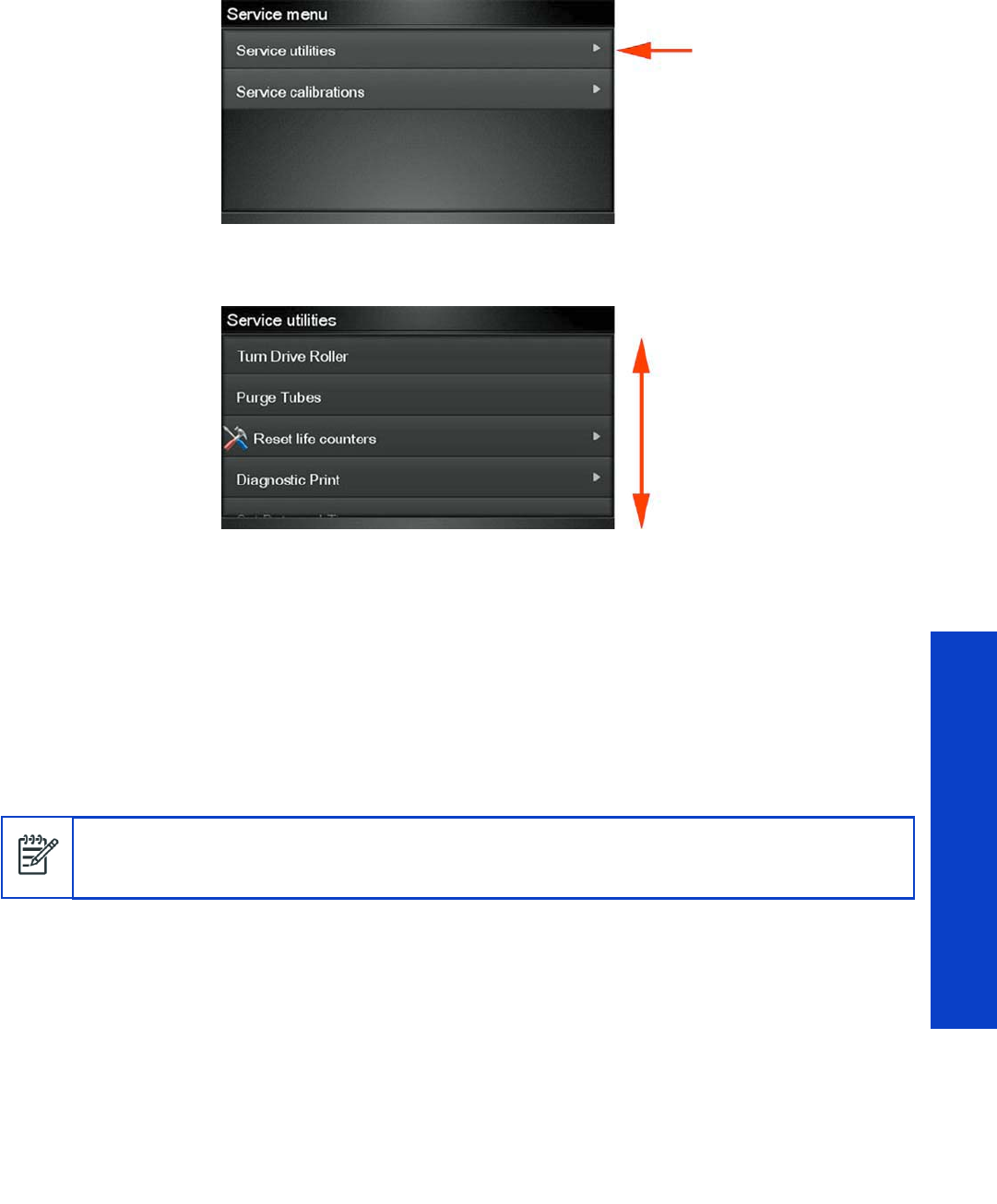
Service Menu 179
Tests, Utilities & Calibrations
5. Press Service utilities.
6. In the Service utilities menu you can scroll up and down the available utilities. Press the name of
whichever utility you want to use.
1. Service Tests and Utilities Menu
1.1 B o o t M o d e
1.1.1 F o r c e D i a g n o s t i c M o d e
Description
a. The Force Diagnostic Mode diagnostic utility allows you to tell the printer to start every time in
diagnostic mode. This is useful if you will be performing multiple tests running from diagnostic
mode. This feature is also included in the Diagnostic Menu.
Procedure
1. Go to Service Test Menu > 1.1 Boot Mode > 1.1.1 Force Diagnostic Mode.
2. The printer asks you to confirm that you want to the printer to start in diagnostic mode.
3. Press OK to confirm, or Cancel to make no changes and exit.
1.1. 2 Fo r c e N o r m a l M o d e
Description
This selection must be made after you no longer want the printer to start in diagnostic mode. After this
selection is made the printer will start as normal. This feature is also included in the Diagnostic Menu.
Procedure
1. Go to Service Test Menu > 1.1 Boot Mode Menu > 1.1.2 Force Normal Mode.
NOTE: Once you force the printer to start in diagnostic mode, in order to change back again, you
must perform the Force Normal Boot diagnostic utility from the Diagnostic menu; or, if the printer is still
in normal mode, from the Service menu.

180 Chapter 4 Service Tests, Utilities & Calibrations
Tests, Utilities & Calibrations
2. The Front Panel asks you to confirm.
1. 2 E l e c t r i c a l Sys t e m
1.2.1 Set Date and Time
Description
The purpose of this Service Utility is to set the printer date and time and the Real Time Clock of the printer.
Procedure
1. Go to Service Test Menu >1.2.1 Set Date and Time.
2. The Front Panel displays the current time (HH:MM:SS) and date (MM:DD:20YY) and a space for you
to enter the new time and date.
3. Use the Up and Down keys to go through the digits and press the OK key to go to the next digit.
You can press the Cancel key at any time to exit the utility without making any changes.
Once the new time has been entered, the Front Panel displays the time that you have entered.
4. Press the OK key to confirm the time, or the Cancel key to exit the utility without making any
changes, or the Back key to modify again.
5. Once the new time has been set, the Front Panel asks you to restart the printer after exiting. Press
any key to exit.
1.2.2 Enable/Disable Firewall
Description
The purpose of this Service Utility is to enable or disable the printer’s firewall.
Procedure
1. Go to Service Test Menu > 1.2.2 Enable/Disable Firewall.
2. The utility checks to see if the firewall is enabled or disabled, and then prompts you to enable or
disable the firewall.
3. Use the Up and Down keys to choose to enable/disable and press the OK key to confirm your
selection. If the utility exits correctly, OK is displayed on the Front Panel.
1.2.3. Enable/Disable Logs
Description
Enabling logs is a useful tool when troubleshooting any error with the printer when the cause of the error
is not obvious, the printer can log all printer activity up until the error occurred, this can give clues as to
the cause and solution to the error. Logs can also be sent via email if the problem must be escalated for
further analysis. This feature is also available in the Diagnostics Menu.
Procedure
1. Go to Service Test Menu > 1.2.3 Enable/Disable Logs.
2. The Front Panel asks whether you want to enable or disable logs. Select Enable logs or Disable
logs and press OK to confirm.
3. If you are enabling logs, the printer asks you to select the component or subsystem you want to
apply the changes to.
NOTE: If the current RTC Clock cannot be set, it could indicate a possible firmware error.

Service Menu 181
Tests, Utilities & Calibrations
4. Select the component or subsystem and press OK to confirm.
5. If the utility exits correctly, OK is displayed on the Front Panel. You must restart the printer to apply
the change you have requested.
1. 2 . 4 I n p u t / O u t p u t
Description
This test is checking the performance of the LAN chip in the Formatter PCA.
It does not check the external LAN components, in fact you could run this test even with the LAN cable not
connected and the results will be exactly the same. If the test fails you must change the Formatter PCA.
Procedure
1. Go to Service Test Menu > 1.2.4 Input/Output.
2. The Front Panel displays various informational messages and the results of the test.
3. The front panel displays the following message.
1. 2 . 5 S e t S e r i a l N u m b e r
Description
The purpose of this Service Utility is to set the Serial Number and Part Number of the printer.
Procedure
1. Go to Service Test Menu > 1.2.5 Set Serial Number.
2. The Front Panel displays the current Serial Number and the new Serial Number of the printer. Use
the Up and Down keys to go through the digits and press the OK key to go to the next digit. You
can press the Cancel key at any time to exit the utility without making any changes.
3. Once the new Serial Number has been entered, the Front Panel displays the Serial Number and
Model Number of the printer. Press the OK key to confirm the Serial Number, or the Cancel key to
exit the utility without making any changes, or the Back key to modify again.
4. If the utility exits correctly, OK is displayed on the Front Panel.
1.2.6 Sleep Mode
Description
The purpose of this Service Utility is to enable/disable the sleep mode when the printer is not used for a
certain period of time (one hour by default).
Procedure
1. Go to Service Test Menu > 1.2.6 Sleep Mode.
2. When prompted by the Front Panel, use the Up and Down arrow keys to either disable or enable
the sleep mode. Press the OK or Cancel key to confirm the selection.
If the current sleep mode cannot be read, it could point to a possible firmware error.
3. Once the selection is confirmed, the Front Panel displays the new sleep mode state.
If the current sleep mode cannot be set, it could indicate a possible firmware error.
4. If the utility exits correctly, OK is displayed on the Front Panel.
1.2.7 Report Test Version
Description
Some parts of the firmware can be upgraded independently from the rest.

182 Chapter 4 Service Tests, Utilities & Calibrations
Tests, Utilities & Calibrations
For example, if we consider that a service test must be changed but the firmware of the printer (for regular
customer work) is stable and does not need any change, it is possible to release a new firmware file that
contains only a new version of the test files. In that case the version of the service tests will be changed
for tracking purposes.
Report Test Version displays the firmware and service menu version on the Front Panel. The format of this
version number is GF_03_01_01_XX where XX = service menu version.
Procedure
1. Go to Service Test Menu > 1.2.7 Report Test Version.
2. The Front Panel displays the service menu version.
3. Press any key to finish.
1. 3 S u b s t r a t e Pa t h
1. 3 .1 Tu r n D r i ve Ro l l e r
Description
The purpose of this Service Utility is to rotate the Drive Roller in order to test it and perform maintenance
cleaning.
Procedure
1. Go to Service Test Menu > 1.3 Substrate Path > 1.3.1 Turn Drive Roller.
2. The printer checks whether substrate is loaded. If substrate is loaded, the Front Panel asks you to
unload the substrate and start again.
3. The Drive Roller begins to turn slowly.
4. Refer to the Cleaning Instructions on page 608.
5. Once you have finished cleaning the Drive Roller and the Overdrive, press the Cancel key to exit.
1.3.2. Enable/Disable OMAS
Description
The purpose of this Service Utility is to enable or disable the OMAS sensor to be able to measure and
troubleshoot the influence of the OMAS sensor on print-quality problems. Sometimes, disabling the OMAS
sensor is recommended when the OMAS cannot detect the surface of the substrate. This could happen if
the substrate is highly reflective or the substrate is very transparent. When the OMAS is disabled the
substrate advance is controlled by the analog encoder on the main drive roller.
Procedure
1. Go to Service Test Menu > 1.3 Substrate Path > 1.3.2 Enable/Disable OMAS.
2. The Front Panel asks whether you want to perform this utility, select Yes and press OK to confirm
your selection.
NOTE: Remove substrate before performing this operation.
NOTE: Open the Window and activate the Window Sensor (using a piece of substrate)
before performing this service utility.
NOTE: Please remember to remove the piece of substrate from the Window Sensor before
closing the Window, as this could damage the Window and the sensor.

Service Menu 183
Tests, Utilities & Calibrations
The printer displays the current OMAS state (enabled/disabled) on the Front Panel and asks you to
select the new state for the OMAS sensor.
3. Select enable or disable and press OK to confirm your selection.
1.3.3 OMAS Sensor Check
Description
The first step of the test shows the temperature of the TOMAS sensor on the screen.
Later, it runs the standard OMAS calibration (the same calibration run every time that a new substrate is
loaded to the printer) determining the level of illumination needed to navigate the substrate.
After that, the test makes a photo of the substrate and analyzes it, returning the “contrast” levels of the
image.
If the test passes, that means the illumination (internal OMAS module red LEDs arrays) can be calibrated
and that the OMAS is in focus. Under those circumstances, the OMAS should be able to navigate.
Procedure
1. Go to Service Test Menu > 1.3 Substrate Path > 1.3.3 OMAS Sensor Check.
2. The Front Panel displays the temperature measured by the TOMAS sensor.
3. The Front Panel asks you to place a standard substrate sheet over the OMAS window.
4. The printer tries to calibrate the level of illumination needed to navigate the substrate. At this point, if
it is not able to find the correct illumination the test will display the FAIL message and will finish. In
that case, it could be that the OMAS module is defective or that the power from the OMAS controller
PCA is not reaching the OMAS module.
5. If the calibration of the illumination succeeds, the printer takes a photo and analyzes it.
6. The Front Panel displays the results of the analysis.
7. If the contrast levels of the image are not as expected, a system error will be displayed. In this case,
if the substrate you have used is a standard blank paper for photocopiers, that means that the
OMAS is not working as expected (maybe it is out of focus, dirty, not correctly installed, etc.).
1. 4 I n k Sys t e m
1. 4 .1 P u r g e Tu b e s
Description
The purpose of this is to prime the Ink Tubes when they are not new and they need to be re-primed or
automatic priming was not completed correctly.
Procedure
1. Go to Service Menu > 1.4 Ink System > 1.4.1 Purge Tubes.
2. The Front Panel warns you if the Ink Cartridges are not suitable for priming. Replace the installed Ink
Cartridges with Ink Cartridges that are new or at least 88% full. Press any key to finish the utility.
3. The Front Panel asks for confirmation; press OK to proceed.
4. Once the printer has restarted, the Front Panel asks you to open the Window and remove all the
Printheads installed in the Carriage.
5. Once all the Printheads have been removed, the Front Panel asks you to install the Setup Printheads
into the Carriage
.

184 Chapter 4 Service Tests, Utilities & Calibrations
Tests, Utilities & Calibrations
6. Once all the Setup Printheads are installed, the Front Panel prompts you to close the Carriage Cover
and the Window.
7. The printer will begin to purge the tubes system.
8. Once the tubes system has been purged, the Front Panel asks you to open the Window.
9. The Front Panel asks you to check that the Setup Printheads are full of ink.
10. The Front Panel asks you to change the ink funnel and waste bottle. Disregard this instruction, do not
change any parts. Continue with the purge procedure, pressing OK to advance through the
procedure, but without changing anything.
11. At the end of the procedure the printer will perform the Printhead Alignment procedure.
1. 5 S c a n Ax i s
1.5.1 Force Drop Detection
Description
The purpose of this is to reset the nozzle health database so that all nozzles are assumed to be correct.
Procedure
1. Go to Service Menu > 1.5 Scan Axis > 1.5.1 Force Drop Detection.
2. The printer asks you if you want to perform this utility. Use the Up and Down keys to select Yes or
No. Press OK to confirm your selection. If you select No, the printer exits the utility.
3. The printer asks you to check that the ink is ready and all the pinch lever is closed.
4. Check that the ink is ready, and the pinch lever is in the closed position. Press any key to continue.
The printer performs a drop detection and displays the drop detector values on the Front Panel.
5. Press OK to accept the values and pass the test or Cancel to reject the values and fail the test.
1. 6 C a r r i a g e
1. 6 .1. C o l o r S e n s o r S h u t t e r D i a g n o s t i c
Description
This Service Utility checks that the Embedded SpectroPhotometer (ESP) shutter is working correctly.
Procedure
1. Go to Service Menu > 1.6 Carriage > 1.6.1 Color Sensor Shutter Diagnostic.
2. Press OK to proceed with the test.
The Carriage moves to the Shutter Actuator in order to open the ESP shutter, then moves to the right-
hand side of the scan axis and stops.
3. Open the window when prompted by the front panel.
4. Look at the ESP Sensor as directed by the front panel, and press OK if it is emitting light downwards
onto the platen (as it should be); press Cancel if you see no light.
NOTE: The drop detector values for nozzles out should be below 150 nozzles per Printhead.
If they are not, print the test plot and verify that this Printhead has so many nozzles out. If the
Printhead has many nozzles out, and it is causing banding, change the Printhead. If the
Printhead is OK, this would indicate an error with the drop detector. Perform the Drop Detector
Calibration and the Force Drop Detection procedures.

Service Menu 185
Tests, Utilities & Calibrations
5. Close the window when prompted by the front panel.
The Carriage moves to the left bump of the printer in order to close the ESP shutter, then moves back
to the same location to the right of the scan axis.
6. Open the window again when prompted by the front panel, and check again for light from the ESP
Sensor.
This time, you should see no light, because the shutter should be closed. Any light indicates a
problem with the shutter mechanism: either something is broken in the shutter itself, or the shutting
mechanism does not work.
7. If you saw the light the first time and not the second time, the shutter is working correctly, and the test
ends.
8. If you found a shutter problem, first locate the Shutter Actuator.
9. When you can see the Shutter Actuator, press OK. The Shutter Actuator should move up for one
second and then move back down. If nothing moves up and down, the actuator may be faulty. The
following screen appears:
If you press OK, the Shutter Actuator should move up and down again. You can repeat this
operation as many times as you like, until you feel sure about the result.
A delay of about 10 seconds is necessary between activations of the Shutter Actuator. This means
that, if you press OK again within 10 seconds, the Shutter Actuator will not move immediately. This
is completely normal and does not indicate any malfunction.
10. After you press Cancel to stop the shutter test, the front panel asks whether the Shutter Actuator
moved correctly and looked undamaged. Press OK if all is well, or Cancel if you saw some
problem.
11. If you press Cancel, the appropriate system error message is shown:
If the shutter actuator appears undamaged, the problem could be electrical. Check that the Shutter
Actuator cables are properly connected. If not, connect them.
If the connections are good, replace the Shutter Actuator, because the problem could be the motor.
If the shutter actuator looks broken, replace it.
In each of these cases, stop the test at this point and start it again from the beginning.
12. If you press OK (the Shutter Actuator is OK), the front panel asks you to locate the Shutter Lid and
check it for damage.
13. If you press Cancel (the Shutter Lid is broken), the appropriate system error message is shown:
14 . If you confirm that the Shutter Lid is not broken, the Carriage moves to the left to reach the Shutter
Deactivator, a metal piece inside the printer used to close the shutter. Then the Carriage moves back
to the right of the platen and the front panel asks you to check again for light.
15. If you see light, then the shutter has not closed correctly and the test tries to determine whether the
problem is in the shutter itself or in the metal piece that the carriage bumps in order to close the
shutter. The Shutter Deactivator is located inside the printer and can be seen only with the help of a
torch. With the window open, look inside the left of the printer with the torch. The Shutter Deactivator
is at the bottom of the left side and protrudes over the platen as shown in the front panel. The dotted
lines indicate that it is inside the printer.
16. Check that the Shutter Deactivator is present (it could be completely missing). Touch it with a finger
to check that it is not loose. Check that it is vertical. Check that it is not broken. It is normal for the
Shutter Deactivator to flex a little when pressed. If you find anything wrong with the Shutter
Deactivator, press Cancel, and the appropriate system error message is shown.

186 Chapter 4 Service Tests, Utilities & Calibrations
Tests, Utilities & Calibrations
17. If you confirm that the Shutter Deactivator is OK, you may see a message saying that the ESP should
be replaced because the problem is in the Shutter Lid.
1.6.2 Color Sensor Measurement Test
Description
This Service Utility checks that the Embedded SpectroPhotometer (ESP) is functioning within predefined
color specifications. The test involves measuring the lightness of the white of the substrate.
To perform this test correctly the printer must have the latest firmware available.
Procedure
1. Make sure that the substrate loaded is suitable for the test: there are certain substrate types that
cannot be used for this type of test. The best results can be achieved by using HP Universal Instant-
dry Gloss Paper (part number Q1273-60232). There are some other substrate types that can be
used:
•HP Bright White Paper
•HP Premium Instant Dry Gloss Paper
•HP Premium Instant Dry Photo Satin Paper
•HP Universal Coated Paper
•HP Universal Heavyweight Coated Paper
2. Go to Service Menu > 1.6 Carriage > 1.6.2 Color Sensor Measurement Test.
3. The front panel displays information about the Spectrophotometer installed in the printer.
The manufacturing date is shown in YYWW format, where YY is the year and WW is the week of
manufacturing.
4. The substrate is advanced 4 inches to cover the platen, and then the Spectrophotometer is used to
measure paper white at five different positions along the scan axis. The measured Lab values are
averaged and displayed.
5. Compare the values from the front panel with the expected results for the loaded substrate type.
If, for example, the value seen for L is 93 when HP Bright White Paper is loaded, this would indicate
that the Spectrophotometer is functioning correctly. The test itself does not detect whether the values
are within the expected range.
1. 6 . 3 C o l o r S e n s o r C h e c k
1. 6 . 4 Te s t C u t t e r
Description
The purpose of this service utility is to check that the Cutter works properly.
Procedure
1. Go to Service Menu >1.6 Carriage > 1.6.4 Test Cutter.
2. Make sure that substrate is loaded, then press OK to proceed with the test.
3. The printer advances the substrate, prepares the Cutter, and tries to cut the substrate.
4. When it has finished cutting, the printer disengages the Cutter.
5. The front panel asks you to confirm that the Cutter has cut the substrate.

Service Menu 187
Tests, Utilities & Calibrations
1. 7 S e r v i c e S t a t i o n
1.7.1. Prime Pen X
Description
The purpose of this Service Utility is to prime a specific Printhead.
Procedure
1. Go to Service Menu > 1.7 Service Station > 1.7.1 Prime Pen X.
2. The Front Panel asks you to select the Printhead. Use the Arrow keys to select the Printhead (0 to 5)
that you want to prime and press the OK key.
3. The printer primes the selected Printhead and the Front Panel displays the following messages:
•Setting pens operational
•Preparing fluid manager
•Priming...
•Terminating fluid manager
•Allowing pens not operational
If there is a failure at this point, the Front Panel displays an error code; troubleshoot the error using
the procedures in Chapter 3 System Error Codes.
4. If the utility exits correctly, OK is displayed on the Front Panel.
1.8 Heating and Curing
1.8.1 Heating and Curing Temperature
Description
The Heating and Curing Temperature utility displays the target temperature, current temperature detected
by the temperature sensors, and the power currently applied.
Procedure
1. Go to Service Menu > 1.8 Heating and Curing > 1.8.1 Heating and Curing Temperature.
2. The printer displays the current values read by the Temperature Sensors (heating/curing). Press any
key to finish the test.
1.8.2 Enable Heating and Curing
Description
This setting enables you to disable the heating system of the printer. This setting is useful for example if
you want to print a quick print to test the printer’s functionality, but do not want to wait for the printer to
heat up to the target temperature.
Procedure
1. Go to Service Menu > 1.8 Heating and Curing > 1.8.2 Enable Heating and Curing.
2. To disable the Heating and Curing, select ‘disable’ using the up and down arrows and press OK.
1. 9 S h ow Te s t M e s s a g e s
Description
Explains how to enter the diagnostics TLC mode.

188 Chapter 4 Service Tests, Utilities & Calibrations
Tests, Utilities & Calibrations
Procedure
1. Go to Service Menu > 1.9 Show Test Messages.
2. Press the OK key to exit.
1.10 Force FW Upgrade
Description
With this option selected the firmware of the printer must first be updated before it will initialize.
Procedure
1. Go to Service Menu > 1.10 Force FW upgrade.
2. The Front Panel asks for confirmation. Press OK to accept the mandatory firmware upgrade mode.
1.11 Hard Disk Recovery
Description
Use this test to reinstall the firmware in the HDD of the printer.
It may be useful when the printer cannot initialize, or hangs up from time to time without any clear cause.
This will fix all the possible issues related to data/file corruption.
It formats the HDD partition used while the printer works in normal condition (detecting the possible bad
sectors of the HDD and marking them as not usable) and, after that, it installs the firmware.
The firmware package that will be used is the one stored in a partition of the HDD that is not used when
the printer is working in normal conditions. If the stored firmware file is also corrupted, the test will not
work correctly and it may happen that you need to change the HDD to “recover” the printer (very low
chances).
The final status, after running the test, is similar to the status of the printer after changing, physically, the
HDD. The advantage is that it can be done remotely and/or without the need for a spare part.
Procedure
1. Go to Service Menu > 1.11 Hard Disk Recovery.
2. When prompted by the Front Panel, remove the substrate from the printer and the procedure will
begin.
3. The Front Panel asks for confirmation, twice; press OK each time to proceed.
2. Image Quality Plots
2.1 Print ALL Plots
Description
The Print ALL Plots allows you to print at once all three basic diagnostic prints in order to diagnose an
image quality defect. These are Printhead Alignment, Printhead Health, and Substrate Advance. Refer to
chapter 5 for more details.
Procedure
1. Go to Service Menu > 2. Image Quality Plots > 2.1 Print ALL Plots.

Service Menu 189
Tests, Utilities & Calibrations
2.2 Printhead Alignment
2.2.1 Test Plot
Description
The Printhead Alignment Test Plot allows you to check the accuracy of the current printhead alignment
page 209.
Procedure
1. Go to Service Menu > 2. Image Quality Plots > 2.2 Printhead Alignment > 2.2.1 Test Plot.
2.2.2 Advanced Test Plot
Description
The purpose of the Advanced Test Plot is to help you to visually check for any alignment problem in the
printer page 218.
Procedure
1. Go to Service Menu > 2. Image Quality Plots > 2.2 Printhead Alignment > 2.2.2 Advanced Test
Plot.
2.2.3 Automatic Printhead Alignment
Description
This Service Utility triggers an Automatic Printhead Alignment.
Procedure
1. Go to Service Menu > 2. Image Quality Plots > 2.2 Printhead Alignment > 2.2.3 Automatic
Printhead Alignment.
2.2.4 Manual PH Alignment
Description
Automatic printhead alignment may not produce optimal registration under certain conditions. Substrate
texturing, elasticity, and the behavior of the substrate under different temperatures may lead to some
imperfections with regard to printhead registration. In these circumstances, select the Manual Printhead
Alignment instead.
2.2.4.1 Print Pattern
Description
The printer prints 17 rows labelled from A to Q. Inspect the print and write down the number of
the straightest line in each row (for example, A:9).
Procedure
1. Go to Service Menu > 2. Image Quality Plots > 2.2 Printhead Alignment > 2.2.4 Manual PH
Alignment > 2.2.4.1 Print Pattern.
2.2.4.2 Manual Alignment Settings
Description
This is where the correction settings can be entered from the Manual Printhead Alignment.
Procedure
1. Go to Service Menu > 2. Image Quality Plots > 2.2 Printhead Alignment > 2.2.4 Manual PH
Alignment > 2.2.4.2 Manual Alignment Settings.

190 Chapter 4 Service Tests, Utilities & Calibrations
Tests, Utilities & Calibrations
2.3 Substrate Advance
2.3.1 Print Adjustment Plot
Description
The purpose of the Print Adjustment Plot is to help you in determining the advance offset in the printer with
the current substrate loaded. This value has to be introduced to the RIP for adjusting the substrate advance
page 214.
Procedure
1. Go to Service Menu > 2. Image Quality Plots > 2.3 Substrate Advance > 2.3.1 Print Adjustment Plot.
2.3.2 Reset Substrate Advance
Description
Resets the substrate advance settings in the printer.
Procedure
1. Go to Service Menu > 2. Image Quality Plots > 2.3 Substrate Advance > 2.3.2 Reset Substrate
Advance.
2.4 Printhead Health
2.4.1 Print Test Plot
Description
The purpose of this Service plot is to show the overall health of the printhead nozzles by visual inspection.
Refer to Chapter 5 for detailed information.
Procedure
1. Go to Service Menu > 2. Image Quality Plots > 2.4 Printhead Health > 2.4.1 Print Test Plot.
2.4.2 Advanced Test Plot
Description
The purpose of this Service plot is to help in identifying which of the printhead nozzles are failing. Refer
to Chapter 5 for detailed information.
Procedure
1. Go to Service Menu > 2. Image Quality Plots > 2.4 Printhead Health > 2.4.2 Advanced Test Plot.
2.4.3 Only for Escalations
Description
Service plot for escalations to HP Division upon request page 220.
Procedure
1. Go to Service Menu > 2. Image Quality Plots > 2.4 Printhead Health > 2.4.3 Only for Escalations.
2.4.4 Clean All Printheads
Description
Launch the automatic procedures for cleaning all the printheads.
Procedure
1. Go to Service Menu > 2. Image Quality Plots > 2.4 Printhead Health > 2.4.4 Clean All Printheads.

Service Menu 191
Tests, Utilities & Calibrations
2.4.5 Clean LC-C Printheads
Description
Launch the automatic procedures for cleaning the LC-C printheads.
Procedure
1. Go to Service Menu > 2. Image Quality Plots > 2.4 Printhead Health > 2.4.5 Clean LC-C
Printheads.
2.4.6 Clean Y-MK Printheads
Description
Launch the automatic procedures for cleaning the Y-MK printheads.
Procedure
1. Go to Service Menu > 2. Image Quality Plots > 2.4 Printhead Health > 2.4.6 Clean Y-MK
Printheads.
2.4.7 Clean LM-M Printheads
Description
Launch the automatic procedures for cleaning the LM-M Printheads.
Procedure
1. Go to Service Menu > 2. Image Quality Plots > 2.4 Printhead Health > 2.4.7 Clean LM-M
Printheads.
2.5 Geometry Check
Description
The purpose of this Service plot is to provide a template for checking the printer’s length accuracy and
figure distortion page 220.
Procedure
1. Go to Service Menu > 2. Image Quality Plots > 2.5 Geometry Check.
2.6 Scan Axis Check
Description
The purpose of this Service plot is to help in diagnose any defect in the Scan Axis page 221.
1. Go to Service Menu > 2. Image Quality Plots > 2.6 Scan Axis Check.
2.7 Vacuum Check
Description
The purpose of this service plot is to help diagnosing problems that could be related to vacuum adjustment
such as substrate crashes, substrate advance, and differential substrate advance (different length side to
side).
Procedure
1. Load the substrate at the rightmost position of the Scan Axis (do not center it), no matter the width of
the roll.
2. Go to Service Menu > 2. Image Quality Plots > 2.7 Vacuum Check.
3. For proper usage of this plot, the vacuum level needs to be changed while the plot is being printed
(in between patterns) page 221.

192 Chapter 4 Service Tests, Utilities & Calibrations
Tests, Utilities & Calibrations
2.8 Side Registration Check
Description
This plot helps you to visually check any alignment problems of the printer caused by substrate expansion.
You can use it to precisely measure the substrate expansion error with 2 dots row accuracy.
Procedure
1. Load the substrate.
2. Go to Service Menu > 2. Image Quality Plots > 2.8 Side Registration Check page 228.
2.11 Others
3. Ink On Substrate Test
3.1Print Test Plot at 6 passes
Description
The purpose of this Service plot is for determining the level of performance of the Drying and Curing
modules page 229.
Procedure
1. Go to Service Menu > 3. Ink On Substrate > 3.1 Print Test Plot at 6 passes.
3.2 Print Test Plot at 8 passes
Description
The purpose of this Service plot is for determining the level of performance of the Drying and Curing
modules page 229.
Procedure
1. Go to Service Menu > 3. Ink On Substrate > 3.1 Print Test Plot at 8 passes.
3.3 Print Test Plot at 10 passes
Description
The purpose of this Service plot is for determining the level of performance of the Drying and Curing
modules page 229.
Procedure
1. Go to Service Menu > 3. Ink On Substrate > 3.1 Print Test Plot at 10 passes.
3.4 Print Test Plot at 12 passes
Description
The purpose of this Service plot is for determining the level of performance of the Drying and Curing
modules page 229.
Procedure
1. Go to Service Menu > 3. Ink On Substrate > 3.1 Print Test Plot at 12 passes.
4. Reset Life Counters (NEVER DONE BY CUSTOMER)
After replacing a part of the printer, you should always reset the life counter of that part.
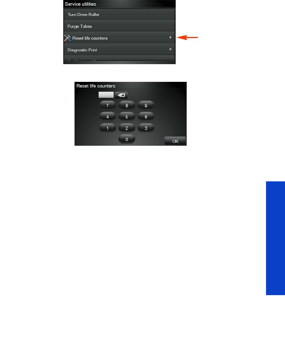
Service Menu 193
Tests, Utilities & Calibrations
To reset the printer’s internal life counters, select Reset life counters from the Service utilities menu.
In order to continue, you must enter the 4-digit access code “5494” and press OK.
You can now choose to reset the counters related to one of the three Service Maintenance Kits, or to a
specific printer part.
4.1 Reset Maint. Kit Usage
Description
The purpose of this Service Utility is to check the maintenance kit usage and/or reset the life counter of
all the components included in the maintenance kit.
Procedure
1. Go to Service Menu > 4. Reset Life Counters > 4.1 Reset Maint. Kit Usage.
2. Select the Service Maintenance Kit for which you want to reset the life counters.
•4.1.1 Reset SMK1 = Resets the life cycles of the following: Carriage Assembly, Trailing cable,
Ink Tubes, Belt, Scan Motor, Heating (Dryer) IR Sensor, Curing IR Sensor, Carriage lubrication,
Line sensor (hours)
•4.1.2 Reset SMK2 = Resets the life cycles of the following: Service Station Motor, Heating IR
Sensor, Carriage lubrication, Rack Motor, Curing IR Sensor, Printhead Cleaning Counters, Spit
Plate spittoon (liters), Line sensor (hours)
•4.1.3 Reset SMK3 = Resets the life cycles of the following: Aerosol filters, Heating IR Sensor,
Carriage lubrication, Curing IR Sensor, Line sensor (hours)
The printer displays the usage percentage and asks you if you want to reset the life counter.
3. Press OK if you want to reset the life counter or Back if you do not want to reset the life counter. If
you choose not to reset the life counter, the printer exits the utility.
4.2 Reset Substrate Path
Description
The purpose of this Service Utility is to check the service part usage and/or reset the life counter for the
Substrate Path.

194 Chapter 4 Service Tests, Utilities & Calibrations
Tests, Utilities & Calibrations
•4.2.1 Drive Roller Motor > Resets the media motor.
•4.2.2 Reset OMAS Sensor > Resets OMAS (M of substrate length, navigable success,
navigable failures).
•4.2.3 Reset Vacuum Fan > Resets Vacuum Fans (hours).
4.3 Reset ISS
Description
The purpose of this Service Utility is to check the service part usage and/or reset the life counter for the ISS.
•4.3.1 APS Pumps > Resets the APS Pump in cycles and hours.
4.4 Reset Scan Axis
Description
The purpose of this Service Utility is to check the service part usage and/or reset the life counter for the
Scan Axis:
•4.4.1 Reset Belt Cycles: Resets the Belt cycles.
•4.4.2 Tubes/Trailing Cables: Resets the cycles of the Trailing Cable and Ink Tubes.
•4.4.3 SAX Motor Cycles: Resets the Scan Motor.
•4.4.4 Encoder Strip: Resets the Encoder Strip.
4.5 Reset Carriage
Description
The purpose of this Service Utility is to check the service part usage and/or reset the life counter for the
Carriage:
•4.5.1 Carriage Cycles: Reset the cycles of the Carriage.
•4.5.2 New Line Sensor: Reset the Line Sensor (hours).
•4.5.3 Cutter Cycles: Reset the cutter cycles (number of times substrate has been cut).
•4.5.4 Color Sensor: Reset the SOL (hours).
•4.5.5 Replace Oiler Foam: Resets the Carriage lubricant.
4.6 Reset Service Station
Description
The purpose of this Service Utility is to check the service part usage and/or reset the life counter for the
Service Station:
•4.6.1 SS Rack Cycles: Resets rack motor.
•4.6.2 Spit Plate Replacement.
•4.6.3 Drop Detector: Resets Drop Detector (hours).
•4.6.4 Complete Service Station: Resets the Service Station motor (cycles), Aerosol Fan (hours),
Rack Motor (Cycles), Split plate spittoon (liters), Aerosol Filters (liters), Spit plate DD (liters),
Drop Detector (hours).
•4.6.5 Maintenance Cartridge.
•4.6.6 Primer Cycles: Resets the Primer.

Service Menu 195
Tests, Utilities & Calibrations
4.7 Reset Heating & Curing
Description
The purpose of this Service Utility is to check the service part usage and/or reset the life counter for the
Heating and Curing:
•4.7.1 Curing Lamps: Resets the Curing Resistors (hours).
•4.7.2 Reset Curing Sensor: Resets Curing IR Sensor.
•4.7.3 Heating Lamps: Resets the Heating Resistors (hours).
•4.7.4 Reset Heating Sensor: Resets the Heating IR Sensor.
•4.7.5 IR Sensors Cleaning: Resets the Curing IR Sensor and Heating IR Sensor.
5. Service Calibrations
Service calibrations allow you to calibrate printer components and settings to ensure optimal
performance. This section guides you through the calibration procedures and provides information about
each calibration.
5.1 Substrate Path
5.1.1 Substrate Advance Calibration
Description
The purpose of this Service Calibration is to calibrate the nominal advance of the substrate. This
calibration is necessary to control the exact movement of the substrate in order to avoid print-quality
problems such as banding. Perform the Service Accuracy Calibration whenever:
•Banding is detected in prints.
•Drive Roller is disassembled or replaced.
•Media-axis Assembly is disassembled or replaced.
The first two options of the test (Print Calibration Pattern and Scan Calibration Pattern) are obsolete and
should not be used. They are in the test for historical reasons but now are not working properly.
The Substrate Advance Calibration performs a calibration in order to obtain a new set of calibration
values. The printer makes a series of substrate advances, and the OMAS sensor registers the distance
covered in each advance.
When all the substrate advances have been performed, the calibration values are calculated based on
the data obtained.
The Substrate Advance Calibration is split into three parts and should always be done in this order:
1. Perform Advance Calibration
2. Check Advance Calibration
3. Clean Drive Roller
Procedure
1. Go to Service Menu > 5. Service Calibrations > 5.1.1 Substrate Advance Calibration.
2. Select Perform Advance Calibration.
NOTE: Before starting the process, make sure that HP Coated Paper is loaded and ready to
print. You could use the service part CQ869-67069 that contains 5 sheets of HP Coated Paper.

196 Chapter 4 Service Tests, Utilities & Calibrations
Tests, Utilities & Calibrations
3. If there is substrate ready, the printer performs the zero search for the Media Motor.
4. When the Media Motor has been initialized, the printer starts to perform the series of substrate
advances. During this process, the front panel displays the current iteration number and the total
number of iterations.
You can cancel the calibration process at any time by pressing Cancel. In this case, the previous
calibration values are restored and the cancelled process has no effect on the printer.
5. If the calibration process finishes without errors, the new calibration values are checked. If the values
are considered valid, they are displayed and saved for use in future. Press OK to return to the main
screen.
6. If the calibration values are not valid, the front panel displays the reason (for example, the
percentage of good navigations is less than 90%). In this case the calibration process has no effect
on the printer. Press OK to return to the main screen.
Check Calibration Status
This option tests whether the current calibration values are valid. The process is very similar to the
calibration process. The printer makes a series of substrate advances, and the OMAS sensor registers the
distance covered in each advance.
Procedure
1. Go to Service Menu > 5. Service Calibrations > 5.1.1 Substrate Advance Calibration.
2. Select Check Advance Calibration.
3. The printer checks whether the current calibration values are valid, using the data obtained during
the substrate advances.
4. If they are not valid, the front panel displays the reason (for example, the AMP1 parameter value is
greater than the maximum allowed).
5. Press OK to return to the main screen.
6. You will need to re-enter the Substrate Advance Calibration submenu and scroll to “Clean Drive
Roller” and press OK.
7. You must select whether you would like to continue with the cleaning of the Drive Roller by pressing
the OK key. Press Back or Cancel to exit the calibration.
8. The printer begins the Drive Roller Cleaning procedure. This could take several minutes.
9. Restart the printer after performing the tests.
5.1.2 OMAS calibration
Description
The purpose of this Service Calibration is to calibrate the OMAS Module. The calibration process consists
of printing a special calibration plot and then scanning it with the printer.The scanned result values are
compared with the actual printed values to obtain a PASS/FAIL result.
NOTE: Both the Automatic and the Manual Substrate Advance Calibration (which can be
launched from the user menu), if they exist, are automatically set to zero for each type of
substrate.
NOTE: Before starting the process, make sure that HP Coated Paper is loaded and ready to
print.

Service Menu 197
Tests, Utilities & Calibrations
In the first step, the test prints a pattern navigating (measuring the movements) with the OMAS and creates
in the hard disk a file with the navigation information from the OMAS system.
In the second step, the test scans the printed pattern with the line sensor measuring the distance between
the lines of the pattern, and stores in the hard disk a file with the information from the line sensor.
Finally the test compares the information from the OMAS and the information from the line sensor scan,
if the comparison is meaningful (there is no problem with the files stored in the hard disk) the firmware
calculates what is the necessary compensation to be applied to the measurements of the OMAS to match
the values measured by the line sensor.
Then, the firmware saves the OMAS compensation value in the NVM.
From this moment on, the measurements of the OMAS system will be compensated, providing better
accuracy.
Perform the OMAS Module Calibration as follows:
Procedure
1. Go to Service Menu > 5. Service Calibrations > 5.1 Substrate Path > 5.1.2 OMAS Calibration.
2. The Front Panel asks for confirmation; press OK.
3. If substrate is already loaded, it is unloaded. If it cannot be unloaded automatically, the Front Panel
asks you to unload it manually.
4. The Front Panel prompts you to load substrate.
•Raise the Media Lever.
•Load the substrate.
•Lower the Media Lever.
5. Select the substrate type (HP Paper Aqueous).
6. The substrate calibration process starts and the Front Panel shows the following messages:
•Calibrating paper advance.
•Trimming roll edge. Please wait.
7. The Front Panel then prompts you to unroll 1 meter of substrate to avoid back tension. Unroll 1 meter
of substrate and press OK.
8. The printer starts to print the OMAS Calibration Pattern. This could take several minutes.
9. The Front Panel announces when the OMAS Calibration Pattern has been printed successfully. Press
OK to continue.
If the OMAS Calibration fails for any reason, a warning message will display on the Front Panel. In
this case, try the following:
NOTE: Before starting the process, make sure that HP Coated Paper is loaded and ready to
print. You could use the service part CQ869-67069 that contains 5 sheets of HP Coated Paper.
NOTE: Disabling the Heaters will significantly speed up this procedure.
NOTE: During this calibration process you have to load the substrate with the Carriage
positioned in the print path.
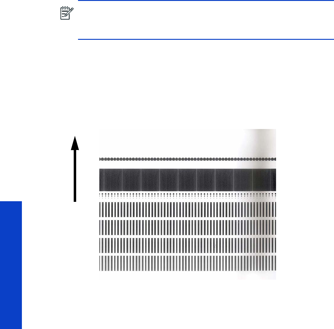
198 Chapter 4 Service Tests, Utilities & Calibrations
Tests, Utilities & Calibrations
•Retry the Paper Advance Calibration.
Scan OMAS Calibration Pattern
1. Re-enter the OMAS Calibration submenu, scroll to Scan Calibration Pattern, and press OK.
2. The Front Panel asks for confirmation. Press the OK key to proceed, or press Back or Cancel to
exit.
3. The Front Panel asks you to load the OMAS Calibration Pattern in to the printer. Make sure that you
rotate the printed pattern 90° clockwise and reload it printed-side down. Press the OK key to
continue.
4. Load the OMAS Calibration Pattern following the instructions on the Front Panel.
5. The Front Panel tells you when the OMAS Calibration Pattern is loaded correctly. Press OK to
continue.
6. The printer scans the OMAS Calibration Pattern, which could take several minutes. The Front Panel
tells you when it is complete. Press OK to continue.
If the OMAS Calibration fails for any reason, a warning message will display on the Front Panel. In
this case, try the following:
•Check that the OMAS Calibration Pattern was not incorrectly cut (trimming the actual pattern)
during the substrate load process. If this is the case, perform the OMAS Calibration again from
the beginning.
•Replace the OMAS Sensor page 432.
•Replace the OMAS Controller Card page 442.
•If the problem continues, replace the Media-Axis Motor page 430.
NOTE: Remove the pattern from the printer and leave it to dry for a few minutes before
continuing with the Calibration.
NOTE: Make sure substrate is not loaded into the printer before starting to scan the OMAS
calibration pattern.
LOAD
DIRECTION

Service Menu 199
Tests, Utilities & Calibrations
5.1.3 Reset Vacuum Calibration
Description
The purpose of this test is to set the default nominal and real values of the Vacuum Fan Assembly.
Procedure
1. Go to Service Menu > 5. Service Calibration Menu > 5.1 Substrate Path > 5.1.3 Reset Vacuum
Calibration.
2. The Front Panel asks for confirmation; press OK.
3. The printer sets the default nominal and real values of the Vacuum Fan.
4. Once the calibration is completed, OK will be displayed on the Front Panel.
5.1.4 Rewinder Calibration
Description
This test must be performed whenever the Rewinder Assembly has been replaced or one of the rewinder
gears have been replaced. The test calculates the optimum power required to move the rewinder system.
Procedure
1. Go to Service Menu > 5. Service Calibration Menu > 5.1 Substrate Path Menu > 5.1.4 Rewinder
Calibration.
2. The Front Panel asks you to remove the substrate, leaving the spindle in the printer. Press OK to
continue.
5.2 Scan Axis
5.2.1 Scan Axis Calibration
Description
The purpose of this Service Calibration is to carry out a PWM check, calibrate the intensity of the Line
Sensor and calibrate the Line Sensor position to the Black Printhead.
Perform the Scan Axis Calibration whenever:
•The Carriage is disassembled or replaced.
•The Encoder Strip is disassembled or replaced.
NOTE: This Service Calibration should ONLY be performed when the Vacuum Fan Assembly
has been replaced.

200 Chapter 4 Service Tests, Utilities & Calibrations
Tests, Utilities & Calibrations
•The Print Platen is disassembled or replaced.
Procedure
1. Go to Service Menu > 5. Service Calibration Menu > 5.2 Scan Axis > 5.2.1 Scan Axis Calibration.
2. The Front Panel asks for confirmation; press OK.
3. Before continuing, the printer will check the following:
•The Media Lever is in the lowered position.
•The correct substrate type is loaded (check list on previous page).
•The substrate is of the correct size (minimum substrate width 24 inches).
If these conditions are not met, a warning will be displayed on the Front Panel and you will need to
restart the calibration from the beginning.
4. The printer will start to check the PWM. Once the PWM has been checked, the results are displayed
on the Front Panel. Press OK to continue or press Back or Cancel to exit the calibration.
5. The printer will start to calibrate the Line Sensor. Once the Line Sensor has been calibrated, the
results are displayed on the Front Panel. Press OK to continue or press Back or Cancel to exit the
calibration.
If the values are not within the range specified, the Front Panel displays the error. In this case, try the
following:
•Try the Scan-Axis Calibration again.
•Replace the Line Sensor page 473.
NOTE: Make sure you load one of the following substrates into the printer before performing
this calibration. If none of them are available, use the service part Q1273-60296.
•HP Bond Paper
•HP Glossy Paper
•HP Coated Paper
•HP Productivity Photo Gloss
•HP Heavyweight Coated Paper
•HP Super Heavyweight Coated Paper
•HP Bright White Inkjet Paper
NOTE: Disabling the Heaters will significantly speed up this procedure.
NOTE: In order to perform this Calibration, you should order the Media Advance Calibration
Kit (Part Number Q1273-60296) which contains two sheets of HP Productivity Gloss Paper.
WARNING! Make sure you keep your hands away from the Print Platen as the Carriage
will be moving at high speed and you could injure yourself or damage the Carriage Assembly.

Service Menu 201
Tests, Utilities & Calibrations
6. The printer starts to calibrate the Line Sensor position to the Black Printhead. It will print a line of
black dots and then scan them:
7. Once the Line Sensor has been calibrated, the results are displayed on the Front Panel. Press OK to
finish the calibration or press Back or Cancel to exit the calibration.
8. The printer performs the Printhead Alignment.
9. The Front Panel asks for confirmation. Press OK to continue. Press Back or Cancel to exit.
10. The Front Panel tells you when the Printhead Alignment is completed. Press OK to continue.
If the Printhead Alignment fails for any reason, a warning message is displayed on the Front Panel.
In this case, try the following:
•Go to the Front Panel menu and retry the Printhead Alignment. If the Alignment completes
successfully, perform the Color Calibration.
•If the Alignment fails again, check the Alignment pattern to see if any of the Printheads are
printing incorrectly. If necessary, perform a Printhead Recovery through the Front Panel and
retry the Printhead Alignment.
11. Once the complete Scan Axis calibration is completed successfully, OK is displayed on the Front
Panel.
5.2.2 Drop Detector Calibration
Description
The purpose of this Service Calibration is to calibrate the Drop Detector in relation to the Carriage
Assembly.
Perform the Drop Detector Calibration whenever:
•Drop Detector is removed or replaced.
Procedure
1. Go to Service Menu > 5. Service Calibration Menu > 5.2 Scan Axis > 5.2.2 Drop Detector
Calibration.
2. The Front Panel asks for confirmation. Press OK to continue, or press Back or Cancel to exit.
3. The printer starts to calibrate the Drop Detector. Once the Drop Detector has been calibrated, the
results are displayed on the Front Panel. Press any key on the Front Panel to finish the calibration.
4. Once the calibration is completed, OK is displayed on the Front Panel.
5.3 Carriage
5.3.1 Line Sensor Calib.
Description
The purpose of this service calibration is to calibrate the intensity of the Line Sensor in the Carriage PCA.
An incorrect calibration can result in edge-detection failures during substrate loading and incorrect
reading of prints that are used for alignment or calibration.

202 Chapter 4 Service Tests, Utilities & Calibrations
Tests, Utilities & Calibrations
Perform the Line Sensor Calibration whenever:
•The edge-detect procedure fails during substrate loading.
•The Carriage is disassembled or replaced.
•The Line Sensor is disassembled or replaced.
•Banding is detected in prints.
•Misalignment between colors is detected.
Procedure
1. Go to Service Menu > 5. Service Calibration Menu > 5.3 Carriage > 5.3.1 Line Sensor Calib.
2. The Front Panel asks for confirmation. Press OK, or press Back or Cancel to exit.
3. Before continuing, the printer will check the following:
•The Media Lever is in the lowered position.
•The correct substrate type is loaded (check list on previous page).
•The substrate is of the correct size (minimum substrate width 24 inches).
If these conditions are not met, a warning will be displayed on the Front Panel and you will need to
restart the calibration from the beginning.
4. The printer starts to calibrate the Line Sensor. Once the Line Sensor has been calibrated, the results
are displayed on the Front Panel. Press OK to continue or press Back or Cancel to exit the
calibration.
If the values are not within the range specified, the Front Panel displays the error. In this case, try the
following:
•Try the Scan-Axis Calibration again.
•Replace the Line Sensor page 473.
NOTE: Make sure you load one of the following substrates into the printer before performing
this calibration. If none of them are available, use the service part Q1273-60296.
•HP Bond Paper
•HP Glossy Paper
•HP Coated Paper
•HP Productivity Photo Gloss
•HP Heavyweight Coated Paper
•HP Super Heavyweight Coated Paper
•HP Bright White Inkjet Paper
NOTE: Disabling the Heaters will significantly speed up this procedure.
NOTE: Make sure you keep your hands away from the Print Platen as the Carriage will be
moving at high speed and you could injure yourself or damage the Carriage Assembly.

Service Menu 203
Tests, Utilities & Calibrations
5. The printer starts to calibrate the Line Sensor position to the Black Printhead. It prints a line of black
dots and then scans them:
6. Once the Line Sensor has been calibrated, the results are displayed on the Front Panel. Press OK to
finish the calibration or press Back or Cancel to exit the calibration.
7. The printer will now perform the Printhead Alignment. When the Front Panel asks for confirmation,
press OK.
8. The Front Panel tells you when the Printhead Alignment is complete. Press OK to continue.
•If the Printhead Alignment fails for any reason, a warning message is displayed on the Front
Panel. In this case, try the following.
•Enter the Front Panel menu and retry the Printhead Alignment. If the Alignment completes
successfully, then perform the Color Calibration.
•If the Alignment fails again, check the Alignment pattern to see if any of the Printheads are
printing incorrectly. If necessary, perform a Printhead Recovery through the Front Panel and
retry the Printhead Alignment.
9. Once the complete Line Sensor calibration is completed successfully, OK is displayed on the Front
Panel.
5.3.2 Primer Calibration
Description
The purpose of this Service Calibration is to find the optimum position of the Primer Assembly with respect
to the Carriage.
The calibration is a visual procedure so you will have to remove the Right Cover before starting.
Procedure
1. Go to Service Menu > 5. Service Calibration Menu > 5.3 Carriage > 5.3.2 Primer Calibration.
2. Remove the Right Cover page 296.
3. Block the Printhead Cleaning Cartridge door switch in the closed position.
4. The Front Panel asks for confirmation. Press any key to continue.
5. Follow the instructions on the Front Panel.
6. The calibration process starts and the Front Panel shows the following messages:
•Homing Primer
•Uncapping SVS
•Homing Carriage
•Computing the Left Scan-Axis Offset
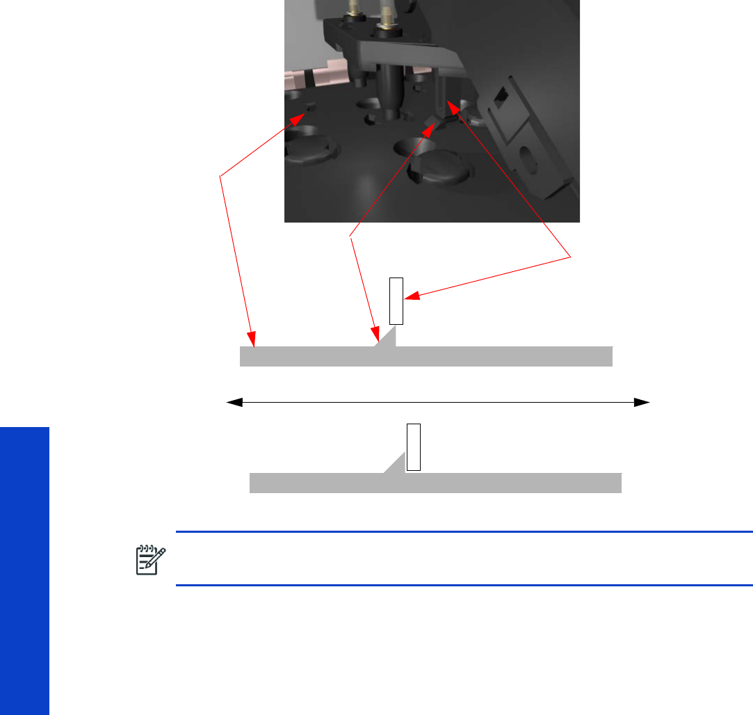
204 Chapter 4 Service Tests, Utilities & Calibrations
Tests, Utilities & Calibrations
7. Once the Left Scan-Axis Offset has been calculated the Front Panel prompts you to use the Up/
Down keys to move the carriage until the right edge of the Left Alignment Mark on the Carriage
Cover is perfectly aligned with the Primer positioning indicator.
While the Carriage is moving, the Front Panel shows the actual position and the direction of
movement and prompts you to press OK when done.
8. The Front Panel shows the actual Left Offset value and the system calculates the Right Scan-Axis
Offset.
9. Once the Right Scan-Axis Offset has been calculated, the Front Panel prompts you to use the Up/
Down keys to move the carriage until the left edge of the Right Alignment Mark is correctly aligned
with the Primer Positioning Indicator.
NOTE: To detect the exact position more easily while aligning the Carriage to the Primer it is
a good idea to press down lightly on the Primer while you are moving the Carriage.
Carriage
Primer
Indicator
Cover
Positioning
ALIGNED
Up key Down key
NOT ALIGNED
Left Alignment
Mark
Carriage Movement
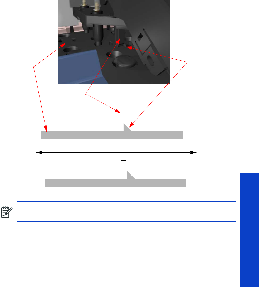
Service Menu 205
Tests, Utilities & Calibrations
10. Use the Up and Down keys to move the Carriage until the left edge of the Right Alignment Mark is
correctly aligned with the Primer Positioning Indicator.
While the Carriage is moving, the Front Panel shows the actual position and the direction of
movement and prompts you to press OK when done.
11. The Front Panel shows the actual Right Offset value.
12. The calibration process continues and the Front Panel shows the following messages as the new
nominal offset value is read and saved to NVM:
•Reading Nominal Offset
•New Nominal Offset is [ActualValue]
•Saving to nvm
•Saved
13. Once the calibration is completed, OK is displayed on the Front Panel.
14 . Replace the Right Cover (page 296).
NOTE: To detect the exact position more easily while aligning the Carriage to the Primer it is
a good idea to press down lightly on the Primer while you are moving the Carriage.
Carriage Right Alignment
Primer
Indicator
Mark
Cover
Positioning
ALIGNED
Up key Down key
NOT ALIGNED
Carriage Movement

206 Chapter 4 Service Tests, Utilities & Calibrations
Tests, Utilities & Calibrations
5.3.3 Color Sensor Shutter Calibration
Description
This Service Calibration tries to open and close the Embedded SpectroPhotometer (ESP) shutter, and
checks optically, using the ESP light, that it opens and closes. If it cannot open the shutter with the default
values, it tries to fine-tune the location where the carriage stops so that the Shutter Actuator can hook the
shutter lid and open it successfully. It will try over a range of ±1 cm around the nominal position, moving
by 1 mm after each attempt, starting at the rightmost position (nominal +1 cm), until the actuator hooks
the shutter. If, by nominal –1 cm, the shutter has not been successfully opened, the test fails. If a successful
position is found, it is stored in the NVM as the new position to be used in future.
Procedure
1. Go to Service Menu > 5. Service Calibration Menu > 5.3 Carriage Menu > 5.3.3 Color Sensor
Shutter Calibration.
2. During calibration, the Carriage moves back and forth and the front panel displays a brief
description of what is happening. When calibration is complete, the following message is
displayed.
3. Press OK to return to the menu.
If the calibration fails, you can use the ESP Shutter Diagnostic in the Service Utilities submenu to identify
which failed part is preventing the shutter from working correctly.
5.3.4 Color Sensor Calibration
Description
The purpose of this Service Calibration is to perform the internal calibration of the Embedded
SpectroPhotometer (ESP). This requires the shutter lid to be closed. An open shutter lid will cause an error
message. You can perform the ESP Shutter Test to check the shutter mechanism.
Procedure
1. Go to Service Menu > 5. Service Calibration Menu > 5.3 Carriage > 5.3.4 Color Sensor
Calibration.
2. Press OK to start the test.
3. When the test is complete, press OK to return to the menu.

207
Print Quality
5 Print Quality
•Initial print quality troubleshooting actions ........................................................................ 208
• How to use the image quality plots........................................................................... 208
• 2.2.1 Printhead alignment test plot............................................................................ 209
• 2.4.1 Printhead health test plot.................................................................................. 212
• 2.3.2 Print adjustment plot........................................................................................ 214
• 2.4.2 Advanced printhead health test plot.................................................................. 216
• 2.4.3 Plot for escalation only ....................................................................................220
• 2.5 Geometry check................................................................................................220
• 2.6 Scan axis check ................................................................................................ 221
• 2.7 Vacuum check...................................................................................................222
• 2.8 Misregistration check .........................................................................................228
• 3.1 Inks on substrate test...........................................................................................229
• Force drop detection................................................................................................230
• Troubleshooting non-uniform curing............................................................................230
• Substrate advance issues..........................................................................................233

208 Chapter 5 Print Quality
Print Quality
Initial print quality troubleshooting actions
For the vast majority of print-quality problems, a Call Agent should request that the customer performs the
troubleshooting actions in the User’s Guide in the chapter ‘Troubleshoot print-quality issues’. Most
problems can be resolved using these procedures without the need for an on-site visit.
RIP and front panel settings
It should be noted that this section describes the troubleshooting procedures for use with the printer’s
internal diagnostic plot. It does not describe the various settings in the printer’s RIP or Front Panel that can
cause changes in the image quality achieved by the printer. Before proceeding with the following
troubleshooting sections, check that none of the setting in the Front Panel or RIP regarding Vertical
Correction, XY Correction or Bow Correction have been set at extreme levels, which the troubleshooting
here would not be able to correct.
How to use the image quality plots
The Printer contains a series of basic image quality tests which help you to diagnose image quality defects.
There is an option to print all three diagnostic prints at once or print them individually.
The three Image Quality plots test the printer in different ways, but can be split into the following sections:
•Printhead Alignment: The purpose of this test is to test the accuracy of the current printhead
alignment.
•Printheads Health: This test is designed to check if the printhead nozzles print correctly.
•Substrate Advance: This test enables you to visually check if there are any substrate advance
issues with the printer.
To print all the test diagnostic prints shown here go to the Service Menu List>2. Image Quality Plots> 2.1
Print ALL plots.
Considerations for printing the diagnostic print
1. Use the same type of substrate that the customer was using when they experienced the image quality
problem.
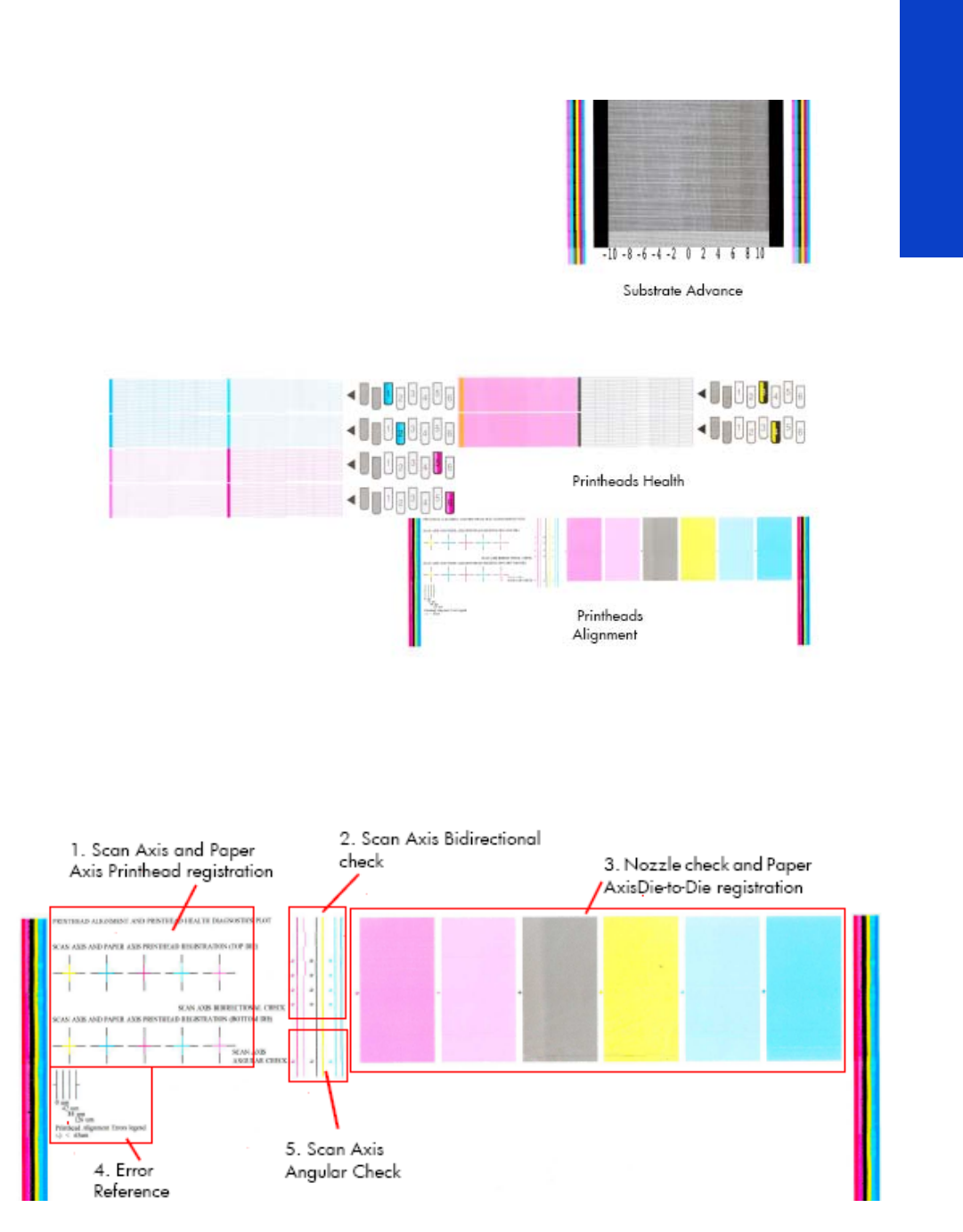
209
Print Quality
2. If you do not see any problems with the Image Quality Test, then the problem may not be with the
printer itself. The problem may be with the RIP. The following is printed when ‘Print all plots’ is
selected.
2.2.1 Printhead alignment test plot
To print this test plot go to Menu List>2. Image Quality Plots>2.2 PH Alignment Menu>2.2.1 Test Plot.
This test is designed to check the accuracy of the current printhead alignment. The plot consists of five
different areas:
1. Scan axis and substrate axis printhead registration
The colored crosses of the plot should show lines perfectly aligned with each other, as shown below.
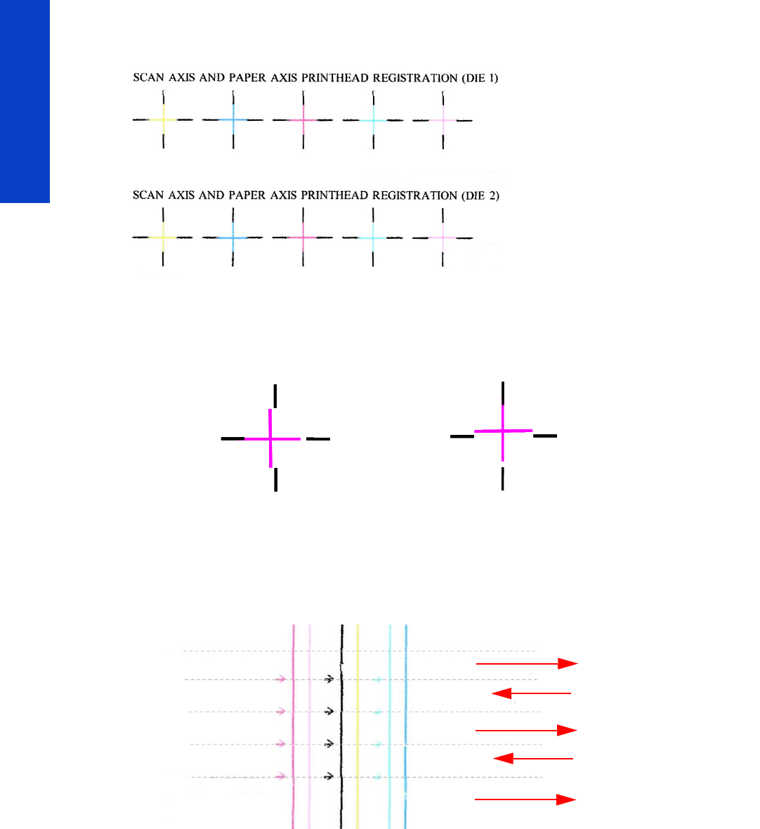
210 Chapter 5 Print Quality
Print Quality
The die 1 and die 2 of the black printhead is used as a reference to which the rest of the printheads are
compared. The substrate does not move while the pattern is being printed.
If the printer is experiencing horizontal misalignment problems, the Alignment Test will print the lines in
the orientation shown below (A). If the printer is experiencing vertical misalignment problems, the
Alignment Test will print the lines in the orientation shown below (B):
2. Scan axis bidirectional check
The small arrows point to the place where lines printed in forward and reverse directions meet. It is at this
point that the registration accuracy must be checked.
The check should be done for the M-Lm, KY and C-Lc printheads. The bidirectional alignment can change
slightly as the substrate thickness varies.
AB
Swath 1 forward
Swath 1 reverse
Swath 2 forward
Swath 2 reverse
Swath 3 forward
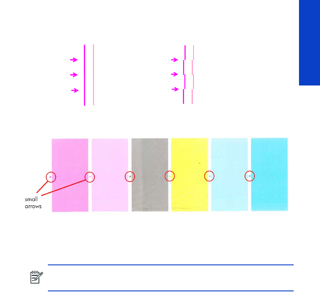
211
Print Quality
The plot should show lines perfectly aligned with each other, a straight vertical line indicates correct
bidirectional alignment (A). If any of the printheads are experiencing bidirectional misalignment issues,
the alignment test will print the lines as show below (B).
3. Nozzle check and substrate axis die-to-die registration
The colors are printed with a halftone, low-ink area fill, in a one-pass print mode.
The small arrows point to the place where two different printhead dies meet. No significant light or dark
lines should be seen at this point. Manual Alignment reset the alignment back to factory defaults.
The patches also provide a basic judgment about the printhead nozzle status. Horizontal bands indicate
weak or missing nozzles.
4. Error reference
The plot contains a reference marked ‘Legend’, this is a guide to deciding if any of the printhead
registrations are correct or incorrect.
•The correct/incorrect criteria shown here corresponds to a plot with a maximum IQ (usually printed
on high quality substrate such as vinyl). Other substrates and usage may accept significantly worse
registrations while stilling producing an acceptable level of image quality.
•Automatic printhead alignment may not produce optimal registration under certain conditions.
Substrate texturing, elasticity and the behavior of the substrate under different temperatures may lead
NOTE: If there are many horizontal bands indicating weak or missing nozzles, the die-to-die
registration test will be a poor indicator of the status of the die-to-die registration. If this occurs,
clean the printheads and reprint the test.
AB
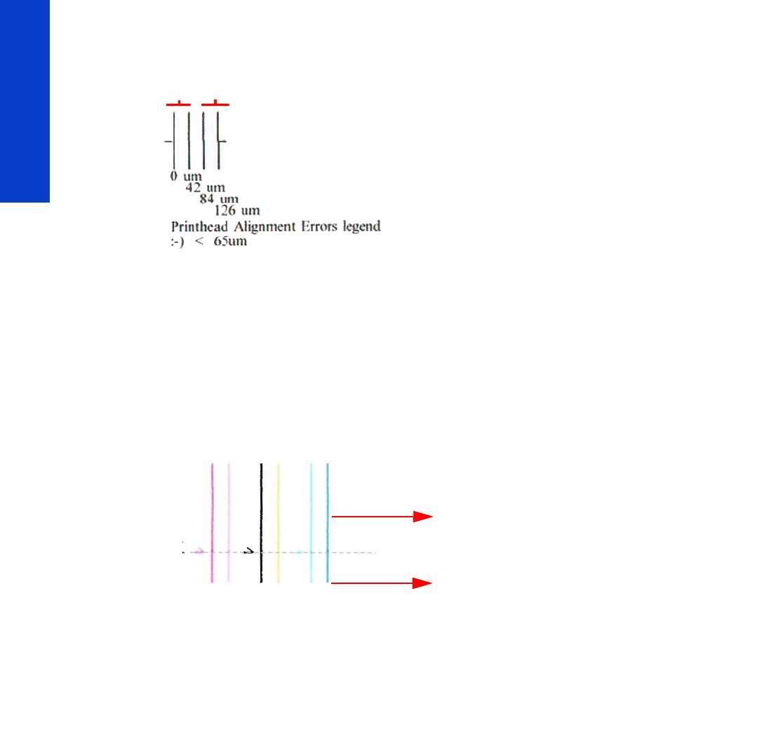
212 Chapter 5 Print Quality
Print Quality
to some imperfections with regards to printhead registration. In these circumstances the user may
choose to use the manual printhead alignment instead, refer to page 189.
5. Scan axis angular check
The small arrow point to the place where the lines printed in subsequent passes meet using unidirectional
print mode. The registration must be checked at that point. The check should be done for the MLm, KY
and CLc printheads. Note that the substrate advances between the upper and lower parts of the plot.
This test mainly relies on the changing surface of the substrate. Problems in the angular alignment lead to
printhead to printhead misregistration. This is because of the staggered orientation of the printheads.
The angular alignment can differ slightly when the type of substrate varies, or when the substrate has
recently been loaded.
Corrective action
1. Perform a Printhead Alignment. Use the same type of substrate that the customer was using when
there were print-quality issues. However it should be noted that some substrate types are not suitable
for the Printhead Alignment.
2.4.1 Printhead health test plot
To print this test plot go to Menu List>2. Image Quality Plots>2.4 Printheads Health>2.4.1 Print Test Plot.
The printhead health test plot is designed to enable you to see the overall health of the printhead nozzles.
The nozzles check (bottom of the plot) is printed in a one-pass full swath mode. The diagnostics test prints
out every single nozzle of each printhead without applying an error-hiding or alignment algorithm.
Incorrect
Correct
Swath 1
Swath 2
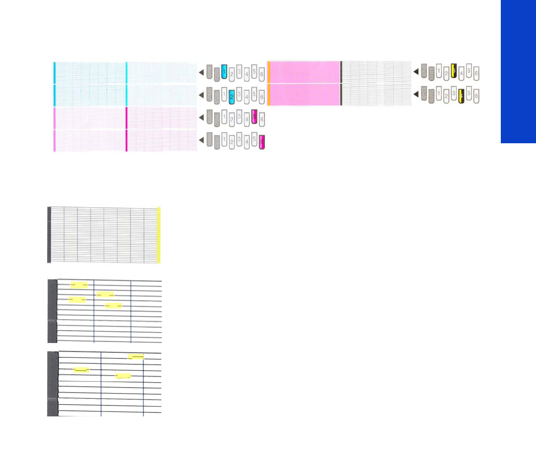
213
Print Quality
For each printhead, you can see both the adjacent and the consecutive nozzles. For every printhead there
is a different horizontal band that can be identified with the help of the template marked with the colors
of the printhead used at the right of every band.
There are a series of numbered stepped diagonal lines. If one or more of the nozzles are malfunctioning
or mis-positioned, you will see that the stepped lines are broken or misdirected in one or more places.
In this example of the plot the print shows a nozzles health pattern without
any failing nozzles. In this case, the case shown corresponds to the black
color.
This is an example of nozzles out. You can see the broken or the skewed
line, in this case marked in yellow to help you to understand the issue. In the
service plot there are no yellow marks.
This is an example of nozzles mispositioned or malfunctioning. You can see
the broken or the skewed line, in this case marked in yellow to help you to
understand the issue. In the service plot there are no yellow marks.
For a more in-depth view of the health of the nozzles you can print the Advance Nozzles Health test plot.
Corrective action
If the printer has nozzle defects, acceptable print quality results can still be achieved because the printer
can automatically compensate for this, there is no need to replace the printhead because of nozzles out.
To improve nozzle defects:
1. To clean the printheads, go to the printer’s front panel and select the ink menu, then Image quality
maintenance > Clean printheads. Select which printheads you need to clean. You can clean all of
the printheads or only some of them. The selections available are:
• Clean all
•Clean M-LM
•Clean C-LC
•Clean K-Y
2. Reprint the Printhead Nozzles Test Plot to verify that the defective nozzles have been corrected.
3. If the problem persists, replace the defective Printhead.
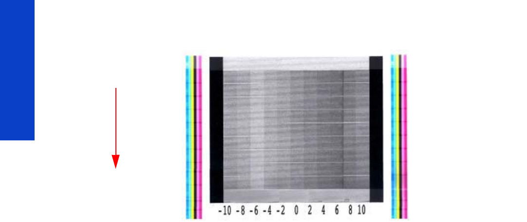
214 Chapter 5 Print Quality
Print Quality
2.3.2 Print adjustment plot
To print this test plot go to Menu List>2. Image Quality Plots>2.3 Substrate Advance>2.3.2 Print
Adjustment Plot.
This plot enables you to visually determine the accuracy of the substrate advance, if there are any
advancement issues they will appear in this diagnostic plot.
The plot can be used to precisely measure the substrate advance error with a one-dot row accuracy to
verify the stability of the substrate advance.
The sample is composed of 11 vertical columns named -10 to 10. Each single column represents an
advance deviation, so column -10 corresponds to a minus deviation and 10 corresponds to a plus
deviation. The advance obtained along the scan axis direction corresponds with the position of the lighter
portion of the pattern in each advance, as shown on the next page.
Printing direction
(substrate axis)
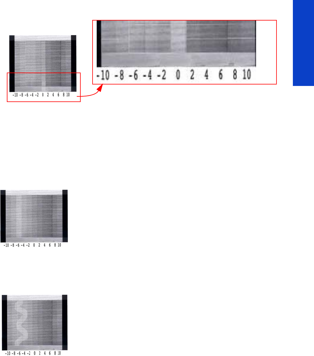
215
Print Quality
A perfectly calibrated printer will show a straight vertical lighter line
in the 0 column. If the lighter line is printed in any of the other
columns, this would indicated there is a constant advance offset along
the entire plot. If the offset is bigger than ± 2.95 mm per meter (the
lighter column is not the center one), this can be adjusted by using the
button on the front panel to change the compensation of the substrate
advance as the printer prints.
It is very important to verify that the substrate selected on the front panel, is the
same as the actual substrate loaded on the printer. You can verify the substrate type
selected through the Front Panel (Main Menu>Substrate Menu>View Loaded
substrate). If an incorrect substrate is selected, this will produce an offset error in the
Substrate Advance.
Corrective action
The figure shown here (left) shows a vertical lighter shaded line placed at column -6,
which indicates an offset of 8.57mm per meter.
This can be adjusted by using the button on the front panel to change the parameters
as the printer prints.
•If the lighter line is in the negative column, increase the compensation
of the substrate advance.
•If the lighter line is in the positive column, decrease the compensation
of the substrate advance.
When the lighter shaded line is in position 0, the process is complete.
If the advance is not a straight line, this would indicate that the printer has a variable
advance error.
If this is the case verify the following:
•Check to see if the OMAS is clean, if it is not clean the OMAS and
reload the substrate and repeat the diagnostic plot.
•Check that the OMAS is functioning correctly. Check the light in the
OMAS blinks while the substrate moves while an image is being
printed.
•Check that the OMAS can function correctly with the type of
substrate loaded. If is cannot, for example with high gloss substrate,
disable the OMAS from the RIP and reprint the diagnostic plot.
•Perform the Scan Axis Calibration page 199.
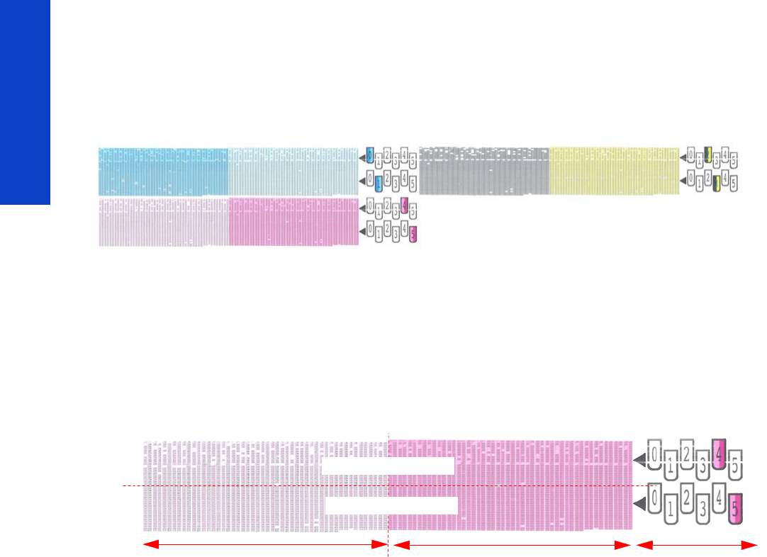
216 Chapter 5 Print Quality
Print Quality
2.4.2 Advanced printhead health test plot
The Advanced Printhead Health Test Plot is not part of the large diagnostic print, but it is similar to the
Printhead Health Test Plot described previously. With this plot however you will be able to identify which
of the Printhead Nozzles is actually failing. To print this test plot go to Menu List>2. Image Quality
Plots>2.4 Printheads Health>2.4.2 Advanced Test Plot.
This plot, like the normal nozzles health test, prints in a special one-pass full swath mode, but unlike the
normal nozzle health test, only a few of the nozzles are printed at once and with small incremental
substrate advances. Eventually all the nozzles of all the printheads are printed, this means printing the plot
can take longer than the normal heath test.
The plot is intended for visual inspection only. The plot consists of three blocks. For each printhead, there
is a different block, which can be easily identified by the colors of the printhead used inside and/or the
template located on the right side. Each block is split horizontally into two areas that correspond to the
colors in the printhead. Vertically, the block is split into sections that correspond to two dies combining
the two staggered printhead of each color (see graphic below).
Light Magenta color Magenta color Template
Printhead 4 (die 1)
Printhead 5 (die 2)
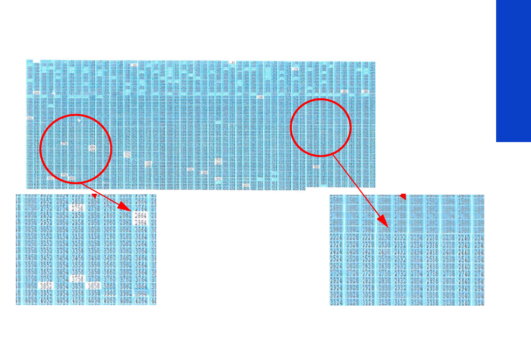
217
Print Quality
Each single region is composed of a series of numbered triangles. Each triangle is related to a single
nozzle in the printhead. If one or more of the nozzles are malfunctioning or mispositioned, you will see
that the rectangles are not filled. The corresponding color and the number printed inside can be read.
Corrective action
If the printer has nozzle defects, the level of image quality achieved can still be considered acceptable
because the printer can automatically compensate for this, there is no need to replace the Printhead
because of nozzles out.
A single die for a single color can contain up to 70 nozzles out and still the print quality will not be
significant degraded.
1. Perform a clean of the printheads
2. If there is still any die above the threshold level (70 nozzles out), perform a hard clean process.
3. If the hard clean has not improved the number of nozzle that have been recovered, perform the hard
clean again.
4. If there are any dies that have more than 70 nozzles out per die, replace the printhead.
This example on the left has many
nozzle outs. The unfilled white
rectangles indicate the nozzle is not
firing. In this example, the zoomed
area has 6 faulty nozzles. The
corresponding nozzle number can be
seen directly from the print.
This is an example of good nozzle health. All rectangles
are perfectly filled with the printhead’s color.
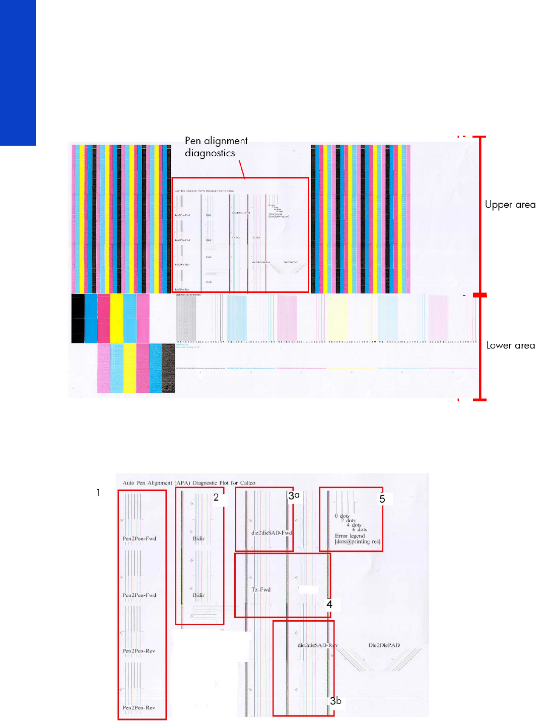
218 Chapter 5 Print Quality
Print Quality
2.2.2 Advanced alignment diagnostic print
This plot helps you to visually check any alignment problems of the printer, it is similar to the process
already described on Page209, but in more detail. You use it to precisely measure the alignment error
with a one dot row accuracy. To print this test plot go to Menu List>2. Image Quality Plots>2.2 PH
Alignment Menu>2.2.2 Advanced Test Plot
The plot is split into two main areas. The area upper area contains the area which checks the printhead
alignment, while the bottom area checks the same color staggered printhead overlap.
Printhead alignment diagnostics
The printhead alignment diagnostics, shown in the red box above, consist of various areas to check the
alignment:

219
Print Quality
1. In this area there are four checks for the printhead to printhead alignment in the scan axis direction
(Pen2Pen-Fwd or Pen2Pen-Rev). It is forward and reverse.
• The top pattern is related to the front printhead (nearest to the user when doing the printhead
replacement).
• The bottom pattern is related to the rear printhead (furthest from the user when doing the print-
head replacement).
The area to check is the junction (marked with a “-”) of the black with the rest of colors.
2. The bidirectional check is at the top, marked as Bidir.
a. The top pattern is related to the front printhead (nearest to the user when doing the printhead
replacement).
b. The bottom pattern is related to the rear printhead (furthest from the user when doing the print-
head replacement)
Check that the lines are continuous without a gap. The junction is marked with a “-”
3. The alignment in the scan axis direction between both printheads of the same color is marked as 3a
(in forward direction die2dieSAD-Fwd) and 3b (in reverser direction die2dieSAD-Rev).
The area to check is the junction (marked with a “-”). The lines have to be continuous.
4. The ThetaZ of the printheads are checked in the area marked as 4.
The area to check is the junction (marked with a “-”). The lines have to be continuous.
5. The area marked as number 5 is a reference legend that shows junction misalignments of 2, 4 and
6 dots. The junction to check has to be below 4 in all the cases. If the error seems to be above 4
dots, then realign the printheads again.
Die overlap alignment
The Die Overlap alignment is at the bottom of the plot. The area to check is only the bottom junction pattern
for all the colors. The clearest band must be around the 0 (±3 dots). Every band is equal to a one-dot error.
Corrective action
In order to solve any problem in the alignment, perform the following:
•Repeat the printhead alignment. Most recommended substrates are glossy papers where printhead
alignment accuracy is best. There are some substrate types that are not suitable for printhead
alignment (transparent, translucent)
•Try cleaning the printheads if the error continues.
•If the error persists, replace the affected printhead.
•If there is an issue in the ThetaZ and it cannot be fixed, check if the substrate is working with the
OMAS sensor, and that the substrate is not loaded with excessive skew. There are some substrates
that cannot be controlled by the OMAS sensor. If the substrate is a type that should work with the
OMAS sensor, check the functionality of the sensor.
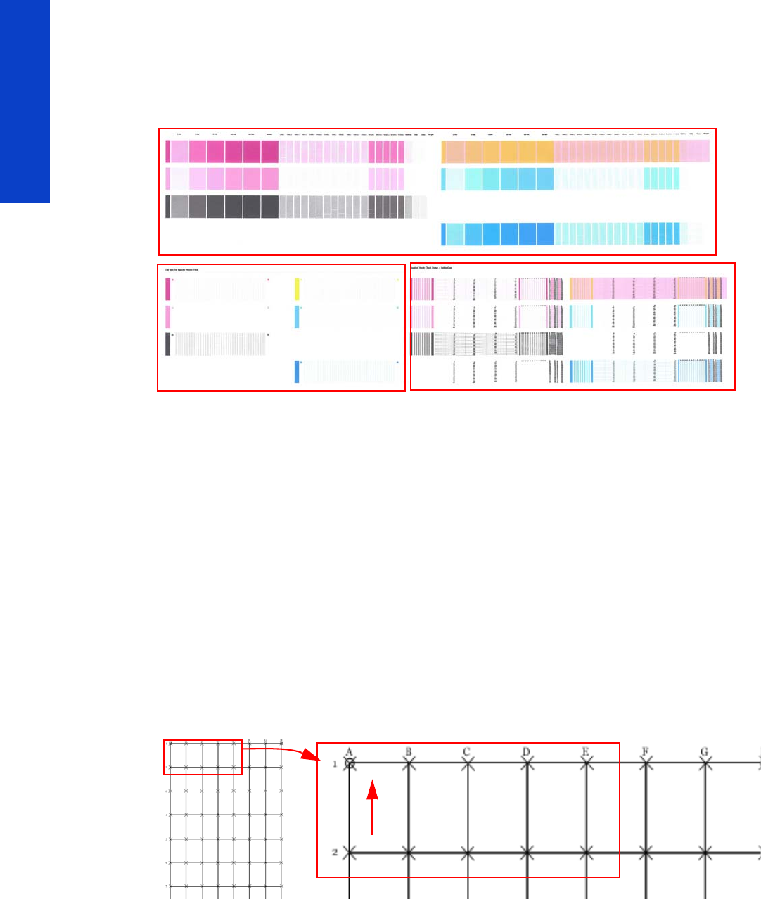
220 Chapter 5 Print Quality
Print Quality
2.4.3 Plot for escalation only
To print this test plot go to Menu List>2. Image Quality Plots>2.4 Printheads Health>2.4.3 Only For
Escalations. There are two identical plots to this test and each plot has three parts to it. The first plot refers
to the rear printheads (number 1, 3, 5), while the second plot refers to the front printheads (2, 4, 6).
This plot is only printed at the request of the HP Division, or in case further help is required and there is
need to escalate an image quality issue to HP Division.
2.5 Geometry check
The Geometry check print test is a simple template designed to check the printer’s length accuracy and
figure distortion performance. To print this test plot go to Menu List>2. Image Quality Plots>2.5 Geometry
Check.
If a customer complains that there is an issue with a plot they are printing, this standard template can be
printed and referred to by both the customer and HP as a single point of reference.
The plot consists of a 7x7 matrix of rectangular boxes. By default, each single rectangle corresponds to
a DIN A4 sheet size (210mm x 297). Based on this, the total printed plot length should be about 2.07
meter (approx. 82”) and 1.47 meters (approx. 58”). However the actual dimensions will highly depend
on what settings have been defined for the Substrate Advance.
Each point in the matrix can be identified by means of a letter in the X axis and number in the Y axis.
There is an arrow in the plot close to the point ‘A1’ to show the printing direction.
The method of evaluating the geometric performance is the following:
1. Select an area on the matrix to evaluate for accuracy and dimensional integrity. The template is
designed so you can measure anything from an A4 sheet upwards to any probable dimension.
2. Place the printed plot on a flat surface. This will minimize any wrinkles before proceeding with the
process.
1
23
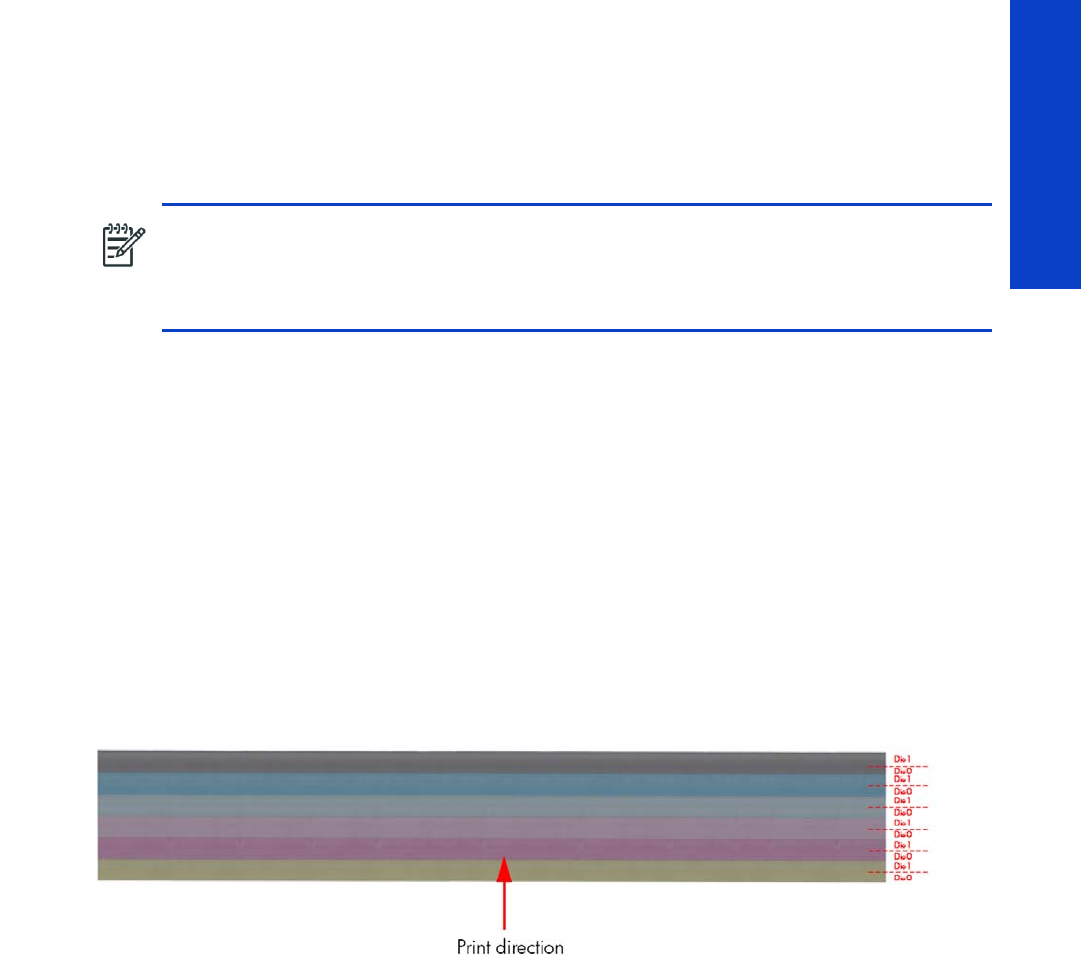
221
Print Quality
3. Find the vector length accuracy by selecting parallel vectors and/or figure distortion by measuring
the diagonals in the selected area.
4. Note the measurements to access the printer’s performance. It will help to keep the measured vectors
identified by using the name convention marked on the plot i.e. A1, A3. This makes it easier to
identify exactly the areas of the plot where the measurements were taken.
Corrective action
1. Reload the substrate following the exact steps from the User’s Guide.
2. In some cases, differences in the substrate advance along the scan axis could cause geometric
defects. Try adjusting the settings in the RIP. Adjust Vacuum level and Backtension levels. Be careful
when adjusting these settings, refer to the RIP supporting documentation for further details of this
type of adjustment.
2.6 Scan axis check
This plot shows any defect in the Encoder Strip along the Scan Axis. To print this test plot go to Menu
List>2. Image Quality Plot>2.6 Scan Axis Check.
Any defects in the encoder strip can decrease the level of image quality of the printer, specifically in the
area where the encoder is defective. The defect is revealed by means of an interference or Vernier pattern
that spans the whole Scan Axis of the printer.
NOTE: To check if a printer complies with the technical specifications, please refer to ‘Line
accuracy’ section in the printer’s data sheet.
NOTE: After loading substrate, allow the substrate to stabilize before printing the plot. Some
types of substrate require up to 3 meters before they are stabilized.
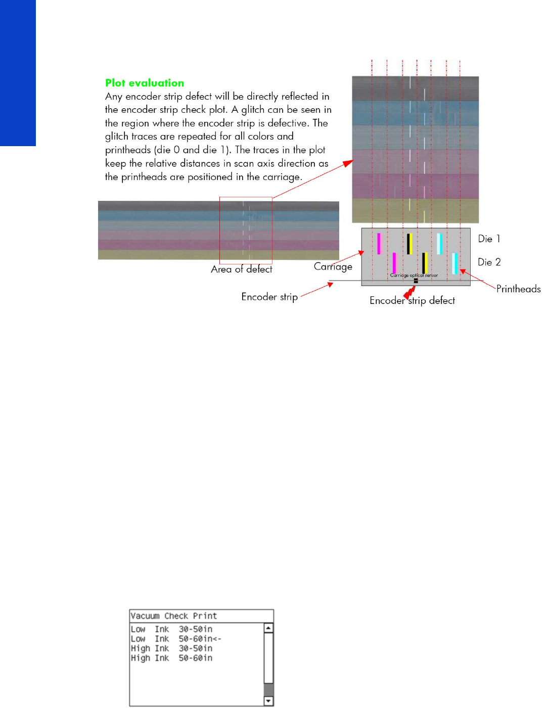
222 Chapter 5 Print Quality
Print Quality
The test plot consists of six horizontal color bands with a black pattern mask on top of them. Each band
is split in to two horizontal areas corresponding to the die 0 and die 1 for the specific color. The plot is
printed in unidirectional mode at 40ips.
Corrective action
If an fault is found with the encoder strip, replace the Encoder Strippage 405.
2.7 Vacuum check
This service plot helps diagnosing problems that could be related to vacuum adjustment such as substrate
crashes, substrate advance, and differential substrate advance (different length side to side). It can also
be used to adjust properly the substrate advance. To print this test plot:
1. Load the substrate at the rightmost position of the scan axis (do not center it), no matter the width of
the roll.
2. Go to Service Menu >2. Image Quality Plots >2.7 Vacuum Check.
3. For proper usage of this plot, the vacuum level needs to be changed while the plot is being printed
(in between patterns).
IMPORTANT NOTE: This plot must be printed with heating and curing enabled. Disabling heating
and curing can change the result.
Printing plot
1. Once the menu 2.7 Vacuum Check is selected, the printer prompts for details of your profile and
your substrate roll width.
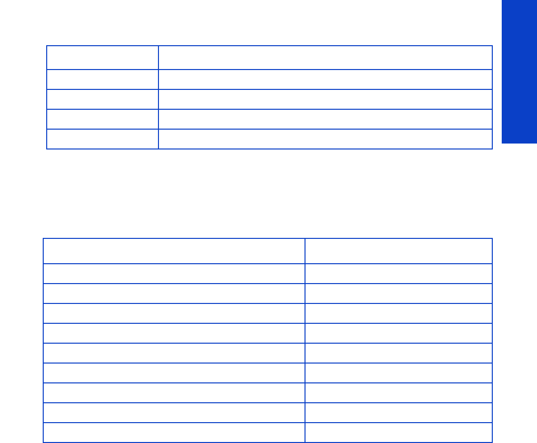
223
Print Quality
2. Select the appropriate one according to the following table.
3. At the next screen select confirm to print.
Modifying the vacuum level during plot printing
If nothing is done, the whole plot will be printed with the default vacuum level of the substrate family
selected in the Front Panel. The table below shows these default values.
To check other vacuum levels, the vacuum parameters need to be modified during the printing of the plot
according the recommendations below. To do so, in the User Menu, go to Ink menu > Image quality
maintenance > Adjust printing params > Adjust vacuum.
Selection When to select
Low Ink 30-50 inches RIP profile ‘Low Ink’, roll width between 30-50 inches.
Low Ink 50-60 inches RIP profile ‘Low Ink’, roll width between 50-60 inches.
High Ink 30-50 inches RIP profile ‘Low Ink’, roll width between 30-50 inches.
High Ink 50-60 inches RIP profile ‘Low Ink’, roll width between 50-60 inches.
Substrate family Vacuum (mm of H2O)
Self-Adhesive 25
Banner 5
Film 25
Fabric 20
Mesh 30
Paper-Aqueous 20
Paper-Solvent 25
Low Temperature Substrate 40
Synthetic Paper 40
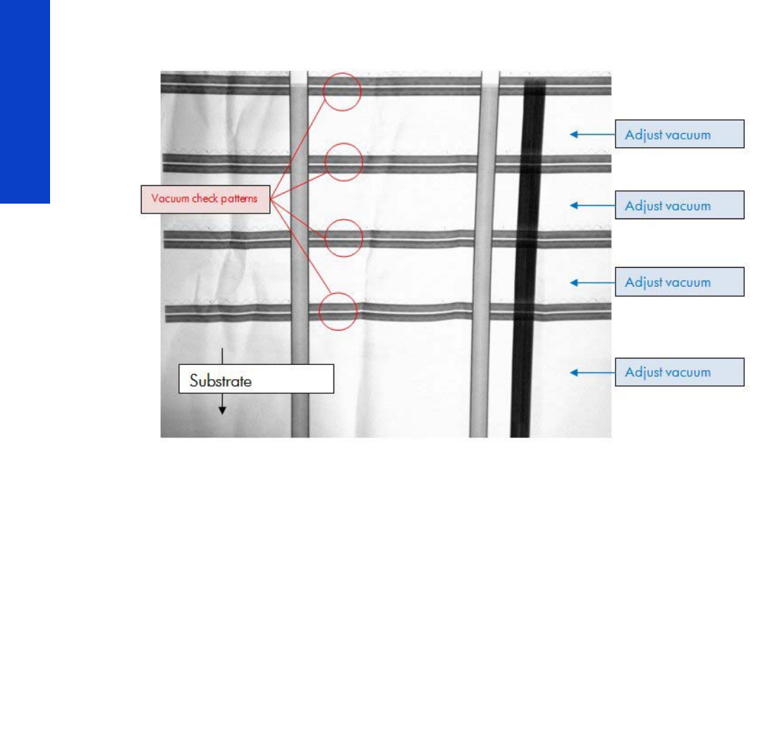
224 Chapter 5 Print Quality
Print Quality
Find below an image of the plot and when during the printing the vacuum levels can be checked (red)
and when during the printing they should be changed (blue).
Recommendations to modify the vacuum level during the plot
Print the first pattern with the default vacuum level for the Front Panel family. This way you can know if the
default value is good.
IMPORTANT NOTE: The default family vacuum level is not necessarily the one selected in the RIP profile.
For the second pattern, there are two options:
•Change the vacuum level to the one selected in the RIP profile.
•Follow the instructions below to increase or decrease the vacuum level.
For the rest of the patterns, increase or decrease the vacuum level according to the instructions below.
The vacuum should be changed at least in 20 mm of H2O steps, to be able to notice changes.
Instructions to increase or decrease the vacuum level
Look at the vacuum check pattern and compare it with the following pictures to decide increasing or
decreasing the vacuum.
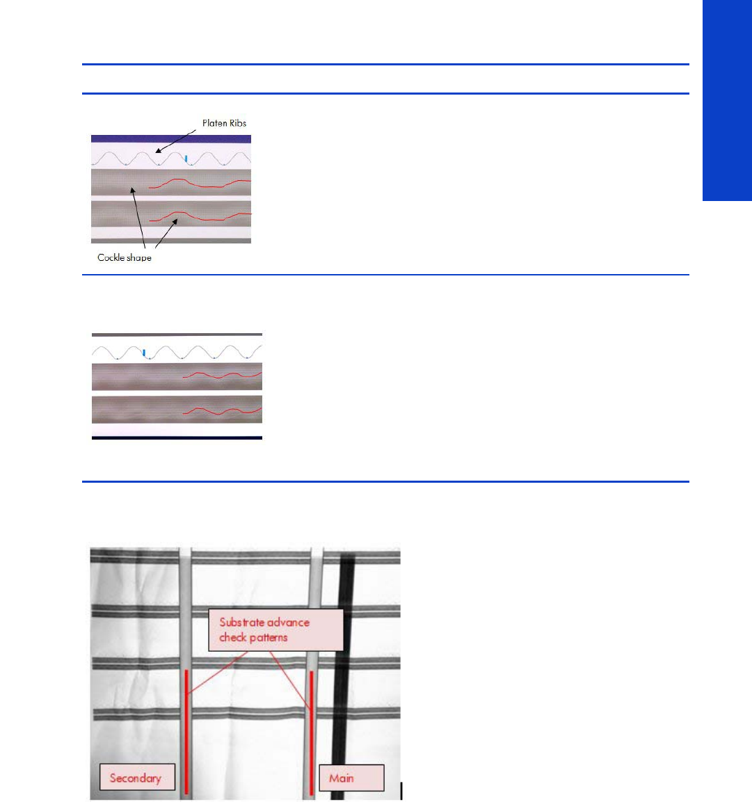
225
Print Quality
The substrate advance patterns
Looking again at the plot, we can see two vertical patterns at each side of it.
These two patters are intended to check that the substrate is advancing correctly.
Pattern Corrective action
•Vacuum is TOO LOW.
•Substrate cockle-like shape does NOT follow the same shape as
the platen ribs.
•This may produce Vertical Banding with a similar shape as the
cockle.
•Increase the vacuum +20 mm H2O.
•Vacuum is OK – it could also be too high.
•Substrate cockle-like shape follows the same shape as the platen
ribs.
•The vacuum level should be set at the minimum vacuum level
that shows this shape.
•If vacuum level is excessive the shape is the same. In this case,
differential substrate advance could appear. See below for
more details.
•There can be some “lateral shift” between the platen ribs shape
and the cockle waves and this is OK.
•It is also OK that shapes are “almost-flat” provided all “peaks”
follow the platen ribs shape.
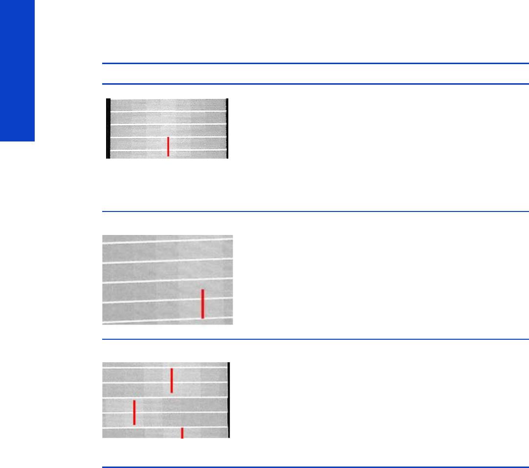
226 Chapter 5 Print Quality
Print Quality
Checking the main substrate advance pattern
Pattern Corrective action
•Substrate advance is OK.
•Light band is uniformly centered on the pattern.
•Max deviation acceptable is ±1 band.
•Substrate advance is NOT OK.
•Light band is uniform but not centered on the pattern.
•The printer can provide good Image Quality but the substrate
advance setting needs to be adjusted.
•This parameter can be adjusted on the fly during plot printing
by going to Ink menu >Image Quality Maintenance ? Substrate
advance calib >Adjust >advance.
•Afterwards, the right value needs to be input in the RIP profile.
•Substrate advance is NOT OK.
•Light band is not uniform.
•Try decreasing the vacuum and/or playing with the input ten-
sion until it gets uniform.
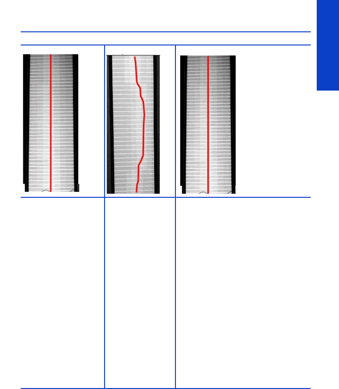
227
Print Quality
Comparing the secondary substrate advance pattern with the main one
Secondary Main
Both vacuum level and
substrate advance are OK.
Secondary pattern looks
similar to main pattern:
uniform and centered.
•Substrate advance
is OK
•Vacuum level is
NOT OK
•This is named dif-
ferential substrate
advance.
•Secondary pattern
is different than the
main pattern, typi-
cally non-uniform,
with a smooth oscil-
lation, while the
main pattern
should be uniform
and centered.
•Vacuum level is too
high or substrate
was loaded with
too much skew.
Reduce vacuum
level and ensure
substrate was
loaded without
skew.
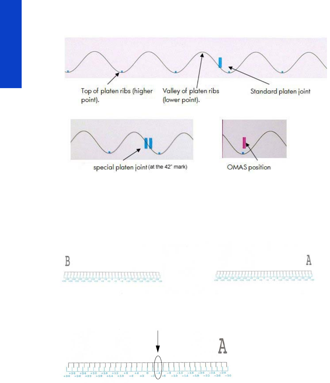
228 Chapter 5 Print Quality
Print Quality
Other plot information
The pictures below show some other features of this plot that can be useful for diagnostic.
2.8 Misregistration check
This plot helps you to visually check any alignment problems of the printer caused by substrate expansion.
You use it to precisely measure the substrate expansion error with 2 dots row accuracy. To print this test
plot go to Menu List>2. Image Quality Plots>2.8 Misregistration Check. The plot is split into two main
areas, the left (B) and the right (A) areas. Each area is made of a basic substrate expansion pattern, which
allows the measurement of the misregistration produced by the substrate expansion.
The error is measured on the pattern where the vertical black line is aligned with the Cyan vertical line.
At this point, the misregistration error can be measured by reading the corresponding number in the right
vertical alignment.
Each side of the plot gives a different error. Usually the error on each side is symmetric to zero (Eg: A=-
4, B=+4). To evaluate the error, compute the difference between B-A.
•If B-A is less than 7, then no expected IQ defects.
•If B-A is more than 7, then there could be grain and less line quality at plot sides.
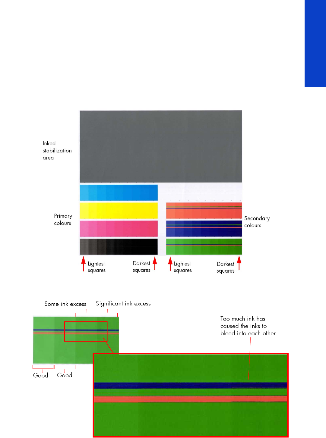
229
Print Quality
Where |A-B| is the absolute value (without sign) of A-B. An acceptable error should be comprised below
(+/- 4 dots)
3.1 Inks on substrate test
The Inks on Substrate Test plot is used to determine the level of performance of the Drying and Curing
Assemblies and to determine if they are performing as expected. To print this test plot go to Menu List>3.
Inks On Substrate Test. A submenu allows you to print the plot with 6, 8, 10, or 12 passes.
At the beginning of the plot is an area used to stabilize the printing system before the diagnostic print is
printed, this area can be ignored. The diagnostic area of the print contains colored blocks representing
each of the primary and secondary colors, the plot shows a scale from lighter to darker intensity (amount
of ink).
To evaluate the Drying test plot look at the last square (in order of increasing ink quantity) that shows no
coalescence, banding or bleed effects.

230 Chapter 5 Print Quality
Print Quality
To evaluate the Curing test plot look at the squares that show ink smudge when touched (see picture) or
that show an ‘oily finish’ (which is more likely).
The following table shows the maximum quantity of ink (the darkest patch) that can be printed using HP
Permanent Gloss Adhesive Vinyl without producing any of the issues previously stated. The
evaluation is performed in the secondary colors only:
Corrective action
At the bottom of edge of each block of primary color, and at the top of each secondary color, there is a
percentage scale which indicates the level of ink used to print that portion of the diagnostic print. This
information can be used to adjust the ink saturation levels in the RIP used by the customer.
Force drop detection
If the Printhead Health test plot (
page 212) has persistent white point banding in only one color that
cannot be fixed with a recovery, you can use this option to resolve the problem by resetting the nozzle
health data base so that all nozzles are assumed to be correct. After the nozzle health data base has been
reset, the drop detection procedure is started
page 184.
The normal cause of this white point banding in a single color is the failure of the drop detector to correctly
detect nozzles pot on the printhead.
This tool is also helpful to diagnose a potential failure of the drop detector. The ’force drop detector tool’
displays the number of nozzles out per printhead. If you print the diagnostic plot image, afterwards you
will be able to compare this number detected by the drop detector with the real number of nozzles out
that you see on the printout.
If there is a mismatch on all the colors, this would probably indicate that the drop detector is not working
correctly or is mispositioned. Before replacing the drop detector, perform a 'drop detector calibration'
page 201) to correctly position it. If the failure (miss-match) is still there after the calibration, replace the
drop detector.
Troubleshooting non-uniform curing
Typically most of the non-uniform drying/curing can be corrected by applying the correct profile setting.
In those cases that the profile adjustment does not improve the uniformity of the curing perform the
following troubleshooting procedure.
1. Set up the printer with the recommended profile for the type of substrate used, setting up the curing
temperature at 100°C through the RIP.
2. Send the file CuringTestDark_103x150.tif to the printer, which is considered a worst case to analyze
ink-curing uniformity (the TIFF file is attached to this PDF document).
3. Allow the printer to warm up, and start the printing process.
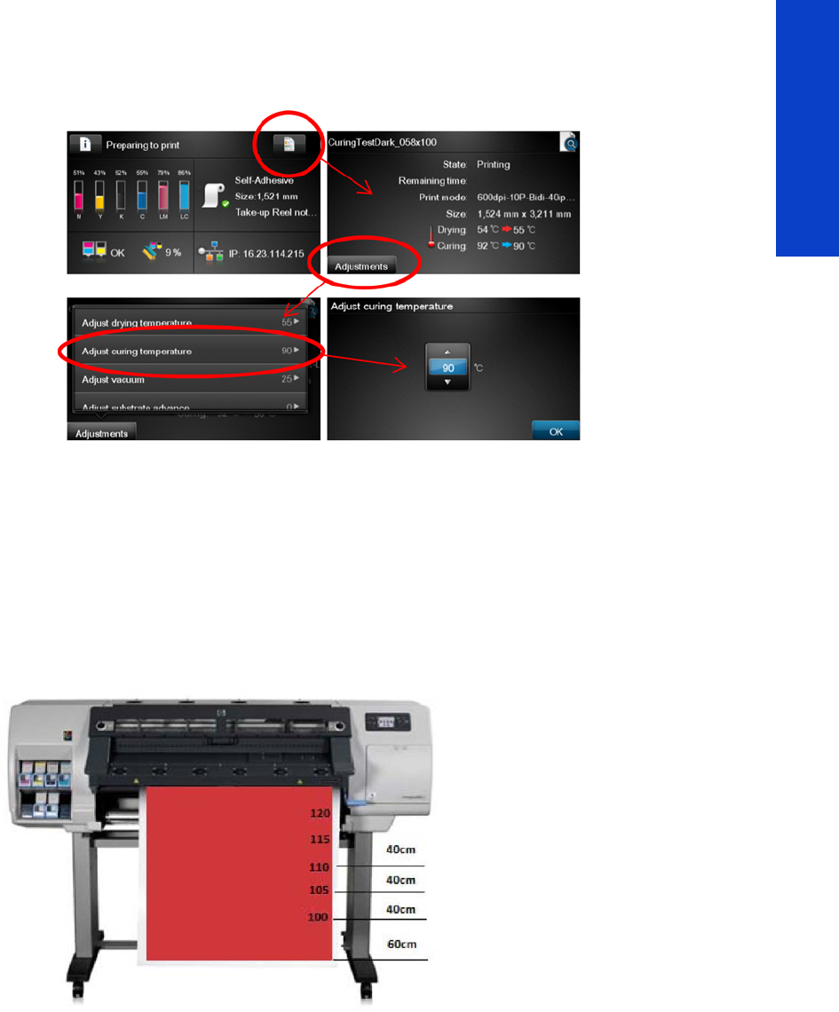
231
Print Quality
4. When approximately 60 cm of the job is done, increase Curing Temperature +5°C (105°C) through
the Front Panel, mark the 105°C step on the job. To do this, go to the Job Properties menu >
Adjustments > Adjust curing temperature.
5. Wait for 40 cm more of the job to be done and then increase Curing Temperature +5°C (110°C),
mark the 110°C on the job.
6. Wait for 40 cm more of the job to be done and then increase Curing Temperature +5°C (115°C),
mark the 115°C on the job.
7. Wait for 40 cm more of the job to be done and then increase Curing Temperature +5°C (120°C),
mark the 120°C on the job.
8. Wait for 40 cm more of the job to be done and then increase Curing Temperature +5°C (125°C),
mark the 125°C on the job.
This troubleshooting test indicates:
On Printed area:
•Initial temperature 100°C is unlikely to cure (which will be the uniform behavior along the printer).
•Upon increasing the temperature the ink will have an improves curing performance (around 110°C)
On the Substrate back liner area:
•Initial temperatures 100°C back liner performs correctly.
•Upon increasing the temperature for some specific types of substrate, shiny spots could appear at a
certain temperature (from115°C - 120°C)

232 Chapter 5 Print Quality
Print Quality
There will be a temperature where curing is correct and the backliner of the substrate is damaged.
If this temperature is found, set up your job at this temperature on the RIP and recheck printing
performance.
If at any temperature tested it is found:
•No curing and correct backliner, or
•Curing but damaged backliner
Then recommend to:
1. Change the Curing IR sensor and repeat the test, if the previous behavior persists.
2. Replace the Curing heaters and repeat the test to recheck correction.

233
Print Quality
Substrate advance issues
The vast majority of issues concerning the substrate advance can be solved by asking the customer to
clean the substrate-advance sensor window. This procedure is described in the User’s Guide.
If, after doing this, the customer is still experiencing image quality issues related to the substrate advance,
use the following procedure.
1. Make sure the window of the OMAS sensor located in the Platen has been completely cleaned of all
ink, the cleaning swabs provided to perform this procedure must be used.
2. Some types of substrate cannot be used with the OMAS sensor, because they are too smooth or
there is too much light reflected from the substrate surface to be able to be read by the OMAS,
examples of these types of substrate are: Clear Film, Backlit, types of Matte film, types of
Polypropylene. Check the troubleshooting procedure on the next page to determine if the error is
with the OMAS or the substrate being used. If the error is with the substrate, there are two options:
• Change the type of substrate to a type that can be used with the OMAS, ideally it will be a
substrate with a readable surface, such as a self-adhesive substrate, the type with a removal
backing.
• Disable the OMAS, and use the analog device to control the substrate advance.
- To disable OMAS, go to Service Test Menu >1.3 Substrate Path Menu>1.3.3 Enable/Dis-
able OMAS. Refer
Page182
- Perform the Substrate Advance Calibration select the (ink) icon on the Front Panel, and
then select ‘Image quality maintenance > Substrate Advance calibration > Print adjust-
ment plot (see the User’s Guide).
3. Perform the ‘OMAS Sensor Check’ to check the electrical functionality of the OMAS
Page183
.
If the OMAS Sensor fails the check, replace the OMAS Sensor
Page432.
4. Perform the ‘TOMAS Sensor Check’ to check the electrical functionality of the TOMAS
Page183
.
If the TOMAS Sensor fails the check, replace the TOMAS Sensor
Page432.

234 Chapter 5 Print Quality
Print Quality
Advance error with the substrate or with OMAS?
Clean OMAS
and reload the
substrate
There is
an
advance
issue
Launch the Visual Substrate
Advance Diagnostic using
HP Glossy Paperb provided
for the calibration. Refer to
page 214 for the details of
the calibration.
Issue fixed?
Launch the user
advance
calibration
adjustment
Acceptable Visual
Substrate Advance
Plot?
Replace the
OMAS
CLOSE
Launch the
Visual Substrate
Advance
Diagnostic using
the Customer’s
substrate
Acceptable Visual
Substrate Advance
Plot?
is the substrate in
the list of non-
OMAS navigable
substratesa
CLOSE
Replace the
OMAS
YES
NO
NO
YES
YES
NO
YES
NO
YES
NO
YES
NO
It could be a
limitation of the
customer’s
substrate
Replace the
OMAS
Is the issue
fixed?
CLOSE
NO
YES
Perform the Substrate
Advance Calibration,
Refer to chapter 4.
b In order to perform this Calibration, you
should order the Substrate Advance
Calibration Kit (Part Number Q1273-
60296) which contains two cut sheets of
HP Universal Instant-dry Gloss Photo Paper
(36-inches wide by 42-inches long).
c ‘OMAS Blinking’ means that the red LED
in the OMAS lens blinks ON/OFF during
substrate advance when OMAS is
a List of types of substrate which are NOT
used (non navigable) by the OMAS:
HP or HP Approved Clear Film
HP or HP Approved Backlit
HP or HP Approved types of Matt film
HP or HP Approved types of
Polypropylene
A non-HP or HP Approved Substrate
OMAS
Blinking?
NO
YES
OMAS
Blinkingc?
is the substrate in
the list of non-
OMAS navigable
substratesa
Perform the
TOMAS check Test passed
YES
Replace the
TOMAS
NO

235
Ink Supplies
6Ink Supplies
•What are ink supplies? .......................................................................................236
•General information about the ink supplies ............................................................239
•General precautions when handling ink supplies....................................................242
•Priming the ink system.........................................................................................243
•When should you replace the ink supplies? ...........................................................243
•Obtaining ink cartridge and printhead information.................................................243
•Troubleshoot ink cartridge and printhead issues .....................................................243
•The front panel recommends replacing or reseating a printhead ...............................244
•Warranty information for ink supplies ...................................................................246
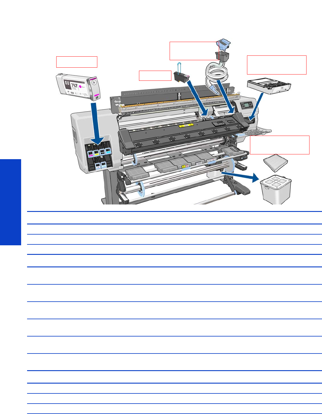
236 Chapter 6 Ink Supplies
Ink Supplies
What are ink supplies?
For each of the six ink colors used in the printer, there are three separate components, the Printhead, the
Printhead Cleaning Cartridge, and the Ink Cartridge. All of these components are called Ink Supplies.
Printheads CPL Description Full Description
CN702A HP 792 Yellow/Black PH HP 792 Yellow/Black Designjet Printhead
CN703A HP 792 Cyan/Light Cyan PH HP 792 Cyan/Light Cyan Designjet Printhead
CN704A HP 792 Lt Magenta/Magenta PH HP 792 Light Magenta/Magenta Designjet Printhead
Ink Cartridges
CN705A HP 792 775ml Blk Ltx Designjet Ink
Crtg
HP 792 775ml Black Latex Designjet Ink Cartridge
CN706A HP 792 775ml Cyn Ltx Designjet Ink
Crtg
HP 792 775ml Cyan Latex Designjet Ink Cartridge
CN707A HP 792 775ml Mag Ltx Designjet Ink
Crtg
HP 792 775ml Magenta Latex Designjet Ink Cartridge
CN708A HP 792 775ml Yelw Ltx Designjet Ink
Crtg
HP 792 775ml Yellow Latex Designjet Ink Cartridge
CN709A HP 792 775ml LtCn Ltx Designjet Ink
Crtg
HP 792 775ml Light Cyan Latex Designjet Ink Cartridge
CN710A HP 792 775ml LtMg Ltx Designjet Ink
Crtg
HP 792 775ml Light Magenta Latex Designjet Ink
Cartridge
Maintenance Materiels
CR278A HP 792 Designjet Printhead Cleaning Kit
CR279A HP 792 Designjet Ink Maintenance Kit
CH622A HP 789 Designjet Printhead Cleaning Container
Ink Cartridges Printhead Cleaning
Printheads Cartridge
Ink Funnel &
Printhead Cleaning
Container & Filter
Waste Ink Tube
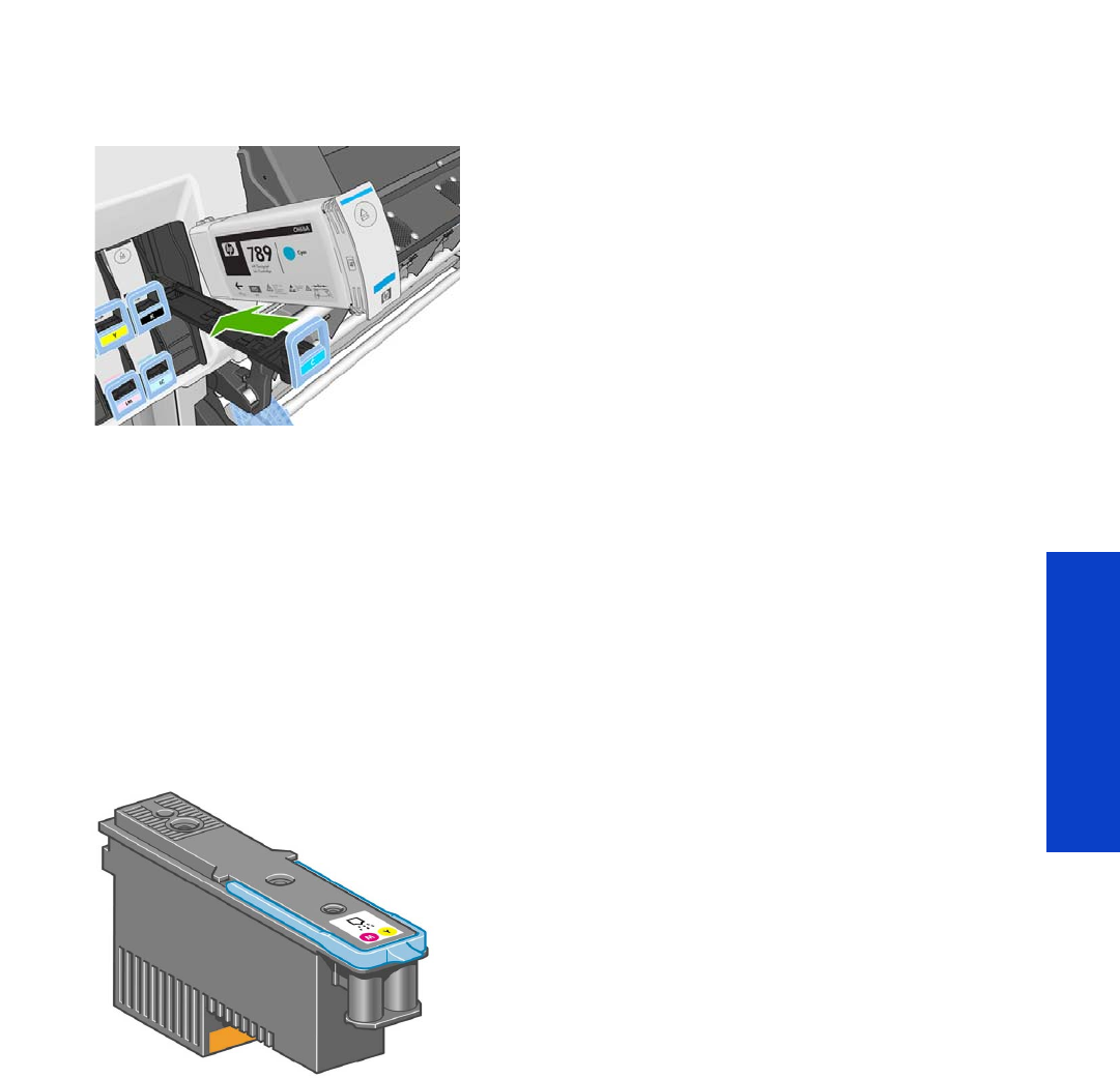
What are ink supplies? 237
Ink Supplies
Ink cartridges
The printer's six ink cartridges provide yellow, magenta, light magenta, light cyan, cyan, and black ink
to the printheads. No introductory ink cartridges are supplied with the printer. The ‘host’ ink cartridges
which are purchased hold approximately 775 ml.
The ink cartridges require no maintenance or cleaning. As long as each ink cartridge is inserted correctly
into its slot, the ink will flow to the printheads. Because the printheads control the amount of ink transferred
to the page, you will continue to see high-quality printing results even when the ink levels are getting low.
The front panel displays the status of the ink cartridge. Using the front panel, detailed information can be
checked on the Ink Cartridges menu.
Printheads
The printheads are connected to the ink cartridges. They use jet action to put ink on the substrate. Each
printhead has two ink cartridge connection points and two jet nozzles, which means that each printhead
accommodates two ink cartridges. For example, the following printhead image indicates a printhead that
draws and jets ink from the magenta and yellow cartridges.
The printheads are extremely durable and do not need to be replaced every time an ink cartridge is
replaced. They are independent of the ink cartridges and will continue giving excellent results even if the
ink cartridges are low on ink.
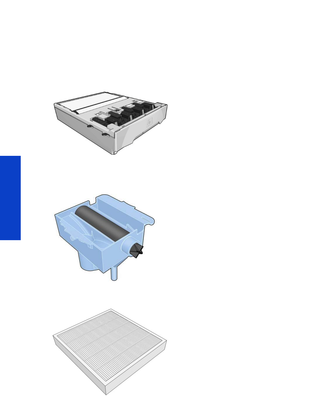
238 Chapter 6 Ink Supplies
Ink Supplies
Waste Management System
Printhead Cleaning Kit
The Printhead Cleaning Kit for the HP Designjet L28500 Printer series is the HP 792 Printhead Cleaning
Kit, part number CR278A. It consists of three main items: Printhead Cleaning Cartridge, Ink Funnel, and
Aerosol Filter.
Printhead Cleaning Cartridge
Use the Printhead Cleaning Kit to clean and maintain the printheads, ensuring the best possible print
quality, and to seal the printheads when they are not in use, preventing them from drying out.
Ink Funnel
The Ink Funnel collects waste ink produced during printhead servicing. It is important that this funnel is
installed, as it prevents significant deposits of ink over various other printer parts. From the Ink Funnel, the
waste ink passes through the Ink Tube Assembly into the Printhead Cleaning Container.
Aerosol Filter
The Aerosol Filter prevents tiny droplets of waste ink reaching the fan of the aerosol extraction system.
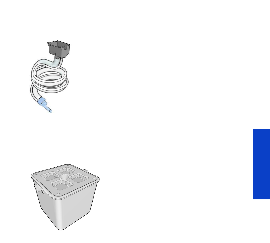
General information about the ink supplies 239
Ink Supplies
Ink Maintenance Kit
To maintain the status of the printhead nozzles, the printer expels a few drops of ink from each nozzle of
each printhead into the Waste Ink Collection System. This is done at the start of each print job, during
printing, whenever a printhead is replaced, and whenever you request a printhead check. It consists of
three main items: the Ink Funnel and the Aerosol Filter (shown above), plus the Ink Tube Assembly, which
passes tiny droplets of waste ink collected by the Ink Funnel to the Printhead Cleaning Container.
If the printer asks you to replace the Ink Tube Assembly, you should also replace the Ink Funnel and the
Aerosol Filter at the same time. These components are designed to keep the printer's waste ink from
damaging the printer and dirtying the environment.
Printhead Cleaning Container
The Printhead Cleaning Container for this system is a separate part: HP 792 Ink Maintenance Kit, part
number CH622A.
General information about the ink supplies
For optimum results from the printer and modular ink delivery system always follow these guidelines when
handling the ink supplies:
•Install the ink cartridges, printheads, and printhead cleaning cartridge before the install-by date,
which is printed on the packaging. The expiration for the ink cartridges is the manufacturing date
marked on the cartridge plus 30 months.
•Allow the printer and the printhead cleaning cartridge to clean the printheads automatically.
•Follow the instructions on the front panel of the printer during installation.
•Avoid unnecessary removal of the ink cartridges and printheads.
•When turning off the printer always use the power-off button on the front panel. The printheads are
then stored correctly, which prevents them from drying out.
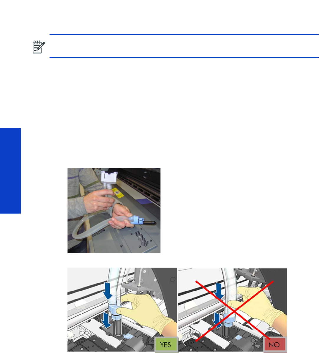
240 Chapter 6 Ink Supplies
Ink Supplies
•The ink cartridges should never be removed while the printer is printing. They should be removed
only when the printer is ready for you to replace them. The front panel will guide you through the
removal and installation procedure.
Installation tips for the Ink Maintenance Kit
Incorrect installation of the Ink Maintenance Kit can interfere with the printer’s ability to manage the ink
flow. Follow this procedure to install the Ink Maintenance kit correctly.
The Ink Tube Assembly
The tube assembly is made from two components:
•The Ink Tube is a small-diameter tube that carries the liquid ink to the container.
•The Air Tube is a large-diameter tube. Air with aerosol particles passes through this tube to the
Aerosol Filter. No liquid ink should be seen in the tube. If liquid is present, this indicates that the
system is not working correctly.
Ink Maintenance Kit installation
If there is liquid ink inside the Air Tube, or you suspect that the Ink Maintenance Kit is not correctly
installed, proceed as follows:
1. Bend the ink tubes as shown below.
2. Insert the tube assembly as shown below, on the left.
NOTE: It is important to share these tips with customers.
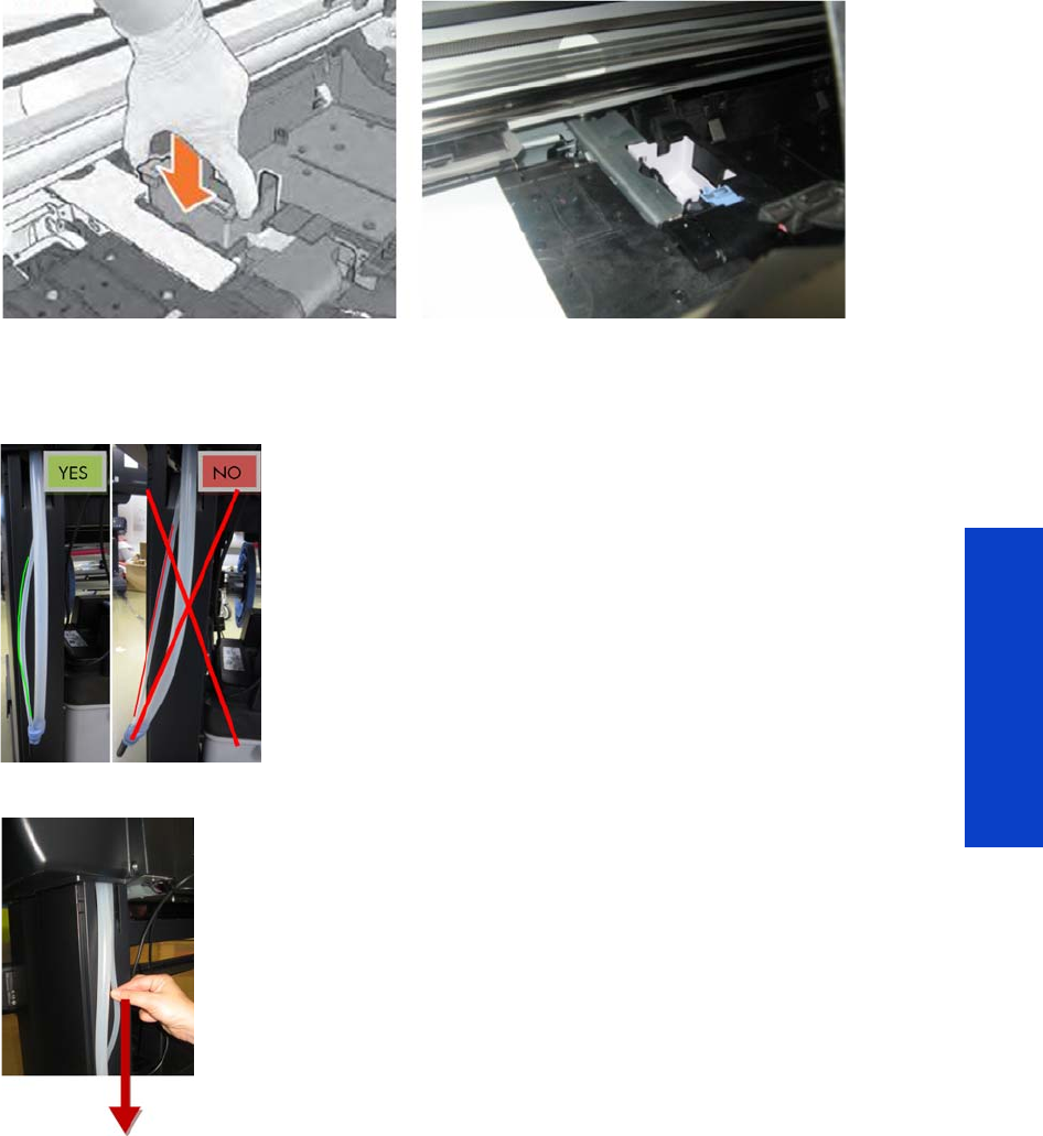
General information about the ink supplies 241
Ink Supplies
3. Slide the tubes all the way down, until the Ink Funnel Holder (light grey plastic part) fits as shown
below. If you have difficulty inserting the tubes, try rotating them slightly.
4. Check that both tubes are fully inserted into the assembly.
The two tubes are of approximately the same length. The Ink Tube should not be shorter than the Air
Tube, this can indicate that a part of the tube has become trapped, and is not installed correctly.
5. Pull down firmly on the Ink Tube (smaller diameter) until they are more or less the same length.
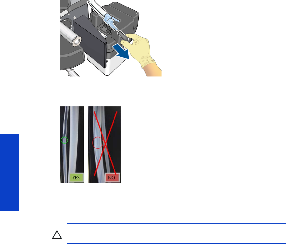
242 Chapter 6 Ink Supplies
Ink Supplies
6. Remove the cap from the end of the tube.
7. Continue the rest of the installation steps, as described in the User’s Guide.
8. After the first print, such as the output from the printhead alignment procedure, check that the ink has
flowed correctly through the Ink Tube (smaller diameter).
9. If the ink did not flow correctly, disassemble the tube, reinstall it, then check the ink flow again.
General precautions when handling ink supplies
•Handle the ink supplies with care; in particular, the printhead, which is a high-precision device and
must be handled carefully.
•Do not touch the printhead nozzles.
•Do not put the printhead down on the nozzles.
•Do not be rough when handling the printheads. Always set them down gently.
•Do not drop the printheads.
•Proper handling will assure optimum performance throughout the printhead’s life.
•The printhead cleaning cartridge should always be handled and stored upright to avoid a potential
spillage of ink.
•Do not touch the end of the ink cartridge which is inserted into the printer as there may be a small
amount of ink on the connection.
•Avoid storing partially used ink cartridges on their ends.
CAUTION: Do not touch, wipe or attempt to clean the printhead nozzles. This can damage
the printhead.

Priming the ink system 243
Ink Supplies
Priming the ink system
When the customer first receives the printer, it is supplied with a set of six Setup Printheads pre-installed
in the Carriage Assembly. These Setup Printheads are used for the priming of the tubes in the modular ink
delivery system. Do not remove the Setup Printheads from the Carriage without following the procedures
in the Setup Guide.
When the printer is powered on for the first time, the printer will automatically perform the priming
process. Without the priming process, the customer will not be able to use the printer.
Why does the printer require priming:
•The Tubes System is empty when the customer receives the printer.
•The Tubes System has to be pressurized and filled with ink, ejecting any air bubbles.
When should you replace the ink supplies?
When to change the ink supplies is mostly determined by you with guidance from the front panel. In
conjunction with the messages displayed in the front panel and the message explanations in this chapter,
you will be able to choose for yourself when is the right time to change the ink supplies.
The Printer will also display the ink level and will tell you when the ink supply is low on ink. This means
you have constantly updated information about the ink supplies.
Printhead guarantied life is 1000 ml although the printheads usually last much longer. See the section
about the ‘Warranty Information for Ink Supplies’ page 246.
Obtaining ink cartridge and printhead information
Please refer to the Printer Status chapter of the User’s Guide.
Troubleshoot ink cartridge and printhead issues
Most of the problems that you could encounter when working with the ink supplies are solved with
guidance from the front panel. A full list of front-panel messages is supplied in the User’s Guide.
Cannot insert an ink cartridge
1. Use the correct procedure to change ink cartridges, through the front panel. Refer to the User´s
Guide for further details.
2. Check that there is no obstruction in the ink cartridge connector.
3. Check that the ink cartridge is the correct color. A connector of an ink cartridge will refuse to con-
nect to a cartridge of an incorrect color
4. Ensure that the ink cartridge is correctly orientated (compare it with the others).
CAUTION: If the Printing Printheads are installed in the carriage during the priming process,
they will be rejected and the front panel will show a warning message.
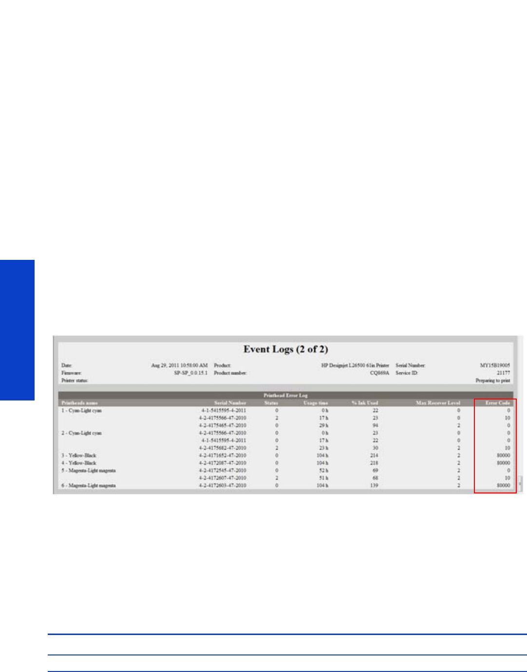
244 Chapter 6 Ink Supplies
Ink Supplies
Cannot insert a printhead
1. Use the correct procedure to change printheads, through the front panel. Refer to the User´s Guide
for further details.
2. Check there is no obstruction in the printhead slot.
3. Check the printhead is correctly orientated.
4. Check that the printhead latch and printhead cover are closed and secured.
The front panel recommends replacing or reseating an ink cartridge
1. Disconnect the ink cartridge.
2. Reconnect the ink cartridge and check the front panel message.
3. If the problem persists, insert a new ink cartridge.
4. If the problem continues, escalate the issue to division level.
The front panel recommends replacing or reseating
a printhead
If there is an error with one of the printheads, the printer will display an error message on the front panel.
However, more information about the specific error can be found by looking at the error code in service
information. In the Embedded Web Server, go to Support Menu > Service support > Printer information
> Events logs > Printhead Error Log > Error Code.
The error code is ALREADY CONVERTED TO HEXADECIMAL and you can go directly to the table below.
In the example we can see several printheads rejected reporting error code (0x00010 TEMP EXTREMELY
HIGH).
The following table explains the meaning of the different hexadecimal values:
•In the Error Code you may see some “combined” numbers, like for example (80010). In that case
you have 2 combined in one number 80000 means Expired and 10 means Temp extremely high.
•When the value of the error code is displayed as 0, it means that the printhead is working correctly.
Error code Meaning Corrective action
0x0000 WORKING

The front panel recommends replacing or reseating a printhead 245
Ink Supplies
A printhead has damaged the substrate
When a printhead touches the substrate, the most probable cause is excessive drying temperature. Reduce
the heating and curing temperature.
Incorrect error messages displayed about the cleaning cartridge
roller
The printer does not detect that a new cleaning cartridge has been installed. We have found several
possible causes:
•Most probable cause the line sensor is dirty and cannot read the white label on the cleaning
cartridge. In that case the solution is to change/clean the line sensor. Review that the aerosol
extraction system is working, if it does not work the aerosol will go again on to the line sensor and
the customer will have the same problem sooner or later.
•In some extreme cases even after changing the line sensor, the counter of the cleaning cartridge was
not reseated. The issue was fixed by running the “EEROM reset” test.
The cleaning cartridge is finished before the level reported reaches the 100%:
•The most probable cause is that the “white label” on the cleaning cartridge (used to detect if it is
new or used one) is detached from the cleaning cartridge. This will provoke a “reset” of the counter
in the middle of the life of the cleaning cartridge.
0x00001 FAILS LOGICAL V Clean the electrical connections between the
printhead and the carriage. Refer to the
User’s Guide.
0x00002 FAILS CONTINUITY
0x00004 SHUTDOWN Refer to the ‘Temperature too high proce-
dure’ below.
0x00008 FAILS VPP Clean the electrical connections between the
printhead and the carriage. Refer to the
User’s Guide.
0x00010 TEMP EXTREMELY HIGH Refer to the ‘Temperature too high proce-
dure’ below.
0x00020 TEMP EXTREMELY LOW Clean the electrical connections between the
printhead and the carriage. Refer to the
User’s Guide.
0x00040 TEMP TOO HIGH Refer to the ‘Temperature too high proce-
dure’ below.
0x00080 TEMP TOO LOW
Clean the electrical connections between the
printhead and the carriage. Refer to the
User’s Guide.
0x00100 BAD ACUMEN INFO
0x00200 NO PRINTHEAD
0x00400 BAD ACUMEN ACCESS
0x00800 WRONG MODEL Replace the printhead. The type of printhead
inserted is not supported by the printer.
0x01000 MISMATCH
0x02000 CSDATA NOT RESPONDING Clean the electrical connections between the
printhead and the carriage. Refer to the
User’s Guide.
0x04000 CSDATA TRANSMIT ERROR
0x08000 FAILS ENERGY CALIBRATION
0x40000 END OF LIFE Replace the ‘out of warranty’ printhead.
0x80000 EXPIRED
Error code Meaning Corrective action
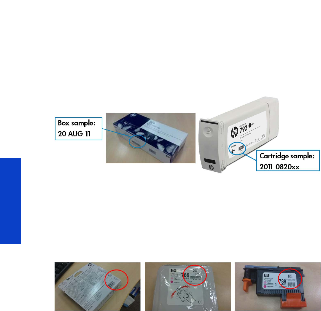
246 Chapter 6 Ink Supplies
Ink Supplies
Warranty information for ink supplies
Ink cartridge
The warranty for the ink cartridges will end when one of the following occurs (whichever occurs first):
•When the end-of-warranty date on the box and the cartridge label arrives (see illustrations).
•When the advertised volume of ink has been delivered: 775 ml/26.2 fl oz.
•When the customer confirms having used non-HP ink in empty over-ride mode.
The end-of-warranty date is also recorded in the smart chip.
Printheads
The warranty for the printheads will end when one of the following occurs (whichever occurs first):
•When the end-of-warranty date on the box, the plastic pocket, and the printhead label arrives.
•When 1000 cc of ink has been consumed by the printhead (aggregated consumption of both
colors).
•When the customer confirms having used non-HP ink in empty over-ride mode.
The end-of-warranty date is also recorded in the smart chip.

Parts and Diagrams
247
7 Parts and Diagrams
•Printer Support...................................................................................................248
•Front Covers ......................................................................................................249
•Top & Back Covers.............................................................................................250
•Electronics Module ............................................................................................. 251
•Power Cabinet ...................................................................................................252
•Right Cover .......................................................................................................253
•Left Cover..........................................................................................................254
•Right Hand Assemblies .......................................................................................255
•Waste Management System ................................................................................256
•Left Hand Assemblies..........................................................................................257
•Vacuum Extra ....................................................................................................258
•Carriage Assembly.............................................................................................260
•Dryer Assembly.................................................................................................. 261
•Curing Assemblies..............................................................................................262
•Curing Fans Assembly ........................................................................................263
•Scan-Axis Assemblies .........................................................................................264
•Drive Roller and Media-Axis Motor.......................................................................265
•Substrate Path Assemblies....................................................................................266
•Media Input (MI) and Pinchwheel Assembly...........................................................267
•Media Entry Assemblies......................................................................................268
•Take-Up Reel Assembly .......................................................................................269
•Miscellaneous Parts ............................................................................................270
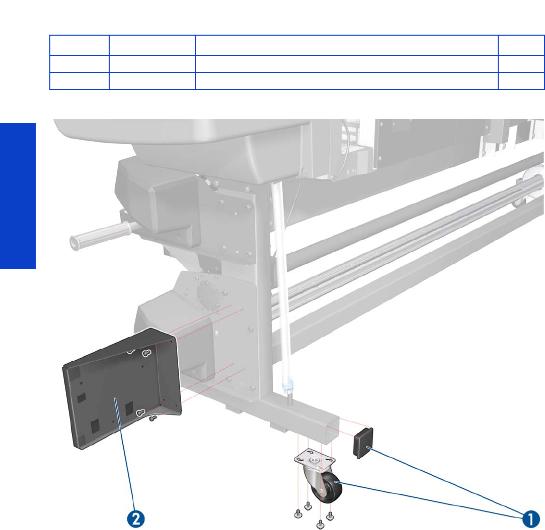
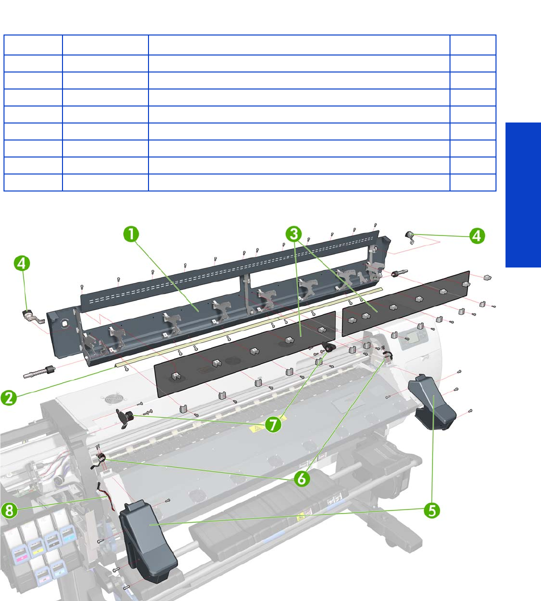
Parts and Diagrams
Front Covers 249
Front Covers
Part Number Part Description Page
1CQ871-67039 Window w/o Dryer 104 SERV 283
2CQ 871-67102 Window Mylar 104
3 CH955-67055 Transparent Window SERV 42
4CH955-67047 Window Locks
5CQ871-67031 Curing Covers 104 SERV 308,310
6CH955-67046 Window Lock Sensor 333,335
7CQ871-67007 Window Hinges (arc side) 104 293
8CQ871-67021 Window Lock Sensor Cable 104
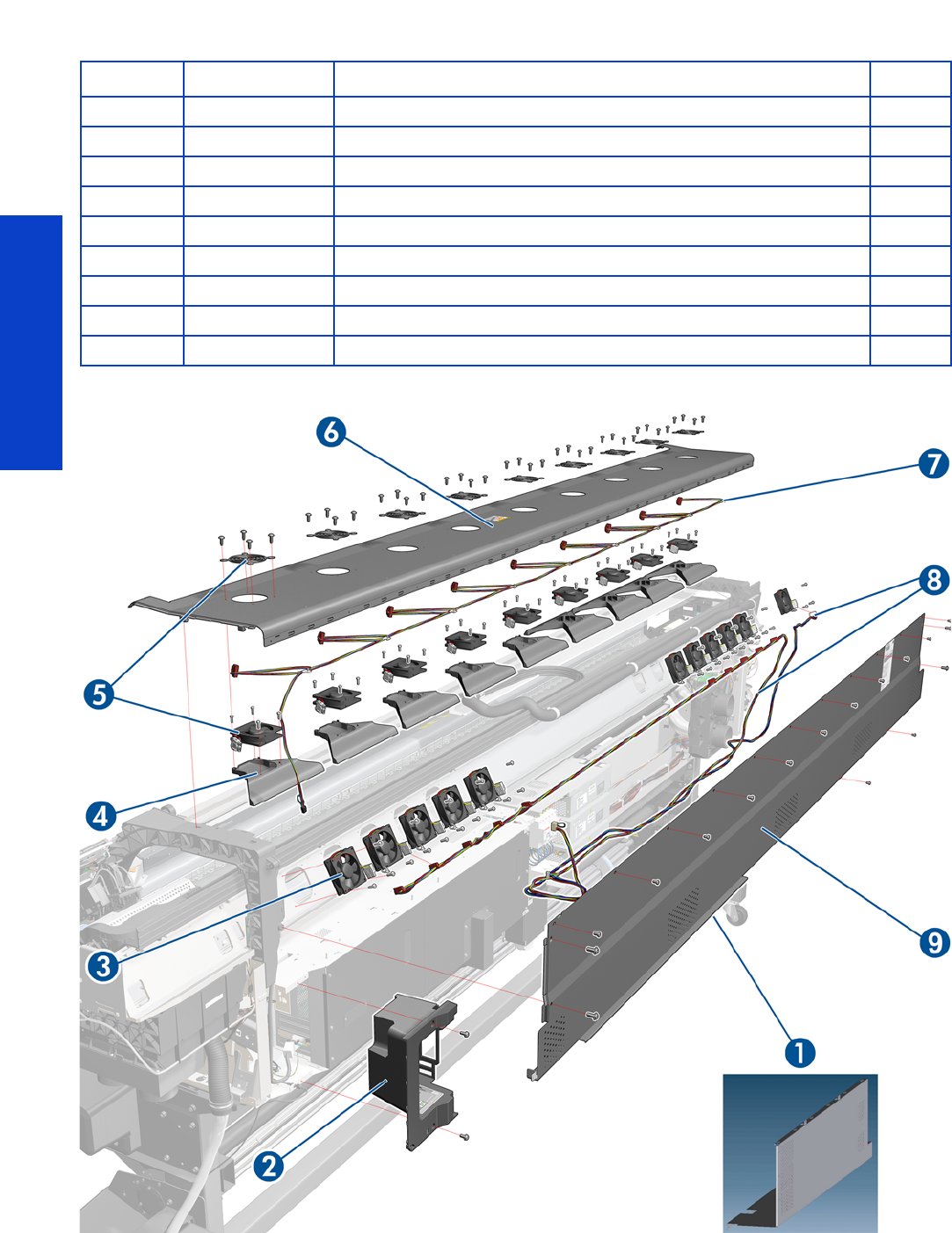
Parts and Diagrams
250 Chapter 7 Parts and Diagrams
Top & Back Covers
Part Number Part Description Page
1CQ 871- 670 69 Ba ck Cove rs 104
2CQ871-67046 Connector Cover Right 104 SERV 318
3 CH955-67088 Rear Dryer Fan (contains 1 fan) 340
4CH955-67050 Top Cover Fan Diffusors (all fan diffusors are included) 337
5CH955-67048 CAL Top Cover Fan and Grille S 337
6CQ871-67038 To p Cove r 104 SE RV 314
7CQ871-67013 Top Cover Fans Cable 104 SERV
8CQ871-67020 Drying Fans Cable 104 SERV
9CQ871-67100 Rear Upper Cover 104 SERV 312
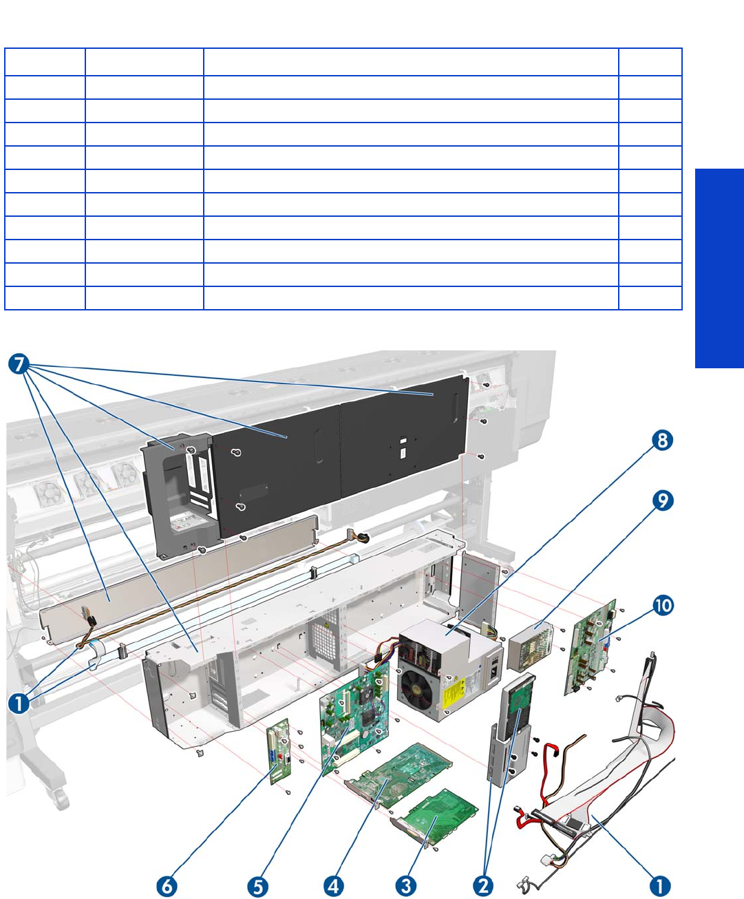
Parts and Diagrams
Electronics Module 251
Electronics Module
Part Number Part Description Page
1CQ871-67003 Ebox Cables 104 SERV
2CQ871-67036 H DD 104 SE RV 454
3CQ869-67061 OMAS Controller PCA SERV 442
4CQ871-670 02 E ng in e PC A 104 SE RV 449
5CQ109-67020 Formatter PCA and Proc and HS 452
6CQ 871- 670 01 I nte rc onn ect PCA 104 SE RV 441
7CQ871-67028 EEBox Base and Cover 104 SERV
8CH955-67006 PSU MR SERV 457
9CQ871-67074 Extra PSU 24 V SERV 323
10 CQ 871- 67030 PrintM ech PC A 104 SERV 467
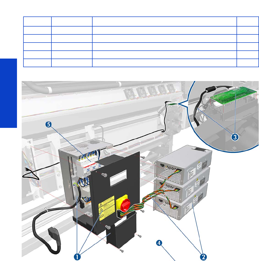
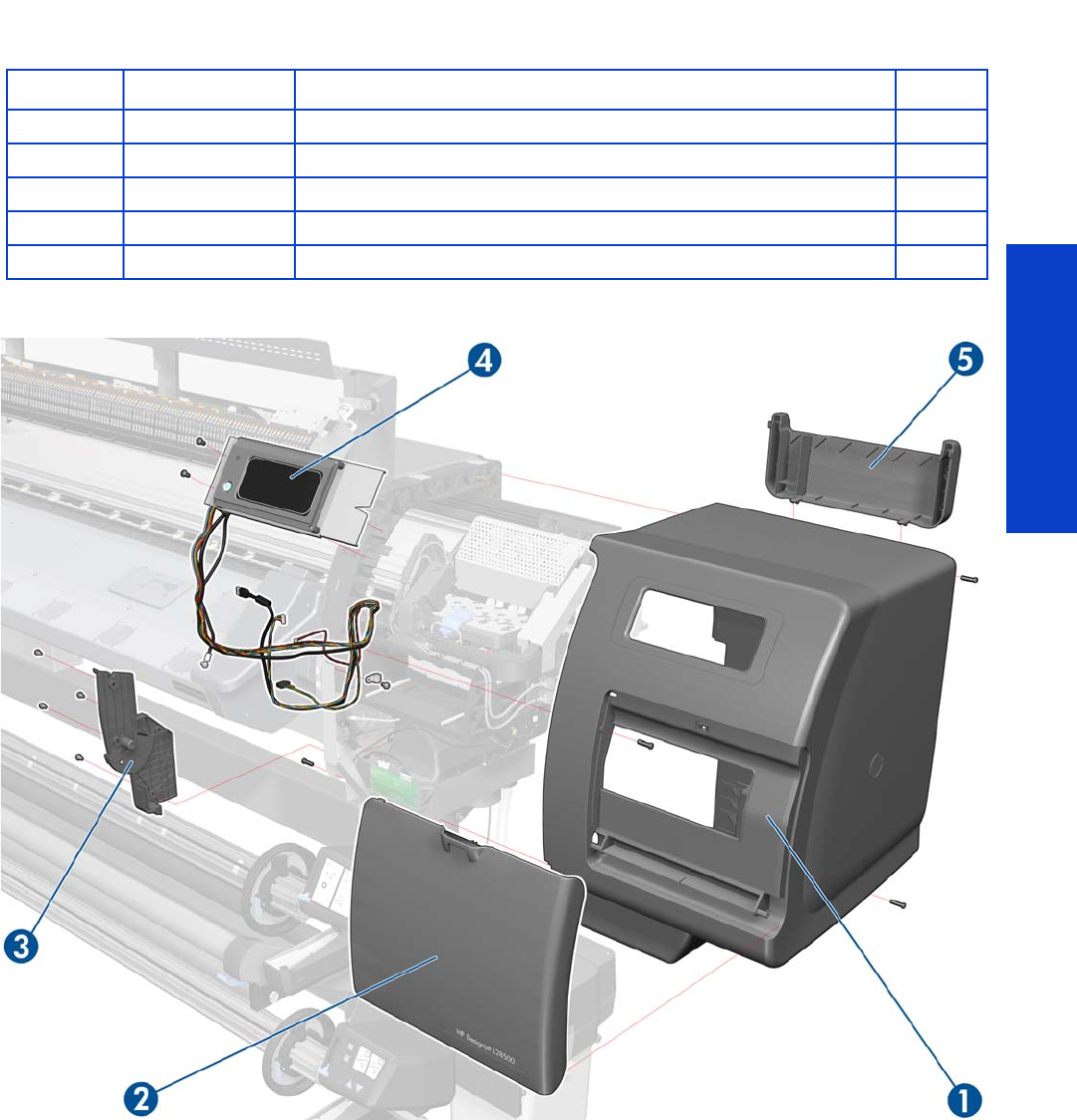
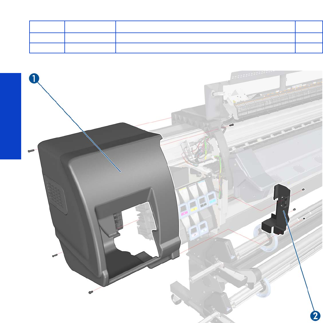
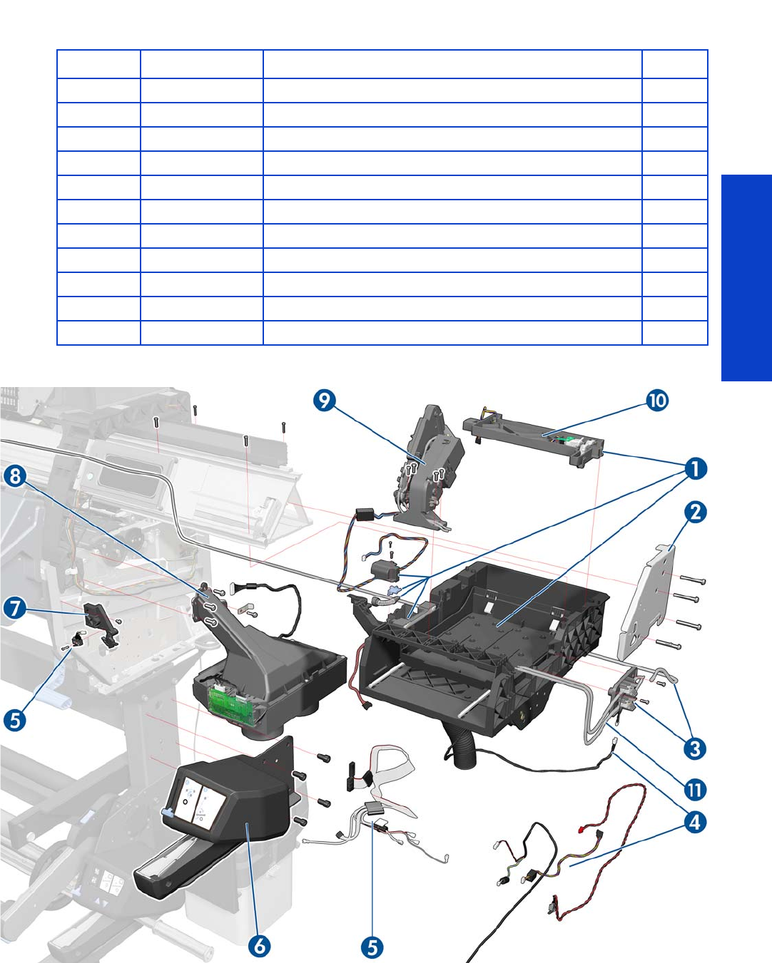
Parts and Diagrams
Right Hand Assemblies 255
Right Hand Assemblies
Part Number Part Description Page
1CQ869-67026 SPI Service Station SERV 351
2Q1273-60086 Bracket Right SERV
3CQ871-67055 Primer Valve and Tubes Assembly 10 347
4CQ871-67081 Cables to SVS Side 104
5Q1273-60273 SVC Cable + Right Switch serv 351
6CQ871-67004 Rewinder RH Module 104 SERV 585
7CM765-67001 SVS Door Sensor Assembly with Screws
8CQ109-67022 Vacuum Fan Assembly SERV 356
9Q6651-60265 Primer Assembly SERV 345
10 CH955-67053 Wiper Motor and Plate SERV 354
11 CQ871-67103 Air Tubes and Fittings SERV
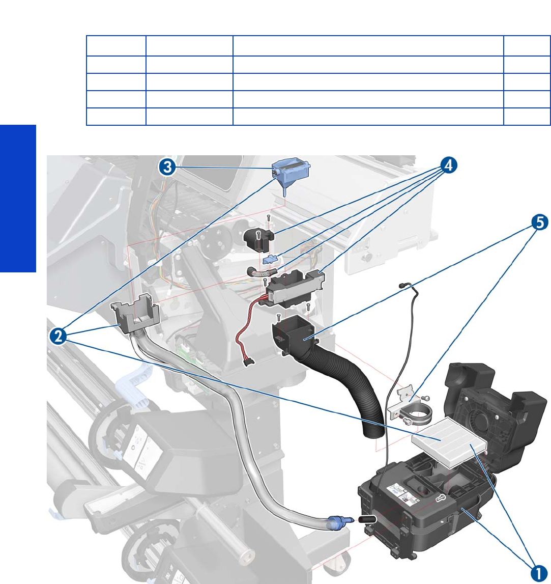
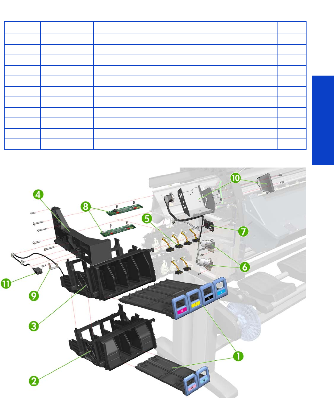
Parts and Diagrams
Left Hand Assemblies 257
Left Hand Assemblies
Part Number Part Description Page
1CH955-67028 Cartridge Trays SERV 540
2CH955-67014 ISS Down Row SERV 394
3CH955-67013 ISS Up Row SERV 394
4CQ869-67009 SPI Left Bracket SERV
5Q1273-60245 ISS to Cartridge Cable MR SERV
6CQ871-67090 APS Asse mb ly SE RV 104 402
7CQ871-67056 SOL Actuator Assembly 104 SERV 481
8CH955-67054 ISS PCAs SERV 398
9CH955-67084 SOL Shutter Bump SERV
10 CQ871-67009 Cable Plate and Cover 104 SERV
11 CQ 871- 67033 Pap er Jam Se nsor 104 SERV 422
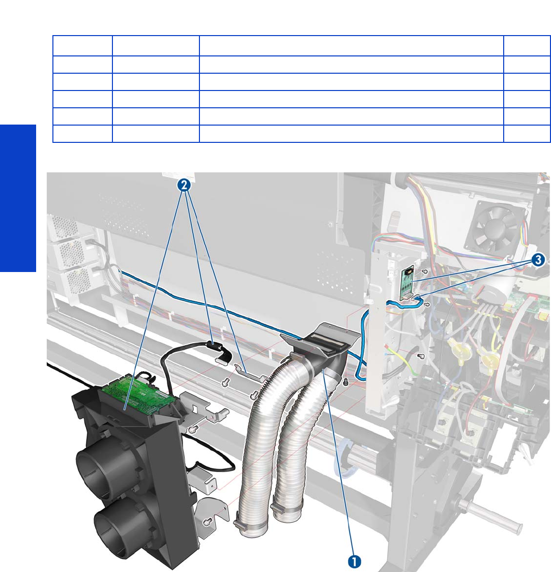
Parts and Diagrams
258 Chapter 7 Parts and Diagrams
Vacuum Extra
Grounding Cables include:
•ISS Grounding Cable (CH956-60223)
•Arc Safet y Gro und (CQ 871-50069 )
•Drying Safety Ground Cable (CQ871-50071)
Part Number Part Description Page
1CQ871-67060 Vac Extra—Frame, Tubes, Pipes 360
2CQ871-67061 Vac Extra (Vacuum Mod with EOLA PCA) 360
3CQ871-67082 ISS P re -D river PCA SE RV 327
CQ871-67079 Grounding Cables 104 SERV
CQ871-67080 Cables to ISS Side 104

Parts and Diagrams
Vacuum Extra 259
Cables to ISS Side include:
•Cover Switch Extension Cable (CQ871-50004)
•Co nve r ter’s O/P Powe r Dryi ng (CQ871- 50 008)
•Converter’s O/P Power Curing (CQ871-50009)
•Vapor/Curing Fans (PM-ARC) Cables (2) (CQ871-50020)
•IR SNS Cooling Fan Cable (CQ871-50025)
•Substrate Crash Cable (CQ871-50033)
•PM-Differential PCA Cable (CQ871-50037)
•Analog Encoder Cable (CQ871-50053)
•Drying Fan s Ca ble (CQ 871-50 056 )
•IR Sensors Cable ( CQ 871-50 057)
•Scan Motor Fan Cable (CQ871-50076)
•PrintMech to EOLA Cable, Boome (CQ871-50086)
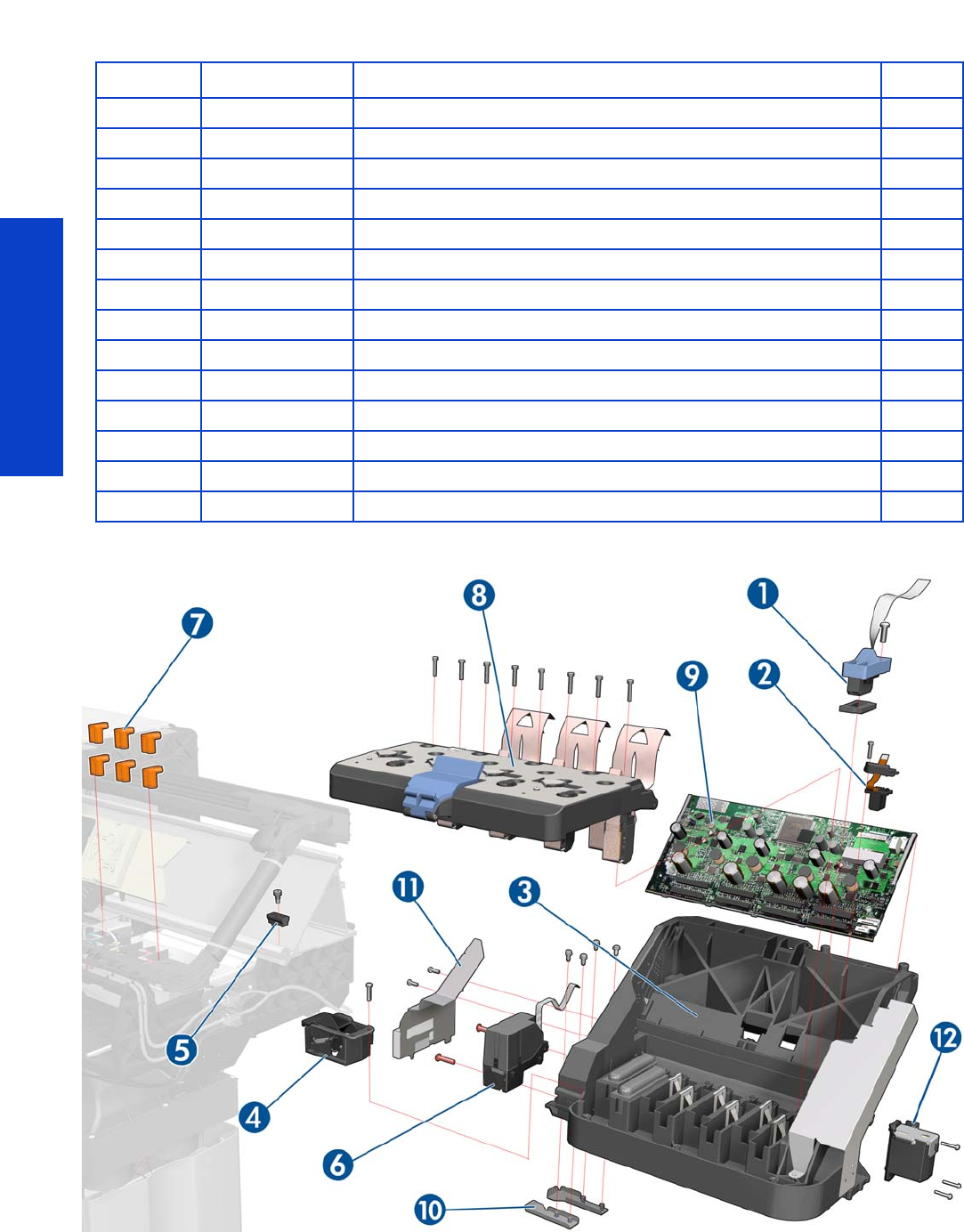
Parts and Diagrams
260 Chapter 7 Parts and Diagrams
Carriage Assembly
Part Number Part Description Page
1CQ869-67062 SPI Line Sensor SERV 473
2CQ871-67012 Encoder Strip and Sensor 104 S 405
3CQ871-67085 Carriage w/o PCA,SOL,LS 104 S 416
4 CH955-67007 Cutter Assembly SERV RoHS 392
5Q6651-60341 Right Carriage Bump + Others S
6CH955-67101 CAL SOL Assembly SERV 477
7Q6651-60335 Setup Printhead Kit SERV
8CH955-67099 Carriage Flex Cables SERV 411
9CQ109-67034 Carriage PCA SERV 408
10 CH955-67083 CSOL Shutter Protector SERV
11 CQ871-67033 Media Jam Sensor 104 SERV 422
12 CQ871-67086 Oiler U-loaded Assembly 414
CQ869-67077 100 ml Synthetic Oil for Carriage
Q6651-60081 Lubrication Felts Kit SERV
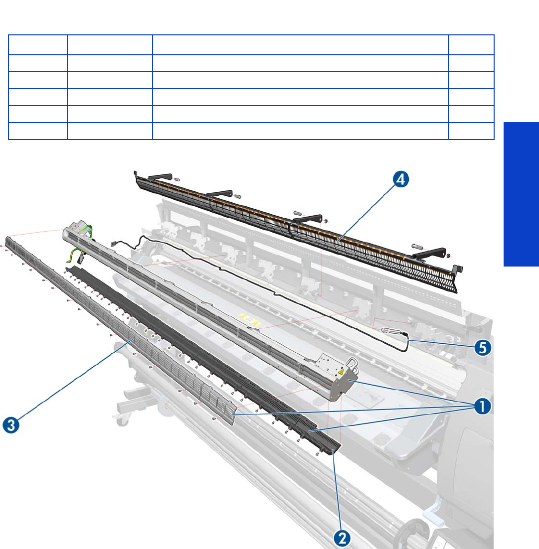
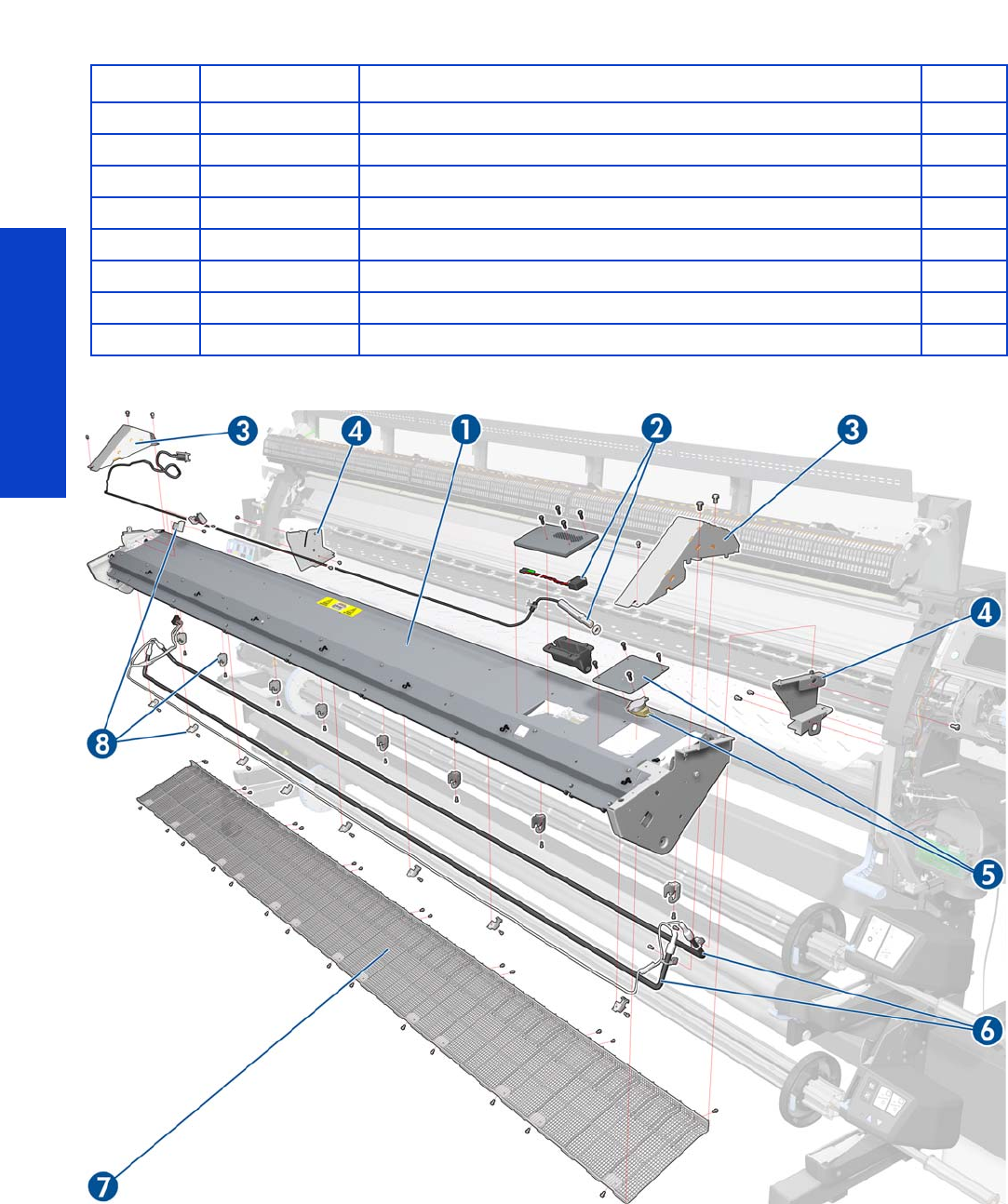
Parts and Diagrams
262 Chapter 7 Parts and Diagrams
Curing Assemblies
Part Number Part Description Page
1CQ871-67041 Curing without Fans, Resist, IR 512
2CQ871-67015 Curing IR Sensor and Fan 104 S 506
3CQ871-67032 Curing Trims 104 SERV 512
4CH955-67089 Curing Bracket SERV 527
5CQ871-67010 Curing Thermal Switch Assembly 104
6CQ871-67022 Curing Resistors 104 SERV 521
7CQ871-67018 Curing Grilles 104 SERV
8CQ871-67062 Curing Resistors Holders SERV 521
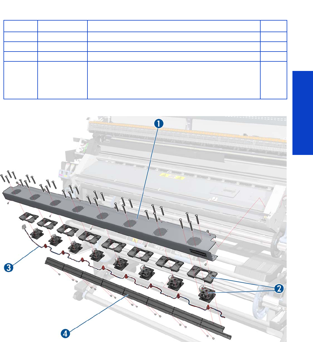
Parts and Diagrams
Curing Fans Assembly 263
Curing Fans Assembly
Part Number Part Description Page
1CQ871-67042 Curing Fans Cover without Fans 104 496
2CH955-67062 Curing Fan SERV 496
3CQ871-67016 Curing Fans Cable 104 SERV
4CQ869-67064
SPI Air Curtain Deflector SERV, comprising:
•7 Air Curtain Deflectors
•1 Air Curtain Deflector-Connector (extreme right) (not used)
Single part repair: use 1 × CQ869-67064
Complete assembly repair: use 2 × CQ869-67064
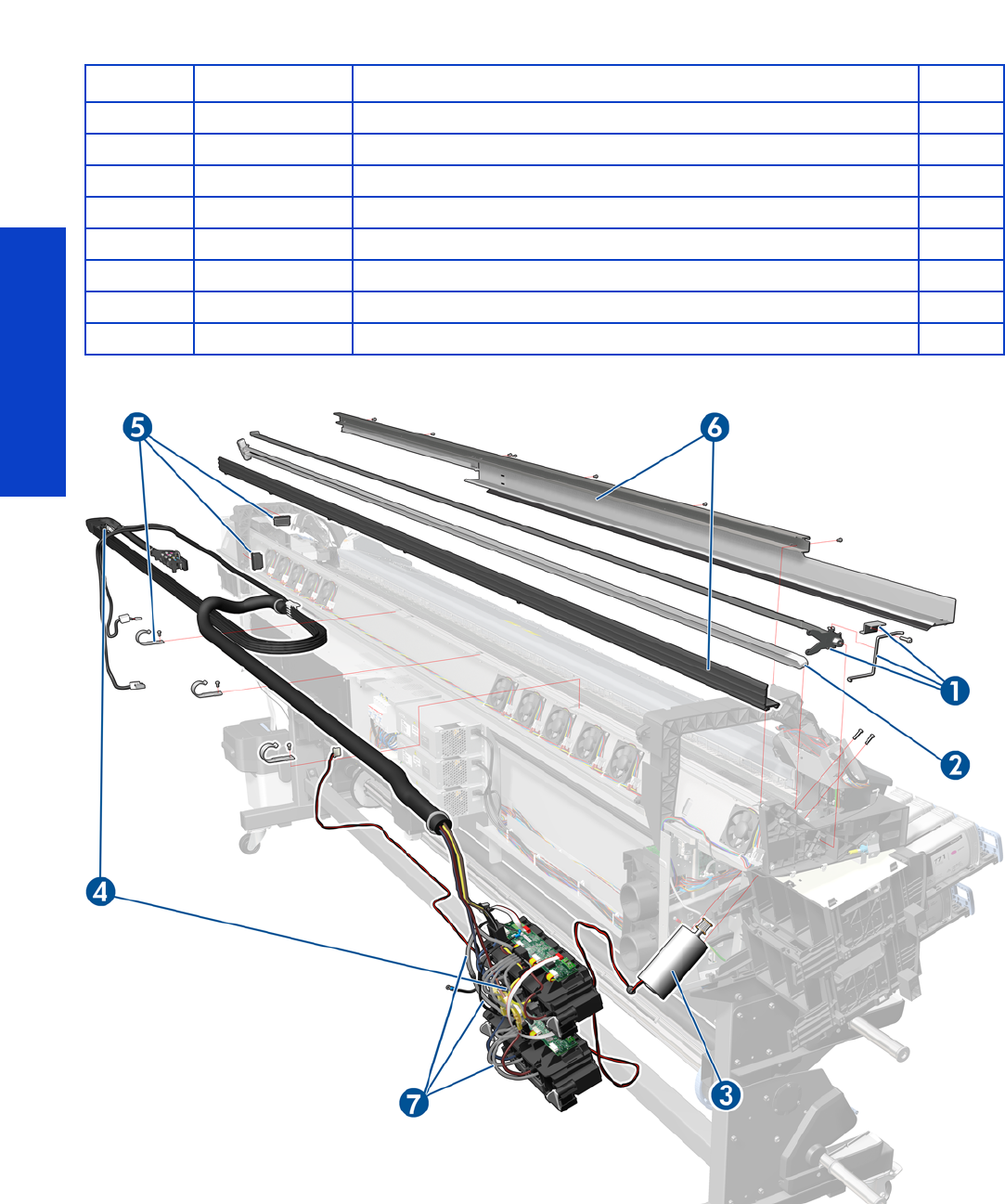
Parts and Diagrams
264 Chapter 7 Parts and Diagrams
Scan-Axis Assemblies
Part Number Part Description Page
1CQ871-67012 Encoder Strip and Sensor 104 S 405
2CQ871-67024 Belt and Tensioner 104 SERV 416
3CQ 871- 67071 Scan Axi s Motor 10 4 SERV 426
4CQ871-67044 SRK and TC 104 SERV 381
5CQ871-67096 SRK and Tube Clips 104 381
6CQ871-67078 Rear and Front Tube Shelf 104 289
7CQ871-67103 Air Tubes and Fittings SERV
CH955-67111 V2 Broken Bag Fixing Tools SER 161
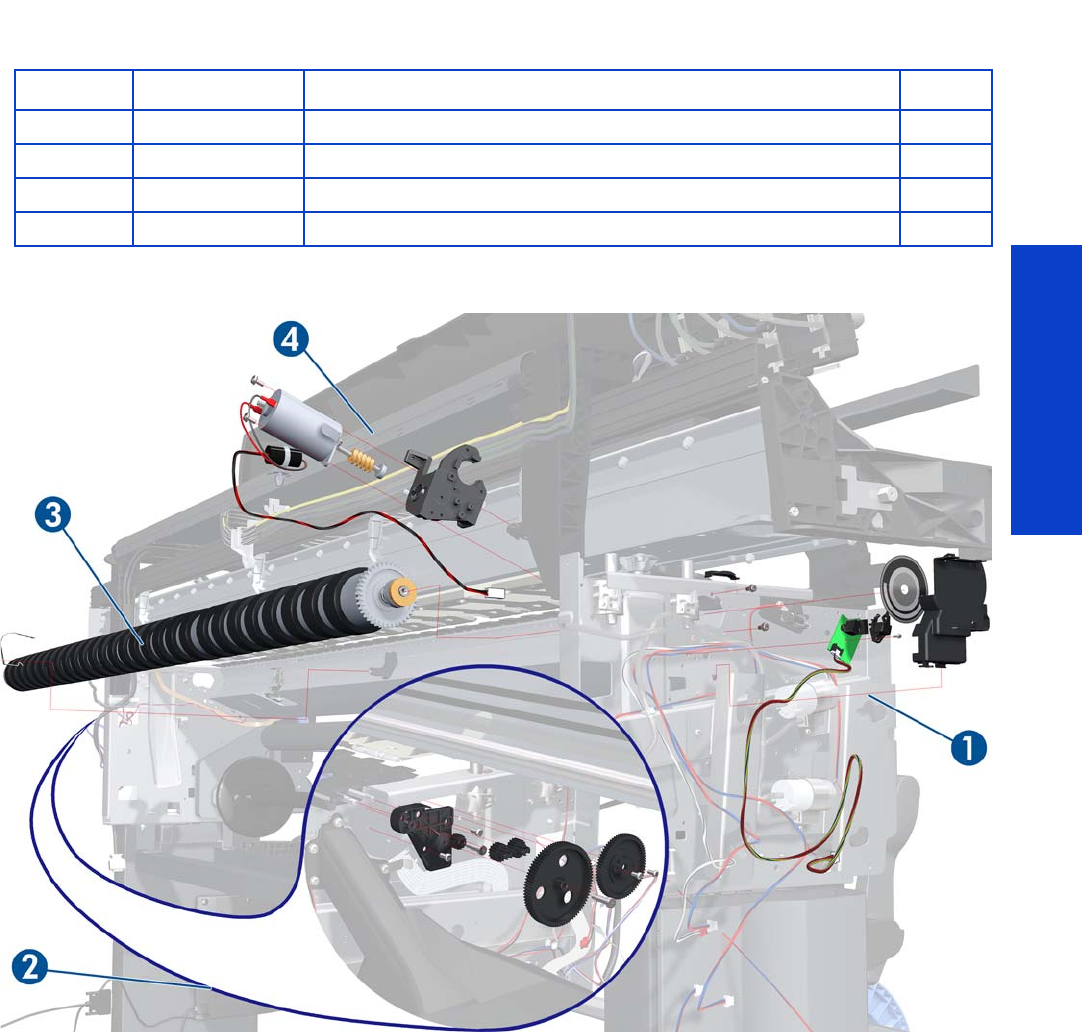
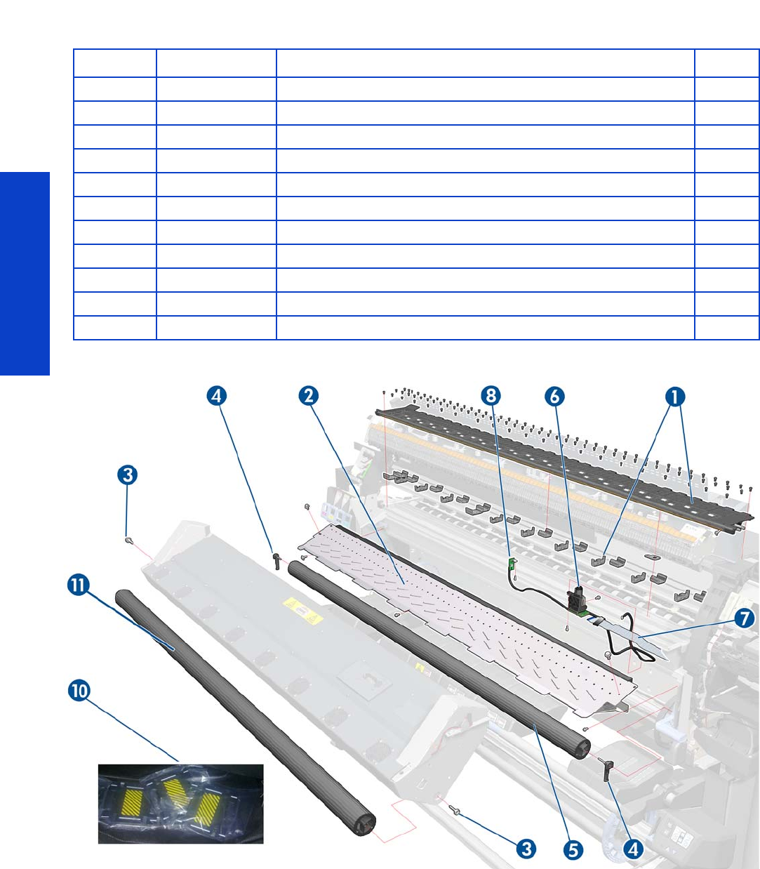
Parts and Diagrams
266 Chapter 7 Parts and Diagrams
Substrate Path Assemblies
Part Number Part Description Page
1CQ871-67037 Pri nt Pl ate n A sse mbly 104 SE RV 530
2CQ871-67011 Output Platen 104 SERV 524
3CH955-67065 Output Roller Support and Pins 554
4Q1273-60103 Input Roll Support SERV 542
5CQ 871-67047 Ent r y Rolle r 104 SE RV 542
6Q6651-60270 OMAS Module SERV 432
7CQ871-67067 OMAS Cable 104 444
8CH955-67066 TOMAS Assembly SERV 438
9CQ871-67073 MI Profile and Mylar 104 544
10 CQ869-67049 SPI Edge Holder SERV
11 CQ871-67098 Round (Plain) Output Roller 104 SERV 554
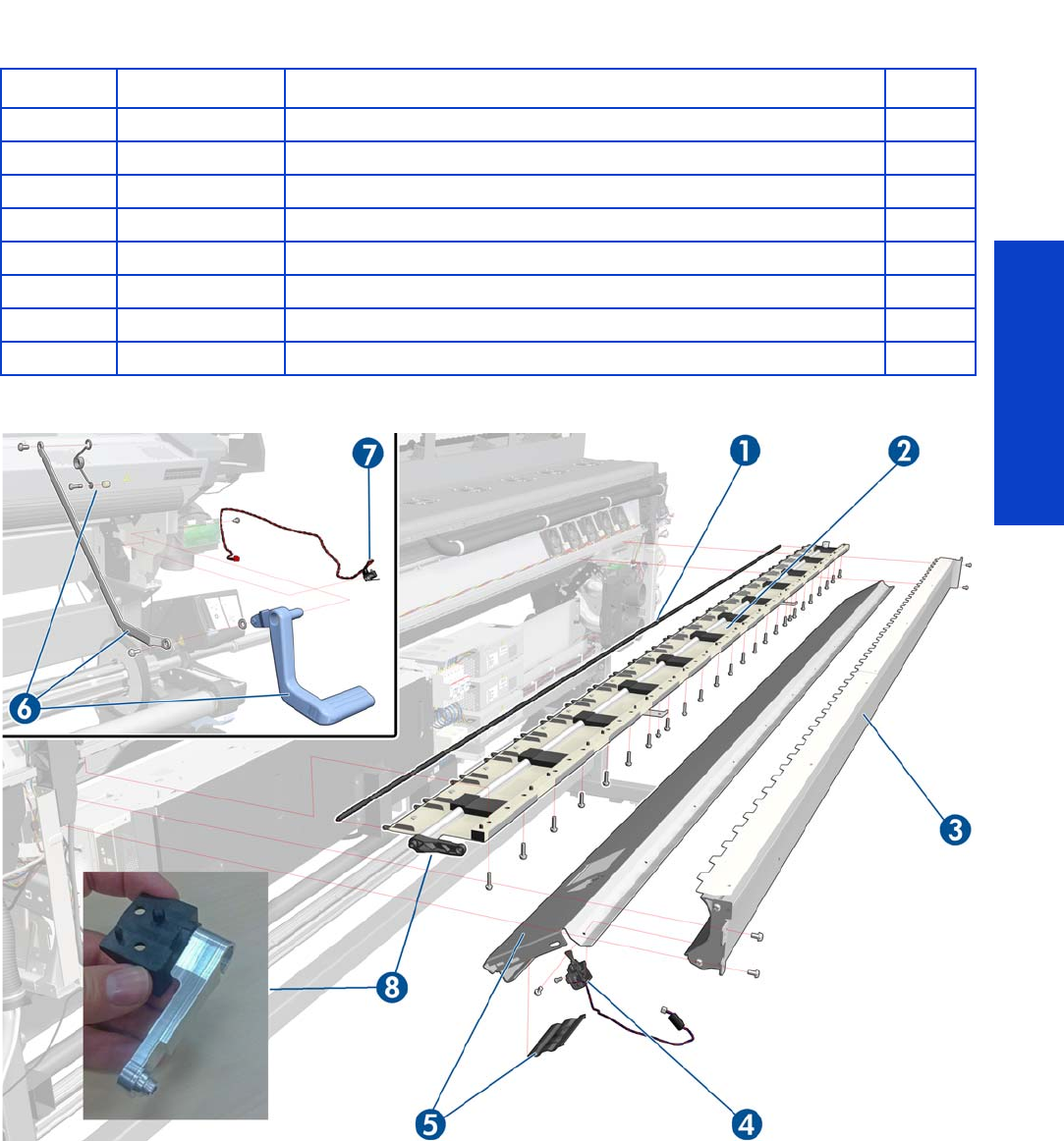
Parts and Diagrams
Media Input (MI) and Pinchwheel Assembly 267
Media Input (MI) and Pinchwheel Assembly
Part Number Part Description Page
1Q6651-60066 Pinchwheels Kit SERV 572
2CQ871-67023 Complete Pinchwheels 104 SERV 569
3CQ871-67073 MI Profile and Mylar 104 544
4CQ869-67021 SPI Media Presence Sensor SERV 557
5CQ 871- 67072 MI Pla ten 104 SE RV 550
6CQ 871-67057 Pi nchwheel Lever Asse mb ly 104 SE RV 561
7CQ871-67053 Media Lever Sensor 104 SERV 299
8CQ871-67101 Metal Cam Arm SERV 564
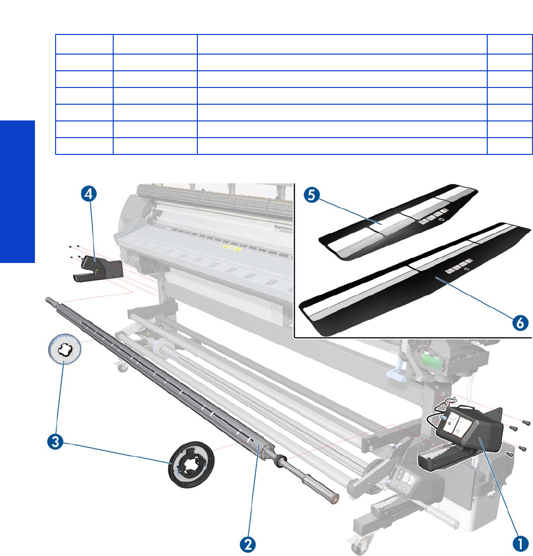
Parts and Diagrams
268 Chapter 7 Parts and Diagrams
Media Entry Assemblies
Part Number Part Description Page
1CQ871-67004 Rewinder Right Module 585
2CQ871-67040 3-inch Spindle 104 SERV
3CH955-67037 Spindle Hub SERV N/A
4CQ871-67026 Rewinder Left Module 104 SERV 582
5CQ869-67048 SPI Loading Accessory SERV
6CQ871-67049 Loading accessory 104 SERV
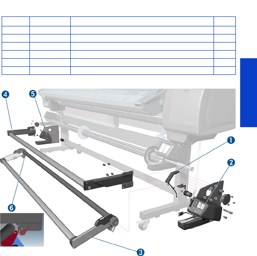
Parts and Diagrams
Take-Up Reel Assembly 269
Take-Up Reel Assembly
Part Number Part Description Page
1CQ871-67035 TUR Sensor Module 104 SERV 599
2CQ871-67034 TUR RH Module 104 SERV 588
3CQ871-67050 TU R Tension B ar 602
4CQ871-67019 TUR Diverter 104 595
5CQ871-67048 TUR LH Module 104 SERV 583
6CQ871-67099 Tension Bar Grounding Cable 104 SERV
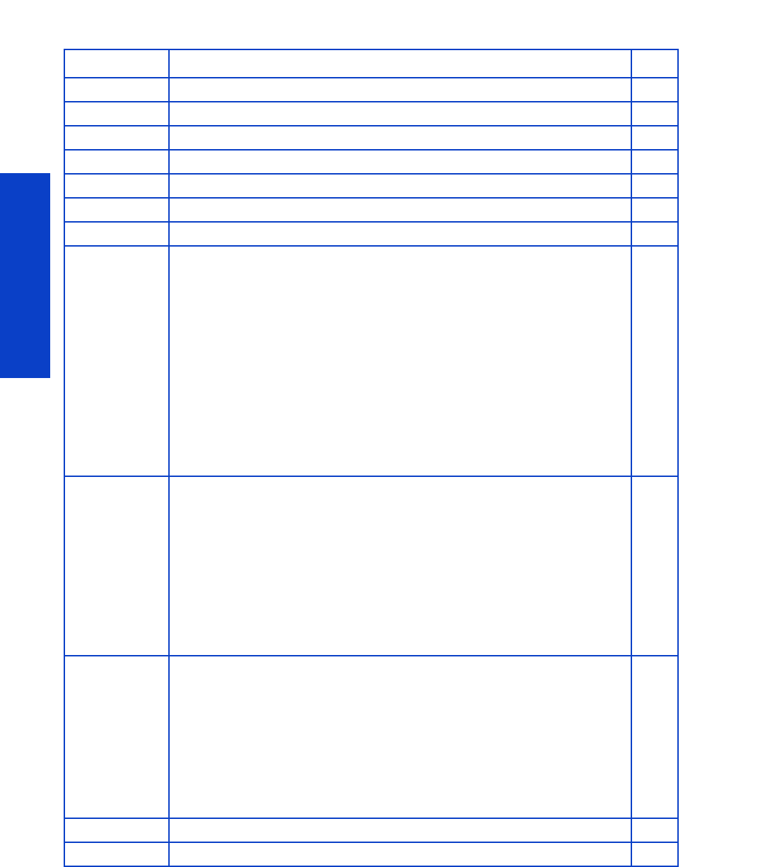
Parts and Diagrams
270 Chapter 7 Parts and Diagrams
Miscellaneous Parts
Part Number Part Description Page
CH955-67114 Right Arc
CH955-67115 Left Arc
CQ 871- 67025 Lab els 104 SE RV
CH955-67108 CAL HP Perm. Gloss Adhesive Vinyl 229
Q1273-60296 Inst Dry Photo Gloss Calibrat
CQ 871- 67077 S crew Set 104
CH955-67070 User’s Maintenance/Cleaning Kit
CQ871-67092
SMK-1 104 SERV
•Scan Axis Motor
•Encoder Strip and Sensor
•Ink Tubes Assembly and Trailing Cable
•Belt & Tension Kit Assembly
•Carriage Assembly without PCA, Cutter, and Color Sensor
•Carriage PCA Cover
•Line Sensor
•Media Jam Sensor
•Drop Detector and Ink Funnel Transmission
•Ink Maintenance Kit
•Two bottles of lubricant oil
•SMK Flyer L28500: Formatter PCA battery check
CQ871-67093
SMK-2 104 SERV
•Service Station
•Line Sensor
•Media Jam Sensor
•Ink Maintenance Kit
•Front Rod Oiler
•Lubrication Felts Kit
•Belt and Tensioner
•Two bottles of lubricant oil
•SMK Flyer L28500: Formatter PCA battery check
CQ 871-67094
SMK-3 104 SERV
•Drop Detector and Ink Funnel Transmission
•Line Sensor
•Ink Maintenance Kit
•Front Rod Oiler
•Lubrication Felts Kit
•Belt and Tensioner
•Two bottles of lubricant oil
•SMK Flyer L28500: Formatter PCA battery check
CQ871-67080 Cables to ISS side 104 SERV
CQ871-67081 Cables to SVS side 104 SERV

271
Removal & Installation
8 Removal & Installation
Two contents lists are provided for this chapter to help you to quickly find the service part you want to
replace. The first list is provided in Service part order and the second in Disassembly order.
Service part order
•Introduction .......................................................................................................277
•Opening the Window ........................................................................................ 281
•APS Assembly ...................................................................................................402
•Belt Assembly ....................................................................................................425
•Carriage Assembly with Belt, Pulley, and Tensioner................................................. 416
•Carriage Flex Cables...........................................................................................411
•Carriage PCA....................................................................................................408
•Cartridge Tray ...................................................................................................540
•Circuit Breakers..................................................................................................464
•Color Sensor Actuator Assembly .......................................................................... 481
•Color Sensor Assembly .......................................................................................477
•Curing Fans and Cover.......................................................................................496
•Curing Heaters .................................................................................................. 521
•Curing Holders ..................................................................................................527
•Curing IR Temperature Sensor & Fan.....................................................................506
•Curing Module .................................................................................................. 512
•Cutter Assembly.................................................................................................392
•Drive Roller .......................................................................................................575
•Drop Detector, Funnel Transmission, Waste Ink Tube ............................................... 376
•Dryer Grill.........................................................................................................483
•Dryer Heater .....................................................................................................494
•Dryer IR Temperature Sensor................................................................................486
•Dryer Protector................................................................................................... 491
•Electronics Enclosure........................................................................................... 470
•Electronics Enclosure Extension Cover ...................................................................329
•Encoder Disc and Sensor ....................................................................................559
•Encoder Strip.....................................................................................................405
•Engine PCA ......................................................................................................449
•Extra PSU 24 V..................................................................................................323
•Formatter Battery................................................................................................463
•Formatter PCA ...................................................................................................452
•Front Panel ........................................................................................................342

272 Chapter 8 Removal & Installation
Removal & Installation
•Front Tube Shelf Beam ........................................................................................289
•Hard Disk Drive .................................................................................................454
•Heater Controller Box ......................................................................................... 331
•Hinge Brakes.....................................................................................................293
•Individual Pinchwheel Rollers ...............................................................................572
•Ink Supply Station (ISS) .......................................................................................394
•Ink Supply Station PCAs (Top and Bottom).............................................................398
•Ink Supply Tubes and Trailing Cable..................................................................... 381
•Input Platen .......................................................................................................550
•Input Roller........................................................................................................542
•Interconnect PCA ...............................................................................................441
•ISS to Cartridge Cables ...................................................................................... 391
•Left Cover..........................................................................................................303
•Left Curing Cover ...............................................................................................308
•Left Trim ........................................................................................................... 306
•Line Sensor Assembly ......................................................................................... 473
•Media-Axis Motor ..............................................................................................430
•Media Input Profile.............................................................................................544
•Media Jam Sensor and Carriage Reflector Assembly...............................................422
•Media Lever Linkage........................................................................................... 561
•Media Sensor....................................................................................................557
•Oiler ................................................................................................................ 414
•OMAS Cable ................................................................................................... 444
•OMAS Controller Card.......................................................................................442
•OMAS: Optical Media Advance Sensor ...............................................................432
•Output Platen ....................................................................................................524
•Output Roller .....................................................................................................554
•Pinchwheel Assembly..........................................................................................569
•Pinchwheel Cam Arm .........................................................................................564
•Power Box Cover................................................................................................ 321
•Power Supply Unit (PSU)......................................................................................457
•Pre-Driver PCA...................................................................................................327
•Primer Assembly ................................................................................................345
•Primer Valve Cable.............................................................................................349
•Primer Valves.....................................................................................................347
•Print Platen ........................................................................................................530
•Printhead Cleaning Cartridge Door ......................................................................555
•Printhead Cleaning Cartridge Door Sensor............................................................556
•PrintMech PCA ..................................................................................................467
•Rear Fans..........................................................................................................340
•Rear Upper Cover .............................................................................................. 312
Service part order

Service part order 273
Removal & Installation
•Rewinder Left-Hand Module ................................................................................ 582
•Rewinder Right-Hand Module.............................................................................. 585
•Right Connector Cover ........................................................................................ 318
•Right Cover....................................................................................................... 296
•Right Curing Cover ............................................................................................. 310
•Right Trim, Media Lever, and Media Lever Sensor .................................................. 299
•Scan-Axis Motor................................................................................................ 426
•Scan-Axis Motor Fan.......................................................................................... 429
•Service Station ...................................................................................................351
•Take-Up Reel Diverter ......................................................................................... 595
•Take-Up Reel Left-Hand Module........................................................................... 583
•Take-Up Reel Right-Hand Module......................................................................... 588
•Take-Up Reel Sensor Module............................................................................... 599
•Tension Bar ...................................................................................................... 602
•TOMAS Cable .................................................................................................. 440
•TOMAS: Temperature Optical Media Advance Sensor ........................................... 438
•Top Cover ......................................................................................................... 314
•Top Cover Fans ................................................................................................. 337
•Vacuum Fan...................................................................................................... 356
•Vacuum Fan Cable ............................................................................................ 358
•Vacuum Fans Extra ............................................................................................ 360
•Waste Ink System .............................................................................................. 369
•Waste Ink System Support .................................................................................. 373
•Waste Ink Tube Guide ........................................................................................374
•Web Wipe Assembly......................................................................................... 354
•Window........................................................................................................... 283
•Window Lock Sensor Left.................................................................................... 333
•Window Lock Sensor Right ................................................................................. 335
Service part order

274 Chapter 8 Removal & Installation
Removal & Installation
Disassembly order
•Introduction .......................................................................................................277
•Opening the Window.........................................................................................281
•Window ...........................................................................................................283
•Front Tube Shelf Beam ........................................................................................289
•Hinge Brakes.....................................................................................................293
•Right Cover .......................................................................................................296
•Right Trim, Media Lever, and Media Lever Sensor .................................................. 299
•Left Cover......................................................................................................... 303
•Left Trim ........................................................................................................... 306
•Left Curing Cover .............................................................................................. 308
•Right Curing Cover ............................................................................................. 310
•Rear Upper Cover .............................................................................................. 312
•Top Cover ......................................................................................................... 314
•Right Connector Cover ........................................................................................ 318
•Power Box Cover................................................................................................321
•Extra PSU 24 V ..................................................................................................323
•Pre-Driver PCA...................................................................................................327
•Electronics Enclosure Extension Cover ...................................................................329
•Heater Controller Box ......................................................................................... 331
•Window Lock Sensor Left ....................................................................................333
•Window Lock Sensor Right ..................................................................................335
•Top Cover Fans..................................................................................................337
•Rear Fans......................................................................................................... 340
•Front Panel ........................................................................................................342
•Primer Assembly................................................................................................ 345
•Primer Valves.....................................................................................................347
•Primer Valve Cable.............................................................................................349
•Service Station...................................................................................................351
•Web Wipe Assembly ........................................................................................ 354
•Vacuum Fan ......................................................................................................356
•Vacuum Fan Cable .............................................................................................358
•Vacuum Fans Extra ............................................................................................ 360
•Waste Ink System ...............................................................................................369
•Waste Ink System Support ...................................................................................373
•Waste Ink Tube Guide ........................................................................................374
•Drop Detector, Funnel Transmission, Waste Ink Tube ...............................................376
•Ink Supply Tubes and Trailing Cable.....................................................................381
•ISS to Cartridge Cables ...................................................................................... 391
•Cutter Assembly .................................................................................................392
•Ink Supply Station (ISS) .......................................................................................394

Disassembly order 275
Removal & Installation
•Ink Supply Station PCAs (Top and Bottom) ............................................................ 398
•APS Assembly................................................................................................... 402
•Encoder Strip .................................................................................................... 405
•Carriage PCA ................................................................................................... 408
•Carriage Flex Cables .......................................................................................... 411
•Oiler................................................................................................................. 414
•Carriage Assembly with Belt, Pulley, and Tensioner ................................................. 416
•Media Jam Sensor and Carriage Reflector Assembly .............................................. 422
•Belt Assembly ................................................................................................... 425
•Scan-Axis Motor................................................................................................ 426
•Scan-Axis Motor Fan.......................................................................................... 429
•Media-Axis Motor ............................................................................................. 430
•OMAS: Optical Media Advance Sensor............................................................... 432
•TOMAS: Temperature Optical Media Advance Sensor ........................................... 438
•TOMAS Cable .................................................................................................. 440
•Interconnect PCA............................................................................................... 441
•OMAS Controller Card ...................................................................................... 442
•OMAS Cable.................................................................................................... 444
•Engine PCA...................................................................................................... 449
•Formatter PCA................................................................................................... 452
•Hard Disk Drive................................................................................................. 454
•Power Supply Unit (PSU) ..................................................................................... 457
•Formatter Battery ............................................................................................... 463
•Circuit Breakers ................................................................................................. 464
•PrintMech PCA.................................................................................................. 467
•Electronics Enclosure .......................................................................................... 470
•Line Sensor Assembly......................................................................................... 473
•Color Sensor Assembly ...................................................................................... 477
•Color Sensor Actuator Assembly...........................................................................481
•Dryer Grill ........................................................................................................ 483
•Dryer IR Temperature Sensor ............................................................................... 486
•Dryer Protector ...................................................................................................491
•Dryer Heater..................................................................................................... 494
•Curing Fans and Cover ...................................................................................... 496
•Curing IR Temperature Sensor & Fan .................................................................... 506
•Curing Module................................................................................................... 512
•Curing Heaters...................................................................................................521
•Output Platen.................................................................................................... 524
•Curing Holders.................................................................................................. 527
•Print Platen ....................................................................................................... 530
•Cartridge Tray................................................................................................... 540
Disassembly order (Continued)

276 Chapter 8 Removal & Installation
Removal & Installation
•Input Roller........................................................................................................542
•Media Input Profile.............................................................................................544
•Input Platen .......................................................................................................550
•Output Roller .....................................................................................................554
•Printhead Cleaning Cartridge Door ......................................................................555
•Printhead Cleaning Cartridge Door Sensor............................................................556
•Media Sensor....................................................................................................557
•Encoder Disc and Sensor ....................................................................................559
•Media Lever Linkage........................................................................................... 561
•Pinchwheel Cam Arm .........................................................................................564
•Pinchwheel Assembly..........................................................................................569
•Individual Pinchwheel Rollers ...............................................................................572
•Drive Roller ....................................................................................................... 575
•Rewinder Left-Hand Module.................................................................................582
•Take-Up Reel Left-Hand Module............................................................................583
•Rewinder Right-Hand Module ..............................................................................585
•Take-Up Reel Right-Hand Module .........................................................................588
•Take-Up Reel Diverter..........................................................................................595
•Take-Up Reel Sensor Module ...............................................................................599
•Tension Bar .......................................................................................................602
Disassembly order (Continued)
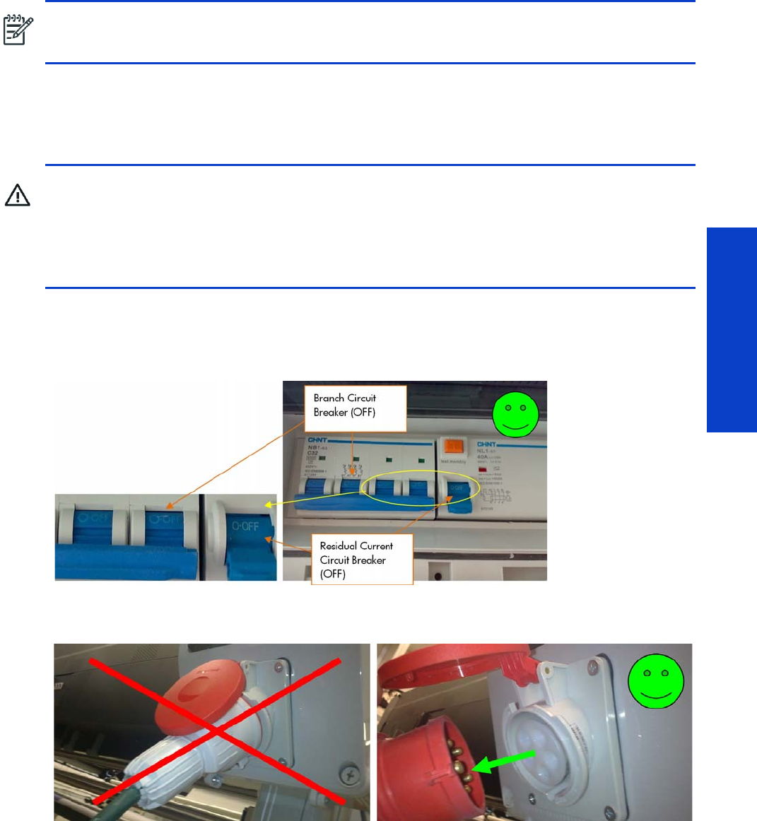
Introduction 277
Removal & Installation
Introduction
This chapter is a step-by-step guide to the removal and installation of the key components of the printer.
You may find it useful to tick off the steps as they are performed. Use the illustrations for each procedure
to identify the parts referred to in the text.
The procedures appear in order of removal. So the whole machine can be stripped down by starting at
the beginning of this chapter and working through the subsequent procedures.
Safety precautions
Review the instructions identified by WARNING and CAUTION symbols before you service the printer.
Follow these warnings and cautions for your protection and to avoid damaging the printer.
See below an example of a compliant Power Distribution Unit in Western Europe: 380–415 VAC, 30–
32 A per phase, 5 wires (3 lines, Neutral, and PE). In this example, to disconnect the printer from the
power source, the Branch Circuit Breaker and the Residual Current Circuit Breaker are shown in the OFF
position.
Also, if a three-phase power plug has been installed, you are recommended to unplug it before servicing
the printer, as shown below.
NOTE: Before using this chapter to remove and install a new component, always make sure that you
have performed the relevant service test from Chapter 4. If the test passes you will not need to replace the
component.
WARNING! Serious shock hazard leading to death or injury may result if you do not take the
following precautions:
•Ensure that the AC power outlet (mains) has a protective earth (ground) terminal.
•Switch the printer off, and disconnect it from the power source, before performing any maintenance.
•Prevent water or other liquids from running onto electrical components or circuits, or through
openings in the module.

278 Chapter 8 Removal & Installation
Removal & Installation
Electrostatic Discharge (ESD) precautions
To prevent damage to the printer circuits from high-voltage electrostatic discharge (ESD):
1. Do not wear clothing that is subject to static build-up.
2. Do not handle integrated circuits (ICs) in carpeted areas.
3. Do not remove an IC or a printed circuit assembly (PCA) from its conductive foam pad or conductive
packaging until you are ready to install it.
4. Ground (earth) your body while disassembling and working on the printer.
5. After removing a cover from the printer, attach an earthing (ground) lead between the PCA common
and earth ground. Touch all tools to earth ground to remove static charges before using them on the
printer.
6. After removing any PCA from the printer, place it on a conductive foam pad or into its conductive
packaging to prevent ESD damage to any ICs on the PCA.
Required tools
The following tools are required to disassemble and repair the printer:
•A magnetic screwdriver with short and long Torx bits, Phillips bits, and flat bits
•A set of L-shaped Torx keys
•A set of Allen keys
•A set of spanners
•Pliers with short and long tips, and cutting pliers
•A multimeter/multitester, for troubleshooting heaters
•Plastic cable ties, short and long
•Scissors
The following additional tools are recommended:
•Latex medical-type gloves
•Lint-free cloths, for cleaning and lubrication
•Lubricant oil, part number 6040-0855 or CQ869-67077
•Ethanol 95 or isopropyl alcohol, for cleaning
•De-ionized water, for cleaning
•Tweezers
•Isolation tape (plastic tape)
•Masking tape
•Small hand-held flashlight
Parts requiring two engineers
Two people are required to replace the parts listed below, either because of the size or weight of the part,
or because of accessibility problems: it may be necessary to remove a large or heavy part in order to
replace the part in question.
There are some large parts that can be handled by one person and are not included in this list.
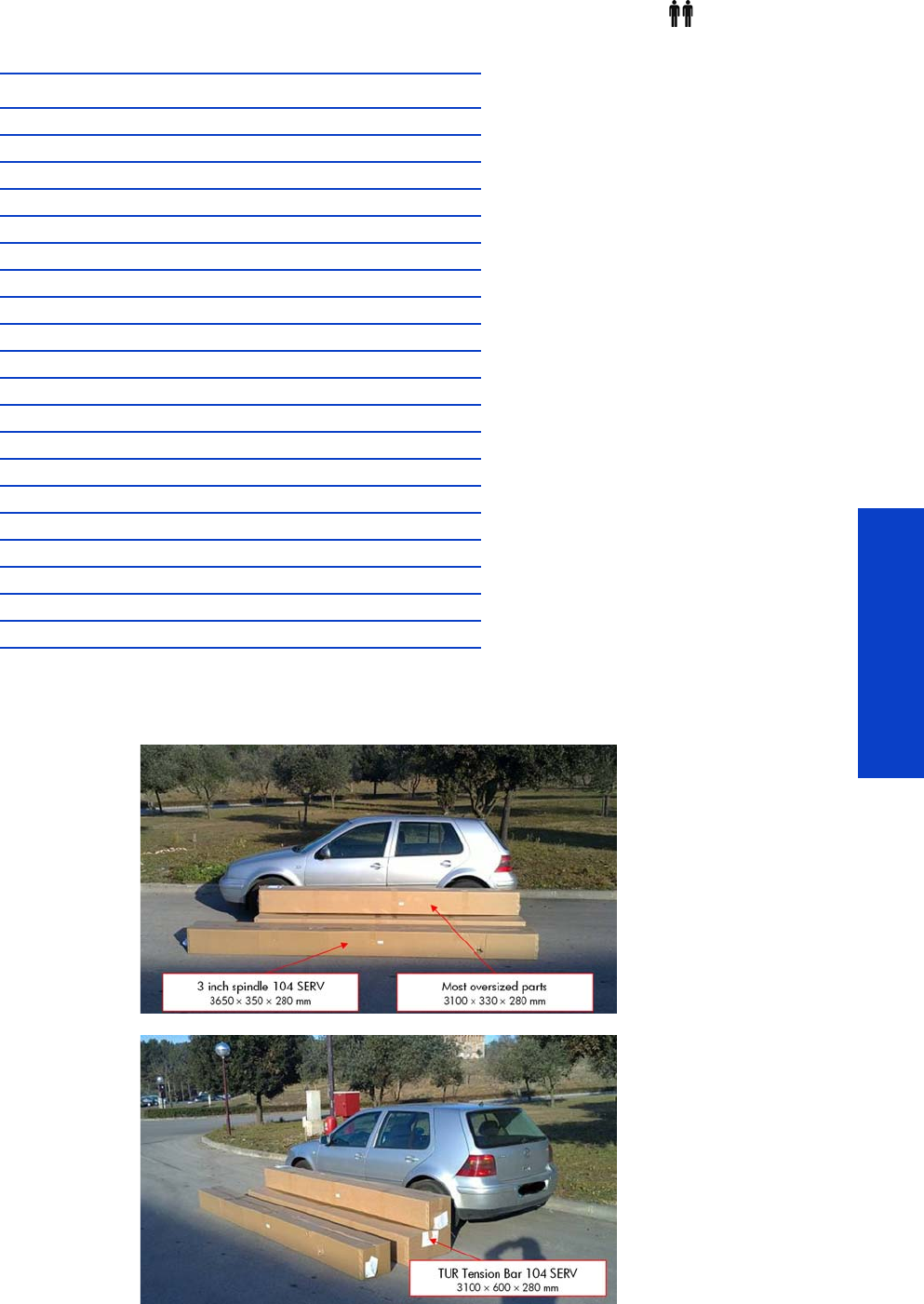
Introduction 279
Removal & Installation
In the rest of this chapter, a procedure that requires two people is indicated by the icon and the text
“(requires two people)”.
Parts requiring special transport
The parts listed below are large; before transporting them, check that they will fit into your vehicle.
Part number Description
CQ871-67011 Output Platen 104 SERV
CQ871-67062 Curing Resistor Holders SERV v2
CQ 871- 67018 Cu ri ng Grilles 104 SE RV
CQ871-67022 Curing Resistors 104 SERV
CQ871-67023 Complete Pinchwheels 104 SERV
CQ871-67037 Print Platen Assembly 104 SERV
CQ871-67038 Top Cover 104 SERV
CQ871-67039 Window without dryer 104 SERV
CQ871-67041 Curing without fans, resist IR - 104 SERV
CQ871-67043 Dryer Module 104 SERV
CQ871-67044 SRK and TC 104 SERV
CQ871-67052 Dryer Plastic Isolators 104 SER
CQ871-67007 Window Hinges – arc side 104 SERV
CQ871-67059 Drive Roller 104 SERV
CQ871-67078 Rear and Front Tube Shelf 104 SERV
CQ871-67072 MI Platen 104 SERV
CQ871-67073 MI Profile and Mylar 104 SERV
CH955-67089 Curing Bracket SERV
CH955-67114 CAL Right Arc
CH955-67115 CAL Left Arc

280 Chapter 8 Removal & Installation
Removal & Installation
These large parts should never be unpacked for transportation as there is a risk of damage. This applies
to all large parts, but especially to the SRK and TC 104 SERV (CQ871-67044), whose packaging protects
the tubes against deformation.
Part number Description Size of package
CQ871-67011 Output Platen 104 SERV 3100 × 330 × 280 mm
CQ871-67019 TUR Diverter 104 SERV 3100 × 330 × 280 mm
CQ871-67022 Curing resistors 104 SERV 3100 × 330 × 280 mm
CQ871-67023 Complete Pinchwheels 104 SERV 3100 × 330 × 280 mm
CQ871-67037 Print Platen Assembly 104 SERV 3100 × 330 × 280 mm
CQ871-67038 Top Cover 104 SERV 3100 × 330 × 280 mm
CQ871-67039 Window without dryer 104 SERV 3100 × 600 × 280 mm
CQ 871- 67040 3 i nch Spin dl e 104 SERV
(Customer Self-Replaceable)
3650 × 350 × 280 mm
CQ871-67041 Curing without fans, resist, IR – 104 SERV 3100 × 330 × 280 mm
CQ871-67042 Curing Fans Cover without fans 104 SERV 3100 × 330 × 280 mm
CQ871-67043 Dryer Module 104 SERV 3100 × 330 × 280 mm
CQ871-67044 SRK and TC 104 SERV 2088 × 457 × 230 mm
CQ871-67047 Entry Roller 104 SERV 3100 × 330 × 280 mm
CQ871-67050 TUR Tension Bar 104 SERV 3100 × 600 × 280 mm
CQ871-67051 Dryer Protection 104 SERV 3100 × 330 × 280 mm
CQ871-67059 Drive Roller 104 SERV 3100 × 330 × 280 mm
CQ871-67069 Back Covers 104 SERV 1650 × 400 × 200 mm
CQ871-67078 Rear and Front Tube Shelf 104 SERV 3650 × 350 × 280 mm
CQ871-67072 MI Platen 104 SERV 3100 × 330 × 280 mm
CQ871-67073 MI Profile and Mylar 104 SERV 3100 × 330 × 280 mm
CQ871-67100 Rear Upper Cover 104 SERV 3100 × 330 × 280 mm
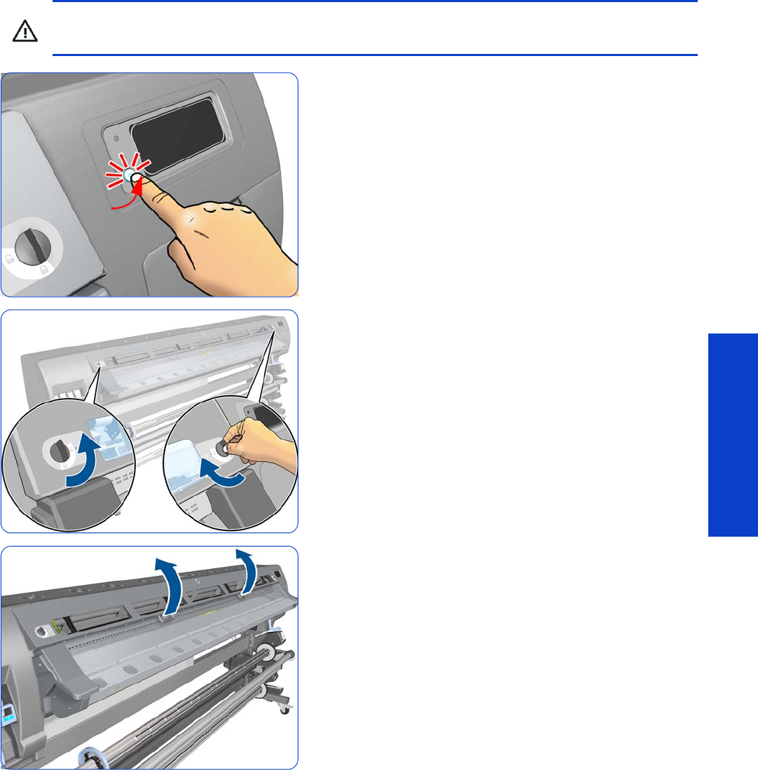
Opening the Window 281
Removal & Installation
Opening the Window
1. Turn off the printer.
2. Unlock the two Window Locks
3. Open the Window.
WARNING! Before opening the Window, observe all safety precautions when working in the area of
the Dryer Assembly. Make sure that the temperature of the print zone has sufficiently cooled down.
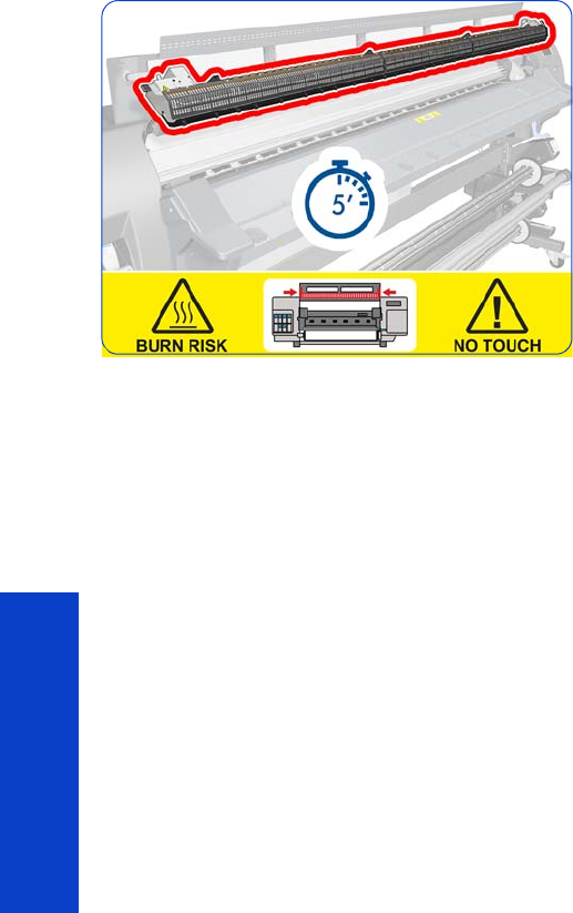
282 Chapter 8 Removal & Installation
Removal & Installation
4. Wait five minutes for the printer to cool down.
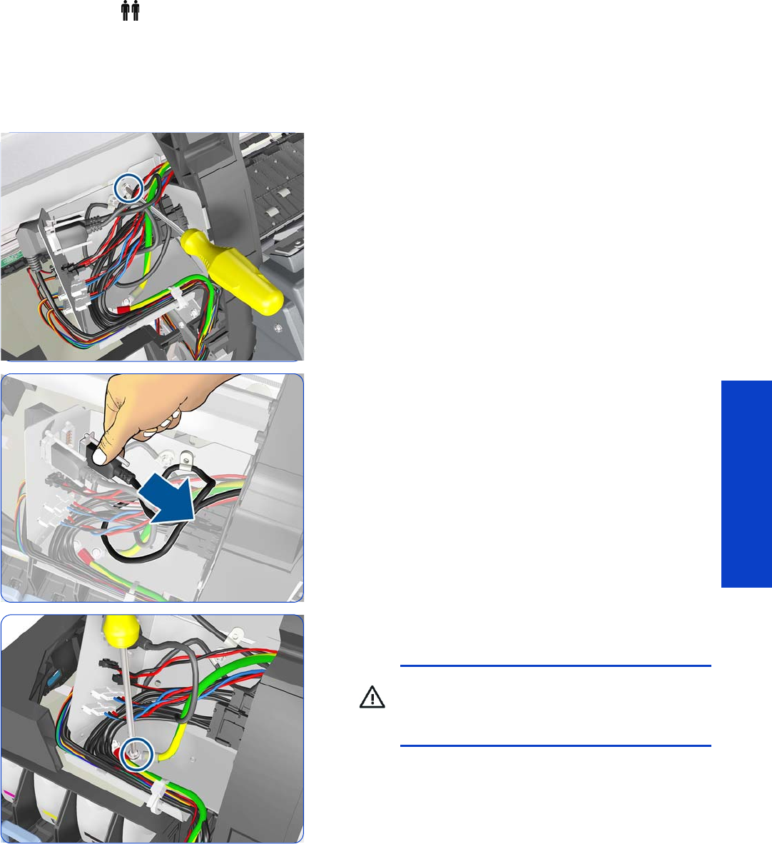
Window 283
Removal & Installation
Window
Removal (requires two people)
1. Open the Window
page 281
.
2. Remove the Left Cover
page 303
.
3. Remove one T20 screw from the Dryer IR Sensor cable
clamp.
4. Loosen two screws on the connector of the Dryer IR
Temperature Sensor cable, by hand or with a flat
screwdriver, and disconnect.
5. Remove one T25 screw, one lock washer, and one
normal washer that secure the dryer grounding cable.
WARNING! To ensure the electrical safety of
the printer, it is very important that this
grounding cable is reinstalled after the new part
has been installed.
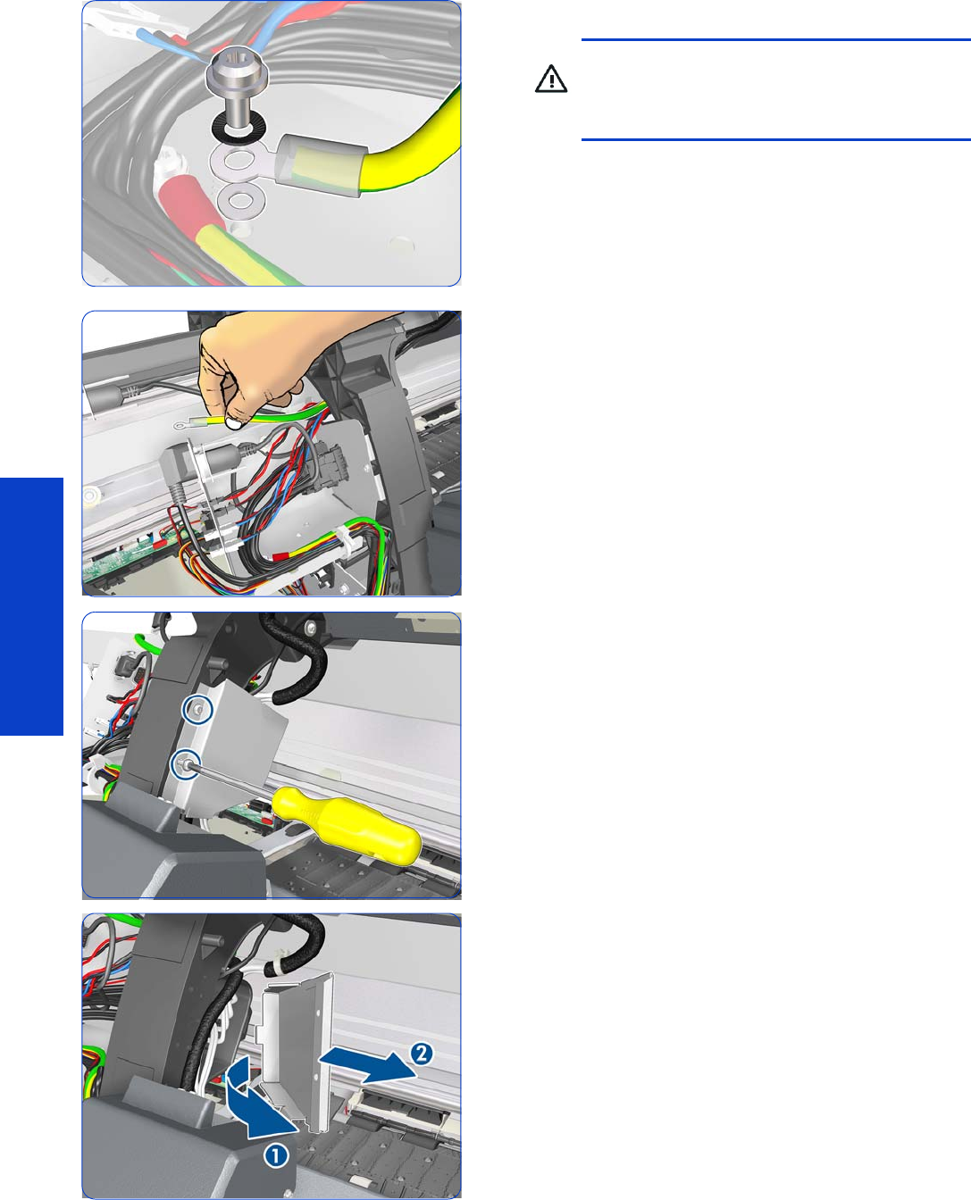
284 Chapter 8 Removal & Installation
Removal & Installation
6. Push the grounding cable to one side.
7. Remove two T-20 screws that secure the Left Cable Plate
to the printer.
8. Rotate (1) and remove (2) the Left Cable Plate.
WARNING! When reinstalling the
grounding cable, it is an important safety point
that the washer is installed between the printer
and the grounding cable.
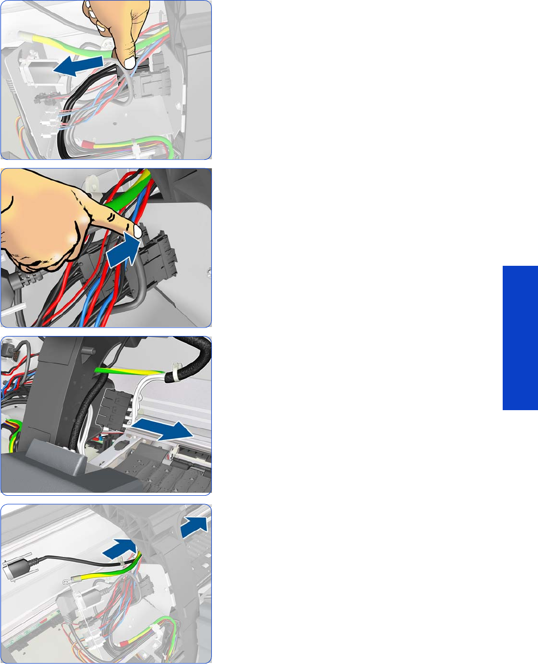
Window 285
Removal & Installation
9. Disconnect the dryer power cable.
10. Unclip the connector and push it aside.
11. Pull the dryer power cable to the right.
12. Continue pulling the dryer power cable to the right.
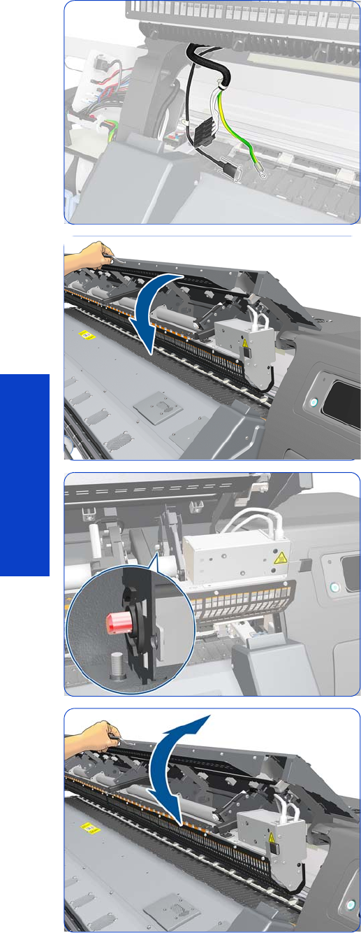
286 Chapter 8 Removal & Installation
Removal & Installation
13. Leave the dryer power cable in this position.
14 . Close the Window slightly.
15. Look for the hole at the end of the hinge shaft at the
right-hand side of the Window.
16. If you don’t see the hole, continue closing and opening
the Window slightly until you can see it.
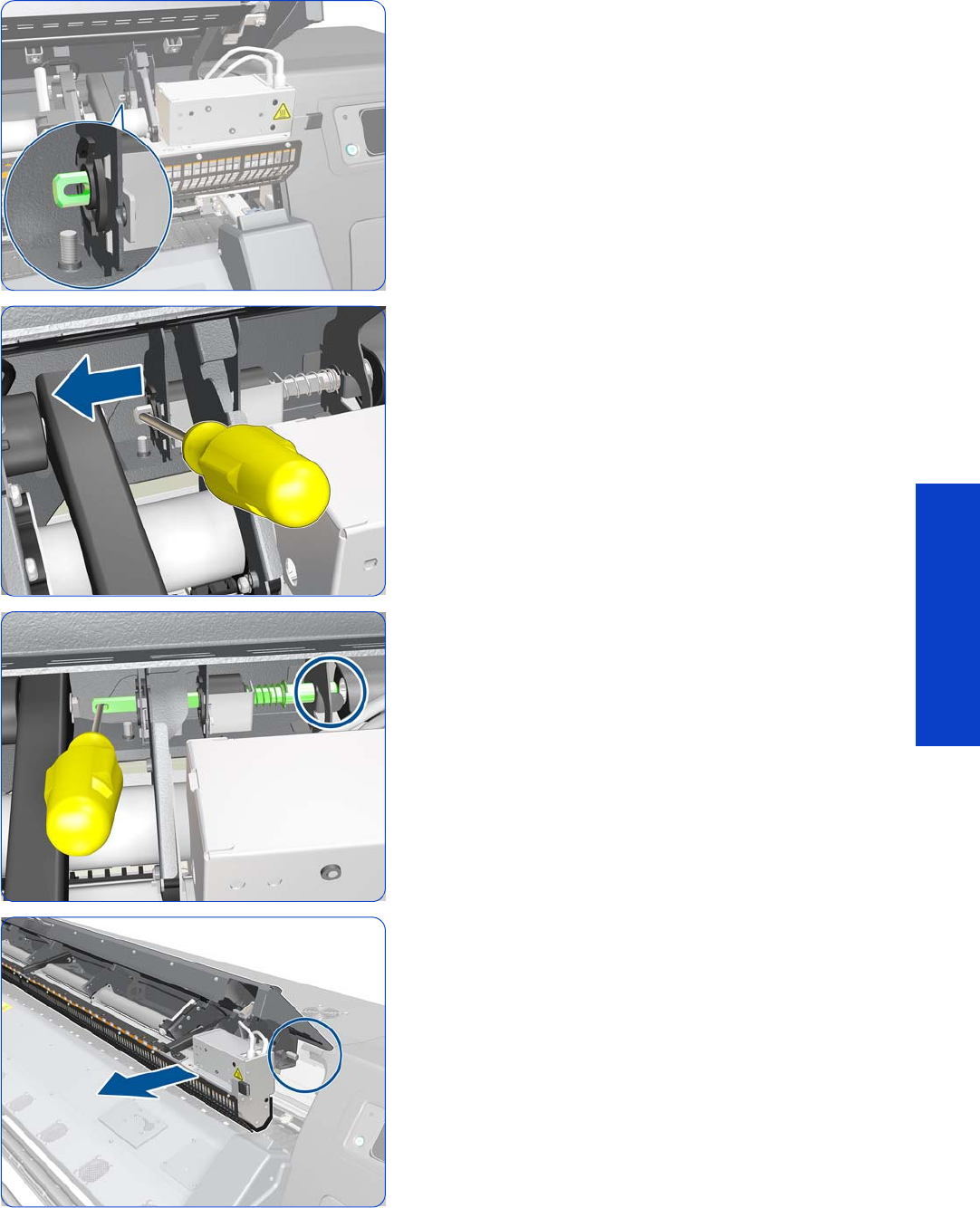
Window 287
Removal & Installation
17. Now you can see the hole.
18 . To disengage the hinge brake, insert a small
screwdriver or similar tool into a hole in the hinge
shaft and slide it to the left.
Tip: Rotating the window upwards while sliding the
shaft helps to reducing the necessary sliding force.
19. Slide the shaft all the way to the left until it is
disengaged.
20.The right-hand side of the Window is now loose.
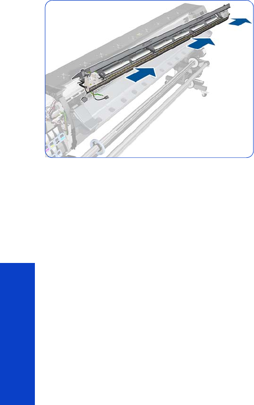
288 Chapter 8 Removal & Installation
Removal & Installation
21. Slide the Window to the right, carefully, because at the
same time you are disengaging the shaft from the left.
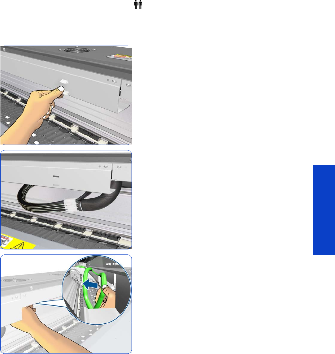
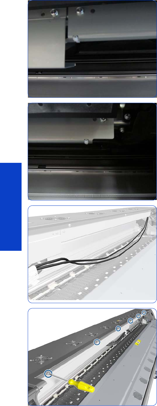
290 Chapter 8 Removal & Installation
Removal & Installation
5. Cut the left-hand cable tie.
6. Cut the right-hand cable tie.
7. The Trailing Cable must be unlinked from the Front Tube
Shelf Beam.
8. Remove six T-20 screws from the Front Tube Shelf
Beam.
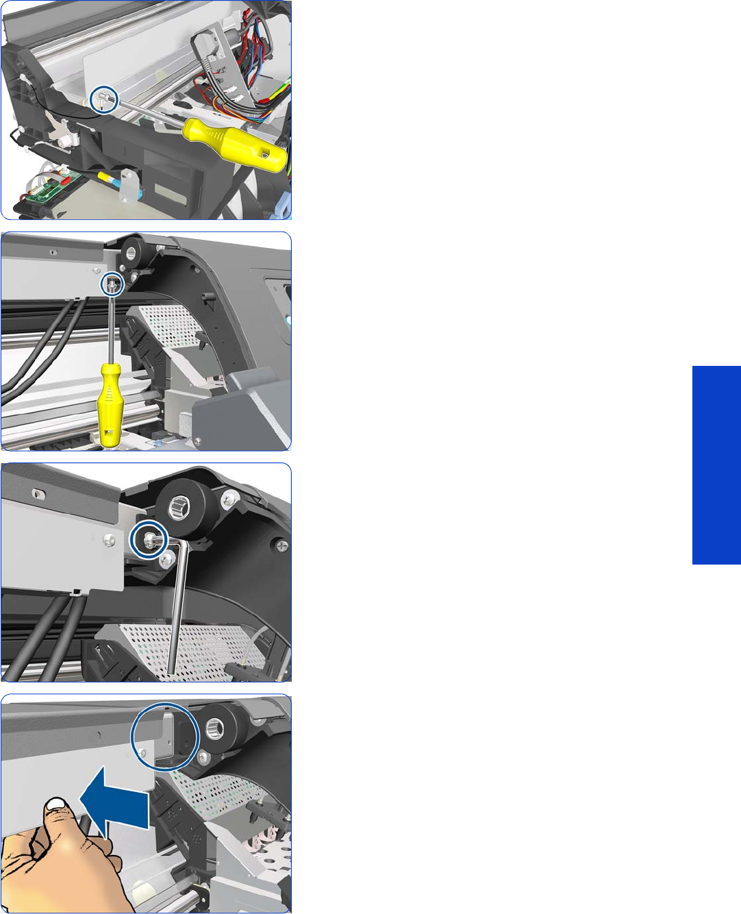
Front Tube Shelf Beam 291
Removal & Installation
9. Remove a T-20 screw.
10. Remove a T-20 screw.
11. Remove a T-20 screw with a Torx T-20 L-shaped
screwdriver.
12. Push in the Front Tube Shelf Beam until it starts to drop.
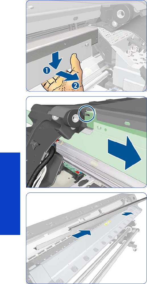
292 Chapter 8 Removal & Installation
Removal & Installation
13. Pull the Front Tube Shelf Beam downwards and then
outwards.
14 . Pull the Front Tube Shelf Beam to the right to detach it
from the printer.
15. Remove the Front Tube Shelf Beam from the printer.
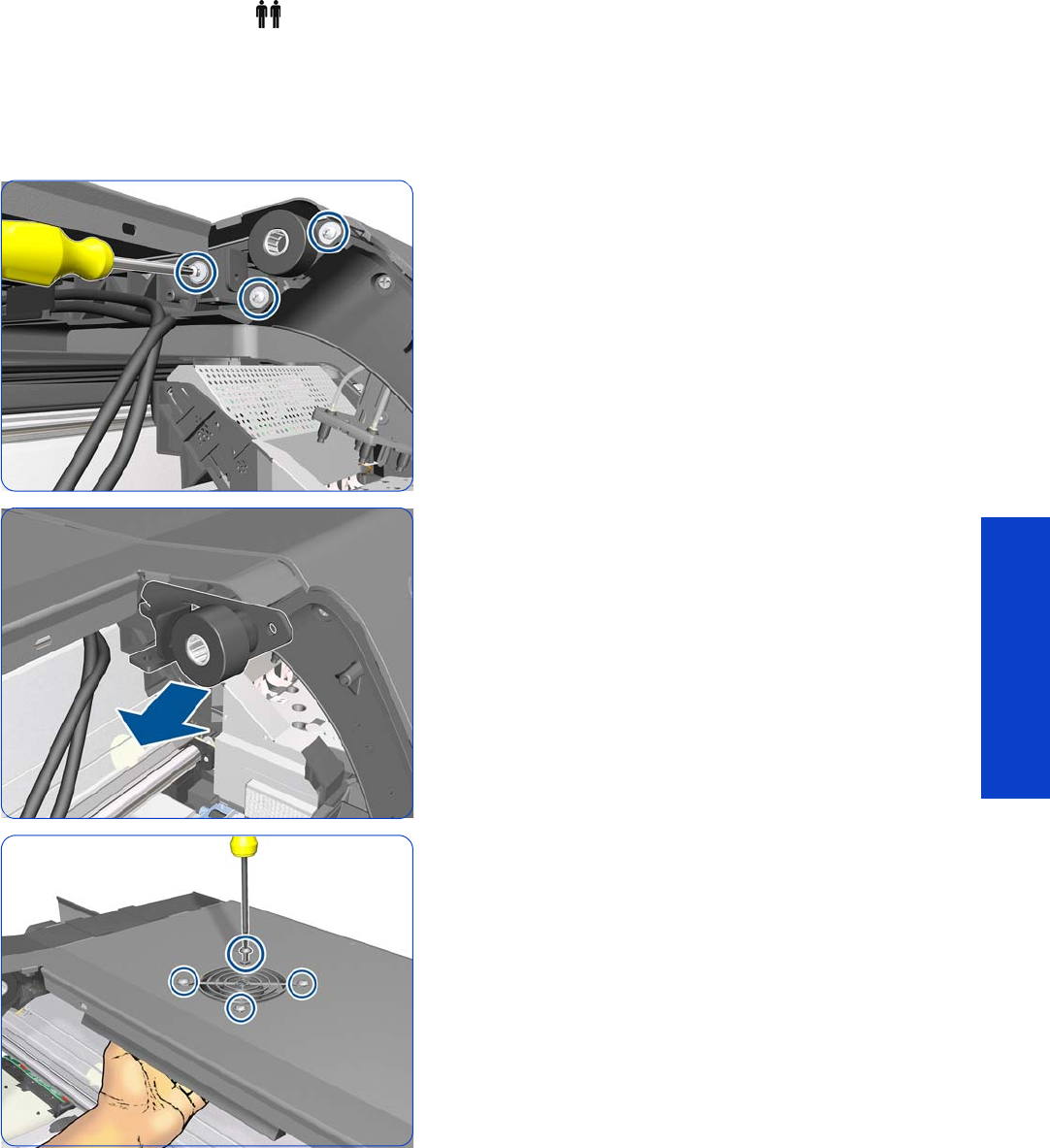
Hinge Brakes 293
Removal & Installation
Hinge Brakes
Removal (requires two people)
1. Remove the Window
page 283
.
2. Remove the Front Tube Shelf Beam
page 289.
3. Remove three T-15 screws from the Right Hinge Brake.
4. Remove the Right Hinge Brake.
5. Remove four T-20 screws from the grill of the Top Cover
Left Fan. When you remove the last screw, hold the Left
Fan and Diffuser with one hand to prevent it from
falling.
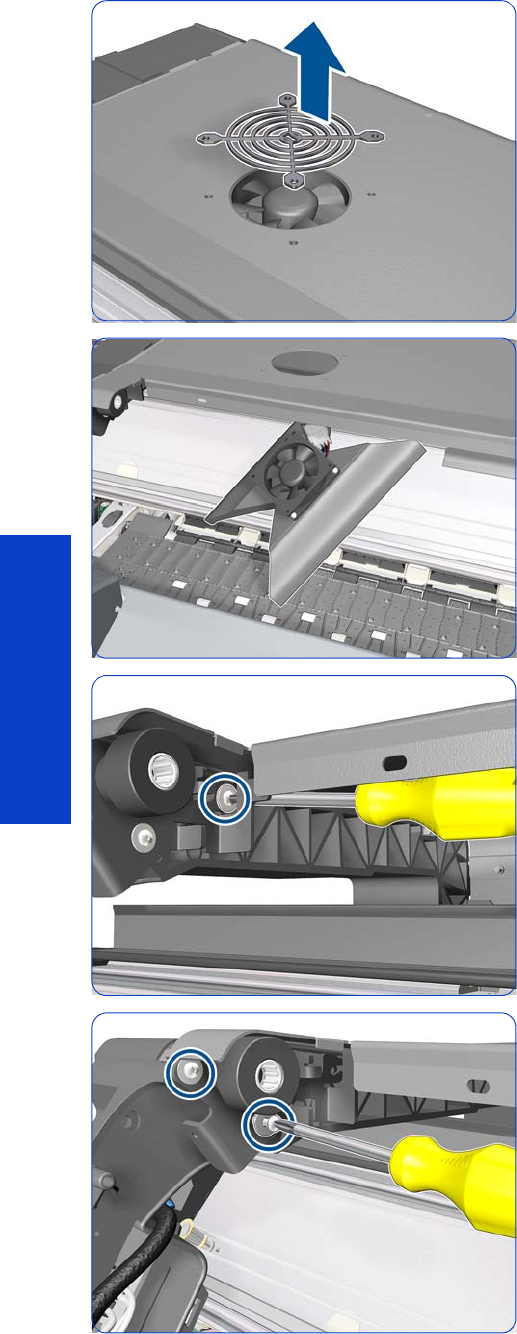
294 Chapter 8 Removal & Installation
Removal & Installation
6. Remove the grill of the Top Cover Left Fan.
7. Leave the Top Cover Left Fan and Diffuser on the
platen.
8. Remove a T-15 screw from the Left Hinge Brake.
9. Remove two T-15 screws from the Left hinge Brake.
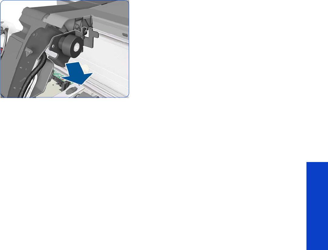
Hinge Brakes 295
Removal & Installation
10. Remove the Left Hinge Brake.
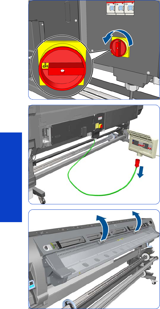
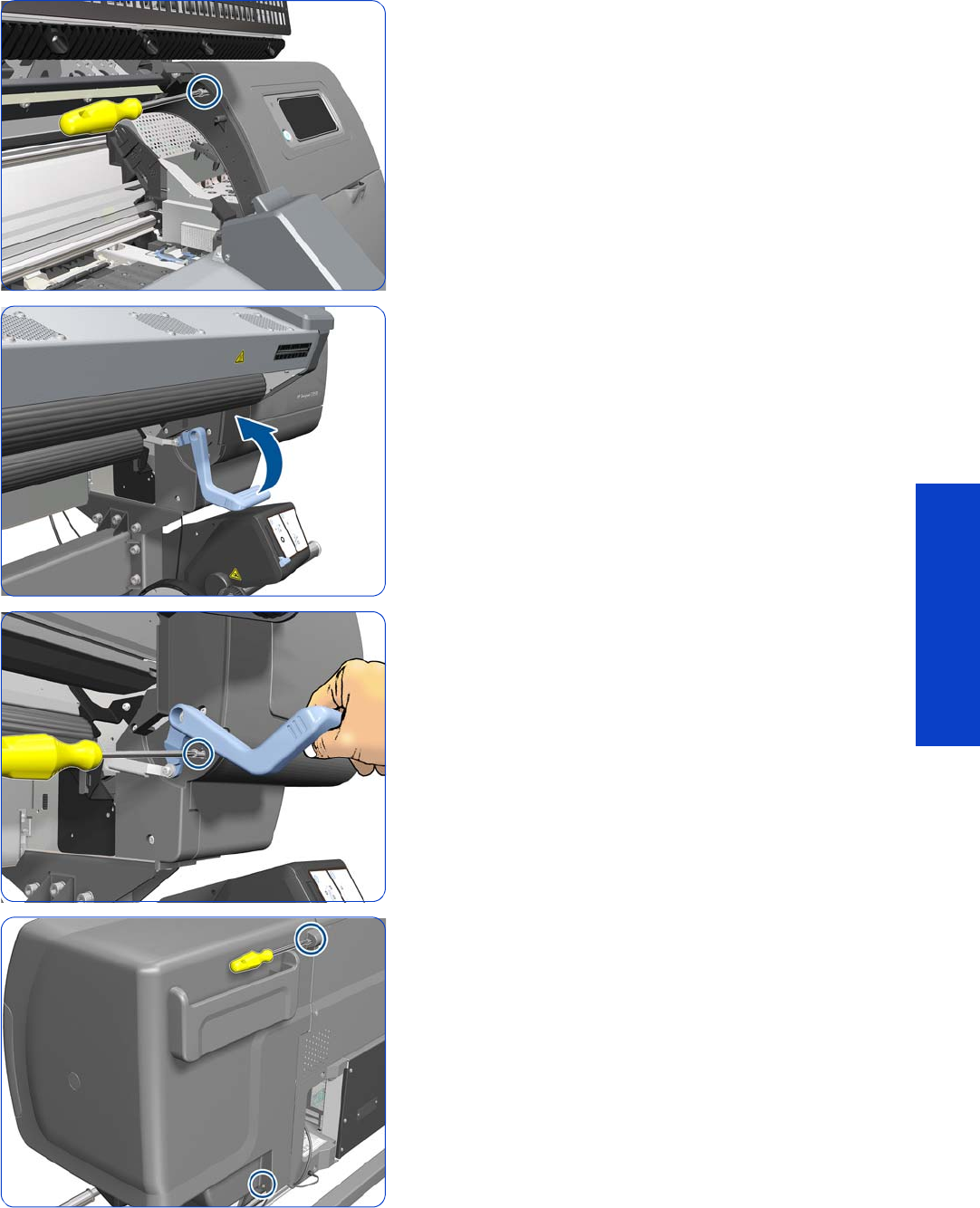
Right Cover 297
Removal & Installation
4. Remove one T-15 screw that secures the Right Cover.
5. Raise the Media Lever about 45°.
6. Keeping the Media Lever raised by 45°, remove the
T-15 screw underneath it.
7. Remove one T-15 screw and one T-20 screw that secure
the Right Cover from the rear of the printer.
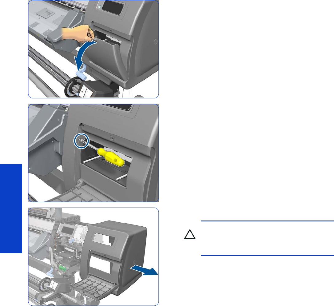
298 Chapter 8 Removal & Installation
Removal & Installation
8. Open the Printhead Cleaning Cartridge Door.
9. Remove one T-15 screw that secures the Right Cover.
10. Remove the Right Cover from the printer.
CAUTION: When installing the Right Cover,
make sure you leave the Printhead Cleaning
Cartridge Door open, otherwise you could
damage the sensor of the door.
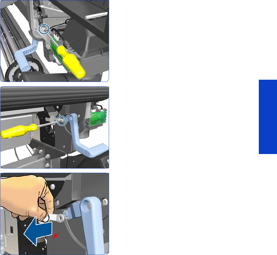
Right Trim, Media Lever, and Media Lever Sensor 299
Removal & Installation
Right Trim, Media Lever, and Media Lever Sensor
Removal
1. Remove the Right Cover
page 296
.
2. Remove the Input Roller
page 542
.
3. Remove the Right Connector Cover
page 318.
4. Remove a T-20 screw that secures the Media Lever.
5. Remove a T-15 screw that secures the Media Lever.
6. Detach the linking piece from the Media Lever.
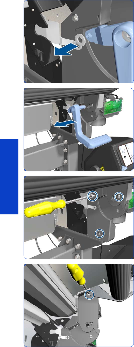
300 Chapter 8 Removal & Installation
Removal & Installation
7. Remove the plastic washer.
8. Remove the Media Lever from the printer.
9. Remove three T-20 screws.
10. Remove a T-20 screw.
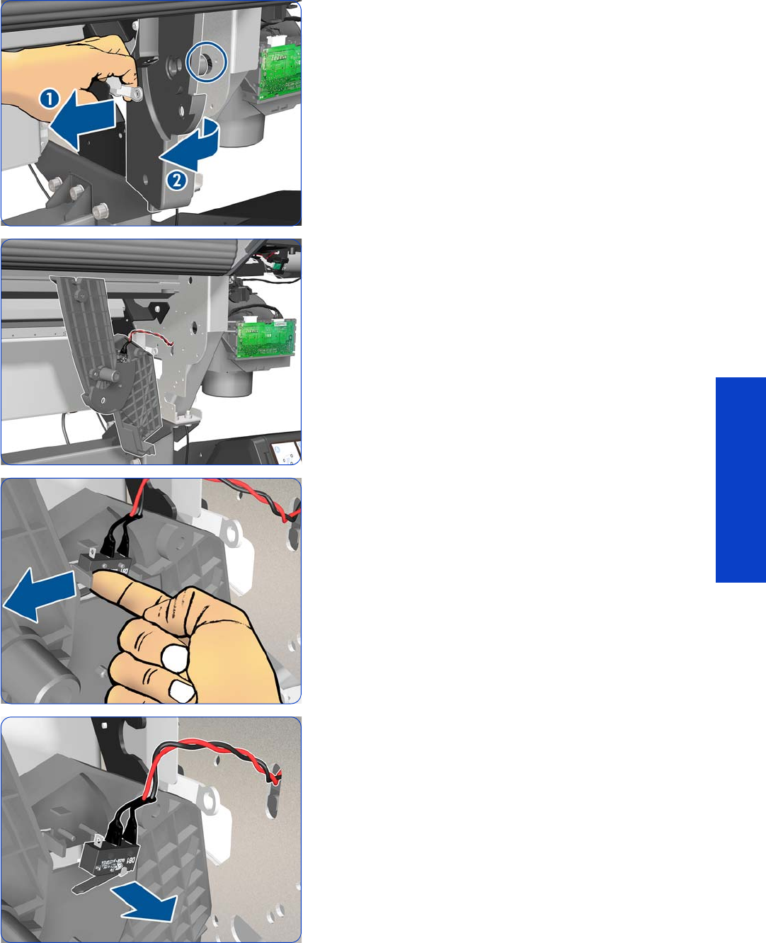
Right Trim, Media Lever, and Media Lever Sensor 301
Removal & Installation
11. Pull the linking piece and rotate the Right Trim to
disengage it from the hole in the side plate. Be careful
not to scratch the Right Trim with the linking piece.
12. This is the best position in which to remove the sensor
from the Right Trim. Be careful not to pull it any further,
because you could damage the cable, which is short.
13. Remove the sensor from the Right Trim.
14 . Move the sensor out of the way.
To disassemble the sensor, disconnect the sensor from
the Mini Interconnect PCA and unroute the cable below
the Service Station.
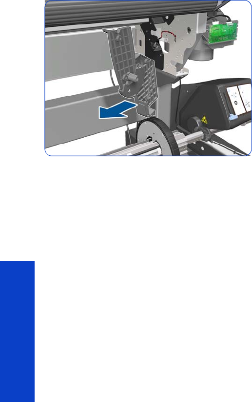
302 Chapter 8 Removal & Installation
Removal & Installation
15. Remove the Right Trim from the printer.

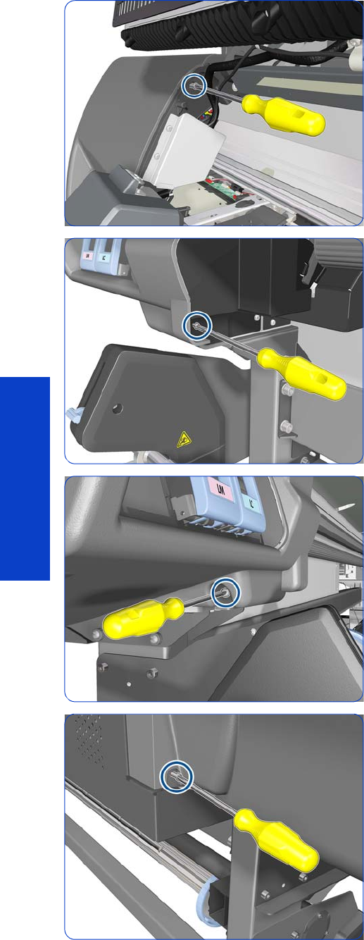
304 Chapter 8 Removal & Installation
Removal & Installation
4. Remove one T-15 screw that secures the Left Cover at
the top.
5. Remove one T-15 screw that secures the Left Cover at
the bottom.
6. Remove one T-20 screw that secures the Left Cover.
7. Remove one T-20 screw that secures the Left Cover.
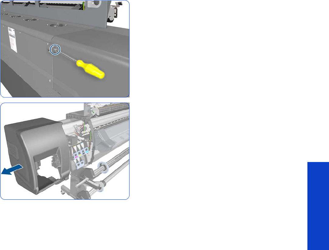
Left Cover 305
Removal & Installation
8. Remove one T-15 screw that secures the Left Cover.
9. Remove the Left Cover from the printer.
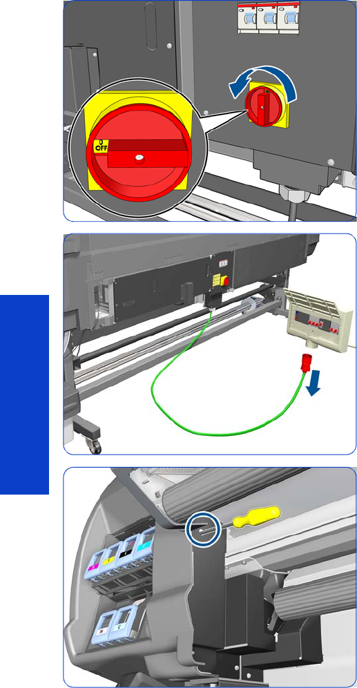
306 Chapter 8 Removal & Installation
Removal & Installation
Left Trim
Removal
1. Turn off the printer.
2. Disconnect electrical power. How this is done depends
on the installation.
3. Remove a T-20 screw that secures the Left Trim.
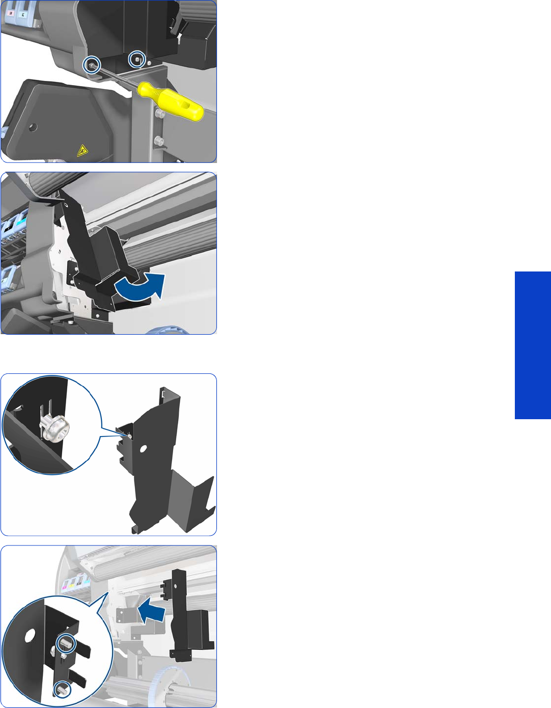
Left Trim 307
Removal & Installation
4. Remove a T-15 screw (left) and a T-20 screw (right).
5. Carefully remove the Left Trim from the printer.
Installation
1. When mounting the Left Trim, make sure to leave the
T-20 screw attached.
2. The Left Trim has two pins. Insert them into the side
plate.

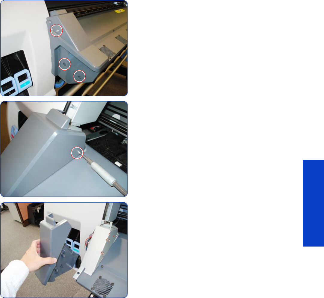
Left Curing Cover 309
Removal & Installation
4. Remove three T-20 screws from the Left Curing Cover.
5. Remove one T-10 screw from the Left Curing Cover.
6. Remove Left Curing Cover by sliding it off.

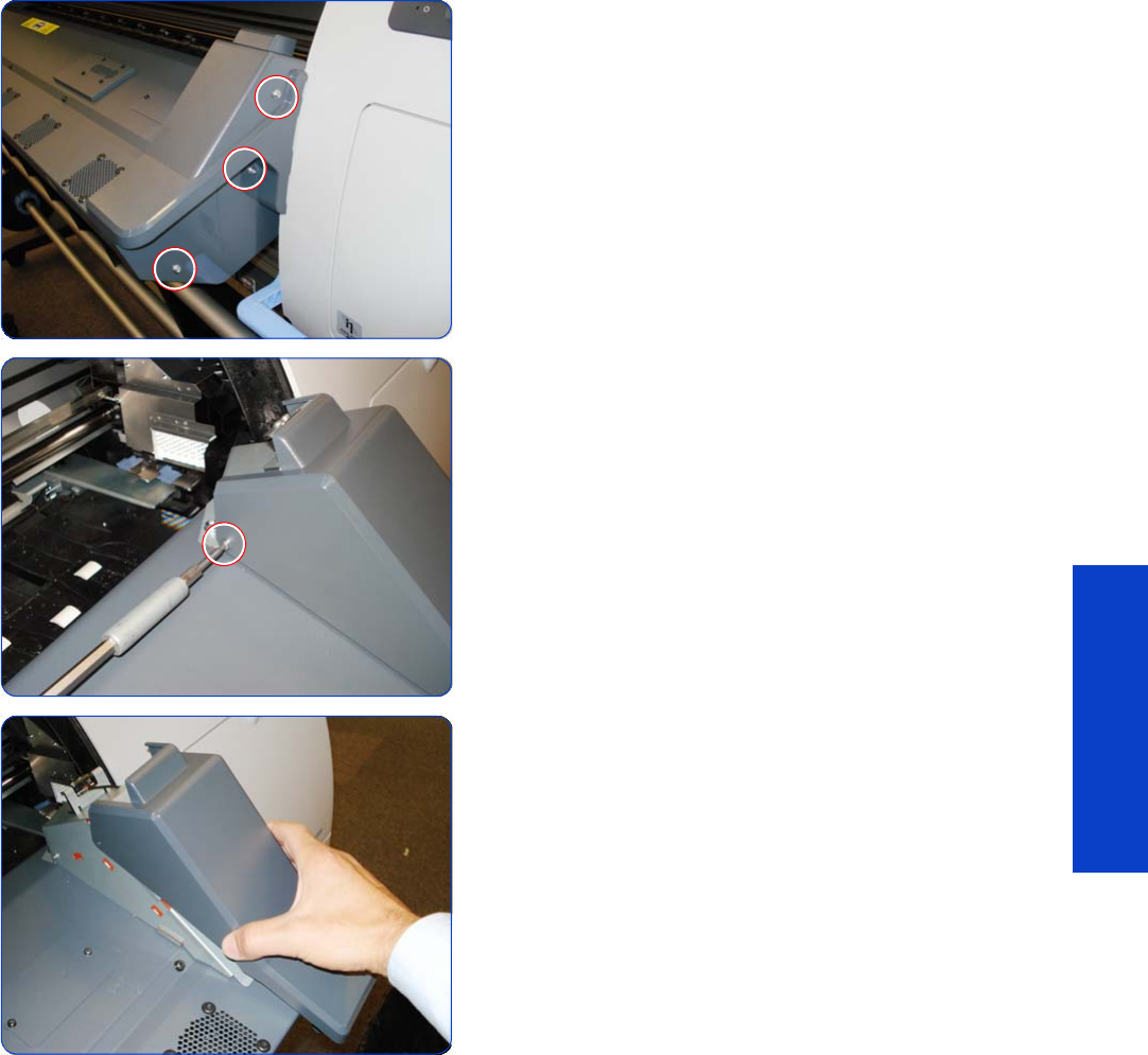
Right Curing Cover 311
Removal & Installation
4. Remove three T-20 screws from the Right Curing Cover.
5. Remove one T-10 screw from the Right Curing Cover.
6. Remove Right Curing Cover.
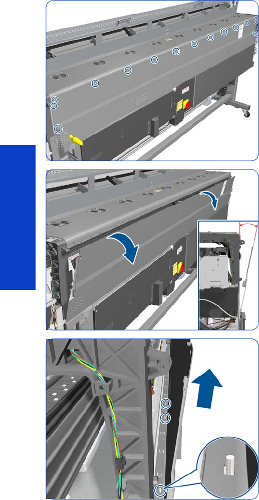
312 Chapter 8 Removal & Installation
Removal & Installation
Rear Upper Cover
Removal
1. Remove the Right Cover
page 296.
2. Remove the Left Cover
page 303
.
3. Remove the Electronics Enclosure Extension Cover
page 329
.
4. Remove eleven T-20 and four T-15 screws from the Rear
Upper Cover.
5. Open the Rear Upper Cover slightly, approximately 10
degrees.
6. Lift the Rear Upper Cover slightly to disengage it from
the pins at the top of the Electronics Enclosure.
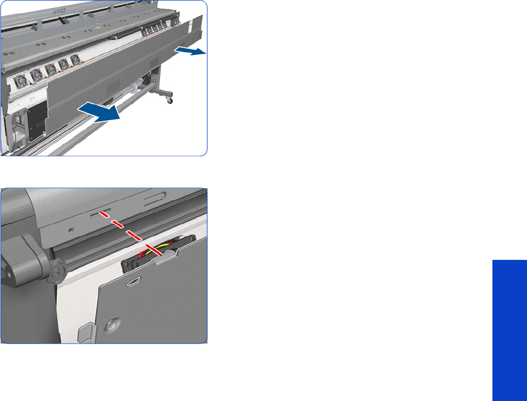
Rear Upper Cover 313
Removal & Installation
7. Remove the Rear Upper Cover from the printer.
Installation
1. When refitting the Rear Upper Cover, be careful to fit
the tabs into the matching holes, and make sure the
pins on top of the Electronics Enclosure are in position.
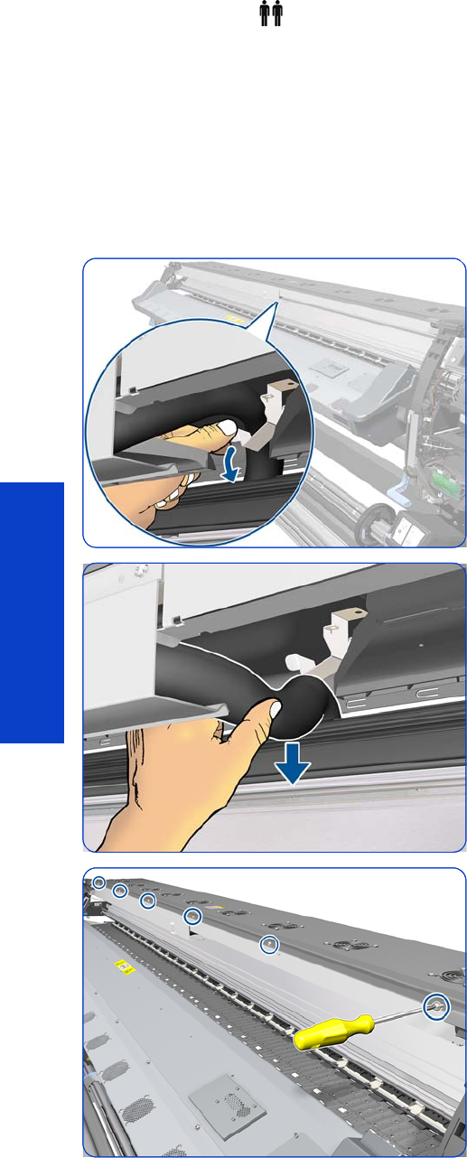
314 Chapter 8 Removal & Installation
Removal & Installation
Top Cover
Removal (requires two people)
1. Remove the Window
page 283
.
2. Remove the Right Cover
page 296
.
3. Remove the Electronics Enclosure Extension Cover
page 329
.
4. Remove the Rear Upper Cover
page 312
.
5. Bend the metal holder to disengage the Ink Supply
Tubes.
6. Disengage the Ink Supply Tubes from the holder.
7. Remove six T-20 screws.
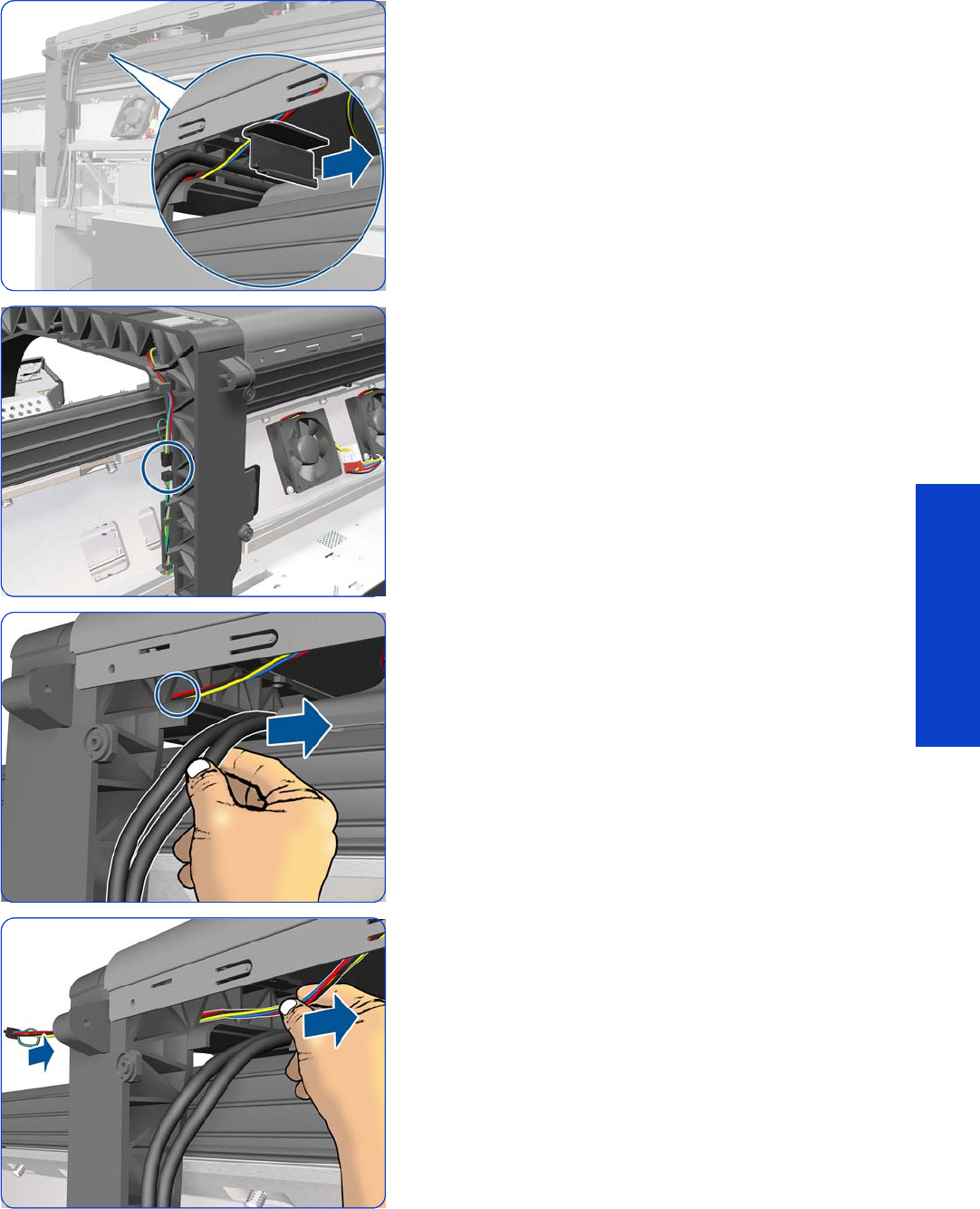
Top Cover 315
Removal & Installation
8. Release the arc clip.
9. Disconnect the Top Fans cable and disengage it from
the Right Arc.
10. Move the Trailing Cables out of the way so that they
don’t obstruct the area indicated with a circle.
11. Pass the cable through the Right Arc. Be careful not to
damage the connector.
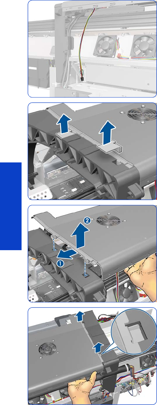
316 Chapter 8 Removal & Installation
Removal & Installation
12. Leave the cable hanging as shown.
13. Remove the two locking plates.
14 . Move the Top Cover slightly sideways and then
upwards to disengage it from the printer.
15. Lift the other end of the Top Cover, and make sure that
both locking pins are free (as shown in the detail).
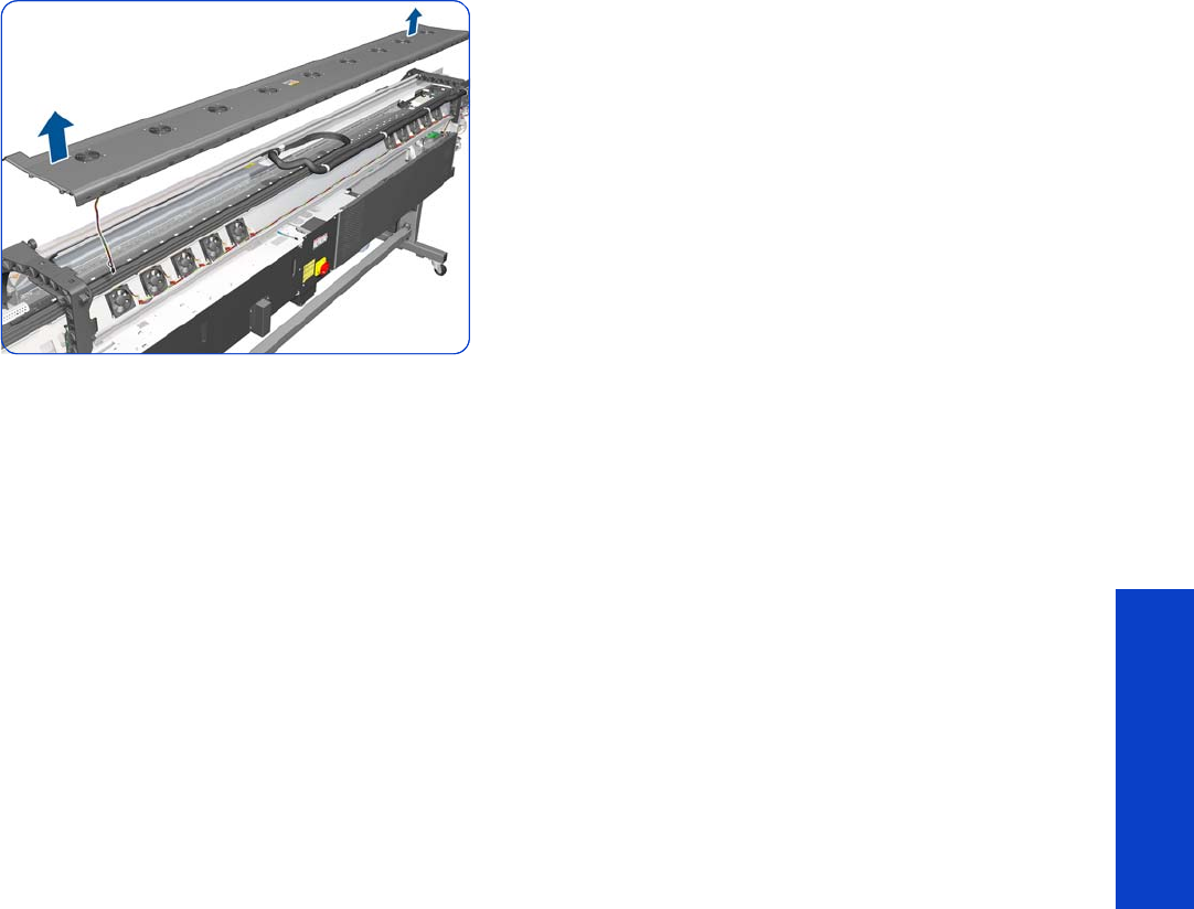
Top Cover 317
Removal & Installation
16. Remove the Top Cover.
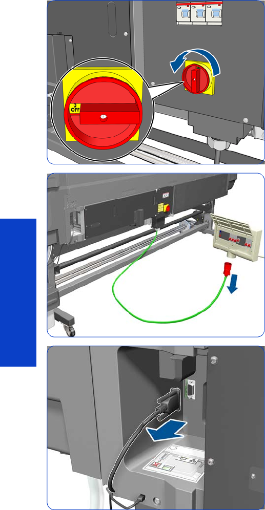
318 Chapter 8 Removal & Installation
Removal & Installation
Right Connector Cover
Removal
1. Turn off the printer.
2. Disconnect electrical power. How this is done depends
on the installation.
3. Disconnect the Take-Up Reel Connector.
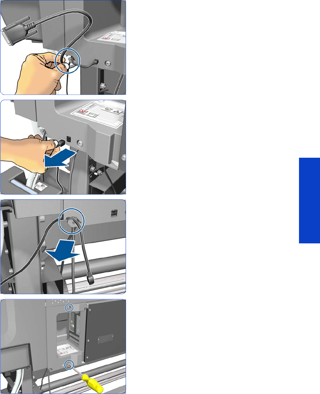
Right Connector Cover 319
Removal & Installation
4. Unroute the Take-Up Reel cable from the Right
Connector Cover.
5. Disconnect the Waste Ink System cable.
6. Disengage the Waste Ink System cable from the clip.
7. Remove two T-20 screws from the Right Connector
Cover.
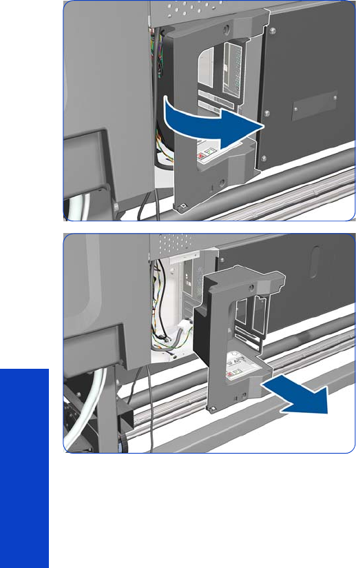
320 Chapter 8 Removal & Installation
Removal & Installation
8. Rotate the Right Connector Cover a few degrees
counter-clockwise so it can be removed completely.
9. Remove the Right Connector Cover from the printer.
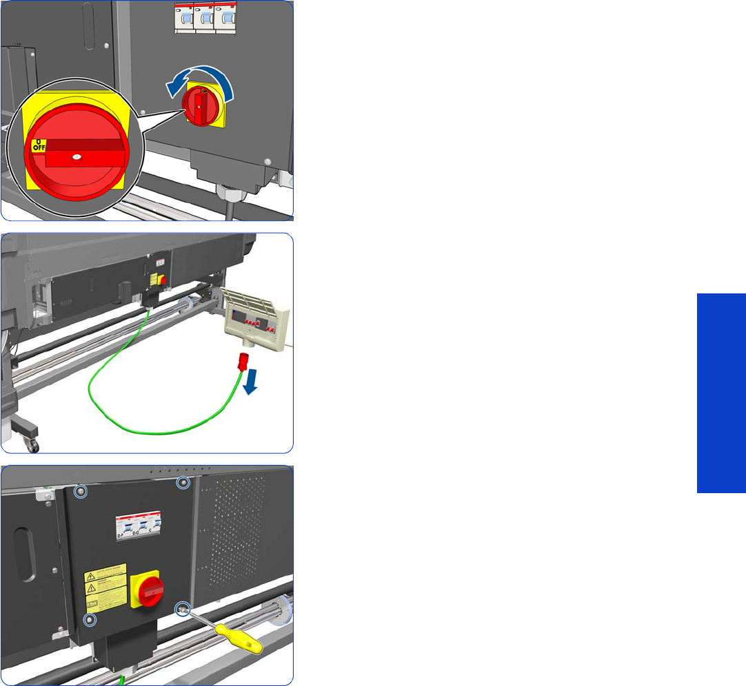
Power Box Cover 321
Removal & Installation
Power Box Cover
Removal
1. Turn off the printer.
2. Disconnect electrical power. How this is done depends
on the installation.
3. Remove four T-20 screws.
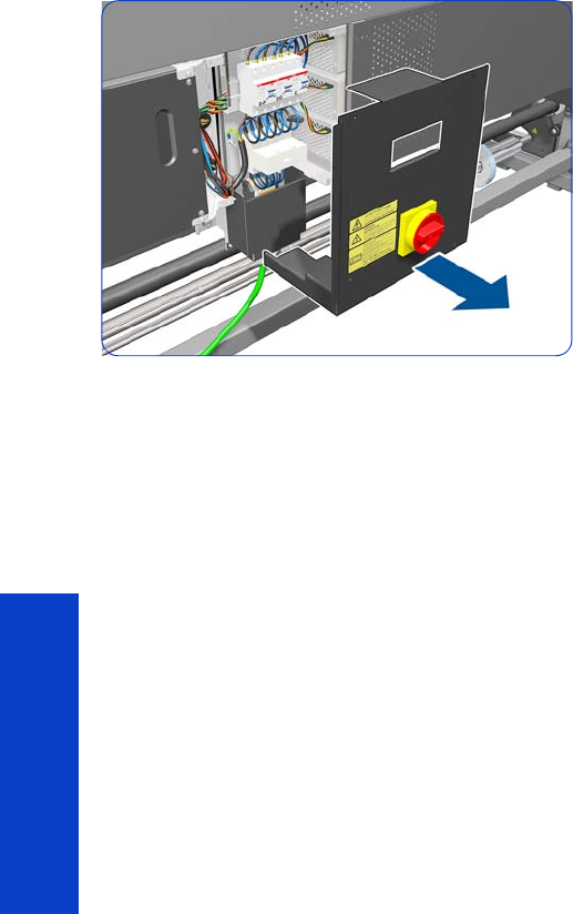
322 Chapter 8 Removal & Installation
Removal & Installation
4. Remove the Power Box Cover.

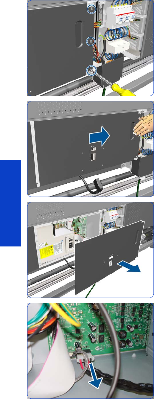
324 Chapter 8 Removal & Installation
Removal & Installation
5. Remove three T-20 screws.
6. Slide the cover to the right.
7. Remove the cover.
8. Disconnect the cable.
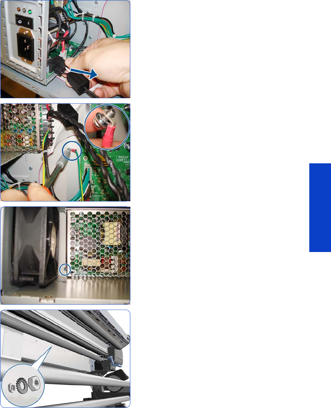
Extra PSU 24 V 325
Removal & Installation
9. Disconnect the cable.
10. Remove the screw; be careful not to lose it.
11. Remove a T-10 screw.
12. Remove the matching washer and nut from the other
side of the printer.
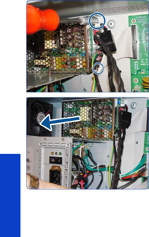
326 Chapter 8 Removal & Installation
Removal & Installation
13. Remove two T-10 screws.
14 . Remove the Extra PSU 24 V.
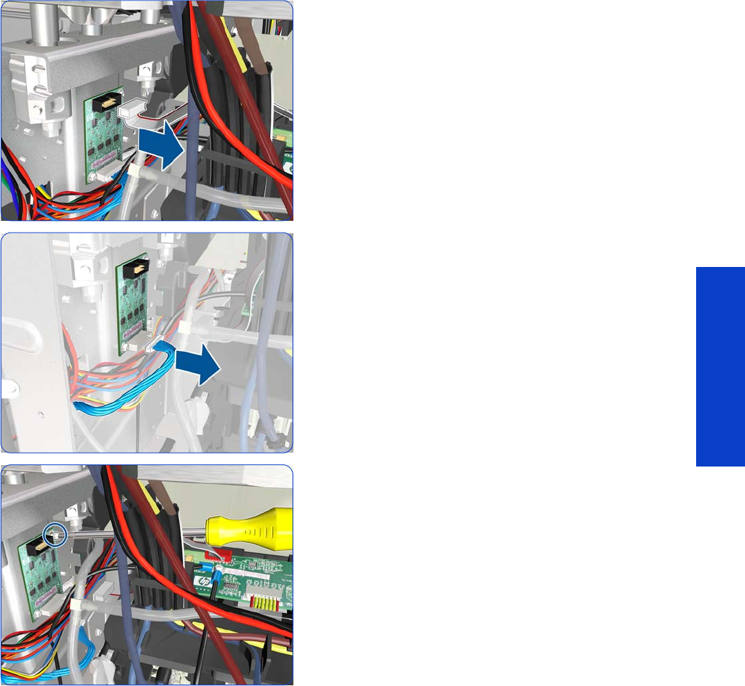

328 Chapter 8 Removal & Installation
Removal & Installation
5. Remove a T-10 screw with an L-shaped Torx screwdriver.
6. Remove the Pre-Driver PCA.
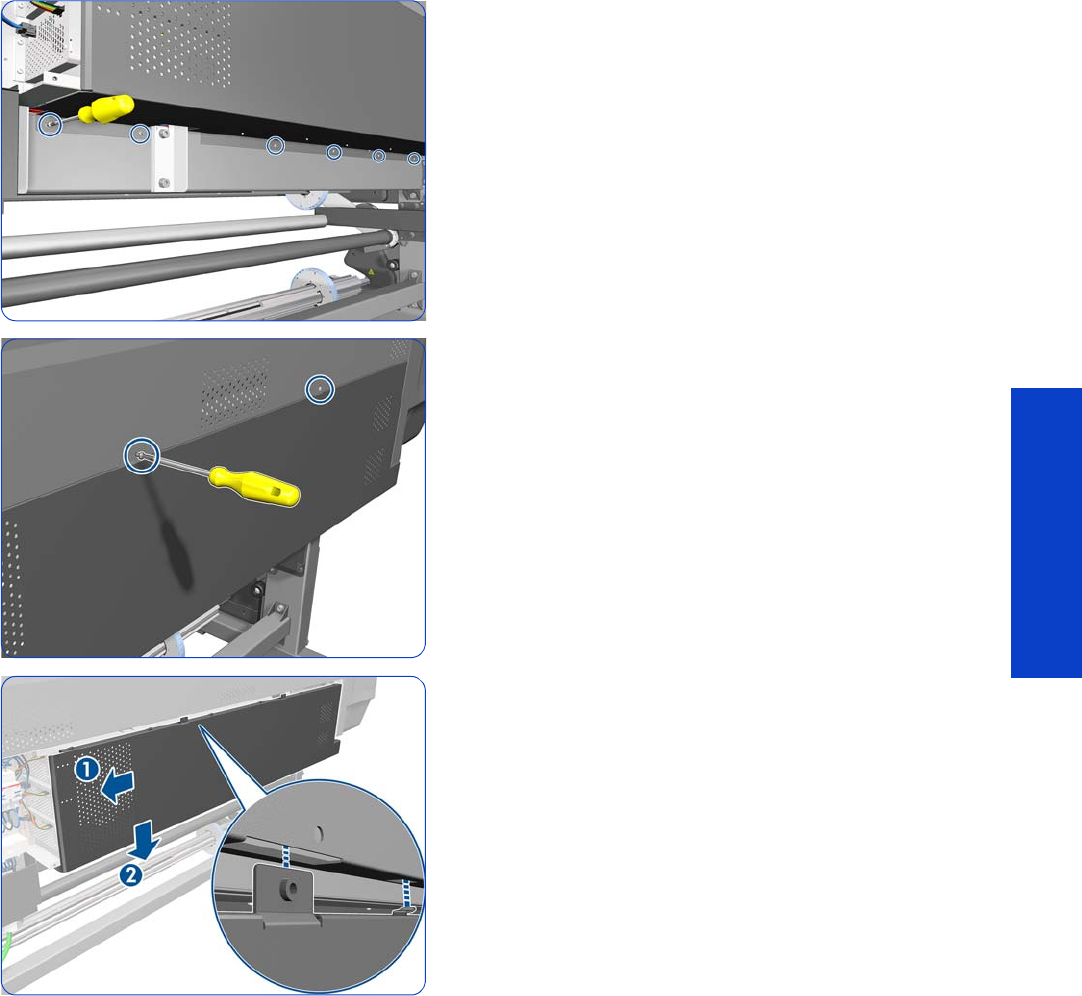
Electronics Enclosure Extension Cover 329
Removal & Installation
Electronics Enclosure Extension Cover
Removal
1. Remove the Power Box Cover
page 321.
2. Remove six T-20 screws.
3. Remove two T-20 screws.
4. Slide the Electronics Enclosure Extension Cover to the
left to release the five hooks, then lower it.
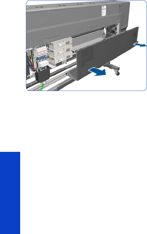
330 Chapter 8 Removal & Installation
Removal & Installation
5. Remove the Electronics Enclosure Extension Cover.
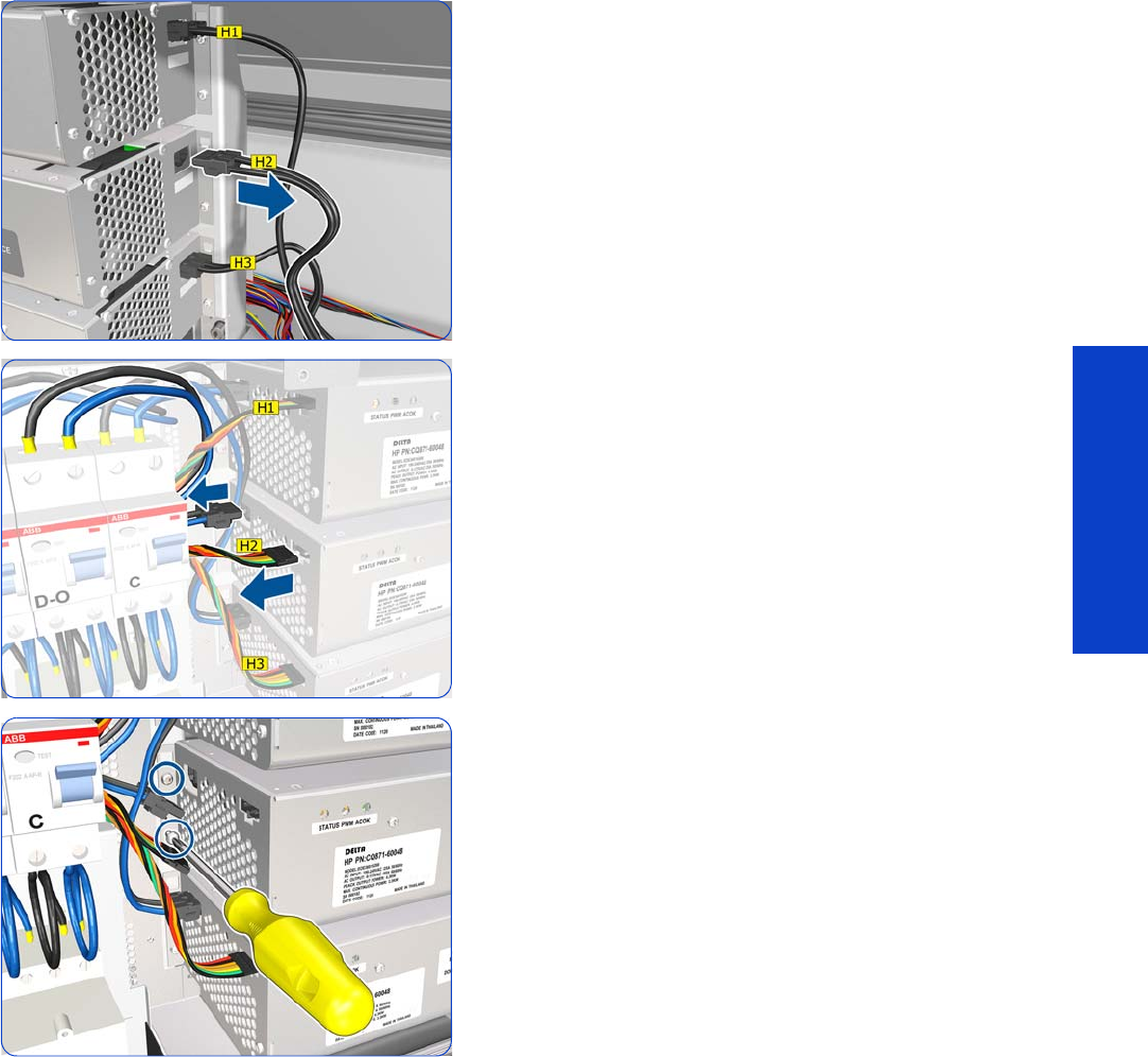
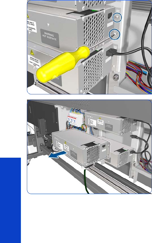
332 Chapter 8 Removal & Installation
Removal & Installation
6. Remove two T-20 screws.
7. Remove the H2 Heater Controller Box.
The H1 and H3 Heater Controller Boxes can be
removed by following the equivalent procedure in each
case.
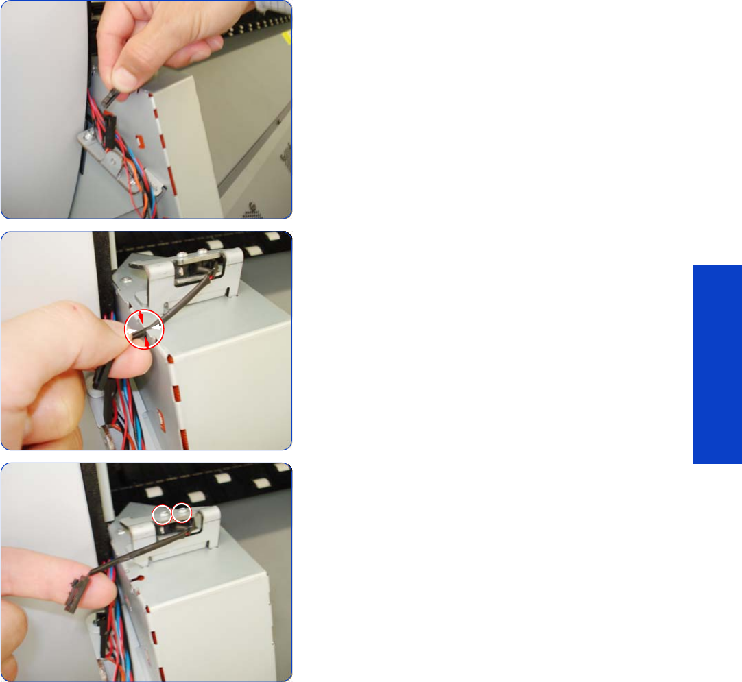
Window Lock Sensor Left 333
Removal & Installation
Window Lock Sensor Left
Removal
1. Remove the Left Curing Cover
page 308.
2. Disconnect the Left Window Lock Sensor.
3. Remove the cable of the Left Window Lock Sensor from
a holding point on the Left Curing Cover.
4. Remove two T-8 screws that secure the Left Curing
Sensor.
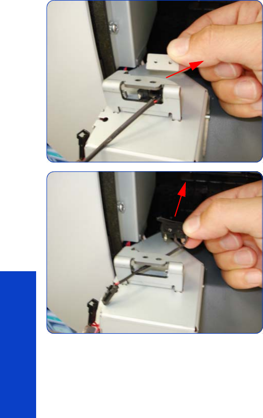
334 Chapter 8 Removal & Installation
Removal & Installation
5. Remove a metal plate from the Left Curing Sensor.
6. Remove the Left Window Lock Sensor.
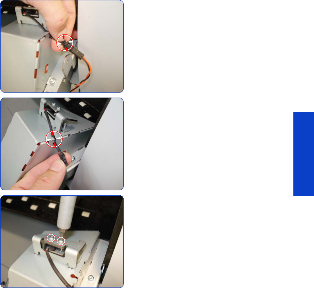
Window Lock Sensor Right 335
Removal & Installation
Window Lock Sensor Right
Removal
1. Remove the Right Curing Cover
page 310.
2. Disconnect the Right Curing Sensor.
3. Remove the cable of the Right Window Lock Sensor
from a holding point on the Right Curing Cover.
4. Remove two T-8 screws that secure the Right Curing
Sensor.
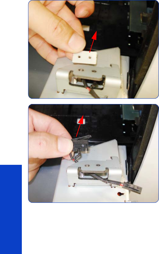
336 Chapter 8 Removal & Installation
Removal & Installation
5. Remove a metal plate from the Right Curing Sensor.
6. Remove the Right Window Lock Sensor.

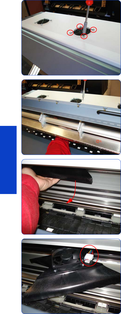
338 Chapter 8 Removal & Installation
Removal & Installation
4. Remove four T-20 screws that secure the Top Cover Fan
to the Top Cover,
5. When the last T-20 screw is being removed, support
the Fan Assembly underneath with your hand to catch
it.
6. Slide the Fan and Diffuser assembly towards you.
7. Disconnect the cable from Fan and Diffuser Assembly.
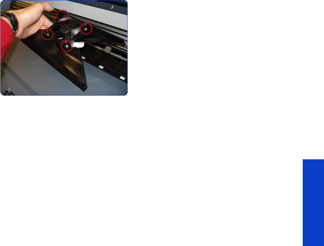
Top Cover Fans 339
Removal & Installation
8. Remove the four T-15 screws that secure the Fan to the
Diffuser Assembly.
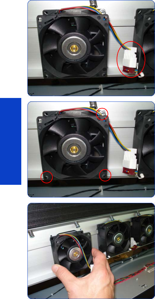
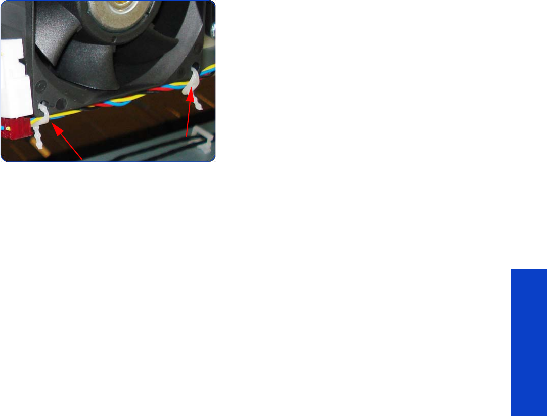
Rear Fans 341
Removal & Installation
6. To remove the Rear Fan Array Cable, remove two
plastic clamps to release the cable from the array of
Fans.
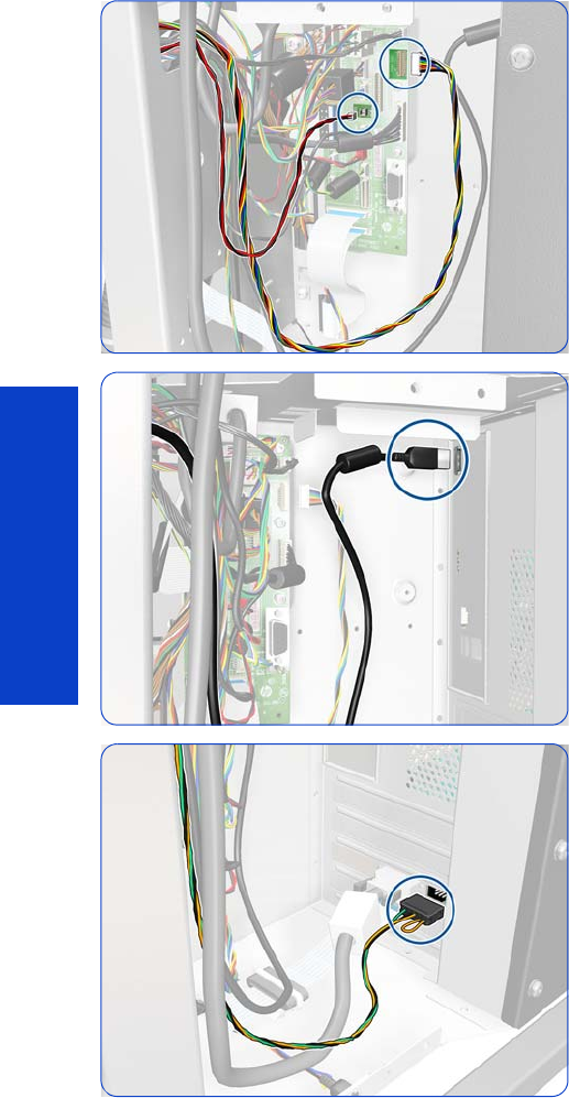
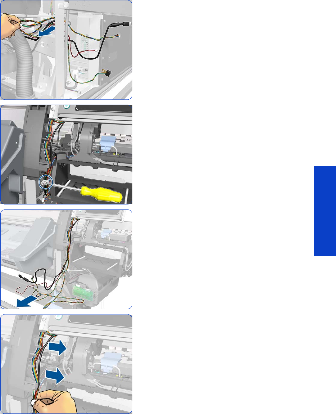
Front Panel 343
Removal & Installation
6. Pass the four disconnected cables through the upper
hole of the side plate.
7. Remove a T-20 screw and then remove the clamp.
8. Move the ends of the four cables out of the front of the
printer.
9. Release the cables from the Right Arc.
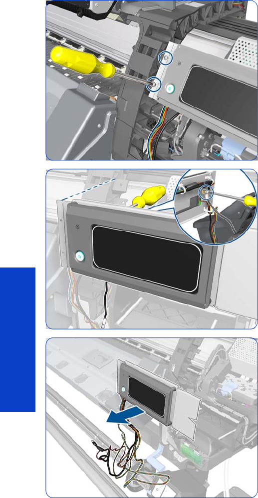
344 Chapter 8 Removal & Installation
Removal & Installation
10. Remove two T-15 screws.
11. Remove a T-20 screw and a washer from the rear of the
Front Panel. This screw attaches the grounding cable
that connects the Front Panel with the side plate.
12. Remove the Front Panel and the cables connected to it.
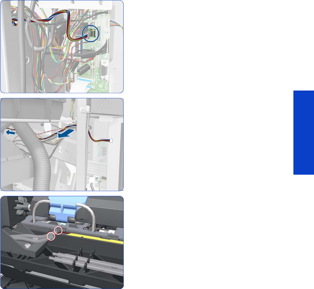
Primer Assembly 345
Removal & Installation
Primer Assembly
Removal
1. Remove the Right Cover
page 296
.
2. Remove the Right Connector Cover
page 318.
3. Remove the Front Panel
page 342.
4. Disconnect the Primer Assembly cable from the
Interconnect PCA.
5. Unroute the Primer Assembly cable from the cable
clamp.
6. Disconnect the two Primer Assembly tubes.
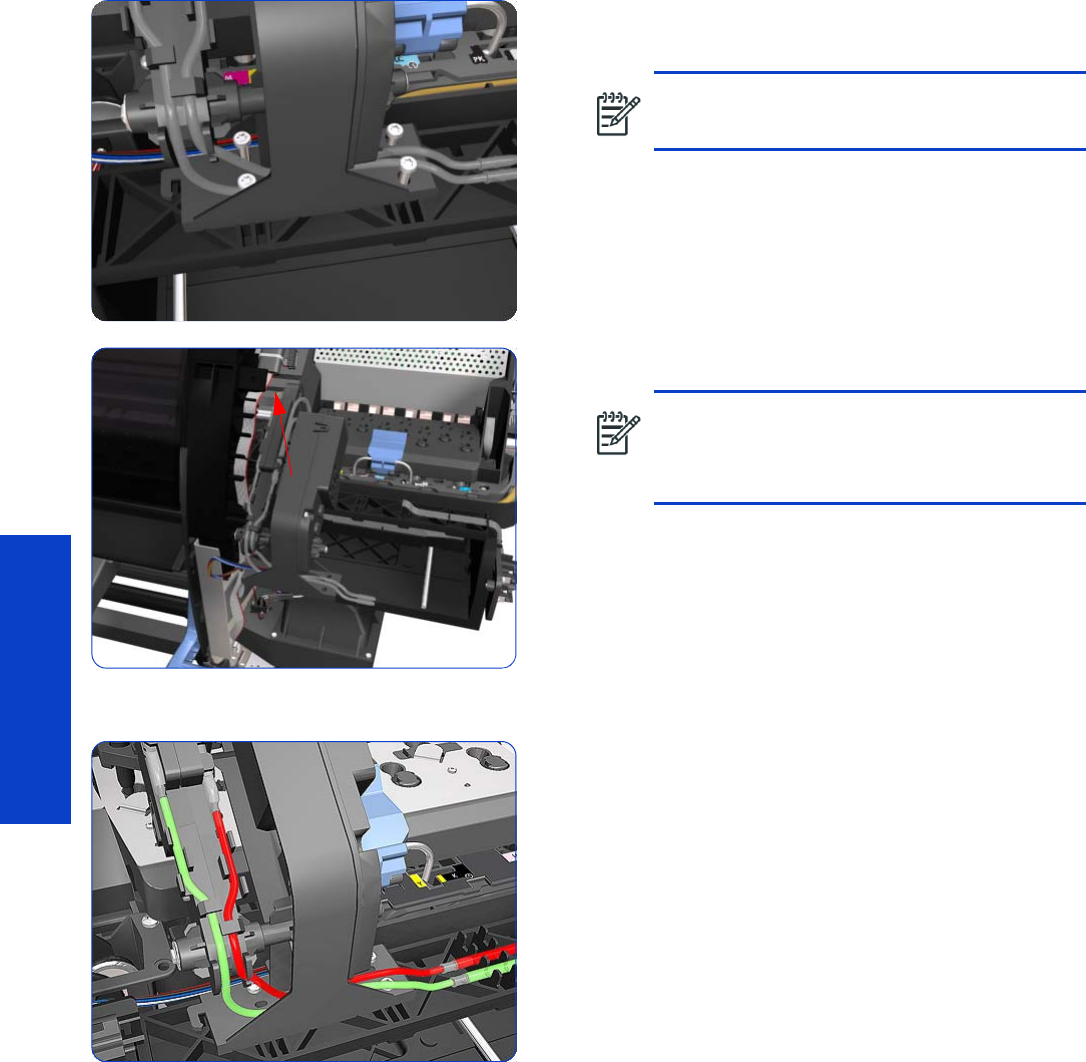
346 Chapter 8 Removal & Installation
Removal & Installation
7. Remove four T-10 screws that secure the Primer
Assembly to the Service Station.
8. Remove the Primer Assembly from the Service Station.
Installation of the Primer Assembly
1. When installing the new Primer Assembly, it is
important to note that the internal tube (red) is shorter
than the external tube (green).
2. Reset the Primer Cycles
page 194.
3. Perform the Primer Calibration
page 203.
NOTE: Use a short screw driver, less than
10 cm in length.
NOTE: When installing the Primer Assembly,
use the identification marks on the Primer
Assembly Tubes to ensure they are correctly
connected.

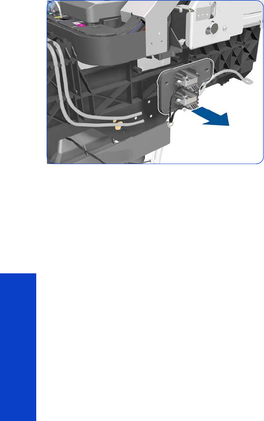
348 Chapter 8 Removal & Installation
Removal & Installation
5. Remove the Primer Valves.
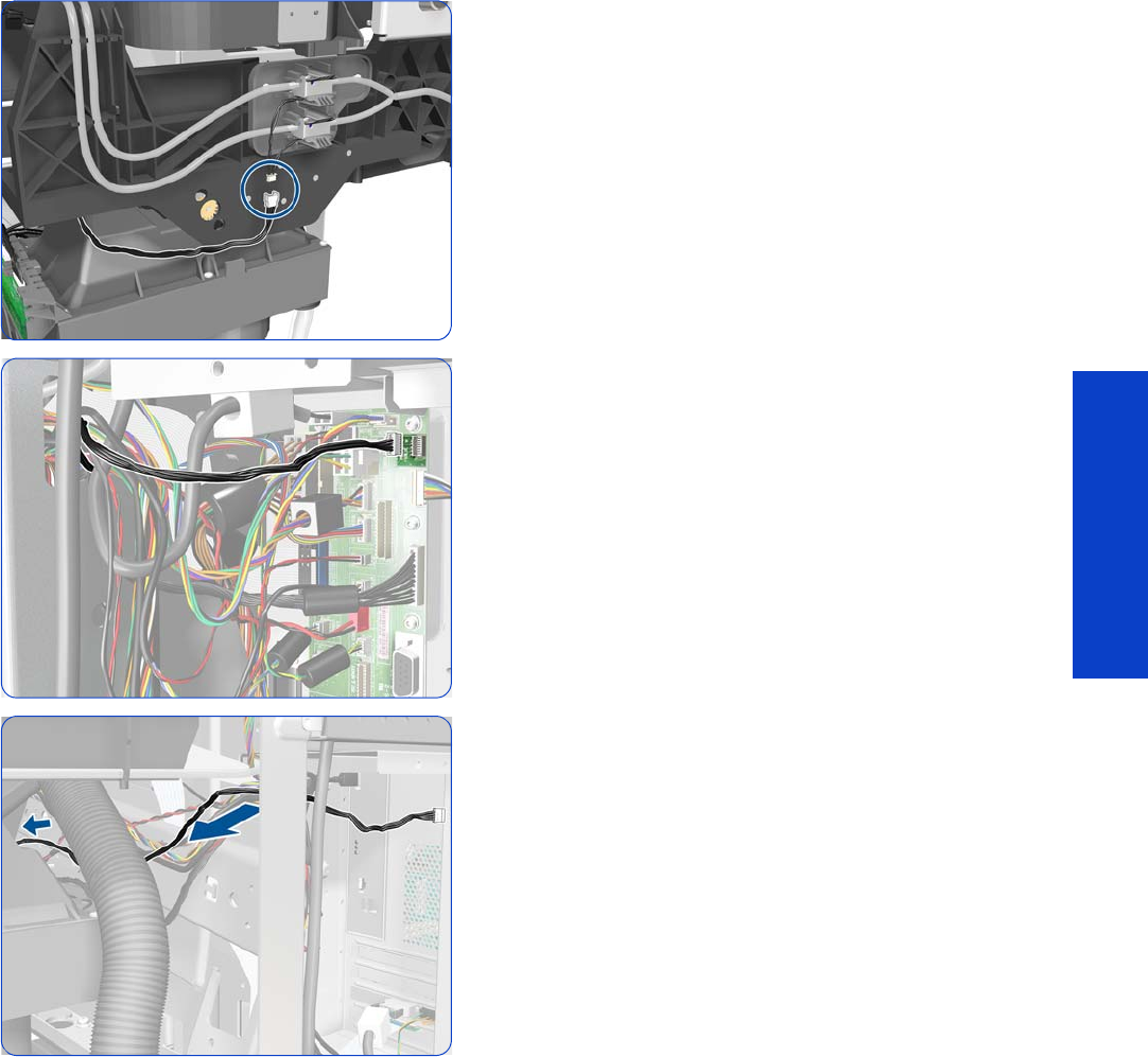
Primer Valve Cable 349
Removal & Installation
Primer Valve Cable
Removal
1. Remove the Right Cover
page 296
.
2. Remove the Right Connector Cover
page 318
.
3. Disconnect the Primer Valve Cable.
4. Disconnect the Primer Valve Cable from the
Interconnect PCA.
5. Pass the Primer Valve Cable through the upper hole of
the side plate.
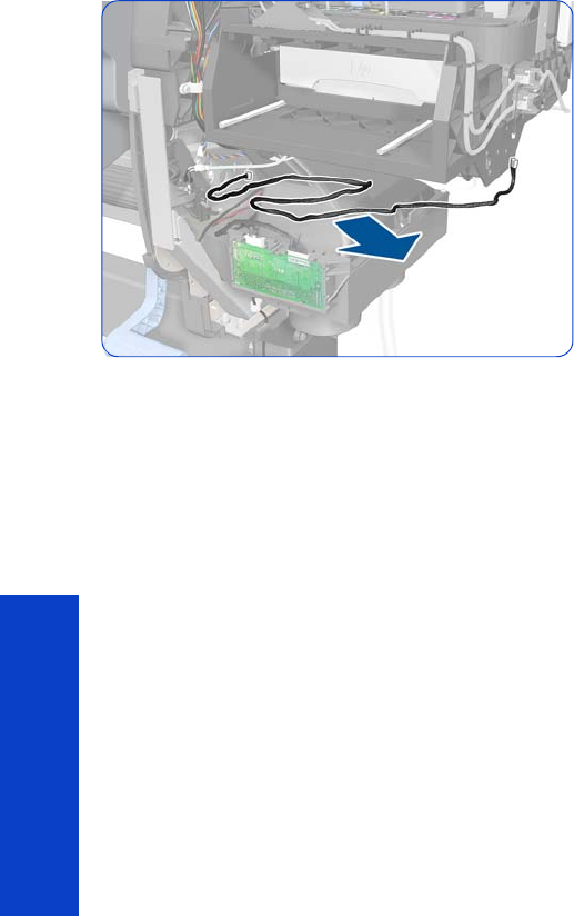
350 Chapter 8 Removal & Installation
Removal & Installation
6. Remove the Primer Valve Cable.
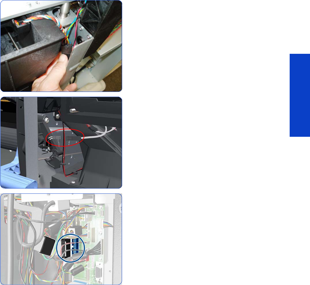
Service Station 351
Removal & Installation
Service Station
Removal
1. Remove the Right Cover
page 296
.
2. Remove the Primer Assembly
page 345.
3. Remove the Primer Valves
page 347.
4. Remove the Drop Detector, Funnel Transmission, and
Waste Ink Tube
page 376.
5. Remove the Printhead Cleaning Cartridge and the Ink
Maintenance Kit.
See the User’s Guide.
6. Disconnect the Web Wipe Motor cable.
7. Disconnect the cable from the Printhead Cleaning
Cartridge Door Switch.
8. Disconnect the Service Station cable from the
Interconnect PCA.
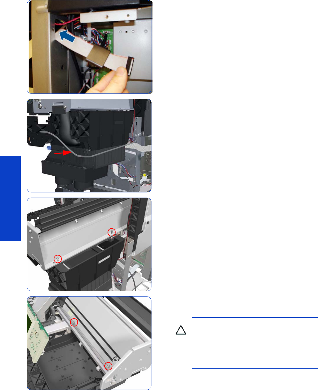
352 Chapter 8 Removal & Installation
Removal & Installation
9. Unroute the Service Station.
10. Unroute the Primer Assembly Valves tube from the
Service Station.
11. Remove two T-15 screws that secure the rear of the
Service Station to the Chassis.
12. Remove two T-15 screws that secure the Service Station
to the Chassis.
CAUTION: When removing the screws, be
very careful NOT to damage the Encoder Strip.
CAUTION: When removing the screws that
secure the Service Station to the X-Axis, hold
the Service station as it could fall when the
screws are removed.
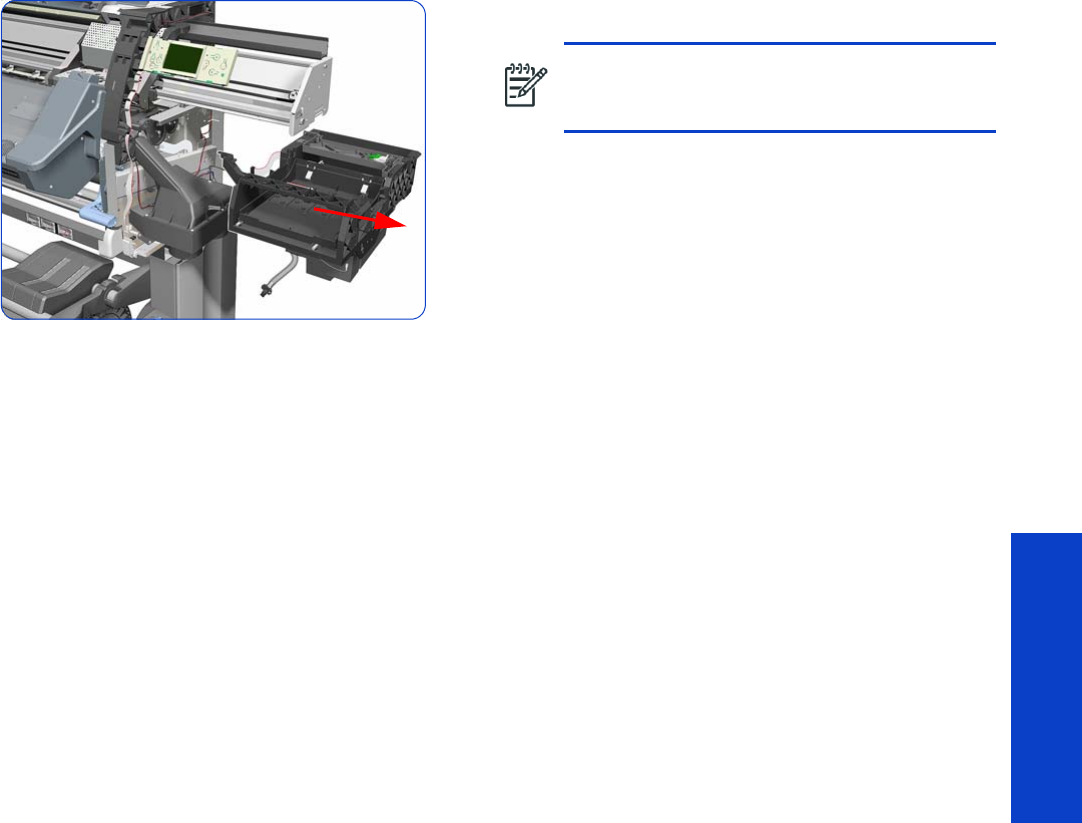
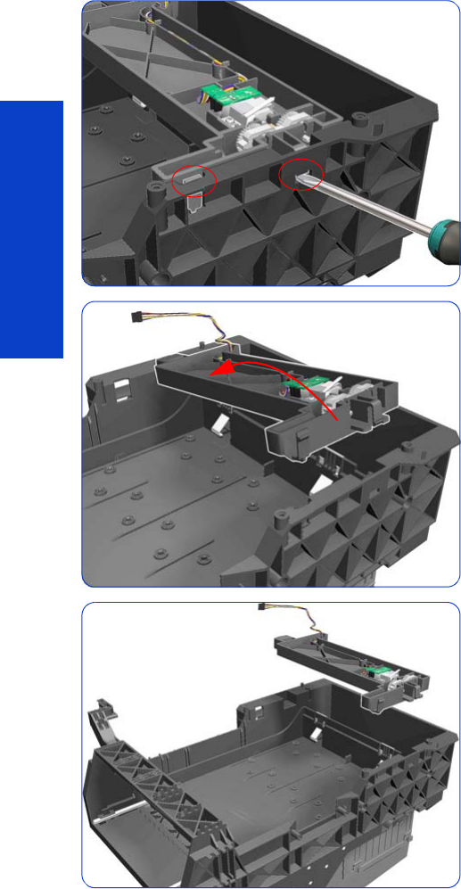
354 Chapter 8 Removal & Installation
Removal & Installation
Web Wipe Assembly
Removal
1. Remove the Right Cover
page 296
.
2. Remove the Right Connector Cover
page 318.
3. Remove the Primer Assembly
page 345.
4. Remove the Primer Valves
page 347.
5. Remove the Printhead Cleaning Cartridge and Ink
Maintenance Kit.
See the User’s Guide.
6. Remove the Drop Detector, Funnel Transmission, and
Waste Ink Tube
page 376.
7. Remove the Service Station
page 351.
8. Release two clips on the right side of the Service
Station.
9. To release the assembly, rotate a little.
10. Remove the Web Wipe Assembly.
11. Reset the Service Station cycle counter
page 194.

Web Wipe Assembly 355
Removal & Installation
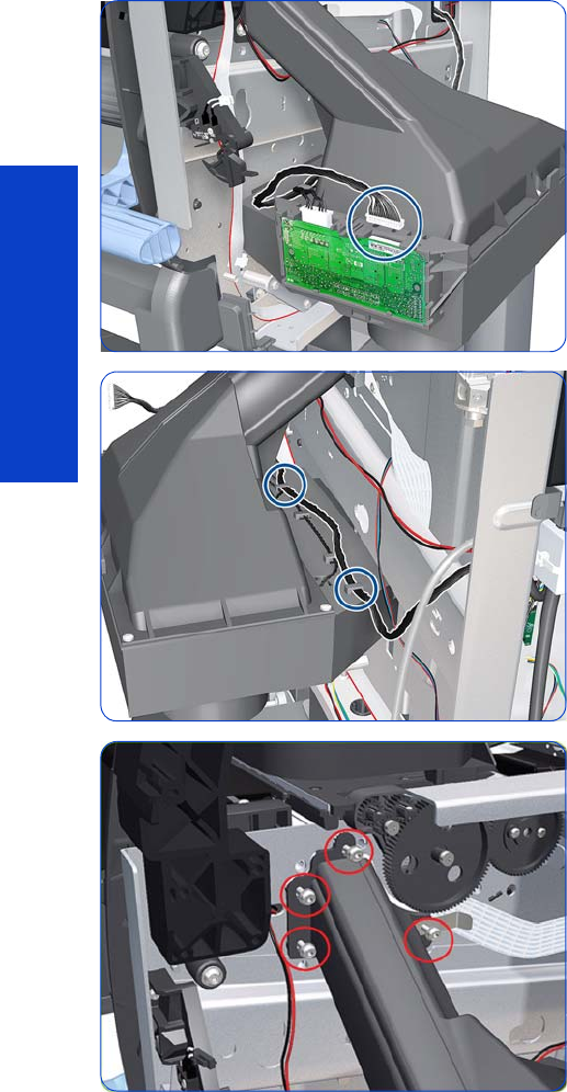
356 Chapter 8 Removal & Installation
Removal & Installation
Vacuum Fan
Removal
1. Remove the Right Cover
page 296
.
2. Remove the Primer Assembly
page 345.
3. Remove the Primer Valves
page 347.
4. Remove the Printhead Cleaning Cartridge and Ink
Funnel. See the
User’s Guide.
5. Remove the Drop Detector, Funnel Transmission, and
Waste Ink Tube
page 376.
6. Remove the Service Station
page 351.
7. Disconnect the cable labelled on the Vacuum Fan PCA
as “Interconnect Cable”.
8. Unroute the cable.
9. Remove four T-20 screws that secure the Vacuum Fan to
the printer.
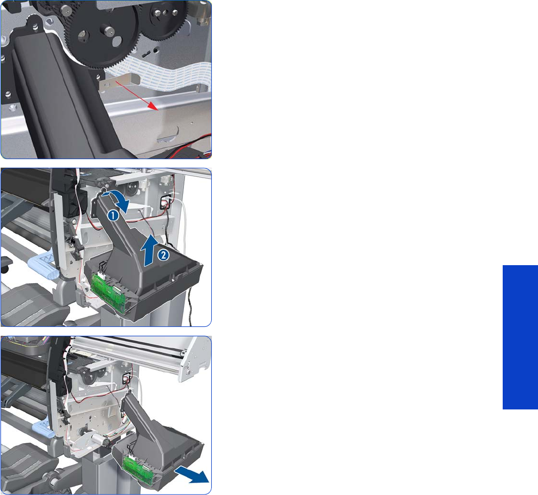
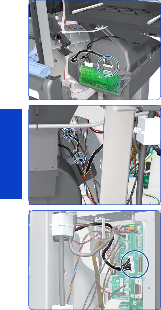
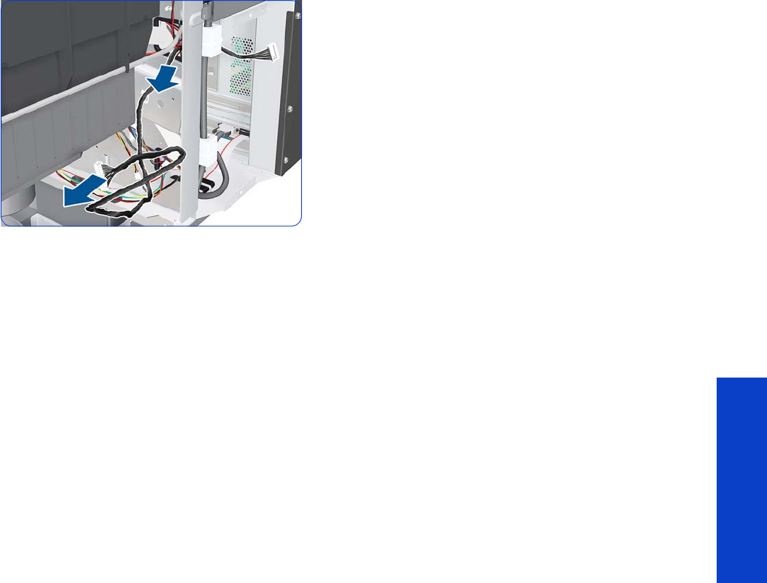
Vacuum Fan Cable 359
Removal & Installation
6. Remove the cable.
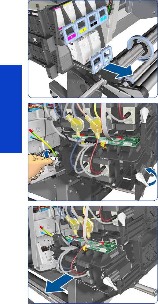
360 Chapter 8 Removal & Installation
Removal & Installation
Vacuum Fans Extra
Removal
1. Remove the Left Cover
page 303
.
2. Remove the Left Trim
page 306.
3. Remove the Input Roller
page 542.
4. Remove the Power Box Cover
page 321.
5. Remove the Electronics Enclosure Extension
page 329.
6. Pull out the bottom row of Ink Cartridge trays (LM and
LC only), but don't remove the Ink Cartridges.
7. Rotate the two latches.
8. Remove the Cartridge Tube Connector.
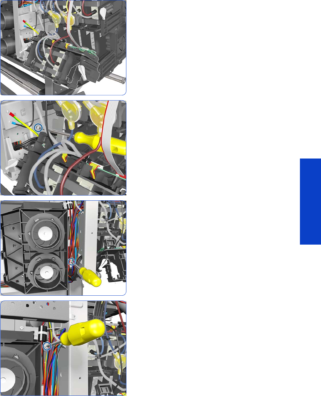
Vacuum Fans Extra 361
Removal & Installation
9. Carefully leave the Cartridge Tube Connector as
shown.
10. Remove a T-20 screw.
11. Remove a T-20 screw.
12. Remove a T-20 screw.
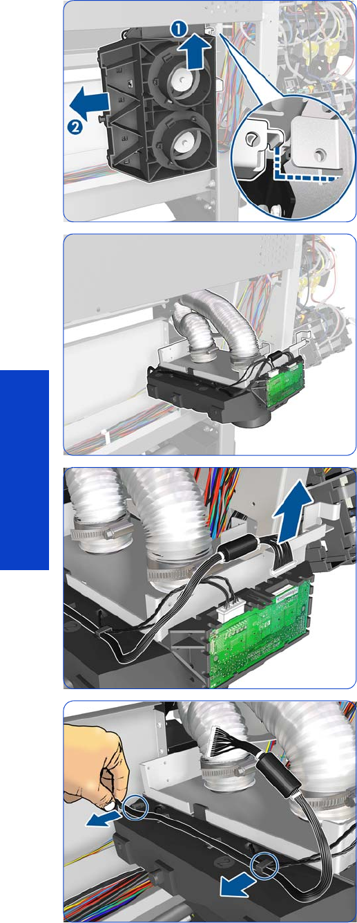
362 Chapter 8 Removal & Installation
Removal & Installation
13. Disengage and remove the Vacuum Fans. The detail
shows the hole in the side plate where the Vacuum
Fans hang.
14 . Carefully leave the Vacuum Fans hanging as shown.
15. Disconnect the Interconnect cable.
16. Release the Interconnect cable from both clips.
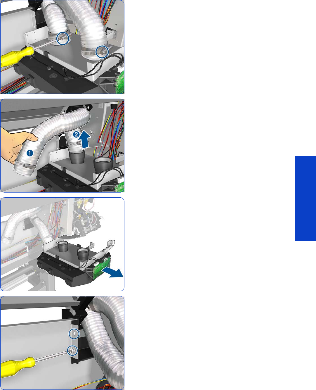
Vacuum Fans Extra 363
Removal & Installation
17. Loosen both metal clamps with a flat-bladed
screwdriver.
18 . Carefully disconnect both tubes.
19. Remove the Vacuum Fans assembly.
20.Remove two T-20 screws.
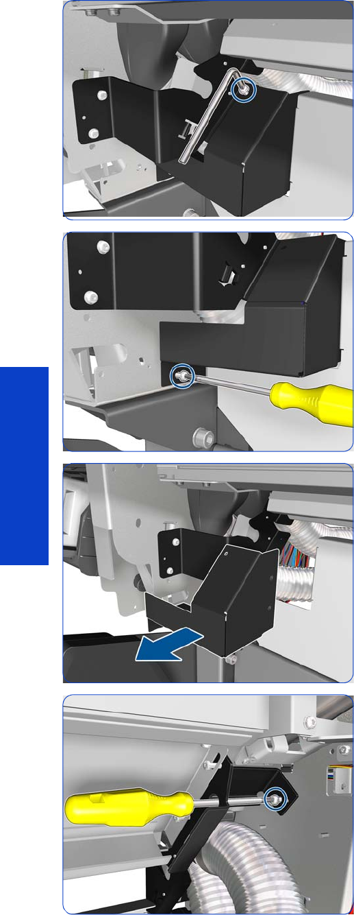
364 Chapter 8 Removal & Installation
Removal & Installation
21. Remove a T-20 screw with an L-shaped Torx
screwdriver.
22.Remove a T-20 screw.
23.Remove the Left Vacuum Trim.
24.Remove a T-20 screw.
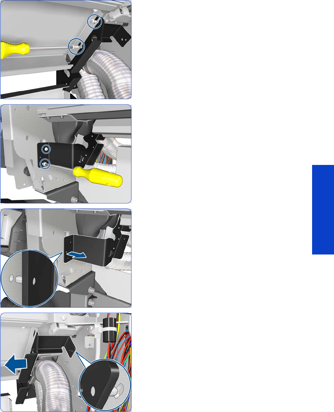
Vacuum Fans Extra 365
Removal & Installation
25.Remove two T-15 screws.
26.Remove two T-20 screws.
27. Disengage the pin of the Left Entry Roller Support from
the left side plate. Be careful not to scratch the side
plate with the pin.
28.Disengage the rear pin of the Left Entry Roller Support
from the left side plate. You can move it only a few
millimeters to the left because of the Input Platen. Be
careful not to scratch the side plate with the pin.
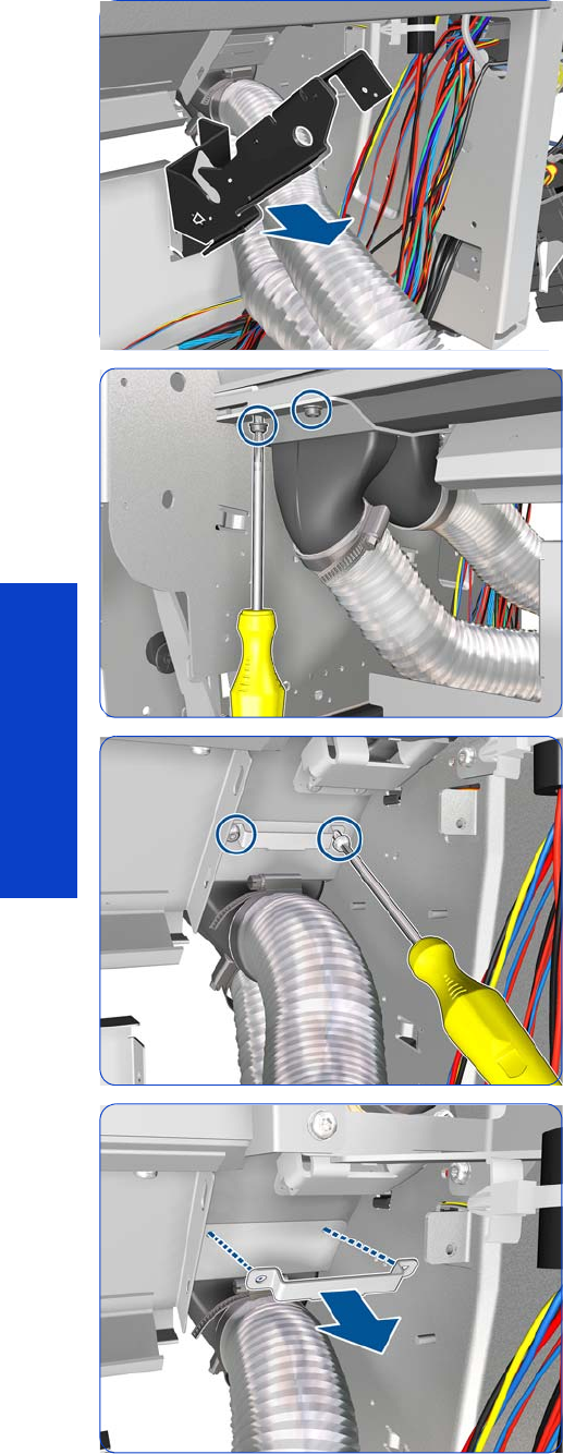
366 Chapter 8 Removal & Installation
Removal & Installation
29. Remove the Left Entry Roller Support from the rear of
the printer.
30.Remove two T-20 screws.
31. Remove two T-20 screws.
32.Remove the Frame Hook.
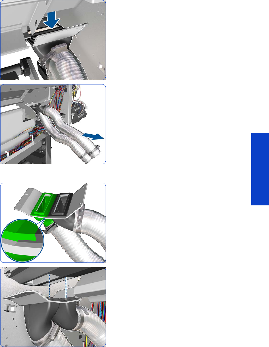
Vacuum Fans Extra 367
Removal & Installation
33.Pull down the tubes assembly to disengage the tubes
from the holes in the Vacuum Beam.
34.Remove the tubes.
Installation
1. Make sure that the two tubes are correctly attached to
the support, as shown.
2. Make sure the tubes are correctly inserted into the
holes in the Vacuum Beam.
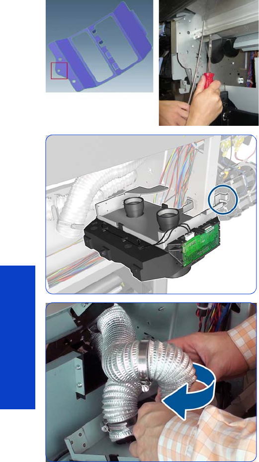
368 Chapter 8 Removal & Installation
Removal & Installation
If the frame in the service kit is the new revision with
extra pulling hole (see picture at far left), you can use
another screwdriver to create leverage and align the
screws with the holes. Be careful not to scratch the
Vacuum Beam; you can protect the beam during this
process.
3. Make sure the bracket is on the right, as shown.
4. Mount the inner tube first, then the outer tube. To mount
each tube correctly, you must first twist the tube
opposite to the direction of the arrow, and then attach
it carefully to the Vacuum Fan, rotating it in the
direction of the arrow.
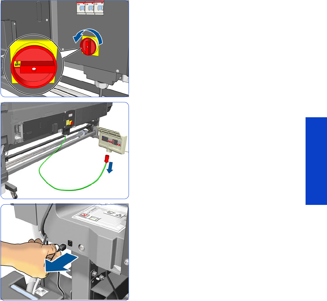
Waste Ink System 369
Removal & Installation
Waste Ink System
This part is Customer Self-Replaceable (CSR).
Removal
1. Turn off the printer.
2. Disconnect electrical power. How this is done depends
on the installation.
3. Disconnect the Waste Ink System cable
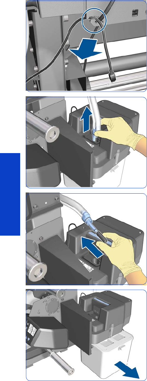
370 Chapter 8 Removal & Installation
Removal & Installation
4. Disengage the Waste Ink System cable from the clip.
5. Pull the bottom of the Ink Tube Assembly out of the
Printhead Cleaning Container. You are recommended
to wear gloves.
6. Cover the end of the Ink Tube with the spare cap from
the Ink Maintenance Kit, to prevent ink from falling out
of the tube.
7. Remove the Printhead Cleaning Container.
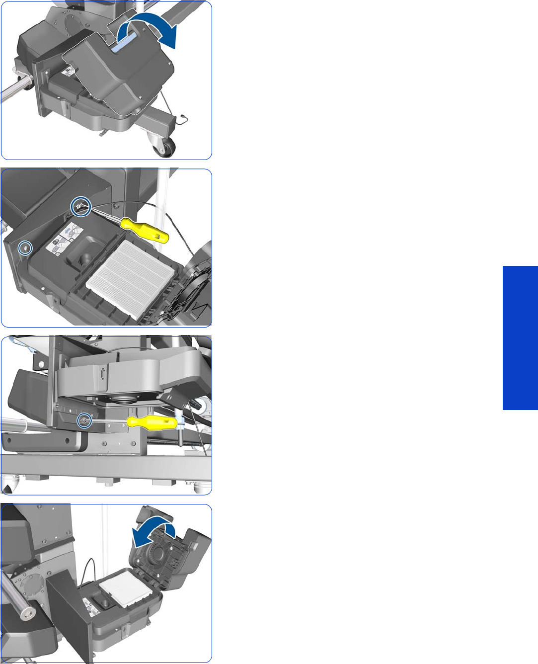
Waste Ink System 371
Removal & Installation
8. Open the Aerosol Filter cover.
9. Remove two T-25 screws.
10. Remove one T-25 screw.
11. Close the Aerosol Filter cover.
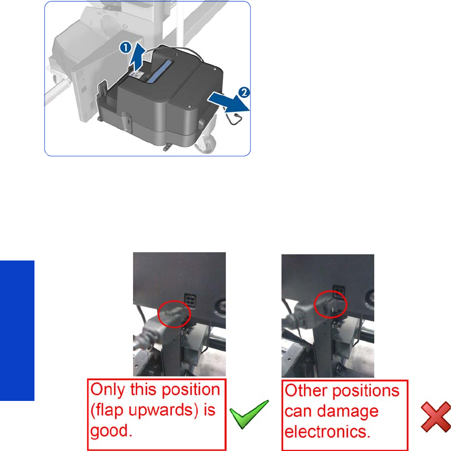
372 Chapter 8 Removal & Installation
Removal & Installation
12. Lift and then pull the Aerosol Filter enclosure to remove
it from the printer.
Installation
When connecting the waste management cable to the left-hand side of the E-Box, special care must be
taken with the connector position. The connector flap must be pointing upwards.
To avoid a wrong connection and/or permanent damage to the electronics, installing the module without
the E-Box plastic connector cover is advised.
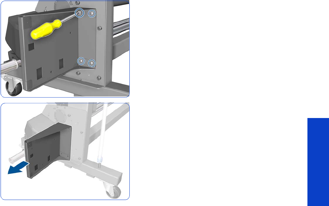
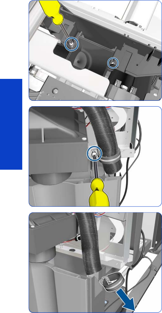
374 Chapter 8 Removal & Installation
Removal & Installation
Waste Ink Tube Guide
Removal
1. Open the Window
page 281.
2. Remove the Right Cover
page 296
.
3. Remove the Ink Maintenance Kit. See the User’s Guide.
4. Remove the Drop Detector, Funnel Transmission, and
Waste Ink Tube
page 376.
5. Remove two T-8 screws that secures the top of the Drain
Tube to the Service Station (long screw driver or wrench
key required).
6. Remove one T-10 screw that secures the Waste Ink Tube
Guide.
7. Slide off the retaining ring from the Waste Ink Tube
Guide.
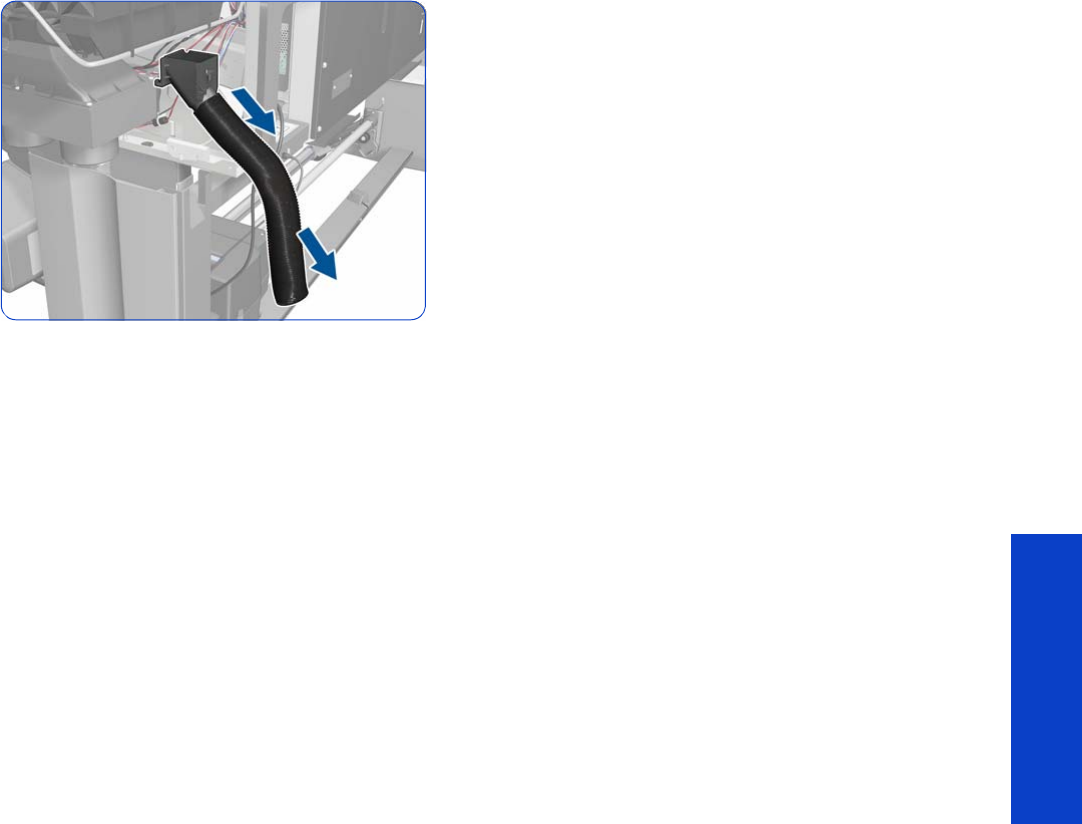
Waste Ink Tube Guide 375
Removal & Installation
8. Slide off the assembly from the Service Station.
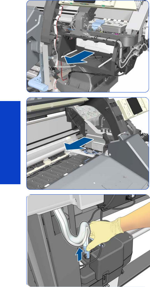
376 Chapter 8 Removal & Installation
Removal & Installation
Drop Detector, Funnel Transmission, Waste Ink Tube
Removal
1. Remove the Right Cover
page 296
.
2. Open the Window
page 281
.
3. Pull out the Printhead Cleaning Cartridge fully from the
Service Station to release the Carriage Assembly.
4. Slide the Carriage Assembly into the print path so you
access the Drop Detector.
5. Pull the bottom of the Waste Ink Tube assembly from
the Printhead Cleaning Container.
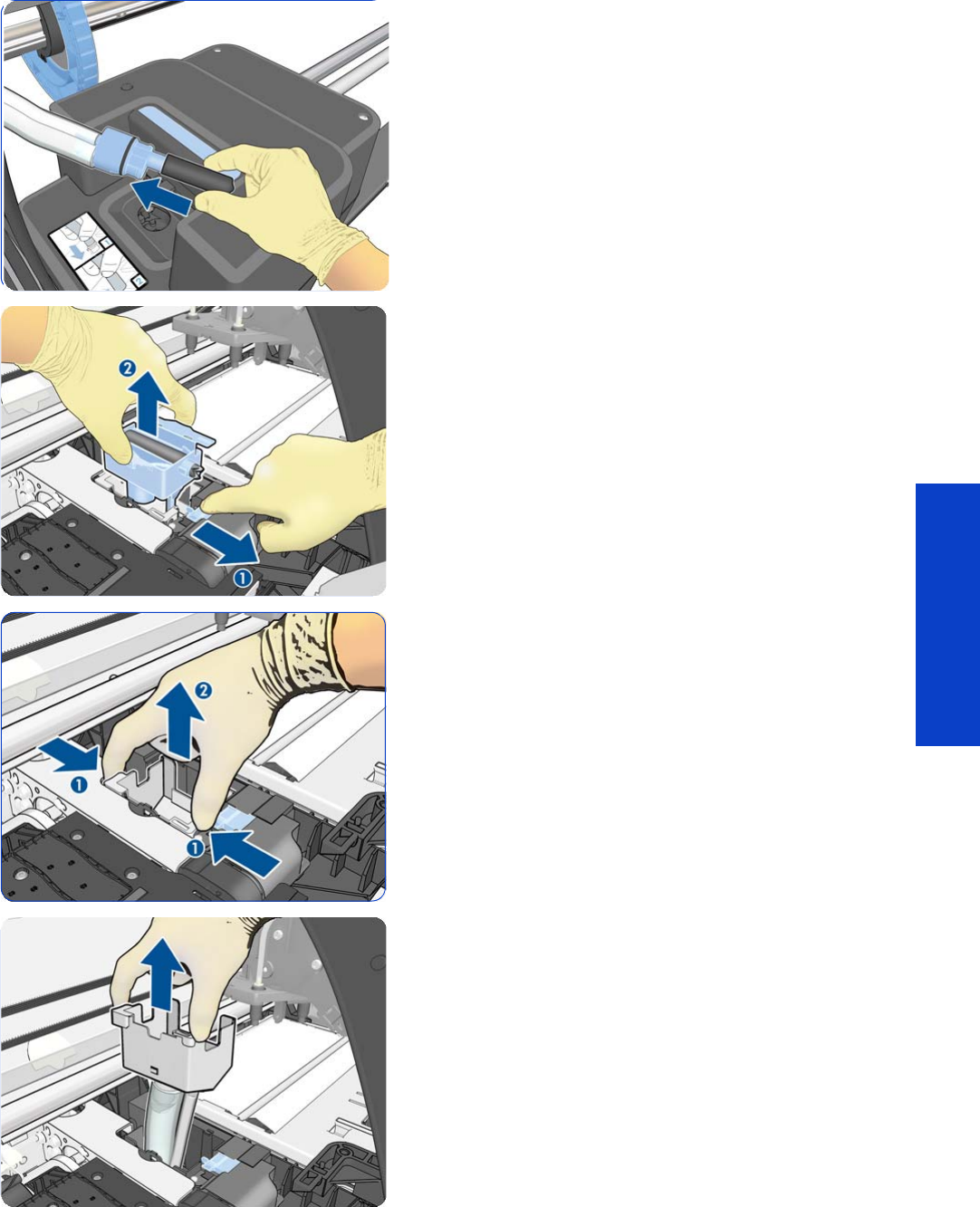
Drop Detector, Funnel Transmission, Waste Ink Tube 377
Removal & Installation
6. Cover the end of the old ink tube with the cap or a
cloth to stop ink leaking out.
7. Pull the slider with one finger (1) while removing the Ink
Funnel with the other hand (2).
8. Pinch the sides of the Funnel Transmission (1) and lift up
the assembly (2).
9. Lift up the Waste Ink Tube Assembly.
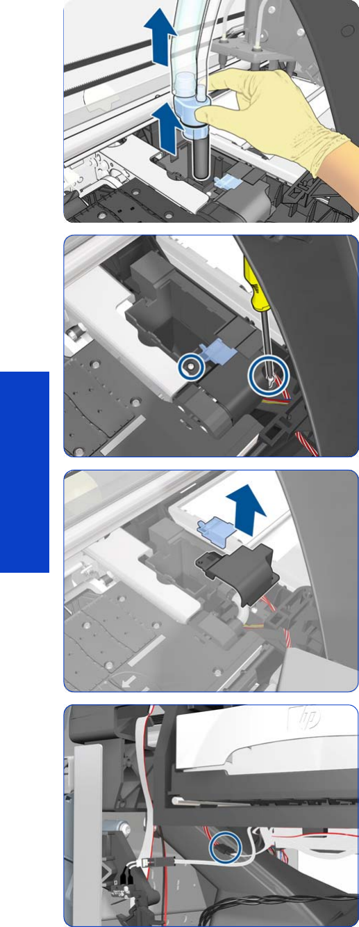
378 Chapter 8 Removal & Installation
Removal & Installation
10. Remove the Waste Ink Tube Assembly.
11. Remove two T-6 screws.
12. Remove the blue slider and Drop Detector Cover.
13. Disconnect the Drop Detector Cable from the Service
Station Cable.
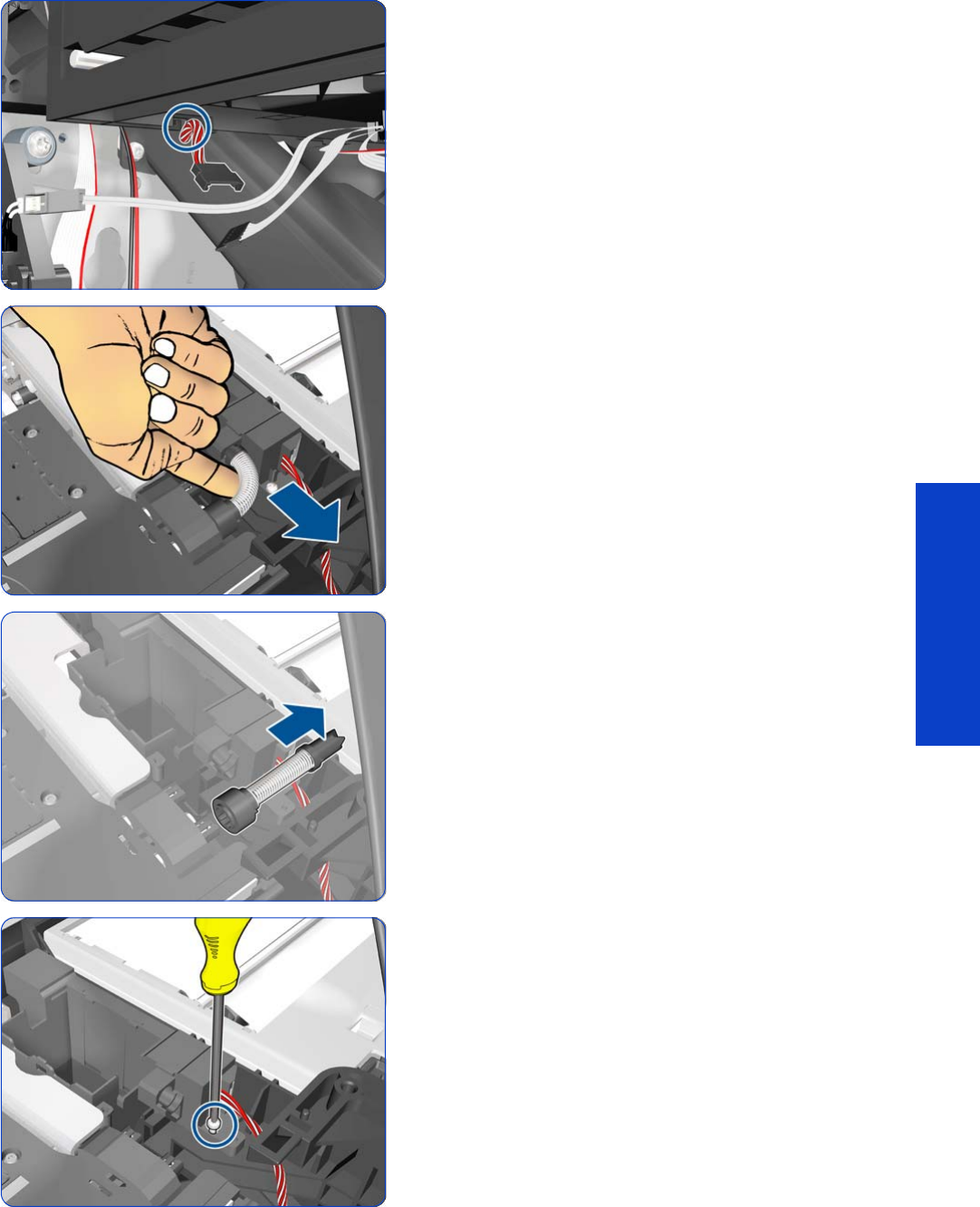
Drop Detector, Funnel Transmission, Waste Ink Tube 379
Removal & Installation
14 . Release the Drop Detector Cable from the Service
Station.
15. Disconnect the spring.
16. Remove the spring.
17. Remove one T-8 screw
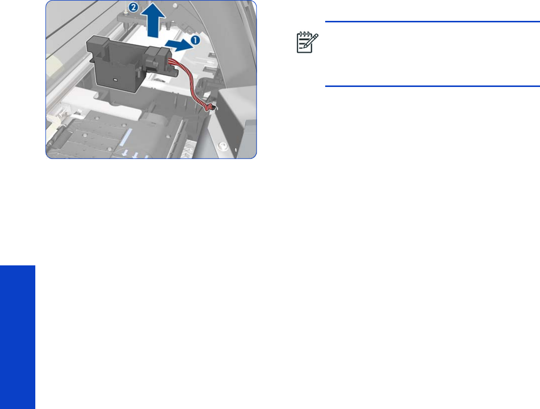
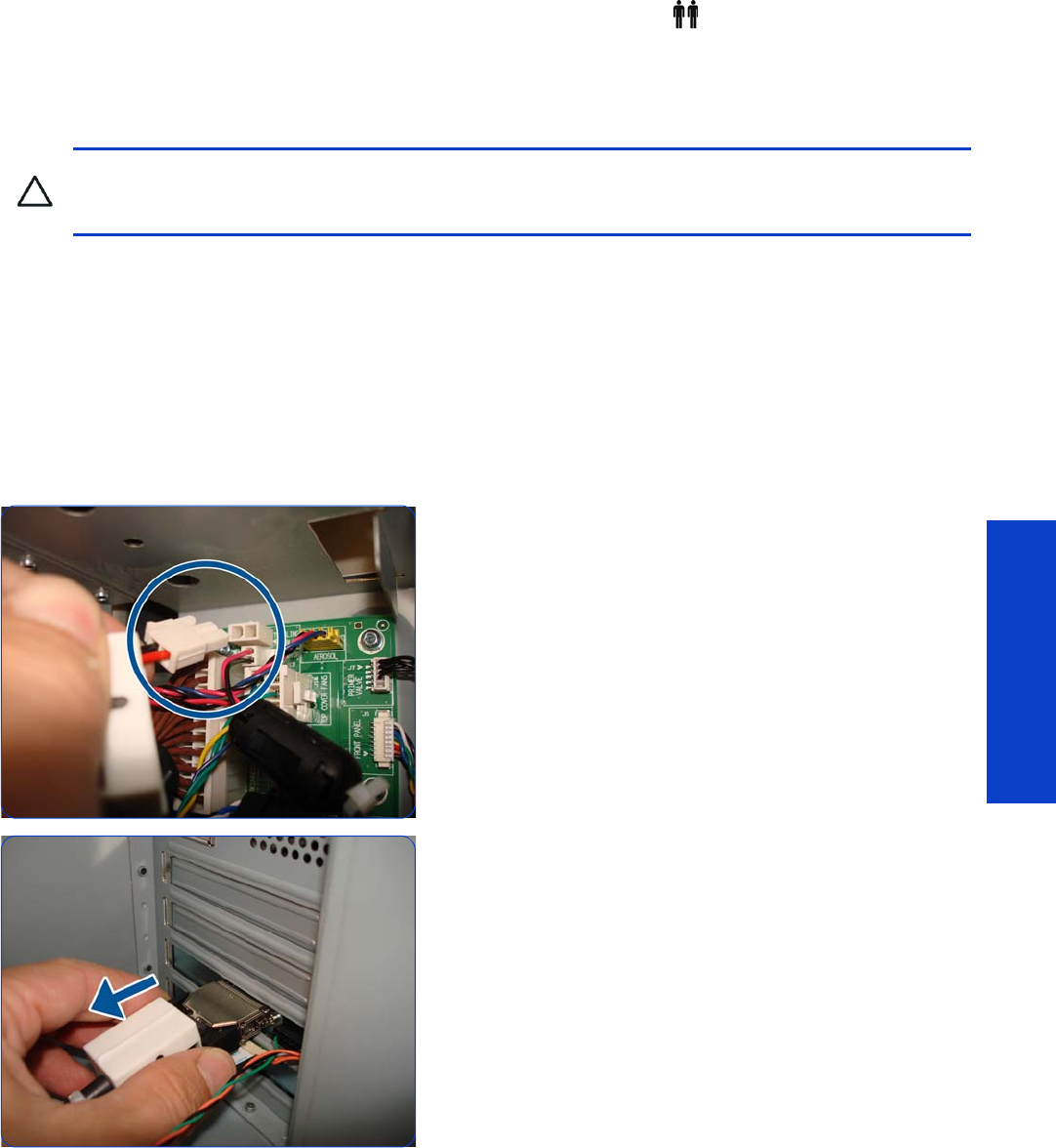
Ink Supply Tubes and Trailing Cable 381
Removal & Installation
Ink Supply Tubes and Trailing Cable
Removal (requires two people)
1. Remove the Left Cover
page 303
.
2. Remove the Right Cover
page 296
.
3. Remove the Window
page 283
.
4. Remove the Electronics Enclosure Extension Cover
page 329
.
5. Remove the Rear Upper Cover
page 312.
6. Remove the Top Cover
page 314
.
7. Disconnect the Trailing Cable from the Interconnect
PCA.
8. Disconnect the Trailing Cable from the Engine PCA.
CAUTION: You must never replace both the Hard Disk Drive and the Ink Supply Tubes and Trailing
Cable at the same time. If these parts need to be replaced, you must first replace one part and then turn
on the printer until it completely initializes. Then turn off the printer and replace the other part.
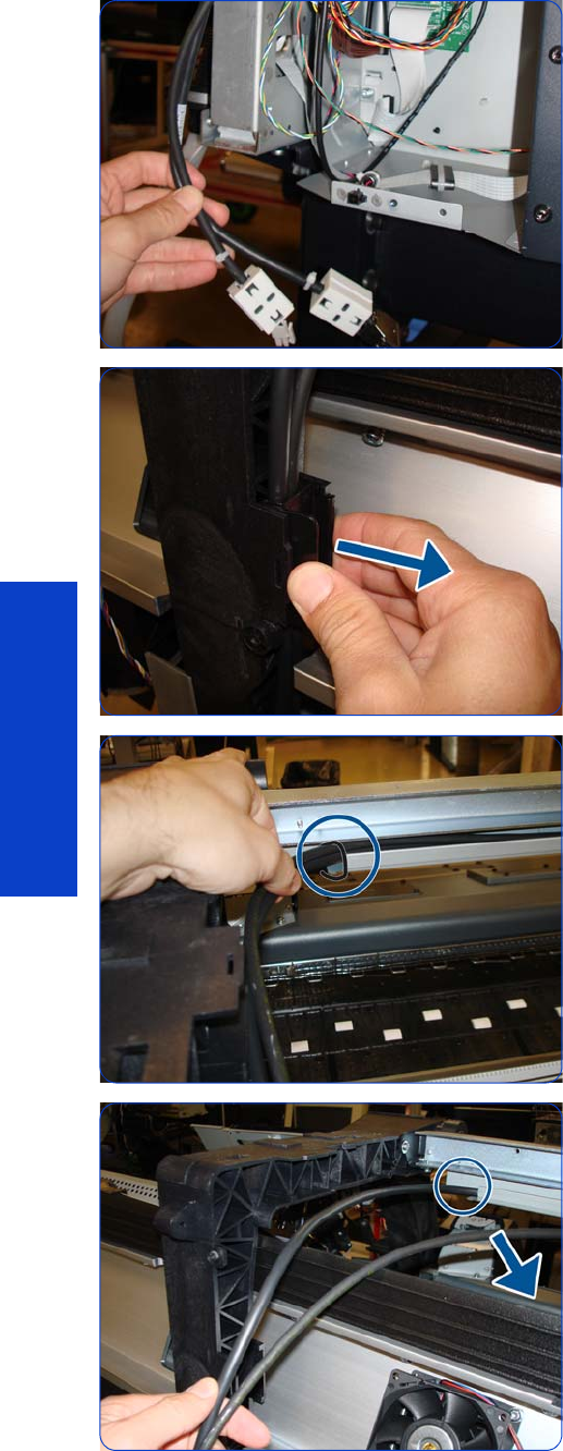
382 Chapter 8 Removal & Installation
Removal & Installation
9. Pull the cables out of the Electronics Enclosure.
10. Release the arc clip.
11. Cut the cable tie that attaches the Trailing Cables to the
Tube Guides.
12. Unroute the Trailing Cables.
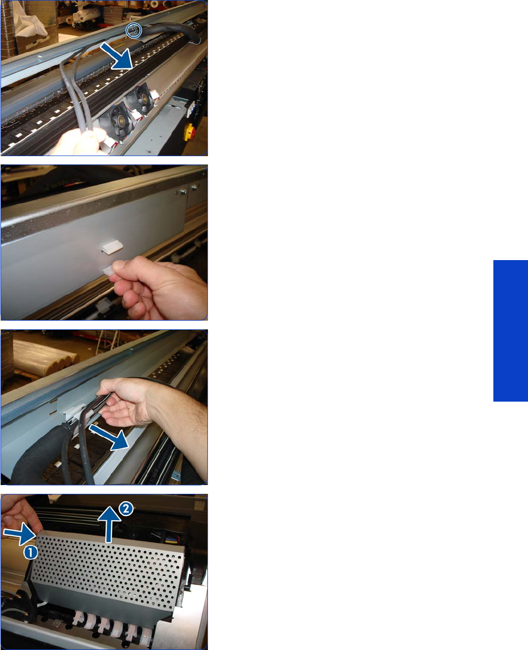
Ink Supply Tubes and Trailing Cable 383
Removal & Installation
13. Cut the cable tie and continue unrouting the Trailing
Cables.
14 . Lift the tab on the Front Tube Shelf Beam.
15. Release the Tubes and Trailing Cables from the Tube
Guides.
16. Press both sides of the Carriage PCA Cover and unclip
it from the Carriage Assembly.
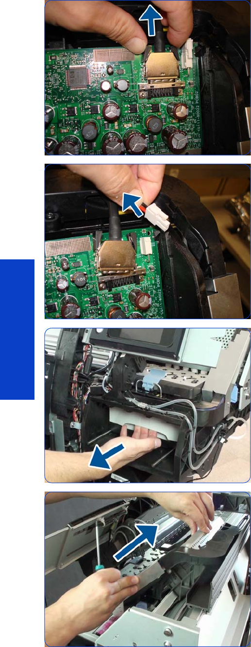
384 Chapter 8 Removal & Installation
Removal & Installation
17. Press inwards on both sides of the data Trailing Cable
connector, and pull to disconnect the cable.
18 . Disconnect the power Trailing Cable connector.
19. Pull the Printhead Cleaning Cartridge forward to freeze
the carriage.
20.Move the carriage in order to get access to the
Carriage Protector screws.
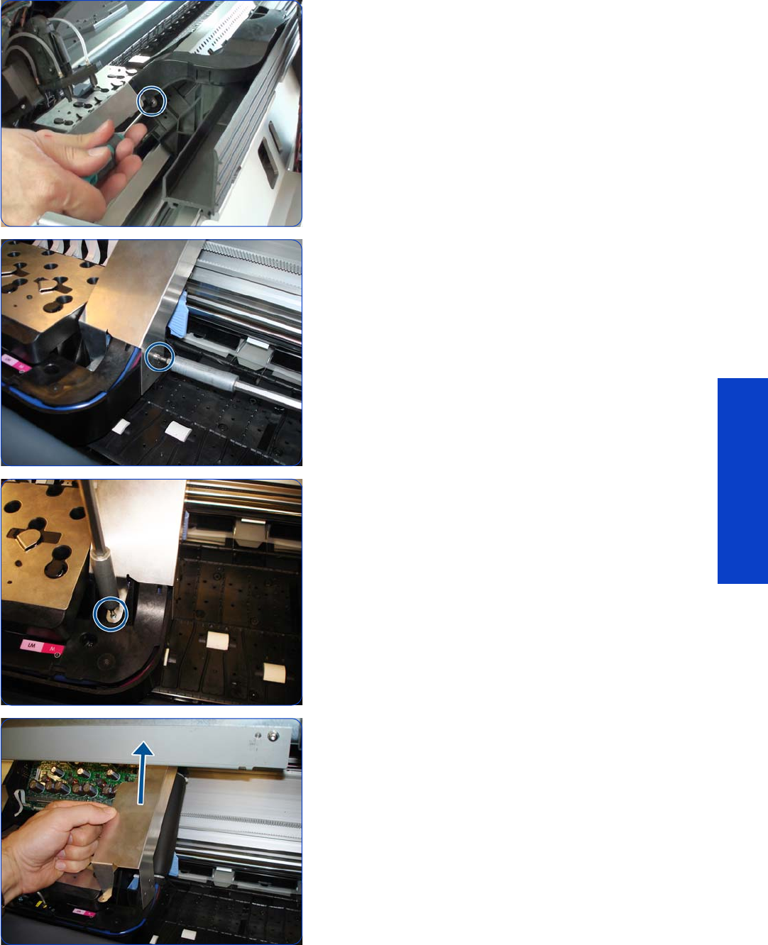
Ink Supply Tubes and Trailing Cable 385
Removal & Installation
21. Remove a T-8 screw.
22.Remove a T-8 screw.
23.Remove a T-8 screw.
24.Remove the Carriage Protector.
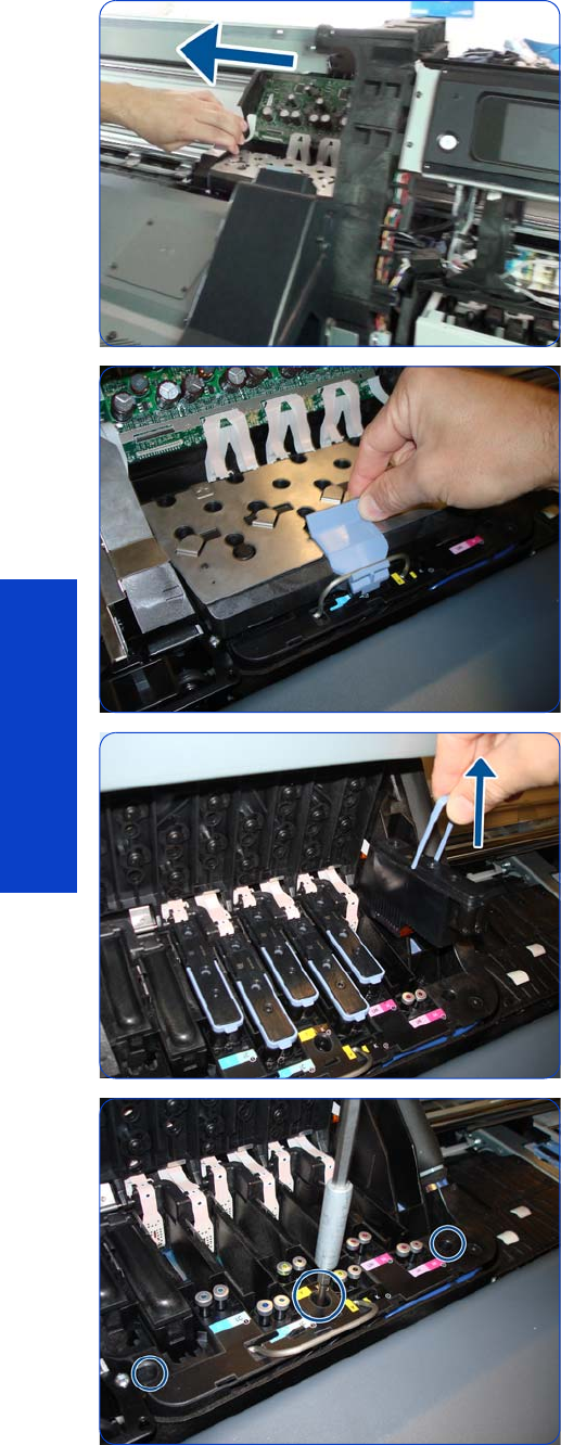
386 Chapter 8 Removal & Installation
Removal & Installation
25.Move the Carriage to the center of the Platen.
26.Open the Carriage Latch.
27. Remove the Printheads.
28.Remove three T-15 screws to freeze the Tubes Crane.
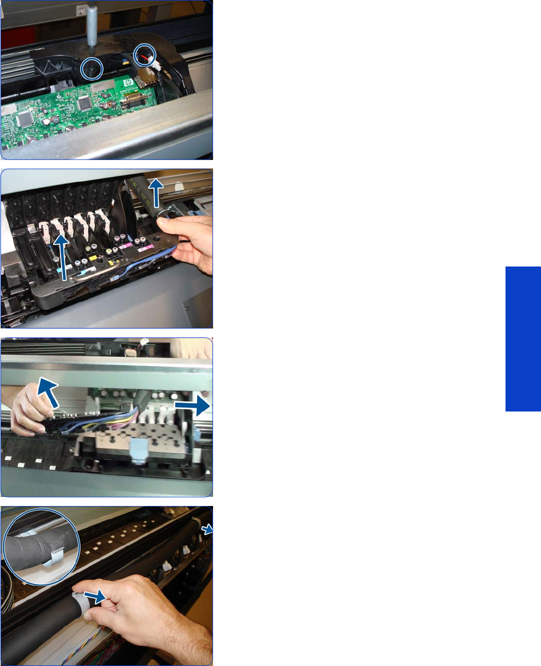
Ink Supply Tubes and Trailing Cable 387
Removal & Installation
29. Remove two T-15 screws to freeze the Tubes Crane.
30.Remove the Tubes Crane.
31. Pull out the Tubes Crane and move the Carriage to the
right to get it out of the way.
32.Disengage the three hooks that hold the Tubes along
their fixed part.
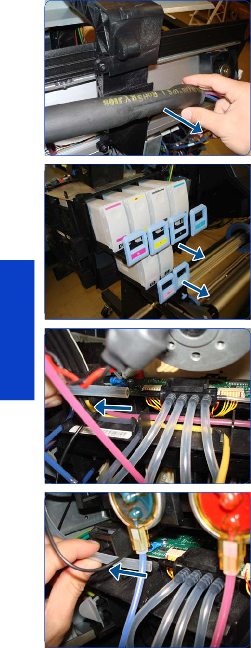
388 Chapter 8 Removal & Installation
Removal & Installation
33.Disengage the Tubes from the Left Arc.
34.Pull out all the Ink Cartridge Trays.
35.Disconnect the top Air Tubes from the Ink Supply Tubes.
36.Disconnect the bottom Air Tubes from the Ink Supply
Tubes.
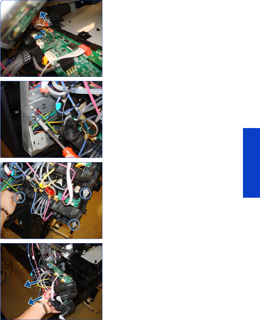
Ink Supply Tubes and Trailing Cable 389
Removal & Installation
37. Disconnect the electrical cable from the ISS Top PCA.
38.Remove the T-20 screw from the ISS grounding cable.
39. Unlock the Ink Supply Tubes.
40.Pull out the Ink Supply Tubes.

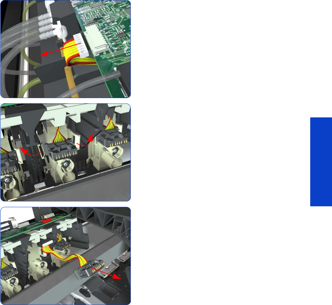
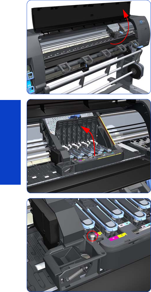
392 Chapter 8 Removal & Installation
Removal & Installation
Cutter Assembly
Removal
1. Select “Replace Cutter” from Service Menu (refer to
Chapter 4) and follow the instructions on the Front
Panel.
2. Open the Window.
3. Open the Carriage Cover.
4. Remove one T-15 screw that secures the Cutter
Assembly to the Carriage Assembly.

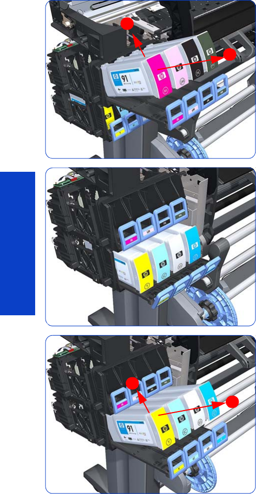
394 Chapter 8 Removal & Installation
Removal & Installation
Ink Supply Station (ISS)
Removal
1. Remove the Left Cover
page 303
.
2. Remove the Scan-Axis Motor
page 426
.
3. Pull out the top row of Cartridge Trays and remove the
Ink Cartridges.
4. Close the top row of Cartridge Trays and pull out the
bottom row.
5. Pull out the bottom row of Cartridge Trays and remove
the Ink Cartridges.
1
2
1
2
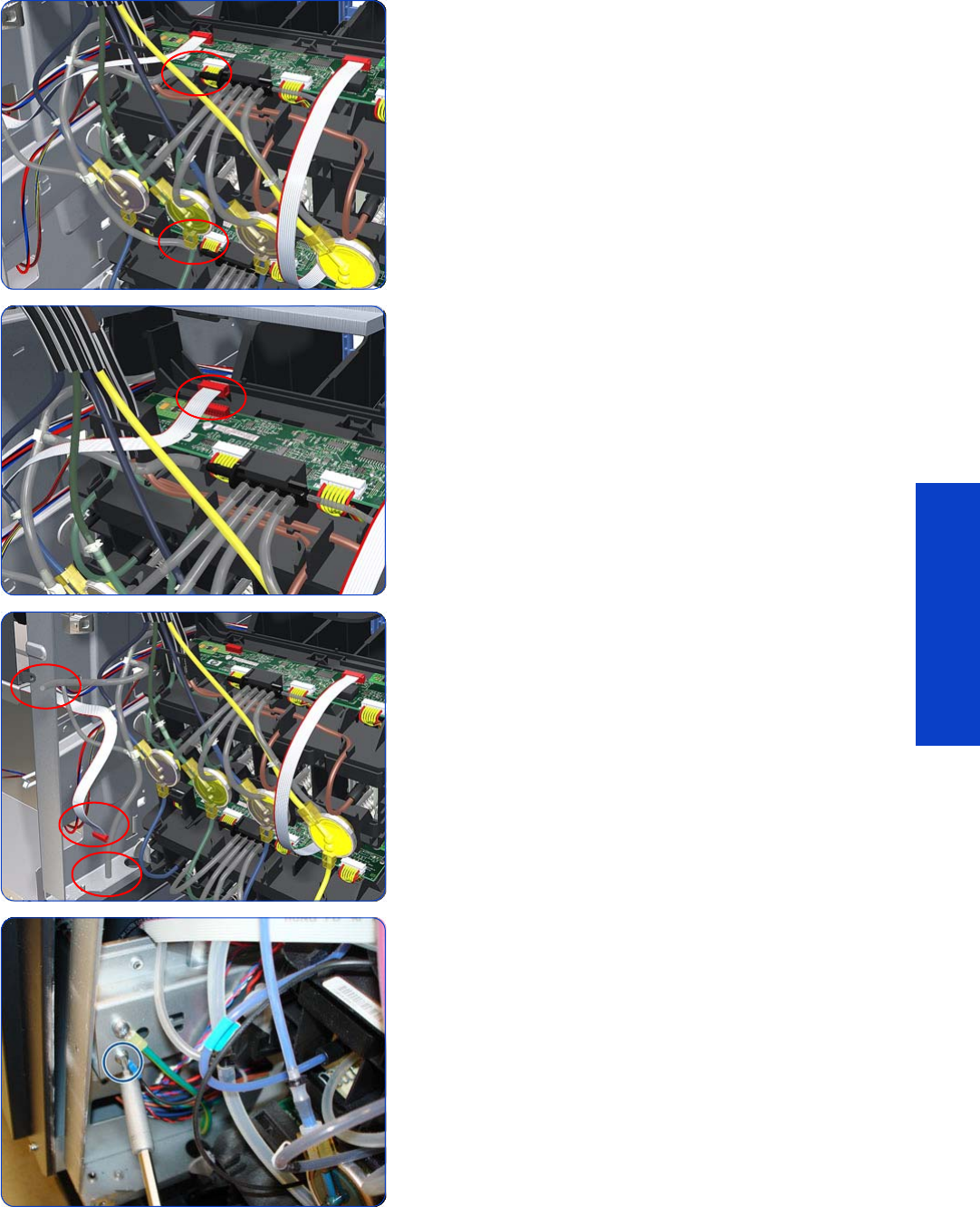
Ink Supply Station (ISS) 395
Removal & Installation
6. Disconnect the top and bottom Air Tubes from the Ink
Supply Tubes.
7. Disconnect the Electrical Cable from the rear of the Ink
Cartridge Tube Connector.
8. Put away the tubes and the cable.
9. Remove one T-20 Screw from the Sideplate (grounding
cable).
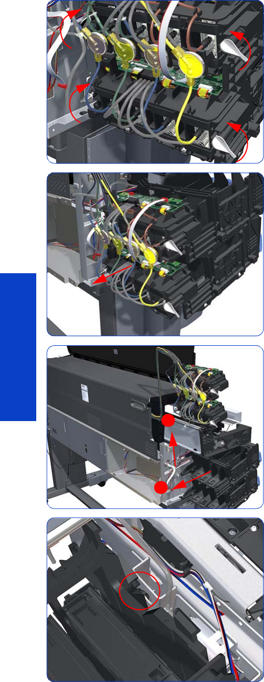
396 Chapter 8 Removal & Installation
Removal & Installation
10. Twist the four latches at the rear of the lower Ink
Cartridge Tube Connector and release the complete
assembly.
11. Lift the Cartridge Tube Connector off the Ink Supply
Station.
12. Remove the Cartridge Tube Connector from the Ink
Supply Station.
13. Unhook the Ink Supply Station from the printer.
1
2
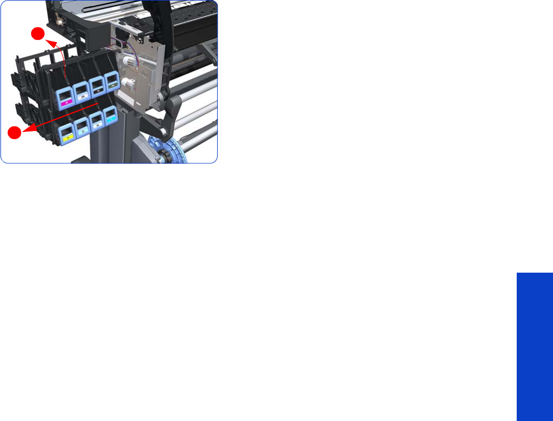
Ink Supply Station (ISS) 397
Removal & Installation
14 . Remove the complete Ink Supply Station (upper and
lower assemblies) from the printer.
1
2
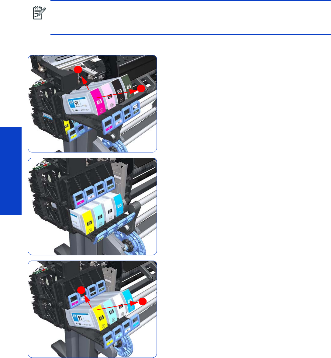
398 Chapter 8 Removal & Installation
Removal & Installation
Ink Supply Station PCAs (Top and Bottom)
Removal
1. Remove the Left Cover
page 303
.
2. Pull out the top row of Cartridge Trays and remove the
Ink Cartridges.
3. Close the top row of Cartridge Trays and pull out the
bottom row.
4. Pull out the bottom row of Cartridge Trays and remove
the Ink Cartridges.
NOTE: You MUST NEVER replace both the Hard Disk Drive and the ISS PCAs (or the Ink Supply Tubes
and Trailing Cable) at the same time. If these parts need to be replaced, you MUST first replace one part
and then power ON the printer until it completely initializes. Then power OFF the printer and replace the
other part.
1
2
1
2
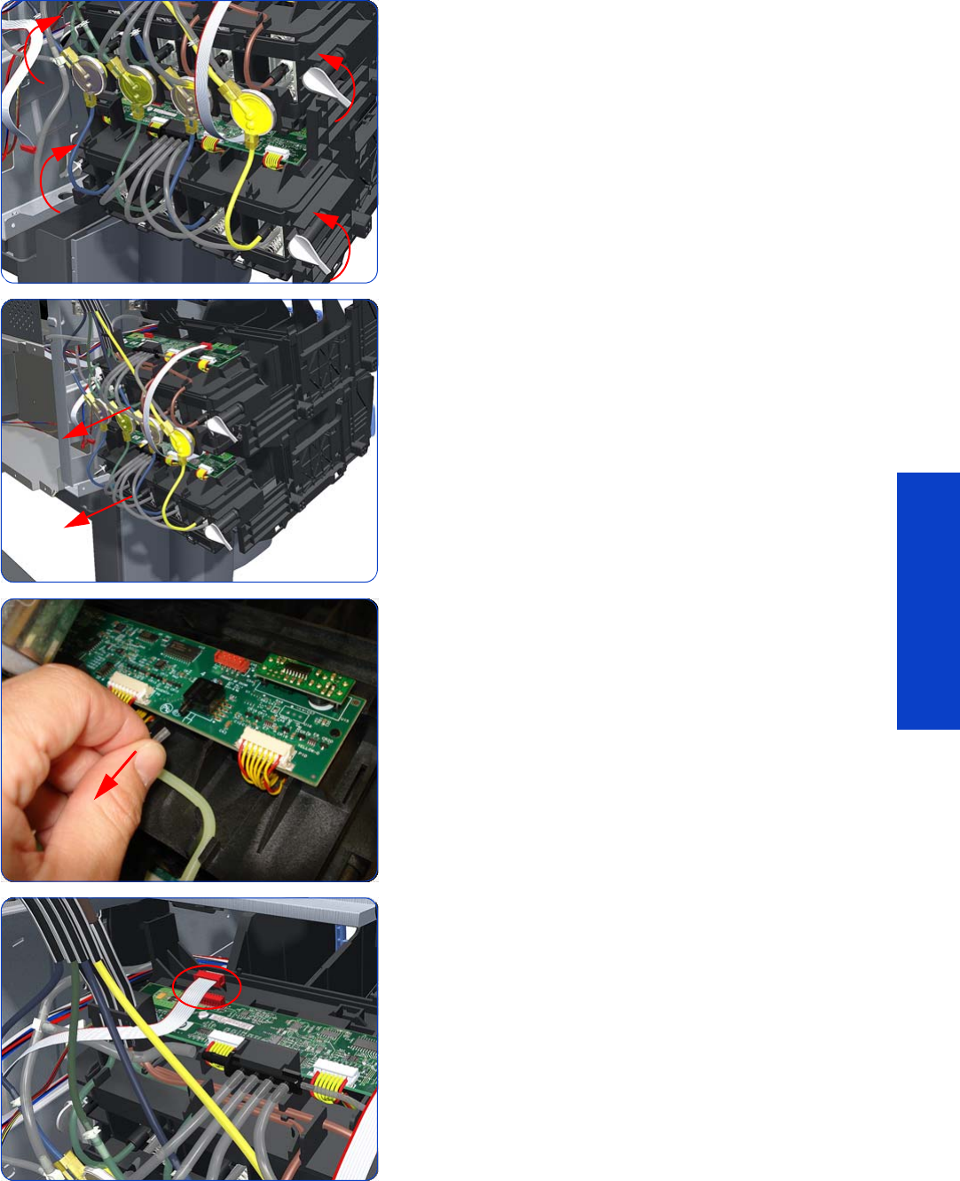
Ink Supply Station PCAs (Top and Bottom) 399
Removal & Installation
5. Twist the four latches at the rear of the lower Ink
Cartridge Tube Connector and release the complete
assembly.
6. Slide the Upper and Lower Cartridge Tube Connectors
out of the ISS Assembly (but do not remove) to gain
access to the ISS Top PCAs.
7. Disconnect the Air Tube from the ISS Top PCA.
8. Disconnect the Electrical Cable from the ISS Top PCA.
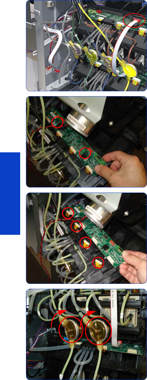
400 Chapter 8 Removal & Installation
Removal & Installation
9. Disconnect the Electrical Cable from the ISS Top PCA.
10. Remove two T-10 screws from the ISS Top PCA.
11. Disconnect four connectors from the ISS Top PCA.
12. Tip: To make the removal easier you can remove the
two Ink Valves located at the rear of the Upper
Cartridge Tube Connector from holders, by turning
them in a clockwise direction.
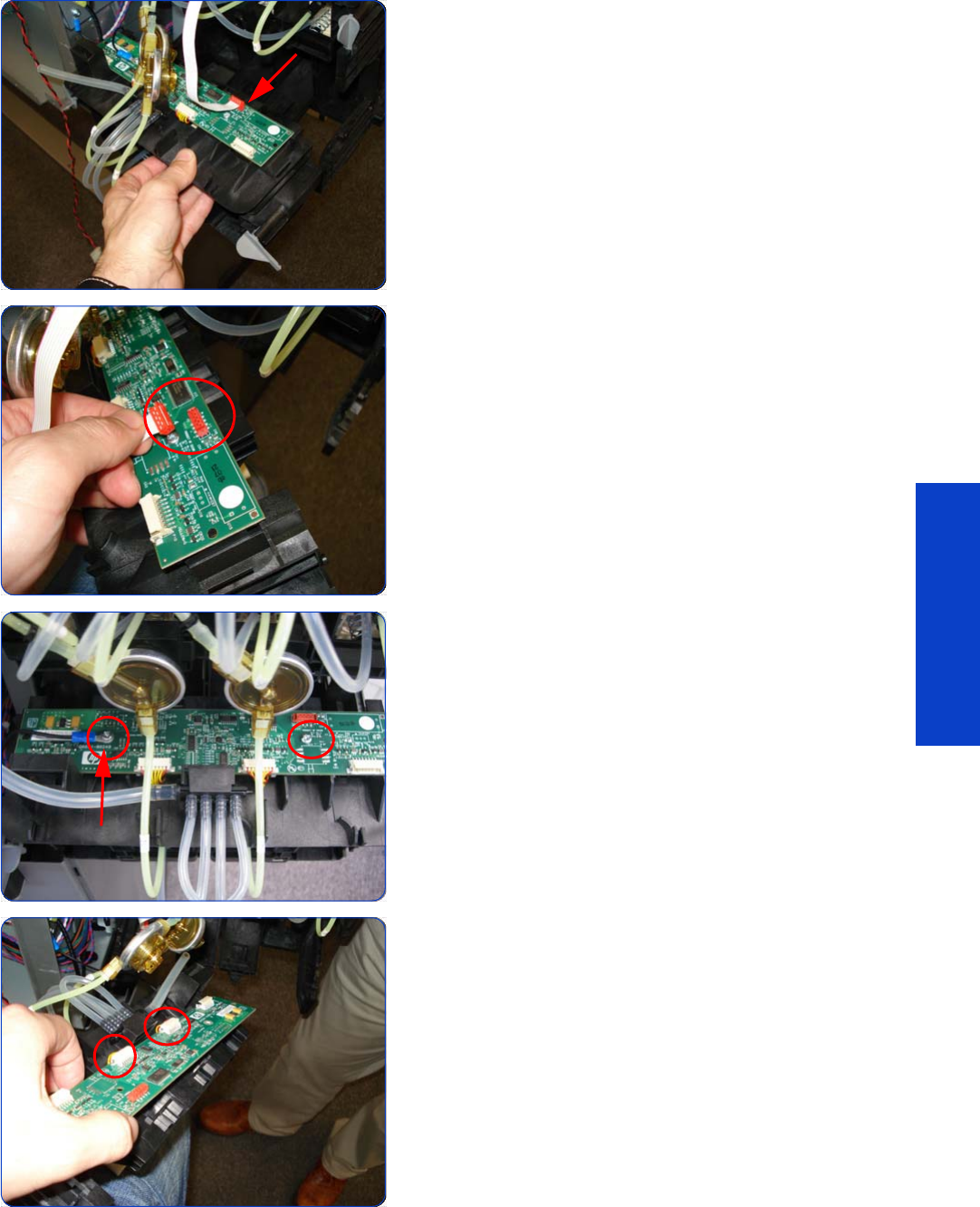
Ink Supply Station PCAs (Top and Bottom) 401
Removal & Installation
13. Slide out the Lower Carriage Tube Connector to gain
access to the ISS Bottom PCA (but do not remove). You
may need to slide in the Upper Carriage Tube
Connector.
14 . Disconnect the Electrical Cable from the ISS Bottom
PCA.
15. Remove two T-10 screws from the ISS Bottom PCA (one
screw also secures a grounding cable).
16. Disconnect the two Electrical Cables from the ISS
Bottom PCA.
Grounding
cable
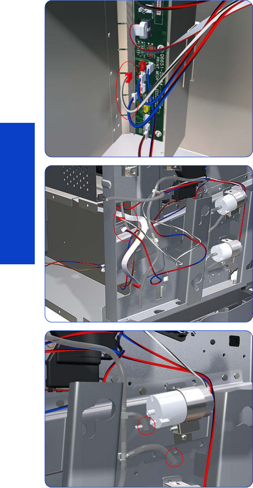
402 Chapter 8 Removal & Installation
Removal & Installation
APS Assembly
Removal
1. Remove the Left Cover
page 296
.
2. Remove the Electronics Enclosure Extension
page 329
.
3. Remove the Scan-Axis Motor
page 426
.
4. Remove the ISS
page 394.
5. Disconnect the APS 1 (Top unit) valve electrical
connectors from the PrintMech PCA.
6. Unroute the APS 1 electrical connections.
7. Disconnect both air tubes from APS 1.
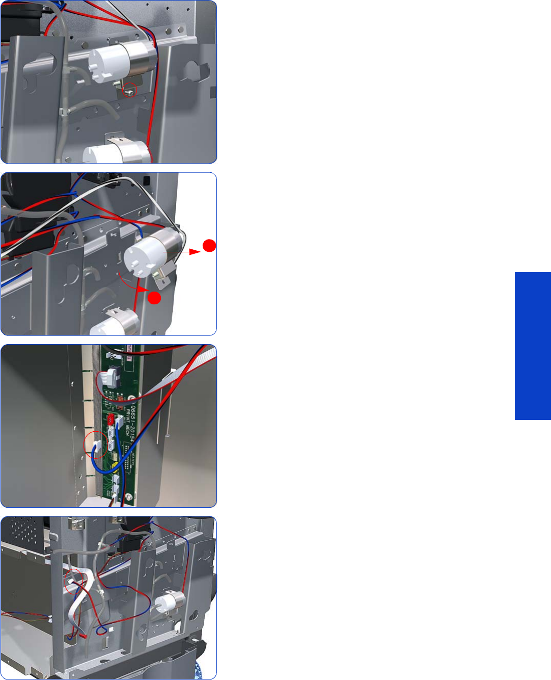
APS Assembly 403
Removal & Installation
8. Remove one T-20 attachment screw from APS 1 (Top
unit).
9. Remove APS 1 (Top unit) from the printer.
10. Disconnect the APS 2 (Top unit) valve electrical
connectors from the PrintMech PCA.
11. Unroute the APS 2 electrical connection.
1
2
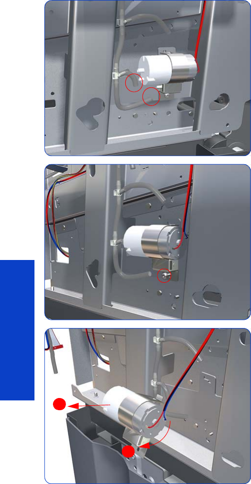
404 Chapter 8 Removal & Installation
Removal & Installation
12. Disconnect both air tubes from APS 2.
13. Remove one T-20 attachment screw from APS 2 (Bottom
unit).
14 . Remove APS 2 (Bottom unit) from the printer.
Installation
After installing the new APS Pumps, reset the APS Pumps life counter
page 194.
1
2
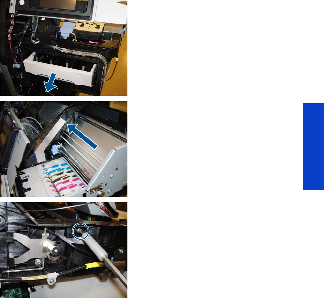
Encoder Strip 405
Removal & Installation
Encoder Strip
Removal
1. Remove the Right Cover
page 296
.
2. Remove the Left Cover
page 303.
3. Uncap the Carriage Assembly by manually pulling out
the Printhead Cleaning Cartridge tray.
4. Move the Carriage Assembly out of the Service Station.
5. On the left-hand side of the printer, remove one T-20
screw.
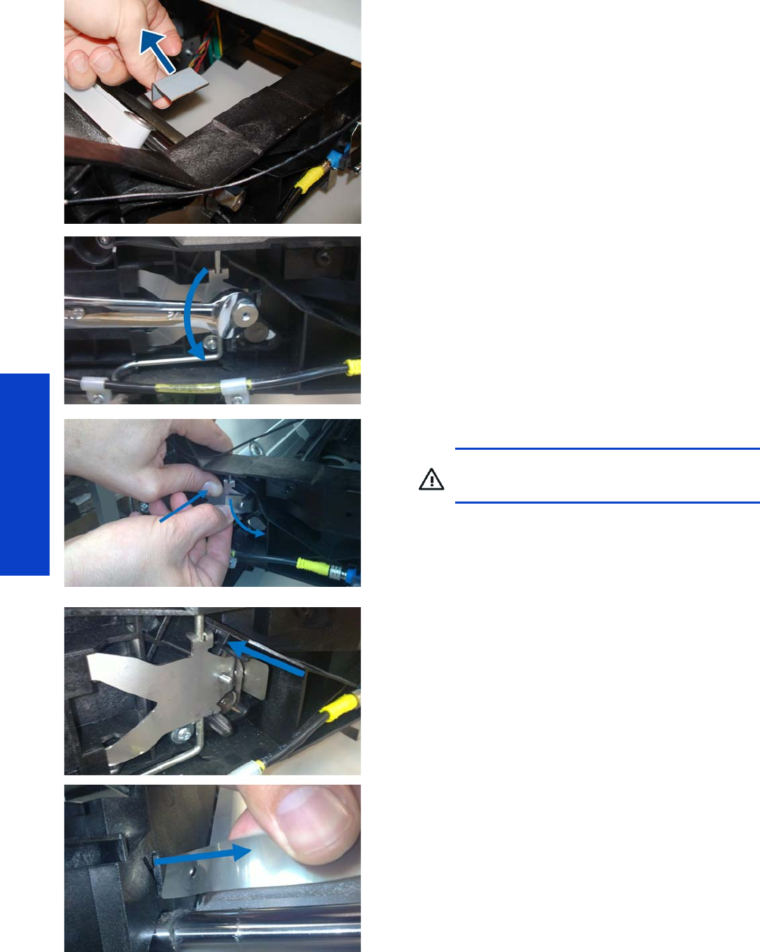
406 Chapter 8 Removal & Installation
Removal & Installation
6. Remove the metal tensioner.
7. Remove the half-inch M-13 nut.
8. Push the tensioner and disengage the Encoder Strip.
9. Release the Encoder Strip from the left bracket.
WARNING! You are recommended to use a
vise grip, otherwise you may cut your fingers.
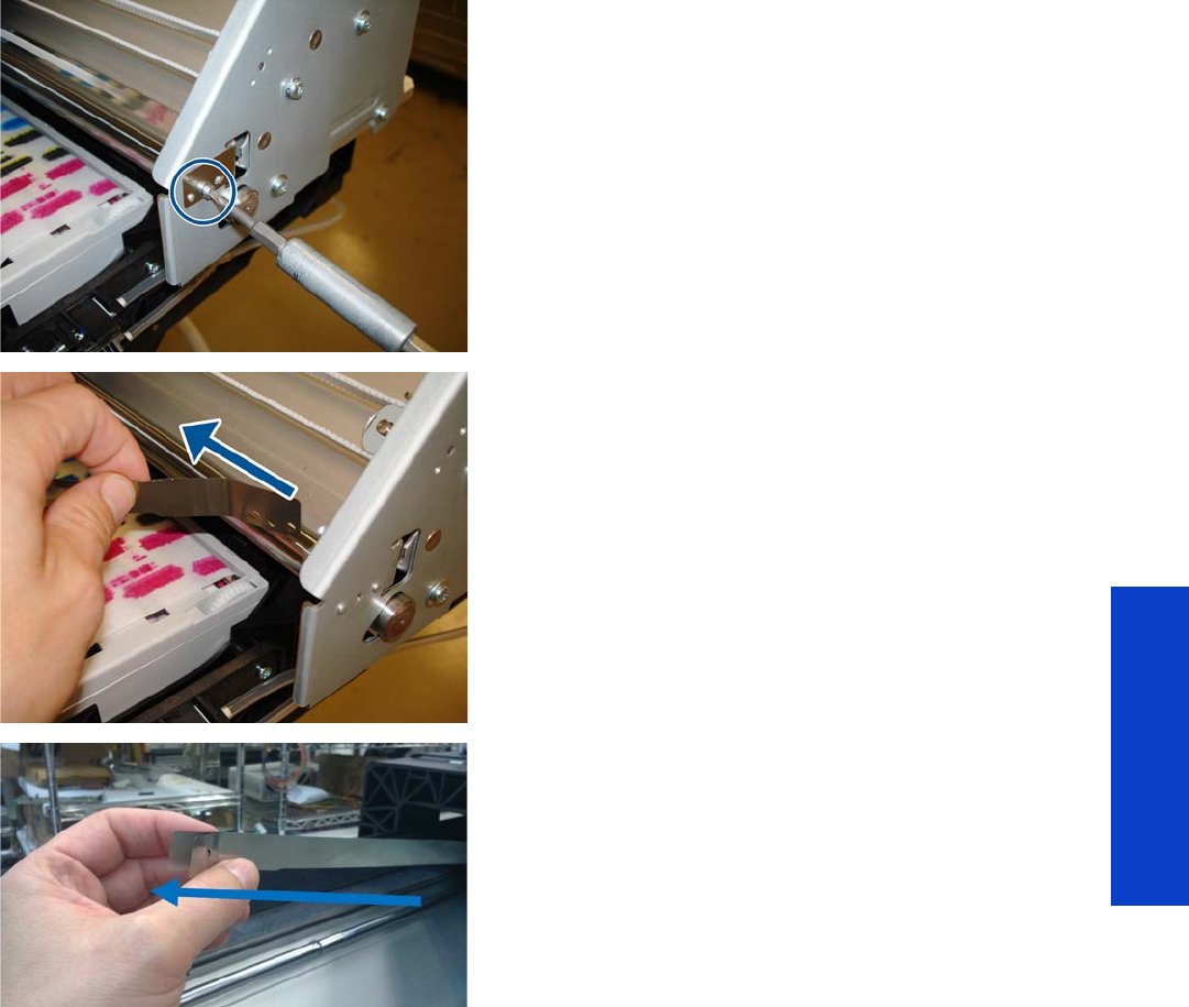
Encoder Strip 407
Removal & Installation
10. On the right-hand side of the printer, remove one T-10
screw.
11. Release the Encoder Strip from the right bracket.
12. On the left-hand side of the Carriage, route the
Encoder Strip through the openings in the Carriage
and gently pull it out of the printer.
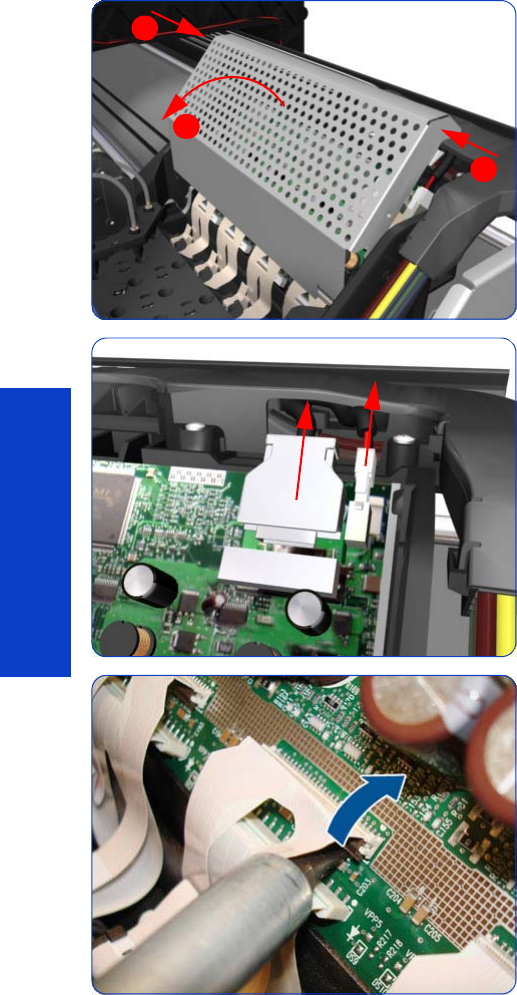
408 Chapter 8 Removal & Installation
Removal & Installation
Carriage PCA
Removal
1. Remove the Right Cover
page 296
.
2. Press the two side of the Carriage PCA Cover and
unclip from the Carriage Assembly.
3. Disconnect the Trailing Cables from the Carriage PCA.
4. Use a flat bladed screwdriver to release ALL the clips,
securing the Carriage Flex Cables to the Carriage
Assembly, by pulling upwards.
1
2
1
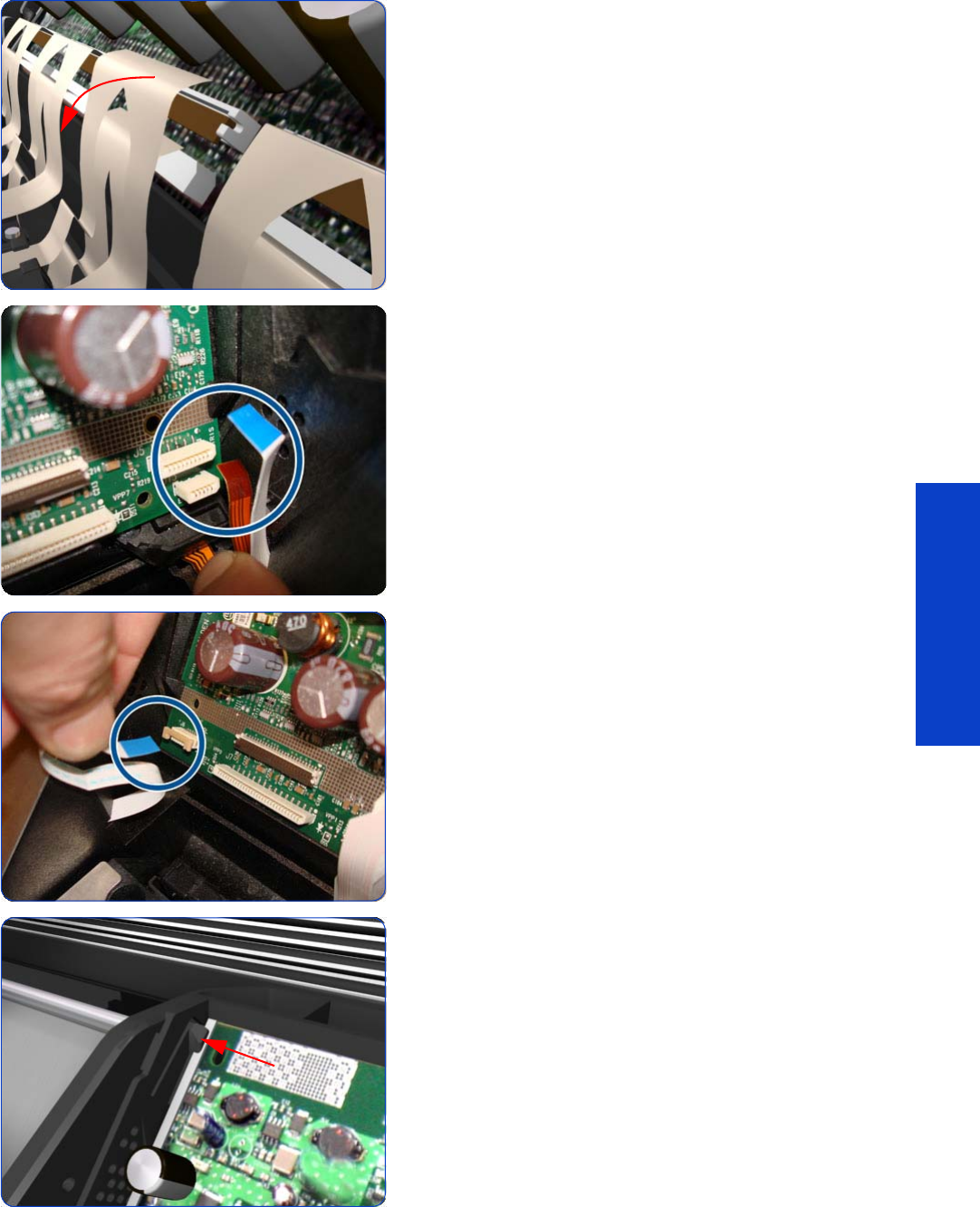
Carriage PCA 409
Removal & Installation
5. Disconnect the Flex Cables from the Carriage PCA.
6. Disconnect the Line Sensor Cable and the Encoder
Sensor Cable from the Carriage PCA.
7. Unlock the connector and disconnect the Color Sensor
Cable from the Carriage PCA.
8. Push inwards the four clips that secure the Carriage
PCA.

410 Chapter 8 Removal & Installation
Removal & Installation
9. Remove the Carriage PCA from the printer.
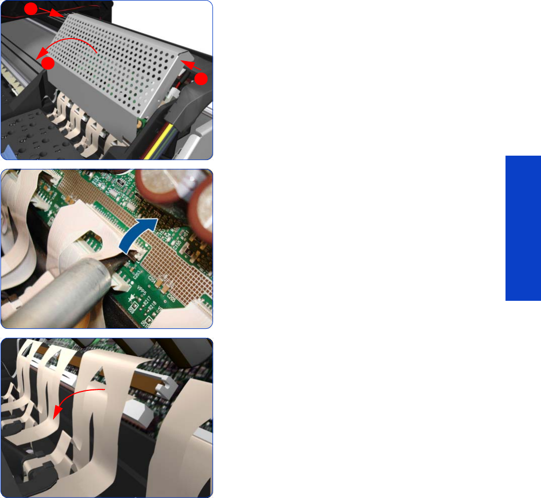
Carriage Flex Cables 411
Removal & Installation
Carriage Flex Cables
Removal
1. Remove the Right Cover
page 296
.
2. Remove the Front Panel
page 342
.
3. Remove the Primer Assembly
page 345
.
4. Press the two side of the Carriage PCA Cover and
unclip from the Carriage Assembly.
5. Use a flat bladed screwdriver to release ALL the clips,
securing the Carriage Flex Cables to the Carriage
Assembly, by pulling upwards.
6. Disconnect the ALL the Flex Cables from the Carriage
PCA.
1
2
1
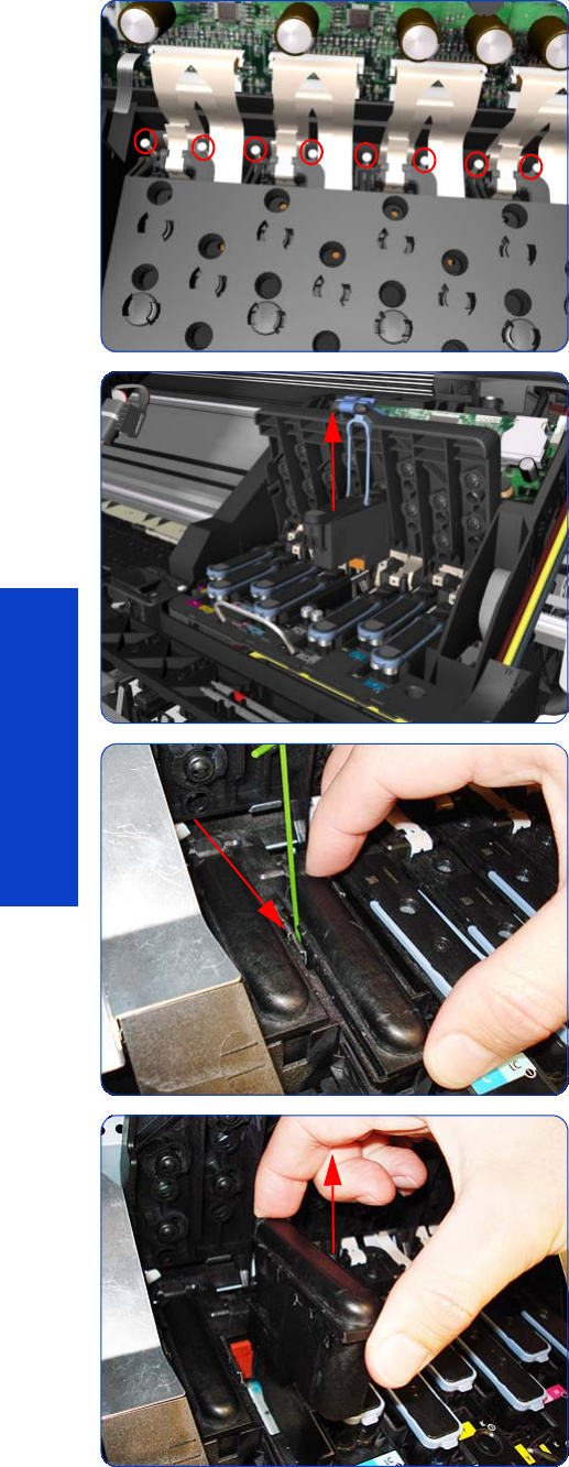
412 Chapter 8 Removal & Installation
Removal & Installation
7. Remove eight T-8 screws that secure the Carriage Flex
Cables to the Carriage Assembly.
8. Open the Carriage Cover and remove ALL the
Printheads from the Carriage Assembly.
9. The two unused spaces of the Carriage Assembly have
dummy printheads installed. To remove them, insert a
thin bladed tool into a small hole on the left to release
them from a latch located underneath.
10. Remove the dummy Printheads.
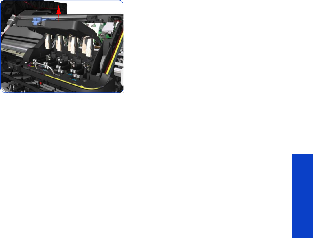
Carriage Flex Cables 413
Removal & Installation
11. Remove the Carriage Flex Cable from the printer.
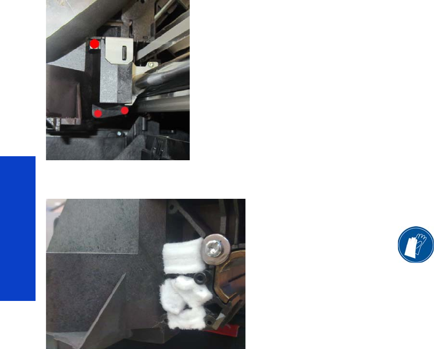
414 Chapter 8 Removal & Installation
Removal & Installation
Oiler
Removal
1. Remove the Right Cover
page 296
.
2. Remove the Printhead Cleaning Cartridge
.
3. Move the Carriage away from the right bracket.
4. On the right side of the carriage, locate the 3 screws
(highlighted in red in the picture) attaching the Oiler to
the Carriage.
Remove these 3 screws (T8 SLOT), starting from the
bottom ones, with a T8 screwdriver or a small flat
screwdriver.
5. Remove the Oiler. Be extremely careful not to damage
the metal Encoder Strip.
6. Remove the 5 Absorber Foams from the Carriage
cavities. You are recommended to wear gloves.
7. With a cloth, clean any oil residue from the Carriage,
especially if you see it around the Line Sensor.
8. Clean and lubricate the Carriage Rail, as described in
the Hardware Maintenance chapter of the User’s
Guide.
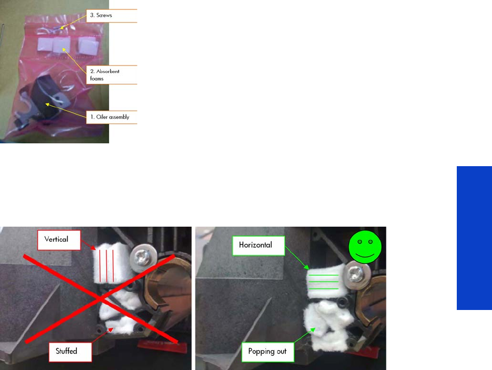
Oiler 415
Removal & Installation
Installation
The Oiler Service Kit, CQ871-67086, contains the following parts:
1. Oiler assembly
2. Absorbent foams
3. Screws (to assemble onto the carriage)
To improve the effectiveness of the absorbent foams, use care when inserting them back into the Carriage.
Insert them as shown in the following picture, with the top pads in a horizontal position and the bottom
pads popping out of their holes.
If the absorbent foams are not inserted correctly, oil may reach the Line Sensor and prevent it from working.
Oil may also reach the print or the Printhead Cleaning Cartridge, which could damage the Printheads.
When tightening the three oiler screws, be careful not to strip the small plastic threads on the carriage.
When replacing the Oiler, you are recommended to check the left-hand side of the Carriage and replace
the rear felt pads if they are very dirty or damaged, using the Lubrication Felts Kit (Q6651-60081). There
are no felt pads on the right-hand side as they are substituted by the Oiler.
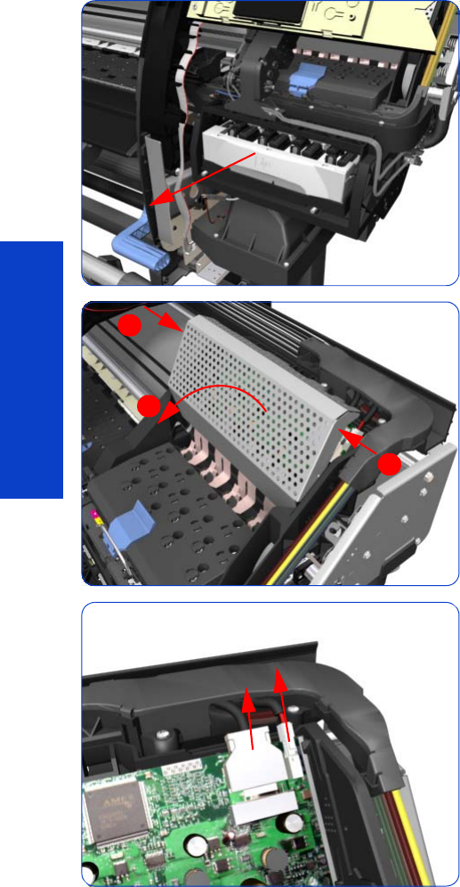
416 Chapter 8 Removal & Installation
Removal & Installation
Carriage Assembly with Belt, Pulley, and Tensioner
Removal
1. Remove the Right Cover
page 296
.
2. Remove the Front Panel
page 342
.
3. Remove the Left Cover
page 303.
4. Remove the Encoder Strip
page 405
.
5. Pull out the Printhead Cleaning Cartridge tray.
6. Press the two side of the Carriage PCA Cover and
unclip from the Carriage Assembly.
7. Disconnect the Trailing Cable from the Carriage PCA.
1
2
1
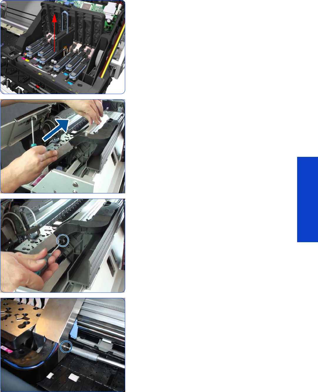
Carriage Assembly with Belt, Pulley, and Tensioner 417
Removal & Installation
8. Open the Carriage Cover and remove ALL the
Printheads from the Carriage Assembly.
9. Move the carriage in order to get access to the
Carriage Protector screws.
10. Remove a T-8 screw.
11. Remove a T-8 screw.
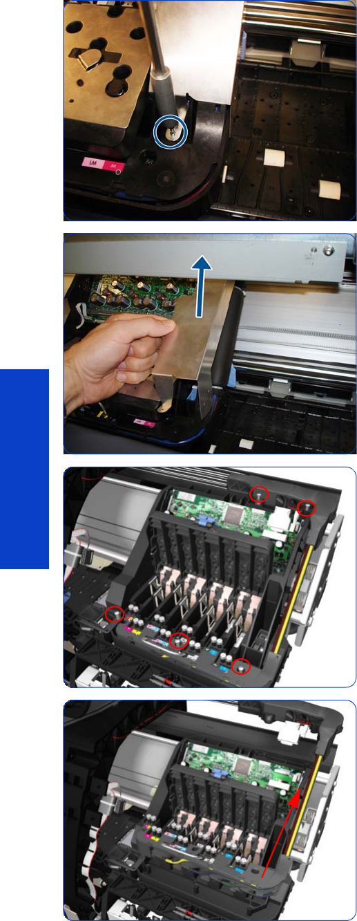
418 Chapter 8 Removal & Installation
Removal & Installation
12. Remove a T-8 screw.
13. Remove the Carriage Protector.
14 . Remove five T-15 screws that secure the Ink Supply
Tubes to the Carriage Assembly.
15. Remove the Ink Supply Tubes from the Carriage
Assembly and safely place to one side of the printer.
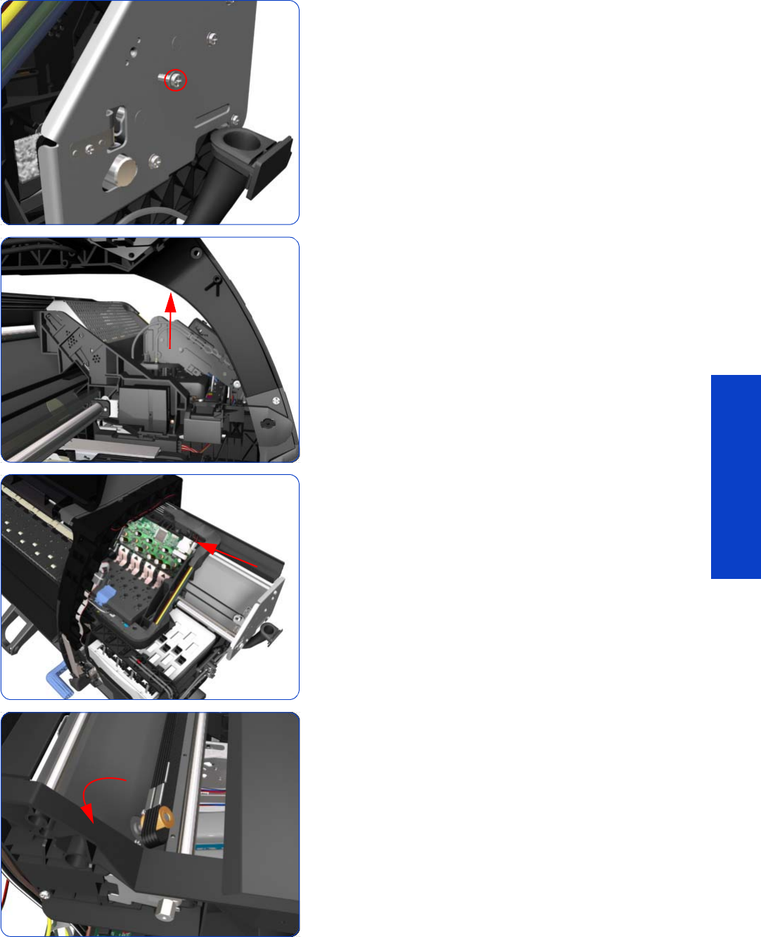
Carriage Assembly with Belt, Pulley, and Tensioner 419
Removal & Installation
16. Remove one T-20 screw that secures the Belt Tensioner
to the Chassis.
17. Lift the Primer and hold the Primer to its maximum
position to avoid damaging it when you move the
Carriage Assembly in the next step.
18 . Move the Carriage Assembly slightly away from the
right Scan-Axis Bracket.
19. Release the Carriage Belt from the Scan-Axis Motor on
the left hand side of the printer.
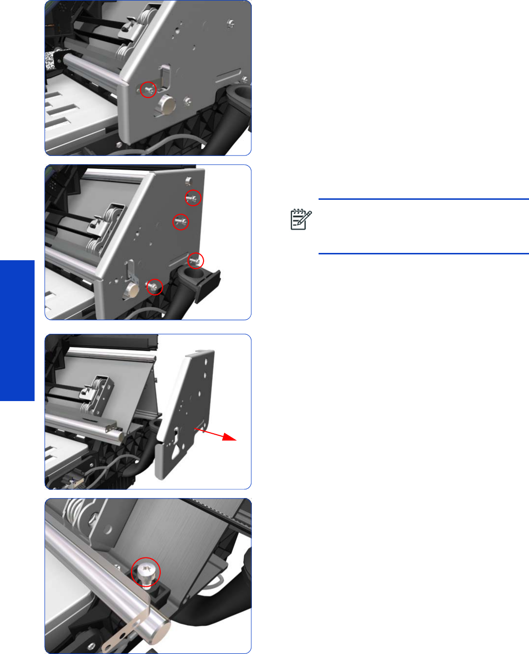
420 Chapter 8 Removal & Installation
Removal & Installation
20.Remove one T-10 screw that secure the Encoder Strip.
21. Remove four T-20 screws that secure the right Scan-Axis
Bracket.
22.Remove the right Scan-Axis Bracket from the printer.
23.Remove the Carriage Stopper Screw (T-20) from the
Chassis.
NOTE: Note that these are Chassis screws
and in normal circumstances should NEVER be
removed, but in this case we need to remove
them in order to remove the Carriage Assembly.
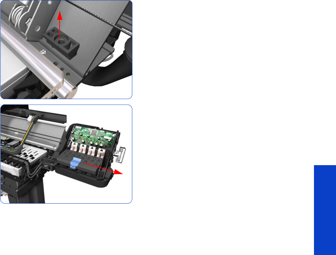
Carriage Assembly with Belt, Pulley, and Tensioner 421
Removal & Installation
24.Remove the Carriage Stopper from the printer.
25.Slide the Carriage Assembly (including the belt) to the
right and out of the printer.
26.If the Carriage Assembly is to be replaced, make sure
that you remove the Belt, the Carriage PCA, Color
Sensor, Encoder and Line Sensors and the Cutter
Assembly (in order to install them on the new Carriage
Assembly).
Installation
After installing the new Carriage Assembly, perform the following operations:
•Scan-Axis Calibration
page 199.
•Line Sensor Calibration
page 201.
•Primer Calibration
page 203.
And reset the following life counters:
•Carriage cycles
page 194.
•Cutter cycles
page 194.
•Replace Oiler Foam
page 194.
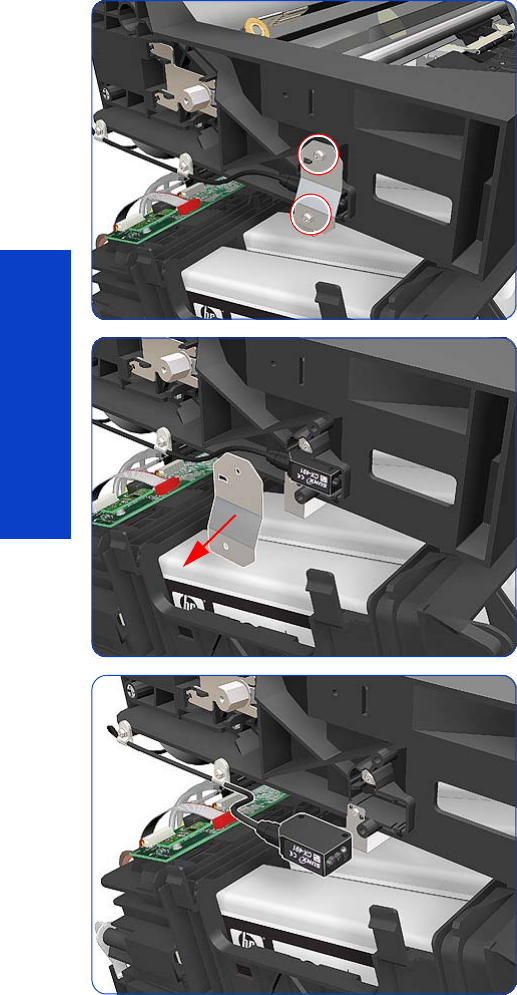
422 Chapter 8 Removal & Installation
Removal & Installation
Media Jam Sensor and Carriage Reflector Assembly
Removal
1. Remove the Left Cover
page 303.
2. Remove the Power Box Cover
page 321.
3. Remove the Electronics Enclosure Extension Cover
page 329.
4. Remove the Rear Upper Cover
page 312.
5. Remove two T-15 screws from the Media Jam Sensor.
6. Remove the Media Jam Sensor Plate.
7. Remove the Media Jam Sensor from the clip on the Left
Scan-Axis Bracket.
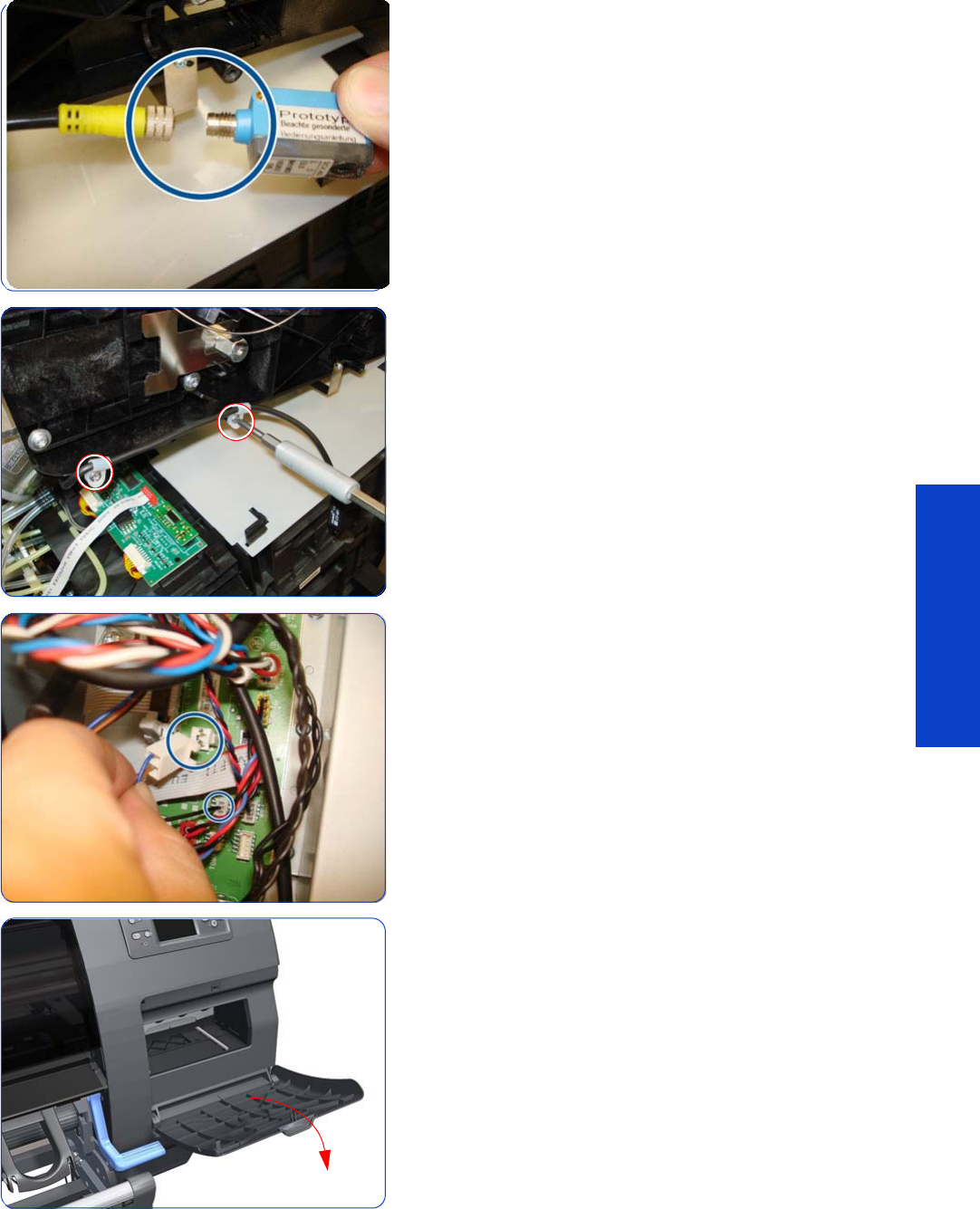
Media Jam Sensor and Carriage Reflector Assembly 423
Removal & Installation
8. Disconnect the Media Jam Sensor from the cable by
unscrewing.
9. Remove two T-15 screws from cable clamps securing the
cable of the Media Jam Sensor to the Left Scan-Axis
bracket, and unroute the cable all the way to the
Printmech PCA.
10. Disconnect the cable of the Media Jam Sensor from the
cable from the PrintMech PCA.
11. Open the Printhead Cleaning Cartridge Door.
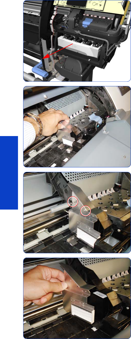
424 Chapter 8 Removal & Installation
Removal & Installation
12. Pull out the Printhead Cleaning Cartridge tray.
13. Slide the Carriage to the center of the platen.
14 . Remove two T-8 screws from the side of the Reflector
Assembly.
15. Remove the Carriage Reflector Assembly.

Belt Assembly 425
Removal & Installation
Belt Assembly
Removal
This procedure is the extra step required to replace the Belt and Tensioner Assembly, once the Carriage
has been disassembled from the printer.
1. Remove the Right Cover
page 296
.
2. Remove the Left Cover
page 303.
3. Remove the Top Cover
page 314
.
4. Remove the Encoder Strip
page 405
.
5. Remove the Carriage Assembly
page 416
.
6. Release the Belt from the bottom of the Carriage
Assembly.
Installation
After installing the new Belt Assembly, reset the Belt Cycles
page 194.
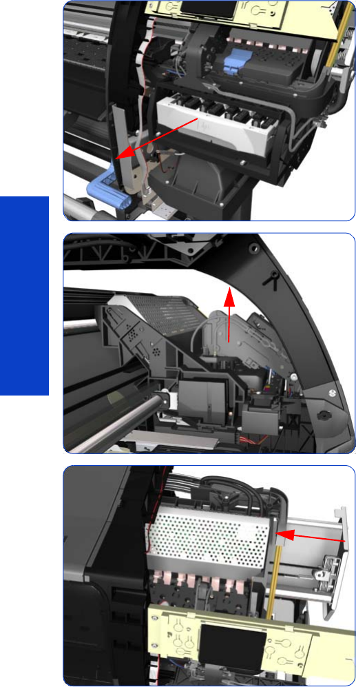
426 Chapter 8 Removal & Installation
Removal & Installation
Scan-Axis Motor
Removal
1. Remove the Right Cover
page 296
.
2. Remove the Left Cover
page 303.
3. Remove the Electronics Enclosure Extension
page 329.
4. Uncap the Carriage Assembly by manually pulling out
the Printhead Cleaning Cartridge tray.
5. Lift the Primer and hold the Primer to its maximum
position to avoid damaging it when you move the
Carriage Assembly in the next step.
6. Move the Carriage Assembly slightly away from the
right Scan-Axis Bracket.
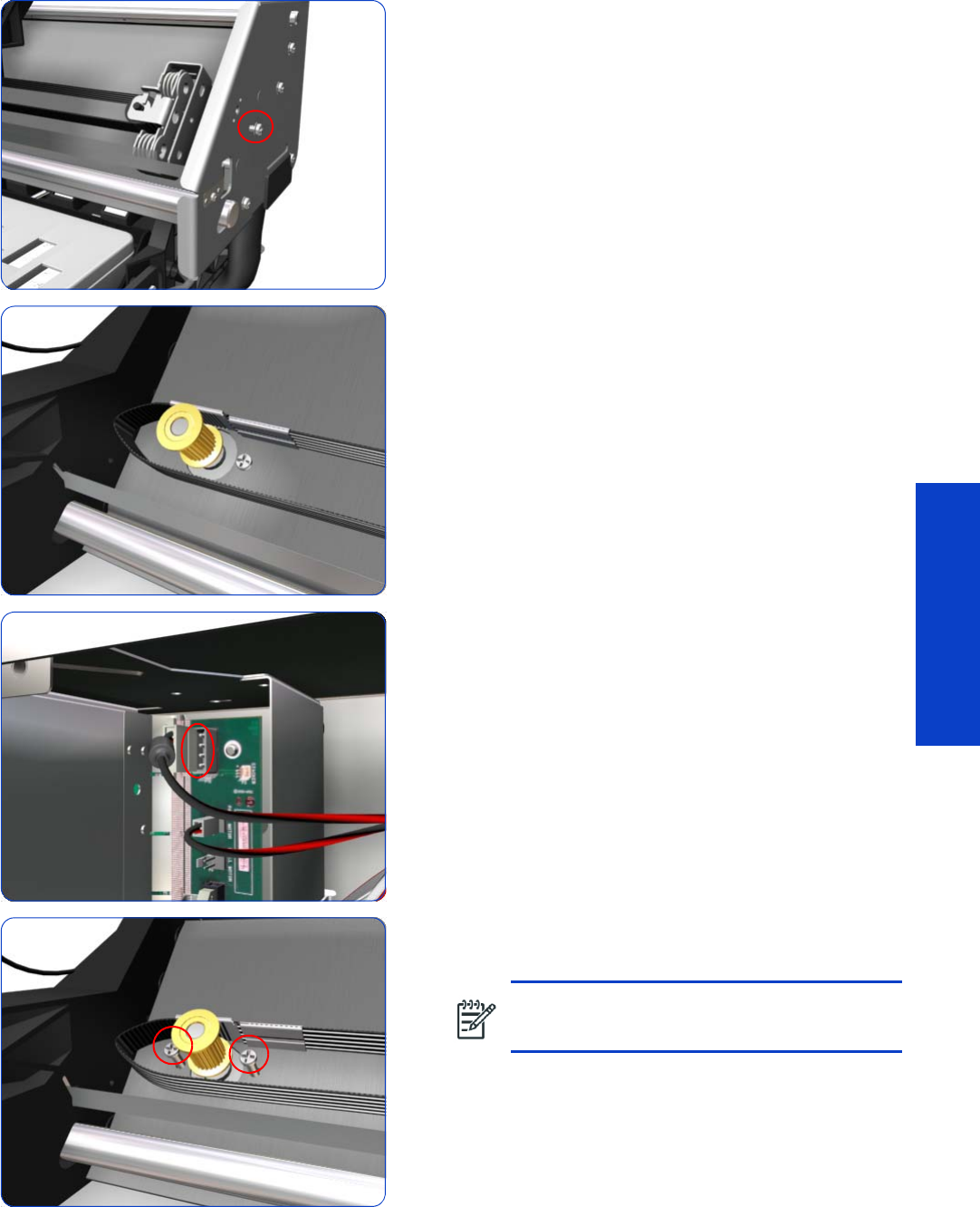
Scan-Axis Motor 427
Removal & Installation
7. Remove one T-15 screw that secures the Belt Tensioner
to the Chassis.
8. Release the Carriage Belt from the Scan-Axis Motor on
the left hand side of the printer.
9. Disconnect the Scan-Axis Motor cable from the
PrintMech PCA, and unroute the cable along its whole
length.
10. Remove two T-20 screws that secure the Scan-Axis
Motor.
NOTE: Make sure you hold the Scan-Axis
Motor securely when removing the screws.

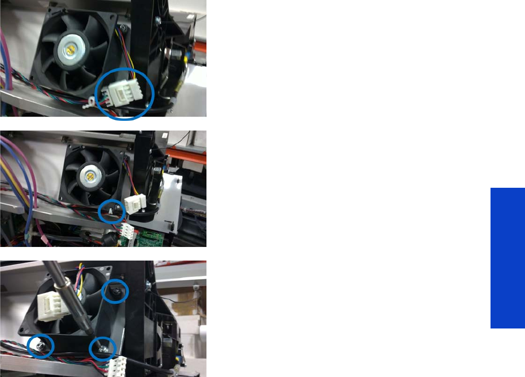
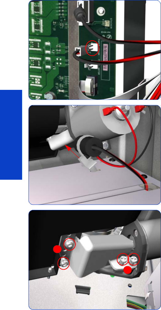
430 Chapter 8 Removal & Installation
Removal & Installation
Media-Axis Motor
Removal
1. Remove the Left Cover
page 303
.
2. Remove the Electronics Enclosure Extension Cover
page 329.
3. Remove the Rear Upper Cover
page 312
.
4. Disconnect the Media-Axis Motor cable from the
PrintMech PCA.
5. Detach the clamp of the ferrite core of the Media-Axis
Motor cable from the printer chassis.
6. Remove the T-15 screws identified (A) and loosen the
T-15 screws identified (B) that secure the Media-Axis
Motor.
B
A
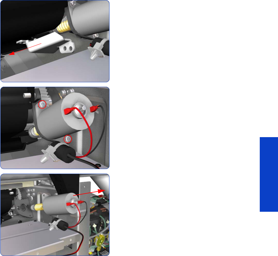
Media-Axis Motor 431
Removal & Installation
7. Remove the Media-Axis Motor Bracket.
8. Remove two T-20 screws that secure the Media-Axis
Motor Bracket.
9. Remove the Media-Axis Motor from the printer.
Installation
Make sure that you apply the grease (included with the support part) to the gears.
After installing the new Media-Axis Motor, make sure you perform the following operations:
•Substrate Advance Calibration
page 195.
•Reset the Drive Roller Motor life counter
page 193.
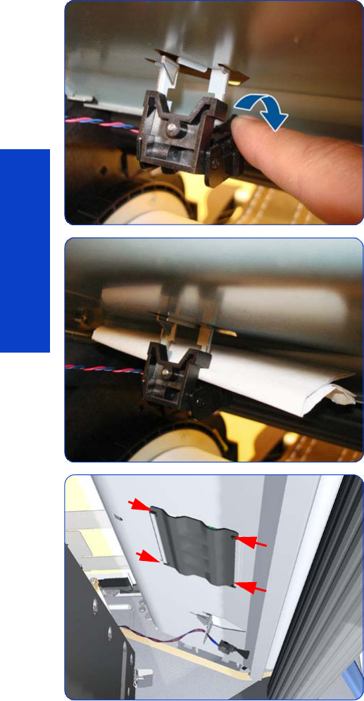
432 Chapter 8 Removal & Installation
Removal & Installation
OMAS: Optical Media Advance Sensor
Removal
1. Remove the Left Cover
page 303
.
2. Remove the Right Cover
page 296
.
3. Remove the Electronics Enclosure Extension Cover
page 329
.
4. Remove the Rear Upper Cover
page 312
.
5. Remove substrate if installed.
6. Remove the Media Sensor screw and unclip the Media
Sensor from the underside of the Input Platen.
7. Let the Media Sensor hang below the Input Platen.
This is to ensure the OMAS ribbon cable does not get
damaged by the sensor flag during the removal
procedure.
8. Squeeze the corners of the OMAS Access Cover to
release it from the bottom of the printer.
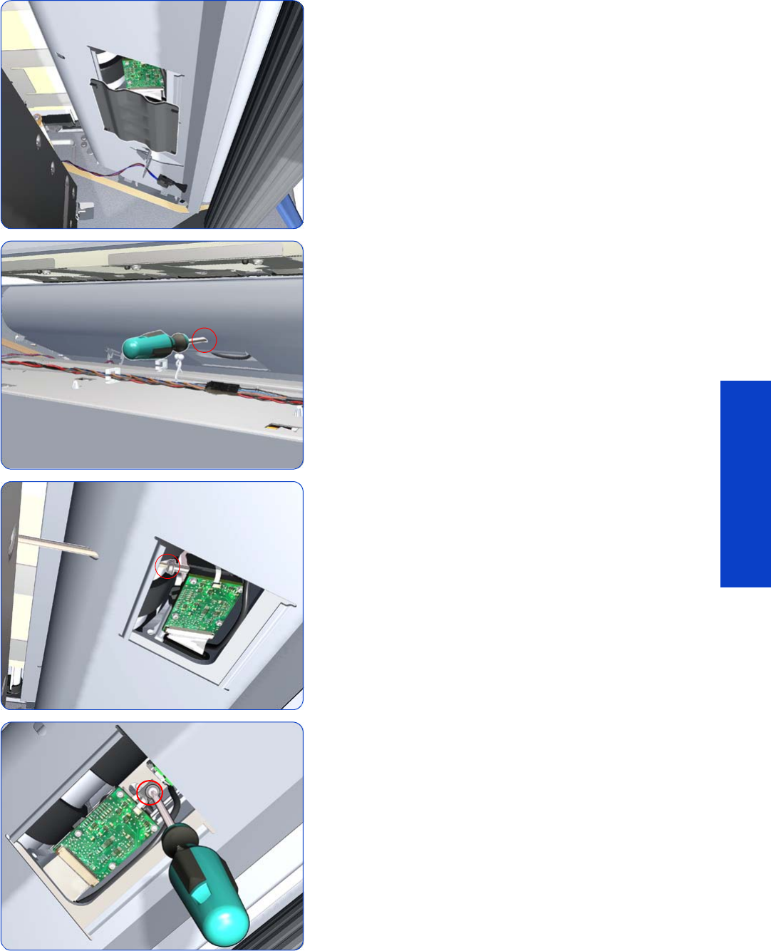
OMAS: Optical Media Advance Sensor 433
Removal & Installation
9. Remove the OMAS Access Cover from the printer.
10. Insert the T-20 thin bladed torx screwdriver (supplied
with the replacement OMAS) into the access hole at
the rear of the printer.
11. Remove and discard one T-20 screw which secures
the OMAS horizontally to the printer.
12. From the bottom of the printer, remove and discard
one T-20 screw which secures the OMAS vertically to
the printer.
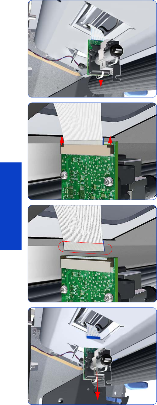
434 Chapter 8 Removal & Installation
Removal & Installation
13. Carefully lower the OMAS from the printer as far as
you can with the large ribbon cable still connected.
14 . Release the two locking clips of the large ribbon cable
connector.
15. Disconnect the large ribbon cable from the OMAS.
16. Remove the OMAS Sensor from the printer.
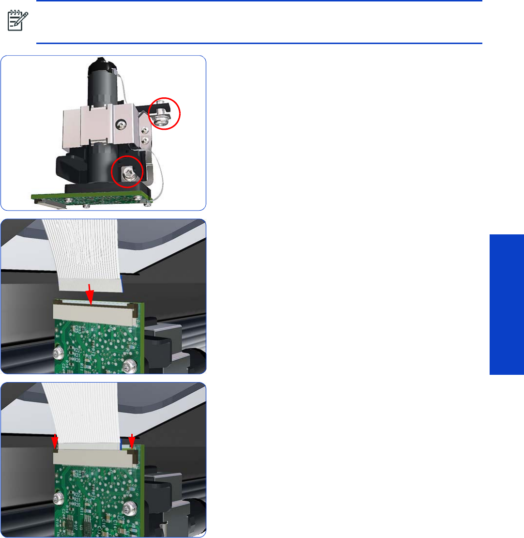
OMAS: Optical Media Advance Sensor 435
Removal & Installation
Installation
1. Verify that the two T-20 attachment screws are correctly
positioned in the Attachment Screw Retainer.
2. Position the OMAS under the printer and connect the
large ribbon.
3. Lock the clips of the large ribbon cable connector.
NOTE: To simplify the installation of the OMAS an Attachment Screw Retainer has been added to hold
the two T-20 attachment screws. This part is delivered attached to the replacement OMAS unit with the
two attachment screws.
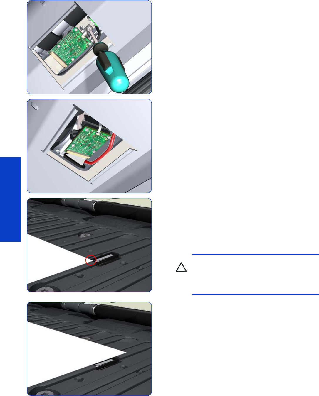
436 Chapter 8 Removal & Installation
Removal & Installation
4. FULLY tighten the T-20 vertical attachment screw.
5. While installing the OMAS, take care not to trap the
cable of the TOMAS.
6. Carefully push the OMAS fully up into its mounting so
that the OMAS window protrudes slightly ABOVE the
Print Platen (approximately 0–2 mm). To ensure the
OMAS is correctly positions, slide a sheet of substrate
over the Platen Ribs until it is stopped by the OMAS.
This ensures the OMAS is protruding slightly above
the platen.
7. Slide a sheet of substrate over the OMAS window, if
the substrate is not stopped by the OMAS, repeat
previous steps to ensure the OMAS is pushed fully up
into its the mounting.
CAUTION: Make sure the OMAS is pushed
completely up into its mounting or you will
encounter an error during the OMAS
calibration because it will not be able to focus
on the substrate.
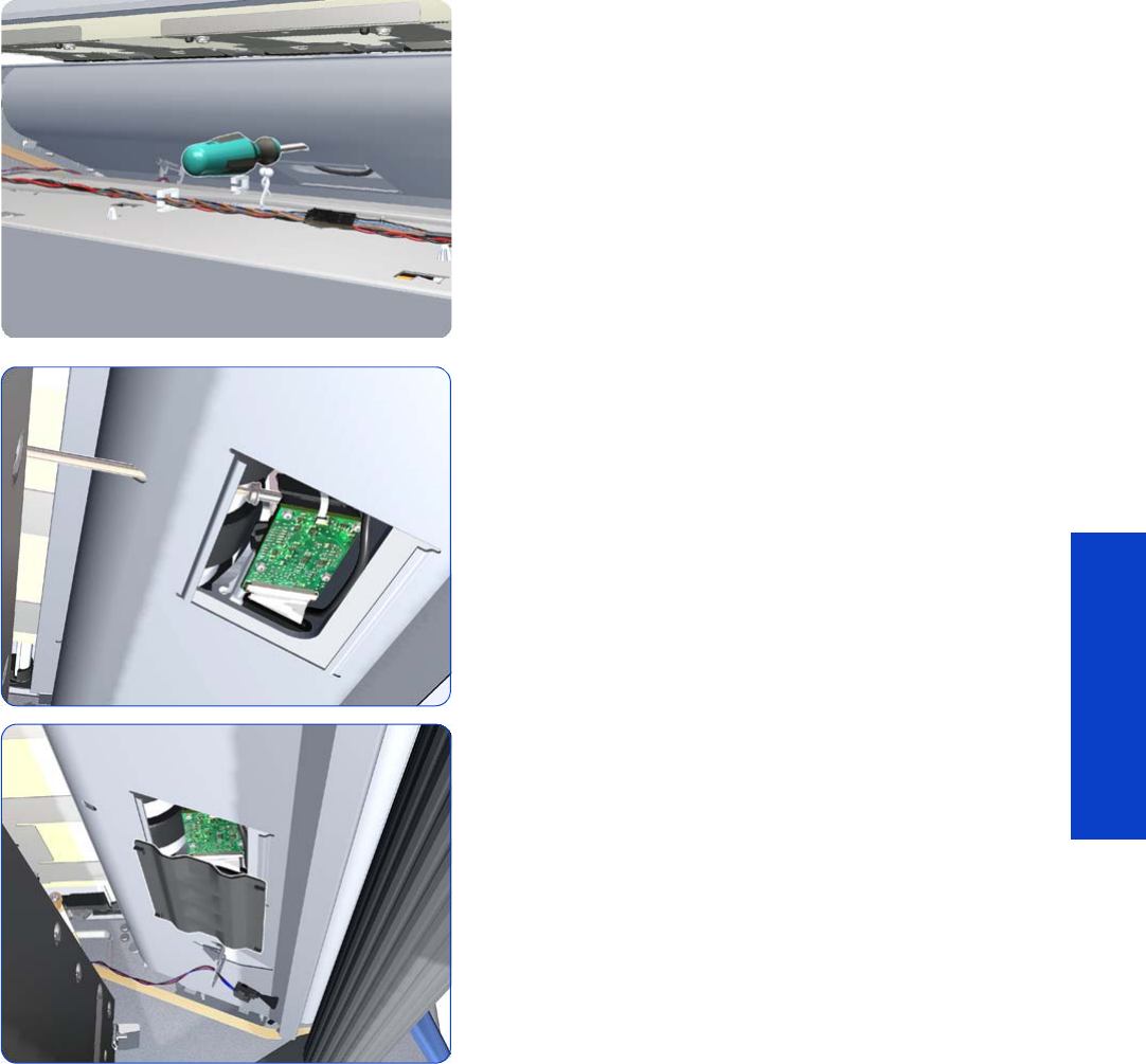
OMAS: Optical Media Advance Sensor 437
Removal & Installation
8. Insert the T-20 thin bladed torx screwdriver into the
access hole at the rear of the printer.
9. Fully tighten the T-20 horizontal attachment screw
which secures the OMAS to the printer.
10. Clip the OMAS access cover back into place by
sliding one edge of the cover into the slot and then
applying enough pressure to it so you can clip it into
the other slot.
Installation
After installing the new OMAS, perform the following operations:
•OMAS Calibration
page 196.
•Reset the OMAS Sensor life counter
page 193.
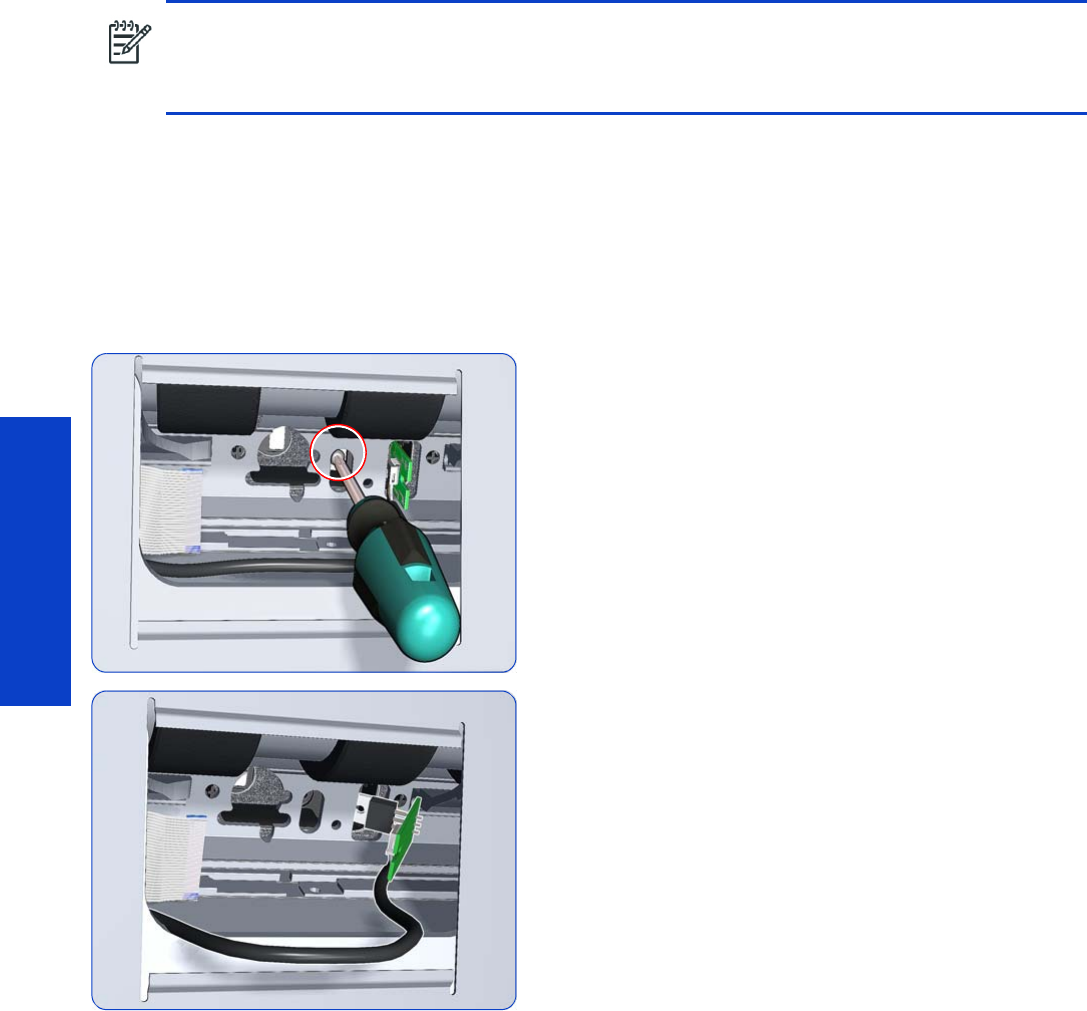
438 Chapter 8 Removal & Installation
Removal & Installation
TOMAS: Temperature Optical Media Advance Sensor
Removal
1. Remove the Right Cover
page 296
.
2. Remove the Electronics Enclosure Extension Cover
page 329
.
3. Remove the Rear Upper Cover
page 312
.
4. Remove substrate if installed.
5. Remove OMAS
page 432
.
6. Remove one T10 screw that secures the TOMAS to the
under side of the platen.
7. Release TOMAS from the holder in the plate.
NOTE: To simplify the installation of the TOMAS an Attachment Screw Retainer has been added to hold
the two T-20 attachment screws. This part is delivered attached to the replacement TOMAS unit with the
two attachment screws. It is also delivered as a separate part with the Print Platen in case the TOMAS is
completely removed during its replacement.
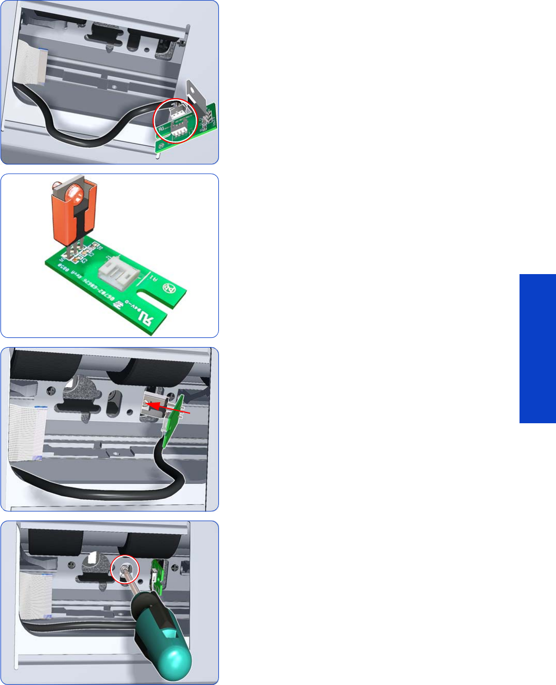
TOMAS: Temperature Optical Media Advance Sensor 439
Removal & Installation
8. Pull out the TOMAS and cable from the underside of
the platen, and disconnect the cable.
9. For installing the new TOMAS a screw is held in the
bracket for easier installation.
10. Insert the new TOMAS into the hole underneath the
platen.
11. Tighten the screw held by the bracket into the platen.
12. There are some important notes on installing the
OMAS if it has been removed while removing the
TOMAS
page 435
.
13. Install the screw holder onto the OMAS and reinstall it.
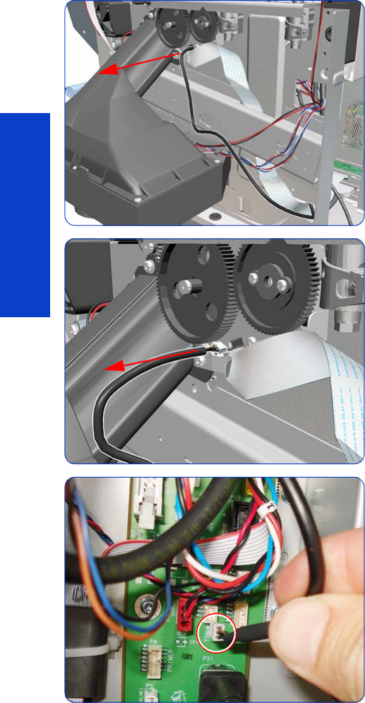
440 Chapter 8 Removal & Installation
Removal & Installation
TOMAS Cable
Removal
1. Remove the Right Cover
page 296
.
2. Primer Assembly
page 345.
3. Primer Valves
page 347.
4. Remove the Drop Detector
page 376.
5. Remove the Service Station
page 351.
6. Remove OMAS
page 432.
7. Remove TOMAS
page 438.
8. Unroute the TOMAS Cable from the right side of the
chassis.
9. Remove the TOMAS cable from the hole in the chassis.
10. Disconnect the TOMAS cable from the Interconnect
board.
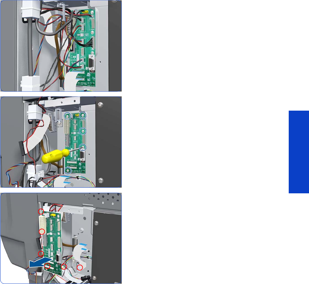
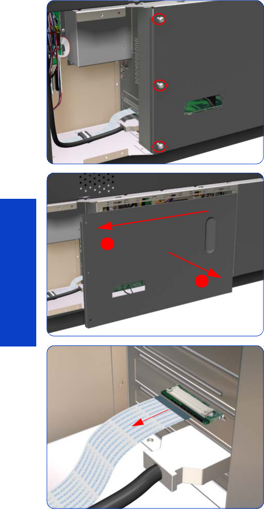
442 Chapter 8 Removal & Installation
Removal & Installation
OMAS Controller Card
Removal
1. Remove the Right Connector Cover
page 318.
2. Remove three T-20 screws that secure the main
electronics cover.
3. Remove the main electronics cover from the printer.
4. Disconnect the OMAS Controller Card to OMAS
ribbon cable.
1
2
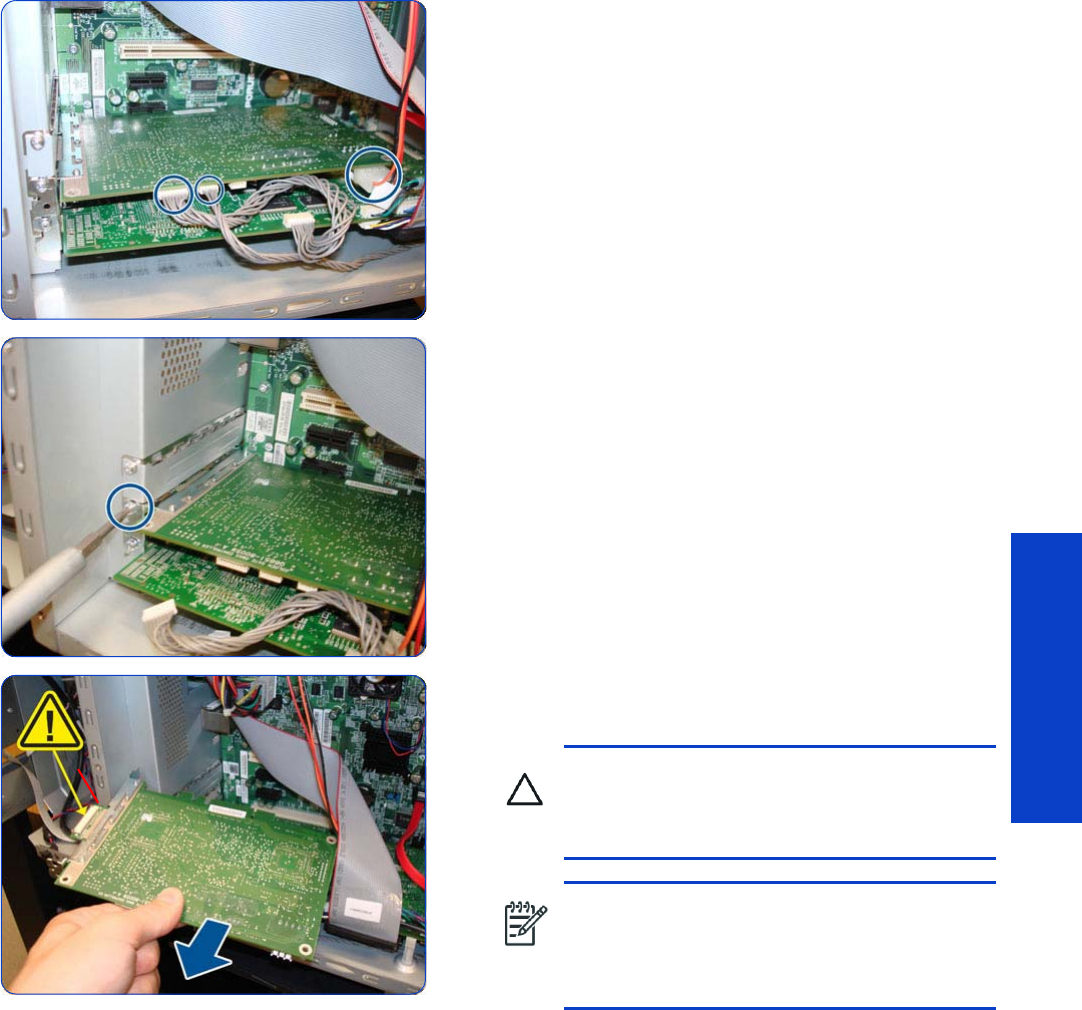
OMAS Controller Card 443
Removal & Installation
5. Disconnect the PrintMech and Engine PCA connection
cables (three connectors) from the OMAS Controller
Card.
6. Remove one T-10 screw that secures the OMAS
Controller Card.
7. Disconnect the OMAS Controller Card from the Engine
PCA and remove it from the printer.
CAUTION: To remove the OMAS Controller
Card without damaging it on the Emodule
cover, you will need to disconnect it first and
then rotate it slightly.
NOTE: After installing a new OMAS
Controller Card, perform the following:
•“1.3.3 OMAS Temperature Calibration”
page 183.
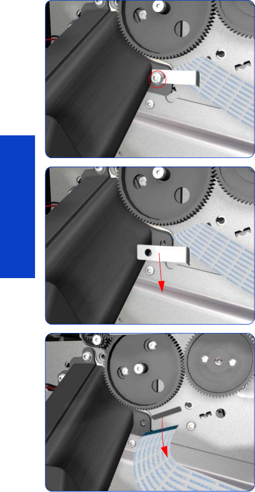
444 Chapter 8 Removal & Installation
Removal & Installation
OMAS Cable
Removal
1. Remove the Right Cover
page 296
.
2. Remove the Right Connector Cover
page 318
.
3. Remove the Service Station
page 351
.
4. Remove the OMAS
page 432
.
5. Remove one T-15 screw that secures the OMAS Cable
clamp from the printer.
6. Remove the OMAS Cable clamp from the printer.
7. Carefully Pull the OMAS Cable out of the Vacuum
Beam.
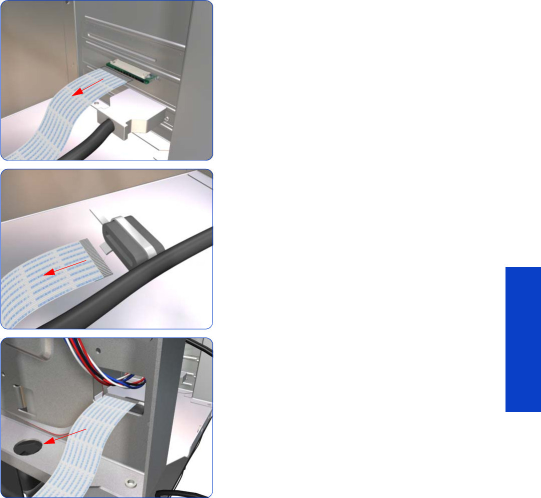
OMAS Cable 445
Removal & Installation
8. Disconnect the OMAS Cable form the OMAS
Controller Card.
9. Unroute the OMAS Cable from the Ferrite Core.
10. Unroute and remove the OMAS Cable from the printer.
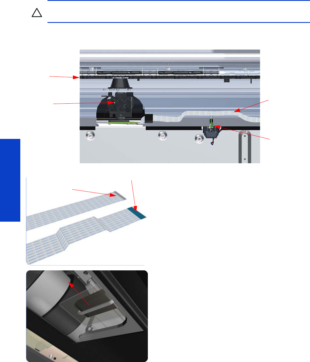
446 Chapter 8 Removal & Installation
Removal & Installation
Installation
The following illustration shows a cross-section of the Vacuum Beam with the OMAS Cable correctly routed
to avoid interference to the Media Sensor.
1. Before you can start to install the OMAS Cable you
must first identify which end connects to which
component. The end of the cable that has the most
perpendicular and diagonal folds is the end that
connects to the OMAS with the blue reinforcing on the
top. The other end must be connected to the OMAS
Controller Card with the blue reinforcing on the bottom.
2. Carefully slide the Ferrite Core and its associated
attachment plate out of the vacuum beam.
CAUTION: It is critical that the OMAS Cable is correctly positioned in the Vacuum Beam so that it does
not cause physical interference to the Media Sensor.
OMAS
Platen
Media Sensor
OMAS Cable
OMAS
OMAS
Controller Card
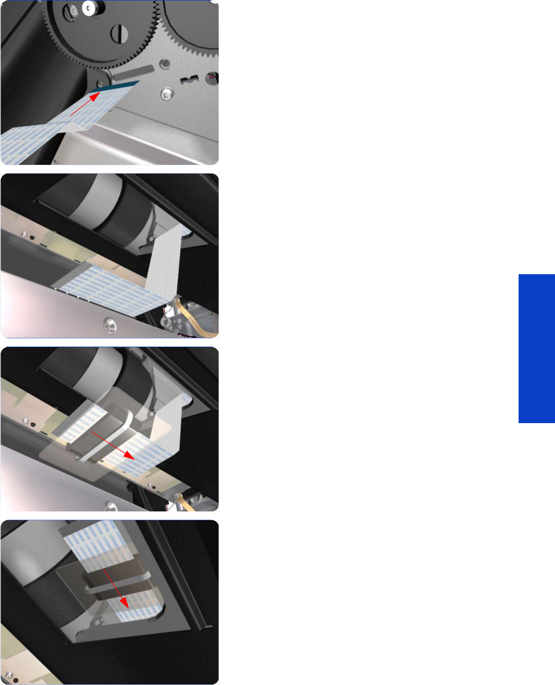
OMAS Cable 447
Removal & Installation
3. Position the OMAS Cable in the Vacuum Beam slot so
that the blue reinforcement enters first.
4. Carefully feed the OMAS cable through the Vacuum
Beam sufficiently to have approximately 20 cm
hanging from the OMAS installation position.
5. Slide the Ferrite Core and its associated Attachment
Plate (on the top) onto the OMAS Cable.
6. Push the Attachment Plate into its slot in the Vacuum
beam until it is level with the edge of OMAS
installation position.
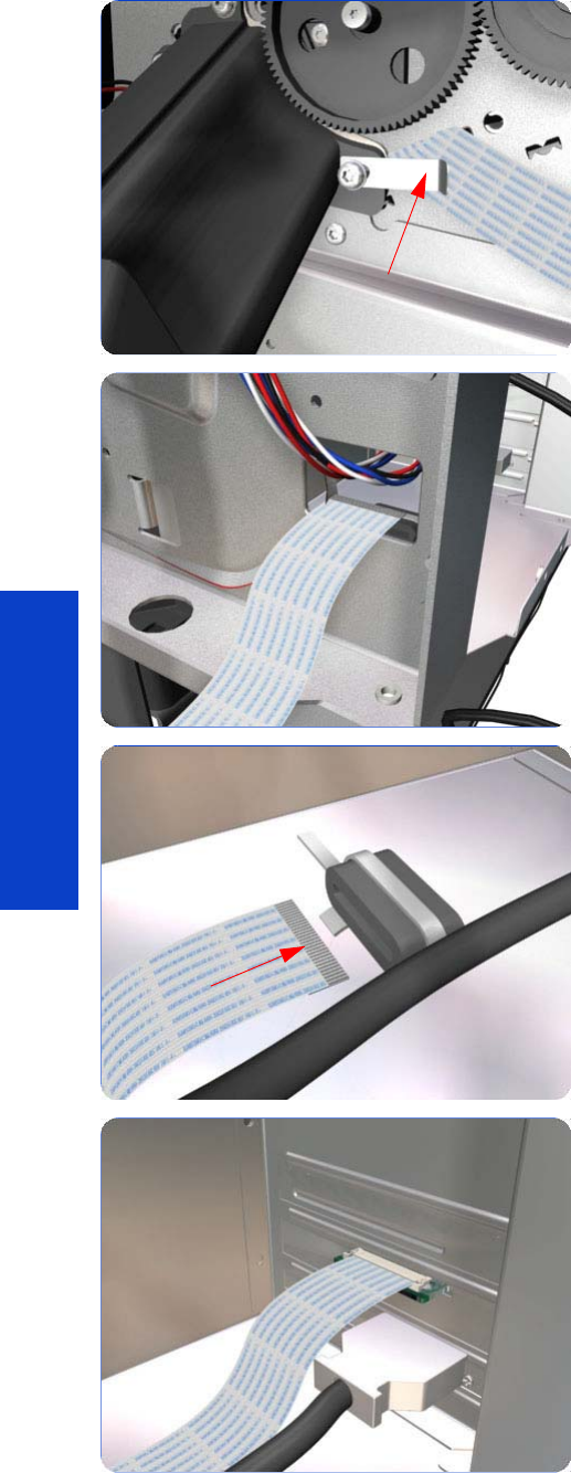
448 Chapter 8 Removal & Installation
Removal & Installation
7. Carefully pull the OMAS Cable back into the Vacuum
Beam (from the Service Station end) until the straight
fold immediately before the first diagonal fold (from the
OMAS sensor end) is aligned with the slot, fold the
OMAS Cable across the diagonal fold, and install the
cable clamp to lock the OMAS Cable in the correct
position.
8. Route the OMAS Cable to the Ferrite Core in the Right
Interconnect panel.
9. Feed the OMAS Cable through Ferrite Core.
10. Connect the OMAS Cable to the OMAS Controller
Card with the connections on the top.
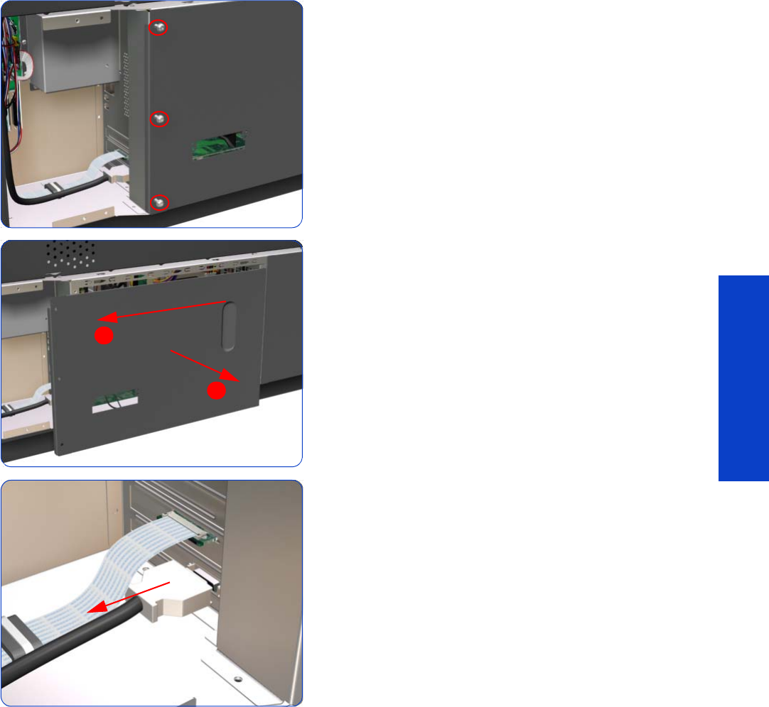
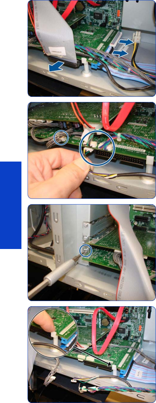
450 Chapter 8 Removal & Installation
Removal & Installation
5a.Disconnect ALL cables connected to the Engine PCA.
5b.Disconnect ALL cables connected to the Engine PCA
6. Remove one T-10 screw that secures the Engine PCA.
7. Unclip the PCA from white plastic clip
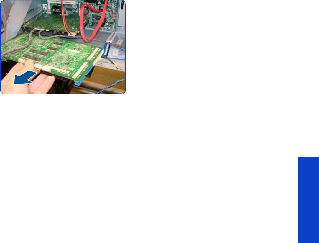
Engine PCA 451
Removal & Installation
8. Remove the Engine PCA from the Formatter PCA.
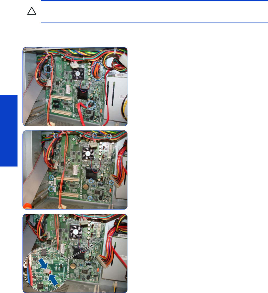
452 Chapter 8 Removal & Installation
Removal & Installation
Formatter PCA
Removal
1. Remove the Engine PCA
page 449
.
2. Remove the OMAS Controller Card
page 442.
3. Disconnect all cables connected to the Formatter PCA,
including the Front Panel USB cable.
4. Remove eight T-10 screws that secure the Formatter
PCA.
5. Release the plastic locating pin that secures the
Formatter PCA.
CAUTION: Do not remove the Fan or the Processor (located under the Fan) from the Formatter PCA. The
Fan and the Processor are part of the Formatter PCA support part and should be replaced as one
assembly.
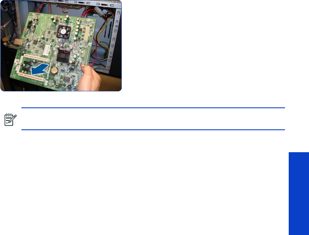
Formatter PCA 453
Removal & Installation
6. Remove the Formatter PCA from the printer.
NOTE: When installing the Formatter PCA, make sure that you first locate it on the plastic locating pin
and then install the screws.
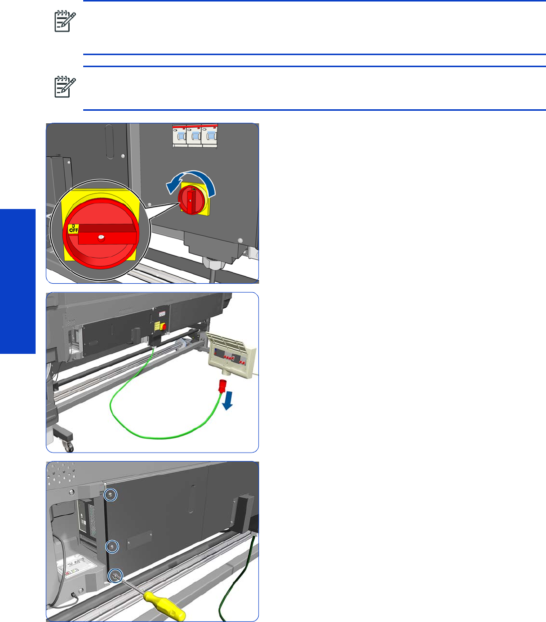
454 Chapter 8 Removal & Installation
Removal & Installation
Hard Disk Drive
Removal
1. Turn off the printer.
2. Disconnect electrical power. How this is done depends
on the installation.
3. Remove three T-20 screws that secure the main
electronics cover.
Before removing the Hard Disk Drive, download the latest firmware version from the HP website:
www.hp.com/go/L28500/support. Copy it to a portable device such as a USB flash drive or a CD and
take it to the repair site.
NOTE: You must never replace both the Hard Disk Drive and the ISS PCAs (or the Ink Supply Tubes and
Trailing Cable) at the same time. If these parts need to be replaced, you must first replace one part and
then turn on the printer until it completely initializes. Then turn off the printer and replace the other part.
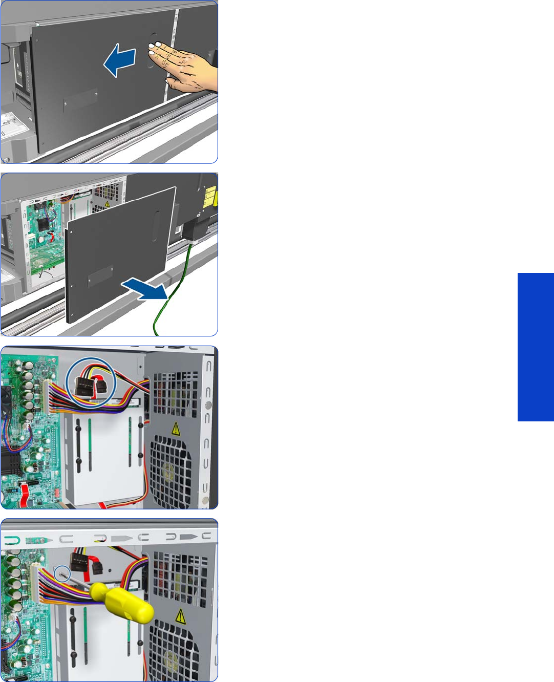
Hard Disk Drive 455
Removal & Installation
4. Slide the main electronics cover to the left.
5. Remove the main electronics cover from the printer.
6. Disconnect two cables from the Hard Disk Drive.
7. Remove one T-10 screw from the Hard Disk Drive
Holder.
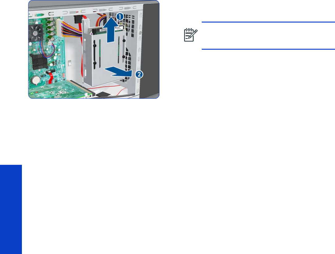
456 Chapter 8 Removal & Installation
Removal & Installation
8. Slide the Hard Disk Drive upwards and remove from
the printer.
9. Switch on the printer and the printer will initialize
normally. The printer will not request the new firmware.
10. Connect the printer to the customer’s network, retrieve
the IP address.
11. Install the new firmware using the Embedded Web
Server. See the User’s Guide.
12. Perform the following:
•Printhead Alignment
.
•Substrate Advance Calibration
.
NOTE: It is not necessary to remove the
screws securing the Hard Disk Drive inside the
metal casing.
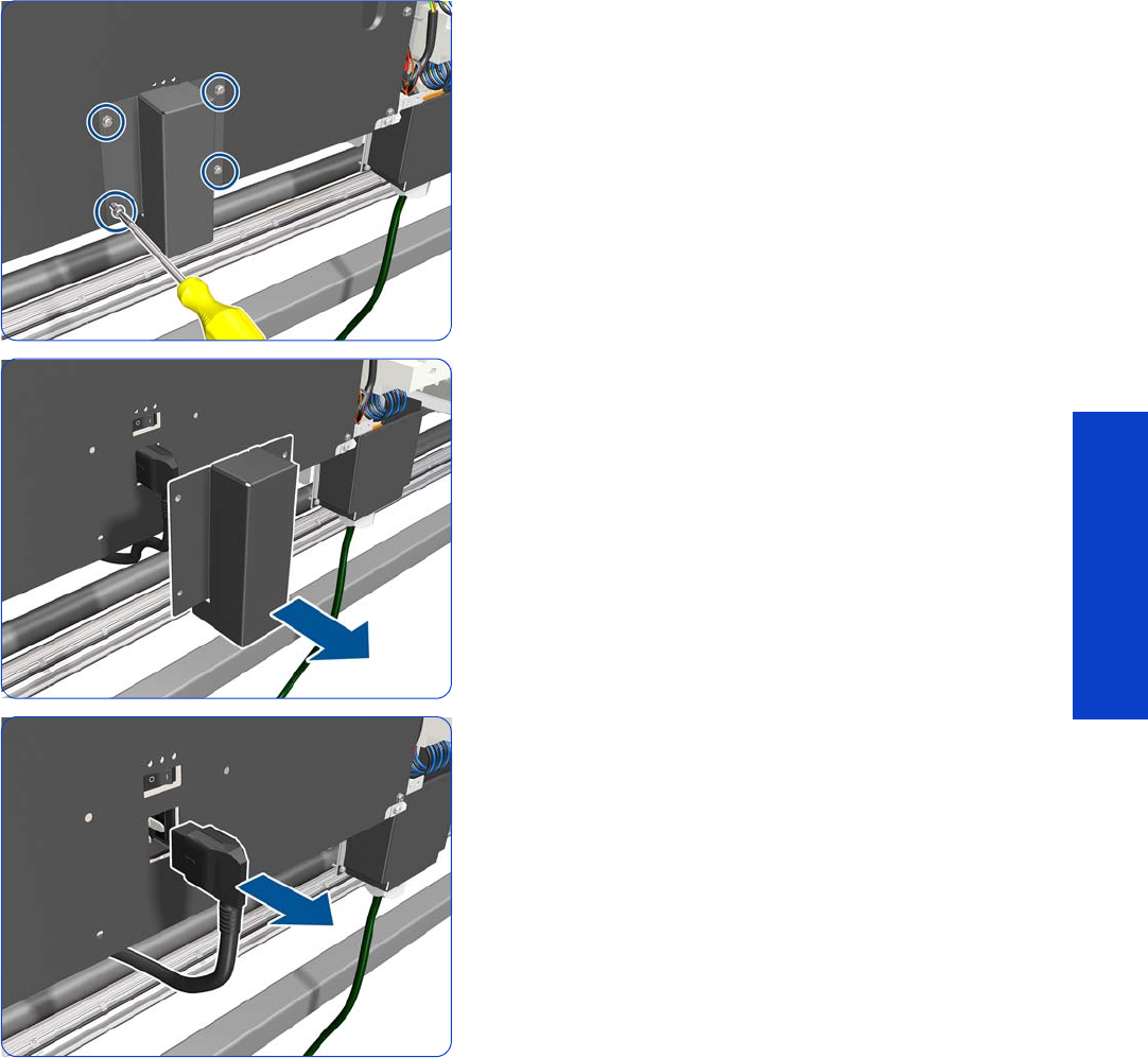
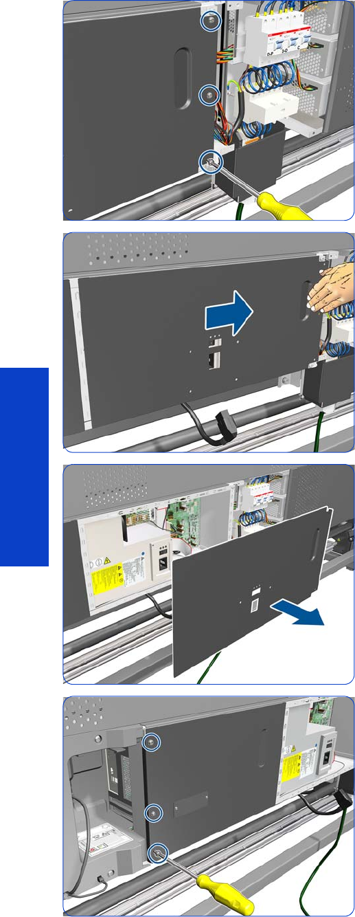
458 Chapter 8 Removal & Installation
Removal & Installation
5. Remove three T-20 screws.
6. Slide the cover to the right.
7. Remove the cover.
8. Remove three screws.
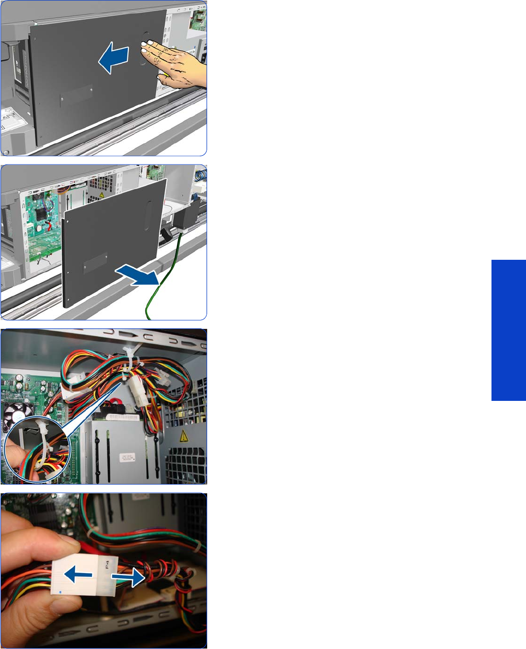
Power Supply Unit (PSU) 459
Removal & Installation
9. Slide the cover to the left.
10. Remove the cover.
11. Untie the cables from the PSU to the Hard Disk Drive
and Formatter PCA.
12. Disconnect all cables.
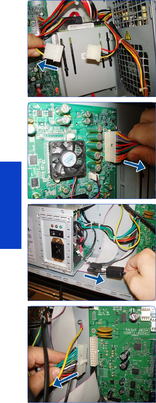
460 Chapter 8 Removal & Installation
Removal & Installation
13. Disconnect all cables.
14 . Disconnect all cables.
15. Disconnect the Extra PSU 24 V cable.
16. Disconnect the PrintMech PCA cable.
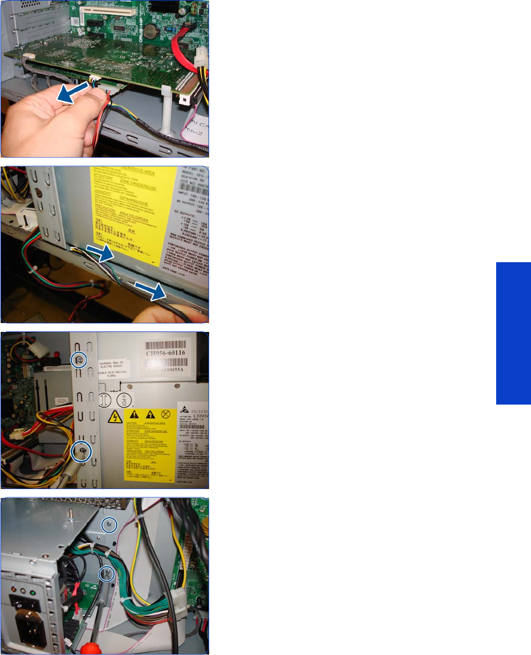
Power Supply Unit (PSU) 461
Removal & Installation
17. Disconnect the OMAS Controller PCA cable.
18 . Pull the cable out to the right.
19. Remove two T-10 screws.
20.Remove two T-10 screws.
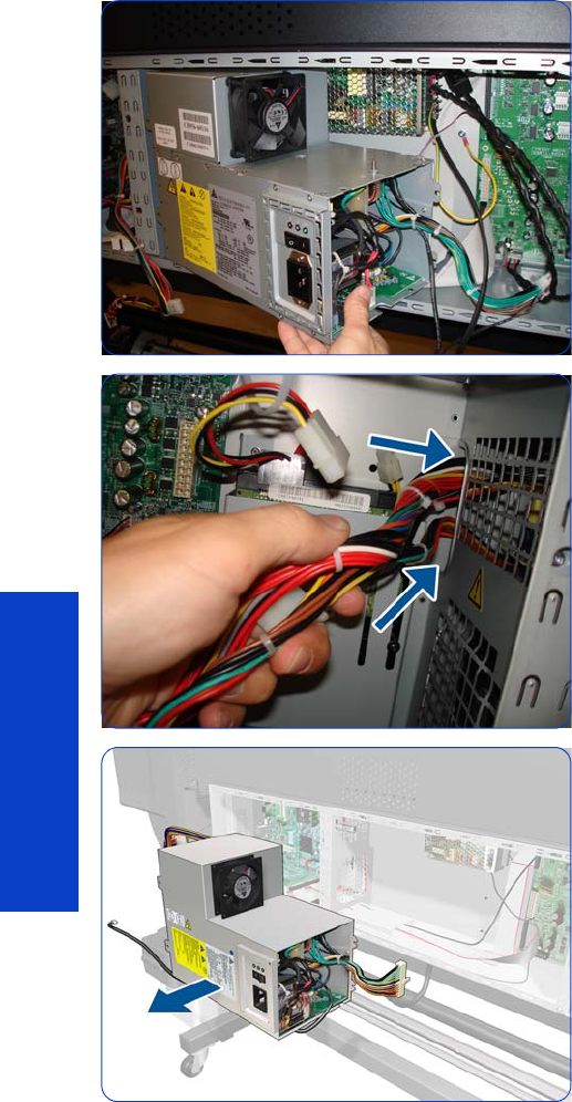
462 Chapter 8 Removal & Installation
Removal & Installation
21. Pull the Power Supply Unit out slightly, but don't try to
remove it yet.
22.Pass the cables through the hole.
23.Remove the Power Supply Unit.
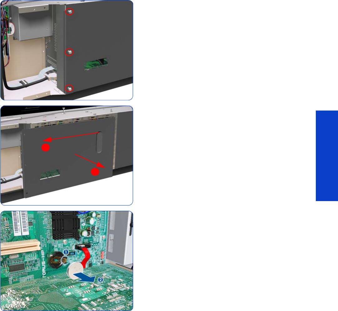
Formatter Battery 463
Removal & Installation
Formatter Battery
Removal
1. Remove the Right Connector Cover
page 318.
2. Remove three T-20 screws that secure the main
electronics cover.
3. Remove the main electronics cover from the printer.
4. Push the clip down (1) and release the battery (2) from
the Formatter PCA.
1
2
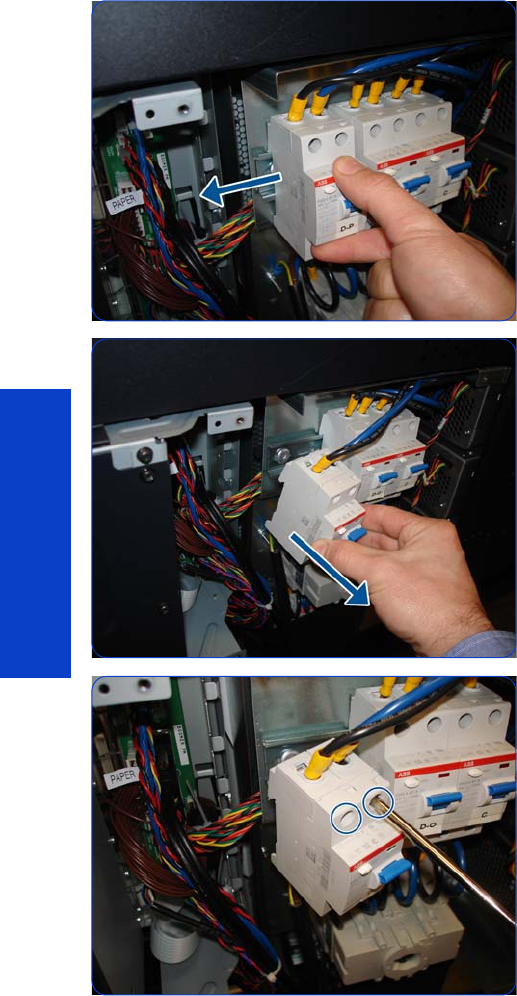
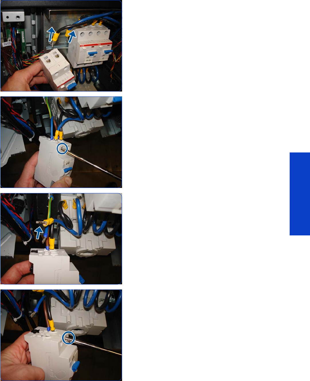
Circuit Breakers 465
Removal & Installation
5. Remove the cables from the top of the Circuit Breaker.
6. Turn the Circuit Breaker upside down and loosen a
screw.
7. Remove the cables.
8. Loosen the other screw.

466 Chapter 8 Removal & Installation
Removal & Installation
9. Remove the cables.
The same procedure can be used to remove the other
Circuit Breakers.

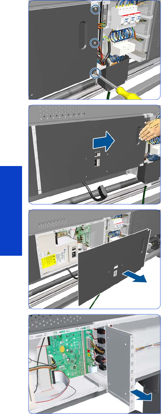
468 Chapter 8 Removal & Installation
Removal & Installation
5. Remove three T-20 screws.
6. Slide the cover to the right.
7. Remove the cover.
8. Remove the PrintMech PCA Separator.
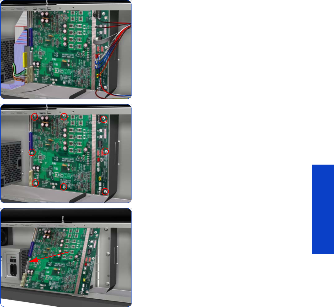
PrintMech PCA 469
Removal & Installation
9. Disconnect all cables from the PrintMech PCA.
10. Remove eight T-10 screws that secure the PrintMech
PCA.
11. Remove the PrintMech PCA from the printer.
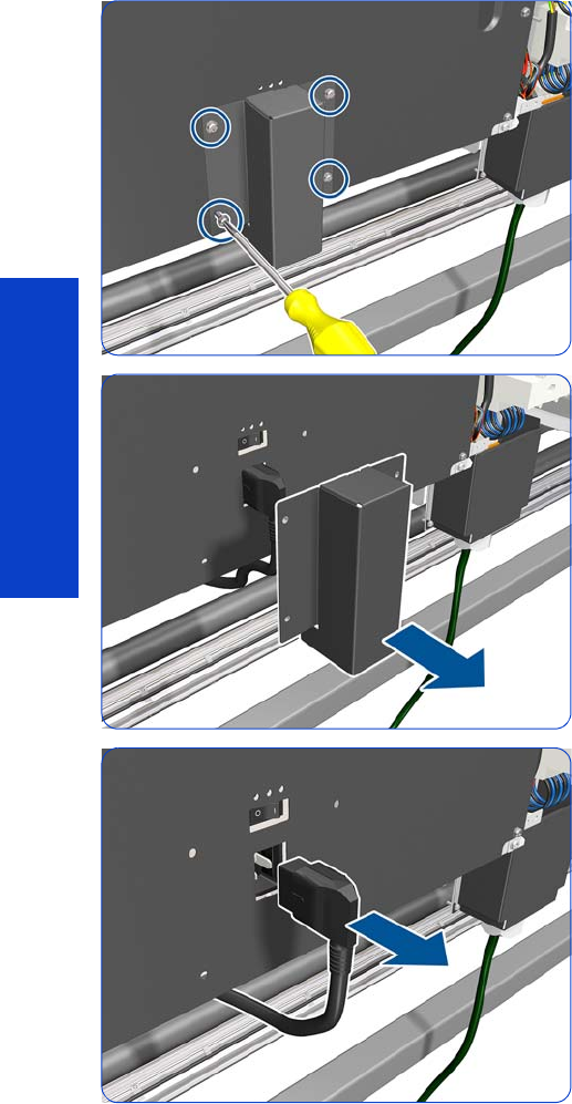
470 Chapter 8 Removal & Installation
Removal & Installation
Electronics Enclosure
Removal
1. Remove the Power Box Cover
page 321.
2. Remove the Electronics Enclosure Extension Cover
page 329.
3. Remove the Rear Upper Cover
page 312.
4. Remove the Right Connector Cover
page 318.
5. Remove four T-20 screws.
6. Remove the power plug cover.
7. Unplug the power plug.
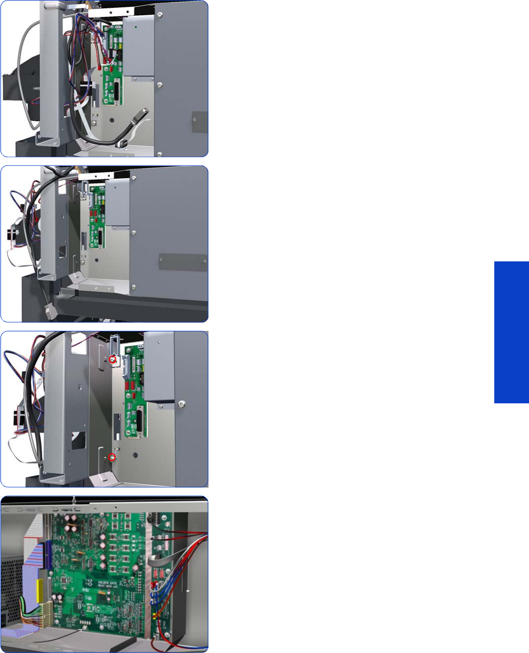
Electronics Enclosure 471
Removal & Installation
8. Disconnect all the cables connected to the PCAs on the
right-hand side: the Interconnect PCA, OMAS
Controller PCA, Formatter PCA, and Engine PCA.
9. Unroute all the disconnected cables so they are clear
of the Electronics Enclosure.
x10. Remove two T-20 screws that secure the right-hand side
of the Electronics Enclosure.
11. Disconnect all cables from the PrintMech PCA.
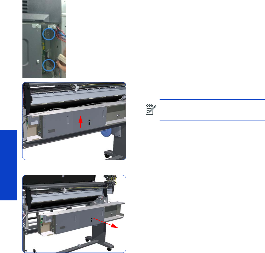
472 Chapter 8 Removal & Installation
Removal & Installation
12. Remove two T-20 screws that secure the left-hand side
of the Electronics Enclosure.
13. Lift the Electronics Enclosure sufficiently (approximately
2 cm) to release it from the attachments.
14 . Remove the Electronics Enclosure from the printer.
CAUTION: Be careful not to damage the
cables on top of the Electronics Enclosure as
you remove it.
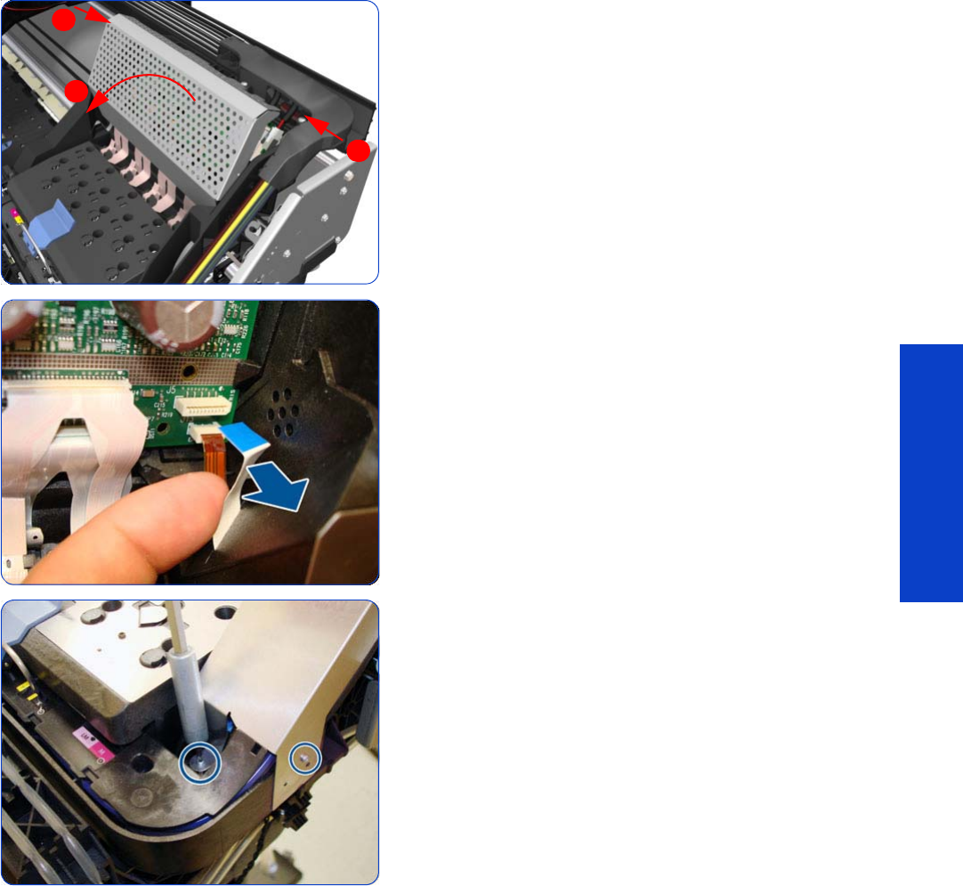
Line Sensor Assembly 473
Removal & Installation
Line Sensor Assembly
Removal
1. Remove the Right Cover
page 296
.
2. Press the two side of the Carriage PCA Cover and
unclip from the Carriage Assembly.
3. Release the clip and disconnect the Line Sensor cable
from the Carriage PCA.
4. Remove two T-8 screws from the metal part.
1
2
1
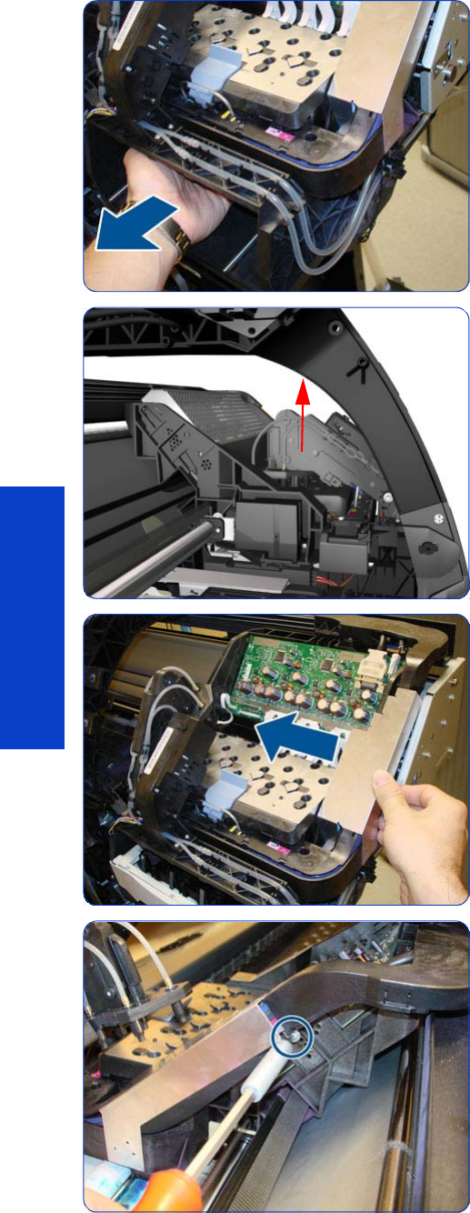
474 Chapter 8 Removal & Installation
Removal & Installation
5. Uncap the Carriage by manually pulling out the
Printhead Cleaning Cartridge
6. Lift the Primer and hold the Primer to its maximum
position to avoid damaging it when you
7. Move the Carriage away from the Service Station.
8. Remove one T-8 screw from the metal Carriage Cover.
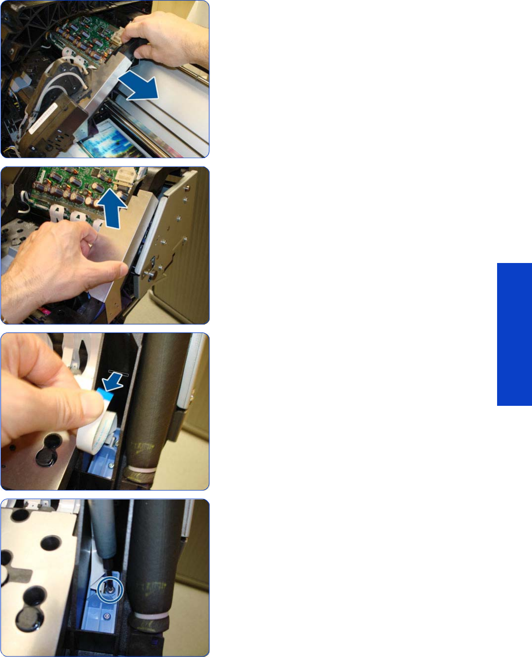
Line Sensor Assembly 475
Removal & Installation
9. Move the Carriage into the Service Station.
10. Remove the Metal Carriage Cover.
11. Pass the Line Sensor Cable through the hole.
12. Remove one T-15 screw that secures the Line Sensor to
the carriage Assembly.
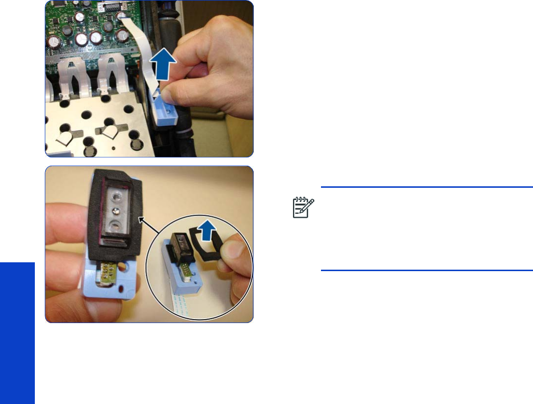
476 Chapter 8 Removal & Installation
Removal & Installation
13. Remove the Line Sensor from the Carriage Assembly.
14 . Remove the protective foam from around the sensor.
NOTE: After installing the NEW Line Sensor,
perform the following Service Calibrations:
•“5.6.1 Line Sensor Calibration”
page 201.
•Reset the life counter “4.6.2 Line Sensor
cycle”
page 194.
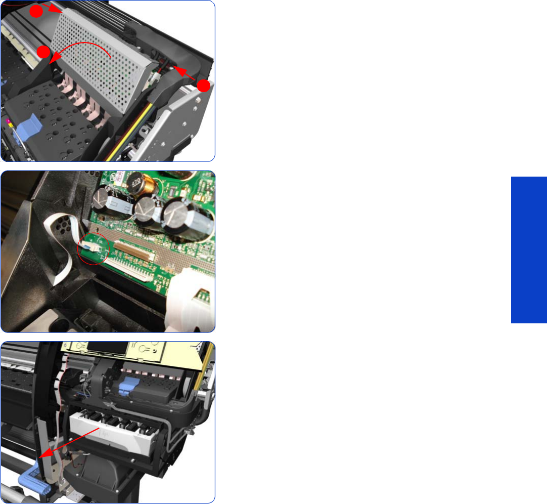
Color Sensor Assembly 477
Removal & Installation
Color Sensor Assembly
Removal
1. Open the Window.
2. Remove the Right Cover
page 296
.
3. Press the two side of the Carriage PCA Cover and
unclip from the Carriage Assembly.
4. Release the clip and disconnect the Color Sensor cable
from the Carriage PCA.
5. Uncap the Carriage Assembly by manually pulling out
the Printhead Cleaning Cartridge tray.
1
2
1
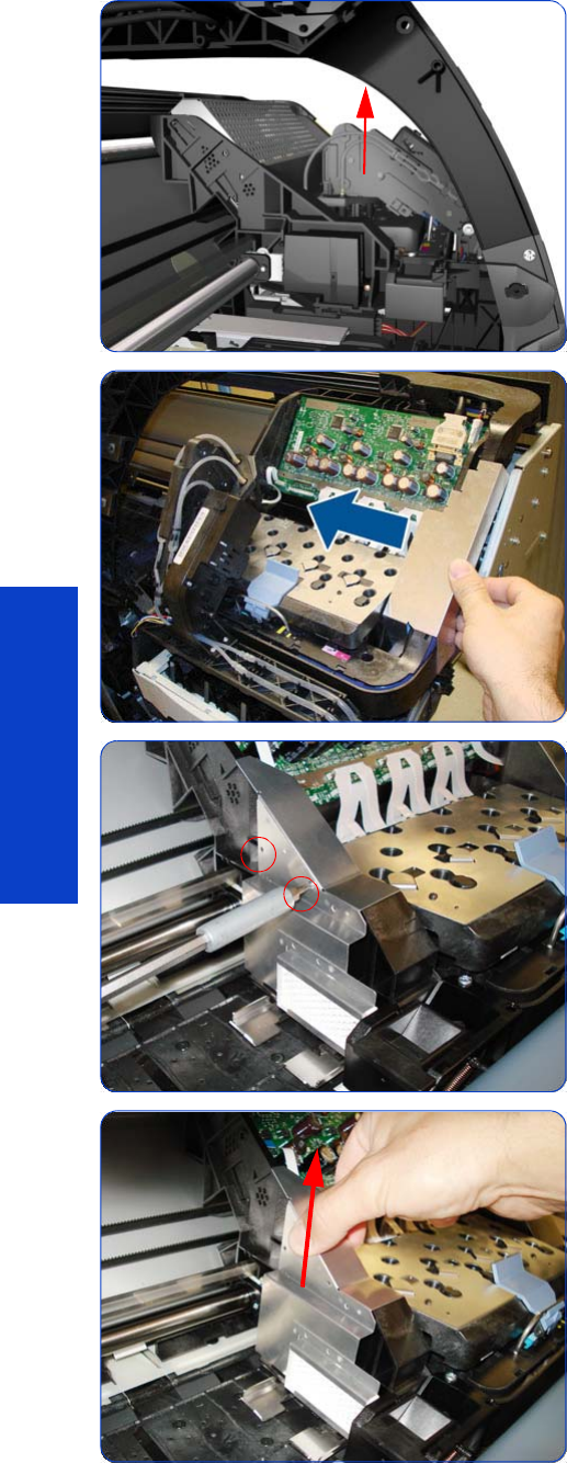
478 Chapter 8 Removal & Installation
Removal & Installation
6. Lift the Primer and hold the Primer to its maximum
position to avoid damaging it when you move the
Carriage Assembly in the next step.
7. Move the Carriage away from the Service Station, into
the center of the platen.
8. Remove two T-8 screws that secure the Reflector
Assembly to the side of the Carriage Assembly.
9. Remove the Reflector Assembly.
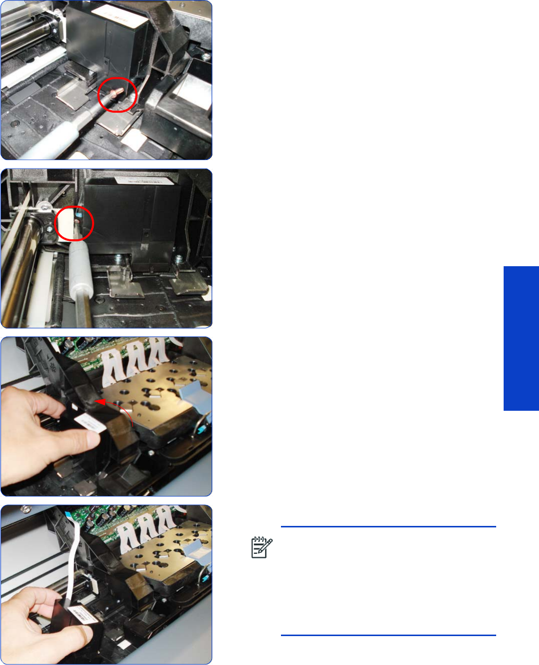
Color Sensor Assembly 479
Removal & Installation
10. Remove one T-10 screw from the front of the Color
Sensor.
11. Remove one T-10 screw from the Rear of the Color
Sensor.
12. Tilt the Color Sensor so it can be removed.
13. Remove the Color Sensor from the Carriage Assembly.
NOTE: After installing the NEW Color
Sensor, perform the following Service
Calibrations:
•“5.6.3 Open Close SOL”
page 206.
•Perform the safety test “3.3 Substrate Path
Sensor ”
page 156.
•Reset the life counter “4.6.5 Color sensor”
page 194.
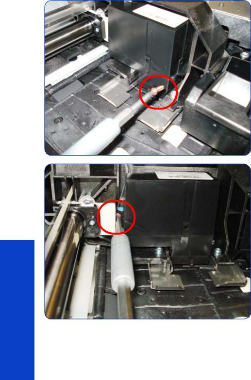
480 Chapter 8 Removal & Installation
Removal & Installation
Installation
1. When installing the T-10 screw to the front of the Color
Sensor, make sure you do not over-tighten the screw.
2. When installing the T-10 screw to the Rear of the Color
Sensor, make sure you do not over-tighten the screw.
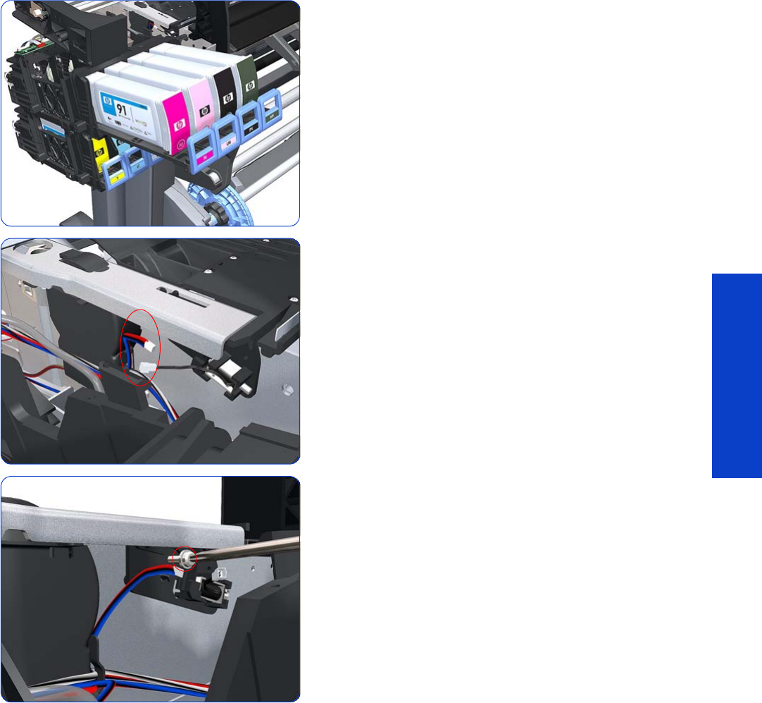
Color Sensor Actuator Assembly 481
Removal & Installation
Color Sensor Actuator Assembly
Removal
1. Remove the Left Cover
page 303
.
2. Slide out the top row of Ink Cartridges from the Ink
Supply Station
3. Disconnect the Color Sensor Actuator Assembly.
4. Remove one T-15 screw that secures the Color Sensor
Actuator Assembly to the printer.
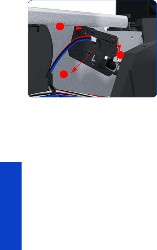
482 Chapter 8 Removal & Installation
Removal & Installation
5. Remove the Color Sensor Actuator Assembly to the
printer.
1
2
3

Dryer Grill 483
Removal & Installation
Dryer Grill
Removal
1. Turn off the printer.
2. Disconnect electrical power. How this is done depends
on the installation.
3. Open the Window.
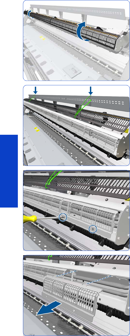
484 Chapter 8 Removal & Installation
Removal & Installation
4. Open the Dryer Grill Protection.
5. Tie the Dryer Grill Protection to the Window at both
ends as shown.
6. Remove two T-10 screws.
7. Remove the Dryer Grill.
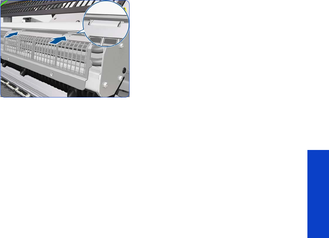
Dryer Grill 485
Removal & Installation
Installation
8. Insert both tabs of the Dryer Grill in the holes.
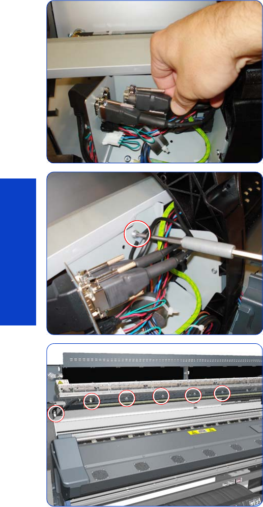
486 Chapter 8 Removal & Installation
Removal & Installation
Dryer IR Temperature Sensor
Removal
1. Twist the Window Locks and open the Dryer Window.
2. Remove the Left Cover
page 303
.
3. Disconnect the Dryer Temperature Sensor cable from
the left side of the printer.
4. Remove one T20 screw from the cable clamp.
5. Remove all the T20 screws from cable clamps that
secure the Temperature Sensor Cable to the inside of
the Dryer Window Assembly.
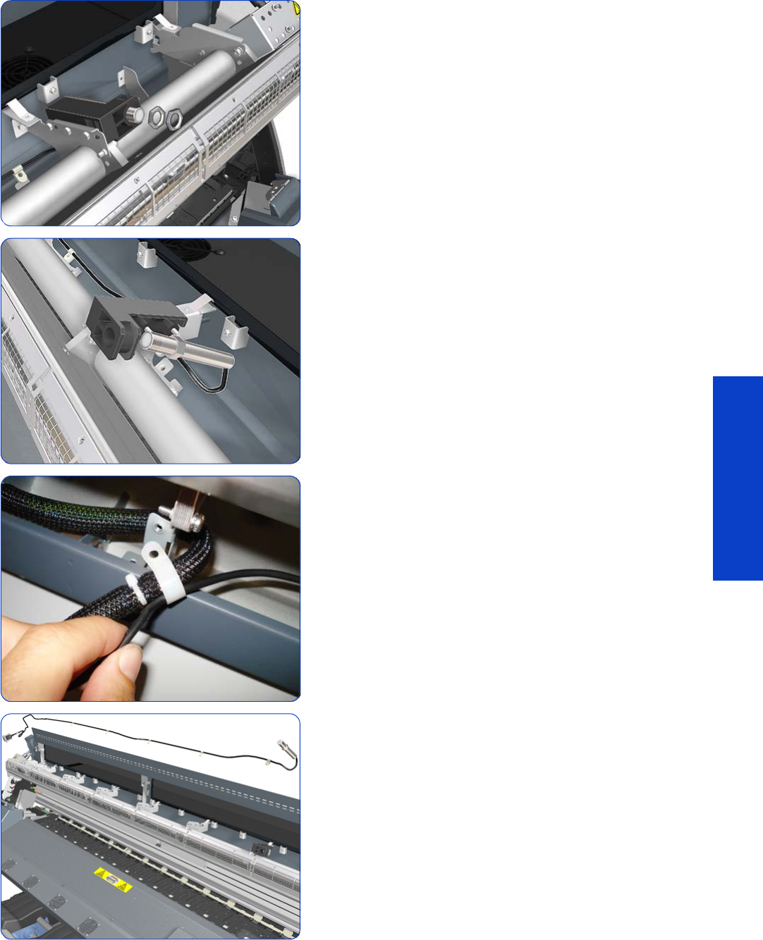
Dryer IR Temperature Sensor 487
Removal & Installation
6. Remove two thin nuts from the Dryer Temperature
Sensor.
7. Remove the Dryer Temperature Sensor from the holder.
8. Remove the Dryer Temperature Sensor Cable from the
cable clamps.
9. Remove the Dryer Temperature Sensor and cable from
the printer.
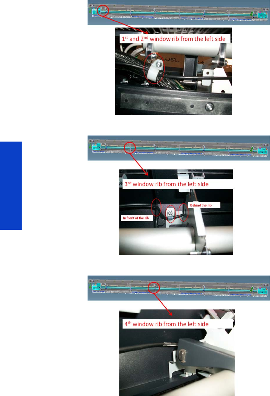
488 Chapter 8 Removal & Installation
Removal & Installation
Installation
Cable routing should be done as shown below.
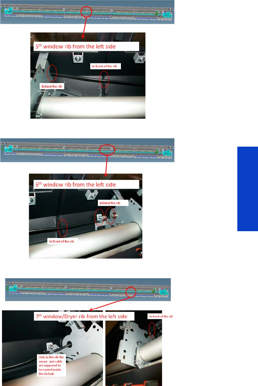
Dryer IR Temperature Sensor 489
Removal & Installation
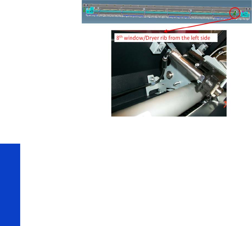
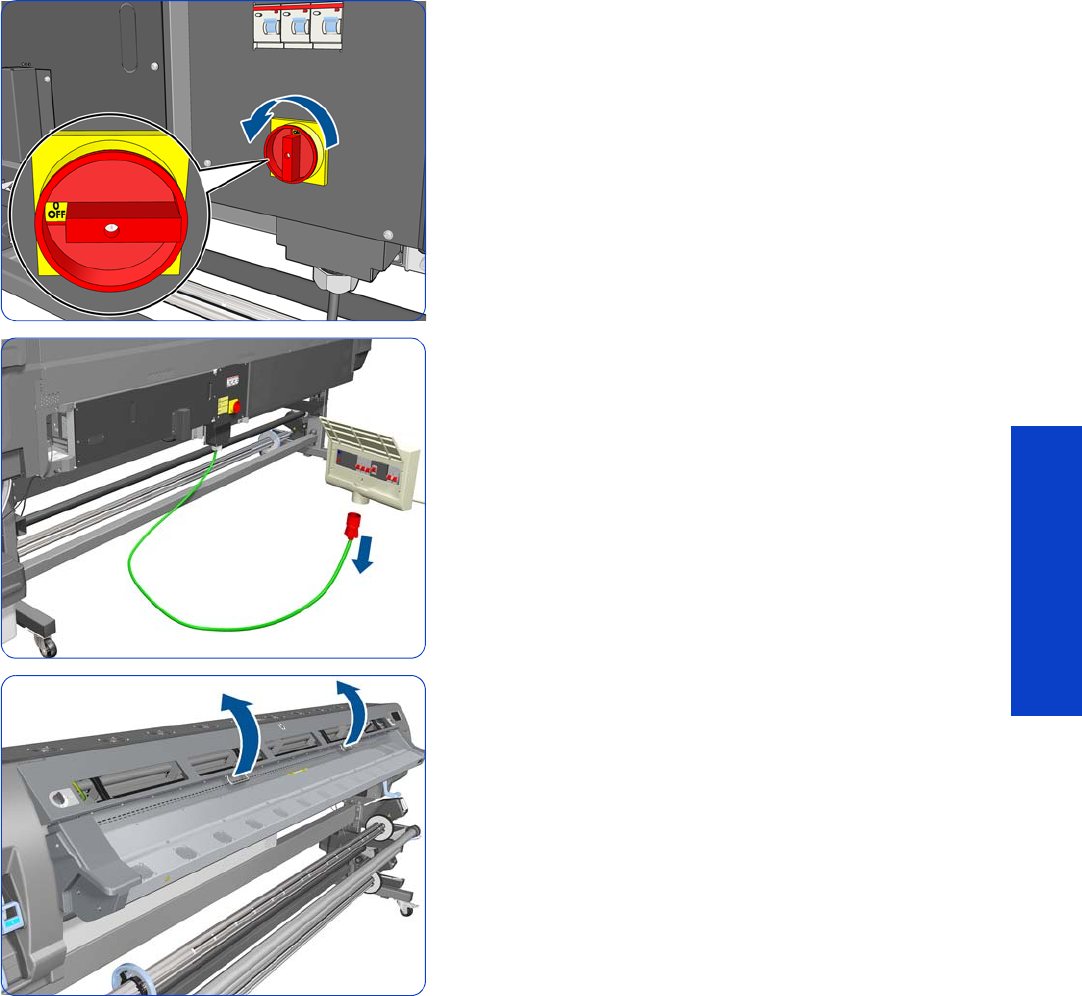
Dryer Protector 491
Removal & Installation
Dryer Protector
Removal
1. Turn off the printer.
2. Disconnect electrical power. How this is done depends
on the installation.
3. Open the Window.
4. Locate the four arms by which the dryer protector is
attached to the window.
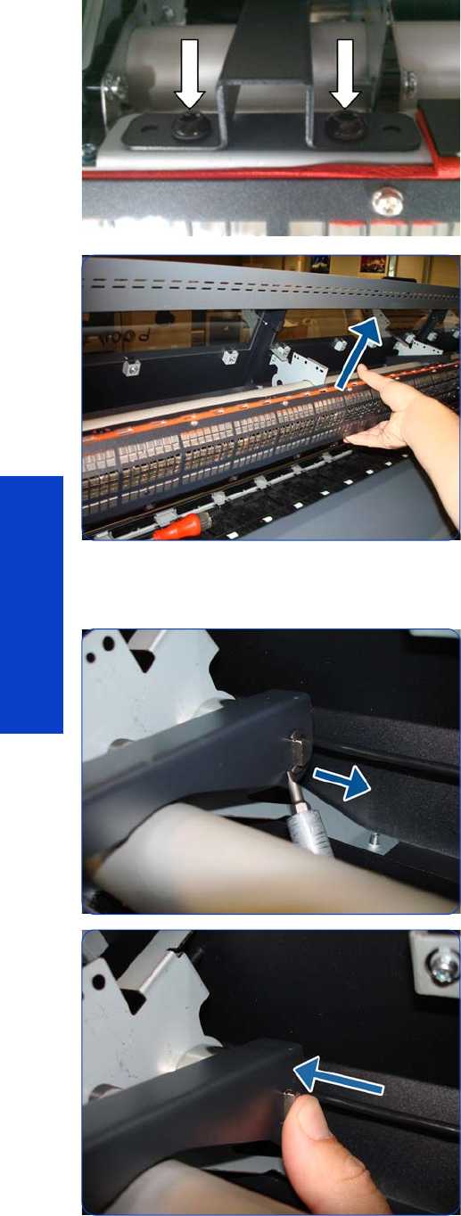
492 Chapter 8 Removal & Installation
Removal & Installation
5. Remove the eight T-20 screws (two in each arm) that
attach the arms to the isolator grid. Take care not to
lose the lock washers, as they will be needed for
installation.
6. Remove the Dryer Protector.
If you need to remove the dryer protector arms, continue with the following steps.
7. Unlock the clip at the side of the arm.
8. Push the arm rod.
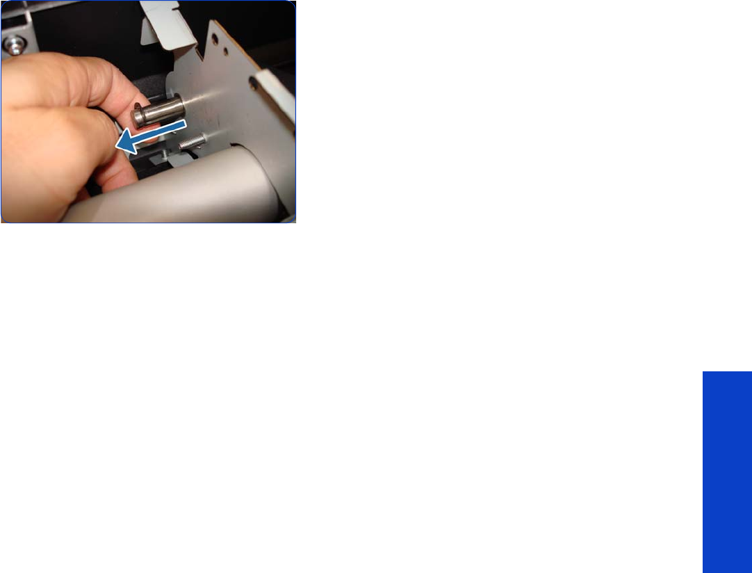
Dryer Protector 493
Removal & Installation
9. From the other side of the bracket, pull the arm rod to
freeze the arm.
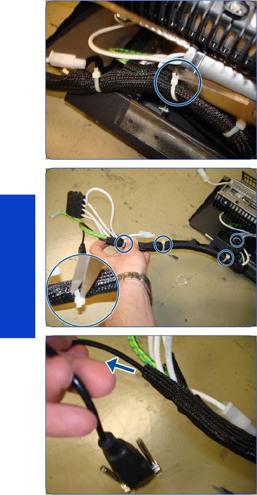
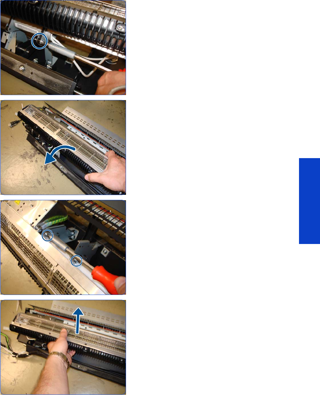
Dryer Heater 495
Removal & Installation
5. Remove eight T-20 screws from this side.
6. Rotate the Dryer Heater to reach the screws on the
other side.
7. Remove seven T-20 screws.
8. Remove the Dryer Heater.
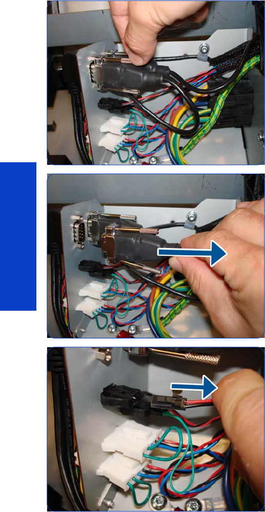
496 Chapter 8 Removal & Installation
Removal & Installation
Curing Fans and Cover
Removal
1. Remove the Left Cover
page 303
.
2. Remove the Left Curing Cover
page 308.
3. Remove the Right Curing Cover
page 310.
4. Loosen two screws on the connector of the Curing IR
Temperature Sensor cable, by hand or with a flat
screwdriver.
5. Disconnect the Curing Temperature Sensor Cable.
6. Disconnect the cable of the Left Windows Lock Sensor.

Curing Fans and Cover 497
Removal & Installation
7. Disconnect the cable of the Curing Fans.
8. Disconnect the cable of the Curing Temperature Sensor
Fan.
9. Disconnect the other cable as shown.
10. Remove a screw as shown.

498 Chapter 8 Removal & Installation
Removal & Installation
11. Remove two T-20 screws that secure the Left Cable Plate
to the printer.
12. Rotate (1) and remove (2) the Left Cable Plate.
13. Unroute the cables from the Cable Protector.
L14 . Push all the cables through the left arch and out the
other side.
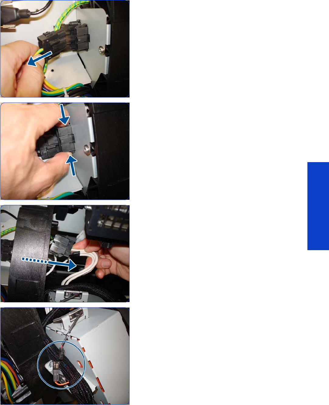
Curing Fans and Cover 499
Removal & Installation
15. Disconnect the Curing Heater Cables from the left side
(upper and lower connectors).
16. Squeeze as shown.
17. Disconnect the Left Window Sensor Cable.
18 . Disconnect as shown.
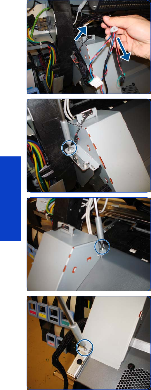
500 Chapter 8 Removal & Installation
Removal & Installation
19. Collect the cables as shown.
20.Remove one T-20 screw from the left side of the Curing
Module (screw closest to the printer).
21. Remove one T-20 screw from the top of the Left Curing
Trim.
22.Remove one T-10 screw from the bottom of the Left
Curing Trim.

Curing Fans and Cover 501
Removal & Installation
23.Remove the Left Curing Trim.
24.Disconnect the Right Window Sensor Cable.
25.Remove one T-20 screw from the Right Curing Trim
(screw furthest from the printer).
26.Remove one T-20 screw from the top of the Right Curing
Trim.
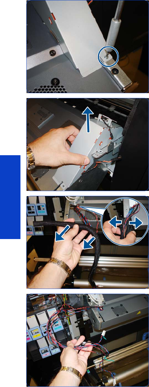
502 Chapter 8 Removal & Installation
Removal & Installation
27. Remove one T-10 screw from the bottom of the Right
Curing Trim.
28.Remove the Right Curing Trim.
29.
30.
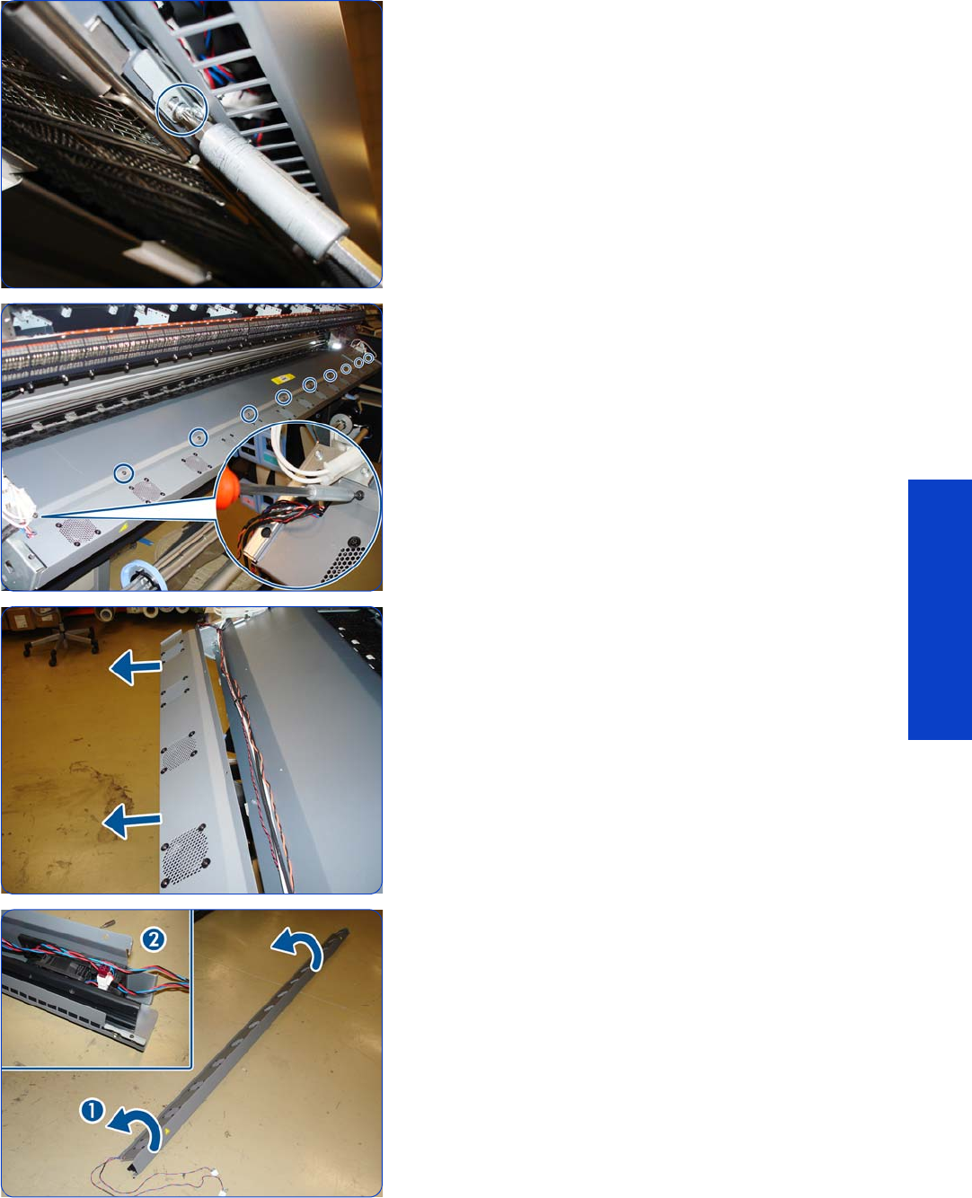
Curing Fans and Cover 503
Removal & Installation
31. Remove eight T10 screws.
D32.Remove ten T-20 screws.
33.Remove the Curing Fans Cover.
34.Place the Curing Fans Cover on the floor or some other
flat surface.
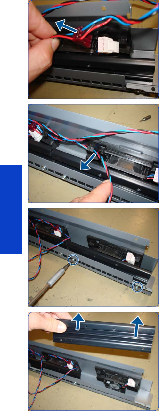
504 Chapter 8 Removal & Installation
Removal & Installation
35.Disconnect the Curing Fans cable.
36.Move the cable out of the way.
37. Remove two T-15 screws.
38.Remove the Fan Deflector.
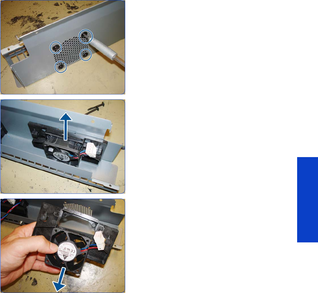
Curing Fans and Cover 505
Removal & Installation
39. Remove four T-20 screws.
40.Lift the Fan.
41. Remove the Fan.
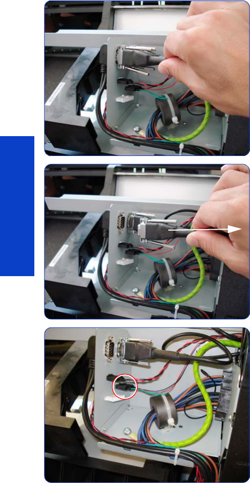
506 Chapter 8 Removal & Installation
Removal & Installation
Curing IR Temperature Sensor & Fan
Removal
1. Remove the Left Cover
page 303.
2. Remove the Left Curing Cover
page 308.
3. Remove the Right Curing Cover
page 310.
4. Remove the Curing Fans Cover
page 496.
5. Loosen two screws on the connector of the Curing IR
Temperature Sensor cable, by hand or with a flat
screwdriver.
6. Disconnect the Curing Temperature Sensor Cable.
7. Disconnect the cable of the Curing Temperature Sensor
Fan.
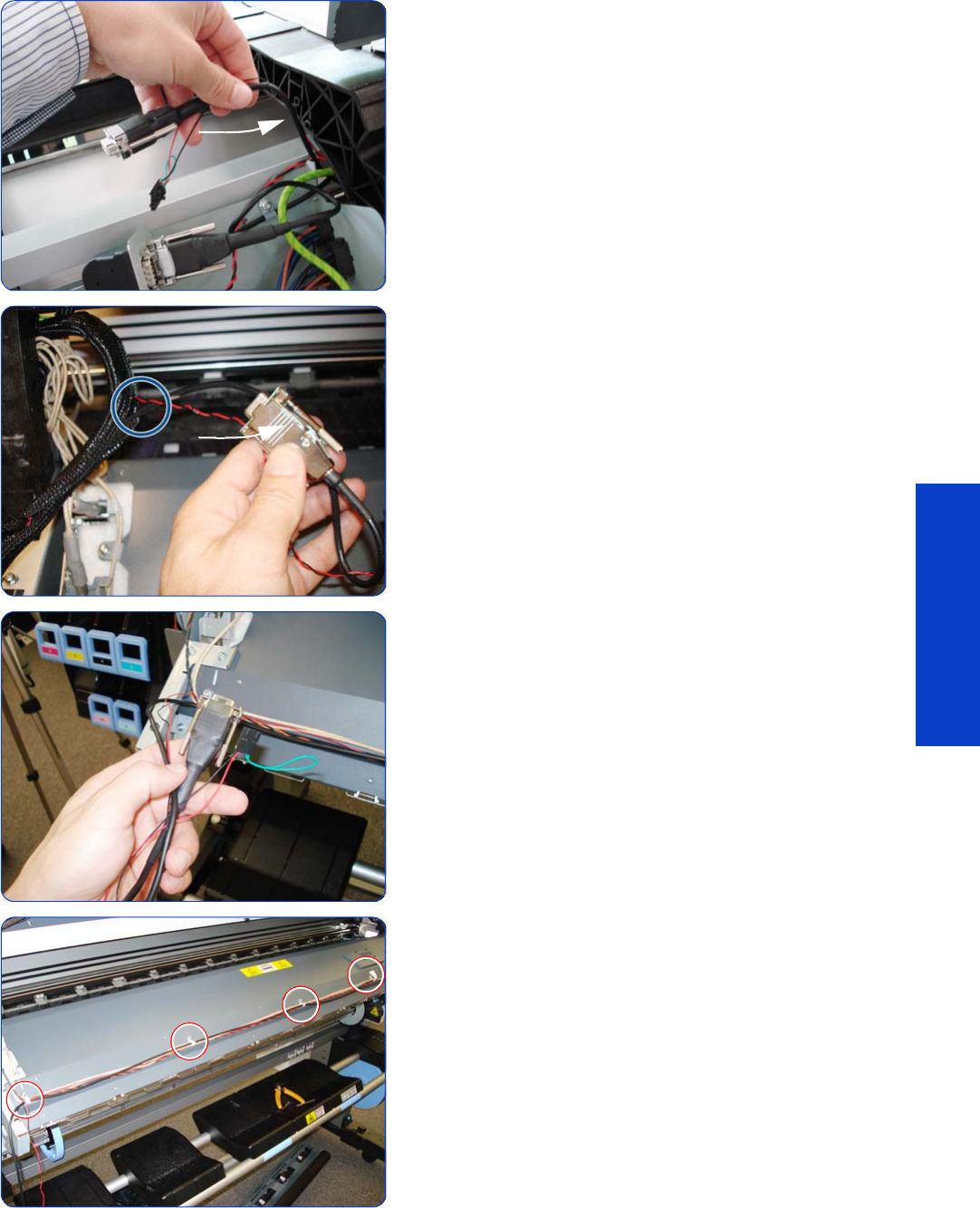
Curing IR Temperature Sensor & Fan 507
Removal & Installation
L8. Push the cables of the Curing Temperature Sensor and
Fan back through underneath the left arch.
9. Unroute the cables from the cable protector.
10. Leave to one side the cables of the Curing Temperature
Sensor and Fan.
11. Unlock the cable clamps that secure the cables of the
Curing Temperature Sensor and Fan to the front of the
curing Module.
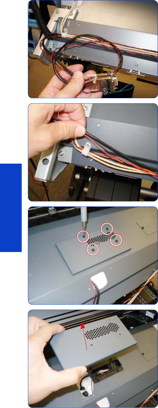
508 Chapter 8 Removal & Installation
Removal & Installation
Tip: Not all of the cable clamps need to be removed,
only those that hold the cables of the Curing
Temperature Sensor and the Fan.
12. Remove only the cables of the Curing Temperature
Sensor and the Fan from the cable clamps. The cables
of the curing heater and right window sensor can stay
in the cable clamps.
13. Remove four T-10 screws securing the cover of the
Curing Temperature Sensor.
14 . Remove the cover.
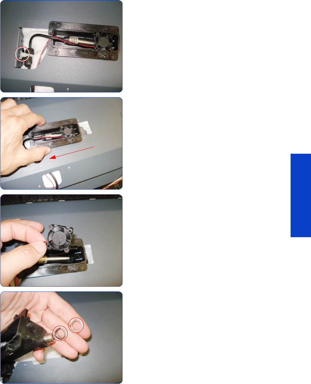
Curing IR Temperature Sensor & Fan 509
Removal & Installation
15. Pull off the ferrite clamp from the Curing Cover.
16. Slide the black plastic holder to the left.
17. Remove the Curing Temperature Sensor Fan from the
black plastic holder.
18 . Remove two thin nuts securing the Curing Temperature
Sensor to the black plastic bracket.
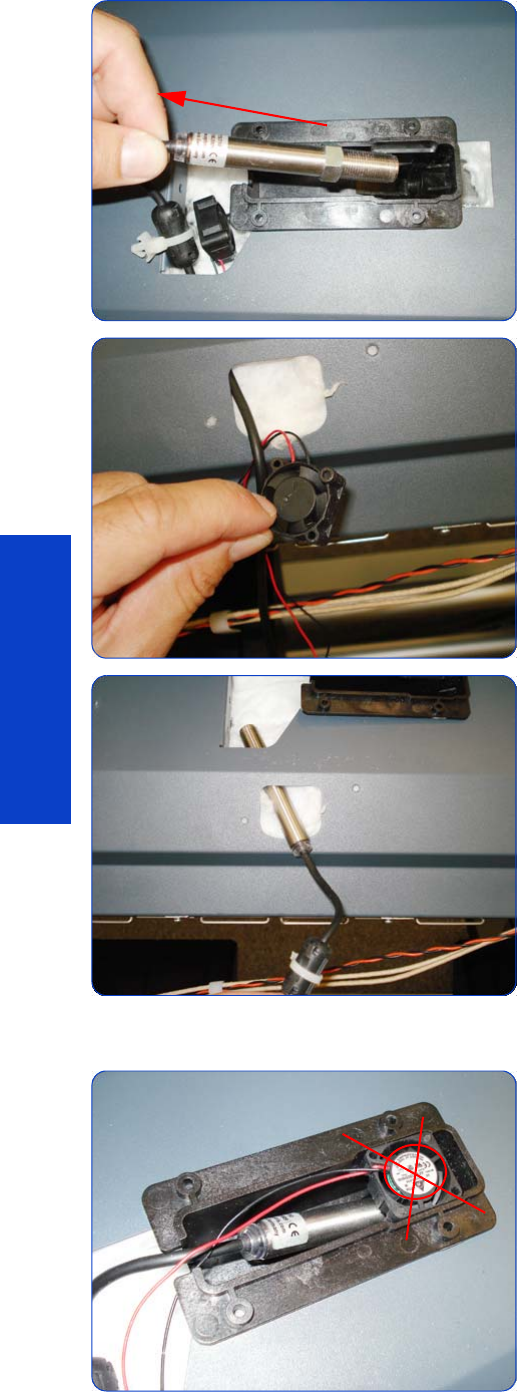
510 Chapter 8 Removal & Installation
Removal & Installation
19. Slide out the Curing IR Temperature sensor.
20.Remove the Curing Temperature Sensor Fan through
the hole in the Curing cover.
21. Remove the Curing Temperature Sensor through the
hole in the Curing cover.
Installation
1. When installing the Curing Temperature Sensor fan, it
is important that the label of the fan is not visible.
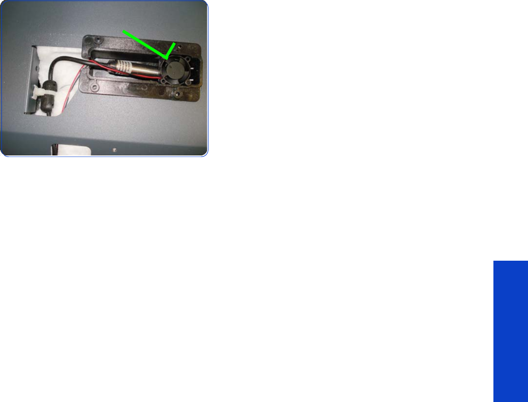
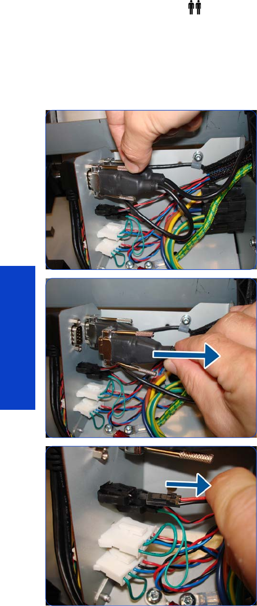
512 Chapter 8 Removal & Installation
Removal & Installation
Curing Module
Removal (requires two people)
1. Remove the Left Cover
page 303
.
2. Remove the Left Curing Cover
page 308.
3. Remove the Right Curing Cover
page 310.
4. Loosen two screws on the connector of the Curing IR
Temperature Sensor cable, by hand or with a flat
screwdriver.
5. Disconnect the Curing Temperature Sensor Cable.
6. Disconnect the cable of the Left Windows Lock Sensor.
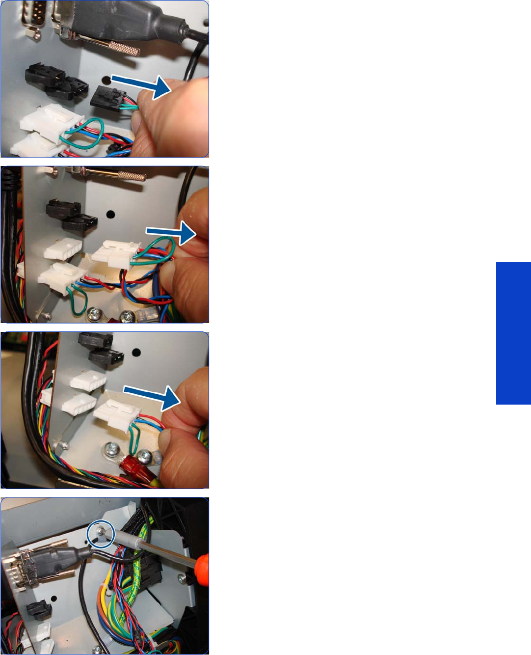
Curing Module 513
Removal & Installation
7. Disconnect the cable of the Curing Fans.
8. Disconnect the cable of the Curing Temperature Sensor
Fan.
9. Disconnect the other cable as shown.
10. Remove a screw as shown.
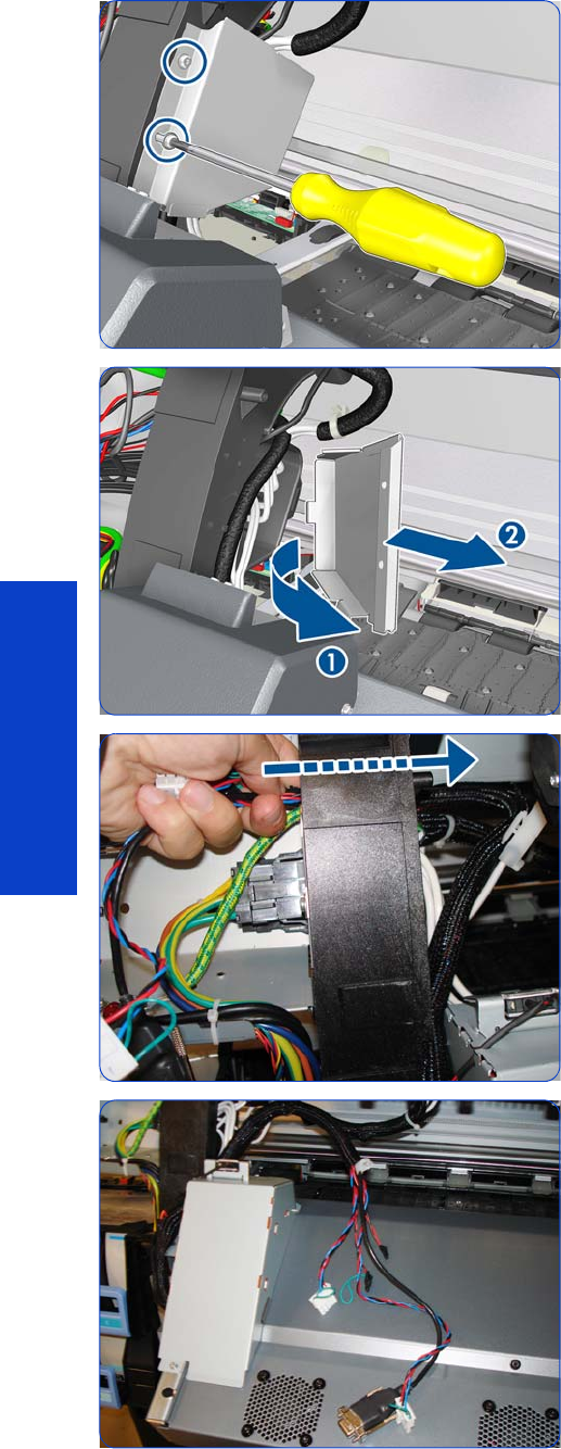
514 Chapter 8 Removal & Installation
Removal & Installation
11. Remove two T-20 screws that secure the Left Cable Plate
to the printer.
12. Rotate (1) and remove (2) the Left Cable Plate.
13. Unroute the cables from the Cable Protector.
L14 . Push all the cables through the left arch and out the
other side.

Curing Module 515
Removal & Installation
15. Disconnect the Curing Heater Cables from the left side
(upper and lower connectors).
16. Squeeze as shown.
17. Disconnect the Left Window Sensor Cable.
18 . Disconnect as shown.

516 Chapter 8 Removal & Installation
Removal & Installation
19. Collect the cables as shown.
20.Remove one T-20 screw from the left side of the Curing
Module (screw closest to the printer).
21. Remove one T-20 screw from the top of the Left Curing
Trim.
22.Remove one T-10 screw from the bottom of the Left
Curing Trim.
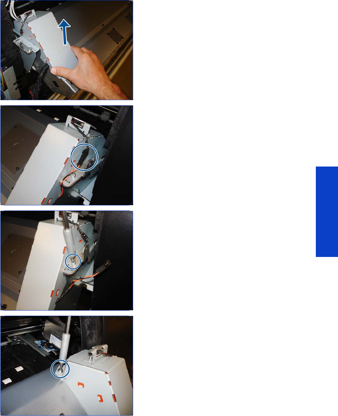
Curing Module 517
Removal & Installation
23.Remove the Left Curing Trim.
24.Disconnect the Right Window Sensor Cable.
25.Remove one T-20 screw from the Right Curing Trim
(screw furthest from the printer).
26.Remove one T-20 screw from the top of the Right Curing
Trim.
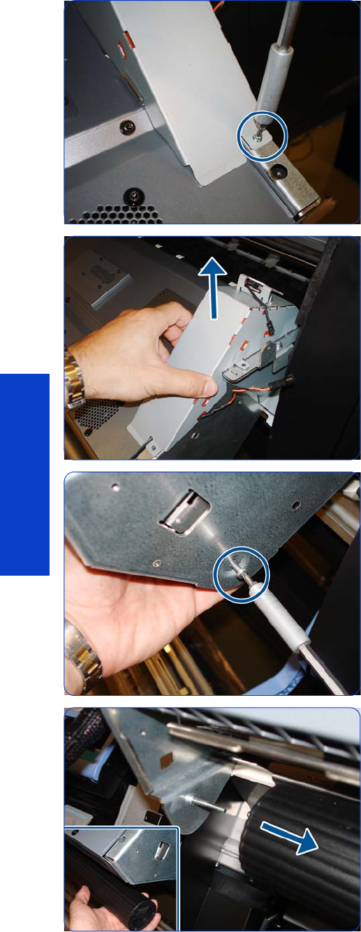
518 Chapter 8 Removal & Installation
Removal & Installation
27. Remove one T-10 screw from the bottom of the Right
Curing Trim.
28.Remove the Right Curing Trim.
29. Remove one T-15 screw that secures the Output Roller to
the right side of the Curing module, and remove the
roller.
30.Slide the Output roller from the pin located on the left
side of the curing Module.
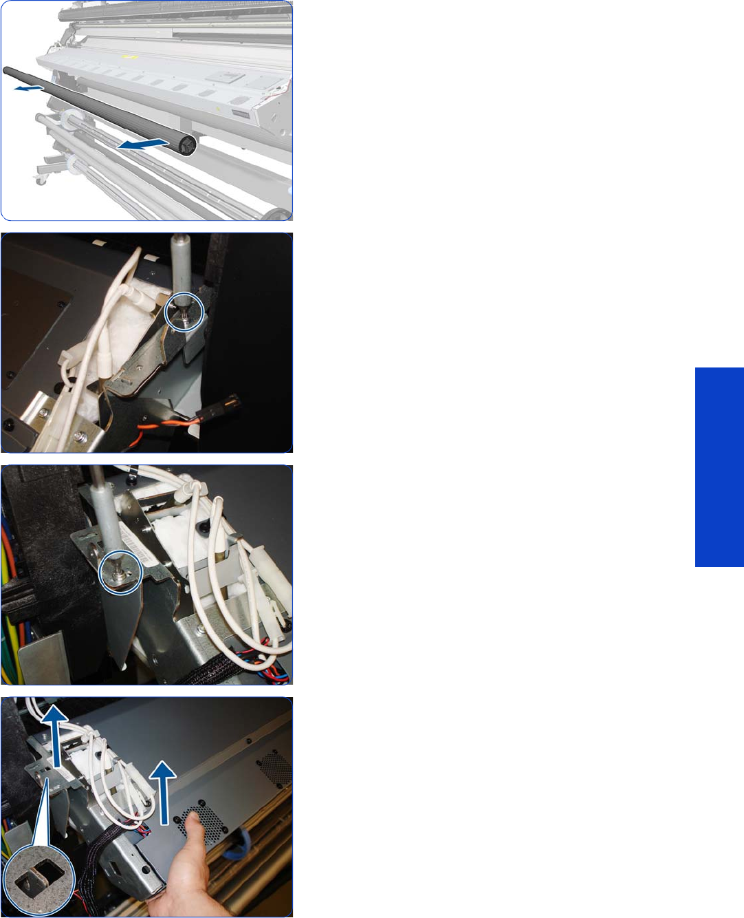
Curing Module 519
Removal & Installation
31. Remove the Output roller.
D32.Remove one T-20 screw from the top right of the Curing
module.
33.Remove one T-20 screw from the left of the Curing
module.
34.Lift the left side of the Curing Module.
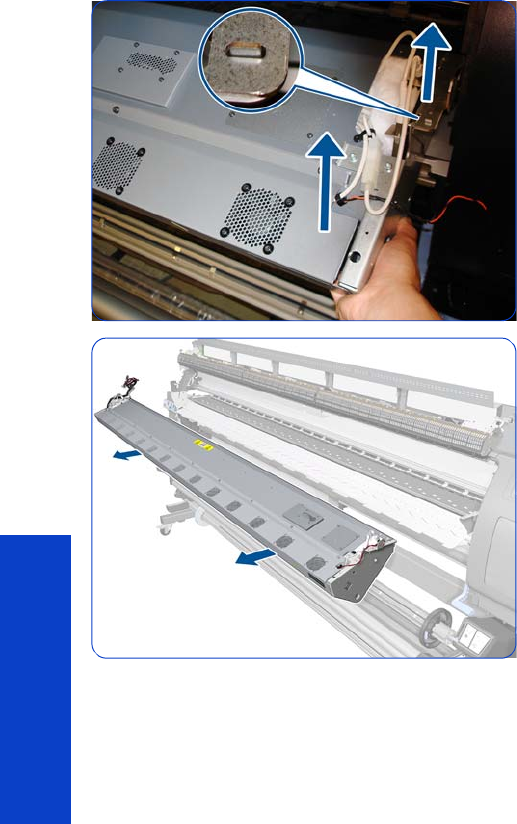
520 Chapter 8 Removal & Installation
Removal & Installation
35.Lift the right side of the Curing Module.
36.Remove the Curing Module.
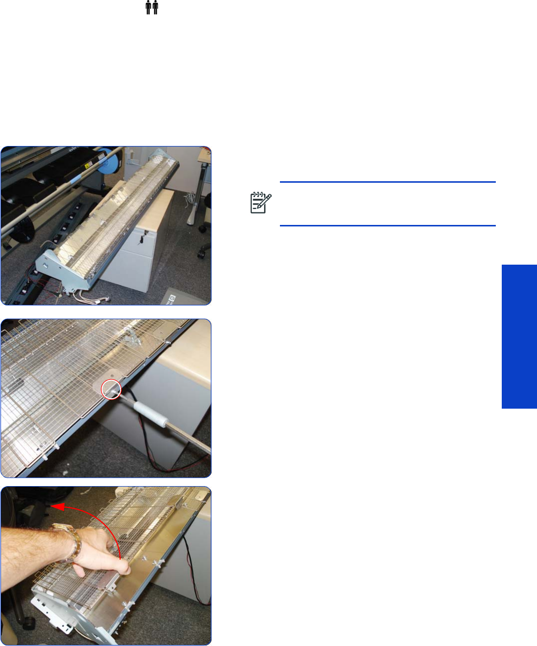
Curing Heaters 521
Removal & Installation
Curing Heaters
Removal (requires two people)
1. Remove the Left Cover
page 303
.
2. Remove the Left Curing Cover
page 308.
3. Remove the Right Curing Cover
page 310.
4. Remove the Curing Fans Cover
page 496.
5. Remove the Curing Module
page 512.
6. Turn the Curing Module upside down and place it on a
flat, even surface.
7. Remove all the T-10 screws that secure the sections of
Curing Heater Grills to the Curing Module.
8. Remove the Heater Grills by lifting up the free end and
removing.
NOTE: When placing it on the flat surface,
take care not to damage the terminals of the
Heaters.
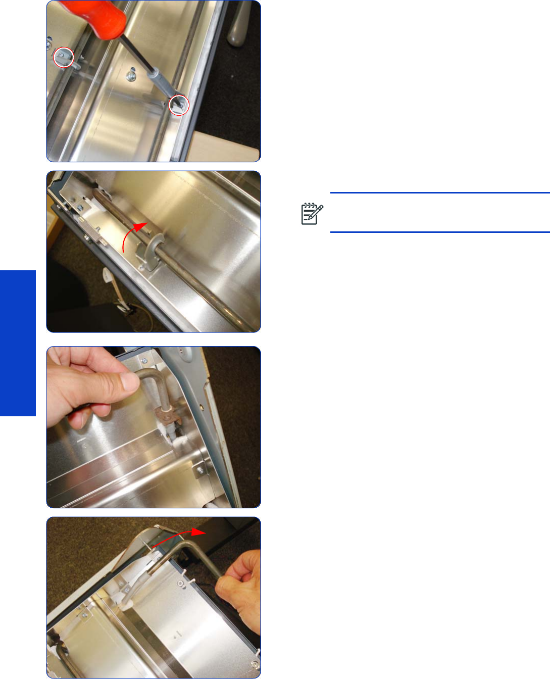
522 Chapter 8 Removal & Installation
Removal & Installation
9. Remove all T-15 screws that secure the heater holders to
the Curing Module.
10. Twist the heater holders to remove them all.
11. Remove the left end of the Output Heater taking care
not to damage the Isolation fiber.
12. Remove the right end of the Output Heater taking care
not to damage the Isolation fiber.
NOTE: The Output Heater Holders are
different from the Overdrive Heater Holders.
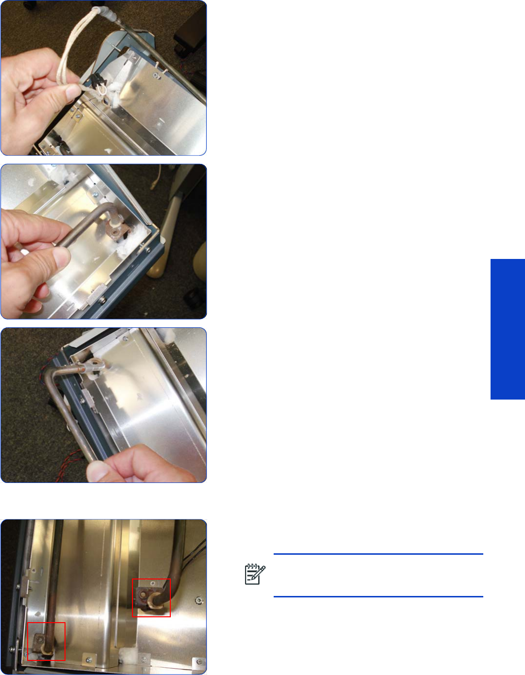
Curing Heaters 523
Removal & Installation
13. Be careful when removing the end of the Output heater
cable, as there is a connector on the end, and this
could damage the isolation fiber.
14 . Remove the Overdrive Heater, taking care not to
damage the Isolation fiber.
15. Remove the other end of the Overdrive Heater.
Installation
1. The ends of the two types of Curing Heaters are
different to avoid installing them incorrectly.
NOTE: After installing the new Curing
Heaters, reset the Curing Lamps life counter
page 195.
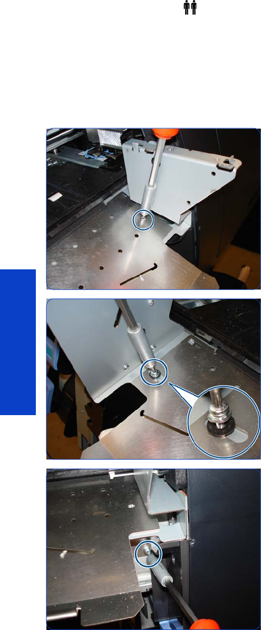
524 Chapter 8 Removal & Installation
Removal & Installation
Output Platen
Removal (requires two people)
1. Remove the Left Cover
page 303
.
2. Remove the Left Curing Cover
page 308.
3. Remove the Right Curing Cover
page 310.
4. Remove the Curing Module
page 512.
5. Remove a T-20 screw from the right side of the Output
Platen.
6. Remove a T-20 screw and a washer from the left side
of the Output Platen.
7. Remove a T-20 screw.
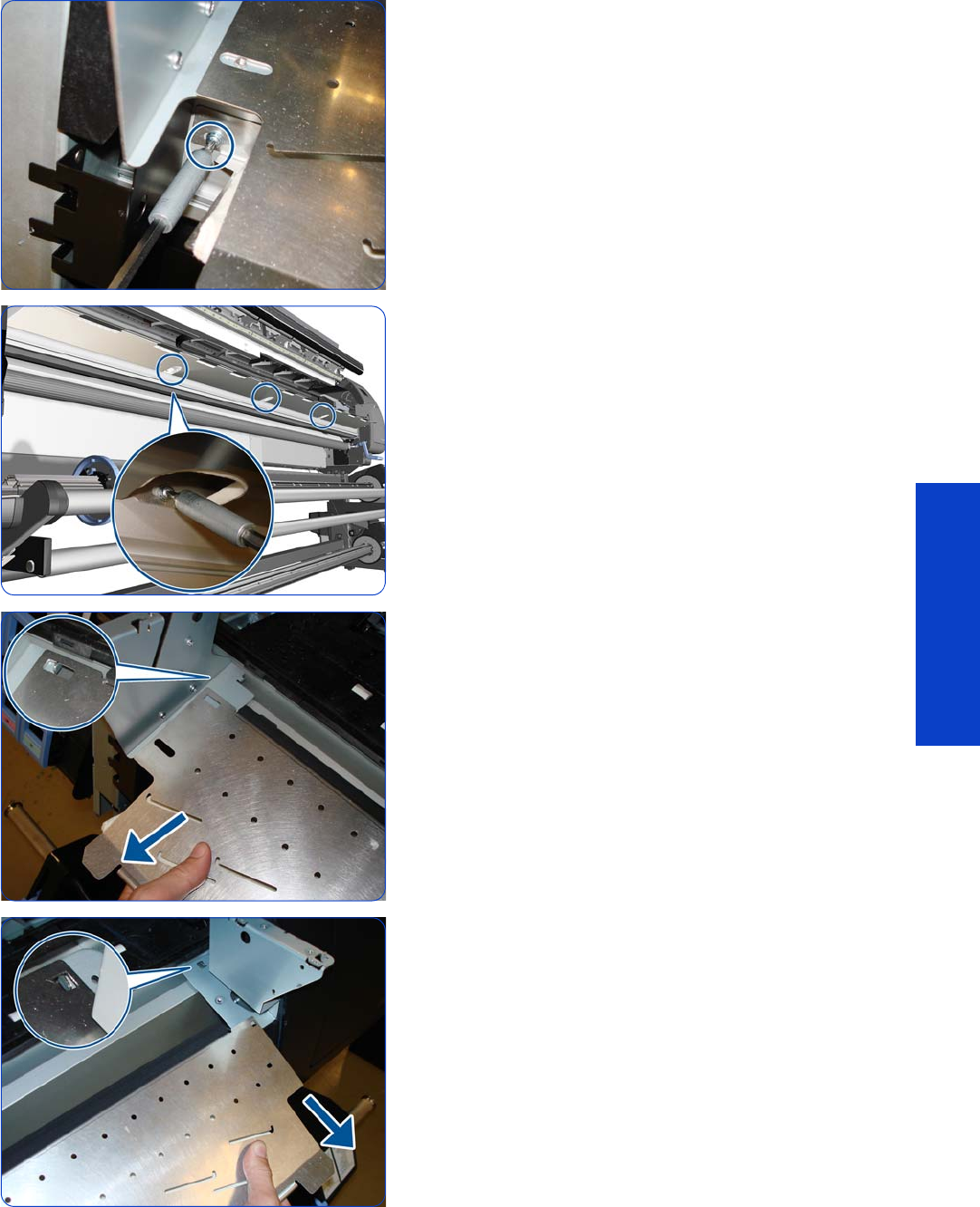
Output Platen 525
Removal & Installation
8. Remove a T-20 screw.
9. Remove three T-20 screws.
10. Detach the left corner of the Output Platen.
11. Detach the right corner of the Output Platen.
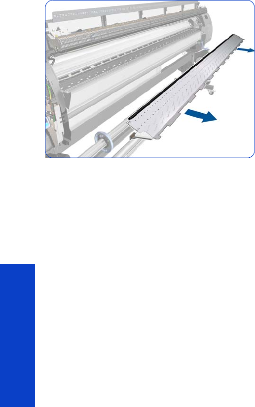
526 Chapter 8 Removal & Installation
Removal & Installation
12. Remove the Output Platen.
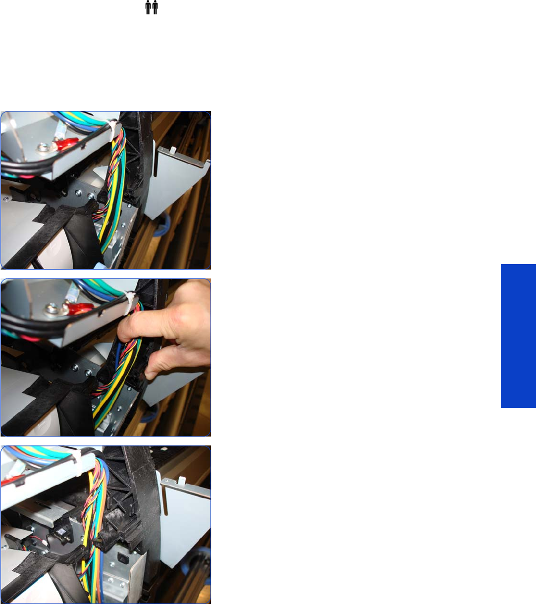
Curing Holders 527
Removal & Installation
Curing Holders
Removal (requires two people)
1. Remove the Right Cover
page 296.
2. Remove the Curing Module
page 512.
3. Remove the Output Platen
page 524.
4. Locate the bundle of cables on the front of the left arch.
5. Pull the cables away from the arch.
6. Put the cables out of the way so that you can reach the
screw that secures the Left Curing Holder to the left
arch.
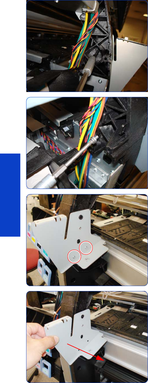
528 Chapter 8 Removal & Installation
Removal & Installation
7. Locate the T-20 screw that secures the Left Curing
Holder to the left arch.
8. Remove the screw.
9. Remove two T-15 screws from the Left Curing Holder.
10. Remove the Left Curing Holder.
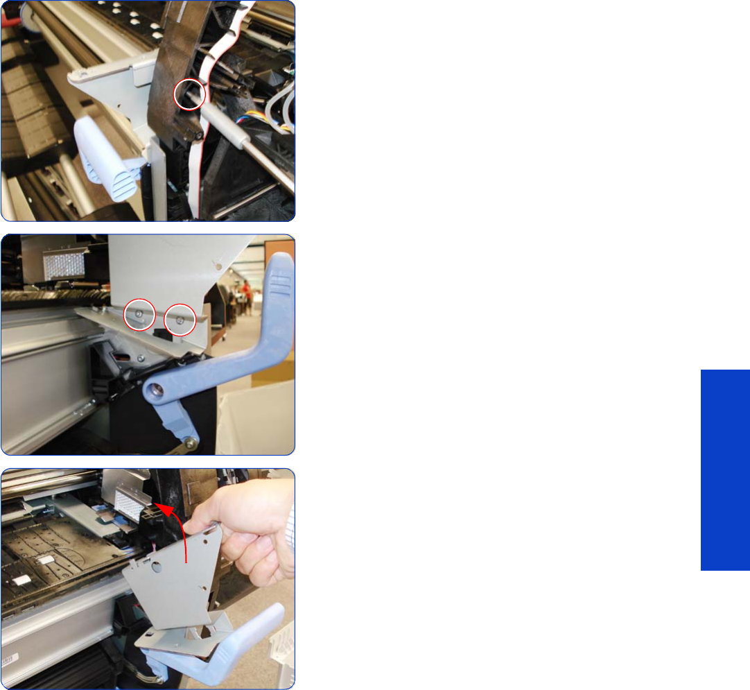
Curing Holders 529
Removal & Installation
11. Remove one T-20 screw that secures the right Curing
Holder to the right arch.
12. Remove two T-15 screws from the Right Curing Holder.
13. Remove the Right Curing Holder
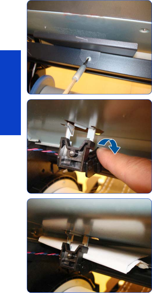
530 Chapter 8 Removal & Installation
Removal & Installation
Print Platen
Removal
1. Remove the Right Cover
page 296
.
2. Remove the Left Cover
page 303.
3. Remove the Service Station
page 351.
4. Remove the Electronics Enclosure Extension Cover
page 329
.
5. Remove the Rear Upper Cover
page 312.
6. Remove the Top Cover
page 314.
7. Remove three or one T-25 screws from the Media
Loading Tool holder.
8. Unclip the Media sensor.
9.
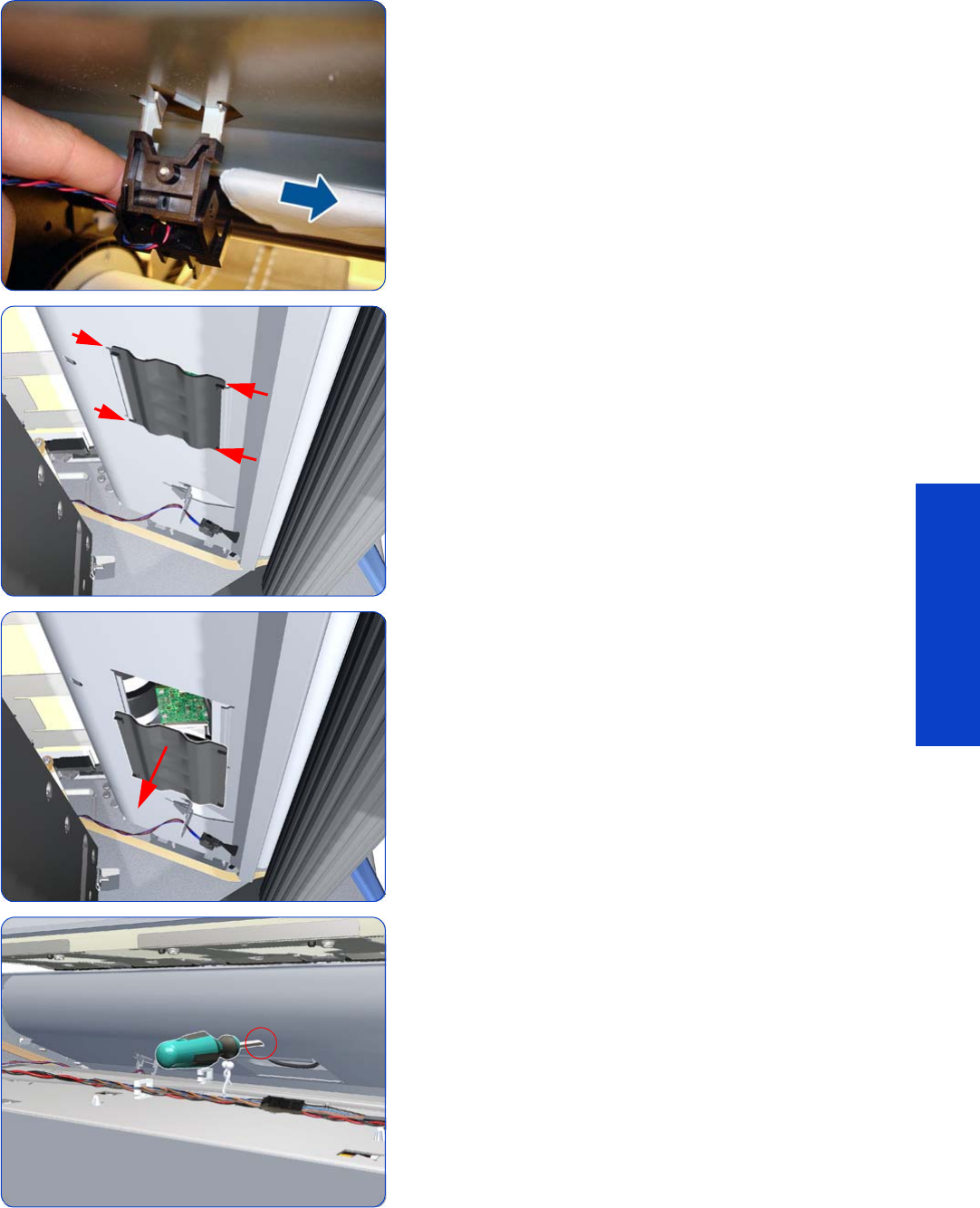
Print Platen 531
Removal & Installation
10.
11. Squeeze the corners of the OMAS Access Cover
release it from the bottom of the printer.
12. Remove the OMAS Access Cover from the printer.
13. Insert the T-20 thin bladed torx screwdriver (supplied
with the replacement OMAS) into the access hole at
the rear of the printer.
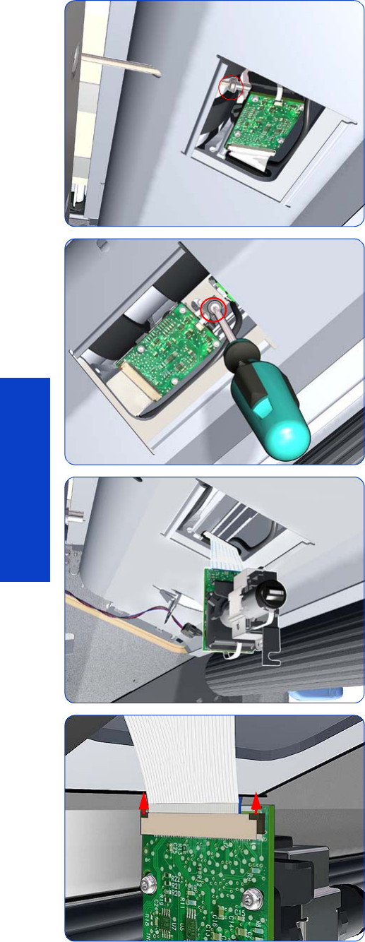
532 Chapter 8 Removal & Installation
Removal & Installation
14 . Loosen approximately two turns the T-20 screw which
secures the OMAS horizontally to the printer.
15. From the bottom of the printer, loosen approximately
two turns the T-20 screw which secures the OMAS
vertically to the printer.
16. Carefully lower the OMAS from the printer as far as
you can with the large ribbon cable still connected.
17. Release the two locking clips of the large ribbon cable
connector.
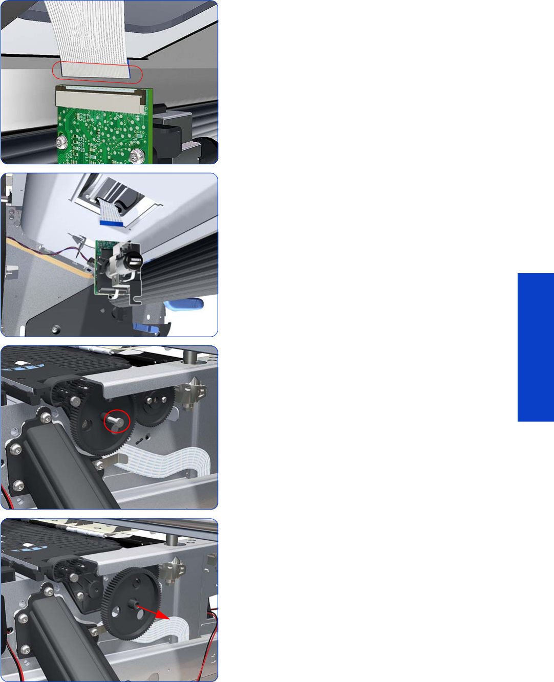
Print Platen 533
Removal & Installation
18 . Disconnect the large ribbon cable from the OMAS.
19. Remove the OMAS Sensor from the printer.
20.Remove one T-15 screw that secures the Print Platen
Gear.
21. Remove the Print Platen Gear from the printer.
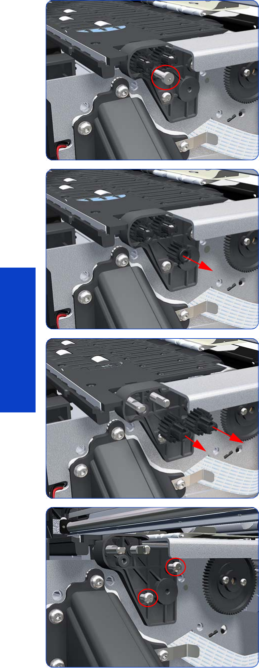
534 Chapter 8 Removal & Installation
Removal & Installation
22.Remove one T-15 screw that secures the small Gear.
23.Remove the small Gear from the printer.
24.Remove the two small Platen Gears by releasing the
clips.
25.Remove two T-20 screws that secure the Gear Bracket.
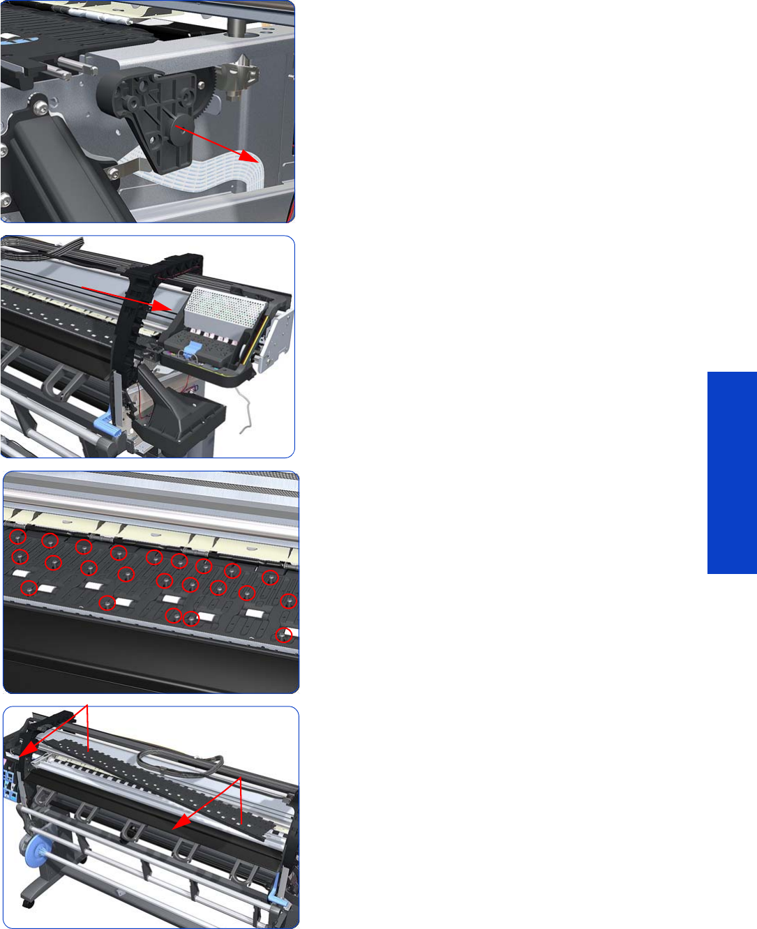
Print Platen 535
Removal & Installation
26.Remove the Gear Bracket from the printer.
27. Move the Carriage Assembly fully to the right.
28.Remove 116 T-10 screws that secure the Print Platen:
29. Remove the Print Platen from the printer.
The OMAS attachment screws have been completely
removed during Print Platen removal.
30.Completely remove OMAS from the printer
page 432.
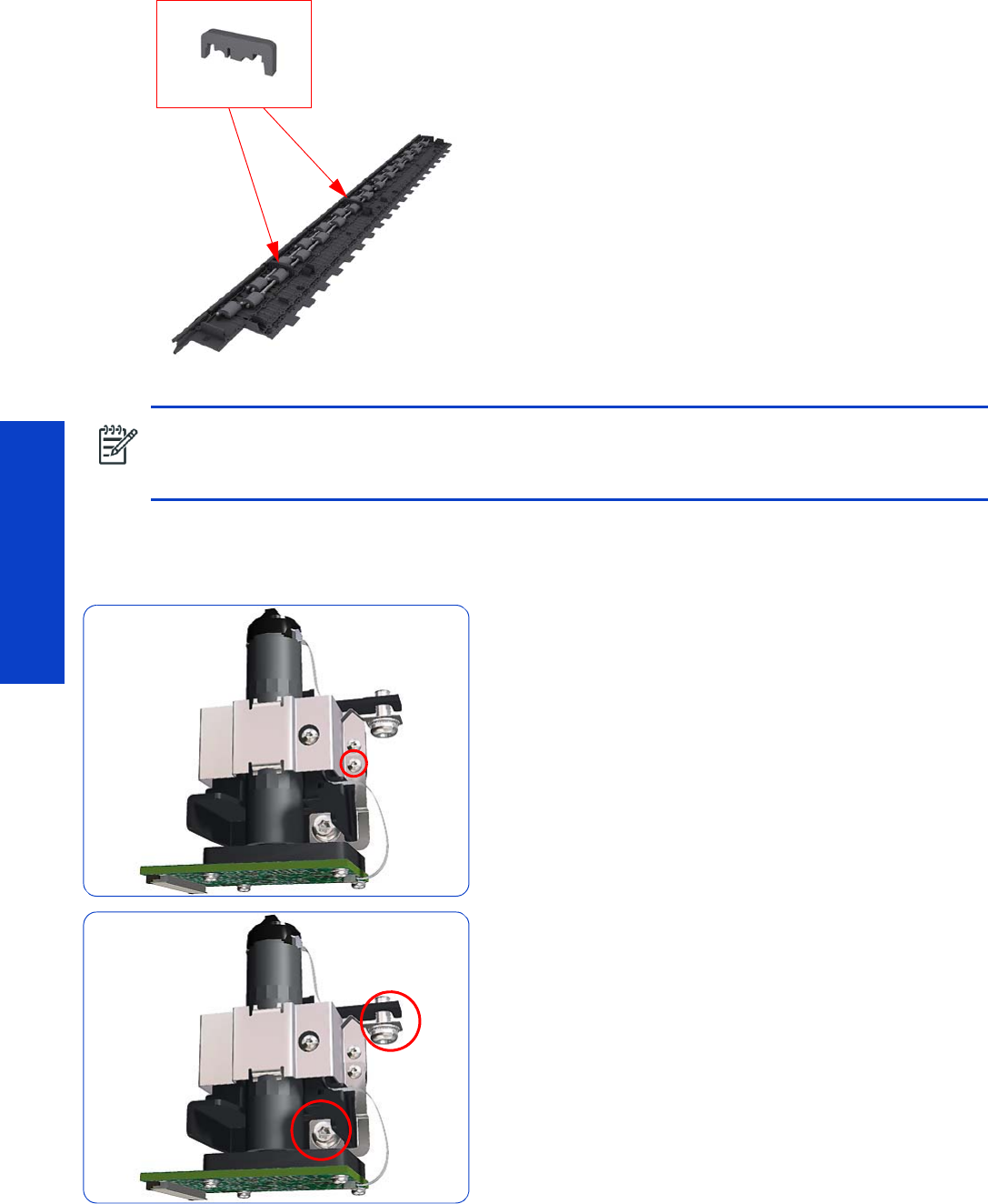
536 Chapter 8 Removal & Installation
Removal & Installation
Installation of the Foam
1. Make sure you take note of the positions of the Foams
located underneath the Print Platen.
1. Install the Print Platen.
2. Position the Attachment Screw Retainer on the OMAS
and secure it with the T-8 attachment screw provided
with Print Platen.
3. Verify that the two T-20 attachment screws are correctly
positioned in the Attachment Screw Retainer.
NOTE: When reinstalling the parts, make sure you apply the grease (included with the support part) to
the gears.
NOTE: After installing the new Print Platen, perform Substrate Advance Calibration
Chapter 5.
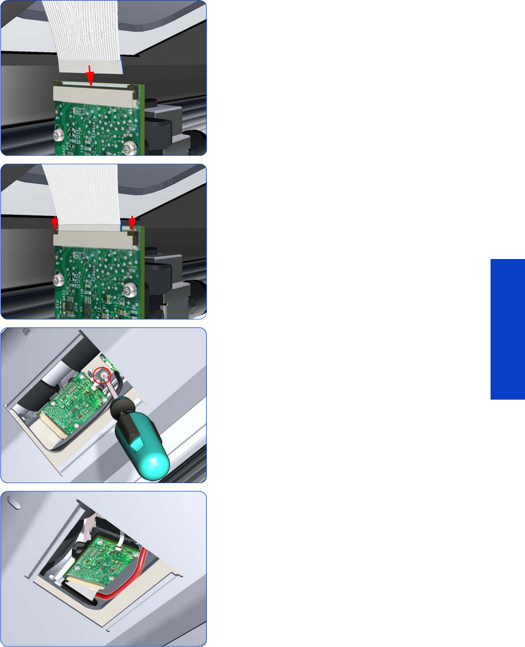
Print Platen 537
Removal & Installation
4. Position the OMAS under the printer and connect the
large ribbon.
5. Lock the clips of the large ribbon cable connector.
6. Fully tighten the T-20 vertical attachment screw.
7. While installing the OMAS, take care not to trap the
cable of the TOMAS.
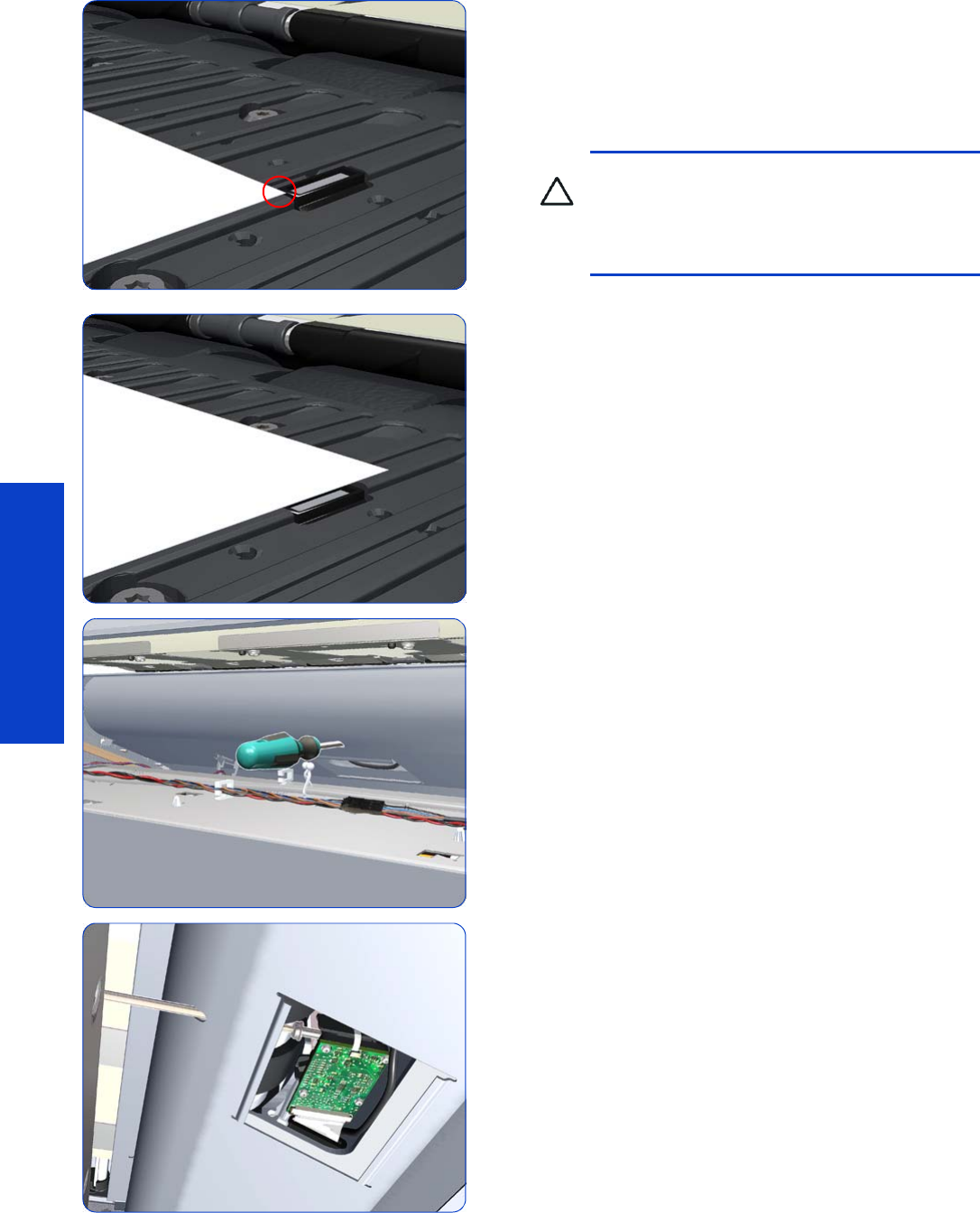
538 Chapter 8 Removal & Installation
Removal & Installation
8. Carefully push the OMAS fully up into its mounting so
it protrudes slightly (approximately 0.1 mm) above the
Print Platen. To ensure the OMAS is correctly
positions, slide a sheet of substrate over the Platen
Ribs until it is stopped by the OMAS. This ensures the
OMAS is protruding slightly above the platen.
9. If the substrate is not stopped by the OMAS, repeat the
previous steps to ensure the OMAS is push fully up into
its the mounting.
10. Insert the T-20 thin bladed Torx screwdriver into the
access hole at the rear of the printer.
11. Fully tighten the T-20 horizontal attachment screw
which secures the OMAS to the printer.
CAUTION: Make sure the OMAS is pushed
completely up into its mounting, or you will
encounter an error during the OMAS
calibration, because it will not be able to focus
on the substrate.
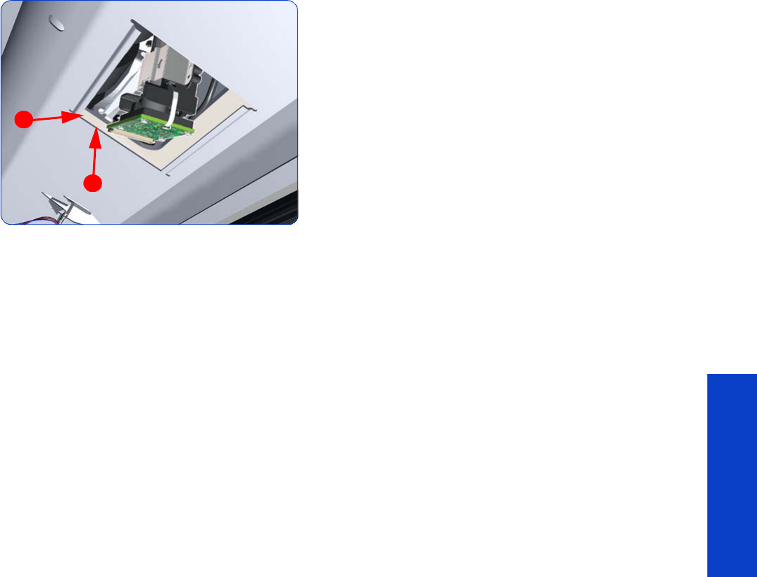
Print Platen 539
Removal & Installation
12. Clip the OMAS access cover back into place by
sliding one edge of the cover into the slot and then
applying enough pressure to it so you can clip it into
the other slot.
13. Perform the following operations:
•OMAS Calibration
page 183
.
•Substrate Advance Calibration
page 195.
1
2
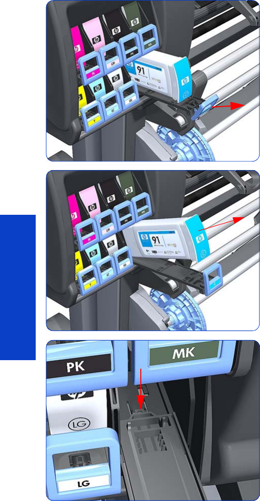
540 Chapter 8 Removal & Installation
Removal & Installation
Cartridge Tray
Removal
1. Release the Tray Lever of the required color and pull
out the Tray.
2. Remove the Ink Cartridge if installed.
3. Press down on the Tray clip.
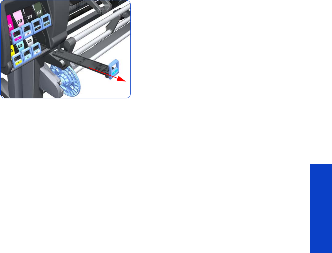
Cartridge Tray 541
Removal & Installation
4. Pull the Tray completely out of the printer.
Installation
Each Cartridge Tray is different, even though they look very similar. When selecting the Cartridge Tray from
the Support Part (it contains eight Cartridge Trays), choose the Tray that exactly matches the one that you
have just removed.
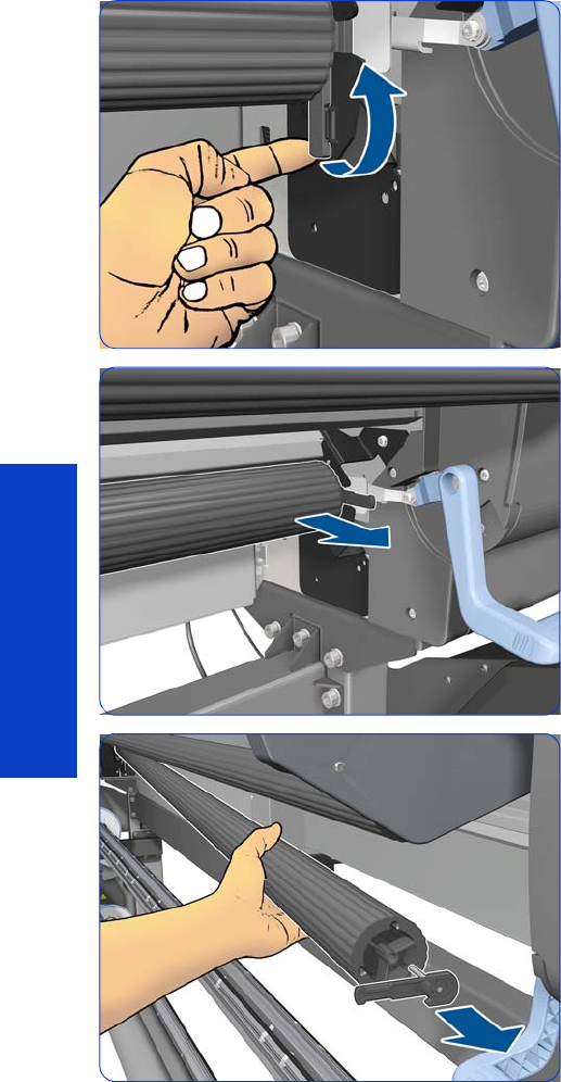
542 Chapter 8 Removal & Installation
Removal & Installation
Input Roller
Removal
1. Raise the right lever to release the right-hand end of the
Input Roller.
2. Pull out the right-hand end of the Input Roller from the
printer.
3. Remove the right lever, but hold the Input Roller firmly to
prevent the left end from falling out.
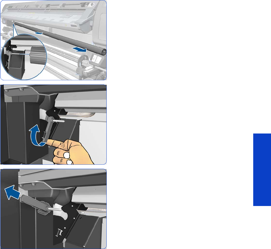
Input Roller 543
Removal & Installation
4. Move the Input Roller to the right and remove it from
the printer. The detail shows how the Input Roller
disengages from the left lever.
5. Raise the left lever.
6. Remove the left lever.
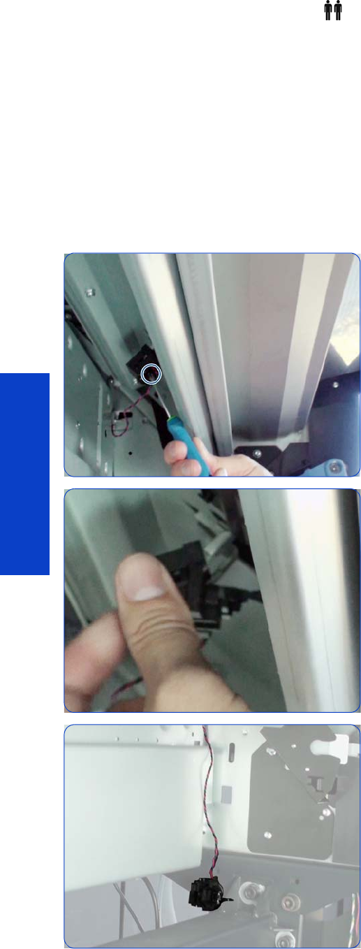
544 Chapter 8 Removal & Installation
Removal & Installation
Media Input Profile
Removal (requires two people)
1. Remove the Power Box Cover
page 321
.
2. Remove the Electronics Enclosure Extension Cover
page 329
.
3. Remove the Left Cover
page 303
.
4. Remove the Right Cover
page 296
.
5. Remove the Rear Upper Cover
page 312
.
6. Remove the Input Roller
page 542
.
7. Remove one T-10 screw.
8. Remove the Media Sensor Holder.
9. Leave the sensor hanging.
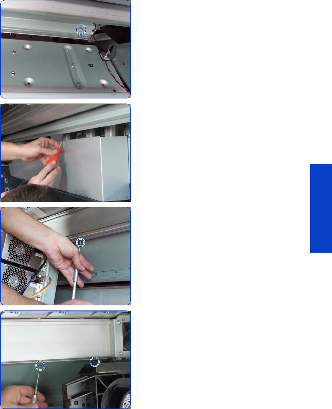
Media Input Profile 545
Removal & Installation
10. Remove twelve T-20 screws.
11. (Continue removing the 12 screws.)
12. (Continue removing the 12 screws.)
13. (Continue removing the 12 screws.)
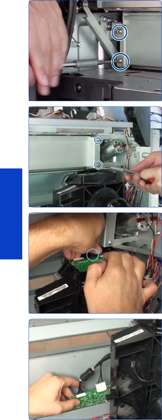
546 Chapter 8 Removal & Installation
Removal & Installation
14 . Remove two T-20 screws.
15. Remove two T-20 screws.
16. Press the plastic clip that holds the left-side EOLA PCA
and remove it. This operation is needed to avoid
damage to the PCA.
17. Leave the left-side EOLA PCA hanging on the cable
tray.
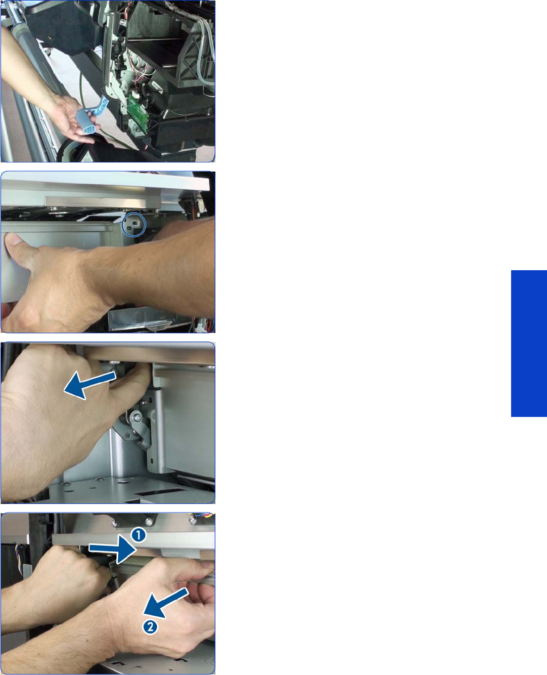
Media Input Profile 547
Removal & Installation
18 . Raise the Media Lever.
19. Detach the right side of the Media Input Profile.
20.Pull the Media Lever to facilitate the removal of the
Media Input Profile.
21. Push the Media Input Profile sideways, and then pull it
out of the printer.
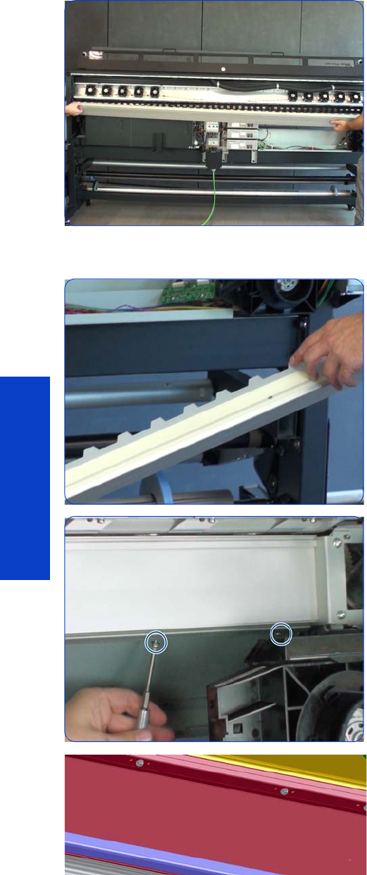
548 Chapter 8 Removal & Installation
Removal & Installation
22.Remove the Media Input Profile.
Installation
1. Be careful not to damage the mylar when mounting it.
2. Be careful not to strip the threads of the screws between
Media Input Platen and Media Input Profile.
If the Media Input Platen contained in the service kit is
the new revision with 3 holes, you can use one of the
extra holes if the original location is stripped.
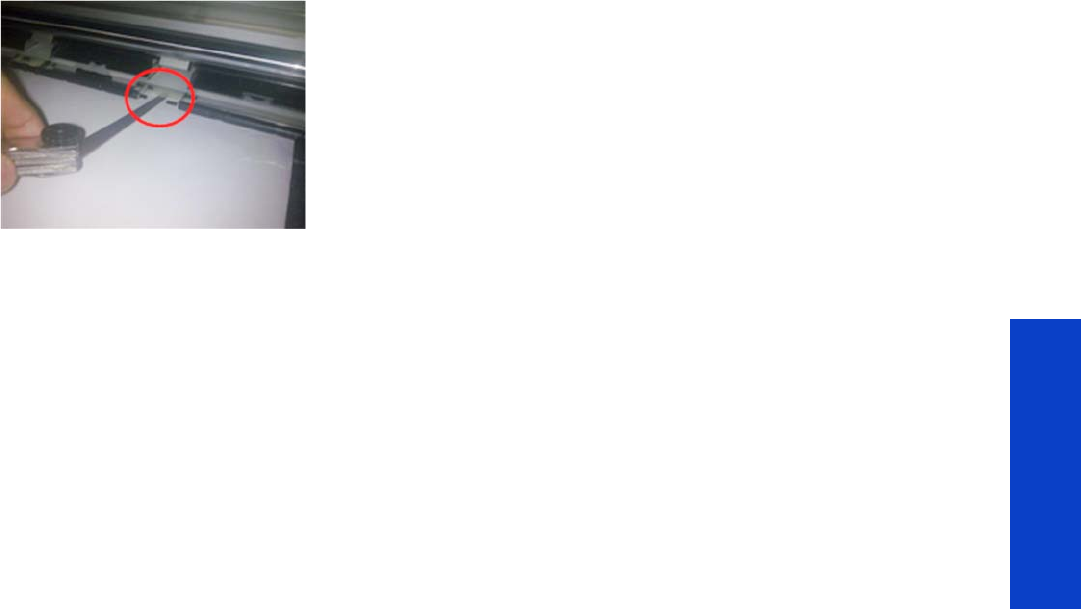
Media Input Profile 549
Removal & Installation
After installation, check the gap between the mylar and the Drive Roller in the following way.
3. Remove 3 inter-pinchwheels, one on the right, one in
the middle, and one on the left.
4. Manually load a piece of HP Permanent Self-Adhesive
Vinyl at the right. There is a small roll provided with the
printer or as a Service Part: CH955-67108 – CAL HP
Perm. Gloss Adhesive Vinyl.
5. Pull the Self-Adhesive material tight from both ends and
check visually that there is a gap between the mylar
and the material.
In this picture, a gauge is used to measure the gap.
However, it is enough to confirm visually that there is a
gap. For reference only, 0.3 mm is the minimum gap, 1
mm is the nominal gap, and 3 mm is the maximum
gap.
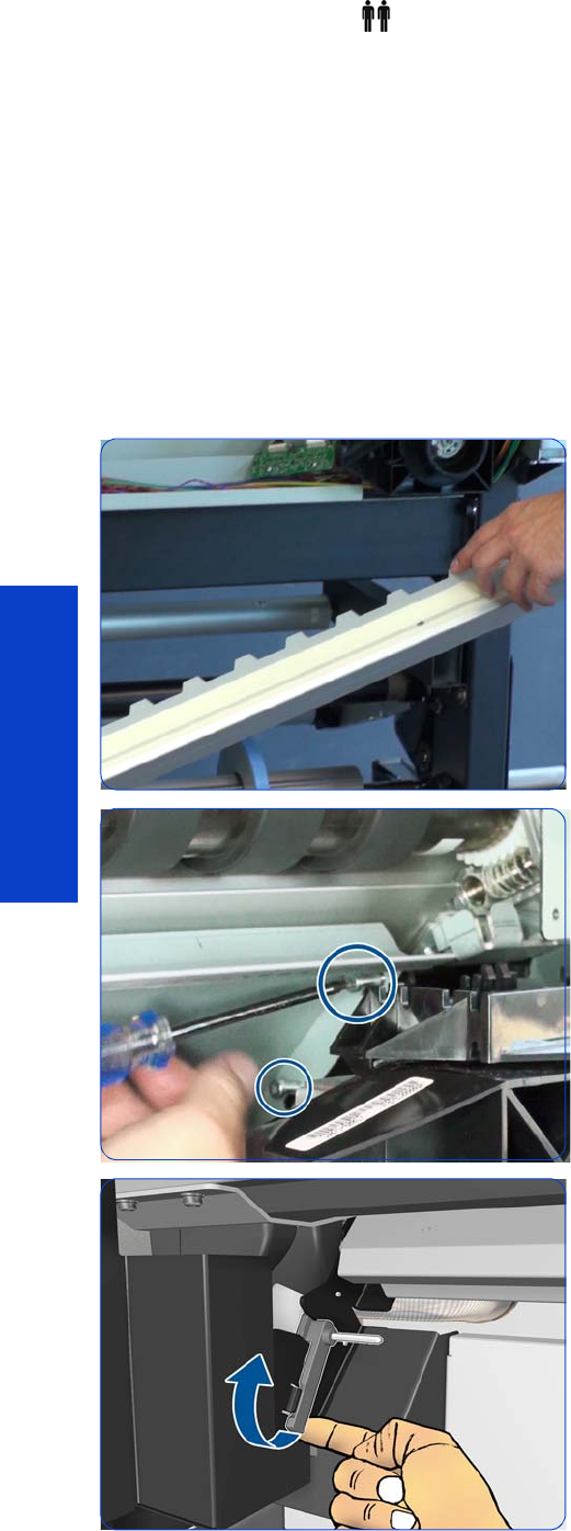
550 Chapter 8 Removal & Installation
Removal & Installation
Input Platen
Removal (requires two people)
1. Remove the Power Box Cover
page 321
.
2. Remove the Electronics Enclosure Extension Cover
page 329
.
3. Remove the Left Cover
page 303
.
4. Remove the Right Cover
page 296
.
5. Remove the Rear Upper Cover
page 312
.
6. Remove the Input Roller
page 542
.
7. Remove the Media Input Profile
page 544
.
8. Be careful not to damage the mylar when removing the
Media Input Profile.
9. Remove two T-15 screws.
10. Raise the Left Lever.
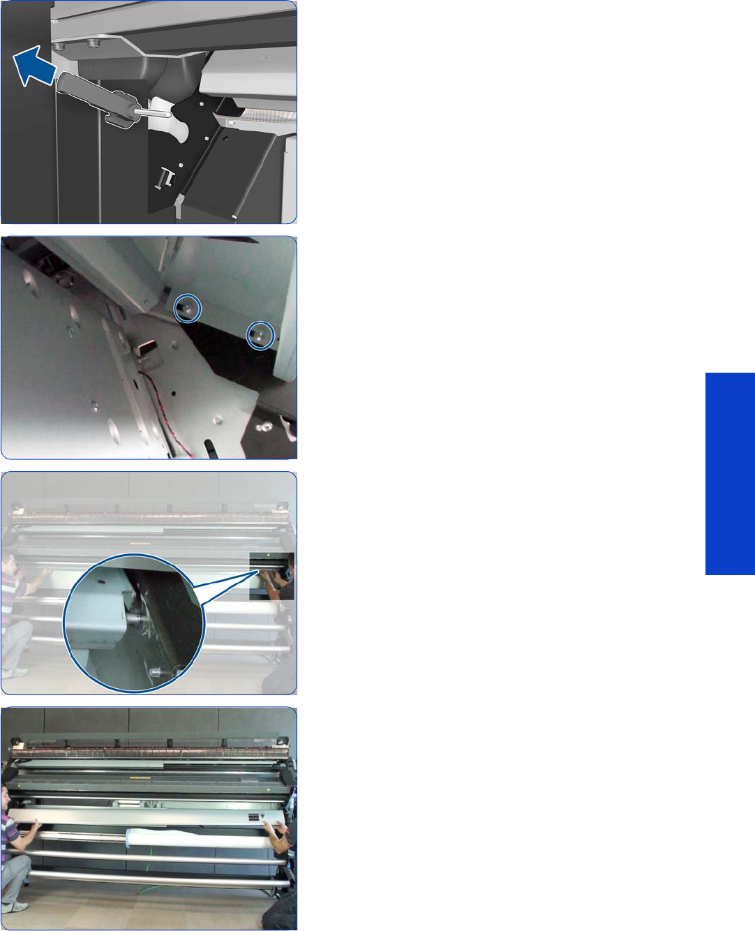
Input Platen 551
Removal & Installation
11. Remove the Left Lever.
12. Remove two T-20 screws.
13. Unhook the right side of the Input Platen.
14 . Remove the Input Platen.
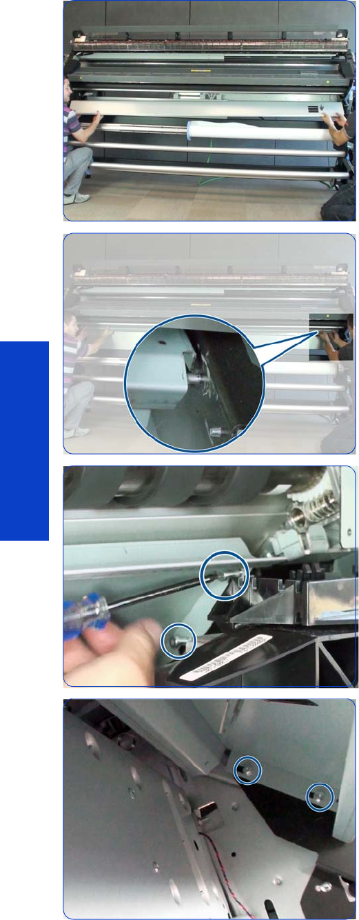
552 Chapter 8 Removal & Installation
Removal & Installation
Installation
1. Insert the Input Platen.
2. Hook it into position on the right.
3. Insert two T-15 screws on the left, and tighten them.
These are locating screws and allow the platen to
move.
4. Insert only the inner T-20 screw on the right. Tighten the
screw until the Platen is pressing against the right side.
Loosen it to allow some sliding movement in the Platen
but without separating it from the right side.
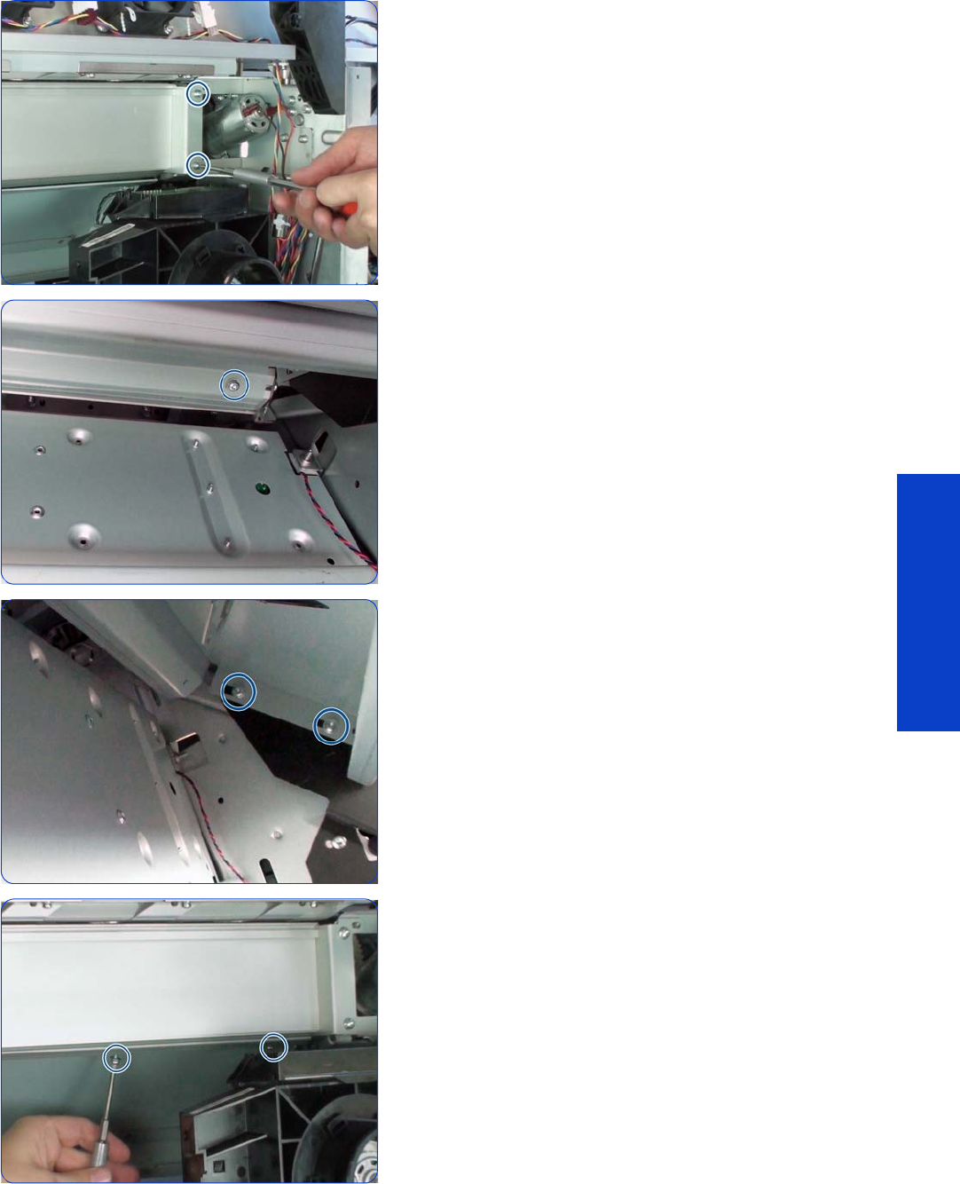
Input Platen 553
Removal & Installation
5. Assemble the Media Input Profile and Mylar and
tighten it into position. Perform the gap check as
described for Media Input Profile installation.
6. With the small freedom in the Media Input Platen,
move it until the platen and the profile are correctly
adjusted. Tighten the rightmost screw between Input
Platen and Media Input Profile. Be careful not to strip
the screw thread.
7. Insert the outer T-20 screw on the right, and tighten
both of them.
8. From right to left, insert and tighten the rest of the
screws between Input Platen and Media Input Profile.
Adjust the Input Platen in position against the Media
Input Profile before inserting every screw. Be careful not
to strip the screw threads.
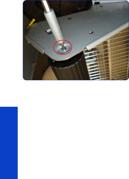
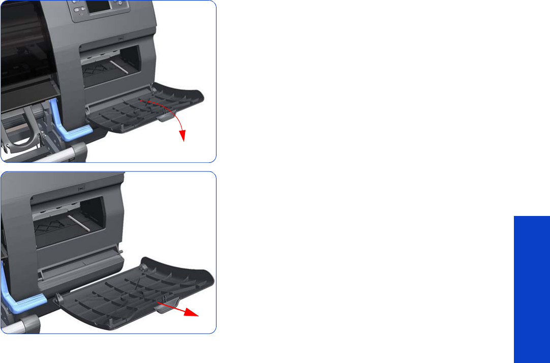
Printhead Cleaning Cartridge Door 555
Removal & Installation
Printhead Cleaning Cartridge Door
Removal
1. Open the Printhead Cleaning Cartridge Door.
2. Unclip and remove the Printhead Cleaning Cartridge
Door from Right Cover.
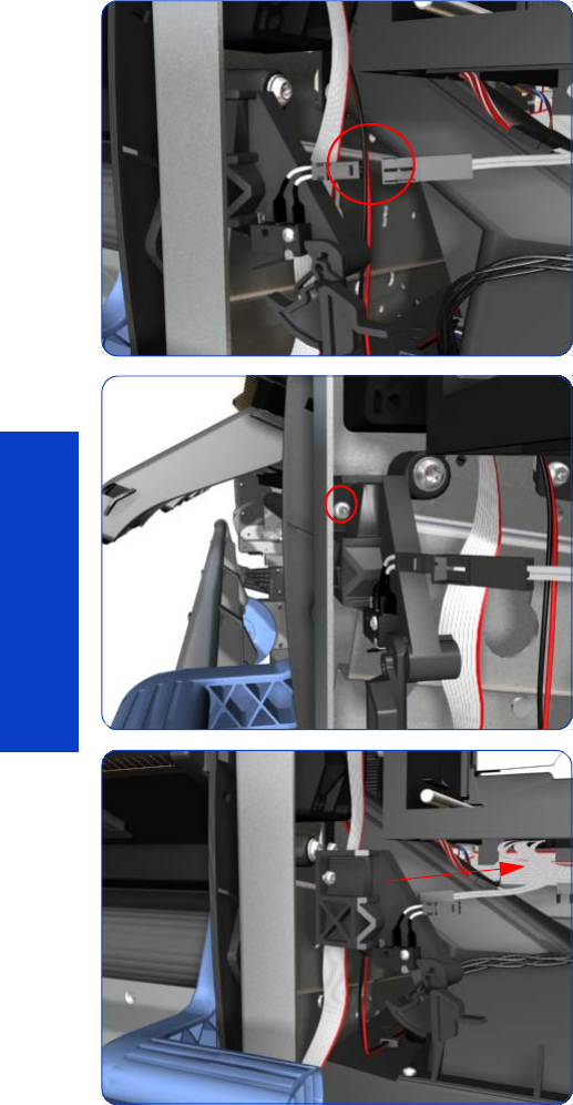
556 Chapter 8 Removal & Installation
Removal & Installation
Printhead Cleaning Cartridge Door Sensor
Removal
1. Remove the Right Cover
page 296
.
2. Disconnect the Printhead Cleaning Cartridge Door
Sensor cable.
3. Release one T-10 screw the attaches the Printhead
Cleaning Cartridge Door Sensor assembly to the
printer.
4. Remove the Printhead Cleaning Cartridge Door Sensor
assembly from the printer.
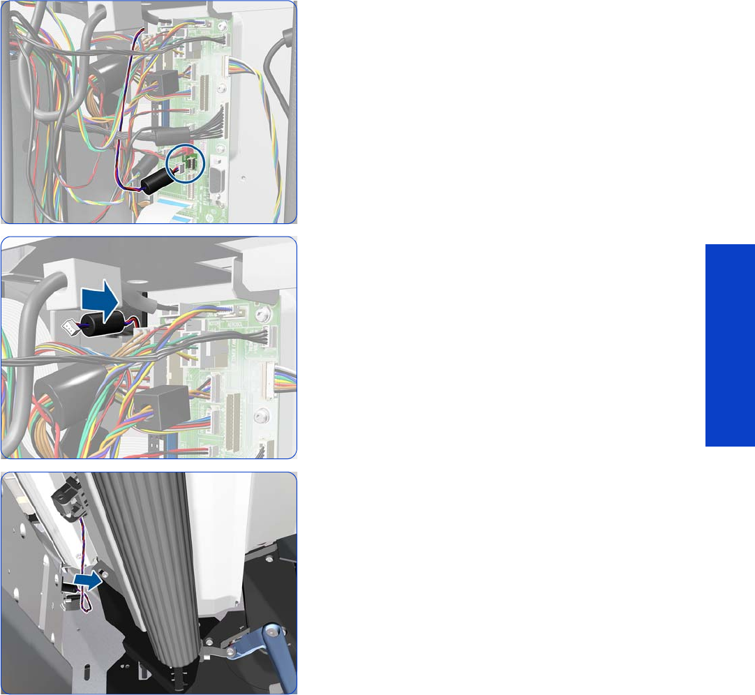
Media Sensor 557
Removal & Installation
Media Sensor
Removal
1. Remove the Right Cover
page 296
.
2. Remove the Right Connector Cover
page 318.
3. Disconnect the Media Sensor cable from the
Interconnect PCA.
4. Pass the Media Sensor Cable and ferrite through the
hole.
5. Take the Media Sensor Cable and ferrite from the front
of the printer and leave it hanging from the Sensor.
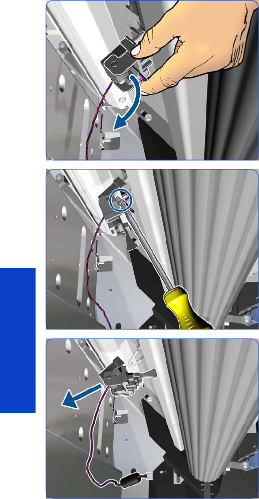
558 Chapter 8 Removal & Installation
Removal & Installation
6. Rotate the Media Sensor Cover.
7. Remove a T-10 screw.
8. Remove the Media Sensor and cable.
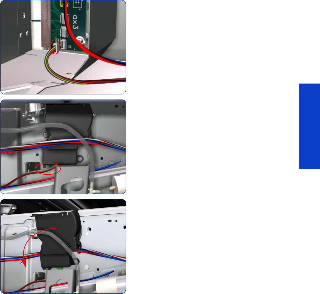
Encoder Disc and Sensor 559
Removal & Installation
Encoder Disc and Sensor
Removal
1. Remove the Left Cover
page 303
.
2. Remove the Electronics Enclosure Extension Cover
page 329.
3. Remove the Ink Supply Station page 394.
4. Disconnect the Encoder Sensor cable from the
PrintMech PCA, and unroute it along its whole length.
5. Release the Encoder Sensor cable from the clip located
on the Encoder Disc Cover.
6. Unclip the Encoder Disc Cover and remove from the
printer.
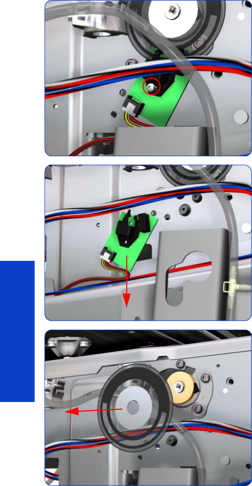
560 Chapter 8 Removal & Installation
Removal & Installation
7. Remove one T-8 screw that secures the Encoder Sensor
to the Chassis.
8. Remove the Encoder Sensor from the printer.
9. Carefully peel the Encoder Disc from the Drive Roller.
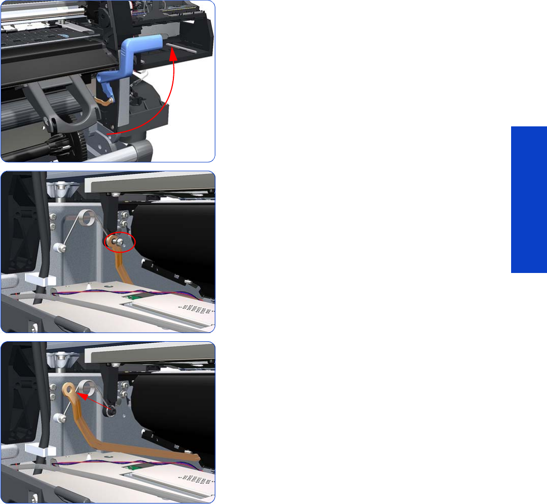
Media Lever Linkage 561
Removal & Installation
Media Lever Linkage
See also Right Trim, Media Lever, and Media Lever Sensor
page 299
.
Removal
1. Remove the Right Cover
page 296
.
2. Remove the Electronics Enclosure Extension Cover
page 329
.
3. Remove the Rear Upper Cover
page 312.
4. Raise the Media Lever.
5. Remove one T-15 screw that secures the Linkage to the
Spring.
6. Remove the Linkage from the Spring.
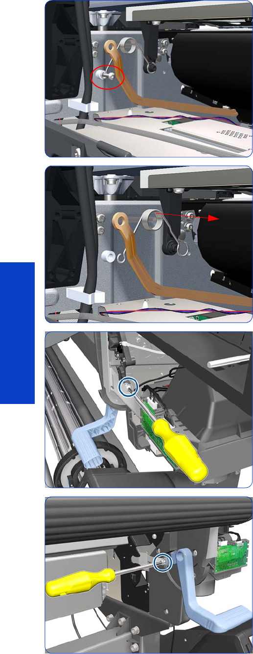
562 Chapter 8 Removal & Installation
Removal & Installation
7. Remove one T-20 screw that secures the Spring to the
Spacer.
8. Remove the Spring and plastic washer.
9. Remove a T-20 screw that secures the Media Lever.
10. Remove a T-15 screw that secures the Media Lever.
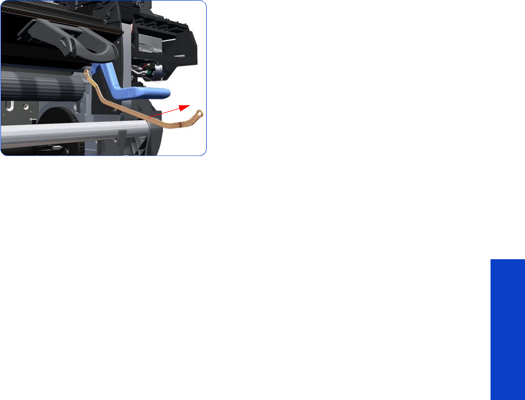
Media Lever Linkage 563
Removal & Installation
11. Remove the Media Lever Linkage from the printer.
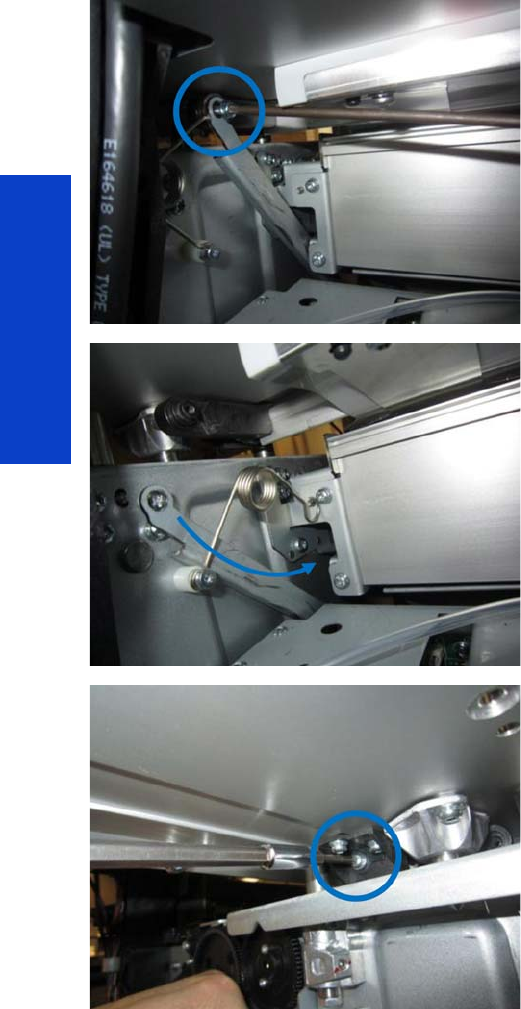
564 Chapter 8 Removal & Installation
Removal & Installation
Pinchwheel Cam Arm
Removal
1. Remove the Right Cover
page 296
.
2. Remove the Left Cover
page 303
.
3. Remove the Electronics Enclosure Extension Cover
page 329
.
4. Remove the Rear Upper Cover
page 312.
5. Remove the Right Connector Cover
page 318.
6. Remove the Service Station
page 351.
7. Remove the screw that joins the Cam Arm, the bi-stable
spring, and the linkage.
8. Lift the blue lever to lower the linkage.
9. Remove the screw that joins the Cam Axial Stopper and
the Cam Arm.
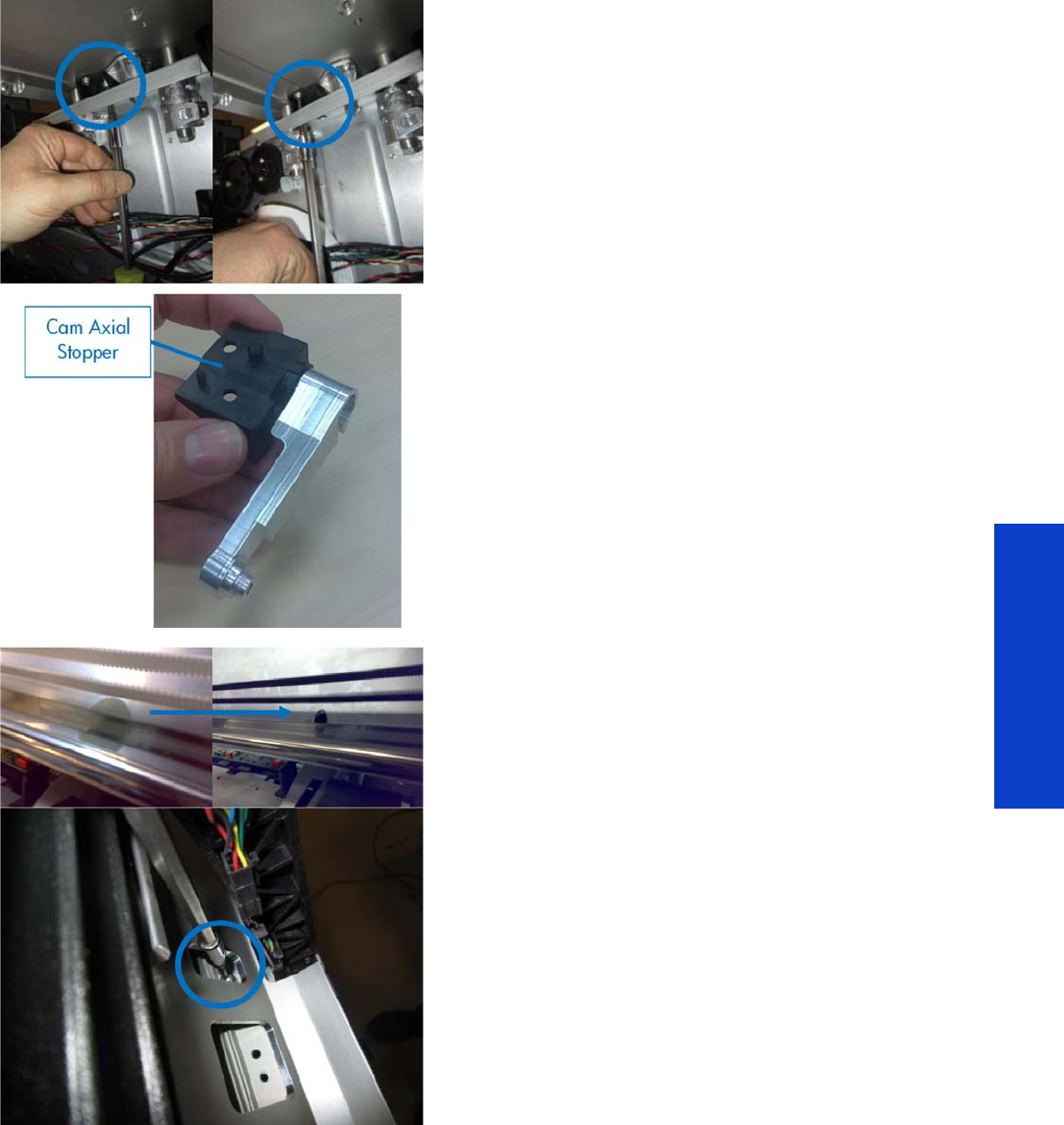
Pinchwheel Cam Arm 565
Removal & Installation
10. tRemove the two screws that join the Cam Axial
Stopper to the Scan Beam.
11. At the front of the printer, remove the two labels that
close the screw holes of the Scan Beam.
IMPORTANT: Keep the labels to replace them later:
they are important to maintain the pressure in the Scan
Beam for drying the print.
Remove the four T-20 screws that hold the Scan Beam,
through the Scan Beam openings.
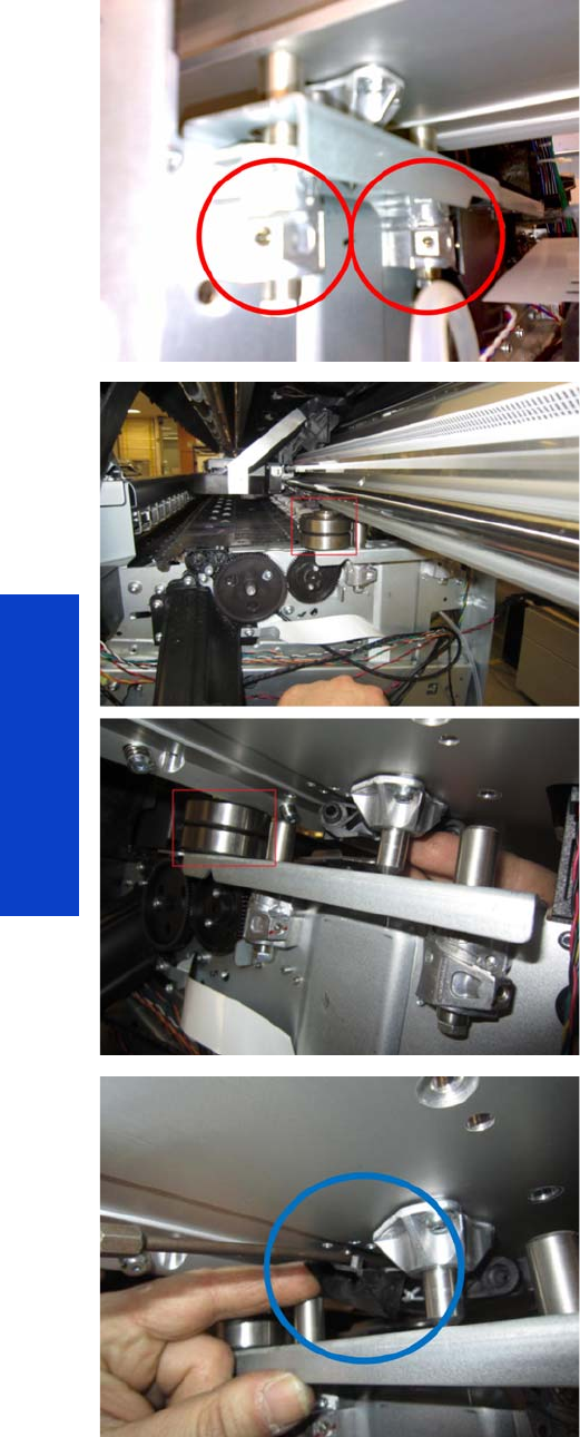
566 Chapter 8 Removal & Installation
Removal & Installation
12. IMPORTANT: Do not touch the highlighted screws
(two on each side).
These screws maintain the printhead-to-paper-spacing
calibration.
13. Lift the Scan Beam on the right-hand side and hold it in
position using a 1.2 in (3 cm) spacer.
14 . Remove the Cam Axial Stopper with the help of a flat
screwdriver.
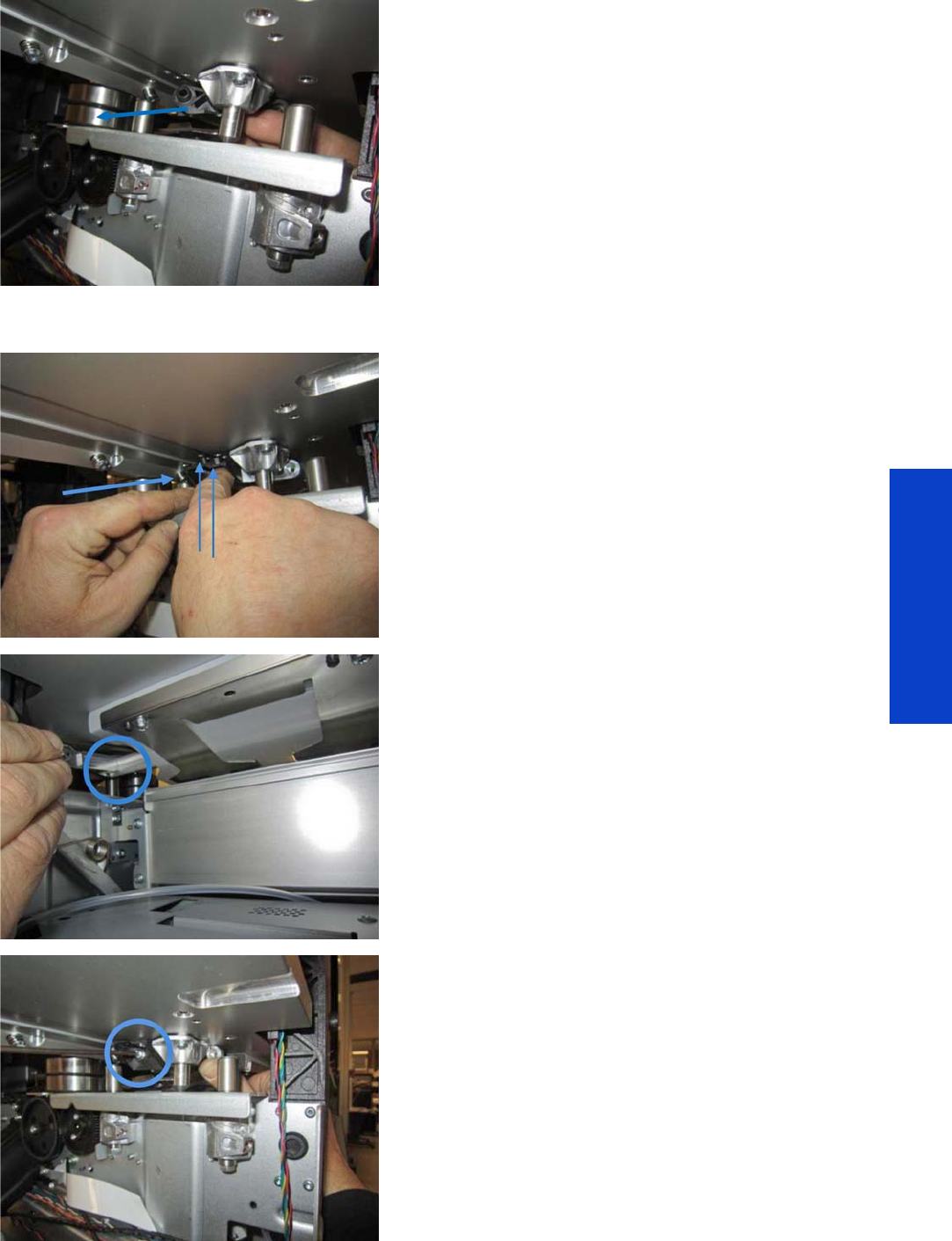
Pinchwheel Cam Arm 567
Removal & Installation
15. Pull out the Cam Arm.
Installation
1. Fit the Cam Axial Stopper into the Scan Beam (2 pins
indicated by arrows in the illustration).
2. Make sure the Cam Arm is well attached to the
Pinchwheel Cam. The circle shows the location of the
attachment.
3. Insert the T-20 screw that joins the Cam Axial Stopper
to the Cam Arm.
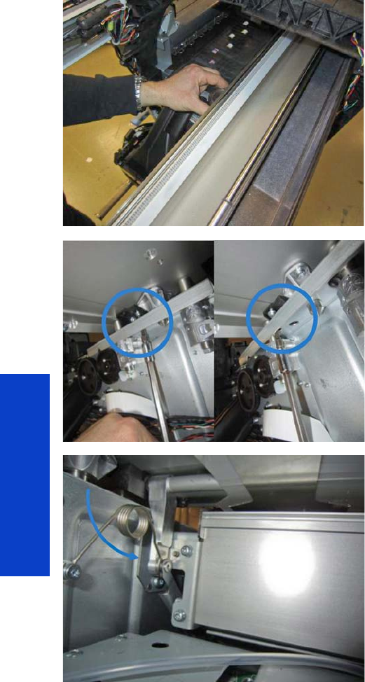
568 Chapter 8 Removal & Installation
Removal & Installation
4. Remove the spacer and lower the Scan Beam.
Then install the four T-20 screws that hold the Scan
Beam.
5. Install the two T-20 screws that join the Cam Axial
Stopper to the Scan Beam.
6. Lower the Cam Arm (lift the Pinchwheels) and attach it
to the bi-stable spring and the linkage.
NOTE: If the metal Cam Arm has never been installed
before, the screw will need to blaze the thread in it.
7. Reassemble the remaining parts.
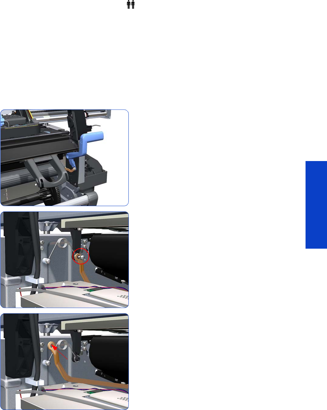
Pinchwheel Assembly 569
Removal & Installation
Pinchwheel Assembly
Removal (requires two people)
1. Remove the Right Cover
page 296
.
2. Remove the Power Box Cover
page 321
.
3. Remove the Electronics Enclosure Extension Cover
page 329
.
4. Remove the Rear Upper Cover
page 312.
5. Remove the Service Station
page 351.
6. Remove the Media Input Profile
page 544.
7. Raise the Media Lever.
8. Remove one T-20 screw that secures the Linkage to the
Spring.
9. Disconnect the linkage from the Pinchwheel cam-arm.
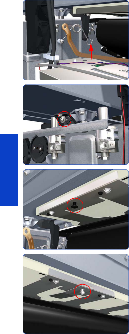
570 Chapter 8 Removal & Installation
Removal & Installation
10. Disconnect the spring from the Pinchwheel cam-arm.
11. Remove one T-20 screw that secures the Cam to the
Cam Lever.
12. Insert a plastic stud in to each Pinchwheel Subassembly
(the Plastic Studs can be found in the replacement
Pinchwheel Assembly kit).
13. Remove one T-20 screw that secures the attachment
plate to the center Pinchwheel Subassembly.
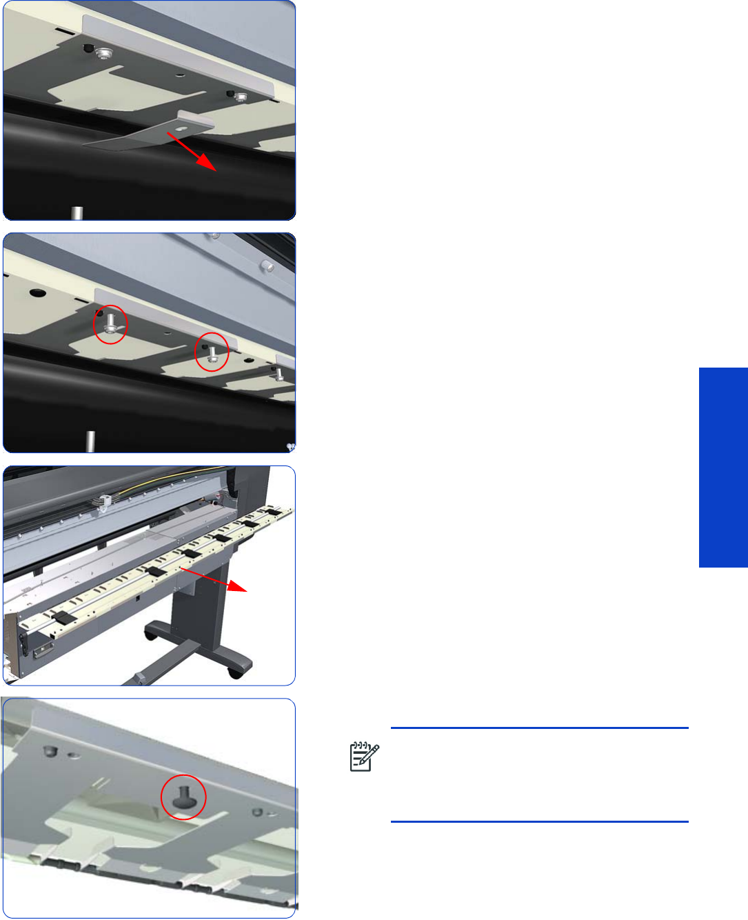
Pinchwheel Assembly 571
Removal & Installation
14 . Remove the attachment plate from the center
Pinchwheel Subassembly.
15. Remove two T-20 screws from each Pinchwheel
Subassembly (a 90 degree angle screwdriver is
included with the replacement Pinchwheel Assembly).
16. Remove the complete Pinchwheel Assembly (including
the Cam and Cam Lever) from the printer.
NOTE: Before installing the NEW Pinchwheel
Assembly, insert the plastic studs in to each
Pinchwheel subassembly. This will make it
easier to install the complete Pinchwheel
Assembly.
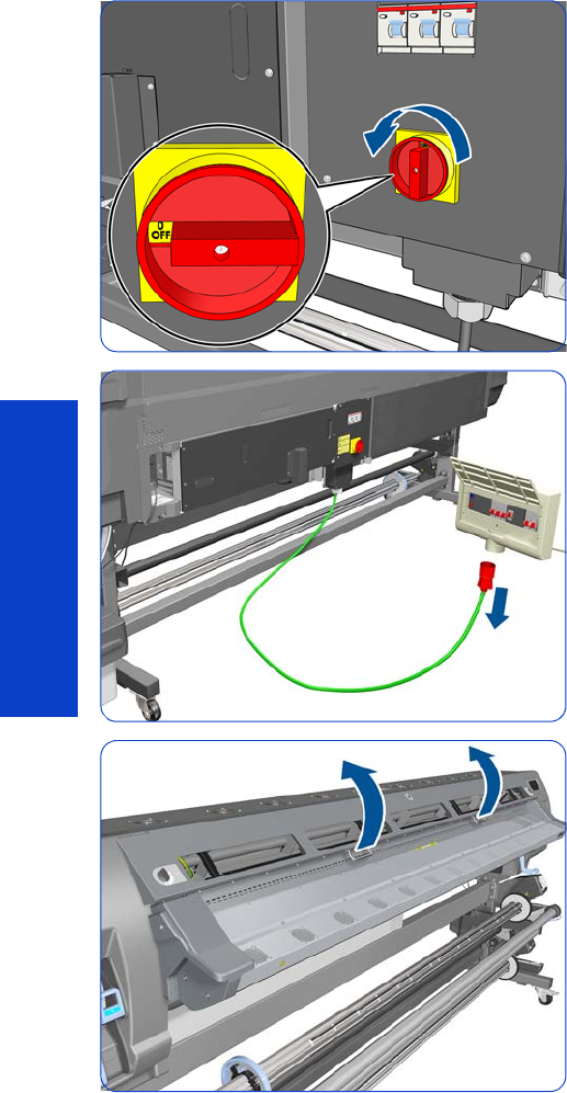
572 Chapter 8 Removal & Installation
Removal & Installation
Individual Pinchwheel Rollers
These are Customer Self-Replaceable (CSR) parts. The User Maintenance Kit provided with the printer
contains spare Pinchwheels and Inter-Pinchwheels.
Removal
1. Turn off the printer.
2. Disconnect electrical power. How this is done depends
on the installation.
3. Open the Window
page 303
.
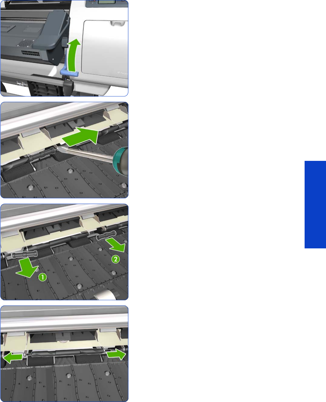
Individual Pinchwheel Rollers 573
Removal & Installation
4. Raise the Media Lever.
5. Going from right to left use a screw driver to push apart
all the pins that secures the Inter-Pinchwheel roller.
6. Remove the two inter-Pinchwheel rollers from both sides
of the Pinchwheel. Remove first the left one (1) and then
the right one(2). You need to go from right to left,
doing this until you reach the individual Pinchwheel
that you need to remove
7. When you have reached the individual Pinchwheel
roller, push apart the metal part that secures the
Pinchwheel roller.
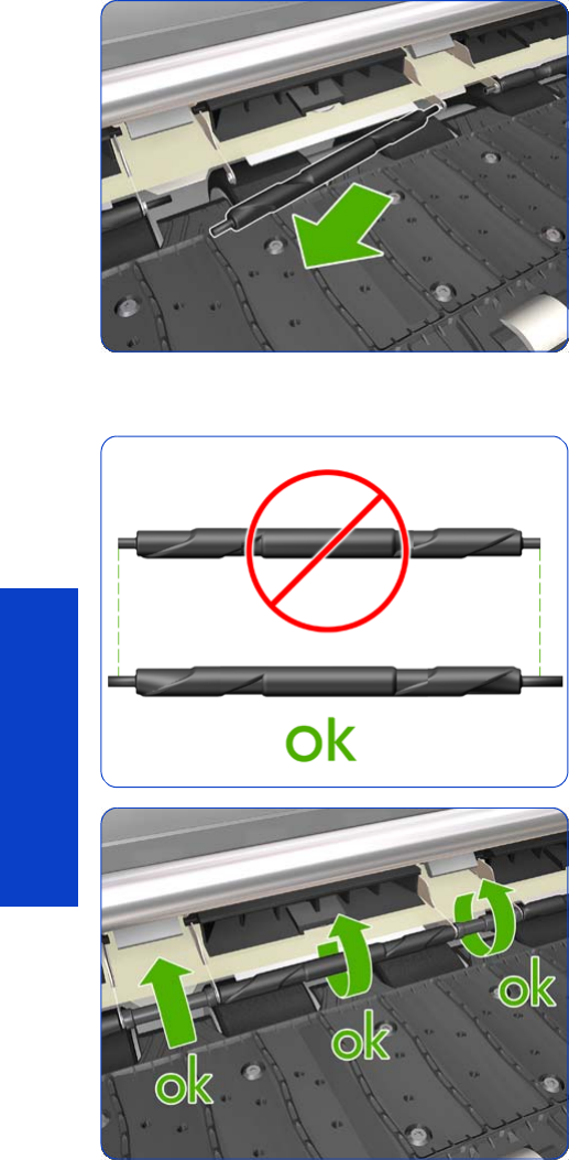
574 Chapter 8 Removal & Installation
Removal & Installation
8. Pull out the individual Pinchwheel roller.
Installation of the Drive Roller
1. When installing the new Pinchwheel rollers, make sure
they are the new type.
2. When the new Pinchwheel roller has been installed,
check that the rollers move freely.
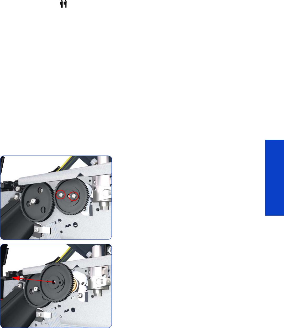
Drive Roller 575
Removal & Installation
Drive Roller
Removal (requires two people)
1. Remove the Right Cover
page 296
.
2. Remove the Left Cover
page 303.
3. Remove the Right Connector Cover
page 318.
4. Remove the Electronics Enclosure Extension Cover
page 329.
5. Remove the Service Station
page 351.
6. Remove the Ink Supply Station
page 394.
7. Remove the Media-Axis Motor
page 430.
8. Remove the Encoder Disc and Sensor
page 559.
9. Remove the Media Lever Linkage
page 561.
10. Remove the Media Sensor
page 557.
11. Remove the Media Input Profile
page 544.
12. Remove the Input Platen
page 550.
13. Remove two T-10 screws that secure the Drive Roller
Gear.
14 . Remove the Drive Roller Gear from the printer.
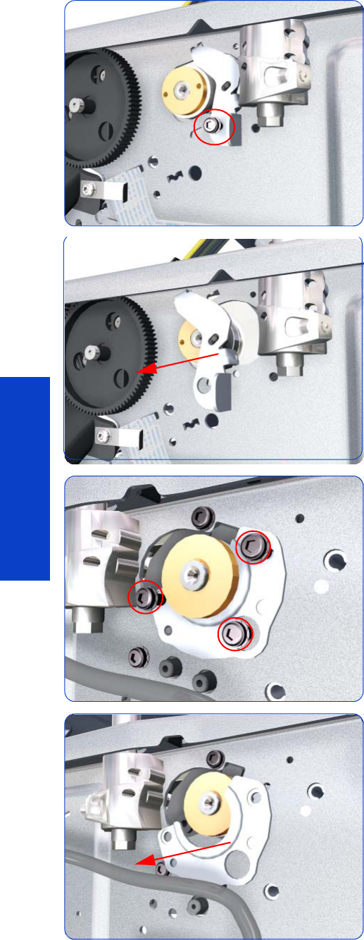
576 Chapter 8 Removal & Installation
Removal & Installation
15. Remove one T-20 screw that secures the cover on the
right hand side of the printer.
16. Remove the Cover.
17. Remove three T-20 screws that secure the cover on the
left hand side of the printer.
18 . Remove the Cover.
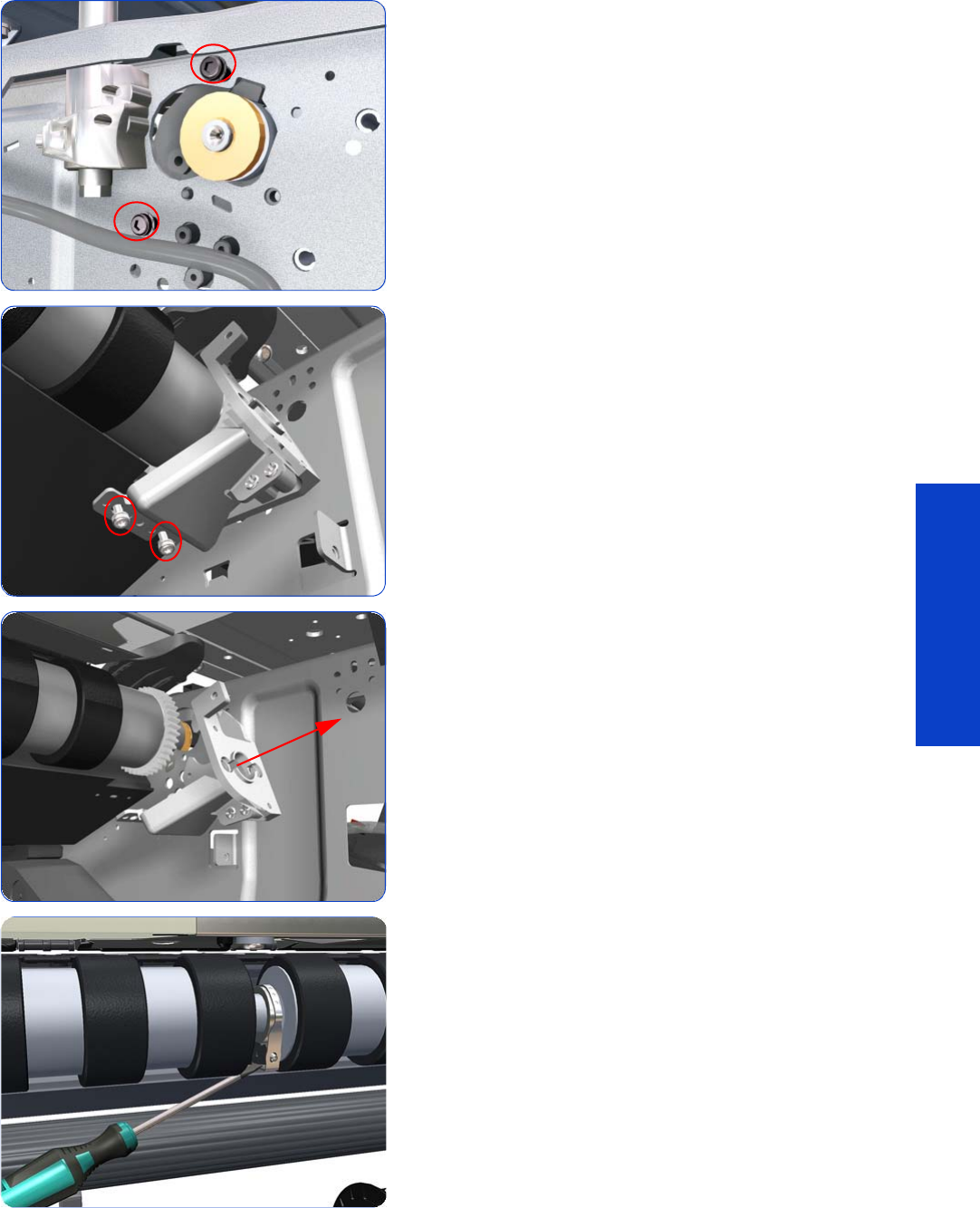
Drive Roller 577
Removal & Installation
19. Remove T-20 screws that secure the Media-Axis Motor
Bracket to the side-plate.
20.Remove two T-20 screws that secure the Media-Axis
Motor Bracket to the Chassis.
21. Remove the Media-Axis Motor Bracket from the printer.
22.Use a flat bladed screwdriver to unclip the Roller
Middle Support Covers.
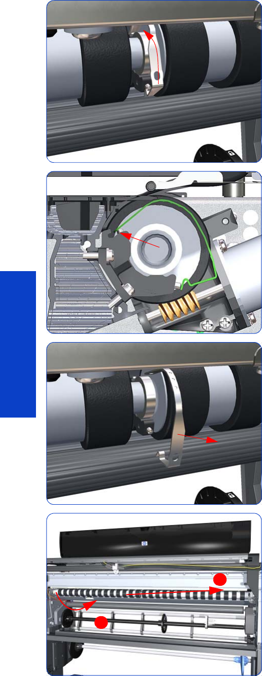
578 Chapter 8 Removal & Installation
Removal & Installation
23.Rotate the Roller Middle Support Cover vertically.
24.Release the Roller Middle Support Cover from its
attachment point.
25.Remove the Roller Middle Support Cover.
26.Remove the Drive Roller by sliding it to the right, then
downwards and then out of the printer.
1
2
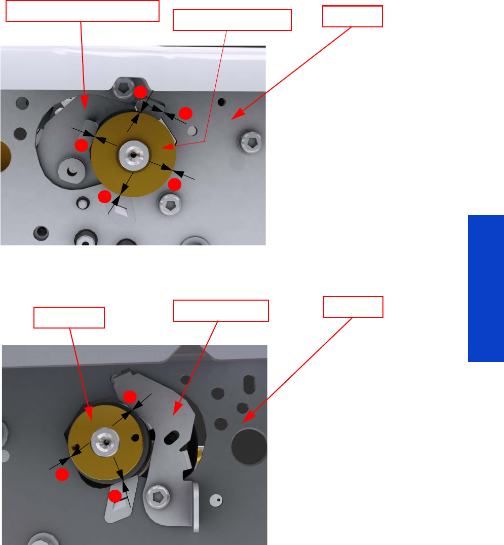
Drive Roller 579
Removal & Installation
Installation of the Drive Roller
When installing the Drive Roller, several different datums have to be met in order to ensure that the Drive Roller has
no axial play. Use the following illustrations to ensure that all the datums are met:
To make sure that all the datums are met when installing the Media-Axis Motor Bracket, make sure you follow these
Left-hand side of the printer
Right-hand side of the printer
Sideplate
Media-Axis Motor Bracket Drive Roller Bearing
1
1
2
3
3
1. Datum between Media-Axis
Motor Bracket and Drive
Roller Bearing
2. Datum between Media-Axis
Motor Bracket and Sideplate
3. Datum between Drive Roller
Bearing and Sideplate
Sideplate
Drive Roller Radial Retainer
2
2
1
1. Datum between Drive
Roller and Radial Retainer
2. Datum between Drive
Roller and Sideplate
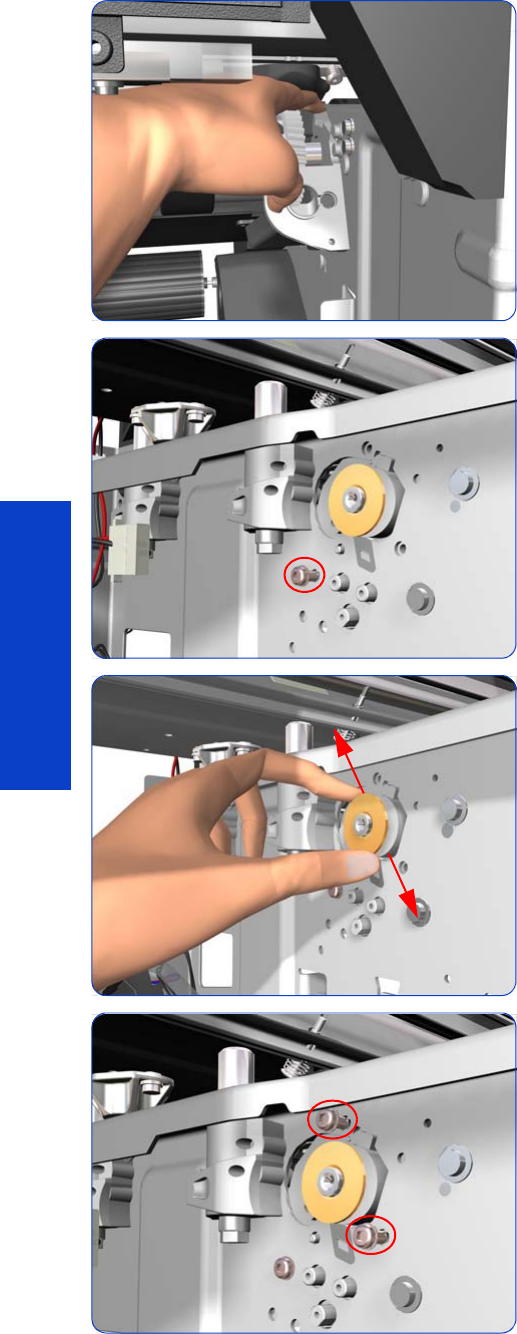
580 Chapter 8 Removal & Installation
Removal & Installation
instructions:
1. Place the Media-Axis Motor Bracket in the correct
position on the printer. Make sure you keep it pushed
down (as shown in the illustration) until the first screw
has been installed and fully tightened.
2. Install the first screw (T-15) in the position shown. Make
sure you tighten the screw fully so that the Media-Axis
Motor Bracket cannot be moved.
3. Check that there is no play (movement) between the
Media-Axis Motor Bracket and the Drive Roller. If there
is play, then check that the screw installed in the
previous step is fully tightened.
4. Install the remaining two screws (T-15) that secure the
Media-Axis Motor Bracket.

Drive Roller 581
Removal & Installation
When reinstalling the parts, make sure you apply the grease (included with the support part) to the gears.
After installing the new Drive Roller, perform Substrate Advance Calibration
Chapter 5
.
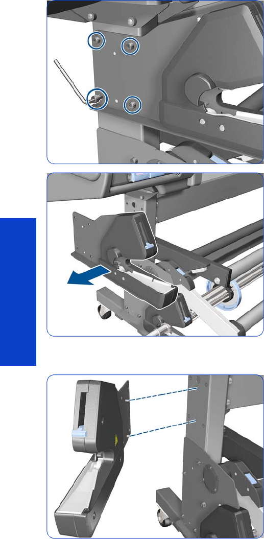
582 Chapter 8 Removal & Installation
Removal & Installation
Rewinder Left-Hand Module
Removal
1. Remove four T-40 screws with an Allen key.
2. Remove the Rewinder Left-Hand Module.
Installation
1. Insert the two pins into the matching holes in the leg.
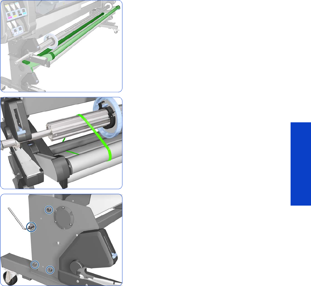
Take-Up Reel Left-Hand Module 583
Removal & Installation
Take-Up Reel Left-Hand Module
Removal
1. Make sure that the Tension Bar is raised.
2. Tie the Take-Up Reel to both sides of the Tension Bar.
3. Remove four T-40 screws with an Allen key.
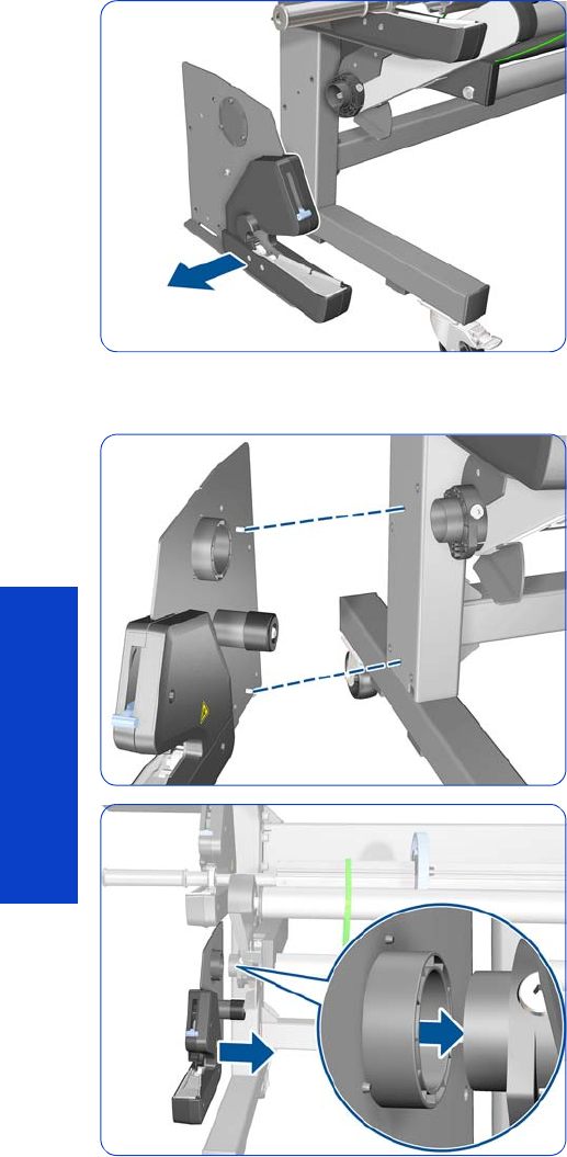
584 Chapter 8 Removal & Installation
Removal & Installation
4. Remove the Take-Up Reel Left-Hand Module.
Installation
1. Align the two pins with the matching holes in the leg.
2. Insert the Take-Up Reel Left-Hand Module carefully.
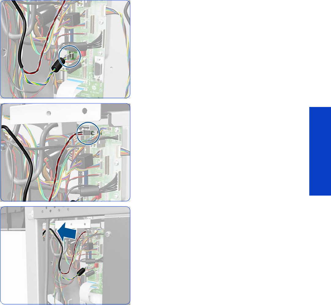
Rewinder Right-Hand Module 585
Removal & Installation
Rewinder Right-Hand Module
Removal
1. Remove the Right Cover
page 296
.
2. Remove the Right Connector Cover
page 318
.
3. Disconnect the Rewinder Encoder connector.
4. Disconnect the Rewinder Motor connector.
5. Pass the cable through the upper hole in the side plate.
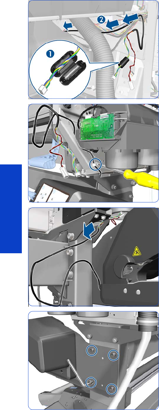
586 Chapter 8 Removal & Installation
Removal & Installation
6. (1) Remove the ferrite from the cable.
(2) Unroute the cable.
7. Remove one T-20 screw.
8. Pass the cable through the hole in the stand.
9. Remove four T-40 screws with an Allen key.
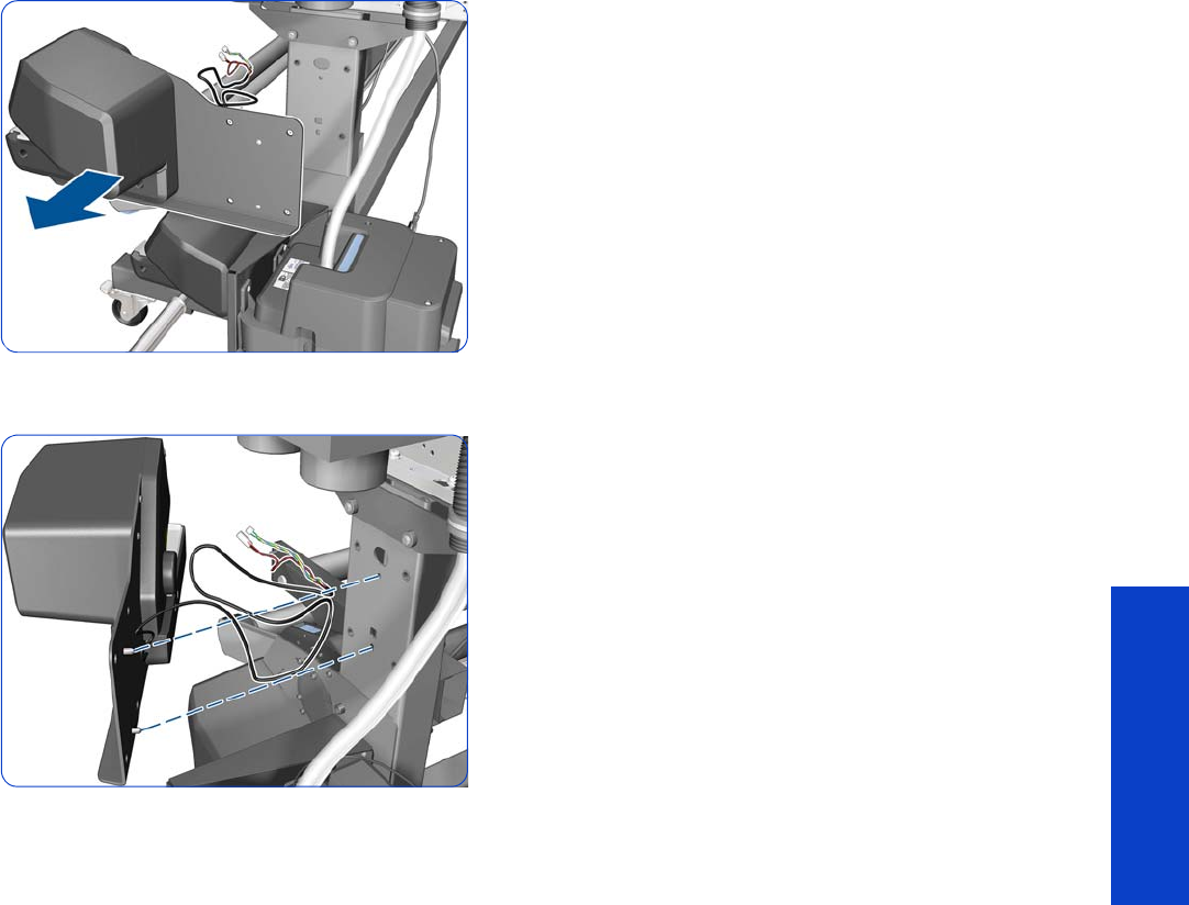
Rewinder Right-Hand Module 587
Removal & Installation
10. Remove the Rewinder Right-Hand Module.
Installation
1. Insert the two pins into the matching holes in the leg.
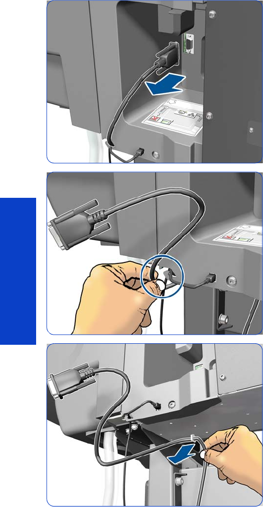
588 Chapter 8 Removal & Installation
Removal & Installation
Take-Up Reel Right-Hand Module
Removal
1. Remove the Take-Up Reel Sensor Module
page 599
.
2. Disconnect the Take-Up Reel Connector.
3. Unroute the Take-Up Reel cable from the Right
Connector Cover.
4. Release the Take-Up Reel cable from the clamp
underneath the E-Box.
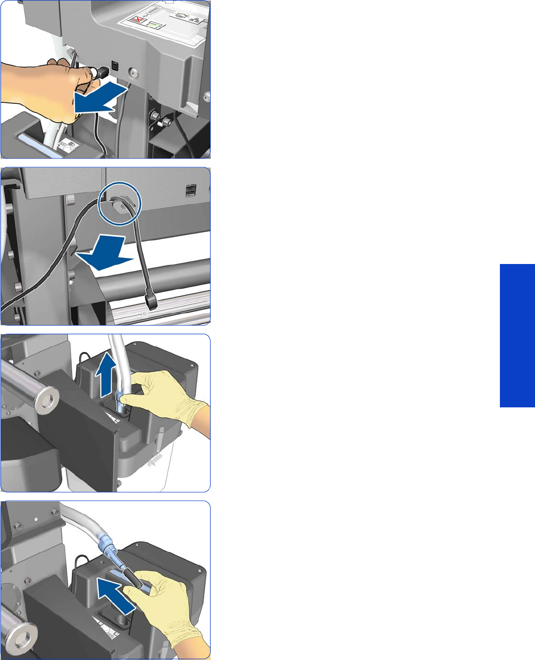
Take-Up Reel Right-Hand Module 589
Removal & Installation
5. Disconnect the Waste Ink System cable.
6. Disengage the Waste Ink System cable from the clip.
7. Pull the bottom of the Ink Tube Assembly out of the
Printhead Cleaning Container. You are recommended
to wear gloves.
8. Cover the end of the Ink Tube with the spare cap from
the Ink Maintenance Kit, to prevent ink from falling out
of the tube.
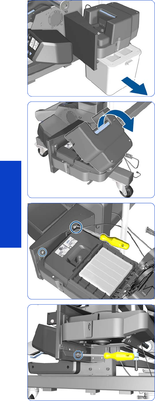
590 Chapter 8 Removal & Installation
Removal & Installation
9. Remove the Printhead Cleaning Container.
10. Open the Aerosol Filter cover.
11. Remove two T-25 screws.
12. Remove a T-25 screw.
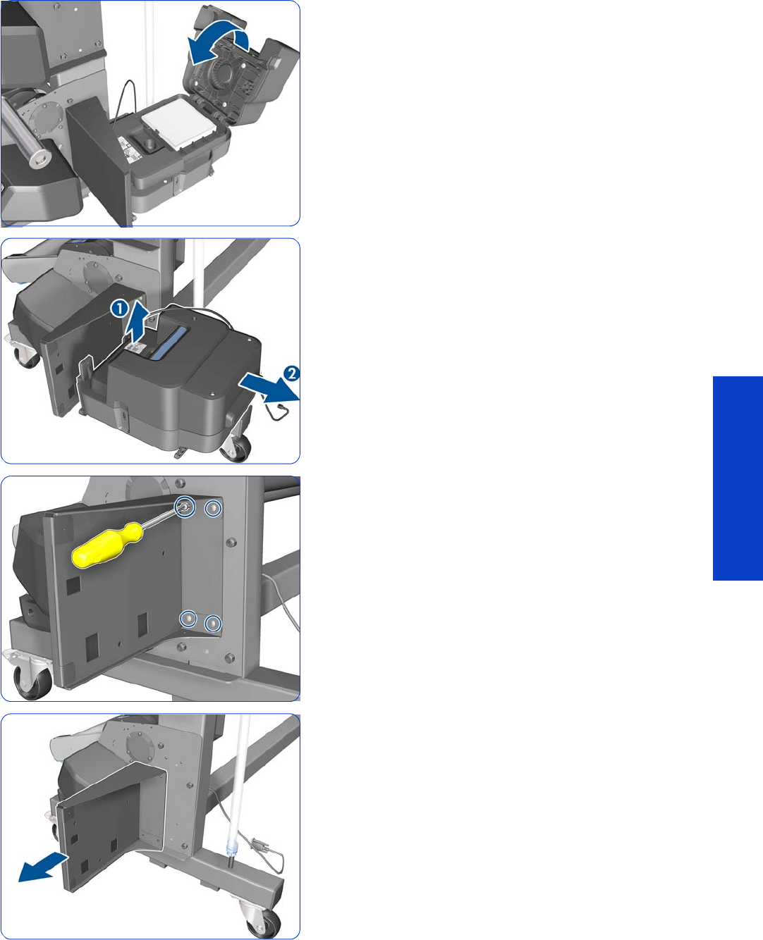
Take-Up Reel Right-Hand Module 591
Removal & Installation
13. Close the Aerosol Filter cover.
14 . Lift and then pull the Aerosol Filter enclosure to remove
it from the printer.
15. Remove four T-25 screws.
16. Remove the support.
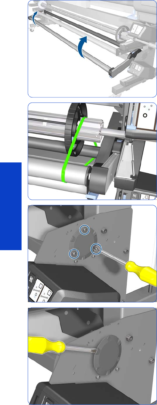
592 Chapter 8 Removal & Installation
Removal & Installation
17. Raise the Tension Bar.
18 . Tie the Tension Bar to the Take-Up Reel.
19. Remove three T-20 screws.
20.Slide out the end cap using a flat-bladed screwdriver.
Three slots are provided in which to introduce the
screwdriver. Be careful not to scratch the Take-Up-Reel
Right Bracket.
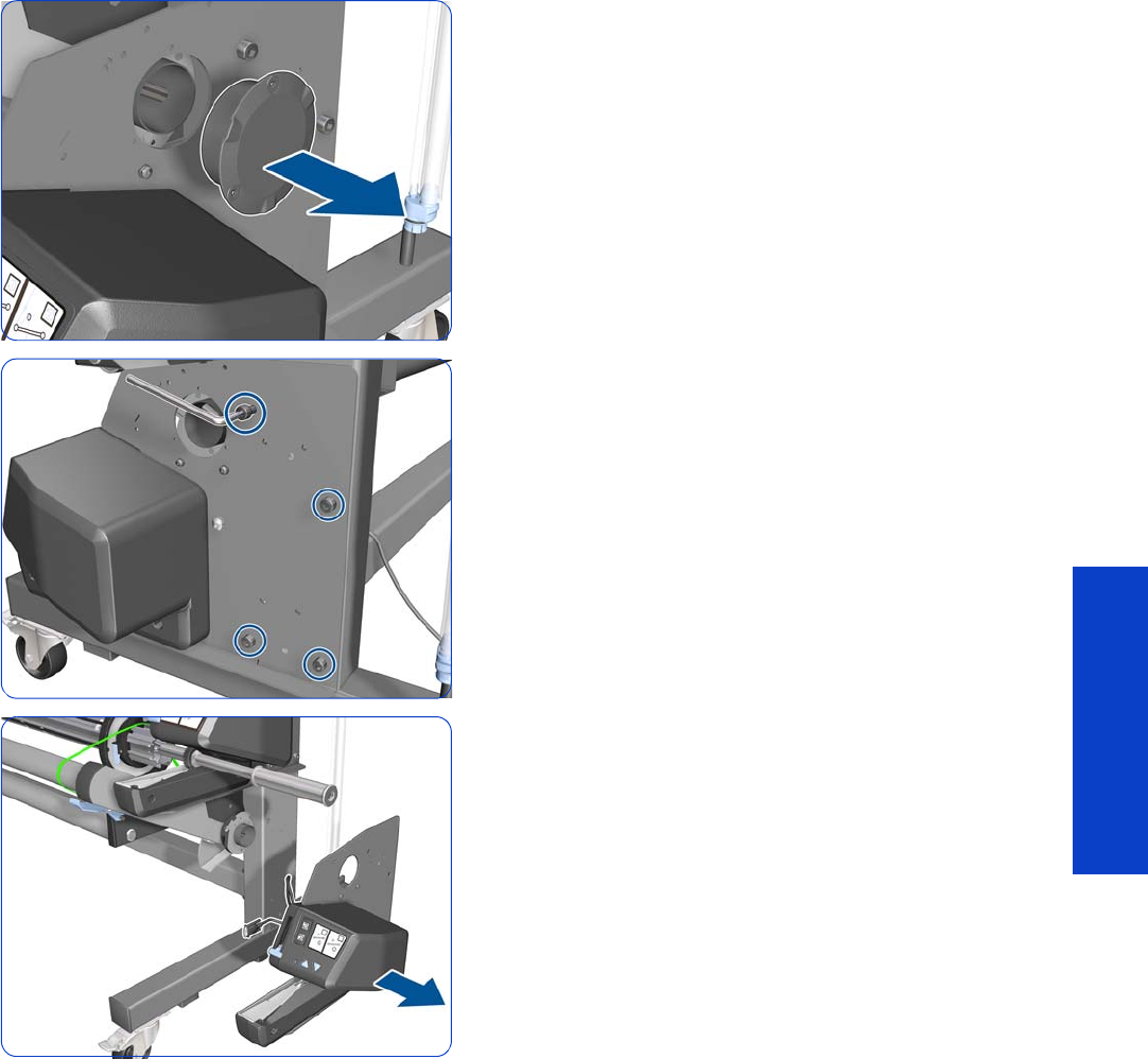
Take-Up Reel Right-Hand Module 593
Removal & Installation
21. Remove the end cap.
22.Remove four T-40 screws with an Allen key.
23.Remove the Take-Up Reel Right-Hand Module.
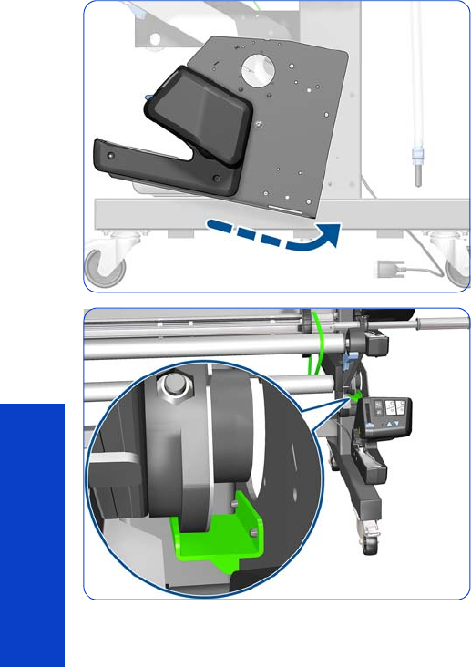
594 Chapter 8 Removal & Installation
Removal & Installation
Installation
1. Rotate the Take-Up Reel Right-Hand Module slightly,
then insert the two pins on the module into the right leg
of the stand.
2. Make sure that the Tension Bar Arm Rear Bushing is
over the Axial Stop (indicated in green).
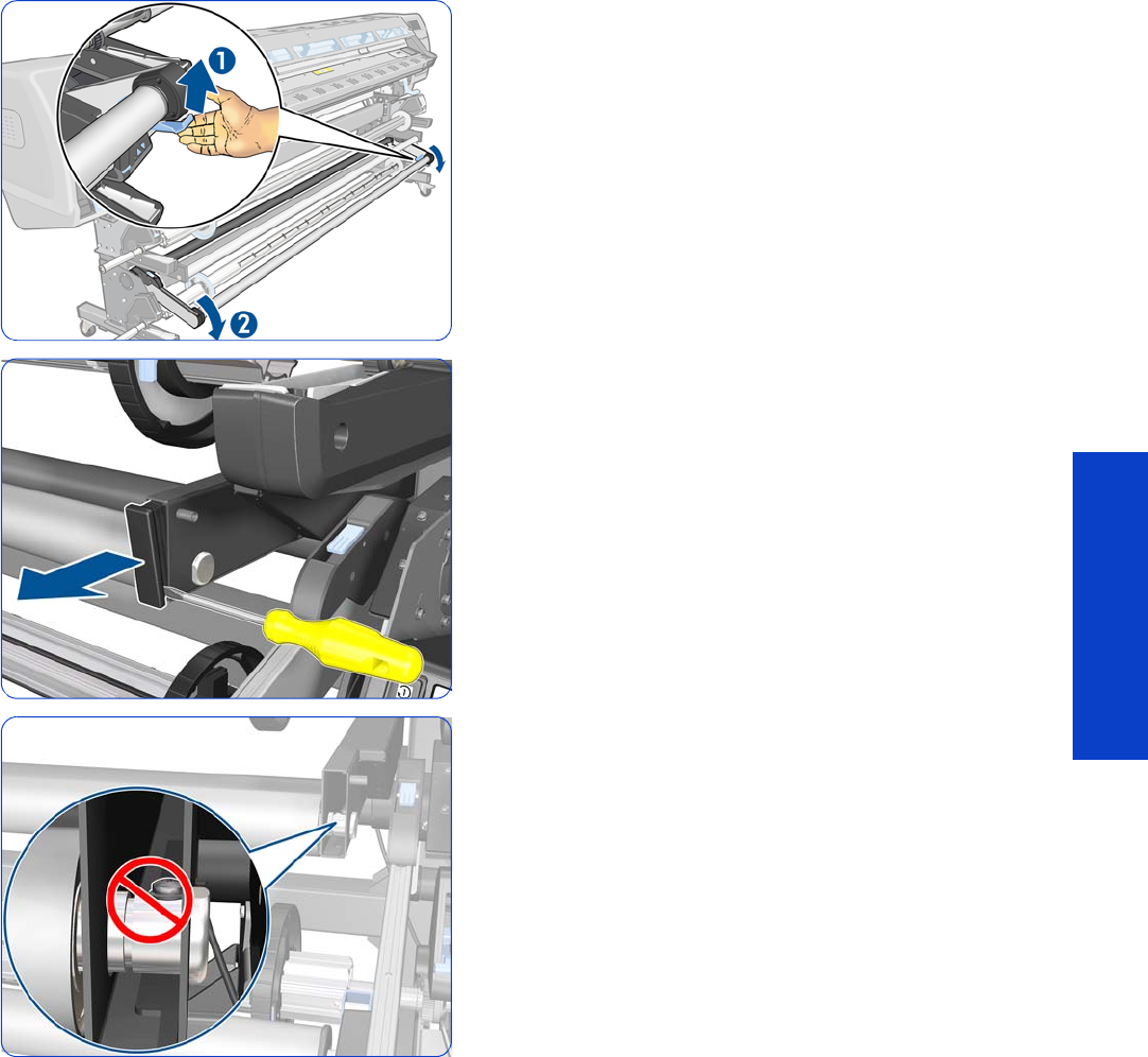
Take-Up Reel Diverter 595
Removal & Installation
Take-Up Reel Diverter
Removal
1. Lift the blue lever to lower the Tension Bar.
2. Remove the plastic cap using a flat-bladed screwdriver.
3. If the screw is positioned so that you can’t remove it (as
shown), then follow the next step.
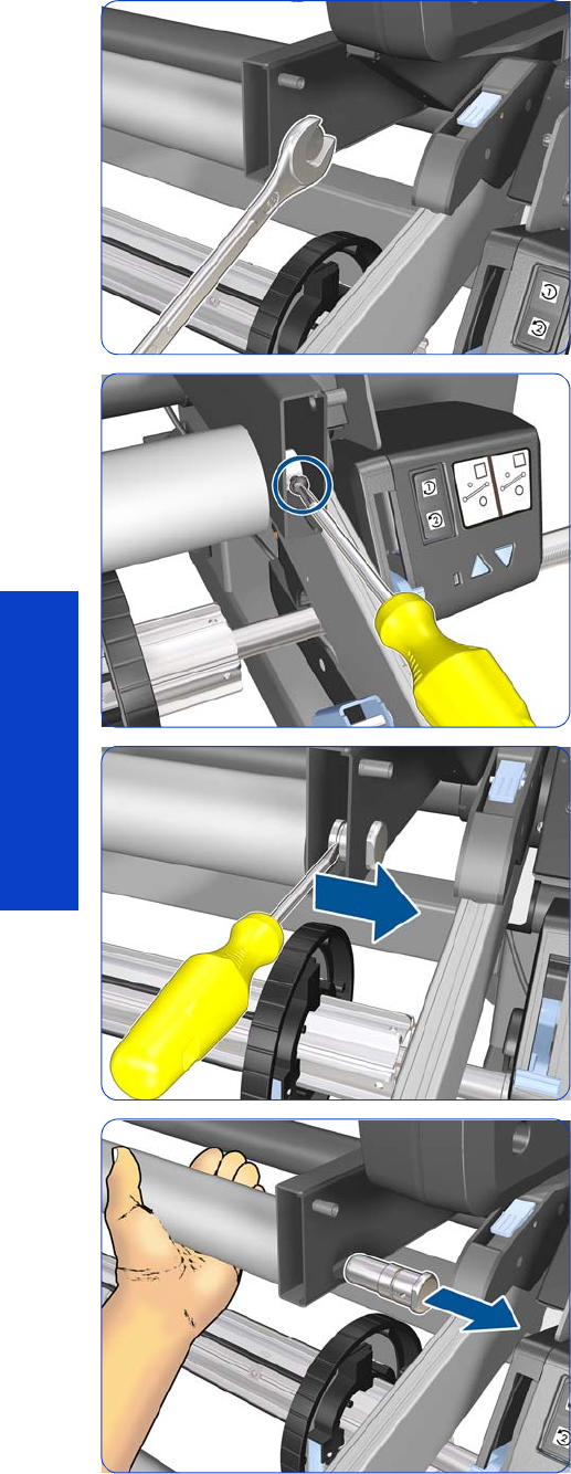
596 Chapter 8 Removal & Installation
Removal & Installation
4. If necessary, use a spanner to rotate the bolt until you
can reach the screw with a screwdriver.
5. Remove the T-20 screw using a Phillips screwdriver.
6. Slide out the bolt using a flat-bladed screwdriver.
7. Hold the Diverter with one hand while removing the
bolt.
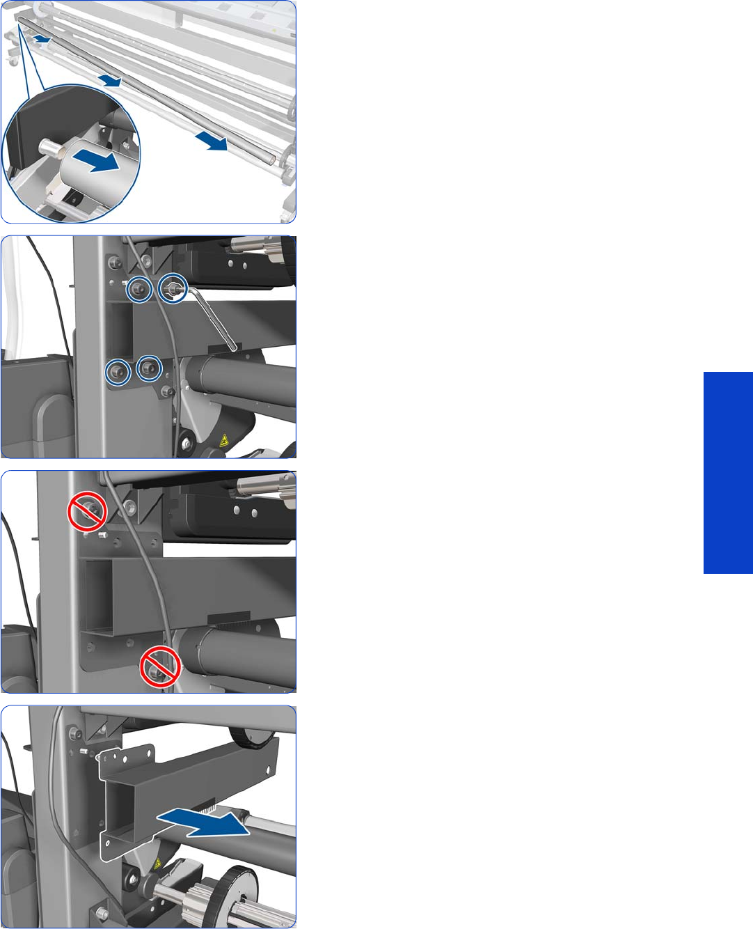
Take-Up Reel Diverter 597
Removal & Installation
8. Move the Diverter to the right to disengage the left-
hand end, then remove the Diverter.
9. Remove four T-40 screws with an Allen key.
10. IMPORTANT: Never remove the screws indicated
here: they have to be calibrated in the factory.
11. Remove the Inner Right Arm. Then follow the same
process to remove the Inner Left Arm.
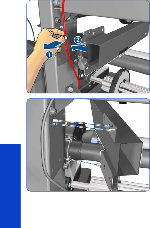
598 Chapter 8 Removal & Installation
Removal & Installation
Installation
1. (1) Move the cable out of the way.
(2) Fit the Inner Right Arm to the printer leg.
2. Fit the Inner Right Arm to the printer leg so that the
three pins go into the matching holes.
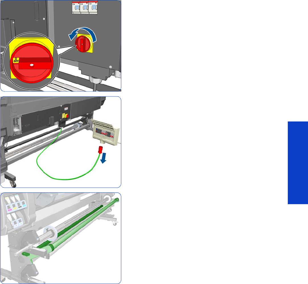
Take-Up Reel Sensor Module 599
Removal & Installation
Take-Up Reel Sensor Module
Removal
1. Turn off the printer.
2. Disconnect electrical power. How this is done depends
on the installation.
3. Make sure that the Tension Bar is in the upper position.
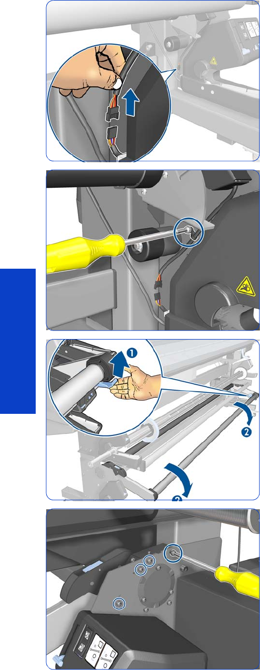
600 Chapter 8 Removal & Installation
Removal & Installation
4. Disconnect the Tension Bar Sensors.
5. Remove one T-20 screw.
6. Lift the blue lever to lower the Tension Bar.
.7. Remove four T-20 screws.
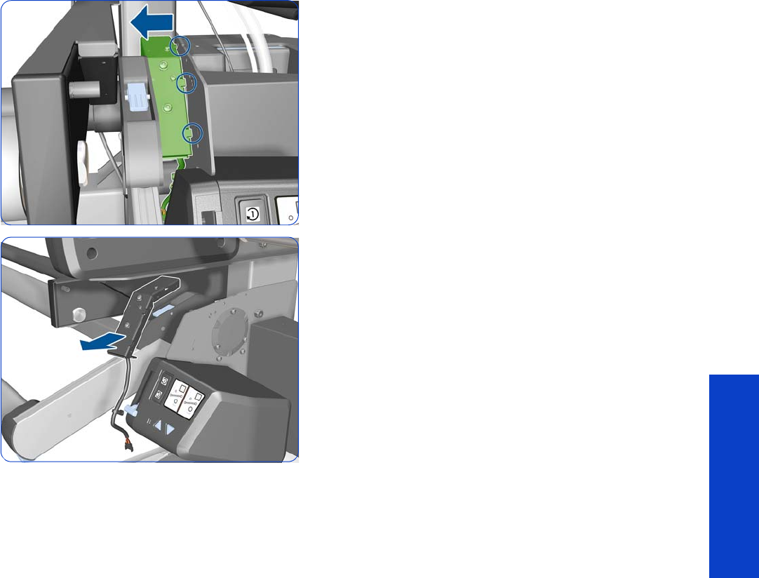
Take-Up Reel Sensor Module 601
Removal & Installation
8. Move the Sensor Support to the left to disengage it
from the printer.
9. Remove the Sensor Support.
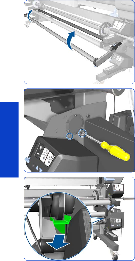
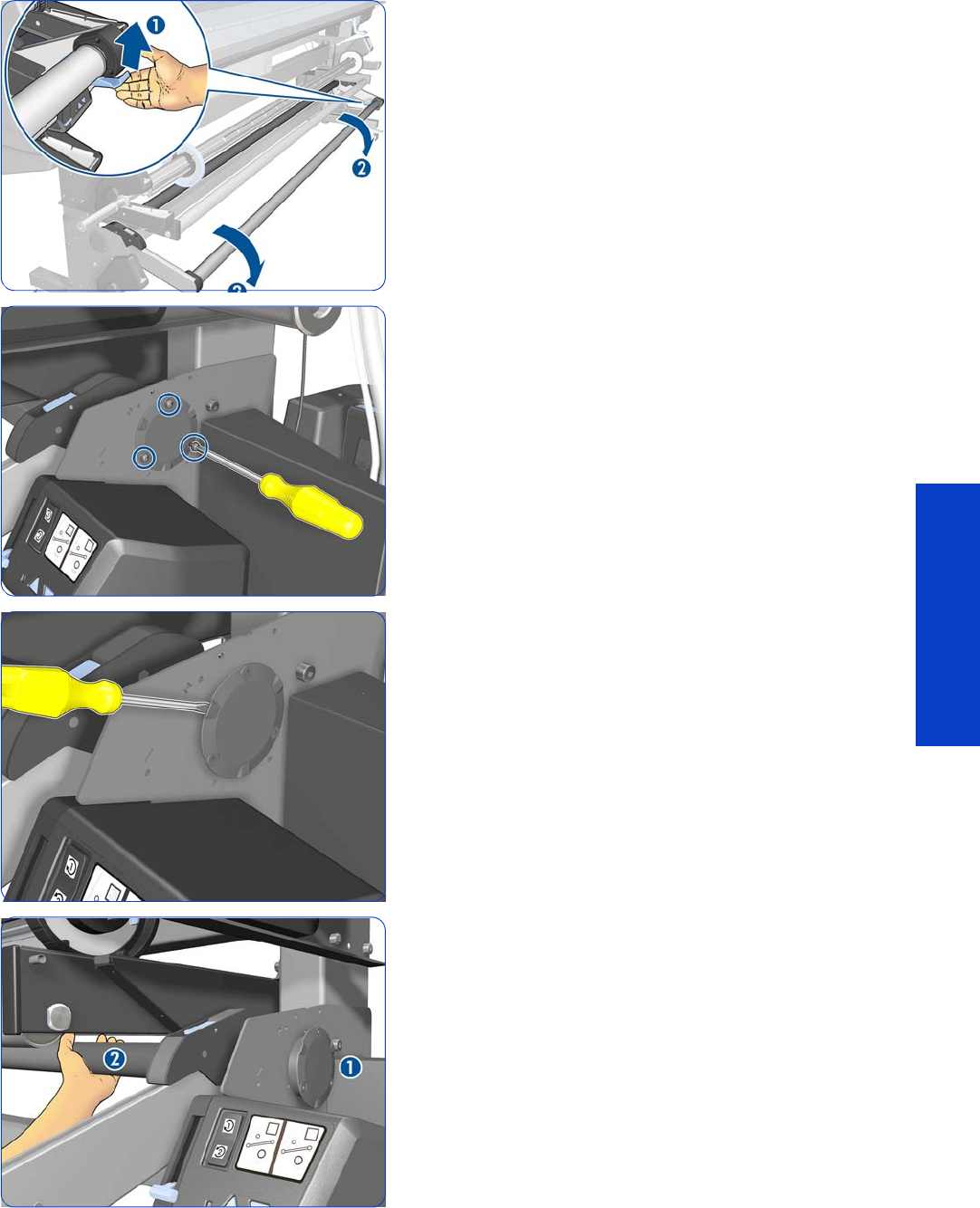
Tension Bar 603
Removal & Installation
5. Lift the blue lever to lower the Tension Bar.
6. Remove three T-20 screws.
7. Slide out the end cap only slightly (do not remove it),
using a flat-bladed screwdriver. Three slots are
provided in which to introduce the screwdriver. Be
careful not to scratch the Take-Up-Reel Right Bracket.
8. The end cap (1) should still be in place. Hold the
Tension Bar with your left hand (2) so that it will not fall
down when you remove the end cap.
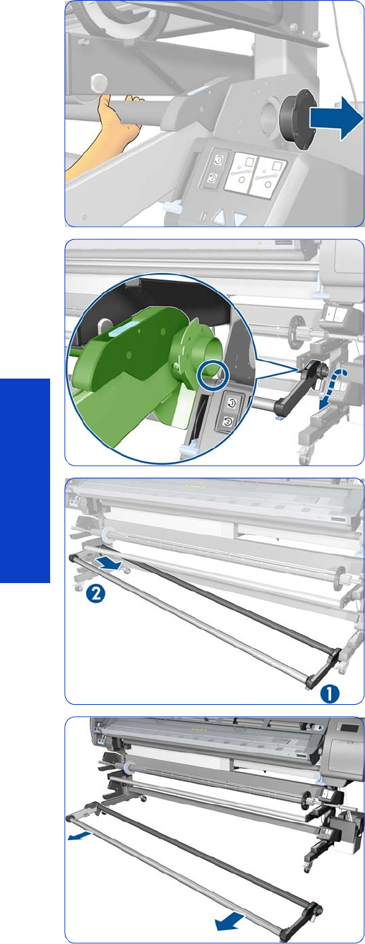
604 Chapter 8 Removal & Installation
Removal & Installation
9. Remove the end cap with your right hand while
holding the Tension Bar with your left hand.
10. Move the right-hand side of the Tension Bar over the
Rewinder, following the path shown by the blue arrow.
11. Disengage the left-hand side of the Tension Bar.
.12. Remove the Tension Bar.
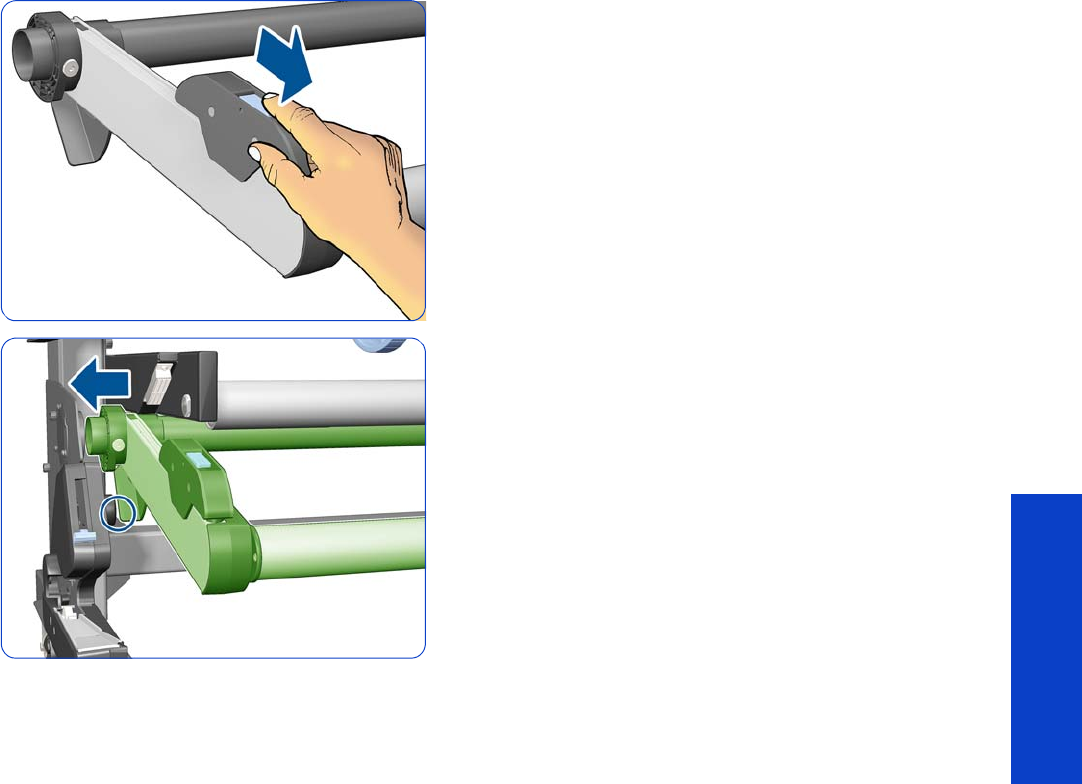
Tension Bar 605
Removal & Installation
Installation
1. Slide the counterweight forwards to make the
installation of the Tension Bar easier.
2. Insert the Tension Bar as shown to avoid bumping into
the part indicated with a circle.

606 Chapter 8 Removal & Installation
Removal & Installation

607
Preventive Maintenance
9 Preventive Maintenance
•Moisture on the printer....................................................................................... 608
•Belt swelling ..................................................................................................... 608
•Clean the printer............................................................................................... 608
•Lubricate the Platen Rollers.................................................................................. 608
•Clean and lubricate the Carriage Rail.................................................................. 609
•Scheduled maintenance ..................................................................................... 609
•Level of printer usage......................................................................................... 609
•Adjust for an uneven floor ....................................................................................611

608 Chapter 9 Preventive Maintenance
Preventive Maintenance
Moisture on the printer
Users should use the printer in an environment between 20% and 80% relative humidity. To recover from
moisture condensation, turn the printer Off, and, using the main roller as a reference, wait until the printer
is completely dry before using it again.
Belt swelling
To prevent new belts from swelling incorrectly, keep them in their bags with desiccant until you need to
install them.
Clean the printer
To maintain the printer in good operating condition, keep it free of dust accumulation, ink, and other
contamination. Cleaning intervals are determined by the printer environment and by the types of Printer
supplies used.
Clean the exterior of the printer
Please refer to the User’s Guide.
Cleaning the Drive Roller and Platen Rollers
1. Perform the Turn Drive Roller Utility (Refer to page 182).
2. Open the window and apply any common household cleaning solution (water based only) to a soft,
lint-free rag and apply it to the Drive Roller and Overdrive surface while it is rotating. Make sure that
you thoroughly clean the Drive Roller and Overdrive surface.
3. Press Enter when you have completed the cleaning procedure.
4. Allow the Drive Roller to dry before loading substrate in to the printer.
Clean the Platen
Please refer to the User’s Guide.
Clean the Substrate-Advance Sensor window
Please refer to the User’s Guide.
Lubricate the Platen Rollers
Please refer to the User’s Guide.
CAUTION: The encoder strip used in this printer must never be cleaned, as cleaning it will
cause irreparable damage, and will need to be replaced.
CAUTION: If ink is spilled on the Platen rollers, remove the ink immediately. Due to the ink's
reflecting properties, ink on the Platen rollers can disrupt the ability of the sensor that detects
the edge of the substrate. To remove ink from the Platen Rollers, perform the following proce-
dure.
CAUTION: Prevent water or other liquids from running onto electrical components or circuits,
or through openings in the Electronics Module.

Clean and lubricate the Carriage Rail 609
Preventive Maintenance
Clean and lubricate the Carriage Rail
Please refer to the User’s Guide.
Scheduled maintenance
In some segments of the printer market, the customer tends to print more than the maximum number of
prints that the throughput allows, exceeding by far the limit of the design. When this happens the customer
runs into print quality problems and continuous Printer failures.
The purpose of scheduled preventive maintenance is to avoid these failures - ensuring a good performance
during all the product life.
Level of printer usage
Non-Volatile Memory (NVM) counters are assigned to counting the number of carriage cycles, carriage
distance, service station cycles, and ink in the waste management module. When certain components of
the printer exceed preset amounts of any of these counters, the front panel displays the following
messages:
•“Service Maintenance #1 required” (related to Carriage cycles and distance)
•“Service Maintenance #2 required” (related to Service Station cycles)
•“Service Maintenance #3 required” (related to Carriage distance and ink into the Waste
Management Module)
When one of these messages is displayed, the appropriate service maintenance kit must be used to
replace the relevant parts of the printer. See “Removal & Installation” on page 271 when replacing the
parts.
IMPORTANT: Both Service Maintenance Kit #1 and Service Maintenance Kit #2 contain, among the
printer parts replaced, all the parts contained in Service Maintenance Kit #3.
Therefore, when Service Maintenance #3 is required, you should check the status of Service Maintenance
#1 and #2. If the status of #1 or #2 is close to 100% (for example, above 95%), it is best to perform that
Service Maintenance instead of #3, to avoid two interventions within a short period of time.
Service Maintenance Kit 1
Service Maintenance Kit #1 (part number CQ871-67092) normally includes the following parts, although
the list of parts may vary slightly:
•Scan Axis Motor
•Encoder Strip and Sensor
•Ink Tubes Assembly and Trailing Cable
•Belt & Tension Kit Assembly
•Carriage Assembly without PCA, Cutter, and Color Sensor
•Carriage PCA Cover
•Line Sensor
•Media Jam Sensor
•Drop Detector and Ink Funnel Transmission
•Ink Maintenance Kit
•Two bottles of lubricant oil

610 Chapter 9 Preventive Maintenance
Preventive Maintenance
•SMK Flyer L28500: Formatter PCA battery check
Reset the SMK1 life counter, see page 193. Perform all user maintenance procedures after the
replacement: clean and lubricate the slider rod, and clean the IR sensors with ethanol and a lint-free cloth.
Service Maintenance Kit 2
Service Maintenance Kit #2 (part number CQ871-67093) normally includes the following parts, although
the list of parts may vary slightly:
•Service Station
•Line Sensor
•Media Jam Sensor
•Ink Maintenance Kit
•Front Rod Oiler
•Lubrication Felts Kit
•Belt and Tensioner
•Two bottles of lubricant oil
•SMK Flyer L28500: Formatter PCA battery check
Reset the SMK2 life counter, see page 193. Perform all user maintenance procedures after the
replacement: clean and lubricate the slider rod, and clean the IR sensors with ethanol and a lint-free cloth.
Service Maintenance Kit 3
Service Maintenance Kit #3 (part number CQ871-67094) normally includes the following parts, although
the list of parts may vary slightly:
•Drop Detector and Ink Funnel Transmission
•Line Sensor
•Ink Maintenance Kit
•Front Rod Oiler
•Lubrication Felts Kit
•Belt and Tensioner
•Two bottles of lubricant oil
•SMK Flyer L28500: Formatter PCA battery check
Reset the SMK3 life counter, see page 193. Perform all user maintenance procedures after the
replacement: clean and lubricate the slider rod, and clean the IR sensors with ethanol and a lint-free cloth.
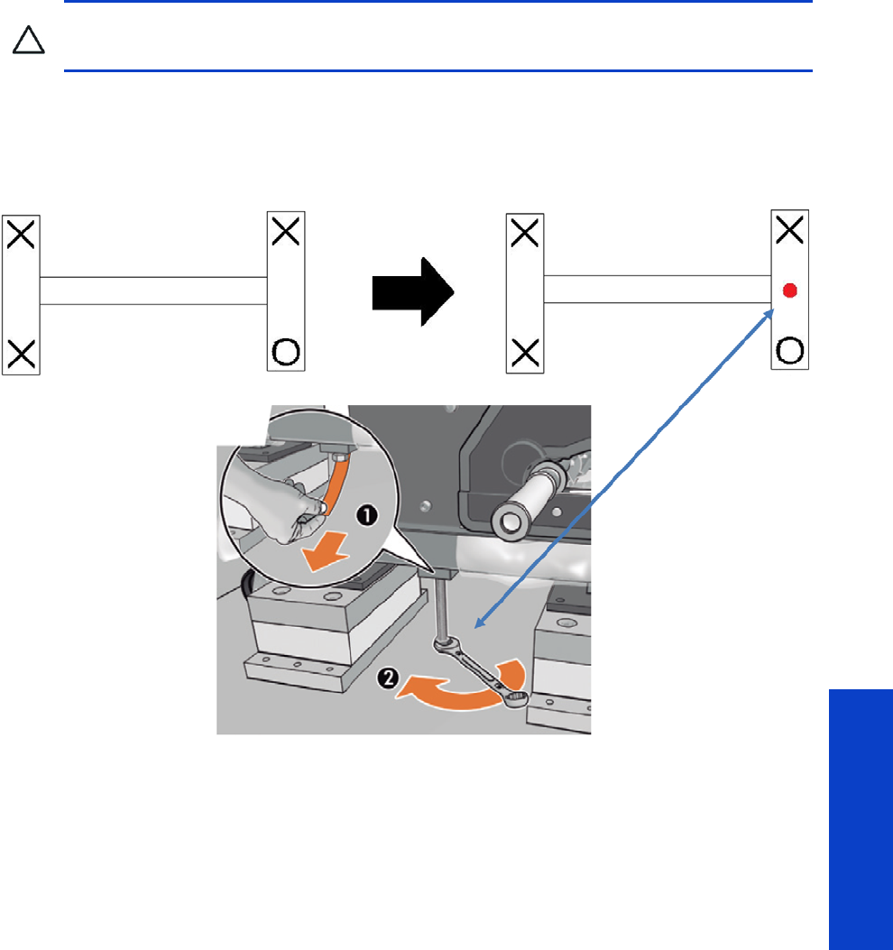
Level of printer usage 611
Preventive Maintenance
Adjust for an uneven floor
The printer will adapt properly to an unevenness of 5 mm. That is, if one of the four wheels is 5 mm above
or below the level of the other three, the four wheels will stay in contact with the ground.
For greater unevenness, when one of the wheels is not in contact with the ground, the lifter screw used to
install the printer can be used to adjust that corner of the printer.
CAUTION: HP strongly recommends installing the printer on an even floor.

612 Chapter 9 Preventive Maintenance
Preventive Maintenance


614 Chapter 10 Move, store, or repack the printer
Preventive Maintenance
Move or store the printer
If you need to move the printer or store it for an extended period of time, prepare it correctly to avoid
possible damage.
1. Do not remove the ink cartridges, printheads, or printhead cleaning cartridge.
2. Make sure that no substrate is loaded.
3. Make sure that the printhead carriage is located in the service station (at the right-hand side of the
printer).
4. Make sure that the Ready message appears on the front panel.
5. Turn off the power by using the Power button on the front panel.
6. Also switch off the power switch at the rear of the printer.
7. Disconnect any cables that connect the printer to a network, a computer, or a scanner.
8. If you have a take-up reel installed, remove the take-up reel sensor and cable-housing unit from the
foot of the printer stand. When reinstalling the housing unit, make sure that the wheel on the foot of
the printer stand is pointing forward.
9. If you intend to turn the printer upside down or on its side, first remove the waste management
system (see the User’s Guide).
10. Check the correct environmental storage conditions in the User’s Guide.
NOTE: If the printer or ink cartridges are moved from a cold location to a warm and humid location,
water from the atmosphere can condensate on the printer parts and cartridges and can result in ink
leaks and printer errors. In this case, wait at least 3 hours before turning on the printer or installing the
ink cartridges, to allow the condensate to evaporate.
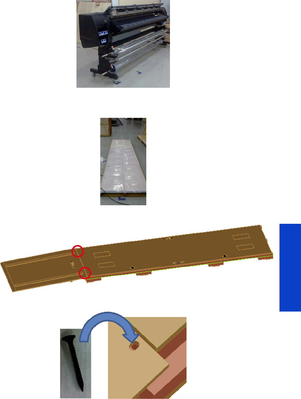
Repack the printer 615
Preventive Maintenance
Repack the printer
1. Follow the instructions for moving or storing the printer
page 614.
2. Ensure that the substrate edge holders are inside their bag.
3. Check that the pallet is not damaged, especially the runners below. Add the polyethylene sheet.
4. Use two of the screws normally used to attach the side panels to lock the ramp to the pallet.
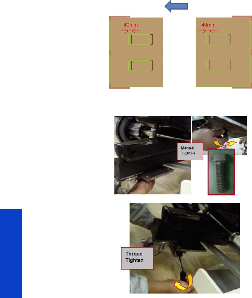
616 Chapter 10 Move, store, or repack the printer
Preventive Maintenance
5. Ensure that the ramp is securely attached before pushing the printer up the ramp onto the pallet. At
least three people are needed for this operation.
6. Move each of the four cushion stands 40 mm as shown, parallel to the length of the printer. To move
a cushion stand, lift one side of the printer at a time. Make sure you are not using the same fixing
holes as the bolt bay slip by using the same holes in the pallet.
7. Insert 4 screws into the metal plate from below. You can use a spanner for this operation. Ensure that
each screw is fully inserted and not slanting.
8. Lower the center bolt until it touches the pallet. Loosen further until the printer is lifted up about
15 mm. Add two cushion stands on each side. To add a cushion stand, lift one side of the printer at
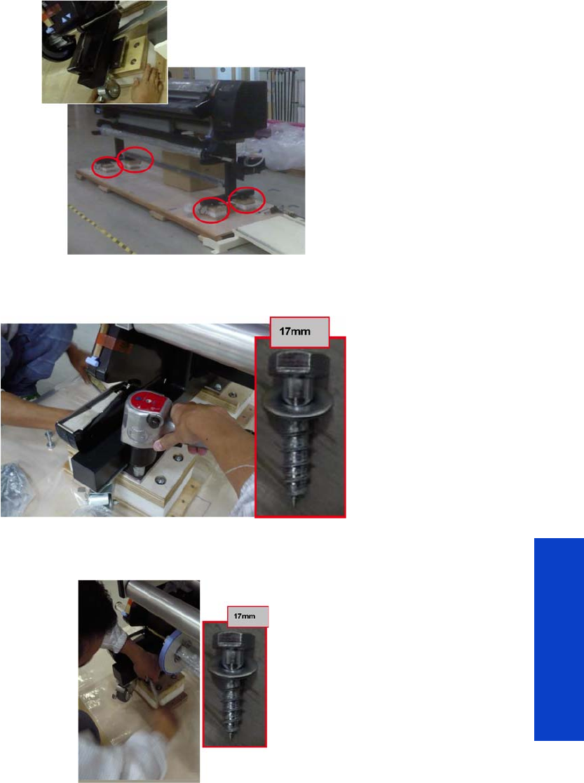
Repack the printer 617
Preventive Maintenance
a time. Once the cushion stand is added, tighten the bolt until it is completely inside the leg. You can
use a spanner for this operation. Ensure that the screw is fully inserted and not slanting.
9. Insert 4 screws into the metal plate. Use a pneumatic gun or #17 spanner to tighten each screw at
the rear of the leg.
10. Use a #17 spanner to tighten the screws at the front of each leg. Ensure that each screw is fully
inserted and not slanting; take care not to strip the threads.
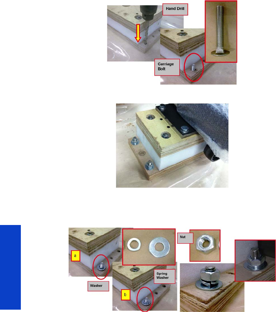
618 Chapter 10 Move, store, or repack the printer
Preventive Maintenance
11. Use a hand drill with an 11 mm drill bit to drill a hole as shown below. Then insert a carriage bolt
from the bottom of the pallet through the plywood.
12. Use 4 bolts per stand as shown: in total, 16 per printer.
13. Insert a flat washer (a) and then a spring washer (b) to the carriage bolt that sticks out as shown.
Add a nut on top of both. You can use a pneumatic gun or #17 spanner for this operation. Ensure
that the nut is fully tightened and not slanting; take care not to strip the threads. This process is
similar for all four cushion stands.
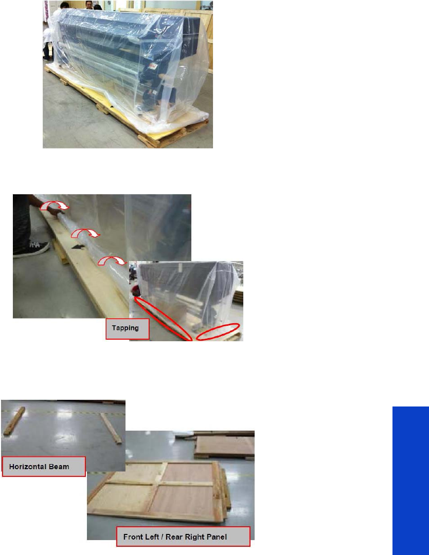
Repack the printer 619
Preventive Maintenance
14 . Cover the printer with the polyethylene bag.
15. The open ends of the cover and the sheet on the pallet should be sealed to prevent air leaks that
could lead to rust. You can use clear plastic 2-inch tape for this purpose.
16. Put the Horizontal Beam (CQ871-00176) on the floor. Then put the Front Left/Rear Right Panel
(CQ871-00172) on the Horizontal Beam. Ensure that the Panel is clean and undamaged, with no
fungus growing on it.
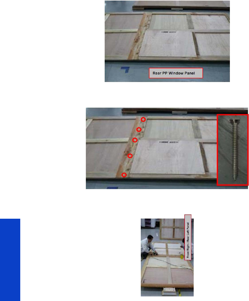
620 Chapter 10 Move, store, or repack the printer
Preventive Maintenance
17. Put the Rear PP Window Panel (CQ871-00204) together with the Front Left/Rear Right Panel as
shown below. Ensure that the Panel is clean and undamaged, with no fungus growing on it.
18 . Use a Torx screwdriver to put 5 screws (CQ871-20117) into the Rear PP Window Panel as shown
below. Ensure that the screws are fully inserted and that there is no gap between panels.
19. Put the Front Right/Rear Left Panel (CQ871-00171) together with the Front Left/Rear Right Panel as
shown below. Ensure that the Panel is clean and undamaged, with no fungus growing on it.
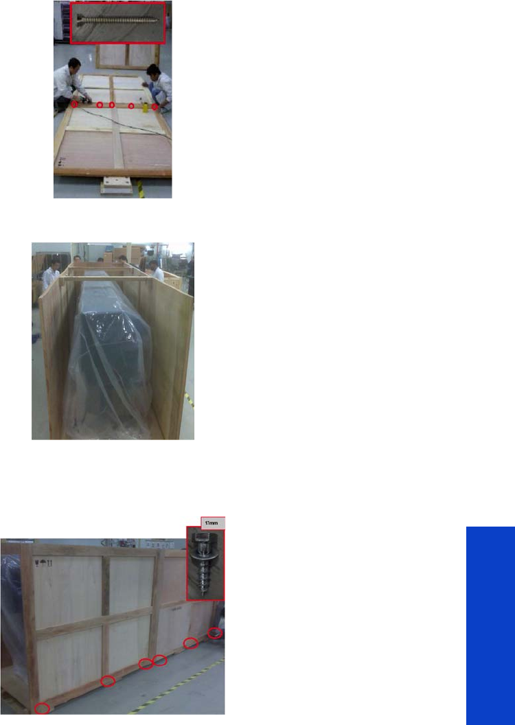
Repack the printer 621
Preventive Maintenance
20. Use a Torx screwdriver to put 5 screws (CQ871-20117) into the Front Right/Rear Left Panel as shown
below. Ensure that the screws are fully inserted and that there is no gap between panels.
21. Move the panels into place around the printer.
22. Attach the panels to the pallet with 6 lag bolts on each side. You are recommended to add a 5 mm
drill hole before adding each bolt. Attach the right and left panels with screws to the front and the
rear panel.
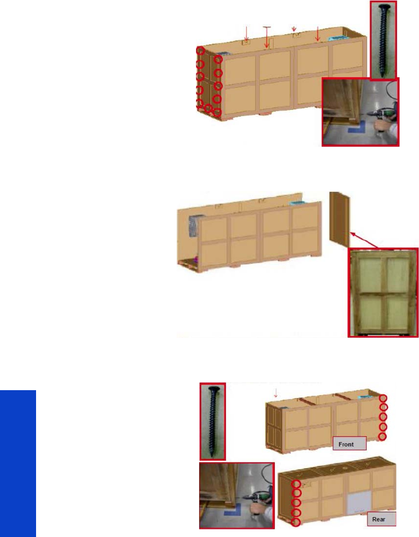
622 Chapter 10 Move, store, or repack the printer
Preventive Maintenance
23. Use a pneumatic gun to screw the Ramp Panel to the Front and Rear Panels as shown below. Ensure
that the screws are fully inserted.
24. Place the Left/Right Panel (CQ871-00174) at the opposite end from the Ramp Panel. Ensure that the
Left/Right Panel is properly inserted into the Front and Rear Panels.
25. Use a pneumatic gun to screw the Left/Right Panel to the Front and Rear Panels as shown below.
Ensure that the screws are fully inserted.
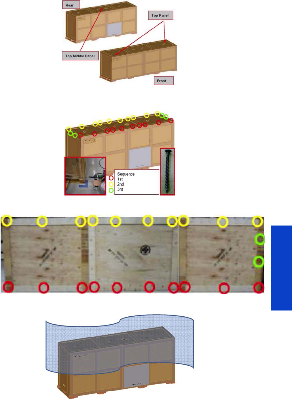
Repack the printer 623
Preventive Maintenance
26. Place the two Top Panels (CQ871-00203) and the Top Middle Panel (CQ871-00251) on the
Horizontal Beam as shown below. Ensure that the Foot Mark and Warning messages are displayed.
27. Use a pneumatic gun to screw the top panels to the other panels as shown below. Ensure that all the
screws are fully inserted.
28. Add a polyethylene sheet as a cover.
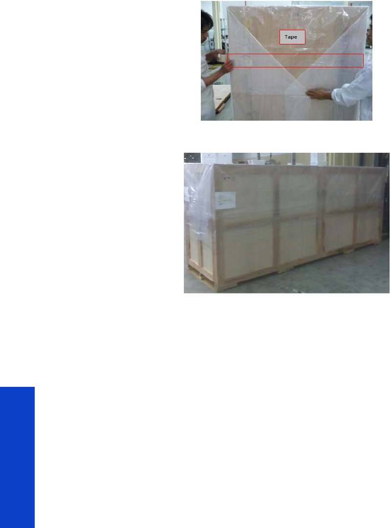
624 Chapter 10 Move, store, or repack the printer
Preventive Maintenance
29. Use packaging tape to secure the open ends as shown below.

Safety
Safety 625
11 S a f e t y p r e c a u t i o n s
• General safety guidelines................................................................................... 626
• Electrical shock hazard ...................................................................................... 626
• Heat hazard..................................................................................................... 626
• Fire hazard....................................................................................................... 626
• Mechanical hazard ........................................................................................... 626
• Scan Axis Encoder Strip hazard.......................................................................... 627
• Burn hazard (heating and curing)........................................................................ 627
• Lifting and handling .......................................................................................... 627
• Warning labels................................................................................................. 628

Safety
626 Safety
General safety guidelines
Before servicing the printer, read the following safety precautions to make sure that you can work on the
printer safely.
•Before servicing the printer, turn it off, and disconnect electrical power. See “Safety precautions” on
page 277.
•Before removing and replacing parts, see “Removal & Installation” on page 271.
Service personnel are expected to have appropriate technical training and experience necessary to be
aware of hazards to which they may be exposed in performing a task, and to take appropriate measures
to minimize the risks to themselves and other people.
Electrical shock hazard
To avoid the risk of electric shock, do not attempt to dismantle any of the components of the printer before
turning off the printer and disconnecting it from the power mains. See “Safety precautions” on page 277.
Heat hazard
The drying and curing subsystems of the printer operate at high temperatures and can cause burns if
touched. To avoid personal injury, take the following precautions.
•Do not touch the internal enclosures of the printer's drying and curing modules when they are hot.
Even after opening the window lock which disconnects drying and curing power, the internal
surfaces could be hot.
•Take special care when accessing the substrate path.
Fire hazard
The Dryer Assembly and Curing Module operate at high temperatures. To avoid the risk of fire, take the
following precautions.
•Check that the power supply meets the requirements specified in the Site Preparation Guide. For
additional information, see “Printer systems” on page 7.
•Do not use aerosol products that contain flammable gases inside or around the printer.
•Do not block or cover the openings of the printer.
•Ensure that the operating temperature of the substrate loaded recommended by the manufacturer is
not exceeded. If this information is not available from the manufacturer, do not load substrates that
cannot be used at an operating temperature under 125°C (257°F).
•Do not load substrates with auto-ignition temperatures below 300°C (572°F). See note below
Mechanical hazard
When the carriage moves, it can crush or cut body parts if they are in the way.
WARNING! The drying and curing modules operate at hazardous voltages capable of
causing death or serious personal injury.
Test method based on EN ISO 6942:2002; Evaluation of materials and material assemblies
when exposed to a source of radiant heat, method B. The test conditions, to determine the
temperature when the substrate starts ignition (either flame or glow) were: Heat flux density:
30 kW/m², copper calorimeter, K type thermocouple.

Safety
Safety 627
Best practice
•Keep your clothing or body parts safe from moving parts of the printer.
•Avoid wearing loose clothing, jewelry like necklaces or bracelets, or any kind of hanging objects.
•If you have long hair, make sure that it is restrained.
•Take care that sleeves and gloves do not get caught in the mechanical parts of the printer.
•Stay clear of the print path when the carriage is moving.
•Also make sure that there are no tools obstructing the operation of the printer.
Scan Axis Encoder Strip hazard
The Scan Axis Encoder Strip is very sharp, and can easily cut your hands when you must work near it.
Best practice
•Wear protective gloves if you must touch the Scan Axis Encoder Strip.
•Do not wear loose clothing or jewelry.
Burn hazard (heating and curing)
The components of the heating and curing systems get very hot and can seriously burn you.
Best practice
•Be careful when you work near the print path.
•Before working on the heating and curing modules, make sure that they are completely cooled off.
Lifting and handling
Improper handling of heavy materials can lead to serious bodily injury.
Best practice
•When handling substrate rolls, care must be taken to avoid back strain and/or injury.
•Always use a forklift, pallet truck, or other handling equipment to lift substrates.
•Always wear personal protective equipment like safety boots and gloves.
•Follow any manpower instructions included in this service manual when you replace components.
Many components, require at least two people for removal.
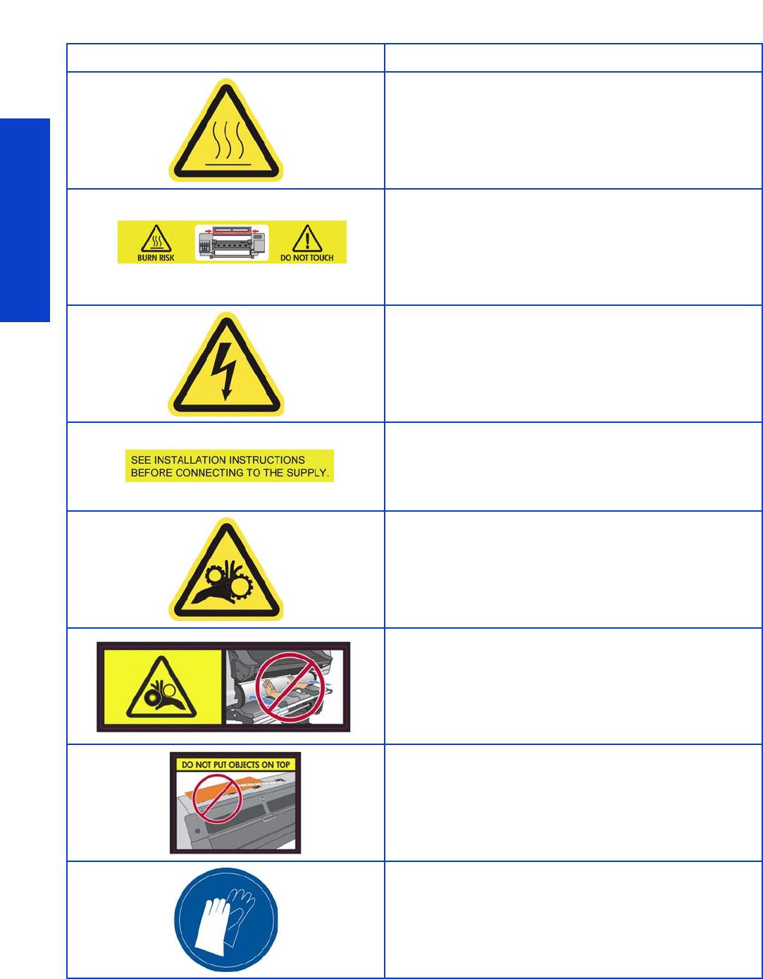
Safety
628 Safety
Warning labels
Label Description
Risk of burns. Do not touch the internal enclosures of the
drying and curing modules.
Risk of burns. Do not touch the drying enclosure of the printer.
Even after opening the window latch, which disconnects the
power to the drying and curing modules, the internal surfaces
could be hot.
Electric shock hazard. Follow all safety precautions described
in this manual.
See installation instructions before connecting to the supply.
Check that the power supply meets the requirements specified
in the Site Preparation Guide. For additional information, see
“Printer systems” on page 7.
Risk of trapped fingers. Do not touch spindle gears while
moving.
Risk of trapped hands. Do not push the roll while loading.
Do not put objects on top of the printer. Do not cover the
fans.
You are recommended to wear gloves when handling ink
cartridges, printhead cleaning cartridges and the printhead
cleaning container.
