HP Designjet T790 & T1300 E Printer Series T2300 MFP Service Manual
User Manual: HP Designjet T790 & T1300 ePrinter series & T2300 eMFP series - Service Manual shared.swissparts.ch - /Manuals/HP/Plotter/
Open the PDF directly: View PDF ![]() .
.
Page Count: 480 [warning: Documents this large are best viewed by clicking the View PDF Link!]
- Troubleshooting
- Using the Touch Control Panel (MFP only)
- Using the Touch Control Panel
- Service Key Combinations
- Product Troubleshooting trees (MFP)
- Product Troubleshooting Tree
- Scanner Troubleshooting Tree
- Scanner CIS Troubleshooting
- Troubleshooting system error codes
- Performing a service test on a failed assembly
- Performing the necessary service calibrations
- Solving scan/print-quality problems
- The Touch Control Panel is blank
- The product does not power on
- The product continuously rejects printheads
- Cover sensors are not working
- The line sensor has problems detecting paper
- Troubleshooting Printer paper jams and printhead crashes
- Troubleshooting Scanner paper jams (MFP only)
- The basket was damaged during the product setup
- Paper-handling troubleshooting
- Ink-supplies troubleshooting
- Connectivity troubleshooting
- System Error Codes
- Introduction
- Product logs
- What to do if the Touch Control Panel is blank
- Continuable and Non-Continuable Error Codes
- System Error Code Brief Descriptions
- System Error Codes—Full Descriptions
- Appendix A: How to troubleshoot SE 79:04
- Appendix B: Emergency firmware upgrade with USB flash drive
- Appendix C: Obtaining the product log and the diagnostics package
- Appendix D: How to check the display list memory for an HP-GL/2 job
- Diagnostics Menu
- Introduction
- Diagnostic Tests and Utilities
- Entering the Diagnostics Menu
- Scan Axis Test
- Paper Drive Test
- Electronics Module Test
- Carriage Assembly Test
- Sensors Test
- Rewinder Test
- Ink Delivery System (IDS) Test
- Service Station Test
- I/O Information Utility
- Enable I/O Interfaces Utility
- Unit Information Utility
- EEROM Reset Utility
- Touch Control Panel Lock Reset
- Hard Disk Recovery Utility
- File System Check
- Service Menu
- Introduction
- Service Utilities
- Entering the Service Utilities Menu
- Turn Drive Roller
- Purge Tubes
- Reset Life Counters
- Diagnostic Print
- Set Date and Time
- Enable/Disable Firewall
- Enable/Disable Sleep Mode
- Disk Wipe DoD 5220.220M
- Hard Disk Recovery Utility
- Show/Hide Touch Control Panel Information
- Enable/Disable Port 280
- File System Check
- I/O Tests
- Rewinder Adjust
- Disable Upper Roll Cover
- Enable Upper Roll Cover
- Special Cutter Mode
- Scanner Validation
- SCANdump
- Adjustment scanner Y-Axis scale
- Service Calibrations
- Parts and Diagrams
- Introduction
- Product Support
- Center Covers Front (1 of 3)
- Center Covers Front (2 of 3)
- Center Covers Front (3 of 3)
- Roll Covers
- Center Covers (Rear)
- Right Cover
- Left Cover
- Right Hand Assemblies
- Left Hand Assemblies
- Carriage Assembly
- Scan-Axis Assemblies
- Paper Path Assemblies (Front)
- Paper Path Assemblies (Rear)
- Roll Supports
- Scanner Parts (1 of 3)
- Scanner Parts (2 of 3)
- Scanner Parts (3 of 3)
- Tools 1
- Tools 2
- Miscellaneous Parts
- Removal and Installation
- Introduction
- Customer Self Repair parts
- Service Calibration Guide to Removal and Installation
- Belt Assembly
- Bin Assembly
- Bi-stable Springs
- Bumpers, Left and Right
- Engine Cables Kit
- Interconnect Cables Kit
- Carriage and Cutter Assembly
- Carriage Bushing, Rear
- Carriage Cover and Carriage Latch
- Carriage Rail Oiler
- Carriage PCA
- Cleanout
- Center Support
- Converger
- Scanner Piston Gas (MFP only)
- Scanner Bumper (MFP only)
- Right Collar Cover (MFP only)
- Front Cover
- Front Top Cover Assembly (MFP only)
- Front Top Cover
- Drop Detector
- EE Box
- Encoder Disk and Encoder Sensor
- Encoder Strip
- Encoder Strip, spring and attachment nut
- Formatter
- Freewheel Assembly
- Right Front Trim
- Full Bleed Foam
- Hard Disk Drive
- Left Ink Cartridge Door
- Right Ink Cartridge Door
- Left Ink Supply Station
- Ink Supply Tubes & Trailing Cable
- Ink Supply Tubes Support Rail
- Interconnect PCA
- Left Collar Cover (MFP only)
- Left Cover
- Left Front Trim
- Left Scanner Cover (MFP only)
- Scanner Latch and Hook Assembly (MFP only)
- Line Sensor
- Media Advance Drive
- Media Lever
- Media Lever Position Sensor
- Media Output Assembly
- Out-of-paper Sensor
- Left Panel
- Pen to Paper Space (PPS) Solenoid
- Pinch Arm Assembly
- Pinchwheel Assembly
- Print Zone Overdrive
- Power Supply Unit
- Real-time Clock Battery
- Rear Cover (MFP only)
- Rear Cover
- Rear Deflectors
- Right Cover
- Right Scanner Cover (MFP only)
- Roll Cover Bumpers, Lower
- Roll Cover, Lower
- Roll Cover, Upper
- Left Roll Guide
- Right Roll Guide
- Roll Support, Lower Left
- Roll Support, Lower Right
- Roll Support Sensor, Lower Left
- Roll Support Sensor, Upper Left
- Roll Support, Upper Left
- Roll Support, Upper Right
- Scan-axis Motor
- Service Station
- Single-sheet Sensor
- Spindle
- Spittoon, Left
- Starwheel Assembly
- Starwheel Lifter, Left
- Starwheel Lifter, Right
- Starwheel Motor
- Wall Spacers
- Scanner Position Sensor (MFP only)
- Torsion Damper (MFP only)
- CIS Element (MFP only)
- Scanner Exit Media Sensors (MFP only)
- Scanner Entry Media Sensors (MFP only)
- Pressure Rollers (MFP only)
- Scanner Controller Board (MFP only)
- Scanner Motor Assembly (MFP only)
- Taco Sensor (MFP only)
- Touch Control Panel
- Window
- Window Position Sensor
- Preventive Maintenance
- CSR Installation Flyers

DESIGNJET T790/T1300 ePrinter series &
T2300 eMFP series
Service manual
For HP Internal Use Only
©Copyright Hewlett-Packard Company 2011
This document contains proprietary
information that is protected by copyright. All
rights are reserved. No part of this document
may be photocopied, reproduced, or
translated to another language without the
prior written consent of Hewlett-Packard
Company.
Edition, April 2011.

Notices
Warranty
The information contained in this
document is subject to change without
notice.
Hewlett-Packard makes no
warranty of any kind with regard to
this material, including, but not
limited to, the implied warranties of
merchantability and fitness for a
particular purpose.
Hewlett-Packard shall not be liable for
errors contained herein or for
incidental or consequential damages
in connection with the furnishing,
performance, or use of this material.
WARNING
The procedures described in this manual are
to be performed by HP-qualified service
personnel only.
Electrical Shock Hazard
Serious shock hazard leading to death or
injury may result if you do not take the
following precautions:
●Ensure that the ac power outlet (mains)
has a protective earth (ground)
terminal.
●Disconnect the product from the power
source prior to performing any
maintenance.
●Prevent water or any other liquids from
running onto electrical components or
circuits, or through openings in the
enclosure.
Electrostatic Discharge
Refer to the beginning of Chapter 4
Introduction on page 202 of this manual, for
precautions you should take to prevent
damage to the product circuits from
electrostatic discharge.
Safety Symbols
General definitions of safety symbols are
given immediately after the table of contents.
WARNING
The Warning symbol calls attention to a
procedure, practice, or the like, which,
if not correctly performed or adhered to,
could result in personal injury. Do not
proceed beyond a Warning symbol until
the indicated conditions are fully
understood and met.
CAUTION
The Caution symbol calls attention to
an operating procedure, practice, or the
like, which, if not correctly performed or
adhered to, could result in damage to or
destruction of part or all of the product.
Do not proceed beyond a Caution
symbol until the indicated conditions
are fully understood and met.
Content Management Department,
Barcelona Division,
Hewlett-Packard Espanola, S.A.
Avda. Graells, 501
08190 Sant Cugat del Valles
Spain
ENWW iii
iv Notices ENWW
Using this Manual
This Service Manual contains information necessary to test, calibrate, maintain and service the
following:
RTL PostScript R-bill PN
HP Designjet T790 24inch CR647A CR648A CR647A-SRV
HP Designjet T790 44inch CR649A CR650A CR647A-SRV
HP Designjet T1300
44inch CR651A CR652A CR647A-SRV
HP Designjet T2300
eMFP 44inch CN727A CN728A CR647A-SRV
When information is only applicable to a specific product, the text will indicate which product it is
applicable to. There are three main areas where this might occur, and at each occurrence an icon will
also be shown:
HP Designjet T2300 Printer series HP Designjet T790/T1300 Printer series Web Enabled
For information about using these products, refer to the corresponding User and Quick Reference
Guides.
Readership
The procedures described in this Service Manual are to be performed by HP Certified service personnel
only.
Part Numbers
Part Numbers for product service parts are located in Chapter 7 Parts and Diagrams on page 173.
ENWW v
vi Using this Manual ENWW

Table of contents
1 Troubleshooting
Using the Touch Control Panel (MFP only) .......................................................................................... 1
Using the Touch Control Panel ............................................................................................................ 3
Service Key Combinations ................................................................................................................... 5
Product Troubleshooting trees (MFP) .................................................................................................. 6
Paper-handling troubleshooting ......................................................................................................... 12
Ink-supplies troubleshooting ............................................................................................................... 13
Connectivity troubleshooting .............................................................................................................. 31
2 System Error Codes
Introduction ......................................................................................................................................... 35
Product logs ....................................................................................................................................... 36
What to do if the Touch Control Panel is blank .................................................................................. 36
Continuable and Non-Continuable Error Codes ................................................................................. 39
System Error Code Brief Descriptions ................................................................................................ 39
System Error Codes—Full Descriptions ............................................................................................. 42
Appendix A: How to troubleshoot SE 79:04 ....................................................................................... 64
Appendix B: Emergency firmware upgrade with USB flash drive ....................................................... 74
Appendix C: Obtaining the product log and the diagnostics package ................................................ 74
Appendix D: How to check the display list memory for an HP-GL/2 job ............................................. 77
3 Diagnostics Menu
Introduction ......................................................................................................................................... 79
Diagnostic Tests and Utilities ............................................................................................................. 80
4 Service Menu
Introduction ....................................................................................................................................... 117
Service Utilities ................................................................................................................................. 117
Service Calibrations ......................................................................................................................... 153
5 Parts and Diagrams
Introduction ....................................................................................................................................... 173
Product Support ............................................................................................................................... 174
Center Covers Front (1 of 3) ............................................................................................................ 175
Center Covers Front (2 of 3) ............................................................................................................ 176
Center Covers Front (3 of 3) ............................................................................................................ 177
ENWW vii
Roll Covers ....................................................................................................................................... 178
Center Covers (Rear) ....................................................................................................................... 179
Right Cover ...................................................................................................................................... 180
Left Cover ......................................................................................................................................... 181
Right Hand Assemblies .................................................................................................................... 182
Left Hand Assemblies ...................................................................................................................... 183
Carriage Assembly ........................................................................................................................... 184
Scan-Axis Assemblies ...................................................................................................................... 185
Paper Path Assemblies (Front) ........................................................................................................ 186
Paper Path Assemblies (Rear) ......................................................................................................... 187
Roll Supports .................................................................................................................................... 188
Scanner Parts (1 of 3) ...................................................................................................................... 189
Scanner Parts (2 of 3) ...................................................................................................................... 190
Scanner Parts (3 of 3) ...................................................................................................................... 191
Tools 1 .............................................................................................................................................. 192
Tools 2 .............................................................................................................................................. 193
Miscellaneous Parts ......................................................................................................................... 194
6 Removal and Installation
Introduction ....................................................................................................................................... 202
Customer Self Repair parts .............................................................................................................. 204
Service Calibration Guide to Removal and Installation .................................................................... 205
Belt Assembly ................................................................................................................................... 207
Bin Assembly .................................................................................................................................... 207
Bi-stable Springs ............................................................................................................................. 210
Bumpers, Left and Right ................................................................................................................... 215
Engine Cables Kit ............................................................................................................................. 218
Interconnect Cables Kit .................................................................................................................... 229
Carriage and Cutter Assembly ......................................................................................................... 237
Carriage Bushing, Rear .................................................................................................................... 245
Carriage Cover and Carriage Latch ................................................................................................. 247
Carriage Rail Oiler ............................................................................................................................ 251
Carriage PCA ................................................................................................................................... 252
Cleanout ........................................................................................................................................... 257
Center Support ................................................................................................................................. 258
Converger ......................................................................................................................................... 261
Scanner Piston Gas (MFP only) ....................................................................................................... 263
Scanner Bumper (MFP only) ............................................................................................................ 266
Right Collar Cover (MFP only) ......................................................................................................... 270
Front Cover ...................................................................................................................................... 275
Front Top Cover Assembly (MFP only) ............................................................................................ 276
Front Top Cover ............................................................................................................................... 278
Drop Detector ................................................................................................................................... 280
EE Box ............................................................................................................................................. 281
Encoder Disk and Encoder Sensor .................................................................................................. 286
Encoder Strip .................................................................................................................................... 287
Encoder Strip, spring and attachment nut ........................................................................................ 288
viii ENWW
Formatter .......................................................................................................................................... 290
Freewheel Assembly ........................................................................................................................ 291
Right Front Trim ............................................................................................................................... 293
Full Bleed Foam ............................................................................................................................... 294
Hard Disk Drive ................................................................................................................................ 295
Left Ink Cartridge Door ..................................................................................................................... 296
Right Ink Cartridge Door ................................................................................................................... 297
Left Ink Supply Station ..................................................................................................................... 299
Ink Supply Tubes & Trailing Cable ................................................................................................... 304
Ink Supply Tubes Support Rail ......................................................................................................... 313
Interconnect PCA ............................................................................................................................. 315
Left Collar Cover (MFP only) ............................................................................................................ 316
Left Cover ......................................................................................................................................... 317
Left Front Trim .................................................................................................................................. 320
Left Scanner Cover (MFP only) ........................................................................................................ 321
Scanner Latch and Hook Assembly (MFP only) ............................................................................... 323
Line Sensor ...................................................................................................................................... 325
Media Advance Drive ....................................................................................................................... 330
Media Lever ...................................................................................................................................... 337
Media Lever Position Sensor ........................................................................................................... 338
Media Output Assembly ................................................................................................................... 340
Out-of-paper Sensor ......................................................................................................................... 341
Left Panel ......................................................................................................................................... 344
Pen to Paper Space (PPS) Solenoid ................................................................................................ 345
Pinch Arm Assembly ....................................................................................................................... 347
Pinchwheel Assembly ...................................................................................................................... 349
Print Zone Overdrive ........................................................................................................................ 357
Power Supply Unit ............................................................................................................................ 362
Real-time Clock Battery .................................................................................................................... 363
Rear Cover (MFP only) .................................................................................................................... 363
Rear Cover ....................................................................................................................................... 366
Rear Deflectors ................................................................................................................................ 367
Right Cover ...................................................................................................................................... 368
Right Scanner Cover (MFP only) ..................................................................................................... 372
Roll Cover Bumpers, Lower ............................................................................................................. 375
Roll Cover, Lower ............................................................................................................................. 378
Roll Cover, Upper ............................................................................................................................. 381
Left Roll Guide .................................................................................................................................. 382
Right Roll Guide ............................................................................................................................... 383
Roll Support, Lower Left .................................................................................................................. 384
Roll Support, Lower Right ............................................................................................................... 385
Roll Support Sensor, Lower Left ..................................................................................................... 387
Roll Support Sensor, Upper Left ..................................................................................................... 388
Roll Support, Upper Left ................................................................................................................... 389
Roll Support, Upper Right ................................................................................................................ 391
Scan-axis Motor ............................................................................................................................... 392
Service Station ................................................................................................................................. 396
ENWW ix
Single-sheet Sensor ......................................................................................................................... 401
Spindle ............................................................................................................................................. 402
Spittoon, Left .................................................................................................................................... 403
Starwheel Assembly ......................................................................................................................... 404
Starwheel Lifter, Left ........................................................................................................................ 405
Starwheel Lifter, Right ...................................................................................................................... 407
Starwheel Motor ............................................................................................................................... 409
Wall Spacers .................................................................................................................................... 411
Scanner Position Sensor (MFP only) ............................................................................................... 413
Torsion Damper (MFP only) ............................................................................................................. 417
CIS Element (MFP only) ................................................................................................................... 420
Scanner Exit Media Sensors (MFP only) ......................................................................................... 421
Scanner Entry Media Sensors (MFP only) ....................................................................................... 422
Pressure Rollers (MFP only) ............................................................................................................ 422
Scanner Controller Board (MFP only) .............................................................................................. 423
Scanner Motor Assembly (MFP only) ............................................................................................... 425
Taco Sensor (MFP only) .................................................................................................................. 426
Touch Control Panel ......................................................................................................................... 428
Window ............................................................................................................................................. 431
Window Position Sensor .................................................................................................................. 434
7 Preventive Maintenance
Preventive Maintenance ................................................................................................................... 436
Preventive Maintenance Kits ............................................................................................................ 443
Appendix A CSR Installation Flyers
Cutter assembly ............................................................................................................................... 446
Freewheel assembly ........................................................................................................................ 447
Freewheel assembly (screwdriver) ................................................................................................... 449
Left side panel (T1200) .................................................................................................................... 451
Pinch arm assembly ......................................................................................................................... 453
Pinch arm assembly (screwdriver) ................................................................................................... 455
Roll cover upper bumpers ................................................................................................................ 457
Roll cover upper bumpers (screwdriver) .......................................................................................... 459
Foot Extension ................................................................................................................................. 461
Front Deflector .................................................................................................................................. 462
Rear Deflector Mylar ........................................................................................................................ 464
Glass Plate ....................................................................................................................................... 466
Latch Handle Cover .......................................................................................................................... 469
xENWW
1 Troubleshooting
●Using the Touch Control Panel (MFP only)
●Using the Touch Control Panel
●Service Key Combinations
●Product Troubleshooting trees (MFP)
●Paper-handling troubleshooting
●Ink-supplies troubleshooting
●Connectivity troubleshooting
Using the Touch Control Panel (MFP only)
The external frame of the Touch Control Panel contains the following elements:
●The Home LED (top-left) is used to return to the Home Screen. When clicked only once, this
same Home Screen is displayed. When pressed for more than 4 seconds, the Accessibility Home
Screen is displayed.
●The Help LED (top-right) is used to access the help menu.
●The Cancel LED (bottom right) is used to cancel any action, when it is active.
●The Back LED (bottom left) is to go back to the previous screen, when it is active.
●The Arrow LEDs (in the middle of each side) enables the user to navigate in both directions.
●The Eject LED (top-right) enables the user to stop the USB connection.
ENWW Using the Touch Control Panel (MFP only) 1

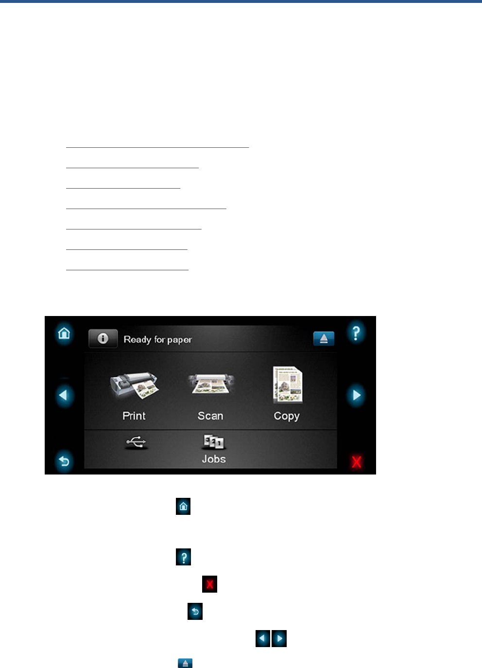
The internal part of the Touch Control Panel is the Home Screen and this is divided into three main
areas:
●The upper area is for the Product Information (left icon) and for displaying high priority alerts
(in text) you can press the most critical alert in the home screen and the others (less critical) will
be shown.
The main menu of the product is accessed by clicking on the Product Information icon and then
selecting the last tab (at the right side)
●The middle area is used to place the three icons for the main work flows of the product, which are:
Print, Scan and Copy.
●The lower area of the Home Screen is reserved for the contents area. The contents area will
contain all the functionality related with printing content, for example in the Job Queue.
When a USB drive is inserted, a USB icon will also be displayed to the left of this area, and
when a Postscript/PDF job is being printed an Adobe logo will display in the
bottom right area
2 Chapter 1 Troubleshooting ENWW
Using the Touch Control Panel
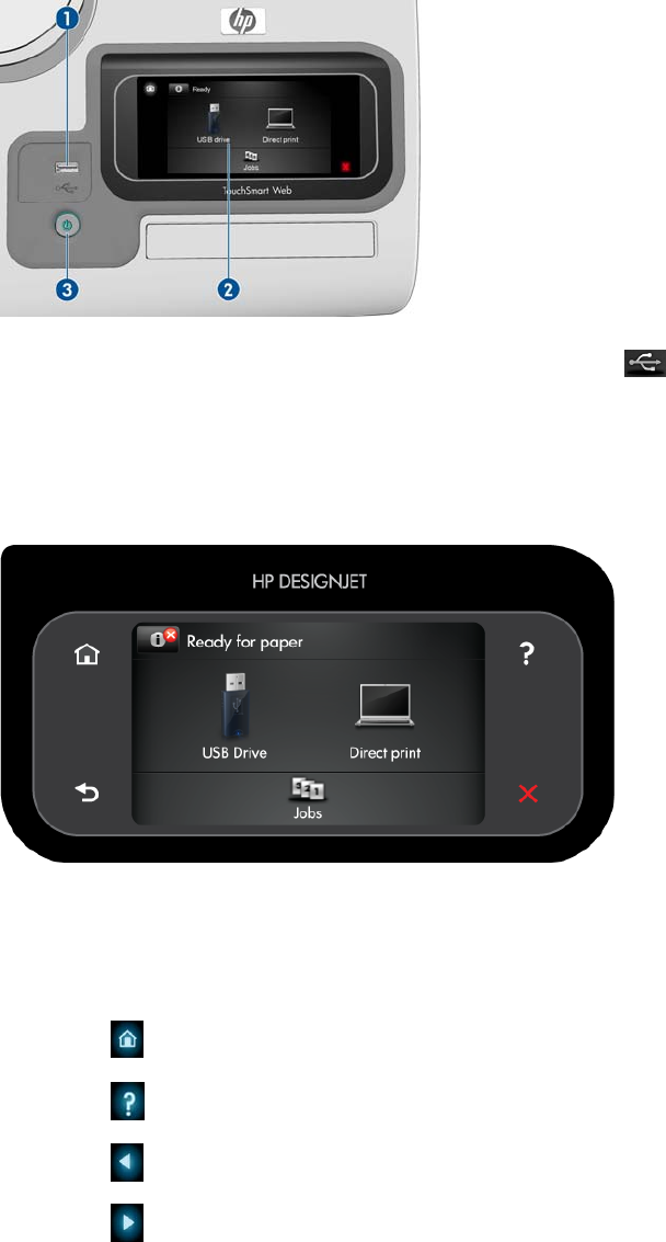
The front panel is located on the front right of the printer. It gives you complete control of your printer:
from the front panel, you can print, view information about the printer, change printer settings, perform
calibrations and tests, and so on. The front panel also displays alerts (warning and error messages)
when needed.
1. A Hi-Speed USB host port, intended for connecting a USB flash drive, which can provide files to
be printed. When a USB flash drive is inserted, a USB icon is displayed on the front panel's
home screen.
2. The front panel itself: a touch-sensitive screen with a graphical user interface.
3. The Power key, with which you can turn the printer on or off. The key is illuminated when the printer
is on. It flashes when the printer is in transition between on and off.
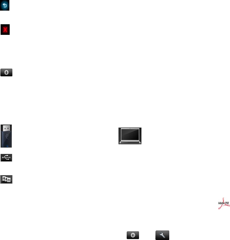
The front panel has a large central area to display dynamic information and icons. On the left and right
sides you can see up to six fixed icons at different times. Normally they are not all displayed at the same
time.
Left and right fixed icons
●Press to return to the home screen.
●Press to view help about the current screen.
●Press to go to the previous item.
●Press to go to the next item.
ENWW Using the Touch Control Panel 3
●Press to go back to the previous screen. This does not discard any changes made in the current
screen.
●Press to cancel the current process.
Home screen dynamic icons
The following items are displayed only on the home screen.
●Press to view information about printer status, change printer settings, or initiate actions such
as loading paper or replacing ink supplies. A smaller warning icon appears if there are actions that
need to be performed.
●To the right of the above button is a message showing the printer status or the most important
current alert. Press this message to see a list of all current alerts, with an icon indicating the severity
of each alert.
●
Press to print a file from a USB flash drive, or to print from a computer.
●Press to view information about the USB flash drive(s). This icon appears only when one or
more USB flash drives are inserted.
●Press to view and manage the job queue. A smaller warning icon appears if there are jobs on
hold.
●While a PostScript or PDF job is printing (PostScript printers only), the Adobe PDF icon is
displayed; pressing it has no effect.
If the printer is left idle for some time, it goes into sleep mode and switches off the front-panel display.
To change the time that elapses before sleep mode, press , then , then Setup > Front panel
options > Sleep mode wait time. You can set a time between 1 and 240 minutes.
The printer wakes from sleep mode and switches on the front-panel display whenever there is some
external interaction with it.
Information about specific uses of the front panel can be found throughout this guide.
4 Chapter 1 Troubleshooting ENWW

Service Key Combinations
Table 1-1 Service Key Combinations
Label Description
Diagnostic mode 1. With the product turned off, press the Power Key
2. When the magic frame LEDs become active, select by
touching one of the following sequences:
◦CANCEL + HOME + HELP: hp-service-1: For The
Onsite Engineer
◦CANCEL + BACK + HELP: hp-service-2: For call
center remote support
The LEDs in the frame will blink a response to confirm the
selected sequence.
Service menu (Service Engineers only) With the product is powered on, access main menu – service
menu.
Password is 3174
For tools that require another password, this is 5494
Service menu (for users) With the product powered on, access main menu – service
menu.
Password is 3174. There is an icon in front of the option,
indicating that the tool is protected (which requires a service
password).
ENWW Service Key Combinations 5
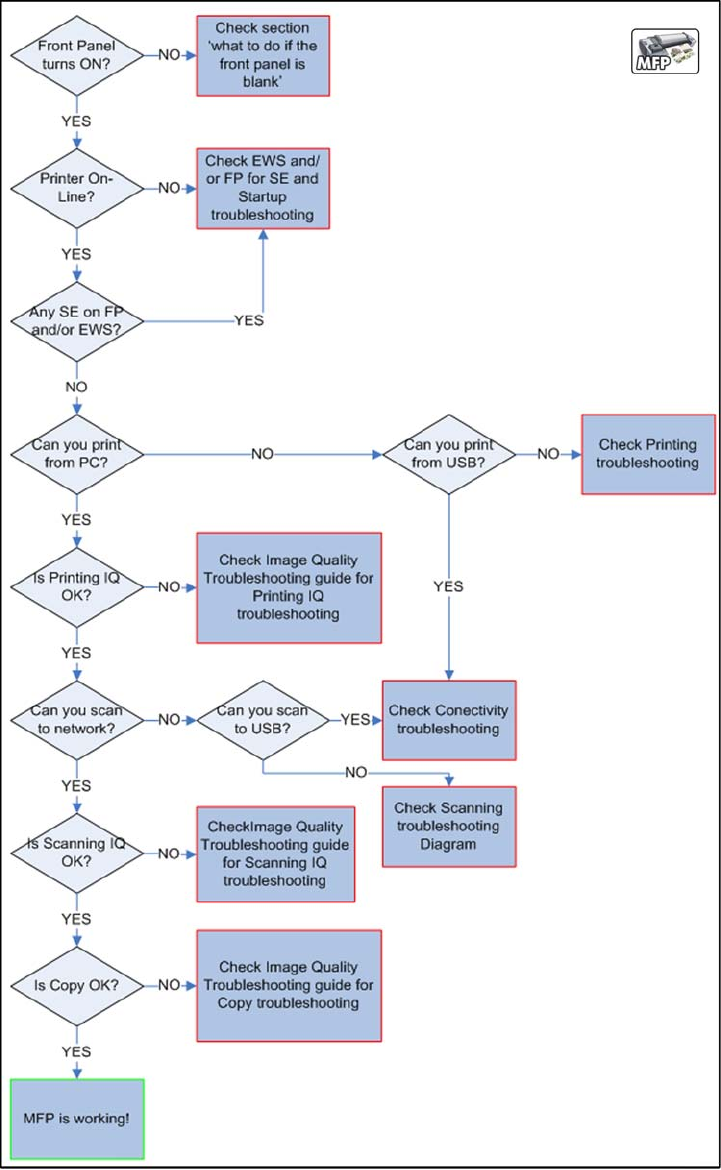
Product Troubleshooting trees (MFP)
Us the following troubleshooting trees to troubleshoot issues with the MFP in the first instance.
Product Troubleshooting Tree
Use this tree to troubleshoot the MFP.
Figure 1-1 Troubleshooting
6 Chapter 1 Troubleshooting ENWW
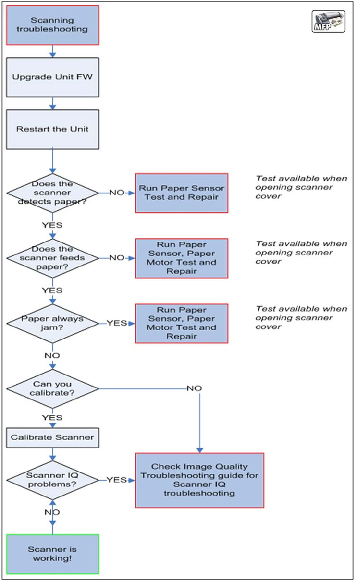
Scanner Troubleshooting Tree
Use this tree to troubleshoot the scanner in the MFP.
Figure 1-2 Scanner Troubleshooting
ENWW Product Troubleshooting trees (MFP) 7
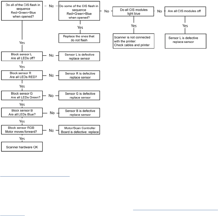
Scanner CIS Troubleshooting
Use this tree to troubleshoot the CIS of the scanner in the MFP.
Figure 1-3 Scanner Troubleshooting
Troubleshooting system error codes
System Error Codes on page 35 contains a list of system error codes and their respective descriptions
and recommended corrective actions. Try only one recommended action at a time and check whether
the error code has disappeared.
If you have an error code which is not documented in this Service Manual or you have an error which
you cannot resolve, then report the error to the HP Response Center or the nearest HP Support Office.
When reporting the error, have the information ready, refer to Reporting a system error to HP support
on page 35:
8 Chapter 1 Troubleshooting ENWW

Performing a service test on a failed assembly
If possible, always perform a Service Test on the component/assembly that you are about to replace,
just to make sure that is the component/assembly that has failed.
Shown below is a list of the Service tests and the component(s) tested:
●Scan Axis Test
◦Star Wheel Lifter
◦PRS
◦Scan Axis Servosystem
◦Cutter
●Paper Drive Test
◦Components of the Paper Axis Subsystem
●Electronics Module Test
◦Formatter
●Carriage assembly test
◦Carriage Assembly
●Sensors Test
◦Scanner Position Sensor (MFP only)
◦Media Lever Position sensor
◦Media sensor
◦Upper or lower roll cover sensor
◦Single-sheet sensor
●Rewinder test
◦Right Roll Support.
●Ink Delivery System Test
◦Ink Supply Station
◦Ink supplies
●Service Station test
◦Service Station.
◦Primer Motor
NOTE: If the test on that component/assembly passes, you should not replace it.
For information on the Service Tests and how to use them see Diagnostics Menu on page 79.
Performing the necessary service calibrations
Is the product calibrated correctly after replacing a component? For information on the Service
Calibrations and how to use them see Service Menu on page 117.
ENWW Product Troubleshooting trees (MFP) 9

NOTE: Remember that certain Calibrations are required even if an Assembly has been disassembled
to gain access to another Assembly or Component.
Solving scan/print-quality problems
Refer to the Image Quality Troubleshooting Guide (in the EWS-Support Tab or in the CD).
The Touch Control Panel is blank
See What to do if the Touch Control Panel is blank on page 36.
The product does not power on
See What to do if the Touch Control Panel is blank on page 36.
The product continuously rejects printheads
▲Clean the flex contacts on the Printhead and in the Carriage Assembly using the Carriage
Interconnect Wiper and try again.
Cover sensors are not working
1. Perform the Sensors Test. See Sensors Test on page 96.
2. Check that the cable for the faulty sensor is not damaged and is connected correctly.
3. Replace the faulty Sensor.
The line sensor has problems detecting paper
1. Check the type of paper that is being used since the Line sensor may have problems detecting
transparent paper or some types of Non-HP paper. Try loading white HP paper in to the product
and check that the Line sensor detects it.
2. The Line Sensor is not calibrated correctly. Perform the Line Sensor Calibration. See Line Sensor
Calibration on page 164.
3. The Line Sensor is damaged or faulty. Replace the Line Sensor. See Line Sensor on page 325.
Troubleshooting Printer paper jams and printhead crashes
The failure modes "paper jam" and "head crash" are grouped together because in many cases a paper
jam causes the paper to lift up into the Carriage path and cause a Printhead crash, thus causing many
paper jam failures to be reported as head crashes.
1. Did the paper jam occur when loading paper?
●If the client has had paper jams, it is common for pieces of paper to get stuck in the paper
path. Clear the paper path.
NOTE: When clearing a paper jam, sometimes paper is stuck in the paper path. To clear this,
you must lift the Media Lever and insert thicker paper into the paper path to push out the paper
that is still stuck there.
2. Is the customer using non-HP paper?
●The use of non-HP paper can easily be the cause of paper jams and head crashes (especially
head crashes because HP paper is specially formulated to avoid cockle, one of the primary
causes of head crashes). If the paper is not HP approved, advise the customer to use HP
paper and check to see whether the problem is now solved.
10 Chapter 1 Troubleshooting ENWW
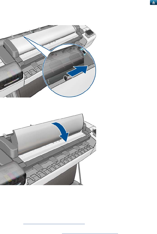
Troubleshooting Scanner paper jams (MFP only)
1. If while feeding paper into the Scanner a jam occurs, use the eject button on the Touch Control
Panel to clear the jam.
2. Unlatch the CIS Cover.
3. Open the CIS and clear the area of any paper.
The basket was damaged during the product setup
1. There are three plastic parts that could break during product installation and need replacing.
2. Check the parts table and graphics in Parts and Diagrams to identify what service parts you must
order. See Product Support on page 174.
3. Replace the component. See Bin Assembly on page 207.
ENWW Product Troubleshooting trees (MFP) 11

Paper-handling troubleshooting
Roll paper The Touch Control Panel of the product indicates that paper is misaligned or incorrectly positioned
●The roll may be loaded the wrong way. The paper should load over the roll toward you.
●Check that the paper is correctly loaded onto the spindle.
●The paper may be loaded at an angle. The right-hand edge must be aligned with the blue line on the
Print Platen.
●Check that the Right Roll Support is properly attached and screwed to the product.
●The Rewinder, located on the Right Roll Support, should maintain proper back tension. If the Right Roll
Support is misaligned or not properly attached to the product, the Rewinder will not function properly.
●To further diagnose problems with the Rewinder, see Rewinder Test on page 98.
●If the customer is experiencing problems with paper jams, check that the Overdrive is not obstructed
by paper or that the Turn Drive Roller Service Utility is being used. See Turn Drive Roller
on page 120
●While attempting to load roll media, if the Front Panel prompts you to remove paper, although no paper
is loaded, calibrate the sheet sensor, refer to Calibrate Sheet Sensor on page 169
Sheet paper ●The sheet must be loaded with the right-hand edge against the white line on the upper roll cover.
●The paper may be crumpled or warped or may have irregular edges.
●If the printer incorrectly detects the presence of a sheet of paper, perform the Calibrate Sheet Sensor,
refer to Calibrate Sheet Sensor on page 169.
●If hand-cut paper is used, the edges may not form a right-angle or they may be rough. If possible, hand-
cut paper should not be used. Only purchased sheet paper should be used in the product.
●If you have problems with paper jams, check that the Overdrive is not obstructed by bits of paper or
using the Turn Drive Roller Service Utility. See Turn Drive Roller on page 120.
●When attempting to load sheet paper from Front Panel, if the printer displays a media skew message
repeatedly, and sheet cannot be loaded, calibrate sheet sensor. refer to Calibrate Sheet Sensor
on page 169
12 Chapter 1 Troubleshooting ENWW
Ink-supplies troubleshooting
●Introduction to ink supplies
●Ink cartridge levels, information and replacement
●Printhead information, replacement and alignment
●Ink cartridge and printhead status messages
●Solving ink-supply problems
●Maintaining and cleaning the printheads
Introduction to ink supplies
Introduction to ink supplies
What are ink supplies?
For each of the ink colors used in the product, there are two components, the Printhead and Ink
Cartridge. These components are called Ink Supplies.
Ink cartridges
The product's six Ink Cartridges provide matte black, magenta, yeloow, cyan, gray and photo black ink
to the Printheads. The color Ink Cartridges supplied with the product have a capacity of 69ml but optional
130 ml are also available.
All these Ink cartridges are physically the same size. Only the internal capacity varies.
ENWW Ink-supplies troubleshooting 13
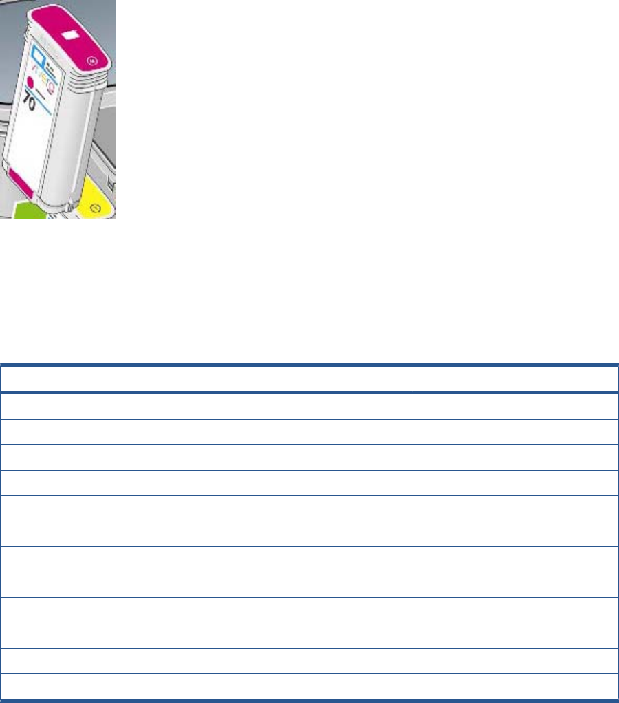
The Ink Cartridges for the T product series require no maintenance or cleaning. As long as each Ink
Cartridge is inserted correctly into its slot, the ink will flow to the Printheads. Because the Printheads
control the amount of ink transferred to the page, you will continue to see high-quality printing results
even when the ink levels are getting low.
The Touch Control Panel displays the status of the Ink Cartridge. Using the Touch Control Panel,
detailed information can be checked on the Ink Cartridges.
Table 1-2 Available Ink Cartridges
Ink cartridge Part number
HP 72 69 ml Photo Black Ink Cartridge C9397A
HP 72 69 ml Cyan Ink Cartridge C9398A
HP 72 69 ml Magenta Ink Cartridge C9399A
HP 72 69 ml Yellow Ink Cartridge C9400A
HP 72 69 ml Gray Ink Cartridge C9401A
HP 72 130 ml Matte Black Ink Cartridge C9403A
HP 72 130 ml Photo Black Ink Cartridge C9370A
HP 72 130 ml Cyan Ink Cartridge C9371A
HP 72 130 ml Magenta Ink Cartridge C9372A
HP 72 130 ml Yellow Ink Cartridge C9373A
HP 72 130 ml Gray Ink Cartridge C9374A
HP 726 300 ml Matte Black Ink Cartridge (T1300 series only) CH575A
Printheads
The Printheads are extremely durable and do not need to be replaced every time an Ink Cartridge is
replaced. They are independent of the Ink Cartridges and will continue giving excellent image-quality
results even if the Ink Cartridges are low on ink.
14 Chapter 1 Troubleshooting ENWW
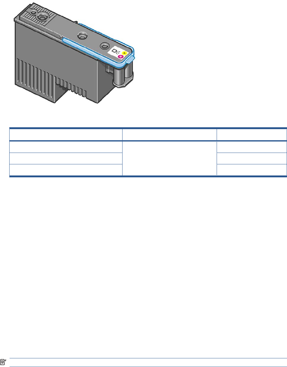
Table 1-3 Available Printheads
Product Model Part number
HP 72 Gray & Photo Black Printhead All C9380A
HP 72 Magenta & Cyan Printhead C9383A
HP 72 Matte Black & Yellow Printhead C9384A
General information about the ink supplies
For optimum results from the product and modular ink delivery system always follow these guidelines
when handling the ink supplies:
●Always install the Ink Cartridges and Printheads before the expiration date, which is on the
packaging.
●Install Ink Cartridges and Printheads in their color-coded slots.
●Follow the instructions on the Touch Control Panel of the product during installation.
●Avoid unnecessary removal of the Ink Cartridges and Printheads.
●When turning off the product always use the Power button on the Touch Control Panel. The
Printheads are then stored correctly which prevents them from drying out.
●The Ink Cartridges should never be removed while the product is printing. They should only be
removed when the product is ready for you to replace them. The Touch Control Panel will guide
you through the removal and installation procedure.
General precautions when handling ink supplies
Use the following precautions when handling Ink Supplies:
NOTE: Do not touch, wipe or attempt to clean the printhead nozzles. This can damage the printhead.
●Handle the ink supplies with care. In particular the Printhead, which is a high precision device and
must be handled carefully.
●Do not touch the Printhead nozzles.
●Do not put the Printhead down on the nozzles.
●Do not be rough when handling the Printheads. Always set them down gently
ENWW Ink-supplies troubleshooting 15
●Do not drop the Printheads.
●Proper handling will assure optimum performance throughout the Printhead life.
●Do not touch the end of the Ink Cartridge which is inserted into the product as there may be a small
amount of ink on the connection.
●Avoid storing partially used Ink Cartridges on their ends.
When should you replace the ink supplies?
When to change the ink supplies is mostly determined by you with guidance from the Touch Control
Panel. In conjunction with the messages displayed in the Touch Control Panel and the message
explanations in this chapter, you will be able to choose for yourself when is the right time to change the
ink supplies.
The product will also display the ink level and will tell you when the ink supply is low on ink. This means
you have constantly updated information about the ink supplies.
Ink cartridge levels, information and replacement
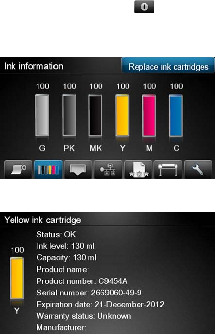
Ink cartridge levels and information
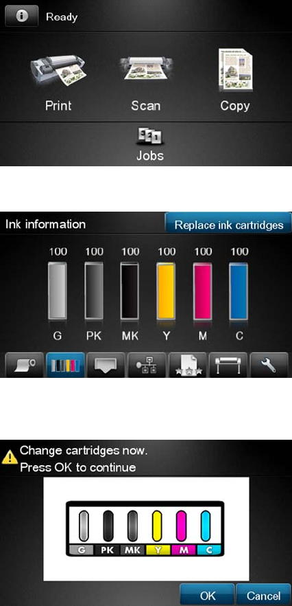
The Touch Control Panel displays Ink Levels shown as level bars. These bars represent how much ink
is remaining in the Ink Cartridges: as ink is used up the bars get shorter in length. To view the ink levels
perform the following steps:
1. Press on the Information icon .
2. Press on the Ink Menu icon. Each of the Ink Cartridges is displayed as a bar indicating the level of
ink remaining.
3. To get further information of an Ink Cartridge, press on the corresponding bar that you want to view.
The information supplied is:
●The current status of the Ink Cartridge.
●The current ink level of the ink cartridge in milliliters.
16 Chapter 1 Troubleshooting ENWW

●Original capacity of the ink cartridge in milliliters.
●The make of the Ink Cartridge (HP no.72 is recommended).
●The product name of the Ink Cartridge.
●The product number of the Ink Cartridge.
●The serial number of the Ink Cartridge.
●The Expiration Date of the ink cartridge.
●The current warranty status of the Ink Cartridge.
●The manufacturer of the Ink Cartridge (HP is recommended).
The product consumes more gray ink than M, C, or Y
This is not a problem, and no action should be taken to “correct” this attribute of the product.
In general the higher frequency of change is because Matte Black ink is the one that is used for lines
and black objects in technical papers (bond, coated, HW coated, natural tracing paper, etc.), which are
the types of contents that are more commonly printed with this type of product.
About gray ink
The T Series products are the first HP Designjet technical products to include Gray ink. One thing that
users may notice is that Gray ink is used in higher quantities than Cyan, Magenta and Yellow inks. This
happens because of the following reasons:
1. Gray areas (which are very typical in technical drawings) can now be printed by using only Gray
ink. In the past, these areas had to be printed by combining Cyan, Magenta and Yellow inks. This
means that Gray ink is used more frequently than the rest of the inks (C, M, Y) which are now used
less frequently, so the difference in consumption is noticeable. However overall the T Series
products will actually need to use in total less ink to print gray areas than previous Designjet
products.
2. Soft colors can now be printed by combining C, M and Y inks with Gray. The addition of Gray ink
softens the color, improving transition areas. It also allows printing soft colors by using less C, M
and Y. These two types of contents are very typical and make the consumption of Gray to increase
and the consumption of C, M and Y to decrease.
Conclusion
However, no matter the combination of inks that are used, when the total cc’s of ink are added up, the
T Series products will always have a lower ink consumption than the HP Designjet 500, 800 and 1000
series for equivalent contents with equivalent levels of print quality.
Changing an Ink Cartridge
There are two occasions when you need to remove an ink cartridge:
●The ink cartridge is very low and you want to replace it with a full cartridge for unattended printing
(you can use up the remaining ink in the first cartridge at a more convenient time).
●The ink cartridge is empty or faulty, and you must replace it to continue printing.
NOTE: Do not try to remove an ink cartridge while printing. Remove an ink cartridge only if you are
ready to insert another one.
Make sure the product wheels are locked (the brake lever is pressed down) to prevent the product from
moving.
ENWW Ink-supplies troubleshooting 17
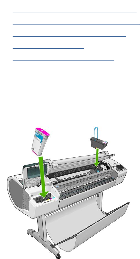
To change an ink cartridge there are two methods, the first is shown below by using the ink tab, the
second method is to access the main menu option (refer to the User's Guide for further details).
1. Press on the Information icon.
2. Press on the Ink Menu icon and the following screen is displayed.
Press on the Replace ink cartridge tab
3. The following screen is displayed, press OK to continue.
4. Open the relevant Ink Cartridge cover for the Ink Cartridge you want to replace.
5. Pull the required Ink Cartridge straight up to remove it from the product. The Touch Control Panel
indicates the missing Ink Cartridge.
6. Before removing the cartridge from its wrapping, shake it vigorously.
7. Unwrap the new ink cartridge, find the label identifying the ink color. Check that the letter or letters
marking the empty slot, matches the letter or letters on the cartridge label.
8. Insert the ink cartridge into its slot.
9. Push the cartridge into the slot until it snaps into position. You will hear a beep and see confirmation
that the cartridge has been inserted.
10. When all cartridges have been inserted, close the cover.
18 Chapter 1 Troubleshooting ENWW
Printhead information, replacement and alignment
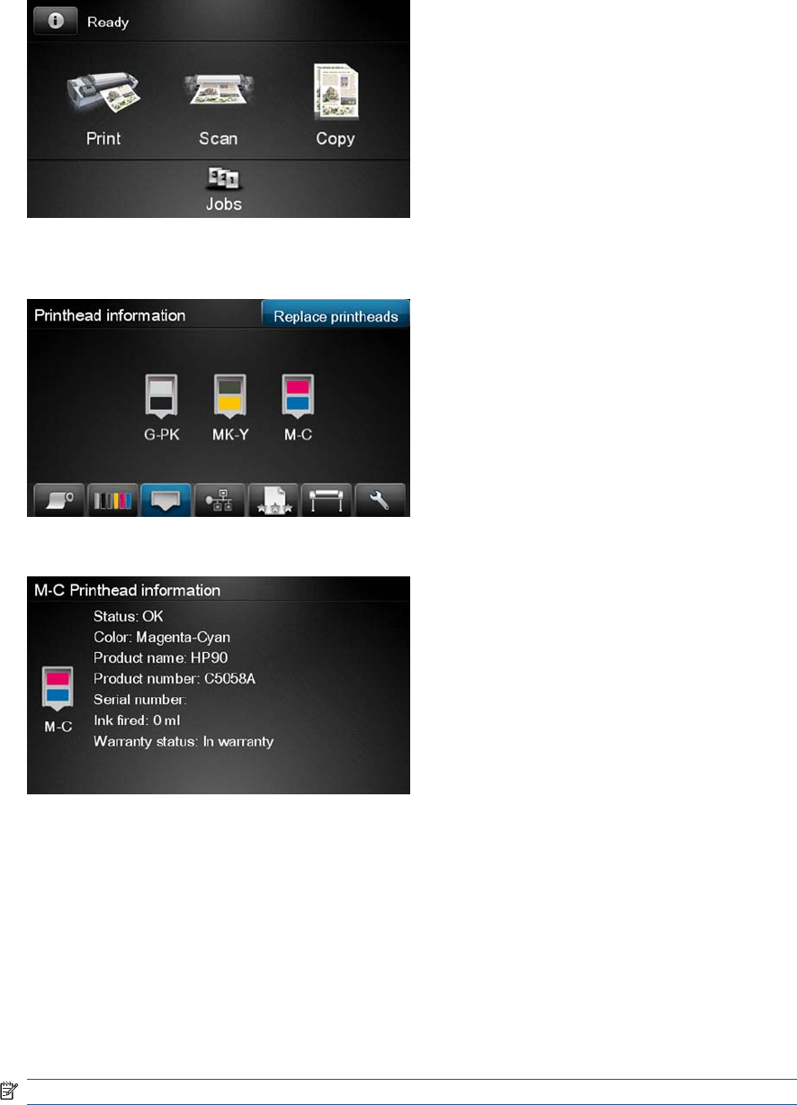
Obtaining Printhead Information
1. Press on the Information icon.
2. Press on the Printhead Menu icon and the following screen is displayed, press on the printhead
that you want information on.
3. The Touch Control Panel displays information on the selected Printhead.
The information supplied is:
●The current status of the printhead.
●The color of the printhead.
●The make of the printhead (HP no.72 is recommended).
●The product number of the Printhead.
●The serial number of the Printhead.
●How much ink has been fired (consumed) by the printhead.
NOTE: It is possible for a printhead to consume more than one Ink Cartridge.
●The current warranty status of the Printhead.
ENWW Ink-supplies troubleshooting 19

Changing a Printhead
To change a Printhead there are two methods, the first is shown below by using the printhead tab, the
second method is to access the main menu option (refer to the User's Guide for further details).
1. Press on the Information icon.
2. Press on the Printhead Menu icon and the following screen is displayed. Press on the Replace
Printhead tab.
3. A screen is displayed, showing an animation of how to install the printhead(s).
4. The product moves the Carriage to the correct position to replace Printheads.
NOTE: If the carriage is left in the removal position for more than three minutes without inserting
or removing any printheads, it will try to move back to its normal position at the right-hand end.
5. Open the Scanner (MFP only) or Window.
6. Locate the carriage on the right side of the product.
20 Chapter 1 Troubleshooting ENWW

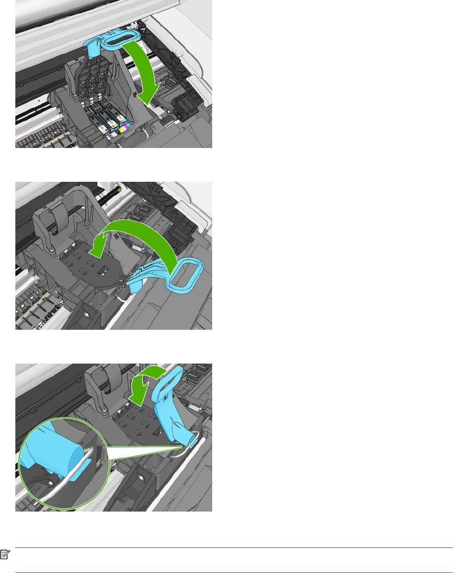
7. Pull the blue handle up and toward you to release the Carriage Cover.
8. Push the handle back.
9. This gives you access to the printheads.
10. The following screen is displayed
ENWW Ink-supplies troubleshooting 21
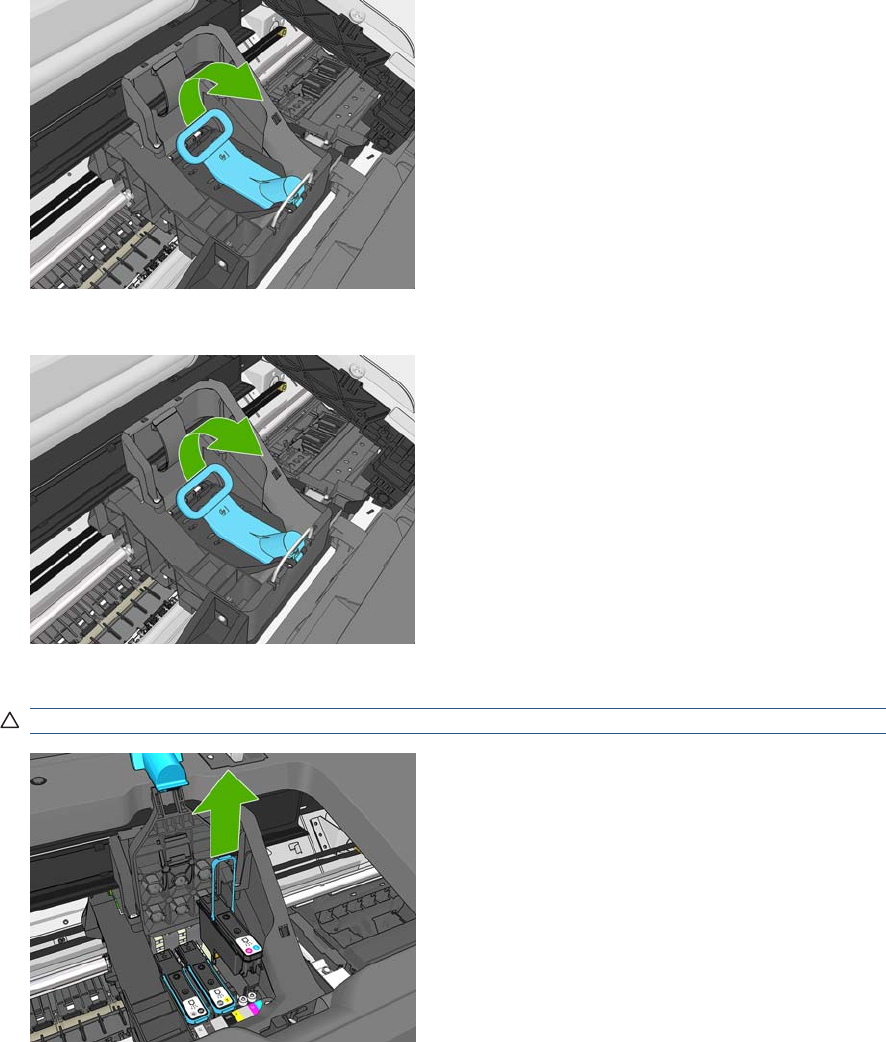
11. Remove a printhead by lifting up the blue handle.
12. Using the blue handle, use steady force to disengage the printhead.
13. Pull the blue handle upward until the printhead is released from the carriage.
CAUTION: Do not pull abruptly because this can damage the printhead.
14. The Touch Control Panel display identifies the missing printhead.
22 Chapter 1 Troubleshooting ENWW
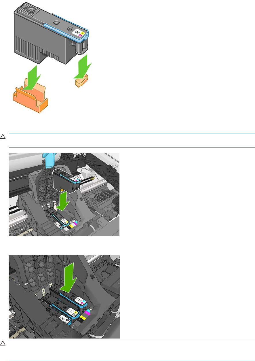
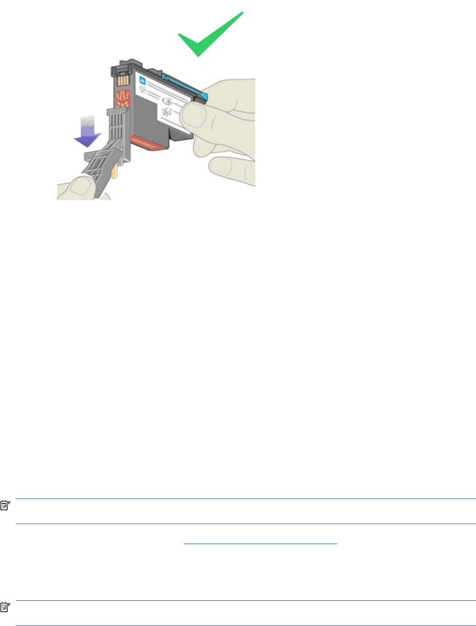
15. To insert a new printhead first remove the orange protective caps.
16. Insert the new printhead into its correct slot in the carriage.
CAUTION: Insert the printhead slowly and vertically, straight down. It may be damaged if you
insert it too fast, or at an angle, or if you rotate it as you insert it.
17. Push down as indicated by the arrow shown below.
CAUTION: When installing the new printhead there may be some resistance, so you need to
press it down firmly but smoothly. You should hear a beep and see confirmation on the Touch
Control Panel display that the printhead has been inserted.
ENWW Ink-supplies troubleshooting 23
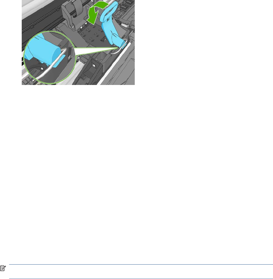
18. Insert all other printheads that need to be installed, and close the carriage lid.
19. Ensure the end of the blue handle catches the wire loop on the near side of the carriage.
20. Lower the handle to rest on the carriage cover.
When all the printheads have been inserted correctly and are accepted by the product, the product
beeps.
NOTE: If the product does not beep when you insert the printhead and the Replace message
appears on the Touch Control Panel display, the printhead may need to be reinserted.
24 Chapter 1 Troubleshooting ENWW
21. Lower the scanner.
22. The Touch Control Panel display confirms that all printheads are correctly inserted. The product
starts checking and preparing the printheads. The default routine process, when all printheads are
changed, takes 10 minutes. If the product finds problems in preparing the printheads, it takes
longer, up to 45 minutes. For a single printhead insertion, the times vary between 2 and 40 minutes.
After all printheads are checked and prepared, the printhead realignment procedure runs
automatically if paper is loaded.
The Touch Control Panel display confirms that all printheads are correctly inserted.
The product will start checking and preparing the printheads. The default routine process, when
all printheads are changed, takes 25 minutes. If the product finds problems in preparing the
printheads, it will take longer, up to 55 minutes. For a single printhead insertion, the times vary
between 15 and 35 minutes. After all printheads are checked and prepared, for the printhead
realignment.
Aligning Printheads
Precise alignment between printheads is essential for accurate colors, smooth color transitions, and
sharp edges in graphical elements. Your product has an automatic printhead alignment process which
runs whenever a printhead has been accessed or replaced.
In cases where the paper has jammed, you have used a custom paper, or are experiencing problems
with color accuracy you may need to align the printheads. If the paper has jammed, it is recommended
that you reinsert the printheads and initiate the realignment procedure with the Image Quality
Maintenance menu.
NOTE: Do not use transparent and semi-transparent paper to align the printheads. Photo paper is
recommended for the best quality.
Reinsert Printheads Procedure
1. If the realignment process is running and the wrong paper is loaded, press the Cancel button on
the Touch Control Panel. Do not print if the realignment process has been canceled. You can restart
the alignment with the Image Quality Maintenance menu procedure.
2. Load the paper you wish to use. You can use a roll that is at least 610 mm (24 in) wide or a cut
sheet that is A2 landscape or larger.
3. Remove and re-insert all the printheads, see Remove a printhead and Insert a printhead. This will
start the printhead alignment procedure.
4. The process will take about six minutes. Wait until the Touch Control Panel display shows the
process complete before using the product.
ENWW Ink-supplies troubleshooting 25
Image Quality Maintenance Procedure
1. Load the paper you wish to use. You can use a roll that is at least 610 mm (24 in) wide or a cut
sheet that is A2 landscape or larger. Do not use transparent and semi-transparent paper to align
the printheads. Photo paper is recommended for the best results; plain, bond and thin coated
papers provide acceptable but marginal results.
2. Press the Menu button to access the main menu and select the Image Quality Maintenance menu
icon.
3. Select Align printheads. The product will check to see if it has enough paper to run the realignment.
4. The realignment procedure will now be performed and the realignment pattern will be printed.
5. The process will take about five minutes. Wait until the Touch Control Panel display shows the
process complete before using the product.
Scanning errors during alignment
If the alignment process FAILs, a Scanning error message is displayed on the Touch Control Panel.
This means that the alignment has not completed successfully. The problem may be due to:
●The paper used was not valid, repeat the alignment with valid paper.
●Printhead health problems, clean printheads.
●The alignment was done with the Scanner open, repeat the alignment with the cover closed.
If the problem persists after using valid paper, cleaning the printheads, and keeping the cover closed,
there may be a failure in the scanning system needing reparation or the printheads, although clean, may
not work and need to be replaced.
Ink cartridge and printhead status messages
Ink Cartridge Status Messages
OK The Ink Cartridge is operating correctly and no action is required.
Missing There is no Ink Cartridge present, or it is not properly connected to the product
Low The Low message is an early warning sign and it is advisable that new supplies should
be obtained of that particular color. The amount of ink remaining in the Ink Cartridge
depends on it’s capacity, but there is approximately 14% of ink available for the user.
Very Low When theVery Low message is displayed, overnight printing should not be attempted.
Changing the Ink Cartridge is strongly recommended to prevent the product from stopping
halfway through a print. There is approximately 8% of ink available for the user.
Empty The product will stop and will not be able to continue printing until a new Ink Cartridge has
been installed. If this occurs halfway through printing an image, you should check the
quality of this image, as stopping mid-plot can affect the print. It would be recommended
to reprint the image once a new Ink Cartridge has been installed.
Reseat You are recommended to remove the Ink Cartridge and then reinsert it.
Replace You are recommended to replace the Ink Cartridge with a new Ink Cartridge.
Altered There is something unexpected about the Ink Cartridge's status.
Expired The Ink Cartridge has passed the expiration date.
Printhead status messages
OK The Printhead is operating correctly and no action is required.
Missing There is no Printhead present, or it is not properly connected to the product.
26 Chapter 1 Troubleshooting ENWW

Test printhead separately You are recommended to test the printheads individually to find the failing printhead.
Remove all the printheads and insert them alone one by one, Closing the latch and the
carriage cover after every insertion. The Touch Control Panel display will indicate the failing
one showing the reseat or replace message.
Reseat You are recommended to start the printhead removal process from the Touch Control
Panel, but instead of removing the printhead, simply press the OK button on the Touch
Control Panel.
Replace You are recommended to remove the printhead and then reinsert it; if that fails, clean the
electrical connections; if that fails, replace the printhead with a new printhead.
Replacement incomplete A printhead replacement process has not completed successfully, relaunch the
replacement process and let it finish completely (it is not needed to change the printheads).
Remove The printhead is not a suitable type for use in printing (for instance, a setup printhead).
Printhead Error Codes
The following table describes the Printhead Error Codes. Refer to the above descriptions of the status
messages for the appropriate action.
Error Code Status Name Status Message Description Comments
0Working OK The printhead is working
properly
1Fails Logical V Replace The printhead may have a vcc
short
2Fails Continuity Reseat Could be caused by bad insertion.
Better to reseat the PEN than to
reject it.
4Shutdown Not used
8Fails Vpp Replace Suspected vpp ink short
16 Temp
Extremely High
Replace Printhead temperature above
normal margins
Could be caused by a short in the ink
supplies
32 Temp
Extremely Low
Reseat Printhead temperature below
normal margins
Could be caused by bad Vpp
continuity
64 Temp too High Replace Printhead temperature above
normal margins
Could be caused by a short in the ink
supplies
128 Temp too Low Reseat Printhead temperature below
normal margins
Could be caused by bad Vpp
continuity
256 Bad Acumen
Info
Replace Critical acumen info outside
margins
Printhead has a manufacturing
problem
512 No Pen Missing There is no printhead
1024 Bad Accumen
Access
Reseat or Test
Separately
Acumen cannot be accessed Bad acumen continuity or a short;
Cannot identify problem printhead
2048 Wrong Model Replace Wrong printhead inserted Mechanical lockouts should prevent
this. Error is redundant
4096 Mismatch Replace Wrong color inserted Mechanical lockouts should prevent
this
8192 CSdata Not
Responding
Reseat CSdata commuication failed Could be caused by bad insertion
16384 CSdata
Transmit Error
Reseat CSdata commuication
incorrect
Could be caused by bad contact
ENWW Ink-supplies troubleshooting 27

Error Code Status Name Status Message Description Comments
32768 Fails Energy
Calibration
Reseat Energy calibration failed Could be caused by bad contact
65536 Empty Dummy OK during Purge Requested during purge, otherwise
should be removed
131072 Full Dummy Remove Requested during purge
262144 End of Life Warning Printhead warranty expired
524288 Expired Warning Printhead has used expired or
non-HP ink
Solving ink-supply problems
Most of the problems that you could encounter when working with the ink supplies are solved with
guidance from the Touch Control Panel. A full list of Touch Control Panel messages are supplied in the
User’s Guide.
You Cannot Insert the Ink Cartridge Into the product
1. Ensure that you have the correct HP no.72 Ink Cartridge.
2. Ensure that the Ink Cartridge is the correct color for that slot.
3. Ensure that the Ink Cartridge is the correct orientation, with the color coded label at the top.
NOTE: Never clean inside the Ink Cartridge slots as this can cause damage to the product.
You Cannot Insert the Printhead Into the Product
1. Ensure that you have the correct HP no.72 Printhead.
2. Ensure that the printhead is the correct color for that slot.
3. Ensure that the printhead is in the correct orientation.
4. Ensure that the protective cap is removed from the Printhead.
The Touch Control Panel says to reset or replace a printhead
1. From the Touch Control Panel, turn the power off then on.
2. Check the Touch Control Panel display message, if it shows the ready message, the product is
ready to print. If the problem remains continue with the next step.
3. Remove the printhead.
28 Chapter 1 Troubleshooting ENWW
4. Clean the electrical connections on the backside of the printhead with a lint-free cloth. You can
carefully use a mild rubbing alcohol if moisture is needed to remove residue. Do not use water.
You can use the Flex Contacts Cleaning Tool.
This is a delicate process and may damage the printhead. Do not touch the nozzles on the bottom
side of the printhead, especially not with any alcohol.
5. Reinsert the printhead.
6. Check the Touch Control Panel display message. If the problem remains, try a new printhead.
Maintaining and cleaning the printheads
Clean the printheads
As long as the product is kept turned on, an automatic cleaning is performed periodically. This ensures
there is fresh ink in the nozzles and prevents nozzle clogs, which ensures color accuracy.
For image quality issues, you can also refer to the Maintenance and Troubleshooting document.
To clean the printheads, press the Menu key to return to the main menu and select the Image Quality
Maintenance menu icon, then Clean printheads. If you have gone through the Image Quality Diagnostic
print process, you know which colors are failing. Select to the pair of printheads which contain the failing
colors. If you are not sure which colors to clean, you can also select to clean all printheads.
Cleaning all printheads takes about nine minutes. Cleaning a single pair of printheads takes about six
minutes. Cleaning all printheads uses more ink than cleaning a single pair.
If you have cleaned the printheads using the Clean printheads procedure from the Touch Control Panel
and are still experiencing image quality problems, you can try cleaning the printhead nozzles manually
using the following procedure.
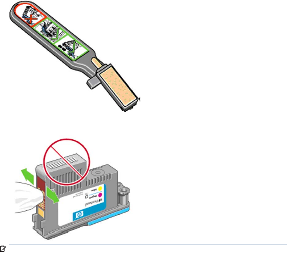
NOTE: This is a delicate process and may damage the printhead. Do not touch the electrical
connections on the backside of the printhead.
You must remove the printhead (see Changing a Printhead on page 20) and using a cotton swab and
a little de-ionized, distilled water, or Carriage Interconnect Wiper clean the bottom of the printhead until
the residue is removed.
Flex Contacts Cleaning Tool
NOTE: The Flex Contacts Cleaning Tool is part of the Maintenance Tool Kit. All the instructions needed
to use the Flex Contacts Cleaning Tool will be packaged with the kit.
ENWW Ink-supplies troubleshooting 29
Whenever you replace the Printhead, check the empty slots to see if they need cleaning. In extreme
circumstances, when a Printhead is inserted, it is possible that the product will not recognize it due to
the build-up of ink on the electrical connection between the Printhead and the Carriage Assembly.
Included with the product is a Flex Contacts Cleaning Tool. This tool is provided in a separate package.
It also contains replacement sponges and an instruction sheet. This tool should be used for cleaning
the electrical interconnects of both the Carriage Assembly and the Printhead.
If the Touch Control Panel displays the message “Reseat” or “Replace” next to the offending printhead,
try cleaning the flex circuits of the Carriage and the Printheads using the Carriage Interconnect Wiper.
NOTE: Do not touch, wipe or attempt to clean the printhead nozzles. This can damage the printhead
and reduce print quality.
30 Chapter 1 Troubleshooting ENWW

Connectivity troubleshooting
Connectivity problems are resolved differently for USB, embedded LAN and Jetdirect connectivity.
Follow the advice given in the appropriate section below.
Embedded LAN connectivity troubleshooting
Perform the following procedure, checking the connectivity carefully after each step to see whether the
problem has been fixed.
1. Change the LAN cable.
a. Disconnect the LAN cable at both the remote end and the product end of the cable.
b. Reconnect using the LAN cable. Use a different LAN cable if possible.
2. Try connecting to a different Ethernet socket in your network, router or switch.
3. If possible, try to reset the Ethernet switch or router. This may involve turning it off and on again.
4. Adjust the configuration settings.
a. Print out the original product I/O settings: from the Touch Control Panel, press , then
then select the Internal Prints menu, then Service information prints > Print
connectivity config.
b. Reset the I/O to factory defaults: from the Touch Control Panel, select the Connectivity menu,
then Advanced > Restore factory settings.
c. Restart the product and wait 5 minutes.
d. Print out the new product I/O settings: from the Touch Control Panel, press , then
then select the Internal Prints menu, then Service information prints > Print connectivity
config.
e. Connect to the product’s Embedded Web Server using the URL shown in the main page of
the Touch Control Panel.
f. Compare the configuration information printed out before and after restoring to factory default
settings. Set any custom I/O settings that may have been lost back to their desired values
using the Configuration information printed.
g. Run the Network Connectivity Test in the Diagnostic & Troubleshooting wizard: From the
Touch Control Panel press , then go to Connectivity > Diagnostics &
troubleshooting > Web-connected printer wizard> Network connectivity Test
ENWW Connectivity troubleshooting 31
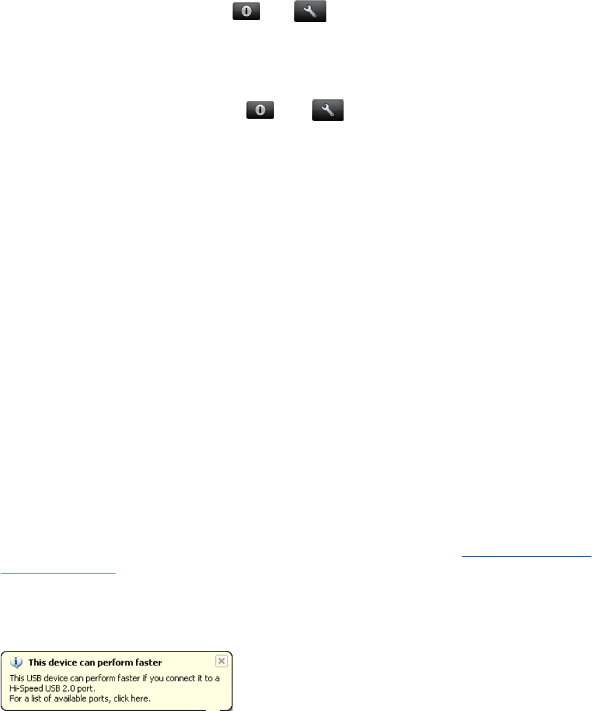
Internet communication failures
If the printer has difficulty in connecting to the Internet, it will display an error message, which enables
you to launch a diagnostic that will automatically detect possible issues in your networking and Internet
access. You can also run the connectivity troubleshooting wizard from the Touch Control Panel or the
EWS.
●From the Touch Control Panel: Press then go to Connectivity > Diagnostics &
troubleshooting > Web-connected printer wizard
●From the EWS: Select Support > Connectivity troubleshooting > Web-connected printer
wizard.
●From the Touch Control Panel go press , then go to Internal prints > Service
information prints > Print connectivity config. the results are then printed out.
The web connected printer wizard can help you:
●To correctly configure the internet connection
●Configure the Automatic Firmware Update
●Troubleshoot Internet connection issues
You can choose to perform all the tests or individual tests. The following options are available:
●All tests
●Network connectivity test: check the printer's connection to the local area network
●Internet connectivity test: check the printer's connection to the Internet
●Firmware update test: check the printer's connection to HP's firmware update servers.
If any test fails, the printer describes the problem and recommends how to solve it.
USB device connectivity troubleshooting
If the product experiences problems with the USB connection (the computer does not detect the product
when the USB cable is plugged in) or with USB performance (throughput is slow) then try the following
checks.
●Check that the Connectivity is not disabled through the I/O Interfaces Utility, Enable I/O Interfaces
Utility on page 111
●Check that the USB port in the computer is a “USB 2.0 High Speed” port. Some old computers and
USB hubs have slower “USB 1.1 Full Speed” ports, and those should not be used with Designjet
products. Do not ignore a warning message on your computer such as:
●Check the USB cable.
◦Check that the USB cable is USB 2.0 Certified: check the USB logo on the packaging of the
cable, or on the cable itself, or check the specifications of the cable.
◦Try a shorter USB cable. Cables close to the 5 m limit often cause problems.
◦Make sure the USB cable doesn’t pass near possible sources of electrical interference (CRT
monitors, engines, etc.).
32 Chapter 1 Troubleshooting ENWW

●Connect the product to a different USB port on the computer. If possible, try using a different
computer.
●Remove any other USB devices from the computer, or connect them to different USB ports.
EIO Jetdirect card connectivity troubleshooting
Perform the following procedure, checking the connectivity carefully after each step to see whether the
problem has been fixed.
1. Check that connectivity is not disabled, .
2. Change the LAN cable.
a. Disconnect the LAN cable at both the remote end and the product end of the cable.
b. Reconnect using the LAN cable. Use a different LAN cable if possible.
3. Try connecting to a different Ethernet socket in your network, router or switch.
4. If possible, try to reset the Ethernet switch or router. This may involve turning it off and on again.
5. Adjust the configuration settings.
a. Print out the original Jetdirect I/O settings: from the Touch Control Panel, select the Internal
Prints menu, then Service information prints > Print connectivity config.
b. Print out the original Jetdirect protocol settings: from the Touch Control Panel, select the
Connectivity menu, then Jetdirect EIO > Modify configuration > Information > Print
protocols > Yes. Return to the main menu.
c. Reset the Jetdirect I/O to factory defaults: from the Touch Control Panel, select the
Connectivity menu, then Jetdirect EIO > Restore factory settings.
d. Restart the product and wait 5 minutes.
e. Print out the new Jetdirect I/O settings: from the Touch Control Panel, select the Internal Prints
menu, then Service information prints > Print connectivity config.
f. Print out the new Jetdirect protocol settings: from the Touch Control Panel, select the
Connectivity menu, then Jetdirect EIO > Modify configuration > Information > Print
protocols > Yes. Return to the main menu.
g. Connect to the product’s Embedded Web Server using the URL shown in the main page of
the Touch Control Panel.
h. Compare the configuration information printed out before and after restoring to factory default
settings. Set any custom I/O settings that may have been lost back to their desired values
using the Configuration information printed.
USB host features
A USB host port is available in the formatter to support new features that may become available in the
future. As a security precaution, the USB port can be disabled through the EWS, Enable I/O Interfaces
Utility on page 111
ENWW Connectivity troubleshooting 33

Accessories
There are two different accessories that can be connected into the USB Host port:.
●PostScript Upgrade Dongle, part number CN500B. This accessory is compatible with all HP
Designjet T790, T1300 and T2300 series.
●External Hard Disk Drive, part number CN501A. This accessory is compatible with all the HP
Designjet T790, T1300 and T2300 series. When this accessory is connected the product will keep
all user data stored in the external hard disk only, which can be removed from the product and
stored separately for confidentiality or security reasons.
Copying the diagnostic package to a USB flash drive
The diagnostic package contains useful information from the product to help you to find the cause of a
problem. The USB host port provides a quick and easy way to retrieve this information into a standard
USB flash drive. See Appendix C: Obtaining the product log and the diagnostics package
on page 74.
Firmware upgrade with USB flash drive
The USB host port can be used to upgrade the product's firmware of the product using a standard USB
flash drive. In this case only a valid .FMW firmware package may be stored in the drive, and it must be
in the root folder, not in a sub folder. Connect the USB flash drive and follow the instructions on the
Touch Control Panel. The USB host port can be used at any time, regardless of what procedure the
printer is performing.
Special firmware upgrades
Emergency firmware upgrade using a USB flash drive
When it is not possible to perform a firmware upgrade using the normal procedures (for instance, in
case of a System Error and the Embedded Web Server is unavailable), it is possible to perform an
emergency firmware upgrade using a USB flash drive. See Appendix B: Emergency firmware upgrade
with USB flash drive on page 74.
Forced firmware upgrade
When the product is started for the first time, a wizard will start. The last step of the wizard asks the user
to configure the automatic firmware update settings, and then and there the user is forced to check if
there is a new version of the firmware available. In certain circumstances the printer may require a
firmware upgrade before it can initialize completely. When this occurs there will be a USB flash drive in
the shipping box with
In certain circumstances the printer may require a firmware upgrade before it can initialize completely.
When this occurs there will be a USB flash drive in the shipping box with the product. Follow the
instructions that come with the flash drive.
NOTE: The USB flash drive is provided only to upgrade the product's firmware. No other uses of the
USB flash drive are supported.
If for any reason the USB flash drive upgrade option fails, download the firmware from the HP.com
website instead. Load the firmware onto any empty flash drive and insert the flash drive into one of the
USB ports of the product. The product will recognize the firmware on the flash drive and display the
install procedure on the Touch Control Panel.
34 Chapter 1 Troubleshooting ENWW

2 System Error Codes
●Introduction
●Product logs
●What to do if the Touch Control Panel is blank
●Continuable and Non-Continuable Error Codes
●System Error Code Brief Descriptions
●System Error Codes—Full Descriptions
●Appendix A: How to troubleshoot SE 79:04
●Appendix B: Emergency firmware upgrade with USB flash drive
●Appendix C: Obtaining the product log and the diagnostics package
●Appendix D: How to check the display list memory for an HP-GL/2 job
Introduction
Understand System Error Codes
System error codes are generally used to report internal system errors. The following pages contain a
list of system error codes and their respective descriptions and recommended corrective actions. Try
only one recommended action at a time, in the order that they appear, and check whether the error code
has disappeared.
Reporting a system error to HP support
If you have an error code that you cannot resolve, then report the error to the HP Response Center or
the nearest HP Support Office. When reporting the error, have the following information ready:
NOTE: If you fail to provide any of the following information, HP Support cannot help you properly.
Make sure you take time to gather all of this information.
●Model and Serial Number of the product, this can be found in the Diagnostics menu, scroll to Unit
Information.
●Which firmware revision the unit is using. this can be found in the Diagnostics menu, scroll to Unit
Information.
●The complete error number, this information can be found in the Product/Printer Information Area.
●The Service Configuration Print. To print this press , then go to 'Internal Prints>Service
Information Prints'.
ENWW Introduction 35
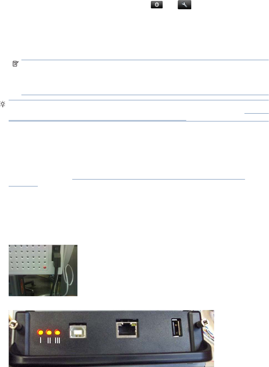
●The Current configuration sheet. To print this press , then go to'Internal Prints>Service
Information Prints'.
●Which software application the customer is using.
●The internal error code, file, and line fields found on the Internal Error Screens available by
pressing Up and Cancel at the same time when the System Error is shown on the Touch Control
Panel. To get the file and line fields, you need to scroll down to the next screen.
NOTE: The file and line fields are important to identify the source of the problem because the
same internal Error Code can be reported in different files and line. In the File field, supply only the
last part of the value (from last slash “/” to the end of the line). For example: for a file: /ae/…./elektra/
hal/motors/ControlledMotor/Elektra/ControlledMotorElektra.cpp you’ll only need to provide the
“ControlledMotorElektra.cpp” part to HP support.
TIP: When investigating a system error, you are recommended to use the diagnostic package to further
understand the problem. To obtain the diagnostic package (which takes a few minutes), see Appendix
C: Obtaining the product log and the diagnostics package on page 74.
Product logs
It is possible to view all the activities the printer performs collected in a log file. To further understand a
system error code, it is useful to have a log showing what the printer was doing at the time when the
system error occurred.
To get product logs, see Appendix C: Obtaining the product log and the diagnostics package
on page 74.
What to do if the Touch Control Panel is blank
The LEDs of the formatter (visible through the cover) and the power supply can help you troubleshoot
a problem if the Touch Control Panel is blank.
The following image shows the Power Supply LED, looking through the cover.
The following image shows the Formatter LEDs, which should be marked I, II and III.
36 Chapter 2 System Error Codes ENWW

Follow these steps to troubleshoot the issue.
1. Switch the power off from the back of the product and disconnect the power cord. Reconnect the
power cord and power on the product.
2. Check that the Touch Screen Panel interface cable is not damaged and is correctly connected
between the Engine PCA and the Touch Control Panel.
3. Check that the connections between the Formatter and the Engine PCA are not damaged and are
correctly connected.
4. Use the following table to interpret the LEDs and find the source of the problem. Remember that
you should read these LEDs when you push the Power button.
Some combinations may require the replacement of two or more components. In this case, always
replace one component at a time. Test the product to see if the problem has disappeared (check
the LEDs again). If the same LED sequence continues, replace the next component indicated in
the table.
Power
supply
LED
Formatter I
LED Formatter
II LED Formatter
III LED Touch
Control
Panel
status
Part to change
1Off Off Off Off Off Power supply, see Power Supply Unit on page 362
2On Off Off Off Off Engine PCA, see EE Box on page 281.
3On On Off Off n/a Formatter, see Formatter on page 290.
4On *Flashing* Off Off n/a Hard Disk Drive, see Hard Disk Drive on page 295.
5On On *Flashing* Off n/a Hard Disk Drive, see Hard Disk Drive on page 295.
6On On On Off n/a 1. Formatter, see Formatter on page 290.
2. Engine PCA, see EE Box on page 281.
7On On On *Flashing* n/a Engine PCA, see EE Box on page 281.
8On *Flashing* On On Off Check the cables, if they are ok replace the
interconnect PCA, see Interconnect PCA
on page 315.
9On Off On on Off 1. Check the USB cable of the Touch Control Panel,
if the cable is ok, replace the Touch Control Panel,
see Touch Control Panel on page 428.
2. Replace the Interconnect PCA, see Interconnect
PCA on page 315.
10 On Off Off *Flashing* Off 1. Check the Power cable of the Touch Control
Panel, if the cable is ok, replace the Touch Control
Panel, see Touch Control Panel on page 428
2. Replace the Interconnect PCA, see Interconnect
PCA on page 315.
11 On Off *Flashing* *Flashing* Off 1. Issue with the firmware, upgrade the product to
the latest firmware, or reinstall the firmware.
2. Replace the Touch Control Panel, see Touch
Control Panel on page 428
ENWW What to do if the Touch Control Panel is blank 37

Power
supply
LED
Formatter I
LED Formatter
II LED Formatter
III LED Touch
Control
Panel
status
Part to change
12 On On On On Touch
Control
Panel
light on
All LEDs on for a few seconds is the normal part of the
initialization of the product. If however the LEDs stay
on, this would indicate a greater problem,
communicated via a system error code on the Touch
Control Panel.
13 On On On On Off Replace the Touch Control Panel on page 428.
38 Chapter 2 System Error Codes ENWW

Continuable and Non-Continuable Error Codes
Some of the Error Codes are continuable, which means you can press OK on the Touch Screen Panel
and continue working with the product. Non-Continuable Error Codes do not allow you to continue
working with the product, in this case power the product OFF and ON again and see if the System Error
disappears. If the Error Code reappears, then the product requires an on-site visit in order to resolve
the problem.
System Error Code Brief Descriptions
Reading a System Error Code
System Error Codes explain which component/system is failing and what action should be taken to
resolve the problem.
System Error Codes are displayed directly on the Touch Control Panel (but can also be seen on the
Information Page) and have been defined in the format XX.YZ. or XX.n:YZ.m.
●XX: Subsystem or process (2 digits).
●n: Subsystem or process index (if more than one used in the product) – optional.
– e.g. Identify the Ink Supply (color and number).
●Y: Who should perform the action (1 digit) – (0 for User or 1 for Service Engineer).
●Z: Action to perform (1 digit).
System Error Code Table
The following table explains the XX part of the System Error Code or Warning:
Code Component/System
01.0 Engine PCA/Electronics module
02.1 Carriage PCA
03 Power supply
06 Formatter
08 Formatter/Touch Control Panel
09 Scanner (MFP only)
11 Trailing cable
21 Service station
22 Ink supply station
24 Tube assembly (IDS)
26.n Ink Cartridge (color = n)
27 Printhead error
38 Output Tray
39 Roll switches
41 Paper-axis motor
42 Scan-axis motor
45 Rewinder
ENWW Continuable and Non-Continuable Error Codes 39

Code Component/System
47 Star wheel motor
48 PPS mechanism
51 Top Cover Sensor
52 Drop detector
55 Line sensor
56 Drive roller analog encoder sensor
59 Electrical system
60 Initialization
61 Print queue
63 Input/output through LAN card
64 Input/output through USB port
65 Input/output (not known what port)
68 Loss of engine counters tracking
71 Memory management
72 Calibration
73 Servo
74 Firmware upgrade
74.1 Media Profile Update
75 Preventive Maintenance Kits
76 Disk Full
78 Media settings
79 Firmware
81 Media advance
84 Roll Feed
86 Paper path
87 Scan axis
93 Ink Pumping
40 Chapter 2 System Error Codes ENWW

Corrective Actions Table
The following table explains the YZ part of the System Error Code or Warning:
Code Recovery Action Response
00 Replace Possible for customer to perform
action
01 Reseat/Reconnect/Clean/Adjust (manually)
02 Calibrate/Adjust (using Automatic Process)
03 Power off and restart the product
04 Upgrade System Firmware
05 Upgrade Driver or Computer Software
06 Add Accessory
07 Escalate
08 Send Plot Again
09 Wrong Part Installed
10 Replace HP qualified personnel assistance
required
11 Reseat/Reconnect/Clean/Adjust (manually)
12 Calibrate/Adjust (using Automatic Process)
13 Power off
14 Upgrade System Firmware
15 Upgrade Driver or Computer Software
16 Add Accessory
17 Escalate
18 Send Plot Again
19 Wrong Part Installed
ENWW System Error Code Brief Descriptions 41

System Error Codes—Full Descriptions
This sections describes each of the system error codes and warnings that could be encountered while
using the product and provides the repaperl action required to solve the problem detected.
NOTE: Replace one component at a time and check whether the error has gone before replacing
another component. Using this procedure you will be able to determine exactly which component failed.
System Error: 01.0:YZ
Problem Description: Communication with Engine PCA failed
Corrective action: Try the following:
1. Switch the power off from the back of the product and disconnect the power cord.
Reconnect the power cord and power on the product.
2. Remove the Formatter and reinsert it again. Ensure that it connects properly in the Engine
PCA connector.
◦Replace the Engine PCA. See EE Box on page 281.
◦Replace the Formatter. See Formatter on page 290.
System Error: 01.1:YZ
Problem Description: Error in the Engine PCA
Corrective action: Try the following:
1. Switch the power off from the back of the product and disconnect the power cord.
Reconnect the power cord and power on the product.
2. Replace the Engine PCA. See EE Box on page 281.
3. Replace the Formatter. See Formatter on page 290.
System Error: 01.2:YZ
Problem Description: Failure communicating with an Ink Supply
Corrective action: Try the following:
1. Switch the power off from the back of the product and disconnect the power cord.
Reconnect the power cord and power on the product.
2. Perform the Ink Delivery System diagnostic test. See Ink Delivery System (IDS) Test
on page 100.
– If the test finds that the ink supply is defective, replace it.
– If the test does not find any errors, remove all the ink supplies from the ISS and reboot
the product.
3. Install the ink cartridges with the product booted in normal mode. Use the replacement
option available from the Touch Control Panel and install the cartridges one by one. If an
error appears after installing a supply, the last supply you installed is defective. Replace
it.
4. Check that the cables between the Left Ink Supply Station and the Engine PCA are not
damaged and are correctly connected. In case of any damage replace the cables; see
Connecting the Data Harness and ISS Harness Cable on page 227
5. Replace the Left Ink Supply Station. See Left Ink Supply Station on page 299.
6. Replace the Engine PCA. See EE Box on page 281.
42 Chapter 2 System Error Codes ENWW

System Error: 02.1:YZ
Problem Description: Problem with the Carriage PCA
Corrective action: Try the following:
1. Switch the power off from the back of the product and disconnect the power cord.
Reconnect the power cord and power on the product.
2. Check that the Trailing Cable is not damaged. Check that the Trailing Cable is correctly
connected between the Engine PCA and Carriage PCA.
3. Replace the Carriage PCA. See Carriage PCA on page 252.
4. Replace the Trailing Cable and Carriage PCA Covers.
5. Replace the Engine PCA. See EE Box on page 281.
System Error: 03:YZ
Problem Description: Problem with Power Supply Unit
Corrective action: Try the following:
1. Switch the power off from the back of the product and disconnect the power cord.
Reconnect the power cord and power on the product.
2. Replace the Power Supply Unit (PSU). See Power Supply Unit on page 362
System Error: 03.0:10
Problem Description: Battery of Real Time Clock ran down
Corrective action: Replace the battery. See Real-time Clock Battery on page 363.
System Error: 06:YZ
Problem Description: Failure reading/writing NVM in Hard disk
Corrective action: Try the following:
1. Switch the power off from the back of the product and disconnect the power cord.
Reconnect the power cord and power on the product.
2. Replace the Hard Disk. See Hard Disk Drive on page 295.
System Error: 07:10
Problem Description: Interconnect Board or Power cable has failed
Corrective action: Try the following:
1. Check the condition and connections of the Power Cable, replace if necessary.
2. Replace the Interconnect Board, , see Interconnect PCA on page 315.
System Error: 07.01:11
ENWW System Error Codes—Full Descriptions 43

Problem Description: DelSol3 ASIC not found or not responding
Corrective action: Try the following:
1. Check the condition and connections of the Interconnect data and power cable, replace
if necessary, , see Interconnect PCA on page 315.
System Error: 07.02:11
Problem Description: USB Cable not connected
Corrective action: Try the following:
1. Check the condition and connections of the USB cable, replace if necessary.
System Error: 07.03:10
Problem Description: USB Hub not found
Corrective action: Try the following:
1. Make sure Interconnect board connector labeled 'INPUT HUB' is properly connected.
2. Make sure Wukong board connector labeled JUSB2 is properly connected to the cable
coming from Interconnect board.
3. If failure continues, troubleshoot the error by changing the USB cable from Engine PCA
to Interconnect, if the error follows to the changed part the USB cable is faulty, if it does
not, the part is faulty.
4. Replace the Interconnect PCA, see Interconnect PCA on page 315.
5. Replace the Formatter Board see Formatter on page 290
6. Replace the Engine PCA see EE Box on page 281
System Error: 07.03:11
Problem Description: USB Scanner connected to incorrect port
Corrective action: Ensure that the USB cable from the Scanner to the Interconnect board is connected at the
connection labeled 'SCANNER' and not 'HOST CON'
System Error: 08:04
Problem Description: Touch Control Panel communication to the product functions at the initialization, but during
normal working the communication is lost.
Corrective action: Try the following:
1. Check the event log at the EWS support pages to see if there is another SE (for instance
07:10) and troubleshoot the problem more accurately.Appendix C: Obtaining the product
log and the diagnostics package on page 74
2. Turn off the product and turn on again, and check to see if the error remains.
3. Upgrade the firmware For more information, see Appendix B: Emergency firmware
upgrade with USB flash drive on page 74
4. Replace the HDD, see Hard Disk Drive on page 295
5. Escalate the issue.
44 Chapter 2 System Error Codes ENWW

System Error: 08:08
Problem Description: A feature on the Touch Control Panel hangs or will not function (copy,scan etc)
Corrective action: Try the following:
1. Turn off the product and turn on again, and check to see if the error remains.
2. Upgrade the firmware For more information, see Appendix B: Emergency firmware
upgrade with USB flash drive on page 74
3. Escalate the issue.
System Error: 08:11
Problem Description: No communication between the product and the Touch Control Panel
Corrective action: Try the following:
1. Check the event log at the EWS support pages to see if there is another SE (for instance
07:10) and troubleshoot the problem more accurately.Appendix C: Obtaining the product
log and the diagnostics package on page 74
2. Check the LED’s on the formatter to see if there is another issue and troubleshoot it more
accurately.
3. Turn off the product and turn on again, and check to see if the error remains.
4. Upgrade the firmware
5. Check the condition of the USB cable, check it is not damaged or incorrectly connected.
Reconnect USB cable (from Engine PCA to the Interconnect PCA or from Interconnect
PCA to the Touch Control Panel
6. Replace the USB cable
7. Replace the Interconnect PCA, see Interconnect PCA on page 315.
8. Replace the Engine PCA see EE Box on page 281
9. If the error continues, replace the Touch Control Panel Touch Control Panel
on page 428
System Error: 08:01:11
Problem Description: Touch Control Panel USB Cable fails
Corrective action: Try the following:
1. Check the condition and connections of the Touch Control Panel USB cable, replace if
necessary.
2. If the error continues, replace the Touch Control Panel Touch Control Panel
on page 428
System Error: 09:01
Problem Description: Media jam in Scanner
Corrective action: Try the following:
1. Open the CIS to solve the media jam and close it again.
2. If no paper is seen, run Scanner Motor Diagnostic, refer to the Users Guide for further
details.
ENWW System Error Codes—Full Descriptions 45

System Error: 09:02
Problem Description: Scanner not calibrated
Corrective action: Calibrate the Scanner Calibrate the Scanner on page 170
System Error: 09:03
Problem Description: File I/O Error
Corrective action: Reboot Product
System Error: 09:04
Problem Description: Contex Library failed to load
Corrective action: 1. Reboot the Product
2. Upgrade the firmware For more information, see Appendix B: Emergency firmware
upgrade with USB flash drive on page 74
System Error: 09.01:10
Problem Description: Scanner Motor is failing
Corrective action: Try the following:
1. Perform the Scanner motor diagnostics.
2. Replace the Scanner Motor Scanner Motor Assembly (MFP only) on page 425
System Error: 09.02:10
Problem Description: CIS A Element is failing
Corrective action: Replace CIS A Element CIS Element (MFP only) on page 420
System Error: 09.03:10
Problem Description: CIS B Element is failing
Corrective action: Replace CIS B Element CIS Element (MFP only) on page 420
System Error: 09.04:10
Problem Description: CIS C Element is failing
Corrective action: Replace CIS C Element CIS Element (MFP only) on page 420
System Error: 09.05:10
Problem Description: CIS D Element is failing
Corrective action: Replace CIS D Element CIS Element (MFP only) on page 420
System Error: 09.06:10
46 Chapter 2 System Error Codes ENWW

Problem Description: CIS E Element is failing
Corrective action: Replace CIS E Element CIS Element (MFP only) on page 420
System Error: 09.08:11
Problem Description: Power cable of the Scanner is failing
Corrective action: Check the condition and connections of the Scanner Power cable, if necessary replace the
cable.
System Error: 09.09:11
Problem Description: USB cable of the Scanner is failing
Corrective action: Check the condition and connections of the Scanner USB cable, if necessary replace the cable.
System Error: 09.10:04
Problem Description: Scanner is in SAFE MODE
Corrective action: Restart the product, if the problem persists replace the SCU. See Scanner Controller Board
(MFP only) on page 423.
System Error: 09.10:10
Problem Description: Scanner SCU is failing
Corrective action: Replace the Scanner SCU.See Scanner Controller Board (MFP only) on page 423.
System Error: 11:YZ
Problem Description: Trailing Cable does not seem to be detected
Corrective action: Try the following:
1. Switch the power off from the back of the product and disconnect the power cord.
Reconnect the power cord and power on the product.
2. Check that the Trailing Cable is not damaged; replace it if necessary. Check that the
Trailing Cable is correctly connected between the Engine PCA and Carriage PCA.
3. Replace the Carriage PCA. See Carriage PCA on page 252.
4. Replace the Engine PCA. See EE Box on page 281.
System Error: 21:YZ
ENWW System Error Codes—Full Descriptions 47

Problem Description: Failure moving Service Station
Corrective action: Try the following:
1. Switch the power off from the back of the product and disconnect the power cord. Check
the Primer Tubes. Reconnect the power cord and power on the product.
2. Make sure that the Service Station path is clear. Remove any visible obstacles (screws,
plastic parts, etc.) restricting the movement of the Service Station.
3. If the carriage has stopped over the service station, on the right side of the product, check
that the cutter is not activated. The cutter may be blocking the carriage over the service
station, preventing the service station from performing the movement correctly. The cutter
is on the left side of the carriage.
4. Perform the Service Station diagnostic test to troubleshoot the problem further. See
Service Station Test on page 106.
5. Replace the Service Station. See Service Station on page 396.
System Error: 21.1:YZ
Problem Description: Failure moving the Primer Motor of the Service Station
Corrective action: Try the following:
1. Remove the Right Cover and make sure the cables from the Engine PCA to the Service
Station are connected and are not damaged. In case of any damage replace the affected
cable; see Engine Cables Kit on page 218
2. Perform the Primer Motor diagnostic test (listed under the service station diagnostic test)
to troubleshoot the problem further. See Primer motor on page 109.
3. Replace the Service Station. See Service Station on page 396.
System Error: 21.2:YZ
Problem Description: Failure testing the length of the Service Station path
Corrective action: Try the following:
1. Switch the power off from the back of the product and disconnect the power cord. Check
the Primer Tubes. Reconnect the power cord and power on the product.
2. Make sure that the Service Station path is clear. Remove any visible obstacles (screws,
plastic parts, etc.) restricting the movement of the Service Station.
3. If the carriage has stopped over the service station, on the right side of the product, check
that the cutter is not activated. It may happen that the cutter is blocking the carriage over
the service station, preventing the service station from performing the movement correctly.
The cutter is on the left side of the carriage.
4. Perform the Service Station diagnostic test to troubleshoot the problem further. See
Service Station Test on page 106.
5. Replace the Service Station. See Service Station on page 396.
System Error: 22.0:YZ
48 Chapter 2 System Error Codes ENWW
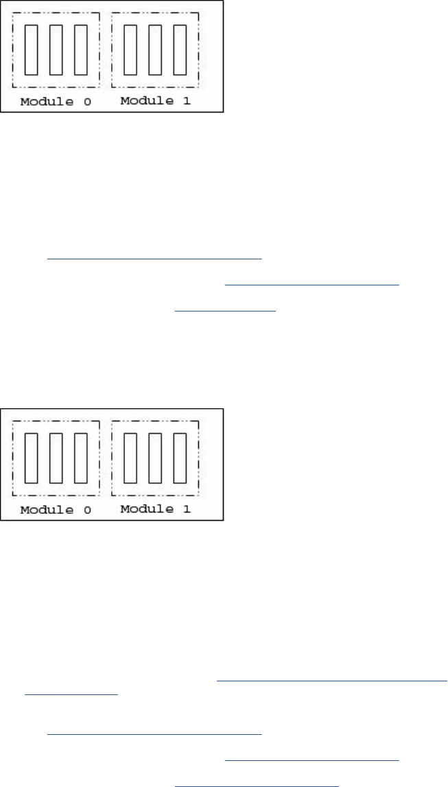
Problem Description: Left Ink Supply Station error, module 0.
Corrective action: Try the following:
1. Switch the power off from the back of the product and disconnect the power cord.
Reconnect the power cord and power on the product.
2. Check that the cables between the Ink Supply Station and the Engine PCA are not
damaged and are properly connected. In case of any damage replace the cable.
3. Perform the Ink Delivery System diagnostic test to troubleshoot the problem further.
See Ink Delivery System (IDS) Test on page 100.
4. Replace the Left Ink Supply Station. See Left Ink Supply Station on page 299.
5. Replace the Engine PCA. See EE Box on page 281.
System Error: 22.1:YZ
Problem Description: Left Ink Supply Station error, module 1
Corrective action: Try the following:
1. Switch the power off from the back of the product and disconnect the power cord.
Reconnect the power cord and power on the product.
2. Check that the cables between the Ink Supply Station and the Engine PCA are not
damaged and are properly connected. In case of any damage replace the cable.
NOTE: Check the Data Harness and ISS Harness Cable are connected in the right
position onto the Engine PCA. These two connectors can be swapped by mistake causing
a SE 22.1:10. Check the instructions in Connecting the Data Harness and ISS Harness
Cable on page 227
3. Perform the Ink Delivery System diagnostic test to troubleshoot the problem further.
See Ink Delivery System (IDS) Test on page 100.
4. Replace the Left Ink Supply Station. See Left Ink Supply Station on page 299.
5. Replace the Engine PCA. See Starwheel Assembly on page 404.
System Error: 24:YZ
ENWW System Error Codes—Full Descriptions 49

Problem Description: Ink Setup failure
Corrective action: Try the following:
1. Switch the power off from the back of the product and disconnect the power cord. Insert
the new purgers, reconnect the power cord and power on the product.
2. Perform the Ink Delivery System diagnostic test in order to check that the bongos
(pushers) go up and down to pressurize ink in the tubes and the Out of Ink sensors work
properly. See Ink Delivery System (IDS) Test on page 100.
3. Try purging the Ink Supply Tubes again once the product has been restarted.
4. If the diagnostic test does not find any problem, install new cartridges in the product and
try purging the Ink Supply Tubes again. It could be that one of the cartridges is defective.
5. If the problem persists, replace the Ink Supply Tubes. You must bring purgers and ink
cartridges. See Ink Supply Tubes & Trailing Cable on page 304.
Warning: 26:01
Problem Description: Ink supply error found during IDS diagnostic test. In the Touch Control Panel message you will
see letters representing the names of the colors of the faulty supplies.
Corrective action: Try the following:
1. Reseat the faulty ink supply and repeat the Ink Delivery System diagnostic test.
2. If the problem persists, replace the faulty ink supply and repeat the Ink Delivery System
diagnostic test.
3. If the problem persists, replace the Left Ink Supply Station. See Left Ink Supply Station
on page 299.
Warning: 39.1:01
Problem Description: Roll 1 switch failed (standby or resume). Roll 1 has been unloaded.
Corrective action: There is no corrective action. This system warning code only notifies the user that the roll has
been unloaded because an unexpected error occurred with Roll 1 in standby or resume
operation.
Warning: 39.2:01
Problem Description: Roll 2 switch failed (standby or resume). Roll 2 has been unloaded.
Corrective action: There is no corrective action. This system warning code only notifies the user that the roll has
been unloaded because an unexpected error occurred with Roll 2 in standby or resume
operation.
System Error: 41:YZ
50 Chapter 2 System Error Codes ENWW

Problem Description: Electrical fault or current limit in Media-Axis Motor
Corrective action: Try the following:
1. Switch the power off from the back of the product and disconnect the power cord.
Reconnect the power cord and power on the product.
2. Check for any visible obstacles restricting the movement of the Media Advance Roller. If
there is a wrinkled mass of paper inside the paper path, lift the Pinch wheels (using Media
Lever) and clear the obstruction.
3. Perform the Paper Drive diagnostic test to troubleshoot the problem furthe. See Paper
Drive Test on page 89.
4. Perform the Rewinder diagnostic test to troubleshoot the problem further. See Rewinder
Test on page 98.
5. Check that the Media Advance Drive cable is not damaged and is correctly connected to
the Engine PCA.
6. Replace the Media Advance Drive. See Media Advance Drive on page 330.
7. Replace the Engine PCA. See EE Box on page 281.
System Error: 42:YZ
Problem Description: Electrical problem (fault, current limit, overheating) in Scan-Axis Motor
Corrective action: Try the following:
1. Switch the power off from the back of the product and disconnect the power cord.
Reconnect the power cord and power on the product.
2. Check for any visible obstacles restricting the movement of the Carriage Assembly.
Remove any obstacle to let the carriage move freely along the whole scan axis. If there
is a wrinkled mass of paper inside the paper path, raise the pinch wheels (using the Media
Lever) and clear the obstruction.
3. Check that the Scan-Axis Motor cable is not damaged and is correctly connected to the
Engine PCA.
4. Replace the Scan-Axis Motor. See Scan-axis Motor on page 392.
5. Replace the Engine PCA. See EE Box on page 281.
System Error: 45.1:YZ
Problem Description: An error with the Rewinder 1 System (Upper Rewinder) has been detected.
Corrective action: Try the following:
1. Switch the power off from the back of the product and disconnect the power cord. Remove
the paper from Roll 1. Reconnect the power cord and power on the product.
2. Check that the Rewinder 1 cable is not damaged and is correctly connected to the Engine
PCA.
3. Check that the Upper Right Roll Support is correctly attached to and aligned with the Right
Cover.
4. Perform the Rewinder diagnostic test to troubleshoot the problem further. See Rewinder
Test on page 98.
5. Replace the Upper Right Roll Support. See Roll Support, Upper Right on page 391.
System Error: 45.2:YZ
ENWW System Error Codes—Full Descriptions 51

Problem Description: An error with the Rewinder 2 System (Lower Rewinder) has been detected .
Corrective action: Try the following:
1. Switch the power off from the back of the product and disconnect the power cord. Remove
the paper from Roll 2. Reconnect the power cord and power on the product.
2. Check that the Rewinder 2 cable is not damaged and is correctly connected to the Engine
PCA.
3. Check that the Lower Right Roll Support is correctly attached to and aligned with the Right
Cover.
4. Perform the Rewinder diagnostic test to troubleshoot the problem further. See Rewinder
Test on page 98.
5. Replace the Lower Right Roll Support. See Roll Support, Lower Right on page 385.
System Error: 47:YZ
Problem Description: Starwheels motor error
Corrective action: Try the following:
1. Switch the power off from the back of the product and disconnect the power cord.
Reconnect the power cord and power on the product.
2. Check for any visible obstacles restricting the movement of the Starwheel Assembly, then
clear the obstruction.
3. Check that the Starwheel Assembly cable is not damaged and is correctly connected to
the Engine PCA.
4. Perform the Scan Axis Starwheel diagnostic test to troubleshoot the problem further.
5. Replace the Starwheel Motor. See Starwheel Motor on page 409.
6. Replace the Engine PCA. See EE Box on page 281.
System Error: 48:YZ
Problem Description: PPS system failure
Corrective action: Try the following:
1. Switch the power off from the back of the product and disconnect the power cord.
Reconnect the power cord and power on the product.
2. Check that the Pen to Paper Space (PPS) Solenoid cable is not damaged and is correctly
connected to the Engine PCA.
3. Perform the Scan Axis PRS diagnostic test to troubleshoot the problem further.
4. Replace the Pen to Paper Space (PPS) Solenoid. See Pen to Paper Space (PPS)
Solenoid on page 345.
5. Replace the Engine PCA. See EE Box on page 281.
System Error: 51:YZ
52 Chapter 2 System Error Codes ENWW

Problem Description: Scanner Position Sensor failure
Corrective action: Try the following:
1. Check that the Scanner Position Sensor cable is not damaged and is correctly connected
to the Engine PCA.
2. Perform the Sensors Test to troubleshoot the problem further. See Sensors Test
on page 96.
3. Replace the Scanner Position Sensor. See Scanner Position Sensor (MFP only)
on page 413.
System Error: 52:10
Problem Description: The product has detected a failure in the Drop Detector.
Corrective action: Try the following:
1. Switch the power off from the back of the product and disconnect the power cord.
Reconnect the power cord and power on the product.
2. Check that the Drop Detector cable is not damaged and is correctly connected to the
Engine PCA.
3. Replace the Drop Detector. See Drop Detector on page 280.
4. Replace the Engine PCA. See EE Box on page 281.
System Error: 55:YZ
Problem Description: Problem with the Line Sensor. The product has detected a failure to access the Line Sensor
EEPROM.
Corrective action: Try the following:
1. Switch the power off from the back of the product and disconnect the power cord.
Reconnect the power cord and power on the product.
2. Perform the Carriage Test to troubleshoot the problem further. See Carriage Assembly
Test on page 93.
3. Check the Line Sensor connections to the Carriage PCA.
4. Replace the Line Sensor. See Line Sensor on page 325.
5. Replace the Carriage PCA. See Carriage PCA on page 252.
System Error: 56:YZ
Problem Description: Drive roller analog encoder homing (also known as “zero search”) failed.
Corrective action: Try the following:
1. Switch the power off from the back of the product and disconnect the power cord.
Reconnect the power cord and power on the product.
2. Perform the Media Path Test to troubleshoot the problem further. See Paper Drive Test
on page 89.
3. Replace the Encoder Disk and Encoder Sensor. See Encoder Disk and Encoder
Sensor on page 286.
4. Replace the Engine PCA. See EE Box on page 281.
ENWW System Error Codes—Full Descriptions 53

System Error: 59.1:09
Problem Description: Two electrical parts have been replaced at the same time.
Corrective action: Replace one part at a time, and restart the product before replacing another.
System Error: 59.2:00
Problem Description: An unsupported or reused part has been installed.
Corrective action: Install only new parts recommended by HP for this product.
System Error: 60.1:YZ, 60.2:YZ
Problem Description: Initialization error
Corrective action: Try the following:
1. Switch the power off from the back of the product, wait two minutes, then switch it back
on again.
2. Check the power cord; try connecting it to another power socket.
3. Check that the product is properly connected in all other respects.
4. Switch the power off from the back of the product; remove the Formatter; reinsert the
Formatter; switch the power on again.
5. If the error persists, get the product log (see Appendix C: Obtaining the product log and
the diagnostics package on page 74) and contact HP with the file.
System Error: 61:YZ
Problem Description: The file format is incorrect or not supported for the current product configuration and the product
cannot process the job.
Corrective action: Try the following:
1. Check if the product supports the file format (formats such as PS, PDF, TIFF and JPEG
are supported by PostScript products only).
2. Switch the power off from the back of the product and disconnect the power cord.
Reconnect the power cord and power on the product.
3. Check the graphic language setting of the product (refer to the User's Guide).
4. Resend the file to the product.
5. Check that the product has the latest firmware version. If not, update the firmware to the
latest version.
System Error: 61:04.1
Problem Description: The PostScript fonts seem to be missing.
Corrective action: Perform a firmware upgrade to re-install the fonts.
System Error: 61:08.1
Problem Description: The file cannot be printed because it is password-protected.
Corrective action: Resend the file without password protection.
54 Chapter 2 System Error Codes ENWW

System Error: 63:01
Problem Description: Cannot retrieve IP addess
Corrective action: Try the following:
1. Connect to another network.
2. Modify the IPv4 configuration.
System Error: 63:YZ
Problem Description: Input/Output problem through the network interface of the Formatter
Corrective action: Try the following:
1. Switch the power off from the back of the product and disconnect the power cord.
Reconnect the power cord and power on the product.
2. Check that the Network cable is correctly connected to the Formatter.
3. Check that the product has the latest firmware version. If not, update the firmware to the
latest version.
4. Replace the Formatter. See Formatter on page 290.
System Error: 64:YZ
Problem Description: Input/Output problem through the USB Port
Corrective action: Try the following:
1. Switch the power off from the back of the product and disconnect the power cord.
Reconnect the power cord and power on the product.
2. Check that the USB cable is correctly connected to the product.
3. Check that the product has the latest firmware version. If not, update the firmware to the
latest version.
4. Replace the Formatter. See Formatter on page 290.
System Error: 64.1:YZ
ENWW System Error Codes—Full Descriptions 55

Problem Description: The External Hard Disk accessory does not seem to be connected
Corrective action: Try the following:
1. Switch the power off from the back of the product. Connect the External Hard Disk
accessory, check that the USB cable is properly connected and power on the product. If
the External Hard Disk accessory is not available (has been lost or broken), proceed with
step 2.
2. If the problem persists, power off from the back of the product. Power on the product again
while pressing the keys Menu, OK and Cancel keys simultaneously until the Touch
Control Panel asks “product configured to use External Hard Disk. Do you want to revert
the product to Internal Hard Disk?”. Confirm by pressing OK (twice). Remove the External
Hard Disk accessory (if connected). The product will restart.
3. After the product reaches the Ready state, try connecting any other USB device (known
to work properly) to the product port where the External Hard Disk accessory should be
connected.
◦If a message appears on the Touch Control Panel reacting to the USB device just
connected (such as “Please remove USB device” or “Press on this menu option...”),
press Cancel and remove the USB Device. This means that the External Hard Disk
accessory is faulty and should be replaced. See Formatter on page 290.
◦If nothing appears on the Touch Control Panel reacting to the USB device just
connected, the Formatter is faulty and should be replaced. See Formatter
on page 290.
System Error: 65:YZ
Problem Description: Memory Driver Internal I/O error, I/O Socket Manager Internal I/O error
Corrective action: Try the following:
1. Switch the power off from the back of the product and disconnect the power cord.
Reconnect the power cord and power on the product.
2. Check that the unknown port cable is correctly connected to the product.
3. Check that the product has the latest firmware version. If not, update the firmware to the
latest version.
4. Replace the Formatter. See Formatter on page 290.
5. Replace the Engine PCA. See EE Box on page 281.
Warning: 68:YZ
Problem Description: Loss of engine counters tracking
Corrective action: The product will continue to function correctly, but the life counters will not continue counting
until you restart the product.
System Error: 71:03
Problem Description: Out of memory
Corrective action: Restart the product.
Warning: 71:04
56 Chapter 2 System Error Codes ENWW

Problem Description: Out of memory.
The total memory available in the product depends on its configuration. It is reported as HP-
GL/2 memory or PS/PDF memory. If the amount of memory that the product needs to process
the file is more than the amount available, the product will display this system warning. The
amount of memory required for processing the file is known as the ‘display list memory’:
●The display list memory should not be confused with the file size of the print job. The size
of the display list memory depends on several variables such as the resolution, file size
and file content.
●The display list memory is not visible to the user, but can be consulted by engineers to
troubleshoot out-of-memory issues. See Appendix D: How to check the display list
memory for an HP-GL/2 job on page 77
.
●There have been a few cases in which a print job with a relatively small file size has
triggered an out-of-memory message. Such print jobs typically have a large number of
objects in them or have complex objects such as raster images with gradients or objects
with multiple layers.
Corrective action: Try the following:
1. Upgrade the firmware to the latest version available.
2. Decrease the print resolution to 300 dpi.
NOTE: If the customer does not accept the print quality after reducing the resolution or
using Econofast print mode, proceed to the workaround in step 3.
ENWW System Error Codes—Full Descriptions 57
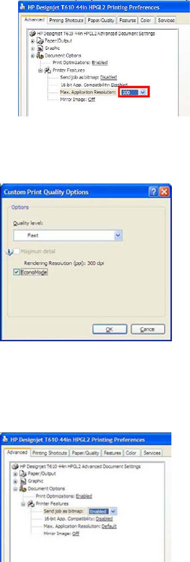
◦The resolution required by the product to process the file is set by the print mode
selected (Best, Normal, Fast). There is a setting available that enables you to
decrease the resolution for each print mode to 300 dpi. If this setting is used, the
rendering resolution will be reduced, but the output (printing) resolution will remain
the default of the selected print mode. There could be an impact on Image Quality
because of the reduction in the rendering resolution; this will be especially noticeable
in circles and lines with very low inclination.
3. Use the ‘Econofast’ print mode. The rendering resolution will be set by default to 300 dpi.
In the Paper/Quality tab of the product properties window, select Custom options and
press the Settings button. In the Custom Print Quality Options window, check the
Economode box.
NOTE: If the Out of Memory message still persists, proceed to the next workaround.
4. Out of Memory issues can always be solved if the processing of the job can be performed
before reaching the product. This can be done by selecting ‘Send Job as Bitmap’. The
main processing of the print job will then be performed by the computer. This form of
printing is recommended when the print job contains raster images, and mixed plots with
raster images and lines, because the process of turning a print job made of raster images
to vector images leads to a significant increase in the display list memory.
Warning: 72.02:09
58 Chapter 2 System Error Codes ENWW

Problem Description: Generic firmware Error
Corrective action: 1. Switch the power off from the back of the product and disconnect the power cord.
Reconnect the power cord and power on the product.
2. Check that the product has the latest firmware version. If not, update the firmware to the
latest version Appendix B: Emergency firmware upgrade with USB flash drive
on page 74
NOTE: If you see system error 79:04, see Appendix A: How to troubleshoot SE 79:04
on page 64.
NOTE: A firmware upgrade will not always solve the problem. The best way to solve this
problem is to report the error to HP correctly. Make sure that you supply all the information
accessed by pressing the Up and Cancel keys together while viewing the system error screen,
or preferably provide the product log and diagnostic package to HP. Refer to Understand
System Error Codes on page 35 and Appendix C: Obtaining the product log and the diagnostics
package on page 74.
Warning: 72.02:YZ
Problem Description: A service calibration should be performed.
Corrective action: To find out which service calibration to perform, print the calibration status. At the Touch Control
Panel, select the Internal Prints icon, then Service information > Print calibration status.
Perform whichever calibration is needed.
Warning: 74:YZ
Problem Description: Error uploading firmware update file
Corrective action: Try the following:
1. Switch the power off from the back of the product and disconnect the power cord.
Reconnect the power cord and power on the product.
2. Make sure the connection between the computer and the product is functioning properly.
3. Try to update the firmware again.
Warning: 74.1:YZ
Problem Description: Error uploading paper profile update file
Corrective action: Try the following:
1. Switch the power off from the back of the product and disconnect the power cord.
Reconnect the power cord and power on the product.
2. Make sure the connection between the computer and the product is functioning properly.
3. Try to upload the paper profile update file again.
4. Make sure the version of the paper profile update file is compatible with the firmware
version the product is using. You can check this on the same Web page where you
downloaded the paper profile update.
System Error: 74.08:04
ENWW System Error Codes—Full Descriptions 59

Problem Description: Problem with the firmware upgrade process
Corrective action: 1. Reboot the Product
2. Try to upgrade the firmware again, for more information, see Appendix B: Emergency
firmware upgrade with USB flash drive on page 74
3. Download again the firmware file from the source, as the original may be corrupted.
4. Replace the Touch Control Panel see Touch Control Panel on page 428
System Error: 75.21:YZ
Problem Description: The spittoons (Left Spittoon, Service Station) have reached 80% capacity.
Corrective action: Use Preventive Maintenance Kit #2 to replace the Left Spittoon and Service Station.
System Error: 75.22:YZ
Problem Description: The spittoons (Left Spittoon, Service Station) are full.
Corrective action: Use Preventive Maintenance Kit #2 to replace the Left Spittoon and Service Station.
System Error: 76:YZ
Problem Description: Hard disk drive is full.
Corrective action: Remove any unnecessary files from the hard disk using the Embedded Web Server. If
the problem persists, run the Hard Disk Recovery Utility (see Hard Disk Recovery
Utility on page 132).
System Error: 78:08
Problem Description: The job received cannot be printed without borders on this paper.
Corrective action: Use a paper that supports borderless printing.
NOTE: This system error code does not require service help. It should be resolved by
the customer.
System Error: 78.1:YZ
Problem Description: Media settings area missing in paper settings file
Corrective action: Try the following:
1. Switch the power off from the back of the product and disconnect the power cord.
Reconnect the power cord and power on the product.
2. Check that the product has the latest firmware version. If not, update the firmware
to the latest version.
System Error: 79:YZ
60 Chapter 2 System Error Codes ENWW

Problem Description: Generic firmware error
Corrective action: Try the following:
1. Switch the power off from the back of the product and disconnect the power cord.
Reconnect the power cord and power on the product.
2. Check that the product has the latest firmware version. If not, update the firmware
to the latest version.
NOTE: If you see system error 79:04, see Appendix A: How to troubleshoot SE
79:04 on page 64.
NOTE: A firmware upgrade will not always solve the problem. The best way to
solve this problem is to report the error to HP correctly. Make sure that you supply
all the information accessed by pressing the Up and Cancel keys together while
viewing the system error screen, or preferably provide the product log and diagnostic
package to HP. See Understand System Error Codes on page 35 and Appendix C:
Obtaining the product log and the diagnostics package on page 74.
System Error: 81:01
Problem Description: Paper axis error—the copier will restart and run a diagnostic test
Corrective action: None
System Error: 81:YZ
ENWW System Error Codes—Full Descriptions 61
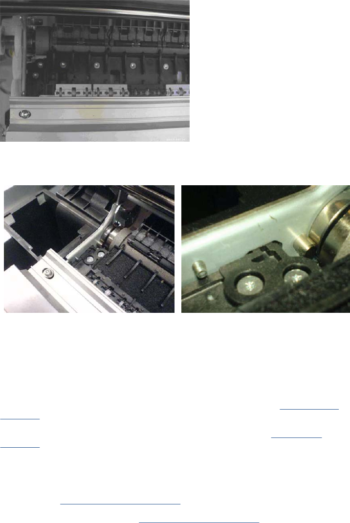
Initial checks: This error can occur because the product has been dropped during transportation, causing structural damage.
Before continuing with the 81:YZ troubleshooting, first look for structural damage.
To identify the structural damage, look for the following three things:
●Consistent 81:YZ error codes.
●Platen fingers rubbing on the roller surface, leaving black marks on the roller.
●A gap on the platen beam. If there’s any gap in Z (vertical direction) between the plastic feature of the
platen and the metal side plate, then the chassis is damaged and the unit cannot be repaired.
Problem
Description: Problem with paper advance. This source of error could come from an error in any of the following systems:
paper motor, disk encoder, cables or main electronics.
Corrective
action: Try the following:
1. Check for any visible obstacles restricting the movement of the Drive Roller. If there is a wrinkled mass
of paper inside the paper path, lift the Pinchwheels (using the Media Lever) and clear the obstruction.
2. Perform the Media Drive diagnostic test to troubleshoot the problem further. See Paper Drive Test
on page 89.
3. Perform the Rewinder diagnostic test to troubleshoot the problem further. See Rewinder Test
on page 98.
4. Check the connections on the Engine PCA; the Media Advance Drive is connected to the connector
labeled Paper Motor.
5. Adjust the encoder disc and motor mount configuration using the Media Advance Drive installation
instructions. See Media Advance Drive on page 330.
6. Replace the Media Advance Drive. See Media Advance Drive on page 330.
System Error: 86:01
Problem Description: Scan axis error—the copier will restart and run a diagnostic test
Corrective action: None
62 Chapter 2 System Error Codes ENWW

System Error: 86:11
Problem Description: Scan Axis movement requires too much force or energy.
Corrective action: Try the following:
1. Check that the cutter disengages correctly.
2. Lubricate the scan axis.
3. Use Preventive Maintenance Kit 1.
System Error: 87:YZ
Problem Description: Problem with the Carriage Encoder Sensor readings
Corrective action: Try the following:
1. Check that the encoder sensor is correctly connected to the Carriage PCA.
2. Make sure the Encoder Strip is not broken or damaged. If necessary, replace it.
See Encoder Strip, spring and attachment nut on page 288.
3. Make sure that the Encoder Strip is clean. If it is dirty, clean it, paying special
attention to the area near the Service Station. See Cleaning the Encoder Strip
on page 437.
4. Clean the Encoder Sensor.
5. Replace the Encoder Sensor.
6. Replace the Carriage PCA. See Carriage PCA on page 252.
7. Replace the Trailing Cables. See Ink Supply Tubes & Trailing Cable on page 304.
System Error: 87.01
Problem Description: Problem finding the Scan-axis encoder reading
Corrective action: Try the following:
1. Switch the power off from the back of the product and disconnect the power cord.
Reconnect the power cord and power on the product.
2. Make sure that the encoder strip is clean. If the encoder strip is dirty, clean it, paying
special attention to the area near the Service Station. See Cleaning the Encoder
Strip on page 437.
3. Clean the encoder sensor.
4. Replace the Encoder Sensor.
System Error: 93:YZ
ENWW System Error Codes—Full Descriptions 63

Problem Description: Unable to pressurize the Ink Delivery System
Corrective action: Try the following:
1. Switch the power off from the back of the product and disconnect the power cord.
Reconnect the power cord and power on the product.
2. Perform the Ink Delivery System diagnostic test to further troubleshoot the problem.
See Ink Delivery System (IDS) Test on page 100.
3. Check that the cables between the Ink Supply Station and the Engine PCA are not
damaged and are properly connected. In case of any damage replace the cable.
4. Replace the Left Ink Supply Station, depending on the results of the diagnostic test.
See Left Ink Supply Station on page 299.
5. Replace the Engine PCA. See EE Box on page 281.
Appendix A: How to troubleshoot SE 79:04
Introduction
The system error 79:04 is a generic firmware error (equivalent to a blue screen in windows). It’s the
system error that the product will display when an unknown exception occurs that cannot be identified
as relating to any specific subsystem of the product.
Since this is a generic error, there can be multiple causes behind it. This document will cover the most
probable causes behind a system error 79:04 and will recommend the most efficient troubleshooting
steps to resolve customer issues.
It is important to mention that, although 79:04 system errors can be caused by a hardware malfunction,
the vast majority of 79:04 system errors are pure software or firmware issues. Before doing anything
else, you are recommended to try the following general-purpose solutions.
1. Update the product’s firmware to the very latest available firmware version, even if the product
appears to be running the latest firmware already.
2. Restore the factory settings from the Touch Screen Panel's Setup menu.
If these do not solve the problem, continue reading about other possible solutions below.
Possible causes
Since the 79:04 system error is a generic error, the number of possible causes behind it is large. The
majority can be grouped, however, into the following groups.
Job related SE79:04
A specific print job that is not correctly formatted for the product or that is not correctly processed by it
can trigger a 79:04 system error.
The incorrect format or processing can come from two sources:
●Incorrect commands in the job itself. For example, a PS job with some commands that do not have
the correct PS format.
●Issues applying to the settings in the job
Possible symptoms
64 Chapter 2 System Error Codes ENWW
79:04 caused by a print job always have the same symptoms:
1. The job is received by the product and starts to process.
2. In the middle of the processing, the product stops and displays 79:04.
3. The product will display the 79:04 system error again after reboot. This is due to the fact that the
product will try to reprint the job, which is pending in the queue, after reboot.
4. After the second reboot, the product will start up normally
5. If the same job is sent again, it will always produce a 79:04 system error
These types of 79:04 system errors are normally caused by jobs that have been generated by 3rd
party applications (RIPs, 3rd party drivers, files exported by an application to PS, PDF, HP-GL/2,
RTL, … or any other format supported by the product). Jobs generated by HP drivers will not
normally generate 79:04 system errors, since the output that our drivers generate is very controlled
and has been designed taking into consideration the characteristics of our product’s language
interpreters.
There is an exception to this general rule: there are certain applications that can generate their
own PS code (Adobe PhotoShop, Adobe Illustrator, Adobe Acrobat, Corel Draw, Freehand,
QuarkXpress, …). When used with a PS driver, these applications generate the output PS
themselves, instead of using the driver’s rendering capabilities. This is known as PostScript pass-
through. So, when using an HP PostScript driver together with an application that has PS
passthrough capabilities, the PS code that comes into the product has not been rendered by the
HP driver, and, should the source file contain any PS commands that are not correctly processed
by the product, a 79:04 system error could occur even though an HP driver is being used.
Solutions and workarounds
When a job consistently generates a 79:04 system error, it is either because of a issue in the
product’s firmware or because of a defect in the job itself (when it has been generated by 3rd party
SW). In order to identify the cause and find out a solution, these issues should always be
impapertely escalated to the GBU through the GCC.
Also, there are some workarounds and short-term solutions that can be tested in order to get the
customer up and running in the shortest possible time:
1. Send the job using a variety of different settings. Many times, the issue is caused by a combination
of the job contents combined with some specific setting(s).
2. If the customer is sending the file directly to the product, try using the HP driver instead.
3. If the issue is occurring when printing through the HP PostScript driver from an application with PS
passthrough, try changing the options in the application so that it prints PS as raster (the option is
typically located in the “Advanced” options of the application’s printing dialog).
4. In some cases, there may be an unfortunate interaction between the particular job and the I/O
connection used to send that job to the product. Try sending the same job using a print queue that
uses a different type of connection. For example, use a network connection instead of USB, or use
the LPD network printing protocol instead of port 9100.
Data related SE79:04
HP Designjet products have Hard Disks and non-volatile memories that contain databases and files that
can be modified with user data. Some examples include:
●The product’s queue
●The hard drive partitions that contain user jobs
ENWW Appendix A: How to troubleshoot SE 79:04 65
●The database that stores the product settings
●The database that stores accounting information
Some of this data is accessed by the product at start-up, and some others are accessed as needed.
If any of this fields contains corrupt data or data with characters or values that cannot be correctly
processed by the product, a 79:04 system error may occur.
Possible symptoms
There are two different types of symptoms for data related 79:04 system errors:
1. When the corrupt data is accessed during start-up:
a. The product will display a 79:04 during the start up process
b. Switching the product off and on again will not solve the issue. The product will continue
displaying the 79:04 system error until the corrupt data has been cleared through a service
procedure
2. When the corrupt data is accessed during normal product operation:
a. The product will start up normally
b. When the data is accessed (for example while printing, while navigating the queue or when
changing some settings), the product displays a 79:04 system error
c. The product can reboot normally
d. When the data is accessed again (typically, under the same conditions as in step “b”), the
79:04 system error is displayed again
Solutions and workarounds
Many times, data-related 79:04 errors are resolved by means of hardware intervention. Since data are
stored in physical components (RAM, EEROM and Hard Disk), replacing these components with new
ones that are empty usually solves the problem. However, there are quicker and more effective solutions
to these types of errors:
1. Clear all information that has been introduced by the user using the standard tools available in the
product.
a. Delete all jobs from the queue (from the Touch Control Panel or the EWS).
b. Reset to factory defaults to clear the user’s configurations and calibrations.
c. Delete any non-standard paper preset in the product (both the ones that have been created
by the user and the ones that have been installed as OMES profiles through the EWS or the
HP product Utility).
2. If step 1 did not resolve the issue, you can use Service Tools to clear additional information that
could be causing the issue.
a. Start the product in Diagnostics Boot Mode.
b. Perform an EEROM reset.
66 Chapter 2 System Error Codes ENWW

3. If step 2 did not resolve the issue, it is possible to run a recovery of the hard disk.
a. Start the product in Diagnostics Boot Mode.
b. Perform a Hard Disk Recovery. This will erase data from the hard disk and reinstall the current
firmware. It may take up to half an hour.
4. If step 3 did not resolve the issue, you can check the hard disk's file system.
a. Start the product in Diagnostics Boot Mode.
b. Perform a File System Check. This will fix any error in the file system structure. It may take a
few minutes, or up to an hour, depending on the state of the hard disk.
Important note:
It is possible that the corrupt data came to be in the product as a consequence of some activity in the
customer’s workflow. In this case, it is possible that the issue will happen again. In these cases, it is
very important to understand the sequence of events in the customer’s workflow that led to the error
occurring. Once the error can be traced in the customer’s workflow, escalate the issue to the GBU
(through the GCC). This is done to implement any changes in the product’s firmware that can prevent
these issues occurring again.
Network related SE79:04
Most HP Designjet products have built-in networking capabilities. Network settings can be set manually,
but in the majority of cases, they are obtained automatically from the product. These settings include
many different fields, such as IP address and subnet mask, available gateways, host and domain names,
etc.
In some cases, there can be issues in the firmware that can cause a certain value in one of these fields
to be interpreted incorrectly, and this can lead to a 79:04 system error.
Symptoms
There is no single set of symptoms that can absolutely pinpoint a network related 79:04 system error.
However, the following guidelines can be applied:
●It can happen when the product starts up or when accessing the Network Configuration section of
the Touch Control Panel or Embedded Web Server. It can also occur apparently randomly when
the product is connected to the network. It can also occur any time a particular network action is
performed, for example when print jobs are sent to the product, or when connecting to the
Embedded Web Server.
●In all these cases, repeating the action after restarting the product with the LAN cable disconnected
does not cause the 79:04 error to occur.
Solutions and workarounds
In the majority of cases, these issues are due to an issue in the product’s firmware. As soon as the
conditions in which the issue happens are understood, it should be escalated to the GBU through the
GCC.
At the same time, the following short-term solutions and workarounds can help the customer to get up
and running in the shortest possible time:
1. Disconnect the network cable in order to restart the product and change network settings.
2. Try resetting the embedded networking settings or Jetdirect settings. See Connectivity
troubleshooting on page 31.
3. In the Network configuration menu in the Touch Control Panel, disable any protocols that you are
not using, including IPv6, IPSec, SNMP and WebServices.
ENWW Appendix A: How to troubleshoot SE 79:04 67

NOTE: Disabling SNMP or WebServices means that customers may not be able to see product
status information; and s and Mac OS print-queue installers will require the user to specify the
product’s IP address and product model manually.
4. If the above steps do not work, try using a different type of print queue. For example, if the problems
occur when printing to a Port 9100 Socket print queue, try using the LDP protocol instead, or USB.
To do this, create a new print queue of the type required and try printing using the new queue
instead.
5. If the above steps do not work and the customer is using the product’s embedded LAN connection,
try using an accessory Jetdirect card instead. Similarly, if the customer is having problems using
an EIO Jetdirect card, try disconnecting the Jetdirect card and using the embedded networking.
In most cases, network problems that seem to occur randomly (when the product is not being sent print
jobs) are caused by an interaction between some other devices in the customer’s network and the
product. Isolating the product from other devices in the network as much as possible by connecting the
product to a private network or a different network subnet may help the customer continue working until
the root cause of the problem is understood and solved.
User Interaction related SE79:04
In some cases the product may not react as expected when a certain set of conditions coincide. In these
cases, if the product doesn’t know how to react, it may simple display a 79:04 system error and force a
reboot. Some examples (not real) that can help to illustrate this:
●An error occurs when a job is cancelled when it is at the “Finishing print” state and when the queue
is disabled
●An error occurs if the Scanner is opened while the product is checking the printheads
These errors will most likely only happen in very specific corner cases that have not been identified
during the development or the qualification of the product, so normally, they do not severely impact the
customer, as they do not affect their regular working flows.
Symptoms
The symptoms here are as numerous as the number of possible interactions between the user and the
product. In any case, it’s possible to identify the steps that caused the error to occur and avoid them as
the steps will always be the same with no variance.
Important: An major element in determining the error is what the state the product was in at the time the
error was displayed. Actions the user has made when the product is drying for example can produce
an error, whereas the same action when the product is doing something else (or is idle) may not produce
any errors.
Solutions and workarounds
The recommended action plan in these cases is to identify the previous steps that caused the error and:
1. Escalate the issue to the GBU through the GCC in order to have it corrected in the firmware.
2. Recommend to the customer that they try to avoid the same steps to prevent the issue
3. If the conditions that cause the error are in the customer’s regular workflow, try to identify a different
way of achieving the same result out of the product.
Random SE79:04: Concurrence issues and memory leaks
Some 79:04 errors happen randomly when the product is being heavily used. However, it’s impossible
to find a single set of conditions that reproduce the problem. It just happens from time to time, without
a defined pattern.
68 Chapter 2 System Error Codes ENWW
These random 79:04 can have two different types of root causes:
●Memory leaks: before a program is executed, it allocates the memory it will need. After the
execution is complete, the allocated memory is freed to be used by other programs. If the allocation
or the release of the memory are not properly programmed, every time the program is executed
some memory will be incorrectly labeled (either as used or as free). This is known as a memory
leak. When a program with a memory leak is executed a lot, the memory becomes progressively
full (since it is not properly freed). When the leak becomes too big, the product is left ‘out of memory’
to execute new processes and a 79:04 is triggered
●Concurrence issues: there are certain resources that can be accessed by multiple programs or by
multiple executions of the same program (what is known as multiple threads). Access to these
resources must be correctly controlled to prevent unexpected behavior. Issues caused by an
incorrect control of these resources are concurrence issues.
In the following you have a simple example: let’s imagine that there is a counter that controls the
communication between the Jetdirect card and the product’s firmware. Whenever a new packet of
information is sent by the Jetdirect card to the product, the counter increases. When the product receives
the packet and processes it correctly, the counter decreases. Another process checks the counter from
time to time to see its value and take conclusions from it. If the counter is near 0, it means that the
product is processing correctly, and if it grows too big, it may mean that there is a bottleneck somewhere
and maybe the Jetdirect card throughput is decreased to control its speed to the product. However, if
the access to this counter is not properly controlled, undesirable effects may happen: in a real
environment, a Jetdirect card processes thousands of information packets per second, so this counter
is updated frequently, both by the Jetdirect and the product. If at a certain point the Jetdirect and the
product try to access the counter at the same time and the code is not prepare to handle this, it may
happen that the Jetdirect cannot increase the counter because the product is writing to it, and what’s
worse, that it does not realize this fact. If this happens a few times each second, it may happen that the
counter is decreasing faster than it’s increasing and that at a certain point it has a negative value. And
then, what will the process that is checking this counter do? Most likely, the process will not be prepared
to react to a negative value and will launch an exception that will trigger a 79:04 system error.
Symptoms
This type of 79:04 always occurs in heavy load conditions, so the symptoms will always be similar to
this pattern:
●A product that is being heavily used (printing a project or in a reprographics environment) produces
79:04 errors randomly, forcing the user to reboot.
●After rebooting, the product can be used without any issues for an extended period of time, but if
the workload is consistently high, a random error will occur again.
●The error can never be associated with a specific file. The file that was being printed when the error
occurred the last time can be printed without issues after reboot. And a file that has been printed
without issues several times can trigger the error in the future.
●This error is very dependant of the workflow the customer has. The most common user workflows
have been extensively tested both by HP and by our beta sites, so it is highly unlikely to see random
79:04 issues in these cases. These random issues tend to occur in very specific corner cases, and
cannot be reproduced unless the exact conditions of the workflow are replicated. They normally
happen when sending files generated by external applications (RIPs, 3rd party drivers, etc.)
Workarounds and solutions
ENWW Appendix A: How to troubleshoot SE 79:04 69

Random 79:04 errors are, by far, the most complex ones to diagnose and to fix. The only solutions
available in these cases are:
1. Run the Hard Disk Recovery utility (see Hard Disk Recovery Utility on page 132).
2. Identify the root cause (either in the files or in the firmware) and fix it in the code, which requires
the intervention of the GBU.
3. Test any options available to modify the customer’s workflow and see if any combination of them
solves the issue.
In both cases, a profound understanding of the customer’s workflow is necessary. In particular, the
information that is needed is:
●Product Touch Control Panel settings
●Application that is being used; RIP or driver that is being used
●Application/RIP/Driver settings
●Type of output files this application, RIP or driver is generating
●Some sample files that are representative of what the customer is using
●Operating System
●Method of connection to the product
●A description of the normal flow when the issue occurs and the typical frequency of occurrence (for
instance, once every hour when sending several files non-stop, each of them with multiple copies)
You are recommended to use the Diagnostics Package to obtain this kind of information.
With this information, the environment can be replicated in order to try to find workarounds. This is also
the information that will be needed at the GBU to investigate and fix the root cause of this issue once it
is escalated.
Hardware related SE79:04
Hardware is, by far, the least likely cause of a 79:04 system error. Replacing hardware components
does not normally fix the issue and increases the total turn around time in finding a workable solution.
In some cases, a failure in a component in the product’s electronics may cause a 79:04 system error,
since the product’s electronics are involved in the execution of the firmware and the processing of jobs.
It needs to be noted, however, that hardware failures in the electronics tend to produce specific system
errors that point directly to the component that is failing.
Some hardware problems that could cause the 79:04 error are:
●Defective clusters in the Hard Disk drive. If these clusters are used to execute the firmware or to
process a job, they may produce a 79:04. It needs to be noted however, that most 79:04 errors
that are resolved by an HDD replacement are in fact, data related 79:04 that could have been
solved more efficiently and quickly following the other steps.
●Defective memory segments. If the RAM memory has some defective segments, a 79:04 may occur
when these segments are used.
●Intermittent defects in the electronic components that are involved in the processing of a job:
Carriage PCA, Trailing cable, Formatter and Engine PCA. This is a highly unlikely cause, since
defects in these components will produce subsystem specific errors.
Symptoms
70 Chapter 2 System Error Codes ENWW

There’s no single set of symptoms behind hardware related 79:04 system errors. The most usual ones,
however are:
●79:04 during start up. Rebooting the product may or may not solve the problem
●79:04 while processing or printing a job. Rebooting the product and printing the same job does not
always produce the error.
Solutions and workarounds
In the following procedure perform each step as it appears in the list and only move on to the next step
once you are sure the 79:04 error has not been cleared:
1. Reboot the product in Diagnostics Boot mode and execute the service tests to validate the
functionality of all the electronics components
●Perform the troubleshooting for “data related 79:04” system errors, refer to Appendix A: How
to troubleshoot SE 79:04 on page 64
2. Replace the memory
3. Replace the HDD Hard Disk Drive on page 295
4. Escalate the issue before replacing any additional parts.
Troubleshooting based on symptoms
This section will describe which troubleshooting steps to perform for a 79:04 system error based on the
symptoms of the issue. Perform each step as it appears in the list and only move on to the next step
once you are sure the 79:04 error has not been cleared:
Touch Control Panel displays 79:04 at Start-up
1. Reboot the product twice. If the System error has been caused by a job because its in an incorrect
format, rebooting twice will clear the error (the first time after reboot, the product will attempt to
print the job again, and this will cause the error to reoccur). If rebooting the product twice solves
the issue, then it is an issue related to the job and you should refer to the section on a Job Related
SE79:04.
2. Upgrade the product’s firmware. Even if the currently installed firmware version is the latest one,
re-install it. Since the product cannot start normally, you will need to upgrade the firmware while
booting the product in Diagnostics Boot Mode. For this, a special file and a special upgrade process
will be needed. For more information, see Appendix B: Emergency firmware upgrade with USB
flash drive on page 74 .
3. Disconnect the network cable and restart the product. If this solves the problem, then it is a network
related 79:04 and you should follow the guidelines for this type of 79:04.
4. Remove all cartridges, printheads and printhead cleaners (if available). Unload the paper. Restart
the product. If the product can start normally, insert the consumables one by one until you isolate
the one that is causing the error. Do not insert any of the replaced consumables in another product
5. Restart the product in Diagnostics Boot Mode and perform the “Electronics test”. If an electronic
component is identified as faulty, replace it.
●Restart the product in Diagnostics Boot Mode and Reset the EEROM. If the issue is solved
by this, this is a data related 79:04 system error and you should follow the guidelines, refer
to Appendix A: How to troubleshoot SE 79:04 on page 64.
6. If the unit has been used for some time and suddenly has started to show this behavior, replace
the Hard Disk Drive.
ENWW Appendix A: How to troubleshoot SE 79:04 71

7. If the issue is new and the issue happens since the first boot, do not replace the HDD.
8. If none of the previous steps solved the issue, escalate the issue with specific information, refer
to Reporting a system error to HP support on page 35
●Unit information: S/N, P/N, accessories
●Conditions where the problem occurs and conditions prior to the first occurrence of the
problem
●The results of the previous 8 steps
●The System Error detailed information (this can be obtained by pressing CANCEL + Down)
●The product logs. In order to obtain the product logs, see Appendix C: Obtaining the product
log and the diagnostics package on page 74.
Touch Control Panel displays 79:04 during product operation – not while sending jobs
1. Reboot the product.
2. Upgrade the product’s firmware. Even if the currently installed firmware version is the latest one,
re-install it.
3. Reset the product to factory defaults, EEROM Reset Utility on page 113
4. In order to narrow the scope of the issue, try the following:
a. Disable the queue
b. Disable any unused network protocols
c. Disable SNMP and WebServices (if they are available in the product)
d. Disable “Sleep mode” from the Service Utilities menu
e. Delete any Paper Presets that you may have uploaded or created using the product's
Spectrophotometer
5. Restart the product in Diagnostics Boot Mode and perform the “Electronics test”. If an electronic
component is identified as faulty, replace it.
6. Format the Hard Disk drive. To do so, you will need to start the product normally, enter the Service
Utilities menu and then the Secure Disk Erase option. Set the Erase method to “Fast Erase” and
then perform the disk erase process, refer to Disk Wipe DoD 5220.220M on page 129. This will
take 45-75 minutes and will erase all user information from the disk, resolving any issue caused
by corrupt data. After the erase process, a firmware update will be required. If this solves the issue,
this is a data related 79:04 system error and you should follow the guidelines for this type of error.
7. Try to identify the combination of settings or actions that led to the system error and try to reach
the same result with a different combination. Escalate the issue to fix the original problem.
8. If none of the previous steps could solve the issue, escalate it with specific information, refer to
Reporting a system error to HP support on page 35.
Touch Control Panel displays 79:04 while printing
While printing a single job
72 Chapter 2 System Error Codes ENWW

The error happens after a single job is sent. It’s easy to identify which job has produced the error, since
every time that this same job is sent, the error is displayed.
1. Reboot the product twice (after the first reboot, the product will show the 79:04 system error again,
since the product will attempt to reprint the last job in the queue, which is the one that caused the
issue)
2. If you are using an HP driver, update the driver to the latest version
3. Upgrade the product’s firmware. Even if the currently installed firmware version is the latest one,
re-install it. Send the job using different print settings. The following ones can be helpful:
a. Try sending the job without selecting a paper profile in the driver
b. Try changing the Image Quality settings
c. If you are using the HP-GL/2 driver, try the option “Send job as bitmap”
d. If you are using the PS driver, try using the HP-GL/2 driver instead
e. If you are using the PS driver from an Adobe application (or any other application that can
handle PS), try changing the application’s print settings so that the PS is generated as Raster.
4. Try the following Touch Control Panel settings:
a. Change the Print Language option in the Touch Control Panel from “Automatic” (which is the
default setting) to the language that is being printed (PS, HP-GL/2, …)
b. Queue = OFF
c. Start Printing = After processing
d. For PS SKUs, try changing the encoding setting (“Automatic” by default) to Binary or ASCII
5. If you are using a 3rd party application that does not print through the HP driver, try modifying the
printing workflow by:
a. Using an HP driver
b. Changing the settings in the application’s printing dialog
6. If you are using an accessory Jetdirect card, try using the internal network connector or USB (if
available).
7. Escalate the issue, providing specific information, refer to Reporting a system error to HP
support on page 35.
Random 79:04 during continuous printing
The error does not happen with a single job. It happens randomly during continuous printing, normally
while the product is managing a heavy load (printing a project or in a reprographics environment).
This type of error is caused either by memory leaks or by concurrence issues in the product’s firmware.
They normally happen in non common environments where these memory leaks or concurrence issues
that have not been detected during qualification have occurred. These issues cause the product to crash
at a completely random moment during printing, and are not associated to a specific job.
Because of this, troubleshooting these issues is normally quite complex.
1. Reboot the product twice (after the first reboot, the product will show the 79:04 system error again,
since the product will attempt to reprint the last job in the queue). If after the second reboot the
issue continues occurring randomly, continue troubleshooting.
2. If you are using an HP driver, update the driver to the latest version
ENWW Appendix A: How to troubleshoot SE 79:04 73

3. Upgrade the product’s firmware. Even if the currently installed firmware version is the latest one,
re-install it.
4. Try restoring the factory default settings from the product's Touch Control Panel.
5. Try the following changes in the workflow:
a. Change the Print Language option in the Touch Control Panel from “Automatic” (which is the
default setting) to the language that is being printed (PS, HP-GL/2, …)
b. Queue = OFF
c. Start Printing = After processing
d. For PS SKUs, try changing the encoding setting (“Automatic” by default) to Binary or ASCII
e. If you are using the HP-GL/2 driver, try sending the job as a bitmap
6. If you are using a 3rd party application that does not print through the HP driver, try modifying the
printing workflow by:
a. Using an HP driver
b. Changing the settings in the application’s printing dialog
7. Escalate the issue with specific information, refer to Reporting a system error to HP support
on page 35
Appendix B: Emergency firmware upgrade with USB flash
drive
When it is not possible to perform a firmware upgrade using the normal procedures (for instance, in
case of a System Error and the Embedded Web Server is unavailable), it is possible to perform an
emergency firmware upgrade using a USB flash drive. Follow the next steps:
1. Copy a valid FMW firmware file onto a USB flash drive. This file is provided in Designjet Online.
Remove all other contents in the flash drive.
2. Turn off the product.
3. Connect the USB flash drive to the USB host port on the formatter.
4. Turn on the product and follow the instruction on the Touch Control Panel.
Appendix C: Obtaining the product log and the diagnostics
package
The product keeps an internal log of its own actions. When a system error occurs, the product log can
help to find the cause and the solution. By default, whenever it restarts, the product deletes the current
log and starts a new one, to avoid using a lot of hard disk space. Once the logs have been captured,
the information can then be escalated to HP division for analysis.
Before retrieving the diagnostic package or product logs with the methods described next, you need to
enable the logs in the product. Follow the process described next to enable the logs.
Enabling the logs in the product
1. Turn off the product with the Power Key on the left of the Touch Control Panel.
2. Press and release the Power Key to turn on the product.
74 Chapter 2 System Error Codes ENWW

3. Wait for about 10 seconds until the 6 buttons on the Touch Control Panel come on and then press
and release one after another the RIGHT -> HOME buttons.
4. Wait for the unit to complete the booting process. The logs are now enabled in the product even if
the product hangs and shows a system error.
You can obtain the product log through the diagnostics package. There are two types of diagnostic
package:
●Diagnostic package (reduced level)
●Extended diagnostic package (full level)
And there are two ways of retrieving the information:
●From the Touch Control Panel with a USB flash drive (reduced level only)
●From the Embedded Web Server (reduced or full level)
NOTE: If the extended diagnostic package is available, it will be the only one visible from the
Embedded Web Server. In order to use the reduced diagnostic package from the Embedded Web
Server, you must disable the extended diagnostic package.
When you have obtained the information, it should be attached to the customer case.
Touch Control Panel method
This method works only if you have a standard USB flash drive. If you do not have a flash drive, use the
Embedded Web Server method. You are also recommended to use the Embedded Web Server if you
need the extended diagnostics package to solve a particularly difficult problem.
1. Take a standard USB flash drive, formatted as FAT32.
2. Create an empty file in the USB flash drive (right-click, New > Text Document) and name it
pdipu_enable.log. Then insert the USB flash drive into the product. Once the product recognizes
the USB, a short beep will be emitted.
3. The product starts to copy the diagnostic package to the USB flash drive. Wait for one or two
minutes. You may hear several short beeps for each file copied to the USB flash drive.
4. When you hear one long beep, that means the entire diagnostics package and the product log have
been copied to the USB flash drive. You can now remove the drive.
5. It will have created a folder with the name part number_serial number_time stamp, and in this folder
you’ll find one or more files with the extension trb. As the name of the folder contains the serial
number, you can reuse the flash drive for different products and the information will not be lost.
6. Disable the logs in the product after the diagnostic package has been retrieved. See Disabling the
logs in the product on page 76.
ENWW Appendix C: Obtaining the product log and the diagnostics package 75

Embedded Web server method
1. You can access the Embedded Web Server by typing the IP address of the product in a Web
browser. In the Support tab, click Service support to display the following page.
2. If the problem persists and is difficult to debug, try the extended diagnostics package. To enable
the extended diagnostics package, click Enable the extended diagnostics package. The product
needs to be restarted after enabling or disabling the extended diagnostics package.
3. At any time after enabling the extended diagnostics package, you can download the package and
the product logs by clicking Download the extended diagnostics package.
4. When you have finishing using the extended diagnostics package, remember to disable it;
otherwise it could affect product performance or even cause undesirable side-effects.
Retrieving logs without the diagnostic package
This method is recommended only if you are unable to use the diagnostic package for some reason.
1. Turn off the product with the Power key on the Touch Control Panel.
2. Enable logs, refer to Enabling the logs in the product on page 74.
3. After DO NOT REBOOT is displayed, retrieve at least the current product log from the following
URL: http://<IP>/hp/device/3432/8828/tmp/, where <IP> is the IP address of the product. Click the
file once to select it, then right-click and select Save target as.
4. The product.log file contains a log of the product activity since it was last restarted. Previous logs
are compressed and stored in .gz files whose names contain the date and time of the product
restart. You may wish to download some of these files as well.
5. Disable the logs in the product (see next).
Disabling the logs in the product
1. Turn off the product with the Power Key on the left of the Touch Control Panel.
2. Press and release the Power Key to switch on the product.
3. Wait for about 10 seconds until the 6 buttons on the Touch Control Panel come on and then press
and release one after another the RIGHT -> BACK buttons.
4. Wait for the unit to complete the booting process. The logs are disabled.
76 Chapter 2 System Error Codes ENWW

Appendix D: How to check the display list memory for an
HP-GL/2 job
The display list memory is the memory the product needs to process an HP-GL/2 file.
If the display list memory that the product needs is greater than the dedicated file processing memory
available, the product will show an out-of-memory message SE 71:04.
Table 2-1 Different memory capacities
Engine PCA and Formatter memory Dedicated file processing memory
1
Hard disk capacity
384MB 2GB
2
1
Dedicated file processing memory is a partition of the internal hard disk that enables file processing. This is the maximum
display list memory that an HP-GL/2 job can use.
2
Can be upgraded to 8GB with the Memory or PostScript Upgrade
Check the display list memory
1. Restart the product, to clear the previous display list.
2. Send the job that you want to check to the product.
TIP: You don't need to print the job, the print preview is enough.
3. Generate the diagnostic package using the Embedded Web Server (from the Support tab, not the
extended diagnostic package).
4. Go to http://IP/hp/device/3432/8828/tmp/pdldir.txt and press F5 till the pdldir.txt file is generated.
5. Sum each row (HPG.0, HPG.1, HPG.X, …) to get the display list memory needed for this job.
●Each HPG vector can hold 2GB.
●Each row from HPG.0 to HPG.15 is a vector of dedicated file processing memory.
●For the T770, only the HPG.0 vector is available (maximum 2GB). For the T770 HD, only
vectors HPG.0 to HPG.3 are available. For the T1200, vectors HPG.0 to HPG.15 are available
(maximum 32GB)
●Each row shows units in bytes. See the example below.
Example:
total 1480
-rw-rw-rw- 1 root root 10485760 Jan 4 11:09 HPG.0
-rw-rw-rw- 1 root root
0 Jan 4 11:09 HPG.1
-rw-rw-rw- 1 root root 0 Jan 4 11:09 HPG.10
-rw-rw-rw- 1 root root 0 Jan 4 11:09 HPG.11
-rw-rw-rw- 1 root root 0 Jan 4 11:09 HPG.12
-rw-rw-rw- 1 root root 0 Jan 4 11:09 HPG.13
-rw-rw-rw- 1 root root 0 Jan 4 11:09 HPG.14
-rw-rw-rw- 1 root root 0 Jan 4 11:09 HPG.15
-rw-rw-rw- 1 root root 0 Jan 4 11:09 HPG.2
-rw-rw-rw- 1 root root 0 Jan 4 11:09 HPG.3
-rw-rw-rw- 1 root root 0 Jan 4 11:09 HPG.4
-rw-rw-rw- 1 root root 0 Jan 4 11:09 HPG.5
-rw-rw-rw- 1 root root 0 Jan 4 11:09 HPG.6
-rw-rw-rw- 1 root root 0 Jan 4 11:09 HPG.7
ENWW Appendix D: How to check the display list memory for an HP-GL/2 job 77
-rw-rw-rw- 1 root root 0 Jan 4 11:09 HPG.8
-rw-rw-rw- 1 root root 0 Jan 4 11:09 HPG.9
Display list => HPG.0 10485760 bytes
78 Chapter 2 System Error Codes ENWW

3 Diagnostics Menu
●Introduction
●Diagnostic Tests and Utilities
Introduction
This chapter explains how to use the product's diagnostic tests and utilities, and what to do in the event
of any failure.
NOTE: If possible, always perform a diagnostic test on a component that you are about to replace, to
make sure that is the component that has failed. If the test on that component passes, there is no need
to replace it.
Initialization Self Test
Initialization sequences
Whenever the product is switched on, it automatically performs a series of internal self-tests and
mechanical initialization sequences. If any part fails, a system error will appear and you should
consult System Error Codes on page 35.
Auto-Diagnostics Test
In the event of a paper or scan-axis jam triggering a system error 86:01 will be displayed.
After restarting, the product will exercise several electromechanical subsystems involved in Paper or
Scan Axis movement. If necessary, you may be asked to move the carriage manually or check whether
the main roller is moving. You may also be asked to launch an Auto-Diagnostics Test.
●In the event of a paper jam, if another paper jam occurs during the first 15 paper advance
movements after the product restarts, the product will ask you to launch the Paper Axis Auto-
Diagnostics.
●In the event of a scan-axis jam, if another scan-axis jam occurs during the first 50 carriage
movements after the product restarts, the product will ask you to launch the Scan Axis Auto-
Diagnostics.
A final result will be shown with all the collected data.
Phone Support
NOTE: In certain circumstances, a Call Agent can try to troubleshoot the product by requesting the
customer to perform a Service Test over the phone. Using this process, it can be determined whether
the product requires any on-site maintenance.
Remember that the key combination for the customer to enter the Service Tests and Utilities is different
from the one that the engineer will use.
ENWW Introduction 79

Diagnostic Tests and Utilities
The following is a list of all diagnostic tests and utilities available in the product. For instructions on
entering the Diagnostics menu, see Entering the Diagnostics Menu on page 81.
Scan Axis Test on page 81
Star-wheel lifter
PRS
Scan axis
Cutter
Paper Drive Test on page 89
Electronics Module Test on page 91
Power Supply
Formatter
Engine Board
Plotter Information
Carriage Assembly Test on page 93
Sensors Test on page 96
Rewinder Test on page 98
Ink Delivery System (IDS) Test on page 100
Ink Delivery System
Check ink supplies
Check leakage
Service Station Test on page 106
Service station
Primer motor
I/O Information Utility on page 110
Enable I/O Interfaces Utility on page 111
Unit Information Utility on page 112
EEROM Reset Utility on page 113
Touch Control Panel Lock Reset on page 114
Hard Disk Recovery Utility on page 115
File System Check on page 116
80 Chapter 3 Diagnostics Menu ENWW
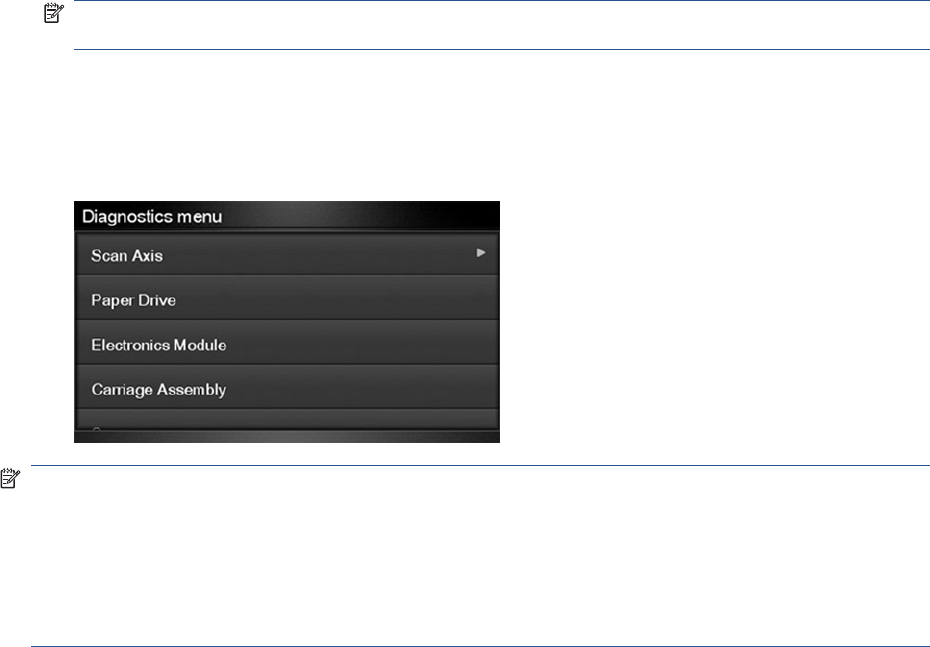
Entering the Diagnostics Menu
1. Make sure the product is switched off with the Power key on the side of the Touch Screen Panel,
and not with the power switch on the back of the product.
2. Press and release the Power key to switch on the product.
3. Wait for about 10 seconds until the 6 buttons on the Touch Control Panel have come on and then
press and release one after another Cancel> Home> Help buttons.
NOTE: Do not push the icons all at the same time, push each one in the order shown above and
release each icon before pressing on the next icon.
4. The 6 buttons on the Touch Control Panel will then blink 4 times; then wait until the product
completes the initialization sequence and shows the Diagnostics menu.
5. In the Diagnostics menu scroll up and down sliding the finger vertically on the Touch Control Panel
and press on the desired option.
NOTE: The Diagnostic Tests and Utilities work in a special mode that does not require the full
initialization of the product. Therefore, whenever you have finished a test, you must power off the
product and power on again before trying to print or before executing another test.
NOTE: In some cases a quick press of a button may not be recognized by the product. When pressing
a button, be sure to press it deliberately for about 1 second.
NOTE: If the product hangs up during a test, switch the product off and restart from step 1.
Scan Axis Test
The complete Scan Axis test consists of individual tests for the different components related to the Scan
Axis. The subsystems included in this assembly are:
●Star Wheel Lifter
●Automatic PPS Adjustment.
●Scan Axis Servosystem
●Cutter
You must perform the Scan-Axis Test after:
●System Error Code 42:XZ.
●System Error Code 47:XZ.
●System Error Code 73:XZ.
●System Error Code 87:XZ.
●System Error Codes related to Scan-Axis shutdown or Carriage jam.
ENWW Diagnostic Tests and Utilities 81
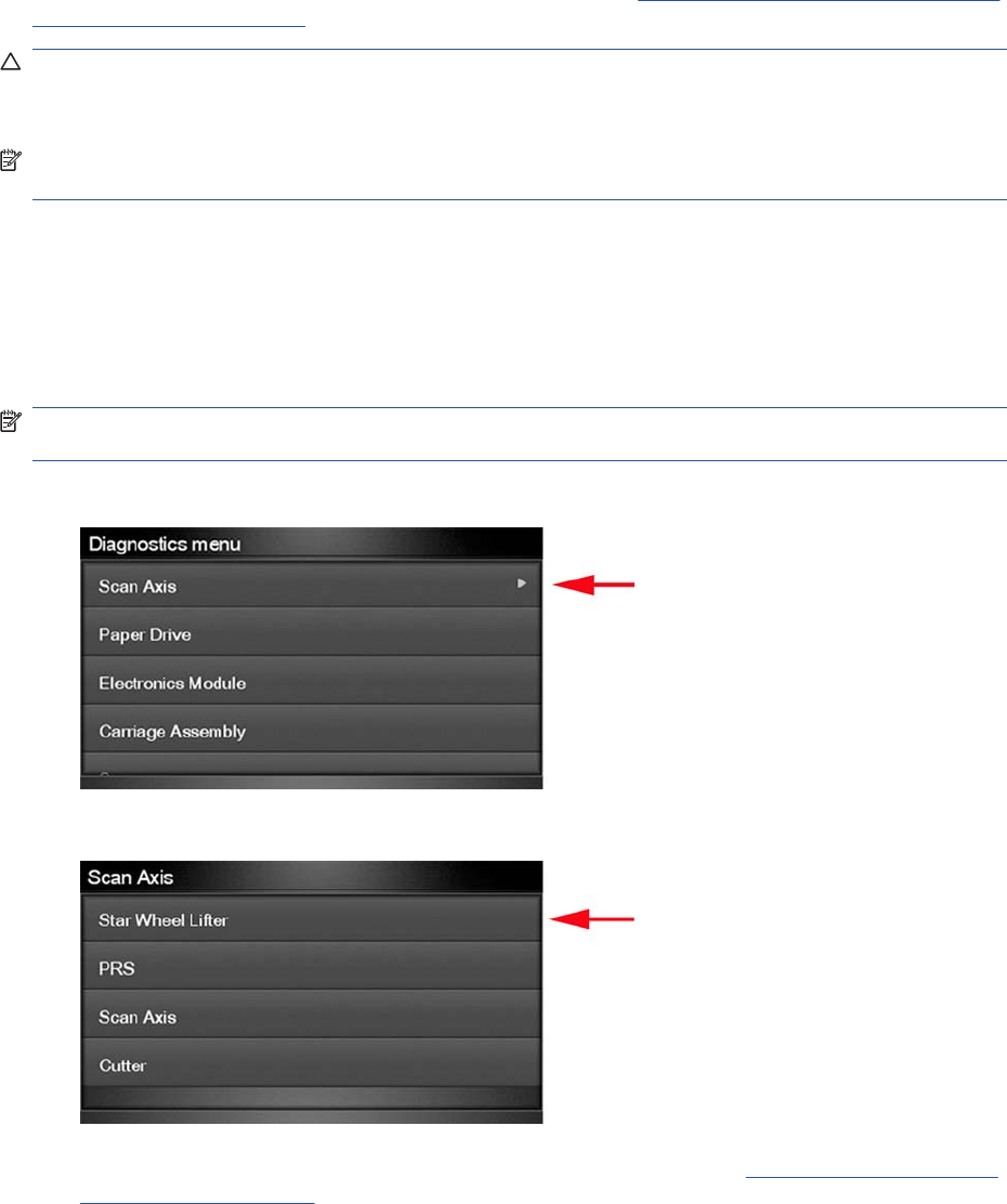
Diagnostic tests also need to be performed after removing or replacing certain product components. If
you have removed or replaced product components, check the Service Calibration Guide to Removal
and Installation on page 205 to see which tests and calibrations you need to perform.
CAUTION: ALL THE COVER SENSORS ARE DISABLED WHEN IN THE SERVICE TESTS MENU.
IF THE CARRIAGE IS MOVING IT WILL NOT STOP IF THE SCANNER IS OPEN, SO BE VERY
CAREFUL NOT TO PUT YOUR HANDS INSIDE.
NOTE: IF POSSIBLE, ALWAYS PERFORM THIS TEST BEFORE REPLACING ANY COMPONENT
OF THE SCAN-AXIS.
Star Wheel Lifter test
The Star Wheel Lifter subassembly is designed to move the Star Wheel support to the up and down
positions. This is used to load roll or sheet paper and avoid damage to the Star Wheel caused by paper
jams etc.
Perform the Scan Axis - Star Wheel Lifter test as follows:
NOTE: Perform this test with the Printheads and the Tubes System installed in order to get values
that can be compared correctly.
1. In the Diagnostics menu, select Scan Axis .
2. The Touch Control Panel will display the following screen, select Star Wheel Lifter.
If there is a failure at any point during the tests, the Touch Control Panel will display the relevant
System Error Code. To troubleshoot any displayed error codes, see System Error Codes—Full
Descriptions on page 42.
3. The product then starts the Star wheel lifter PWM control test to check the subsystem. As the test
executes the Touch Control Panel displays the following messages:
●Initializing
●Checking movement
●Testing…
82 Chapter 3 Diagnostics Menu ENWW
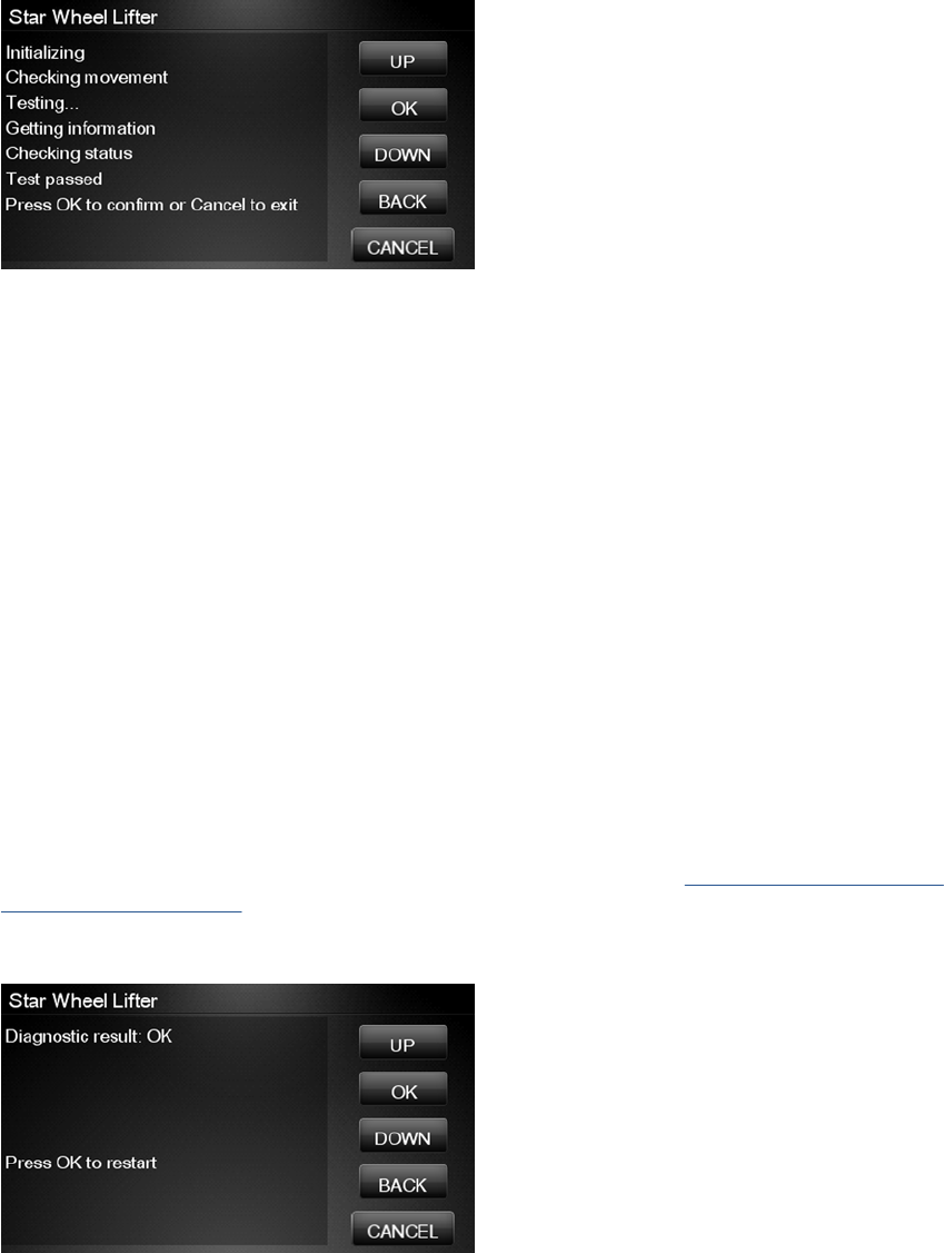
●Getting information
●Checking Status
4. The Touch Control Panel displays the test results and prompts you to continue.
5. Press OK to continue. Once you continue the test, the Touch Control Panel displays the following
messages:
●Checking motors
●Checking movement
●Getting data
●Analyzing
●Checking status
●Checking motor
●Checking movement
●Checking motor data
●Analyzing
●Checking Status
If there is a failure at any point during the test, the Touch Control Panel will display the relevant
System Error Code. To troubleshoot any displayed error codes, see System Error Codes—Full
Descriptions on page 42.
6. The Touch Control Panel shows the test complete display for a few seconds.
7. Press OK to end the test and restart the product.
PRS Test
ENWW Diagnostic Tests and Utilities 83
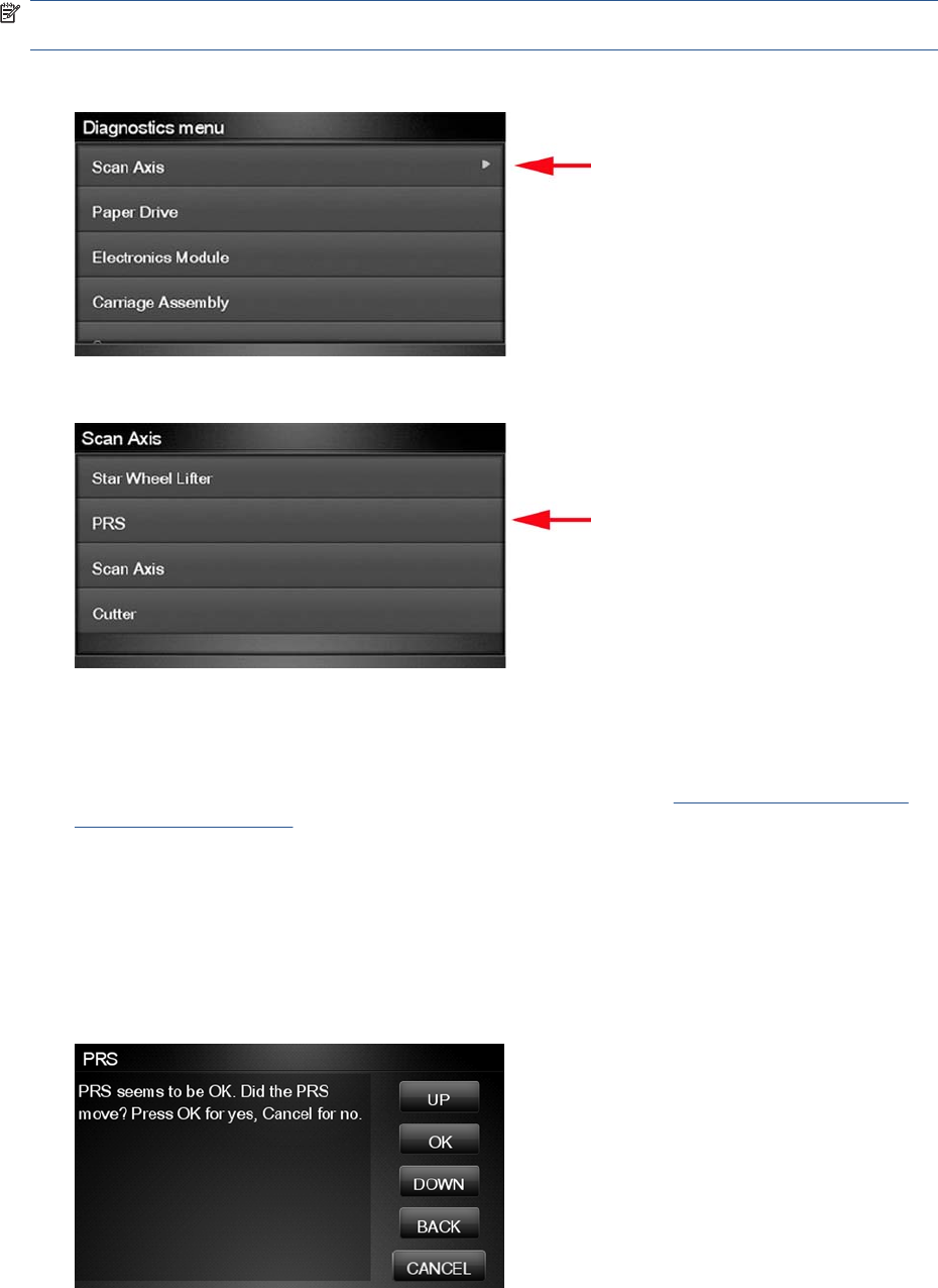
The PRS subsystem is designed to move the carriage assembly between two predetermined vertical
positions with respect to the plane of the print platen. This allows different papers of different thicknesses
to be used without losing print quality.
Perform the Scan Axis - PRS test as follows.
NOTE: Perform this test with the Printheads and the Tubes System installed in order to get values
that can be compared correctly.
1. In the Diagnostics menu, scroll to Scan Axis and press on this menu option.
2. The Touch Control Panel will display the following screen, select PRS.
3. In the Scan Axis submenu, scroll to PRS and press OK to start the test
The product will start the Scan Axis subsystem Common Initialization and PRS test initialization.
If there is a failure at any point during the tests, the Touch Control Panel will display the relevant
system error code. To troubleshoot any displayed error codes, see System Error Codes—Full
Descriptions on page 42.
4. The product then starts the PRS test to check the subsystem. As the test executes, the Touch
Control Panel displays the following messages:
●Initializing
●Checking movement
5. Once the test has completed, the Touch Control Panel prompts you to confirm that the PRS moved.
84 Chapter 3 Diagnostics Menu ENWW
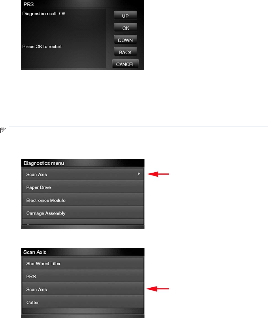
6. If the PRS moved, press OK to accept the results. If the PRS did not move, press Cancel to reject
the results and exit the test.
7. Press OK to end the test and restart the product.
Scan Axis Test
The Scan Axis subsystem is designed to move the carriage assembly between two predetermined
horizontal positions with respect to the plane of the print platen. This allows papers of different widths
to be used without losing print quality.
Perform the Scan Axis - Scan Axis test as follows:
NOTE: Perform this test with the Printheads and the Tubes System installed in order to get values
that can be compared correctly.
1. In the Diagnostics menu, select Scan Axis.
2. The Touch Control Panel will display the following screen, select Scan Axis.
3. The product checks the Scan Axis motor. The Touch Control Panel displays the following
messages:
●Initializing
●Checking motors
4. Depending on the results of the tests, you may be asked to perform the following operations.
ENWW Diagnostic Tests and Utilities 85
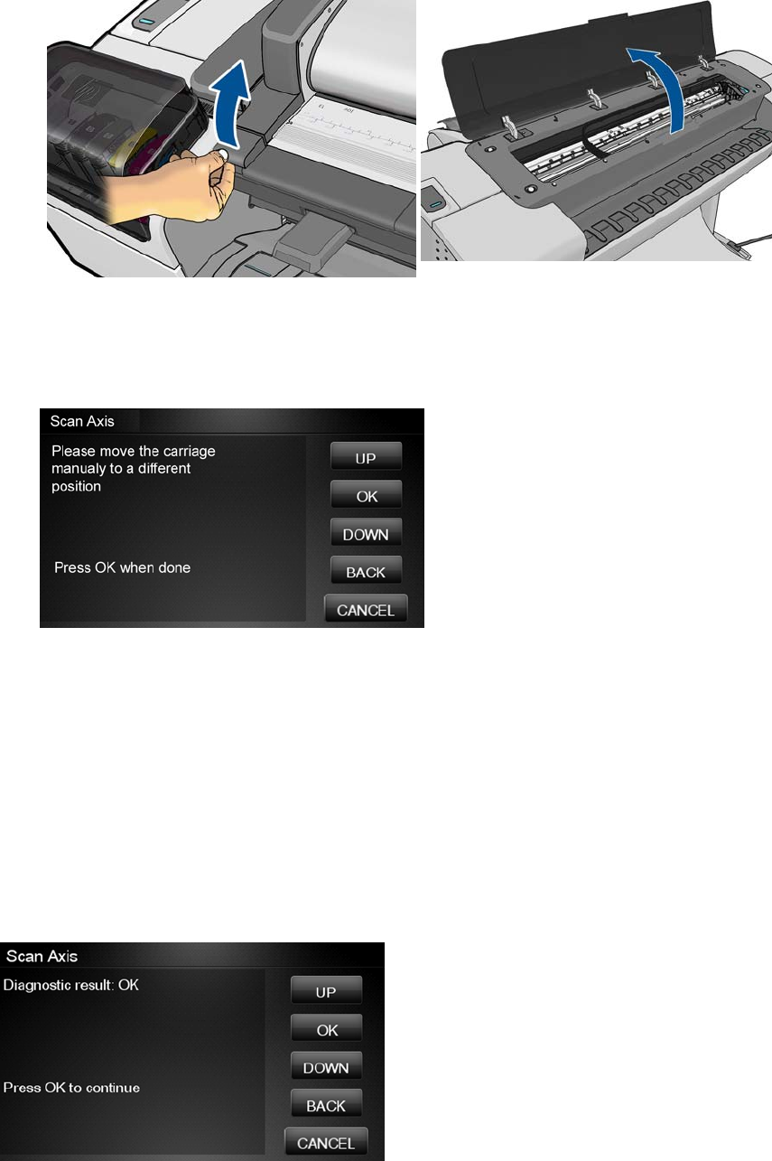
a. Open the Scanner (MFP only) or Window.
b. Manually move the carriage to another position. The carriage should not offer resistance to
manual movement. Do not force any product part while moving the carriage. The Touch
Control Panel will show a text describing the action and an animation as an example of the
requested operation. Press OK when you have finished moving the carriage.
c. Close the Scanner or Window.
5. Afterwards, the test will automatically continue checking for possible Scan Axis errors. The carriage
will move automatically along the Scan Axis several times, taking a few minutes. As the test
executes, the Touch Control Panel displays the following messages:
●Checking paper jam
●Checking movement
●Checking life counters status
6. If the Scan Axis passes the test, the Touch Control Panel displays the following message, otherwise
it displays an error code. Press OK to continue.
Cutter test
86 Chapter 3 Diagnostics Menu ENWW
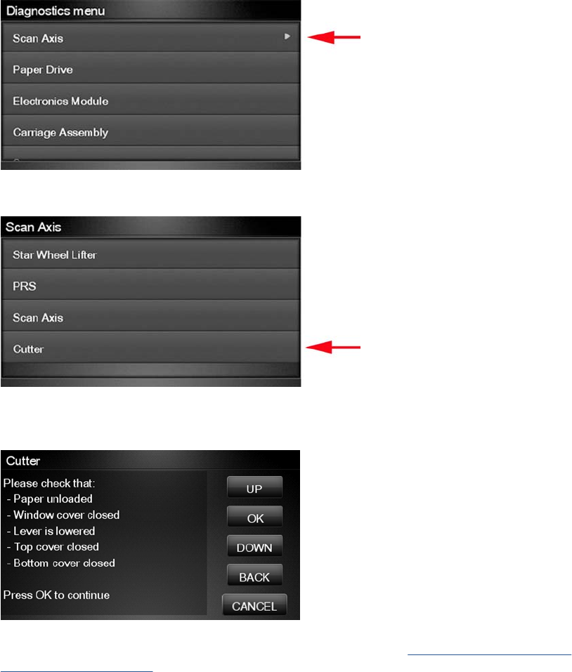
The Cutter is designed to cut roll paper after printing to the defined sheet size. Before executing this
test you should run the Scan Axis, Media Drive and Carriage tests to ensure that each of these
subsystems is operating correctly.
Perform the Scan Axis - Cutter test as follows.
1. In the Diagnostics menu, select Scan Axis.
2. The Touch Control Panel will display the following screen, select Cutter.
3. The following screen is displayed, check that the paper is unloaded and all the covers are closed,
and select OK.
If there is a failure at any point during the tests, the Touch Control Panel will display the relevant
system error code. To troubleshoot the displayed error code, see System Error Codes—Full
Descriptions on page 42.
ENWW Diagnostic Tests and Utilities 87
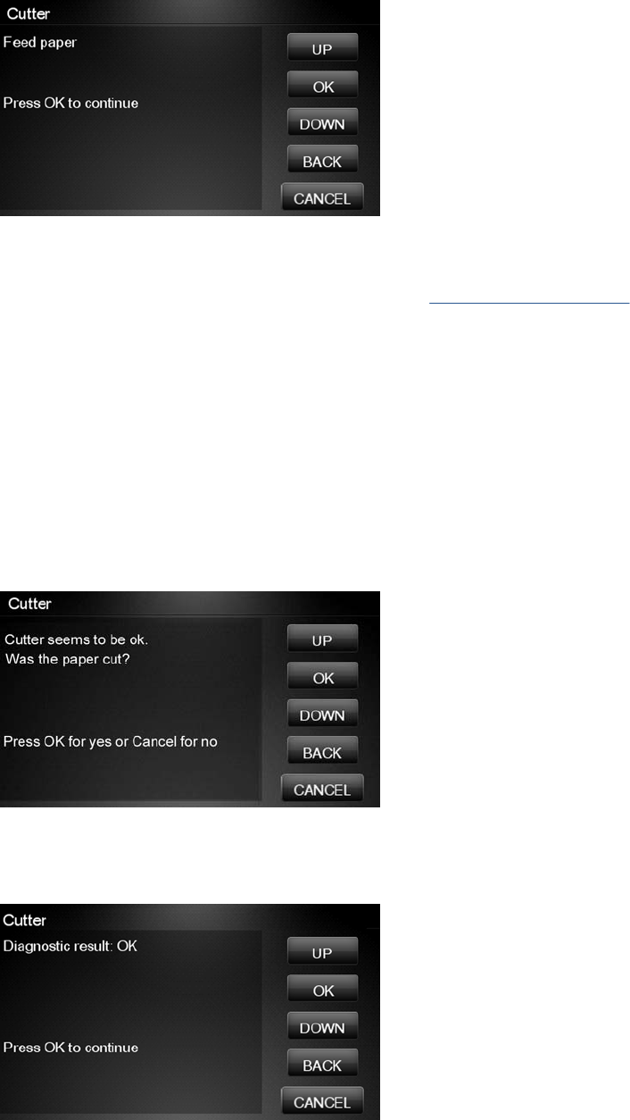
4. The following screen is displayed. With the Media Lever lowered, feed a roll of paper (not a sheet)
into the paper path until it reaches the product roller. Then press OK to continue.
If you have not fed enough paper into the product, the diagnostic will show a message saying that
the paper was not detected and the test will fail and the product will reboot. In this case, try again,
taking care to feed more paper. If the problem continues, check that the sensors are working
correctly. If necessary, perform the Sensors Test (see Sensors Test on page 96).
5. The product then starts an actual test cut of the paper. As the test executes the Touch Control
Panel displays the following messages:
●Advancing paper
●Preparing cutter
●Cutting paper
●Disengaging cutter
6. Once the test has completed the Touch Control Panel displays the test result and prompts you to
confirm that the cutter worked.
7. Press OK if the cutter worked or Cancel if the cutter did not work.
8. Press OK to end the test and restart the product.
88 Chapter 3 Diagnostics Menu ENWW
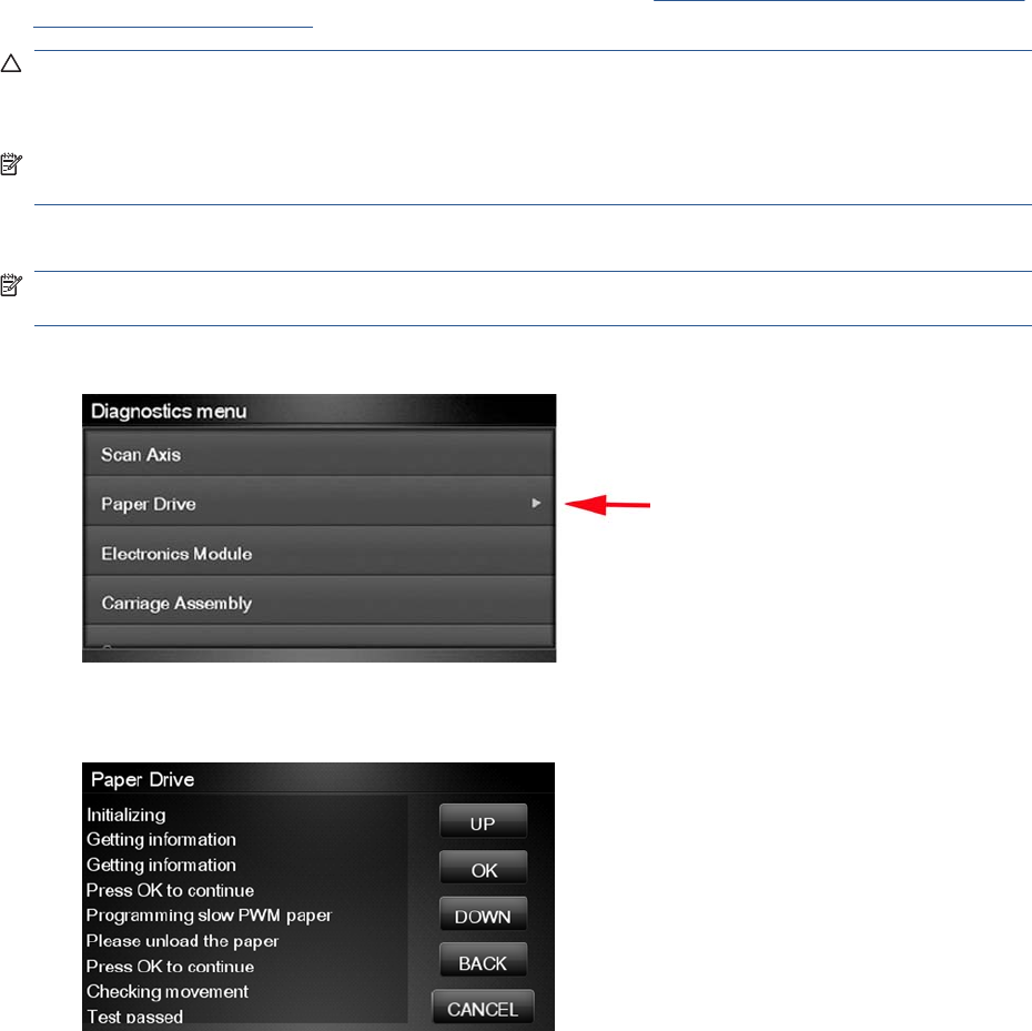
Paper Drive Test
The Paper Drive test diagnoses failures of components of the Paper Axis.
You must perform the Paper Drive Test after:
●System Error Code 81:XZ.
●System Error Code 41:XZ.
●System Error Code 73:XZ.
Diagnostic tests also need to be performed after removing or replacing certain product components. If
you have removed or replaced product components, check the Service Calibration Guide to Removal
and Installation on page 205 to see which tests and calibrations you need to perform.
CAUTION: ALL THE COVER SENSORS ARE DISABLED WHEN IN THE SERVICE TESTS MENU.
IF THE CARRIAGE IS MOVING IT WILL NOT STOP IF THE SCANNER IS OPEN, SO BE VERY
CAREFUL NOT TO PUT YOUR HANDS INSIDE.
NOTE: IF POSSIBLE ALWAYS PERFORM THIS TEST BEFORE REPLACING ANY COMPONENT
OF THE MEDIA-AXIS.
Perform the Paper Drive test as follows:
NOTE: Perform this test with the Printheads and the Tubes System installed in order to get values
that can be compared correctly.
1. In the Diagnostics menu, select Paper Drive.
2. The Touch Control Panel displays the following screen, select OK to continue with the process.
Unload paper if loaded, and select OK again.
ENWW Diagnostic Tests and Utilities 89
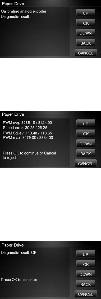
3. The Touch Control Panel then displays the Analog Encoder calibration results.
The GAIN for channels A and B should be lower than 5.
4. If the results are correct, press OK to accept the results. If the results are not correct, press
Cancel to reject the results and fail the test.
5. If you accept the results, the Touch Control Panel will continue with the tests. It will ask you to
press OK to continue with the process. When prompted, unload paper if any is loaded.
6. The Touch Control Panel then displays the test results.
●The first PWM avg result (forward move) should be between 7700 and 10560 and the second
Pwm avg (backward move) between 7600 and 10450.
●The first Speed error result should be no more than 78.65 and the second no more than 112.5.
●The first PWM StDev result should be no more than 162.5 and the second no more than 187.5.
●The first PWM max result should be no more than 12250 and the second no more than 12125.
7. If the results are correct, press OK to accept the results. If the results are not correct, press
Cancel to reject the results and FAIL the test.
8. If you accept the results, the Touch Control Panel shows the following screen, press OK to finish.
90 Chapter 3 Diagnostics Menu ENWW
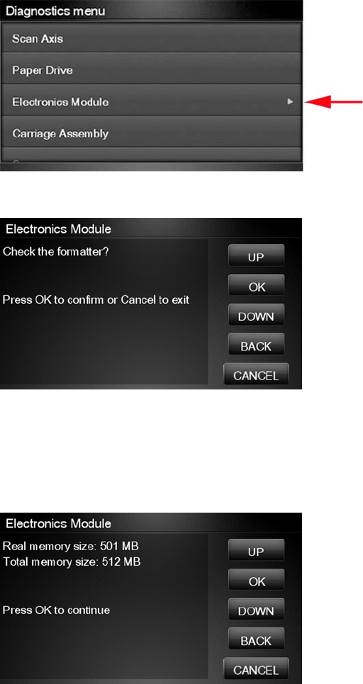
Electronics Module Test
The purpose and scope of this test is different when compared to some of the other HP Designjet
products of the same platform. This procedure tests only the formatter, as the other subsystems such
as the PSU or Engine PCA are tested during the Initialization of the product every time the unit is
switched on.
The purpose of this test is to diagnose a failure in the operation of the Formatter. The information shown
in the Touch Control Panel is:
●The memory size
●Type and size of the partitions on the Hard Disk
●Size and percentage used of the data and boot partitions on the Hard Disk.
Perform the Electronics Module test as follows:
1. In the Diagnostics menu, select Electronics Module.
2. The Touch Control Panel then prompts you to test the Formatter, press OK.
3. The Formatter memory size test starts and the Touch Control Panel displays the following
messages:
●Getting information
4. The Touch Control Panel then displays the Formatter memory size.
ENWW Diagnostic Tests and Utilities 91
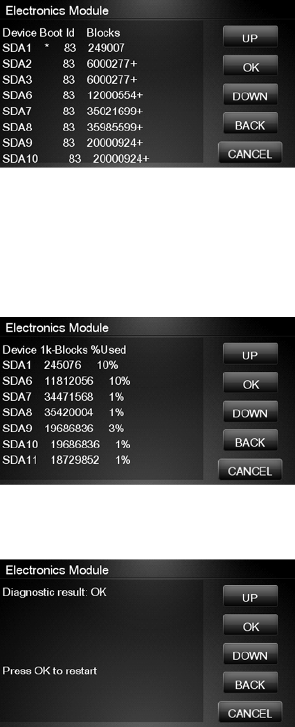
5. Press OK to continue.
6. The Formatter hard disk test starts and the Touch Control Panel displays the following messages:
●Getting information
7. The Touch Control Panel then displays Formatter Hard Disk information test results.
8. Press any key to continue.
9. The Formatter hard disk file information test starts and the Touch Control Panel displays the
following messages:
●Getting information
10. The Touch Control Panel then displays Formatter Hard Disk File information test results.
11. Press any key to continue.
12. If the test is successful, the Touch Control Panel displays the following message.
13. Press OK to end the test and restart the product.
92 Chapter 3 Diagnostics Menu ENWW
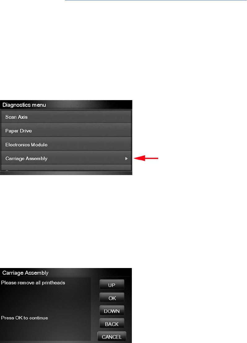
Carriage Assembly Test
The Carriage Assembly test diagnoses failures of any components of the Carriage. This test should be
run in any of the following circumstances.
●Before replacing the Carriage Assembly.
●After removing or replacing certain product components. If you have removed or replaced product
components, check the Service Calibration Guide to Removal and Installation on page 205 to see
which tests and calibrations you need to perform.
●If printhead alignment fails repeatedly.
●If, when loading paper, the search for the edge of the paper fails repeatedly.
●If no printheads are detected (check more than one).
●If the system error message 02.1:10 appears.
If an error is detected during the test, the Touch Control Panel will display an error code and message.
The test will not continue after that point.
1. In the Diagnostics menu, select Carriage Assembly.
2. The test starts and the Touch Control Panel displays the following messages:
●Initializing
●Getting information
●Checking voltages
3. It will then display the actual values of various parameters, together with their permitted (valid)
range. In each case, press OK to continue with the test.
4. Partway through the test, the Touch Control Panel asks you to remove the printheads.
5. Open the Scanner (MFP only) or Window.
ENWW Diagnostic Tests and Utilities 93
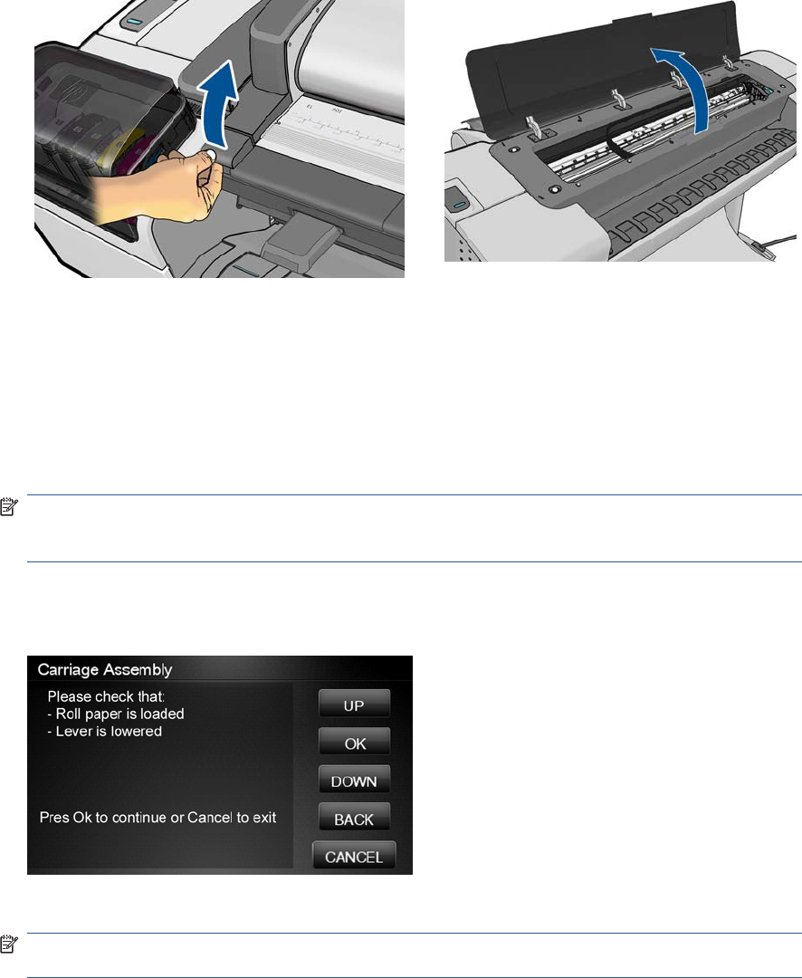
6. Open the Carriage Cover.
7. Remove all the printheads from the Carriage.
8. Close the Carriage Cover.
9. Close the Scanner (MFP only) or Window.
10. Press OK to continue.
NOTE: If the Touch Control Panel reports that a printhead is still detected in the product, remove
the printhead. If you are sure that you have already removed all the printheads, press Cancel to
continue the test.
11. The test continues, displaying the values and valid ranges of some more parameters.
12. The Touch Control Panel then prompts you to load roll paper.
13. Load roll paper.
NOTE: For the LED test to work properly, the paper must be loaded completely through the
carriage path.
14. Press OK to continue or Cancel to exit.
94 Chapter 3 Diagnostics Menu ENWW
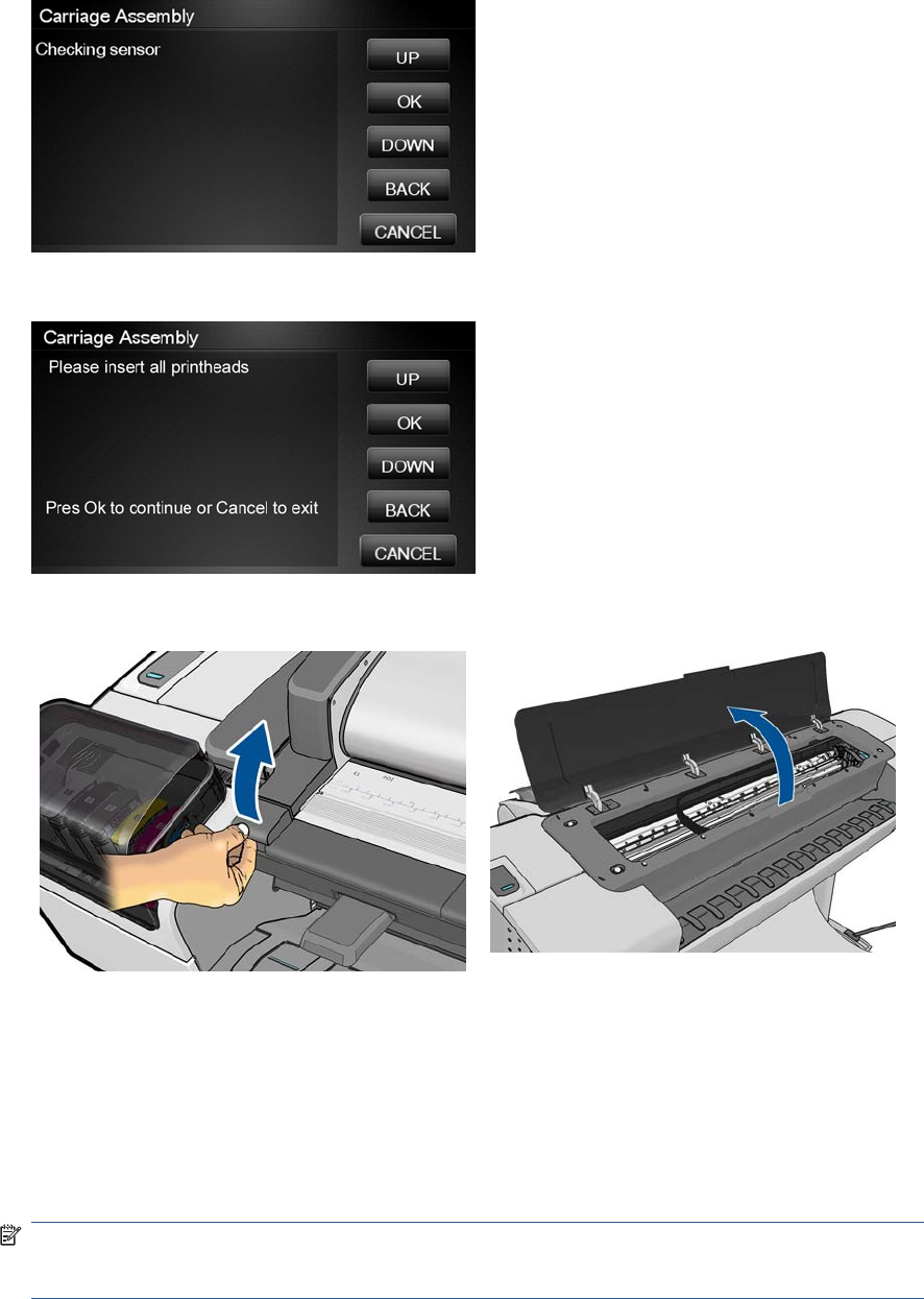
15. The product tests the carriage LEDs and sensors, which may take a few minutes.
16. The Touch Control Panel then asks you to re-insert all the printheads that you removed earlier.
17. Open the Scanner (MFP only) or Window.
18. Open the Carriage Cover.
19. Insert all the printheads.
20. Close the Carriage Cover.
21. Close the Scanner (MFP only or Window.
22. Press OK to continue.
NOTE: If the Touch Control Panel reports that a printhead is not detected in the product, insert
the printhead. If you are sure that you have already inserted all the printheads, press Cancel to
continue the test.
ENWW Diagnostic Tests and Utilities 95
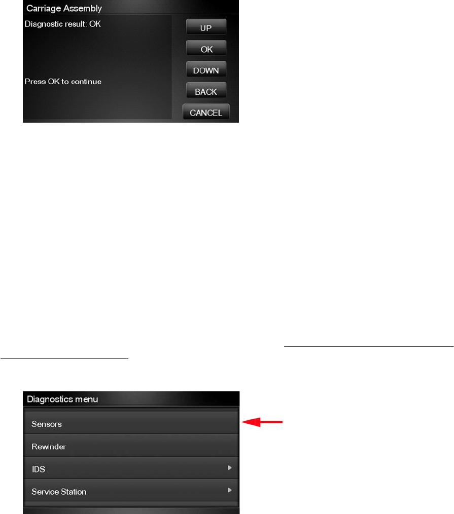
23. The product makes some further checks. If all is well, the Touch Control Panel displays the following
message.
24. Press OK to end the test.
Sensors Test
The Sensors test diagnoses failures of any sensors of the product. Always run this test before replacing
any of the following sensors:
●Scanner Position sensor (MFP only)
●Media Lever position sensor
●Media sensor
●Upper or lower roll cover sensor
●Single-sheet sensor
Diagnostic tests also need to be performed after removing or replacing certain product components. If
you have removed or replaced product components, check the Service Calibration Guide to Removal
and Installation on page 205 to see which tests and calibrations you need to perform.
1. In the Diagnostics menu, scroll to Sensors and press on this menu option.
96 Chapter 3 Diagnostics Menu ENWW
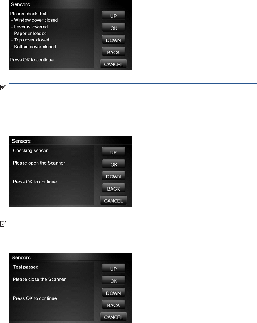
2. The Sensors test starts and the Touch Control Panel prompts you to check default sensor positions.
For the T770 series, the cover sensors are not present and not tested.
Check that the sensors are in the default positions and press OK to continue.
NOTE: If the product detects any sensor in a position that is not expected, a message will be
shown. If the sensor is in the correct position, there must be a problem with the sensor (for example,
the Scanner is closed but the message indicates that it is not closed); in this case, replace the faulty
sensor.
3. The Scanner Position sensor test starts and the Touch Control Panel prompts you to open the
Scanner (MFP only).
Open the Scanner and press OK to continue.
NOTE: Make sure that no object is interfering with the sensor.
4. The Touch Control Panel prompts you to close the Scanner, if the sensor detects the scanner
closing the following screen is displayed.
Close the Scanner and press OK to continue.
ENWW Diagnostic Tests and Utilities 97
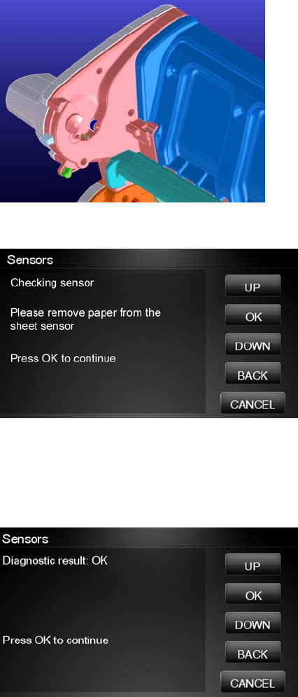
5. Follow the same procedure for the Pinchwheel Lever Sensor, the Media Sensor, and the Roll
Covers.
To test the Media Sensor, you will have to feed paper into the product until it reaches the sensor.
6. The Touch Control Panel asks you to remove the paper.
When you have removed the paper, press OK to continue.
7. The Touch Control Panel may ask you to reinsert the paper.
8. When the tests are complete, the Touch Control Panel displays a final message. Press OK to
continue.
Rewinder Test
The Rewinder test diagnoses failures of the Rewinder located in the Rear Paper Path Assemblies.
Always run this test before replacing the Right Roll Support.
Perform this test after:
●System Error Code 41:YZ
●System Error Code 45:YZ
●System Error Code 81:YZ
98 Chapter 3 Diagnostics Menu ENWW
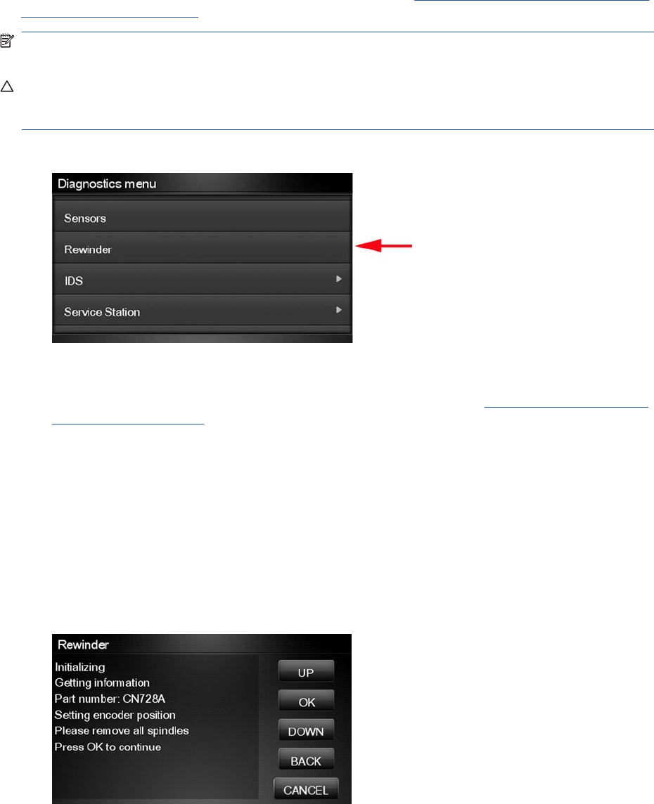
Diagnostic tests also need to be performed after removing or replacing certain product components. If
you have removed or replaced product components, check the Service Calibration Guide to Removal
and Installation on page 205 to see which tests and calibrations you need to perform.
NOTE: Perform this test with the Printheads and the Tubes System installed in order to get values
that can be compared correctly.
CAUTION: ALL THE COVER SENSORS ARE DISABLED WHEN IN THE DIAGNOSTICS MENU. IF
THE CARRIAGE IS MOVING IT WILL NOT STOP IF THE SCANNER IS OPENED, SO BE VERY
CAREFUL NOT TO PUT YOUR HANDS INSIDE.
1. In the Diagnostics menu, scroll to Rewinder and press on this menu option.
The product will start the Open Loop, Rewinder Servo System, and Media Driver PWM tests.
If there is a failure at any point during the tests, the Touch Control Panel will display the relevant
System Error Code. To troubleshoot any displayed error codes, see System Error Codes—Full
Descriptions on page 42.
2. The Rewinder test starts and the Touch Control Panel displays the following messages:
●Initializing
●Getting information
●Part Number: P/N
●Setting encoder position
3. The Touch Control Panel prompts you to make sure the paper is unloaded and the spindles are
removed.
4. Remove the paper from the product.
5. Remove the spindles from the roll supports.
6. Press OK to continue.
ENWW Diagnostic Tests and Utilities 99
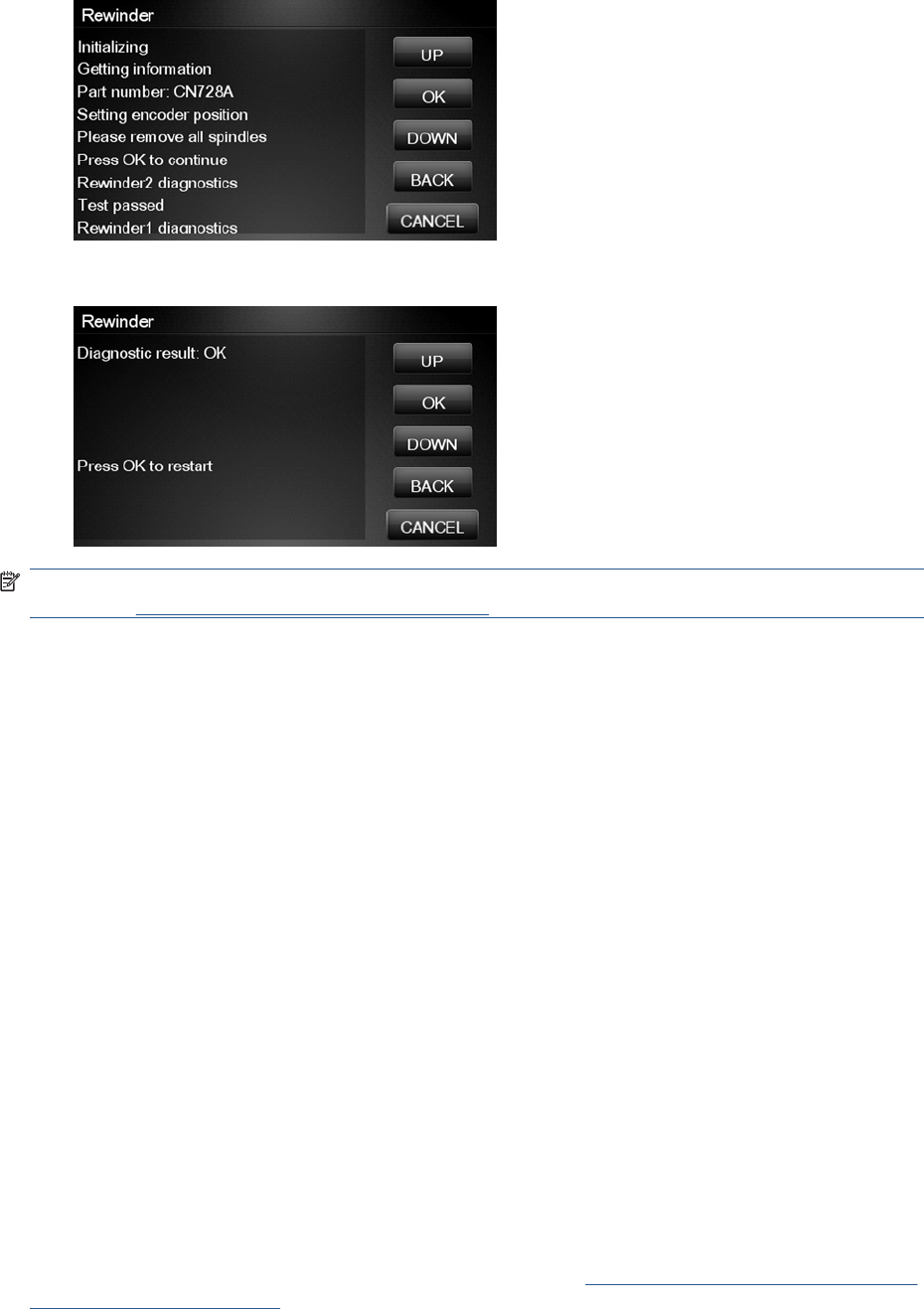
7. The Touch Control Panel displays the results.
8. The Touch Control Panel displays the test results. Press OK to end the test and restart the product.
NOTE: Once you have completed the Rewinder diagnostic test, you must perform a Paper Advance
Calibration. Paper Advance Calibration on page 155.
Ink Delivery System (IDS) Test
The complete Ink Delivery System test consists of three individual tests for the different components
related to this subsystem. These three tests and their associated functions are:
●Ink Delivery System
◦Check the Ink Supply Station subsystem.
◦Show tubes usage (as a percentage of expected life).
◦Test communication with Ink Supplies.
●Check Ink Supplies
◦Test communication with Ink Supplies.
◦Show ink levels.
◦Check that Ink Supplies are ready for purging: the remaining ink is enough for the setup
process and the ink supply is not faulty.
●Check Leakage
◦Check the Ink Supply Station subsystem.
◦Check for ink supplies or tubes leakage.
Diagnostic tests also need to be performed after removing or replacing certain product components. If
you have removed or replaced product components, check the Service Calibration Guide to Removal
and Installation on page 205 to see which tests and calibrations you need to perform
100 Chapter 3 Diagnostics Menu ENWW
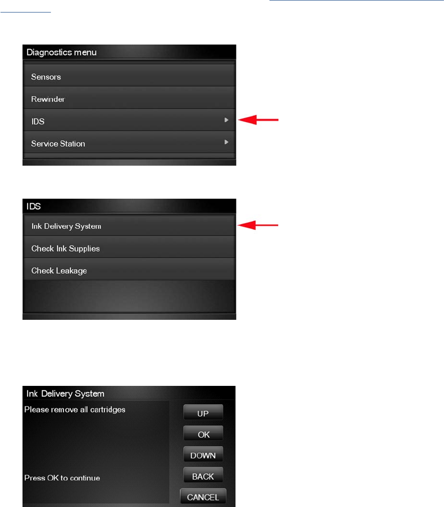
Ink Delivery System
If there is a failure at any point during the tests, the Touch Control Panel will display the relevant System
Error Code. To troubleshoot any displayed error codes, see System Error Codes—Full Descriptions
on page 42.
1. In the Diagnostics menu, scroll to IDS and press on this menu option.
2. The Touch Control Panel shows the IDS submenu.
3. In the IDS submenu, scroll to Ink Delivery System and press OK to start the test.
4. The Ink Delivery System test starts and the Touch Control Panel prompts you to remove all the Ink
Supplies.
5. Remove all the Ink Cartridges.
6. Press OK to continue.
ENWW Diagnostic Tests and Utilities 101
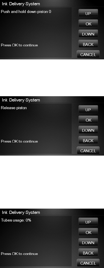
7. The Touch Control Panel then prompts you push down Piston 0.
8. Press and hold down Piston 0, which is located at the furthest left Ink Cartridge position.
9. Press OK.
10. The Touch Control Panel then prompts you to release Piston 0.
11. Release Piston 0.
12. Press OK to continue.
13. Repeat the steps above for each piston.
14. The Touch Control Panel then displays the tubes usage, expressed in percentage of the expected
subsystem life.
15. Press OK to continue.
102 Chapter 3 Diagnostics Menu ENWW
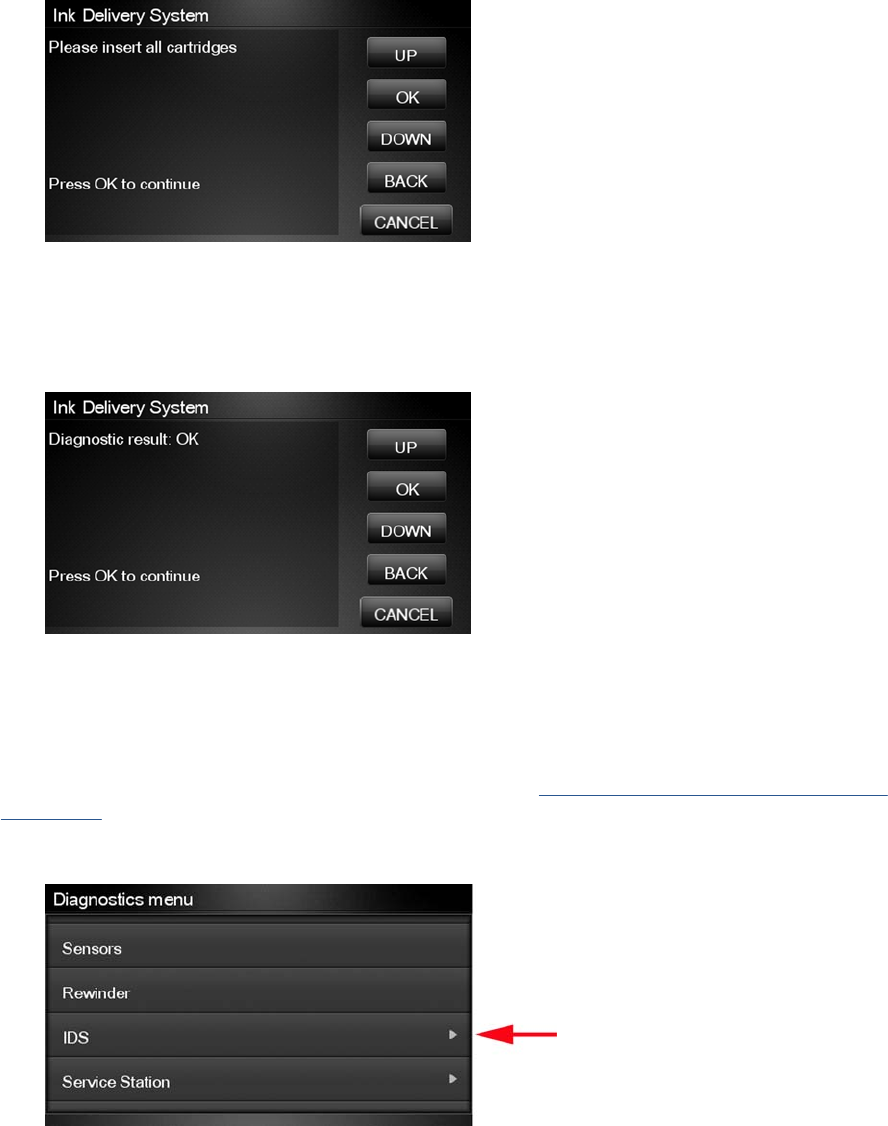
16. The Touch Control Panel prompts you to insert all the Ink Cartridges.
17. Install all the Ink Cartridges.
18. Press OK to continue.
19. The Touch Control Panel then displays Acumen Supplies test results.
20. Press OK to end the test and return to the Diagnostics menu.
Check Ink Supplies
If there is a failure at any point during the tests, the Touch Control Panel will display the relevant System
Error Code. To troubleshoot any displayed error codes, see System Error Codes—Full Descriptions
on page 42.
1. In the Diagnostics menu, scroll to IDS and press on this menu option.
ENWW Diagnostic Tests and Utilities 103
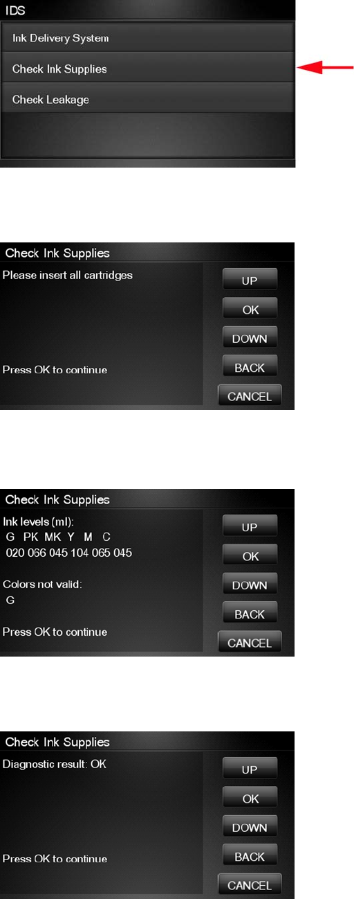
2. The Touch Control Panel shows the IDS submenu.
3. In the IDS submenu, scroll to Check Ink Supplies and press OK to start the test.
4. The Touch Control Panel prompts you to insert all the ink cartridges.
5. The Touch Control Panel shows the ink levels of all the cartridges. A list of the “colors not valid”
for purge are shown below. If all of the cartridges are valid for purging, the “Colors not valid” item
will not be shown on the Touch Control Panel.
6. Press OK to exit.
7. The Touch Control Panel then displays the test results.
8. Press OK to end the test and return to the Diagnostics menu.
104 Chapter 3 Diagnostics Menu ENWW
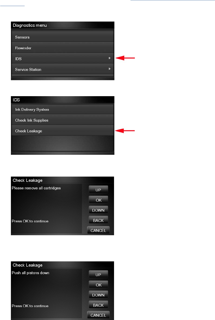
Check Leakage
If there is a failure at any point during the tests, the Touch Control Panel will display the relevant System
Error Code. To troubleshoot any displayed error codes, see System Error Codes—Full Descriptions
on page 42.
1. In the Diagnostics menu, scroll to IDS and press on this menu option.
2. In the IDS submenu, scroll to Check Leakage and press OK to start the test.
3. The Ink Delivery System test starts and the Touch Control Panel prompts you to remove all the Ink
Cartridges.
4. Remove all the Ink Cartridges and press OK to continue.
5. The Touch Control Panel prompts you to push down all the pistons.
ENWW Diagnostic Tests and Utilities 105
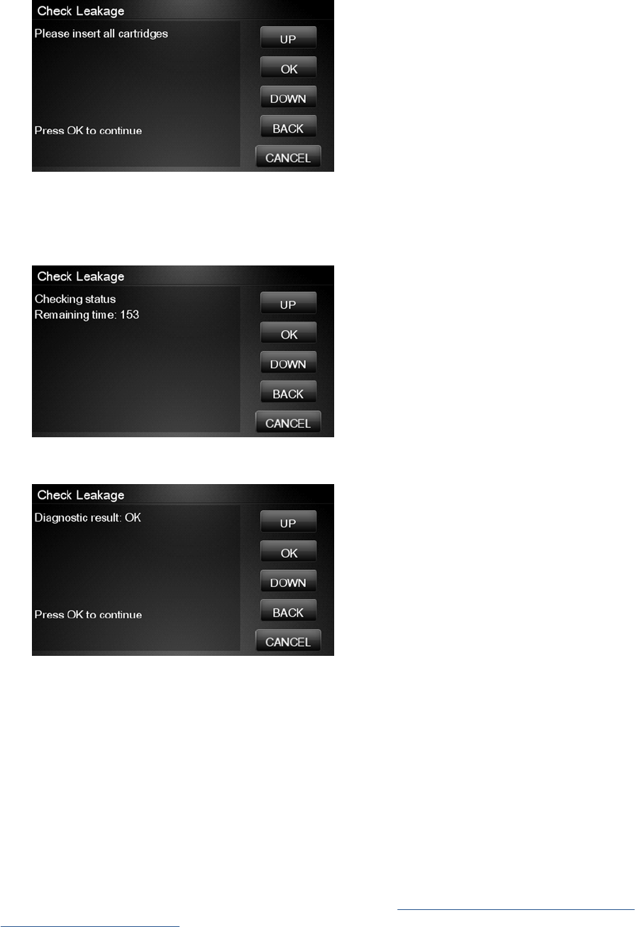
6. Use your fingers to push all of the pistons down, and press OK to continue.
7. If the Ink Supply Station is working properly, the Touch Control Panel prompts you to insert all the
Ink Cartridges.
8. Install all the Ink Cartridges and press OK to continue.
9. The leakage check starts and the Touch Control Panel displays the remaining time until the leakage
check is finished.
10. The Touch Control Panel then displays Check Leakage test results.
11. Press OK to end the test and return to the Diagnostics menu.
Service Station Test
The complete Service Station test consists of individual tests for the different components related to this
subsystem.
These tests are:
●Service Station
●Primer Motor
Diagnostic tests also need to be performed after removing or replacing certain product components. If
you have removed or replaced product components, check the Service Calibration Guide to Removal
and Installation on page 205 to see which tests and calibrations you need to perform.
106 Chapter 3 Diagnostics Menu ENWW
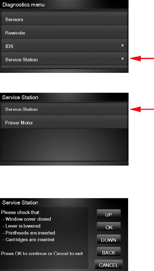
Service station
1. In the Diagnostics menu, scroll to Service Station and press on this menu option.
2. The Touch Control Panel will show the Service Station submenu.
3. In the Service Station submenu, scroll to Service Station and press OK to start the test.
4. The Touch Control Panel then prompts you to check the status of the product.
5. Check that:
●The Scanner is closed.
●The Media Lever is lowered.
●All Printheads are inserted.
●Valid Cartridges are inserted.
6. Press OK to continue.
ENWW Diagnostic Tests and Utilities 107
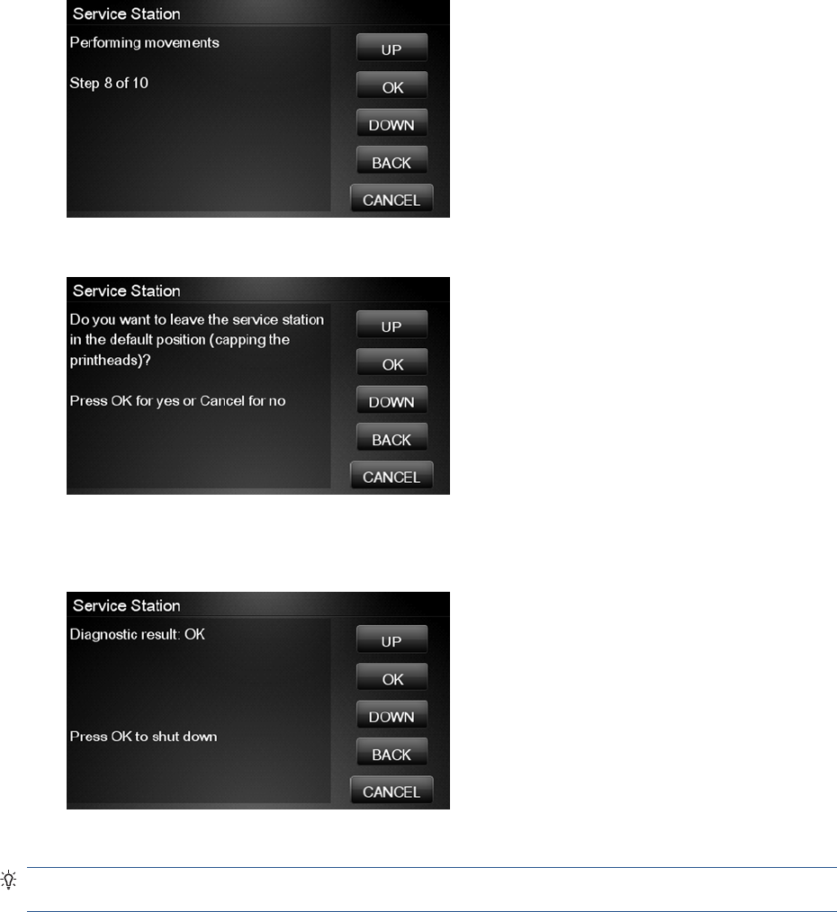
7. The product performs a series of movements numbered from 1 to 10. It takes about a minute to
perform all movements.
8. The Touch Control Panel then asks if you want to cap the printheads.
9. Press OK to cap the Service Station or Cancel to skip this test.
10. The Touch Control Panel prompts you to shut down the product to complete the test.
11. Press OK to shut down the product.
TIP: If a system error message is displayed during the procedure, follow the procedure described in
the System Errors section. A system error 21 indicates that the service station is not working properly.
108 Chapter 3 Diagnostics Menu ENWW
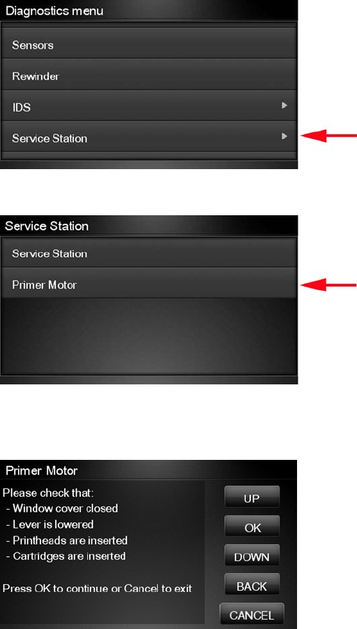
Primer motor
1. In the Diagnostics menu, scroll to Service Station and press on this menu option.
2. The Touch Control Panel will show the Service Station submenu.
3. In the Service Station submenu, scroll to Primer Motor and press OK to start the test.
4. The Touch Control Panel then prompts you to check the status of the product.
5. Check that:
●The Scanner is closed.
●The Media Lever is lowered.
●All Printheads are inserted.
●Valid Cartridges are inserted.
ENWW Diagnostic Tests and Utilities 109
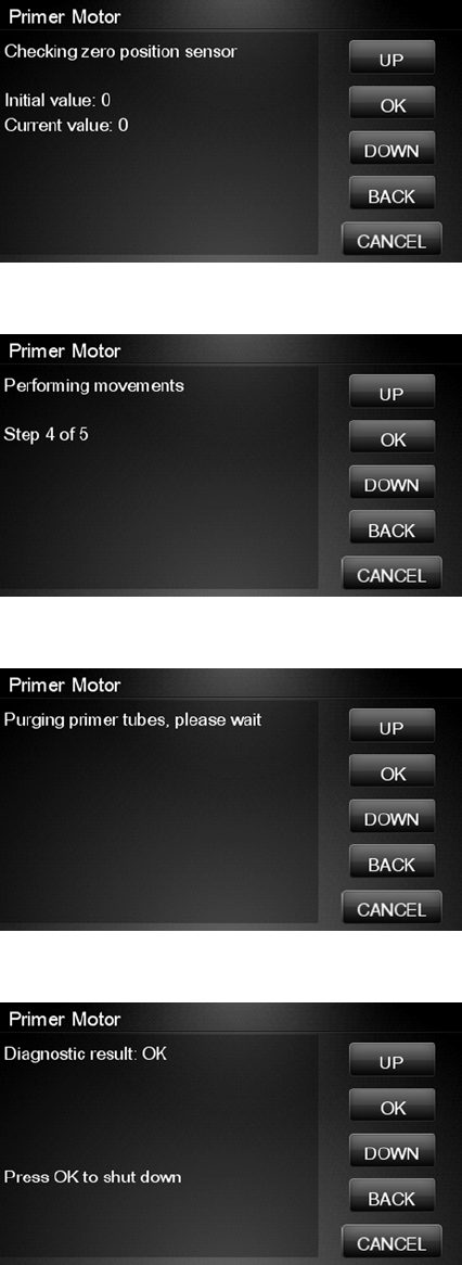
6. The product performs two movements. Then a screen is shown where the zero position sensor is
checked. It is a sensor that detects when the primer is in the zero position. The initial value for the
sensor is shown. Then the primer motor is moved until a changed is shown in current value.
7. The product performs a series of movements to test the primer.
8. If the test passes, the product purges the tubes. This process takes about a minute.
9. The Touch Control Panel prompts you to shut down the product to complete the test.
10. Press OK to shut down the product.
I/O Information Utility
The I/O Information utility retrieves the TCP/IP Network configuration parameters from the product.
110 Chapter 3 Diagnostics Menu ENWW
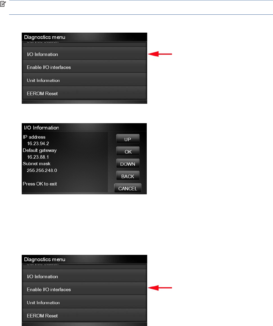
NOTE: In some cases, particularly after resetting the product to factory defaults, it may take as long
as 5 minutes to obtain an IP configuration.
1. In the Diagnostics menu, scroll to I/O Information and press on this menu option.
2. The Touch Control Panel displays the I/O Information.
3. Press OK to finish.
Enable I/O Interfaces Utility
This utility is used to enable/disable the USB and LAN connections.
1. In the Diagnostics menu, scroll to Enable I/O Interfaces and press on this menu option.
ENWW Diagnostic Tests and Utilities 111
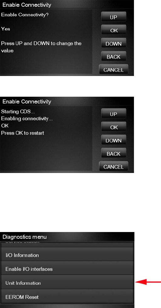
2. The Touch Control Panel prompts you to enable the connectivity. Press OK to confirm or, UP or
Down to change the option YES or NO.
3. The connectivity is enabled if YES option is confirmed. Press OK to restart.
Unit Information Utility
1. The Unit Information test retrieves the Firmware Version, Serial Number and Part Number of the
product.
2. In the Diagnostics menu, scroll to Unit Information and press on this menu option.
3. The Unit Information test starts and the Touch Control Panel displays the following message:
●Initializing
●Getting information
112 Chapter 3 Diagnostics Menu ENWW
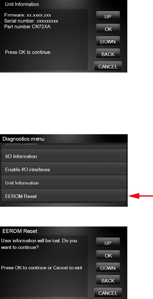
4. The Touch Control Panel displays the firmware level, serial number of the product and the part
number.
5. Press OK to continue and return to the menu.
EEROM Reset Utility
The EEROM Reset test resets the product to the factory defaults and delete any user information/files.
1. In the Diagnostics menu, scroll to EEROM and press on this menu option.
2. The EEROM Reset test starts and the Touch Control Panel asks whether you want to continue.
3. Press OK to continue the test or Cancel to cancel it.
4. The EEROM Reset test continues and the Touch Control Panel displays the following message:
●Initializing
●Setting default configuration
ENWW Diagnostic Tests and Utilities 113
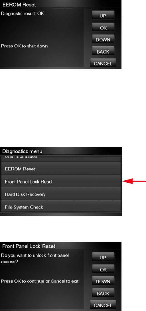
5. The Touch Control Panel prompts you to shut down the product to complete the test.
6. Press OK to shut down the product.
Touch Control Panel Lock Reset
This utility enables the Touch Control Panel to be unlocked when it has been locked by mistake and
cannot be remotely unlocked from Web JetAdmin.
1. In the Diagnostics menu, scroll to Touch Control Panel lock reset and press on this menu option
.
2. The Touch Control Panel prompts you to unlock Touch Control Panel access. Press OK to unlock
access or Cancel to exit.
114 Chapter 3 Diagnostics Menu ENWW
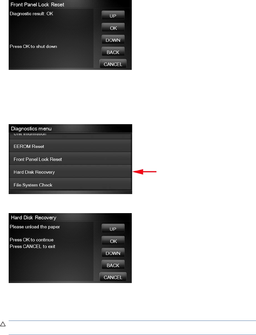
3. The Touch Control Panel lock is reset. Press OK to end the utility and return to the main menu.
Hard Disk Recovery Utility
The Hard Disk Recovery utility erases the hard disk and restores the factory firmware. This option is
also available from the Service Menu.
1. In the Service Utilities submenu, select Hard Disk Recovery and press this menu option.
2. The Touch Control Panel reminds you to unload the paper.
3. Press OK to proceed or Cancel to exit.
If you press OK, the product begins to erase the hard disk and restore the factory firmware; it
restarts automatically during this process. The Touch Control Panel displays a progress bar.
CAUTION: Do not try to interrupt this process. All Touch Screen Panel keys are disabled until it
has finished.
ENWW Diagnostic Tests and Utilities 115
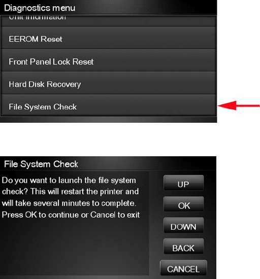
File System Check
The File System Check checks the file system on the hard disk and automatically corrects any problems
that it finds. This option is also available from the Service Menu.
1. In the Diagnostics menu, select File System Check and press on this menu option.
2. The Touch Control Panel asks you if you want to proceed with the File System Check.
3. Press OK to proceed or Back/Cancel to exit.
If you press OK, the product restarts and the File System Check is performed.
116 Chapter 3 Diagnostics Menu ENWW

4 Service Menu
●Introduction
●Service Utilities
●Service Calibrations
Introduction
This chapter explains the product's internal Service Utilities and Calibrations, available from the Service
Menu.
Service Utilities
The following is a list of all internal Service Utilities available in the product. To access them, see Entering
the Service Utilities Menu on page 118.
Turn Drive Roller on page 120
Purge Tubes on page 121
Reset Life Counters on page 123
Reset Maintenance Kit usage
Reset life counters PMK1
Reset life counters PMK2
Reset usage counters
Diagnostic Print on page 125
Image Quality Service Best
Image Quality Service Normal
Advanced Diagnostic Print
Paper advance
Printhead alignment
Nozzle health
Force drop detection
Set Date and Time on page 126
Enable/Disable Firewall on page 128
Enable/Disable Sleep Mode on page 129
Disk Wipe DoD 5220.220M on page 129
Sanity level
ENWW Introduction 117
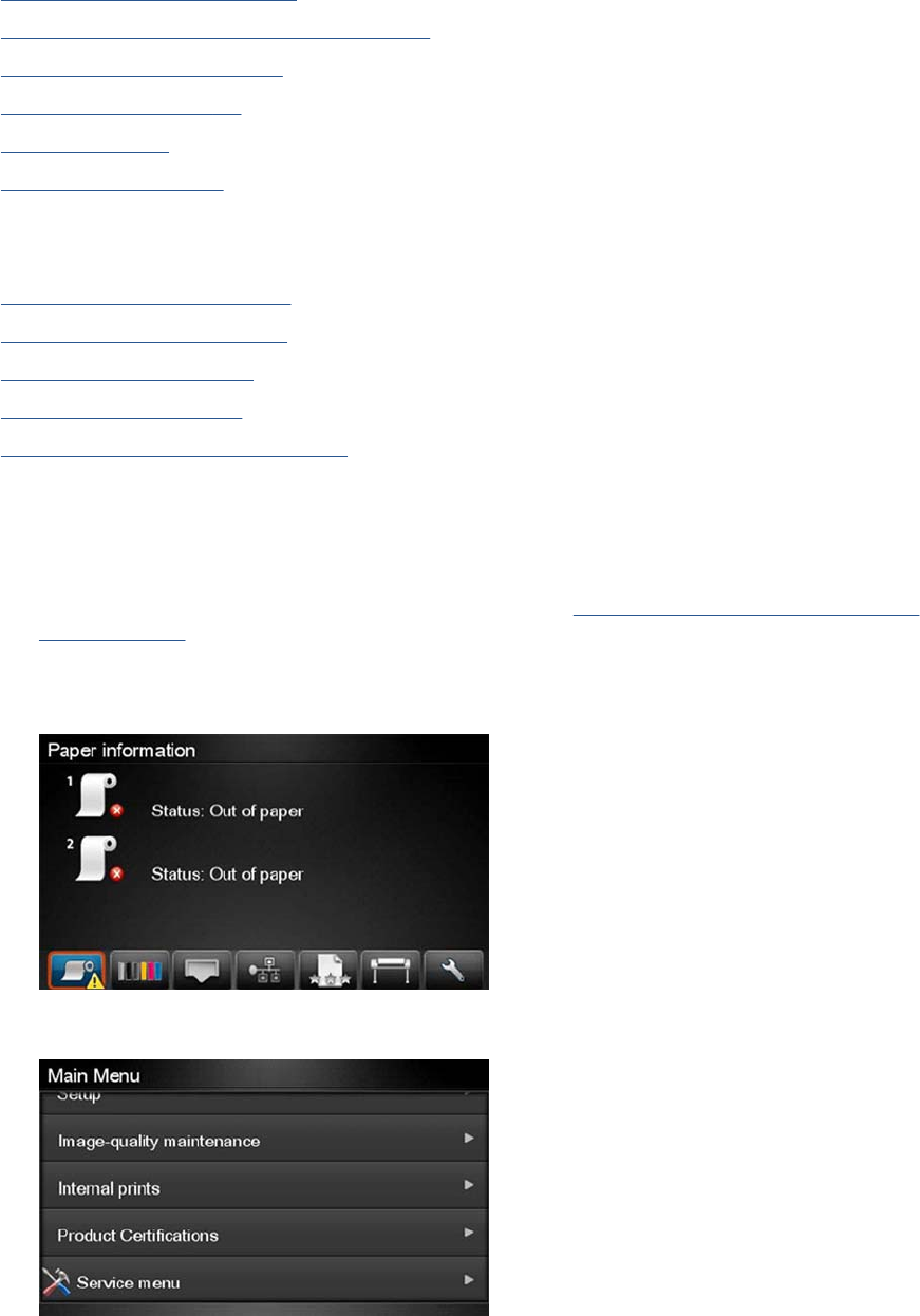
Insecure mode
1-pass mode
5-pass mode
Disk Wipe (DOD 5220.220M)
Hard Disk Recovery Utility on page 132
Show/Hide Touch Control Panel Information on page 133
Enable/Disable Port 280 on page 134
File System Check on page 135
I/O Tests on page 135
Rewinder Adjust on page 137
Adjust Rewinder 1
Adjust Rewinder 2
Disable Upper Roll Cover on page 138
Enable Upper Roll Cover on page 139
Special Cutter Mode on page 140
Scanner Validation on page 140
Adjustment scanner Y-Axis scale on page 148
Entering the Service Utilities Menu
1. From the Home Screen press the Information icon on the top left corner of the screen. For
information regarding the Touch Control Panel keys, see Using the Touch Control Panel (MFP
only) on page 1 or .
2. From the product Information Area, press the Main Menu / tool icon on the bottom right corner of
the screen.
3. Scroll down to the lowest menu option and press on the Service menu option.
118 Chapter 4 Service Menu ENWW
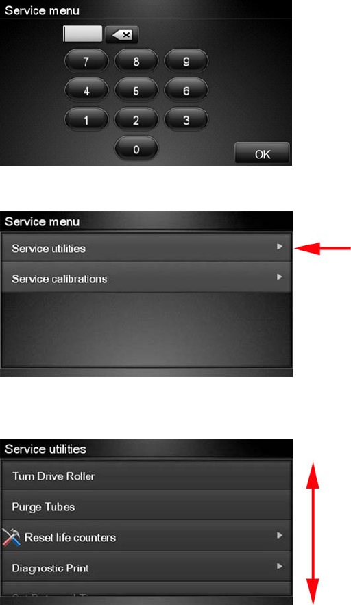
4. Enter the 4-digit 1st level access code “3174” and press OK.
5. Press on the Service utilities menu option.
6. From the Service utilities menu you can scroll up and down the available utilities. Press on the
selected menu option.
ENWW Service Utilities 119
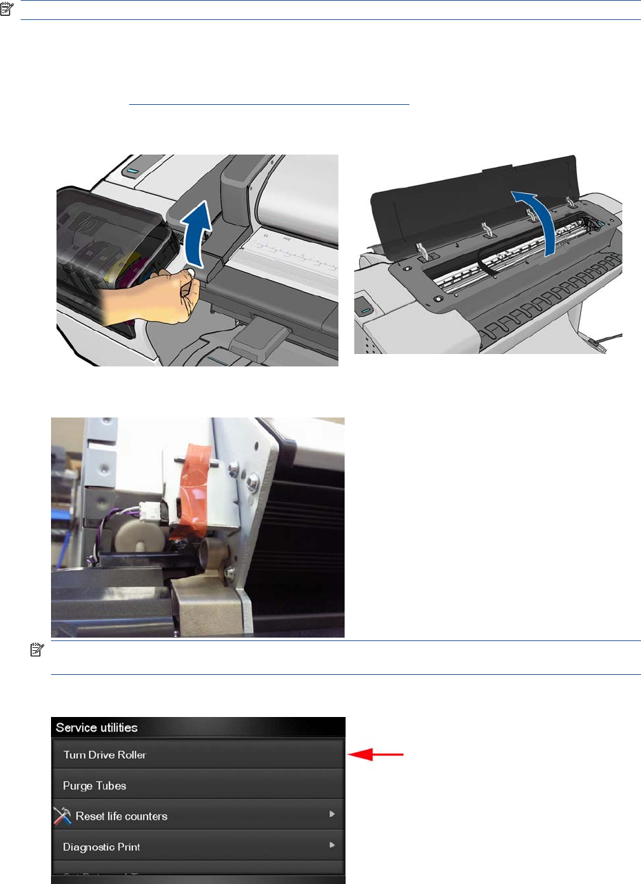
Turn Drive Roller
The purpose of this Service Utility is to rotate the Drive Roller and the Overdrive in order to clean them.
NOTE: Remove the media from the product before proceeding with the procedure.
Perform the Turn Drive Roller utility as follows:
1. Remove Media from the paper path.
2. Remove the Right Scanner Cover (MFP only) on page 372.
3. Open the Scanner (MFP only) or Window.
4. Place a strip of tape of the actuator of the Scanner Position Sensor (MFP only).
NOTE: Care should be taken when removing the tape from the actuator after the procedure is
complete, as the part can be broken.
5. In the Service Utilities submenu, scroll to Turn Drive Roller and press on this menu option.
120 Chapter 4 Service Menu ENWW
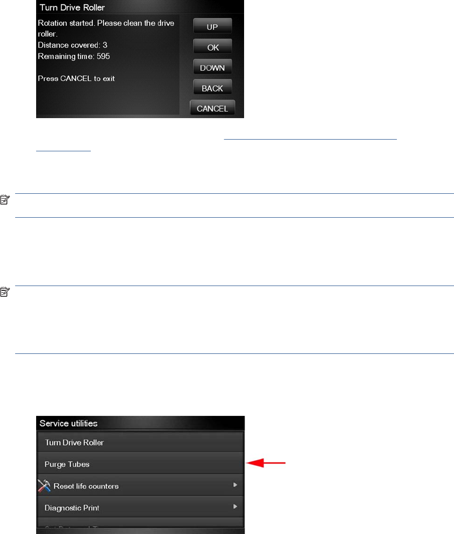
6. The test begins and the Touch Control Panel displays the following message:
●Checking Media Presence Sensor
7. If paper is loaded, the service utility will be cancelled. In this case, unload the paper and start again
from step 1. If no paper is loaded, the test will continue.
8. The Drive Roller begins to turn slowly and the following message is displayed on the Touch Control
Panel:
9. To clean the drive roller and overdrive, see Cleaning the Drive Roller and Overdrive
on page 436.
10. Once you have finished cleaning the Drive Roller and the Overdrive, press the Cancel key to stop
the roller.
NOTE: REMEMBER TO REMOVE THE PIECE OF PAPER FROM THE SCANNER POSITION
SENSOR BEFORE CLOSING THE SCANNER AS THIS COULD DAMAGE THE SENSOR.
Purge Tubes
The purpose of this Service Utility is to Prime the Tubes when the Ink Tubes are not new and they need
to be re-primed or automatic priming was not completed correctly.
NOTE: Make sure that NEW Ink Cartridges are installed or that the ink volume remaining in the Ink
cartridges is below 88% before starting to prime the tubes. If you do not comply, you will get a warning
message and cannot finish the test.
NOTE: Before using the Purge Tubes utility, you must insert the dummy printheads using the Change
Printheads procedure.
Once you have inserted the dummy printheads using the Change Printheads procedure, perform the
Purge Tubes utility as follows:
1. In the Service Utilities submenu, scroll to Purge Tubes and press on this menu option.
ENWW Service Utilities 121
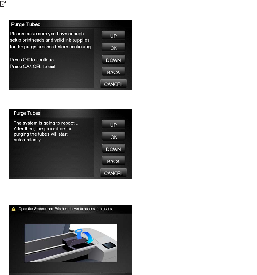
2. The Touch Control Panel prompts you to confirm that the dummy printheads are correctly inserted.
If the dummy printheads are correctly inserted, press OK.
NOTE: If you have not inserted the dummy printheads, press BACK or CANCEL to exit the test.
Insert the dummy printheads using the Change Printheads procedure.
3. The Touch Control Panel displays a message to say the product is going to reboot.
4. Once the tubes system has been purged, the following message will instruct you to open the
Carriage to access the printheads:
5. Once you have opened the carriage cover, the Touch Control Panel prompts you to check that the
Setup Printheads contain ink. If the Ink Supply Tubes have been primed correctly, the windows will
contain ink. If the windows on top of each Setup Printhead do not contain ink, then you may need
to repeat the Prime Tubes process from the beginning.
6. If all the Setup Printheads contain ink, select All with some ink. If one or more of the Setup
Printheads do not contain ink, select Not all with ink.
7. The Touch Control Panel then prompts you to remove the Setup Printheads and install the
Printheads.
8. Remove all the Setup Printheads from the Carriage and install the previously removed Printheads.
9. Once all the Printheads are installed, the Touch Control Panel will instruct you to close all the
covers.
122 Chapter 4 Service Menu ENWW
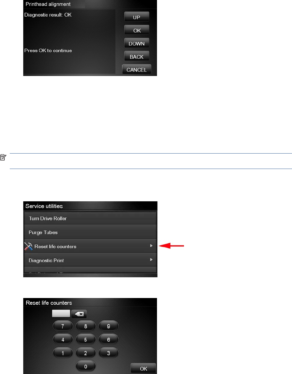
10. The product will now perform the Printhead Alignment and Touch Control Panel will prompt you to
continue with the Printhead Alignment, select Align now and press the OK key.
11. Once the Printhead Alignment is completed, the following message will be displayed on the Touch
Control Panel. Press the OK key to continue.
Reset Life Counters
The purpose of this Service Utility is to reset the internal life counters.
There are two submenus that allow you to:
●Reset all the counters related to a Preventive Maintenance Kit (PMK).
●Reset only the counters related to a specific replaced part.
NOTE: ALWAYS RESET THE LIFE COUNTER OF A CORRESPONDING PART AFTER
REPLACING IT.
Perform the Reset Life Counters utility as follows:
1. In the Service Utilities submenu, scroll to Reset Life Counters and press this menu option.
2. Enter the 4-digit 2nd level access code “5494” and press OK.
3. Select Reset Maintenance Kit usage to reset the Life Counter for all parts included in a
Preventative Maintenance Kit (PMK).
ENWW Service Utilities 123
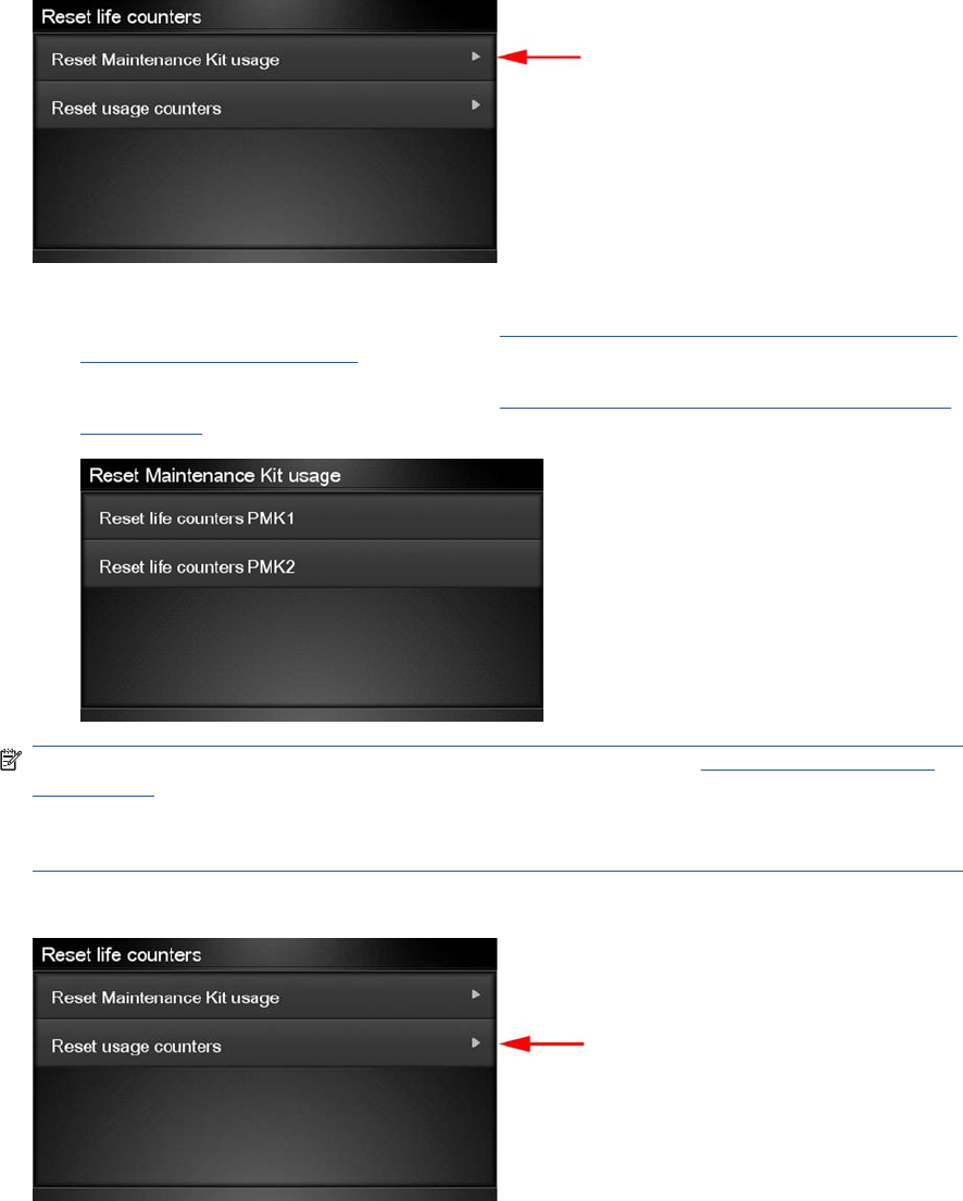
You can choose from the following Preventive Maintenance Kits:
●Preventive Maintenance Kit 1 (PMK1). See Preventive Maintenance Kit #1 for 44-in models
(CH538-67024) on page 443.
●Preventive Maintenance Kit 2 (PMK2). See Preventive Maintenance Kit #2 (CH538-67040)
on page 444.
NOTE: For more information about the counters that are reset, See Preventive Maintenance
on page 436.
It is also advisable to check the status of the Life Counters related to the other Preventive
Maintenance Kits to avoid multiple trips to the customer.
4. Select Reset usage counters to reset the Life Counter of a single part.
●Tubes and Trailing Cable
●Scan-Axis Belt
●Scan Motor
●Left Spittoon
●Right Spittoon
●Full Bleed Foams
●Carriage
124 Chapter 4 Service Menu ENWW
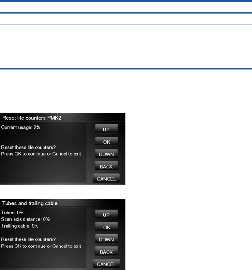
●Service Station
●Scanner Counters
If you replace a part, you should reset the Life Counters as follows:
Replaced part Reset Life Counters
Scan-axis motor SV Scan-Axis Motor
Belt assembly SV Scan-Axis Belt
Carriage assembly SV Carriage
Ink supply tubes SV (with trailing cables) Tubes and Trailing Cable
Service station SV Right Spittoon & Service Station
5. Once you have selected the Life Counters to reset, a message similar to the following will be
displayed on the Touch Control Panel. Press the OK key to reset the selected Life Counters or
press Cancel to exit without resetting the Life Counters.
Example 1:
Example 2:
Diagnostic Print
The purpose of this Service Utility is to print the Diagnostic Print in order to identify Print Quality
problems. Information regarding the Diagnostic Print is located in Chapter 6, Print Quality, for further
ENWW Service Utilities 125
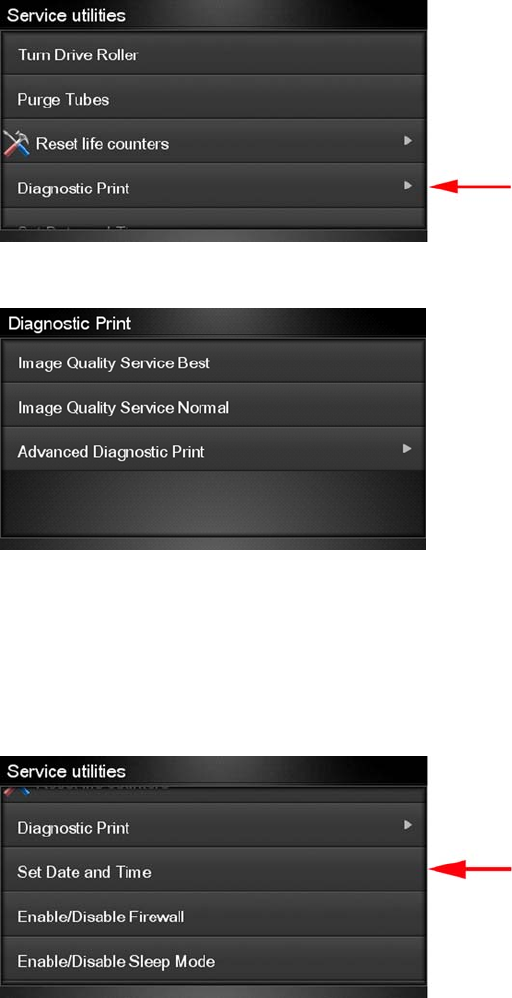
information on using this print refer to the Image Quality Troubleshooting Guide (in the EWS-Support
Tab or in the CD).
1. Select Diagnostic Print.
2. Select the Diagnostic Print required.
Set Date and Time
The purpose of this Service Utility is to set the internal clock of the product.
Perform the Set Date and Time utility as follows:
1. In the Service Utilities submenu, scroll to Set Date and Time and press this menu option.
126 Chapter 4 Service Menu ENWW
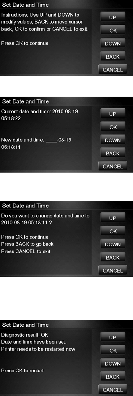
2. The product will display the current time and the new time. Use the Up and Down keys to go through
the digits and press the OK key to go to the next digit. You can press the Cancel key at any time
to exit the utility without making any changes.
3. Follow the instructions to enter the new date and time, then press OK.
4. Press OK to confirm the new date and time. Press Back to modify the new date and time. Press
Cancel to exit without changing the date and time.
If the clock cannot be set, there could be a firmware error. Make sure you have the latest version
of the firmware.
5. Once the new time has been confirmed, the Touch Control Panel will prompt you to restart the
product.
6. Press OK to restart the product.
ENWW Service Utilities 127
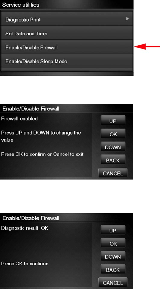
Enable/Disable Firewall
The purpose of this Service Utility is to enable or disable the system firewall. There are currently no
known cases when this will be needed, but it may help some users experiencing unexplained
connectivity failures on embedded LANs.
Perform the Enable/Disable Firewall utility as follows:
1. In the Service Utilities submenu, scroll to Enable/Disable Firewall and press this menu option.
2. The Touch Control Panel tells you whether the firewall is currently enabled or disabled, and allows
you to change its status by pressing the Up and Down keys and then the OK key.
3. The system upgrades the internal memory to reflect the chosen selection.
4. Press OK to finish.
128 Chapter 4 Service Menu ENWW
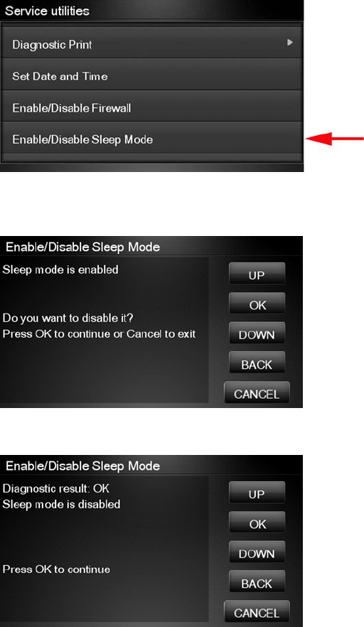
Enable/Disable Sleep Mode
1. In the Service Utilities submenu, scroll to Enable/Disable Sleep Mode and press on this menu
option.
2. The Touch Control Panel tells you whether sleep mode is currently enabled or disabled. Press
OK to continue or Cancel to leave the sleep mode status unchanged.
3. The Touch Control Panel displays the sleep mode status. Press OK to return to the menu.
Disk Wipe DoD 5220.220M
The purpose of this Service Utility is to erase data from the internal Hard Disk securely, according to
the directive DoD 5220.220M.
The product's hard disk is used as a temporary storage area for print jobs. The Secure Disk Wipe utility
can erase your information from the hard disk to prevent unauthorized access.
ENWW Service Utilities 129
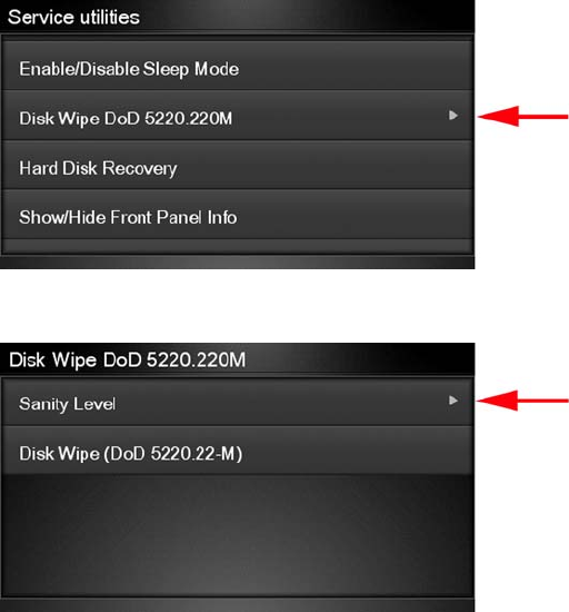
Secure Disk Wipe provides three different levels of security:
●Insecure Mode: All pointers to the information are erased. The information itself is not erased,
and remains on the hard disk until the disk space it occupies is needed for new print jobs. The new
print information overwrites the old information. While the information remains on the disk, it is
difficult for most people to access, but may be accessed using software designed for that purpose.
This is the normal method in which files are erased on most computer systems; it is the fastest
method but the least secure. This is the default security level when using Secure Disk Erase.
●1 Pass Mode: All pointers to the information are erased, and the information itself is overwritten
with a fixed character pattern. This method is slower than Insecure Fast Erase, but more secure.
It may still be possible to access fragments of the erased information by using special tools to detect
residual magnetic traces.
●5 Pass Mode: All pointers to the information are erased, and the information itself is repetitively
overwritten using an algorithm designed to eliminate any residual traces. This is the slowest
method, but the most secure. Secure Sanitizing Erase meets the US Department of Defense
5220-220M requirements for clearing and sanitization of disk paper.
Execute the Disk Wipe DoD 5220.220M utility as follows:
1. In the Service Utilities submenu, scroll to Disk Wipe DoD 5220.220M and press this menu option.
2. In the Disk Wipe DoD 5220.220M submenu, scroll to Sanity Level and press OK.
130 Chapter 4 Service Menu ENWW
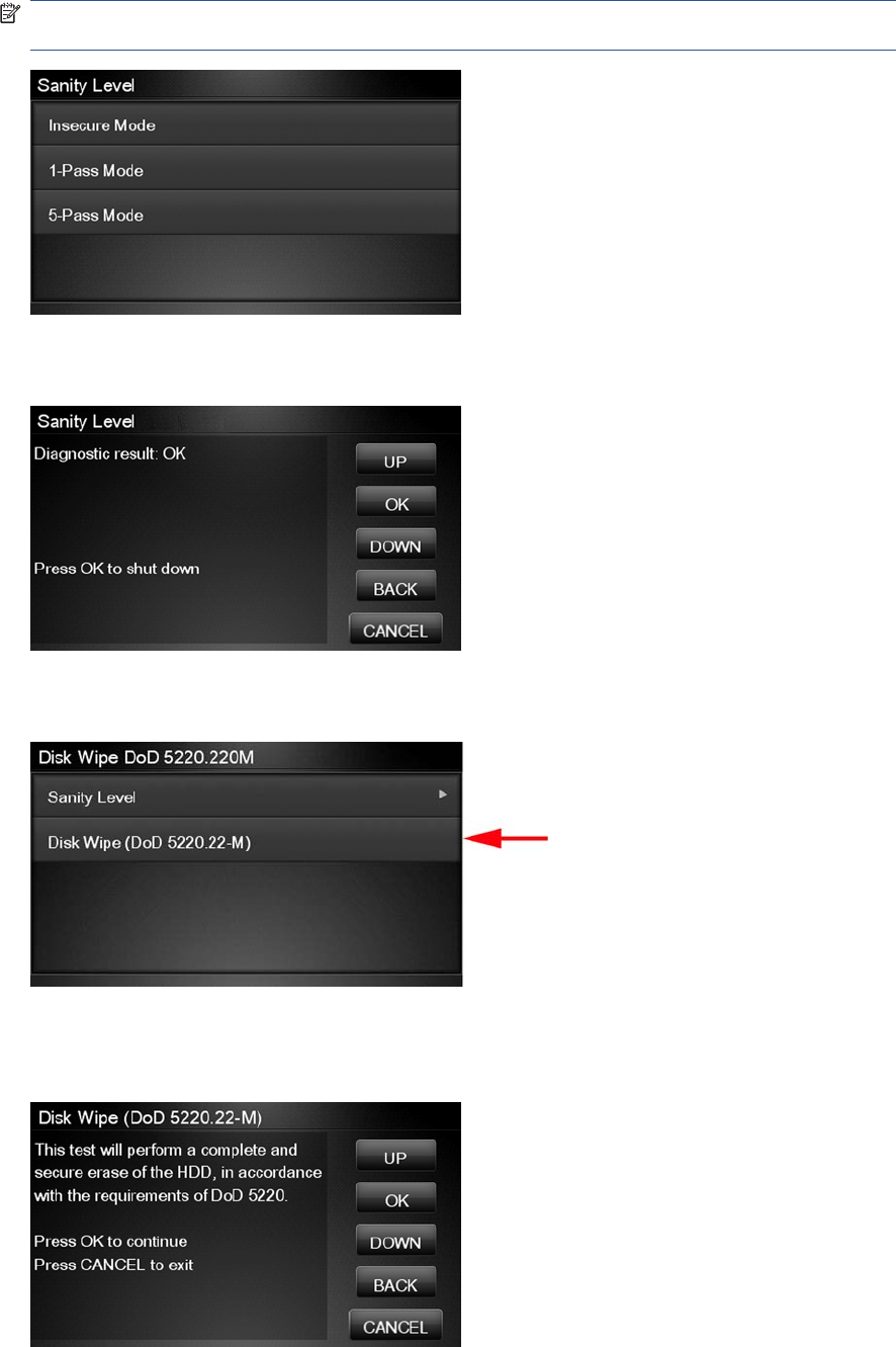
3. In the Sanity Level submenu, scroll to the required Sanity Level and press OK.
NOTE: Erasing the Hard Disk drive using either of the Secure Sanitize Levels is a very slow
process, 6 hours for the 1 Pass mode and 40 hours for the 5 Pass mode.
4. When the Sanity Level has been changed, the Touch Control Panel displays the following
message, or an error message if there is some problem.
5. In the Disk Wipe DoD 5220.220M submenu, scroll to Disk Wipe (DoD 5220.220M) and press
OK.
6. When the following message appears on the Touch Control Panel, you must select whether you
would like to perform a complete erase of the Hard Disk Drive using the previously selected erase
mode by pressing OK. Press Cancel to exit the utility
ENWW Service Utilities 131
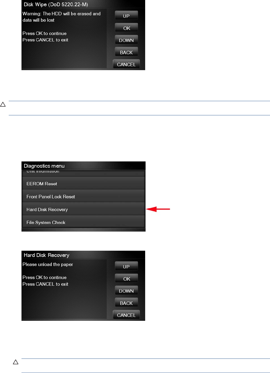
7. When the following message appears on the Touch Control Panel, you must select whether you
want to continue and completely erase the Hard Disk Drive by pressing OK. Press Cancel to exit
the utility.
8. The erase process starts and the Touch Control Panel shows a setup progress bar.
9. The product reboots into the Disk Wipe mode, and continues with the disk erase until it is completed.
CAUTION: Do not try to interrupt this process. All Touch Control Panel keys are disabled while the
product erases the Hard Disk Drive.
Hard Disk Recovery Utility
The Hard Disk Recovery utility erases the hard disk and restores the factory firmware.
1. In the Service Utilities submenu, select Hard Disk Recovery and press this menu option.
2. The Touch Control Panel reminds you to unload the paper.
3. Press OK to proceed or Cancel to exit.
If you press OK, the product begins to erase the hard disk and restore the factory firmware; it
restarts automatically during this process. The Touch Control Panel displays a progress bar.
CAUTION: Do not try to interrupt this process. All Touch Screen Panel keys are disabled until it
has finished.
132 Chapter 4 Service Menu ENWW
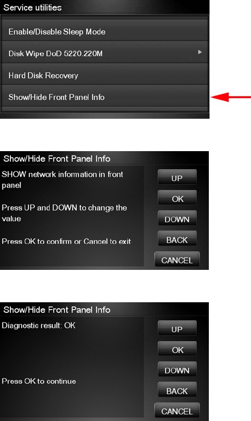
Show/Hide Touch Control Panel Information
The purpose of this utility is to prevent network information from being viewed directly from the EWS or
the screen of the Touch Control Panel.
1. In the Service Utilities submenu, scroll to SNMP Language Write Access and press this menu
option.
2. Use the Up and Down button to change if network information is viewable, press OK to confirm.
3. The change is complete, press OK to return to the main menu.
ENWW Service Utilities 133
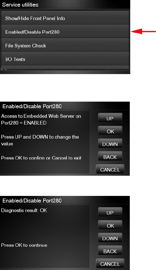
Enable/Disable Port 280
This security utility allows you to enable or disable port 280 communication with the Embedded Web
Server using the embedded LAN connection.
1. In the Service Utilities submenu, scroll to Enable/Disable Port280 and press on this menu option.
2. The Touch Control Panel tells you whether the port is currently enabled or disabled, and allows
you to change the situation by using the Up and Down keys and pressing OK.
3. Press OK to finish.
134 Chapter 4 Service Menu ENWW
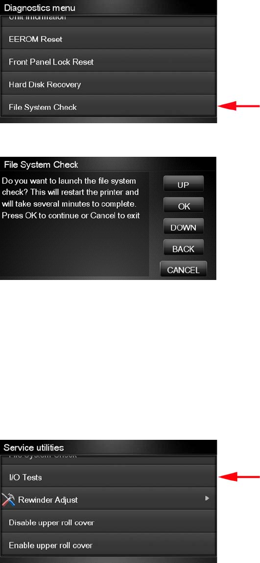
File System Check
The File System Check checks the file system on the hard disk and automatically corrects any problems
that it finds.
1. In the Diagnostics menu, select File System Check and press on this menu option.
2. The Touch Control Panel asks you if you want to proceed with the File System Check.
3. Press OK to proceed or Back/Cancel to exit.
If you press OK, the product restarts and the File System Check is performed.
I/O Tests
The I/O Tests service test checks the network interface hardware of the Formatter. To run this test
successfully, the product’s embedded LAN connector must be connected to an Ethernet network.
Perform this test after replacing the Formatter.
1. In the Service Utilities submenu, scroll to I/O Tests and press on this menu option.
ENWW Service Utilities 135
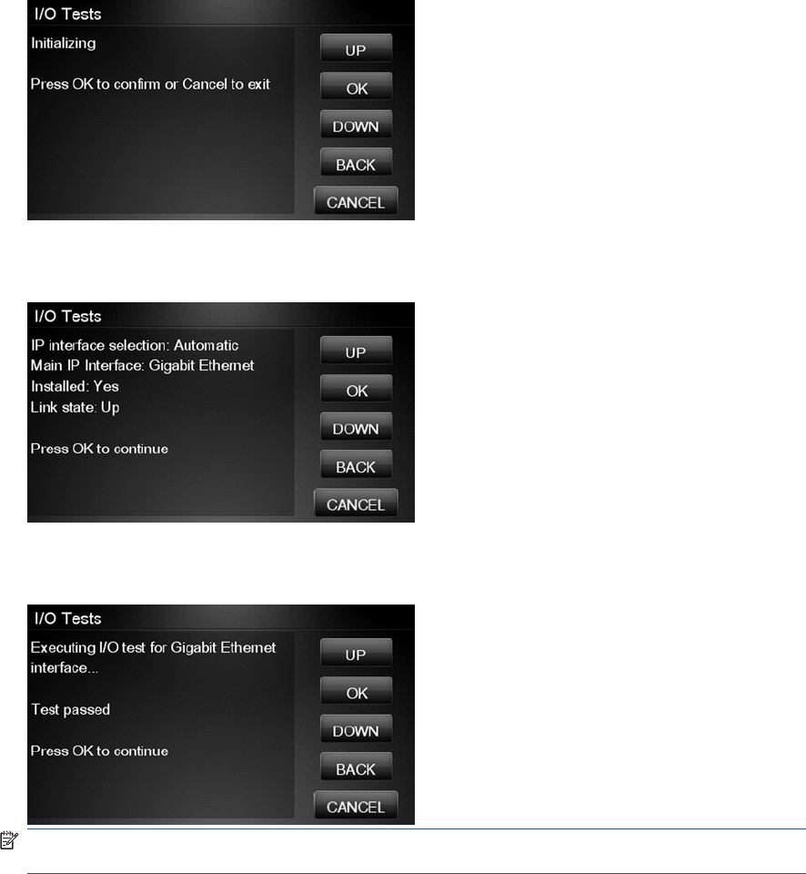
2. The Touch Control Panel asks you if you want to proceed with the I/O tests.
Press OK to proceed or Cancel to exit.
3. The Touch Control Panel displays the I/O information.
4. Press OK to start the test. The product tests the I/O interfaces and displays the result as passed
or failed after a few seconds.
NOTE: If the test fails when the product is connected to a network, there may be a hardware
problem with the network chip on the formatter board.
136 Chapter 4 Service Menu ENWW
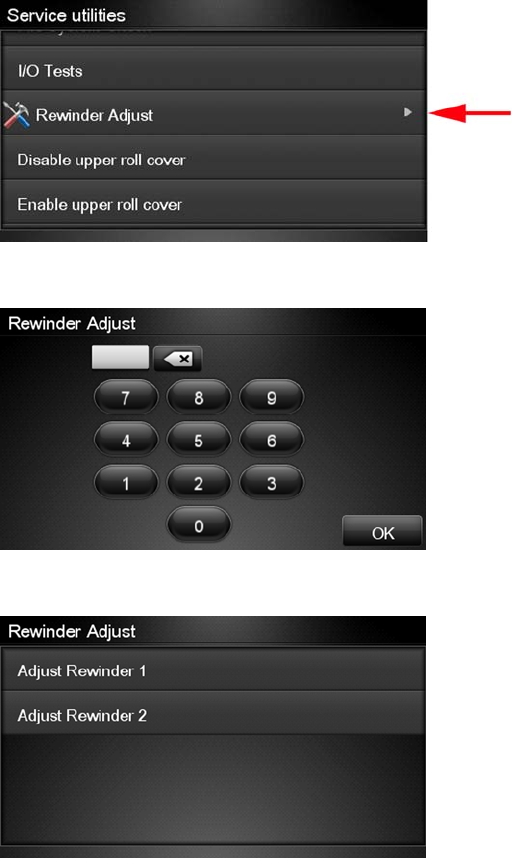
Rewinder Adjust
The Rewinder Adjust utility clears the calibration parameters associated with a Rewinder motor when it
has to be replaced.
The changes made by this utility take effect only after the product has been restarted. Therefore, you
are recommended to proceed in the following order.
1. Use the Rewinder Adjust utility to reset the calibration parameters.
a. In the Service Utilities submenu, scroll to Rewinder Adjust and press on this menu option.
b. Enter the 4-digit 2nd level access code “5494” and press OK.
c. Select the Rewinder for roll 1 or roll 2 and press OK.
ENWW Service Utilities 137
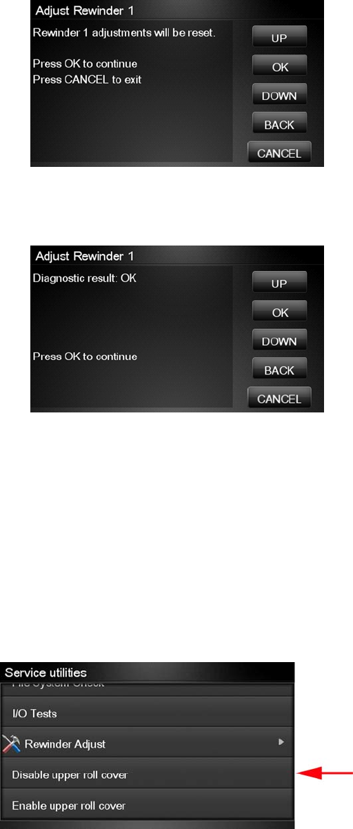
d. Confirm your selection by pressing OK.
e. The product resets the calibration parameters and checks that the default values have been
correctly saved inside the NVM memory. If the check fails, a 79:04 error is generated, and the
procedure is interrupted. Otherwise, the product confirms success as follows.
2. Turn off the product.
3. Replace the Rewinder motor.
Disable Upper Roll Cover
With the upper roll cover enabled, the arm pinches may leave marks on some types of glossy instant-
dry paper; these marks may be particularly visible in prints with black area fills. This utility disables the
upper roll cover in order to allow the product to print with the upper roll cover opened. The roll cover will
be re-enabled automatically when the product is restarted.
Before starting, you should load instant-dry paper as Roll 1.
1. In the Service Utilities submenu, scroll to Disable upper roll cover and press this menu option.
If roll 1 is not active, it is automatically advanced to the platen and activated.
138 Chapter 4 Service Menu ENWW
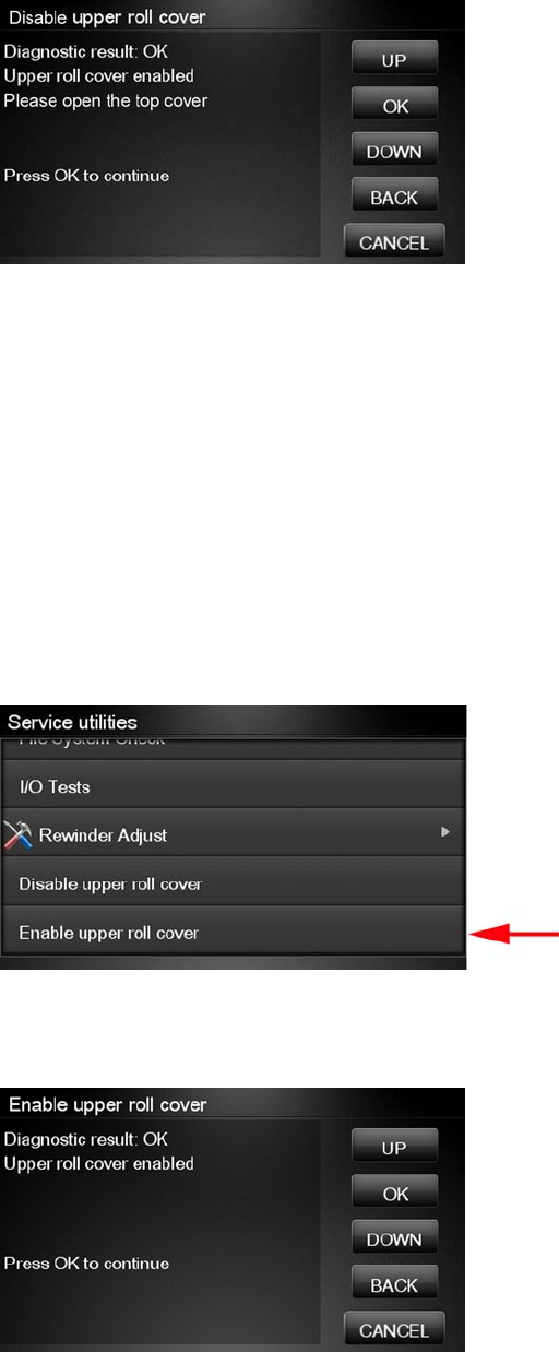
2. Wait until you see the following message.
Open the upper roll cover and press OK.
Disabling the upper roll cover has some implications for the operation of the product.
●If the product switches to printing on Roll 2 for any reason, Roll 1 can be unloaded. This can be
avoided by not loading any Roll 2.
●If the roll cover is closed without restarting the system or by selecting the Enable Upper Roll Cover
utility, you may see print quality issues and false reports of paper jams.
●A new roll cannot be loaded as Roll 1.
Enable Upper Roll Cover
This utility re-enables the upper roll cover without restarting the product.
1. In the Service Utilities submenu, scroll to Enable upper roll cover and press on this menu option.
2. Close the roll cover when requested by the Touch Control Panel.
3. Wait until you see the following message.
Press OK.
ENWW Service Utilities 139
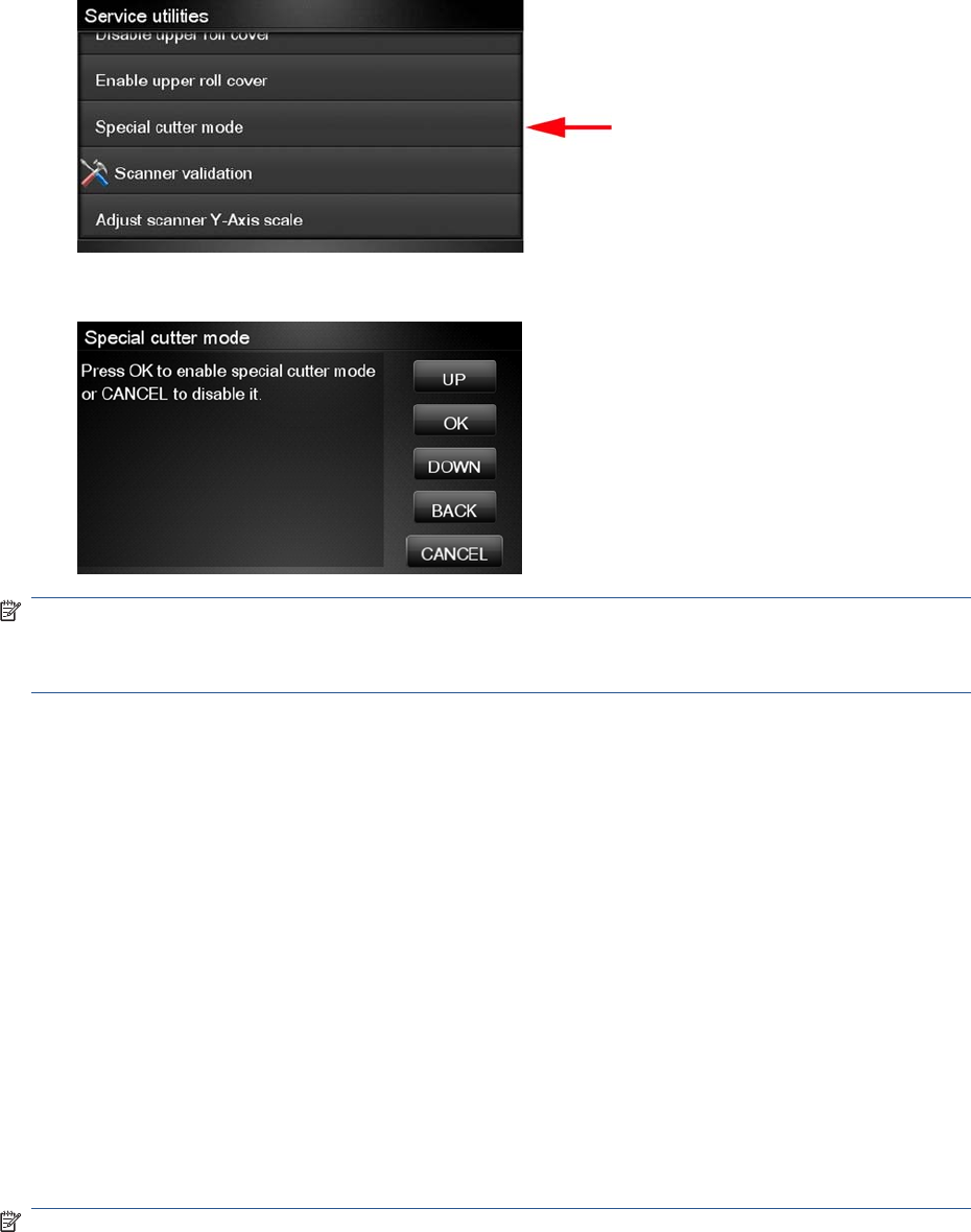
Special Cutter Mode
The purpose of this utility is to improve the cut quality for some papers that present some cut-quality
problems (straightness problems) using the normal mode. When this mode is enabled, this utility
changes the cutting mode for all generic natural tracing papers. This mode reduces the problems, but
cuts more slowly.
1. In the Service Utilities submenu, scroll to Special cutter mode and press on this menu option.
2. Press OK to enable special cutter mode or Cancel to disable it.
NOTE: Once enabled, this mode will remain in operation, even after the product has restarted, until
you disable it using the same utility.
NOTE: Remember that only tracing papers are affected by this utility.
Scanner Validation
By executing this validation, the product will perform the following scanner tests:
●ScanDump
●Focus
●Skew
●Dead/hot pixels
●Alignment/Stitching
●Chromatic aberration
●Streak
●Gray matching
●Signal noise
NOTE: Before running the scanner validation check that the calibration sheet is free from dust, spots
or stripes. Check that the calibration sheet is not dirty, wrinkled, scratched or folded.
140 Chapter 4 Service Menu ENWW
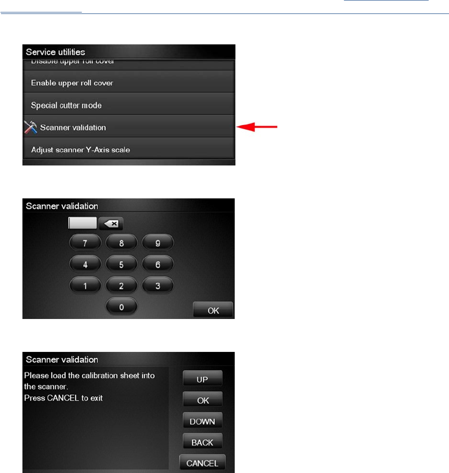
NOTE: Before running the scanner validation open the scanner to check that the glass plate is free of
dirt, dust and scratches. Clean the glass plate if necessary before proceeding Cleaning the Glass
Plate on page 440.
1. In the Service Utilities submenu, scroll down and select the Scanner validation option.
2. Enter the 4-digit 2nd level access code “5494” and press OK.
3. The Touch Control Panel will then prompt you to load the calibration sheet.
ENWW Service Utilities 141
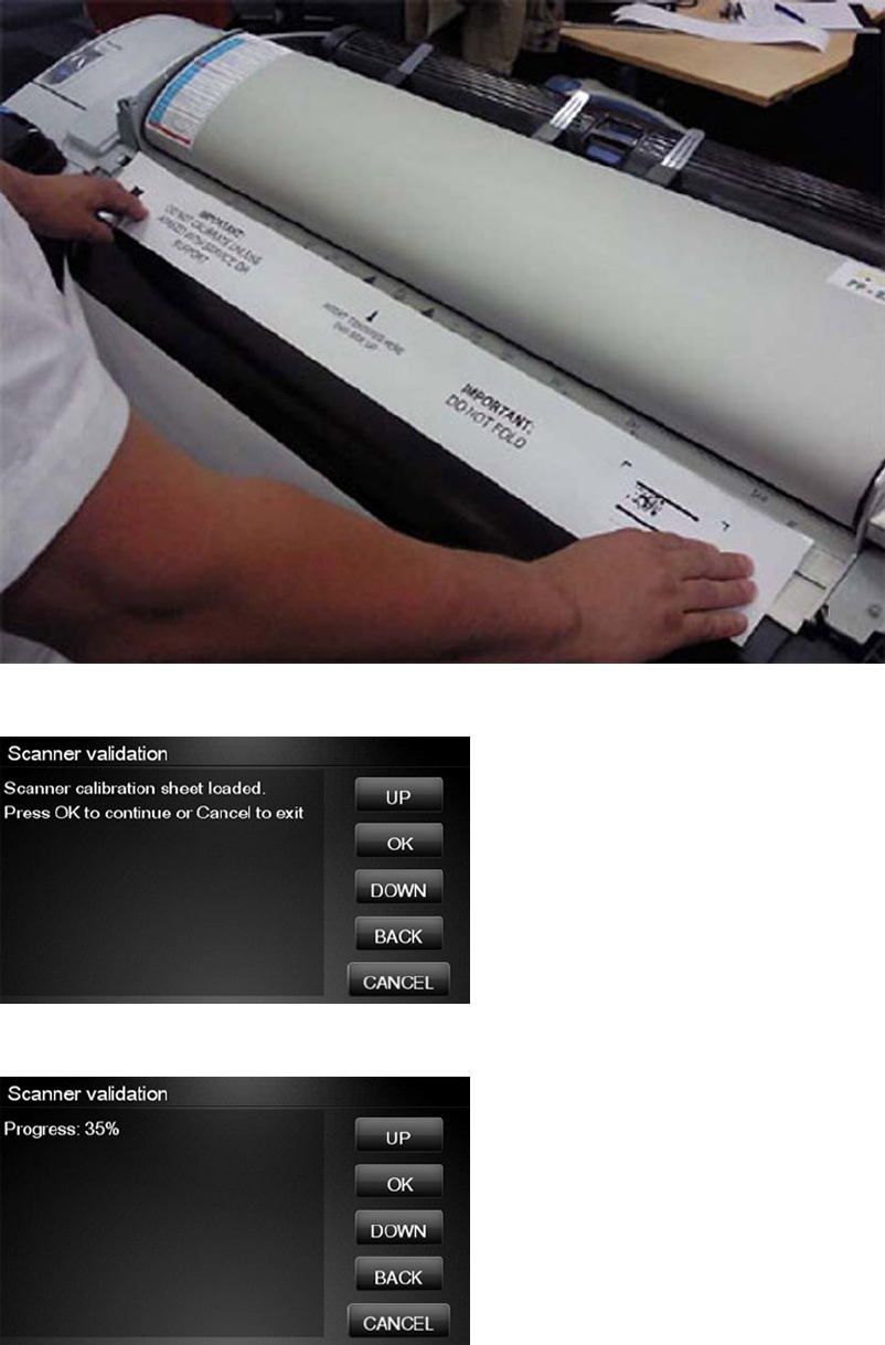
4. Hold the calibration sheet from both sides and place it facing the arrow in the centre of the sheet
in front of the Page icon present on the input tray of the scanner. Push the sheet with both hands
on both sides at the same time to load the sheet with no skew. Press OK to continue with the test.
5. Press OK to continue with the test.
6. The Touch Control Panel will then display a percentage with the progress of the validation.
142 Chapter 4 Service Menu ENWW
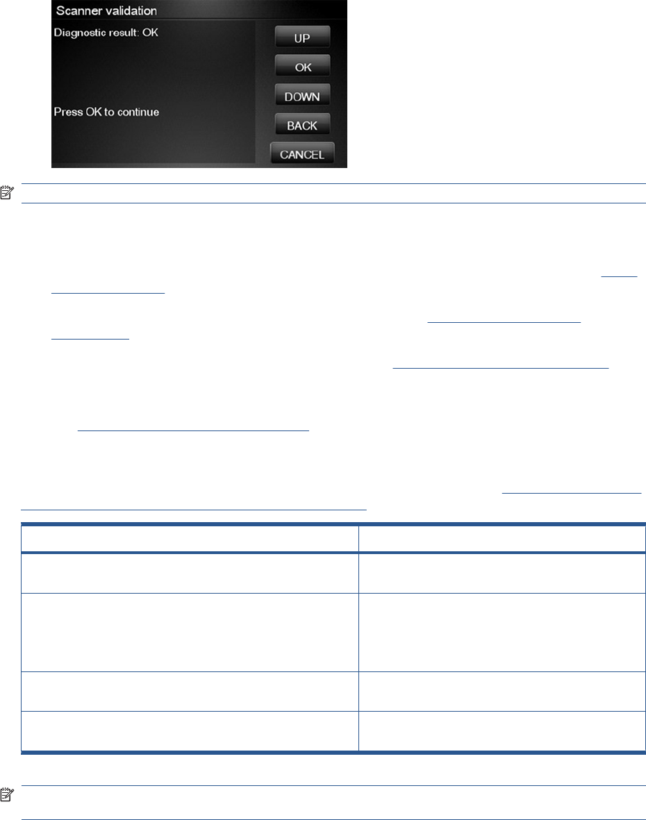
7. Wait until the scanner validation test has completed. The Touch Control Panel will then show the
test results. Press OK to continue
NOTE: If scanner validation result is FAIL:
●Check that the calibration sheet is in good condition according to previous note. Replace with a
new one if necessary.
●Check that the glass plate is in good condition. Replace with a new one if necessary, see Glass
Plate on page 466.
●Inspect that the glass plate is correctly installed and is clean, Cleaning the Glass Plate
on page 440.
●Perform a scanner calibration and repeat the validation Calibrate the Scanner on page 170.
●If the scanner validation result is FAIL with error CWS_RC_VAL_DEADPIXEL_FOUND, replace
the individual CIS element accordingly; see Removal and Installation, Individual CIS Element
see CIS Element (MFP only) on page 420.
After the validation, a set of files is saved in the CWS_validation folder. SCANdump and log files will be
written every time a validation is being executed. TIFF files will only be written if a test fails. If the
validation is performed again the files are overwritten. To retrieve the log files, Appendix C: Obtaining
the product log and the diagnostics package on page 74. The following files are written:
File name CWS_validation folder
SCANdump_Xxx.con SCANdump files can be opned with SCANview. (part of
SCANtest)
scanTRUSTresult.log Results file, contains the following:
●Measured values and limits
●Error codes (if any)
scanTRUST.log The Log file. Primarily contains information that can help
troubleshoot where an error has occurred.
*.tif Scanned images of failed tests. These are mainly for
escalation to division for troubleshooting purposes.
NOTE: The Diagnostic package (reduced level) will contain only all LOG and CON files. Extended
diagnostic package (full level) will contain all files.
ENWW Service Utilities 143
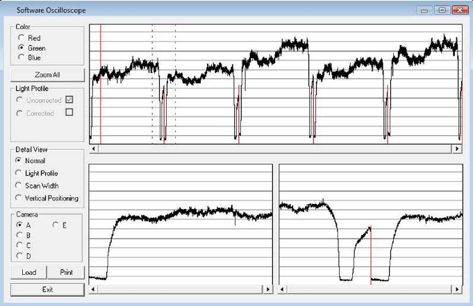
SCANdump
SCANdump is an archive file that can be viewed with SCANview (SCANtest). The SCANdump file
consists of the following:
●Four light profiles (see below for an explanation on Light Profiles).
◦RGB: Unadjusted.
◦RGB: Adjusted.
◦Grey: Unadjusted.
◦Grey: Adjusted.
●A statistic file and documentation about how to use the system.
Light Profiles
The light profiles are a snapshot of what the image sensor sees at the time the SCANdump was made.
The light profiles will in some degree be affected by of wear and tear, cleanness, and also the condition
of the calibration sheet that was used to calibrate the unit. There are two types of light profile, adjusted
and unadjusted.
The Unadjusted light profile is a raw picture of the light source. All imperfections of the sensors and the
light guide (in one, the CIS elements), are visible. Only the general light level has been manipulated.
The Adjusted light profile is corrected according to the calibration sheet, in other words, the calibration
sheet has been used as a reference to correct the imperfection of the CIS elements.
144 Chapter 4 Service Menu ENWW
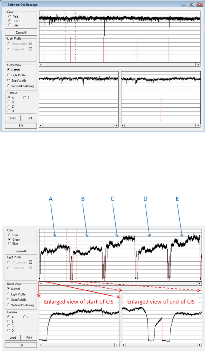
Since we do the basic calibration in two modes, one for the color channels and one for Gray, two sets
of profiles are included in the SCANdump file.
General view of the light profile
This is the overview screen of the profiles of the CIS elements, here shown as A, B; C; D; E. Each arc
represents a CIS element. The lower half of the screen can be used to amplify the profile of a selected
CIS element, for a closer look.
Reading the Uncorrected Light Profile
A uncorrected light profile should be within the Min/Max shown here. Since the Light source is located
at the end of the CIS element it is normal that the light profile’s level is higher here and that the level
drops a little towards the center of the CIS.
ENWW Service Utilities 145
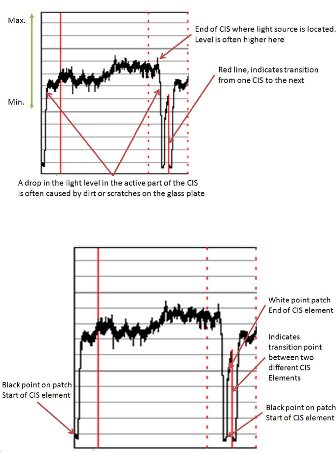
A white patch is located at each end of the CIS element. The one at the start of the CIS is a bit smaller
than the one at the end, it makes a black point, unlike the end which makes a Black and a White point.
Reading the Corrected Light Profile
A corrected light profile should be within the Min/Max shown here.
146 Chapter 4 Service Menu ENWW
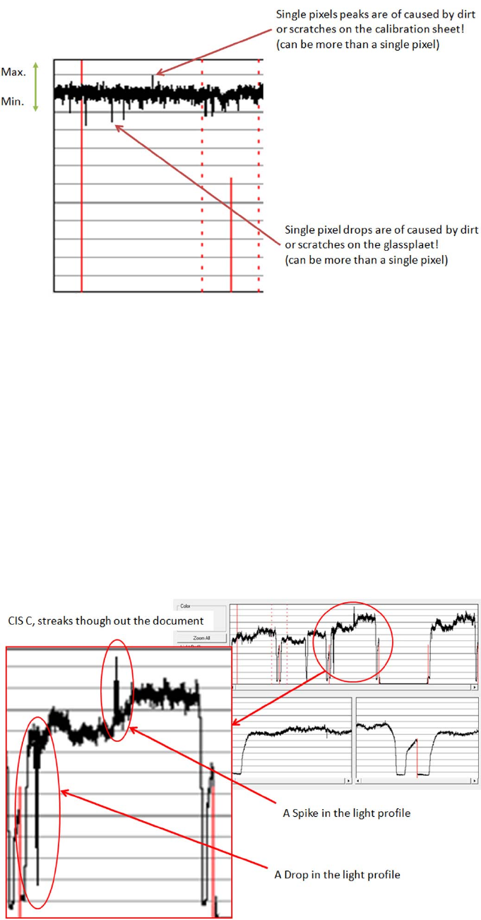
Peaks will show up in a scan as a lighter color and not necessarily in all colors, it depends on which
color channels are being affected by the dirt/ scratch.
Drops will be seen as a dark line in the scan and again not necessarily in all colors, it depends on which
color channels are being affected by the dirt/ scratch.
If the peak or the drop is within 1-2 div (lines) it is usually not noticeable in the scan and is just general
noise. The dirt or the scratch can be from one pixel to several!
Statistics File
This file contains useful information about the usage of the system, along with firmware version and last
calibration date.
Troubleshooting image quality using the light profiles
A drop in the light profile is often caused by dirt/dust on the glass plate A spike is related to the calibration,
either dirt or dust on the glass plate during the calibration or a dirty calibration sheet.
A light profile with an about 20 pixel drop can be a contaminated lens in the CIS module.
ENWW Service Utilities 147
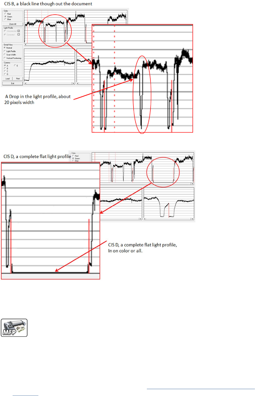
A light profile with an about 20 pixel drop can be a contaminated lens in the CIS module.
A completely flat light profile in one color or all colors can either be one specific LED or the entire CIS
module that is faulty.
Adjustment scanner Y-Axis scale
The scanner may produce a vertical distortion in scanned images. It is important in CAD plots to maintain
the aspect ratio of the originals. The purpose of this utility is to correct this vertical distortion. This sections
describes how to calculate and set the Y-Axis adjustment scale.
Use the following procedure to print the Scanner IQ plot.
1. From the Home Screen press the Information icon on the top left corner of the screen. For
information regarding the Touch Control Panel keys, Using the Touch Control Panel (MFP only)
on page 1.
148 Chapter 4 Service Menu ENWW
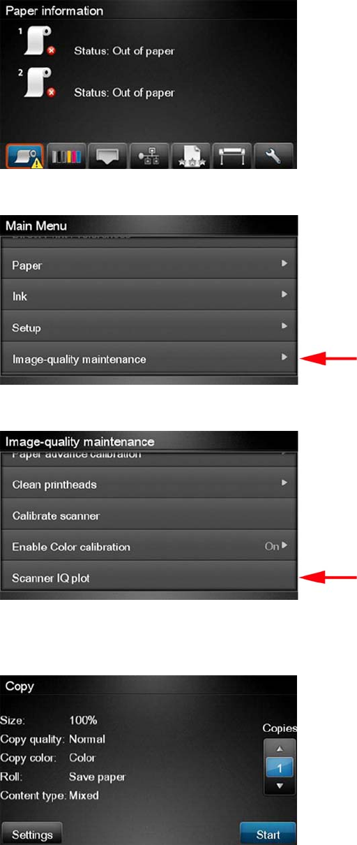
2. From the product Information Area, press the Main Menu/tool icon on the bottom right corner of
the screen.
3. From the Main Menu, scroll down and select the Image-quality maintenance option.
4. From the Image-quality maintenance menu, scroll down and select the Scanner IQ plot to print.
5. The next procedure describes how to copy the Scanner IQ plot:
6. From the Home Screen press the Copy icon on the left side of the screen
ENWW Service Utilities 149
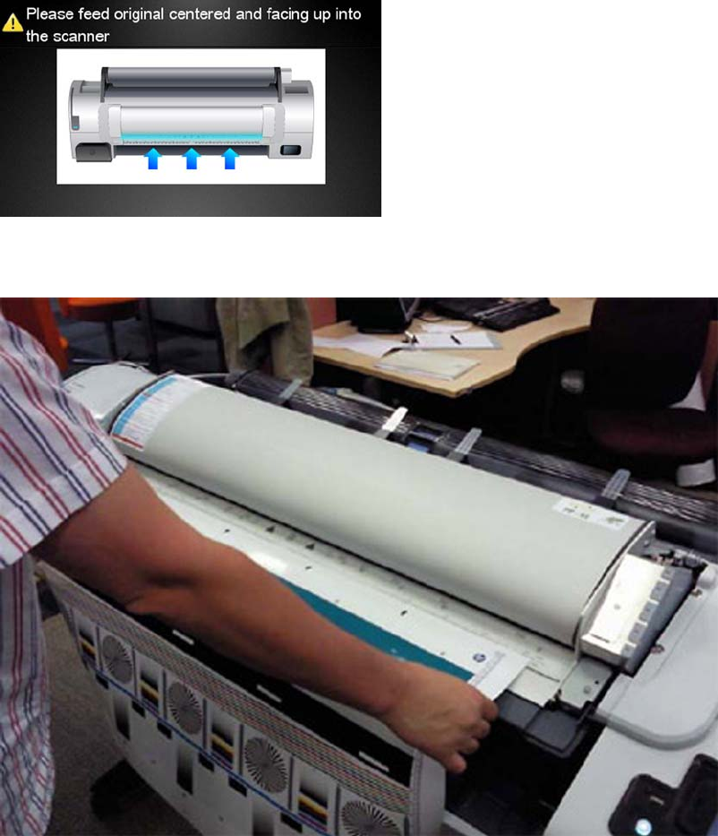
7. Press Start.
8. The Control Panel prompts you to feed the original. Load the Scanner IQ plot that you printed
previously in the Scanner input tray. Wait then for the product to scan and print the image.
150 Chapter 4 Service Menu ENWW
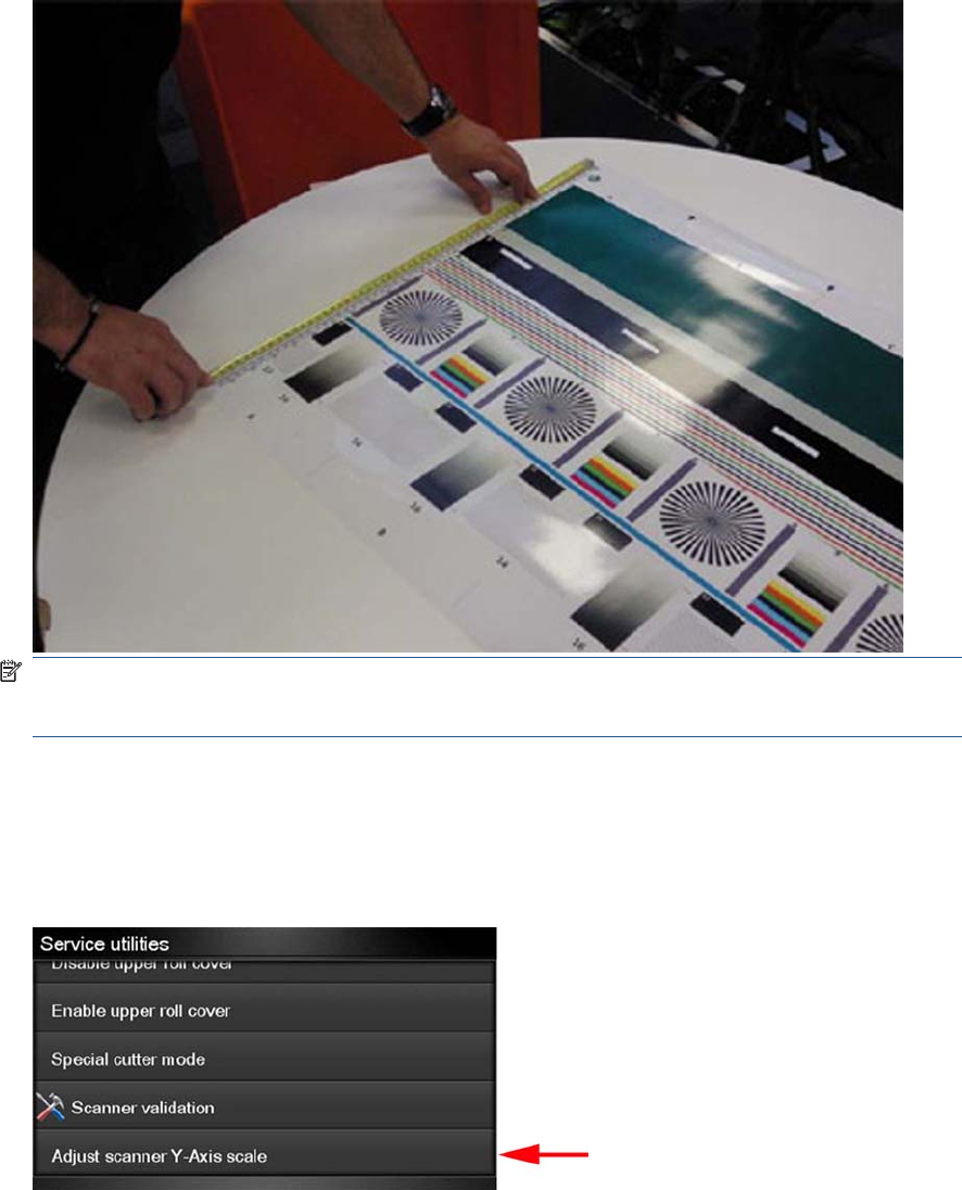
9. Follow the next steps to calculate the Y-Axis adjustment scale: Measure the total length of the two
vertical rules at both sides of the copied plot (we call it M1 and M2).
NOTE: If M1 is quite different from M2 (more than 1mm or 1/16th inch) then refer to incorrect
paper advance, skew during scanning, or horizontal wrinkles in the Image-quality troubleshooting
guide on chapter 3, page 31 .
10. If M1 and M2 are similar (within 1mm or 1/16th inch) then consider M1 = M2 = M and calculate P
as: Y-Axis adjustment scale = -100 × ( M – T ) / T Where T is the total length of the vertical rules
(T = 22 inches or 57 mm). Follow the next steps to set the Y-Axis adjustment scale:
11. In the Service Utilities submenu, scroll to the Adjustment scanner Y-Axis scale and press on this
option.
ENWW Service Utilities 151
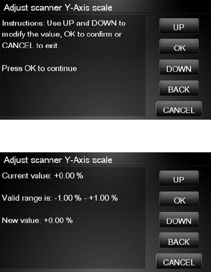
12. Press OK to continue.
13. Press UP and DOWN to pre-set the new value of Y-Axis adjustment scale and press OK.
14. Repeat the process from step 6 onwards until M is equal to T.
152 Chapter 4 Service Menu ENWW
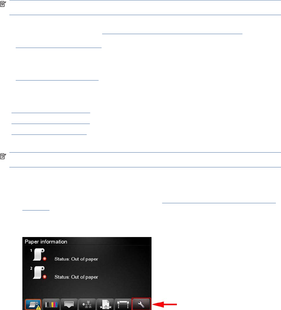
Service Calibrations
The product has several calibration procedures that must be performed under certain conditions.
NOTE: REMEMBER THAT CERTAIN CALIBRATIONS ARE REQUIRED EVEN IF AN ASSEMBLY
HAS BEEN DISASSEMBLED TO GAIN ACCESS TO ANOTHER ASSEMBLY OR COMPONENT.
The following is a list of all internal service calibrations available in the product. For instructions to enter
the service calibrations menu, see Entering the Service Calibrations Menu on page 153.
+ Paper Advance Calibration on page 155
Print calibration pattern
Scan calibration pattern
+ Drop Detector Calibration on page 162
Calibrate drop detector
Reset calibration flag
Line Sensor Calibration on page 164
Calibrate Sheet Sensor on page 169
Calibrate the Scanner on page 170
NOTE: If all the Calibrations need to be performed (for example, when both the Formatter and the
Engine PCA have been replaced), you must perform them in the above order.
Entering the Service Calibrations Menu
1. From the Home Screen press the Information icon on the top left corner of the screen. For
information regarding the Touch Control Panel keys Using the Touch Control Panel (MFP only)
on page 1.
2. From the product Information Area, press the Main Menu / tool icon on the bottom right corner of
the screen.
ENWW Service Calibrations 153
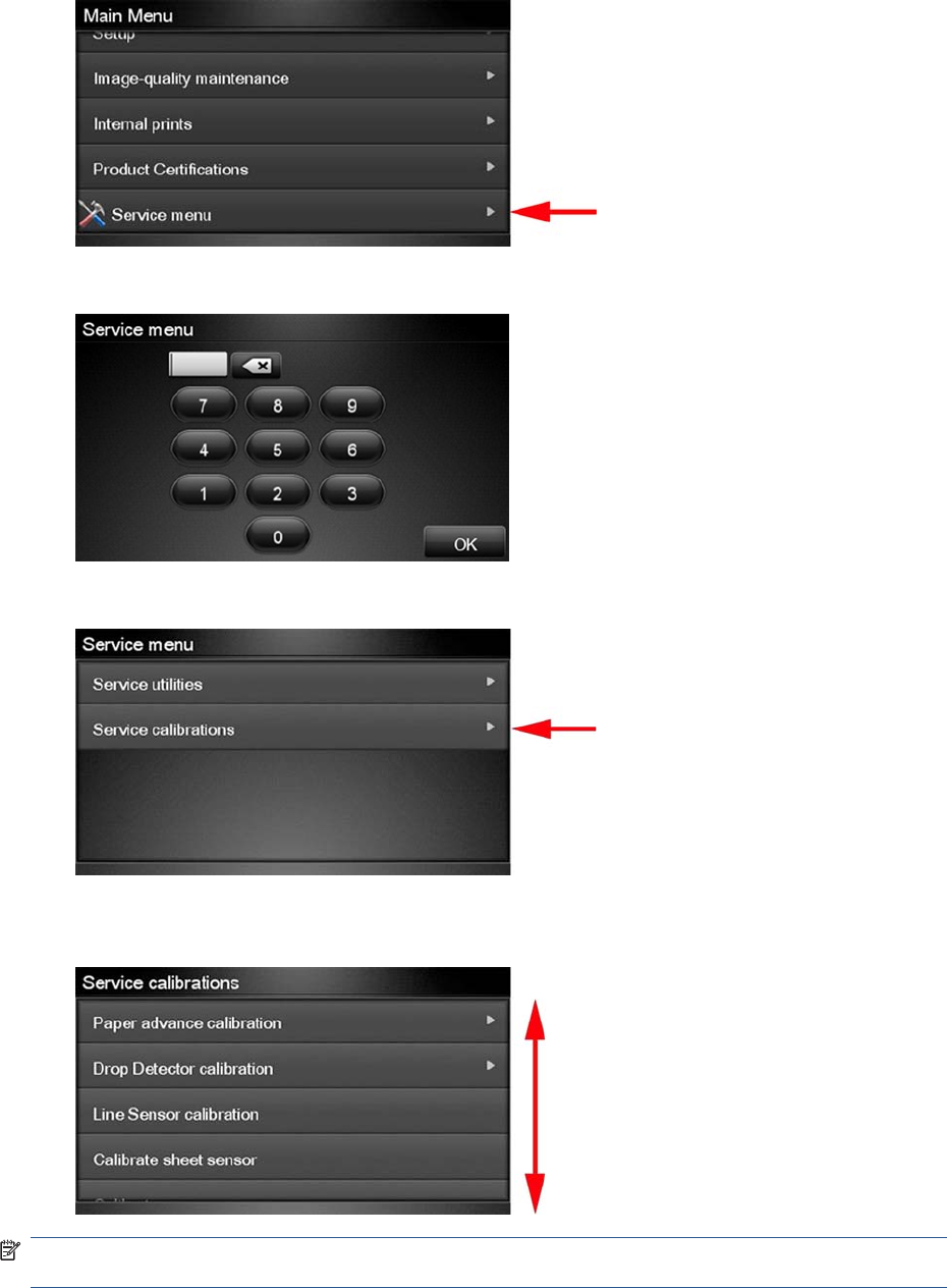
3. Scroll down to the lowest menu option and press on the Service menu option.
4. Enter the 4-digit 1st level access code “3174” and press OK.
5. Press on the Service calibrations menu option.
6. From the Service calibrations menu you can scroll up and down the available utilities. Press on the
selected menu option.
NOTE: In some cases a quick press of a button may not be recognized by the product. When pressing
a button, be sure to press it firmlyl.
154 Chapter 4 Service Menu ENWW
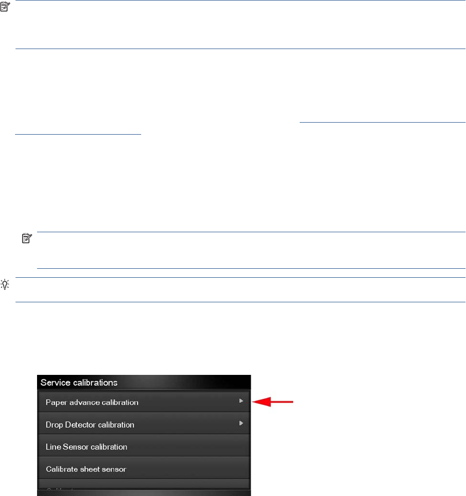
Paper Advance Calibration
The purpose of this Service Calibration is to calibrate the nominal advance of the paper. This calibration
is necessary to control the exact movement of the paper in order to avoid print quality problems like
banding.
If you need to perform a Paper Advance Calibration to solve a print quality problem, it is recommended
that you first try the Paper Advance Calibration from the user's menu, which will calibrate the product
to a specific paper type.
NOTE: You can perform Paper Advance Calibration on a sheet or roll, but the paper type should
always be HP Universal Instant-dry Photo Gloss. You are recommended to order the Paper Advance
Calibration Kit (24-in models: Q6683-60241, 44-in models: Q6687-60093), which contains two sheets
of HP Universal Instant-dry Photo Gloss paper.
Perform the Service Accuracy Calibration whenever:
●Banding is detected in prints.
Service calibrations also need to be performed after removing or replacing certain product components.
If you have removed or replaced product components, check the Service Calibration Guide to Removal
and Installation on page 205 to see which tests and calibrations you need to perform.
The Paper Advance Calibration is split into two parts and should always be done in this order:
1. Print Calibration Pattern - The product first calibrates the Analog Encoder and then prints the Paper
Advance Calibration pattern.
2. Scan Calibration Pattern - The product scans the Paper Advance Calibration pattern in order to
calibrate the nominal advance of the paper.
NOTE: Only scan the Calibration Pattern in the product that was used to actually print it. Using
the Calibration in a different product could cause it to experience paper advance problems. After
scanning the Calibration Pattern, it should be discarded.
TIP: If you are using roll paper, you are recommended to calibrate using the upper roll, which will give
better results.
Perform the Paper Advance Calibration as follows.
1. Unload paper from the product.
2. In the Service Calibrations submenu, scroll to Paper advance calibration and press OK.
ENWW Service Calibrations 155
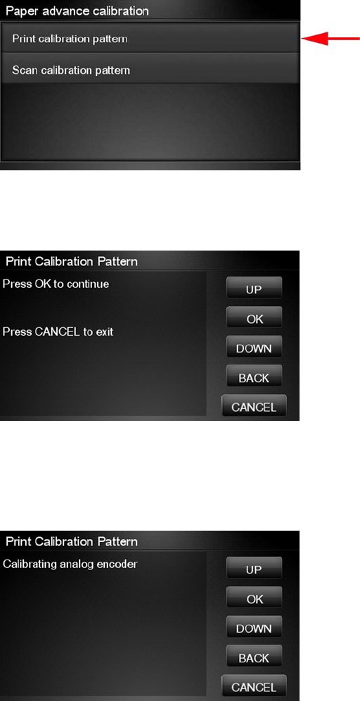
3. In the Paper Advance Calibration submenu, scroll to Print Calibration Pattern and press OK.
4. When the following message appears on the Touch Control Panel, you must select whether you
would like to continue with the calibration by pressing the OK key. Press Cancel to exit the
calibration.
5. If paper is detected, the product will prompt you to remove it. If paper is not detected, the calibration
will continue.
6. The product will start to calibrate the Analog Encoder and the following message will be displayed
on the Touch Control Panel.
If the Calibration is not done or if the values are out of the limits, a warning message will appear
on the Touch Control Panel. In this case, try the following:
●Check that the product has the latest firmware version. If not, update the firmware to the latest
version.
●Retry the Paper Advance Calibration.
156 Chapter 4 Service Menu ENWW
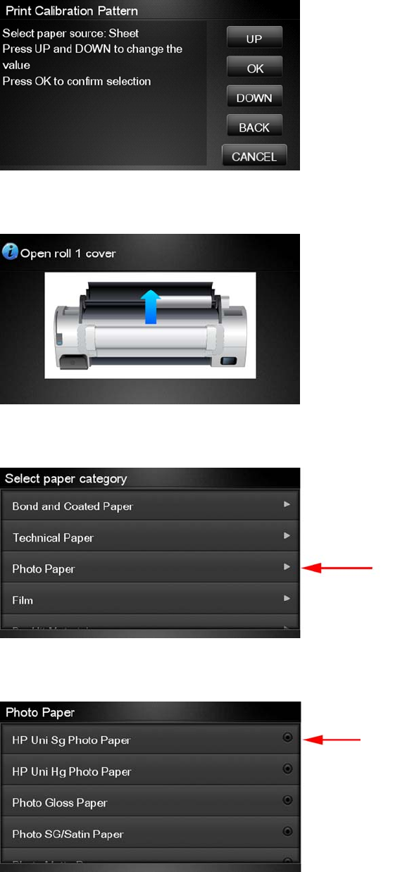
7. Once the Analog Encoder has been calibrated correctly, the Touch Control Panel prompts you to
select the type of paper you will use. Use the Arrow keys to choose roll or sheet paper. Press
the OK key to start loading the paper.
8. The Touch Control Panel prompts you to load the paper. Make sure you load the paper that
corresponds to your paper type selection.
9. The Touch Control Panel prompts you to select the paper category you will use for the calibration.
Scroll to your paper category and select it to continue the paper load process.
10. The Touch Control Panel prompts you to select the specific type of paper you will use for the
calibration. Scroll through the menu and select your paper type.
ENWW Service Calibrations 157
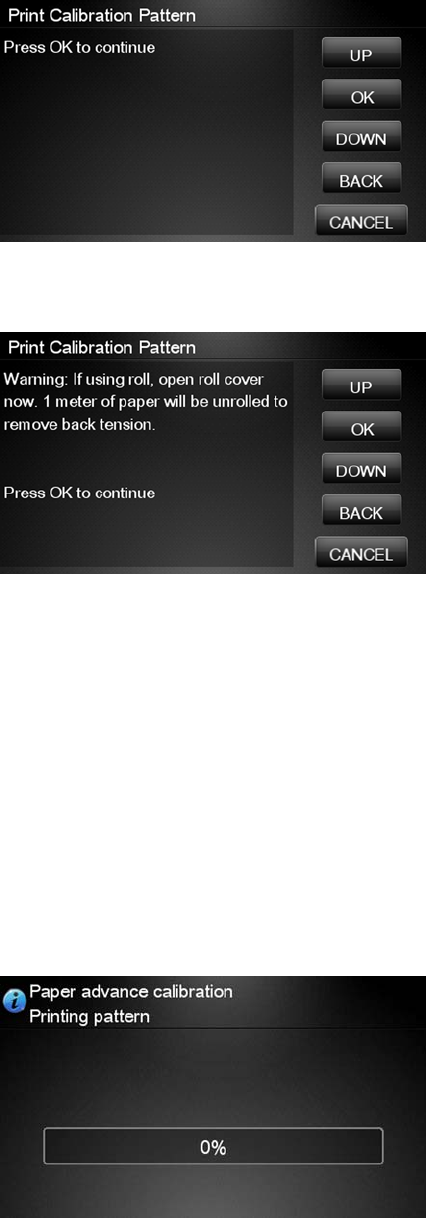
11. The Touch Control Panel displays the following screen, press ok.
12. Once the paper is loaded into the product, the following message will appear on the Touch Control
Panel.
If roll paper has been loaded instead of a cut sheet, it’s important that you open the cover of the
loaded roll. After you press OK, the product will automatically unroll 1 meter of paper and roll it
back again to remove the back tension, and then start printing the pattern. Please note that opening
the roll cover is crucial for avoiding potential paper jams during this operation. Press the OK key
to continue.
13. Press OK to continue.
14. The product advances and reels in about a meter of paper. The Touch Control Panel displays the
following messages:
●Advancing Paper
●Printing Pattern
15. The product will start to print the Paper Advance Calibration Pattern. This could take several
minutes during which the following message will be displayed on the Touch Control Panel.
158 Chapter 4 Service Menu ENWW
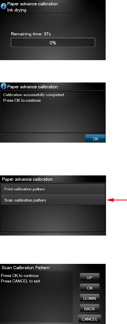
16. When the Calibration Pattern has been printed successfully, the Touch Control Panel reminds you
to leave it to dry for a while.
17. When the Calibration Pattern is dry, the Touch Control Panel will prompt you to continue. Press
OK.
18. If you are printing on a roll, the product cuts the paper and unloads the roll.
19. Return to the Paper Advance Calibration submenu, scroll to Scan Calibration Pattern and
press OK
20. When the following message appears on the Touch Control Panel, you must select whether you
would like to continue with the calibration by pressing the OK key. Press Back or Cancel to exit
the calibration.
ENWW Service Calibrations 159
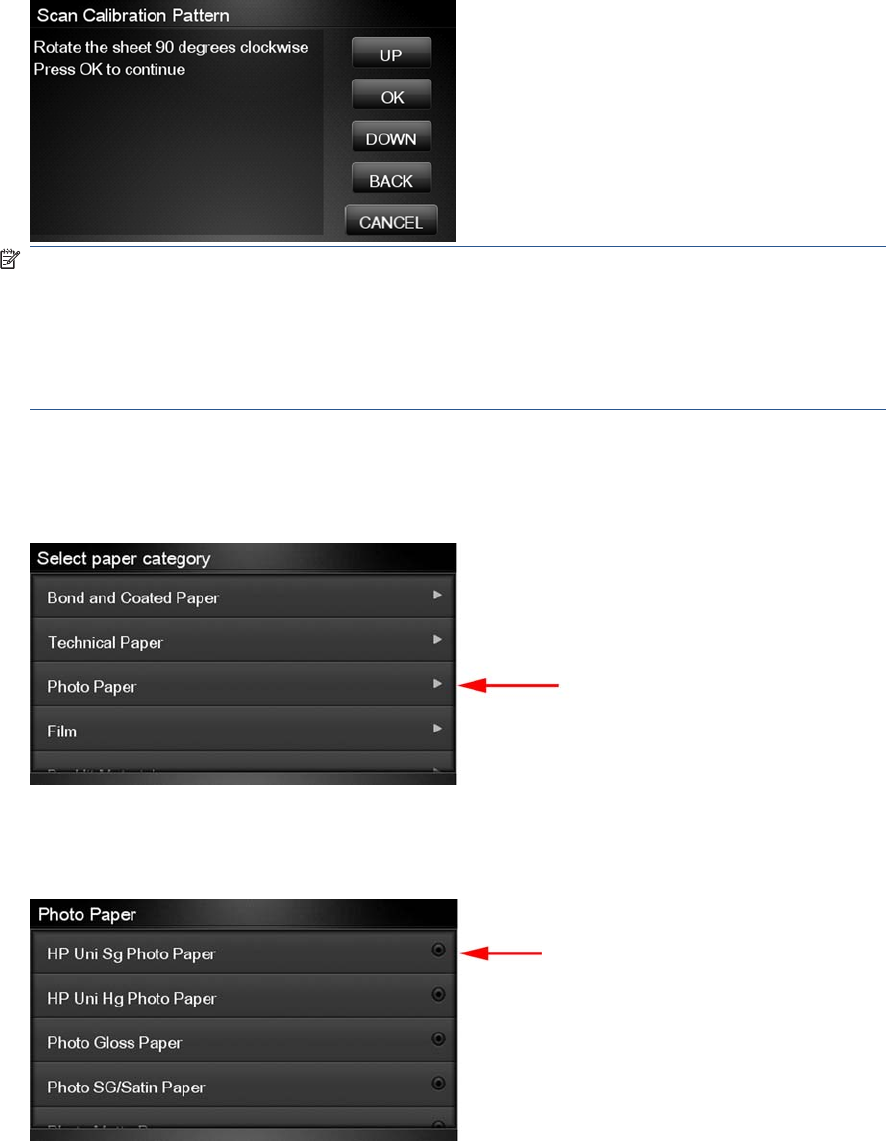
21. A message will appear advising you that you will need to load the Calibration Pattern into the
product. Make sure that you rotate the printed pattern 90° clockwise and reload it printed-side down,
so that the black arrows go into the product first. Press the OK key to continue.
NOTE: Only scan the Calibration Pattern in the product that was used to actually print it. Using
the Calibration in a different product could cause it to experience paper advance problems.
After scanning the Calibration Pattern, it should be discarded. When loading the Calibration
Pattern, use the Cutter blade on the Print Platen to align the edge of the sheet. If you follow this
advice, you will prevent the cutter from cutting a section of the Calibration Pattern, which could
cause the Calibration to FAIL.
22. The Touch Control Panel prompts you to select the paper category you used for the calibration.
Select the same paper that you used to perform the Paper Advance Calibration print. Use the
Arrow keys to scroll to your paper category and press the OK key to continue the paper load
process.
23. The Touch Control Panel prompts you to select the specific type of paper you used for the
calibration. Use the Arrow keys to scroll through the menu and the OK key to select your paper
type.
160 Chapter 4 Service Menu ENWW
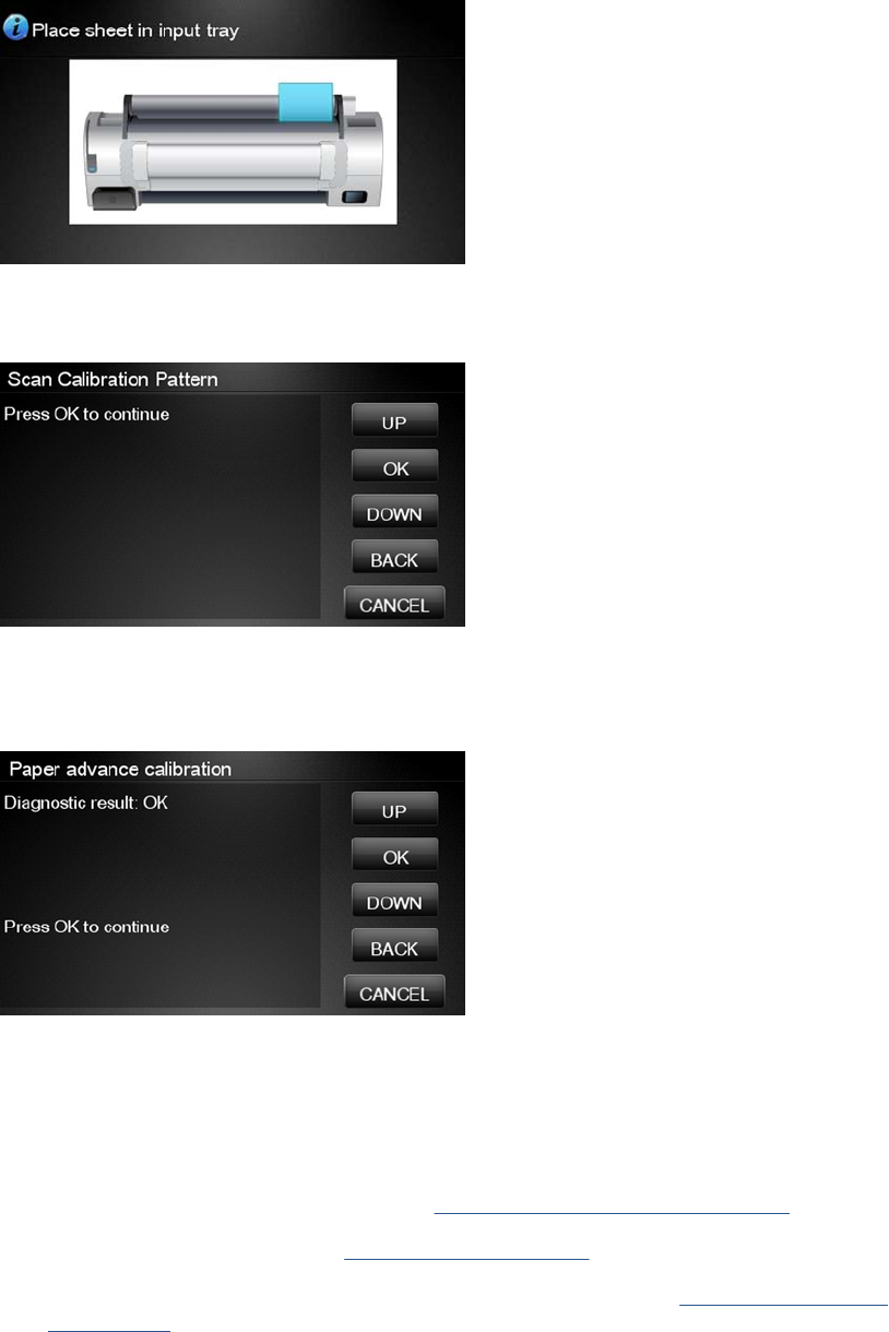
24. Load the calibration pattern into the product and the Touch Control Panel displays the normal sheet
loading procedure.
25. When the Calibration Pattern is successfully loaded the Touch Control Panel displays the following
screen, press OK to start the scan.
26. The Touch Control Panel displays the following screen. The product will scan the Calibration
Pattern which could take several minutes. Once the calibration is completed successfully, the
following message will be displayed on the Touch Control Panel. Press the OK key to continue.
If the Paper Advance Calibration fails for any reason, a warning message will appear on the Touch
Control Panel. In this case, try the following:
●Check that the Calibration Pattern was not incorrectly cut (trimming the actual pattern) during
the paper load process. If this is the case, perform the Paper Advance Calibration again
from step 1.
●Perform a Line Sensor Calibration. See Line Sensor Calibration on page 164.
●Replace the Line Sensor. See Line Sensor on page 325.
●If the problem continues, replace the Media Advance Driver. See Media Advance Drive
on page 330.
ENWW Service Calibrations 161
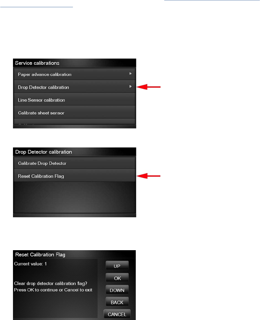
Drop Detector Calibration
The purpose of this Service Calibration is to calibrate the Drop Detector (located in the Service Station)
in relation to the Carriage Assembly. There are two menu options to calibrate the Drop Detector:
●Calibrate Drop Detector
●Reset Calibration Flag
Always perform the Reset Calibration Flag calibration BEFORE calibrating the drop detector.
Service calibrations also need to be performed after removing or replacing certain product components.
If you have removed or replaced product components, check the Service Calibration Guide to Removal
and Installation on page 205 to see which tests and calibrations you need to perform.
Reset Calibration Flag
Run this option before replacing the drop detector (service station), so that the product will not try to
perform a drop detection until the new drop detector has been calibrated.
1. In the Service Calibrations submenu, select Drop Detector calibration and press OK.
2. In the Drop Detector Calibration menu, scroll to Reset Calibration Flag and press OK.
3. When the following message appears on the Touch Control Panel, you must select whether you
would like to continue with the calibration by pressing the OK key. Press Cancel to exit the
calibration.
162 Chapter 4 Service Menu ENWW
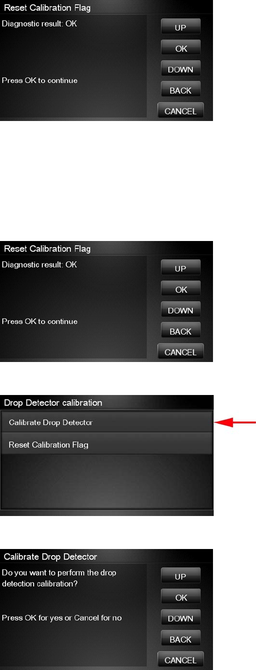
4. The product resets the calibration flag. Press OK to return to the menu.
5. Shut down the product and replace the drop detector.
6. Start the product and calibrate the drop detector.
Calibrate Drop Detector
1. In the Service Calibrations submenu, scroll to Drop Detector calibration and press OK.
2. In the Drop Detector Calibration submenu, scroll to Calibrate Drop Detector and press OK.
3. Tthe following message is displayed on the Touch Control Panel, select the OK button.
ENWW Service Calibrations 163
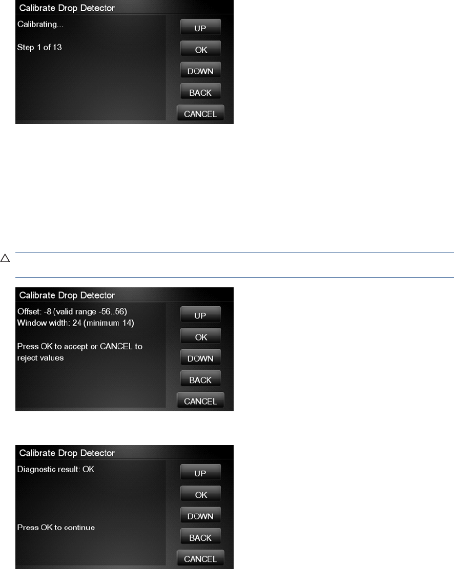
4. The product will start to calibrate the Drop Detector, which takes about 30 seconds.
5. Once the Drop Detector has been calibrated, the results will be displayed on the Touch Control
Panel. Press OK to finish the calibration.
The offset is the displacement from the nominal carriage position for doing the drop detection. width
refers to values captured by the drop detector sensor. The offset should be within the valid range,
and the window width should be at least the minimum shown. If the values are correct, press OK
to accept them. If not, the drop detector is not correctly installed, either because the service station
has not been correctly installed in the scan axis or because the drop detector is not correctly
installed or not working properly. Press Cancel to reject the values.
CAUTION: Do not accept these values if they are not within the right range, as the product will
not work properly.
6. Press OK to end the calibration.
Line Sensor Calibration
The purpose of this Service Calibration is to calibrate the intensity of the line sensor in the Carriage
PCA. An incorrect calibration can result in edge-detection failures during paper loading and incorrect
reading of prints that are used for alignment or calibration.
164 Chapter 4 Service Menu ENWW
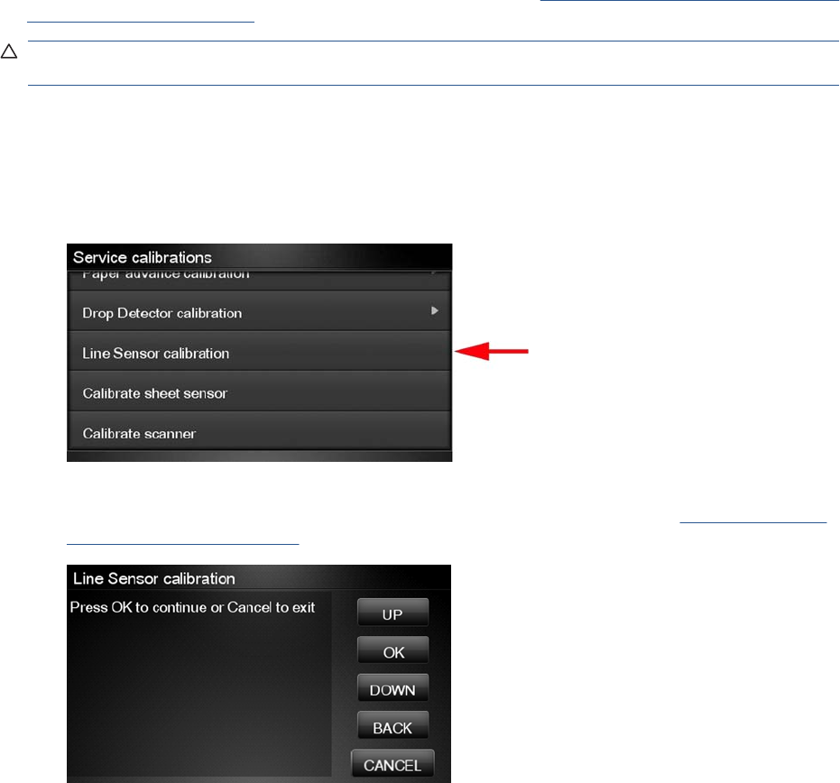
Perform the Line Sensor Calibration in the following cases.
●If the edge detect procedure fails during paper loading.
●If the Carriage is disassembled or replaced.
●If the Line Sensor is disassembled or replaced.
●If banding is detected in prints.
●If misalignment between colors is detected.
Service calibrations also need to be performed after removing or replacing certain product components.
If you have removed or replaced product components, check the Service Calibration Guide to Removal
and Installation on page 205 to see which tests and calibrations you need to perform.
CAUTION: Keep your hands away from the Print Platen during calibration, as the Carriage moves at
high speed and you could injure yourself or damage the Carriage Assembly.
The full calibration process
1. If possible, load a roll of glossy paper with a width of at least 24 inches into the product before
starting the calibration. The product will later reject paper that is too narrow or not glossy.
2. In the Service Calibrations submenu, scroll to Line Sensor calibration and press OK.
3. When the following message appears on the Touch Control Panel, press the OK key to continue
or the Cancel key to exit the calibration. If the product detects no paper, see The manual paper
loading process on page 167.
ENWW Service Calibrations 165
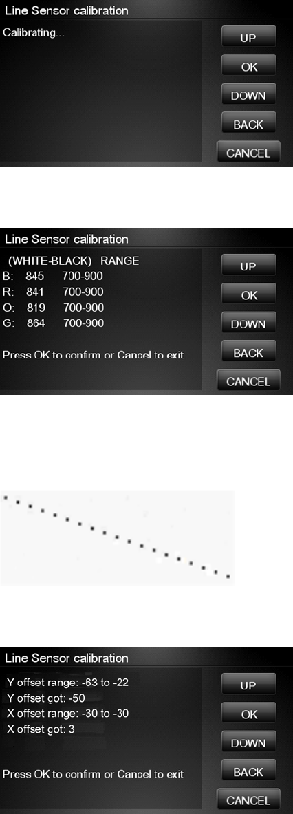
4. The Touch Control Panel displays the following while the calibration is in progress.
5. The product calibrates the intensity of the LEDs and displays the results on the Touch Control
Panel. Press OK to continue or press Cancel to exit the calibration.
If the values are not within the range specified, an error appears on the Touch Control Panel. In
this case, repeat the calibration from the beginning. If necessary, replace the Line Sensor.
6. The next step is to calibrate the Line Sensor position. The product prints a line of black dots and
then scans them.
7. Once the Line Sensor position has been calibrated, the results are displayed on the Touch Control
Panel. Press OK to continue or Cancel to exit.
8. If the calibration fails or the values are out of range, try the following solutions.
●Reseat the line sensor.
●Repeat the calibration again from the beginning.
●Replace the Line Sensor.
166 Chapter 4 Service Menu ENWW
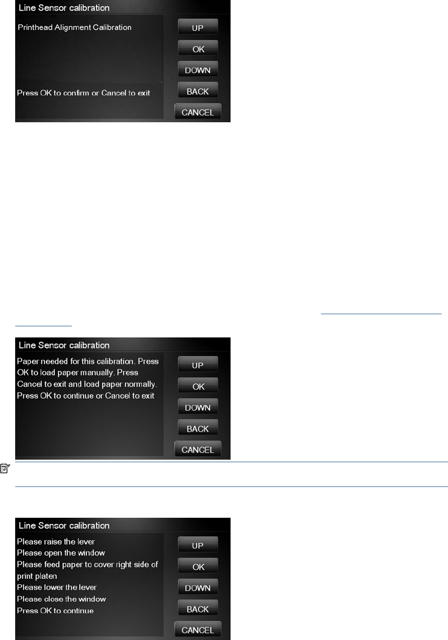
9. The product now tries to align the printheads. When the following message appears on the Touch
Control Panel, press OK to continue or Cancel to exit.
10. If printhead alignment cannot be completed, try the following.
●Enter the Touch Control Panel menu and retry printhead alignment from there. If the alignment
completes successfully, then perform color calibration.
●If the alignment fails again, check the alignment pattern to see whether any of the printheads
are printing incorrectly. If necessary, perform a printhead recovery through the Touch Control
Panel and retry printhead alignment.
11. If the printhead alignment ends successfully, you have completed the full Line Sensor calibration
process.
The manual paper loading process
1. If the product detects no paper, the following message is displayed. If you think you can load paper
normally, press Cancel and resume the full calibration process (see The full calibration process
on page 165). Otherwise, press OK to proceed with manual loading.
NOTE: The manual loading process performs only a partial calibration, after which you should
try again to load roll paper and perform the full calibration.
2. The Touch Control Panel prompts you to load the paper manually.
ENWW Service Calibrations 167
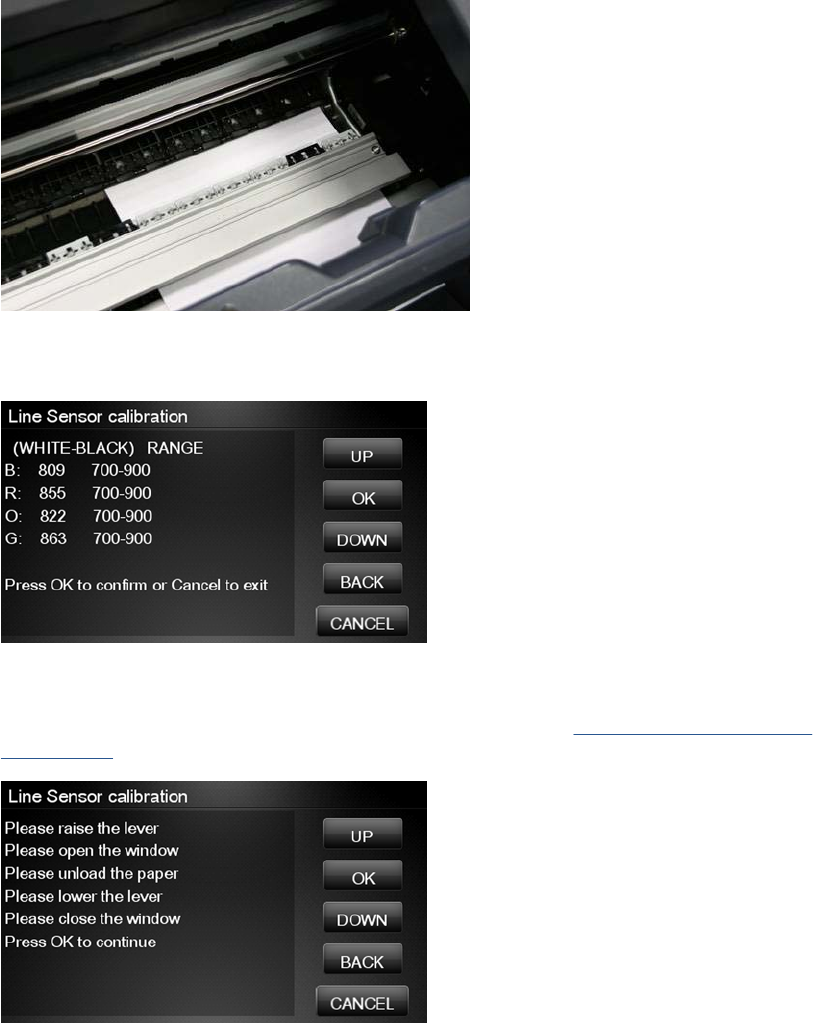
3. Feed a sheet of paper manually into the product (the product will not try to move it) until it fully
covers the right-hand size of the print platen. It must cover the line sensor so that the product
detects it. An A4 or US Letter paper size is sufficient.
4. When you have loaded the paper, press OK. The product starts the calibration process, and
displays the results on the Touch Control Panel if successful. Press OK to continue.
If the calibration fails, start again from the beginning. If necessary, try replacing the Line Sensor.
5. The Touch Control Panel asks you to unload the paper. It then reminds you to reload roll paper in
the normal way and perform the full Line Sensor calibration (see The full calibration process
on page 165).
168 Chapter 4 Service Menu ENWW
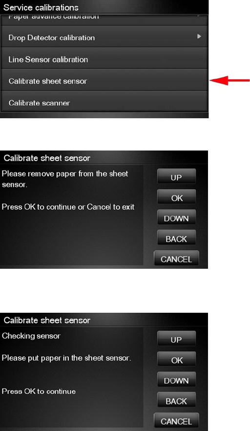
Calibrate Sheet Sensor
The purpose of this Service Calibration is to calibrate the sheet sensor. This sensor should be calibrated
whenever a new sensor is installed. This calibration should also be performed if the following problems
are encountered:
●While attempting to load roll media, if the Front Panel prompts you to remove paper, although there
is no paper in the path, calibrate sheet sensor.
●When attempting to load sheet paper from Front Panel, if the printer repeatedly displays a paper
skew message, and the sheet cannot be loaded, calibrate the sheet sensor.
1. In the Service Calibrations submenu, select Calibrate sheet sensor.
2. Remove paper from the sheet sensor and press OK to continue.
3. When you see the following message, insert sheet paper into the sheet sensor and press OK to
continue.
ENWW Service Calibrations 169
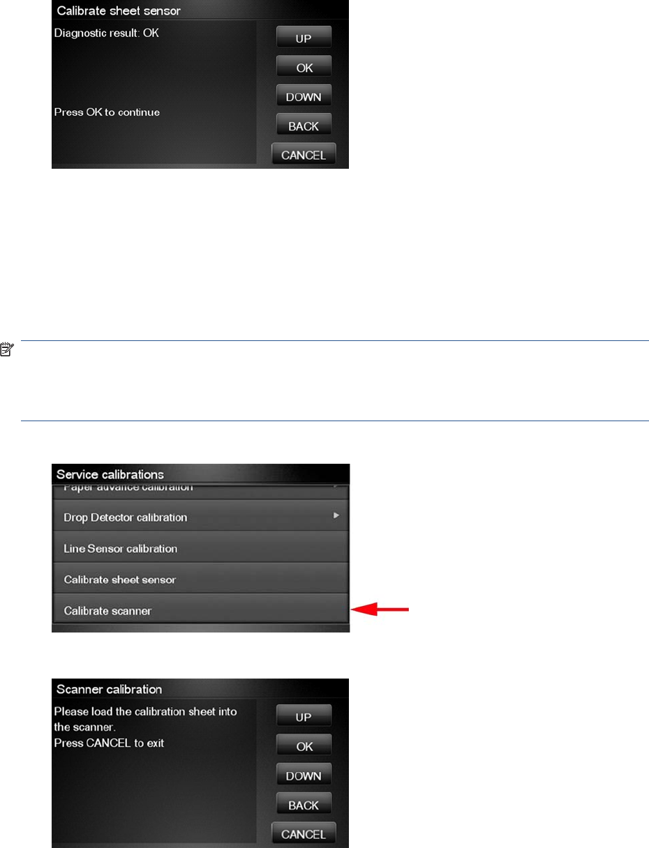
4. If the calibration was successful, a message appears such as the following. If you see an error
message, check that the sheet sensor is connected, and retry the calibration.
Calibrate the Scanner
The purpose of this is to perform a full calibration of the scanner consisting of the following tests:
●Basic Calibration
●Alignment/stitching
●CLC matrix
NOTE: Before running the scanner calibration inspect that the calibration sheet is free dust, spots or
stripes. Check that the calibration sheet is not dirty, wrinkled, scratched or folded before.
NOTE: Before running the scanner calibration open the scanner to inspect that the glass plate is free
of dirt, dust and scratches. Clean the glass plate if necessary before proceeding.
1. In the Service calibrations submenu, scroll to the Calibrate scanner and press on this option
2. The Control Panel will then prompt you to load the calibration sheet.
170 Chapter 4 Service Menu ENWW
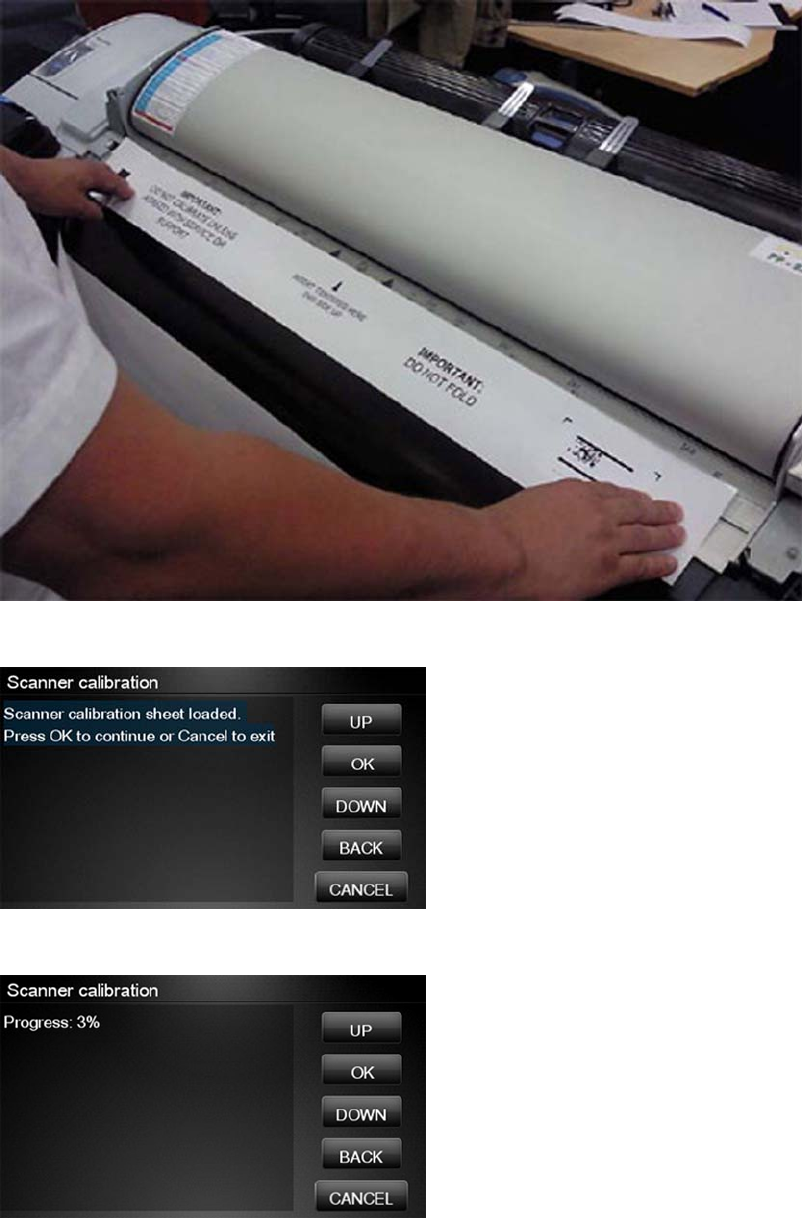
3. Hold the calibration sheet from both sides and place it facing the arrow in the centre of the sheet
in front of the Page icon present on the input tray of the scanner. Push the sheet with both hands
on both sides at the same time to load the sheet with no skew.
4. Press OK to continue with the test.
5. The Control Panel will then display a percentage with the progress of the calibration.
ENWW Service Calibrations 171
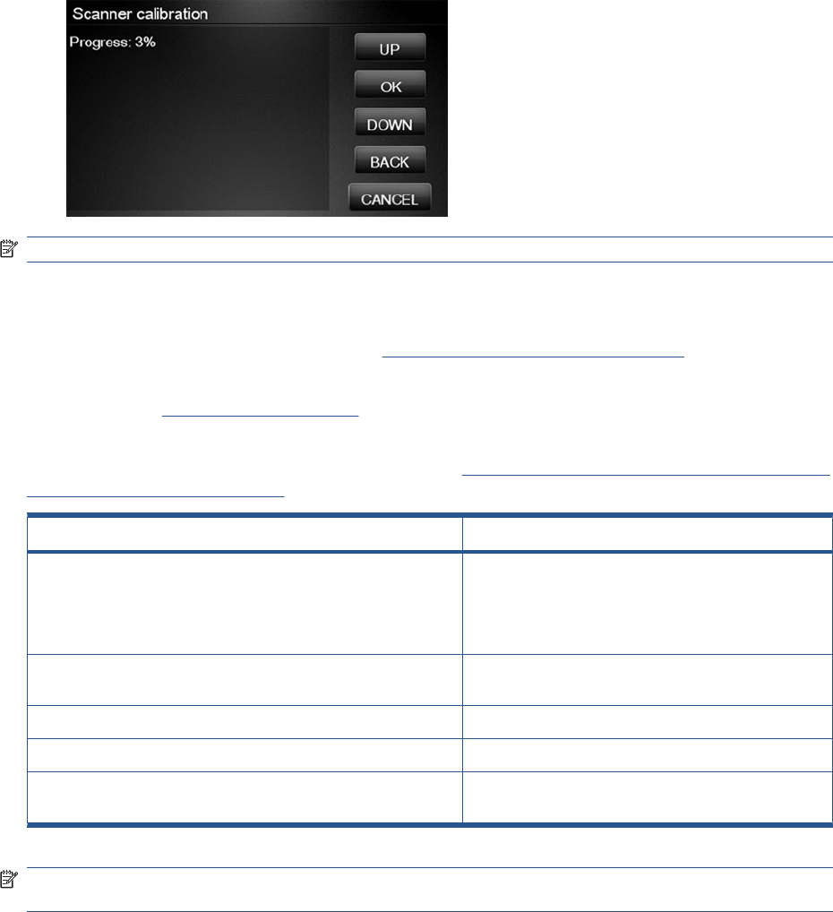
6. The Control Panel will then display a percentage with the progress of the calibration.
NOTE: If scanner calibration result is FAIL then:
●Check that the calibration sheet is in good condition according to previous note. Replace with a
new one if necessary.
●Check that the glass plate is clean, see Cleaning the Glass Plate on page 440
●Check that the glass plate is in good condition and correctly installed. See Removal and
Installation, Glass Plate on page 466
After the calibration, a set of files is saved in the CWS_calibration folder. If the calibration is performed
again the files are overwritten. To retrieve the log files, Appendix C: Obtaining the product log and the
diagnostics package on page 74
File name CWS_Calibration folder
scanTRUSTresult.log The results file. Contains:
●The calculated corrections
●Error codes (if any)
scanTRUST.log The Log file. Primarily contains information that can help
troubleshoot where an error has occurred.
BarCodeScan.tif Scanned image of the barcode.
BarCodeScan_Marked.tif A marked image of the barcode that has been read.
StitchArea_XX.tif Imaged of CIS transition areas used for Alignment/
Stitching calibration
NOTE: Diagnostic package (reduced level) will contain only all LOG and CON files. Extended
diagnostic package (full level) will contain all files.
172 Chapter 4 Service Menu ENWW

5 Parts and Diagrams
Product Support on page 174
Center Covers Front (1 of 3) on page 175
Center Covers Front (2 of 3) on page 176
Center Covers Front (3 of 3) on page 177
Roll Covers on page 178
Center Covers (Rear) on page 179
Right Cover on page 180
Left Cover on page 181
Right Hand Assemblies on page 182
Left Hand Assemblies on page 183
Carriage Assembly on page 184
Scan-Axis Assemblies on page 185
Paper Path Assemblies (Front) on page 186
Paper Path Assemblies (Rear) on page 187
Roll Supports on page 188
Scanner Parts (1 of 3) on page 189
Scanner Parts (2 of 3) on page 190
Scanner Parts (3 of 3) on page 191
Tools 1 on page 192
Tools 2 on page 193
Miscellaneous Parts on page 194
Introduction
The list of parts in this chapter include the notation (CSR A) or (CSR B) for parts that can be replaced
by the customer. All other parts must be replaced by an engineer. See Customer Self Repair parts
on page 204.
ENWW Introduction 173
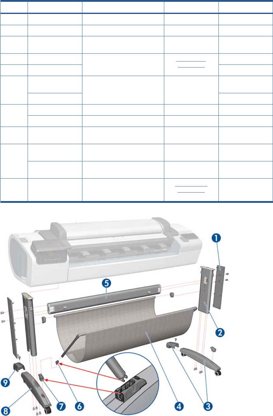
Product Support
HP Part Number Part Description Cross-reference Products Applicable
1Q5669-60718 Leg Cover (CSR A) (Left & Right) All
2Q5669-60716 Leg Assembly (Left & Right) All
3CN727-60056 Stand Foot w/ extension w/ screw
(x2)
T2300
4Q6659-60237 Bin Assembly (includes Bin Support,
gray color) (CSR A)
Bin Assembly
on page 207
T1300-44”-2R, T2300
Q5669-60719 T790–24”
5Q6659-60236 Cross-brace Assembly T790-44”-1R,
T1300-44”-2R, T2300
Q5669-60717 T790–24”
6Q5669-67063 Basket Tube × 2 (CSR A) T790, T1300
Q6659–60159 Basket Tube T2300
7Q5669-60715 Foot Bracket × 2 T790-44”-1R, T790–
24” T1300-44”-2R
8Q5669-60730 Hardware Kit (Includes screws for
Legs Assembly) (CSR A)
T2300
CH639–69001 Foot Assembly (includes 2 feet,
black color)
T790, T2300
9CN727-60093 Stand Foot Extension (w/screw) Foot Extension
on page 461
T2300
174 Chapter 5 Parts and Diagrams ENWW
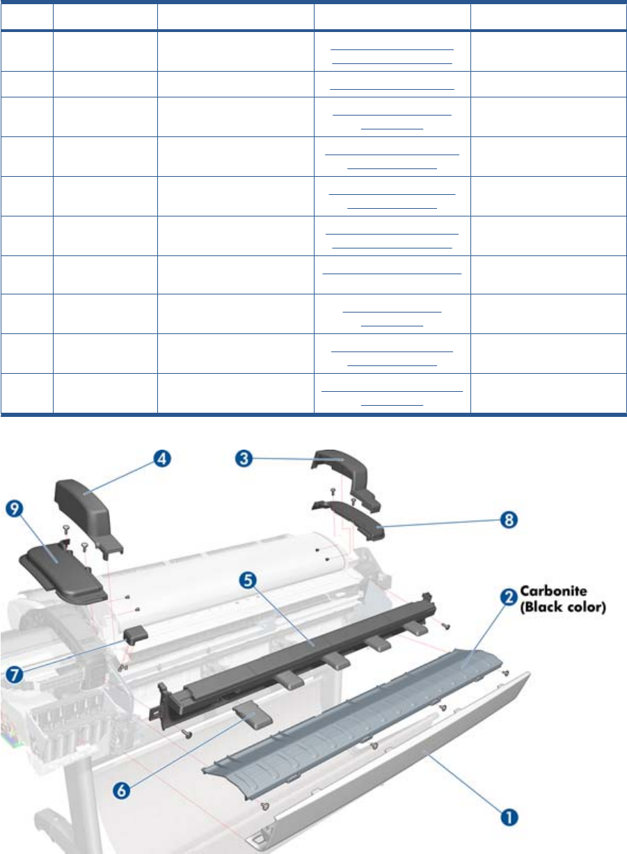
Center Covers Front (1 of 3)
HP Part Number Part Description Cross-reference Products Applicable
-CH538–67071 Scanner Position sensor Scanner Position Sensor
(MFP only) on page 413
T2300
1Q6687–60064 Front Cover Front Cover on page 275 T2300
2CN727–60052 Anti ESD Media Output Assy
Carbonite
Media Output Assembly
on page 340
T2300
3CN727–60058 Scanner Cover Right Right Scanner Cover (MFP
only) on page 372
T2300
4CN727–60059 Scanner Cover Left Left Scanner Cover (MFP
only) on page 321
T2300
5CN727–60063 Front Top Cover Assy Front Top Cover Assembly
(MFP only) on page 276
T2300
6CN727–60066 Front Deflector (incl. 2 pcs) Front Deflector on page 462 T2300
7CN727–60064 Latch Handle Cover Latch Handle Cover
on page 469
T2300
8CN727–60060 Collar cover Right Right Collar Cover (MFP
only) on page 270
T2300
9CN727–600621 Collar Cover Left Left Collar Cover (MFP only)
on page 316
T2300
ENWW Center Covers Front (1 of 3) 175
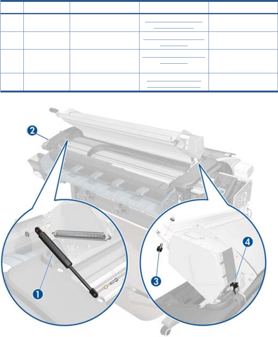
Center Covers Front (2 of 3)
HP Part Number Part Description Cross-reference Products Applicable
1CN727–60068 Scanner Piston Gas Assy Scanner Piston Gas (MFP
only) on page 263
T2300
2CN727–69004 Torsion Damper Torsion Damper (MFP only)
on page 417
T2300
3CN727–60069 Scanner Bumper Assy
(includes wrench #8 and allen
key #10)
Scanner Bumper (MFP only)
on page 266
T2300
4CH538–67071 Position sensor Scanner Position Sensor
(MFP only) on page 413
T2300
176 Chapter 5 Parts and Diagrams ENWW
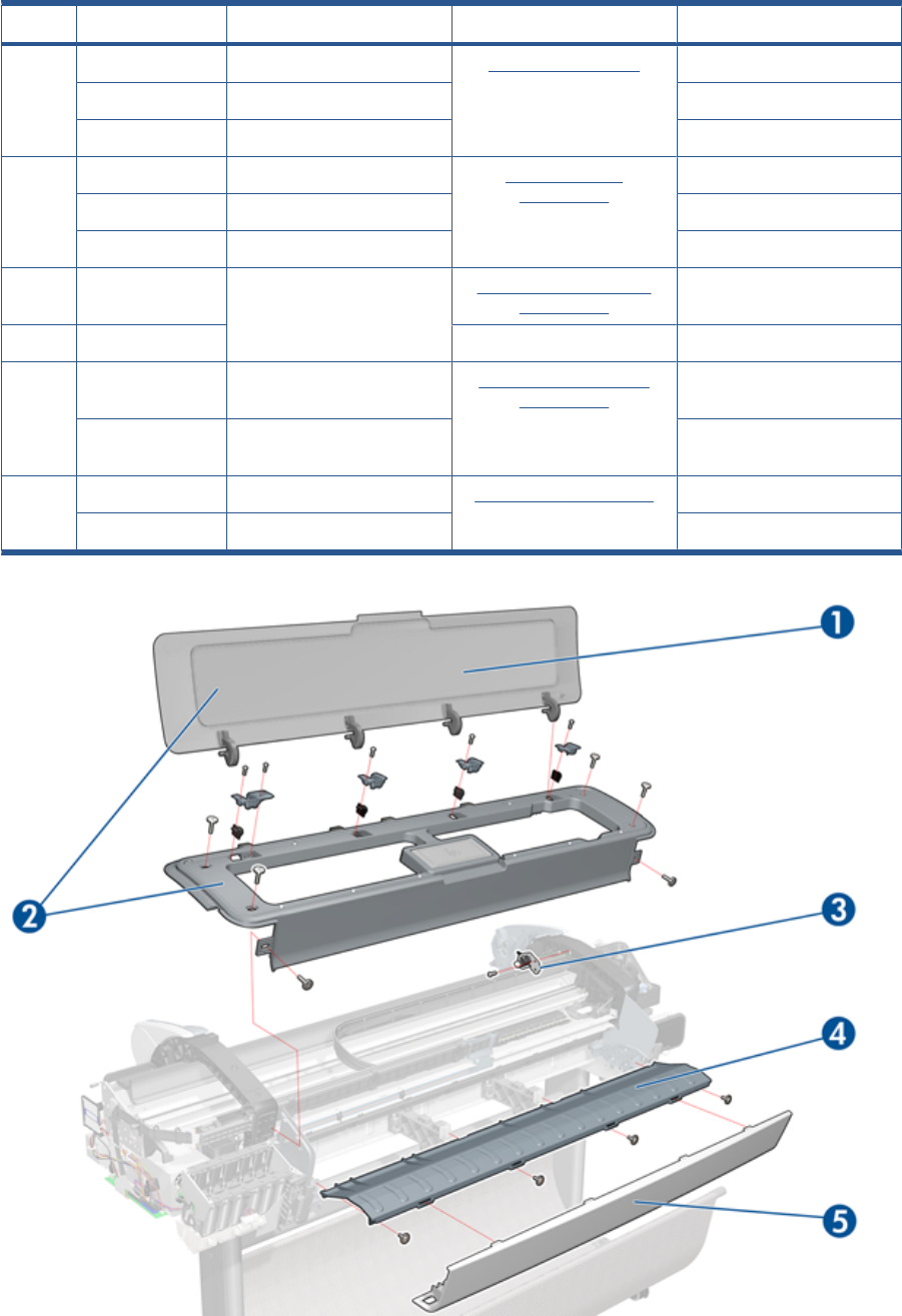
Center Covers Front (3 of 3)
HP Part Number Part Description Cross-reference Products Applicable
1CR649–67001 T790 Window 44 SV Window on page 431 T790-44”-1R,
CR647–67002 T790 Window 24 SV T790-24”
CR651–67002 T1300 Window 44 SV T1300-44”-2R
2CR647–67003 T790 Top Cover 24 SV Front Top Cover
on page 278
T790-24”,
CR649–67002 T790 Top Cover 44 SV T790-44”-1R,
CR651–67001 T1300 Top Cover SV T1300-44”-2R
3CH538–67071 Window Position Sensor (with
shield)
Window Position Sensor
on page 434
T790, T1300
Q5669-60675 T2300
4Q6659-60089 Media Output Assembly 44”
products
Media Output Assembly
on page 340
T1300, T790-44”
Q5669-60155 Anti-ESD Media Output
Assembly 24”
T790-24”
5 Q6687-60064 Front Cover All 44” products Front Cover on page 275 T790-44”-1R, T1300, T2300
Q6683-60201 Front Cover All 24” products T790-24”
ENWW Center Covers Front (3 of 3) 177
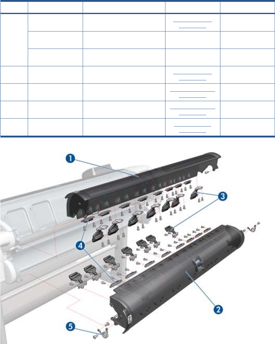
Roll Covers
HP Part Number Part Description Cross-reference Products Applicable
1CH538-67003 Upper Roll Cover Assembly with
pinches
Roll Cover, Upper
on page 381
T790-44”-1R, T1300,
T2300
CQ305–60018 Upper Roll Cover Assembly Basic
SV
T790-24”
CH539-67009 Upper Roll Cover Assembly Basic
SV
T790-44”
2CH538-67002 Lower Roll Cover Assembly with
pinches
Roll Cover, Lower
on page 378
T1300, T2300
3CH538-67037 Pinch Arm Assembly for Roll Cover
(CSR A)
Pinch Arm Assembly
on page 347
T1300, T2300
4CH538-67050 Roll Cover Freewheel Assembly
(CSR A)
Freewheel Assembly
on page 291
T1300, T2300
5CH538-67047 Roll Cover Bi-stable Springs Left
and Right
Bi-stable Springs
on page 210
T1300, T2300
178 Chapter 5 Parts and Diagrams ENWW
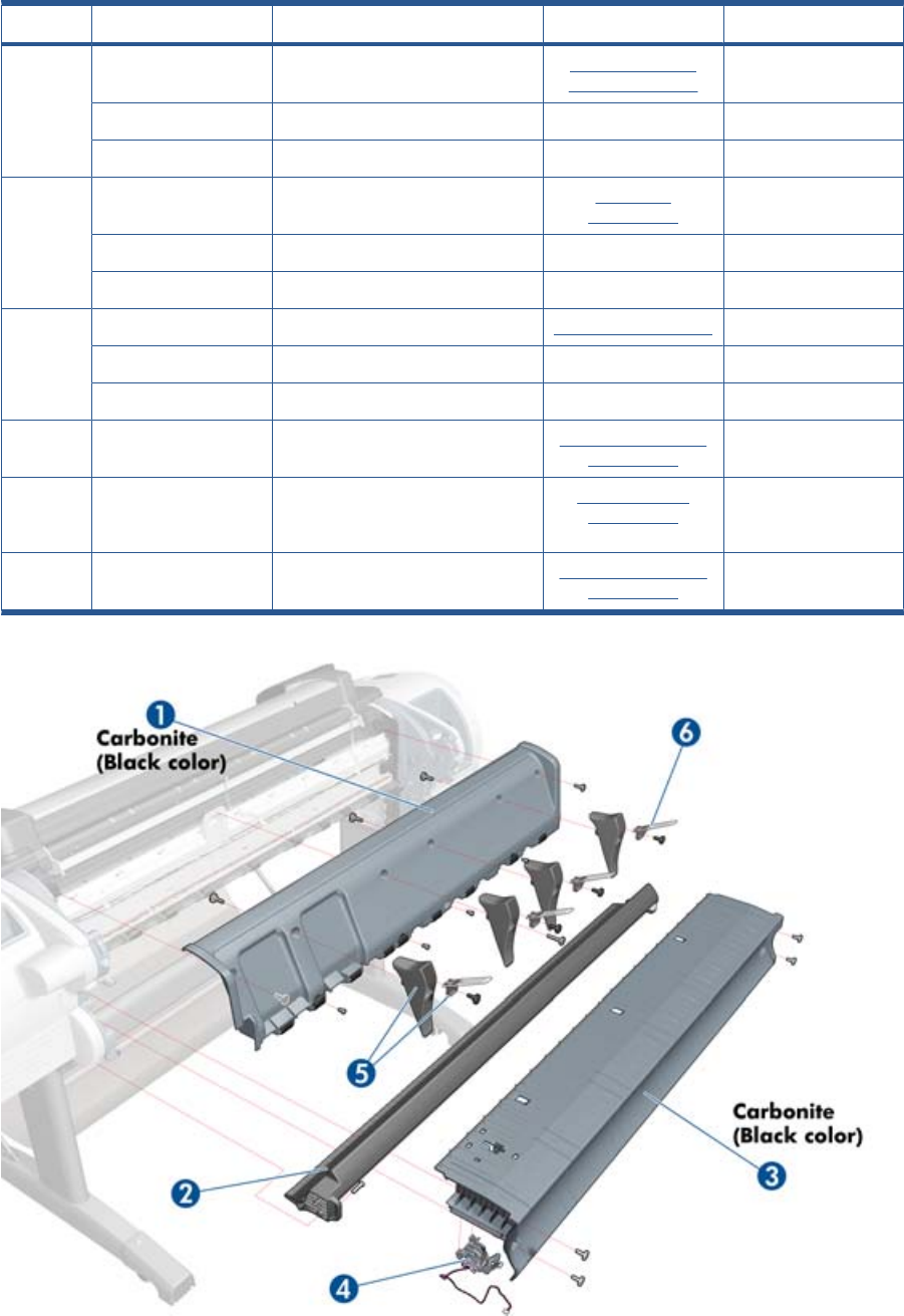
Center Covers (Rear)
HP Part Number Part Description Cross-reference Products Applicable
1CN7227–60091 Back Cover Assembly Carbonite Rear Cover (MFP
only) on page 363
T1300-44”-2R, T2300
CQ305-60015 Rear Cover T790–24”
CH538-67012 Back Cover SV T790–44”
2CH538-67022 Converger Assembly Converger
on page 261
T1300-44”-2R, T2300
CQ305-60019 Converger CR Assembly T790-24”
CH539-67010 Converger CR Assembly T790-44”
3CN727–60047 Clean Out 44 new re carbon Cleanout on page 257 T2300
Q6683-67802 Cleanout 24 rev B T790-24”
CH538-60105 Cleanout TT T790-44”, T1300
4Q5669-67801 Out-of-paper Sensor Out-of-paper Sensor
on page 341
All
5CN727–60092 Rear Deflector
Parts
Rear Deflectors
on page 367
T2300
6CN727–60094 Rear Deflector Mylar Assembly
(CSR A)
Rear Deflector Mylar
on page 464
T2300
ENWW Center Covers (Rear) 179
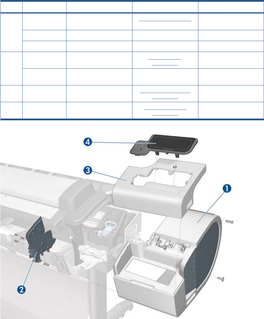
Right Cover
HP Part Number Part Description Cross-reference Products Applicable
1CN727–60083 Right Cover (Without Right
Ink Door Cover)
Right Cover on page 368 T1300, T2300
CH539-67006 Right Cover T790-24”
CH538-67014 T1200 Right Cover T790-44”
2CN727–60053 Integrated Front Trim
Carbonite (Left and Right)
Right Front Trim
on page 293
All
Q6675-60109 Integrated Front Trim (Left
and Right)
T790-24”, T790-44”
3CN727–60074 Right Ink Door Cover (FP not
included)
Right Ink Cartridge Door
on page 297
All
4CN727–67019 Touch Control Panel Touch Control Panel
on page 428
All
180 Chapter 5 Parts and Diagrams ENWW
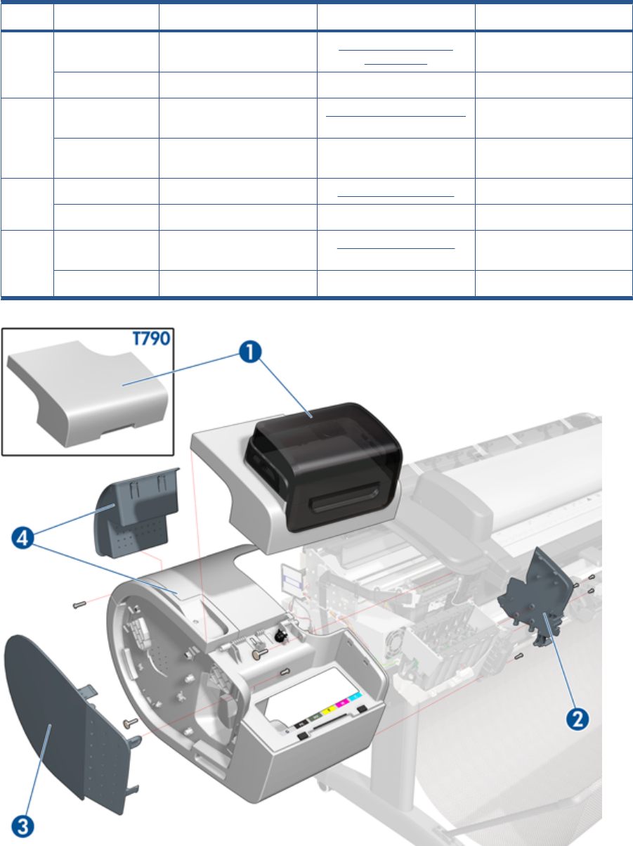
Left Cover
HP Part Number Part Description Cross-reference Products Applicable
1CH538-67017 Left Ink Cartridge Door Left Ink Cartridge Door
on page 296
T1300-44”-2R, T2300
CH539-67008 Left Ink Cartridge Door T790-24”, T790-44”
2CN727-60053 Integrated Front Trim L & R
Carbonite)
Left Front Trim on page 320 All
Q6675-60109 Integrated Front Trim (Left
and Right)
T790-24”, T790-44”
3CH538-67005 Left Side Panel (CSR B) Left Panel on page 344 T1300-44”-2R, T2300
CH539-67002 Left Side Panel (CSR B) T790-24”, T790-44”
4 CN727-60050 Left Cover with ink Door
Carbonite
Left Cover on page 317 T1300-44”-2R, T2300
CH539-67005 Left Cover with Ink Door T790-24”, T790-44”
ENWW Left Cover 181
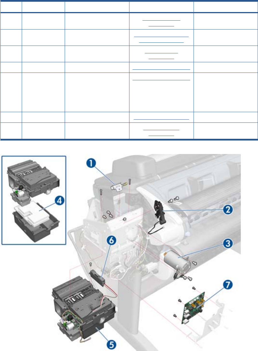
Right Hand Assemblies
HP Part Number Part Description Cross-reference Products Applicable
1Q6675-60043 Carriage Rail Oiler Carriage Rail Oiler
on page 251
All
2Q5669-67807 Pen to Paper Space (PPS)
Solenoid
Pen to Paper Space (PPS)
Solenoid on page 345
All
3CH538-60141 Scan-Axis Motor Scan-axis Motor
on page 392
All
4Q5669-60667 Service Station Spittoon Service Station on page 396 All
5CH538-67040 Service Station (includes
Drop Detector and Service
Station Spittoon). Does not
include Front Panel Holder
nor Cable holder located
under the primer
Service Station on page 396 All
6Q5669-60666 Drop Detector Drop Detector on page 280 All
7CN727–67020 Interconnect PCA Interconnect PCA
on page 315
All
182 Chapter 5 Parts and Diagrams ENWW
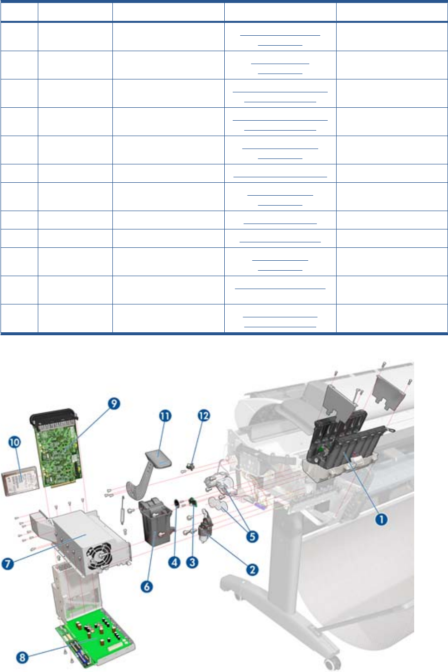
Left Hand Assemblies
HP Part Number Part Description Cross-reference Products Applicable
1Q6683-60188 Left Ink Supply Station Left Ink Supply Station
on page 299
All
2Q6718-67017 Starwheel Motor Starwheel Motor
on page 409
All
3CK837-67020 Encoder Sensor Encoder Disk and Encoder
Sensor on page 286
All
4Q5669-60702 Encoder Disk Encoder Disk and Encoder
Sensor on page 286
All
5CH538-67027 Media Advance Transmission Media Advance Drive
on page 330
All
6Q5669-67049 Left Spittoon Spittoon, Left on page 403 T1300-44”-2R, T2300
7CR651-67004 Power Supply SV Power Supply Unit
on page 362
All
8CR651-67006 Engine PCA w/PSU SV EE Box on page 281 All
9CR651-67005 Formatter w/o HDD Formatter on page 290 All
10 CR650-67001 SATA HDD w/FW Hard Disk Drive
on page 295
All
11 Q5669-60705 Media Lever Media Lever on page 337 T790-24”, T790-44”-1R,
T2300
12 Q5669-60706 Media Lever Position Sensor Media Lever Position
Sensor on page 338
T2300
ENWW Left Hand Assemblies 183
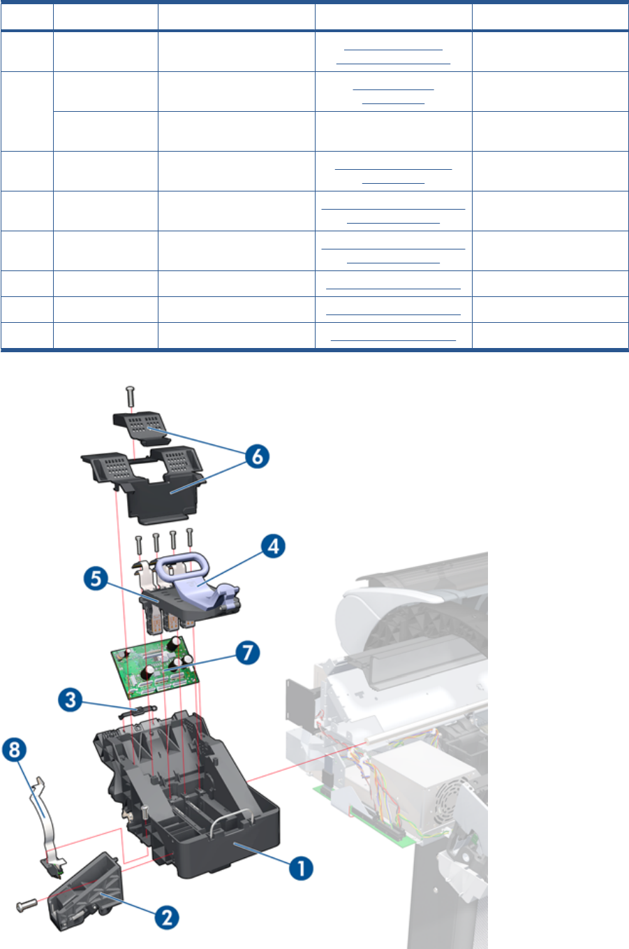
Carriage Assembly
HP Part Number Part Description Cross-reference Products Applicable
1CH538-67044 Carriage with Cutter
Assembly
Carriage and Cutter
Assembly on page 237
All
2CH538-67019 Cutter Assembly with Screw
CSR A)
Cutter assembly
on page 446
T2300
CN727-67023 Cutter Assembly with Screw
SV
All
3Q5669-60687 Carriage Rear Bushing Carriage Bushing, Rear
on page 245
All
4CK837-67001 Carriage Latch Carriage Cover and Carriage
Latch on page 247
All
5CK837-67002 Carriage Cover Carriage Cover and Carriage
Latch on page 247
All
6CK837-67003 Carriage PCA Cover Carriage PCA on page 252 T2300
7CK837-67005 Carriage PCA Carriage PCA on page 252 All
8Q6683-67004 Line Sensor Line Sensor on page 325 All
184 Chapter 5 Parts and Diagrams ENWW
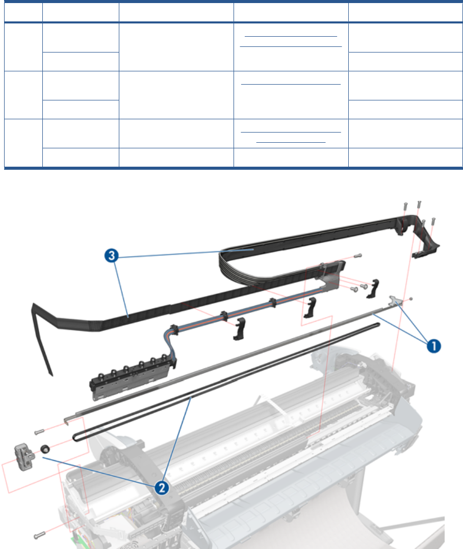
Scan-Axis Assemblies
HP Part Number Part Description Cross-reference Products Applicable
1CK839-67005 Encoder Strip (including
Encoder Strip Spring and Nut)
Encoder Strip, spring and
attachment nut on page 288
T790-44”-1R, T1300-44”-2R,
T2300
CK837–67017 T790-24”
2CH538-67018 Belt Assembly with Belt
Tensioner (3)
Belt Assembly on page 207 T790-44”-1R, T1300-44”-2R,
T2300
CQ305–60016 T790-24”
3 CN727-60097 Tube System with Trailing
Cable and ferrite parts
Ink Supply Tubes & Trailing
Cable on page 304
T790-44”-1R, T1300-44”-2R,
T2300
CR647-67004 Tubes System 24 T790-24”
ENWW Scan-Axis Assemblies 185
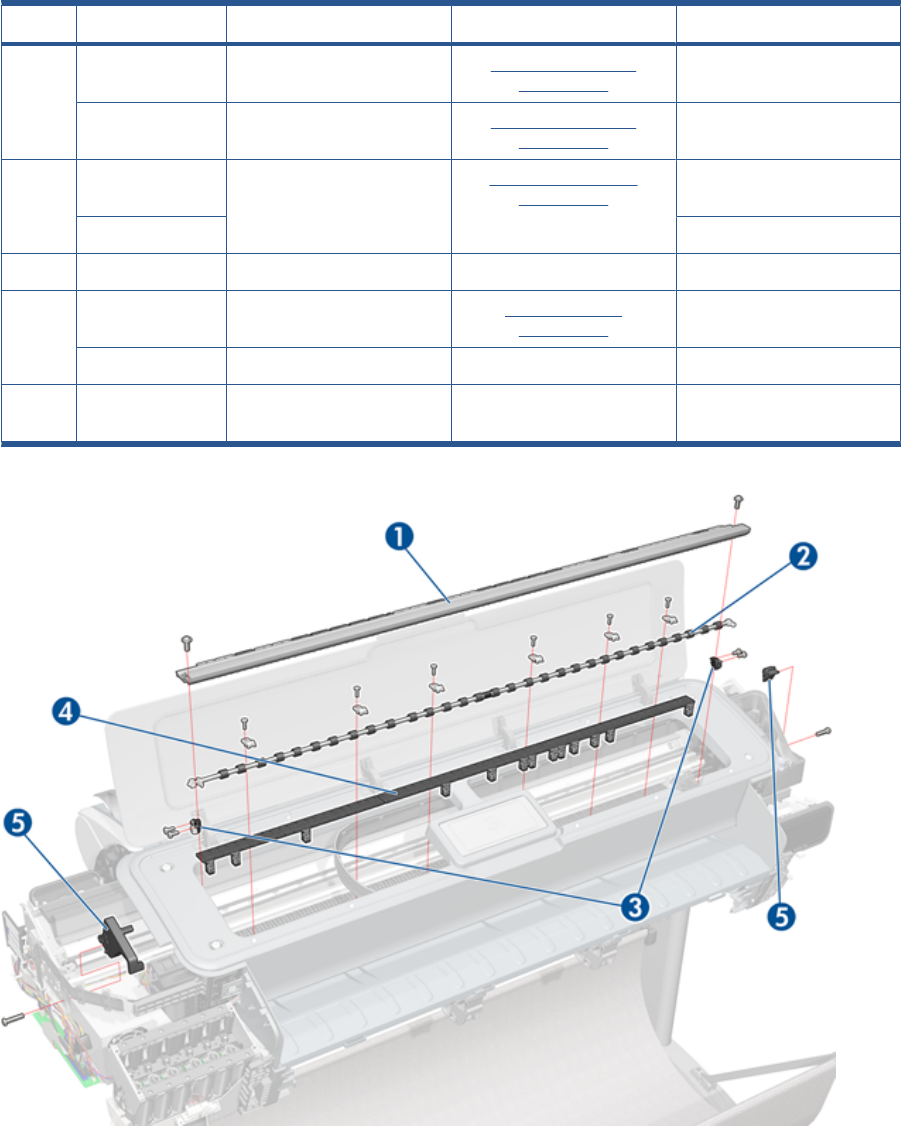
Paper Path Assemblies (Front)
HP Part Number Part Description Cross-reference Products Applicable
1Q6687-60060 Starwheel Assembly Starwheel Assembly
on page 404
T790-44”-1R, T1300-44”-2R,
T2300
Q6683-60196 Starwheel Assembly Starwheel Assembly
on page 404
All 24-in models
2Q6677-60018 Print Zone Overdrive Print Zone Overdrive
on page 357
T790-44”-1R, T1300-44”-2R,
T2300
Q6675–60042 T790-24”
3Q5669-67054 Starwheel Support Assembly All
4Q6659-60182 Full Bleed Foam Kit Full Bleed Foam
on page 294
T790-44”-1R T1300-44”-2R,
T2300
Q5669–60701 Full Bleed Foam Kit T790-24”
5CH538-67064 Bumper Cutter Actuator (Left
and Right)
T2300
186 Chapter 5 Parts and Diagrams ENWW
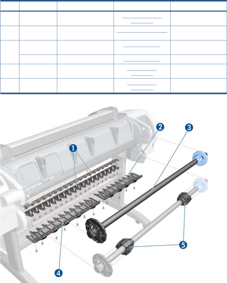
Paper Path Assemblies (Rear)
HP Part Number Part Description Cross-reference Products Applicable
1Q6687-60085 Pinchwheel Assembly
on page 349
All
2Q6677-60019 Left Roll Guide Left Roll Guide on page 382 T790-44”-1R, T1300-44”-2R,
T2300
3Q6687-67001 Spindle (CSR A) Spindle on page 402 T790-44”-1R, T1300-44”-2R,
T2300
CQ305-60020 Spindle (CSR A) Spindle on page 402 T790-24”
4Q6675-60044 Right Roll Guide Right Roll Guide
on page 383
T790-44”-1R, T1300-44”-2R,
T2300
5Q6675-60093 3-inch Core Adaptors (2) Right Roll Guide
on page 383
T790-44”-1R, T1300-44”-2R,
T2300
ENWW Paper Path Assemblies (Rear) 187
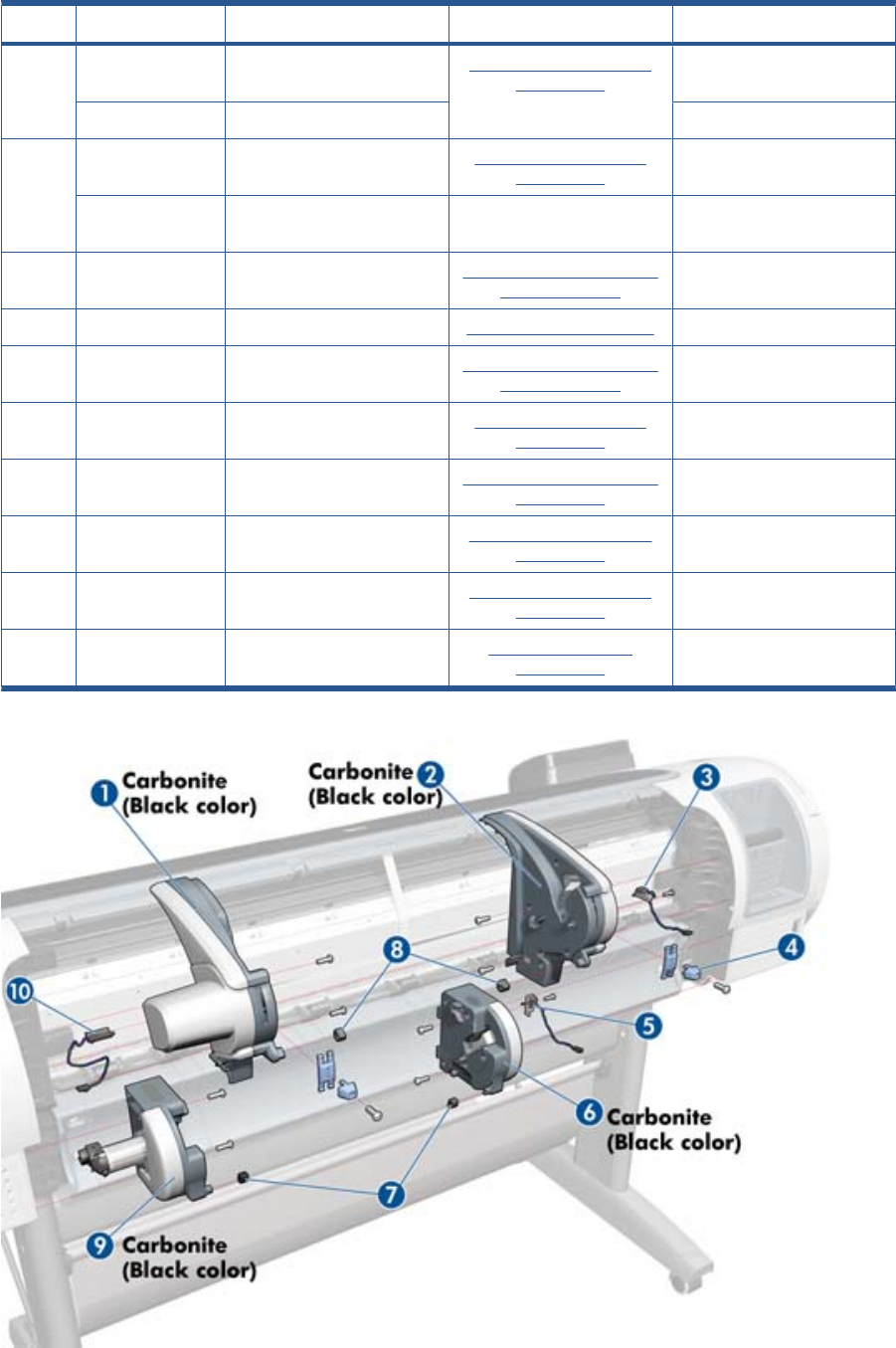
Roll Supports
HP Part Number Part Description Cross-reference Products Applicable
1CR651–67007 Upper Right Roll Cover
Support Carbonite
Roll Support, Upper Right
on page 391
T1300-44”-2R, T2300
CR647–67006 Upper Right Support T790-24”, T790-44”
2CN727-60045 Upper Left Roll Cover
Support Carbonite
Roll Support, Upper Left
on page 389
T1300-44”-2R, T2300
CH539-67007 Upper Left Support without
Sensor
T790-24”, T790-44”
3CH538-67065 Upper Left Support Sensor
with Cable
Roll Support Sensor, Upper
Left on page 388
T1300-44”-2R, T2300
4CH538-67046 Wall Spacers, Left and Right Wall Spacers on page 411 All
5CH538-67041 Lower Left Support Sensor
with Cable
Roll Support Sensor, Lower
Left on page 387
T1300-44”-2R, T2300
6CN727-60049 Lower Left Roll Cover
Support Carbonite
Roll Support, Lower Left
on page 384
T2300
7CH538-67052 Lower Roll Support Bumpers,
Left and Right
Roll Cover Bumpers, Lower
on page 375
T1300-44”-2R
8CH538-67051 Upper Roll Support Bumpers,
Left and Right (CSR A)
Roll cover upper bumpers
on page 457
All
9CN727-60048 Lower Right Roll Cover
Support Carbonite
Roll Support, Lower Right
on page 385
T1300-44”-2R, T2300
10 CH538-67033 Single Sheet Sensor Single-sheet Sensor
on page 401
All
188 Chapter 5 Parts and Diagrams ENWW
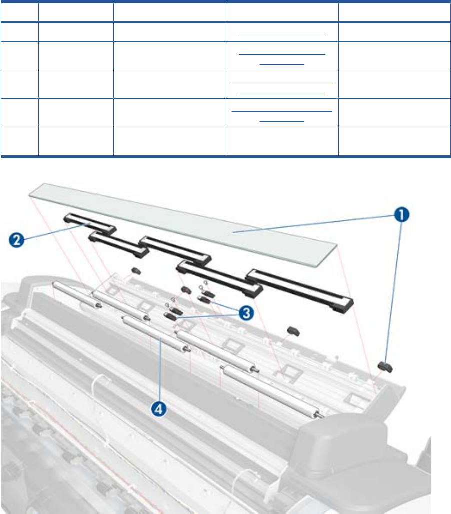
Scanner Parts (1 of 3)
HP Part Number Part Description Cross-reference Products Applicable
1CN727-69005 Glass Plate Glass Plate on page 466 T2300
2CN727-69010 Individual CIS Element CIS Element (MFP only)
on page 420
T2300
3CN727–69003 Media Sensors Scanner Exit Media Sensors
(MFP only) on page 421
T2300
4CN727–69002 Pressure Rollers Pressure Rollers (MFP only)
on page 422
T2300
-CN727–69006 Calibration Sheet (also
includes a cleaning cloth)
T2300
ENWW Scanner Parts (1 of 3) 189
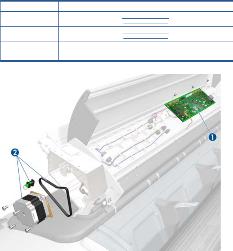
Scanner Parts (2 of 3)
HP Part Number Part Description Cross-reference Products Applicable
1CN727–69009 Scanner Controller Board
(SCU)
Scanner Controller Board
(MFP only) on page 423
T2300
2CN727-69001 Stepper Motor w. Encoder
Sensor and belt
Scanner Motor Assembly
(MFP only) on page 425
T2300
—CN727–69007 Power/Reset/Awake Cable) T2300
—CN727–69008 Cable USB T2300
190 Chapter 5 Parts and Diagrams ENWW

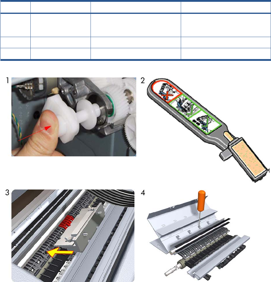
Tools 1
HP Part Number Part Description Products Applicable
1Q6675-67018 Media Driver Tool Kit (includes the
Handle for Media Driver Tool Support
and the Media Driver Adjustment Tool)
All
2Q5669-60690 Flex Contacts Cleaning Tool (CSR A) All
3-4 Q6687-60084 Pinchwheel Insertion Tool All
192 Chapter 5 Parts and Diagrams ENWW
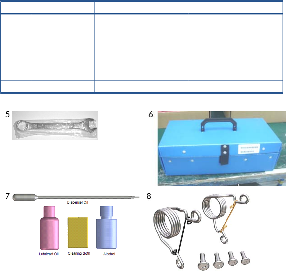
Tools 2
HP Part Number Part Description Products Applicable
5Q6675-67017 Spanner Tool All
6Q6683-67001 Tool Kit (includes pinchwheel alignment
tool, paper driver tool, spanner # 13, oil
dispenser, insert spring tool, tweezers,
T15 screwdriver, 100 cc isopropyl
alcohol, lubricant oil, plastic gloves, flex
contacts cleaning tool and cleaning kit)
T2300
7Q5669-60692 Lubrication Kit (CSR A) T2300
8CH538-67047 Bi-stable Spring Left and Right T1300-44”-2R, T2300
ENWW Tools 2 193
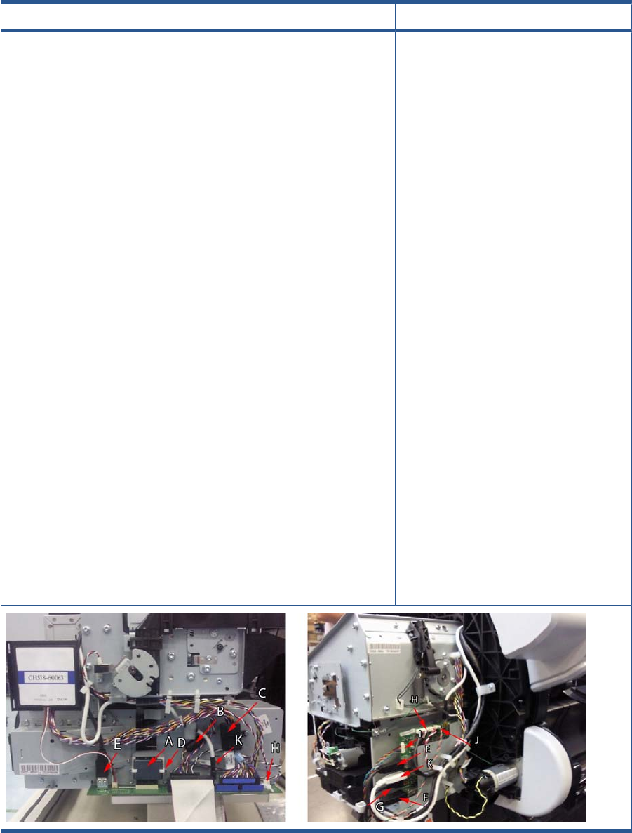
Miscellaneous Parts
HP Part Number Part Description Products Applicable
CH538-67006 Engine Cables Kit
Cables included
●CH538-50012: TT Touch Control Panel
Cable
●CH538-60049: TT Top Rewinder
Encoder Cable
●9170–2158 Ferrite Trailing Cable (A)
●9170–2364: Ferrite Engine Harness (B)
●9170-2408: Ferrite Data Harness (C)
●CK837-40005: Holder Ferrite Trailing
Cable (D)
●CN27–50001: Cable USB Engine to
Interconnect (E)
●CN27–50003: Cable USB Interconnect
to Ext Host (F)
●CN27–50004: Cable USB Interconnect
to Touch Control Panel (G)
●CN27–50006: Cable Power Engine to
Interconnect (H)
●CN27–50008: Cable Power–Data
Interconnect to Touch Control Panel (I)
●CN27–50009: Cable Interconnect to
Power Switch (J)
●CN27–50010: Cable Micci2 Engine to
Interconnect (K)
●CN27–50021: Cable USB Grounding (L)
T1300-44”-2R, T2300
194 Chapter 5 Parts and Diagrams ENWW
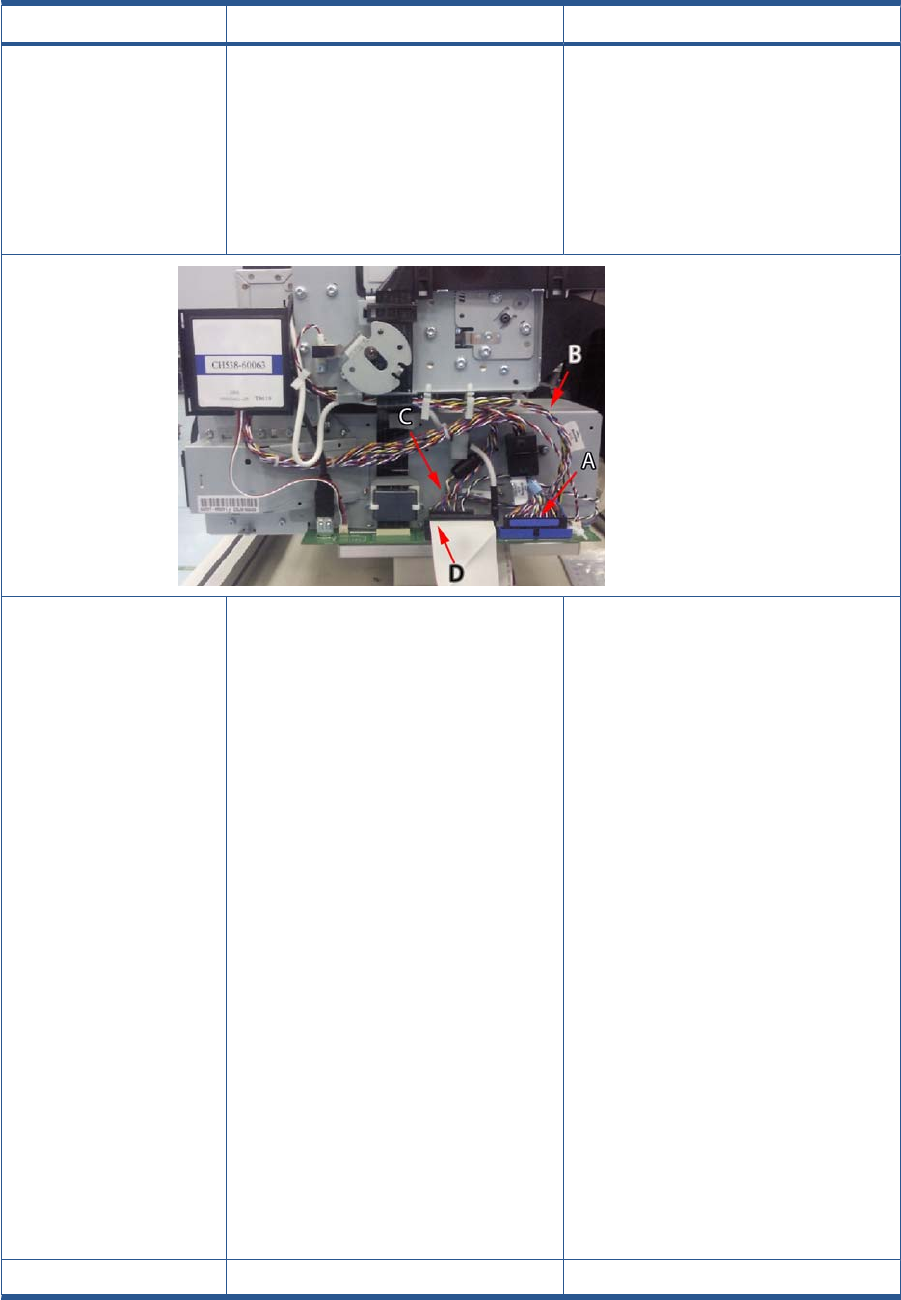
HP Part Number Part Description Products Applicable
●CH538-50001: TT Mechatronic Data
Harness (A)
●CH538-50002: TT Mechatronic Power
Harness (B)
●CH538-50003: TT Engine Harness (C)
●Q6675-50002: ISS Cable Harness Left
with ferrite (D)
CN727-67016 Interconnect Cables Kit 44in
Cables and included
●1400-0719: Cable tie
●9170-2158: Core-Ferrite Ribbon Core
Rohs
●CK837-40005: Holder_TC_ferrite
●CN727-50001: Cable USB SonGoku to
Snoopy
●CN727-50003: Cable USB Snoopy to Ext
Host
●CN727-50004: Cable USB Snoopy to FP
●CN727-50006: Cable Power SonGoku to
Snoopy
●CN727-50008: Cable Power-Data
Snoopy to FP
●CN727-50009: Cable Snoopy to Power
Switch
●CN727-50010: Cable Micci2 SonGoku to
Snoopy
●CN727-50021: USB Grounding Gasket
Cable
T790-44”-1R T1300-44”-2R, T2300
CN727-60084 Serial Number Label (CSR A) All
ENWW Miscellaneous Parts 195

HP Part Number Part Description Products Applicable
CH538-67024 Preventive Maintenance Kit #1
Included
●9223-1023: AP KFT-PPR .004-IN-THK
27-IN
●CH538-60141 Scan Axis Motor Poly-V
SV
T790-44”-1R, T1300-44”-2R, T2300
CH538-67040 Preventive Maintenance Kit #2
Included
●0515-5119: SCREW-MACH M2.5 X 0.45
16MM-LG
●CH538-60051: Service Station Assy
Turbo T
T790-44”-1R T1300-44”-2R
Q6687-60093 Paper Advance Calibration Kit (CSR A) T790-24”, T790-44”-1R, T790-44”-2R
T1300-44”-2R
Q6675-67004 Ink System Purgers (6 units) (CSR A) T790-24”, T790-44”-1R, T790-44”-2R
T1300-44”-2R
Q6675-67005 Ink System Purgers (100 units) T790-24”, T790-44”-1R, T790-44”-2R
T1300-44”-2R
CH538-67005 Left Side Panel SV
CQ533-60001 Europe Power Cord SV kit
CQ533-60002 America Power Cord SV kit
CQ533-60003 Asia Power Cord SV kit
CH539-67003 Engine Cables 1-Roll 44-in Kit: The following
Cables are included:
●CH538-50003:TT Engine Harness
●CH538-50012:TT Front Panel C
●CH538-60049: TT Top Rewinder
Encoder Cable
●CH539-50002: TT MINUS Mechatronic
Power Ha
●CH539-50003: TT MINUS Mechatronic
Data Harn
●Q6675-50002: ISS Cable Harness Left
with fe
T790-44”1R
196 Chapter 5 Parts and Diagrams ENWW

HP Part Number Part Description Products Applicable
CQ305-60014 Engine Cables 1-Roll 24-in Kit: The following
Cables are included:
●CH538-50003: TT Engine
●CH538-60049: TT Top Rewinder
Encoder
●CQ305-50001: TT 24 FRONT PANEL
●TT 24 MECHATRONIC POWER
●CQ305-50003: TT 24 MECHATRONIC
DATA
●Q6675-50002: ISS Cable Harness Left
with ferrite
T790-24”1R
CR647-67001 Interconnect Cables 24-in Kit: The following
Cables are included:
●1400-0719: CABLE TIE .062-1.125-DIA .
14-W
●9170-2158: CORE-FERRITE RIBBON
CORE ROH
●9170-2364: CORE-SPLIT SHIELDING
BEAD ROHS
●9170-2408: CORE-SHIELDING BEAD
ROHS
●CK837-40005: Holder_TC_ferrite
●CN727-50003: Cable USB Snoopy to Ext
Ho
●CN727-50004: Cable USB Snoopy to FP
●CN727-50008: Cable Power-Data
Snoopy to
●CN727-50009: Cable Snoopy to Power
Switch
●CN727-50021: USB Grounding Gasket
Cable
●CR647-50001: USB Cable from Main
PCA to Int
●CR647-50002: Power Cable from Main
to Inter
●CR647-50003: Micci2 SonGoku to
Snoopy – 24
●CR647-80003: LABEL-SECURITY
T790-24”1R
CR647-67005 Support Label T790 Nameplate T790-24”
CR648-67001 Support Label 7T90 PS Nameplate T790-24”, T790-44”-1R
CR651-67003 Support Label T1300 Nameplate T1300-44”-2R
ENWW Miscellaneous Parts 197

HP Part Number Part Description Products Applicable
CR652-67001 Support Label T1300 PS Nameplate T1300-44”-2R, T1300-44”-2R, T2300
CQ305-60017 Preventive Maintenance Kit 1
●CH538-67044: Carriage with Cutter
Assembly SV
●CH538-60141: Scan Axis Motor SV
●CK837-67014: T1120/620 Ink Supply
Tubes 24
●CQ305-60016: T770 Belt 24 SV
T790-24”
198 Chapter 5 Parts and Diagrams ENWW

6 Removal and Installation
●Introduction on page 202
●Service Calibration Guide to Removal and Installation on page 205
●Belt Assembly on page 207
●Bin Assembly on page 207
●Bi-stable Springs on page 210
●Bumpers, Left and Right on page 215
●Carriage and Cutter Assembly on page 237
●Carriage Bushing, Rear on page 245
●Carriage Cover and Carriage Latch on page 247
●Carriage Rail Oiler on page 251
●Carriage PCA on page 252
●CIS Element (MFP only) on page 420
●Cleanout on page 257
●Converger on page 261
●Drop Detector on page 280
●EE Box on page 281
●Encoder Disk and Encoder Sensor on page 286
●Encoder Strip on page 287
●Encoder Strip, spring and attachment nut on page 288
●Engine Cables Kit on page 218
●Formatter on page 290
●Freewheel Assembly on page 291
●Front Cover on page 275
●Front Top Cover Assembly (MFP only) on page 276
●Front Top Cover on page 278
●Full Bleed Foam on page 294
●Hard Disk Drive on page 295
ENWW 199

●Ink Supply Tubes & Trailing Cable on page 304
●Ink Supply Tubes Support Rail on page 313
●Interconnect Cables Kit on page 229
●Latch Handle Cover on page 469
●Left Collar Cover (MFP only) on page 316
●Left Cover on page 317
●Left Ink Cartridge Door on page 296
●Left Ink Supply Station on page 299
●Left Front Trim on page 320
●Left Panel on page 344
●Left Scanner Cover (MFP only) on page 321
●Line Sensor on page 325
●Media Advance Drive on page 330
●Media Lever on page 337
●Media Lever Position Sensor on page 338
●Media Output Assembly on page 340
●Out-of-paper Sensor on page 341
●Pen to Paper Space (PPS) Solenoid on page 345
●Pinch Arm Assembly on page 347
●Pinchwheel Assembly on page 349
●Print Zone Overdrive on page 357
●Power Supply Unit on page 362
●Pressure Rollers (MFP only) on page 422
●Real-time Clock Battery on page 363
●Right Collar Cover (MFP only) on page 270
●Right Front Trim on page 293
●Right Ink Cartridge Door on page 297
●Rear Cover (MFP only) on page 363
●Rear Cover on page 366
●Rear Deflectors on page 367
●Right Scanner Cover (MFP only) on page 372
●Right Cover on page 368
●Roll Cover Bumpers, Lower on page 375
●Roll Cover, Lower on page 378
200 Chapter 6 Removal and Installation ENWW

●Roll Cover, Upper on page 381
●Left Roll Guide on page 382
●Right Roll Guide on page 383
●Roll Support, Lower Left on page 384
●Roll Support, Lower Right on page 385
●Roll Support Sensor, Lower Left on page 387
●Roll Support Sensor, Upper Left on page 388
●Roll Support, Upper Left on page 389
●Roll Support, Upper Right on page 391
●Scan-axis Motor on page 392
●Scanner Piston Gas (MFP only) on page 263
●Scanner Position Sensor (MFP only) on page 413
●Scanner Bumper (MFP only) on page 266
●Service Station on page 396
●Single-sheet Sensor on page 401
●Spindle on page 402
●Spittoon, Left on page 403
●Starwheel Assembly on page 404
●Starwheel Lifter, Left on page 405
●Starwheel Lifter, Right on page 407
●Starwheel Motor on page 409
●Scanner Controller Board (MFP only) on page 423
●Scanner Entry Media Sensors (MFP only) on page 422
●Scanner Exit Media Sensors (MFP only) on page 421
●Scanner Latch and Hook Assembly (MFP only) on page 323
●Scanner Motor Assembly (MFP only) on page 425
●Taco Sensor (MFP only) on page 426
●Torsion Damper (MFP only) on page 417
●Touch Control Panel on page 428
●Wall Spacers on page 411
●Window on page 431
●Window Position Sensor on page 434
ENWW 201

Introduction
This chapter is a step-by-step guide to the removal and installation of the key components of the product.
You may find it useful to check off the steps as they are performed. Use the illustrations for each
procedure to identify the parts referred to in the text.
Some of the procedures have a video available which can be downloaded. When a video is available
the following graphic is shown. Click on the graphic to download the video. These videos and others,
are also available from the Service Media Library.
The Service Media Library is available through the following links:
●HP Employees and contingent workers: http://thesml.hp.com
●HP Channel partners, external call centers (requires registration):http://h20181.www2.hp.com/plm
●HP Customers:http://www.hp.com/go/sml
NOTE: Before using this chapter to remove and install a new component, always make sure that you
have performed the relevant service test from Chapter 4. If the test passes you will not need to replace
the component.
Safety Precautions
Review the instructions identified by WARNING and CAUTION symbols before you service the product.
Follow these warnings and cautions for your protection and to avoid damaging the product.
NOTE: Serious shock hazard leading to death or injury may result if you do not take the following
precautions:
●Ensure that the ac power outlet (mains) has a protective earth (ground) terminal.
●Switch the product off, and disconnect it from the power source prior to performing any
maintenance.
●Prevent water or other liquids from running onto electrical components or circuits, or through
openings in the module.
Electrostatic Discharge (ESD) Precautions
To prevent damage to the product's circuits from high-voltage electrostatic discharge (ESD):
1. Do not wear clothing that is subject to static build-up.
2. Do not handle integrated circuits (ICs) in carpeted areas.
3. Do not remove an IC or a printed circuit assembly (PCA) from its conductive foam pad or conductive
packaging until you are ready to install it.
4. Ground (earth) your body while disassembling and working on the product.
202 Chapter 6 Removal and Installation ENWW

5. After removing a cover from the product, attach an earthing (ground) lead between the PCA
common and earth ground. Touch all tools to earth ground to remove static charges before using
them on the product.
6. After removing any PCA from the product, place it on a conductive foam pad or into its conductive
packaging to prevent ESD damage to any ICs on the PCA.
Required Tools
All the special tools and equipment required to disassemble, service and repair the product are provided
in the Toolkit P/N Q6683-67001. Some tools can be ordered separately from the toolkit. See Tools 1
on page 192 and Tools 2 on page 193.
The Toolkit contains the following tools:
Description/Comments HP Part Number
13 mm Combination Spanner Q6675-67011
Alcohol Q6675-60091
Allen Key #2 Q6675-60041
Cleaning Cloth 9300-2531
Flex Contacts Cleaning Support Q1271-40384
Lubricant Oil Q6675-60090
Media Driver Adjustment Tool Q6675-67009
Handle for Media Driver Tool Support Q6675-67010
Spanner Q6675-67011
Oil Dispenser Q6675-60062
Manual Pinch Arm Alignment Tool Q5669-20595
Spring Insertion Tool Q5669-20594
Protective Plastic Gloves Q6675-60035
Screwdriver 8710-2456
Tweezers Q6675-60037
T Series Cleaning Assembly C6071-60218
You will also need the following standard hand tools:
Description/Comments Size
Long Torx Screwdriver 1/4 inch drive
Torx Bit (75 mm) 8
10
15
20
Philips Screwdriver 1
Pliers N/A
Snips N/A
ENWW Introduction 203

Description/Comments Size
Pipe Spanner 5.5 mm
Flat-bladed Screwdriver N/A
Customer Self Repair parts
Some product parts are designated Customer Self Repair (CSR) parts, which means that a faulty part
can be replaced by the customer. Non-CSR parts need to be replaced by an engineer. There are two
categories of CSR parts:
●CSR A: Customer self-repair is mandatory, as mentioned in the product's warranty statement. If
HP is asked to replace such parts, the customer will be charged for travel and labor costs. Parts
should be replaceable by end users (customers) from a mechanical perspective within 5 minutes,
with simple or no tools required. Examples include spindles and cartridges.
●CSR B: Parts are easy to replace, but some knowledge of the product and technical skills may be
required. The customer can decide whether to replace the part or to call for an engineer.
The CSR parts are listed below.
Part number Description CSR type In box
CH538-67005 T1200 Left Side Panel SV (see Left side panel (T1200) on page 451) B Yes
Q5669-60690 Flex Contacts Cleaning Tool SV ANo
Q5669-60692 Troja Lubrication Kit SV ANo
Q6683-60241 Paper Advance Calibration T Se ANo
Q6687-60093 Paper Advance Calibration T Se ANo
CN727-67023 Cutter Assy with screw (see Cutter assembly on page 446) A Yes
CH538-67050 T1200/T770 Roll Cover Freewheel SV (see Freewheel assembly
on page 447)
AYes
Q6659-60183 Spindle 44 SV ANo
Q6675-60093 3" Adaptor kit - Troja Service ANo
CN727-60084 Serial Label SV ANo
CH538-67049 T1200 Support & cables for removable HDD ANo
Q5669-60718 Leg Cover SV ANo
Q6659-60237 Bin Assembly 44 SV ANo
Q5669-60730 Hardware Kit SV ANo
Q5669-67063 Basket Tubes + Adaptors Servic ANo
Q6675-67004 Ink System Purgers (6 units) AYes
CH538-67037 Pinch Arm Assembly for Roll Cover SV (see Pinch arm assembly
on page 453)
AYes
CH538-67051 Roll Cover Upper Bumpers (see Roll cover upper bumpers on page 457) A Yes
CN727–60064 Latch Handle ID AYes
CN727–60066 Front Deflector Assemble AYes
CN727-60094 Rear Deflector Mylar Assembly A Yes
204 Chapter 6 Removal and Installation ENWW

Part number Description CSR type In box
CN727-60093 Stand Foot Extension w/ screw AYes
CN727-60095 Scanner Glass Plate Holders (w/o glass plate) AYes
CN727-69005 Scanner Glass Plate A Yes
For further information
●CSR Corporate Standards: http://standards.corp.hp.com/smc/hpstd/AHP0001501.htm
●CSR Web site: http://www.hp.com/go/csrparts/
●CSR Parts Availability (EasiTool): https://easitool.atlanta.hp.com/
●HP Parts Page: http://partpage.corp.hp.com/default.asp
Service Calibration Guide to Removal and Installation
Using the Service Calibration Guide
When you remove most product components, you will need to perform a particular set of Service
Calibrations and Diagnostic tests to ensure proper product performance.
The Service Calibration Table explains which service calibrations and diagnostic tests need to be
performed whenever you remove and install particular product components.
The calibrations and tests must be performed in the order in which they are listed.
NOTE: Even if you do not replace the removed component with a new component, you still need to
perform the calibrations indicated in the table.
Diagnostics and Calibration Table
Component Diagnostic Tests Service Utilities & Calibrations
Carriage Assembly Carriage Assembly, Scan Axis, Cutter. Line Sensor Calibration. After
replacement, Reset Life Counters.
Carriage Cover, Carriage Latch,
Carriage PCA
Carriage Assembly Line Sensor Calibration.
Carriage Rear Bushing Carriage Assembly, Scan Axis, Cutter. Line Sensor Calibration.
Cleanout Assembly Carriage Assembly
Cutter Assembly Scan Axis, Cutter.
Drop Detector Service Station. Reset Calibration Flag, Drop Detector
Calibration.
Encoder Disk, Encoder Sensor Paper Drive, Electronics Module Paper Advance Calibration.
Encoder Strip Scan Axis
Formatter, Front Panel, Hard Disk
Drive, Engine PCA, Power Supply
Unit
Electronics Module
Ink Supply Station Left Ink Delivery System. After replacement, reset Life Counters.
Ink Supply Tubes, Support Rail Sensors.
Line Sensor Line Sensor Calibration.
ENWW Service Calibration Guide to Removal and Installation 205

Component Diagnostic Tests Service Utilities & Calibrations
Media Advance Drive Paper Drive Paper Advance Calibration.
Media Advance Roller Paper Drive, Sensors. Paper Advance Calibration.
Media Lever Position Sensor Sensors
Out of Paper Sensor Sensors, Carriage Assembly.
Pen to Paper Space (PPS) Solenoid Scan Axis PRS..
Pinch Roller, Paper Drive, Sensors
Preventative Maintenance #1 Carriage Assembly, Scan Axis, Sensors. Line Sensor Calibration. After
replacement, reset Life Counters.
Preventative Maintenance #2 Service Station. Drop Detector Calibration. After
replacement, reset Life Counters.
Primer Assembly Service Station. Drop Detector Calibration.
Print Zone Overdrive Starwheel Lifter..
Glass Plate, CIS Element, Scanner
Exit Media Sensor, Scanner Entry
Media Sensor, Scanner Controller
PCA, Scanner Motor Assembly
Sensors. Calibrate the Scanner, Scanner
Validation.
Single Sheet Sensor Sensors. Calibrate Sheet Sensor
Performing the Service Calibrations and Diagnostic Tests
When you are ready to perform the service calibrations and diagnostic tests that correspond to the
component you have installed or replaced, consult the following sections for procedures:
●Paper Drive Test on page 89.
●Electronics Module Test on page 91.
●Carriage Assembly Test on page 93.
●Sensors Test on page 96.
●Rewinder Test on page 98.
●Ink Delivery System (IDS) Test on page 100.
●Service Station Test on page 106.
●Paper Advance Calibration on page 155.
●Drop Detector Calibration on page 162.
●Line Sensor Calibration on page 164.
206 Chapter 6 Removal and Installation ENWW
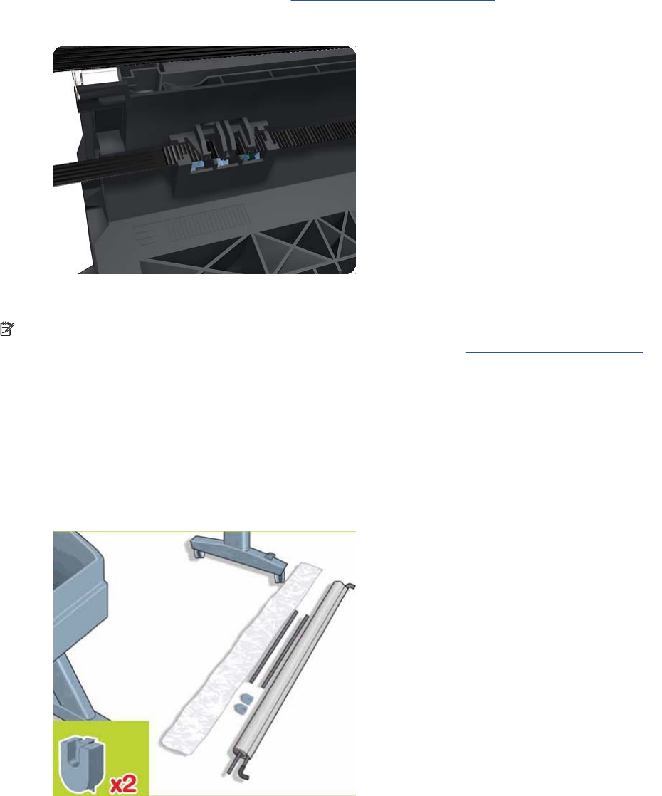
Belt Assembly
Removal
1. Switch off the product and remove the power cable.
2. Remove the Carriage Assembly. See Carriage Assembly on page 184.
3. Slide the Belt Assembly out of the attachment on the Carriage Assembly.
4. Remove the Belt Tensioner Assembly.
NOTE: When you finish installing or replacing this component, you must perform the necessary
Service Calibrations. To find which calibrations you must perform, see Service Calibration Guide to
Removal and Installation on page 205.
Bin Assembly
Removal
1. Switch off the product and remove the power cable.
2. Lay out the components of the basket.
ENWW Belt Assembly 207
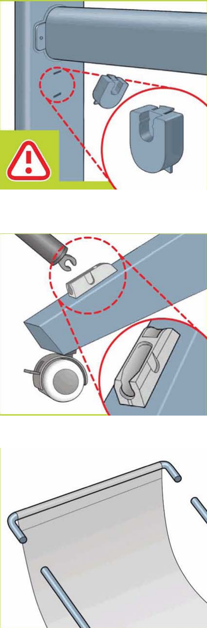
3. Fit the basket supports to the stand legs, one to each leg.
4. Fit the two short tubes to the product’s feet, one on the front of each foot. Each tube should click
into place.
5. Attach the basket’s front tubes to the two short tubes on each foot.
208 Chapter 6 Removal and Installation ENWW
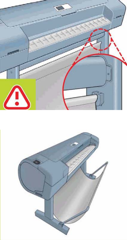
6. Rest the basket's rear tubes on the supports that you have just fitted to each leg of the stand.
7. The basket is now complete.
ENWW Bin Assembly 209
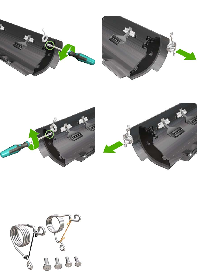
Bi-stable Springs
These parts should not be replaced by customers.
Removal
1. Remove the Roll Cover, Lower on page 378.
2. Unscrew the Left Bi-stable Spring from the Lower Roll Cover.
3. Unscrew the Right Bi-stable Spring from the Lower Roll Cover.
Installation
1. There are two pre-loaded Bi-stable Springs, one for the left side (gold link) and one for the right
side (black link). There are two screws for each Bi-stable Spring (total four screws).
210 Chapter 6 Removal and Installation ENWW
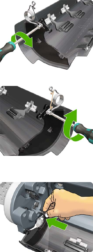
2. Screw the right Bi-stable Spring (black link) onto the right side of the Lower Roll Cover.
3. Screw the left Bi-stable Spring (gold link) onto the left side of the Lower Roll Cover.
4. Hold the Roll Cover with two hands while mounting it in the Roll Support.
5. Insert the Lower Roll Cover right-side hinge into the Lower Right Roll Support pin.
ENWW Bi-stable Springs 211
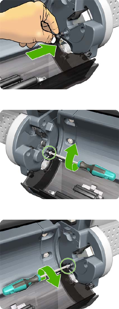
6. Insert the Lower Roll Cover left-side hinge into the Lower Left Roll Support pin.
7. Screw the Lower Roll Cover to the Lower Right Roll Support.
8. Screw the Lower Roll Cover to the Lower Left Roll Support.
212 Chapter 6 Removal and Installation ENWW
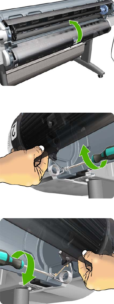
9. Close the Lower Roll Cover until the other end of the Bi-stable Screw is in front of the hole on the
Lower Left Roll Support (if necessary, hold the Roll Cover for a moment with your head).
10. Screw the left pre-loaded Bi-stable Spring to the Lower Left Roll Support. Do not let the cover close
completely.
11. Screw the right pre-loaded Bi-stable Spring to the Lower Right Roll Support.
12. Close the Lower Roll Cover completely.
ENWW Bi-stable Springs 213
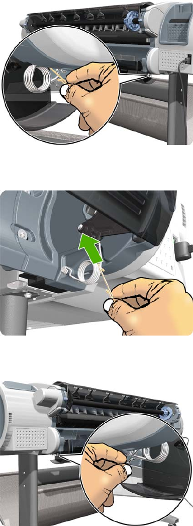
13. Free one end of the right metal link of the right Bi-stable Spring.
14. Free the other end of the right metal link of the right Bi-stable Spring (if necessary, play slightly with
the Lower Roll Cover).
15. Free one end of the left metal link of the left Bi-stable Spring (if necessary, play slightly with the
Lower Roll Cover).
214 Chapter 6 Removal and Installation ENWW
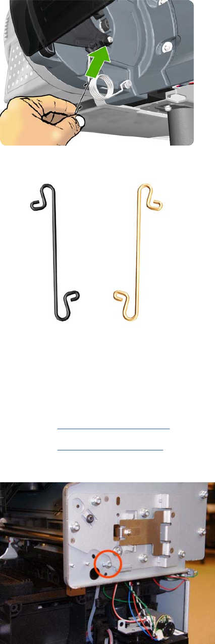
16. Free the other end of the metal link of the left Bi-stable Spring.
17. Store the metal links that you have removed.
Bumpers, Left and Right
Removal
1. Switch off the product and remove the power cable.
2. Remove the Right Cover on page 368.
3. Remove the Left Cover on page 317.
4. Remove the T-15 screw that secures the right bumper.
ENWW Bumpers, Left and Right 215

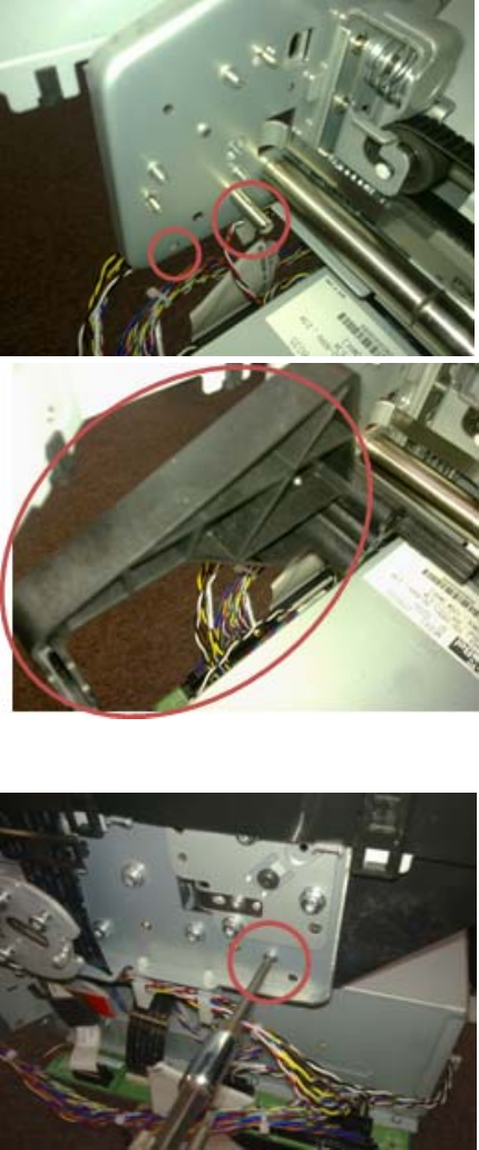
4. Attach the left bumper. Make sure to snap the bumper on to both parts shown.
5. Secure the left bumper to the product with a T-15 screw.
ENWW Bumpers, Left and Right 217
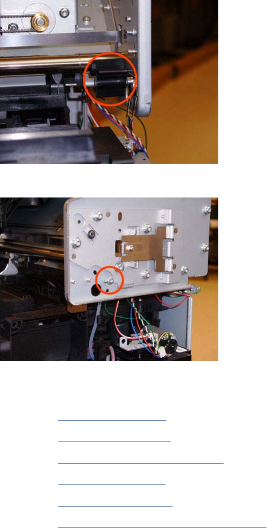
6. Attach the right bumper.
7. Secure the right bumper to the product with a T-15 screw.
Engine Cables Kit
1. Remove the Converger on page 261.
2. Remove the Rear Cover on page 366.
3. Remove the Rear Cover (MFP only) on page 363
4. Remove the Left Cover on page 317.
5. Remove the Right Cover on page 368.
6. Remove the Right Scanner Cover (MFP only) on page 372.
7. Open the Scanner (MFP only) or Window.
218 Chapter 6 Removal and Installation ENWW
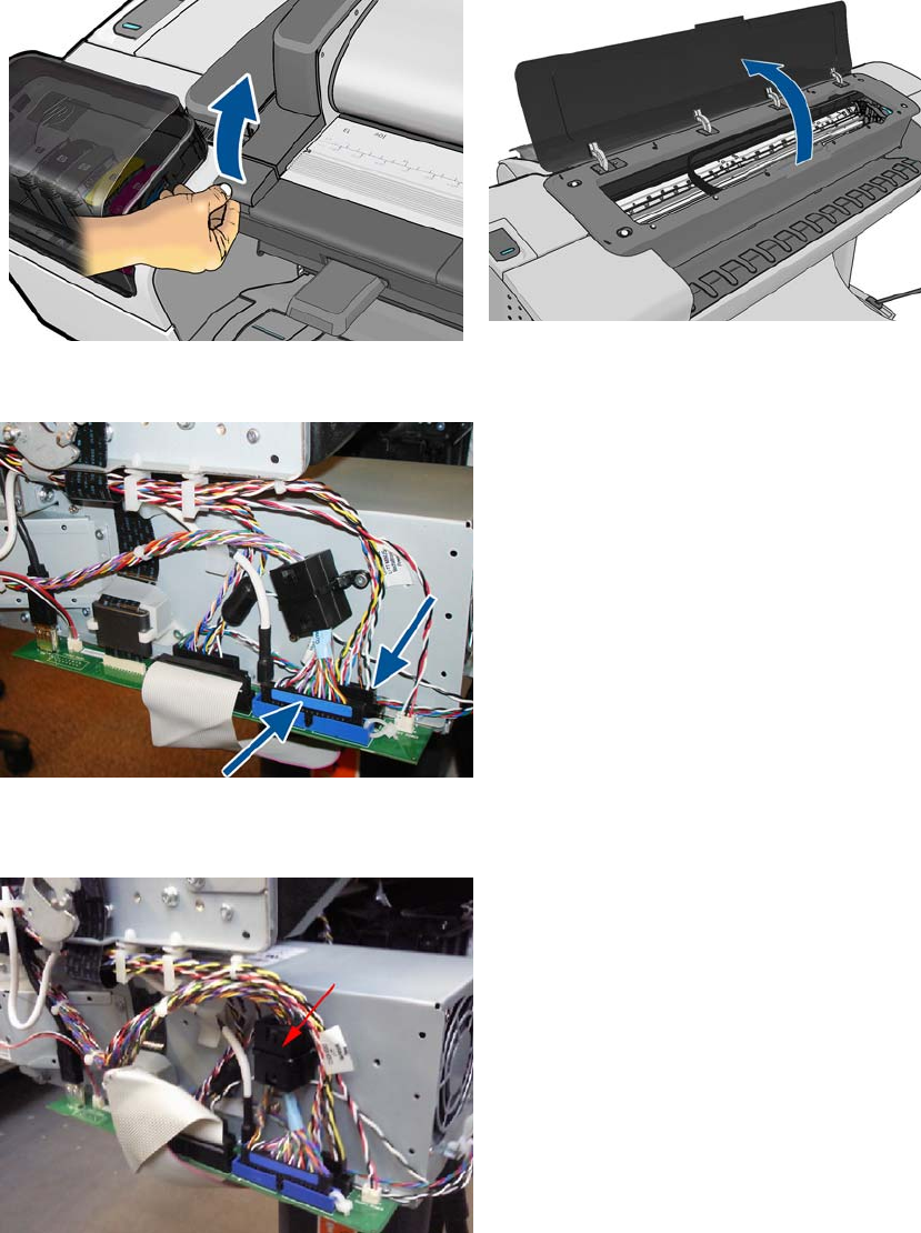
8. Unplug both connectors.
9. Cut the cable tie that fixes the ferrite on to the Data Harness. Open the ferrite and remove from the
cable (this action is required to be able to pass the harness under the arc).
ENWW Engine Cables Kit 219
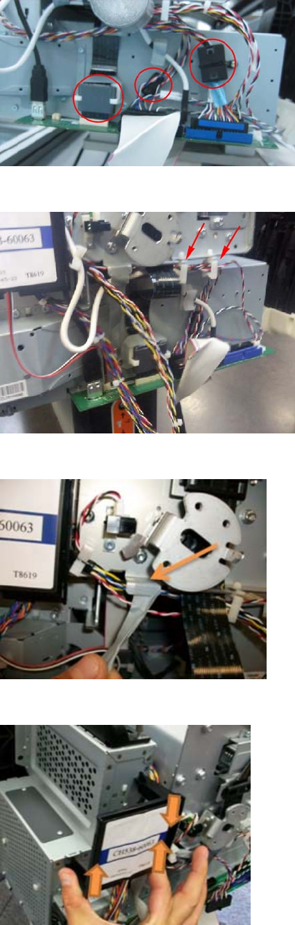
10. Make sure all the ferrites are removed.
11. Detach both cable branches from their holders.
12. Remove the tape from the cable branch.
13. Remove the RFID tag support.
220 Chapter 6 Removal and Installation ENWW
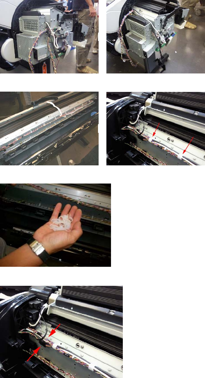
14. Detach both cable branches.
15. Unscrew all nine cable ties from the upper cable branch.
16. Keep the cable ties and screws to for reuse after replacing the cable.
17. Locate the Scanner Position Sensor connections.
ENWW Engine Cables Kit 221
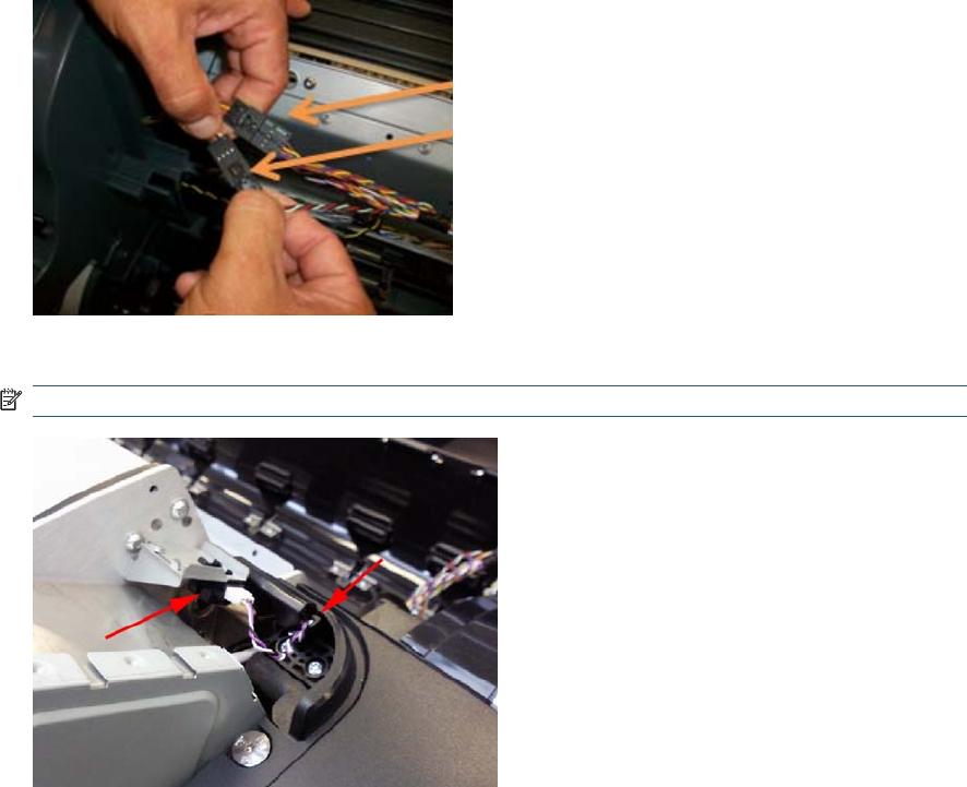
18. Unplug both connectors shown in the picture.
19. Disconnect the cable from the Scanner Position Sensor, and remove the cable from the hook.
NOTE: Steps 17 and 18 are not required for the HP Designjet T790 & T1300 Printers.
222 Chapter 6 Removal and Installation ENWW
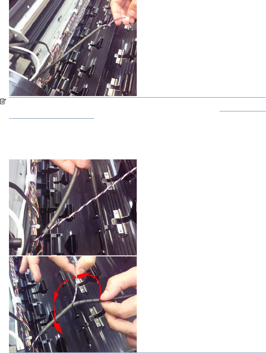
20. Pull the cable under the cover.
NOTE: In order to avoid accidentally disconnecting the sensor while opening the scanner,
because the cable is incorrectly adjusted, follow the installation steps carefully on Scanner Position
Sensor (MFP only) on page 413.
NOTE: When replacing the Data Harness, make sure you reuse the spiral binding tube that
protects the sensor cables onto the new Data Harness. This protection is needed in order to prevent
damage to the cables during transportation. In order to put the spiral binding tube on the cable,
hold the sensor cable and insert binding from beginning of the sensor branch and rotate the binding.
ENWW Engine Cables Kit 223
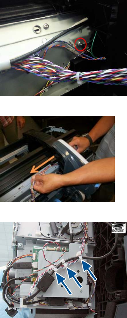
21. Remove the screw that holds the grounding cables.
22. Pull both Data and Power Harness under the left arc
23. On the other side of the unit, detach Power and Data cables from cable ties.
224 Chapter 6 Removal and Installation ENWW
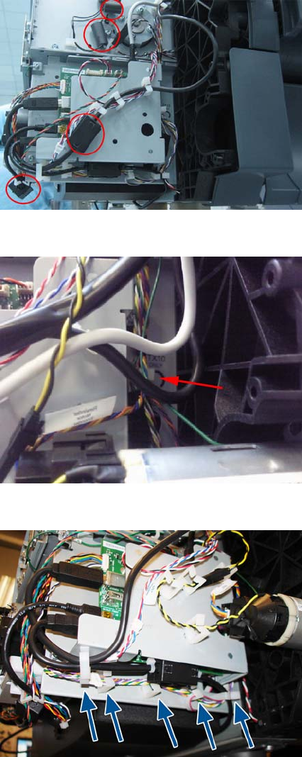
24. Remove the ferrites.
25. Remove Power and Data cables from more cable ties.
26. Remove Power and Data cables from more cable ties.
ENWW Engine Cables Kit 225
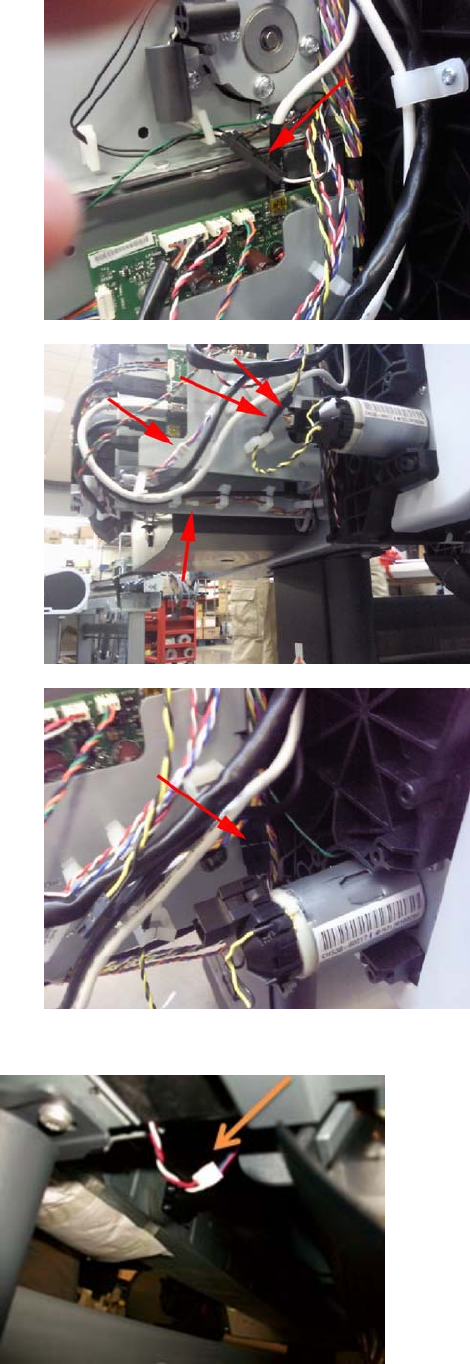
27. Disconnect the 6 Power and Data connectors around the Interconnect Board.
●
●
●
28. Disconnect the Media Sensor from below the unit and pull the cable through the arc.
226 Chapter 6 Removal and Installation ENWW
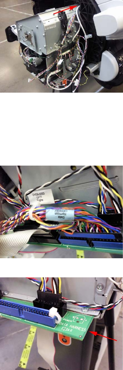
29. Pull the Power and Data Harness under the arc right.
Connecting the Data Harness and ISS Harness Cable
Wether you are reconnecting or replacing the cables it is important that the ISS Harness and Data
Harness are connected correctly to their corresponding connectors on the Engine PCA, it is possible to
swap them over in error and connect them into each others connectors, and cause a 22.1:10 system
error. Perform the following procedure to correctly identify the Data Harness and ISS Harness and
connect them correclty
1. The Data Harness can be identified with a label on the cable.
2. The corresponding connector on the Engine PCA is also marked 'Data Harness'.
ENWW Engine Cables Kit 227
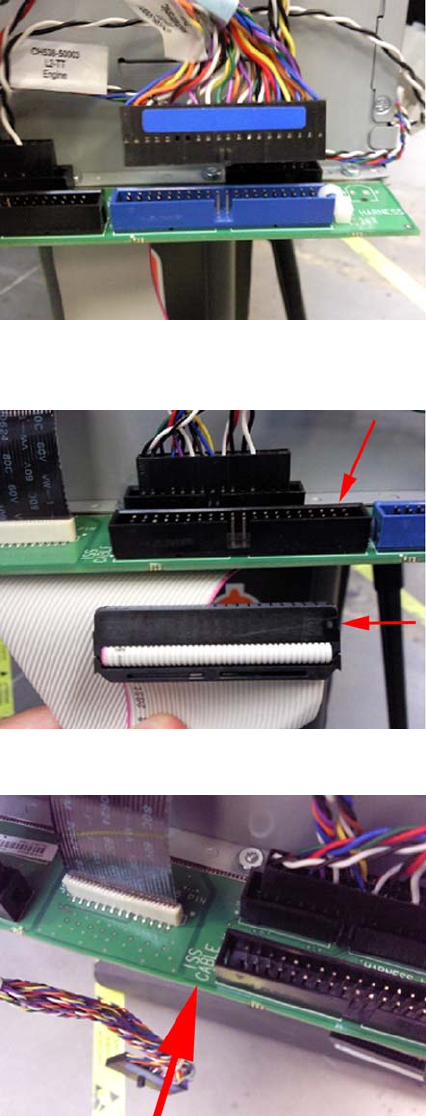
3. The connector of the Data Harness has a blue label, and the corresponding connector on the
Engine PCA is also blue.
4. The Connector on ISS Harness cable is black and the corresponding connector on the Engine PCA
is also black.
5. The corresponding connector on the Engine PCA is also marked 'ISS Cable'.
228 Chapter 6 Removal and Installation ENWW
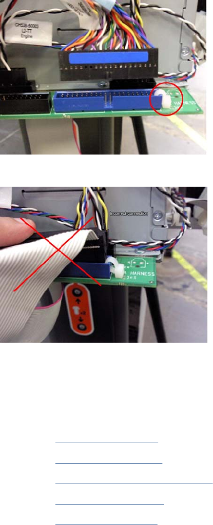
6. The connector for the Data Harness on the Engine PCA includes a cable tie that prevents an
incorrect connection of the ISS Harness Cable.
7. The connector of the ISS Harness Cable cannot be inserted because of the cable tie.
Interconnect Cables Kit
Remove Touch Panel Cables
1. Switch off the product and remove the power cable.
2. Remove the Converger on page 261
3. Remove the Rear Cover on page 366
4. Remove the Rear Cover (MFP only) on page 363
5. Remove the Right Cover on page 368.
6. Remove the Left Cover on page 317.
7. If necessary, manually move the Carriage Assembly fully right into the docking station.
ENWW Interconnect Cables Kit 229
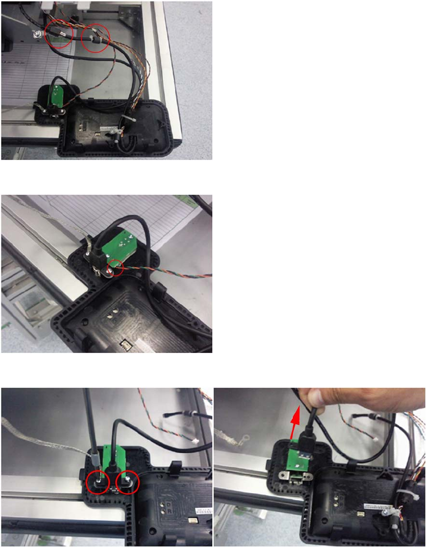
8. Remove the Touch Control Panel from the holder and disconnect the Touch Control Panel USB
and Data-Power cables
9. Disconnect the Power Button Cable .
10. Remove the two screws and remove the USB Host connector leaving the metal grounding gasket.
11. Remove the screw that fastens the USB Host cable.
230 Chapter 6 Removal and Installation ENWW
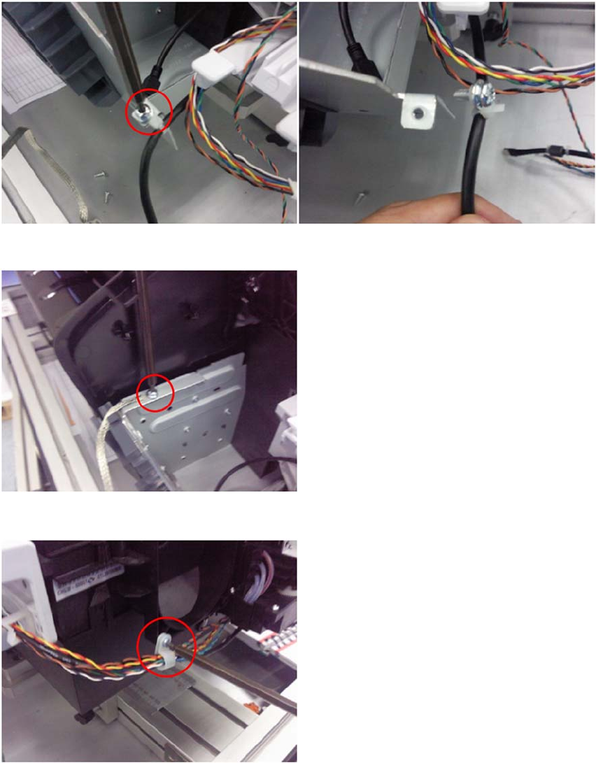
12. Remove the screw that holds the grounding cable.
13. Remove the screw from the clamp that secures the Touch Control Panel Power-Data cable.
14. Remove the USB, Power-Data and Power Button cables from the cable clamps
ENWW Interconnect Cables Kit 231

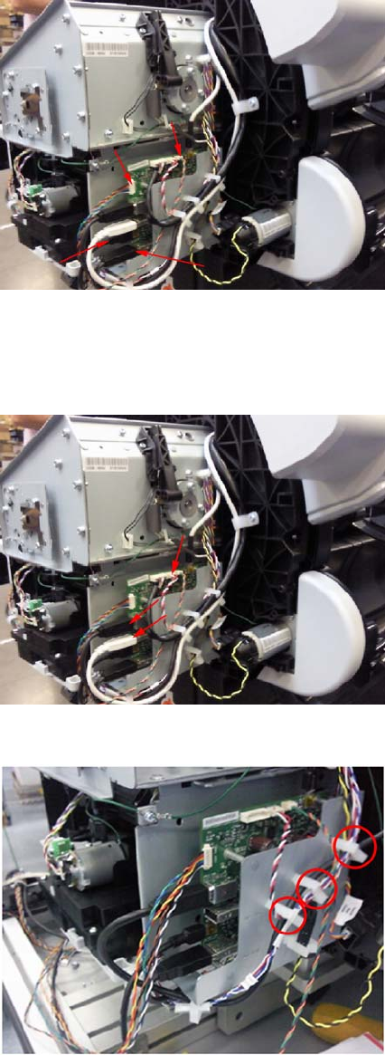
18. Disconnect from Interconnect Board the cables: Cable USB Interconnect to Ext Host, Cable USB
Interconnect to Touch Panel, Cable Power-Data Interconnect to Touch Panel, Cable Interconnect
to Power Switch.
Remove Engine to Interconnect Cables
1. Disconnect from the Interconnect Board the cables: Cable USB Engine to Interconnect, Cable
Micci2 Engine to Interconnect, and Cable Power Engine to Interconnect.
2. Remove the USB, Micci2 and Power cables from the clamps.
ENWW Interconnect Cables Kit 233
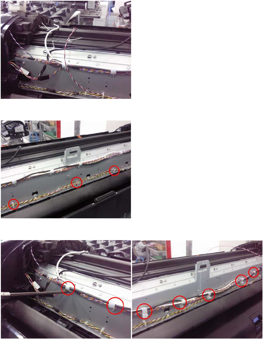
3. Pass the right side of USB, Micci2 and Power cables under the arcs.
4. Remove the 5 Power cable from the clamps all along the back of the chassis.
5. Remove the 5 screws that hold the clamps and remove the USB and Micci2 cables.
234 Chapter 6 Removal and Installation ENWW
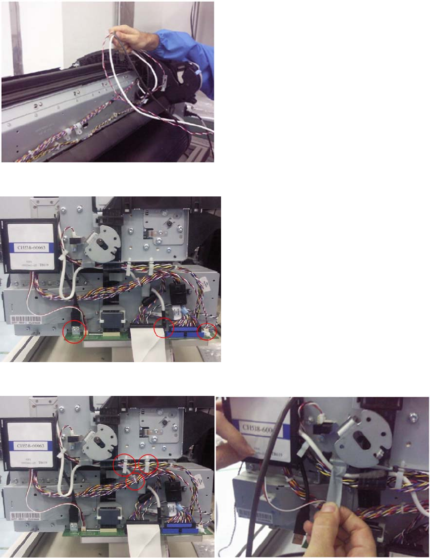
6. Pass the right side of the USB, Micci2 and Power Cables under the left arc.
7. Disconnect the USB, Micci2 and Power cables from the Engine PCA.
8. Remove the Micci2 and Power cables from the clamps; remove the taping that hold the cables.
ENWW Interconnect Cables Kit 235
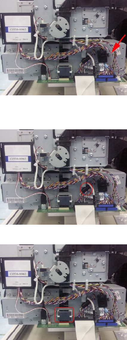
9. Remove the screw that fastens the ferrite on the Data Harness to the EE Box. (This ferrite is
included in the new Cables and Ferrites Kit; make sure to assemble and fasten the new ferrite it in
the same position.).
10. Unclip to open and remove the ferrite on the Engine Harness. Ensure to assemble back the Ferrite
on the Engine Harness holding the same group of cables and in the same position; this ferrite is
included in the new Cables and Ferrites Kit.
11. Remove the 2 screws, disconnect the Trailing Cable and remove the ferrite.
236 Chapter 6 Removal and Installation ENWW
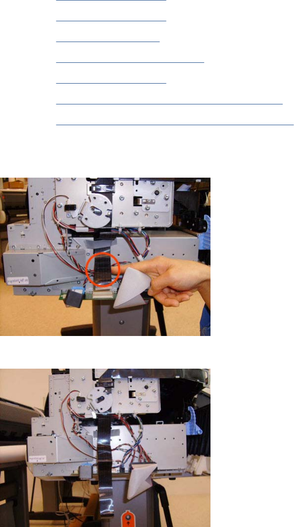
Carriage and Cutter Assembly
Removal
1. Switch off the product and remove the power cable.
2. Remove the Front Cover on page 275.
3. Remove the Right Cover on page 368.
4. Remove the Left Cover on page 317.
5. Remove the Touch Control Panel on page 428.
6. Remove the Front Cover on page 275.
7. Remove the Front Top Cover Assembly (MFP only) on page 276.
8. Remove the Encoder Strip, spring and attachment nut on page 288.
9. If necessary, manually move the Carriage Assembly fully right into the docking station.
10. Disconnect the ribbon cable of the Trailing Cables from the Electronics Module.
11. Unroute the Trailing Cables.
ENWW Carriage and Cutter Assembly 237
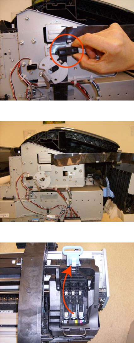
12. Unclip and remove the cable clamp of the Trailing Cables.
13. Remove 3 Cable Clamps, then unroute the Trailing Cables.
14. Open the Carriage Cover.
238 Chapter 6 Removal and Installation ENWW
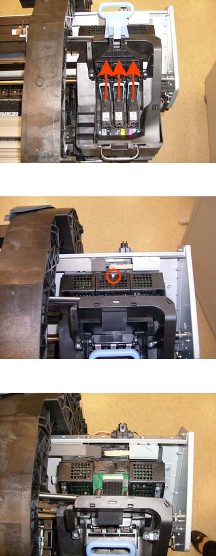
15. Remove all the Printheads.
16. Unscrew the small cover of the Carriage PCA.
17. Remove the small cover of the Carriage PCA.
ENWW Carriage and Cutter Assembly 239
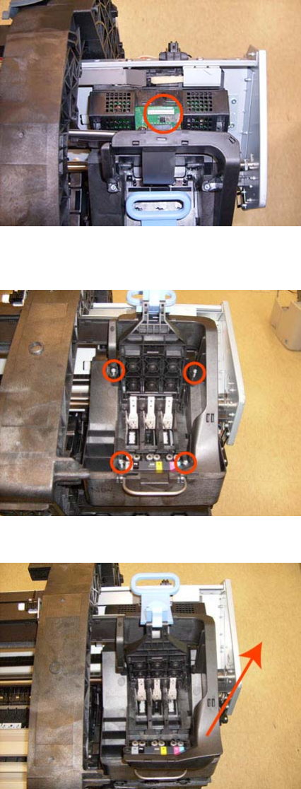
18. Disconnect the ribbon cable of the Trailing Cable from the Carriage PCA.
19. Open the latch, and remove the four T-15 screws that secure the Ink Supply Tubes to the Carriage
Assembly.
20. Carefully lift out the Ink Supply Tubes and close the carriage cover at the same time.
240 Chapter 6 Removal and Installation ENWW
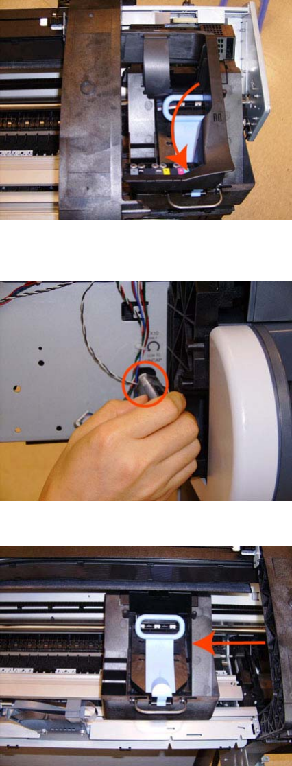
21. Close and lock the Carriage Cover.
22. Loosen the T-10 uncapping screw sufficiently so you can manually move the Carriage Assembly
in step 26.
23. Push the Carriage Assembly into the print path.
ENWW Carriage and Cutter Assembly 241
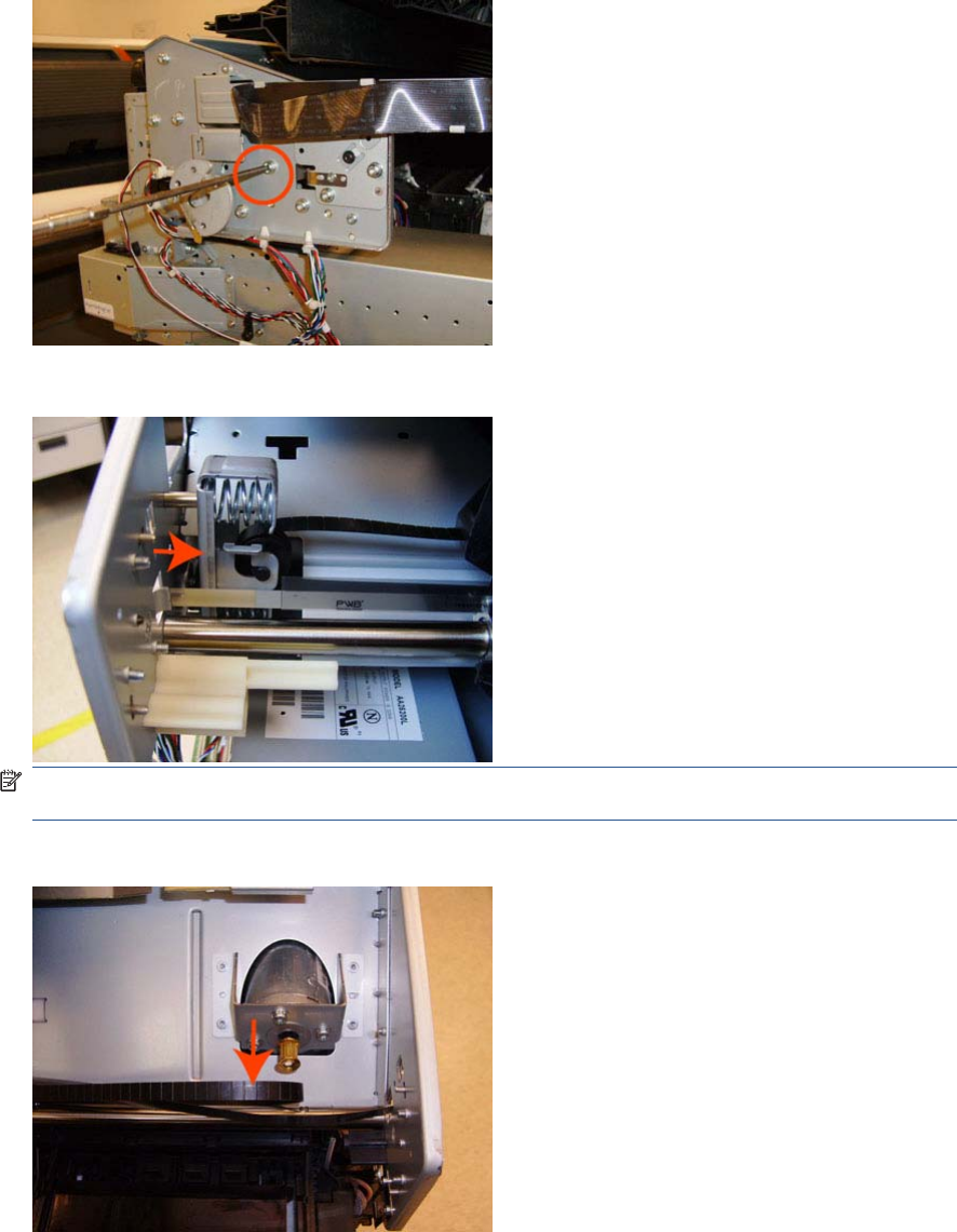
24. Loosen the T-15 screw Belt Tensioner to the product to remove the tension from the belt.
25. Leave the Belt Tensioner in place with all the tension removed.
NOTE: The photo shows the 44-in product, which has one spacer just above the red arrow. The
24-in product has two spacers.
26. Remove the Belt Assembly from the Scan-Axis Motor drive wheel.
242 Chapter 6 Removal and Installation ENWW
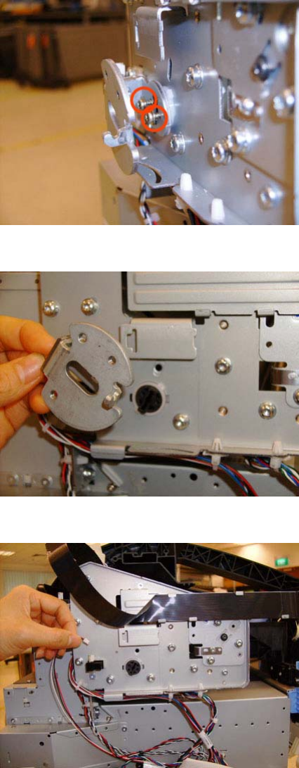
27. Remove the two T-10 screws that secure the Media Lever attachment plate.
28. Remove the Media Lever attachment plate.
29. Disconnect the Pinchwheel Lifter Sensor, and unroute the cable.
ENWW Carriage and Cutter Assembly 243
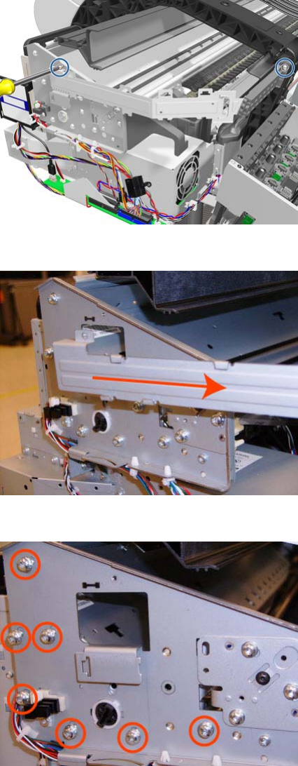
30. Remove two T-15 screws from the Trailing Cable Support.
31. Remove the Trailing Cable Support.
32. Remove the seven T-15 screws that secure the Scan Side Panel to the product.
244 Chapter 6 Removal and Installation ENWW
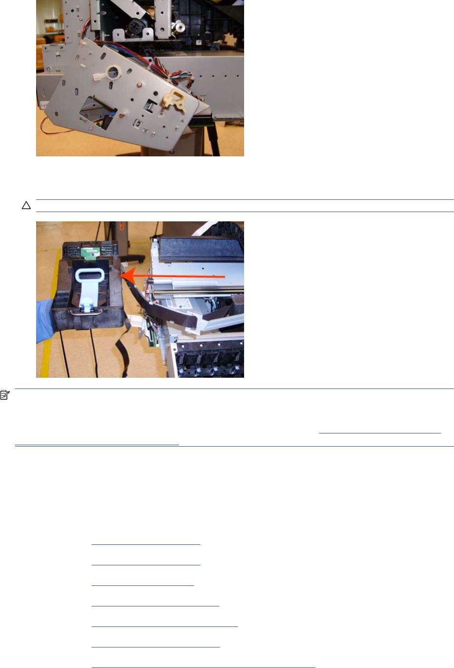
33. Remove the Scan Side Panel.
34. Carefully slide the Carriage Assembly and Belt Assembly out of the product (and the Trailing Cable
if you are removing it with the Carriage Assembly).
CAUTION: Be careful not to damage the PRS Slider.
NOTE: When you reinstall the Carriage Assembly, take care not to damage the PRS Slider.
NOTE: When you finish installing or replacing this component, you must perform the necessary
Service Calibrations. To find which calibrations you must perform, see Service Calibration Guide to
Removal and Installation on page 205.
Carriage Bushing, Rear
Removal
1. Switch off the product and remove the power cable.
2. Remove the Front Cover on page 275.
3. Remove the Right Cover on page 368.
4. Remove the Left Cover on page 317.
5. Remove the Cutter assembly on page 446.
6. Remove the Touch Control Panel on page 428.
7. Remove the Front Top Cover on page 278.
8. Remove the Front Top Cover Assembly (MFP only) on page 276.
ENWW Carriage Bushing, Rear 245
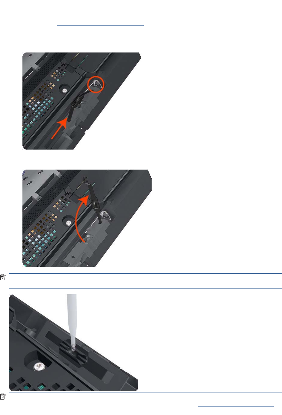
9. Remove the Scanner Position Sensor (MFP only) on page 413.
10. Remove the Encoder Strip, spring and attachment nut on page 288.
11. Remove the Carriage Assembly on page 184.
12. Squeeze the left hand clip of the Carriage Rear Bushing sufficiently to be able to release it from
the Carriage Assembly.
13. Rotate the Carriage Rear Bushing vertically and remove it from the Carriage Assembly.
NOTE: When you reinstall the Carriage Rear Bushing, use the Oil and Oil Dispenser from the
Lubrication Kit to add 2 or 3 drops of oil to the small depression in it.
NOTE: When you finish installing or replacing this component, you must perform the necessary
Service Calibrations. To find which calibrations you must perform, see Service Calibration Guide to
Removal and Installation on page 205.
246 Chapter 6 Removal and Installation ENWW


6. Remove the small cover of the Carriage PCA.
7. Disconnect the ribbon Trailing Cable from the Carriage PCA.
8. Remove the four T-15 screws that secure the Ink Supply Tubes to the Carriage Assembly.
248 Chapter 6 Removal and Installation ENWW

9. Carefully lift out the Ink Supply Tubes and close the carriage cover at the same time.
10. Close and lock the Carriage Cover.
11. Carefully move the Ink Supply Tubes into the print path.
ENWW Carriage Cover and Carriage Latch 249
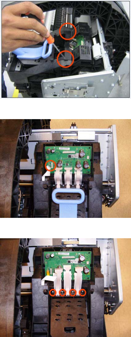
12. Remove the cover on each side of the Carriage PCA using a screwdriver to unclip it.
13. Disconnect the 6 ribbon cables of the Carriage Cover from the Carriage Assembly PCB.
14. Remove four T-8 screws that secure the Carriage Assembly Cover hinge.
250 Chapter 6 Removal and Installation ENWW
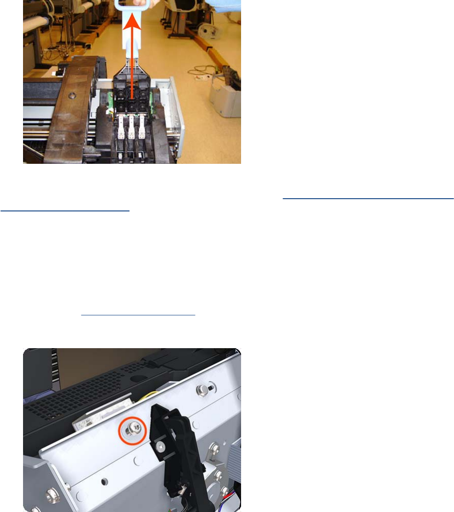
15. Carefully lift the Carriage Cover in the vertical position to remove it from the Carriage Assembly.
When you finish installing or replacing this component, you must perform the necessary Service
Calibrations. To find which calibrations you must perform, see Service Calibration Guide to Removal
and Installation on page 205.
Carriage Rail Oiler
Removal
1. Switch off the product and remove the power cable.
2. Remove the Right Cover on page 368.
3. Remove the T-20 Carriage Rail Oiler attachment screw.
ENWW Carriage Rail Oiler 251
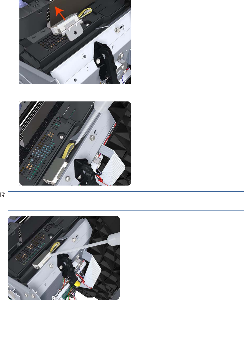
4. Remove the Carriage Rail Oiler from the product.
5. Add 2 or 3 drops of oil in the depression where the Slider fits.
NOTE: When you reinstall the Carriage Rail Oiler, use the Oil and Oil Dispenser from the Lubrication
Kit to add 2 or 3 drops of oil to the foam of the Carriage Rail Oiler and in the small depression of the
Carriage Rear Bushing.
Carriage PCA
Removal
1. Switch off the product and remove the power cable.
2. Remove the Right Cover on page 368.
252 Chapter 6 Removal and Installation ENWW
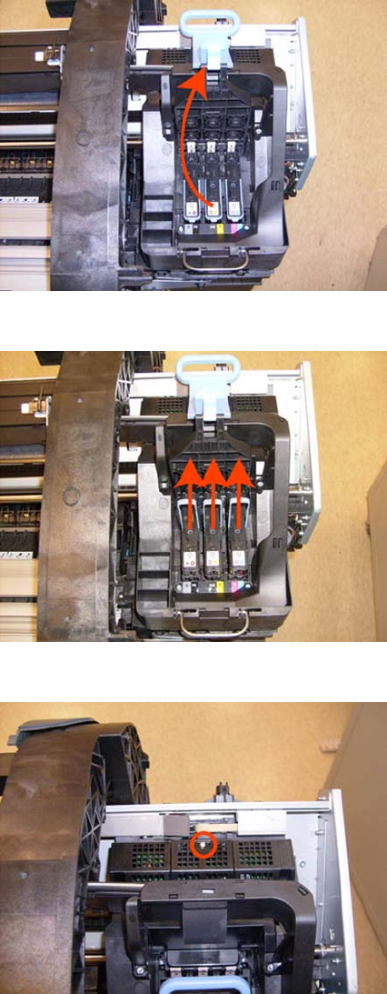
3. Open the Carriage Cover.
4. Remove all the Printheads.
5. Unscrew the small cover of the Carriage PCA.
ENWW Carriage PCA 253
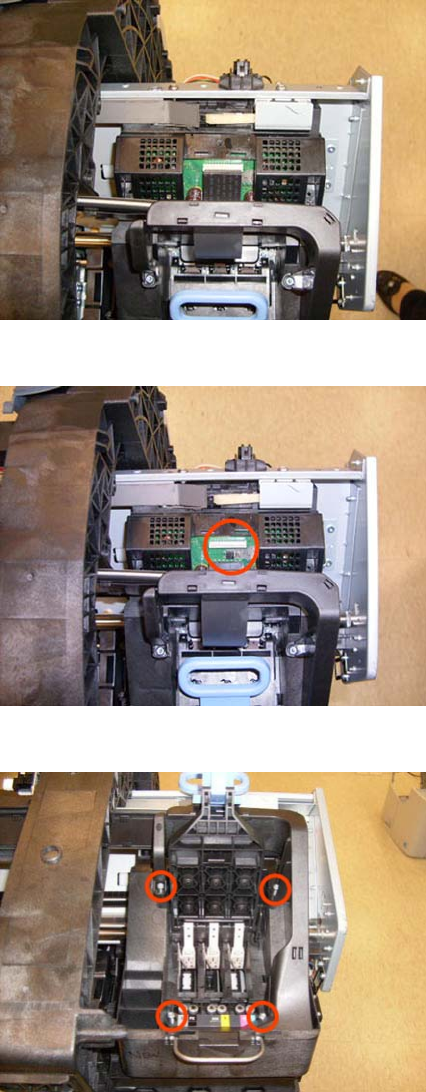
6. Remove the small cover of the Carriage PCA.
7. Disconnect the ribbon Trailing Cable from the Carriage PCA.
8. Remove the four T-15 screws that secure the Ink Supply Tubes to the Carriage Assembly.
254 Chapter 6 Removal and Installation ENWW
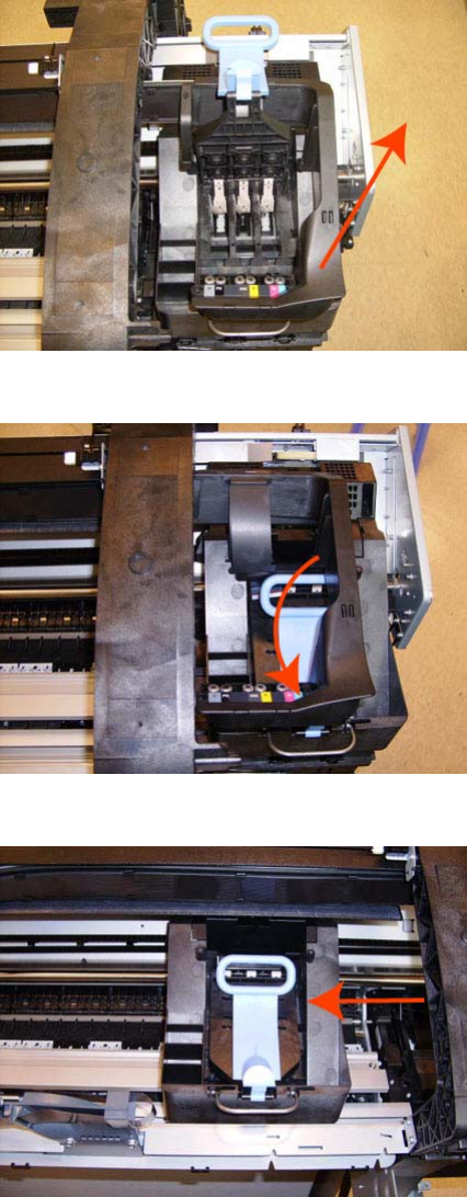
9. Carefully lift out the Ink Supply Tubes and close the carriage cover at the same time.
10. Close and lock the Carriage Cover.
11. Carefully move the Ink Supply Tubes into the print path.
ENWW Carriage PCA 255
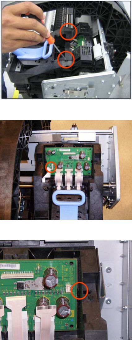
12. Remove the cover on each side of the Carriage PCA using a screwdriver unclip it.
13. Disconnect all cables from the Carriage Assembly PCB.
14. Press the locking clip to release the Carriage Assembly PCB from the carriage.
256 Chapter 6 Removal and Installation ENWW
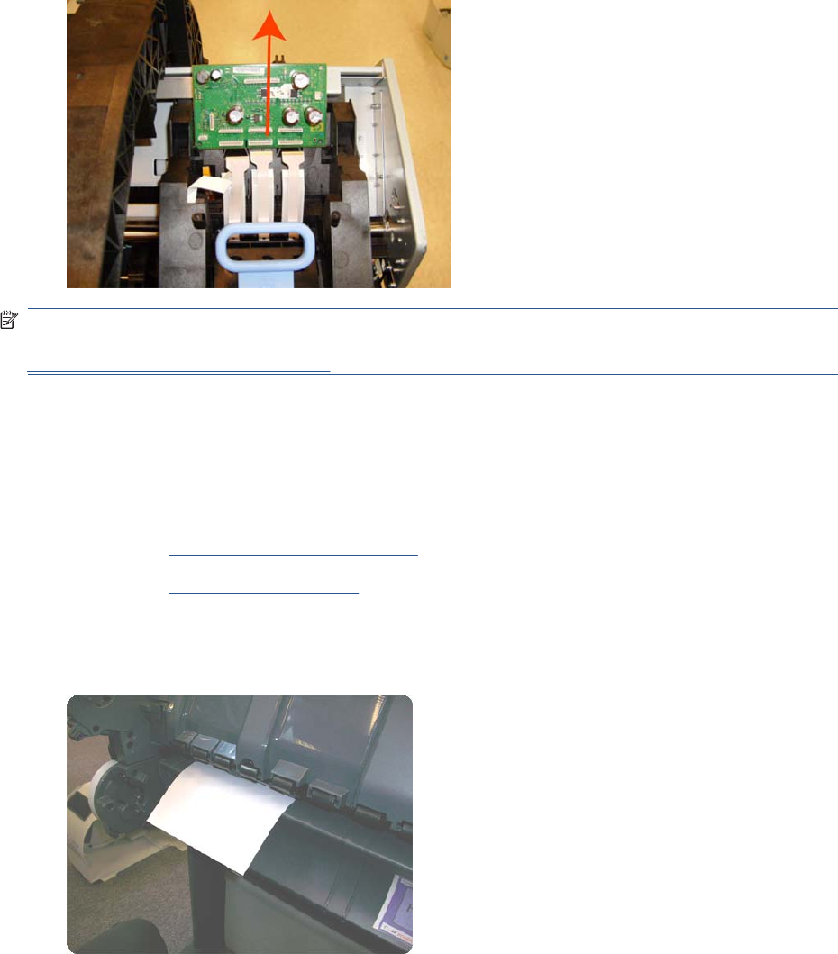
15. Remove the Carriage PCA from the carriage.
NOTE: When you finish installing or replacing this component, you must perform the necessary
Service Calibrations. To find which calibrations you must perform, see Service Calibration Guide to
Removal and Installation on page 205.
Cleanout
Removal
1. Switch off the product and remove the power cable.
2. Remove the Roll Cover, Lower on page 378.
3. Remove the Converger on page 261.
4. In order to avoid any damage to the paper sensor, you are recommended to introduce a sheet of
A4 bond paper into the paper path, as shown, so that the paper sensor flag will be down and out
of the way when you are handling the cleanout.
ENWW Cleanout 257
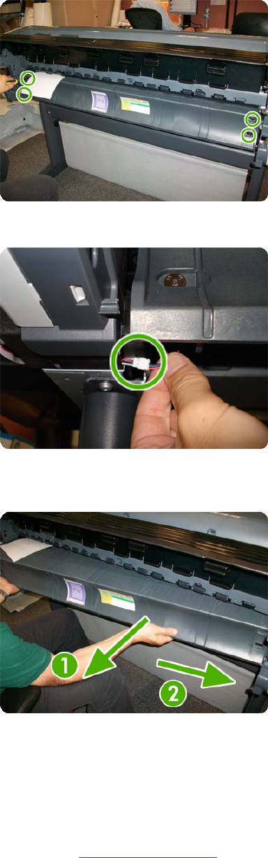
5. Unscrew four T-15 screws as shown.
6. Disconnect the paper sensor cable connector.
7. Extract the right side of the cleanout, as shown, and then the left side. Be careful with the paper
sensor cable.
Center Support
Removal
1. Switch off the product and remove the power cable.
2. Remove the Cleanout on page 257.
258 Chapter 6 Removal and Installation ENWW
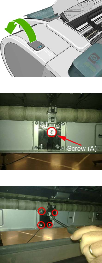
3. Lift up the blue lever on the left.
4. Remove one T-15 screw indicated (A). Do not loosen or remove the other screws
5. Do not remove the screws circled.
ENWW Center Support 259
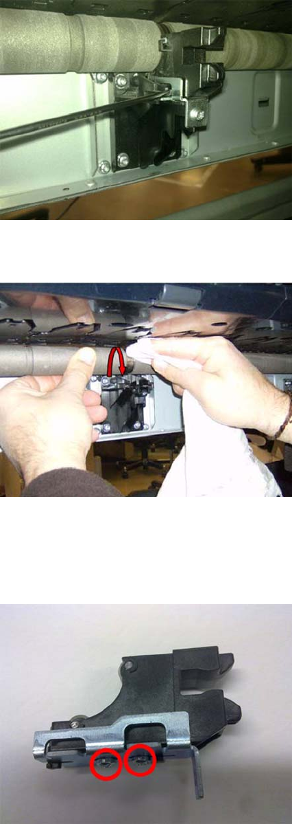
6. Remove the Slider Support. Use a flat end screw driver as a lever to remove the part.
7. Clean the roller at the center support section, you can push with a dust cloth, while moving the
center support from the print zone area and from the center support area.
8. Remove as much of the metallic particles from the roller as you can. Use a dust cloth.
Installation
1. The two screws indicated here must be loose before installing the part.
260 Chapter 6 Removal and Installation ENWW
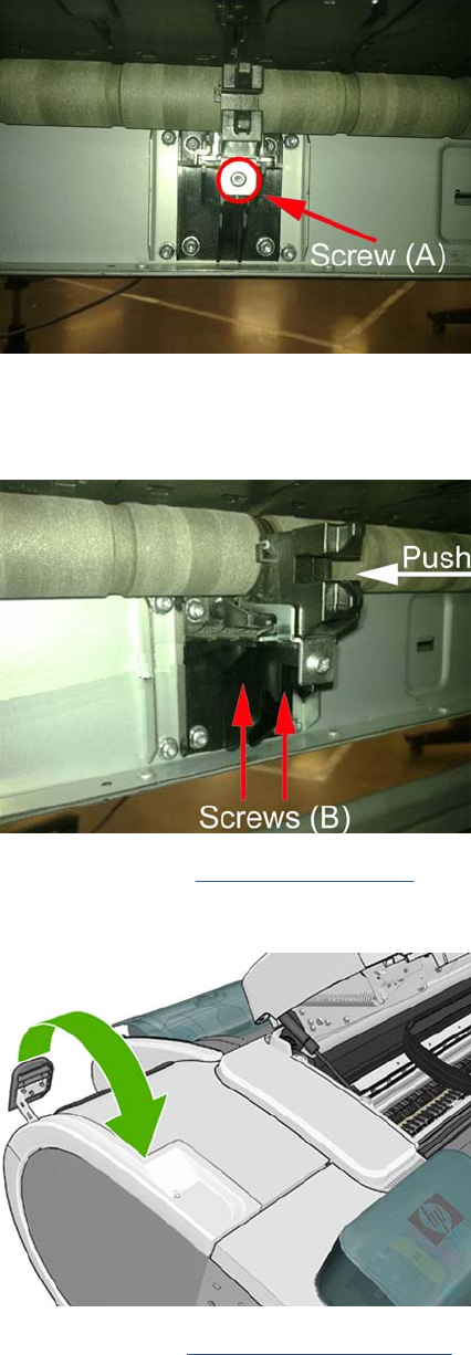
2. Insert the slider on to the center support and tighten the T–15 screw indicated (A).
3. Adjust the center support. While pushing the plastic part of the slider center support against the
roller (A), tighten loose screws B. To tighten the screws, insert the screw driver from below, in the
direction indicated by the arrows
4. Install the Cleanout Cleanout on page 257
5. Move down the blue lever on the left.
6. Perform the (PAX) Scan Axis Test on page 81.
Converger
Switch off the product and remove the power cable.
ENWW Converger 261
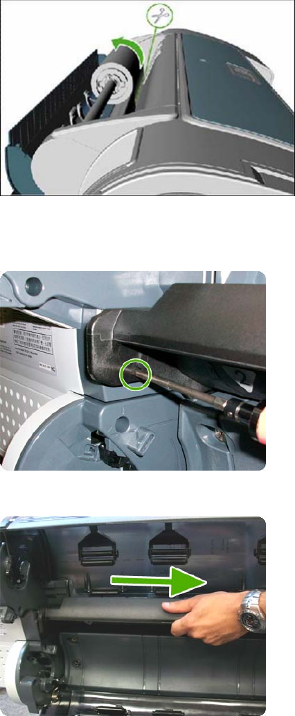
Removal
1. Open the upper roll cover and rewind the upper roll.
2. Remove the upper roll and spindle and close the upper roll cover.
3. Rewind and remove the lower roll in the same way.
4. Remove the screw on the left side of the converger at the rear of the product.
5. Move the converger slightly in the direction of the arrow.
262 Chapter 6 Removal and Installation ENWW
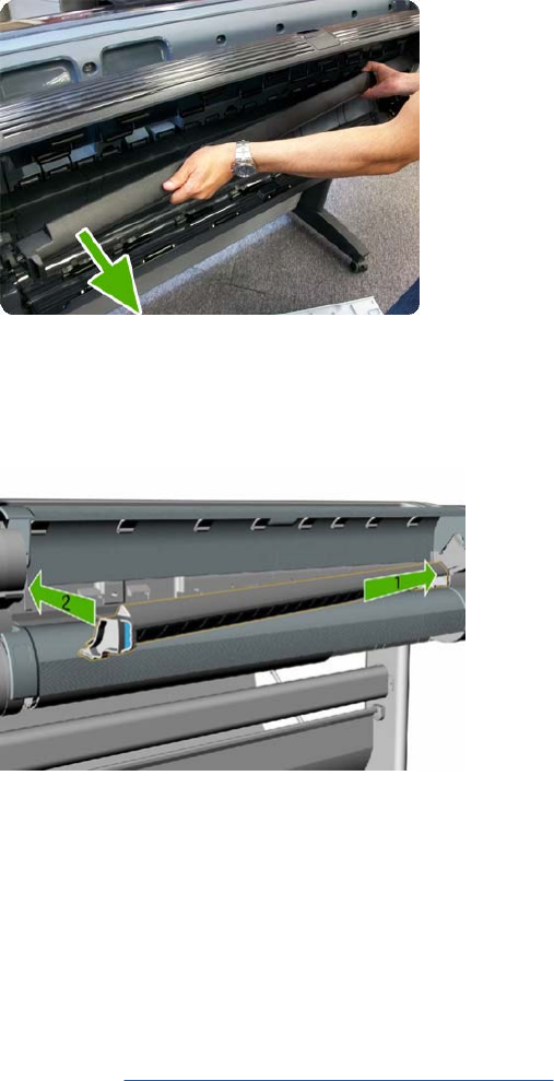
6. Move the right side of the converger in the direction of the arrow, then remove the whole converger
from the product.
Installation
1. Replace the converger by inserting the right end into position first, and then pushing the handle
into place.
2. Replace the screw.
3. Replace and reload the rolls of paper.
4. Close the covers.
Scanner Piston Gas (MFP only)
1. Switch off the product and remove the power cable.
2. Remove the Left Scanner Cover (MFP only) on page 321
ENWW Scanner Piston Gas (MFP only) 263
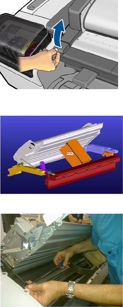
3. Open the Scanner.
4. Remove the material from the packaging box and place it as in the picture, the scanner will rest on
this box while the piston is being replaced.
5. Remove screw and straight bushing.
264 Chapter 6 Removal and Installation ENWW
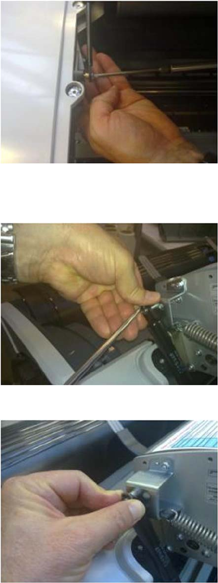
6. Make sure the bushing and screw do not fall into the product's cavity by placing your hand
underneath as you remove it. Reuse the screw later.
7. Remove the circilp on the other end of the piston gas using a flat screw driver, ensure that the
circilp is kept under control by holding it with your left hand as shown in the picture. There are two
spare circilps provided in the kit.
8. Install the circlip securing the new Piston in place as shown
ENWW Scanner Piston Gas (MFP only) 265
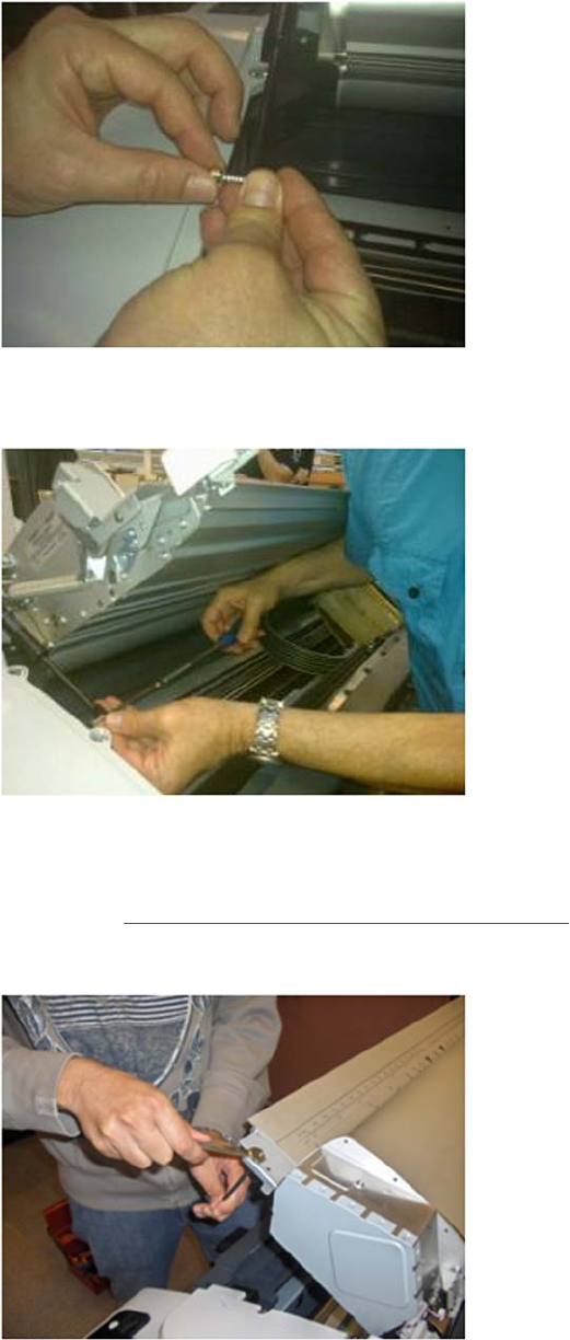
9. Assemble back the straight bushing and screw as shown in the picture.
10. While screwing back the screw make sure that the weight of the scanner is handled by the installer
to align the screw and the hole.
Scanner Bumper (MFP only)
1. Remove the Right Scanner Cover (MFP only) on page 372
2. Remove the hexagonal nut from the stopper with a 10 mm wrench key and a 8 mm wrench
266 Chapter 6 Removal and Installation ENWW
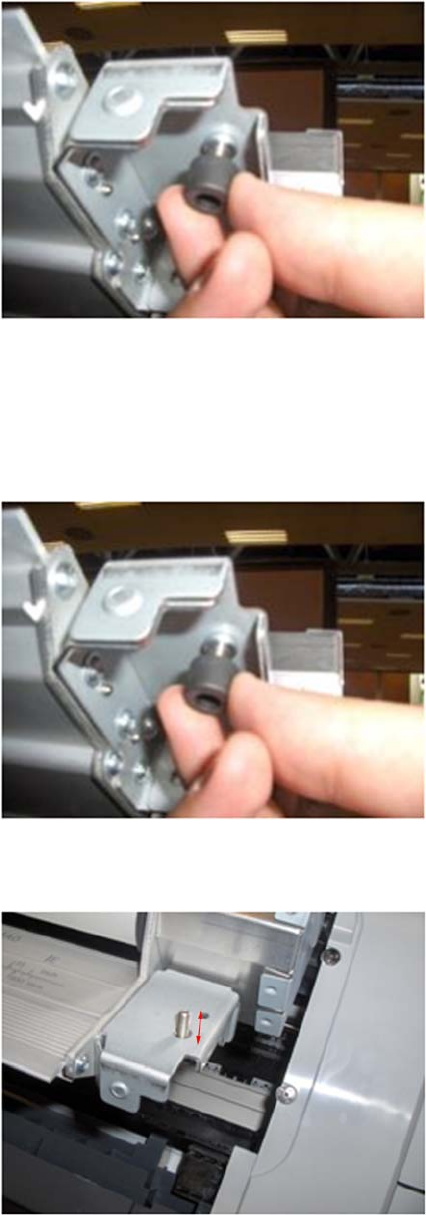
3. Remove the Scanner Bumper by unscrewing it from the metal bracket in a counterclockwise
direction.
Installation
The installation of the Scanner Bumper requires a small adjustment (included in the installation
procedure) so that the paper is held by the part.
1. Insert the new bumper screw into the bracket and turn in a clockwise direction.
2. Continue to turn the bumper screw into the bracket until approximately 1 cm emerges from the
other side of the bracket.
ENWW Scanner Bumper (MFP only) 267
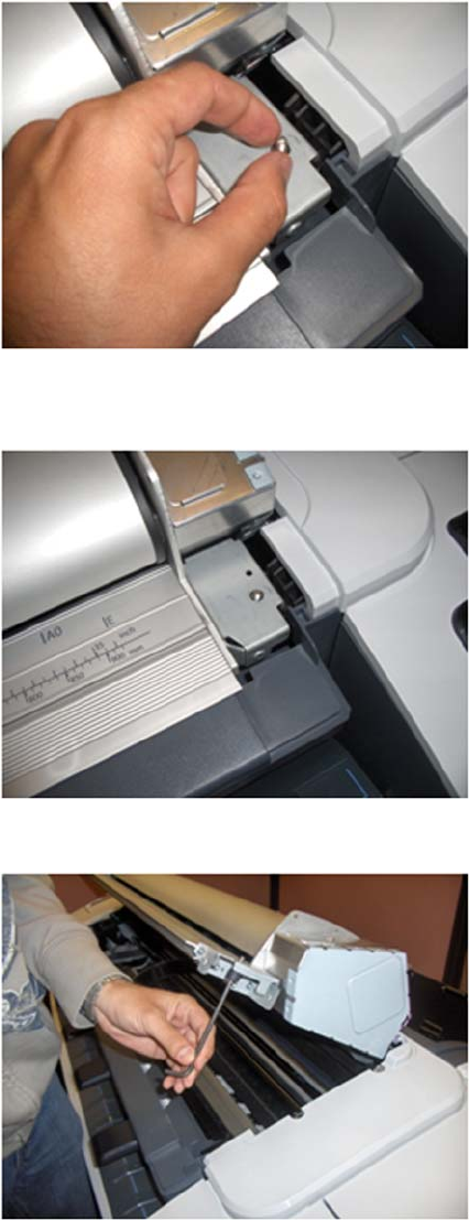
3. Turn the tip of the screw in an anti-clockwise direction.
4. Continue to turn the tip of the screw in an anti-clockwise direction until the tip of the screw is level
with the surface (until it is flush).
5. To adjust the bumper insert an allen key #10 into the screw as shown.
268 Chapter 6 Removal and Installation ENWW
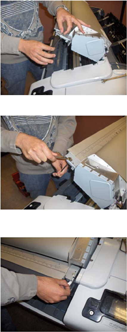
6. Hold the nut so that it does not turn as you make the adjustment. Turn the allen key one revolution.
7. While securing the screw with a 10 mm wrench key, use an 8 mm wrench to tighten the nut.
8. In order to check if the adjustment is correct, place a strip of paper as shown in the picture, on the
flat surface of the right interface bracket and close the scanner .
ENWW Scanner Bumper (MFP only) 269
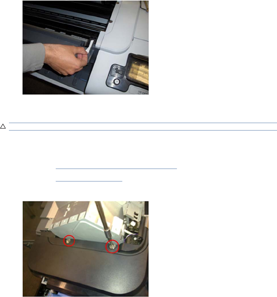
9. If the bumper is correctly adjusted it should hold the paper.
Right Collar Cover (MFP only)
CAUTION: When removing the Right Collar Cover be careful not to damage sensor actuator.
Removal
1. Switch off the product and remove the power cable.
2. Remove the Right Scanner Cover (MFP only) on page 372
3. Remove the Right Cover on page 368.
4. Remove two T-15 screws that secure the Right Collar Cover to the product.
270 Chapter 6 Removal and Installation ENWW
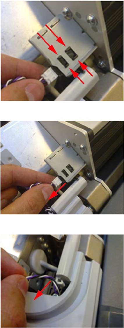
5. Remove the Scanner Position Sensor from the holder, unclip it by pushing the retaining clips in the
direction shown.
6. Remove the sensor
7. Remove sensor cable from Right Collar Cover anchor feature
ENWW Right Collar Cover (MFP only) 271
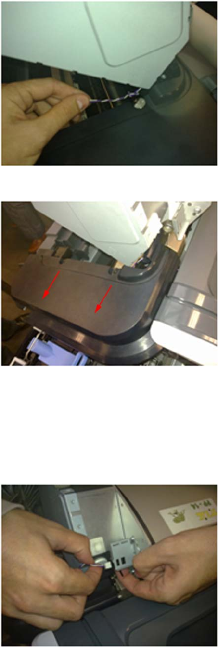
8. Leave the sensor to one side to remove the collar
9. Remove the collar by sliding it in the direction indicated
Installation
Installing the Right Collar is the same as the removal procedure, however care must be taken with the
Cable and Sensor of the Scanner Position sensor. Shown below is the procedure for correctly reinstalling
this part.
1. With the Scanner open, reinstall the Scanner Position sensor onto the holder by pushing the sensor
assembly from the back.
2. Close the Scanner.
272 Chapter 6 Removal and Installation ENWW
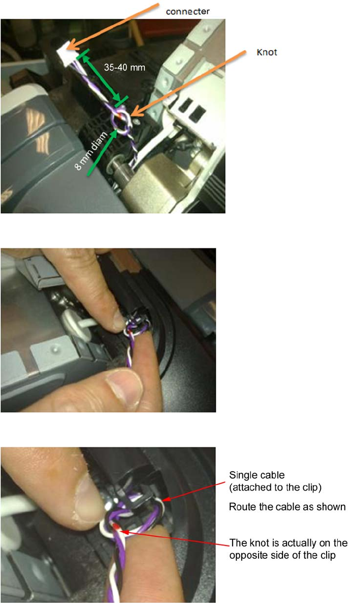
3. Ensure that cable of Scanner Position cable is as shown below.
4. Anchor the knot of the cable on to the small clip of the Right Collar.
5. Ensure the knot of the cable is correctly placed on the clip as shown here.
ENWW Right Collar Cover (MFP only) 273
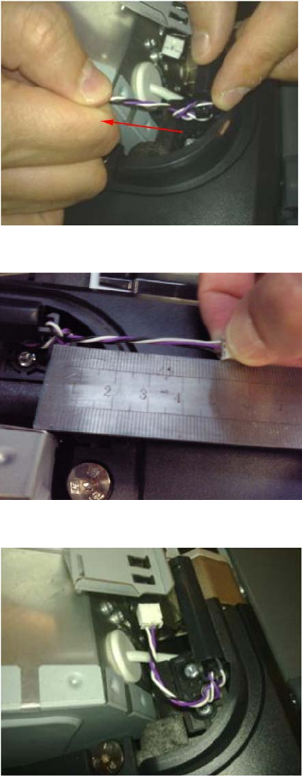
6. Once in the clip of the collar, pull slightly from the white connector in the direction of the arrow until
the knot is fully attached.
7. Make sure that the cable length is now 50-55 mm long from the knot to the connector.
8. Connect the cable.
274 Chapter 6 Removal and Installation ENWW
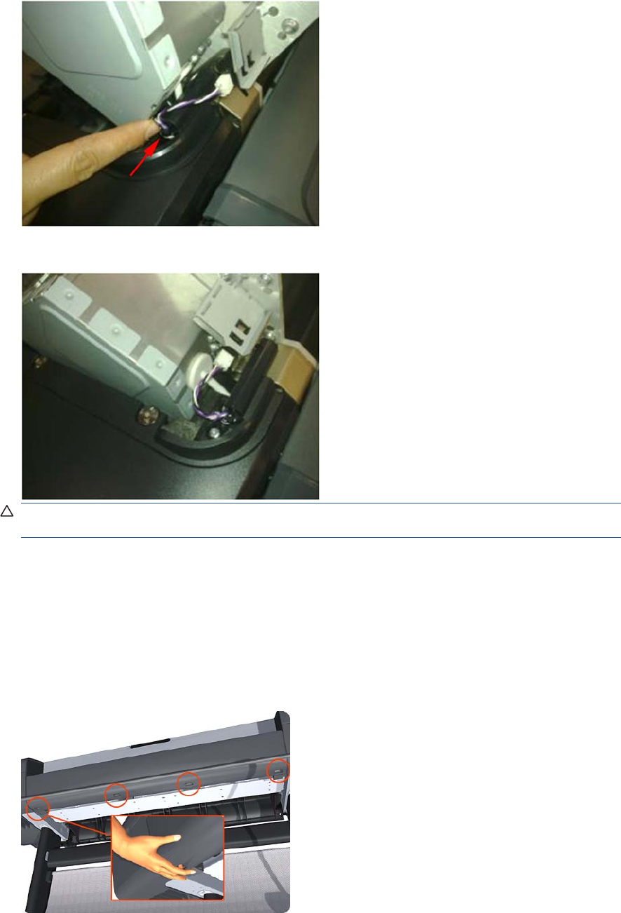
9. Push the knot of the cable in the direction of the arrow (if needed) .
10. Make sure that the cable is long enough when the scanner is in open position
CAUTION: If the cable of the Scanner Position Sensor is too long it may be become trapped
between the Right Scanner Cover and the Right Collar
Front Cover
Removal
1. Switch off the product and remove the power cable.
2. Squeeze each of the four attachment clips under the Front Cover, to release the cover from the
product.
ENWW Front Cover 275
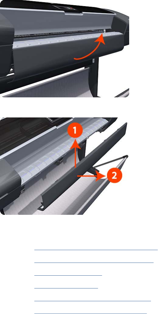
3. Carefully pull the bottom of the Front Cover forwards until you can release it from its attachments.
4. Unhook the Front Cover from the four attachments and remove it from the product.
Front Top Cover Assembly (MFP only)
1. Remove the Right Scanner Cover (MFP only) on page 372
2. Remove the Left Scanner Cover (MFP only) on page 321
3. Remove the Right Cover on page 368
4. Remove the Left Cover on page 317
5. Remove the Right Collar Cover (MFP only) on page 270
6. Remove the Left Collar Cover (MFP only) on page 316
276 Chapter 6 Removal and Installation ENWW
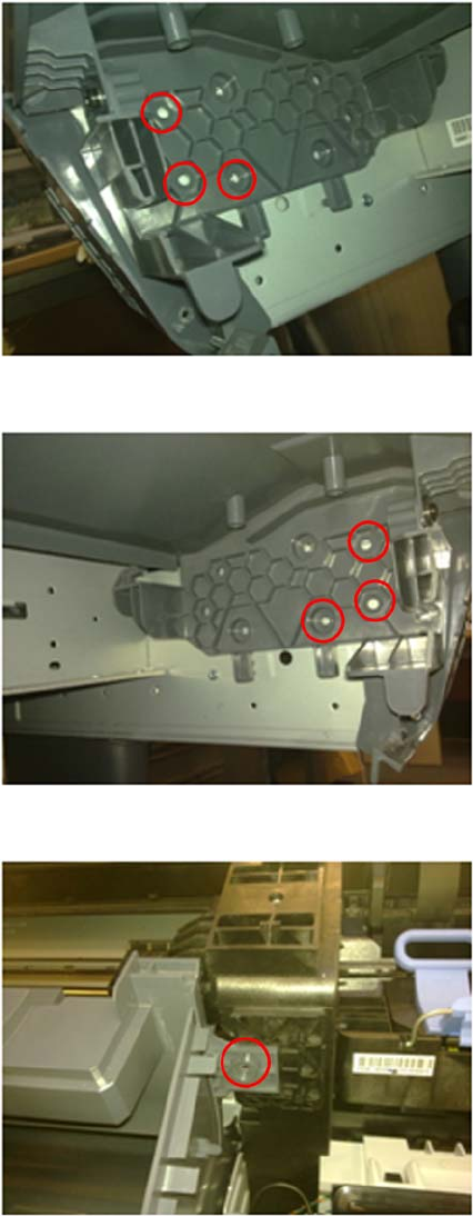
7. Remove three screws from the Left Ink Trim (no need to remove the Left Ink Trim).
8. Remove three screws from the Right Ink Trim (no need to remove the Right Ink Trim).
9. Remove one T-15 screw that secures the Front Top cover to the right arc.
ENWW Front Top Cover Assembly (MFP only) 277
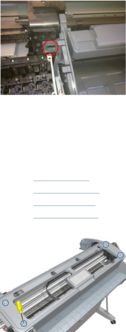
10. Remove one T-15 screw that secures the Front Top cover to the left arc.
11. Lift up the Front Top Cover by adjusting the trims.
Front Top Cover
Removal
1. Switch off the printer and remove the power cable.
2. Remove the Window on page 431.
3. Remove the Right Cover on page 368.
4. Remove the Left Cover on page 317.
5. Remove the Rear Cover on page 366.
6. Remove the four T-15 top screws that secure the Top Cover to the printer.
278 Chapter 6 Removal and Installation ENWW
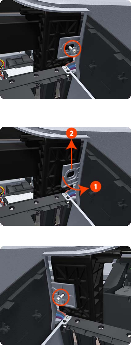
7. Remove the front T-15 screw that secures the front left side of the Top Cover to the printer.
8. Carefully pull the attachment clip forward until you can lift the bottom left corner of the Top Cover
approximately 10 mm.
9. Remove the front T-15 screw that secures the front left side of the Top Cover to the printer.
ENWW Front Top Cover 279
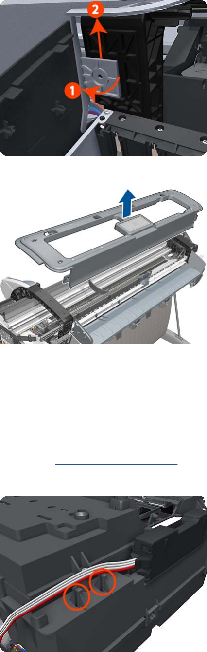
10. Carefully pull the attachment clip forward until you can lift the bottom left corner of the Top Cover
approximately 10 mm.
11. Lift the Top Cover of the printer sufficiently to gain access to the Touch Control Panel ribbon cable.
Drop Detector
Removal
1. Switch off the product and remove the power cable.
2. Remove the Right Cover on page 368.
3. Remove the Service Station on page 396.
4. Unroute the Drop Detector ribbon cable from the Service Station cable clamps.
280 Chapter 6 Removal and Installation ENWW
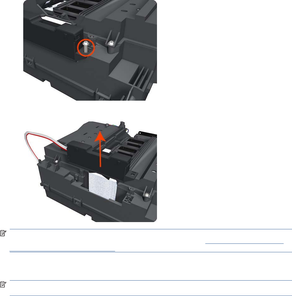
5. Remove the T-10 screw that secures the Drop Detector to the Service Station.
6. Lift the Drop Detector off the Service Station.
NOTE: When you finish installing or replacing this component, you must perform the necessary
Service Calibrations. To find which calibrations you must perform, see Service Calibration Guide to
Removal and Installation on page 205.
EE Box
NOTE: The installation section of this procedure contains an important note that is critical to the correct
installation/reinstallation of this part.
Removal
1. Switch off the product and remove the power cable.
ENWW EE Box 281

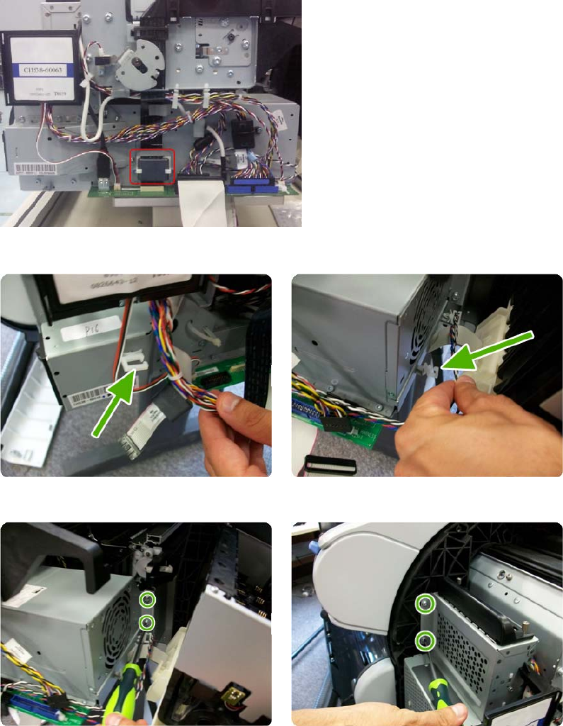
5. Remove the Ferrite from the Trailing Cable without removing its plastic holder that is fastened to
the EE Box.
6. Unclip the cables from the cable ties.
7. Remove the four screws shown in the pictures..
ENWW EE Box 283
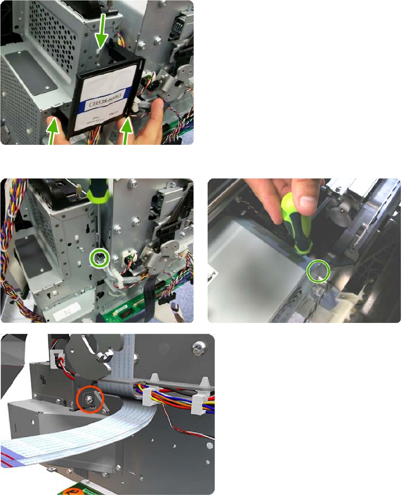
8. Remove the RFID support.
9. Remove the three screws shown in the pictures
284 Chapter 6 Removal and Installation ENWW
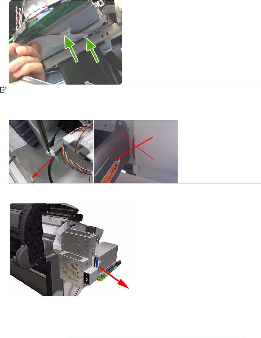
10. Unclip the ISS cable from the cable ties.
NOTE: When reinstalling/installing the USB Ext Host cable, you must leave the cable tightened
behind the Service Station using the cable tie. Put the tie in position and pull from the cable to the
front so that the cable goes straight to the other end. This is to prevent the cable from being trapped
when installing the Right Cover.
11. Carefully remove the EE Box out of the product.
Installation
▲When installing/reinstalling the EE Box make sure the Data Harness and ISS Harness Cable are
connected correctly into the Engine PCA. These two connectors can be swapped in error causing
a SE 22.1:10. Refer to Connecting the Data Harness and ISS Harness Cable on page 227
ENWW EE Box 285
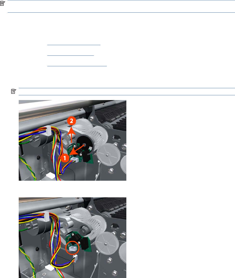
Encoder Disk and Encoder Sensor
NOTE: Never install a previously used Encoder Sensor PCA. This can cause serious problems, and
may make the product unusable.
Removal
1. Switch off the product and remove the power cable.
2. Remove the Left Cover on page 317.
3. Remove the EE Box on page 281.
4. Remove the Spittoon, Left on page 403.
5. Remove the Encoder Disk from the Media Advance Roller spindle, and lift it straight out of the
product.
NOTE: The Media Advance Roller spindle is delicate. Remove the Encoder Disk gently.
6. Disconnect the two Encoder Sensor connectors.
286 Chapter 6 Removal and Installation ENWW
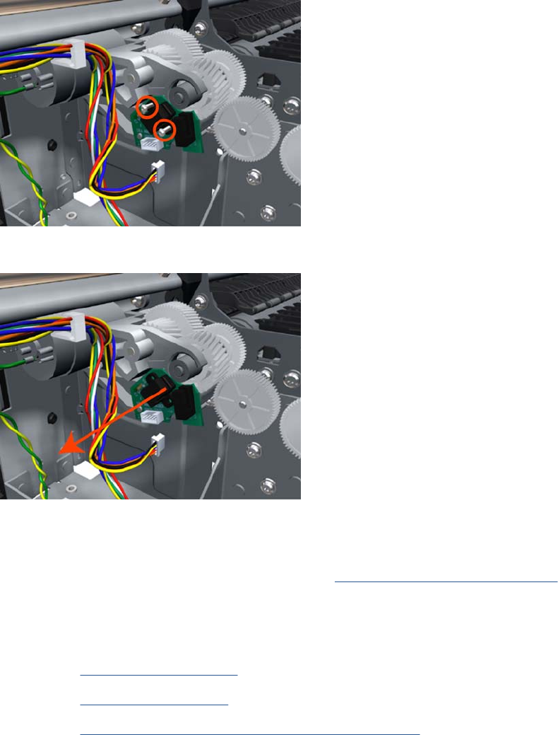
7. Remove two T-6 screws that secure the Encoder Sensor to the Media Advance Drive.
8. Remove the Encoder Sensor PCA from the product.
Encoder Strip
For information about the Encoder Strip service parts, see Scan-Axis Assemblies on page 185.
Removal
1. Switch off the product and remove the power cable.
2. Remove the Right Cover on page 368.
3. Remove the Left Cover on page 317.
4. Remove the Encoder Strip, spring and attachment nut on page 288.
ENWW Encoder Strip 287
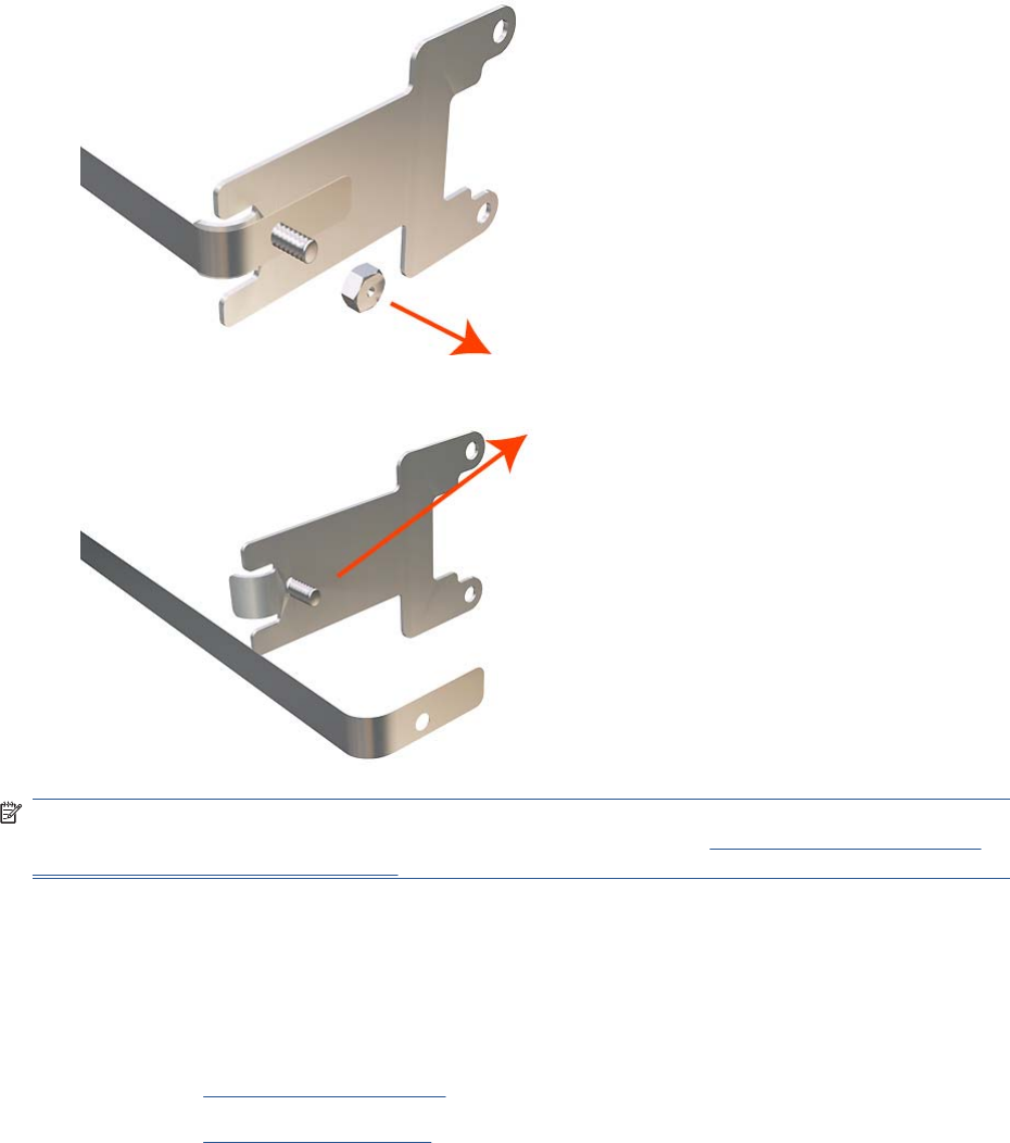
5. Use the spanner provided in the tool kit to remove the 13 mm locking nut that secures the Encoder
Strip to the Encoder Strip Spring.
6. Remove the Encoder Strip Spring.
NOTE: When you finish installing or replacing this component, you must perform the necessary
Service Calibrations. To find which calibrations you must perform, see Service Calibration Guide to
Removal and Installation on page 205.
Encoder Strip, spring and attachment nut
Removal
1. Switch off the product and remove the power cable.
2. Remove the Right Cover on page 368.
3. Remove the Left Cover on page 317.
288 Chapter 6 Removal and Installation ENWW
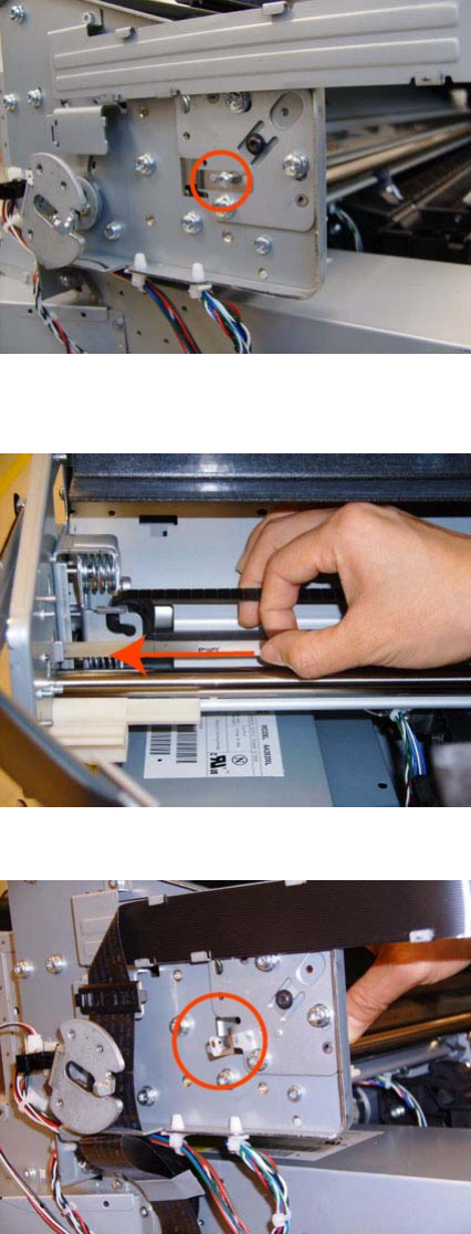
4. Remove the T-10 screw that secures Encoder Strip to the product.
5. Grip the Encoder Strip and move it towards the left to take off the tension until you have completed
the next step.
6. Unclip the Encoder Strip from its attachment lugs.
ENWW Encoder Strip, spring and attachment nut 289
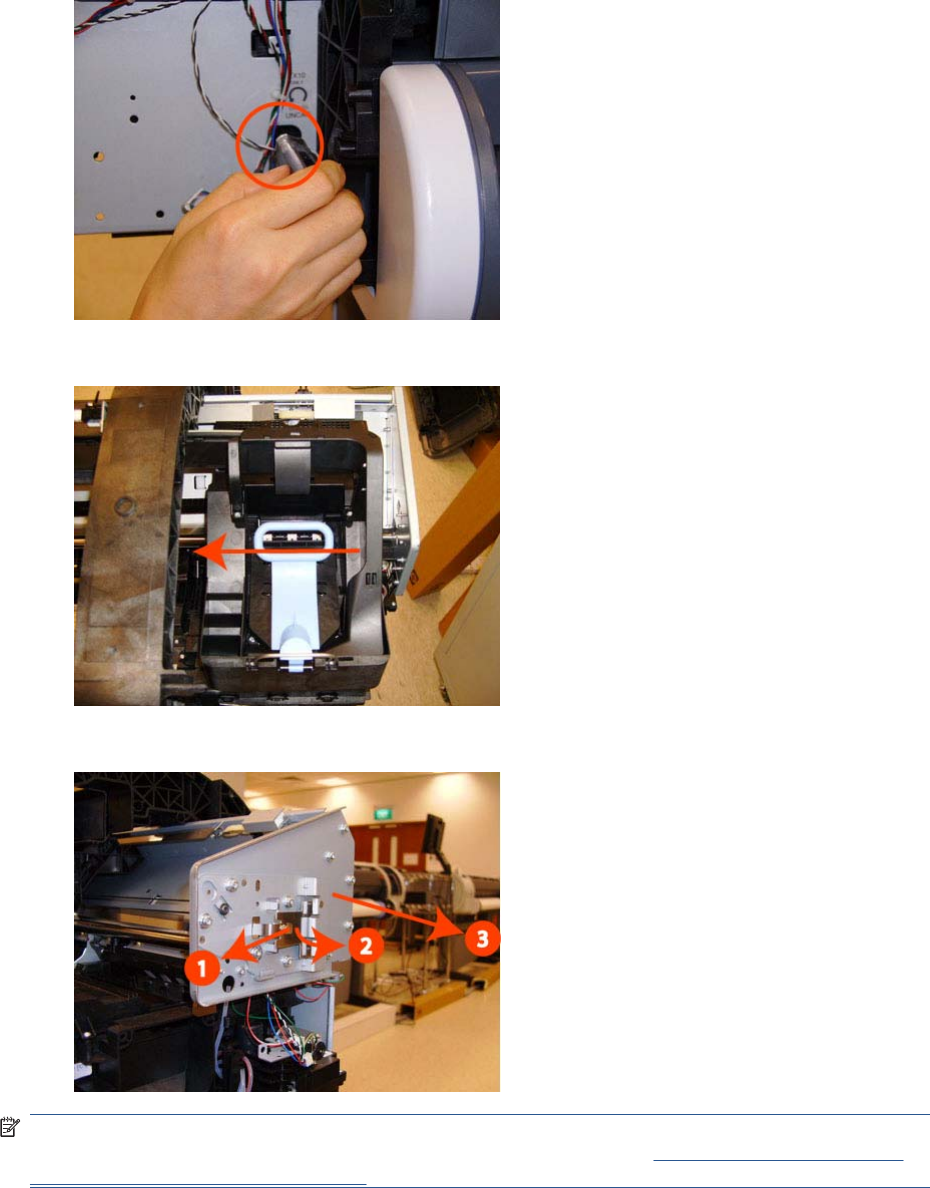
7. Loosen the T-10 uncapping screw sufficiently so you can manually move the Carriage Assembly
in the next step.
8. Push the Carriage Assembly into the print path.
9. Unclip the Encoder Strip tensioner from the right hand end and pull the encoder strip straight out.
NOTE: When you finish installing or replacing this component, you must perform the necessary
Service Calibrations. To find which calibrations you must perform, see Service Calibration Guide to
Removal and Installation on page 205.
Formatter
Removal
1. Turn off the product and remove the power cable.
290 Chapter 6 Removal and Installation ENWW
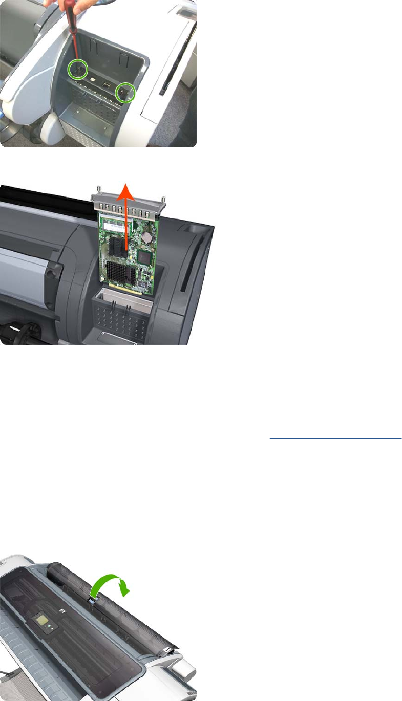
2. Fully loosen the two locking thumbscrews that secure the Formatter in the product.
3. Lift the Formatter out of the product.
Installation
1. When you install a new Formatter, follow the instructions provided on the flier that accompanies it
to set up the product.
2. If you try to install a Hard Disk Drive that was previously used in a different product, the product
displays a System Error and will not start successfully. See Hard Disk Drive on page 295.
Freewheel Assembly
These parts can be replaced by customers who have the appropriate flier.
Removal and installation
1. Open the roll cover.
ENWW Freewheel Assembly 291
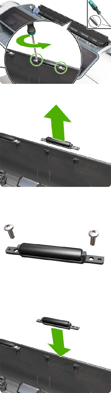
2. Unscrew the freewheel assembly.
3. Remove the freewheel assembly.
4. Locate the new freewheel assembly and screws.
5. Fit the freewheel assembly to the roll cover.
292 Chapter 6 Removal and Installation ENWW
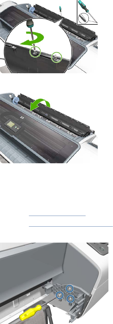
6. Screw the freewheel assembly to the roll cover.
7. Close the roll cover.
Right Front Trim
Removal
1. Switch off the product and remove the power cable.
2. Remove the Front Cover on page 275.
3. Remove the Media Output Assembly on page 340.
4. Remove the three T-20 screws that secure the Right Front Trim to the product.
ENWW Right Front Trim 293
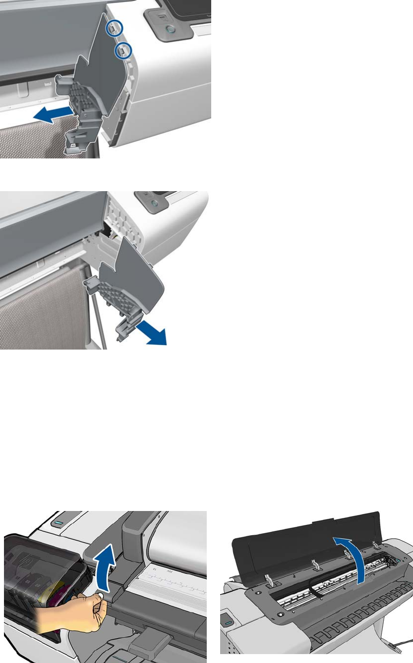
5. Unclip the Right Front Trim and pull it away from the printer.
6. Remove Right Front Trim from the product.
Full Bleed Foam
Removal
The complete Full Bleed Foam is constructed of three separate sections, left, center and right. This
procedure describes how to remove the left section only. Removal of the other two sections is done in
the same way.
1. Switch off the product and remove the power cable.
2. Open the Scanner (MFP only) or Window.
294 Chapter 6 Removal and Installation ENWW
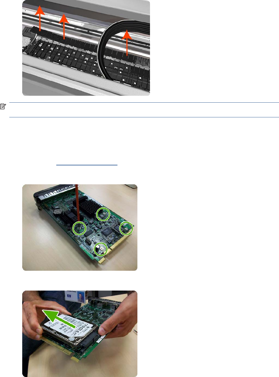
3. Remove the Left Full Bleed Foam from the left platen, and remove the Platen Middle Foams that
are exposed once the Full Bleed Foam has been removed.
NOTE: When you reinstall the full bleed foams, take care to correctly seat them to avoid possible
damage to the Carriage Assembly
Hard Disk Drive
Removal and installation
1. Remove the Formatter on page 290.
2. Unscrew four screws in the formatter.
3. Remove the hard disk drive from the formatter by applying force in the direction of the arrow.
ENWW Hard Disk Drive 295
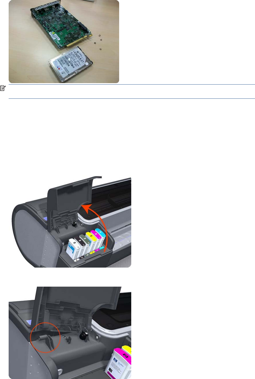
4. Insert a new hard disk drive.
NOTE: If you try to insert a previously used hard disk drive, the product displays a System Error
and will not start successfully.
5. Replace all screws that you removed earlier.
Left Ink Cartridge Door
Removal
1. Switch off the product and remove the power cable.
2. Open the Left Ink Cartridge Door.
3. Unclip the left side of the Left Ink Cartridge Door.
296 Chapter 6 Removal and Installation ENWW
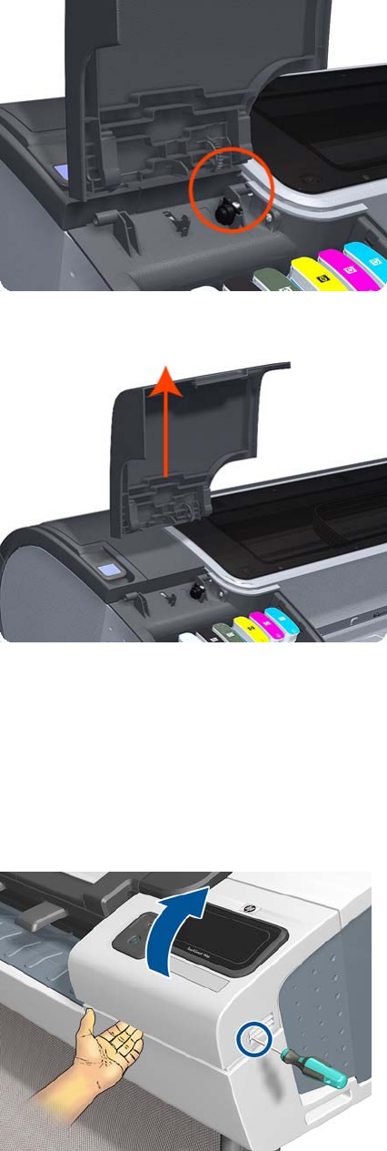
4. Unclip the right side of the Left Ink Cartridge Door.
5. Remove the Left Ink Cartridge Door.
Right Ink Cartridge Door
Removal
1. Switch off the product and remove the power cable.
2. Open the Right Ink Cartridge Door by inserting a screwdriver into the side to unlatch it, and then
lift up the door.
ENWW Right Ink Cartridge Door 297
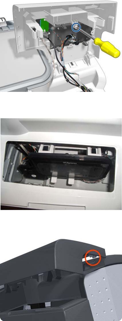
3. Remove one T-15 screw from the right ink door.
4. Pass the Touch Control Panel through the window of the ink door and place it on the features as
shown in the picture.
5. Slide up the Right Ink Cartridge Door to remove.
298 Chapter 6 Removal and Installation ENWW
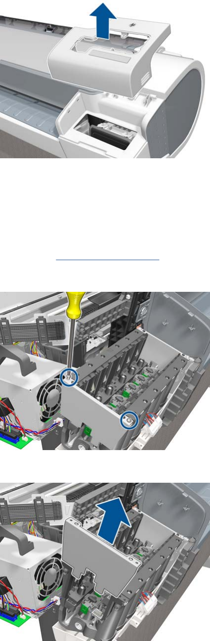
6. Remove the Right Ink Cartridge Door.
Left Ink Supply Station
Removal
1. Switch off the product and remove the power cable.
2. Remove the Left Cover on page 317.
3. Remove two T-10 screws that secure the Left Side Plate of the Left Ink Supply Station.
4. Remove the Left Side Plates of the Left Ink Supply Station.
ENWW Left Ink Supply Station 299
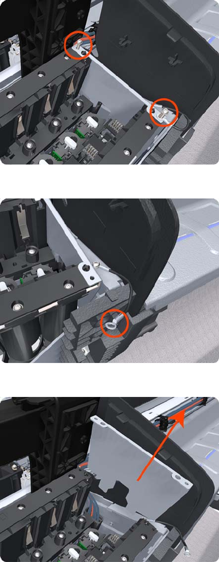
5. Remove two T-10 screws that secure the Right Side Plate of the Left Ink Supply Station.
6. Remove the two Left Ink Supply Station bonding cables.
7. Remove the Right Side Plate of the Left Ink Supply Station.
300 Chapter 6 Removal and Installation ENWW
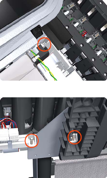
8. Remove the T-20 screw that secures the Left Ink Supply Station to the product.
9. Remove the two T-20 screws that secure the Left Ink Supply Station to the product.
ENWW Left Ink Supply Station 301
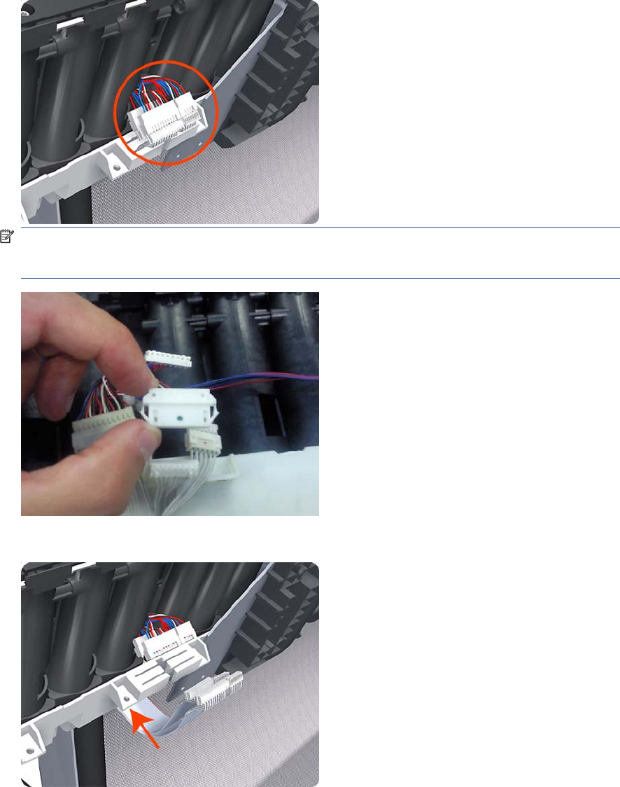
10. Disconnect the four connectors from the Left Ink Supply Station.
NOTE: If you need to change the ISS Harness Cable, make sure you keep the previously used
plastic connector. The new cable will arrive with a female end, which you will replace with the
existing male end.
11. Unroute the four cables from the Left Ink Supply Station.
302 Chapter 6 Removal and Installation ENWW
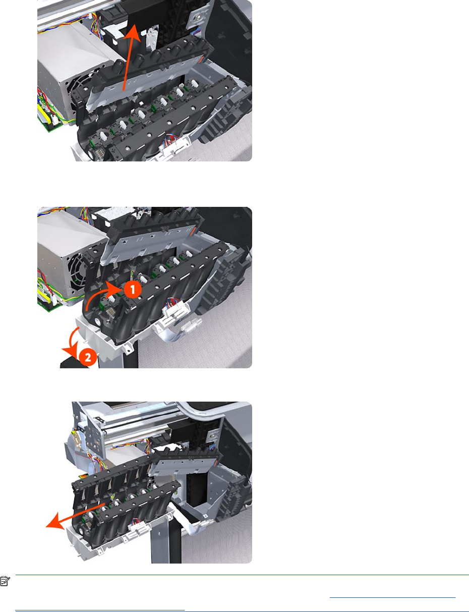
12. Carefully lift the Cartridge Tubes Connector out of the Left Ink Supply Station.
13. Carefully lift the Left Ink Supply Station enough so that you can rotate it counterclockwise to release
the front attachment from the product.
14. Carefully lift the Left Ink Supply Station completely out of the product.
NOTE: When you finish installing or replacing this component, you must perform the necessary
Service Calibrations. To find which calibrations you must perform, see Service Calibration Guide to
Removal and Installation on page 205.
ENWW Left Ink Supply Station 303
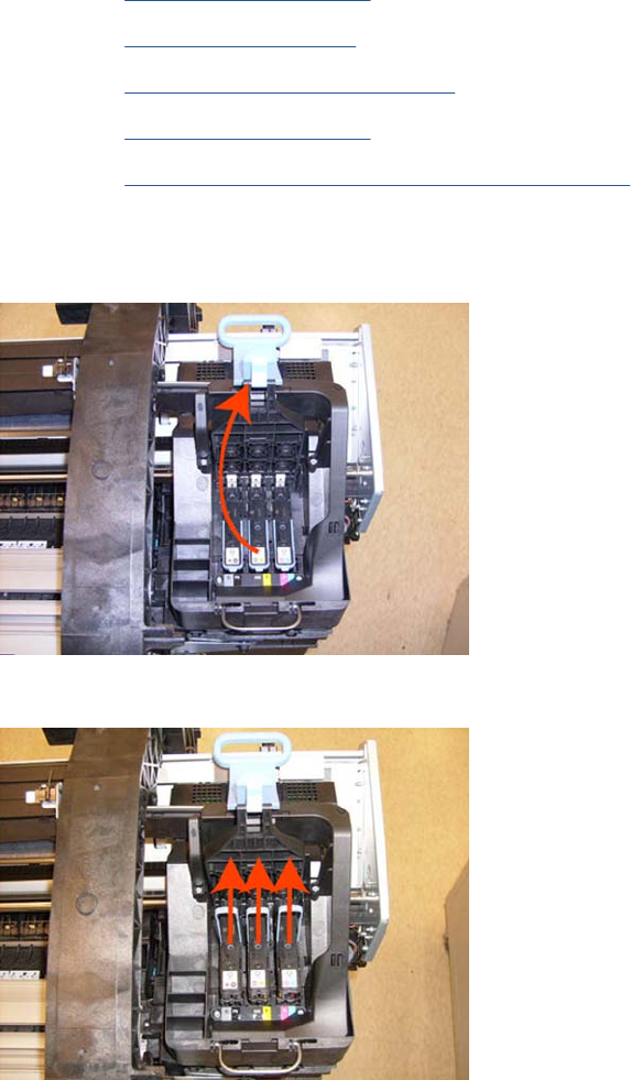
Ink Supply Tubes & Trailing Cable
Removal
1. Switch off the product and remove the power cable.
2. Remove the Right Cover on page 368.
3. Remove the Left Cover on page 317.
4. Remove the Touch Control Panel on page 428.
5. Remove the Front Cover on page 275
6. Remove the Front Top Cover Assembly (MFP only) on page 276
7. Uncap the Service Station.
8. Open the Carriage Cover.
9. Remove all the Printheads.
304 Chapter 6 Removal and Installation ENWW
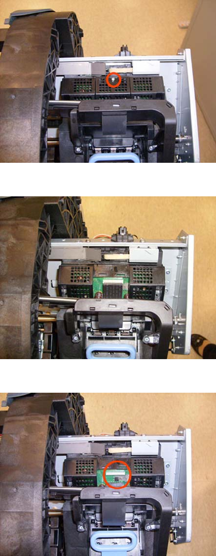
10. Remove one T-10 screw from the small cover.
11. Remove the small cover of the Carriage PCA.
12. Disconnect the ribbon Trailing Cable from the Carriage PCA.
ENWW Ink Supply Tubes & Trailing Cable 305
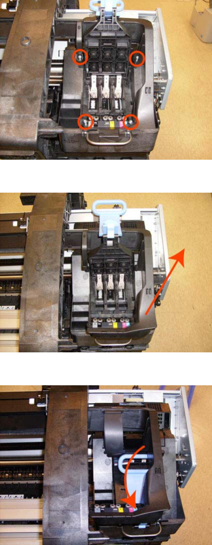
13. Remove the four T-15 screws that secure the Ink Supply Tubes to the Carriage Assembly.
14. Carefully lift out the Ink Supply Tubes and close the carriage cover at the same time.
15. Close and lock the Carriage Cover.
306 Chapter 6 Removal and Installation ENWW
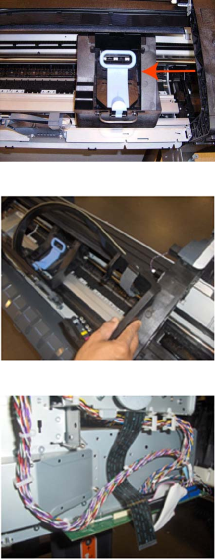
16. Carefully move the Ink Supply Tubes into the print path.
17. Place the Ink Supply tubes on top of the product as shown here.
18. Remove the Trailing Cable from the Main Engine PCA.
ENWW Ink Supply Tubes & Trailing Cable 307
19. Remove five clips from the Trailing Cable Left guide.
20. Leave the Trailing Cable as shown .
21. There are two different Left Brackets, but the procedure is the same for both.
308 Chapter 6 Removal and Installation ENWW
22. Remove all the Front Tube Guide clips.
23. Remove the top T-15 screw that secures Ink Supply Tubes guide to the product.
24. Remove the two front T-20 screws that secure Ink Supply Tubes guide to the product.
ENWW Ink Supply Tubes & Trailing Cable 309
25. Carefully lift the Ink Supply Tubes guide enough until you can slide it forwards out of the product.
26. Use a flat bladed screw driver to release all the Ink Supply Tube clamps from the product.
27. Remove two T-10 screws that secure the Left Side Plate of the Left Ink Supply Station.
310 Chapter 6 Removal and Installation ENWW
28. Remove the Left Side Plates of the Left Ink Supply Station.
29. Remove two T-10 screws that secure the Right Side Plate of the Left Ink Supply Station.
30. Remove the Left Ink Supply Station bonding cable.
ENWW Ink Supply Tubes & Trailing Cable 311
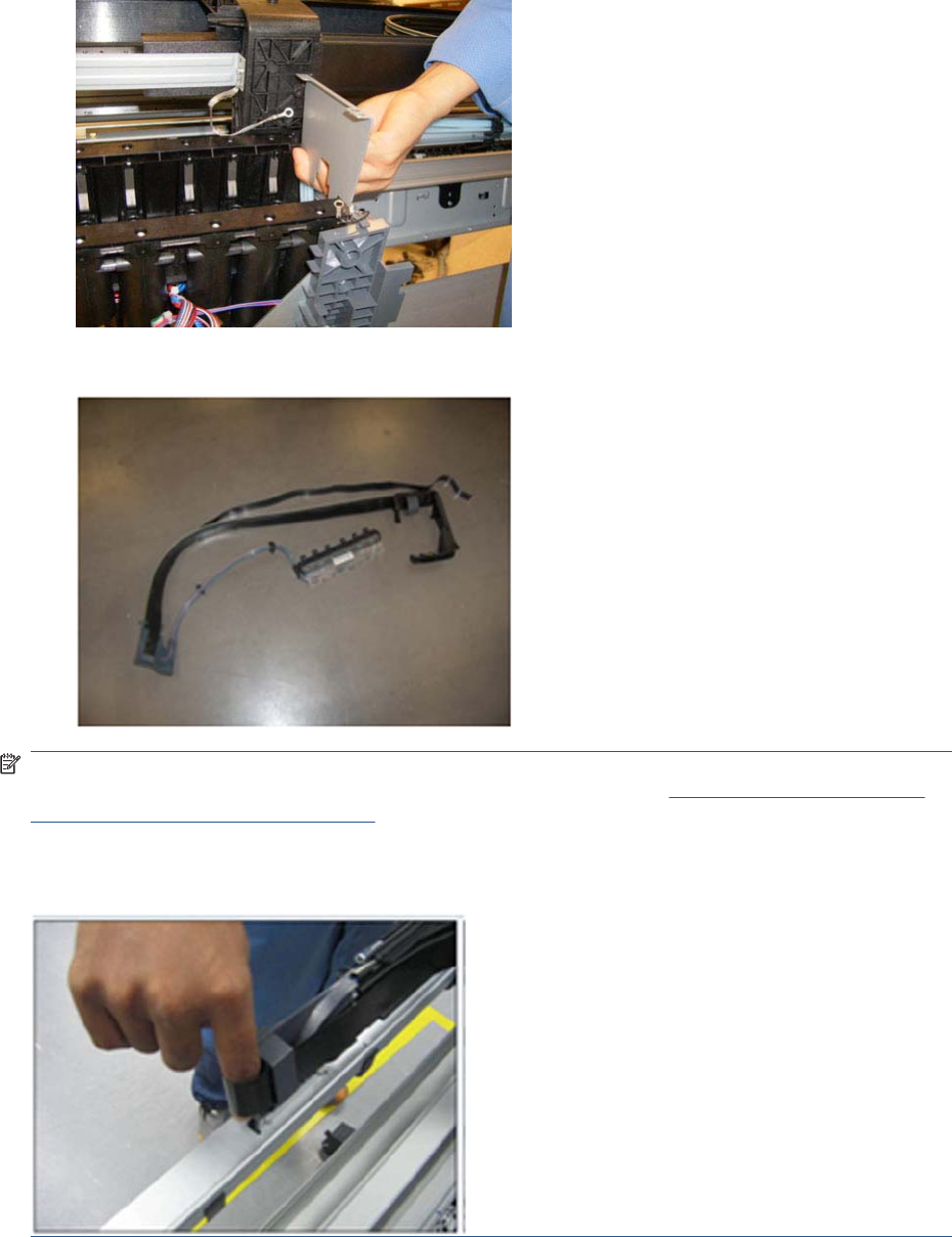
31. Remove the Right Side Plate of the Left Ink Supply Station.
32. Carefully remove the Ink Supply Tubes from the assembly.
NOTE: When you finish installing or replacing this component, you must perform the necessary
Service Calibrations. To find which calibrations you must perform, see Service Calibration Guide to
Removal and Installation on page 205.
When installing the Trailing Cable into the Product, use your finger to create a bend in the cable, there
should be sufficient to avoid creasing the cable.
312 Chapter 6 Removal and Installation ENWW
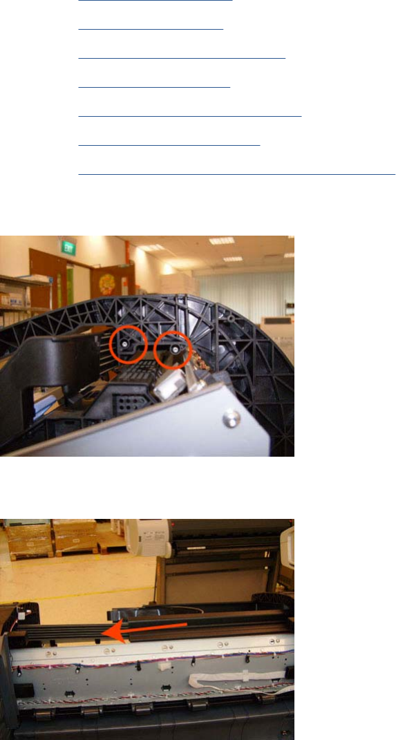
Ink Supply Tubes Support Rail
Removal
1. Switch off the product and remove the power cable.
2. Remove the Right Cover on page 368.
3. Remove the Left Cover on page 317.
4. Remove the Touch Control Panel on page 428.
5. Remove the Rear Cover on page 366.
6. Remove the Rear Cover (MFP only) on page 363.
7. Remove the Front Top Cover on page 278.
8. Remove the Front Top Cover Assembly (MFP only) on page 276.
9. Remove two T-15 screws that secure the Ink Supply Tubes Support Rail to the right Top Cover
Support.
10. Carefully slide the Ink Supply Tubes Support Rail to the left until the right end is clear of the right
Top Cover Support.
ENWW Ink Supply Tubes Support Rail 313
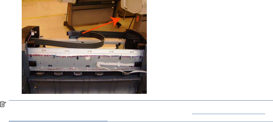
11. Remove the Ink Supply Tubes Support Rail from the product.
NOTE: When you finish installing or replacing this component, you must perform the necessary
Service Calibrations. To find which calibrations you must perform, see Service Calibration Guide to
Removal and Installation on page 205.
314 Chapter 6 Removal and Installation ENWW
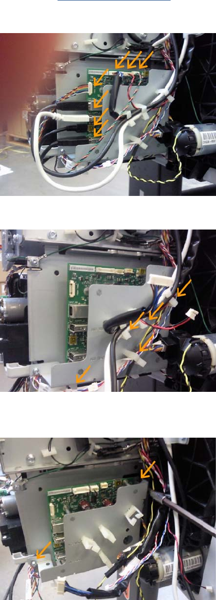
Interconnect PCA
Removal
1. Switch off the product and remove the power cable.
2. Remove the Right Cover on page 368.
3. Disconnect the eight cables indicated from the Interconnect PCA.
4. Remove the cable from the cable clamps indicated here.
5. Loosen (do not remove completely) the two screws that secure the metal plate to the bottom-left
and top-right corners.
ENWW Interconnect PCA 315
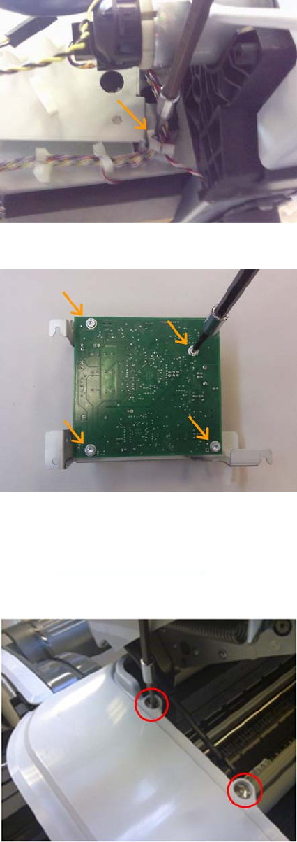
6. Remove the screw that secures the metal plate to the bottom right corner.
7. Remove the four screws that secure the Interconnect PCA with the metal plate
Left Collar Cover (MFP only)
1. Remove Left Cover on page 317
2. Remove two T-15 screws that secure the Left Collar Cover to the product.
316 Chapter 6 Removal and Installation ENWW
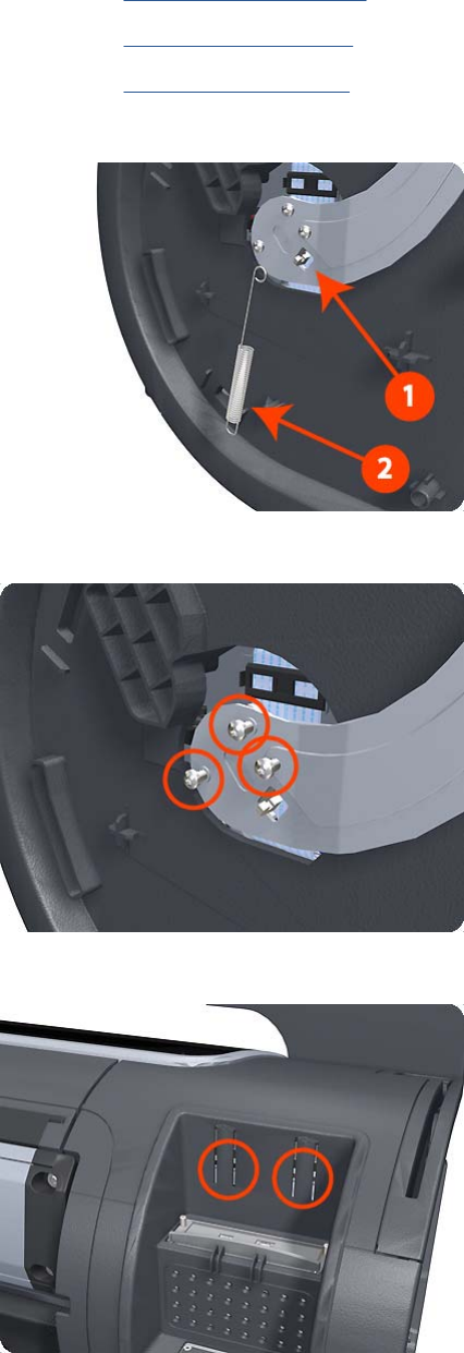
Left Cover
Removal
1. Switch off the product and remove the power cable.
2. Remove the Front Cover on page 275.
3. Remove the Converger on page 261.
4. Remove the Left Panel on page 344.
5. Unclip the spring from the attachment points on the Media Lever and Left Cover.Cover).
6. Remove three T-20 screws that secure the Media Lever.
7. Use a flat-bladed screwdriver to unclip the two attachment clips of the Formatter Housing.
ENWW Left Cover 317
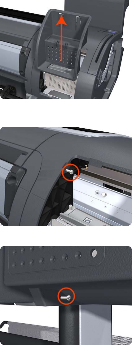
8. Lift the Formatter Housing out of the product.
9. Remove one T-15 screw that secures the Left Cover (top rear, accessible under the Formatter
Housing).
10. Remove one T-15 screw that secures the Left Cover (bottom rear).
318 Chapter 6 Removal and Installation ENWW
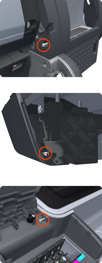
11. Remove one T-15 screw that secures the Left Cover (bottom rear).
12. Remove one T-15 screw that secures the Left Cover (bottom front, accessible under Front Cover).
13. Remove one T-15 screw that secures the Left Cover (top front, accessible Ink Cartridge Door).
ENWW Left Cover 319
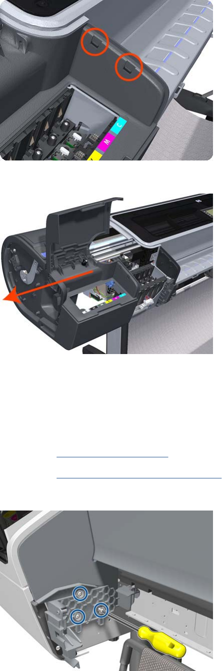
14. Unclip the Left Trim.
15. Remove the Left Cover from the product.
Left Front Trim
Removal
1. Switch off the product and remove the power cable.
2. Remove the Front Cover on page 275.
3. Remove the Media Output Assembly on page 340.
4. Remove three T-20 screws that secure the Left Front Trim to the product.
320 Chapter 6 Removal and Installation ENWW
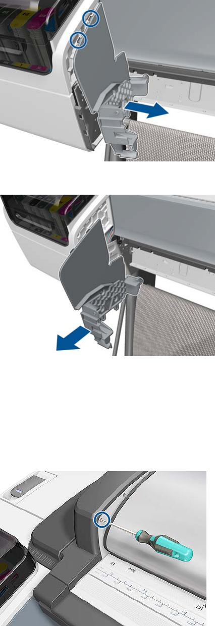
5. Unclip the Left Front Trim and pull it away from the printer.
6. Remove Left Front Trim from the product.
Left Scanner Cover (MFP only)
Removal
1. Switch off the product and remove the power cable.
2. Remove one T–10 screw that secure the front of the Left Scanner Cover.
ENWW Left Scanner Cover (MFP only) 321
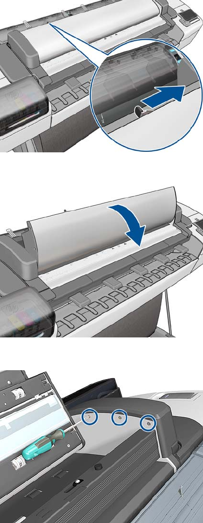
3. Unlatch the CIS Cover.
4. Open the CIS.
5. Remove three T-10 screws that secure the Left Scanner Cover.
322 Chapter 6 Removal and Installation ENWW

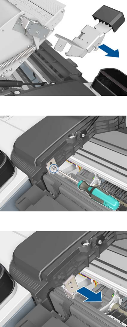
3. Remove the Latch Assembly.
4. Remove one T-15 screw .
5. Remove the Latch Hook.
324 Chapter 6 Removal and Installation ENWW
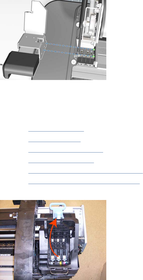
Installation
▲When assembling back the new Latch make sure it fits into the reference pins.
Line Sensor
Removal
1. Switch off the product and remove the power cable.
2. Remove the Right Cover on page 368.
3. Remove the Left Cover on page 317.
4. Remove the Touch Control Panel on page 428.
5. Remove the Front Top Cover on page 278
6. Remove the Front Top Cover Assembly (MFP only) on page 276
7. Remove the Scanner Position Sensor (MFP only) on page 413.
8. Open the Carriage Cover.
ENWW Line Sensor 325

9. Remove all the Printheads.
10. Remove one T-10 screw from the small cover.
11. Remove the small cover of the Carriage PCA.
326 Chapter 6 Removal and Installation ENWW
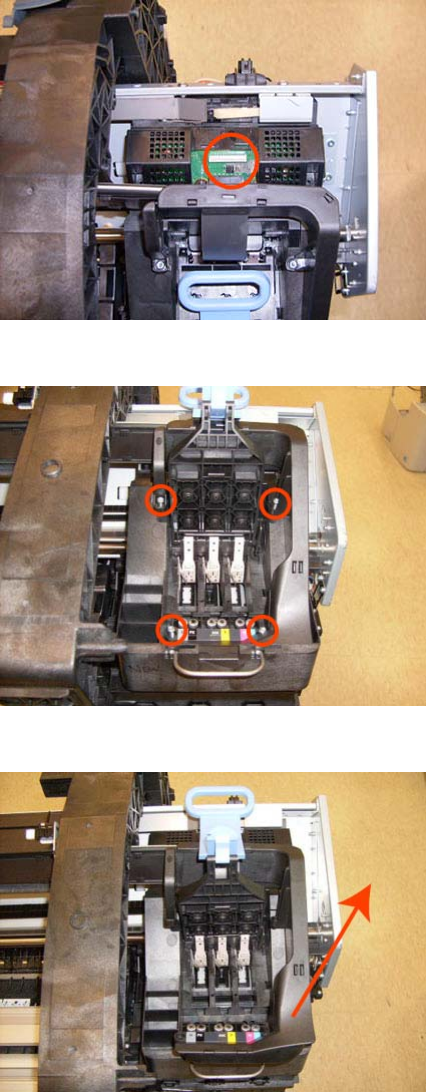
12. Disconnect the ribbon cable of the Trailing Cables from the Carriage PCA.
13. Remove the four T-15 screws that secure the Ink Supply Tubes to the Carriage Assembly.
14. Carefully lift out the Ink Supply Tubes and close the carriage cover at the same time.
ENWW Line Sensor 327
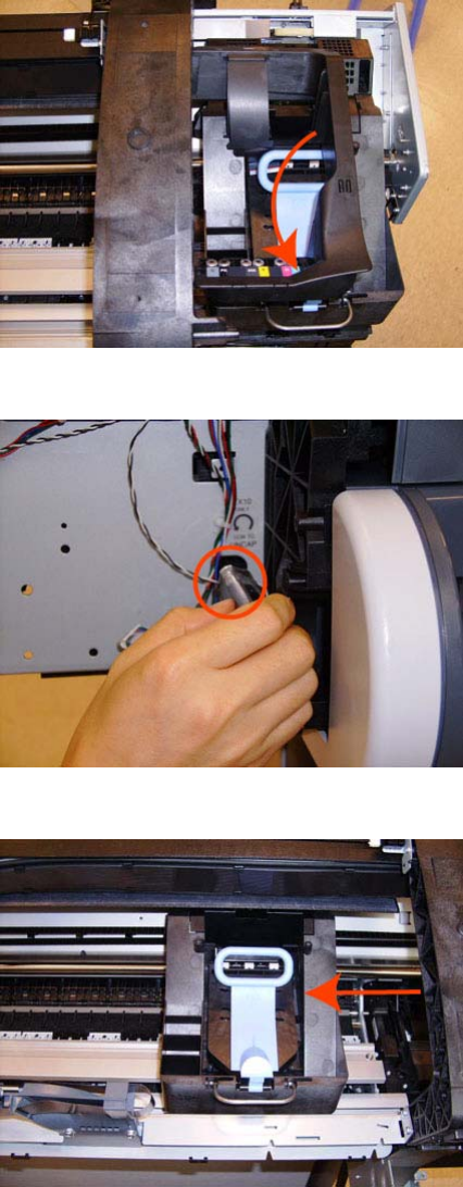
15. Close and lock the Carriage Cover.
16. Loosen the T-10 uncapping screw sufficiently so you can move the Carriage Assembly manually.
17. Push the Carriage Assembly into the print path.
328 Chapter 6 Removal and Installation ENWW
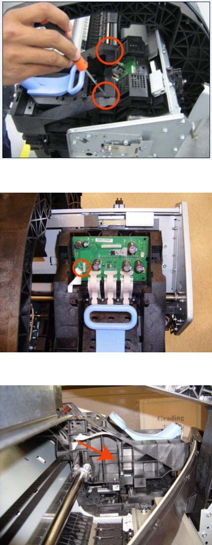
18. Remove the cover on each side of the Carriage PCA using a screwdriver unclip it.
19. Disconnect the Line Sensor electrical connection from the Carriage PCA.
20. Carefully unroute the Line Sensor cable from the Carriage Assembly.
ENWW Line Sensor 329
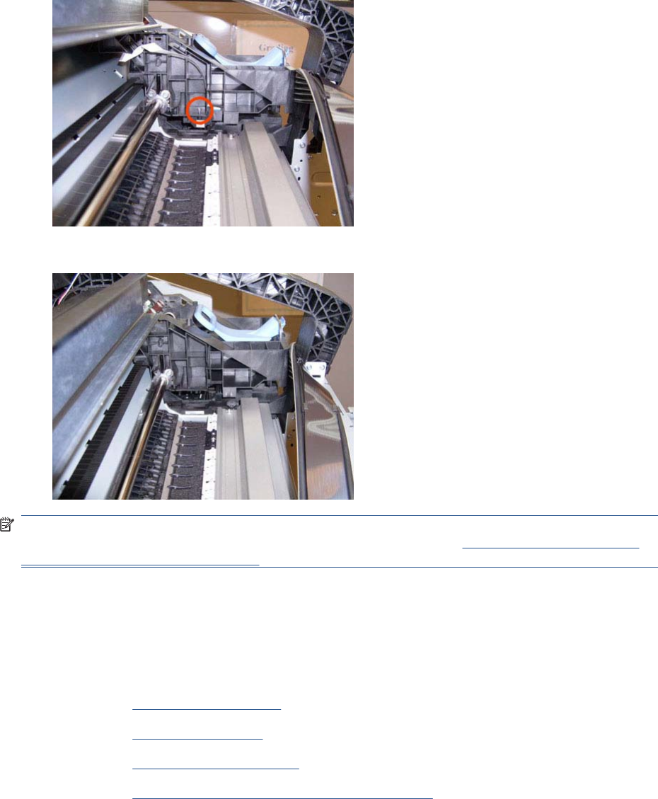
21. Remove one T-10 screw that secures the Line Sensor to the Carriage Assembly.
22. Remove the Line Sensor from Carriage Assembly.
NOTE: When you finish installing or replacing this component, you must perform the necessary
Service Calibrations. To find which calibrations you must perform, see Service Calibration Guide to
Removal and Installation on page 205.
Media Advance Drive
Removal
1. Switch off the product and remove the power cable.
2. Remove the Left Cover on page 317.
3. Remove the EE Box on page 281.
4. Remove the Spittoon, Left on page 403.
5. Remove the Encoder Disk and Encoder Sensor on page 286.
330 Chapter 6 Removal and Installation ENWW
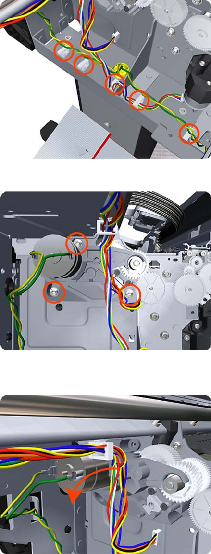
6. Unroute the Media Advance Drive power cable.
7. Remove three T-20 screws that secure the Media Advance Drive to the product.
8. Grip the motor housing of the Media Advance Drive and gently pull it towards you sufficiently to
allow you disengage the Media Advance Drive from the product.
ENWW Media Advance Drive 331
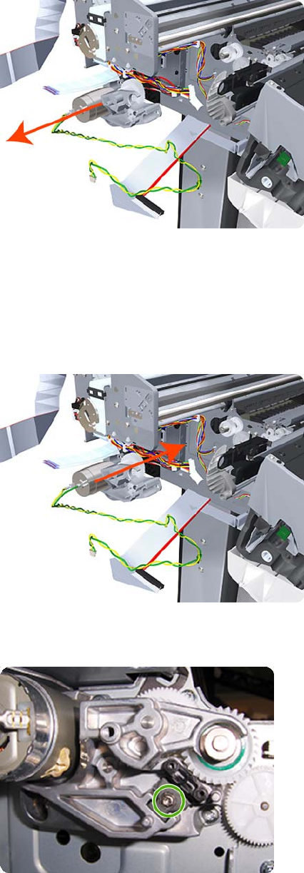
9. Carefully lift the Media Advance Drive out of the product.
Installation without encoder sensor adjustment
Use the following procedure to install and adjust a new Media Advance Drive. This is the normal
procedure that should be followed in most cases. You will need Media Advance Drive Adjustment Tool
from the Tool Kit (Q6683-67001).
1. Carefully position the Media Advance Drive in the product.
2. Be careful not to touch the encoder sensor adjustment screw; not even when replacing the encoder
disc and sensor.
332 Chapter 6 Removal and Installation ENWW
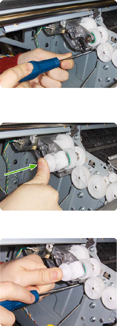
3. Insert the three T-15 attachment screws, but do not fully tighten them.
4. Position the Media Advance Drive Adjustment Tool on the end Media Advance Roller shaft, push
it firmly onto the shaft and maintain a constant pressure to ensure it is flush to the Media Advance
Drive.
5. While maintaining pressure on the Media Advance Drive Adjustment Tool, fully tighten the three
T-15 attachment screws in the order shown.
6. Remove the Media Advance Drive Adjustment Tool.
Installation with encoder sensor adjustment
Use the following procedure to install and adjust a new Media Advance Drive, and to adjust the encoder
sensor. This procedure is recommended only when the motor mount has to be replaced or the encoder
ENWW Media Advance Drive 333
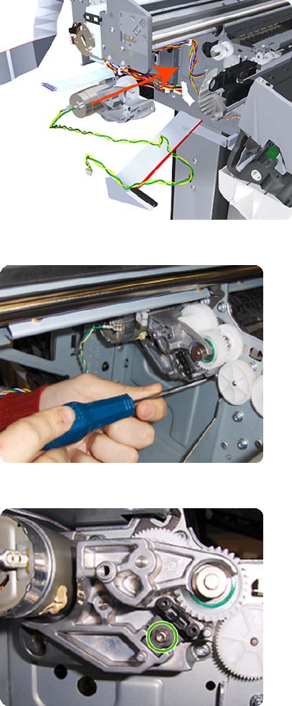
sensor has to be readjusted. You will need Media Advance Drive Adjustment Tool from the Tool Kit
(Q6683-67001).
1. Carefully position the Media Advance Drive in the product.
2. Insert the three T-15 attachment screws, but do not fully tighten them.
3. Loosen the encoder sensor adjustment screw.
334 Chapter 6 Removal and Installation ENWW
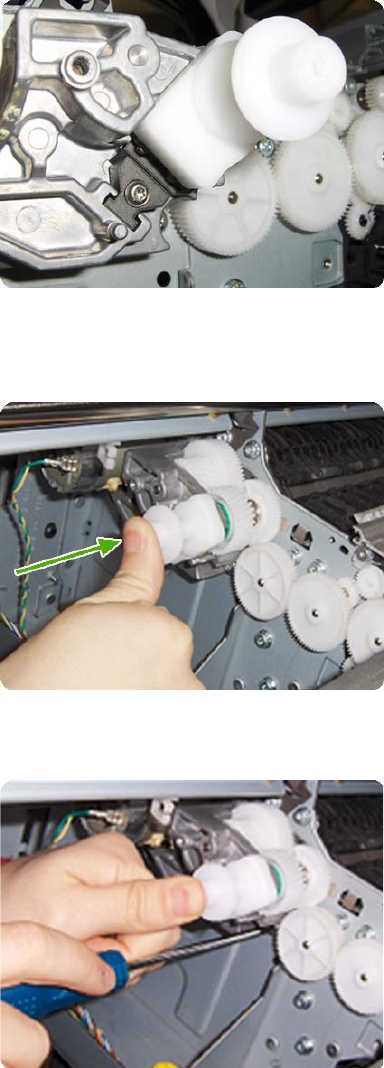
4. Add the Encoder Sensor Tool to the Media Drive Adjustment Tool.
5. Position the Media Advance Drive Adjustment Tool on the end Media Advance Roller shaft, push
it firmly onto the shaft and maintain a constant pressure to ensure it is flush to the Media Advance
Drive.
6. While maintaining pressure on the Media Advance Drive Adjustment Tool, fully tighten the three
T-15 attachment screws in the order shown.
ENWW Media Advance Drive 335
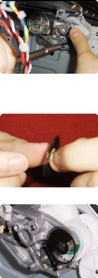
7. While maintaining pressure on the Media Advance Drive Adjustment Tool, fully tighten the encoder
sensor adjustment screw.
8. Remove the Media Advance Drive Adjustment Tool.
Encoder disk assembly
1. Remove the paper that protects the glue of a new encoder.
2. Pre-assemble the encoder on the roller without using pressure.
336 Chapter 6 Removal and Installation ENWW
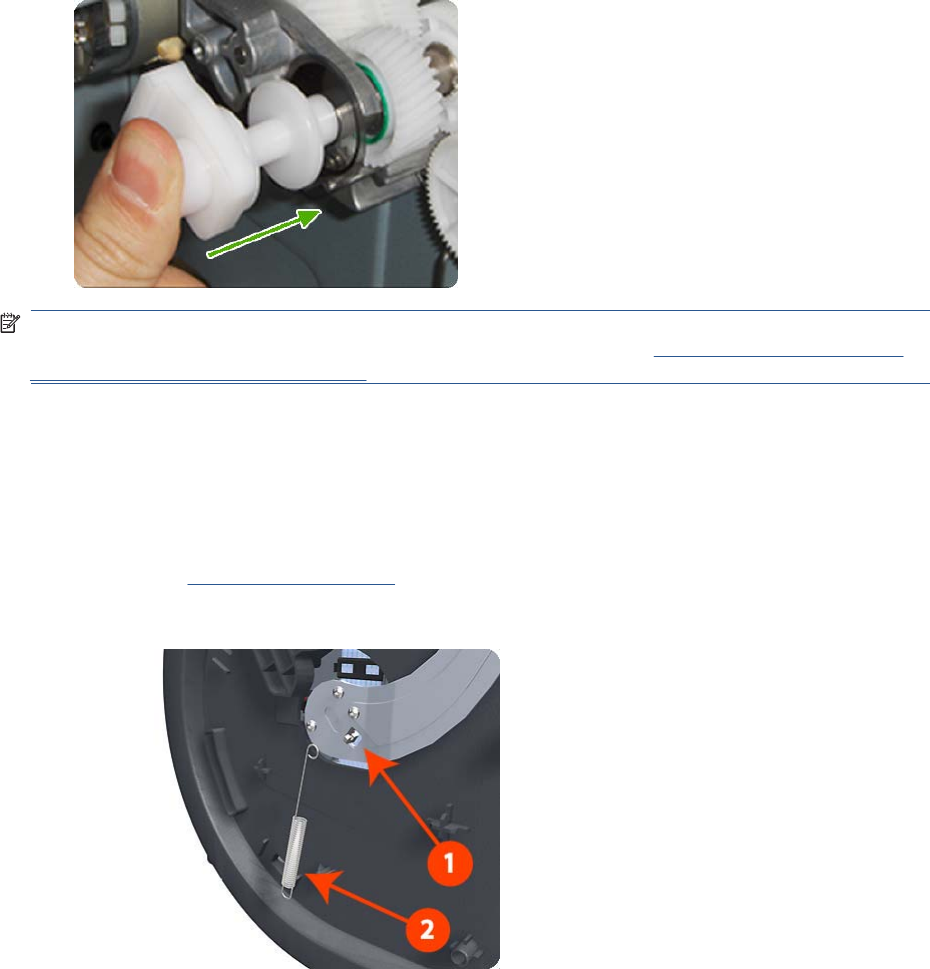
3. Press the encoder using the Media Advance Drive Adjustment Tool (reversed) so that it sticks to
the roller.
NOTE: When you finish installing or replacing these components, you must perform the necessary
Service Calibrations. To find which calibrations you must perform, see Service Calibration Guide to
Removal and Installation on page 205.
Media Lever
Removal
1. Switch off the product and remove the power cable.
2. Remove the Left Panel on page 344.
3. Unclip the spring from the attachment points on the Media Lever and Left Cover.
ENWW Media Lever 337
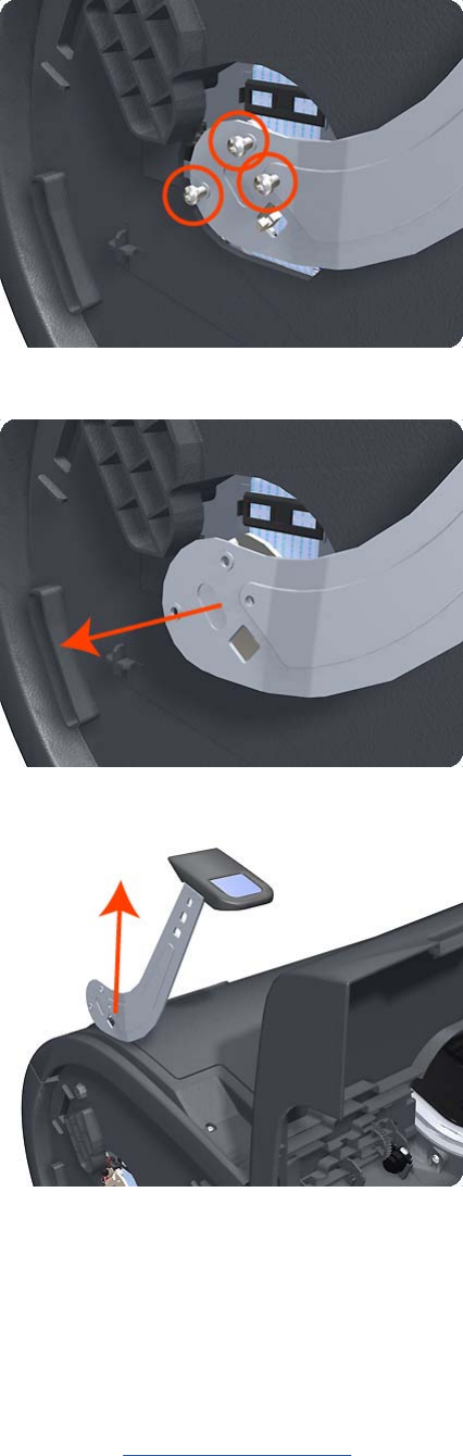
4. Remove three T-15 screws that secure the Media Lever.
5. Lift the Media Lever of the mounting.
6. Remove the Media Lever from the product.
Media Lever Position Sensor
Removal
1. Switch off the product and remove the power cable.
2. Raise the Media Lever.
3. Remove the Left Cover on page 317.
338 Chapter 6 Removal and Installation ENWW
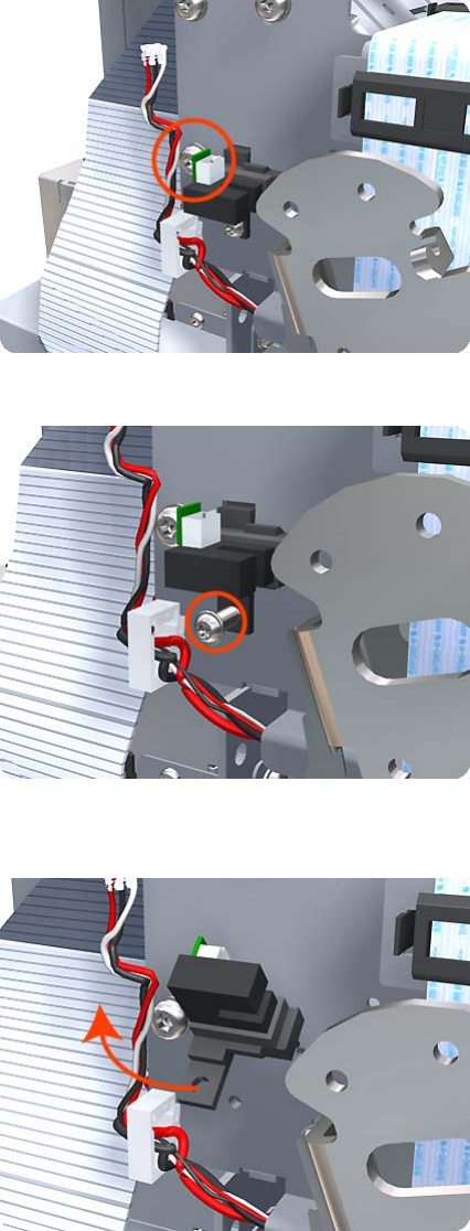
4. Disconnect the Media Lever Position Sensor.
5. Remove one T-10 screw that secures the Media Lever Position Sensor to the Scan Side Panel.
6. Rotate the Media Lever Position Sensor vertically to disengage the attachment lug from the Scan
Side Panel.
ENWW Media Lever Position Sensor 339
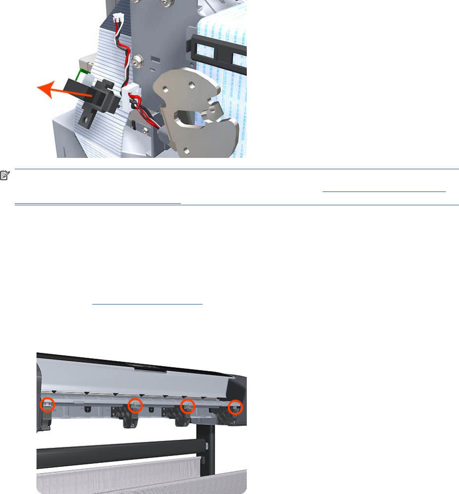
7. Remove the Media Lever Position Sensor.
NOTE: When you finish installing or replacing this component, you must perform the necessary
Service Calibrations. To find which calibrations you must perform, see Service Calibration Guide to
Removal and Installation on page 205.
Media Output Assembly
Removal
1. Switch off the product and remove the power cable.
2. Remove the Front Cover on page 275.
3. Remove four T-15 screws and washers that secure the Media Output Assembly to the product.
340 Chapter 6 Removal and Installation ENWW
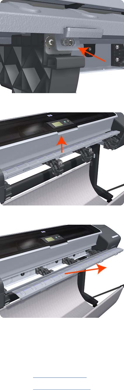
4. Release the four attachment clips.
5. Lift the front of the Media Output Assembly.
6. Slide the Media Output Assembly forwards out of the product.
Out-of-paper Sensor
Removal
1. Switch off the product and remove the power cable.
2. Remove the Spindle on page 402.
3. Remove the Cleanout on page 257.
ENWW Out-of-paper Sensor 341
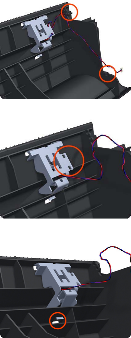
4. Unroute the Out Of Paper Sensor electrical cables from the Clean Out Assembly.
5. Unroute (unwind) the Out Of Paper Sensor electrical cables from the Out Of Paper Sensor cover.
6. Press the clip to remove the Out Of Paper Sensor cover from the Clean Out Assembly.
342 Chapter 6 Removal and Installation ENWW
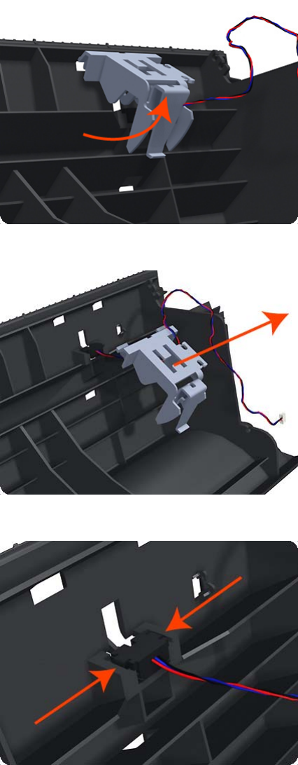
7. Rotate the Out Of Paper Sensor cover approximately 45 degrees.
8. Remove the Out Of Paper Sensor cover from the Clean Out Assembly.
9. Squeeze the Out Of Paper Sensor attachment clips to remove it from the Clean Out Assembly.
ENWW Out-of-paper Sensor 343
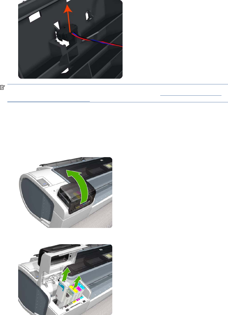
10. Lift the Out Of Paper Sensor out of the Clean Out Assembly.
NOTE: When you finish installing or replacing this component, you must perform the necessary
Service Calibrations. To find which calibrations you must perform, see Service Calibration Guide to
Removal and Installation on page 205.
Left Panel
This part can be replaced by customers who have the appropriate flier.
Removal
1. Open the ink cartridge cover on the left.
2. Remove the ink cartridges.
344 Chapter 6 Removal and Installation ENWW
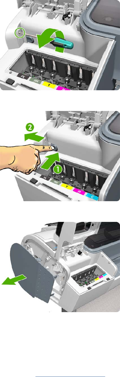
3. Remove the T-15 screw that attaches the left panel to the left cover.
4. Press the clip as shown to free the left panel.
5. Remove the left panel.
Pen to Paper Space (PPS) Solenoid
Removal
1. Switch off the product and remove the power cable.
2. Remove the Right Cover on page 368.
ENWW Pen to Paper Space (PPS) Solenoid 345
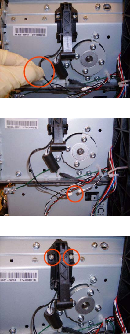
3. Unroute the Pen to Paper Space (PPS) Solenoid cable from the cable clamp.
4. Disconnect the Pen to Paper Space (PPS) Solenoid connector from the L1 Data Harness.
5. Remove two T-10 screws that secure the Pen to Paper Space (PPS) Solenoid to the product.
346 Chapter 6 Removal and Installation ENWW
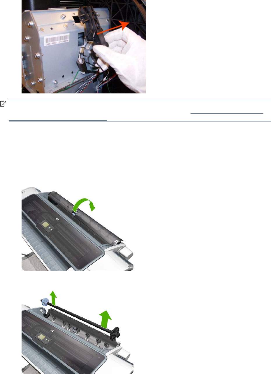
6. Remove the Pen to Paper Space (PPS) Solenoid from the product.
NOTE: When you finish installing or replacing this component, you must perform the necessary
Service Calibrations. To find which calibrations you must perform, see Service Calibration Guide to
Removal and Installation on page 205.
Pinch Arm Assembly
These parts can be replaced by customers who have the appropriate flier.
Removal and installation
1. Open the upper or lower roll cover.
2. Remove the spindle.
ENWW Pinch Arm Assembly 347
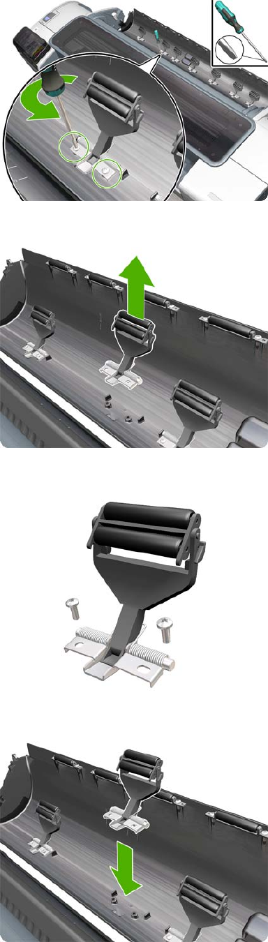
3. Unscrew the pinch arm assembly.
4. Remove the pinch arm assembly.
5. Locate the new pinch arm assembly and screws.
6. Fit the pinch arm assembly to the roll cover.
348 Chapter 6 Removal and Installation ENWW
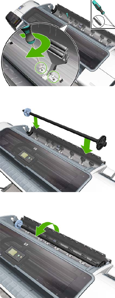
7. Screw the pinch arm assembly to the roll cover.
8. Insert the spindle.
9. Close the roll cover.
Pinchwheel Assembly
Removal
1. Switch off the product and remove the power cable.
2. Open the Scanner (MFP only) or Window.
ENWW Pinchwheel Assembly 349

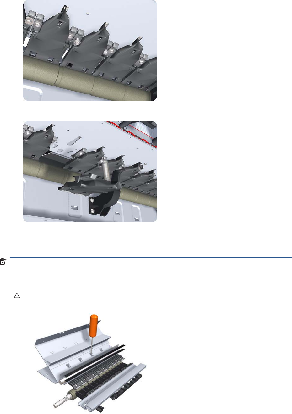
8. Remove two T-10 screws that secure the to the product.
9. Remove the from the product.
Installation
Use the following procedure to align the using the Pinchwheel Alignment Tool during reassembly.
NOTE: Never remove and replace all the Pinchwheel Assemblies at the same time. In order to align
a , you need a minimum one correctly aligned by the manufacturer.
1. Insert the Pinchwheel Insertion Tool through the appropriate access hole for the you are installing.
CAUTION: Be very careful not to damage the Encoder Strip or the Belt Assembly with the
Pinchwheel Insertion Tool.
ENWW Pinchwheel Assembly 351
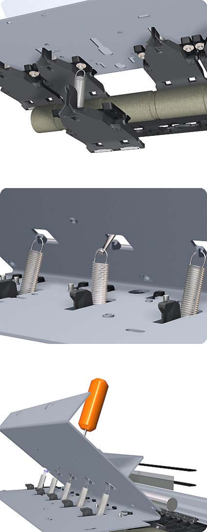
2. Position the new correctly on its hanger.
3. Hook the spring of the you are installing with the Pinchwheel Insertion Tool.
4. Attach the spring to its attachment point on the hanger and remove the Pinchwheel Insertion Tool.
352 Chapter 6 Removal and Installation ENWW
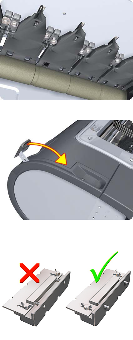
5. Attach the new with the two T-15 screws that secure to the product but do fully not tighten the
screws.
6. Lower the Media Lever.
7. Make sure the Pinchwheel Alignment Tool is in the collapsed position.
8. Fit the end of the Pinchwheel Alignment Tool to the you need to align.
ENWW Pinchwheel Assembly 353
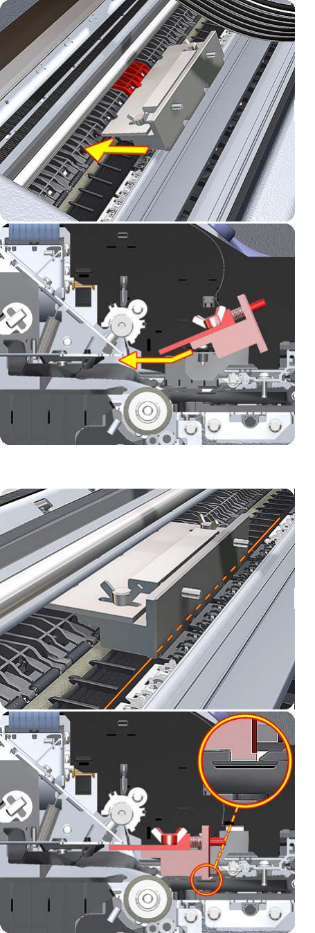
9. Set the Pinchwheel Alignment Tool on the print platen. The tool should fit as shown below.
354 Chapter 6 Removal and Installation ENWW
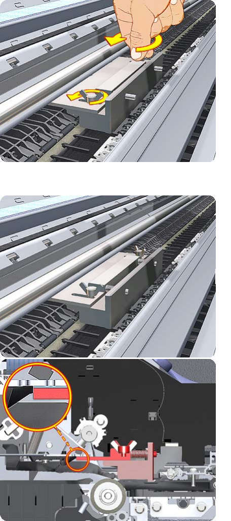
10. Loosen the wing nuts on the Pinchwheel Alignment Tool.
11. Allow the Pinchwheel Alignment Tool to expand. Make sure that the tool is fully expanded.
ENWW Pinchwheel Assembly 355
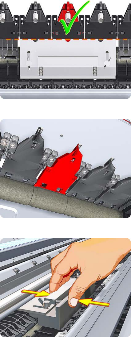
12. When the Pinchwheel Alignment Tool is fully expanded, the is properly aligned.
13. Fully tighten the two T-15 attachment screws that secure the to the product.
14. Collapse the Pinchwheel Alignment Tool to remove it.
356 Chapter 6 Removal and Installation ENWW
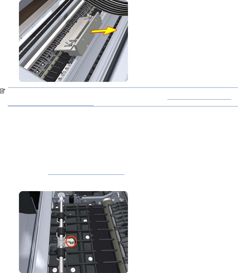
15. Remove the Pinchwheel Alignment Tool from the product.
NOTE: When you finish installing or replacing this component, you must perform the necessary
Service Calibrations. To find which calibrations you must perform, see Service Calibration Guide to
Removal and Installation on page 205.
Print Zone Overdrive
Removal
The Print Zone Overdrive is in two sections (left and right). This procedure describes the removal of
both sections. If you want to remove only one of the sections, skip the steps for the other section.
1. Switch off the product and remove the power cable.
2. Remove the Starwheel Assembly on page 404.
3. Remove one T-8 screw that secures the left clamp of the Print Zone Overdrive to the Platen.
ENWW Print Zone Overdrive 357
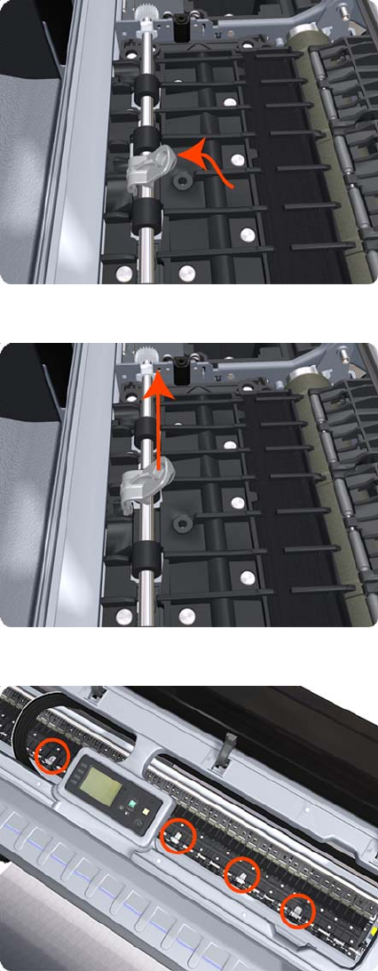
4. Lift attachment clamp vertically to release it from the Platen.
5. Remove the clamp.
6. Repeat the three preceding steps to remove the remaining five attachment clamps.
358 Chapter 6 Removal and Installation ENWW
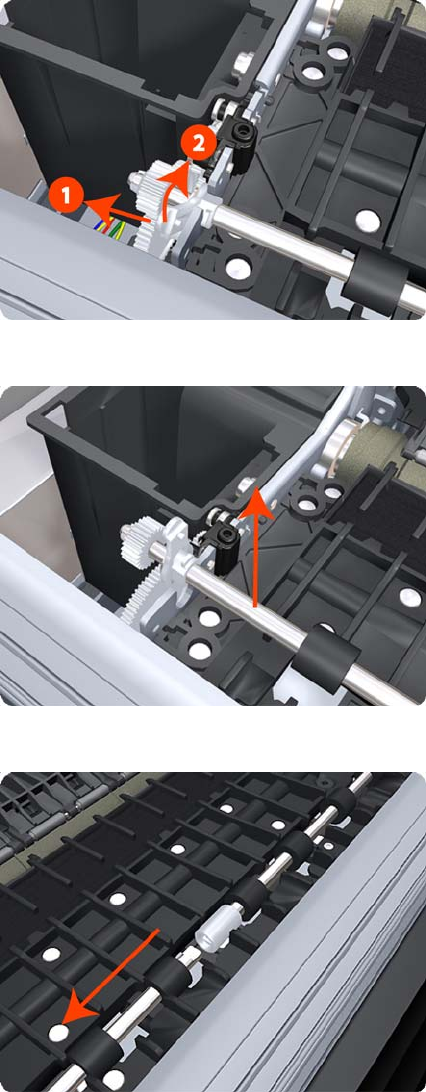
7. Use a flat-bladed screwdriver to unclip the left Print Zone Overdrive retaining clip and rotate the
clip vertically.
8. Carefully lift the left Print Zone Overdrive enough (10 mm) so you can slide it to the left.
9. Slide the left Print Zone Overdrive to the left disengage the center coupling.
ENWW Print Zone Overdrive 359
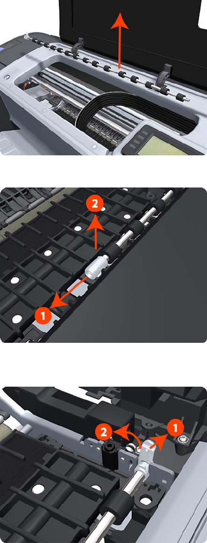
10. Carefully lift the left Print Zone Overdrive out of the product.
11. Remove the center coupling.
12. Use a flat-bladed screwdriver to unclip the left Print Zone Overdrive retaining clip and rotate the
clip vertically.
360 Chapter 6 Removal and Installation ENWW
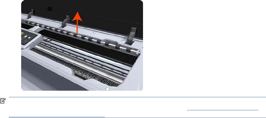
13. Carefully lift the right Print Zone Overdrive out of the product.
NOTE: When you finish installing or replacing this component, you must perform the necessary
Service Calibrations. To find which calibrations you must perform, see Service Calibration Guide to
Removal and Installation on page 205.
ENWW Print Zone Overdrive 361

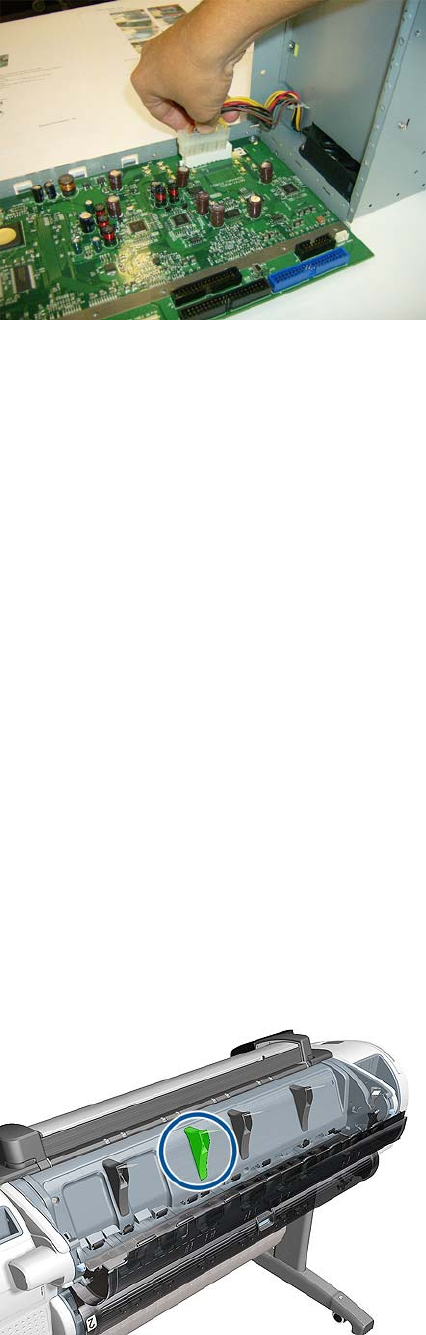
4. Disconnect cable and hooks.
Real-time Clock Battery
Removal and installation
1. Turn the product off and unplug the cable. Unplug any network or USB cables.
2. Remove the screws that attach the formatter to the product with your fingers, or with the help of a
flat screwdriver, and remove the formatter.
3. Locate the round, flat battery in the formatter.
4. Push the battery slightly to one side and then pull it up. A little force may be required.
5. Insert the new battery by pressing it down.
6. Insert the formatter into the product by pressing it down, and tighten the screws.
7. Reconnect the cables and turn the product on.
Rear Cover (MFP only)
Removal
1. Switch off the product and remove the power cable.
2. Open the Upper Roll Cover.
3. The deflector indicated must be removed first.
ENWW Real-time Clock Battery 363
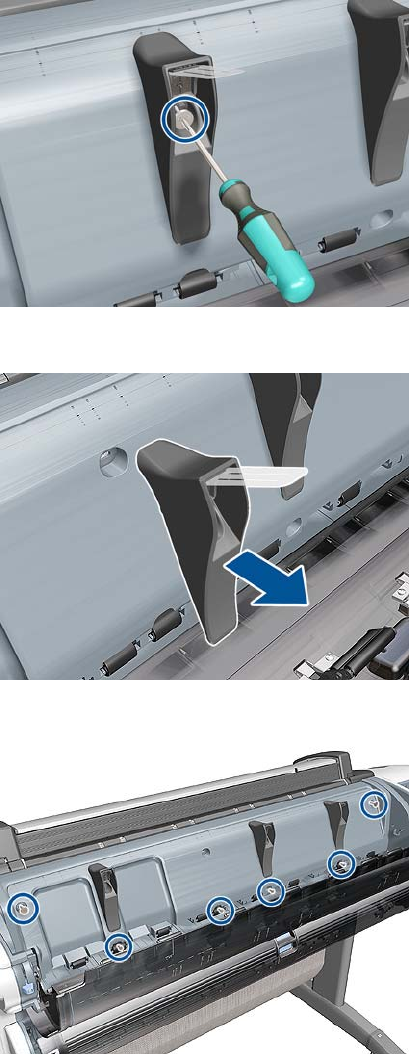
4. Remove one T-10 screw that secures the deflector.
5. Remove the deflector assembly.
6. Remove six T-15 screw.
364 Chapter 6 Removal and Installation ENWW
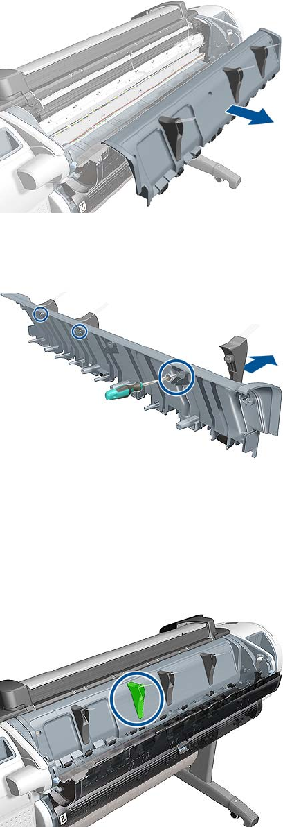
7. Remove the Rear Cover and place on a flat surface.
8. Remove the remaining deflectors from the old Rear Cover, by removing one screw from each
deflector.
Installation
1. Install the three old deflectors onto the new Rear Cover and place the Rear cover Assembly onto
the back of the product (but DO NOT install the indicated deflector yet).
2. Install the remaining deflector onto the new Rear Cover and secure it with one T–10 screw.
ENWW Rear Cover (MFP only) 365
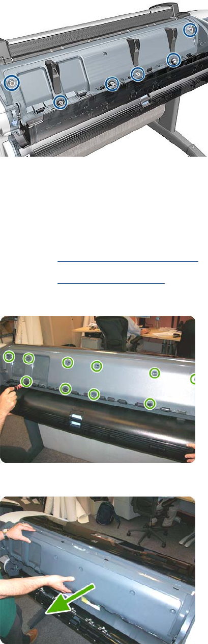
3. Secure the new Rear Cover on to the back of the product with six T-10 screws.
Rear Cover
Removal
1. Switch off the printer and remove the power cable.
2. Remove the Roll Cover, Upper on page 381.
3. Remove the Converger on page 261.
4. Remove the six T-15 and four T-20 screws that secure the Rear Cover to the printer.
5. Remove the Rear Cover from the printer.
366 Chapter 6 Removal and Installation ENWW
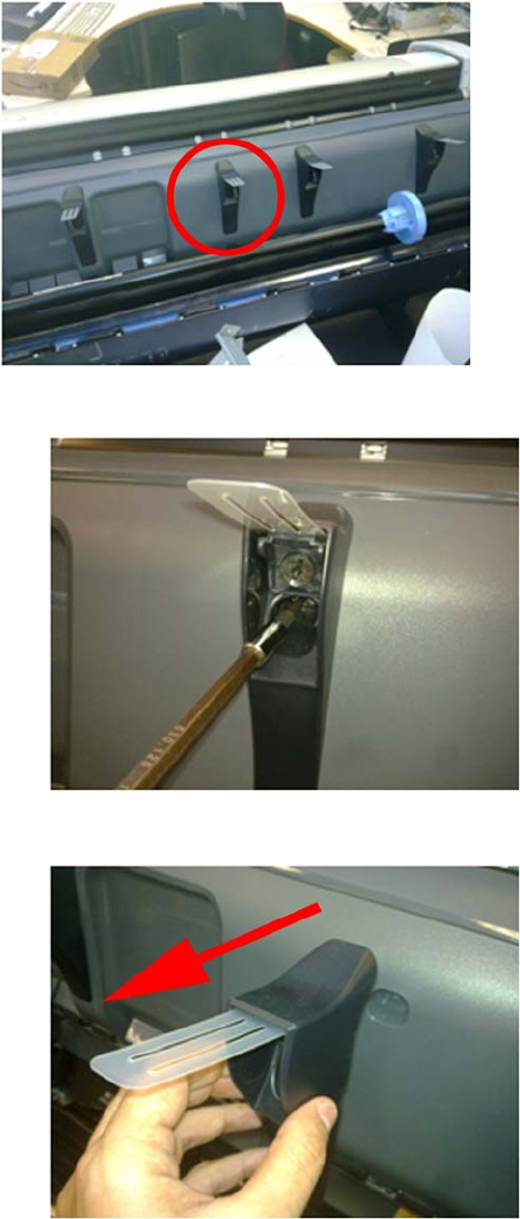
Rear Deflectors
Center Right Rear Deflector
The Center Right Rear Deflector has a different removal procedure than the other rear deflectors
1. Remove one T-10 screw from the Center Right Rear Deflector.
2. Remove the Center Right Rear Deflector.
ENWW Rear Deflectors 367
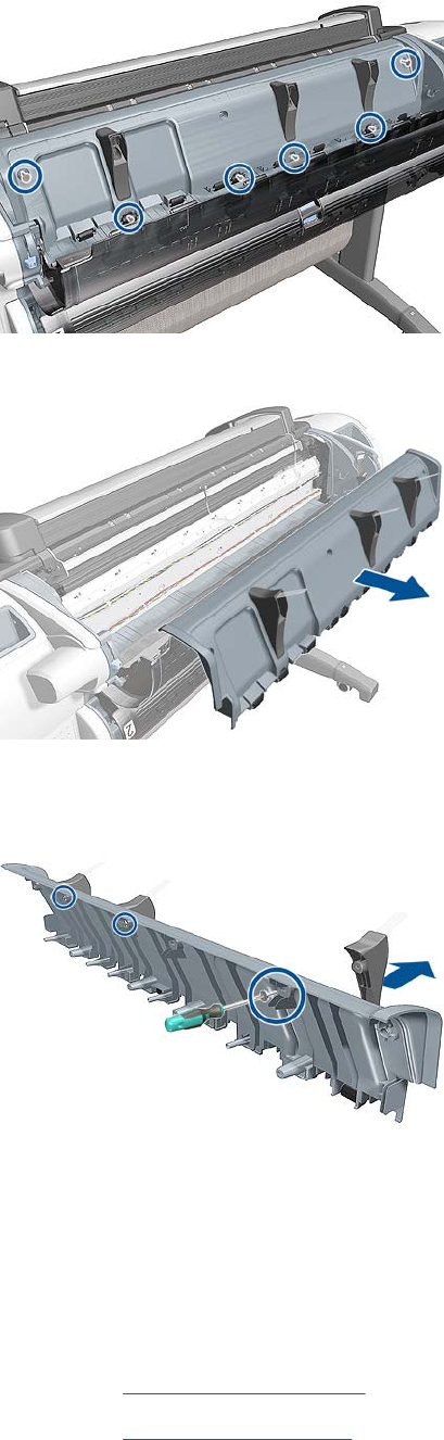
Remaining Rear Deflectors
1. Remove six T-15 screw.
2. Remove the Rear Cover and place on a flat surface.
3. Remove the remaining deflectors from the old Rear Cover, by removing one screw from each
deflector.
Right Cover
Removal
1. Switch off the product and remove the power cable.
2. Remove the Front Cover on page 275.
3. Remove the Converger on page 261.
368 Chapter 6 Removal and Installation ENWW
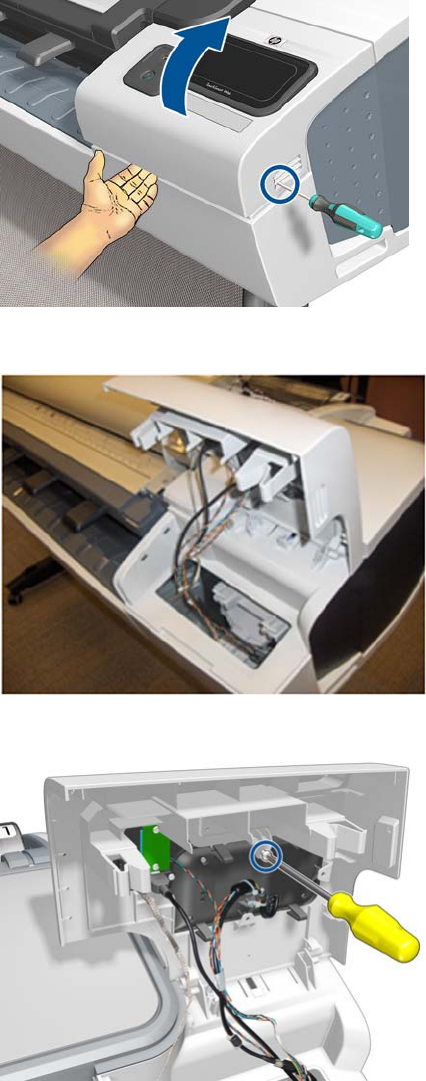
4. Open the Right Ink Cartridge Door by inserting a screwdriver into the side to unlatch it, and then
lift up the door.
5. Open completely the right ink door so it stays up.
6. Remove one T-15 screw from the right ink door.
ENWW Right Cover 369
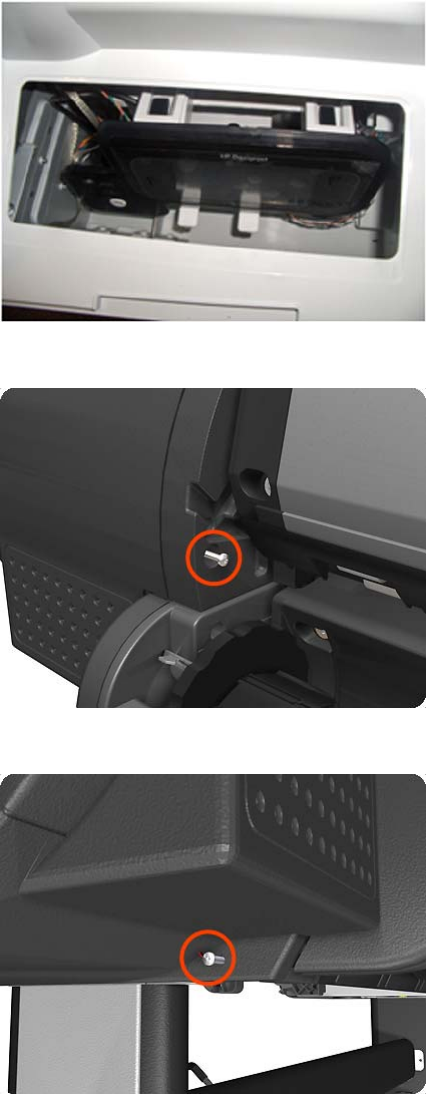
7. Pass the Touch Control Panel through the window of the ink door and place it on the features as
shown in the picture.
8. Remove one T-15 screw that secures the Right Cover to the product (at the rear of the product).
9. Remove one T-15 screw that secures the Right Cover to the product (at the rear of the product).
370 Chapter 6 Removal and Installation ENWW
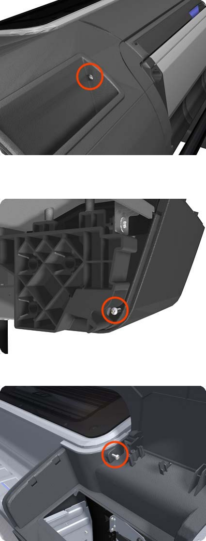
10. Remove one T-15 screw that secures the Right Cover to the product (at the rear of the product).
11. Remove one T-15 screw that secures the Right Cover to the product (accessible under the Front
Cover).
12. Remove one T-15 screw that secures the Right Cover to the product.
ENWW Right Cover 371
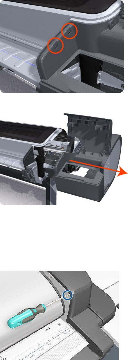
13. Unclip the Right Trim.
14. Remove the Right Cover from the product.
Right Scanner Cover (MFP only)
Removal
1. Switch off the product and remove the power cable.
2. Remove one T–10 screw that secures the front of the Right Scanner Cover.
372 Chapter 6 Removal and Installation ENWW
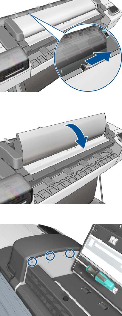
3. Unlatch the CIS.
4. Open the CIS.
5. Remove three T-10 screws that secure the rear of the Right Scanner Cover.
ENWW Right Scanner Cover (MFP only) 373
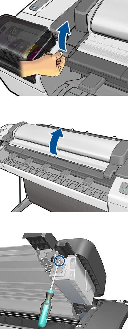
6. Open the latch of the Scanner.
7. Open the Scanner.
8. Remove one T-15 screw from below the Right Scanner Cover.
374 Chapter 6 Removal and Installation ENWW
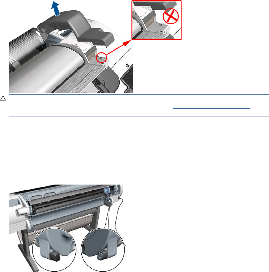
9. Remove the Right Scanner Cover.
CAUTION: Do not unscrew the hexagonal nut from bumper assembly. If accidentally unscrewed
refer to bumper adjustment in the installation procedure (see Scanner Bumper (MFP only)
on page 266)
Roll Cover Bumpers, Lower
Removal and installation
1. Remove the lower roll cover.
2. Identify the bumpers at the rear of the product.
ENWW Roll Cover Bumpers, Lower 375
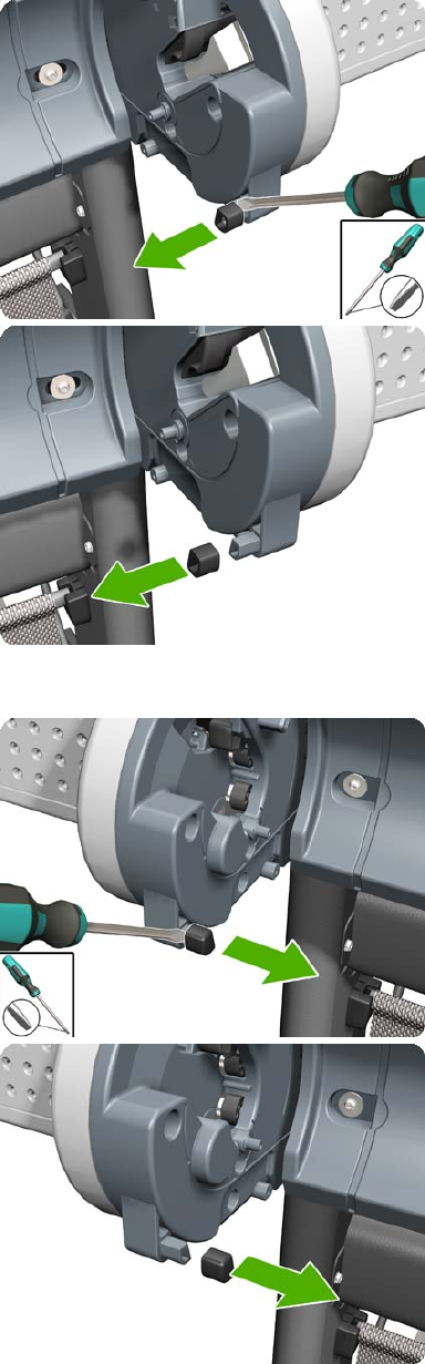
3. Use a screwdriver to lever off the bumper.
4. Remove the other bumper in the same way.
376 Chapter 6 Removal and Installation ENWW
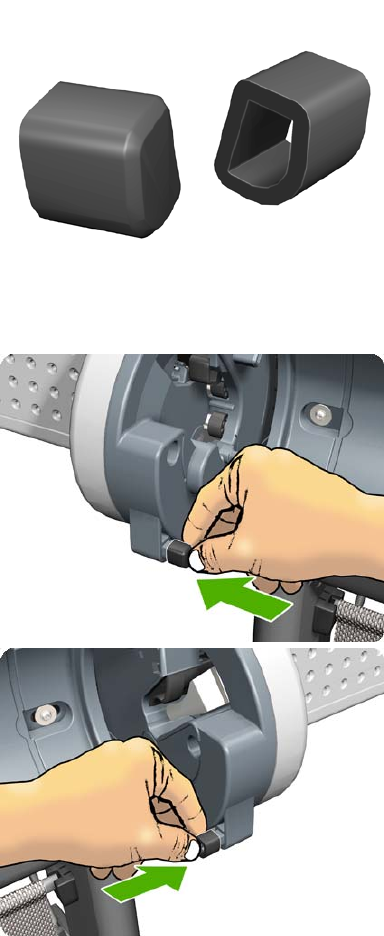
5. Locate the new bumpers.
6. Fit the new bumpers into place.
7. Replace the lower roll cover.
ENWW Roll Cover Bumpers, Lower 377
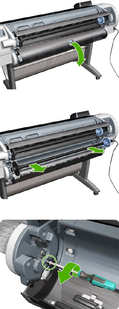
Roll Cover, Lower
Removal
1. Open the lower roll cover.
2. Remove the spindle.
3. Remove the screw connecting the roll cover to the product on the left.
378 Chapter 6 Removal and Installation ENWW
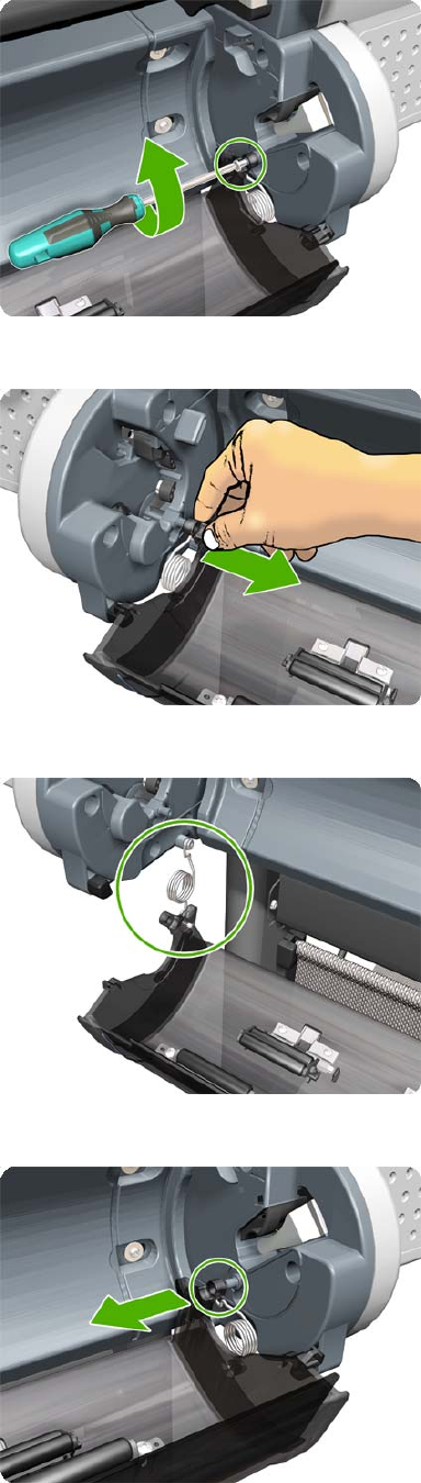
4. Remove the screw connecting the roll cover to the product on the right.
5. Detach the roll cover from the product on the left-hand side.
6. Leave the roll cover hanging from the bi-stable spring.
7. Detach the roll cover from the product on the right-hand side.
ENWW Roll Cover, Lower 379
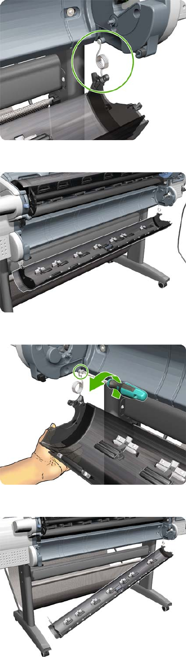
8. Leave the roll cover hanging from the bi-stable spring.
9. Both ends of the roll cover are now connected to the product only by the bi-stable springs.
10. Hold the roll cover with one hand while unscrewing the bi-stable spring from the product.
11. Leave one end of the roll cover resting on the floor.
380 Chapter 6 Removal and Installation ENWW
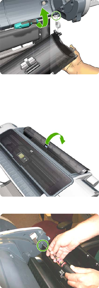
12. Hold the roll cover with one hand while unscrewing the other bi-stable spring from the product.
Roll Cover, Upper
Removal
1. Open the Upper Roll Cover.
2. Remove the screw on the Roll Cover's left side that attaches to the Upper Left Roll Support.
ENWW Roll Cover, Upper 381
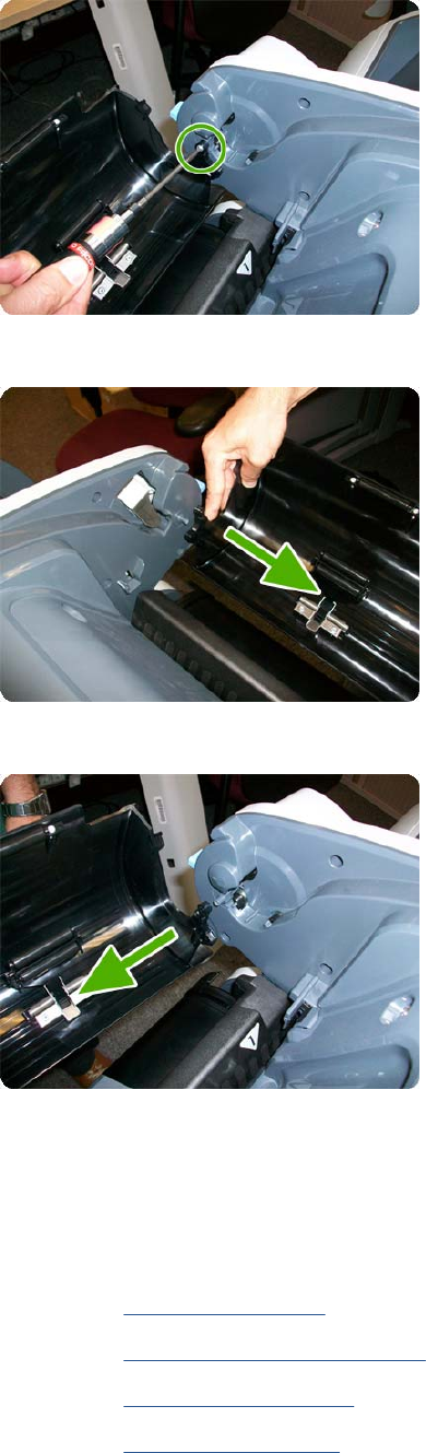
3. Remove the screw on the Roll Cover's right side that attaches to the Upper Right Roll Support.
4. Remove the Roll Cover hinge from the Roll Left Support Pin.
5. Remove the Roll Cover hinge from the Roll Right Support Pin.
Left Roll Guide
Removal
1. Switch off the product and remove the power cable.
2. Remove the Spindle on page 402.
3. Remove the Roll Cover, Lower on page 378.
4. Remove the Converger on page 261.
5. Remove the Cleanout on page 257.
382 Chapter 6 Removal and Installation ENWW
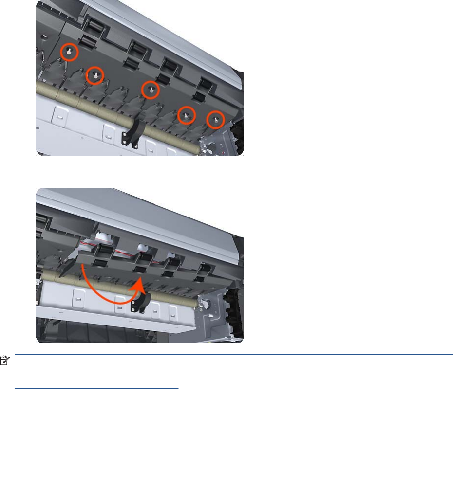
6. Remove five T-20 screws that secure the Left Roll Guide to the product.
7. Lower the left end and remove the Left Roll Guide from the product.
NOTE: When you finish installing or replacing this component, you must perform the necessary
Service Calibrations. To find which calibrations you must perform, see Service Calibration Guide to
Removal and Installation on page 205.
Right Roll Guide
Removal
1. Switch off the product and remove the power cable.
2. Remove the Left Roll Guide on page 382.
ENWW Right Roll Guide 383
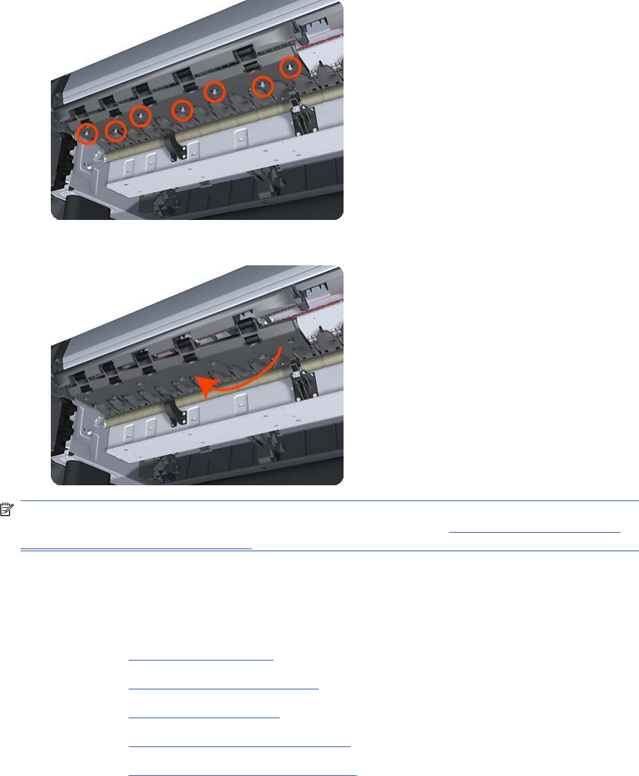
3. Remove seven T-20 screws that secure the Right Roll Guide to the product.
4. Lower the right end and remove the Right Roll Guide from the product.
NOTE: When you finish installing or replacing this component, you must perform the necessary
Service Calibrations. To find which calibrations you must perform, see Service Calibration Guide to
Removal and Installation on page 205.
Roll Support, Lower Left
Removal
1. Remove the Converger on page 261.
2. Remove the Roll Cover, Lower on page 378.
3. Remove the Rear Cover on page 366.
4. Remove the Rear Cover (MFP only) on page 363.
5. Remove the Roll Support, Upper Left on page 389.
6. Remove screws as shown.
384 Chapter 6 Removal and Installation ENWW

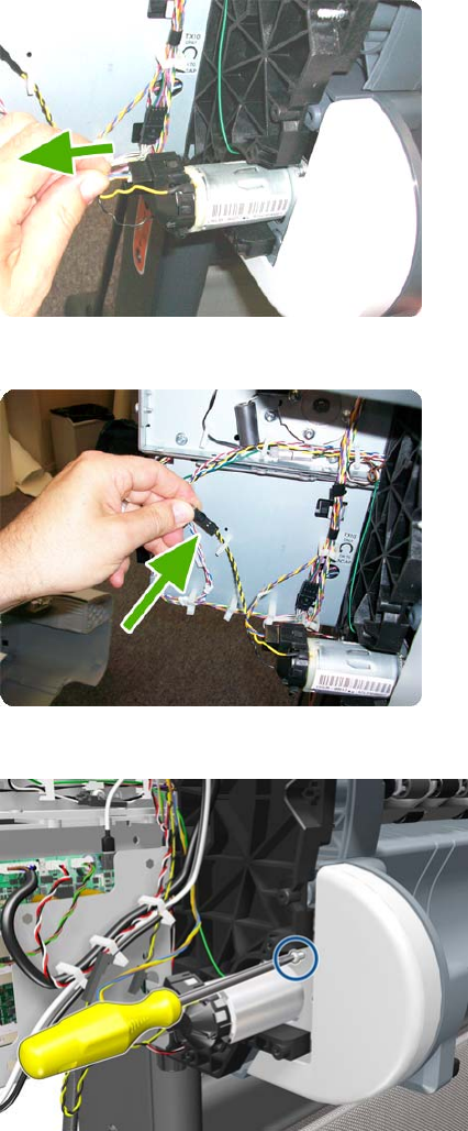
3. Unplug the motor encoder cable.
4. Unplug the motor cable.
5. Remove the T-15 screw of the grounding cable.
386 Chapter 6 Removal and Installation ENWW


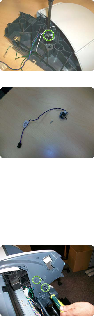
2. Unscrew the screw as shown.
3. Remove the sensor.
Roll Support, Upper Left
Removal
1. Remove the Roll Cover, Upper on page 381.
2. Remove the Converger on page 261.
3. Remove the Rear Cover on page 366.
4. Remove the Rear Cover (MFP only) on page 363.
5. Remove the two T–15 screws as shown.
ENWW Roll Support, Upper Left 389
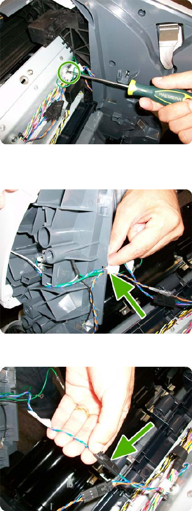
6. Remove the T–20 screw as shown.
7. Unplug the Upper Left Roll Support, taking care not to damage the cables. Detach all cables from
the Roll Support.
8. Disconnect the cable connector as shown.
390 Chapter 6 Removal and Installation ENWW
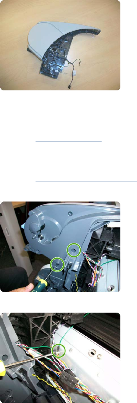
9. Remove the Upper Left Roll Support.
Roll Support, Upper Right
Removal
1. Remove the Converger on page 261.
2. Remove the Roll Cover, Upper on page 381.
3. Remove the Rear Cover on page 366.
4. Remove the Rear Cover (MFP only) on page 363.
5. Remove two T-15 screws.
6. Remove one T-20 screws.
ENWW Roll Support, Upper Right 391
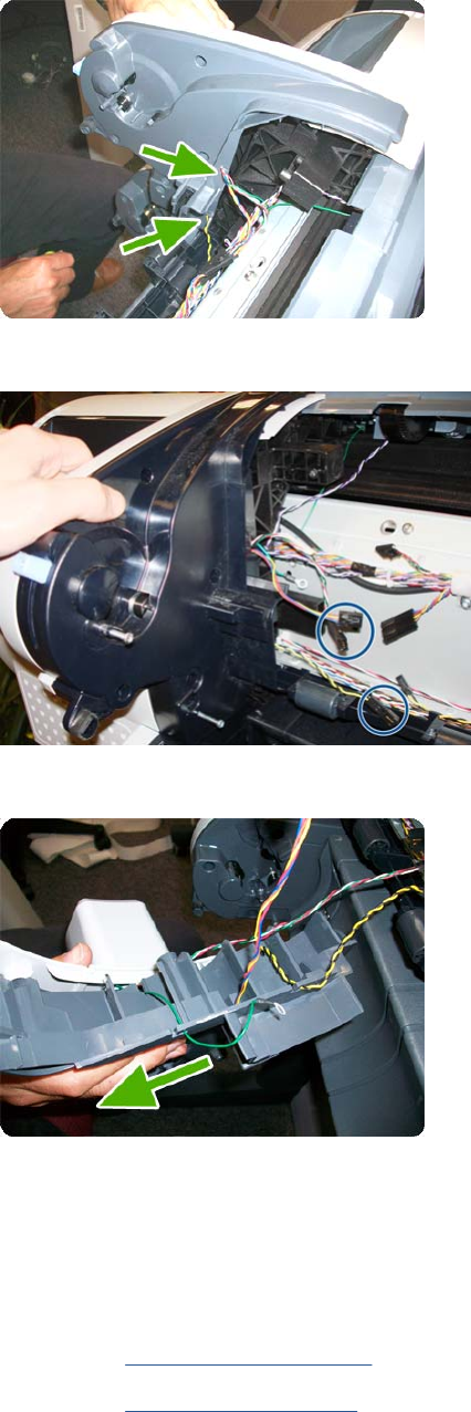
7. Unplug the Upper Right Roll Support, taking care not to damage the cables. Detach all cables from
the Roll Support.
8. Important disconnect three connectors.
9. Remove the Upper Right Roll Support.
Scan-axis Motor
Removal
1. Switch off the product and remove the power cable.
2. Remove the Right Cover on page 368.
3. Remove the Left Cover on page 317.
392 Chapter 6 Removal and Installation ENWW
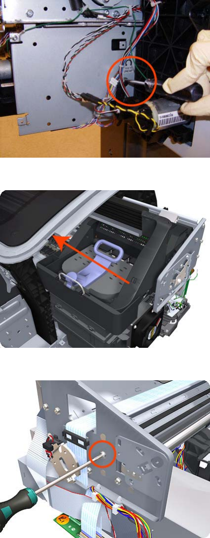
4. Loosen the T-10 uncapping screw sufficiently so you can move the Carriage Assembly manually.
5. Push the Carriage Assembly into the print path.
6. Loosen the T-20 screw Belt Tensioner to the product to remove the tension from the belt.
ENWW Scan-axis Motor 393
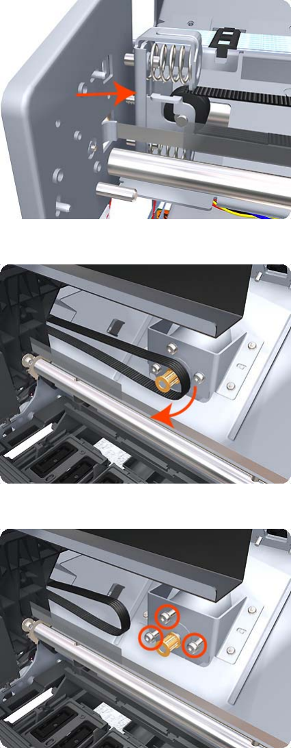
7. Leave the Belt Tensioner in place.
8. Remove the Belt Assembly from the drive wheel of the Scan-Axis Motor.
9. Remove three T-20 screws that secure the Scan-Axis Motor to the product.
394 Chapter 6 Removal and Installation ENWW
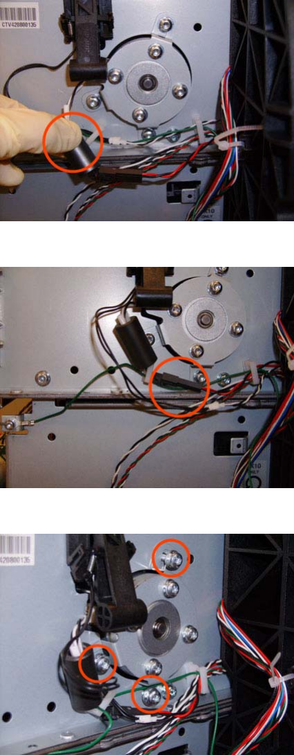
10. Unroute the Scan-Axis Motor supply cable from the cable clamp.
11. Disconnect the Scan-Axis Motor supply connector from the L1 Harness.
12. Remove three T-20 screws that secure the Scan-Axis Motor to the product.
ENWW Scan-axis Motor 395
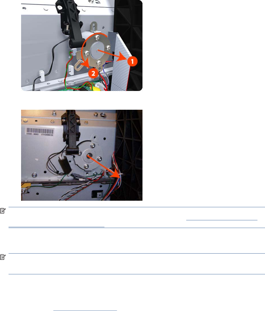
13. Carefully pull the Scan-Axis Motor out of the product (10 mm) until you can rotate it approximately
30 degrees counterclockwise.
14. Remove the Scan-Axis Motor from the product.
NOTE: When you finish installing or replacing this component, you must perform the necessary
Service Calibrations. To find which calibrations you must perform, see Service Calibration Guide to
Removal and Installation on page 205.
Service Station
NOTE: The Service Station repair kit does not include the Touch Control Panel Holder nor the Cable
holder under the primer. These parts need to be re-used from the product when replacing the Service
Station.
Removal
1. Switch off the product and remove the power cable.
2. Remove the Right Cover on page 368.
396 Chapter 6 Removal and Installation ENWW
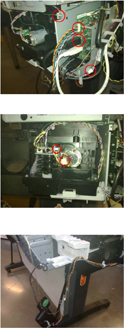
3. Disconnect and remove the following cables indicated from the Intermediate PCA.
4. Disconnect and remove the following cables indicated from the Primer of the Service Station.
5. Remove the Touch Control Panel from the holder and leave it carefully hanging as shown in the
picture.
ENWW Service Station 397
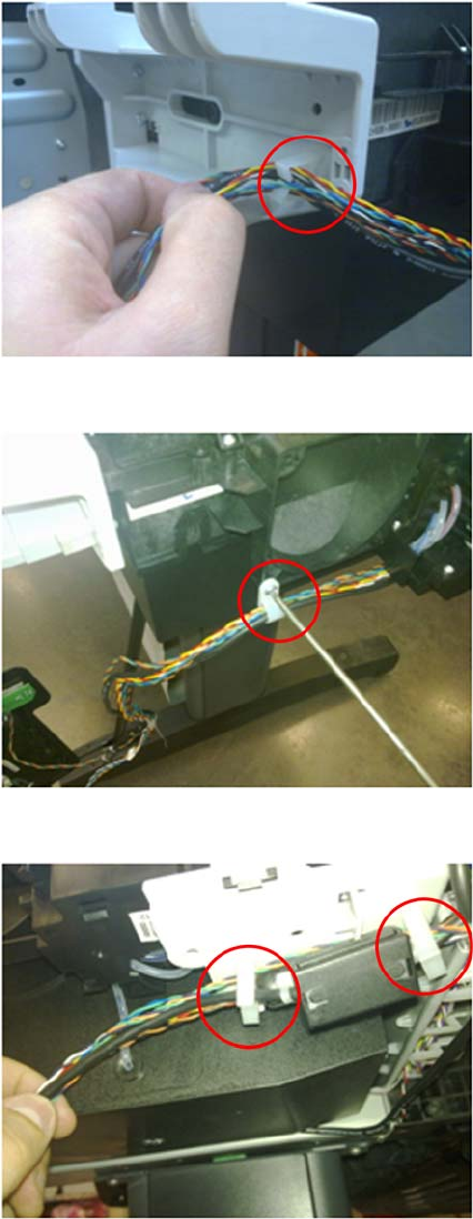
6. Remove the Touch Control Panel cable from the cable tie.
7. Remove the cable tie by removing the screw indicated.
8. Remove the cables indicated from the cable ties.
398 Chapter 6 Removal and Installation ENWW
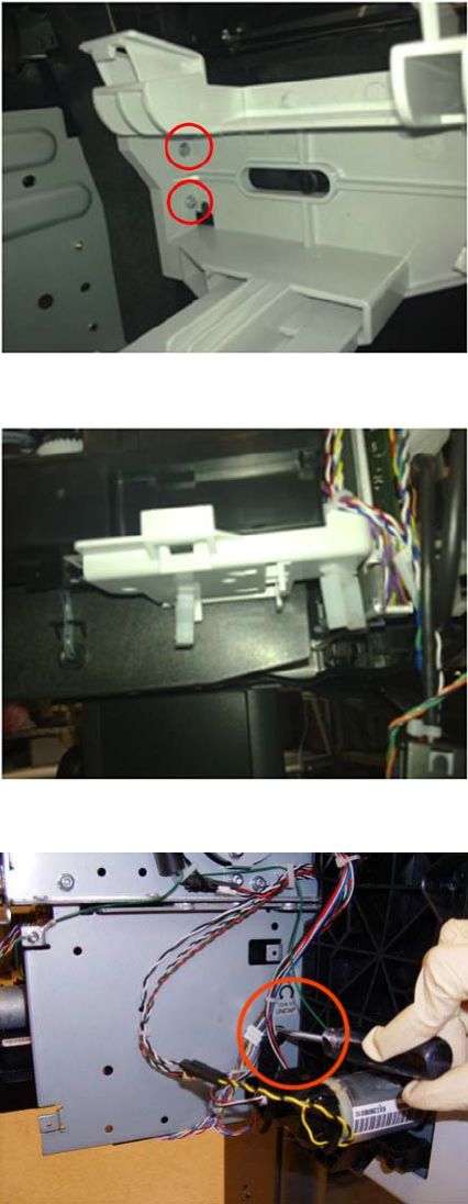
9. Remove both screws from the Touch Control Panel Holder (do not discard them as the parts will
be reused).
10. Unclip the cable holder from underneath the primer (do not discard it as the part will be reused).
11. Loosen the T-10 uncapping screw enough so that you can move the Carriage Assembly manually.
ENWW Service Station 399
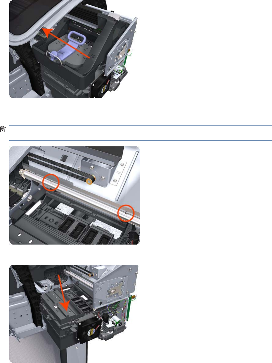
12. Push the Carriage Assembly into the print path to gain access to two T-10 screws that secure the
Service Station to the Carriage Rail.
13. Remove the two Allen T-8 screws that secure the Service Station to the Carriage Rail. To avoid
damaging the Encoder Strip, you can use a standard screwdriver.
NOTE: Support the Service Station so that it does not fall when you remove the attachment
screws.
14. Lower the Service Station until you can slide it carefully from the product.
400 Chapter 6 Removal and Installation ENWW
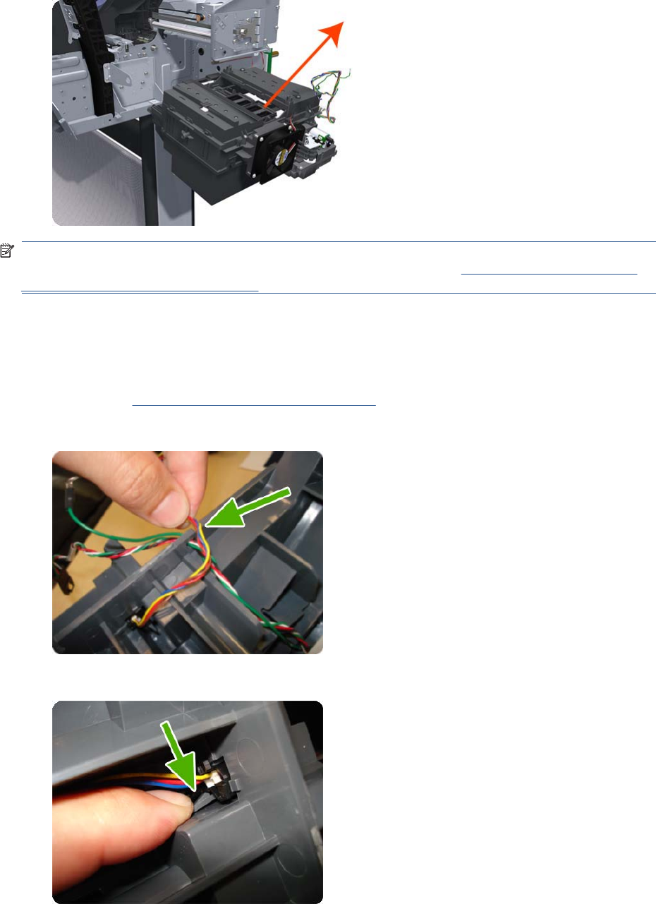
15. Carefully slide the Service Station from the product.
NOTE: When you finish installing or replacing this component, you must perform the necessary
Service Calibrations. To find which calibrations you must perform, see Service Calibration Guide to
Removal and Installation on page 205.
Single-sheet Sensor
Removal
1. Remove the Roll Support, Upper Right on page 391.
2. Disengage the cable.
3. Push down the clip that holds the Siva sensor (you can use a screwdriver).
ENWW Single-sheet Sensor 401
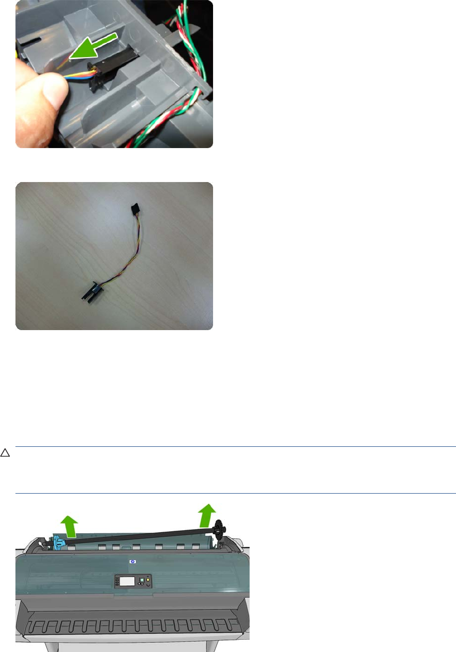
4. Pull out the sensor.
5. The sensor has been removed.
Spindle
Removal
1. Open the roll cover.
2. Remove the black end of the spindle from the product, then the blue end.
CAUTION: Be sure to remove the black end first. Removing the blue end first could damage the
black end.
CAUTION: Do not insert your fingers into the spindle supports during the removal process.
402 Chapter 6 Removal and Installation ENWW
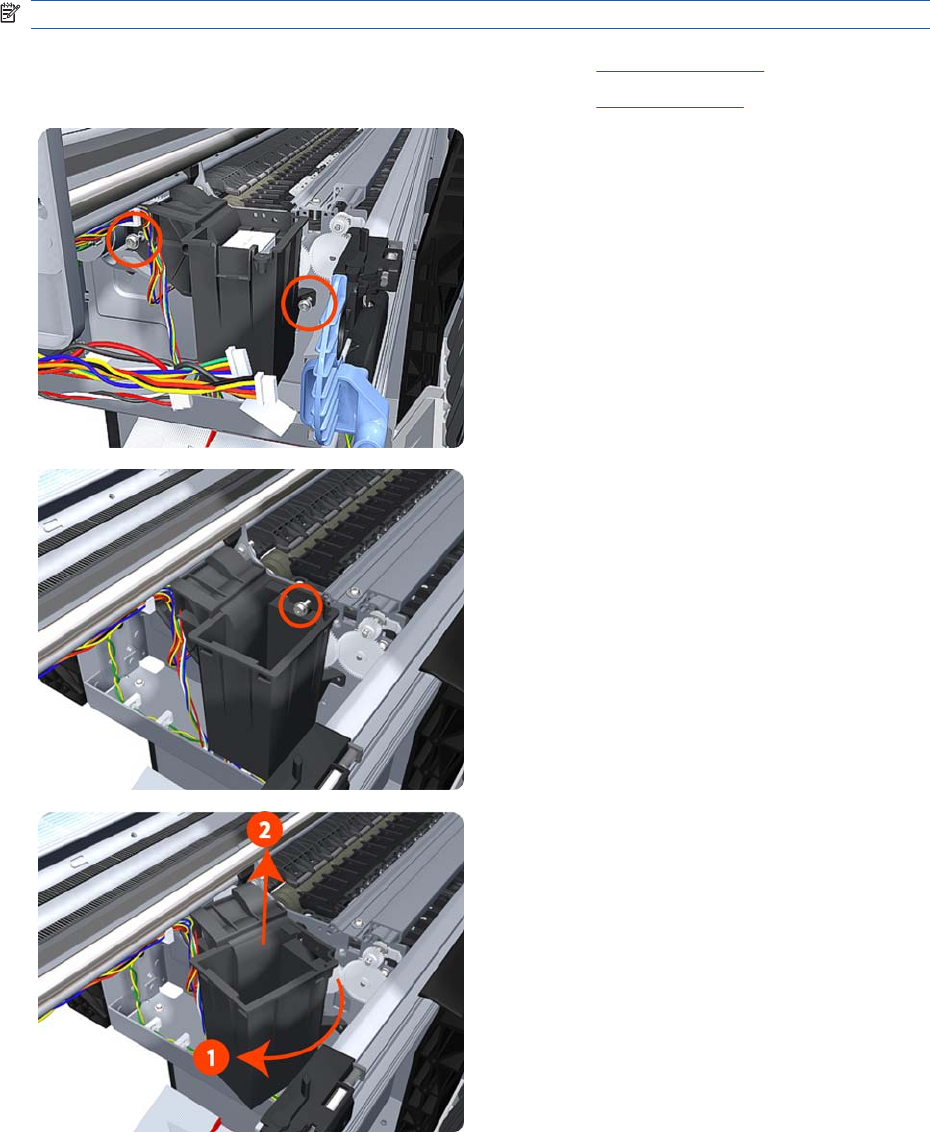
Spittoon, Left
Removal
This procedure describes how to remove the complete Left Spittoon which is necessary to gain access
to other components.
NOTE: Switch off the product and remove the power cable.
1. Remove the Left Cover on page 317.
2. Remove the EE Box on page 281.
3. Remove two T-20 screws that secure the Left Spittoon to
the product.
4. Remove one T-8 screw that secures the Left Spittoon to the
product.
5. Rotate the Left Spittoon clockwise approximately 45
degrees and carefully lift it out of the product.
ENWW Spittoon, Left 403
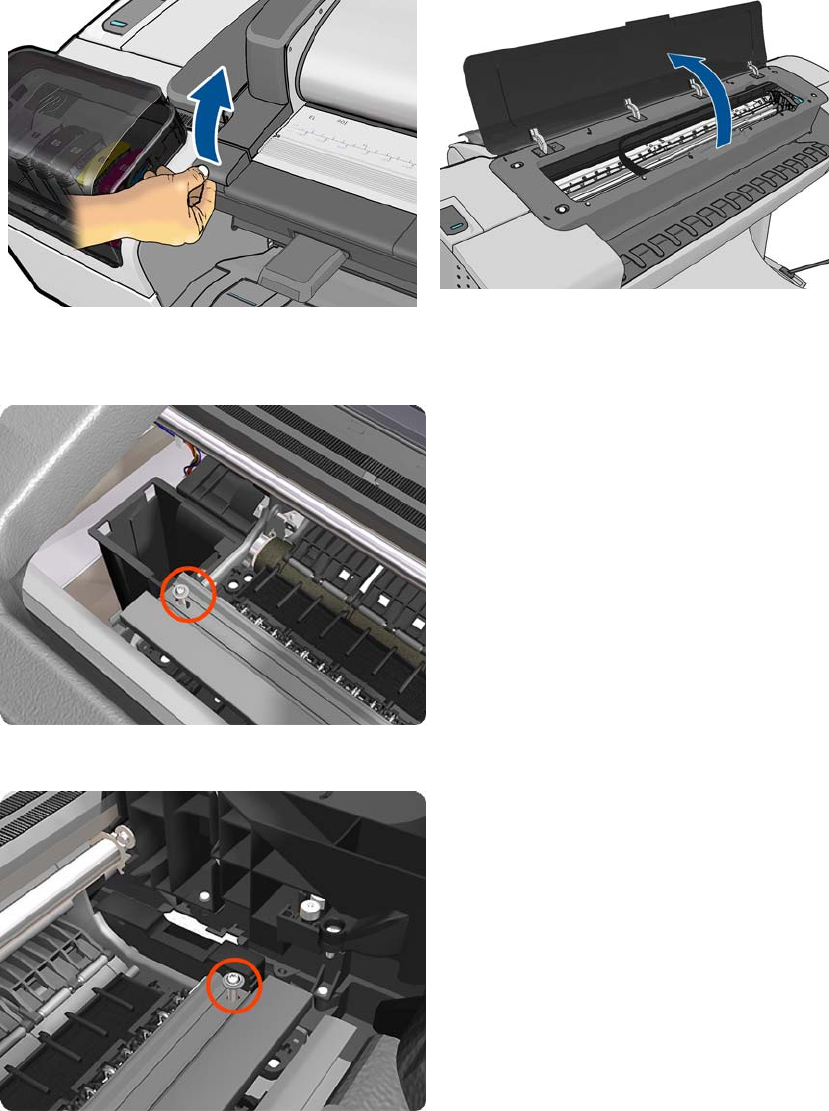
Starwheel Assembly
Removal
1. Switch off the product and remove the power cable.
2. Open the Scanner (MFP only) or Window.
3. Remove one T-10 screw that secures the Starwheel Assembly to the product. Use a short screw
driver as this will allow the best access.
4. Remove another T-10 screw that secures the Starwheel Assembly to the product.
404 Chapter 6 Removal and Installation ENWW
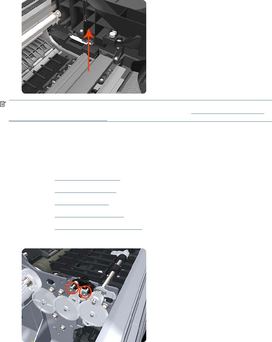
5. Carefully lift the Starwheel Assembly out of the product.
NOTE: When you finish installing or replacing this component, you must perform the necessary
Service Calibrations. To find which calibrations you must perform, see Service Calibration Guide to
Removal and Installation on page 205.
Starwheel Lifter, Left
Removal
1. Switch off the product and remove the power cable.
2. Remove the Front Cover on page 275.
3. Remove the Left Cover on page 317.
4. Remove the EE Box on page 281.
5. Remove the Spittoon, Left on page 403.
6. Remove the Starwheel Assembly on page 404.
7. Remove two T-8 screws that secure the Left Starwheel Lifter to the product.
ENWW Starwheel Lifter, Left 405
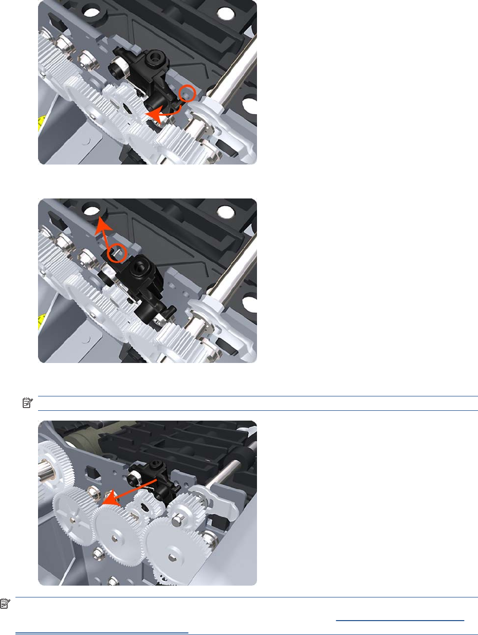
8. Rotate the Left Starwheel Lifter sufficiently to disengage the right attachment lug.
9. Tilt the Left Starwheel Lifter sufficiently to disengage the left attachment lug.
10. Remove the Left Starwheel Lifter from the product.
NOTE: Do not remove the spring from the Left Starwheel Lifter, because it is difficult to reattach.
NOTE: When you finish installing or replacing this component, you must perform the necessary
Service Calibrations. To find which calibrations you must perform, see Service Calibration Guide to
Removal and Installation on page 205.
406 Chapter 6 Removal and Installation ENWW
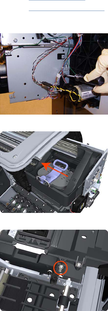
Starwheel Lifter, Right
Removal
1. Switch off the product and remove the power cable.
2. Remove the Right Cover on page 368.
3. Remove the Starwheel Assembly on page 404.
4. Loosen the T-10 uncapping screw sufficiently so you can manually move the Carriage Assembly
in step 8.
5. Push the Carriage Assembly into the print path.
6. Remove one T-10 screw that secures the Drop Detector to the Service Station.
ENWW Starwheel Lifter, Right 407
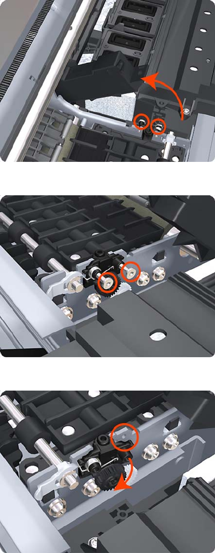
7. Rotate the Drop Detector vertically to gain access to the two screws that secure the Right Starwheel
Lifter.
8. Remove two T-8 screws that secure the Right Starwheel Lifter to the product.
9. Rotate the Right Starwheel Lifter sufficiently to disengage the right attachment lug.
408 Chapter 6 Removal and Installation ENWW
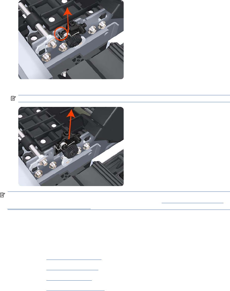
10. Tilt the Right Starwheel Lifter sufficiently to disengage the left attachment lug.
11. Remove the Right Starwheel Lifter from the product.
NOTE: Do not remove the spring from the Right Starwheel Lifter, because it is difficult to reattach.
NOTE: When you finish installing or replacing this component, you must perform the necessary
Service Calibrations. To find which calibrations you must perform, see Service Calibration Guide to
Removal and Installation on page 205.
Starwheel Motor
Removal
1. Switch off the product and remove the power cable.
2. Remove the Front Cover on page 275.
3. Remove the Left Cover on page 317.
4. Remove the EE Box on page 281.
5. Remove the Spittoon, Left on page 403.
ENWW Starwheel Motor 409
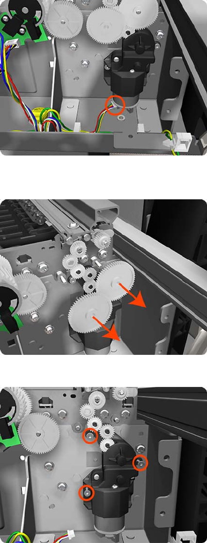
6. Disconnect the Starwheel Motor electrical connector.
7. Carefully pull the two gear wheels off their shafts to gain access to the Starwheel Motor attachment
screws.
8. Remove three T-8 screws that secure the Starwheel Motor to the product.
410 Chapter 6 Removal and Installation ENWW
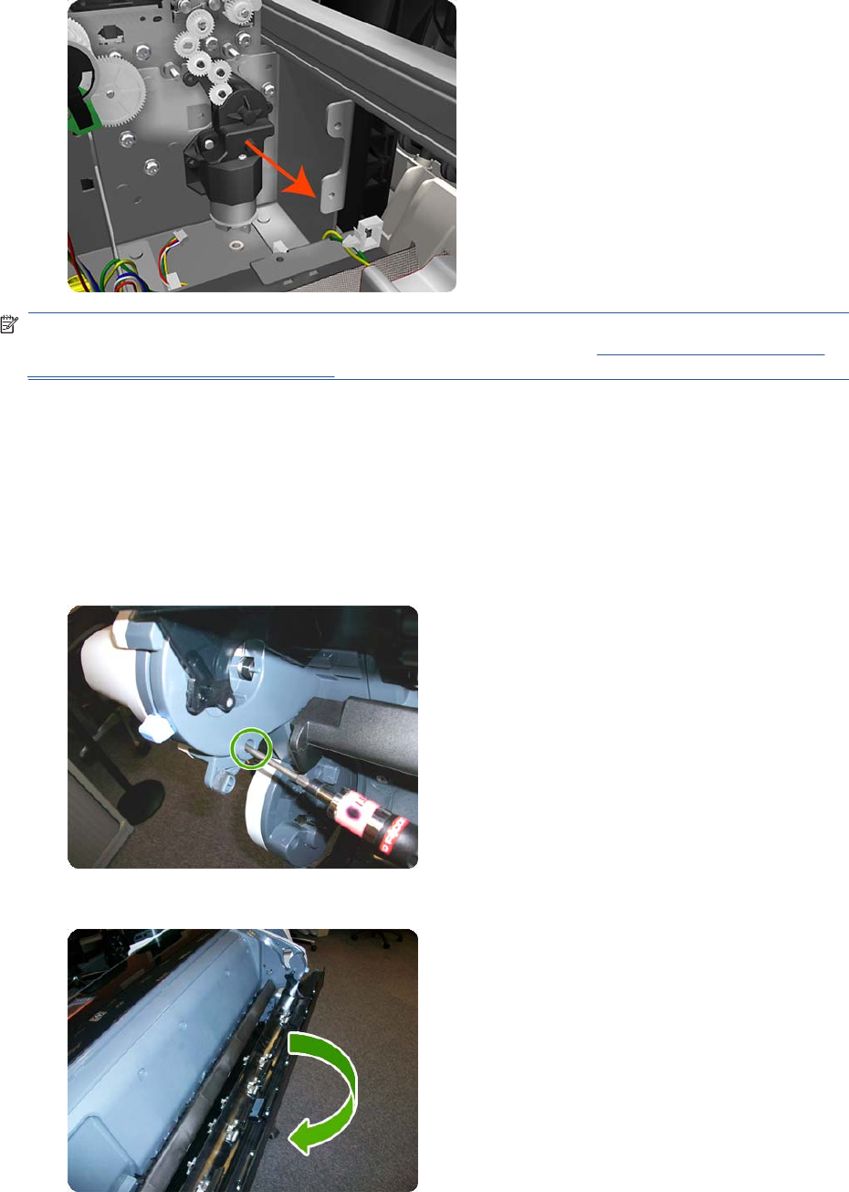
9. Lift the Starwheel Motor out of the product.
NOTE: When you finish installing or replacing this component, you must perform the necessary
Service Calibrations. To find which calibrations you must perform, see Service Calibration Guide to
Removal and Installation on page 205.
Wall Spacers
Removal
The illustrations show the removal of the Right Wall Spacer; the procedure is the same for the Left Wall
Spacer.
1. Remove a screw.
2. Open the Upper Roll Cover.
ENWW Wall Spacers 411
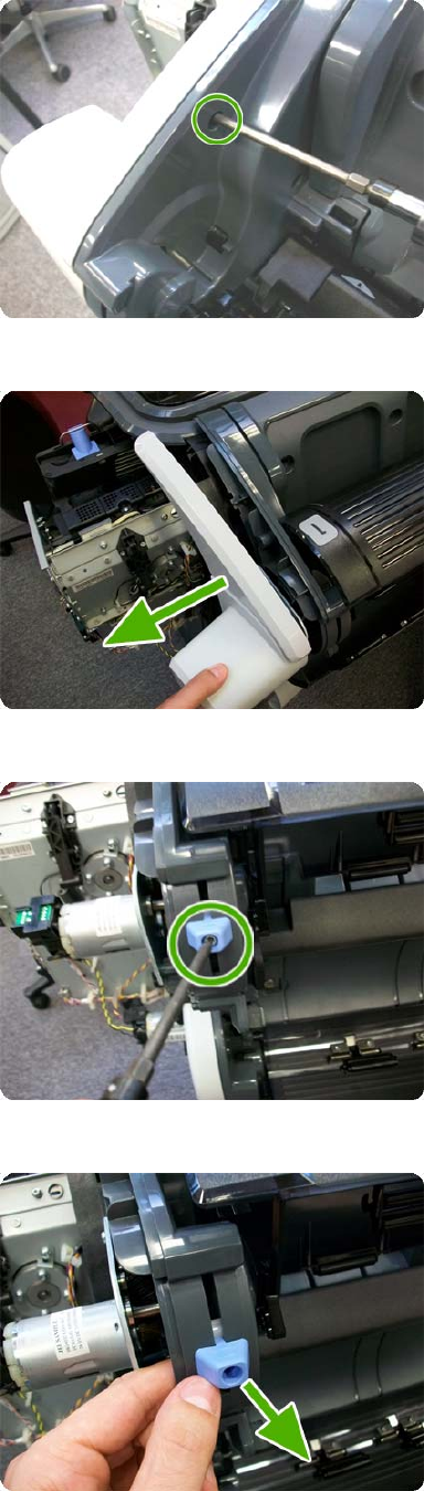
3. Remove a screw.
4. Remove the Upper Roll Cover Support.
5. Remove a screw.
6. Remove a blue Wall Spacer.
412 Chapter 6 Removal and Installation ENWW
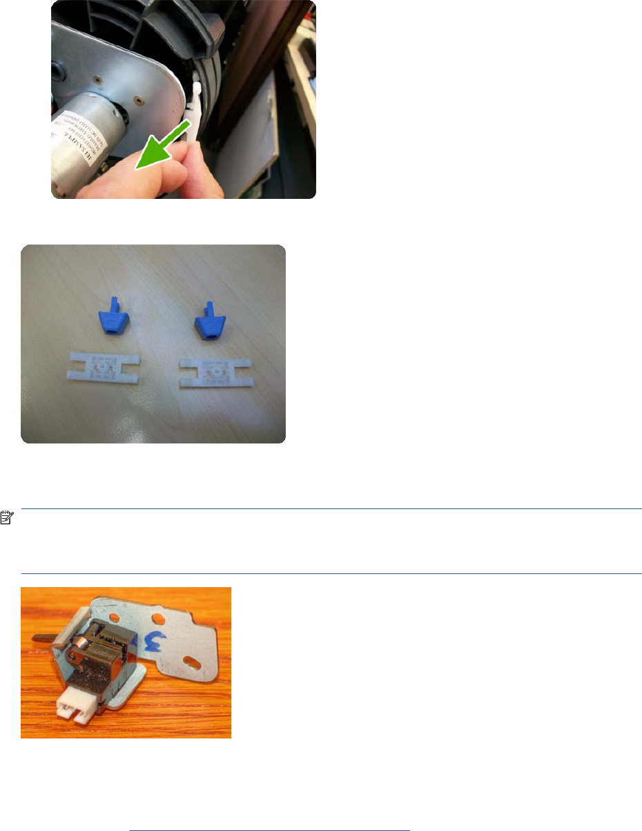
7. Remove a white slider.
After removing Right and Left Wall Spacers, here are the removed parts.
Scanner Position Sensor (MFP only)
NOTE: Disassemble metal casing before installing it.
NOTE: In order to avoid accidentally disconnecting the sensor while opening the scanner, because
the cable is incorrectly adjusted, follow the installation steps carefully in the installation procedure.
Removal
1. Switch off the product and remove the power cable.
2. Remove the Right Scanner Cover (MFP only) on page 372.
ENWW Scanner Position Sensor (MFP only) 413
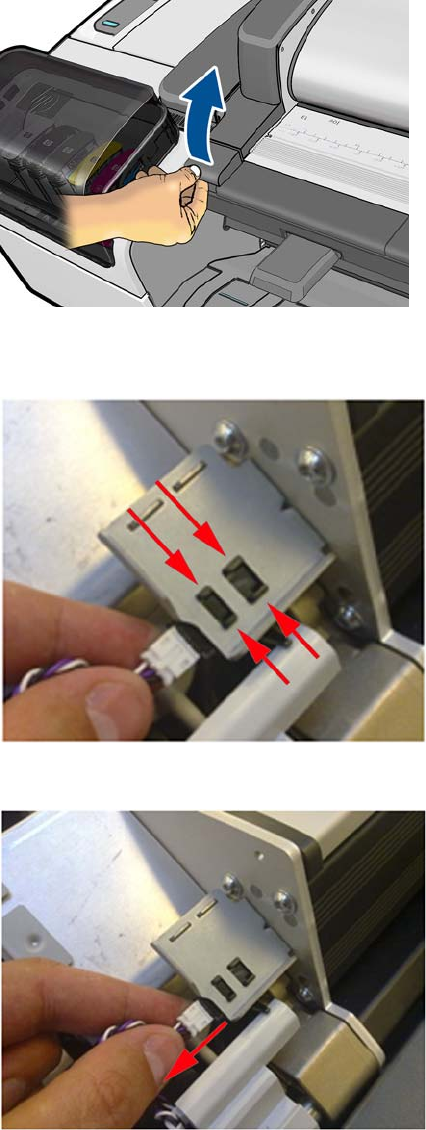
3. Open the Scanner.
4. Remove the Scanner Position Sensor from the holder by unclipping it (keep the sensor cable
plugged into the sensor).
5. Remove the Scanner Position Sensor.
414 Chapter 6 Removal and Installation ENWW
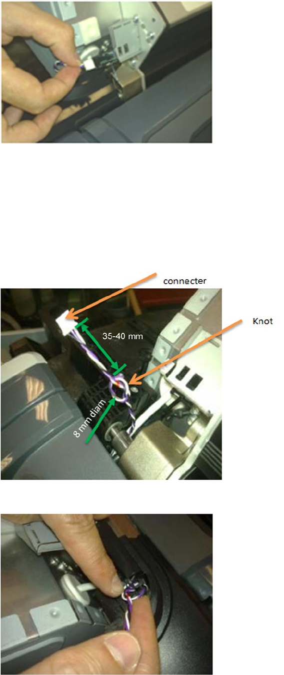
6. Disconnect the Scanner Position Sensor from the cable.
Installation
The correct adjustment of the cable of the Scanner Position Sensor is important, if the cable is not
adjusted correctly this could cause the cable to disconnect when the scanner is opened, or become
trapped between covers.
1. Make sure that the cable has a knot on the collar anchor of around 8 mm diameter, and located
around 35-40 mm from the end of the white connector. This is to ensure there is a movement space
for the cable when the scanner is opened and closed.
2. Anchor the knot of the cable on to the small clip of the Right Collar.
ENWW Scanner Position Sensor (MFP only) 415
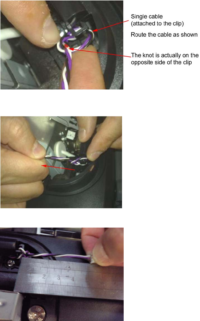
3. Ensure the knot of the cable is correctly placed on the clip as shown here.
4. Once in the clip of the collar, pull slightly from the white connector in the direction of the arrow until
the knot is fully attached.
5. Make sure that the cable length is now 50-55 mm long from the knot to the connector.
416 Chapter 6 Removal and Installation ENWW
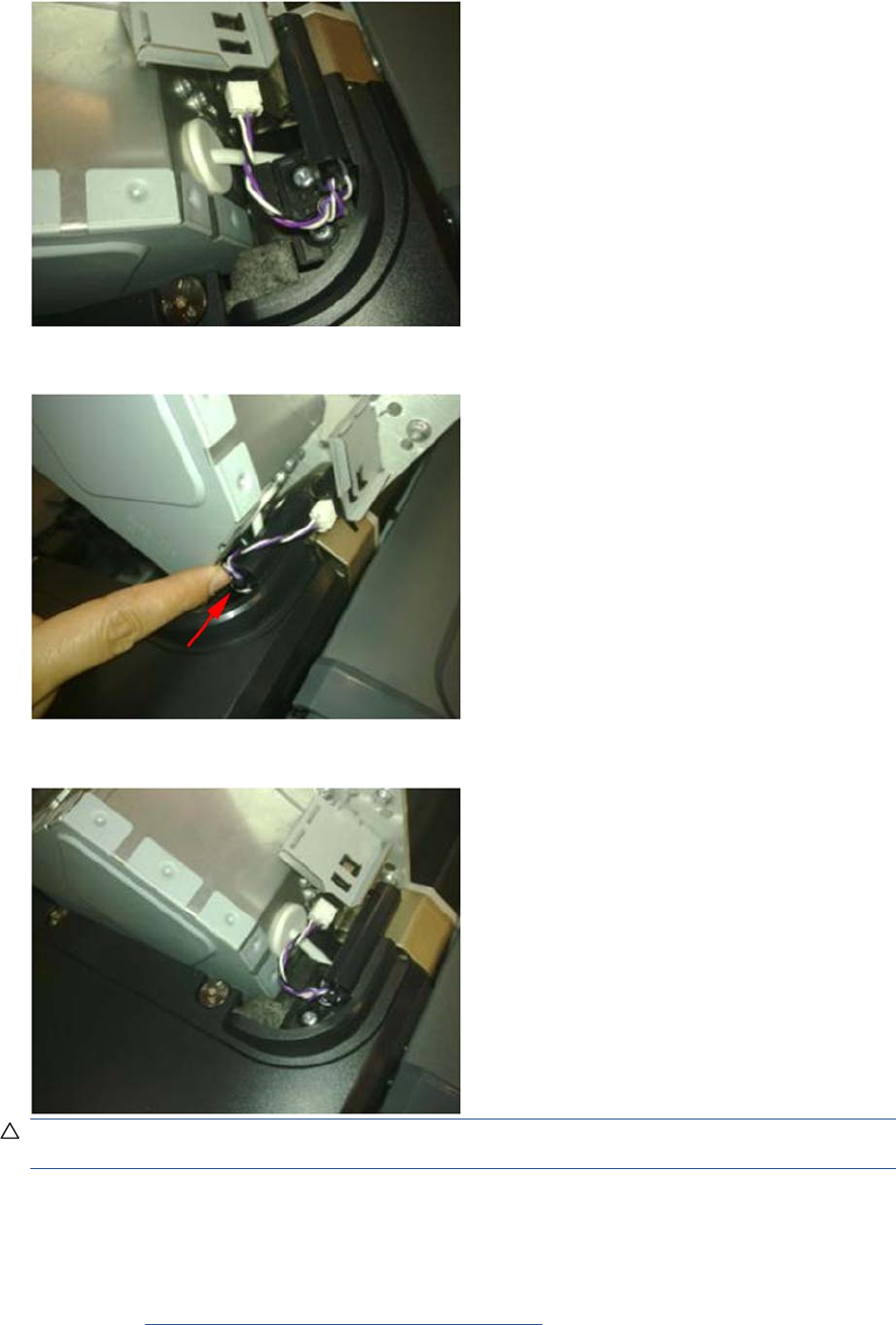
6. Connect the cable.
7. Push the knot of the cable in the direction of the arrow (if needed) .
8. Make sure that the cable is long enough when the scanner is in open position
CAUTION: If the cable of the Scanner Position Sensor is too long it may be become trapped
between the Right Scanner Cover and the Right Collar
Torsion Damper (MFP only)
1. Switch off the product and remove the power cable.
2. Remove the Left Scanner Cover (MFP only) on page 321.
ENWW Torsion Damper (MFP only) 417
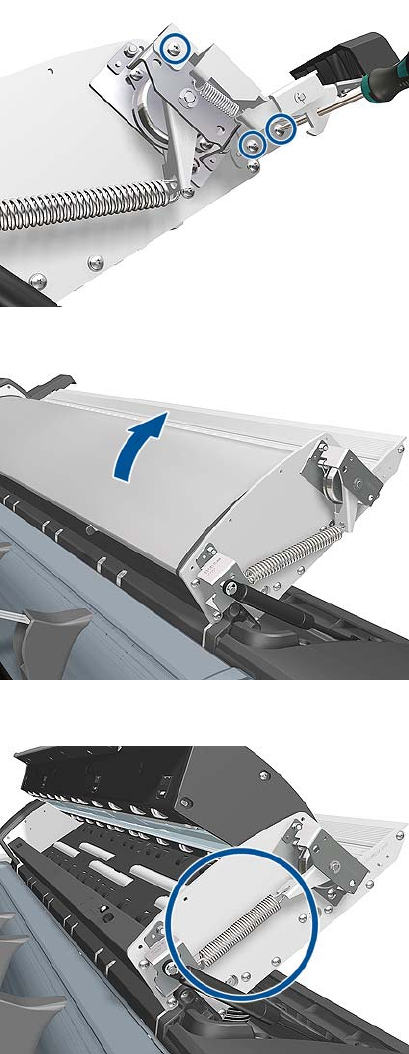
3. Remove three T-20 screws that secure the Torsion bracket to the left side
4. Put the CIS in a neutral position.
5. Remove the Torsion Damper from a clip on the side.
418 Chapter 6 Removal and Installation ENWW
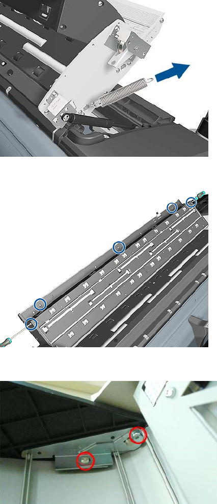
6. Remove the Torsion Damper Spring.
7. Remove five T-20 screws and open the CIS unit.
8. Loosen two T-20 screws to release the clamp on the damper shaft.
ENWW Torsion Damper (MFP only) 419

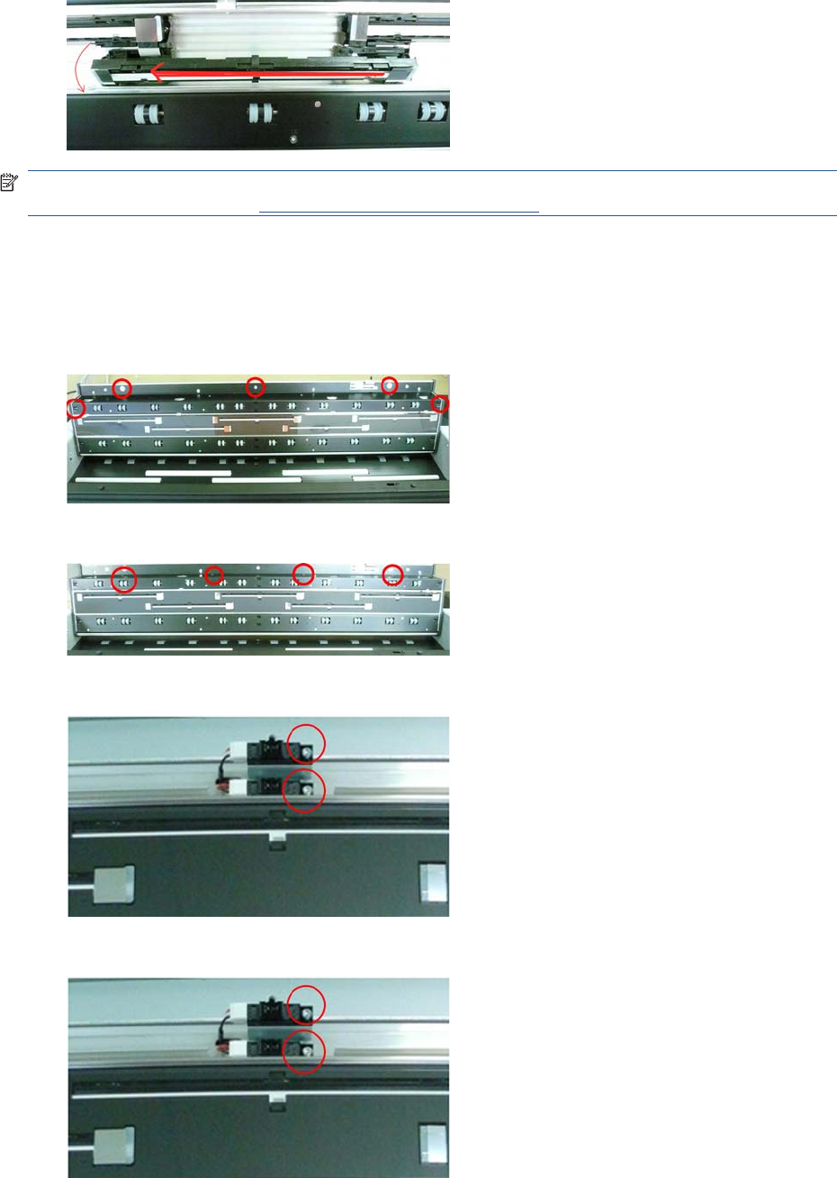
5. Flip CIS out and slide out to the side.
NOTE: After installing a new CIS element thoroughly clean the Scanner of dust and dirt and perform
the Scanner Calibration, see Calibrate the Scanner on page 170.
Scanner Exit Media Sensors (MFP only)
1. Switch off the product and remove the power cable.
2. Open the CIS and remove five T-20 screws.
3. Remove four T-10 screws and remove the Rear Roller Cover.
4. Disconnect the cables from the Exit Sensors.
5. Remove the T-10 screws.
ENWW Scanner Exit Media Sensors (MFP only) 421
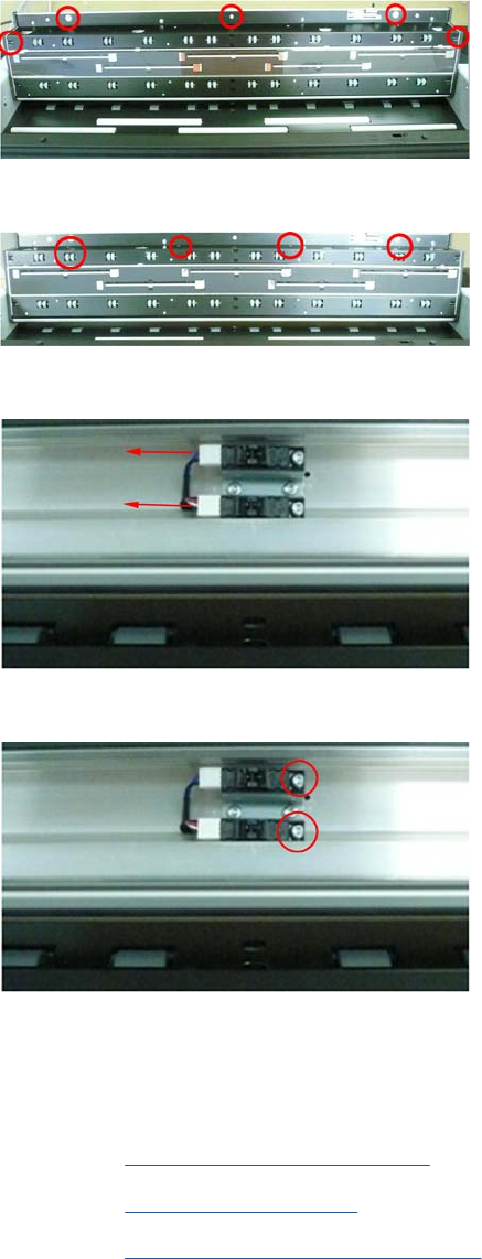
Scanner Entry Media Sensors (MFP only)
1. Switch off the product and remove the power cable.
2. Open the CIS and remove five T-20 screws .
3. Remove four T-10 screws and remove the Front Roller Cover.
4. Disconnect the cables from the Entry Sensors.
5. Remove the T-10 screws.
Pressure Rollers (MFP only)
1. Switch off the product and remove the power cable.
2. Remove the Roll Cover, Upper on page 381.
3. Remove the Converger on page 261
4. Remove the Rear Cover (MFP only) on page 363
422 Chapter 6 Removal and Installation ENWW
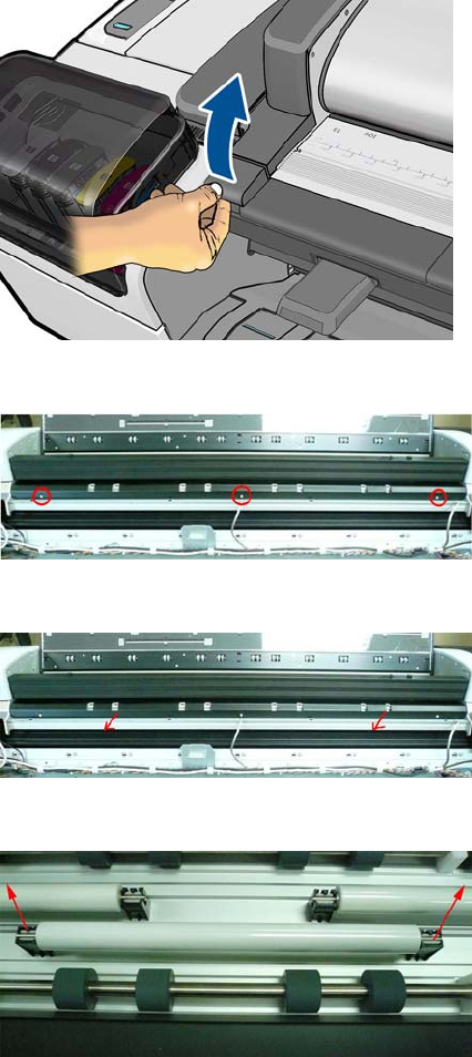
5. Open the Scanner.
6. Remove three T-15 screws that secure the Roller Cover Sheet
7. Remove the Roller Cover Sheet by pulling it out.
8. Remove Pressure rollers by pulling them out.
Scanner Controller Board (MFP only)
1. Switch off the product and remove the power cable.
ENWW Scanner Controller Board (MFP only) 423
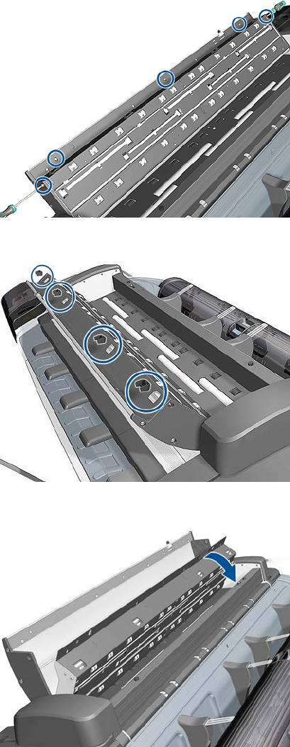
2. Open the CIS unit and remove five T-20 screws.
3. Remove four pinch rollers from the CIS unit.
4. Close the cover of the CIS unit, but leave the top cover open.
424 Chapter 6 Removal and Installation ENWW
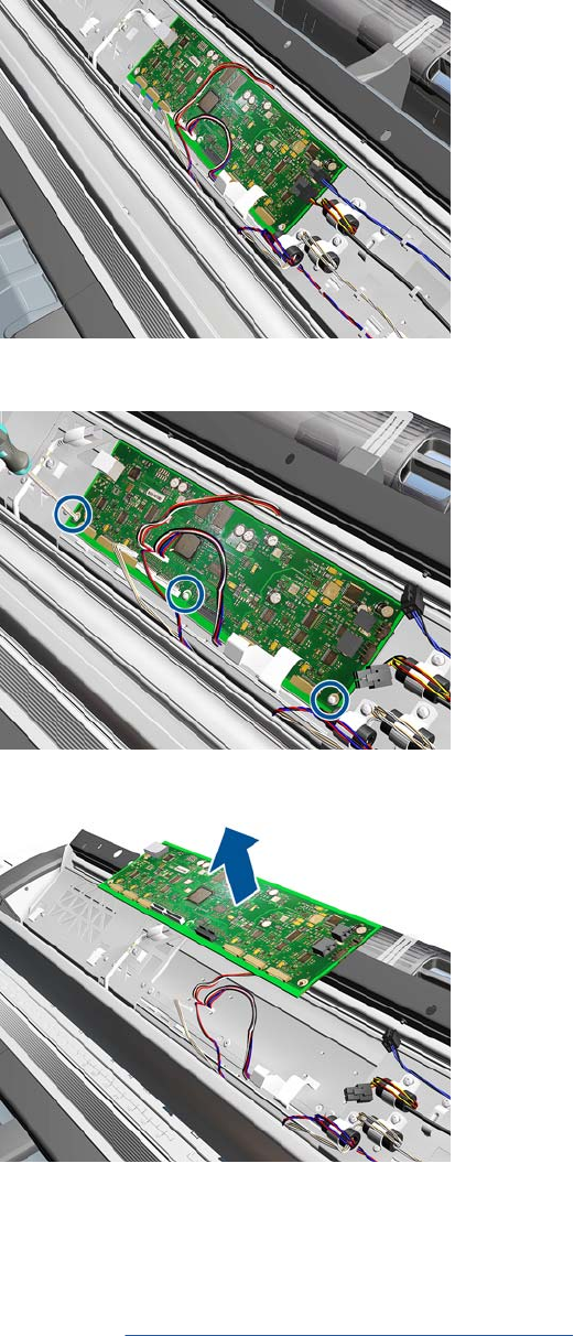
5. Disconnect all cables from the Scanner Controller Board.
6. Remove three T-10 screws from the Scanner Controller Board.
7. Remove the Scanner Controller Board.
Scanner Motor Assembly (MFP only)
1. Switch off the product and remove the power cable.
2. Remove the Right Scanner Cover (MFP only) on page 372
ENWW Scanner Motor Assembly (MFP only) 425
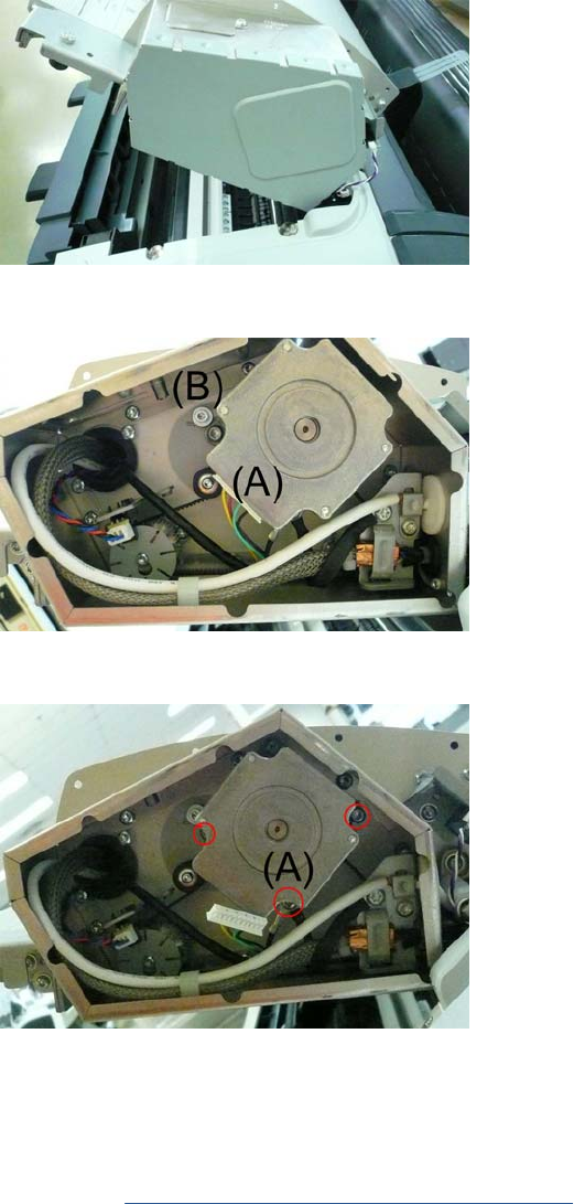
3. Remove the Scanner Motor Enclosure cover by pulling it off.
4. Disconnect the Motor Cables (A) and loosen the Belt Tensioner screw (B).
5. Disconnect grounding cable (A) and remove two T-20 screws that secure the Scanner Motor. .
Taco Sensor (MFP only)
1. Switch off the product and remove the power cable.
2. Remove the Right Scanner Cover (MFP only) on page 372
426 Chapter 6 Removal and Installation ENWW
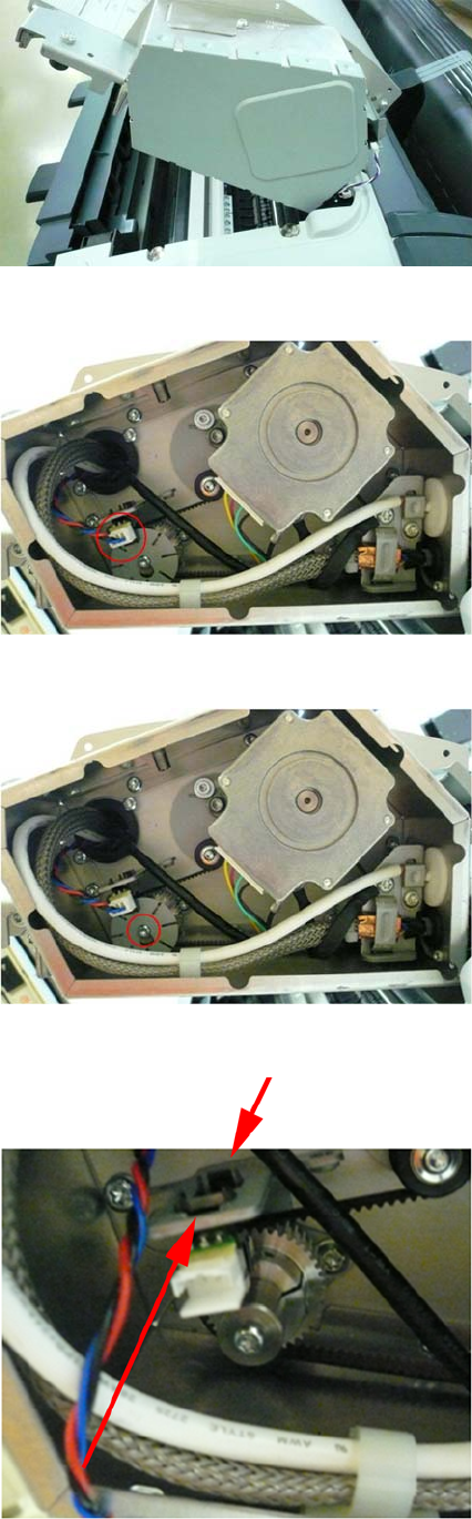
3. Remove the Scanner Motor Enclosure cover by pulling it off.
4. Disconnect the Taco Sensor.
5. Remove T-10 screw that secures the Taco Wheel and remove.
6. Release the Taco Sensor from clips and remove.
ENWW Taco Sensor (MFP only) 427
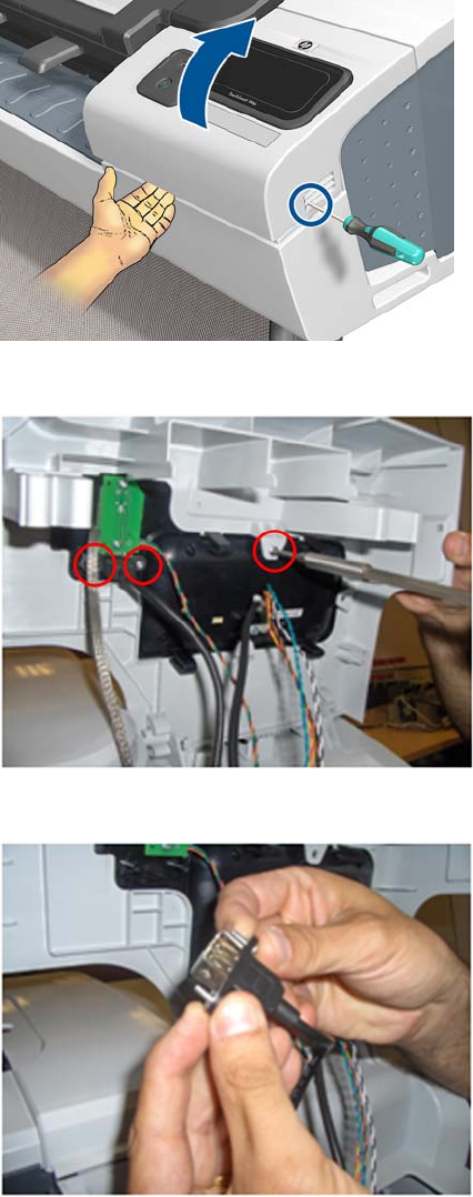
Touch Control Panel
Removal
1. Switch off the product and remove the power cable.
2. Open the Right Ink Cartridge Door by inserting a screwdriver into the side to unlatch it, and then
lift up the door.
3. Remove one T-15 screw and two T-10 screws from the back of the Touch Control Panel.
4. Disconnect the USB and Grounding cable from the Touch Control Panel.
428 Chapter 6 Removal and Installation ENWW
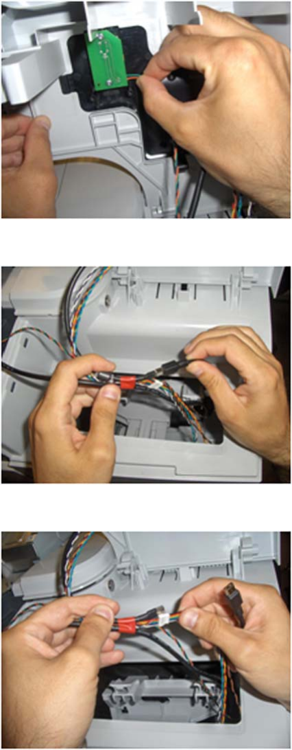
5. Disconnect the small cable.
6. Disconnect the USB cable from the cable bundle
7. Disconnect the Harness Cable from the cable bundle.
ENWW Touch Control Panel 429
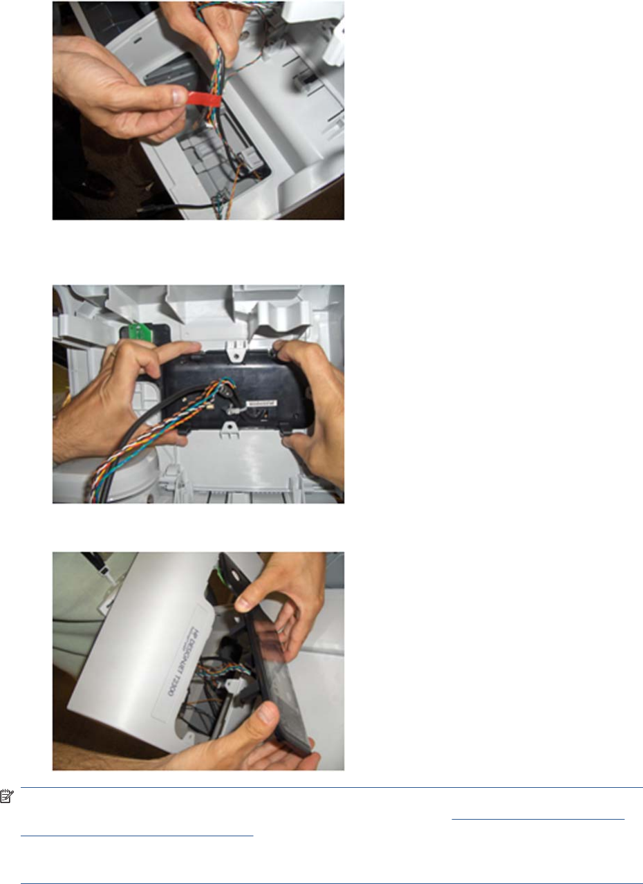
8. Remove the tape securing the cable bundle.
9. Press on the four corners of the Touch Control Panel to release it from the back of the Right Ink
Door.
10. Remove the Touch Control Panel from the Right Ink Door.
NOTE: When you finish installing or replacing this component, you must perform the necessary
Service Calibrations. To find which calibrations you must perform, see Service Calibration Guide to
Removal and Installation on page 205.
NOTE: When you reinstall the Touch Control Panel, you must make sure that the Ferrite Core is
correctly positioned. The Ferrite Core is necessary to avoid electrostatic interference being generated.
430 Chapter 6 Removal and Installation ENWW
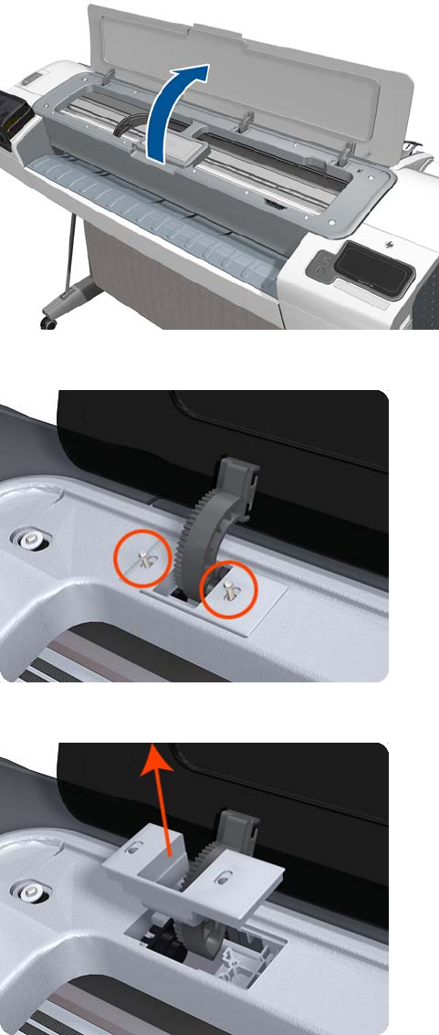
Window
Removal
1. Switch off the printer and remove the power cable.
2. Open the Window.
3. Remove the two T-15 screws that secure the left Window hinge locking plate to the Top Cover.
4. Remove the left Window hinge locking plate from the Top Cover.
ENWW Window 431
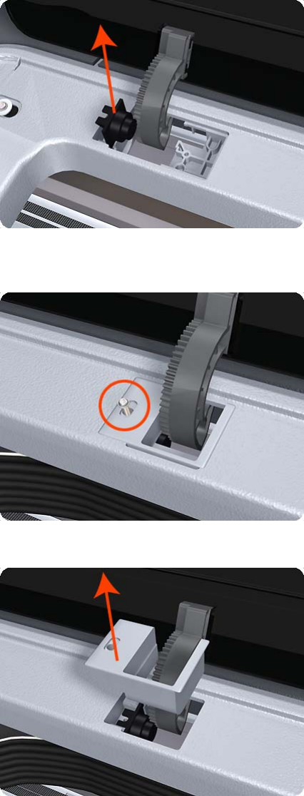
5. Remove the Damper Rotary from the Top Cover (T1200 only).
6. Remove the T-15 screws that secure each of the remaining three Window hinge locking plates to
the Top Cover.
7. Remove the remaining three Window hinge locking plates from the Top Cover.
432 Chapter 6 Removal and Installation ENWW
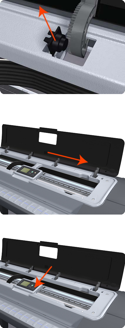
8. Remove the remaining three Damper Rotary pieces from the Top Cover.
9. Grip the Window at the left and right edges and move it horizontally towards the right as far as it
will go.
10. Pull the Window towards the front to disengage the hinges.
ENWW Window 433
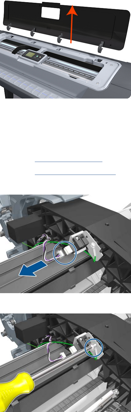
11. Lift the Window vertically out of the printer.
Window Position Sensor
Removal
1. Switch off the printer and remove the power cable.
2. Remove the Rear Cover on page 366.
3. Remove the Front Top Cover on page 278.
4. Disconnect the Window Position Sensor.
5. Remove one T-15 screw that secures the Window Position Sensor to the printer.
434 Chapter 6 Removal and Installation ENWW
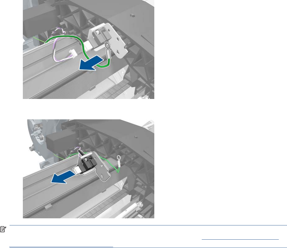
6. Remove the grounding cable. Do not forget to replace it when installing the new Window Position
Sensor.
7. Remove the Window Position Sensor from the printer.
NOTE: When you finish installing or replacing this component, you must perform the necessary
Service Calibrations. To find which calibrations you must perform, see Service Calibration Guide to
Removal and Installation on page 205.
ENWW Window Position Sensor 435

7 Preventive Maintenance
●Preventive Maintenance
●Preventive Maintenance Kits
Preventive Maintenance
Cleaning the Product
To maintain the product in good operating condition, keep it free of accumulated dust, ink, and other
contamination. Cleaning intervals are determined by the product environment and by the types of
product supplies used.
General Cleaning
Proper general cleaning should include the following:
NOTE: To prevent an electric shock, make sure that the product is switched OFF and unplugged
before any cleaning is performed. Do not let any water get inside the product.
1. Blow away dust accumulation with compressed air if available.
2. Clean the outer surface of the product with a damp sponge or cloth. Use a mild soap and water
solution if necessary. Do not use abrasive cleaners.
3. Wipe the product dry with a soft lint-free cloth.
Cleaning the Drive Roller and Overdrive
NOTE: If ink is spilled on the Overdrive, remove the ink. Due to the ink's reflectance, ink on the
Overdrive can disrupt the product's edge-sensing function. To remove any ink from the Overdrive,
perform the following procedure:Prevent water or other liquids from running onto electrical components
or circuits, or through openings in the Electronics Module.
1. Perform the Turn Drive Roller Utility. See Turn Drive Roller on page 120.
2. Open the Scanner (MFP only) or Window.
436 Chapter 7 Preventive Maintenance ENWW
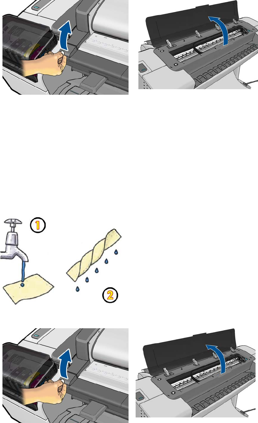
3. Apply any common household cleaning solution (water based only) to a soft, lint-free rag and apply
it to the Drive Roller and Overdrive surface while it is rotating. Make sure that you thoroughly clean
the Drive Roller and Overdrive surface.
4. Press Enter when you have completed the cleaning procedure.
5. Allow the Drive Roller to dry before loading paper in to the product.
Cleaning the Encoder Strip
1. Make sure that the product is not printing and that the Carriage Assembly is located at the Service
Station on the far right side of the product.
2. Using tap water and a small cloth that will not leave fibers in the product, dampen the cloth and
remove any excess water so that the cloth is damp but not wet.
3. Open the Scanner (MFP only) or Window.
ENWW Preventive Maintenance 437
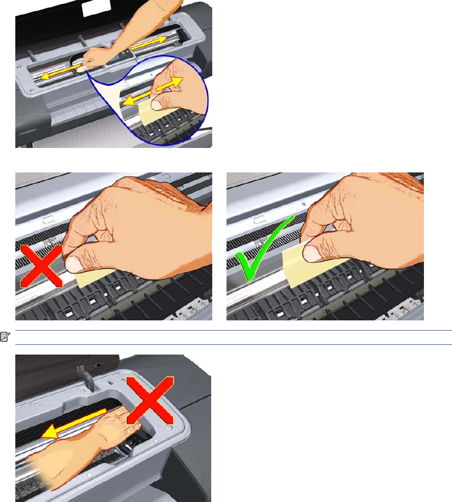
4. Hold the cloth in an inverted “U” shape around the Encoder Strip and carefully wipe until no ink
residue appears on the cloth. Be very careful not to scratch the Encoder Strip with your fingernail
or any other object.
Make sure that you are holding the cloth correctly.
NOTE: Do not move the Carriage Assembly away from the Service Station.
5. Close the product Scanner or Window.
438 Chapter 7 Preventive Maintenance ENWW
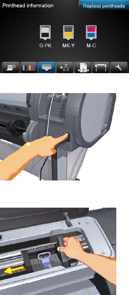
6. Press on the Printhead Menu icon and the following screen is displayed. Press on the Replace
Printhead tab. The Carriage Assembly moves to the left and stops in the correct position to remove
the printheads.
7. Turn off the product by using the power switch on the back of the product.
8. Open the Scanner and move the Carriage Assembly further to the left, allowing you to access the
Service Station.
ENWW Preventive Maintenance 439
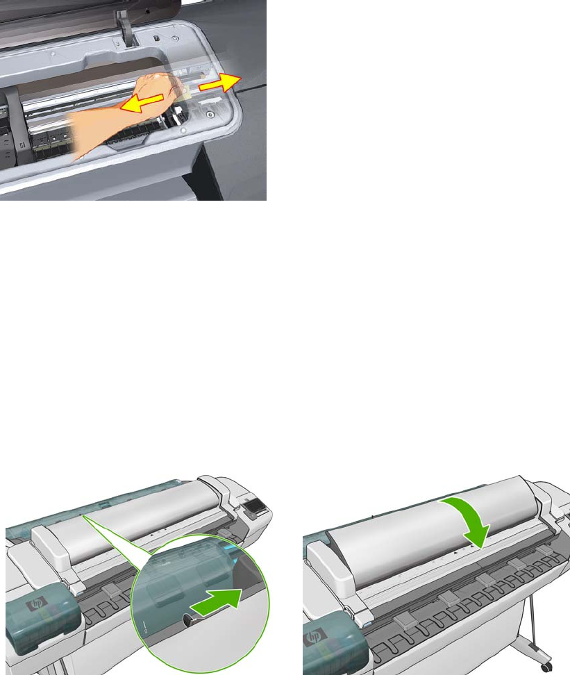
9. Clean the part of the encoder strip inside the Service Station by repeating steps 2 to 6.
10. Close the Scanner or Window.
11. Turn the product back on.
Cleaning the Glass Plate
The customer is recommended to clean the glass plate periodically, depending on the usage of the
product. Keeping the glass free from smears, dust and dirt is an essential part of avoiding image quality
issues. If the customer complains of image quality issues, you can also clean the glass plate using the
following procedure.
1. Turn off the product using the power key at the front, then also turn off the power switch at the rear
and disconnect the power cable.
2. There is a small lever at the rear left of the scanner. Slide the lever to the right and open the CIS.
440 Chapter 7 Preventive Maintenance ENWW
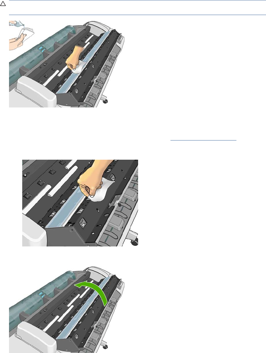
3. Gently wipe the glass plate and the surrounding area with a lint-free cloth dampened with water
and then wrung dry. A suitable cloth is provided with the product.
CAUTION: Do not use abrasives, acetone, benzene or fluids that contain these chemicals. Do
not spray liquids directly onto the scanner glass plate or anywhere else in the scanner.
Do not worry about tiny droplets of water left on the glass: they will evaporate.
4. Optionally, for more thorough cleaning:
●Remove the glass plate and clean it on both sides. See Glass Plate on page 466.
●Clean the pressure rollers (between the feed rollers).
5. Close the CIS and gently push it down to lock it into place.
6. Clean the area immediately in front of the scanner, where the scanned sheet rests before scanning.
7. Reconnect the product's power cable, turn on the power switch at the rear, and turn on the product
using the power key.
ENWW Preventive Maintenance 441

Carriage Assembly Lubrication
To ensure correct operation of the product you must lubricate the Carriage Assembly whenever any of
the following are encountered if:
●The Touch Control Panel displays "Maintenance #1 required".
●There is excessive noise when moving the Carriage Assembly.
●A shut down of the carriage PWM error message appears.
●There are IQ (vertical banding problems).
You should also lubricate the Carriage Assembly whenever you change any of the following service
parts:
●The Carriage Rear Bushing.
●The Carriage Assembly.
●The Carriage Rail Oiler.
To lubricate the Carriage Assembly you will require the Lubrication Kit (Q5669-60692). Use the following
procedure to lubricate the Carriage Assembly:
1. Use the IPA alcohol (Q6675-60070) and the cleaning cloth to clean the Carriage Rail and the
Carriage Slider Rod. Do not use IPA alcohol in California or other areas that restrict the volatile
organic compound (VOC) content of cleaning solvents. A regulatory compliant alternate should be
used.
2. Use an Oil Dispenser (Q6675-60062) to lubricate the Carriage Rail and the Carriage Slider Rod.
3. Replace the Carriage Rail Oiler on page 251 with the new one contained in the kit and add 2 or 3
drops of oil to the foam of the Carriage Rail Oiler.
4. Use an Oil Dispenser (Q6675-60062) to lubricate the Carriage Rear Bushing.
Moisture on the Product
Users should use the product in an environment between 20% and 80% relative humidity. To recover
from moisture condensation, turn the product Off, and, using the main roller as a reference, wait until
the product is completely dry before using it again.
Noisy Carriage Bushing
To prevent noisy movement of the carriage, remove aluminum or dust particles from the bushing at the
back of the carriage, and from the slider path along which the bushing moves. Lubricate the slider path
using the Lubrication Kit (Q5669-60692).
Belt Swelling
To prevent new belts from swelling incorrectly, keep them in their bags with desiccant until you need to
install them.
Level of Product Usage
Normal product use means 6,000,000 Carriage Cycles (which corresponds to approximately 100,000
A0 prints on average). Under normal usage conditions, it will be approximately 5 years before the product
needs maintenance. If the product is used more than the normal usage conditions, then it will need
maintenance service much more frequently.
One of the EEROM counters is assigned to counting the number of carriage cycles.
442 Chapter 7 Preventive Maintenance ENWW

Service Part LIFE_VALUE Maintenance Advice
Belt Cycles 3,000,000 PMKIT1
Bushings Life 3,000,000 PMKIT1
Trailing Cable Cycles 3,000,000 PMKIT1
Scan Axis Cycles 3,000,000 PMKIT1
Scan Axis Distance Covered 4,500,000 PMKIT1
Tubes Cycles 3,000,000 PMKIT1
Right Spittoon Volume 600,000,000 PMKIT2
Left Spittoon Volume 51,000,000 PMKIT2
When these components of the product exceed this amount, the Touch Control Panel displays the
following message:
"Maintenance #1 required"
"Maintenance #2 required”
Once one of the maintenance advised messages is displayed, the relevant preventive maintenance kit
must be used to replace the most worn parts of the product. See Removal and Installation
on page 199 when replacing the necessary parts.
Preventive Maintenance Kits
There is no preventive maintenance kit for the cutter, which is expected to last for the life of the product.
Preventive Maintenance Kit #1 for 24-in models (CQ305–60017)
Part Number Description
CH538-67044 Carriage with Cutter Assembly SV
CH538-60141 Scan Axis Motor SV
CK837-67014 T1120/620 Ink Supply Tubes 24
CQ305-60016 T770 Belt 24 SV
NOTE: The Lubrication Kit is not included in the Preventive Maintenance Kit. See Tools 2
on page 193.
Preventive Maintenance Kit #1 for 44-in models (CH538-67024)
Part Number Description
CH538-67044 Carriage with Cutter Assembly SV
CH538-60141 Scan Axis Motor SV
CH538-67025 Tube System 44 Assembly with Trailing Cable SV (Ferrite(s) of the Tube System/
Trailing Cable are not included in the kit. Please re-use them from the product).
CH538-67018 Belt 44 SV
ENWW Preventive Maintenance Kits 443


A CSR Installation Flyers
This appendix reproduces the fliers that illustrate how to install CSR parts.
●Cutter assembly
●Freewheel assembly
●Freewheel assembly (screwdriver)
●Left side panel (T1200)
●Pinch arm assembly
●Pinch arm assembly (screwdriver)
●Roll cover upper bumpers
●Roll cover upper bumpers (screwdriver)
●Foot Extension
●Front Deflector
●Rear Deflector Mylar
●Glass Plate
●Latch Handle Cover
ENWW 445
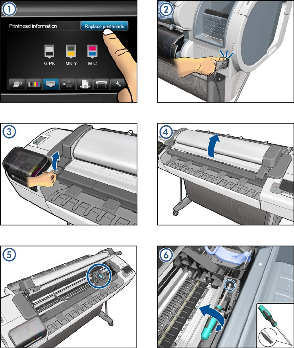
Cutter assembly
446 Appendix A CSR Installation Flyers ENWW
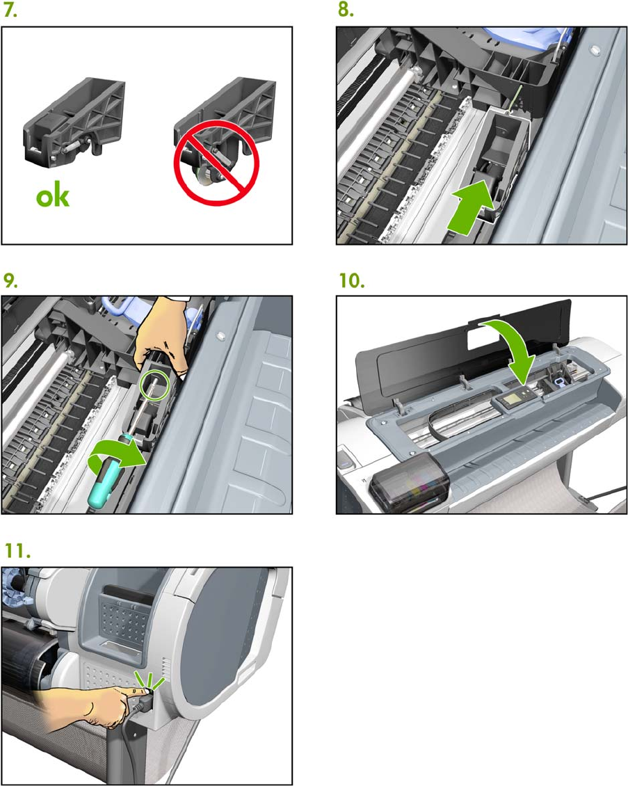
ENWW Cutter assembly 447
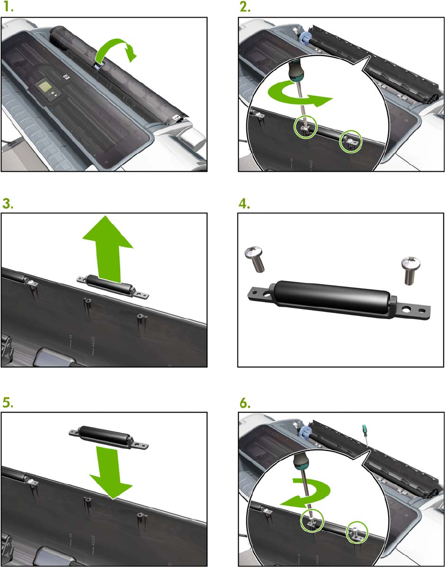
Freewheel assembly
448 Appendix A CSR Installation Flyers ENWW

ENWW Freewheel assembly 449
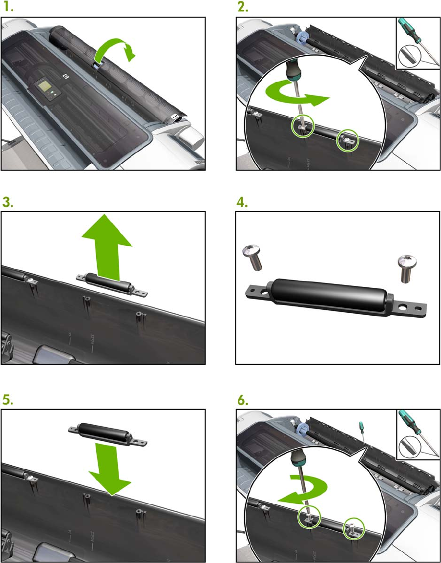
Freewheel assembly (screwdriver)
450 Appendix A CSR Installation Flyers ENWW
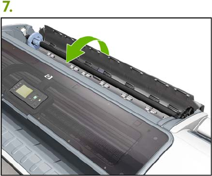
ENWW Freewheel assembly (screwdriver) 451
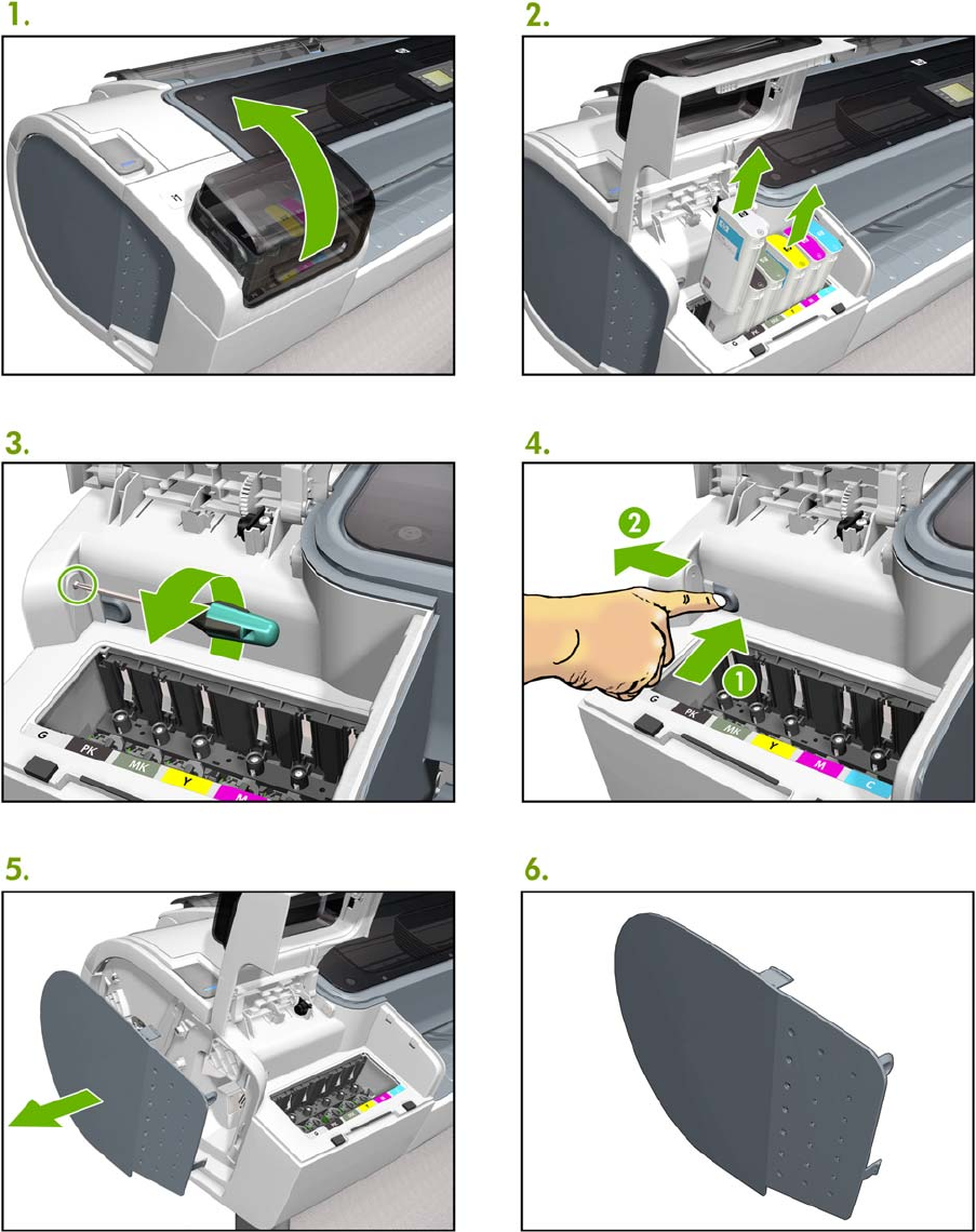
Left side panel (T100)
452 Appendix A CSR Installation Flyers ENWW
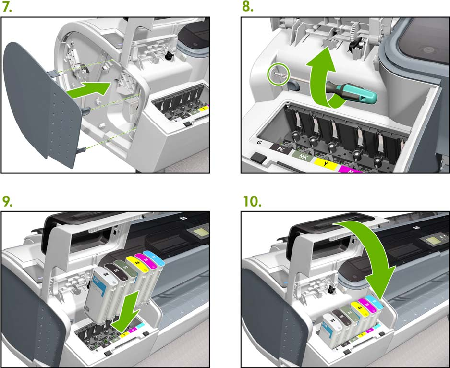
ENWW Left side panel (T1200) 453
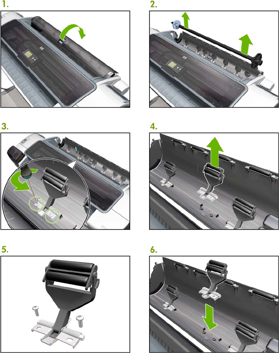
Pinch arm assembly
454 Appendix A CSR Installation Flyers ENWW
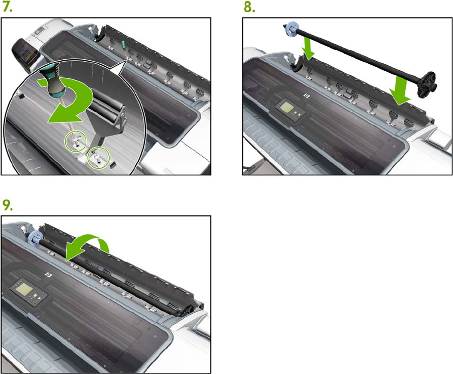
ENWW Pinch arm assembly 455
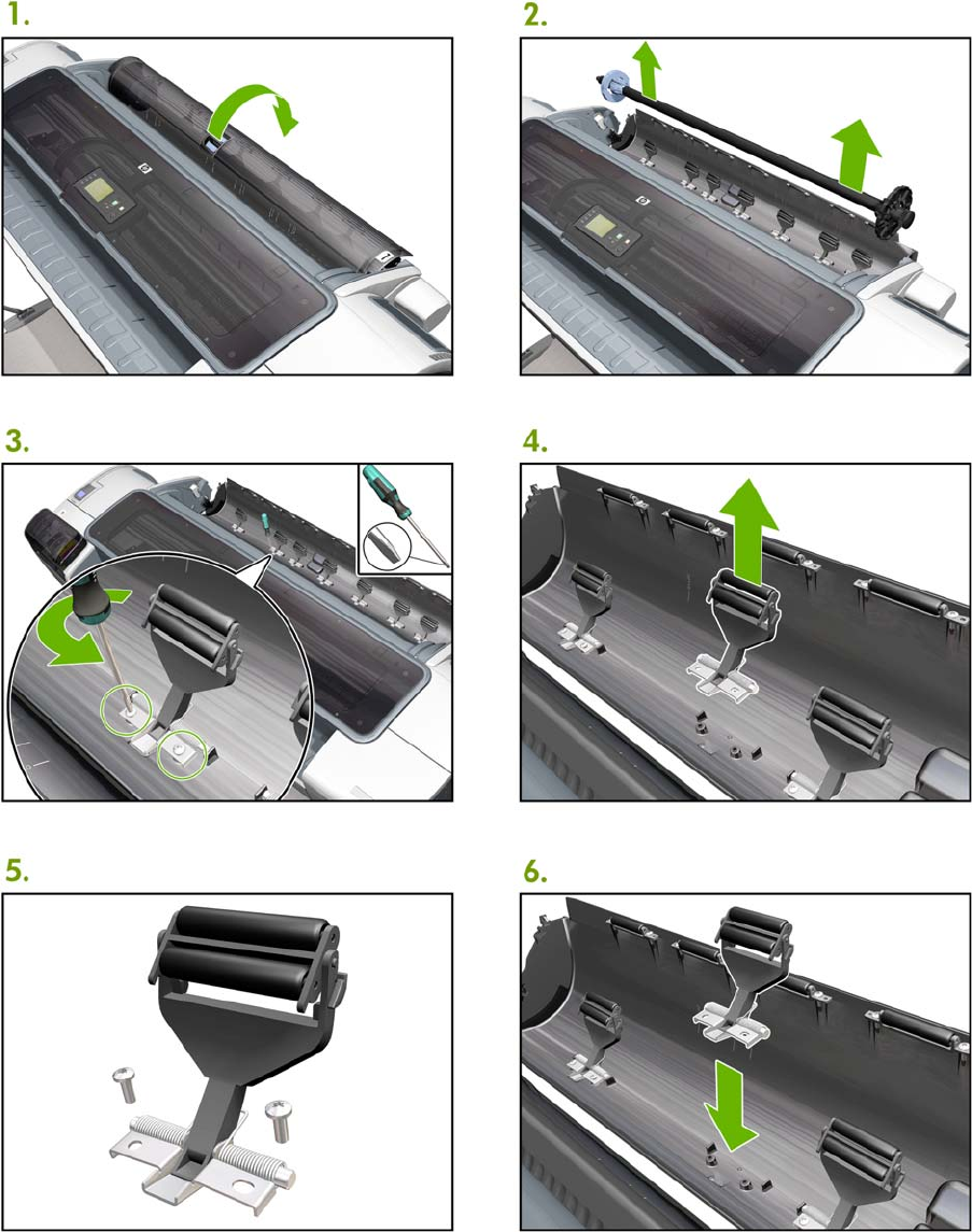
Pinch arm assembly (screwdriver)
456 Appendix A CSR Installation Flyers ENWW
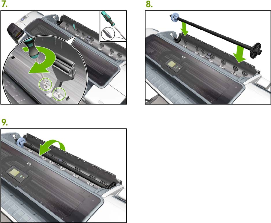
ENWW Pinch arm assembly (screwdriver) 457
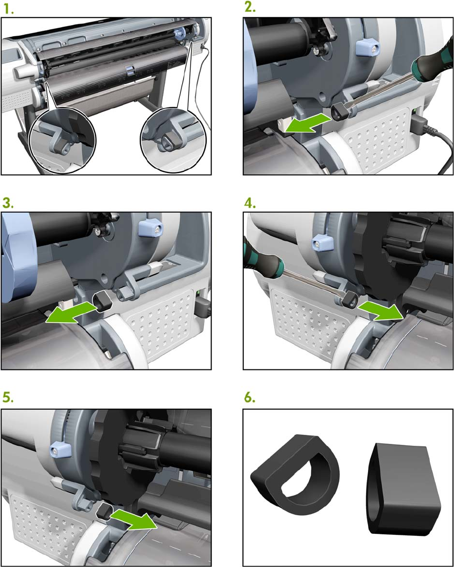
Roll cover upper bumpers
458 Appendix A CSR Installation Flyers ENWW

ENWW Roll cover upper bumpers 459
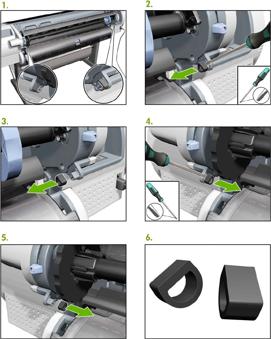
Roll cover upper bumpers (screwdriver)
460 Appendix A CSR Installation Flyers ENWW
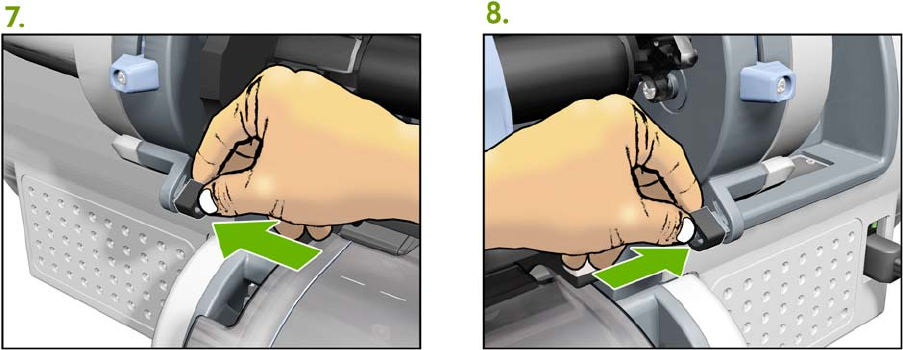
ENWW Roll cover upper bumpers (screwdriver) 461
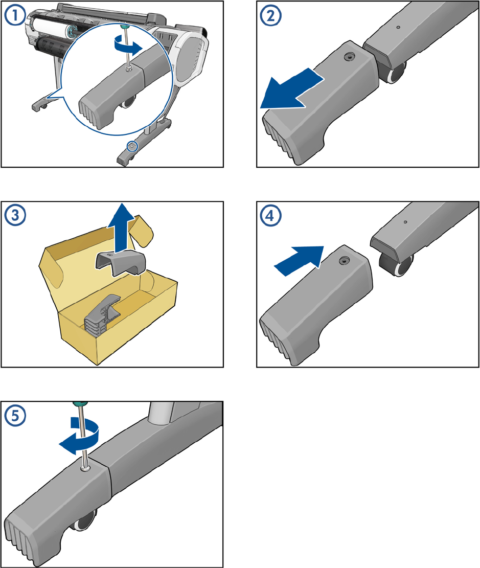
Foot Extension
462 Appendix A CSR Installation Flyers ENWW
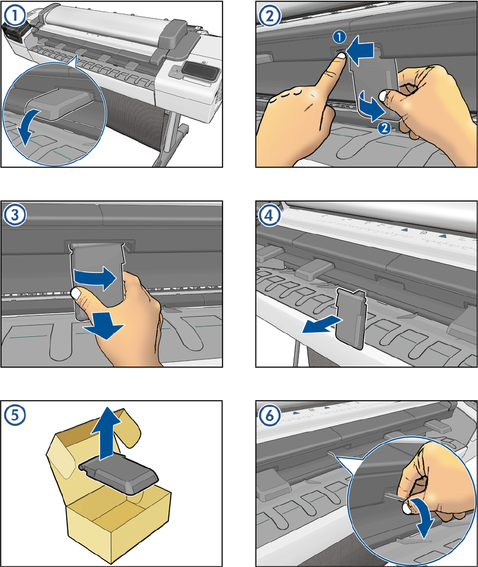
Front Deflector
ENWW Front Deflector 463
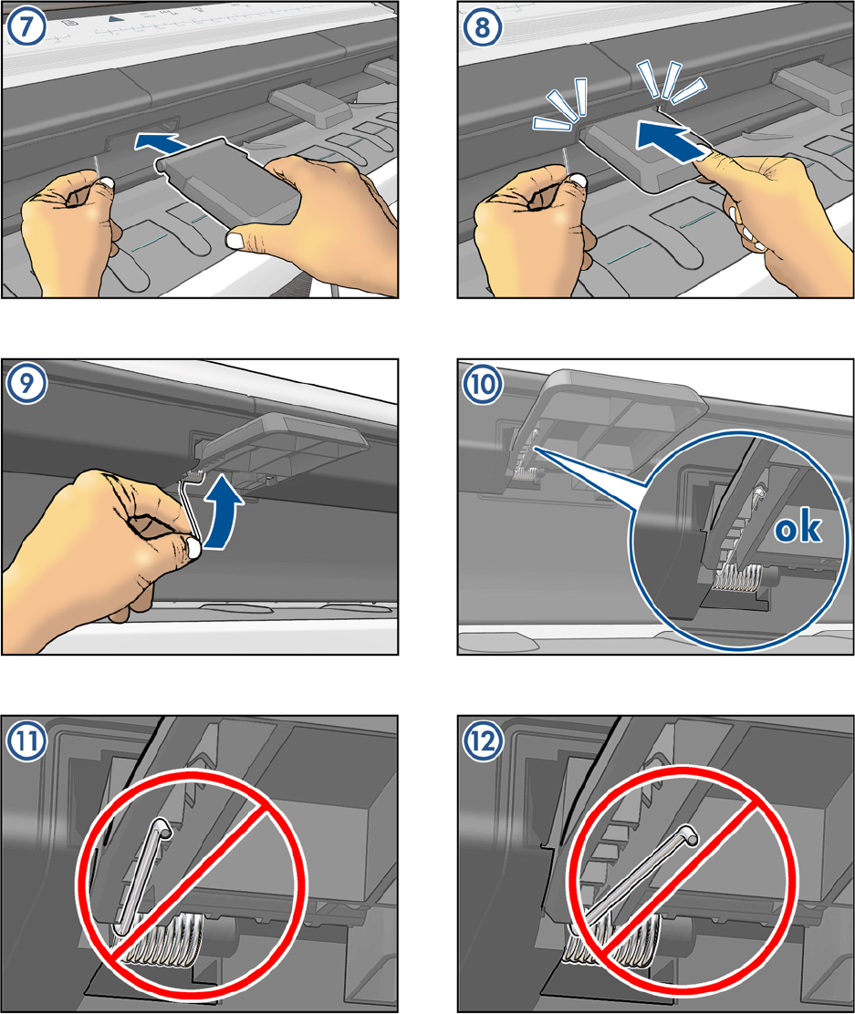
464 Appendix A CSR Installation Flyers ENWW
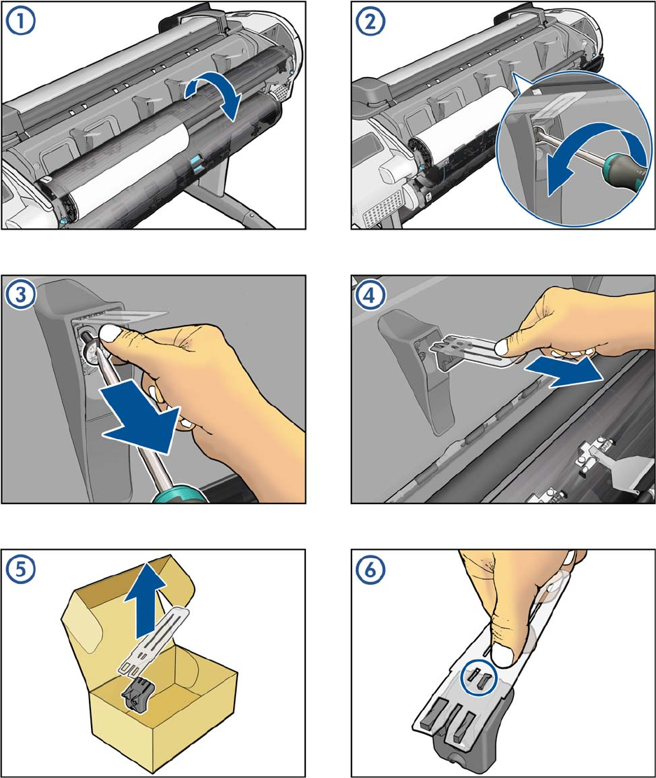
Rear Deflector Mylar
ENWW Rear Deflector Mylar 465
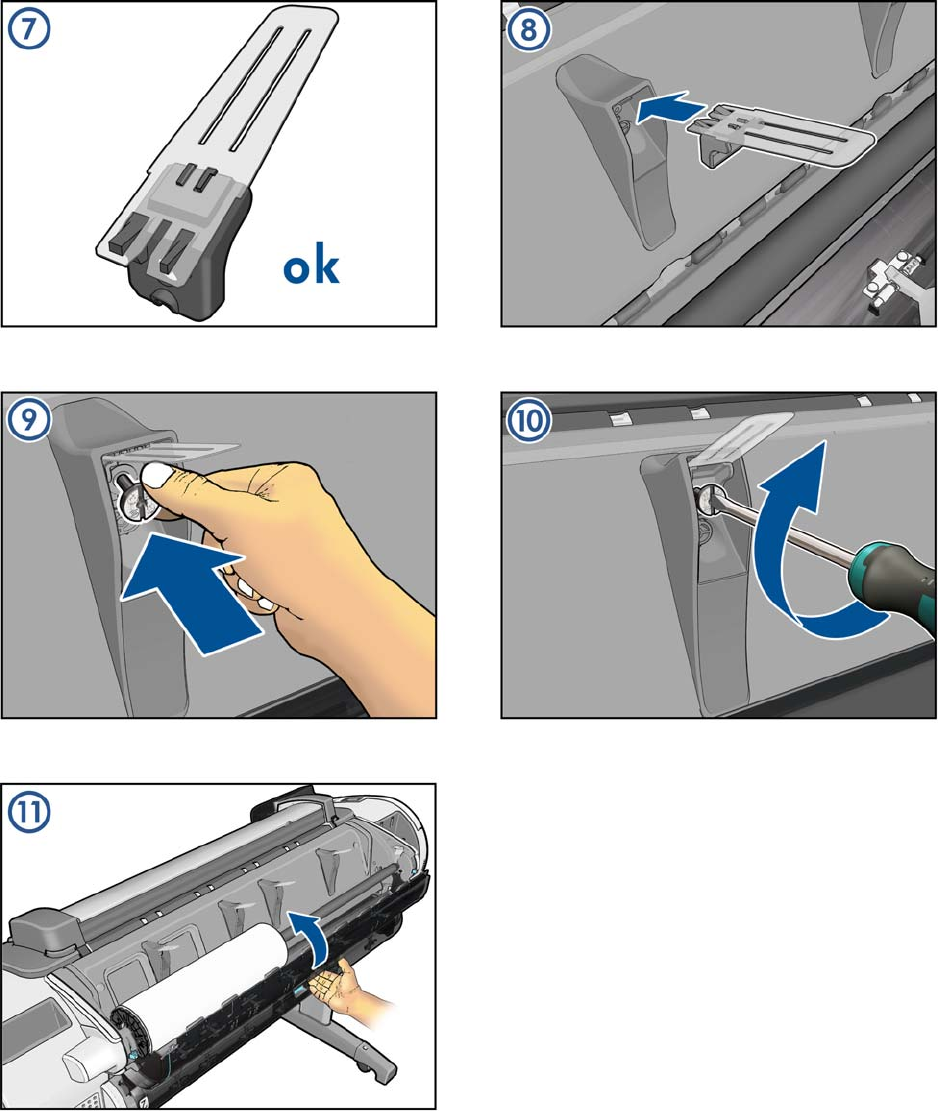
466 Appendix A CSR Installation Flyers ENWW
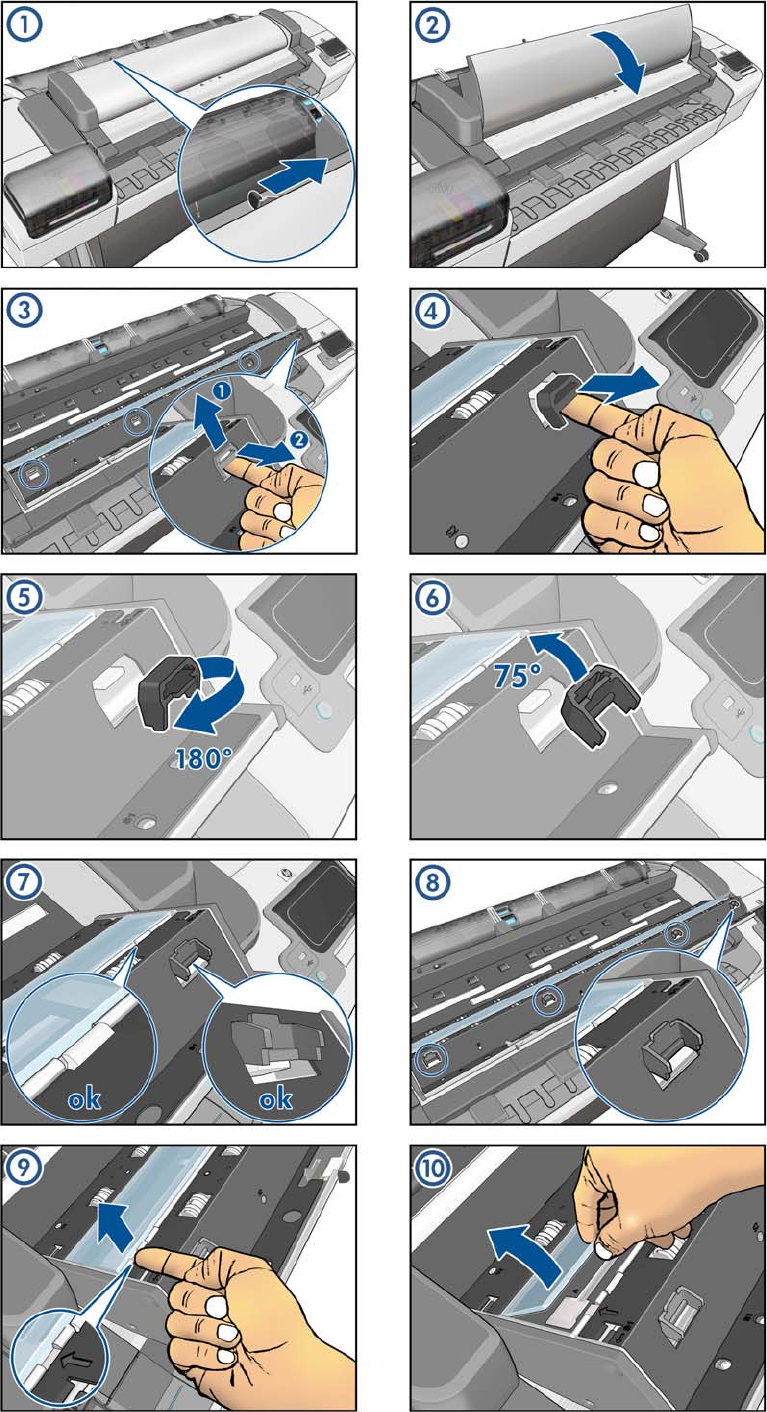
Glass Plate
ENWW Glass Plate 467
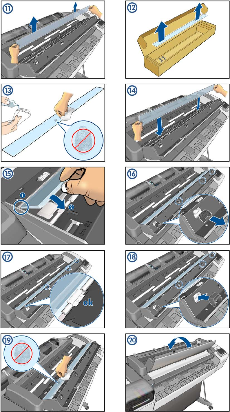
468 Appendix A CSR Installation Flyers ENWW
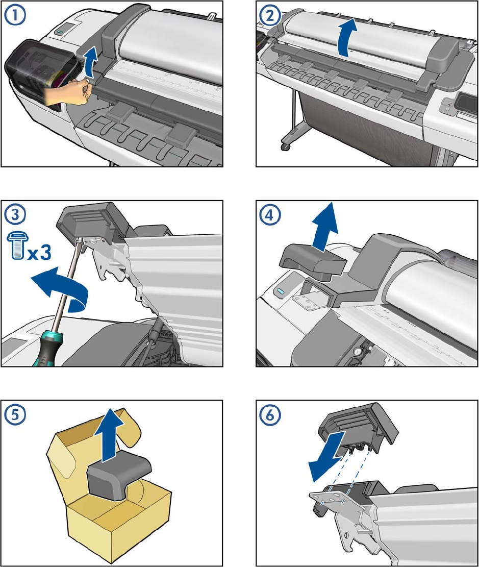
Latch Handle Cover
ENWW Latch Handle Cover 469
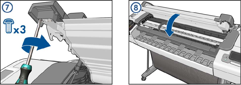
470 Appendix A CSR Installation Flyers ENWW
