HPE Integrity MC990 X Server User Guide MC990X 855704 002
User Manual:
Open the PDF directly: View PDF ![]() .
.
Page Count: 65
- User Guide
- Contents
- 1 Integrity MC990 X system overview
- 2 Operational procedures
- Precautions
- System control network
- Accessing the system control network
- Connecting to the system control network
- Communicating with the system
- Powering the system up and down
- 3 System control
- 4 Using the Foundation Software
- 5 Component replacement procedures
- 6 Integrity MC990 X system Troubleshooting
- 7 Support and other resources
- A Technical specifications and pinouts
- B System technical information
- C Safety and regulatory information
- Glossary
- Index

HPE Integrity MC990 X Server
User Guide
Abstract
This guide provides an overview of the architecture, general operation and descriptions of the major
components that comprise the HPE Integrity MC990 X Server system. It also provides the standard procedures
for powering on and powering off the system, basic troubleshooting and maintenance information, Foundation
Software usage information, and important safety and regulatory specifications.
Part Number: 855704-002
Published: July 2016
Edition: 2

©Copyright 2016 Hewlett Packard Enterprise Development LP
The information contained herein is subject to change without notice. The only warranties for Hewlett Packard Enterprise products
and services are set forth in the express warranty statements accompanying such products and services. Nothing herein should
be construed as constituting an additional warranty. Hewlett Packard Enterprise shall not be liable for technical or editorial errors
or omissions contained herein.
Links to third-party websites take you outside the Hewlett Packard Enterprise website. Hewlett Packard Enterprise has no control
over and is not responsible for information outside the Hewlett Packard Enterprise website.
Acknowledgements
Intel®Xeon®are trademarks of Intel Corporation in the in the U.S. and other countries.
Google™is a registered trademarks of Google Inc.
Linux®is a registered trademark of Linus Torvalds in the U.S. and other countries.
Red Hat®is a registered trademark of Red Hat, Inc. in the United States and other countries.
SUSE LINUX is a registered trademark of Novell Inc.
Windows is a registered trademark of Microsoft Corporation in the United States and other countries.
NUMAlink®and NUMAflex®are trademarks or registered trademarks of Silicon Graphics International Corp. or its subsidiaries
in the United States and/or other countries worldwide.
Warranty
To obtain a copy of the warranty for this product, see the warranty information website:
BCS Global Limited Warranty and
Technical Support
http://bizsupport2.austin.hp.com/bc/docs/support/SupportManual/c01865770/c01865770.pdf.
Revision History
Publication DateEditionHPE Part Number
March 2016First855704-001
July 2016Second855704-002
Contents
1 Integrity MC990 X system overview......................................................6
MC990 X server chassis.....................................................................................................6
System features..................................................................................................................7
Modularity and scalability...............................................................................................7
Distributed shared memory (DSM)................................................................................8
Physical memory riser..............................................................................................8
Distributed shared I/O....................................................................................................8
Rack management controller.........................................................................................9
Reliability, availability, and serviceability........................................................................9
System components.........................................................................................................10
Unit numbering............................................................................................................12
Rack numbering...........................................................................................................12
2 Operational procedures.......................................................................13
Precautions.......................................................................................................................13
ESD precaution............................................................................................................13
Safety precautions.......................................................................................................13
System control network.....................................................................................................13
Accessing the system control network..............................................................................14
Connecting to the system control network........................................................................14
Communicating with the system.......................................................................................15
The command line interface........................................................................................15
Example CLI commands used................................................................................15
Powering the system up and down...................................................................................15
Preparing to power up.................................................................................................15
Powering up and down from the command line interface............................................16
Booting directly from an RMC......................................................................................17
USB-connected console hardware requirements...................................................17
Remote LAN connection to the RMC...........................................................................17
Establishing RMC IP hardware connections................................................................18
Using DHCP to establish an IP address.................................................................18
Using a static IP address........................................................................................18
Power up the system using the RMC network connection..........................................19
Monitoring power up....................................................................................................19
Power down the system...............................................................................................20
3 System control.....................................................................................21
Levels of system control...................................................................................................21
System management overview....................................................................................21
RMC overview.............................................................................................................22
BMC overview..............................................................................................................23
System controller interaction.............................................................................................23
System controllers............................................................................................................23
RMC functions.............................................................................................................23
4 Using the Foundation Software...........................................................25
Monitoring main memory health........................................................................................25
About main memory health monitoring........................................................................25
Retrieving main memory health information................................................................25
Accessing MEMlog messages with commands.....................................................25
Monitoring system performance........................................................................................26
About the system monitoring software.........................................................................26
hubstats command......................................................................................................27
linkstat command.........................................................................................................27
3
gr_systat command.....................................................................................................27
nodeinfo command......................................................................................................27
topology command......................................................................................................28
Enabling CPU frequency scaling......................................................................................30
About CPU frequency scaling......................................................................................30
CPU frequency scaling for Integrity MC990 X systems...............................................31
Configuring the powersave setting on systems with the intel_pstate directory......31
Enabling CPU frequency scaling systems without the intel_pstate directory.........32
Changing the governor setting on systems without the intel_pstate directory.......32
Configuring turbo mode on systems without the intel_pstate directory..................35
Additional Foundation Software utilities............................................................................35
5 Component replacement procedures..................................................37
Maintenance precautions and procedures........................................................................37
Preparing the system for maintenance or upgrade.....................................................37
Returning the system to operation...............................................................................37
Removing the chassis top cover.......................................................................................38
Adding or replacing PCIe or GPU cards...........................................................................39
Installing cards in the MC990 X server chassis...........................................................39
Installing or replacing a drive............................................................................................40
Remove or replace a 2.5-inch hard drive.....................................................................41
Remove or replace a 1.8-inch SSD option drive..........................................................42
Replacing a MC990 X server chassis power supply.........................................................43
Replacing a MC990 X server chassis fan assembly.........................................................44
6 Integrity MC990 X system Troubleshooting.........................................46
Troubleshooting chart.......................................................................................................46
LED status indicators........................................................................................................46
Power supply LEDs.....................................................................................................46
System motherboard status LEDs...............................................................................47
7 Support and other resources...............................................................49
Accessing Hewlett Packard Enterprise Support...............................................................49
Accessing updates............................................................................................................49
Websites...........................................................................................................................50
Documentation feedback..................................................................................................50
A Technical specifications and pinouts...................................................51
Integrity MC990 X system specifications..........................................................................51
Integrity MC990 X system physical specifications............................................................51
Integrity MC990 X system environmental specifications...................................................52
Integrity MC990 X system electrical specifications...........................................................52
I/O port specifications.......................................................................................................54
Motherboard VGA port information..............................................................................54
Ethernet port................................................................................................................55
Serial port....................................................................................................................55
USB port......................................................................................................................56
B System technical information..............................................................57
System architecture..........................................................................................................57
ccNUMA architecture........................................................................................................58
Cache coherency.........................................................................................................58
Non-uniform memory access (NUMA).........................................................................59
C Safety and regulatory information.......................................................60
Safety information.............................................................................................................60
Regulatory information......................................................................................................61
4
CMN number...............................................................................................................61
Glossary.................................................................................................62
Index.......................................................................................................63
5
1 Integrity MC990 X system overview
This chapter provides an overview of the physical and architectural aspects of the
HPE Integrity MC990 X Server system. The major components of the Integrity MC990
X system are described and illustrated.
The Integrity MC990 X system is an advanced symmetric multiprocessing (SMP)
computer system with 8 Intel processor sockets as a cache-coherent single system
image (SSI). Each processor socket in the system houses multiple compute cores.
In an SMP system, each MC990 X server chassis contains memory that it shares
with all other processors in the system. Because the Integrity MC990 X system is
modular, it combines the advantages of lower entry-level cost with global scalability
in processors, memory, and I/O. You can install and operate the Integrity MC990 X
system in your lab or server room. One 42U rack holds one base MC990 X server
chassis, one expansion MC990 X server chassis, one rack management controller
(RMC) unit, power distribution units (PDU), and optional mass storage units.
This chapter consists of the following sections:
•“MC990 X server chassis” (page 6)
•“System features” (page 7)
•“System components” (page 10)
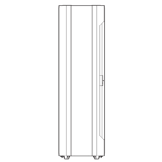
Figure 1 (page 6) shows the front view of a single-rack Integrity MC990 X system .
Figure 1 Integrity MC990 X system rack
MC990 X server chassis
The basic enclosure within the Integrity MC990 X system is the MC990 X server
chassis. The MC990 X server chassis contains one four-socket motherboard connected
6
to support up to 28 NUMAlink ports, each with a maximum bi-directional bandwidth
communication rate of up to 7.47 GB/sec.
Each MC990 X server chassis has ports that are brought out to external NUMAlink
connectors located on the front of the enclosure. The single rack houses two MC990
X server chassis (making up the MC990 X server), an RMC unit, and optional external
storage.
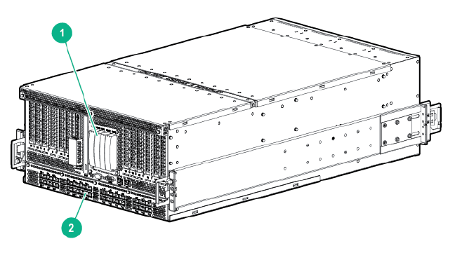
Figure 2 (page 7) shows an example of a MC990 X server chassis prior to mounting
in a rack.
The system requires a minimum of one rack with enough PDUs to support two MC990
X server chassis, one RMC, and any optional equipment installed in the rack.
You can also add additional PCIe expansion cards or RAID and non-RAID disk storage
to your server system.
Figure 2 MC990 X server chassis
2. NUMAlink connectors (28)1. System drive assembly
System features
The main features of the Integrity MC990 X system are discussed in the following
sections:
•“Modularity and scalability” (page 7)
•“Distributed shared memory (DSM)” (page 8)
•“Rack management controller” (page 9)
•“Distributed shared I/O” (page 8)
•“Reliability, availability, and serviceability” (page 9)
Modularity and scalability
The Integrity MC990 X system is modular. The compute/memory/PCIe components
are housed in two MC990 X server chassis. Additional optional mass storage may
be added to the system along with additional MC990 X server chassis. You can add
different types of PCIe board options to a server to achieve the desired system
configuration. You can easily configure systems around processing capability, I/O
capability, memory size, or storage capacity. Each air-cooled MC990 X server chassis
has redundant, hot-swap fans and redundant, hot-swap power supplies. Internal drives
also can be hot-swapped as long as redundant configurations are set up.
7
Distributed shared memory (DSM)
In the Integrity MC990 X system, memory is physically distributed both within and
among the MC990 X server chassis (compute/memory/I/O); however, it is accessible
to and shared by all NUMAlinked devices within the SSI. This means all NUMAlinked
components sharing a single Linux operating system, operate and share the memory
fabric of the system. Memory latency is the amount of time required for a processor
to retrieve data from memory. Memory latency is lowest when a processor accesses
local memory. Note the following sub-types of memory within a system:
•If a processor accesses memory that it is connected to on a MC990 X server
chassis motherboard, the memory is referred to as the processor local memory.
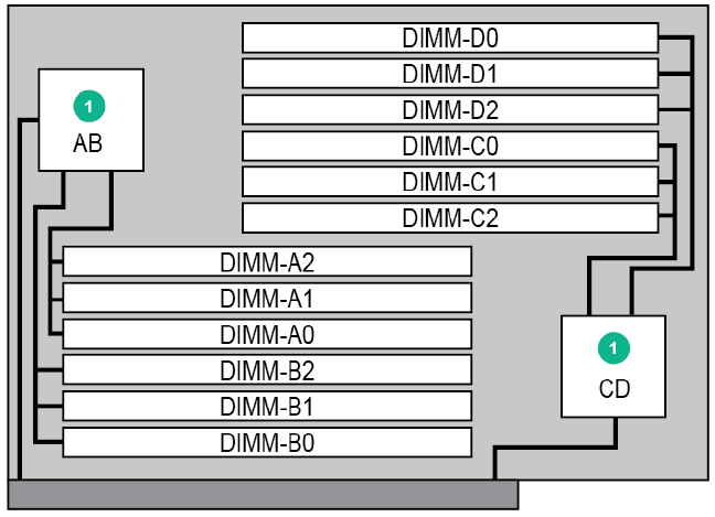
Figure 3 (page 8) shows a conceptual block diagram of the motherboard memory
riser board pathways.
•If processors access memory located in another NUMAlinked MC990 X server
chassis motherboard within the system, the memory is referred to as remote
memory.
•The total memory within the NUMAlinked Integrity MC990 X system is referred
to as global memory.
Physical memory riser
Physical memory nodes are memory risers and each is made up of two board
assemblies: memory riser board and power board. Eight memory riser assemblies
plug into each MC990 X server chassis motherboard. The memory riser power board
receives power directly from the motherboard. A maximum of 12 DDR4 memory
DIMMs are supported in each memory riser.
Figure 3 MC990 X server chassis memory riser block diagram
1. Memory controller
Distributed shared I/O
Like DSM, I/O devices are distributed within the MC990 X server chassis. Each BaseIO
riser is accessible by all compute nodes within the SSI through the NUMAlink
interconnect fabric.
8
Rack management controller
Each Integrity MC990 X system has a rack management controller (RMC) generally
located directly above or below the MC990 X server chassis in a rack. The RMC
supports powering up and down of the system motherboards and environmental
monitoring of all Integrity MC990 X system units within the SSI. In addition, the RMC
provides the top layer of system control for Integrity MC990 X system. Through the
use of an internal 24-port Ethernet switch, a single RMC can provide system control
for up to 16 MC990 X server chassis in an expanded Integrity MC990 X system.
One GigE port from each MC990 X server chassis motherboard connects to the RMC
via Cat-5 cable.
Reliability, availability, and serviceability
The Integrity MC990 X system components have the following features to increase
the reliability, availability, and serviceability (RAS) of the systems.
•Power and cooling:
MC990 X server chassis power supplies are redundant and can be
hot-swapped.
◦
◦MC990 X server chassis have overcurrent protection at the motherboard
and power supply level.
◦MC990 X server chassis fans are redundant and can be hot-swapped.
◦MC990 X server chassis fans run at multiple speeds. Speed increases
automatically when temperature increases or when a single fan fails.
•System monitoring:
System controllers monitor the internal power and temperature of the MC990
X server chassis components, and can automatically shut down an enclosure
to prevent overheating.
◦
◦All main memory has Intel Single Device Data Correction to detect and
correct 8 contiguous bits failing in a memory device. Additionally, the main
memory can detect and correct any two-bit errors coming from two memory
devices (8 bits or more apart).
◦All high speed links including Intel Quick Path Interconnect (QPI), Intel
Scalable Memory Interconnect (SMI), and PCIe have cyclic redundancy
check (CRC) check and retry.
◦The NUMAlink interconnect network is protected by CRC.
◦Each MC990 X server chassis installed has status LEDs that indicate the
server operational condition; LEDs are viewable at the front of the unit.
•Power-on and boot:
Automatic testing occurs after you power on the system. These power-on
self-tests or POSTs are also referred to as power-on diagnostics or PODs.
◦
◦Processors and memory are automatically disabled when a self-test failure
occurs.
◦Boot times are minimized.
9

•Further RAS features:
Systems can report status inventory information, provide hardware logs of
out-of-range conditions, or perform recovery procedures via remote
commands.
◦
◦All system faults are logged in files.
◦Memory can be scrubbed using error checking code (ECC) when a single-bit
error occurs.
System components
The Integrity MC990 X system includes the following major components:
•42U rack—These racks are used for the MC990 X server chassis, RMC, and
optional external storage in the Integrity MC990 X system. Up to three MC990
X systems can be installed in each 42U rack.
•Server chassis—The Integrity MC990 X system includes one base server chassis
and one expansion server chassis. Each 5U-high server chassis contains four
power supplies, one four-processor compute/memory board, and other optional
riser enabled drives and boards for the Integrity MC990 X system. The base
server chassis also has a BaseIO riser not present in the expansion server
chassis. Figure 4 (page 10) shows the MC990 X server chassis front panel
components.
•Motherboard—Holds four processor sockets and 8 memory risers with up to 12
DIMMs per memory riser for a maximum of 96 DIMMs per motherboard. Each
motherboard can be ordered with risers that enable the base MC990 X server
chassis to support up to four full-height x16 PCIe cards and up to eight full-height
x8 PCIe cards.
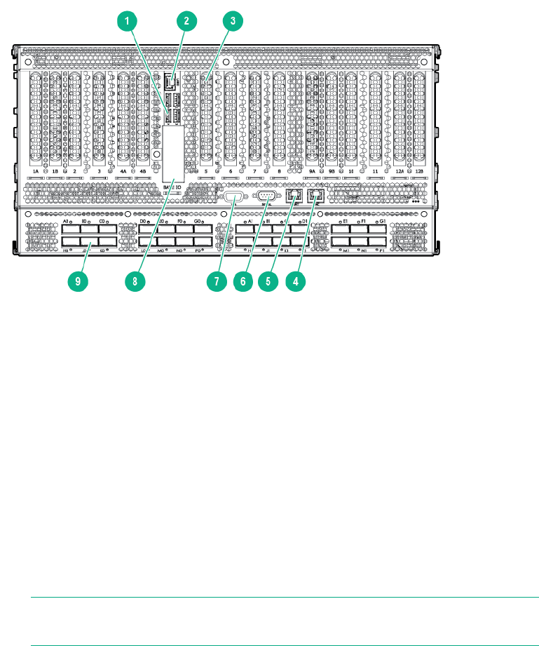
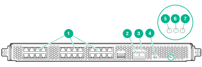
Figure 4 MC990 X base server chassis front components
2. ETH01. USB ports (4)
4. Disk or SS drives (4)3. DVD drive
6. MGMT port5. RMC port
8. VGA port7. Serial port
10. NUMAlink ports (28)9. Optional 1.8-inch SSD drive bays
10
•Drives—Each MC990 X base server chassis has a drive tray that supports one
optional slim-line SATA DVD drive and four 2.5-inch hard disk or solid state drives.
An MC990 X expansion server chassis does not require a drive assembly and
can accommodate four additional PCIe cards.
Figure 5 MC990 X expansion server chassis front components
2. ETH01. USB ports (4)
4.RMC port3. PCIe card slots (16)
6.Serial port5. MGMT port
8.Optional 1.8-inch SSD drive bays7. VGA port
9. NUMAlink ports (28)
•Internal PCIe enabled slots—The MC990 X server chassis and motherboard
support the following types of PCIe option boards:
◦Four full-height, half-length, Gen3 x8 PCIe slots
◦Four full-height, 10.5-inch length, Gen3 x8 PCIe slots
◦Four full-height, double-wide, 10.5-inch length, Gen3 x16 PCIe slots
NOTE: The x16 PCIe slots support cards with a maximum power
consumption of 300 watts.
•NUMAlink Connectors—The external NUMAlink connectors are located on the
lower-front portion of each MC990 X server chassis.
•BaseIO board—Optional I/O riser board (connected directly to the motherboard)
that supports base system I/O functions including one Gbit Ethernet connector
(top), four USB ports, and bays for two optional external 1.8-inch solid state drives
(SSDs).
Internally, the BaseIO board supports:
◦Four internal 3GB/s SATA ports (for the four 2.5-inch disk drives in the MC990
X server chassis chassis)
◦Two internal 6GB/s SATA ports (for the two optional mini 1.8-inch SSDs)
11
◦One internal USB 2.0 port (for the internal DVD)
NOTE: Each Integrity MC990 X system (or SSI within a system) requires one
BaseIO board. Figure 6 (page 12) shows the front components of the BaseIO
board. The SSD drives (bottom) are enclosed with a metal cover.
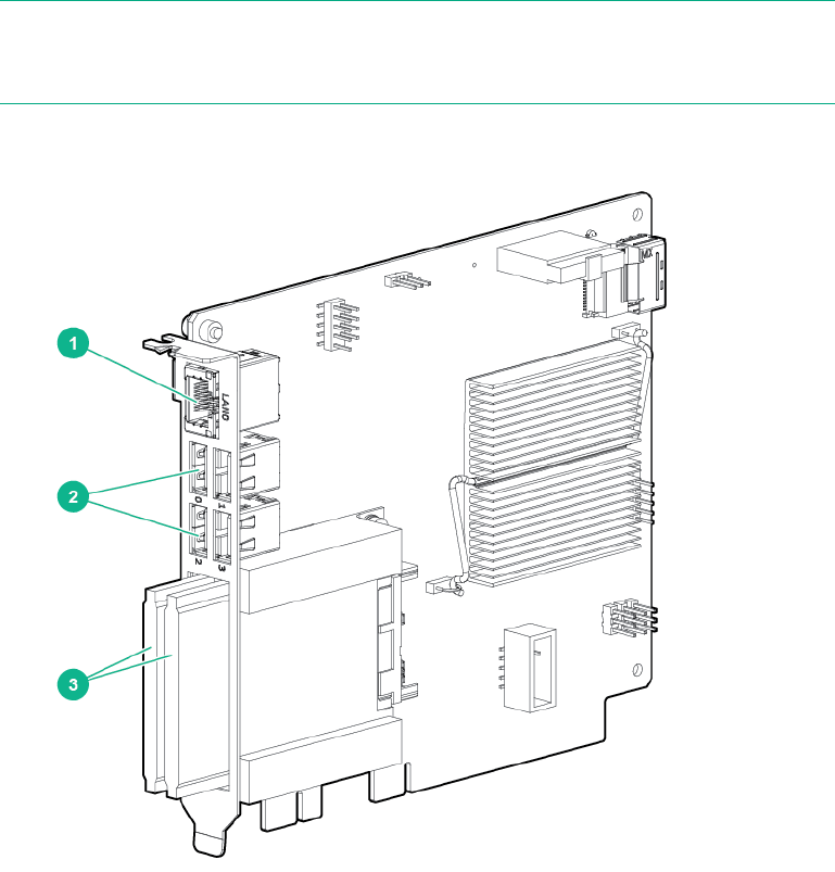
Figure 6 BaseIO board front panel components
1. Ethernet port
2. USB ports (4)
3. Solid State Drives (2)
Unit numbering
Bays in the racks are numbered using standard units. A standard unit (U) is equal to
1.75 inches (4.445 cm). Because the chassis occupy multiple units, locations within
a rack are identified by the bottom unit (U) in which the chassis resides. For example,
in a 42U rack, an MC990 X server chassis positioned in U01 through U05 is identified
as U01.
Rack numbering
Each rack is numbered with a three-digit number sequentially beginning with 001. A
rack contains two MC990 X server chassis, one RMC, optional mass storage
enclosures, and other optional components. In a single rack system, the rack number
is always 001.
12

2 Operational procedures
This chapter provides an overview on how to operate your new system in the following
sections:
•“Precautions” (page 13)
•“System control network” (page 13)
•“Powering the system up and down” (page 15)
Precautions
Before operating your system, familiarize yourself with the safety information in the
following sections:
•“ESD precaution” (page 13)
•“Safety precautions” (page 13)
ESD precaution
CAUTION: Observe all ESD precautions. Failure to do so can result in damage to
the equipment.
HPE recommends wearing an approved wrist strap when you handle any
ESD-sensitive device to eliminate possible ESD damage to equipment. Connect the
wrist strap cord directly to earth ground.
Safety precautions
WARNING! Before operating or servicing any part of this product, read the “Safety
information” (page 60).
WARNING! Keep fingers and conductive tools away from high-voltage areas. Failure
to follow these precautions will result in serious injury or death. The high-voltage areas
of the system are indicated with high-voltage warning labels.
WARNING! If a lithium battery is installed in your system as a soldered part, only
qualified service personnel should replace this lithium battery. For a battery of another
type, replace it only with the same type or an equivalent type recommended by the
battery manufacturer, or an explosion could occur. Discard used batteries according
to the manufacturer instructions.
CAUTION: Power off the system only after the system software has been shut
down in an orderly manner. If you power off the system before you halt the operating
system, data may be corrupted.
System control network
All MC990 X server chassis use an RMC which communicates with the chassis board
level BMCs within each SSI. These components in concert are generically known as
the system control network.
The Integrity MC990 X system control network provides control and monitoring
functionality for each motherboard, power supply, and fan assembly in each MC990
X server chassis in the system.
13

The RMC network provides the following functionality:
•Powering the entire system up and down.
•Powering individual MC990 X server chassis up and down.
•Monitoring the environmental state of the system, including voltage levels.
•Monitors and controls status LEDs on the enclosure.
•Supports entry of controller commands to monitor or change particular system
functions within a particular MC990 X server chassis. See the HPE Integrity
MC990 X Server RMC Software User Guide for a complete list of command line
interface (CLI) commands.
•Provides access to the system OS console allowing you to run diagnostics and
boot the system.
•Provides the ability to flash system BIOS.
Accessing the system control network
Access to the system control network is accomplished by the following methods:
•A LAN connection to the RJ-45 WAN port on the RMC, (see Figure 7 (page 14)).
•A USB-to-micro-USB serial connection to the “Console” port (see CNSL in Figure 7
(page 14)) on the RMC front panel example.
Figure 7 RMC front panel connections
2. WAN port1. Network ports (24)
4. CNSL port3. AUX port
6. PG (Power Good) LED indicator5. RST button
7. HB (Heart Beat) LED indicator
Connecting to the system control network
The Ethernet connection is the preferred method of accessing the system console.
Administrators can perform one of the following options for connectivity:
•A portable system console can be directly connected to the RMC micro-USB
connect port, (labeled CNSL). See Figure 7 (page 14). This requires connecting
from a laptop or workstation that is physically located near the system.
•A LAN connection is used to communicate directly with the RMC, using the IPMI
2.x protocols. This LAN connection must be made to the RJ-45 WAN port on the
RMC. This connection can be used with a local or remote IPMI-enabled console
device.
14

Communicating with the system
The two primary ways to communicate with and administer the MC990 X system are
through the RMC interface command line interface (CLI) or through an IPMI 2.x LAN
interface.
The command line interface
The Integrity MC990 X system CLI is accessible by logging directly into a RMC.
Log in to the RMC as root with the default password “root”. As in this example:
asylum$ ssh root@mc990x-rmc
root@mc990x-rmc's password: root
MC990 X RMC, Rev. 1.1.xx [Bootloader 1.1.x]
RMC:r001i01c> help
NOTE: HPE recommends changing all default logins and passwords.
Once a connection to the RMC is established, system control commands can be
entered. See “Example CLI commands used” (page 15) for some examples.
See “Powering up and down from the command line interface” (page 16) for additional
specific examples of using the CLI commands.
Example CLI commands used
The following is a list of some available CLI commands:
auth authenticate SSN/APPWT change
bios perform bios actions
bmc access BMC shell
rmc access RMC shell
config show system configuration
console access system consoles
help list available commands
hel access hardware error logs
hwcfg access hardware configuration variable
leds display system LED values
log display system controller logs
power access power control/status
Type <cmd> --help for help on individual commands.
Powering the system up and down
This section explains how to power up and power down individual units, or your entire
Integrity MC990 X system, as follows:
•“Preparing to power up” (page 15)
•“Powering up and down from the command line interface” (page 16)
•“Booting directly from an RMC” (page 17)
Using an RMC connection, you can power up and power down an individual MC990
X server chassis, or the entire system.
Preparing to power up
To prepare to power up your system, follow these steps:
15

1. Check to ensure that the power connector on the cable between the rack PDUs
and the wall power-plug receptacles are securely plugged in.
2. For each individual MC990 X server chassis that you want to power up, make
sure that the power cables are plugged into all the chassis power supplies
correctly, see the example in Figure 8 (page 16). Setting the circuit breakers on
the PDUs to the (On) position will apply power to the individual MC990 X server
chassis and will start the RMC if it is plugged into the same PDU. Turn (Off) the
PDU breaker switch on the PDU(s) that supply power to the MC990 X server
chassis or RMC power supplies if you want to remove all power from a particular
unit.
Figure 8 MC990 X server chassis power supply cable location
2. HARP fan assembly1. Enclosure fan assembly (4)
3. Enclosure power supply with power input
connector (4)
3. If you plan to power up an Integrity MC990 X system that includes optional mass
storage enclosures, make sure that the power switch on the rear of each
PSU/cooling module (one or two per enclosure) is in the (On) position.
4. Make sure that all PDU circuit breaker switches (see the examples in the following
subsection) are turned (On) to provide power to the server when the system is
powered up.
Powering up and down from the command line interface
The Integrity MC990 X system CLI is accessible by logging into the RMC as “root”.
Commands issued at the CLI of a local console prompt typically only affect the local
SSI or a part of the system. Depending on the directory level you are logged in at,
you may power up an entire SSI, a single rack, or a single MC990 X server chassis.
In CLI command console mode, you can obtain only limited information about the
overall system configuration. An RMC has information about all the MC990 X server
chassis in its rack or SSI. Each MC990 X server chassis has information about its
internal motherboard and options, and also (if other enclosures are attached via
NUMAlink to the unit) information about those MC990 X server chassis units.
16
Booting directly from an RMC
Use a USB-to-micro USB cable to administer your system locally from the RMC.
Connect the cable from your administrative laptop or other device directly to the port
labeled CNSL on the RMC. Note that the RMC will not (by default) require a password
when you login via the CNSL port.
The console type and how these console types are connected to the Integrity MC990
X system is determined by what console option is chosen. Establish either a serial
connection and/or network/Ethernet LAN connection to the RMC.
USB-connected console hardware requirements
The local USB-connected terminal should be set to the following functional modes:
•Baud rate of 115,200
•8 data bits
•One stop bit
•No parity
•No hardware flow control (RTS/CTS)
The physical console is located on the MC990 X server chassis that has the BaseIO
board installed.
Figure 9 RMC Ethernet LAN (WAN port) location
2. WAN1. Network ports (24)
4. CNSL3. AUX port
6. PG LED indicator5. RST button
7. HB LED indicator
Remote LAN connection to the RMC
If you have an Integrity MC990 X system and wish to use a remote or local system
to administer the system via LAN, you can connect via Ethernet cable to the RMC
node WAN port identified in Figure 9 (page 17).
•The terminal should be set to the operational modes described in the previous
subsection.
•If you intend to use a LAN-connected administrative server to communicate with
the RMC, the RMC will either need to be assigned a DHCP IP address, or you
will need to configure it with a static IP address. See the following subsections
for more information.
17

Establishing RMC IP hardware connections
For IP address configuration, there are two options: DHCP or static IP. The following
subsections provide information on the setup and use of both.
NOTE: Both options require the use of the RMC micro-USB serial port, refer to
Figure 7 (page 14).
LAN Network (LAN RJ-45) connections to the RMC are always made via the WAN
port.
For DHCP, you must determine the IP address that the RMC has been assigned; for
a static IP, you must also configure the RMC to use the desired static IP address.
To use the serial port connection, you must attach and properly configure a micro-USB
interface cable to the RMC CNSL port. Configure the serial port as described in
“USB-connected console hardware requirements” (page 17).
When the serial port session is established, the console will show an RMC login, and
the user can login to the RMC as user "root". Note that there is not (by default) a
password required to access the RMC via the CNSL port.
Using DHCP to establish an IP address
To obtain and use a DHCP generated IP address, plug the RMC external RJ-45
network port (WAN) into a network that provides IP addresses via DHCP; the RMC
can then acquire an IP address.
To determine the IP address assigned to the RMC, you must first establish a
connection to the RMC serial LAN port (as indicated in the section “USB-connected
console hardware requirements” (page 17)), and run the command "ifconfig
eth1". This will report the IP address that the RMC is configured to use.
NOTE: Running the RMC with DHCP is not recommended as the preferred option
for Integrity MC990 X systems. The nature of DHCP makes it difficult to determine
the IP address of the RMC, and it is possible for that IP address to change over time,
depending on the DHCP configuration usage. The exception would be a configuration
where the system administrator is using DHCP to assign a "permanent" IP address
to the RMC.
To switch from a static IP back to DHCP, the configuration file /etc/sysconfig/
ifcfg-eth1 on the RMC must be modified. To edit this file, see additional instructions
in the “Using a static IP address” (page 18) section. The file must contain the following
line to enable use of DHCP:
BOOTPROTO=dhcp
Using a static IP address
To configure the RMC to use a static IP address, the user/administrator must edit the
configuration file /etc/sysconfig/ifcfg-eth1 on the RMC. The user can use
the vi command (i.e. "vi /etc/sysconfig/ifcfg-eth1") to modify the file.
The configuration file should be modified to contain these lines:
BOOTPROTO=static
IPADDR=<IP address to use>
NETMASK=<netmask>
GATEWAY=<network gateway IP address>
HOSTNAME=<hostname to use>
NOTE: The "GATEWAY" and "HOSTNAME" lines are optional.
18

After modifying the file, save, and write it using the vi command ":w!", and then exit
vi using ":q". Then reboot the RMC using the reboot command. After reboot, it will
be configured with the specified IP address.
Power up the system using the RMC network connection
You can use a network connection to power on your Integrity MC990 X system as
described in the following steps:
1. You can use the IP address of the RMC to perform an SSH login, as follows:
ssh root@<IP-ADDRESS>
Typically, the default LAN password for the RMC set out of the factory is “root”.
The following example shows the RMC prompt:
MC990 X RMC, Rev. 1.1.xx [Bootloader 1.1.x]
RMC:r001i01c>
This refers to rack 1, RMC 1.
NOTE: HPE recommends changing all default logins and passwords.
2. Power up your Integrity MC990 X system using the power on command, as
follows:
RMC:> power on
The system will take time to fully power up (depending on size and options). Larger
systems take longer to fully power up. Information on booting Linux from the shell
prompt is included at the end of the next section (“Monitoring power up” (page 19)).
The following command options may be used with the RMC CLI:
Example 1 Power up
Usage: power [-vcow] on|up [TARGET]—turns power on
-v, --verbose verbose output
-c, --clear clear EFI variables (system and partition targets
only)
-o, --override override partition check
-w, --watch watch boot progress
Example 2 Power down
Usage: power [-vo] off |down [TARGET]—shuts power down
Example 3 Reset system
Usage: power [-vchow] reset [TARGET]—resets the system power
Example 4 Power status check
Usage: power [-vl0ud] status [TARGET]—checks power-on status
To monitor the power-on sequence during boot, see the next section “Monitoring
power up” (page 19), the -uvpower option must be included.
Monitoring power up
Establish another connection to the RMC and use the uvcon command to open a
system console and monitor the system boot process. Use the following steps:
RMC:> uvcon
uvcon: attempting connection to localhost...
19

uvcon: connection to RMC (localhost) established.
uvcon: requesting baseio console access at r001i01b00...
uvcon: tty mode enabled, use ’CTRL-]’ ’q’ to exit
uvcon: console access established
uvcon: RMC <--> BASEIO connection active
************************************************
******* START OF CACHED CONSOLE OUTPUT *******
************************************************
******** [20100512.143541] BMC r001i01b10: Cold Reset via NL
broadcast reset
******** [20100512.143541] BMC r001i01b07: Cold Reset via NL
broadcast reset
******** [20100512.143540] BMC r001i01b08: Cold Reset via NL
broadcast reset
******** [20100512.143540] BMC r001i01b12: Cold Reset via NL
broadcast reset
******** [20100512.143541] BMC r001i01b14: Cold Reset via NL
broadcast reset
******** [20100512.143541] BMC r001i01b04: Cold Reset via NL....
NOTE: Use CTRL-]-q to exit the console when needed.
Depending on the size of your system, it can take 5 to 10 minutes for the Integrity
MC990 X system to boot to the EFI shell. When the shell> prompt appears, enter
fs0: as in the following example:
shell> fs0:
At the fs0: prompt, enter the Linux boot loader information, as follows:
fs0:> /efi/suse/elilo.efi
The ELILO Linux Boot loader is called and various configuration scripts are run and
the SUSE Linux Enterprise Server 12 Service Pack xinstallation program appears.
Power down the system
To power down the MC990 X system, use the power off command, as follows:
RMC:> power off
==== r001i01c (PRI) ====
You can also use the power status command, to check the power status of your
system:
RMC:> power status
==== r001i01c (PRI) ====
on: 0, off: 16, unknown: 0, disabled: 0
20

3 System control
This chapter describes the general interaction and functions of the overall Integrity
MC990 X system control. System control parameters depend on the overall size and
complexity of the Integrity MC990 X system but will generally include the following
three areas:
•The RMC (one per Integrity MC990 X system)
•The individual MC990 X server chassis-based board management controllers
(BMC)—report to the RMC
Levels of system control
The system control network configuration of your server will depend on the size of
the system and control options selected. Typically, an Ethernet LAN connection to
the system controller network is used. This Ethernet connection is made from a local
or remote PC, server or workstation connected to the RMC.
The RMC is a separate stand-alone controller installed in the Integrity MC990 X system
rack. The RMC acts as a gateway and buffer between the Integrity MC990 X system
control network and any other public or private local area networks or systems used
to communicate with the Integrity MC990 X system SSI.
IMPORTANT: The Integrity MC990 X system control network is a private, closed
network. It should not be reconfigured in any way to change it from the standard
Integrity MC990 X system factory installation. It should not be directly connected to
any other network. The Integrity MC990 X system control network is not designed
for, and does not accommodate additional network traffic, routing, address naming
(other than its own schema), or DCHP controls (other than its own configuration). The
Integrity MC990 X system control network also is not security hardened, nor is it
tolerant of heavy network traffic, and is vulnerable to Denial of Service attacks.
System management overview
An Ethernet connection directly from the RMC (Figure 10 (page 22)) to a local private
or public LAN allows the system to be administered directly from a local or remote
console. Note that there is no direct inter-connected system controller function in any
optional expansion or storage modules.
The system control network is designed into all MC990 X server chassis motherboards.
Controllers within the system report and share status information via the RMC Ethernet
interconnect cables. This maintains controller configuration and topology information
between all controllers in an SSI. Figure 11 (page 22) shows an example system
control network using an optional and separate (remote) workstation to monitor a
single-rack Integrity MC990 X system. It is also possible to connect an optional PC
or server directly to the RMC via USB, see Figure 11 (page 22) for an example diagram
of RMC system management.
NOTE: External mass storage enclosures are not specifically monitored by the
system controller network. Most optional mass storage enclosures have their own
internal microcontrollers for monitoring and controlling all elements of the disk array.
See the user guide for your mass storage option for more information on this topic.
For information on software commands used for administering network connected
Integrity MC990 X systems using the RMC, see the HPE Integrity MC990 X Server
RMC Software User Guide.
21
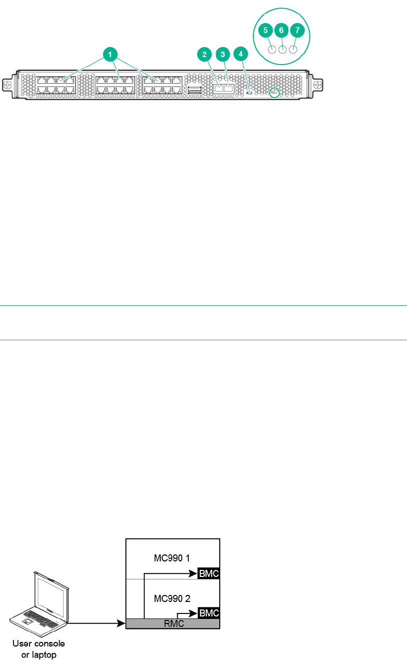
Figure 10 RMC front panel
2. WAN/LAN connector1. Network ports (24)
4. CNSL micro-USB connector3. AUX port
6. PG (Power Good) LED indicator5. RST button
7. HB (Heart Beat) LED indicator
RMC overview
The RMC system for the Integrity MC990 X system manages power control and
sequencing, provides environmental control and monitoring, initiates system resets,
stores identification and configuration information, and provides console/diagnostic
and scan interface.
The RMC provides the top layer of system control for the Integrity MC990 X system.
This controller is a stand alone 1U high rack mount chassis.
NOTE: Physical placement of the RMC is above or below the MC990 X server
chassis in a rack. The RMC slides out the front of the rack only.
The RMC uses an internal 24-port Ethernet switch, which can provide system control
for up to 16 MC990 X server chassis in an expanded system. The RMC accepts
direction via IPMI 2.x-enabled protocol software and supports powering-up and
powering-down individual motherboards and environmental monitoring of all units
within the MC990 X server chassis.
The RMC sends operational requests to the BMC on each compute/memory
motherboard installed. The RMC and the BMC are active whenever power is applied
to the system and are not dependent on the Integrity MC990 X system having the
operating system booted and operational.
The RMC in a system distributes its inquiries and information to all the MC990 X
server chassis motherboards within the SSI.
Figure 11 RMC functionality
22

BMC overview
Each system motherboard has a baseboard management controller. The BMC is a
built-in specialized microcontroller hardware component that monitors and reports on
the functional health status of the motherboard. The BMC provides a key functional
element in the overall Intelligent Platform Management Interface (IPMI) architecture.
The BMC acts as an interface to the higher levels of system control such as the RMC
node and the higher level control system used in the optional system management
node. The BMC can report any on-board sensor information that it has regarding
temperatures, power status, operating system condition and other functional
parameters that may be reported by the motherboard. When any of the preset limits
fall out of bounds, the information will be reported by the BMC and an administrator
can take some corrective action. This could entail a chassis shutdown, reset (NMI)
or power cycling of the MC990 X server chassis.
The individual motherboard BMCs do not have information on the status of other
motherboards within the SSI. This function is handled by the RMC and reported to
an administrative console/server. Note that motherboards equipped with an optional
BaseIO riser board have a dedicated BMC Ethernet port.
System controller interaction
In all MC990 X server chassis, the RMC and BMC system controllers communicate
with each other in the following ways:
•System control commands and communications are passed between the
administration node and the RMC via LAN or a local USB interface cable.
•The RMC communicates directly with the BMC in each installed MC990 X server
chassis via a dedicated internal Gigabit Ethernet network.
•Each MC990 X server chassis has a dedicated RMC interface connector on the
front of the system chassis.
System controllers
Each Integrity MC990 X system must have at least one RMC installed. “RMC functions”
(page 23) describe the basic features and functions of the BMC controllers.
NOTE: For additional information on controller commands, see the HPE Integrity
MC990 X Server RMC Software User Guide.
RMC functions
The following list summarizes the control and monitoring functions that the RMC
performs:
•Supports a Gigabit Ethernet interface
•Supports a limited (IPMI 2.x) interface for power control
•Controls powering up/down of the MC990 X server chassis in the system
•Supports Time Sync by providing synchronous Ethernet to each node BMC
•Provides a platform from which system data can be captured on failure
•Provides a platform from which various firmware updates can be initiated
•Provides inventory of system components as well various firmware revisions
currently flashed
•Monitors and reports issues with the RMC related to power, fans, temperature,
free memory and disk space
23
•Provides RJ45 ports for connections to the MC990 X server chassis BMC
The following connectors and LEDs are also located on the front panel of the RMC:
•Stack connector—38 circuit ipass connector used to expand the system
management network by connecting to a second RMC
•WAN port—RJ45 port used to connect to the customer’s LAN or an in-rack
administration node
•AUX port—RJ45 port currently is non-functional (reserved for future use)
•CNSL port—micro USB B port used for a local console/server connection
•RST switch—recessed push button switch used for reset of the RMC. The switch
is accessed by inserting a small screw driver or similar device through an opening
in the front panel.
•PG LED—green power good LED is illuminated when the correct power levels
are present in the RMC.
•HB LED—green heart beat LED flashes when the RMC is functioning normally
24
4 Using the Foundation Software
Foundation Software (FS) includes automatic boot-time optimization utilities, reliability
features, and technical support tools. Designed for high-performance computing,
these tools help maximize system performance and availability.
While many FS utilities and tools work in the background to optimize program
performance, other tools require configuration information from the system
administrator. The FS components that this guide addresses are:
•“Monitoring main memory health” (page 25)
•“Monitoring system performance” (page 26)
•“Enabling CPU frequency scaling” (page 30)
•“Additional Foundation Software utilities” (page 35)
Monitoring main memory health
About main memory health monitoring
The MEMlog utility monitors the overall system health of each DIMM on your system.
The MEMlog utility is configured for your system when the Foundation Software is
installed.
To verify that MEMlog utility is running, enter the following command:
#service memlog status
Retrieving main memory health information
HPE recommends that you check your computer system periodically to determine
whether the MEMlog utility has reported any hardware errors.
The MEMlog utility verifies and diagnoses problems with the DIMMs. The utility’s
messages appear in /var/log/messages.
The following explains how to access information from the MEMlog utility through the
monitoring tools or by using commands:
•“Accessing MEMlog messages with commands” (page 25)
Accessing MEMlog messages with commands
There are two ways to use commands to retrieve information about memory problems
or memory health:
•Scan the system log for entries that contain the string MEMLOG. If problems arise
with any of the DIMMs on your system, the MEMlog utility writes a message to
/var/log/messages. To retrieve these messages, enter the following command:
#grep MEMLOG /var/log/messages
r1i0n0:Dec 9 07:29:45 r1i0n0 MEMLOG[4595]: Read ECC P1-DIMM1A Rank 0 DRAM U9 DQ4 Temp = 21C
r1i0n0:Dec 9 07:30:00 r1i0n0 MEMLOG[4595]: P1-DIMM1A has a failed DRAM and must be replaced
soon.
Exposure to Uncorrected Error is high
r1i0n0:Dec 9 07:30:00 r1i0n0 MEMLOG[4595]: Read ECC P1-DIMM1A Rank 0 Bank 0 Row 0x0 Col 0x8
Temp = 21C
r1i0n0:Dec 9 07:30:00 r1i0n0 MEMLOG[4595]: Read ECC P1-DIMM1A Rank 0 DRAM U9 DQ4 Temp = 21C
r1i0n0:Dec 9 07:30:12 r1i0n0 MEMLOG[4595]: Read ECC P1-DIMM3A Rank 0 Temp = 22C
r1i0n0:Dec 9 07:30:12 r1i0n0 MEMLOG[4595]: Read ECC P1-DIMM3A Rank 0 DRAM U9 DQ4 Temp = 22C
r1i0n0:Dec 9 07:30:25 r1i0n0 MEMLOG[4595]: P1-DIMM3A has a failed DRAM and must be replaced
soon.
Exposure to Uncorrected Error is high
r1i0n0:Dec 9 07:30:25 r1i0n0 MEMLOG[4595]: Read ECC P1-DIMM3A Rank 0 Bank 0 Row 0x0 Col 0x8
Temp = 22C
25
•Use the memlog command to retrieve a report. The report lists all the DIMMs in
the system and contains an error summary for each DIMM. To obtain this report,
enter the following command:
rli0no: # memlogd —c
user config match for X9DRT-Dakota
found 2 sockets, highest socket number 1, deviceID Ivybridge, mem ctlrs/socket 1.
P1-DIMM1A Size 8192MB Width 4 Rank 2 Row 15 Col 11 Bank 8 Serial 405031E4 Part
HMT31GR7EFR4C-RD 1867
Tue Dec 9 07:28:48 2014 Rank 0 Dram U9 Bank 0 Row 0x0 Col 0x8 multiaddress C DQ4 Temp = 21C
hits 19
Tue Dec 9 07:31:31 2014 Rank 1 Dram U9B Bank 0 Row 0x0 Col 0x0 single DQ4 Temp = 21C hits 1
P1-DIMM2A Size 8192MB Width 4 Rank 2 Row 15 Col 11 Bank 8 Serial 409031CA Part
HMT31GR7EFR4C-RD 1867
P1-DIMM3A Size 8192MB Width 4 Rank 2 Row 15 Col 11 Bank 8 Serial 405031DE Part
HMT31GR7EFR4C-RD 1867
Tue Dec 9 07:30:12 2014 Rank 0 Dram U9 Bank 0 Row 0x0 Col 0x8 multiaddress C DQ4 Temp = 22C
hits 2
P1-DIMM4A Size 8192MB Width 4 Rank 2 Row 15 Col 11 Bank 8 Serial 40C031C7 Part
HMT31GR7EFR4C-RD 1867
P2-DIMM1A Size 8192MB Width 4 Rank 2 Row 15 Col 11 Bank 8 Serial 402031AA Part
HMT31GR7EFR4C-RD 1867
P2-DIMM2A Size 8192MB Width 4 Rank 2 Row 15 Col 11 Bank 8 Serial 407031A8 Part
HMT31GR7EFR4C-RD 1867
P2-DIMM3A Size 8192MB Width 4 Rank 2 Row 15 Col 11 Bank 8 Serial 407031E7 Part
HMT31GR7EFR4C-RD 1867
P2-DIMM4A Size 8192MB Width 4 Rank 2 Row 15 Col 11 Bank 8 Serial 40C031E8 Part
HMT31GR7EFR4C-RD 1867
The preceding example output includes 8 DIMMs. Note the following in this output:
◦Information about the first DIMM, P1-DIMM1A, is on the first line. The two
lines that follow are the DIMM repair tag, which shows that this DIMM has
been encountering corrected errors.
◦The third DIMM, P1-DIMM3A, has also encountered corrected errors.
◦The last number on each line of inventory is 1867. This number is the channel
speed that the memory controller set at boot time for that DIMM.
Monitoring system performance
This section includes the following topics:
•“About the system monitoring software” (page 26)
•“hubstats command” (page 27)
•“linkstat command” (page 27)
•“gr_systat command” (page 27)
•“nodeinfo command” (page 27)
•“topology command” (page 28)
About the system monitoring software
You can use Linux utilities, FS utilities, and open source utilities to monitor system
performance.
The Linux utilities include w(1),ps(1),top(1),vmstat(8),iostat(1), and
sar(1). You can use Linux system monitoring utilities on all MC990 X platforms,
including Integrity MC990 X systems and Integrity MC990 X for SAP HANA TDI
appliances.
The FS utilities include hubstats,linkstat,nodeinfo, and topology. HPE
supports these utilities on all MC990 X platforms, including Integrity MC990 X for SAP
HANA TDI appliances.
26
hubstats command
The hubstats command monitors NUMAlink traffic, directory cache operations, and
global reference unit (GRU) traffic statistics on MC990 X systems. It is useful as a
performance monitoring tool and as a tool to help you to diagnose and identify faulty
hardware. The uvstats library supplies the hubstats command with statistics from
the MC990 X dashboard.
linkstat command
The linkstat command monitors NUMAlink traffic on MC990 X systems. The
linkstat command returns information about packets and Mbytes sent/received
on each NUMAlink in the system. It is useful as a performance monitoring tool and
as a tool to help you to diagnose and identify faulty hardware. The uvstats library
supplies the linkstat command with statistics from the MC990 X dashboard.
gr_systat command
The gr_systat command monitors CPU and memory activity on x86 systems. It’s
graphical output display includes information about CPU utilization, I/O wait times,
IRQs, and memory utilization, both for the system as a whole and for each node. The
gr_systat command is a useful performance monitoring tool.
nodeinfo command
nodeinfo is a tool for monitoring per-node NUMA memory statistics on MC990 X
systems. The nodeinfo tool reads /sys/devices/system/node/*/meminfo
and /sys/devices/system/node/*/numastat on the local system to gather
NUMA memory statistics.
Sample memory statistics from the nodeinfo command are:
MC990X-sys:~ # nodeinfo
Memory Statistics Tue Oct 26 12:01:58 2010
MC990X-sys
---------------------- Per Node KB ------------ ----- Preferred Alloc ----- --
Loc/Rem--
node Total Free Used Dirty Anon Slab hit miss foreign interlv local
remote
0 16757488 16277084 480404 52 34284 36288 20724 0 0 0 20720
4
1 16777216 16433988 343228 68 6772 17708 4477 0 0 0
3381 1096
2 16777216 16438568 338648 76 6908 12620 1804 0 0 0
709 1095
3 16760832 16429844 330988 56 2820 16836 1802 0 0 0
708 1094
4 16777216 16444408 332808 88 10124 13588 1517 0 0 0
417 1100
5 16760832 16430300 330532 72 1956 17304 4546 0 0 0
3453 1093
6 16777216 16430788 346428 36 3236 15292 3961 0 0 0
2864 1097
7 16760832 16435532 325300 44 1220 14800 3971 0 0 0
2877 1094
TOT 134148848 131320512 2828336 492 67320 144436 42802 0 0 0 35129
7673
Press "h" for help
From an interactive nodeinfo session, enter hfor a help statement. For example:
Display memory statistics by node.
q quit
+ Increase starting node number. Used only if more nodes than
will fit in the current window.
- Decrease starting node number. Used only if more nodes than
will fit in the current window.
b Start output with node 0.
e Show highest node number.
k show sizes in KB.
27

m show sizes in MB.
p show sizes in pages.
t Change refresh rate.
A Show/Hide memory policy stats.
H Show/Hide hugepage info.
L Show/Hide LRU Queue stats.
Field definitions:
hit - page was allocated on the preferred node
miss - preferred node was full. Allocation occurred on THIS node
by a process running on another node that was full
foreign - Preferred node was full. Had to allocate somewhere
else.
interlv - allocation was for interleaved policy
local - page allocated on THIS node by a process running on THIS node
remote - page allocated on THIS node by a process running on ANOTHER
node
(press any key to exit from help screen)
topology command
The topology command provides topology information about your system. Application
programmers can use the topology command to help optimize execution layout for
their applications.
The topology command includes many options. For more information, enter
topology --help on the command line.
Example 5 topology command showing the system summary
mc990x-sys:~ # topology
System type: MC990 X
System name: harp34-sys
Serial number: MC-00000034
Partition number: 0
2 Compute chassis
8 CPUs
2 Nodes
30.00 GB Memory Total
15.00 GB Max Memory on any Node
1 BASE I/O Riser
2 Network Controllers
2 Storage Controllers
2 USB Controllers
1 VGA GPU
Example 6 topology command requests system summary and shows node
and CPU information
mc990x-sys:~ # topology --summary --nodes --cpus
System type: MC990 X
System name: harp34-sys
Serial number: MC-00000034
Partition number: 0
2 Compute chassis
8 CPUs
2 Nodes
30.00 GB Memory Total
15.00 GB Max Memory on any Node
1 BASE I/O Riser
2 Network Controllers
2 Storage Controllers
2 USB Controllers
1 VGA GPU
Index ID NASID CPUS Memory
28

--------------------------------------------
0 r001i11b00h0 0 4 15316 MB
1 r001i11b00h1 2 4 15344 MB
CPU Compute PhysID CoreID APIC-ID Family Model Speed L1(KiB) L2(KiB)
L3(KiB)
---------------------------------------------------------------------------------
0 r001i11b00h0 00 00 0 6 45 2599 32d/32i 256
20480
1 r001i11b00h0 00 01 2 6 45 2599 32d/32i 256
20480
2 r001i11b00h0 00 02 4 6 45 2599 32d/32i 256
20480
3 r001i11b00h0 00 03 6 6 45 2599 32d/32i 256
20480
4 r001i11b00h1 01 00 8 6 45 2599 32d/32i 256
20480
5 r001i11b00h1 01 01 10 6 45 2599 32d/32i 256
20480
6 r001i11b00h1 01 02 12 6 45 2599 32d/32i 256
20480
7 r001i11b00h1 01 03 14 6 45 2599 32d/32i 256
20480
Example 7 topology command showing IRQs assigned to devices
mc990x-sys:~ # topology --irq
Index Location NASID PCI Address IRQ(s) Device
--------------------------------------------------------------------
0 r001i01s00 0 0000:00:1f.2 519 Intel SATA RAID Controller
. . . 0000:02:00.0 1529-1532 Intel I210 Gigabit Network Connection
. . . 0000:06:00.0 255 Matrox G200eR2
4 r001i06s01 8 0001:01:00.0 56,1511-1526 LSI SAS2308 Fusion-MPT SAS-2
4 r001i06s02 8 0001:02:00.0 64,1480-1510 Intel P3700 Non-Volatile Memory Controller
4 r001i06s03 8 0001:03:00.0 66,1527,1533-1562 Intel P3700 Non-Volatile Memory Controller
5 r001i06s05 10 0002:02:00.0 88,1563-1593 Intel P3700 Non-Volatile Memory Controller
5 r001i06s06 10 0002:03:00.0 90,1594-1624 Intel P3700 Non-Volatile Memory Controller
6 r001i06s07 12 0003:01:00.0 104,1625-1655 Intel P3700 Non-Volatile Memory Controller
6 r001i06s08 12 0003:02:00.0 106,1656-1686 Intel P3700 Non-Volatile Memory Controller
7 r001i06s10 14 0004:01:00.0 128,1687-1717 Intel P3700 Non-Volatile Memory Controller
7 r001i06s11 14 0004:02:00.0 130,1718-1748 Intel P3700 Non-Volatile Memory Controller
12 r001i16s01 24 0005:01:00.0 152,2493-2508 LSI SAS2308 Fusion-MPT SAS-2
12 r001i16s02 24 0005:02:00.0 160,1749-1779 Intel P3700 Non-Volatile Memory Controller
12 r001i16s03 24 0005:03:00.0 162,1780-1810 Intel P3700 Non-Volatile Memory Controller
13 r001i16s05 26 0006:02:00.0 184,1811-1841 Intel P3700 Non-Volatile Memory Controller
13 r001i16s06 26 0006:03:00.0 186,1842-1872 Intel P3700 Non-Volatile Memory Controller
14 r001i16s07 28 0007:01:00.0 200,1873-1903 Intel P3700 Non-Volatile Memory Controller
14 r001i16s08 28 0007:02:00.0 202,1904-1934 Intel P3700 Non-Volatile Memory Controller
15 r001i16s10 30 0008:01:00.0 224,1935-1965 Intel P3700 Non-Volatile Memory Controller
15 r001i16s11 30 0008:02:00.0 226,1966-1996 Intel P3700 Non-Volatile Memory Controller
20 r001i28s01 40 0009:01:00.0 2558 NVIDIA GK110BGL [Tesla K40m]
20 r001i28s02 40 0009:02:00.0 256,1997-2027 Intel P3700 Non-Volatile Memory Controller
20 r001i28s03 40 0009:03:00.0 258,2028-2058 Intel P3700 Non-Volatile Memory Controller
21 r001i28s04 42 000a:01:00.0 2557 NVIDIA GK110BGL [Tesla K40m]
21 r001i28s05 42 000a:02:00.0 280,2059-2089 Intel P3700 Non-Volatile Memory Controller
21 r001i28s06 42 000a:03:00.0 282,2090-2120 Intel P3700 Non-Volatile Memory Controller
22 r001i28s07 44 000b:01:00.0 296,2121-2151 Intel P3700 Non-Volatile Memory Controller
22 r001i28s08 44 000b:02:00.0 298,2152-2182 Intel P3700 Non-Volatile Memory Controller
22 r001i28s09 44 000b:03:00.0 2560 NVIDIA GK110BGL [Tesla K40m]
23 r001i28s10 46 000c:01:00.0 320,2183-2213 Intel P3700 Non-Volatile Memory Controller
23 r001i28s11 46 000c:02:00.0 322,2214-2244 Intel P3700 Non-Volatile Memory Controller
23 r001i28s12 46 000c:03:00.0 2559 NVIDIA GK110BGL [Tesla K40m]
28 r001i38s01 56 000d:01:00.0 344,2509-2524 LSI SAS2308 Fusion-MPT SAS-2
28 r001i38s02 56 000d:02:00.0 352,2245-2275 Intel P3700 Non-Volatile Memory Controller
28 r001i38s03 56 000d:03:00.0 354,2276-2306 Intel P3700 Non-Volatile Memory Controller
29 r001i38s05 58 000e:02:00.0 376,2307-2337 Intel P3700 Non-Volatile Memory Controller
29 r001i38s06 58 000e:03:00.0 378,2338-2368 Intel P3700 Non-Volatile Memory Controller
30 r001i38s07 60 000f:01:00.0 392,2369-2399 Intel P3700 Non-Volatile Memory Controller
30 r001i38s08 60 000f:02:00.0 394,2400-2430 Intel P3700 Non-Volatile Memory Controller
31 r001i38s10 62 0010:01:00.0 416,2431-2461 Intel P3700 Non-Volatile Memory Controller
31 r001i38s11 62 0010:02:00.0 418,2462-2492 Intel P3700 Non-Volatile Memory Controller
Example 8 topology command showing interrupt count info with –v option
mc990x-sys:~ # topology --irq -v
Index Location NASID PCI Address IRQ(s) INTCNT Device
--------------------------------------------------------------------------------
0 r001i01s00 0 0000:00:1f.2 519 703608 Intel SATA RAID Controller
29

. . . 0000:02:00.0 1529-1532 11088420 Intel I210 Gigabit Network Connection
. . . 0000:06:00.0 255 0 Matrox G200eR2
4 r001i06s01 8 0001:01:00.0 56,1511-1526 0 LSI SAS2308 Fusion-MPT SAS-2
4 r001i06s02 8 0001:02:00.0 64,1480-1510 0 Intel P3700 Non-Volatile Memory Controller
4 r001i06s03 8 0001:03:00.0 66,1527,1533-1562 0 Intel P3700 Non-Volatile Memory Controller
5 r001i06s05 10 0002:02:00.0 88,1563-1593 0 Intel P3700 Non-Volatile Memory Controller
5 r001i06s06 10 0002:03:00.0 90,1594-1624 0 Intel P3700 Non-Volatile Memory Controller
6 r001i06s07 12 0003:01:00.0 104,1625-1655 0 Intel P3700 Non-Volatile Memory Controller
Example 9 topology command showing local CPU and node info for each
device
You can use the output from this command to help you place applications close to
their I/O device for better direct memory access performance.
mc990x-sys:~ # topology --io -v --nox
Index Location NASID PCI Address Node Local CPUS Device
-------------------------------------------------------------------------
0 r001i01s00 0 0000:00:1f.2 0 0-14,480-494 Intel SATA RAID Controller
. . . 0000:02:00.0 0 0-14,480-494 Intel I210 Gigabit Network Connection
. . . 0000:06:00.0 0 0-14,480-494 Matrox G200eR2
4 r001i06s01 8 0001:01:00.0 4 60-74,540-554 LSI SAS2308 Fusion-MPT SAS-2
4 r001i06s02 8 0001:02:00.0 4 60-74,540-554 Intel P3700 Non-Volatile Memory Controller
4 r001i06s03 8 0001:03:00.0 4 60-74,540-554 Intel P3700 Non-Volatile Memory Controller
5 r001i06s05 10 0002:02:00.0 5 75-89,555-569 Intel P3700 Non-Volatile Memory Controller
5 r001i06s06 10 0002:03:00.0 5 75-89,555-569 Intel P3700 Non-Volatile Memory Controller
6 r001i06s07 12 0003:01:00.0 6 90-104,570-584 Intel P3700 Non-Volatile Memory Controller
6 r001i06s08 12 0003:02:00.0 6 90-104,570-584 Intel P3700 Non-Volatile Memory Controller
7 r001i06s10 14 0004:01:00.0 7 105-119,585-599 Intel P3700 Non-Volatile Memory Controller
7 r001i06s11 14 0004:02:00.0 7 105-119,585-599 Intel P3700 Non-Volatile Memory Controller
12 r001i16s01 24 0005:01:00.0 12 180-194,660-674 LSI SAS2308 Fusion-MPT SAS-2
12 r001i16s02 24 0005:02:00.0 12 180-194,660-674 Intel P3700 Non-Volatile Memory Controller
12 r001i16s03 24 0005:03:00.0 12 180-194,660-674 Intel P3700 Non-Volatile Memory Controller
13 r001i16s05 26 0006:02:00.0 13 195-209,675-689 Intel P3700 Non-Volatile Memory Controller
13 r001i16s06 26 0006:03:00.0 13 195-209,675-689 Intel P3700 Non-Volatile Memory Controller
14 r001i16s07 28 0007:01:00.0 14 210-224,690-704 Intel P3700 Non-Volatile Memory Controller
14 r001i16s08 28 0007:02:00.0 14 210-224,690-704 Intel P3700 Non-Volatile Memory Controller
15 r001i16s10 30 0008:01:00.0 15 225-239,705-719 Intel P3700 Non-Volatile Memory Controller
15 r001i16s11 30 0008:02:00.0 15 225-239,705-719 Intel P3700 Non-Volatile Memory Controller
20 r001i28s01 40 0009:01:00.0 20 300-314,780-794 NVIDIA GK110BGL [Tesla K40m]
Enabling CPU frequency scaling
About CPU frequency scaling
CPU frequency scaling allows the operating system to scale the processor frequency
automatically and dynamically. HPE configures the CPU frequency scaling setting on
all MC990 X computer systems before the computer system leaves the factory. The
default setting is assumed to be correct for most implementations. The CPU frequency
scaling setting lets your system take advantage of the Intel Turbo Boost technology
that is built into each processor.
The Intel Turbo Boost Technology allows processor cores to run faster than the base
operating frequency as long as they are operating below the limits set for power,
current, and temperature. The CPU frequency scaling setting also affects power
consumption and enables you to manage power consumption. For example,
30

theoretically, you can cut power consumption if you clock the processors from 2 GHz
down to 1 GHz.
CPU frequency scaling for Integrity MC990 X systems
The procedures that explain how to configure CPU frequency scaling on MC990 X
systems depend on whether your system includes the intel_pstate directory. If
your MC990 X system includes the intel_pstate directory, then CPU frequency
scaling is enabled with the Intel P State driver. The path to the intel_pstate
directory on your system is: /sys/device/system/cpu/intel_pstate
NOTE: The ability to configure CPU frequency scaling is not available on MC990
X for SAP HANA TDI platforms. HPE configures this setting appropriately on MC990
X for SAP HANA TDI appliances.
After checking your MC990 X system for the presence of this directory, the following
settings are available to you:
•The CPU frequency settings for MC990 X systems that include an intel_pstate
directory are:
◦performance (default)
◦powersave
•The CPU frequency settings for MC990 X systems that do not include an
intel_pstate directory are:
◦conservative
◦ondemand (default)
◦performance. This setting directs the processors to run at or near their
maximum speeds.
◦powersave. This setting slows down the processors and might be suitable
for your site during periods of low use.
◦userspace
Configuring the powersave setting on systems with the intel_pstate directory
By default, the CPU frequency setting on MC990 X servers that include the
intel_pstate directory is performance. During non-peak production times, you
might want to configure the powersave setting.
To configure the powersave setting:
1. Log in as root to the system you want to configure.
2. Use the cpupower command in one of the following formats:
•To enable the powersave setting, enter the following command:
#cpupower frequency-set -g powersave
•To re-enable the performance setting, which is the default, enter the
following command:
#cpupower frequency-set -g performance
3. Enter the following command to retrieve the setting that is in effect:
#cpupower frequency-info
31

Verify that the setting you specified appears in the command output in the
current policy field.
4. (Optional) Use a text editor to edit the /etc/init.d/after.local file and
add the following line:
cpupower frequency-set -g powersave
The preceding line ensures that after each boot, the system sets the powersave
setting.
Enabling CPU frequency scaling systems without the intel_pstate directory
The procedure in this topic explains how to enable or disable CPU frequency scaling
on MC990 X systems that do not include the intel_pstate directory.
To enable CPU frequency scaling:
1. Log in as root to the system you want to configure.
2. Use a text editor to open file /etc/sysconfig/x86config, and verify or
change the system setting from within this file.
This file contains the settings that enable or disable CPU frequency scaling.
To enable CPU frequency scaling, set
UV_DISABLE_CPU_FREQUENCY_SCALING=no.
To disable CPU frequency scaling, set
UV_DISABLE_CPU_FREQUENCY_SCALING=yes.
3. Enter the following command to propagate the new system setting:
#/usr/sbin/x86config
4. Enter one of the following commands to restart services:
•On RHEL 6 platforms, enter the following:
#service cpuspeed restart
•On RHEL 7 and SLES 12 platforms, enter the following:
#modprobe acpi_cpufreq
•On SLES 11 platforms, enter the following:
#service haldaemon restart
5. Change the CPU frequency governor setting and configure turbo mode.
Proceed to “Changing the governor setting on systems without the intel_pstate
directory” (page 32)
Changing the governor setting on systems without the intel_pstate directory
The default CPU frequency governor setting can inhibit system performance. Use the
procedure in this topic to change the governor setting.
Changing the governor setting is a prerequisite to configuring turbo mode. When you
enable turbo mode, you enable the CPU frequency to exceed its nominal level for
short periods of time, depending on the processor, temperature, current, power, and
other factors. For general information about turbo mode, see the following website:
https://www-ssl.intel.com/content/www/us/en/architecture-and-technology/
turboboost/turbo-boost-technology.html
The following procedure explains how to set the CPU frequency governor appropriately
and points you to the procedure that explains how to configure turbo mode
32
1. Make sure that CPU frequency is enabled.
For information, see “Enabling CPU frequency scaling systems without the
intel_pstate directory” (page 32).
2. Decide which governor setting is suitable for your site.
ondemand is the default setting. HPE recommends that you change this to a
site-specific setting and that you configure the governor to performance.
The possible power governor settings are:
governor setting Effect
ondemand Dynamically switches between the available CPUs if
at 95% of CPU load. Default.
HPE does not recommend this setting. Consider using
the performance setting.
performance Runs the CPUs at the maximum frequency.
HPE recommends this setting.
conservative Dynamically switches between the available CPUs if
at 75% of CPU load.
powersave Runs the CPUs at the minimum frequency.
userspace Runs the CPUs at user-specified frequencies.
3. Use one of the following platform-specific methods to change the setting:
•On RHEL 7 platforms, complete the following steps:
Enter the following command:
#cpupower frequency-set -g governor
a.
For governor, specify the setting you chose in the previous step.
b. Enter the following command and verify that the governor setting you
specified appears in the cpupower command output in the current
policy field:
#cpupower frequency-info
c. To ensure that the governor setting persists across reboots, enter the
following command:
#systemctl enable cpupower
•On RHEL 6 platforms, complete the following steps:
Open file /etc/sysconfig/cpuspeed.a.
b. Search for the GOVERNOR= string.
c. Edit the setting, adding the governor setting you chose in the previous
step.
d. Save and close the file.
e. Enter the following command:
#service cpuspeed restart
f. To ensure that the governor setting persists across reboots, use a
text editor to edit the /etc/init.d/after.local file, add the
following line, and then save and close the file:
cpupower freqency-set -g governor
•On SLES 12 platforms, complete the following steps:
33

Enter the following command:
#cpupower frequency-set -g governor
a.
For governor, specify the setting you chose in the previous step.
b. Enter the following command and verify that the governor setting you
specified appears in the cpupower command output in the current
policy field:
#cpupower frequency-info
NOTE: The remainder of the steps in this procedure for SLES 12
platforms ensure that governor setting persists across reboots.
c. Use a text editor to create file
/usr/lib/systemd/system/cpupower.service, populate the file
with the following content, and then save and close the file:
[Unit]
Description=Configure CPU power related settings
After=syslog.target
[Service]
Type=oneshot
RemainAfterExit=yes
EnvironmentFile=/etc/sysconfig/cpupower
ExecStart=/usr/bin/cpupower $CPUPOWER_START_OPTS
ExecStop=/usr/cpupower $CPUPOWER_STOP_OPTS
[Install]
WantedBy=multi-user.target
d. Use a text editor to create file /etc/sysconfig/cpupower, populate
the file with the following content, and then save and close the file:
CPUPOWER_START_OPTS="frequency-set -g performance"
CPUPOWER_STOP_OPTS="frequency-set -g ondemand"
e. To ensure that the governor setting persists across reboots, enter the
following command:
#systemctl enable cpupower
•On SLES 11 platforms, complete the following steps:
a. Enter the following command:
#cpupower frequency-set -g governor
For governor, specify the setting you chose in the previous step.
b. Enter the following command and verify that the governor setting you
specified appears in the cpupower command output in the current
policy field:
#cpupower frequency-info
c. To ensure that the governor setting persists across reboots, use a
text editor to edit the /etc/init.d/after.local file, add the
following line, and then save and close the file:
cpupower freqency-set -g governor
4. (Conditional) Configure turbo mode.
Complete this step if you want to configure turbo mode.
34
If your goal was to configure a nondefault governor setting, you do not need to
configure turbo mode.
Proceed to “Configuring turbo mode on systems without the intel_pstate directory”
(page 35)
Configuring turbo mode on systems without the intel_pstate directory
The following procedure explains how to configure turbo mode.
1. Make sure that you configured a governor setting.
For information about how to configure a governor setting, see “Changing the
governor setting on systems without the intel_pstate directory” (page 32).
2. Use the cat(1) command to retrieve the list of available frequencies. For example:
# cat /sys/devices/system/cpu/cpu0/cpufreq/scaling_available_frequencies
3301000 3300000 3200000 3100000 3000000 2900000 2800000 2700000 2600000
2500000 2400000 2300000 2200000 2100000 2000000 1900000 1800000 1700000
1600000 1500000 1400000 1300000 1200000
The preceding output shows the available frequencies, listed in order from the
highest, 3301000 KHz, to the lowest, 1200000 KHz.
On MC990 X systems, the second frequency listed is always the processor
nominal frequency. This is a 3.3 GHz processor, so 3300000 KHz is the nominal
frequency.
You can also obtain the nominal frequency by entering the following command
and examining the information in the model name field:
#cat /proc/cpuinfo
3. Use the cpupower command to set the frequency to the nominal frequency of
3.3 GHz plus 1 MHz.
That is, specify a frequency of 3301 MHz. For example:
#cpupower frequency-set -u 3301MHz
Later, if you want to disable turbo mode, enter the following command to set the
maximum frequency back to the nominal frequency:
#cpupower frequency-set -u 3300MHz
Additional Foundation Software utilities
This section includes information about additional Foundation Software commands
and utilities that typically require no user involvement. HPE technical support staff
members might guide you in the use of these commands when troubleshooting or
tuning.
base-configuration A collection of configuration scripts for MC990 X
systems.
ha-stonith-plugins-uv Provides STONITH agents to implement fencing on
MC990 X systems through the RMC or CMC.
irqbalance Controls interrupt request (IRQ) affinity on MC990
X systems. The daemon starts when a system boots.
If a device generates IRQs, irqbalance attempts
to distribute the interrupts to the CPUs that are on
the same chassis (or node) upon which the interrupt
originated.
By default, this utility starts every two minutes. To
change that interval, set IRQBALANCE_SLEEPTIME
in /etc/sysconfig/irqbalance to the desired
35
number of seconds and restart irqbalance or
reboot your system.
The base-configuration package automatically
configures the irqbalance utility.
36

5 Component replacement procedures
This chapter provides information about installing and removing PCIe cards, chassis
fans and system disk drives from your Integrity MC990 X system, as follows:
•“Maintenance precautions and procedures” (page 37)
•“Removing the chassis top cover” (page 38)
•“Adding or replacing PCIe or GPU cards” (page 39)
•“Installing or replacing a drive” (page 40)
Maintenance precautions and procedures
This section describes how to open the system for maintenance and upgrade, protect
the components from static damage, and return the system to operation. The following
topics are covered:
•“Preparing the system for maintenance or upgrade” (page 37)
•“Returning the system to operation” (page 37)
WARNING! To avoid problems that could void your warranty, your HPE or other
approved service provider should perform all the setup, addition, or replacement of
parts, cabling, and service of your Integrity MC990 X system, with the exception of
the following items that you can perform yourself:
•Using your network access workstation to enter commands and perform system
functions such as powering up and powering down, as described in this guide.
•Installing, removing or replacing PCIe or GPU cards in the MC990 X server
chassis
•Installing or replacing hard disk or SSD drives in the MC990 X server chassis
•Remove and replace an MC990 X server chassis fan assembly
•Remove and replace an MC990 X server chassis power supply
•Remove and replace an MC990 X server chassis BaseIO card
Be sure to observe all ESD precautions when removing or replacing these components.
See “ESD precaution” (page 13).
Preparing the system for maintenance or upgrade
To prepare the system for maintenance, follow these steps:
1. If you are logged on to the system, log out. Follow standard procedures for
gracefully halting the operating system.
2. Go to the section “Powering the system up and down” (page 15) if you are not
familiar with power down procedures.
3. After the system is powered off, locate the PDUs in the rack and turn off the circuit
breaker switches on each PDU.
Returning the system to operation
When you finish installing or removing components, return the system to operation
as follows:
1. Turn each of the PDU circuit breaker switches to the (On) position.
2. Power up the system. If you are not familiar with the proper power-up procedure,
review the section “Powering the system up and down” (page 15).
37
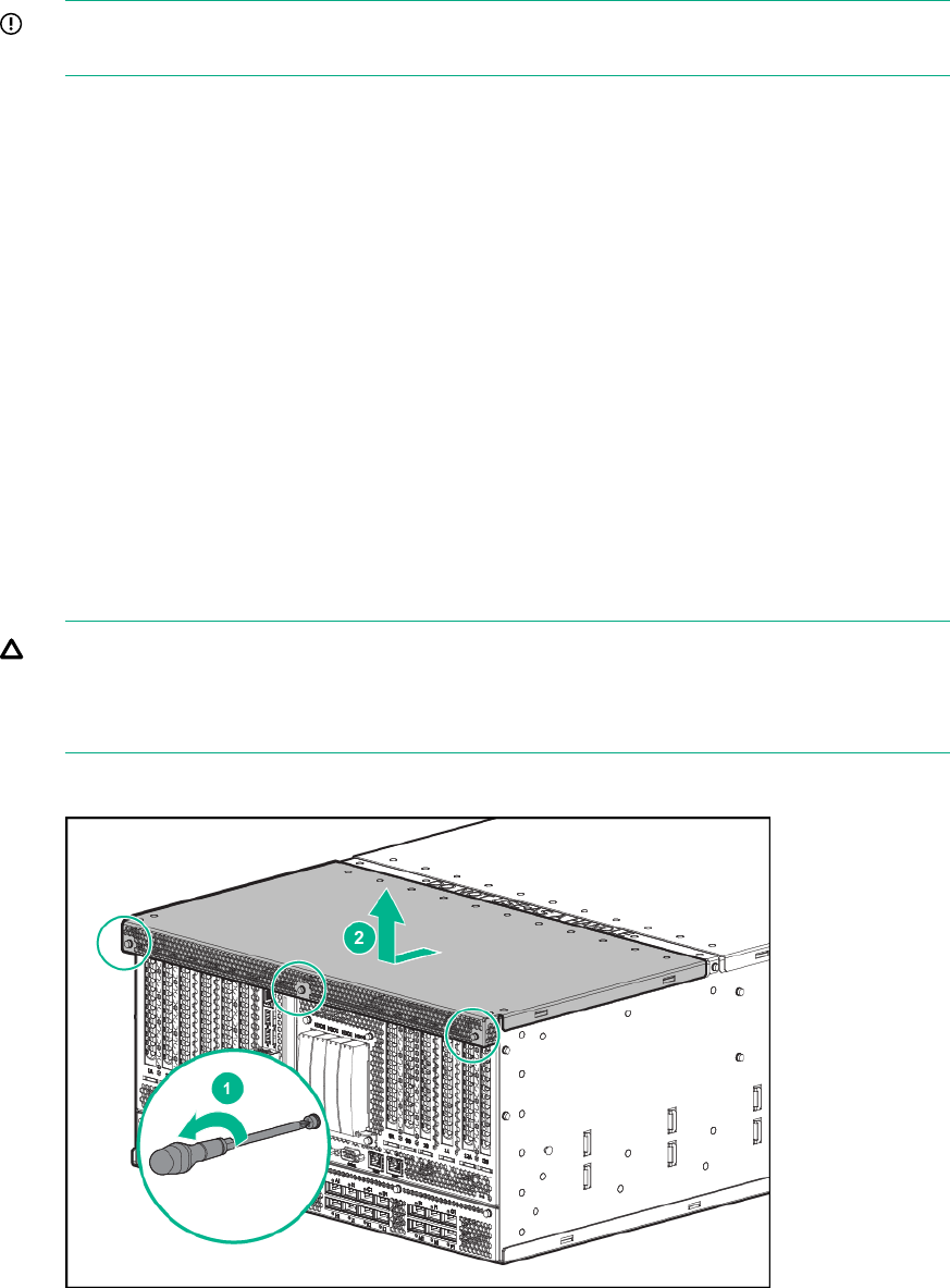
3. Verify that the LEDs on the system power supplies and system front components
turn on and illuminate green which indicates that the power-up procedure is
proceeding properly.
If your system does not boot correctly, see “Integrity MC990 X system Troubleshooting”
(page 46), for troubleshooting procedures.
Removing the chassis top cover
IMPORTANT: The MC990 X server chassis cover should not be removed while
the Integrity MC990 X system is powered up.
As shown in Figure 12 (page 38), the MC990 X server chassis top is a two-piece
bifurcated front and rear chassis cover. The top cover does not need to be removed
for system disk replacement, power supply maintenance, or system fan
remove/replace. Other service actions require that you remove the front chassis cover,
detailed below.
To remove a MC990 X server chassis cover, use a T10 Torx driver with the following
instructions:
1. Power down the chassis by turning off the PDU(s) providing power to the unit or
by disconnecting all power supply cords from the chassis rear (or both).
2. Remove the front panel (bezel) by grasping at either end and pulling it off.
3. In a multi-chassis system, you may need to remove the NUMALink connector
cables from the front of the unit. Be sure they are labeled for proper re-installation.
4. Ensure that all other rack-mounted enclosures are in place and pull the chassis
out the front.
5. Using the Torx driver, remove the three front retaining screws from the top cover
and carefully set them aside for re-installation after completion of the procedure.
6. Grasp the front cover and slide it forward and upward from the chassis.
CAUTION: Always re-install the chassis cover after you have accessed any internal
components to ensure proper airflow and cooling for the system. Failure to re-install
the cover may cause thermal over-temperature conditions and automatic shut-down
of the chassis.
Figure 12 MC990 X server chassis cover removal
38

Adding or replacing PCIe or GPU cards
WARNING! Before installing, operating, or servicing any part of this product, read
the “Safety precautions” (page 13).
This section provides instructions for adding or replacing a PCIe or GPU-based PCIe
card in your Integrity MC990 X system. To maximize the operating efficiency of your
cards, be sure to read all the introductory matter before beginning the installation.
CAUTION: To protect the PCIe cards from ESD damage, HPE recommends that
you use a grounding wrist strap while installing a PCIe card.
Installing cards in the MC990 X server chassis
Always follow the manufacturer’s instructions or restrictions for installing their card.
IMPORTANT: Addition of a new PCIe/GPU card requires a reboot to initiate
recognition and functionality. Removal (without replacement) of an existing PCIe card
may cause system error messages. When installing PCIe cards, ensure that the input
current rating specified on the AC input label is not exceeded.
The PCIe slots available in the MC990 X server chassis consist of the following:
•Four full-height, half-length, Gen3 x8 PCIe slots
•Four full-height, 10.5-inch length, Gen3 x8 PCIe slots
•Four full-height, double-wide, 10.5-inch length, Gen3 x16 PCIe slots
NOTE: The x16 PCIe slots support cards with a maximum power consumption
of 300 watts.
The procedure requires a T-10 Torx driver and Phillips-head screwdriver to complete.
Before installing the PCIe expansion cards, be sure to remove each respective slot
cover and use its screw to secure your expansion card in place. Shut down the
operating system and remove all power from the chassis before starting.
1. Working from the front of the chassis, grasp the front panel on either side and
pull it off the enclosure. Use the Torx driver to remove the three screws that
secure the front top cover. See the section “Removing the chassis top cover”
(page 38) for additional detail. Remove any NUMAlink cables and label for
replacement.
2. Push the two rail release latches in and slide the chassis forward. Remove the
chassis cover as detailed in “Removing the chassis top cover” (page 38).
3. Select an available slot based on the size of your PCIe card.
4. If replacing an existing PCIe card, disconnect any cables from the old card and
remove its top retaining screw. If using an empty PCIe slot, remove the metal
slot cover from the selected slot and retain its screw.
5. Fit the new PCIe card into the slot connector with the connector(s) extending out
the front of the chassis, making sure the card’s upper tab is flush with the chassis
front, and then secure the board with the screw that previously held the metal
slot cover.
6. Reinstall the front top cover, push the chassis back into the rack until it latches
and reconnect all cables.
NOTE: Each NUMAlink cable should be labeled with source/destination
information.
39
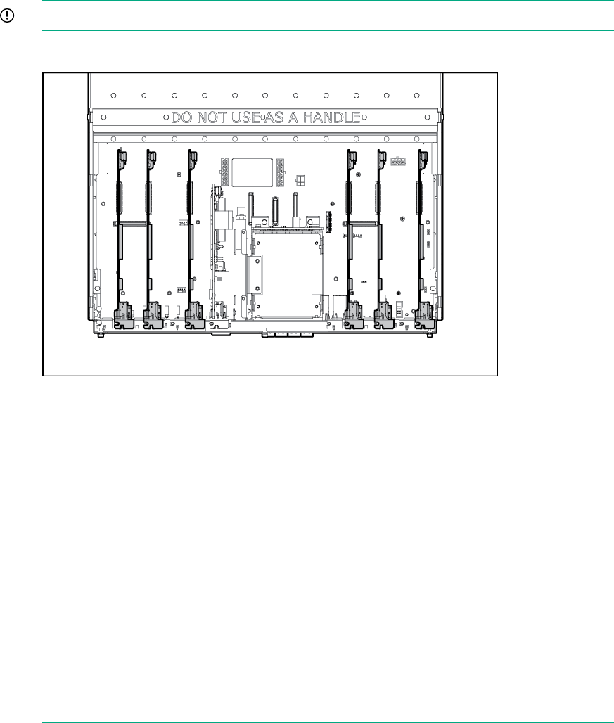
IMPORTANT: After installation of a new card, be sure to re-boot your system.
Figure 13 PCIe full-height x8 and x16 card slot locations
Installing or replacing a drive
The MC990 X server chassis holds up to four hard disk drives in a tray assembly at
the front of the chassis. The disk riser assembly occupies the riser card 1 position on
the MC990 X server chassis motherboard. It is located between the two side PCIe
risers at the front of the chassis. The disk riser assembly supports both 2.5-inch solid
state (SSD) and 2.5-inch spinning disks, see Figure 14 (page 41). Note that the riser
also supports one optional DVD that should be installed or replaced by a trained
service person. Instructions for installing/removing/replacing the DVD drive are not
in this document.
The drive-tray riser interface supports five devices. You can operate the DVD and
hard drives at the same time. Note that the tray assembly is not configured to support
five 2.5-inch hard drives if the DVD drive slot is unused. Figure 14 (page 41) calls out
the location of the 2.5-inch system drive assembly on the front of the chassis as well
as showing the location of the two 1.8-inch SSD option drives.
NOTE: An MC990 X server chassis expansion chassis does not include a standard
drive/riser card assembly.
40
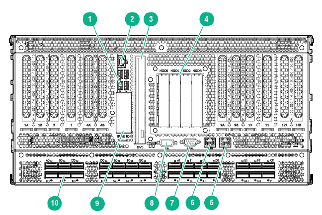
Figure 14 MC990 X front drive array location
2. Ethernet port1. USB port (4)
4. System drive assembly3. DVD drive
6. MGMT port5. RMC port
8. VGA port7. Serial port
10. NUMAlink ports (28)9. 1.8–inch SSD drive bays
Remove or replace a 2.5-inch hard drive
Each 2.5-inch hard disk drive in the MC990 X server chassis drive tray is secured in
a drive sled that slides in and out of the drive tray assembly and locks in place.
Use the following steps and illustrations to add or replace a hard disk drive in the
MC990 X server chassis:
1. Shut down the Integrity MC990 X system operating system.
2. To remove power from the chassis, unplug all the MC990 X server chassis power
supply cords.
3. Grasp the perforated front chassis cover at either end and pull it off the front of
the unit.
4. Locate the drive you need to remove and push in its top release latch, see
Figure 15 (page 42) for an example.
5. Pull the drive retention handle outward to completely unlock the drive-sled
assembly.
6. Pull the drive-sled assembly straight out and lift it away from the chassis.
7. Select the tray location for the new hard disk drive. If the new drive is not equipped
with a MC990 X server chassis style mounting bracket (sled), remove the old
drive’s sled and install the hardware on the replacement drive. Check with your
support provider if you do not have the appropriate sled hardware to install
additional drives in the tray.
8. If you have disconnected power, reconnect all the chassis power supplies and
restart the system. Use the instructions in “Powering the system up and down”
(page 15) if you are unfamiliar with the power-up procedure.
41
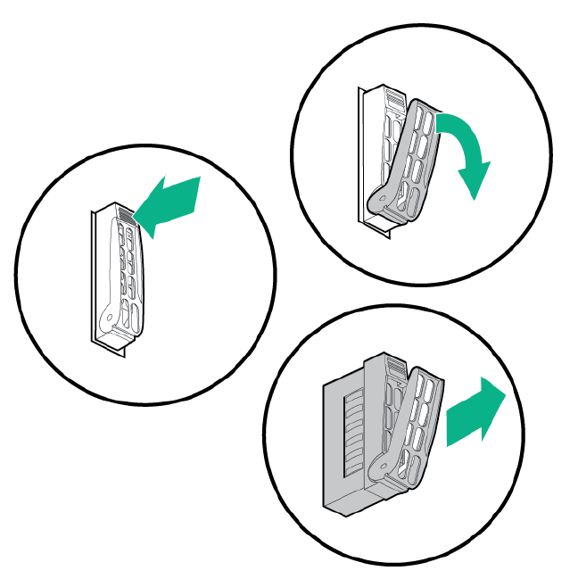
Figure 15 Hard drive remove/replace
Remove or replace a 1.8-inch SSD option drive
The BaseIO card supports two optional “mini” 1.8-inch SATA solid-state-drives (SSDs)
which are accessible from the front of the chassis. The two SSD slots are located
directly below the BaseIO board’s USB ports. The two SSDs connect internally via a
cable to two 6GB/s SATA ports. The SSDs are accessible from the front of the chassis.
A metal cover used to protect the SSDs is held in place by a single T10 Torx screw.
An SSD may be hot-swapped only if it is part of a RAID drive-pair. In this case you
may leave the operating system running and the MC990 X server chassis in the rack.
Use the following information to remove or replace a 1.8-inch SSD in the BaseIO:
1. Access the front of the rack and remove the MC990 X server chassis front panel
(bezel) by grasping at either end and pulling it off.
2. Use a T10 Torx driver to unscrew and remove the outer metal cover that protects
the SSDs.
3. Extract a drive by grasping the front of the drive and pulling straight out.
4. Insert a new drive by sliding the SSD into the empty slot until it fully engages the
connector.
5. Replace the BaseIO board SSD cover and secure it with the T10 Torx screw.
42
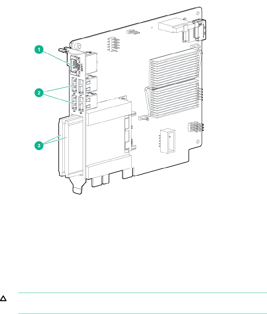
Figure 16 Optional 1.8-inch solid state drives
1. Ethernet port
2. USB ports (4)
3. SSD drives (2)
Replacing a MC990 X server chassis power supply
To remove and replace power supplies in an MC990 X server chassis, you do not
need any tools. Under most circumstances a single power supply can be replaced
without shutting down the enclosure or the complete system. In the case of a fully
configured MC990 X server chassis, this may not be possible.
CAUTION: The body of the power supply may be hot; allow time for cooling and
handle with care.
Use the following steps to replace a power supply in the MC990 X server chassis:
1. Open the rear door of the rack and locate the power supply that needs
replacement. The power supplies are located along the bottom section of each
MC990 X server chassis, see Figure 17 (page 44) for an example.
2. Disengage the power-cord retention clip and disconnect the power cord from the
power supply that needs replacement.
3. Press the retention latch of the power supply toward the power connector to
release the supply from the chassis.
4. Using the power supply handle, pull the power supply straight out until it is partly
out of the chassis. Use one hand to support the bottom of the supply as you fully
extract it from the enclosure. Note that each supply is 10.4-inches (26.4 cm) long
and weighs 2.65 lb (1.2 kg).
5. Align the rear of the replacement power supply with the chassis opening.
43
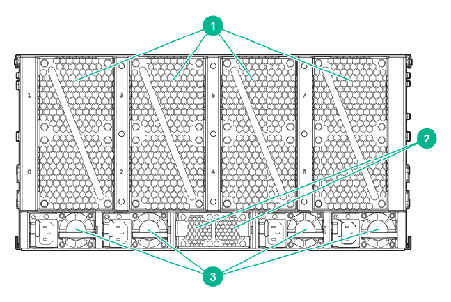
6. Slide the power supply into the chassis until the retention latch engages; you
should hear an audible click.
7. Reconnect the power cord to the supply and engage the retention clip.
Figure 17 MC990 X server chassis power supply and fan locations
2. HARP fan assembly1. Enclosure fan assembly (4)
3. Enclosure power supplies (4)
Replacing a MC990 X server chassis fan assembly
Chassis cooling for each MC990 X server chassis is provided by four rear-mounted
fan assemblies (as seen in Figure 17 (page 44)). Each chassis cooling fan unit is
made up of two stacked 80mm fans.
If one fan assembly fails, the remaining fans will ramp up to full speed and the
overheat/fan fail/info LED on the front control panel will illuminate (the system can
continue to run with a single failed fan assembly).
Note that each power supply in the system is cooled by an individual internal cooling
fan.
You will need to access the rack from the back to remove and replace a fan assembly.
Note that under most circumstances a fan can be replaced while the system is
operating. You will not need any tools to complete the replacement procedure.
Use the following steps to replace a MC990 X server chassis fan assembly:
1. Open the rack rear door and identify the fan assembly that has failed.
2. Grasp the handle of the failed cooling fan assembly and pull the unit straight out.
See Figure 18 (page 45) for an example of the chassis fan assembly.
3. Slide a new fan assembly completely into the open slot until the fan-interconnect
engages and the new unit is flush with the rear of the chassis.
4. Confirm that the new fan assembly is operational and close the rack rear door.
44
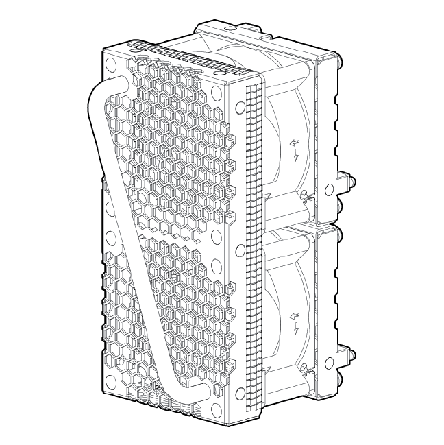
Figure 18 MC990 X server chassis rear fan assembly
45

6 Integrity MC990 X system Troubleshooting
This chapter provides the following sections to help you troubleshoot your system:
•“Troubleshooting chart” (page 46)
•“LED status indicators” (page 46)
Troubleshooting chart
Table 1 (page 46) lists recommended actions for problems that can occur.
Table 1 Troubleshooting chart
Recommended ActionProblem Description
Ensure that the power cords of the MC990 X server
chassis are seated properly in all power receptacles.
The system will not power on.
Ensure that the PDU circuit breakers are on and properly
connected to the wall source.
If the power cords are plugged in and the circuit breaker
is on, contact your support provider.
Ensure all the power cables of the chassis are plugged
in.
An individual chassis will not power on.
Confirm the PDU(s) supporting the chassis are on.
Contact your authorized support organization.The system will not boot the operating
system.
See Table 2 (page 47) for a description of the status
message.
An amber LED illuminates on a
motherboard.
Ensure the power cable to the supply is firmly connected
at both ends and that the PDU is turned to on. Check
The amber (yellow) status LED of a power
supply is lit or the LED is not lit at all. See
Table 2 (page 47). and confirm the supply is fully plugged into it’s slot. If the
green LED does not light, contact your support engineer.
Reseat the PCIe card.The PWR LED of a populated PCIe slot is
not illuminated.
Reseat the card. If the fault LED remains on, replace the
card.
The Fault LED of a populated PCIe slot is
illuminated (on).
Replace the disk drive.The amber or red LED of a disk drive is on.
LED status indicators
There are a number of LEDs on the MC990 X server chassis that can help you detect,
identify and potentially correct functional interruptions in the system. The following
subsections describe these LEDs and ways to use them to understand potential
problem areas.
Power supply LEDs
Each power supply installed in a MC990 X server chassis has a bi-color status LED.
The LED will either light green or amber (yellow), or flash green or yellow to indicate
the status of the individual supply. See Table 2 (page 47) for a complete list of the
MC990 X server chassis power supply LED states.
46

Table 2 MC990 X server chassis power supply LED states
Amber LEDGreen LEDPower supply status
OffOffNo AC power to the supply
OnOffPower supply has failed
BlinkingOffPower supply problem warning
OffBlinkingAC available to supply (standby) but chassis
system power is off
OffOnPower supply on (system is on)
The system RMC unit uses two power supplies and two cables. Each supply in the
RMC uses a blue LED to indicate normal function and a red LED for errors. See
Table 3 (page 47) for RMC power supply status indicators.
Table 3 RMC power supply LED states
Red LEDBlue LEDPower supply status
OffOffNo AC power to either supply
OnOffA power supply has failed
BlinkingOffNo AC power to one supply
OffOnPower supply on (system is on)
System motherboard status LEDs
Each MC990 X server chassis motherboard installed in a chassis has a total of 23
LED indicators visible from the front of the unit. Note that the LEDs are located behind
the perforated front-panel sheet metal and may not be clearly visible except when lit:
Starting from the left side of the motherboard:
•There is a single red over-current LED
•A 4-stack of green 12V power good LEDs
•A 4-stack of green CPU (0-3) power good LEDs
•One green 3.3V auxiliary power LED and one 3.3V power good LED
•One green 5V auxiliary power LED and one green 5V power good LED
•12V auxiliary power and 12V main power green LEDs
•Power supply OK and system power OK green LEDs
•An amber sleep state and platform reset LEDs
•Power good for HARP ASIC 0 and 1 green LEDs
On the far right side of the board are:
•Unit identifier blue/white LED
•A green BMC heartbeat LED
If the system motherboard is powered on and there is no LED activity showing on the
unit, it must be replaced. Figure 19 (page 48) shows the locations of the motherboard
LEDs.
47
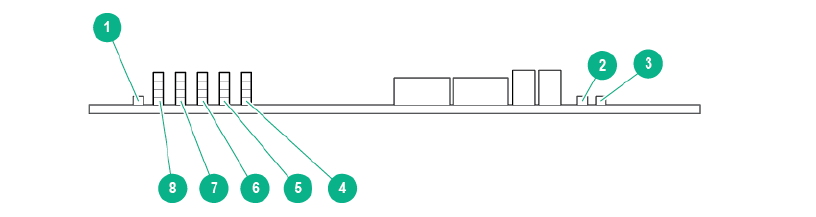
Figure 19 System motherboard status LED locations and functions
1. 12V overcurrent
2. Unit ID
3. PMC heartbeat
Power Good P12V DPower Good P12V CPower Good P12V B4. Power Good P12V A
Power Good CPU 3Power Good CPU 2Power Good CPU 15. Power Good CPU 0
Power Good PSVPower Good PSV AuxPower Good P2V36. Power Good P3V3
Aux
System Power OKPower Supply Power OKPower Good P12V E7. Power Good P12V
Aux
Power Good HARP 1Power Good HARP 0Platform Reset8. Sleep A state
48

7 Support and other resources
Accessing Hewlett Packard Enterprise Support
•For live assistance, go to the Contact Hewlett Packard Enterprise Worldwide
website:
www.hpe.com/assistance
•To access documentation and support services, go to the Hewlett Packard
Enterprise Support Center website:
www.hpe.com/support/hpesc
Information to collect
•Technical support registration number (if applicable)
•Product name, model or version, and serial number
•Operating system name and version
•Firmware version
•Error messages
•Product-specific reports and logs
•Add-on products or components
•Third-party products or components
Accessing updates
•Some software products provide a mechanism for accessing software updates
through the product interface. Review your product documentation to identify the
recommended software update method.
•To download product updates, go to either of the following:
Hewlett Packard Enterprise Support Center Get connected with updates
page:
www.hpe.com/support/e-updates
◦
◦Software Depot website:
www.hpe.com/support/softwaredepot
•To view and update your entitlements, and to link your contracts, Care Packs,
and warranties with your profile, go to the Hewlett Packard Enterprise Support
Center More Information on Access to Support Materials page:
www.hpe.com/support/AccessToSupportMaterials
IMPORTANT: Access to some updates might require product entitlement when
accessed through the Hewlett Packard Enterprise Support Center. You must
have an HP Passport set up with relevant entitlements.
49

Websites
LinkWebsite
www.hpe.com/info/enterprise/docsHewlett Packard Enterprise Information Library
www.hpe.com/support/hpescHewlett Packard Enterprise Support Center
www.hpe.com/assistanceContact Hewlett Packard Enterprise Worldwide
www.hpe.com/support/e-updatesSubscription Service/Support Alerts
www.hpe.com/support/softwaredepotSoftware Depot
www.hpe.com/storage/spockSingle Point of Connectivity Knowledge (SPOCK)
Storage compatibility matrix
www.hpe.com/storage/whitepapersStorage white papers and analyst reports
Documentation feedback
Hewlett Packard Enterprise is committed to providing documentation that meets your
needs. To help us improve the documentation, send any errors, suggestions, or
comments to Documentation Feedback (docsfeedback@hpe.com). When submitting
your feedback, include the document title, part number, edition, and publication date
located on the front cover of the document. For online help content, include the product
name, product version, help edition, and publication date located on the legal notices
page.
50

A Technical specifications and pinouts
This appendix contains technical specification information about your system, as
follows:
•“Integrity MC990 X system specifications” (page 51)
•“Integrity MC990 X system physical specifications” (page 51)
•“Integrity MC990 X system environmental specifications” (page 52)
•“Integrity MC990 X system electrical specifications” (page 52)
•“I/O port specifications” (page 54)
Integrity MC990 X system specifications
Table 4 (page 51) summarizes the Integrity MC990 X system configuration ranges.
Note that while each MC990 X server chassis motherboard houses four processor
sockets; each socket holds multiple processor cores. The number of cores supported
will change based on customer selection and processor availability.
Table 4 Integrity MC990 X system configuration ranges
MaximumMinimumCategory
4 processors4 processors (1 motherboard)1
Processors per server chassis
184Cores per Processor
2 per system2 per systemServer chassis
1 per server1 per serverMotherboards
8 per motherboard2 per motherboardMemory risers on motherboard
96 DIMMs per board32 DIMMs per boardMotherboard DIMM capacity
32GB8GBMemory capacity per DIMM
1 per system1 per systemRMC units
One per SSIOne per SSINumber of BaseIO riser boards
1The quad-socket MC990 X server chassis motherboard supports 4 processors using multi-processor
cores.
Integrity MC990 X system physical specifications
Table 5 (page 51) shows the physical specifications of the rack-mounted Integrity
MC990 X system.
Table 5 MC990 X server chassis and 42U rack physical specifications
SpecificationFeature
Height: 5U 8.64 inches (22 cm)Dimensions for single MC990 X server chassis
Width: 17.5 inches (44.5 cm)
Depth: 31.8 inches (80.8 cm)
136 lb. (62 kg)Weight of single MC990 X server chassis (fully
configured)
Height: 78.75 in. (200 cm)Dimensions for a single 24-inch wide 42U rack,
including doors and side panels Width: 28 in. (70.1 cm)
Depth: 45.5 in. (115.6 cm)
51

Table 5 MC990 X server chassis and 42U rack physical specifications (continued)
SpecificationFeature
Height: 88.8 in. (225.8 cm)Shipping dimensions (single rack)
Width: 44 in. (111.8 cm)
Depth: 62.75 in. (159.4 cm)
2,070 lb. (939 kg) air cooled (approximate)Single rack shipping weight (max)
1,579 lb. (716 kg) air cooled (approximate)Single rack system weight installed (max)
*Empty rack weight is approximately 391 lb. (177
kg)
Front: 48 in. (121.9 cm)42U rack access requirements:
Rear: 48 in. (121.9 cm)
Top: 18 in. (45.7 cm)
Integrity MC990 X system environmental specifications
Table 6 (page 52) lists the environmental specifications of the Integrity MC990 X
system.
Table 6 Environmental specifications
SpecificationFeature
+5 °C (41 °F) to +35 °C (95 °F) (up to 1500 m / 5000 ft.)Temperature tolerance (operating)
+5 °C (41 °F) to +30 °C (86 °F) (1500 m to 3000 m /5000 ft. to
10,000 ft.)
De-rate max ambient temperature by 1.8 °F (1 °C) per 1000 ft.
(305 m) of altitude above 5000 ft. (1525 m)
-40 °C (-40 °F) to +60 °C (140 °F)Temperature tolerance
(non-operating)
20% to 80% operating (no condensation)Relative humidity
8% to 80% non-operating (no condensation)
Approximately 17.74 kBTU/hr (1.48 tons)Heat dissipation to air
Ambient air or optional water coolingCooling requirement
650 CFM Max (1104 m3/hr)Single chassis air-flow: intake (front),
exhaust (rear) 475 CFM typical (407 m3/hr)
10,000 ft. (3,049 m) operatingMaximum altitude
40,000 ft. (12,195 m) non-operating
Approximately 77 dBA (at rear of rack)Acoustic sound pressure
Integrity MC990 X system electrical specifications
Table 7 (page 52) shows the power specifications for the MC990 X system.
Table 7 MC990 X system electrical specifications
SpecificationFeature
12-Volt, 1600 Watt (Platinum) [200-240 VAC]Server chassis power supply (4 per chassis)
52

Table 7 MC990 X system electrical specifications (continued)
SpecificationFeature
12-Volt, 1000 Watt (Platinum) [100-120 VAC]
Four 8-ft (2.4 m) drop cablesServer chassis power cords
Server chassis power requirements
100-120V (90-140 VAC min/max)Voltage
200-240V (180-264 VAC min/max)
50-60 Hz (47-63 Hz min/max)Frequency
5.33 kVA (5.22kW) per chassisPower (maximum per MC990 X server chassis)
10 msHold-up time
Single-phase PDU power requirements
180-264 VACVoltage
50-60 HzFrequency
Three-phase PDU power requirements
180-264 VAC (North America)Voltage
312-457 VAC (International)
50-60 HzFrequency
Less than 10% at full loadTotal harmonic distortion
The Integrity MC990 X system RMC power and technical specifications are provided
in Table 8 (page 53).
Table 8 RMC specifications
SpecificationFeature
1.72 inches (44 mm)Height
17.2 inches (43.7 cm)Width
29.84 inches (75.8 cm)Depth
20 lb. (9.1 kg)Weight
Two per RMCRMC power supply
Two 8-ft (2.4 m) drop cablesRMC power cords
RMC power requirements
100-120V (90-132 VAC min/max)Voltage
200-240V (180-264 VAC min/max)
50-60 Hz (47-63 Hz min/max)Frequency
(50W) per supplyPower
20 msHold-up time
Maximum = 35 CFM (60 m3) per hourAir flow (front to back)
Approximately 68 dBAAcoustical noise
Approximately 171 BTU (0.02 tons) per hourHeat dissipation to air
53
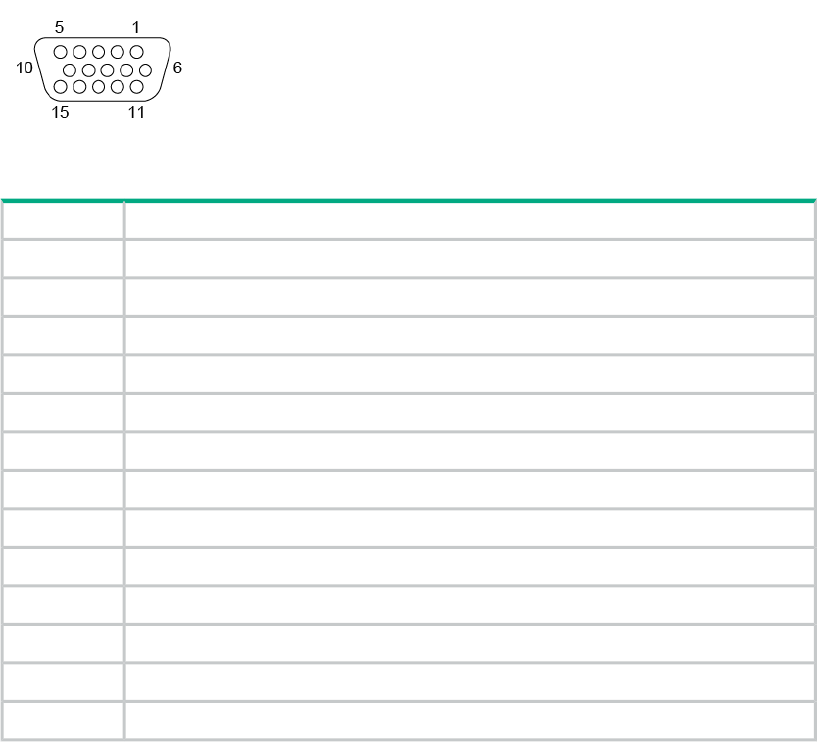
I/O port specifications
This section contains specifications and port pinout information for the base I/O ports
of your system, as follows:
•“Motherboard VGA port information” (page 54)
•“Ethernet port” (page 55)
•“Serial port” (page 55)
•“USB port” (page 56)
Motherboard VGA port information
The 15-pin VGA port on the motherboard (see Figure 20 (page 54)) has the following
features:
•Server-class 2D hardware acceleration support with integrated 24-bit RAMDAC
•Display resolution up to 1600 x 1200 @ 60Hz
•Up to 128 Mbytes DDRII memory interface support
•A USB keyboard/mouse can be supported by the BaseIO blade connectors
The motherboard VGA interface (see Table 9 (page 54)) can be used for all basic
interaction with your Integrity MC990 X system. Note that it does not provide a direct
interconnect to the system RMC.
Figure 20 VGA port connector
Table 9 VGA port pin functions
FunctionPin
Red1
Green2
Blue3
N/C4
Ground5
Ground6
Ground7
Ground8
Ground9
Ground10
N/C11
DDCDAT12
HSYNC13
54
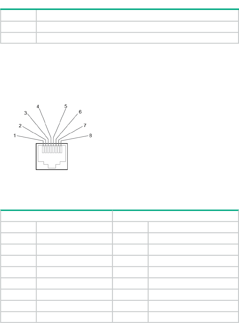
Table 9 VGA port pin functions (continued)
FunctionPin
VSYNC14
DDCCLK15
Ethernet port
The system auto-selects the Ethernet port speed and type (duplex vs. half-duplex)
when the server is booted, based on what it is connected to. Figure 21 (page 55)
shows the Ethernet port.
Figure 21 Ethernet port connector
Table 10 (page 55) shows the cable pinout assignments for the Ethernet port operating
in 10/100-Base-T mode and also operating in 1000Base-T mode.
Table 10 Ethernet port pinouts
Gigabit Ethernet PinoutsEthernet 10/100Base-T Pinouts
AssignmentPinsAssignmentPins
Transmit/Receive 0 +1Transmit +1
Transmit/Receive 0 –2Transmit –2
Transmit/Receive 1 +3Receive +3
Transmit/Receive 2 +4NU4
Transmit/Receive 2 –5NU5
Transmit/Receive 1 –6Receive –6
Transmit/Receive 3 +7NU7
Transmit/Receive 3 –8NU8
NU = Not used
Serial port
The system motherboards have 9-pin serial interface connectors. These ports provide
serial access to the individual chassis and are capable of transferring data at rates
as high as 230 kbps. Other features of the ports include the following:
•Programmable data, parity, and stop bits
•Programmable baud rate and modem control
Figure 22 (page 56) shows a serial port.
55
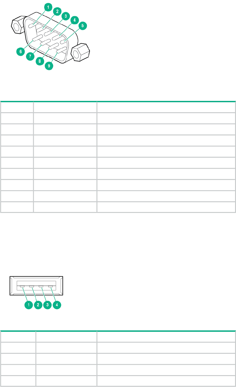
Figure 22 Serial port connector
Table 11 (page 56) shows pinout assignments for the 9-pin male DB-9 connector.
Table 11 Serial port pinout
DescriptionAssignmentPin
Data carrier detectDCD1
Receive dataRXD2
Transmit dataTXD3
Data terminal readyDTR4
Signal groundGND5
Data set readyDSR6
Request to sendRTS7
Clear to sendCTS8
Ring indicatorRI9
USB port
Figure 23 (page 56) shows the USB type A connector provided on the BaseI/O that
supports general USB applications and optional keyboard and mouse configurations.
Table 12 (page 56) lists the pin assignments for the USB type A connector.
Figure 23 USB type A port connector
Table 12 Pin assignments for USB type A connector
Wire colorSignalPin
RedVCC1
White-Data2
Green+Data3
BlackGround4
56
B System technical information
System architecture
The Integrity MC990 X system is based on a cache-coherent non-uniform memory
access architecture. Because it is modular, the Integrity MC990 X system architecture
combines the advantages of lower entry cost with the ability to scale processors,
memory, and I/O independently.
The system interconnect architecture for the Integrity MC990 X system is a
seventh-generation NUMAlink SMP architecture known as NUMAlink 7. In the
NUMAlink 7 architecture, all processors and memory can be tied together into a single
logical system. This combination of processors, memory, and internal switches
constitute the interconnect fabric called NUMAlink within each Integrity MC990 X
system SSI.
The basic expansion building block for the NUMAlink interconnect is the MC990 X
server chassis. Each chassis uses two HARP ASICs and four Intel processors with
multiple cores and on-chip secondary caches. Each HARP ASIC supports two internal
communication hubs and each of the chassis Intel processors are connected to a hub
via one 8.0GT/s quick path interconnect channel.
The HARP ASIC is the heart of the MC990 X server chassis technology. This
specialized ASIC acts as a crossbar between the processors and remote DRAM
memory. The ASIC enables any processor to access the memory of all processors
in the SSI. Figure 24 (page 58) shows a functional block diagram of the MC990 X
server chassis.
57
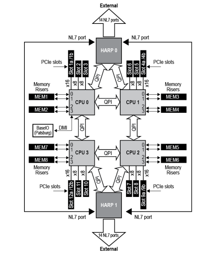
Figure 24 MC990 X server chassis motherboard functional block diagram
ccNUMA architecture
As the name implies, the cache-coherent non-uniform memory access (ccNUMA)
architecture has two parts, cache coherency and nonuniform memory access, which
are discussed in the sections that follow.
Cache coherency
The Integrity MC990 X system server uses caches to reduce memory latency. Although
data exists in local or remote memory, copies of the data can exist in various processor
caches throughout the system. Cache coherency keeps the cached copies consistent.
To keep the copies consistent, the ccNUMA architecture uses directory-based
coherence protocol. In directory-based coherence protocol, each block of memory
(128 bytes) has an entry in a table that is referred to as a directory. Like the blocks
of memory that they represent, the directories are distributed among the
compute/memory blade nodes. A block of memory is also referred to as a cache line.
Each directory entry indicates the state of the memory block that it represents. For
example, when the block is not cached, it is in an unowned state. When only one
processor has a copy of the memory block, it is in an exclusive state. And when more
than one processor has a copy of the block, it is in a shared state; a bit vector indicates
which caches may contain a copy.
58
When a processor modifies a block of data, the processors that have the same block
of data in their caches must be notified of the modification. The Integrity MC990 X
system uses an invalidation method to maintain cache coherence. The invalidation
method purges all unmodified copies of the block of data, and the processor that
wants to modify the block receives exclusive ownership of the block.
Non-uniform memory access (NUMA)
In DSM systems, memory is physically located at various distances from the
processors. As a result, memory access times (latencies) are different or non-uniform.
For example, it takes less time for a processor blade to reference its locally installed
memory than to reference remote memory.
59

C Safety and regulatory information
This appendix provides safety information and regulatory specifications for your system
in the following sections:
•“Safety information” (page 60)
•“Regulatory information” (page 61)
For additional important safety, environmental, and regulatory information, see Safety
and Compliance Information for Server, Storage, Power, Networking, and Rack
Products, available at http://www.hpe.com/support/
Safety-Compliance-EnterpriseProducts.
Safety information
Read and follow these instructions carefully:
1. Follow all warnings and instructions marked on the product and noted in the
documentation included with this product.
2. Unplug this product before cleaning. Do not use liquid cleaners or aerosol
cleaners. Use a damp cloth for cleaning. Do not use this product near water.
3. Do not place this product or components of this product on an unstable cart,
stand, or table. The product may fall, causing serious damage to the product.
4. Slots and openings in the system are provided for ventilation. To ensure reliable
operation of the product and to protect it from overheating, these openings must
not be blocked or covered. This product should never be placed near or over a
radiator or heat register, or in a built-in installation, unless proper ventilation is
provided.
5. This product should be operated from the type of power indicated on the marking
label. If you are not sure of the type of power available, consult your dealer or
local power company.
6. Do not allow anything to rest on the power cord. Do not locate this product where
people will walk on the cord.
7. Never push objects of any kind into this product through cabinet slots as they
may touch dangerous voltage points or short out parts that could result in a fire
or electric shock. Never spill liquid of any kind on the product.
8. Do not attempt to service this product yourself except as noted in this guide.
Opening or removing covers of node and switch internal components may expose
you to dangerous voltage points or other risks. Refer all servicing to qualified
service personnel.
9. Unplug this product from the wall outlet and refer servicing to qualified service
personnel under the following conditions:
•When the power cord or plug is damaged or frayed.
•If liquid has been spilled into the product.
•If the product has been exposed to rain or water.
•If the product does not operate normally when the operating instructions are
followed. Adjust only those controls that are covered by the operating
instructions. Improper adjustment of other controls may result in damage.
•If the product has been dropped or the cabinet has been damaged.
•If the product exhibits a distinct change in performance, indicating a need
for service.
CAUTION: Slide/rail mounted equipment is not to be used as a shelf or a
workspace.
60

Figure 25 Slide rail equipment warning
10. If a lithium battery is a soldered part, only qualified service personnel should
replace this lithium battery. For other types, replace it only with the same type or
an equivalent type recommended by the battery manufacturer, or the battery
could explode. Discard used batteries according to the manufacturer’s instructions.
11. Use only the proper type of power supply cord set (provided with the system) for
this unit.
12. Do not attempt to move the system alone. Moving a rack requires at least two
people.
13. Keep all system cables neatly organized in the cable management system. Loose
cables are a tripping hazard that cause injury or damage the system.
Regulatory information
For important safety, environmental, and regulatory information, see Safety and
Compliance Information for Server, Storage, Power, Networking, and Rack Products,
available at http://www.hp.com/support/Safety-Compliance-EnterpriseProducts.
This product contains a laser that is classified as a Class 1 laser device.
CMN number
The MC990 X server chassis CMN model number is: CMN061
The RMC chassis CMN model number is: CMN062
Each model number listed above is marked on the regulatory label which is affixed
to each chassis during the production process. The regulatory labels are placed as
near as possible to the power supply AC inputs.
61
Glossary
ACPI Advanced Configuration and Power Interface
APPWT Average Peak Performance in Weighted Teraflops
BMC Baseboard Management Controller
CLI Command Line Interface
CNSL Console abbreviation
CRC Cyclic Redundancy Check
DSM Distributed Shared Memory
ECC Error Checking Code
EFI Extensible Firmware Interface
FQDN Fully Qualified Domain Name
GPU Graphic Processing Unit
IPMI Intelligent Platform Management Interface
KVM Keyboard, video, mouse
MCS Multi-Category Security
MLS Multi-Level Security
NMI Nonmaskable Interrupt
NTP Network Time Protocol
NUMA Non-Uniform Memory Access
PDU Power Distribution Unit
QPI Quick Path Interconnect
RAS Reliability, Availability, Serviceability
RMC Rack Management Console
RS Remote Solutions
SAS Serial Attached SCSI
SEL System Error Log
SELinux Security Enhanced Linux
SID SAP HANA System Identifier
SMI Scalable Memory Interconnect
SMN System Management Node
SMP Symmetric Multiprocessing
SSD Solid State Drive
SSI Single System Image
TDI Tailored Datacenter Integration
UID Unit IDentifier
YaST Yet another Setup Tool
62
Index
A
accessing
system control network, 14
updates, 49
architecture
MC990 X system, 57
NUMA, 58
B
BaseIO board
overview, 11
BMC
communication with RMC, 23
overview, 23
boot system
from RMC, 17
C
cache coherency, 58
CLI
power up system, 16
CMN number, 61
commands
gr_systat, 27
hubstats, 27
linkstat, 27
nodeinfo, 27
topology, 28
configuring
powersave with intel_pstate, 31
connecting
system control network, 14
contacting Hewlett Packard Enterprise, 49
CPU frequency governor
changing on systems without intel_pstate, 32
CPU frequency scaling
changing the governor setting, 32
configuring on systems with intel_pstate, 31
configuring turbo mode on systems without
intel_pstate, 35
enabling on systems without intel_pstate, 32
overview, 30
D
distributed
I/O, 8
memory, 8
distributed shared memory, 8
documentation
providing feedback on, 50
drives
install or replace, 40
overview, 11
E
Ethernet port
specifications, 55
F
fan assembly
replacement procedure, 44
features
MC990 X system, 7
Foundation Software
additional utilities, 35
enable CPU frequency scaling, 30
monitor main memory health, 25
monitor system performance, 26
using, 25
G
gr_systat command, 27
H
HDD
replace 2.5-inch, 41
hubstats command, 27
I
I/O
distributed, 8
install
drives, 40
PCIe cards, 39
IP
DHCP addressing, 18
static addressing, 18
L
linkstat command, 27
M
main memory health
overview, 25
retrieving information, 25
maintenance
add/replace PCIe cards, 39
install or replace drives, 40
install PCIe cards, 39
precautions, 37
preparing, 37
remove server top cover, 38
replace 1.8-inch SSD, 42
replace 2.5-inch HDD, 41
replace enclosure fan assembly, 44
replace enclosure power supply, 43
return system to operation, 37
MC990 X
major system components, 10
port specifications, 54
system architecture, 57
system configurations, 51
system electrical specifications, 52
63
system features, 7
system modularity, 7
system overview, 6
system physical specifications, 51
system reliability, availability, serviceability
features, 9
MC990 X server chassis
overview, 6
MEMlog
accessing messages with memlog command,
25
memlog command
accessing MEMlog messages, 25
memory
block diagram, 8
distributed, 8
monitoring
main memory health, 25
system performance, 26
motherboard
overview, 10
N
nodeinfo command, 27
NUMA
architecture, 58
cache coherency, 58
overview, 59
O
overview
BaseIO board, 11
BMC, 23
CPU frequency scaling, 30
drives, 11
major system components, 10
MC990 X server chassis, 6
MC990 X system, 6
monitoring main memory health, 25
motherboard, 10
NUMA, 59
PCIe slots, 11
RMC, 9, 22
server chassis, 10
system control, 21
system control network, 13
system management, 21
system monitoring, 26
P
PCIe
add/replace cards, 39
install cards, 39
overview, 11
power and cooling, 9
power down system, 20
power supply
replacement procedure, 43
power up system
from CLI, 16
monitoring, 19
preparing, 15
remote LAN, 19
power-on and boot, 9
powersave
configuring on systems with intel_pstate, 31
precautions
ESD, 13
maintenance, 37
safety, 13, 60
R
rack
numbering, 12
overview, 10
regulatory information, 61
remote LAN
power up system, 19
replace
1.8-inch SSD, 42
2.5-inch HDD, 41
drives, 40
enclosure fan assembly, 44
enclosure power supply, 43
PCIe cards, 39
RMC
boot system, 17
communication with BMC, 23
functions, 23
IP hardware connections, 18
LAN connection, 17
overview, 9, 22
serial terminal connect requirements, 17
specifications, 53
RMC system controller, 23
S
safety
precautions, 60
serial port
specifications, 55
server chassis
overview, 10
remove top cover, 38
SMP, 6
specifications
Ethernet port, 55
MC990 X and rack physical, 51
MC990 X electrical, 52
MC990 X system configurations, 51
RMC, 53
serial port, 55
system environmental, 52
USB port, 56
VGA port, 54
SSD
replacement procedure, 42
SSI, 6
64
status indicators
motherboard, 47
power supply, 46
support
Hewlett Packard Enterprise, 49
system
CPU frequency scaling, 31
environmental specifications, 52
system communication, 15
CLI, 15
system components, 10
system control
levels, 21
overview, 21
system control network
accessing, 14
connecting, 14
overview, 13
system management
overview, 21
system monitoring, 9
overview, 26
T
topology command, 28
troubleshooting
chart, 46
motherboard LEDs, 47
power supply LEDs, 46
status indicators, 46
U
unit (U) numbering, 12
updates
accessing, 49
USB port
specifications, 56
using
Foundation Software, 25
V
VGA port
specifications, 54
W
websites, 50
65
