HPE ProLiant MicroServer Gen10 Maintenance And Service Guide Hardware
User Manual:
Open the PDF directly: View PDF ![]() .
.
Page Count: 101 [warning: Documents this large are best viewed by clicking the View PDF Link!]
- HPE ProLiant MicroServer Gen10 Maintenance and Service Guide
- Contents
- Customer self repair
- Illustrated parts catalog
- Removal and replacement procedures
- Safety considerations
- Prepare the server for hardware replacement
- Prepare the server for operation
- Replacing an LFF drive
- Replacing an SFF drive
- Replacing an optical drive
- Replacing an SSD
- Replacing the SSD cables
- Replacing the non-hot-plug drive cable assembly
- Replacing a DIMM
- Replacing an expansion board
- Replacing an internal USB device
- Replacing the fan
- Replacing the power supply
- System battery replacement
- Replacing the system board assembly
- Replacing the external RDX backup system
- HP Trusted Platform Module
- Troubleshooting
- Diagnostic tools
- Component identification
- Cabling
- Specifications
- Websites
- Support and other resources
- Acronyms and abbreviations

HPE ProLiant MicroServer Gen10
Maintenance and Service Guide
Part Number: 872673-003
Published: August 2018
Edition: 3
Abstract
This document contains information on the hardware spare parts supported by the server and
the relevant component replacement procedures. This document is intended for the person
who installs, administers, and troubleshoots server or storage products. Hewlett Packard
Enterprise assumes that you are qualified to service computer equipment, and are trained in
recognizing hazards in products with hazardous energy levels.

© Copyright 2017–2018 Hewlett Packard Enterprise Development LP
Notices
The information contained herein is subject to change without notice. The only warranties for Hewlett
Packard Enterprise products and services are set forth in the express warranty statements accompanying
such products and services. Nothing herein should be construed as constituting an additional warranty.
Hewlett Packard Enterprise shall not be liable for technical or editorial errors or omissions contained
herein.
Confidential computer software. Valid license from Hewlett Packard Enterprise required for possession,
use, or copying. Consistent with FAR 12.211 and 12.212, Commercial Computer Software, Computer
Software Documentation, and Technical Data for Commercial Items are licensed to the U.S. Government
under vendor's standard commercial license.
Links to third-party websites take you outside the Hewlett Packard Enterprise website. Hewlett Packard
Enterprise has no control over and is not responsible for information outside the Hewlett Packard
Enterprise website.
Acknowledgments
AMD Opteron™ is a trademark of Advanced Micro Devices, Inc.
ClearCenter™, ClearOS™, and ClearVM™ are trademarks of ClearCenter.
Microsoft® and Windows® are either registered trademarks or trademarks of Microsoft Corporation in the
United States and/or other countries.
Contents
Customer self repair............................................................................... 6
Illustrated parts catalog........................................................................16
System components................................................................................................................... 16
Fan spare part..................................................................................................................16
Four bay non-hot-plug drive cable assembly spare part.................................................. 17
System board assembly spare parts................................................................................17
System battery spare part................................................................................................ 17
DIMM spare parts.............................................................................................................17
Power supply spare part.................................................................................................. 17
Server options.............................................................................................................................18
SSD cable spare parts..................................................................................................... 19
Trusted Platform Module spare part.................................................................................19
Removal and replacement procedures...............................................20
Safety considerations..................................................................................................................20
Electrostatic discharge..................................................................................................... 20
Symbols on equipment.....................................................................................................20
Server warnings and cautions..........................................................................................21
Prepare the server for hardware replacement............................................................................ 22
Power down the server.................................................................................................... 22
Remove the front bezel.................................................................................................... 22
Remove the chassis cover............................................................................................... 25
Remove the system board assembly............................................................................... 25
Prepare the server for operation................................................................................................. 27
Install the system board assembly................................................................................... 27
Install the chassis cover................................................................................................... 28
Install the front bezel........................................................................................................ 29
Power up the server......................................................................................................... 30
Replacing an LFF drive...............................................................................................................31
Remove the LFF drive......................................................................................................31
Install the LFF drive..........................................................................................................32
Replacing an SFF drive.............................................................................................................. 33
Remove the SFF drive..................................................................................................... 33
Install the SFF drive......................................................................................................... 34
Replacing an optical drive...........................................................................................................36
Remove the optical drive..................................................................................................36
Install the optical drive......................................................................................................37
Replacing an SSD.......................................................................................................................39
Remove the SSD..............................................................................................................39
Install the SSD..................................................................................................................41
Replacing the SSD cables.......................................................................................................... 42
Replacing the SSD power cable...................................................................................... 42
Replacing the SSD SATA cable....................................................................................... 44
Replacing the non-hot-plug drive cable assembly...................................................................... 47
Remove the non-hot-plug drive cable assembly.............................................................. 47
Install the non-hot-plug drive cable assembly.................................................................. 49
Replacing a DIMM.......................................................................................................................51
Contents 3
Remove the DIMM........................................................................................................... 51
Install a DIMM.................................................................................................................. 52
Replacing an expansion board................................................................................................... 53
Remove the expansion board.......................................................................................... 53
Remove the air baffle from the expansion board............................................................. 54
Install a low-profile bracket on the expansion board........................................................ 54
Install the expansion board.............................................................................................. 55
Replacing an internal USB device.............................................................................................. 56
Remove the internal USB device..................................................................................... 56
Install the internal USB device......................................................................................... 57
Replacing the fan........................................................................................................................ 57
Remove the fan................................................................................................................58
Install the fan....................................................................................................................59
Replacing the power supply........................................................................................................60
Remove the power supply................................................................................................60
Install the power supply....................................................................................................63
System battery replacement....................................................................................................... 65
System battery information...............................................................................................65
Replacing a system battery..............................................................................................65
Replacing the system board assembly....................................................................................... 67
Remove the system board assembly............................................................................... 67
Install the system board assembly................................................................................... 69
Re-entering the system serial and SKU numbers............................................................ 70
Replacing the external RDX backup system...............................................................................70
HP Trusted Platform Module.......................................................................................................71
Troubleshooting....................................................................................72
Troubleshooting resources..........................................................................................................72
Diagnostic tools.................................................................................... 73
Product QuickSpecs................................................................................................................... 73
Aptio Setup Utility........................................................................................................................73
Using the Aptio Setup Utility ............................................................................................73
Restoring and customizing configuration settings............................................................73
Clearing the BIOS configuration settings......................................................................... 74
Marvell Storage Utility ................................................................................................................ 76
Installing the Marvell Storage Utility................................................................................. 76
Marvell BIOS Utility..................................................................................................................... 76
Accessing the Marvell BIOS Utility under UEFI boot mode............................................. 76
Accessing the Marvell BIOS Utility under legacy boot mode........................................... 77
HPE Smart Storage Administrator.............................................................................................. 77
USB support ...............................................................................................................................78
Keeping the system current........................................................................................................ 78
Firmware ......................................................................................................................... 78
Firmware update.............................................................................................................. 78
Drivers, firmware, and software updates .........................................................................80
Component identification.....................................................................81
Front panel components............................................................................................................. 81
Front panel LEDs and buttons.................................................................................................... 82
Rear panel components..............................................................................................................83
Rear panel LEDs.........................................................................................................................84
System board components......................................................................................................... 85
4Contents
DIMM slot locations..........................................................................................................86
DIMM identification...........................................................................................................86
PCIe slot description........................................................................................................ 88
Drive numbering..........................................................................................................................89
Drive screws................................................................................................................................89
Cabling...................................................................................................90
Cabling overview ........................................................................................................................90
Four-bay non-hot-plug drive cabling........................................................................................... 90
Solid state drive cabling.............................................................................................................. 91
Optical drive cabling....................................................................................................................92
Fan cabling................................................................................................................................. 93
Power supply cabling.................................................................................................................. 93
Specifications........................................................................................94
Environmental specifications...................................................................................................... 94
Server specifications...................................................................................................................94
Power supply specifications........................................................................................................94
200 W power supply specifications.................................................................................. 95
Websites................................................................................................ 96
Support and other resources...............................................................97
Accessing Hewlett Packard Enterprise Support......................................................................... 97
ClearCARE technical support..................................................................................................... 97
Accessing updates......................................................................................................................97
Warranty information...................................................................................................................98
Regulatory information................................................................................................................98
Documentation feedback............................................................................................................ 99
Acronyms and abbreviations.............................................................100
Contents 5

Customer self repair
Hewlett Packard Enterprise products are designed with many Customer Self Repair (CSR) parts to
minimize repair time and allow for greater flexibility in performing defective parts replacement. If during
the diagnosis period Hewlett Packard Enterprise (or Hewlett Packard Enterprise service providers or
service partners) identifies that the repair can be accomplished by the use of a CSR part, Hewlett
Packard Enterprise will ship that part directly to you for replacement. There are two categories of CSR
parts:
•Mandatory—Parts for which customer self repair is mandatory. If you request Hewlett Packard
Enterprise to replace these parts, you will be charged for the travel and labor costs of this service.
•Optional—Parts for which customer self repair is optional. These parts are also designed for customer
self repair. If, however, you require that Hewlett Packard Enterprise replace them for you, there may or
may not be additional charges, depending on the type of warranty service designated for your product.
NOTE: Some Hewlett Packard Enterprise parts are not designed for customer self repair. In order to
satisfy the customer warranty, Hewlett Packard Enterprise requires that an authorized service provider
replace the part. These parts are identified as "No" in the Illustrated Parts Catalog.
Based on availability and where geography permits, CSR parts will be shipped for next business day
delivery. Same day or four-hour delivery may be offered at an additional charge where geography
permits. If assistance is required, you can call the Hewlett Packard Enterprise Support Center and a
technician will help you over the telephone. Hewlett Packard Enterprise specifies in the materials shipped
with a replacement CSR part whether a defective part must be returned to Hewlett Packard Enterprise. In
cases where it is required to return the defective part to Hewlett Packard Enterprise, you must ship the
defective part back to Hewlett Packard Enterprise within a defined period of time, normally five (5)
business days. The defective part must be returned with the associated documentation in the provided
shipping material. Failure to return the defective part may result in Hewlett Packard Enterprise billing you
for the replacement. With a customer self repair, Hewlett Packard Enterprise will pay all shipping and part
return costs and determine the courier/carrier to be used.
For more information about the Hewlett Packard Enterprise CSR program, contact your local service
provider. For the North American program, go to the Hewlett Packard Enterprise CSR website.
Parts only warranty service
Your Hewlett Packard Enterprise Limited Warranty may include a parts only warranty service. Under the
terms of parts only warranty service, Hewlett Packard Enterprise will provide replacement parts free of
charge.
For parts only warranty service, CSR part replacement is mandatory. If you request Hewlett Packard
Enterprise to replace these parts, you will be charged for the travel and labor costs of this service.
Réparation par le client (CSR)
Les produits Hewlett Packard Enterprise comportent de nombreuses pièces CSR (Customer Self Repair
= réparation par le client) afin de minimiser les délais de réparation et faciliter le remplacement des
pièces défectueuses. Si pendant la période de diagnostic, Hewlett Packard Enterprise (ou ses
partenaires ou mainteneurs agréés) détermine que la réparation peut être effectuée à l'aide d'une pièce
CSR, Hewlett Packard Enterprise vous l'envoie directement. Il existe deux catégories de pièces CSR :
6 Customer self repair

•Obligatoire—Pièces pour lesquelles la réparation par le client est obligatoire. Si vous demandez à
Hewlett Packard Enterprise de remplacer ces pièces, les coûts de déplacement et main d'œuvre du
service vous seront facturés.
•Facultatif—Pièces pour lesquelles la réparation par le client est facultative. Ces pièces sont
également conçues pour permettre au client d'effectuer lui-même la réparation. Toutefois, si vous
demandez à Hewlett Packard Enterprise de remplacer ces pièces, l'intervention peut ou non vous être
facturée, selon le type de garantie applicable à votre produit.
REMARQUE: Certaines pièces Hewlett Packard Enterprise ne sont pas conçues pour permettre au client
d'effectuer lui-même la réparation. Pour que la garantie puisse s'appliquer, Hewlett Packard Enterprise
exige que le remplacement de la pièce soit effectué par un Mainteneur Agréé. Ces pièces sont identifiées
par la mention "Non" dans le Catalogue illustré.
Les pièces CSR sont livrées le jour ouvré suivant, dans la limite des stocks disponibles et selon votre
situation géographique. Si votre situation géographique le permet et que vous demandez une livraison le
jour même ou dans les 4 heures, celle-ci vous sera facturée. Pour toute assistance, appelez le Centre
d’assistance Hewlett Packard Enterprise pour qu’un technicien vous aide au téléphone Dans les
documents envoyés avec la pièce de rechange CSR, Hewlett Packard Enterprise précise s'il est
nécessaire de lui retourner la pièce défectueuse. Si c'est le cas, vous devez le faire dans le délai indiqué,
généralement cinq (5) jours ouvrés. La pièce et sa documentation doivent être retournées dans
l'emballage fourni. Si vous ne retournez pas la pièce défectueuse, Hewlett Packard Enterprise se réserve
le droit de vous facturer les coûts de remplacement. Dans le cas d'une pièce CSR, Hewlett Packard
Enterprise supporte l'ensemble des frais d'expédition et de retour, et détermine la société de courses ou
le transporteur à utiliser.
Pour plus d'informations sur le programme CSR de Hewlett Packard Enterprise, contactez votre
Mainteneur Agrée local. Pour plus d'informations sur ce programme en Amérique du Nord, consultez le
site Web Hewlett Packard Enterprise.
Service de garantie "pièces seules"
Votre garantie limitée Hewlett Packard Enterprise peut inclure un service de garantie "pièces seules".
Dans ce cas, les pièces de rechange fournies par Hewlett Packard Enterprise ne sont pas facturées.
Dans le cadre de ce service, la réparation des pièces CSR par le client est obligatoire. Si vous demandez
à Hewlett Packard Enterprise de remplacer ces pièces, les coûts de déplacement et main d'œuvre du
service vous seront facturés.
Riparazione da parte del cliente
Per abbreviare i tempi di riparazione e garantire una maggiore flessibilità nella sostituzione di parti
difettose, i prodotti Hewlett Packard Enterprise sono realizzati con numerosi componenti che possono
essere riparati direttamente dal cliente (CSR, Customer Self Repair). Se in fase di diagnostica Hewlett
Packard Enterprise (o un centro di servizi o di assistenza Hewlett Packard Enterprise) identifica il guasto
come riparabile mediante un ricambio CSR, Hewlett Packard Enterprise lo spedirà direttamente al cliente
per la sostituzione. Vi sono due categorie di parti CSR:
•Obbligatorie—Parti che devono essere necessariamente riparate dal cliente. Se il cliente ne affida la
riparazione ad Hewlett Packard Enterprise, deve sostenere le spese di spedizione e di manodopera
per il servizio.
•Opzionali—Parti la cui riparazione da parte del cliente è facoltativa. Si tratta comunque di componenti
progettati per questo scopo. Se tuttavia il cliente ne richiede la sostituzione ad Hewlett Packard
Enterprise, potrebbe dover sostenere spese addizionali a seconda del tipo di garanzia previsto per il
prodotto.
NOTA: alcuni componenti Hewlett Packard Enterprise non sono progettati per la riparazione da parte del
cliente. Per rispettare la garanzia, Hewlett Packard Enterprise richiede che queste parti siano sostituite da
Customer self repair 7

un centro di assistenza autorizzato. Tali parti sono identificate da un "No" nel Catalogo illustrato dei
componenti.
In base alla disponibilità e alla località geografica, le parti CSR vengono spedite con consegna entro il
giorno lavorativo seguente. La consegna nel giorno stesso o entro quattro ore è offerta con un
supplemento di costo solo in alcune zone. In caso di necessità si può richiedere l'assistenza telefonica di
un addetto del centro di supporto tecnico Hewlett Packard Enterprise. Nel materiale fornito con una parte
di ricambio CSR, Hewlett Packard Enterprise specifica se il cliente deve restituire dei component. Qualora
sia richiesta la resa ad Hewlett Packard Enterprise del componente difettoso, lo si deve spedire ad
Hewlett Packard Enterprise entro un determinato periodo di tempo, generalmente cinque (5) giorni
lavorativi. Il componente difettoso deve essere restituito con la documentazione associata nell'imballo di
spedizione fornito. La mancata restituzione del componente può comportare la fatturazione del ricambio
da parte di Hewlett Packard Enterprise. Nel caso di riparazione da parte del cliente, Hewlett Packard
Enterprise sostiene tutte le spese di spedizione e resa e sceglie il corriere/vettore da utilizzare.
Per ulteriori informazioni sul programma CSR di Hewlett Packard Enterprise, contattare il centro di
assistenza di zona. Per il programma in Nord America fare riferimento al sito Web.
Servizio di garanzia per i soli componenti
La garanzia limitata Hewlett Packard Enterprise può includere un servizio di garanzia per i soli
componenti. Nei termini di garanzia del servizio per i soli componenti, Hewlett Packard Enterprise fornirà
gratuitamente le parti di ricambio.
Per il servizio di garanzia per i soli componenti è obbligatoria la formula CSR che prevede la riparazione
da parte del cliente. Se il cliente invece richiede la sostituzione ad Hewlett Packard Enterprise dovrà
sostenere le spese di spedizione e di manodopera per il servizio.
Customer Self Repair
Hewlett Packard Enterprise Produkte enthalten viele CSR-Teile (Customer Self Repair), um
Reparaturzeiten zu minimieren und höhere Flexibilität beim Austausch defekter Bauteile zu ermöglichen.
Wenn Hewlett Packard Enterprise (oder ein Hewlett Packard Enterprise Servicepartner) bei der Diagnose
feststellt, dass das Produkt mithilfe eines CSR-Teils repariert werden kann, sendet Ihnen Hewlett Packard
Enterprise dieses Bauteil zum Austausch direkt zu. CSR-Teile werden in zwei Kategorien unterteilt:
•Zwingend—Teile, für die das Customer Self Repair-Verfahren zwingend vorgegeben ist. Wenn Sie
den Austausch dieser Teile von Hewlett Packard Enterprise vornehmen lassen, werden Ihnen die
Anfahrt- und Arbeitskosten für diesen Service berechnet.
•Optional—Teile, für die das Customer Self Repair-Verfahren optional ist. Diese Teile sind auch für
Customer Self Repair ausgelegt. Wenn Sie jedoch den Austausch dieser Teile von Hewlett Packard
Enterprise vornehmen lassen möchten, können bei diesem Service je nach den für Ihr Produkt
vorgesehenen Garantiebedingungen zusätzliche Kosten anfallen.
HINWEIS: Einige Hewlett Packard Enterprise Teile sind nicht für Customer Self Repair ausgelegt. Um den
Garantieanspruch des Kunden zu erfüllen, muss das Teil von einem Hewlett Packard Enterprise
Servicepartner ersetzt werden. Im illustrierten Teilekatalog sind diese Teile mit „No“ bzw.
„Nein“ gekennzeichnet.
CSR-Teile werden abhängig von der Verfügbarkeit und vom Lieferziel am folgenden Geschäftstag
geliefert. Für bestimmte Standorte ist eine Lieferung am selben Tag oder innerhalb von vier Stunden
gegen einen Aufpreis verfügbar. Wenn Sie Hilfe benötigen, können Sie das Hewlett Packard Enterprise
Support Center anrufen und sich von einem Mitarbeiter per Telefon helfen lassen. Den Materialien von
Hewlett Packard Enterprise, die mit einem CSR-Ersatzteil geliefert werden, können Sie entnehmen, ob
das defekte Teil an Hewlett Packard Enterprise zurückgeschickt werden muss. Wenn es erforderlich ist,
das defekte Teil an Hewlett Packard Enterprise zurückzuschicken, müssen Sie dies innerhalb eines
vorgegebenen Zeitraums tun, in der Regel innerhalb von fünf (5) Geschäftstagen. Das defekte Teil muss
mit der zugehörigen Dokumentation in der Verpackung zurückgeschickt werden, die im Lieferumfang
enthalten ist. Wenn Sie das defekte Teil nicht zurückschicken, kann Hewlett Packard Enterprise Ihnen das
8Customer self repair

Ersatzteil in Rechnung stellen. Im Falle von Customer Self Repair kommt Hewlett Packard Enterprise für
alle Kosten für die Lieferung und Rücksendung auf und bestimmt den Kurier-/Frachtdienst.
Weitere Informationen über das Hewlett Packard Enterprise Customer Self Repair Programm erhalten Sie
von Ihrem Servicepartner vor Ort. Informationen über das CSR-Programm in Nordamerika finden Sie auf
der Hewlett Packard Enterprise Website unter.
Parts-only Warranty Service (Garantieservice ausschließlich für Teile)
Ihre Hewlett Packard Enterprise Garantie umfasst möglicherweise einen Parts-only Warranty Service
(Garantieservice ausschließlich für Teile). Gemäß den Bestimmungen des Parts-only Warranty Service
stellt Hewlett Packard Enterprise Ersatzteile kostenlos zur Verfügung.
Für den Parts-only Warranty Service ist das CSR-Verfahren zwingend vorgegeben. Wenn Sie den
Austausch dieser Teile von Hewlett Packard Enterprise vornehmen lassen, werden Ihnen die Anfahrt- und
Arbeitskosten für diesen Service berechnet.
Reparaciones del propio cliente
Los productos de Hewlett Packard Enterprise incluyen muchos componentes que el propio usuario puede
reemplazar (Customer Self Repair, CSR) para minimizar el tiempo de reparación y ofrecer una mayor
flexibilidad a la hora de realizar sustituciones de componentes defectuosos. Si, durante la fase de
diagnóstico, Hewlett Packard Enterprise (o los proveedores o socios de servicio de Hewlett Packard
Enterprise) identifica que una reparación puede llevarse a cabo mediante el uso de un componente CSR,
Hewlett Packard Enterprise le enviará dicho componente directamente para que realice su sustitución.
Los componentes CSR se clasifican en dos categorías:
•Obligatorio—Componentes cuya reparación por parte del usuario es obligatoria. Si solicita a Hewlett
Packard Enterprise que realice la sustitución de estos componentes, tendrá que hacerse cargo de los
gastos de desplazamiento y de mano de obra de dicho servicio.
•Opcional—Componentes cuya reparación por parte del usuario es opcional. Estos componentes
también están diseñados para que puedan ser reparados por el usuario. Sin embargo, si precisa que
Hewlett Packard Enterprise realice su sustitución, puede o no conllevar costes adicionales,
dependiendo del tipo de servicio de garantía correspondiente al producto.
NOTA: Algunos componentes de Hewlett Packard Enterprise no están diseñados para que puedan ser
reparados por el usuario. Para que el usuario haga valer su garantía, Hewlett Packard Enterprise pone
como condición que un proveedor de servicios autorizado realice la sustitución de estos componentes.
Dichos componentes se identifican con la palabra "No" en el catálogo ilustrado de componentes.
Según la disponibilidad y la situación geográfica, los componentes CSR se enviarán para que lleguen a
su destino al siguiente día laborable. Si la situación geográfica lo permite, se puede solicitar la entrega en
el mismo día o en cuatro horas con un coste adicional. Si precisa asistencia técnica, puede llamar al
Centro de asistencia técnica de Hewlett Packard Enterprise y recibirá ayuda telefónica por parte de un
técnico. Con el envío de materiales para la sustitución de componentes CSR, Hewlett Packard Enterprise
especificará si los componentes defectuosos deberán devolverse a Hewlett Packard Enterprise. En
aquellos casos en los que sea necesario devolver algún componente a Hewlett Packard Enterprise,
deberá hacerlo en el periodo de tiempo especificado, normalmente cinco días laborables. Los
componentes defectuosos deberán devolverse con toda la documentación relacionada y con el embalaje
de envío. Si no enviara el componente defectuoso requerido, Hewlett Packard Enterprise podrá cobrarle
por el de sustitución. En el caso de todas sustituciones que lleve a cabo el cliente, Hewlett Packard
Enterprise se hará cargo de todos los gastos de envío y devolución de componentes y escogerá la
empresa de transporte que se utilice para dicho servicio.
Para obtener más información acerca del programa de Reparaciones del propio cliente de Hewlett
Packard Enterprise, póngase en contacto con su proveedor de servicios local. Si está interesado en el
programa para Norteamérica, visite la página web de Hewlett Packard Enterprise CSR.
Customer self repair 9

Servicio de garantía exclusivo de componentes
La garantía limitada de Hewlett Packard Enterprise puede que incluya un servicio de garantía exclusivo
de componentes. Según las condiciones de este servicio exclusivo de componentes, Hewlett Packard
Enterprise le facilitará los componentes de repuesto sin cargo adicional alguno.
Para este servicio de garantía exclusivo de componentes, es obligatoria la sustitución de componentes
por parte del usuario (CSR). Si solicita a Hewlett Packard Enterprise que realice la sustitución de estos
componentes, tendrá que hacerse cargo de los gastos de desplazamiento y de mano de obra de dicho
servicio.
Customer Self Repair
Veel onderdelen in Hewlett Packard Enterprise producten zijn door de klant zelf te repareren, waardoor
de reparatieduur tot een minimum beperkt kan blijven en de flexibiliteit in het vervangen van defecte
onderdelen groter is. Deze onderdelen worden CSR-onderdelen (Customer Self Repair) genoemd. Als
Hewlett Packard Enterprise (of een Hewlett Packard Enterprise Service Partner) bij de diagnose vaststelt
dat de reparatie kan worden uitgevoerd met een CSR-onderdeel, verzendt Hewlett Packard Enterprise
dat onderdeel rechtstreeks naar u, zodat u het defecte onderdeel daarmee kunt vervangen. Er zijn twee
categorieën CSR-onderdelen:
•Verplicht—Onderdelen waarvoor reparatie door de klant verplicht is. Als u Hewlett Packard Enterprise
verzoekt deze onderdelen voor u te vervangen, worden u voor deze service reiskosten en arbeidsloon
in rekening gebracht.
•Optioneel—Onderdelen waarvoor reparatie door de klant optioneel is. Ook deze onderdelen zijn
ontworpen voor reparatie door de klant. Als u echter Hewlett Packard Enterprise verzoekt deze
onderdelen voor u te vervangen, kunnen daarvoor extra kosten in rekening worden gebracht,
afhankelijk van het type garantieservice voor het product.
OPMERKING: Sommige Hewlett Packard Enterprise onderdelen zijn niet ontwikkeld voor reparatie door
de klant. In verband met de garantievoorwaarden moet het onderdeel door een geautoriseerde Service
Partner worden vervangen. Deze onderdelen worden in de geïllustreerde onderdelencatalogus
aangemerkt met "Nee".
Afhankelijk van de leverbaarheid en de locatie worden CSR-onderdelen verzonden voor levering op de
eerstvolgende werkdag. Levering op dezelfde dag of binnen vier uur kan tegen meerkosten worden
aangeboden, indien dit mogelijk is gezien de locatie. Indien assistentie is gewenst, belt u het Hewlett
Packard Enterprise Support Center om via de telefoon ondersteuning van een technicus te ontvangen.
Hewlett Packard Enterprise vermeldt in de documentatie bij het vervangende CSR-onderdeel of het
defecte onderdeel aan Hewlett Packard Enterprise moet worden geretourneerd. Als het defecte
onderdeel aan Hewlett Packard Enterprise moet worden teruggezonden, moet u het defecte onderdeel
binnen een bepaalde periode, gewoonlijk vijf (5) werkdagen, retourneren aan Hewlett Packard Enterprise.
Het defecte onderdeel moet met de bijbehorende documentatie worden geretourneerd in het
meegeleverde verpakkingsmateriaal. Als u het defecte onderdeel niet terugzendt, kan Hewlett Packard
Enterprise u voor het vervangende onderdeel kosten in rekening brengen. Bij reparatie door de klant
betaalt Hewlett Packard Enterprise alle verzendkosten voor het vervangende en geretourneerde
onderdeel en kiest Hewlett Packard Enterprise zelf welke koerier/transportonderneming hiervoor wordt
gebruikt.
Neem contact op met een Service Partner voor meer informatie over het Customer Self Repair
programma van Hewlett Packard Enterprise. Informatie over Service Partners vindt u op de Hewlett
Packard Enterprise website.
Garantieservice "Parts Only"
Het is mogelijk dat de Hewlett Packard Enterprise garantie alleen de garantieservice "Parts Only" omvat.
Volgens de bepalingen van de Parts Only garantieservice zal Hewlett Packard Enterprise kosteloos
vervangende onderdelen ter beschikking stellen.
10 Customer self repair

Voor de Parts Only garantieservice is vervanging door CSR-onderdelen verplicht. Als u Hewlett Packard
Enterprise verzoekt deze onderdelen voor u te vervangen, worden u voor deze service reiskosten en
arbeidsloon in rekening gebracht
Reparo feito pelo cliente
Os produtos da Hewlett Packard Enterprise são projetados com muitas peças para reparo feito pelo
cliente (CSR) de modo a minimizar o tempo de reparo e permitir maior flexibilidade na substituição de
peças com defeito. Se, durante o período de diagnóstico, a Hewlett Packard Enterprise (ou fornecedores/
parceiros da Hewlett Packard Enterprise) concluir que o reparo pode ser efetuado pelo uso de uma peça
CSR, a Hewlett Packard Enterprise enviará a peça diretamente ao cliente. Há duas categorias de peças
CSR:
•Obrigatória—Peças cujo reparo feito pelo cliente é obrigatório. Se desejar que a Hewlett Packard
Enterprise substitua essas peças, serão cobradas as despesas de transporte e mão-de-obra do
serviço.
•Opcional—Peças cujo reparo feito pelo cliente é opcional. Essas peças também são projetadas para
o reparo feito pelo cliente. No entanto, se desejar que a Hewlett Packard Enterprise as substitua,
pode haver ou não a cobrança de taxa adicional, dependendo do tipo de serviço de garantia
destinado ao produto.
OBSERVAÇÃO: Algumas peças da Hewlett Packard Enterprise não são projetadas para o reparo feito
pelo cliente. A fim de cumprir a garantia do cliente, a Hewlett Packard Enterprise exige que um técnico
autorizado substitua a peça. Essas peças estão identificadas com a marca "No" (Não), no catálogo de
peças ilustrado.
Conforme a disponibilidade e o local geográfico, as peças CSR serão enviadas no primeiro dia útil após
o pedido. Onde as condições geográficas permitirem, a entrega no mesmo dia ou em quatro horas pode
ser feita mediante uma taxa adicional. Se precisar de auxílio, entre em contato com o Centro de suporte
técnico da Hewlett Packard Enterprise para que um técnico o ajude por telefone. A Hewlett Packard
Enterprise especifica nos materiais fornecidos com a peça CSR de reposição se a peça com defeito deve
ser devolvida à Hewlett Packard Enterprise. Nos casos em que isso for necessário, é preciso enviar a
peça com defeito à Hewlett Packard Enterprise, você deverá enviar a peça com defeito de volta para a
Hewlett Packard Enterprise dentro do período de tempo definido, normalmente em 5 (cinco) dias úteis. A
peça com defeito deve ser enviada com a documentação correspondente no material de transporte
fornecido. Caso não o faça, a Hewlett Packard Enterprise poderá cobrar a reposição. Para as peças de
reparo feito pelo cliente, a Hewlett Packard Enterprise paga todas as despesas de transporte e de
devolução da peça e determina a transportadora/serviço postal a ser utilizado.
Para obter mais informações sobre o programa de reparo feito pelo cliente da Hewlett Packard
Enterprise, entre em contato com o fornecedor de serviços local. Para o programa norte-americano,
visite o site da Hewlett Packard Enterprise.
Serviço de garantia apenas para peças
A garantia limitada da Hewlett Packard Enterprise pode incluir um serviço de garantia apenas para
peças. Segundo os termos do serviço de garantia apenas para peças, a Hewlett Packard Enterprise
fornece as peças de reposição sem cobrar nenhuma taxa.
No caso desse serviço, a substituição de peças CSR é obrigatória. Se desejar que a Hewlett Packard
Enterprise substitua essas peças, serão cobradas as despesas de transporte e mão-de-obra do serviço.
Customer self repair 11
12 Customer self repair
Customer self repair 13
14 Customer self repair
Customer self repair 15
Illustrated parts catalog
This chapter lists the hardware spare parts supported by the server.
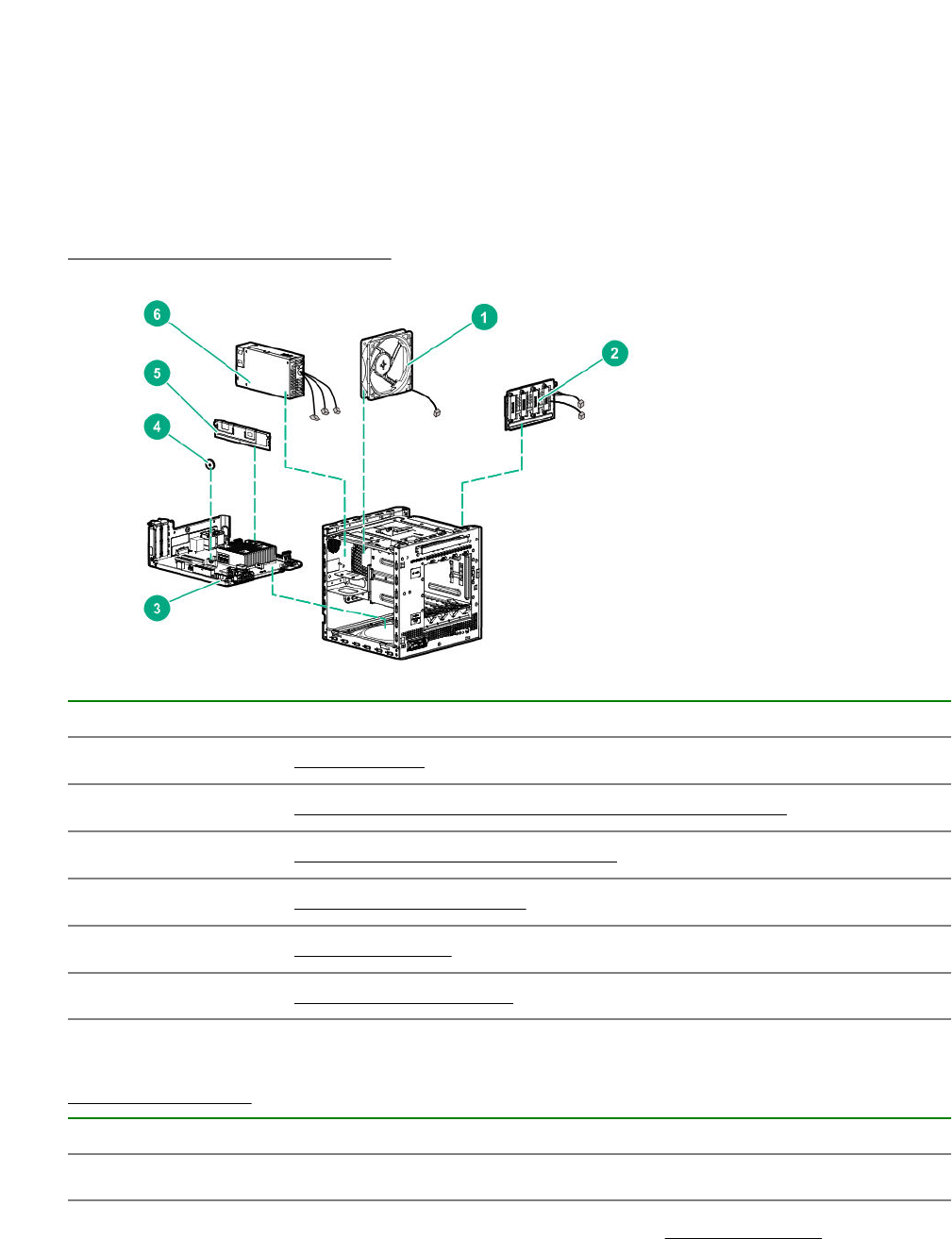
System components
Hewlett Packard Enterprise continually improves and changes product parts. For complete and current
supported spare parts information, see the Hewlett Packard Enterprise PartSurfer website:
http://www.hpe.com/info/partssurfer
Item Description
1Fan spare part on page 16
2Four bay non-hot-plug drive cable assembly spare part on page 17
3System board assembly spare parts on page 17
4System battery spare part on page 17
5DIMM spare parts on page 17
6Power supply spare part on page 17
Fan spare part
Customer self repair on page 6: Mandatory
Description Spare part number
Fan 874740-001
For more information on the removal and replacement procedures, see Replacing the fan on page 57.
16 Illustrated parts catalog

Four bay non-hot-plug drive cable assembly spare part
Customer self repair on page 6: Mandatory
Description Spare part number
Four bay non-hot-plug drive cable assembly 874741-001
For more information on the removal and replacement procedures, see Replacing the non-hot-plug
drive cable assembly on page 47.
System board assembly spare parts
Customer self repair on page 6: Mandatory
The system board assembly spare includes the system board attached to the tray, with the heatsink and
the rear USB EMI shield installed.
Description Spare part number
System board assembly with AMD Opteron X3216 APU 874737-001
System board assembly with AMD Opteron X3418 APU P07949-001
System board assembly with AMD Opteron X3421 APU 874738-001
For more information on the removal and replacement procedures, see Replacing the system board
assembly on page 67.
System battery spare part
Customer self repair on page 6: Mandatory
Description Spare part number
3.3-V, 220-mAh lithium battery coin 319603-001
For more information on the removal and replacement procedures, see System battery replacement on
page 65.
DIMM spare parts
Customer self repair on page 6: Mandatory
Description Spare part number
8 GB, single-rank x8 PC4-2400T-E 869537-001
16 GB, dual-rank x8 PC4-2400T-E 869538-001
For more information on the removal and replacement procedures, see Replacing a DIMM on page 51.
Power supply spare part
Customer self repair on page 6: Mandatory
Four bay non-hot-plug drive cable assembly spare part 17
Description Spare part number
200 W power supply 874739-001
For more information on the removal and replacement procedures, see Replacing the power supply on
page 60.
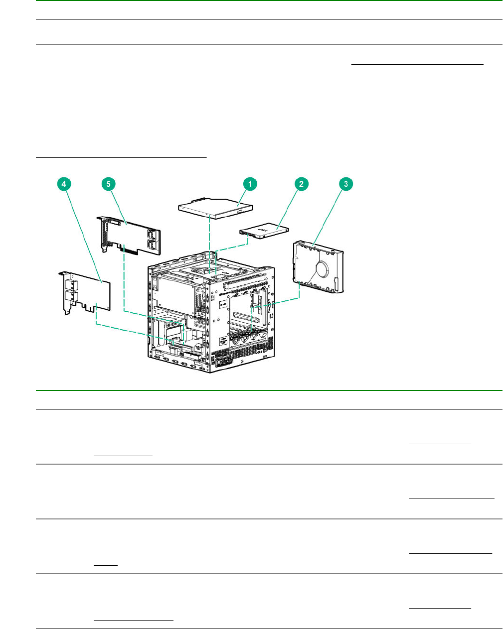
Server options
Hewlett Packard Enterprise continually improves and changes product parts. For complete and current
supported spare parts information, see the Hewlett Packard Enterprise PartSurfer website:
http://www.hpe.com/info/partssurfer
Item Description
1 Optical drive
For more information on the removal and replacement procedures, see Replacing an
optical drive on page 36.
2 Solid state drive
For more information on the removal and replacement procedures, see Replacing an SSD
on page 39.
3 LFF non-hot-plug hard drive
For more information on the removal and replacement procedures, see Replacing an LFF
drive on page 31.
4 Network controller
For more information on the removal and replacement procedures, see Replacing an
expansion board on page 53.
Table Continued
18 Server options
Item Description
5 Storage controller
For more information on the removal and replacement procedures, see Replacing an
expansion board on page 53.
6SSD cable spare parts on page 19*
7Trusted Platform Module spare part on page 19*
*Not shown
SSD cable spare parts
Customer self repair on page 6: Mandatory
Description Spare part number
SSD power cable, SSD SATA cable 874742-001
For more information on the removal and replacement procedures, see Replacing the SSD cables.
Trusted Platform Module spare part
Customer self repair on page 6: No
Description Spare part number
TPM 2.0 812119-001
SSD cable spare parts 19

Removal and replacement procedures
This chapter provides detailed instructions on how to remove and replace component spare parts.
Safety considerations
Before performing service procedures, review all the safety information.
Electrostatic discharge
Be aware of the precautions you must follow when setting up the system or handling components. A
discharge of static electricity from a finger or other conductor may damage system boards or other static-
sensitive devices. This type of damage may reduce the life expectancy of the system or component.
To prevent electrostatic damage:
• Avoid hand contact by transporting and storing products in static-safe containers.
• Keep electrostatic-sensitive parts in their containers until they arrive at static-free workstations.
• Place parts on a grounded surface before removing them from their containers.
• Avoid touching pins, leads, or circuitry.
• Always be properly grounded when touching a static-sensitive component or assembly. Use one or
more of the following methods when handling or installing electrostatic-sensitive parts:
◦ Use a wrist strap connected by a ground cord to a grounded workstation or computer chassis. Wrist
straps are flexible straps with a minimum of 1 megohm ±10 percent resistance in the ground cords.
To provide proper ground, wear the strap snug against the skin.
◦ Use heel straps, toe straps, or boot straps at standing workstations. Wear the straps on both feet
when standing on conductive floors or dissipating floor mats.
◦ Use conductive field service tools.
◦ Use a portable field service kit with a folding static-dissipating work mat.
If you do not have any of the suggested equipment for proper grounding, have an authorized reseller
install the part.
For more information on static electricity or assistance with product installation, contact an authorized
reseller.
Symbols on equipment
The following symbols might be found on the equipment to indicate the presence of potentially hazardous
conditions.
This symbol indicates the presence of hazardous energy circuits or electric shock
hazards. Refer all servicing to qualified personnel.
WARNING: To reduce the risk of injury from electric shock hazards, do not open this
enclosure. Refer all maintenance, upgrades, and servicing to qualified personnel.
20 Removal and replacement procedures
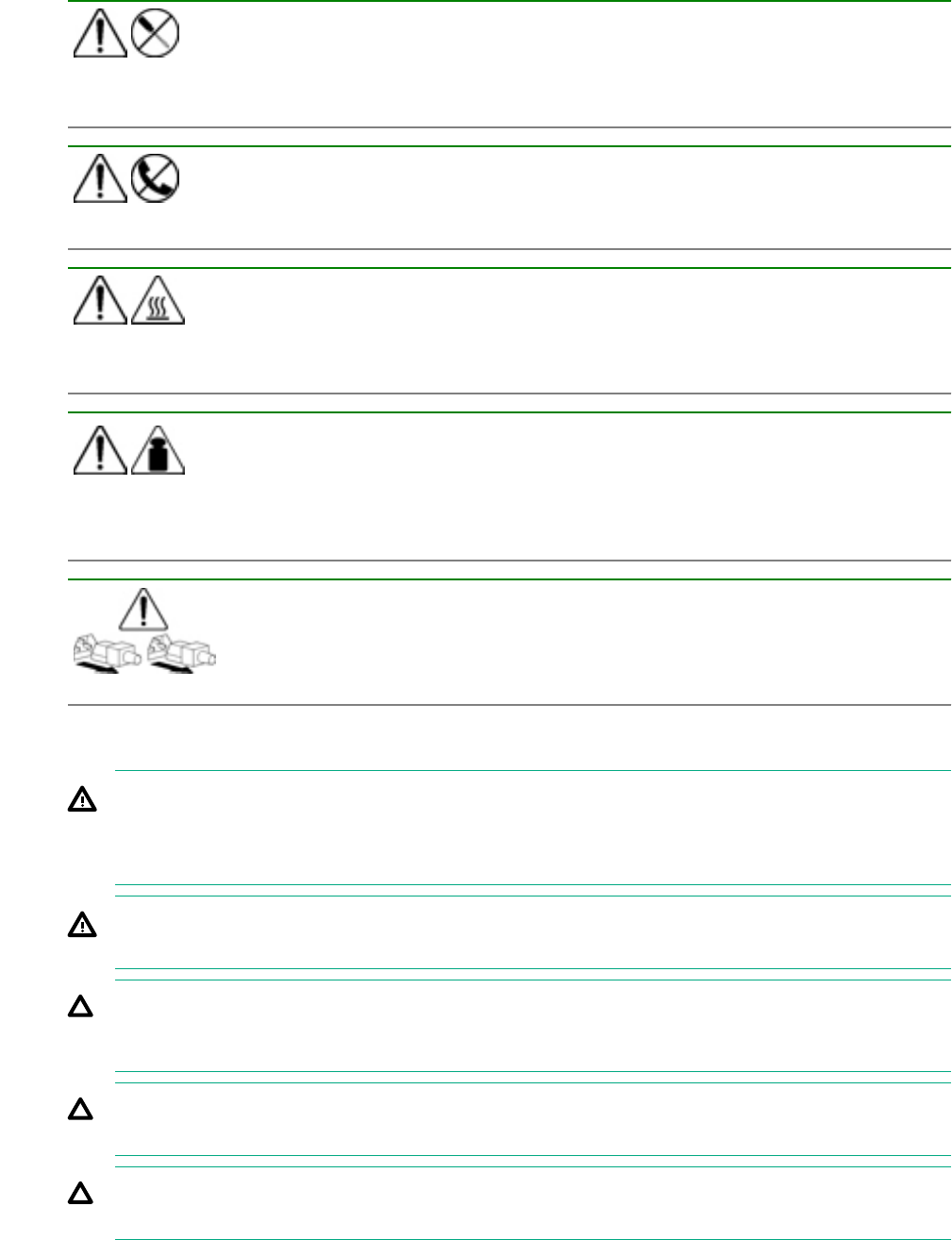
This symbol indicates the presence of electric shock hazards. The area contains no
user or field serviceable parts. Do not open for any reason.
WARNING: To reduce the risk of injury from electric shock hazards, do not open this
enclosure.
This symbol on an RJ-45 receptacle indicates a network interface connection.
WARNING: To reduce the risk of electric shock, fire, or damage to the equipment, do
not plug telephone or telecommunications connectors into this receptacle.
This symbol indicates the presence of a hot surface or hot component. If this surface is
contacted, the potential for injury exists.
WARNING: To reduce the risk of injury from a hot component, allow the surface to cool
before touching.
This symbol indicates that the component exceeds the recommended weight for one
individual to handle safely.
WARNING: To reduce the risk of personal injury or damage to the equipment,
observe local occupational health and safety requirements and guidelines for manual
material handling.
These symbols, on power supplies or systems, indicate that the equipment is supplied
by multiple sources of power.
WARNING: To reduce the risk of injury from electric shock, remove all power cords to
disconnect power from the system completely.
Server warnings and cautions
WARNING: To reduce the risk of personal injury, electric shock, or damage to the equipment,
disconnect the power cord to remove power from the server. Pressing the Power On/Standby button
does not shut off system power completely. Portions of the power supply and some internal circuitry
remain active until AC power is removed.
WARNING: To reduce the risk of personal injury from hot surfaces, allow the drives and the internal
system components to cool before touching them.
CAUTION: Protect the server from power fluctuations and temporary interruptions with a regulating
UPS. This device protects the hardware from damage caused by power surges and voltage spikes
and keeps the server in operation during a power failure.
CAUTION: To prevent improper cooling and thermal damage, do not operate the server with the
media bay blank, chassis cover, or the front bezel removed.
CAUTION: To prevent damage to electrical components, properly ground the server before
beginning any installation procedure. Improper grounding can cause electrostatic discharge.
Server warnings and cautions 21

CAUTION: To avoid data loss, Hewlett Packard Enterprise recommends that you back up all server
data before installing or removing a hardware option, or performing a server maintenance or
troubleshooting procedure.
Prepare the server for hardware replacement
Prerequisites
Before powering down the server for any upgrade or maintenance procedures, perform a backup of
critical server data and programs.
Procedure
1. Power down the server on page 22.
2. Disconnect the power cord from the AC source, and then from the server.
3. Disconnect all peripheral cables from the server.
4. To access some components and perform certain service procedures, do one or more of the following
procedures:
•Remove the front bezel on page 22.
•Remove the chassis cover on page 25.
•Remove the system board assembly on page 25.
5. Place the server on a flat, level work surface.
Power down the server
Prerequisites
Before powering down the server for any upgrade or maintenance procedures, perform a backup of
critical server data and programs.
Procedure
• Press and release the Power On/Standby button.
This method initiates a controlled shutdown of applications and the OS before the server enters
standby mode.
• Press and hold the Power On/Standby button for more than 4 seconds to force the server to enter
standby mode.
This method forces the server to enter standby mode without properly exiting applications and the OS.
If an application stops responding, you can use this method to force a shutdown.
The system power LED changes to red indicating that the server is in standby mode. Auxiliary power
is still present in the system in this mode.
Remove the front bezel
To access the drive bays, remove the front bezel.
22 Prepare the server for hardware replacement
Removing a locked front bezel
Prerequisites
1. Power down the server on page 22.
2. Disconnect the power cord from the AC source, and then from the server.
3. Disconnect all peripheral cables from the server.
4. Remove the chassis cover on page 25.
Procedure
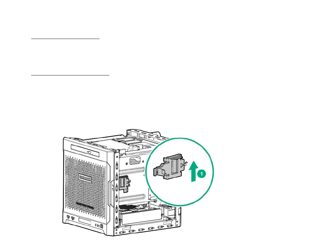
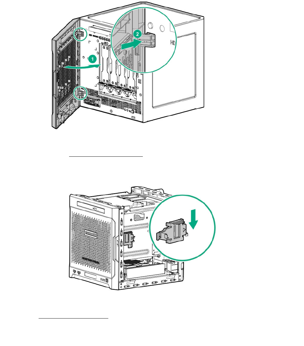
1. To unlock the front bezel from the chassis, slide the release tab upward.
2. Open the front bezel.
The front bezel is a removable part. Opening the bezel will loosen it from the front panel.
3. To completely detach the bezel from the front panel, pull the bezel hinges from the chassis.
Retain the bezel for later use.
Removing a locked front bezel 23
Removing an unlocked front bezel
Prerequisites
1. Power down the server on page 22.
2. Disconnect the power cord from the AC source, and then from the server.
3. Disconnect all peripheral cables from the server.
Procedure
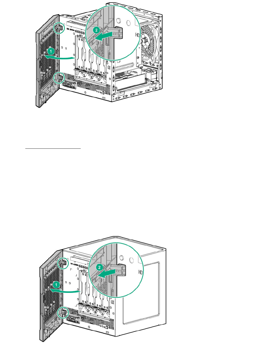
1. Open the front bezel.
The front bezel is a removable part. Opening the bezel will loosen it from the front panel.
2. To completely detach the bezel from the front panel, pull the bezel hinges from the chassis.
Retain the bezel for later use.
24 Removing an unlocked front bezel
Remove the chassis cover
To access the front bezel lock and the internal components, remove the chassis cover.
Procedure
1. If installed, unlock and remove the security padlock and/or the Kensington security lock.
For more information, see the lock documentation.
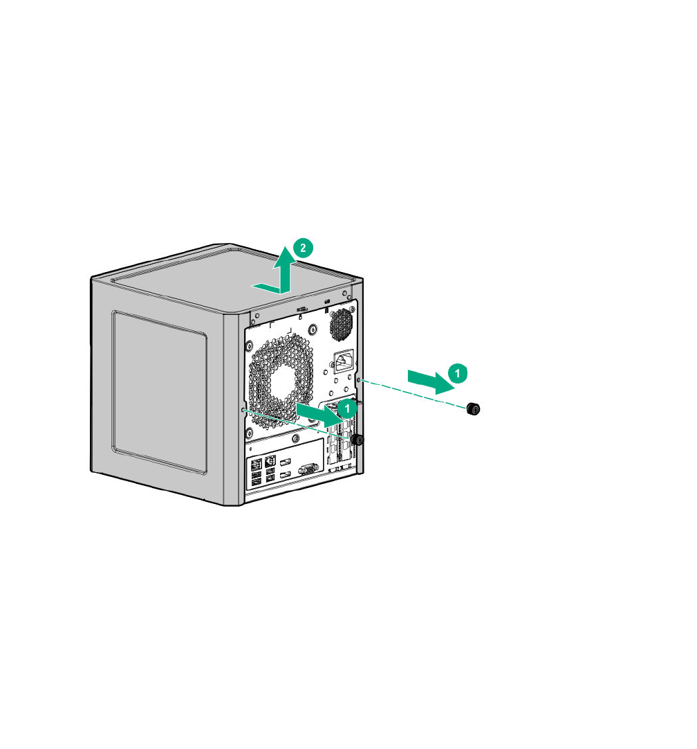
2. Remove the chassis cover thumbscrews.
If the thumbscrews are too tight, use a T-15 screwdriver to remove it.
3. Slide the chassis cover toward the rear panel, and then lift it from the server.
Remove the system board assembly
To install or remove hardware components on the system board or to access the CMOS header, remove
the system board assembly.
Remove the system board assembly
Prerequisites
Before you perform this procedure, make sure that you have a T-15 Torx screwdriver available.
Procedure
1. If installed, remove the internal USB device.
2. To serve as a reference for system cable connections when the system board assembly is installed
back into the server, take a picture of the current system board cable connections.
3. Disconnect the following system cables:
Remove the chassis cover 25
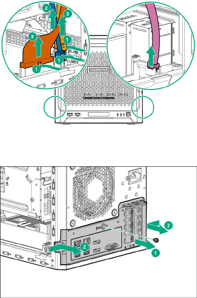
• Power supply cable
• Optical drive or SSD SATA cable (optional)
• LFF/SFF drive SATA cable – This cable can either be connected to the system board or to an
installed HBA.
• Fan cable
4. Remove the system board assembly screw.
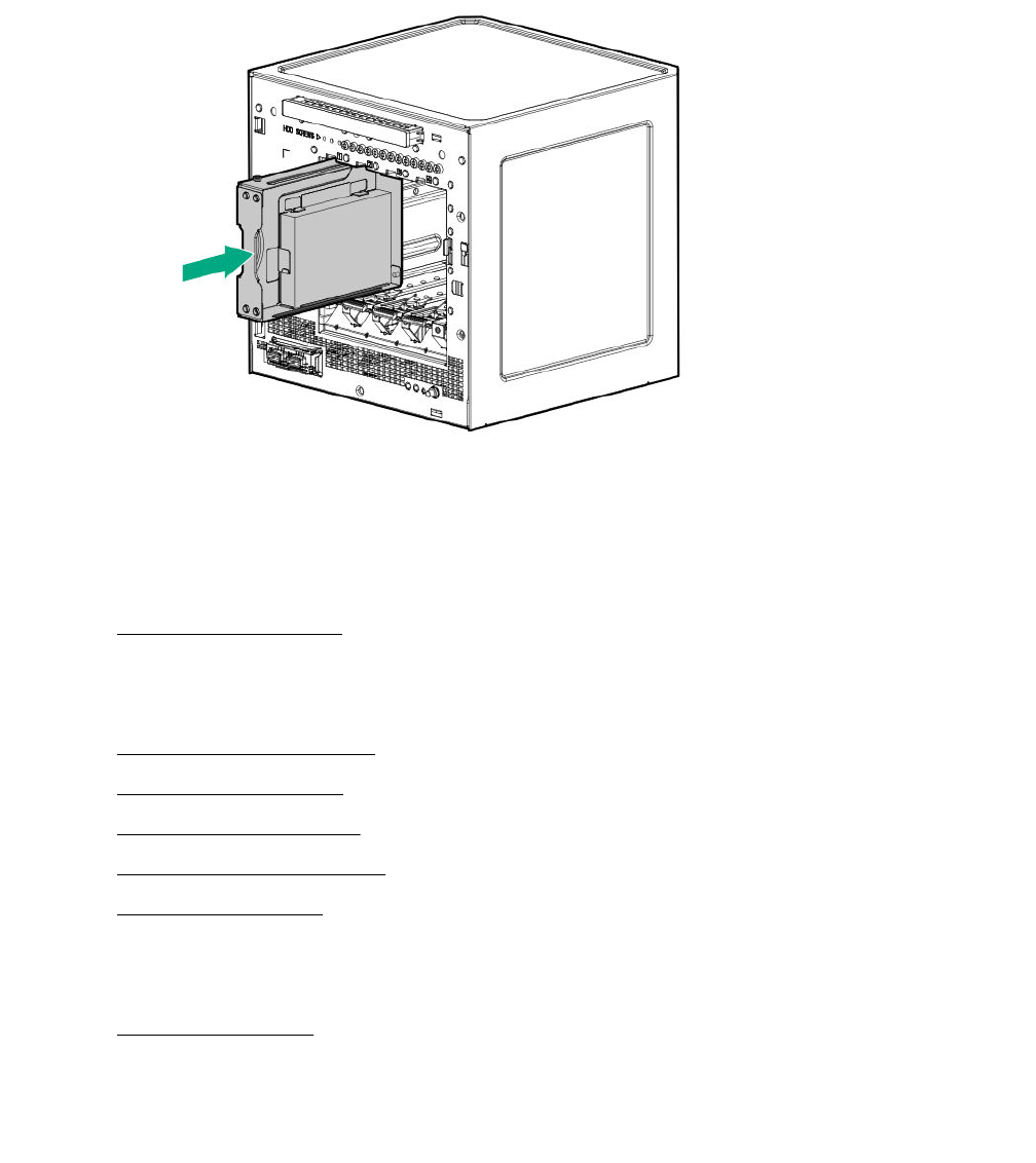
5. Place a finger in the notch on both sides of the system board assembly, and then pull out the
assembly.
26 Removal and replacement procedures

Prepare the server for operation
Procedure
1. Depending on what hardware was replaced, do one or more of the following:
•Install the system board assembly on page 27.
•Install the chassis cover on page 28.
•Install the front bezel on page 29.
2. If removed, attach the security padlock and/or the Kensington security lock.
For more information, see the lock documentation.
3. Connect all peripheral cables to the server.
4. Connect the power cord to the server power jack, and then to the AC source.
5. Secure the power cord and rear panel cables based on the standard cable management practices.
6. Power up the server on page 30.
Install the system board assembly
To secure the system board inside the chassis, install the system board assembly.
Install the system board assembly
Prerequisites
Before you perform this procedure, make sure that you have a T-15 Torx screwdriver available.
Procedure
1. Slide the system board assembly into the chassis.
2. Press against the system board assembly until it clicks into place.
3. Install the system board assembly screw.
Prepare the server for operation 27
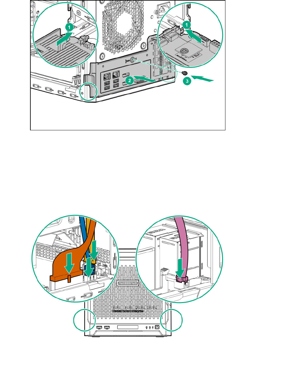
4. Connect the following system cables:
• Power supply cable
• Optical drive or SSD SATA cable (optional)
• LFF/SFF drive SATA cable – This cable can either be connected to the system board or to an
installed HBA.
• Fan cable
5. If removed, install the internal USB device.
Install the chassis cover
To prevent access to the front bezel lock and the internal components, install the chassis cover.
28 Install the chassis cover
Install the chassis cover
Prerequisites
1. Verify that all internal cables are properly connected and are secured in their respective cable ties.
2. Verify that the drive cables are not blocking the fan blades.
Procedure
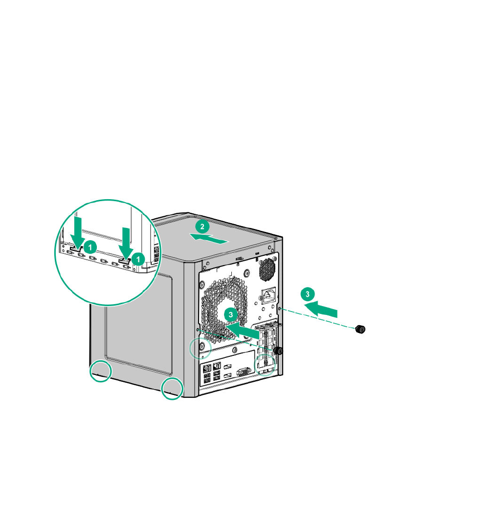
1. Insert the tabs on the bottom left and right sides of the chassis cover into the corresponding slots on
the chassis.
2. Slide the chassis cover towards the front panel.
3. Install the chassis thumbscrews.
4. If removed, install the security padlock and/or the Kensington security lock.
For more information, see the lock documentation.
Install the front bezel
To cover the drive bays, install the front bezel.
Procedure
1. Attach the bezel to the front panel, and then close it.
Install the chassis cover 29
2. If you prefer to secure the bezel to the chassis, do the following:
a. If installed, remove the chassis cover.
b. Slide the release tab downwards to lock the bezel to the chassis.
c. Install the chassis cover on page 28.
Power up the server
Press the Power On/Standby button.
The server exits standby mode and applies full power to the system. The system power LED changes to
green.
30 Power up the server
Replacing an LFF drive
Procedure
1. Power down the server on page 22.
2. Disconnect the power cord from the AC source, and then from the server.
3. Disconnect all peripheral cables from the server.
4. Remove the front bezel on page 22.
5. Remove the LFF drive on page 31.
6. Install the new LFF drive.
7. Install the front bezel on page 29.
8. Connect all peripheral cables to the server.
9. Connect the power cord to the server power jack, and then to the AC source.
10. Power up the server on page 30.
Remove the LFF drive
Prerequisites
Before you perform this procedure, make sure that you have a T-15 Torx screwdriver available.
Procedure
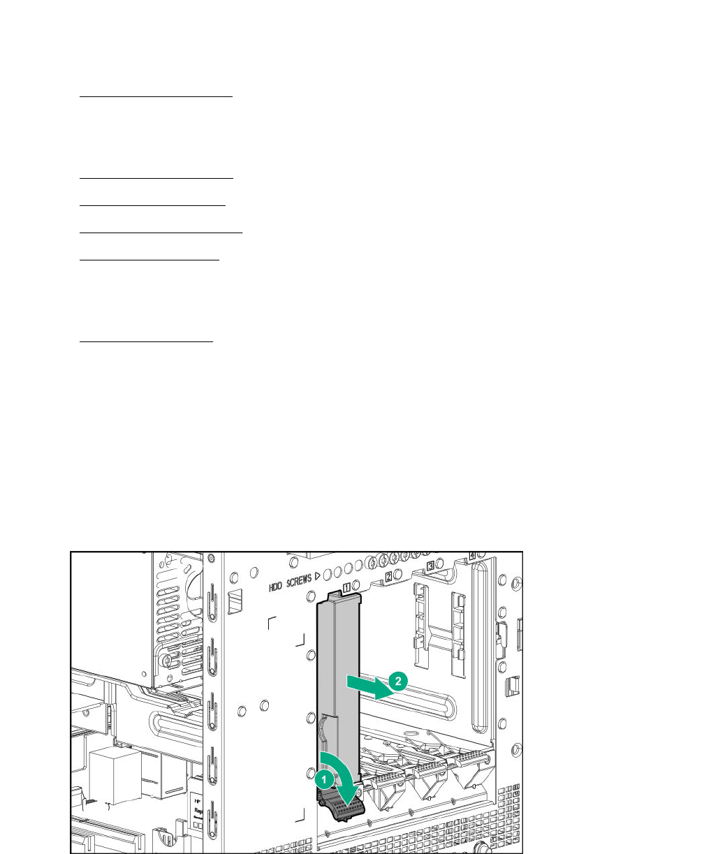
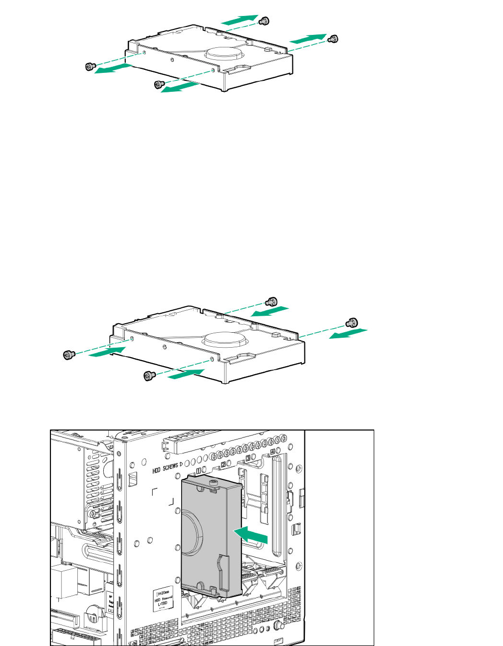
1. To disengage the drive, press the drive latch.
2. Slide the drive out of the drive bay.
3. Remove the screws from both sides of the drive.
Replacing an LFF drive 31
Install the LFF drive
Prerequisites
Before you perform this procedure, make sure that you have the following items available:
• T-15 Torx screwdriver
• LFF drive spare
Procedure
1. Install the screws in the drive.
2. Slide the drive into the drive bay until it clicks into place.
32 Install the LFF drive
Replacing an SFF drive
Procedure
1. Power down the server on page 22.
2. Disconnect the power cord from the AC source, and then from the server.
3. Disconnect all peripheral cables from the server.
4. Remove the front bezel on page 22.
5. Remove the SFF drive on page 33.
6. Install the new SFF drive.
7. Install the front bezel on page 29.
8. Connect all peripheral cables to the server.
9. Connect the power cord to the server power jack, and then to the AC source.
10. Power up the server on page 30.
Remove the SFF drive
Prerequisites
Before you perform this procedure, make sure that you have a T-10 Torx screwdriver available.
Procedure
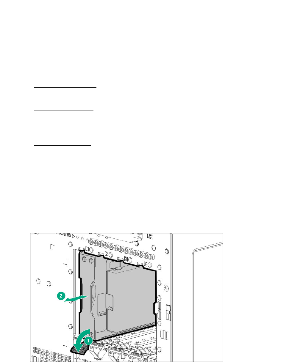
1. To disengage the drive converter tray, press the drive latch.
2. Slide the converter tray out of the drive bay.
3. Remove the screws on the bottom of the converter tray.
Replacing an SFF drive 33
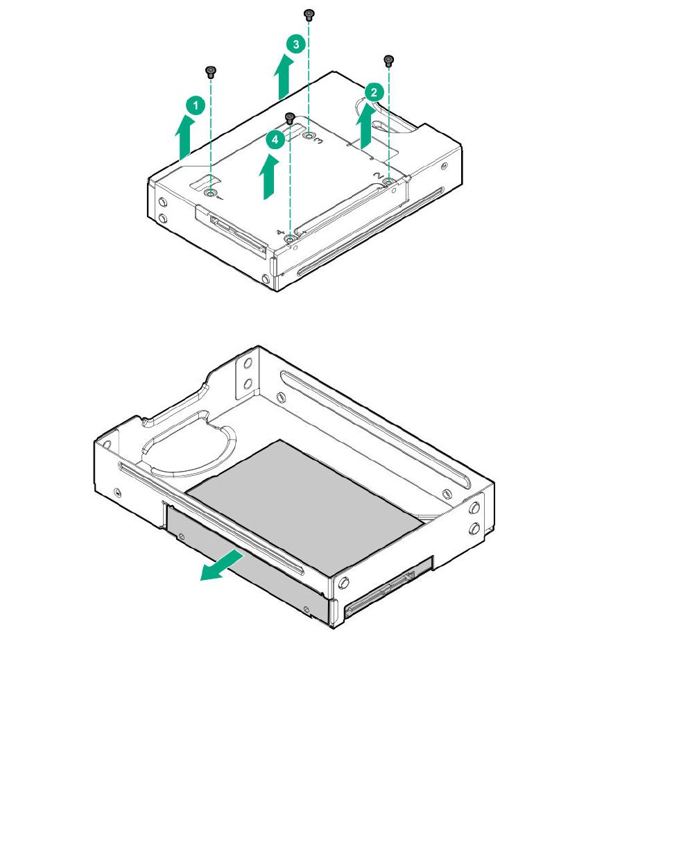
4. Remove the drive from the converter tray.
Install the SFF drive
Prerequisites
Before you perform this procedure, make sure that you have the following items available:
• T-10 Torx screwdriver
• SFF drive spare
Procedure
1. Install the SFF drive in the drive converter tray.
34 Install the SFF drive
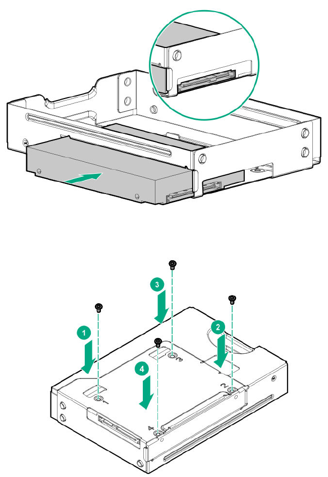
2. Follow the callout sequence in the following illustration to install the screws on the bottom side of the
converter tray.
3. Slide the converter tray into the drive bay until it clicks into place.
Removal and replacement procedures 35
Replacing an optical drive
Procedure
1. Power down the server on page 22.
2. Disconnect the power cord from the AC source, and then from the server.
3. Disconnect all peripheral cables from the server.
4. Remove the chassis cover on page 25.
5. Remove the front bezel on page 22.
6. Remove the optical drive on page 36.
7. Install the new optical drive.
8. Install the front bezel on page 29.
9. Connect all peripheral cables to the server.
10. Connect the power cord to the server power jack, and then to the AC source.
11. Power up the server on page 30.
Remove the optical drive
Prerequisites
Before you perform this procedure, make sure that you have following items available:
• T-15 Torx screwdriver
• Phillips No. 2 screwdriver
36 Replacing an optical drive
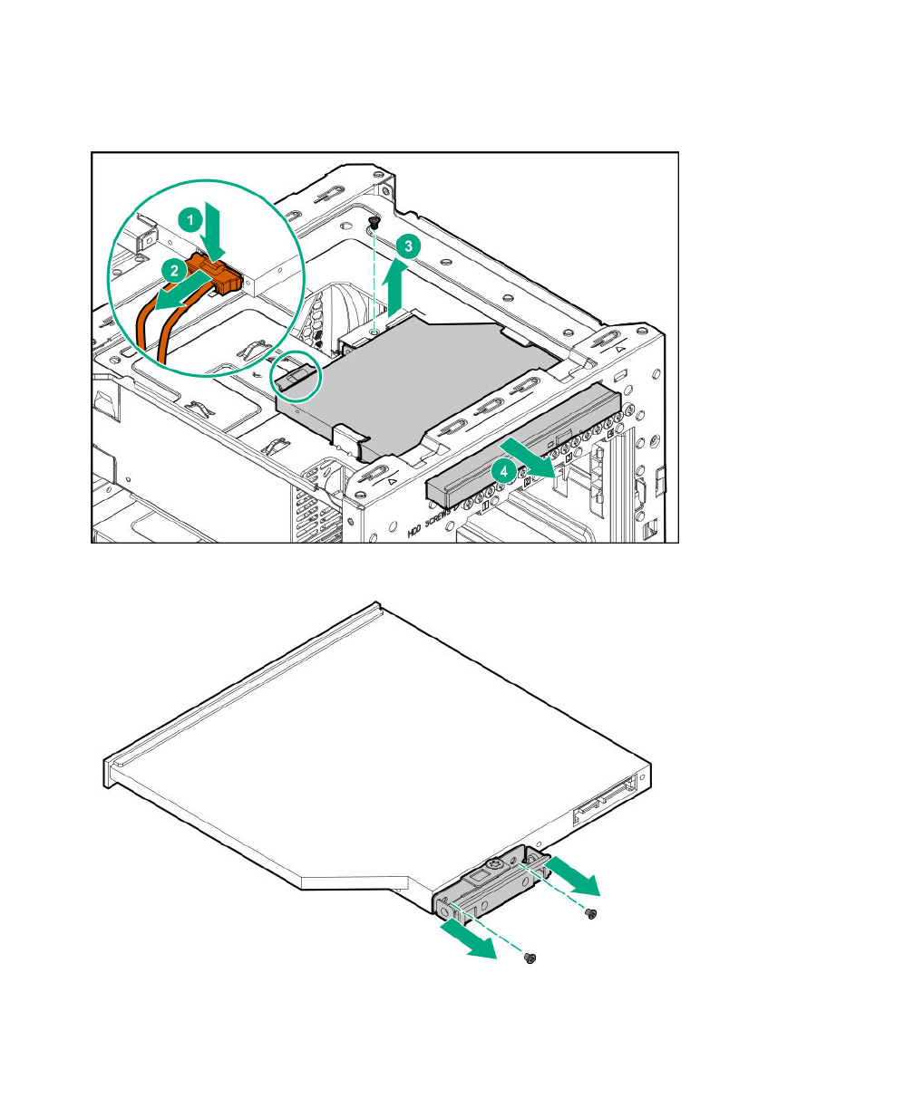
Procedure
1. Disconnect the optical drive SATA Y-cable from the optical drive.
2. Remove the optical drive screw.
3. Slide the optical drive out of the media bay.
4. Remove the bracket from the optical drive.
Install the optical drive
Prerequisites
Before you perform this procedure, make sure that you have the following items available:
Install the optical drive 37
• T-15 Torx screwdriver
• Phillips No. 2 screwdriver
• Optical drive spare
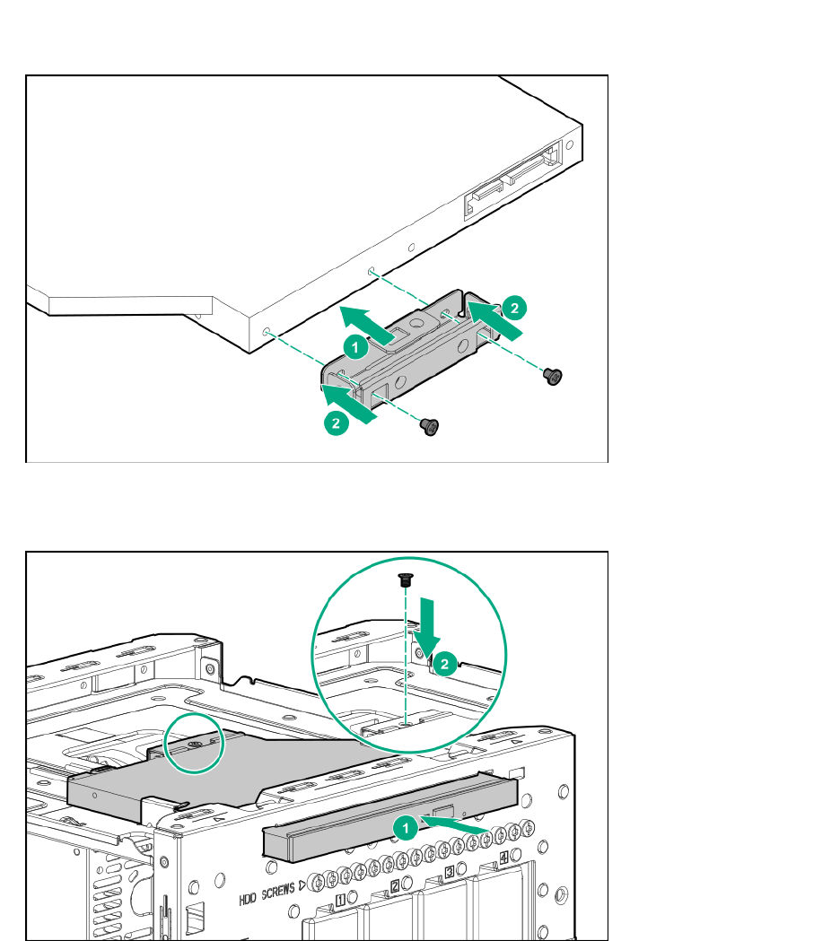
Procedure
1. Attach the bracket to the optical drive.
2. Slide the optical drive into the media bay.
3. Install the optical drive screw.
4. Connect the common end of the cable to the optical drive.
38 Removal and replacement procedures
Replacing an SSD
Procedure
1. Power down the server on page 22.
2. Disconnect the power cord from the AC source, and then from the server.
3. Disconnect all peripheral cables from the server.
4. Remove the chassis cover on page 25.
5. Remove the SSD on page 39.
6. Install the new SSD.
7. Install the chassis cover on page 29.
8. Connect all peripheral cables to the server.
9. Connect the power cord to the server power jack, and then to the AC source.
10. Power up the server on page 30.
Remove the SSD
Prerequisites
Before you perform this procedure, make sure that you have the following items available:
• T-10 Torx screwdriver
• T-15 Torx screwdriver
Procedure
1. Disconnect the SSD power and SATA cables from the SSD.
Replacing an SSD 39
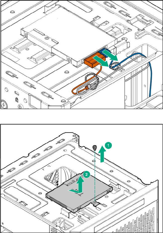
2. Remove the SSD tray screw and slide the tray out of the chassis.
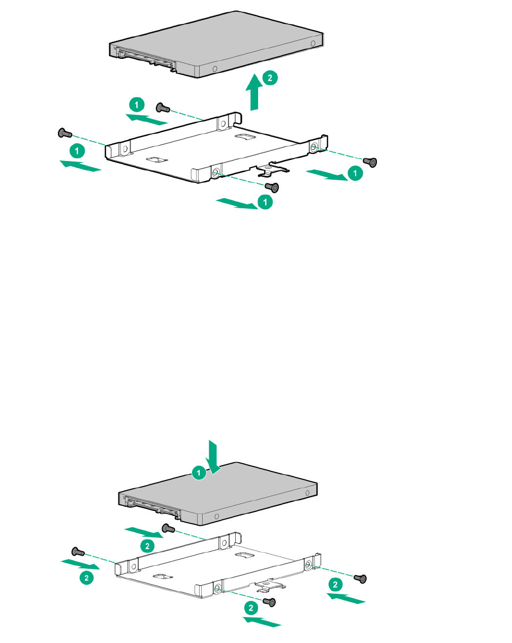
3. Remove the SSD screws, and then remove the SSD from the tray.
40 Removal and replacement procedures
Install the SSD
Prerequisites
Before you perform this procedure, make sure that you have the following items available:
• T-10 Torx screwdriver
• T-15 Torx screwdriver
• SSD spare
Procedure
1. Place the SSD in the SSD tray, and then install the SSD screws.
2. Install the SSD assembly in the media bay, and then secure it with the screw.
Install the SSD 41
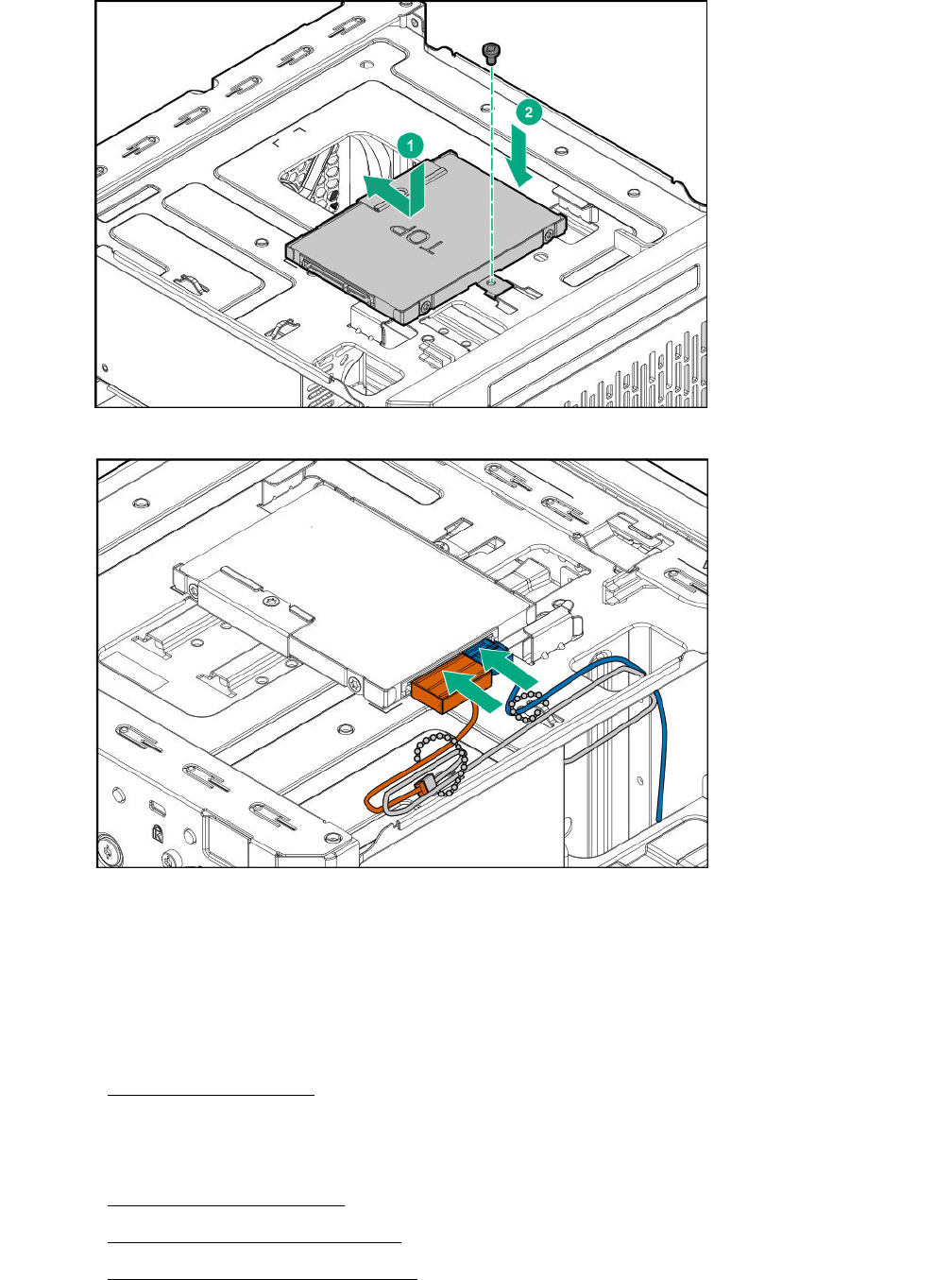
3. Connect the SSD power and SATA cables to the SSD.
Replacing the SSD cables
Replacing the SSD power cable
Procedure
1. Power down the server on page 22
2. Disconnect the power cord from the AC source, and then from the server.
3. Disconnect all peripheral cables from the server.
4. Remove the chassis cover on page 25.
5. Disconnect the SSD power cable.
6. Connect the new SSD power cable.
42 Replacing the SSD cables
7. Install the chassis cover on page 28.
8. Connect all peripheral cables to the server.
9. Connect the power cord to the server power jack, and then to the AC source.
10. Power up the server on page 30.
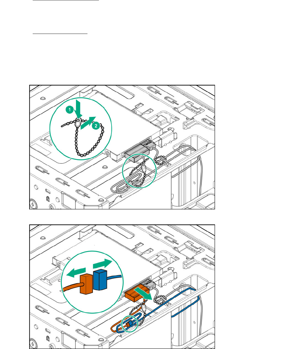
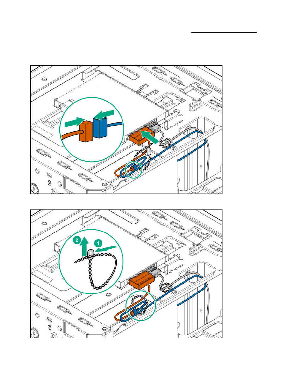
Disconnect the SSD power cable
Procedure
1. Open the cable tie securing the SSD power cable.
2. Disconnect the SSD power cable from the SSD, and then from the power supply cable labeled P3.
Disconnect the SSD power cable 43
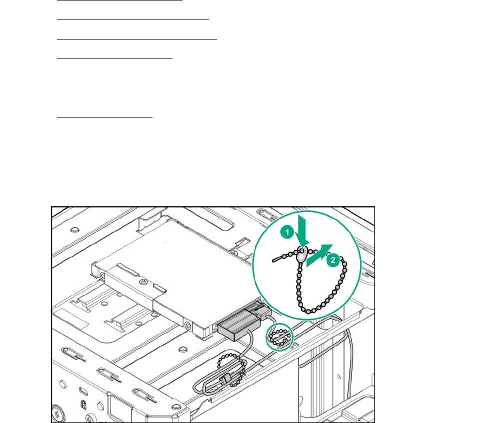
Connect the SSD power cable
Prerequisites
Before you perform this procedure, make sure that you have the SSD power cable spare available.
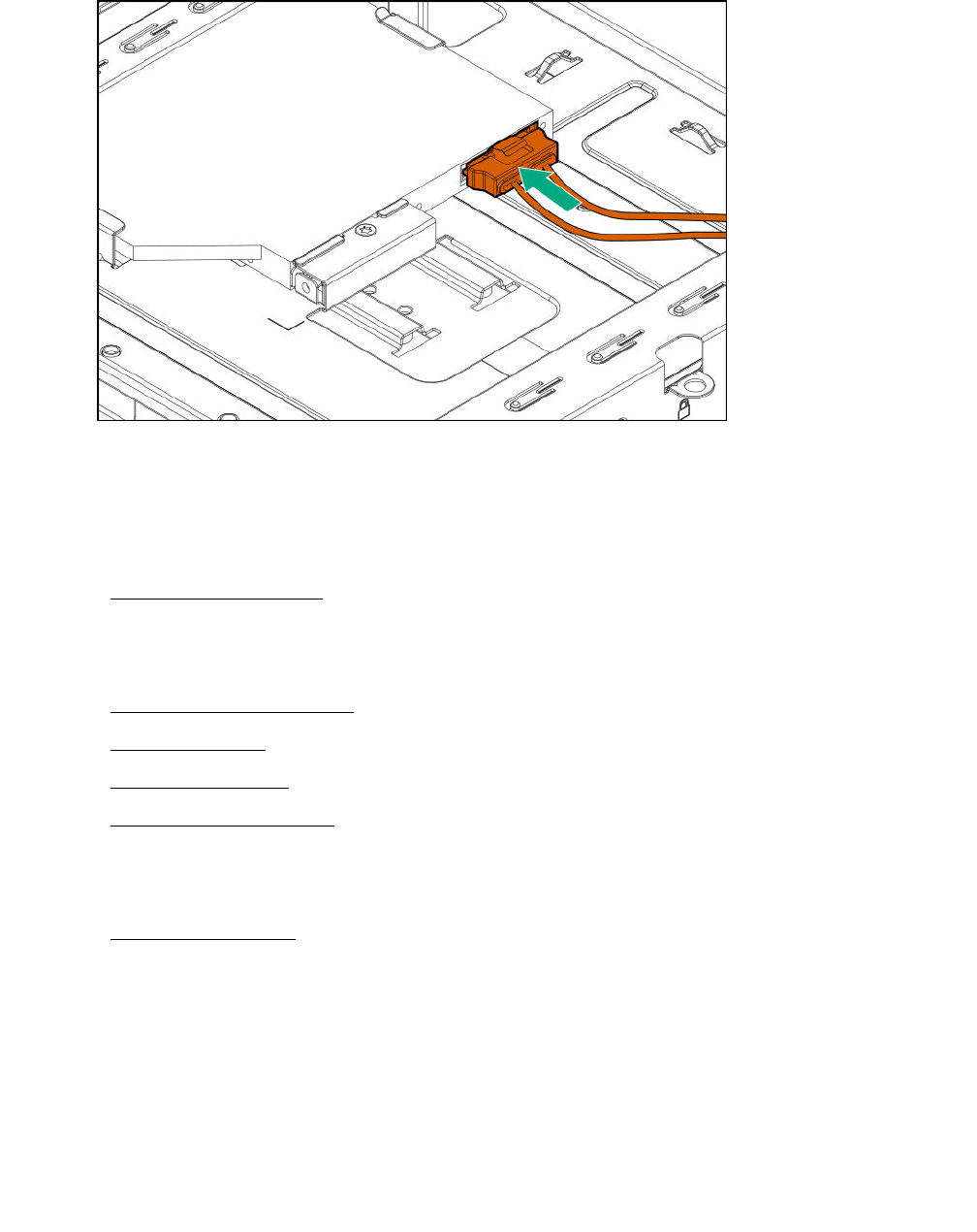
Procedure
1. Connect the SSD power cable to the power supply cable labeled P3, and then to the SSD.
2. Bundle the extra length of the SSD power cable, and then secure it in the cable tie.
Replacing the SSD SATA cable
Procedure
1. Power down the server on page 22
2. Disconnect the power cord from the AC source, and then from the server.
44 Connect the SSD power cable
3. Disconnect all peripheral cables from the server.
4. Remove the chassis cover on page 25.
5. Disconnect the SSD SATA cable.
6. Connect the new SSD SATA cable.
7. Install the chassis cover on page 28.
8. Connect all peripheral cables to the server.
9. Connect the power cord to the server power jack, and then to the AC source.
10. Power up the server on page 30.
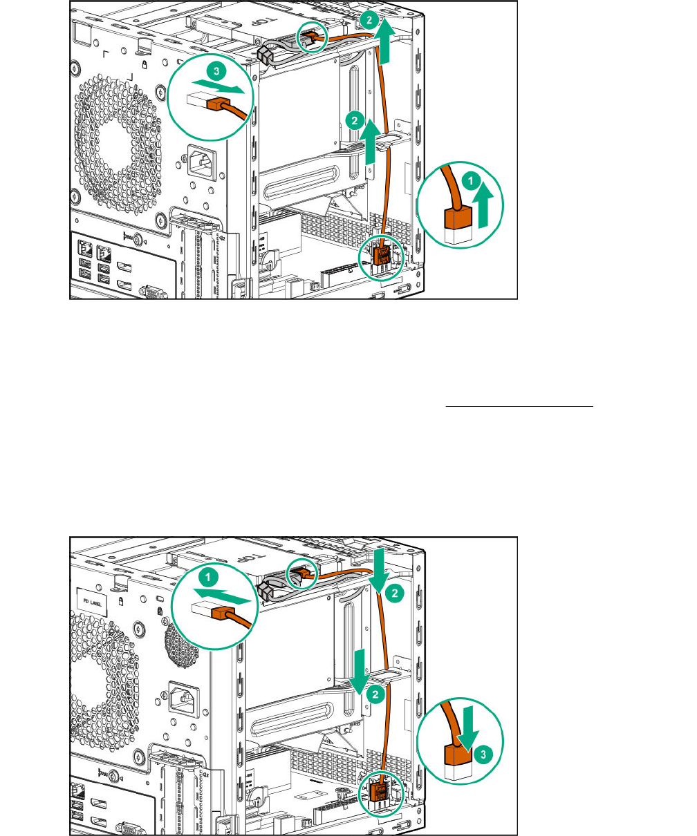
Disconnect the SSD SATA cable
Procedure
1. Open the cable tie securing the SSD SATA cable.
2. Disconnect the SATA cable from the SATA connector, and then pull the cable out of the left side
chassis opening.
3. Disconnect the SATA cable from the SSD.
Disconnect the SSD SATA cable 45
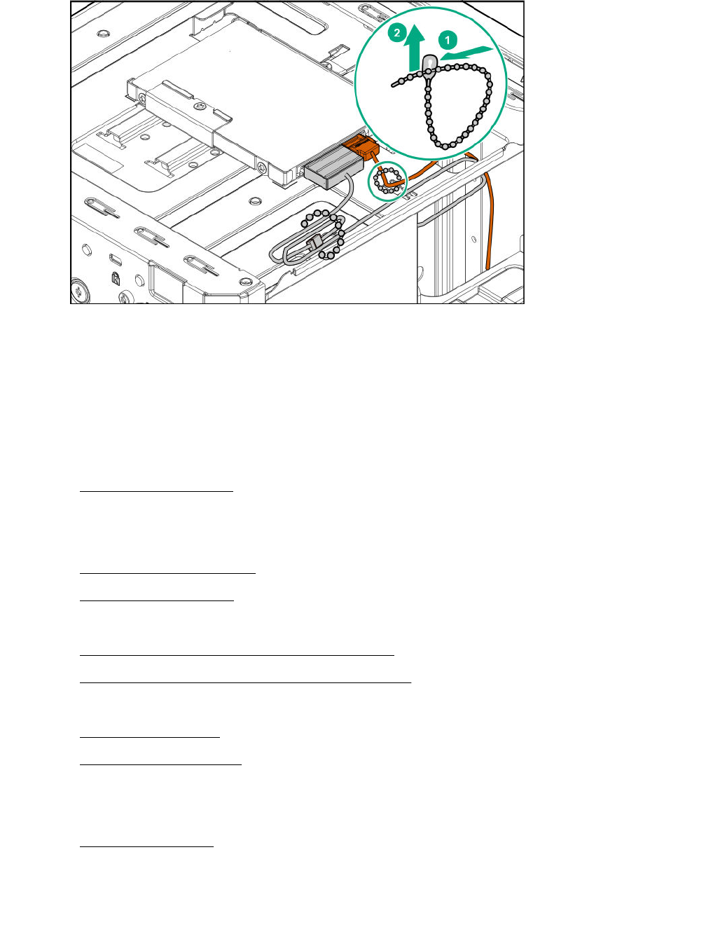
Connect the SSD SATA cable
Prerequisites
Before you perform this procedure, make sure that you have the SSD SATA cable spare available.
Procedure
1. Connect the SATA cable to the SSD.
2. Route the cable through the left side chassis opening down to the system board.
3. Connect the SATA cable to the SATA connector.
4. Bundle the extra length of the SSD SATA cable, and then secure it in the cable tie.
46 Connect the SSD SATA cable
Replacing the non-hot-plug drive cable assembly
The non-hot-plug drive cable assembly consists of the drive power and SATA cables attached to a
bracket. If either the drive power or SATA cable becomes defective, the entire cable assembly will need to
be replaced.
Procedure
1. Power down the server on page 22.
2. Disconnect the power cord from the AC source, and then from the server.
3. Disconnect all peripheral cables from the server.
4. Remove the chassis cover on page 25.
5. Remove the front bezel on page 22.
6. Remove all installed drives.
7. Remove the non-hot-plug drive cable assembly on page 47.
8. Install the new non-hot-plug drive cable assembly.
9. Install all removed drives.
10. Install the front bezel on page 29.
11. Install the chassis cover on page 29.
12. Connect all peripheral cables to the server.
13. Connect the power cord to the server power jack, and then to the AC source.
14. Power up the server on page 30.
Remove the non-hot-plug drive cable assembly
Prerequisites
Before you perform this procedure, make sure that you have a T-15 Torx screwdriver available.
Replacing the non-hot-plug drive cable assembly 47
Procedure
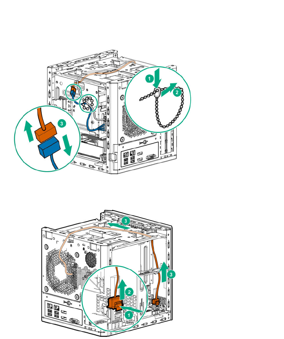
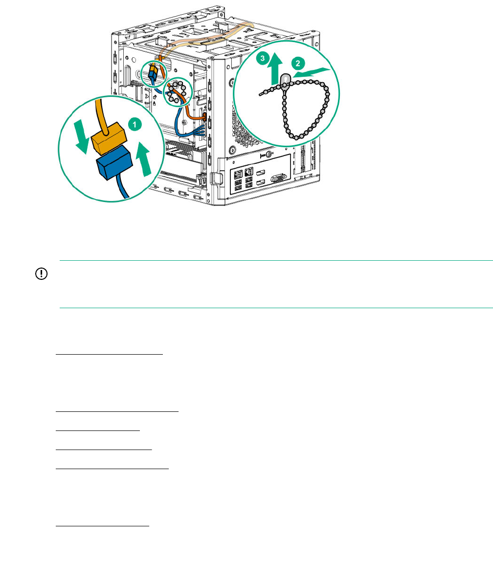
1. Open the cable tie on the right side of the chassis.
2. Disconnect the drive power cable from the P2 power supply connector, and then release it from the
cable tie.
3. Press and hold the release button on the SATA cable connector, and then disconnect the cable.
4. Pull out the SATA cable from the chassis.
5. Remove the cable bracket screw.
6. Pull out the cable assembly from the chassis.
48 Removal and replacement procedures
Install the non-hot-plug drive cable assembly
Prerequisites
Before you perform this procedure, make sure that you have the following items available:
• T-15 Torx screwdriver
•Non-hot-plug drive cable assembly spare
Procedure
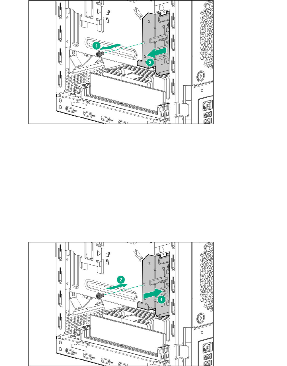
1. Slide the cable assembly into the chassis.
2. Install the cable bracket screw.
3. Route the SATA cable across the opening underneath the top of the chassis, and then down towards
the left side of the system board.
Install the non-hot-plug drive cable assembly 49
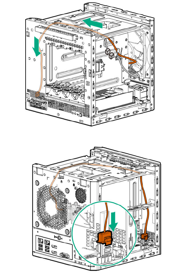
4. Connect the cable to the SATA connector.
5. Connect the drive power cable to the P2 power supply connector.
6. Secure the drive power and SATA cables in the cable tie.
50 Removal and replacement procedures
Replacing a DIMM
IMPORTANT: Before replacing a DIMM, expansion board, or any other circuit board component due
to a perceived hardware error, verify that the component is firmly seated in the slot. Do not bend or
flex circuit boards when reseating components.
Procedure
1. Power down the server on page 22.
2. Disconnect the power cord from the AC source, and then from the server.
3. Disconnect all peripheral cables from the server.
4. Remove the chassis cover on page 25.
5. Remove the DIMM on page 51.
6. Install the new DIMM.
7. Install the chassis cover on page 29.
8. Connect all peripheral cables to the server.
9. Connect the power cord to the server power jack, and then to the AC source.
10. Power up the server on page 30.
Remove the DIMM
Procedure
1. Open the DIMM slot latches.
2. Remove the DIMM.
Replacing a DIMM 51
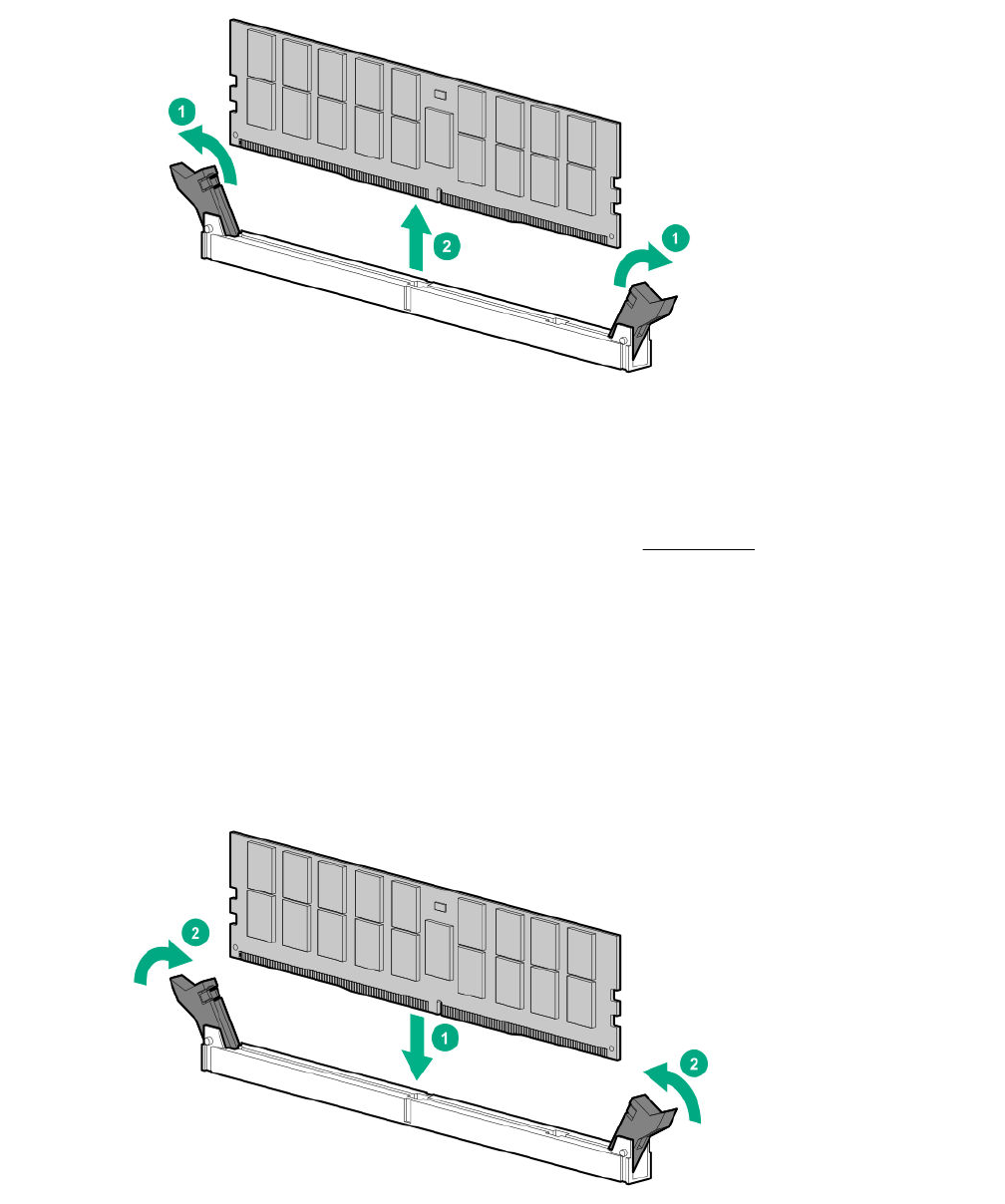
Install a DIMM
Prerequisites
Before you perform this procedure, make sure that you have the DIMM spare available.
Procedure
1. Open the DIMM slot latches.
2. Align the notch on the bottom edge of the DIMM with the keyed surface of the DIMM slot, and then
fully press the DIMM into the slot until the latches snap back into place.
The DIMM slots are structured to ensure proper installation. If you try to insert a DIMM but it does not
fit easily into the slot, you might have positioned it incorrectly. Reverse the orientation of the DIMM and
insert it again.
52 Install a DIMM
Replacing an expansion board
IMPORTANT: Before replacing a DIMM, expansion board, or any other circuit board component due
to a perceived hardware error, verify that the component is firmly seated in the slot. Do not bend or
flex circuit boards when reseating components.
Procedure
1. Power down the server on page 22.
2. Disconnect the power cord from the AC source, and then from the server.
3. Disconnect all peripheral cables from the server.
4. Remove the chassis cover on page 25.
5. Remove the system board assembly on page 25.
6. Remove the expansion board on page 53.
7. If the new expansion board is shipped with an air baffle attached, remove this baffle from the
board.
8. If the new expansion board is shipped with a full-height bracket attached, remove the bracket from
the board and replace it with a low-profile bracket.
9. Install the new expansion board.
10. Install the system board assembly on page 27.
11. Connect all necessary internal cabling to the expansion board.
For more information, see the expansion board documentation.
12. Install the chassis cover on page 29.
13. Connect all peripheral cables to the server.
14. Connect the power cord to the server power jack, and then to the AC source.
15. Power up the server on page 30.
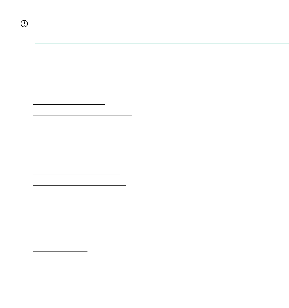
Remove the expansion board
Prerequisites
Before you perform this procedure, make sure that you have a T-15 Torx screwdriver available.
Procedure
1. Disconnect all cables connected to the expansion board.
2. Remove the expansion board bracket screw.
3. Remove the expansion board.
Replacing an expansion board 53
Remove the air baffle from the expansion board
Procedure
Remove the air baffle from the expansion board.
The number and location of the latches that secure the baffle to the board will vary depending on the
expansion board. The illustration below is an example image only. See the expansion board
documentation for model-specific information.
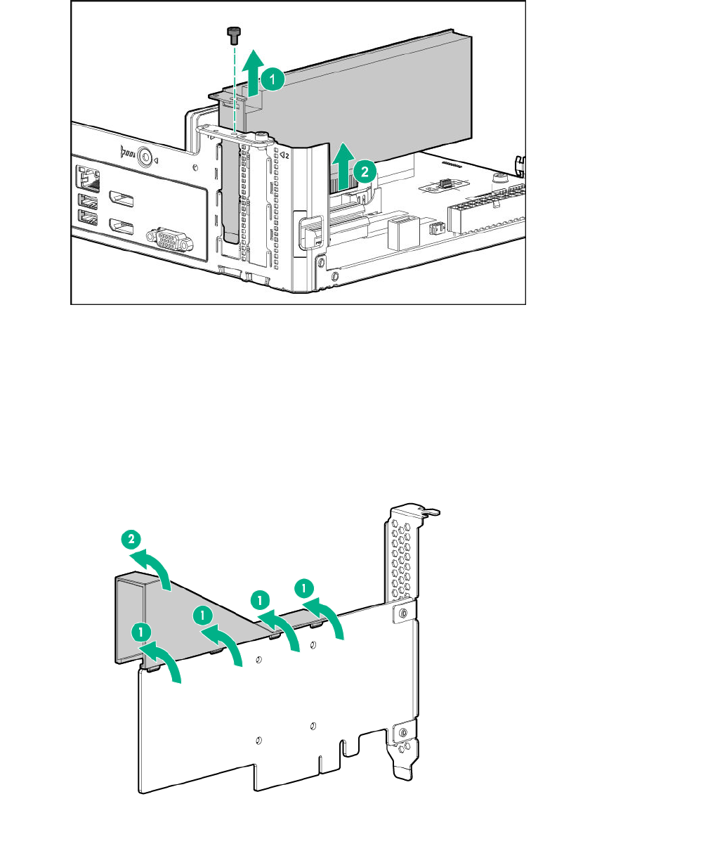
Install a low-profile bracket on the expansion board
The number and location of the bracket screws will vary depending on the expansion board. The
illustrations below are example images only. See the expansion board documentation for model-specific
information.
54 Remove the air baffle from the expansion board
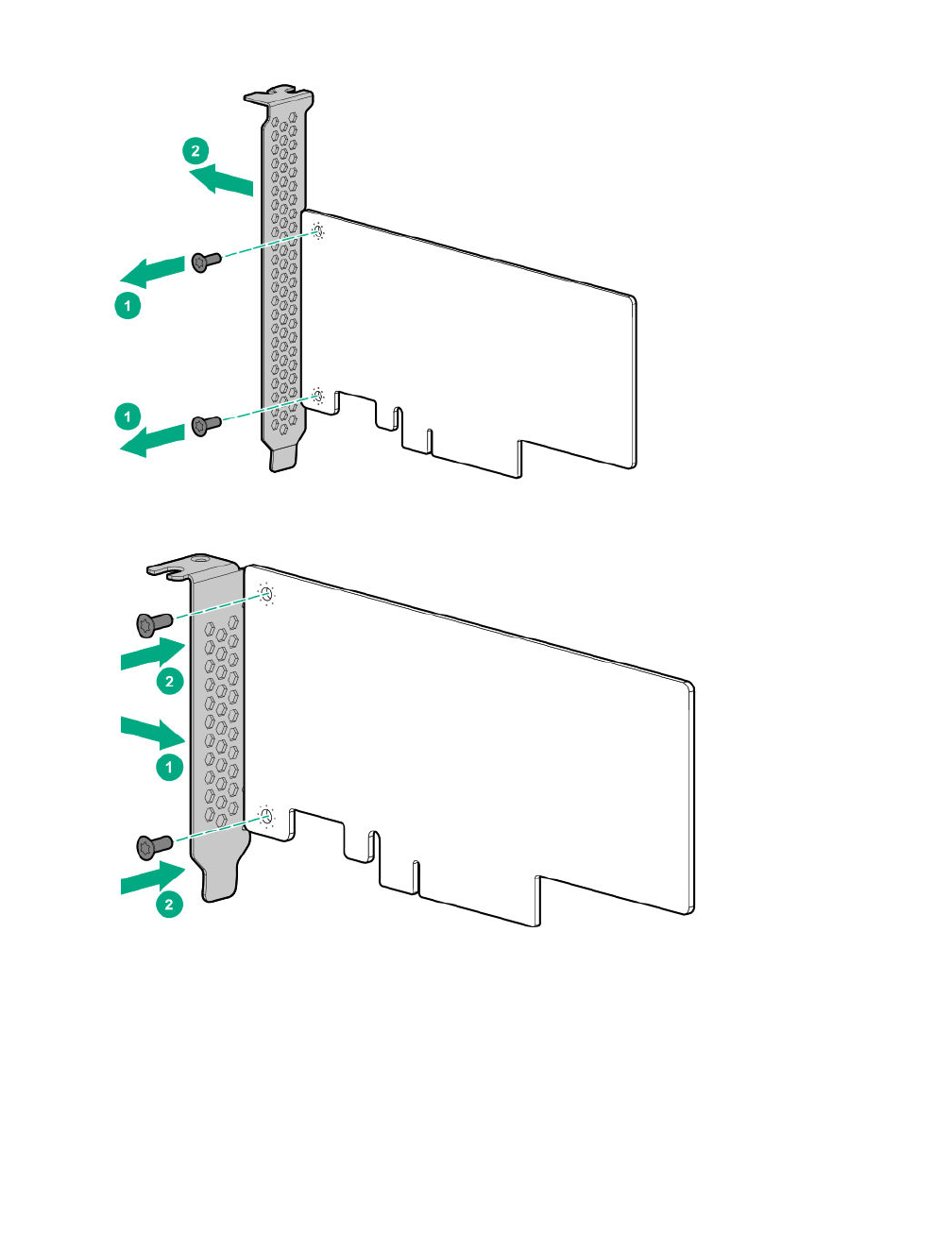
Procedure
1. Remove the full-height bracket from the expansion board.
2. Install the low-profile bracket on the expansion board.
Install the expansion board
Prerequisites
Before you perform this procedure, make sure that you have the following items available:
• T-15 Torx screwdriver
• Expansion board spare
Procedure
1. Verify that any switches or jumpers on the expansion board are set properly.
Install the expansion board 55
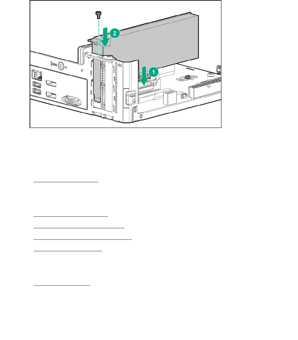
For more information, see the expansion board documentation.
2. Install the expansion board. Verify that the board is firmly seated in the slot.
Replacing an internal USB device
Procedure
1. Power down the server on page 22.
2. Disconnect the power cord from the AC source, and then from the server.
3. Disconnect all peripheral cables from the server.
4. Remove the chassis cover on page 25.
5. Remove the internal USB device.
6. Install the new internal USB device.
7. Install the chassis cover on page 28.
8. Connect all peripheral cables to the server.
9. Connect the power cord to the server power jack, and then to the AC source.
10. Power up the server on page 30.
For more information on any required setup or configuration procedures, see the USB device
documentation.
Remove the internal USB device
Procedure
Disconnect the USB device from the internal USB port.
56 Replacing an internal USB device
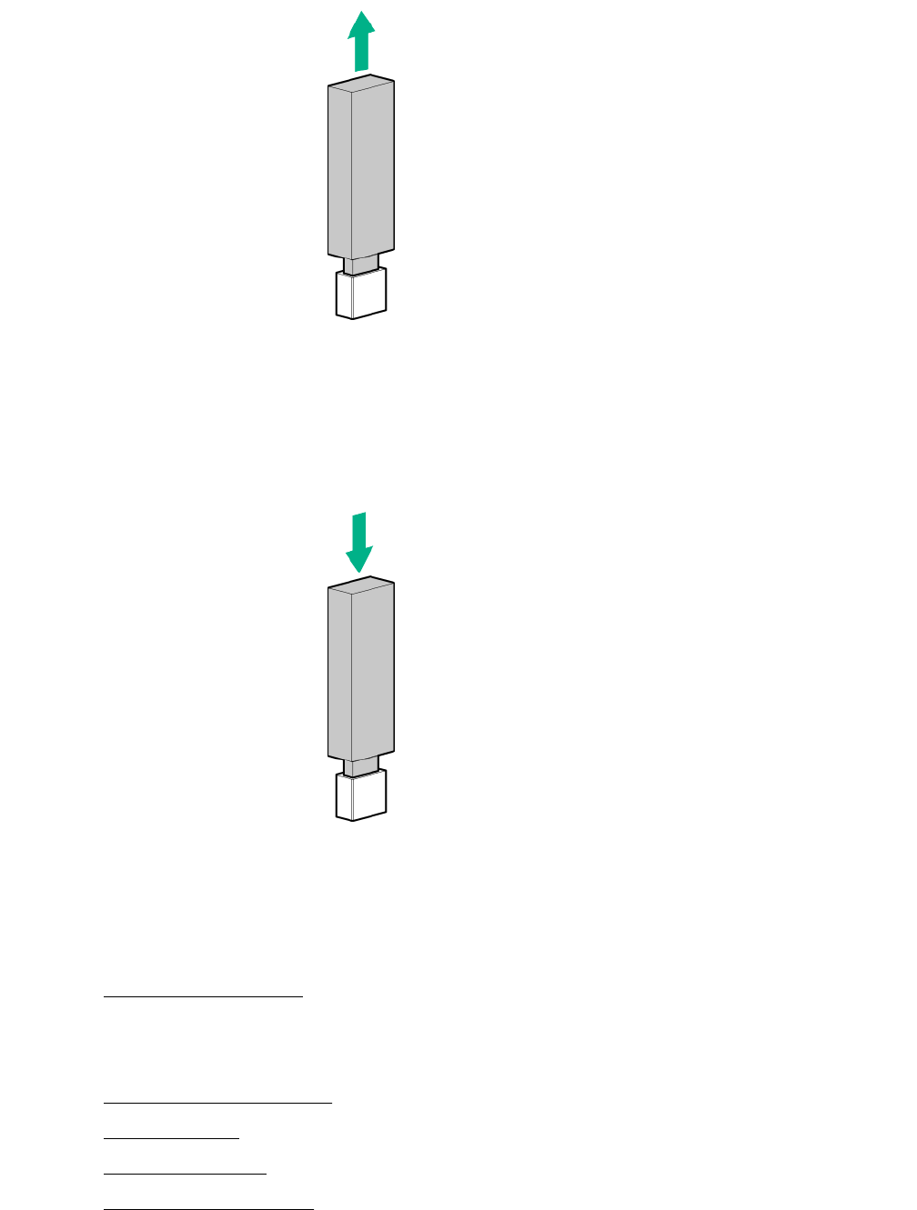
Install the internal USB device
Procedure
Plug the USB device into the internal USB port.
Replacing the fan
Procedure
1. Power down the server on page 22.
2. Disconnect the power cord from the AC source, and then from the server.
3. Disconnect all peripheral cables from the server.
4. Remove the chassis cover on page 25.
5. Remove the fan on page 58.
6. Install the new fan.
7. Install the chassis cover on page 28.
Install the internal USB device 57
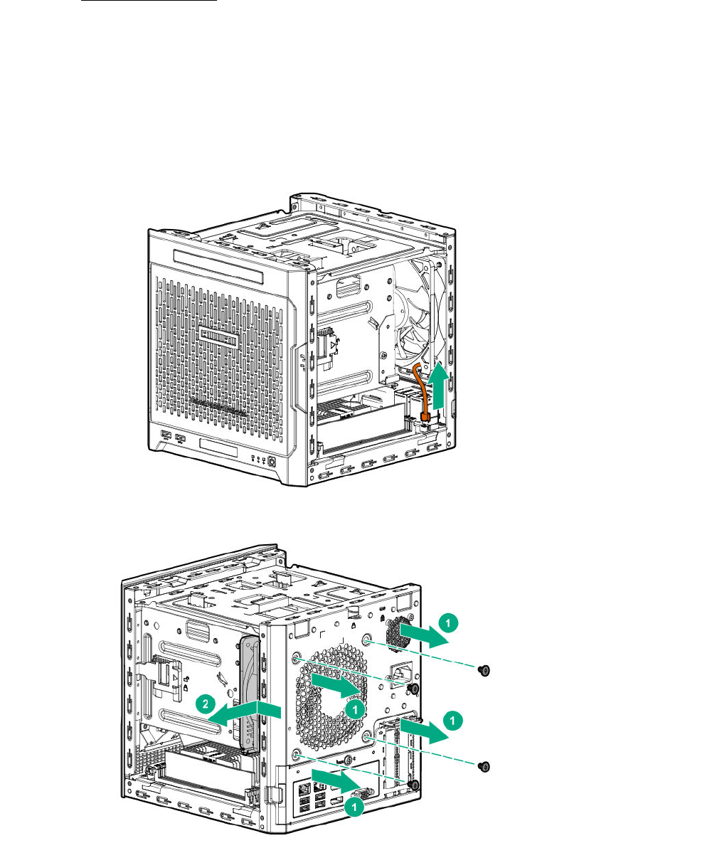
8. Connect all peripheral cables to the server.
9. Connect the power cord to the server power jack, and then to the AC source.
10. Power up the server on page 30.
Remove the fan
Prerequisites
Before you perform this procedure, make sure that you have a T-15 Torx screwdriver available.
Procedure
1. Disconnect the fan cable.
2. Remove the fan screws, and then remove the fan.
58 Remove the fan
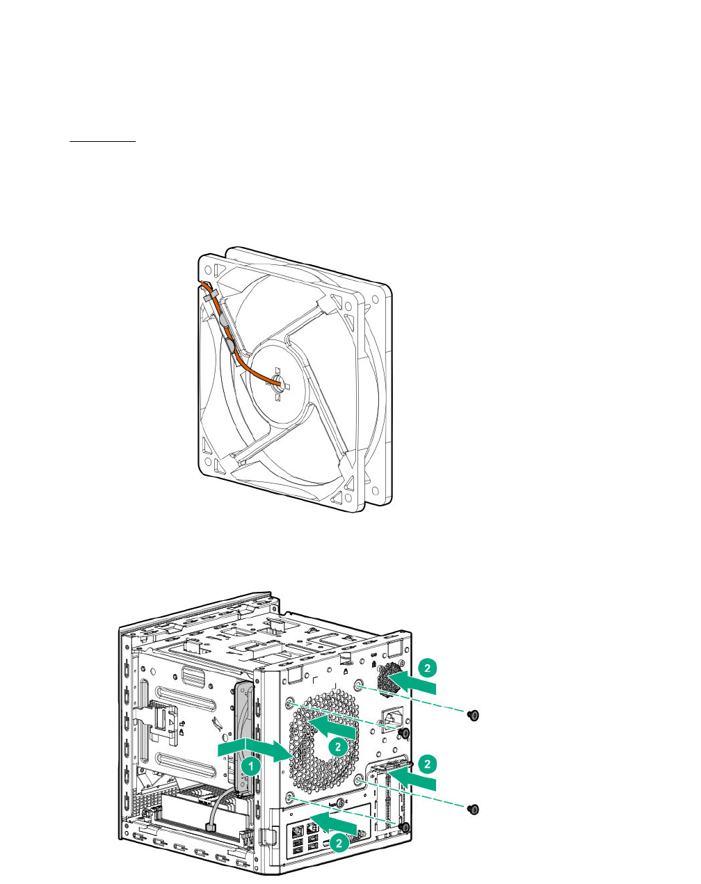
Install the fan
Prerequisites
Before you perform this procedure, make sure that you have the following items available:
• T-15 Torx screwdriver
•Fan spare
Procedure
1. Ensure that the fan cable is secured on the tabs located on the rear side of the fan.
2. With the fan label facing the rear panel, hold the fan against its position on the rear of the chassis, and
then secure it with the screws.
3. Connect the fan cable.
Install the fan 59
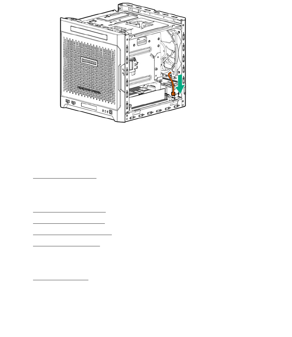
Replacing the power supply
Procedure
1. Power down the server on page 22.
2. Disconnect the power cord from the AC source, and then from the server.
3. Disconnect all peripheral cables from the server.
4. Remove the chassis cover on page 25.
5. Remove the power supply on page 60.
6. Install the new power supply.
7. Install the chassis cover on page 29.
8. Connect all peripheral cables to the server.
9. Connect the power cord to the server power jack, and then to the AC source.
10. Power up the server on page 30.
Remove the power supply
Prerequisites
Before you perform this procedure, make sure that you have T-15 Torx screwdriver available.
Procedure
1. Disconnect the power supply cables:
60 Replacing the power supply
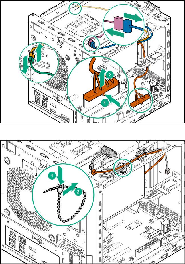
• On the left side of the chassis, disconnect the 24-pin power supply cable from the system board.
• If an ODD or SSD is installed in the media bay, disconnect the P3 power supply cable from that
drive power connector.
• On right side of the chassis, disconnect the P2 power supply cable from the LFF/SFF drive power
connector.
2. Open the cables tie securing the P3 power supply cable, and then release the cable.
3. Pull out all the power supply cables towards the left side of the chassis.
Removal and replacement procedures 61
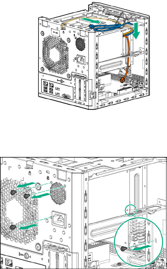
4. Remove the power supply screws:
• Three screws on the rear panel
• One screw on the power supply bracket
5. Remove the power supply:
a. Press a finger against the power jack to push the power supply from the rear panel wall.
b. Slide the power supply towards the front side of the server until the power supply bracket is
disengaged from the chassis.
c. Remove the power supply from the power supply bay.
62 Removal and replacement procedures
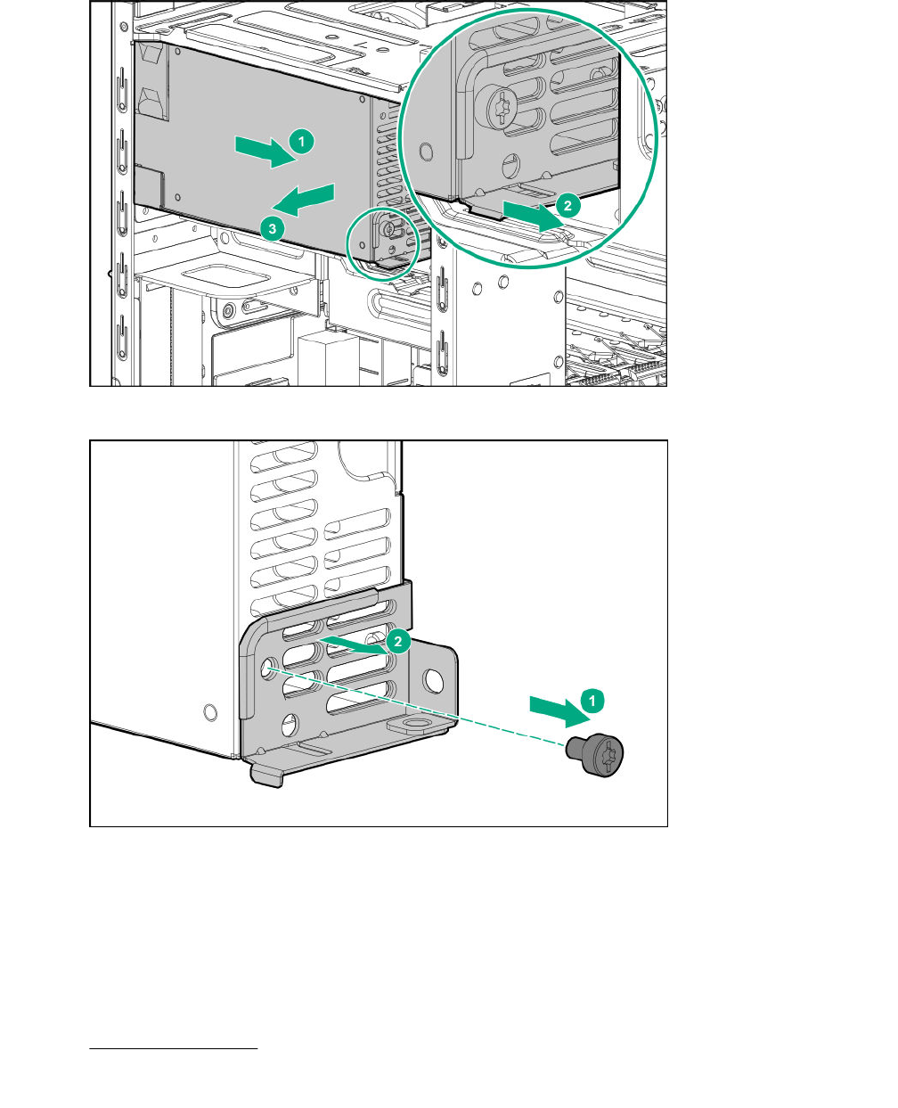
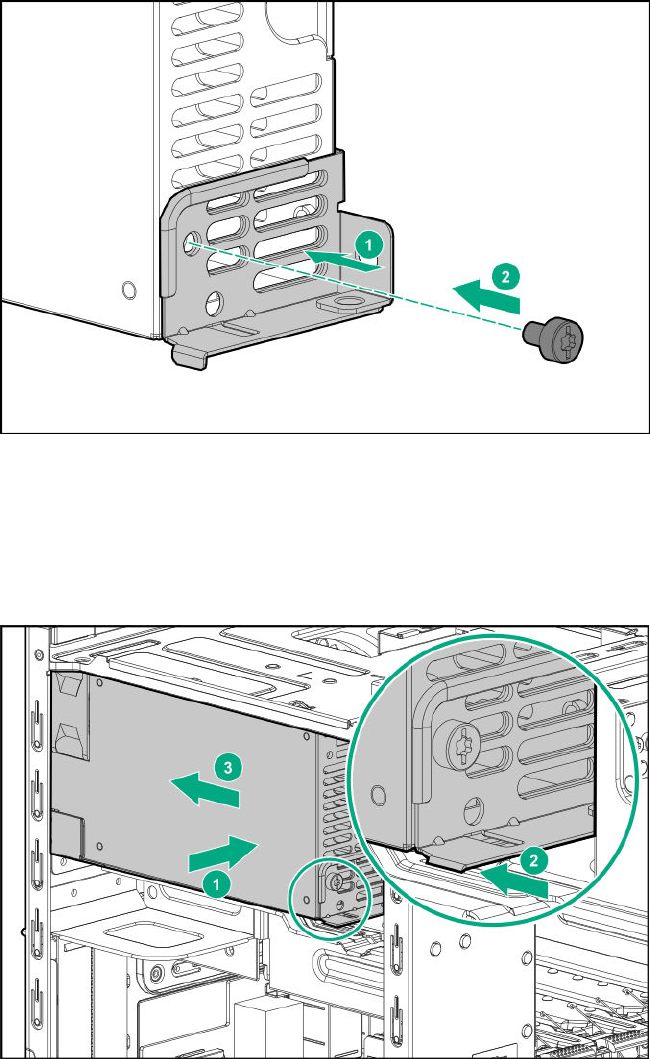
2. Install the power supply:
a. Install the power supply in the power supply bay.
b. Ensure that the power supply bracket is engaged in the chassis.
c. Slide the power supply towards the rear panel wall.
3. Install the power supply screws:
• Three screws on the rear panel
• One screw on the power supply bracket
64 Removal and replacement procedures
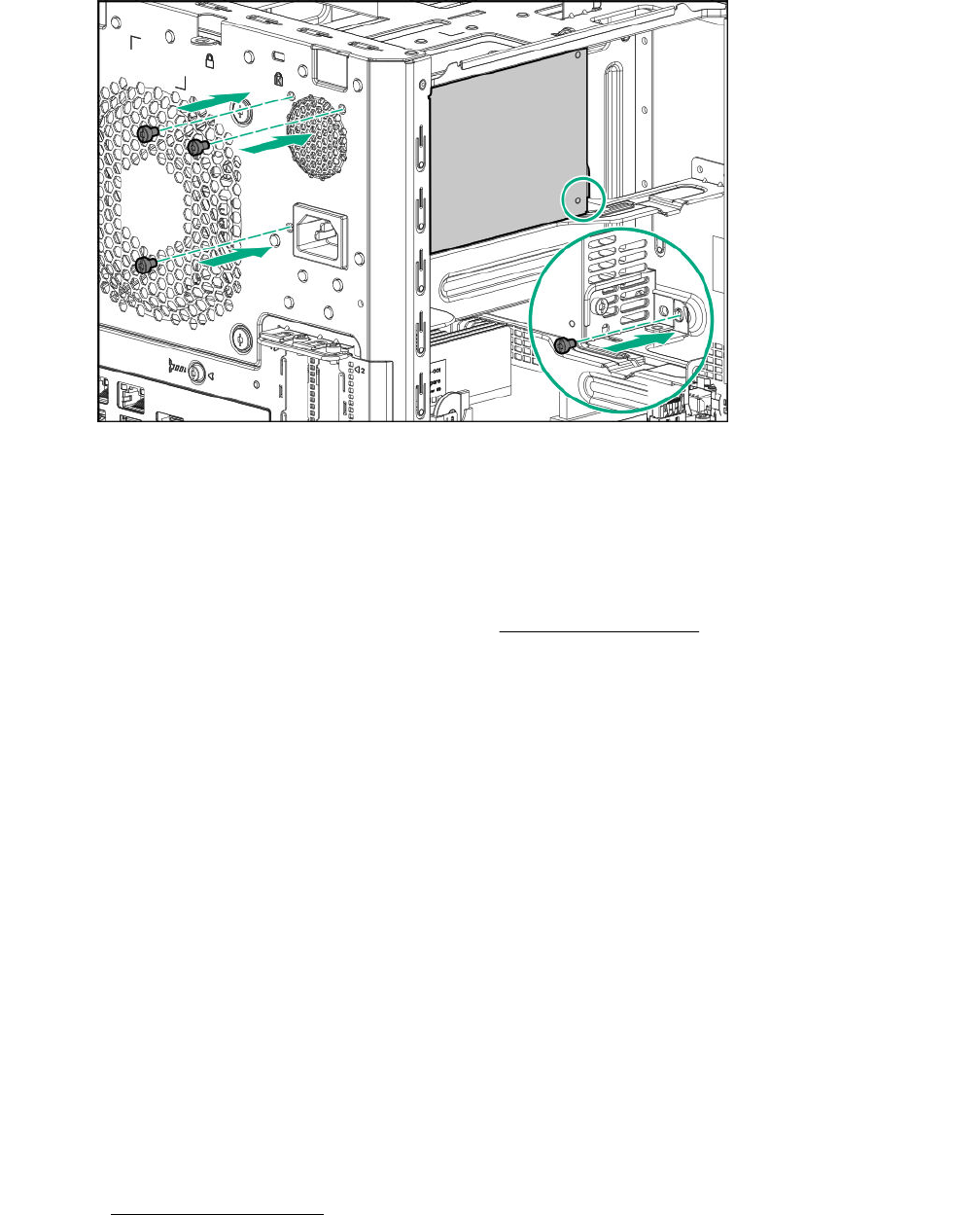
4. Connect the power supply cables:
a. Route the power supply cables through their respective chassis openings.
b. Connect the power supply cables to their respective cable connectors.
c. Bundle the extra length of the P3 power supply cable in the cable ties located on the top chassis.
For a detailed view of these cable routing, see Power supply cabling.
System battery replacement
System battery information
The server contains an internal lithium manganese dioxide, a vanadium pentoxide, or an alkaline battery
that provides power to the real-time clock. If this battery is not properly handled, a risk of the fire and
burns exists. To reduce the risk of personal injury:
• Do not attempt to recharge the battery.
• Do not expose the battery to temperatures higher than 60°C (140°F).
• Do not disassemble, crush, puncture, short external contacts, or dispose the battery in fire or water.
• If the server no longer automatically displays the correct date and time, then replace the battery that
provides power to the real-time clock. Under normal use, battery life is 5 to 10 years.
Replacing a system battery
Procedure
1. Power down the server on page 22.
2. Disconnect the power cord from the AC source, and then from the server.
3. Disconnect all peripheral cables from the server.
System battery replacement 65
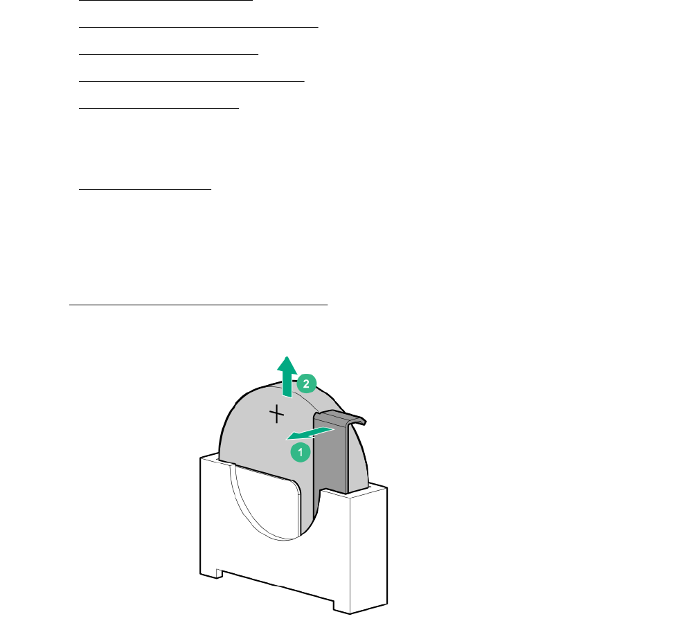
4. Remove the chassis cover on page 25.
5. Remove the system board assembly on page 25.
6. Replace the system battery on page 66.
7. Install the system board assembly on page 27.
8. Install the chassis cover on page 28.
9. Connect all peripheral cables to the server.
10. Connect the power cord to the server power jack, and then to the AC source.
11. Power up the server on page 30.
Replace the system battery
Procedure
1. Locate the battery on the system board.
2. Slightly push the metal tab, and then remove the system battery from its socket.
3. Slightly push the metal lab, and then install the new system battery in the socket.
66 Replace the system battery
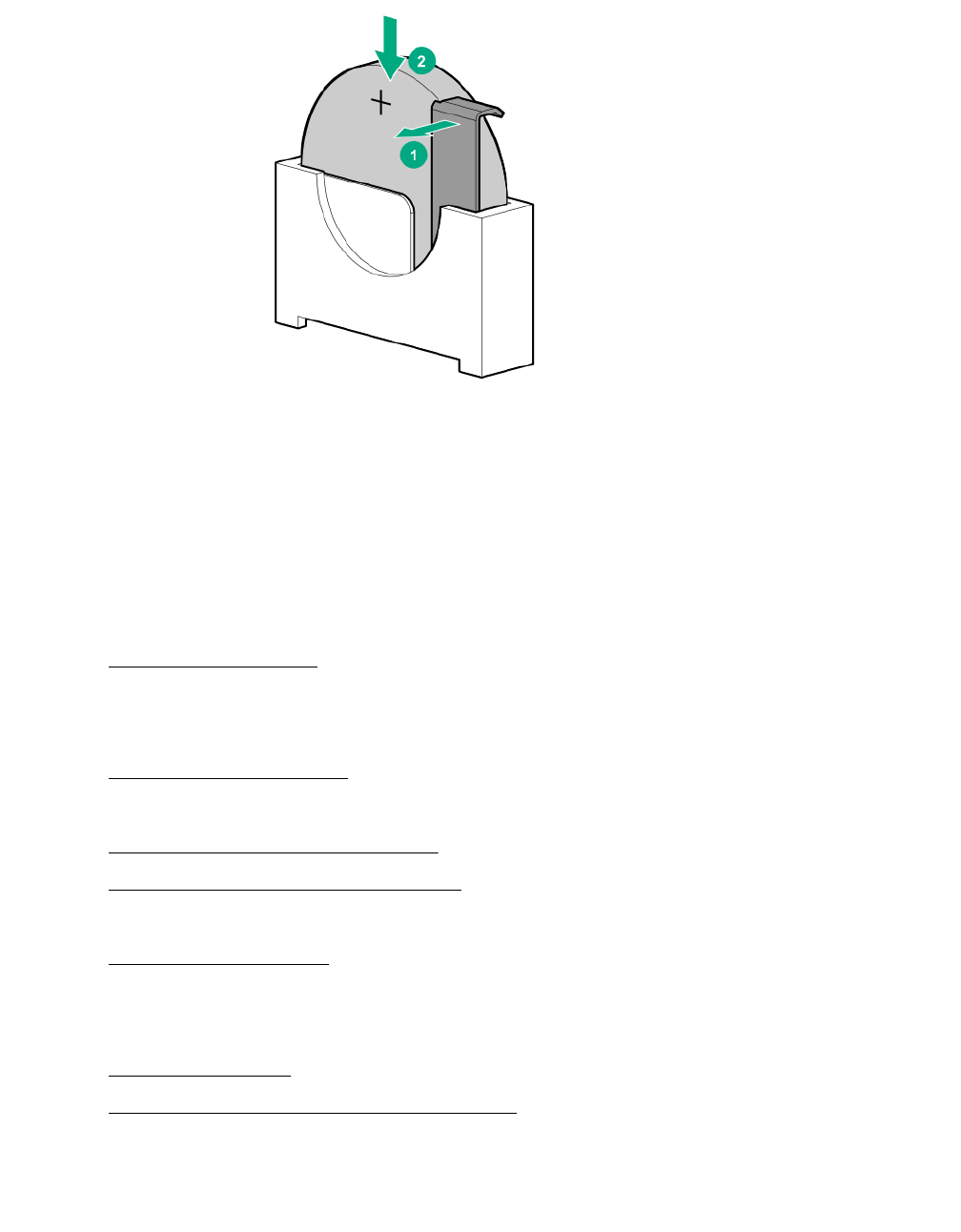
For more information about battery replacement or proper disposal, contact an authorized reseller or an
authorized service provider.
Replacing the system board assembly
Procedure
1. Power down the server on page 22.
2. Disconnect the power cord from the AC source, and then from the server.
3. Disconnect all peripheral cables from the server.
4. Remove the chassis cover on page 25.
5. If installed, remove the internal USB device.
6. Remove the system board assembly on page 67.
7. Install the new system board assembly.
8. If removed, install the internal USB device.
9. Install the chassis cover on page 29.
10. Connect all peripheral cables to the server.
11. Connect the power cord to the server power jack, and then to the AC source.
12. Power up the server on page 30.
13. Re-enter the system serial and SKU numbers.
Remove the system board assembly
Prerequisites
Before you perform this procedure, make sure that you have a T-15 Torx screwdriver available.
Replacing the system board assembly 67
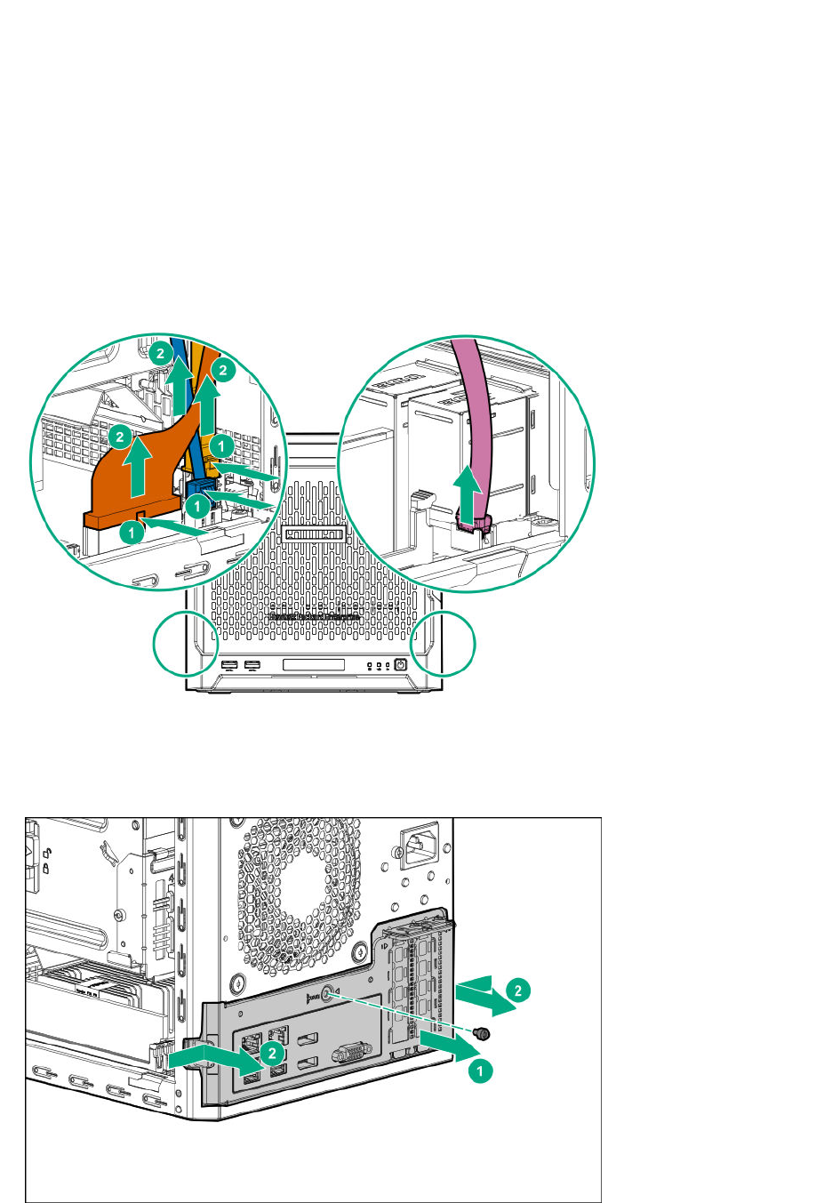
Procedure
1. To serve as a reference for system cable connections when the system board assembly is installed
back into the server, take a picture of the current system board cable connections.
2. Disconnect the following system cables:
• Power supply cable
• Optical drive or SSD SATA cable (optional)
• LFF/SFF drive SATA cable – This cable can either be connected to the system board or to an
installed Smart Array controller board
• Fan cable
3. Remove the system board assembly screw.
4. Place the finger in the notch on the either side of the system board tray assembly, and then pull out the
assembly.
68 Removal and replacement procedures
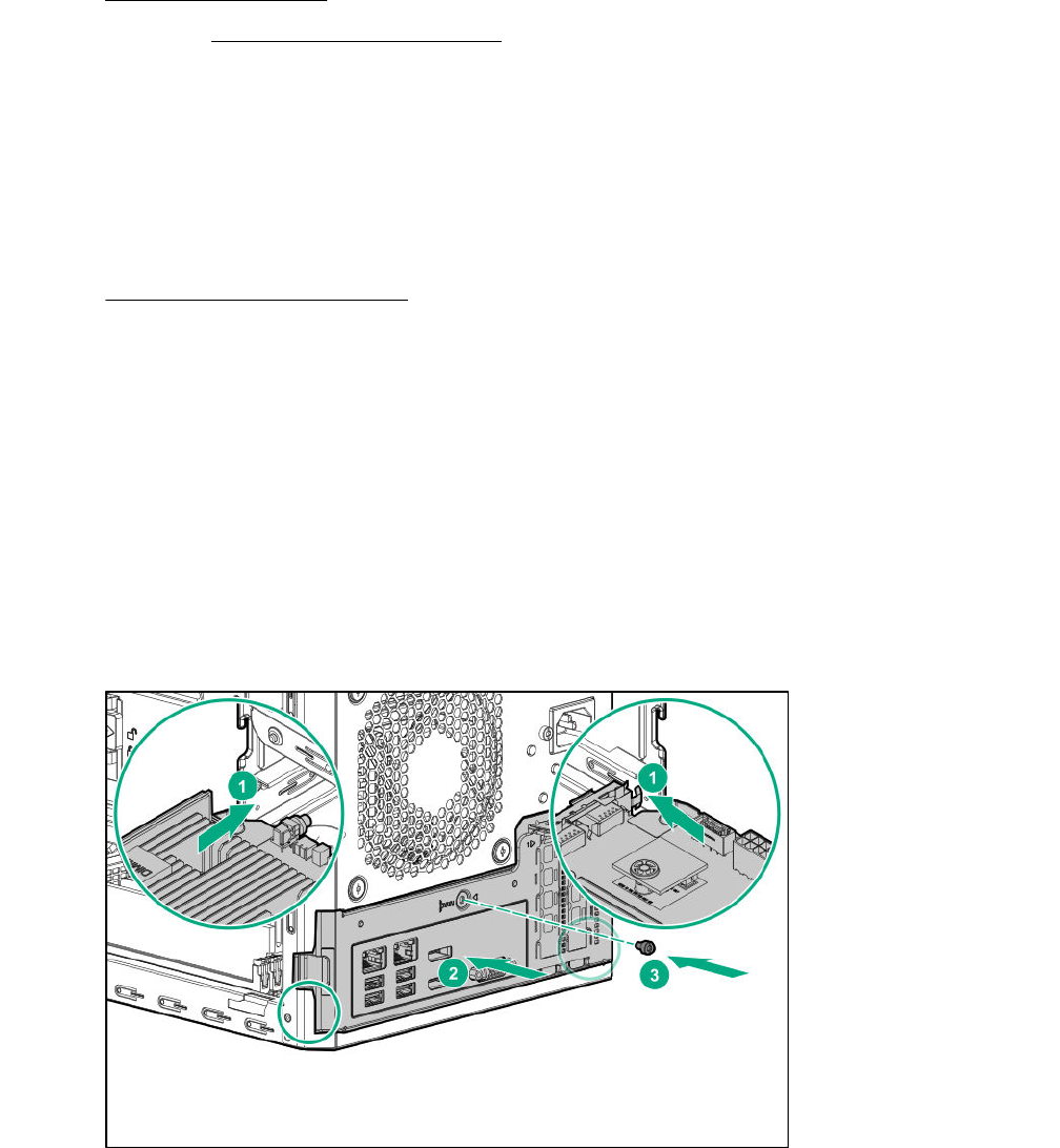
5. Remove all the DIMMs.
6. If installed, remove all expansion boards.
Install the system board assembly
Prerequisites
Before you perform this procedure, make sure that you have the following items available:
• T-15 Torx screwdriver
•System board assembly spare
Procedure
1. Install the components removed from the old system board on the new system board spare. This
might include one or more of the following:
• DIMMs
• Expansion boards
2. Slide the system board assembly into the chassis.
3. Press against the system board assembly until it clicks into place.
4. Install the system board assembly screw.
5. Connect the following system cables:
• Power supply cable
• Optical drive or SSD SATA cable (optional)
Install the system board assembly 69
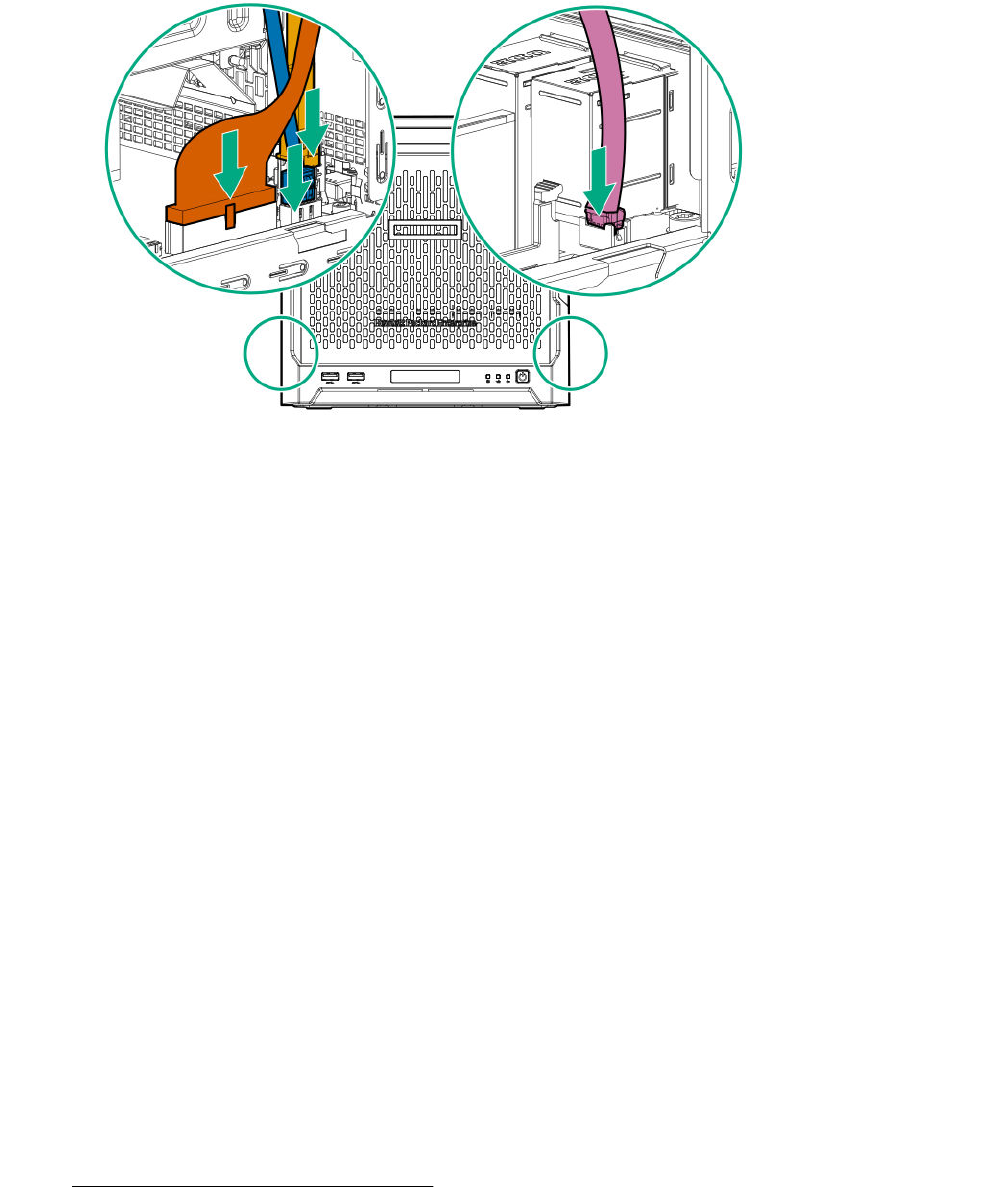
• LFF/SFF drive SATA cable - This cable can either be connected to the system board or to an
installed Smart Array controller board
• Fan cable
Re-entering the system serial and SKU numbers
The system serial number (S/N) and SKU number (PID) are visible on the label located above the fan
ventilation holes on the rear panel.
Procedure
1. To access the Aptio Setup Utility, on the enter setup prompt, press the F2 or Del key.
2. Select Advanced > View FRU Information, and then press the Enter key.
3. Select System Serial Number, and then press the Enter key.
4. Enter the serial number, and then press the Enter key
This serial number should always match the system serial number located on the chassis.
5. Select System SKU Number, and then press the Enter key.
6. Enter the system SKU number, and then press the Enter key.
This SKU number should always match the system SKU number located on the chassis.
7. To confirm the changes and exit the utility, press the F4 key.
The server automatically reboots.
Replacing the external RDX backup system
This server supports several RDX backup system spare parts. For more information on replacing these
parts, see the Storage section of the Hewlett Packard Enterprise Information Library:
http://www.hpe.com/info/storage/docs
70 Re-entering the system serial and SKU numbers

HP Trusted Platform Module
The TPM is not a customer-removable part.
CAUTION: Any attempt to remove an installed TPM from the system board breaks or disfigures the
TPM security rivet. Upon locating a broken or disfigured rivet on an installed TPM, administrators
should consider the system compromised and take appropriate measures to ensure the integrity of
the system data.
If you suspect a TPM board failure, leave the TPM installed and remove the system board. Contact a
Hewlett Packard Enterprise authorized service provider for a replacement system board and TPM board.
HP Trusted Platform Module 71

Troubleshooting
Troubleshooting resources
Use the following resources for troubleshooting the system:
• For information on resolving common problems, comprehensive courses of action for fault isolation
and identification, issue resolution, and software maintenance, see the HPE ProLiant MicroServer
Gen10 at:
http://www.hpe.com/info/gen10-troubleshooting
• For information on the latest server download options, issue resolutions, user documentation, and
product advisories, see the HPE ProLiant MicroServer Gen10 support page at:
http://www.hpe.com/support/microservergen10
72 Troubleshooting

Diagnostic tools
Product QuickSpecs
For more information about product features, specifications, options, configurations, and compatibility, see
the product QuickSpecs on the HPE ProLiant MicroServer Gen10 website:
http://www.hpe.com/servers/microserver
Aptio Setup Utility
The Aptio Setup Utility is embedded in the system ROM. This utility enables you to perform a wide range
of configuration activities, including the following:
• Configuring system devices and installed options
• Enabling and disabling system features
• Displaying system information
• Selecting the primary boot controller
• Configuring memory options
Using the Aptio Setup Utility
To use the Aptio Setup Utility, use the following keys:
Key Action
F2 or Del (during POST) Access the Aptio Setup Utility.
Left and right arrows Navigate the menus.
Up and down arrows Navigate menu items.
Enter Select menu items.
F4 Save selections and exit the utility.
F1 Access help for the highlighted configuration
option.
Esc Exit the utility.
Default configuration settings are applied to the server in either of the following scenarios:
• When the system powers up for the first time
• When the system is restored to the default settings
Default configuration settings are sufficient for typical server operations. However, you can modify the
configuration settings as needed. The system prompts you to access the Aptio Setup Utility every time
the system is powered up.
Restoring and customizing configuration settings
The following options are available for restoring or customizing the configuration settings:
Diagnostic tools 73
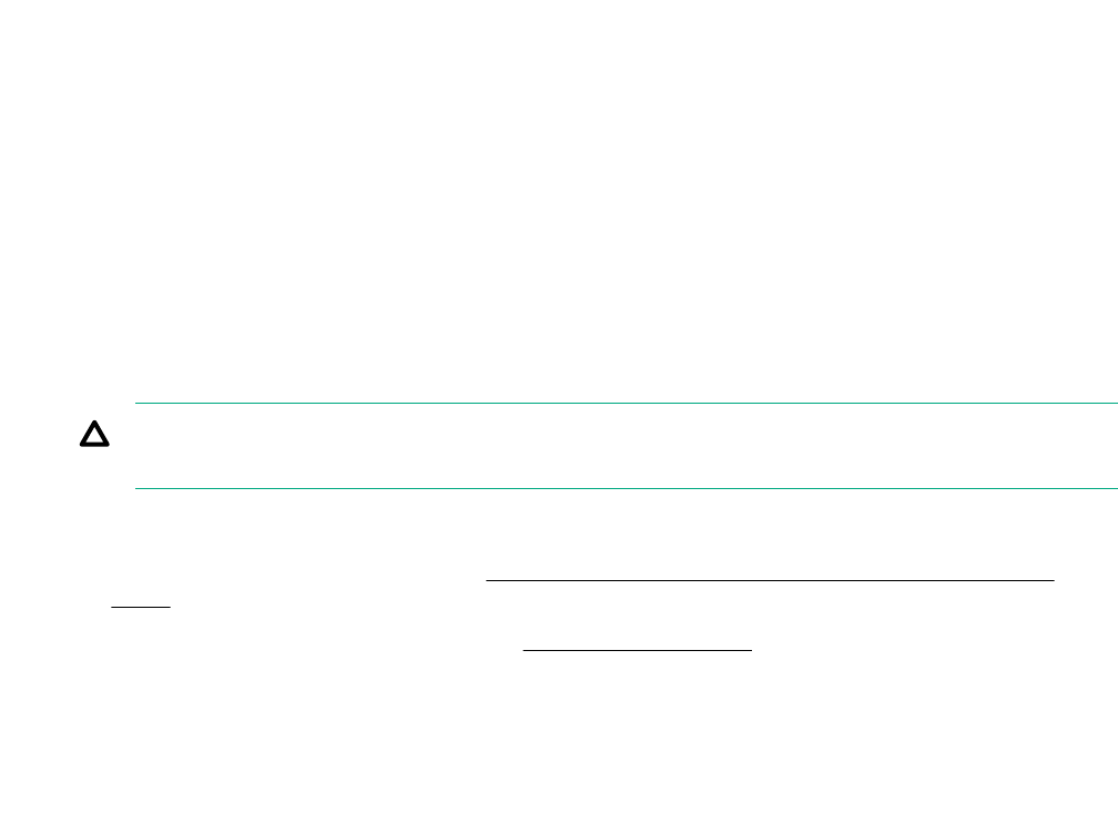
• Reset all configuration settings to the factory default settings.
• Restore and use the system default configuration settings.
• Configure default settings as necessary, and then save the configuration as the user default
configuration.
• Restore the user default configuration.
To restore the user default configuration, select Save & Exit > Default Option > Restore User
Default.
Clearing the BIOS configuration settings
The server BIOS configuration settings such as the system date and time, boot sequence, and hardware
settings are stored in the CMOS. These settings are configured in the Aptio Setup Utility.
You might need to clear the CMOS if any of the following conditions occur:
• POST errors or boot issues
• Corrupted BIOS settings
• Incorrect settings made in the Aptio Setup Utility have caused error messages to be unreadable.
• If there is a hardware compatibility issue of a known compatible component.
• If the power-on password is forgotten.
CAUTION: Be careful when clearing or altering the BIOS settings. Changing some settings might
prevent the server from booting up correctly or might result in data loss.
Clearing the CMOS resets the BIOS settings to their factory default state. To clear the CMOS:
• If the Aptio Setup Utility is accessible, use the Restore Defaults option under the Save & Exit
menu.
• If the Aptio Setup Utility is not accessible, use the CMOS header.
After clearing the CMOS, use the Aptio Setup Utility to reconfigure the BIOS settings.
Clearing the BIOS settings by using the Aptio Setup Utility
Procedure
1. Reboot the server.
2. To access the Aptio Setup Utility, on the enter setup prompt, press the F2 or Del key.
3. Select the Save & Exit menu.
4. Under Default Options, select Restore Defaults, and then press the Enter key.
5. Select Yes.
6. To confirm the change and exit the utility, press the F4 key.
74 Clearing the BIOS configuration settings
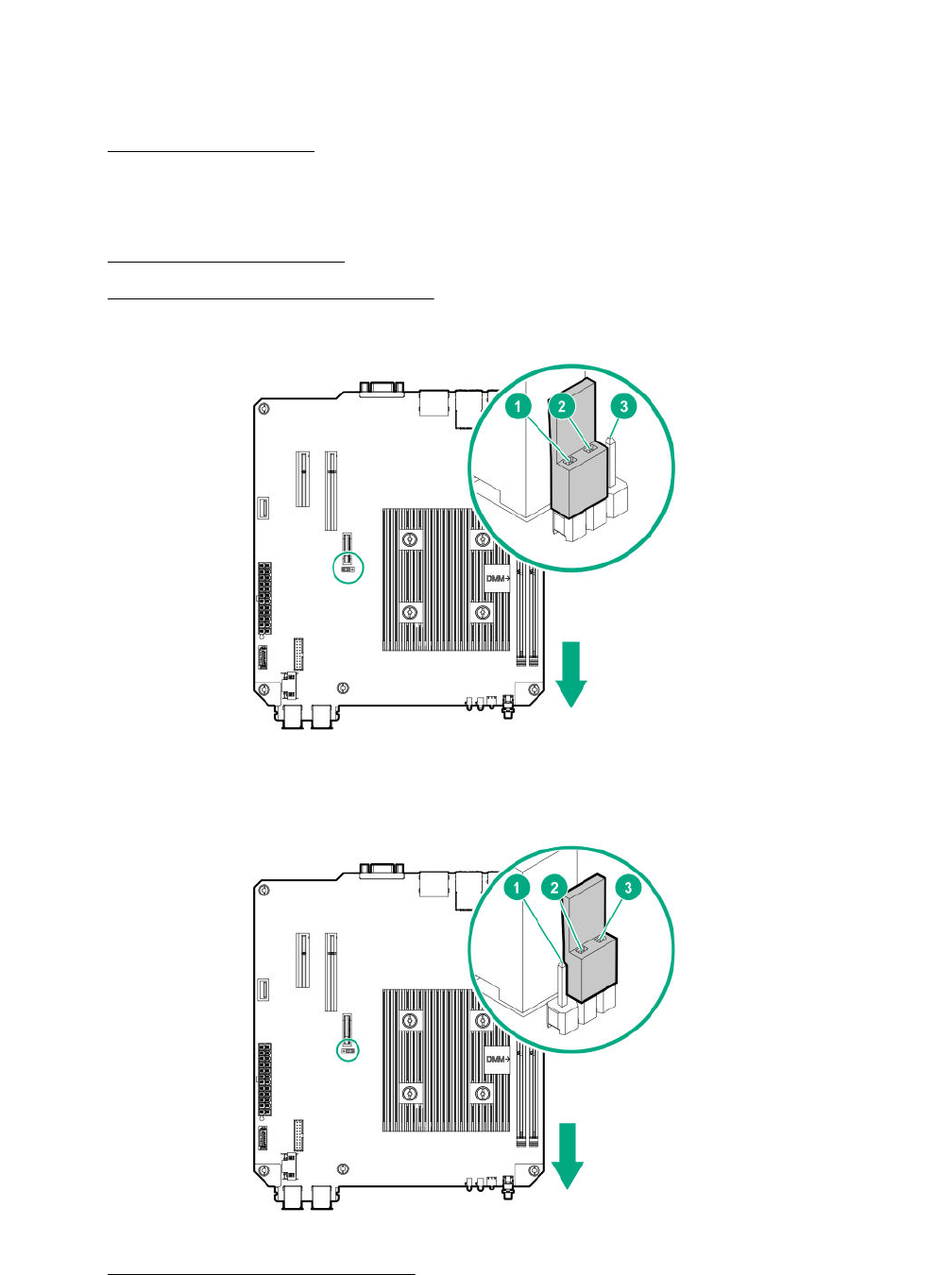
Clearing the BIOS settings by using the CMOS header
The arrow shown in the steps 6 and 7 illustrations points to the front of the server.
Procedure
1. Power down the server on page 22.
2. Disconnect the power cord from the AC source, and then from the server.
3. Disconnect all peripheral cables from the server.
4. Remove the chassis cover on page 25.
5. Remove the system board assembly on page 25.
6. Remove the jumper from its default position on pins 2 and 3, and place them on pins 1 and 2.
7. After five seconds, remove the jumper from pins 1 and 2, and move it back to the default position on
pins 2 and 3.
8. Install the system board assembly on page 27.
Clearing the BIOS settings by using the CMOS header 75

9. Install the chassis cover on page 29.
10. Connect all peripheral cables to the server.
11. Connect the power cord to the server power jack, and then to the AC source.
12. Power up the server on page 30.
Marvell Storage Utility
The Marvell Storage Utility (MSU) is a configuration and management utility for the embedded Marvell
88SE9230 PCIe to SATA 6Gb/s Controller. This Marvell storage controller supports hardware RAID 0, 1,
and 10 levels. Use the MSU to create and manage RAID virtual disks and arrays using the drives
connected to the embedded storage controller.
To enable MSU access through GUI or CLI, install the MSU in the server.
For more information, see the Marvell Storage Utility User Guide for HPE MicroServer Gen10 in the
Hewlett Packard Enterprise Support Center website:
http://www.hpe.com/info/microservergen10-docs
Installing the Marvell Storage Utility
Procedure
1. Go to the HPE ProLiant MicroServer Gen10 download page:
http://www.hpe.com/downloads/microservergen10
2. Click drivers, software & firmware.
3. Select the server OS from the operating system drop-down menu.
4. Click Utility.
5. Download the Marvell Storage Utility (MSU) for HPE MicroServer Gen10 Server
package to the target server.
6. Unzip the package and open the Marvell_MSU folder.
7. Follow the installation procedure described in the instructions.txt file.
Marvell BIOS Utility
The Marvell BIOS Utility (MBU) is built into the ROM of the embedded Marvell 88SE9230 PCIe to SATA
6Gb/s Controller. This Marvell storage controller supports the hardware RAID 0, 1, and 10 levels. Use the
MBU to create and manage RAID virtual disks and arrays using the drives connected to the embedded
storage controller.
For more information, see the Marvell BIOS Utility User Guide for HPE MicroServer Gen10 in the Hewlett
Packard Enterprise Support Center website:
http://www.hpe.com/info/microservergen10-docs
Accessing the Marvell BIOS Utility under UEFI boot mode
The UEFI boot mode is the server default boot mode.
76 Marvell Storage Utility
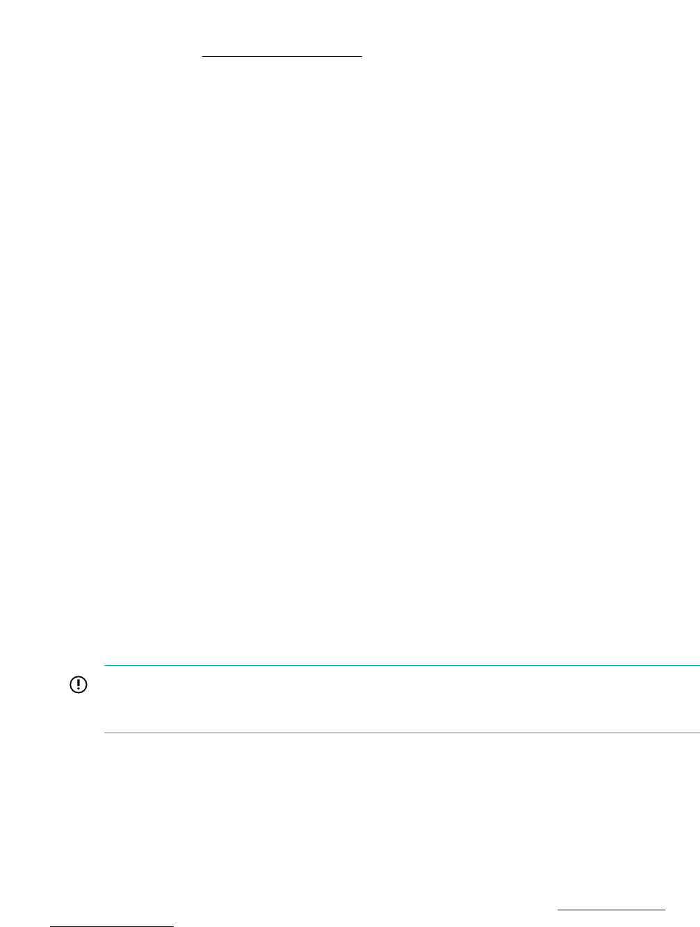
Prerequisites
Accessing the MBU using the RAID command in the UEFI Shell prompt requires system BIOS version
A330 or later. If needed, update the system BIOS.
Procedure
1. Reboot the server.
2. To access the One-Time Boot Menu, press the F11 key when prompted.
3. Select UEFI: Built-in EFI Shell, and then press the Enter key.
4. At the Shell prompt, type RAID, and then press the Enter key.
Shell>RAID
Accessing the Marvell BIOS Utility under legacy boot mode
Procedure
1. Reboot the server.
2. On the POST drive information screen, press Ctrl+M.
HPE Smart Storage Administrator
HPE SSA is the main tool for configuring arrays on HPE Smart Array SR controllers. It exists in three
interface formats: the HPE SSA GUI, the HPE SSA CLI, and HPE SSA Scripting. All formats provide
support for configuration tasks. Some of the advanced tasks are available in only one format.
The diagnostic features in HPE SSA are also available in the standalone software HPE Smart Storage
Administrator Diagnostics Utility CLI.
During the initial provisioning of the server or compute module, an array is required to be configured
before the operating system can be installed. You can configure the array using SSA.
HPE SSA is accessible both offline (either through HPE Intelligent Provisioning or as a standalone
bootable ISO image) and online:
• Accessing HPE SSA in the offline environment
IMPORTANT: If you are updating an existing server in an offline environment, obtain the latest
version of HPE SSA through Service Pack for ProLiant before performing configuration
procedures.
Using one of multiple methods, you can run HPE SSA before launching the host operating system. In
offline mode, users can configure or maintain detected and supported devices, such as optional Smart
Array controllers and integrated Smart Array controllers. Some HPE SSA features are only available in
the offline environment, such as setting the boot controller and boot volume.
• Accessing HPE SSA in the online environment
This method requires an administrator to download the HPE SSA executables and install them. You
can run HPE SSA online after launching the host operating system.
For more information, see HPE Smart Array SR Gen10 Configuration Guide at the Hewlett Packard
Enterprise website.
Accessing the Marvell BIOS Utility under legacy boot mode 77

USB support
Hewlett Packard Enterprise servers support both USB 2.0 ports and USB 3.0 ports. Both port types
support installing all types of USB devices (USB 1.0, USB 2.0, and USB 3.0), but might run at lower
speeds in specific situations:
• USB 3.0 capable devices operate at USB 2.0 speeds when installed in a USB 2.0 port.
• In UEFI boot mode, Hewlett Packard Enterprise provides legacy USB support in the preboot
environment before the operating system loads for USB 1.0, USB 2.0, and USB 3.0 speeds.
• In legacy boot mode, Hewlett Packard Enterprise provides legacy USB support in the preboot
environment before the operating system loads for USB 1.0 and USB 2.0 speeds. USB 3.0 ports can
be used with all devices in legacy boot mode but are not available at USB 3.0 speeds in the preboot
environment. Standard USB support (USB support from within the operating system) is provided by
the OS through the appropriate USB device drivers. Support for USB 3.0 varies by operating system.
The pre-OS behavior of the USB ports is configurable in the Aptio Setup Utility.
Keeping the system current
Firmware
Firmware is a software program that is stored in the system ROM chip on the system board or to an
optional controller. Firmware controls the system when it is first powered on and then passes control to
the operating system.
The firmware on the system board of the server is called the system ROM or the BIOS. The firmware on
another piece of hardware configured in the server is called the option ROM.
Firmware update
Update the firmware (also called "flashing the ROM") as part of regular server maintenance. In addition,
check for specific firmware updates in between regular updates to help keep the server performing
optimally.
Firmware updates are created for, but are not limited to, the following reasons:
• To provide critical problem fixes that ensure system stability, such as upgrades that might prevent
server unresponsiveness and other issues that could put the system at risk.
• To correct product issues, such as ROM or processor functionality.
• To improve system performance or make the system more serviceable.
Server downtime and time spent removing, returning, and ultimately replacing hardware might be avoided
by first updating the firmware during the troubleshooting process. Many product issues that result in
hardware replacement are preventable or correctable with a firmware update. Hewlett Packard Enterprise
recommends checking for a firmware update before sending a part back to Hewlett Packard Enterprise
for replacement.
On servers that have add-on options, Hewlett Packard Enterprise recommends checking for firmware
upgrades for each installed option whenever an update to the system ROM or to another option is
performed. This ensures that the entire system is running the latest updates for each component.
Multiple methods exist to update the system ROM:
78 USB support

• EFI tool under Embedded UEFI Shell
• Online Flash components
Product entitlement is required to perform updates.
CAUTION: Any kind of system interruption during the firmware update results in errors that might
corrupt the BIOS settings. These errors prevent the server from booting up. To prevent these update
errors, observe the following cautions:
• Attach a UPS to the server to provide backup power to the system when updating the firmware.
• Do not perform a forced shutdown of the server .
• Do not perform a forced closure of the firmware update tool.
User default settings after BIOS update
When updating the system BIOS from version A320 (or earlier) to version A330 (or later), the following
system BIOS settings will revert to their factory default values:
• System time and date
• Drive configuration
• Boot device sequence
• System passwords
• Security setup
Before performing the BIOS update, manually record the user default values for these listed BIOS
settings so that they can be restored after completing the BIOS update.
Updating the system ROM using the EFI tool from within the Embedded UEFI Shell
For systems configured in UEFI boot mode, use the following procedure to update the firmware.
Procedure
1. Access the System ROM Flash component for your server from the Hewlett Packard Enterprise
Support Center website (http://www.hpe.com/support/hpesc) and save the package in a USB key.
2. Copy the file to a USB device.
3. Attach the USB device to the server .
4. To access the One-Time Boot Menu option, when prompted, press the F11 key.
5. Select UEFI: Built-in EFI Shell.
6. To obtain the assigned file system volume for the USB key, enter the map -r command at the UEFI
Shell prompt.
7. Change to the file system that contains the System ROM Flash Binary file that you downloaded for
your server . Enter one of the fsx file systems available, such as fs0 or fs1, and then press the
Enter key.
If no other storage devices are mounted on the system, the USB drive is fs0: on the UEFI shell.
User default settings after BIOS update 79
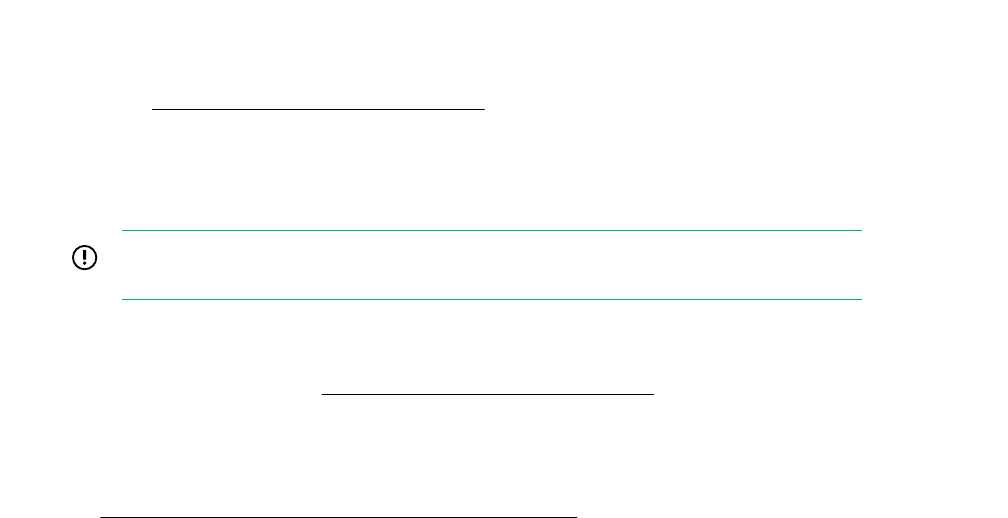
8. To change from the current directory to the directory that contains the binary file, enter the cd
command.
9. To flash the system ROM from the downloaded binary file, enter the flashbios.nsh command.
10. Reboot the server .
A reboot is required after the firmware update in order for the updates to take effect and for hardware
stability to be maintained.
Online Flash components
Online Flash components provide updated system firmware that can be installed directly on supported
operating systems. To download this component, go to the Hewlett Packard Enterprise Support Center
website (http://www.hpe.com/support/hpesc). Under Select your HPE product, enter the product
name or number, and then click Go. To update the firmware, follow the instructions inside the firmware
update package. The firmware update takes effect after rebooting the server.
Drivers, firmware, and software updates
IMPORTANT: Always perform a backup before installing or updating device drivers.
• For the latest option ROM and driver updates for Hewlett Packard Enterprise hardware options,
download the individual drivers, firmware, and components from the Hewlett Packard Enterprise
Support Center website (http://www.hpe.com/support/hpesc). Under Select your HPE product,
enter the product name or number, and then click Go.
• For the latest system ROM and other systems software components, download the individual drivers,
firmware, and components from the server download page on the Hewlett Packard Enterprise website:
http://www.hpe.com/downloads/microservergen10
80 Online Flash components
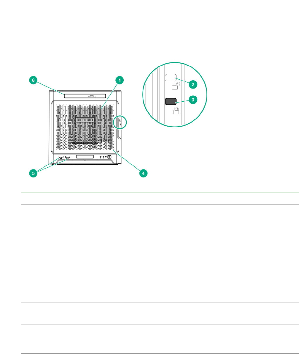
Component identification
This chapter describes the external and internal server features and components.
Front panel components
Item Component Description
1 Drive bays (4, behind the front
bezel)
By default, the drive bays support 3.5-inch LFF SATA
drives.
To support 2.5-inch SFF drives, install the SFF drive
converter option.
2 Front bezel unlock indicator To remove the front bezel from the chassis, this groove
must show the blue indicator.
3 Front bezel lock indicator To lock the front bezel in the chassis, this groove must show
the blue indicator.
4 Front bezel To access the front drive bays, remove this bezel.
5 USB 3.0 ports (2) Connect USB 3.0 devices to these ports. USB 3.0 support
after POST varies by operating system.
6 Media bay When the relevant enablement options kits are installed,
this bay supports either a slim-type optical disc drive or
solid state drive option.
Component identification 81
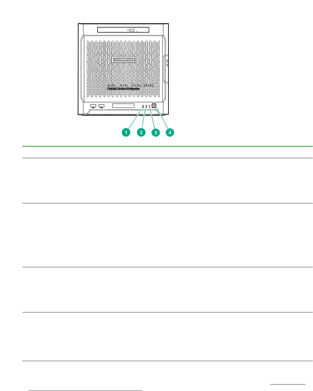
Front panel LEDs and buttons
Item Description Status
1 Drive activity LED Flashing green = Ongoing drive activity
Off = No drive activity
This LED only reflects the status of LFF/SFF drives and SSD
that are connected to the onboard SATA ports.
2 NIC status LED Solid green = Linked to network
Flashing green = Network active
Off = No network activity
This LED only reflects the status of Ethernet connections
managed by the embedded Broadcom BCM5720 Gigabit
Ethernet controller.
3 Health LED Solid green = Normal
Flashing amber = One or more components is in degraded
condition.1
Flashing red = One or more components is in critical condition.1
4 Power on/Standby button and
system power LED
Flashing green = Ongoing power-on sequence
Solid green = System on and normal operation
Amber = System in standby
Off = No power present2
1 To identify which component is in the degraded or critical state, reboot the server. A POST error message screen
showing the affected component will appear for about 30 seconds. Depending on how critical the component health
status is, the system boot may or may not be completed. For troubleshooting information, see the HPE ProLiant
MicroServer Gen10 Troubleshooting Guide.
82 Front panel LEDs and buttons
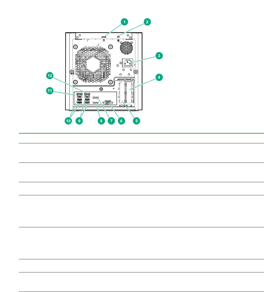
2 If the server does not power on, verify the following items:
• The site power is available.
• The power cord is properly connected to the server power jack and to a working power source.
• The internal power supply cable is properly connected to the system board.
Rear panel components
Item Component Description
1 Padlock eye To lock the chassis cover and prevent access to the internal
components, attach a padlock here.
2 Kensington security slot To secure the server to a heavy or immovable object,
connect an anti-theft security cable here.
3 Power jack Connects the power cord.
4 Expansion slot 2, PCIe3 ×4 (1) For additional hardware capabilities, install a compatible
low‑profile PCIe expansion board here. This expansion slot
supports expansion boards with a physical connector link
widths of up to ×16.1
5 Expansion slot 1, PCIe3 ×8 (8, 4,
1)
For additional hardware capabilities, install a compatible
low‑profile PCIe expansion board here. This expansion slot
supports expansion boards with a physical connector link
widths of up to ×16.1
6 Video port Connects to an analog VGA monitor or projector.
7 Display port 1 Connects to a digital display device, such as a high-
resolution set top boxes or TV displays.2
Table Continued
Rear panel components 83
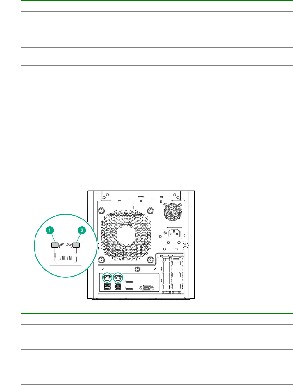
Item Component Description
8 Display port 2 Connects to a digital display device, such as a high-
resolution set top boxes or TV displays.2
9 USB 2.0 ports (2) Connect USB 2.0 devices to these ports.
10 USB 3.0 ports (2) Connect USB 3.0 devices to these ports. USB 3.0 support
after POST varies by operating system.
11 NIC port 1 (1 Gb) Connect an Ethernet cable here to connect the server to a
wired network.3
12 NIC port 2 (1 Gb) Connect an Ethernet cable here to connect the server to a
wired network.3
1 This expansion slot is open-ended, which enables down-plugging. Down-plugging means a larger-width expansion
board can be installed in a smaller-width connector. For this server, the expansion slot supports low-profile expansion
boards with a physical connector link width of up to ×16. The board operates at the highest common negotiable link
width specified for the slot.
2 To support 4K resolution at a full 60 Hz frame rate, this Display port requires dual-channel memory configuration.
Single-channel memory configuration will only support up to 30 Hz frame rate.
3 This NIC port supports 10/100/1000 Mbps data transfer rate per port.
Rear panel LEDs
Item Description Status
1 NIC link LED Solid green = Link exists
Off = No link exists
2 NIC status LED Solid green = Linked to network
Flashing green = Network active
Off = No network activity
84 Rear panel LEDs
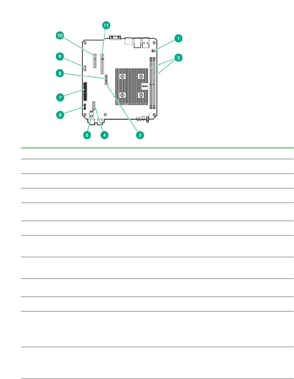
System board components
Item Component Description
1 Fan connector Connects the fan cable.
2 DIMM slots These slots support standard UDIMMs with ECC only.
3 CMOS header Use the jumper on this header to clear the CMOS.
4 TPM connector This connector supports the TPM 2.0 option for data security
solution.
5 LFF/SFF drive SATA port Connects the LFF/SFF drive SATA cable.1
6 Optical drive or SSD
SATA port
Connects the optical drive or SSD SATA cable.1
7 System board power
connector
Connects the power supply cable.
8 System battery This battery provides power to the server real-time clock and BIOS
settings.
9 Internal USB 2.0 port Connect internal USB devices to this port.
10 Expansion slot 2, PCIe3
×4 (1)
For additional hardware capabilities, install a compatible low-profile
PCIe expansion board here. This expansion slot supports
expansion boards with a physical connector link widths of up to
×16.2
11 Expansion slot 1, PCIe3
×8 (8, 4, 1)
For additional hardware capabilities, install a compatible low-profile
PCIe expansion board here. This expansion slot supports
expansion boards with a physical connector link widths of up to
×16.2
1 These are SATA 6Gb/s ports.
System board components 85
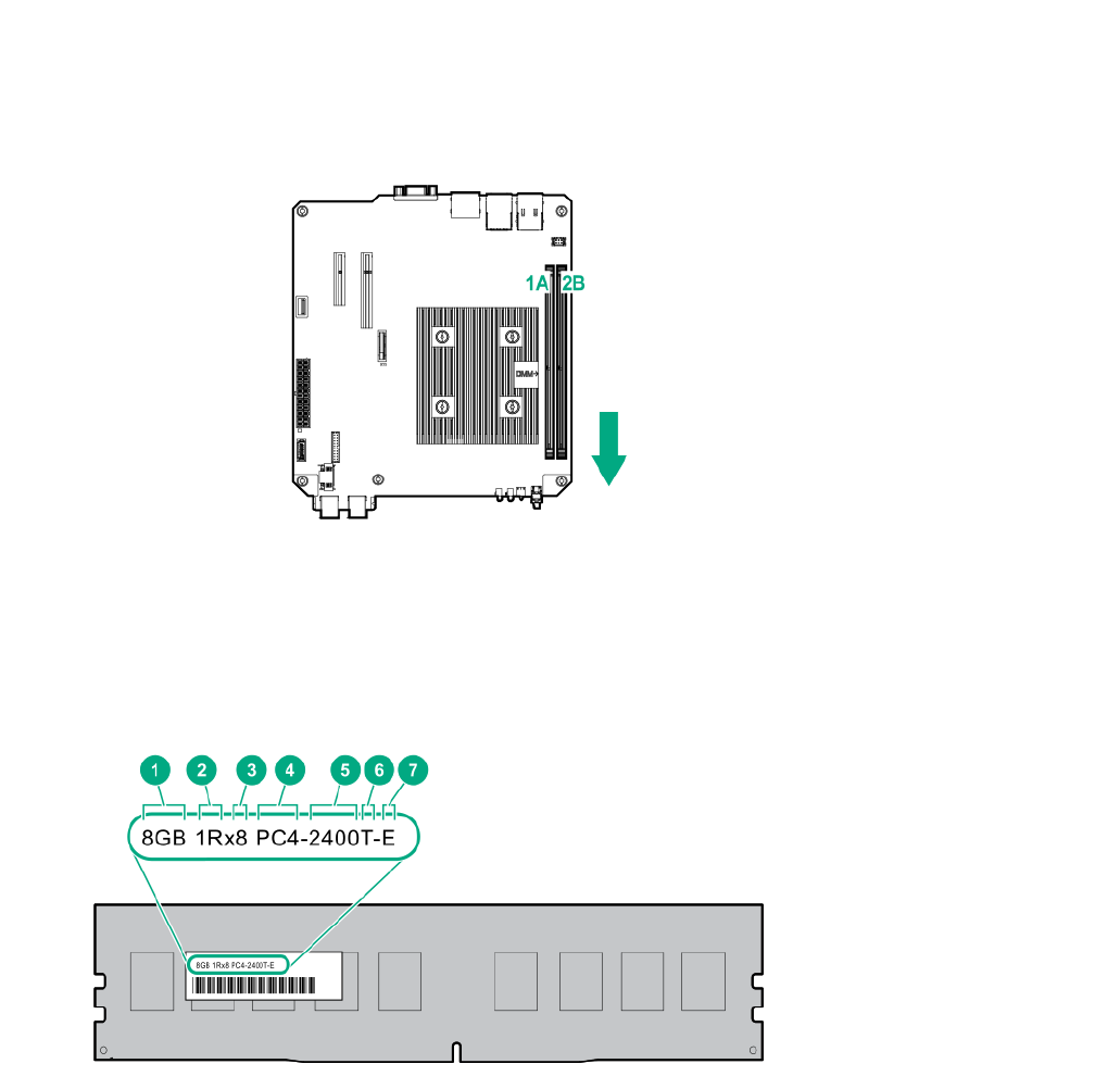
2 This expansion slot is open-ended, which enables down-plugging. Down-plugging means a larger-width expansion
board can be installed in a smaller-width connector. For this server, the expansion slot supports low-profile expansion
boards with a physical connector link widths of up to ×16. The board operates at the highest common negotiable link
width specified for the slot.
DIMM slot locations
The DIMM slots are numbered 1 and 2. The arrow in the following illustration points to the front of the
server.
DIMM identification
To determine DIMM characteristics, see the label attached to the DIMM. The information in this section
helps you to use the label to locate specific information about the DIMM.
86 DIMM slot locations
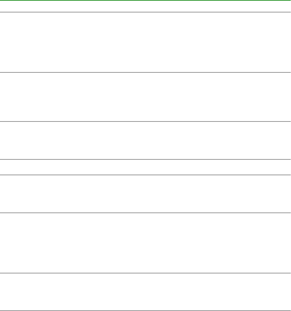
Item Description Definition
1 Capacity 8 GB
16 GB
32 GB
64 GB
128 GB
2 Rank 1R = Single-rank
2R = Dual-rank
4R = Quad-rank
8R = Octal-rank
3 Data width on DRAM x4 = 4-bit
x8 = 8-bit
x16 = 16-bit
4 Memory generation PC4 = DDR4
5 Maximum memory speed 2133 MT/s
2400 MT/s
2666 MT/s
6 CAS latency P = CAS 15-15-15
T = CAS 17-17-17
U = CAS 20-18-18
V = CAS 19-19-19 (for RDIMM, LRDIMM)
V = CAS 22-19-19 (for 3DS TSV LRDIMM)
7 DIMM type R = RDIMM (registered)
L = LRDIMM (load reduced)
E = UDIMM (unbuffered ECC)
Component identification 87
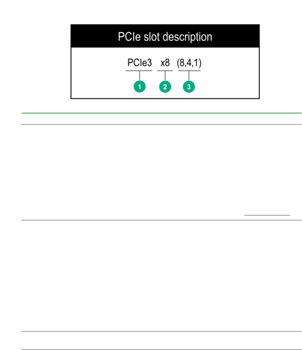
PCIe slot description
Item Description Definition
1 PCI Express version Each PCIe version corresponds to a specific data
transfer rate between the processor and peripheral
devices. Generally, a version update corresponds to an
increase in transfer rate.
• PCIe 1.x
• PCIe 2.x
• PCIe 3.x
The PCIe technology is under constant development.
For the latest information, see the PCI-SIG website.
2 Physical connector link width PCIe devices communicate through a logical
connection called an interconnect or link. At the
physical level, a link is composed of one or more lanes.
The number of lanes is written with an "×" prefix with
×16 being the largest size in common use.
•×1
•×2
•×4
•×8
•×16
3 Negotiable link width These numbers correspond to the maximum link
bandwidth supported by the slot.
88 PCIe slot description
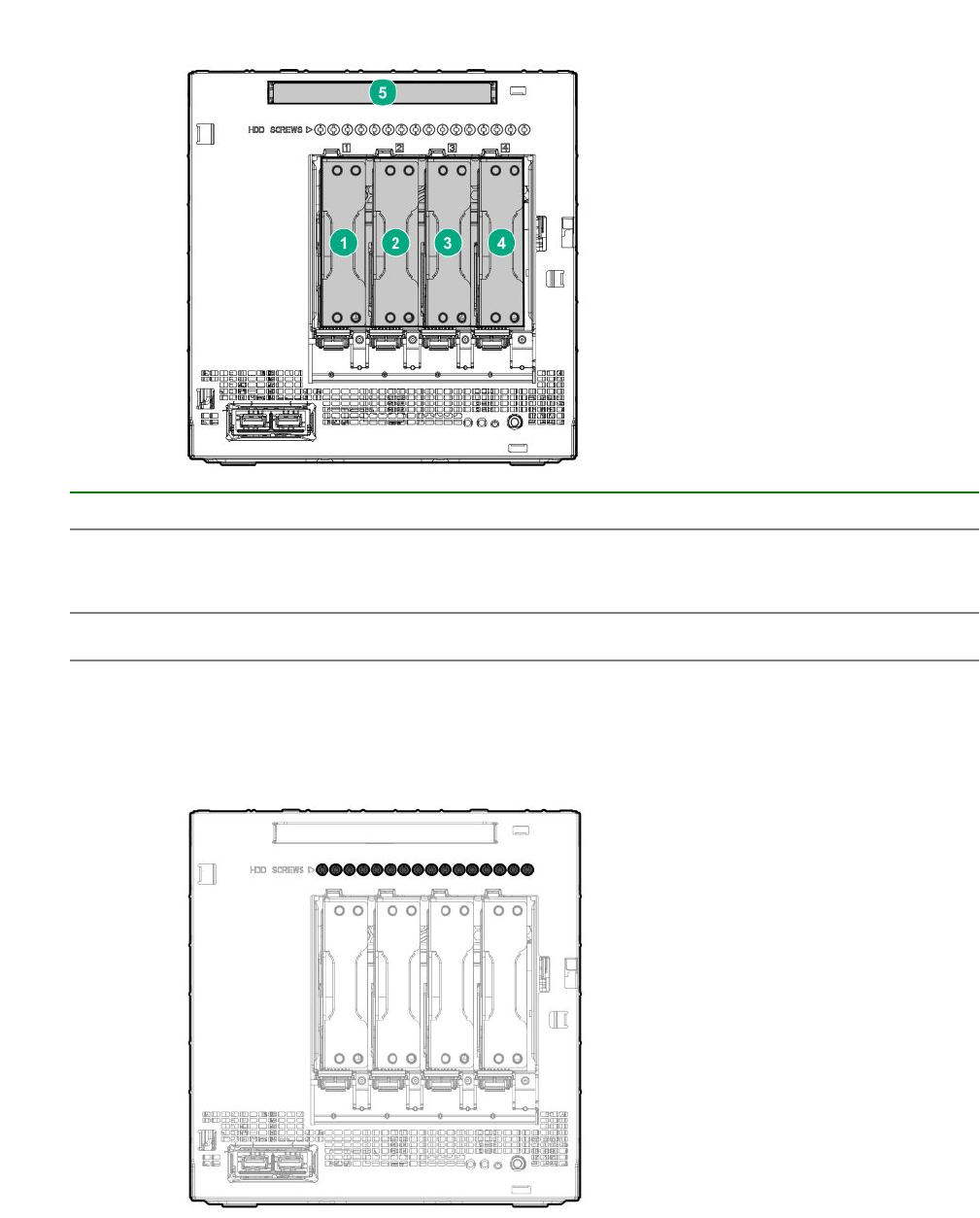
Drive numbering
Item Description
1-4 LFF/SFF drives
To support 2.5-inch SFF drives, install the SFF drive converter option.
5 Solid state drive or optical disc drive
Drive screws
There are 16 T-15 Torx screws located above the drive bays. Use these screws to install LFF or SFF
drives in the server.
Drive numbering 89
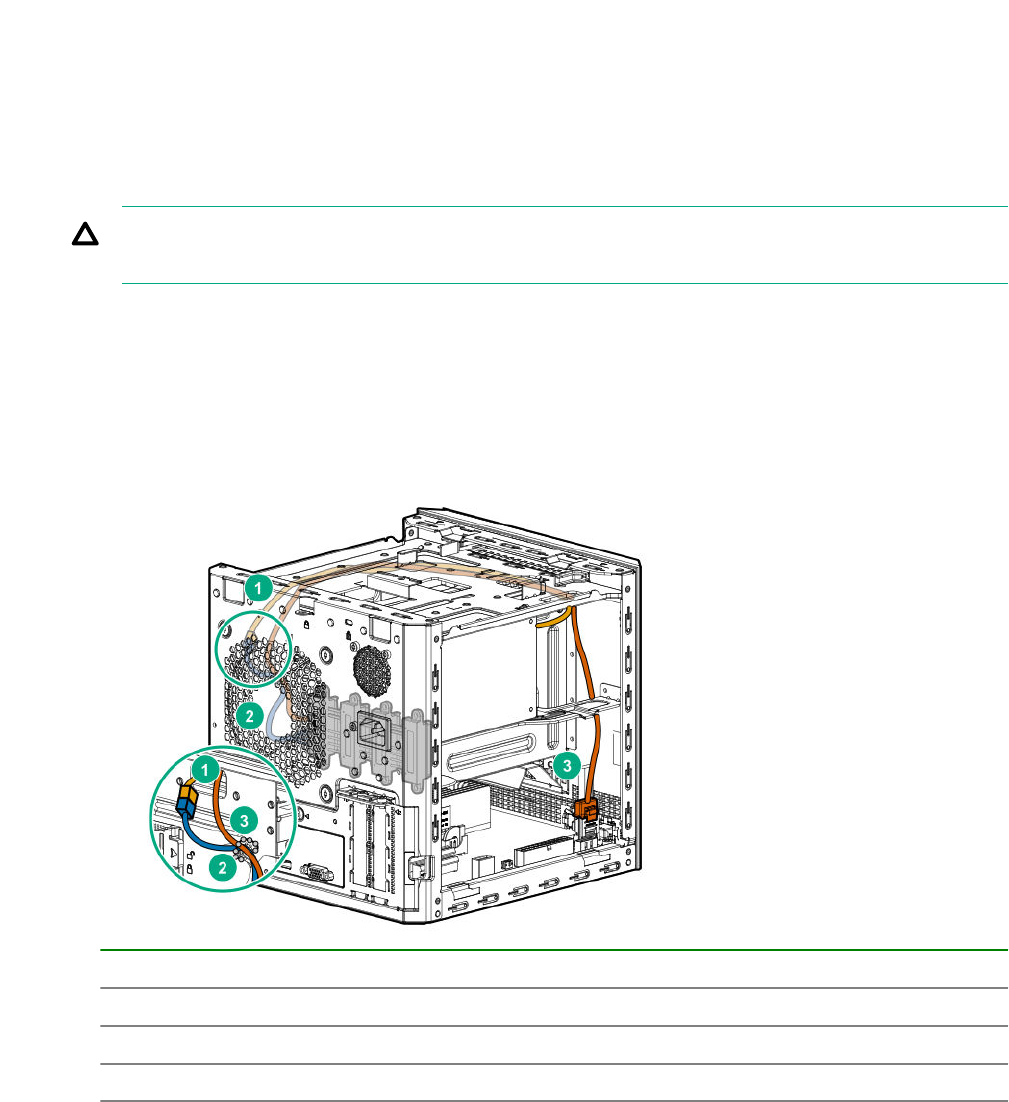
Cabling
Cabling overview
This section provides guidelines that help you make informed decisions about cabling the server and
hardware options to optimize performance.
CAUTION: When routing cables, always be sure that the cables are not in a position where they
can be pinched or crimped.
Four-bay non-hot-plug drive cabling
The four-bay non-hot-plug drive cable assembly consists of the drive power and SATA cables attached to
a bracket. If either the drive power or SATA cable becomes defective, the entire cable assembly will need
to be replaced.
• LFF/SFF drive SATA cable connected to the system board
Item Description
1 P2 power supply cable
2 LFF/SFF drive power cable
3 LFF/SFF drive SATA cable
• LFF/SFF drive SATA cable connected to a Smart Array storage controller board
90 Cabling
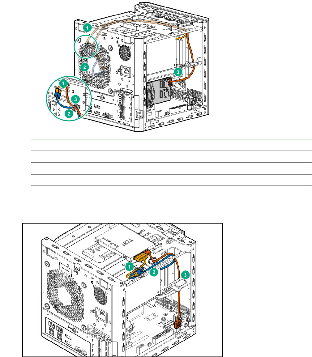
Item Description
1 P2 power supply cable
2 LFF/SFF drive power cable
3 LFF/SFF drive SATA cable
Solid state drive cabling
Solid state drive cabling 91
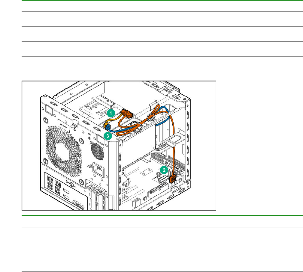
Item Description
1 SSD power cable
2 P3 power supply cable
3 SSD SATA cable
Optical drive cabling
Item Description
1 Optical drive power cable
2 Optical drive SATA cable
3 P3 power supply cable
92 Optical drive cabling
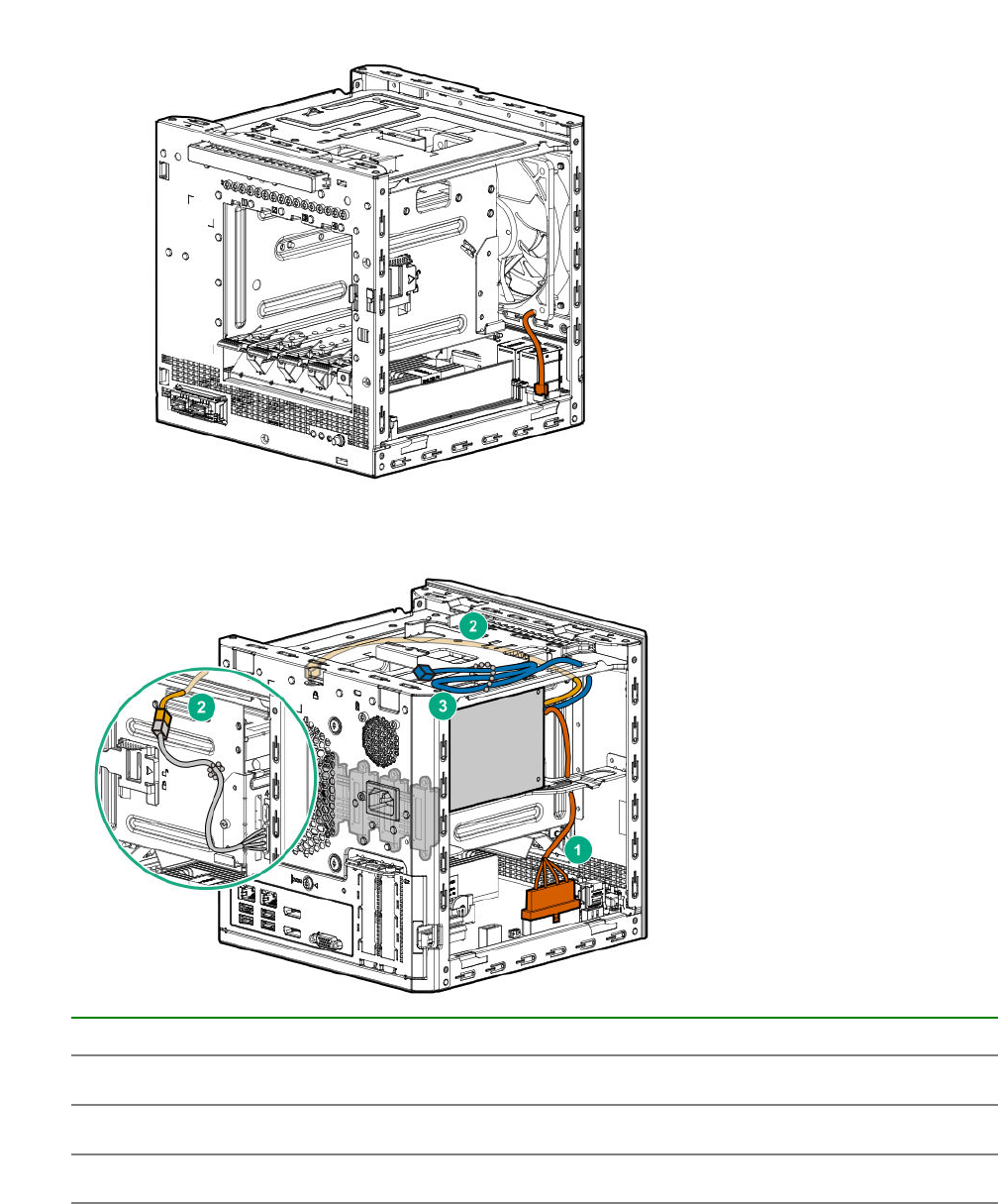
Fan cabling
Power supply cabling
Item PSU cable marker Description
1 P1 System board power cable
2 P2 LFF/SFF drive power cable
3 P3 Optical drive/SSD power cable
Fan cabling 93

Specifications
Environmental specifications
Specification Value
Temperature range1—
Operating210°C to 35°C (50°F to 95°F)
Nonoperating -30°C to 60°C (-22°F to 140°F)
Relative humidity (noncondensing) —
Operating 10% to 90%
28°C (82.4°F) maximum web bulb temperature
(noncondensing) across the operating temperature
range of 0°C to 40°C.
Nonoperating 5% to 95%
38.7°C (101.7°F), maximum wet bulb temperature
1 All temperature ratings shown are for sea level. An altitude derating of 1.0°C per 304.8 m (1.8°F per 1000 ft) to 3048
m (10,000 ft) is applicable. No direct sunlight allowed. Maximum rate of change is 20°C per hour (36°F per hour). The
upper limit and rate of change might be limited by the type and number of options installed.
2 System performance during standard operation might degrade if there is a fan fault or if the internal server
temperature is above 30°C (86°F).
Server specifications
Dimension Value
Height 23.50 cm (9.25 in)
Depth 25.40 cm (10.00 in)
Width 23.00 cm (9.06 in)
Weight (approximate values)
Minimum (one drive and one DIMM installed, no media
drive or expansion board installed)
6.495 kg (14.32 lb)
Maximum (four drives, two DIMMs, optical drive or
SSD, and two expansion boards installed)
9.69 kg (21.36 lb)
Power supply specifications
The server is configured with a non-hot-plug, nonredundant 200 W power supply.
94 Specifications

200 W power supply specifications
Specification Value
Input requirements
Rated input voltage 100 V AC to 240 V AC
Rated input frequency 50 Hz to 60 Hz
Rated input current 3.5 A at 100 V AC
Rated input power 244 W at 115 V AC
Efficiency >82% at full load
Power supply output
Rated steady-state power 200 W
Maximum peak power 200 W
Rated output power 200 W
200 W power supply specifications 95

Websites
General websites
Hewlett Packard Enterprise Information Library
www.hpe.com/info/EIL
Subscription Service/Support Alerts
www.hpe.com/support/e-updates
Single Point of Connectivity Knowledge (SPOCK) Storage compatibility matrix
www.hpe.com/storage/spock
Storage white papers and analyst reports
www.hpe.com/storage/whitepapers
For additional general support websites, see Support and other resources.
Product websites
Product QuickSpecs
http://www.hpe.com/servers/microserver
HPE ProLiant MicroServer Gen10 support page
http://www.hpe.com/support/microservergen10
HPE ProLiant MicroServer Gen10 documents
http://www.hpe.com/info/microservergen10-docs
96 Websites

Support and other resources
Accessing Hewlett Packard Enterprise Support
• For live assistance, go to the Contact Hewlett Packard Enterprise Worldwide website:
http://www.hpe.com/assistance
• To access documentation and support services, go to the Hewlett Packard Enterprise Support Center
website:
http://www.hpe.com/support/hpesc
Information to collect
• Technical support registration number (if applicable)
• Product name, model or version, and serial number
• Operating system name and version
• Firmware version
• Error messages
• Product-specific reports and logs
• Add-on products or components
• Third-party products or components
ClearCARE technical support
Support for ClearOS and ClearVM is not provided by Hewlett Packard Enterprise. Support for ClearOS
and ClearVM is purchased and delivered by ClearCenter. You can purchase single support incidents by
submitting a support ticket to ClearCenter, or you can purchase a Bronze, Silver, Gold, or Platinum
ClearCARE subscription. For more information, go to the ClearOS website:
https://www.clearos.com/
Several levels of professional technical support are available to licensed users. For more information, go
to the ClearCARE support website:
https://www.clearos.com/products/support/clearcare-overview
Accessing updates
• Some software products provide a mechanism for accessing software updates through the product
interface. Review your product documentation to identify the recommended software update method.
• To download product updates:
Hewlett Packard Enterprise Support Center
www.hpe.com/support/hpesc
Support and other resources 97
Hewlett Packard Enterprise Support Center: Software downloads
www.hpe.com/support/downloads
Software Depot
www.hpe.com/support/softwaredepot
• To subscribe to eNewsletters and alerts:
www.hpe.com/support/e-updates
• To view and update your entitlements, and to link your contracts and warranties with your profile, go to
the Hewlett Packard Enterprise Support Center More Information on Access to Support Materials
page:
www.hpe.com/support/AccessToSupportMaterials
IMPORTANT: Access to some updates might require product entitlement when accessed through
the Hewlett Packard Enterprise Support Center. You must have an HPE Passport set up with
relevant entitlements.
Warranty information
To view the warranty information for your product, see the links provided below:
HPE ProLiant and IA-32 Servers and Options
www.hpe.com/support/ProLiantServers-Warranties
HPE Enterprise and Cloudline Servers
www.hpe.com/support/EnterpriseServers-Warranties
HPE Storage Products
www.hpe.com/support/Storage-Warranties
HPE Networking Products
www.hpe.com/support/Networking-Warranties
Regulatory information
To view the regulatory information for your product, view the Safety and Compliance Information for
Server, Storage, Power, Networking, and Rack Products, available at the Hewlett Packard Enterprise
Support Center:
www.hpe.com/support/Safety-Compliance-EnterpriseProducts
Additional regulatory information
Hewlett Packard Enterprise is committed to providing our customers with information about the chemical
substances in our products as needed to comply with legal requirements such as REACH (Regulation EC
No 1907/2006 of the European Parliament and the Council). A chemical information report for this product
can be found at:
www.hpe.com/info/reach
For Hewlett Packard Enterprise product environmental and safety information and compliance data,
including RoHS and REACH, see:
www.hpe.com/info/ecodata
For Hewlett Packard Enterprise environmental information, including company programs, product
recycling, and energy efficiency, see:
98 Warranty information

www.hpe.com/info/environment
Documentation feedback
Hewlett Packard Enterprise is committed to providing documentation that meets your needs. To help us
improve the documentation, send any errors, suggestions, or comments to Documentation Feedback
(docsfeedback@hpe.com). When submitting your feedback, include the document title, part number,
edition, and publication date located on the front cover of the document. For online help content, include
the product name, product version, help edition, and publication date located on the legal notices page.
Documentation feedback 99

Acronyms and abbreviations
3DS TSV
three-dimensional stacked through-silicon via (integrated circuit packaging technology)
APU
Accelerated Processing Unit
CAS
column address strobe
CSR
Customer Self Repair
DDR4
double data rate - 4
ETY
Entry (HPE drive family)
HPE SSA
HPE Smart Storage Administrator
ISO
International Organization for Standardization
LFF
large form factor
LRDIMM
load reduced dual in-line memory module
MDL
Midline (HPE drive family)
PCIe
Peripheral Component Interconnect Express
POST
Power-On Self-Test
PSU
power supply unit
RDIMM
registered dual in-line memory module
RoHS
Restriction of Hazardous Substances
REACH
Registration, Evaluation, Authorization, Restriction of Chemicals (European Union chemical regulatory
framework)
100 Acronyms and abbreviations
RI
read intensive (HPE SSD category)
SATA
serial ATA
SSD
solid state drive
TPM
Trusted Platform Module
UDIMM
unregistered dual in-line memory module
UEFI
Unified Extensible Firmware Interface
UPS
uninterruptible power supply
Acronyms and abbreviations 101
