HPGL2 RTL Reference Guide 5961 3526 540pages Sep96
User Manual:
Open the PDF directly: View PDF ![]() .
.
Page Count: 540 [warning: Documents this large are best viewed by clicking the View PDF Link!]

Company confidential. HP-GL/2 and HP RTL Reference Guide, draft 2. Freeze Status: open
This is the black on page i (seq: 1)
Hewlett-Packard
Raster Transfer Language
The HP-GL/2 and HP RTL
Reference Guide
A Handbook for Program Developers
Hewlett-Packard
Graphics Language/2

This is the black on page ii (seq: 2)
Company confidential. HP-GL/2 and HP RTL Reference Guide, draft 2. Freeze Status: open
Copyright Hewlett-Packard Company 1990, 1992,
1994, 1996
HP Part number of this manual:
5961–3526
First edition, October 1993
Second edition, September 1996
Bi-Tronics, HP-GL, HP-GL/2, and PCL are trademarks
of Hewlett-Packard Company.
AppleTalk is a trademark of Apple Computer Inc.
Microsoft is a registered trademark of Microsoft Cor-
poration.
PostScript is a trademark of Adobe Systems Incorpo-
rated which may be registered in certain jurisdictions.
See Appendix C for a note on page 480 about other trade-
marks.
Library of Congress Cataloging-in-Publication Data
The HP-GL/2 and HP RTL Reference Guide: A Hand-
book for Program Developers /
Hewlett-Packard
p. cm.
Includes Index
ISBN 0–201–63325–6
1. HP-GL/2 (Computer program language)
2. HP RTL (Computer program language)
3. Computer graphics. I. Hewlett-Packard.
QA.76.73.H6H52 1996
ISBN 0–201–63325–6
Notices
This document contains proprietary information, which
is protected by copyright. All rights are reserved. The
information contained in this document is subject to
change without notice and should not be construed as a
commitment by the Hewlett-Packard Company. No
part of the document may be photocopied, reproduced,
or translated to another language without the prior writ-
ten consent of Hewlett-Packard Company.
Hewlett-Packard assumes no responsibility for any
errors that may appear in this document nor does it
make expressed or implied warranty of any kind
with regard to this material, including, but not lim-
ited to, the implied warranties of merchantability
and fitness for a particular purpose. The Hew-
lett-Packard Company shall not be liable for incidental
or consequential damages in connection with, or aris-
ing out of the furnishing, performance, or use of this
document and the program material which it describes.
The cover illustration, reproduced by kind permission
of the Ajuntament of Barcelona, Spain, shows the Casa
Batlló, built in 1904–1906 by the Catalan architect
Antoni Gaudí. The original photograph used to pro-
vide the master of the cover was printed on a
Hewlett-Packard DesignJet 755CM printer.
The publisher offers discounts on this book when or-
dered in quantity for special sales. For more
information please contact:
Corporate & Professional Publishing Group
Addison-Wesley Publishing Company
One Jacob Way
Reading, Massachusetts 01867
U.S.A.
Text printed on recycled and acid-free paper.
Hewlett-Packard Company
Barcelona Division
Avda. Graells, 501
08190 Sant Cugat del Vallès
Barcelona, Spain

iii
This is the black on page iii (seq: 3)
Company confidential. HP-GL/2 and HP RTL Reference Guide, draft 2. Freeze Status: open
Preface
This is a generic guide to HP-GL/2 (Hewlett-Packard’s standardized Graphics Language) and
HP RTL (Hewlett-Packard’s Raster Transfer Language) supported by many HP graphics peripher-
als. This manual describes each of the instructions of HP-GL/2 and each of the commands of
HP RTL, without relying on a specific device or technology.
You must use a programming language in addition to HP-GL/2 or HP RTL. However, this book
will not teach you how to program your computer. Your method of programming will depend on
your computer system, the programming language you use, and your level of expertise. This
book, though, does give recommendations on getting the most from your device.
This book describes how to write programs using HP-GL/2 and HP RTL.
PART 1 deals with general concepts and principles.
Chapter 1 on page 3 describes the concepts needed to create programs that use HP-GL/2 and
HP RTL, including plotting concepts, vector and raster images, defining the limits of your
picture, the coordinate system used, units of measure, and switching from one plotting
context to another.
PART 2 describes HP-GL/2.
Chapter 2 on page 17 describes the groups of instructions that make up HP-GL/2, the status
of the pen and its location, how to scale pictures, and the notation used to define HP-GL/2
instructions.
Chapter 3 on page 29 describes the HP-GL/2 kernel, that is, the core set of instructions
supported by all HP-GL/2 devices. Each group is explained in detail, with examples. The
HP-GL/2 print model is also described.
Chapter 4 on page 77 describes the groups of extension instructions, that are provided for
specific types of peripheral devices.
Chapter 5 on page 95 starts with a reference summary of all the HP-GL/2 instructions, in
alphabetical order of their names, and is followed by a complete description of all the HP-
GL/2 instructions, in alphabetical order of their two-letter acronyms.
Chapter 6 on page 331 summarizes the elements of HP-GL/2 that are dependent on the
device in use.
PART 3 describes HP RTL.
Chapter 7 on page 337 describes the concepts needed to create HP RTL raster programs. It
includes a description of the notation used to define HP RTL commands.
Chapter 8 on page 341 explains how to set the limits of your images, how to set the image
resolution, how to scale images, and also describes the coordinate system used for placing
images on the page.
Chapter 9 on page 351 describes how to define colors, the use of color modes and palettes,
and how to use indexes to select colors. It also explains how to use patterns.
This is the blue on page iii (seq: 3)

iv
This is the black on page iv (seq: 4)
Company confidential. HP-GL/2 and HP RTL Reference Guide, draft 2. Freeze Status: open
Chapter 10 on page 365 describes the interactions between picture elements. It explains
how patterns and texture relate to raster images through logical operations, the default print
model, and image and pattern transparency.
Chapter 11 on page 375 describes how to transfer raster data to the device. It includes a
description of what happens when overflow occurs, and the various supported methods of
compressing data.
Chapter 12 on page 391 describes the interactions between HP RTL and physical device
settings, HP-GL/2, and PJL.
Chapter 13 on page 397 contains some examples of HP RTL raster programs.
Chapter 14 on page 403 lists, in alphabetical order of their names, the HP RTL commands
used in raster programs.
Chapter 15 on page 455 contains a summary of the features of HP RTL that may vary from
device to device.
PART 4 consists of some general appendixes.
Appendix A on page 461 has some programming hints on getting the best from your system.
Appendix B on page 475 lists the logical operations used in HP-GL/2 and HP RTL.
Appendix C on page 477 lists the font kind and value parameters used in the HP-GL/2 AD
(Alternate Font Definition) and SD (Standard Font Definition) instructions.
A Glossary of terms and abbreviations and an Index follow at the end of the book.
Additional Documentation
The Product Comparison Guide for HP Languages on HP Plotters and Large-Format Printers,
HP part number 5959–9734, shows the differences between the implementations of HP-GL/2 on
various HP devices.
The PCL 5 Printer Language Technical Reference Manual, HP part number 5961–0509, de-
scribes the commands of PCL 5.
The PCL 5 Comparison Guide, HP part number 5961-0602, describes which HP-GL/2 instruc-
tions are supported on HP LaserJet series printers.
The PJL Technical Reference Manual, HP part number 5010–3999, describes the Printer Job Lan-
guage.
Terms and Conventions Used in this Book
In this book, numbers are expressed using SI (International System of Units) standards. Numbers
with more than four digits are placed in groups of three, separated by a space instead of a comma,
counting to both sides of the decimal point (for example, 54 321.123 45).
type denotes an ASCII control character, such as (escape), (carriage return),
(line feed), or (end-of-text).
All references to the RS-232-C interface apply equally to the CCITT V.24 interface.
See page 26 (for HP-GL/2) and page 338 (for HP RTL) for descriptions of other notational con-
ventions used in this book. The term instruction refers to the interface with HP-GL/2; the term
command is used consistently to refer to the interface with HP RTL or PCL. See the Glossary on
page 483 for explanations of other terms used.

v
This is the black on page v (seq: 5)
Company confidential. HP-GL/2 and HP RTL Reference Guide, draft 2. Freeze Status: open
Contents
!
##" %
"# $!" &%
#!$# # ## !# " '
#! ## !#
-044+/) #/& 2+/4+/) 0/%'143
"'%4023 #/& #34'2 .#)'3
2#1*+%3 +.+43
#2&:-+1 +.+43
0(4:-+1 +.+43
*' 002&+/#4' 934'.
$30-54' #/& '-#4+6' 06'.'/4
/4'2#%4+0/3 $'47''/ +(('2'/4 002&+/#4' 934'.3
!/+43 0( '#352'
: !/+43 0( '#352'
!/+43 0( '#352'
304201+% #/& /+304201+% %#-+/)
2+/4'2 0$ #/)5#)'
0/4'84 7+4%*+/)
'
#! #!$# # '
*' /3425%4+0/ 20513
*' '2/'-
*' 84'/3+0/3
'/ 4#453 #/& 0%#4+0/
'/ 4#453
'/ 0%#4+0/
%#-+/)
: 9/4#8
04#4+0/ !3'& +/ 4*+3 00, 40 2'3'/4 /3425%4+0/ 9/4#8
#2#.'4'2 02.#43
This is the blue on page v (seq: 5)

vi
This is the black on page vi (seq: 6)
Company confidential. HP-GL/2 and HP RTL Reference Guide, draft 2. Freeze Status: open
+( 10),*63$5,10 $0' 5$564 3162
45$%.,4+,0* ()$6.5 10',5,104
+( &$.,0* 1,054 $0'
4,0* &$.,0* ))(&5,7(.:
'$25,0* 5+( < 113',0$5( :45(/ )13 3,05(34 51 $5&+ 5+( :45(/
'$25,0* 5+( < 113',0$5( :45(/ )13 .155(34 51 $5&+ 5+( :45(/
",0'18,0* (55,0* 62 1)5<.,2 ,/,54
15$5,0* $ ,&563(
0',0* #163 31*3$/ $0' '7$0&,0* 5+( $*(
+( !(&513 3162
(0 2 13 180
3$8,0* ,0(4
3$8,0* ,3&.(4
3$8,0* 3&4
0*.( 1) 15$5,10
+( 1.:*10 3162
,..,0* 5+(0 '*,0* 1/2$3(' 8,5+ '*,0* 5+(0 ,..,0*
4,0* 5+( 1.:*10 6))(3
3$8,0* (&5$0*.(4
3$8,0* "('*(4
3$8,0* 1.:*104
3$8,0* 6%21.:*104
,..,0* 1.:*104
+( ,0( $0' ,.. 553,%65(4 3162
4,0* ,0( 553,%65(4 $0' :2(4
4,0* ,.. :2(4
(.(&5,0* $ ;(0 $0' +$0*,0* ,0( ",'5+
+( +$3$&5(3 3162
"13-,0* 8,5+ 5+( +$3$&5(3 (..
18 #163 (7,&( (.(&54 1054
4,0* $%(.4
()$6.5 $%(. 10',5,104
+$3$&5(3 14,5,10,0*
17,0* 51 5+( $33,$*(<(5630 1,05
'',0* $33,$*( (56304 $0' ,0( (('4 51 $%(.4
0+$0&,0* $%(.4
< 3,05,0*
3($ ,..4
+( (30(. 3,05 1'(.
95(0'(' 3,05 1'(.
< $0' 3,05 1'(.4

vii
This is the black on page vii (seq: 7)
Company confidential. HP-GL/2 and HP RTL Reference Guide, draft 2. Freeze Status: open
" !
*' '%*.+%#, 1#0*+%2 73'.2+/.
'(+.+.) # +%341'
*/1&2 #.& */1& /,'1#.%'
*' /6.,/#&#$,' '3 #.& 2'1:'(+.'& *#1#%3'12
$3#+.+.) '5+%' 43043
2+.) 43043 .2314%3+/.2
4--#18 /( 43043 '20/.2'2
*' #,'33' 73'.2+/.
'(+.+.) !/41 #,'33'
*' 4#,:/.3'73 73'.2+/.
2+.) 4#,:/.3'73 /1 /--#.&2
/&+(+%#3+/.2 3/ : .2314%3+/.2 +. 4#,:/.3'73 /&'
*' +)+3+9+.) 73'.2+/.
*' +)+3+9+.) 1/%'&41'
+)+3+9+.) 6+3* 3*' ,/33'1
*' &5#.%'& 1#6+.) 73'.2+/.
1#6+.) '9+'1 415'2
*' &5#.%'& '73 73'.2+/.
"
1% $2/,43'
.%*/1 /1.'1
,3'1.#3' /.3 '(+.+3+/.
1% ',#3+5'
$2/,43' 1% *1'' /+.3
')+. ,/3
'9+'1 ',#3+5'
" '9+'1 $2/,43'
*#1#%3'1 +,, /&'
+1%,'
/--'.3
*#1#%3'1 ,/3
'3 /,/1 #.)' (/1 ',#3+5' /,/1 #3#
*/1& /,'1#.%' /&'
+)+3+9' ,'#1
'(#4,3 #,4'2
$2/,43' +1'%3+/.
/6.,/#& *#1#%3'1
+)+3+9' /+.3
',#3+5' +1'%3+/.
'(+.' #$', '1-+.#3/1
'(+.' #1+#$,' '73 #3*
&)' '%3#.),' $2/,43'
.#$,' 433'1

viii
This is the black on page viii (seq: 8)
Company confidential. HP-GL/2 and HP RTL Reference Guide, draft 2. Freeze Status: open
%(& .+7(.-
%(& &$2"-(+& &+"2*4&
620" /"$&
! %(& !&%(&
0*,"07 .-2 &+&$2*.- #7
&$.-%"07 .-2 &+&$2*.- #7
*++ .+7(.-
0",& %4"-$&
*++ 7/&
-*2*"+*8&
-/32 "-%
-/32 &+"2*4& "-%
! -/32 !*-%.5
*-& 220*#32&1
"#&+
"#&+ .%&
"#&+ 0*(*-
*-& 7/&
&0(& .-20.+
&11"(&
&%*" 7/&
3,#&0 .' &-1
.2 &"%7
32/32 *(*2*8&% .*-2 "-% &- 2"231
32/32 00.0
32/32 "0%9+*/ *,*21
32/32 %&-2*'*$"2*.-
32/32 "-%
32/32 2"231
+.2 #1.+32&
&- .+.0 11*(-,&-2
&- .5-
.+7+*-& -$.%&%
%4"-$& 3++ "(&
.+7(.- .%&
*6&+ +"$&,&-2
+.2 &+"2*4&
+.2 *8&
&- /
! &- !*%2)
3"+*27 &4&+
*++ &$2"-(+& #1.+32&
"12&0 *++ &'*-*2*.-
.2"2& ..0%*-"2& 712&,
&/+.2

ix
This is the black on page ix (seq: 9)
Company confidential. HP-GL/2 and HP RTL Reference Guide, draft 2. Freeze Status: open
)** %#2!,'*% %*!2)4%
%*!2)4% 0# (0%% -),2
%*%#2 *2%0,!2% -,2
#!*!"*% -0 )2+!. -,21
#!*%
2!,$!0$ -,2 %&),)2)-,
"1-*32% (!0!#2%0 )8%
(!0!#2%0 *!,2
7+"-* -$%
%*%#2 %,
%*!2)4% (!0!#2%0 )8%
%*%#2 2!,$!0$ -,2
-02
#0%%,%$ %#2-01
0!,1.!0%,2 !2!
0!,1.!0%,#7 -$%
1%09%&),%$ ),% 7.%
%*-#)27 %*%#2
)** %$'%
%, )$2( ,)2 %*%#2)-,
!$" %"' ( & !#
3,#2)-,1 3..-02%$
!0$5!0% !,$ 712%+ (!0!#2%0)12)#1
--0$),!2% !,'%1
(-0$ ,'*%1
)** 7.%1 !,$ ),% 0-.%02)%1
(!0!#2%01 !,$ -,21
%,1 !,$ -*-01
,)2)!* -,$)2)-,1
!$" !$#
0)2),' 0)4%01
-++!,$ 7,2!6
1#!.% %/3%,#%1
!0!+%2%0)8%$ 1#!.% %/3%,#%1
-+"),),' -++!,$1
!$"
%22),' !12%0 -3,$!0)%1
%22),' 2(% -')#!* !'% )8% !,$ ,.32 ),$-5 ), 9
%22),' 2(% )$2( !,$ %)'(2 ),

x
This is the black on page x (seq: 10)
Company confidential. HP-GL/2 and HP RTL Reference Guide, draft 2. Freeze Status: open
$34'2 2$1*+%3
0/420--+/) .$)' '30-54+0/
0/4+/5053 $/& +3%2'4' '30-54+0/
%$-+/) $34'2 .$)'3
07 40 %$-' $/ .$)'
!*' 522'/4 %4+6' 03+4+0/
0..$/&3 40 *$/)' 4*'
')$4+6' 04+0/
! $4+6' '30-54+0/ "/+43
2+.$290-023
-$%, $/& #*+4' '('2'/%'3
0-02:'(+/+4+0/ 0..$/&3
1'%+(9+/) 0-023
/&'8'& '-'%4+0/
+2'%4 '-'%4+0/
$-'44'3
/%0&+/) 0-023
0-02 0&'3
-$%, $/& #*+4' 0&'
+.1-' 0-02 0&'
! .$)+/) 0&'
: .$)+/) 0&'
'(+/+/) 4*' ! $-'44'
*$/)+/) 4*' '($5-4 $-'44'
*$/)+/) 4*' -$%, $/& #*+4' '('2'/%'3
"3+/) ! /&'8'3
5-4+:-$/' $4$
"3+/) /&'8
8$.1-' 20)2$..+/) 4*' 0-02 $-'44'
$-(40/+/)
$44'2/3
81024+/) $44'2/3 40 :
$44'2/ 2+'/4$4+0/
!
!'8452'
0)+%$- 1'2$4+0/3
#*+%* 0)+%$- 1'2$4+0/ 40 "3'
!*' '($5-4 2+/4 0&'-

xi
This is the black on page xi (seq: 11)
Company confidential. HP-GL/2 and HP RTL Reference Guide, draft 2. Freeze Status: open
Transparency 366. . . . . . . . . . . . . . . . . . . . . . . . . . . . . . . . . . . . . . . . . . . . . . . . . . . . . . . . . . . . . . .
Source and Pattern Both Opaque 366. . . . . . . . . . . . . . . . . . . . . . . . . . . . . . . . . . . . . . . . . .
Source Opaque, Pattern Transparent 367. . . . . . . . . . . . . . . . . . . . . . . . . . . . . . . . . . . . . . .
Source Transparent, Pattern Opaque 367. . . . . . . . . . . . . . . . . . . . . . . . . . . . . . . . . . . . . . .
Source and Pattern Both Transparent 367. . . . . . . . . . . . . . . . . . . . . . . . . . . . . . . . . . . . . . .
The Effect of Transparency 368. . . . . . . . . . . . . . . . . . . . . . . . . . . . . . . . . . . . . . . . . . . . . . . .
#&$ $!% &&! &
Transferring Raster Data 371. . . . . . . . . . . . . . . . . . . . . . . . . . . . . . . . . . . . . . . . . . . . . . . . . . . . .
Implicit Start Raster Graphics 372. . . . . . . . . . . . . . . . . . . . . . . . . . . . . . . . . . . . . . . . . . . . .
Commands in Raster Mode 372. . . . . . . . . . . . . . . . . . . . . . . . . . . . . . . . . . . . . . . . . . . . . . .
Implicit End Raster Graphics 372. . . . . . . . . . . . . . . . . . . . . . . . . . . . . . . . . . . . . . . . . . . . . .
When Overflow Occurs 372. . . . . . . . . . . . . . . . . . . . . . . . . . . . . . . . . . . . . . . . . . . . . . . . . . . . . .
PlaneĆbyĆPlane Printing and Scaling 375. . . . . . . . . . . . . . . . . . . . . . . . . . . . . . . . . . . . . . . . . . . .
Compressing Data 376. . . . . . . . . . . . . . . . . . . . . . . . . . . . . . . . . . . . . . . . . . . . . . . . . . . . . . . . . . .
RowĆBased Unencoded (Compression Method 0) 377. . . . . . . . . . . . . . . . . . . . . . . . . . . .
BlockĆBased Unencoded (Compression Method 4) 377. . . . . . . . . . . . . . . . . . . . . . . . . . .
RunĆLength Encoding (Compression Method 1) 379. . . . . . . . . . . . . . . . . . . . . . . . . . . . . .
TIFF Packbits Encoding (Compression Method 2) 379. . . . . . . . . . . . . . . . . . . . . . . . . . . .
SeedĆRow or DeltaĆRow Encoding (Compression Method 3) 380. . . . . . . . . . . . . . . . . . .
Adaptive Encoding (Compression Method 5) 383. . . . . . . . . . . . . . . . . . . . . . . . . . . . . . . .
CCITT Encoding Methods 386. . . . . . . . . . . . . . . . . . . . . . . . . . . . . . . . . . . . . . . . . . . . . . . .
#&$ !&$&"!% &'! ! &$ )%& %
Interactions with Physical Device Settings 387. . . . . . . . . . . . . . . . . . . . . . . . . . . . . . . . . . . . . . .
Interactions with HPĆGL/2 387. . . . . . . . . . . . . . . . . . . . . . . . . . . . . . . . . . . . . . . . . . . . . . . . . . . .
Changing Language Contexts and Modes 389. . . . . . . . . . . . . . . . . . . . . . . . . . . . . . . . . . . .
Transferring Pen Position and Palettes 389. . . . . . . . . . . . . . . . . . . . . . . . . . . . . . . . . . . . . .
Merging Vector and Raster Data 390. . . . . . . . . . . . . . . . . . . . . . . . . . . . . . . . . . . . . . . . . . .
Printer Job Language (PJL) 390. . . . . . . . . . . . . . . . . . . . . . . . . . . . . . . . . . . . . . . . . . . . . . . . . . .
PJL Commands Supported on HP RTL Devices 390. . . . . . . . . . . . . . . . . . . . . . . . . . . . . .
Example Showing the Structure of a PJL Job 391. . . . . . . . . . . . . . . . . . . . . . . . . . . . . . . . .
AppleTalk 391. . . . . . . . . . . . . . . . . . . . . . . . . . . . . . . . . . . . . . . . . . . . . . . . . . . . . . . . . . . . . . . . . .
#&$ %&$ $"$ ! ( #%
Example of RGB Color or Monochrome Data with Merged HPĆGL/2 and no Scaling 393. .
Color Raster 395. . . . . . . . . . . . . . . . . . . . . . . . . . . . . . . . . . . . . . . . . . . . . . . . . . . . . . . . . . . .
Monochrome Raster 395. . . . . . . . . . . . . . . . . . . . . . . . . . . . . . . . . . . . . . . . . . . . . . . . . . . . .
Example of CMY or KCMY Data without Scaling 396. . . . . . . . . . . . . . . . . . . . . . . . . . . . . . . .
Example of 24Ćbit RGB Data with Scaling 397. . . . . . . . . . . . . . . . . . . . . . . . . . . . . . . . . . . . . . .
#&$ " ! $!
AppleTalk Configuration 402. . . . . . . . . . . . . . . . . . . . . . . . . . . . . . . . . . . . . . . . . . . . . . . . . . . . .
Assign Color Index 403. . . . . . . . . . . . . . . . . . . . . . . . . . . . . . . . . . . . . . . . . . . . . . . . . . . . . . . . . .
Compression Method 404. . . . . . . . . . . . . . . . . . . . . . . . . . . . . . . . . . . . . . . . . . . . . . . . . . . . . . . .

xii
This is the black on page xii (seq: 12)
Company confidential. HP-GL/2 and HP RTL Reference Guide, draft 2. Freeze Status: open
32+.,85* 1&,* &7&
855*27 &77*52
*67.2&7.32 &67*5 *.,-7
*67.2&7.32 &67*5 $.)7-
3:203&) &77*52
2) &67*5 5&4-.(6
27*5 > 3)*
27*5 ! 3)*
35*,5382) 3035
3,.(&0 4*5&7.32
39* 35.=327&0 *(.43.276
39* 35.=327&0 ! &7.9* *63087.32 "2.76
39* #*57.(&0 ! &7.9* *63087.32 "2.76
*,&7.9* 37.32
&77*52 327530
&77*52
&77*52 *+*5*2(* 3.27
&77*52 !5&264&5*2(< 3)*
86-34 &0*77*
&67*5 .2* &7-
*2)*5 0,35.7-1
*6*7
*7 08* &5&1*7*5
*7 5&4-.(6 *63087.32
*7 5**2 &5&1*7*5
*7 *) &5&1*7*5
.140* 3035
385(* &67*5 *.,-7
385(* &67*5 $.)7-
385(* !5&264&5*2(< 3)*
7&57 &67*5 5&4-.(6
!5&26+*5 &67*5 &7& '< 0&2*
!5&26+*5 &67*5 &7& '< 3:03(/
"2.9*56&0 ;.7 &2,8&,* 7&57 3+
% ++6*7
" # & $ !
! -&5&(7*5.67.(6
%!
% " " ! !
"6.2, & 53,5&11.2, &2,8&,*

xiii
This is the black on page xiii (seq: 13)
Company confidential. HP-GL/2 and HP RTL Reference Guide, draft 2. Freeze Status: open
"7/3- ? $/8. 64-6'22/3- '3-9'-+7
<'251+ '3-9'-+
<'251+ 64-6'22/3- '3-9'-+
"7/3- ! ;/8. 64-6'22/3- '3-9'-+7
4251+8+ 6'5./)7 64-6'2
3/8/'1/>'8/43 '3* !+62/3'8/43@6/38+6 +7+8
8'68/3- ' 64-6'2
!.+ 4*= 4, ' 64-6'2
;/8)./3- 4*+7
3*/3- ' 64-6'2
"7/3- ? 37869)8/437 '3* ! 422'3*7
* 37869)8/437 '3* 422'3*7
42(/3+* 422'3*7
98598 37869)8/437
'0/3- ,,/)/+38 "7+ 4, %496 =78+2
+88/3- 84 34; ?
+6,462'3)+
478 42598+6 +7496)+7
+246= />+
43,/-96+ 2'-+ '8' 422'3*
422'3*7
6/38 '8'
6/38 :+6693
'-+ 648+)8/43
359898598
'-+ '=498 '3* 47/8/43/3-
'-+ 6/+38'8/43 '3* />+
6+' 4, 8.+ 98598
&+64 /11/3-
4:/3- 8.+ 966+38 )8/:+ 47/8/43
6+5'6/3- %496 '8'
'78+6 6'5./)7
'8' 4256+77/43
+3*/3- '78+6 '8'
+6-+* #+)846 '3* '78+6 '8'
)'1/3- '78+6 2'-+7
!6'375'6+3)=
"7/3- 4146
% 5+6'8/43
4146 '1+88+ 5+6'8/437
"7+6 5+6'8/437
!649(1+7.448/3-

xiv
This is the black on page xiv (seq: 14)
Company confidential. HP-GL/2 and HP RTL Reference Guide, draft 2. Freeze Status: open
$ "!
$ " "!
% #
#
#
#
"#$!
#! #
%
!! % ! #"!
$

xv
This is the black on page xv (seq: 15)
Company confidential. HP-GL/2 and HP RTL Reference Guide, draft 2. Freeze Status: open
List of Figures
-+63) ")'5134 %0( %45)3 /%+)4
-+63) %3(<.-2 %0( 1*5<.-2 -/-54 %0( 5,) **)'5-7) #-0(18
-+63) %3(<.-2 -/-54
-+63) /%+) )*13) 22.:-0+ 1*5<.-2 -/-54
-+63) /%+) *5)3 22.:-0+ 1*5<.-2 -/-54
-+63) 113(-0%5) :45)/
-+63) 3-+-0 1* 113(-0%5)4
-+63) &41.65) 17)/)05
-+63) ).%5-7) 17)/)05
-+63) %0( < 113(-0%5) :45)/4
-+63) **)'54 1* 15%5-10 10 5,) 113(-0%5) :45)/
-+63) 415312-' %0( 0-415312-' '%.-0+
-+63) 8-5',-0+ *31/ 0) 105)95 51 015,)3
-+63) !4)3<!0-5 '%.-0+ 8-5, )*%6.5 %0(
-+63) %/) !4)3<!0-5 '%.-0+ 8-5, )8 %0(
-+63) )8 %0( !4)3<!0-5 '%.-0+ 8-5, )+%5-7) "%.6)4
-+63) ,%0+-0+ 5,) -;) 1* % 3%8-0+
-+63) 3%8-0+ -'563)4 -()<&:<-()
-+63) 3)%5-0+ -3313 /%+)4
-+63) %5',-0+ 5,) < %0( 113(-0%5) :45)/4
-+63) 1-0'-()05 113(-0%5) :45)/4
-+63) -0) )+/)054 %0( #-0(184
-+63) 15%5-0+ % -'563)
-+63) 3%8-0+ -0)4
-+63) 3%8-0+ -3'.)4 %0( 3'4
-+63) 3'4 5,316+, ,3)) -7)0 1-054
-+63) 0+.) 1* 15%5-10
-+63) -..-0+ %0( (+-0+ ,%354
-+63) 3%8-0+ % )'5%0+.)
-+63) -..)( )'5%0+.)4 8-5, %0( 8-5,165 (+)4
-+63) 18 #)(+)4 %3) 3%80
-+63) -/2.) #)(+)
-+63) -..)( #)(+)4 %0( -3'.)4
-+63) 3%8-0+ 6&21.:+104
-+63) -..-0+ 1.:+104 7)0(( -.. )5,1(
-+63) -..-0+ 1.:+104 10<$)31 #-0(-0+ -.. )5,1(
-+63) 1605-0+ 1-054 -0 % 1.:+10
-+63) -0) 0(4 553-&65)
-+63) -**)3)05 )0 #-(5,4 %0( -0) :2)4
This is the blue on page xv (seq: 15)

xvi
This is the black on page xvi (seq: 16)
Company confidential. HP-GL/2 and HP RTL Reference Guide, draft 2. Freeze Status: open
+)52' +-- 91'3
+)52' +-- 2'# /%*02 02/'2
+)52' *#2#%4'2 '-- #/& ;
+)52' %#-#$-' #/& +4.#1 *#2#%4'2 '--
+)52' 4+%, 0/4 *#2#%4'2 '--
+)52' +8'&;1#%'& 0/4
+)52' 201024+0/#--9;1#%'& 0/4
+)52' 2+/4+/) #$'-3
+)52' #$'- 2+'/4#4+0/ #/& +2'%4+0/
+)52' " /3425%4+0/
+)52' #$'- 2+)+/ /3425%4+0/ 40 '/4'2 '84
+)52' ':+'2 526'
+)52' *02& /)-'
+)52' *#/)+/) 2% .004*/'33 7+4* 4*' *02& /)-'
+)52' "#29+/) 4*' *02& /)-'
+)52' !3+/) 4*' /%*02 02/'2 /3425%4+0/
+)52' !3+/) 4*' 2% '-#4+6' /3425%4+0/ 40 2#7 2%3
+)52' 0--+/'#2 0+/43 7+4* 4*' /4'2.'&+#4' 0+/4 0543+&' 4*' /& 0+/43
+)52' 2#7+/) 2%3 4*205)* *2'' 0+/43
+)52' ':+'2 526'3 !3+/) '-#4+6' 002&+/#4'3
+)52' ':+'2 526'3 !3+/) $30-54' 002&+/#4'3
+)52' *#2#%4'2 +-- 6'2(-07
+)52' !3+/) 4*' *#2#%4'2 +-- /3425%4+0/
+)52' (('%43 0( *02& /)-' 0/ +2%-' .004*/'33
+)52' 2#7+/) +2%-'3 7+4* +(('2'/4 #&++ #/& +/' 91'3
+)52' /4'2#%4+0/ 0( #$'- +2'%4+0/ #/& #2#.'4'2 +)/
+)52' #$'-+/) 7+4* # "'24+%#- '84 #4*
+)52' *#2#%4'2 -04 /3425%4+0/
+)52' *02& 0-'2#/%' 0&'
+)52' *#2#%4'2 -01' +3' #/& 5/
+)52' (('%4 0( 02+:0/4#- #/& "'24+%#- '84 #4*3
+)52' %#-#$-' "'2353 +4.#1 "#2+#$-' '84 #4* 2+/4+/)
+)52' #$'- 2+/4 +2'%4+0/ +3' #/& 5/
+)52' "#29+/) 2+/4 +2'%4+0/ 7+4* 4*' /3425%4+0/
+)52' !3+/) 4*' $30-54' +2'%4+0/ /3425%4+0/ 7+4* #$'-3
+)52' 2'#4+/) # 07/-0#&'& *#2#%4'2
+)52' +3' #/& 5/ #2#.'4'23
+)52' (('%43 0( +(('2'/4 +3'5/ #2#.'4'23
+)52' (('%43 0( #/& 0/ #$'- +2'%4+0/ 7+4* 4*' /3425%4+0/
+)52' "#29+/) 2+/4 +2'%4+0/ 7+4* 4*' /3425%4+0/
+)52' !3+/) 4*' '-#4+6' +2'%4+0/ /3425%4+0/ 7+4* #$'-3
+)52' 052 '84 #4*3
+)52' " /3425%4+0/ *#2#%4'2 03+4+0/ (02 02.#- #2#.'4'2
+)52' " /3425%4+0/ *#2#%4'2 03+4+0/ (02 '6'23' #2#.'4'2
+)52' !3+/) 4*' '(+/' "#2+#$-' '84 #4* " /3425%4+0/ 7+4* #$'-3

xvii
This is the black on page xvii (seq: 17)
Company confidential. HP-GL/2 and HP RTL Reference Guide, draft 2. Freeze Status: open
Figure 85. Simple Edged Rectangle 156. . . . . . . . . . . . . . . . . . . . . . . . . . . . . . . . . . . . . . . .
Figure 86. Using the EA (Edge Rectangle Absolute) Instruction 158. . . . . . . . . . . . . . . .
Figure 87. Using the EP (Edge Polygon) Instruction 161. . . . . . . . . . . . . . . . . . . . . . . . . .
Figure 88. ER (Edge Rectangle Relative) Instruction 162. . . . . . . . . . . . . . . . . . . . . . . . .
Figure 89. Using the ER (Edge Rectangle Relative) Instruction 164. . . . . . . . . . . . . . . .
Figure 90. Adding Extra Space to Labels 166. . . . . . . . . . . . . . . . . . . . . . . . . . . . . . . . . . . .
Figure 91. Anisotropic and Isotropic Scaling of Wedges 168. . . . . . . . . . . . . . . . . . . . . . .
Figure 92. Wedges with Positive and Negative Radii 168. . . . . . . . . . . . . . . . . . . . . . . . . .
Figure 93. A Simple Pie Chart 170. . . . . . . . . . . . . . . . . . . . . . . . . . . . . . . . . . . . . . . . . . . . .
Figure 94. Printing Labels Using the Primary Font 172. . . . . . . . . . . . . . . . . . . . . . . . . . . .
Figure 95. Printing Labels Using the Secondary Font 174. . . . . . . . . . . . . . . . . . . . . . . . . .
Figure 96. Filling a Polygon 176. . . . . . . . . . . . . . . . . . . . . . . . . . . . . . . . . . . . . . . . . . . . . . .
Figure 97. Shading Patterns 181. . . . . . . . . . . . . . . . . . . . . . . . . . . . . . . . . . . . . . . . . . . . . . .
Figure 98. UserĆDefined Fill Pattern 182. . . . . . . . . . . . . . . . . . . . . . . . . . . . . . . . . . . . . . .
Figure 99. Patterns for Fill Type 21 182. . . . . . . . . . . . . . . . . . . . . . . . . . . . . . . . . . . . . . . . .
Figure 100. Rectangles with Different Fill Types 184. . . . . . . . . . . . . . . . . . . . . . . . . . . . . .
Figure 101. Default P1/P2 Locations for an 8Ćinch by 10Ćinch Page 188. . . . . . . . . . . . . .
Figure 102. Example Using IR 25,25,75,75 191. . . . . . . . . . . . . . . . . . . . . . . . . . . . . . . . . .
Figure 103. Example Using IR -50,0,200,100 191. . . . . . . . . . . . . . . . . . . . . . . . . . . . . . . .
Figure 104. Effective Window 194. . . . . . . . . . . . . . . . . . . . . . . . . . . . . . . . . . . . . . . . . . . . .
Figure 105. How the IW (Input Window) Instruction Clips 195. . . . . . . . . . . . . . . . . . . . .
Figure 106. Four Line Ends 197. . . . . . . . . . . . . . . . . . . . . . . . . . . . . . . . . . . . . . . . . . . . . . .
Figure 107. Five Line Joins 198. . . . . . . . . . . . . . . . . . . . . . . . . . . . . . . . . . . . . . . . . . . . . . .
Figure 108. Overlapping Line Ends without Line Join Selection 199. . . . . . . . . . . . . . . .
Figure 109. Miter Limit 199. . . . . . . . . . . . . . . . . . . . . . . . . . . . . . . . . . . . . . . . . . . . . . . . . .
Figure 110. Miter Limit Clipping 200. . . . . . . . . . . . . . . . . . . . . . . . . . . . . . . . . . . . . . . . . .
Figure 111. Line Attributes Example 201. . . . . . . . . . . . . . . . . . . . . . . . . . . . . . . . . . . . . . .
Figure 112. Printing TwoĆByte Characters 206. . . . . . . . . . . . . . . . . . . . . . . . . . . . . . . . . . .
Figure 113. Label Origin Positioning 208. . . . . . . . . . . . . . . . . . . . . . . . . . . . . . . . . . . . . . .
Figure 114. Hanging Labels from Various Points 210. . . . . . . . . . . . . . . . . . . . . . . . . . . . .
Figure 115. Line Type Patterns and Pattern Percentages 212. . . . . . . . . . . . . . . . . . . . . . .
Figure 116. Rectangles Drawn with Fixed and Adaptive Line Types 215. . . . . . . . . . . . .
Figure 117. Using the PD (Pen Down) Instruction 238. . . . . . . . . . . . . . . . . . . . . . . . . . . .
Figure 118. Triangle Drawn Using the PE (Polyline Encoded) Instruction 244. . . . . . . .
Figure 119. Example that Uses Polygon Mode 250. . . . . . . . . . . . . . . . . . . . . . . . . . . . . . .
Figure 120. Pixel Placement 251. . . . . . . . . . . . . . . . . . . . . . . . . . . . . . . . . . . . . . . . . . . . . . .
Figure 121. Plotting Using Relative Coordinates 254. . . . . . . . . . . . . . . . . . . . . . . . . . . . .
Figure 122. How Plot Size Affects the Coordinate System 256. . . . . . . . . . . . . . . . . . . . .
Figure 123. Origin and Orientation for Other Devices 257. . . . . . . . . . . . . . . . . . . . . . . . .
Figure 124. Pen Width 261. . . . . . . . . . . . . . . . . . . . . . . . . . . . . . . . . . . . . . . . . . . . . . . . . . .
Figure 125. Fill Rectangle Absolute 265. . . . . . . . . . . . . . . . . . . . . . . . . . . . . . . . . . . . . . . .
Figure 126. Filling a Rectangle Specified by Absolute Coordinates 267. . . . . . . . . . . . . .
Figure 127. Raster Fill Definition 269. . . . . . . . . . . . . . . . . . . . . . . . . . . . . . . . . . . . . . . . . .
Figure 128. Using the RO Instruction without Using the IP Instruction 272. . . . . . . . . .
Figure 129. Using IP and IW after the RO Instruction 273. . . . . . . . . . . . . . . . . . . . . . . .

xviii
This is the black on page xviii (seq: 18)
Company confidential. HP-GL/2 and HP RTL Reference Guide, draft 2. Freeze Status: open
Figure 130. Using IP after the RO Instruction 273. . . . . . . . . . . . . . . . . . . . . . . . . . . . . . .
Figure 131. Fill Rectangle Relative 277. . . . . . . . . . . . . . . . . . . . . . . . . . . . . . . . . . . . . . . . .
Figure 132. Filling Rectangles with Different Patterns Using Relative Coordinates 279.
Figure 133. Relative Arc Three Point with Intermediate Point Outside End Points 281.
Figure 134. Example Using the RT Instruction 282. . . . . . . . . . . . . . . . . . . . . . . . . . . . . . .
Figure 135. Isotropic Scaling 288. . . . . . . . . . . . . . . . . . . . . . . . . . . . . . . . . . . . . . . . . . . . . .
Figure 136. Left and Bottom Parameters Set to 0 or 100% 289. . . . . . . . . . . . . . . . . . . . .
Figure 137. Example of Plotting beyond the P1/P2 Limits 290. . . . . . . . . . . . . . . . . . . . . .
Figure 138. Specifying Absolute Character Sizes 296. . . . . . . . . . . . . . . . . . . . . . . . . . . . .
Figure 139. SI Instruction with Negative Width 296. . . . . . . . . . . . . . . . . . . . . . . . . . . . . .
Figure 140. SI Instruction with Negative Height 296. . . . . . . . . . . . . . . . . . . . . . . . . . . . . .
Figure 141. SI Instruction with Negative Width and Height 296. . . . . . . . . . . . . . . . . . . .
Figure 142. Character Slant 297. . . . . . . . . . . . . . . . . . . . . . . . . . . . . . . . . . . . . . . . . . . . . . .
Figure 143. Slanting to the Left and to the Right 298. . . . . . . . . . . . . . . . . . . . . . . . . . . . .
Figure 144. Drawing Symbols 301. . . . . . . . . . . . . . . . . . . . . . . . . . . . . . . . . . . . . . . . . . . . .
Figure 145. Using the SR Instruction 306. . . . . . . . . . . . . . . . . . . . . . . . . . . . . . . . . . . . . . .
Figure 146. Patterns for Fill Type 21 311. . . . . . . . . . . . . . . . . . . . . . . . . . . . . . . . . . . . . . . .
Figure 147. Transparency Mode On 314. . . . . . . . . . . . . . . . . . . . . . . . . . . . . . . . . . . . . . . .
Figure 148. Transparency Mode Off 315. . . . . . . . . . . . . . . . . . . . . . . . . . . . . . . . . . . . . . . .
Figure 149. Using a UserĆDefined Line Type 317. . . . . . . . . . . . . . . . . . . . . . . . . . . . . . . .
Figure 150. Fill Wedge with Isotropic or Anisotropic Scaling 321. . . . . . . . . . . . . . . . . . .
Figure 151. Terminology Used with Wedges 322. . . . . . . . . . . . . . . . . . . . . . . . . . . . . . . . .
Figure 152. Wedge with a Negative Radius 322. . . . . . . . . . . . . . . . . . . . . . . . . . . . . . . . . .
Figure 153. PieĆChart 323. . . . . . . . . . . . . . . . . . . . . . . . . . . . . . . . . . . . . . . . . . . . . . . . . . . .
Figure 154. Using HPĆGL/2 to Set Page Size and Window Size 337. . . . . . . . . . . . . . . . . .
Figure 155. Setting the Width and Height in HP RTL 338. . . . . . . . . . . . . . . . . . . . . . . . .
Figure 156. Specifying Scaling Parameters 343. . . . . . . . . . . . . . . . . . . . . . . . . . . . . . . . . . .
Figure 157. HPĆGL/2 and HP RTL Page Orientations 344. . . . . . . . . . . . . . . . . . . . . . . . .
Figure 158. Planes of Primary Colors 347. . . . . . . . . . . . . . . . . . . . . . . . . . . . . . . . . . . . . . .
Figure 159. Pattern Reference Point 358. . . . . . . . . . . . . . . . . . . . . . . . . . . . . . . . . . . . . . . .
Figure 160. HP RTL Pattern Orientation 359. . . . . . . . . . . . . . . . . . . . . . . . . . . . . . . . . . . .
Figure 161. HPĆGL/2 Pattern Orientation for Portrait Layout 359. . . . . . . . . . . . . . . . . .
Figure 162. HPĆGL/2 Pattern Orientation for Landscape Layout 359. . . . . . . . . . . . . . . .
Figure 163. Forming a New Image Using Color, Pattern, and Source Image 363. . . . . . .
Figure 164. Creating an Image with Transparent White" Source Pixels 365. . . . . . . . . .
Figure 165. Creating an Image with Transparent White" Source and Pattern Pixels 365
Figure 166. Creating an Image with Color and Transparent White" Pixels 366. . . . . . .
Figure 167. Creating an Image with Color Using Opaque Transparency Modes 368. . . .
Figure 168. Creating a Color Image with Source Opaque and Pattern Transparent 369
Figure 169. Creating a Color Image with Source Transparent and Pattern Opaque 369
Figure 170. Page to be Printed 373. . . . . . . . . . . . . . . . . . . . . . . . . . . . . . . . . . . . . . . . . . . .
Figure 171. Output as it Appears on Media 374. . . . . . . . . . . . . . . . . . . . . . . . . . . . . . . . . .
Figure 172. Shading Patterns 427. . . . . . . . . . . . . . . . . . . . . . . . . . . . . . . . . . . . . . . . . . . . . .
Figure 173. Using a Programming Language (BASIC or C) to Draw a Triangle 459. . . .

1
This is the black on page 1 (seq: 19)
Company confidential. HP-GL/2 and HP RTL Reference Guide, draft 2. Freeze Status: open
PART 1: Introduction to Plotting and
Printing Using HP-GL/2 and HP RTL
This Part contains the following sections:
'*..&)$ )! ,&).&)$ *) "+.-
" .*,- )! -.", ($"-
,+%& - &(&.-
,!4'&+ &(&.-
*#.4'&+ &(&.-
%" **,!&)." 3-."(
-*'/." )! "'.&0" *0"(").
).", .&*)- ".1"") &##","). **,!&)." 3-."(-
)&.- *# "-/,"
4 )&.- *# "-/,"
)&.- *# "-/,"
-*.,*+& )! )&-*.,*+& '&)$
,&).", * )$/$"
*)."2. 1&. %&)$
This is the blue on page 1 (seq: 19)
PRINTING
PLOTTING &

2
This is the black on page 2 (seq: 20)
Company confidential. HP-GL/2 and HP RTL Reference Guide, draft 2. Freeze Status: open

3
This is the black on page 3 (seq: 21)
Company confidential. HP-GL/2 and HP RTL Reference Guide, draft 2. Freeze Status: open
Chapter 1: Plotting and Printing
Plotting and Printing Concepts
There are three types of object that you may want to print or plot on your HP device: vectors,
images, and characters.
Vector objects are composed of straight lines, and are normally defined using the instructions of
HP-GL/2. Combinations of straight lines can be used to form rectangles and other polygons.
They can also be used to create curves, and HP-GL/2 contains instructions that let you create
arcs, circles, ellipses, and more complex curves. You can also use HP-GL/2 instructions to fill
areas with patterns of various types. HP-GL/2 is also used to define the logical page, picture
frame, or window, which is that part of the physical page on which objects are placed.
Characters are normally printed using the commands of the PCL Printer Language, which give
you access to a wide range of character sets (fonts). PCL also allows you to define graphics
limits. See the PCL 5 Technical Reference Manual for more information about these com-
mands. HP-GL/2 can also be used to create character labels (text) that appear on drawings.
Image objects, such as scanned photographs or other objects, are normally placed on the
printed or plotted page using the commands of Hewlett-Packard’s Raster Transfer Language,
HP RTL. You can also use HP RTL to shade areas. HP RTL is essentially a subset of PCL.
You can use HP-GL/2 in conjunction with either PCL or HP RTL to create different parts of a
single drawing or picture, or to create consecutive pages in different environments. There are
commands and instructions that allow you to switch from one environment to another. Plotters
and printers that support both HP-GL/2 and HP RTL or PCL are described as dual-context de-
vices.
Printing with HP-GL/2 requires leaving the PCL or HP RTL mode and entering HP-GL/2 mode.
Switching between modes involves only a few commands or instructions, and software applica-
tions may easily switch between the modes as needed.
HP-GL/2 graphics may be created within application software, or imported from existing ap-
plications. For various types of images (many technical drawings and business graphics, for
example), it is advantageous to use vector graphics instead of raster graphics. The advantages
include faster I/O transfer of large objects and smaller disk storage requirements.
As a guideline, use raster graphics for small, complex images, or those images that cannot be
accomplished with HP-GL/2 (such as scanned photographs). Use HP-GL/2 for images that
would involve a large amount of I/O data transfer if printed using raster graphics, or for draw-
ings that are already in HP-GL/2 format. If the image is easier to describe using vectors instead
of raster lines, it usually prints faster using HP-GL/2.
Further detailed discussion of PCL is beyond the scope of this book, except where it directly
interacts with HP-GL/2 and HP RTL; for more information about PCL, refer to the books listed
in the Preface on page iii.
This is the blue on page 3 (seq: 21)
PRINTING
PLOTTING &
4
This is the black on page 4 (seq: 22)
Company confidential. HP-GL/2 and HP RTL Reference Guide, draft 2. Freeze Status: open
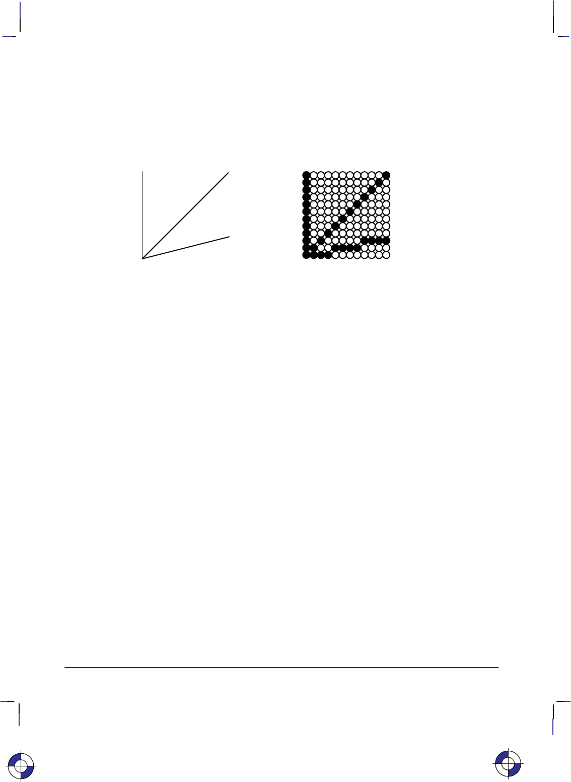
Vectors and Raster Images
Your plotter or printer produces output from two types of data: vector or raster. Vector data
defines the data as a series of straight lines, or vectors; raster data defines it in terms of the
pixels, or dots, that make up the image. As you can see in the following example, even straight
lines are composed of a series of dots in raster images.
Figure 1. Vectors and Raster Images
Pen plotters are vector devices; that is, they receive vector data and produce vector output.
Printers, both ink jet and laser, and ink jet and electrostatic plotters are raster devices. Howev-
er, not all raster devices accept and handle data the same way. For example, your raster device
may be able to accept vector data, which it then converts into raster data before printing or plot-
ting. Additionally, your raster device may be able to accept raster data directly, thereby saving
the processing time of vector-to-raster conversion, which may be significant.
Graphics Limits
The physical page is the actual piece (sheet or roll) of media, the paper or other substance on
which the device is to print or plot its output. The term is also used to refer to the size of the
media.
The area available for printing or plotting usually does not extend to the limits of your paper or
other media. There is a physical limit beyond which your device cannot draw. This limit pro-
vides a neat margin for holding the media, and prevents the smearing of ink by pen-plotter
pinch rollers and loss of vacuum on electrostatic plotters and printers.
The device recognizes two types of graphics limits:
Hard-clip limits
Soft-clip limits.
Hard-clip limit refers to a physical boundary beyond which, for example, a pen cannot move.
Soft-clip limit refers to a boundary set by a program, and allows pen movement only within its
borders. Similarly, ink jet and other plotters and printers have physical limits and program-set
limits beyond which no plotting or printing occurs. You can set soft-clip limits at any time in
your program. When you switch on or initialize the device, the hard-clip and soft-clip limits
are the same.
This is the blue on page 4 (seq: 22)This is the blue on page 4 (seq: 22)
5
This is the black on page 5 (seq: 23)
Company confidential. HP-GL/2 and HP RTL Reference Guide, draft 2. Freeze Status: open
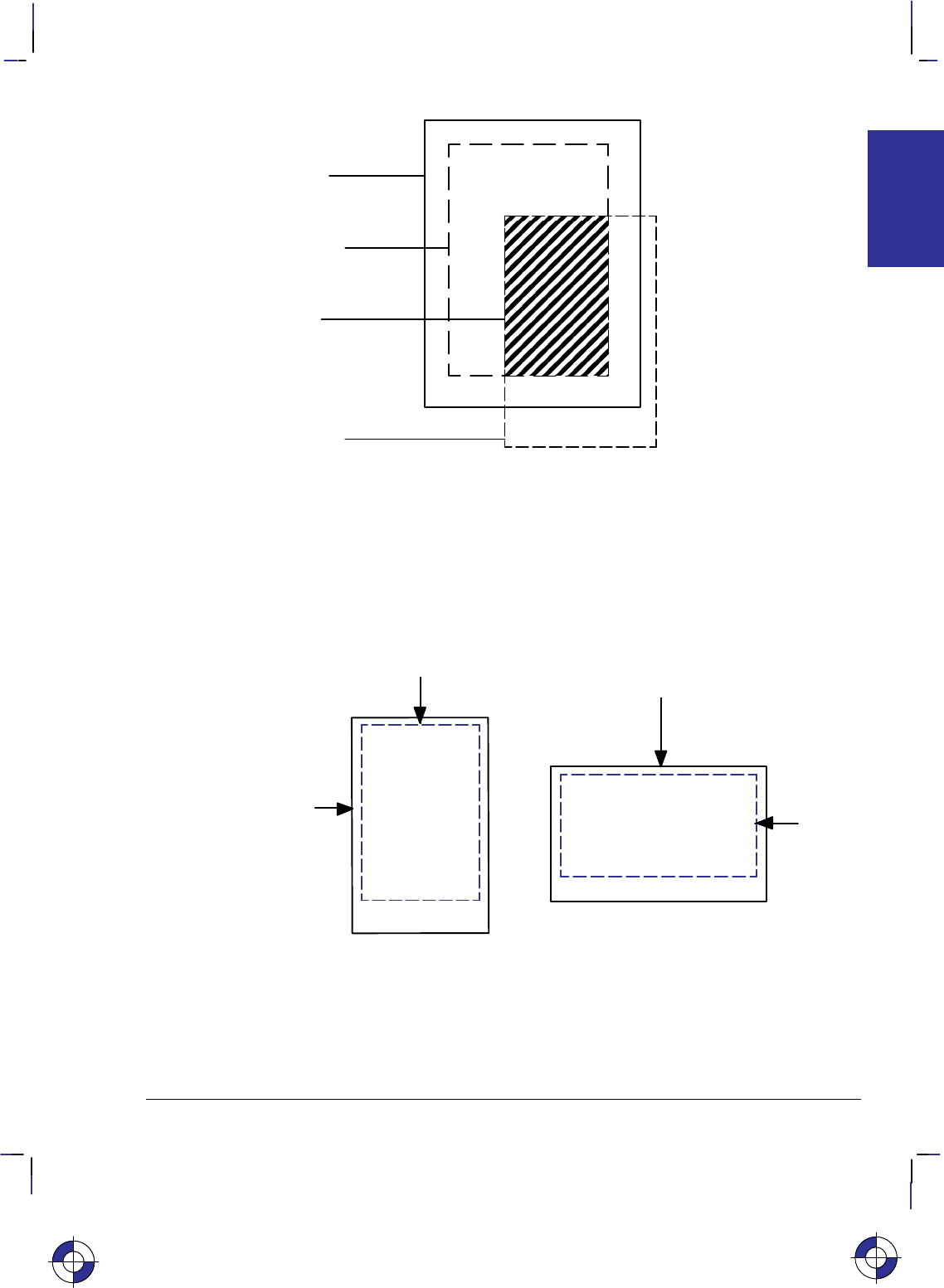
Edge of
printing
medium
HardĆclip
limits (PS
instruction)
Effective
window
SoftĆclip
limits (IW
instruction)
Figure 2. Hard-Clip and Soft-Clip Limits and the Effective Window
Hard-Clip Limits
The hard-clip limits represent the physical boundary beyond which the device cannot plot or
print data. These are device-dependent boundaries. Some devices can automatically sense the
media size and set the hard-clip limits inside the media edges. One margin is often larger than
the others; refer to the documentation for your device for details of page sizes. The hard-clip
limits are also referred to as the logical page.
Hard-clip limits
Hard-clip
limits
Edge of page
Edge of
page Printable area Printable area
Figure 3. Hard-Clip Limits
This is the blue on page 5 (seq: 23)
PRINTING
PLOTTING &
6
This is the black on page 6 (seq: 24)
Company confidential. HP-GL/2 and HP RTL Reference Guide, draft 2. Freeze Status: open
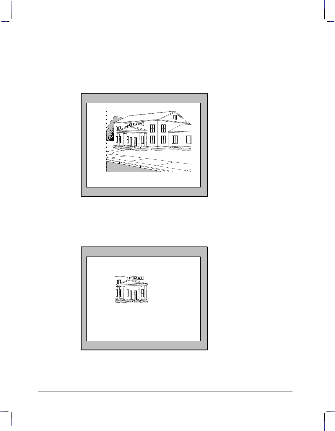
Soft-Clip Limits
Soft-clip limits temporarily restrict the positioning of data to a specified area of the page.
These limits let you draw attention to a particular set of data and they are often called windows.
Usually soft-clip limits ensure that nothing is drawn beyond a particular portion of the page.
For example, look at the following sketch of a public library:
Figure 4. Image Before Applying Soft-Clip Limits
After printing the full picture, suppose that you decide to draw a new picture showing only the
entrance area, using the space around it for text. To create the new image, just add soft-clip
limits to temporarily restrict printing to the part that you want. Then add program lines to ex-
tend the soft-clip limits and add the text. Refer to the next illustration:
You can add
text here
Figure 5. Image After Applying Soft-Clip Limits
7
This is the black on page 7 (seq: 25)
Company confidential. HP-GL/2 and HP RTL Reference Guide, draft 2. Freeze Status: open
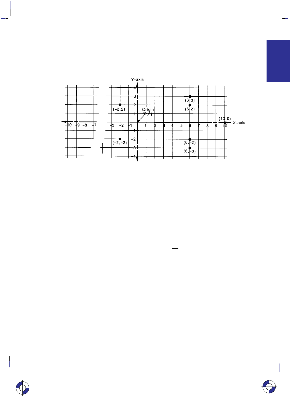
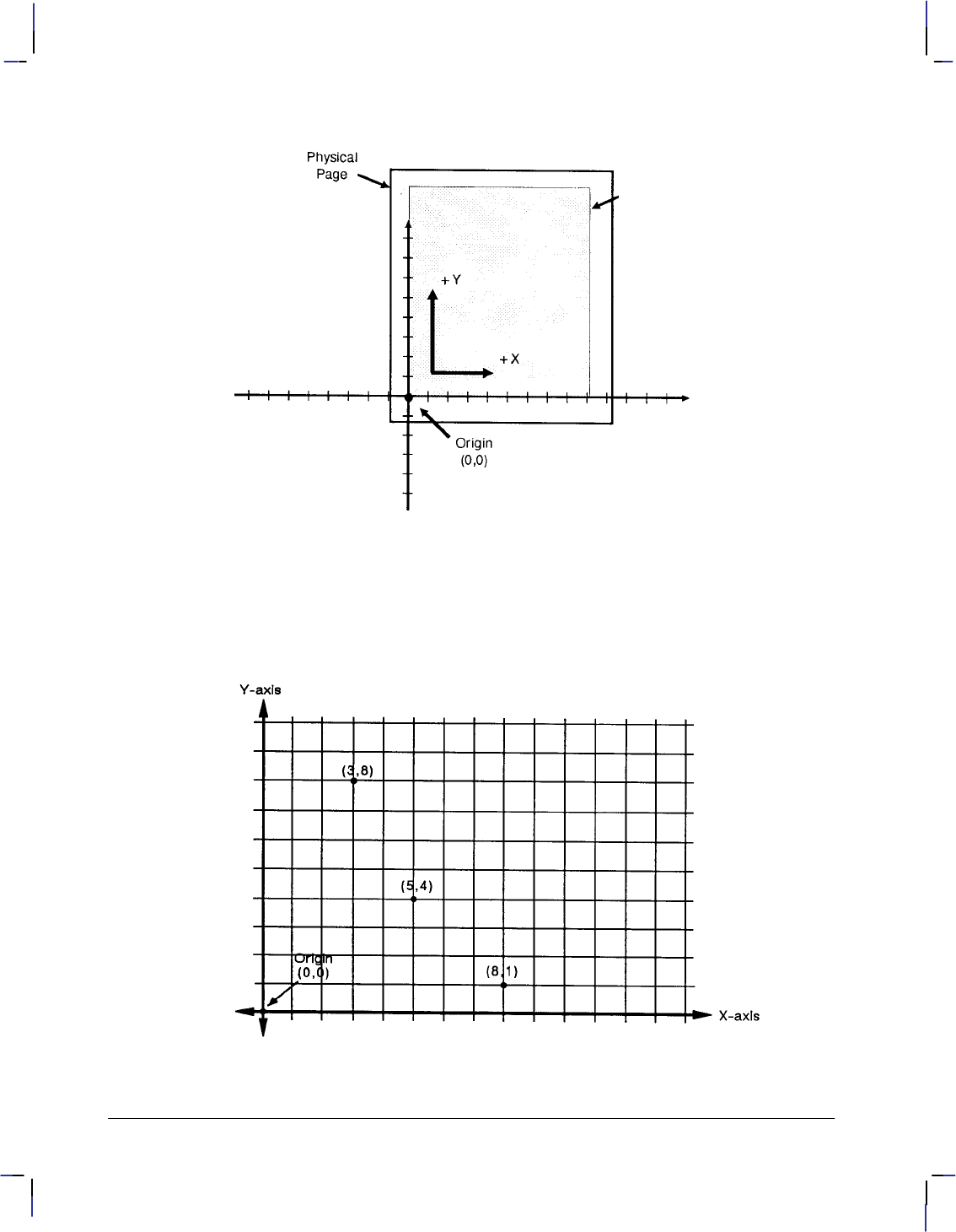
The Coordinate System
HP-GL/2, PCL, and HP RTL all use a Cartesian Coordinate System, which is a grid formed by
two perpendicular axes, usually called the X-axis and Y-axis (refer to Figure 6). The intersec-
tion of the axes is called the origin of the system and has a location of (0,0).
Figure 6. Coordinate System
To locate any point on the grid, move from the origin a number of units along the X-axis, then
move a number of units parallel to the Y-axis. The number of units you move matches a coordi-
nate location. Each point is designated by the combination of its X-coordinate and
Y-coordinate, known as an X,Y coordinate pair. In the figure above, positive X values are
plotted to the right of the origin, and positive Y values are plotted above the origin.
Study the figure above to locate these points: (0,0); (–2,2); (6,2); (6,3); (10,0); (6,–3); (6,–2);
(–2,–2); (0,0). Draw a straight line between each point in the order listed. (You should have
drawn an arrow pointing right.) This is a simple demonstration of how to define a vector pic-
ture in HP-GL/2 mode.
Note: To specify a point when programming an application, you must always give a complete
X,Y coordinate pair; the X coordinate is first and the Y coordinate second. This book shows
coordinate pairs in parentheses (X,Y) for clarity. Do not use parentheses in your instruction
sequence.
Using the default HP-GL/2 coordinate system, the origin for “printers” (see page 10) is in the
lower-left corner of the window, as shown in the figure below. Using the IP or IR instruction,
you can move the origin to other locations. Then, using the SC instruction, you can define
practically any units for your coordinate system. See Using Scaling Effectively on page 33.
In HP-GL/2 for “plotters” (see page 10) using portrait orientation, the origin is in the upper-left
corner, and increasing Y-values go across the page. In HP-GL/2 for “plotters” using landscape
orientation, the origin is in the upper-right corner, and increasing Y-values go down the page.
In HP RTL and PCL, the origin is in the upper-left corner, and increasing Y-values go down the
page. The HP RTL coordinate system is described in The Current Active Position (CAP) on
page 347, and interactions between different coordinate systems are explained on page 10.
Adapting the HP-GL/2 system to match PCL and HP RTL is described on pages 37 and 38.
This is the blue on page 7 (seq: 25)
PRINTING
PLOTTING &
8
This is the black on page 8 (seq: 26)
Company confidential. HP-GL/2 and HP RTL Reference Guide, draft 2. Freeze Status: open
HardĆclip Limits
The default HPĆGL/2
Coordinate System
is positioned so that
the Effective Window
lies in the upperĆright
quadrant of the CarĆ
tesian Coordinate
System
Figure 7. Origin of Coordinates
Absolute and Relative Movement
HP-GL/2, PCL, and HP RTL all have the concept of a current position; in HP-GL/2, this is
called the current pen location; in PCL and HP RTL, it is the current active position.
Figure 8. Absolute Movement
9
This is the black on page 9 (seq: 27)
Company confidential. HP-GL/2 and HP RTL Reference Guide, draft 2. Freeze Status: open
The PA (Plot Absolute) and PR (Plot Relative) instructions of HP-GL/2 allow you to specify
whether you want to draw using absolute or relative “pen” moves. Absolute movement uses
X,Y coordinates to specify an exact, fixed point relative to the origin (0,0). In Figure 8, the
coordinates (3,8), (5,4), and (8,1) are always in the same place with respect to the origin, no
matter where the pen is when the coordinates are issued.
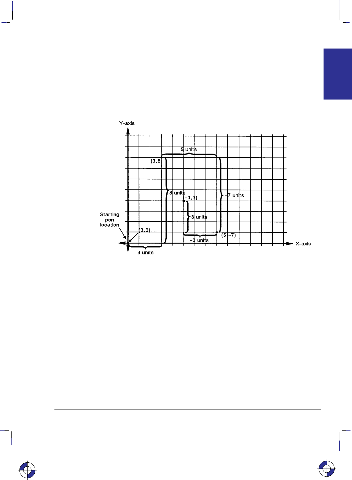
Relative movement uses X,Y increments to specify the number of units that the pen moves
from its current pen location. All HP-GL/2 instructions that use relative increments include
“relative” in their name, except the PE (Polyline Encoded) instruction. An example is the ER
(Edge Rectangle Relative) instruction.
Figure 9. Relative Movement
In Figure 9 for example, assume that the pen is currently at the origin (0,0). To move to the
absolute points shown in the previous figure using relative coordinates, count 3 units to the
right and 8 units up from the current pen location; these are both positive directions with re-
spect to the origin. This is the relative location (3,8). Now move 5 positive X-units and 7
negative Y-units from this location to the lower point; this is the relative location (5,–7). From
this location, move to the last point by moving 3 negative X-units and 3 positive Y-units:
(–3,3).
Relative movement is useful in many applications where you know the dimensions of the shape
you want, but do not want to calculate the absolute coordinates. For example, if you want a
box 4 X-units by 8 Y-units, you can use the ER (Edge Rectangle Relative) instruction to draw
the box without having to calculate the absolute coordinates of the opposite corner. (The ER
instruction draws a rectangle using the current pen location as one corner, and the specified
relative coordinates as the opposite corner.)
Absolute pen movement is the default mode; coordinates received within a PU (Pen Up) or PD
(Pen Down) instruction are interpreted as absolute plotter-units unless a PR (Plot Relative)
instruction has established relative mode. As with absolute coordinates, the relative units can
be either user-units or plotter-units (see page 12), depending on whether the SC (Scale) instruc-
tion is in effect.
This is the blue on page 9 (seq: 27)
PRINTING
PLOTTING &
10
This is the black on page 10 (seq: 28)
Company confidential. HP-GL/2 and HP RTL Reference Guide, draft 2. Freeze Status: open
Note: Relative increments are added to the current pen location. The device automatically
converts the new relative location to absolute coordinates and updates the current pen location.
Therefore, since relative movement can cause some rounding if scaled coordinates are not inte-
gers, absolute movement or integers should be used to guarantee end-points. Using relative
coordinates can be faster in cases where the I/O speed limits your print speed, since relative
coordinates are generally smaller numbers and therefore need less data transmitted over the I/O
interface.
Interactions between Different Coordinate Systems
Landscape
orientation
HP RTL
and PCL
HP-GL/2
printers
HP-GL/2
plotters
Portrait
orientation Landscape
orientation
Portrait
orientation
Portrait
orientation Landscape
orientation
or
or
Figure 10. HP RTL, PCL, and HP-GL/2 Coordinate Systems; the “orientation” refers
to the paper-feed direction
The default PCL and HP RTL coordinate systems are different from the default HP-GL/2 coor-
dinate system; furthermore, the default system in HP-GL/2 differs for devices that support the
HP-GL/2 Technical Graphics Extension (see page 77; devices termed “plotters” in Figure 10)
and those that do not (“printers” in Figure 10).
For devices that support the Technical Graphics Extension, the page size is determined by the
PS (Plot Size) instruction; for other devices, the page size is the picture frame size imported
from PCL. In addition, the default origin is at different places, depending on the context (PCL,
HP RTL, or HP-GL/2), the device type (“plotter” or “printer”), and the orientation (portrait or
landscape direction of paper feed). The directions of +X and +Y also differ.
The HP-GL/2 coordinate system can be set up to match the PCL and HP RTL coordinate sys-
tems; see the examples on pages 37 and 38.
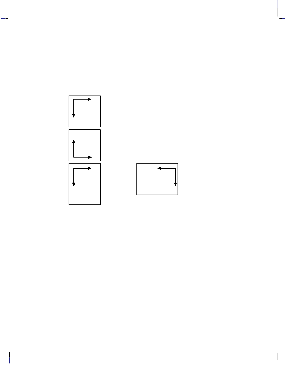
The relationship between the orientation of the HP-GL/2 coordinate system and the PCL or
HP RTL coordinate system is important if you are using PCL or HP RTL with HP-GL/2. The
following figure illustrates this relationship for the default HP-GL/2 orientation for “printers”
and the PCL logical page orientation. As shown in the illustration, in this HP-GL/2 orientation,
the origin of the HP-GL/2 coordinate system defaults to the lower-left corner of the PCL picture
frame. (The HP-GL/2 and PCL X-coordinates increase in the same direction, but the Y-coordi-
11
This is the black on page 11 (seq: 29)
Company confidential. HP-GL/2 and HP RTL Reference Guide, draft 2. Freeze Status: open
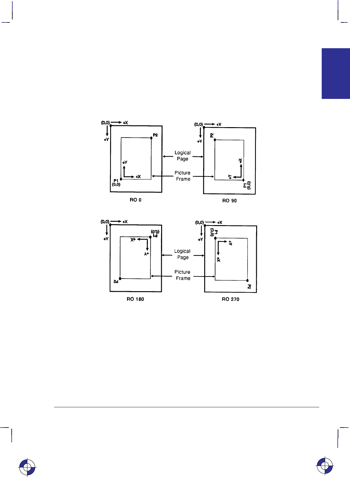
nates increase in opposite directions.) Notice that a change in the PCL logical page orientation
changes the orientation of the PCL coordinate system and the HP-GL/2 coordinate system.
The relationship between the coordinate systems can be changed using the HP-GL/2 RO (Ro-
tate) instruction. Rotations specified by the RO instruction are relative to the default HP-GL/2
orientation (which matches the PCL orientation). Figure 11 shows how the RO instruction mo-
difies the HP-GL/2 orientation relative to the logical page.
Note: A change in PCL print direction has no effect on the HP-GL/2 orientation, the physical
position of the picture frame, or the picture frame anchor point.
Figure 11. Effects of Rotation on the Coordinate System; the outer rectangles repre-
sent the PCL coordinates, the inner ones those of HP-GL/2; P1 and P2 are defined on
page 31
This is the blue on page 11 (seq: 29)
PRINTING
PLOTTING &

12
This is the black on page 12 (seq: 30)
Company confidential. HP-GL/2 and HP RTL Reference Guide, draft 2. Freeze Status: open
Units of Measure
HP-GL/2, PCL, and HP RTL use different systems for measuring units. See the PCL 5 Refer-
ence Guide for information on PCL units of measure.
HP-GL/2 Units of Measure
In HP-GL/2 mode, you can measure along the X,Y axes and express coordinates using two
types of units: plotter-units and user-units.
One plotter-unit equals 0.025 mm. When you specify distances in plotter-units, the device con-
verts the number of plotter-units to equivalent dot coordinates before printing. Under default
conditions, the device uses plotter-units.
The following table lists equivalent measurements for plotter-units.
Plotter-units Equivalent Value
1 plotter-unit = 0.025 mm ( 0.00098 inch)
40 plotter-units = 1 mm
1016 plotter-units = 1 inch
3.39 plotter-units = 1 dot at 300 dots per inch
User-units: The size of units along the X and Y axes may be redefined using the SC (Scale)
instruction; see Scaling on page 24 and the description of the SC instruction on page 290.
User-units allow you to customize the coordinate system to represent any value. For example,
you could plot the moon cycle for the year by dividing the X-axis into 31 units for days of the
month and the Y-axis into 12 units for months of the year. To mark a point on December 25,
you would give the coordinate (25,12) rather than calculating the exact location in plotter-units.
Before printing, the device internally converts user-units to dot locations.
Internally, the device uses a different unit of measure. It maps HP-GL/2, HP RTL, and PCL
units to this unit of measure. This internal unit is device-dependent, typically 1/7200 inch. All
positioning is kept in internal units and rounded to physical dot positions when data is printed.
HP RTL Units of Measure
In HP RTL (and also PCL), coordinates are normally specified in terms of the native resolution
of the device. You can also specify the dimensions of HP RTL images in decipoints
(1/720-inch). See Setting the Width and Height in HP RTL on page 342.
This is the blue on page 12 (seq: 30)

13
This is the black on page 13 (seq: 31)
Company confidential. HP-GL/2 and HP RTL Reference Guide, draft 2. Freeze Status: open
Isotropic and Anisotropic Scaling
When you alter the scale of an image, you can indicate whether units are of equal size on the
X- and Y-axes (isotropic scaling) or unequal (anisotropic scaling). Isotropic scaling preserves
the shapes of things like circles and squares; anisotropic scaling distorts circles into ellipses and
squares into rectangles. In the following diagram, the X-axis is assumed to be horizontal, and
the Y-axis vertical.
Figure 12. Isotropic and Anisotropic Scaling
HP Printer Job Language (PJL)
Printers and plotters that use HP RTL also recognize some of the commands of HP’s Printer Job
Language (PJL). These commands allow you to control the device and its operating environ-
ment independently of the program that generates the plotted or printed image. The relevant
commands are summarized on page 394.
Context Switching
There are a number of commands that are recognized by a range of plotters and printers, for
switching between HP RTL, PCL, HP-GL/2, and PJL:
HP-GL/2 HP RTL
PJL
Enter RTL Mode (
Enter HP-GL/2 Mode
Universal Exit Language
(
@PJL ENTER
LANGUAGE=HPGL2
ESC%#A)
ESC%#B)
ESC%–12345X)
ESCor Reset ( E)
(
or PCL
@PJL ENTER
LANGUAGE=PCL
(PCL printers only)
Figure 13. Switching from One Context to Another
This is the blue on page 13 (seq: 31)
PRINTING
PLOTTING &
This is the blue on page 13 (seq: 31)

14
This is the black on page 14 (seq: 32)
Company confidential. HP-GL/2 and HP RTL Reference Guide, draft 2. Freeze Status: open
You can find more details in the descriptions of the HP RTL commands (those beginning ),
starting on page 403. The @PJL commands are described on page 394.
HP-GL/2 instructions and HP RTL commands interact with each other. There is a detailed de-
scription of the effects of each environment on the other on page 391.

15
This is the black on page 15 (seq: 33)
Company confidential. HP-GL/2 and HP RTL Reference Guide, draft 2. Freeze Status: open
PART 2: HP-GL/2
This Part contains the following sections:
$'% "'%#('#" '# ,
" &*+),+#'& )',(*
& ++,* & '+#'&
$#&!
2 0&+/
$'% , %"
" '& #!,)+#'& & ++,* )',(
" +') )',(
" '$0!'& )',(
" #& & #$$ ++)#,+* )',(
" ")+) )',(
2 )#&+#&!
$'% , *'"&#"&
" "&#$ )("#* /+&*#'&
" $++ /+&*#'&
" ,$2'&+/+ /+&*#'&
" #!#+#1#&! /+&*#'&
" -& ).#&! /+&*#'&
" -& /+ /+&*#'&
$'% , "&'%('#" %"
An alphabetical list of all the HP-GL/2 instructions.
$'% (!!%+ # , ) $""&
,&+#'&* ,((')+
).) & 0*+% ")+)#*+#*
'')#&+ &!*
"') &!$*
#$$ 0(* & #& )'()+#*
")+)* & '&+*
&* & '$')*
&#+#$ '&#+#'&*
This is the blue on page 15 (seq: 33)

16
This is the black on page 16 (seq: 34)
Company confidential. HP-GL/2 and HP RTL Reference Guide, draft 2. Freeze Status: open

17
This is the black on page 17 (seq: 35)
Company confidential. HP-GL/2 and HP RTL Reference Guide, draft 2. Freeze Status: open
Chapter 2: Introduction to HP-GL/2
HP-GL/2 is the standardized version of the Hewlett-Packard Graphics Language. It is designed
to provide a set of consistent functions across a wide range of peripheral devices, both plotters
and printers. Its aim is therefore to reduce programming effort and the future compatibility of
your programs, while allowing great flexibility in creating images.
This chapter describes the principles of HP-GL/2 and introduces the following topics:
The Instruction Groups—the Kernel and the Extensions.
Pen Status and Location.
Scaling.
HP-GL/2 Instructions and Syntax.
HP-GL/2 consists of a kernel set of instructions that are supported on all HP-GL/2 devices. In
addition, there are sets of extensions that allow you to make full use of the functions of particu-
lar types of device. These extension instructions are not supported on all HP-GL/2 devices.
In addition to using the instructions of HP-GL/2, you may also want to use the commands of
the PCL Printer Language or of the HP Raster Transfer Language (HP RTL).
The Instruction Groups
HP-GL/2 is made up of a core set of instructions (called the HP-GL/2 kernel) and several ex-
tensions. All HP-GL/2 devices support the kernel instructions. The extensions (see page 20)
help you to make use of special technologies or device capabilities. Many plotters support the
Technical Graphics Extension; many devices also support the Palette Extension. The remaining
extensions make use of specific technologies and are, therefore, device-specific.
The Kernel
The kernel is the foundation of HP-GL/2 and contains most of the instructions. All HP-GL/2
devices support the kernel instructions. The kernel consists of five functional groups:
Configuration and Status.
Vector.
Polygon.
Line and Fill Attributes.
Character.
Each of these groups is explained below. Guidance on how to use the instructions of each
group is given in Chapter 3: The HP-GL/2 Kernel on page 29.
This is the blue on page 17 (seq: 35)
INTRODUCTION
HP-GL/2

18
This is the black on page 18 (seq: 36)
Company confidential. HP-GL/2 and HP RTL Reference Guide, draft 2. Freeze Status: open
The Configuration and Status Group
The instructions in this group help you set up the environment for your plot, by establishing
default conditions and scaling and manipulating the plotting area. There is more information
starting on page 29.
CO[“c...c”] Comment
DF Default Values
IN[n] Initialize
IP[p1x,p1y[,p2x,p2y]] Input P1 and P2
IR[p1x,p1y[,p2x,p2y]] Input Relative P1 and P2
IW[xll,yll,xur,yur] Input Window
PG[n] Advance Full Page
RO[angle] Rotate Coordinate System
RP[n] Replot
SC[xmin,xmax,ymin,ymax[,type[,left,bottom]]] Scale
or SCxmin,xfactor,ymin,yfactor,2
The Vector Group
The instructions in this group enable you to draw vector graphics, that is, lines and arcs. You
can use either absolute coordinates or relative coordinates for your data. There is more in-
formation starting on page 41.
AAxcenter,ycenter,sweep_angle[,chord_angle] Arc Absolute
ARxincr,yincr,sweep_angle[,chord_angle] Arc Relative
ATxinter,yinter,xend,yend[,chord_angle] Absolute Arc Three Point
CIradius[,chord_angle] Circle
PA[x,y[,...]] Plot Absolute
PD[x,y[,...]] Pen Down
PE[flag][value/x,y]...[flag][value/x,y] Polyline Encoded
PR[x,y[,...]] Plot Relative
PU[x,y[,...]] Pen Up
RTxincrinter,yincrinter,xincrend,yincrend[,chord_angle] Relative Arc Three Point
The Polygon Group
The instructions in this group use the polygon buffer in your peripheral device. Some of the
instructions draw shapes, while others control the filling and edges of these shapes. There is
more information starting on page 44.
EAx,y Edge Rectangle Absolute
EP Edge Polygon
ERx,y Edge Rectangle Relative
EWradius,start_angle,sweep_angle[,chord_angle] Edge Wedge
FP[fill_method] Fill Polygon
PM[polygon_definition] Polygon Mode
RAx,y Fill Rectangle Absolute
RRx,y Fill Rectangle Relative
WGradius,start_angle,sweep_angle[,chord_angle] Fill Wedge

19
This is the black on page 19 (seq: 37)
Company confidential. HP-GL/2 and HP RTL Reference Guide, draft 2. Freeze Status: open
The Line and Fill Attributes Group
The instructions in this group let you use different line types and fill types. They also let you
manipulate fill patterns and use different pen widths. There is more information starting on
page 53.
AC[x,y] Anchor Corner
FT[fill_type[,option1[,option2]]] Fill Type
LA[kind,value[,kind,value[,kind,value]]] Line Attributes
LTline_type[,pattern_length[,mode]] Line Type
PW[width[,pen]] Pen Width
RF[index[,width,height,pen_number[,pen_number...]]] Raster Fill Definition
SM[character[character2]] Symbol Mode
SP[pen_number] Select Pen
UL[index[,gap1,...gapn]] User-Defined Line Type
WU[type] Pen Width Unit Selection
The Character Group
The instructions in this group let you use different fonts or character sets, and manipulate their
direction, size, and appearance. There is more information starting on page 57.
AD[kind,value...[,kind,value]] Alternate Font Definition
CF[fill_mode[,edge_pen]] Character Fill Mode
CP[spaces,lines] Character Plot
DI[run,rise] Absolute Direction
DR[run,rise] Relative Direction
DT[label_terminator[,mode]]; Define Label Terminator
DV[path[,line]] Define Variable Text Path
ES[width[,height]] Extra Space
LBtext...text label_terminator Label
LO[position] Label Origin
SA Select Alternate Font
SD[kind,value...[,kind,value]] Standard Font Definition
SI[width,height] Absolute Character Size
SL[tangent_of_angle] Character Slant
SR[width,height] Relative Character Size
SS Select Standard Font
TD[mode] Transparent Data
This is the blue on page 19 (seq: 37)
INTRODUCTION
HP-GL/2

20
This is the black on page 20 (seq: 38)
Company confidential. HP-GL/2 and HP RTL Reference Guide, draft 2. Freeze Status: open
The Extensions
The extension instructions of HP-GL/2 let you exploit more fully the capabilities of your pe-
ripheral device. Many HP-GL/2 devices, especially plotters, support the Technical Graphics
extension, and many devices also support the Palette extension. The remaining groups make
use of specific technologies, and are therefore more device-specific. For example, because you
cannot digitize on raster devices, those devices do not support the Digitizing extension. The
extensions are:
Technical Graphics.
Palette.
Dual-Context.
Digitizing.
Advanced Drawing.
Advanced Text.
Each of these groups is explained below. Guidance on how to use the instructions of each
group is given in Chapter 4: The HP-GL/2 Extensions on page 77.
The Technical Graphics Extension
The instructions in this group add flexibility that is often required in technical fields, such as
computer-aided design, architectural rendering, integrated circuit layout, and so on. There is
more information starting on page 77.
BP[kind,value...[,kind,value]] Begin Plot
CT[mode] Chord Tolerance Mode
DL[character_number[character_number2]
[[,up]x,y...[,up],x,y] Download Character
EC[n] Enable Cutter
FR Frame Advance
MC[mode[,opcode]] Merge Control (also in the Advanced
Drawing Extension)
MG[message] Message
MT[type] Media Type
NR[timeout] Not Ready
OE;Output Error
OH;Output Hard-Clip Limits
OI;Output Identification
OP;Output P1 and P2
OS;Output Status
PS[length[,width]] Plot Size
QL[quality_level] Quality Level
ST[switches] Sort
VS[pen_velocity[,pen_number]] Velocity Select

21
This is the black on page 21 (seq: 39)
Company confidential. HP-GL/2 and HP RTL Reference Guide, draft 2. Freeze Status: open
The Palette Extension
The instructions in this group help you integrate raster technology with the vector capabilities
of your peripheral device; the instructions are not, however, restricted to raster devices, and pen
plotters may support this extension, defaulting some instructions in accordance with their
technology. There is more information starting on page 82.
CR[black-ref_red,white-ref_red,black-ref_green, Set Color Range for
white-ref_green,black-ref_blue,white-ref_blue] Relative Color Data
NP[n] Number of Pens
PC[pen[,red,green,blue]] Pen Color Assignment
SV[screen type[,option1[],option2]] Screened Vectors
TR[n] Transparency Mode
The Dual-Context Extension
The instructions in this group are useful when you want to integrate word-processed text and
raster graphics images with vector graphics for desktop presentations. There is more informa-
tion starting on page 83.
FIfont_id Primary Font Selection by ID
FNfont_id Secondary Font Selection by ID
SB[n] Scalable or Bitmap Fonts (also in the
Advanced Text Extension)
and the following commands of PCL and HP RTL:
%#A Enter PCL Mode/Enter HP RTL Mode
EReset
The Digitizing Extension
The instructions in this group are used only with pen plotters, and are used for digitizing coor-
dinates. There is more information starting on page 89.
DC Digitize Clear
DP Digitize Point
OD;Output Digitized Point and Pen Status
The Advanced Drawing Extension
The instructions in this group allow you to draw bezier curves, and to specify how raster de-
vices are to place picture elements (pixels) on the page. There is more information starting on
page 92.
BRx1,y1,x2,y2,x3,y3[,...x1,y1,x2,y2,x3,y3] Bezier Relative
BZx1,y1,x2,y2,x3,y3[,...x1,y1,x2,y2,x3,y3] Bezier Absolute
MC[mode[,opcode]] Merge Control (also in the Technical
Graphics Extension)
PP[mode] Pixel Placement
INTRODUCTION
HP-GL/2
This is the blue on page 21 (seq: 39)

22
This is the black on page 22 (seq: 40)
Company confidential. HP-GL/2 and HP RTL Reference Guide, draft 2. Freeze Status: open
The Advanced Text Extension
The instruction that forms this group allows you to use either 8-bit or 16-bit character sets.
There is more information starting on page 94.
LM[mode[,row_number]] Label Mode
SB[n] Scalable or Bitmap Fonts (also in the
Dual-Context Extension)
Pen Status and Location
Since printing vector graphics has traditionally been performed with pen plotters, the terms pen
and pen location (or pen position) are used to described the cursor in HP-GL/2 mode, and the
current active position (CAP) in HP RTL or PCL mode. Whether the pen is logical (for raster
devices) or physical (for pen plotters), it must be selected in order to print. Instructions such as
PU (Pen Up) or PD (Pen Down), and phrases such as “current pen position” or “moving the
pen” apply to the imaginary pen just as they do a physical pen on a pen plotter.
Pen Status
Pen status refers to whether the “pen” is up or down. Use the PU (Pen Up) instruction with X,Y
coordinates to move the pen to the desired printing location without drawing a line. Use the PD
(Pen Down) instruction with X,Y coordinates to lower the pen and begin drawing from the cur-
rent location to the first specified X,Y coordinate.
When you enter HP-GL/2 mode for the first time following a Reset (E) command, no pen
has been selected and the pen is up. This means that no lines are drawn when HP-GL/2 instruc-
tions are given until a pen is selected. This can be done using the SP (Select Pen) instruction.
Most drawing instructions require that the pen be lowered to produce marks on the page. Once
lowered with a PD instruction, the pen remains down for subsequent HP-GL/2 printing instruc-
tions until a PU or IN (Initialize) instruction is issued. The pen remains selected until a new SP
instruction is received. You must be aware of the pen’s up/down status to avoid drawing stray
lines between parts of your picture.
Note: Upon entry into HP-GL/2 mode, a good programming practice is to select a pen and is-
sue a pen-up move to the initial starting position. This ensures that a pen is selected and is in
the proper position to begin drawing.
Whenever the device receives a PD instruction, it produces a dot at the current pen loca-
tion. If the pen is already down when the device receives an instruction with an automatic
pen down, the unnecessary dot can mar your final output. For best results, include a PU
instruction before any instruction with an automatic pen down.
Only the portion of the pen falling within the effective window is printed. The pen is
centered on a line between the beginning and end points, with half of the pen width falling
on either side of this line.
The definition of each instruction tells you whether it has an automatic pen down. If you
find that part of your image is not drawn, make sure your instruction sequence uses the PD
instruction before the affected instructions.
This is the blue on page 22 (seq: 40)

23
This is the black on page 23 (seq: 41)
Company confidential. HP-GL/2 and HP RTL Reference Guide, draft 2. Freeze Status: open
Instructions that Include an Automatic Pen-Down Movement
Every time you use a PU or PD instruction, the device updates the pen up/down status. The
following instructions include an automatic PD instruction as part of their function. After per-
forming their complete function, they return the pen to its previous up/down state.
CI Circle
EA Edge Rectangle Absolute
EP Edge Polygon
ER Edge Rectangle Relative
EW Edge Wedge
FP Fill Polygon
LB Label
PE Polyline Encoded (using a flag)
RA Fill Rectangle Absolute
RR Fill Rectangle Relative
SM Symbol Mode
WG Fill Wedge
Pen Location
Pen location refers to the X,Y coordinates of the pen. Most instructions, when completed, up-
date the pen location. The next instruction then begins at that location. Some instructions do
not update the current pen location. The definition of each instruction tells you whether the
current pen location is updated or restored. Use the PU (Pen Up) instruction with the desired
X,Y coordinates to lift the pen and move it to a new location.
The DF (Default Values) instruction does not reset the current pen location; the IN (Initialize)
instruction moves it to the origin of the hard-clip limits. You should specify your beginning
pen location for each HP-GL/2 drawing.
“
Lost” Mode
Parameter values less than the range maximum are passed by the parser; these values may sub-
sequently be unscaled into device-dependent internal resolution units (for example, 7 200 or
9 600 units-per-inch) that exceed the device-dependent internally representable number range.
If this occurs, the device enters a “lost” mode; all relative drawing instructions are ignored until
a instruction is received which specifies an absolute move to a point within the internally repre-
sentable number range.
When “lost” mode is entered, the pen is raised and the following instructions are ignored: AA,
AR, AT, CI, CP, EA, ER, EW, LB, PE, PM, PR, RA, RR, RT, and WG.
The instructions allowed in “lost” mode are: AC, AD, CF, CO, DF, DI, DR, DT, DV, ES, FT,
IN, IP, IR, IW, LA, LO, LT, PA, PD, PG, PU, PW, RF, RO, RP, SA, SB, SC, SD, SI, SL, SM,
SP, SR, SS, TD, UL, WU, and the PM1/PM2 forms of PM.
The instructions IN, PG, RP, and PA, with in-range parameters, clear “lost” mode; PD and PU
in absolute plotting mode, with in-range parameters, also clear “lost” mode. When PD clears
“lost” mode, a line is drawn from the last valid current position to the first point in the PD pa-
rameter sequence. If PA clears “lost” mode, the pen will not go down until a PD instruction is
received.
INTRODUCTION
HP-GL/2
This is the blue on page 23 (seq: 41)

24
This is the black on page 24 (seq: 42)
Company confidential. HP-GL/2 and HP RTL Reference Guide, draft 2. Freeze Status: open
When “lost” in polygon mode, “PM2” clears “lost” mode, closes the current polygon using the
current pen state, and restores the original pen position and up/down state. “PM1” does not
clear “lost” mode, but it does close the current subpolygon using the current pen up/down state
if the starting vertex is valid. The buffer then contains:
the valid points up to, but not including the point that set “lost” mode;
the points after “lost” mode is cleared;
and the closure point.
Points stored after “lost” mode is cleared are stored as pen-up points until a PD instruction is
received.
When “lost” mode is entered while drawing an arc or a wedge, only the valid arc segments that
were generated before the arc segment that caused the device to be “lost” are drawn. If a rect-
angle instruction (EA, ER, RA, or RR) contains parameters that would make the device enter
“lost” mode, error 3 (invalid parameter) is set and the instruction is ignored.
Scaling
When you scale a drawing, you define your own units of measurement instead of using plotter-
units; the device converts your units (user-units) to dot positions for placing the image on the
page. Scaling allows control of the device using units that are easy for you to work with.
For example, you can scale your drawing to divide the drawing area into 100 squares. As you
plan the drawing, you can think in terms of 100 squares rather than plotter-units. Another ex-
ample of scaling is that since 400 plotter-units equals 1 centimeter, you can establish this scale
to print in user-units equal to 1 centimeter each.
Scaling begins with the scaling points, P1 and P2 (see The Scaling Points, P1 and P2 on page
31). P1 and P2 act as two points marking opposite corners of a rectangle. You can make this
rectangle any size and place it anywhere in relation to the origin, depending on the plotter-unit
coordinates you specify for P1 and P2. (P1 and P2 default to opposite corners of the hard-clip
limits, but you can change their locations using the Input P1 and P2 [IP] or Input Relative P1
and P2 [IR] instructions). P1 is also the default origin (0,0) for the coordinate system.
After you have defined the positions for P1 and P2, or have accepted the default, use this imagi-
nary rectangle to set up scaling for your drawing. With the SC (Scale) instruction you specify
how many sections the rectangle divides into horizontally (the X-axis) and how many sections
the rectangle divides into vertically (the Y-axis). In this way you create your user-units.
Scaling also allows you to enlarge or reduce your image by changing the locations of P1 and
P2. P1 and P2 represent physical locations in relation to the hard-clip limits. When the imagi-
nary rectangle formed by P1 and P2 is enlarged or reduced with the IP or IR instructions, the
HP-GL/2 image is also enlarged or reduced to fit the new P1/P2 rectangle. (For a more detailed
explanation of scaling and the Scale (SC) instruction, see page 290.)
For importing existing HP-GL/2 images, another method of enlarging or reducing drawings
exists. It involves varying the size of the hard-clip limits and is described in Absolute and Rel-
ative Pen Movement on page 8. This method allows you to scale an image while maintaining
the aspect ratio of all elements (including fonts). The Scale instruction does not affect the size
of fonts.
This is the blue on page 24 (seq: 42)
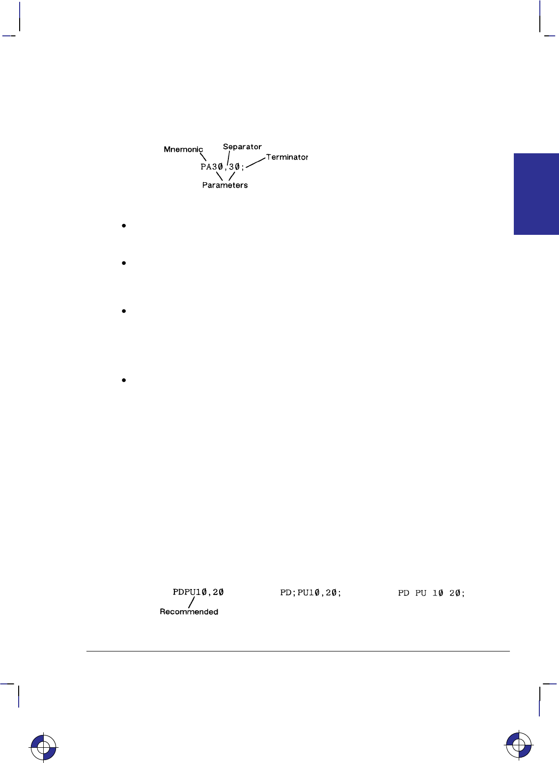
25
This is the black on page 25 (seq: 43)
Company confidential. HP-GL/2 and HP RTL Reference Guide, draft 2. Freeze Status: open
HP-GL/2 Syntax
The following illustration shows a typical HP-GL/2 instruction and the description of its com-
ponents.
Each HP-GL/2 instruction consists of up to four parts:
A two-character mnemonic which defines the function of the instruction. It can be upper-
case or lowercase. For example, IN is the Initialize instruction, SP is the Select Pen
instruction, and CI is the Circle instruction.
Parameters are used with certain HP-GL/2 instructions to tell the device to complete the
instruction in a particular way. Some instructions have no parameters, some have required
parameters. and some have optional parameters. Some instructions have additional param-
eters that further qualify other parameters.
Separators which separate one parameter from the next. You are recommended to use a
comma as a separator, though you can use spaces. However, in some computer systems,
spaces are automatically removed before being sent to the peripheral device. If the second
of a pair of parameters starts with a plus or minus sign, this is also interpreted as a separa-
tor for numeric parameters. Separators are not used with the DT, LB, PE, and SM
instructions.
A terminator which separates one instruction from the next. The recommended way of
separating instructions is by using no explicit terminator, that is, the mnemonic for the next
instruction constitutes the separator from the previous. Most instructions can also be
terminated with a semicolon, though dropping the semicolon will reduce the amount of
data transmitted to the device by about 10%. Some instructions (for example, PG, PE, and
all output instructions) must be terminated with a semicolon. The LB instruction, de-
scribed on page 206, requires a special terminator set by the DT (Define Label Terminator)
instruction (see page 154). We recommend you place a semicolon at the end of the last
instruction in your program to terminate the instruction and ensure the proper completion
of your program.
In the example above, “PA” is the mnemonic, “30” and “30” are its two parameters, “,” is a
separator, and “;” is the terminator.
The following illustration shows the flexibility of the syntax. Each variation of the two-instruc-
tion sequence is permissible; however, the first method is recommended—using the first letter
of the next mnemonic to terminate instructions, using no spaces between parameters, and sepa-
rating parameters with a comma. This method sends fewer bytes to the device, thereby
reducing transmission times.
This is the blue on page 25 (seq: 43)
INTRODUCTION
HP-GL/2

26
This is the black on page 26 (seq: 44)
Company confidential. HP-GL/2 and HP RTL Reference Guide, draft 2. Freeze Status: open
The program examples used in this book are spaced out so that the function of each instruction
can be clearly seen. It is not recommended to arrange your instructions in this manner. In par-
ticular, do not leave any spaces between the DT and LB instructions and their parameters.
Notation Used in this Book to Present Instruction Syntax
The following notation is used in the descriptions of instruction syntax in this book:
MN Instruction mnemonic, always two uppercase characters.
parameters All parameters are shown in italics. A comma is always shown as
the separator between parameters. A space, “+”, or “–” is also
valid, although not preferred. (A “+” or “–” is a valid separator
only for numeric parameters.)
[ ] Parameters in square brackets are optional; you must have an even
number of X,Y coordinates.
[,...] Any number of the previous parameter; you must have an even
number of X,Y coordinates.
;Instruction terminator. A semicolon is normally optional and is
shown in square brackets in most instruction syntaxes. Although a
semicolon is always shown in instruction syntaxes, any non-nu-
meric character is also valid.
Three exceptions to the optional use of the semicolon as an
instruction terminator occur in the following instructions: PE (Po-
lyline Encoded), LB (Label), and CO (Comment). PE and PG
(Advance Full Page) must be terminated by a semicolon. LB is
terminated by the non-printing end-of-text character (—deci-
mal 3), or a user-defined character. The comment string of the
CO instruction must be delimited by double quotes.
A semicolon terminator is always required following the last
instruction prior to leaving HP-GL/2 mode.
Labels require a special terminator, usually the ASCII end-of-text
() character (decimal code 3). See the descriptions of the LB
and DT instructions.
Note that although X,Y coordinates are normally shown in parentheses in text—for example,
(3,4) or (0,0)—the parentheses are not part of the syntax and must not be entered in your
instructions.
Omitting Optional Parameters
Some instructions have optional parameters that take on default values if they are omitted.
When you omit a parameter, you must omit all subsequent parameters in the same instruc-
tion—the DT (Define Label Terminator) instruction is an exception.
For example, the LT (Line Type) instruction has three optional parameters: line_type, pat-
tern_length, and mode. The following instruction shows all three being used (line_type = 6,
pattern_length = 25, mode = 1).
LT 6,25,1;
If you omit the second parameter you must also omit the third parameter, as shown below:
LT 6;

27
This is the black on page 27 (seq: 45)
Company confidential. HP-GL/2 and HP RTL Reference Guide, draft 2. Freeze Status: open
The device uses the most recently specified pattern_length and mode. If you have not specified
a pattern_length or mode since sending a DF (Default Values) or IN (Initialize) instruction, the
device uses the parameter’s defaults.
For example, if you send the following instructions (omitting the second parameter), the device
interprets the “1” as the second parameter, not the third:
LT 6,1; or LT 6,,1;
Parameter Formats
You must give parameters in the format (type of units) required by each HP-GL/2 instruction.
The required format is stated in the parameter table of each instruction’s description, and is de-
scribed below.
Numbers within the defined ranges do not cause errors; however, the range may exceed the de-
vice’s physical printing area. Numbers that move the pen position outside the effective window
result in image clipping. The ranges specified are minimums; your device may support a great-
er range of values than those shown in this book.
Integer
An integer from –8 388 608 (–223) to 8 388 607 (223 – 1). The device automatically rounds
fractional parameters to the nearest integer within the range. Sending a number outside the
parameter range may produce unexpected results.
Clamped Integer
An integer from –32 768 (–215) to 32 767 (215 –1). The device automatically rounds fractional
parameters to the nearest integer. Sending a number outside this range does not cause an error,
but the number is “clamped” to the limits of the range. For example, when parsing a clamped
integer, the device treats all numbers above 32 767 as 32 767. Certain instructions have param-
eters which are restricted to a smaller range. These ranges are listed in the parameter tables for
each instruction. Sending a number outside the reduced parameter range may produce unex-
pected results.
Real
A number between –8 388 608.000 0 (–223) and 8 388 607.999 9 (223 – 1). You are assured of
at least six significant digits (including integer and fractional portion). You may omit the deci-
mal point when no decimal fraction is specified. Sending a number outside the parameter range
may produce unexpected results. The device cannot use exponential format numbers (for ex-
ample, 6.03E8). If you are using a computer or language that uses the exponential format, you
must use integer variables or a formatting technique to output fixed-point real numbers.
Clamped Real
A number between –32 768.000 0 (–215) and 32 767.999 9 (215 –1); you are assured of at least
six significant digits (including integer and fractional portion). You may omit the decimal point
when no decimal fraction is specified. Sending a number outside this range does not cause an
error, but the number is “clamped” to the limits of the range. For example, the device treats all
numbers above 32 767.999 9 as 32 767.999 9. Certain instructions have parameters which are
INTRODUCTION
HP-GL/2
This is the blue on page 27 (seq: 45)

28
This is the black on page 28 (seq: 46)
Company confidential. HP-GL/2 and HP RTL Reference Guide, draft 2. Freeze Status: open
restricted to a smaller range. These ranges are listed in the parameter tables for each instruc-
tion. Sending a number outside the reduced parameter range may produce unexpected results.
Label or Character
Any character or sequence of characters. In the HP-GL/2 language, text is described using the
term “label”. Refer to the Label (LB) instruction on page 206 for a complete description.
Current Unit
When you see the term “current units” in a parameter table, the unit system of that parameter
depends on whether scaling is on or off. When scaling is on, the units are user-units; when
scaling is off, the units are plotter-units (described under Units of Measure on page 12).
Quoted String
A character or sequence of characters enclosed in double quotes. It is used primarily in the MG
(Message), BP (Begin Plot), and CO (Comment) instructions. Two consecutive double quotes
form one double quote in the string.
29
This is the black on page 29 (seq: 47)
Company confidential. HP-GL/2 and HP RTL Reference Guide, draft 2. Freeze Status: open
Chapter 3: The HP-GL/2 Kernel
The Kernel instructions form a base set of instructions that are normally supported on all HP-
GL/2 devices. They are grouped as follows:
The Configuration and Status Group page 29.
The Vector Group page 41.
The Polygon Group page 44.
The Line and Fill Attributes Group page 53.
The Character Group page 57.
This chapter also contains a description of HP-GL/2 Printing; see page 73.
The Configuration and Status Group
The Configuration and Status Group instructions help you:
Establish default conditions and values for HP-GL/2 features.
Scale images in the dimensional units you want to use.
Enlarge or reduce images for different media sizes.
Draw equal-sized and mirror-imaged drawings.
Adapt the coordinate system to match PCL and HP RTL.
Establish a window (soft-clip limits).
Rotate the HP-GL/2 coordinate system.
Add comments to your HP-GL/2 instruction sequence.
These instructions make no mark on the media; they establish default conditions, perform scal-
ing, and manipulate the plotting area.
The following instructions form the Configuration and Status Group:
CO Comment Allows comments to be included in an HP-GL/2 instruction
sequence.
DF Default Values Sets most programmable features to their default conditions.
IN Initialize Sets all programmable features to their default conditions.
IP Input P1 and P2 Establishes new or default locations for the scaling points P1
and P2.
IR Input Relative P1 and P2 Establishes P1 and P2 locations with respect to the hard-clip
limits.
IW Input Window Sets up a window (soft-clip limits).
This is the blue on page 29 (seq: 47)
KERNEL
HP-GL/2
30
This is the black on page 30 (seq: 48)
Company confidential. HP-GL/2 and HP RTL Reference Guide, draft 2. Freeze Status: open
PG Advance Full Page Terminates the plot and advances the page (see note).
RO Rotate Coordinate
System Rotates the HP-GL/2 coordinate system.
RP Replot Plots multiple copies of a stored plot (see note).
SC Scale Establishes a user-unit coordinate system.
Note: The PG and RP instructions are device-dependent; they are useful in plotter applications
and some printer applications, but are not the optimal solution for PCL printers. Other PCL
commands, for example, the Number of Copies (&l#X) command or the Form Feed ()
control code, perform similar functions.
The factory environment defaults are:
Scale mode is off (current units are plotter-units).
The soft-clip limits default to the hard-clip limits (in PCL dual-context mode, the window
is the default picture frame).
The default origin (0,0) depends on the type of device, and is shown on page 10. (PCL
dual-context uses the PCL default logical page coordinate system).
P1 and P2 are in opposite corners according to the viewing perspective, as shown on page
10 (in PCL dual-context mode, the lower-left and upper-right corners of the picture frame).
Establishing Default Conditions
Whether you are using HP-GL/2 mode, PCL printer language mode, or HP Raster Transfer
Language (HP RTL) mode, you should establish default conditions at the beginning of each
print job to prevent unexpected results due to “leftover” instruction parameters from a previous
job. From within HP-GL/2 mode there are two ways to establish default conditions: using the
IN (Initialize) instruction or using the DF (Default Values) instruction. You can also power the
device off and then on, or use the control-panel reset function (if available) to reset the device.
Using the IN instruction sets the device to its user-selected defaults. This process is called ini-
tialization. The Reset command (E) of PCL and HP RTL executes an IN instruction
automatically, so if a reset was sent at the beginning of your print job, HP-GL/2 instruction pa-
rameters are at their user-selected default state when HP-GL/2 mode is first entered. (On
devices that support the Technical Graphics Extension [see page 77] the Reset command
executes a BP [Begin Plot] instruction, which includes the functions of IN.)
Note: HP-GL/2 instruction parameters are set to their default values the first time HP-GL/2
mode is entered during a print job (assuming that an E reset is sent at the beginning of the
job). After instructions have been sent to modify the current print environment, the instruction
parameters are no longer set to their defaults. When you re-enter HP-GL/2 mode, immediately
sending an IN instruction ensures that HP-GL/2 features are set to their default conditions (if
that is what you want).
The DF instruction is not as powerful as the IN instruction. The conditions set by the DF and
IN instructions are described on pages 136 and 189 respectively.

31
This is the black on page 31 (seq: 49)
Company confidential. HP-GL/2 and HP RTL Reference Guide, draft 2. Freeze Status: open
The Scaling Points, P1 and P2
When you scale a drawing, you define your own units of measurement, which the device then
converts to plotter-units. Scaling relies on the relationship between two points P1 and P2.
These two points are called the scaling points because they take on the user-unit values that
you specify with the SC (Scale) instruction. You can change the locations of P1 and P2 using
either the IP (Input P1 and P2), or IR (Input Relative P1 and P2) instruction.
P1 and P2 always represent an absolute location, defined in plotter-units. They designate oppo-
site corners of a rectangular printing area. The P1/P2 rectangular area is not a graphics limit;
plotting is not restricted to the P1/P2 area. You can change the size of the rectangular printing
area and move it anywhere within the hard-clip limits, or even outside these limits, depending
on the plotter-unit coordinates you specify using the IP or IR instructions. The biggest benefit
of scaling is that your plot will normally retain the same relative proportions on any size of me-
dia, except when you use IP with parameters or IR.
If the SC (Scale) instruction is not used, that is scale mode is “off”, all HP-GL/2 measurements
are in fixed plotter-units (0.025 mm).
Using the Scale Instruction
Scaling allows you to establish units of measure with which you are familiar, or which are more
logical to your drawing. The SC (Scale) instruction determines the number of user-units along
the X- and Y-axes between P1 and P2. The actual size of the units depends on the locations of
P1 and P2 and the range of user-units set up by the SC instruction.
There are three types of scaling:
Anisotropic scaling indicates that the size of the units along the X-axis may be different
from the size of the units on the Y-axis.
Isotropic scaling indicates that the units are the same size on both axes.
Point-factor scaling sets up a ratio of plotter-units to user-units.
The Scale instruction does not change the locations of P1 and P2, only their coordinate values.
Also, scaling is not limited to the rectangular area defined by P1 and P2, but extends across the
entire plotting range.
For example, to divide the X-axis into 12 units representing months, and the Y-axis into 10
units representing currency values, specify the X-axis to scale from 0 to 12, and the Y-axis to
scale from 0 to 10. P1 becomes the origin with user-unit coordinate (0,0) and P2 becomes
(12,10). The entire plotting area is now divided into the desired units. Subsequent plotting
instructions use these units. If you tell the device to move to the point (3,4), it moves to the
location equivalent to (3,4) user-units, not (3,4) plotter-units.
If you move the locations of P1 and P2, the size of the user-units changes. Assume that the
previous illustration showed P1 and P2 in their default locations (the lower-left and upper-right
corners, respectively, of the hard-clip limits for PCL printers). In Figure 15, P1 and P2 have the
same user-unit values (set with the Scale instruction, SC), but their physical locations have
been changed, using the IP (Input P1 and P2) instruction. Note that the size of the user-units
has decreased.
This is the blue on page 31 (seq: 49)
KERNEL
HP-GL/2
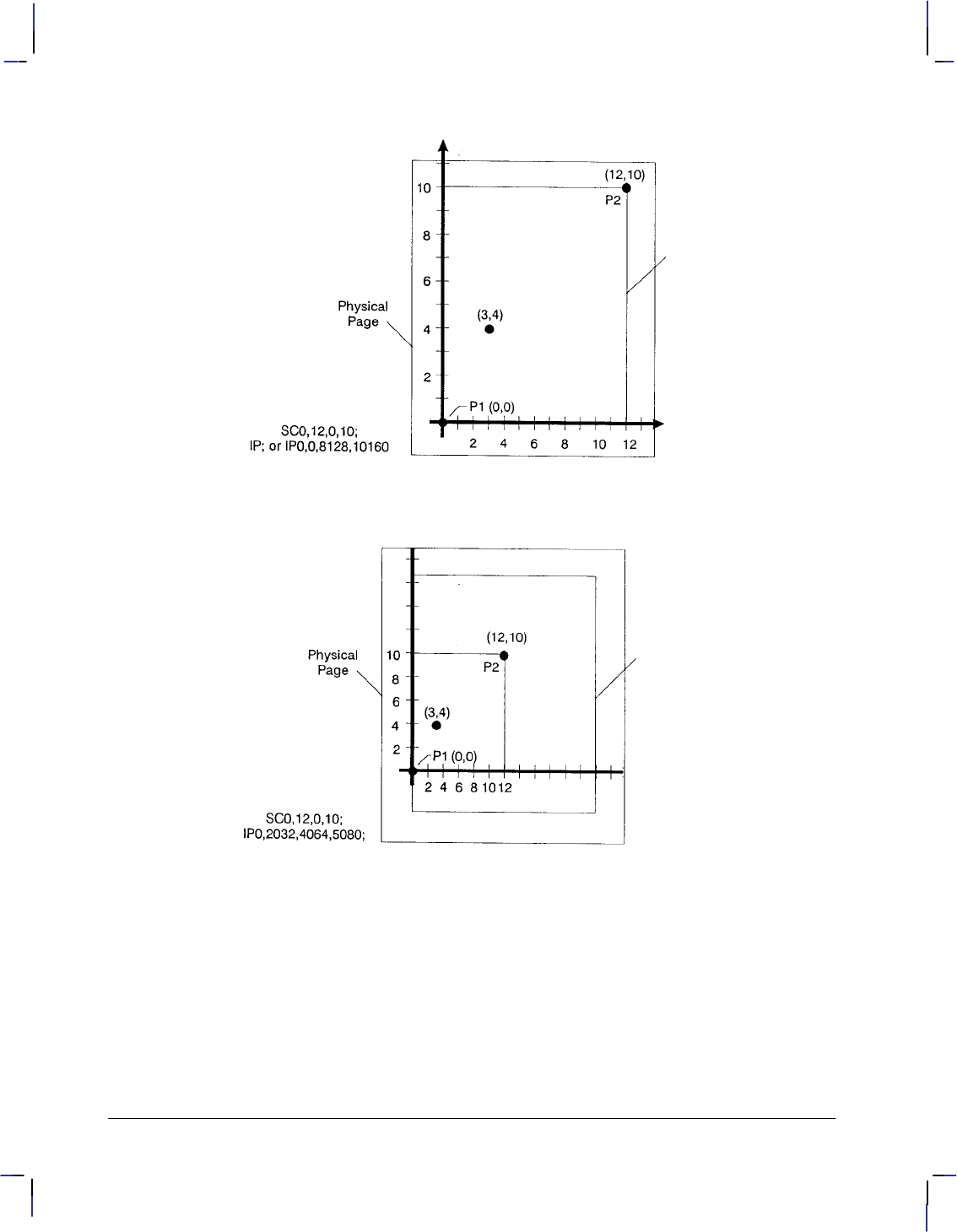
32
This is the black on page 32 (seq: 50)
Company confidential. HP-GL/2 and HP RTL Reference Guide, draft 2. Freeze Status: open
Figure 14. User-Unit Scaling with Default P1 and P2
Figure 15. Same User-Unit Scaling with New P1 and P2
To further illustrate the flexibility of user-unit scaling, Figure 16 shows the P1 and P2 locations
with negative user-unit values.
Note that the framework set by the scaling points P1 and P2 is not a graphics limit. The user-
unit coordinate system extends across the entire plotting area. You can print to a point beyond
P1 or P2 as long as you are within the hard-clip limits. In this example, P1 is in the –X and –Y
quadrant.
Note: You can use coordinate points that are outside of the hard-clip limits or even off the
page, but only that portion of the vector graphics image that falls within the effective window is
printed. For example, you can draw a small portion of the circumference of a circle with a
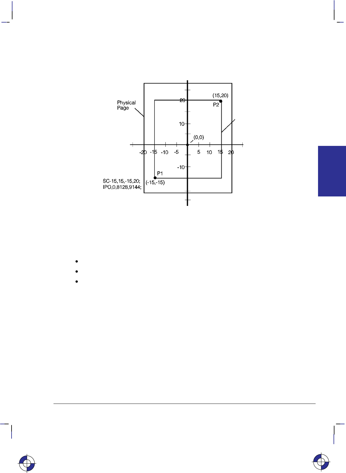
33
This is the black on page 33 (seq: 51)
Company confidential. HP-GL/2 and HP RTL Reference Guide, draft 2. Freeze Status: open
5-foot radius by moving the pen 5 feet from the page and issuing a CI instruction specifying a
5-foot radius; only the portion of the arc that falls within the effective window is printed.
Refer to the SC (Scale) instruction on page 290 for more information on scaling drawings.
Figure 16. New P1 and P2 User-Unit Scaling with Negative Values
Using Scaling Effectively
The following sections describe how to combine scaling and P1/P2 concepts to do the follow-
ing.
Enlarge or reduce the size of a drawing.
Draw equal-sized pictures on the same page.
Create mirror-imaged pictures.
Enlarging or Reducing a Picture
The basic technique for changing a picture’s size is to scale the printing area defined by P1 and
P2, and then move the locations of P1 and P2 to define a smaller or larger area. This is espe-
cially useful when you want to print the picture on any portion of the page.
Note: Only scaled drawings (those using the SC instruction) are enlarged or reduced when the
P1/P2 locations change. Use PCL picture frame scaling when you import into PCL HP-GL/2
images created without the SC instruction.
To maintain the proportions of scaled plots, set P1 and P2 to define an area with the same as-
pect ratio as the original scaling rectangle. For example, if the area defined by P1 and P2 is
3000 x 2000 plotter-units, its aspect ratio is 3:2. To enlarge the plot, set P1 and P2 to define a
larger area that maintains a 3:2 ratio.
The following example illustrates this technique using a square (isotropic) P1/P2 scaling rectan-
gle with a scale of 0 to 10 for both axes. After drawing a circle within the scaled area, the
This is the blue on page 33 (seq: 51)
KERNEL
HP-GL/2
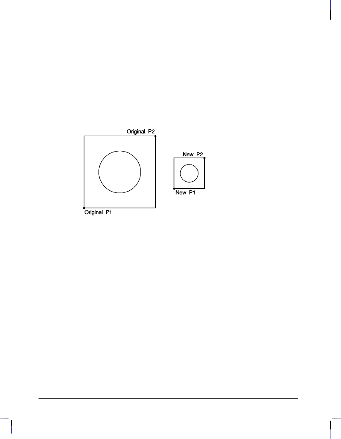
34
This is the black on page 34 (seq: 52)
Company confidential. HP-GL/2 and HP RTL Reference Guide, draft 2. Freeze Status: open
locations of P1 and P2 move to form a new square area that maintains the 1:1 ratio. Note that
the circle printed in the new area is smaller but is still a circle, not an ellipse.
IP 0,0,2000,2000; Set P1 to be (0,0) and P2 to be (2000,2000).
SC 0,10,0,10; Set up user-unit scaling to range from (0,0) to (10,10).
SP 1; Select pen number 1. Even though there may be no physical pen,
the SP instruction must be used to enable printing.
PA 5,5; Begin absolute plotting from the center of the square (5,5).
CI 3; Print a circle with a radius of 3 user-units.
IP 2500,500,3500,1500; Input a new P1 and P2 position for printing the smaller circle.
PA 5,5; Begin absolute plotting from the center of the new square (5,5).
CI 3; Print the second circle with a radius of 3 user-units.
Figure 17. Changing the Size of a Drawing
Drawing Equal-Sized Pictures on a Page
You may occasionally want to print more than one drawing on the same page for a side-by-side
comparison. This can be useful for comparing parts, assemblies, layouts, or other similar in-
formation. The easiest way to draw equal-sized pictures on one piece of paper is to take
advantage of the fact that P2 follows P1 whenever you change the location of P1.
The following example locates P1 and P2 on the left side of the paper and scales the area for
the first image. Then, for the second image, only the P1 location is moved to the right side of
the paper; P2 automatically tracks P1, so the printing area retains the same dimensions as the
first drawing. The printed rectangle around the second area shows P2 in its new location.
IP 500,500,5450,7500; Set P1 to be (500,500) and P2 to be (5450,7500).
SC 0,10,0,15; Set up user-unit scaling to range from (0,0) to (10,15).
SP 1; Select pen number 1.
PA 0,0; Begin absolute plotting from the origin (0,0).
PD 10,0,10,15,0,15,0,0; Pen down and print from (0,0) to (10,0) to (10,15) to (0,15) to
(0,0)
PU ; Pen up.
IP 5550,500; Input a new P1 and allow P2 to automatically track it.
PA 0,0; Begin absolute plotting from the new origin.
PD 10,0,10,15,0,15,0,0; Pen down and print from (0,0) to (10,0) to (10,15) to (0,15) to
(0,0)
PU ; Pen up.

35
This is the black on page 35 (seq: 53)
Company confidential. HP-GL/2 and HP RTL Reference Guide, draft 2. Freeze Status: open
Figure 18. Drawing Pictures Side-by-Side
Note: The P1/P2 frames are not windows or graphics limits; the pen can print HP-GL/2 images
anywhere within the hard-clip limits. The new P1 and P2 retain their scaled values. This al-
lows you to use the same coordinates on both halves of the page. In contrast, if you do not
assign a scale to P1 and P2, you must calculate the new plotter-unit coordinates for the drawing
on the second half of the page.
Creating Mirror-Images
For most drawings, you will probably set P1 and P2 so that P1 is at the origin of the coordinate
system and P2 is in the opposite corner of the scaling area. However, you can change the rela-
tionship of P1 and P2 to produce a mirror-image effect.
You can “mirror-image” any scaled drawing (those drawings using the SC instruction) by
changing the relative locations of P1 and P2, or changing the coordinate system by using SC.
You can mirror-image labels using the DI (Absolute Direction) and DR (Relative Direction)
instructions, the SR (Relative Character Size) instruction, or using the SI (Absolute Character
Size) instruction.
The following example uses a subroutine to generate the arrows shown in Figure 19. Because
the program changes the relative locations of P1 and P2, the direction of the arrow is different
in each of the four drawings. The program sets P1 and P2, draws the plot, then returns to reset
P1 and P2 (using the IP instruction). This continues until all four possible mirror-images are
plotted. (The original drawing is shown in each picture so you can compare the orientation of
the mirror-image.)
IP 1500,3600,3000,5100; Specify the P1/P2 locations for the first arrow figure.
SC –15,15,–10,10; Set up user scaling: (–15,–10) to (15,10).
(Run subroutine) Run the subroutine (below) that prints the arrow image.
IP 3000,3600,1500,5100; Change the physical locations of P1 and P2 to flip the image to
the left.
(Run subroutine) Print the second image.
This is the blue on page 35 (seq: 53)
KERNEL
HP-GL/2
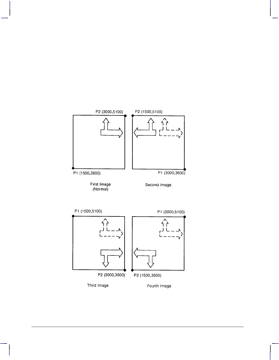
36
This is the black on page 36 (seq: 54)
Company confidential. HP-GL/2 and HP RTL Reference Guide, draft 2. Freeze Status: open
IP 1500,5100,3000,3600; Change the physical locations of P1 and P2 to flip the image
down.
(Run subroutine) Print the third image.
IP 3000,5100,1500,3600; Change P1/P2 locations to flip the image to the left and down.
(Run subroutine) Print the fourth image.
Subroutine that prints the arrow figure:
PA 1,2;
PD 1,4,3,4,3,7,2,7,4,9,6,7,5,7,5,4,12,4,12,5,14,3,12,1,12,2,1,2;
PU ; End of subroutine.
Figure 19. Creating Mirror Images
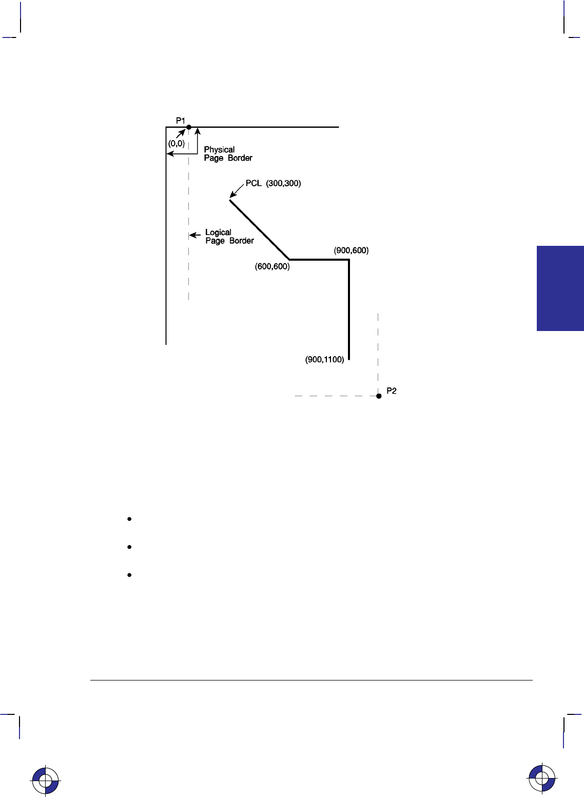
37
This is the black on page 37 (seq: 55)
Company confidential. HP-GL/2 and HP RTL Reference Guide, draft 2. Freeze Status: open
Adapting the HP-GL/2 Coordinate System for Printers to Match the PCL
System
Figure 20. Matching the HP-GL/2 and PCL Coordinate Systems
The example illustrated in Figure 20 uses the IR and SC instructions to change HP-GL/2 coor-
dinate system for “printers” (see Figure 10 on page 10) to match the default PCL coordinate
system. The IR instruction is used to invert the Y-axis so that the Y values increase as the pen
moves down the page. The SC instruction equates user-units to dot positions (300 dots-per-
inch). The example draws a few lines in both PCL and HP-GL/2 modes to demonstrate that the
coordinate systems are lined up correctly (the end points of the lines intersect).
Notes:
Sending an IN (Initialize) or DF (Default) instruction causes the coordinate system to
revert to the HP-GL/2 default.
Since this example is based on the default top margin and text length, changing the top
margin or the text length would move the two coordinate systems out of alignment.
The commands starting with the Escape character () are PCL commands.
EReset the device.
&l2A Set the page size to letter (8.5 by 11 inches).
&l0O Specify portrait orientation.
&l0E Set top margin to 0.
*p0x0Y Move to position (0,0).
*c5760x7920Y Set PCL picture frame to 8 inches x 11 inches (size of logical
page) in portrait orientation; units are decipoints (1/720-inch).
This is the blue on page 37 (seq: 55)
KERNEL
HP-GL/2

38
This is the black on page 38 (seq: 56)
Company confidential. HP-GL/2 and HP RTL Reference Guide, draft 2. Freeze Status: open
*c0T Set picture frame anchor point to current PCL cursor position
(0,0).
%1B Enter HP-GL/2 mode with the HP-GL/2 cursor or pen at the PCL
cursor position.
IN ; Initialize HP-GL/2 instruction values. (The IN instruction moves
the pen position from the anchor point to the HP-GL/2 origin, the
lower-left corner of the PCL picture frame.) Note that on color
devices, this instruction destroys the PCL color environment.
SP 1; Select pen number 1.
SC 0,3.3867,0,–3.3867,2; Set up a user scale with a user-unit equal to 1/300 inch. Scale
instruction type 2, the scale is the ratio of plotter-units/user-units
(1016 plotter-units-per-inch/300 dots-per-inch = 3.3867). The
negative Y-value changes the HP-GL/2 Y direction to match that
of the PCL coordinate system.
IR 0,100; Place P1—point (0,0)—at the top of the PCL picture frame.
PU 0,0; Lift the pen and move to (0,0), the upper left corner—since the
HP-GL/2 coordinate system now matches the PCL coordinate sys-
tem. Every subsequent pen move can be specified using the same
coordinate numbers in either mode.
The following instructions demonstrate that the grids are synchro-
nized.
PU 300,300; Lift the pen and move it to (300,300).
PD 600,600; Draw a line to (600,600). This draws a line at a 45 angle down
from the starting point.
%1A Enter PCL mode with HP-GL/2’s pen position (600,600) being
inherited as PCL’s current active position (CAP).
*c300a4b0P Draw a horizontal line (rule) that is 300 PCL units wide by 4 PCL
units. Note that the cursor position after a rule is printed is at the
beginning of the rule—in this case (600,600).
%1B Enter HP-GL/2 mode (inheriting PCL’s CAP).
PU ; Lift the pen.
PR 300,0; Move to a point 300 user-units (dots) to the right.
PD ; Place the pen down.
PR 0,500; Print a line 500 user-units down.
%1A Enter PCL mode with the CAP at the current HP-GL/2 pen posi-
tion.
EReset the device to end the job and eject a page.
Adapting the HP-GL/2 Coordinate System for Plotters to Match the HP RTL
System
If you place the following instructions at the head of your HP-GL/2 file (after any BP, IN, PS,
QL, and MT instructions), the coordinate systems of HP-GL/2 for “plotters” (see Figure 10 on
page 10) and HP RTL will be the same, in terms of their orientation and their axes (see Figure
21), and will use 300 dots per inch (dpi) as user-units instead of device units:
RO 90; (portrait layout) or RO180; (landscape layout). This rotates the coordinate system
so that the origin is in the lower-left corner with the +X-axis to the
right and the +Y-axis upwards.
This is the blue on page 38 (seq: 56)

39
This is the black on page 39 (seq: 57)
Company confidential. HP-GL/2 and HP RTL Reference Guide, draft 2. Freeze Status: open
IP 0,0,1016,–1016; Set the P1/P2 interval to be 1 inch (1016 plotter-units).
IR 0,100; Move P1 and P2 so that P1 is at the HP RTL origin and P2 is
1 inch away.
SC 0,300,0,300; Value depends on resolution; this is for 300 dpi.
AC 0,0; Default the anchor corner to HP RTL (0,0).
PU 0,0; Raise the pen and move it to (0,0).
Figure 21. Coincident Coordinate Systems
Windowing: Setting up Soft-Clip Limits
Soft-clip limits temporarily restrict pen movement to a rectangular area, or window. When you
initialize or set the device to default conditions, the soft-clip limits are the same as the hard-clip
limits. To create a window, you use the Input Window (IW) instruction. The device does not
draw outside the window.
Figure 22 shows the four types of line segments you can specify from one point to another.
Type From Last Point To New Point
1Inside window area Inside window area
2 Inside window area Outside window area
3 Outside window area Inside window area
4 Outside window area Outside window area
Figure 22. Line Segments and Windows
The IW instruction lets you control the size of the HP-GL/2 printing area so that you can draw
a particular portion of a drawing. You can leave the rest as white space, or use the remaining
area for labels, or another drawing. Refer to Graphic Limits on page 4, and the IW instruction
description on page 197.
This is the blue on page 39 (seq: 57)
KERNEL
HP-GL/2
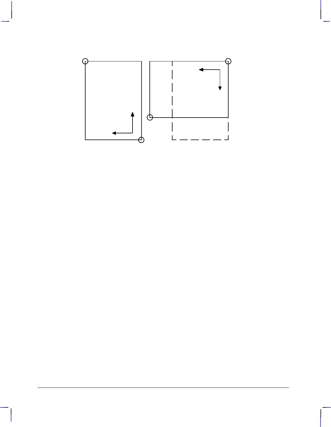
40
This is the black on page 40 (seq: 58)
Company confidential. HP-GL/2 and HP RTL Reference Guide, draft 2. Freeze Status: open
Rotating a Picture
P2
P1
P2
P1
Default 90Ćdegree rotation
Figure 23. Rotating a Picture
+X
+Y
+X
+Y
Plotters always set the X-axis parallel to the longest edge of your plot; small-format printers set
the Y-axis parallel to the longest edge. However, you can change this orientation using the RO
(Rotate Coordinate System) instruction to rotate the coordinate system counterclockwise 90,
180, or 270. Figure 23 shows the default, for most HP-GL/2 devices, and rotated orientation
of the axes and locations of P1 and P2.
Note that P2 is now off the page. This occurs because the X, Y coordinates of P1 and P2 do not
change. To set P1 and P2 at the hard-clip limits, use either the IP or IR instruction after the RO
instruction; see page 275 for more information. If you reset your coordinate system to its de-
fault orientation, remember to reset P1 and P2, using either the IP or IR instruction again.
Ending Your Program and Advancing the Page
When using a raster device, you must indicate the end of your plot before the device will raster-
ize and draw it. For printers with PCL capability, this may require you to exit from HP-GL/2
mode and send a Form Feed () control character in the PCL context. The PG (Advance Full
Page) instruction automatically signals the end of incoming data for the device and starts the
rasterization process. You may be able to use a control-panel function to achieve the same re-
sult, but the PG instruction is more efficient. Using PG can save you time since, for this
function, you will not have to interact with the device. In multi-user environments, PG is a
necessary plot separator.
PG advances the roll-feed paper (on pen and raster devices) the length set by the PS (Plot Size)
instruction, or the default page size if there is no PS instruction. The PS instruction is described
on page 259.
If your device supports it, you can make additional copies of a plot by following the PG
instruction with the RP (Replot) instruction. Generally, your device must have an area, such as
disk space or a memory buffer, to support this feature. Since the plot is already stored in the
device, using RP frees the computer while the copies are drawn.

41
This is the black on page 41 (seq: 59)
Company confidential. HP-GL/2 and HP RTL Reference Guide, draft 2. Freeze Status: open
The Vector Group
The Vector Group instructions enable you to achieve the following results in your programs:
Use absolute and relative coordinates when plotting.
Draw lines, arcs, and circles.
Encode coordinates to increase your device’s throughput.
The following instructions form the Vector Group:
AA Arc Absolute Draws an arc using absolute coordinates.
AR Arc Relative Draws an arc using relative coordinates.
AT Absolute Arc Three Point Draws an arc from the current pen location through two ab-
solute points.
CI Circle Draws a circle with a specified radius.
PA Plot Absolute Enables movement to absolute coordinate locations, with
respect to the origin (0,0).
PD Pen Down Lowers the “pen” to the page.
PE Polyline Encoded Increases throughput by encrypting common HP-GL/2
instructions.
PR Plot Relative Enables movement relative to the current pen location.
PU Pen Up Lifts the pen from the page.
RT Relative Arc Three Point Draws an arc from the current pen location through two rela-
tive points.
The factory environment defaults are:
The plotting mode is absolute (the PA instruction).
The pen state is up (PU).
Pen Up or Down
Most HP-GL/2 instructions perform their functions with the pen either up or down. Specifying
the pen’s up/down state is necessary to avoid drawing unwanted lines between figures. The PU
(Pen Up) instruction raises the pen and can also move to a desired plotting location before
drawing. The PD (Pen Down) instruction lowers the pen and can draw from the current loca-
tion to a specified location. Turning on the device or sending an IN (Initialize) instruction
raises the pen. Some instructions automatically cause the pen to be down (see page 23).
Drawing Lines
You can draw lines between two points (X,Y coordinate pairs) using the PD (Pen Down)
instruction and a series of absolute or relative coordinate pairs. The device draws only the por-
tion of the line that falls within the effective window.
Note: When using HP-GL/2 to draw lines, you can increase your device’s throughput by using
the Polyline Encoded (PE) instruction to send coordinates. The PE instruction requires that you
convert coordinates from decimal to base 64 or 32. This conversion increases especially the
This is the blue on page 41 (seq: 59)
KERNEL
HP-GL/2
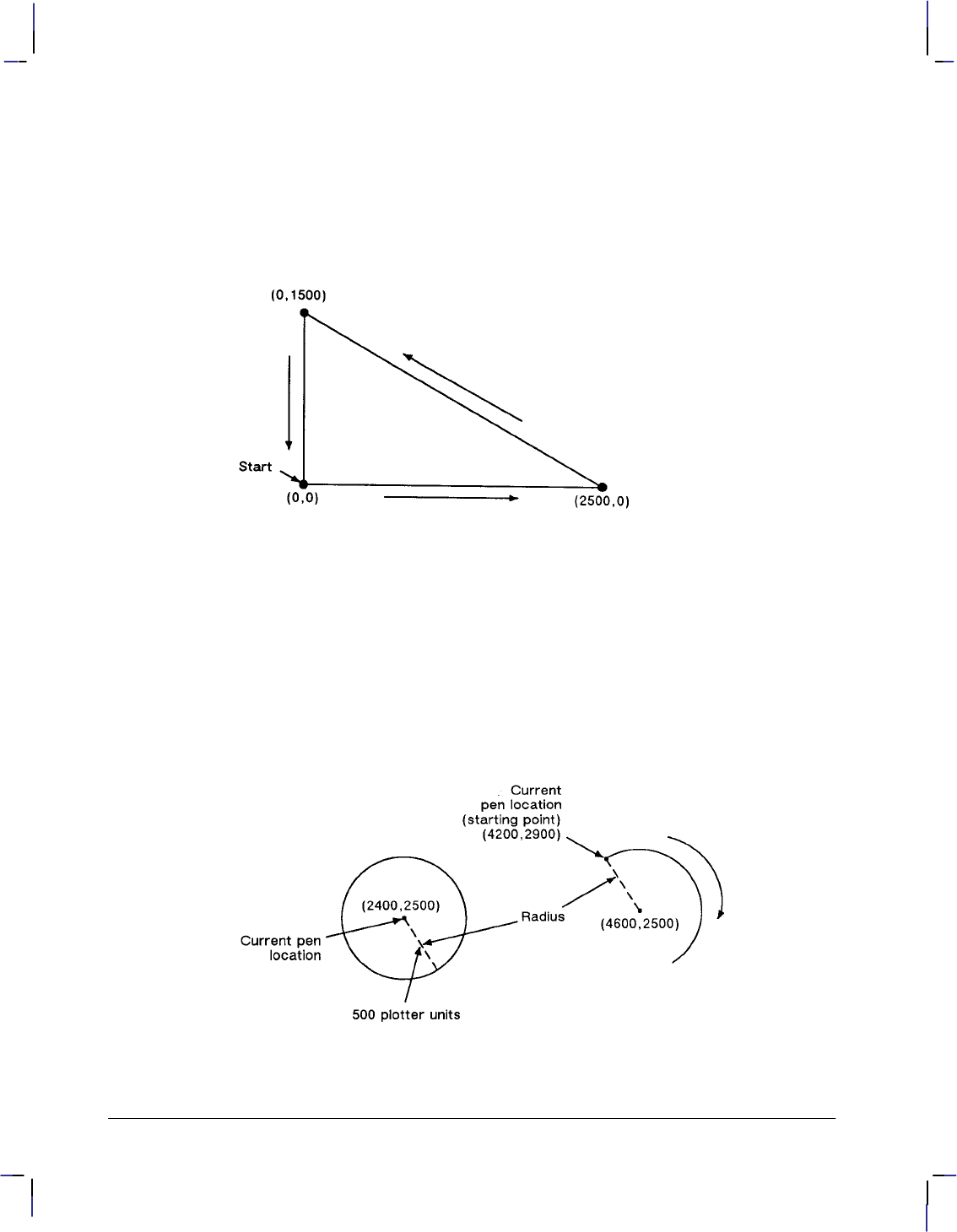
42
This is the black on page 42 (seq: 60)
Company confidential. HP-GL/2 and HP RTL Reference Guide, draft 2. Freeze Status: open
throughput when you use a serial interface. The PE instruction, with its parameters, is used in
place of the PA, PD, PR, PU, and SP instructions.
In the following example, note that the PA (Plot Absolute) instruction specifies absolute plot-
ting, and the coordinate pair (0,0) sets the beginning pen location.
PA 0,0; Begin absolute plotting from coordinate (0,0).
PD 2500,0,0,1500,0,0; Specify Pen Down and draw lines between the points.
Figure 24. Drawing Lines
Note: Any line drawn along the border of the effective window causes the line to be clipped,
producing a line width of one-half of what it should be. For example, in the above plot, the
lines from (0,0) to (0,1500), and (0,0) to (2500,0) are clipped if the origin (0,0) is one corner of
the effective window.
Drawing Circles
The CI (Circle) instruction uses your current pen position as the center of the circle; you speci-
fy the radius of the circle.
Figure 25. Drawing Circles and Arcs
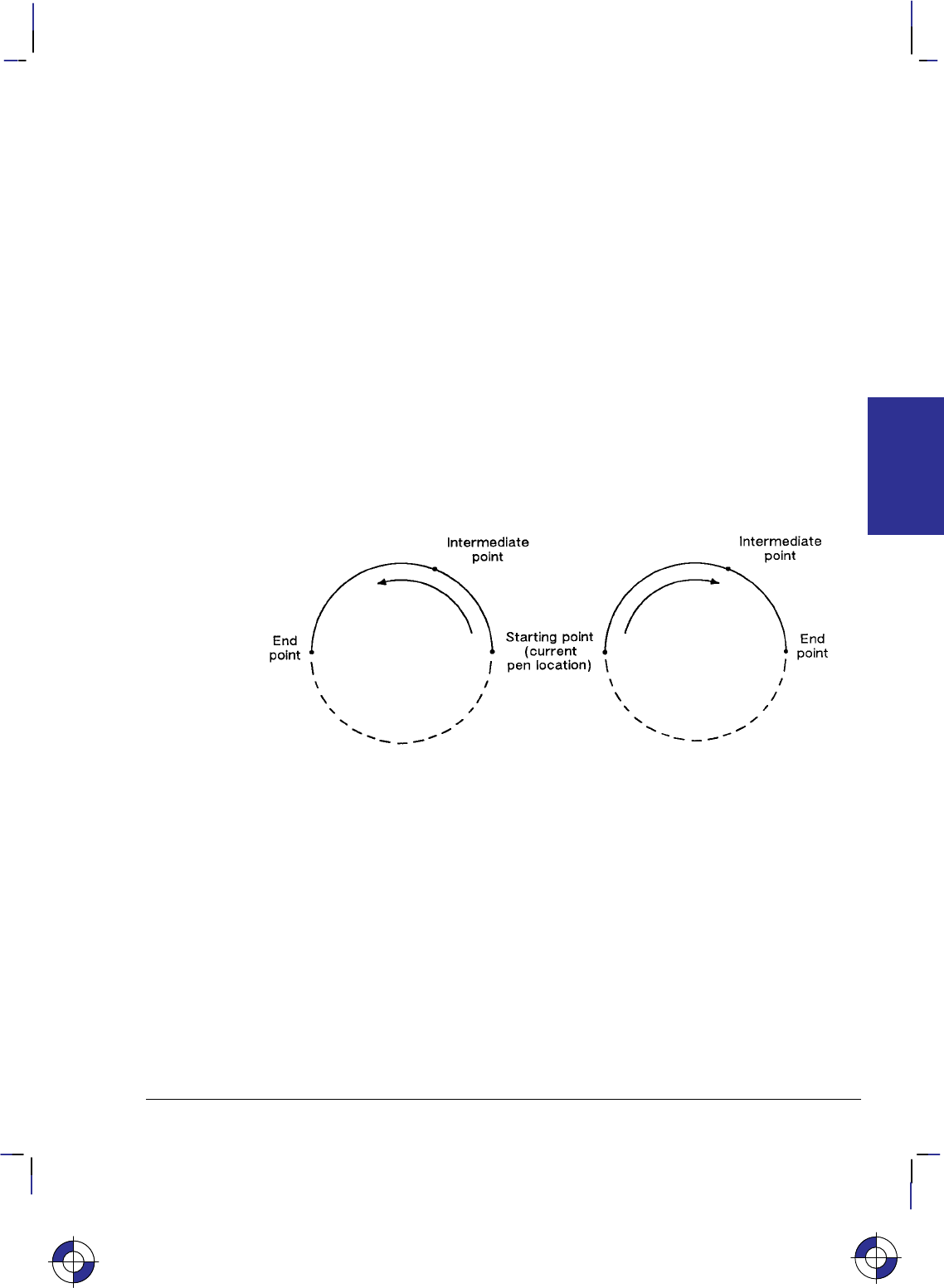
43
This is the black on page 43 (seq: 61)
Company confidential. HP-GL/2 and HP RTL Reference Guide, draft 2. Freeze Status: open
The following example shows a simple instruction sequence using CI to draw a circle with a
radius of 500 plotter-units. The circle is shown on the left of Figure 25.
PA 2400,2500; Specify absolute plotting and move to position (2400,2500).
CI 500; Draw a circle with a radius of 500 plotter-units; the center of the
circle is the current pen location (2400,2500). The CI instruction
automatically causes the pen to be lowered.
Drawing Arcs
The AA (Arc Absolute) and AR (Arc Relative) instructions use the following method for draw-
ing arcs. Your current pen location becomes one end of the arc; you specify the center point
with one parameter (setting the radius), and set another parameter to specify the number of de-
grees through which you want the arc drawn.
You can also draw arcs using the AT (Absolute Arc Three Point) and RT (Relative Arc Three
Point) instructions. These instructions use three known points (your current pen location plus
two points you specify) to calculate a circle and draw the appropriate arc segment of its circum-
ference. The arc is drawn from the starting point so that it passes through the intermediate
point before the end point, using clockwise or counter-clockwise drawing as required. Refer to
Figure 26.
Figure 26. Arcs through Three Given Points
The following example shows a simple instruction sequence using AA to draw an arc. The arc
is shown on the right of Figure 25.
PA 4200,2900; Set starting point to (4200,2900).
PD ; Set pen down.
AA 4600,2500,–180; Using the Arc Absolute instruction, specify the pivot point of the
arc, thereby setting the radius; draw the arc for 180 in a negative
angle of rotation.
This is the blue on page 43 (seq: 61)
KERNEL
HP-GL/2
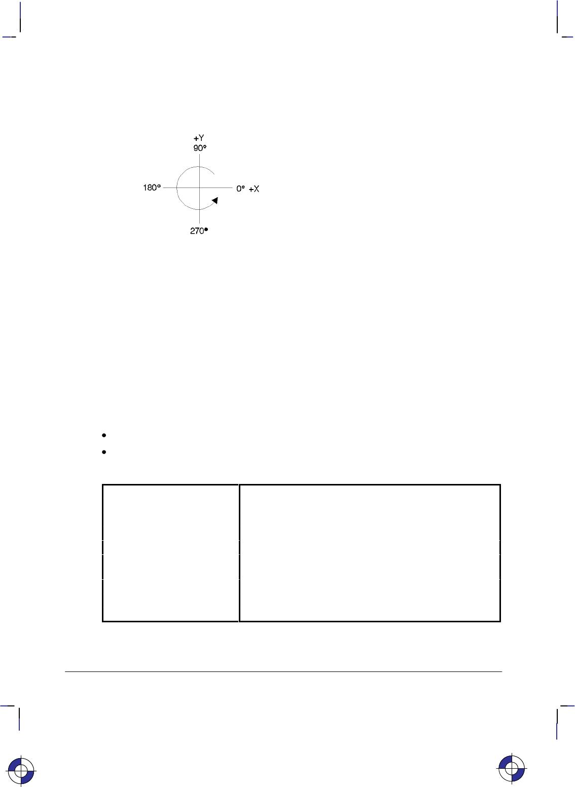
44
This is the black on page 44 (seq: 62)
Company confidential. HP-GL/2 and HP RTL Reference Guide, draft 2. Freeze Status: open
Angle of Rotation
A positive angle of rotation is in the direction of the +X-axis to the +Y-axis as shown below. A
negative angle of rotation is in the direction of the +X-axis to the –Y-axis.
Figure 27. Angle of Rotation
The relationship of the +X-axis to +Y-axis (and –Y-axis) can change as a result of the scaling
point or scaling factor changes, thus, changing the direction of a positive (or negative) angle of
rotation.
The Polygon Group
All of the instructions in the Polygon Group use the polygon buffer, a temporary data storage
area in your device. Using the polygon buffer is an integral part of drawing wedges, rectangles,
and other types of polygons. Some of the instructions in this group define and draw complete
shapes while others act only on the contents of the polygon buffer. The information in this sec-
tion enables you to achieve the following results in your programs:
Draw circles, wedges, and rectangles.
Use polygon mode for drawing polygons, subpolygons, and circles.
The following instructions form the Polygon Group:
EA Edge Rectangle Absolute Outlines a rectangle defined with absolute coordinates.
EP Edge Polygon Outlines the contents of the polygon buffer.
ER Edge Rectangle Relative Outlines a rectangle defined with relative coordinates.
EW Edge Wedge Defines and outlines a wedge-shaped polygon.
FP Fill Polygon Fills the polygon shape specified in the polygon buffer.
PM Polygon Mode Allows you to create user-defined polygons in the polygon
buffer.
RA Fill Rectangle Absolute Fills a rectangle specified with absolute coordinates.
RR Fill Rectangle Relative Fills a rectangle specified with relative coordinates.
WG Fill Wedge Defines and fills a wedge-shaped polygon.
This is the blue on page 44 (seq: 62)
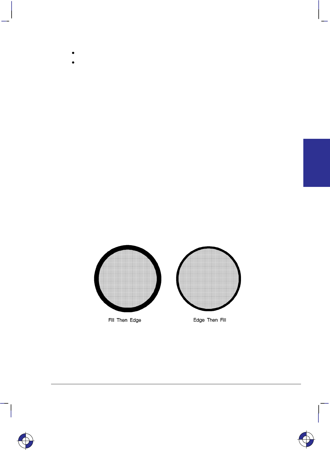
45
This is the black on page 45 (seq: 63)
Company confidential. HP-GL/2 and HP RTL Reference Guide, draft 2. Freeze Status: open
The factory environment defaults for the polygon group are:
Polygon buffer cleared (“PM0”).
Polygon mode off (“PM2”).
Filling then Edging Compared with Edging then Filling
When transparency mode is opaque (specified by “TR0;”), filling then edging an object may
produce different results from edging and then filling. This is especially true when large pen
widths are used. The following example illustrates this:
TR 0; Set transparency mode off (opaque)
PU 4000,6000; Position pen.
PW 5; Select pen width of 5 units.
PM 0; Enter polygon mode.
CI 1000; Draw a circle with a radius of 1000 units.
PM 2; Close polygon and exit polygon mode.
FT 10,30; Select 30% shading fill type.
FP ;
EP ; Fill then Edge polygon.
PU 4000,3000; Select pen position (4000, 3000) for second circle.
PM 0; Enter polygon mode.
CI 1000; Draw another circle with a radius of 1000 units.
PM 2; Close polygon and exit polygon mode.
EP ;
FP ; Edge then Fill polygon (circle).
The center of the left circle is located at (4000,3000). The center of the right circle is located at
(4000,6000).
You should normally fill an area first and then edge it.
Figure 28. Filling and Edging Charts
Using the Polygon Buffer
The polygon buffer is a temporary storage area for information. In it the device collects the
instructions and coordinates that define a polygon you want to print. This polygon remains in
the buffer until replaced by another polygon, or until the buffer is cleared by initializing the
KERNEL
HP-GL/2
This is the blue on page 45 (seq: 63)
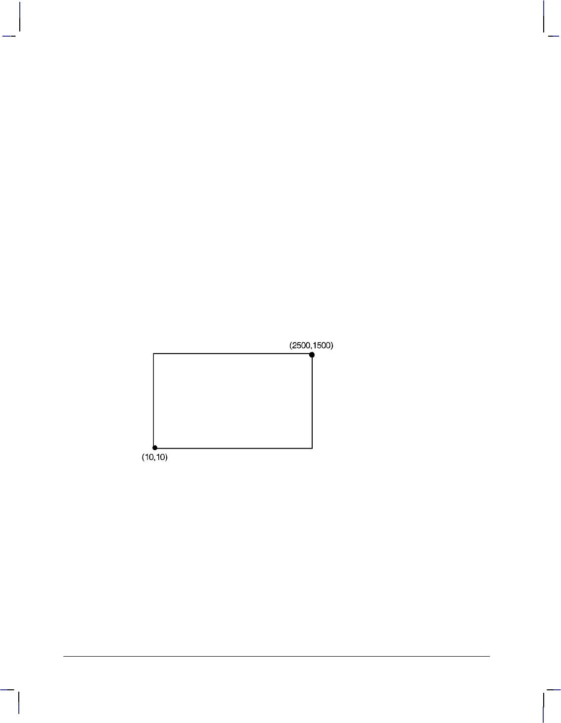
46
This is the black on page 46 (seq: 64)
Company confidential. HP-GL/2 and HP RTL Reference Guide, draft 2. Freeze Status: open
device. Some instructions use the polygon buffer automatically, while other instructions re-
quire that you enter the polygon mode. The following instructions use the polygon buffer, but
do not allow you to enter polygon mode first:
EA Edge Rectangle Absolute
ER Edge Rectangle Relative
EW Edge Wedge
RA Fill Rectangle Absolute
RR Fill Rectangle Relative
WG Fill Wedge
Drawing Rectangles
You can draw a rectangle by outlining (edging) the defined area using the EA (Edge Rectangle
Absolute) or ER (Edge Rectangle Relative) instructions, or by filling (RA or RR), or a com-
bination. To draw a rectangle, the device uses the current pen location for one corner; you give
the coordinates for the diagonally opposite corner. The device draws the rectangle defined by
these two points.
The following simple instruction sequence uses EA to draw a rectangle:
PA 10,10; Specify absolute plotting and move to (10,10).
EA 2500,1500; Draw the outline of a rectangle, with the lower left corner being
the current pen location (10,10) and the upper right corner being
(2500,1500).
Figure 29. Drawing a Rectangle
The RA (Fill Rectangle Absolute) and RR (Fill Rectangle Relative) instructions fill their rect-
angles with the default or current fill pattern. You may also want to edge (or outline) the
rectangle for better image definition with some fill types.
The following instruction sequence draws two filled rectangles, one edged and one not:
PA 0,0; Specify absolute plotting and move to location (0,0).
FT 3; Specify fill type 3 (hatching—parallel lines).
RR 1500,1000; Fill a rectangular shape with the currently active fill pattern. The
lower left corner of the rectangle is the current location (0,0), and
the upper right corner is 1500 plotter-units in the X direction and
1000 plotter-units in the Y direction from the starting location.
EP ; Draw an edge around the rectangle that was just drawn. Since the
previous RR instruction leaves its definition in the polygon buffer
(1500,1000), you do not need to specify the coordinates again.
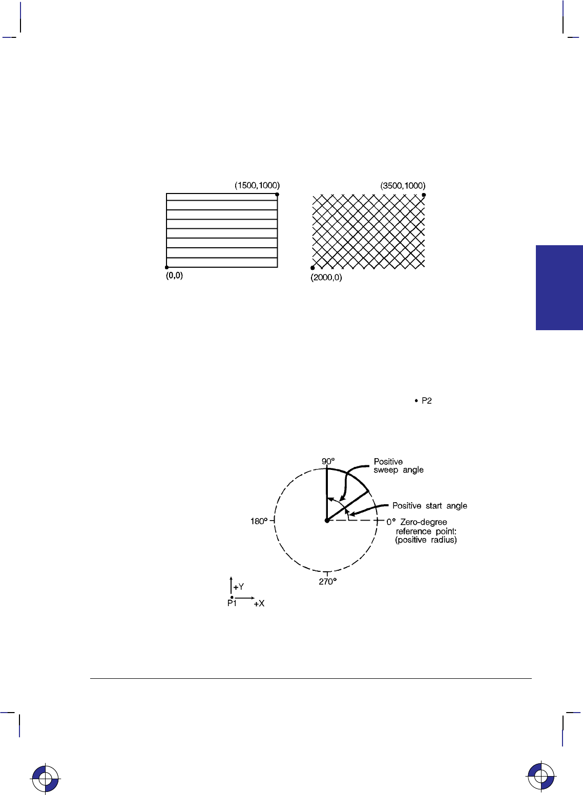
47
This is the black on page 47 (seq: 65)
Company confidential. HP-GL/2 and HP RTL Reference Guide, draft 2. Freeze Status: open
PR 2000,0; Specify relative plotting and move the cursor 2000 plotter-units in
the X direction from the current pen location.
FT 4,100,45; Specify fill type number 4 (cross-hatching), set the spacing to 100
plotter-units between fill lines, and set the fill line angle to 45.
RR 1500,1000; Fill a rectangle with the currently specified fill type. Use the cur-
rent pen location (0,0) as the lower left corner of the rectangle and
a point (1500,1000) relative plotter-units away for the upper right
corner.
Figure 30. Filled Rectangles, with and without Edges
Drawing Wedges
A wedge is a section of a circle. Wedges are commonly used to draw pie charts. You can draw
a wedge by outlining (edging) the defined area using the EW (Edge Wedge) instruction, or you
can create filled wedges using the WG (Fill Wedge) instruction.
Figure 31. How Wedges are Drawn
This is the blue on page 47 (seq: 65)
KERNEL
HP-GL/2
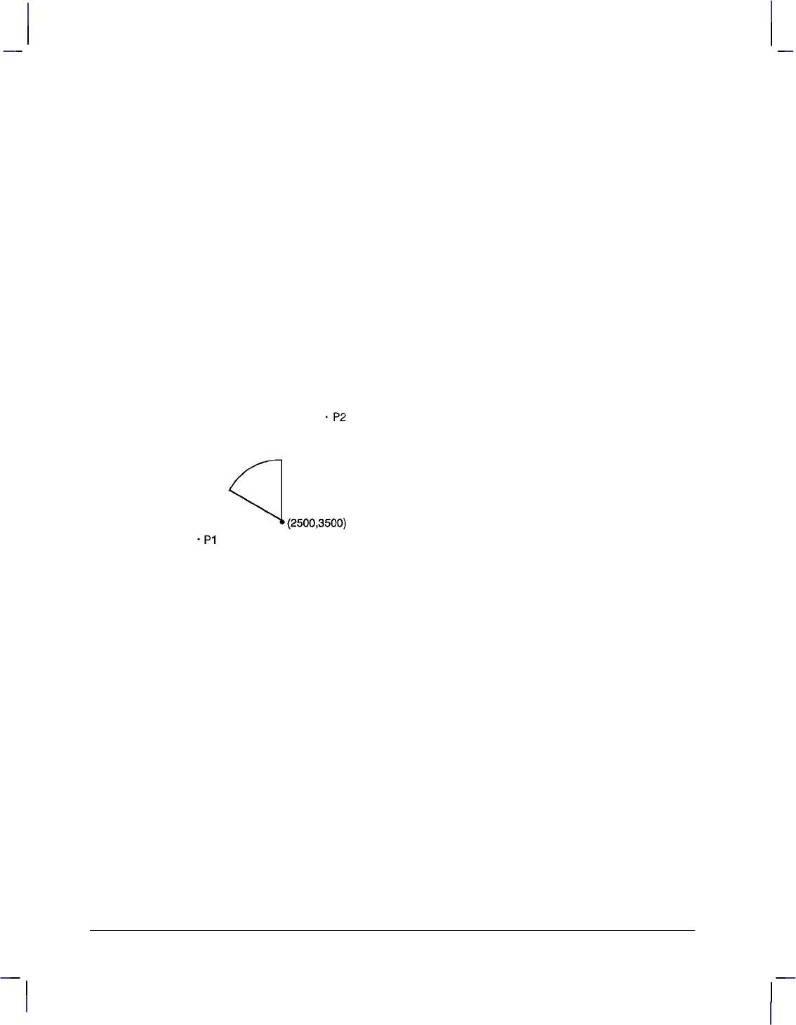
48
This is the black on page 48 (seq: 66)
Company confidential. HP-GL/2 and HP RTL Reference Guide, draft 2. Freeze Status: open
The wedge instructions use your current pen location as the center point; you specify the radius,
the start angle, and the sweep angle. The radius determines the length of the two sides of the
wedge. The sign (positive or negative) of the radius determines the location of a zero-degree
reference point. The start angle is the number of degrees from the zero-degree reference point
at which you want to draw the first radius. The sweep angle is the number of degrees through
which you want to draw the arc. To draw or fill a circle, simply specify a 360 sweep angle.
Figure 31 shows the different parameters of a wedge with a positive radius.
A positive angle of rotation is in the direction of the +X-axis to the +Y-axis as shown in Figure
27 on page 44. A negative angle of rotation is in the direction of the +X-axis to the –Y-axis.
The following example draws a wedge using the EW instruction. The radius of the wedge is
600 plotter-units, the wedge begins 90 from the zero-degree reference point, and the wedge
“sweeps” for 60.
PA 2500,3500; Specify absolute plotting and move to location (2500,3500).
EW 600,90,60; Draw the outline of a wedge, using the current pen location
(2500,3500) as the point of the wedge. The wedge has a radius of
600 plotter-units, begins at 90 from the default zero-degree refer-
ence point, and “sweeps” for 60.
Figure 32. Simple Wedge
The following example uses different fill types with wedges and circles:
PA 1400,2500; Select absolute plotting mode and move to (1400,2500).
WG 600,150,120; Fill a wedge with radius 600 plotter-units, a start angle of 150,
and a sweep angle of 120. Since no fill type was specified, the
wedge is black (solid black is the default fill type).
PA 2300,2500; Specify absolute plotting and move to (2300,2500).
FT 3,75,45; Select fill type number 3 (hatching—parallel lines), with 75 plot-
ter-units between hatching lines, and hatching lines tilted at 45.
WG 600,90,180; Fill a wedge with the current fill type; use a radius of 600 plotter-
units, a start angle of 90, and a sweep angle of 180.
FT 1,0,0; Specify a fill type of solid black.
WG 600,270,60; Fill a wedge using the same center and radius as the previous
wedge. Start the wedge at 270 with a sweep of 60.
FT 4,60,45; Specify fill type number 4 (cross-hatching) with 60 plotter-units
between lines and the lines tilted at 45.
WG 600,330,120; Fill a wedge using the same center and radius as the previous two
wedges. Start the wedge at 330 with a sweep of 120.
PA 3500,2500; Select absolute plotting and move to (3500,2500).
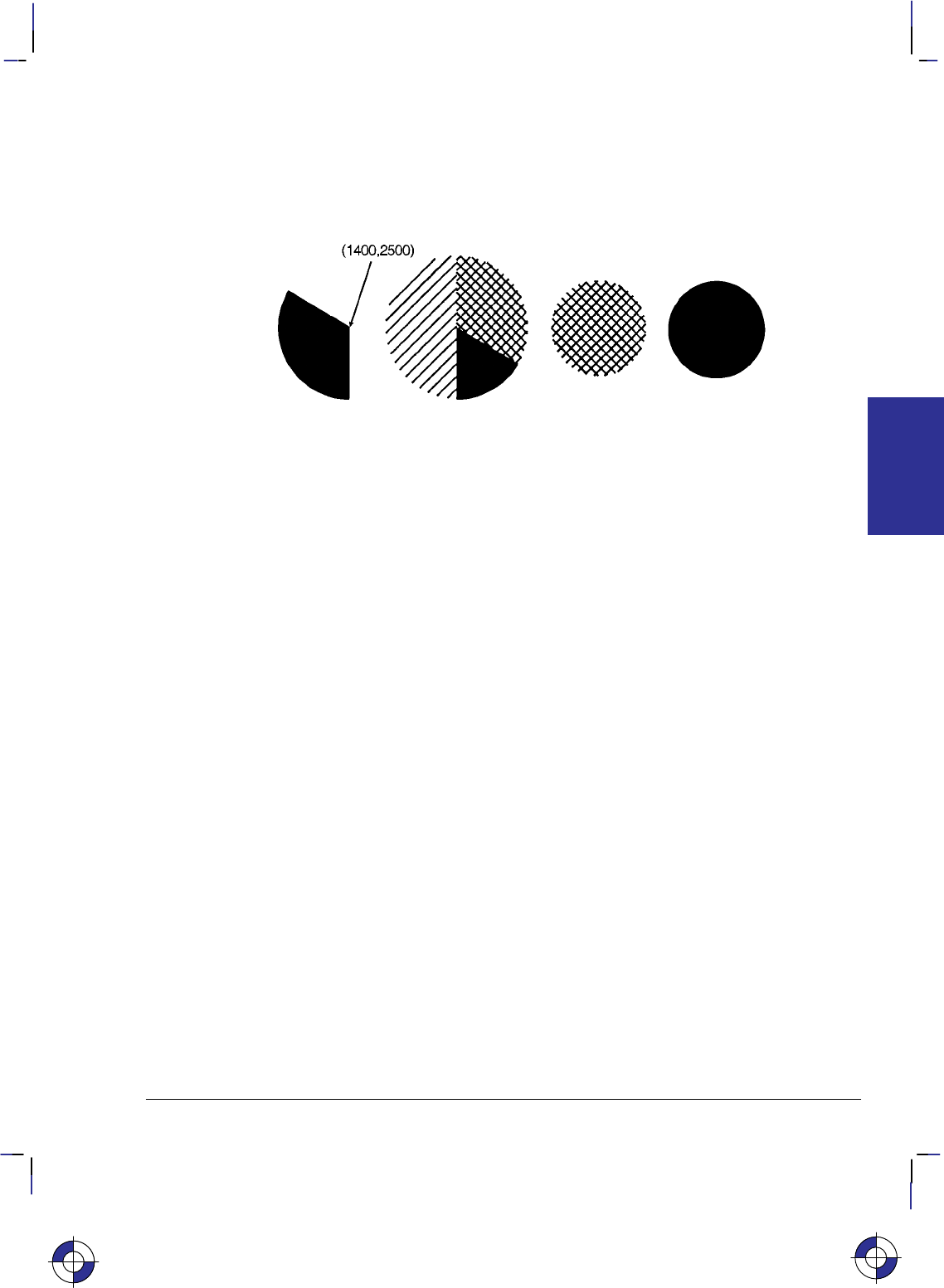
49
This is the black on page 49 (seq: 67)
Company confidential. HP-GL/2 and HP RTL Reference Guide, draft 2. Freeze Status: open
WG 400,0,360; Create a filled circle using the current fill type (cross-hatching),
specifying a start angle of 0 and a 360 sweep.
PA 4500,2500; Move to (4500,2500).
FT ; Select a solid fill.
WG 400,0,360; Fill a 360 wedge (circle).
Figure 33. Filled Wedges and Circles
Drawing Polygons
A polygon consists of one or more closed sequences of connected line segments (which may
cross each other). Drawing polygons requires the use of the polygon mode. The Polygon Mode
(PM) instruction tells the device to store subsequent instructions and coordinates in the polygon
buffer before printing the shape. (Rectangles and wedges are polygons which have their own
drawing instructions; the device automatically generates and stores the coordinates in the poly-
gon buffer.)
Polygon Definition Instructions
You can use the following instructions in polygon mode to create polygons. These instructions
are stored in the polygon buffer until they are replaced with another polygon or the device is
initialized.
AA Arc Absolute
AR Arc Relative
AT Absolute Arc Three Point
BP Begin Plot
BR Bezier Relative
BZ Bezier Absolute
CI Circle
PA Plot Absolute
PD Pen Down
PE Polyline Encoded
PM1/PM2 Polygon Mode
PR Plot Relative
PU Pen Up
RT Relative Arc Three Point
This is the blue on page 49 (seq: 67)
KERNEL
HP-GL/2
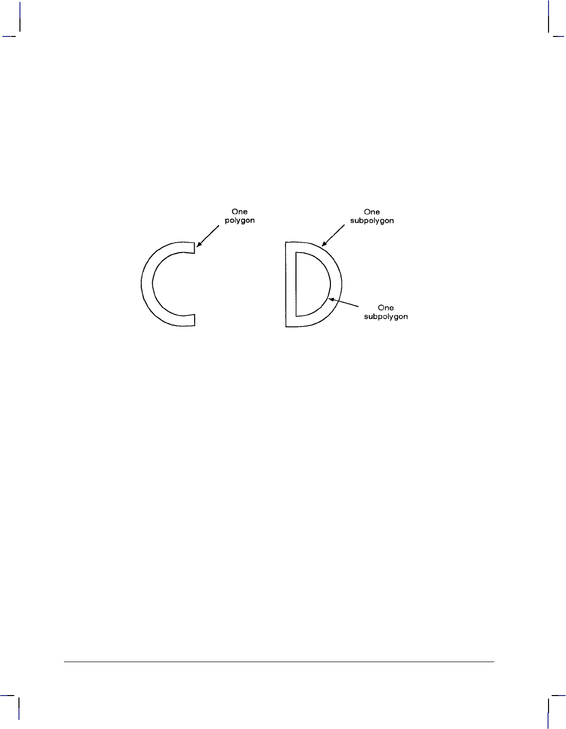
50
This is the black on page 50 (seq: 68)
Company confidential. HP-GL/2 and HP RTL Reference Guide, draft 2. Freeze Status: open
Drawing Subpolygons
While in polygon mode, you can define either one polygon or a series of subpolygons. Like a
polygon, a subpolygon is a closed sequence of connected line segments. For example, the
block letter C is one complete polygon. However, the block letter D is actually two subpoly-
gons: the outline and the “hole”.
To create one polygon, for example, the letter C, move the pen to the starting location for the
polygon, then use the PM (Polygon Mode) instruction to enter polygon mode. Define the shape
of the C using the appropriate instructions and coordinates, then exit polygon mode (“PM1”).
Now draw the polygon using either the EP (Edge Polygon) or FP (Fill Polygon) instruction.
Figure 34. Drawing Subpolygons
To create a series of subpolygons, for example, the letter D, move the pen to the starting loca-
tion of the first subpolygon, then enter polygon mode. Define the outer shape of the letter D
using the appropriate instructions and coordinates, then close the subpolygon (“PM1”), staying
in polygon mode. Define the inner shape of the D, then exit polygon mode (“PM2”). Now
draw the subpolygons using either the EP or FP instruction. For more information on entering
and exiting polygon mode, refer to the PM instruction discussed on page 251.
In polygon mode, you can define points with the pen up or down. However, the EP instruction
only draws between points defined when the pen was down. In contrast, the FP instruction fills
between all points, regardless of whether they were defined when the pen was up or down. An
exception is that the line connecting two subpolygons is never drawn, and is not a fill boundary.
Filling Polygons
There are two methods which can be selected for filling polygons: the even/odd fill method
(which is the default) and the non-zero winding fill method.
Even/Odd Fill Method
There is a simple way to determine which portions of a single polygon or series of subpolygons
is filled when you send a FP (Fill Polygon) instruction using method 0 (fill using even/odd
rule): Draw a straight line extending from any point within an enclosed area of the polygon to
a point outside the polygon. FP fills the enclosed area in question only if the line you have
drawn intersects the edges of the polygon an odd number of times. The next figure illustrates
this “even/odd” rule.
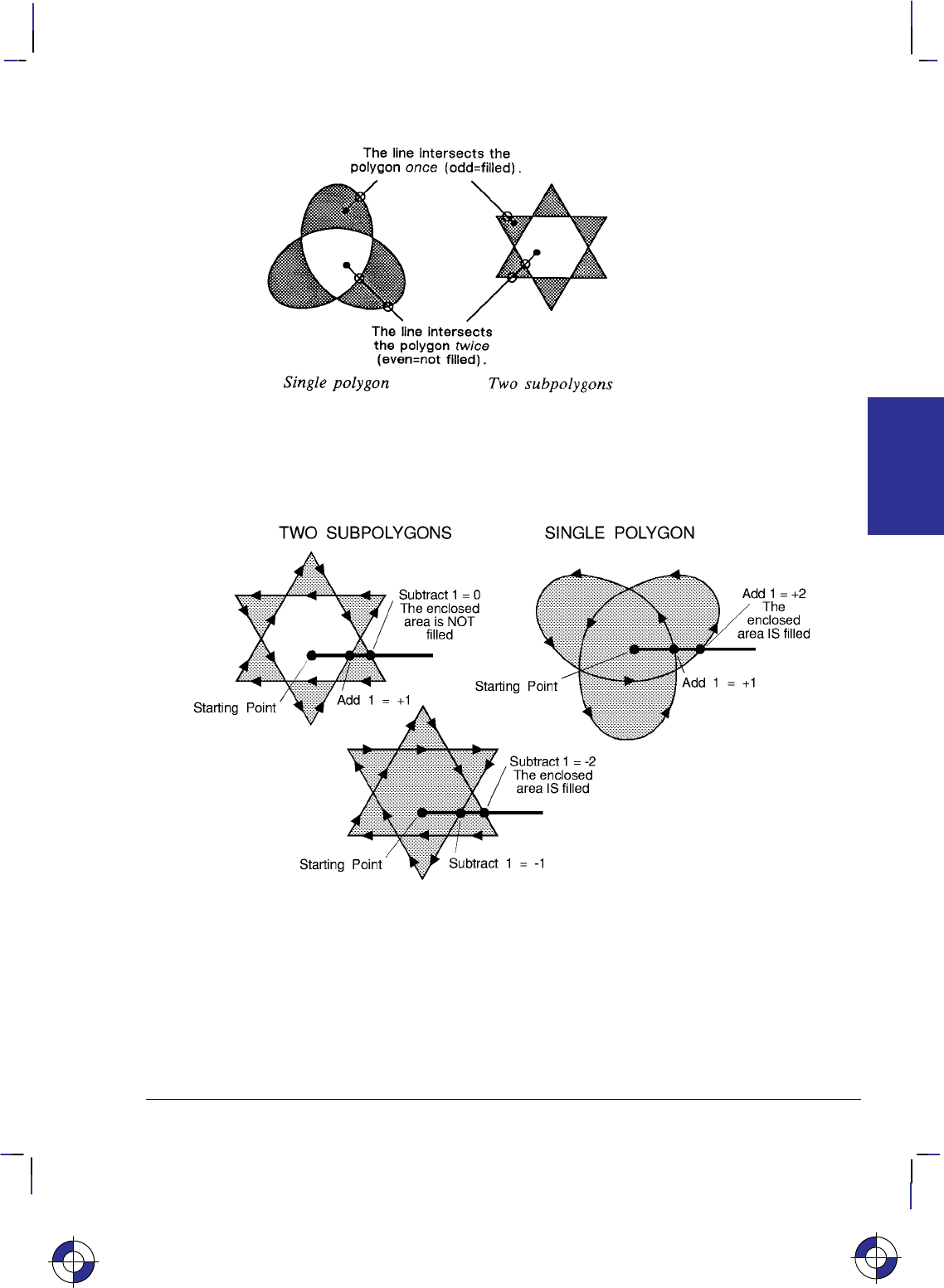
51
This is the black on page 51 (seq: 69)
Company confidential. HP-GL/2 and HP RTL Reference Guide, draft 2. Freeze Status: open
Figure 35. Filling Polygons: Even/Odd Fill Method
Non-Zero Winding Fill Method
Figure 36. Filling Polygons: Non-Zero Winding Fill Method
The non-zero winding fill algorithm (fill method 1) determines whether a point is inside a re-
gion enclosed by a line path using the following steps:
1. Draw a ray from the point across the path segment.
2. Add 1 every time the line segment crosses the ray from left to right or bottom to top.
3. Subtract 1 every time the segment crosses the ray from right to left or top to bottom.
This is the blue on page 51 (seq: 69)
KERNEL
HP-GL/2

52
This is the black on page 52 (seq: 70)
Company confidential. HP-GL/2 and HP RTL Reference Guide, draft 2. Freeze Status: open
4. FP fills the enclosed area in question if the sum of steps 2 and 3 is non-zero.
Figure 36 illustrates the non-zero winding fill concept. Note the importance of the direction in
which the lines are drawn.
Drawing Circles in Polygon Mode
Polygon mode interprets the CI (Circle) instruction differently from the other HP-GL/2 instruc-
tions. The device treats a circle as a complete subpolygon. The device automatically closes
the first polygon (if any) before starting the circle, and uses the first coordinates (if any) after
the circle is drawn to start a new subpolygon.
If you did not close your first polygon completely before sending the CI instruction, the device
automatically closes the polygon by adding a point (at the starting point of the previous sub-
polygon). This can change your current pen location and the placement of the circle in your
polygon, resulting in an inaccurate polygon.
A circle (360 arc) specified by AA, AR, AT, or RT is not treated as if it was preceded and fol-
lowed by “PM1”.
CI with a zero radius is a syntactically correct but geometrically degenerate subpolygon that
produces a dot. The following example shows how CI can produce syntactically incomplete
subpolygons:
PU ; Pen Up.
PA 1000,1000; Move to (1000,1000).
PM 0; Enter polygon mode with the point (1000,1000) in the buffer.
CI 200: The subpolygon consisting of the single point (1000,1000) is im-
plicitly closed; it has fewer than three points, and effectively
disappears. After this CI instruction, the pen-up state and the
location (1000,1000) are restored, but this point is not put into the
polygon buffer.
CI 500; This CI instruction again forces closure, and the restored position
point is discarded.
PM 2; Close polygon mode.
FP ; Fill polygon. The result is a torus without a center dot.
Calculating How Much of the Polygon Buffer is Used
You can use the following formula to estimate how much buffer space a polygon consumes.
Each point in a polygon uses 9 bytes. For example, the minimum number of points the device
will hold is 512; if you multiply 512 points by 9 bytes per point, the result is 4608 bytes (4.5
Kbytes). That means the minimum your device can store in the polygon buffer is 4.5 Kbytes.
That is the worst case, however; unless the device has a substantial amount of fonts, macros, or
graphics already downloaded into user memory, you can put much more into the polygon buff-
er. As we just calculated, for every 4.5 Kbytes of extra unused user memory, the polygon
buffer can store 512 more points. You can see how in most cases there is little chance of a
polygon buffer overflow, especially with the addition of optional device memory.
The following formula explains how to calculate the buffer space used by a polygon:
number of points in polygon 9 = buffer space consumed by polygon
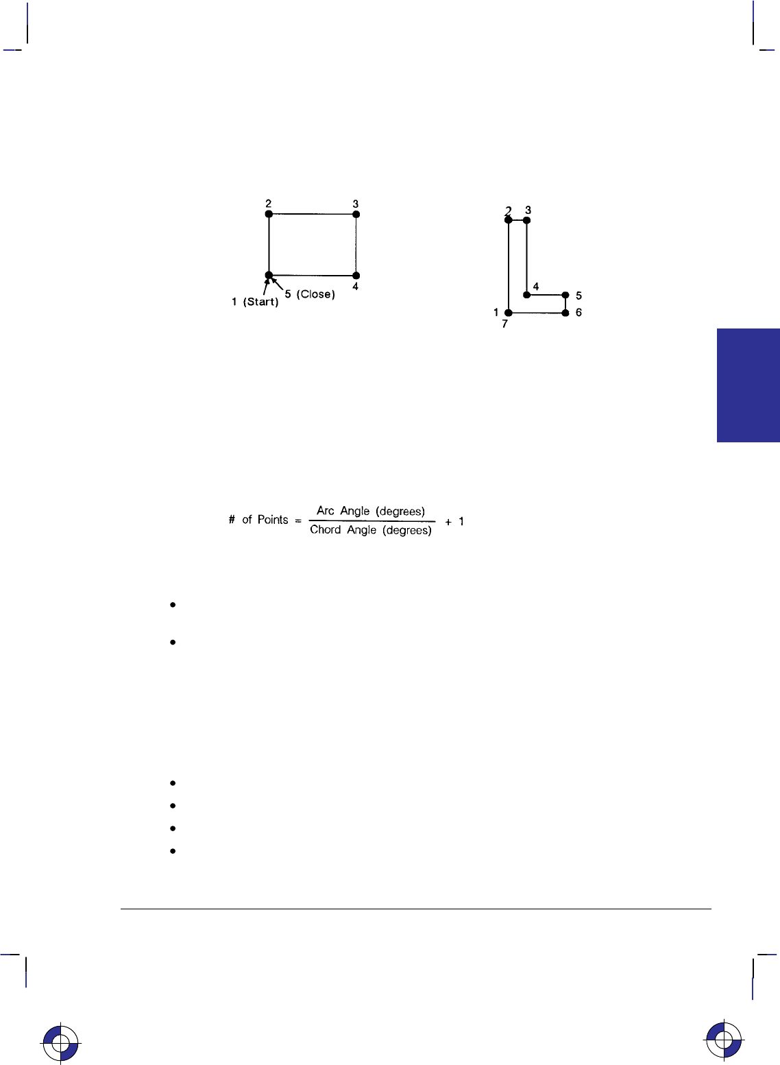
53
This is the black on page 53 (seq: 71)
Company confidential. HP-GL/2 and HP RTL Reference Guide, draft 2. Freeze Status: open
Counting the Points in a Polygon
The starting pen location and each subsequent point define a polygon. As shown in the follow-
ing illustration, a rectangle is defined by five points, not four. This is because the starting
location is counted again as the ending location. The second shape has seven points.
Figure 37. Counting Points in a Polygon
Counting the Points in a Circle or Arc
When a circle or arc defines a polygon, the number of points depends on the number of chords
in the arc. There is always one more point than the number of chords, because the starting
location is counted again as the ending location. Use the following formula to determine the
number of points used to draw a circle or arc:
Using this formula, a full circle with the default chord angle of 5 consists of 73 points
(360/5 + 1 = 73), and a 45 arc with a chord angle of 3 consists of 16 points (45/3 + 1 = 16).
If the chord angle does not divide evenly into the arc, round up to the next integer before
adding one: 45/2 + 1 = 23 + 1 = 24.
In polygon mode, the smaller a circle’s chord angle, the more chords will be stored in the
polygon buffer to draw it.
The Line and Fill Attributes Group
The Line and Fill Attributes Group instructions enable you to achieve the following results in
your HP-GL/2 applications:
Select a pen for plotting or printing.
Enhance your drawings with various line types (repeated patterns of dots and dashes).
Enhance your drawings with different fill types (shading patterns).
Position fill-type patterns.
This is the blue on page 53 (seq: 71)
KERNEL
HP-GL/2
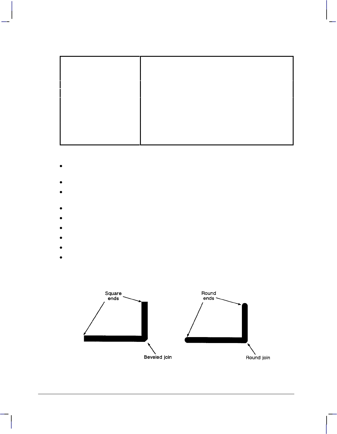
54
This is the black on page 54 (seq: 72)
Company confidential. HP-GL/2 and HP RTL Reference Guide, draft 2. Freeze Status: open
The following instructions form the Line and Fill Attributes Group:
AC Anchor Corner Specifies the starting point for fill patterns.
FT Fill Type Selects the pattern to use when filling polygons.
LA Line Attributes Specifies how line ends and joins are shaped.
LT Line Type Selects the line pattern to use for drawing lines.
PW Pen Width Specifies a new pen width.
RF Raster Fill Definition Defines a pattern for use as area fill.
SM Symbol Mode Draws a symbol at each coordinate location.
SP Select Pen Selects a pen for plotting.
UL User-Defined Line Type Defines a line pattern.
WU Pen Width Unit Selection Specifies whether the pen width is defined in millimeters or
as a percentage of the P1/P2 distance.
The factory environment defaults are:
The line type is solid, and the line-type repeat length is 4% of the diagonal distance from
P1 to P2.
The line cap is butt, the line join is mitered, and the miter limit is 5.
The pen color is the default HP-GL/2 palette, the pen widths are 0.35 mm., and the pen
width selection mode is metric.
The selected pen is 0 (no pen).
Symbol mode is off.
The fill type is solid bidirectional.
The user-defined line types are the eight standard types as defined by the LT instruction.
The area fill anchor corner is (0,0) plotter-units.
The user-defined fill types are solid fill.
Using Line Attributes and Types
Figure 38. Line Ends Attribute

55
This is the black on page 55 (seq: 73)
Company confidential. HP-GL/2 and HP RTL Reference Guide, draft 2. Freeze Status: open
You can change the appearance of the lines you draw by using the LA (Line Attribute) and LT
(Line Type) instructions. The LA instruction lets you specify whether the ends of lines and
corners of joined lines should appear as square, triangular, round, or beveled.
Line types are repeated patterns of dots and/or dashes (including solid lines). The following
shows some examples of line types. You can also vary the width of the lines and line types you
draw by using the PW (Pen Width) instruction. Note that the pen widths used in labels are de-
termined by the stroke weight, specified in the AD and SD instructions.
Figure 39. Different Pen Widths and Line Types
Once you specify a line type and line attributes, all lines created by the following instructions
are drawn using the new line type and attributes. Line types and their interactions with fill pat-
terns are discussed on page 56.
Instructions Affected by Line Types
AA Arc Absolute
AR Arc Relative
AT Absolute Arc Three Point
BR Bezier Relative
BZ Bezier Absolute
CI Circle
EA Edge Rectangle Absolute
EP Edge Polygon
ER Edge Rectangle Relative
EW Edge Wedge
FP Fill Polygon
PA Plot Absolute
PD Pen Down
PE Polyline Encoded
PR Plot Relative
RA Fill Rectangle Absolute
RR Fill Rectangle Relative
RT Relative Arc Three Point
WG Fill Wedge
KERNEL
HP-GL/2
This is the blue on page 55 (seq: 73)
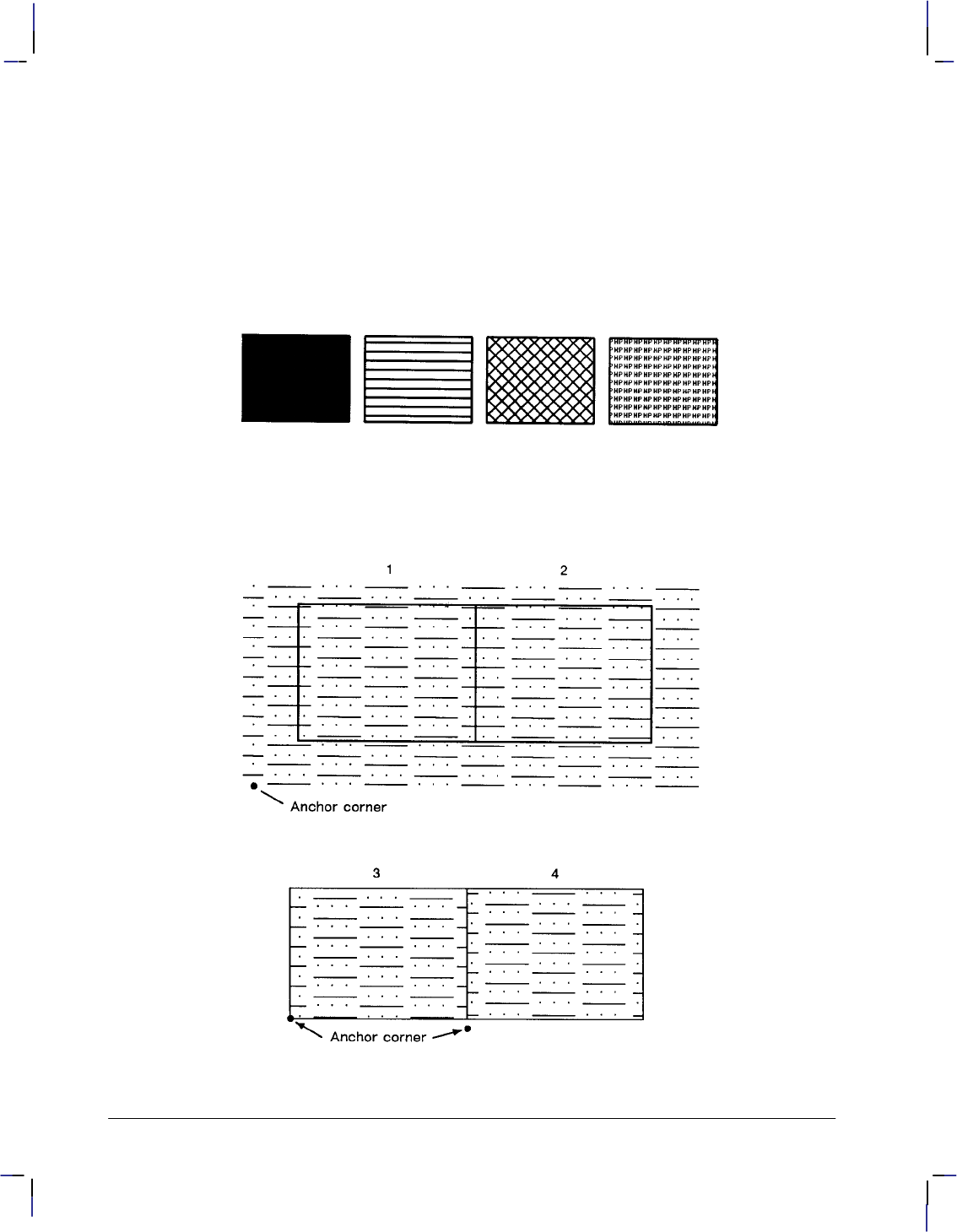
56
This is the black on page 56 (seq: 74)
Company confidential. HP-GL/2 and HP RTL Reference Guide, draft 2. Freeze Status: open
Using Fill Types
Using the FT (Fill Type) instruction adds detail to your drawings and increases their visual ef-
fectiveness. The fill type affects the following instructions:
CF Character Fill
FP Fill Polygon
RA Fill Rectangle Absolute
RR Fill Rectangle Relative
WG Fill Wedge
Figure 40. Fill Types
There are several different types of fill that can be used, including solid, hatch, cross-hatch, and
raster. The range is device-dependent. Figure 40 shows some commonly used types. You may
also be able to define your own types of fill.
Figure 41. Fill Area Anchor Corner

57
This is the black on page 57 (seq: 75)
Company confidential. HP-GL/2 and HP RTL Reference Guide, draft 2. Freeze Status: open
When you use HP-GL/2 hatching or cross-hatch fill types, the lines are drawn using the current-
ly selected line width, line type, and line attributes. For example, if you have selected a dashed
line type and a hatched fill type, your figure is filled with dashed, parallel lines.
All fill types have an anchor corner, the starting point of the fill pattern. Its default location is
the current-unit origin (0,0). Conceptually, the fill type replicates out from the anchor corner in
the +X-directions and +Y-directions, as shown in Figure 41. Areas are filled by that portion of
the fill type resident to the area (refer to rectangles 1 and 2).
Use the AC (Anchor Corner) instruction to position the fill type in relation to the area. Rectan-
gle 3 has an anchor corner set in its the lower-left corner. Rectangle 4 has an anchor corner set
below the lower-left corner to alter the pattern’s position and give contrast to the adjacent area.
Selecting a “Pen” and Changing Line Width
Even though a printer and some types of plotter do not print with a physical pen as a pen plotter
does, they nevertheless use a “logical pen” which emulates the action of a physical pen. You
must use the SP (Select Pen) or PE (Polyline Encoded) instruction to draw.
You can change the width of the logical pen using the PW (Pen Width) instruction. Subsequent
lines are drawn using the new width. Use PW to vary the line thickness and enhance your
plots. You may change widths as often as you like, without sending an SP instruction again.
For pen plotters, the PW instruction causes the plotter to behave as if a wider or narrower pen is
being used, whether or not you have switched to a pen with a different width. The plotter com-
pensates by restroking lines to the approximate width specified.
Pen (line) widths can be specified either in millimeters or as a percentage of the diagonal dis-
tance from P1 to P2. Use the WU (Pen Width Unit Selection) instruction to select how the pen
width is specified. Since using the WU instruction defaults the width of all pens, send WU be-
fore a PW instruction.
The Character Group
When you create an HP-GL/2 graphic and want to add text, you can either enter PCL mode to
add text to your image or you can print text from within HP-GL/2 mode. (There is no support
for text in HP RTL mode.) If this is your first experience with HP-GL/2, you should know that
the term “label” is used to indicate the printing of text. This section discusses the various ways
you can “label” your images using the device’s vector graphics instructions.
The Character Group instructions enable you to do the following things:
Work with the character cell.
Use different fonts.
Print or plot with proportionally-spaced and fixed-spaced fonts.
Designate and select standard and alternate fonts.
Position and print labels using any supported font.
Change label size, slant, and direction.
Use variables in labels.
This is the blue on page 57 (seq: 75)
KERNEL
HP-GL/2
This is the blue on page 57 (seq: 75)
58
This is the black on page 58 (seq: 76)
Company confidential. HP-GL/2 and HP RTL Reference Guide, draft 2. Freeze Status: open
The following instructions form the Character Group:
AD Alternate Font Definition Specifies an alternate font for labeling.
CF Character Fill Mode Specifies how outline fonts are rendered.
CP Character Plot Moves the pen the specified number of character cells from
the current pen location.
DI Absolute Direction Specifies the slope of labels independent of P1 and P2 loca-
tions.
DR Relative Direction Specifies the slope of labels relative to P1 and P2 locations.
DT Define Label Terminator Defines the character or code that “turns off” labeling.
DV Define Variable Text
Path Specifies the label path as right, left, up, or down.
ES Extra Space Increases or reduces space between label characters and
lines.
LB Label Prints text using the currently selected font.
LO Label Origin Positions labels relative to the current pen location.
SA Select Alternate Font Selects the font designated by AD for labeling.
SD Standard Font Definition Specifies the standard font for labeling.
SI Absolute Character Size Specifies an absolute character size (in centimeters).
SL Character Slant Specifies the slant at which labels are printed.
SR Relative Character Size Specifies the size of characters as a percentage of the P1/P2
distance.
SS Select Standard Font Selects the font designated by SD for labeling.
TD Transparent Data Specifies whether control characters perform their normal
function or are printed as characters when printing text.
Working with the Character Cell
In each font, the basis for each character or space is the character cell. Think of the character
cell as a rectangular area around a character that includes blank areas above and to the right of
the character. Refer to Figure 42 and the following explanations of some terms.
Baseline—The imaginary line on which a line of text rests. A character’s descender (such as
the bottom of a lowercase “g”) extends below the baseline.
Line Feed—The distance from the baseline of a line of text to the baseline of the next character
line above or below. For most fonts, the linefeed is about 1.2 times the point size (1.33 times
the point size for stick fonts).
Point Size—Traditional character measure roughly equivalent to the height of a capital letter M
plus the depth of a descender. Point size is usually measured in units of 1/72-inch.
Delta-X—The implied pen movement that occurs after a character is printed. It includes the
space taken up by the character as well as the white space between the characters set by the ES
(Extra Space) instruction. In a fixed-spaced font, delta-X is the same for every character. In a
proportionally-spaced font, delta-X varies from one character to another.
Pitch—The number of characters per inch. It is the inverse of delta-X. A pitch of 10 means
that the delta-X is one-tenth of an inch; ten characters will fit into a one-inch space. Pitch is
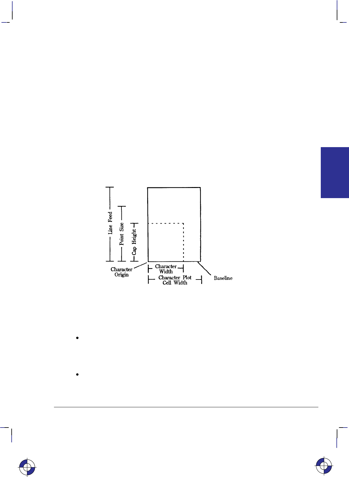
59
This is the black on page 59 (seq: 77)
Company confidential. HP-GL/2 and HP RTL Reference Guide, draft 2. Freeze Status: open
only used to measure fixed-space fonts, because proportionally-spaced fonts include characters
with different delta-X values.
Cap Height—The distance from the baseline to the top of a capital letter. For most fonts, the
cap height is approximately 0.7 times the point size (0.67 times the point size for the stick
font).
Character Origin—The point at which the baseline meets the left edge of the character cell.
Character Width—The lateral area allocated for character rendering. This is the horizontal
distance occupied by a printed character if intercharacter spacing is eliminated. Wide charac-
ters (such as “W”) may span the entire character width area, while narrow characters (such as a
period) include white space on both sides. For calculation purposes, nominal character width is
approximately 0.5 delta-X (or 0.67 delta-X for the stick font).
Character Plot (CP) Cell—A rectangular area with the height of a linefeed and a width extend-
ing from the beginning of one character to the beginning of the next (delta-X).
Character Plot (CP) Cell Width—The distance from the left edge of one character to the begin-
ning of the next character.
Figure 42. Character Cell and HP-GL/2
Types of Fonts
In HP-GL/2 mode, the device uses at least one of three different types of fonts:
Scalable Outline Fonts—Characters can be displayed at any size. The characters are
defined as a set of points on the outline of a character and corresponding mathematical
relationships describing the interaction between these outline points. A scalable outline
character can be resized (using SI and SR), rotated (using DI, DR, and RO), and distorted
(using SL).
Bitmap Fonts—Characters defined as an array of dots in a raster pattern. Bitmap charac-
ters cannot be transformed using DI, DR, SI, SR, or SL, but they can be used with all of the
other instructions in this section—see the SB (Scalable or Bitmap Fonts) instruction, which
is in the Dual-Context Extension, on page 288. Bitmap characters are always placed in an
This is the blue on page 59 (seq: 77)
KERNEL
HP-GL/2
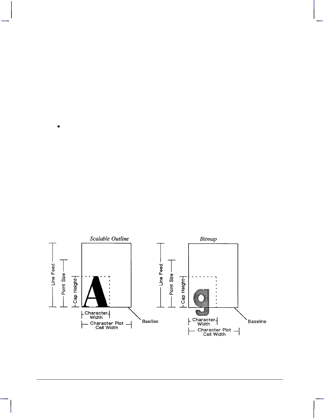
60
This is the black on page 60 (seq: 78)
Company confidential. HP-GL/2 and HP RTL Reference Guide, draft 2. Freeze Status: open
orthogonal direction to the page, closest to the print direction established using the DI and
DR instructions (see Figure 73 on page 140).
Bitmap fonts affect labels as follows:
–Bitmap characters can only be printed horizontally or vertically. If the print direction
(DI or DR) is not orthogonal, the offset between characters follows the print direction,
but the characters themselves are rotated to the nearest 90.
–Bitmap characters cannot be stretched. A size instruction (SI or SR) renders labels in
the closest available size. The SI or SR height parameter determines the best-fit size
for proportionally-spaced fonts, the width parameter for fixed-space fonts.
–Bitmap fonts cannot be slanted or edged; SL and CF have no effect on them.
Stick and Arc Fonts—Characters are drawn as a series of vectors. The characters are
defined as a set of end-points. You can resize (using SI or SR), rotate (using RO, DI, and
DR), and distort (using SL) stick fonts. Stick fonts are defined on a dimensionless grid.
The main body of each character fits within a 32-by-32-unit box, with descenders extend-
ing beneath. The stick font is fixed-spaced, and the arc font is proportionally-spaced. All
HP-GL/2 devices support stick fonts.
Stick fonts (typefaces 48, 49, and 50) are a series of vectors whose width depends on the
character size and the stroke weight parameter in the AD or SD instruction. The formula
used is device-dependent, but is typically:
line width = 0.1 min(height, 1.5 character width) 1.13stroke weight
where stroke weight is an integer in the range –7 to +7. An AD or SD with a stroke
weight of 9999 renders the stick font in the current pen width.
The figures below show each type of font in relation to its character cell.
Figure 43. Scalable and Bitmap Character Cell
Note: Proportionally-spaced fonts do not actually have a fixed character “cell”. The width
occupied by each character depends on the character’s shape.
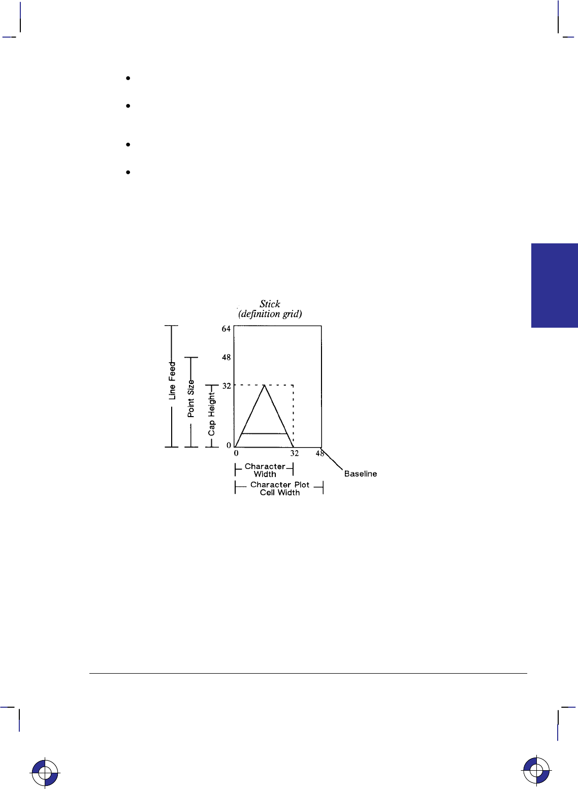
61
This is the black on page 61 (seq: 79)
Company confidential. HP-GL/2 and HP RTL Reference Guide, draft 2. Freeze Status: open
Fixed-Vector Font—The horizontal space for all characters is the same, and each character
is always drawn using a fixed number of vectors, regardless of its size or direction.
Variable-Arc Font—Characters are proportionally spaced, that is, the amount of horizontal
space occupied by each character varies from one character to another. Characters are
drawn using arcs, so that they have smoother contours.
Fixed-Arc Font—The horizontal space for all characters is the same. Characters are
drawn using arcs for greater smoothness.
Drafting Font—Characters are designed to provide reliable character recognition in
situations where photo reduction may cause image degradation and loss of resolution. The
characters are drawn in such a way as to avoid confusion between lines and figures. Thus
the letter “B” and the digit “8” have a wider bottom than top part, but the “8” has a full,
round shape to avoid blur. The digits “6” and “9” have large bodies, but with open stems.
The set also includes symbols used in drafting, such as 1 and n. The HP Drafting font is
a fixed-space vector font.
When you use the SI (Absolute Character Size) or SR (Relative Character Size) instructions to
change the size of the characters, or use the ES (Extra Space) instruction to add extra space
around them, you alter the size of the CP (Character Plot) cell.
Figure 44. Stick Font Character Cell
KERNEL
HP-GL/2
This is the blue on page 61 (seq: 79)
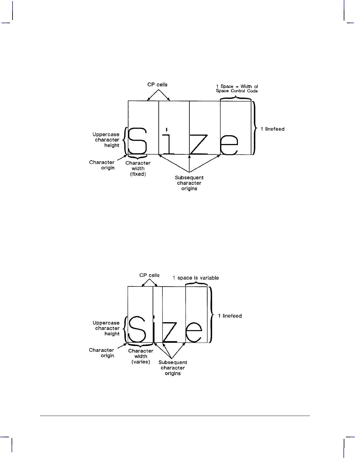
62
This is the black on page 62 (seq: 80)
Company confidential. HP-GL/2 and HP RTL Reference Guide, draft 2. Freeze Status: open
Printing or Plotting with Fixed-Spaced and Proportionally-Spaced Fonts
Figures 45 and 46 show the difference between fixed-spaced and proportionally-spaced fonts.
Figure 45. Fixed-Spaced Font
Proportionally-spaced (variable-space) fonts, by definition, use different amounts of horizontal
space for each letter. This variation produces some differences in the definition of the character
cell, and in the way some of the labeling instructions work with these fonts. These differences
are described in this section.
With proportionally-spaced fonts, the actual space occupied by each character varies according
to the character’s width (see Figure 46).
Figure 46. Proportionally-Spaced Font
When printing proportionally-spaced fonts, the CP (Character Plot) instruction uses the width
of the Space () control code to determine horizontal spaces and the Line Feed height for de-
termining vertical spacing. The ES (Extra Space) instruction (see page 169) uses the horizontal

63
This is the black on page 63 (seq: 81)
Company confidential. HP-GL/2 and HP RTL Reference Guide, draft 2. Freeze Status: open
escapement distance (a font metric) to compute horizontal spaces and the Line Feed height for
determining vertical spacing. Both of the character size instructions (SI and SR) use cap height
and average character width in calculating character size. Otherwise, these instructions behave
the same as they do with fixed-spaced fonts.
Designating and Selecting Fonts
If you intend to label with the default fixed-spaced (stick) font, you do not need to use the SD
or AD instructions for designating standard and alternate fonts. However, if you intend to use a
different font (for example, to match accompanying PCL text), you must use the SD or AD
instructions to designate fonts before you can select those fonts for labeling (using either SA or
SS).
Standard and Alternate Fonts
The following outlines some of the principles to use when labeling with different fonts:
Designate the standard and alternate fonts using the SD or AD instruction before labeling.
If you are using the stick font (the default) as your standard font, you need specify only
your alternate font.
Select either the standard or alternate font, using either the SS or SA instruction before
labeling.
Note that labeling always begins with the standard font, unless you use the SA instruction
before you begin your label (or finish the previous label in the alternate font).
Switch from the standard font to the alternate font, either using SS and SA or the Shift
In/Shift Out method. If you are changing fonts within a text string, the Shift In/Shift Out
method is usually more efficient. See Accessing Special Characters on page 72. Switch
from the standard font to the alternate font using the ASCII Shift Out control character (,
decimal code 14). Switch from the alternate font to the standard font using the ASCII Shift
In control character (, decimal code 15). (Note that a Shift In () or Shift Out ()
outside of the label instruction string is ignored.)
How Your Device Selects Fonts
The following summarizes the procedure that your device follows to select a font. The criteria
are based on the parameters of the AD and SD instructions. The procedure is necessary be-
cause fixed-space and variable-space fonts use different criteria to determine text size. For
fixed-space fonts, the pitch determines the size. The height parameter of the AD and SD
instructions is only used to distinguish between fonts with equal pitch. For variable-space
fonts, the height parameter of the AD and SD instructions determines the text size; the pitch
parameter is ignored. Your HP-GL/2 device performs the following steps in order:
1. If the specified character set does not exist, the device uses the user default set (set from
the control panel, if there is one) or the factory default set.
2. If the specified font spacing (fixed or variable) is available, it is used; otherwise the device
uses the remaining space option.
3. If the remaining fonts are proportionally spaced, the pitch is ignored. For fixed-space
fonts, if the specified pitch is not available, the device selects the next greater pitch. If no
greater pitch is available, the device selects the closest available smaller pitch. (A pitch of
This is the blue on page 63 (seq: 81)
KERNEL
HP-GL/2

64
This is the black on page 64 (seq: 82)
Company confidential. HP-GL/2 and HP RTL Reference Guide, draft 2. Freeze Status: open
12 characters per inch [cpi] is greater than one of 10 cpi; greater pitch means smaller char-
acters.) Note that any specified pitch is available for scalable fonts.
4. The device selects the closest available height to the height parameter. The closest avail-
able height is in terms of absolute difference. For example, if the device has 6-, 8-, and
12-point fonts and the specified height is 10, both 8- and 12-point fonts are selected for the
next selection criterion. All fonts with heights within a quarter-point of the specified
height are considered to satisfy the height criteria. Note that any specified height is avail-
able for scalable fonts. Height is ignored for fixed-space fonts.
5. If the specified posture (upright or italic) is available in the remaining fonts, the device
selects that posture; otherwise, this attribute is ignored.
6. If the specified stroke weight is available in the remaining fonts, the device selects that
stroke weight. Note that any stroke weight is available for stick fonts.
If the specified stroke weight is greater than or equal to zero and is not available, the
device selects the next thicker stroke weight. If no thicker stroke weight is available,
the device selects the next thinner stroke weight.
If the specified stroke weight is less than zero and is not available, the device selects
the next thinner stroke weight. If no thinner stroke weight is available, the device se-
lects the next thicker stroke weight.
7. If the specified typeface is available, the device selects that typeface; otherwise, the device
ignores this attribute. The stick fonts are typefaces 48, 49, and 50. The character set and
posture selections must match an available stick font.
8. If more than one font emerges after this procedure, the location of fonts provides the fol-
lowing order of priority:
Downloaded bitmap soft fonts in ascending font ID order.
Downloaded scalable soft fonts in ascending font ID order.
Bitmap external cartridge fonts.
Scalable external cartridge fonts.
Bitmap internal fonts.
Scalable internal fonts.
9. If multiple fonts remain, a font in the specified orientation (the result of the DI or DR
instruction) is selected. If none of the fonts is defined in the specified orientation, automat-
ic rotation is applied to one of the remaining fonts.
Using Labels
Use the LB (Label) instruction to add text to plots, to create text charts, or to emphasize areas
of a diagram or graph that need special attention or explanation. You can control almost all
aspects of the label’s appearance: its position, size, slant, spacing, and direction. All labels are
drawn using the font currently designated (refer to the SD or AD instructions) and selected for
use (refer to the SS or SA instructions).
If you are using a font other than the default, use SD (Standard Font Definition) or AD (Alter-
nate Font Definition) instructions to designate a font. Then, use the SS (Select Standard Font)
or SA (Select Alternate Font) instructions to select the designated font for use. You can follow

65
This is the black on page 65 (seq: 83)
Company confidential. HP-GL/2 and HP RTL Reference Guide, draft 2. Freeze Status: open
the LB (Label) instruction with virtually any characters, including non-printing control codes,
such as a Line Feed () or Carriage Return ().
At the end of a label, you must use a special label terminator to signify the end of text. The
default terminator is the ASCII end-of-text character (decimal code 3), or you can define a
terminator using the DT instruction. Without the label terminator in place, your device contin-
ues to label your picture with all subsequent HP-GL/2 instructions and parameters.
Note: Symbol mode, set by the SM instruction, is a special case of a Label.
The following example demonstrates printing a simple label using the SD instruction to desig-
nate a font, the SS instruction to select that font, the DT instruction to define a label terminator,
and the LB instruction to print the label, including Carriage Returns and Line Feeds.
Note: In the examples, if a Carriage Return-Line Feed pair is required in the example, it is in-
dicated as .
PA 1500,2500; Specify absolute plotting and move to (1500,2500).
SD 1,21,2,1,4,25,5,1,6,0,7,52; Designate the 25-point Univers Italic font as the standard
font.
DT*,1; Define the asterisk character as the label terminator (the “1” indi-
cates that the terminator—the asterisk—shouldn’t be printed).
(Don’t leave any spaces before the asterisk.)
SA ; Select the alternate font for printing. Since an alternate font
hasn’t been designated, the default (say, 11.5-point) stick font is
selected.
LBThis is the Stick Font (Default) *; Print the first line of text, followed by
two Carriage Returns and two Line Feed control codes. Notice
how the asterisk terminates the label. Note also that if you in-
clude any spaces between the “LB” and “This”, they will cause
spaces to appear on the plotted page.
SS ; Select the standard font.
LBThis is Univers Italic*; Print the line of text in the newly specified font.
Figure 47. Printing Labels
Default Label Conditions
The following label default conditions are established when the device is initialized, or set to
default conditions. To change these settings, refer to the appropriate section or instruction.
Symbol set (character set)—HP Roman-8.
Font spacing—Device-dependent.
Pitch—Device-dependent; normally 9 characters per inch. (Refer to your device’s HP-
GL/2 option documentation for any of the following instructions: AD, SD, SI, SR.)
Height—Device-dependent; normally 11.5 point.
This is the blue on page 65 (seq: 83)
KERNEL
HP-GL/2
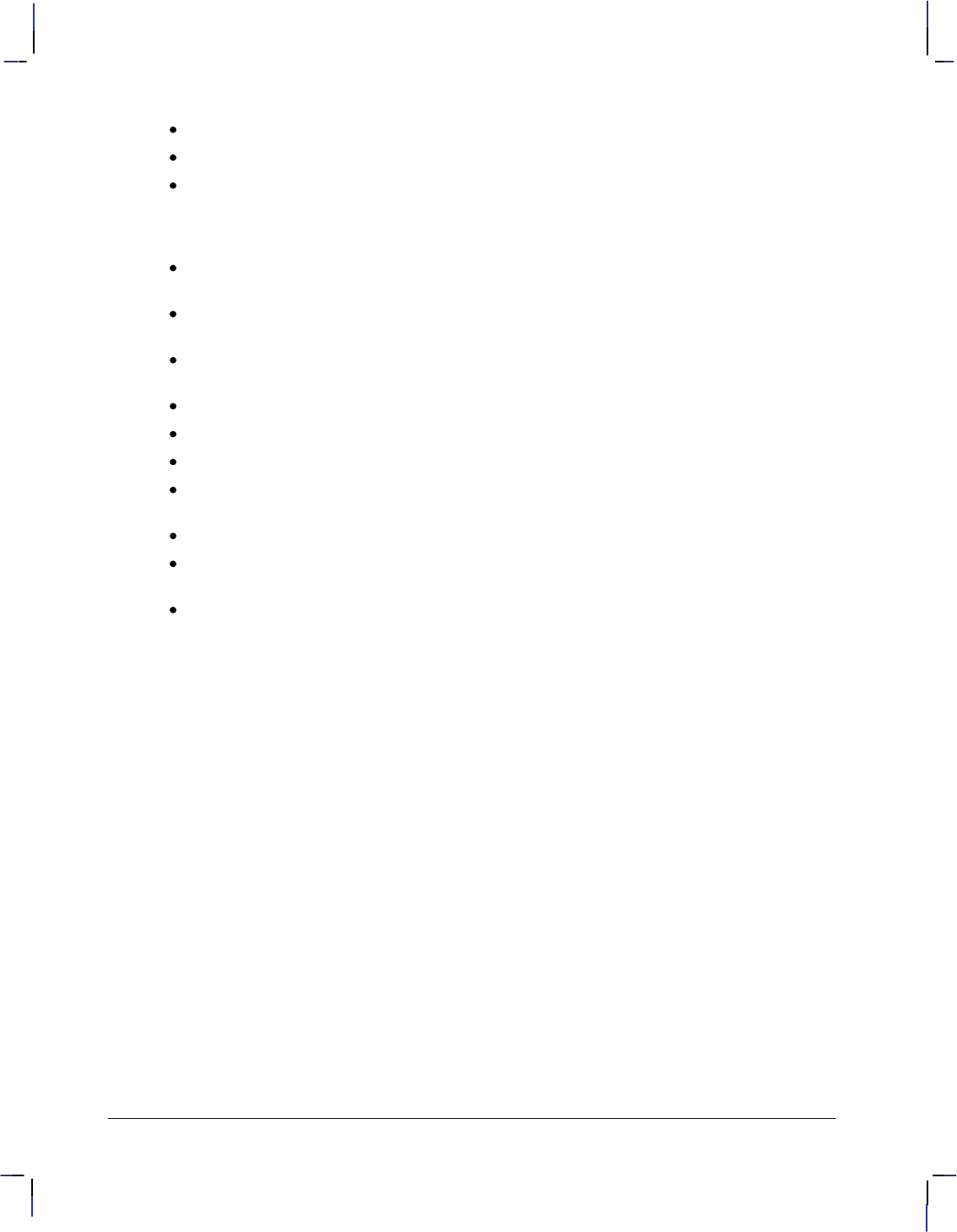
66
This is the black on page 66 (seq: 84)
Company confidential. HP-GL/2 and HP RTL Reference Guide, draft 2. Freeze Status: open
Posture—Device-dependent.
Stroke weight—Device-dependent.
Typeface—HP-GL/2 stick.
(For each of the above settings, refer to the AD and SD [Alternate and Standard Font Defi-
nition] instructions.)
Label terminator—ASCII end-of-text character (decimal code 3). Refer to the DT
(Define Label Terminator) instruction.
Label starting point—Current pen location (LO1). Refer to the LO (Label Origin)
instruction.
Label direction—Horizontal (the positive X-direction; it may be vertical on the paper).
Refer to the DI, DR, and DV instructions.
Label direction mode—Absolute. Refer to the DI instruction.
Label size mode—Absolute. Refer to the SI instruction.
Character width and height—Device-dependent. Refer to the SI instruction.
Space between characters and lines—Normal (no extra space). Refer to the ES (Extra
Space) instruction.
Character slant—None (vertical). Refer to the SL (Character Slant) instruction.
Character fill mode—Solid fill, no edging. Refer to the CF (Character Fill Mode) instruc-
tion.
Transparent data mode—Off. Refer to the TD instruction.
Character Positioning
LB uses the current pen position as the reference for the label position. LO (Label Origin) can
left-align, center, right-align, and adjust the vertical position about the current pen position.
The default label starting point is approximately at the intersection of the left edge of the char-
acter and the baseline. After printing a character, the pen position is updated by that character’s
delta-X distance to the starting point of the next character (unless modified by ES). This con-
tinues until the end of the label string (unless an embedded control character such as a carriage
return or line feed is encountered). When printing the label, the pen position is updated accord-
ing to the current path (DV) and label origin (LO). DV operates during the label, determining
the character-to-character direction.
LB updates the pen position, but not the carriage-return point. characters move the carriage-
return point down; DV changes this direction. The carriage-return point is maintained in
physical units, not user units.
Moving to the Carriage-Return Point
When you begin labeling, the current pen location is the carriage-return point (the beginning
of your line of text is the point to which the pen is “returned” when a carriage return () con-
trol code is sent to the device). When the device encounters a CP (Character Plot) instruction,
or a carriage return control code within a Label instruction, the pen moves to the carriage-re-
turn point, adjusted up or down by any line feeds.

67
This is the black on page 67 (seq: 85)
Company confidential. HP-GL/2 and HP RTL Reference Guide, draft 2. Freeze Status: open
The following instructions update the carriage-return point to the current location:
AA Arc Absolute
AR Arc Relative
AT Absolute Arc (Three Point)
BR Bezier Relative
BZ Bezier Absolute
CP Character Plot (see note)
DF Default Values
DI Absolute Direction
DR Relative Direction
DV Define Variable Text Path
IN Initialize
LO Label Origin
PA Plot Absolute
PD Pen Down (see note)
PE Polyline Encoded
PR Plot Relative
PU Pen Up (see note)
RO Rotate Coordinate System
RT Relative Arc (Three Point)
Note: A PD or PU instruction with parameters also updates the carriage-return point. The CP
instruction with a non-zero lines parameter updates the carriage-return point’s vertical location.
The LB (Label) instruction does not update the carriage-return point to the current pen location,
but continues labeling from the current pen location. This feature allows you to issue several
label instructions that write one long label and still use a to get to the beginning of the entire
label.
Control Characters
There are two modes of operation for printing HP-GL/2 labels: normal and transparent data.
Normal mode is the default; all character codes within a label are printed using the currently
selected font, undefined character codes produce a space, and all control codes are ignored un-
less they perform a function, as follows (these are the codes in the PC-8 compatible symbol
sets):
Control
Code Decimal
code Description
Null () 0 No Operation (NOP).
End-of-text
()3An indication of the end of a label. If an alternative label
terminator has been defined (using the DT instruction),
this code performs no operation (NOP).
Bell()7 No Operation (NOP).
Backspace
()8The pen moves to the position before the last printed
character. For proportionally-spaced fonts, a backspace
centers the overstriking character on the overstruck char-
acter; the pen position should end up at the same position
as before the backspace. A backspace as the first charac-
ter of a label is ignored.
This is the blue on page 67 (seq: 85)
KERNEL
HP-GL/2
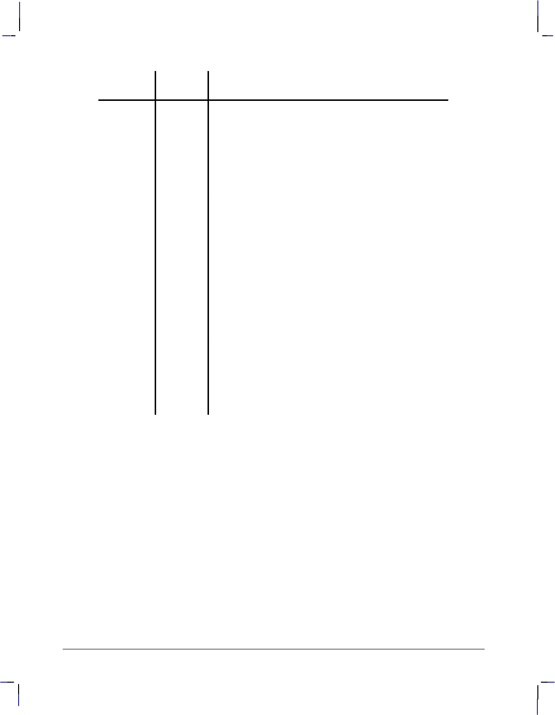
68
This is the black on page 68 (seq: 86)
Company confidential. HP-GL/2 and HP RTL Reference Guide, draft 2. Freeze Status: open
Control
Code DescriptionDecimal
code
Horizontal
Tab ()9The pen moves to the next tab stop. Stops are located at
the carriage-return point and at every eighth column be-
tween that point and the edge of the current window. A
column is equal to the width of a Space character in the
current font; it may be modified by the ES instruction.
Line Feed
()10 The pen position and carriage-return point advance one
line from their current positions. For HP-GL/2 labels, a
line is the character-cell height.
Vertical Tab
()11 No Operation (NOP).
Form Feed
()12 No Operation (NOP).
Carriage
Return ()13 The pen position is updated to the carriage-return point
(usually the pen position when the LB instruction was
executed, adjusted by any line feeds).
Shift Out
()14 Invoke the Alternate Font (equivalent to the SA instruc-
tion).
Shift In ()15 Invoke the Standard Font (equivalent to the SS instruc-
tion).
Escape
()27 No Operation (NOP).
Space ()32 The pen position moves one column to the right. If the
current font contains a character definition for the space
code, it is printed; otherwise it is a non-printing space.
The space width may be modified by the ES instruction.
Transparent data mode, enabled by the TD instruction, prints all character codes in the current
font; a space is printed for undefined character codes. The only functionality of a character
code (including control codes) is the printing of a graphic image or a space. The only excep-
tion is the currently defined label terminator which prints an image or a space (if DT mode is 0)
and also terminates the label.
For example, in the PC-8 symbol set, the eighth note musical symbol is identified by a charac-
ter code of 13. In transparent data mode, a code of 13 produces the eighth note; in normal
mode it produces a carriage return.
In the 8-bit compatible symbol sets, character codes 0 through 31 and 128 through 159 are con-
trol codes. The 7-bit compatible sets are treated in the same way, except that codes 128
through 255 are undefined (128 through 159 are NOPs and 160 through 255 are spaces). Values
32 and 255 are not considered control codes because they produce a space in any mode.

69
This is the black on page 69 (seq: 87)
Company confidential. HP-GL/2 and HP RTL Reference Guide, draft 2. Freeze Status: open
Adding Carriage Returns and Line Feeds to Labels
Carriage returns and line feeds are non-printing ASCII control characters. You can insert these
formatting characters using a character-string function like CHR$ in BASIC, or by producing
them directly from the keyboard. Most of the examples in this book represent these characters
in bold uppercase letters such as and .
When you use a string function such as CHR$, you must separate it from the label in a suitable
manner, using a concatenation symbol such as “+”, “;”, or “,”. For example, in BASIC you use
the “+” symbol between the label (which is enclosed in quotation marks, and the CHR$ func-
tion, like these:
“LBThis is a label”+CHR$(3)
“LBThis is another label”+CHR(13)+CHR$(10)+“on two lines”+CHR$(3)
If you can enter control characters from the keyboard, the same two labels would be:
“LBThis is a label”
“LBThis is another labelon two lines”
Both pairs of examples produce the following labels:
This is a label This is another label
on two lines
Enhancing Labels
You can enhance your labels by changing such aspects as the character size and slant, the space
between characters and lines, and the orientation or placement of the label on the page. To ef-
fectively use these enhancements you should understand the properties of the character cell.
Refer to Working with the Character Cell on page 58.
Character Size and Slant
Two mechanisms control the character size:
The AD and SD (font definition) instructions allow the specification of the point size or
pitch. The character size of proportionally-spaced fonts depends on the point size; pitch is
ignored. The size of fixed-space fonts depends on pitch. AD and SD preserve a charac-
ter’s design aspect and cannot by themselves create tall skinny characters or short fat ones.
The SI and SR (character size) instructions perform graphic transformations on characters
in order to produce a certain size. These instructions can vary a character’s cap height and
width independently, allowing tall skinny or short fat characters.
To obtain the most typographically correct characters, use “SI;” to disable graphic transforma-
tions so that characters will be as close as possible to what the font designer intended. Size will
be based solely on parameters last specified by AD or SD. If special graphic effects are re-
quired (such as rubbering or mirroring of characters), enable them with SI or SR.
You can change the size of the characters using the SI (Absolute Character Size) and SR (Rela-
tive Character Size) instructions. The SI instruction establishes the character width and height
in centimeters of the uppercase “A” and maintains this character size independent of the loca-
tion of P1 and P2 or the page size. The SR instruction establishes the character width and
height of the uppercase “A” as a percentage of the distance between P1 and P2. Subsequent
changes in the location of P1 and P2 cause the character size to change with the SR instruction.
KERNEL
HP-GL/2
This is the blue on page 69 (seq: 87)
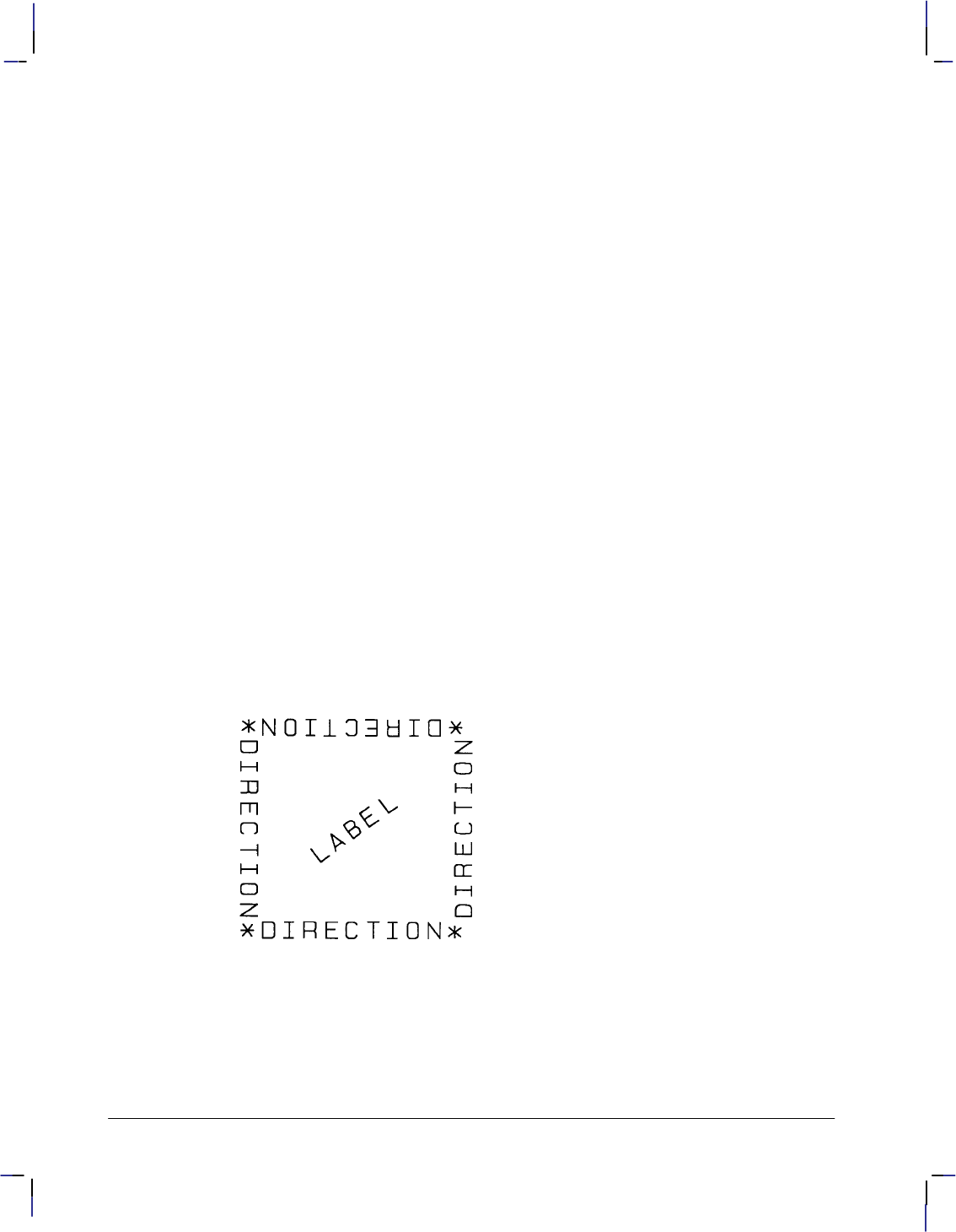
70
This is the black on page 70 (seq: 88)
Company confidential. HP-GL/2 and HP RTL Reference Guide, draft 2. Freeze Status: open
Changing the character size changes the size of the CP (Character Plot) cell and proportionally
changes the line width used in labels (refer to AD and SD).
Note: When the Shift In () or Shift Out () control codes are used to select a font, the font
size reverts to that font specified using the AD or SD instructions.
You can use the SL (Character Slant) instruction to slant the characters at a specified angle in
either direction from the left vertical side of the CP (Character Plot) cell. The CP cell is not
altered.
Character Spaces and Text Lines
You can use the ES (Extra Space) instruction to automatically increase or decrease spaces be-
tween all characters or lines. For example, ES can be used to increase space between every
character in a label such as “M E M O R A N D U M”), or to increase or decrease space be-
tween every line of text (such as double-spacing).
You can use the CP (Character Plot) instruction to move the pen a specific number of lines or
spaces (character cells) from the current pen location. Use the CP instruction, for example, to
indent a label a certain number of spaces.
Label Orientation and Placement
You can place your labels anywhere on the page in any orientation. The DI (Absolute Direc-
tion) instruction specifies the angle at which you want to print the characters, independent of
the location of P1 and P2. The DR (Relative Direction) instruction specifies the angle at which
you want to print the characters as a function of the P1 and P2 distance; thus when you change
P1 and P2, the label angle changes to maintain the same orientation.
The DI and DR instructions allow you to print text at any angle with the letters in their normal
side-by-side orientation.
Figure 48. Label Orientation and Direction
Note: Bitmap characters are always printed orthogonally to the page (refer to Figure 73 on
page 140). Scalable characters print in the direction specified.
The DV (Define Variable Text Path) instruction allows you to specify the text path (right, left,
up, or down) and the direction of Line Feeds with respect to the text path.
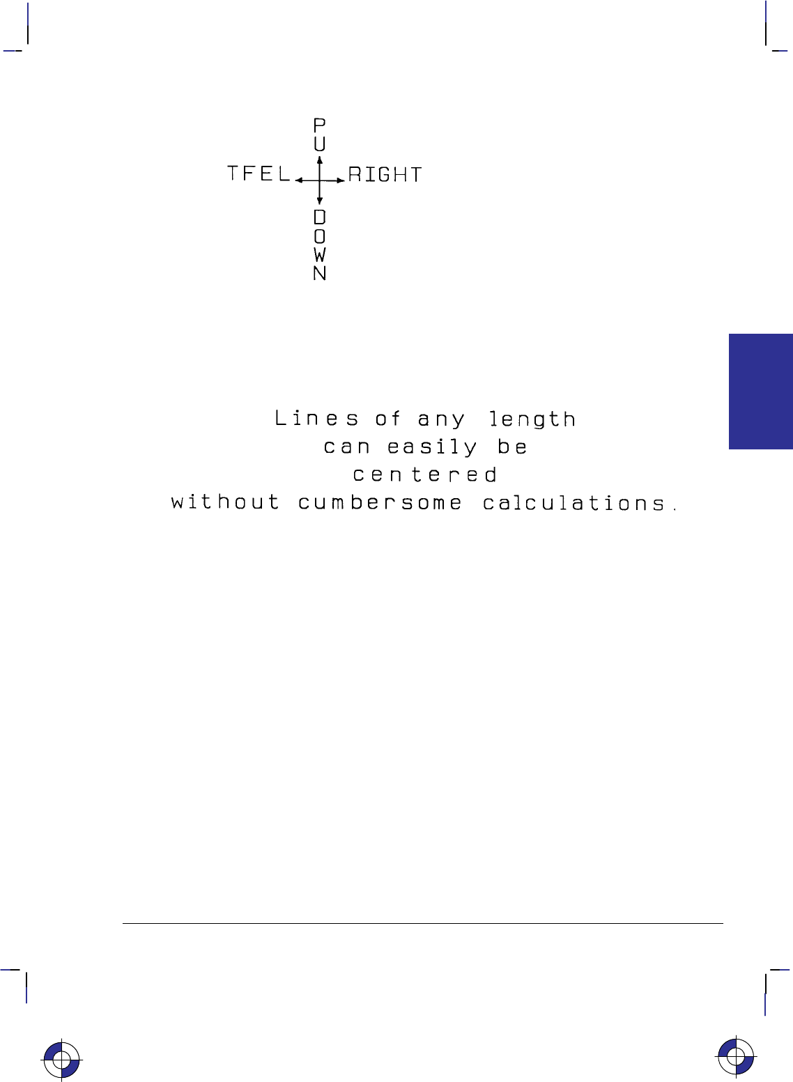
71
This is the black on page 71 (seq: 89)
Company confidential. HP-GL/2 and HP RTL Reference Guide, draft 2. Freeze Status: open
Figure 49. DV Instruction with +X to the Right and +Y Upwards
The LO (Label Origin) instruction simplifies placing labels on a drawing. Normally, the first
character origin is the current pen location when the Label instruction is issued. The LO
instruction allows you to specify that the label be centered or right- or left-justified from a
point. For example, the following illustration shows four centered lines of text.
Figure 50. Label Origin Instruction to Center Text
These lines use one (X,Y) coordinate pair, one LO instruction to center labels, and a Carriage
Return and Line Feed after each line. Without this instruction, an alternative method would
involve calculating the length of the line in CP (Character Plot) cells, dividing by two, and us-
ing the CP instruction to backspace the required number of cells. The LO instruction saves
calculation, decreases the number of characters sent to the device, and allows you to take ad-
vantage of proportionally-spaced fonts when the character widths are not known to the
software.
Terminating Labels
LB tells the device to print every character following the instruction, rather than interpreting
the characters as graphics instructions. In order to allow the normal terminator, the semicolon
(;), to be used in text, the instruction is defined so that you must use the special label terminator
to tell the device to once again interpret characters as graphics instructions. (If the instruction
had been defined otherwise, you wouldn’t be able to print semicolons in your text.)
The default label terminator is the non-printing ASCII end-of-text character (decimal code
3, and denoted in BASIC by CHR$(3)). You must use the label terminator, or the device prints
the rest of your file as text instead of executing the instructions. You can change the label ter-
minator using the DT (Define Label Terminator) instruction.
This is the blue on page 71 (seq: 89)
KERNEL
HP-GL/2
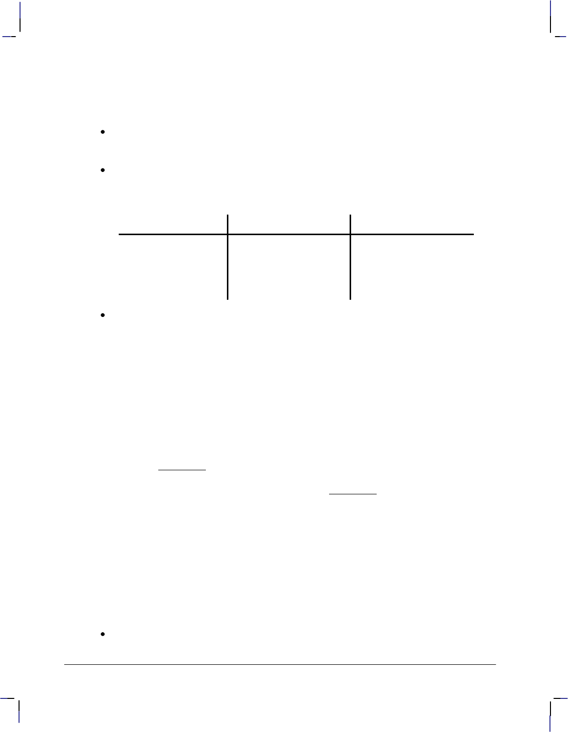
72
This is the black on page 72 (seq: 90)
Company confidential. HP-GL/2 and HP RTL Reference Guide, draft 2. Freeze Status: open
Accessing Special Characters
There are several ways of accessing special characters (those not normally available on your
keyboard):
Use a function defined for your programming language, such as CHR$ in BASIC to enter
the decimal code, for example, CHR$(120) to draw the character “ in symbol set 5
(Roman Extensions).
On some computers, you can produce ASCII control characters from the keyboard by
pressing two keys simultaneously. Check your computer documentation for the availability
of this option and for the appropriate combination of keys on your system. Here are some
common control characters and their equivalents for some computer systems:
Control Character ASCII code (decimal) Keyboard equivalent
(end-of-text) 3 CONTROL and C
(backspace) 8 CONTROL and H
(line feed) 10 CONTROL and J
(carriage return) 13 CONTROL and M
Use the SS (Select Standard Font) and SA (Select Alternate Font) instructions to switch
between character sets, as in the following example.
SD 1,21,2,0,7,48; Define the US ASCII (1,21) stick font (7,48) with fixed spac-
ing (2,0) as the standard font.
AD 1,83,2,1,7,50; Define the Spanish (1,83) HP-GL fixed arc font (7,50) with
variable spacing (2,1) as the alternate font.
SS ; Select the standard font.
LBUS ASCII, fixed-vector font Print the first label.
CP –22,–2; Reposition 22 spaces left and two down for the second label.
SA ; Select the alternate font.
LBSPANISH SET, variable-arc font Print the first part of the second label.
CP –17,–2; Reposition the cursor.
LB]sus seCHR$(124)as? Print the remainder of the Spanish label. Here, the keyboard
“]” character (ASCII 93) corresponds to the “¿” in the Span-
ish character set, and “CHR$(124)” is whatever produces
ASCII character number 124 (“ñ”) from that character set
(use for the latter whatever means is available with your pro-
gramming language).
This generates:
US ASCII, fixed-vector font
SPANISH SET, variable-arc font
¿sus señas?
Use the equivalent ASCII character on your keyboard in the label string. For example, in
symbol set 5 (Roman Extensions), the character “ is ASCII code 120, which is the
character “x” on an English keyboard.
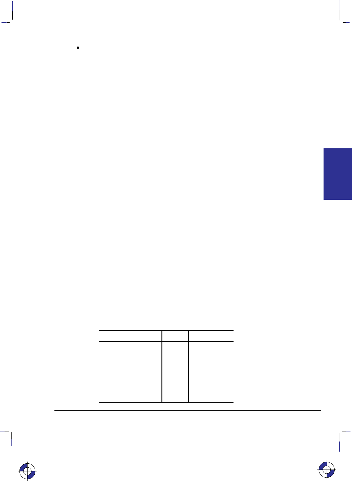
73
This is the black on page 73 (seq: 91)
Company confidential. HP-GL/2 and HP RTL Reference Guide, draft 2. Freeze Status: open
If you need to use a special character from another set in the middle of a label, using the
SS and SA instructions to toggle between sets can be inefficient. Instead, it might be easier
to use the control characters shift-in (, decimal code 15) and shift-out (, 14) to toggle
between the sets. For example:
SD 1,115,3,3,4,30; Define a standard font
AD 1,5,3,3,4,30; and an alternate font containing the symbol “” (accessed
from the keyboard as “x”)
LB3x–5; Create the label, producing:
3–5
HP-GL/2 Printing
The HP-GL/2 print model specifies how images are constructed and combined when rendering
a page in HP-GL/2. The following terms are used:
Primitive—Any graphic item that marks the page (characters, vectors, polygons, and so on).
Destination—A composite of all primitives previously placed on the page.
Source—A solid black primitive possibly with added attributes such as current color and area
fill. HP-GL/2 source data does not have transparent bits.
Pattern—An area fill attribute for a graphic object like a polygon, for example, solid fills,
hatched fills, shaded fills, and user-defined raster patterns. (User-defined raster patterns can be
either color or monochrome; all other fills are monochrome.)
Current Color—The color of the currently selected pen.
Texture—Monochrome pattern plus current color. See page 366.
Transparency mode—Determines how the pattern’s white pixels affect the destination. In
transparent mode (1), white pixels have no effect on the destination. In opaque mode (2), white
pixels block out corresponding destination areas.
Area Fills
The Line and Fill Attributes group contains instructions for filling primitives: FT (Fill Type)
and RF (Raster Fill Definition). The Palette extension contains instructions that determine pen
colors (PC) and the number of pens (NP).
The following table shows which graphic images may have color or area fill applied:
Graphic Image Color Area Fill
Vectors Yes No
Arcs, circles Yes No
Polygons* Yes Yes
Characters:
Vector
Scalable
Bitmapped
Yes
Yes
Yes
Yes
Yes
Yes
This is the blue on page 73 (seq: 91)
KERNEL
HP-GL/2
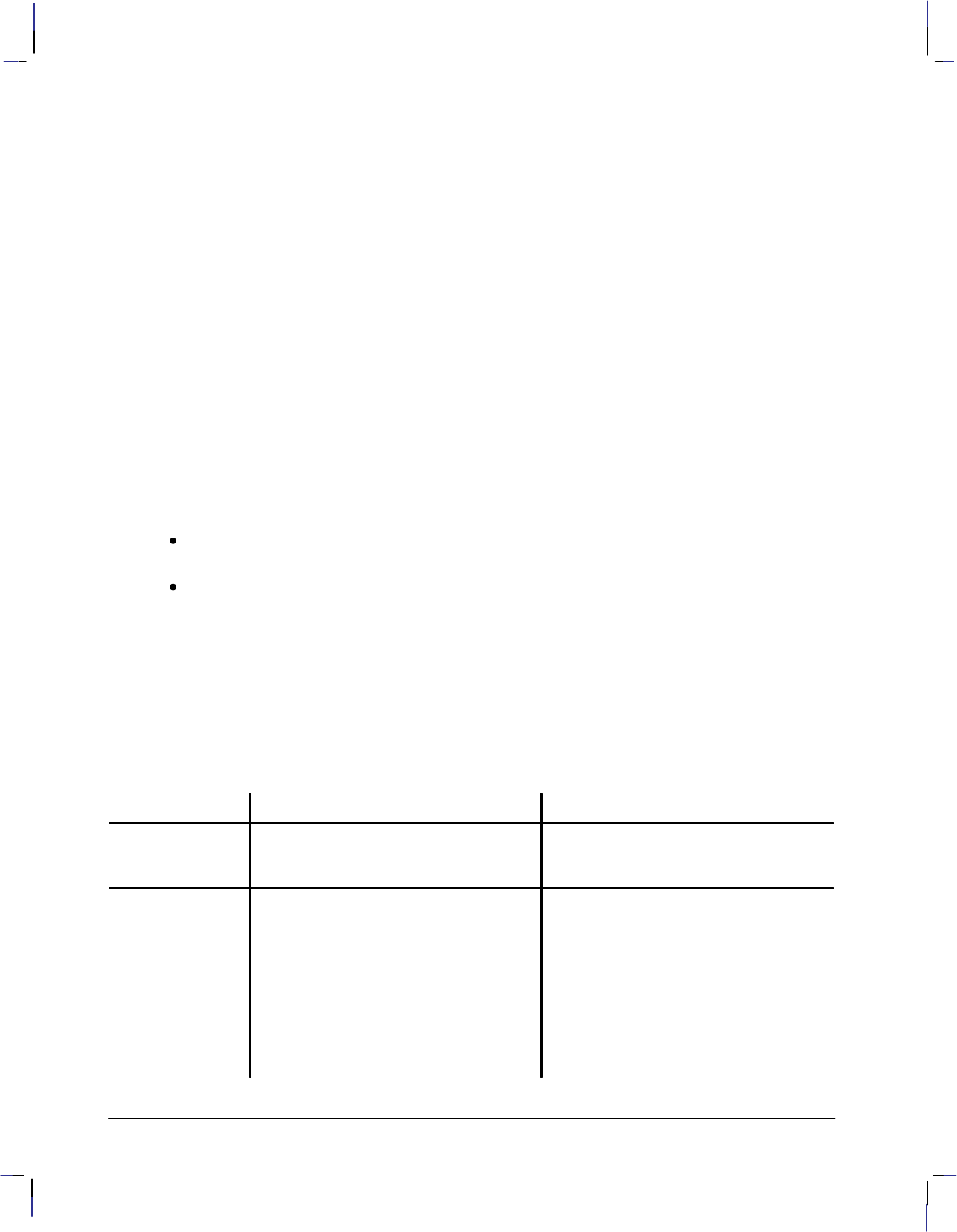
74
This is the black on page 74 (seq: 92)
Company confidential. HP-GL/2 and HP RTL Reference Guide, draft 2. Freeze Status: open
* “Polygons” refers to objects filled with the FP
instruction that were created with the polygon,
wedge, and rectangle instructions (EA, ER, EW,
PM, RA, RR, and WG).
The current color can be applied to any area except user-defined fills having color information
(defined by RF and accessed by “FT11”). Area fills cannot be combined; for example, you
cannot obtain a “shaded hatch” except by defining a user-defined pattern or screened vectors
(using SV).
The Kernel Print Model
In the HP-GL/2 kernel print model, non-white source pixels, to which current color and pattern
have been added, replace destination pixels. White pixels imposed on the source by a pattern
are transparent and have no effect.
Extended Print Model
More options are allowed when the Technical Graphics and Palette extensions are added to the
kernel. Two instructions then determine the state of the HP-GL/2 print model: TR (Transparen-
cy Mode) and MC (Merge Control).
MC can perform logical operations (AND, OR, exclusive-OR, and NOT) on non-white
source, texture, and destination pixels.
TR determines whether white source pixels affect the destination.
The kernel print model is equivalent to “TR1” (transparent), “MC0” (replacement) in the ex-
tended print model.
HP-GL/2, HP RTL, and PCL Print Models
Although the HP–GL/2 and the HP RTL and PCL print models are slightly different (notably in
their treatment of whites), logical raster operations (“ROPs”) using TR and MC are similar.
Dual-context applications may prefer to remain in HP-GL/2 for efficiency and use the HP-GL/2
print model. The complete set of 256 logical operations is listed on page 475.
HP RTL and PCL Print Model HP-GL/2 Print Model
Default Print
Model The non-white source and pattern pixels
are OR’d with each other and replace
destination pixels.
The non-white source and pattern pixels
are OR’d with each other and replace
destination pixels.
Transparency
Modes HP RTL and PCL have both source and
pattern transparency modes, which de-
termine whether white source and pat-
tern pixels are applied to the destina-
tion.
“White” is defined by the white refer-
ence in the color space.
Default transparency: white source and
pattern pixels are transparent.
HP-GL/2 has pattern transparency
mode, but not source transparency
mode, since there is no bounding box as
in raster mode or character cells.
The CR instruction defines “white” by
setting a white reference.
Default transparency: white pattern pix-
els are transparent.

75
This is the black on page 75 (seq: 93)
Company confidential. HP-GL/2 and HP RTL Reference Guide, draft 2. Freeze Status: open
HP-GL/2 Print ModelHP RTL and PCL Print Model
Current Color The current color is selected from the
palette by the Foreground Color
(*v#S) command.
The default is black.
HP RTL and PCL cannot import HP-
GL/2 patterns.
The current color is selected from the
palette by the SP instruction.
The default is pen number 0 (normally
white).
HP-GL/2 can import HP RTL and PCL
patterns.
Area Fill Area fill is selected by pre-defined
(*c#G) and downloadable
(*c#W) patterns.
Area fill is selected by pre-defined (FT)
and downloadable (RF) patterns.
Logical
Operations
*l#O determines the interaction be-
tween source, texture, and destination. “MC1” determines the interaction be-
tween source, texture, and destination.
KERNEL
HP-GL/2
This is the blue on page 75 (seq: 93)

76
This is the black on page 76 (seq: 94)
Company confidential. HP-GL/2 and HP RTL Reference Guide, draft 2. Freeze Status: open
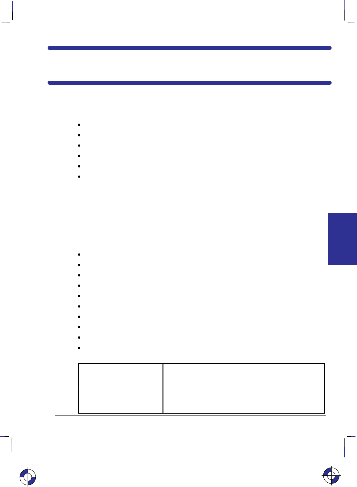
77
This is the black on page 77 (seq: 95)
Company confidential. HP-GL/2 and HP RTL Reference Guide, draft 2. Freeze Status: open
Chapter 4: The HP-GL/2 Extensions
This chapter describes the Extension instructions that rely on specific technologies or function-
ality. The Extensions are:
The Technical Graphics Extension page 77.
The Palette Extension page 82.
The Dual-Context Extension page 83.
The Digitizing Extension page 89.
The Advanced Drawing Extension page 92.
The Advanced Text Extension page 94.
The Technical Graphics Extension
Many HP-GL/2 devices, in particular pen plotters, support the Technical Graphics Extension,
though most of these instructions are not available on PCL devices. These instructions give
added flexibility when your applications require more technical functions, such as computer-
aided design and drawing, architectural rendering, integrated circuit layout, and so on. The
instructions in the Technical Graphics Extension let you achieve the following results:
Specify chord tolerances for arcs, circles, and wedges.
Design and download user-defined characters.
Turn on and off the device’s automatic cutter.
Advance the media for long-axis plotting.
Write a message to the device’s control panel.
Ask the device to output information to the computer.
Specify a user-defined page size.
Set the quality level of output.
Sort your plot data for faster throughput on pen plotters.
Set the pen speed on pen plotters.
These instructions form the Technical Graphics Extension (those marked * are device-specific):
BP Begin Plot Indicates the beginning of a plot.
CT Chord Tolerance Mode Allows you to adjust the number of chords in an arc or circle
by indicating how chords are to be specified.
DL Download Character Allows you to store user-defined characters a buffer.*
EC Enable Cutter Turns a device’s automatic cutter on or off.*
FR Frame Advance Advances the media to the next frame for long-axis plotting.
This is the blue on page 77 (seq: 95)
EXTENSIONS
HP-GL/2
This is the blue on page 77 (seq: 95)
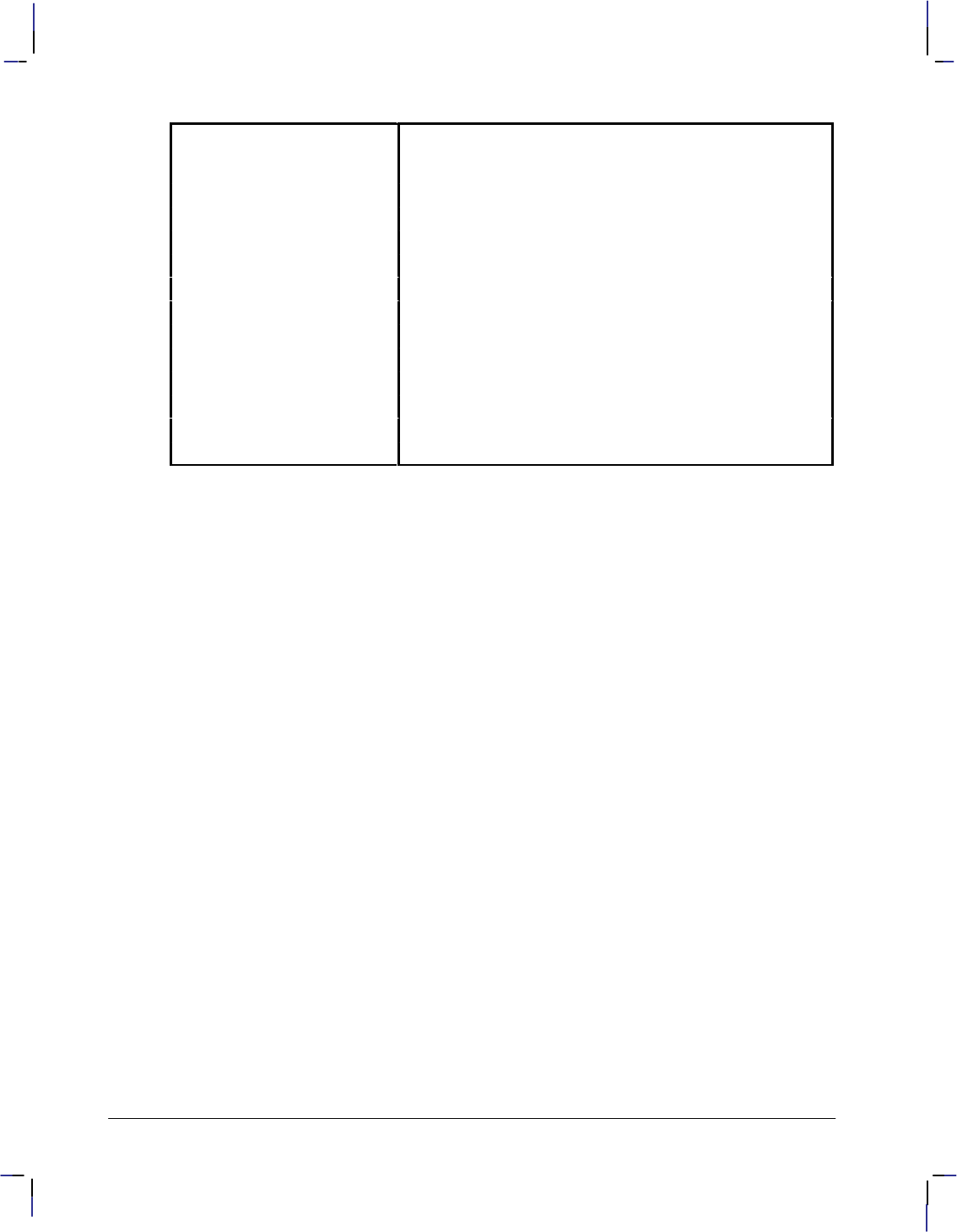
78
This is the black on page 78 (seq: 96)
Company confidential. HP-GL/2 and HP RTL Reference Guide, draft 2. Freeze Status: open
MC Merge Control Controls the pixel color when two or more graphics ele-
ments intersect. (This instruction is also part of the Ad-
vanced Drawing Extension.)
MG Message Writes a message to the device’s front-panel display.*
MT Media Type Indicates the type of media loaded in the device.
NR Not Ready Takes the device off-line.*
OE Output Error Outputs any program errors (for debugging).
OH Output Hard-Clip Limits Outputs the hard-clip limit coordinates.
OI Output Identification Outputs a device identification string.
OP Output P1 and P2 Outputs the P1 and P2 coordinate locations.
OS Output Status Outputs device status information.
PS Plot Size Sets the hard-clip limits to a given size.
QL Quality Level Indicates the level of quality for plotting.
ST Sort Indicates the types of sorting the device can use.
VS Velocity Select Sets the pen speed for all or for selected pens.*
Defining a Picture
A picture begins with a BP instruction and is terminated by a PG, RP, or another BP instruction.
The picture is divided into the picture header and the picture body. The picture header con-
tains the instructions that set up the picture to be plotted. The picture body contains the
instructions that actually cause the device to mark the paper.
The Picture Header State
The BP, PG, or RP instructions or power-up start the picture header state. The following
instructions, if used, must be issued in the picture header:
MT Media Type
PS Plot Size
QL Quality Level.
Each of these instructions affects the entire picture.
Note that the following instructions are permitted in the picture header; however, the PS (Plot
Size) instruction defaults their settings and therefore should precede them:
AC Anchor Corner
IP Input P1 and P2
IR Input Relative P1 and P2
IW Input Window.
The Picture Body State
Any instruction that could result in marks being made on the page or edges added to the poly-
gon-fill buffer terminates the picture header and starts the picture body. The following
instructions start the picture body (if it is in picture header state) and are allowed in picture
body state:
AA Arc Absolute
AR Arc Relative

79
This is the black on page 79 (seq: 97)
Company confidential. HP-GL/2 and HP RTL Reference Guide, draft 2. Freeze Status: open
AT Absolute Arc Three Point
BR Bezier Relative
BZ Bezier Absolute
CI Circle
CP Character Plot
EA Edge Rectangle Absolute
EP Edge Polygon
ER Edge Rectangle Relative
EW Edge Wedge
FP Fill Polygon
LB Label
PA Plot Absolute
PD Pen Down
PE Polyline Encoded
PM Polygon Mode
PR Plot Relative
PU Pen Up (with parameters)
RA Fill Rectangle Absolute
RR Fill Rectangle Relative
RT Relative Arc Three Point
WG Fill Wedge.
Replotting and the Picture Header
RP (Replot) should be placed immediately following the picture, with no intervening instruc-
tions other than output requests. The currently stored plot referenced by RP will disappear
upon the next BP instruction, and also upon the next transition into the picture body. If a pic-
ture does not start with a BP (that is, it began after the last PG or RP), and an RP is issued while
still in the picture header, it is device-dependent whether the previous picture is replotted.
Chords and Chord Tolerance
To draw curves, the device draws a series of straight lines, called chords, for each arc segment.
The smoothness of the curve depends on the number of chords used to draw it—the more
chords, the smoother the shape appears. Figure 65 on page 125 shows circles drawn with dif-
ferent numbers of chords.
The number of chords in any curved shape is determined by the chord tolerance—the allow-
able deviation from a smooth curve. Many instructions let you set the chord tolerance you
want. Chord tolerance can be specified as either an angle in degrees, or as the maximum dis-
tance the arc drawn may deviate from the true arc. These two methods are called chord angle
and deviation distance. The chord angle is the default method. The Chord Tolerance Mode
(CT) instruction selects the method.
Note: Do not use an “adaptive” line type (see the description of the LT instruction on page
215) when you draw circles, arcs, wedges, or polygons. The device will attempt to draw the
complete pattern in every chord; there are 72 chords in a circle using the default chord angle.
The Downloadable Set and User-Defined Characters
If you need special label characters or symbols that are not included in any of the supplied
character sets, you can design your own characters or symbols, or even an entire character set.
The DL (Download Character) instruction allows you to download these characters. The DL
This is the blue on page 79 (seq: 97)
EXTENSIONS
HP-GL/2

80
This is the black on page 80 (seq: 98)
Company confidential. HP-GL/2 and HP RTL Reference Guide, draft 2. Freeze Status: open
instruction can define up to 94 characters to be stored in a buffer for repeated use during a plot.
The character plot cell used by the DL instruction is always a fixed-space character cell, re-
gardless of the spacing in the current font.
Merging Pixels
The MC (Merge Control) instruction controls the color of pixels where two or more page mark-
ing primitives intersect on the page. This instruction, like the Logical Operation (*l#O)
command of HP RTL, supports all 256 Microsoft Windows ternary (ROP3) raster operation
codes—see page 475. Raster operations specify how source, destination, and pattern data are
combined to produce final images. A common application of the MC instruction is the render-
ing of complex polygon fill patterns. You can find a more detailed explanation of how raster
operations work in Chapter 10: Interactions between Picture Elements on page 365.
Obtaining Device Output
When the device receives an output instruction, it responds by making the information avail-
able in the form of an output response that can be read by a computer with an input statement.
Most programming languages use an input statement such as ENTER, INPUT, READ, READLN,
FSCANF, or GET to read the response from the device. When you read the output response, be
sure to specify the correct number and type of variables that are to receive the data. For exam-
ple, BASIC requires that a character string variable should be in the form A$, and a numeric
variable can be in the form A. Refer to your programming language documentation for the cor-
rect input statement to use and the correct format for numeric and character-string variables.
Output responses containing more than one piece of information should be read completely to
clear the output buffer, with a separate variable for each piece of information. For example, the
OH (Output Hard-Clip Limits) instruction outputs four integers; an input statement might be:
fscanf (device, ”%d,%d,%d,%d\n”, &x1, &y1, &x2, &y2);
or:
INPUT #1, A,B,Y,Z
Note that the output instructions must be terminated with a semicolon.
Output instructions should not be used on networks or unidirectional interfaces.
For Centronics Users
The Centronics interface supports data transmission in one direction only. They do not return
information to the computer. However, output instructions will perform other expected opera-
tions, such as setting or clearing status bits in the device’s memory.
For HP-IB Users
A device signals the end of its output response with an output response terminator. For HP-IB
users, the default output response terminator is a carriage return followed by a line feed (
).
Be sure that your device is not set to LISTEN ONLY. If it is, the device will not send an output
response and your program will halt. Refer to your product documentation for more informa-
tion about HP-IB addressing.

81
This is the black on page 81 (seq: 99)
Company confidential. HP-GL/2 and HP RTL Reference Guide, draft 2. Freeze Status: open
For RS-232-C, Bi-Tronics, and MIO Users
The device outputs information according to the handshake protocol. Your computer documen-
tation should specify whether or not delays are required.
A device signals the end of its output response with an output response terminator. For the
RS-232-C, Bi-Tronics, and MIO interfaces, the default output response terminator is a carriage
return ().
Using Output Instructions
Use the following procedures for sending output instructions to your device:
1. Send the output instruction to the device as you do other HP-GL/2 instructions. Note that
all the output instructions use terminators, normally a semicolon, and have no parameters.
2. Read the device’s output response immediately, using an input statement appropriate to
your computer language, keeping in mind the number and type of variables.
Do not send multiple output instructions and then try to read all the responses sequentially.
This can lead to intermittent timing problems, depending on what the computer and the device
are currently doing.
Identifying the Device and its Functions
When you have more than one peripheral (for example, several plotters and printers) connected
to a computer, it may be necessary to have the device output its identification so that you can
be sure it is on-line. The OI (Output Identification) instruction can output the device ID to the
computer.
Obtaining Error Information
Use the OE (Output Error) instruction for error retrieval. The OE instruction outputs the error
number that corresponds to the first HP-GL/2 error the device receives. Use this instruction to
identify errors by number when debugging a program. In addition, these errors set the error bit
of the status byte in the response to OS (Output Status) instruction.
Obtaining Status Byte Information
The eight-bit status byte stores information about device operating conditions. Use the OS
(Output Status) instruction to learn the status of the device’s current operating conditions. Each
condition is assigned a bit number (from 0 to 7) and a corresponding decimal value. (The
conditions, bit numbers, and corresponding decimal values are shown in the description of the
OS instruction.) You can obtain the value of the status byte by reading the response to the OS
instruction or executing an HP-IB serial poll of the device.
Summary of Output Responses
The following table lists output responses generated by HP-GL/2 output instructions. Note that
numeric ranges do not include the sign of the response. For example, if a five-digit response is
a negative value, a minus sign precedes the five digits. The minus sign does not replace a digit.
In addition to these parameters, the output terminator is always sent at the end of output, and
commas are sent to separate parameters.
This is the blue on page 81 (seq: 99)
EXTENSIONS
HP-GL/2
82
This is the black on page 82 (seq: 100)
Company confidential. HP-GL/2 and HP RTL Reference Guide, draft 2. Freeze Status: open
Instruction Parameters Returned Type Range
OE Error number Integer 1 digit
OH XLL, YLL, XUR, YUR Integers up to 6 digits each (plotter-units)
OI Model number String up to 30 characters
OP P1X, P1Y
, P2X, P2YIntegers up to 8 digits each
OS Status number Integer up to 3 digits
The Palette Extension
This Extension contains instructions that satisfy the functionality of devices, such as raster de-
vices, with special palette features. If you have access to a pen plotter and a raster device, you
will want to define a palette to get the most from your HP-GL/2 program on the raster device,
while maintaining pen plotter functionality. Pen plotters may support this extension, defaulting
some instructions in accordance with pen plotter technology.
The following instructions form the Palette Extension:
CR Set Color Range for
Relative Color Data Sets the color range for red-green-blue (RGB) data.
NP Number of Pens Sets the size of the HP-GL/2 palette.
PC Pen Color Assignment Assigns colors to specific pens.
SV Screened Vectors Selects the type of screening to apply to vectors and area fills.
TR Transparency Mode Designates an overlaying white area of pattern or area fill as
transparent or opaque.
Defining Your Palette
The palette is an array of virtual pens, each having an associated color value and an associated
width (pen-width is strictly an HP-GL/2 concept, not a PCL or HP RTL concept). The PC
instruction defines pen colors in terms of red-green-blue (RGB) components. The PW and WU
instructions (of the Line and Fill Attributes Group in the HP-GL/2 Kernel) set pen widths. The
SP instruction selects a pen. A palette should be defined just after initialization and before
sending graphics data. Defining a palette includes the following:
1. Indicating the size of the palette (NP). On dual-context color printers, the palette should be
created in PCL and then used within HP-GL/2.
2. Assigning a color to each pen in the palette (PC).
3. Specifying the width for each pen in the palette (PW—part of the Line and Fill Attributes
Group).
For maximum flexibility, you may want to allow the user to specify values for these items.
For pen plotters it is the responsibility of the user to ensure that the correct pens (color and
width) have been loaded into the appropriate carousel stall.
Devices may support logical pens beyond the number of physical pens. Devices perform a mo-
dulo function on any logical pen number beyond the physical number so the device can select
the appropriate physical pen.
This is the blue on page 82 (seq: 100)
83
This is the black on page 83 (seq: 101)
Company confidential. HP-GL/2 and HP RTL Reference Guide, draft 2. Freeze Status: open
Dual-Context Operation
HP-GL/2, PCL, and HP RTL create different default palettes at reset or power-up. However,
only one palette can be active at a time. Therefore, when switching from one context to anoth-
er, the active palette is always transferred and becomes the active palette in the other contexts.
PCL, HP RTL, or HP-GL/2 can all modify the active palette.
Effect of a Color Palette on Monochrome Devices
Most monochrome large-format devices produce varying levels of gray-scale area fills and lines
for pens other than black and white in the color palette. However, the gray scale is unpredict-
able when drawing a raster pattern with a colored pen. For example, yellow may be converted
to a light shade of gray, and red to a darker shade of gray. A red pen used in a 10% raster fill
pattern may produce an area fill more dense than expected.
Small-format monochrome devices may not have gray-scale capability. All lines produced will
be 100% black.
The Dual-Context Extension
The Dual-Context Extension is implemented by devices that support both HP-GL/2 and Hew-
lett-Packard’s PCL Printer Language or Raster Transfer Language (HP RTL), allowing both
raster and vector images on the same page. Apart from some minor differences, HP RTL is a
subset of PCL. This extension gives you the flexibility to switch modes on devices that support
both vector and text or raster facilities, typically for desk-top presentations, where you may
want to merge word-processed text and graphics images with vector graphics images.
The Dual-Context Extension contains the following commands and instructions:
%#A Enter PCL Mode or
Enter HP RTL Mode Instructs the device to interpret subsequent
instructions as PCL or HP RTL commands.
%#B Enter HP-GL/2 Mode Instructs the device to interpret subsequent
instructions as HP-GL/2 instructions.
EReset Restores certain device defaults.
FI Primary Font Selection by ID Designates a font as the primary font.
FN Secondary Font Selection by ID Designates a font as the secondary font.
SB Scalable or Bitmap Fonts Specifies the type of font to be used in labels.
(This instruction is also part of the Advanced Text
Extension.)
The Dual-Context Extension includes three additional HP-GL/2 instructions and three PCL or
HP RTL escape sequences that are recognized in the HP-GL/2 context. See Part 3 of this book
for a description of the HP RTL commands.
HP RTL does not have a “picture frame” into which HP-GL/2 pictures are fitted; it uses the
whole of the logical page.
The following terms are used in describing PCL devices:
Picture presentation directives—PCL commands that enter and leave the HP-GL/2 context,
define a delimiting rectangle (the picture frame) for the HP-GL/2 plot, and specify a scaling
factor.
This is the blue on page 83 (seq: 101)
EXTENSIONS
HP-GL/2

84
This is the black on page 84 (seq: 102)
Company confidential. HP-GL/2 and HP RTL Reference Guide, draft 2. Freeze Status: open
Picture frame—The destination rectangle when transferring an HP-GL/2 plot to the PCL log-
ical page. PCL picture frame size commands specify its size.
Picture frame scaling factor—The ratio of the size of the picture frame to the size of the HP-
GL/2 plot. There may be two scaling factors for the X and Y directions.
Picture frame anchor point—The upper left corner of the picture frame, which is set to the
current active position (CAP) in the PCL environment when the picture frame anchor point
command is executed.
Refer to the PCL5 Technical Reference manual or Part 3 of this book (for HP RTL) for a com-
plete description of the dual-context environment.
Using Dual-Context PCL or HP RTL Commands
The three commands listed above that begin with an escape character (), are recognized by
some devices to switch between modes or to reset a device. The escape control code is decimal
27. The character “#” in these commands must be replaced by a numeric value, to further de-
scribe the function of the command. Full details of all PCL commands can be found in the
PCL documentation. HP RTL commands are in Part 3 of this book, starting on page 335.
The %–1B command, which if you use it must be at the start of your HP-GL/2 programs, is
a PCL and HP RTL command which puts your device into HP-GL/2 mode. Subsequent data is
interpreted as HP-GL/2 data. Merging with PCL or HP-RTL images is disabled. Not all de-
vices support this stand-alone mode.
The %#A command, besides entering PCL or HP RTL mode, controls the translation of the
pen location to PCL or HP RTL equivalents, called the current active position (CAP). The CAP
can be moved explicitly anywhere within the PCL or HP RTL logical page.
In PCL devices, after an E command, the CAP is “floating” until printable data or a com-
mand affecting the CAP is received. This means that it moves in accordance with PCL
orientation, margin, and spacing commands. Once printable data or an instruction or command
affecting the CAP is received, the CAP becomes “fixed”, that is, it is no longer affected by
changes to orientation, margins, or spacing.
Switching Contexts
Two commands, %#A and %#B are used to switch between HP-GL/2 and PCL or
HP RTL contexts. %2B or %3B can also transfer the PCL coordinate system and mea-
surement unit. The active palette is always transferred and remains active in either context.
E, which resets the device in HP-GL/2, PCL, and HP RTL modes and has the same func-
tionality as IN, always returns the device to PCL or HP RTL parsing mode.
HP-GL/2 may be integrated with PCL in two ways:
Using the PCL picture frame (%0B or %1B).
Using the PCL coordinate system and measurement unit (%2B or %3B).
HP-GL/2 may be integrated with HP RTL in one way:
Using the HP RTL logical page (%0B or %1B).

85
This is the black on page 85 (seq: 103)
Company confidential. HP-GL/2 and HP RTL Reference Guide, draft 2. Freeze Status: open
Defining the PCL Picture Frame
HP-GL/2 plots may be placed on the PCL logical page by specifying the size and location of a
destination rectangle or picture frame. To use this method, specify the size and location of the
picture frame using PCL picture presentation commands before entering HP-GL/2. A plot
created using the SC (Scale) instruction (scaling on) is automatically scaled to fit the picture
frame. A plot created in absolute plotter-units with scaling off may be explicitly scaled by oth-
er PCL picture presentation commands before the transfer. The data flow for this method looks
like this:
PCL commands
...
Specify the PCL picture frame dimensions and anchor point
Explicitly scale the HP-GL/2 plot if it was originally drawn in plotter-units
Enter HP-GL/2 with ESC%0B or ESC%1B
HP-GL/2 instructions
...
Exit HP-GL/2 with ESC%#A
PCL commands
Note that if no picture frame is defined, the PCL logical page is used as the default.
Transferring the PCL Coordinate System
By transferring the PCL coordinate system and measurement unit into HP-GL/2, vector and
raster objects can be intermixed on the logical page as necessary. To use this method of inte-
grating HP-GL/2 and PCL, use a value of 2 or 3 with %#B; note that values of 2 and 3 are
not supported on all devices. The PCL current active position (CAP) may also be transferred.
The data stream then looks like this:
PCL commands
...
Enter HP-GL/2 with %2B or %3B
HP-GL/2 instructions
...
Exit HP-GL/2 with %#A
PCL commands
When you enter HP-GL/2 using %2B or %3B, the PCL origin, axes, and print direction
transfer into HP-GL/2. Imported PCL graphics are rotated because the Y-axes of PCL and HP-
GL/2 increase in opposite directions. RO moves the HP-GL/2 origin to where the PCL origin
would be if it were rotated by the PCL Print Direction command (&a#P). HP-GL/2
instructions that use current units use PCL dot units.
A SC (Scale) instruction with parameters switches back to the HP-GL/2 coordinate system: de-
faults are set, SC is executed, and picture-frame scaling is applied. An “IN”, “BP”, or “SC;”
instruction restores the PCL dot coordinate system.
Exiting HP-GL/2 after %2B performs an “RO0” and turns off user-defined scaling; then
plotter-units are used.
This is the blue on page 85 (seq: 103)
EXTENSIONS
HP-GL/2
86
This is the black on page 86 (seq: 104)
Company confidential. HP-GL/2 and HP RTL Reference Guide, draft 2. Freeze Status: open
Merging with HP RTL
Many HP RTL devices support HP-GL/2 with the Technical Graphics Extension. For such de-
vices, always start in HP-GL/2 with the picture header. The data stream looks like this:
HP-GL/2 instructions
...
Exit HP-GL/2 and enter HP RTL with %#A
HP RTL commands
...
Enter HP-GL/2 with %0B or %1B
HP-GL/2 instructions
Note that the HP-GL/2 origin and orientation are not modified by HP RTL.
Palettes
HP-GL/2 and HP RTL or PCL create different default palettes at reset or power-up. Both con-
texts allow the active palette to be modified. In dual-context operations, only one palette can
be active at a time. Therefore, when switching from one context to another, the active palette is
always transferred and becomes the active palette in both contexts. In HP-GL/2, the relevant
palette instructions are:
IN,
Initialize Defaults the palette size to two pens for monochrome raster devices
and eight pens for color raster devices. The 8-pen default HP-GL/2
palette is different from the default RGB 8-pen PCL and HP RTL
palette.
PC,
Pen Color Assignment Modifies palette colors. HP RTL and PCL use the palette program-
ming commands *v#A, *v#B, *v#C, and *v#I.
CR,
Set Color Range for
Relative Color Data
Sets the range for specifying relative color data. HP RTL and PCL
use the Configure Image Data (*v#W) command.
SP,
Select Pen Selects a “current” color. HP RTL and PCL use the Foreground Col-
or (*v#S) command.
PCL Fonts
Fonts are not transferred between contexts, but HP-GL/2 complies with PCL font specifica-
tions. The AD and SD instructions use the same font selection algorithm as PCL, based on font
attribute priority to find the closest match to the user’s request. See How Your Device Selects
Fonts on page 63. The SB instruction, in the Dual-Context extension, may specify either scal-
able or bitmap fonts.
PCL Macros
PCL macros can include HP-GL/2 instructions. The HP-GL/2 instructions in the macro must
be contained within a shell of PCL macro commands, the %#B command for entering HP-
GL/2, and the %#A command to re-enter PCL.
87
This is the black on page 87 (seq: 105)
Company confidential. HP-GL/2 and HP RTL Reference Guide, draft 2. Freeze Status: open
Modifications to HP-GL/2 Instructions in Dual-Context Mode
The following HP-GL/2 instructions are modified in Dual-Context Mode as summarized below.
Functional differences are also described in the individual instruction descriptions. Those
marked with an asterisk (*) are for PCL only.
AC,
Anchor Corner (*) IN, DF, or E place the anchor point at the lower-left corner of the
picture frame relative to the current coordinate system.
BP,
Begin Plot (*)
(Technical Extension)
In PCL devices, the PG portion of BP is ignored and BP is mapped
to IN regardless of the kind and value parameters. Data previously
formatted for the current page is not cleared.
(In HP RTL devices, BP performs the PG and IN functions.)
DF,
Default Values (*) “AC;” places the anchor point at the lower-left corner of the picture
frame relative to the current coordinate system.
“IW;” sets the user window equal to PCL picture frame window.
FT,
Fill Type Additional fill types (21 and 22) are imported from PCL or HP RTL.
Fill type 21 selects a PCL or HP RTL predefined patterned fill. Op-
tion 1 specifies a pattern type from 1 to 6 (see the FT instruction de-
scription). Option 2 is ignored.
Fill type 22 uses the PCL or HP RTL user-defined fill specified by
*c#W. Option 1 is the PCL or HP RTL ID of the user-defined
fill. Option 2 is ignored. An invalid option 1 (for example, the pat-
tern has been deleted), prints a solid fill in the current color.
IP,
Input P1 and P2 (*) “IP;” sets P1 to the lower-left corner of the PCL picture frame
(viewed from the current HP-GL/2 orientation) and P2 to the oppo-
site corner. Parameters are scaled by the picture frame scaling fac-
tor.
IR,
Input Relative
P1 and P2 (*)
The references to the hard-clip limits are replaced by the PCL pic-
ture frame. The default positions for P1 and P2 are the lower-left
and upper-right corners of the picture frame, as viewed from the cur-
rent orientation.
IW,
Input Window (*) “IW;” defaults the window to the PCL picture frame. The maximum
printable area is the intersection of the user-defined window, the PCL
picture frame, the PCL logical page, and the hard-clip limits. Pa-
rameters specified in plotter-units are scaled by the picture frame
scaling factor.
EXTENSIONS
HP-GL/2
This is the blue on page 87 (seq: 105)
88
This is the black on page 88 (seq: 106)
Company confidential. HP-GL/2 and HP RTL Reference Guide, draft 2. Freeze Status: open
PG,
Advance Full Page PG is ignored in PCL. A page eject can only be accomplished by the
form feed () character. In PCL, a form feed causes an uncondi-
tional page eject and advances the current active position to the same
horizontal position at the top of the next form (top margin).
A PCL reset, page length, page size, orientation, or input cassette
control instruction causes a conditional page eject. When a page is
ejected, the PCL or HP RTL cursor is set to the “home position” (at
the left and top margin) on the new page. A page eject caused by a
PCL command does not effect the HP-GL/2 cursor position.
PM,
Polygon Mode
E is also recognized in polygon mode.
PS,
Plot Size (*)
(Technical Extension)
In PCL devices, PS is ignored when HP-GL/2 is entered by %#B
with 0 or a positive value; the plot size is set by the PCL picture
frame.
(In HP RTL devices, PS operates as defined while the device is in
picture-header state.)
PW,
Pen Width (*) Metric widths are scaled by the ratio of the size of the PCL picture
frame to the HP-GL/2 plot size. For example, if HP-GL/2 plot size
is twice as large as the PCL picture frame, “WUPW.3” sets the vector
width to 0.15 mm.
RO,
Rotate Coordinate
System (*)
Rotations are relative to the default HP-GL/2 coordinate system, as
defined for PCL or HP RTL. P1 or P2 may be rotated outside the
current picture frame; they can be repositioned to the rotated lower-
left and upper-right corners of the picture frame by issuing an “IP;”
or an “IR;” instruction.
The user-defined window is rotated, and any portion that is rotated
outside the picture frame is clipped to the picture frame. The win-
dow can be set equal to the picture frame by an “IW;” instruction.
RP,
Replot (*) This instruction is ignored in PCL; a page eject can only be accom-
plished from the PCL context by sending a form feed () control
character.
SC,
Scale (*) When user-scaling mode is off, current units are:
(plotter-units * (PCL picture-frame-size HP-GL/2 plot-size))
Left and bottom parameters are relative to the PCL picture frame,
viewed from the current orientation. The directional implications of
left and bottom assume the default P1/P2 orientation.
SI,
Absolute Character
Size (*)
The width and height parameters, in centimeters, are adjusted by the
picture frame scaling factor.
89
This is the black on page 89 (seq: 107)
Company confidential. HP-GL/2 and HP RTL Reference Guide, draft 2. Freeze Status: open
SV,
Screened Vectors
(Palette Extension)
Additional screen types (21 and 22) are imported from PCL or
HP RTL.
Screen type 21 selects PCL or HP RTL predefined patterned fill.
Option 1 specifies a pattern fill type between 1 and 6 (see the SV
instruction description). Option 2 is ignored.
Screen type 22 selects the PCL or HP RTL user-defined fill specified
by *c#W. Option 1 is the PCL or HP RTL ID of the fill. Option
2 is ignored. An invalid option 1 (for example, a deleted pattern),
prints a solid fill in the current color.
TD,
Transparent Data
E is a special case. In normal mode, E within a label string
will cause a device reset and transition to the PCL or HP RTL envi-
ronment. In transparent mode, E within a label string is printed
rather than performing a device reset.
WU,
Pen Width Unit
Selection (*)
If an HP-GL/2 plot size is specified, metric units are adjusted by the
current PCL picture frame scaling factor.
The Digitizing Extension
This section defines a block of instructions that satisfy the digitizing requirements of pen plot-
ters. This Extension is available on pen plotters only; raster devices are incapable of digitizing
an image. Check your product’s documentation to determine whether this extension is sup-
ported. The information in this section discusses the instructions used in digitizing, together
with the methods and procedures for digitizing and verifying the entry of a point.
“Digitizing” is moving the pen or a digitizing sight to a point on the plotting surface, register-
ing the point, and sending the X,Y coordinates of that point to the computer. This lets you
recreate a drawing from hard-copy, instead of redesigning it from scratch or scanning the entire
drawing into your computer.
Devices that implement this extension include front-panel controls for moving the pen or digi-
tizing sight and for entering and storing the X,Y coordinates and pen status of the digitized
point.
The Digitizing Extension instructions are:
DC Digitize Clear Clears and exits digitize mode
DP Digitize Point Enters digitize mode
OD Output Digitize Point and Pen
Status Outputs the coordinate location of the digitized
point
The Digitizing Procedure
Although you can use a pen for digitizing, we recommend you use a digitizing sight. Refer to
your product’s documentation for information on using a digitizing sight. Digitize with the
sight in the pen-down position for the highest accuracy.
Note: To avoid smearing ink on the tip of the digitizing sight or damaging the sight, do not
load the digitizing sight directly into the pen carousel.
This is the blue on page 89 (seq: 107)
EXTENSIONS
HP-GL/2
This is the blue on page 89 (seq: 107)

90
This is the black on page 90 (seq: 108)
Company confidential. HP-GL/2 and HP RTL Reference Guide, draft 2. Freeze Status: open
When you are ready to digitize your plot, use the DP (Digitize Point) instruction to enter digi-
tize mode. Refer to your pen plotter’s documentation to enter the digitized point from the
plotter’s control panel. After entering the point, use the OD (Output Digitized Point and Pen
Status) instruction to send the X,Y coordinates of the point and the pen status (up or down) to
your computer. The DC (Digitize Clear) instruction clears and exits digitize mode.
Digitizing with the Plotter
Familiarize yourself with the Digitizing Extension instructions listed above before reviewing
the digitizing methods here. When digitizing, you must make sure that a point has been entered
before attempting to retrieve that point. The following sections show you the methods for digi-
tizing and retrieving points.
Manual Digitizing
The manual method is the easiest digitizing method to understand. However, it is not efficient
when you want to enter many points, or when user interaction during program execution is not
possible. The following steps detail a typical program using the manual method:
1. Put the plotter into digitizing mode by sending a DP instruction to the device.
2. Have the program display or print a message on the computer screen prompting you to en-
ter a point.
3. Cause the program to pause until instructed to continue. Using the BASIC INPUT state-
ment and entering an empty string when the user is ready to continue will work on some
systems. Some versions of BASIC use statements such as STOP, WAIT, or PAUSE.
4. Move the digitizing sight (or pen) to the desired point using the control-panel cursor-con-
trol buttons. Complete final positioning with the sight or pen down. Press the appropriate
button on your pen plotter’s control panel (refer to your plotter’s documentation).
5. Cause the program to resume. The way you resume program execution depends on the
statement you used to halt the program. If you used an input statement in step 3, press the
Return key on the computer.
6. Output he digitized information to the computer using the Output Digitized Point and Pen
Status (OD) instruction. Have your computer read the information (X,Y coordinates and
the pen state). Then take the necessary steps to process the digitized data.
Using this method, you do not need to monitor the status byte because the program does not
proceed to the OD instruction until you enter a point and cause the program to resume.
The following program digitizes a single point and displays the coordinates and pen status:
Send to the device: “DP;”
Prompt the user: “Press plotter’s Enter button to digitize the point.”
Prompt the user: “Press computer’s Return key to continue.”
Wait for the Return key.
Send to the device: “OD;”
Read from the device: X,Y,P
Print out: X,Y,P

91
This is the black on page 91 (seq: 109)
Company confidential. HP-GL/2 and HP RTL Reference Guide, draft 2. Freeze Status: open
Monitoring the Status Byte
The second digitizing method monitors bit position 2 of the plotter’s status byte, which is set
when a digitized point is available. Refer to the OS (Output Status) instruction for details of
the contents of the status byte.
There are a variety of ways to monitor bit position 2, depending on the instructions available in
your computer. If there are instructions in your programming language to check bits directly,
the third least significant bit should be checked for the occurrence of a 1.
If no bit operations are available, the status byte can be operated on arithmetically to check for
the availability of a digitized point. Executing successive divisions by a power of 2 and check-
ing the answer for an odd or even integer is a common way of monitoring bits without
converting the number to binary form. The following steps detail a program using this method:
1. Send a DP instruction to the plotter.
2. Have the program display or print a message on the computer screen prompting you to en-
ter a point.
3. Send an OS instruction followed by a loop dividing the status value and checking for a fi-
nal odd or even value.
When you press the control-panel button to enter a digitized point, the X,Y coordinates and
the pen status information are stored and bit position 2 is set. The status value increments
by the value of bit 2; your division yields the odd integer, allowing the program to contin-
ue.
4. Send an OD instruction. Read and display the X,Y coordinates and pen status. Then take
the necessary steps to process the digitized data.
Example: Digitizing by Monitoring the Status Byte
The following program checks the proper bit of the status byte. The program uses an integer
statement (INT) that truncates, not rounds—refer to your programming language documenta-
tion.
Send to the device: “DP;”
Prompt the user: “Press plotter’s Enter button to digitize the point.”
Send to the device: “OS;”
Read from the device: STATUS
STATUS = INT(STATUS/4)
If STATUS = INT(STATUS/2)*2 then loop to the “send OS;” statement above
Send to the device: “OD;”
Read from the device: X,Y,P
Print out: X,Y,P
Example: Digitizing Many Points
When the computer is used to monitor bit position 2, it may not process the data points immedi-
ately. Allocate space for the total number of points to be digitized. Then establish a loop to
process the total number of points and call a subroutine each time to check that a point has been
entered.
When you are prompted to enter a point in the following example, use the cursor keys to move
the digitizing sight to each location, then press the appropriate control-panel button that enters
EXTENSIONS
HP-GL/2
This is the blue on page 91 (seq: 109)
92
This is the black on page 92 (seq: 110)
Company confidential. HP-GL/2 and HP RTL Reference Guide, draft 2. Freeze Status: open
digitized points. After digitizing the program’s 25 points, all coordinates are displayed on the
computer’s screen.
For C = 1 to 25
Send to the device: “DP;”
Prompt the user: “Enter point number” C
Execute subroutine (see below)
Send to the device: “OD;”
Read from the device: X(C),Y(C),P(C)
Next C
For C = 1 to 25
Print out: X(C),Y(C),P(C)
Next C
Subroutine to check status bit 2:
Send to the device: “OS;”
Read from the device: STATUS
STATUS=INT(STATUS/4)
If STATUS = INT(STATUS/2)*2 then loop in subroutine
Return from subroutine.
The Advanced Drawing Extension
The Advanced Drawing Extension groups four instructions that are of use in advanced drawing
environments. The following instructions make up the Advanced Drawing Extension:
BR Bezier Relative Draws Bezier curves using relative coordinates.
BZ Bezier Absolute Draws Bezier curves using absolute coordinates.
MC Merge Control Controls the pixel color when two or more graphics elements inter-
sect. (This instruction is also part of the Technical Graphics Ex-
tension.)
PP Pixel Placement Determines how pixels are placed on a grid during polygon fills on
raster devices.
Drawing Bezier Curves
The BZ (Bezier Absolute) and BR (Bezier Relative) instructions use your current pen position
as the first control point in the Bezier curve. You specify the second, third, and fourth control
points. If you are drawing more than one curve, the fourth control point of the first curve (X3,
Y3) becomes the first control point of the next curve. The following example shows a simple
instruction sequence using BZ to draw a Bezier Curve in the shape of a sine wave (shown in the
figure following the example).
PA 1000,5000; Specify absolute plotting and move to position (1000,5000).
PD ; Pen down.
BZ 2000,8000,4000,2000,5000,5000; Draw a Bezier curve with (1000,5000) as the start-
ing point (first control point). Specify (2000,8000), (4000,2000),
and (5000,5000) as the second, third, and fourth control points.
This is the blue on page 92 (seq: 110)
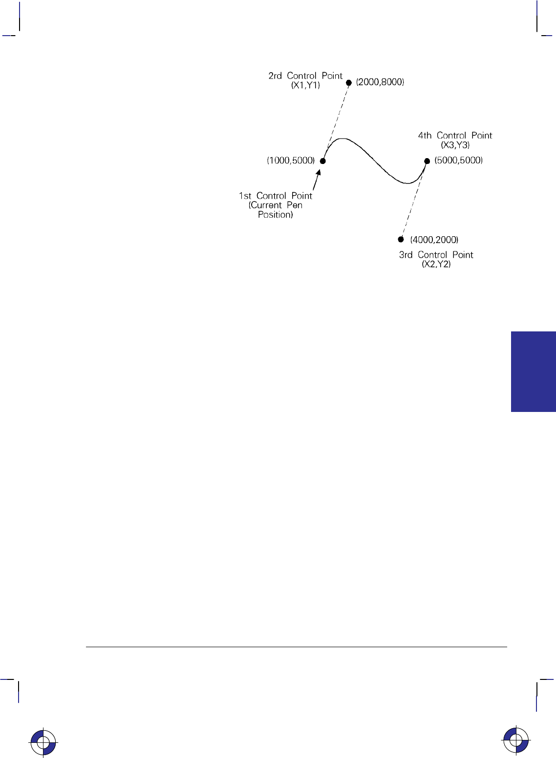
93
This is the black on page 93 (seq: 111)
Company confidential. HP-GL/2 and HP RTL Reference Guide, draft 2. Freeze Status: open
Figure 51. Bezier Curve
Merging and Placing Pixels
The MC (Merge Control) instruction controls the color of pixels where two or more page mark-
ing primitives intersect on the page. This instruction, like the Logical Operation (*l#O)
command of HP RTL, supports all 256 Microsoft Windows ternary (ROP3) raster operation
codes—see page 475. Raster operations specify how source, destination, and pattern data are
combined to produce final images. A common application of the MC instruction is the render-
ing of complex polygon fill patterns. You can find a more detailed explanation of how raster
operations work in Chapter 10: Interactions between Picture Elements on page 365.
When it is printing or plotting, the device places pixels on a theoretical grid covering the print-
able area of a page. When the sides of two polygons touch each other, the pixels along the
border may be printed twice or not at all, depending on the logical operation in effect (see the
left side of Figure 52). For example, if a source rectangle consisting of all 1’s is exclusive-
ORed with a destination that also consists of all 1’s, a white rectangle (all 0’s) is printed. If
another source rectangle is placed on the page touching the first rectangle, the two rectangles
are white-filled except at their common border; that is because (1 xor 1) xor 1 = 1, black.
To correct this situation, two models of pixel placement are used: grid intersection and grid
centered. The grid intersection model is the default; pixels are rendered on the intersections of
the grid. In the grid-centered model, the number of rows and columns are each reduced by one,
and pixels are placed at the centers of the squares, rather than at the intersections.
EXTENSIONS
HP-GL/2
This is the blue on page 93 (seq: 111)
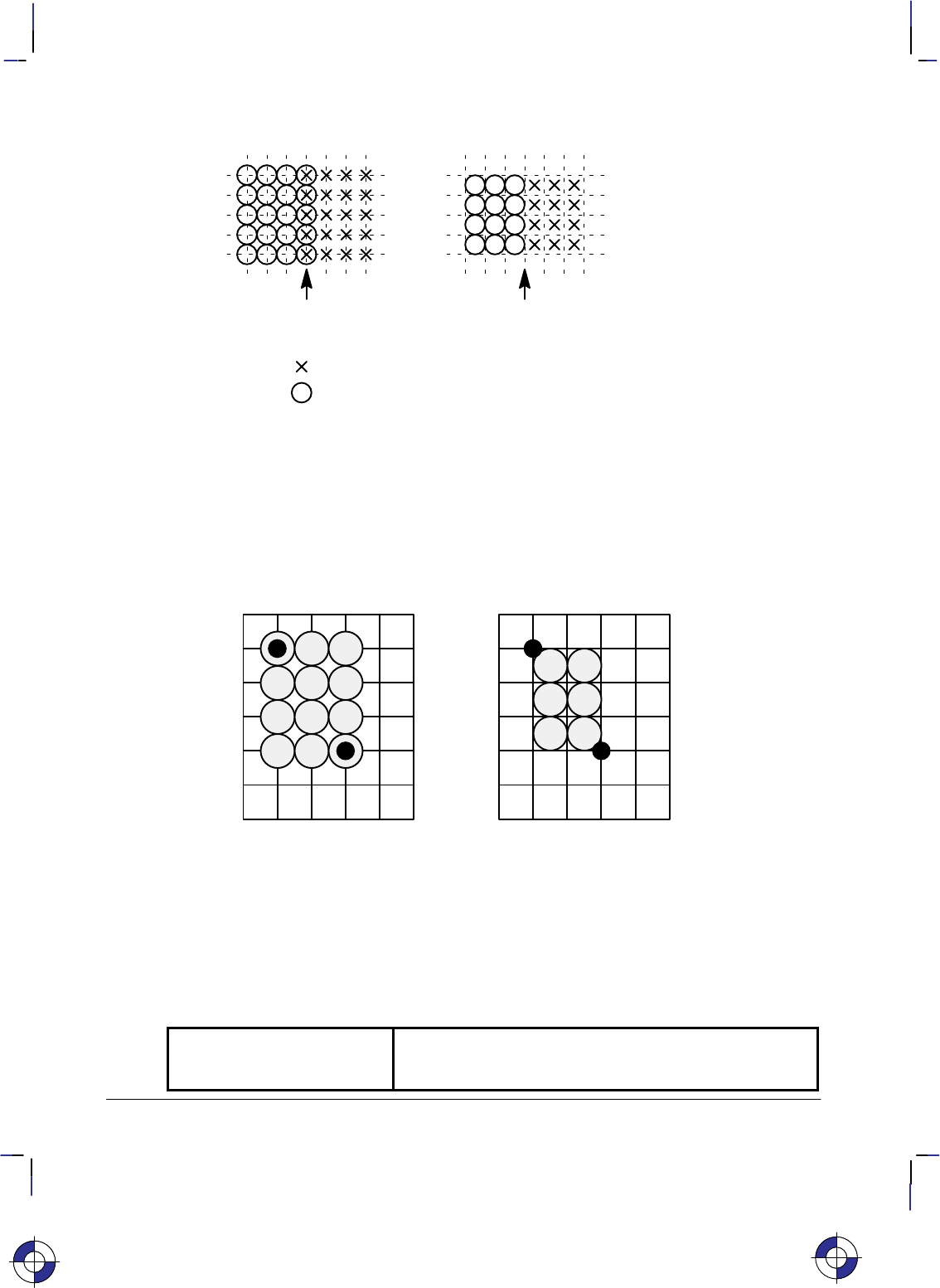
94
This is the black on page 94 (seq: 112)
Company confidential. HP-GL/2 and HP RTL Reference Guide, draft 2. Freeze Status: open
Common boundary overlap
Device XORs these to produce
undesired results
Common boundary
No overlap
Grid Intersection Grid Centered
Pixels in first polygon area
Pixels in second polygon area
Figure 52. Pixel Placement Variations
Figure 53 shows the concepts of the two models. Assume a rectangle extends from coordinate
position (1,1) to position (3,4), with the origin of coordinates at the top left, and the X-axis hor-
izontal. The grid-centered model produces a rectangle that is one dot row thinner and one dot
row shorter than the grid intersection model. Thus when two or more polygons on a page share
a common border, grid centering can be turned on.
Microsoft Windows fills polygons based on the grid-centered method.
(0,0)
(1,1)
(3,4)
Grid Intersection
(0,0)
(1,1)
(3,4)
Grid Centered
Figure 53. Pixel Placement
The Advanced Text Extension
The Advanced Text Extension contains two instructions that are of use if you use two-byte
character sets, such as Kanji, and if you want to access bitmap fonts from within the HP-GL/2
environment. The following instructions make up the Advanced Text Extension:
LM Label Mode Determines how LB and SM interpret two-byte characters.
SB Scalable or Bitmap Fonts Specifies the type of font to be used in labels. (This instruc-
tion is also part of the Dual-Context Extension.)
This is the blue on page 94 (seq: 112)

95
This is the black on page 95 (seq: 113)
Company confidential. HP-GL/2 and HP RTL Reference Guide, draft 2. Freeze Status: open
Chapter 5:
HP-GL/2 Instruction Reference
In the following table, the instructions of HP-GL/2 are listed in order of their names. On the
reference pages that follow the table, the instructions are listed in order of their two-character
mnemonics; that order is also used in the table that starts on page 97. For groupings of the
instructions (the Kernel groups and the Extensions), see pages 17 through 22.
Instruction name Instruction syntax Page
Absolute Arc Three Point ATxinter,yinter,xend,yend[,chord_angle] 110
Absolute Character Size SI[width,height] 298
Absolute Direction DI[run,rise] 139
Advance Full Page PG[n] 249
Alternate Font Definition AD[kind,value...[,kind,value]] 106
Anchor Corner AC[x,y] 103
Arc Absolute AAxcenter,ycenter,sweepangle[,chord_angle] 100
Arc Relative ARxincr,yincr,sweep_angle[,chord_angle] 108
Begin Plot BP[kind,value...[,kind,value]] 113
Bezier Absolute BZx1,y1,x2,y2,x3,y3[,...x1,y1,x2,y2,x3,y3] 118
Bezier Relative BRx1,y1,x2,y2,x3,y3[,...x1,y1,x2,y2,x3,y3] 116
Character Fill Mode CF[fill_mode[,edge_pen]] 120
Character Plot CP[spaces,lines] 128
Character Slant SL[tangent_of_angle] 301
Chord Tolerance Mode CT[mode] 133
Circle CIradius[,chord_angle] 123
Comment CO[“c...c”] 127
Default Values DF 136
Define Label Terminator DT[label_terminator[,mode]]; 154
Define Variable Text Path DV[path[,line]] 156
Digitize Clear DC 135
Digitize Point DP 148
Download Character DL[character_number[character_number2]
[[,up]x,y...[,up],x,y] 144
Edge Polygon EP 164
Edge Rectangle Absolute EAx,y 160
Edge Rectangle Relative ERx,y 166
Edge Wedge EWradius,start_angle,
sweep_angle[,chord_angle] 171
Enable Cutter EC[n] 163
Extra Space ES[width[,height]] 169
Fill Polygon FP[fill_method] 179
This is the blue on page 95 (seq: 113)
INSTRUCTIONS
HP-GL/2

96
This is the black on page 96 (seq: 114)
Company confidential. HP-GL/2 and HP RTL Reference Guide, draft 2. Freeze Status: open
Instruction name Instruction syntax Page
Fill Rectangle Absolute RAx,y 269
Fill Rectangle Relative RRx,y 281
Fill Type FT[fill_type[,option1[,option2]]] 183
Fill Wedge WGradius,start_angle,
sweep_angle[,chord_angle] 324
Frame Advance FR 181
Initialize IN[n] 189
Input P1 and P2 IP[p1x,p1y[,p2x,p2y]] 191
Input Relative P1 and P2 IR[p1x,p1y[,p2x,p2y]] 194
Input Window IW[xll,yll,xur,yur] 197
Label LBtext...text label_terminator 206
Label Mode LM[mode[,row_number]] 208
Label Origin LO[position] 211
Line Attributes LA[kind,value[,kind,value[,kind,value]]] 200
Line Type LTline_type[,pattern_length[,mode]] 215
Media Type MT[type] 223
Merge Control MC[mode[,opcode]] 220
Message MG[message] 222
Not Ready NR[timeout] 227
Number of Pens NP[n] 225
Output Digitized Point and Pen Status OD;228
Output Error OE;229
Output Hard-Clip Limits OH;231
Output Identification OI;232
Output P1 and P2 OP;233
Output Status OS;235
Pen Color Assignment PC[pen[,red,green,blue]] 239
Pen Down PD[x,y[,...]] 241
Pen Up PU[x,y[,...]] 262
Pen Width PW[width[,pen]] 264
Pen Width Unit Selection WU[type] 328
Pixel Placement PP[mode] 255
Plot Absolute PA[x,y[,...]] 237
Plot Relative PR[x,y[,...]] 257
Plot Size PS[length[,width]] 259
Polygon Mode PM[polygon_definition] 251
Polyline Encoded PE[flag][value/x,y]...[flag][value/x,y] 243
Primary Font Selection by ID FIfont_id 175
Quality Level QL[quality_level] 267
Raster Fill Definition RF[index[,width,height,
pen_number[,pen_number...]]] 272
Relative Arc Three Point RTxincrinter,yincrinter,
xincrend,yincrend[,chord_angle] 284

97
This is the black on page 97 (seq: 115)
Company confidential. HP-GL/2 and HP RTL Reference Guide, draft 2. Freeze Status: open
Instruction name Instruction syntax Page
Relative Character Size SR[width,height] 308
Relative Direction DR[run,rise] 149
Replot RP[n] 279
Rotate Coordinate System RO[angle] 275
Scalable or Bitmap Fonts SB[n] 288
Scale SC[xmin,xmax,ymin,ymax[,type[,left,
bottom]]] 290
Screened Vectors SV[screen_type[,option1[],option2]] 313
Secondary Font Selection by ID FNfont_id 177
Select Alternate Font SA 287
Select Pen SP[pen_number] 306
Select Standard Font SS 311
Set Color Range for Relative Color Data CR[black-ref_red,white-ref_red,
black-ref_green,white-ref_green,
black-ref_blue,white-ref_blue] 131
Sort ST[switches] 312
Standard Font Definition SD[kind,value...[,kind,value]] 296
Symbol Mode SM[character[character2]] 303
Transparency Mode TR[n] 318
Transparent Data TD[mode] 316
User-Defined Line Type UL[index[,gap1,...gapn]] 320
Velocity Select VS[pen_velocity[,pen_number]] 322
In addition, the following commands of PCL and HP RTL may be available to you:
Command name Command syntax Page
Enter PCL Mode %#A 422
Enter RTL Mode %#A 422
Enter HP-GL/2 Mode %#B 420
Escape E437
The following table lists the HP-GL/2 instructions in order of their mnemonics:
Instruction syntax Instruction name Page
AAxcenter,ycenter,sweepangle[,chord_angle] Arc Absolute 100
AC[x,y] Anchor Corner 103
AD[kind,value...[,kind,value]] Alternate Font Definition 106
ARxincr,yincr,sweep_angle[,chord_angle] Arc Relative 108
ATxinter,yinter,xend,yend[,chord_angle] Absolute Arc Three Point 110
BP[kind,value...[,kind,value]] Begin Plot 113
BRx1,y1,x2,y2,x3,y3[,...x1,y1,x2,y2,x3,y3] Bezier Relative 116
BZx1,y1,x2,y2,x3,y3[,...x1,y1,x2,y2,x3,y3] Bezier Absolute 118
This is the blue on page 97 (seq: 115)
INSTRUCTIONS
HP-GL/2

98
This is the black on page 98 (seq: 116)
Company confidential. HP-GL/2 and HP RTL Reference Guide, draft 2. Freeze Status: open
Instruction syntax Instruction name Page
CF[fill_mode[,edge_pen]] Character Fill Mode 120
CIradius[,chord_angle] Circle 123
CO[“c...c”] Comment 127
CP[spaces,lines] Character Plot 128
CR[black-ref_red,white-ref_red,
black-ref_green,white-ref_green,
black-ref_blue,white-ref_blue] Set Color Range for Relative Color Data 131
CT[mode] Chord Tolerance Mode 133
DC Digitize Clear 135
DF Default Values 136
DI[run,rise] Absolute Direction 139
DL[character_number[character_number2]
[[,up]x,y...[,up],x,y] Download Character 144
DP Digitize Point 148
DR[run,rise] Relative Direction 149
DT[label_terminator[,mode]]; Define Label Terminator 154
DV[path[,line]] Define Variable Text Path 156
EAx,y Edge Rectangle Absolute 160
EC[n] Enable Cutter 163
EP Edge Polygon 164
ERx,y Edge Rectangle Relative 166
ES[width[,height]] Extra Space 169
EWradius,start_angle,
sweep_angle[,chord_angle] Edge Wedge 171
FIfont_id Primary Font Selection by ID 175
FNfont_id Secondary Font Selection by ID 177
FP[fill_method] Fill Polygon 179
FR Frame Advance 181
FT[fill_type[,option1[,option2]]] Fill Type 183
IN[n] Initialize 189
IP[p1x,p1y[,p2x,p2y]] Input P1 and P2 191
IR[p1x,p1y[,p2x,p2y]] Input Relative P1 and P2 194
IW[xll,yll,xur,yur] Input Window 197
LA[kind,value[,kind,value[,kind,value]]] Line Attributes 200
LBtext...text label_terminator Label 206
LM[mode[,row_number]] Label Mode 208
LO[position] Label Origin 211
LTline_type[,pattern_length[,mode]] Line Type 215
MC[mode[,opcode]] Merge Control 220
MG[message] Message 222
MT[type] Media Type 223
NP[n] Number of Pens 225
NR[timeout] Not Ready 227

99
This is the black on page 99 (seq: 117)
Company confidential. HP-GL/2 and HP RTL Reference Guide, draft 2. Freeze Status: open
Instruction syntax Instruction name Page
OD;Output Digitized Point and Pen Status 228
OE;Output Error 229
OH;Output Hard-Clip Limits 231
OI;Output Identification 232
OP;Output P1 and P2 233
OS;Output Status 235
PA[x,y[,...]] Plot Absolute 237
PC[pen[,red,green,blue]] Pen Color Assignment 239
PD[x,y[,...]] Pen Down 241
PE[flag][value/x,y]...[flag][value/x,y] Polyline Encoded 243
PG[n] Advance Full Page 249
PM[polygon_definition] Polygon Mode 251
PP[mode] Pixel Placement 255
PR[x,y[,...]] Plot Relative 257
PS[length[,width]] Plot Size 259
PU[x,y[,...]] Pen Up 262
PW[width[,pen]] Pen Width 264
QL[quality_level] Quality Level 267
RAx,y Fill Rectangle Absolute 269
RF[index[,width,height,
pen_number[,pen_number...]]] Raster Fill Definition 272
RO[angle] Rotate Coordinate System 275
RP[n] Replot 279
RRx,y Fill Rectangle Relative 281
RTxincrinter,yincrinter,
xincrend,yincrend[,chord_angle] Relative Arc Three Point 284
SA Select Alternate Font 287
SB[n] Scalable or Bitmap Fonts 288
SC[xmin,xmax,ymin,ymax[,type[,left,
bottom]]] Scale 290
SD[kind,value...[,kind,value]] Standard Font Definition 296
SI[width,height] Absolute Character Size 298
SL[tangent_of_angle] Character Slant 301
SM[character[character2]] Symbol Mode 303
SP[pen_number] Select Pen 306
SR[width,height] Relative Character Size 308
SS Select Standard Font 311
ST[switches] Sort 312
SV[screen_type[,option1[],option2]] Screened Vectors 313
TD[mode] Transparent Data 316
TR[n] Transparency Mode 318
UL[index[,gap1,...gapn]] User-Defined Line Type 320
VS[pen_velocity[,pen_number]] Velocity Select 322
WGradius,start_angle,
sweep_angle[,chord_angle] Fill Wedge 324
WU[type] Pen Width Unit Selection 328
This is the blue on page 99 (seq: 117)
INSTRUCTIONS
HP-GL/2
100
This is the black on page 100 (seq: 118)
Company confidential. HP-GL/2 and HP RTL Reference Guide, draft 2. Freeze Status: open
AA, Arc Absolute
Purpose
To draw an arc, using absolute coordinates, which starts at the current pen location and pivots
around the specified center point.
Syntax
AA Xcenter,Ycenter,sweep_angle[,chord_angle][;]
Parameter Format Functional Range Parameter Default
Xcenter,Ycenter current units device-dependent
(at least –223 to 223 – 1) no default
sweep_angle clamped real –32 768 to 32 767 no default
chord_angle* clamped real device-dependent
(at least 0 to 180)device-dependent
(usually 5)
* If you have used the “CT1” instruction, the chord_angle is interpreted as a deviation dis-
tance in current units; see the CT instruction on page 133.
Group
This instruction is in the Vector Group.
Use
The AA instruction draws an arc starting at the current pen location using the current pen up/
down status and line type and attributes. After drawing the arc, the pen location is updated to
the end of the arc; the carriage-return point (see page 66) is moved to the end of the arc.
Note: Do not use an adaptive line type when drawing arcs with small chord angles. The device
attempts to draw the complete pattern in every chord (there are 72 chords in a circle using the
default chord angle).
Xcenter, Ycenter: Specify the absolute location of the center of the arc. (The center of the
arc is the center of the circle that would be drawn if the arc was 360.) Coordinates are
interpreted in current units: as user-units when scaling is on; as plotter-units when scaling
is off. If current scaling is not isotropic, the arc drawn is elliptical rather than circular.
sweep_angle: Specifies in degrees the angle through which the arc is drawn. A positive
angle is drawn in a positive direction (counter-clockwise rotation); a negative angle is
drawn in the negative direction (clockwise rotation). All values outside the range –360 to
+360 are converted modulo 360.
chord_angle: Specifies, in degrees, the chord angle used to draw the arc. The default is a
chord angle of 5. The chord_angle specifies the maximum angle created when lines from
each end of the chord intersect the center point of the circle (see Figure 54). The smaller
the chord angle, the smoother the curve. The useful range is from 0.0 to 180.0. A chord
This is the blue on page 100 (seq: 118)
AA Instruction
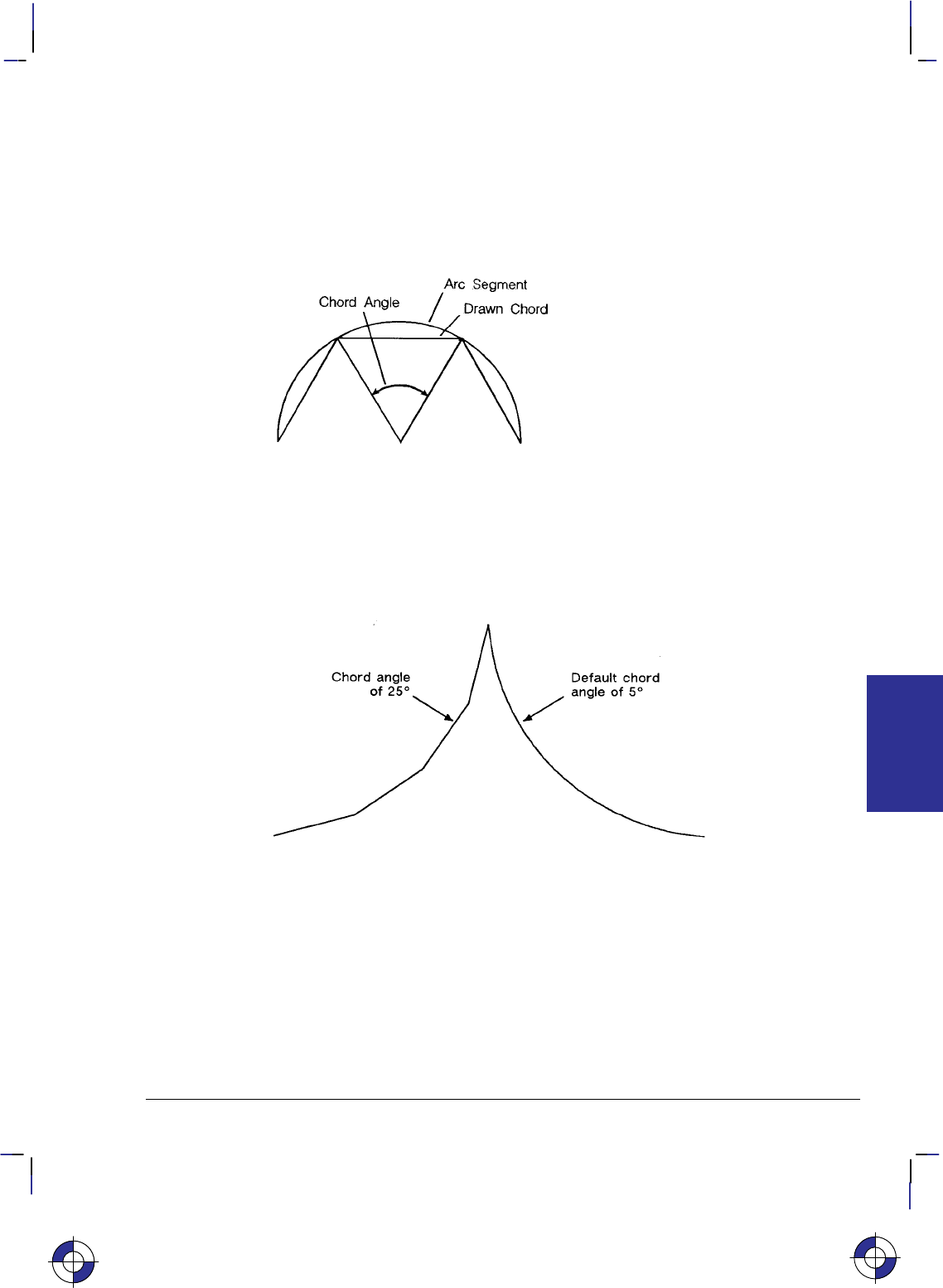
101
This is the black on page 101 (seq: 119)
Company confidential. HP-GL/2 and HP RTL Reference Guide, draft 2. Freeze Status: open
angle less than 0.5 is clamped to 0.5. The specified value is interpreted modulo 360; if
the result is greater than 180, 360
minus the modulo result
is used.
The number of chords used is the absolute value of sweep_angle chord_angle; a non-integer
quotient is rounded up.
The chord angle used to draw the arc is set to sweep_angle number of chords. If the sweep
angle is less than 0.5, the chord angle is set to the sweep angle.
Figure 54. Chord Angle
For a specific chord angle, a circle or arc always has the same number of chords, regardless of
its size. For example, for the default chord angle, a circle is always composed of 72 chords
(360/5 per chord = 72 chords). This results in larger circles appearing less smooth than
smaller circles with the same chord angle; setting the chord angle to a smaller number will help
large circles or arcs appear more smooth (see Figure 55).
Figure 55. Changing Arc Smoothness with the Chord Angle
Note that the CT (Chord Tolerance Mode) instruction in the Technical Graphics extension
changes the above computation.
Related Instructions
AR Arc Relative
AT Absolute Arc Three Point
BR Bezier Relative
BZ Bezier Absolute
CI Circle
This is the blue on page 101 (seq: 119)
AA Instruction
INSTRUCTIONS
HP-GL/2
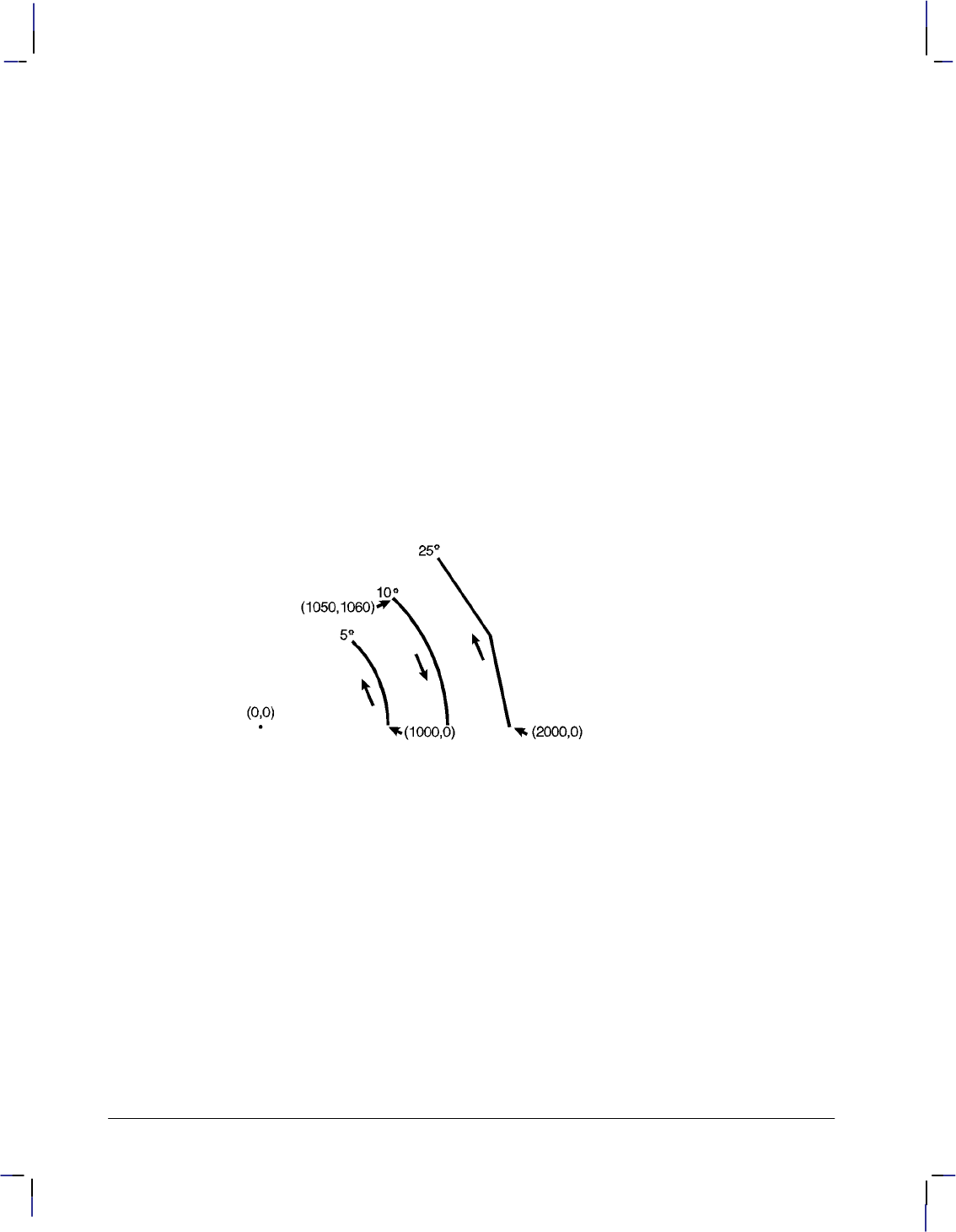
102
This is the black on page 102 (seq: 120)
Company confidential. HP-GL/2 and HP RTL Reference Guide, draft 2. Freeze Status: open
CT Chord Tolerance Mode
LA Line Attributes
LT Line Type
PW Pen Width
RT Relative Arc Three Point
Example
PA 2000,0; Specify (2000,0) as the starting point.
PD ; Pen down.
AA 0,0,45,25; Draw a 45 arc (positive angle) with center coordinates of (0,0)
and a chord angle of 25.
PU 1050,1060; Lift the pen and move to (1050,1060).
PD ; Pen down.
AA 0,0,–45,10; Draw a 45 arc (negative angle) using the same center point as the
first arc, but with a 10 chord angle.
PU 1000,0; Lift the pen and move to (1000,0).
PD ; Pen down.
AA 0,0,45; Draw another 45 arc (positive angle) with the same center point,
but with the default chord angle (5).
Figure 56. Varying the Chord Angle
AA Instruction

103
This is the black on page 103 (seq: 121)
Company confidential. HP-GL/2 and HP RTL Reference Guide, draft 2. Freeze Status: open
AC, Anchor Corner
Purpose
To position the starting point of any fill pattern. Use AC to ensure that the selected fill pattern
is positioned as expected within the figure.
Syntax
AC X,Y[;]
or
AC [;]
Parameter Format Functional Range Parameter Default
X, Y coordinates current units device-dependent
(at least –223 to 223 – 1) no default
Group
This instruction is in the Line and Fill Attributes Group.
Use
The anchor corner is the point at which any fill pattern starts. Setting the anchor corner guar-
antees that a corner point of the selected fill pattern is at the specified coordinate, aligned
vertically and horizontally.
No Parameters: Defaults the anchor corner to the origin of the hard-clip limits (or plot-
ting area). This is not necessarily equivalent to “AC0,0”, which starts the fill pattern at the
current-unit origin.
X, Y coordinates: Define the position of the starting point for any fill pattern.
If the X,Y location is defined in plotter-units, turning scaling on or changing the locations of P1
and P2 has no effect on the anchor corner location. If, however, the X,Y location is defined in
user-units, the physical location of the anchor corner moves with changes in scaling or to P1
and P2. For example, assume the scaling is from 0 to 10 in both axes and the anchor corner is
specified as the point (2,3). If the scaling is changed to 0 to 5 in both axes, the anchor corner is
still (2,3) but it is in a different physical location now that the user-units are a different size (the
user-units have become twice as large). Turning off scaling causes the anchor corner to be fro-
zen in the plotter-unit equivalent of its current user-unit value.
IN and DF default the anchor corner to the origin of the hard-clip limits relative to the current
coordinate system.
A more detailed description of the use of the anchor corner is in Using Fill Types on page 56.
This is the blue on page 103 (seq: 121)
AC Instruction
INSTRUCTIONS
HP-GL/2

104
This is the black on page 104 (seq: 122)
Company confidential. HP-GL/2 and HP RTL Reference Guide, draft 2. Freeze Status: open
Using AC in a Dual-Context Environment
IN (Initialize), DF (Default Values), or E (Reset) place the anchor point at the origin of the
hard-clip limits relative to the current coordinate system. The equivalent, though not identical,
HP RTL and PCL command is Pattern Reference Point.
Example
The following example first prints three adjacent squares with fill patterns anchored at the ori-
gin of the hard-clip limits. The fill pattern is continuous across each of the squares. In the set
of squares below that, each square has an anchor corner set at its own origin. Notice how this
helps distinguish between the adjacent figures. The orientation shown is for a PCL printer; for
a plotter, the orientation is rotated –90 or –180.
PA 3000,3000; Specify absolute plotting and move to location (3000,3000).
FT 3,400,45; Specify fill type number 3 (parallel lines), with each line 400 plot-
ter-units apart and set at a 45 angle.
RR 1000,1000; Fill a rectangle using the current pen location as one corner, and a
point 1000 plotter-units in the +X-direction and 1000 plotter-units
in the +Y-direction as the opposite corner.
ER 1000,1000; Edge the outline of the rectangle just filled.
PR 1000,0; Move 1000 plotter-units in the +X-direction.
FT 4,400,45; Select fill type number 4 (cross-hatch).
RR 1000,1000; Create a rectangle the same size as the first one, and fill it with
cross-hatch.
ER 1000,1000; Edge its outline.
PR 1000,0; Move to the right another 1000 plotter-units.
FT 3,400,45; Create another rectangle of the same size, this time filled with
pattern number 3 again.
RR 1000,1000;
ER 1000,1000;
PA 3000,1500; Move to absolute location (3000,1500).
AC 3000,1500; Move the anchor corner to location (3000,1500).
RR 1000,1000; Fill a rectangle with the same dimensions as the previous three
rectangles and edge its outline.
ER 1000,1000;
PA 4000,1500; Move to location (4000,1500).
AC 4000,1500; Specify the location as the anchor corner.
FT 4,400,45; Select fill type number 4 (cross-hatch).
RR 1000,1000; Fill and edge another rectangle.
ER 1000,1000;
PA 5000,1500; Move to absolute location (5000,1500).
AC 5000,1500; Specify that location as the anchor corner.
FT 3,400,45; Select fill type number 3; fill and edge another rectangle.
RR 1000,1000;
ER 1000,1000;
AC Instruction
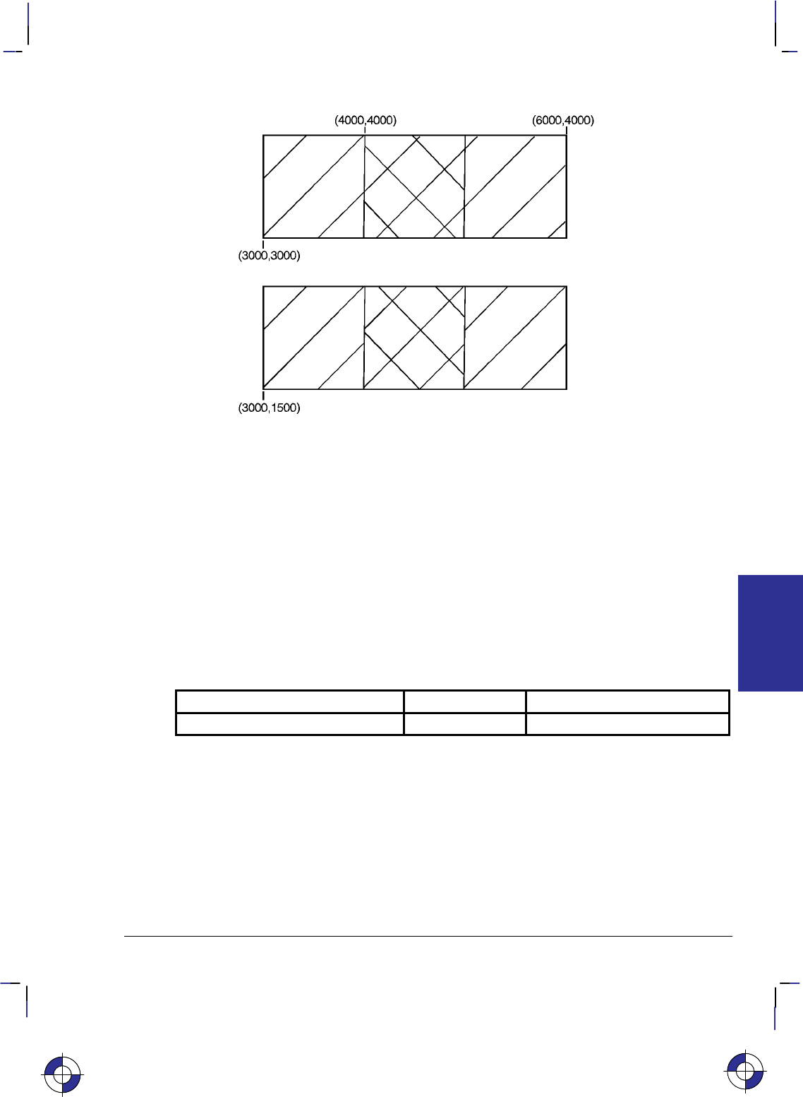
105
This is the black on page 105 (seq: 123)
Company confidential. HP-GL/2 and HP RTL Reference Guide, draft 2. Freeze Status: open
Figure 57. Using the AC (Anchor Corner) Instruction
Related Instructions and Commands
FP Fill Polygon
FT Fill Type
RA Fill Rectangle Absolute
RF Raster Fill Definition
RR Fill Rectangle Relative
SV Screened Vectors
WG Fill Wedge
*p#R Pattern Reference Point
Possible Error Conditions
Error Condition Error Number Printer or Plotter Response
Position overflow 3 Ignores instruction.
This is the blue on page 105 (seq: 123)
AC Instruction
INSTRUCTIONS
HP-GL/2
106
This is the black on page 106 (seq: 124)
Company confidential. HP-GL/2 and HP RTL Reference Guide, draft 2. Freeze Status: open
AD, Alternate Font Definition
Purpose
To define an alternative character set (font) and its characteristics: symbol set identification,
font spacing, pitch, height, posture, stroke weight, and typeface. To define a standard font, use
the SD instruction.
Syntax
AD kind,value...[,kind,value][;]
or
AD [;]
Parameter Format Functional Range Parameter Default
kind clamped integer 1 to 7 no default
value clamped real kind-dependent* kind-dependent*
* Refer to the table following the parameter descriptions.
Group
This instruction is in the Character Group.
Use
This instruction is similar to the SD (Standard Font Definition) instruction (see page 296) that
defines the primary HP-GL/2 font. The AD instruction defines an alternate HP-GL/2 font and
its characteristics: font spacing, pitch, height, posture, stroke weight, and typeface. It allows
the font characteristics to be assigned to the secondary (alternate) font definition. Use AD to
set up an alternate font that you can easily access when labeling.
No Parameters: Defaults the alternate font characteristics to that of the device-dependent
default scalable font, not a bitmap font.
kind: Specifies the characteristic for which you are setting a value (see the following
table).
value: Defines the properties of the characteristic specified by the kind parameter.
Note: When selecting fonts, the different characteristics (symbol set, spacing, pitch, and so on)
are prioritized as shown in the table, with character set being the highest priority and typeface
being the lowest. The font selection priority is the same for HP-GL/2 as for PCL font selection.
For more information about the priority of font characteristics, see How Your Device Selects
Fonts on page 63.
The tables in Appendix C: Font Definitions on page 477 list the kind parameters with their
associated values (note that these tables are also valid for the SD [Standard Font Definition]
instruction). For kinds 1 and 7, your device may support values other than those listed there.
Refer to your User’s Guide or HP-GL/2 option manual for more information about the attrib-
utes and values supported.
This is the blue on page 106 (seq: 124)
AD Instruction
107
This is the black on page 107 (seq: 125)
Company confidential. HP-GL/2 and HP RTL Reference Guide, draft 2. Freeze Status: open
Any combination of kind, value parameters is allowed; the last value for a specified kind pre-
vails.
Kind Attribute Range of Values Default Value Description
1Character set device-dependent 277 Roman-8
2Font Spacing 0 (fixed),
1 (proportional) device-dependent fixed spacing
3 Pitch >0 to 32 767 (valid to
2 decimal places) device-dependent characters per inch
4 Height 0 to 32 767 device-dependent font point size
5 Posture 0 to 32 767 device-dependent upright or italic
6Stroke Weight –7 to 7, 9999 0 normal
7 Typeface device-dependent device-dependent scalable font
The IN (Initialize) and DF (Default Values) instructions restore default alternate font attributes.
Related Instructions
DT Define Label Terminator
FI Select Primary Font
FN Select Secondary Font
LB Label
SA Select Alternate Font
SB Scalable or Bitmap Fonts
SD Standard Font Definition
SI Absolute Character Size
SR Relative Character Size
SS Select Standard Font
TD Transparent Data
Example
The instruction “AD1,21,2,1,4,30,5,1,6,3,7,5;” designates a 30-point Times Roman Bold Italic
font in the ASCII symbol set (use the SA [Select Alternate Font] instruction to select this font
after it is designated):
AD 1,21 Symbol set—US ASCII
2,1 Spacing—proportional
4,30 Height—30-point
5,1 Posture—italic
6,3 Stroke weight—bold
7,5; Typeface—Times Roman
Note that the pitch parameter is missing in this instruction because the designated font is pro-
portionally spaced.
This is the blue on page 107 (seq: 125)
AD Instruction
INSTRUCTIONS
HP-GL/2
108
This is the black on page 108 (seq: 126)
Company confidential. HP-GL/2 and HP RTL Reference Guide, draft 2. Freeze Status: open
AR, Arc Relative
Purpose
To draw an arc, using relative coordinates, which starts at the current pen location and pivots
around the specified center point.
Syntax
AR Xincr,Yincr,sweep_angle[,chord_angle][;]
Parameter Format Functional Range Parameter Default
X,Y increments current units device-dependent
(at least –223 to 223 – 1) no default
sweep_angle clamped real –32 768 to 32 767 no default
chord_angle* clamped real 0.0 to 360device-dependent
(usually 5)
* If you have used the “CT1” instruction, the chord_angle is interpreted as a deviation dis-
tance in current units; see the CT instruction on page 133.
Group
This instruction is in the Vector Group.
Use
The AR instruction draws the arc starting at the current pen location using the current pen up/
down status, line type, and attributes. After drawing the arc, the pen location remains at the
end of the arc; the carriage-return point (see page 66) is moved to the end of the arc.
Note: Do not use an adaptive line type when drawing arcs with small chord angles. The device
attempts to draw the complete pattern in every chord (there are 72 chords in a circle using the
default chord angle).
X, Y increments: Specify the center of the arc relative to the current location. (The
center of the arc is the center of the circle that would be drawn if the arc was 360.)
Coordinates are interpreted in current units: as user-units when scaling is on; as plotter-
units when scaling is off. If current scaling is not isotropic, the arc drawn is elliptical
rather than circular.
sweep_angle: Specifies (in degrees) the angle through which the arc is drawn. A positive
angle draws an angle in the positive direction (counter-clockwise rotation); a negative
angle draws the angle in the negative direction (clockwise rotation). All values outside the
range –360 to +360 are converted modulo 360.
If either the sweep angle or the calculated radius is zero and the pen is down, a dot (zero-
length vector) is drawn at the current pen position.
This is the blue on page 108 (seq: 126)
AR Instruction
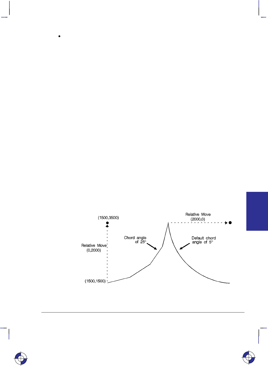
109
This is the black on page 109 (seq: 127)
Company confidential. HP-GL/2 and HP RTL Reference Guide, draft 2. Freeze Status: open
chord_angle: Specifies the chord angle used to draw the arc. The default is a chord angle
of 5. Refer to the Arc Absolute (AA) instruction discussion on page 100 for information
on setting and determining the chord angle.
Note that the CT (Chord Tolerance Mode) instruction in the Technical Graphics extension
changes the above computation.
Related Instructions
AA Arc Absolute
AT Absolute Arc Three Point
BR Bezier Relative
BZ Bezier Absolute
CI Circle
CT Chord Tolerance Mode
LA Line Attributes
LT Line Type
PW Pen Width
RT Relative Arc Three Point
Example
PA 1500,1500; Specify the starting position as (1500,1500).
PD ; Put the pen down.
AR 0,2000,80,25; Draw an arc with a center point 0 plotter-units in the X direction
and 2000 plotter-units in the Y direction from (1500,1500). Spec-
ify the arc section to be 80 (positive angle), with a chord angle of
25.
AR 2000,0,80; Draw an arc with a center point 2000 plotter-units in the X direc-
tion and 0 plotter-units in the Y direction from the current pen
position. Specify the arc section to be 80 (positive angle), with a
default chord angle (usually 5).
Figure 58. Using the AR (Arc Relative) Instruction to Draw Arcs
This is the blue on page 109 (seq: 127)
AR Instruction
INSTRUCTIONS
HP-GL/2

110
This is the black on page 110 (seq: 128)
Company confidential. HP-GL/2 and HP RTL Reference Guide, draft 2. Freeze Status: open
AT, Absolute Arc Three Point
Purpose
To draw an arc segment, using absolute coordinates, from a starting point, through an inter-
mediate point, to an end point. Use AT when you know these three points of an arc.
Syntax
AT Xinter,Yinter, Xend,Yend[,chord_angle][;]
Parameter Format Functional Range Parameter Default
X, Y intermediate
and end points current units device-dependent
(at least –223 to 223 – 1) no defaults
chord_angle* clamped real 0 to 360device-dependent
(usually 5)
* If you have used the “CT1” instruction, the chord_angle is interpreted as a deviation dis-
tance in current units; see the CT instruction on page 133.
Group
This instruction is in the Vector Group.
Use
The AT instruction uses the current pen location and two specified points to calculate a circle
and draw the appropriate arc segment of its circumference. The arc starts at the current pen
location, using the current pen, line type, line attributes and pen up/down status. You specify
the intermediate and end points. After drawing the arc, the pen location remains at the end of
the arc; the carriage-return point (see page 66) is moved to the end of the arc.
Xinter, Yinter: Specify the absolute location of an intermediate point of the arc. The arc is
drawn in a positive or negative angle of rotation, as necessary, so that it passes through the
intermediate point before the end point.
Xend, Yend: Specify the absolute location of the end point of the arc.
chord_angle: Specifies the chord angle used to draw the arc. The default is a chord angle
of 5. (The Arc Absolute (AA) instruction description on page 100 contains more informa-
tion on chords and chord angles.)
Intermediate and end point coordinates are interpreted in current units: as user-units when scal-
ing is on; as plotter-units when scaling is off. If current scaling is not isotropic, the arc drawn is
elliptical rather than circular. Note the following about locating the intermediate and end
points:
If the intermediate point and end point are the same as the current pen location, the instruc-
tion draws a dot.
This is the blue on page 110 (seq: 128)
AT Instruction

111
This is the black on page 111 (seq: 129)
Company confidential. HP-GL/2 and HP RTL Reference Guide, draft 2. Freeze Status: open
If the intermediate point is the same as either the current pen location or the end point, a
line is drawn between the current pen location and the end point.
If the end point is the same as the current pen location, a circle is drawn, with its diameter
being the line from the current pen position to the intermediate point.
If the current pen position, intermediate point, and end point are collinear, a straight line is
drawn.
If the intermediate point does not lie between the current pen location and the end point,
and the three points are collinear, two lines are drawn; one from the current pen location
and the other from the end point, leaving a gap between them. Refer to the following
illustration. Both lines extend to the hard-clip limits or current window.
Figure 59. Collinear Points with the Intermediate Point outside the End Points
Note that the CT (Chord Tolerance Mode) instruction in the Technical Graphics extension
changes the above computation.
Related Instructions
AA Arc Absolute
AR Arc Relative
BR Bezier Relative
BZ Bezier Absolute
CI Circle
CT Chord Tolerance Mode
LA Line Attributes
LT Line Type
PW Pen Width
RT Relative Arc Three Point
This is the blue on page 111 (seq: 129)
AT Instruction
INSTRUCTIONS
HP-GL/2
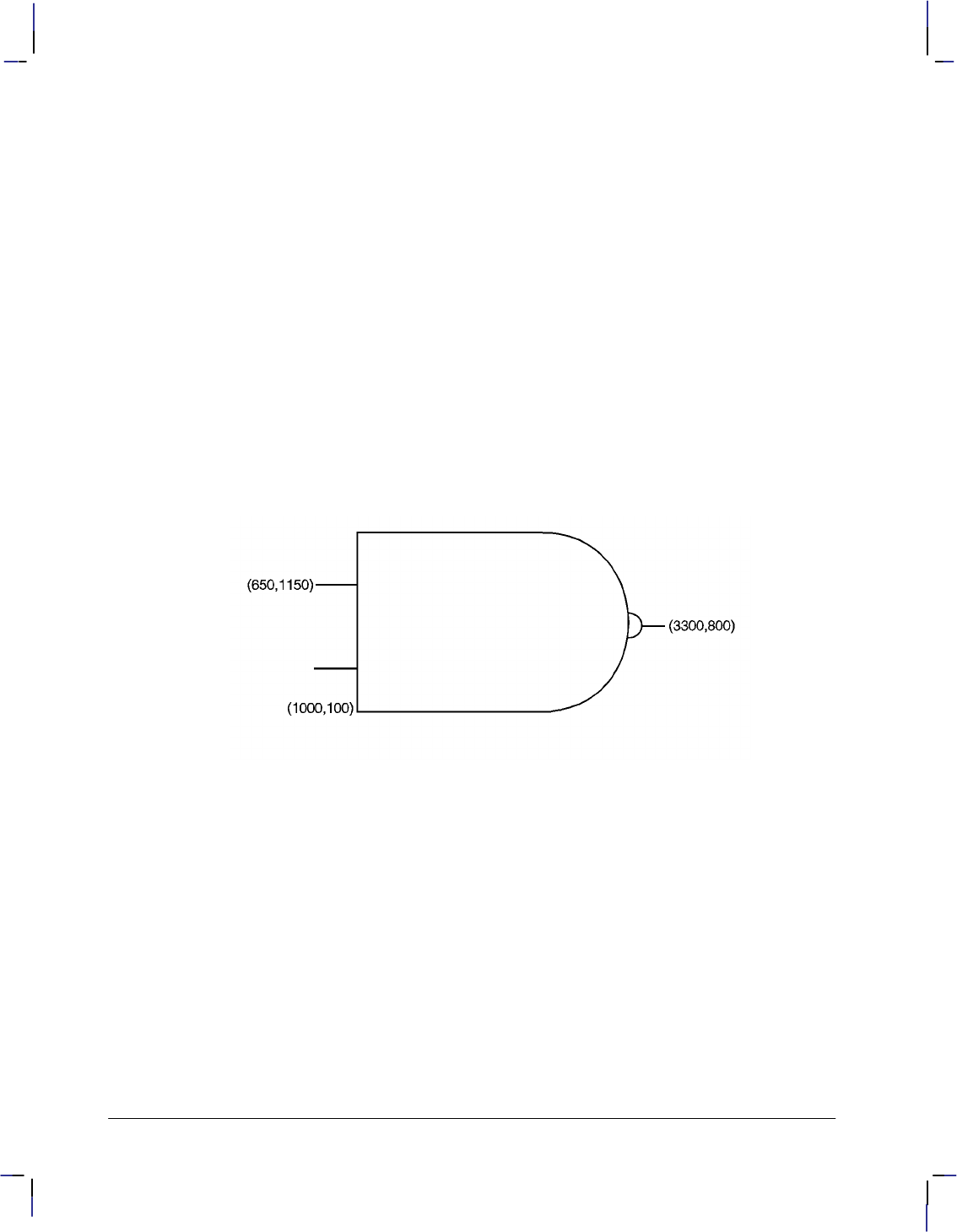
112
This is the black on page 112 (seq: 130)
Company confidential. HP-GL/2 and HP RTL Reference Guide, draft 2. Freeze Status: open
Example
PA 1000,100; Specify (1000,100) as the starting location.
PD 2500,100; Place the pen down, and draw a line to (2500,100).
PU 650,1150; Lift the pen, and move to (650,1150).
PD 1000,1150; Place the pen down, and draw a line to (1000,1150).
PU 650,450; Lift the pen, and move to (650,450).
PD 1000,450; Place the pen down, and draw a line to (1000,450).
PU 1000,100; Lift the pen, and move to (1000,100).
PD 1000,1500,2500,1500; Place the pen down, draw a line to (1000,1500), then to
(2500,1500).
AT 3200,800,2500,100; Print an arc, starting at current pen position (2500,1500), passing
through (3200,800) and ending at (2500,100).
PU 3200,900; Lift the pen, and move to (3200,900).
PD ; Set the pen down.
AT 3300,800,3200,700; Print an arc, starting at the current pen position, passing through
(3300,800) and ending at (3200,700).
PU 3300,800; Lift the pen, and move to (3300,800).
PD 3500,800; Pen down, and draw a line to (3500,800).
Figure 60. Drawing Arcs through Three Points
AT Instruction

113
This is the black on page 113 (seq: 131)
Company confidential. HP-GL/2 and HP RTL Reference Guide, draft 2. Freeze Status: open
BP, Begin Plot
Purpose
To place the device into the picture header state and indicate the beginning of a new plot.
Syntax
BP kind,value...[,kind,value][;]
or
BP[;]
Parameter Format Functional Range Parameter Default
kind clamped integer 1 to 5 no default
value kind-dependent kind-dependent kind-dependent
Group
This instruction is in the Technical Graphics Extension.
Use
BP produces the equivalent of PG (Advance Full Page) and IN (Initialize). It begins a new plot
regardless of whether the previous plot was terminated. It makes the previous plot unavail-
able—that is, BP followed by RP (Replot) produces nothing.
No parameters: all values are defaulted.
kind and value parameters: The kind parameter is a clamped integer between 1 and 5; the
value parameter is kind-dependent. These parameters must be specified in pairs, as shown
in the table on the next page.
For a buffered raster device, the default behavior of BP is to discard the previous plot if it has
not yet been printed with either PG or RP. The instruction “BP4,1” allows overriding the de-
fault behavior by generating a PG. For a plotter or other “plot as you parse” device, a “4,1”
pair is always NOP’d and a BP instruction always results in a conditional page advance. For
spooled plotters, the previous plot may or may not be discarded before printing if it was not
properly terminated.
BP starts a new plot and guarantees that it starts on a clean page. It performs an IN to ensure
that the plot starts in a known state, and puts the device into picture header state.
BP starts a new plot regardless of whether the last plot was terminated properly, even when one
or more of its parameters are in error. This provides a measure of error recovery, in case that
the previous user’s application did not complete plotting properly. The parameters specified in
the BP instruction apply only to the plot started by the current BP.
BP is recognized in polygon mode (the polygon buffer is cleared), but not in label mode.
This is the blue on page 113 (seq: 131)
BP Instruction
INSTRUCTIONS
HP-GL/2
114
This is the black on page 114 (seq: 132)
Company confidential. HP-GL/2 and HP RTL Reference Guide, draft 2. Freeze Status: open
Kind Format Meaning and Value
1 quoted
string (see
page 28)
Picture name: The default is a device-dependent name, such as a se-
quence number or the time of day if a clock is available. The parameter
value can be used by devices that implement control-panel spool-queue
manipulation to identify the plot for the user. The value parameter is
assumed to be in the same language as for the control-panel when it was
powered on; that is, if you power up the machine in Spanish, the device
assumes that the picture name is encoded in the Spanish character set.
2 clamped
integer Number of copies: The default is 1.
When the device receives an RP (Replot) instruction, only the additional
number of copies specified by RP are made; this is regardless of the
number of copies specified (and already printed) by BP. For example,
“BP2,3;(plot data)RP2” results in a total of five copies of the plot, not
nine.
3 clamped
integer File-disposition code: Controls replot capability.
0Enables replot; saves the file if room exists (the default).
1Destroys the file after printing. The file is not saved in memory or
on disk. This value prevents retrieval of the file through the RP
instruction or the device’s control panel.
Note that “BP2,n,3,1” still produces n copies of the plot.
4 clamped
integer Render last plot if unfinished:
0No (the default).
1Yes.
5 clamped
integer Autorotation: A device may choose to rotate the hard-clip limits 90 to
save paper. This option can disable such autorotation, giving the
computer complete control over where the plot is placed. Support
of autorotation is device-dependent.
0Enable (the default).
1Disable.
If the same kind parameter is used more than once, the last one prevails. For example,
“BP4,0,4,1;” does render the previous plot.
Pen plotters do not recognize kind = 4 or 5.
Using BP in a PCL Dual-Context Environment
If you entered HP-GL/2 mode with %#B (where # is 0 or positive), the device ignores the
PG functionality of the BP instruction. Data previously formatted for the current page is not
cleared.
When you enter HP-GL/2 mode with %–1B, the behavior of the BP instruction is depen-
dent on the device technology, as follows:
If the device is a buffered raster device, the default behavior of BP discards the previous
plot if it has not yet been printed with either PG or RP. The instruction “BP4,1” allows
overriding the default behavior by generating a PG.
BP Instruction

115
This is the black on page 115 (seq: 133)
Company confidential. HP-GL/2 and HP RTL Reference Guide, draft 2. Freeze Status: open
For a pen plotter or any device that plots data as it is received, a “BP4,1” is always ignored
and a BP instruction always results in a conditional page advance (if the page has been
plotted on, the page is advanced). %#B is ignored.
Using BP in a Dual-Context HP RTL Environment
If you use the BP instruction in a dual-context HP RTL device, the device performs only the PG
function of the instruction.
Related Instructions and Commands
IN Initialize
PG Advance Page
RP Replot
%#B Enter HP-GL/2 mode command from PCL or HP RTL
BP Instruction
This is the blue on page 115 (seq: 133)
BP Instruction
INSTRUCTIONS
HP-GL/2

116
This is the black on page 116 (seq: 134)
Company confidential. HP-GL/2 and HP RTL Reference Guide, draft 2. Freeze Status: open
BR, Bezier Relative
Purpose
To draw a series of Bezier curves using relative coordinates.
Syntax
BR X1,Y1,X2,Y2,X3,Y3,...[X1,Y1,X2,Y2,X3,Y3][;]
Parameter Format Functional Range Parameter Default
X, Y increments current units device-dependent
(at least –223 to 223–1) no default
Group
This instruction is in the Advanced Drawing Extension.
Use
BR draws a Bezier curve using the present pen position as the first control point, and the de-
fined control points as increments. All curve control points are relative to the first control point
of that curve.
X,Y coordinates: Specify the location of the second (X1,Y1), third (X2,Y2), and fourth
(X3,Y3) control points in relative increments, that is, all of these values are relative to the
current pen location at the start of the Bezier curve.
The curves are drawn with the current pen, line type, line attributes, and pen state (up or down);
and they are clipped to the hard-clip limits and the soft-clip window. The current pen location
is updated to the end point of the curve at the termination of each Bezier curve defined by the
instruction. After each new Bezier curve, the last control point is used by the next Bezier curve
as its first control point. The carriage-return point (see page 66) is moved to the last X,Y.
After the first four control points are defined (one present-position control point and three con-
trol points) the optional parameters define subsequent Bezier curves by adding three additional
control points.
BR is allowed in Polygon Mode. The first chord after “PM1” is not treated as a pen-up move.
Related Instructions
AA Arc Absolute
AR Arc Relative
AT Absolute Arc Three Point
BZ Bezier Absolute
CI Circle
LA Line Attributes
LT Line Type
PW Pen Width
RT Relative Arc Three Point
This is the blue on page 116 (seq: 134)
BR Instruction
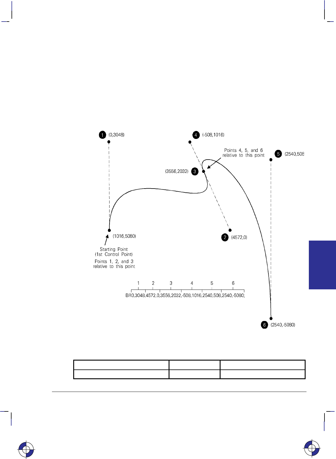
117
This is the black on page 117 (seq: 135)
Company confidential. HP-GL/2 and HP RTL Reference Guide, draft 2. Freeze Status: open
Example
PS 5000,7000; Plot Size 5000 by 7000 units.
SP 1; Select Pen number 1.
PA 1016,5080; Plot Absolute to the location (1016,5080), the first control point.
PD ; Pen Down.
BR 0,3048, 4572,0, 3556,2032, –508,1016, 2540,508, 2540,–5080; Points 1, 2, and 3
(the control points of the first Bezier curve) are relative to
(1016,5080). Point 3 becomes the first control point for the se-
cond Bezier curve (the new current position is updated to
(4572,7112)). Points 4, 5, and 6 are relative to (4572,7112). Point
6 becomes the final current position (7112,2032).
Figure 61. Bezier Curves Using Relative Coordinates
Possible Error Conditions
Error Condition Error Number Printer or Plotter Response
Invalid number of control points 2 The Bezier segment is discarded.
This is the blue on page 117 (seq: 135)
BR Instruction
INSTRUCTIONS
HP-GL/2
118
This is the black on page 118 (seq: 136)
Company confidential. HP-GL/2 and HP RTL Reference Guide, draft 2. Freeze Status: open
BZ, Bezier Absolute
Purpose
To draw a series of Bezier curves using absolute coordinates.
Syntax
BZ X1,Y1,X2,Y2,X3,Y3,...[X1,Y1,X2,Y2,X3,Y3][;]
Parameter Format Functional Range Parameter Default
X, Y coordinates current units device-dependent no default
Group
This instruction is in the Advanced Drawing Extension.
Use
BZ draws a Bezier curve using the present pen position as the first control point, and the de-
fined points as further control points. All curve control points are in absolute coordinates.
X, Y coordinates: Specify the location of the second (X1,Y1), third (X2,Y2), and fourth
(X3,Y3) control points in absolute coordinates.
The curves are drawn with the current pen, line type, line attributes, and pen state (up or down);
and they are clipped to the hard-clip limits and the soft-clip window. The current pen location
is updated to the end point of the curve at the termination of each Bezier curve defined by the
instruction. After each new Bezier curve, the last control point is used by the next Bezier curve
as the first control point. The carriage-return point (see page 66) is moved to the last X,Y.
After the first four control points are defined (one present-position control point and three con-
trol points) the optional parameters define subsequent Bezier curves by adding three additional
control points.
BZ is allowed in Polygon Mode. The first chord after “PM1” is not treated as a pen-up move.
Related Instructions
AA Arc Absolute
AR Arc Relative
AT Absolute Arc Three Point
BR Bezier Relative
CI Circle
LA Line Attributes
LT Line Type
PW Pen Width
RT Relative Arc Three Point
This is the blue on page 118 (seq: 136)
BZ Instruction

119
This is the black on page 119 (seq: 137)
Company confidential. HP-GL/2 and HP RTL Reference Guide, draft 2. Freeze Status: open
Example
PS 5000,7000; Plot Size 5000 by 7000 units.
SP 1; Select Pen number 1.
PA 1016,5080; Plot Absolute to the location (1016,5080), the first control point.
PD ; Pen Down.
BZ 1016,8128,5588,5080,4572,7112,4064,8128,7112,7620,7112,2032;
Points 1, 2, and 3 (the second, third, and fourth control points of
the first Bezier curve; point 3 becomes the first control point for
the second Bezier curve) followed by points 4, 5, and 6 (the se-
cond, third, and fourth control points of the second Bezier curve;
point 6 becomes the final current position).
Figure 62. Bezier Curves Using Absolute Coordinates
Possible Error Conditions
Error Condition Error Number Printer or Plotter Response
Invalid number of control points 2 The Bezier segment is discarded.
BZ Instruction
INSTRUCTIONS
HP-GL/2
This is the blue on page 119 (seq: 137)
120
This is the black on page 120 (seq: 138)
Company confidential. HP-GL/2 and HP RTL Reference Guide, draft 2. Freeze Status: open
CF, Character Fill Mode
Purpose
To specify the way scalable outline fonts are filled and edged; bitmap and stick fonts cannot be
edged and can be filled only with raster fill, shading, or PCL and HP RTL cross-hatch patterns.
Scalable characters may be filled with any of the fill patterns specified by the FT instruction
(shading, hatching, cross-hatch, and user-defined raster fill patterns). If your device does not
support outline fonts, this instruction may perform no operation (a NOP); pen plotters generally
do not support outline fonts.
Syntax
CF fill_mode[,edge_pen][;]
or
CF [;]
Parameter Format Functional Range Parameter Default
fill_mode clamped integer 0, 1, 2, or 3 0 (solid fill, no edging)
edge_pen integer device-dependent
(at least –223 to 223–1) current pen
Group
This instruction is in the Character Group.
Use
No Parameters: Defaults characters to solid fill with no edging. Equivalent to “CF0,0”.
fill_mode: Specifies how the device renders filled characters according to the following
parameter values:
0Specifies solid fill using the current pen and edging with the specified pen (or cur-
rent pen if the edge_pen parameter is not specified).
1Specifies edging with the specified pen (or current pen if the edge_pen parameter
is not specified). Characters are filled only if they cannot be edged (bitmap or
stick characters), using the edge pen.
2Specifies filled characters using the current fill type (refer to the FT instruction on
page 183). If the fill pattern does not incorporate color information, the currently
selected pen is used. Characters are not edged; if the edge_pen parameter is speci-
fied, it is ignored.
3Specifies filled characters using the current fill type (refer to the FT instruction).
If the fill pattern does not incorporate color information, the currently selected pen
is used. Characters are edged with the specified pen (or current pen if the
edge_pen parameter is not specified).
This is the blue on page 120 (seq: 138)
CF Instruction
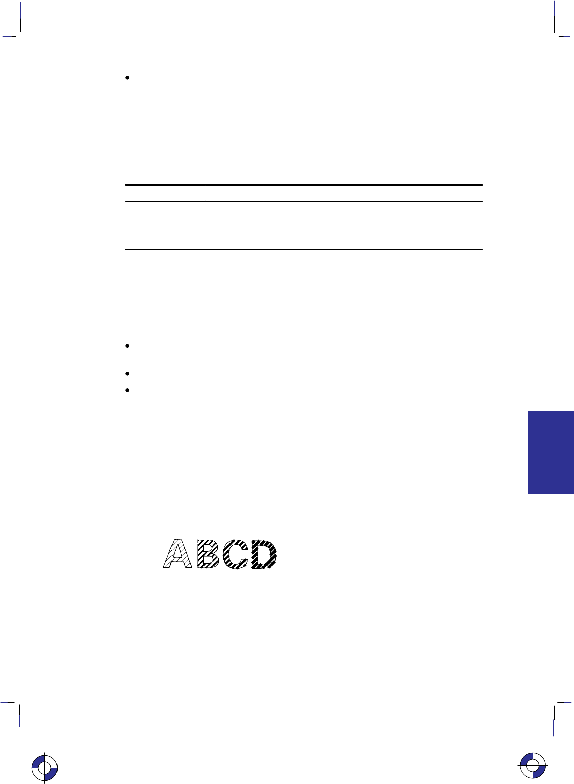
121
This is the black on page 121 (seq: 139)
Company confidential. HP-GL/2 and HP RTL Reference Guide, draft 2. Freeze Status: open
edge_pen: For characters that are to be edged, this parameter indicates the pen that is used
to edge the character. Edging width is device-dependent and varies with the character size;
it is not determined by the width of the pen specified as the edge pen. If edge_pen is
greater than the maximum number of pens in the device, the modulo function is applied, as
described for the SP instruction on page 306. Specifying pen 0 for the edge pen does not
necessarily mean that no edging will take place; it indicates that edging will be done by
pen 0. (However, on monochrome devices, 0 does mean no edging, and 1 means black
edging.)
The following table summarizes the functions of this instruction:
Fill No edging Edge using current pen Edge using pen 0
Solid CF; CF0; CF0,0;
None — CF1; CF1,0;
Current fill type CF2; CF3; CF3,0;
Note that the DI (Absolute Direction) and DR (Relative Direction) instructions do not cause
rotation of fill patterns. Fill patterns remain fixed with respect to the current coordinate system.
The CF instruction remains in effect until another CF instruction is executed, or the device is
initialized or set to default conditions.
The effect of CF on the three font types is device-dependent. At least the following minimum
implementation is supported:
For bitmap fonts, filling is limited (at least shading, user-defined RF, and PCL or HP RTL
patterns are supported) and edging may not be supported.
For stick fonts, filling is limited and edging may not be supported.
For scalable outline fonts, both filling and edging are supported.
Note also that the edge pen width is not specifiable; its thickness automatically increases with
the point size.
The thickness of fill lines for hatching and cross hatch is selected using the PW (Pen Width)
instruction. Due to the way hatching and cross-hatch lines are drawn, they may extend beyond
the character outline by up to 1/2 of the current pen width. When using a small pen width and
specifying a black edge pen, the edging covers up hatching lines that extend outside the charac-
ter outline. However, as the pen width increases, the edge pen may not be wide enough to
compensate for this, resulting in a fill that overlaps the character edges. To ensure that the
character fill looks correct when using hatching patterns, use a narrow pen width, especially for
small point sizes (see Figure 63).
Figure 63. Character Fill Overflow
CF Instruction
This is the blue on page 121 (seq: 139)
INSTRUCTIONS
HP-GL/2
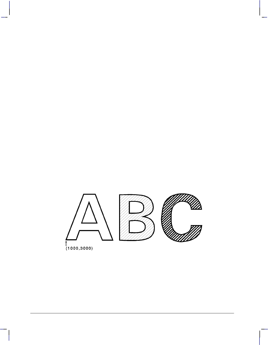
122
This is the black on page 122 (seq: 140)
Company confidential. HP-GL/2 and HP RTL Reference Guide, draft 2. Freeze Status: open
Related Instructions
DI Absolute Direction
DR Relative Direction
SB Scalable or Bitmap Fonts
FT Fill Type
Example
The following series of instructions produce the result shown below:
SD 1,21,2,1,4,140,5,0,6,3,7,52; Specify a 140-point Univers Bold font.
SS ; Select it for printing.
PA 1000,3000; Specify absolute plotting and move to (1000,3000).
DT*; Specify an asterisk (*) as the label terminator (non-printing).
FT 3,50,45; Specify a hatching fill type with 50 plotter-units between each
line, with the lines set at a 45 angle.
CF 1,1; Select character fill mode 1 (edge) and edge with pen number 1
(black on a monochrome device).
LBA*; Print the letter “A”.
PR 127,0; Move the pen position 127 plotter-units to the right.
PW .1; Set the pen width to 0.1 mm.
CF 3,1; Select character fill mode 3 (fill and edge) and edge with pen
number 1.
LBB*; Print the letter “B”.
PW .5; Set the pen width to 0.5 mm to change the thickness of the fill
lines.
LBC*; Print the letter “C”.
Figure 64. Using the CF (Character Fill) Instruction
CF Instruction
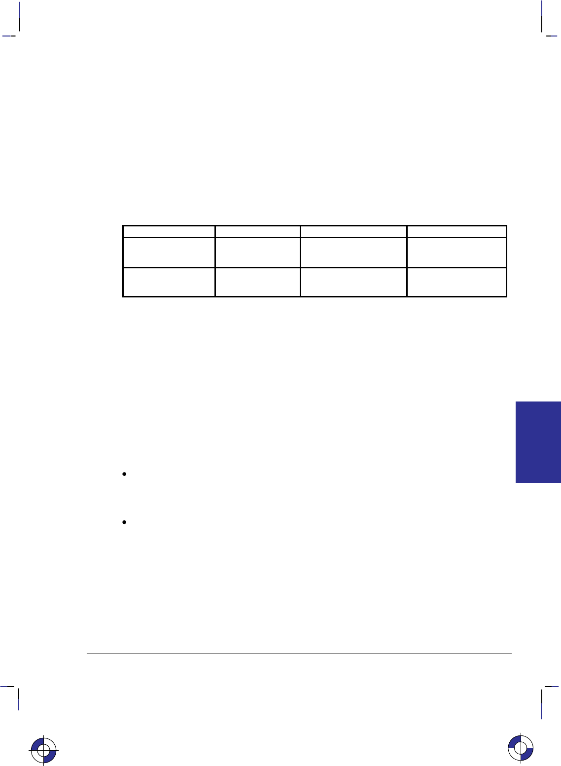
123
This is the black on page 123 (seq: 141)
Company confidential. HP-GL/2 and HP RTL Reference Guide, draft 2. Freeze Status: open
CI, Circle
Purpose
To draw the circumference of a circle using the specified radius and chord angle. If you want a
filled circle, refer to the WG (Fill Wedge) instruction on page 324 or Drawing Circles in Poly-
gon Mode on page 52.
Syntax
CI radius[,chord_angle][;]
Parameter Format Functional Range Parameter Default
radius current units device-dependent
(at least –223 to 223 – 1) no default
chord_angle* clamped real 0.0 to 360device-dependent
(usually 5)
* If you have used the “CT1” instruction, the chord_angle is interpreted as a deviation dis-
tance in current units; see the CT instruction on page 133.
Group
This instruction is in the Vector Group.
Use
The CI instruction includes an automatic pen down. When a CI instruction is received, the pen
lifts, moves from the center of the circle (the current pen location) to the starting point on the
circumference, lowers the pen, draws the circle, then returns with the pen up to the center of the
circle. After the circle is drawn, the previous pen up/down status is restored. To avoid leaving a
dot at the center of the circle, move to and from the circle’s center with the pen up.
radius: Measured from the current pen location. Coordinates are interpreted in current
units: as user-units when scaling is on; as plotter-units when scaling is off. If you specify a
negative radius, the circle begins and ends at the 180 reference point (see Figure 27 on
page 44). A zero radius produces a dot.
chord_angle: Specifies the chord angle used to draw the arc. The default is a chord angle
of 5. Refer to the AA (Arc Absolute) instruction discussion for an explanation of the
chord angle. If you use the CT (Chord Tolerance Mode) instruction described on page 133
and begin specifying chords in terms of deviation distance, this parameter is that distance
in current units.
Each chord of the circle is drawn using the currently defined line type, width, and attributes.
(Refer to The Line and Fill Attributes Group on page 53 for more information.) Do not use an
adaptive (negative) line type to draw a circle, as the device attempts to draw a complete pattern
for every chord (72 with the default chord angle). Always use isotropic scaling in drawings that
contain circles, unless you want your circles to “stretch” with aspect ratio changes of the draw-
This is the blue on page 123 (seq: 141)
CI Instruction
INSTRUCTIONS
HP-GL/2

124
This is the black on page 124 (seq: 142)
Company confidential. HP-GL/2 and HP RTL Reference Guide, draft 2. Freeze Status: open
ing (anisotropic scaling may produce an ellipse—see Figure 12 on page 13). There is more
information in Scaling on page 24.
Note that the CT (Chord Tolerance Mode) instruction in the Technical Graphics extension
changes the above computation.
Related Instructions
AA Arc Absolute
AR Arc Relative
AT Absolute Arc Three Point
CT Chord Tolerance Mode
EW Edge Wedge
LA Line Attributes
LT Line Type
PW Pen Width
RT Relative Arc Three Point
SC Scale
WG Fill Wedge
CI Instruction

125
This is the black on page 125 (seq: 143)
Company confidential. HP-GL/2 and HP RTL Reference Guide, draft 2. Freeze Status: open
Example: Effects of Chord Angle on Circle Smoothness
SP 1; Select pen number 1 (black).
SC –3000,3000,–2000,2000,1; Specify scaling mode, making P1 equal to (–3000,–2000)
user-units and P2 equal to (3000,2000) user-units. Isotropic scal-
ing is specified.
PA –1700,2000; Specify absolute plotting and move to (–1700,2000), the center of
the circle to be drawn.
CI 750,45; Draw a circle with a radius of 750 user-units and a chord angle of
45 (8 chords).
PA 300,2000; Specify absolute plotting and move to (300,2000) to draw another
circle.
CI 750,30; Draw this circle with a radius of 750 user-units and a chord angle
of 30 (12 chords).
PA –1700,–200; Specify absolute plotting and move to (–1700,–200), the center
point of a third circle.
CI 750,15; Draw this circle with a radius of 750 user-units and a chord angle
of 15 (24 chords).
PA 300,–200; Specify absolute plotting and move to (300,–200), the center of
the fourth circle.
CI 750; Draw this circle with a radius of 750 user-units and a chord angle
of 5, the default (72 chords).
Figure 65. Effects of Chord Angle on Circle Smoothness.
This is the blue on page 125 (seq: 143)
CI Instruction
INSTRUCTIONS
HP-GL/2

126
This is the black on page 126 (seq: 144)
Company confidential. HP-GL/2 and HP RTL Reference Guide, draft 2. Freeze Status: open
Example: Circles with Different Radii and Line Types
SC –75,75,–75,75,1; Set up user scaling with (–75,–75) as P1 and (75,75) as P2; the “1”
parameter specifies isotropic scaling.
PA 0,0; Specify absolute plotting and move to user-unit location (0,0).
LT ; Specify a default line type (solid).
CI 5; Draw a circle with a radius of 5 user-units.
LT 0; Select line type 0 (dotted).
CI –12; Draw a circle with a radius of 12 user-units (the minus sign indi-
cates starting at the 180 point).
LT 1; Select line type 1.
CI 19; Draw a circle with a radius of 19 user-units.
LT 2; Then select line type 2.
CI –26; Draw a circle with a radius of 26 user-units.
LT 3; Select line type 3.
CI 33; Draw a circle with a radius of 33 user-units.
LT 4; Then select line type 4.
CI –40; Draw a circle with radius of 40 user-units.
LT 5; Draw the outer two circles; the first with a line type of 5
CI 47; and a radius of 47 user-units.
LT 6; Draw the second with a line type of 6
CI 54; and a radius of 54 user-units.
Figure 66. Drawing Circles with Different Radii and Line Types
CI Instruction

127
This is the black on page 127 (seq: 145)
Company confidential. HP-GL/2 and HP RTL Reference Guide, draft 2. Freeze Status: open
CO, Comment
Purpose
To allow comments to be inserted within an HP-GL/2 instruction sequence. The comment
string of the CO instruction must be delimited by double quotes. HP-GL/2 comments are ig-
nored by the device.
Syntax
CO [“c...c”][;]
Parameter Format Functional Range Parameter Default
“c...c” quoted string
(see page 28) any text characters en-
closed in double quotes no default
Group
This instruction is in the Configuration and Status Group.
Use
To add comments to HP-GL/2 instruction lists.
This is the blue on page 127 (seq: 145)
CO Instruction
INSTRUCTIONS
HP-GL/2

128
This is the black on page 128 (seq: 146)
Company confidential. HP-GL/2 and HP RTL Reference Guide, draft 2. Freeze Status: open
CP, Character Plot
Purpose
To move the pen the specified number of spaces and lines from the current pen location. Use
CP to position a label for indenting, centering, and so on. It does not plot characters; that is
normally done by the LB (Label) instruction.
Syntax
CP spaces,lines[;]
or
CP [;]
Parameter Format Functional Range Parameter Default
spaces clamped real –32 768 to 32 767 no default
lines clamped real –32 768 to 32 767 no default
Group
This instruction is in the Character Group.
Use
The CP (Character Plot) instruction includes an automatic pen up. When the instruction is com-
pleted, the original pen up/down status is restored.
CP moves the pen position in relation to the current position. CP is a movement instruction and
does not affect the margin; to repeat the same movement for subsequent labels, you must issue
new CP instructions. (For information about the Carriage Return point, see Moving to the Car-
riage Return Point on page 66.) For more information on spaces, lines, and the character cell,
refer to Working with the Character Cell on page 58.
No Parameters: Performs a Carriage Return and Line Feed (moves one line down and
returns to the Carriage Return point).
spaces: Specifies the number of spaces the pen moves relative to the current pen location.
Positive values specify the number of spaces the pen moves to the right of the current pen
position; negative values specify the number of spaces the pen moves to the left. Right and
left are relative to the current label direction. The space width is uniquely defined for each
font; use the ES (Extra Space) instruction to adjust the width.
Note: If you are using a proportionally-spaced font, the width of the Space () control
code is used.
lines: Specifies the number of lines the pen moves relative to the current pen location.
Positive values specify the number of lines the pen moves up from the current pen position;
negative values specify the number of lines the pen moves down (a value of –1 is equiva-
lent to a Line Feed). Up and down are relative to the current label direction. The Line
This is the blue on page 128 (seq: 146)
CP Instruction

129
This is the black on page 129 (seq: 147)
Company confidential. HP-GL/2 and HP RTL Reference Guide, draft 2. Freeze Status: open
Feed distance is uniquely defined for each font; use the ES (Extra Space) instruction to
adjust the height.
When you move the pen up or down a specific number of lines, the Carriage Return point shifts
up or down accordingly.
The illustration below shows the interaction of label direction and the sign (+/–) of the parame-
ters.
Figure 67. Interaction of Label Direction and Parameter Sign
The following illustration shows the direction of labeling with a vertical text path (set by
“DV1” or “DV1,0”); refer to the DV (Define Variable Text Path) instruction for more informa-
tion).
Figure 68. Labeling with a Vertical Text Path
This is the blue on page 129 (seq: 147)
CP Instruction
INSTRUCTIONS
HP-GL/2
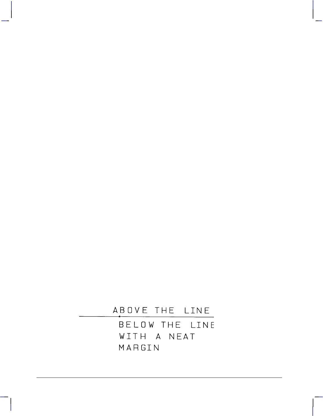
130
This is the black on page 130 (seq: 148)
Company confidential. HP-GL/2 and HP RTL Reference Guide, draft 2. Freeze Status: open
Related Instructions
DI Absolute Direction
DR Relative Direction
DV Define Variable Text Path
ES Extra Space
LB Label
LO Label Origin
SB Scalable or Bitmap Fonts
SI Absolute Character Size
SR Relative Character Size
Example
The following example produces lettering along a line (but not directly on top of it), and aligns
labels along a left margin. Movement of the carriage-return point is demonstrated, as well as
different methods of placing the text. The text is placed using the CP instruction with parame-
ters, then with a Carriage Return-Line Feed ( ) combination, and using a CP instruction
without parameters to emulate a .
PA 5000,2500; Specify absolute plotting and move to (5000,2500).
PD 1500,2500; Set the pen down and draw a line to (1500,2500).
PU ; Lift the pen.
CP 5,.35; Move the pen 5 spaces to the right and 0.35 lines up so that the
label is placed just above the line.
DT$,1; Define a label terminator ($) and specify that it does not print.
SD 1,21,2,1,4,14,5,0,6,3,7,52; Designate a 14-point Univers Bold font.
SS ; Select it.
LBABOVE THE LINE$; Print the first line of text. (Note that there are no spaces after
“LB”.)
PA 2500,2500; Move the pen to (2500,2500).
WG 20,0,360; Draw a dot marking the new carriage-return point (360 black-
filled wedge with a diameter of 20 plotter-units).
CP 0,–.95 Move the pen down 0.95 lines, with no left or right movement.
LBBELOW THE LINE WITH A NEAT$; Print the second line; Carriage Return-Line
Feed; print the third line.
CP ; The CP instruction without parameters functions as a .
LBMARGIN$; Print the fourth line.
Figure 69. CP (Character Plot) Instruction
CP Instruction

131
This is the black on page 131 (seq: 149)
Company confidential. HP-GL/2 and HP RTL Reference Guide, draft 2. Freeze Status: open
CR, Set Color Range for Relative Color Data
Purpose
To establish the range for specifying primary color—for example, red/green/blue (RGB)—data.
This instruction maps current pen colors to a numeric range while leaving the current palette
colors themselves unchanged. Pen plotters ignore (NOP) this instruction.
In an RGB color model, “primary1” or “p1” is red, “primary2” or “p2” is green, and “prima-
ry3” or “p3” is blue.
Syntax
CR black-ref_p1,white-ref_p1,black-ref_p2,white-ref_p2,black-ref_p3,white-ref_p3[;]
or
CR [;]
Parameter Format Functional Range Parameter Default
black-ref
(p1, p2, p3) clamped real –32 768 to 32 767 0
white-ref
(p1, p2, p3) clamped real –32 768 to 32 767 255
Group
This instruction is in the Palette Extension.
Use
The black-reference for a primary color denotes a value assigned to the absence of that color.
The white-reference denotes the value given to a fully saturated primary color. When you have
set the reference ranges, use the PC (Pen Color Assignment) instruction to define the colors of
your pens.
No parameters: Defaults the black color references to 0 and the white references to 255.
Equivalent to “CR0,255,0,255,0,255;”.
black-ref, white-ref (primary1, primary2, primary3): Sets the color to a range for each
primary color. The first two parameters set the black- and white-references (respectively)
for primary1 (or red), the second pair for primary2 (or green), and the final pair for prima-
ry3 (or blue).
Using a black-reference of 0 and a white reference of 100 makes it easy to specify colors as
percentages of their fully saturated levels. Use the instruction “CR 0,100,0,100,0,100;”.
The reference values are reset to their defaults by the IN (Initialize) instruction.
In dual-context mode, CR can change the black and white references for palettes created by IN,
BP, or *v#W. The new references are remembered when the PCL or HP RTL context is
entered. This instruction is ignored if the current palette was created by *r#U or E.
The equivalent PCL and HP RTL command is Configure Image Data (bytes 6 through 17).
This is the blue on page 131 (seq: 149)
CR Instruction
INSTRUCTIONS
HP-GL/2
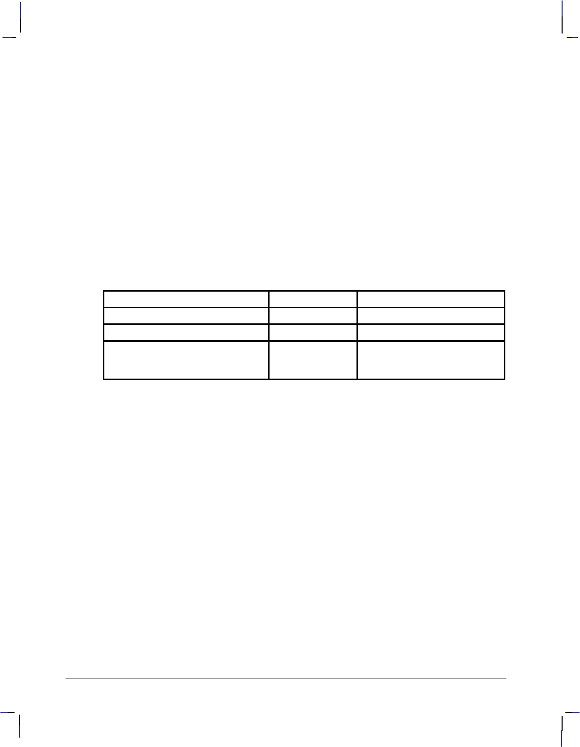
132
This is the black on page 132 (seq: 150)
Company confidential. HP-GL/2 and HP RTL Reference Guide, draft 2. Freeze Status: open
Related Instructions
NP Number of Pens
PC Pen Color Assignment
SV Screened Vectors
TR Transparency Mode
Example
CR 0,63,0,63,0,63; This instruction sets the black references for each primary to 0,
and the white references to 63. The value for a medium blue
would be 0,0,31.
CR 4,63,0,127,0,31; This instruction sets the black reference to 4,0,0 and the white
reference to 63,127,31. In this case, medium blue would be
4,0,15.
Possible Error Conditions
Error Condition Error Number Printer or Plotter Response
One to five parameters 2 The instruction is ignored
Seven or more parameters 2 The extra parameters are ignored
The black reference value for any
primary color is equal to its white
reference value
3The instruction is ignored
CR Instruction

133
This is the black on page 133 (seq: 151)
Company confidential. HP-GL/2 and HP RTL Reference Guide, draft 2. Freeze Status: open
CT, Chord Tolerance Mode
Purpose
To specify whether the chord_angle parameter of the AA, AR, AT, CI, EW, RT, and WG
instructions is interpreted as a chord angle in degrees or as a deviation distance in current units.
This instruction changes the way the number of chords is determined. It is defaulted by DF or
IN.
Syntax
CT mode[;]
or
CT[;]
Parameter Format Functional Range Parameter Default
mode clamped integer 0 or 1 0
Group
This instruction is in the Technical Graphics Extension.
Use
A plotted circle or arc actually consists of a series of straight line segments (chords) that
approximate to arc segments. Increasing the number of chords increases the smoothness of the
circle or arc, but uses more of the device’s disk space. Chord tolerance is the acceptable devi-
ation from a smooth circle, and can be established as either a chord angle or a deviation
distance.
No parameters: equivalent to “CT0”.
mode: Specifies the type of chord tolerance, as follows:
0Sets the chord tolerance mode to chord angle, which specifies, in degrees, the
maximum angle created when lines from each end of the chord intersect the center
point of the circle. When chord tolerance is specified as a chord angle, a circle or
arc will have the same number of chords, regardless of its size. See the left-hand
side of Figure 70.
1Sets the chord tolerance mode to deviation distance, which specifies, in current
units, the maximum distance between the chord and the arc segment it represents.
When you specify a deviation distance, the number of chords in a circle will vary
with its size. See the right-hand side of Figure 70.
Note that when you change from the default mode of chord angle to deviation distance, the
chord angle parameter of the arc instructions (AA, AR, AT, and RT), the wedge instructions
(EW and WG), and the circle instruction (CI) will be interpreted as current units, not degrees.
This is the blue on page 133 (seq: 151)
CT Instruction
INSTRUCTIONS
HP-GL/2
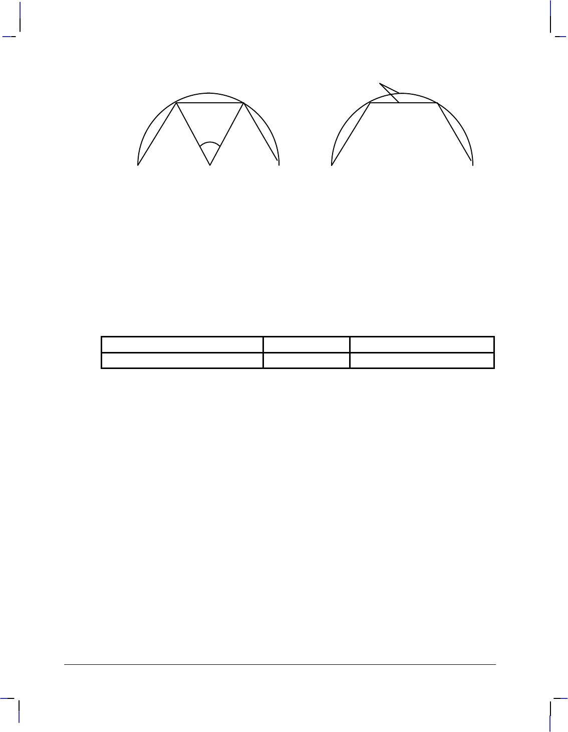
134
This is the black on page 134 (seq: 152)
Company confidential. HP-GL/2 and HP RTL Reference Guide, draft 2. Freeze Status: open
chord
tolerance
angle
drawn chord arc
segment
drawn chord arc
segment
deviation distance
Figure 70. Chord Tolerance Mode
Related Instructions
AA Arc Absolute
AR Arc Relative
AT Absolute Arc Three Point
CI Circle
EW Edge Wedge
RT Relative Arc Three Point
WG Fill Wedge
Possible Error Conditions
Error Condition Error Number Printer or Plotter Response
The mode is not 0 or 1. 3 The instruction is ignored
CT Instruction

135
This is the black on page 135 (seq: 153)
Company confidential. HP-GL/2 and HP RTL Reference Guide, draft 2. Freeze Status: open
DC, Digitize Clear
Purpose
To terminate digitize mode and reactivate automatic pen lift and storage. This instruction is
only supported by pen plotters.
Syntax
DC [;]
Group
This instruction is in the Digitizing Extension.
Use
If you are using an interrupt routine in a digitizing program to branch to another plotting func-
tion, use DC to clear the digitize mode immediately after the branch.
When the device receives the DC instruction, it terminates digitize mode. It may also turn off
any control-panel light (awaiting input of digitized point) and reactivate automatic pen lift.
Refer to The Digitizing Extension on page 89 and your device’s documentation for more in-
formation.
Related Instructions
DP Digitize Point
OD Output Digitized Point and Pen Status
OS Output Status
Possible Error Conditions
Error Condition Error Number Plotter Response
One or more parameters are specified 2 The parameters are ignored
This is the blue on page 135 (seq: 153)
DC Instruction
INSTRUCTIONS
HP-GL/2
136
This is the black on page 136 (seq: 154)
Company confidential. HP-GL/2 and HP RTL Reference Guide, draft 2. Freeze Status: open
DF, Default Values
Purpose
To return the device’s HP-GL/2 settings to the factory default settings. Use the DF instruction
to return the device to a known state while maintaining the current locations of P1 and P2, un-
like the IN (Initialize) instruction. When you use DF at the beginning of a instruction
sequence, graphics parameters such as character size, slant, or scaling are defaulted.
Syntax
DF [;]
Group
This instruction is in the Configuration and Status Group.
Use
The DF instruction resets the device to the following conditions:
Function Equivalent
Instruction Default Condition
Anchor Corner AC; Anchor corner set to the origin of the hard-clip lim-
its
Alternate Font Definition AD; Restore default (device-dependent) alternate font
characteristics
Character Fill Mode CF; Solid fill, no edging, uses the current pen
Absolute Direction DI; Absolute character direction parallel to X-axis
Define Label Terminator DT; and non-printing mode
Define Variable Text Path DV; Text printed in the +X-direction with Line Feed in
the –Y-direction
Extra Space ES; No extra space
Fill Type FT; Solid bidirectional fill (all previously specified pa-
rameters for other fill types revert to their defaults)
Input Window IW; Hard-clip limits (printable area)
Line Attributes LA; Butt caps, mitered joins, and miter limit=5
Label Origin LO1; Standard labeling starting at current location
Line Type LT; Solid line, relative mode, pattern length=4% of di-
agonal distance from P1 to P2
Plotting Mode PA; Absolute plotting
Polygon Mode PM0;PM2; Polygon buffer cleared
Raster Fill RF; Solid raster fill in the current color for all patterns
This is the blue on page 136 (seq: 154)
DF Instruction
137
This is the black on page 137 (seq: 155)
Company confidential. HP-GL/2 and HP RTL Reference Guide, draft 2. Freeze Status: open
Function Default Condition
Equivalent
Instruction
Scale SC; User-unit scaling off
Standard Font Definition SD; Restore default (device-dependent) standard font
characteristics
Absolute Character Size SI; Turns off size transformation
Character Slant SL; No slant
Symbol Mode SM; Turns off symbol mode
Select Standard Font SS; Standard font selected
Transparent Data TD; Normal printing mode
User-Defined Line Type UL; Defaults all 8 line types
In addition, the device updates the carriage-return point for labeling to the current pen location.
(See page 66 for more information on the carriage-return point.) DF defaults the PD and PU
forms of the PA and PR instructions to be forms of PA; it clears the current pattern residue and
terminates any sequence of continuous vectors (see the LA and LT instructions).
The DF instruction does not affect the following HP-GL/2 conditions:
Locations of P1 and P2.
Current pen, its selection, location, width, width unit selection, and up/down state.
Plot size.
HP-GL/2 drawing rotation.
Generated errors are not cleared.
Using DF with the Technical Graphics Extension
The DF instruction also affects the following instructions:
Function Equivalent
Instruction Default Condition
Chord Tolerance Mode CT; Sets the mode to chord angle
Merge Control MC; Sets merge control off
Media Type MT; Device-dependent—uses the control-panel setting
Quality Level QL; Device-dependent
Sort ST; Device-dependent
Velocity Select VS; Device-dependent speed for all pens
This is the blue on page 137 (seq: 155)
DF Instruction
INSTRUCTIONS
HP-GL/2
138
This is the black on page 138 (seq: 156)
Company confidential. HP-GL/2 and HP RTL Reference Guide, draft 2. Freeze Status: open
Using DF with the Palette Extension
The DF instruction also affects the following instructions:
Function Equivalent
Instruction Default Condition
Set Color Range for
Relative Color Data CR0,255,
0,255,
0,255;
Range 0 through 255 for each primary color (red,
green, blue)
Number of Pens NP; Device-dependent
Pen Color Assignment PC; Determined by the number of pens
Screened Vectors SV; No screening (solid vectors); defaults other pre-
viously specified options
Transparency Mode TR1; Transparency mode on
Using DF in a Dual-Context Environment
The DF instruction also affects the following instructions:
Function Equivalent
Instruction Default Condition
Anchor Corner AC; Places the anchor point at the origin of the current
coordinate system
Input Window IW; Sets the user window equal to the hard-clip limits
Scalable or Bitmap Fonts SB0; Scalable fonts only
Using DF with the Advanced Text Extension
The DF instruction also affects the following instructions:
Function Equivalent
Instruction Default Condition
Label Mode LM; 8-bit mode, row-number 0
Scalable or Bitmap Fonts SB0; Scalable fonts only
Related Instructions
BP Begin Plot
IN Initialize
LM Label Mode
MC Merge Control
PP Pixel Placement
DF Instruction

139
This is the black on page 139 (seq: 157)
Company confidential. HP-GL/2 and HP RTL Reference Guide, draft 2. Freeze Status: open
DI, Absolute Direction
Purpose
To specify the slope or direction at which characters are drawn, independent of P1 and P2 set-
tings. Use DI to change labeling direction when you are labeling curves in line charts,
schematic drawings, blueprints, and survey boundaries.
Syntax
DI run,rise[;]
or
DI [;]
Parameter Format Functional Range Parameter Default
run (or cos )clamped real –32 768 to 32 767 1
rise (or sin )clamped real –32 768 to 32 767 0
Group
This instruction is in the Character Group.
Use
The DI instruction updates the carriage-return point to the current location. While DI is in ef-
fect, with or without parameters, the label direction is not affected by changes in the locations
of P1 and P2. However, the DV (Define Variable Text Path) instruction interacts with the DI
instruction (and DR), as explained later in this section.
The DI instruction remains in effect until another DI or DR instruction is executed, or the de-
vice is initialized or set to default conditions.
No Parameters: Defaults the label direction to absolute and horizontal (parallel to
X-axis). Equivalent to “DI1,0”.
run or cos Specifies the X-component of the label direction.
rise or sin Specify the Y-component of the label direction.
Together, the parameters specify the slope and direction of the label.
You can express the parameters in measured units as run and rise, or using the trigonometric
functions cosine and sine according to the following relationships:
where: run and rise = number of measured units
= the angle measured in degrees
sin /cos = rise/run
= tan–1(rise/run)
and tan = sin /cos
This is the blue on page 139 (seq: 157)
DI Instruction
INSTRUCTIONS
HP-GL/2
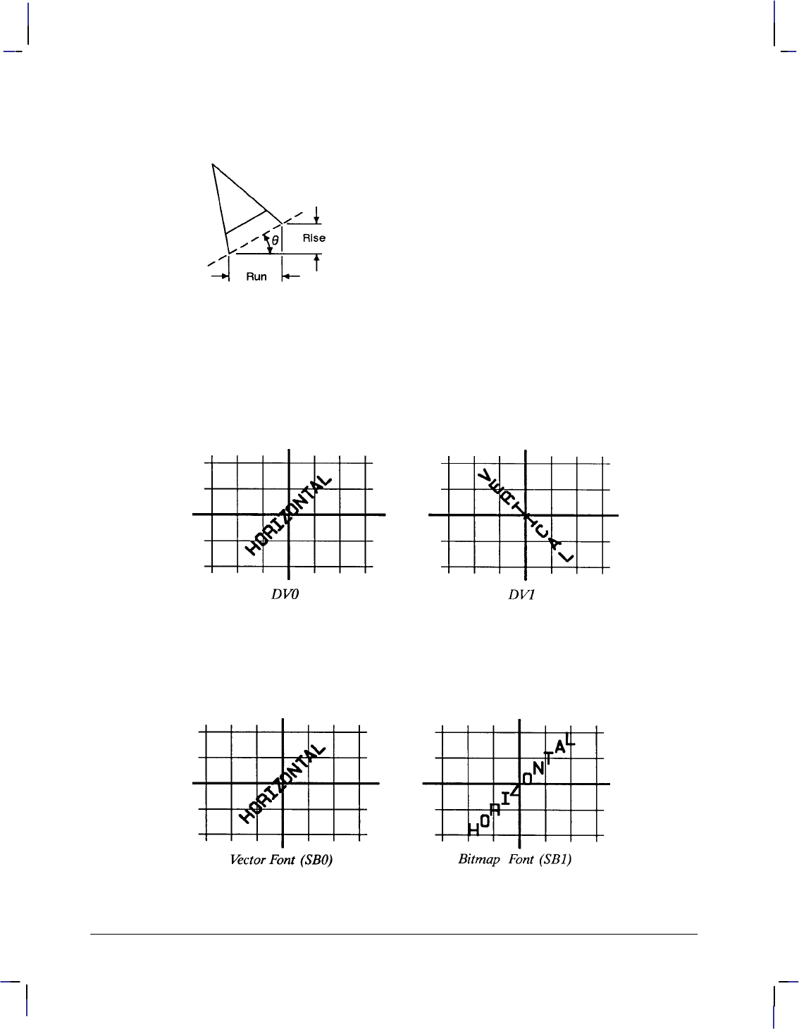
140
This is the black on page 140 (seq: 158)
Company confidential. HP-GL/2 and HP RTL Reference Guide, draft 2. Freeze Status: open
Note that the run and rise determine the slope or angle of an imaginary line under the base of
each character in the label. See Figure 71.
Figure 71. Character Slope Rise and Run
When plotting in horizontal mode (that is, you have not used the DV [Define Variable Text
Path] instruction), the run and rise appear to determine the slope of the entire label. However,
if you have used the DV instruction to label in a vertical path, the label appears to slant in the
opposite direction, even though the base of each letter is plotted on the same slope. Figure 72
compares how labels plotted with the same run and rise parameters appear with horizontal
“DV0” and vertical “DV1” text paths.
Figure 72. Effect of Horizontal and Vertical Text Paths
For devices that support the Dual-Context Extension, if an “SB1;” instruction has been sent, the
device draws the label along the nearest perpendicular. In the case of bisection, the angle is
rounded down (so 45 would be rounded to 0). See Figure 73.
Figure 73. Scalable Versus Bitmap Variable Text Path Printing
DI Instruction
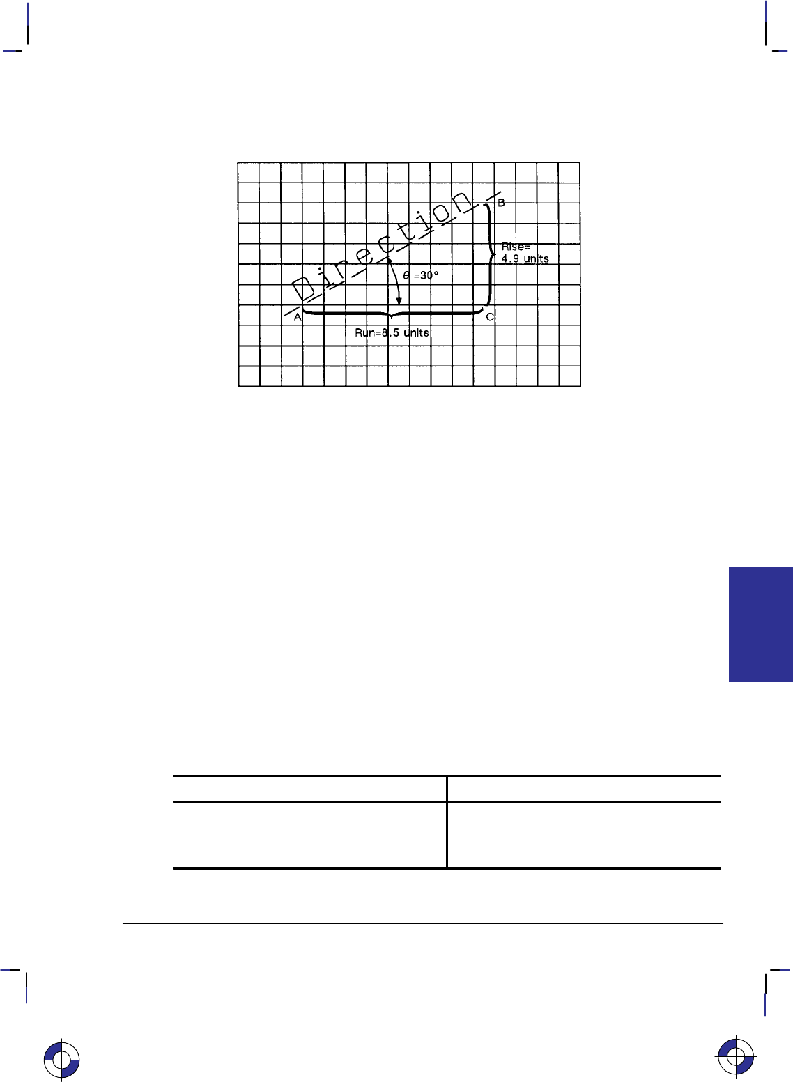
141
This is the black on page 141 (seq: 159)
Company confidential. HP-GL/2 and HP RTL Reference Guide, draft 2. Freeze Status: open
Suppose you want your label plotted in the direction shown in Figure 74. You can do this in
one of two ways: measure the run and rise, or measure the angle.
Figure 74. Label Print Direction Rise and Run
To measure the run and rise, first draw a grid with the lines parallel to the X- and Y-axis. The
grid units should be the same size on all sides, but their actual size is irrelevant. Then, draw
one line parallel to the label and one parallel to the X-axis. The lines should intersect to form
an angle.
Select a point on the open end of your angle (where another line would create a triangle). On
the line parallel to the X-axis, count the number of grid units from the intersection of the two
lines to your selected point. This is the run; in Figure 74, the run is 8.5. Now, count the num-
ber of units from your selected point along a perpendicular line that intersects the line along the
label. This is the rise; in Figure 74, the rise is 4.9.
Your DI instruction using the run and rise is “DI8.5,4.9;”.
If you know the angle (), you can use the trigonometric functions sine (sin) and cosine (cos).
In this example, = 30, cos 30 = 0.866, and sin 30 = 0.5.
Your DI instruction using the sine and cosine would be “DI.866,.5;”.
Whichever set of parameters you use, the label is drawn in the same direction as shown in Fig-
ure 74.
When using either method, at least one parameter must not be zero. The ratio of one parameter
to the other is more important than the actual numbers. The following table lists three common
label angles produced by using 1’s and 0’s.
DI instruction Label direction
DI 1,0; horizontal
DI 0,1; vertical
DI 1,1; (or any other equal non-zero values) 45
This is the blue on page 141 (seq: 159)
DI Instruction
INSTRUCTIONS
HP-GL/2
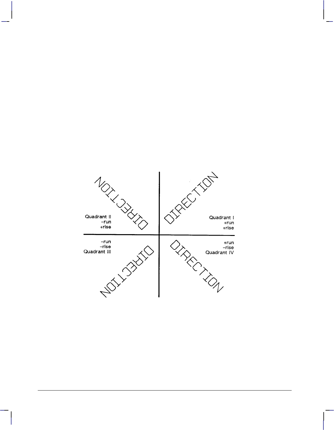
142
This is the black on page 142 (seq: 160)
Company confidential. HP-GL/2 and HP RTL Reference Guide, draft 2. Freeze Status: open
The relative size and sign of the two parameters determine the amount of rotation. If you imag-
ine the current pen location to be the origin of a coordinate system for the label, you can see
that the signs of the parameters determine which quadrant the label is in.
Examples
PA 3500,2500; Enter absolute plotting mode and move to (3500,2500).
DT*; Define an asterisk (*) as the label terminator.
DI 1,1; Select the first quadrant.
LBDIRECTION*; Print the word “DIRECTION” and send a Carriage Return to re-
turn the pen to the Carriage Return point (3500,2500).
DI –1,1; Select the second quadrant.
LBDIRECTION*; Print the word and Carriage Return.
DI –1,–1; Select the third quadrant.
LBDIRECTION*; Print the same word and Carriage Return.
DI 1,–1; Select the fourth quadrant.
LBDIRECTION*; Print the same word and Carriage Return.
Figure 75. Varying Print Direction with the DI Instruction
The following example illustrates the use of positive and negative parameters, the use of the
cosine and sine, how the LB instruction updates the current pen location, and how DI updates
the carriage-return point.
PA 3500,2500; Specify absolute plotting and move to (3500,2500).
DT#,1; Define the “#” character as the label terminator.
DI 0,1; Set the label direction to print at 90.
LB____1990#; Print “____1990”.
DI 1,1; Set the label direction to 45.
LB____1991#; Print “____1991”.
DI 1,0; Set the label direction to 0.
DI Instruction
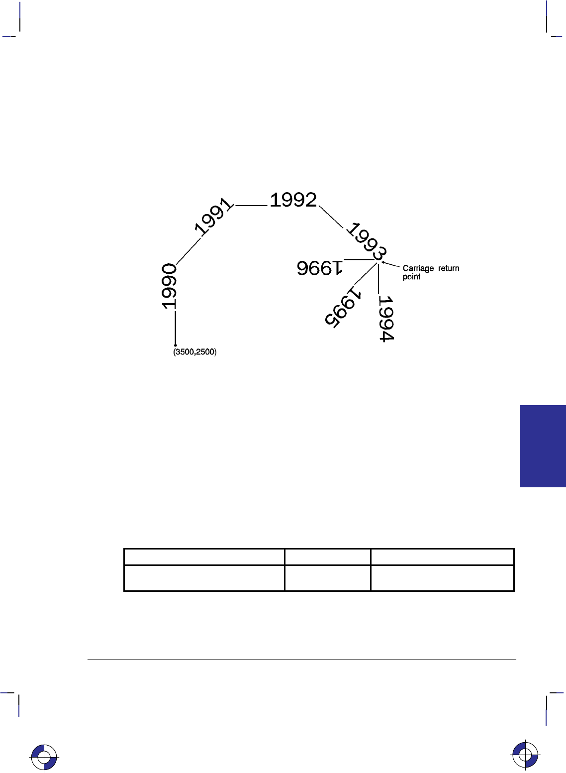
143
This is the black on page 143 (seq: 161)
Company confidential. HP-GL/2 and HP RTL Reference Guide, draft 2. Freeze Status: open
LB____1992#; Print “____1992”;
DI .71,–.71; Change the label direction using the cosine and sine of 315.
LB____1993#; Print “____1993”.
DI 0,–1; Change the label direction using the cosine and sine of 270.
LB____1994#; Print “____1994”; Carriage Return.
DI –.71,–.71; Set the label direction using the cosine and sine of 270.
LB____1995#; Print “____1995”; Carriage Return.
DI ,–1,0; Set the label direction using the cosine and sine of –180.
LB____1996#; Print “____1996”; Carriage Return.
Figure 76. Using the DI (Absolute Direction) Instruction with Labels
Related Instructions
CF Character Fill Mode
CP Character Plot
DR Relative Direction
DV Define Variable Text Path
LB Label
SB Scalable or Bitmap Fonts
SI Absolute Character Size
SL Character Slant
SR Relative Character Size
Possible Error Conditions
Error Condition Error Number Printer or Plotter Response
Both parameters = 0 or
number out of range 3Ignores instruction
This is the blue on page 143 (seq: 161)
DI Instruction
INSTRUCTIONS
HP-GL/2
144
This is the black on page 144 (seq: 162)
Company confidential. HP-GL/2 and HP RTL Reference Guide, draft 2. Freeze Status: open
DL, Download Character
Purpose
To design characters and load them into a buffer for repeated use. Use DL whenever you want
to create characters or symbols that are not included in the device’s character sets.
Syntax
DL character_number[,up],X,Y...[[,up],X,Y][;]
or
DL character_number[;]
or
DL character_number1,character_number2[,up],X,Y...[[,up],X,Y][;]
or
DL character_number1,character_number2[;]
or
DL [;]
Parameter Format Functional Range Parameter Default
character_number,
character_number1,
character_number2*
clamped integers 0 through 255 no default
up clamped integer –128 no default
X,Y coordinates clamped integers –127 through 127 no default
* A pair of character numbers (character_number1,character_number2) is only valid in
16-bit mode (see the LM [Label Mode] instruction on page 208).
Group
This instruction is in the Technical Graphics Extension.
Use
After you designate (SD or AD) and select (SS or SA) the HP-GL/2 downloadable 8-bit charac-
ter set (character set 531, symbol set ID 16S), use the DL instruction to create characters vector
by vector, one character per instruction. Once defined with DL, characters can be used in the
LB instruction. They can also be used in Symbol Mode (SM), but will not be centered unless
they have been defined that way in the character grid. All text attributes (size, slant, direction,
and label origin) apply to downloadable characters. The characters you define in the download-
able set have fixed spacing and are upright. All text attributes (size, slant, direction, and label
origin) apply to downloadable characters. They may be intermixed with other fonts. After LB
prints the character, the character origin is advanced 48 grid units, unless modified by the ES
(Extra Space) instruction.
No parameters: Clears all characters in the downloadable character set from the buffer.
All characters are then undefined.
This is the blue on page 144 (seq: 162)
DL Instruction

145
This is the black on page 145 (seq: 163)
Company confidential. HP-GL/2 and HP RTL Reference Guide, draft 2. Freeze Status: open
character_number: An integer in the range 33 to 126, specifying the decimal value of the
character. If the character_number has been previously defined, the new definition over-
writes the old one.
In 8-bit mode, character_number specifies the character number of the character, and there
should not be any subsequent character_number2 specified. In 16-bit mode (see the LM
instruction on page 208), the character number is specified by the pair of numbers,
character_number1,character_number2.
When it is not followed by additional coordinate parameters (“DLcharacter_number[;]” or
“DLcharacter_number1character_number2[;]”), this instruction clears the corresponding
character from the downloadable set. Clearing a character makes it undefined, and refer-
ring to such a character in a label string results in a space.
up: A clamped integer with the value –128. The up-flag indicates that the next pair of
coordinates defines a move with the pen up; subsequent moves are made with the pen
down. Pen up is the default for the first pair of coordinates.
X, Y coordinates: Clamped integers in the range –127 to 127 primitive grid units. These
coordinates are drawn on a 32-by-32-unit grid. After the first pair, which always defines a
pen-up move, all coordinates define moves with the pen down, unless they are preceded by
an up-flag.
The number of characters following the character_number parameter is not restricted.
Your device can download 94 characters with at least 20 points (coordinate pairs) in each
character.
In symbol mode, the character drawn at the vector end-points uses the current downloaded defi-
nition, not the definition in effect when the SM was received. If a downloaded character
defined at the time of SM becomes undefined before the execution of the symbol mode (by PA
or PR), no symbol is drawn and error 3 is generated. The vectors specified by PA or PR are,
however, drawn normally.
If any HP-GL/2 error is generated while processing DL, the partially defined character is not
saved, and the old character is cleared.
Defining a Downloadable Character
The device allocates space in the downloadable character buffer as needed. The DL font uses a
fixed overhead of 206 bytes (consumed when the first character is downloaded), plus two over-
head bytes per defined character. The points in a DL character average 1½ bytes each.
1. Design the character in absolute units on a 32-by-32-unit grid in a 48-by-64-unit cell.
Note that the origin (0,0) is in the lower-left corner of the grid. This is the same grid used
for fixed-vector character sets in the device. The area occupied by a 32-by-32-unit grid is
approximately the size of an uppercase A. The downloaded character may extend outside
this grid to 127 units on each axis. The point size of a downloadable set corresponds to
48 grid units.
2. Assign a character number (decimal code) to the downloadable character.
3. Designate the starting point with the first X,Y coordinate pair, which is always a pen-up
move.
4. Specify the vectors of the character using absolute X,Y coordinates.
This is the blue on page 145 (seq: 163)
DL Instruction
INSTRUCTIONS
HP-GL/2
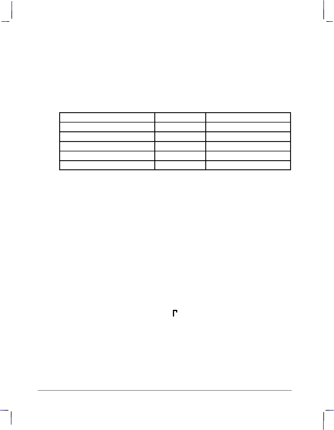
146
This is the black on page 146 (seq: 164)
Company confidential. HP-GL/2 and HP RTL Reference Guide, draft 2. Freeze Status: open
Related Instructions
AD Alternate Font Definition
LB Label
SA Select Alternate Font
SD Standard Font Definition
SS Select Standard Font
Possible Error Conditions
Error Condition Error Number Printer or Plotter Response
Y-coordinate missing 2 Ignores instruction
Up-flag follows X-coordinate 2 Ignores instruction
Parameter out of range 3 Ignores instruction
X,Y data out of range 3 Ignores instruction
Buffer overflow 7 Ignores instruction
Example
This sequence of instructions uses a character that is downloaded:
AD 1,531,3,3 Alternate Font Definition: character set 531, pitch 3 characters per
inch.
DL 65, 10,0, 10,30, 28,30, 28,24 Download Character number 65 (“A”), starting at
(10,0), draw to (10,30), to (28,30), and finally to (28,24).
PU Pen Up.
PA 300,300 Plot Absolute, moves the pen to (300,300).
LBThe symbol for gamma is A Label, using the shift-out () character, decimal code
14, to switch to the alternate font, and the end-of-text () char-
acter, decimal 3, to terminate the text.
(An alternative sequence, using the SA (Select Alternate Font)
instruction, would be:
LBThe symbol for gamma is SALBA
but is four bytes longer.)
This is the result:
The symbol for gamma is
Figure 77 shows how the gamma symbol fits in its character grid.
DL Instruction

147
This is the black on page 147 (seq: 165)
Company confidential. HP-GL/2 and HP RTL Reference Guide, draft 2. Freeze Status: open
Space: 48 grid units
Line: 64 grid units
Character width: 32 grid units
Character height: 32 grid units
Start
(10,0)
(10,30)
(28,30)
End
(28,24)
Origin
(0,0)
Figure 77. Creating a Downloaded Character
This is the blue on page 147 (seq: 165)
DL Instruction
INSTRUCTIONS
HP-GL/2

148
This is the black on page 148 (seq: 166)
Company confidential. HP-GL/2 and HP RTL Reference Guide, draft 2. Freeze Status: open
DP, Digitize Point
Purpose
To enable digitize mode and suppress automatic pen lift and storage. In digitize mode, you
have full control of the pen holder. The device remains in digitize mode until a point is entered
using a front-panel control, or digitize mode is terminated by the DC (Digitize Clear) instruc-
tion.
Syntax
DP [;]
Group
This instruction is in the Digitizing Extension.
Use
This instruction suppresses any automatic pen storage and lift that may be implemented in the
plotter.
This instruction may turn on a control-panel light to indicate that it is waiting for you to enter a
point. Use the control-panel cursor-buttons to move the digitizing sight to the appropriate loca-
tion, lower the sight, and then press the appropriate control-panel button (usually the Enter
button).
Entering a point sets bit position 2 of the OS instruction status byte to indicate that a digitized
point is available for output when requested by the OD instruction. Use the OD instruction to
retrieve the X,Y coordinates of the point and the pen state (up or down). Then you can display
these coordinates on your computer screen or write them to a file.
See The Digitizing Extension on page 89 for more information.
Related Instructions
DC Digitize Clear
OD Output Digitized Point and Pen Status
OS Output Status
Possible Error Conditions
Error Condition Error Number Plotter Response
One or more parameters are specified 2 The parameters are ignored
This is the blue on page 148 (seq: 166)
DP Instruction

149
This is the black on page 149 (seq: 167)
Company confidential. HP-GL/2 and HP RTL Reference Guide, draft 2. Freeze Status: open
DR, Relative Direction
Purpose
To specify the direction in which labels are drawn, relative to the scaling points P1 and P2.
Label direction is adjusted when P1 and P2 change so that labels maintain the same relationship
to the scaled data. Use DR to change labeling direction when you are labeling curves.
Syntax
DR run,rise[;]
or
DR [;]
Parameter Format Functional Range Parameter Default
run clamped real –32 768 to 32 767 1% of P2X–P1X
rise clamped real –32 768 to 32 767 0
Group
This instruction is in the Character Group.
Use
The DR instruction updates the Carriage Return point to the current location. While DR is in
effect, with or without parameters, the label direction is affected by changes in the location of
P1 and P2. DR is also affected by the DV (Define Variable Text Path) instruction. Refer to the
DI instruction for an explanation of this interaction.
A DR instruction remains in effect until another DR or DI instruction is executed, or until the
device is initialized or set to default conditions.
No Parameters: Defaults the label direction to relative and horizontal (parallel to the
X-axis). Equivalent to “DR1,0”.
run: Specifies a percentage of the distance between P1X and P2X.
rise: Specifies a percentage of the distance between P1Y and P2Y
.
Figure 78. Rise and Run Parameters
You define the parameters of run and rise as shown in Figure 78.
This is the blue on page 149 (seq: 167)
DR Instruction
INSTRUCTIONS
HP-GL/2
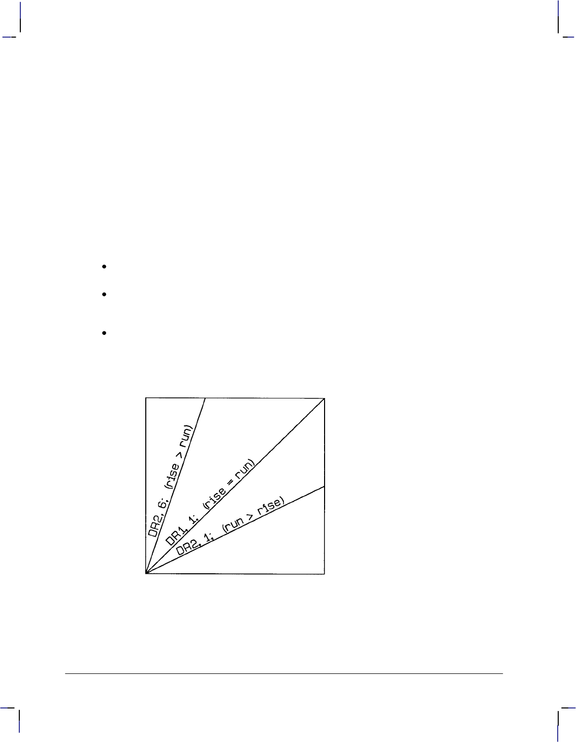
150
This is the black on page 150 (seq: 168)
Company confidential. HP-GL/2 and HP RTL Reference Guide, draft 2. Freeze Status: open
With the DR instruction, the use of run and rise is somewhat different than with DI. Run is
expressed as a percentage of the horizontal distance between P1 and P2; rise is expressed as a
percentage of the vertical distance between P1 and P2.
actual run = run parameter 100 (P2X – P1X)
actual rise = rise parameter 100 (P2Y – P1Y)
Figure 79 shows the effects of using three different sets of run and rise parameters. Notice how
the text baseline varies as the run percentage is greater than, equal to, and less than the value
for the rise.
To calculate the angle of the label, use the run and rise parameters to form a fraction that is less
than or equal to 1. It doesn’t matter whether run or rise is the numerator. For example, if
run=4 and rise=6, the fraction is 4/6; if run=6 and rise=4, the fraction is still 4/6.
The larger of the two terms determines whether the directional line intersects the top or side of
the P1/P2 area, as follows:
If run=rise, the fraction is 1, and the directional line runs from corner to corner of the
P1/P2 area. (The exact corner is determined by the sign of the parameters.)
If run>rise, the line intersects the side of the plotting area, a fraction of the way up towards
the top scaling point. For example, if P1 is in the lower-left corner, run>rise, and the
fraction is 1/2, the directional line intersects half-way up towards P2.
If run<rise, the line intersects the top of the plotting area, a fraction of the way across
towards the right scaling point. For example, if P1 is in the lower left corner, rise>run, and
the fraction is 2/6, the directional line intersects the top one-third (2/6) of the way towards
P2.
Figure 79. Effects of Different Rise/Run Parameters
If the P1/P2 rectangle is square, the DR and DI instructions have exactly the same effect. The
advantage of using the DR instruction is that, as the locations of P1 and P2 change, the slope of
the baseline changes to match the stretching or compressing of the P1/P2 rectangle. For exam-
DR Instruction
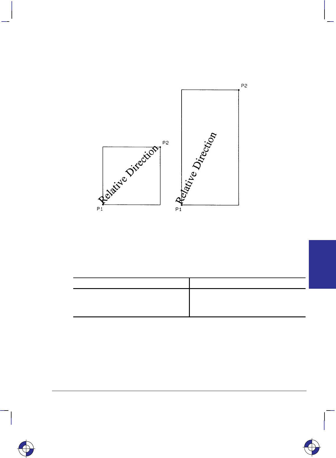
151
This is the black on page 151 (seq: 169)
Company confidential. HP-GL/2 and HP RTL Reference Guide, draft 2. Freeze Status: open
ple, if the relative direction is set so that rise=run, the slope of the baseline is 45 as long as the
P1/P2 rectangle is square. If the P1/P2 rectangle stretches so that it is twice as high as it is
wide, the slope of the baseline remains parallel to an imaginary line running from P1 to P2 (see
Figure 80).
Figure 80. Effects of P1 and P2 on Label Direction with the DR Instruction
Labels begin at the current pen location and thus are drawn parallel to the directional line, not
necessarily on it. Also, negative parameters have the same effect on direction as described for
the DI instruction.
At least one parameter must not be zero. The ratio of the parameters to each other is more im-
portant than the actual numbers. The table below lists three common label angles produced by
using ones and zeros.
DR instruction Label direction
DR 1,0; horizontal
DR 0,1; vertical
DR 1,1; (or any other equal non-zero values) diagonal from P1 to P2
The relative size and sign of the two parameters determine the amount of rotation. If you imag-
ine the current pen location to be the origin of a coordinate system for the label, you can see
that the signs of the parameters determine in which quadrant the label is in.
DR and DI Compared
DR acts like DI except that DR parameters are relative to the locations of P1 and P2. There-
fore, as shown below, for some P1/P2 orientations, positive DR parameters produce the same
effects as negative DI parameters.
This is the blue on page 151 (seq: 169)
DR Instruction
INSTRUCTIONS
HP-GL/2
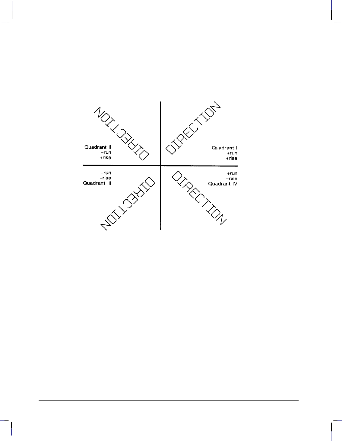
152
This is the black on page 152 (seq: 170)
Company confidential. HP-GL/2 and HP RTL Reference Guide, draft 2. Freeze Status: open
If P1 = (0, 0) and P2 = (10 000, 5 000), DR 1,1 is equivalent to DI 2,1;
If P1 = (0, 5 000) and P2 = (10 000, 0), DR 1,1 is equivalent to DI 2,–1;
If P1 = (10 000, 0) and P2 = (0, 5 000), DR 1,1 is equivalent to DI –2,1;
If P1 = (10 000, 5 000) and P2 = (0, 0), DR 1,1 is equivalent to DI –2,–1;
Figure 81. Varying Print Direction with the DR Instruction
Related Instructions
CF Character Fill Mode
CP Character Plot
DI Absolute Direction
DV Define Variable Text Path
IP Input P1 and P2
IR Input Relative P1 and P2
LB Label
SB Scalable or Bitmap Fonts
SI Absolute Character Size
SL Character Slant
SR Relative Character Size
Example
This example illustrates the use of positive and negative parameters, how the LB instruction
updates the current pen location, and how DR updates the carriage-return point.
Note that this is the same example shown with the DI instruction. The only changes are switch-
ing the DI to DR and using the 1:0 ratio instead of the sine and cosine. However, if you print
DR Instruction
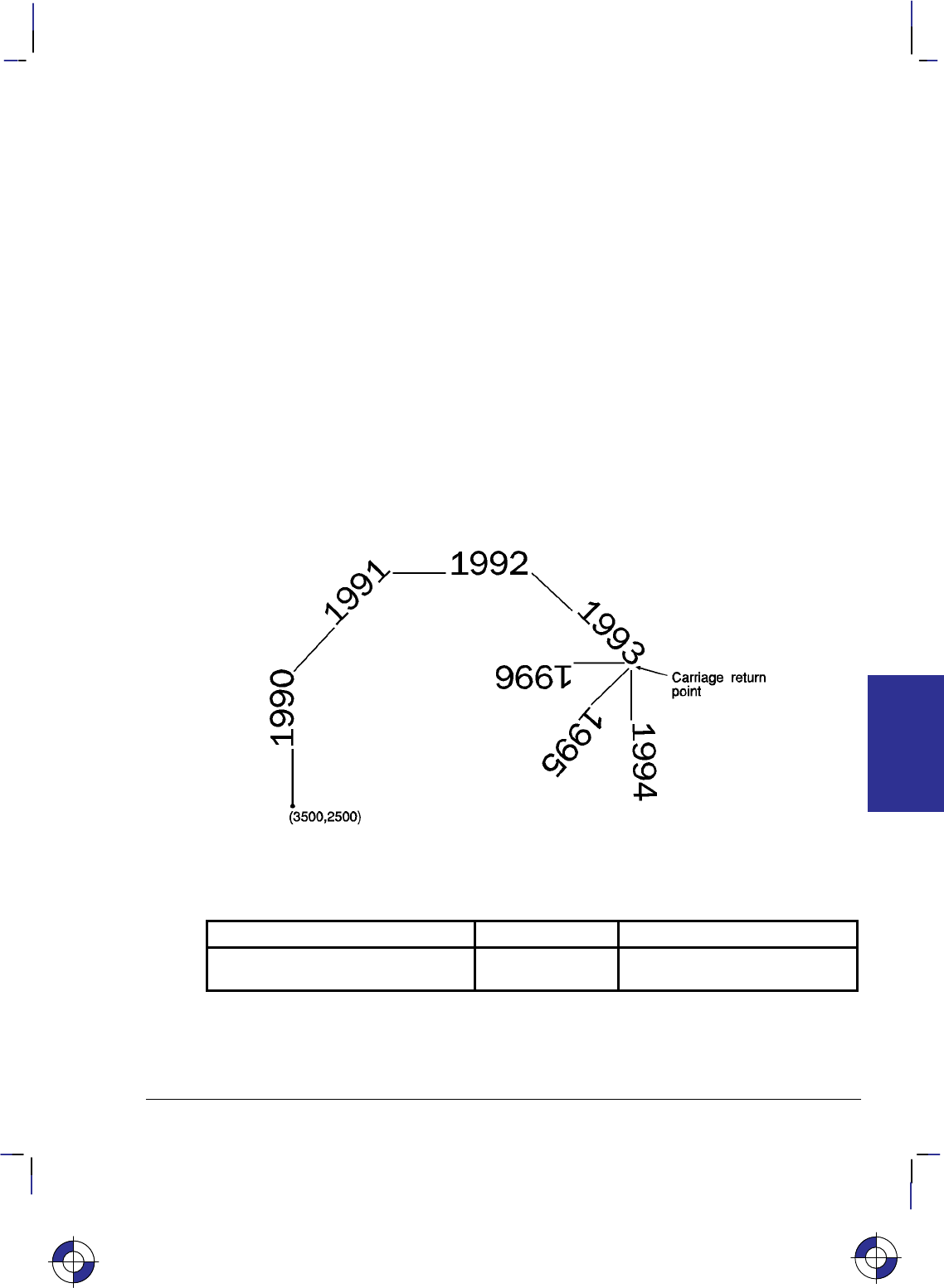
153
This is the black on page 153 (seq: 171)
Company confidential. HP-GL/2 and HP RTL Reference Guide, draft 2. Freeze Status: open
them both and measure them, you’ll discover that they are slightly different sizes. The size
difference results from the DR instruction’s use of the percentage of the P2/P1 distance.
Note; Labels begin at the current pen location and thus are drawn parallel to the directional
line, not necessarily on it.
PA 3500,2500; Specify absolute plotting and move to (3500,2500).
DT#,1; Define the “#” character as the label terminator.
DR 0,1; Set the label direction
LB____1990#; Print “____1990”.
DR 1,1; Set the label direction
LB____1991#; Print “____1991”.
DR 1,0; Set the label direction
LB____1992#; Print “____1992”.
DR 1,–1; Change the label direction
LB____1993#; Print “____1993”.
DR 0,–1; Set the label direction.
LB____1994#; Print “____1994” and Carriage Return.
DR –1,–1; Set the label direction.
LB____1995#; Print “____1995” and Carriage Return.
DR –1,0; Set the label direction.
LB____1996#; Print “____1996” and Carriage Return.
Figure 82. Using the DR (Relative Direction) Instruction with Labels
Possible Error Conditions
Error Condition Error Number Printer or Plotter Response
Both parameters = 0 or
number out of range 3Ignores instruction
This is the blue on page 153 (seq: 171)
DR Instruction
INSTRUCTIONS
HP-GL/2

154
This is the black on page 154 (seq: 172)
Company confidential. HP-GL/2 and HP RTL Reference Guide, draft 2. Freeze Status: open
DT, Define Label Terminator
Purpose
To specify the character to be used as the label terminator and whether it is printed. Use DT to
define a new label terminator if you need a different one or if your computer cannot use the
default (, decimal code 3).
Syntax
DT label_terminator[,mode];
or
DT ;
You must use a terminator (;) with this instruction.
Parameter Format Functional Range Parameter Default
label_terminator label any character except
, , , and ;
(decimal codes 0, 5, 27,
and 59 respectively)*
(decimal code 3)
mode clamped integer 0 or 1 1 (non-printing)
* If you specify a label_terminator of decimal code 0, 5, or 27, the device ignores the
instruction; the terminator remains unchanged.
Group
This instruction is in the Character Group.
Use
The character immediately following DT is interpreted to be the new label terminator. You
must terminate all LB (Label) instructions following a DT instruction with the specified label
terminator.
No Parameter: Defaults the label terminator to (not a semicolon) and the mode to
non-printing. Equivalent to “DT,1;”.
label_terminator: Specifies the label terminator as the character immediately following
the DT mnemonic. (If you use a space between the mnemonic and your intended la-
bel_terminator parameter, the space becomes the label terminator; that is why the
examples of DT in this book show no space after the instruction mnemonic, unlike most
other instructions.)
mode: Specifies whether the label terminator is printed.
0The label terminator prints if it is a printable character and performs its function if
it is a control code.
1The label terminator does not print if it is a printing character and does not per-
form its function if it is a control code. (This is the default.)
This is the blue on page 154 (seq: 172)
DT Instruction

155
This is the black on page 155 (seq: 173)
Company confidential. HP-GL/2 and HP RTL Reference Guide, draft 2. Freeze Status: open
In 16-bit mode, the label terminator and all 8-bit control codes of an LB instruction must have a
first byte set to 0. For example, and escape character (, ASCII 27) would be sent as a 0
followed by a 27. The exception is E in dual-context devices, which is parsed and executed
regardless of byte boundaries with the LB and SM instructions.
If you are using LM to label a 16-bit character set, you need to switch back to 8-bit mode for
the terminator. DT works with 8-bit terminators only; it does not work with 16-bit characters.
A DT instruction remains in effect until another DT instruction is executed, or the device is
initialized or set to default conditions.
Related Instructions
LB Label
TD Transparent Data
Examples
The following instructions show how to define and print using a non-printing label terminator:
DT#; Define “#” as the label terminator.
LBThe label terminator WILL NOT print.#; This instruction would print as:
The label terminator WILL NOT print.
This example shows how to define and use a printable label terminator:
DT#,0; Define “#” as the label terminator.
LBThe label terminator WILL print.#; This instruction would print as:
The label terminator WILL print.#
This is the blue on page 155 (seq: 173)
DT Instruction
INSTRUCTIONS
HP-GL/2

156
This is the black on page 156 (seq: 174)
Company confidential. HP-GL/2 and HP RTL Reference Guide, draft 2. Freeze Status: open
DV, Define Variable Text Path
Purpose
To specify the text path for subsequent labels and the direction of Line Feeds as either right,
left, up, or down. Use DV to “stack” characters in a column.
Syntax
DV path[,line][;]
or
DV [;]
Parameter Format Functional Range Parameter Default
path clamped integer 0, 1, 2, or 3 0 (horizontal)
line clamped integer 0 or 1 0 (normal Line Feed)
Group
This instruction is in the Character Group.
Use
The DV instruction determines the text path, the direction that the current location moves after
each character is drawn and the direction that the carriage-return point moves when a Line Feed
is included in the label string. It alters the relative positions of successive characters in a label,
but does not change the orientation of individual characters. It updates the carriage-return point
to the current pen location.
No Parameter: Defaults the text path to horizontal (not stacked) with normal Line Feed.
Equivalent to “DV0,0”.
path: Specifies the location of each character with respect to the preceding character,
relative to the labeling direction defined by the DI or DR instructions. The text path set by
DV is not affected by changes in P1 and P2.
00 (in the +X-direction). Within a label, each character begins to the right of the
previous character. This is a horizontal text path (unless altered by DI or DR).
1–90 (in the –Y-direction). Within a label, each character begins below the pre-
vious character. This is a vertical text path (unless altered by DI or DR).
2–180 (in the –X-direction). Within a label, each character begins to the left of
the previous character. This is a horizontal text path (unless altered by DI or DR).
3–270 (in the +Y-direction). Within a label, each character begins above the pre-
vious character. This is a vertical text path (unless altered by DI or DR).
For PCL printers, the path values represent paths that are to the right (0), down (1), left (2),
and up (3).
Figure 83 shows the four text paths. +X is to the right; +Y is up.
This is the blue on page 156 (seq: 174)
DV Instruction

157
This is the black on page 157 (seq: 175)
Company confidential. HP-GL/2 and HP RTL Reference Guide, draft 2. Freeze Status: open
Figure 83. Four Text Paths
line: Specifies the location of each character with respect to the preceding character,
relative to the labeling direction defined by the DI or DR instructions.
0–90 (normal Line Feed). Sets the direction of Line Feeds –90 with respect to
the text path.
Figure 84. DV Instruction Character Position for Normal (0) Parameter (+X is to
the right; +Y is up)
This is the blue on page 157 (seq: 175)
DV Instruction
INSTRUCTIONS
HP-GL/2
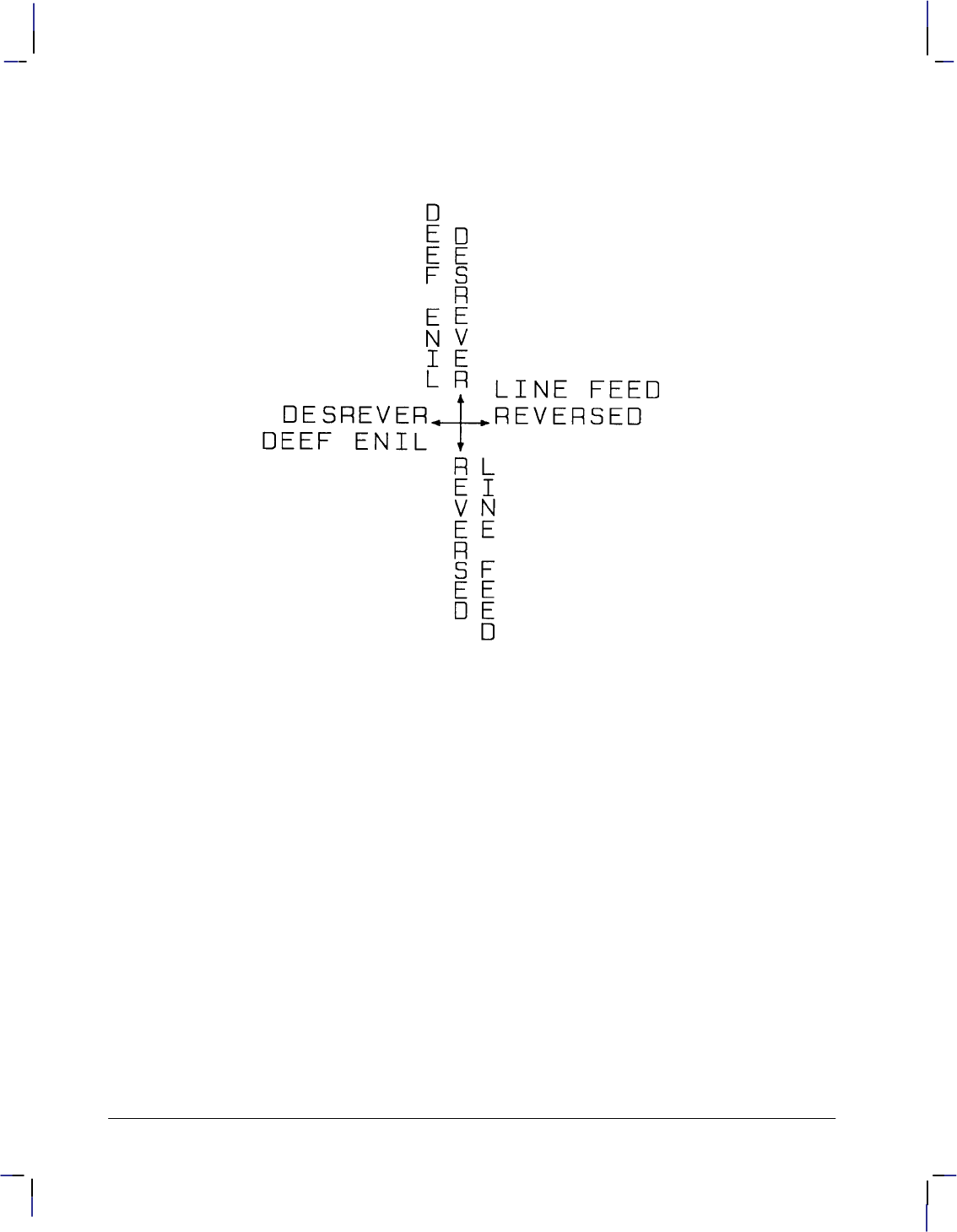
158
This is the black on page 158 (seq: 176)
Company confidential. HP-GL/2 and HP RTL Reference Guide, draft 2. Freeze Status: open
1 +90° (reversed Line Feed). Sets the direction of Line Feeds +90° with respect to
the text path.
Figure 85. DV Instruction Character Position for Reverse (1) Parameter
Note: Used with specific LO (Label Origin) settings, labels can be concatenated (see the LO
instruction ).
Related Instructions
CP Character Plot
DI Absolute Direction
DR Relative Direction
LB Label
LO Label Origin
DV Instruction
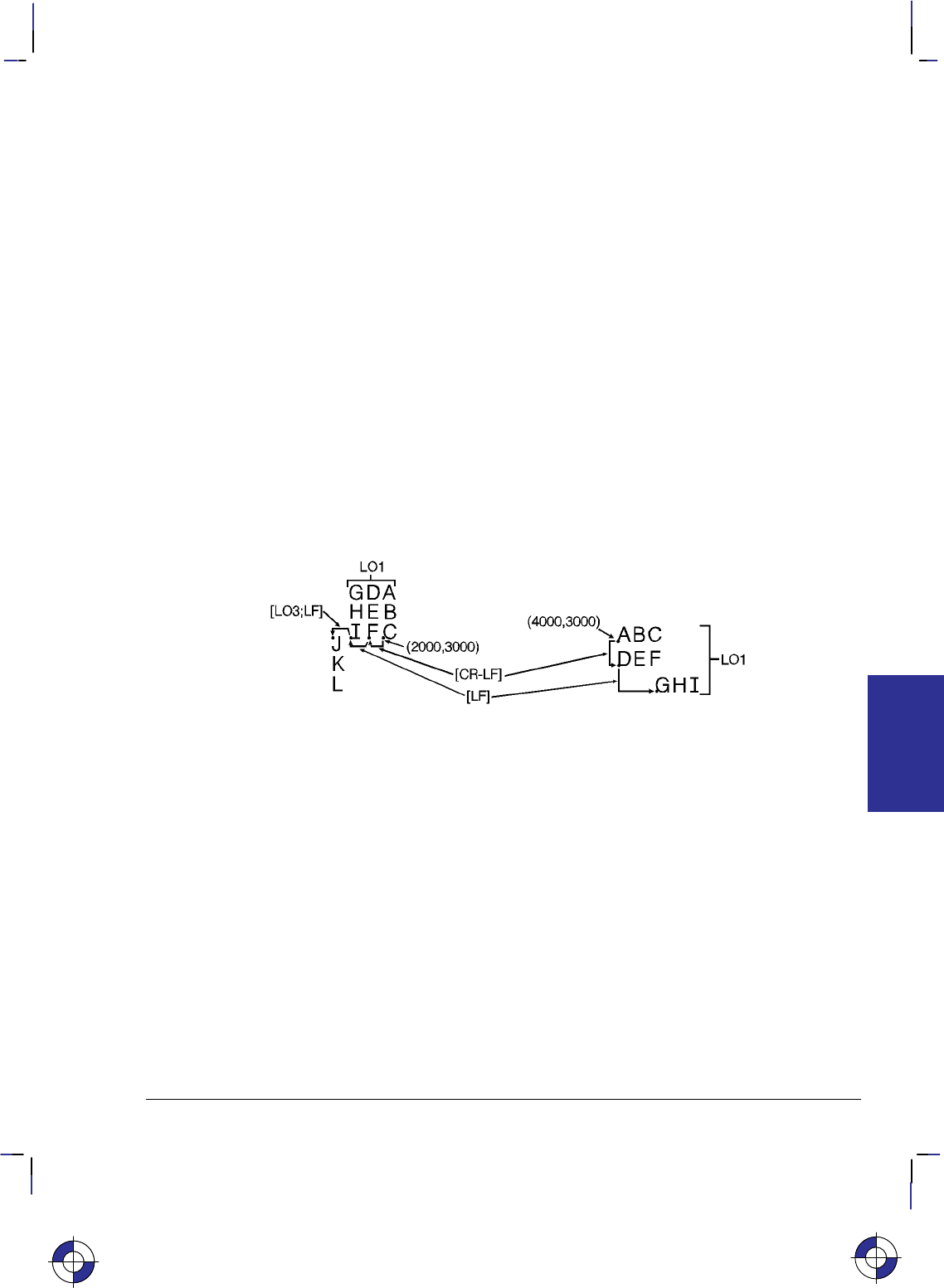
159
This is the black on page 159 (seq: 177)
Company confidential. HP-GL/2 and HP RTL Reference Guide, draft 2. Freeze Status: open
Example
The following example illustrates how Line Feeds and Carriage Returns affect vertical labels.
Horizontal labels are shown for comparison.
PA 2000,3000; Specify absolute plotting and move to (2000,3000).
DV 1; Define the text path so that each character begins below the pre-
vious character (vertical text path).
DT@; Define the “@” character as the label terminator (non-printing).
LBABC @; Print ABC, followed by a Carriage Return and Line Feed.
LBDEF@; Print DEF, followed by a Line Feed.
LBGHI@; Print GHI, followed by a Line Feed.
LO 3; Change the label origin to 3 (the default LO1 was used prior to
this).
LBJKL@ Print KJL.
LO 1; Return to the default label origin.
PA 4000,3000; Move to (4000,3000).
DV 0; Define the text path so that each character begins to the right of
the previous one (horizontal [default] text path).
LBABC @; Print ABC, followed by a Carriage Return and Line Feed.
LBDEF@; Print DEF, followed by Line Feed.
LBGHI@; Print GHI (without a Carriage Return or Line Feed).
Figure 86. Using the Define Variable Text Path (DV) Instruction with Labels
This is the blue on page 159 (seq: 177)
DV Instruction
INSTRUCTIONS
HP-GL/2
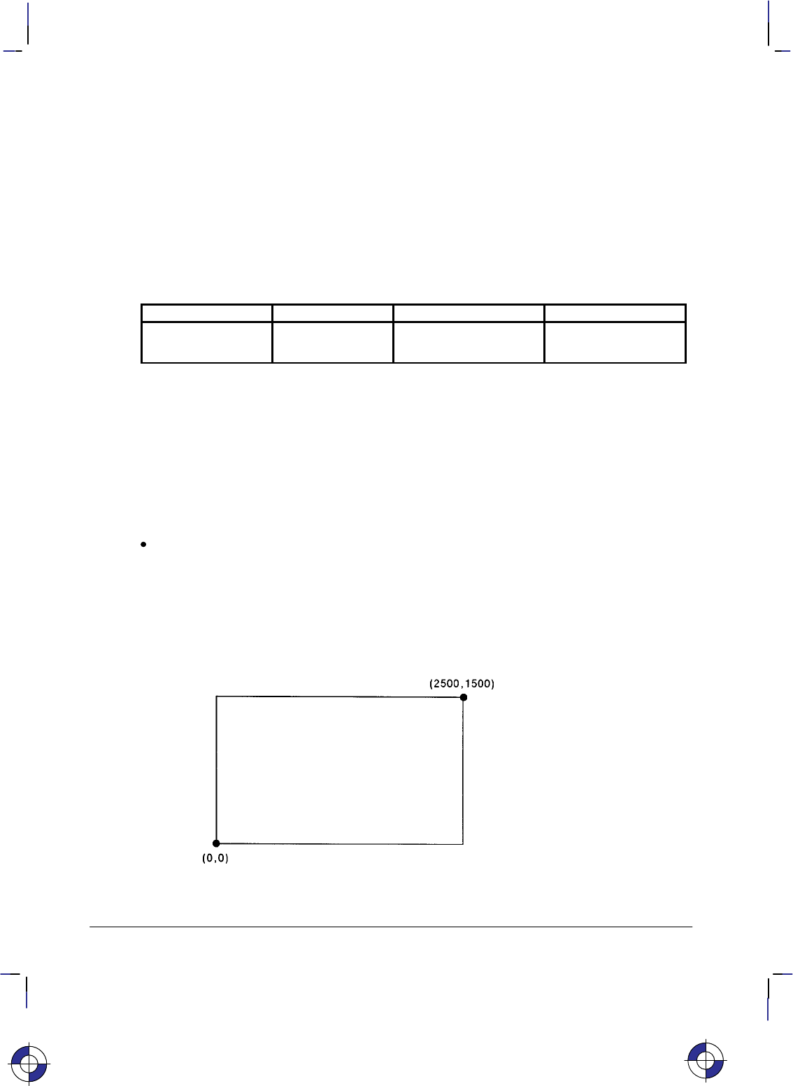
160
This is the black on page 160 (seq: 178)
Company confidential. HP-GL/2 and HP RTL Reference Guide, draft 2. Freeze Status: open
EA, Edge Rectangle Absolute
Purpose
To define and outline a rectangle using absolute coordinates. Use EA when drawing charts or
schematic diagrams that require rectangles.
Syntax
EA X,Y[;]
Parameter Format Functional Range Parameter Default
X,Y coordinates current units device-dependent
(at least –223 to 223 – 1) no default
Group
This instruction is in the Polygon Group.
Use
The EA instruction defines and edges a rectangle using absolute coordinates and the current
pen, line type and line attributes. The EA instruction performs an automatic pen down. When
the instruction execution is complete, the original pen location and up/down status are restored.
X,Y coordinates: Specify the opposite corner of the rectangle from the current pen loca-
tion. The current pen location is the starting point of the rectangle. Coordinates are
interpreted in current units: as user-units when scaling is on; as plotter-units when scaling
is off.
The following illustration shows the current pen location in the lower left corner and the
instruction’s X,Y coordinates in the upper-right corner. Depending on the coordinate values,
the points can be in any two diagonally opposite corners.
Figure 87. Simple Edged Rectangle
This is the blue on page 160 (seq: 178)
EA Instruction

161
This is the black on page 161 (seq: 179)
Company confidential. HP-GL/2 and HP RTL Reference Guide, draft 2. Freeze Status: open
Note: Any line drawn along the border of the effective window causes the line to be clipped,
producing a line width one-half of the defined pen width. For example, all the lines drawn in
the above example are half the width of the other lines since they are clipped at the window
borders.
The only difference between the EA instruction and the RA (Fill Rectangle Absolute) instruc-
tion is that the EA instruction produces an outlined rectangle, and RA, a filled one.
The EA instruction clears the polygon buffer and then uses it to define the rectangle before
drawing. Refer to Drawing Polygons on page 49 for more information.
A dot is drawn if the X,Y coordinates coincide with the current position. A line is drawn if one
of the coordinates equals the corresponding coordinate of the current position.
Related Instructions
EP Edge Polygon
ER Edge Rectangle Relative
FP Fill Polygon
LA Line Attributes
LT Line Type
PW Pen Width
RA Fill Rectangle Absolute
RR Fill Rectangle Relative
Example
The following example uses absolute coordinates to draw some rectangles. The same image is
drawn using the ER instruction instead in the example on page 167. Compare this EA example
with the ER example to understand the differences between the coordinates used (relative as
against absolute).
SC 0,150,0,150,1; Set up user scaling, with P1 being (0,0) user-units and P2 being
(150,150) user-units. (Isotropic scaling is specified.)
PA 75,105; Specify absolute plotting mode and move to (75,105).
EA 115,130; Use EA to outline the shape of a rectangle that begins at (75,105)
and has an upper right corner of (115,130) user-units.
PA 95,105;
PD 95,95; Draw a line from (95,105) to (95,95).
PD 65,95,65,90; Draw a line from the current pen location (95,95) to (65,95), and
another line from there to (65,90).
PU 45,90; Lift the pen and move to (45,90).
EA 85,65; Draw the outline of a rectangle with an upper left corner of
(45,90) and an lower right corner of (85,65).
PU 95,95; Lift the pen and move to (95,95).
PD 125,95,125,90; Lower the pen and draw a line to (125,95), then to (125,90).
PU 145,90; Lift the pen and move to (145,90).
EA 105,65; Draw the outline of a rectangle, with the upper right corner at
(145,90) and the lower left corner at (105,65).
This is the blue on page 161 (seq: 179)
EA Instruction
INSTRUCTIONS
HP-GL/2
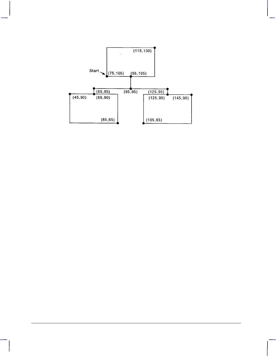
162
This is the black on page 162 (seq: 180)
Company confidential. HP-GL/2 and HP RTL Reference Guide, draft 2. Freeze Status: open
Figure 88. Using the EA (Edge Rectangle Absolute) Instruction
EA Instruction

163
This is the black on page 163 (seq: 181)
Company confidential. HP-GL/2 and HP RTL Reference Guide, draft 2. Freeze Status: open
EC, Enable Cutter
Purpose
To enable or disable the automatic cutter function on your device. Not all devices have an au-
tomatic cutter.
Syntax
EC n[;] or
EC [;]
Parameter Format Functional Range Parameter Default
nclamped integer –32 768 to 32 767 no parameter
(enabled)
Group
This instruction is in the Technical Graphics Extension.
Use
If the cutter is enabled, cutting is done after each PG and RP instruction. Roll-feed devices that
do not have a cutter may draw a line where the media should be cut.
No parameters: Enables the cutter function. This is the default condition.
n: Disables the cutter function. This may be any number (a clamped integer) in the
device’s range.
This is the blue on page 163 (seq: 181)
EC Instruction
INSTRUCTIONS
HP-GL/2

164
This is the black on page 164 (seq: 182)
Company confidential. HP-GL/2 and HP RTL Reference Guide, draft 2. Freeze Status: open
EP, Edge Polygon
Purpose
To outline the polygon currently stored in the polygon buffer. Use EP to edge polygons that
you defined in polygon mode and with the Fill Rectangle and Wedge instructions (RA, RR, and
WG).
Syntax
EP [;]
Group
This instruction is in the Polygon Group.
Use
The EP instruction outlines any polygon that is currently in the polygon buffer. This includes
wedges and rectangles defined using the EA, ER, EW, RA, RR, and WG instructions. EP ac-
cesses the data in the polygon buffer, but does not clear the buffer or change the data in any
way.
The EP instruction only edges between points that were defined with the pen down, using the
current pen, line type and attributes. When the instruction execution is complete, the original
pen location and up/down status are restored.
EP is ignored in polygon mode (after “PM0” and before “PM2”) or whenever the buffer is
empty.
Related Instructions
EA Edge Rectangle Absolute
ER Edge Rectangle Relative
EW Edge Wedge
LA Line Attributes
LT Line Type
PM Polygon Mode
PW Pen Width
RA Fill Rectangle Absolute
RR Fill Rectangle Relative
WG Fill Wedge
This is the blue on page 164 (seq: 182)
EP Instruction

165
This is the black on page 165 (seq: 183)
Company confidential. HP-GL/2 and HP RTL Reference Guide, draft 2. Freeze Status: open
Example
The following example creates a shape in polygon mode, then uses EP to outline it.
PA 2000,10; Specify absolute plotting and move to position (2000,10).
PM 0; Enter polygon mode.
PD 10,2000,10,10,2000,10; Store a pen down instruction, and then store points (10,2000),
(10,10), and (2000,10).
PM 1; Close the polygon.
PU 610,610; While still in polygon mode, lift the pen and move to (610,610).
CI 500; Draw a circle with a diameter of 500 plotter-units.
PM 2; Close the current subpolygon and exit polygon mode.
EP ; Outline the polygon that was just stored in the polygon buffer.
Figure 89. Using the EP (Edge Polygon) Instruction
This is the blue on page 165 (seq: 183)
EP Instruction
INSTRUCTIONS
HP-GL/2
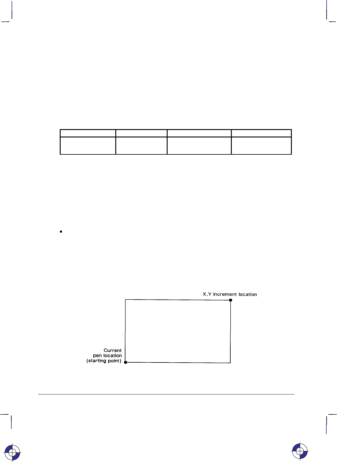
166
This is the black on page 166 (seq: 184)
Company confidential. HP-GL/2 and HP RTL Reference Guide, draft 2. Freeze Status: open
ER, Edge Rectangle Relative
Purpose
To define and outline a rectangle using relative coordinates. Use ER when drawing charts or
schematic diagrams that require rectangles.
Syntax
ER X,Y[;]
Parameter Format Functional Range Parameter Default
X,Y increments current units device-dependent
(at least –223 to 223 – 1) no default
Group
This instruction is in the Polygon Group.
Use
The ER instruction defines and edges a rectangle using relative coordinates and the current pen,
line type, and line attributes. The ER instruction includes an automatic pen down. When the
instruction operation is complete, the original pen location and up/down status are restored.
X,Y increments: Specify the opposite corner of the rectangle from the current pen loca-
tion. The current pen location is the starting point of the rectangle. Increments are
interpreted in current units: as user-units when scaling is on; as plotter-units when scaling
is off.
Note: The following illustration shows the current pen location in the lower left corner and the
instruction’s X,Y increment location in the upper right corner. When you draw a rectangle,
these points can be in any two diagonally opposite corners.
Figure 90. ER (Edge Rectangle Relative) Instruction
This is the blue on page 166 (seq: 184)
ER Instruction

167
This is the black on page 167 (seq: 185)
Company confidential. HP-GL/2 and HP RTL Reference Guide, draft 2. Freeze Status: open
The only difference between the ER instruction and the RR (Fill Relative Rectangle) instruction
is that the ER instruction produces an outlined rectangle, and RR, a filled one.
The ER instruction clears the polygon buffer and then uses it to define the rectangle before
drawing. Refer to Using the Polygon Buffer on page 45 for more information.
A dot is drawn if both X and Y coordinates are zero. A line is drawn if one of the coordinates
is zero.
Related Instructions
EA Edge Rectangle Absolute
EP Edge Polygon
FP Fill Polygon
LA Line Attributes
LT Line Type
PW Pen Width
RA Fill Rectangle Absolute
RR Fill Rectangle Relative
Example
The following example uses relative coordinates to draw the same image shown in the EA
instruction example. Compare this example with the EA example to understand the differences
between the coordinates used.
SC 0,150,0,150,1; Specify user scaling, with P1 being (0,0) and P2 (150,150); the
“1” indicates isotropic scaling.
PA 75,105; Enter absolute plotting mode and move to (75,105).
ER 40,25; Draw a rectangle using the current pen location as the lower left
corner and a point (40,25) user-units away as the upper right cor-
ner.
PR 20,0; Specify relative plotting and move the pen 20 user-units to the
right.
PD 0,–10; Place the pen down and draw a line to a point 10 user-units down.
PD –30,0,0,–5; With the pen down, move 30 user-units to the left and 5 units
down.
PU –20,0; Lift the pen and move 20 user-units to the left.
ER 40,–25; Draw the outline of a rectangle with the current pen location as
one corner and a point (40,–25) user-units away as the opposite
corner.
PU 50,5; Lift the pen and move 50 user-units to the right and 5 units up.
PD 30,0, 0,–5; Place the pen down and draw a line 30 user-units to the right, then
5 units down.
PU 20,0; Lift the pen and move 20 user-units to the right.
ER –40,–25; Draw a rectangle from that point, with the current pen location
being one corner and the opposite corner being 40 user-units to the
left and 25 units down.
This is the blue on page 167 (seq: 185)
ER Instruction
INSTRUCTIONS
HP-GL/2

168
This is the black on page 168 (seq: 186)
Company confidential. HP-GL/2 and HP RTL Reference Guide, draft 2. Freeze Status: open
Figure 91. Using the ER (Edge Rectangle Relative) Instruction
ER Instruction

169
This is the black on page 169 (seq: 187)
Company confidential. HP-GL/2 and HP RTL Reference Guide, draft 2. Freeze Status: open
ES, Extra Space
Purpose
To adjust the space between characters and lines of labels without affecting the character size.
Syntax
ES width[,height][;]
or
ES [;]
Parameter Format Functional Range Parameter Default
width clamped real –32 768 to 32 767 0
height clamped real –32 768 to 32 767 0
Group
This instruction is in the Character Group.
Use
The device interprets the parameters as follows:
No Parameters: Defaults the spaces and lines between characters to no extra space.
Equivalent to “ES0,0”.
width: Specifies an increase (positive number) or decrease (negative number) in the space
between characters. The width parameter is a fraction of the character plot cell width. For
example, “ES.15” under default conditions causes the CP cell width to increase by 15%
(1.15 its current width). Character images are not supported by ES. For maximum
legibility, do not specify more than one extra space or subtract more than half a space.
height: Specifies an increase (positive number) or decrease (negative number) in the space
between lines. The height parameter is a fraction of the line feed height of the character
plot cell. For maximum legibility, do not specify more than two extra lines, or subtract
more than half a line.
For proportionally spaced fonts, the ES percentage applies to each individual character cell;
therefore cell size varies from character to character.
An ES instruction remains in effect until another ES instruction is executed, or until the device
is initialized or set to default conditions.
Related Instructions
CP Character Plot
LB Label
This is the blue on page 169 (seq: 187)
ES Instruction
INSTRUCTIONS
HP-GL/2
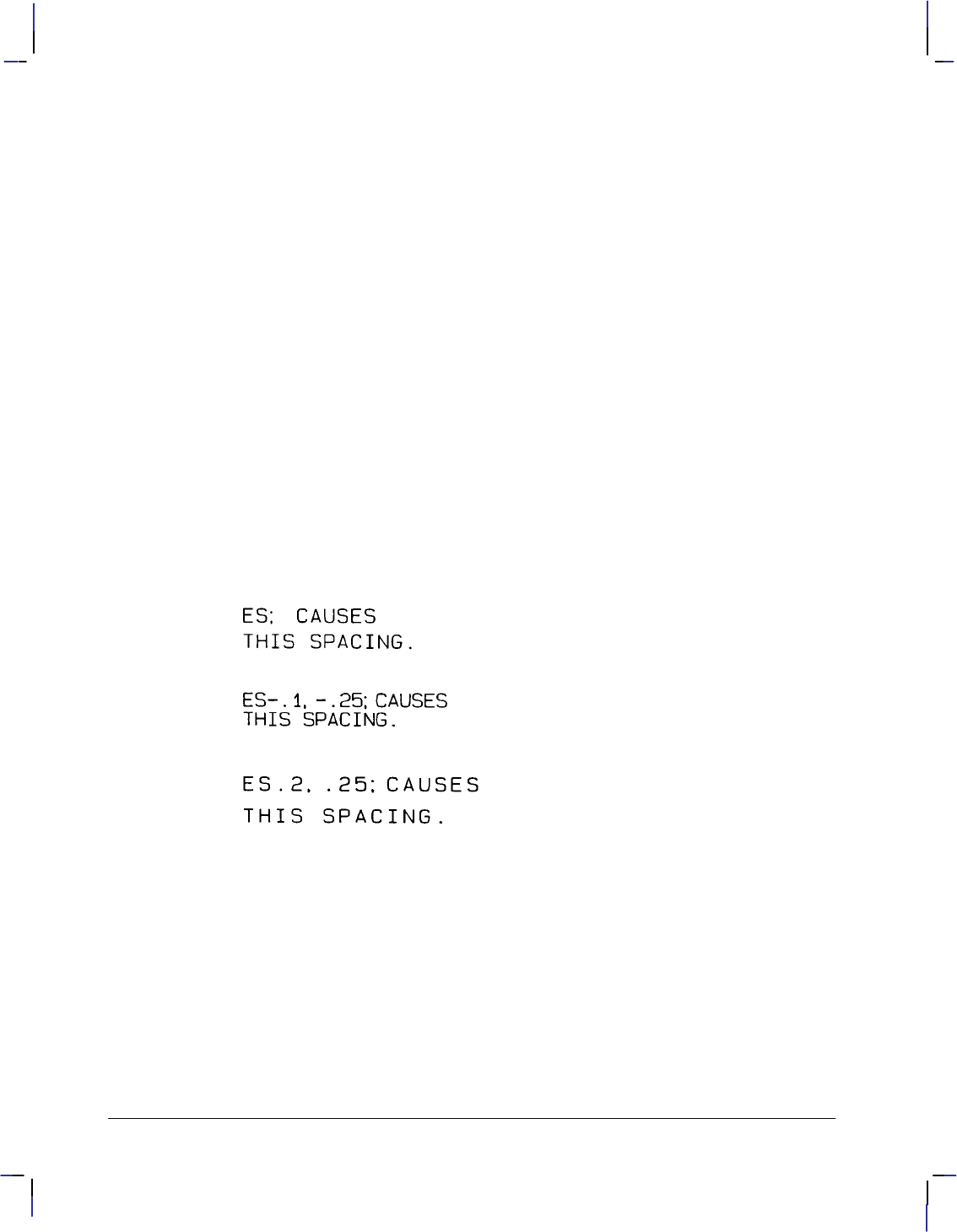
170
This is the black on page 170 (seq: 188)
Company confidential. HP-GL/2 and HP RTL Reference Guide, draft 2. Freeze Status: open
Example
PA 2500,3200; Specify absolute plotting and move to (2500,3200).
SI .187,.269; Specify a relative character size of .187 cm wide by .269 cm
high.
DT#; Define the “#” character as the label terminator.
ES ; Set the extra space setting to default (no extra space).
LBES; CAUSES#; Print “ES; CAUSES”.
CP ; Send a CP instruction as a
LBTHIS SPACING.#; and print “THIS SPACING.”
PA 2500,2500; Move to (2500,2500).
ES –.1,–.25; Decrease the inter-character spacing by .1 and the inter-line spac-
ing by 0.25.
LBES–.1,–.25; CAUSES#; Print “ES–.1,–.25; CAUSES”.
CP ; Send CP in place of ,
LBTHIS SPACING.#; and print “THIS SPACING.”
PA 2500,1800; Move to (2500,1800).
ES .2,.25; Increase the inter-character spacing by .2 and the inter-line spac-
ing by .25 of the Space control code.
LBES.2,.25; CAUSES#; Print “ES.2,.25; CAUSES”.
CP ; Send CP in place of ,
LBTHIS SPACING.#; and print “THIS SPACING.”
Figure 92. Adding Extra Space to Labels
ES Instruction

171
This is the black on page 171 (seq: 189)
Company confidential. HP-GL/2 and HP RTL Reference Guide, draft 2. Freeze Status: open
EW, Edge Wedge
Purpose
To outline any wedge. Use EW to draw sections of pie charts.
Syntax
EW radius,start_angle,sweep_angle,[,chord_angle][;]
Parameter Format Functional Range Parameter Default
radius current units device-dependent
(at least –223 to 223 – 1) no default
start_angle clamped real –32 768 to 32 767
(modulo 360) no default
sweep_angle clamped real –360° to +360°no default
chord_angle* clamped real 0.0° to 360°device-dependent
(usually 5°)
* If you have used the “CT1” instruction, the chord_angle is interpreted as a deviation dis-
tance in current units; see the CT instruction on page 133.
Group
This instruction is in the Polygon Group.
Use
The EW instruction defines and edges a wedge using the current pen, line type and attributes.
The EW instruction includes an automatic pen down. When the instruction execution is com-
plete, the original pen location and up/down status are restored.
EW deletes any stored polygon and stores the wedge in the polygon buffer with an implicit pen-
down that overrides any explicit pen-up (PU); therefore the wedge may be subsequently filled
by FP or re-edged by EP.
If the wedge has more points than will fit in the polygon buffer, the portion of the wedge that
fits in the buffer is closed and edged, and the remainder of the wedge is discarded.
The only difference between the EW instruction and the WG (Fill Wedge) instruction is that the
EW instruction produces an outlined wedge, and the WG instruction, a filled one.
Always use isotropic scaling in drawings that contain wedges unless you wish the wedges to
“stretch” with changes in the aspect ratio of the drawing (causing elliptical wedges). For more
information, refer to the discussion of scaling and the Scale (SC) instruction on page 290.
This is the blue on page 171 (seq: 189)
EW Instruction
INSTRUCTIONS
HP-GL/2
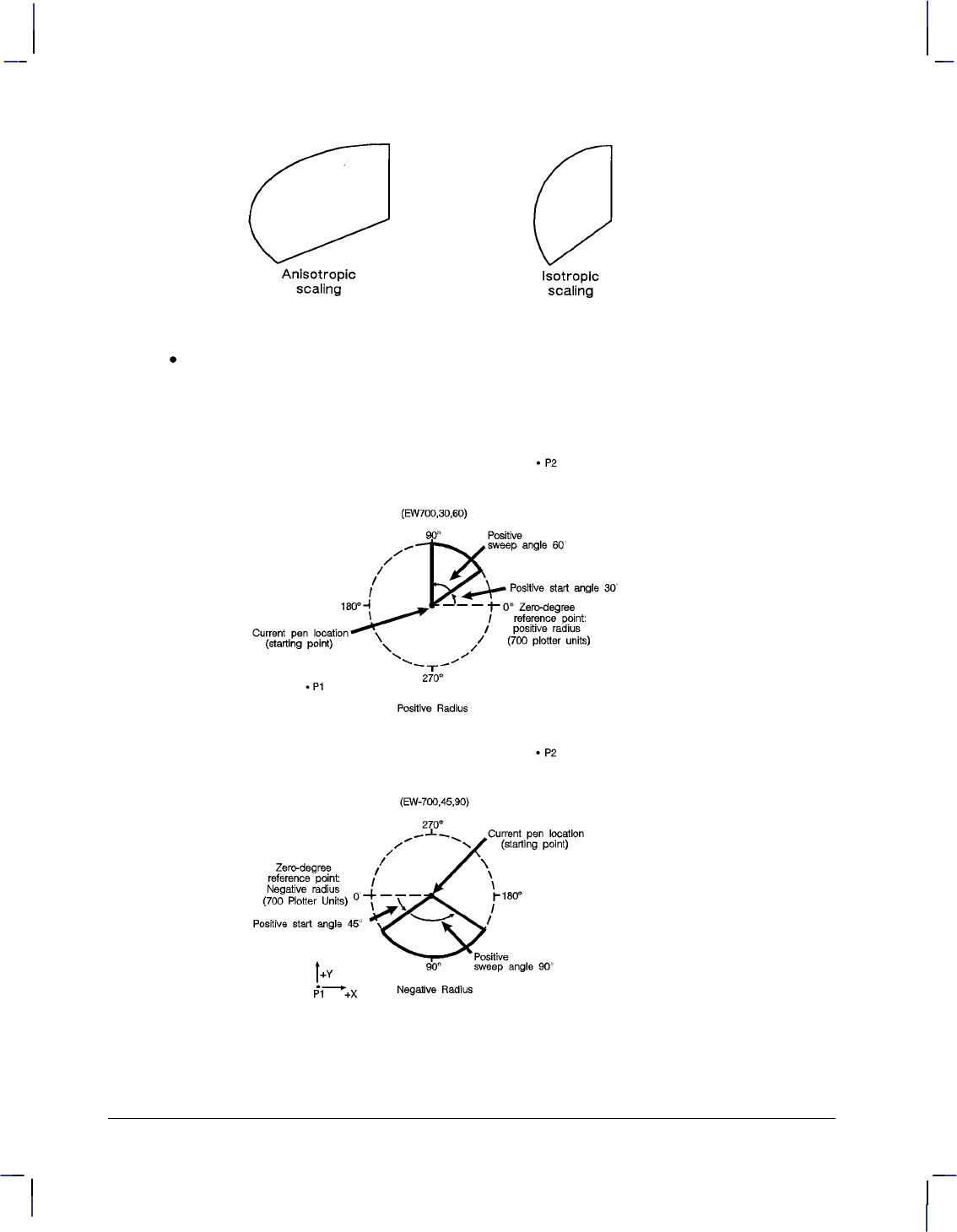
172
This is the black on page 172 (seq: 190)
Company confidential. HP-GL/2 and HP RTL Reference Guide, draft 2. Freeze Status: open
Figure 93. Anisotropic and Isotropic Scaling of Wedges
radius: Specifies the distance from the current pen location to the start of the wedge’s arc.
Since the wedge is a portion of a circle, this parameter is the radius of the circle. It speci-
fies the distance from the current pen location (which becomes the center of the circle), to
any point on the circumference of the circle.
Figure 94. Wedges with Positive and Negative Radii
The radius is interpreted in current units: as user-units when scaling is on; as plotter-units
when scaling is off. The sign (positive or negative) of the radius determines the location of
the zero-degree reference point. Figure 94 shows the location of the zero-degree reference
EW Instruction

173
This is the black on page 173 (seq: 191)
Company confidential. HP-GL/2 and HP RTL Reference Guide, draft 2. Freeze Status: open
point for a positive and negative radius. The X- and Y-axes are to the right and upwards
respectively.
start_angle: Specifies the beginning point for the arc as the number of degrees from the
zero-degree reference point. A positive start angle positions the radius counter-clockwise
from the zero-degree reference point. A negative start angle positions the radius clockwise
from the zero-degree reference point. Counter-clockwise is considered the direction from
the positive X-axis towards the positive Y-axis of the coordinate system. Changes to
orientation, P1 and P2 locations, and scaling can each have an effect on the direction of
rotation.
sweep_angle: Specifies the number of degrees through which the arc is drawn. A positive
sweep angle is in the direction of the +X-axis to the +Y-axis; a negative sweep angle is in
the direction of the +X-axis to the –Y-axis. However, the relative position of the +X-axis
to the +Y-axis can change as a result of scaling point or scaling factor changes, thus,
changing the direction of the sweep angle. Angles with absolute values greater than 360
have their signs preserved, and they are bounded to 360. If the sweep angle is 360
after bounding, no radius is drawn.
chord_angle: Specifies the chord angle used to draw the arc. Refer to the Arc Absolute
(AA) instruction discussion on page 100 for further information on chords and chord
angles.
A zero radius draws a dot at the current position; a zero sweep angle draws a line from the cur-
rent position to the start of the wedge’s arc.
Related Instructions
CI Circle
CT Chord Tolerance Mode
EP Edge Polygon
FP Fill Polygon
LA Line Attributes
LT Line Type
PW Pen Width
SC Scale
WG Fill Wedge
Possible Error Conditions
Error Condition Error Number Printer or Plotter Response
Polygon buffer overflow 7 Edges contents of buffer
This is the blue on page 173 (seq: 191)
EW Instruction
INSTRUCTIONS
HP-GL/2
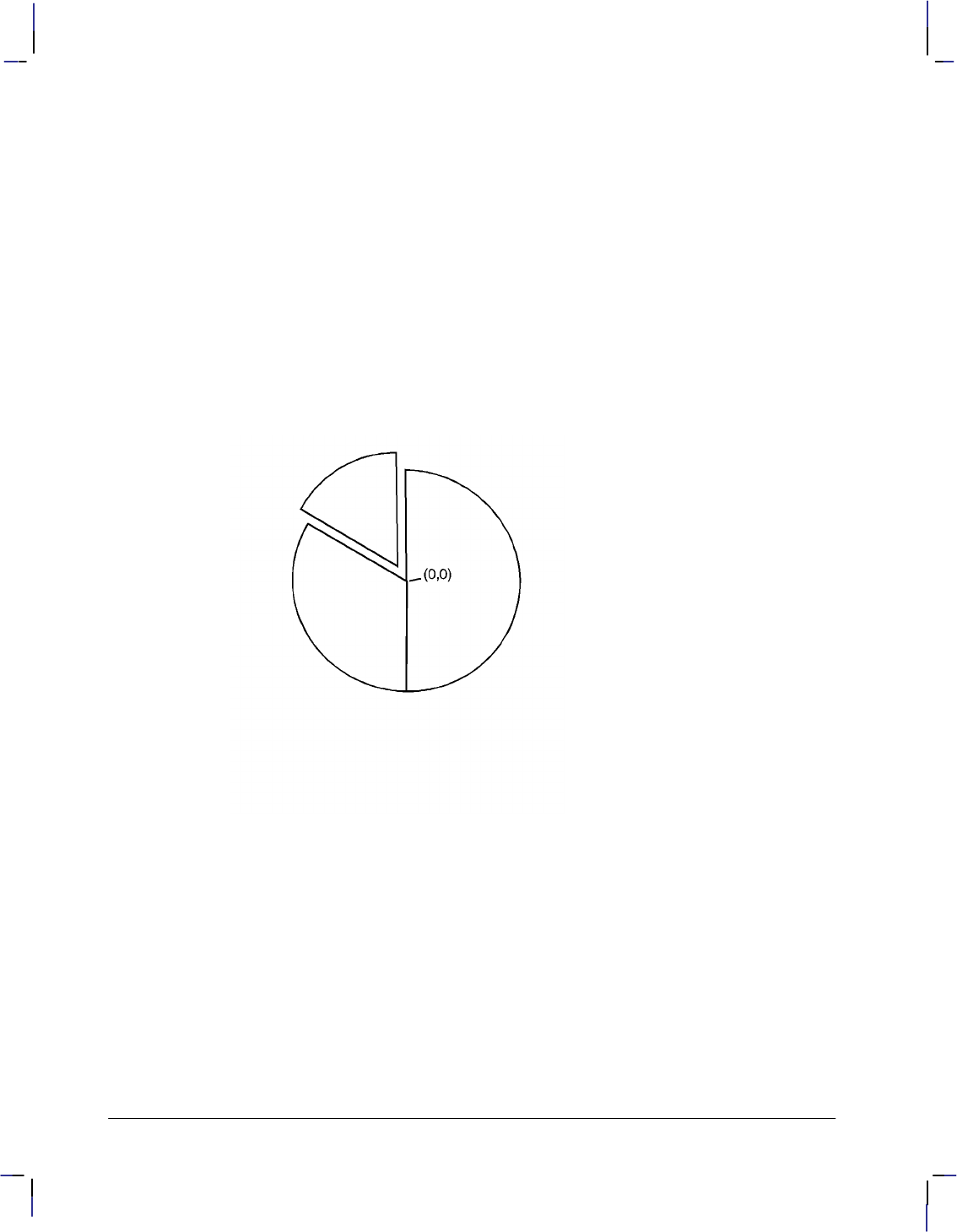
174
This is the black on page 174 (seq: 192)
Company confidential. HP-GL/2 and HP RTL Reference Guide, draft 2. Freeze Status: open
Example
SC –3000,3000,–2000,2000,1; Enter the scaling mode, specifying P1 as (–3000,–2000)
and P2 as (3000,2000). Use isotropic scaling.
PA 0,0; Specify absolute plotting and move to user-unit location (0,0).
EW –1000,90,180; Draw a wedge section with a radius of 1000 user-units, a start
angle of 90, and a sweep angle of 180. The minus sign before
the radius (–1000) sets the zero-degree reference point to the left
side of the drawing.
EW –1000, 330,120; Using the same center point and zero-degree reference point, draw
a wedge section outline starting at 330 and sweeping 120.
PR –60,110; Move the cursor 60 user-units to the left and 110 user-units up.
EW –1000,270,60; From the new center point location, draw a wedge using a nega-
tive zero-reference point, starting at 270 degrees and sweeping for
60.
Figure 95. A Simple Pie Chart
EW Instruction
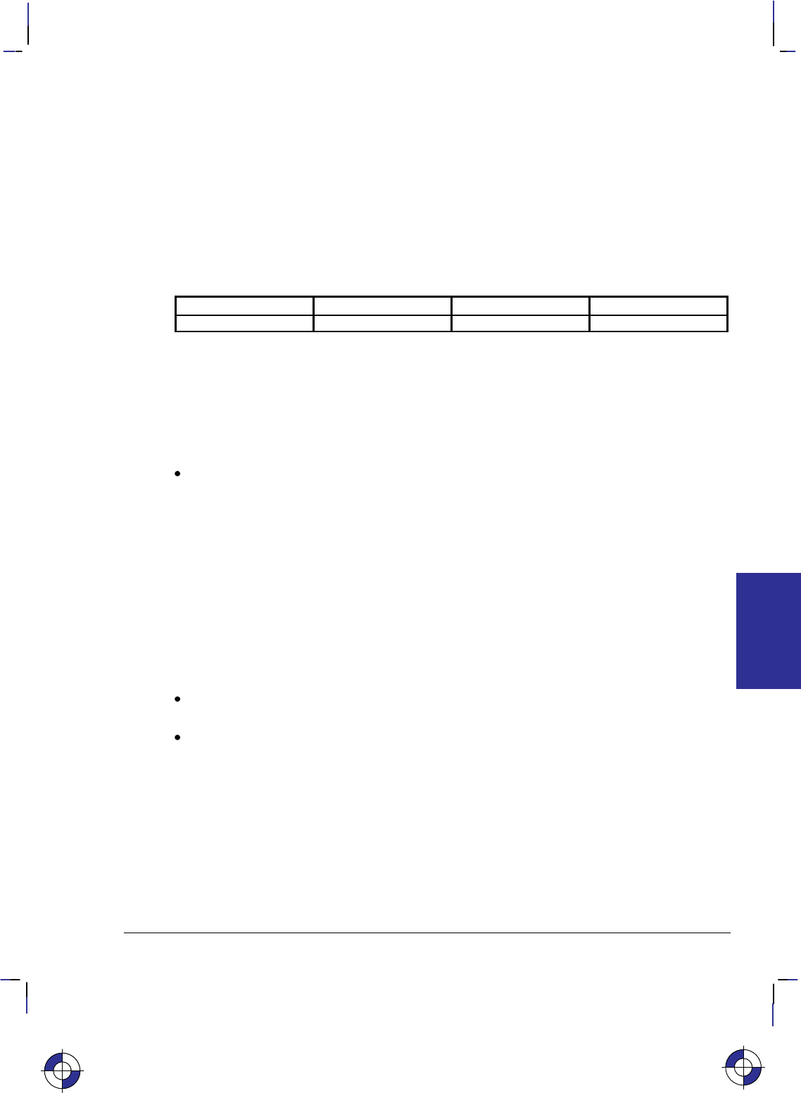
175
This is the black on page 175 (seq: 193)
Company confidential. HP-GL/2 and HP RTL Reference Guide, draft 2. Freeze Status: open
FI, Primary Font Selection by ID
Purpose
To designate any font that has been assigned a font ID as the primary (standard) font. Font IDs
are assigned in the PCL environment.
Syntax
FI font_ID[;]
Parameter Format Functional Range Parameter Default
font_ID integer 0 to 32767 no default
Group
This instruction is in the Dual-Context Extension for PCL-devices only. HP RTL does not have
any support for fonts.
Use
font_ID: A non-negative integer assigned in the PCL environment. If the designated font
is present, the primary font attributes are set to those of the selected font. If the selected
font is proportionally spaced, the pitch attribute is not changed. The instruction is ignored
if no font exists with the specified ID.
This instruction allows any accessible font that has been assigned a font_ID number to be se-
lected as the primary (standard) font (the font characteristics are assigned to the standard font).
As mentioned, the font must be accessible to the device as either a resident font, a downloaded
font, or a loaded cartridge font. To be selected, the font must have been previously assigned a
font ID number in PCL mode. Also, for scalable fonts, the FI instruction must be preceded by
an SD instruction specifying the font’s point size or pitch (see the example below).
When the device receives this instruction and the requested font is present, the primary font
characteristics are set to those of the requested font. If the selected font is proportionally
spaced, the pitch characteristic is not changed.
This instruction does not select the font for label printing if you are currently using the
alternate font.
The FI instruction implicitly changes the value of SB. For example, if “SB0;” is in effect
and FI selects a bitmap font, SB is set to 1. This affects the performance of certain HP-
GL/2 instructions. Refer to the SB instruction on page 288.
Related Instructions and Commands
AD Alternate Font Definition
FN Secondary Font Selection by ID
LB Label
SA Select Alternate Font
SB Scalable or Bitmap Fonts
SD Standard Font Definition
SS Select Standard Font
This is the blue on page 175 (seq: 193)
FI Instruction
INSTRUCTIONS
HP-GL/2

176
This is the black on page 176 (seq: 194)
Company confidential. HP-GL/2 and HP RTL Reference Guide, draft 2. Freeze Status: open
(#X Select Primary Font by ID #
)#X Select Secondary Font by ID #
*c#D Font ID
*c#F Font Control
(The commands that begin with are PCL commands.)
Example
The following example demonstrates assigning a font ID number from within PCL mode, enter-
ing HP-GL/2 mode, using the FI instruction to select that font, and printing a short line of text.
*c15D Specify a font ID number of 15.
(s1p18v0s3b52T Select an 18-point Univers Bold font as the primary font.
*c6F Assign the currently selected font as a temporary font with the
current ID number (15).
%0B Enter HP-GL/2 mode.
IN ; Initialize HP-GL/2 mode.
SP 1; Select pen number 1.
PA 1500,1500; Move to location (1500,1500).
DT#; Define “#” as a label terminator (non-printing).
LBLaserJet Printers #; Print “LaserJet Printers” in the currently selected font, which is
the default stick font; Carriage Return/Line Feed. (Note, label
text should not contain carriage-returns or any control codes un-
less specifically desired for plotting.)
SD 4,18; Use the SD instruction to designate an 18-point font from within
HP-GL/2 mode.
FI 15; Then select the PCL font with font ID number of 15 as the prima-
ry font.
SS Then select the primary font for printing.
LBLaserJet Printers#; Print “LaserJet Printers” in the newly selected font.
Figure 96. Printing Labels Using the Primary Font
FI Instruction

177
This is the black on page 177 (seq: 195)
Company confidential. HP-GL/2 and HP RTL Reference Guide, draft 2. Freeze Status: open
FN, Secondary Font Selection by ID
Purpose
To designate any font that has been assigned a font ID as the secondary (alternate) font. Font
IDs are assigned in the PCL environment.
Syntax
FN font_ID[;]
Parameter Format Functional Range Parameter Default
font_ID integer 0 to 32767 no default
Group
This instruction is in the Dual-Context Extension for PCL-devices only. HP RTL does not have
any support for fonts.
Use
font_ID: A non-negative integer assigned in the PCL environment. If the designated font
is present, the secondary font attributes are set to those of the selected font. If the selected
font is proportionally spaced, the pitch attribute is not changed. The instruction is ignored
if no font exists with the specified ID.
This instruction allows any accessible font that has been assigned a font_ID number to be se-
lected as the secondary (alternate) font (the font characteristics are assigned to the secondary
font). The font must be accessible to the device as either a resident font, a downloaded font, or
a loaded cartridge font. To be selected, the font must have been previously assigned a font ID
number in PCL mode. Also, for scalable fonts, the FN instruction must be accompanied by an
AD instruction specifying the font’s point size (see the example below).
When the device receives this instruction and the requested font is present, the secondary font
characteristics are set to those of the requested font. If the selected font is proportionally
spaced, the pitch characteristic is not changed.
This instruction does not select the font for label printing if you are currently using the
standard font.
The FN instruction implicitly changes the value of SB. For example, if “SB0;” is in effect
and FN selects a bitmap font, SB is set to 1. This affects the performance of certain HP-
GL/2 instructions. Refer to the SB instruction on page 288.
Related Instructions
AD Alternate Font Definition
FI Primary Font Selection by ID
LB Label
SA Select Alternate Font
SB Scalable or Bitmap Fonts
SD Standard Font Definition
SS Select Standard Font
This is the blue on page 177 (seq: 195)
FN Instruction
INSTRUCTIONS
HP-GL/2

178
This is the black on page 178 (seq: 196)
Company confidential. HP-GL/2 and HP RTL Reference Guide, draft 2. Freeze Status: open
(#X Select Primary Font by ID #
)#X Select Secondary Font by ID #
*c#D Font ID
*c#F Font Control
(The commands that begin with are PCL commands.)
Example
The following example demonstrates assigning a font ID number from within PCL mode, enter-
ing HP-GL/2 mode, using the FN instruction to select that font, and printing a short line of text.
*c28D Specify a font ID number of 28.
(s1p18v0s3b52T Select an 18-point Univers Bold font as the primary font.
*c6F Assign the currently selected font as a temporary font with the
current ID number (28).
%0B Enter HP-GL/2 mode.
IN ; Initialize HP-GL/2 mode.
SP 1; Select pen number 1.
PA 1500,1500; Move to location (1500,1500).
DT#; Define “#” as a label terminator (non-printing).
LBLaserJet Printers #; Print “LaserJet Printers” in the currently selected font, which is
the default stick font; Carriage Return/Line Feed.
AD 4,18; Use the AD instruction to designate an 18-point font from within
HP-GL/2 mode.
FN 28; Assign the PCL font with font ID number of 28 as the secondary
font.
SA ; Then select the font.
LBLaserJet Printers#; Print “LaserJet Printers” in the newly selected font.
Figure 97. Printing Labels Using the Secondary Font
FN Instruction

179
This is the black on page 179 (seq: 197)
Company confidential. HP-GL/2 and HP RTL Reference Guide, draft 2. Freeze Status: open
FP, Fill Polygon
Purpose
To fill the polygon currently in the polygon buffer. Use FP to fill polygons defined in polygon
mode or with the Edge Rectangle or Edge Wedge instructions (EA, ER, EW, RA, RR, or WG).
Syntax
FP fill_method [;]
or
FP [;]
Parameter Format Functional Range Parameter Default
fill_method clamped integer 0 or 1 0 (even/odd fill)
Group
This instruction is in the Polygon Group.
Use
The FP instruction fills any polygon that is currently in the polygon buffer. FP accesses the
data in the polygon buffer, but does not clear the buffer or change the data in any way.
The FP instruction fills between points defined with either the pen down or the pen up. The
polygon is filled using the current pen, fill type, line type and attributes (if the fill type is not
raster). The FP instruction includes an automatic pen down. When the instruction execution is
complete, the original pen location and up/down status are restored.
No Parameter: Uses the odd-even algorithm; same as “FP0”.
fill_method: Specifies the algorithm used to determine which portions of the polygon are
“inside” the polygon and therefore are to be filled:
0Even/odd fill algorithm (default)
1Non-zero winding fill algorithm
Note: The even/odd (method 0) and non-zero (method 1) winding fill methods are described
in detail under Filling Polygons on page 50.
The even/odd fill algorithm determines whether a given point is inside the polygon by (con-
ceptually) drawing a ray from a particular point in any direction and counting the number of
polygon segments the ray crosses. If the ray crosses an odd number of segments, the point is
inside the polygon; if the ray crosses an even number of segments, the point is outside the poly-
gon.
The two fill algorithms may yield different results depending on the complexity of the polygon
shape and the direction in which the paths are drawn. For example, in a polygon consisting of
two concentric circles, the even/odd algorithm does not fill the inner circle, regardless of the
directions in which the circles are drawn. The non-zero winding fill algorithm will fill both
circles if they are drawn in opposite directions.
This is the blue on page 179 (seq: 197)
FP Instruction
INSTRUCTIONS
HP-GL/2
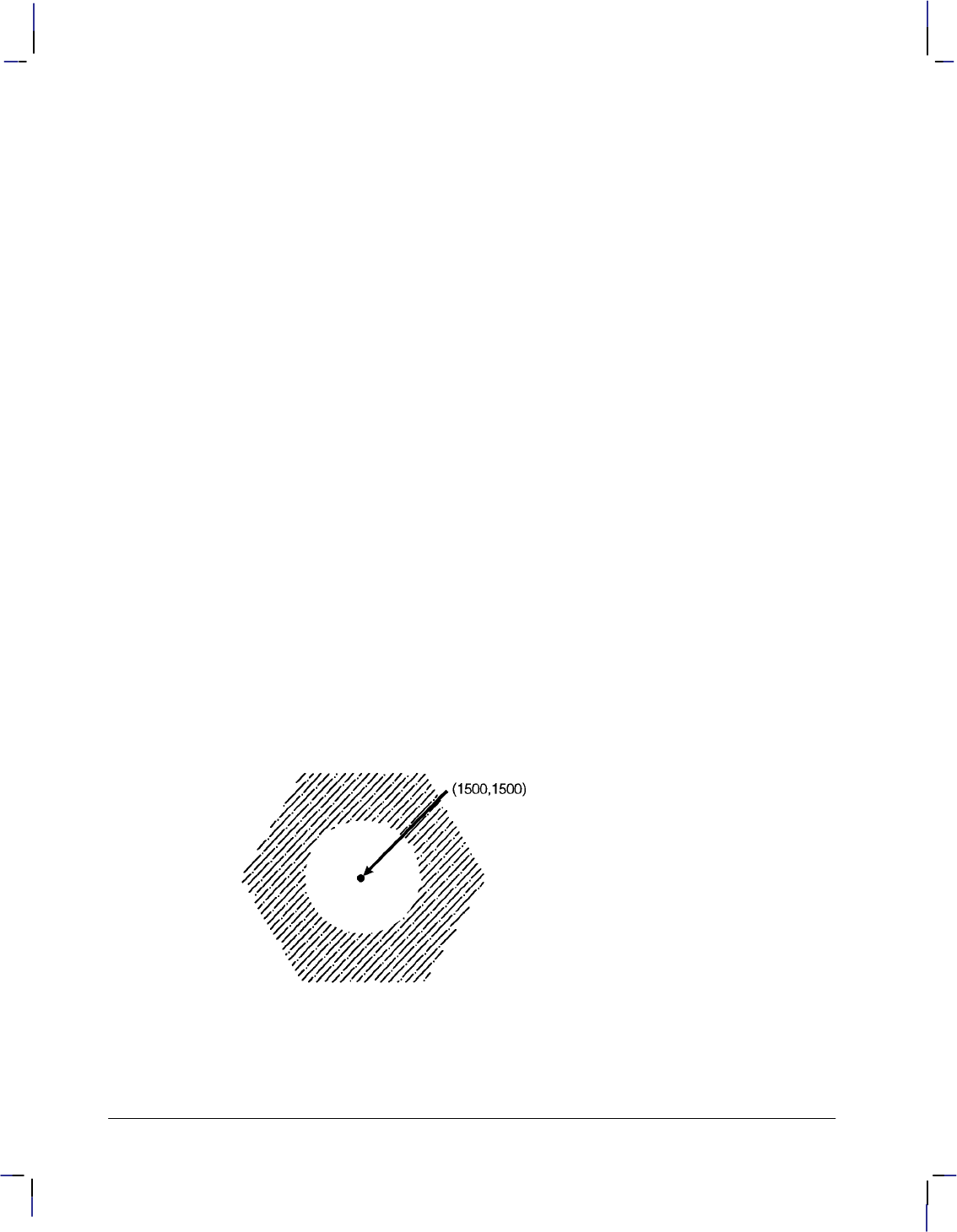
180
This is the black on page 180 (seq: 198)
Company confidential. HP-GL/2 and HP RTL Reference Guide, draft 2. Freeze Status: open
Related Instructions
EA Edge Rectangle Absolute
ER Edge Rectangle Relative
EW Edge Wedge
FT Fill Type
LA Line Attributes
LT Line Type
PM Polygon Mode
PW Pen Width
RA Fill Rectangle Absolute
RR Fill Rectangle Relative
WG Fill Wedge
Example
The example below creates a polygon composed of two subpolygons. In this case, the FP
instruction fills alternating areas, beginning with the outside area.
PA 1500,1500; Specify absolute plotting and move to (1500,1500).
PM 0; Enter the polygon mode.
CI 1000,60; Store a circle with radius of 1000 plotter-units and a 60 chord
angle.
PA 1500,1500; Store a pen move to (1500,1500),
CI 500; and another circle with a 500 plotter-units radius and a 5 (de-
fault) chord angle.
PM 2; Close the current polygon and exit polygon mode.
LT 4; Select line type 4.
FT 3,50,45; Select fill type 3. Specify a 50 plotter-units distance between the
fill lines, and slant the lines at a 45 angle.
FP ; Using even/odd fill method, fill the polygon currently in the poly-
gon buffer with the line and fill types just specified.
Figure 98. Filling a Polygon
FP Instruction

181
This is the black on page 181 (seq: 199)
Company confidential. HP-GL/2 and HP RTL Reference Guide, draft 2. Freeze Status: open
FR, Frame Advance
Purpose
To advance the media to align adjacent frames, forming the equivalent of a long-axis plot. The
device treats each frame as a separate window and plots only the data falling within that win-
dow. Using the PS (Plot Size) instruction for long-axis plotting is simpler and faster than using
FR.
Syntax
FR [;]
Group
This instruction is in the Technical Graphics Extension.
Use
FR updates the current pen location to the new plotter-unit origin, leaves the pen in the up posi-
tion, and clears the polygon buffer.
The length parameter of the PS (Plot Size) instruction determines the frame size. When
lengthwidth, the orientation is reverse landscape and each FR instruction extends the plot in
the direction of the positive X-axis. When length<width, the orientation is reverse portrait and
each FR instruction extends the plot in the direction of the positive Y-axis.
The length advanced with an FR instruction is shorter than that of a PG instruction; the margins
between the plotter areas are deleted so that the frames share a common edge.
After each frame advance, the plotter-unit origin moves to the lower-left corner of the new
frame. The physical locations of P1 and P2 are retained, but the logical locations relative to the
current origin change.
FR is ideal for use with roll-feed plotters. When using single-sheet devices, frames will share a
common edge only when complete frames will fit on the current sheet. If multiple frames will
not fit, the current page is printed and ejected. The next sheet loaded will contain the new
frame. Any device that can store an entire multi-frame plot can print multiple copies using ei-
ther the BP or RP instructions.
Note that a cut-sheet device which cannot store the entire plot can still produce multiple copies
when specified in the BP instruction; however, the user must collate the copies. In this case,
however, the RP instruction is equivalent to a PG.
Related Instructions
AC Anchor Corner
IW Input Window
PS Plot Size
This is the blue on page 181 (seq: 199)
FR Instruction
INSTRUCTIONS
HP-GL/2
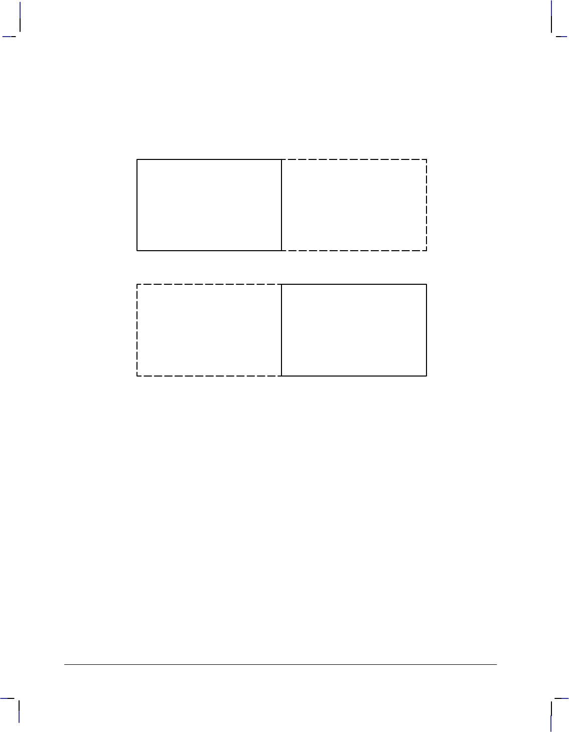
182
This is the black on page 182 (seq: 200)
Company confidential. HP-GL/2 and HP RTL Reference Guide, draft 2. Freeze Status: open
Example
In the following example, the P1/P2 values are input as
IP 0,0,20000,7200;
After sending FR, the logical values of P1 and P2 on the new frame become (–10 000,0) and
(10 000,7200) respectively.
(0,0) default P1 location
(20 000,7200) P2
Execute FR instruction
P1 (-10 000,0) (0,0)
(10 000,7200) P2
The anchor corner and window retain their coordinate values after each frame advance. If spe-
cified in user-units, they maintain their physical locations with respect to P1 and P2; if
specified in plotter-units, they shift their physical locations with the plotter-unit origin. If you
have not sent an AC or IW instruction, each frame advance defaults the anchor corner and win-
dow with respect to the hard-clip limits of the current frame.
FR Instruction

183
This is the black on page 183 (seq: 201)
Company confidential. HP-GL/2 and HP RTL Reference Guide, draft 2. Freeze Status: open
FT, Fill Type
Purpose
To select the shading pattern used to fill polygons (FP), rectangles (RA or RR), characters (CF),
or wedges (WG). Use FT to enhance plots with solid fill, parallel lines (hatching), cross-hatch-
ing, or patterned (raster) fill.
Syntax
FT fill_type[,option1[,option2]][;]
or
FT [;]
Parameter Format Functional Range Parameter Default
fill_type clamped integer 1, 2, 3, 4, 10, 11, 21, 22 1
option1, option2 clamped real fill_type-dependent* fill_type-dependent*
* Refer to the table following the parameter descriptions.
Group
This instruction is in the Line and Fill Attributes Group.
Use
There are six base forms of fill type, and additional ones for devices that support the dual-con-
text environment—see page 83. The fill_type parameter tells the device which form you are
using.
No parameters: equivalent to “FT1”—the fill type is solid.
fill_type: selects the fill pattern. It is a clamped integer whose value is restricted to those
given in the table below, which lists the option parameter values and the corresponding
fill_types.
option1 and option2: When the option parameters are omitted, the device uses the last
specified parameters for that fill type. For example, if you specified fill_type 3 with line
spacing and angle parameters, then switched to fill_type 4 without specifying any line
parameters, the device would draw fill type 4 with default line spacing and angles because
they have not yet been specified for that fill type. If you then switched back to fill type 3,
you would not need to respecify the line spacing and angle parameters because the device
would use the values previously specified for the fill type 3 instruction.
The ranges (clamped real values) and definitions of these optional parameters depends on
the type of fill selected, as follows:
This is the blue on page 183 (seq: 201)
FT Instruction
INSTRUCTIONS
HP-GL/2
184
This is the black on page 184 (seq: 202)
Company confidential. HP-GL/2 and HP RTL Reference Guide, draft 2. Freeze Status: open
Fill_type Description Option1 Option2 Note
1solid bidirectional (ignored) (ignored) 1
2 solid unidirectional (ignored) (ignored) 1
3 hatched (parallel lines) spacing of lines angle of lines 2
4 cross-hatched spacing of lines angle of lines 2
10 shading shading level (ignored) 3
11 user-defined pattern
(using RF instruction) raster-fill index pen flag 4
21 predefined pattern imported
from PCL or HP RTL pattern type (ignored) 5
22 user-defined pattern (using
PCL or HP RTL command) pattern ID (ignored) 6
Notes:
1. Directionality is pertinent to pen plotters only. On raster devices, only primary colors are
guaranteed to be truly solid. Other colors may be produced by a dither pattern, and will be
as close to solid as the device can produce, or the device may choose the closest primary
color. Option1 and option2 are both ignored.
2. For fill_types 3 and 4, the option1 parameter specifies the distance between the lines in the
fill. This distance is specified in current units measured along the X-axis. The default
spacing is 1% of the diagonal distance from P1 to P2. Subsequent changes in the P1/P2
locations affect this distance and therefore spacing. Option1 must be a positive number up
to 32 767 (if 0 is specified, 1% is used). Spacing is interpreted as a percentage only in its
default state; otherwise, it is interpreted as current units.
The option2 parameter specifies an angle in degrees, of the lines in the fill. The range of
valid values is –32 768 to 32 767, though the useful range is 0° to 360°. This angle is
measured counter-clockwise from the positive plotter-unit X-axis, as shown in Figure 27 on
page 44. 0 and 180 are horizontal, 90 and 270 are vertical. For fill_type 3, the pattern for
each hatched line starts on a line through the anchor corner at a 90°-angle to the angle pa-
rameter, and every other hatch line is staggered one-half the pattern length. One set of
lines for cross-hatched fill types is drawn at the specified angle, and the other set is drawn
at that angle plus 90°.
Fill_types 3 and 4 use the current pen, line type, and attributes unless the spacing is such
that the fill pattern is solid.
If spacing is defined in plotter-units, turning scaling on or changing the locations of P1 and
P2 has no effect. If, however, the spacing is defined in user units, the spacing fluctuates
with changes to P1 and P2 or scaling. Turning off scaling causes the spacing to be frozen
in the plotter-unit equivalent of its current user-unit value.
When you fill with adaptive line types (those whose value is negative), the pattern length is
adjusted to fit an integral number of complete patterns between polygon edge intersections,
and there is no staggering of the pattern in every other hatch line; the anchor corner only
affects the positioning of the hatch fill lines. The vector used in adjusting the pattern
length is each line segment of the hatch fill, that is, each interior piece between two edges
of the polygon.
FT Instruction
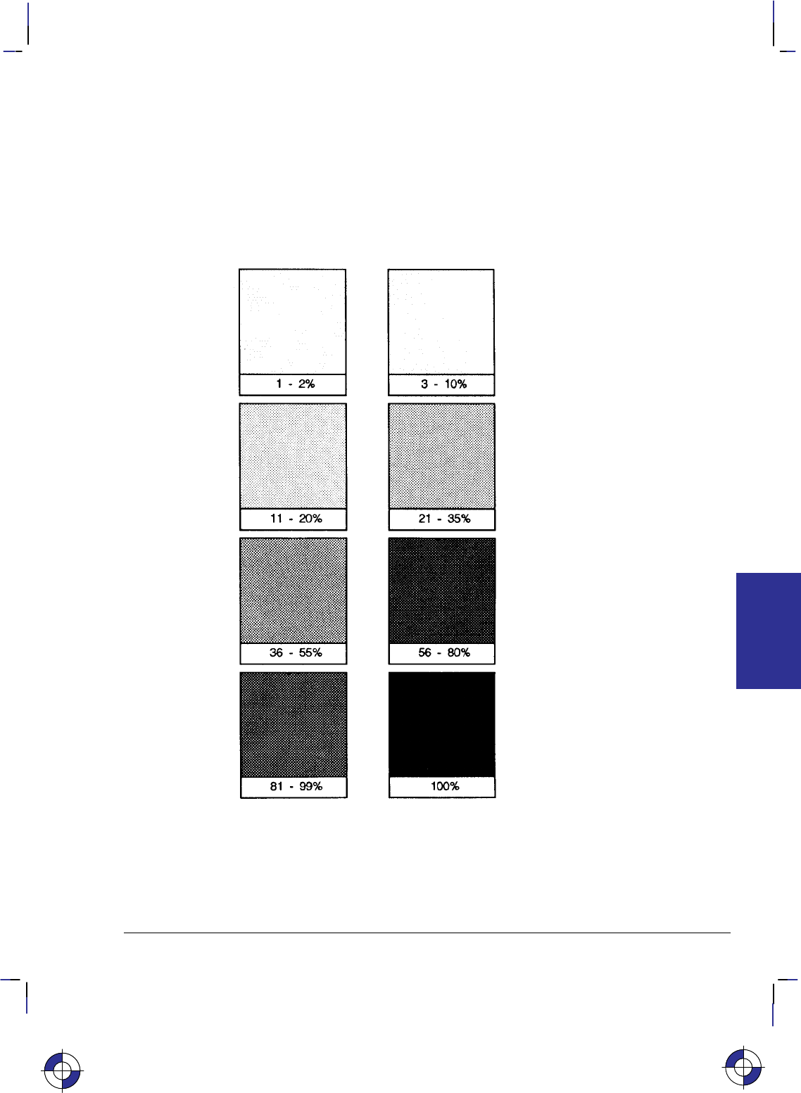
185
This is the black on page 185 (seq: 203)
Company confidential. HP-GL/2 and HP RTL Reference Guide, draft 2. Freeze Status: open
The end-points of hatched fills are treated with the current line cap. Lines are not clipped
to the polygon.
3. For fill_type 10, the option1 value specifies the level of shading. The level is specified as a
percentage. The device uses at least nine predefined levels of shading equally divided be-
tween 0 and 100%. The default is 50%. Each shading level is generated by adding white
pixels to the current pen color raster pattern; these added pixels are the only white pixels in
the pattern that are subject to transparency (see the TR instruction on page 318). The fol-
lowing illustration shows various levels of shading and the specified percentage:
Figure 99. Shading Patterns
4. For fill_type 11, the option1 parameter selects the corresponding user-defined raster fill.
The range is the same as the index parameter of the RF (Raster Fill Definition) instruction;
the default is 1. If the pattern was defined using only 1s and 0s (see the RF instruction),
the pattern is printed in the current pen color; option2 specifies whether or not the current
color should be applied. If option2 is “1” (true), the color of the currently selected pen is
This is the blue on page 185 (seq: 203)
FT Instruction
INSTRUCTIONS
HP-GL/2
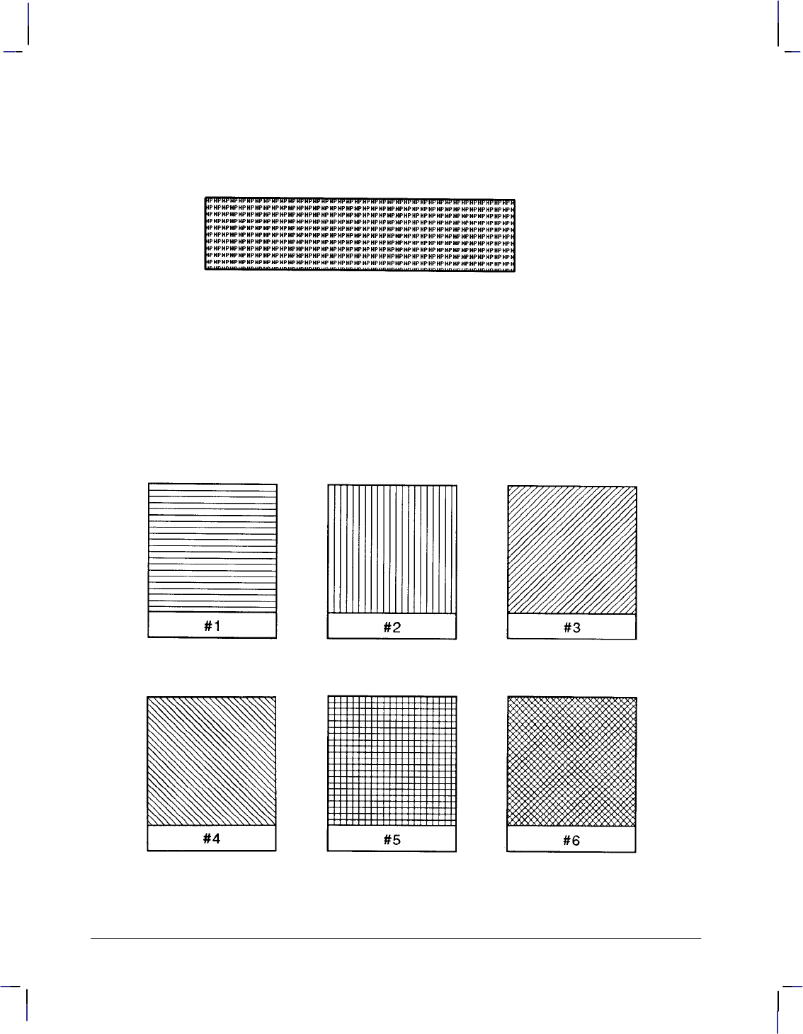
186
This is the black on page 186 (seq: 204)
Company confidential. HP-GL/2 and HP RTL Reference Guide, draft 2. Freeze Status: open
applied to the 1s pixels in the pattern. If option2 is “0” or is not present, the pattern of the
1s pixels is printed in the color of pen number 1. If the pattern definition includes indexes
other than 0 and 1, option2 is ignored. If you have not used an RF instruction, the device
uses solid fill.
Figure 100. User-Defined Fill Pattern
Using FT in a Dual-Context Environment
Additional fill types (21 and 22) are imported from PCL or HP RTL. Fill_type 21 selects a
PCL or HP RTL predefined patterned fill. Option1 specifies a pattern type from 1 to 6 (see Fig-
ure 101). Option2 is ignored. Fill_type 22 uses the PCL or HP RTL user-defined fill specified
by *c#W. Option1 is the PCL or HP RTL ID of the user-defined fill. Option2 is ignored.
An invalid option1 (for example, where the pattern has been deleted), prints a solid fill in the
current color.
Figure 101. Patterns for Fill Type 21
FT Instruction

187
This is the black on page 187 (seq: 205)
Company confidential. HP-GL/2 and HP RTL Reference Guide, draft 2. Freeze Status: open
5. For fill_type 21, which is only available with devices that support the dual-context exten-
sion, the predefined pattern fill is imported from PCL or HP RTL. Option1 specifies the
pattern type, using a value from 1 to 6 as shown in Figure 101.
1 horizontal lines
2 vertical lines
3 diagonal lines (lower left to upper right)
4 diagonal lines (lower right to upper left)
5 cross-hatching with horizontal and vertical lines
6 cross-hatching with diagonal lines.
6. For fill_type 22, which is also only available with devices that support the dual-context
extension, the user-defined fill pattern is that specified using the *c#W PCL or HP RTL
command. Option1 specifies the PCL or HP RTL identification of the user-defined pattern
fill. If option1 is invalid for any reason (for example, the pattern was deleted), the device
uses a solid fill in the current color.
Note that PCL and HP RTL use the term “pattern” for fill-type.
Related Instructions
CF Character Fill Mode
LA Line Attributes
LT Line Type
PW Pen Width
RF Raster Fill Definition
FP Fill Polygon
RA Fill Rectangle Absolute
RR Fill Rectangle Relative
SV Screened Vectors
WG Fill Wedge
Example
This sequence of instructions:
PA 2000,2000; Specify absolute plotting and move to location (2000,2000).
FT ; Fill Type, default value 1 (solid bidirectional).
RR 2500,300; Fill Rectangle Relative coordinates.
EP ; Edge Polygon (outlines current polygon).
PR 0,300; Plot Relative coordinates.
FT 3,80,30; Fill Type, type 3 (hatching), spacing 80 user-units (X-direction),
inclination 30.
RR 2500,300; Fill Rectangle Relative coordinates.
EP ; Edge Polygon.
PR 0,300; Plot Relative coordinates.
FT 10,36; Fill Type 10 (shading), 36%.
RR 2500,300; Fill Rectangle Relative coordinates.
EP ; Edge Polygon.
This is the blue on page 187 (seq: 205)
FT Instruction
INSTRUCTIONS
HP-GL/2
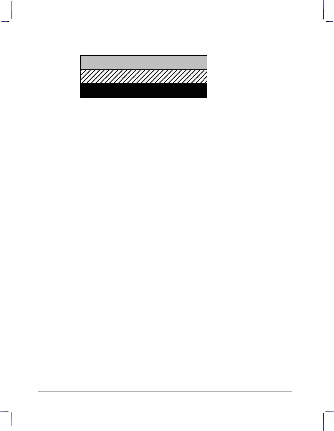
188
This is the black on page 188 (seq: 206)
Company confidential. HP-GL/2 and HP RTL Reference Guide, draft 2. Freeze Status: open
produces this output:
Figure 102. Rectangles with Different Fill Types
FT Instruction

189
This is the black on page 189 (seq: 207)
Company confidential. HP-GL/2 and HP RTL Reference Guide, draft 2. Freeze Status: open
IN, Initialize
Purpose
To resets all programmable HP-GL/2 functions to their default settings. Use the IN instruction
to return the device to a known HP-GL/2 state and to cancel settings that may have been
changed by a previous instruction sequence. (The E Reset command and the BP [Begin
Plot] instruction issue an automatic IN instruction).
Syntax
IN n[;] or
IN [;]
Parameter Format Functional Range Parameter Default
nclamped integer 1 (see below) no parameter
Group
This instruction is in the Configuration and Status Group.
Use
No parameter: Defaults to the feature settings specified using the device’s control panel,
and sets all other programmable HP-GL/2 features to their factory defaults.
n: Defaults all programmable HP-GL/2 features to the factory-set conditions.
If n is fractional, it is rounded to the nearest integer, so 0.6 is rounded to 1. Any number in
the range –223 to 223–1 (other than 1 on some devices—see below) is treated like “IN;” (no
parameter).
An “IN1” instruction is used in some devices, principally pen plotters, as a temporary over-
ride of control-panel defaults; a subsequent “IN” (with no parameter) will restore the
control-panel defaults. “IN1” is not recommended unless it is imperative that the pro-
gram control the device.
All instruction sequences should begin with IN to clear unwanted conditions from the previous
instruction sequence, even though an E command and a BP (Begin Plot) instruction auto-
matically execute an IN instruction. All HP-GL/2 errors are cleared.
Once HP-GL/2 mode is entered and instructions are issued, the HP-GL/2 conditions are no
longer initialized. To place HP-GL/2 into the default state, send the IN instruction.
IN does not default pen selection; the pen selected before IN remains selected afterwards, and
is raised (up state) in the lower-left corner of the hard-clip limits.
The IN instruction sets the device to the same conditions as the DF (Default Values) instruction
(see page 136), plus the following:
This is the blue on page 189 (seq: 207)
IN Instruction
INSTRUCTIONS
HP-GL/2
190
This is the black on page 190 (seq: 208)
Company confidential. HP-GL/2 and HP RTL Reference Guide, draft 2. Freeze Status: open
Function Equivalent
Instruction Default Condition
Plot Absolute PA0,0; Returns the pen location to the lower-left corner of
the hard-clip limits
Pen Up PU; Raises the pen
Pen Width PW; Sets the pen width to 0.35 mm
Rotate Coordinate System RO0; Cancels drawing rotation
Input P1 and P2 IP; Sets P1 and P2 to the lower-left and upper-right cor-
ners, respectively, of the hard-clip limits
Pen Width Unit Selection WU; Sets pen width mode to metric; units are millimeters
Using IN in a Dual-Context Environment
The IN instruction interacts with PCL. In dual-context mode it will overwrite the PCL color
configuration and replace it with the HP-GL/2 default. For this reason, the instruction should
not be used in the middle of a job.
Using IN with the Palette Extension
The IN instruction also affects the following instruction:
Function Equivalent
Instruction Default Condition
Number of Pens NP; Sets number of pens to 2 or 8 (see page 225)
Using IN with the Technical Graphics Extension
The IN instruction also affects the following instruction:
Function Equivalent
Instruction Default Condition
Plot Size PS; Sets the plot length to the hard-clip limits
Related Instructions
BP Begin Plot
DF Default Values
OS Output Status
IN Instruction
191
This is the black on page 191 (seq: 209)
Company confidential. HP-GL/2 and HP RTL Reference Guide, draft 2. Freeze Status: open
IP, Input P1 and P2
Purpose
To establish new or default locations for the scaling points P1 and P2. P1 and P2 are used by
the SC (Scale) instruction to establish user-unit scaling. You can also use IP in advanced tech-
niques such as printing mirror-images (as explained on page 35), enlarging and reducing
drawings (see page 33), and enlarging and reducing relative character size (see page 308),
changing label direction (see page 149), changing pen widths (see pages 264 and 328), chang-
ing spacing for hatch-filled patterns (see page 183), or changing the line type pattern length
(see page 215). IP does not affect the window limits (see page 197).
Syntax
IP P1X,P1Y[,P2X,P2Y][;]
or
IP [;]
Parameter Format Functional Range Parameter Default
P1X,P1Y,P2X,P2Yinteger –230 to 230 – 1 (see below)
Group
This instruction is in the Configuration and Status Group.
Use
The default location of P1 for “printers” (that is, devices that do not support the Technical
Graphics Extension) is the lower-left corner of the hard-clip limits; the default location of P2 is
the upper-right corner, as shown in Figure 103. (The default picture frame extends from the top
margin to the bottom margin, and from the left edge to the right edge of the logical page.) For
“plotters” (that is, devices that do support the Technical Graphics Extension) the default posi-
tion and orientation of the X- and Y-axes is different (see Figure 10 on page 10) but the
positions of P1 and P2 relative to the axes is as in Figure 103.
No Parameters: Sets P1 and P2 to their default locations, adjusted by any current axis
rotation.
Note: If an IP instruction without parameters is executed after the axes are rotated with the
RO instruction, P1 and P2 locations change to reflect the rotation. If the coordinate system
orientation subsequently changes (for example, by sending an RO instruction), the plotter-
unit position is maintained with respect to the new orientation.
X,Y coordinates: Specify the location of P1 (and, optionally, P2) in plotter-units (see page
12). Specifying P2 is not required. If P2 is not specified, P2 tracks P1 and its coordinates
change so that the X,Y distances between P2 and P1 stay the same. This tracking process
can locate P2 outside the effective window. Used carefully, the tracking function can be
useful for preparing more than one equal-sized drawing on a page. For an example, refer
to Drawing Equal-Sized Pictures on a Page on page 34. Neither X,Y coordinate of P1 can
equal the corresponding coordinate of P2. If either coordinate of P1 equals the correspond-
ing coordinate of P2, the coordinate of P2 is incremented by 1 plotter-unit.
This is the blue on page 191 (seq: 209)
IP Instruction
INSTRUCTIONS
HP-GL/2
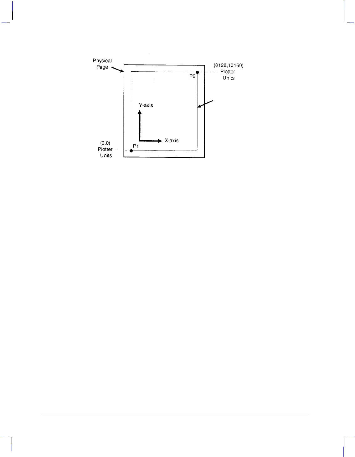
192
This is the black on page 192 (seq: 210)
Company confidential. HP-GL/2 and HP RTL Reference Guide, draft 2. Freeze Status: open
Figure 103. Default P1/P2 Locations for an 8-inch by 10-inch Page
The locations of P1 and P2 interact with the following instructions:
DR Relative Direction
FT Fill Type
IW Input Window
LB Label
LT Line Type
PW Pen Width
RO Rotate Coordinate System
SC Scale
SR Relative Character Size
WU Pen Width Unit Selection
An IP instruction remains in effect until another IP instruction is executed, an IR instruction is
executed, the device is initialized, or a PS (Plot Size) instruction is issued on a “clean” (un-
plotted) page.
IP clears the current pattern residue and terminates any continuous vector sequence (see the LA
and LT instructions).
Using IP in a Dual-Context Environment (PCL only)
“IP;” sets P1 to the lower-left corner of the PCL picture frame (viewed from the current HP-
GL/2 orientation) and P2 to the opposite corner. Parameters are scaled by the picture frame
scaling factor.
Related Instructions
IR Input Relative P1 and P2
IW Input Window
OP Output P1 and P2
RO Rotate Coordinate System
SC Scale
IP Instruction

193
This is the black on page 193 (seq: 211)
Company confidential. HP-GL/2 and HP RTL Reference Guide, draft 2. Freeze Status: open
Possible Error Conditions
Error Condition Error Number Printer or Plotter Response
One or three parameters 2 Ignores instruction
This is the blue on page 193 (seq: 211)
IP Instruction
INSTRUCTIONS
HP-GL/2
194
This is the black on page 194 (seq: 212)
Company confidential. HP-GL/2 and HP RTL Reference Guide, draft 2. Freeze Status: open
IR, Input Relative P1 and P2
Purpose
To establish new or default locations for the scaling points P1 and P2 relative to the hard-clip
limits. P1 and P2 are used by the SC (Scale) instruction to establish user-unit scaling. IR can
also be used in advanced techniques such as printing mirror-images (as explained on page 35),
enlarging and reducing drawings (see page 33), and enlarging and reducing relative character
size (see page 308), changing label direction (see page 149), changing pen widths (see pages
264 and 328), changing spacing for hatch-filled patterns (see page 183), or changing the line
type pattern length (see page 215). IR does not affect the window limits (see page 197).
Syntax
IR P1X,P1Y[,P2X,P2Y][;]
or
IR [;]
Parameter Format Functional Range Parameter Default
P1X,P1Y,P2X,P2Yclamped real –32 768 to 32 767 0,0,100,100%
Group
This instruction is in the Configuration and Status Group.
Use
When P1 and P2 are set using IR, the scaled area is page size-independent. The P1/P2 rectan-
gular area will occupy the same proportional space on any size media.
No Parameters: Defaults P1 and P2 to the lower-left and upper-right corners of the
hard-clip limits, respectively.
X,Y coordinates: Specify the location of P1 (and, optionally, P2) as percentages of the
hard-clip limits (specifying P2 is not required). If P2 is not specified, P2 tracks P1; the P2
coordinates change so that the distances of X and Y between P1 and P2 remain the same.
This tracking process can cause P2 to be located outside the effective window. Used
carefully, the tracking function can be useful for preparing more than one equal-sized
drawing on a page. For an example, refer to Drawing Equal-Sized Pictures on a Page on
page 34.
Neither X,Y coordinate of P1 can equal the corresponding coordinate of P2. If either coordi-
nate of P1 equals the corresponding coordinate of P2, the coordinate of P2 is incremented by 1
plotter-unit.
Sending the instruction “IR25,25,75,75” establishes new locations for P1 and P2 that create an
area half as high and half as wide as the hard-clip limits, in the center of the page. Refer to
Figure 104.
This is the blue on page 194 (seq: 212)
IR Instruction
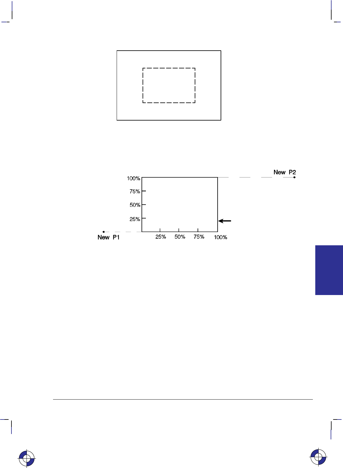
195
This is the black on page 195 (seq: 213)
Company confidential. HP-GL/2 and HP RTL Reference Guide, draft 2. Freeze Status: open
New P2
New P1
100%
75%
50%
25%
0,0 25% 50% 75% 100%
HardĆClip Limits
Figure 104. Example Using IR 25,25,75,75
P1 or P2 can also be set outside the hard-clip limits by specifying parameters less than zero or
greater than 100. For example, sending “IR–50,0,200,100” would set P1 and P2 as shown in
Figure 105.
HardĆClip Limits
Figure 105. Example Using IR –50,0,200,100
If you specify P1 and P2 beyond the hard-clip limits, your drawing is scaled with respect to
those locations; however, only the portion of the drawing fitting within the hard-clip limits is
drawn.
Note: The specified P1/P2 percentages are converted to the equivalent plotter-unit coordinates.
If the coordinate system orientation subsequently changes (for example, by sending an RO
instruction), the plotter-unit position is maintained with respect to the new orientation. If an IP
instruction without parameters is executed after the axes have been rotated with the RO instruc-
tion, P1 and P2 locations change to reflect the rotation.
The locations of P1 and P2 interact with the following instructions:
DR Relative Direction
FT Fill Type
IW Input Window
LB Label
LT Line Type
PW Pen Width
RO Rotate Coordinate System
SC Scale
SR Relative Character Size
WU Pen Width Unit Selection
This is the blue on page 195 (seq: 213)
IR Instruction
INSTRUCTIONS
HP-GL/2
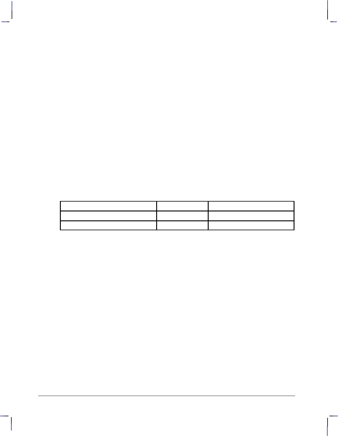
196
This is the black on page 196 (seq: 214)
Company confidential. HP-GL/2 and HP RTL Reference Guide, draft 2. Freeze Status: open
An IR instruction remains in effect until another IR instruction is executed, an IP instruction is
executed, or the device is initialized, or a PS (Plot Size) instruction is issued on a “clean” (un-
plotted) page.
IR clears the current pattern residue and terminates any continuous vector sequence (see the LA
and LT instructions).
Using IR in a Dual-Context Environment (PCL only)
The references to the hard-clip limits are replaced by the PCL picture frame. The default posi-
tions for P1 and P2 are the lower-left and upper-right corners of the picture frame, as viewed
from the current orientation.
Related Instructions
IP Input P1 and P2
IW Input Window
OP Output P1 and P2
RO Rotate Coordinate System
SC Scale
Possible Error Conditions
Error Condition Error Number Printer or Plotter Response
One or three parameters 2 Ignores instruction
More than four parameters 2 Uses first four parameters
IR Instruction
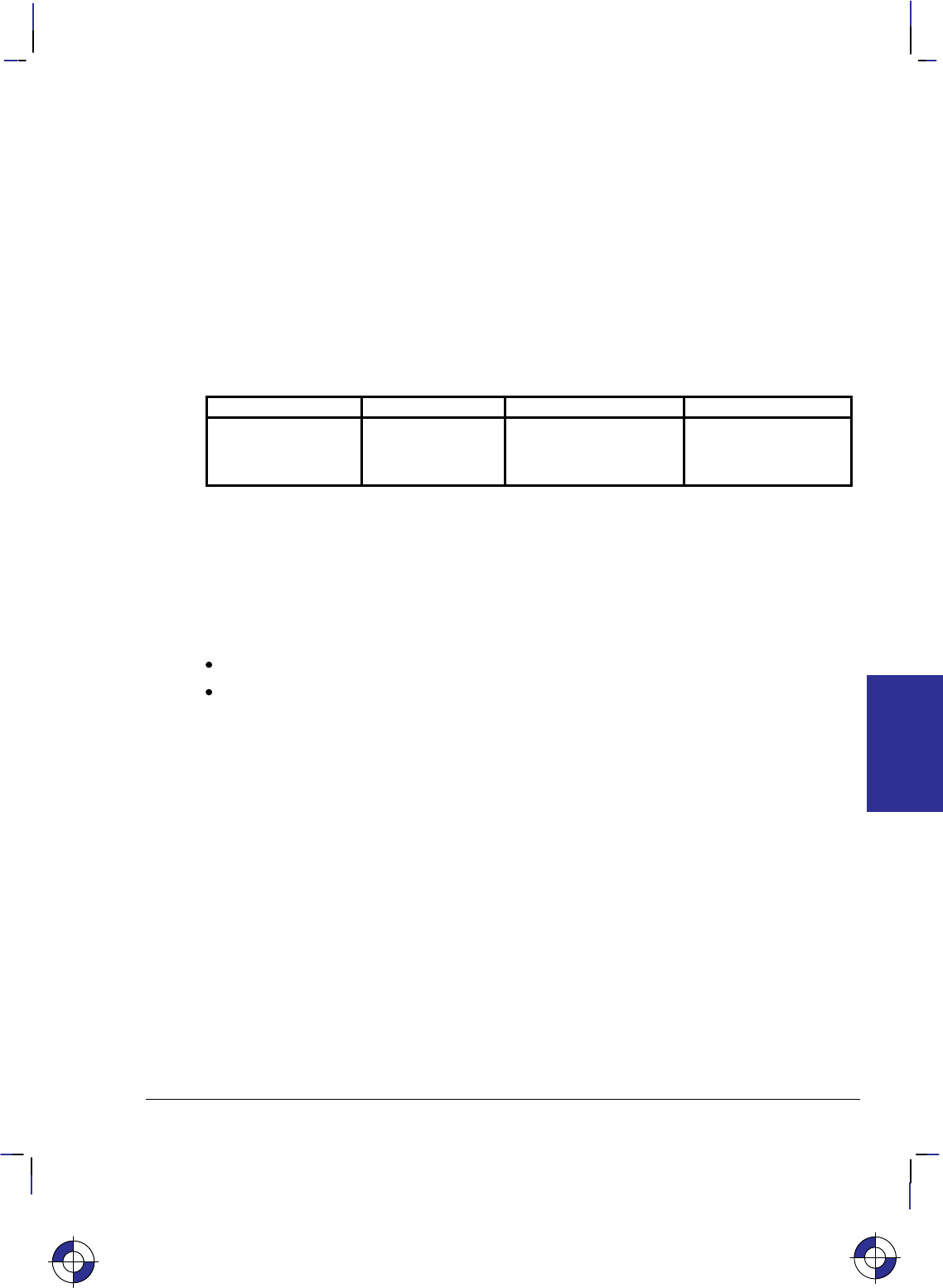
197
This is the black on page 197 (seq: 215)
Company confidential. HP-GL/2 and HP RTL Reference Guide, draft 2. Freeze Status: open
IW, Input Window
Purpose
To define a rectangular area, or window, that establishes soft-clip limits. Subsequent HP-GL/2
drawing is restricted to this area. Use IW to restrict printing to a specified area on the page.
Syntax
IW XLL,YLL,XUR,YUR[;]
or
IW [;]
Parameter Format Functional Range Parameter Default
XLL,YLL,XUR,YUR current units device-dependent
(at least –223 to 223 – 1) hard-clip limits (the
picture frame in PCL
dual-context mode)
Group
This instruction is in the Configuration and Status Group.
Use
The device interprets the instruction parameters as follows.
No Parameters: Resets the soft-clip limits to the hard-clip limits.
X,Y coordinates: Specify the opposite diagonal corners of the window area. For PCL
printers, these are the lower-left (LL) and upper-right (UR) corners. Coordinates are
interpreted in the current units: as user-units when scaling is on; as plotter-units when
scaling is off.
If the X or Y parameters of the lower-left corner are greater than the equivalent parameters
of the upper-right corner, parameters are automatically exchanged. The window is a line if
XLL = XUR or YLL = YUR, and a dot if all parameters are equal.
For plotters, the corners used depend on the orientation; see Interactions between Different
Coordinate Systems on page 10.
When scaling is off, the window is defined in plotter-units and is static, that is, it is not affected
by changes to P1 and P2. (However, in dual-context mode, parameters specified in plotter-units
are scaled by the picture frame scaling factor.)
When scaling is on, subsequent changes to P1 and P2 move the window in relation to the physi-
cal page, but keep the same user coordinate locations. However, sending a subsequent SC
instruction binds the window to its equivalent plotter-units. The window does not change with
any subsequent IP or IR instructions.
When you turn on the device, the window is automatically set to the hard-clip limits. You can
define a window that extends beyond these limits; however the device cannot print vector
This is the blue on page 197 (seq: 215)
IW Instruction
INSTRUCTIONS
HP-GL/2
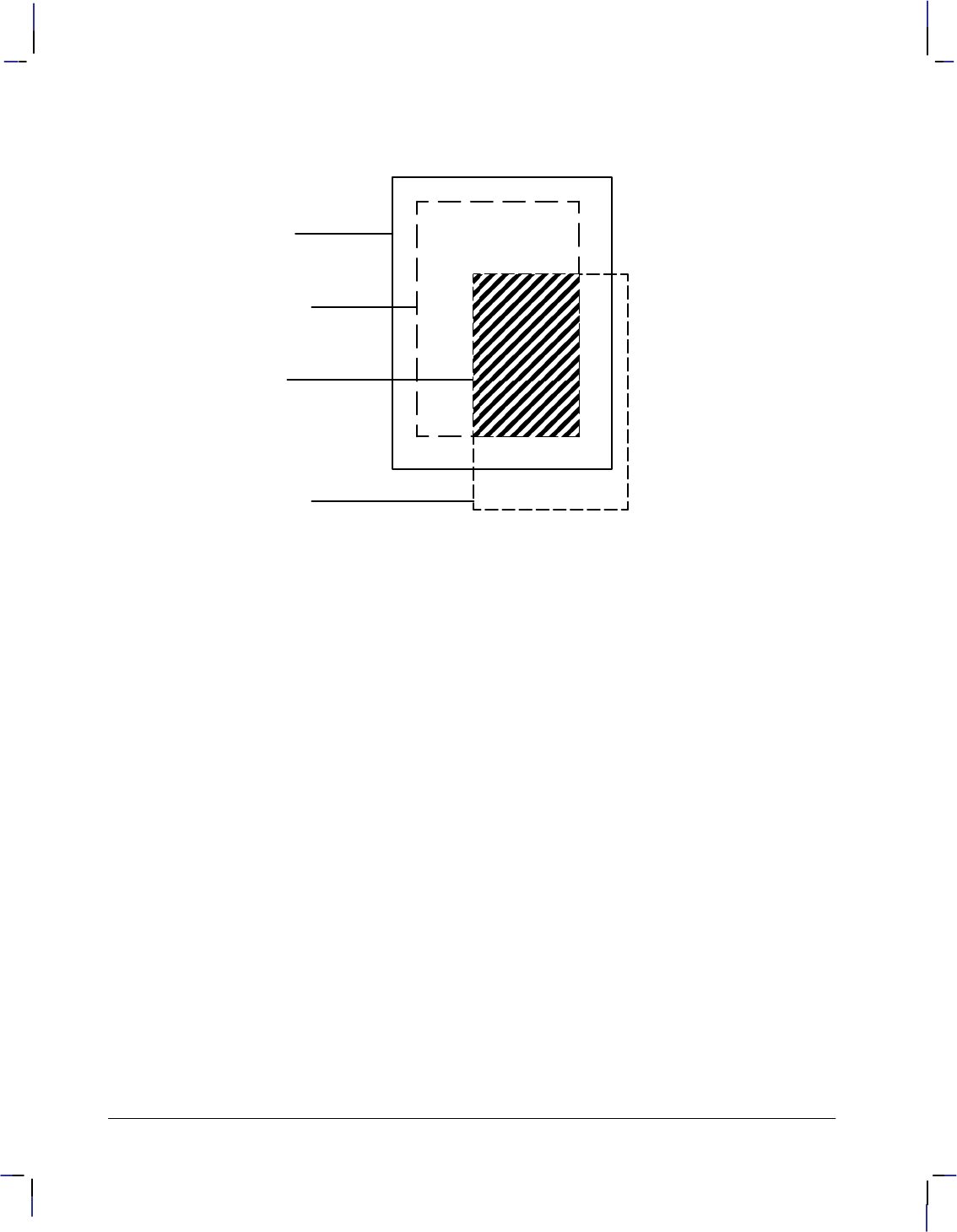
198
This is the black on page 198 (seq: 216)
Company confidential. HP-GL/2 and HP RTL Reference Guide, draft 2. Freeze Status: open
graphics beyond the effective window. All programmed pen motion is restricted to this area.
For more information, refer to Windowing: Setting Up Soft-Clip Limits on page 39.
Edge of
printing
medium
HardĆclip
limits (PS
instruction)
Effective
window
SoftĆclip
limits (IW
instruction)
Figure 106. Effective Window
If the window falls entirely outside of the hard-clip limits, no image is drawn. This can happen
when you define a window that is normally within the hard-clip limits and a subsequent Rotate
Coordinate System (RO) instruction moves the window outside the hard-clip limits.
The IW instruction remains in effect until another IW instruction is executed, the device is ini-
tialized or set to default conditions, or a PS is issued on a clean page. Power-on, IN, or DF
default the window to the hard-clip limits.
IW clears the current pattern residue and terminates any continuous vector sequence (see the
LA and LT instructions).
Using IW in a Dual-Context Environment (PCL only)
“IW;” defaults the window to the PCL picture frame. The maximum printable area is the inter-
section of the user-defined window, PCL picture frame, the PCL logical page, and the hard-clip
limits. Parameters specified in plotter-units are scaled by the picture frame scaling factor.
Related Instructions
FR Frame Advance
IP Input P1 and P2
IR Input Relative P1 and P2
RO Rotate Coordinate System
SC Scale
IW Instruction

199
This is the black on page 199 (seq: 217)
Company confidential. HP-GL/2 and HP RTL Reference Guide, draft 2. Freeze Status: open
Example
The following example draws a label, then establishes a window and again draws the label
along with a line. Notice how the line and label are clipped after the window is established, but
not before.
SI .2,.35; Set Absolute Character Size to 0.2 by 0.35 cm.
PA 2000,3200; Specify absolute plotting and move to location (2000,3200) (plot-
ter-units).
DT@,1; Define label terminator to be the “@” character, without printing
the character.
LBTHIS IS AN EXAMPLE OF IW@; Print a label beginning at (2000,3200).
IW 3000,1300,4500,3700; Specify a soft-clip window (in plotter-units).
PD 2000,1700 Pen Down; print a line from the current pen position to
(2000,1700). Current pen position at start of instruction is at the
letter W baseline.
LBTHIS IS AN EXAMPLE OF IW@; Print the same label at (2000,1700).
PU 3000,1300; Pen Up and move to position (3000,1300).
PD 4500,1300,4500,3700; Pen Down and begin drawing box indicating the soft-clip win-
dow.
PD 3000,3700,3000,1300; Finish drawing the soft-clip window box.
PU ; Pen Up.
Figure 107. How the IW (Input Window) Instruction Clips
This is the blue on page 199 (seq: 217)
IW Instruction
INSTRUCTIONS
HP-GL/2

200
This is the black on page 200 (seq: 218)
Company confidential. HP-GL/2 and HP RTL Reference Guide, draft 2. Freeze Status: open
LA, Line Attributes
Purpose
To specify how line ends and line joins are physically shaped. Use this instruction when draw-
ing lines thicker than 0.35 mm.
Syntax
LA kind,value[,kind,value[,kind,value]][;]
or
LA [;]
Parameter Format Functional Range Parameter Default
kind clamped integer 1, 2, or 3 no default
value clamped integer
clamped integer
clamped real
Kind 1: 1 through 4
Kind 2: 1 through 6
Kind 3: 1 through 32 767
1 (Butt)
1 (Mitered)
5
Group
This instruction is in the Line and Fill Attributes Group.
Use
There are three line attributes: line ends, line joins, and the miter limit. The LA instruction pa-
rameters are used in pairs: the first parameter, kind, selects a line attribute, and the second
parameter, value, defines the appearance of that attribute. The device uses the current line at-
tributes when the optional parameter pairs are omitted.
No Parameters: Defaults the line attributes to butt ends, mitered joins, and a miter limit
of 5. Equivalent to “LA1,1,2,1,3,5”.
kind: Specifies the line attribute for which you are setting a value. Attributes and kind
parameter values are listed in the following table.
value: Defines the characteristics of the attribute specified by the kind parameter. The
available values are listed in the following table and described under each attribute.
The current line attributes remain in effect when optional parameter pairs are omitted.
A continuous sequence of pen-down vectors uses the current line join and miter limit for coin-
cident first and last points. A continuous vector sequence is interrupted when a vector’s end
point is not coincident with the next pen-down vector’s starting point, or by the AC, DF, IN, IP,
IR, IW, LA, LT, PG, PW, RF, RO, RP, SC, SP, TR, UL, or WU instruction.
Instructions that restore the current pen position (CI, EA, EP, ER, EW, FP, PM, RA, RR, and
WG) save the last vector’s end point upon completion. The pen-down sequence is continued
when the current pen position is restored. The last vector’s end point is also saved by CP or LB
and before each SM symbol is drawn; the vector sequence is continued if the starting point of
This is the blue on page 200 (seq: 218)
LA Instruction
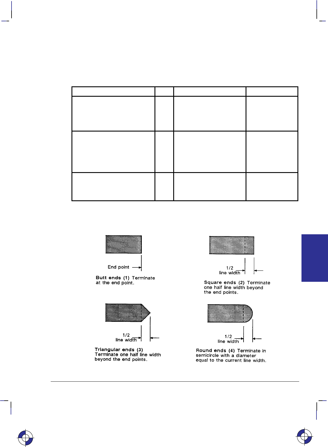
201
This is the black on page 201 (seq: 219)
Company confidential. HP-GL/2 and HP RTL Reference Guide, draft 2. Freeze Status: open
the next pen-down vector is coincident with the saved vector end point, that is, there can be any
number of pen-up vectors between two consecutive pen-down vectors.
The clipping of a line end and line join is device-dependent.
The ends of each dash are treated with the current line cap; corners with a dash are treated with
the current line join. Labels are always drawn with rounded ends and joins.
Attribute Kind Value Description
Line Ends: (Lines with a width
less than a device-dependent
limit always have butt caps and
no join, regardless of the current
attribute setting)
1 1
2
3
4
Butt (default)
Square
Triangular
Round
Line Joins: (Lines with a width
less than that same device-de-
pendent limit always have butt
caps and no join, regardless of
the current attribute setting)
2 1
2
3
4
5
6
Mitered (default)
Mitered/beveled
Triangular
Round
Beveled
No join applied
Miter Limit: (Full range is 1 to
32 767, but values less than 1 are
automatically set to 1)
3 Device-dependent 5 (default, refer to
description under
Miter Limit on page
203)
Line Ends
Figure 108. Four Line Ends
This is the blue on page 201 (seq: 219)
LA Instruction
INSTRUCTIONS
HP-GL/2
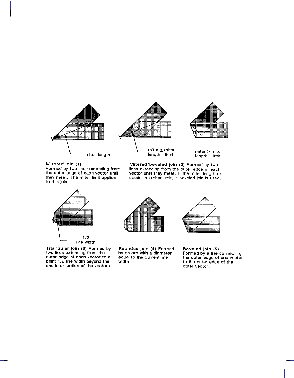
202
This is the black on page 202 (seq: 220)
Company confidential. HP-GL/2 and HP RTL Reference Guide, draft 2. Freeze Status: open
The value you specify for line ends determines how the ends of line segments are shaped. Fig-
ure 108 describes the four types of line ends.
Line Joins
The value you specify for the line joins attribute determines how connecting line ends (corners)
are shaped. The following illustration describes the five types of line joins. If the first and last
points of a series of lines are the same, they join according to the current line join and miter
limit.
Figure 109. Five Line Joins
When you select “no join” (“LA2,6;”), the currently selected line ends for the two lines merely
overlap. Refer to the following illustration.
LA Instruction
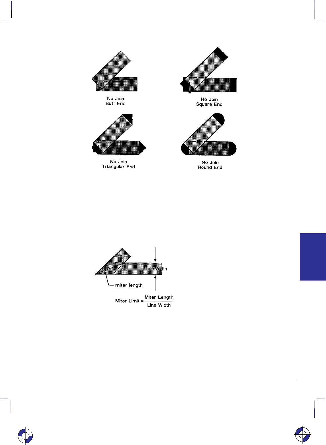
203
This is the black on page 203 (seq: 221)
Company confidential. HP-GL/2 and HP RTL Reference Guide, draft 2. Freeze Status: open
Figure 110. Overlapping Line Ends without Line Join Selection
Miter Limit
The value you specify for miter limit determines the maximum “length” of a mitered join, as
shown in the following illustration. The miter limit is the ratio of the miter length (the length
of the diagonal line through the join of two connecting lines), to the line width. For example,
with the default miter limit of 5, the miter length can be as long as 5 times the line width.
Figure 111. Miter Limit
When the miter length exceeds the miter limit, the point of the miter is clipped to the miter lim-
it (the clipped miter is equivalent to a beveled join). The default miter limit is usually
sufficient to prevent clipping except at very narrow join angles.
This is the blue on page 203 (seq: 221)
LA Instruction
INSTRUCTIONS
HP-GL/2
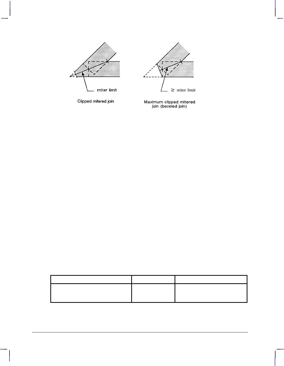
204
This is the black on page 204 (seq: 222)
Company confidential. HP-GL/2 and HP RTL Reference Guide, draft 2. Freeze Status: open
Figure 112. Miter Limit Clipping
An LA instruction remains in effect until another LA instruction is executed, or the device is
initialized or set to default conditions.
Related Instructions
AA Arc Absolute
AR Arc Relative
AT Absolute Arc Three Point
BR Bezier Relative
BZ Bezier Absolute
CI Circle
EA Edge Rectangle Absolute
EP Edge Polygon
ER Edge Rectangle Relative
EW Edge Wedge
FP Fill Polygon
FT Fill Type
LT Line Type
PW Pen Width
RA Fill Rectangle Absolute
RR Fill Rectangle Relative
RT Relative Arc Three Point
UL User-Defined Line Type
WG Fill Wedge
Possible Error Conditions
Error Condition Error Number Printer or Plotter Response
Kind or value is within the data for-
mat limits, but outside the range de-
fined by the instruction
0 The kind,value pair is ignored;
all other kind,value pairs are
executed
LA Instruction
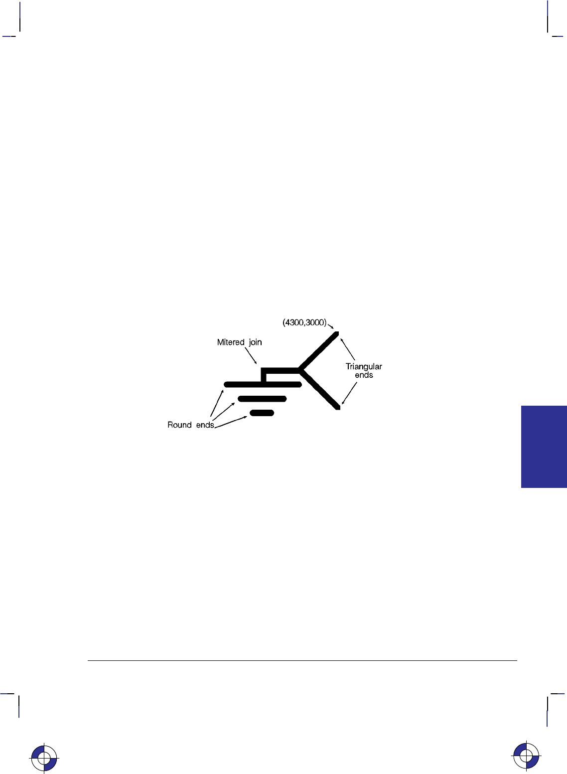
205
This is the black on page 205 (seq: 223)
Company confidential. HP-GL/2 and HP RTL Reference Guide, draft 2. Freeze Status: open
Example
The following example draws an electrical ground symbol using the LA instruction.
PA 4000,3000; Specify absolute plotting and move the pen to (4000,3000).
PW 2; Set the pen width to 2 mm.
LA 1,3; Specify a triangular line end.
PD 3500,2500,4000,2000; Place the pen down, and draw from the current location to
(3500,2500), then to (4000,2000).
PU 3500,2500; Lift the pen and move to (3500,2500).
LA 2,2,3,20; Set the line join to mitered/beveled and the miter limit to 20.
PD 3000,2500,3000,2300; Set the pen down and draw a line to (3000,2500), then to
(3000,2300).
PU 2500,2300; Lift the pen and move it to (2500,2300).
LA 1,4; Specify round line ends.
PD 3500,2300; Draw a line to (3500,2300).
PU 2700,2100; Lift the pen and move to (2700,2100).
PD 3300,2100; Then set the pen down and draw a line to (3300,2100).
PU 2900,1900; Lift the pen and move to (2900,1900).
PD 3100,1900; Then draw a line to (3100,1900).
Figure 113. Line Attributes Example
This is the blue on page 205 (seq: 223)
LA Instruction
INSTRUCTIONS
HP-GL/2
206
This is the black on page 206 (seq: 224)
Company confidential. HP-GL/2 and HP RTL Reference Guide, draft 2. Freeze Status: open
LB, Label
Purpose
To print text using the currently defined font. Use LB to annotate drawings or create text-only
charts.
Syntax
LB text . . . text label_terminator
Parameter Format Functional Range Parameter Default
text . . . text character any character(s) no default
label_terminator character, as de-
fined by DT any character except
, , , and ;
(decimal codes 0, 5, 27,
and 59 respectively)
(decimal code 3)
Group
This instruction is in the Character Group.
Use
The LB instruction includes an automatic pen-down function. When the instruction is com-
pleted, the original pen up/down status is restored.
text . . . text: Up to 256 ASCII characters, drawn using the currently selected font. (Refer
to the AD, SA, SD, and SS instructions for details on specifying and selecting fonts.)
Don’t leave any spaces between LB and its text (unless that is what you want).
You can include control characters such as the Carriage Return (, decimal code 13) and
Line Feed (, decimal code 10). These characters invoke the specified function or not,
depending on the transparent data mode; see the TD instruction on page 316.
The label begins at the current pen location, (unless altered by LO). After each character is
drawn, the pen is moved to the next character origin. The pen location is not updated until
LB is terminated. An embedded line feed moves both the pen and the carriage-return point
one line in the current line direction; an embedded carriage return moves the pen to the
carriage-return point. (Refer to Working With the Character Cell on page 58.)
label_terminator: Terminates the LB instruction. You must use the special label termina-
tor (refer to the DT instruction on page 154) to tell the device to exit the label mode. If
you do not use the label terminator, everything following the LB mnemonic is printed in
the label, including other instructions. The default label_terminator is the non-printing
end-of-text character (decimal code 3). You can define a different terminator using the
DT instruction.
LB updates the current pen position, but not the carriage-return point. The AA, AR, AT, CP,
DF, DI, DR, DV, IN, LO, PA, PE, PR, RO, and RT instructions, and PU or PD with parameters,
This is the blue on page 206 (seq: 224)
LB Instruction
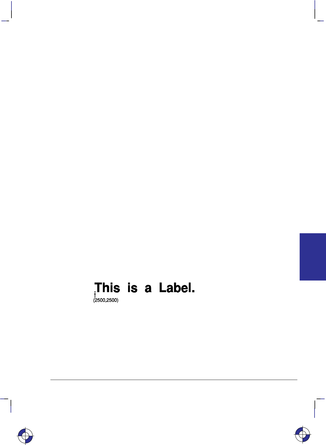
207
This is the black on page 207 (seq: 225)
Company confidential. HP-GL/2 and HP RTL Reference Guide, draft 2. Freeze Status: open
or CP with a non-zero lines parameter all update the carriage-return point to the current pen
position.
In 16-bit mode, the label terminator and all 8-bit control codes must have the first byte set to
zero. For example, an escape character (, ASCII 27) would be sent as a 0 followed by a 27.
The exception is E in dual-context devices, which is parsed and executed regardless of byte
boundaries with the LB and SM instructions.
Related Instructions
AD Alternate Font Definition
CP Character Plot
DI Absolute Direction
DR Relative Direction
DT Define Label Terminator
DV Define Variable Text Path
ES Extra Space
FI Select Primary Font
FN Select Secondary Font
LO Label Origin
SA Select Alternate Font
SB Scalable or Bitmap Fonts
SD Standard Font Definition
SI Absolute Character Size
SL Character Slant
SR Relative Character Size
SS Select Standard Font
TD Transparent Data
Example
PA 2500,2500; Move to absolute location (2500,2500).
DT*; Specify the asterisk (*) as the label terminator.
SD 1,21,2,1,4,25,5,0,6,3,7,52; Designate the 25-point Univers Bold font as the standard
font.
SS ; Select it.
LBThis is a Label.*; Prints “This is a Label.” in the currently selected font.
This is the blue on page 207 (seq: 225)
LB Instruction
INSTRUCTIONS
HP-GL/2

208
This is the black on page 208 (seq: 226)
Company confidential. HP-GL/2 and HP RTL Reference Guide, draft 2. Freeze Status: open
LM, Label Mode
Purpose
To determine how the LB (Label) and SM (Symbol Mode) instructions interpret characters. It
is mostly used with two-byte character sets such as Kanji.
Syntax
LM mode,[row_number][;]
or
LM [;]
Parameter Format Functional Range Parameter Default
mode clamped integer 0 or 1 0 (8-bit)
row_number clamped integer 0 through 255 0
Group
This instruction is in the Advanced Text Extension.
Use
No parameters: Equivalent to “LM0,0”.
mode: Determines the interpretation mode as follows:
0(8-bit mode; the default). Interprets each byte as a character.
1(16-bit mode). Interprets every two bytes as a character.
row_number: Used only in mode 0 (8-bit) when a 16-bit character set is selected. The
row_number indicates the first byte, with an LB or SM instruction supplying the second
byte.
Changing Label Mode turns Symbol Mode off (it executes “SM;”—see the SM instruction on
page 303).
If mode specifies 8-bit, LB and SM interpret each byte as a character code. If mode specifies
16-bit, LB and SM interpret each pair of bytes as a character code. LM does not affect the DT
(Define Label Terminator) and DL (Download Character) instructions.
In 16-bit mode, the label terminator and all 8-bit control codes must have the first byte set to
zero. All other byte 1 values are treated as undefined characters. For example, an escape char-
acter (, ASCII 27) would be sent as a 0 followed by a 27. The exception is E in
dual-context devices, which is parsed and executed regardless of byte boundaries with the LB
and SM instructions.
A 16-bit character-set can be regarded as a two dimensional, 256 x 256 matrix. In 16-bit mode,
the first parameter specifies the row and the second specifies the column.
The row_number parameter is used only if a 16-bit character-set is being interpreted in 8-bit
mode; the first byte is then assumed to equal the row_number. For example, if you enter
This is the blue on page 208 (seq: 226)
LM Instruction

209
This is the black on page 209 (seq: 227)
Company confidential. HP-GL/2 and HP RTL Reference Guide, draft 2. Freeze Status: open
“LM0,37” and select a 16-bit character set, the label string “LBAB” will print characters
(37,65) and (37,66)—characters A and B are ASCII characters 65 and 66.
In 8-bit mode the label buffer holds at least 256 characters, including control codes and the la-
bel terminator. In 16-bit mode, the label buffer holds at least 128 characters.
Printing Kanji and Other Two-Byte Characters
HP-GL/2 allows 8-bit character sets like ASCII with a maximum of 256 characters, and 16-bit
character sets like Kanji with a possible 65 536 characters; however, LB assumes a default
mode of 8-bit characters. Therefore, to print Kanji, change the mode with LM, select a Kanji
font, and use LB to send a 16-bit label:
1. Select 16-bit character mode via the LM instruction (“LM1;”).
2. Select a Kanji font using the SD or AD instructions (for example, “SD1,1611;SS;”).
3. Send the label with LB, specifying two bytes for each desired character.
If the Kanji symbol set is selected and an unrecognized character is seen, the undefined Kanji
character (four dots defining the character cell area) are printed instead of a space.
When printing a Kanji typeface, the stroke weight may be automatically lightened to achieve
satisfactory print quality for complex characters.
Figure 114 shows LB in normal data mode with either Kanji Set 16-bit symbol set invoked. Set
1611 is JIS Kanji Level 1. Set 1643 is JIS Kanji Levels 1 and 2. The result applies in either
8-bit mode with row_number set to the byte 1 value or the byte values used in 16-bit mode.
The black zone encompasses the defined area for either Kanji character set. In this zone, LB
prints either a Kanji character or 4 dots.
In the blue-shaded zones, the action is as though byte 2 were from the US ASCII character set.
The white zones would print a space as for undefined character codes.
In the gray-shaded zones, the action is dependent on label mode, LM. In 8-bit mode, each byte
is interpreted as in the US ASCII character set. This makes the row_number useful with the
two Kanji character sets; in some implementations of 16-bit character sets, the use of row_num-
ber may be disallowed in 8-bit mode if those sets define characters in this region. In 16-bit
mode, LM1, values in these zones are undefined character codes that print a space.
In 16-bit mode with an 8-bit character set invoked, all byte 1 values except zero become unde-
fined character codes.
This concept is consistent with transparent data mode and can be extended for symbol mode.
In transparent data mode, control codes and undefined characters print a space. In symbol
mode, the character actually printed at the end of vectors is taken from the currently invoked
character set. Thus, defining a symbol character in 16-bit mode and then invoking an 8-bit set
would draw a space. Similarly, in 8-bit mode with a 16-bit set invoked, the character drawn
would come from above using row_number for byte 1 and the symbol character value for byte
2. Note that changing from 8- to 16-bit mode or vice versa turns symbol mode off.
This is the blue on page 209 (seq: 227)
LM Instruction
INSTRUCTIONS
HP-GL/2
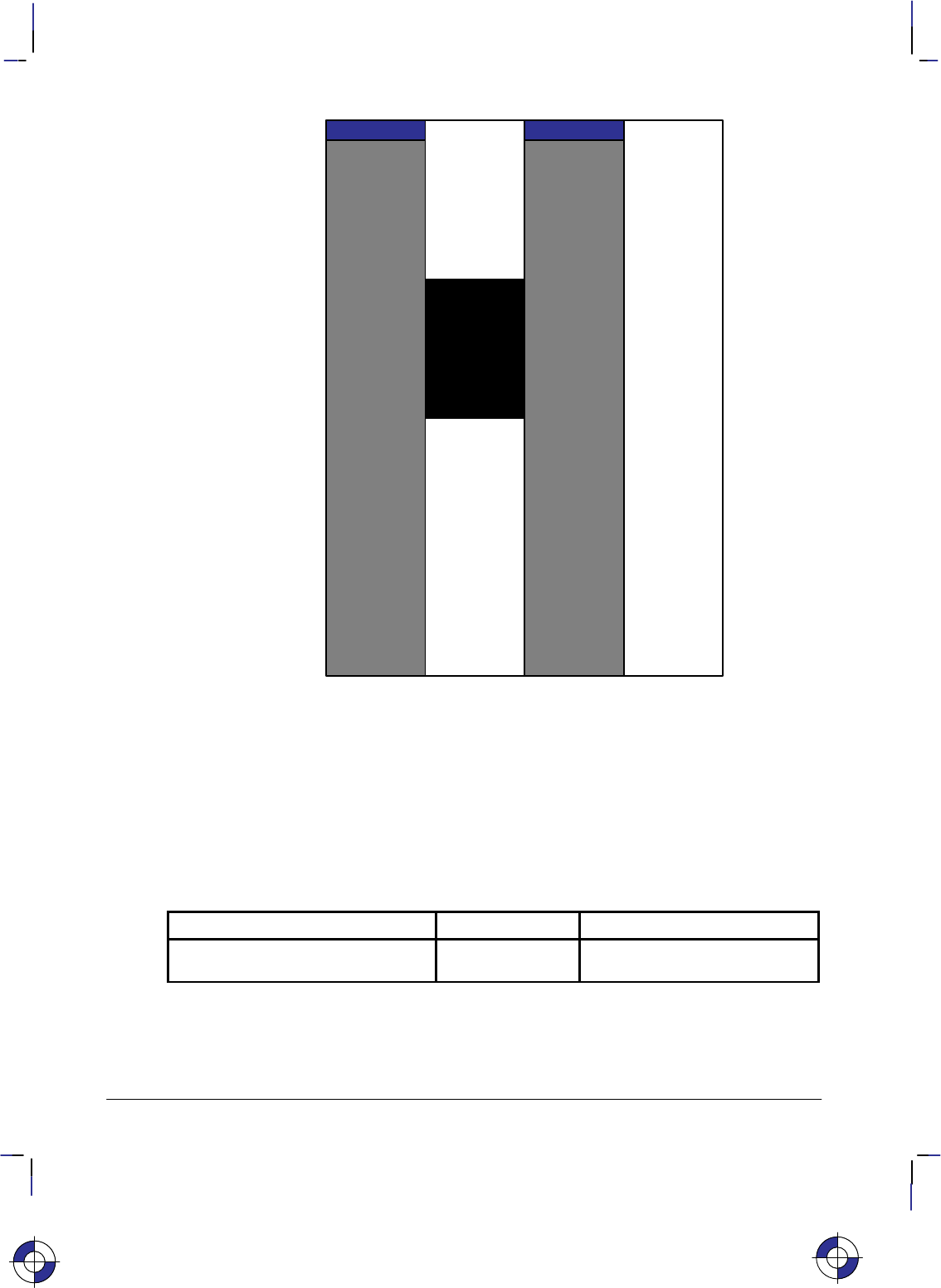
210
This is the black on page 210 (seq: 228)
Company confidential. HP-GL/2 and HP RTL Reference Guide, draft 2. Freeze Status: open
Byte 1
0
1
32
126
127
255
33
0 32 33 126 127 159 160 255
Byte 2
Figure 114. Printing Two-Byte Characters
Related Instructions
LB Label
SM Symbol Mode
Possible Error Conditions
Error Condition Error Number Printer or Plotter Response
Row_number is less than 0 or greater
than 255 3Row_number is set to zero and
the instruction is executed
This is the blue on page 210 (seq: 228)
LM Instruction

211
This is the black on page 211 (seq: 229)
Company confidential. HP-GL/2 and HP RTL Reference Guide, draft 2. Freeze Status: open
LO, Label Origin
Purpose
To position labels relative to the current pen location. Use the LO instruction to center, left
justify, or right justify labels. The label can be drawn above or below the current pen location
and can also be offset by an amount equal to .25 times the point size (or 16 grid units [0.33
times the point size] for the Stick font).
Syntax
LO position[;]
or
LO [;]
Parameter Format Functional Range Parameter Default
position clamped integer 1 through 9,
11 through 19, or 21 1
Group
This instruction is in the Character Group.
Use
The device interprets the parameters as follows:
No Parameters: Defaults the label origin. Equivalent to “LO1”.
position: Specifies the label location relative to the current pen location. Values 1, 2, 3,
11, 12, or 13 left-justify the label; values 4, 5, 6, 14, 15, or 16 center the label; and values
7, 8, 9, 17, 18, or 19 right-justify the label. Values 11, 14, or 17 position the character cell
above the current pen location; values 13, 16, or 19 position the label below the current pen
position or at intermediate points. Values 1 to 9 position the character cell relative to the
current pen position; values 11 to 14 and 16 to 19 offset the labels (the offset is one-quarter
of the character’s point size, or one-third of the point size [16 grid units] for stick fonts).
Left and right are interpreted relative to the character baseline; above and below are
relative to the character-up vector. The position numbers are graphically illustrated in
Figure 115. Each dot represents the current pen location.
The values 11 to 14 and 16 to 19 differ from LO 1 to 4 and 6 to 9 only in that the labels are off-
set from the current pen location. Values 5 and 15 are the same.
The label position 21 provides a PCL-compatible label origin. The character(s) are printed at
the same location as in PCL. (Label position 21 is not shown in Figure 115 because the exact
location is dependent on the PCL position.)
Label origins do not change text path. To change the text path, use the DV (Define Variable
Text Path) instruction.
Each time an LO instruction is sent, the Carriage Return point is updated to the location the pen
was in when the LO instruction was received. The current pen location (but not the carriage-re-
This is the blue on page 211 (seq: 229)
LO Instruction
INSTRUCTIONS
HP-GL/2
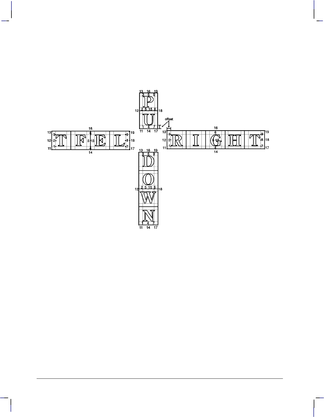
212
This is the black on page 212 (seq: 230)
Company confidential. HP-GL/2 and HP RTL Reference Guide, draft 2. Freeze Status: open
turn point) is updated after each character is drawn and the pen automatically moves to the next
character origin. If you want to return a pen to its previous location prior to the next label
instruction, you can send a Carriage Return after the label text but before the label terminator.
LO positions are applied to imaginary box drawn round the label on a line-by-line basis, regard-
less of the text path set by DV. Figure 115 shows LO positions for each of the possible text
paths. Note the horizontal and vertical offsets for values 11 to 14 and 16 to 19.
Figure 115. Label Origin Positioning
LO updates the carriage-return point to the current position. The current pen position (but not
the carriage-return point) is updated after each character is printed, and the pen moves automat-
ically to the next character origin. When you embed Carriage Return characters in a label, each
portion of the label is positioned according to the label origin, just as if they were written as
separate label instructions. A Carriage Return after the label, but before the label terminator,
returns the pen to the current origin before the next LB.
Control characters such as spaces, horizontal tabs, or backspaces affect the label length for
positioning purposes; however, a backspace at the beginning of a label is ignored.
An LO instruction remains in effect until another LO instruction is executed, or the device is
initialized or set to default conditions.
The pen position at the end of the label string depends on whether two successive LB instruc-
tions concatenate together as though only one label was given. The DV/LO combinations
which permit concatenation are:
LO Instruction

213
This is the black on page 213 (seq: 231)
Company confidential. HP-GL/2 and HP RTL Reference Guide, draft 2. Freeze Status: open
Text Path Label Origin
DV0 (right) LO’s 1, 2, 3, and 11, 12, 13, and 21
DV1 (down) LO’s 3, 6, 9, and 13, 16, 19
DV2 (left) LO’s 7, 8, 9, and 17, 18, 19
DV3 (up) LO’s 1, 4, 7, and 11, 14, 17, and 21
The DV and LO combination is applied on a line-by-line basis; a “line” is established by a car-
riage return, line feed, or the label terminator.
The following two rules determine where the pen is positioned after a label string is drawn.
Rule 1 is for DV/LO combinations which permit concatenation; rule 2 clarifies other DV/LO
combinations:
If a concatenation combination is specified, the pen position is updated to give the normal
delta X space between the last character of the first label, and the first character of the
second label.
Note: For proportional fonts that use a pair-wise spacing table, the pen position is updated
using an average delta X space.
If a non-concatenation combination is specified, the pen position that existed immediately
prior to the LB instruction is restored.
Related Instructions
CP Character Plot
DV Define Variable Text Path
LB Label
Example
SP 1; Select pen number 1.
SC –4000,4000,–5000,5000; Specify scaling by assigning (–4000,–5000) to P1 and
(4000,5000) to P2.
SI .17,.26; Set the absolute character size to 0.17 cm wide by 0.26 cm high.
PA 0,500; Move to (0,500).
PD –500,0,0,–500,500,0,0,500; Set the pen down and draw lines from (0,500) to (–500,0),
to (0,–500), to (500,0), and then to (0,500).
DT#; Define label terminator as “#” character.
CI 10; Draw a small circle (radius 10 plotter-units) to represent the label
origin point.
LO 4; Specify a label origin of 4.
LBCentered on point#; Print “Centered on point”.
PU –500,0; Lift the pen and move to (–500,0).
CI 10; Draw another small circle.
LO 18; Specify a label origin of 18.
LBLeft center offset#; Print “Left center offset”.
PU 0,–500; Lift the pen.
CI 10; Draw another small circle.
This is the blue on page 213 (seq: 231)
LO Instruction
INSTRUCTIONS
HP-GL/2
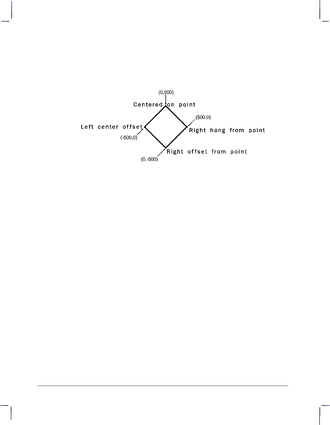
214
This is the black on page 214 (seq: 232)
Company confidential. HP-GL/2 and HP RTL Reference Guide, draft 2. Freeze Status: open
LO 13; Specify label origin number 13.
LBRight offset from point#; Print “Right offset from point”.
PA 500,0; Move to (500,0).
CI 10; Draw another small circle (dot).
LO 3; Specify label origin number 3.
LBRight hang from point#; Print the last label, “Right hang from point”.
Figure 116. Hanging Labels from Various Points
LO Instruction
215
This is the black on page 215 (seq: 233)
Company confidential. HP-GL/2 and HP RTL Reference Guide, draft 2. Freeze Status: open
LT, Line Type
Purpose
To specify the line pattern to be used when drawing lines. Use LT to vary lines and enhance
your plot. Note that the ends of dashed line segments in a line pattern are affected by current
line attributes (refer to the LA instruction on page 200).
Syntax
LT line_type[,pattern_length[,mode]][;]
or
LT [;] or
LT 99 [;]
Parameter Format Functional Range Parameter Default
line_type clamped integer –8 through 8,
99 solid line
restores previous line type
pattern_length clamped real >0 through 32 767 4% of the distance
between P1 and P2
mode clamped integer 0 or 1 0 (relative)
Group
This instruction is in the Line and Fill Attributes Group.
Use
The LT instruction applies to lines drawn by the AA, AR, AT, CI, EA, EP, ER, EW, FP, PA, PD,
PE, PR, RA, RR, RT, and WG instructions. Line types are drawn using the current line attrib-
utes set by the Line Attribute (LA) instruction. For example, if you have used LA to specify
rounded ends, the device draws each dash in a dashed line pattern with rounded ends.
No Parameters: Defaults the line type to solid and saves the previous line type, pattern
length, and any unused portion of the pattern (residue).
line_type: Subsequent lines are drawn with the corresponding line pattern. Line patterns
can be of fixed or adaptive type.
Positive line types (1 to 8) are fixed line types and use the specified pattern length to
draw lines. Any unused part of the pattern (the residue) is carried over into the next
line to give the appearance of the pattern wrapping round corners. The residue is
saved when any of the following instructions are received: CI, EA, EP, ER, EW, FP,
PM, RA, RR, or WG. The residue is restored when the current pen position is restored
upon completion of these HP-GL/2 instructions. You can redefine the eight line types
using the UL instruction.
The current residue and vector end point are also saved before each symbol is drawn,
and on receipt of a CP, LB, or SM instruction. The current residue is restored if the
This is the blue on page 215 (seq: 233)
LT Instruction
INSTRUCTIONS
HP-GL/2
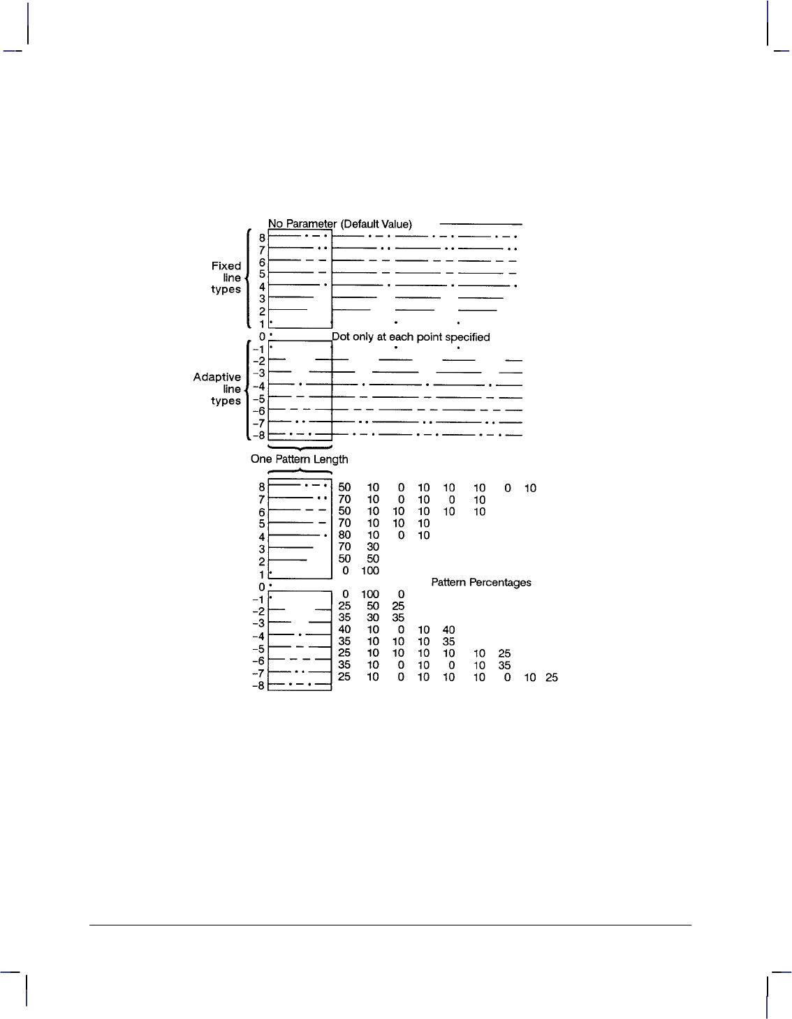
216
This is the black on page 216 (seq: 234)
Company confidential. HP-GL/2 and HP RTL Reference Guide, draft 2. Freeze Status: open
starting point of the next pen-down vector coincides with the saved vector end point;
there can be any number of pen-up vectors before the pen-down vector.
Line patterns are composed of alternate pen down and pen up moves which are per-
centages of the pattern length (the first percentage is always pen down). Figure 117
first shows the line type patterns, then gives the pattern percentages.
Figure 117. Line Type Patterns and Pattern Percentages
Instructions that Affect LT1 to LT8
The following instructions clear the current residue and vector end points:
AC Anchor Corner
DF Default Values
IN Initialize
IP Input P1 and P2
IR Input Relative P1 and P2
IW Input Window
LA Line Attributes
LT Line Type (except “LT;” and “LT99”)
PG Advance Full Page
LT Instruction

217
This is the black on page 217 (seq: 235)
Company confidential. HP-GL/2 and HP RTL Reference Guide, draft 2. Freeze Status: open
PW Pen Width
RF Raster Fill Definition
RO Rotate Coordinate System
RP Replot
SC Scale
SP Select Pen
TR Transparency Mode
UL User-Defined Line Type
WU Pen Width Unit Selection
A zero line type (0) draws only a dot at the X,Y coordinates for AA, AR, AT, BR, BZ,
CI, PA, PD, PR, and RT instructions. Zero pen-down values and zero-length lines also
produce dots. A dot is a one plotter-unit long vector, drawn using the current line end
and pen width. (Dots within lines are drawn at the correct angle, but zero-length vec-
tors are drawn along the user’s current X-axis.)
Negative line types (–1 to –8) are adaptive line types, using the same patterns as line
types 1 to 8. However the pattern length is automatically adjusted so that each line
contains one or more complete patterns.
Adaptive line types are derived from the corresponding fixed line types; if the fixed
line type ends in a “pen-up stretch”, the first percentage is reduced by half and the
amount that it is reduced is added as the last percentage. This ensures that the drawn
vector end points are always visible when an adaptive line type is selected; the pattern
is “on” (or had the pen down) at the beginning and end of the pattern repeat segment.
For redefined fixed line types (see the UL instruction) that end in a “pen-down
stretch”, the adaptive line type is derived by adding the first and last pen-down gap
percentages and using half the sum for both the first and last gap percentages.
Note: Do not use an adaptive line type when you draw circles, arcs, wedges, or poly-
gons. The device will attempt to draw the complete pattern in every chord; there are
72 chords in a circle using the default chord angle.
LT99 restores the previous line type (and residue if it is a fixed-line type).
Note: If a solid line type is selected (“LT;”) when the LT99 instruction is issued, and
the current pen position has not changed, the previously selected line type can be in-
voked using LT99. LT99 is ignored when a non-solid line type is in effect, or if the
pen is in a different position from when the previous non-solid line ended. An exam-
ple using this instruction is to print a line in a non-solid line type, followed by a
rectangle in solid black; beginning at the end point of the previous line, use LT99 to
print another line in the previous non-solid line type.
Instructions that Affect LT99
Sending any of the following instructions while plotting with a solid line type clears
the previous line type and a subsequent “LT99” has no effect:
AC Anchor Corner
BP Begin Plot
DF Default Values
IN Initialize
IP Input P1 and P2
IR Input Relative P1 and P2
IW Input Window
LA Line Attributes
LT Line Type (except “LT;” and “LT99”)
This is the blue on page 217 (seq: 235)
LT Instruction
INSTRUCTIONS
HP-GL/2

218
This is the black on page 218 (seq: 236)
Company confidential. HP-GL/2 and HP RTL Reference Guide, draft 2. Freeze Status: open
PG Advance Full Page
PW Pen Width
RF Raster Fill Definition
RO Rotate Coordinate System
SC Scale
SP Select Pen
TR Transparency Mode
UL User-Defined Line Type
WU Pen Width Unit Selection
pattern_length: Specifies the length of one complete line pattern, either as a percentage
of the diagonal distance between the scaling points P1 and P2 or in millimeters (see mode
below). You must specify a length greater than zero (or use the default). If you do not
specify a length, the device uses the last value specified.
mode: Specifies how the values of the pattern_length parameter are interpreted. If you
do not specify a mode, the device uses the last value specified.
0Relative mode: Interprets the pattern_length parameter as a percentage of the
diagonal distance between P1 and P2.
When specified as a percentage, the pattern length changes along with changes in
P1 and P2.
1Absolute mode: Interprets the pattern_length parameter in millimeters.
When specified in millimeters, fixed line-type patterns assume the specified
length, but adaptive line-type pattern lengths are adjusted downward to fit an inte-
gral number of patterns per vector. (This is true for relative mode and absolute
mode.)
If you do not specify the pattern_length and mode parameters, then the device uses their current
values. When using relative mode and isotropic scaling, the pattern_length changes with
changes to Xmin,Ymin and Xmax,Ymax.
An LT instruction remains in effect until another LT instruction is executed or the device is ini-
tialized or set to default conditions.
Related Instructions
AA Arc Absolute
AR Arc Relative
AT Absolute Arc Three Point
CI Circle
EA Edge Rectangle Absolute
EP Edge Polygon
ER Edge Rectangle Relative
EW Edge Wedge
FP Fill Polygon
FT Fill Type
PA Plot Absolute
PD Pen Down
PE Polyline Encoded
PR Plot Relative
PW Pen Width
RA Fill Rectangle Absolute
RR Fill Rectangle Relative
LT Instruction
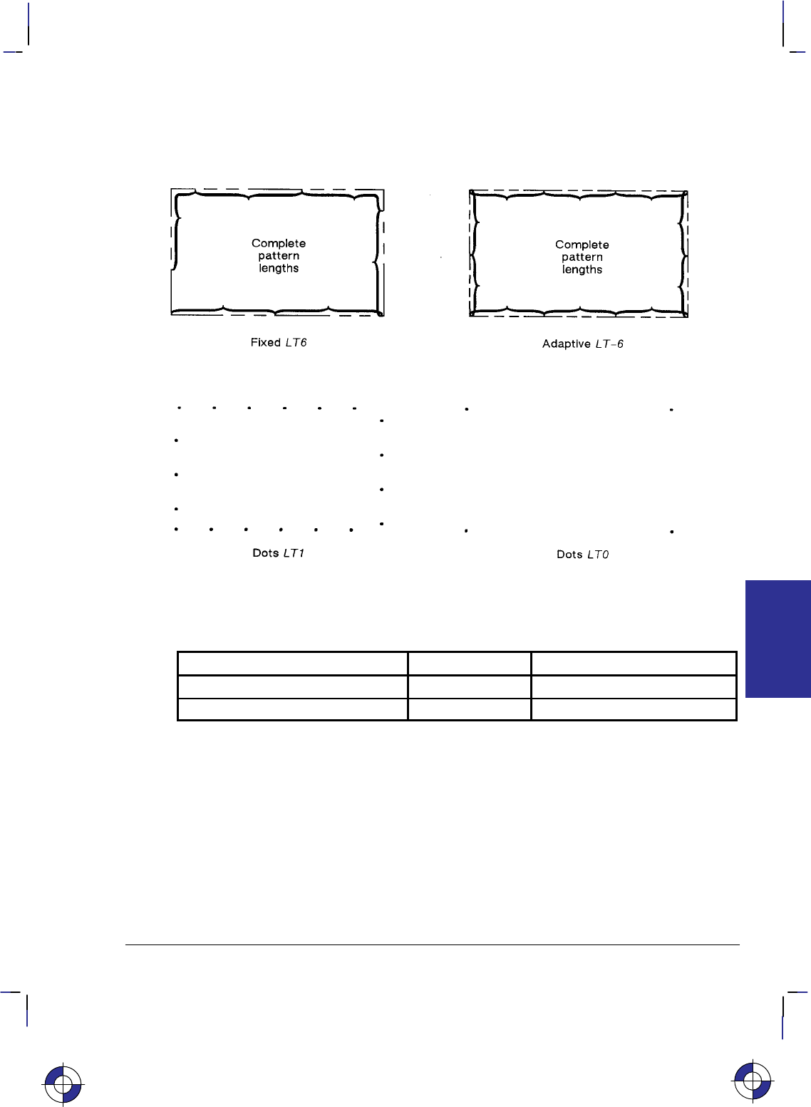
219
This is the black on page 219 (seq: 237)
Company confidential. HP-GL/2 and HP RTL Reference Guide, draft 2. Freeze Status: open
RT Relative Arc Three Point
UL User-Defined Line Type
WG Fill Wedge
Figure 118. Rectangles Drawn with Fixed and Adaptive Line Types
Possible Error Conditions
Error Condition Error Number Printer or Plotter Response
Pattern_length is 0 3 Ignores the instruction.
Mode is not 0 or 1 3 Ignores the instruction.
This is the blue on page 219 (seq: 237)
LT Instruction
INSTRUCTIONS
HP-GL/2
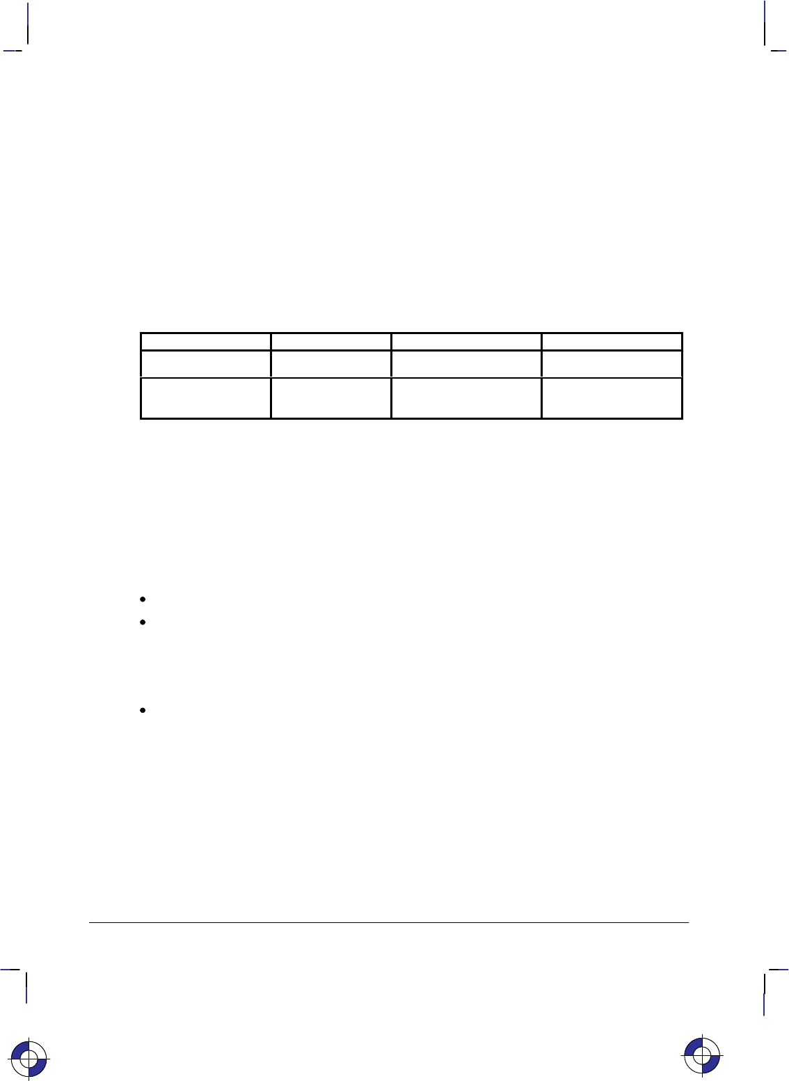
220
This is the black on page 220 (seq: 238)
Company confidential. HP-GL/2 and HP RTL Reference Guide, draft 2. Freeze Status: open
MC, Merge Control
Purpose
To provide control over the color of those pixels where two or more graphics intersect on the
page. This instruction is for raster devices only; it performs no function on pen plotters.
Syntax
MC mode[,opcode][;]
or
MC [;]
Parameter Format Functional Range Parameter Default
mode clamped integer 0 or 1 0 (off)
opcode clamped integer 0 to 255 252 (mode=0)
168 (mode=1)
Group
This instruction is in the Technical Graphics and the Advanced Drawing Extensions.
Use
The merged color is a result of a device-dependent table look-up algorithm in the device. The
table look-up functions on a pixel-by-pixel basis and applied to all graphics done with HP-GL/2
instructions: vectors, text, and polygon fill (including raster patterns).
No parameters: equivalent to “MC0”. Defaults merge control to off.
mode: A clamped integer which specifies one of the following modes:
0 Merge control off: each graphic replaces the pixels at the destination location, and
overwrites the pixels without merging. This is the default.
1 Merge control on: the device creates a merge color at the intersection of the vectors.
opcode: Specifies the logical operations that are to be performed on a source, destination,
and patterned image before drawing the final image. These raster operations are defined in
RGB space and are listed in the table on pages 475 and 476. This parameter is a clamped
integer in the range 0 to 255. The default is 252 when mode=0, and 168 when mode=1.
The logical operations are defined in reverse polish notation (RPN) with the following defini-
tions:
D: Destination (that is, the pixel that is already defined at the point)
S: Source (the new pixel to be applied to the point)
T: Texture (any fill pattern)
a: And o: Or
n: Not x: Exclusive or
This is the blue on page 220 (seq: 238)
MC Instruction

221
This is the black on page 221 (seq: 239)
Company confidential. HP-GL/2 and HP RTL Reference Guide, draft 2. Freeze Status: open
For example, when the mode is 0, the opcode default is 252 (TSo), which is the logical opera-
tion Texture or Source.
When the mode is 1, the opcode default is 168 (DTSoa), which is the logical operation
Destination and (Texture or Source).
Finally, a more complex example is the value 225 (TDSoxn), which is the logical operation
not (Texture xor (Destination or Source)).
The MC (Merge Control) instruction is closely related to the Logical Operation (*l#O) of
PCL and HP RTL (see page 424); the opcode values are the same as the numerical (#) parame-
ter of that command. Logical Operations on page 367 contains more information that equally
applies to the MC instruction.
The following table shows three common opcodes, constructed by reading the output values
bottom-up.
Pixel Combinations Desired Destination Values
Texture
Pixel Source
Pixel Destination
Pixel Source
Overwrite Transparency
Source/
Destination
XOR
0 0 0 0 0 0
001011
010111
011110
100000
101011
110111
111110
Resulting Opcode: 204 (0xCC) 238 (0xEE) 102 (0x66)
Using MC in a Dual-Context Environment
The MC instruction interacts with PCL and HP RTL. In dual-context mode the raster operation
set by this instruction carries over to PCL or HP RTL; similarly any raster operation set in PCL
or HP RTL using the Logical Operation command carries over to HP-GL/2.
Related Instructions and Commands
RF Raster Fill Definition
*l#O Logical Operation
This is the blue on page 221 (seq: 239)
MC Instruction
INSTRUCTIONS
HP-GL/2

222
This is the black on page 222 (seq: 240)
Company confidential. HP-GL/2 and HP RTL Reference Guide, draft 2. Freeze Status: open
MG, Message
Purpose
To write a message to the display on a device’s control panel. If the device does not have a
control panel with a display, this instruction is ignored (a NOP).
Syntax
MG message[;]
or
MG [;]
Parameter Format Functional Range Parameter Default
message quoted string any characters no default
Group
This instruction is in the Technical Graphics Extension.
Use
Character codes in the message are interpreted in the character set enabled at power-up for dis-
play of control-panel menu commands and error messages. The character set selected for
labeling does not affect the display of this instruction.
No parameters: clears the display.
message: Long text lines automatically wrap to the next line if one exists. Once the end
of the display is reached, however, the message does not wrap and overwrite the beginning
of the display.
You can use the following control codes within your message; all other control codes (see
page 67) are ignored: Backspace (), Line Feed (), Carriage Return ().
If your device uses one display for displaying messages and control-panel menus, the device
switches between the MG message and the control-panel menu (for user responses). The de-
vice restores the MG message after the user responds to the control-panel prompt. The device
retains the message until it is overwritten or cleared by another MG instruction or the device is
initialized.
This is the blue on page 222 (seq: 240)
MG Instruction

223
This is the black on page 223 (seq: 241)
Company confidential. HP-GL/2 and HP RTL Reference Guide, draft 2. Freeze Status: open
MT, Media Type
Purpose
To indicate the type of media loaded in the device. This instruction, when used, must appear in
the picture header state; otherwise it is ignored.
Syntax
MT type[;]
or
MT [;]
Parameter Format Functional Range Parameter Default
type clamped integer 0 to 6 device-dependent
Group
This instruction is in the Technical Graphics Extension.
Use
Your device uses this information according to its plotting or printing technology. The device
might, for example, change the resolution, the ink-drop volume, the speed of plotting or print-
ing, or change from unidirectional to bidirectional plotting, or respond in some other way as
necessary. The actual changes made may take into account both the MT and QL (Quality Lev-
el) instructions, internal knowledge of the pen type, and any control-panel set-ups.
All devices recognize the types listed, though several of the types may be treated in the same
way, for example, 1 and 3.
No parameters: The device uses the front-panel setting.
type: A clamped integer in the range 0 to 6, specifying the type of media, as follows:
0Paper
1Transparency film
2Vellum
3Polyester film, such as Mylar
4Translucent paper
5Special paper
6Glossy paper
Related Instruction
QL Quality Level
This is the blue on page 223 (seq: 241)
MT Instruction
INSTRUCTIONS
HP-GL/2

224
This is the black on page 224 (seq: 242)
Company confidential. HP-GL/2 and HP RTL Reference Guide, draft 2. Freeze Status: open
Possible Error Conditions
Error Condition Error Number Printer or Plotter Response
Instruction used outside picture head-
er state (see page 78) 1Ignores instruction
MT Instruction

225
This is the black on page 225 (seq: 243)
Company confidential. HP-GL/2 and HP RTL Reference Guide, draft 2. Freeze Status: open
NP, Number of Pens
Purpose
To establish the size (the number of pens) of the HP-GL/2 palette.
Syntax
NP n[;] or
NP [;]
Parameter Format Functional Range Parameter Default
nclamped integer device-dependent*device-dependent**
* Parameter must be a power of two.
** The default palette size for monochrome raster devices is 2. The default palette size
for color raster devices is 8.
Group
This instruction is in the Palette Extension.
Use
The palette is an array of logical pens, each having an associated color value and an associated
width. Define pen colors through the PC (Pen Color Assignment) instruction, described on
page 239. Establish pen widths through the PW (Pen Width) and WU (Pen Width Units Selec-
tion) instructions, described on pages 264 and 328 respectively.
No Parameters: Defaults the palette size for monochrome devices to 2 pens, and for
color raster devices to 8 pens.
n: Sets the size of the palette as a power of 2. If n is not a power of 2, the device uses
the next larger power of 2. The maximum value of n, while device-dependent, is equal to
or greater than the number of distinct colors the device can produce. If n is greater than the
maximum, the device uses the maximum-size palette.
For pen plotters, NP defines the number of pens and also pen number 0; thus “NP8” defines
pens 1 through 8 plus no pen (pen 0).
For raster devices, NP defines the palette size, for pens numbered 0 through n–1; thus
“NP8” defines pens 0 through 7.
NP does not default pen colors or widths for existing pen values. For example, if the palette
size is decreased from 8 to 4, the pen colors and widths of the first four pens of the old palette
are retained. If the palette size is increased from 8 to 16, the colors and widths for the first
eight pens remain the same, and those for the remainder are defaulted.
If the current pen is outside the range of the new palette size, the device applies a modulo func-
tion to select a pen number within the range of the new palette. The base of the modulo
This is the blue on page 225 (seq: 243)
NP Instruction
INSTRUCTIONS
HP-GL/2
226
This is the black on page 226 (seq: 244)
Company confidential. HP-GL/2 and HP RTL Reference Guide, draft 2. Freeze Status: open
function is either n (for a pen plotter) or n–1 (for a raster device), that is 8 or 7 in the examples
above. See the SP instruction on page 306.
This instruction is usually defaulted by the IN (Initialize) and BP (Begin Plot) instructions.
In dual context environments, you should import the palettes created within PCL, rather than
defining palettes with this instruction.
Possible Error Conditions
Error Condition Error Number Printer or Plotter Response
n<2 3 Ignores instruction
NP Instruction
227
This is the black on page 227 (seq: 245)
Company confidential. HP-GL/2 and HP RTL Reference Guide, draft 2. Freeze Status: open
NR, Not Ready
Purpose
To take the device off-line for a specified amount of time. This can enable you to set control-
panel conditions before starting to plot or print.
Syntax
NR timeout[;]
or
NR [;]
Parameter Format Functional Range Parameter Default
timeout clamped integer 0 to 7200 0
Group
This instruction is in the Technical Graphics Extension.
Use
Place this instruction at the beginning of a plot after the IN or BP instruction. The timeout fea-
ture of this instruction allows the user to set up pen groupings, media registration, pen force and
acceleration, and so on. The device restores its online status and resumes plotting when either
the timeout elapses or the user puts the device back online (whichever comes first).
No parameters: Defaults the timeout to zero (no time-out); equivalent to “NR0”.
timeout: Specifies in seconds how long a user may need to perform any control-panel
set-up operations or media loading. The maximum time-out is device-dependent and may
be clamped without error.
On devices that cannot perform a page advance, the PG instruction places the device in a “not
ready” state. The device remains off-line until new media is loaded or the necessary user inter-
action occurs.
The function performed by “NR;” may produce an indefinite time-out by enabling single-user
mode in a device that can be logically configured to be either a shared or a single-user device,
for example, a device that can accept plots from several ports at once, by interleaving plots in a
queue, or from a single port with no interleaving. This change is device-dependent and is en-
abled using front-panel interaction or switches that can be set by the user.
This is the blue on page 227 (seq: 245)
NR Instruction
INSTRUCTIONS
HP-GL/2
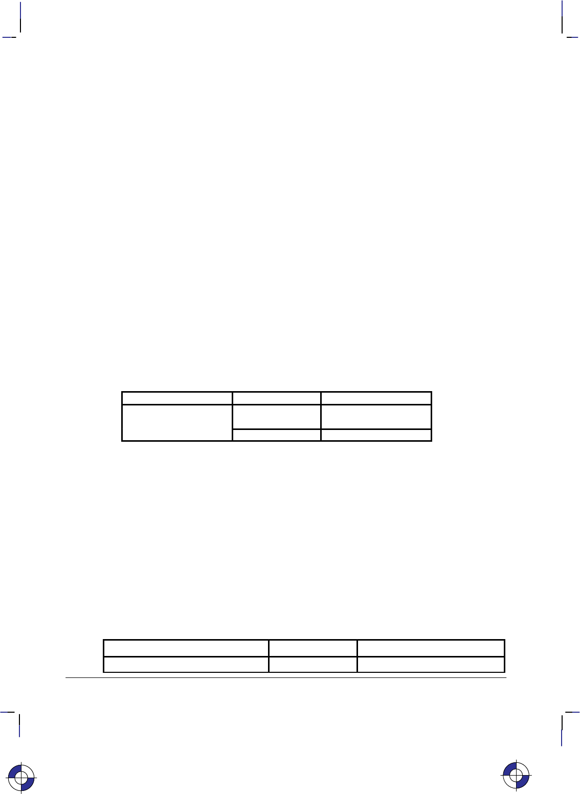
228
This is the black on page 228 (seq: 246)
Company confidential. HP-GL/2 and HP RTL Reference Guide, draft 2. Freeze Status: open
OD, Output Digitized Point and Pen Status
Purpose
To output the X,Y coordinates and pen status (up or down) associated with the last digitized
point. The ranges of the X,Y coordinates are the hard-clip limits of the device; the pen status is
either 0 (up) or 1 (down).
Syntax
OD ;
You must use a terminator with output instructions.
Group
This instruction is in the Digitizing Extension.
Use
Use the following procedure for sending output instructions:
1. Send the OD instruction to the device as you do other HP-GL/2 instructions.
2. Read the device’s output response immediately using an input statement appropriate to
your programming language, keeping in mind the number and type of the variables.
Response Format Range
x,y,pen status (followed
by a terminator) x,y: current units device-dependent
(at least –223 to 223–1)
pen status: integer 0 (up) or 1 (down)
Receipt of this instruction clears bit position 2 of the OS instruction status byte. The tim-
ing of output depends on the interface you are using.
The terminator is a carriage return () for RS-232-C, Bi-Tronics, and MIO interfaces and
carriage return and line feed ( ) for HP-IB interfaces.
3. Output digitized points one at a time. Digitize the point, then output the point to the com-
puter. Continue in this manner until all points on your plot are digitized.
Related Instructions
DC Digitize Clear
DP Digitize Point
OS Output Status
Possible Error Conditions
Error Condition Error Number Printer or Plotter Response
One or more parameters are specified 2 The parameters are ignored
This is the blue on page 228 (seq: 246)
OD Instruction

229
This is the black on page 229 (seq: 247)
Company confidential. HP-GL/2 and HP RTL Reference Guide, draft 2. Freeze Status: open
OE, Output Error
Purpose
To debug programs by retrieving a number that corresponds to the HP-GL/2 error received by
the plotter since the most recent OE, BP, or IN instruction, or power-up. Do not use this
instruction on networks or unidirectional interfaces.
Syntax
OE ;
You must use a terminator with output instructions.
Group
This instruction is in the Technical Graphics Extension.
Use
The OE instruction outputs an integer in the range 0 through 7, corresponding to the first HP-
GL/2 error (if any) that has occurred. The plotter only outputs the first error. If you suspect
more than one error, place the instruction in as many locations in your program as necessary.
The following table defines the error numbers:
HP-GL/2
Error Number Meaning
0No error
1 Unrecognized instruction (or not recognized in current state)
2 Wrong number of parameters
3 Out-of-range or invalid parameter
4 and 5 Not used
6 Position overflow (“lost” mode; see page 23)
7 Buffer overflow, or out of memory
After returning the error number, the plotter sets its internal error number to zero, and clears
bit 5 of the status byte (see the OS instruction), indicating that no error has occurred since the
last OE instruction.
A posted error is not changed until it is cleared.
Multiple errors are set from left to right. For example, “LA 1,9,2;” causes an invalid parameter
error (3) because of the “9”, not a wrong number of parameters error (2).
An instruction is ignored for the following error conditions:
Unrecognized instruction
Missing required parameters
Parameter exceeds the defined limits.
This is the blue on page 229 (seq: 247)
OE Instruction
INSTRUCTIONS
HP-GL/2

230
This is the black on page 230 (seq: 248)
Company confidential. HP-GL/2 and HP RTL Reference Guide, draft 2. Freeze Status: open
If more parameters are supplied than are expected for an instruction, the extra parameters are
ignored and the instruction is executed normally. An error 2 is posted.
If the polygon buffer is full and insertion of more data is attempted, only the portion of the
polygon that fits in the buffer is edged and filled; then an error 7 is posted. The polygon buffer
is large enough to store at least 512 vertices.
If a parameter in the AD, LA, PA, PD, PR, PU, or SD instructions exceeds the limits defined by
the data format type, the out-of-range parameter and all subsequent parameters are ignored.
However, if a kind or value parameter to the AD, BP, LA, or SD instruction is within the data
format type limits, but outside the range defined by the instruction, that parameter pair is ig-
nored; all preceding and subsequent valid pairs are executed. Integer parameter values are
rounded before range checking is performed.
Example
This sequence of instructions contains two errors:
PA 1000,1000,20; PA instruction should have an even number of parameters
ED ; Non-existent instruction
OE ; Output Error
This OE instruction returns 2 followed by a terminator. (The terminator is a carriage return
[] for RS-232-C, Bi-Tronics, and MIO interfaces and carriage return and line feed [ ] for
HP-IB interfaces.) By referring to the table, you know that error 2 indicates the wrong number
of parameters. Once the first error is corrected, run the program again to find the other HP-
GL/2 error.
OE Instruction

231
This is the black on page 231 (seq: 249)
Company confidential. HP-GL/2 and HP RTL Reference Guide, draft 2. Freeze Status: open
OH, Output Hard-Clip Limits
Purpose
To output the X,Y coordinates of the current hard-clip limits to the computer. Use OH to deter-
mine the plotter-unit dimensions of the area within which plotting can occur. Do not use this
instruction on networks or on unidirectional interfaces.
Syntax
OH ;
You must use a terminator with output instructions.
Group
This instruction is in the Technical Graphics Extension.
Use
The OH instruction outputs four integer values, XLL, YLL, XUR, YUR, representing the hard-clip
limits.
The coordinates are always expressed in plotter-units and represent the lower-left (XLL, YLL)
and upper-right (XUR, YUR) corners of the hard-clip limits. After sending the OH instruction,
have your computer program immediately read the device’s output response.
Example
The following program outputs the plotter identification. Use whatever statements your com-
puter language requires to perform the input and output operations.
Send to the device: “%–1BBPIN” Enter HP-GL/2 mode, begin a plot, and ini-
tialize HP-GL/2.
Send to the device: “OH;” Output Hard-Clip Limits.
Read from the device: A,B,Y,Z Read the values into four variables, A, B, Y, and Z.
Print: A,B,Y,Z Print out the four variables, A, B, Y, and Z.
Typical output from the OH instruction might be:
0 0 21050 15000
followed by a terminator. (The terminator is a carriage return [] for RS-232-C, Bi-Tronics,
and MIO interfaces and carriage return and line feed [ ] for HP-IB interfaces.)
Related Instruction
PS Plot Size
This is the blue on page 231 (seq: 249)
OH Instruction
INSTRUCTIONS
HP-GL/2

232
This is the black on page 232 (seq: 250)
Company confidential. HP-GL/2 and HP RTL Reference Guide, draft 2. Freeze Status: open
OI, Output Identification
Purpose
To output the plotter’s identifying order number. This information is useful in a remote operat-
ing configuration (where several plotters are connected to the computer) to determine which
plotter model is online, or when software needs the plotter’s model number. Do not use this
instruction on networks or on unidirectional interfaces.
Syntax
OI ;
You must use a terminator with output instructions.
Group
This instruction is in the Technical Graphics Extension.
Use
The OI instruction outputs the plotter ID, which is a character string of up to 30 characters, and
represents the device’s order number and letter.
Example
The following program outputs the plotter identification. Use whatever statements your com-
puter language requires to perform the input and output operations.
Send to the device: “%–1BBPIN” Enter HP-GL/2 mode, begin a plot, and ini-
tialize HP-GL/2.
Send to the device: “OI;” Output Identification.
Read from the device: A$ Read the device’s identification into the program.
Print: A$ Print it out.
Typical output from this instruction might be:
C4699A
followed by a terminator. (The terminator is a carriage return [] for RS-232-C, Bi-Tronics,
and MIO interfaces and carriage return and line feed [ ] for HP-IB interfaces.)
This is the blue on page 232 (seq: 250)
OI Instruction

233
This is the black on page 233 (seq: 251)
Company confidential. HP-GL/2 and HP RTL Reference Guide, draft 2. Freeze Status: open
OP, Output P1 and P2
Purpose
To output the X, Y coordinates (in plotter-units) of the current scaling points P1 and P2 to the
computer. Use OP to help compute the number of plotter-units per user-unit when scaling is on.
OP can also be used with the IW (Input Window) instruction to set the window to P1 and P2
from your program. Do not use this instruction on networks or on unidirectional interfaces.
Syntax
OP ;
You must use a terminator with output instructions.
Group
This instruction is in the Technical Graphics Extension.
Use
The OP instruction outputs four integer values, P1X, P1Y
, P2X, P2Y
, representing the values of
the coordinates of P1 and P2. The range is device-dependent, but is at least –223 to 223–1.
Note that P2 tracks P1 and can be outside your plotter’s range.
The P1 and P2 coordinates are output as plotter-units. After sending the OP instruction, have
your program immediately read the plotter’s response.
On completion of the output, bit position 1 of the status word is cleared; refer to the OS (Output
Status) instruction.
Example
The following program outputs the plotter’s P1 and P2 coordinates. Use whatever statements
your computer language requires to perform the input and output operations.
Send to the device: “%–1BBPIN” Enter HP-GL/2 mode, begin a plot, and ini-
tialize HP-GL/2.
Send to the device: “OP;” Output P1 and P2.
Read from the device: A,B,X,Y Read the values of P1 and P2 into your program.
Print: A,B,X,Y Print them out.
Typical output from this simple program might be:
0 0 21050 15000
followed by a terminator. (The terminator is a carriage return [] for RS-232-C, Bi-Tronics,
and MIO interfaces and carriage return and line feed [ ] for HP-IB interfaces.)
This is the blue on page 233 (seq: 251)
OP Instruction
INSTRUCTIONS
HP-GL/2

234
This is the black on page 234 (seq: 252)
Company confidential. HP-GL/2 and HP RTL Reference Guide, draft 2. Freeze Status: open
Related Instructions
IP Input P1 and P2
IR Input Relative P1 and P2
OS Output Status
PS Plot Size
OP Instruction

235
This is the black on page 235 (seq: 253)
Company confidential. HP-GL/2 and HP RTL Reference Guide, draft 2. Freeze Status: open
OS, Output Status
Purpose
To output the decimal value of the status byte. Use OS to debug your program. Do not use this
instruction on networks or on unidirectional interfaces.
Syntax
OS ;
You must use a terminator with output instructions.
Group
This instruction is in the Technical Graphics Extension.
Use
The OS instruction outputs an integer in the range 0 through 255, corresponding to the value of
the status byte.
When this instruction is executed, the internal 8-bit status byte is converted into an ASCII inte-
ger between 0 and 255, followed by a terminator, and sent to your computer. (The terminator is
a carriage return [] for RS-232-C, Bi-Tronics, and MIO interfaces and carriage return and
line feed [ ] for HP-IB interfaces.) Your computer program should read the response; refer
to the following table to find the largest decimal value that can be subtracted from the output
response; the condition corresponding to that value has been met.
Continue subtracting the largest possible decimal value from the remainder of the output re-
sponse. Each time you subtract a value, the corresponding condition has been met. Continue
this process until the remainder is 0.
Decimal value Meaning Bit number
1Pen is down 0
2 P1 or P2 newly established; cleared by OP. 1
4 Digitized point entered; cleared by OD. 2
8 Initialized; cleared by OS. 3
16 Ready for data (bit always set to 1). 4
32 Error; cleared by OE. 5
64 Not used (reserved). 6
128 Not used (bit always set to 0). 7
On power-up, the status byte is 26, the sum of 16 (ready for data), 8 (initialized), and 2 (P1/P2
newly established). On execution of OS, bit number 3 is cleared and the status byte is 18.
This is the blue on page 235 (seq: 253)
OS Instruction
INSTRUCTIONS
HP-GL/2

236
This is the black on page 236 (seq: 254)
Company confidential. HP-GL/2 and HP RTL Reference Guide, draft 2. Freeze Status: open
See Monitoring the Status Byte on page 91 for further examples of how to use this instruction.
Related Instructions
IN Initialize
IP Input P1 and P2
IR Input Relative P1 and P2
OE Output Error
OP Output P1 and P2
PS Plot Size
Example
The following program outputs the numeric representation of the status byte. Use whatever
statements your computer language requires to perform the input and output operations.
Send to the device: “%–1BBPIN” Enter HP-GL/2 mode, begin a plot, and ini-
tialize HP-GL/2.
Send to the device: “OS;” Output Status.
Read from the device: S.
Print: S.
OS Instruction

237
This is the black on page 237 (seq: 255)
Company confidential. HP-GL/2 and HP RTL Reference Guide, draft 2. Freeze Status: open
PA, Plot Absolute
Purpose
To establish absolute plotting and moves the pen to the specified absolute coordinates from the
current pen position.
Syntax
PA X,Y [,...][;]
or
PA [;]
Parameter Format Functional Range Parameter Default
X,Y coordinates current units device-dependent
(at least –223 to 223 – 1) no default
Group
This instruction is in the Vector Group.
Use
The device interprets the parameters as follows:
No Parameters: Establishes absolute plotting for subsequent instructions.
X,Y coordinates: Specify the absolute location to which the pen moves. When you
include more than one coordinate pair, the pen moves to each point in the order given,
using the current pen up/down status. If the pen is up, PA moves the pen to the point; if the
pen is down, PA draws a line to the point. Lines are drawn using the current line width,
type, and attributes.
Coordinates are interpreted in current units: as user-units when scaling is on; as plotter-
units when scaling is off.
Note: If an odd number of coordinates is specified (in other words, an X coordinate without a
corresponding Y coordinate), the device ignores the last unmatched coordinate.
When you use the SM (Symbol Mode) instruction, PA draws the specified symbol at each X,Y
coordinate.
When you use the PM (Polygon Mode) instruction, the X,Y coordinates enter the polygon buff-
er for use when the polygon is edged or filled.
The carriage-return point (see page 66) is moved to the last X,Y.
Related Instructions
PE Polyline Encoded
PR Plot Relative
PD Pen Down
This is the blue on page 237 (seq: 255)
PA Instruction
INSTRUCTIONS
HP-GL/2
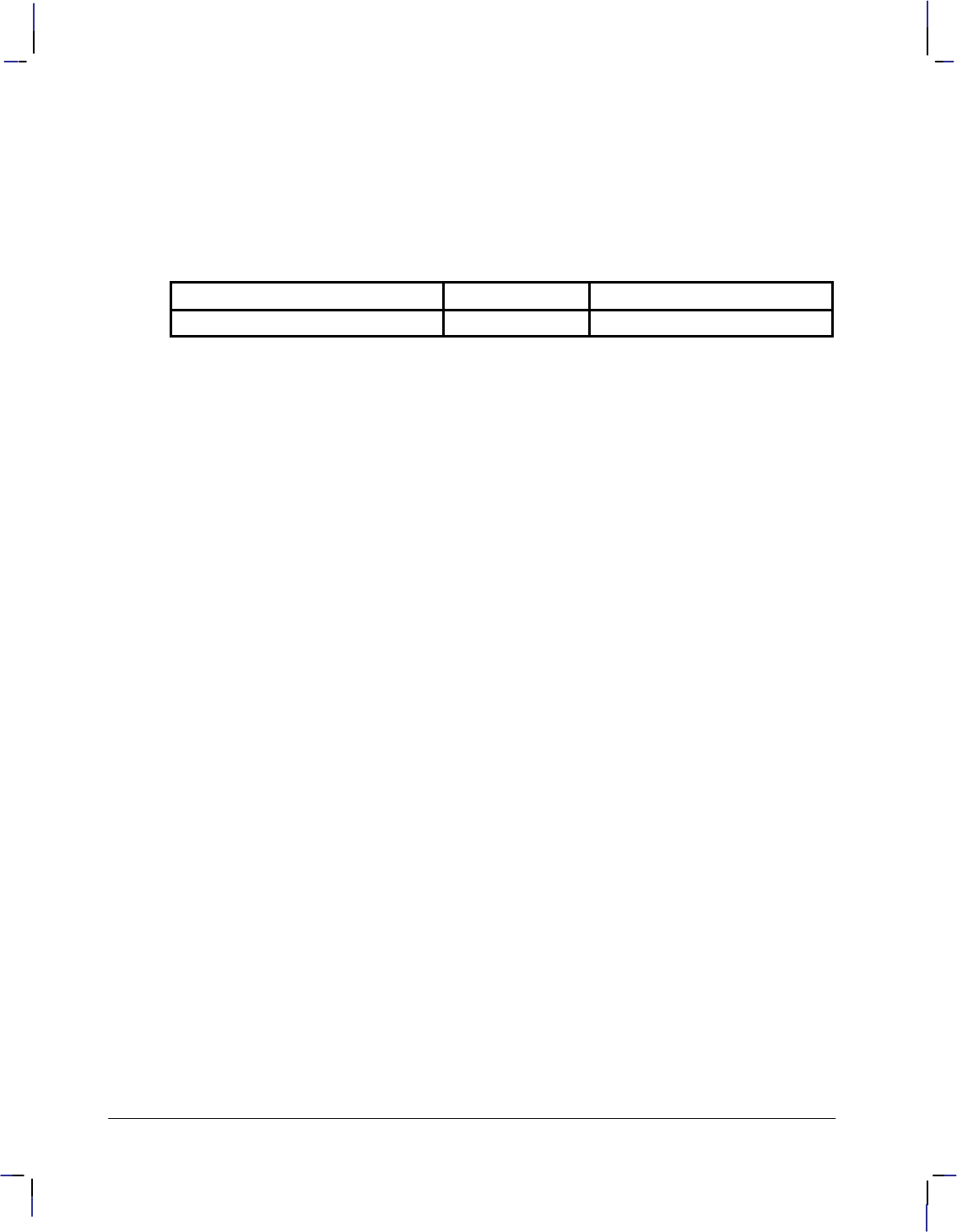
238
This is the black on page 238 (seq: 256)
Company confidential. HP-GL/2 and HP RTL Reference Guide, draft 2. Freeze Status: open
PU Pen Up
LA Line Attributes
LT Line Type
PW Pen Width
SM Symbol Mode
Possible Error Conditions
Error Condition Error Number Printer or Plotter Response
Odd number of parameters 2 Unmatched parameter is ignored.
PA Instruction
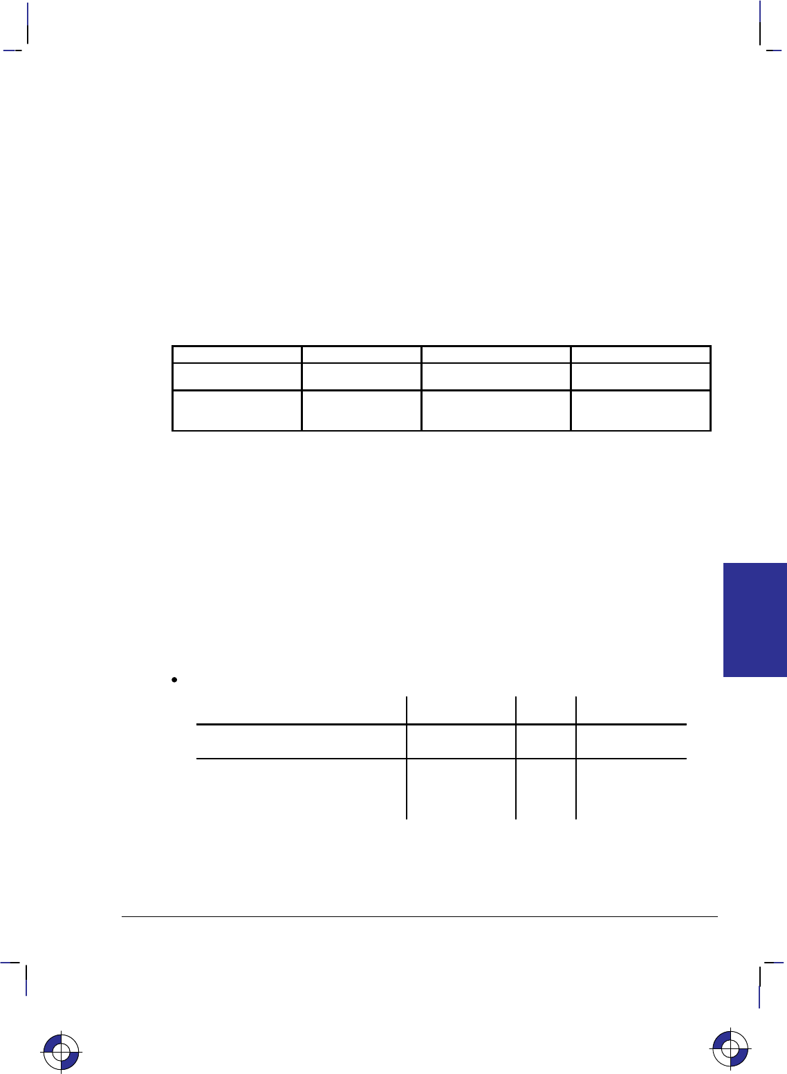
239
This is the black on page 239 (seq: 257)
Company confidential. HP-GL/2 and HP RTL Reference Guide, draft 2. Freeze Status: open
PC, Pen Color Assignment
Purpose
To assign colors to specific pens. This instruction is ignored by pen plotters.
Syntax
PC pen,primary1,primary2,primary3[;]
or
PC pen[;]
or
PC [;]
Parameter Format Functional Range Parameter Default
pen integer determined by NP no default
primary1, primary2,
primary3 clamped real determined by CR (see table below)
Group
This instruction is in the Palette Extension.
Use
With a red/green/blue (RGB) color model, primary1 is red, primary2 is green, and primary3 is
blue.
PC remains in effect until another PC instruction assigns new values for a specific pen or all
pens in the palette, or until the device is initialized by the IN instruction. The first eight pens
for color devices default to the colors in the table below, even when the palette is larger than
eight pens. The remaining pen colors are device-dependent. For a monochrome device, 0 de-
faults to white; all remaining pen colors default to black.
No parameters: Defaults the colors of all pens as follows:
Number of Pens in Palette Pen Number Color Monochrome
2 (NP2) 0
1
White
Bl k
White
Bl k
()
1 Black Black
4 (NP4) 0 White White
(N )
0
1
2
Wte
Black
Rd
Wte
Black
Bl k
2
3
Red
G
Black
Bl k
3 Green Black
This is the blue on page 239 (seq: 257)
PC Instruction
INSTRUCTIONS
HP-GL/2
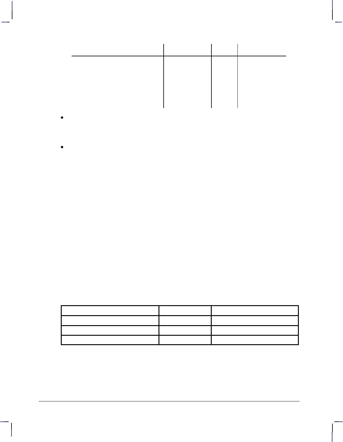
240
This is the black on page 240 (seq: 258)
Company confidential. HP-GL/2 and HP RTL Reference Guide, draft 2. Freeze Status: open
Number of Pens in Palette MonochromeColorPen Number
8 (NP8) 0 White White
8(N 8)
0
1
2
Wte
Black
Rd
Wte
Black
Bl k
2
3
Red
G
Black
Bl k
3
4
Green
Yll
Black
Bl k
4
5
Yellow
Bl e
Black
Black
5
6
Blue
Magenta
Black
Black
6
7
Magenta
Cyan
Black
Black
7
C
yan
Bl
ac
k
pen: Specifies the number of the pen being defined. When you specify only the pen
number (and no RGB values), the pen assumes the color as specified in the table above for
the color space of the palette (for example, “PC3;” defaults pen 3 to green). The range for
the pen parameter is defined by the size of the palette; see the NP instruction on page 225.
primary1, primary2, primary3: Specify the primary component values for the specified
pen. Refer to the CR (Set Color Range for Relative Color Data) instruction on page 131
for a description of the range associated with the RGB values.
If a primary parameter is outside the color range defined in the CR instruction, the value is
clamped to the color range limits.
For a monochrome device that accepts color descriptions, pen 0 defaults to white; all remaining
pen colors default to “equivalent gray levels”. An equivalent gray level means that lighter col-
ors (like yellow) are converted to light gray shades, and darker colors (like purple) are
converted to dark gray shades. The mapping algorithm is device-dependent. However, equiva-
lent gray levels are solid colors, and any white pixels in them are not subject to transparency
mode (TR).
Example
The following instructions set pens 1, 2, and 3, using the default color range for an RGB color
space:
PC 1,255,0,0; Pen 1 is red.
PC 2,0,255,0; Pen 2 is green.
PC 3,0,0,255; Pen 3 is blue.
Possible Error Conditions
Error Condition Error Number Printer or Plotter Response
2 or 3 parameters 2 Ignores instruction
More than 4 parameters 2 Ignores extra parameters
Out-of-range parameter 3 Ignores instruction
PC Instruction

241
This is the black on page 241 (seq: 259)
Company confidential. HP-GL/2 and HP RTL Reference Guide, draft 2. Freeze Status: open
PD, Pen Down
Purpose
To lower the device’s logical pen and draw subsequent graphics instructions.
Syntax
PD X,Y[,...][;]
or
PD [;]
Parameter Format Functional Range Parameter Default
X,Y coordinates current units device-dependent
(at least –223 to 223 – 1) no default
Group
This instruction is in the Vector Group.
Use
On pen plotters, this instruction lowers the pen to draw lines on the page. On other devices it
emulates this lowering of the pen, and must be executed before lines can be drawn.
No Parameters: Prepares the device to draw subsequent graphics instructions.
X,Y coordinates or increments: Draws (in current units) to the point specified. You can
specify as many X,Y coordinate pairs as you want. When you include more than one
coordinate pair, the device draws to each point in the order given. Coordinates are inter-
preted in current units: as user-units when scaling is on; as plotter-units when scaling is off.
Whether the PD instruction uses coordinates or increments depends on the most recently
executed PA or PR instruction. If no PA or PR instruction is issued, absolute plotting (PA)
is used.
The carriage-return point (see page 66) is moved to the last X,Y.
When you use the SM (Symbol Mode) instruction, PD draws the specified symbol at each X,Y
coordinate.
When you use the PM (Polygon Mode) instruction, the X,Y coordinates enter the polygon buff-
er (and are used when the polygon is edged or filled).
Note that “PD;PU;” leaves a dot.
This is the blue on page 241 (seq: 259)
PD Instruction
INSTRUCTIONS
HP-GL/2
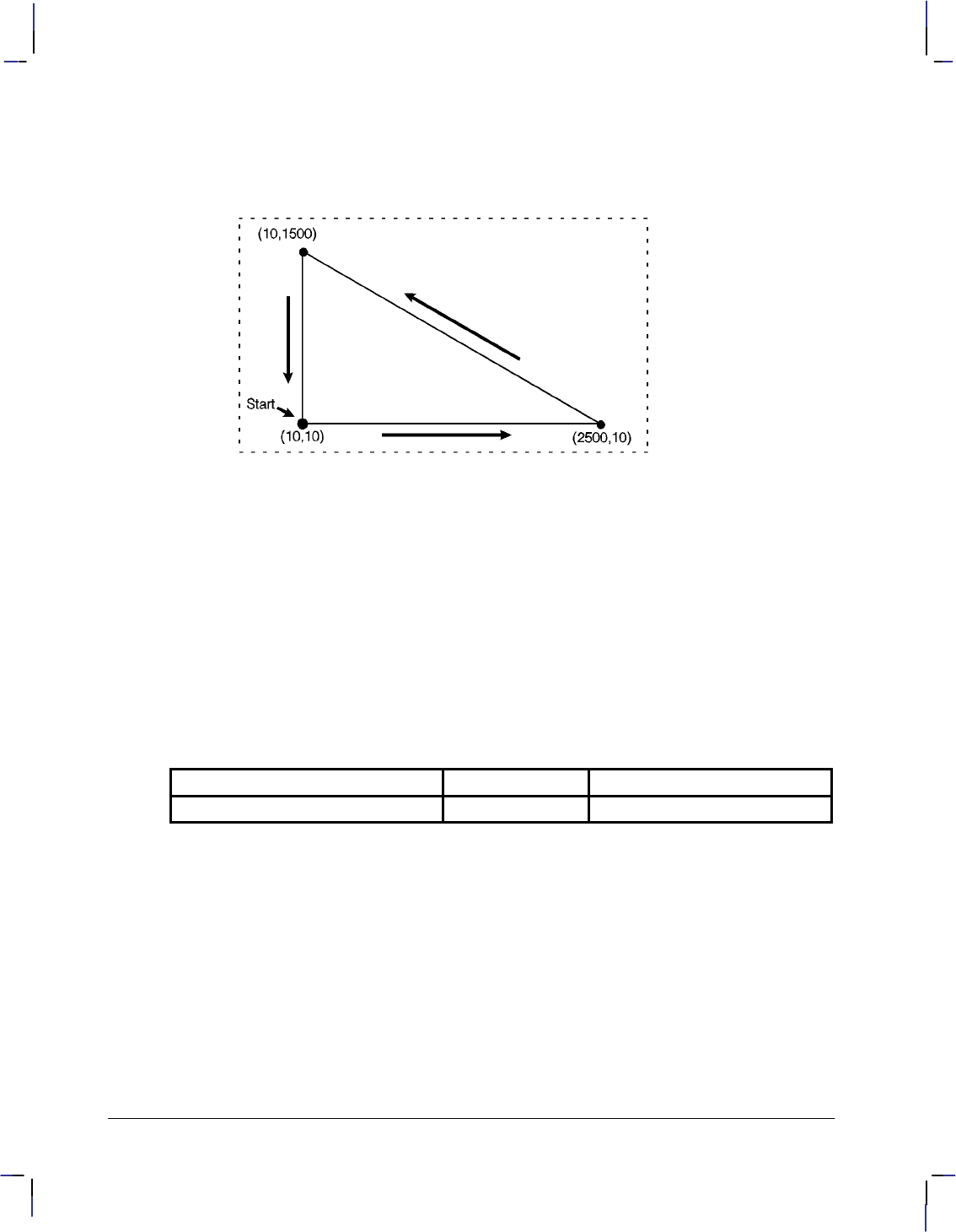
242
This is the black on page 242 (seq: 260)
Company confidential. HP-GL/2 and HP RTL Reference Guide, draft 2. Freeze Status: open
Example
PA 10,10; Begin absolute plotting from coordinate (10,10).
PD 2500,10,10,1500,10,10; Set the Pen Down and draw lines between the specified points.
Figure 119. Using the PD (Pen Down) Instruction
Related Instructions
LA Line Attributes
LT Line Type
PA Plot Absolute
PE Polyline Encoded
PR Plot Relative
PU Pen Up
PW Pen Width
SM Symbol Mode
Possible Error Conditions
Error Condition Error Number Printer or Plotter Response
Odd number of parameters 2 Unmatched parameter is ignored.
PD Instruction
243
This is the black on page 243 (seq: 261)
Company confidential. HP-GL/2 and HP RTL Reference Guide, draft 2. Freeze Status: open
PE, Polyline Encoded
Purpose
To incorporate the PA, PR, PU, PD, and SP instructions into an encrypted format that substan-
tially decreases the size of your file and the time required for data transmission. (This
instruction is especially useful when using an RS-232-C interface or when you need to mini-
mize the file size.)
Syntax
PE [flag[value]]coord_pair...[flag[value]]coord_pair;
or
PE ;
Note: Parameter values are self-terminating; do not use commas with this instruction. Also,
you must use a semicolon to terminate PE.
Parameter Format Functional Range Parameter Default
flag character ‘:’, ‘<’, ‘>’, ‘=’, or ‘7’ no default
value character flag-dependent* see below
coord_pair character device-dependent
(at least –223 to 223 – 1) no default
* Refer to the table following the parameter description.
Group
This instruction is in the Vector Group.
Use
Lines are drawn using the current line type and current units. The device draws to all points
with the pen down unless a pen up flag precedes the X,Y coordinates. If the final move is made
with the pen up, the pen remains in the up position; otherwise the pen is left in the down posi-
tion.
The PE instruction causes the device to interpret coordinate pairs as relative coordinates unless
they are preceded by an absolute value flag (“=”). Relative integer coordinates produce the
most compact data stream. For best results, scale your drawings so you use only integer coordi-
nates and use relative plotting mode. After PE is executed, the previous plotting mode
(absolute or relative) is restored. The PE instruction represents vectors in base 64 (default) or
base 32 (explained under Encoding PE Flag Values and X,Y Coordinates). In parameter value
data, all spaces, delete characters, control characters, as well as ASCII characters 128 through
160 and 255 are ignored.
No parameters: Updates the carriage-return point. The PE instruction without parameters
does not affect the pen’s current location or up/down status.
This is the blue on page 243 (seq: 261)
PE Instruction
INSTRUCTIONS
HP-GL/2
244
This is the black on page 244 (seq: 262)
Company confidential. HP-GL/2 and HP RTL Reference Guide, draft 2. Freeze Status: open
flag: Indicates how the device interprets subsequent values. Flags are ASCII characters
and are not encoded (unlike values and coord_pairs). The device disregards the eighth bit
of a flag (for example, a character code of 61 and a character code of 189 both send “=”
[the Absolute flag]).
Flag Meaning Description
: Select
Pen Indicates that the subsequent value is the desired pen number. A PE
instruction without a Select-pen flag defaults to the currently selected
pen.*
< Pen Up Raises the pen and moves to the subsequent coordinate pair value. (All
coordinate pair values not preceded by a Pen-up flag are considered
pen down moves.)**
>Fraction-
al Data Indicates that the subsequent value specifies the number of fractional
binary bits contained in the coordinate data. Default is zero.
= Absolute Indicates that the next point is defined by absolute coordinates.
7 7-bit
Mode Indicates that all subsequent coordinate pair values should be inter-
preted in 7-bit mode. Once you send a seven-bit flag, base 32 is used
and eighth bits are ignored for the remainder of the instruction.
* Because SP is not allowed in polygon mode, if you select a pen within PE while in
polygon mode, the Select Pen flag is ignored.
** We recommend you always follow a pen-up flag with a relative move of (0,0). This
ensures that the next plotting coordinates are drawn.
value: Specifies data according to the preceding flag. For example, a value following a
Select-pen flag is a pen number. Values are encoded in the same manner as coordinate
data. Instructions for encoding values follow the parameter descriptions.
–Pen Number—Specifies the pen to be selected (the range is device-dependent). The
pen number must be encoded into a base 64 or base 32 equivalent.
–Number of Fractional Binary Bits—Specifies the number of fractional binary bits con-
tained in the coordinate data. The number of fractional binary bits must be encoded
into a base 64 or base 32 equivalent (see the explanation below).
Value Format Range
Pen number integer device-dependent
Number of fractional binary bits integer device-dependent
If the current pen position goes out of the supported range, the device ignores plotting
instructions until it receives an absolute PA or PE coordinate within the range.
X,Y coordinates: Specifies a coordinate pair encoded into a base 64 (default) or a base 32
equivalent. Use base 64 if your system can send 8 bits of data without parity. Use 7-bit
mode and base 32 coordinate values if your system requires a parity bit.
When you are in symbol mode (refer to the SM instruction), PE draws the specified symbol
at each X,Y coordinate. When you are in polygon mode (refer to the PM instruction), the
X,Y coordinates enter the polygon buffer; they are used when the polygon is edged or
filled.
This instruction updates the carriage-return point to the last X,Y position.
PE Instruction

245
This is the black on page 245 (seq: 263)
Company confidential. HP-GL/2 and HP RTL Reference Guide, draft 2. Freeze Status: open
Encoding PE Flag Values and X,Y Coordinates
Flag values and X,Y coordinates are encoded into a base 64 (default) or base 32 equivalent
(7-bit mode). The following steps give a generic algorithm for encoding a number. Assume x
is the number to be encoded. Use steps 1 and 2 only if you are encoding fractional data; other-
wise, begin with step 3. Note: When converting numbers to base 32 or 64 (step 4 in the
following instructions), note that highest order digits are always in the high range, all other dig-
its are in the low range. Therefore, if there is only one digit in a number, it is in the high range.
Steps Example
1. Fraction adjustment. If you are using fractional data,
this step converts the number of decimal places in your
data to the number of binary fractional bits. Assume
“n” is the number of fractional binary bits specified by
the fractional data flag.
x = 82.83
a. Multiply the number of decimal places contained
in the data by 3.33. 2 3.33 = 6.66
b. Round that number up to the next integer to get
integer n.
x = x 2n
n = round (decimal places
3.33) = 7
x = 82.83 27 = 10 525.42
2. Round to an integer. Round the results of step 1 to
the nearest integer.
x = round (x)
x = round (10 525.42) = 10 525
3. Set the sign bit. If x is positive, multiply it by two. If
x is negative, multiply the absolute value of x by two
and add one. This sets the sign bit.
if (x 0)
x = 2 x
else x = 2 abs(x) + 1
x = 2 10 525 = 21 050
4. Convert the number to base 64 or 32 and encode the data.
Convert x to a base 64 number if your system sends 8 bits without parity. Convert x to a
base 32 number if your system sends 7 bits with parity (seven-bit flag is sent).
Encode each base 64 or 32 digit into the ASCII character range, as described below.
Output each character as it is encoded, starting with the least significant digit. The most
significant digit is used to terminate the number and is encoded into a different ASCII
character range than the low-order digits.
Each number in a coordinate pair is represented as zero or more non-terminator
characters, followed by a terminator character. A character is a non-terminator or
terminator depending on the range it is in; refer to the following table. For example, in
base 64 there are 64 non-terminator and 64 terminator characters. Either kind represents
a “digit.”
For 8-bit data (base 64), the non-terminators are in the range 63 through 126, and the
terminators are in the range 191 through 254.
For 7-bit data (base 32), the non-terminators are in the range 63 through 94, and the
terminators are in the range 95 through 126.
Note: Values following the fractional data or select pen flag also must be encoded.
This is the blue on page 245 (seq: 263)
PE Instruction
INSTRUCTIONS
HP-GL/2
246
This is the black on page 246 (seq: 264)
Company confidential. HP-GL/2 and HP RTL Reference Guide, draft 2. Freeze Status: open
Steps Example
while n base
output CHR$(63 + (n MOD base))
n = n base
end
if base = 64 then n = 191 + n
if base = 32 then n = 95 + n
output CHR$(n)
4. a. Base 64. Encode all the low order digits into the
ASCII range 63 to 126. For a digit with value i, use
ASCII character CHR$(63 + i). Encode the highest
order digit (or the single digit in a one-digit number)
into the range 191 to 254.
21 0504 096=5 rem 570
570 64 = 8 remainder 58
5 in 4 096’s place
8 in 64’s place
58 in 1’s place
Low order digit: 1’s place
(range 63 to 126)
63 + 58 = 121
output CHR$ (121)
Next order digit: 64’s place
(range 63 to 126)
63 + 8 = 71
output CHR$ (71)
High order digit: 4 096’s place
(range 191 to 254)
191 + 5 = 196
output CHR$ (196)
4. b. Base 32. Encode all the low order digits into the
ASCII range 63 to 94. For a digit with value i, use
ASCII character CHR$(63 + i). Encode the highest
order digit (or the single digit in a one-digit number)
into the range 95 to 126.
21 0501 024=20 rem 570
570 32 = 17 remainder 26
20 in 1024’s place
17 in 32’s place
26 in 1’s place
Low order digit: 1’s place
(range 63 to 94)
63 + 26 = 89
output CHR$(89)
Next order digit: 32’s place
(range 63 to 94)
63 + 17 = 80
output CHR$ (80)
High order digit: 1 024’s place
(range 95 to 126)
95 + 20 = 115
output CHR$ (115)
Programming Considerations with the PE Instruction
When using PE (in the default relative mode), the application program does not know the cur-
rent pen location after printing a label (normally, the current pen location is updated to the end
of the label.) If this presents a problem in your program, follow these steps:
1. Create a flag called “lost” in your program.
PE Instruction

247
This is the black on page 247 (seq: 265)
Company confidential. HP-GL/2 and HP RTL Reference Guide, draft 2. Freeze Status: open
Note: At the beginning of your application program, set “lost” to “true”. Then, specify the
next coordinate in absolute mode (PA or PE=).
2. After labeling (or any instruction which updates the current pen location), set “lost” to
“true”.
3. If “lost” = “true” at the beginning of the PE instruction, use an Absolute flag for the first
coordinate pair only (subsequent coordinates are interpreted as relative).
4. Set “lost” to “false”.
When you are converting and encoding data, note the following:
n 64. You can optimize your application by shifting six bits to the right, since shifting is
normally faster than division.
n MOD 64. The number can be logically AND’d with 63, also for improved performance.
Example
The following partial program converts three relative real coordinates to base 64:
Prompt user: “Input number of fractional decimal places in data”.
Read the response into: F (in this example, 2 decimal places).
Calculate Number of Fractional Binary Bits.
F = F * 3.33
F = INT(F) INT is the integer function.
A = F
IF F 0 THEN F = 2*ABS(F) ELSE F = 2*ABS(F)+1
F = 191+F
Send to the device: “PE>”+CHR$(F) (using BASIC language notation)
Convert coordinate data to base 64
FOR J = 1 to 6
READ C
C = C * (2^A) (^ is the exponential function)
C = INT(C)
IF C 0 THEN C = 2*C ELSE C = 2*ABS(C)+1
WHILE C 64
Send to the device: CHR$(63+(C MOD 64))
C = C 64
End WHILE
C = 191+C
Send to the device: CHR$(C)
NEXT J
Send to the device: “;”
Typical data for this program might be: 10.58,0,–5.58,10.67,–5,–10.67
This is the blue on page 247 (seq: 265)
PE Instruction
INSTRUCTIONS
HP-GL/2
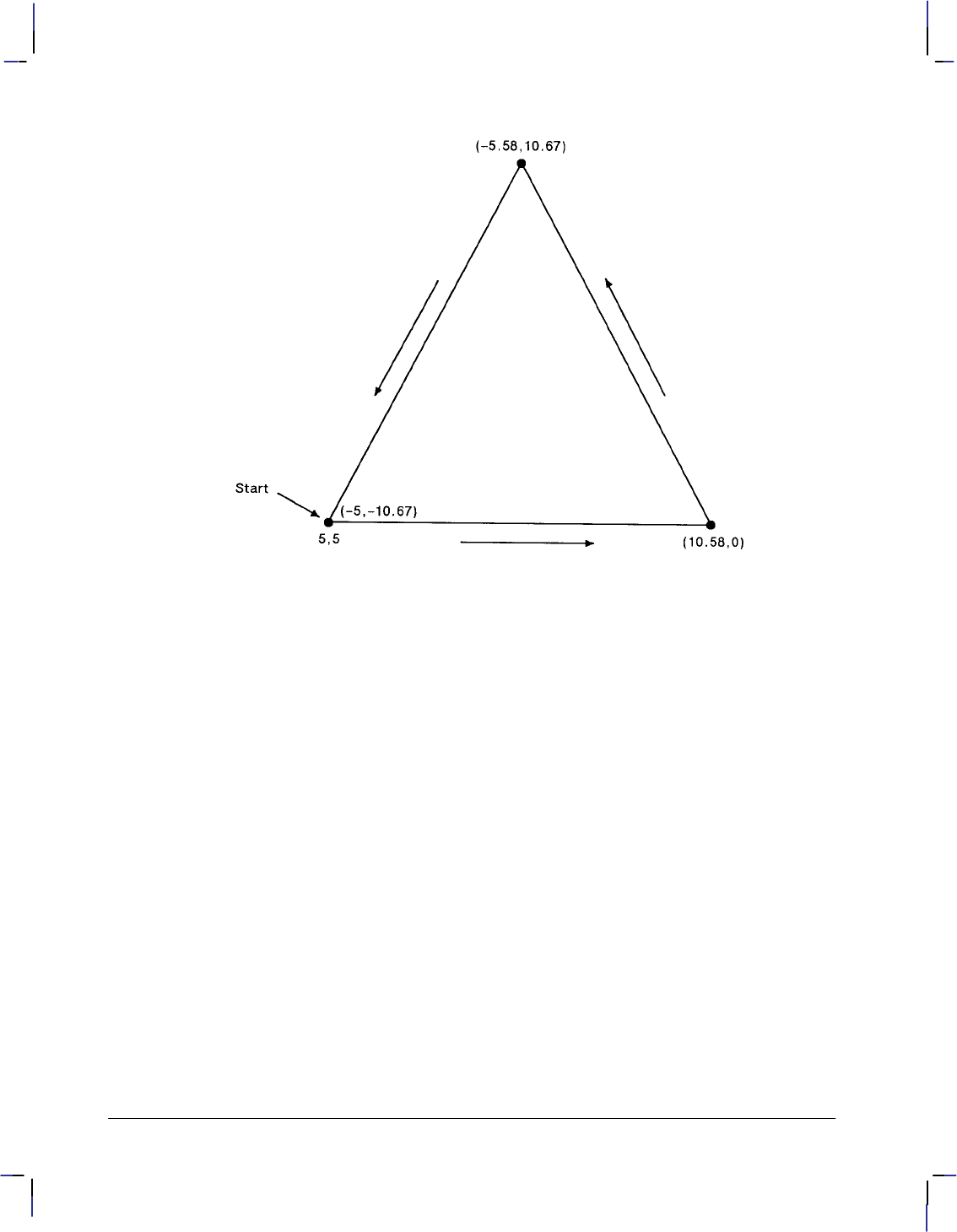
248
This is the black on page 248 (seq: 266)
Company confidential. HP-GL/2 and HP RTL Reference Guide, draft 2. Freeze Status: open
Figure 120. Triangle Drawn Using the PE (Polyline Encoded) Instruction
A PE instruction to draw this triangle, with numbers in brackets [] denoting ASCII characters,
might be:
Hexadecimal:
PE : [197] Select pen no. 6 (191+6). 3A C5
> [198] 7 fractional bits (2 decimal places, 191+7). 3E C6
< Pen up. 3C
= [63][211][63][211] Absolute move to (5,5). 3D 3F D3 3F D3
[83][233][191] Plot relative by (+10.58,+0). 53 E9 BF
[84][213][107][233] Plot relative by (–5.58,+10.67). 54 D5 6B E9
[64][211][108][233] Plot relative by (–5,–10.67). 40 D3 6C E9
; Terminate instruction. 3B
Related Instructions
LA Line Attributes
LT Line Type
PA Plot Absolute
PD Pen Down
PR Plot Relative
PU Pen Up
PW Pen Width
SM Symbol Mode
PE Instruction

249
This is the black on page 249 (seq: 267)
Company confidential. HP-GL/2 and HP RTL Reference Guide, draft 2. Freeze Status: open
PG, Advance Full Page
Purpose
For devices with page advance capability: to terminate the plot being sent, to draw it, and to
advance the page.
For devices without page advance capability: If the media has been plotted on, to perform the
function of the NR (Not Ready) instruction (see page 227).
On PCL devices with HP-GL/2 capability, this instruction is ignored (see Using PG in a PCL
Dual-Context Environment below).
Syntax
PG n[;] or
PG [;]
The PG instruction, with or without parameters, must be terminated with a semicolon, unless it
is immediately followed by the RP (Replot) instruction (see page 279).
Parameter Format Functional Range Parameter Default
nclamped integer –32 768 to 32 767 no parameter
Group
This instruction is in the Configuration and Status Group.
Use
Some devices require an end-of-file marker to designate the end of incoming data. The PG
instruction is a common marker for HP-GL/2 devices (the RP instruction is another). When the
PG instruction is received, the plot is drawn and the page is ejected. If the plotter expects but
does not receive the PG instruction, it will wait for user interaction through the control panel
before it draws the plot.
PG moves the current pen location to the lower-left corner of the hard-clip limits on the next
page, raises the pen, and retains the current plotting mode (relative or absolute). PG does not
affect P1 and P2 values or plot rotation.
No Parameter: Advances the page only if you have plotted on the current page. This is
the recommended method of using the PG instruction.
n: Advances the page whether or not you have plotted on the media.
The current plot remains stored after a page eject until an instruction is received that marks the
page or adds edges in the polygon buffer.
PG clears the current pattern residue and terminates any continuous vector sequence (see the
LA and LT instructions).
This is the blue on page 249 (seq: 267)
PG Instruction
INSTRUCTIONS
HP-GL/2

250
This is the black on page 250 (seq: 268)
Company confidential. HP-GL/2 and HP RTL Reference Guide, draft 2. Freeze Status: open
Using PG in a PCL Dual-Context Environment
PG is ignored in PCL. A page eject is possible only can only be accomplished by the form feed
() control character. A form feed causes an unconditional page eject and advances the cur-
rent active position to the same horizontal position at the top of the next form (top margin).
Note that the HP-GL/2 pen position is not affected by a form feed; it occupies the same position
on the next page. A PCL reset, page length, page size, orientation, or input cassette control
instruction causes a conditional page eject. When a page is ejected, the PCL cursor is set to the
“home position” (at the left and top margin) on the new page. A page eject caused by a PCL
command does not effect the HP-GL/2 cursor position.
This HP-GL/2 instruction is ignored by the device since it could cause undesirable results when
importing plots. A page eject can be accomplished only from the PCL printer language mode.
In an HP RTL dual-context environment, an E (Reset) command performs the PG func-
tion; a form feed () character is ignored.
Related Instructions
BP Begin Plot
PS Plot Size
RP Replot
PG Instruction

251
This is the black on page 251 (seq: 269)
Company confidential. HP-GL/2 and HP RTL Reference Guide, draft 2. Freeze Status: open
PM, Polygon Mode
Purpose
To enter polygon mode for defining shapes, such as block letters or any unique area, and exits
for subsequent filling or edging. Fill polygons using the FP (Fill Polygon) instruction or outline
them using the EP (Edge Polygon) instruction.
Syntax
PM polygon_definition [;]
or
PM [;]
Parameter Format Functional Range Parameter Default
polygon_definition clamped integer 0, 1, and 2 0
Group
This instruction is in the Polygon Group.
Use
In polygon mode, you define the area of the polygon(s) using graphics instructions. These
instructions (and associated X,Y coordinates) are stored in the polygon buffer. The polygon is
not drawn until you exit polygon mode and fill or outline the area.
No Parameters: Clears the polygon buffer and enters polygon mode. Equivalent to
“PM0”.
polygon_definition: Defines polygon mode status as follows.
0Clears the polygon buffer and enters polygon mode.
1Closes the current polygon (or subpolygon) with a pen-up edge, and remains in
polygon mode; all instructions sent following PM1 but before a PM2 (or the next
PM1) are stored as one subpolygon.
2Closes current polygon (or subpolygon) and exits polygon mode.
The following paragraphs explain how to use each parameter. The order in which you use these
instructions is very important. “PM1” and “PM2” are ignored if not preceded by “PM0”.
“PM0” or “PM”
Use “PM0” to clear the polygon buffer and enter polygon mode. While in polygon mode, only
certain instructions are allowed, as follows:
AA Arc Absolute
AR Arc Relative
AT Absolute Arc Three Point
This is the blue on page 251 (seq: 269)
PM Instruction
INSTRUCTIONS
HP-GL/2

252
This is the black on page 252 (seq: 270)
Company confidential. HP-GL/2 and HP RTL Reference Guide, draft 2. Freeze Status: open
BP Begin Plot (this instruction automatically closes polygon mode and initializes the
device)
BR Bezier Relative
BZ Bezier Absolute
CI Circle
CO Comment
DF Default Values (this instruction automatically closes polygon mode and applies
defaults to the device)
IN Initialize (this instruction automatically closes polygon mode and initializes the
device)
PA Plot Absolute
PD Pen Down
PE Polyline Encoded
PM1/PM2 Polygon Mode
PR Plot Relative
PU Pen Up
RT Relative Arc Three Point
The polygon buffer stores the lines (vectors) that define your polygon. These vectors are ac-
cessed later when you exit polygon mode and fill or edge the polygon.
Note: While in polygon mode, the CI instruction is interpreted differently than other graphics
instructions. Refer to Drawing Circles in Polygon Mode on page 52 for more details. When
you use the PE instruction in polygon mode, you cannot change pens; any new pen selection is
ignored.
When you define a polygon, the pen location before the “PM0” instruction is the first point
(vertex) of the polygon, and the first point stored in the polygon buffer. For example, if you
execute the instructions “PA0,1750;PM0”, the absolute coordinates (0,1750) specify the first
point of your polygon. Each subsequent pair of coordinates defines a point, or vertex, of the
polygon.
You can define points with the pen up or down. However, the EP instruction only draws be-
tween points that are defined when the pen is down. On the other hand, the FP instruction fills
the area(s) between all vertices, regardless of whether the pen is up or down when the vertices
are defined.
It is good programming practice to “close” the polygon before exiting polygon mode. Closing
a polygon means adding the final vertex that defines a continuous shape; the last coordinates or
increments represent the same location as the first. If you have not closed the polygon, execut-
ing “PM1” or “PM2” forces closure by adding a point to close the polygon.
You can also use the IN (Initialize) or DF (Default Values) instructions while in polygon mode.
Both instructions exit polygon mode, clear the polygon buffer, and begin executing subsequent
instructions immediately. Output instructions can also be used; they are not stored in the poly-
gon buffer, but are executed immediately. You must exit polygon mode to execute other
HP-GL/2 graphics instructions.
“PM1”
Use “PM1” to close the current polygon (or subpolygon) and remain in polygon mode; the de-
vice adds a closure point if necessary. When you use “PM1”, the point after “PM1” becomes
the first point of the next subpolygon. This move is not used as a boundary when filling a poly-
gon with FP. When drawing the polygon, the pen always moves to this point in the up position,
PM Instruction

253
This is the black on page 253 (seq: 271)
Company confidential. HP-GL/2 and HP RTL Reference Guide, draft 2. Freeze Status: open
regardless of the current pen status. Each subsequent coordinate pair after “PM1” defines a
point of the subpolygon.
With the exception of the first chord in AA, AR, AT, and RT, this point is treated as a pen-up
move regardless of the current pen state. All subsequent points become vertices of the subpoly-
gon until “PM1” or “PM2”. “PM1” adds a point to implicitly close a polygon that has not
already been explicitly closed.
“PM2”
Use “PM2” to close the current polygon (or subpolygon) and exit polygon mode. Remember, if
you have not closed your polygon, executing “PM2” adds a point to close the polygon. Refer
to Pen Location on page 23.
After you exit polygon mode, the EP (Edge Polygon) or FP (Fill Polygon) instructions draw the
polygon. Although points may be defined with the pen up or down, EP draws only between
points defined with the pen down, while FP fills the areas between all defined points.
A polygon with fewer than three points is not drawn; it is not filled by FP nor edged by EP.
This syntactical incompleteness is different from when a polygon is correctly specified but geo-
metrically degenerate (for example, a polygon limited to coincident points is rendered as a dot,
and one limited to collinear points is rendered as a line).
A point added by implicit closure counts as one of the three points. If a complex polygon con-
tains a dot (a zero-dimension subpolygon), enough points must be specified (for example, by
“PR0,0;”) to have three upon closure.
Using PM in a Dual-Context Environment
E is also recognized in polygon mode. It causes the device to exit polygon mode, clear the
polygon buffer, exit HP-GL/2 mode, and eject a page. Sending an E while in polygon
mode is not recommended, but it performs an important function (allowing you to recover from
a previous job that left the device in polygon mode).
Example
The following example draws the surface area of a 3-prong electrical receptacle as a series of
subpolygons, then fills and edges it using the FP and EP instructions, respectively.
PA 2000,2000; Specify absolute plotting and move to (2000,2000).
PM 0; Enter polygon mode.
PD 3000,2000,3000,3000; Store a Pen Down instruction, and store locations (3000,2000)
and (3000,3000).
PD 2000,3000,2000,2000; Store two more pen-down locations, (2000,3000) and
(2000,2000).
PM 1; Close the first polygon (the outer square).
PD 2080,2160,2480,2160, 2480,2340,2080,2340,2080,2160; Store 5 pen-down locations
for a subpolygon.
PM 1; Close the subpolygon (the lower rectangle).
PD 2080,2660,2480,2660,2480,2840,2080,2840,2080,2660; Store pen-down locations for
another subpolygon.
PM 1; Close the second subpolygon (the upper rectangle).
PM Instruction
INSTRUCTIONS
HP-GL/2
This is the blue on page 253 (seq: 271)
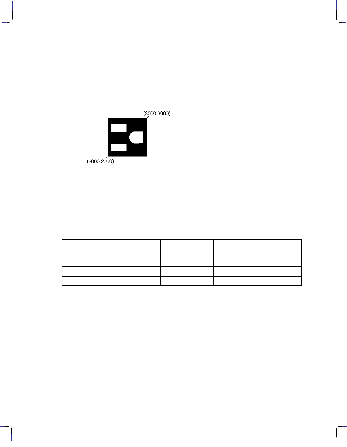
254
This is the black on page 254 (seq: 272)
Company confidential. HP-GL/2 and HP RTL Reference Guide, draft 2. Freeze Status: open
PD 2920,2340,2920,2660,2720,2660; Begin a third subpolygon that draws the ground plug
portion of the receptacle.
AA 2720,2500,180; Store a 180 arc that goes from (2720,2660) to (2720,2500).
PD 2920,2340; Complete the ground-plug subpolygon.
PM 2; Close the subpolygon and exit polygon mode.
FP ; Fill (even/odd) the polygon.
EP ; Then edge the polygon and subpolygons currently stored in the
buffer.
Figure 121. Example that Uses Polygon Mode
Related Instructions
EP Edge Polygon
FP Fill Polygon
Possible Error Conditions
Error Condition Error Number Printer or Plotter Response
Invalid instruction used in polygon
mode 1Ignores invalid instruction
Parameter out of range 3 Ignores instruction
Buffer overflow 7 Ignores overflowing points
PM Instruction
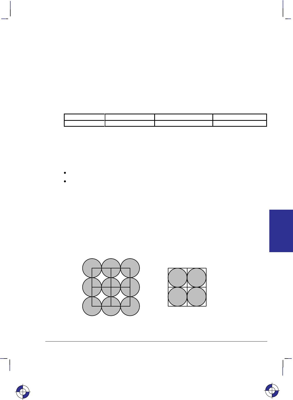
255
This is the black on page 255 (seq: 273)
Company confidential. HP-GL/2 and HP RTL Reference Guide, draft 2. Freeze Status: open
PP, Pixel Placement
Purpose
To control how pixels are placed on a grid during polygon fills on raster devices.
Syntax
PP mode[;]
or
PP [;]
Parameter Format Functional Range Parameter Default
mode clamped integer 0 or 1 0
Group
This instruction is in the Advanced Drawing Extension.
Use
No parameter: Places pixels centered at grid intersections. Same as “PP0”.
mode: Specifies the placement mode.
0Grid intersection (the default). Places pixels centered at grid intersections.
1Grid centered. Places pixels inside the boxes created by grid intersections.
Microsoft Windows fills polygons based on pixels placed between grid intersections. HP-
GL/2 normally fills polygons with pixels placed at grid intersections (see below). Unwanted
results occur when a polygon with a grid intersection-based fill is combined with ROPs (see the
MC instruction on page 220). For example, two squares laid down side by side using an exclu-
sive-OR logical operation will result in a blank line between them. Further details are in
Placing Pixels on page 93.
Figure 122 shows the differences between filling a 2x2 rectangle with pixels placed at grid in-
tersections (mode 0) and non-grid intersections (mode 1).
Figure 122. Pixel Placement
This is the blue on page 255 (seq: 273)
PP Instruction
INSTRUCTIONS
HP-GL/2
256
This is the black on page 256 (seq: 274)
Company confidential. HP-GL/2 and HP RTL Reference Guide, draft 2. Freeze Status: open
“PP1” decreases by one pixel the height and the width of the trapezoids formed by decomposi-
tion. “PP0” renders portions that are zero height or width as lines, and portions that are both
zero length and width as dots. “PP1” does not render portions that are zero height or width.
Note that pixel placement is applied after the soft-clip window is established, so pixels may be
subject to clipping.
Possible Error Conditions
Error Condition Error Number Printer or Plotter Response
Any mode value other than 0 or 1. 3 Ignores instruction
PP Instruction

257
This is the black on page 257 (seq: 275)
Company confidential. HP-GL/2 and HP RTL Reference Guide, draft 2. Freeze Status: open
PR, Plot Relative
Purpose
To establish relative plotting and move the pen to specified points, with each move relative to
the current pen location.
Syntax
PR X,Y[,...;]
or
PR [;]
Parameter Format Functional Range Parameter Default
X,Y increments current units device-dependent
(at least –223 to 223 – 1) no default
Group
This instruction is in the Vector Group.
Use
The device interprets the parameters as follows:
No Parameters: Defaults to relative plotting mode for subsequent instructions.
X, Y (increments): Specify incremental moves relative to the current pen location. When
you include more than one relative coordinate pair, the pen moves to each point in the
order given (relative to the previous point), using the current pen up/down status.
The carriage-return point (see page 66) is moved to the last X,Y.
If the pen is up, PR moves the pen to the point; if the pen is down, PR draws a line to the point.
Lines are drawn using the current line width, type, and attributes.
When you use the SM (Symbol Mode) instruction, PR draws the specified symbol at each X,Y
coordinate. When you use the PM (Polygon Mode) instruction, the X,Y coordinates enter the
polygon buffer (and are used when the polygon is edged or filled).
Coordinates are interpreted in current units: as user-units when scaling is on; as plotter-units
when scaling is off.
Related Instructions
LA Line Attributes
LT Line Type
PA Plot Absolute
PD Pen Down
PE Polyline Encoded
PW Pen Width
SM Symbol Mode
This is the blue on page 257 (seq: 275)
PR Instruction
INSTRUCTIONS
HP-GL/2
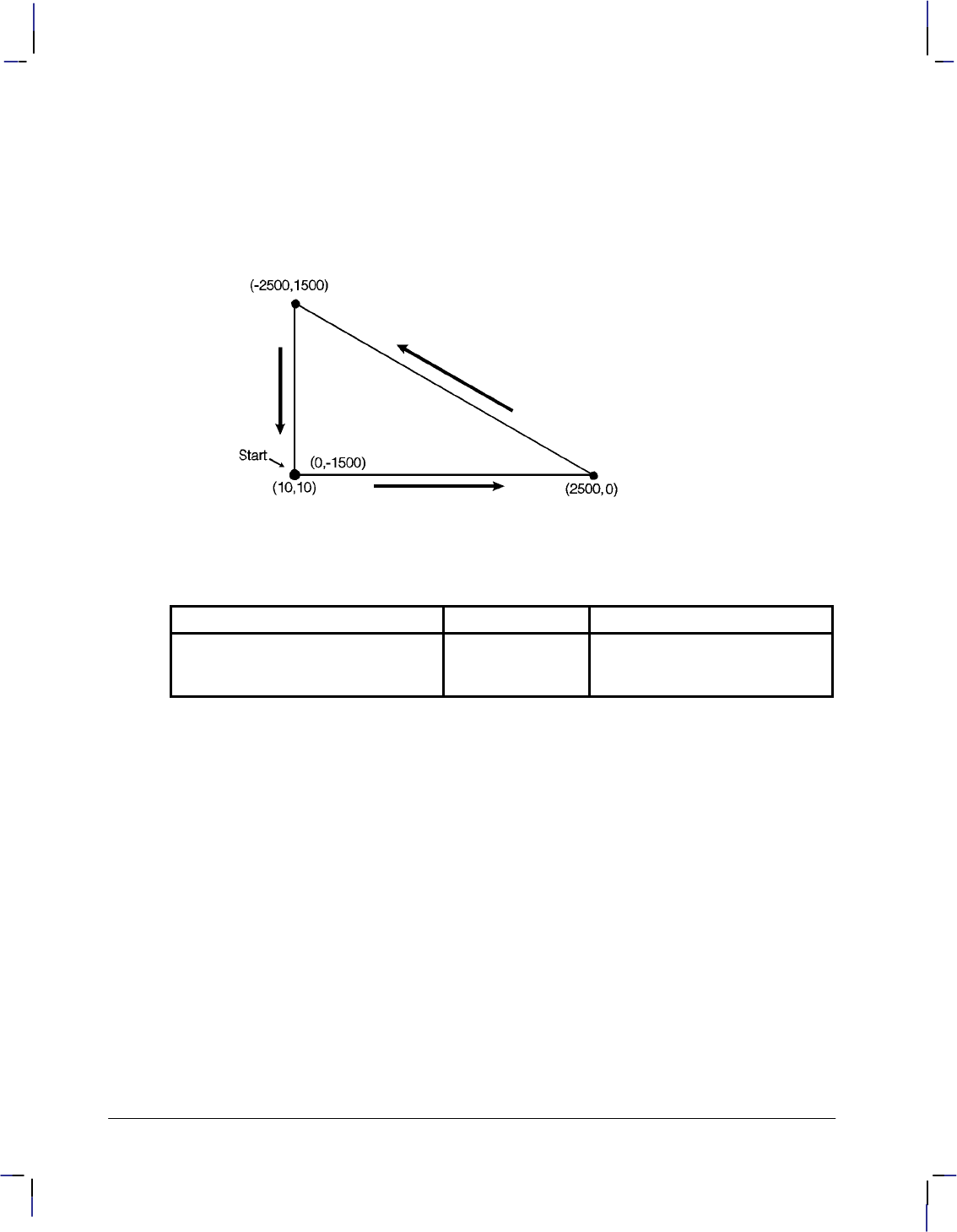
258
This is the black on page 258 (seq: 276)
Company confidential. HP-GL/2 and HP RTL Reference Guide, draft 2. Freeze Status: open
Example
PA 10,10; Move to absolute position (10,10).
PD ; Put the pen down.
PR 2500,0,–2500,1500,0,–1500; Specify relative plotting and draw lines beginning at
(10,10) and then moving the relative coordinate distances indi-
cated.
Figure 123. Plotting Using Relative Coordinates
Possible Error Conditions
Error Condition Error Number Printer or Plotter Response
An odd number of coordinates (an X
coordinate without a corresponding
Y coordinate)
2Ignores the last unmatched coor-
dinate.
PR Instruction

259
This is the black on page 259 (seq: 277)
Company confidential. HP-GL/2 and HP RTL Reference Guide, draft 2. Freeze Status: open
PS, Plot Size
Purpose
To set the hard-clip limits to a given size. Use PS to simplify long-axis plotting or to minimize
paper waste when drawing small plots. This is especially useful for plotters with roll-feed me-
dia. When used, this instruction must appear in the picture header information (see page 78).
Syntax
PS length[,width][;]
or
PS [;]
Parameter Format Functional Range Parameter Default
length integer device-dependent hard-clip limits*
width integer device-dependent hard-clip limits*
* The default length and width for single-sheet media is the hard-clip limits; for roll-feed
media the default length is approximately 1.5 times the media width.
Group
This instruction is in the Technical Graphics Extension.
Use
Send PS immediately after the BP (Begin Plot) or IN (Initialize) instruction (IN defaults PS if
the device is in picture header state [see page 78], that is no marks have been made on the me-
dia) and before any drawing instructions. DF (Default Values) does not default PS. Note that
the entire plot must be done within the scope of a single PS instruction; you cannot change the
plot size in the middle of a plot.
No Parameters: Defaults the plot length and width to the hard-clip limits (the maximum
printable area).
length: Establishes a new length, in plotter-units, of the hard-clip limits. The length
always corresponds to the direction of the plot frame advance. Refer to the documentation
for your device or HP-GL/2 option for the maximum length of a single plot. If the length
is less than or equal to 0, the device ignores the instruction.
width: Establishes the new width, in plotter-units, of the hard-clip limits. The width is
always the horizontal direction. If the width is less than or equal to 0, the device ignores
the instruction.
If you specify a plot size larger than your media’s maximum plotting area, your plot size is
clamped to the hard-clip limits. Figure 124 indicates how PS orients the default coordinate
system according to the length and width after clamping. The default origin defines the lower-
left corner of the hard-clip limits and is always located on the side of the plot frame opposite
the next plot frame.
This is the blue on page 259 (seq: 277)
PS Instruction
INSTRUCTIONS
HP-GL/2
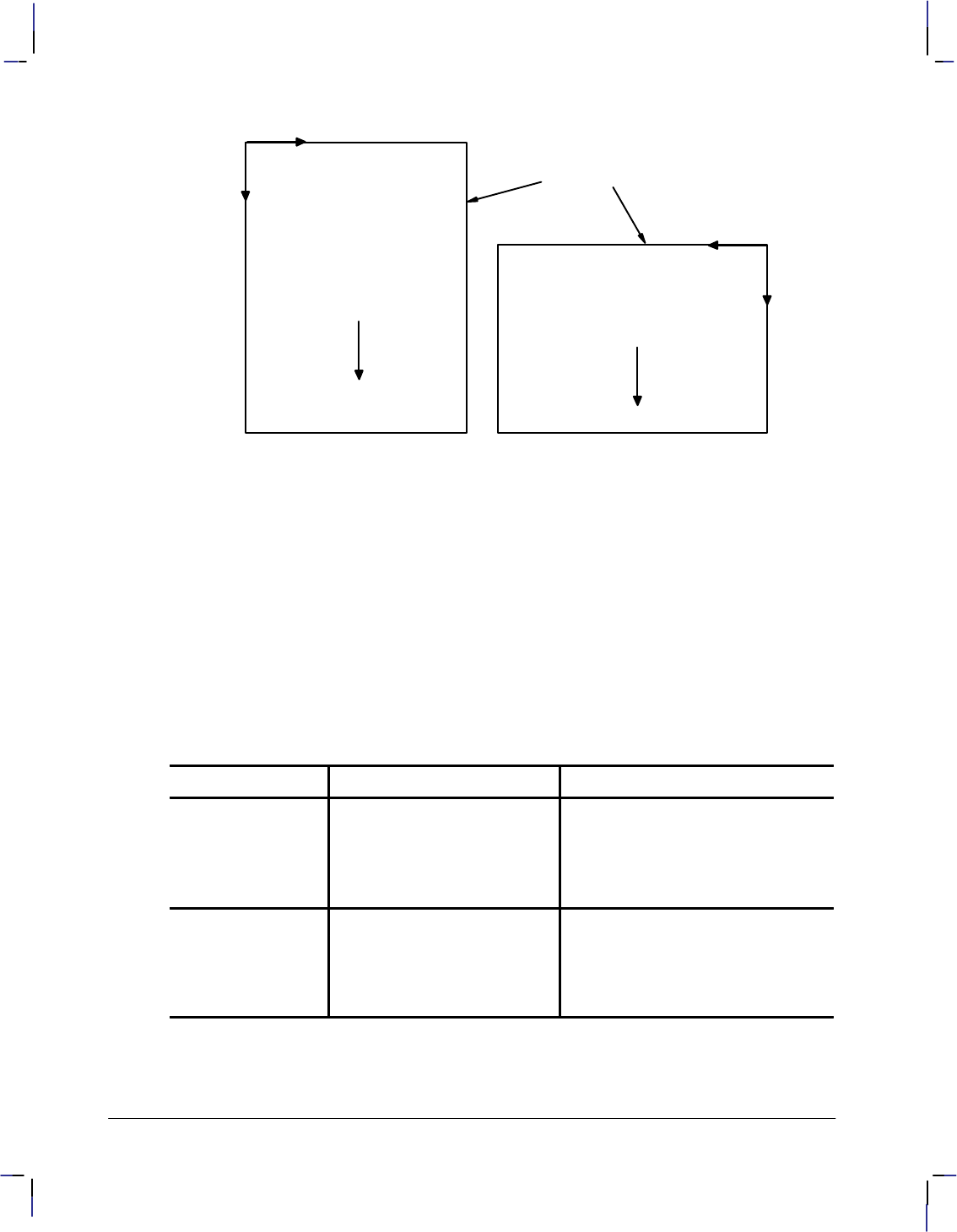
260
This is the black on page 260 (seq: 278)
Company confidential. HP-GL/2 and HP RTL Reference Guide, draft 2. Freeze Status: open
+X
0,0
0,0
Plot Size (PS)
length
width Plot Size (PS)
length < width
+ Y
+ X
+ Y
Direction
of frame
advance Direction
of frame
advance
logical page
Figure 124. How Plot Size Affects the Coordinate System
PS defaults P1 and P2 to the lower-left and upper-right corners of the hard-clip limits, defaults
the size of the user-defined window and the location of the anchor corner. and clears the poly-
gon buffer. Any previous rotation (RO) is then added to the default X-axis orientation. Current
scaling is applied to the new physical area. The device also updates the current pen location to
the lower-left corner of the new plotting area.
If an RO (Rotate Coordinate System) instruction (see page 275) is sent after PS, the direction of
the X-axis changes. The implementation of RO is relative to the autorotated position. PS sent
after RO does not change the RO rotation, but does update the X-axis to the new longer side.
The PG (Advance Page) instruction will advance the media by the distance of the length param-
eter plus the necessary white space between plots. The following lists some standard paper
sizes and equivalent PS parameters.
Measurement Standard Paper Sizes Equivalent PS Parameters*
English 8.5 x 11 inches (A-size) PS 8900,7350;
11 x 17 inches (B-size) PS 15000,9850;
17 x 22 inches (C-size) PS 21050,15000;
22 x 34 inches (D-size) PS 32300,21050;
Metric 210 x 297 mm. (A4-size) PS 9600,7100;
297 x 420 mm. (A3-size) PS 14550,10600;
420 x 594 mm. (A2-size) PS 22450,14550;
594 x 840 mm. (A1-size) PS 31400,22450;
* These plot sizes are based on 16-mm margins on three sides of the media, the fourth mar-
gin being 40-mm. These values are also based on loading C-sized media horizontally in
the device, with all other media being loaded vertically. Refer to the User’s Guide for your
device for instructions on loading media.
PS Instruction
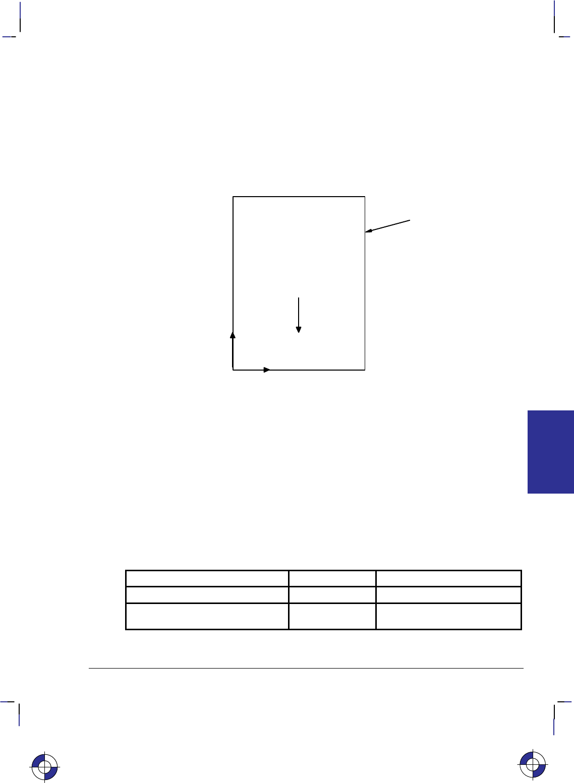
261
This is the black on page 261 (seq: 279)
Company confidential. HP-GL/2 and HP RTL Reference Guide, draft 2. Freeze Status: open
When combining the PS (Plot Size) and SC (Scale) instructions and accurate scaling is essen-
tial, note the following:
If you specify a plot size larger than your media’s maximum plotting area, your plot size will be
reduced to the hard-clip limits and your user-units will be smaller than you intended. To cor-
rect this, add an IP (Input P1 and P2) instruction so that the P1/P2 area is equal to the intended
size of your PS instruction (IP0,0,PSlength,PSwidth). This moves P2 off the page, but guaran-
tees accurate scaling. Place the IP instruction between the PS and SC instructions.
Note that devices that support the PS instruction have their origin as shown in Figure 124; other
devices have their origin and orientation as shown in Figure 125.
(0,0)
+ Y
+ X
Direction
of frame
advance
logical page
Figure 125. Origin and Orientation for Other Devices
Using PS in a PCL Dual-Context Environment
PS is ignored when HP-GL/2 is entered by %#B with 0 or a positive value; the plot size is
set by the PCL picture frame.
Related Instructions
FR Frame Advance
OH Output Hard-Clip Limits
PG Advance Full Page
Possible Error Conditions
Error Condition Error Number Printer or Plotter Response
Length or width 0 3 Ignores instruction
Instruction used outside picture head-
er state (see page 78) 1Ignores instruction
This is the blue on page 261 (seq: 279)
INSTRUCTIONS
HP-GL/2
PS Instruction

262
This is the black on page 262 (seq: 280)
Company confidential. HP-GL/2 and HP RTL Reference Guide, draft 2. Freeze Status: open
PU, Pen Up
Purpose
To move to subsequent points without drawing. Use PU to move to another location without
drawing a connecting line.
Syntax
PU X,Y[,...;]
or
PU [;]
Parameter Format Functional Range Parameter Default
X,Y coordinates or
increments current units device-dependent
(at least –223 to 223 – 1) no default
Group
This instruction is in the Vector Group.
Use
The PU instruction emulates a pen plotter which must raise the pen to prevent drawing stray
lines on the page.
No Parameters: Prevents drawing subsequent graphics instructions (unless the instruction
contains an automatic pen down).
X,Y coordinates or increments: Move to the point(s) specified. You can specify as many
X,Y coordinate pairs as you want. When you include more than one coordinate pair, the
device moves to each point in the order given.
The carriage-return point (see page 66) is moved to the last X,Y.
When you use the SM (Symbol Mode) instruction, PU draws the specified symbol at each X,Y
coordinate.
When you use the PM (Polygon Mode) instruction, the X,Y coordinates enter the polygon buff-
er (for use when the polygon is edged or filled).
Coordinates are interpreted in current units: as user-units when scaling is on; as plotter-units
when scaling is off. Whether the PU instruction uses absolute coordinates or relative coordi-
nates (increments) depends on the most recently executed PA or PR instruction. If you have not
issued a PA or PR instruction, absolute plotting (PA) is used.
Note that “PD;PU;” leaves a dot.
This is the blue on page 262 (seq: 280)
PU Instruction

263
This is the black on page 263 (seq: 281)
Company confidential. HP-GL/2 and HP RTL Reference Guide, draft 2. Freeze Status: open
Related Instructions
PA Plot Absolute
PD Pen Down
PE Polyline Encoded
PR Plot Relative
SM Symbol Mode
Possible Error Conditions
Error Condition Error Number Printer or Plotter Response
An odd number of coordinates (an X
coordinate without a corresponding
Y coordinate)
2Ignores the last unmatched coor-
dinate.
This is the blue on page 263 (seq: 281)
PU Instruction
INSTRUCTIONS
HP-GL/2
264
This is the black on page 264 (seq: 282)
Company confidential. HP-GL/2 and HP RTL Reference Guide, draft 2. Freeze Status: open
PW, Pen Width
Purpose
To specify a new width for the logical pen. Subsequent lines are drawn in this new width. Use
PW to vary your lines and enhance your drawings. Pen width can be specified as a fixed value
or relative to the distance between P1 and P2. The pen width units are selected using the WU
instruction (the default is metric—millimeters).
Syntax
PW width[,pen][;]
or
PW [;]
Parameter Format Functional Range Parameter Default
width clamped real device-dependent* dependent**
pen integer device-dependent all pens
* Normally 0 to 32 767, but at least 16 384 plotter-units (409.6 mm).
** Dependent on the mode set by the WU (Pen Width Unit Selection) instruction: if mode is
metric, default width is 0.35 mm; if mode is relative, default width is 0.1% of the diagonal
distance from P1 to P2.
Group
This instruction is in the Line and Fill Attributes Group.
Use
You may change the pen width as often as you like, without sending another SP instruction. If
the pen is down when you change the width, the new width takes effect at the next line. If you
use WU to change the type of units used for the width parameter (metric or relative), send the
WU instruction before PW.
No Parameters: Defaults the pen line width according to the current units set by WU:
0.35 mm if metric; 0.1% of the diagonal distance from P1 to P2 if relative.
width: Specifies the line width. When the parameter is zero or is thinner than the thinnest
supported width, the device assumes the thinnest line width (1 dot wide). When it is
greater than the device’s maximum, the maximum is used.
pen: Specifies the pen number to which the new width applies. If the pen parameter is not
specified, the device applies the width to both pens. Specifying pen numbers less than 0 or
greater than the number of pens available causes the device to ignore the instruction.
Note: Pen width does not set the width of lines for drawing labels (unless the stroke weight
value is set to 9999 [Stick/Arc fonts only]). The width of character lines is determined by the
stroke weight attribute of the AD (Alternate Font Definition) or SD (Standard Font Definition)
instructions.
This is the blue on page 264 (seq: 282)
PW Instruction
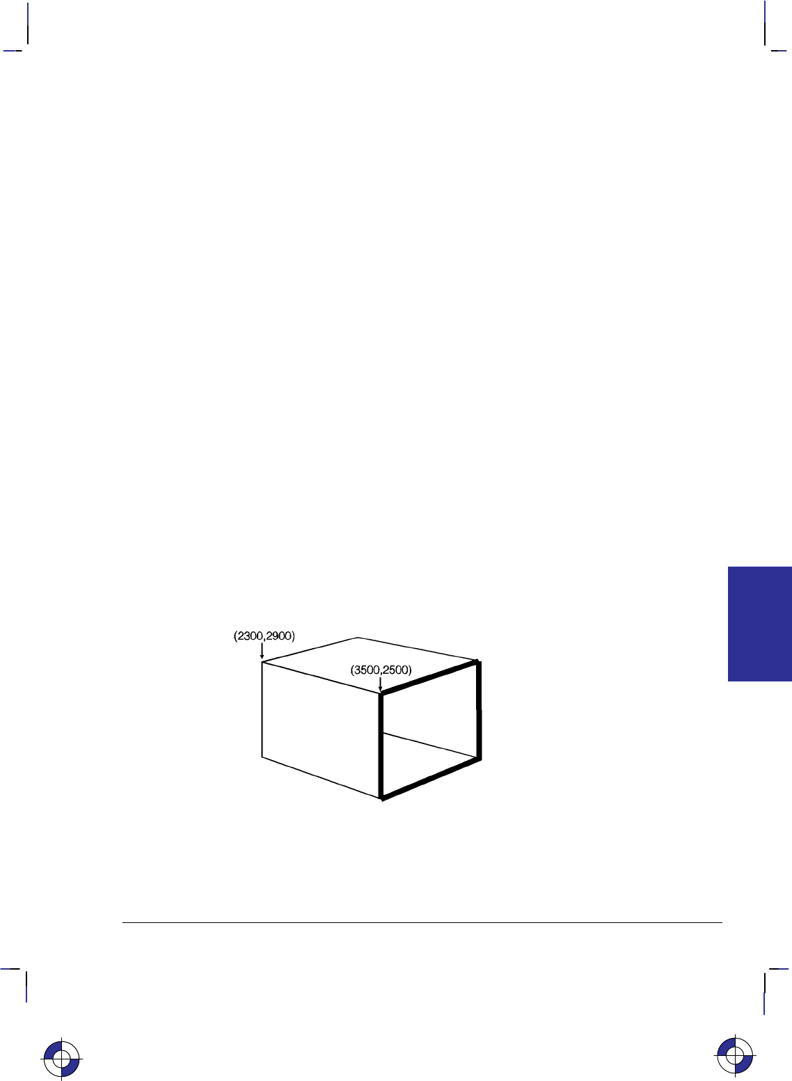
265
This is the black on page 265 (seq: 283)
Company confidential. HP-GL/2 and HP RTL Reference Guide, draft 2. Freeze Status: open
Vectors are drawn centered on coordinates, but any portion of a line width that extends beyond
the window is clipped.
PW clears the current pattern residue and terminates any continuous vector sequence (see the
LA and LT instructions).
A PW instruction remains in effect until another PW instruction or a WU instruction is
executed. PW is not defaulted by the DF (Default Values) instruction.
Using PW in a PCL Dual-Context Environment
Metric widths are scaled by the ratio of the size of the PCL picture frame to the HP-GL/2 plot
size. For example, if HP-GL/2 plot size is twice as large as the PCL picture frame, “WUPW.3”
sets the vector width to 0.15 mm.
Example
PA 3500,2500; Specify absolute plotting and move the pen to (3500,2500).
PW 1.5; Select a pen width of 1.5 mm.
PD 4500,2800, 4500,1800,3500,1500,3500,2500; Set the pen down and draw a line from
the current position to (4500,2800), then (4500,1800), next to
(3500,1500), and then to (3500,2500).
PW .8; Set the pen width to 0.8 mm.
PD 2300,2900,2300,1900,3500,1500; Place the pen down and print a line to (2300,2900),
then to (2300,1900), and finally to (3500,1500).
PW .5; Set the pen width to 0.5 mm.
PU 2300,2900; Lift the pen, and move to (2300,2900).
PD 3300,3200,4500,2800; Set the pen down and draw a line to (3300,3200) and then
another line to (4500,2800).
PW .25; Set the pen width to 0.25 mm.
PU 4500,1800; Lift the pen, and move to (4500,1800).
PD 3500,2100; Set the pen down and print a line to (3500,2100).
Figure 126. Pen Width
This is the blue on page 265 (seq: 283)
INSTRUCTIONS
HP-GL/2
PW Instruction

266
This is the black on page 266 (seq: 284)
Company confidential. HP-GL/2 and HP RTL Reference Guide, draft 2. Freeze Status: open
Related Instructions
SP Select Pen
SV Screened Vectors
WU Pen Width Unit Selection
PW Instruction

267
This is the black on page 267 (seq: 285)
Company confidential. HP-GL/2 and HP RTL Reference Guide, draft 2. Freeze Status: open
QL, Quality Level
Purpose
To set “best”, “normal” or “draft” mode for your output. Use QL on raster devices to optimize
your usage of toner or ink when draft quality is sufficient.
Syntax
QL quality_level [;]
or
QL [;]
Parameter Format Functional Range Parameter Default
quality_level clamped integer 0 to 100 device-dependent
Group
This instruction is in the Technical Graphics Extension.
Use
The entire plot must be done with one quality level setting. You cannot change quality levels in
the picture body state.
No Parameter: Device-dependent. Each device makes different use of this instruction
depending on the hardware technology and firmware implementation. The result will be
seen in different speed/quality trade-offs. For example, a pen plotter primarily varies pen
speed, but may vary acceleration as well. An electrostatic plotter might vary paper speed,
resolution, or rasterization algorithms. Refer to the manual for your product or HP-GL/2
option for the number of quality levels and the effects the various levels have on the
output.
quality_level: Specifies the level of quality for your plot from 0 (draft quality) to 100
(presentation, best, or final quality). The number of quality levels supported is device-de-
pendent. When quality level is 0 (draft), a plotter may not implement MC (Merge Control)
or may limit it to vectors only.
A device with only one quality level will ignore this instruction. A device with two or more
levels will support at least 0 and 100 and will map any other value to one of the supported val-
ues. Mapping to another value may occur either through rounding to the nearest supported
value (for example, a device with only two levels would treat “QL60;” the same as “QL100;”),
or through applying a threshold (for example, anything over 80 is mapped to 100).
For a pen plotter, QL is primarily a speed control. The pen speed set by the VS (Velocity Se-
lect) instruction or from the device’s control panel is the maximum speed, which corresponds to
“QL0;”. If the pen speed is not set by VS or from the control panel, the plotter determines the
maximum speed based on its knowledge of the media type (from the MT instruction) and pen
type (from the carousel). Minimum speed, corresponding to “QL100;”, is linearly interpolated
between the media and pen types. The default level for pen plotters is usually “QL0;” (maxi-
mum speed).
This is the blue on page 267 (seq: 285)
QL Instruction
INSTRUCTIONS
HP-GL/2

268
This is the black on page 268 (seq: 286)
Company confidential. HP-GL/2 and HP RTL Reference Guide, draft 2. Freeze Status: open
Possible Error Conditions
Error Condition Error Number Printer or Plotter Response
Instruction used outside picture head-
er state (see page 78) 1Ignores instruction
QL Instruction
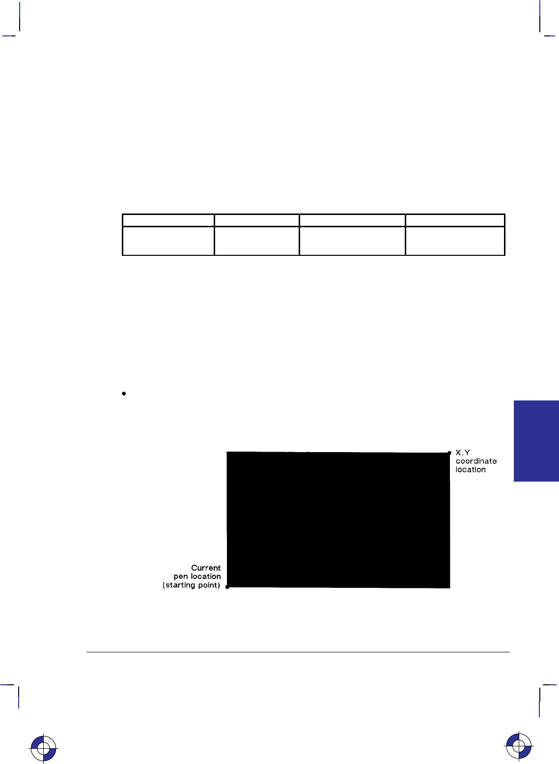
269
This is the black on page 269 (seq: 287)
Company confidential. HP-GL/2 and HP RTL Reference Guide, draft 2. Freeze Status: open
RA, Fill Rectangle Absolute
Purpose
To define and fill a rectangle using absolute coordinates. Use RA to fill rectangular shapes in
drawings. (To outline a rectangle using absolute coordinates, use the EA instruction.)
Syntax
RA X,Y[;]
Parameter Format Functional Range Parameter Default
X,Y coordinates current units device-dependent
(at least –223 to 223 – 1) no default
Group
This instruction is in the Polygon Group.
Use
The RA instruction defines and fills a rectangle using the current pen, the current line and fill
types, and absolute X,Y coordinates. The RA instruction includes an automatic pen down.
When the instruction operation is complete, the original pen location and up/down status are
restored.
X,Y coordinates: Specify the corner of the rectangle that is diagonally opposite from the
current pen location (the starting point of the rectangle). Coordinates are interpreted in
current units: as user-units when scaling is on; as plotter-units when scaling is off.
Figure 127. Fill Rectangle Absolute
This is the blue on page 269 (seq: 287)
RA Instruction
INSTRUCTIONS
HP-GL/2

270
This is the black on page 270 (seq: 288)
Company confidential. HP-GL/2 and HP RTL Reference Guide, draft 2. Freeze Status: open
Note: Figure 127 shows the current pen location in the lower-left corner and the instruction’s
X,Y coordinates in the upper-right corner. Depending on the X,Y coordinates used, these
points can be in any two diagonally opposite corners.
The only difference between the RA instruction and the EA (Edge Rectangle Absolute) instruc-
tion is that the RA instruction produces a filled rectangle, and EA, an outlined one.
The RA instruction clears the polygon buffer and then uses it to define the rectangle before
drawing. Refer to Using the Polygon Buffer on page 45.
A dot is drawn if X,Y are coincident with the current position. A line is drawn if the X or Y
coordinate equals the corresponding coordinate of the current position; for some hatch or raster-
filled patterns, the line may fall in white spaces of the fill and not be drawn.
Related Instructions
EA Edge Rectangle Absolute
EP Edge Polygon
ER Edge Rectangle Relative
FP Fill Polygon
FT Fill Type
LT Line Type
RF Raster Fill Definition
RR Fill Rectangle Relative
Example
The following example uses RA with three different fill types to create rectangles such as those
you might use in a bar chart. The rectangles in the right bar are edged using the EA instruction.
(For more information about fill types, refer to the FT instruction description on page 183.)
PA 400,400; Enter absolute plotting mode and move to (400,400).
RA 800,1200; Draw a rectangle with (400,400) as the lower left corner and
(800,1200) as the upper right corner.
PA 400,1200; Move the pen to (400,1200).
FT 3,50; Select fill type 3 (parallel lines) with a 50 plotter-units space be-
tween lines.
RA 800,1600; Draw a rectangle with (400,1200) as the lower left corner and
(800,1600) as the upper right corner.
PA 400,1600; Move to (400,1600).
FT 4; Specify fill type 4 (cross-hatching).
RA 800,2000; Draw a rectangle with a lower left corner of (400,1600) and an
upper right corner of (800,2000).
PA 1200,400; Move to location (1200,400).
FT ; Select the default fill type (solid black).
RA 1600,1200; Fill and edge a rectangle using (1200,400) as the lower left corner
EA 1600,1200; and (1600,1200) as the upper right corner.
PA 1200,1200; Move to absolute position (1200,1200).
FT 3,50; Select fill type 3, with a 50 plotter-units distance between each
line.
RA 1600,1600; Draw a rectangle with (1200,1200) as the lower left corner and
(1600,1600) as the upper right.
RA Instruction
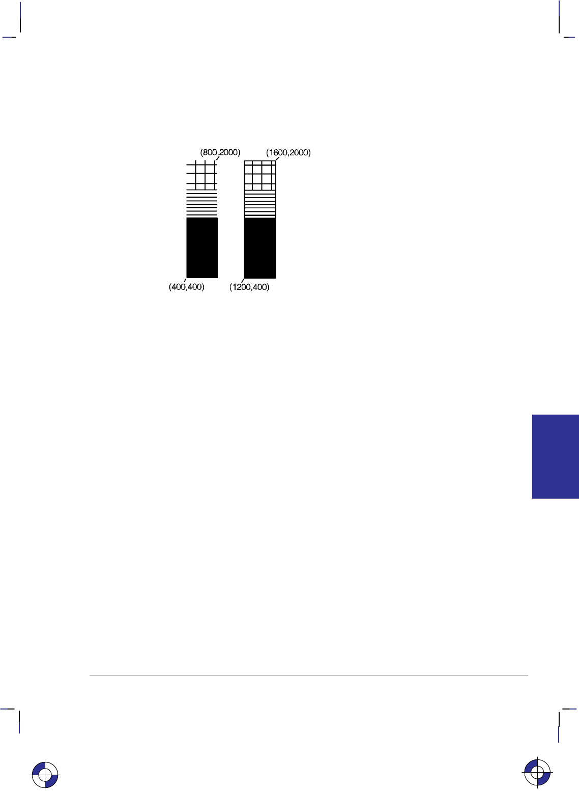
271
This is the black on page 271 (seq: 289)
Company confidential. HP-GL/2 and HP RTL Reference Guide, draft 2. Freeze Status: open
EA 1600,1600; Using the default line type, edge the rectangle just drawn.
PA 1200,1600; Move to (1200,1600).
FT 4; Select the cross-hatch pattern fill type.
RA 1600,2000; Draw and edge a rectangle with the current pen location as one
EA 1600,2000; corner and (1600,2000) as the opposite corner.
Figure 128. Filling a Rectangle Specified by Absolute Coordinates
This is the blue on page 271 (seq: 289)
RA Instruction
INSTRUCTIONS
HP-GL/2
272
This is the black on page 272 (seq: 290)
Company confidential. HP-GL/2 and HP RTL Reference Guide, draft 2. Freeze Status: open
RF, Raster Fill Definition
Purpose
To define a rectangular pattern that may be used as area fill and for screened vectors (see the
SV instruction). Use RF to create your own fill types and screen patterns.
Syntax
RF index,width,height,pen_number[,...pen_number][;]
or
RF index[;]
or
RF [;]
Parameter Format Functional Range Parameter Default
index clamped integer device-dependent 1 (solid)
width clamped integer device-dependent*no default
height clamped integer device-dependent*no default
pen_number integer device-dependent** no default
* The range is between 1 and a positive power of 2; at least the values 8, 16, 32, and 64
are supported.
** See the NP (Number of Pens) instruction on page 225.
Group
This instruction is in the Line and Fill Attributes Group.
Use
The RF instruction does not select a fill type; use the FT (Fill Type) instruction with a type pa-
rameter of 11 and the corresponding raster fill index number for the second parameter (for
example, “FT11,3” for an index number of 3).
No Parameters: Defaults all raster fill patterns to solid fill.
index: Specifies the index number of the pattern being defined. At least eight patterns can
exist concurrently.
When you send RF with an index parameter only (“RFn”), the corresponding pattern is
defaulted to solid fill.
width, height: Specify the width and height (in pixels) of the pattern being defined. A
pixel is equal to the size of one dot at the current device resolution.
pen_number: Represents a pixel in the pattern being defined and indicates its color.
This is the blue on page 272 (seq: 290)
RF Instruction
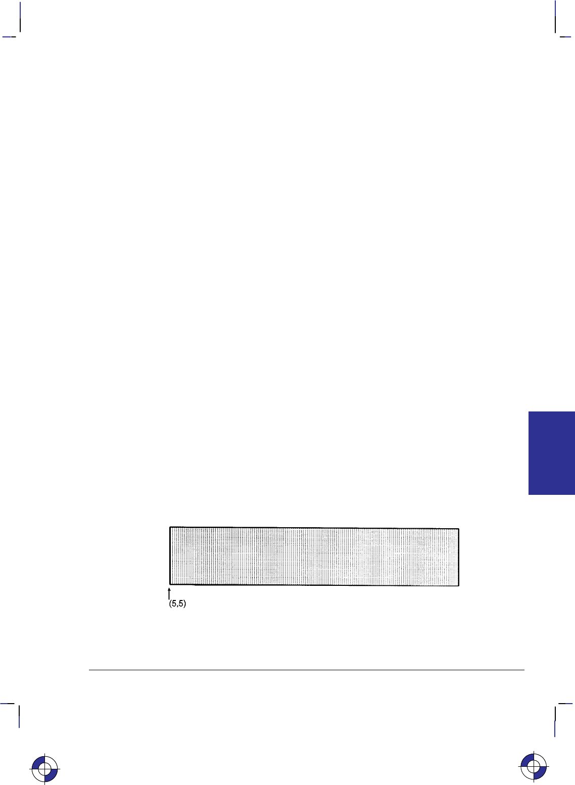
273
This is the black on page 273 (seq: 291)
Company confidential. HP-GL/2 and HP RTL Reference Guide, draft 2. Freeze Status: open
The pen_number parameters define pixels left to right, top to bottom. Each pixel takes on the
color of the specified pen (negative numbers are treated as zero). The total number of
pen_number parameters should be equal to the width times the height parameters. For exam-
ple, to define a pattern that is 8 x 16 pixels, you need 128 pen_number parameters. If you do
not include enough pen_number parameters, the rest of the pixels are assumed to be white
(zero). Patterns are printed in rows parallel to the plotter-unit X-axis.
The color palette current at the time of the fill, not at the time of the pattern definition, deter-
mines the pattern colors actually used (by FP, RA, RR, or WG). If a pen_number is larger than
the palette in effect at the time of rendering, the modulo function is applied, as described for
SP.
If the pattern associated with the particular index is defined multiple times during a single plot
and all definitions are used to fill objects, the resulting patterns are device-dependent. (Devices
using a direct bitmap may print the pattern defined when the object was filled, while devices
using an intermediate data format may render all objects with the last pattern defined.)
A pattern defined only with the pen_number parameters 0 or 1 can be printed directly using the
currently selected pen (see the FT instruction on page 183).
RF terminates the current vector path (see the LA instruction).
Related Instructions
AC Anchor Corner
FT Fill Type
SV Screened Vectors
Example
PA ; Specify absolute plotting.
PU 5,5; Lift the pen and move to absolute position (5,5).
RF 2,8,4, 0,0,0,0,0,0,0,0, 0,0,0,1,1,0,0,0, 0,0,0,1,1,0,0,0, 0,0,0,0,0,0,0,0; Define a raster
fill pattern (index number 2) that is 8 dots wide by 4 dots high.
FT 11,2; Select the user-defined pattern having an index number of 2.
RR 4000,800; Fill a rectangle with the fill pattern just specified, with a lower left
corner of (5,5) and an upper right corner 4000 plotter-units to the
right and 800 plotter-units up.
EP ; Edge the outline of the rectangle.
Figure 129. Raster Fill Definition
This is the blue on page 273 (seq: 291)
INSTRUCTIONS
HP-GL/2
RF Instruction

274
This is the black on page 274 (seq: 292)
Company confidential. HP-GL/2 and HP RTL Reference Guide, draft 2. Freeze Status: open
Possible Error Conditions
Error Condition Error Number Printer or Plotter Response
Index out of range 3 Ignores instruction
RF Instruction

275
This is the black on page 275 (seq: 293)
Company confidential. HP-GL/2 and HP RTL Reference Guide, draft 2. Freeze Status: open
RO, Rotate Coordinate System
Purpose
To rotate the device’s coordinate system relative to the default HP-GL/2 coordinate system, in
the following increments of rotation: 90, 180, and 270. Use RO to orient your drawing ver-
tically or horizontally, or to reverse the orientation.
Syntax
RO angle[;]
or
RO [;]
Parameter Format Functional Range Parameter Default
angle clamped integer 0, 90, 180, or 2700
Group
This instruction is in the Configuration and Status Group.
Use
The device interprets the instruction parameters as follows:
No Parameter: Defaults the orientation of the coordinate system to 0. Equivalent to
“RO0”. This is the same as PCL’s current orientation in PCL devices; for other devices,
see the description of the PS (Plot Size) instruction on page 259.
angle: Specifies the degree of rotation:
0Sets the orientation to horizontal (+X direction).
90 Rotates and shifts the coordinate system 90 in a positive angle of rotation from
the horizontal (+X direction).
180 Rotates and shifts the coordinate system 180 in a positive angle of rotation from
the horizontal (+X direction).
270 Rotates and shifts the coordinate system 270 in a positive angle of rotation from
the horizontal (+X direction).
The carriage-return point is updated to the current pen location.
A positive angle of rotation is in the direction of the +X-axis to the +Y-axis as shown in Figure
27 on page 44). (A negative angle of rotation is not allowed in the RO instruction.)
The relationship of the X-axis to Y-axis can change as a result of the scaling point or scaling
factor changes, thus changing the direction of a positive angle of rotation.
The physical location of the pen does not change when you rotate the coordinate system. The
device updates the pen’s X,Y coordinate location to reflect the new orientation.
This is the blue on page 275 (seq: 293)
RO Instruction
INSTRUCTIONS
HP-GL/2
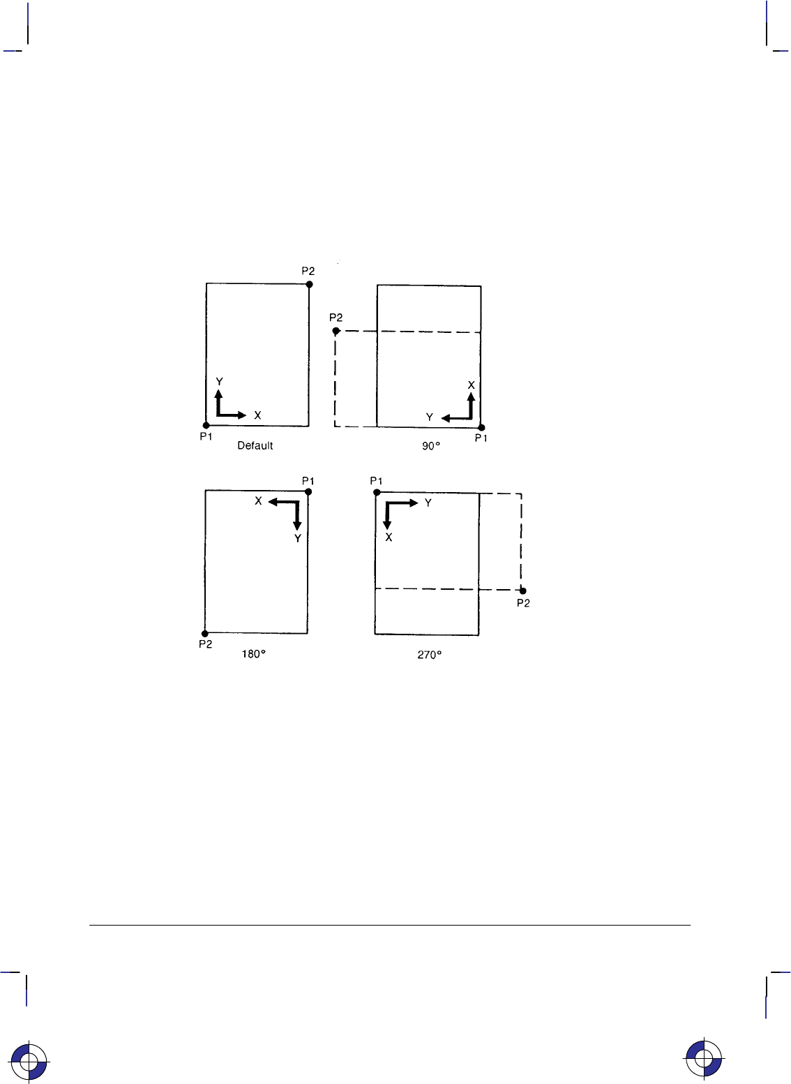
276
This is the black on page 276 (seq: 294)
Company confidential. HP-GL/2 and HP RTL Reference Guide, draft 2. Freeze Status: open
The scaling points P1 and P2 rotate with the coordinate system. However, they maintain the
same X,Y coordinate values as before the rotation. This means that P1 and P2 can be located
outside of the hard-clip limits. Follow the “RO90” or “RO270” instructions with “IP;” or “IR;”
to relocate points P1 and P2 to their default locations for that orientation.
Rotation is not cumulative; “RO90RO90;” rotates 90, not 180.
The RO instruction remains in effect until the rotation is changed by another RO instruction, or
the device is initialized. Figure 130 shows the default orientation and the result of rotating the
orientation for PCL devices, without relocating P1 and P2.
Figure 130. Using the RO Instruction without Using the IP Instruction
When the RO instruction is used, the soft-clip window, if defined, is also rotated, and any por-
tion that is rotated outside of the picture frame is clipped to the picture frame boundaries. The
soft-clip window can be set equal to the picture frame by issuing an “IW;” instruction (see Fig-
ure 131; the “PCL Picture Frame” is the hard-clip limits on non-PCL devices).
The RO instruction also rotates the contents of the polygon buffer, changes pen coordinates to
reflect the new orientation (but does not affect the pen position), and terminates the current vec-
tor path (see the LA instruction).
RO Instruction
This is the blue on page 276 (seq: 294)
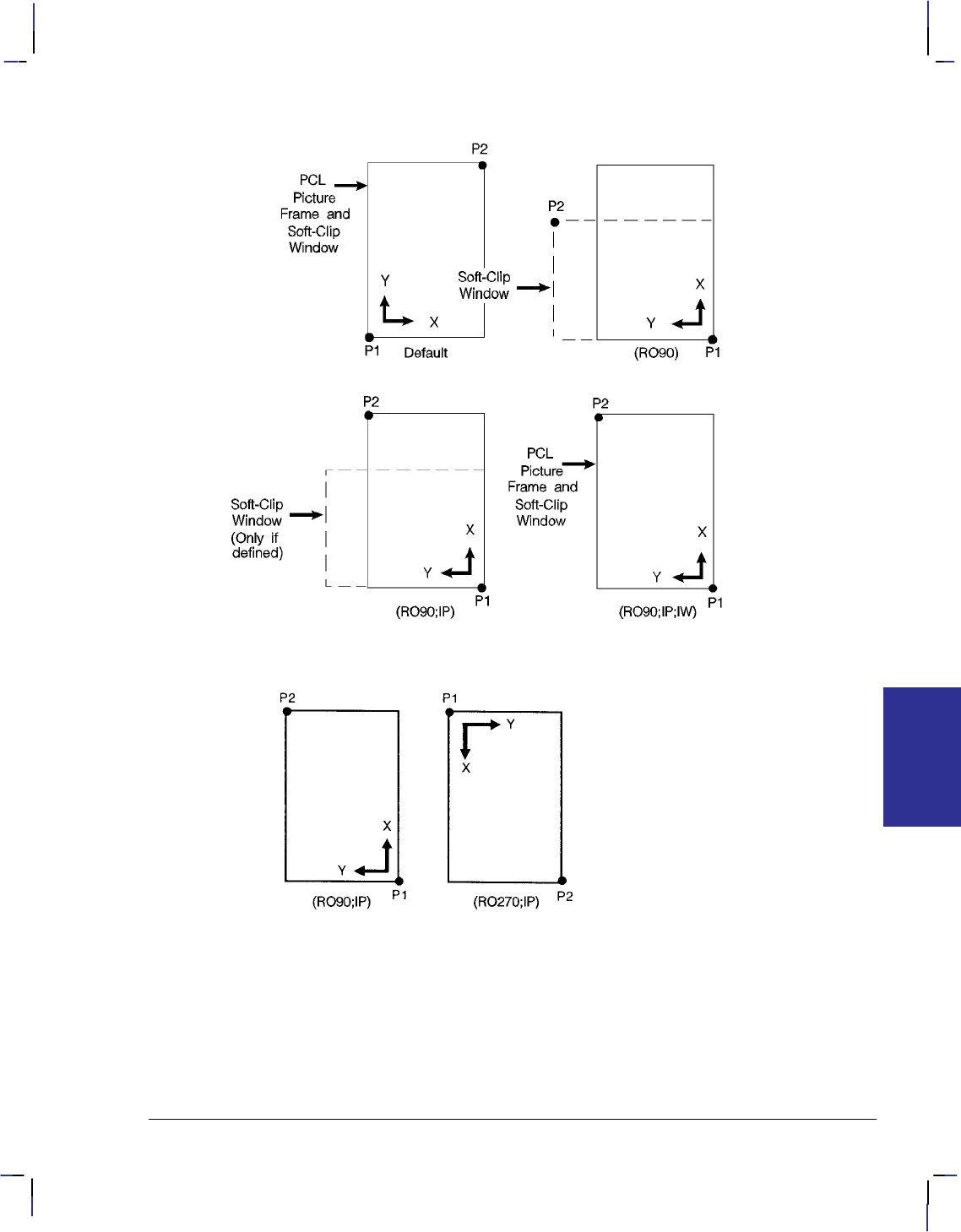
277
This is the black on page 277 (seq: 295)
Company confidential. HP-GL/2 and HP RTL Reference Guide, draft 2. Freeze Status: open
Figure 131. Using IP and IW after the RO Instruction
Figure 132. Using IP after the RO Instruction
Figure 132 shows the locations of P1 and P2 when you follow the rotation with the IP instruc-
tion.
When you set-up a soft-clip window (see the IW instruction), RO also rotates the window. If a
portion of a window rotates outside the hard-clip limits, it is clipped. Note that “IP;” does not
affect the window limits. Use “IW;” to reset the window to the size of the hard-clip limits.
RO Instruction
INSTRUCTIONS
HP-GL/2

278
This is the black on page 278 (seq: 296)
Company confidential. HP-GL/2 and HP RTL Reference Guide, draft 2. Freeze Status: open
Using RO in a PCL Dual-Context Environment
Rotations are relative to the default HP-GL/2 coordinate system, as defined for PCL. P1 or P2
may be rotated outside the current picture frame; they can be repositioned to the rotated lower-
left and upper-right corners of the picture frame by issuing an “IP;” or an “IR;” instruction.
The user-defined window is rotated, and any portion that is rotated outside the picture frame is
clipped to the picture frame. The window can be set equal to the picture frame by an “IW;”
instruction.
Related Instructions
IP Input P1 and P2
IR Input Relative P1 and P2
IW Input Window
RO Instruction

279
This is the black on page 279 (seq: 297)
Company confidential. HP-GL/2 and HP RTL Reference Guide, draft 2. Freeze Status: open
RP, Replot
Purpose
To draw multiple copies of plots. Your device must have an internal hard disk or designated
buffer area to store the plot. This instruction is ignored on devices that cannot store the plot
data.
Syntax
RP n; or
RP ;
This instruction, with or without a parameter, must be terminated by a semicolon.
Parameter Format Functional Range Parameter Default
nclamped integer –32 768 to 32 767 1
Group
This instruction is in the Configuration and Status Group.
Use
Use the RP instruction at the end of your plot, following the PG (Advance Full Page) instruc-
tion when you want more than one copy of a plot.
No Parameter: Assumes you want one additional copy.
n: Specifies the number of additional copies required.
The device ignores the instruction when printing the current page would produce no marks on
the media.
RP prints the page when the plot has not already been terminated by a PG instruction. If n is
less than or equal to zero and there is no previous PG instruction, the device prints the page (it
issues a “PG;” instruction) and otherwise ignores the instruction. If n is greater than the maxi-
mum value allowed for the device, the value is clamped to the maximum value.
RP clears the current pattern residue and terminates any continuous vector sequence (see the
LA and LT instructions).
Using RP in a PCL Dual-Context Environment
This instruction is ignored in PCL; a page eject can only be accomplished from the PCL con-
text by sending a form feed () control character. To print more than one plot, use the NC
(Number of Copies) instruction described on page 225.
This is the blue on page 279 (seq: 297)
RP Instruction
INSTRUCTIONS
HP-GL/2

280
This is the black on page 280 (seq: 298)
Company confidential. HP-GL/2 and HP RTL Reference Guide, draft 2. Freeze Status: open
Related Instructions
BP Begin Plot
NC Number of Copies
PG Advance Full Page
RP Instruction
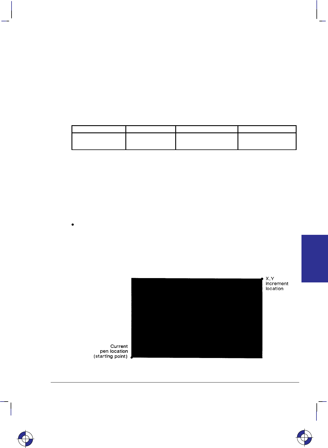
281
This is the black on page 281 (seq: 299)
Company confidential. HP-GL/2 and HP RTL Reference Guide, draft 2. Freeze Status: open
RR, Fill Rectangle Relative
Purpose
To defines and fills a rectangle using relative coordinates. Use RR to fill rectangular shapes in
drawings. (To outline a rectangle using relative coordinates, use the ER instruction.)
Syntax
RR X,Y[;]
Parameter Format Functional Range Parameter Default
X,Y increments current units device-dependent
(at least –223 to 223 – 1) no default
Group
This instruction is in the Polygon Group.
Use
The RR instruction defines and fills a rectangle using the current pen, the current line and fill
types, and relative coordinates. The RR instruction includes an automatic pen down. After the
instruction is executed, the original pen location and up/down status are restored.
X,Y increments: Specify the corner of the rectangle that is diagonally opposite from the
current pen location, which is the starting point of the rectangle. Coordinates are inter-
preted in current units: as user-units when scaling is on; as plotter-units when scaling is off.
Note: Figure 133 shows the current pen location in the lower-left corner and the instruction’s
X,Y increments in the upper-right corner. However, these points can be in any two opposite
corners depending on the coordinates used.
Figure 133. Fill Rectangle Relative
This is the blue on page 281 (seq: 299)
RR Instruction
INSTRUCTIONS
HP-GL/2

282
This is the black on page 282 (seq: 300)
Company confidential. HP-GL/2 and HP RTL Reference Guide, draft 2. Freeze Status: open
The only difference between the RR instruction and the ER (Edge Relative Rectangle) instruc-
tion is that the RR instruction produces a filled rectangle, and ER, an outlined one.
The RR instruction clears the polygon buffer and then uses it to define the rectangle before
drawing. A rectangle requires enough buffer space to hold five points.
A dot is drawn if both X and Y coordinates are zero. A line is drawn if one of the coordinates
is zero.
Related Instructions
EA Edge Rectangle Absolute
EP Edge Polygon
ER Edge Rectangle Relative
FP Fill Polygon
RA Fill Rectangle Absolute
Example
The following example uses RR with three different fill types (refer to the FT instruction de-
scription) to create rectangles such as those you might use in a bar chart. The rectangles in the
right bar are edged using the ER instruction.
PA 400,400; Specify absolute plotting and move to location (400,400).
RR 400,800; Fill a rectangle with the default fill (black), with (400,400) as the
lower left corner and the upper right corner 400 plotter-units to the
right and 800 plotter-units up from there.
PR 0,800; Enter the relative plotting mode and move 800 plotter-units in the
Y direction.
FT 3,50; Select fill type 3 (parallel lines).
RR 400,400; Draw a rectangle using the current pen location as the lower left
corner; the upper right corner is 400 plotter-units to the right and
400 plotter-units up from the lower left corner.
PR 0,400; Move 400 plotter-units up.
FT 4; Select fill type 4 (cross-hatching).
RR 400,400; Draw a rectangle using the current pen position as the lower left
corner and a point 400 plotter-units to the right and 400 plotter-
units up as the upper right corner.
PA 1200,400; Move to absolute location (1200,400).
FT ; Select the default fill type (solid black).
RR 400,800; Draw and edge a rectangle that begins at the current pen position
ER 400,800; and extends 400 plotter-units to the right, then 800 plotter-units up
from there.
PR 0,800; Move 800 plotter-units up from the current position.
FT 3,50; Select fill type 3 (parallel lines), with 50 plotter-units between
each line.
RR 400,400; Draw and edge a rectangle using the current pen location as the
ER 400,400; lower left corner and a point 400 plotter-units up and 400 plotter-
units to the right as the upper right corner.
PR 0,400; Move 400 plotter-units up from the current pen position.
FT 4; Select fill type 4 (cross-hatching).
RR Instruction
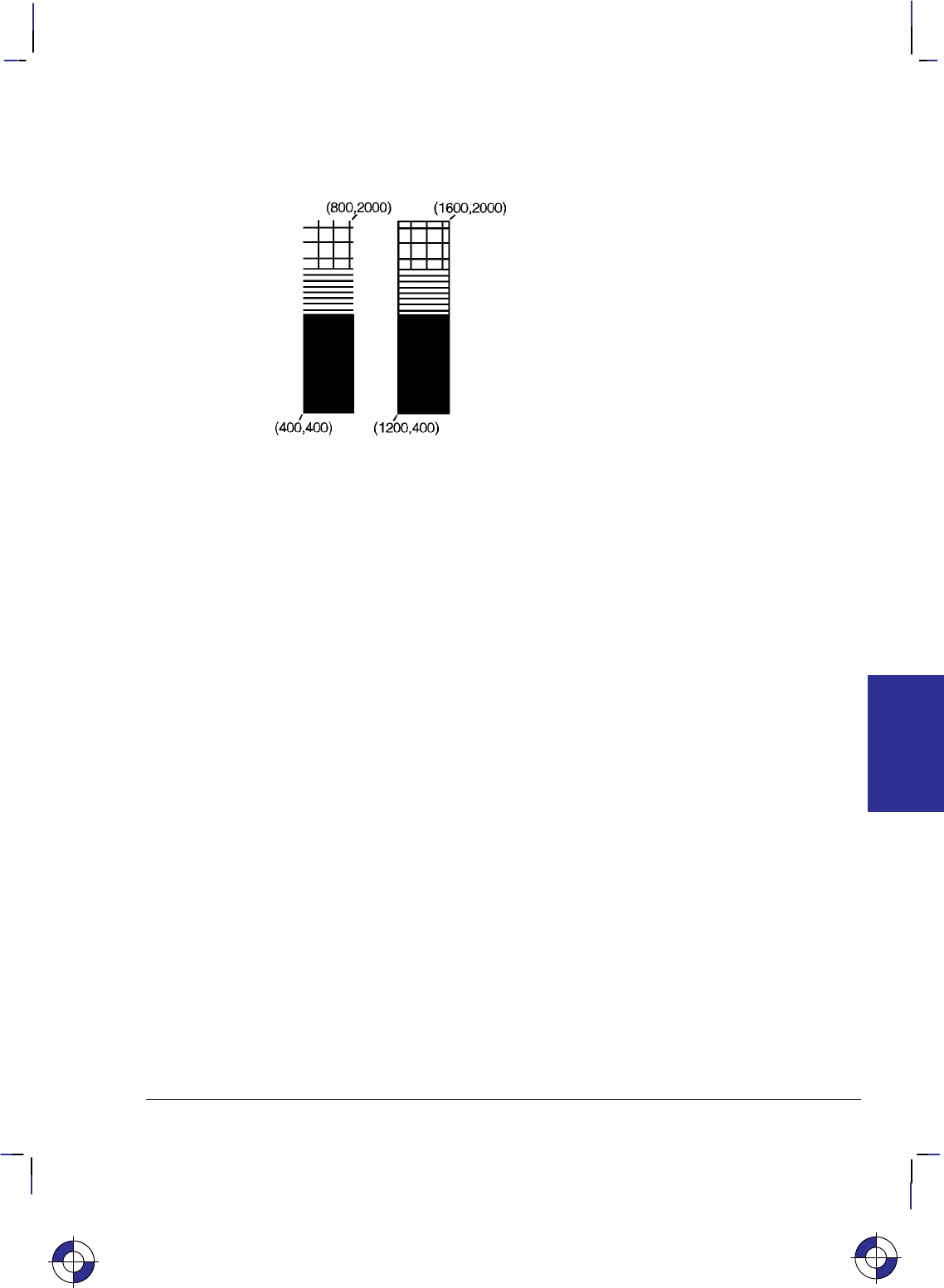
283
This is the black on page 283 (seq: 301)
Company confidential. HP-GL/2 and HP RTL Reference Guide, draft 2. Freeze Status: open
RR 400,400; Draw and edge a rectangle using the current pen location as the
ER 400,400; lower left corner, the right corner being (400,400) relative plotter-
units away.
Figure 134. Filling Rectangles with Different Patterns Using Relative Coordinates
This is the blue on page 283 (seq: 301)
RR Instruction
INSTRUCTIONS
HP-GL/2
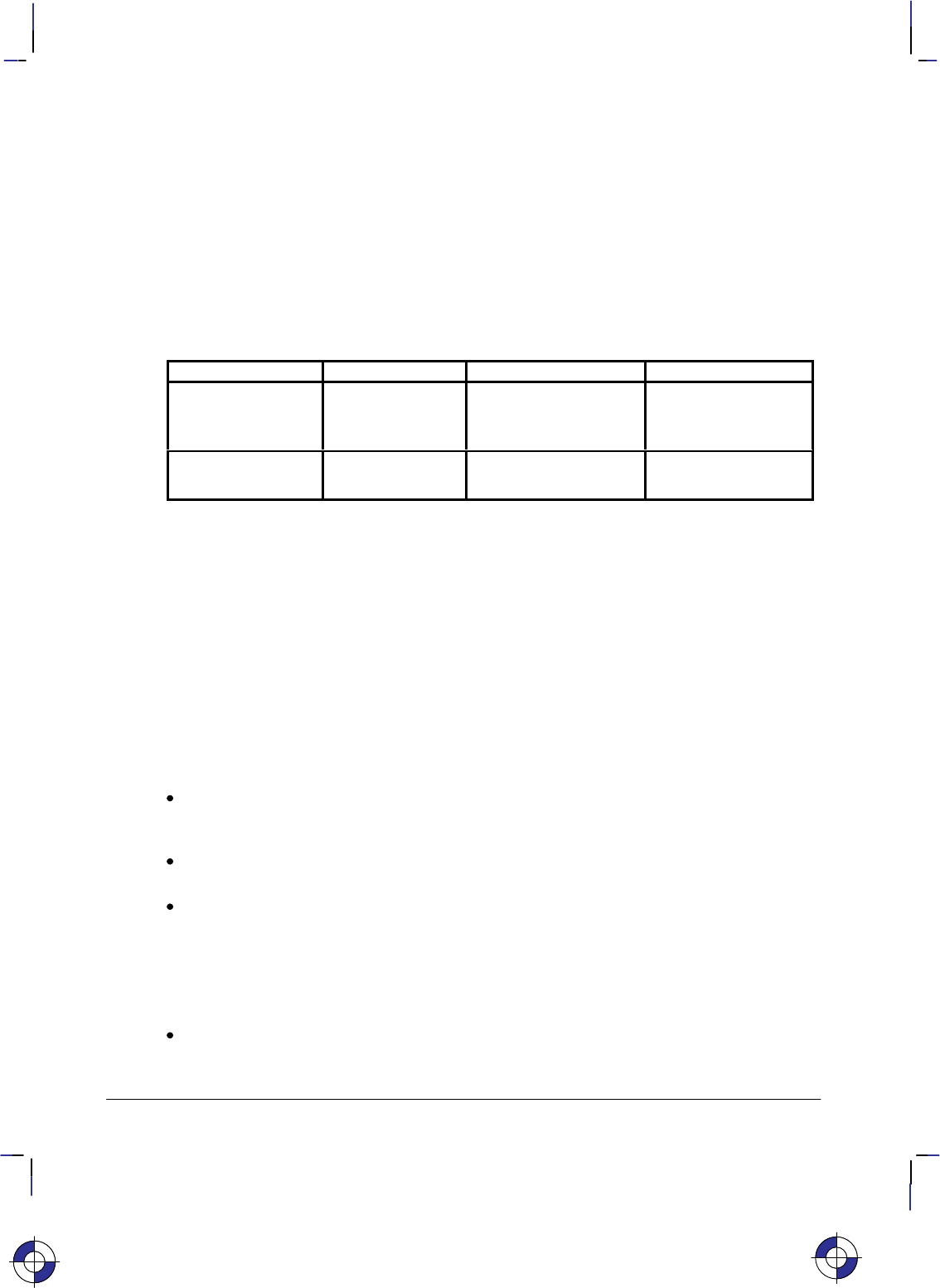
284
This is the black on page 284 (seq: 302)
Company confidential. HP-GL/2 and HP RTL Reference Guide, draft 2. Freeze Status: open
RT, Relative Arc Three Point
Purpose
To draw an arc segment, using relative coordinates, from a starting point through an intermedi-
ate point to an end point. Use RT when you know these three points of an arc.
Syntax
RT Xincr_inter,Yincr_inter, Xincr_end,Yincr_end[,chord_angle][;]
Parameter Format Functional Range Parameter Default
X, Y increments
(intermediate and
end points)
current units device-dependent
(at least –223 to 223 – 1) no defaults
chord_angle* clamped real 0° to 360°device-dependent
(usually 5°)
* If you have used the “CT1” instruction, the chord_angle is interpreted as a deviation dis-
tance in current units; see the CT instruction on page 133.
Group
This instruction is in the Vector Group.
Use
The RT instruction uses the current pen location and two specified points to calculate a circle
and draw the appropriate arc segment of its circumference. The arc starts at the current pen
location, using the current pen, line type, line attributes and pen up/down status. You specify
the intermediate and end points. After drawing the arc, the pen location remains at the end of
the arc; the carriage-return point (see page 66) is moved to the end of the arc.
Xincr_inter,Yincr_inter: Specify the location of an intermediate point of the arc in relative
increments (relative to the current pen location). The arc is drawn in a negative or positive
direction, as necessary, so that it passes through the intermediate point before the end point.
Xincr_end,Yincr_end: Specify the location of the end point of the arc in relative increments
(relative to the current pen location).
chord_angle: Specifies the chord angle used to draw the arc. The default is a chord angle
of 5°. (The Arc Absolute instruction description on page 100 contains more information
on chords and chord angles.)
Intermediate and end point coordinates are interpreted in current units: as user-units when scal-
ing is on; as plotter-units when scaling is off. If current scaling is not isotropic, the arc drawn is
elliptical rather than circular. Note the following about intermediate and end points:
If the intermediate point and end point are the same as the current pen location, the instruc-
tion draws a dot.
This is the blue on page 284 (seq: 302)
RT Instruction
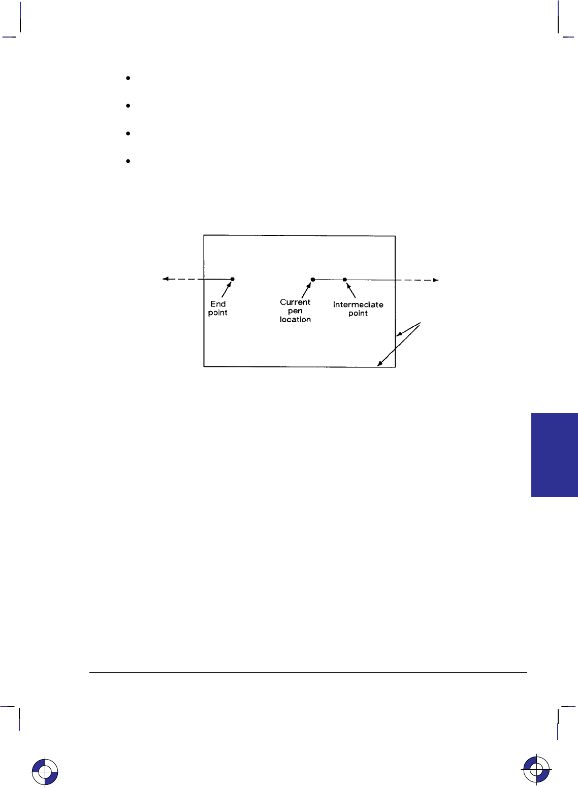
285
This is the black on page 285 (seq: 303)
Company confidential. HP-GL/2 and HP RTL Reference Guide, draft 2. Freeze Status: open
If the intermediate point is the same as either the current pen location or the end point, a
line is drawn between the current pen location and the end point.
If the end point is the same as the current pen location, a circle is drawn, with its diameter
being the distance between the current pen position and the intermediate point.
If the current pen position, intermediate point, and end point are collinear, a straight line is
drawn.
If the intermediate point does not lie between the current pen location and the end point,
and the three points are collinear, two lines are drawn, one from the current pen location
and the other from the end point, leaving a gap between them. Refer to the following
illustration. Both lines extend to the hard-clip limits or current window.
Figure 135. Relative Arc Three Point with Intermediate Point Outside End Points
Note that the CT (Chord Tolerance Mode) instruction in the Technical Graphics extension
changes the above computation.
Related Instructions
AA Arc Absolute
AR Arc Relative
AT Absolute Arc Three Point
BR Bezier Relative
BZ Bezier Absolute
CI Circle
LA Line Attributes
LT Line Type
PW Pen Width
This is the blue on page 285 (seq: 303)
RT Instruction
INSTRUCTIONS
HP-GL/2
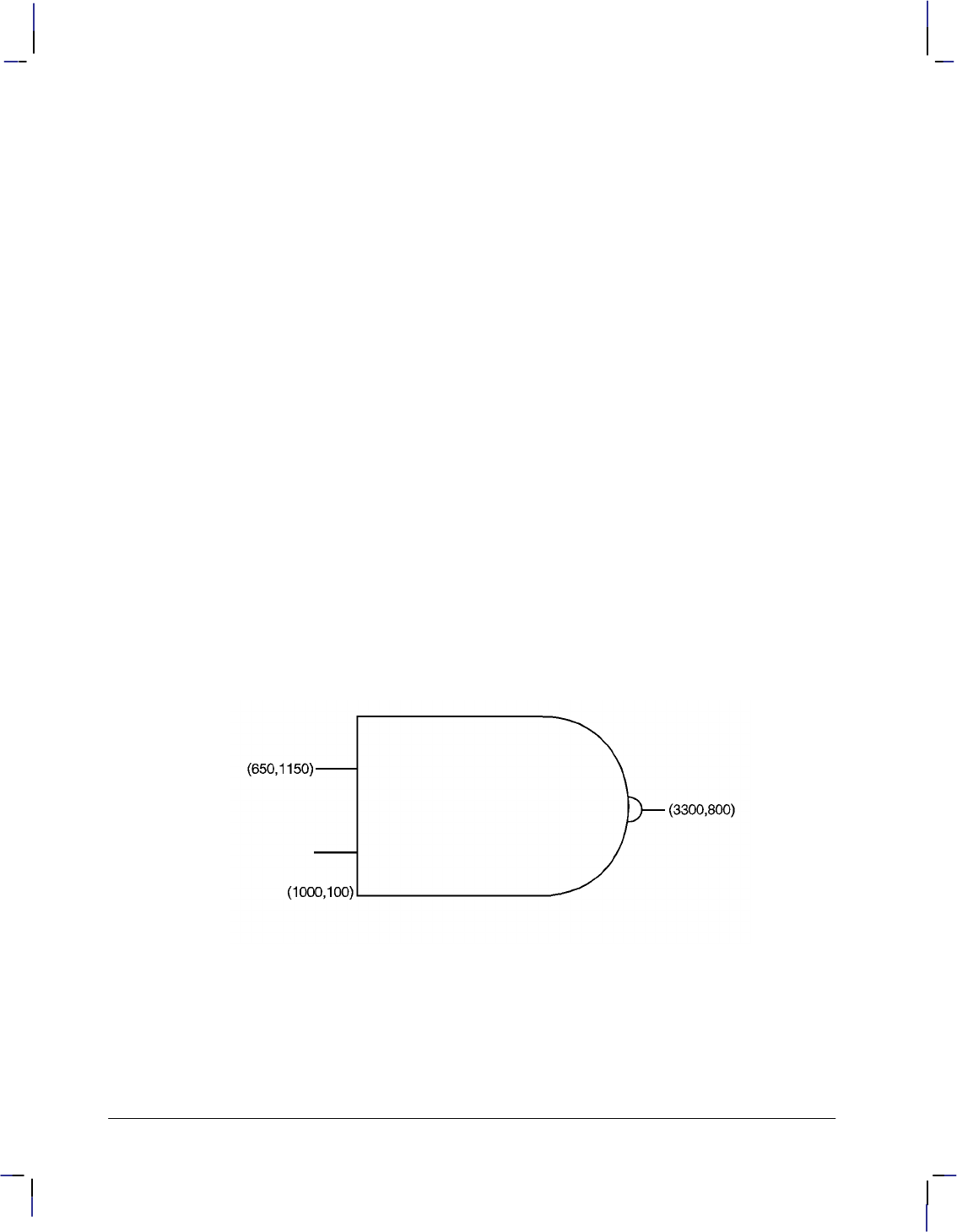
286
This is the black on page 286 (seq: 304)
Company confidential. HP-GL/2 and HP RTL Reference Guide, draft 2. Freeze Status: open
Example
PA 1000,100; Specify the absolute point (1000,100) as the starting location.
PR ; Specify relative plotting.
PD 1500,0; Pen down, and draw to (1500,0) relative plotter-units from the
current pen location (1000,100).
PU –1850,1050; Lift the pen and move (–1850,1050) relative coordinates.
PD 350,0; Place the pen down, and draw a line 350 plotter-units in the X
direction.
PU –350,–700; Lift the pen and move (–350,–700) plotter-units from the current
location.
PD 350,0; Place the pen down, and draw a line 350 plotter-units in the X
direction.
PU 0,–350; Lift the pen and move 350 plotter-units to the left.
PD 0,1500,1500,0; Place the pen down, draw a line 1500 plotter-units up and then
another line 1500 units to the right.
RT 700,–750,0,–1500; Draw an arc from the current pen position through a point
(700,–750) plotter-units away, with an ending point (0,–1500)
plotter-units from the beginning of the arc.
PU 700,850; Lift the pen and move it (700,850) plotter-units from the current
pen position.
PD ; Pen down.
RT 100,–100,0,–200; Draw an arc from the current pen position, through a point
(100,–100) plotter-units away, with an ending point (0,–200) from
the starting point of the arc.
PU 100,100; Lift the pen and move it (100,100) plotter-units from the current
pen position.
PD 200,0; Pen down, and draw a line 200 plotter-units in the X direction.
Figure 136. Example Using the RT Instruction
RT Instruction

287
This is the black on page 287 (seq: 305)
Company confidential. HP-GL/2 and HP RTL Reference Guide, draft 2. Freeze Status: open
SA, Select Alternate Font
Purpose
To select the alternate font (already designated by the AD instruction) for subsequent labeling.
Use the SA instruction to shift from the currently selected standard font to the designated alter-
nate font.
Syntax
SA [;]
Group
This instruction is in the Character Group.
Use
The SA instruction tells the device to draw subsequent labeling instructions using characters
from the alternate symbol set previously designated by the AD instruction. The SA instruction
is equivalent to using the Shift Out control character (, decimal 14) within a label string.
The default designated alternate font uses symbol set 277 (Roman-8). The alternate font re-
mains in effect until an SS instruction is executed, a Shift In control character (, decimal 15)
is encountered, or the device is initialized or set to default conditions.
Related Instructions
AD Alternate Font Definition
DT Define Label Terminator
FI Select Primary Font
FN Select Secondary Font
LB Label
SD Standard Font Definition
SS Select Standard Font
This is the blue on page 287 (seq: 305)
SA Instruction
INSTRUCTIONS
HP-GL/2
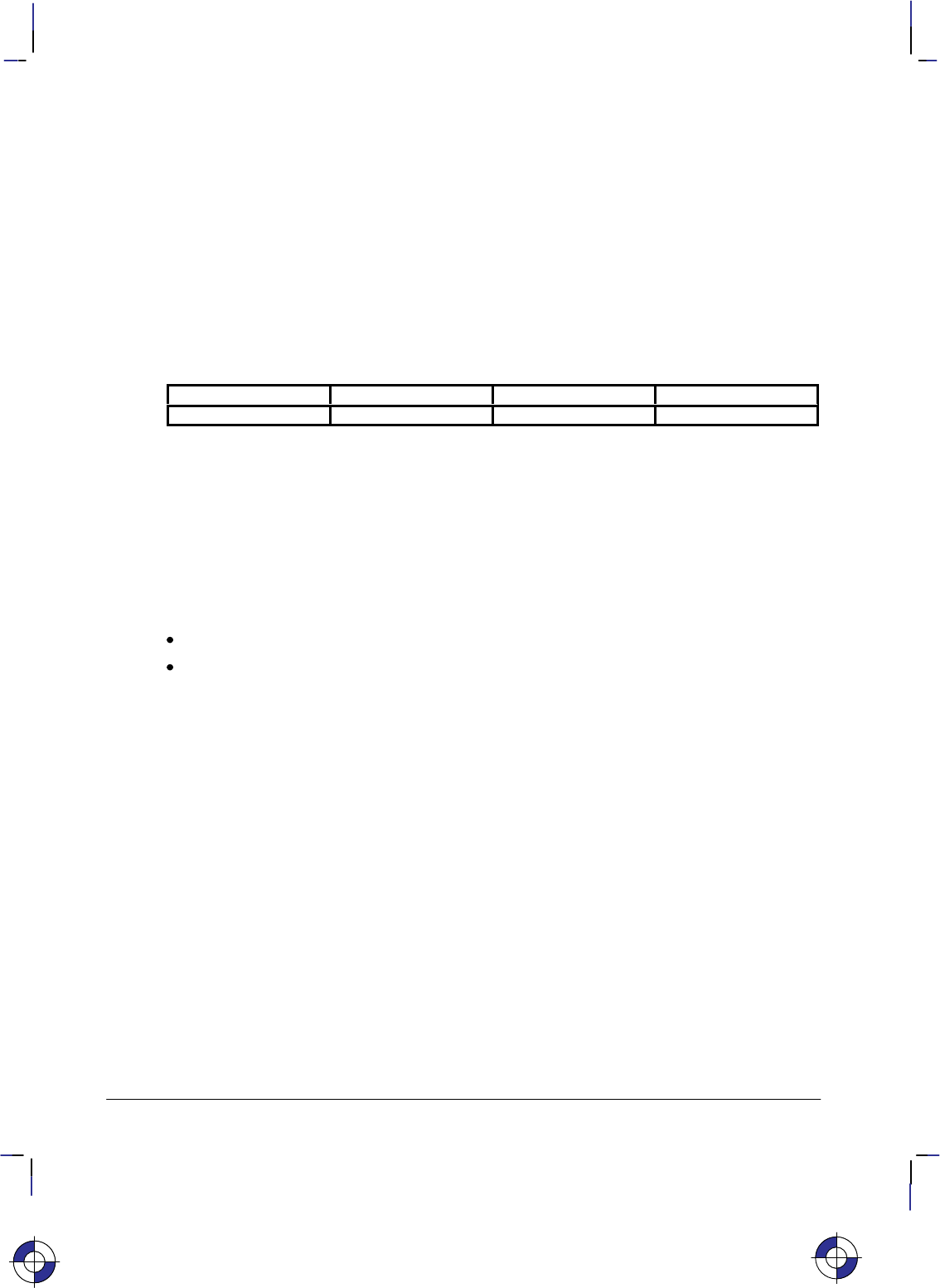
288
This is the black on page 288 (seq: 306)
Company confidential. HP-GL/2 and HP RTL Reference Guide, draft 2. Freeze Status: open
SB, Scalable or Bitmap Fonts
Purpose
To specify the type of font to be used in subsequent labeling. It allows you to restrict font
selection to only scalable fonts and the stick and arc fonts, disregarding bitmap fonts.
Syntax
SB n[;] or
SB [;]
Parameter Format Functional Range Parameter Default
nclamped integer 0 or 1 0
Group
This instruction is in the Dual-Context and Advanced Text Extensions.
Use
This instruction is defaulted by the DF (Default Values) and IN (Initialize) instructions. The SB
instruction takes effect immediately, changing both the standard (primary) and alternate (sec-
ondary) fonts to be scalable only or bitmap allowed, as requested.
No Parameter: Defaults to scalable fonts. Equivalent to “SB0”.
n: Determines the type of font according to the following parameter values:
0Scalable fonts only.
1Bitmap fonts are allowed. All fonts will be subject to the same restrictions as bit-
map fonts; that is, there is limited character fill, no slant, limited direction and
size, and character-clipped rather than bit-clipped.
SB1 (bitmap) changes the meanings of the following HP-GL/2 kernel instructions,
and can affect their performance:
CF Bitmap characters cannot be edged.
DI, DR Bitmap characters can be printed only with orthogonal orientations
(0, 90, 180, or 270). Refer to the DI instruction for an illustra-
tion of direction instructions with bitmap fonts.
SI, SR Sizes for bitmap fonts are approximate only.
SL Slant is ignored for bitmap fonts.
Scalable fonts respond more accurately to some HP-GL/2 instructions. The choice of scalable
or bitmap fonts can affect the performance of the following HP-GL/2 instructions: AD, SD, CP,
LB.
Note: The FI and FN instructions implicitly change the value of SB. For example, if SB = 0
and FI selects a bitmap font, SB is set to 1.
This is the blue on page 288 (seq: 306)
SB Instruction

289
This is the black on page 289 (seq: 307)
Company confidential. HP-GL/2 and HP RTL Reference Guide, draft 2. Freeze Status: open
SB is ignored in devices that do not support both scalable and bitmap fonts.
Scalable fonts are computationally more complex than bitmap fonts, but they respond more
accurately to some HP-GL/2 instructions. Bitmap fonts may offer a wider range of typefaces
on some devices for plots that do not use the size, direction, slant, or character fill instructions.
SB takes place immediately, changing both the standard and alternate fonts to scalable or bit-
map, as requested.
The DF and IN instructions default SB to 0.
Related Instructions
CF Character Fill Mode
DI Absolute Direction
DR Relative Direction
SI Absolute Character Size
SL Character Slant
SR Relative Character Size
This is the blue on page 289 (seq: 307)
SB Instruction
INSTRUCTIONS
HP-GL/2
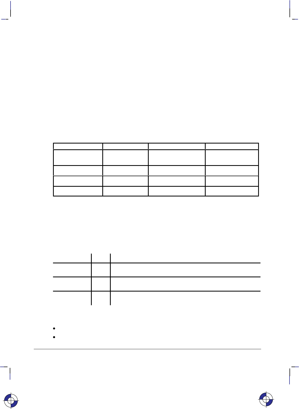
290
This is the black on page 290 (seq: 308)
Company confidential. HP-GL/2 and HP RTL Reference Guide, draft 2. Freeze Status: open
SC, Scale
Purpose
To establish a user-unit coordinate system by mapping user-defined coordinate values onto the
scaling points P1 and P2. For more information about the basic concept of scaling, refer to
Scaling on page 24.
Syntax
SC XMIN,XMAX,YMIN,YMAX[,type[,left,bottom]][;]
or
SC XMIN,XFAC TOR ,YMIN,YFAC TOR ,type[;]
or
SC [;]
Parameter Format Functional Range Parameter Default
X, Y coordinates real device-dependent
(at least –223 to 223 – 1) no default
type clamped integer 0, 1, or 2 0
left clamped real 0 to 100% 50%
bottom clamped real 0 to 100% 50%
Group
This instruction is in the Configuration and Status Group.
Use
There are three forms of scaling: anisotropic, isotropic, and point-factor. The type parameter
tells the device which form you are using. Refer to the following table.
Scaling Form Type Description
Anisotropic 0 Establishes standard user-unit scaling allowing different unit size
on X-axis and Y-axis.
Isotropic 1 Establishes standard user-unit scaling with same unit size on X-
axis and Y-axis.
Point Factor 2 Establishes P1 user-unit location and a specific ratio of plotter-
units to user-units.
An SC instruction remains in effect until another SC instruction is executed, or the device is
initialized or set to default conditions.
No Parameters: Turns off scaling; subsequent coordinates are in plotter-units.
Parameters: Turns on scaling as specified by the parameters; subsequent coordinates are
in user-units.
This is the blue on page 290 (seq: 308)
SC Instruction

291
This is the black on page 291 (seq: 309)
Company confidential. HP-GL/2 and HP RTL Reference Guide, draft 2. Freeze Status: open
Scaling Types 0 and 1
The following forms of scaling establish a user-unit coordinate system by mapping user-defined
coordinate values onto the scaling points P1 and P2. The type parameter selects between aniso-
tropic (Type 0) and isotropic scaling (Type 1).
Scaling Form Type Syntax
Anisotropic 0 XMIN,XMAX,YMIN,YMAX[,type];
Isotropic 1 XMIN,XMAX,YMIN,YMAX,1[,left,bottom]][;]
XMIN,XMAX,YMIN,YMAX: These parameters represent the user-unit X- and Y-axis ranges,
respectively.
For example, “SC0,15,0,10” indicates 15 user-units along the X-axis and 10 user-units
along the Y-axis. As a result, the first and third parameters (XMIN and YMIN) are the coor-
dinate pair that is mapped onto P1; the second and fourth parameters (XMAX and YMAX)
are the coordinate pair mapped onto P2. Using the same example, the coordinate location
of P1 is (0,0) and P2 is (15,10). This is different from the IP instruction, where the param-
eters are expressed as X,Y coordinate pairs rather than as ranges.
Note: XMIN cannot be set equal to XMAx, and YMIN cannot be set equal to YMAX.
As their names suggest, you will normally want to specify XMIN smaller than XMAX, and
YMIN smaller than YMAX. If you specify XMIN larger than XMAX and YMIN larger than
YMAX, your illustration is drawn as a mirror-image, reversed and/or upside down, depend-
ing on the relative positions of P1 and P2.
The parameters of the SC instruction are always mapped onto the current P1 and P2 loca-
tions. P1 and P2 retain these new values until scaling is turned off or another SC
instruction redefines the user-unit values. Thus, the size of a user unit could change if any
change is made in the relative position and distance between P1 and P2 after an SC instruc-
tion is executed.
The new P1 and P2 points become the basis for all instructions that normally use P1 and P2
(DR, FT, SR, and so on); however, the new P1/P2 are temporary anchor points that are only
in effect while the SC instruction that produced them is in effect; a new SC instruction uses
the old P1/P2.
type: Specifies anisotropic or isotropic scaling.
0Anisotropic scaling. Allows a user-unit along the X-axis to be a different size than
user-units along the Y-axis. Printed shapes are distorted when you use anisotropic
scaling. For example, a circle might be drawn as an ellipse—oval-shaped instead
of round. (Left and bottom parameters are ignored for anisotropic scaling.)
1Isotropic scaling. Produces user-units that are the same size on both the X- and
Y-axes. The following illustrations show how the device adjusts the location of
(XMIN,YMIN) and (XMAX,YMAX) to create the largest possible isotropic area with-
in the P1/P2 limits. (Remember, the user-units are always square regardless of the
shape of the isotropic area.)
left, bottom: Positions the isotropic area in the P1/P2 limits. (These parameters are
always specified together and are valid for isotropic scaling only.) The left parameter
indicates the percentage of the unused space on the left of the isotropic area; the bottom
parameter indicates the percentage of unused space below.
This is the blue on page 291 (seq: 309)
SC Instruction
INSTRUCTIONS
HP-GL/2
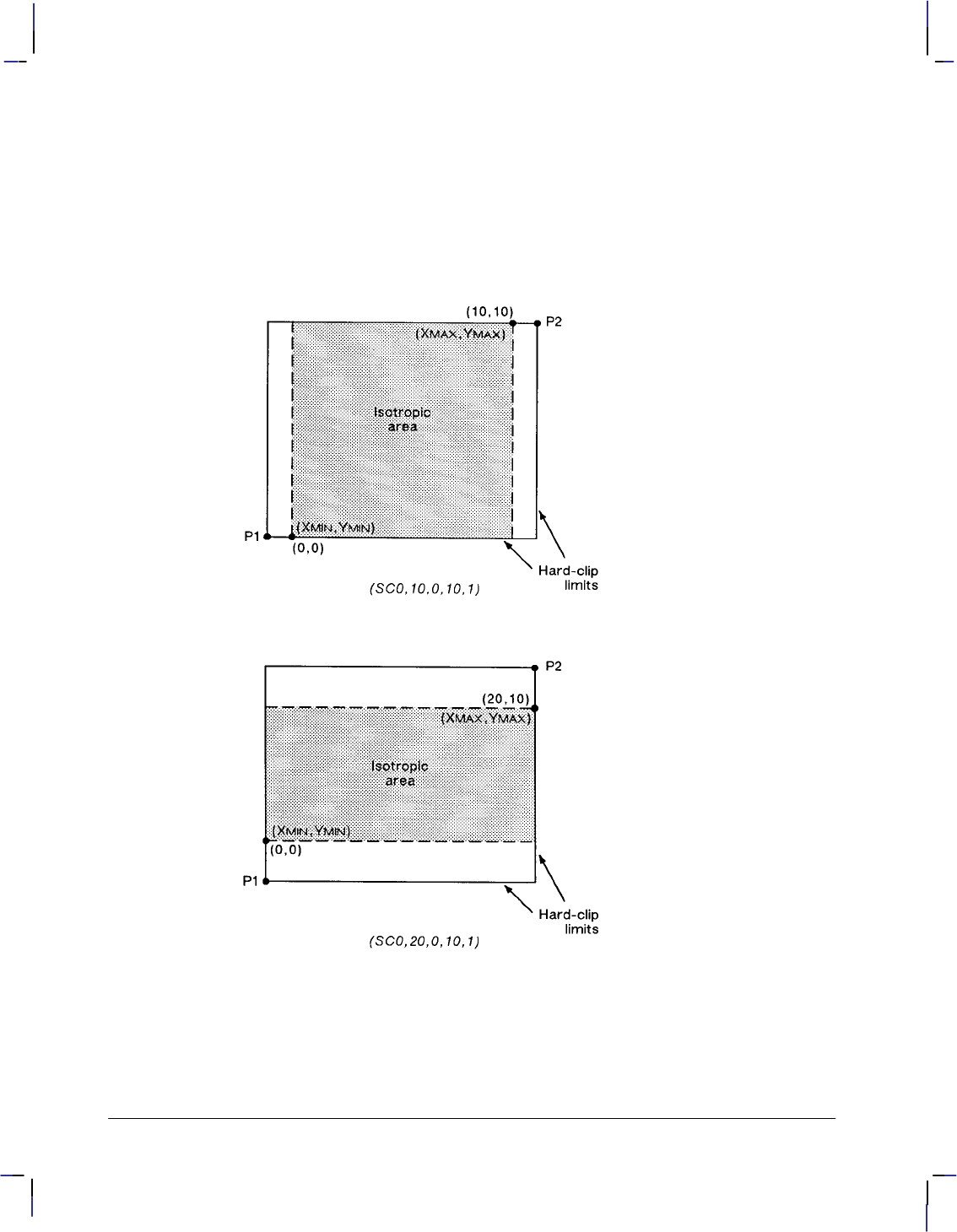
292
This is the black on page 292 (seq: 310)
Company confidential. HP-GL/2 and HP RTL Reference Guide, draft 2. Freeze Status: open
The defaults for the left and bottom parameters are each 50%. This centers the isotropic
area on the page with the unused space equally divided between left and right or top and
bottom, as shown in the previous illustrations.
Although you must specify both parameters, the device applies only one: the left parameter
applies when there is extra horizontal space; the bottom parameter applies when there is
extra vertical space. The following examples illustrate left and bottom parameters of 0%
and 100%.
Figure 137. Isotropic Scaling
SC Instruction
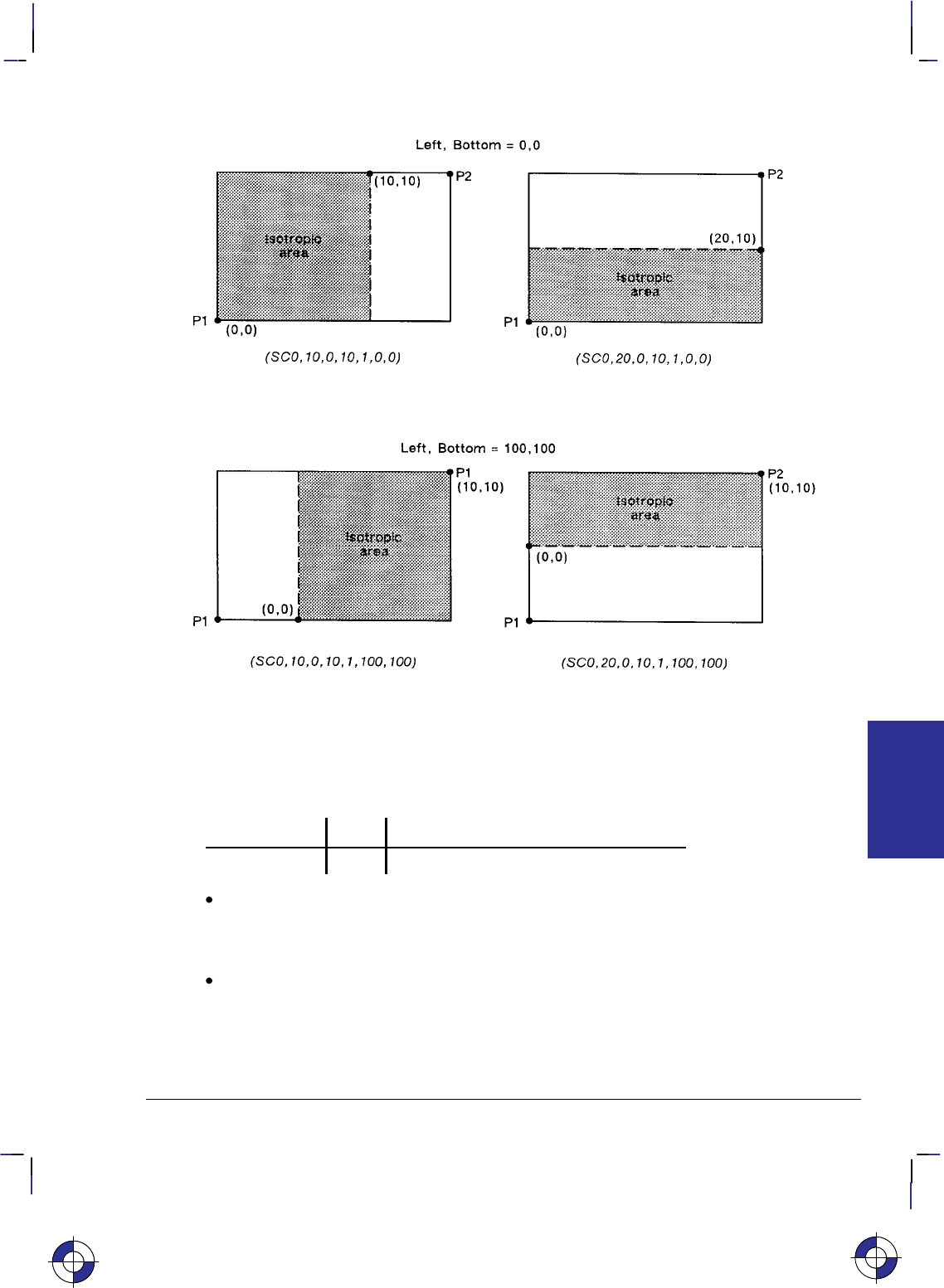
293
This is the black on page 293 (seq: 311)
Company confidential. HP-GL/2 and HP RTL Reference Guide, draft 2. Freeze Status: open
Figure 138. Left and Bottom Parameters Set to 0 or 100%
Scaling Type 2
The third form of scaling, point-factor scaling, sets a specific ratio of plotter-units to user-units,
and establishes the user-units coordinate of P1.
Scaling Form Type Syntax
Point Factor 2 XMIN,XFACTOR,YMIN,YFACTOR,2;
XMIN,XFACTOR,YMIN,YFACTOR; Establish the user-unit coordinates of P1 and the ratio of
plotter to user-units. XMIN and YMIN are the user-unit coordinates of P1. XFACTOR sets the
number of plotter-units per user-unit on the X-axis; YFACTOR sets the number of plotter-
units per user-unit on the Y-axis.
type: Must be 2 for this type of scaling.
This is the blue on page 293 (seq: 311)
SC Instruction
INSTRUCTIONS
HP-GL/2
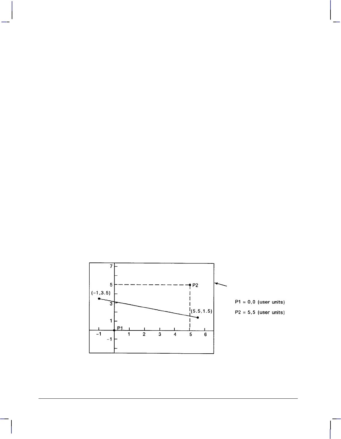
294
This is the black on page 294 (seq: 312)
Company confidential. HP-GL/2 and HP RTL Reference Guide, draft 2. Freeze Status: open
Using SC in a PCL Dual-Context Environment
When user-scaling mode is off, current units are:
(plotter-units * (PCL picture-frame-size HP-GL/2 plot-size))
Left and bottom parameters are relative to the PCL picture frame, viewed from the current
orientation. The directional implications of left and bottom assume the default P1/P2 orienta-
tion.
Examples
The following examples explain the effect of several parameter selections.
SC 0,1,0,1,2; Moves the origin to P1 and establishes a 1:1 ratio of user-units to
plotter-units.
SC 0,40,0,40,2; Allows scaling in millimeters since 1 millimeter = 40 plotter-
units. Each user-unit is 1 millimeter.
SC 0,1.016,0,1.016,2; Allows scaling in thousandths of an inch since 1 inch = 1016 plot-
ter-units.
While scaling is on (after any form of the SC instruction has been executed), only those HP-
GL/2 instructions that can be issued in “current units” are interpreted as user-units; the
instructions that can be issued only in plotter-units are still interpreted as plotter-units. (The
instruction syntax discussion pertaining to each instruction tells you which kind of units each
parameter requires.)
The SC parameters are mapped onto the current locations of P1 and P2. P1 and P2 do not repre-
sent a graphic limit; therefore, the new user-unit coordinate system extends across the entire
range of the plotter-unit coordinate system. Thus, you can print to a point beyond P1 or P2, as
long as you are within the effective window. For example, you can print from the point
(–1,3.5) to the point (5.5,1.5) as shown in the following illustration.
Figure 139. Example of Plotting beyond the P1/P2 Limits
SC Instruction
295
This is the black on page 295 (seq: 313)
Company confidential. HP-GL/2 and HP RTL Reference Guide, draft 2. Freeze Status: open
Related Instructions
IP Input P1 and P2
IR Input Relative P1 and P2
IW Input Window
Possible Error Conditions
Error Condition Error Number Printer or Plotter Response
More than 7 parameters 2 Executes first 7 parameters
For types 0 or 1:
More than 6 or less than 4 parameters 2Ignores instruction
For type 2:
Other than 5 parameters 2Ignores instruction
XMIN=XMAX or YMIN=YMAX or
number out of range 3Ignores instruction
XFACTOR=0 or YFACTOR=0 3 Ignores instruction
This is the blue on page 295 (seq: 313)
SC Instruction
INSTRUCTIONS
HP-GL/2

296
This is the black on page 296 (seq: 314)
Company confidential. HP-GL/2 and HP RTL Reference Guide, draft 2. Freeze Status: open
SD, Standard Font Definition
Purpose
To define the standard character set (font) and its characteristics: symbol set identification, font
spacing, pitch, height, posture, stroke weight, and typeface. To define an alternate font, use the
AD instruction.
Syntax
SD kind,value...[,kind,value] [;]
or
SD [;]
Parameter Format Functional Range Parameter Default
kind clamped integer 1 to 7 no default
value clamped real kind-dependent* kind-dependent*
* Refer to the table following the parameter descriptions.
Group
This instruction is in the Character Group.
Use
This instruction is similar to the AD (Alternate Font Definition) instruction (see page 106) that
defines a secondary HP-GL/2 font. The SD instruction defines the standard HP-GL/2 font and
its characteristics: font spacing, pitch, height, posture, stroke weight, and typeface. It allows
the font characteristics to be assigned to the primary font definition. Use SD to set up the stan-
dard font that you can easily access when labeling.
No Parameters: Defaults the standard font characteristics to that of the device-dependent
default scalable font, not a bitmap font.
kind: Specifies the characteristic for which you are setting a value (see the following
table).
value: Defines the properties of the characteristic specified by the kind parameter.
Note: When selecting fonts, the different characteristics (symbol set, spacing, pitch, etc.) are
prioritized as shown in the table above, with symbol set being the highest priority and typeface
being the lowest. The font selection priority is the same for HP-GL/2 as for PCL font selection.
For more information about the priority of font characteristics, see How Your Device Selects
Fonts on page 63.
The tables in Appendix C: Font Definitions on page 477 list the kind parameters with their
associated values (note that these tables are also valid for the AD [Alternate Font Definition]
instruction). For kinds 1 and 7, your device may support values other than those listed there.
Refer to your User’s Guide or HP-GL/2 option manual for more information about the attrib-
utes and values supported.
This is the blue on page 296 (seq: 314)
SD Instruction
297
This is the black on page 297 (seq: 315)
Company confidential. HP-GL/2 and HP RTL Reference Guide, draft 2. Freeze Status: open
Any combination of kind, value parameters is allowed; the last kind specified prevails.
Kind Attribute Range of Values Default Value Description
1Character set device-dependent 277 Roman-8
2Font Spacing 0 (fixed),
1 (proportional) device-dependent fixed spacing
3 Pitch >0 to 32 767 (valid to
2 decimal places) device-dependent characters per inch
4 Height 0 to 32 767 device-dependent font point size
5 Posture 0 to 32 767 device-dependent upright or italic
6Stroke Weight –7 to 7, 9999 0 normal
7 Typeface device-dependent device-dependent scalable font
The IN (Initialize) and DF (Default Values) instructions restore default primary font attributes.
Related Instructions
AD Alternate Font Definition
DT Define Label Terminator
FI Select Primary Font
FN Select Secondary Font
LB Label
SA Select Alternate Font
SB Scalable or Bitmap Fonts
SI Absolute Character Size
SR Relative Character Size
SS Select Standard Font
TD Transparent Data
Example
The instruction “SD1,21,2,1,4,25,5,0,6,3,7,51;” designates a 25-point Gill Sans Bold font in the
ASCII symbol set (use the Select Standard Font (SS) instruction to select this font after it is
designated):
SD 1,21 Symbol set—US ASCII
2,1 Spacing—proportional
4,25 Height—25-point
5,0 Posture—upright
6,3 Stroke weight—bold
7,51; Typeface—Gill Sans
Note that the pitch parameter is missing in the above instruction because the designated font is
proportionally spaced.
SD Instruction
This is the blue on page 297 (seq: 315)
SD Instruction
INSTRUCTIONS
HP-GL/2

298
This is the black on page 298 (seq: 316)
Company confidential. HP-GL/2 and HP RTL Reference Guide, draft 2. Freeze Status: open
SI, Absolute Character Size
Purpose
To specify the size of labeling characters in centimeters. Use SI to establish character size in-
dependent of P1 and P2.
Syntax
SI width, height[;]
or
SI [;]
Parameter Format Functional Range Parameter Default
width clamped real –32 768 to 32 767 (see note)*
height clamped real –32 768 to 32 767 (see note)*
* Note: Dependent on the current pitch and font height set by the AD or SD instruction.
Group
This instruction is in the Character Group.
Use
While SI is in effect, with or without specifying parameter values, the size of characters in the
currently selected font are not affected by changes in P1 and P2.
No Parameters: Character size is as specified by the SD (Standard Font Definition) and
AD (Alternate Font Definition) instructions.
width: Specifies the width of the nominal character in centimeters. A negative width
parameter mirrors labels in the right-to-left direction. The nominal character width is 0.5
of the point size (0.67 for the stick font).
height: Specifies the cap height in centimeters. A negative height parameter mirrors
labels in the top-to-bottom direction.
If both the width and the height are negative, characters are rotated through 180.
Changing character size also changes the width of line used to draw Stick font characters.
Note that in most languages the width of a letter is typically less than the height. If you set
your characters to have a different “aspect ratio”, they may look odd to your readers.
The maximum size of a character is device-dependent, but is larger than a page; for A-size de-
vices, characters at least as large as 12 times the page width and height are possible; for
roll1–feed devices, characters up to the paper roll length are possible.
An SI instruction remains in effect until another SI instruction is executed, an SR instruction is
executed, or the device is initialized or set to default conditions.
This is the blue on page 298 (seq: 316)
SI Instruction

299
This is the black on page 299 (seq: 317)
Company confidential. HP-GL/2 and HP RTL Reference Guide, draft 2. Freeze Status: open
SI and SR functionality is the same, except that SR parameters are relative to P1 and P2. See
the description of the SR instruction on page 308. When SI is in effect, moving P1 to the right
of P2, or moving P1 above P2 does not cause character mirroring.
Bitmap Fonts
If a bitmap font is selected, that is, the “SB1;” instruction is in effect, an SI instruction may
not be executed accurately. Labels are rendered using the bitmap font that most closely
approximates the character height or width specified by SI (character size is determined by
height for proportional fonts and by width for fixed-spaced fonts).
When “SB1;” is in effect, characters cannot be mirrored with negative SI parameters.
Using SI in a Dual-Context Environment
The width and height parameters, in centimeters, are adjusted by the picture frame scaling fac-
tor. The picture frame scaling factor is the ratio of the size of the PCL picture frame to the
HP-GL/2 plot size. See the PCL5 Printer Language Technical Reference manual for more in-
formation.
Related Instructions
AD Alternate Font Definition
CP Character Plot
DI Absolute Direction
DR Relative Direction
LB Label
SB Scalable or Bitmap Fonts
SD Standard Font Definition
SR Relative Character Size
Examples
The following example demonstrates the SI instruction using both the default Stick typeface
and the Univers typeface. The samples on the left were printed using the Stick font, first using
the default (11.5-point) and then specifying an absolute character size of 1 cm wide by 1.5 cm
high. On the right, a Univers font was used, first at 12-point and scaled to 1 cm by 1.5 cm us-
ing the SI instruction.
PA 700,3000; Enter absolute plotting mode and move to (700,3000).
DT#; Define the label terminator as the “#” character.
LBPrint#; Print the word “Print” in the default font.
PA 700,2000; Move to (700,2000).
SI 1,1.5; Specify an absolute character size of 1cm wide by 1.5 cm high.
LBPrint#; Print the word “Print”.
SI ; Send SI with no parameters to return to the default size.
SD 1,21,2,1,4,12,5,0,6,0,7,52; Designate a 12-point Univers font.
SS ; And select it.
PA 4000,3000; Move to (4000,3000).
LBPrint#; Print “Print” in 12-point Univers.
This is the blue on page 299 (seq: 317)
SI Instruction
INSTRUCTIONS
HP-GL/2
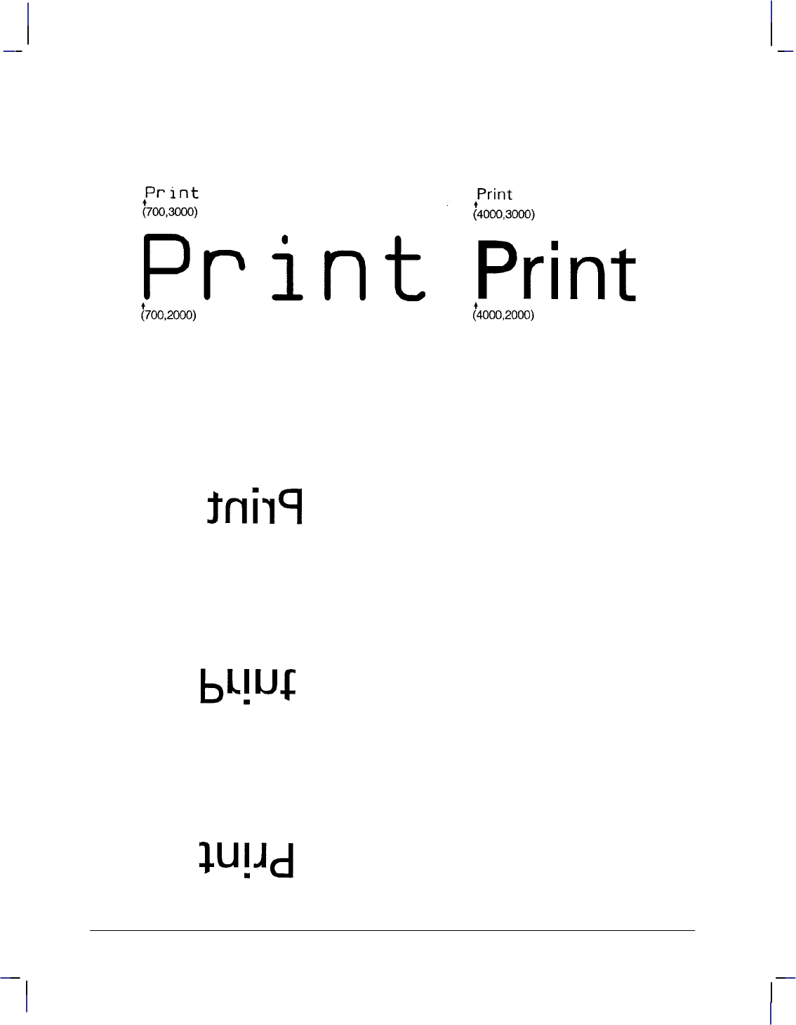
300
This is the black on page 300 (seq: 318)
Company confidential. HP-GL/2 and HP RTL Reference Guide, draft 2. Freeze Status: open
PA 4000,2000; Move the pen to (4000,2000).
SI 1,1.5; Specify a character size of 1 cm by 1.5 cm.
LBPrint#; Then print “Print”.
Figure 140. Specifying Absolute Character Sizes
In each case the current pen location is at the end of the stem of the letter “P”.
The following are examples of negative parameters producing mirror-images of labels. A nega-
tive width parameter mirrors labels in the right-to-left direction.
SI –.6,.9;
LBPrint#;
Figure 141. SI Instruction with Negative Width
A negative height parameter mirrors labels in the top-to-bottom direction.
SI .6,–.9;
LBPrint#;
Figure 142. SI Instruction with Negative Height
Negative width and height parameters together mirror labels in both directions, causing the la-
bel to appear to be rotated 180.
SI –.6,–.9;
LBPrint#;
Figure 143. SI Instruction with Negative Width and Height
SI Instruction

301
This is the black on page 301 (seq: 319)
Company confidential. HP-GL/2 and HP RTL Reference Guide, draft 2. Freeze Status: open
SL, Character Slant
Purpose
To specify the slant at which labels are drawn using scalable or stick fonts. Use SL to create
slanted text for emphasis, or to re-establish upright labeling after an SL instruction with param-
eters has been in effect. (Note that the SL instruction has no effect when using bitmap fonts,
that is, when an “SB1;” instruction is in effect.)
Syntax
SL tangent_of_angle[;]
or
SL [;]
Parameter Format Functional Range Parameter Default
tangent_of_angle clamped real –32 768 to 32 767 0
Group
This instruction is in the Character Group.
Use
The device interprets the parameters as follows:
No Parameter: Defaults the slant to zero (no slant). Equivalent to “SL0;”.
tangent of angle: Interpreted as an angle from the vertical. The base of the character
always stays on the horizontal as shown in the following illustration.
Figure 144. Character Slant
The SL instruction only affects each character relative to an imaginary line beside the label.
The direction or placement of the label on the drawing does not affect the SL instruction; nei-
ther do the settings of P1 and P2. The DI and DR instructions, however, do affect the slant
direction, since the base of a character always stays on the baseline of the label.
This is the blue on page 301 (seq: 319)
SL Instruction
INSTRUCTIONS
HP-GL/2
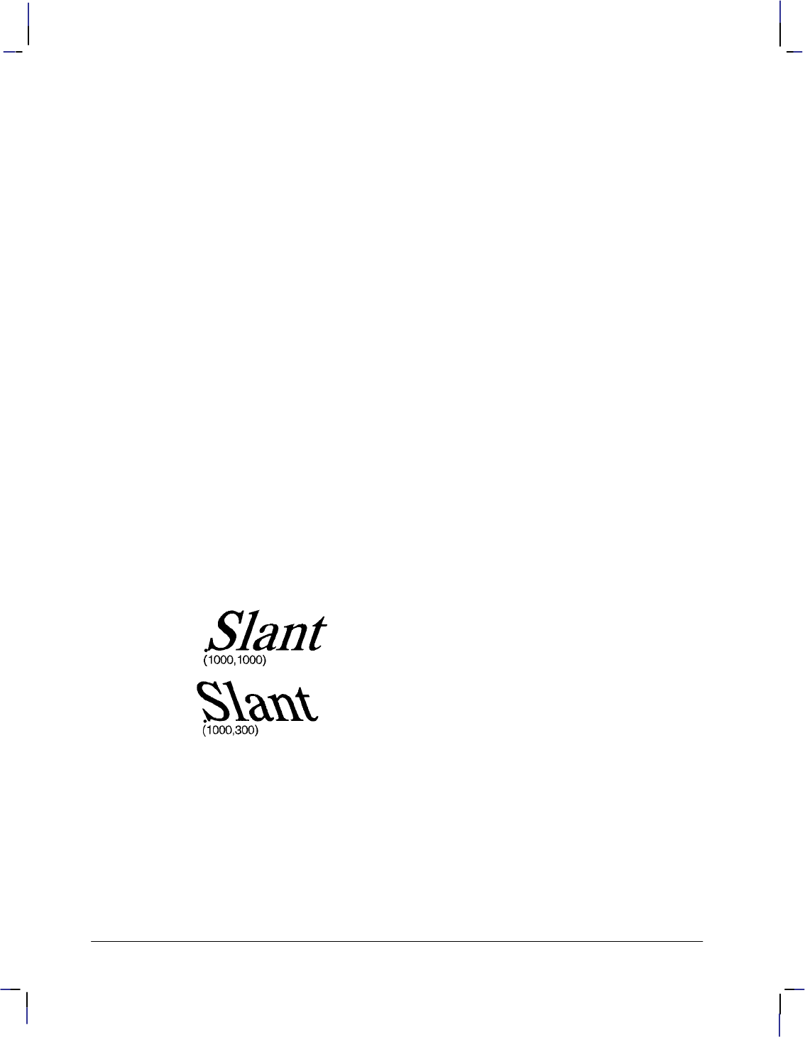
302
This is the black on page 302 (seq: 320)
Company confidential. HP-GL/2 and HP RTL Reference Guide, draft 2. Freeze Status: open
You can specify the actual tangent value, or you can use the TAN function available in most
computer languages.
Note: Many languages require that tangents be calculated in radians. Consult your program-
ming language documentation if you are not familiar with your language’s tangent function.
An SL instruction remains in effect until another SL instruction is executed, or the device is
initialized or set to default conditions.
Related Instructions
DI Absolute Direction
DR Relative Direction
LB Label
SB Scalable or Bitmap Fonts
Example
The following example illustrates the Slant instruction using an angle of 20 (tan 20 = 0.36).
SD 1,21,2,1,4,25,5,0,6,0,7,4101; Designate the 25-point CG Times font as the standard
(primary) font.
SI .7,1; Set the absolute character size to 0.7 cm wide by 1 cm high.
PA 1000,1000; Establish absolute plotting and move to (1000,1000).
DT#,1; Specify a label terminator (#).
SL .36; Set the slant angle for 20 from vertical (forward slant).
LBSlant#; Print “Slant”.
PA 1000,300; Move to (1000,300).
SL –.36; Change the slant angle to –20 from upright.
LBSlant#; And print “Slant”.
Figure 145. Slanting to the Left and to the Right
SL Instruction

303
This is the black on page 303 (seq: 321)
Company confidential. HP-GL/2 and HP RTL Reference Guide, draft 2. Freeze Status: open
SM, Symbol Mode
Purpose
To draw the specified symbol at each X,Y coordinate point using the PA, PD, PE, PR, and PU
instructions. Use SM to create scatter-grams, indicate points on geometric drawings, and differ-
entiate data points on multi-line graphs.
Syntax
SM character[;]
or
SM charactercharacter2[;]
or
SM [;]
Parameter Format Functional Range Parameter Default
character
character2*
character Decimal codes 1 to 255
(most printing charac-
ters except 0, 5, 27, and
59)**
no default
*Character2 is only valid in 16-bit mode (see the LM instruction on page 208). In 16-bit
mode, both character and character2 are needed to specify the character. In 8-bit mode,
character2 would be considered the start of a new instruction.
** Decimal code 59 (the semicolon) is an HP-GL/2 terminator and cannot be used as a symbol
in any symbol set. Use it only to cancel symbol mode (“SM;”).
Group
This instruction is in the Line and Fill Attributes Group.
Use
The SM instruction draws the specified symbol at each X,Y coordinate point for subsequent PA,
PD, PE, PR, and PU instructions. The SM instruction includes an automatic pen down; after
the symbol is drawn, the pen position and any dashed-line residue are restored.
No Parameter: Terminates symbol mode.
character, character2: Draws the specified character centered at each subsequent X,Y
coordinate. The symbol is drawn in addition to the usual function of each HP-GL/2
instruction.
The character is drawn in the font selected at the time the vectors are drawn. If you change to a
new symbol set, the character changes to the corresponding character from the new symbol set.
The character fill (CF), size (SI and SR), slant (SL), and direction (DI and DR) instructions af-
fect how the character is drawn. Specifying a non-printing character cancels symbol mode. If
downloadable characters have been defined (see DL) they can be used in symbol mode plotting.
This is the blue on page 303 (seq: 321)
SM Instruction
INSTRUCTIONS
HP-GL/2

304
This is the black on page 304 (seq: 322)
Company confidential. HP-GL/2 and HP RTL Reference Guide, draft 2. Freeze Status: open
An SM instruction remains in effect until another SM instruction is executed or the device is
initialized or set to default conditions.
The character is centered at the coordinate point and printed after each vector intersection is
drawn. The geographic middle of stick-font characters is the character center, but the middle is
different for lowercase characters and characters with descenders. For all other fonts, the center
of the rectangle formed by cap height and character width is the character center.
The pen is automatically lowered to draw the character at each point; however, this automatic
pen-down does not affect the pen state used when drawing other entities.
Symbol mode only applies to the PA, PD, PE, PR, and PU instructions. The circle and rectan-
gle instructions have symbols only for the PA instruction coordinate point.
Example
The following example shows several uses of symbol mode: with the pen down for a line graph,
with the pen up for a scatter-gram, and with the pen down for geometric drawings.
Note: Symbol mode works only with the PA, PD, PE, PR, and PU instructions. Notice that the
circle and rectangle have symbols only for the PA instruction coordinate point.
SM*; Enter symbol mode, using the asterisk (*) as the symbol.
PA 200,1000; Move to absolute location (200,1000).
PD 200,1230,400,1560; Set the pen down, and draw first to (200,1230), then to
(400,1560).
PD 700,1670,1300,1600,1800,2000; Place the pen down and draw from the current pen
position (400,1560) to (700,1670), then to (1300,1600), then to
(1800,2000).
PU ; Lift the pen.
SM3; Enter symbol mode again with “3” as the current symbol.
PA 700,500,900,450,1300,850; Print a “3” in the following locations: (700,500),
(900,450), and (1300,850).
PA 1750,1300,2500,1350; With the pen still up and “3” still the current symbol, print a
“3” at (1750,1300) and (2500,1350).
PU ; Lift the pen.
SM; Exit symbol mode.
PA 3300,1100; Move to (3300,1100).
PD ; Set the pen down.
SMY; Enter symbol mode with “Y” as the symbol.
PA 4400,1890; Draw a line to (4400,1890) and print a “Y”.
SMZ; Re-enter symbol mode with “Z” as the current symbol.
PA 4600,1590; Draw a line to (4600,1590) and print a “Z”.
SMX; Specify “X” as the next symbol.
PA 3300,1100; Move to (3300,1100), and print an “X”.
PU ; Lift the pen.
SMA; Specify “A” as the new symbol.
PA 4000,400; Move to (4000,400).
CI 400; Draw a circle with a radius of 400 plotter-units and print an “A” in
the center.
SM*; Specify “*” as the new symbol.
SM Instruction
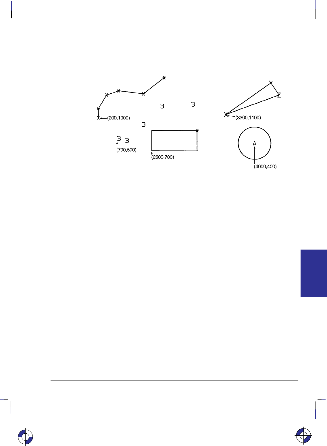
305
This is the black on page 305 (seq: 323)
Company confidential. HP-GL/2 and HP RTL Reference Guide, draft 2. Freeze Status: open
PA 2600,700; Move to (2600,700).
EA 1500,200; Edge the outline of a rectangle and print an “*” at the starting
point.
Figure 146. Drawing Symbols
Related Instructions
PA Plot Absolute
PD Pen Down
PE Polyline Encoded
PR Plot Relative
PU Pen Up
This is the blue on page 305 (seq: 323)
SM Instruction
INSTRUCTIONS
HP-GL/2
306
This is the black on page 306 (seq: 324)
Company confidential. HP-GL/2 and HP RTL Reference Guide, draft 2. Freeze Status: open
SP, Select Pen
Purpose
To select the device’s logical pen for subsequent plotting. An SP instruction must be included
at the beginning of each instruction sequence to enable the device to draw.
Syntax
SP pen_number[;]
or
SP [;]
Parameter Format Functional Range Parameter Default
pen_number integer device-dependent
(at least –223 to 223 – 1) 0 (no pen)
Group
This instruction is in the Line and Fill Attributes Group.
Use
Although your device may not have physical pens, for the purpose of compatibility it has “log-
ical” pens which you must select to print your drawing.
No Parameters: Equivalent to “SP0”.
pen_number: Selects the device’s logical pen. The device will not draw unless an SP is
sent.
0Selects pen 0 on raster devices. For pen plotters, stores the pen in the carousel and
subsequent plotting commands are not drawn.
>0 Selects the pen number. In raster devices, different pen numbers may represent
pens of the same color but with different widths.
The modulo function is applied if the pen number is greater than the current pal-
ette size or the maximum number of pens in the device:
for raster devices,
pen_used = ((
pen_number
– 1) MOD (number_of_pens –1)) + 1
for pen plotters,
pen_used = ((
pen_number
– 1) MOD (number_of_pens)) + 1
For monochrome devices, if pen_number>0 a black pen is selected.
Pen 0 defaults to white on black-and-white devices; other colors default to gray
levels.
Use the PW (Pen Width) instruction to change the line width. You may change widths as often
as you like, without sending an SP instruction again.
This is the blue on page 306 (seq: 324)
SP Instruction

307
This is the black on page 307 (seq: 325)
Company confidential. HP-GL/2 and HP RTL Reference Guide, draft 2. Freeze Status: open
Note: If you are not using the TR (Transparency Mode) instruction, white is always transpar-
ent; a transparent pen is the same as no pen. For more information on the TR instruction see
page 318.
The default black-and-white palette consists of two pens: black and white. The default color
raster palette has eight pens defined below; pen 0 is selected at power-up.
Number of Pens in Device Pen Number Color
2 0
1
White
Bl k
1 Black
8 0 White
1 Black
2 Red
3 Green
4
5
Yellow
Bl
5
6
Blue
M
6
7
Magenta
C
7 Cyan
SP clears the pattern residue and terminates any sequence of continuous vectors (see the LA
and LT instructions).
Related Instructions
PW, Pen Width
TR, Transparency Mode
WU, Pen Width Unit Selection
This is the blue on page 307 (seq: 325)
SP Instruction
INSTRUCTIONS
HP-GL/2
308
This is the black on page 308 (seq: 326)
Company confidential. HP-GL/2 and HP RTL Reference Guide, draft 2. Freeze Status: open
SR, Relative Character Size
Purpose
To specify the size of characters as a percentage of the distance between P1 and P2. Use SR to
establish relative character size so that if the P1/P2 distance changes, the character size adjusts
to occupy the same relative amount of space.
Syntax
SR width,height[;]
or
SR [;]
Parameter Format Functional Range Parameter Default
width clamped real –32 768 to 32 767 0.75% of P2X–P1X
height clamped real –32 768 to 32 767 1.5% of P2Y–P1Y
Group
This instruction is in the Character Group.
Use
While the SR instruction is in effect (with or without parameters), changes in P1 and P2 affect
the size of characters in the currently selected font.
No Parameters: Defaults the relative character width to 0.75% of the distance
(P2X – P1X) and the height to 1.5% of the distance (P2Y – P1Y).
width: Sets the character width to the specified percentage of the distance between the
X-coordinates of P1 and P2. A negative width parameter mirrors labels in the right-to-left
direction.
height: Sets the character height to the specified percentage of the distance between the
Y-coordinates of P1 and P2. A negative height parameter mirrors labels in the top-to-bot-
tom direction.
If both the width and the height are negative, characters are rotated through 180.
Note: Changing character size also changes the stroke weight of labels; the device adjusts char-
acters relative to changes in P1/P2. As long as the aspect ratio remains the same with changes
in P1/P2, characters will have the same appearance relative to the new P1/P2 rectangle.
The character size you specify with SR is a percentage of (P2X – P1X) and (P2Y – P1Y). The
device calculates the actual character width and height from the specified parameters as fol-
lows:
actual width = (width parameter/100) x (P2X – P1X)
actual height = (height parameter/100) x (P2Y – P1Y)
This is the blue on page 308 (seq: 326)
SR Instruction

309
This is the black on page 309 (seq: 327)
Company confidential. HP-GL/2 and HP RTL Reference Guide, draft 2. Freeze Status: open
For example, suppose P1 and P2 are located at (–6956,–4388) and (6956,4388), respectively. If
you establish relative sizing and specify a width of 2 and a height of 3.5, the device determines
the actual character size as follows:
width = (2/100) x (6956 – (–6956)) = 278.24 plotter-units or 0.695 cm
height = (3.5/100) x (4388 – ( –4388) ) = 307.16 plotter-units or 0.768 cm
If you changed P1 and P2 settings to (100,100) and (5000,5000), but did not change the SR pa-
rameters, the character size would change as follows:
width = (2/100) x (5000 – 100) = 98 plotter-units or 0.245 cm
height = (3.5/100) x (5000 – 100) = 171.5 plotter-units or 0.429 cm
Note that in most languages the width of a letter is typically less than the height. If you set
your characters to have a different “aspect ratio”, they may look odd to your readers.
Note: Either negative SR parameters or switching the relative position of P1 and P2 produces
mirror-images of labels. When P1 is in the lower left and P2 is in the upper right, the SR
instruction gives the same mirroring results as the SI instruction. However, if you move P1 to
the right of P2, characters are mirrored right-to-left; when you move P1 above P2, characters
are mirrored top-to-bottom. When both of these situations occur (using negative parameters in
the SR instruction with an unusual P1/P2 position) double mirroring may result in either direc-
tion, in which case the two inversions cancel, and lettering appears normal.
An SR instruction remains in effect until another SR instruction is executed, an SI instruction is
executed, or the device is initialized or set to default conditions.
If a bitmap font (“SB1;”) is selected, SR may not accurately transform characters; labels are
rendered in the font most closely approximating the height specified by SR. Negative parame-
ters or unusual P1/P2 locations do not cause mirroring.
After SR is in effect, “SI;” must be sent to use the size specified by SD or AD.
Related Instructions
CP Character Plot
DI Absolute Direction
DR Relative Direction
IP Input P1 and P2
IR Input Relative P1 and P2
SB Scalable or Bitmap Fonts
SI Absolute Character Size
Examples
The following example first shows a label with a character size relative to P1 and P2 (SR).
Next, the locations of P1 and P2 are changed; then, the character size percentages are specified.
Notice that the new character size has equal parameters of 2.5; because the P1/P2 area is
square, the resulting characters are square.
IP –6956,–4388,6956,4388; Set P1 at (–6956,–4388) and P2 at (6956,4388).
DT@; Specify “@” as the label terminator.
SR ; Default the character size as a percentage of the P1/P2 rectangle.
PA 0,2700; Move the pen to (0,2700).
This is the blue on page 309 (seq: 327)
SR Instruction
INSTRUCTIONS
HP-GL/2
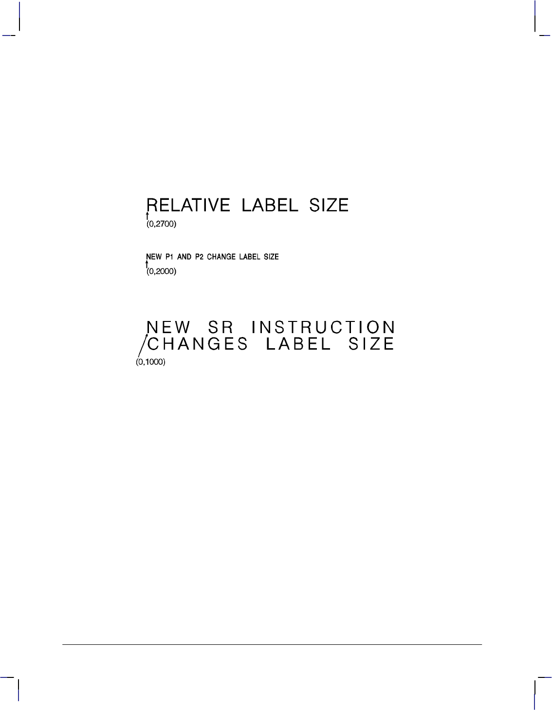
310
This is the black on page 310 (seq: 328)
Company confidential. HP-GL/2 and HP RTL Reference Guide, draft 2. Freeze Status: open
LBRELATIVE LABEL SIZE@; Print “RELATIVE LABEL SIZE”.
IP 0,0,5500,5500; Move P1 to (0,0) and P2 to (5500,5500).
PA 0,2000; Then move the pen to (0,2000).
LBNEW P1 AND P2 CHANGE LABEL SIZE@; Print “NEW P1 AND P2 CHANGE LA-
BEL SIZE”.
PA 0,1000; Move to (0,1000).
SR 2.5,2.5; Set the character size to 2.5% by 2.5% of the P1/P2 rectangle.
LBNEW SR INSTRUCTION@; Print “NEW SR INSTRUCTION”.
CP ; Send CP for Carriage Return/Line Feed.
LBCHANGES LABEL SIZE@; Print “CHANGES LABEL SIZE”.
Figure 147. Using the SR Instruction
SR and SI functionality is the same, except that SR parameters are relative to P1 and P2.
Therefore, as shown in the following examples, some P1/P2 orientations cause positive SR pa-
rameters to produce the same effect as negative SI parameters; corresponding mirror images
will be produced.
DI 1,0; Horizontal labels
IP 0,0,10160,5080; P1 = (0,0), P2 = (10160,5080)
SR 1,4; Equivalent to “SI 0.25,0.5;”
IP 0,5080,10160,0; P1 = (0,5080), P2 = (10160,0)
SR 1,4; Equivalent to “SI 0.25,–0.5;”
IP 10160,0,0,5080; P1 = (10160,0), P2 = (0,5080)
SR 1,4; Equivalent to “SI –0.25,0.5;”
IP 10160,5080,0,0; P1 = (10160,5080), P2 = (0,0)
SR 1,4; Equivalent to “SI –0.25,–0.5;”
See the SI instruction on page 298 for further examples.
SR Instruction

311
This is the black on page 311 (seq: 329)
Company confidential. HP-GL/2 and HP RTL Reference Guide, draft 2. Freeze Status: open
SS, Select Standard Font
Purpose
To select the standard font (already designated by the SD (Standard Font Definition) instruc-
tion) for subsequent labeling. Use the SS instruction to shift from the currently selected
alternate font to the designated standard font.
Syntax
SS [;]
Group
This instruction is in the Character Group.
Use
The SS instruction tells the device to print subsequent labeling instructions using characters
from the standard symbol set designated by the SD instruction. The SS instruction is equivalent
to using the Shift In control character (, ASCII decimal code 15) within a label string.
The default-designated standard font is the Stick font, and uses symbol set 277 (Roman-8).
This font is in effect when the device is initialized or set to default conditions. The SS instruc-
tion remains in effect until an SA instruction or a Shift Out control character (, ASCII
decimal code 14) is executed.
Related Instructions
AD Alternate Font Definition
DT Define Label Terminator
FI Select Primary Font
FN Select Secondary Font
LB Label
SA Select Alternate Font
SD Standard Font Definition
This is the blue on page 311 (seq: 329)
SS Instruction
INSTRUCTIONS
HP-GL/2

312
This is the black on page 312 (seq: 330)
Company confidential. HP-GL/2 and HP RTL Reference Guide, draft 2. Freeze Status: open
ST, Sort
Purpose
To specify how the device is to sort vectors for plotting. Raster devices ignore this instruction.
Syntax
ST switches[;]
or
ST [;]
Parameter Format Functional Range Parameter Default
switches clamped integer –1,0, and any sum of 1,
2, and 4 (1 through 7) 0
Group
This instruction is in the Technical Graphics Extension.
Use
The sorting switches are device-dependent and vary according to the hardware technology,
buffer size, and plotting/CPU speed trade-offs.
No Parameter: Defaults the sorting to a device-dependent switch. Refer to the documen-
tation for your device or HP-GL/2 option to determine what switches are supported and
which is the default.
switches: Determines sorting as follows:
–1 Turns on all sorting (or optimal combination).
0Turns off all sorting; plots vectors in the order they are received.
1Pen sorting; vectors are sorted by pen color rather than in the order in which they
were received.
2End-point swap (bidirectional plotting); swaps successive vector end points to
minimize pen-up moves.
4Geographic sorting; sorts all vectors by their geographic area before moving to
another area.
There are no out-of-range parameters (within the clamped integer constraint). The switches
pertinent to the device are used, and others are ignored.
This is the blue on page 312 (seq: 330)
ST Instruction
313
This is the black on page 313 (seq: 331)
Company confidential. HP-GL/2 and HP RTL Reference Guide, draft 2. Freeze Status: open
SV, Screened Vectors
Purpose
To select the type of screening (area fill) to be applied to vectors. Options include lines, hatch-
ing patterns (fill types 3 and 4), arcs, circles, edges of polygons, rectangles, wedges and PCL
and HP RTL user-defined patterns. SV does not affect solid fill types, stroked characters, or
edges of characters. Pen plotters ignore this instruction.
Syntax
SV screen_type [,option1 [,option2]][;]
or
SV [;]
Parameter Format Functional Range Parameter Default
screen_type clamped integer 0, 1, 2, 21, 22 0: no screening (solid)
option1, option2 clamped integer type-dependent* type-dependent
* Refer to the table following the parameter descriptions.
Group
This instruction is in the Palette Extension.
Use
There are four types of screen fill: shaded fill, HP-GL/2 user-defined raster fill, predefined PCL
and HP RTL cross-hatch patterns, and PCL and HP RTL user-defined patterns.
No Parameters: Defaults to no screening (solid fill—same as “SV0;”).
screen_type: Selects the types of screening as follows:
0No screening (options 1 and 2 are ignored)
1Shaded fill
2HP-GL/2 user-defined raster fill (RF instruction)
21 Predefined PCL or HP RTL cross-hatch patterns
22 PCL or HP RTL user-defined patterns
option1, option2: The definition of these optional parameters depends on the screen type
selected.
This is the blue on page 313 (seq: 331)
SV Instruction
INSTRUCTIONS
HP-GL/2
314
This is the black on page 314 (seq: 332)
Company confidential. HP-GL/2 and HP RTL Reference Guide, draft 2. Freeze Status: open
Screen_Type Description Option1 Option2
1Shaded Fill % Shading (0 through 100)
default is 50% Ignored
2 HP-GL/2
User-Defined
Raster Fill
Pattern Index
(device-dependent: at least 1 to 8)
default is 1
0—false
(default)
1—true
For Type 1, option1 specifies the shading percentage using a number from 0 to 100. For
example, to print vectors that are shaded 15%, specify “SV1,15;”.
For Type 2, option1 specifies the index number of the fill pattern created using the RF
(Raster Fill Definition) instruction.
Option2 is a Boolean flag that is ignored unless the RF pattern is defined using only 0’s and
1’s. If this parameter is 1, the current color is applied to the “1” pattern pixels, and white
to the “0” pixels.
All parameters are optional. If all parameters are omitted, screening is turned off (the vectors
are solid).
If screen_type is present, but option1 and/or option2 are omitted, values previously specified
for the specified screen_type are used. If none have been specified since the last power-on, IN,
DF, or E Reset, the defaults are assumed.
All screening patterns use the current anchor corner (see the AC instruction description on page
103).
SV terminates the vector path (see the LA instruction).
Using SV in a Dual-Context Environment
Additional screen types (21 and 22) are imported from PCL or HP RTL.
Screen_Type Description Option1 Option2
21 PCL or HP RTL cross-hatch 1 through 6 Ignored
22 PCL or HP RTL user-defined pattern fill Pattern ID Ignored
For Type 21, the option1 parameter selects one of the six predefined cross-hatch patterns
using a value between 1 and 6 (see Figure 148).
For Type 22, the optional parameter selects the corresponding user-defined pattern speci-
fied by way of the *c#W instruction. Option1 specifies the pattern associated with the
user-defined fill pattern. An invalid option1 (for example, a deleted pattern), prints a solid
fill in the current color.
1 horizontal lines
2 vertical lines
3 diagonal lines (lower left to upper right)
4 diagonal lines (lower right to upper left)
5 cross-hatching with horizontal and vertical lines
6 cross-hatching with diagonal lines.
SV Instruction
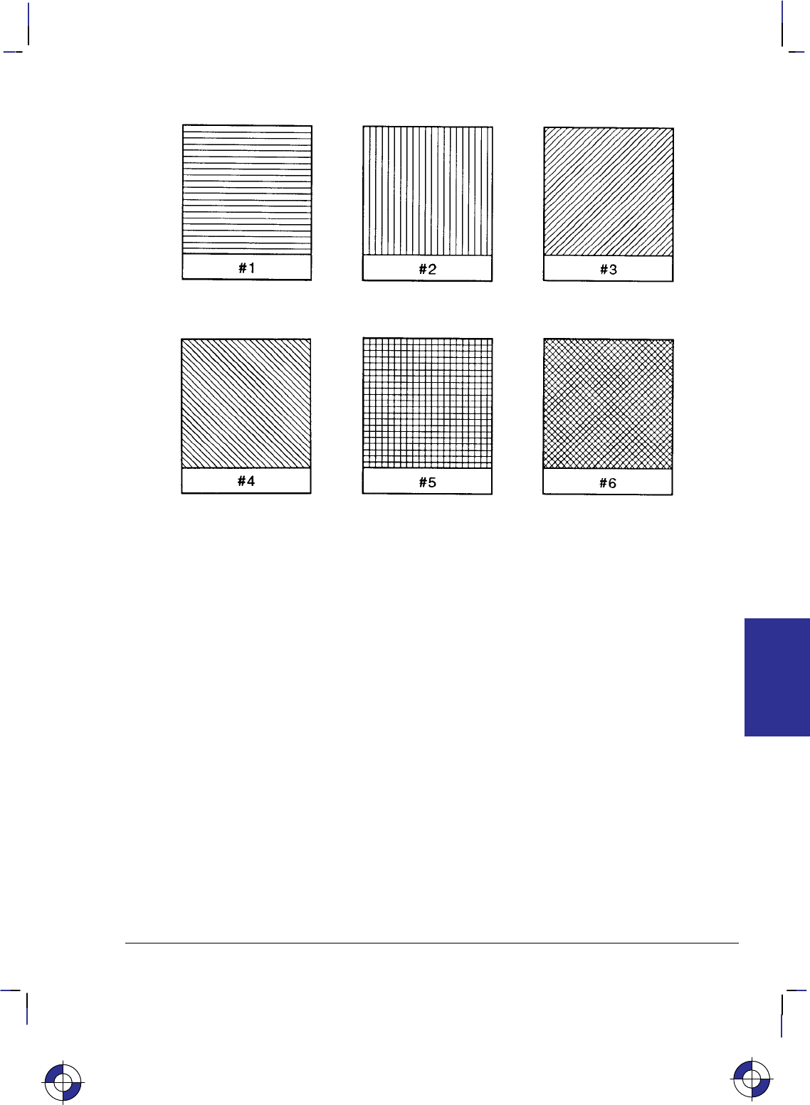
315
This is the black on page 315 (seq: 333)
Company confidential. HP-GL/2 and HP RTL Reference Guide, draft 2. Freeze Status: open
Figure 148. Patterns for Fill Type 21
Related Instructions
AC Anchor Corner
FT Fill Type
LT Line Type
PW Pen Width
RF Raster Fill Definition
WU Pen Width Unit Selection
This is the blue on page 315 (seq: 333)
SV Instruction
INSTRUCTIONS
HP-GL/2
316
This is the black on page 316 (seq: 334)
Company confidential. HP-GL/2 and HP RTL Reference Guide, draft 2. Freeze Status: open
TD, Transparent Data
Purpose
To specify whether control characters perform their associated control function or print as char-
acters when labeling. Use the TD instruction to print characters that function only as control
characters in normal mode.
Syntax
TD mode[;]
or
TD [;]
Parameter Format Functional Range Parameter Default
mode clamped integer 0 or 1 0 (normal)
Group
This instruction is in the Character Group.
Use
The device interprets the parameters as follows:
No Parameters: Defaults the labeling mode to normal. Equivalent to “TD0”.
mode: Selects the normal or transparent data mode for labeling.
0Normal. Control codes with an associated functionality perform their function
and do not print. Control characters with no defined function are ignored. Char-
acter codes that are undefined in the current font are printed as spaces. Refer to
Control Characters on page 67.
1Transparent. All characters are printed and perform no other function (except the
currently defined label terminator, which terminates the label). The device prints
a space for non-printing or undefined characters.
Transparent data mode must be enabled to access printable characters which have character
codes with an associated functionality in normal mode. For example, the left arrow in the PC-8
symbol set has a character code of 27. In normal mode, a character code of 27 is interpreted as
an escape character (); in transparent data mode, a character code of 27 prints a left arrow.
Using TD in a Dual-Context Environment
Note that in normal mode, E within a label string causes a device reset and transition to the
PCL or HP RTL environment. In transparent mode, E within a label string is printed rather
than performing a device reset.
This is the blue on page 316 (seq: 334)
TD Instruction

317
This is the black on page 317 (seq: 335)
Company confidential. HP-GL/2 and HP RTL Reference Guide, draft 2. Freeze Status: open
Related Instructions
AD Alternate Font Definition
DT Define Label Terminator
LB Label
SA Select Alternate Font
SD Standard Font Definition
SS Select Standard Font
This is the blue on page 317 (seq: 335)
TD Instruction
INSTRUCTIONS
HP-GL/2
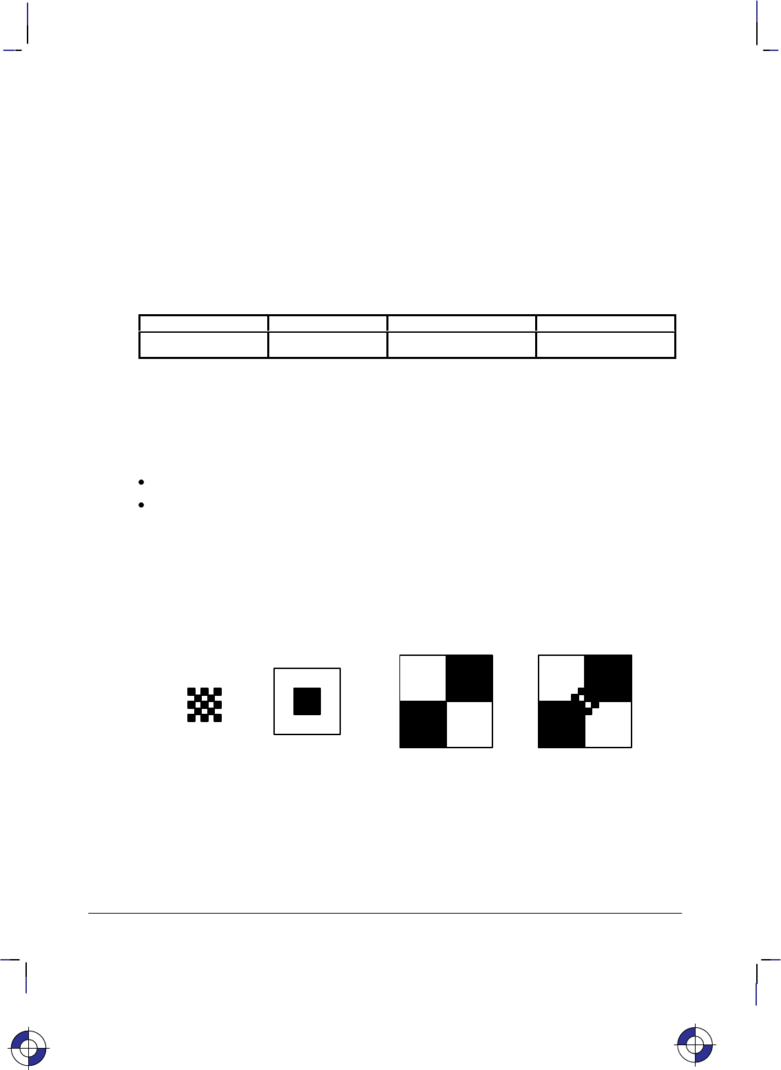
318
This is the black on page 318 (seq: 336)
Company confidential. HP-GL/2 and HP RTL Reference Guide, draft 2. Freeze Status: open
TR, Transparency Mode
Purpose
To define how the white areas of the area-fill (or pattern) affect the destination graphics image.
Syntax
TR n[;] or
TR [;]
Parameter Format Functional Range Parameter Default
nclamped integer 0 or 1 1 (on)
Group
This instruction is in the Palette Extension.
Use
No Parameters: Defaults to transparency mode = on (equivalent to “TR1;”).
n: Specifies whether transparency mode is on or off:
0Transparency mode = off. Overlaying white areas are opaque.
1Transparency mode = on (default). Overlaying white areas are transparent.
When transparency mode is on (default), the portion of an area-fill (or pattern) which is defined
by white pixels does not affect the destination; whatever was already written to the page “shows
through” the white areas in the new image. “White” is defined as the white reference specified
in the CR instruction.
+=+
Pattern
Source
Result
(current image)
Destination
Figure 149. Transparency Mode On
When transparency mode is off, all source pixels are written to the destination, obscuring any
underlying images.
This is the blue on page 318 (seq: 336)
TR Instruction

319
This is the black on page 319 (seq: 337)
Company confidential. HP-GL/2 and HP RTL Reference Guide, draft 2. Freeze Status: open
+=+
Pattern
Source
Result
Destination
(current image)
Figure 150. Transparency Mode Off
The transparency mode is defaulted by the E (Reset) command, and the BP (Begin Plot),
IN (Initialize) and DF (Default) instructions.
More information on the interactions between source data, texture, and destination data can be
found in Chapter 10: Interactions between Picture Elements on page 365.
This is the blue on page 319 (seq: 337)
TR Instruction
INSTRUCTIONS
HP-GL/2

320
This is the black on page 320 (seq: 338)
Company confidential. HP-GL/2 and HP RTL Reference Guide, draft 2. Freeze Status: open
UL, User-Defined Line Type
Purpose
To create line types by specifying gap patterns, which define the lengths of spaces and lines that
make up a line type.
Syntax
UL index [,gap1,...,gapn][;]
or
UL [;]
Parameter Format Functional Range Parameter Default
index clamped integer 1 through 8
(or –1 through –8) no default
gap1 to gapn clamped real 0 to 32767 default line types
Group
This instruction is in the Line and Fill Attributes Group.
Use
The UL command allows you to define and store your own line types. The instruction does not
itself select a line type. Use the LT instruction to select the line type once you have defined it
with UL.
No Parameters: Defaults all line types (refer to the LT instruction).
index: Identifies the number of the line type to be redefined. Specifying an index number
without gap parameters sets the line type identified by the index to the default pattern for
that number. The index number may not be 0.
The index parameter uses absolute values, so (UL–n) is the same as (ULn). Redefining a
standard fixed line type automatically redefines the corresponding adaptive line type.
gap1, ... gapn: Specify alternate pen-down and pen-up stretches in the line type pattern; if
gaps are numbered starting with 1, odd numbered gaps are pen-down moves, even num-
bered gaps are pen-up moves. The first gap is a pen-down move. Gap values are
converted to percentages of the LT instruction’s pattern_length parameter.
A maximum of 20 gaps are allowed for each user-defined line type. Gap values must be
non-negative; a gap value of zero produces a dot if specified for an odd numbered gap that
is preceded or followed by a non-zero even-numbered gap. The sum of the gap parameters
must be greater than zero.
The BP (Begin Plot), IN (Initialize) and DF (Default Values) instructions return user-defined
line types to their default patterns.
UL clears the pattern residue and terminates any sequence of continuous vectors (see the LA
and LT instructions).
This is the blue on page 320 (seq: 338)
UL Instruction

321
This is the black on page 321 (seq: 339)
Company confidential. HP-GL/2 and HP RTL Reference Guide, draft 2. Freeze Status: open
Related Instructions
LA Line Attributes
LT Line Type
Example
The following example demonstrates redefining and printing a line type.
PA 4000,3000; Specify absolute plotting and move to (4000,3000).
UL 8,0,15,0,15,0,15,40,15; Redefine the user-defined line type with an index number of 8;
specify the lines and spaces as follows, in percentages of the line
distance: gap1 as a dot (0%), gap2 as a space (15%), gap3 as
another dot (0%), gap4 as a space (15%), gap5 as another dot
(0%), gap6 as a space (15%), gap7 as a line (40%), and gap8 as a
space (15%).
LT 8,10; Specify line type number 8 (just defined), with a pattern length of
10% of the distance between P1 and P2.
PU 2000,2500; Lift the pen and move to (2000,2500).
PD 5000,2500; Set the pen down and draw to (5000,2500).
Figure 151. Using a User-Defined Line Type
Possible Error Conditions
Error Condition Error Number Printer or Plotter Response
Sum of gap parameters equals zero 3 Ignores instruction
A gap is negative 3 Ignores instruction
Index out of range 3 Ignores instruction
This is the blue on page 321 (seq: 339)
INSTRUCTIONS
HP-GL/2
UL Instruction

322
This is the black on page 322 (seq: 340)
Company confidential. HP-GL/2 and HP RTL Reference Guide, draft 2. Freeze Status: open
VS, Velocity Select
Purpose
To specify the pen speed for pen plotters; other devices ignore this instruction. Use VS on pen
plotters to optimize pen life and line quality for each pen and media combination. Increase line
quality and create a slightly thicker line on any media by slowing the pen speed.
Syntax
VS pen_velocity[,pen_number][;]
or
VS [;]
Parameter Format Functional Range Parameter Default
pen_velocity clamped integer device-dependent* device-dependent
pen_number clamped integer device-dependent** all pens
* Your plotter’s fastest pen velocity may be greater or less than 60 cm/s. Refer to the
manual for your plotter for more information.
** Your plotter carousel may handle a different number of pens, or if you are using a ras-
ter device, you may have a different number of logical pens that you can use. Refer to
the manual for your plotter or HP-GL/2 option for any additional information.
Group
This instruction is in the Technical Graphics Extension.
Use
Use the VS instruction to increase the pen life and line quality produced by your pens. Slowing
the pen speed increases line quality.
The velocity set by this instruction (or the front panel) determines the maximum velocity corre-
sponding to quality level 0 (see QL). As quality level is increased, the plotter will use a lower
velocity, based on the maximum set by VS or the front panel. The default quality level (QL0)
should be used when explicit control over velocity is required.
The VS instruction remains in effect until another VS instruction is received or the plotter is
initialized or set to default conditions.
No Parameters: Sets the speed for all pens to the default value. Refer to the manual for
your plotter or HP-GL/2 option for any additional information.
pen_velocity: Specifies the pen speed in centimeters per second (cm/s). You can incre-
ment the pen speed by 1 cm/s. If the specified velocity is greater than the plotter’s
maximum speed, the maximum speed is used. The selected velocity applies only when the
pen is down. The pen-up speed is device-dependent.
This is the blue on page 322 (seq: 340)
VS Instruction
323
This is the black on page 323 (seq: 341)
Company confidential. HP-GL/2 and HP RTL Reference Guide, draft 2. Freeze Status: open
pen_number: Applies the pen speed to a specific pen. When this parameter is omitted,
the velocity applies to all pens.
The following table lists the velocity range and recommended speed for each pen type.
Pen Type Recommended Velocity Range
(cm/s) Recommended Plotting Speed
(cm/s)
Fiber-tip paper 5 to 80 40
Fiber-tip transparency 5 to 15 10
Disposable drafting 10 to 30 20
Refillable drafting 5 to 15 15
Note that your plotter may let you set pen speed from the control panel. However, the pen
speed you specify using the control-panel buttons may apply to all pens. Refer to the manual
for your plotter for any additional information.
Possible Error Conditions
Error Condition Error Number Printer or Plotter Response
More than 2 parameters 2 Ignores extra parameter
Pen_number 0 3 Ignores instruction
Pen_number > plotter’s maximum 3Ignores instruction
This is the blue on page 323 (seq: 341)
VS Instruction
INSTRUCTIONS
HP-GL/2

324
This is the black on page 324 (seq: 342)
Company confidential. HP-GL/2 and HP RTL Reference Guide, draft 2. Freeze Status: open
WG, Fill Wedge
Purpose
To define and fill any wedge. Use WG to draw filled sections of a pie chart.
Syntax
WG radius,start_angle,sweep_angle[,chord_angle][;]
Parameter Format Functional Range Parameter Default
radius current units device-dependent
(at least –223 to 223 – 1) no default
start_angle clamped real –32768 to 32767 no default
sweep_angle clamped real –360° to +360°no default
chord_ angle* clamped real 0° to 360°device-dependent
(usually 5°)
* If you have used the “CT1” instruction, the chord_angle is interpreted as a deviation dis-
tance in current units; see the CT instruction on page 133.
Group
This instruction is in the Polygon Group.
Use
The WG instruction defines and fills a wedge using the current pen, fill type, and line types.
The WG instruction includes an automatic pen down. When the instruction operation is com-
plete, the original pen location and up/down status are restored.
The only difference between the WG instruction and the EW (Edge Wedge) instruction is that
the WG instruction produces a filled wedge, and the EW, an outlined one.
WG deletes any stored polygon and stores the wedge in the polygon buffer with an implicit
pen-down that overrides any explicit pen-up (PU); therefore the wedge may be subsequently
re-filled by FP or edged by EP.
If the wedge has more points than will fit in the polygon buffer, the portion of the wedge that
fits in the buffer is closed and filled, and the remainder of the wedge is discarded.
Always use isotropic scaling in any drawing that contains wedges (to avoid drawing an ellipti-
cal wedge). (Refer to Scaling on page 24 for more information.)
This is the blue on page 324 (seq: 342)
WG Instruction

325
This is the black on page 325 (seq: 343)
Company confidential. HP-GL/2 and HP RTL Reference Guide, draft 2. Freeze Status: open
Figure 152. Fill Wedge with Isotropic or Anisotropic Scaling
radius: Specifies the distance from the current pen location to the start of the wedge’s arc.
Since the wedge is a portion of a circle, this parameter is the radius of the circle. It speci-
fies the distance from the current pen location (which becomes the center of the circle), to
any point on the circumference of the circle.
The radius is interpreted in current units: as user-units when scaling is on; as plotter-units
when scaling is off. The sign of the radius (+ or –) determines the location of the zero-de-
gree reference point. Figures 153 and 154 show the location of the zero-degree reference
point for a positive and negative radius.
start_angle: Specifies the beginning point of the arc as the number of degrees from the
zero-degree reference point. A positive start angle positions the radius in the positive
direction (the direction from the +X-axis toward the +Y-axis) from the zero-degree refer-
ence point; a negative start_angle positions the radius in a negative direction from the
zero-degree reference point. If you specify a start angle greater than 360°, a start_angle
equal to the remainder of the start_angle/360° is used.
sweep_angle: Specifies in degrees the angle through which the arc is drawn. A positive
angle draws the angle in the positive direction (angle of rotation — +X-axis to the +Y-
axis); a negative angle draws the angle in the negative direction (+X-axis to the –Y-axis).
(Note, the relation of the +X-axis to the +Y-axis/–Y-axis can change as a result of scaling
point or scaling factor changes.) Angles with absolute values greater than 360° have their
signs preserved, and they are bounded to 360°. If the sweep_angle is 360° after bound-
ing, a radius is not drawn.
chord_angle: Specifies the chord angle used to define the arc. Refer to the discussion of
chord angles in the Arc Absolute (AA) instruction on page 100.
A zero radius draws a dot at the current position; a zero sweep_angle draws a line from the cur-
rent position to the start of the wedge’s arc.
Related Instructions
EP Edge Polygon
EW Edge Wedge
CI Circle
FP Fill Polygon
FT Fill Type
SC Scale
This is the blue on page 325 (seq: 343)
WG Instruction
INSTRUCTIONS
HP-GL/2
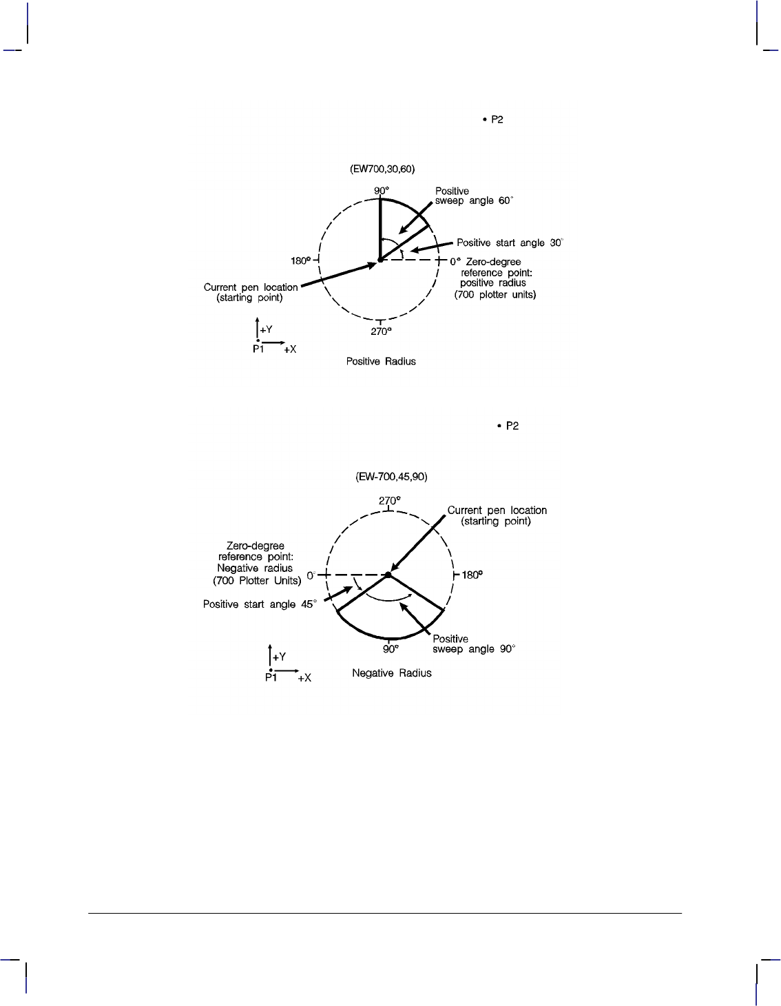
326
This is the black on page 326 (seq: 344)
Company confidential. HP-GL/2 and HP RTL Reference Guide, draft 2. Freeze Status: open
Figure 153. Terminology Used with Wedges
Figure 154. Wedge with a Negative Radius
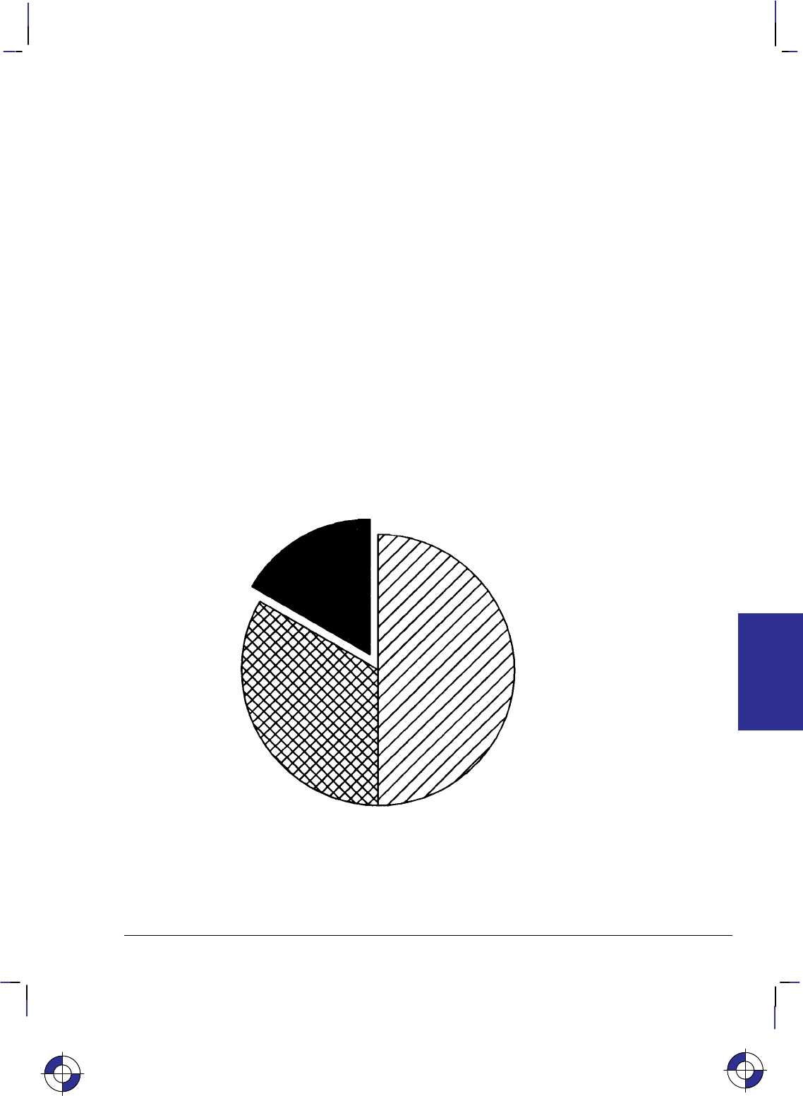
327
This is the black on page 327 (seq: 345)
Company confidential. HP-GL/2 and HP RTL Reference Guide, draft 2. Freeze Status: open
Example of a Pie Chart
SC –3000,3000,–2000,2000,1; Set up user scaling, with P1 being (–3000,–2000) and P2
being (3000,2000). Specify isotropic scaling.
PA 0,0; Enter absolute plotting mode and move to user-unit position (0,0).
FT 3,75,45; Select fill type 3 (parallel lines), with 75 user-units between lines
and the lines slanted 45.
WG –1000,90,180; Fill a wedge with the current fill pattern; use a radius of 1000
user-units, a starting angle of 90 and a sweep angle of 180. The
zero-degree reference point is on the left side of the circle (indi-
cated by the negative radius parameter [–1000]).
EW –1000,90,180; Draw an outline (edge) around the same wedge.
FT 4,60,45; Select fill type 4 (cross-hatching), specifying 60 user-units be-
tween lines and with the lines tilted at 45.
WG –1000,330,120; Fill a wedge that has the same radius and center point, but with a
starting angle of 330 and a sweep angle of 120.
EW –1000,330,120; Edge the same wedge.
PR –60,110; Specify relative plotting and move the pen 60 user-units to the left
and 110 units up.
FT 1; Select fill type 1 (solid black).
WG –1000,270,60; Fill a wedge with a radius of 1000 user-units, a start angle of
270, and a sweep angle of 60.
EW –1000,270,60; Edge the outline of the wedge that was just filled.
Figure 155. Pie-Chart
The center point of the above circle is located at (0,0).
WG Instruction
This is the blue on page 327 (seq: 345)
WG Instruction
INSTRUCTIONS
HP-GL/2

328
This is the black on page 328 (seq: 346)
Company confidential. HP-GL/2 and HP RTL Reference Guide, draft 2. Freeze Status: open
WU, Pen Width Unit Selection
Purpose
To specify how the width parameter of the PW (Pen Width) instruction is interpreted (whether
metric or relative units).
Syntax
WU type[;]
or
WU [;]
Parameter Format Functional Range Parameter Default
type clamped integer 0 or 1 0 (metric)
Group
This instruction is in the Line and Fill Attributes Group.
Use
Since using WU, with or without parameters, defaults all pen widths, send the WU instruction
before a PW instruction (which sets a new pen width).
No Parameters: Defaults type parameter to 0 (metric) and all pen widths to 0.35 mm.
type: Specifies how the width parameter of the PW (Pen Width) instruction is interpreted.
0Metric. Interprets the pen width parameter in millimeters.
1Relative. Interprets the pen width parameter as a percentage of the diagonal dis-
tance between P1 and P2.
A WU instruction remains in effect until another WU instruction is executed, or the device is
initialized. WU is not defaulted by the DF (Default Values) instruction.
WU clears the current pattern residue and terminates any continuous vector sequence (see the
LA and LT instructions).
Using WU in a PCL Dual-Context Environment
If an HP-GL/2 plot size is specified, metric units are adjusted by the current PCL picture frame
scaling factor.
Related Instructions
SP Select Pen
PW Pen Width
This is the blue on page 328 (seq: 346)
WU Instruction

329
This is the black on page 329 (seq: 347)
Company confidential. HP-GL/2 and HP RTL Reference Guide, draft 2. Freeze Status: open
Possible Error Conditions
Error Condition Error Number Printer or Plotter Response
Type parameter is not 0 or 1 3 Ignores instruction.
This is the blue on page 329 (seq: 347)
WU Instruction
INSTRUCTIONS
HP-GL/2

330
This is the black on page 330 (seq: 348)
Company confidential. HP-GL/2 and HP RTL Reference Guide, draft 2. Freeze Status: open

331
This is the black on page 331 (seq: 349)
Company confidential. HP-GL/2 and HP RTL Reference Guide, draft 2. Freeze Status: open
Chapter 6: Summary of HP-GL/2
Device-Dependencies
The following HP-GL/2 attributes and parameters are device-dependent; check in the documen-
tation for your device for the values and characteristics that it supports.
Functions Supported
Which of the HP-GL/2 Extensions are supported—see Chapter 4: The HP-GL/2 Extensions
on page 77.
Whether the following instructions of the Technical Graphics Extension are supported:
–DL (Download Character, page 144)
–EC (Enable Cutter, page 163)
–MG (Message, page 222)
–NR (Not Ready, page 227)
any clamping of the timeout parameter of NR
the meaning of “NR;”
–PS (Plot Size, page 259)
–VS (Velocity Select, page 322)
the range of supported pen velocities, including the pen-up speed, and the
default velocity for VS.
Whether the PG (Advance Full Page) instruction of the Configuration and Status Group is
supported (see pages 30 and 249).
Whether the RP (Replot) instruction of the Configuration and Status Group is supported
(see pages 30 and 279).
–The maximum number of replots supported (see page 279).
–Whether the previous picture is replotted if a picture does not start with a BP (that is, it
began after the last PG or RP), and an RP is issued while still in the picture header (see
page 79).
Function of the BP (Begin Plot) instruction of the Technical Graphics Extension (see pages
113—114).
–In a dual-context environment,
–Support of auto-rotation (see the kind 5 parameter of BP),
–Picture name (the kind=1 parameter of BP).
This is the blue on page 331 (seq: 349)
DEVICES
HP-GL/2

332
This is the black on page 332 (seq: 350)
Company confidential. HP-GL/2 and HP RTL Reference Guide, draft 2. Freeze Status: open
Hardware and System Characteristics
Whether the device is a “printer” or a “plotter” as defined on page 10.
Timing of responses to output instructions (see pages 81 and 228).
The default quality level and the range of levels supported for the QL (Quality Level)
instruction (see page 267).
The default type parameter of the MT (Media Type) instruction (see page 223).
The range of supported sort algorithms for the ST (Sort) instruction (see page 312).
Coordinate Ranges
The range of internally held coordinates (see page 23).
X and Y parameter coordinate ranges in the following instructions:
AA (Arc Absolute, page 100)
AC (Anchor Corner, page 103)
AR (Arc Relative, page 108)
AT (Absolute Arc Three Point, page 110)
BR (Bezier Relative, page 116)
BZ (Bezier Absolute, page 118)
EA (Edge Rectangle Absolute, page 160)
ER (Edge Rectangle Relative, page 166)
IW (Input Window, page 197)
PA (Plot Absolute, page 237)
PD (Pen Down, page 241)
PE (Polyline Encoded, page 243)
PR (Plot Relative, page 257)
PU (Pen Up, page 262)
RA (Fill Rectangle Absolute, page 269)
RR (Fill Rectangle Relative, page 281)
RT (Relative Arc Three Point, page 284)
SC (Scale, page 290).
The range of returned X and Y coordinates from the OD (Output Digitized Point and Pen
Status) and OP (Output P1 and P2) instructions (see pages 228 and 233).
The range of the number of fractional binary bits in the PE (Polyline Encoded) instruction
(see page 243).
Range of radii supported in the CI (Circle), EW (Edge Wedge), and WG (Fill Wedge)
instructions (see pages 123, 171, and 324).
The range of values of the length and width parameters of the PS (Plot Size) instruction
(see page 259).
Chord Angles
Chord_angle parameter default (usually 5) in the following instructions:
AA (Arc Absolute, page 100)
AR (Arc Relative, page 108)
This is the blue on page 332 (seq: 350)This is the blue on page 332 (seq: 350)This is the blue on page 332 (seq: 350)

333
This is the black on page 333 (seq: 351)
Company confidential. HP-GL/2 and HP RTL Reference Guide, draft 2. Freeze Status: open
AT (Absolute Arc Three Point, page 110)
CI (Circle, page 123)
EW (Edge Wedge, page 171)
RT (Relative Arc Three Point, page 284)
WG(Fill Wedge, page 324).
Fill Types and Line Properties
The range of supported fill-types (see page 56).
Edging width in the edge_pen parameter of the CF (Character Fill Mode) instruction (see
page 120).
The range of values of the width parameter of the PW (Pen Width) instruction (see page
264).
The range of values of the miter limit attribute of the LA (Line Attributes) instruction (see
page 200).
–The clipping of a line end and line join (see page 200).
–The lower limit below which line ends and line joins always have butt caps and no
join.
The supported heights and widths of raster fill patterns in the RF (Raster Fill Definition)
instruction (see page 272).
Characters and Fonts
Default label conditions for font spacing, pitch, height, posture, stroke weight, character
width and height, and typeface (see pages 65, 106, and 296).
Default scalable font (see page 106).
Character sets and typefaces supported (kinds 1 and 7 of the AD and SD instructions—see
pages 106, 296, and 477).
The maximum size of a character (see page 298).
This is the blue on page 333 (seq: 351)
DEVICES
HP-GL/2
This is the blue on page 333 (seq: 351)

334
This is the black on page 334 (seq: 352)
Company confidential. HP-GL/2 and HP RTL Reference Guide, draft 2. Freeze Status: open
Pens and Colors
The range of supported pens in the following instructions:
CF (Character Fill Mode edge_pen parameter, page 120)
NP (Number of Pens—the parameter must be a power of 2; the default palette size for
monochrome raster devices is 2, and for color raster devices is 8—page 225)
PE (Polyline Encoded following a select-pen flag, page 243)
PW (Pen Width pen parameter, page 264)
RF (Raster Fill Definition pen_number parameters, page 272)
SP (Select Pen pen_number parameter, page 306)
VS (Velocity Select, page 322).
In the PC (Pen Color Assignment) instruction, the colors assigned to any pens after the first
eight for a color device, when no parameters are specified (see page 239).
The table look-up algorithm in the device, to determine the merged color, using the MC
(Merge Control) instruction (see page 220).
The mapping from colors to gray levels in monochrome devices (see page 239).
Initial Conditions
Language context when the device is powered on (see page 420).
The default conditions set by the DF (Default Values) instruction (see page 136) for the
following instruction defaults:
AD (Alternate Font Definition)
MT (Media Type)
NP (Number of Pens)
QL (Quality Level)
SD (Standard Font Definition)
ST (Sort)
VS (Velocity Select).
This is the blue on page 334 (seq: 352)This is the blue on page 334 (seq: 352)

335
This is the black on page 335 (seq: 353)
Company confidential. HP-GL/2 and HP RTL Reference Guide, draft 2. Freeze Status: open
PART 3: HP RTL
This Part contains the following sections:
%(& $#%('
"1+3+.) 1+5'12
/--#.& 8.3#7
%(& # # # "
'33+.) #23'1 /4.+'2
#23'1 1#0*+%2
%#,+.) #23'1 -#)'2
*' 411'.3 %3+5' /2+3+/.
%(& # # $!$&'
1+-#18/,/12
0'%+(8+.) /,/12
/,/1 /&'2
'(+.+.) 3*' #,'33'
!2+.) .&'7'2
7#-0,' 1/)1#--+.) 3*' /,/1 #,'33'
#,(3/.+.)
#33'1.2
%(& #(&( $#' (*# ()& !"#('
'7341'
/)+%#, 0'1#3+/.2
*' '(#4,3 1+.3 /&',
1#.20#1'.%8
%(& &#'" (( # (
1#.2('11+.) #23'1 #3#
"*'. 5'1(,/6 %%412
,#.'9$89,#.' 1+.3+.) #.& %#,+.)
/-01'22+.) #3#
%(& #(&( $#' (*# # (& +'("'
.3'1#%3+/.2 6+3* *82+%#, '5+%' '33+.)2
.3'1#%3+/.2 6+3* 9
1+.3'1 /$ #.)4#)'
This is the blue on page 335 (seq: 353)
CONCEPTS
HP RTL

336
This is the black on page 336 (seq: 354)
Company confidential. HP-GL/2 and HP RTL Reference Guide, draft 2. Freeze Status: open
(($$#
! ! $
.%($ ' '$') ') '&'!)'% + -"+! ) / & &' $"&
.%($ ' ') + -"+!',+ $"&
.%($ ' /"+ + -"+! $"&
!
A list of all the HP RTL commands.
! "% #
!)+)"*+"*

337
This is the black on page 337 (seq: 355)
Company confidential. HP-GL/2 and HP RTL Reference Guide, draft 2. Freeze Status: open
Chapter 7: HP RTL Concepts
HP RTL is Hewlett-Packard’s Raster Transfer Language. It is a language that is understood by
various plotters and printers, and is used to produce plotted or printed output from those de-
vices. HP RTL is similar to Hewlett-Packard’s PCL printer language; many of its commands
are the same as those of PCL, though some are different, and you should be aware of these dif-
ferences if you are already familiar with PCL.
This chapter makes some initial recommendations on writing HP RTL driver programs, and
defines the syntax of HP RTL commands. Not all devices support all commands, or all parame-
ter values of commands; check the product-specific documentation for details.
Writing HP RTL Drivers
Writing a raster driver is somewhat simpler than writing a vector driver, since raster drivers
assume that the data is already in raster format. HP RTL is made up of considerably fewer
commands than its companion vector graphics language, HP-GL/2. On the other hand, since a
raster-format image is closer to a raster device’s native mode of operation than vector output, a
raster language is by nature more device-dependent than a vector language.
Some users may choose to write a driver to support only one specific device. However, it is
assumed that most driver authors will want to write their drivers in such a way that they can be
easily adapted to different HP RTL devices, both present and future. This part of the book
therefore attempts clearly to identify areas of the language that are device-dependent so that the
programmer can define program variables and organize program procedures accordingly.
Printers and plotters with both HP-GL/2 and HP RTL share a consistent, verified command
implementation across our product line. In addition, some plotters also include additional ras-
ter implementations.
When you are developing an HP RTL driver, consider the following aspects of the support you
provide:
Color and monochrome raster. Some monochrome devices convert color raster data to
shades of gray.
The resolution of your final output. For example, some devices support both 300 and 600
dots per inch (dpi) resolutions.
Plotting “on-the-fly”. Output begins immediately when the first row of raster data is
received, unlimited raster print or plot sizes can be supported, though queueing and nesting
are disabled.
Image storing. Queueing and nesting of output may be supported if the data fits in memory
(limited by the available memory on the device). When memory is full, the device may
automatically switch to plotting on-the-fly.
Raster data compression to improve throughput.
This is the blue on page 337 (seq: 355)
CONCEPTS
HP RTL
This is the blue on page 337 (seq: 355)

338
This is the black on page 338 (seq: 356)
Company confidential. HP-GL/2 and HP RTL Reference Guide, draft 2. Freeze Status: open
You should read Appendix A: Writing Efficient Programs—Some Tips on page 461.
HP RTL Command Syntax
HP RTL is based on Hewlett-Packard’s PCL printer language, and uses the PCL language syn-
tax. This section describes HP RTL syntax and explains how you can combine HP RTL
commands. Note that although HP RTL is based on PCL and follows the PCL language syntax,
HP RTL does not support the fonts and character commands that are part of PCL. HP RTL is
used only to describe raster data. However HP RTL command definition is consistent with that
of PCL, so the transition from one language to the other is quite simple, allowing a wide range
of HP peripherals to be supported.
HP RTL language commands are compact escape sequence codes that are embedded in the job
data stream. This approach minimizes both data transmission and command decoding over-
head.
Notation for Parameter Formats
You must give parameters in the format required by each HP RTL command. The format of
numeric parameters is usually as ASCII characters representing the number. Note that numeric
ranges are minimums; your peripheral may support a larger range. Some values are described
as clamped. This means that if the value is larger than the maximum allowed, the maximum is
used; if it is less than the minimum allowed, the minimum is used. Note that the device does
not recognize exponential format (for example, 6.03E8).
Where binary numbers must be entered into HP RTL commands, they are shown as a decimal
value in parentheses. For example, the binary number three is denoted by (3), and is encoded
in a byte as the binary sequence 00000011. These parentheses must not be encoded.
Other numbers are normally entered as ASCII characters.
Escape Sequences
HP RTL commands are also referred to as escape sequences. Escape sequence commands con-
sist of two or more characters. The first character is always the ASCII escape character,
identified by the symbol. As the device monitors incoming data from a computer, it is
“looking for” the character. When the character appears, the device reads it and its
associated characters as a command to be performed and not as data to be printed. (An excep-
tion is when the character appears in the middle of binary data of a specified length: it is
interpreted as data, not as a command.)
There are two forms of HP RTL escape sequences: two-character escape sequences and para-
meterized escape sequences. The only two-character escape sequence used in HP RTL is E
for Reset.
Some escape sequences in this guide contain spaces for clarity. Do not include these spaces
when using escape sequences (for example, do not leave a space between the and the E of
the Reset command). Note that raster commands are case-sensitive: an e, for example,
cannot be substituted for an E.
Parameterized escape sequences normally contain a numeric parameter, which is shown in the
syntax descriptions and in many examples by the # character. In all cases, this must be re-
placed by a suitable value.
This is the blue on page 338 (seq: 356)This is the blue on page 338 (seq: 356)

339
This is the black on page 339 (seq: 357)
Company confidential. HP-GL/2 and HP RTL Reference Guide, draft 2. Freeze Status: open
Parameterized Escape Sequences
Parameterized escape sequences have the following form:
X y # Z [data]
where y, #, and [data] may be optional, depending on the command. The following table sum-
marizes the parameterized escape sequences:
HP RTL Syntax: X y # Z[data]
Parameter Parameter Type Description
X Parameterized
Character A character indicating that the escape sequence is
parameterized.
Parameterized characters used in HP RTL are:
%personality mode changes (ASCII code point 37),
&device feature control commands (code point 38),
*graphics control commands (code point 42).
y Group Character A character in the ASCII range 97–122 decimal (lower-
case letters) which specifies the group type of control
being performed. Group characters used in HP RTL
are a, b, r, t, and v.
# Value Field A group of characters specifying a numeric value.
The numeric value is represented as a string of ASCII
characters within the range 48–57 decimal (0 through
9) which may be preceded by a + or – sign (ASCII code
points 43 and 45) and may contain a fractional portion
indicated by the digits after a decimal point ( . –code
point 46). The specific numeric ranges and defaults
for each command are given in
Chapter 14: HP RTL
Command Reference
starting on page 403.
Z Termination
Parameter Character Any character in the ASCII range 65–90 decimal (up-
percase letters). This character terminates the escape
sequence. See
Combining Commands
on page 340 for
an explanation of the use of lowercase letters (those in
the range 97–122).
[data] Eight-bit binary data The number of bytes of binary data is specified by the
value field of the escape sequence. Binary data imme-
diately follows the terminating character of the escape
sequence. Where specific values for binary data are
used in this book, they are described either in binary
form or in decimal enclosed in parentheses. (Do not
enclose the data in square brackets [ ] or parentheses
(); these are included for clarity only.)
Note: For clarity in explaining how to use specific HP RTL commands, spaces have sometimes
been inserted; do not leave spaces when you encode these commands.
This is the blue on page 339 (seq: 357)
CONCEPTS
HP RTL

340
This is the black on page 340 (seq: 358)
Company confidential. HP-GL/2 and HP RTL Reference Guide, draft 2. Freeze Status: open
Combining Commands
Following is an example of four HP RTL commands that have the effect of setting index num-
ber 1 to be cyan (0% red, 100% green and blue, based on the default color range of 0 to 255):
*v0A Set Red Parameter to 0
*v255B Set Green Parameter to 255
*v255C Set Blue Parameter to 255
*v1I Assign Color Index 1.
In this example all the commands begin with the same parameterized character (*) and group
character (v); the commands belong to the same group. When this is the case, the commands
can be combined by making all termination parameter characters except the last one lowercase.
The combined command series is:
*v0a255b255c1I
The lowercase letters (a, b, and c) are termination parameter characters, and can be any
ASCII character in the range 97–122 decimal (a through z) only. The termination (final) pa-
rameter character (in this case I) must remain in uppercase.
Note the following about combining escape sequences:
Parameter characters always apply to the value preceding the parameter character.
Commands can only be combined when the first two characters after the —the parame-
terized character and the group character—are identical.
Combined commands are performed in the order that they are combined, from left to right.
Each command is performed immediately; the device does not wait for the termination
parameter character to begin executing the commands.
Some commands do not allow a lowercase parameter character. These commands can only
be used to terminate a combined command. Chapter 14: HP RTL Command Reference on
page 403 shows which commands do and do not allow lowercase parameter characters.
Commands that allow lowercase parameter characters are shown with both lowercase and
uppercase letters separated by a vertical bar (|) (for example, *v#a|A). Commands that
require an uppercase parameter character are shown without the lowercase letter (for exam-
ple, *rC).
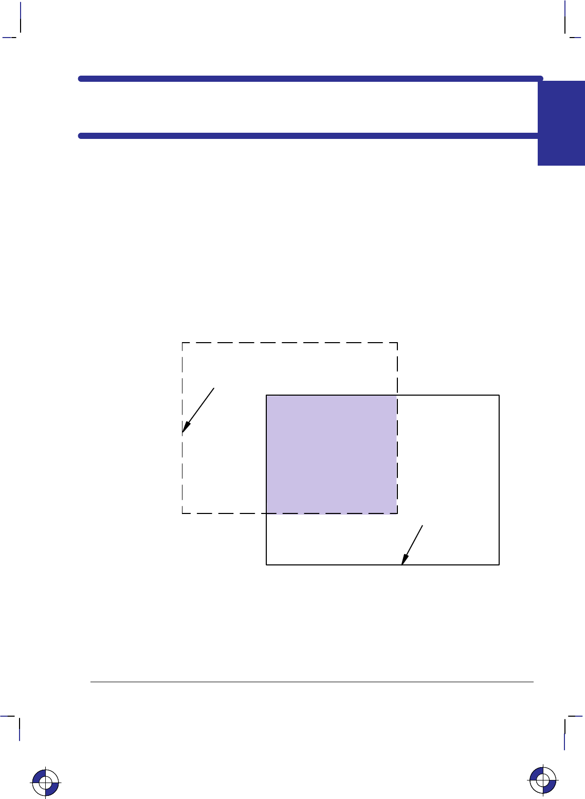
341
This is the black on page 341 (seq: 359)
Company confidential. HP-GL/2 and HP RTL Reference Guide, draft 2. Freeze Status: open
Chapter 8: Defining an Image
This chapter describes how to set the size of your picture, how to control its resolution, and
how to scale images. It also includes a description of the coordinate system and the current
active position (CAP), and describes how to move about the page.
Setting Raster Boundaries
You can use HP-GL/2 instructions to define the logical page and window in which your
HP RTL picture should appear. In addition, HP RTL supports its own raster height and width
parameters, which can be used to save on data transmission time and for scaling.
Setting the Logical Page Size and Input Window in HP-GL/2
Area
printed
Soft-clip limits =
window area
(IW instruction)
Hard-clip
limits =
logical page
(PS instruction)
Figure 156. Using HP-GL/2 to Set Page Size and Window Size
Before entering HP RTL mode, you can define boundaries using the HP-GL/2 PS (Plot Size)
and IW (Input Window) instructions. HP RTL respects these boundaries; no raster data will be
printed outside them. If you fail to use the PS (Plot Size) instruction, the maximum length
printable is 1.5 times the roll width (for roll-feed media).
This is the blue on page 341 (seq: 359)
IMAGES
HP RTL
This is the blue on page 341 (seq: 359)This is the blue on page 341 (seq: 359)
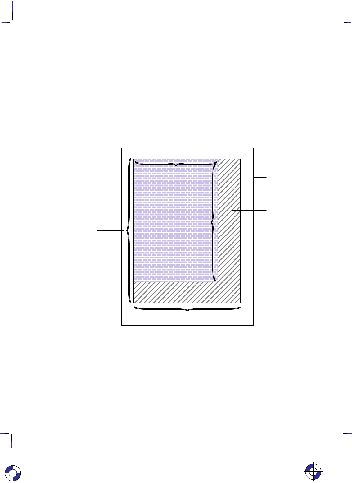
342
This is the black on page 342 (seq: 360)
Company confidential. HP-GL/2 and HP RTL Reference Guide, draft 2. Freeze Status: open
The area defined by the PS instruction is referred to as the logical page. Its borders are called
the hard-clip limits. The area defined by the IW instruction is called a window; its borders
form the soft-clip limits. Full details of the PS and IW instructions are on pages 259 and 197
respectively. Note that HP-GL/2 scaling as defined using the SC (Scale) instruction is not car-
ried over to HP RTL. HP RTL has its own scaling: see Scaling Raster Images on page 345.
HP-GL/2 and HP RTL do not automatically use the same units for defining resolution. HP RTL
uses the device’s native resolution; HP-GL/2 uses either device units or user units, which are
defined with the instructions SC (Scale) and IP (Input P1 and P2). If you define the HP-GL/2
resolution to be the device’s native resolution, you can thereby simplify coding your driver pro-
gram. (There is more information in Controlling Image Resolution on page 344.)
Setting the Width and Height in HP RTL
logical page
source raster width
source raster
height
zero-filled
(“background”
color)
data pixels sent
data
rows
sent
Raster
Image
Figure 157. Setting the Width and Height in HP RTL
Besides setting boundaries in HP-GL/2, after entering HP RTL mode you can optionally set
raster boundaries using the HP RTL commands Source Raster Width (*r#S) and Source
Raster Height (*r#T). These commands define the boundaries of your output in terms of
pixel width and pixel height respectively. (Pixel height is sometimes referred to as the number
of pixel rows.)
The main advantage to setting source width and height is to avoid sending unnecessary data.
When source width is specified and you send a row of data containing fewer pixels than the
source width, the remaining pixels are filled with zeros by the device. (A zero-filled area is
This is the blue on page 342 (seq: 360)

343
This is the black on page 343 (seq: 361)
Company confidential. HP-GL/2 and HP RTL Reference Guide, draft 2. Freeze Status: open
printed with the color defined for index 0. See Using HP RTL Indexes on page 358.) Similarly,
when you send fewer rows of data than specified by source height, the empty rows are
zero-filled by the device.
Figure 157 shows an example of zero-filling using source height and width.
When you send a row of pixels that is longer than the source width, the excess pixels are dis-
carded; the data is clipped. When you send more rows than specified by source height, the
excess rows are discarded.
It is also possible to set the Destination Raster Width (*t#H) and the Destination Raster
Height (*t#V). When this is done, the source width and height are still used to determine
zero-filling and clipping. After zero-filling and clipping, if scale mode is on (that is, the Start
Raster Graphics command [*r#A] with a value of 2 or 3 has been used), the image is scaled
to the destination width and height. (Note that source width and height must be specified for
scaling to work. See Scaling Raster Images on page 345.) Finally, the image is clipped to the
soft-clip and hard-clip limits defined by the HP-GL/2 instructions IW and PS.
The HP RTL raster system uses the concept of a bounded raster picture or raster area. Within
this area, the device fills missing and incomplete rows with zeros and clips data that would fall
outside. This is described more fully in Using Index 0 on page 359.
The raster height extends vertically from the CAP to one of:
The distance specified by Source Raster Height if raster scaling is off
The distance specified by Destination Raster Height if raster scaling is on
The row preceding an implicit or explicit End Raster Graphics command (*rC)
The lower edge of the printable area.
The raster width extends from the left raster margin (the CAP or the left edge of the logical
page), and is limited to one of:
The distance specified by Source Raster Width if scaling is off
The distance specified by Destination Raster Width if scaling is on
The right edge of the logical page.
Source raster width and height refer to bits of “source” data. One bit of data may result in sev-
eral physical pixels if the resolution is set to less than the physical device resolution. See
Controlling Image Resolution on page 344.
Maximum Width and Height
Two factors govern the maximum raster image size:
The device’s physical limits: Physical limits include the maximum picture size (the maxi-
mum number of pixels for height and width), and the amount of data that a device can store
in its memory or on its disk. See the device documentation for information on how many
pixels the device can handle, and how much memory and/or disk space is available for ras-
ter images.
The HP RTL language limits: For all devices, the maximum source width is 65 535 pixels,
and the maximum source height is 65 535 raster rows. Each limit applies only if the corre-
This is the blue on page 343 (seq: 361)
IMAGES
HP RTL

344
This is the black on page 344 (seq: 362)
Company confidential. HP-GL/2 and HP RTL Reference Guide, draft 2. Freeze Status: open
sponding command (Source Raster Width or Source Raster Height) is issued.
Raster Graphics
A dot is the smallest mark a printer or plotter can make. Its size and spacing are device specif-
ic, and the size of a dot may vary in any device. A raster image is composed of rows of dots.
These rows are organized from top to bottom of the image. A pixel is the smallest definable
picture element in an image. A row of pixels is transferred to the printer or plotter as a string of
bytes (a byte consists of eight bits). The resolution of an image is the number of dots per inch
(dpi) in both dimensions of the image. At maximum device resolution, a pixel consists of one
dot. At lower resolutions, or when you are scaling a picture, a pixel may consist of more than
one dot.
Controlling Image Resolution
How you set the resolution determines how many physical dots are printed for each pixel of
data you transfer. The maximum physical resolution varies from one device to another.
When you set the HP RTL resolution to the device’s maximum physical resolution (the ma-
chine resolution), one dot is printed for each pixel of data you send. For instance, if the
maximum physical resolution is 300 dots per inch (dpi) and you set the HP RTL resolution to
300 dpi, each pixel of data you send causes one dot to appear on the media. A resolution of
300 dpi means that the device can place dots of ink anywhere in a grid of 300-by-300 dots in
every square inch of the printable area of the page.
Some devices allow different native resolutions, up to the machine resolution. In such cases,
the native resolution can be set using the @PJL SET RESOLUTION=... command (see page
394). At lower native resolutions, each pixel consists of more than one dot, but dot spacing
remains the same and the same number of dots per inch are printed.
When 150 dpi is requested in HP RTL in a machine whose native resolution is 300 dpi, printing
is still at 300 dpi, but each pixel is now composed of four dots, and is twice as wide and tall as
a pixel printed at 300 dpi. Your image data consists of 150 pixels for each linear inch, but 600
dots are actually printed (300 in each of two rows).
300 dpi 150 dpi Machine resolution
in HP RTL in HP RTL is 300 dpi
Note that this means that the same amount of data produced at a lower resolution creates a larg-
er image than the original; that is, the image is scaled up isotropically. For instance, if you set
the resolution to half the original resolution, the same data produces an image that is twice as
wide and twice as high as the original:
300 dpi 150 dpi
This is the blue on page 344 (seq: 362)This is the blue on page 344 (seq: 362)This is the blue on page 344 (seq: 362)

345
This is the black on page 345 (seq: 363)
Company confidential. HP-GL/2 and HP RTL Reference Guide, draft 2. Freeze Status: open
Requesting a lower resolution does not cause less detail to be printed. The device still prints at
the native resolution, but it makes the image larger, for the same data. To keep the image the
same size, you must send less data to the device, in this case one quarter.
If the native resolution is set to 300 dpi on a device that actually prints 600 dpi, and the re-
quested resolution from HP RTL is, say, 200 dpi, the image is first approximated as close as it
can by 300 dpi pixels, and then each 300 dpi pixel is printed as a 2x2 array of dots. If however,
the native resolution on the same device is set to 600 dpi, each HP RTL pixel at 200 dpi will be
printed as a 3x3 square of dots.
When the native resolution is smaller than the maximum physical resolution, the image is first
scaled to the native resolution, and then scaled again to the physical resolution. The result is an
image with lower resolution, but which occupies less memory.
If you set HP RTL resolution to be greater than the device’s maximum physical resolution,
more than one pixel of data is required to produce one physical dot on the device. This means
that some detail is lost, and the image appears smaller than the original; it is scaled down iso-
tropically. The device, as always, still prints at its maximum physical resolution, but it
produces a smaller image.
The algorithm used for scaling down is device-dependent.
You use the HP RTL command Set Graphics Resolution (*t#R) to specify the resolution.
Note that the Set Graphics Resolution command does not affect the resolutions of fill patterns
defined in HP-GL/2 using the RF (Raster Fill Definition) instruction. You may also be able to
specify the device resolution through the device’s control panel, or by using the @PJL SET
RESOLUTION=... command (see page 394).
Continuous and Discrete Resolution
Continuous resolution means that you can specify any resolution within the allowable range;
you are not restricted to specific values.
However, on devices that support only discrete resolutions, the device can only create pictures
at certain well-defined resolutions. For instance, a device with a maximum physical resolution
of 300 dpi may support only 75, 150, and 300 dpi. On these devices, if you request an unsup-
ported resolution through HP RTL, the resolution value is mapped to the next higher supported
resolution to ensure that the output is created without data loss. On the device just mentioned,
if a you request a resolution of 200 dpi, it is printed at 300 dpi; if you request a resolution of
140 dpi, it is printed at 150 dpi.
Some devices support continuous resolutions within a certain range. Other devices only sup-
port incremental resolutions. Some devices support a discrete draft resolution for the fast
production of prints; others allow a continuous range of resolutions for normal (final) or best
(enhanced) quality output.
Scaling Raster Images
HP RTL does not follow HP-GL/2 scaling as defined with the HP-GL/2 SC (Scale) instruction.
HP RTL does, however, support its own scaling using the Destination Raster Width, Destination
Raster Height, and Start Raster Graphics commands. You can either enlarge or reduce an
image using scaling. When scaling an image down, loss of detail always results. The algo-
rithm used for scaling down is device-dependent.
This is the blue on page 345 (seq: 363)
IMAGES
HP RTL

346
This is the black on page 346 (seq: 364)
Company confidential. HP-GL/2 and HP RTL Reference Guide, draft 2. Freeze Status: open
The Start Raster Graphics command (*r#A) with a value of 2 or 3 turns on scale mode. In
that case, the image is rendered in the specified size, independently of the resolution of the de-
vice.
The Source Raster Width (*r#S) and Source Raster Height (*r#T) commands define the
size of the source, and the Destination Raster Width (*t#H) and Destination Raster Height
(*t#V) commands define the size of the destination. (Source data is the data that is to be
added to the page; destination data is the data after it has been placed on the page.) The scale
factor is implicitly derived from the source and destination data sizes. However, scaling only
occurs if both the width and the height of the source are explicitly specified.
If only one destination dimension is given, the other dimension is implicitly determined to
maintain isotropic scaling (see page 13). If no destination dimensions are specified, the image
is scaled so that it is the largest that will fit in the area between the current Y-position and the
bottom edge of the current page, and the left graphics margin and the right edge of the page;
isotropic scaling is maintained.
In order to use scaling, you must specify a source raster width and height. If one or the other is
not specified, the device will not enter scale mode; the Start Raster Graphics command will
default to scale mode off.
How to Scale an Image
Once you have set the page size using the HP-GL/2 PS (Plot Size) instruction, scaling occurs
either isotropically (without distortion) or anisotropically (with distortion)—see page 13.
There are three options for scaling:
You specify either a destination width or height, and Start Raster Graphics with scale mode
on. In this case, the scale factor is determined by comparing the source and destination
sizes for the dimension you specified (either width or height). Isotropic scaling is main-
tained; the image is not distorted.
You specify both a destination width and height, and Start Raster Graphics with scale mode
on. In this case, the scale factors are determined by comparing the source and destination
sizes for both dimensions. The output is scaled anisotropically, that is, the image is
“stretched” or “shrunk” to fit the destination dimensions. If the source-to-destination ratio
is the same for both width and height, isotropic scaling results.
You do not specify a destination width or height, and Start Raster Graphics with scale
mode on. In this case, the image is scaled isotropically to render the largest image that fits
on the part of the logical page that is below the CAP and to the right of the left graphics
margin. (The left graphics margin is set either to the CAP’s X-location or to the left side of
the logical page when you Start Raster Graphics.) Note that since isotropic scaling is used,
the image may not actually fill the logical page.
It is possible to set the destination width or height to be larger than the actual page size. In this
case, the image is still scaled using the implicitly determined scale factor(s). After scaling, the
image is clipped along the window and logical page boundaries set by the HP-GL/2 instructions
IW and PS.
Figure 158 shows an example of isotropic and anisotropic scaling. It is assumed that no win-
dow is specified, and that the logical page is set to the same size as the destination dimensions.
If the logical page were a different size, scaling would happen at the same ratio, but the image
would be clipped to the logical page.
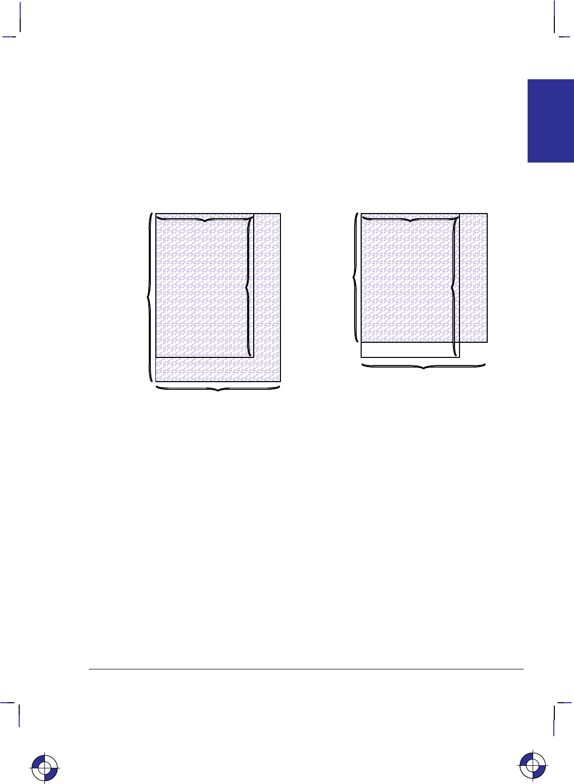
347
This is the black on page 347 (seq: 365)
Company confidential. HP-GL/2 and HP RTL Reference Guide, draft 2. Freeze Status: open
Zero-filling of pixels and rows based on source width and height is done before scaling. See
Setting the Width and Height in HP RTL on page 342 for more information on zero-filling.
Scaling takes precedence over any resolution setting (from the HP RTL command Set Graphics
Resolution). When scale mode is on, the resolution setting is ignored.
Scaling usually adds significantly to the processing time required to generate an image. As
an alternative, you might consider scaling the image at the host computer before transmission.
But if this increases the overall image size, the file will take longer to transmit, offsetting gains
in printing speed.
Destination raster width
Destination
height not
specified—
causes
isotropic
scaling
Source raster width
Source
raster
height
Isotropic Scaling
Destination raster width
Destination
raster
height
Source raster width
Source
raster
height
Anisotropic Scaling
Figure 158. Specifying Scaling Parameters
The Current Active Position (CAP)
In the HP RTL coordinate system, the origin (0,0) is always the upper-left corner of the logical
page. In the HP-GL/2 coordinate system, the origin (0,0) is the upper-left corner of the logical
page when length width in the PS instruction, and the upper-right corner of the logical page
when length < width in the PS instruction.
HP-GL/2 maintains the position of the pen on the paper as the “current pen location.” In
HP RTL terms, this is called the current active position (CAP). It can be thought of as the row
and column location of the logical “cursor” within an image.
The device maintains HP-GL/2’s pen location and HP RTL’s CAP separately. It is possible,
however, when switching from HP-GL/2 mode to HP RTL mode, to transfer the HP-GL/2 pen
location so that it becomes the HP RTL CAP. Similarly, when switching from HP RTL mode to
HP-GL/2 mode, you can choose to transfer the HP RTL CAP so that it becomes the HP-GL/2
pen location.
On some devices, the “auto-rotate” feature might cause HP-GL/2 objects to be rotated, but not
HP RTL data. We therefore recommend that you disable this feature (using the HP-GL/2 Begin
Plot instruction “BP5,1”) to avoid problems when merged vector and raster data are used.
This is the blue on page 347 (seq: 365)This is the blue on page 347 (seq: 365)This is the blue on page 347 (seq: 365)
IMAGES
HP RTL
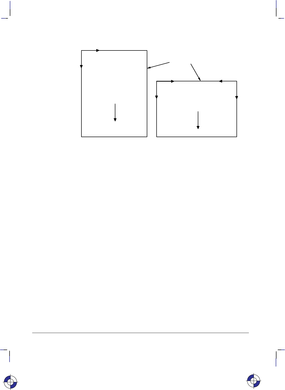
348
This is the black on page 348 (seq: 366)
Company confidential. HP-GL/2 and HP RTL Reference Guide, draft 2. Freeze Status: open
+ Y (HP RTL)
+ X (HP-GL/2)
HP RTL and
HP-GL/2
0,0
HP RTL 0,0 HP-GL/2 0,0
Plot Size (PS)
length
width Plot Size (PS)
length < width
+ X (HP RTL)
+ Y (HP-GL/2)
+ X + X
+ Y + Y
Direction
of frame
advance Direction
of frame
advance
logical page
Figure 159. HP-GL/2 and HP RTL Page Orientations
Commands to Change the CAP
You use these HP RTL commands to move the Current Active Position (CAP):
Move CAP Horizontal (Decipoints) &a#H page 425
Move CAP Horizontal *p#X page 426
Move CAP Vertical *p#Y page 427
Y Offset *b#Y page 453.
The Move CAP Horizontal and Move CAP Vertical commands use native resolution units, such
as dots-per-inch.
Note that the Move CAP Horizontal (Decipoints) command and the Y Offset command in non-
raster mode are to be made obsolete, so you should not use them in new application programs.
You can also use the Move CAP Horizontal (Decipoints) and Y Offset commands to move the
HP RTL CAP. Both commands support relative positioning. Move CAP Horizontal (Deci-
points) also allows you to position an absolute distance from the left boundary of the logical
page. (A “decipoint” is 1/720 inch.)
The Reset command (E) resets the CAP to the HP RTL origin (0,0). An HP-GL/2 PG (Ad-
vance Full Page) or BP (Begin Plot) instruction, or any instruction that results in a page
advance, also resets the CAP to the HP RTL origin (0,0).
At the start of raster graphics, the CAP is at the current Y-position on the left graphics margin.
After printing the raster image, the CAP moves to the left graphics margin at the dot row fol-
lowing the last row of raster data. If a Destination Raster Height command was issued, the
final location of the CAP is on the left graphics margin, one dot row below the lowest part of
the picture frame defined by that Destination Raster Height command.
This is the blue on page 348 (seq: 366)

349
This is the black on page 349 (seq: 367)
Company confidential. HP-GL/2 and HP RTL Reference Guide, draft 2. Freeze Status: open
Negative Motion
It can be important when you are printing or plotting an image for the device to know whether
there might be any movement of the CAP in a direction opposite to the movement of paper.
This is known as negative motion. Negative motion is:
Any HP-GL/2 drawing operation.
Any operation that would print in the negative Y-axis direction with respect to previously
printed data.
Any Y Offset command in raster mode that moves the CAP in the negative Y-axis direc-
tion.
You use this HP RTL command to tell the device whether to expect negative motion:
Negative Motion &a#N page 428.
You tell the device you are not using negative motion using the Negative Motion command
with a value of 1 (&a1N), the device may interleave parsing of data and printing, to reduce
the printing time and to reduce the memory requirements. Printing on the device is not guaran-
teed if a command is later issued that might cause negative motion to take place.
HP RTL Native Resolution Units
CAP movement should normally be performed at HP RTL native resolution. The native resolu-
tion is usually a sub-multiple of the physical device resolution, which is the number of dots per
inch that the device can print. HP RTL native resolutions are device-dependent. On devices
that support several native resolutions, the native resolution can be selected by the command:
@PJL SET RESOLUTION=# page 394.
The native resolution is used in HP RTL for two purposes:
To select the resolution for CAP movements.
To select the resolution to which the raster image is to be scaled. Selecting a smaller reso-
lution than the device’s maximum physical resolution uses less memory but does not
exploit the detail that the device can provide. Lower resolutions are therefore recom-
mended when you produce drafts, and not for final production runs.
This is the blue on page 349 (seq: 367)
IMAGES
HP RTL

350
This is the black on page 350 (seq: 368)
Company confidential. HP-GL/2 and HP RTL Reference Guide, draft 2. Freeze Status: open
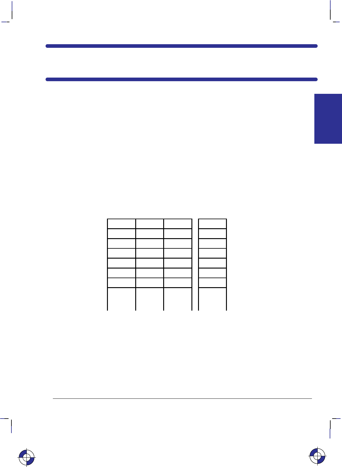
351
This is the black on page 351 (seq: 369)
Company confidential. HP-GL/2 and HP RTL Reference Guide, draft 2. Freeze Status: open
Chapter 9: Defining Colors
This chapter describes how to define colors and how to select colors from a palette. It also de-
scribes halftoning and how to use patterns.
Palettes
A palette is a collection of colors, in which the color is selected by an index number. All
HP RTL color modes have default palettes. Only one palette can be active at a time, though
you can push palettes onto a stack and pop them from the stack. The active palette is overwrit-
ten whenever a new palette is created or a palette is popped from the stack. The active palette
is always transferred between HP RTL and HP-GL/2 on devices that support palettes in
HP RTL.
The figure below illustrates a palette. Each palette entry associates an index number with three
primary color components; for HP-GL/2 only, a “pen width” is also associated with each entry.
Primary 1
(e.g. red) Primary 2
(green) Primary 3
(blue) HP-GL/2
pen width
Index 0 Pixel encoding mode
1 Pixel or Plane
2 Direct or Indirect
3
4Bits per primary
5 Primary 1 (red)
6 Primary 2 (green)
n
(maximum
255)
Primary 3 (blue)
Palettes are used differently depending on whether the device is in raster mode or not: in non-
raster mode, the palette is always needed to select colors; in raster mode, the palette is used
only for indexed color selection, but not for direct selection.
Raster Color and Non-Raster Color
Raster mode (see Transferring Raster Data on page 375) is normally entered by a Start Raster
Graphics (*r#A) command and ended by an End Raster Graphics (*rC) command. In
non-raster mode, the palette is always used to select colors; the color of a pattern is specified
using the Foreground Color (*v#S) command. In raster mode, the palette is only used for
indexed color selection, and not for direct color selection.
This is the blue on page 351 (seq: 369)
COLORS
HP RTL
This is the blue on page 351 (seq: 369)
COLORS
HP RTL
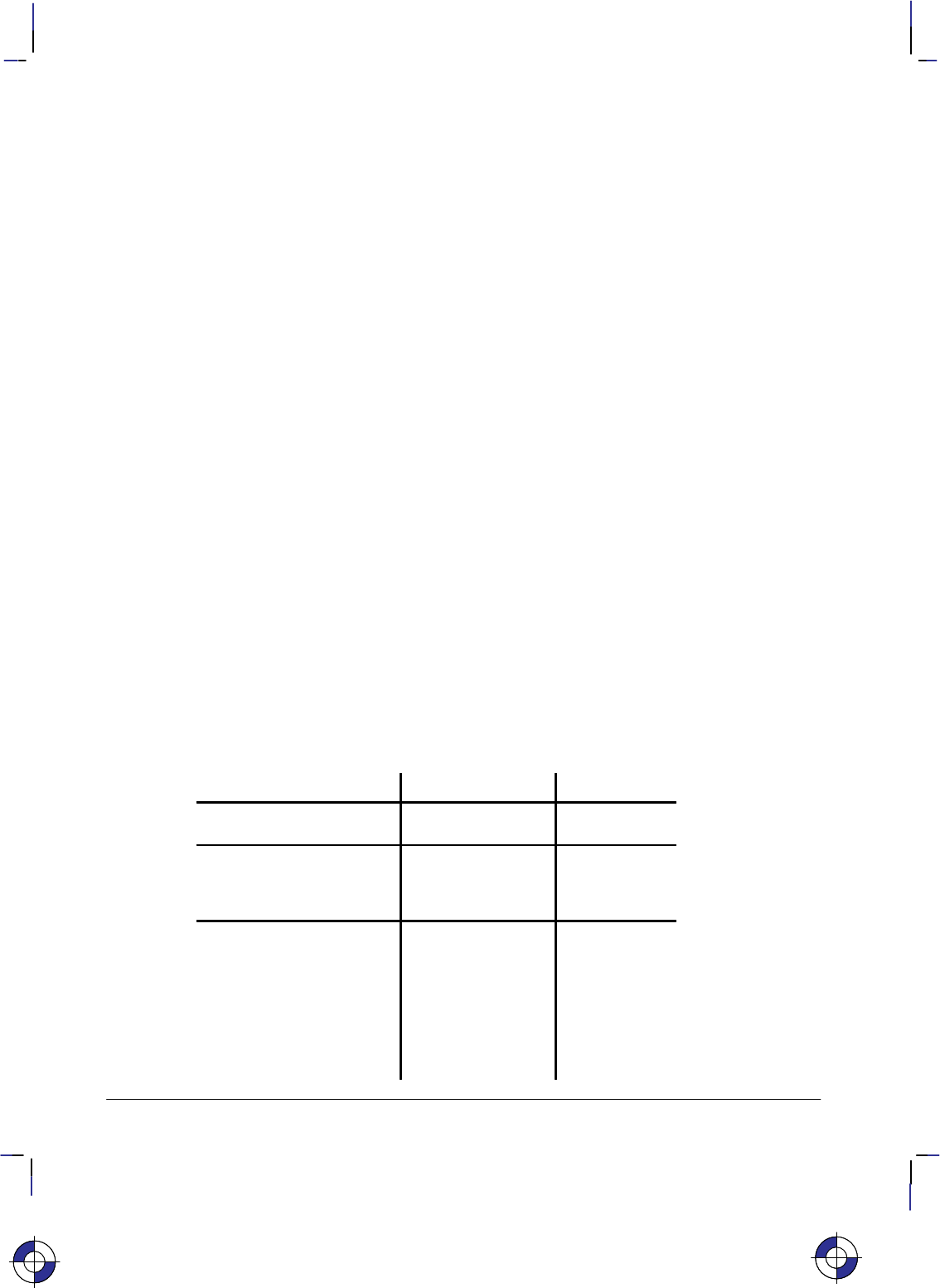
352
This is the black on page 352 (seq: 370)
Company confidential. HP-GL/2 and HP RTL Reference Guide, draft 2. Freeze Status: open
Color Modes
There are four color modes in HP RTL: black-and-white, simple-color, HP RTL imaging, and
HP-GL/2 imaging. All these modes create a palette; you cannot modify the palettes in simple
color mode or in blac-and-white mode. Only one palette at a time can be active; the current
palette is destroyed whenever a new one is created.
Black and White Mode
This is the default color mode, and is the mode following power up; the device reverts to this
mode after a Reset (E) command. The palette defines two colors: white at index 0 and
black at index 1.
Simple Color Mode
This mode is entered using the Simple Color (*r#U) command. It has a fixed size, fixed
color, unmodifiable palette, which can be eight-color CMY, sixteen-color KCMY, two-color
black and white, or eight-color RGB. It can only be used if the pixel encoding mode is indexed
planar.
The Simple Color command should be used to specify CMY or KCMY data.
HP RTL Imaging Mode
This mode is entered using the Configure Image Data (*v#W) command. It allows up to 24
bits per pixel for color specification. Using halftoning, you can specify more colors than with
simple color mode. The pixel encoding mode, number of bits per pixel, number of bits per pri-
mary, black and white color references, and the color palette can all be programmed in this
mode.
The Configure Image Data (*v#W) command creates one of three different programmable
palettes (see below).
The default HP RTL palettes are defined as follows:
Number of Planes Index Number Color
1
(bits per index=1)
0
1
White
Black
2
(bits per index=2)
0
1
2
3
Black
Red
Green
White
3-8
(bits per index=3 or greater)
0
1
2
3
4
5
6
7
> 7
Black
Red
Green
Yellow
Blue
Magenta
Cyan
White
Black
This is the blue on page 352 (seq: 370)This is the blue on page 352 (seq: 370)
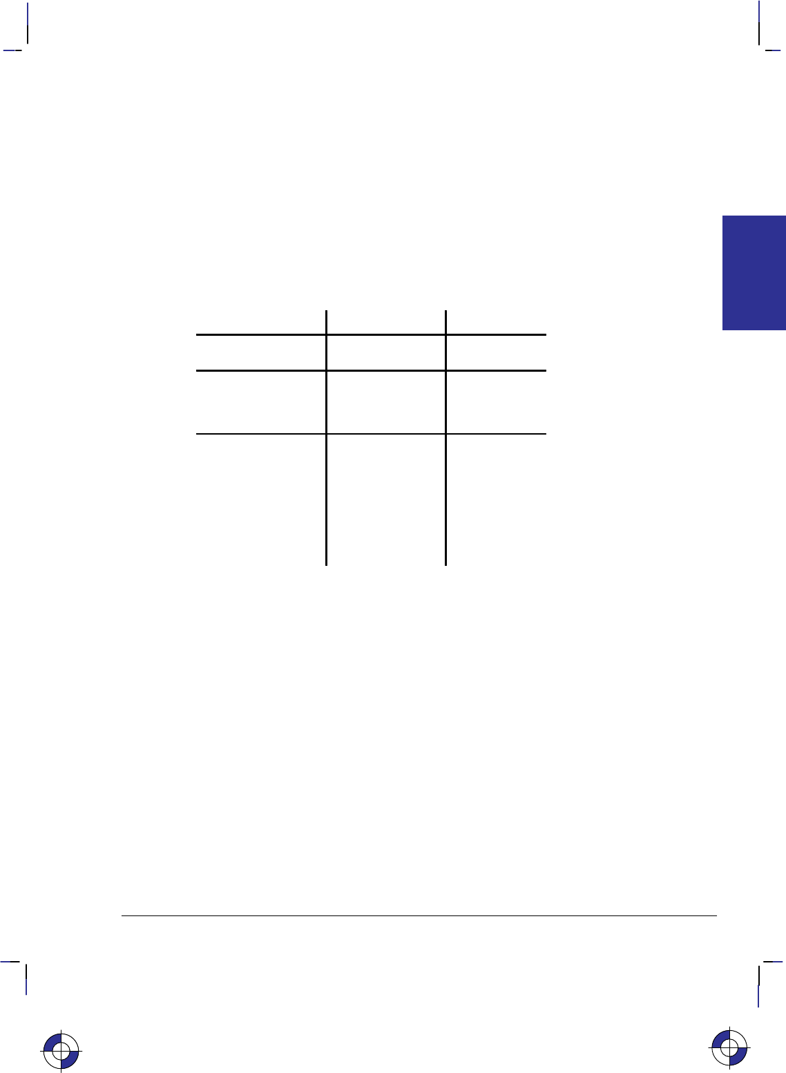
353
This is the black on page 353 (seq: 371)
Company confidential. HP-GL/2 and HP RTL Reference Guide, draft 2. Freeze Status: open
The black and white references specified by the Configure Image Data command have no effect
on the default palettes; however if a palette entry is reprogrammed with a different color, the
black and white references are used to specify the primary components of the new color.
HP-GL/2 Imaging Mode
In HP-GL/2, the IN (Initialize) and BP (Begin Plot) commands start color imaging and also
default the number of bits per index, and create a default programmable palette. This palette
can be modified in HP RTL or in HP-GL/2. (The active palette can be transferred between
HP RTL and HP-GL/2.)
As shown below, the default HP-GL/2 palettes are different from the default HP RTL palettes.
These palettes can be modified in the same way as the default HP RTL palettes.
Number of Pens Pen Number Color
2 0
1
White
Black
4 0
1
2
3
White
Black
Red
Green
8 0
1
2
3
4
5
6
7
> 7
White
Black
Red
Green
Yellow
Blue
Magenta
Cyan
Black
Specifying Colors
Colors can be specified by either indexed or direct selection. If you are using simple color
mode or black-and-white mode, only indexed selection is available. Otherwise, byte #1 of the
Configure Image Data command (*v#W) determines the format in which raster data is to be
transmitted and interpreted.
Raster colors—colors that are specified in raster transfer mode—can be selected directly or
indirectly, depending on the meaning of the bits that are transferred; that is, the transmitted bit
combinations for each pixel may form a palette index number or they may directly specify
component proportions.
Non-raster colors—for example, foreground colors or multi-colored patterns—cannot be se-
lected directly.
This is the blue on page 353 (seq: 371)
COLORS
HP RTL

354
This is the black on page 354 (seq: 372)
Company confidential. HP-GL/2 and HP RTL Reference Guide, draft 2. Freeze Status: open
Indexed Selection
Indexed selection specifies a color’s index number in a palette. In non-raster mode, the Fore-
ground Color command (*v#S) selects a color by palette index. In raster mode, each data
bit combination forms an index number. For example, three bits allow eight index numbers for
eight colors.
Direct Selection
Direct selection specifies a color’s proportions of the RGB primary colors. For example a
24-bit-per-pixel representation for the color cyan is (hexadecimal 00, FF, FF) for red, green,
and blue primaries, and (FF, F0, 00) is a slightly red-tinted yellow.
Primary Colors
Red
Green
Blue
Data planes
Figure 160. Planes of Primary Colors in a Red-Green-Blue Color Model
HP RTL is based on a “plane model” for defining images. You can think of one plane of data
as a monochrome image, where “monochrome” doesn’t necessarily mean black, but could be
any single color. For devices that support multiple planes, by stacking planes on top of each
other, different color combinations can be achieved. The more planes, the more color combina-
tions are possible. If you use a red-green-blue (RGB) or a cyan-magenta-yellow (CMY) color
model, you use three planes; with a black-cyan-magenta-yellow (KCMY) model there are four
planes.
Two-tone monochrome devices support only one plane of data, which yields a two-tone image
(normally black and white). Grayscale monochrome devices support multiple data planes but
convert the planes to shades of gray for printing. Color devices support multiple data planes
and actually print these multiple data planes in color. Color raster data may be interpreted as
gray scales on monochrome devices or when monochrome/gray-scale is selected through the
control panel of the device or through PJL.
This is the red on page 354 (seq: 372)
This is the yellow on page 354 (seq: 372)
This is the green on page 354 (seq: 372)
This is the blue on page 354 (seq: 372)

355
This is the black on page 355 (seq: 373)
Company confidential. HP-GL/2 and HP RTL Reference Guide, draft 2. Freeze Status: open
Color specifications are based on a range of values for each primary component. The basis of
these specifications is device-dependent. The end-points of the range for each component are
called the black and white references for that component. Colors relative to these predefined
limits are derived by specifying the amount of each component.
Assume, for instance, that you define one plane of data to be red, another green, and another
blue. (These are, in fact, the recommended definitions for three-plane devices.) By laying
these images on top of each other, up to eight colors can be achieved in any given pixel. All
three together in one pixel gives white. Solid red and green together give yellow; green and
blue together give cyan; and so on, following the standard red-green-blue (RGB) color model.
Black and White References
For RGB color spaces, the black-reference for a primary color denotes a value assigned to the
absence of that color, and the white-reference denotes the value given to a fully saturated pri-
mary color. Regardless of the number chosen, the white reference represents the maximum
amount of output color that the device can produce, and the black reference is the minimum
amount of that primary. For example, if you define the white reference for the color red to be
100, this number represents the reddest red that the device can produce. If you specified 10 as
the white reference for red, 10 would represent the same red.
For example, if the red, green, and blue white references are set to 64 and the black references
are all 0, a 50% blue would be represented by the numbers 0, 0, 32, and a 50% yellow would be
32, 32, 0.
But if the white references are set to 64, 128, and 32 respectively, and the black references are
set to 4, 0, 0, the 50% blue is 4, 0, 16 and the 50% yellow is 34, 64, 0.
However, for all practical purposes, the following values are recommended for each primary
color: for an RGB color model use a white reference of 255 and a black reference of 0; for a
CMY color model, use a white reference of 0 and a black reference of 255.
Color-Definition Commands
You use these commands to define how the device handles color data:
Configure Image Data *v#W[data] page 409
Set Red Parameter *v#A page 442
Set Green Parameter *v#B page 441
Set Blue Parameter *v#C page 439
Assign Color Index *v#I page 407
Push/Pop Palette *p#P page 434
Simple Color *r#U page 443.
If you are using the HP RTL command Configure Image Data to specify re-programmable pal-
ettes, for pixel encoding modes 0, 1, or 4, you use the Set Number of Bits per Index byte of this
command to tell the device how many data planes to expect. This command also resets the
HP RTL palette to its default—see Defining the HP RTL Palette on page 356.
You can combine different images with different numbers of planes on the same page. For in-
stance, you could have a three-plane color image and one-plane monochrome image on the
same page.
The Simple Color command should be used to specify CMY or KCMY data.
COLORS
HP RTL
This is the blue on page 355 (seq: 373)
356
This is the black on page 356 (seq: 374)
Company confidential. HP-GL/2 and HP RTL Reference Guide, draft 2. Freeze Status: open
Encoding Colors
Several bits per pixel are required to produce multiple colors. For HP RTL Imaging Mode, you
use byte #1 of the Configure Image Data command (*v#W) to select the method. The bits
that define pixels may be encoded by plane, by pixel, or in plane-by-plane format.
Encoding by Plane
When colors are encoded by plane, each pixel in a row receives one bit (plane), then every
pixel receives the next plane, until the pixels in a row are completely defined. That is, all the
pixels in a row are partially defined by each plane until the last plane for that row is sent. The
number of planes is the number of bits needed to define (color) a pixel. In the following exam-
ple, the highlighted bits comprise the color index for the third pixel in the first row.
*b#V row 1 plane 1 b1 b1 b1 b1 b1 b1 ...
*b#V plane 2 b2 b2 b2 b2 b2 b2 ...
*b#W plane 3 b3 b3 b3 b3 b3 b3 ...
*b#V row 2 plane 1 b1 b1 b1 b1 b1 b1 ...
Encoding by Pixel
When colors are encoded by pixel, all the bits for a pixel are sent as a group (for example,
24-bit RGB), then all the bits for the next pixel until the pixels in a row are defined. Each pixel
receives all its bits before any bits are sent for the next pixel. Byte boundaries are ignored,
with the bits for successive pixels following one another. For example, if four bits are needed
to define a pixel, then every group of four bits in the data stream defines a pixel. The high-
lighted group below defines the second pixel in the first row.
*b#W row 1 b4 b3 b2 b1 c4 c3 c2 c1 ...
*b#W row 2 b4 b3 b2 b1 ...
The HP RTL options for selecting colors and encoding raster data are:
Planar Encoding Pixel Encoding
Indexed Selection Indexed planar Indexed pixel
Direct Selection Direct planar Direct pixel
Encoding Plane-by-Plane
Another way of sending a color image to a device is by decomposing the entire image into sep-
arate color planes. This is typically done using the device’s primary colors (for example, black,
cyan, magenta, and yellow), and an entire image is sent for each primary color. The Y Offset
command (*b#Y) is used to regain the starting position so that the planes can be overlaid as
intended.
Defining the HP RTL Palette
HP RTL maintains an internal palette from which you can choose colors for each pixel of data.
For indexed selection, the size of the color palette depends on the number of planes being used:
for one plane, there are two possible colors; for two planes, there are four possible colors; for
This is the blue on page 356 (seq: 374)

357
This is the black on page 357 (seq: 375)
Company confidential. HP-GL/2 and HP RTL Reference Guide, draft 2. Freeze Status: open
three planes, there are eight possible colors; and so on. HP RTL allows for up to eight data
planes or 256 possible colors. The maximum number of planes, and thus the maximum palette
size, is device-dependent.
In indexed mode, data sent to the device uses the index number to choose a color for each pixel.
See Using HP RTL Indexes on page 358.
In direct pixel encoding mode, the palette is not used.
Note that the HP RTL palette on some devices is independent of the HP-GL/2 palette. On these
devices, palettes cannot be automatically transferred between HP-GL/2 and HP RTL. See the
descriptions of the Enter RTL Mode and Enter HP-GL/2 Mode commands in Chapter 14 for
more information on transferring palettes.
Changing the Default Palette
Creating a new palette overwrites the old one. The Push/Pop Palette command (*p#P) can
save (push) the current palette and then restore (pop) it. Palette entries can be modified in HP-
GL/2 by the CR (Set Color Range for Relative Color Data), NP (Number of Pens), and PC (Pen
Color Assignment) instructions, or by the HP RTL commands Set Red/Green/Blue Parameter
(*v#A, *v#B, and *v#C) and Assign Color Index (*v#I).
When you switch from HP RTL to HP-GL/2 or vice versa, the palette is transferred. So any
changes made in one environment are automatically transferred to the other. As a result, if you
want to use separate palettes in the different environments, you must use the Push/Pop Palette
command.
You can use a combination of commands to change the HP RTL palette defaults to any color.
For instance, to set index 5 to a 50% blue, you use the following combined HP RTL command:
*v0a0b127c5I
The commands combined here are Set Red Parameter, Set Green Parameter, Set Blue Parame-
ter, and Assign Color Index. Note that 127 is halfway (50%) between 0 and 255, the default
range for the Set Red/Green/Blue Parameter commands.
A “50%” blue may not appear the same on all devices. Differences in imaging technology, me-
dia, imaging agent (ink or toner, for example), and environmental conditions can cause color
differences among devices. These differences are subject to program control, but their cover-
age is beyond the scope of this book.
You can assign any color supported by a device to an index. On some devices, non-primary
colors are printed using a dithering technique, as in HP-GL/2 mode. (Primary colors are those
colors that a device can create by printing zero, one, or two ink or toner colors together, usually
red, green, blue, magenta, cyan, yellow, black, and white.)
Changing the Black and White References
By default, the RGB value for black is 0,0,0, and the value for white is 255,255,255. You can
change these white and black references using the HP RTL command Configure Image Data.
For instance, if you work in percentages, you could use the following command to set the
ranges to 0 to 100:
*v18W(0)(0)(3)(8)(8)(8)(100)(100)(100)(0)(0)(0)
The last six numbers set the white references for red, green, and blue, and then the correspond-
ing black references. (For clarity, numbers in the data string are shown in decimal, enclosed in
This is the blue on page 357 (seq: 375)
COLORS
HP RTL

358
This is the black on page 358 (seq: 376)
Company confidential. HP-GL/2 and HP RTL Reference Guide, draft 2. Freeze Status: open
parentheses. In practice, they must be transmitted as binary numbers, without parentheses; the
first six are one-byte values, the second six are two bytes each. See page 409 for more in-
formation on the Configure Image Data command; the example on page 360 shows a similar
command to that just described, but using different white reference values.)
Now, to set index 5 to 50% blue using the white and black references just defined, use the fol-
lowing combined command:
*v0a0b50c5I
Using HP RTL Indexes
When you send data to the device, you send it one row at a time. Assuming you are sending
single-plane data, you send all the data for the first row, then all the data for the second row,
and so on.
For example, the loop in a sample program might look like this:
for n := 1 to number_of_rows do
for m := 1 to width_in_pixels do
send one pixel (one bit) of data;
You can think of the color palette as an array in a programming language. The color of each
pixel is determined by “indexing into” the color palette using the bit value (0 or 1) as the sub-
script. A “0” pixel accesses the color assigned to index 0 (by default, white); a “1” pixel
accesses the color assigned to index 1 (by default, black).
For instance, assume you sent the following data to the device:
0 1 0 1 1 1 1 1 0 0 0 0 1 1 1 1
Based on the HP RTL default palette, the first pixel would be white, the second black, the third
white, and so on.
Multi-Plane Data
As with single-plane data, you send multi-plane data one row at a time. However, with multi-
plane data, you send all the planes for each row together—all the planes for the first row, then
all the planes for the second row, and so on. (Even in block transfers, the order of the data re-
mains the same. Block transfers are explained under Compressing Data on page 380.)
For example, if you have three planes of data, the loop in a sample program might look like
this:
for n := 1 to number_of_rows do
begin
send one row of data for first plane;
send one row of data for second plane;
send one row of data for third plane;
end;
(“Send one row of data” implies a loop to send each row a pixel at a time, as shown in the sing-
le-plane example above.)
This is the blue on page 358 (seq: 376)

359
This is the black on page 359 (seq: 377)
Company confidential. HP-GL/2 and HP RTL Reference Guide, draft 2. Freeze Status: open
Once the data for all planes in a row has been received, the bits that make up each pixel are
combined to arrive at the index number. As with single-plane printing, this index number is
used to index into the palette to determine which color to print each pixel.
For instance, assume you sent the following data to the device:
Plane 1: 0 1 0 1 1 1 1 1 0 0 0 0 1 1 1 1
Plane 2: 0 1 1 1 1 1 1 1 0 0 0 0 0 0 0 0
Plane 3: 1 0 1 0 0 1 1 0 1 0 0 1 0 0 1 1
The color for each pixel is now defined by a three-digit binary number, which is the index num-
ber. Plane 1 is the least significant bit of the number; plane 3 is the most significant. To get the
index number, turn the page clockwise so that the right edge is at the bottom. Read the binary
numbers from left to right, top to bottom. The first pixel is 100, or decimal 4. The second
(highlighted by the rectangle) is 011, or 3.
The index numbers for this row of pixels are: 4 3 6 3 3 7 7 3 4 0 0 4 1 1 5 5
If you are using the HP RTL default palette, the first pixel of this row would map to index 4,
which is blue. The second pixel maps to index 3, which is yellow. The third maps to index 6,
which is cyan. And so on.
Note that when you are using three planes per row and the HP RTL default palette, you are ef-
fectively sending planes of red, green, and blue: plane 1 is red; plane 2 is green; and plane 3 is
blue.
The same technique for determining index colors is used when there are only two data planes.
In this case, the binary number is only two digits, so there are only four possible index numbers
(0 to 3).
Using Index 0
Index 0 functions like any other index: you can assign a color to it, and you can send data such
that any given pixel is printed with that color. The color of index 0 in the default palette is
white for 1 plane per row and black for 2 or more planes per row.
When you use the HP RTL commands Source Raster Width (*r#S) and Source Raster
Height (*r#T), 0 is also the default value for short or missing rows. This means, for in-
stance, that you can use index 0 as a “background color” to form a border around an image.
You must send the 0 for any border at the top and to the left of the image. But the device will
automatically fill in the empty space to the right and below the image with zeros. Since there is
less data to transmit, transmission time is reduced. See the illustration under Setting the Width
and Height in HP RTL on page 342.
If you are in raster graphics mode (after a Start Raster Graphics command, *r#A) with scale
mode off, you can use index 0 as a background color by using the Y Offset command
(*b#Y) to skip over parts of the image that should be set to the color of index 0. Rows that
you skip are filled with zeros and printed with the color of index 0. The Y Offset command is
not allowed in raster graphics mode when scale mode is on (see page 379).
Another alternative is to create background or borders using HP-GL/2 commands before enter-
ing HP RTL mode.
This is the blue on page 359 (seq: 377)
COLORS
HP RTL

360
This is the black on page 360 (seq: 378)
Company confidential. HP-GL/2 and HP RTL Reference Guide, draft 2. Freeze Status: open
Example: Programming the Color Palette
First the Configure Image Data command (*v18W[data]) is sent, where [data] is:
Byte # Binary data Decimal value Effect
0 00000000 0 Color space device-dependent RGB
1 00000000 0 Pixel encoding mode is indexed by plane
2 00000011 3 3 bits per index
3 00001000 8 8 bits for red
4 00001000 8 8 bits for green
5 00001000 8 8 bits for blue
6, 7 0000000011111111 255 White reference for red is 255
8, 9 0000000011111111 255 White reference for green is 255
10, 11 0000000001111111 127 White reference for blue is 127
12, 13 0000000000000000 0 Black reference for red is 0
14, 15 0000000000000000 0 Black reference for green is 0
16, 17 0000000000000000 0 Black reference for blue is 0
Now program the palette to the desired values:
Set index 0 to white:
*v255A Set red parameter
*v255B Set green parameter
*v127C Set blue parameter
*v0I Assign to index 0
Set index 1 to green:
*v0A Set red parameter
*v255B Set green parameter
*v0C Set blue parameter
*v1I Assign to index 1
and so on until:
Set index 7 to black:
*v0A Set red parameter
*v0B Set green parameter
*v0C Set blue parameter
*v7I Assign to index 7
Halftoning
Halftoning is the process of converting an image that consists of continuous ranges of tones into
a form that simulates these tones by the use of dots of color. Monochrome newspaper
photographs are a typical example of halftoning, where continuous tones of gray are repre-
sented by black and white dots of various sizes.
Color printers may use halftone algorithms to print a continuous-tone image using a set of pix-
els of the eight primary colors; in this way, the eye perceives a continuous range of colors. For
example, a dither pattern can convert from 256 colors to 8 colors, or a color image can be con-
verted to monochrome. The Render Algorithm command (*t#J) provides a choice of
This is the blue on page 360 (seq: 378)This is the blue on page 360 (seq: 378)

361
This is the black on page 361 (seq: 379)
Company confidential. HP-GL/2 and HP RTL Reference Guide, draft 2. Freeze Status: open
various algorithms. A single page may have multiple Render Algorithm calls during page com-
position, but only one is in effect at any given time.
The Render Algorithm command allows for the following types of processing:
Pattern dither: Pixels are intensified by increasing the number of dots according to the desired
density of color; the dots are scattered uniformly in a pattern. Normally this pattern uses a
small matrix, and is therefore faster and requires fewer resources than other algorithms.
Clustered dither: This is similar to pattern dither, but the dots are placed so as to form “bigger”
pixels instead of dispersing them. The result is a clustering of the intensified pixels. The result
is similar to that often used in newspaper and magazine photographs.
Scatter dither: Pixels are intensified by increasing the number of dots according to the desired
density of color; the dots are scattered in a random fashion. This method generally gives a bet-
ter appearance than either pattern or clustered dither.
Device best: This is the render method that HP believes will provide the best output for a par-
ticular device in most cases. Note, however, that the recommended dither pattern varies with
the image, the intended use of the image, and the subjective judgment of the user.
Patterns
A pattern is a rectangular area tile whose design is combined with the source data and the data
already prepared for printing (the “destination” or “current image”) at the place where the
source is to be printed. It may be a single-plane monochrome mask or a multi-plane raster col-
or pattern. The Current Pattern command (*v#T) designates an active pattern, which stays
in effect until another is specified or the device is reset. A Reset command (E) changes
back to the default pattern, which is 100% black.
These are the commands that are used in conjunction with HP RTL patterns:
Pattern ID *c#G page 431
Download Pattern *c#W page 417
Current Pattern *v#T page 414
Pattern Control *c#Q page 430
Pattern Reference Point *p#R page 432
Foreground Color *v#S page 423.
The Pattern ID command (*c#G) assigns a unique identification number to a user-defined
or HP-defined pattern. User-defined patterns are downloaded with the Download Pattern com-
mand (*c#W). Such patterns should be no larger than the minimum needed to uniquely
define the pattern. Colors in user-defined patterns are rendered as indexes into the current pal-
ette. HP-defined patterns do not have to be explicitly downloaded—they simply have to be
selected for use. The supplied patterns are solid black (or Foreground Color, *v#S), solid
white, shadings between 1% and 100%, and six hatched patterns (horizontal, vertical, and diag-
onal lines, and cross-hatching with horizontal and vertical lines or diagonal lines).
Patterns are selected for application to a raster image with the Current Pattern (*v#T) com-
mand. After use, a pattern should be deleted or reset to foreground color (using *v0T);
otherwise all subsequent images will be filled with the pattern. Patterns can be deleted using
the Pattern Control (*c#Q) command. A Reset (E) defaults the pattern to 100% black.
Tiling is the means by which a pattern is applied to a source image. The pattern, whose upper-
left pixel coincides with the pattern reference point, is repeated horizontally and vertically
This is the blue on page 361 (seq: 379)
COLORS
HP RTL
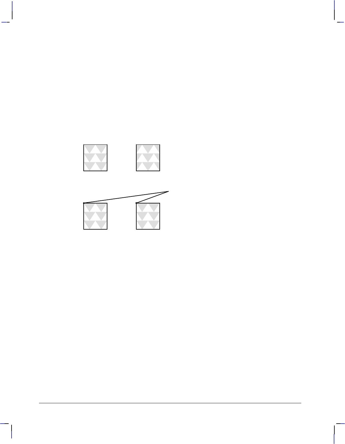
362
This is the black on page 362 (seq: 380)
Company confidential. HP-GL/2 and HP RTL Reference Guide, draft 2. Freeze Status: open
across the page. The tiling of patterns is controlled by the Pattern Reference Point (*p#R)
command. This command sets the pattern reference point at the CAP. The default pattern ref-
erence point is the upper left corner of the logical page (0,0); unless this command is sent, the
pattern is tiled with respect to position (0,0).
To fill an area with a pattern, the base pattern is tiled (replicated) across the fill area. The pat-
tern reference point is the starting point for tiling, where the upper left corner of the base
pattern is positioned on the logical page.
When all tiles use the same pattern reference point, the pattern in adjoining or overlapping frag-
ments is aligned. The Pattern Reference Point (*p#R) command sets the reference point to
the CAP, allowing the pattern to be adjusted for different fill areas. The reference point may be
shifted for as many fill areas as there are on a page; an area must be filled before the reference
point is moved for the next area fill. This command can be used to start the pattern at a particu-
lar place in each adjoining or overlapping fragment of the fill area, regardless of alignment.
Two areas filled (tiled) when the Pattern
Reference Point is at the default (0,0) positionReference Point is at the default (0,0) position
Two areas filled when the Pattern Reference
Point is placed at the upper left corner of
each area before tiling
Pattern Reference Point
Figure 161. Pattern Reference Point
Patterns, including user-defined patterns, are applied to images only when the pattern is se-
lected by a Current Pattern (*v#T) command, which can occur any number of times per
page.
Use the following general procedure to fill your images with a non-solid pattern. If you choose
to use an HP-supplied pattern, you need only follow steps 2 and 4.
1. Define a binary raster image as the pattern.
2. Assign a pattern identification number (*c#G).
3. Download the pattern (*c#W).
4. Apply the pattern to subsequent images (*v#T).
Exporting Patterns to HP-GL/2
In HP-GL/2, patterns are downloaded by the RF (Raster Fill Definition) instruction and applied
by the FT (Fill Type) or SV (Screened Vectors) instruction. The CF (Character Fill Mode)
instruction specifies how outline fonts are to be rendered, including changing the fill pattern for
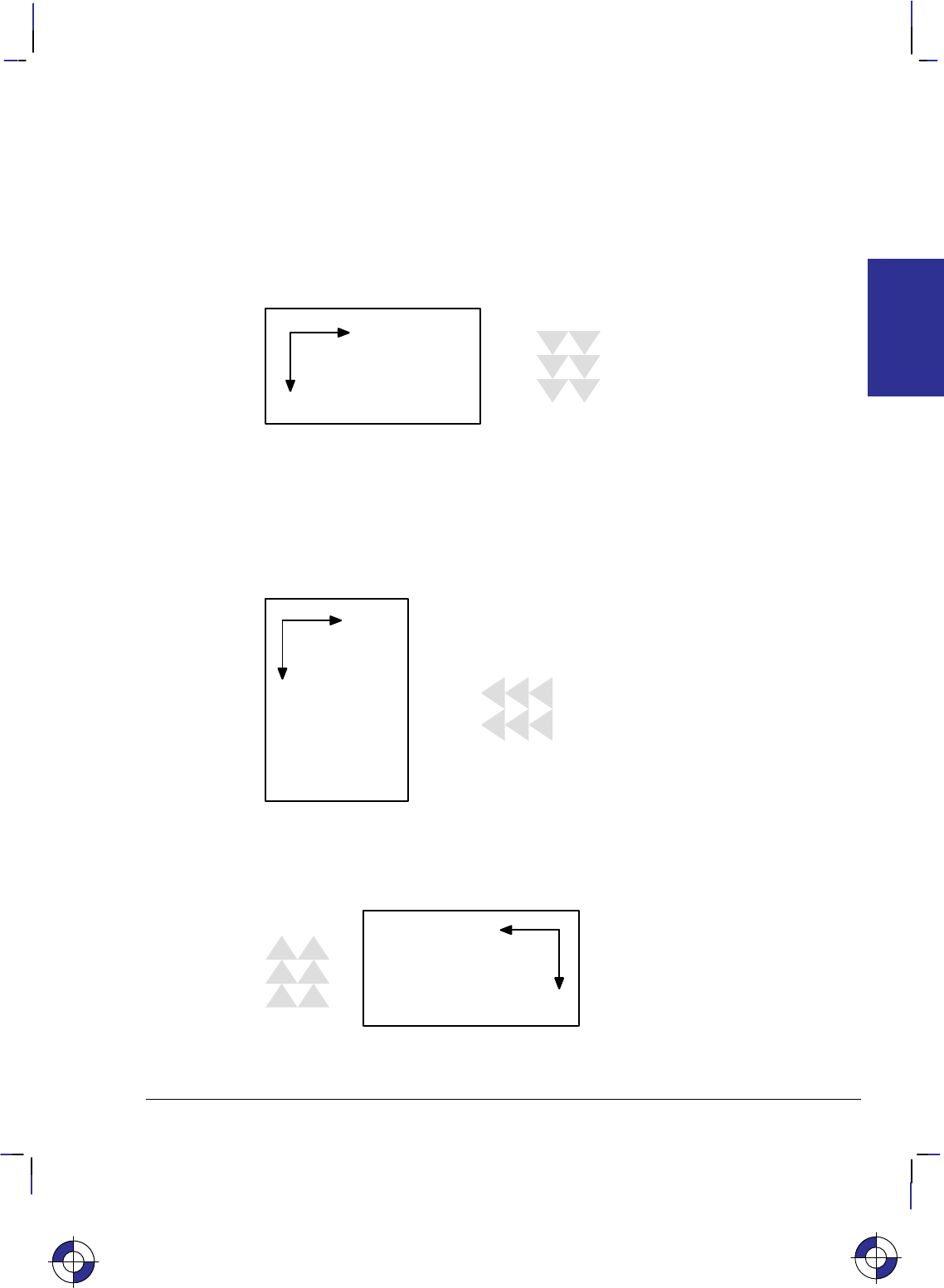
363
This is the black on page 363 (seq: 381)
Company confidential. HP-GL/2 and HP RTL Reference Guide, draft 2. Freeze Status: open
bitmap and stick fonts. HP-GL/2 may use HP RTL patterns, but HP RTL cannot use HP-GL/2
patterns.
Pattern Orientation
Patterns are always rendered according to the coordinate system in use: in HP RTL, each row is
generated along the X-axis and the rows are incremented along the Y-axis. Since HP RTL has a
fixed orientation (the X-axis is horizontal and the Y-axis vertical), patterns are always produced
with rows along the horizontal axis:
Figure 162. HP RTL Pattern Orientation
Patterns imported from HP RTL into HP-GL/2 inherit the current HP-GL/2 coordinate system,
which defines the page orientation and the current rotation. Assuming a zero rotation
(“RO0;”), HP RTL patterns obtain the following orientations:
Page Portrait: Rows are produced along the vertical axis (X-axis from positive to negative)
and rows increment along the horizontal axis (Y-axis from negative to positive). Thus patterns
have an orientation of 270 with respect to HP RTL:
Figure 163. HP-GL/2 Pattern Orientation for Portrait Layout
Page Landscape: Rows are produced along the horizontal axis (X-axis from positive to nega-
tive) and rows increment along the vertical axis (Y-axis from negative to positive). Thus
patterns have an orientation of 180 with respect to HP RTL:
Figure 164. HP-GL/2 Pattern Orientation for Landscape Layout
If an extra rotation is added with the RO command, this rotation also applies to the pattern.
This is the blue on page 363 (seq: 381)
COLORS
HP RTL

364
This is the black on page 364 (seq: 382)
Company confidential. HP-GL/2 and HP RTL Reference Guide, draft 2. Freeze Status: open
Coincident Coordinate Systems: If you want the HP-GL/2 and HP RTL coordinate systems to
coincide, use the technique described on page 38.

365
This is the black on page 365 (seq: 383)
Company confidential. HP-GL/2 and HP RTL Reference Guide, draft 2. Freeze Status: open
Chapter 10: Interactions between
Picture Elements
Once an image has been placed on the logical page (for example, some vectors or text using
HP-GL/2), and another image (for example, a scanned photograph) is to be added to it, you can
specify how they are to be merged together, and how patterns, colors, and transparency filters
will affect the final image. At the same time, using HP RTL, you can add color and patterns to
your images. You can even change the appearance of data that has already been prepared and
sent to the device. First, some terms.
The destination image or current image is whatever is currently defined on the page. This in-
cludes all images placed through previous operations, whether using HP-GL/2 or HP RTL.
Source data is the data that is about to be added to the page. There are two types of source
data: mask and raster.
Mask source is HP-GL/2 data. The source data acts like a stencil whose shape allows a
pattern or the selected pen’s color to pour through onto the page.
Raster source is HP RTL data, and may be specified by either the indexed or direct method
(see Specifying Colors on page 353). In the indexed method, each pixel identifies a palette
index; in the direct method, each pixel is specified by its color components.
The meaning of “white” pixels depends on the type of image data: single-plane raster source, a
white pixel is one whose value is a 0-bit; otherwise, for indexed raster source, a white pixel is
one that selects a white palette entry, and for direct raster source, a white pixel is one for which
all color primaries meet or exceed their white reference values. In HP-GL/2, source data is
considered as a black mask, so there are no “white” pixels. Note that skipping over areas in
raster mode automatically assigns index 0 (normally white) to empty areas; see Using Index 0
on page 359 for more information.
There are two transparency modes, source transparency mode and pattern transparency mode.
In both cases, the transparency mode affects only “white” pixels. When the mode is transpar-
ent, the “white” pixels, as defined above, have no effect on the destination (the current image);
when the mode is opaque, the “white” pixels are applied to the destination. By default, white
pixels are transparent for both HP RTL raster data and HP-GL/2 vector data.
Source transparency mode is a flag that specifies whether the “white” pixels in the source
image are transparent or opaque. In HP RTL, the source transparency is selected by the
Source Transparency Mode command (*v#N); in HP-GL/2, there is no source transpar-
ency. Note that on devices that do not support the Source Transparency Mode command,
the HP-GL/2 TR (Transparency Mode) instruction may apply to HP RTL data—see The
Product Comparison Guide for HP Languages on HP Plotters and Large-Format Printers
for further guidance.
Pattern transparency mode is a flag that specifies whether the “white” pixels in the pattern
are transparent or opaque. In HP RTL, the pattern transparency is selected by the Pattern
This is the blue on page 365 (seq: 383)
INTERACTIONS
HP RTL

366
This is the black on page 366 (seq: 384)
Company confidential. HP-GL/2 and HP RTL Reference Guide, draft 2. Freeze Status: open
Transparency Mode command (*v#O); in HP-GL/2, it is selected by the TR (Transpar-
ency Mode) instruction.
Transparency modes are defined before printable data is sent to the device. White dots that
are introduced in the dithering process are not subject to transparency modes; they are al-
ways opaque.
Foreground color is the color selected by the Foreground Color command (*v#S) from the
current palette. Foreground color affects everything except color patterns and HP-GL/2 primi-
tives; HP-GL/2 uses the SP (Select Pen) instruction. Raster color interacts with foreground
color. To avoid undesired interactions with color raster images, select a black foreground color.
For monochrome patterns, texture is the combination of a pattern and the foreground color. For
user-defined color patterns, the term is synonymous with pattern.
Logical operations (or raster operations) are combinations of logical functions such as and, or,
xor, and not applied to the source, texture, and destination (current image). Logical operations
are applied using the Logical Operation command (*l#O—the character following the * is a
lowercase letter L; that after the # is an uppercase letter O). Logical operations are also set by
the HP-GL/2 MC (Merge Control) instruction; they are shared between HP RTL and HP-GL/2,
the last one used prevailing in both environments. Logical operations and transparency modes
are defined before the printable source data is sent to the device. The default source and pat-
tern transparency modes are both transparent.
The transparency is specified first:
IF (source is transparent and source white)
RETURN destination
IF (source is opaque and source white)
RETURN logical operation (source, texture, destination)
IF (pattern is transparent and pattern white)
RETURN destination
ELSE RETURN logical operation (source, texture, destination)
These are the commands that are used in conjunction with transparency and logical operations:
Source Transparency Mode *v#N page 447
Pattern Transparency Mode *v#O page 433
Logical Operation *l#O page 424.
Texture
Texture is the result of a logical and operation on a downloaded monochrome pattern and the
foreground color; or if the current downloaded pattern is multi-colored, synonymous with pat-
tern (downloaded color patterns are not combined with the foreground color).
Texture is combined with the current image and a source image to produce a new image. The
way in which they are combined is determined by a Logical Operation (*l#O). The logical
operation performed is also affected by the source and pattern transparency modes.
Figure 165 shows how these components interact.
This is the blue on page 366 (seq: 384)
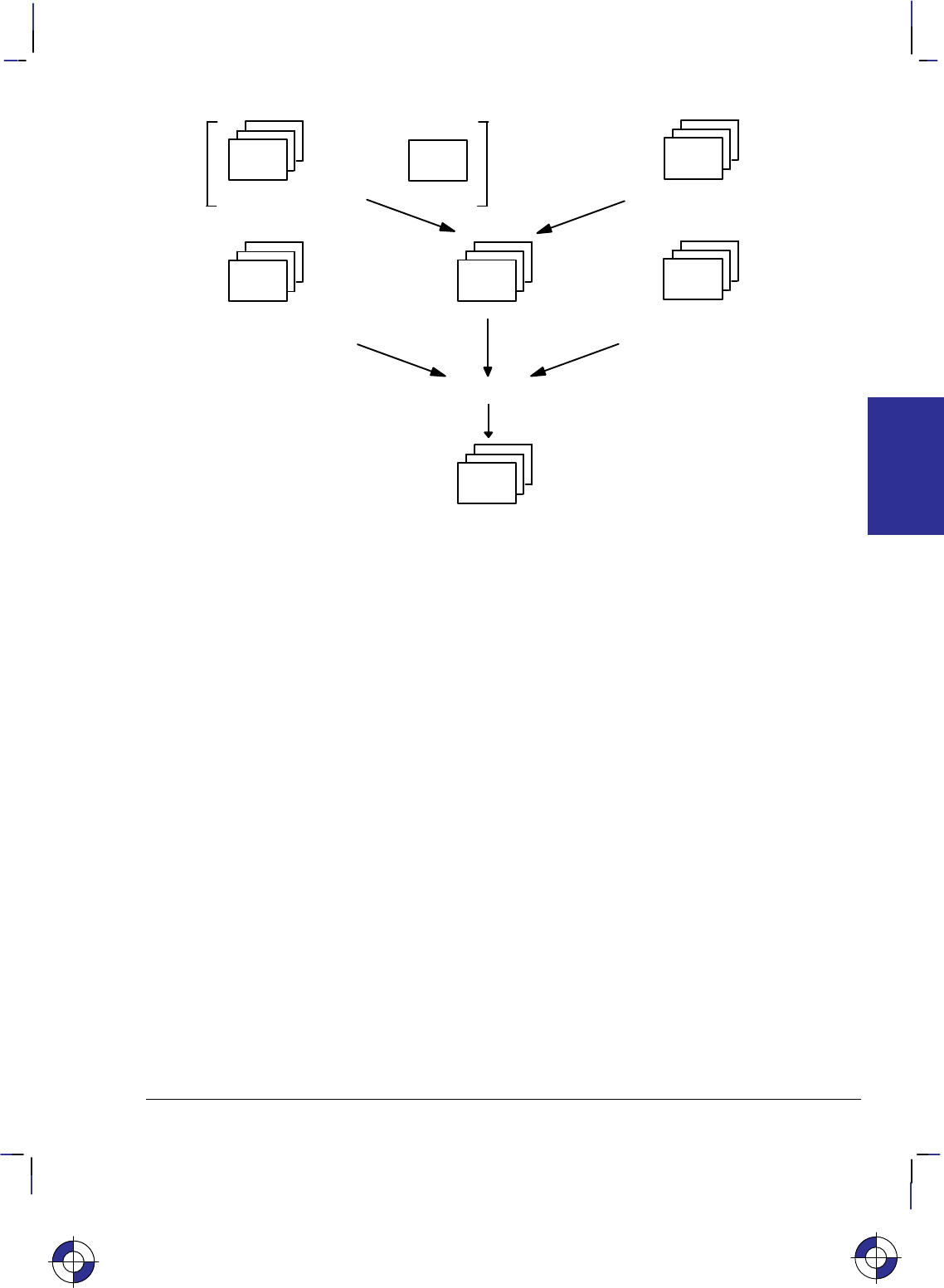
367
This is the black on page 367 (seq: 385)
Company confidential. HP-GL/2 and HP RTL Reference Guide, draft 2. Freeze Status: open
Foreground
color Pattern
Logical
AND
User-defined
color pattern
or
Texture
Source
image
Current
image
Logical operation
New image
(Destination)
(New destination)
Figure 165. Forming a New Image Using Color, Pattern, and Source Image
Logical Operations
Logical operations are operations that are applied to three components: the destination (current
image), the source data, and the texture. They are combinations of the logical operators and,
or, xor and not. The numerical operand of the Logical Operation (*l#O) command or the
MC (Merge Control) instruction defines what transformation is to be applied to these three op-
erands. The table in the description of the command (see page 424) describes each
transformation in reverse polish notation. Thus the default value (252) is TSo, which is (tex-
ture or source).
The operands and operators used are: a=
and
S= source o = or
T= texture n = not
D= destination (current image) x = xor (exclusive or)
The logical operations defined by HP RTL are specified in RGB-space, where white = 1 and
black = 0. However, because the devices that support HP RTL normally operate in CMY-space
where white = 0 and black = 1, the results may not be intuitive if you are used to thinking in
CMY-terms. For example, oring white with black in RGB-space yields white, which is the
same as anding in CMY-space. To convert from one color space to the other, write the opera-
tion code in binary, invert the bits (swap 0’s and 1’s), and reverse the order; thus TSo is 252,
binary 11111100, which becomes 11000000, decimal 192 or TSa.
This is the blue on page 367 (seq: 385)
INTERACTIONS
HP RTL
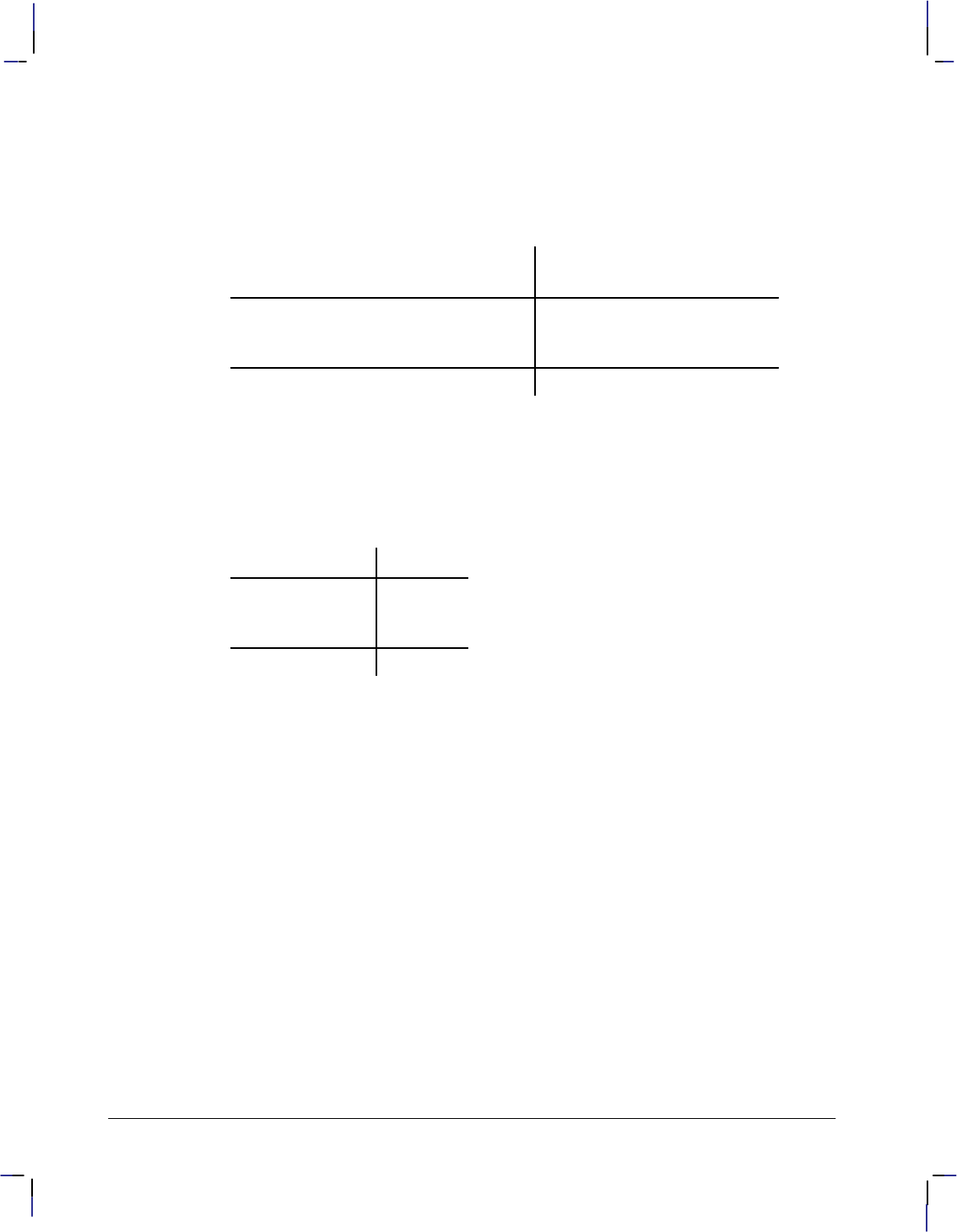
368
This is the black on page 368 (seq: 386)
Company confidential. HP-GL/2 and HP RTL Reference Guide, draft 2. Freeze Status: open
Which Logical Operation to Use?
To decide which numerical parameter to use in the Logical Operation command, you must first
decide what logical combination of operations are to be applied to the three operands, T (tex-
ture), S (source image), and D (destination—current image). One way of doing this is to draw
a matrix of the possible bit-values of the three operands, and of the desired result, like this:
Bits
76543210
T: Texture ( = color and pattern ) 11110000
S: Source 1 1 0 0 1 1 0 0
D: Destination (current image) 1 0 1 0 1 0 1 0
Desired result: If S then D else T 10111000
The final row is the result you want to achieve for each setting of texture, source, and destina-
tion bits. Binary 10111000 is decimal 184, so the command to use would be *l184O.
One bit is used to define each of the primary colors; the result of a logical operation is the
Boolean transform applied to the operand bits. For example, consider what happens if a des-
tination pixel is yellow (R=1, G=1, B=0), the texture color for that pixel is white (R=1, G=1,
B=1), and the source is green (R=0, G=1, B=0), as shown in the following table:
RGB
T: Texture 111
S: Source 0 1 0
D: Destination 1 1 0
Result: 101
Here, the result of operation 184 is shown; the pixel would appear magenta (R=1, G=0, B=1).
An Alternative Method
An alternative method is to describe the transformation as a Boolean expression; for example,
(T and (not S)) or (S and D) which is
TSnaSDao in reverse polish form;
if necessary, apply some simplifying transformations to get the result into one of the forms
listed in the description of the Logical Operation command. In the above case, the formula can
be transformed into TSDTxax, which, again, is operation 184.
[Some of the Boolean transformations that you might need to use are:
not (A and B) is equivalent to (not A) or (not B)
not (A or B) (not A) and (not B)
A xor B (A and (not B)) or ((not A) and B)
A and (not A) 0
A or (not A) 1
Further treatment is beyond the scope of this guide—see any good textbook on Boolean alge-
bra.]
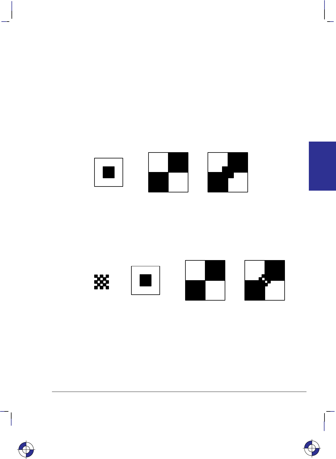
369
This is the black on page 369 (seq: 387)
Company confidential. HP-GL/2 and HP RTL Reference Guide, draft 2. Freeze Status: open
A Choice of Operations
Some of the logical operations you might choose to use are:
184: TSDTxax If S then D, else T
240: TUse T only
102: DSx If S then invert D, else D
255: 1White
226: DSTDxax If S then T, else D
204: SUse S only
The Default Print Model
The default print model is shown below.
+=
Source
Result
Destination
(current image)
Figure 166. Creating an Image with Transparent “White” Source Pixels
The default source and pattern transparency modes, which are explained in the next section, are
both transparent, and the default logical operation is TSo (Texture or Source, 252). (Note,
however, that the MC (Merge Control) instruction can cause a default of DTSoa (168), de-
pending on its mode parameter; for more information see the description of MC on page 220.)
In the case where a pattern is used, the result is:
+=+
Pattern
Source
Result
(current image)
Destination
Figure 167. Creating an Image with Transparent “White” Source and Pattern Pixels
This is the blue on page 369 (seq: 387)
INTERACTIONS
HP RTL
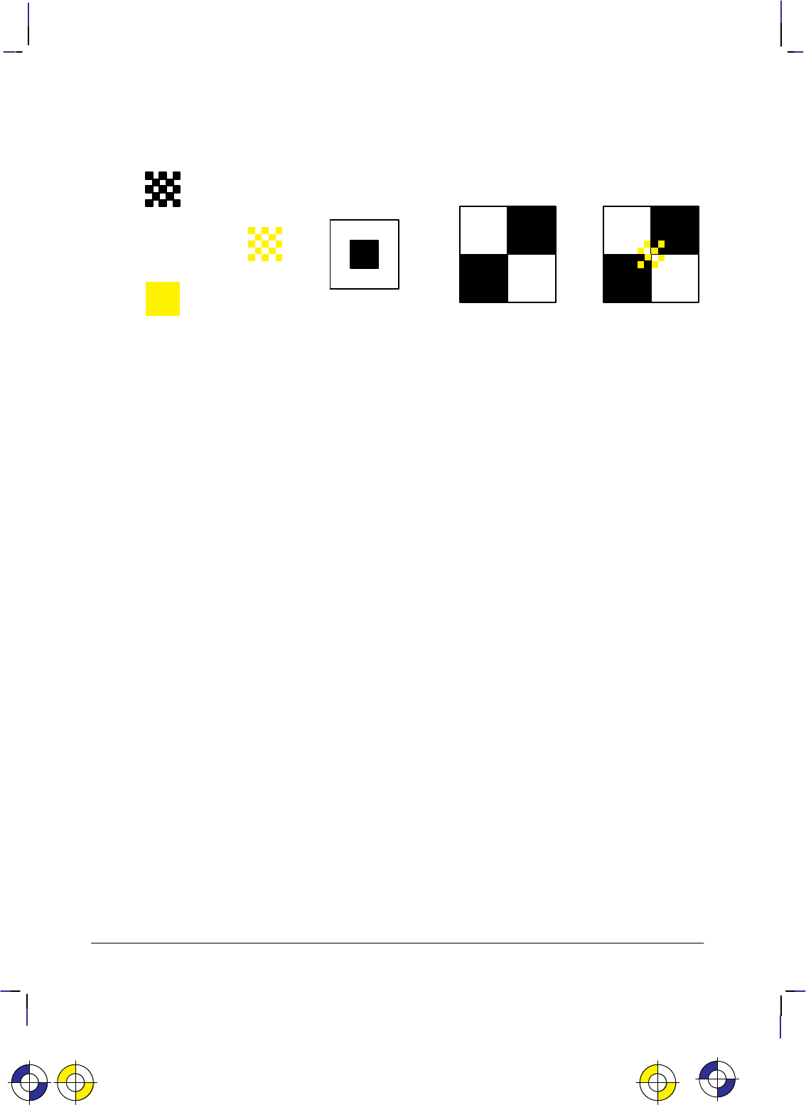
370
This is the black on page 370 (seq: 388)
Company confidential. HP-GL/2 and HP RTL Reference Guide, draft 2. Freeze Status: open
Where a foreground color is defined, the result is:
+=+
Pattern
Source
Result
Texture
Foreground
color
+=
Destination
(current image)
Figure 168. Creating an Image with Color and Transparent “White” Pixels
Transparency
There are two transparency modes, source transparency mode and pattern transparency mode.
Source transparency controls whether the white pixels in the source will affect the current
image. If the mode is opaque, the white pixels affect the current image; when it is transparent,
they don’t. Pattern and foreground color do not affect white pixels.
Similarly, pattern transparency mode affects whether the white pixels in the pattern affect the
current image.
Source transparency mode is set by the *v#N command; pattern transparency mode is set
by the *v#O command. In both cases, #=0 is transparent and #=1 is opaque. These two
commands do not apply to HP-GL/2 data.
Transparency modes and logical operations interact. Only in the case of both modes being
opaque is the final transformation the same as the logical operation specified in the table of
logical operations. In other cases, further transformations have to be applied to derive the final
appearance of the image.
The four basic interactions are described below. For this discussion, source_mask and pat-
tern_mask are the transparency masks, where transparent pixels are 0’s and opaque pixels are
1’s. These transparency masks are used to determine whether source pixels are to be applied to
the destination.
Source and Pattern Both Opaque
texture = color and pattern
result = logical_operation ( current_image, source_data, texture )
This is the yellow on page 370 (seq: 388)This is the blue on page 370 (seq: 388)

371
This is the black on page 371 (seq: 389)
Company confidential. HP-GL/2 and HP RTL Reference Guide, draft 2. Freeze Status: open
Source Opaque, Pattern Transparent
texture = color and pattern
temp_result = logical_operation ( current_image, source_data, texture )
image_a = temp_result and (not source_mask)
image_b = temp_result and pattern_mask
image_c = (not pattern_mask) and source_mask and current_image
result = image_a or image_b or image_c
The effect is to restrict the result of the logical operation by forcing bits 3 and 2 to 10, retaining
the values of bits 7-6-5-4 and bits 1 and 0 set by the logical operation. (The revised logical
operation is xxxx10xx, where the x’s are as defined by the Logical Operation command.)
Source Transparent, Pattern Opaque
texture = color and pattern
temp_result = logical_operation ( current_image, source_data, texture )
image_a = temp_result and source_mask
image_b = current_image and (not source_mask)
result = image_a or image_b
The effect is to restrict the result of the logical operation by forcing bits 5 and 4 and bits 1 and
0 both to 10, retaining the values of bits 7 and 6 and bits 3 and 2 set by the logical operation.
(The revised logical operation is xx10xx10, where the x’s are as defined by the Logical Opera-
tion command.)
Source and Pattern Both Transparent
texture = color and pattern
temp_result = logical_operation ( current_image, source_data, texture )
image_a = temp_result and source_mask and pattern_mask
image_b = current_image and (not source_mask)
image_c = current_image and (not pattern_mask)
result = image_a or image_b or image_c
The effect is to restrict the result of the logical operation by forcing bits 5-4-3-2-1-0 to 101010,
retaining the values of bits 7 and 6 set by the logical operation. (The revised logical operation
is xx101010, where the x’s are as defined by the Logical Operation command.)
For operand values of the logical operation between 0 and 63, the result is 42 (DTSana); for
values between 64 and 127, the result is 106 (DTSax); for values between 128 and 191, it is
170 (D); and for values between 192 and 255, it is 234 (DTSao).
This is the blue on page 371 (seq: 389)
INTERACTIONS
HP RTL
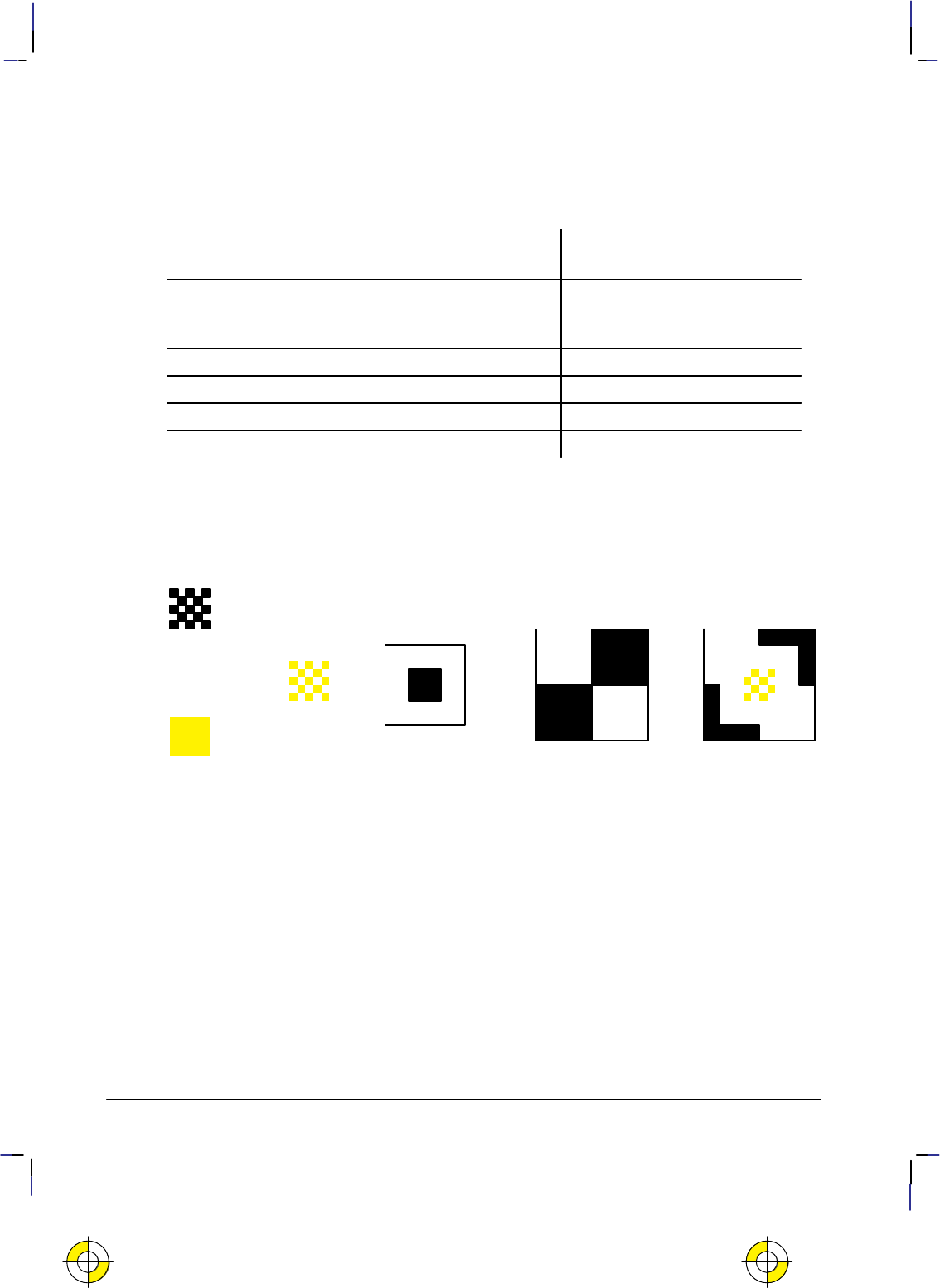
372
This is the black on page 372 (seq: 390)
Company confidential. HP-GL/2 and HP RTL Reference Guide, draft 2. Freeze Status: open
The Effect of Transparency
Thus to achieve a particular result, the logical operation chosen must be altered to take account
of the source and pattern transparency modes. Bits printed
like this
in the following table are
forced settings.
Bits
76543210
Texture ( = color and pattern ) 11110000
Source 1 1 0 0 1 1 0 0
Destination (current image) 1 0 1 0 1 0 1 0
Case 1: Source and pattern are opaque 252 = 11111100
Case 2: Source opaque, pattern transparent 248 = 1111
10
00
Case 3: Source transparent, pattern opaque 238 = 11
10
11
10
Case 4: Source and pattern are transparent 234 = 11
101010
The following illustrations show how texture and source are applied to a destination image,
with various settings of the transparency modes. (In the case of a monochrome image, the tex-
ture is simply the pattern.)
+=+
Pattern
Source
Result
Texture
Foreground
color
+=
Destination
(current image)
Figure 169. Creating an Image with Color Using Opaque Transparency Modes
This is the yellow on page 372 (seq: 390)
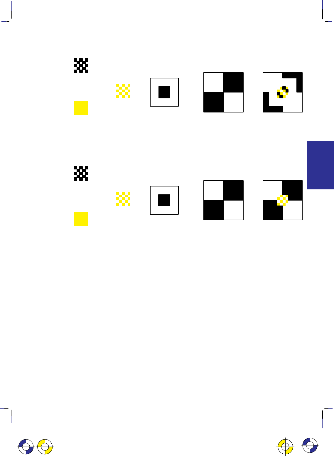
373
This is the black on page 373 (seq: 391)
Company confidential. HP-GL/2 and HP RTL Reference Guide, draft 2. Freeze Status: open
+=+
Pattern
Source
Result
Texture
Foreground
color
+=
Destination
(current image)
Figure 170. Creating a Color Image with Source Opaque and Pattern Transparent
(Case 2)
+=+
Pattern
Source
Result
Texture
Foreground
color
+=
Destination
(current image)
Figure 171. Creating a Color Image with Source Transparent and Pattern Opaque
(Case 3)
Case 4 is shown in Figure 168 on page 370.
This is the yellow on page 373 (seq: 391)This is the blue on page 373 (seq: 391) This is the yellow on page 373 (seq: 391)
INTERACTIONS
HP RTL

374
This is the black on page 374 (seq: 392)
Company confidential. HP-GL/2 and HP RTL Reference Guide, draft 2. Freeze Status: open

375
This is the black on page 375 (seq: 393)
Company confidential. HP-GL/2 and HP RTL Reference Guide, draft 2. Freeze Status: open
Chapter 11: Transmitting Data
So far we have looked at several concepts regarding raster data, as well as discussing some
commands used for setting up the raster transfer. This section explains the basic commands
used actually to transfer the data.
Transferring Raster Data
When all the setup is complete, you tell the device to expect raster data by sending the HP RTL
command Start Raster Graphics (*r#A). The parameters in this command tell the device
whether to start graphics at the left side of the logical page or at the CAP, and whether to start
graphics with or without scaling. When the device is in raster mode, some commands are al-
lowed and some are ignored—see the list of commands on page 403 for details.
The Raster Line Path command (*b#L) specifies the vertical direction in which the raster
image will “grow”. Because of problems that can occur if an image requires more memory
than the device has available, you are recommended to use the “downwards” direction
(*b0L) in this command. See When Overflow Occurs on page NO TAG.
Once the device is in raster mode, you can send it data using two HP RTL commands: Transfer
Raster Data by Plane (*b#V), and Transfer Raster Data by Row/Block (*b#W). The
data sent with these commands must be formatted according to the current compression meth-
od—see Compressing Data on page 380.
The two Transfer commands are used to send raster data to the device in a row-by-row format.
Transfer Raster Data by Plane (*b#V) increments the plane counter but not the row point-
er; it is therefore used to send each plane in a multi-plane row except the last. Transfer Raster
Data by Row/Block (*b#W) moves the CAP to the next raster row, and is therefore used to
send the last plane of a multi-plane row.
When you have only one plane of data to print, you only need the second command, Transfer
Raster Data by Row/Block. You send each row of raster data with this command. After the
device renders this data internally, the row counter is incremented, and the device is ready to
receive data for the next row. When you use a block-based compression method, you issue this
command only once for each block.
When all the data for an image has been sent, you exit raster graphics mode with the HP RTL
command End Raster Graphics.
Use these commands to enter and exit raster mode and to send raster data to the device:
Start Raster Graphics *r#A page 448
End Raster Graphics *rC page 419
Transfer Raster Data by Plane *b#V[data] page 449
Transfer Raster Data by Row/Block *b#W[data] page 451
Compression Method *b#M page 408
Y Offset *b#Y page 453
Raster Line Path *b#L page 435.
This is the blue on page 375 (seq: 393)
DATA TRANSMIT
HP RTL
This is the blue on page 375 (seq: 393)

376
This is the black on page 376 (seq: 394)
Company confidential. HP-GL/2 and HP RTL Reference Guide, draft 2. Freeze Status: open
Note that the Compression Method command, the two transfer commands, the Y Offset com-
mand, and the Raster Line Path command all begin with *b. You can combine these
commands using the technique described on page 340. You must put the other commands be-
fore the transfer command in the combined command. Transfer commands (which must end in
a capital letter, and are followed by data) can only end a combined command; they cannot be-
gin one.
Implicit Start Raster Graphics
A Transfer Raster Data by Plane (*b#V[data]) or Transfer Raster Data by Row/Block
(*b#W[data]) command is permitted with no preceding Start Raster Graphics (*r#A)
command. Either transfer command implicitly puts the device into (unscaled) raster mode and
uses the left edge of the logical page as the left graphics margin, corresponding to a Start Raster
Graphics with parameter value 0. It is strongly recommended, however, that you start raster
graphics explicitly using the Start Raster Graphics command.
Commands in Raster Mode
After an explicit or implicit Start Raster Graphics command, the device enters a restricted state
called raster mode. This mode “locks out” (ignores) commands that would affect rendering of
the graphics image. These commands remain locked out until raster mode is terminated by an
explicit or implicit End Raster Graphics command.
Some additional commands are ignored in scaled raster mode only. Scaled raster mode is in
effect after a Start Raster Graphics command with a value of 2 or 3 is received (and Source
Raster Width and Source Raster Height were specified), and until an implicit or explicit End
Raster Graphics command.
Commands that are neither explicitly ignored or explicitly allowed when the device is in raster
mode cause an implicit End Raster Graphics command to be executed, and are then executed as
usual.
Implicit End Raster Graphics
Receipt of any data other than an HP RTL command listed on page 403 as explicitly allowed or
explicitly ignored causes an implicit End Raster Graphics with all of its defined functionality.
It is strongly recommended, however, that you end raster graphics explicitly.
When Overflow Occurs*
Your device uses internal random-access memory (RAM) to store vector and raster data. In
normal operating mode, the device stores all data for an image before printing it in one pass.
It is possible, however, to send more data for one page than will fit in storage. This is more
likely to occur with raster data, since this data is more voluminous than vector data. (In most
cases, vector data is stored as endpoints, whereas raster data includes one bit of data for each
color-plane of each pixel of the image.) Some very complex vector drawings may also over-
flow RAM.
If your images consistently overflow RAM and you have not expanded the RAM as much as
* Note that this section does not apply to all HP RTL devices.
This is the blue on page 376 (seq: 394)
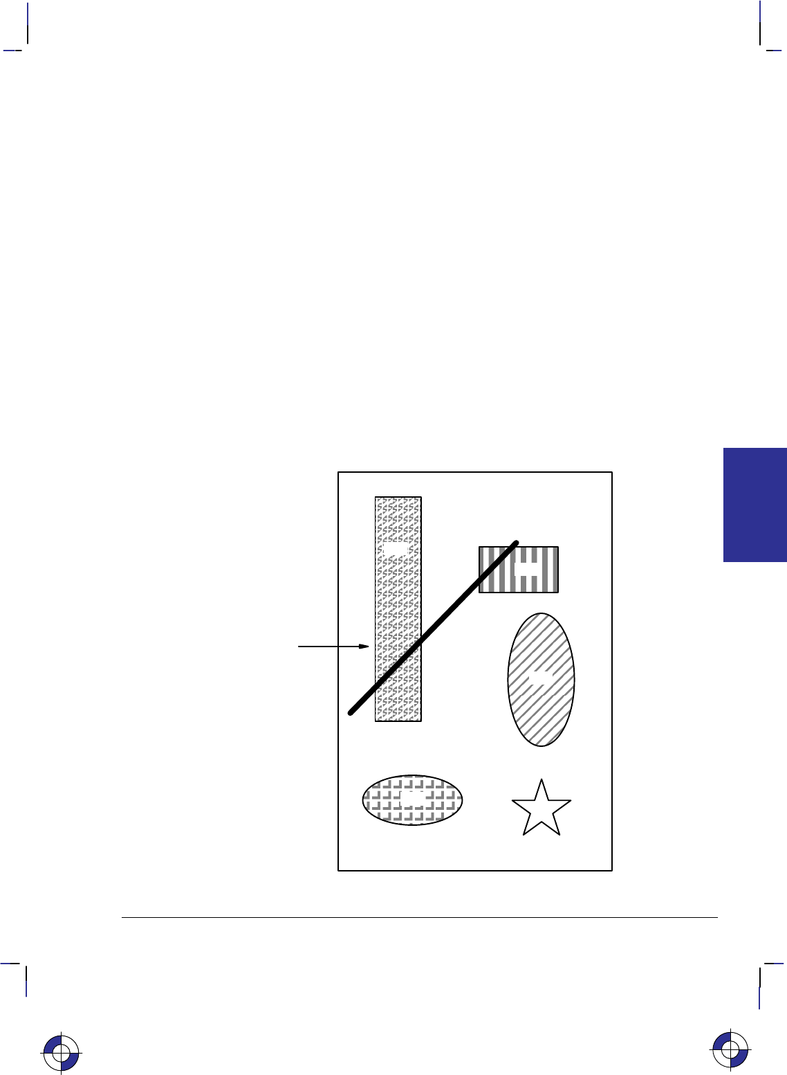
377
This is the black on page 377 (seq: 395)
Company confidential. HP-GL/2 and HP RTL Reference Guide, draft 2. Freeze Status: open
possible, you should consider adding more RAM for best performance.
A note on how images are stored in RAM:
In most cases, vector data is converted to a special internal format that includes the end-
points and vector characteristics.
Raster data is first decompressed (if one of the compression modes was used for transmis-
sion) and then recompressed using a special internal algorithm. The amount of RAM an
image occupies depends on the density of the image. Very dense images like maps and
scanned images occupy the most RAM.
There are two strategies that HP devices use to overcome problems associated with storage
overflow: “on-the-fly” plotting and “superflow” mode.
On-the-Fly Plotting
Regardless of the amount of RAM installed in your device, when an image exceeds the avail-
able RAM, the device immediately enters on-the-fly plotting mode. The effect of this mode
depends on whether the device was in the HP-GL/2 context or the HP RTL context when the
overflow occurred.
If the device was in the HP-GL/2 (vector) context when the RAM overflow occurred, it
switches to “flow mode” and discards the HP-GL/2 object. At this stage, nothing is printed, but
a message such as Out of Memory/Data was lost may be displayed.
3
1
6
5
4
2
RAM over-
flow occurs
at this point
while re-
ceiving ras-
ter image 3
Figure 172. Page to be Printed
This is the blue on page 377 (seq: 395)
DATA TRANSMIT
HP RTL
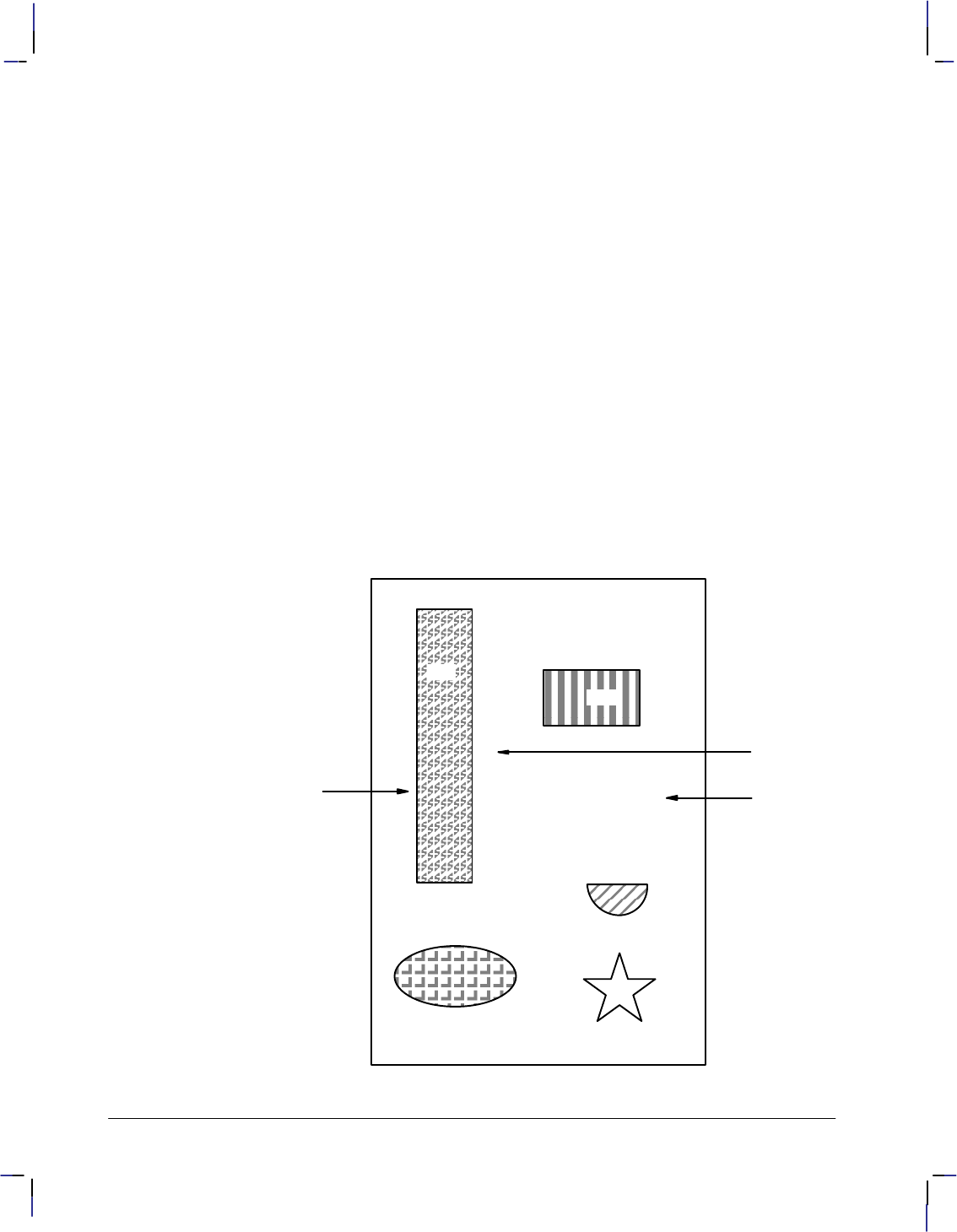
378
This is the black on page 378 (seq: 396)
Company confidential. HP-GL/2 and HP RTL Reference Guide, draft 2. Freeze Status: open
If the device was in HP RTL (raster) context when the RAM overflow occurred, it switches to
“flow mode” and prints all vector and raster data it has received so far that are physically lo-
cated above the one that caused the transition to “flow mode”.
Once the device is in “flow mode”, all HP-GL/2 objects that are subsequently received are dis-
carded; all HP RTL objects are printed as they arrive, together with all objects already placed in
the same area of the page, that arrived before “flow mode” was entered.
If a Y Offset command that would require reverse media movement is received during on-the-
fly plotting, the Y Offset command is ignored and the remainder of the data is discarded.
The following example illustrates on-the-fly plotting.
Consider the page shown in Figure 172, consisting of vectors and several raster images. This is
the file, as the final page is intended to look. The numbers represent the order in which the
vectors and raster images are sent. Images 1, 3, 4, and 5, printed from the top to the bottom,
are raster images. Images 2 and 6 are vector images.
If RAM overflows at the point shown while receiving raster image 3, the device enters on-the-
fly plotting mode and finishes printing image 3. Part of image 4 is discarded because of
negative motion; image 6 is discarded because it is an HP-GL/2 object. Image 2, however,
which was completely received before image 3, is printed.
The actual page would appear as in Figure 173.
The implication of the on-the-fly memory-handling technique is that you should begin the data
stream with the most important data to be certain it will print. In practical terms, this usually
3
1
2
RAM overflow
occurred at this
point while receiv-
ing raster image 3
Figure 173. Output as it Appears on Media
5
4
Upper part of
image 4 lost
due to nega-
tive motion
Vector image 6
not printed (re-
ceived during
flow mode)

379
This is the black on page 379 (seq: 397)
Company confidential. HP-GL/2 and HP RTL Reference Guide, draft 2. Freeze Status: open
means sending vectors before a large raster image, since the device can do on-the-fly plotting
of the raster image.
“Superflow” Mode
An improved algorithm is used on some devices, compared with that just described. Again,
when there is not enough memory to process a request, data so far accumulated is flushed, but
only the minimum necessary to enable the processing of the new data.
Swaths (bands) of data are flushed each time an overflow occurs, the flushing continuing until
there is sufficient memory to honor the request or until all swaths have been flushed.
Swaths are also flushed each time any type of object (vector or raster) is placed on the page at
swath n and no negative motion is specified; in this case, all swaths up to and including swath
n–1 are flushed. If any data is subsequently received for swaths up to n–1, it is lost and an error
message is given.
The effect of this is that, provided pictures are properly ordered into bands, they are more likely
to be printed successfully. Whenever possible, send to the device first those objects that occupy
the top of the page, and afterwards those that come below.
In both vector and raster cases, memory overflow causes the device to print the uppermost part
of the picture, and release the associated memory. It is then able to accept more data.
Plane-by-Plane Printing and Scaling
This section applies to devices, such as electrostatic plotters, that print one plane of a complete
page, followed by the next plane, and so on until the entire page has been printed. Other de-
vices, such as ink-jet plotters, can print all planes at once; this section does not apply to the
latter type of device.
When scaling is on and you are using plane-by-plane printing, you cannot use the Y Offset
command (*b#Y) to move the CAP. For this reason it is necessary to exit raster graphics
mode before moving the CAP back to the top of the output between planes. Since exiting raster
graphics also resets the compression method to the default (0), you must set the compression
method again before going back into raster graphics mode.
Calculating the Y Offset value is more complicated for scaled printing than for unscaled print-
ing. During unscaled printing, the device moves one physical row per row of data sent, so the
Y Offset value is simply equal to the number of data rows sent. However, during scaled print-
ing, the device generally prints more (or fewer) physical rows than the actual number of data
rows sent, so the number of physical rows no longer equals the number of data rows. Since you
must tell the Y Offset command the number of physical rows to move back the CAP, you must
calculate the Y Offset based on how much the image was scaled.
The formula for calculating the Y Offset for scaled raster graphics is as follows:
offset
round
destination height
720.0
resolution
where
round
is a function that returns an integer after rounding.
This is the blue on page 379 (seq: 397)
DATA TRANSMIT
HP RTL

380
This is the black on page 380 (seq: 398)
Company confidential. HP-GL/2 and HP RTL Reference Guide, draft 2. Freeze Status: open
destination height
is the value from the Destination Raster Height command, that
is, the height of the destination image in decipoints.
720.0 is the number of decipoints per inch.
resolution
is the resolution in dots per inch (dpi) as specified in the Set
Graphics Resolution command. If no resolution is set, use the
device’s default resolution. Note that although any resolution
setting is ignored during scaled raster graphics, the Y Offset
command is nonetheless sensitive to the current resolution set-
ting. This is why the formula requires the resolution parameter.
In essence, the formula converts the destination raster height to inches, and multiplies it by the
current dots-per-inch setting to get the number of dots to move. Multiply this offset value by
–1 (to cause the page to move backwards), and use this as the value (#) in the Y Offset com-
mand, as in the Summary of Normal Execution Sequence on page 466.
If you specified destination raster width and not destination raster height, you can calculate the
destination height as follows:
destination height
trunc
destination width
source width
source height
where
trunc
is a function that returns an integer after truncation.
Due to the potential for rounding error, it is more accurate to specify explicitly destination
height in HP RTL than to calculate it using this formula.
Compressing Data
Raster images normally require that you send a bit (1/8 byte) of data for each pixel; if the
image is in color, at least three bits are required per pixel, often much more. For this reason,
raster image files are generally much larger than vector image files, in which only the endpoints
are sent.
In order to cut down on the amount of data that must be sent for raster images, HP RTL offers
several data compression methods. These methods use different “tricks” to reduce the quantity
of data that must be transmitted. Most of the tricks involve having the device replicate identi-
cal data instead of sending it explicitly.
You use the HP RTL command Compression Method (*b#M) to select a compression meth-
od.
Note that data compression applies only to data transmission. As soon as the data is received
by the device, it is decompressed, and then interpreted according to the pixel encoding mode.
Depending on the image and the compression method, a compressed image can be much small-
er than an uncompressed one, with corresponding savings in data transmission time. For this
reason, we recommend using data compression whenever possible. There is, of course, a trade-
off between the host compression time plus device decompression time and the saving in
transmission time.
For ease of explanation, the examples in this section are very small and therefore do not show
any significant reduction in the size of the data.
This is the blue on page 380 (seq: 398)

381
This is the black on page 381 (seq: 399)
Company confidential. HP-GL/2 and HP RTL Reference Guide, draft 2. Freeze Status: open
Another way of reducing the amount of data sent to the device is to use the Y Offset command
(*b#Y). This allows you to send partial rows of data. The Transfer Raster Data by Plane
(*b#V) and Transfer Raster Data by Row/Block (*b#W) commands also let you specify
empty rows or planes, by using a zero parameter.
HP RTL supports seven data compression methods:
Run-length encoding (row-based) – method 1 page 383
Tagged Image File Format (TIFF) revision 4.0 “Packbits” encoding
(row-based) – method 2 page 383
Seed-row encoding (row-based) – method 3 page 384
Adaptive encoding (block-based) – method 5 page 387
Three CCITT methods for monochrome data – methods 6, 7, and 8 page 390.
In addition, there are two unencoded (uncompressed) methods:
Row-based unencoded transmission – method 0 page 381
Block-based unencoded transmission – method 4 page 381.
It is possible to mix compression methods on the same page. This allows you to use the most
efficient method for each row, or, for block-based methods, for each block. You can also mix
row-based and block-based methods in one image.
The following sections explain each data compression method. The method numbers refer to
the respective values of the Compression Method parameter (#).
Row-Based Unencoded (Compression Method 0)
This is the default method; there is no compression of data. The number of bits required for
each pixel is determined by the Configure Image Data (*v#W) or Simple Color (*r#U)
command. For one bit per pixel, the most significant bit (bit 7) of the first byte corresponds to
the first pixel in the row; the least significant bit (bit 0) corresponds to the eighth pixel in the
row; the most significant bit of the second byte corresponds to the ninth bit in the row, and so
on.
Data for each row must end on a byte boundary. If the number of bits per row is not evenly
divisible by 8, you must still send a complete byte. For instance, if there are 2500 bits per row,
you must send 313 bytes; the last four bits of the last byte can contain anything. You can use
the Source Raster Width command (*r#S) to clip off the unwanted data. You could also fill
the trailing bits with data that will index to a non-printing color, usually white.
For example, to send the string of characters “UUUUATT” to the device, you would use the
command sequence: *r1A*b0m7WUUUUATT*rC.
Block-Based Unencoded (Compression Method 4)
This is basically the same as row-based unencoded, except that only one command is needed to
transfer data for an entire block of data (Transfer Raster Data by Row/Block—*b#W).
The first four bytes of the block make up a 32-bit number specifying the number of pixels of
data to expect for each row. The device uses this value to determine when to increment the
plane and row pointers. Note that this number is sent only at the beginning of the block, not at
This is the blue on page 381 (seq: 399)
DATA TRANSMIT
HP RTL

382
This is the black on page 382 (seq: 400)
Company confidential. HP-GL/2 and HP RTL Reference Guide, draft 2. Freeze Status: open
the beginning of each row. Also, this number is a true 32-bit unsigned binary integer, not a
string of ASCII digits that make up a number as is the case with many other HP RTL parame-
ters. Each pixel may be defined by more than one bit of data.
As with the row-based unencoded method, each row must start and end on a byte boundary. If
the number of pixels per row specified in the first four bytes of the block is not evenly divisible
by 8, it is rounded up to the next multiple of 8. For instance, if the first four bytes contain the
number 2500, it is rounded up to 2504. Data is not clipped based on this four-byte number.
Instead, the row is padded to or clipped at the Source Raster Width (*r#S). Similarly, the
Source Raster Height (*r#T) command allows padding or clipping to the height of the
image.
When the row is completely defined, the row-pointer is incremented, and plane pointer is reset
to 1, and the CAP is set to the left graphics margin. If the last row of data specifies an incom-
plete row, or if all the planes have not been defined, the unspecified data is assumed to be 0.
With block-based transfers, data is still sent by row and by plane. For instance, with three
planes per row, data for a block is transmitted as follows:
*b#W Transfer Raster Data by Row/Block
[number of pixels per row] 32-bit integer value
row 1 plane 1 Data organized by row and plane
row 1 plane 2 .
row 1 plane 3 .
row 2 plane 1 .
row 2 plane 2
row 2 plane 3
.
.
row n plane 1
row n plane 2
row n plane 3
If there is only one plane per row, the data for each plane is transmitted as follows:
*b#W Transfer Raster Data by Row/Block
[number of pixels per row] 32-bit integer value
row 1 Data organized by row
row 2 .
..
..
row n
The parameter value (#) in the Transfer Raster Data by Row/Block command (*b#W) refers
to the size of the entire block, including the four-byte prefix; the value (#) is equal to
4)ǒȱ
number of pixels per row
8ȳ
number of rows
number of planes
Ǔ
The “number of pixels per row/8” expression, rounded up to the next integer, yields the number
of bytes per row. (The angular brackets in the formula represent the “ceiling function,” indicat-
ing that the result should be rounded up.)

383
This is the black on page 383 (seq: 401)
Company confidential. HP-GL/2 and HP RTL Reference Guide, draft 2. Freeze Status: open
Run-Length Encoding (Compression Method 1)
With run-length encoding, the raster data consists of byte pairs: the first byte is a repetition
count, and the second byte is a data byte. The repetition count can range from 0 to 255, and
tells how many times the following byte is to be repeated. A count of 0 means the following
byte occurs only once and is not repeated. A count of 255 means the byte is repeated 255 times
for a total of 256 occurrences.
Run-length encoding is a row-based encoding method; a separate Transfer Raster Data com-
mand is required for each plane and row.
Run-length encoding relies on byte pairs. If the parameter value (#) in the Transfer Raster Data
command is odd, the entire transfer sequence is ignored.
Assume you want to send the following data to the device. The data is shown as binary num-
bers and as ASCII characters:
01010101 01010101 01010101 01010101 01000001 01010100 01010100
UUUUATT
Using run-length encoding, you would use the following combined command to send the row.
The numbers in parentheses must be sent as binary bytes. For instance, (3) is binary 00000011.
The entire escape sequence is:
00011011 00101010 01100010 00110001 01101101 00110110 01010111 ...
*b1m6W
... 00000011 01010101 00000000 01000001 00000001 01010100
(3) U (0) A (1) T
where
1 m means compression method 1 (run-length encoding).
6 W means there are six bytes of data following. Note that this is the
length of the compressed data, not the uncompressed data.
(3) U means repeat the “U” pattern 3 times for a total of four bytes.
(0) A means do not repeat the “A” pattern.
(1) T means repeat the “T” pattern once for a total of two bytes.
The data transfer sequence would be: *r1A*b1m6W(3)U(0)A(1)T*rC using the
notation for binary numbers described above.
TIFF Packbits Encoding (Compression Method 2)
Tagged Image File Format (TIFF) “packbits” encoding is a combination of row-based
unencoded and run-length encoding (methods 0 and 1). You can mix unencoded, or
literal, bytes with repeated bytes.
TIFF Packbits encoding is a row-based encoding method. A separate Transfer Raster Data
command is required for each plane and row.
This is the blue on page 383 (seq: 401)
DATA TRANSMIT
HP RTL

384
This is the black on page 384 (seq: 402)
Company confidential. HP-GL/2 and HP RTL Reference Guide, draft 2. Freeze Status: open
With TIFF Packbits encoding, raster data is always preceded by a control byte. The control
byte can fall into three ranges:
0 to 127 There are from 1 to 128 literal data bytes following the control byte. 0 means 1
literal byte; 127 means 128 literal bytes, and so on.
–1 to –127 The data byte following the control byte is repeated the number of times repre-
sented by the absolute value of the control byte. (Negative numbers are
represented by their two’s complement, that is, the number of identical bytes is
equal to –(control byte) + 1.)
–128 This control byte is ignored, and the next byte is treated as a control byte.
Assume you want to send the same data as shown with run-length encoding to the device:
01010101 01010101 01010101 01010101 01000001 01010100 01010100
UUUUATT
Using TIFF Packbits encoding, you could use the following combined command to send the
row. As with run-length encoding, the numbers in parentheses must be sent as binary bytes.
For instance, (–3), the two’s complement of (3), is binary 11111101, decimal 253. Spaces are
added for clarity.
* b 2m 6W (–3)U (0)A (–1)T
where 2 m means compression method 2 (TIFF Packbits encoding).
6 W means there are six bytes of data following. Note that this is the
length of the compressed data, not the uncompressed data.
(–3) U means repeat the “U” pattern 3 times for a total of four bytes.
(0) A means the “A” pattern is a 1-byte literal.
(–1) T means repeat the “T” pattern once for a total of two bytes.
Another valid way to code this data is with the following combined command:
* b 2m 6W (–3)U (2)ATT
Here, the last three bytes are sent as a literal ((2)ATT).
Again, the entire data transfer sequence would be:
*r1A*b2m6W(–3)U(0)A(–1)T*rC
or *r1A*b2m6W(–3)U(2)ATT*rC
using the notation for binary numbers described above for run-length encoding.
When using TIFF Packbits encoding, it is more efficient to code two consecutive identical by-
tes as a repeated byte than as a literal. However, if the repeated bytes are preceded and
followed by literal bytes, it is more efficient to code the entire group as literal bytes. It is al-
ways most efficient to code three identical bytes as a repeated byte.
Seed-Row or Delta-Row Encoding (Compression Method 3)
Seed-row encoding describes a raster row by recording only the changes from the previous row
(the seed row). Seed-row encoding is sometimes called delta row compression because it iden-
385
This is the black on page 385 (seq: 403)
Company confidential. HP-GL/2 and HP RTL Reference Guide, draft 2. Freeze Status: open
tifies the delta, or change, between one row and the next. Unreplaced bytes are replicated from
the seed row.
Seed-row encoding is a row-based encoding method. A separate Transfer Raster Data com-
mand is required for each plane and row.
With seed-row encoding, the device takes the previous row of data and makes the changes indi-
cated by the delta data to create a new row. The new row is rendered, and becomes the new
seed row.
The format of a single delta is:
<command byte> [<optional offset bytes>] <1 to 8 replacement bytes>
The command byte contains both an offset and the number of bytes to replace:
754 0
Number of bytes
to replace Relative offset from last untreated byte
bits
The three higher-order bits indicate the number of consecutive bytes to replace (000=1 to
111=8). The five lower-order bits contain the offset relative to the current byte of the byte to be
replaced. The values of the offset have the following definitions:
0–30 Relative offset of 0–30 bytes from the first untreated byte (either the first byte in a
row, or the first byte following the most recent replacement byte). The first offset
in a raster row is relative to the left graphics margin. One to eight replacement
bytes follow this command byte.
For example, assume that the current byte is the first byte in the row. If the offset
is 7, bytes 0 through 6 are unchanged; and if there are five replacement bytes, by-
tes 7 through 11 are replaced. The new current byte is 12. A second offset of 3
means that bytes 12, 13, and 14 are unchanged and byte 15 is the next to be re-
placed.
31 Indicates that an additional offset byte follows the command byte. The value of
the offset byte is added to the command byte offset (31) to get the actual offset. If
the offset byte is 0, the offset is 31. If the offset byte value is 255, yet another
offset byte follows. The last offset byte is indicated by a value less than 255. All
the offset bytes are added to the offset in the command byte to get the actual offset
value.
For example, if there are two offset bytes and the last contains 175, the total offset
would be 31+255+175=461.
Consider the following data stream using seed-row encoding. The data is shown as binary
numbers:
000 11111 11111111 10000000 10010111
where: 000 means replace one byte.
11111 means add 31 to offset, and that the next byte is an offset byte.
11111111 means add 255 to offset, and that the next byte is an offset byte.
10000000 means add 128 to the offset; since this is less than 255, the next byte
is the data byte.
This is the blue on page 385 (seq: 403)
DATA TRANSMIT
HP RTL

386
This is the black on page 386 (seq: 404)
Company confidential. HP-GL/2 and HP RTL Reference Guide, draft 2. Freeze Status: open
10010111 replaces the byte at an offset of 31 + 255 + 128 = 414 bytes.
The seed row is initialized to 0 whenever raster mode is entered. Every raster transfer affects
the seed row, regardless of the compression method; this allows seed-row encoding to be com-
bined with other methods to achieve better compression performance.
A vertical offset also affects the seed row. The Y Offset command (*b#Y) skips rows, leav-
ing them blank, and sets the seed row to zero. *b0Y moves down zero rows (or up, if the
Raster Line Path command specified upward movement) and sets the seed row to zero.
Seed-Row Encoding and Raster Width
The width of the seed row is equal to the Source Raster Width (*r#S).
The Transfer Raster Data commands (*b#V and *b#W) both contain a number (#) of
bytes of data to expect for the entire command. If this byte count is reached before the literal
replacement count is met, the byte count has precedence, and no further bytes are replaced in
that row. Data beyond the byte count is parsed as ASCII commands and not as binary data.
Seed-Row Encoding and Multi-Plane Data
When you are using more than one plane of data per row, the device maintains a seed row for
each plane. This allows seed-row compression to operate on each plane of graphics indepen-
dently. However, a Y Offset affects all planes and seed rows simultaneously.
Programming with Seed-Row Encoding
With seed-row encoding, if only one bit in a row is different from the preceding row, then only
one replacement byte must be sent (with its location specified in one or more command bytes).
Here, seed-row encoding is very efficient. However, if a row is completely different from the
preceding row, then the entire row must be transmitted. In this case, another compression
method might be more efficient. For this reason, seed-row encoding is often mixed with other
compression methods for greatest efficiency.
In order to mix compression methods, it is important to understand how the seed row is affected
by various HP RTL commands.
Effect of Other Commands on the Seed Row
The seed row is updated by all row-based graphics transfers. This means that data sent with
any row-based compression method is available as a seed row. (In multi-plane images, a sepa-
rate seed row is updated for each plane.)
The seed row is zeroed by the Start Raster Graphics, End Raster Graphics, and Y Offset com-
mands. If there is more than one plane of data, all seed rows are zeroed. In addition, the seed
row is zeroed at the completion of any block-based transfer.
Note the effect of the following commands when the device is in raster mode (after a Start Ras-
ter Graphics command) and seed-row encoding is active:
*b0W Transfer Raster Data by Row/Block. Repeats the previous row. The seed
row is unchanged.
*b1Y Move down one raster row. The seed row is set to zeros.

387
This is the black on page 387 (seq: 405)
Company confidential. HP-GL/2 and HP RTL Reference Guide, draft 2. Freeze Status: open
*b0Y Move down zero raster rows (that is, do not move the CAP). The seed
row is set to zeros.
Horizontal CAP moves have no effect on the seed row.
Example of Seed-Row Encoding
The following data is to be compressed using seed-row encoding. It is assumed there is only
one plane of data. All graphics data is given in binary. The italicized bytes are the ones re-
placed using seed-row encoding:
Byte #: 1 2 3 4 5
Row 1: 00000000 11111111 00000000 00000000 00000000
Row 2: 00000000 11111111 11110000 00000000 00000000
Row 3: 00001111 11111111 11110000 10101010 10101010
The following HP RTL commands generate the data shown above:
*r1A
Start Raster Graphics initializes the seed row to all zeros.
*b3m2W 000 00001 11111111 [data is shown in binary]
Compression Method to 3 (seed-row encoding) and Transfer Raster Data by Row/
Block for row 1. One byte is replaced. The command byte signifies a single byte
replacement (top three bits are 0) and the replacement occurs with an offset of 1 byte
from the current position (lower five bits contain a relative offset of 1). The replace-
ment byte follows and contains 11111111.
*b2W 000 00010 11110000 [data is shown in binary]
Transfer Raster Data by Row/Block for row 2. One byte is replaced. The command
byte signifies a single byte replacement (top three bits are 0) and the replacement oc-
curs with an offset of 2 bytes from the current position (lower five bits contain a
relative offset of 2). The replacement byte follows and contains 11110000.
*b5W 000 00000 00001111 001 00010 10101010 10101010
[data is shown in binary]
Transfer Raster Data by Row/Block for row 3. Three bytes are replaced using two
commands. The first command byte signifies a single byte replacement (top three bits
are 0) and the replacement occurs with an offset of 0 bytes from the current position
(lower five bits contain a relative offset of 0). The replacement byte follows and con-
tains 00001111. The second command calls for the replacement of two bytes (top
three bits are 001) and the replacement occurs with an offset of 2 bytes from the cur-
rent untreated position (lower five bits contain a relative offset of 2). The two
replacement bytes follow the command byte.
Adaptive Encoding (Compression Method 5)
Adaptive compression uses compression methods 0 to 3 to compress optimally an entire block
of data. When the row data within a block is no longer optimally compressed by one method,
the compression method can be changed to adapt to the data. Adaptive compression also
allows the specification of empty or duplicate rows to skip white space or replicate identical
rows within a block.
This is the blue on page 387 (seq: 405)
DATA TRANSMIT
HP RTL

388
This is the black on page 388 (seq: 406)
Company confidential. HP-GL/2 and HP RTL Reference Guide, draft 2. Freeze Status: open
In adaptive compression, a raster image is interpreted as a block of data, rather than as individ-
ual rows. The Transfer Raster Data by Row/Block command (*b#W) is sent only once at
the beginning of a raster transfer; its value field specifies the number of bytes in the block. The
block size of the compressed data is limited to 32 767 bytes. To transfer more bytes, more
blocks can be sent.
Adaptive compression uses three control bytes at the beginning of each row within the block.
The first of these bytes, the command byte, identifies the type of compression for that row. The
following two bytes specify either the number of bytes within the row or the number of dupli-
cate or empty rows. The following shows the format of an adaptive compression raster row:
<command byte><# of bytes or rows><# of bytes or rows><raster data>
The command byte designates the compression method, an empty row, or a duplicate row. The
following shows the command byte values, which are sent in binary format:
Byte = 0 Unencoded
1 Run-Length Encoding
2 Tagged Image File Format (TIFF) revision 4.0
3 Delta Row
4 Empty Row
5 Duplicate Row
If an out-of-range command byte is encountered on a row, the remainder of the block is
skipped, the CAP is not updated, and the seed row is cleared.
For cases 0 to 3, the two-byte binary field (# of bytes or rows) specifies the row length (that is,
the total number of bytes to be transferred for that row within the raster block). For cases 4 and
5, this field defines the number of empty or duplicate rows to be encountered after the current
row, including the current row. The most significant byte (high byte) of this field is sent first,
followed by the least significant byte (low byte).
The maximum value for # of bytes or rows is 65 535; however, the image is clipped to the log-
ical page. The value does not include the three control bytes (the command byte and itself).
Values 0 to 3 indicate the identical compression methods described previously. Values 4 and 5
are explained below.
Empty Row A command byte of 4 causes a row of zeros to be printed. The number of rows
printed is contained in # of bytes or rows, following the command byte. An empty-row opera-
tion resets the seed row to 0 and updates CAP.
Duplicate Row A command byte of 5 causes the previous row to be printed again the number
of times contained in # of bytes or rows, following the command byte. A duplicate-row opera-
tion updates CAP, but does not change the seed row.
Adaptive Compression Guidelines
Compression methods cannot be mixed within one row.
Within a block, the seed row is updated by every raster compression method or type of row.
For example, a row compressed with method 2 updates the seed row, while the effect of an
empty row initializes the seed row to zeros. Maintaining the seed row allows method 3 to
be mixed with other methods in order to achieve optimal compression performance.
CAP is updated with each row of the raster block.
The Y Offset command moves the entire block of raster data and also initializes the seed
row to zeros. The seed row is set to 0 even if the Y Offset is 0.

389
This is the black on page 389 (seq: 407)
Company confidential. HP-GL/2 and HP RTL Reference Guide, draft 2. Freeze Status: open
Block size takes precedence over row length. If the row length of any line exceeds the
block size, the row size is truncated to the block size.
For method 1, a row length of 0 increments the CAP and zero-fills the seed row. If the row
length is odd, the CAP is incremented and the row data is skipped (thrown away), but the
seed row is unchanged.
For method 2, if the row length is 1, then one byte is consumed from the I/O, and the CAP
is incremented. The data is ignored and the seed row is zeroed.
For methods 2 and 3, if the row length terminates the data before the control byte value is
satisfied (for example, the literal byte count is greater than the row length), the data follow-
ing the control byte (if any) is discarded. The CAP is incremented.
Since method 3 requires that the seed row be available when entering raster mode, the seed
row is initialized to 0s on raster graphics mode entry (*r#A). The seed row is also
initialized on receipt and completion of each raster block.
For method 3, if the row length is 0, the current row is duplicated and the CAP is increm-
ented.
For method 3, if the row length is 1, then one byte is consumed from the I/O, the current
row is duplicated and CAP is incremented. The data is ignored.
For duplicate and empty rows a row length of 0 does not update CAP; however, the seed
row is initialized to 0.
Example of Adaptive Encoding
The following example demonstrates adaptive compression:
*t300R Sets the graphics resolution to 300 dpi.
*r1A Start Raster Graphics initializes the seed row to all zeros.
*b5M Set Compression method to 5, Adaptive Compression.
*b84W Transfer a raster block of data containing 84 bytes as detailed below.
As you see in the example data below, the first three rows are compressed
using method 3 compression. The next row is compressed by compression
method 1. The following three rows of data are specified as duplicate rows of
the previous row. Finally, the last three rows are compressed using method 3.
The CAP is updated after each raster row within the block is processed. (The
row number is not part of the data.) All data shown is in hexadecimal format.
Row Command Byte Bytes or
Rows Raster Data (hexadecimal)
103 00 09 E0 FF F0 00 FF FF 00 0F FF
203 00 09 E0 00 00 FF F0 0F FF 00 00
303 00 09 E0 FF F0 00 FF FF 00 0F FF
401 00 06 00 FF 05 00 00 FF
505 00 03
603 00 09 E0 FF F0 00 FF FF 00 0F FF
703 00 09 E0 00 00 FF F0 0F FF 00 00
803 00 09 E0 FF F0 00 FF FF 00 0F FF
*rC End Raster Graphics.
This is the blue on page 389 (seq: 407)
DATA TRANSMIT
HP RTL

390
This is the black on page 390 (seq: 408)
Company confidential. HP-GL/2 and HP RTL Reference Guide, draft 2. Freeze Status: open
CCITT Encoding Methods
The first four bytes of the Transfer Raster Data by Row/Block (*b#W) command are a
32-bit unsigned binary integer that specifies the number of pixels in a row. After decoding, any
data exceeding the specified Source Raster Width (*r#S) is clipped, and any incompletely
specified rows are appended with 0s. If Source Raster Height (*r#T) is specified, unde-
fined rows are zero-filled and excess rows are clipped.
CCITT Groups 3 and 4 encoding methods are by current definition monochrome compression
methods, that is, data is sent for one plane only. The colors defined for indexes 0 and 1 are al-
ways used for printing, regardless of how many planes were defined with the Set Number of
Bits per Index byte of the HP RTL command Configure Image Data. When index 0 is set to a
color other than white, a two-color image results: index 0’s color appears wherever a “0” bit is
sent, and index 1’s color appears wherever a “1” bit is sent. The CCITT methods are particu-
larly useful for text data.
A transfer command with a count of 4 is analogous to sending *b0W in compression meth-
od 0; nothing is transferred but the seed row is zeroed.
Since methods 6, 7, and 8 are defined only for monochrome devices, selecting any of these
methods causes the device to assume that all data planes except the first are zeroed; that is, the
data is interpreted as 0s and 1s that are to be rendered in the colors currently defined as index 0
and 1, respectively. The number of bits per index as set by the Configure Image Data
(*v#W) command and the palette are unchanged.
CCITT Group 3 One-Dimensional Encoding (Compression Method 6)
CCITT Group 3 one-dimensional encoding is a block-based compression method that uses a
statistical encoding similar to Huffman encoding. The length of alternating white and black (0-
and 1-bit) runs are calculated, and then a table lookup is employed to output the corresponding
binary codes. Refer to CCITT Fascicle VII.3 Recommendation T.4 for details.
CCITT Group 3 Two-Dimensional Encoding (Compression Method 7)
CCITT Group 3 two-dimensional encoding is similar to CCITT Group 3 one-dimensional en-
coding; row 1 uses one-dimensional encoding, and rows 2 through K–1 are sent using
two-dimensional encoding, where K is the K-factor used when the data was encoded. Refer to
CCITT Fascicle VII.3 Recommendation T.4 for details.
CCITT Group 4 Encoding (Compression Method 8)
CCITT Group 4 encoding is a block-based compression method similar to the CCITT Group 3
encoding methods, except that all encoding is two-dimensional; it does not include end-of-line
delimiters, and does not allow padding to byte boundaries. Refer to CCITT Fascicle VII.3
Recommendation T.6 for details.

391
This is the black on page 391 (seq: 409)
Company confidential. HP-GL/2 and HP RTL Reference Guide, draft 2. Freeze Status: open
Chapter 12: Interactions between
HP RTL and Other Systems
Interactions with Physical Device Settings
Potentially, the settings of the front panel of a plotter or printer may affect the resolution of
printing, whether color or monochrome output is to be produced, and other parameters concern-
ing the overall rendering of data. See the documentation associated with the device for more
details.
Interactions with HP-GL/2
Subject to some constraints, you can combine, on the same page, images defined by HP RTL
and vector graphics produced by HP-GL/2. HP RTL interacts with HP-GL/2 in several ways.
When HP-GL/2 vector data and HP RTL raster data are combined, their temporal order is main-
tained, and each source component is combined with the destination bitmap according to the
print model state variable settings in effect when that component was issued. By default, white
is transparent in both environments. The following table summarizes these interactions and
tells you where to turn for more information. Section names in italics refer to section titles;
command names refer to command descriptions in Chapter 14. You can find a full description
of all HP-GL/2 instructions in Part 2 of this book.
Summary of HP-GL/2 Interactions
Interaction Description
Transferring the HP-GL/2 pen position
to the HP RTL Current Active Position
(CAP) and conversely
See Changing Language Contexts and Modes on
page 393, the Enter RTL Mode command on page
422, and the Enter HP-GL/2 Mode command on
page 420.
Transferring the HP-GL/2 palette to
the HP RTL palette and conversely See Changing Language Contexts and Modes on
page 393, the Enter RTL Mode command on page
422, and the Enter HP-GL/2 Mode command on
page 420.
The IN (Initialize), BP (Begin Plot), and NP (Num-
ber of Pens) instructions change the unified palette
to the configuration defined in HP-GL/2.
This is the blue on page 391 (seq: 409)
HP RTL and
OTHER SYSTEMS
This is the blue on page 391 (seq: 409)This is the blue on page 391 (seq: 409)

392
This is the black on page 392 (seq: 410)
Company confidential. HP-GL/2 and HP RTL Reference Guide, draft 2. Freeze Status: open
Summary of HP-GL/2 Interactions
Interaction Description
Setting boundaries (hard-clip and soft-
clip limits) using the HP-GL/2 PS
(Plot Size) and IW (Input Window)
instructions; beware of unexpected in-
teractions due to the different coordi-
nate systems used, and on rotation.
See Setting Raster Boundaries on page 341.
The PS (Plot Size) instruction is automatically im-
ported into HP RTL mode, and sets the logical page
size to the hard-clip limits. Similarly, the IW (Input
Window) instruction sets the soft-clip limits. Clip-
ping may occur unexpectedly if you fail to use these
instructions.
Resetting the HP RTL CAP to its ori-
gin with HP-GL/2 instructions that
cause a page advance
See The Current Active Position (CAP) on page 347.
Any command that results in a page advance, such
as PG (Advance Full Page), BP (Begin Plot), or RP
(Replot), results in resetting the HP RTL CAP to
(0,0).
Exiting the HP-GL/2 picture header
state due to raster transfer commands See Changing Language Contexts and Modes on
page 393.
Using HP RTL patterns in HP-GL/2 See Exporting Patterns to HP-GL/2 on page 362 and
Pattern Orientation on page 363.
HP RTL cannot use patterns defined using HP-GL/2;
HP-GL/2 can use HP RTL patterns to fill areas.
However, the Set Graphics Resolution (*t#R)
command does not affect the resolution of raster fill
patterns defined with the RF (Raster Fill Definition)
instruction.
MC (Merge Control) instruction and
the Logical Operation command The Logical Operation (*l#O) command and the
MC (Merge Control) instruction are shared between
languages—the last one sent is applied to subse-
quent images and vectors. Whether the TR (Trans-
parency Mode) instruction is transferred to HP RTL
is device-dependent.
On devices that support it, the currently specified Media Type (MT instruction) may apply to
the overall rendering of vector and raster data. Potentially, front panel features may also affect
the overall rendering of both vector and raster data. See The Product Comparison Guide for
HP Languages on HP Plotters and Large-Format Printers for more information.
The Reset (E) command is recognized in both the HP-GL/2 and HP RTL contexts, with the
exception of two cases: in HP-GL/2 label mode with “TD1;” in effect, and in an HP RTL binary
data transfer.
Commands and instructions that set the color reference values for palette definitions are sepa-
rate and non-interacting. (These are Configure Image Data—*v#W and Set Color Range
for Relative Color Data—CR.) When a palette is imported from one context to another, the
colors are remapped to achieve visibly identical colors using the current color reference in the
target context. In other words, the colors that are imported are already normalized to physical
device colors, which are not affected by the current color references in the context just entered.

393
This is the black on page 393 (seq: 411)
Company confidential. HP-GL/2 and HP RTL Reference Guide, draft 2. Freeze Status: open
Changing Language Contexts and Modes
You use these commands to switch between HP-GL/2 and HP RTL, and to reset the device:
Enter HP-GL/2 Mode %#B page 420
Enter RTL Mode %#A page 422
Reset Epage 437.
See the command descriptions, starting on page 403, for further details.
In order to process HP RTL commands, the device must first be put into the HP RTL context or
“mode.” If the device is in the HP-GL/2 context, you use the context-switching command Enter
RTL Mode to tell the device to begin processing HP RTL commands. (Enter RTL Mode is the
same as the Enter PCL Mode command used to enter the PCL context on PCL devices.) If the
device is in a language context other than HP-GL/2, you may have to return to HP-GL/2 mode
before changing to HP RTL mode.
Sending raster data exits the HP-GL/2 “picture header state,” so HP-GL/2 instructions like PS
(Plot Size) must be sent before sending any raster data.
When you first enter the HP RTL context, you are in the HP RTL command mode. You can set
boundaries, colors, resolution, and other parameters in this mode.
From the HP RTL command mode, you must enter the HP RTL raster mode in order to transfer
raster data to the device (see Transferring Raster Data on page 375). You can think of the ras-
ter mode as a subset of the command mode. Some parameter-setting commands are ignored
during the raster mode. You use the HP RTL commands Start Raster Graphics and End Raster
Graphics to enter and leave raster mode.
A further distinction is made as to whether the device is in scaled or unscaled raster mode. The
parameter in the Start Raster Graphics command tells the device whether to enter scaled or un-
scaled raster mode.
When you are finished with an HP RTL command set, you use the HP RTL command Enter
HP-GL/2 Mode to return to processing HP-GL/2 vectors. A plotter that does not allow mixing
HP-GL/2 and HP RTL on the same page is called a stand-alone plotter, set by %–1B; one
that does allow such mixing is a dual-context plotter, set by %#B with #0. If HP-GL/2 is
entered with a –1 parameter (%–1B), all HP RTL state variables, including “negative mo-
tion disabled”, are ignored. Switching back into HP RTL mode causes a Reset (E) to be
performed.
Transferring Pen Position and Palettes
The Enter RTL Mode (%#A) and Enter HP-GL/2 Mode (%#B) commands both have
parameters that allow you to transfer the pen position between the two contexts. On devices
that support unified palettes, the palette is always transferred when you switch modes.
When a palette is transferred, both its size and the colors of its entries are imported, and the
device remaps the colors as necessary to achieve visibly identical colors in the target context.
That is, the color of the HP-GL/2 pen 0 matches the color of the HP RTL palette at index 0, pen
1 matches index 1, and so on. The default palette in the target context is not affected. (Indexes
are explained in Using HP RTL Indexes on page 358.)
Some devices do not support transferring palettes between the HP-GL/2 and HP RTL contexts.
The Product Comparison Guide for HP Languages on HP Plotters and Large-Format Printers
gives more information.
This is the blue on page 393 (seq: 411)
HP RTL and
OTHER SYSTEMS

394
This is the black on page 394 (seq: 412)
Company confidential. HP-GL/2 and HP RTL Reference Guide, draft 2. Freeze Status: open
Merging Vector and Raster Data
HP RTL devices allow you to mix HP-GL/2 vector data and HP RTL raster data on the same
page.
You can send HP-GL/2 vector data and HP RTL raster data in any order. You can even send
multiple vector and raster images for the same page. The only limitation is disk or memory
space.
Vector and raster images are rendered in the order they are received. (Rendering refers to when
the image is created in the device’s internal bitmap.) The image is not normally drawn until the
device receives an HP-GL/2 end plot instruction, usually a PG (Advance Full Page).
When vectors are rendered on top of raster images, the result is dependent on the HP-GL/2 in-
structions TR (Transparency Mode) and MC (Merge Control), though a later Logical Operation
(*l#O) command overrides a Merge Control instruction.
When raster images are rendered on top of other raster images or on top of vectors, the result
depends on the current Source Transparency Mode (*v#N) and Logical Operation
(*l#O) commands that are in effect, though a later HP-GL/2 MC (Merge Control) instruc-
tion overrides a Logical Operation.
Some devices that support nesting allow pictures to be rotated automatically, using the “auto-
rotate” feature. When you are merging vector and raster data, you are recommended to disable
this feature, using the HP-GL/2 “BP5,1” instruction.
Some devices may have to start printing before receiving the entire image in order to free up
memory. When this is the case, subsequent vector instructions in the data stream may be ig-
nored; only the current raster image is completed. For this reason, it is recommended that on
devices supporting “on-the-fly” plotting, vectors be sent before raster data whenever possible.
This way, no vector data will be lost, and as long as only one raster image follows the vector
data, the raster image will print to completion. On devices that support “superflow” mode, vec-
tor and raster data should be sent sorted in bands. See When Overflow Occurs on page 377 for
more about this.
Handling of merged vector and raster data in plane-by-plane mode (where the Set Pixel Encod-
ing Mode byte of the Configure Image Data command is set to 4, indexed plane-by-plane) is
device-dependent.
Printer Job Language (PJL)
Access to printer and plotter languages other than HP-GL/2 and HP RTL is supported through
the Printer Job Language (PJL). PJL is available from the HP RTL or HP-GL/2 context through
the Universal Exit Language/Start of PJL command (%–12345X).
Which languages a device supports is device-dependent.
PJL Commands Supported on HP RTL Devices
Here is a summary of the PJL commands used by devices that support HP RTL. Note that not
all devices recognize all PJL commands or all operands of PJL commands. All these com-
mands are preceded by @PJL and followed by a carriage return/line feed pair, as shown in the
example that follows the summary. White space (tabs or blanks) around equals-signs is option-
al, as is trailing white space following the command, before carriage return (CR) and line-feed
This is the blue on page 394 (seq: 412)

395
This is the black on page 395 (seq: 413)
Company confidential. HP-GL/2 and HP RTL Reference Guide, draft 2. Freeze Status: open
(LF). See the Printer Job Language Technical Reference Manual for full details, and The Prod-
uct Comparison Guide for HP Languages on HP Plotters and Large-Format Printers for
information relating to specific devices.
@PJL COMMENT
@PJL ECHO
@PJL ENTER LANGUAGE = HPGL
HPGL2
POSTSCRIPT
@PJL EOJ [NAME = “...”]
@PJL JOB [NAME = “...”]
@PJL RESET
@PJL SET MARGINS = NORMAL|SMALLER
MIRROR = ON|OFF
ORIENTATION = PORTRAIT|LANDSCAPE
PALETTESOURCE = DEVICE|SOFTWARE
PAPERLENGTH = value in decipoints (1/720-inch)
PAPERWIDTH = value in decipoints (1/720-inch)
RENDERMODE = COLOR|GRAYSCALE
RESOLUTION = 300|600
RET = ON|OFF
%–12345X (universal exit language)
Example Showing the Structure of a PJL Job
%–12345X@PJL JOB NAME = “...” CR LF
@PJL COMMENT HP DESIGNJET 750C PLOTTER USING CR LF
@PJL COMMENT ... HP–GL/2, MONOCHROME, 600dpi CR LF
@PJL SET RESOLUTION = 600 CR LF
@PJL SET RENDERMODE = GRAYSCALE CR LF
@PJL SET MIRROR = OFF CR LF
@PJL SET MARGINS = NORMAL CR LF
@PJL SET PALETTESOURCE = SOFTWARE CR LF
@PJL SET PAPERLENGTH = 8423 CR LF
@PJL SET PAPERWIDTH = 5958 CR LF
@PJL SET ORIENTATION = PORTRAIT CR LF
@PJL SET RET = ON CR LF
@PJL ENTER LANGUAGE = HPGL2 CR LF
... (HP-GL/2 instructions and HP RTL commands) ...
%–12345X@PJL EOJ NAME = “...” CR LF
Note that the @PJL SET command overrides the control-panel settings, allowing drivers to de-
fine their own requirements without interference from the control panel.
AppleTalk
If your printer or plotter is connected to an Apple computer network, you can use the Apple-
Talk Configuration command (&b#W) to communicate with an AppleTalk driver. See page
406 for information about this command.
This is the blue on page 395 (seq: 413)
HP RTL and
OTHER SYSTEMS

396
This is the black on page 396 (seq: 414)
Company confidential. HP-GL/2 and HP RTL Reference Guide, draft 2. Freeze Status: open

397
This is the black on page 397 (seq: 415)
Company confidential. HP-GL/2 and HP RTL Reference Guide, draft 2. Freeze Status: open
Chapter 13: HP RTL
Raster Programming Examples
HP RTL supports several methods for sending raster data to devices. You set the method using
the pixel encoding mode byte of the Configure Image Data command.
Some devices do not support plane-by-plane mode. All devices support row-by-row mode
within the limits of memory and disk space.
This section shows three examples of raster programs:
3-bit RGB color or 1-bit monochrome data with merged HP-GL/2 and no scaling
CMY or KCMY data without scaling
24-bit RGB data with scaling.
The program examples show you the commands required for general raster programs, and the
order in which they must be sent to the raster device. You may need to adapt these examples to
your specific application. Use of the Source and Pattern Transparency Mode commands, and
the Negative Motion command depend on the requirements of your application program.
Spaces, brackets [ ], and parentheses () are only included in the commands for clarity; do not
include them in your programs.
Example of RGB Color or Monochrome Data with Merged
HP-GL/2 and no Scaling
Here we show how to print some raster data as part of a driver that also does vector plotting.
We assume that half-toning is done by the driver. All parameter fields are ASCII character data
unless otherwise specified.
%–12345X (Enter PJL) This is a universal exit language/start of PJL. Im-
mediately afterwards send the following commands to assign a job
name, and to switch the device out of PJL and into HP-GL/2 lan-
guage:
@PJL JOB NAME=“...” Insert any further PJL commands, such as
@PJL SET RESOLUTION=600
to further control the image, before entering HP-GL/2.
@PJL ENTER LANGUAGE=HPGL2
E(Reset) Reset HP RTL and HP-GL/2 defaults.
%0B (Enter HP-GL/2 Mode). This command is required when combin-
ing vector and raster data. If this sequence is not used, or the
parameter is –1 as required by an HP-GL/2-only driver, any vec-
This is the blue on page 397 (seq: 415)
EXAMPLES
HP RTL
This is the blue on page 397 (seq: 415)

398
This is the black on page 398 (seq: 416)
Company confidential. HP-GL/2 and HP RTL Reference Guide, draft 2. Freeze Status: open
tors sent before raster will be plotted and ejected before raster data
is rendered.
BP 5,1; (Begin Plot) Turn off auto rotation to prevent the possible cross-
ing of raster and auto-rotated vector data due to possible image
nesting.
IN ; (Initialize) Include this for devices that do not recognize the BP
instruction.
PS length, width; (Plot Size) Set the logical HP-GL/2 and HP RTL page size. Pa-
rameters are in device units (1016 per inch, 40 per millimeter).
TR 0; Turn off Transparency mode (if applicable).
<vector data> When merging HP-GL/2 data, send all vector (HP-GL/2) data that
is to be rendered before the raster image. If you are using devices
that operate most efficiently when pictures are organized into
swaths, you may want to switch back and forth between vector
mode and raster mode, so as to organize the data into appropriate
bands; send first the data that is to appear at the top of the page,
and so on. In this case there is a trade-off between the number of
switchings and the need to order the data into bands.
PU ; (Pen Up) Raise the pen.
PA x,y; (Plot Absolute) Move to an absolute location to begin the raster
image. Parameters X,Y are in HP-GL/2 plotter units.
%1A (Enter RTL) Enter HP RTL mode using the current HP-GL/2 pen
position as Current Active Position (CAP).
*v1N Turn off Source Transparency mode to cover vector images that
are overlapped by HP RTL raster data.
*v1O Turn off Pattern Transparency mode also.
&a1N (Negative Motion) The value 1 specifies that no negative motion
will be used. Only raster data will be received from now to the
end of the page. This causes printing to begin immediately rather
than waiting for memory to fill or all the raster data to be sent to
the device. This setting is recommended if you organize your data
so that “on-the-fly” plotting is done (see page 377); do not use it if
you organize your data into bands for devices that use “superflow”
mode (see page 379).
*r#S (Source Raster Width) Width (#) is specified in pixels. Source
raster height is not required; the height of the image is defined by
the number of rows transmitted.
*t#R (Set Graphics Resolution) The default is 300 dpi. The value
must be consistent with that used in the @PJL SET RESOLUTION
command. (The PJL command specifies how the device is to op-
erate; the *t#R command sets the resolution of the data.)

399
This is the black on page 399 (seq: 417)
Company confidential. HP-GL/2 and HP RTL Reference Guide, draft 2. Freeze Status: open
Color Raster
If you are using color raster data, continue as follows:
*v6W[0][0][3][8][8][8] Configure Image Data – configures the raster mode. Note: The
parameter values in brackets are in binary not ASCII.
Color space = 0
Pixel encoding mode =0 (Indexed by plane)
Bits per index =3 (3 bits per index)
Bits per Red primary =8 (8 bits per red)
Bits per Green primary =8 (8 bits per green)
Bits per Blue primary =8 (8 bits per blue)
*r1A Start raster graphics at the CAP.
Repeat for each raster row:
*b#M (Compression Method) Raster data compression is highly rec-
ommended to improve throughput. Test each row for the most
efficient method.
*b#V<data> Send red data
*b#V<data> Send green data
*b#W<data> Send blue data and increment row.
The # parameter specifies the number of bytes of <data> follow-
ing the V and W specifiers.
*rC End raster graphics.
%0B Return to HP-GL/2 mode.
PG ; End and print the current page.
E(Reset) Reset HP RTL and HP-GL/2 defaults.
%–12345X@PJL EOJ NAME=“...”
Exit the current language context and start PJL.
Monochrome Raster
If you are using monochrome raster data, continue as follows:
*r1A Start raster graphics at the CAP.
Repeat for each raster row:
*b#M (Compression Method) Raster data compression is highly rec-
ommended to improve throughput. Test each row for the most
efficient method.
*b#W<data> Send raster data and increment row.
The # parameter specifies the number of bytes of <data> follow-
ing the W specifier.
*rC End raster graphics.
%0B Return to HP-GL/2 mode.
PG ; End and print the current page.
E(Reset) Reset HP RTL and HP-GL/2 defaults.
%–12345X@PJL EOJ NAME=“...”
Exit the current language context and start PJL.
This is the blue on page 399 (seq: 417)
EXAMPLES
HP RTL

400
This is the black on page 400 (seq: 418)
Company confidential. HP-GL/2 and HP RTL Reference Guide, draft 2. Freeze Status: open
Example of CMY or KCMY Data without Scaling
The following sequence is recommended for sending row-by-row raster data to the device. All
parameter fields are ASCII decimal data unless otherwise specified.
%–12345X (Enter PJL) This is a universal exit language/start of PJL. Im-
mediately afterwards send the following commands to assign a job
name, and to switch the device out of PJL and into HP-GL/2 lan-
guage:
@PJL JOB NAME=“...” Insert any further PJL commands, such as
@PJL SET RESOLUTION=300
to further control the image, before entering HP-GL/2.
@PJL ENTER LANGUAGE=HPGL2
E(Reset) Reset HP RTL and HP-GL/2 defaults.
%0B (Enter HP-GL/2 Mode). This command is required when combin-
ing vector and raster data. If this sequence is not used, or the
parameter is a –1 as required by an HP-GL/2- only driver, any
vectors sent before raster will be plotted and ejected before raster
data is rendered.
BP 5,1; (Begin Plot) Turn off auto rotation to prevent the possible cross-
ing of raster and auto-rotated vector data due to possible image
nesting.
IN ; (Initialize) Include this for devices that do not recognize the BP
instruction.
PS length, width; (Plot Size) Set the logical HP-GL/2 and HP RTL page size. Pa-
rameters are in device units (1016 per inch, 40 per millimeter).
%#A (Enter RTL) Enter HP RTL mode using the current active posi-
tion (CAP).
# = 0, use the previous HP RTL CAP
# = 1, use the current HP-GL/2 pen position as CAP
*v1N Turn off Source Transparency mode, where appropriate.
*v1O Turn off Pattern Transparency mode, where appropriate.
&a1N (Negative Motion) The value 1 specifies that no negative motion
will be used, plot on the fly. Only raster data will be received
from now to the end of the page. This causes printing to begin
immediately rather than waiting for memory to fill or all the raster
data to be sent to the device. This setting is required for simple-
color mode using a KCMY palette.
*r#S (Source Raster Width) Width (#) is specified in pixels. Source
raster height is not required; the height of the image is defined by
the number of rows transmitted.
*t#R (Set Graphics Resolution) The default is 300 dpi. The value
must be consistent with that used in the @PJL SET RESOLU-
TION command. (The PJL command specifies how the device is
to operate; the *t#R command sets the resolution of the data.)
*r#U (Simple Color) Color selection from a CMY or KCMY palette.
Value (#) = –4 KCMY palette, 4 planes
–3 CMY palette, 3 planes
This is the blue on page 400 (seq: 418)

401
This is the black on page 401 (seq: 419)
Company confidential. HP-GL/2 and HP RTL Reference Guide, draft 2. Freeze Status: open
*r1A Start raster graphics at the CAP.
Repeat for each raster row:
*b#M (Compression Method) Raster data compression is highly re-
commended to improve throughput. Test each row for the most
efficient method.
*b#V<data> Send Black data (send this plane if KCMY) is selected
*b#V<data> Send Cyan data
*b#V<data> Send Magenta data
*b#W<data> Send Yellow data and increment row.
The “#” parameter specifies the number of bytes of <data> fol-
lowing the V and W specifiers.
*rC End raster graphics.
%0B Return to HP-GL/2 mode.
PG ; End and print the current page.
E(Reset) Reset HP RTL and HP-GL/2 defaults.
%–12345X@PJL EOJ NAME=“...”
Exit the current language context and start PJL.
Example of 24-bit RGB Data with Scaling
In this example 24-bit/pixel data is sent to the device, to be half-toned and scaled by the device
before printing. This is a good solution where the driver does not want to do the halftoning.
All parameter fields are ASCII decimal data unless otherwise specified.
The driver may need to perform gamma and color corrections to the image prior to printing. A
typical gamma correction factor for an HP DesignJet 650C (model B) printing on HP Special
Paper is around 2.5. Each pixel needs to be modified by the equation:
new_pixel_value = ((pixel_value/255)1/gamma) * 255 + 0.5
where: gamma=2.5
The function is usually implemented by a lookup table for the 256 possible pixel values.
Some PCL devices are capable of performing gamma correction using the Gamma Correction
(*t#I) command; in such cases the driver should not perform gamma corrections, or a
double correction will occur; the original unmodified data should be sent.
%–12345X@PJL JOB NAME=“...” Insert any further PJL commands, such as
@PJL SET RESOLUTION=300
to further control the image, before entering HP-GL/2.
@PJL ENTER LANGUAGE=HPGL2 Enter PJL (Printer Job Language) and switch into
HP-GL/2 language.
EReset HP RTL and HP-GL/2 defaults.
%0B Enter HP-GL/2 mode.
BP 5,1; Initialize, and turn off auto-rotation.
PS x,y; Set the logical HP RTL page size hard-clip limits. Specify x,y
in device units (1016 per inch, 40 per millimeter) to set new page
size – it will allow printing of greater than default page length.
TR 0; Turn off Transparency mode.
This is the blue on page 401 (seq: 419)
EXAMPLES
HP RTL

402
This is the black on page 402 (seq: 420)
Company confidential. HP-GL/2 and HP RTL Reference Guide, draft 2. Freeze Status: open
%0A Enter HP RTL mode using the current active position (CAP).
*v1N Turn off Source transparency mode.
*v1O Turn off Pattern transparency mode.
&a1N No negative motion, printing to begin immediately rather than
waiting for memory to fill or all the raster data to be sent to the
device, if applicable.
*r#S Set source raster width (in pixels).
*r#T Set source raster height (in pixels).
*t#H Set raster destination width (in decipoints—1/720–inch).
*t#V Set raster destination height (in decipoints—1/720–inch). The
ratio of source to destination sets the amount of up-scaling or
down-scaling. Note that the Set Graphics Resolution (*t#R)
command is not used in scaling mode.
*v6W[0][3][3][8][8][8] Configure Image Data – configures the raster mode. Note: The
parameter values in brackets are in binary not ASCII.
Color space = 0
Pixel encoding mode =3 (Direct by pixel)
Bits per index =3 (3 bits per index)
Bits per Red primary =8 (8 bits per red)
Bits per Green primary =8 (8 bits per green)
Bits per Blue primary =8 (8 bits per blue)
*r3A Turn on scaling mode and start raster graphics at the CAP.
Repeat for each raster row:
*b#M Compression method. Raster data compression is highly recom-
mended to improve throughput (data transmission). Test each row
for the most efficient method.
*b#W<data> Send data. Each 24-bit pixel is sent as a sequence of three bytes.
The data format is RGBRGBRGB... The number of RGB triplets
is the width defined by Raster Source Width above. The # is the
total number of bytes in <data> and, if not compressed, would
be three times the width.
*rC End raster graphics.
%0B Return to HP-GL/2 mode.
PG ; End of page terminator.
E(Reset) Reset HP RTL and HP-GL/2 defaults.
%–12345X@PJL EOJ NAME=“...”
Exit the current language context and start PJL.

403
This is the black on page 403 (seq: 421)
Company confidential. HP-GL/2 and HP RTL Reference Guide, draft 2. Freeze Status: open
Chapter 14:
HP RTL Command Reference
The following table lists the commands of HP RTL in the order of their escape sequences, with
their parameterized characters in the order:
%Personality mode changes
&Device feature control commands
*Graphics control commands.
It also shows the pages on which you can find more information about them; the notes are on
page 405.
(The table on page 404 gives the same information, organized by function.) All com-
mands are described in detail on pages 406 through 453 in the order of their command names.
Command name Escape sequence Page Notes
Enter RTL Mode %#A 422 4
Enter HP-GL/2 Mode %#B 420 4
Universal Exit Language/Start of PJL %–12345X 452 4
Move CAP Horizontal (decipoints) &a#h|H 425 4, 5
Negative Motion &a#n|N 428 4
AppleTalk Configuration &b#W[binary data] 406 3
Raster Line Path *b#l|L 435 1
Compression Method *b#m|M 408 3
Transfer Raster Data by Plane *b#V[data] 449 3
Transfer Raster Data by Row/Block *b#W[data] 451 3
Y Offset *b#y|Y 453 2, 6
Pattern ID *c#g|G 431 3
Pattern Control *c#q|Q 430 3
Download Pattern *c#W[pattern data] 417 3
Logical Operation *l#o|O 424 1
Push/Pop Palette *p#p|P 434 1
Pattern Reference Point *p#r|R 432 3
Move CAP Horizontal (RTL units) *p#x|X 426 4
Move CAP Vertical (RTL units) *p#y|Y 427 4
This is the blue on page 403 (seq: 421)
REFERENCE
HP RTL

404
This is the black on page 404 (seq: 422)
Company confidential. HP-GL/2 and HP RTL Reference Guide, draft 2. Freeze Status: open
Command name NotesPageEscape sequence
Start Raster Graphics *r#a|A 448 1
Source Raster Width *r#s|S 446 1
Source Raster Height *r#t|T 445 2
Simple Color *r#u|U 443 1
End Raster Graphics *rC 419 3
Destination Raster Width *t#h|H 416 2
Render Algorithm *t#j|J 436 1
Set Graphics Resolution *t#r|R 440 1
Destination Raster Height *t#v|V 415 2
Set Red Parameter *v#a|A 442 1
Set Green Parameter *v#b|B 441 1
Set Blue Parameter *v#c|C 439 1
Assign Color Index *v#i|I 407 1
Source Transparency Mode *v#n|N 447 3
Pattern Transparency Mode *v#o|O 433 3
Foreground Color *v#s|S 423 1
Current Pattern *v#t|T 414 3
Configure Image Data *v#W[data] 409 1
Reset E437 4
Here is the same information organized by function:
Command name Escape sequence Page Notes
Context Switching:
AppleTalk Configuration &b#W[binary data] 406 3
Enter HP-GL/2 Mode %#B 420 4
Enter RTL Mode %#A 422 4
Universal Exit Language/Start of PJL %–12345X 452 4
Reset E437 4
Defining an Image:
Destination Raster Height *t#v|V 415 2
Destination Raster Width *t#h|H 416 2
Move CAP Horizontal (decipoints) &a#h|H 425 4, 5
Move CAP Horizontal (RTL units) *p#x|X 426 4
Move CAP Vertical (RTL units) *p#y|Y 427 4
Negative Motion &a#n|N 428 4
Raster Line Path *b#l|L 435 1
Set Graphics Resolution *t#r|R 440 1
Source Raster Height *r#t|T 445 2

405
This is the black on page 405 (seq: 423)
Company confidential. HP-GL/2 and HP RTL Reference Guide, draft 2. Freeze Status: open
Command name NotesPage
Escape sequence
Source Raster Width *r#s|S 446 1
Y Offset *b#y|Y 453 2, 6
Defining Colors:
Assign Color Index *v#i|I407 1
Configure Image Data *v#W[data] 409 1
Foreground Color *v#s|S 423 1
Push/Pop Palette *p#p|P434 1
Render Algorithm *t#j|J 436 1
Set Blue Parameter *v#c|C 439 1
Set Green Parameter *v#b|B 441 1
Set Red Parameter *v#a|A 442 1
Simple Color *r#u|U 443 1
Defining Patterns:
Current Pattern *v#t|T 414 3
Download Pattern *c#W[pattern data]417 3
Pattern Control *c#q|Q 430 3
Pattern ID *c#g|G 431 3
Pattern Reference Point *p#r|R 432 3
Interactions between Picture Elements:
Logical Operation *l#o|O 424 1
Pattern Transparency Mode *v#o|O 433 3
Source Transparency Mode *v#n|N 447 3
Transmitting Data:
Compression Method *b#m|M 408 3
End Raster Graphics *rC 419 3
Start Raster Graphics *r#a|A 448 1
Transfer Raster Data by Plane *b#V[data] 449 3
Transfer Raster Data by Row/Block *b#W[data]451 3
Notes:
1. Command is ignored in raster mode, without ending raster mode implicitly.
2. Command is allowed in non-scaled raster mode, but is ignored in scaled raster mode without
ending raster mode implicitly.
3. Command is always allowed in raster mode.
4. Command is allowed in raster mode, and ends raster mode implicitly.
5. Command is to be made obsolete—use *p#X instead.
6. Command is to be made obsolete outside of raster mode—use *p#Y instead.
This is the blue on page 405 (seq: 423)
REFERENCE
HP RTL

406
This is the black on page 406 (seq: 424)
Company confidential. HP-GL/2 and HP RTL Reference Guide, draft 2. Freeze Status: open
AppleTalk Configuration
&b#W[data]
Purpose
This command provides communication with an AppleTalk driver. It is not used in DOS.
# Parameter and Termination Character
#Number of bytes of ASCII character data. The default is 0.
Range: 0 through 32 767. Other values cause the command to be ignored.
This command cannot be combined with others that follow. The uppercase “W” terminator must
be used with this command.
Use
This command can be used to provide a job name, to rename the printer for identification on the
AppleTalk network, or to provide a printer type, such as HP-GL/2 or PostScript. The data field
consists of a keyword (JOB, RENAME, or TYPE), a space, and a value; the value is terminated
either by a null () character or by the expiration of the count of data bytes. The following
binary sequences are recognized:
JOB <job name>
This renames the current job; up to 127 characters can be specified; there is no default
job name.
RENAME <new name>
This changes the name field of the device’s AppleTalk Network Identifier (Name Bind-
ing Protocol name field); between 1 and 31 characters can be specified; all characters are
valid except a null () which terminates the device name, “@”, “:”, “*”, “=”, “”
(hexadecimal C5) and hexadecimal FF. (If an invalid character appears, the command is
ignored.)
TYPE <type name>
This changes the type field of the device’s AppleTalk Network Identifier (Name Binding
Protocol type field); between 1 and 31 characters can be specified; all characters are val-
id except a null () which terminates the device type, “@”, “:”, “*”, “=”, “”
(hexadecimal C5) and hexadecimal FF. (If an invalid character appears, the command is
ignored.) Type changes occur only after the present job is completed.
This is the blue on page 406 (seq: 424)

407
This is the black on page 407 (seq: 425)
Company confidential. HP-GL/2 and HP RTL Reference Guide, draft 2. Freeze Status: open
Assign Color Index
*v#i|I
Purpose
This command assigns the currently specified red, green, and blue (RGB) parameters to the desig-
nated index number. RGB parameters are specified by the Set Red Parameter (*v#A), Set
Green Parameter (*v#B), and Set Blue Parameter (*v#C) commands.
# Parameter
#Index number. The default is 0.
Range: 0 to (2n – 1) where “n” is the number of bits per index (planes per row) speci-
fied in the Set Number of Bits per Index byte of the Configure Image Data command.
(Assign Color Index with an out-of-range value resets the RGB parameters to 0, but is
otherwise ignored.)
Use
The parameters set by Set Red/Green/Blue Parameter are reset to 0 after executing this command.
This command is ignored during raster mode.
This is the blue on page 407 (seq: 425)
REFERENCE
HP RTL

408
This is the black on page 408 (seq: 426)
Company confidential. HP-GL/2 and HP RTL Reference Guide, draft 2. Freeze Status: open
Compression Method
*b#m|M
Purpose
This command determines how raster data is interpreted in the Transfer Raster Data by Plane and
Transfer Raster Data by Row/Block (*b#V or *b#W) commands. The compression
method stays in effect until explicitly changed by another Compression Method command or until
defaulted by an explicit or implicit End Raster Graphics (*rC) or a machine Reset (E).
# Parameter
#The following values are allowed. The default is 0.
0unencoded (row-based)
1run-length encoding (row-based)
2Tagged Image File Format (TIFF) revision 4.0 “Packbits” encoding (row-based)
3seed-row or delta–row encoding (row-based)
4unencoded (block-based)
5adaptive encoding (block-based)
6CCITT Group 3 one-dimensional encoding (block-based)
7CCITT Group 3 two-dimensional encoding (block-based)
8CCITT Group 4 encoding (block-based)
Range: 0 through 8 (out-of-range or unimplemented values default to 0).
Use
See Compressing Data on page 380 for a description of the data compression methods. The fol-
lowing is a summary of the format of data used in methods 1, 2, 3, and 5:
1{ <repetition-count> <literal data-byte to be repeated> }...
2{ { <0 to 127> <1 to 128 literal data-bytes> } |
{ <–1 to –127> <data-byte to be repeated 1 to 127 times> } |
{ –128 (ignored)} }...
3{ <no. of replacement bytes (000 to 111 = 1 to 8; 3 bits)
+ offset from current byte (5 bits)>
[<additional offset byte(s)>] <1 to 8 replacement bytes> } ...
5{ <command byte> <no. of bytes/row (2-byte field)><raster data> } ...
Command byte = 0 Unencoded
1 Run-Length Encoding
2 Tagged Image File Format (TIFF)
3 Delta Row
4 Empty Row
5 Duplicate Row
This is the blue on page 408 (seq: 426)

409
This is the black on page 409 (seq: 427)
Company confidential. HP-GL/2 and HP RTL Reference Guide, draft 2. Freeze Status: open
Configure Image Data
*v#W[data]
Purpose
This command configures the device for color imaging by performing the following actions:
Specifies the number of bits per index and defaults the color palette accordingly.
Sets the color space.
Sets the pixel encoding mode.
Sets the number of bits per primary for red, green, and blue.
Sets the white- and black-reference values for red, green, and blue.
# Parameter and Termination Character
#There is no default. The parameter is defined as follows:
6Perform the actions listed above. Set the white and black reference values based on
the number of bits per primary red, green, and blue. In this case, the black reference
is always set to 0, and the white reference is set to 2number of bits per primary – 1. Use 8
bits per primary to retain the default color range of 0 through 255 (28 – 1 = 255).
18 Perform the actions listed above. Set the white and black reference values to the
explicit settings in the last 12 bytes of the data.
Range: 6, 18. (Other values less than 18 cause the command to be ignored. Values
greater than 18 are valid, but only the first 18 bytes are used.)
This command cannot be combined with others that follow. The uppercase “W” terminator must
be used with this command.
Use
This command is ignored in raster mode.
The data field is interpreted as shown in the table on the next page. Bytes 0 through 5 are interpreted as
six 1-byte unsigned binary integers; bytes 6 through 17 are interpreted as six 2-byte signed binary
integers.
The sections Encoding Colors on page 356 and Defining the HP RTL Palette on page 356 de-
scribe the concepts behind the Configure Image Data command. Refer to this section for more
information on data planes, the color palette, indexes, and raster modes.
This is the blue on page 409 (seq: 427)
REFERENCE
HP RTL
410
This is the black on page 410 (seq: 428)
Company confidential. HP-GL/2 and HP RTL Reference Guide, draft 2. Freeze Status: open
Bit Number
Byte 15 8 7 0 Byte
0Color Space Pixel Encoding Mode 1
2Number of Bits per Index Number of Bits per Primary
Red 3
4Number of Bits per Primary
Green Number of Bits per Primary
Blue 5
6White Reference for Red 7
8 White Reference for Green 9
10 White Reference for Blue 11
12 Black Reference for Red 13
14 Black Reference for Green 15
16 Black Reference for Blue 17
The following sections describe each Configure Image Data parameter as a subcommand.
Byte 0: Set Color Space
Sets the color space.
Byte 0 value:
The following value is allowed:
0(The default) Device-dependent red/green/blue.
Range: 0 (out-of-range values default to 0). Other values are reserved for future color
spaces.
Byte 1: Set Pixel Encoding Mode
Defines how the device is to render planes of raster data.
Byte 1 value:
The following values are allowed:
0(The default) Indexed by plane (indexed color selection; encoded by plane). Also
called row-by-row raster mode.
1Indexed by pixel (indexed color selection; encoded by pixel).
2Direct by plane (direct color selection; encoded by plane).
3Direct by pixel (direct color selection; encoded by pixel).
4Indexed plane-by-plane (encoded plane-by-plane).
Range: 0 through 4 (out-of-range values cause the entire Configure Image Data com-
mand to be ignored).
Note: Plane-by-plane mode (parameter value 4) is only supported on a limited number of color
devices. Also, some raster devices render color data in gray-scales when set to monochrome
mode.
See also Merging Vector and Raster Data on page 394 for information on how raster and vector
data are overlaid.

411
This is the black on page 411 (seq: 429)
Company confidential. HP-GL/2 and HP RTL Reference Guide, draft 2. Freeze Status: open
Indexed by Plane (mode 0)
In mode 0, one bit (plane) is sent for each pixel in a row; then the next plane is sent, until the pix-
els are completely defined. The planes define a pixel by forming a palette index number.
Assuming three bits per pixel, the highlighted bits below are the palette entry for pixel 4 (i1 is the
least significant bit).
row 1 plane 1 (red) i1 i1 i1 i1 i1 ...
plane 2 (green) i2 i2 i2 i2 i2 ...
plane 3 (blue) i3 i3 i3 i3 i3 ...
row 2 plane 1 (red) i1 i1 i1 i1 i1 ...
In row-by-row raster mode, images with more than one plane per row are specified by sending all
the planes for each raster row before proceeding to the next row. Depending on the compression
mode, row-by-row raster mode allows both the Transfer Raster Data by Plane and Transfer Raster
Data by Row/Block commands. For more information, see Transferring Raster Data on page
375.
In this mode, the picture may switch back and forth between HP-GL/2 data and HP RTL raster
data, and the objects are overlaid in temporal order.
Indexed by Pixel (mode 1)
In mode 1, each pixel in a row receives all its bits, then the next pixel receives all its bit, and so
on. The bits of each pixel form a palette index number. Byte boundaries are ignored, with the
bits for successive pixels following one another. Assuming four bits per pixel, the highlighted
bits below define the index for pixel 2 of row 1. Again, i1 is the least significant bit.
row 1 i4 i3 i2 i1 i4 i3 i2 i1 ...
row 2 i4 i3 i2 i1 i4 i3 i2 i1 ...
row 3 i4 i3 i2 i1 i4 i3 i2 i1 ...
Direct by Plane (mode 2)
In mode 2, the data for each row is downloaded by sequential planes, and directly specifies each
color component. Byte boundaries are ignored, with the bits for successive pixels following one
another. The highlighted block below defines the actual primaries for pixel 4 of row 1.
row 1 plane 1 (red) r r r
r
r r r ...
plane 2 (green) g g g
g
g g g ...
plane 3 (blue) b b b
b
b b b ...
row 2 plane 1 (red) r r r r r r r ...
Direct by Pixel (mode 3)
In mode 3, the color raster data is downloaded pixel by pixel, and directly specifies each color
component. Byte boundaries are ignored, with the bits for successive pixels following one anoth-
er. Assuming eight bits per primary, the highlighted block below defines the actual primaries for
pixel 1 of row 2.
row 1 r7–r0 g7–g0 b7–b0 ...
row 2 r7–r0 g7–g0 b7–b0 ...
row 3 r7–r0 g7–g0 b7–b0 ...
This is the blue on page 411 (seq: 429)
REFERENCE
HP RTL

412
This is the black on page 412 (seq: 430)
Company confidential. HP-GL/2 and HP RTL Reference Guide, draft 2. Freeze Status: open
Indexed Plane-by-Plane (mode 4)
In mode 4, you can obtain large color pictures that would otherwise exceed the device’s memory
limits. When used in this way, device specific restrictions may affect temporal ordering or the
ability to switch between vector and raster data. Mode 4 uses this procedure:
Separate the color image into four bilevel bitmaps representing the cyan, magenta, yellow,
and black planes.
Set the number of bits per index to 1.
In between planes, redefine palette index #1 for each plane.
In between planes, use the Y Offset command (*b#Y) to reposition the CAP so that the
planes will line up as intended.
Send the planes in order, one at a time, using the Transfer Raster Data by Row/Block com-
mand (*b#W). While in plane-by-plane mode, if data is sent using the Transfer Raster
Data by Plane command (*b#V) the command and the associated data are parsed and
ignored.
In plane-by-plane mode, index 0 is always treated as transparent, and setting index 0 to another
color has no visible effect until row-by-row raster mode is resumed. In plane-by-plane mode,
index 1 is interpreted as the primary nearest to the color assigned to index 1.
Byte 2: Set Number of Bits per Index
Sets the number of bits required for indexing into the relative color palette when the Pixel Encod-
ing Mode is 0, 1, or 4; it is ignored for modes 2 and 3. It creates a default palette of the size 2n
where “n” is the number of bits per index.
Byte 2 value:
Number of bits to access a palette entry (that is, number of planes per row). The
default is 1.
Range: 1 through 8 (0 is interpreted as 1).
Note: The maximum number of bits per index (and thus the maximum palette size) is device-de-
pendent. Values greater than those supported by a device are clamped to the highest supported
value.)
The default HP RTL palettes are described under Defining the HP RTL Palette on page 356.
Bytes 3 through 5: Set Number of Bits per Primary
Sets the number of bits per primary for red (byte 3), green (byte 4), and blue (byte 5).
Bytes 3–5 value:
Number of bits of data. There is no default.
Range: 0 to 255.
Note: The maximum number of bits per primary is device-dependent and also depends on the
mode. Values greater than those supported by a device are either clamped to the highest sup-
ported value or cause the command to be ignored.
If the Configure Image Data parameter value (#) is 6, these bytes determine the white- and black-
reference values for the color range. In this case, the black reference is always set to 0, and the

413
This is the black on page 413 (seq: 431)
Company confidential. HP-GL/2 and HP RTL Reference Guide, draft 2. Freeze Status: open
white reference is set to 2number of bits per primary – 1. Use 8 to retain the default color range of
0 through 255 (28 – 1 = 255).
The following table shows sample values for the number of bits per primary, and the resulting
color ranges:
Color If the number of bits
per primary is... ...the black and white
references can be...
Red (Byte 3) 8 0 through 255
Green (Byte 4) 6 0 through 63
Blue (Byte 5) 8 0 through 255
Bytes 6 through 17: Set Color Range White/Black Reference
Set the limits for RGB parameters by setting white and black references for each primary color.
You can only include these bytes in the data when the Configure Image Data value (#) is 18.
Bytes 6–17 values:
White and black references, as shown in the table at the beginning of the
Configure Image Data command.
The defaults are: 0 for the black references,
2number of bits per primary – 1 for the white references.
Range: –32 768 through 32 767 for each reference.
Use these bytes to explicitly set the black and white references. These are the limits defined for
the primaries of a color, and are used to specify colors directly in pixel encoding modes 2 and 3.
They are also used to specify colors when modifying the palette, but have no effect on the default
palette colors. White and black references for each color primary can be set in two ways:
Implicitly, using the short form of the Configure Image Data command, with a value field of
6. Bytes 6 through 17 are not sent, and the white and black references for each primary are
set implicitly: black references are set to red=0, green=0, blue=0; white references are set to
red = 2(# bits per red primary)–1,
green = 2(# bits per green primary)–1,
blue = 2(# bits per blue primary)–1.
Explicitly, using the long form of the Configure Image Data command, with a value field of
18.
The default black reference is red=0, green=0, blue=0; the default white reference is red=255,
green=255, blue=255.
Setting the black reference greater than the white reference for any of the three RGB components
produces an inverse mapping for that color component. For example, if the black and white ref-
erences for red are set to 255 and 0 respectively, a value of 50 would represent a fairly intense
red.
White and black reference changes affect the palette only following palette reprogramming com-
mands (*v#A, *v#B, *v#C, and *v#I).
Note: The equivalent HP-GL/2 instruction is CR (Set Color Range for Relative Color Data).
This is the blue on page 413 (seq: 431)
REFERENCE
HP RTL

414
This is the black on page 414 (seq: 432)
Company confidential. HP-GL/2 and HP RTL Reference Guide, draft 2. Freeze Status: open
Current Pattern
*v#t|T
Purpose
This command selects the current pattern type for raster images.
# Parameter
#The following values are allowed. The default is 0.
0Solid black or foreground color.
1Solid white.
2HP-defined shading pattern.
3HP-defined hatched pattern.
4User-defined pattern.
Range: 0 to 4.
Use
Values of 2, 3, and 4 activate the “current pattern”, which is the one defined by Pattern ID
(*c#G), see page 431. The current pattern remains active even if Pattern ID is subsequently
changed, that is, until a new Current Pattern command is issued.
This command is ignored during raster mode.
This is the blue on page 414 (seq: 432)

415
This is the black on page 415 (seq: 433)
Company confidential. HP-GL/2 and HP RTL Reference Guide, draft 2. Freeze Status: open
Destination Raster Height
*t#v|V
Purpose
This command defines the height in decipoints (1/720 inch) of the destination raster image de-
noted by subsequent Start Raster Graphics (*r#A) commands with the scale mode on
(parameter value 2 or 3).
# Parameter
#Height in decipoints. There is no default.
Range: 0 through 65 535 (out-of-range values are clamped).
Zero or absent values default destination raster height to a value in which isotropic scaling is
maintained.
Use
If the specified destination height exceeds the logical page size, the scale factor is maintained and
the image is clipped at the top or bottom boundary of the logical page, depending on the Raster
Line Path (*b#L).
This command is ignored during raster scaling mode.
See also Scaling Raster Images on page 345.
This is the blue on page 415 (seq: 433)
REFERENCE
HP RTL

416
This is the black on page 416 (seq: 434)
Company confidential. HP-GL/2 and HP RTL Reference Guide, draft 2. Freeze Status: open
Destination Raster Width
*t#h|H
Purpose
This command defines the width in decipoints (1/720 inch) of the destination raster image de-
noted by subsequent Start Raster Graphics (*r#A) commands with scale mode on (parameter
value 2 or 3).
# Parameter
#Width in decipoints. There is no default.
Range: 0 through 65535 (out-of-range values are clamped).
Zero or absent values default destination raster width to a value in which isotropic scaling is
maintained.
Use
If the specified destination width exceeds the logical page size, the scale factor is maintained and
the image is clipped at the right boundary of the logical page.
This command is ignored during raster scaling mode.
See also Scaling Raster Images on page 24.
This is the blue on page 416 (seq: 434)

417
This is the black on page 417 (seq: 435)
Company confidential. HP-GL/2 and HP RTL Reference Guide, draft 2. Freeze Status: open
Download Pattern
*c#W[pattern data]
Purpose
This command loads user-defined pattern data.
# Parameter and Termination Character
#The number of bytes of pattern data. The default is 0.
Range: 0 to 2 147 483 647 (231 – 1).
This command cannot be combined with others that follow. The uppercase “W” terminator must
be used with this command.
Use
Loaded patterns may be loaded by their ID number, deleted, and made temporary or permanent.
The pattern being loaded is assigned the current value of the Pattern ID (*c#G). Any pattern
that already has this ID is deleted before the new pattern is loaded. If the current pattern, speci-
fied by the last Pattern ID command, is deleted, the current pattern reverts to solid black or
foreground color.
Colors in user-defined patterns are rendered as indexes into the current palette. A color pattern
that uses non-primary colors (colors other than black, white, red, green, blue, cyan, magenta, or
yellow) may interact with dithering, producing unpredictable results.
For efficient use of memory, the defined pattern size should be no larger than the minimum neces-
sary to make the pattern unique.
The byte-aligned binary data field is shown on the next page. Missing data is assumed to be zero;
excess or invalid data is discarded. Three formats are available: 0, 1, and 20.
Format byte: The following pattern formats are supported:
01 bit per pixel: black and white, or foreground color and white.
These patterns have one bit per pixel; a 1-bit indicates black or the foreground col-
or; a 0-bit indicates white or transparent (depending on the source and pattern
transparency modes). A 0-bit cannot be colored.
11 or 8 bits per pixel. These patterns use the current palette; data is sent pixel by
pixel, and the pixel encoding byte determines the number of bits defining a pixel.
20 Resolution-specified pattern; 1 bit per pixel, as for Format 0; the pixel-encoding
byte must be 1.
This is the blue on page 417 (seq: 435)
REFERENCE
HP RTL
418
This is the black on page 418 (seq: 436)
Company confidential. HP-GL/2 and HP RTL Reference Guide, draft 2. Freeze Status: open
Formats 0 and 1
Bit Number
Byte 15 8 7 0 Byte
0Format (0 or 1; see above) Reserved (0) 1
2Pixel encoding (see below) Reserved (0) 3
4Height in pixels—the number of raster rows in the pattern, interpreted at the
pattern resolution; if the height is 0, the data is ignored and no pattern is de-
fined. 5
6Width in pixels—the number of raster dots in the pattern, interpreted at the
pattern resolution; if the width is 0, the data is ignored and no pattern is de-
fined. 7
8
.
.
.
Pattern image—the raster image describing the pattern; rows must be word-
aligned. 9
.
.
.
Pixel encoding byte: The value is either 1 or 8.
1The color of each pattern dot is specified by a single bit, supporting a palette of two
colors (which need not be black and white).
8The color of each pattern dot is specified by one byte of data, allowing 256 colors.
If the value of any byte is greater than the current palette size, the modulo function
is applied to the value.
The default resolution for formats 0 and 1 is 300 dpi.
Format 20
Bit Number
Byte 15 8 7 0 Byte
0Format (20; see above) Reserved (0) 1
2Pixel encoding
(1; as for formats 0 and 1 above) Reserved (0) 3
4Height in pixels (as for formats 0 and 1 above). 5
6 Width in pixels (as for formats 0 and 1 above). 7
8
X resolution—for printers that operate in either 300 dpi or 600 dpi mode. Any
300 dpi image requested while the device is in 600 dpi mode is scaled to the
correct size. Any 600 dpi image requested while the device is in 300 dpi
mode is discarded.
9
10 Y resolution—as X resolution.
The X and Y resolutions must be the same. 11
12
.
.
.
Pattern image—the raster image describing the pattern; rows must be word-
aligned. 13
.
.
.

419
This is the black on page 419 (seq: 437)
Company confidential. HP-GL/2 and HP RTL Reference Guide, draft 2. Freeze Status: open
End Raster Graphics
*rC
Purpose
This command ends raster mode. It signifies the end of the transfer of a raster graphics image
and ends the current raster row.
# Parameter and Termination Character
There is no value parameter. If a value field (between the “r” and the “C”) is received, it is ig-
nored and the command is still executed.
This command cannot be combined with others that follow. The uppercase “C” terminator must
be used with this command.
Use
This command cannot be combined with others that follow. The uppercase “C” terminator must
be used with this command.
Receipt of this command causes the following operations, in order:
1. Resets the seed row used by compression method 3 to zeros.
2. If a source raster height was specified, moves the CAP vertically, in the direction specified
by Raster Line Path (*b#L), to the raster row immediately following the end of the raster
area. If no source raster height was specified, the CAP is positioned in the direction of Ras-
ter Line Path to the row following the last completed row.
3. Fills the area through which the CAP moves with zeros.
4. Moves the CAP horizontally to the left graphics margin. If raster graphics started at the cur-
rent CAP (Start Raster Graphics 1 or 3), the CAP after the End Raster Graphics is at the
same X-coordinate as the starting CAP. If raster graphics started at the left edge of the log-
ical page (Start Raster Graphics 0 or 2), the CAP after the End Raster Graphics is at the left
edge of the logical page.
5. Defaults the compression method to 0.
6. Enables commands that were ignored by Start Raster Graphics (*r#A).
7. Resets the plane pointer to the first plane of the next row.
Note: When this command is received before a row is completed, it is device-dependent whether
or not the incomplete row is rendered. If rendered, the incomplete row is zero-filled, the row is
incremented, and the plane pointer is set to the first plane of the next row. If not rendered, the
row is not incremented as the result of the incomplete row.
See also Implicit End Raster Graphics on page 376.
This is the blue on page 419 (seq: 437)
REFERENCE
HP RTL

420
This is the black on page 420 (seq: 438)
Company confidential. HP-GL/2 and HP RTL Reference Guide, draft 2. Freeze Status: open
Enter HP-GL/2 Mode
%#B
Purpose
This command causes the device to begin interpreting incoming data as HP-GL/2 instructions
instead of HP RTL commands. It is ignored if received when the device is in HP-GL/2 mode.
# Parameter and Termination Character
#The following values are allowed:
–1 Context switch from HP RTL to “stand-alone plotter” (see below).
0The HP-GL/2 pen position is set to the previous HP-GL/2 pen position.
1The HP-GL/2 pen position is set to the current HP RTL CAP.
Range: –1, 0, or 1. A missing value is interpreted as 0 and negative values become –1.
Positive values set the functions according to the last bit position.
This command cannot be combined with others that follow. The uppercase “B” terminator must
be used with this command.
Use
The HP-GL/2 palette is set to the HP RTL palette. HP-GL/2 and HP RTL have a unified palette,
that is, the HP-GL/2 palette is set to the HP RTL palette when entering HP-GL/2 mode.
Note: Some devices do not support transferring the palette from HP RTL to HP-GL/2.
For parameter values 0 and 1, the usual HP-GL/2 environment is modified. For parameter value
–1, the HP-GL/2 context behaves as a stand-alone plotter, except that the Reset (E) and En-
ter RTL Mode commands (%#A) are recognized.
HP-GL/2 mode remains in effect until %#A, E, power-on, or a PJL context switch
(%–12345X). The language context at power on is device-dependent.
Except for the CAP, palette, and the current MC (Merge Control) setting—which comes from the
Logical Operation setting—HP-GL/2 state variables are not affected by HP RTL mode and retain
their previous HP-GL/2 values upon receipt of this command. However, state variables are reset
by the BP (Begin Plot) instruction, which is executed for a parameter value of –1.
Stand-Alone Plotter Mode
Execution as a single-context, stand-alone plotter involves the following sequence:
1. Enter HP-GL/2 mode using a –1 parameter (%–1B).
2. Transmit one or more HP-GL/2 plots.
3. Exit HP-GL/2 mode (%#A, E, or %–12345X)
This is the blue on page 420 (seq: 438)

421
This is the black on page 421 (seq: 439)
Company confidential. HP-GL/2 and HP RTL Reference Guide, draft 2. Freeze Status: open
Upon entering HP-GL/2 with a –1 parameter (“stand-alone plotter” mode), the following actions
occur:
1. A conditional page advance is performed. That is, if any data was received for the current
page, a page advance is performed. This causes the page to plot.
2. The HP-GL/2 BP (Begin Plot) instruction is executed. This performs an HP-GL/2 initializa-
tion. Thus the HP-GL/2 output begins on a new page. Note that stand-alone plotter mode
does not allow plotting vector (HP-GL/2) and raster (HP RTL) data on the same page.
3. No HP RTL commands except Reset (E), Enter RTL Mode (%#A), and Universal
Exit Language/Start of PJL (%–12345X) are recognized.
When you switch back from stand-alone plotter mode to HP RTL mode (with the Enter RTL
Mode command), the current page is closed and printed and a conditional page advance is per-
formed; a Reset is also performed.
Dual-Context Mode
When the value field is non-negative, the HP-GL/2 and HP RTL contexts can be merged. Both
types of data can be used on the same page, with HP-GL/2 graphics integrated directly with
HP RTL images. HP RTL patterns can be used in HP-GL/2. The CAP, the palette, and the logical
operation are also transferred between HP-GL/2 and HP RTL.
If HP-GL/2 is entered with a value of 1, the carriage-return point is also updated to the new cur-
rent position, that is, the current HP RTL CAP.
The HP RTL palette redefinition commands (Configure Image Data—*v#W, Set Red/Green/
Blue Parameter—*v#A, *v#B, *v#C, and Assign Color Index—*v#I) change the
colors selected by the SP (Select Pen) instruction.
If a Reset (E) command is issued in dual-context mode, it affects the HP-GL/2 state as fol-
lows:
A BP (Begin Plot) instruction is executed with Technical Extension.
The HP-GL/2 plot size and orientation revert to their defaults.
The pen colors selected by the SP (Select Pen) instruction revert to their defaults.
The HP RTL palette is transferred to HP-GL/2 and the following occurs:
1. The widths associated with entries in the imported HP RTL palette are defaulted according to
the current setting of the WU (Pen Width Unit Selection) instruction.
2. The palette becomes the HP-GL/2 default palette for the BP (Begin Plot) and IN (Initialize)
instructions until an “IN 1;”, Reset (E) or Enter RTL Mode (%#A) command is
executed.
3. If the current pen number is larger than the imported HP RTL palette size, the modulo func-
tion (as defined in the SP (Select Pen) instruction) is applied to obtain a pen number that can
index into the HP-GL/2 palette.
This is the blue on page 421 (seq: 439)
REFERENCE
HP RTL

422
This is the black on page 422 (seq: 440)
Company confidential. HP-GL/2 and HP RTL Reference Guide, draft 2. Freeze Status: open
Enter RTL Mode
%#A
Purpose
This command, also known as Enter PCL Mode, causes the device to begin interpreting incoming
data as HP RTL commands. It exits HP-GL/2 mode.
# Parameter and Termination Character
#The following values are allowed:
0(The default) The HP RTL CAP is set to the previous HP RTL CAP.
1The HP RTL CAP is set to the HP-GL/2 pen position.
Range: 0, 1. A missing or negative value is interpreted as 0. All other values set the
functions according to the last bit position.
This command cannot be combined with others that follow. The uppercase “A” terminator must
be used with this command.
Use
The HP RTL palette is set to the HP-GL/2 palette. HP-GL/2 and HP RTL have a unified palette,
that is, the HP RTL palette is set to the HP-GL/2 palette when entering HP RTL mode.
Note: Some devices do not support transferring the palette from HP-GL/2 to HP RTL.
No HP RTL state variables except the CAP, palette, and the current MC (Merge Control) set-
ting—which becomes the Logical Operation setting—are explicitly affected by exiting HP-GL/2
mode. The HP RTL default palette is unaffected; only the user-defined palette is updated. Also
the current setting of the number of bits per index is modified to the smallest value which will
accommodate all entries in the new palette. (Number of bits per index is normally set via the
Configure Image Data command, *v#W.)
The PS (Plot Size) and IW (Input Window) currently specified for HP-GL/2 mode are automati-
cally imported into HP RTL mode. The logical page size is set to the hard-clip limits, the
HP RTL CAP is updated to retain its logical position, and any subsequent raster image is clipped
to the IW window.
If the current HP-GL/2 position is outside the bounds of the HP RTL logical page and the value
field is 1, the CAP is set to the nearest point on the logical page boundary.
This command is ignored if it is received when the device is already in HP RTL mode, except that
it implicitly performs an End Raster Graphics command (*rC) if the device is in raster mode.
This is the blue on page 422 (seq: 440)

423
This is the black on page 423 (seq: 441)
Company confidential. HP-GL/2 and HP RTL Reference Guide, draft 2. Freeze Status: open
Foreground Color
*v#s|S
Purpose
This command sets the foreground color to the specified index of the current palette.
# Parameter
#Index number. The default is 0.
Range: 0 through 2n–1, where n is the number of bits per index.
Out-of-range values are mapped into a new index using the modulo(palette-size) function. For
example, if the current palette size is 8 and the parameter specified is 10, the index is mapped as
10 modulo 8, that is, 2. If the current palette was created in HP-GL/2, the mapping used by HP-
GL/2 is used, as described for the SP (Select Pen) instruction on page 306.
Use
Foreground Color affects monochrome patterns defined in HP RTL. It has no effect on HP-GL/2
data; HP-GL/2 uses the selected pen and ignores the foreground color.
To avoid unwanted interactions with color raster images, you are advised to select a black fore-
ground color.
After you have defined a foreground color, changing any of the following will not change the
foreground color until a new Foreground Color command is issued:
Active palette
Configure Image Data command (*v#W)
Render Algorithm command (*t#J).
This command is ignored during raster mode.
This is the blue on page 423 (seq: 441)
REFERENCE
HP RTL

424
This is the black on page 424 (seq: 442)
Company confidential. HP-GL/2 and HP RTL Reference Guide, draft 2. Freeze Status: open
Logical Operation
*l#o|O
Purpose
This command specifies the logical (raster) operation (ROP) to be performed in RGB-space on
the destination (D), source (S), and texture (T) data to produce new destination data. (The “tex-
ture” is explained on page 366; the “destination” is the current image on the composed page.)
# Parameter
#Logical operation value, as defined on page 475.
Range: 0 to 255. The default is 252 (TSo, Texture or Source).
Use
This command provides 256 logical operations that map directly to their Microsoft ROP3 coun-
terparts. For full details of the behavior of this command, and its use, see page 367.
Note: The equivalent HP-GL/2 instruction is MC (Merge Control), see page 220.
The Logical Operation command interacts with HP-GL/2. In dual-context mode the raster opera-
tion set by this command carries over to HP-GL/2; similarly any raster operation set in HP-GL/2
using the MC (Merge Control) instruction carries over to HP RTL.
This is the blue on page 424 (seq: 442)

425
This is the black on page 425 (seq: 443)
Company confidential. HP-GL/2 and HP RTL Reference Guide, draft 2. Freeze Status: open
Move CAP Horizontal (Decipoints)
&a#h|H
Purpose
This command moves the CAP horizontally by the specified number of decipoints (1 decipoint =
1/720 inch). Horizontal movement is independent of the device’s resolution. Devices that do not
have an integral number of decipoints to dots implement fractional decipoints for dot addressing.
Note: This command is to be made obsolete; do not use it in new applications—use Move CAP
Horizontal (HP RTL Native Resolution Units) instead (*p#X)—see page 426.
# Parameter
#Number of decipoints. A missing parameter is interpreted as 0.
Range: –32 767 through 32 767 (out-of-range values are clamped).
Use
Use a plus sign (+) before the number to move to the right relative to the CAP, a minus sign (–) to
move to the left relative to the CAP, and no sign to move an absolute distance from the logical
page left bound.
This command can move the CAP anywhere along the horizontal axis. Requests for movement
outside the logical page are allowed.
Note: The physical distance covered by a byte depends on each device’s physical resolution.
For instance, at 300 dpi, there are 300/8 = 37.5 bytes per inch, so each byte is 1/37.5 = .027 in-
ches wide.
This is the blue on page 425 (seq: 443)
REFERENCE
HP RTL

426
This is the black on page 426 (seq: 444)
Company confidential. HP-GL/2 and HP RTL Reference Guide, draft 2. Freeze Status: open
Move CAP Horizontal (HP RTL Native Resolution Units)
*p#x|X
Purpose
This command moves the CAP horizontally by the specified number of HP RTL Native Resolu-
tion Units. Thus if the native resolution is 300 dots-per-inch, a horizontal move of two inches
requires a parameter value of 600.
# Parameter
#Number of HP RTL Native Resolution Units. There is no default.
Range: –32 767 through 32 767 (out-of-range values are clamped).
Use
Use a plus sign (+) before the number to move to the right relative to the CAP, a minus sign (–) to
move to the left relative to the CAP, and no sign to move an absolute distance from the logical
page left bound.
This command can move the CAP anywhere along the horizontal axis. Requests for movement
outside the logical page are allowed. The movement is independent of the raster resolution, as set
by the Set Graphics Resolution (*t#R) command.
Some devices support several native resolutions, which can be selected with the command:
@PJL SET RESOLUTION=... (see page 394).
This is the blue on page 426 (seq: 444)

427
This is the black on page 427 (seq: 445)
Company confidential. HP-GL/2 and HP RTL Reference Guide, draft 2. Freeze Status: open
Move CAP Vertical (HP RTL Native Resolution Units)
*p#y|Y
Purpose
This command moves the CAP vertically by the specified number of HP RTL Native Resolution
Units. Thus if the native resolution is 300 dots-per-inch, a vertical move of two inches requires a
parameter value of 600.
# Parameter
#Number of HP RTL Native Resolution Units. There is no default.
Range: –32 767 through 32 767 (out-of-range values are clamped).
Use
Use a plus sign (+) before the number to move down relative to the CAP, a minus sign (–) to
move up relative to the CAP, and no sign to move an absolute distance from the logical page top
bound.
This command can move the CAP anywhere along the vertical axis. Requests for movement out-
side the logical page are allowed. The movement is independent of the raster resolution, as set by
the Set Graphics Resolution (*t#R) command.
Some devices support several native resolutions, which can be selected with the command:
@PJL SET RESOLUTION=... (see page 394).
This is the blue on page 427 (seq: 445)
REFERENCE
HP RTL

428
This is the black on page 428 (seq: 446)
Company confidential. HP-GL/2 and HP RTL Reference Guide, draft 2. Freeze Status: open
Negative Motion
&a#n|N
Purpose
This command specifies whether negative motion will be used. Negative motion is defined as:
Any HP-GL/2 drawing operation
Any operation that would print in the negative Y-axis direction with respect to previously
printed data
Any Y Offset in raster mode that moves the CAP in the negative Y-axis direction.
For further information about negative motion, see the description of the CAP on page 347, and
the explanation of “on-the-fly” plotting on page 377.
# Parameter
#The following values are allowed. The default is 0.
0Image may contain negative motion.
1Image contains no negative motion.
Range: 0, 1 (a missing value is interpreted as 0, and other values cause the command to
be ignored).
Use
Negative motion is any command that would potentially require the CAP to move in a negative Y
direction. In particular, when Raster Line Path (*b#L) = 0, any negative Y Offset (*b#Y)
command; when raster line path = 1, any positive Y Offset command, or any data transfer com-
mand; or any HP-GL/2 drawing operation.
A value of 0 enables negative motion. Multiple raster images and merged raster and vector
images may be composed on a page before printing begins.
A value of 1 disables negative motion. A device may interleave parsing and printing to reduce
page printing time and memory requirements. A value of 1 guarantees the printing of parsed data
while data printing advances in the positive Y-axis direction.
Devices normally compose an entire page in memory or on a hard disk before printing. This
command, with a parameter value of 0, allows for multiple raster images on a page, or for merged
raster and vector images on the page.
However, if there is only one raster image remaining to put on the page, and that image does not
use negative motion, it is advantageous on some devices to issue this command with a 1 parame-
ter. These devices can begin printing immediately, without waiting for the entire image to be
stored in memory or on disk.
This is the blue on page 428 (seq: 446)

429
This is the black on page 429 (seq: 447)
Company confidential. HP-GL/2 and HP RTL Reference Guide, draft 2. Freeze Status: open
Note: Some devices cannot simultaneously receive and print raster images. On these devices,
this command has no effect.
If negative motion is set to 1 and the image nonetheless contains negative motion (as defined
above), the effect is device-dependent.
Note: If HP-GL/2 is entered with a –1 parameter (%–1B), all HP RTL state variables are
ignored, including “negative motion disabled”. Switching back to HP RTL causes a Reset
(E) to be performed.
REFERENCE
HP RTL

430
This is the black on page 430 (seq: 448)
Company confidential. HP-GL/2 and HP RTL Reference Guide, draft 2. Freeze Status: open
Pattern Control
*c#q|Q
Purpose
This command manipulates user-defined patterns. See Patterns on page 361.
# Parameter
#The following values are allowed. The default is 0.
0Delete all patterns (temporary and permanent)
1Delete all temporary patterns
2Delete the pattern specified by the last Pattern ID command.
Range: 0, 1, 2. The command is ignored for other values.
Use
Temporary patterns are deleted by a Reset (E).
If a pattern used on the current page is deleted, it is retained internally and not disposed of until
the page is printed.
If the current pattern, specified by the last Pattern ID command, is deleted, subsequent raster
images will be rendered in black or the foreground color.
Note: Support of permanent patterns is device-dependent.
This is the blue on page 430 (seq: 448)
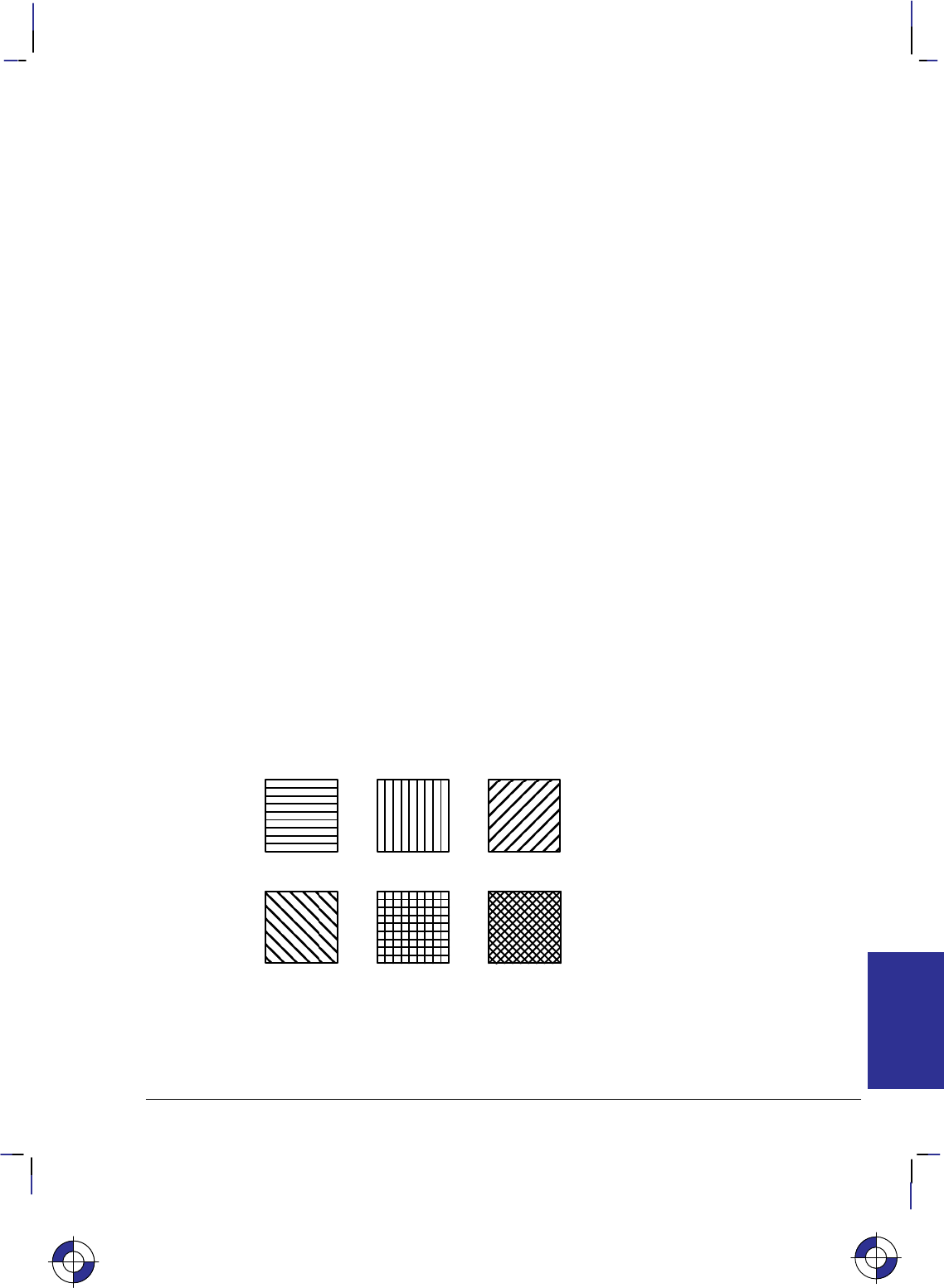
431
This is the black on page 431 (seq: 449)
Company confidential. HP-GL/2 and HP RTL Reference Guide, draft 2. Freeze Status: open
Pattern ID
*c#g|G
Purpose
This command designates a unique identification number for user-defined and HP-defined pat-
terns. See Patterns on page 361.
# Parameter
#Pattern ID. The default is 0.
Range: 0 to 32 767.
Use
This command must be sent before loading a user-defined pattern; when a new pattern is down-
loaded, any pattern that is already loaded and has the same pattern ID is deleted.
The “current pattern” is the one associated with the last specified ID when the Current Pattern
(*v#T) command was executed. If no ID existed, raster images are rendered in black or the
foreground color.
For HP-defined shading patterns, IDs 1 to 100 determine the shading (on a nonlinear mapping of
1% to 100%). For HP-defined hatched patterns, IDs 1 to 6 select the type of hatched pattern:
1Horizontal lines
2Vertical lines
3Diagonal lines (lower left to upper right)
4Diagonal lines (lower right to upper left)
5Cross-hatching with horizontal and vertical lines
6Cross-hatching with diagonal lines.
Figure 174. Shading Patterns
For raster images, an HP- or user-defined pattern is activated by specifying Pattern ID and Cur-
rent Pattern (*v#T)—see page 414.
This is the blue on page 431 (seq: 449)
REFERENCE
HP RTL

432
This is the black on page 432 (seq: 450)
Company confidential. HP-GL/2 and HP RTL Reference Guide, draft 2. Freeze Status: open
Pattern Reference Point
*p#r|R
Purpose
This command sets the “tiling” (replication) of patterns with respect to the Current Active Posi-
tion (CAP) rather than position (0,0). See Patterns on page 361.
# Parameter
#Only the value 0 is allowed.
Range: 0. The command is ignored for other values.
Use
Note: A similar, though not identical HP-GL/2 instruction is AC (Anchor Corner).
This is the blue on page 432 (seq: 450)

433
This is the black on page 433 (seq: 451)
Company confidential. HP-GL/2 and HP RTL Reference Guide, draft 2. Freeze Status: open
Pattern Transparency Mode
*v#o|O
Purpose
This command sets the pattern transparency mode. See Patterns on page 361.
# Parameter
#The following values are allowed. The default is 0.
0Transparent; the pattern’s white pixels are not applied to the destination; the destina-
tion image shows through the pattern.
1Opaque; the pattern’s white pixels are applied to the destination; the corresponding
parts of the destination image are blocked out by the pattern.
Range: 0, 1. Other values cause the command to be ignored.
Use
A value of 0 makes the pattern’s white areas transparent, allowing the corresponding parts of the
destination image to show through. With a transparency mode of 1, the white pixels in the pattern
are applied directly to the destination.
This command is ignored during raster mode.
This is the blue on page 433 (seq: 451)
REFERENCE
HP RTL

434
This is the black on page 434 (seq: 452)
Company confidential. HP-GL/2 and HP RTL Reference Guide, draft 2. Freeze Status: open
Push/Pop Palette
*p#p|P
Purpose
This command saves (pushes) or restores (pops) the palette from the palette stack.
# Parameter and Termination Character
#The following values are allowed. The default is 0.
0Pushes (saves) the palette.
1Pops (restores) the palette.
Range: 0 or 1. This command is ignored for other values. A value of 0 pushes the cur-
rent palette, which is unaffected. A value of 1 pops the most recently pushed palette,
which overwrites the current palette and becomes the new current palette. As with any
stack, the last item pushed is the first item popped.
Use
Pushing a palette saves the following parameters to allow for palette restoration:
Color definitions for each palette entry.
Pen widths (the palette is also used in HP-GL/2).
Black and white references.
Number of bits per index expected for raster transfers.
Pixel encoding mode.
Number of bits per primary expected for raster transfers.
Stack size is limited by the device’s available memory. Pushes past the stack limit or attempts to
pop an empty stack are ignored. E empties the palette stack and overwrites the current pal-
ette with the default black and white palette. Entering PJL, which causes an E, has the same
effect. The HP-GL/2 instructions IN and BP overwrite the current palette with the default HP-
GL/2 palette, but have no effect on the palette stack.
This is the blue on page 434 (seq: 452)

435
This is the black on page 435 (seq: 453)
Company confidential. HP-GL/2 and HP RTL Reference Guide, draft 2. Freeze Status: open
Raster Line Path
*b#l|L
Purpose
This command specifies the following:
The vertical direction that a Transfer Raster Data by Row/Block (*b#W) command incre-
ments the raster row within an image.
The vertical direction that the Y Offset (*b#Y) command moves the CAP.
The vertical direction in which an explicit or implicit End Raster Graphics (*rC) com-
mand moves the CAP if a Source Raster Height (*r#T) command has been specified.
The handling of line feeds in HP-GL/2 labels is not affected.
# Parameter
#The following values are allowed. The default is 0.
0Increment raster row in the +Y direction of the HP RTL coordinate system.
1Increment raster row in the –Y direction of the HP RTL coordinate system.
Range: 0, 1 (a missing value is interpreted as 0, and other values cause the command to
be ignored).
Use
This command is ignored after the Start Raster Graphics (*r#A) or Transfer Raster Data
(*b#V or *b#W) commands until the next explicit or implicit End Raster Graphics
(*rC) command. Since the raster image will “grow” in the specified direction, it is the user’s
responsibility to position the CAP to avoid unwanted overlaying of the image with vector or other
raster graphics.
This is the blue on page 435 (seq: 453)
REFERENCE
HP RTL

436
This is the black on page 436 (seq: 454)
Company confidential. HP-GL/2 and HP RTL Reference Guide, draft 2. Freeze Status: open
Render Algorithm
*t#j|J
Purpose
This command selects the algorithm to be used for rendering page marking entities on a given
page. See Halftoning on page 360.
# Parameter
#The following values are allowed. The default is 0; note that the PCL default for this
command is 3.
0Device best.
3Pattern dither (to be made obsolete; use 11 instead).
5Device best (monochrome).
7Cluster-ordered dither.
8Cluster-ordered dither (monochrome).
11 Pattern dither.
12 Pattern dither (monochrome).
13 Scatter dither.
14 Scatter dither (monochrome).
Range: 0, 3, 5, 7, 8, 11, 12, 13, 14. The command is ignored for other values of the
parameter.
Use
The device-best halftone algorithm is device-dependent.
Monochrome Rendering: A gray value is generated from the three primary colors; this value is
computed according to the NTSC standard, which for device RGB color space is
Gray = 0.3 Red + 0.59 Green + 0.11 Blue.
Cluster-Ordered Dither: A pixel is intensified at a point (x,y) depending on the desired intensity,
I(x,y), and on an n-by-n dither matrix, D, where
i = x modulo n
j = y modulo n.
For RGB color spaces, if I(x,y) < D(i,j), the point corresponding to (x,y) is intensified; otherwise
it is not. The intensity of each primary color is determined according to this scheme. The rela-
tionship between I and D depends on the specified color space.
This is the blue on page 436 (seq: 454)

437
This is the black on page 437 (seq: 455)
Company confidential. HP-GL/2 and HP RTL Reference Guide, draft 2. Freeze Status: open
Reset
E
Purpose
This command causes the following actions:
Prints any partial pages of data which may have been received. Reset does not cause a page
eject if the page does not contain an image (raster graphics or HP-GL/2 graphics).
Executes the HP-GL/2 instructions BP (Begin Plot) and IN (Initialize).
Resets all programmable features to their default values. Programmable features whose de-
faults can be set from the front panel are set to those defaults. Values reset are:
Graphics resolution
Compression method
Seed row
Source width to logical page width
Bits per index
Pixel encoding mode
Number of bits of red, green, and blue
Scaling off
Render algorithm to device-best
Foreground color
Logical operation
Source and pattern transparency to transparent
Current pattern to solid
Pattern reference point to (0,0)
Palette HP RTL black-and-white.
Returns and fixes the HP RTL CAP to (0,0).
Deletes temporary patterns.
Returns the device to HP RTL parsing mode.
Implicitly ends raster mode, if necessary.
This is the blue on page 437 (seq: 455)
REFERENCE
HP RTL

438
This is the black on page 438 (seq: 456)
Company confidential. HP-GL/2 and HP RTL Reference Guide, draft 2. Freeze Status: open
# Parameter and Termination Character
There is no value parameter.
This command cannot be combined with others that follow. The uppercase “E” terminator must
be used with this command.
Use
The uppercase “E” terminator must be used with this command. There is no value parameter.
Both the HP-GL/2 and HP RTL contexts recognize the Reset command.
After the Reset command, the device remains online, no subsequent data is lost, and there is no
effect on I/O or host-to-peripheral communication.
E is a valid HP-GL/2 terminator, and incorporates all the functionality of the BP (Begin Plot)
and IN (Initialize) instructions, as well as defaulting the HP RTL and HP-GL/2 palettes.
Within an HP-GL/2 label, when transparent data mode is on (“TD1;”), E is interpreted as data
and does not reset the device. When “TD0;” is in effect, the command causes a reset.
When the device is expecting HP RTL data, E is interpreted as data and does not reset the
device. The device expects HP RTL data following the HP RTL commands Configure Image
Data (*v#W), Transfer Raster Data by Plane (*b#V), and Transfer Raster Data by Row/
Block (*b#W). The length of the data the device expects varies and is specified in each
command.
This is the blue on page 438 (seq: 456)

439
This is the black on page 439 (seq: 457)
Company confidential. HP-GL/2 and HP RTL Reference Guide, draft 2. Freeze Status: open
Set Blue Parameter
*v#c|C
Purpose
This command specifies the blue component of any new color entry of the color palette.
# Parameter
#Blue parameter. The default is 0.
Range: Black reference to white reference for blue (as defined in the Configure Image
Data command, *v#W). Out-of-range values are clamped. (The absolute limits are
–32 768 to 32 767.)
Use
The parameter is applied and then initialized to 0 after each Assign Color Index command
(*v#I).
This is the blue on page 439 (seq: 457)
REFERENCE
HP RTL

440
This is the black on page 440 (seq: 458)
Company confidential. HP-GL/2 and HP RTL Reference Guide, draft 2. Freeze Status: open
Set Graphics Resolution
*t#r|R
Purpose
This command defines the resolution at which graphics data is to be plotted or printed.
# Parameter
#Resolution in dots per inch (dpi). The default resolution is device-dependent.
Range: 0 through 32 767 (out-of-range values are clamped). The 0 through 32 767
range represents HP RTL limits; device limits may be more restrictive. The actual phys-
ical (or native) resolution is device-dependent. Support of continuous or incremental
resolution is device-dependent.
Use
If the requested resolution is not supported, the resolution value is mapped to the next higher sup-
ported resolution to ensure that the picture is printed without data loss. For example, if a device
supports both 180 dpi and 90 dpi and the requested resolution is greater than 90 dpi, 180 dpi is
selected; otherwise 90 dpi is selected. If the resolution value is greater than the maximum for the
device, that maximum is used.
The graphics resolution is ignored in raster scaling mode. The supplied source and destination
widths and heights are used instead; see page 347.
This command is ignored during raster mode.
On devices that support several native resolutions, the image is first scaled up or down to the na-
tive resolution selected by the @PJL SET RESOLUTION command. Selecting a low native
resolution uses less memory but has more granularity; it is more appropriate for draft quality. A
high native resolution uses more memory but has better quality. For example, if the resolution is
set to 300 dpi through PJL and the Set Graphics Resolution command specifies a larger value
(such as 600), the image is scaled down to 300 dpi, with loss of detail. If the device’s machine
resolution is 600 dpi, pixels are then replicated.
See also Controlling Image Resolution on page 344.
This is the blue on page 440 (seq: 458)

441
This is the black on page 441 (seq: 459)
Company confidential. HP-GL/2 and HP RTL Reference Guide, draft 2. Freeze Status: open
Set Green Parameter
*v#b|B
Purpose
This command specifies the green component of any new color entry of the color palette.
# Parameter
#Green parameter. The default is 0.
Range: Black reference to white reference for green (as defined in the Configure Image
Data command, *v#W). Out-of-range values are clamped. (The absolute limits are
–32 768 to 32 767.)
Use
The parameter is applied and then initialized to 0 after each Assign Color Index command
(*v#I).
This is the blue on page 441 (seq: 459)
REFERENCE
HP RTL

442
This is the black on page 442 (seq: 460)
Company confidential. HP-GL/2 and HP RTL Reference Guide, draft 2. Freeze Status: open
Set Red Parameter
*v#a|A
Purpose
This command specifies the red component of any new color entry of the color palette.
# Parameter
#Red parameter. The default is 0.
Range: Black reference to white reference for red (as defined in the Configure Image
Data command, *v#W). Out-of-range values are clamped. (The absolute limits are
–32 768 to 32 767.)
Use
The parameter is applied and then initialized to 0 after each Assign Color Index command
(*v#I).
This is the blue on page 442 (seq: 460)

443
This is the black on page 443 (seq: 461)
Company confidential. HP-GL/2 and HP RTL Reference Guide, draft 2. Freeze Status: open
Simple Color
*r#u|U
Purpose
This command creates a fixed-size palette whose color specification cannot be modified. The
pixel encoding mode is always indexed planar.
# Parameter and Termination Character
#The following values are allowed. The default is to use the current palette, which may
be the HP-GL/2 palette.
–4 Four planes, device black/cyan/magenta/yellow (KCMY) palette.
–3 Three planes, device cyan/magenta/yellow (CMY) palette.
1One plane, black.
3Three planes, device red/green/blue (RGB) palette.
Range: –4, –3, 1, 3.
Use
This command creates a new palette and overwrites the current palette. HP RTL commands and
HP-GL/2 instructions that modify the palette (NP, PC, *v#A, *v#B, *v#C, and
*v#I) are ignored. When a Simple Color palette is popped from the stack (using *p#P), it
cannot be modified; pixel encoding then reverts to indexed planar.
RGB, CMY, or KCMY raster data must be sent by plane (using *b#V) as well as by row
(with *b#W). The last plane in each row is sent using the *b#W command; all other
planes are sent using the *b#V command.
When KCMY mode is selected:
–HP RTL devices lock out the Color Model and HP-GL/2 objects, so KCMY raster objects
cannot be mixed with any other object on the same page.
–Raster scaling is also ignored in this mode.
–Gray-scaling in KCMY mode is rendered as black and white, but the gray-scale algorithm is
device-dependent.
–Transparencies and logical operations are not supported.
When CMY mode is selected using the Simple Color command, it is device-dependent whether
you can use scaling.
Planes must be sent in order; for example, for CMY, cyan, magenta, yellow.
The Simple Color palettes are listed on the next page.
This is the blue on page 443 (seq: 461)
REFERENCE
HP RTL

444
This is the black on page 444 (seq: 462)
Company confidential. HP-GL/2 and HP RTL Reference Guide, draft 2. Freeze Status: open
4-plane KCMY (value = –4)
Index Black Color
pen pen(s)
0 White White
1 Black White
2 White Cyan
3 Black Cyan
4 White Magenta
5 Black Magenta
6 White Blue
7 Black Blue
8 White Yellow
9 Black Yellow
10 White Green
11 Black Green
12 White Red
13 Black Red
14 White Black
15 Black Black
3-plane CMY (value = –3)
Index Color
0 White
1 Cyan
2 Magenta
3 Blue
4 Yellow
5 Green
6 Red
7 Black
Single-plane K (value = 1)
Index Color
0 White
1 Black
3-plane RGB (value = 3)
Index Color
0 Black
1 Red
2 Green
3 Yellow
4 Blue
5 Magenta
6 Cyan
7 White
This is the blue on page 444 (seq: 462)

445
This is the black on page 445 (seq: 463)
Company confidential. HP-GL/2 and HP RTL Reference Guide, draft 2. Freeze Status: open
Source Raster Height
*r#t|T
Purpose
This command specifies the height in pixel rows of the source raster image denoted by subse-
quent Start Raster Graphics (*r#A) commands. Height is perpendicular to the pixel rows and
is measured in the direction specified by the Raster Line Path command (*r#L).
# Parameter
#Height in pixel rows. There is no default.
Range: 0 through 65 535 (out-of-range values are clamped). A missing parameter is
interpreted as 0.
Note: The 65 535 limit is the HP RTL limit. Actual limits are device-dependent. Values exceed-
ing the device limits are clamped.
Use
The Source Raster Width (*r#S) and Source Raster Height commands must precede a Start
Raster Graphics (*r#A) command where scale mode is set to “on” (parameter value 2 or 3).
Without the Source Raster Width and Source Raster Height commands, raster graphics will begin
with the scale mode off, that is, as if a parameter value of 0 or 1 were sent.
A Reset command causes an explicitly set source raster height to become undefined.
Plane or row data that is not specified for the full source raster height is filled out with zeros.
Zero-filled data is printed in the color specified for index 0 in the palette.
When a Transfer Raster Data (*b#V or *b#W) command is received that causes any pixel
row to extend beyond the row boundary set by the Source Raster Height command, the row out-
side the boundary is clipped. This includes the case where the CAP is moved beyond the height
boundary or above the starting position with a Y Offset (*b#Y) command and the printing of
raster data is attempted.
If the user has specified a source raster height of 0 and a Start Raster Graphics (or Transfer Raster
Data) command is received, then the entire raster graphic is clipped.
If the user has not set the source raster height, then raster height is not used; that is, there is no
default value.
Upon receiving an explicit or implicit End Raster Graphics command, the CAP is set to the left
graphics margin of the next pixel row after the raster height boundary. The location of the “next”
pixel row depends on the direction specified by the Raster Line Path command.
See also Setting the Width and Height in HP RTL on page 342.
This is the blue on page 445 (seq: 463)
REFERENCE
HP RTL

446
This is the black on page 446 (seq: 464)
Company confidential. HP-GL/2 and HP RTL Reference Guide, draft 2. Freeze Status: open
Source Raster Width
*r#s|S
Purpose
This command specifies the width in pixels of the source raster image denoted by subsequent
Start Raster Graphics (*r#A) commands. Width is in the direction of (parallel to) the raster
rows.
# Parameter
#Width in pixels. The default is the logical page width for unscaled graphics (from the
left graphics margin), undefined for scaled graphics.
Range: 0 through 65 535 (out-of-range values are clamped). A missing parameter is
assumed to be 0.
Note: The 65 535 limit is the HP RTL limit. Actual limits are device-dependent. Values exceed-
ing the device limits are clamped.
Use
The Source Raster Width and Source Raster Height (*r#T) commands must precede a Start
Raster Graphics (*r#A) command where scale mode is set to “on” (parameter value 2 or 3).
Without the Source Raster Width and Source Raster Height commands, raster graphics will begin
with the scale mode off, that is, as if a parameter value of 0 or 1 were sent.
The default source raster width is also affected by changes in the left graphics margin; that is, if a
Start Raster Graphics command is sent with a parameter value of 1 or 3 (which sets the left
graphics margin to the CAP), the default source raster width is interpreted as extending from the
left graphics margin to the right edge of the logical page. This “tracking” behavior terminates
when the source raster width is set explicitly, and resumes after a Reset (E) command.
Plane or row data that is not specified for the full source raster width is filled out with zeros; data
exceeding the source raster width is clipped. (Zero-filled data is printed in the color specified for
index 0 in the palette.)
If the user specified a source raster width of 0 and a Start Raster Graphics (or Transfer Raster
Data) command is received, the entire raster graphic is clipped.
This command is ignored during raster mode.
See also Setting the Width and Height in HP RTL on page 342.
This is the blue on page 446 (seq: 464)

447
This is the black on page 447 (seq: 465)
Company confidential. HP-GL/2 and HP RTL Reference Guide, draft 2. Freeze Status: open
Source Transparency Mode
*v#n|N
Purpose
This command sets the source image’s transparency mode to transparent or opaque.
# Parameter
#The following values are allowed. The default is 0.
0Transparent; the source’s white pixels are not applied to the destination; the destina-
tion image shows through the source.
1Opaque; the source’s white pixels are applied to the destination; the corresponding
parts of the destination image are blocked out by the source.
Range: 0, 1. Other values cause the command to be ignored.
Use
A value of 0 makes the source’s white areas transparent, allowing the corresponding parts of the
destination image to show through. With a transparency mode of 1, the white pixels in the source
are applied directly to the destination.
This command is ignored during raster mode.
Note: Some devices do not support this command; consider using the HP-GL/2 TR (Transpar-
ency Mode) instruction instead.
This is the blue on page 447 (seq: 465)
REFERENCE
HP RTL

448
This is the black on page 448 (seq: 466)
Company confidential. HP-GL/2 and HP RTL Reference Guide, draft 2. Freeze Status: open
Start Raster Graphics
*r#a|A
Purpose
This command places the device in raster mode with scale mode on or off, fixes the starting posi-
tion of the graphics image, and sets the left graphics margin.
# Parameter
#The following values are allowed. The default value is 0.
0Start raster graphics at logical page left bound.
1Start raster graphics at the current active position (CAP).
2Turn on scale mode and start graphics at logical page left boundary.
3Turn on scale mode and start graphics at the CAP.
Range: 0 through 3 (out-of-range values default to 0).
Use
Both Source Raster Width (*r#S) and the Source Raster Height (*r#T) must be specified
before starting raster graphics in scale mode. If neither is specified, or if only one is specified, a
Start Raster Graphics command with a parameter value of 2 or 3 will function as if the parameter
value were 0 or 1, respectively; that is, raster graphics will start with scale mode off.
A value of 0 or 2 starts the image at the current vertical position on the left boundary of the log-
ical page; that is, the left graphics margin is set to 0. A value of 1 or 3 starts the image at the
current position; that is, the left graphics margin is set to the current horizontal position.
For a Raster Line Path (*b#L) of 0 (the default), the starting corner becomes the upper left
corner of the image. For a Raster Line Path of 1, the starting corner becomes the lower left cor-
ner of the picture.
Values of 2 or 3 turn scale mode on. Scaled images are rendered in the specified size independent
of device resolution.
On devices that support several native resolutions, the image is first scaled up or down to the na-
tive resolution selected by the @PJL SET RESOLUTION command. Selecting a low native
resolution uses less memory but has more granularity; it is more appropriate for draft quality. A
high native resolution uses more memory but has better quality.
Note: When you scale an image down, loss of detail always results. The algorithm used for scal-
ing down is device-dependent
See also Implicit Start Raster Graphics on page 376.
This is the blue on page 448 (seq: 466)

449
This is the black on page 449 (seq: 467)
Company confidential. HP-GL/2 and HP RTL Reference Guide, draft 2. Freeze Status: open
Transfer Raster Data by Plane
*b#V[data]
Purpose
This command transfers the number of bytes specified in the value field to the device, but does
not move the CAP to the next raster row. The plane pointer is incremented, but not the row point-
er.
# Parameter and Termination Character
#Number of bytes in the data field. If data is compressed, this refers to the length of the
compressed data. There is no default.
Range: 0 through 32 767. Out-of-range values are clamped.
If the number of bytes specified in the value field (#) is greater than 32 767, the first 32 767 bytes
following the command are interpreted as data, and byte 32 768 is interpreted as the beginning of
the next HP RTL command.
This command cannot be combined with others that follow. The uppercase “V” terminator must
be used with this command.
Use
Use this command to send each plane except the last in a multi-plane raster row. It is not used for
single-plane rows, or for the last plane in a multi-plane row, since row position is not affected by
this command. To transfer raster data and increment the row pointer, the Transfer Raster Data by
Row/Block (*b#W) command must be sent. The least significant planes are sent first (see
Multi-Plane Data on page 358).
The number of data bytes is independent of source raster width and can vary from plane to plane.
If the image width can accommodate more data than is sent, the undefined data is assumed to be
all zeros. For information on how to use this feature, see Setting the Width and Height in HP RTL
on page 342.
Empty planes can be sent using Transfer Raster Data by Plane with a value of 0 (*b0V).
A row can be ended “early” with a Transfer Raster Data by Row/Block with a value of 0
(*b0W). Absent data is assumed to be zeros: in row-by-row raster mode, when the com-
bined planes yield an index of 0, those pixels are rendered with whatever color has been assigned
to index number 0 in the color palette. (This command is not used in plane-by-plane raster
mode.) This can be used as a method of data compression.
Extra planes are ignored. For example, if three planes have been assigned to each row with the
Set Number of Bits per Index byte of the Configure Image Data (*v#W) command, but four
planes are sent for a given row, the fourth plane is ignored. If a Transfer Raster Data by Row/
Block command is used for one of the extra color planes, the data is ignored, but the row is
incremented and subsequent planes are again interpreted as valid data (for the next row).
The data in the data field is interpreted according to the current compression method. This com-
mand is used only for row-based compression methods. The Transfer Raster Data by Plane
This is the blue on page 449 (seq: 467)
REFERENCE
HP RTL

450
This is the black on page 450 (seq: 468)
Company confidential. HP-GL/2 and HP RTL Reference Guide, draft 2. Freeze Status: open
command and its associated data are parsed and ignored if sent when a block-based compression
method is in effect. See the Compression Method (*b#M) command for a listing of row-
based and block-based compression methods.
This command is only allowed in row-by-row raster mode. (Plane-by-plane raster mode requires
only one plane of data at a time, so this command is not needed.) If this command is received
when the device is in plane-by-plane raster mode, the command and its associated data are parsed
and ignored.
Note: When an explicit or implicit End Raster Graphics (*rC) command is received before
the row is completed with a Transfer Data by Row/Block command, it is device-dependent
whether or not the incomplete row is rendered. See the note under the End Raster Graphics
command.
Note: If a block of data is transferred using a block-based compression mode before the previous
row is completely defined, the plane pointer is set to the first plane of the next row at the begin-
ning of the block transfer. As with End Raster Graphics, it is device-dependent whether or not
the incomplete row is rendered.
This is the blue on page 450 (seq: 468)

451
This is the black on page 451 (seq: 469)
Company confidential. HP-GL/2 and HP RTL Reference Guide, draft 2. Freeze Status: open
Transfer Raster Data by Row/Block
*b#W[data]
Purpose
This command transfers the number of bytes specified in the value field to the device in a
row-by-row or block format depending on the current compression method (*b#M).
# Parameter and Termination Character
#Number of bytes in the data field. If data is compressed, this refers to the length of the
compressed data. There is no default.
Range: 0 through 2 147 483 647 (231 – 1) (out-of-range values are clamped).
This command cannot be combined with others that follow. The uppercase “W” terminator must
be used with this command.
Use
For row-based formats, this command is used for single-plane rows (including those sent in
plane-by-plane mode) or for the last plane in a multi-plane row. After execution, the row pointer
is incremented, the plane pointer in a multi-plane row is reset to 1, and the CAP is set to the left
graphics margin at the start of the next row.
For block-based formats, this command is used for block transfer of single- or multi-plane rows
with implied or explicit row and plane divisions. Row and plane divisions depend on the number
of planes and the current compression method. At the end of the block transfer, the row pointer is
incremented, the plane pointer is set to the first plane of the next row, and the CAP is set to the
left graphics margin.
Empty or incomplete rows may be sent. See Transfer Raster Data by Plane (*b#V).
This is the blue on page 451 (seq: 469)
REFERENCE
HP RTL

452
This is the black on page 452 (seq: 470)
Company confidential. HP-GL/2 and HP RTL Reference Guide, draft 2. Freeze Status: open
Universal Exit Language/Start of PJL
%–12345X
Purpose
This command causes the current context processor to shut down in an orderly fashion and exit
into the Printer Job Language (PJL). See page 394 for more information about PJL.
# Parameter and Termination Character
#–12345 Exit the current language context and start PJL.
Range: –12345. Only the exact nine-character sequence (%–12345X) is guaran-
teed to cause exit from the current language context. Note that the value (–12345) is a
string of characters and not an integer value.
This command cannot be combined with others that follow. The uppercase “X” terminator must
be used with this command.
Use
This command performs the following actions:
Performs all the actions associated with the Reset command (E).
Turns control over to PJL.
The command is always recognized in both the HP-GL/2 and HP RTL contexts, except in the fol-
lowing cases:
In the HP-GL/2 context, within an HP-GL/2 label, when transparent data mode is on
(“TD1”).
In the HP RTL context, when in an HP RTL binary data transfer.
Note: Devices that support only HP-GL/2 and HP RTL may ignore this command. On devices
that support additional language contexts, the command may or may not be recognized in those
contexts.
This is the blue on page 452 (seq: 470)

453
This is the black on page 453 (seq: 471)
Company confidential. HP-GL/2 and HP RTL Reference Guide, draft 2. Freeze Status: open
Y Offset
*b#y|Y
Purpose
This command moves the CAP vertically the number of pixel rows specified in the value field.
# Parameter
#Number of pixel rows of vertical movement. There is no default.
Range: –32 767 through 32 767 (out-of-range values are clamped; a missing value is
interpreted as 0).
Use
Use a plus sign (+) before the value, or an unsigned value, to move the CAP in the direction spe-
cified by the Raster Line Path (*b#L) command. Use a minus sign (–) before the value to
move the CAP in the direction opposite to the raster line path. The CAP is allowed to move out-
side the logical page. Unlike the Move CAP commands (*p#X, *p#Y, and &a#H),
there is no absolute move possible with this command.
This command is to be made obsolete outside of raster mode.
When Y Offset is used in raster mode, skipped rows are zero-filled up to the offset requested, or
the current source raster height, whichever comes first. If a negative Y Offset value places the
CAP above the position at which raster graphics was started (or below in the case of Raster Line
Path = 1), no zero-filling is done for rows that lie outside the raster area.
The physical distance that this command moves the CAP varies according to the current resolu-
tion.
Executing this command causes the seed row to be zeroed, even if the command has a 0 or miss-
ing parameter value (#).
This command is ignored during raster scaling mode. Use the Move CAP Vertical (*p#Y)
command instead.
Note: When this command is received before a row is completed, it is device-dependent whether
or not the incomplete row is rendered. If it is rendered, the incomplete row is zero filled, the row
pointer is incremented, and the plane pointer is reset to 1. If it is not rendered, the row pointer is
not incremented as a result of the incomplete row.
This is the blue on page 453 (seq: 471)
REFERENCE
HP RTL

454
This is the black on page 454 (seq: 472)
Company confidential. HP-GL/2 and HP RTL Reference Guide, draft 2. Freeze Status: open

455
This is the black on page 455 (seq: 473)
Company confidential. HP-GL/2 and HP RTL Reference Guide, draft 2. Freeze Status: open
Chapter 15: Summary of HP RTL
Device-Dependencies
The following table lists the HP RTL characteristics that can vary among devices.
Dependency Description
Resolution, Rendering, and Scaling
Size and spacing of dots See Raster Graphics on page 344.
Native device resolution The actual number of dots per inch (dpi) a device can plot.
“Native” resolutions are usually a multiple of physical device
resolution. Native resolutions can be set by the @PJL SET
RESOLUTION command. See Controlling Image Resolution
on page 344, the Set Graphics Resolution (*t#R) command
on page 440, the Move CAP (*p#X and *p#Y) com-
mands on pages 426 and 427, and Printer Job Language (PJL)
on page 394.
Resolution type Options are continuous or incremental resolution. Only devices
that support continuous resolution can accurately plot a specific
resolution. See Continuous and Incremental Resolution on page
345 and the Set Graphics Resolution (*t#R) command on
page 440.
Resolution Range and
Default Allowable range and default for the Set Graphics Resolution
(*t#R) command. The resolution setting is independent of
the physical device resolution. Images are scaled to the re-
quested resolution. If explicit scaling is requested in the Start
Raster Graphics (*r#A) command, the resolution setting is
ignored. See Controlling Image Resolution on page 344, Draft
and Final Resolution on page 345, and the Set Graphics Resolu-
tion command on page 440.
Scaled-Down Rendering When scaling an image down, loss of detail always results. The
algorithm used for scaling down is device-dependent. See Con-
trolling Image Resolution on page 344 and Scaling Raster
Images on page 345.
This is the blue on page 455 (seq: 473)
DEVICES
HP RTL

456
This is the black on page 456 (seq: 474)
Company confidential. HP-GL/2 and HP RTL Reference Guide, draft 2. Freeze Status: open
Dependency Description
Resolution, Rendering, and Scaling (continued)
Source Raster Height
(*r#T) and Source
Raster Width (*r#S)
Ranges
These ranges are determined by a device’s physical limits. See
Setting the Width and Height in RTL on page 342, and the com-
mand descriptions on pages 446 and 445.
Plot Management
Large Plots What happens if a plot is too large to fit into the memory of the
device is device-dependent. See When Overflow Occurs on
page 377.
Negative Motion
Command Implementation Some devices cannot simultaneously receive and plot raster
images. On these devices, the Negative Motion (&a#N)
command has no effect. When the command promises no nega-
tive motion and the image nonetheless contains negative mo-
tion, the effect is device-dependent. See Negative Motion on
page 349 and the description of the Negative Motion command
on page 428.
Color Palette Management
Color Support Options are full color, grayscale monochrome (color maps to
gray), and two-tone monochrome (no color support). Two-tone
monochrome devices may not support certain HP RTL com-
mands. See Primary Colors on page 354, Specifying Colors on
page 353. The actual color printed is also device-dependent.
Maximum Palette Size The larger the palette, the more colors can be explicitly defined.
Palette size is set using the Number of Bits per Index byte of the
Configure Image Data (*v#W) command. The maximum
value corresponds to the number of data planes the device sup-
ports. See Defining the RTL Palette on page 356 and the Con-
figure Image Data command on page 409.
Number of Bits per
Primary This byte of the Configure Image Data (*v#W) command
determines the ranges for defining custom palette colors. See
page 409.
Palette Transferability Some devices allow you to transfer the color palette between
RTL and HP-GL/2. See Defining the RTL Palette on page 356,
Transferring Pen Position and Palettes on page 393, and the
descriptions of the Enter HP-GL/2 Mode (%#B) command
on page 420 and the Enter RTL Mode (%#A) command on
page 422.

457
This is the black on page 457 (seq: 475)
Company confidential. HP-GL/2 and HP RTL Reference Guide, draft 2. Freeze Status: open
Dependency Description
Color Palette Management (continued)
Pixel Encoding Mode Some devices support a special pixel encoding mode called pla-
ne-by-plane raster. Pixel encoding mode is set in the Configure
Image Data (*v#W) command. Future devices may support
other pixel encoding modes. See the description of the Confi-
gure Image Data command on page 409. Merging vector and
raster data is also device-dependent; see page 394.
Non-primary Colors Some devices plot non-primary colors using a dithering tech-
nique. See Defining the RTL Palette on page 356, Halftoning
on page 360, and the interaction with patterns in the description
of the Download Pattern (*c#W) command on page 417.
Miscellaneous Dependencies
Rendering of Incomplete
Rows When the CAP is moved with a Y Offset (*b#Y) command,
or when raster graphics mode ends, some devices plot rows that
are incomplete; other devices discard data received so far for
that row. See the descriptions of the Y Offset command on page
453, the End Raster Graphics (*rC) command on page 419,
the Transfer Raster Data by Plane (*b#V) command on page
449, and the Transfer Raster Data by Row/Block (*b#W)
command on page 451.
Language Contexts The language context at power-on is device-dependent.
Some devices require the Enter RTL Mode (%#A)
command to be issued in the HP-GL/2 context. See Changing
Language Contexts and Modes on page 393.
Some devices support language contexts other than HP-GL/2
and HP RTL using the Universal Exit Language / Start of PJL
(%–12345X) command. This command may or may not be
recognized from within the additional contexts. See Changing
Language Contexts and Modes on page 393, Printer Job Lan-
guage (PJL) on page 394,and the command description on page
452.
Control Panel Settings from the control (front) panel of the device may affect
plots. See Interactions with Physical Device Settings on page
391.
This is the blue on page 457 (seq: 475)
DEVICES
HP RTL

458
This is the black on page 458 (seq: 476)
Company confidential. HP-GL/2 and HP RTL Reference Guide, draft 2. Freeze Status: open

459
This is the black on page 459 (seq: 477)
Company confidential. HP-GL/2 and HP RTL Reference Guide, draft 2. Freeze Status: open
PART 4: Appendixes
This Part contains the following sections:
"6.2, & 53,5&11.2, &2,8&,*
"6.2, > #.7- 53,5&11.2, &2,8&,*6
;&140* &2,8&,*
;&140* 53,5&11.2, &2,8&,*
"6.2, ! :.7- 53,5&11.2, &2,8&,*6
3140*7* 5&4-.(6 53,5&1
2.7.&0.=&7.32 &2) !*51.2&7.32?5.27*5 *6*7
7&57.2, & 53,5&1
!-* 3)< 3+ & 53,5&1
:.7(-.2, 3)*6
2).2, & 53,5&1
"6.2, > 26758(7.326 &2) ! 311&2)6
) 26758(7.326 &2) 311&2)6
31'.2*) 311&2)6
87487 26758(7.326
&/.2, ++.(.*27 "6* 3+ $385 <67*1
*77.2, 73 23: >
*5+351&2(*
367 31487*5 *6385(*6
*135< .=*
32+.,85* 1&,* &7& 311&2)
311&2)6
5.27 &7&
5.27 9*5582
&,* 537*(7.32
248787487
&,* &<387 &2) 36.7.32.2,
&,* 5.*27&7.32 &2) .=*
5*& 3+ 7-* 87487
%*53 .00.2,
39.2, 7-* 855*27 (7.9* 36.7.32
This is the blue on page 459 (seq: 477)

460
This is the black on page 460 (seq: 478)
Company confidential. HP-GL/2 and HP RTL Reference Guide, draft 2. Freeze Status: open
,!+,%)# */, .
-.!, ,+$%-
. *(+,!--%*)
!) %)# -.!, .
!,#! !.*, ) -.!, .
'%)# -.!, (#!-
,)-+,!)0
-%)# *'*,
+!,.%*)
*'*, '!..! +!,.%*)-
-!, +!,.%*)-
,*/'!-$**.%)#
% !#"
% # #"
%) 0(*' !.
%) *). +%)#
%) %.$
%) !%#$.
%) *-./,!
%) .,*&! !%#$.
%) 0+!"!
""!& !" !$#"
%

461
This is the black on page 461 (seq: 479)
Company confidential. HP-GL/2 and HP RTL Reference Guide, draft 2. Freeze Status: open
Appendix A: Writing Efficient
Programs–Some Tips
Before you can write graphics programs for your plotter or printer, you must be familiar with
your computer and a programming language the computer understands. You can use any com-
puter system and programming language that outputs ASCII literal strings and uses input and
output statements to transfer information to and from a peripheral device. This book assumes
that you already have experience in the programming language you select.
This appendix discusses the following fundamental programming concepts:
Using a programming language.
How to structure a complete graphics program.
Using HP-GL/2 instructions and HP RTL commands.
Making efficient use of your system.
Page layout and positioning.
Preparing your data.
Using color.
User operations.
If you are an inexperienced HP-GL/2 or HP RTL programmer, use the following guidelines to
ensure success:
Know your equipment; this includes the computer and the device. Know how to write,
edit, save, and run a program. Determine how your computer sends (outputs) information
to and reads (inputs) information from peripheral devices.
Know your programming language. Get a good programming manual for the language you
are using, that is specific to your computer system. Always use the syntax your language
requires. Common mistakes are substituting the letter O for the number zero, or a lower-
case letter L for the number one. Also, substituting a semicolon for a comma or omitting a
quotation mark can make the difference between failure and success.
Enter HP-GL/2 instructions as they appear in the text. You may omit spaces and, for most
instructions, the terminating semicolon.
Enter HP RTL commands exactly as they appear in the text. Normally every letter, sym-
bol, and number is significant. In some cases extra spaces have been inserted in the
examples to improve their clarity; these can safely be omitted from your programs. In all
cases, the “#” character in the command definition must be replaced by a numeric value as
defined for the command.
This is the blue on page 461 (seq: 479)
TIPS
PROGRAMMING

462
This is the black on page 462 (seq: 480)
Company confidential. HP-GL/2 and HP RTL Reference Guide, draft 2. Freeze Status: open
Using a Programming Language
How you send an instruction or command to your device depends on the programming lan-
guage you are using. Some languages include some graphics statements, but these are
primarily for the computer’s monitor. Some common languages used for printing and plotting
are BASIC, FORTRAN, Pascal, and C.
BASIC (Beginner’s All-purpose Symbolic Instruction Code) is one of the most common lan-
guages used for printing and plotting. It uses statements resembling English to perform
many complex operations. Note that any graphics statements included in your version of
BASIC are probably designed for your computer monitor, not your printer or plotter.
FORTRAN (FORmula TRANslator) is a problem-oriented language. Programmers can think
in terms of the problem and write programs as algebraic expressions and arithmetic state-
ments.
Pascal is a block-structured language requiring structured programming, but still allowing
many operator and control statements.
Cis a general-purpose programming language at a fairly low level, with economy of expres-
sion and modern control flow and data structures as its primary attributes.
Follow these steps to send an instruction in your language:
1. Use whatever opening statements are required to define the computer’s output port and
establish the device as the recipient of an output string. These are called configuration
statements and usually must be the first statements in your program.
2. Send the string to the device using an output statement.
Note: Before sending any instructions or commands to your device, you must be certain that
your computer and device are communicating properly. Refer to your peripheral’s documenta-
tion for interconnection instructions.
Using HP-GL/2 With Programming Languages
The HP-GL/2 examples included in this book are given in a “generic” format (they show the
instructions required to perform a specific function but do not use a specific programming lan-
guage). In most cases, the instructions are accompanied by a brief description of the instruction
being used.
To see how HP-GL/2 instructions are used in BASIC and the C programming language, see the
following examples.
This is the blue on page 462 (seq: 480)This is the blue on page 462 (seq: 480)
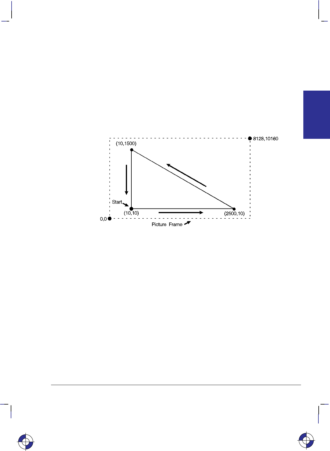
463
This is the black on page 463 (seq: 481)
Company confidential. HP-GL/2 and HP RTL Reference Guide, draft 2. Freeze Status: open
Example: BASIC Language
This example uses the BASIC language to print three lines forming a simple triangle (shown in
Figure 175); note that “CHR$(27)” is the escape character, denoted in this book by the symbol
.
10 LPRINT CHR$(27);“E”; :REM Reset the device
20 LPRINT CHR$(27);“%0B”; :REM Enter HP-GL/2 Mode
30 LPRINT “IN”; :REM Initialize HP-GL/2 Mode
40 LPRINT “SP1PA10,10”; :REM Select Pen and move to (10,10)
50 LPRINT “PD2500,10,10,1500,10,10;”; :REM Pen down and draw the triangle
60 LPRINT CHR$(27);“%0A”; :REM Enter PCL or HP RTL Mode
70 LPRINT CHR$(27);“E”; :REM Reset to end job/eject page
Figure 175. Using a Programming Language (BASIC or C) to Draw a Triangle
Example: C Programming Language
This example uses the C programming language to print the same three lines shown in Figure
175; “\033” is the octal character for ASCII code point 27, the escape character, denoted in this
book by the symbol .
#include <stdio.h>
main()
{
FILE *prn;
prn = fopen(“PRN”,“wb”); /* Open the device */
fprintf(prn,“\033E”); /* E to reset device */
fprintf(prn,“\033%0B”); /* Enter HP-GL/2 */
fprintf(prn,“IN”); /* Initialize HP-GL/2 Mode */
fprintf(prn,“SP1PA10,10”); /* Select pen 1 and move to (10,10) */
fprintf(prn,“PD2500,10,10,1500,10,10;”); /* Pen down and draw the triangle */
fprintf(prn,“\033%0A”); /* Enter PCL/HP RTL at previous CAP */
fprintf(prn,“\033E”); /* Reset to end job/eject page */
}
This is the blue on page 463 (seq: 481)
TIPS
PROGRAMMING

464
This is the black on page 464 (seq: 482)
Company confidential. HP-GL/2 and HP RTL Reference Guide, draft 2. Freeze Status: open
Using HP RTL with Programming Languages
Most of the HP RTL examples in this book show simply the strings of characters that have to be
sent to the device to achieve a particular result. In each case you will need to place these
strings in suitable output statements of the programming language you are using. All HP RTL
commands start with the ASCII escape character, decimal 27. If you are programming in
BASIC, this will normally be encoded as CHR$(27). Thus to send a sequence of commands
represented in this book as:
*v1N
&a1N
you might code this in BASIC as
PRINT #1, CHR$(27)+”*v1N”
PRINT #1, CHR$(27)+”&a1N”
A Complete Graphics Program
Initialization and Termination—Device Reset
Hewlett-Packard strongly recommends the use of both the E command and the
%–12345X command (Universal Exit Language/Start of PJL—also referred to as the
“UEL Command”) at the beginning and end of each job. (The order of these commands is crit-
ical; refer to the following example.) This allows the next job to start with the default settings
as a known base. Starting with the default environment at the beginning of each print job elim-
inates the need to set every feature each time a job is run.
%–12345X UEL command (exit language)
PJL preamble Job control commands such as @PJL JOB NAME=“...”
EReset command
Page 1 header Page control commands
Page 1 body
...
Page n header and body Page control commands (if a number of consecutive pages within
a job have the same format, the associated page control com-
mands only need to be sent once for that group of pages)
EReset command
%–12345X@PJL EOJ NAME=“...” UEL command (exit language) and end job
Note that the UEL command has the same effect as the Reset command, and also enters PJL
mode for printers and plotters that support PJL. The Reset command should be included to en-
sure backward compatibility with devices that do not support PJL.
Do not perform a Reset within a job, except between pages to reestablish all default values for
HP-GL/2 and HP RTL.
This is the blue on page 464 (seq: 482)This is the blue on page 464 (seq: 482)

465
This is the black on page 465 (seq: 483)
Company confidential. HP-GL/2 and HP RTL Reference Guide, draft 2. Freeze Status: open
Starting a Program
Whatever programming language you use, you should start it with the following sequence of
commands and instructions:
%–12345X (Enter PJL) This is a universal exit language/start of PJL. Im-
mediately afterwards, without an intervening , send the
following commands to assign a job name, and to switch the de-
vice out of PJL and into HP-GL/2 language:
@PJL JOB NAME=“...” Insert any further PJL commands, such as
@PJL SET RESOLUTION=600
to further control the image, before entering HP-GL/2.
@PJL ENTER LANGUAGE=HPGL2
E(Reset) Reset HP-GL/2 and other defaults.
%#B (Enter HP-GL/2 Mode). The parameter (#) may be –1, 0, or 1,
and depends on whether or not you are mixing HP-GL/2 vector
data with HP RTL raster images or PCL5 font characters. This
command is described on page 420.
The Body of a Program
BP 5,1; (Begin Plot) Tells the device that a new picture is coming. BP
ensures that output is written to a clean page. It also ensures that
devices with HP-GL/2 and HP-GL emulation are switched to the
HP-GL/2 mode. A recommended pair of parameters is 5,1 to set
auto-rotation off.
IN ; (Initialize) Initializes the device to specific defaults.
PS length, width; (Plot Size) Sets the hard-clip limits using the specified length
and width, including long-axis plots. It is important for devices
with nesting capability to be able to determine the plot size with
the PS instruction. It is also important for roll-feed plotters as the
media will then advance only the size of the page specified. Pa-
rameters are in device units (1016 per inch, 40 per millimeter).
TR 0; Turn off Transparency mode to improve throughput (if applica-
ble).
<vector data> When merging HP-GL/2 data with HP RTL or PCL5 data, send all
vector (HP-GL/2) data that is to be rendered before the raster
image. However, if you are using devices that operate most effi-
ciently when pictures are organized into swaths, you may want to
switch back and forth between vector mode and raster mode, so as
to organize the data into appropriate bands; send first the data that
is to appear at the top of the page, and so on. In this case there is
a trade-off between the number of switchings and the need to or-
der the data into bands.
Switching Modes
%#A (Enter RTL Mode) Once the HP-GL/2 setup is complete, trans-
fer to HP RTL. Use the %#B (Enter HP-GL/2 Mode)
command to switch back to HP-GL/2.
This is the blue on page 465 (seq: 483)
TIPS
PROGRAMMING

466
This is the black on page 466 (seq: 484)
Company confidential. HP-GL/2 and HP RTL Reference Guide, draft 2. Freeze Status: open
Summary of Normal Execution Sequence for HP RTL
The normal execution sequence for raster commands, without color, is as follows:
Set Graphics Resolution *t#R
Source Raster Height *r#T
Source Raster Width *r#S
Destination Raster Height *t#V (if you are using scaling)
Destination Raster Width *t#H (if you are using scaling)
Configure Image Data *v#W[data]
Start Raster Graphics *r#A
Compression Method *b#M
Transfer Raster Data *b#W[raster data] or *b#V[raster data]
...
Y Offset *b#Y
Compression Method *b#M
Transfer Raster Data *b#W[raster data] or *b#V[raster data]
...
Compression Method *b#M
Transfer Raster Data *b#W[raster data]
...
End Raster Graphics *rC
Note that the resolution, width, and height are all set outside the start...data...end sequence.
The picture should be sent, using the most efficient compression method for each row, during
the start...data...end sequence.
Ending a Program
Your program should finish (in HP-GL/2) with:
PG ; End and print the current page. Don’t forget the semicolon.
E(Reset) Reset defaults.
%–12345X@PJL EOJ NAME=“...”
Exit the current language context and start PJL.
Summary of recommended initialization and termination sequence
Enter PJL, start a new job,
and switch to HP-GL/2
Initialize (merged vector and raster)
Print or plot data
Terminate, advance page
On closing a job: Reset, universal exit lan-
guage/start PJL, and end job
%–12345X@PJL JOB NAME=“...”
@PJL ENTER LANGUAGE=HPGL2
E%0BBPINPS10160,8116;
...
PUSP0PG;
E%–12345X@PJL EOJ NAME=“...”
This is the blue on page 466 (seq: 484)

467
This is the black on page 467 (seq: 485)
Company confidential. HP-GL/2 and HP RTL Reference Guide, draft 2. Freeze Status: open
Using HP-GL/2 Instructions and HP RTL Commands
Not all devices interpret all commands and instructions in the same way. See The Product
Comparison Guide for HP Languages on HP Plotters and Large-Format Printers for device-de-
pendencies.
NOP’d Instructions and Commands
Be aware of any instructions and commands that are ignored by your target devices.
Combined Commands
In HP RTL, combined commands are shorter than commands spelled out separately; the shorter
commands require less data transmission time. See Combining Commands on page 340.
Output Instructions
Do not use HP-GL/2 output instructions to interrogate the device for information. Network and
Centronics interface support becomes difficult, if not impossible, when information is requested
from the device.
Making Efficient Use of Your System
Here are some suggestions that may help you to create efficient graphics programs, including
device drivers.
Getting to Know HP-GL/2
Firstly, you should read through Chapters 2, 3, and 4 of this book. They explain the concepts
used by HP-GL/2. Try to get familiar with some of the simpler instructions in the Kernel.
Look up their descriptions in the reference section of the book (Chapter 5). These descriptions
contain many examples of partial programs that use the instructions being defined.
If you see unfamiliar instructions, find the instruction description in the reference part of the
book and read about the instruction; instructions are listed alphabetically by their two-character
mnemonics. Think of an application that you would like to program and then look for an ex-
ample that uses some of the elements you desire. After trying some examples and seeing how
the instructions interact, you should be well on your way to learning the HP-GL/2 language.
HP-GL/2 Vector Graphics
There are different approaches (instructions) and techniques that can be used to create an HP-
GL/2 picture. To assist in determining the most efficient approach to creating an image, several
points are identified below:
When you use line caps and joins:
–Most efficient – round join with butt cap
–Least efficient – round join with triangular cap.
This is the blue on page 467 (seq: 485)
TIPS
PROGRAMMING
This is the blue on page 467 (seq: 485)This is the blue on page 467 (seq: 485)

468
This is the black on page 468 (seq: 486)
Company confidential. HP-GL/2 and HP RTL Reference Guide, draft 2. Freeze Status: open
When you use text, if you want the character to be printed at the same location as it would
in PCL, use label origin position 21.
Default pen widths (5 dots wide or less) produce the highest speed.
Hewlett-Packard recommends using polygon mode when the number of points in a polygon
is 1000 or less.
The Polyline Encoded instruction can reduce data by 60% to 70%.
When drawing shapes, use a instruction that was designed to draw that shape. For exam-
ple, to draw a rectangle, use the ER instruction to produce it, instead of stroking the shape
line by line.
When drawing arcs or circles, use the Bezier instructions to eliminate the need to compute
the chord angle, thus resulting in better quality and efficiency.
To Scale text, use the HP-GL/2 font selection commands, such as SD or AD, that use
Intellifont or TrueType to scale the text. Scaling text in HP-GL/2, using the SR or SI
instructions, is much less efficient.
Font transformations in HP-GL/2, such as mirroring, scaling, slanting, rotating, and outlin-
ing are very processing intensive. An ERROR 21 (print overrun) may occur. The error can
be controlled by using the HP LaserJet Page Protection feature, if available.
Automatic Pen Down
The following instructions include an automatic pen down as part of their function. After com-
pleting their function, they restore the pen to its previous state (up or down). For more
information, see page 23.
CI, EA, EP, ER, EW, FP, LB, RA, RR, SM, WG.
“Lost” Mode
The pen position may sometimes become unknown to the device. This can happen as a result
of scaling. It is known as “lost” mode. See page 23 for more information.
Current Location
The following instructions update the current location. See page 66 for more information.
AA, AR, AT, BR, BZ, DF, DI, DR, DV, IN, LO, PA, PD, PE, PR, PU, RO, and RT.
Appearance of Characters
To obtain the most typographically correct characters, use “SI;” to disable graphic transforma-
tions, so that characters will be as close as possible to what the font designer intended. Size
will be based solely on parameters last specified by AD or SD. If special graphic effects are
desired, such as rubbering or mirroring of characters, enable graphic transformations with SI
and SR.

469
This is the black on page 469 (seq: 487)
Company confidential. HP-GL/2 and HP RTL Reference Guide, draft 2. Freeze Status: open
Performance
The printing speed will vary with the performance of the sending computer and the complexity
of the picture being sent. In general the objective is to get the total processing and transmission
times below the print time. Care should be taken when selecting:
The type and performance of the driving computer.
Choice of I/O system (Centronics, Bi-Tronics, RS-232, Networking, and so on).
HP RTL raster mode: 24-bit/pixel RGB, 1-bit/pixel Mono, 3-bit/pixel RGB or CMY or
4-bit/pixel KCMY.
In HP RTL, the scaling factor.
In HP RTL, the data compression technique used.
Transparency modes. In HP RTL, set both the source and pattern transparency modes to
opaque where possible.
Host Computer Resources
Consider scaling images at the host computer instead of in the device. Which method is best
depends on available host resources, page size, image complexity, and the scale factor. Com-
parative testing should look at host processing time, data transmission time, and device
processing time.
Memory Size
In normal operation graphical objects sent to the device are stored in memory until the com-
plete image has been sent. The amount of memory needed for an image will depend on the
number and type of the objects and how well the device can compress them internally. Pictures
containing a lot of images or detailed drawings will use more memory. Printing will automati-
cally begin when the memory is full.
When printing images it is often useful to disable this feature by sending the HP RTL command
to prevent Negative Motion (&a1N). This saves memory, and printing will start as soon as
the first rows of data have been received. Only images that do not move the current active
position (CAP) up the page can use this mode.
Configure Image Data Command
The Configure Image Data command has implications on the kind of data generated in the de-
vice, and although it is device-dependent, there are some general guidelines on memory
requirements. The fastest method is direct selection using three planes; monochrome is next
efficient, followed by direct selection by pixel with default black and white reference values;
Simple Color mode is also efficient; all other methods are generally less efficient.
PCL Commands
Since PCL printers are command driven devices and each command takes a finite amount of
time to process, pages composed of a large number of commands may not print at maximum
speed. Most commands can be used frequently on a page without adversely affecting the print-
This is the blue on page 469 (seq: 487)
TIPS
PROGRAMMING

470
This is the black on page 470 (seq: 488)
Company confidential. HP-GL/2 and HP RTL Reference Guide, draft 2. Freeze Status: open
er’s performance; however, certain commands take more time to process and therefore, if used
frequently on a page, may decrease printer performance. An excessive number of font selec-
tions per page (selection using font characteristic commands or selection by ID number) may
decrease printer performance.
Print Data
There is a limit on the amount of data, as well as the number of commands, that the printer can
process per page at maximum speed.
Print Overrun
As data is received by the printer, it is processed and stored in an intermediate format. The
intermediate data is later processed and printed. During the physical printing of a page, the
page moves through the printer at a constant speed. Thus, some pages cannot be printed be-
cause the page’s intermediate data cannot be processed fast enough to keep up with the physical
speed of the page as it moves through the printer. When this condition occurs, an error number
‘‘21’’ (‘‘ERROR 21’’ – print overrun) is displayed on the printer’s control panel. A page caus-
ing this error can be printed by setting the printer’s page protection feature to ON (see next
section).
Page Protection
If enabled, page protection reserves an amount of memory for the page image process, allowing
the printer to create the entire page image (in memory) before physically moving the paper
through the printer.
Note: The page protection feature is available only with additional optional memory on many
HP LaserJet printers. (One exception is the LaserJet 4 printer, which supports page protection
for letter-size paper in 300 dpi mode with the standard 2 Mbytes memory.) Refer to the ap-
propriate User’s Manual for specific memory requirements.
The Page Protection feature can be used to prevent possible ‘‘ERROR 21’’ conditions. ‘‘ER-
ROR 21’’ is reported when data is too complex for the device to process concurrent with actual
physical printing. A frequent cause of ‘‘ERROR 21’’ when printing graphics is that the pro-
gram sends commands to print a single point many times during the page run.
Page protection can be set for letter, A4, or legal sized pages. Set page protection for the page
size most often used.
Input/Output
The throughput of your device is the time it takes to complete a page. To take full advantage of
your peripheral’s speed, use a parallel interface, such as Centronics or HP-IB. For the best
throughput with an RS-232-C interface, use the highest baud rate the device supports.
Parallel and network communications interfaces provide the fastest data transmission times.
This is particularly important when transmitting raster data. However, if you use the RS-232-C
serial interface, turn parity checking off at the device. If parity checking is on, the eighth bit of
each byte is used as a check bit, which is inconsistent with raster data.
The parallel (Centronics) interface has higher throughput than the RS-232-C serial I/O. Raster
graphics processing will usually benefit from increased I/O throughput.
This is the blue on page 470 (seq: 488)

471
This is the black on page 471 (seq: 489)
Company confidential. HP-GL/2 and HP RTL Reference Guide, draft 2. Freeze Status: open
Page Layout and Positioning
How you present information on the page may have a bearing on the programming techniques
used.
Page Orientation and Size
HP RTL orientation is portrait; HP-GL/2 has the X-axis along the larger axis, and the Y-axis
along the shorter axis. See The Coordinate System on page 7.
If the user specifies page size in inches, the driver multiplies the size by 1016; if specified in
millimeters, by 40. Then use the PS instruction to specify the page size.
Area of the Output
Some devices have a built-in default for the size of their output. This can be set smaller by
changing options on the control panel of the device. To make pictures longer than these sizes it
is necessary to set the plot size using the HP-GL/2 PS (Plot Size) instruction.
The PS (Plot Size) instruction currently specified for HP-GL/2 mode is automatically imported
into HP RTL mode; the logical page size is set to the hard-clip limits. The IW (Input Window)
specified for HP-GL/2 mode is also imported into HP RTL mode. Vector and raster images are
clipped to the window area.
Zero Filling
By using source raster width and height, you can avoid sending unnecessary “blank” data for
borders. You can also use the Y Offset command to skip over rows that should be left zero,
thus creating a background. See Using Index 0 on page 359.
Moving the Current Active Position
There are four commands that set the CAP position in HP RTL (the current active position):
Move CAP Horizontal (native HP RTL units) *p#X
Move CAP Vertical (native HP RTL units) *p#Y
Move CAP Horizontal (decipoints) &a#H
Y Offset (pixels) *b#Y
The Y Offset command (when in non-raster mode) and Move CAP Horizontal (Decipoints)
command are to be made obsolete, so you should not use them in new application programs.
This is the blue on page 471 (seq: 489)
TIPS
PROGRAMMING

472
This is the black on page 472 (seq: 490)
Company confidential. HP-GL/2 and HP RTL Reference Guide, draft 2. Freeze Status: open
Preparing Your Data
How you send data to the device has a significant effect on the overall performance of your
plotting or printing system.
Raster Graphics
To minimize I/O transmission time and conserve memory, avoid sending to the device unneces-
sary raster data that represents white space. This is accomplished using the raster compression
modes and raster reduction techniques available.
Set the resolution before the Start Raster Graphics command. Once this command is received,
the resolution cannot be changed until after an End Raster Graphics command is issued.
Some applications and I/O drivers insert carriage returns and line feeds into the data stream sent
to the printer. This modification of data must be suppressed for correct operation with HP RTL.
The most efficient way to draw lines (horizontal, vertical, and diagonal) and polygons is using
HP-GL/2 vector graphics.
Data Compression
Mix compression methods to get the most efficient transmission. See Compressing Data on
page 380. If you are using TIFF Packbits encoding, see the note in that section on when to en-
code data and when to send literal data.
There are seven compression methods available that will considerably improve throughput, and
two methods of sending uncompressed raster data. The amount of compression that can be
achieved varies considerably with the type of data being sent. Large areas of color compress
well whereas images with a lot of detail do not. We recommend your driver should try each
compression mode on each row of data and send the one that turns out to be smallest. (Note:
Compression modes 6, 7 and 8 are for monochrome only.)
Sending Raster Data
Raster data is printed a row at a time. Avoid using the negative Y Offset command (*b#Y)
as this requires a significant amount of additional memory for the device to handle the move.
If you do not use negative motion and you are not sending any vector data, you can indicate
this using &a1N and printing begins immediately (on-the-fly) with the first row of raster
data the device receives.
Merged Vector and Raster Data
When you use both HP RTL and HP-GL/2 in an application program, you should try to mini-
mize the number of switches of context between these two environments. Note that the palette
is transferred when you switch environments.
Vectors could be given first priority in occupying memory space with whatever is left over for
raster data. Vector and raster data are treated on a first-in-first-out basis. The bottom portion of
raster data sent could be lost if the combined vectors and raster exceed the memory space. If
multiple raster images are sent to the same page and the memory space is exceeded, printing
This is the blue on page 472 (seq: 490)

473
This is the black on page 473 (seq: 491)
Company confidential. HP-GL/2 and HP RTL Reference Guide, draft 2. Freeze Status: open
begins and all subsequent vector and raster images are ignored. The image that hit the limit
will be printed in its entirety.
You can merge vector and raster data as long as your vector and raster data take up less than the
available memory. Although the vector data can be sent at any time, we strongly recommend
you send all the vector data first in case you run out of memory and so that raster printing can
begin on-the-fly. In situations where the device runs out of memory during HP RTL, the image
data will be printed as long as the CAP position does not move backwards with respect to the
motion of the paper. An alternative strategy is to arrange data into bands, for devices that use
superflow mode (see “Superflow” Mode on page 379).
The interaction between the vector and raster data is determined in HP-GL/2 by the TR (Trans-
parency Mode) instruction and in HP RTL by the Source Transparency (*v#N) command,
and in both environments by the latest MC (Merge Control) instruction or Logical Operation
command issued.
Merging HP-GL/2 and HP RTL data is not supported for KCMY data using the Simple Color
(*r–4U) command.
Scaling Raster Images
HP RTL images can be enlarged or reduced by the device. To scale the image:
Set the Source Raster Width (*r#S) and Source Raster Height (*r#T) to the source
image size.
Set the Destination Raster Width (*t#H) and Destination Raster Height (*t#V) to
the new size.
Send the Start Raster Graphics (*r#A) command with parameter 2 or 3 (to enable scal-
ing.) The scale factor is implied by the relationship between source and destination sizes.
Scaling is achieved by pixel replication.
Note that the HP-GL/2 scaling defined by the SC (Scale) command has no effect on HP RTL
images.
Transparency
In HP RTL, it is usually more efficient to explicitly set the transparency modes off initially, and
then to switch them on and off as required.
Using Color
Consider the following aspects of the use of color in your output.
KCMY Operation
When sending 4-bit/pixel KCMY output, it is possible to place up to 4 dots of ink per pixel on
the paper (it is normally limited to 2 dots). With some media types this may result in excessive
wetting of the media and care should be taken when writing drivers to avoid these conditions.
This is the blue on page 473 (seq: 491)
TIPS
PROGRAMMING

474
This is the black on page 474 (seq: 492)
Company confidential. HP-GL/2 and HP RTL Reference Guide, draft 2. Freeze Status: open
Color Palette Operations
HP-GL/2 and HP RTL can share one common (unified) palette. Palette entries can be modified
in either HP-GL/2 (NP, CR, PC) or HP RTL (*v#A, *v#B, *v#C, *v#I) com-
mands. IN and BP always establish a default HP-GL/2 palette whose size is device-dependent.
The palette is copied from one context to another via the context-switch commands (%#A
and %#B). When a palette is imported, both its size and the colors of its entries are
imported.
User Operations
Users can affect the way the device operates, by selecting options on the front control panel.
However, a driver can override control-panel settings by using appropriate PJL commands (see
page 394).
Troubleshooting
Sometimes you may find that your printer or plotter produces results that you did not expect.
First check in the device’s User’s Guide to see that the feature you want is supported. Other
software that you are using may also have documentation that you should check.
This is the blue on page 474 (seq: 492)This is the blue on page 474 (seq: 492)

475
This is the black on page 475 (seq: 493)
Company confidential. HP-GL/2 and HP RTL Reference Guide, draft 2. Freeze Status: open
Appendix B: Logical Operations
These logical operations are used with the HP-GL/2 MC (Merge Control) instruction (see page
220) and the HP RTL Logical Operation (*l#O) command (see page 424).
Input
Value Boolean
Function
00
1 DTSoon
2 DTSona
3 TSon
4 SDTona
5DTon
6 TDSxnon
7 TDSaon
8 SDTnaa
9 TDSxon
10 DTna
11 TSDnaon
12 STna
13 TDSnaon
14 TDSonon
15 Tn
16 TDSona
17 DSon
18 SDTxnon
19 SDTaon
20 DTSxnon
21 DTSaon
22 TSDTSanaxx
23 SSTxDSxaxn
24 STxTDxa
25 SDTSanaxn
26 TDSTaox
27 SDTSxaxn
28 TSDTaox
29 DSTDxaxn
30 TDSox
31 TDSoan
32 DTSnaa
33 SDTxon
34 DSna
35 STDnaon
36 STxDSxa
37 TDSTanaxn
Input
Value Boolean
Function
38 SDTSaox
39 SDTSxnox
40 DTSxa
41 TSDTSaoxxn
42 DTSana
43 SSTxTDxaxn
44 STDSoax
45 TSDnox
46 TSDTxox
47 TSDnoan
48 TSna
49 SDTnaon
50 SDTSoox
51 Sn
52 STDSaox
53 STDSxnox
54 SDTox
55 SDToan
56 TSDToax
57 STDnox
58 STDSxox
59 STDnoan
60 TSx
61 STDSonox
62 STDSnaox
63 TSan
64 TSDnaa
65 DTSxon
66 SDxTDxa
67 STDSanaxn
68 SDna
69 DTSnaon
70 DSTDaox
71 TSDTxaxn
72 SDTxa
73 TDSTDaoxxn
74 DTSDoax
75 TDSnox
Input
Value Boolean
Function
76 SDTana
77 SSTxDSxoxn
78 TDSTxox
79 TDSnoan
80 TDna
81 DSTnaon
82 DTSDaox
83 STDSxaxn
84 DTSonon
85 Dn
86 DTSox
87 DTSoan
88 TDSToax
89 DTSnox
90 DTx
91 DTSDonox
92 DTSDxox
93 DTSnoan
94 DTSDnaox
95 DTan
96 TDSxa
97 DSTDSaoxxn
98 DSTDoax
99 SDTnox
100 SDTSoax
101 DSTnox
102 DSx
103 SDTSonox
104 DSTDS-
onoxxn
105 TDSxxn
106 DTSax
107 TSDTSoaxxn
108 SDTax
109 TDSTDoaxxn
110 SDTSnoax
111 TDSxnan
112 TDSana
This is the blue on page 475 (seq: 493)
OPERATIONS
LOGICAL

476
This is the black on page 476 (seq: 494)
Company confidential. HP-GL/2 and HP RTL Reference Guide, draft 2. Freeze Status: open
Input
Value Boolean
Function
113 SSDxTDxaxn
114 SDTSxox
115 SDTnoan
116 DSTDxox
117 DSTnoan
118 SDTSnaox
119 DSan
120 TDSax
121 DSTDSoaxxn
122 DTSDnoax
123 SDTxnan
124 STDSnoax
125 DTSxnan
126 STxDSxo
127 DTSaan
128 DTSaa
129 STxDSxon
130 DTSxna
131 STDSnoaxn
132 SDTxna
133 TDSTnoaxn
134 DSTDSoaxx
135 TDSaxn
136 DSa
137 SDTSnaoxn
138 DSTnoa
139 DSTDxoxn
140 SDTnoa
141 SDTSxoxn
142 SSDxTDxax
143 TDSanan
144 TDSxna
145 SDTSnoaxn
146 DTSDToaxx
147 STDaxn
148 TSDTSoaxx
149 DTSaxn
150 DTSxx
151 TSDTSonoxx
152 SDTSonoxn
153 DSxn
154 DTSnax
155 SDTSoaxn
156 STDnax
157 DSTDoaxn
158 DSTDSaoxx
159 TDSxan
160 DTa
Input
Value Boolean
Function
161 TDSTnaoxn
162 DTSnoa
163 DTSDxoxn
164 TDSTonoxn
165 TDxn
166 DSTnax
167 TDSToaxn
168 DTSoa
169 DTSoxn
170 D
171 DTSono
172 STDSxax
173 DTSDaoxn
174 DSTnao
175 DTno
176 TDSnoa
177 TDSTxoxn
178 SSTxDSxox
179 SDTanan
180 TSDnax
181 DTSDoaxn
182 DTSDTaoxx
183 SDTxan
184 TSDTxax
185 DSTDaoxn
186 DTSnao
187 DSno
188 STDSanax
189 SDxTDxan
190 DTSxo
191 DTSano
192 TSa
193 STDSnaoxn
194 STDSonoxn
195 TSxn
196 STDnoa
197 STDSxoxn
198 SDTnax
199 TSDToaxn
200 SDToa
201 STDoxn
202 DTSDxax
203 STDSaoxn
204 S
205 SDTono
206 SDTnao
207 STno
208 TSDnoa
Input
Value Boolean
Function
209 TSDTxoxn
210 TDSnax
211 STDSoaxn
212 SSTxTDxax
213 DTSanan
214 TSDTSaoxx
215 DTSxan
216 TDSTxax
217 SDTSaoxn
218 DTSDanax
219 STxDSxan
220 STDnao
221 SDno
222 SDTxo
223 SDTano
224 TDSoa
225 TDSoxn
226 DSTDxax
227 TSDTaoxn
228 SDTSxax
229 TDSTaoxn
230 SDTSanax
231 STxTDxan
232 SSTxDSxax
233 DSTDS-
anaxxn
234 DTSao
235 DTSxno
236 SDTao
237 SDTxno
238 DSo
239 SDTnoo
240 T
241 TDSono
242 TDSnao
243 TSno
244 TSDnao
245 TDno
246 TDSxo
247 TDSano
248 TDSao
249 TDSxno
250 DTo
251 DTSnoo
252 TSo
253 TSDnoo
254 DTSoo
255 1

477
This is the black on page 477 (seq: 495)
Company confidential. HP-GL/2 and HP RTL Reference Guide, draft 2. Freeze Status: open
Appendix C: Font Definitions
The font definitions in this Appendix apply to the kind and value parameters of the AD (Alternate
Font Definition) and SD (Standard Font Definition) instructions of HP-GL/2. See pages 106 and
296 respectively.
Kind 1: Symbol Set
The symbol set characteristic defines the set of characters to be used in the standard (SD) or alter-
nate (AD) font. These values are listed in order of the PCL identification.
Note: Stick font is available only in ASCII, Roman-8, and Roman Extension symbol sets.
Values Description and
Symbol Set ID
0 (and 277) Default Set Roman-8
[8U]
1 Math-7* [0A]
2 Line Draw-7* [0B]
3 HP Large Characters
(264x Terminals)* [0C]
4 Danish/Norwegian ver-
sion 1 (ISO 60) [0D]
36 Norwegian Version 2
[1D]
5 Roman Extensions* [0E]
6 French (ISO 25)* [0F]
37 United Kingdom (ISO 4)
[1E]
38 French (ISO 69) [1F]
39 German (ISO 21) [1G]
263 Greek-8 [8G]
8 Hebrew-7 [0H]
264 Hebrew-8 [8H]
9 Italian (ISO 15) [0I]
202 Microsoft Publishing [6J]
234 DeskTop [7J]
330 PS Text [10J]
426 Ventura International
[13J]
458 Ventura US [14J]
11 JIS ASCII* (ISO 14)
[0K]
43 Katakana* (ISO 13) [1K]
267 Kana-8 [8K]
Values Description and
Symbol Set ID
299 Korean-8 [9K]
1611 JIS Kanji-1 [50K]
1643 JIS Kanji-2 [51K]
12 Line Draw-7 [0L]
44 HP Block Characters
[1L]
76 Tax Line Draw [2L]
268 Line Draw-8 [8L]
300 Ventura ITC Zapf
Dingbats [9L]
332 PS ITC Zapf Dingbats
[10L]
364 ITC Zapf Dingbats
Series 100 [11L]
396 ITC Zapf Dingbats
Series 200 [12L]
428 ITC Zapf Dingbats
Series 300 [13L]
13 Math-7 [0M]
45 Tech-7 (DEC) [1M]
173 PS Math [5M]
205 Ventura Math [6M]
269 Math-8 [8M]
14 ECMA-94 Latin 1
(8-bit version;
ISO 8859/1) [0N]
78 ECMA-94 Latin 2
(ISO 8859/2) [2N]
174 ECMA-128 Latin 5
(ISO 8859/9) [5N]
This is the blue on page 477 (seq: 495)
DEFINITIONS
FONT

478
This is the black on page 478 (seq: 496)
Company confidential. HP-GL/2 and HP RTL Reference Guide, draft 2. Freeze Status: open
Kind 1: Symbol Set (continued)
Values Description and
Symbol Set ID
334 ECMA-113/88
Latin/ Cyrillic
(ISO 8859/5.2) [10N]
15 OCR-A [0O]
47 OCR-B [1O]
79 OCR-M [2O]
145 PC Line [4O]
16 APL (typewriter-paired)
[0P]
48 APL (bit-paired) [1P]
18 Cyrillic ASCII
(ECMA-113/86;
ISO 8859/5) [0R]
50 Cyrillic [1R]
114 PC Cyrillic [3R]
19 Swedish for names
(ISO 11) [0S]
83 Spanish (ISO 17)* [2S]
115 Swedish (ISO 10)* [3S]
147 Portuguese (ISO 16)*
[4S]
243 HP European Spanish
[7S]
275 HP Latin Spanish [8S]
531 HP-GL Download [16S]
563 HP-GL Drafting [17S]
595 HP-GL Special Symbols
[18S]
20 Thai-8 [0T]
276 Turkish-8 [8T]
21 ANSI US ASCII (ISO 6)
[0U]
Values Description and
Symbol Set ID
53 Legal [1U]
85 International Reference
Version (ISO 2)* [2U]
181 HPL Language Set [5U]
245 OEM-1 (DEC Set) [7U]
277 (and 0) Roman-8 (default) [8U]
309 Windows [9U]
341 PC-8 (Code Page 437)
[10U]
373 PC-8 Danish/Norwegian
[11U]
405 PC-850 Multilingual
[12U]
501 Pi Font [15U]
565 PC-852 (Latin 2) [17U]
22 Arabic
(McKay’s version)* [0V]
278 Arabic-8 [8V]
25 3 of 9 Barcode [0Y]
57 Industrial 2 of 5 Barcode
[1Y]
89 Matrix 2 of 5 Barcode
[2Y]
153 Interleaved 2 of 5
Barcode [4Y]
185 CODABAR Barcode
[5Y]
217 MSI/Plessey Barcode
[6Y]
249 Code 11 Barcode [7Y]
281 UPC/EAN Barcode [8Y]
505 USPS Zip [15Y]
26 Not used [0Z]
* Not recommended for future use. This symbol set is of limited usage and is being discontin-
ued.

479
This is the black on page 479 (seq: 497)
Company confidential. HP-GL/2 and HP RTL Reference Guide, draft 2. Freeze Status: open
Kind 2: Font Spacing
The font spacing characteristic defines whether the spacing is fixed (all characters occupying an
equal horizontal space) or proportional (each character occupying a space proportional to its
size). Refer to Types of Fonts on page 59.
Values Description
0 Fixed spacing (default)
1 Proportional spacing
Kind 3: Pitch
The pitch characteristic is a horizontal measurement defining the number of characters-per-inch
for fixed-spaced fonts. Note: When selecting proportional fonts, do not include pitch in the font
definition instruction (SD or AD).
Values Description
0 to
32 767.999 9 Characters per inch
(default:
device-dependent)
Fixed-spaced fonts depend on pitch to determine character size. Proportional fonts ignore pitch.
Note that with the SD and AD instruction you cannot create tall, skinny characters or short, wide
characters; the character aspect ratio is preserved unless an SI or SR instruction overrides it.
Kind 4: Height
For proportional fonts, the height characteristic defines the font point size (the height of the char-
acter cell). (Fixed-spaced fonts ignore height; the point size is calculated using the font pitch.)
There are approximately 72 points in an inch. Note that with the font definition instruction (SD
or AD), you cannot create tall, skinny characters or short, wide characters; the character aspect
ratio is preserved.
Values Description
0 to
32 767.999 9 Font point size
(default:
device-dependent)
Kind 5: Posture
Posture defines the character’s vertical posture. The default posture is upright.
Values Description
0 Upright (default)
1 Italic
2 Alternate Italic
DEFINITIONS
FONT
This is the blue on page 479 (seq: 497)

480
This is the black on page 480 (seq: 498)
Company confidential. HP-GL/2 and HP RTL Reference Guide, draft 2. Freeze Status: open
Kind 6: Stroke Weight
The stroke weight characteristic defines the line thickness used in the font’s design.
Values Description Values Description
–7 Ultra Thin 1 Semi Bold
7
–6
Ultra Thin
Extra Thin
1
2
Semi Bold
Demi Bold
–5 Thin 3 Bold
–4 Extra Light 4 Extra Bold
–3
g
Light 5 Black
–2
g
Demi Light 6 Extra Black
–1
0
g
Semi Light
Mdi B k T
7
9999
Ultra Black
Si kf l
0 Medium, Book or Text 9999 Stick font only
The default stroke weight is medium. When relative sizing is in effect, changes in P1 and P2
cause the relative stroke weight to change in relation to the change in P1/P2. If the aspect ratio of
the P1/P2 rectangle is maintained as P1 and P2 are moved, a medium stroke weight font still
looks “medium” after it is enlarged or reduced.
Note: Available stroke weights are the same as those available within PCL.
When the Stick font (typeface 48) is selected, the value 9999 renders it using the current pen
width.
Kind 7: Typeface
The typeface characteristic selects the font’s design style, which gives the font its distinctiveness.
Typefaces can only be printed if the device has access to them; if they are internal fonts, are soft
fonts that are downloaded to the device, or if they reside in a font cartridge or single inline
memory module (SIMM) that is plugged into the device. All HP-GL/2 devices support the stick
fonts (48, 49, and 50).
These typeface names may be registered trademarks of a third party. Use of these fonts may be
conditional upon a license grant from the owners of the fonts. Hewlett-Packard makes no repre-
sentation as to the quality or performance of the fonts, and any reference to the fonts does not
grant any license or right to use the fonts.
Values Description
0 Line Printer or Line Draw
1 Pica
2 Elite
3 Courier
4 Helvetica
5 Times Roman
6 Letter Gothic
7 Script
8 Prestige
9 Caslon
10 Orator
11 Presentation
13 Serifa
14 Futura
Values Description
15 Palatino
16 ITC Souvenir
17 Optima
18 ITC Garamond
20 Coronet
21 Broadway
23 Century Schoolbook
24 University Roman
27 ITC Korinna
28 Naskh (generic Arabic
typeface)
29 Cloister Black
30 ITC Galliard
31 ITC Avant Garde Gothic

481
This is the black on page 481 (seq: 499)
Company confidential. HP-GL/2 and HP RTL Reference Guide, draft 2. Freeze Status: open
Kind 7: Typeface (continued)
Values Description
32 Brush
33 Blippo
34 Hobo
35 Windsor
38 Peignot
39 Baskerville
41 Trade Gothic
42 Goudy Old Style
43 ITC Zapf Chancery
44 Clarendon
45 ITC Zapf Dingbats
46 Cooper
47 ITC Bookman
48 Stick (default)
49 HP-GL drafting
50 HP-GL fixed arc
51 Gill Sans
52 Univers
53 Bodoni
54 Rockwell
55 Melior
56 ITC Tiffany
57 ITC Clearface
58 Amelia
59 Park Avenue
60 Handel Gothic
61 Dom Casual
62 ITC Benguiat
63 ITC Cheltenham
64 Century Expanded
65 Franklin Gothic
68 Plantin
69 Trump Mediaeval
70 Futura Black
71 ITC American Typewriter
72 Antique Olive
73 Uncial
74 ITC Bauhaus
Values Description
75 Century Oldstyle
76 ITC Eras
77 ITC Friz Quadrata
78 ITC Lubalin Graph
79 Eurostile
80 Mincho
81 ITC Serif Gothic
82 Signet Roundhand
83 Souvenir Gothic
84 Stymie
87 Bernhard Modern
89 Excelsior
90 Grand Ronde Script
91 Ondine
92 P.T.Barnum
93 Kaufman
94 ITC Bolt Bold
96 Helv Monospaced
97 Revue
101 Garamond (Stempel)
102 Garth Graphic
103 ITC Ronda
104 OCR-A
105 ITC Century
106 Englische Schreibschrift
107 Flash
108 Gothic Outline (URW)
109 Stensil (ATF)
110 OCR-B
111 Akzidenz-Grotesk
112 TD Logos
113 Shannon
114 ITC Century
152 Maru Gosikku
153 Gosikku (Kaku)
154 Socho
155 Kyokasho
156 Kaisho
DEFINITIONS
FONT
This is the blue on page 481 (seq: 499)

482
This is the black on page 482 (seq: 500)
Company confidential. HP-GL/2 and HP RTL Reference Guide, draft 2. Freeze Status: open

483
This is the black on page 483 (seq: 501)
Company confidential. HP-GL/2 and HP RTL Reference Guide, draft 2. Freeze Status: open
Glossary of Terms and Abbreviations
#The representation of a numerical parameter in
a parameterized escape sequence or HP RTL
command. See the Value Field in the table on
page 339.
The vertical bar, when shown in a command,
indicates that one or other of the options either
side may be chosen, but not both. For example,
in the command “*v#a|A”, either the “a” or
the “A” may be coded, resulting in the com-
mand “*v#a” or “*v#A”. See
Combining Commands on page 340.
absolute movement: Moving to a point, the loca-
tion of which is specified with respect to the
origin of the coordinate system. See page 8.
adaptive compression: In HP RTL, a method of
compressing data in which an entire block of
data is processed. The method adapts to the
data, using a combination of unencoded, run-
length encoding, TIFF encoding, and seed-row
encoding. See page 387.
adaptive line type: In HP-GL/2, when the length
of the pattern forming a line is adjusted auto-
matically so that one or more complete patterns
are used to form the line. Contrast with fixed
line type. See the LT (Line Type) instruction on
page 215.
anchor corner: In HP-GL/2, the starting point of
a fill pattern. See page 57 and the AC (Anchor
Corner) instruction on page 103.
angle of rotation: See rotation and Figure 27 on
page 44.
anisotropic scaling: Scaling of an image in which
the width and height are scaled by different pro-
portions, turning circles into ellipses and
squares into rectangles. See page 13.
AppleTalk: A networking system for use with Ap-
ple computers.
arc font: A font whose characters are drawn as a
series of vectors. The font is proportionally
spaced. See page 59.
ASCII: American Standard Code for Information
Interchange.
aspect ratio: The ratio of the width to the height
of an image.
background color: In HP RTL, the color selected
by index 0; in black-and-white mode, this is
white by default.
backspace (): A control character, ASCII 8, that
causes the pen location to move backwards in
a label. See page 67.
baseline: The imaginary line on which a line of
text rests. A character’s descender (such as the
bottom of a lowercase “g”) extends below the
baseline. See page 58.
baud rate: The rate at which data is transmitted on
a serial channel, such as RS-232-C, between a
computer and a peripheral device. To commu-
nicate properly, the computer and the
peripheral device must be configured to the
same baud rate.
best print quality: Multiple passes, unidirection-
al, interlaced print quality.
bit: The binary ones and zeros in computer data.
In monochrome printers, a single bit defines a
pixel: a 1-bit prints a black pixel and a 0-bit
prints a white pixel.
Bits Pixel rows
11111111
10101010
A color pixel may require more bits per pix-
el; for example, two bits for four colors,
three bits for eight, and so on.
This is the blue on page 483 (seq: 501)
GLOSSARY

484
This is the black on page 484 (seq: 502)
Company confidential. HP-GL/2 and HP RTL Reference Guide, draft 2. Freeze Status: open
bitmap: A region of memory treated as a rectan-
gular array of pixels. Bitmap graphics is the
same as raster graphics.
bitmap font: A font whose characters are defined
as an array of dots in a raster pattern. Bitmap
characters are always placed in an orthogonal
direction to the page. See page 59.
Bi-Tronics interface: An industry standard bi-
directional parallel input/output interface.
(See also parallel interface.)
black-and-white mode: In HP RTL, the default
color mode following a Reset command.
White is at index 0, black at 1. See page 352.
black reference: For RGB color spaces, the mini-
mum amount of a primary color that a device
can produce, normally none. (Contrast with
white reference.) See pages 131 and 355.
buffer: A part or parts of computer or device
memory where data is held until it can be pro-
cessed. The term is usually applied to a
memory area reserved for I/O operations.
CAD: Computer-Aided Design.
CAP: Current Active Position.
cap height: The distance from the baseline to the
top of a capital letter. For most fonts, the cap
height is approximately 0.7 times the point size
(0.67 times the point size for the stick font).
See page 58.
carriage axis: In HP RTL, the Y-axis. The direc-
tion across the paper, perpendicular to the
direction of movement of the paper.
carriage return (): A control character, ASCII
13, that causes the pen location to move to the
carriage-return point in a label. See pages 66
and 67.
carriage-return point: The location to which a
control character returns the pen, the begin-
ning of a line of text. See page 66.
CCITT: The International Telegraph and Tele-
phone Consultative Committee of the
International Telecommunication Union,
which sets international standards for hardware
and communications protocols. (The acronym
is from the French name of the organization.)
CCITT compression methods: Data compres-
sion methods specified by CCITT
recommendations. See page 390.
Centronics I/O: An industry standard unidirec-
tional parallel input/output interface. (See also
parallel interface.)
character: A letter, digit or other symbol that is
represented by one byte (or, for Asian charac-
ters, two bytes).
character height: The vertical area allocated for
character rendering. See page 58.
character origin: The point at which the baseline
meets the left edge of the character cell. See
page 58.
character plot cell: A rectangular area with the
height of a linefeed and a width extending from
the beginning of one character to the beginning
of the next (delta-X). See page 58.
character plot cell width: The distance from the
left edge of one character to the beginning of
the next character. See page 58.
character set: Same as font.
character width: The lateral area allocated for
character rendering. See page 58.
chord angle: See chord tolerance.
chord tolerance: In HP-GL/2, the amount by
which a chord deviates from a true circle or arc,
expressed either as a chord angle or a deviation
distance. See page 79 and the CT (Chord Toler-
ance Mode) instruction on page 133.
clamped integer: An integer value that is
constrained within certain limits. If the value
supplied is greater than the maximum, the max-
imum value is used; if it is less than the
minimum, the minimum value is used. See
pages 27 and 338.
clipping limit: See hard-clip limit and soft-clip
limit.
clustered dither: A type of dither that grows a big
dot by adding neighboring dots to it. See dither.
CMY: Cyan–magenta–yellow.
color palette: See palette.
color selection: See direct color selection, in-
dexed color selection.

485
This is the black on page 485 (seq: 503)
Company confidential. HP-GL/2 and HP RTL Reference Guide, draft 2. Freeze Status: open
command: An instruction to a device to perform
some function. HP RTL commands are all es-
cape sequences.
compression: The compacting of data so that
more efficient use is made of the means of
transmission between a computer and a periph-
eral device. HP RTL supports several methods
of data compression. The Set Compression
Method command (*b#M) allows you to
code raster data in any of several formats. See
pages 380 and 408.
configuration: The process of changing the set-
tings of a device. This is normally done using
the control panel or PJL.
context: The environment in which a command or
instruction is executed; in dual-context mode,
either HP-GL/2 vector data or HP RTL images
are accepted by the device; in single-context
mode, only HP-GL/2 instructions are valid.
continuous tone: Halftoning in which the varia-
tions are rendered as a continuous series of
tones without using a dither pattern. See page
360.
control code: A non-printable ASCII character
that indicates a printer or plotter function, for
example, carriage return (CR) or line feed (LF).
See page 67.
control panel: The combination of keys, LEDs,
and a display that allows an operator to commu-
nicate with a device and allows the device to
communicate with an operator.
coordinate system: The grid of X and Y values
that define a point on a page. See page 7.
Current Active Position: In HP RTL, the position
on the logical page where the next graphics dot
will be printed. Compare with the pen location
in HP-GL/2. See page 347.
current image: Whatever is currently defined on
the page. This includes all images placed
through previous operations. Also called the
destination.
data compression: See compression.
decipoint: A unit of measurement equal to
1/720-inch.
default: A value used instead of one explicitly
specified. A factory default is a value pro-
grammed into a device at the factory. A user
default is one that can be changed by the user,
either from the control panel or through pro-
gramming.
delta-row encoding: Same as seed-row encoding.
delta-X: The implied pen movement that occurs
after a character is printed, including the space
taken up by the character as well as the white
space between the characters set by the ES (Ex-
tra Space) instruction. See page 58.
destination: Same as current image.
deviation distance: See chord tolerance.
device: A printer or plotter attached to a computer.
device best: In HP RTL, half-toning in which the
rendering is what HP considers will provide the
best output for a particular device in most
cases. See page 360.
direct by pixel: In HP RTL, a color selected di-
rectly, with the data for each row being
downloaded pixel by pixel. See the description
of the Configure Image Data (*v#W) com-
mand on page 409.
direct by plane: In HP RTL, a color selected di-
rectly, with the data for each row being
downloaded plane by plane. See the descrip-
tion of the Configure Image Data (*v#W)
command on page 409.
direct color selection: In HP RTL, a color se-
lected by specifying the proportions of its
primary components. For example, a 24-bit-
per-pixel representation of a reddish yellow
might be 0xfff000, where 0xff is the red compo-
nent, 0xf0 is the green part, and 0x00 is the
blue. (Contrast with indexed color selection.)
See page 353.
dither: A pixel is intensified at a point (x,y) de-
pending on the desired intensity, I(x,y), and on
an n x n dither matrix, D, where
i = x modulo n
j = y modulo n
For RGB color spaces, if I(x,y) < D(i,j), the
point at (x,y) is intensified; otherwise it is
not. This applies to each primary color.
(Also called ordered dither or clustered dith-
er.) See page 360.
This is the blue on page 485 (seq: 503)
GLOSSARY

486
This is the black on page 486 (seq: 504)
Company confidential. HP-GL/2 and HP RTL Reference Guide, draft 2. Freeze Status: open
dot: The smallest mark a printer or plotter can
make; its size and placing are device-specific.
The number of dots printed per inch is the de-
vice’s native resolution.
downloading: Transmitting data from a computer
to a peripheral device, such as a plotter or a
printer.
dpi: Dots per inch; the device’s addressable reso-
lution of raster images.
drafting font: A font in which the characters are
designed to provide reliable character recogni-
tion in situations where photo reduction may
cause image degradation and loss of resolution.
See page 59.
driver: Software used to control input and output
between a computer and a peripheral device,
such as a printer or a plotter.
dual-context plotter: A plotter mode that allows
the mixing of HP-GL/2 and HP RTL images on
the same page. Contrast with stand-alone plot-
ter. See the description of the Enter HP-GL/2
Mode (%#B) command on page 420 and
The Dual-Context Extension of HP-GL/2 on
page 83.
encoding by pixel: In HP RTL, when all the bits
for a pixel are sent as a group (for example,
24-bit RGB), then all the bits for the next pixel
until the pixels in a row are defined. Each pixel
receives all its bits before any bits are sent for
the next pixel. See indexed by pixel and the de-
scription of the Configure Image Data
(*v#W) command on page 409.
encoding by plane: In HP RTL, when each pixel
in a row receives one bit (plane), then every
pixel receives the next plane, until the pixels in
a row are completely defined. That is, all the
pixels in a row are partially defined by each
plane until the last plane for that row is sent.
The number of planes is the number of bits
needed to define (color) a pixel. See indexed by
plane and the description of the Configure
Image Data (*v#W) command on page
409.
encoding plane-by-plane: In HP RTL, a method
of encoding color images in which the colors
are separated into cyan, magenta, yellow, and
black planes. These planes are then transferred
to the device one at a time and aligned using the
Y Offset command. See indexed plane-by-
plane and the description of the Configure
Image Data (*v#W) command on page
409.
end-of-text (): A control character, ASCII 3,
that is used to terminate HP-GL/2 labels. See
page 67.
escape character: The ASCII character whose
decimal value is 27, used at the start of all HP
RTL commands. It is denoted by the symbol
in this book. As the printer or plotter moni-
tors incoming data from a computer, it is
“looking for” this character. When this charac-
ter appears, the device reads it and its
associated characters as a command to be per-
formed, not as data to be printed or plotted.
escape sequence: A sequence of characters, start-
ing with an escape character. HP RTL
commands are escape sequences.
even/odd fill method: In HP-GL/2, a method of
determining which parts of a polygon should be
filled. See page 50.
extension: The device-specific sets of instructions
in HP-GL/2. See page 20.
factory default: Settings that are programmed
into a device at the factory. They are used un-
less you override them using the control panel
of the device or by sending appropriate com-
mands to the device.
fast or draft print quality: Typically, single-pass,
bidirectional print quality.
fill type: The HP-GL/2 term for a pattern.
final or normal print quality: The recommended
print quality, with a good balance between
quality and performance.
fixed-arc font: A font in which the horizontal
space for all characters is the same. Characters
are drawn using arcs for greater smoothness.
See page 59.
fixed line type: In HP-GL/2, when the pattern
forming a line is drawn at the specified length;
any unused part of the pattern (the residue) is

487
This is the black on page 487 (seq: 505)
Company confidential. HP-GL/2 and HP RTL Reference Guide, draft 2. Freeze Status: open
used on the next line of a continuous vector se-
quence. Contrast with adaptive line type. See
the LT (Line Type) instruction on page 215.
fixed-spaced font: A font whose delta-X is the
same for every character. See page 58.
fixed-vector font: A font in which the horizontal
space for all characters is the same, and each
character is always drawn using a fixed number
of vectors, regardless of its size or direction.
See page 59.
font: A set of characters that uses each code-point
for a specific purpose, such as the alphabet and
associated characters for a national language,
or a set of graphics. Also called character set.
foreground color: In HP RTL, the color selected
by the Foreground Color command (*v#S)
from the current palette. Foreground color af-
fects everything except color patterns and
HP-GL/2 primitives. Raster color interacts
with foreground color. See page 423.
front panel: See control panel.
gamma correction: A correction that is applied to
the intensity of a color to improve its perceived
correctness.
gray scale: Same as gray shade.
gray shades: On a monochrome device, the vari-
ous densities of black that produce shades of
gray on the paper. Images that are created in
color may map the colors to gray shades when
they are printed on a monochrome device.
halftoning: In HP RTL, the reduction of a colored
image from, say, 256 colors to 8; or the conver-
sion of a colored image to monochrome. The
Render Algorithm command (*t#J) pro-
vides a choice of algorithms. See pages 360
and 436. See also dither.
hard-clip limit: A boundary of a printing area be-
yond which a device cannot print or plot. See
page 5.
hard-clip limit origin: The point with coordinates
(0,0) in the coordinate system; this varies de-
pending on whether the device is a printer or a
plotter, whether it supports PCL or HP RTL,
and whether the orientation is portrait or land-
scape. See Interactions between Different
Coordinate Systems on page 10.
HP-GL/2: Hewlett-Packard’s Graphics Lan-
guage/2, that is understood by many plotters
and printers. For various types of images
(many types of technical drawings and business
graphics, for example), it is advantageous to
use vector graphics instead of raster graphics.
Advantages include faster I/O transfer of large
pictures and smaller storage requirements.
HP RTL: Hewlett-Packard’s Raster Transfer Lan-
guage, that is understood by many plotters and
printers. For various types of images, it is ad-
vantageous to use raster graphics.
image: A picture composed of rows of dots; same
as raster graphics.
indexed by pixel: In HP RTL, a color selected by
index, with the data for each row being down-
loaded pixel by pixel. See encoding by pixel
and the description of the Configure Image
Data (*v#W) command on page 409.
indexed by plane: In HP RTL, a color selected by
index, with the data for each row being down-
loaded plane by plane. See encoding by plane
and the description of the Configure Image
Data (*v#W) command on page 409.
indexed color selection: In HP RTL, a color se-
lected by its index number in the palette. In an
eight-color palette, three bits are sufficient to
define the palette. (Contrast with direct color
selection.) See page 353.
indexed plane-by-plane: In HP RTL, a color se-
lected by index, with the data for the entire
image being downloaded plane by plane. See
encoding plane-by-plane and the description of
the Configure Image Data (*v#W) com-
mand on page 409.
initialize: To set a peripheral device, such as a
plotter, to known defaults. See reset.
I/O: Input/Output.
I/O buffer: The random access memory (RAM)
within a printer or plotter where commands and
This is the blue on page 487 (seq: 505)
GLOSSARY

488
This is the black on page 488 (seq: 506)
Company confidential. HP-GL/2 and HP RTL Reference Guide, draft 2. Freeze Status: open
data are stored.
isotropic scaling: Scaling of an image in which
the width and height are scaled by the same pro-
portions, keeping circles circular and squares
square. See page 13.
job boundary: The beginning or end of a print job,
indicated using the @PJL JOB or @PJL EOJ
command.
KCMY: Black–cyan–magenta–yellow.
kernel: The principal set of instructions in HP-
GL/2. See page 17.
label: In HP-GL/2, any printed text. See The
Character Group on page 57.
label mode: In HP-GL/2, whether characters con-
sist of one or two bytes. See the LM (Label
Mode) instruction on page 208.
landscape: Picture orientation where the width is
greater than the height, typical of landscape
paintings.
line feed (): The distance from the baseline of
a line of text to the baseline of the next charac-
ter line above or below. A control character,
ASCII 10, that causes the pen location to move
downwards one character in a label. See pages
58 and 67.
logical operations: Combinations of logical func-
tions such as AND, OR, XOR, and NOT
applied to the source, texture, and current
image. Logical operations are applied using
the MC (Merge Control) instruction and the
Logical Operation command (*l#O). See
pages 220, 367 and 424.
logical page: That part of the physical page on
which an image can be drawn, as defined by the
HP-GL/2 PS (Plot Size) instruction. See hard-
clip limit.
“lost” mode: When the HP-GL/2 current pen
location is outside the range of coordinates of
the device. See page 23.
machine resolution: See resolution.
mask source: See source data.
media: The paper or other substance on which a
picture is printed or plotted.
media axis: X-axis.
mnemonic: The two-character name of an HP-
GL/2 instruction. See page 25.
mode: The environment within which commands
and instructions are recognized and executed.
For example, HP RTL, HP-GL/2, or PJL. (Also
called context.)
monochrome: Black and white images. A device
that prints or plots monochrome images may be
able to produce shades of gray (see gray
shades).
native resolution: The physical resolution of the
device. A device may support more than one
native resolution, which can be selected using
the command @PJL SET RESOLUTION=#
(see page 394).
negative motion: Any of the following:
An HP-GL/2 drawing operation
An operation that would print in the
negative Y-axis direction with respect to
previously printed data
A Y Offset in raster mode that moves
the CAP in the negative Y-axis direc-
tion.
See pages 349 and 428.
noise dither: Same as scatter halftone dither.
non-raster color: A color selected in non-raster
mode, for example, a foreground color or a col-

489
This is the black on page 489 (seq: 507)
Company confidential. HP-GL/2 and HP RTL Reference Guide, draft 2. Freeze Status: open
ored pattern; the palette is always used to select
such colors.
non-raster mode: A state in which the device can
handle commands that affect rendering. (See
also raster mode.)
non-zero winding fill method: In HP-GL/2, a
method of determining which parts of a poly-
gon should be filled. See page 51.
normal print quality: Single-pass, non-depleted
print quality.
on-the-fly plotting: When the buffer memory in
a device becomes full, some devices plot every-
thing that is currently held in the buffer. As a
result, they can continue with the current plot,
provided that it does not require negative mo-
tion of the medium. See page 377.
ordered dither: See dither.
orientation: The presentation of graphics on a
page. See landscape and portrait and also In-
teractions between Different Coordinate
Systems on page 10. In HP-GL/2, the amount
by which characters in a label are rotated.
origin: See hard-clip limit origin.
overflow: To exceed the capacity of the storage
space in a buffer. When buffer overflow oc-
curs, the excess data may be lost.
P1, P2: See scaling points and page 31.
packbits encoding: See TIFF packbits encoding.
page dirty: A page to which vector or raster data
has been sent.
palette: A collection of colors that are selected by
index numbers. Only one palette can be active
at a time. See page 356.
paper axis: In HP RTL, the X-axis. The direction
in which the paper moves.
parallel interface: An input/output (I/O) interface
that transmits more than one bit of information
simultaneously. Centronics and Bi-Tronics are
industry-wide parallel interface standards.
pattern: A rectangular area tile whose design is
applied to the current image through the source.
It may be a single-plane monochrome mask or
a multi-plane raster color pattern. In HP RTL,
the Current Pattern command (*v#T) des-
ignates an active pattern, which stays in effect
until another is specified or the device is reset.
A reset changes back to the default pattern,
which is 100% black. Foreground color is not
applied to a color pattern. See page 361. (HP-
GL/2 uses the term fill type.)
pattern dither: Halftoning in which pixels are in-
tensified by increasing the number of dots
according to the desired density of color; the
dots are scattered in a pattern.
pattern transparency mode: In HP RTL, a flag
that specifies whether the “white” pixels in the
pattern are transparent or opaque. When the
mode is transparent, the “white” pixels have no
effect on the current image; when the mode is
opaque, the “white” pixels are applied to the
current image. See page 370.
PCL: Printer Control Language. For more in-
formation see PCL5 Printer Language
Technical Reference Manual, HP part number
5961–0509.
pen: In HP-GL/2, a pen has an associated color and
width and is used to draw primitives.
pen location: In HP-GL/2, the X and Y coordi-
nates of the point where the logical pen would
next mark the media. Compare with the Cur-
rent Active Position in HP RTL. See page 23.
pen status: In HP-GL/2, whether the logical pen
is up (and therefore not marking the media) or
down (drawing). See page 22.
peripheral device: A device separate from, but
used with, a computer; for example, a printer or
a plotter.
physical page: The size of the sheet or roll of me-
dia installed on the device.
physical resolution: See resolution.
picture body: In HP-GL/2, the state when marks
have been made on the media. Contrast with
picture header. See page 78.
picture frame: The destination rectangle when
transferring an HP-GL/2 plot to the PCL logical
page. PCL picture frame size commands speci-
fy its size.
This is the blue on page 489 (seq: 507)
GLOSSARY

490
This is the black on page 490 (seq: 508)
Company confidential. HP-GL/2 and HP RTL Reference Guide, draft 2. Freeze Status: open
picture frame anchor point: The upper left cor-
ner of the picture frame, which is set to the
current active position (CAP) in the PCL envi-
ronment when the picture frame anchor point
command is executed.
picture frame scaling factor: The ratio of the size
of the picture frame to the size of the HP-GL/2
plot. There may be two scaling factors for the
X and Y directions.
picture header: The state when no marks have yet
been made on the media. Contrast with picture
body. See page 78.
picture presentation directives: PCL commands
that enter and leave the HP-GL/2 context, de-
fine a delimiting rectangle (the picture frame)
for the HP-GL/2 plot, and specify a scaling fac-
tor.
pie chart: A circle divided up into sections, each
representing a part of some statistical data. See
page 47.
pitch: The number of characters per inch. It is the
inverse of delta-X. A pitch of 10 means that the
delta-X is one-tenth of an inch; ten characters
will fit into a one-inch space. Pitch is only used
to measure fixed-space fonts, because propor-
tionally-spaced fonts include characters with
different delta-X values. See page 58.
pixel: The smallest definable picture element in an
image. At maximum machine resolution, a
pixel consists of one dot. When scaling up, or
at lower resolutions, a pixel may consist of
more than one dot.
pixel height: The height of an image, in terms of
number of pixels.
pixel rows: Same as pixel height.
pixel width: The width of an image, in terms of
number of pixels.
PJL: Printer Job Language. PJL commands pro-
vide job-level control, such as the ability to
switch between plotter languages between
jobs, to change the printer’s control panel set-
tings, and modify the message displayed on the
control panel.
plane: In HP RTL, a separation of a color image
into monochrome parts, each consisting of one
primary color. When the planes are laid upon
one another, the full color image results. See
page 354.
plane counter: In HP RTL, an internal counter
that records which color plane is being pro-
cessed in the device.
plotter: A device that produces output from a
computer on paper or other media. The output
is primarily graphics and images, but can also
include text. In HP-GL/2, the term should
strictly be used only for devices that support the
PS (Plot Size) instruction of the Technical
Graphics Extension.
plotter-unit: The default unit of measure for HP-
GL/2 devices, 0.025 millimeters. See page 12.
point size: A character measure roughly equiva-
lent to the height of a capital letter M plus the
depth of a descender, usually measured in units
of 1/72-inch. See page 58.
polygon: A closed sequence of line segments.
polygon mode: In HP-GL/2, when the device is
storing information about polygons and other
objects into the polygon buffer, before drawing
or filling the item. See page 49.
polygon buffer: In HP-GL/2, a temporary storage
area in which information about polygons is
stored. See page 45.
portrait: Picture orientation where the width is
less than the height, typical of portrait paint-
ings.
posture: An attribute of a font that indicates
whether characters are upright or italic. See the
SD (Standard Font Definition) instruction on
page 296.
predefined palette: A palette that is built in to the
device.
primitive: Any graphic item that marks the page
(characters, vectors, polygons, and so on).
print cartridge: A cartridge containing ink which
is directed through a series of tiny nozzles in its
end. They can provide a wide range of pen at-
tributes, removing the need to select and load
pens into a carousel. Print cartridges have re-
placed pens and thereby provide a more
versatile means of printing images.
print quality: This can be best (or enhanced) print
quality, fast (or draft) print quality, or normal
(or final) print quality.

491
This is the black on page 491 (seq: 509)
Company confidential. HP-GL/2 and HP RTL Reference Guide, draft 2. Freeze Status: open
printable area: The area of a physical page in
which the printer or plotter is able to place ink.
See hard-clip limit.
printer: A device that produces output from a
computer on paper or other media. The output
is primarily text, but can also include graphics
and images. In HP-GL/2, the term should
strictly be used only for devices that do not sup-
port the PS (Plot Size) instruction of the
Technical Graphics Extension.
proportionally-spaced font: A font whose del-
ta-X varies from one character to another. See
page 58.
quality of printing: This can be best (or en-
hanced) print quality, fast (or draft) print
quality, or normal (or final) print quality.
raster area: In HP RTL, the bounds of a raster pic-
ture. Within this area, the printer or plotter fills
missing or incomplete rows with zeros, and
clips data that would fall outside. See also ras-
ter height, raster width and page 342.
raster clean: In HP RTL, a page to which no raster
data has been sent.
raster color: In HP RTL, a color specified in raster
mode; the palette is used for indexed color
selection, but not for direct color selection.
raster graphics: Images composed of rows of
dots. (Contrast with vector graphics.) See
pages 4 and 344.
raster height: In HP RTL, the vertical distance
between the Current Active Position (CAP) and
one of:
the distance specified by Source Raster
Height (*r#T) if scaling is off, or
the row preceding an End Raster com-
mand (*rC), or
the lower edge of the logical page.
See page 343.
raster mode: In HP RTL, the Start Raster
(*r#A) command begins a restricted state
called raster mode, where raster data is sent to
the device. Raster mode continues until an End
Raster (*rC) command is executed. See
page 376.
raster operations: See logical operations.
raster scaling: In HP RTL, if scaling is on, the size
of the raster picture is determined by Destina-
tion Raster Width (*t#H) and Destination
Raster Height (*t#V). To enable raster
scaling, Source Raster Height (*r#S) and
Source Raster Width (*r#T) must be speci-
fied, but destination sizes are optional,
defaulting to logical page boundary. See page
345.
raster source: See source data.
raster width: In HP RTL, the distance between
the left raster margin (the Current Active Posi-
tion (CAP) or the left edge of the logical page)
and:
the distance specified by Source Raster
Width (*r#S) if scaling is off, or
the right edge of the logical page.
See page 343.
relative movement: Moving to a point, the loca-
tion of which is specified with respect to the
current location of the pen. See page 8.
rendering: In HP RTL, the process of interpreting
data as a raster image when the image is created
in the device’s internal bitmap at native resolu-
tion.
reset: A state in which the plotter or printer is in
a known condition. A device can be reset by
sending the Reset command (E). See page
437.
residue: See fixed line type.
resolution: Image sharpness. Physical or machine
resolution is the number of dots per inch (dpi)
that a device is capable of printing. A resolu-
tion of 300 dpi means that the printer or plotter
can place dots of ink anywhere in a grid of
300-by-300 dots in every square inch of the
printable area of the page. Some devices allow
different native resolutions, up to the machine
resolution. See page 344.
This is the blue on page 491 (seq: 509)
GLOSSARY

492
This is the black on page 492 (seq: 510)
Company confidential. HP-GL/2 and HP RTL Reference Guide, draft 2. Freeze Status: open
reverse polish notation: A notation for Boolean
(logical) expressions in which the operands are
placed before the operators. For example,
“T S and” denotes the expression “T and S”;
“AB or not” denotes “not (A or B)”.
RGB: Red–green–blue.
ROP2, ROP3: Microsoft’s version of logical op-
erations; see the Microsoft document Binary
and Ternary Raster Operation Codes.
rotation: Turning the axes of coordinates through
a multiple of 90. See page 44.
row: In HP RTL, a line of dots that extends across
the page.
row-by-row raster mode: In HP RTL, the encod-
ing mode in which data is indexed by plane.
See also encoding by plane and indexed by
plane, and the description of the Configure
Image Data (*v#W) command on page
409.
row pointer: In HP RTL, an internal pointer to the
row of data that is being processed by the de-
vice.
RS-232-C interface: A serial interface standard-
ized by the Electronic Industries Association.
run-length encoding: A method of compressing
data in which each byte of data is preceded by
a count of the number of times it is to be re-
peated. See page 383.
scalable outline font: A font whose characters can
be displayed at any size. See page 59.
scale: To divide the printing area into units conve-
nient for your application.
scale mode: In HP-GL/2, whether user-units are
being used; scale mode is “on” following an SC
(Scale) instruction with parameters. In
HP RTL, the same as scaled raster mode. See
pages 24 and 345.
scaled raster mode: In HP RTL, a mode in which
the size of the raster picture is determined by
the Destination Raster Width (*t#H) and
Destination Raster Height (*t#V) com-
mands. See page 345.
scaling points: In HP-GL/2, the opposite points,
P1 and P2, that are used to specify user-unit
coordinates for scaling drawings. See page 31.
scatter halftone dither: A dithering method
whereby dither thresholds are randomly dis-
tributed within a large cell.
seed-row encoding: A method of compressing
data in which only those bytes in the row that
are different from those in the previous row are
transmitted. (Also known as delta-row encod-
ing.) See page 384.
serial interface: An input/output (I/O) interface
that transmits information bit-by-bit. RS-232
is an industry-wide standard form of serial in-
terface.
setup sheet: A sheet of paper used to show the cur-
rent configuration settings of a plotter. On
some devices, by marking new choices on a set-
up sheet and loading it into the plotter, the
configuration of the plotter can be changed.
shift in (): A control character, ASCII 15, that
changes from the alternate to the standard font
in a label. See page 67.
shift out (): A control character, ASCII 14, that
changes from the standard to the alternate font
in a label. See page 67.
simple color mode: In HP RTL, a mode, entered
by the Simple Color command (*r#U), that
creates a fixed color, unmodifiable palette. The
palette can be an 8-pen CMY palette or a 4-pen
KCMY palette. The pixel encoding mode is in-
dexed planar. See pages 352 and 443.
single-context plotter: Same as stand-alone plot-
ter.
soft-clip limit: A user-defined limit beyond which
the device will not print or plot. Also referred
to as a window. See page 6.
source data: The data that is to be added to the
page. There are two types of source data—
mask and raster. In both cases, the
transparency mode affects only “white” pixels.
See page 365.
Mask source is HP-GL/2 data. The data acts
like a stencil whose 1-bits allow the pattern
or selected pen color to pour through onto
the page.

493
This is the black on page 493 (seq: 511)
Company confidential. HP-GL/2 and HP RTL Reference Guide, draft 2. Freeze Status: open
Raster source is HP RTL data, and may be
specified by either the indexed or direct
method (see direct color selection and in-
dexed color selection). In the indexed
method, each pixel identifies a palette index;
in the direct method, each pixel is specified
by its color components.
source transparency mode: A flag that specifies
whether the “white” pixels in the source image
are transparent or opaque. When the mode is
transparent, the “white” pixels have no effect
on the current image; when the mode is opaque,
the “white” pixels are applied to the current
image. See page 370 and the TR (Transparency
Mode) instruction on page 318.
space (): A control character, ASCII 32, that
causes the pen position to move one character
to the right so that a blank space appears in a la-
bel. See page 67.
stand-alone plotter: A plotter that does not allow
mixing HP-GL/2 and HP RTL on the same
page. See the description of the Enter HP-GL/2
Mode (%#B) command on page 420.
state variables: The values held internally by a
device that indicate how it should handle data,
commands, and instructions; for example,
whether negative motion is allowed.
stick font: A font whose characters are drawn as
a series of vectors. The font is fixed-spaced.
All HP-GL/2 devices support stick fonts. See
page 59.
stroke weight: An attribute of a font that indicates
the thickness of its characters, such as thin, me-
dium, or bold. See the SD (Standard Font
Definition) instruction on page 296.
subpolygon: A part of a polygon; for example, the
letter “D” is two subpolygons—the outline and
the “hole”. See page 50.
switching: Changing a plotter or printer from one
mode to another, for example, from HP-GL/2
mode to HP RTL mode. See page 393.
symbol mode: In HP-GL/2, when a character is
drawn at the end of each vector. See the SM
(Symbol Mode) instruction on page 303.
tab: See horizontal tab.
Tagged Image File Format encoding: See TIFF
packbits encoding.
text path: The direction that the current pen loca-
tion moves after a character is drawn. See the
DV (Define Variable Text Path) instruction on
page 156.
texture: The result of a logical and operation on
a downloaded monochrome pattern and the
foreground color; or if the current downloaded
pattern is multi-colored, synonymous with pat-
tern (downloaded color patterns are not
combined with the foreground color). See page
366.
TIFF packbits encoding: A method of compres-
sing data in which allows for sequences of
repeated bytes and sequences of unrepeated by-
tes of data. See page 383.
tiling: The means by which a pattern is applied to
a source image. The pattern, whose upper-left
pixel coincides with the fill reference point, is
repeated horizontally and vertically across the
page. See page 361.
transparency mode: How the pattern’s white pix-
els affect the destination. In transparent mode,
white pixels have no effect on the destination.
In opaque mode, white pixels block out corre-
sponding destination areas. See pages 73 and
370, the TR (Transparency Mode) instruction
on page 318, and the Source Transparency
Mode and Pattern Transparency Mode com-
mands on pages 447 and 433 respectively.
transparent data mode: In HP-GL/2, when the
function of a control character is ignored and its
graphic image or a space is printed. See page
67.
typeface: An attribute of a font that describes the
design style of its characters. See the SD (Stan-
dard Font Definition) instruction on page 296.
This is the blue on page 493 (seq: 511)
GLOSSARY

494
This is the black on page 494 (seq: 512)
Company confidential. HP-GL/2 and HP RTL Reference Guide, draft 2. Freeze Status: open
UEL command: See Universal Exit Language
command.
Universal Exit Language command: The com-
mand that switches to PJL mode. It consists of
an escape character (, decimal 27) followed
by the eight characters “%–12345X”. The
UEL command causes the device to leave HP
RTL or HP-GL/2 mode and return to PJL. See
page 452.
user default: A default that is selectable through
the device’s control panel. For example, the
number of copies, manual feed mode, color or
monochrome, and so on.
user-defined pattern: In addition to the patterns
that are built into HP RTL, users can define
their own patterns. These are downloaded us-
ing the Download Pattern (*c#W)
command, and can be used in both HP RTL and
HP-GL/2 contexts. See pages 320, 361 and
417.
user-unit: The size of units defined for a device’s
X and Y coordinates in HP-GL/2. See page 12.
variable-arc font: A font in which the characters
are proportionally spaced. Characters are
drawn using arcs, so that they have smoother
contours. See page 59.
vector graphics: A method of drawing lines, area
fills, and other objects. (Contrast with raster
graphics and see also HP-GL/2.) See page 4.
wedge: A section of a circle, commonly used to
draw pie charts. See page 47.
“white” pixels: In HP RTL, for indexed raster
source, a white pixel is one that selects a white
palette entry. For direct raster source, a white
pixel is one for which all color primaries meet
or exceed their white reference values. See
page 365.
white reference: For RGB color spaces, the value
given to a fully saturated primary color, the
maximum amount of a primary color that a de-
vice can produce (in a red–green–blue model,
the reddest red, greenest green, or bluest blue).
(Contrast with black reference.) See pages 131
and 355.
window: See soft-clip limit.
X-axis: In HP RTL, the paper axis. In HP-GL/2,
this may be changed by a RO (Rotate Coordi-
nate System) instruction.
Y-axis: In HP RTL, the carriage axis. In HP-GL/2,
this may be changed by a RO (Rotate Coordi-
nate System) instruction.
Y offset: In HP RTL, a movement in the Y-axis.
See the description of the Y Offset command on
page 453.
zero-degree reference point: A point that deter-
mines the orientation of a wedge. See page
324.
zero-filling: In HP RTL, within a raster area, the
device fills missing or incomplete rows of data
with zeros.

495
This is the black on page 495 (seq: 513)
Company confidential. HP-GL/2 and HP RTL Reference Guide, draft 2. Freeze Status: open
Index
# character, meaning of in command syntax, 477
| character, meaning of in command syntax, 477
AA (Arc Absolute) instruction, 96
example of use, 98
with PM, 249
how to use, 43
abbreviations, 477
Absolute Arc Three Point (AT) instruction. See
AT (Absolute Arc Three Point) instruction
Absolute Character Size (SI) instruction. See SI
(Absolute Character Size) instruction
absolute coordinates, 8, 477
example of use, 157
Absolute Direction (DI) instruction. See DI
(Absolute Direction) instruction
AC (Anchor Corner) instruction, 99
example of use, 100
how to use, 57
in dual-context mode, 86
AD (Alternate Font Definition) instruction, 102
accessing special characters, 73
example of use, 103
with DL, 142
with FN, 174
how to use, 72
adaptive, line type, 213, 477
adaptive data compression, 383, 477
example, 385–386
Advance Full Page (PG) instruction. See PG
(Advance Full Page) instruction
advanced drawing extension, 91
summary of instructions, 21
advanced text extension, 92
summary of instructions, 22
advancing the media, 177
adaptive data compression, 383, 479
example, 385–386
Advance Full Page (PG) instruction. See PG
(Advance Full Page) instruction
advanced drawing extension, 91
summary of instructions, 21
advanced text extension, 91, 92
summary of instructions, 22
advancing the media, 177
alternate font, 173, 283
Alternate Font Definition (AD) instruction. See
AD (Alternate Font Definition) instruction
anchor corner, 57, 99, 178, 479
picture frame, 83, 486
Anchor Corner (AC) instruction. See AC (An-
chor Corner) instruction
angle of rotation, 44
angles, measuring, 137
anisotropic scaling, 13, 286, 342, 479
AppleTalk, 391, 479
AppleTalk Configuration command, 391, 402
AR (Arc Relative) instruction, 104
example of use, 105
how to use, 43
Arc Absolute (AA) instruction. See AA (Arc
Absolute) instruction
arc font, 60, 479
Arc Relative (AR) instruction. See AR (Arc Rel-
ative) instruction
arcs
accuracy of drawing, 129
counting points, 53
drawing, 43
example, 43
ASCII, meaning of, 479
aspect ratio, 479
Assign Color Index command, 403
use of, 353
AT (Absolute Arc Three Point) instruction, 106
This is the blue on page 495 (seq: 513)
INDEX

496
This is the black on page 496 (seq: 514)
Company confidential. HP-GL/2 and HP RTL Reference Guide, draft 2. Freeze Status: open
example of use, 108
how to use, 43
auto-rotate feature, 343, 390
background color, 355, 479
backspace () control character, 67, 479
baseline, 58, 479
BASIC, use of, 458
baud rate, 479
Begin Plot (BP) instruction. See BP (Begin Plot)
instruction
bell () control character, 67
best print quality, 479
Bezier Absolute (BZ) instruction. See BZ (Bezi-
er Absolute) instruction
Bezier curves, drawing, 92
Bezier Relative (BR) instruction. See BR (Bezi-
er Relative) instruction
binary data, in RTL commands, 335
bit, definition of, 479
bitmap, 480
bitmap font, 59, 284, 480
Bi-Tronics interface, 80
Bi-tronics interface, and raster graphics, 480
black reference, 127, 348, 480
changing, 353
black-and-white color mode, 351, 480
block-based unencoded data compression,
377–378
borders, creating, 355
boundaries of an image, 337
BP (Begin Plot) instruction, 109
auto-rotate feature, 343, 390
dual-context mode, 86, 417
HP-GL/2 imaging mode, 352
Reset command in dual-context mode, 417,
433
resetting HP RTL state variables, 344, 416
stand-alone plotter mode, 417
BR (Bezier Relative) instruction, 112
example of use, 113
control character. See backspace () control
character
buffer, 480
polygon, 44, 52
BZ (Bezier Absolute) instruction, 114
example of use, 92, 115
C language, use of, 458
CAP. See current active position
cap height, 59, 480
carriage axis, 480
carriage return () control character, 68, 480
adding to a label, 69
carriage-return point, 135, 480
CP instruction, 126
DR instruction, 145
moving to, 66
CCITT, 480
Group 3 encoding data compression, 386
Group 4 encoding data compression, 386
cell
character, 58, 59
width of character, 59
Centronics interface, 80
and raster graphics, 466, 480
CF (Character Fill Mode) instruction, 116
example of use, 118
in HP-GL/2, 358
use with SB, 284
character
adjusting space, 165
bitmap fonts, 60
cap height, 59, 480
cell, 58, 59
width, 59
definition of, 480
height, 480
default, 65, 66
lines, 70
origin, 59, 480
pitch, 58, 486
default, 65
plot cell, 480
width, 480
posture, default, 66
scalable, 60
set. See font

497
This is the black on page 497 (seq: 515)
Company confidential. HP-GL/2 and HP RTL Reference Guide, draft 2. Freeze Status: open
size, 294, 304
slant, 69, 297
slope, 135
spacing, 70
default, 65
stick fonts, 61
stroke weight, default, 66
typeface, default, 66
user-defined, 140
width, 59, 480
default, 66
Character Fill Mode (CF) instruction. See CF
(Character Fill Mode) instruction
character group, 57
summary of instructions, 19
Character Plot (CP) instruction. See CP (Charac-
ter Plot) instruction
character set
default, 65
of selected font, 63
Character Slant (SL) instruction. See SL (Char-
acter Slant) instruction
chord angle, 53, 79, 129
chord deviations, 129
chord tolerance, 79, 480
Chord Tolerance Mode (CT) instruction. See CT
(Chord Tolerance Mode) instruction
CI (Circle) instruction, 119
example of use, 121, 122
with EP, 161
with filling and edging, 45
with FP, 176
with LO, 209
with SM, 300
how to use, 43
use in polygon mode, 248
Circle (CI) instruction. See CI (Circle) instruc-
tion
circles
counting points, 53
drawing, 42
drawing in polygon mode, 52
example of drawing, 43
example of filling, 48
clamped integers, 27
clamped real numbers, 27
clamped values, 334, 480
clipping. See hard-clip limits, soft-clip limits
clustered dither. See rendering
CMY, 480
CO (Comment) instruction, 123
colors
background color, 479
black-and-white mode, 351, 480
current, 73
direct selection, 349
driver considerations, 333
efficient programming, 469
encoding
by pixel, 350
by plane, 350
plane-by-plane, 350
HP-GL/2-imaging mode, 352
indexed selection, 349
intersecting graphics, 216
KCMY operation, 469
modes, 351
palette colors. See palette
raster and non-raster, 348
RTL-imaging mode, 351
setting colors, 347, 480
simple-color mode, 351
commands, 481
color definition, 348
combining, 336, 463
NOP’d, 463
summary of, 399
syntax, 334
terminology, iv
Comment (CO) instruction. See CO (Comment)
instruction
communications interfaces, effect on raster data
transmission, 466
compressing data, 376, 481
adaptive encoding method, 383, 479
example, 385–386
block-based unencoded method, 377–378
CCITT Group 3 encoding method, 386
CCITT Group 4 encoding method, 386
delta-row encoding method. See seed-row en-
coding method
efficient programming, 468
row-based unencoded method, 377
run-length encoding method, 379, 488
example, 379
INDEX
This is the blue on page 497 (seq: 515)

498
This is the black on page 498 (seq: 516)
Company confidential. HP-GL/2 and HP RTL Reference Guide, draft 2. Freeze Status: open
seed-row encoding method, 380, 488
effect of other commands, 382
example, 383
TIFF Packbits encoding method, 379, 489
example, 380
Compression Method command, 404
use of, 376, 383
computer resources, 465
computer-aided design (CAD), 480
configuration (changing device settings), 481
configuration and status group, 29
summary of instructions, 18
Configure Image Data command, 405
creation of palettes, 351
efficient programming, 465
Set Color Range White/Black Reference, 409
Set Color Space, 406
Set Number of Bits per Index, 408
CCITT data compression methods, 386
effect of Enter RTL Mode command on, 418
use with color-definition commands, 348
Set Number of Bits per Primary, 408
Set Pixel Encoding Mode, 406
direct selection of colors, 349, 350
merging vector and raster data, 390
RTL-imaging mode, 351
setting the black and white references, 353
SP (Select Pen) instruction in dual-context
mode, 417
contexts, 481
changing, 389
switching between RTL and HP-GL/2, 13, 416
continuous resolution. See rendering; resolution
control codes
ASCII, 481
in labels, 67
printing, 312
control panel, 481, 483
message, 218
coordinate system, 7, 481
matching HP-GL/2 with PCL or HP RTL, 3, 7,
37, 38
rotating, 271
RTL and HP-GL/2, 343
transferring from PCL, 85
CP (Character Plot) instruction, 124
example of use, 126
with ES, 166
with SR, 305
CR (Set Color Range for Relative Color Data)
instruction, 127
example of use, 128
HP RTL default palette, 353
control character. See carriage return ()
control character
cross-hatching, 57, 179
CT (Chord Tolerance Mode) instruction, 129
current active position, 22, 343, 481
move horizontal, 422
move horizontal (decipoints), 421
move vertical, 423
moving between RTL and HP-GL/2, 416, 418
resolution, 345
current image, 361, 481
Current Pattern command, 410
use of, 357, 358
current unit, definition, 28
cutter enable and disable, 159
data compression, 376, 481
data planes
concept of, 348
multi-plane, 354
data, raster, in RTL commands, 335
DC (Digitize Clear) instruction, 131
debugging programs, 225
decipoint, 12, 344, 481
Default Values (DF) instruction. See DF (De-
fault Values) instruction
defaults, 30, 481
labels, 65
Define Label Terminator (DT) instruction. See
DT (Define Label Terminator) instruction
Define Variable Text Path (DV) instruction. See
DV (Define Variable Text Path) instruction
delta-row encoding data compression. See seed-
row encoding data compression
delta-X, 58, 481
destination data, 342

499
This is the black on page 499 (seq: 517)
Company confidential. HP-GL/2 and HP RTL Reference Guide, draft 2. Freeze Status: open
destination image, 73, 361, 481
Destination Raster Height command, 411
use of, 339, 341, 342
Destination Raster Width command, 412
use of, 339, 341, 342
deviation distance, 79, 129
device, 481
identification, 81
device best. See rendering
device settings, interactions of HP RTL with, 387
DF (Default Values) instruction, 132
in dual-context mode, 86
DI (Absolute Direction) instruction, 135
equivalence with DR, 147
example of use, 138
use with CF, 117
use with SB, 284
Digitize Clear (DC) instruction. See DC (Digi-
tize Clear) instruction
Digitize Point (DP) instruction. See DP (Digitize
Point) instruction
digitizing extension, 88
summary of instructions, 21
direct selection of colors, 349, 481
directives, picture presentation, 83, 486
disabling the cutter, 159
disabling the plotter, 223
discrete resolution, 341–342
dither. See rendering
DL (Download Character) instruction, 140
example of use, 142
dot, 340, 482
drawing, 213
dots per inch (dpi). See resolution
Download Character (DL) instruction. See DL
(Download Character) instruction
Download Pattern command, 413
use of, 357
downloading, 482
DP (Digitize Point) instruction, 144
example of use, 90, 91
dpi (dots per inch). See resolution
DR (Relative Direction) instruction, 145
equivalence with DI, 147
example of use, 148
use with CF, 117
use with SB, 284
drafting font, 61, 482
drawing
arcs, 43
Bezier curves, 92
circles, 42
polygon mode, 52
dots, 213
lines, 41
polygons, 49
rectangles, 46
subpolygons, 50
wedges, 47
drivers, 333, 482
DT (Define Label Terminator) instruction, 150
example of use, 151
with CF, 118
with CP, 126
with DI, 138
with DR, 148
with DV, 155
with ES, 166
with FI, 172
with FN, 174
with IW, 195
with LB, 203
with LO, 209
with SI, 295
with SL, 298
with SR, 305
dual-context extension, 83
summary of instructions, 21
dual-context plotter mode, 3, 417, 482
DV (Define Variable Text Path) instruction, 152
example of use, 155
use with DI, 135
use with DR, 145
EA (Edge Rectangle Absolute) instruction, 156
example of use, 46, 157
with RA, 266
with SM, 300
EC (Enable Cutter) instruction, 159
edge pen, 117
INDEX
This is the blue on page 499 (seq: 517)

500
This is the black on page 500 (seq: 518)
Company confidential. HP-GL/2 and HP RTL Reference Guide, draft 2. Freeze Status: open
Edge Polygon (EP) instruction. See EP (Edge
Polygon) instruction
Edge Rectangle Absolute (EA) instruction. See
EA (Edge Rectangle Absolute) instruction
Edge Rectangle Relative (ER) instruction. See
ER (Edge Rectangle Relative) instruction
Edge Wedge (EW) instruction. See EW (Edge
Wedge) instruction
edging rectangles, 46
effective window, 6, 41, 193
efficient programming, 457
programming languages, 458
using source width and height, 339
using zero filling (index 0), 355
ejecting a page, 245, 275
electrostatic plotters, 4
Enable Cutter (EC) instruction. See EC (Enable
Cutter) instruction
encoding
by pixel, 350, 482
by plane, 350, 482
plane-by-plane, 350, 482
End Raster Graphics command, 415
implicit, 372
by Enter RTL Mode command, 418
by Reset command, 433
leaving raster mode, 371
raster height, 339
seed-row compression, 382
end-of-text () control character, 67, 71, 150,
482
ends of lines, 196
enlarging and reducing images, 33
Enter HP-GL/2 Mode command, 416
use of, 352, 389
Enter PCL Mode command. See Enter RTL
Mode command
Enter RTL Mode command, 418
same as Enter PCL Mode, 389
transferring palette, 352, 417
EP (Edge Polygon) instruction, 160
example of use, 161
with filling and edging, 45
with FT, 183
with PM, 249
with RF, 269
ER (Edge Rectangle Relative) instruction, 162
example of use, 46, 163
with AC, 100
with RR, 278
error number
information, 81
returned by device, 225
ES (Extra Space) instruction, 165
example of use, 166
& a # h|H. See Move CAP Horizontal (De-
cipoints) command
& a # n|N. See Negative Motion command
& b # W. See AppleTalk Configuration
command
% # A. See Enter RTL Mode command
% # B. See Enter HP-GL/2 Mode command
% # x|X. See Universal Exit Language/Start
of PJL command
* b # l|L. See Raster Line Path command
* b # m|M. See Compression Method com-
mand
* b # V[data]. See Transfer Raster Data by
Plane command
* b # W[data]. See Transfer Raster Data by
Row/Block command
* b # y|Y. See Y Offset command
* c # g|G. See Pattern ID command
* c # q|Q. See Pattern Control command
* c # W[data]. See Download Pattern com-
mand
* l # o|O. See Logical Operation command
* p # p|P. See Push/Pop Palette command
* p # r|R. See Pattern Reference Point com-
mand
* p # x|X. See Move CAP Horizontal com-
mand
* p # y|Y. See Move CAP Vertical com-
mand
* r # a|A. See Start Raster Graphics com-
mand
* r # s|S. See Source Raster Width com-
mand
* r # t|T. See Source Raster Height com-
mand
* r # u|U. See Simple Color command

501
This is the black on page 501 (seq: 519)
Company confidential. HP-GL/2 and HP RTL Reference Guide, draft 2. Freeze Status: open
* r C. See End Raster Graphics command
* t # h|H. See Destination Raster Width
command
* t # j|J. See Render Algorithm command
* t # r|R. See Set Graphics Resolution com-
mand
* t # v|V. See Destination Raster Height
command
* v # a|A. See Set Red Parameter command
* v # b|B. See Set Green Parameter com-
mand
* v # c|C. See Set Blue Parameter command
* v # i|I. See Assign Color Index command
* v # n|N. See Source Transparency Mode
command
* v # o|O. See Pattern Transparency Mode
command
* v # s|S. See Foreground Color command
* v # t|T. See Current Pattern command
* v # W. See Configure Image Data com-
mand
control character. See escape () control
character
E. See Reset command
escape () control character, 68, 482
escape sequences. See commands
(end-of-text) control character. See end-of-
text () control character
even/odd fill method, 50, 482
EW (Edge Wedge) instruction, 167
example of use, 48, 170
with WG, 323
how wedges are drawn, 47
examples
See also individual HP-GL/2 instructions
24-bit RGB data with scaling, 397
3-bit RGB, merged HP-GL/2, no scaling, 393
adaptive data compression, 385
CMY or KCMY data, no scaling, 396
color palette, 356
coordinates, 38
drawing
arcs, 43
circles, 43
lines, 42
rectangles, 46
wedges, 48
filling
rectangles, 46
wedges and circles, 48
hints on using, 460
initialization and termination, 460
PJL job, 391
programming, 393–398
run-length encoding compression, 379
seed-row compression, 383
TIFF Packbits encoding compression, 380
extension, 482
details of groups, 77
summary of instructions, 20
Extra Space (ES) instruction. See ES (Extra
Space) instruction
factory default, 482
fast print quality, 482
control character. See form feed () control
character
FI (Primary Font Selection by ID) instruction,
171
example of use, 172
fill and line types, 53
fill method
even/odd fill, 50
non-zero winding, 51
fill patterns
creating and printing, example, 269
starting point, 99
user-defined, 268
Fill Polygon (FP) instruction. See FP (Fill Poly-
gon) instruction
Fill Rectangle Absolute (RA) instruction. See
RA (Fill Rectangle Absolute) instruction
Fill Rectangle Relative (RR) instruction. See RR
(Fill Rectangle Relative) instruction
fill reference point, 357
fill type, 56, 482
Fill Type (FT) instruction. See FT (Fill Type)
instruction
Fill Wedge (WG) instruction. See WG (Fill
Wedge) instruction
INDEX
This is the blue on page 501 (seq: 519)

502
This is the black on page 502 (seq: 520)
Company confidential. HP-GL/2 and HP RTL Reference Guide, draft 2. Freeze Status: open
filling
areas, 309
characters, 116
rectangles, 46
wedges and circles, example, 48
film, specifying media type, 219
final or normal print quality, 482
final resolution, 341, 345, 436, 444
fixed line type, 211, 482
fixed-arc font, 61, 482
fixed-spaced font, 58, 62, 483
fixed-vector font, 61, 483
FN (Secondary Font Selection by ID) instruction,
173
example of use, 174
font, 483
alternate, 102, 283
arc, 60, 479
baseline, 58
bitmap, 59, 284, 480
characteristics, 102
defining, 292
delta-X, 58, 481
drafting, 61, 482
filling characters, 116
fixed-arc, 61, 482
fixed-spaced, 58, 62, 483
fixed-vector, 61, 483
height, 475
line feed distance, 58
mirror-image, 294
pitch, 475
point size, 58, 486
posture, 475
primary, 307
proportionally-spaced, 58, 62, 294, 487
scalable, 284
scalable outline, 59, 488
selection
primary, 171
secondary, 173
spacing, 474
default, 65
standard, 292, 307
stick, 60, 294, 489
stroke weight, 475, 489
symbol set, 473
typeface, 476, 489
using, 59
variable-arc, 61, 490
foreground color, 362, 483
texture and patterns, 362
Foreground Color command, 419
use of, 362
form feed () control character, 68, 275
FORTRAN, use of, 458
FP (Fill Polygon) instruction, 175
example of use, 176
with filling and edging, 45
with PM, 249
how to fill polygons, 50
FR (Frame Advance) instruction, 177
example of use, 178
frame, PCL picture frame, 84
Frame Advance (FR) instruction. See FR (Frame
Advance) instruction
front panel. See control panel
FT (Fill Type) instruction, 179
example of use, 183
with AC, 100
with CF, 118
with filling and edging, 45
with FP, 176
with RA, 266
with RF, 269
with RR, 278
with WG, 323
exporting HP RTL patterns, 358
in dual-context mode, 87
gamma correction, 397, 483
gaps, user-defined line types, 316
glossary, 479
glossy paper, specifying media type, 219
graphics, raster, 340
gray scale, 82, 347, 483
gray shade, 483

503
This is the black on page 503 (seq: 521)
Company confidential. HP-GL/2 and HP RTL Reference Guide, draft 2. Freeze Status: open
group character, in RTL commands, 335
halftoning, 356, 483
hard-clip limits, 5, 483
origin, 483
PS (Plot Size) instruction, 338
hatched fill, 57, 179
height, of selected font, 64
height of an image, 338
maximum, 339
horizontal movement of CAP, 421
horizontal tab () control character, 68
host computer resources, 465
HP RTL, 3, 483
exporting patterns to HP-GL/2 from, 358
interactions of HP-GL/2 with, 387
introduction, 333
HP RTL-imaging color mode, 351
HP-GL/2, 3, 483
color-imaging mode in HP RTL, 352
exporting patterns from HP RTL to, 358
interactions of HP RTL with, 387
introduction, 17
HP-IB interface, 80
control character. See horizontal tab ()
control character
I/O, 483
identification, device, 81
image, definition of, 483
implicit commands
End Raster Graphics, 372
Start Raster Graphics, 372
IN (Initialize) instruction, 185
dual-context plotters, 417
example of use
with FI, 172
with FN, 174
HP-GL/2 imaging mode, 352
performed by Reset command, 433
indexes, 354, 483
index 0, 355
selection of colors, 349
initialize
and terminate programs, 460
definition of, 483
Initialize (IN) instruction. See IN (Initialize)
instruction
ink-jet printers and plotters, 4
Input P1 and P2 (IP) instruction. See IP (Input
P1 and P2) instruction
Input Relative P1 and P2 (IR) instruction. See
IR (Input Relative P1 and P2) instruction
Input Window (IW) instruction. See IW (Input
Window) instruction
instruction, terminology, iv
instructions, output, 81
integer parameter, definition of, 27
interactions between picture elements, 361
interactions of HP RTL with device settings, 387
interactions of HP RTL with HP-GL/2, 387
interactions of HP-GL/2 with HP RTL, 387
internal units of measure, 12
IP (Input P1 and P2) instruction, 187
example of use
with FR, 178
with SR, 305
in dual-context mode, 87
with HP RTL, 338
IR (Input Relative P1 and P2) instruction, 190
in dual-context mode, 87
isotropic scaling, 13, 286, 342, 484
italic. See posture
IW (Input Window) instruction, 193
clipping, 339, 467
defining soft-clip limits, 337
example of use, 195
importing into RTL, 418
in dual-context mode, 87
scaling, 342
job (in PJL), 484
job control. See Printer Job Language (PJL)
joins of lines, 196
INDEX
This is the blue on page 503 (seq: 521)

504
This is the black on page 504 (seq: 522)
Company confidential. HP-GL/2 and HP RTL Reference Guide, draft 2. Freeze Status: open
KCMY, 484
efficient use of color, 469
kernel, 29, 484
instructions, 17
LA (Line Attributes) instruction, 196
appearance of lines, 54
example of use, 201
label, 57, 484
defaults, 65
direction, 135
default, 66
direction mode, default, 66
mode, 484, 489
orientation, 70
parameter definition, 28
pen movement, 124
placement, 70
printing, 64
size mode, default, 66
starting point, default, 66
terminator, 71, 150
default, 66
text, 57
Label (LB) instruction. See LB (Label) instruc-
tion
Label Mode (LM) instruction. See LM (Label
Mode) instruction
Label Origin (LO) instruction. See LO (Label
Origin) instruction
landscape orientation, 484
patterns, 359
language contexts and modes, changing, 389
language syntax, 334
large plots, overcoming storage problems, 372
laser printers, 4
layers and transparency mode, 314
LB (Label) instruction, 202
example of use, 203
with CF, 118
with CP, 126
with DI, 138
with DL, 142
with DR, 148
with DT, 151
with DV, 155
with ES, 166
with FI, 172
with FN, 174
with IW, 195
with LO, 209
with SI, 295
with SL, 298
with SR, 305
control character. See line feed () control
character
limits. See hard-clip limits, soft-clip limits
line and fill attributes group, 53
summary of instructions, 19
Line Attributes (LA) instruction. See LA (Line
Attributes) instruction
line feed () control character, 484
adding to a label, 69
line feed distance, 58
line segments, used for drawing arcs, 129
Line Type (LT) instruction. See LT (Line Type)
instruction
lines
attributes, 54
drawing, 41
efficiently, 468
example, 42
ends, 196, 197
fill types, 53
intersecting window area, 39
joins, 196, 198
line feed (), specifying direction, 152
miter limit, 199
miter limits, 196
residue, 211
screening, 309
segments, 39
type, 54
adaptive, 213, 479
fixed, 211, 482
user-defined, 316
width, 294
LM (Label Mode) instruction, 204
LO (Label Origin) instruction, 207
example of use, 209
with DV, 155

505
This is the black on page 505 (seq: 523)
Company confidential. HP-GL/2 and HP RTL Reference Guide, draft 2. Freeze Status: open
location, pen, 23
Logical Operation command, 420
inherited from MC instruction, 418
inherited into MC instruction, 416
use of, 362
logical operations, 362, 484
how to use, 363
list of, 471
merging graphics, 216
logical page, 5, 338, 484
long-axis plotting, 177
lost mode, 23, 484
lowercase characters, use of in RTL commands,
336
LT (Line Type) instruction, 211
appearance of lines, 54
example of use
with CI, 122
with FP, 176
with UL, 317
machine resolution. See resolution
mask source, 361, 484
MC (Merge Control) instruction, 216
interaction with HP RTL, 365, 390
logical operations, 362, 363
transferred from RTL, 416
transferred to RTL, 418
media, definition of, 484
media axis, 484
Media Type (MT) instruction. See MT (Media
Type) instruction
memory size, 465, 468
Merge Control (MC) instruction. See MC
(Merge Control) instruction
merging vector and raster data, 390
Message (MG) instruction. See MG (Message)
instruction
MG (Message) instruction, 218
MIO interface, 80
mirror-images
creating, 35
font, 294
miter limits of lines, 196, 199
mnemonic, 484
in HP-GL/2 instructions, 25
mode
changing, 389
definition of, 484
monochrome, 347, 484
device, 82
driver considerations, 333
Move CAP Horizontal (Decipoints) command,
421
use of, 344, 467
Move CAP Horizontal command, 422
use of, 344, 467
Move CAP Vertical command, 423
use of, 344, 467
movement. See absolute coordinates; current
active position
MT (Media Type) instruction, 219
multi-plane data, 354
Mylar, specifying media type, 219
native resolution, 484
Move CAP commands, 422, 423
Negative Motion command, 424
definition of negative motion, 484
use of, 345
negative rotation, 44
nesting images, driver considerations, 333
noise dither. See rendering
non-raster color, 484
non-raster mode, 485
non-zero winding fill method, 51, 485
NOP’d commands, 463
normal print quality, 485
Not Ready (NR) instruction. See NR (Not
Ready) instruction
notation for syntax, 26
NP (Number of Pens) instruction, 221
HP RTL default palette, 353
NR (Not Ready) instruction, 223
null () control character, 67
INDEX
This is the blue on page 505 (seq: 523)

506
This is the black on page 506 (seq: 524)
Company confidential. HP-GL/2 and HP RTL Reference Guide, draft 2. Freeze Status: open
Number of Pens (NP) instruction. See NP (Num-
ber of Pens) instruction
OD (Output Digitized Point and Pen Status)
instruction, 224
OE (Output Error) instruction, 225
example of use, 226
offline, disabling the plotter, 223
OH (Output Hard-Clip Limits) instruction, 227
example of use, 227
OI (Output Identification) instruction, 228
example of use, 228
on-the-fly plotting, 373, 485
driver considerations, 333
OP (Output P1 and P2) instruction, 229
example of use, 229
operations, logical, 362
ordered dither. See rendering
orientation
HP-GL/2 and PCL or HP RTL, 10
of selected font, 64
of the page, 467, 485
origin
hard-clip limits, 483, 485
label, 207
OS (Output Status) instruction, 231
example of use, 232
outlining rectangles, 46
output, obtaining, 80
Output Digitized Point and Pen Status (OD)
instruction. See OD (Output Digitized Point
and Pen Status) instruction
Output Error (OE) instruction. See OE (Output
Error) instruction
Output Hard-Clip Limits (OH) instruction. See
OH (Output Hard-Clip Limits) instruction
Output Identification (OI) instruction. See OI
(Output Identification) instruction
output instructions, 81, 463
Output P1 and P2 (OP) instruction. See OP (Out-
put P1 and P2) instruction
Output Status (OS) instruction. See OS (Output
Status) instruction
overflow, definition of, 485
overwriting pixels, 216
P1 and P2, 24, 31, 485
changing values, 187
setting relative values, 190
PA (Plot Absolute) instruction, 233
example of use
with AA, 98
with AC, 100
with AR, 105
with AT, 108
with BR, 113
with BZ, 115
with CF, 118
with CI, 121, 122
with CP, 126
with DI, 138
with DL, 142
with DR, 148
with DV, 155
with EA, 157
with EP, 161
with ER, 163
with ES, 166
with EW, 170
with FI, 172
with FN, 174
with FP, 176
with FT, 183
with IW, 195
with LA, 201
with LB, 203
with LO, 209
with PD, 238
with PM, 249
with PR, 254
with PW, 261
with RA, 266
with RF, 269
with RR, 278
with RT, 282
with SI, 295
with SL, 298
with SM, 300

507
This is the black on page 507 (seq: 525)
Company confidential. HP-GL/2 and HP RTL Reference Guide, draft 2. Freeze Status: open
with SR, 305
with UL, 317
with WG, 323
how to use, 42
packbits encoding. See TIFF Packbits encoding
data compression
page
dirty, 485
eject, 245, 275
physical, 4, 485
size. See PS (Plot Size) instruction
palette, 349, 485
changing black and white references, 353
default, 351
changing, 353
defining, 352
efficient programming, 470
example program, 356
moving between RTL and HP-GL/2, 389, 416,
418
predefined, 486
palette extension, 82
summary of instructions, 21
paper, specifying media type, 219
paper axis, 485
parallel interface, 485
parameterized character, in RTL commands, 335
parameters
formats, 27
in HP-GL/2 instructions, 25
integer, 27
label, 28
notation for, 334
real, 27
parity checking, effect on raster data transmis-
sion, 466
Pascal, use of, 458
path of text, 152
Pattern Control command, 426
use of, 357
Pattern ID command, 427
use of, 357
Pattern Reference Point command, 428
use of, 358
Pattern Transparency Mode command, 429
use of, 366
patterns, 73, 357, 485
Current Pattern command, 357, 358, 410
dither, 357, 485
Download Pattern command, 357, 413
exporting from HP RTL to HP-GL/2, 358
line residue, 211
orientation, 359
making HP RTL the same as HP-GL/2, 38
Pattern Control command, 357, 426
Pattern ID command, 357, 427
Pattern Reference Point command, 358, 428
Pattern Transparency Mode command, 366,
429
PCL- or HP RTL-defined, 179
raster fill, 179
texture and foreground color, 362
transparency mode, 361, 485
See also Pattern Transparency Mode com-
mand
user-defined, 179
PC (Pen Color Assignment) instruction, 235
example of use, 236
HP RTL default palette, 353
PCL (Printer Control Language), 333, 334, 485
PCL or HP RTL, coordinate system, 3, 7, 12
PD (Pen Down) instruction, 237
example of use, 238
with AA, 98
with AR, 105
with AT, 108
with BR, 113
with BZ, 115
with CP, 126
with EA, 157
with EP, 161
with ER, 163
with IW, 195
with LA, 201
with LO, 209
with PM, 249
with PR, 254
with PW, 261
with RT, 282
with SM, 300
with UL, 317
how to use, 42
using to draw lines, 41
PE (Polyline Encoded) instruction, 239
example of use, 241, 243
INDEX
This is the blue on page 507 (seq: 525)

508
This is the black on page 508 (seq: 526)
Company confidential. HP-GL/2 and HP RTL Reference Guide, draft 2. Freeze Status: open
pen
automatic down, 23
definition of, 485
location, 8, 22, 23, 271, 485
movement, 8
labeling, 124
plotters, 4
position and palettes, transferring between HP-
GL/2 and HP RTL, 389
selection, 57, 302
status, 22, 485
width, 57
Pen Color Assignment (PC) instruction. See PC
(Pen Color Assignment) instruction
Pen Down (PD) instruction. See PD (Pen Down)
instruction
pen plotters, 4
Pen Up (PU) instruction. See PU (Pen Up)
instruction
Pen Width (PW) instruction. See PW (Pen
Width) instruction
Pen Width Unit Selection (WU) instruction. See
WU (Pen Width Unit Selection) instruction
performance considerations, 465
peripheral device, definition of, 485
PG (Advance Full Page) instruction, 245
in dual-context mode, 87
resetting the CAP, 344
to start plotting, 390
physical resolution. See resolution
picture body, 78, 485
picture frame, 83, 84, 485
anchor point, 83, 486
from PCL, 84
scaling factor, 83, 486
picture header, 78, 486
picture presentation directives, 83, 486
pie charts, 167, 320, 486
example, 323
using wedges, 47
pitch, 58, 475, 486
default, 65
of selected font, 63
pixel, 340, 486
bitmap array, 480
direct selection of color by, 481
height, 338, 486
rows, 338, 486
width, 338, 486
Pixel Placement (PP) instruction. See PP (Pixel
Placement) instruction
PJL. See Printer Job Language (PJL)
plane-by-plane plotting
direct selection of color by, 481
scaling, 375
planes of data, 486
concept of, 348
counter, 486
Plot Absolute (PA) instruction. See PA (Plot Ab-
solute) instruction
Plot Relative (PR) instruction. See PR (Plot Rel-
ative) instruction
plot size, 337
Plot Size (PS) instruction. See PS (Plot Size)
instruction
plotter
definition of, 486
internal units of measure, 12
plotter-unit, 12, 486
plotting area, 467
plotting text, at an angle, 135
PM (Polygon Mode) instruction, 247
example of use, 49, 249
with EP, 161
with filling and edging, 45
with FP, 176
in dual-context mode, 87
point size, 58, 486
of font, 475
point-factor scaling, 286
polyester film, specifying media type, 219
polygon buffer, 44, 486
use of, 45
polygon group, 44
summary of instructions, 18
polygon mode, 44, 49, 486
buffer use, 52
counting points, 53
drawing circles, 52
Polygon Mode (PM) instruction. See PM (Poly-
gon Mode) instruction
polygons, 486
definition instructions, 49

509
This is the black on page 509 (seq: 527)
Company confidential. HP-GL/2 and HP RTL Reference Guide, draft 2. Freeze Status: open
drawing, 49
even/odd fill method, 50
filling, 50
non-zero winding fill method, 51
Polyline Encoded (PE) instruction. See PE (Po-
lyline Encoded) instruction
portrait orientation, 486
patterns, 359
positioning text, 124
positive rotation, 44
posture, 486
default, 66
of selected font, 64, 475
PP (Pixel Placement) instruction, 251
PR (Plot Relative) instruction, 253
example of use, 254
with AC, 100
with CF, 118
with ER, 163
with EW, 170
with FT, 183
with RR, 278
with RT, 282
with WG, 323
presentation directives, 83, 486
primary font, 307
Primary Font Selection by ID (FI) instruction.
See FI (Primary Font Selection by ID)
instruction
primitive, 73, 486
print cartridge, 486
print model, default, 365
print quality, 486, 487
best, 479
fast, 482
final, 482
normal, 485
printable area, 4, 487
printer, 4
definition of, 487
internal units of measure, 12
Printer Control Language (PCL), 485
Printer Job Language (PJL), 13, 486
commands used with RTL, 390
example job, 391
switching between RTL and PJL, 390
switching to, 448
printing, 73
labels, 64
text, 57
at an angle, 135
programming examples, using, 460
See also examples
programming languages, use with HP-GL/2, 458
proportionally-spaced font, 58, 62, 294, 487
PS (Plot Size) instruction, 255
clipping, 339, 467
See also hard-clip limits
current active position (CAP), 343
defining hard-clip limits, 337
example of use
with BR, 113
with BZ, 115
importing into RTL, 418
in dual-context mode, 87
overriding default size, 467
scaling, 342
use before sending raster data, 389
PU (Pen Up) instruction, 258
example of use
with AA, 98
with AT, 108
with CP, 126
with DL, 142
with EA, 157
with EP, 161
with ER, 163
with filling and edging, 45
with IW, 195
with LA, 201
with LO, 209
with PW, 261
with RF, 269
with RT, 282
with SM, 300
with UL, 317
Push/Pop Palette command, 430
use of, 353
PW (Pen Width) instruction, 260
changing line widths, 57
example of use, 261
with CF, 118
with filling and edging, 45
INDEX
This is the blue on page 509 (seq: 527)

510
This is the black on page 510 (seq: 528)
Company confidential. HP-GL/2 and HP RTL Reference Guide, draft 2. Freeze Status: open
with LA, 201
in dual-context mode, 87
use with CF, 117
QL (Quality Level) instruction, 263
Quality Level (QL) instruction. See QL (Quality
Level) instruction
quality of printing, 486, 487
best, 479
fast, 482
normal, 485
queueing images, driver considerations, 333
quoted string, 28
RA (Fill Rectangle Absolute) instruction, 265
example of use, 46, 266
radius, wedge, 48
range, of parameter values, 27
raster
area, 487
boundaries, 337
clean, 487
color, 348, 487
data, 4
merging with vector data, 390, 468
transmission, 468
graphics, 340, 487
graphics fill, 179
height, 339, 487
logical operations, 362
mode, 371, 487
commands allowed in/ignored in, 372, 399
operations. See logical operations
patterns, user-defined, 179
scaling, 487
source, 487
source data, 361
transferring data, 371
width, 339, 487
Raster Fill Definition (RF) instruction. See RF
(Raster Fill Definition) instruction
Raster Line Path command, 431
interaction with Source Raster Height com-
mand, 441
large images, 371
raster mode, 371
Raster Transfer Language, 333
real parameter, definition of, 27
rectangles, 46
red-green-blue color model, 348, 488
reducing and enlarging images, 33
Relative Arc Three Point (RT) instruction. See
RT (Relative Arc Three Point) instruction
Relative Character Size (SR) instruction. See SR
(Relative Character Size) instruction
relative coordinates, 8, 487
example of use, 163
Relative Direction (DR) instruction. See DR
(Relative Direction) instruction
Render Algorithm command, 432
use of, 356, 357
rendering, 357, 487
clustered dither, 357
device best, 357
halftoning, 356
order of, 390
pattern dither, 357, 485
scatter dither, 357
Replot (RP) instruction. See RP (Replot) instruc-
tion
reset, 487
Reset command, 433–434
current active position (CAP), 344
dual-context plotters, 417
stand-alone plotters, 416
residue of line pattern, 211, 487
resolution, 340, 487
and scaling, 343
continuous or discrete, 341–342
draft or final, 341, 345, 436, 444
driver considerations, 333
effect of changing, 340
front panel, 341
machine, 340, 484
native, 340, 345, 484
physical, 340, 485
PJL command, 340, 341
RTL and HP-GL/2, 338

511
This is the black on page 511 (seq: 529)
Company confidential. HP-GL/2 and HP RTL Reference Guide, draft 2. Freeze Status: open
setting, 468
resources, host computer, 465
reverse polish notation, 488
RF (Raster Fill Definition) instruction, 268
example of use, 269
exporting HP RTL patterns, 358
use with HP RTL, 341
RGB color model, 348, 488
rise and run, measuring, 137
RO (Rotate Coordinate System) instruction, 271
in dual-context mode, 88
pattern rotation, 359
ROPs. See logical operations
Rotate Coordinate System (RO) instruction. See
RO (Rotate Coordinate System) instruction
rotation, 488
angle, 44, 479
coordinate systems, 359
auto-rotate feature, 343, 390
row printer, 488
row-based unencoded data compression, 377
row-by-row raster mode, 488
rows, 340, 488
RP (Replot) instruction, 275
in dual-context mode, 88
RR (Fill Rectangle Relative) instruction, 277
example of use, 46, 278
with AC, 100
with FT, 183
with RF, 269
RS-232-C serial interface, 80, 488
and raster graphics, 466
RT (Relative Arc Three Point) instruction, 280
example of use, 282
how to use, 43
run and rise, measuring, 137
run-length encoding data compression, 379, 488
example, 379
SA (Select Alternate Font) instruction, 283
example of use
with DL, 142
with FN, 174
how to use, 72
SB (Scalable or Bitmap Fonts) instruction, 284
effect on other instructions, 284
use with DI, 136
SC (Scale) instruction, 286
example of use, 290
with CI, 121, 122
with EA, 157
with ER, 163
with EW, 170
with LO, 209
with WG, 323
in dual-context mode, 88
use with HP RTL, 338, 341
scalable or bitmap fonts, 116, 284
Scalable or Bitmap Fonts (SB) instruction. See
SB (Scalable or Bitmap Fonts) instruction
scalable outline font, 59, 488
Scale (SC) instruction. See SC (Scale) instruc-
tion
scale mode, 31, 488
scaled raster mode, 488
scaling, 24, 341, 488
and resolution, 343
anisotropic, 13, 342, 479
efficient programming, 469
factor, picture frame, 83, 486
isotropic, 13, 342, 484
plane-by-plane plotting, 375
points (P1 and P2), 24, 31, 488
types, 286
scatter halftone dither. See rendering
Screened Vectors (SV) instruction
See also SV (Screened Vectors) instruction
exporting HP RTL patterns, 358
screening, area fill, 309
SD (Standard Font Definition) instruction, 292
example of use, 73, 293
with CF, 118
with CP, 126
with FI, 172
with LB, 203
with SI, 295
with SL, 298
how to use, 72
INDEX
This is the blue on page 511 (seq: 529)

512
This is the black on page 512 (seq: 530)
Company confidential. HP-GL/2 and HP RTL Reference Guide, draft 2. Freeze Status: open
secondary font. See AD (Alternate Font Defini-
tion) instruction
Secondary Font Selection by ID (FN) instruction.
See FN (Secondary Font Selection by ID)
instruction
seed-row encoding data compression, 380, 488
effect of other commands on, 382
example, 383
Select Alternate Font (SA) instruction. See SA
(Select Alternate Font) instruction
Select Pen (SP) instruction. See SP (Select Pen)
instruction
Select Standard Font (SS) instruction. See SS
(Select Standard Font) instruction
separators, in HP-GL/2 instructions, 25
serial interface, 488
Set Blue Parameter command, 435
SP (Select Pen) instruction in dual-context
mode, 417
use of, 353
Set Color Range for Relative Color Data (CR)
instruction. See CR (Set Color Range for
Relative Color Data) instruction
Set Color Range White/Black Reference, in Con-
figure Image Data command, 409
Set Color Space, in Configure Image Data com-
mand, 406
Set Graphics Resolution command, 436
Move CAP commands, 422, 423
use of, 341
Set Green Parameter command, 437
SP (Select Pen) instruction in dual-context
mode, 417
use of, 353
Set Number of Bits per Index, in Configure
Image Data command, 408
Set Number of Bits per Primary, in Configure
Image Data command, 408
Set Pixel Encoding Mode, in Configure Image
Data command, 406
Set Red Parameter command, 438
SP (Select Pen) instruction in dual-context
mode, 417
use of, 353
setup sheet, 488
shaded fill, 179
shift-in () control character, 68, 69, 283, 488
example of use, 73
shift-out () control character, 68, 69, 283, 488
example of use, 73
with DL, 142
SI (Absolute Character Size) instruction, 294
equivalent to SR, 306
example of use, 295
with ES, 166
with IW, 195
with LO, 209
with SL, 298
in dual-context mode, 88
interaction with IP, 306
negative parameters, 296
use with SB, 284
control character. See shift-in () control
character
Simple Color command, 439
use of, 351
Simple Color Mode command, simple color
mode, 488
single-context plotter. See stand-alone plotter
mode
size of logical page, 337
SL (Character Slant) instruction, 297
example of use, 298
use with SB, 284
slant of characters, 69, 297
SM (Symbol Mode) instruction, 299
example of use, 300
control character. See shift-out () control
character
soft-clip limits, 6, 488
effective window, 41
Input Window (IW) instruction, 338
window, 39, 178, 193, 272
solid fill, 179
Sort (ST) instruction. See ST (Sort) instruction
source data, 73, 488
scaling, 342
transparency mode, 361
types of, 361
source height, maximum, 339
Source Raster Height command, 441
CCITT data compression methods, 386
index 0, 355

513
This is the black on page 513 (seq: 531)
Company confidential. HP-GL/2 and HP RTL Reference Guide, draft 2. Freeze Status: open
scaling, 342
setting boundaries, 338
Source Raster Width command, 442
CCITT data compression methods, 386
index 0, 355
scaling, 342
setting boundaries, 338
source transparency mode. See Source Transpar-
ency Mode command; transparency
Source Transparency Mode command, 443
use of, 366
use of TR if unavailable, 361
source width, maximum, 339
SP (Select Pen) instruction, 302
dual-context devices, 417
example of use
with BR, 113
with BZ, 115
with CI, 121
with FI, 172
with FN, 174
with LO, 209
HP-GL/2 primitives, 362
palette redefinition commands in dual-context
mode, 417
Reset command in dual-context mode, 417
use of, 57
space () control character, 68, 489
spacing
fonts, 474
default, 65
of selected font, 63
special paper, specifying media type, 219
SR (Relative Character Size) instruction, 304
equivalent to SI, 306
example of use, 305
interaction with IP, 306
use with SB, 284
SS (Select Standard Font) instruction, 307
example of use
with CF, 118
with CP, 126
with FI, 172
with LB, 203
with SI, 295
how to use, 72
ST (Sort) instruction, 308
stand-alone plotter mode, 416, 489
Standard Font Definition (SD) instruction. See
SD (Standard Font Definition) instruction
start angle, 48
Start Raster Graphics command, 444
commands allowed/ignored after, 372, 399
data transfer, 371
implicit use of, 372
index 0, 355
scaling, 341, 342
seed-row compression, 382, 383
starting and stopping programs, 460
state variables, 489
states
picture body, 78
picture header, 78
status byte, 81
stick font, 60, 294, 489
characters, 61
storage problems with large plots, 372
storing images, driver considerations, 333
stretching a line-type pattern, 316
string, quoted (definition of), 28
stroke weight, 64, 489
default, 66
subpolygons, 50, 489
incomplete, 52
superflow mode, 375
SV (Screened Vectors) instruction, 309
in dual-context mode, 88
sweep angle, 48
switching
contexts, 13
definition of, 489
Symbol Mode (SM) instruction. See SM (Sym-
bol Mode) instruction
symbol set, 473
default, 65
syntax, 334, 335
syntax notation, 26
INDEX
This is the blue on page 513 (seq: 531)

514
This is the black on page 514 (seq: 532)
Company confidential. HP-GL/2 and HP RTL Reference Guide, draft 2. Freeze Status: open
Tagged Image File Format. See TIFF Packbits
encoding data compression
TD (Transparent Data) instruction, 312
in dual-context mode, 88
interaction with Reset command, 434
technical graphics extension, 77
summary of instructions, 20
terminating labels, 71
terminating programs, 460
termination parameter character, in RTL com-
mands, 335
terminator, in HP-GL/2 instructions, 25
terms used in this book, 479
text
angle, 70
character positioning, 207
path, 152, 489
printing, 202
printing or plotting at an angle, 137
texture, 73, 362, 489
logical operations, 362
TIFF Packbits encoding data compression, 379,
489
example, 380
tiling, 357, 489
TR (Transparency Mode) instruction, 314
example of use, with filling and edging, 45
for HP-GL/2 patterns, 362
interaction with HP RTL, 390
use if Source Transparency Mode command
unavailable, 361
Transfer Raster Data by Plane command, 445
use of, 371
Transfer Raster Data by Row/Block command,
447
adaptive data compression, 384
block-based unencoded compression, 377, 378
CCITT data compression methods, 386
seed-row compression, 383
transferring raster data, 371
use of, 383
transferring raster data, 371
translucent paper, specifying media type, 219
transmission time, 468
transparency, 366
effect on logical operations, 362, 368
efficient programming, 469
pattern transparency mode, 361, 485
source transparency mode, 361
transparency film, specifying media type, 219
transparency mode, 73, 489
Transparency Mode (TR) instruction. See TR
(Transparency Mode) instruction
transparent data, 67
Transparent Data (TD) instruction. See TD
(Transparent Data) instruction
typeface, 476, 489
default, 66
of selected font, 64
UL (User-Defined Line Type) instruction, 316
example of use, 317
unidirectional interface, 80
units
device internal, 12
PCL and HP RTL coordinate system, 12
Universal Exit Language/Start of PJL command,
448, 490
use of, 390
upright. See posture
user default, 490
user-defined fill types, 56
User-Defined Line Type (UL) instruction. See
UL (User-Defined Line Type) instruction
user-defined pattern, 490
user-defined shading patterns, 179
user-unit, 12, 490
in scaling, 287
value field, in RTL commands, 335
values allowed for parameters, 27
variable-arc font, 61, 490
vector data, 4
merging with raster data, 390, 468

515
This is the black on page 515 (seq: 533)
Company confidential. HP-GL/2 and HP RTL Reference Guide, draft 2. Freeze Status: open
vector fill, 309
vector graphics, 490
vector group, 41
summary of instructions, 18
vellum, specifying media type, 219
Velocity Select (VS) instruction. See VS (Veloc-
ity Select) instruction
vertical text path, 125
VS (Velocity Select) instruction, 318
wedges, 490
drawing, 47
example, 48
filling, 320
example, 48
weight of font, 475
WG (Fill Wedge) instruction, 320
compared with EW (Edge Wedge), 167
example of use, 47, 323
with CP, 126
white pixels, 361, 490
white reference, 127, 348, 490
changing, 353
transparency mode, 361
white space, 468
width of an image, 338
maximum, 339
width of lines, 57, 294
window. See soft-clip limits
WU (Pen Width Unit Selection) instruction, 324
in dual-context mode, 88, 417
X-axis, 490
PCL and HP RTL coordinate system, 12
Y Offset, definition of, 490
Y Offset command, 449
and Negative Motion command, 424
current active position (CAP), 344
efficient programming, 467
index 0, 355
memory considerations, 468
moving the CAP, 467
plane-by-plane encoding, 350
plane-by-plane plotting and scaling, 375
seed-row compression, 382
Y-axis, 490
PCL and HP RTL coordinate system, 12
zero filling, 490
and scaling, 343
index 0, 355
using source width and height, 339
Y Offset command, 467
zero-degree reference point, 490
INDEX
This is the blue on page 515 (seq: 533)

516
This is the black on page 516 (seq: 534)
Company confidential. HP-GL/2 and HP RTL Reference Guide, draft 2. Freeze Status: open

Please give us your feedback
on the quality of this documentation
Circle the appropriate score
Overall ease of use of this manual
Use of language in the document
Use of graphics in the document
Please explain any low score:
Any other comments on any of the documentation accompanying the device:
12345
Poor Excellent
Cut here
Name:
Organization:
Address:
Job Title:
Alternatively, you can fax
this form to:
USA (1) 619 592 6640, or
Spain (34) 3 582 1400
Phone:
If mailing to the address in
Spain, fill out
the other
sheet
.
Thank you
5959–9733
12345
12345
If mailing to the address in
the USA (see over), fill out
this sheet
.
This is the black on page i (seq: 535)
Company confidential. HP-GL/2 and HP RTL Reference Guide, draft 2. Freeze Status: open
This is the blue on page i (seq: 535)
HP DesignJet Marketing Center
Hewlett-Packard Company
Building #7
16399 West Bernardo Drive
San Diego, CA 92127
U.S.A.
BUSINESS REPLY MAIL
FIRST CLASS MAIL PERMIT NO. 24343 SAN DIEGO, CA
POSTAGE WILL BE PAID BY ADDRESSEE
NO POSTAGE
NECESSARY
IF MAILED
IN THE
UNITED STATES
R
B Fold here and then staple or tape the ends together B
A A A Any comments?
This is the black on page ii (seq: 536)
Company confidential. HP-GL/2 and HP RTL Reference Guide, draft 2. Freeze Status: open
This is the blue on page ii (seq: 536)

Please give us your feedback
on the quality of this documentation
Circle the appropriate score
Overall ease of use of this manual
Use of language in the document
Use of graphics in the document
Please explain any low score:
Any other comments on any of the documentation accompanying the device:
12345
Poor Excellent
Cut here
Name:
Organization:
Address:
Job Title:
Alternatively, you can fax
this form to:
USA (1) 619 592 6640, or
Spain (34) 3 582 1400
Phone:
Thank you
If mailing to the address in
Spain (see over), fill out
this sheet
.
If mailing to the address in
the USA, fill out
the other
sheet
.
5959–9733
12345
12345
This is the black on page iii (seq: 537)
Company confidential. HP-GL/2 and HP RTL Reference Guide, draft 2. Freeze Status: open
This is the blue on page iii (seq: 537)
Hewlett-Packard Company
Barcelona Division
Attn: Learning Products Dept.
Avda. Graells, 501
08190 Sant Cugat del Vallès
Spain
R
B Fold here and then staple or tape the ends together B
A A A Any comments?
This is the black on page iv (seq: 538)
Company confidential. HP-GL/2 and HP RTL Reference Guide, draft 2. Freeze Status: open
This is the blue on page iv (seq: 538)

This is the black on page v (seq: 539)
Company confidential. HP-GL/2 and HP RTL Reference Guide, draft 2. Freeze Status: open
About this edition
Edition dates are as follows:
2nd edition, May 1996
New editions are complete revisions of the manual. Change sheets, which may be issued between editions, contain additional infor-
mation. The dates on the title page change only when a new edition is published. Minor corrections that do not affect the function of
the product may be made at reprint without a change to the print date.
Many product updates and fixes do not require manual changes and, conversely, manual corrections may be done without accompa-
nying product changes. Therefore, do not expect a one to one correspondence between product updates and manual revisions.

This is the black on page vi (seq: 540)
Company confidential. HP-GL/2 and HP RTL Reference Guide, draft 2. Freeze Status: open
Manual Part Number: 5959–9733
Printed in Spain, June 1996
The complete reference to these important graphics languages that are supported by
many Hewlett-Packard graphics peripherals.
This comprehensive tutorial offers you a complete education in HP-GL/2, the standard-
ized version of Hewlett-Packard’s Graphics Language, and HP RTL, Hewlett-Packard’s
Raster Transfer Language. To help you get the highest quality output from your plotters
and printers, this information is broken down into these distinct parts:
Introduction to Plotting and Printing using HP-GL/2 and HP RTL;
HP-GL/2 (including descriptions of the kernel and the extensions with
a complete alphabetically-arranged reference section);
HP RTL (including how to define images, colors, and interactions, and
how to transmit data, with a complete alphabetically-arranged
reference section);
Tips on writing efficient programs, and an extensive Glossary and Index.
You will learn how to make effective use of the coordinate system, how to scale your
data, how to write device drivers, how to set colors, and how to compress raster data.
The book assumes that you have a knowledge of your computing system and familiarity
with at least one programming language. All numbers are presented using the Interna-
tional System of Units.
