HP LaserJet P2050 And P2030 Series Printers LJ P2030_P2050
HP Laserjet P2055 HP Laserjet P2055 shared.swissparts.ch - /Manuals/HP/LaserJet/Mono Laserjet/
User Manual: HP LJ P2030_P2050
Open the PDF directly: View PDF ![]() .
.
Page Count: 322 [warning: Documents this large are best viewed by clicking the View PDF Link!]
- Product basics
- Product comparison
- Product features
- Product walkaround
- Supported product software
- Software included with the product
- Supported printer drivers for Windows (HP LaserJet P2050 Series Printers)
- Supported printer drivers for Windows (HP LaserJet P2030 Series Printers)
- Supported printer drivers for Macintosh (HP LaserJet P2050 Series Printers only)
- Supported printer drivers for Macintosh (HP LaserJet P2030 Series Printers only)
- Other software provided
- System minimum requirements
- Connectivity
- Control panel
- Paper and print media
- Manage and maintain
- Theory of operation
- Removal and replacement
- Introduction
- Removal and replacement strategy
- Electrostatic discharge
- Required tools
- Before performing service
- After performing service
- Post-service test
- Print cartridge
- Tray 2 cassette
- Rollers and pads
- External panels, covers, and doors
- Internal assemblies
- Formatter PCA; HP LaserJet P2030 Series
- Formatter PCA; HP LaserJet P2050 Series
- Paper-pickup-gear assembly
- Cartridge-door switch
- Tray 1 pickup solenoid
- Fan
- Reverse-sensor assembly; HP LaserJet P2050 Series
- Power-switch assembly
- Connecting PCA
- Inlet-cable assembly
- Registration assembly
- Laser/scanner assembly
- Fuser
- Engine controller unit (ECU)
- Paper-feed-guide assembly
- Main motor
- Face-down-drive or duplexing-paper-feed assembly
- Duplex solenoid; HP LaserJet P2050 Series
- Paper-retaining-delivery assembly
- Solve problems
- Solve general problems
- Menu map (HP LaserJet P2050 Series Printers only)
- Troubleshooting process
- Tools for troubleshooting
- Problem-solve diagrams
- Status-light patterns (HP LaserJet P2030 Series Printers only)
- Status-alert messages (HP LaserJet P2030 Series Printers only)
- Interpret control-panel messages (HP LaserJet P2050 Series Printers only)
- Event-log messages
- Paper-handling problems
- Solve image-quality problems
- Solve print-quality problems
- Solve performance problems
- Solve connectivity problems
- Service mode functions
- Parts and diagrams
- Service and support
- Specifications
- Regulatory information
- Index
HP LaserJet P2050 and P2030 Series Printers
Service Manual

HP LaserJet P2030 Series and HP LaserJet
P2050 Series Printers
Service Manual
Copyright and License
© 2008 Copyright Hewlett-Packard
Development Company, L.P.
Reproduction, adaptation, or translation
without prior written permission is prohibited,
except as allowed under the copyright laws.
The information contained herein is subject
to change without notice.
The only warranties for HP products and
services are set forth in the express warranty
statements accompanying such products
and services. Nothing herein should be
construed as constituting an additional
warranty. HP shall not be liable for technical
or editorial errors or omissions contained
herein.
Part number: CE457-90980
Edition 1, 10/2008
Trademark Credits
Adobe
®
, Acrobat
®
, and PostScript
®
are
trademarks of Adobe Systems Incorporated.
Intel® Core™ is a trademark of Intel
Corporation in the U.S. and other countries/
regions.
Microsoft®, Windows®, and Windows®XP
are U.S. registered trademarks of Microsoft
Corporation.
Windows Vista® is either a registered
trademark or trademark of Microsoft
Corporation in the United States and/or other
countries.
UNIX
®
is a registered trademark of The Open
Group.
ENERGY STAR and the ENERGY STAR
mark are registered U.S. marks.

Table of contents
1 Product basics
Product comparison ............................................................................................................................. 2
HP LaserJet P2050 Series Printers ..................................................................................... 2
HP LaserJet P2030 Series Printers ..................................................................................... 3
Product features ................................................................................................................................... 4
HP LaserJet P2050 Series Printers ..................................................................................... 4
HP LaserJet P2030 Series Printers .................................................................................... 5
Product walkaround .............................................................................................................................. 6
HP LaserJet P2050 Series Printers ..................................................................................... 6
Front view ............................................................................................................ 6
Rear view ............................................................................................................ 7
Interface ports ..................................................................................................... 8
Model and serial number label ............................................................................ 8
HP LaserJet P2030 Series Printers ..................................................................................... 9
Front view ............................................................................................................ 9
Rear view .......................................................................................................... 10
Interface ports ................................................................................................... 11
Model and serial-number label location ............................................................ 12
Supported product software ............................................................................................................... 13
Software included with the product .................................................................................... 13
Software installation types for Windows ............................................................ 13
Macintosh software ........................................................................................... 13
Supported printer drivers for Windows (HP LaserJet P2050 Series Printers) ................... 13
Supported printer drivers for Windows (HP LaserJet P2030 Series Printers) ................... 13
Supported printer drivers for Macintosh (HP LaserJet P2050 Series Printers only) .......... 13
Supported printer drivers for Macintosh (HP LaserJet P2030 Series Printers only) .......... 14
Other software provided .................................................................................................... 14
Software for Windows ....................................................................................... 14
HP ToolboxFX (HP LaserJet P2050 Series Printers only) ............... 14
Status Alerts software (HP LaserJet P2030 Series Printers only) .................... 14
Software for networks ....................................................................................... 14
HP Web Jetadmin ............................................................................ 14
Embedded Web server (HP LaserJet P2055dn, HP LaserJet
P2055x, and HP LaserJet P2035n printers only). ............................ 14
ENWW iii
Software for other operating systems ............................................................... 15
System minimum requirements .......................................................................................................... 16
Windows requirements ...................................................................................................... 16
Macintosh requirements .................................................................................................... 16
Connectivity ........................................................................................................................................ 17
Supported networks (HP LaserJet P2050 Series Printers) ................................................ 17
Supported network (HP LaserJet P2030 Series Printers) ................................................. 18
2 Control panel
Control panel (HP LaserJet P2050 Series Printers only) ................................................................... 22
Control-panel layout ........................................................................................................... 22
Use the control-panel menus ............................................................................................. 23
Use the menus .................................................................................................. 23
Reports menu .................................................................................................................... 24
System setup menu ........................................................................................................... 25
Service menu ..................................................................................................................... 27
Network config. menu (HP LaserJet P2055dn and HP LaserJet P2055x only) ................. 28
Control panel (HP LaserJet P2030 Series Printers only) ................................................................... 30
3 Paper and print media
Supported paper and print media ....................................................................................................... 32
Paper for the HP LaserJet P2050 Series Printers ............................................................. 32
Supported paper and print media sizes ............................................................ 32
Supported paper and print media types ............................................................ 33
Tray and bin capacity ........................................................................................ 34
Paper for the HP LaserJet P2030 Series Printers ............................................................. 34
Supported paper and print media sizes ............................................................ 34
Supported paper and print media types ............................................................ 36
Tray and bin capacity ........................................................................................ 37
Load paper and print media ............................................................................................................... 38
Load trays ......................................................................................................................... 38
Paper orientation for loading trays ................................................................... 38
Tray 1 ................................................................................................................ 39
Tray 2 ................................................................................................................ 40
Load A6-size paper .......................................................................... 40
Optional Tray 3 (HP LaserJet P2050 Series Printers only) ............................... 41
Load A6-size paper .......................................................................... 41
Manual feed ...................................................................................................... 42
Configure trays ................................................................................................................................... 43
Configure trays (HP LaserJet P2050 Series Printers only) ................................................ 43
Configure trays (HP LaserJet P2030 Series Printers only) ............................................... 43
Use paper output options .................................................................................................................. 44
Print to the top (standard) output bin ................................................................................. 44
iv ENWW
Print to the straight-through paper path (rear output) ........................................................ 45
4 Manage and maintain
Print the information pages ............................................................................................................... 48
Print the information pages (HP LaserJet P2050 Series Printers only) ............................. 48
Print the information pages (HP LaserJet P2030 Series Printers only) ............................. 48
Demo page ........................................................................................................ 48
Configuration page ............................................................................................ 49
Supplies Status page ........................................................................................ 49
Use the HP ToolboxFX software (HP LaserJet P2050 Series Printers only) ..................................... 50
View HP ToolboxFX ........................................................................................................... 50
Status ................................................................................................................................. 51
Event log ........................................................................................................... 51
Alerts .................................................................................................................................. 52
Set up Status Alerts .......................................................................................... 52
Set up E-mail Alerts .......................................................................................... 52
Help ................................................................................................................................... 52
Device Settings .................................................................................................................. 53
Device Information ............................................................................................ 53
Paper Handling ................................................................................................. 54
Printing .............................................................................................................. 54
PCL6 ................................................................................................................. 54
PCL5c ............................................................................................................... 54
PostScript .......................................................................................................... 54
Print quality ....................................................................................................... 54
Paper Types ...................................................................................................... 55
System Setup .................................................................................................... 55
Troubleshooting ................................................................................................ 55
Network Settings ................................................................................................................ 55
Shop for Supplies .............................................................................................................. 55
Other Links ........................................................................................................................ 55
Manage a network product ................................................................................................................. 57
Embedded Web server (HP LaserJet P2055dn, HP LaserJet P2055x, and HP LaserJet
P2035n only) ...................................................................................................................... 57
Open the embedded Web server ...................................................................... 57
Status tab .......................................................................................................... 57
Settings tab ....................................................................................................... 58
Networking tab .................................................................................................. 58
Links .................................................................................................................. 58
Use HP Web Jetadmin software ........................................................................................ 58
Use security features ......................................................................................................... 58
Secure the embedded Web server ................................................................... 58
Manage supplies ................................................................................................................................ 59
Supplies life ....................................................................................................................... 59
ENWW v
Manage the print cartridge ................................................................................................. 59
Print-cartridge storage ....................................................................................... 59
Use genuine HP print cartridges ....................................................................... 59
HP policy on non-HP print cartridges ................................................................ 59
Print-cartridge authentication ............................................................................ 59
HP fraud hotline and Web site .......................................................................... 59
Replace supplies and parts ................................................................................................................ 61
Supply replacement guidelines .......................................................................................... 61
Redistribute toner .............................................................................................................. 61
Change the print cartridge ................................................................................................. 62
Install memory (HP LaserJet P2050 Series Printers only) ................................................................. 64
Install product memory ...................................................................................................... 64
Check DIMM installation .................................................................................................... 67
Save resources (permanent resources) ........................................................................... 67
Enable memory for Windows ............................................................................................. 68
Clean the product ............................................................................................................................... 69
Clean the print-cartridge area ............................................................................................ 69
Clean the paper path (HP LaserJet P2050 Series Printers only) ...................................... 70
Clean the paper path (HP LaserJet P2030 Series Printers only) ...................................... 70
Clean the Tray 1 pickup roller ............................................................................................ 71
Clean the Tray 2 pickup roller ............................................................................................ 75
5 Theory of operation
Introduction ......................................................................................................................................... 80
Internal components ........................................................................................................................... 81
Timing ................................................................................................................................................. 83
Engine control system ........................................................................................................................ 84
DC controller ...................................................................................................................... 85
Low-voltage power supply ................................................................................................. 85
High-voltage power supply ................................................................................................ 86
Laser/scanner system ........................................................................................................................ 88
Laser failure detection ....................................................................................................... 89
Image-formation system ..................................................................................................................... 90
Pickup/feed/delivery system ............................................................................................................... 94
Jam detection .................................................................................................................... 95
6 Removal and replacement
Introduction ......................................................................................................................................... 98
Removal and replacement strategy ................................................................................................... 98
Electrostatic discharge ....................................................................................................................... 98
Required tools ................................................................................................................................... 99
Before performing service ................................................................................................................ 100
After performing service ................................................................................................................... 100
vi ENWW
Post-service test ............................................................................................................................... 101
Print-quality test ............................................................................................................... 101
Print cartridge ................................................................................................................................... 102
Tray 2 cassette ................................................................................................................................. 103
Rollers and pads .............................................................................................................................. 104
Pickup roller; Tray 1 ......................................................................................................... 104
Pickup roller assembly; Tray 2 ......................................................................................... 107
Separation-pad assembly; Tray 2 .................................................................................... 110
Transfer roller .................................................................................................................. 111
External panels, covers, and doors .................................................................................................. 114
DIMM door (HP LaserJet P2050 Series only) .................................................................. 114
Right cover ....................................................................................................................... 115
Reinstall the right cover ................................................................................... 117
Left cover ......................................................................................................................... 118
Rear cover, rear door, and duplex-paper-feed assembly ................................................ 120
Top-cover assembly ........................................................................................................ 124
Cartridge-door assembly and front cover ........................................................................ 127
Reinstall the cartridge-door assembly and front cover .................................... 129
Internal assemblies .......................................................................................................................... 130
Formatter PCA; HP LaserJet P2030 Series .................................................................... 130
Formatter PCA; HP LaserJet P2050 Series .................................................................... 132
Paper-pickup-gear assembly ........................................................................................... 134
Reinstall the paper-pickup-gear assembly ...................................................... 135
Cartridge-door switch ....................................................................................................... 137
Tray 1 pickup solenoid ..................................................................................................... 138
Fan ................................................................................................................................... 140
Reverse-sensor assembly; HP LaserJet P2050 Series ................................................... 142
Power-switch assembly ................................................................................................... 144
Connecting PCA .............................................................................................................. 147
Inlet-cable assembly ........................................................................................................ 150
Registration assembly ..................................................................................................... 152
Laser/scanner assembly .................................................................................................. 156
Fuser ................................................................................................................................ 158
Reinstall the fuser ........................................................................................... 162
Engine controller unit (ECU) ............................................................................................ 163
Reinstall the ECU ............................................................................................ 170
Paper-feed-guide assembly ............................................................................................. 172
Main motor ....................................................................................................................... 174
Face-down-drive or duplexing-paper-feed assembly ....................................................... 177
Duplex solenoid; HP LaserJet P2050 Series ................................................................... 180
Paper-retaining-delivery assembly .................................................................................. 181
7 Solve problems
ENWW vii
Solve general problems .................................................................................................................... 186
Troubleshooting checklist ................................................................................................ 186
Factors that affect product performance .......................................................................... 187
Basic problem solving ...................................................................................................... 188
Menu map (HP LaserJet P2050 Series Printers only) ...................................................................... 190
Troubleshooting process .................................................................................................................. 191
Pre-troubleshooting checklist .......................................................................................... 191
Tools for troubleshooting .................................................................................................................. 193
Continuous self-test (HP LaserJet P2050 Series only) .................................................... 193
Half self-test functional check .......................................................................................... 193
Drum rotation functional check ....................................................................................... 193
Heating element check .................................................................................................... 194
High-voltage contacts check ............................................................................................ 194
Checking the print cartridge contacts ............................................................ 194
Component locations ....................................................................................................... 196
Problem-solve diagrams ................................................................................................................... 202
Repetitive image defect ruler ........................................................................................... 202
Engine controller PCA ..................................................................................................... 203
Major components ........................................................................................................... 205
PCAs ................................................................................................................................ 206
General timing chart ........................................................................................................ 207
Circuit diagram ................................................................................................................. 207
Status-light patterns (HP LaserJet P2030 Series Printers only) ....................................................... 209
Status-alert messages (HP LaserJet P2030 Series Printers only) ................................................... 215
Interpret control-panel messages (HP LaserJet P2050 Series Printers only) .................................. 219
Control-panel messages .................................................................................................. 219
Event-log messages ......................................................................................................................... 227
Print the event log (HP LaserJet P2050 Series Printers only) ......................................... 227
Print an event log (HP LaserJet P2030 Series Printers only) .......................................... 227
Event log messages ........................................................................................................ 227
Paper-handling problems ................................................................................................................. 229
Jams ................................................................................................................................ 229
Common causes of jams ................................................................................. 229
Jam locations .................................................................................................. 230
Clear jams ....................................................................................................... 230
Internal areas .................................................................................. 230
Input trays ....................................................................................... 235
Output bins ..................................................................................... 239
Solve image-quality problems .......................................................................................................... 241
Printed page is different from what appeared onscreen .................................................. 241
Image defect examples .................................................................................................... 242
Light print or faded .......................................................................................... 242
Toner specks ................................................................................................... 243
Dropouts .......................................................................................................... 243
viii ENWW
Vertical lines .................................................................................................... 243
Gray background ............................................................................................. 243
Toner smear .................................................................................................... 244
Loose toner ..................................................................................................... 244
Vertical repetitive defects ................................................................................ 244
Misformed characters ...................................................................................... 244
Page skew ....................................................................................................... 245
Curl or wave .................................................................................................... 245
Wrinkles or creases ......................................................................................... 245
Toner scatter outline ....................................................................................... 246
Solve print-quality problems ............................................................................................................. 247
Print-quality problems associated with paper .................................................................. 247
Print-quality problems associated with the environment .................................................. 247
Print-quality problems associated with jams .................................................................... 247
Solve performance problems ........................................................................................................... 248
Solve connectivity problems ............................................................................................................. 249
Solve direct-connect problems ........................................................................................ 249
Solve network problems .................................................................................................. 249
Service mode functions .................................................................................................................... 250
Secondary service menu (HP LaserJet P2050 Series Printers only) .............................. 250
Open the secondary service menu ................................................................. 250
Secondary service menu structure .................................................................. 250
Engine resets ................................................................................................................... 251
Engine test page ............................................................................................. 251
Restore defaults .............................................................................................. 251
NVRAM initialization (HP LaserJet P2050 Series Printers only) ..................... 251
8 Parts and diagrams
Order parts, accessories, and supplies ............................................................................................ 254
Part numbers .................................................................................................................................... 255
Paper-handling accessories ............................................................................................ 255
Print cartridges ................................................................................................................. 255
Memory ............................................................................................................................ 255
Cables and interfaces ...................................................................................................... 255
Whole unit replacement ................................................................................................... 256
Screws .............................................................................................................................................. 257
How to use the parts lists and diagrams .......................................................................................... 258
External covers, panels, and doors .................................................................................................. 260
HP LaserJet P2035 .......................................................................................................... 260
HP LaserJet P2055 .......................................................................................................... 262
Internal components ......................................................................................................................... 264
Internal components 1 of 5 .............................................................................................. 264
Internal components 2 of 5 .............................................................................................. 266
ENWW ix
Internal components 3 of 5 .............................................................................................. 268
Internal components 4 of 5 .............................................................................................. 270
Internal components 5 of 5 .............................................................................................. 272
Alphabetical parts list ....................................................................................................................... 274
Numerical parts list ........................................................................................................................... 277
Appendix A Service and support
Hewlett-Packard limited warranty statement .................................................................................... 282
Print cartridge limited warranty statement ........................................................................................ 283
End User License Agreement .......................................................................................................... 284
Customer self-repair warranty service .............................................................................................. 286
Customer support ............................................................................................................................. 287
HP maintenance agreements ........................................................................................................... 288
On-site service agreements ............................................................................................. 288
Next-day on-site service .................................................................................. 288
Weekly (volume) on-site service ..................................................................... 288
Repack the product .......................................................................................................... 288
Extended warranty ........................................................................................................... 289
Appendix B Specifications
Physical specifications ..................................................................................................................... 292
Electrical specifications .................................................................................................................... 292
Acoustic emissions ........................................................................................................................... 293
Operating environment ..................................................................................................................... 293
Appendix C Regulatory information
FCC regulations ............................................................................................................................... 296
Declaration of conformity .................................................................................................................. 297
Declaration of conformity ................................................................................................. 297
Safety statements ............................................................................................................................. 298
Laser safety ..................................................................................................................... 298
Canadian DOC regulations .............................................................................................. 298
VCCI statement (Japan) .................................................................................................. 298
Power cord statement (Japan) ......................................................................................... 298
EMI statement (Korea) ..................................................................................................... 298
Laser statement for Finland ............................................................................................. 299
Substances Table (China) ............................................................................................... 300
Index ................................................................................................................................................................. 301
xENWW

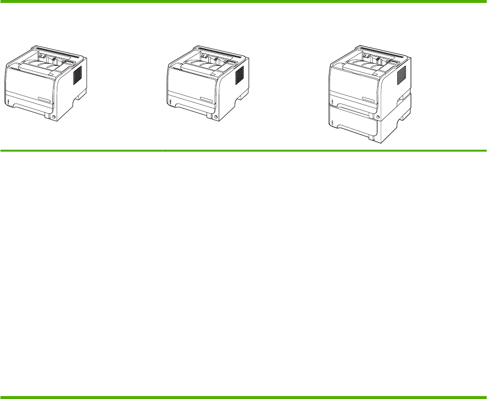
Product comparison
HP LaserJet P2050 Series Printers
HP LaserJet P2055d printer
CE457A
HP LaserJet P2055dn printer
CE459A
HP LaserJet P2055x printer
CE460A
●Prints up to 35 pages per minute (ppm)
on Letter size paper and 33 ppm on A4
size paper
●Contains 64 megabytes (MB) of random
access memory (RAM) and is
expandable to 320 MB.
●HP print cartridge, rated for up to 2,300
pages
●Tray 1 holds up to 50 sheets
●Tray 2 holds up to 250 sheets
●125-sheet face-down output bin
●Straight-through output path
●2-line control-panel display
●Hi-speed USB 2.0 port
●One open dual inline memory module
(DIMM) slot
Has the same features as the HP LaserJet
P2035d model printer, plus the following:
●Gigabit networking port
●HP Jetdirect print server/networking
solution
●Contains 128 MB RAM and is
expandable to 384 MB.
Has the same features as the HP LaserJet
P2035dn model printer, plus the following:
●500-sheet input tray (Tray 3)
2 Chapter 1 Product basics ENWW
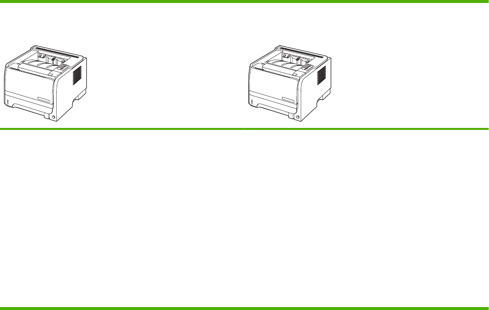
HP LaserJet P2030 Series Printers
HP LaserJet P2035 printer
CE461A
HP LaserJet P2035n printer
CE462A
●Prints up to 30 pages per minute (ppm) on Letter-size paper and
30 ppm on A4-size paper
●Contains 16 megabytes (MB) of random access memory (RAM).
●HP print cartridge, rated for up to 2,300 pages
●Tray 1 holds up to 50 sheets
●Tray 2 holds up to 250 sheets
●125-sheet face-down output bin
●Straight-through output path
●Hi-speed USB 2.0 port
●Parallel port
Has the same features as the HP LaserJet P2035 model, with the
following differences:
●10/100 networking port
●No parallel port
ENWW Product comparison 3

Product features
HP LaserJet P2050 Series Printers
Feature Description
Performance ●600 MHz processor
User interface ●2-line display
●HP ToolboxFX (a Web-based status and problem-solving tool)
●Windows® and Macintosh printer drivers
●Embedded Web server to access support and order supplies (for network-connected models
only)
Printer drivers ●HP PCL 6 (included on CD)
●HP PCL 5c Universal Print Driver for Windows (HP UPD PCL 5c) (available for download from
the Web)
●HP postscript emulation Universal Print Driver for Windows (HP UPD PS) (available for
download from the Web)
●XML Paper Specification (XPS) Driver (available for download from the Web)
Resolution ●FastRes 1200—produces 1200-dots-per-inch (dpi) print quality for fast, high-quality printing of
business text and graphics
●ProRes 1200—produces 1200-dpi printing for the best quality in line art and graphic images
●600 dpi—provides the fastest printing
Fonts ●45 internal scalable fonts available for PCL and 35 for HP postscript emulation
●80 device-matching screen fonts in TrueType format available with the software solution
Accessories ●500-sheet input tray
●HP Jetdirect external print server
Connectivity ●Hi-Speed USB 2.0 connection
●Gigabit networking connection (HP LaserJet P2055dn and HP LaserJet P2055x only)
Supplies ●The supplies status page contains information about toner level, page count, and estimated
pages remaining.
●The product checks for an authentic HP print cartridge at installation.
●Integration with HP Sure Supply Web site for replacement-cartridge reordering
Supported operating systems ●Microsoft
®
Windows
®
2000, Windows
®
Server 2003, Windows
®
XP, and Windows Vista™
●Macintosh OS X V10.3, V10.4, and V10.5
●Novell NetWare (TCP/IP only) (HP LaserJet P2055dn and HP LaserJet P2055x only)
Accessibility ●The online user guide is compatible with text screen-readers.
●The print cartridge can be installed and removed by using one hand.
●All doors can be opened by using one hand.
●Media can be loaded in Tray 1 by using one hand.
4 Chapter 1 Product basics ENWW

HP LaserJet P2030 Series Printers
Feature Description
Performance ●266 MHz processor
User interface ●2-button, 6 LED control panel
●Windows® and Macintosh printer drivers
●Embedded Web server to access support and order supplies (for network-connected models
only)
Printer drivers ●Host-based printer drivers for Windows and Macintosh, included on the product CD
●HP UPD PCL 5c printer driver (available for download from the Web)
●XML Paper Specification (XPS) printer driver (available for download from the Web)
Resolution ●FastRes 1200—produces 1200-dots-per-inch (dpi) print quality for fast, high-quality printing of
business text and graphics
●600 dpi—provides the fastest printing
Fonts ●45 internal scalable fonts
●80 device-matching screen fonts in TrueType format available with the software solution
Connectivity ●Hi-Speed USB 2.0 connection
●Parallel connection (HP LaserJet P2035 printer only)
●10/100 networking port (HP LaserJet P2035n printer only)
Supplies ●The supplies status page contains information about toner level, page count, and estimated
pages remaining.
●The product checks for an authentic HP print cartridge at installation.
●Integration with HP Sure Supply Web site for replacement-cartridge reordering
Accessories ●HP Jetdirect external print server
Supported operating systems ●Microsoft
®
Windows
®
2000, Windows
®
Server 2003, Windows
®
XP, and Windows Vista™
●Macintosh OS X V10.3, V10.4, and V10.5
Accessibility ●The online user guide is compatible with text screen-readers.
●The print cartridge can be installed and removed by using one hand.
●All doors can be opened by using one hand.
●Media can be loaded in Tray 1 by using one hand.
ENWW Product features 5
Product walkaround
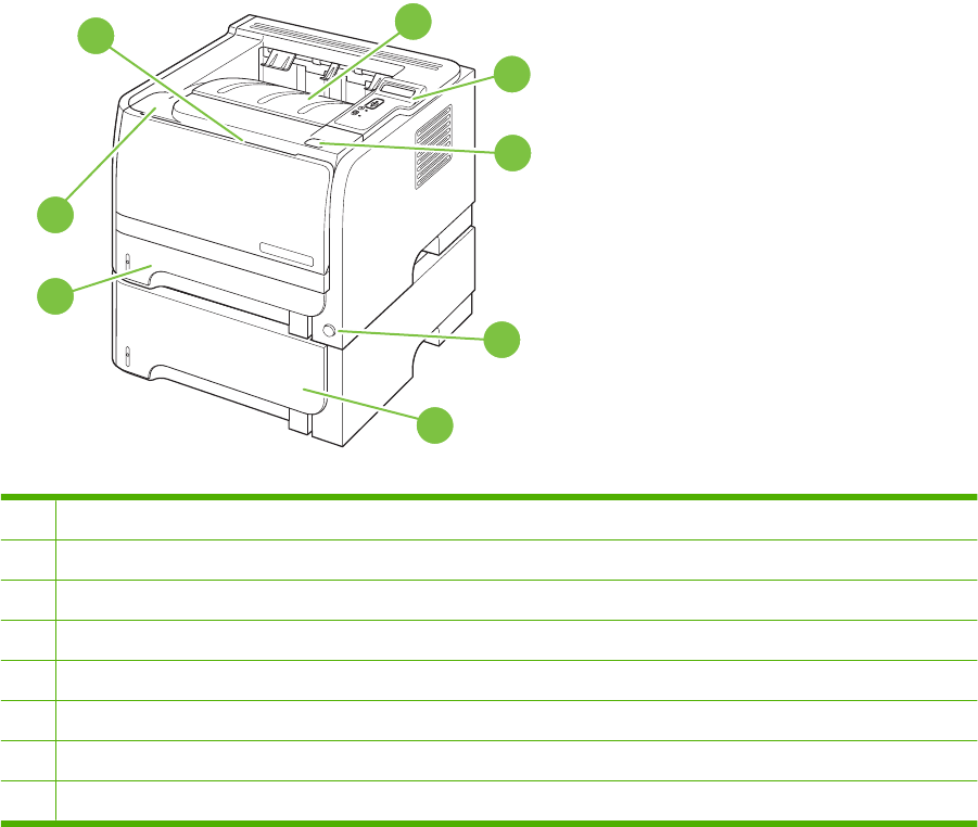
HP LaserJet P2050 Series Printers
Front view
6
1
8
7
3
5
2
4
1Tray 1 (pull to open)
2Top output bin
3Control panel
4Print-cartridge-door release button
5On/off switch
6Optional Tray 3 (included with the HP LaserJet P2055x printer)
7Tray 2
8Print-cartridge door
6 Chapter 1 Product basics ENWW
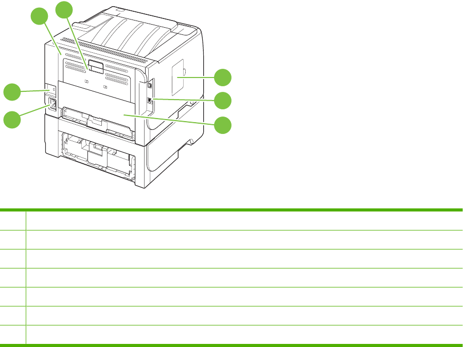
Rear view
6
12
7
3
4
5
1Jam-release door (pull the green handle to open)
2Straight-through paper path (pull to open)
3DIMM cover (provides access to the DIMM slot)
4Interface ports
5Rear duplex jam-release door
6Power connection
7Slot for a cable-type security lock
ENWW Product walkaround 7
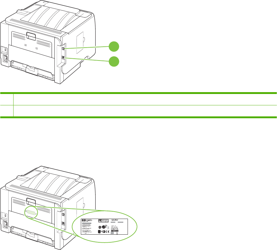
Interface ports
1
2
1Hi-Speed USB 2.0 connection, for connecting directly to a computer
2Gigabit networking connection (10/100/1000 networking port)
Model and serial number label
The label that contains the model and serial numbers is on the outside of the rear output door (straight-
through paper path).
8 Chapter 1 Product basics ENWW
HP LaserJet P2030 Series Printers
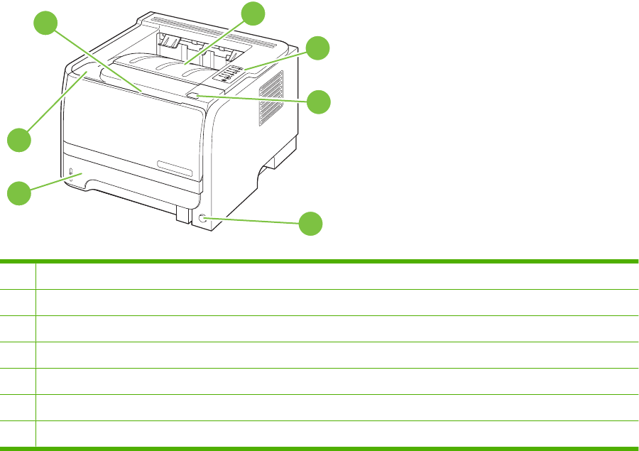
Front view
1
7
6
3
5
2
4
1Tray 1 (pull to open)
2Top output bin
3Control panel
4Print-cartridge-door release button
5On/off switch
6Tray 2
7Print-cartridge door
ENWW Product walkaround 9
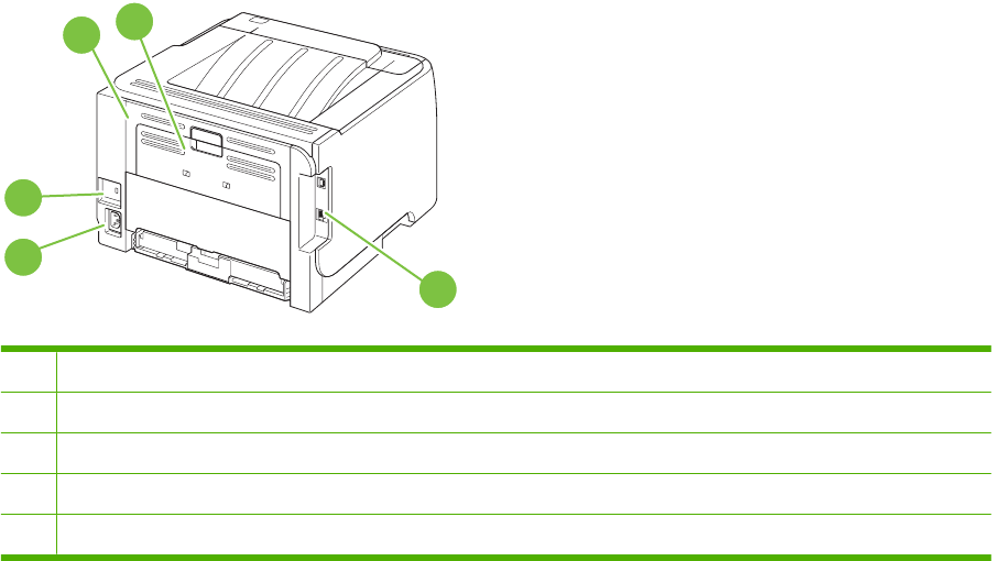
Rear view
4
12
5
3
1Jam-release door (pull the green handle to open)
2Straight-through paper path (pull to open)
3Interface ports
4Power connection
5Slot for a cable-type security lock
10 Chapter 1 Product basics ENWW
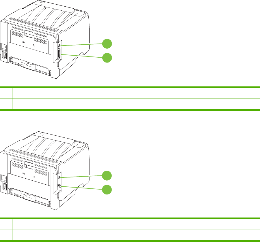
Interface ports
Figure 1-1 HP LaserJet P2035 printer
1
2
1Hi-Speed USB 2.0 port
2Parallel port
Figure 1-2 HP LaserJet P2035n printer
1
2
1Hi-Speed USB 2.0 port
210/100 network port
ENWW Product walkaround 11
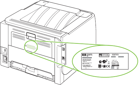
Model and serial-number label location
The label that contains the model and serial numbers is on the rear of the product.
12 Chapter 1 Product basics ENWW

Supported product software
Software included with the product
There are several options for completing a recommended install. Easy Install will complete the
installation with default settings. Advanced Install allows you to select custom settings and choose the
components that are installed.
Software installation types for Windows
You can choose from the following types of software installations:
●Recommended Installation . This method installs the full set of drivers and software, including
status, alerting, and troubleshooting tools. This method is recommended for computers in a direct-
connect or a home/small network environment.
●Express Installation. This method installs the minimum set of drivers and software. This method
is recommended for servers or computers in a network environment.
Macintosh software
●HP Printer Utility
Supported printer drivers for Windows (HP LaserJet P2050 Series
Printers)
●HP PCL 6 (on the product CD)
●HP PCL 5c Universal Print Driver (HP UPD PCL 5c) (available for download from the Web)
●HP postscript emulation Universal Print Driver (HP UPD PS) (available for download from the Web)
●XPS (XML Paper Specification) driver (available for download from the Web)
The printer drivers include online Help that has instructions for common printing tasks and also describes
the buttons, checkboxes, and drop-down lists that are in the printer driver.
NOTE: For more information about the UPD, see www.hp.com/go/upd.
Supported printer drivers for Windows (HP LaserJet P2030 Series
Printers)
The product features a host-based printer driver.
The printer drivers include online Help that has instructions for common printing tasks and also describes
the buttons, checkboxes, and drop-down lists that are in the printer driver.
Supported printer drivers for Macintosh (HP LaserJet P2050 Series Printers
only)
The HP installer provides PostScript
®
Printer Description (PPD) files, Printer Dialog Extensions (PDEs),
and the HP Printer Utility for use with Macintosh computers.
The PPDs, in combination with the Apple PostScript printer drivers, provide access to device features.
Use the Apple PostScript printer driver that comes with the computer.
ENWW Supported product software 13

Supported printer drivers for Macintosh (HP LaserJet P2030 Series Printers
only)
The HP installer provides a printer driver and the HP Printer Utility for use with Macintosh computers.
Other software provided
Software for Windows
HP ToolboxFX (HP LaserJet P2050 Series Printers only)
HP ToolboxFX is a software program that you can use for the following tasks:
●Checking the product status
●Checking the supplies status and ordering supplies online
●Setting up alerts
●Setting up e-mail notification for certain product and supplies events
●Viewing and changing product settings
●Viewing product documentation
●Gaining access to troubleshooting and maintenance tools
You can view HP ToolboxFX when the product is directly connected to your computer or is connected
to a network. HP ToolboxFX is installed as part of the basic installation (recommended).
Status Alerts software (HP LaserJet P2030 Series Printers only)
The Status Alerts software provides information about the current status of the product.
The software also provides pop-up alerts when certain events occur, such as an empty tray or a problem
with the product. The alert includes information about solving the problem.
Software for networks
HP Web Jetadmin
HP Web Jetadmin is a browser-based management tool for HP Jetdirect-connected printers within your
intranet, and it should be installed only on the system administrator’s computer.
To download a current version of HP Web Jetadmin and for the latest list of supported host systems,
go to www.hp.com/go/webjetadmin.
When installed on a host server, any client can gain access to HP Web Jetadmin by using a supported
Web browser (such as Microsoft® Internet Explorer 4.x or Netscape Navigator 4.x or later) by navigating
to the HP Web Jetadmin host.
Embedded Web server (HP LaserJet P2055dn, HP LaserJet P2055x, and HP LaserJet P2035n printers
only).
The device is equipped with an embedded Web server, which provides access to information about
device and network activities. This information appears in a Web browser, such as Microsoft Internet
Explorer, Netscape Navigator, Apple Safari, or Firefox.
14 Chapter 1 Product basics ENWW

The embedded Web server resides on the device. It is not loaded on a network server.
The embedded Web server provides an interface to the device that anyone who has a network-
connected computer and a standard Web browser can use. No special software is installed or
configured, but you must have a supported Web browser on your computer. To gain access to the
embedded Web server, type the IP address for the device in the address line of the browser. (To find
the IP address, print a configuration page. For more information about printing a configuration page,
see Print the information pages on page 48.)
For a complete explanation of the features and functionality of the embedded Web server, see
Embedded Web server (HP LaserJet P2055dn, HP LaserJet P2055x, and HP LaserJet P2035n only)
on page 57.
Software for other operating systems
OS Software
UNIX To download the HP UNIX modelscripts, follow these steps.
1. Go to www.hp.com, and click Software & Driver Download.
2. Type the name of the product in the product name box.
3. In the list of operating systems, click UNIX.
4. Download the appropriate file or files.
Linux For information, go to www.hp.com/go/linuxprinting.
Citrix Use the printer driver provided with the product.
ENWW Supported product software 15
System minimum requirements
Windows requirements
●512 MB of RAM
●350 MB of disk space
Macintosh requirements
●256 MB of RAM
●150 MB of disk space
16 Chapter 1 Product basics ENWW

Connectivity
Supported networks (HP LaserJet P2050 Series Printers)
The product supports the TCP/IP network protocol. It is the most widely used and accepted networking
protocol. Many networking services use this protocol. This product also supports IPv4 and IPv6. The
following tables list the networking services/protocols that are supported on the product.
Table 1-1 Printing
Service name Description
port9100 (Direct Mode) The default TCP/IP printing port on the HP Jetdirect print
server, accessed by software such as HP Standard Port
Line printer daemon (LPD) LPD provides line printer spooling services for TCP/IP
systems. Use LPD services on the HP Jetdirect print server.
WS Print Use the Microsoft Web Services for Devices (WSD) Print
services supported on the HP Jetdirect print server.
Table 1-2 Network product discovery
Service name Description
SLP (Service Location Protocol) Device Discovery Protocol, used to help find and configure
network devices. Used primarily by Microsoft-based software
programs.
multicast Domain Name Service (mDNS—also known as
“Rendezvous” or “Bonjour”)
Device Discovery Protocol, used to help find and configure
network devices. Used primarily by Apple Macintosh-based
software programs.
WS Discovery Allows Microsoft WS discovery protocols on the print server.
LLMNR (TCP/IP v6) Indicates whether link local multicast name resolution
(LLMNR) requests are responded to over IPv6.
NetBIOS over TCP/IP Provides communication among applications on separate
computers within a local area network. Because the
programming interface runs through TCP/IP (NBT), each
computer in the network has both a NetBIOS name and an IP
address relevant to a host name (even though the two names
might not be the same).
DNS Client DNS domain name that the HP Jetdirect print server resides in
(for example, support.hp.com).
Table 1-3 Messaging and management
Service name Description
HTTP (hypertext transfer protocol) Allows Web browsers to communicate with embedded Web
server.
EWS (embedded Web server) Allows a user to manage the product through a Web browser.
SNMP (simple network management protocol) Used by network programs for product management. SNMP
V3 and standard MIB-II (Management Information Base)
objects are supported.
ENWW Connectivity 17

Service name Description
Web Jetadmin (WJA) Management program that provides controlled access to
HP Jetdirect and product features.
EPC HP Easy Printer Care Software 2.0 (EPC 2.0) provides
HP Web Jetadmin-type functions for small and micro
businesses with up to 15 HP LaserJet products. EPC 2.0
delivers effortless laser product upkeep and protection for your
printing investment, in addition to simple, consolidated
supplies replenishment.
Table 1-4 IP addressing
Service name Description
DHCP (dynamic host configuration protocol) For Automatic IP address assignment. DHCP server provides
the product with an IP address. Generally requires no user
intervention for product to obtain IP address from a DHCP
server.
BOOTP (bootstrap protocol) For Automatic IP address assignment. BOOTP server
provides the product with an IP address. Requires the
administrator to type the product MAC hardware address on
the BOOTP server in order for the product to obtain an IP
address from that server.
Auto IP For Automatic IP address assignment. If neither a DHCP
server nor a BOOTP server is present, this service allows the
product to generate a unique IP address.
Manual IP Manually configure the IP address on the print server by using
the product control panel or the embedded Web server.
Telnet Set configuration parameters by using the default IP address
to create a Telnet connection from your system to the HP
Jetdirect print server. When configured, the print server saves
the configuration when turned off and then turned on.
RARP You can configure the print server to use RARP on UNIX and
Linux systems. Use RARP to answer the print server's RARP
request and supply the print server with the IP address. The
RARP method allows you to only configure the IP address.
ARP/PING You can configure an HP Jetdirect print server with an IP
address using the arp command from a supported system.
The workstation from which the configuration is made must be
located on the same network segment as the HP Jetdirect print
server.
Supported network (HP LaserJet P2030 Series Printers)
The product supports the TCP/IP network protocol. It is the most widely used and accepted networking
protocol. Many networking services use this protocol. This product also supports IPv4 and IPv6. The
following tables list the networking services/protocols that are supported on the product.
Table 1-3 Messaging and management (continued)
18 Chapter 1 Product basics ENWW

Table 1-5 Printing
Service name Description
port9100 (Direct Mode) Printing service
Line printer daemon (LPD) Printing service
Table 1-6 Network product discovery
Service name Description
SLP (Service Location Protocol) Device Discovery Protocol, used to help find and configure
network devices. Used primarily by Microsoft-based software
programs.
multicast Domain Name Service (mDNS—also known as
“Rendezvous” or “Bonjour”)
Device Discovery Protocol, used to help find and configure
network devices. Used primarily by Apple Macintosh-based
software programs.
Table 1-7 Messaging and management
Service name Description
HTTP (hypertext transfer protocol) Allows Web browsers to communicate with embedded Web
server.
EWS (embedded Web server) Allows a user to manage the product through a Web browser.
SNMP (simple network management protocol) Used by network programs for product management. SNMP
V1, V2, and standard MIB-II (Management Information Base)
objects are supported.
Table 1-8 IP addressing
Service name Description
DHCP (dynamic host configuration protocol) For Automatic IP address assignment. DHCP server provides
the product with an IP address. Generally requires no user
intervention for product to obtain IP address from a DHCP
server.
BOOTP (bootstrap protocol) For Automatic IP address assignment. BOOTP server
provides the product with an IP address. Requires the
administrator to type the product MAC hardware address on
the BOOTP server in order for the product to obtain an IP
address from that server.
Auto IP For Automatic IP address assignment. If neither a DHCP
server nor a BOOTP server is present, this service allows the
product to generate a unique IP address.
ENWW Connectivity 19
20 Chapter 1 Product basics ENWW

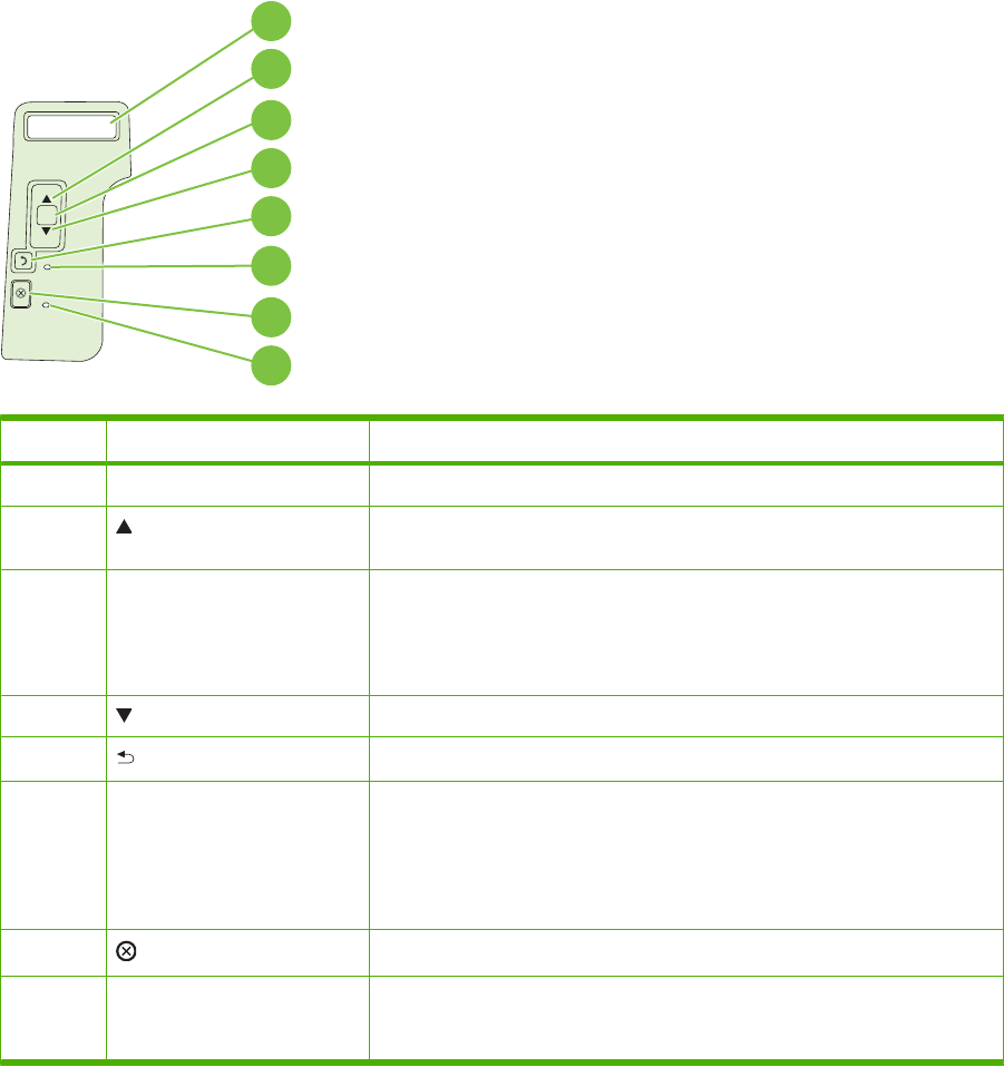
Control panel (HP LaserJet P2050 Series Printers only)
Control-panel layout
Use the control panel to obtain product and job status information and to configure the product.
OK
1
7
6
5
4
3
2
8
Number Button or light Function
1Control-panel display Shows status information, menus, help information, and error messages.
2 Up arrow Navigates to the next submenu or the next value in a menu selection list, moves
the cursor forward a single position, or increases the value of numeric items
3OK button ●Saves the selected value for an item
●Performs the action that is highlighted on the control-panel display
●Clears an error condition when the condition is clearable
4 Down arrow Navigates to the next item in the list, or decreases the value of numeric items
5 Back button Backs up one level in the menu tree or backs up one numeric entry
6Ready light ●On: The product is online and ready to accept data to print.
●Off: The product cannot accept data because it is offline (paused) or has
experienced an error.
●Blinking: The product is processing a job.
7 Cancel button Cancels the current print job
8Error light ●Off: The product is functioning without error.
●Blinking: Action is required. See the control-panel display.
22 Chapter 2 Control panel ENWW

Use the control-panel menus
To gain access to the control-panel menus, complete the steps below.
Use the menus
1. Press OK.
2. Press the down arrow or the up arrow to navigate the listings.
3. Press OK to select the appropriate option.
4. Press the back button to return to the previous level.
NOTE: Asterisks that appear on the control panel note that the menu item is selected.
The following are the main menus.
Main menus (Setup menu) Reports
System setup
Service
Network config. (HP LaserJet P2055dn and HP LaserJet P2055x
only)
ENWW Control panel (HP LaserJet P2050 Series Printers only) 23

Reports menu
Use the Reports menu to print reports that provide information about the product.
Menu item Description
Demo page Prints a page that demonstrates print quality.
Menu structure Prints a map of the control-panel-menu layout. Lists the active settings for each
menu.
Config report Prints a list of all the product settings. Includes network information when the product
is connected to a network.
Supplies status Prints the status for the print cartridge, including the following information:
●Estimated pages remaining
●Part number
●Number of pages printed
Network report Prints a list of all product network settings
PCL font list Prints a list of all the PCL 5c fonts that are installed
PCL 6 font list Prints a list of all the PCL 6 fonts that are installed
PS font list Prints a list of all the PostScript (PS) fonts that are installed
Service page Prints the service report
Usage page Prints a page that lists PCL 5c pages, PCL 6 pages, PS pages, pages that were
jammed or mispicked in the product; and reports the page count
24 Chapter 2 Control panel ENWW

System setup menu
Use this menu to establish basic product settings. The System setup menu has several sub-menus.
Menu item Sub-menu item Sub-menu item Description
Language Select the language for the control-panel
display messages and the product reports.
Quiet mode On
Off
Enable or disable quiet mode. When quiet
mode is turned on, the product prints at a
slower speed. This setting is used for heavy
media.
The default setting is Off.
Paper setup Def. paper size A list of available sizes
appears.
Select the size for printing internal reports or
any print job that does not specify a size.
Def. paper type A list of available media types
appears.
Select the media type for printing internal
reports or any print job that does not specify
a type.
Tray n
NOTE: n = 1, 2, or 3
Paper type
Paper size
Select the default size and type for the tray
from the list of available sizes and types.
Paper out action Wait forever
Override
Cancel
Select how the product should react when a
print job requires a size or type that is not
available or when a specified tray is empty.
Select Wait forever to make the product wait
until you load the correct media and press
OK. This is the default setting.
Select Override to print on a different size or
type after a specified delay.
Select Cancel to automatically cancel the
print job after a specified delay.
If you select either Override or Cancel, the
control panel prompts you to specify the
number of seconds to delay. Press the up
arrow to increase the time, up to
3600 seconds. Press the down arrow to
decrease the time.
Print quality Cartridge low (1-20) The percentage threshold determines when
the product begins reporting low toner.
Print density (1–5) Select the amount of toner to apply to thicken
edges and lines.
The default setting is 3.
ENWW Control panel (HP LaserJet P2050 Series Printers only) 25

Menu item Sub-menu item Sub-menu item Description
Display contrast Medium
Darker
Darkest
Lightest
Lighter
Adjust the contrast of the LCD.
Courier font Regular
Dark
Select a version of the Courier font.
The default is Regular.
26 Chapter 2 Control panel ENWW

Service menu
Use this menu to restore default settings, clean the product, and activate special modes that affect print
output.
Menu item Description
Cleaning mode Use this option to clean the product if you see toner specks or other marks on the
printed output. The cleaning process removes dust and excess toner from the paper
path.
When you select this item, the product prompts you to load plain paper in Tray 1 and
then press OK to begin the cleaning process. Wait until the process is complete.
Discard the page that prints.
USB speed Sets the USB speed to High or Full. For the product to actually operate at high
speed, it must have high speed enabled and be connected to an EHCI host controller
that is also operating at high speed. This menu item also does not reflect the current
operating speed of the product.
The default setting is High.
Less paper curl If printed pages are consistently curled, use this option to set the product to a mode
that reduces curl.
The default setting is Off.
Archive print If you are printing pages to be stored for a long time, use this option to set the product
to a mode that reduces toner smearing and dusting.
The default setting is Off.
Restore defaults Sets all customized settings to the factory default values.
ENWW Control panel (HP LaserJet P2050 Series Printers only) 27

Network config. menu (HP LaserJet P2055dn and HP LaserJet P2055x
only)
Use this menu to establish network configuration settings.
Menu item Description
CFG TCP/IP Access the TCP/IP menu and set TCP/IP protocol parameters.
BOOTP=YES* Enable IPv4 configuration by a BOOTP Server.
DHCP=YES* Enable IPv4 configuration by a DHCP Server. (This item only displays on the control
panel when BOOTP=NO*.
If DHCP=YES* and the print server has a DHCP lease, you can configure the following DHCP
settings:
●RELEASE: Select whether to release (YES) or save (NO) the current lease.
●RENEW: Select whether to renew (YES or NO) the lease.
AUTO IP=YES* Automatically assign a link-local IPv4 address in the form 169.254.x.x.
To manually set an IP, specify BOOTP=NO*, DHCP=NO* and AUTO IP=NO*, and then set the
following TCP/IPv4 parameters from the control panel:
Each byte of the IPv4 address (IP)
Subnet Mask (SM)
Syslog Server (LG)
Default Gateway (GW)
Idle Timeout period (default is 270 seconds, 0 disables the timeout)
CFG DNS 1: IPv4 address of a primary DNS server (one byte at a time).
CFG DNS 2: IPv4 address of a secondary DNS server (one byte at a time).
IPV6 = YES*: Enable IPv6 operation. Select NO to disable IPv6 operation.
POLICY=RTR_AV/RTR_UN/ALWAYS: Set one of the following IPv6 addressing policies:
●RTR_AV: (default) Stateful auto-configuration method is determined by a router. The router
specifies whether the print server obtains its address, configuration information, or both from
a DHCPv6 server.
●RTR_UN: Try to obtain stateful configuration from a DHCPv6 server (when a router is not
available).
●ALWAYS: Always try to obtain stateful configuration from a DHCPv6 server (whether or not
a router is available).
MANUAL= KEEP/DISABLE: Set the behavior of a manually configured IPv6 address detected on
the print server.
●KEEP (default): Maintain the address in an active state.
●DISABLE: Maintain the address, but in an inactive state.
Print an HP Jetdirect configuration page to verify your settings. (The print server can overwrite
selected parameters with values that ensure proper operation.)
28 Chapter 2 Control panel ENWW

Menu item Description
WEB Embedded Web server accepts communications using HTTPS (Secure HTTP) only, or both HTTP
and HTTPS.
●HTTPS: Accept only HTTPS (print server appears as a secure site).
●HTTP/HTTPS: Accept either HTTP or HTTPS.
SECURITY Reset current security settings to factory defaults.
●KEEP (default): Retain current security settings.
●RESET: Reset security settings to factory defaults.
FIREWALL Disable Firewall.
●KEEP (default): Retain Firewall operation as configured.
●DISABLE: Disable Firewall operation.
PRINT Print a configuration page for the selected item.
SECURITY: Print the current security settings.
CFG LINK Manually configure the HP Jetdirect print server's network link.
Set the link speed and communication mode. These must match the network. The available
settings depend on the print server model.
CAUTION: Changing the link setting can cause the loss of network communication with the print
server.
●AUTO (default): Use auto negotiation to set the highest link speed and communication mode
allowed. If auto negotiation fails, either 100TX HALF or 10TX HALF is set depending on the
detected link speed of the hub/switch port. (A 1000T half-duplex selection is not supported.)
●10T HALF: 10 Mbps, half-duplex operation.
●10T FULL: 10 Mbps, Full-duplex operation.
●100TX HALF: 100 Mbps, half-duplex operation.
●100TX FULL: 100 Mbps, full-duplex operation.
●100TX AUTO: Limits auto-negotiation to a maximum link speed of 100 Mbps.
●1000TX FULL: 1000 Mbps, full-duplex operation.
ENWW Control panel (HP LaserJet P2050 Series Printers only) 29
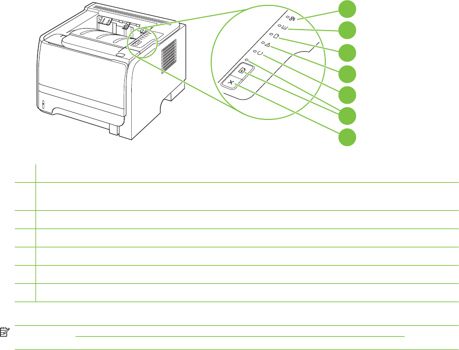
Control panel (HP LaserJet P2030 Series Printers only)
The printer control panel is comprised of six lights and two buttons. The lights produce patterns that
identify the printer status.
1
7
6
5
4
3
2
1Jam light: Indicates a jam in the printer
2Toner light: When the print cartridge is low, the Toner light illuminates. When the print cartridge is out of the printer, the
Toner light blinks.
3Paper out light: Indicates the printer is out of paper
4Attention light: Indicates the print cartridge door is open or other errors exist
5Ready light: Indicates the printer is ready to print
6Go button and light
7Cancel button: To cancel the print job currently printing, press the Cancel button.
NOTE: See Status-light patterns (HP LaserJet P2030 Series Printers only) on page 209 for a
description of the light patterns.
30 Chapter 2 Control panel ENWW


Supported paper and print media
Paper for the HP LaserJet P2050 Series Printers
Supported paper and print media sizes
This product supports a number of paper sizes, and it adapts to various media.
NOTE: To obtain best results, select the correct paper size and type in the printer driver before printing.
Table 3-1 Supported paper and print media sizes
Size and dimensions Tray 1 Tray 2 Optional 500-sheet
Tray 3
Duplexer
Letter
216 x 279 mm (8.5 x 11 inches)
Legal
216 x 356 mm (8.5 x 14 inches)
A4
210 x 297 mm (8.27 x 11.69 inches)
A5
148 x 210 mm (5.83 x 8.27 inches)
A6
105 x 148 mm (4.1 x 5.8 inches)
B5 (JIS)
182 x 257 mm (7.17 x 10.12 inches)
Executive
184 x 267 mm (7.24 x 10.51 inches)
Postcard (JIS)
100 x 148 mm (3.9 x 5.8 inches)
Double Postcard (JIS)
148 x 200 mm (5.8 x 7.9 inches)
16K
184 x 260 mm (7.2 x 10.2 inches)
16K
195 x 270 mm (7.7 x 10.6 inches)
16K
197 x 273 mm (7.8 x 10.8 inches)
8.5 x 13
216 x 330 mm (8.5 x 13 inches)
32 Chapter 3 Paper and print media ENWW

Size and dimensions Tray 1 Tray 2 Optional 500-sheet
Tray 3
Duplexer
Envelope Commercial #10
105 x 241 mm (4.13 x 9.49 inches)
Envelope B5 ISO
176 x 250 mm (6.7 x 9.8 inches)
Envelope C5 ISO
162 x 229 mm (6.93 x 9.84 inches)
Envelope DL ISO
110 x 220 mm (4.33 x 8.66 inches)
Envelope Monarch
98 x 191 mm (3.9 x 7.5 inches)
Custom
76 x 127 mm to 216 x 356 mm
(3.0 x 5.0 inches to 8.5 x 14 inches)
Supported paper and print media types
For a complete list of specific HP-brand paper that this product supports, go to www.hp.com/go/
ljp2050series_software.
Paper type (control panel) Paper type (printer driver) Tray 1 Tray 2 Optional 500-
sheet Tray 3
Duplexer
PLAIN 75–95 G Plain
LIGHT 60-74 G Light 60-74g
MID-WEIGHT Mid-weight
HEAVY 111–130 G Heavy 111–130g
EXTRA HEAVY 131–175 G Extra heavy 131–175g
TRANSPARENCY Monochrome Laser
Transparency
LABELS Labels
LETTERHEAD Letterhead
PREPRINTED Preprinted
PREPUNCHED Prepunched
COLOR Colored
ROUGH Rough
BOND Bond
Table 3-1 Supported paper and print media sizes (continued)
ENWW Supported paper and print media 33

Paper type (control panel) Paper type (printer driver) Tray 1 Tray 2 Optional 500-
sheet Tray 3
Duplexer
RECYCLED Recycled
ENVELOPE Envelope
Tray and bin capacity
Tray or bin Paper type Specifications Quantity
Tray 1 Paper Range:
60 g/m
2
(16 lb) bond to 200 g/m
2
(54 lb) bond
Maximum stack height: 5 mm
(0.3 inch)
Equivalent to 50 sheets of 75 g/
m
2
(20 lb) bond
Envelopes Less than 60 g/m
2
(16 lb) bond to
90 g/m
2
(24 lb) bond
Up to 5 envelopes
Labels Maximum 0.23 mm (0.009 inch)
thick
Maximum stack height: 5 mm
(0.3 inch)
Transparencies Minimum 0.13 mm (0.005 inch)
thick
Maximum stack height: 5 mm
(0.3 inch)
Tray 2 Paper Range:
60 g/m
2
(16 lb) bond to 135 g/m
2
(36 lb) bond
Equivalent to 250 sheets of 75 g/
m
2
(20 lb) bond
Maximum stack height for A6
paper: 15 mm (0.59 inch)
Transparencies Minimum 0.13 mm (0.005 inch)
thick
Maximum stack height: 26 mm
(1.0 inch)
Optional 500-sheet Tray 3 Paper Range:
60 g/m
2
(16 lb) bond to 135 g/m
2
(36 lb) bond
Equivalent to 500 sheets of 75 g/
m
2
(20 lb) bond
Maximum stack height for A6
paper: 40 mm (1.6 inches)
Transparencies Minimum 0.13 mm (0.005 inch)
thick
Maximum stack height: 54 mm
(2.1 inches)
Standard top bin Paper Up to 125 sheets of 75 g/m
2
(20
lb) bond
Paper for the HP LaserJet P2030 Series Printers
Supported paper and print media sizes
This product supports several paper sizes, and it adapts to various media.
NOTE: To obtain the best print results, select the appropriate paper size and type in the print driver
before printing.
34 Chapter 3 Paper and print media ENWW

Table 3-2 Supported paper and print media sizes
Size and dimensions Tray 1 Tray 2
Letter
216 x 279 mm (8.5 x 11 inches)
Legal
216 x 356 mm (8.5 x 14 inches)
A4
210 x 297 mm (8.27 x 11.69 inches)
A5
148 x 210 mm (5.83 x 8.27 inches)
A6
105 x 148 mm (4.1 x 5.8 inches)
B5 (JIS)
182 x 257 mm (7.17 x 10.12 inches)
Executive
184 x 267 mm (7.24 x 10.51 inches)
Postcard (JIS)
100 x 148 mm (3.9 x 5.8 inches)
Double Postcard (JIS)
148 x 200 mm (5.8 x 7.9 inches)
16K
184 x 260 mm (7.2 x 10.2 inches)
16K
195 x 270 mm (7.7 x 10.6 inches)
16K
197 x 273 mm (7.8 x 10.8 inches)
8.5 x 13
216 x 330 mm (8.5 x 13 inches)
Envelope Commercial #10
105 x 241 mm (4.13 x 9.49 inches)
Envelope B5 ISO
176 x 250 mm (6.7 x 9.8 inches)
Envelope C5 ISO
162 x 229 mm (6.93 x 9.84 inches)
Envelope DL ISO
ENWW Supported paper and print media 35

Size and dimensions Tray 1 Tray 2
110 x 220 mm (4.33 x 8.66 inches)
Envelope Monarch
98 x 191 mm (3.9 x 7.5 inches)
Custom
76 x 127 mm to 216 x 356 mm
(3.0 x 5.0 inches to 8.5 x 14 inches)
Supported paper and print media types
For a complete list of specific HP-brand paper that this product supports, go to www.hp.com/support/
ljp2030series.
Paper type (printer driver) Tray 1 Tray 2
Plain Paper
Light 60–74 g/m
2
Midweight (96–110 g/m
2
)
Heavy (111–130 g/m
2
)
Extra Heavy (131–175 g/m
2
)
Transparency
Labels
Letterhead
Preprinted
Prepunched
Color
Rough
Bond
Recycled
Envelope
HP Multipurpose Paper
HP Office Paper
HP LaserJet Paper
HP Premium Choice Paper
Table 3-2 Supported paper and print media sizes (continued)
36 Chapter 3 Paper and print media ENWW

Tray and bin capacity
Tray or bin Paper type Specifications Quantity
Tray 1 Paper Range:
60 g/m
2
(16 lb) bond to 200 g/m
2
(54 lb) bond
Maximum stack height: 5 mm
(0.3 inch)
Equivalent to 50 sheets of 75 g/
m
2
(20 lb) bond
Envelopes Less than 60 g/m
2
(16 lb) bond to
90 g/m
2
(24 lb) bond
Up to 5 envelopes
Labels Maximum 0.23 mm (0.009 inch)
thick
Maximum stack height: 5 mm
(0.3 inch)
Transparencies Minimum 0.13 mm (0.005 inch)
thick
Maximum stack height: 5 mm
(0.3 inch)
Tray 2 Paper Range:
60 g/m
2
(16 lb) bond to 135 g/m
2
(36 lb) bond
Equivalent to 250 sheets of 75 g/
m
2
(20 lb) bond
Maximum stack height for A6
paper: 15 mm (0.59 inch)
Transparencies Minimum 0.13 mm (0.005 inch)
thick
Maximum stack height: 26 mm
(1.0 inch)
Standard top bin Paper Up to 125 sheets of 75 g/m
2
(20
lb) bond
ENWW Supported paper and print media 37
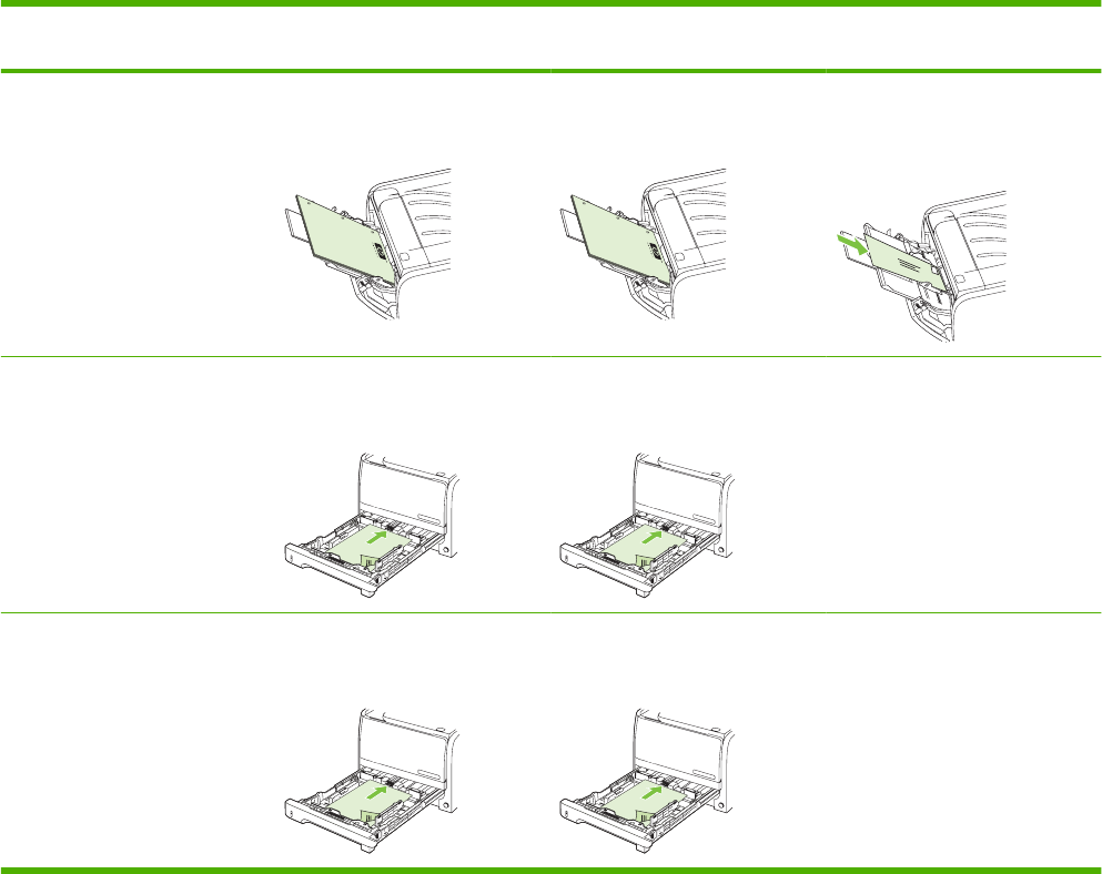
Load paper and print media
Load trays
Paper orientation for loading trays
If you are using paper that requires a specific orientation, load it according to the information in the
following table.
Tray Single-sided printing Duplex printing (HP LaserJet
P2050 Series Printers only)
Envelope printing
Tray 1 Face-up
Top edge leading into the product
Face-up
Top edge leading into the product
Front of envelope face-up
Short edge with postage leading
into the product
Tray 2 Face-down
Top edge at the front of the tray
Face-down
Top edge at the front of the tray
Use only Tray 1 for printing
envelopes.
Optional Tray 3 (HP LaserJet
P2050 Series Printers only)
Face-down
Top edge at the front of the tray
Face-down
Top edge at the front of the tray
Use only Tray 1 for printing
envelopes.
38 Chapter 3 Paper and print media ENWW
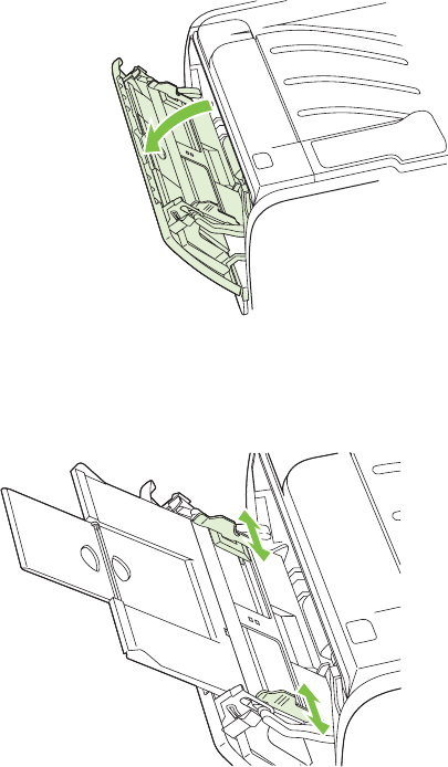
Tray 1
Tray 1 is accessed from the front of the product. The product prints from Tray 1 before trying to print
from other trays.
Media guides ensure that the media is correctly fed into the product and that the print is not skewed
(crooked on the media). When loading media, adjust the media guides to match the width of the media
that you are using.
ENWW Load paper and print media 39
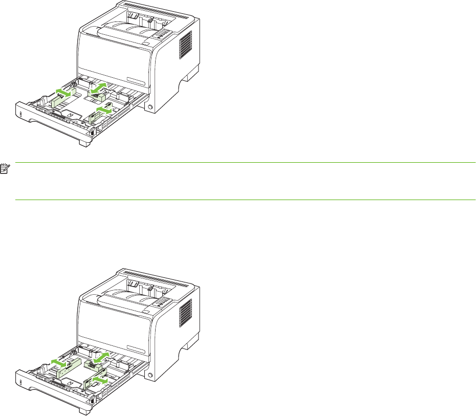
Tray 2
Media guides ensure that the media feeds correctly into the product and that the print is not skewed.
Tray 2 has side and rear media guides. When loading media, adjust the media guides to match the
length and width of the media that you are using.
NOTE: When you add new media, make sure that you remove all of the media from the input tray and
straighten the stack of new media. This reduces jams by preventing multiple sheets of media from
feeding through the product at one time.
Load A6-size paper
When loading A6-size paper, adjust the length by sliding forward only the center panel of the rear media
guide.
40 Chapter 3 Paper and print media ENWW
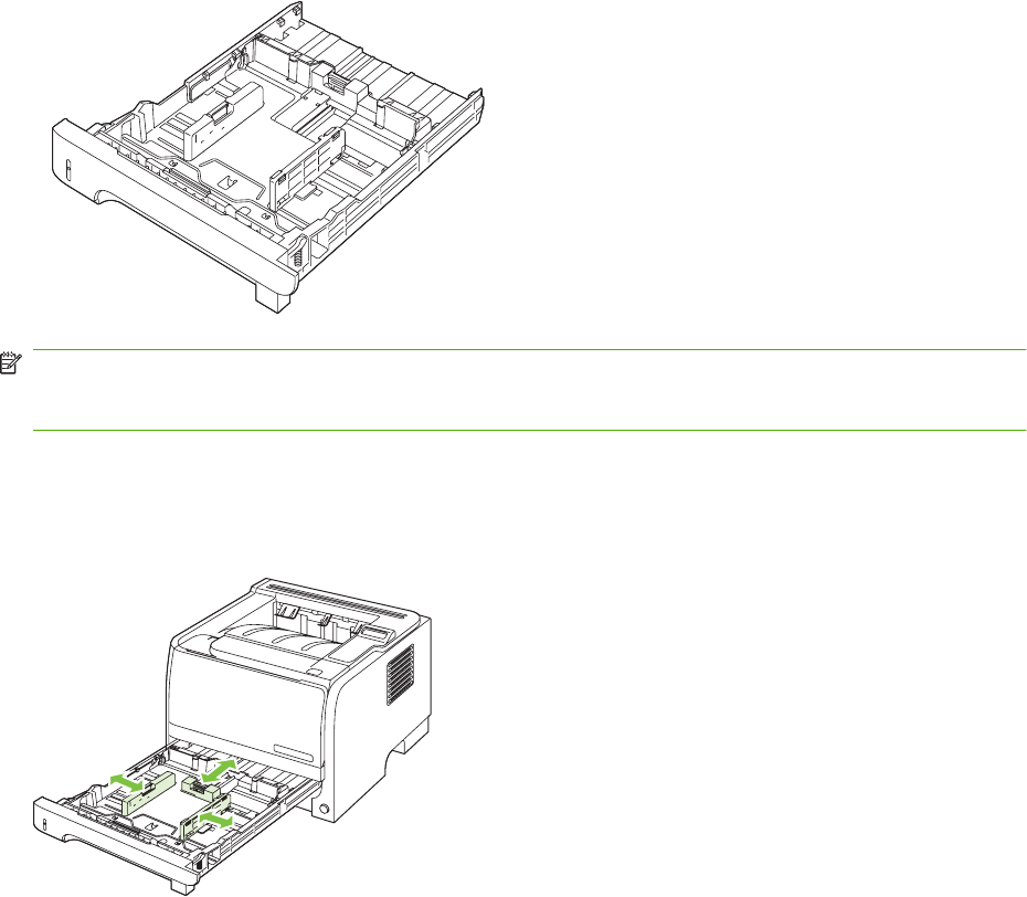
Optional Tray 3 (HP LaserJet P2050 Series Printers only)
Media guides ensure that the media feeds correctly into the product and that the print is not skewed.
Tray 2 has side and rear media guides. When loading media, adjust the media guides to match the
length and width of the media that you are using.
NOTE: When you add new media, make sure that you remove all the media from the input tray and
straighten the stack of new media. This reduces jams by preventing multiple sheets of media from
feeding through the product at one time.
Load A6-size paper
When loading A6-size paper, adjust the length by sliding forward only the center panel of the rear media
guide.
ENWW Load paper and print media 41
Manual feed
You can use manual feed when printing mixed media. For example, you can use manual feed to print
an envelope, and then a letter, and then an envelope, and so on. Load envelopes in Tray 1 and load
letterhead in Tray 2.
To print using manual feed, open the product Properties or Printer Setup, and then select Manual Feed
(tray 1) from the Source Tray drop-down list. After you have enabled manual feed, press the OK button
to print.
42 Chapter 3 Paper and print media ENWW

Configure trays
Configure trays (HP LaserJet P2050 Series Printers only)
1. Press OK.
2. Press the down arrow to select System setup, and then press OK.
3. Press the down arrow to select Paper setup, and then press OK.
4. Press the down arrow to select the desired tray, and then press OK.
5. Press the down arrow to select Paper type or Paper size, and then press OK.
6. Press the down arrow to select the size or type.
7. Press OK to save the settings.
Configure trays (HP LaserJet P2030 Series Printers only)
Use either the printer driver or the embedded Web server to configure the trays for a particular paper
type and size.
Printer driver Click the Paper/Quality tab and select the type and size in the Paper Options area.
Embedded Web server (HP LaserJet
P2035n only)
Click the Settings tab, and then click the Paper Handling option from the left-side
pane.
ENWW Configure trays 43
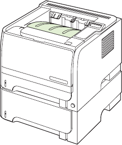
Use paper output options
The product has two output locations: the top (standard) output bin and the straight-through paper path
(rear output).
Print to the top (standard) output bin
The top output bin collects paper face-down, in the correct order. The top output bin should be used for
most print jobs, including transparencies. To use the top output bin, be sure that the rear output (straight-
through paper path) is closed. To avoid jams, do not open or close the rear output while the product is
printing.
44 Chapter 3 Paper and print media ENWW
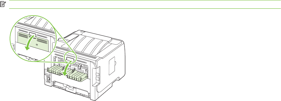
Print to the straight-through paper path (rear output)
The product always uses the straight-through paper path if it is open. Paper exits face-up, with the last
page on top (reverse order).
Printing from Tray 1 to the rear output provides the straightest path. Opening the straight-through paper
path might improve performance with the following paper types:
●Envelopes
●Labels
●Small custom-size paper
●Postcards
●Paper heavier than 120 g/m
2
(32 lb)
To open the straight-through paper path, grasp the handle at the top of the rear door, and pull the door
down.
NOTE: Be sure to open the straight-through paper path, not the jam-release door.
ENWW Use paper output options 45
46 Chapter 3 Paper and print media ENWW


Print the information pages
Print the information pages (HP LaserJet P2050 Series Printers only)
From the product control panel, you can print information pages that give details about the product and
its current configuration using the Reports menu.
Name of report Description
Demo page Prints a page that demonstrates print quality.
Menu structure Prints the control-panel menu map that shows the layout and
current settings for the control-panel menu items.
Config report Prints the current product configuration.
Supplies status Prints a supplies status page that shows the supplies levels for
the product, an approximate number of pages remaining,
cartridge-usage information, the serial number, a page count,
and ordering information, when available.
Network Report Prints a list of all product network settings.
Usage Page Prints a page that shows a count of all paper sizes that have
passed through the product, lists whether they were one-sided
or two-sided, and shows a page count.
PCL Font List Prints a PCL font list that shows all the PCL 5c fonts that are
currently available to the product.
PS font list Prints a PS font list that shows all the PS fonts that are currently
available to the product.
PCL 6 Font List Prints a list of installed PCL6 fonts.
Service Page Prints the service report.
Print the information pages
1. Press OK.
2. Press the down arrow to select Reports, and then press OK.
3. Press the down arrow to select the required report, and then press OK to print.
Print the information pages (HP LaserJet P2030 Series Printers only)
You can print the following information pages.
Demo page
The Demo page contains examples of text and graphics. To print a Demo page, do one of the following:
●Press the Go button when the product Ready light is on and no other jobs are printing.
●Select it from the Print Information Pages drop-down list on the Services tab in Printer
Preferences.
48 Chapter 4 Manage and maintain ENWW
Configuration page
The configuration page lists the current settings and properties of the product. It also contains a status
log report. To print a configuration page, do one of the following:
●Press and hold the Go button for 5 seconds when the product Ready light is on and no other jobs
are printing.
●Select it from the Print Information Pages drop-down list on the Services tab in Printer
Preferences.
Supplies Status page
You can print the Supplies Status page by selecting it from the Print Information Pages drop-down list
on the Services tab in Printer Preferences. The Supplies Status page provides the following
information:
●The estimated number of pages remaining on the print cartridge
●The number of pages and print jobs that have been processed
●Ordering and recycling information
ENWW Print the information pages 49
Use the HP ToolboxFX software (HP LaserJet P2050 Series
Printers only)
HP ToolboxFX is a program that you can use to complete the following tasks:
●Check the product status.
●Configure the product settings.
●View troubleshooting information.
●View online documentation.
You can view HP ToolboxFX when the product is directly connected to a computer or when it is
connected to the network. You must perform the recommended full software installation to use
HP ToolboxFX.
View HP ToolboxFX
Open HP ToolboxFX in one of these ways:
●In the Windows notification area or on your desktop, double-click the HP ToolboxFX icon.
●On the Windows Start menu, click Programs (or All Programs in Windows XP), click HP, click
HP LaserJet P2050 Series, and then click HP ToolboxFX.
50 Chapter 4 Manage and maintain ENWW

Status
The Status folder contains links to the following main pages:
●Device status. This page indicates product conditions such as a jam or an empty tray. After you
correct a problem, click Refresh status to update the product status.
●Supplies status. View details such as the estimated percent of toner remaining in the print
cartridge and the number of pages that have been printed with the current print cartridge. This page
also has links for ordering supplies and for finding recycling information.
●Device configuration. View a detailed description of the current product configuration, including
the amount of memory installed and whether optional trays are installed.
●Network summary. View a detailed description of the current network configuration, including the
IP address and network status.
●Print info pages. Print the Configuration page and other information pages, such as the Supplies
status page.
●Event log. View a history of product errors. The most recent error is listed first.
Event log
The Event log is a table that contains codes corresponding to error messages that have appeared on
the product control-panel display, a brief description of each error, and the number of pages that printed
when each error occurred. For more information about error messages, see Interpret control-panel
messages (HP LaserJet P2050 Series Printers only) on page 219.
ENWW Use the HP ToolboxFX software (HP LaserJet P2050 Series Printers only) 51

Alerts
The Alerts folder contains links to the following main pages:
●Set up Status Alerts. Set up the product to send you pop-up alerts for certain events, such as low
toner levels.
●Set up E-mail Alerts. Set up the product to send you e-mail alerts for certain events, such as low
toner levels.
Set up Status Alerts
Use this to set up the product so that it sends alerts to your computer when jams, low levels of toner in
HP print cartridges, a non-HP print cartridge in use, empty input trays, and specific error messages
occur.
You can select to receive a pop-up, a notification area icon, a desktop alert, or any combination of these.
The pop-up and desktop alerts only appear when the product is printing from the computer on which
you set up the alerts. Desktop alerts are only visible momentarily, and disappear automatically.
Change the Cartridge low threshold setting, which sets the toner level that causes a low toner alert,
on the System setup page.
NOTE: You must click Apply before your changes take effect.
Set up E-mail Alerts
Use this to configure up to two e-mail addresses to receive alerts when certain events occur. You can
specify different events for each e-mail address. Use the information for the e-mail server that will send
out the e-mail alert messages for the product.
NOTE: You can only configure e-mail alerts to be sent from a server that does not require user
authentication. If your e-mail server requires you to log in with a username and password, you cannot
enable e-mail alerts.
NOTE: You must click Apply before your changes take effect.
Help
The Help folder contains links to the following main pages:
●Troubleshooting. View troubleshooting help topics, print troubleshooting pages, and clean the
product.
●Paper and Print Media. Print information about how to obtain optimal results from your product
using various types of paper and print media.
●How do I? Link to the user-guide index.
●User Guide. View information about the product usage, warranty, specifications, and support. The
User Guide is available in both HTML and PDF format.
52 Chapter 4 Manage and maintain ENWW

Device Settings
The Device Settings folder contains links to the following main pages:
●Device Information. View information such as the product description and a contact person.
●Paper Handling. Configure trays or change the product paper-handling settings, such as default
paper size and default paper type.
●Printing. Change the default product print settings, such as number of copies and paper
orientation.
●PCL 6. Change the PCL settings.
●PCL 5c. Change the PCL settings.
●PostScript. Change the PS settings.
●Paper Types. Change the mode settings for each media type, such as letterhead, prepunched, or
glossy paper.
●System Setup. Change the system settings, such as jam recovery and auto-continue. Change the
Cartridge low threshold setting, which sets the toner level that causes a low toner alert.
●Troubleshooting. Gain access to various procedures required to maintain the product.
●Password. Set a password to protect the device settings. Once a password is set, users will be
prompted to enter the password before being allowed to change device settings. This password is
the same as the embedded Web server password.
Device Information
The Device Information page stores data about your product for future reference. The information that
you type in the fields on this page appears on the Configuration page. You can type any character in
each of these fields.
NOTE: You must click Apply before your changes take effect.
ENWW Use the HP ToolboxFX software (HP LaserJet P2050 Series Printers only) 53

Paper Handling
Use these options to configure your default settings. These are the same options that are available on
the control-panel menus on the control panel. For more information, see Control panel on page 21.
The following options are available for handling print jobs when the product is out of media:
●Select Wait for paper to be loaded.
●Select Cancel from the Paper out action drop-down list to cancel the print job.
●Select Override from the Paper out time drop-down list to send the print job to another paper tray.
The Paper out time field specifies how long the product waits before acting on your selections. You
can specify from 0 to 3600 seconds.
NOTE: You must click Apply before your changes take effect.
Printing
Use these options to configure the settings for all print functions. These are the same options that are
available on the control panel. For more information, see Control panel on page 21.
NOTE: You must click Apply before your changes take effect.
PCL6
Use these options to configure the settings when you are using the PCL print personality.
NOTE: You must click Apply before your changes take effect.
PCL5c
Use these options to configure the settings when you are using the PCL print personality.
NOTE: You must click Apply before your changes take effect.
PostScript
Use this option when you are using the PostScript print personality. When the Print PostScript error
option is turned on, the PostScript error page automatically prints when PostScript errors occur.
NOTE: You must click Apply before your changes take effect.
Print quality
Use the HP ToolboxFX print-quality options to improve the appearance of print jobs. These are the same
options that are available on the product control panel. For more information, see Control panel (HP
LaserJet P2050 Series Printers only) on page 22.
The four options provided for controlling print quality are resolution, REt (Resolution Enhancement
technology), print density, and EconoMode.
●Resolution. Select 600 resolution for average print jobs and FastRes 1200 for higher-quality print
jobs. Select ProRes 1200 for the highest-quality print job, but a longer printing time.
●REt. You can turn on REt, which HP provides for improved print quality.
54 Chapter 4 Manage and maintain ENWW

●Print density. For increased print density, select a higher number. For decreased print density,
select a lower number.
●EconoMode. Turn EconoMode on when you are printing average print jobs. EconoMode is a
feature that allows the product to use less toner per page. Selecting this option might extend the
life of the toner supply and might reduce cost per page. However, it reduces print quality. The
printed image is lighter, but it is adequate for printing drafts or proofs. HP does not recommend
full-time use of EconoMode. If EconoMode is used full-time, it is possible that the toner supply can
outlast the mechanical parts in the print cartridge. If print quality begins to degrade under these
circumstances, install a new print cartridge, even if there is toner supply remaining in the cartridge.
NOTE: You must click Apply before the changes take effect.
Paper Types
Use these options to configure print modes that correspond to the various media types. To reset all
modes to factory defaults, select Restore modes.
NOTE: You must click Apply before your changes take effect.
System Setup
Use these system settings to configure miscellaneous print settings. These settings are not available
on the control panel.
NOTE: You must click Apply before your changes take effect.
Troubleshooting
During the printing process, paper, toner and dust particles can accumulate inside the product. Over
time, this buildup can cause print-quality problems such as toner specks or smearing. The HP ToolboxFX
provides an easy method for cleaning the paper path. For more information, see Clean the paper path
(HP LaserJet P2050 Series Printers only) on page 70.
Network Settings
The system administrator can use this tab to control the network-related settings for the product when
it is connected to an IP-based network.
Shop for Supplies
This button, at the top of each page, links to a Web site where you can order replacement supplies. You
must have Internet access to use this feature.
Other Links
This section contains links that connect you to the Internet. You must have Internet access to use any
of these links. If you use a dial-up connection and did not connect when you first opened HP ToolboxFX,
ENWW Use the HP ToolboxFX software (HP LaserJet P2050 Series Printers only) 55
you must connect before you can visit these Web sites. Connecting might require that you close
HP ToolboxFX and reopen it.
●HP Instant Support. Connects to the HP Instant Support Web site.
●Support and Troubleshooting. Connects to the support site for the product where you can search
for help with a specific problem.
●Product Registration. Connects to the HP product registration Web site.
56 Chapter 4 Manage and maintain ENWW

Manage a network product
Embedded Web server (HP LaserJet P2055dn, HP LaserJet P2055x, and
HP LaserJet P2035n only)
The embedded Web server allows you to view product and network status and to manage printing
functions from your computer. Use the embedded Web server for the following tasks:
●View product status information
●Determine the remaining life on all supplies and order new ones
●View and change the size and type of paper loaded in each tray
●View and change the product default configuration settings
●View and change network configuration
You do not need to install any software on the computer. Use one of these supported Web browsers:
●Internet Explorer 6.0 (and later)
●Netscape Navigator 7.0 (and later)
●Firefox 1.0 (and later)
●Mozilla 1.6 (and later)
●Opera 7.0 (and later)
●Safari 1.2 (and later)
●Konqueror 3.2 (and later)
The embedded Web server works when the product is connected to a TCP/IP-based network. The
embedded Web server does not support IPX-based connections or direct USB connections.
NOTE: You do not have to have Internet access to open and use the embedded Web server. However,
if you click a link on any of the pages, you must have Internet access in order to go to the site associated
with the link.
Open the embedded Web server
To open the embedded Web server, type the IP address or hostname of the product in the address field
of a supported Web browser.
TIP: After you open the URL, bookmark it so that you can return to it quickly in the future.
The embedded Web server has three tabs that contain settings and information about the product: the
Status tab, the Settings tab, and the Networking tab.
Status tab
This tab provides information about product and supplies status, product and network configuration, and
supplies reordering.
ENWW Manage a network product 57

Settings tab
This tab allows you to configure the product from your computer. If this product is networked, consult
with the network administrator before changing settings on this tab.
Networking tab
This tab allows the network administrator to control network-related settings for the product when it is
connected to an IP-based network.
Links
Links are located in the upper-right part of the Status pages. You must have Internet access in order to
use any of these links. If you use a dial-up connection and did not connect when you first opened the
embedded Web server, you must connect before you can visit these Web sites. Connecting might
require that you close the embedded Web server and reopen it.
●Order Supplies. Click this link to connect to the Sure Supply Web site and order genuine
HP supplies from HP or a reseller of your choice.
●Product Support. Click this link to connect to the support site for the product. You can search for
help regarding general topics.
Use HP Web Jetadmin software
HP Web Jetadmin is a Web-based software solution for remotely installing, monitoring, and
troubleshooting network-connected peripherals. The intuitive browser interface simplifies cross-platform
management of a wide range of devices, including HP and non-HP devices. Management is proactive,
allowing system administrators the ability to resolve issues before users are affected. Download this
free, enhanced-management software at www.hp.com/go/webjetadmin_software.
To obtain plug-ins to HP Web Jetadmin, click plug-ins, and then click the download link that is next to
the name of the plug-in that you want. The HP Web Jetadmin software can automatically notify you
when new plug-ins are available. On the Product Update page, follow the directions to automatically
connect to the HP Web site.
If installed on a host server, HP Web Jetadmin is available to any client through a supported Web
browser, such as Microsoft Internet Explorer 6.0 for Windows or Netscape Navigator 7.1 for Linux.
Browse to the HP Web Jetadmin host.
NOTE: Browsers must be Java-enabled. Browsing from an Apple computer is not supported.
Use security features
The product supports security standards and recommended protocols that help you keep the product
secure, protect critical information on your network, and simplify the way you monitor and maintain the
product.
For in-depth information about HP's secure imaging and printing solutions, visit www.hp.com/go/
secureprinting. The site provides links to white papers and FAQ documents about security features.
Secure the embedded Web server
You can configure the embedded Web server so that access to some tabs requires a password.
58 Chapter 4 Manage and maintain ENWW

Manage supplies
Using, storing, and monitoring the print cartridge can help ensure high-quality output.
Supplies life
For information regarding specific product yield, see www.hp.com/go/learnaboutsupplies.com.
To order supplies, see Parts and diagrams on page 253.
Manage the print cartridge
Print-cartridge storage
Do not remove the print cartridge from its package until you are ready to use it.
CAUTION: To prevent damage to the print cartridge, do not expose it to light for more than a few
minutes.
Use genuine HP print cartridges
When you use a genuine new HP print cartridge, you can obtain the following supplies information:
●Percentage of supplies remaining
●Estimated number of pages remaining
●Number of pages printed
HP policy on non-HP print cartridges
Hewlett-Packard Company cannot recommend the use of non-HP print cartridges, either new or
remanufactured.
NOTE: Any damage caused by a non-HP print cartridge is not covered under the HP warranty and
service agreements.
To install a new HP print cartridge, see Change the print cartridge on page 62. To recycle the used
cartridge, follow the instructions included with the new cartridge.
Print-cartridge authentication
The device automatically authenticates the print cartridge when it is inserted into the device. During
authentication, the device notifies you whether a cartridge is a genuine HP print cartridge.
If the device control-panel message states that this is not a genuine HP print cartridge and you believe
you purchased an HP print cartridge, see HP fraud hotline and Web site on page 59.
HP fraud hotline and Web site
Call the HP fraud hotline (1-877-219-3183, toll-free in North America) or go to www.hp.com/go/
anticounterfeit when you install an HP print cartridge and the control-panel message says the cartridge
is non-HP. HP will help determine if the cartridge is genuine and take steps to resolve the problem.
ENWW Manage supplies 59
Your print cartridge might not be a genuine HP print cartridge if you notice the following:
●You are experiencing a high number of problems with the print cartridge.
●The cartridge does not look like it usually does (for example, the orange pull tab is missing, or the
packaging differs from HP packaging).
60 Chapter 4 Manage and maintain ENWW
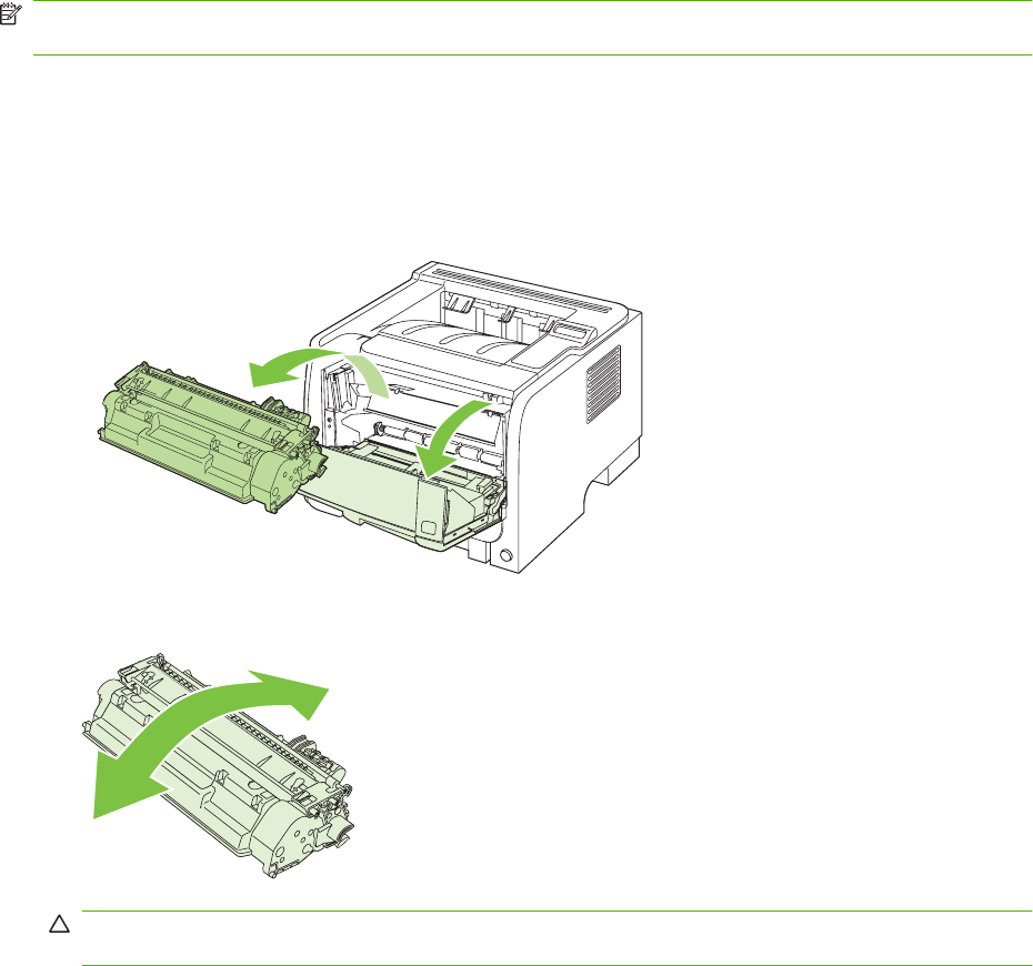
Replace supplies and parts
Supply replacement guidelines
Keep the following guidelines in mind when setting up the product.
●Sufficient space is required above and in the front of the product for removing supplies.
●The product should be located on a flat, sturdy surface.
NOTE: Hewlett-Packard recommends the use of HP supplies in this product. Use of non-HP supplies
can cause problems requiring service that is not covered by the HP warranty or service agreements.
Redistribute toner
When toner is low, faded or light areas appear on the printed page. You might be able to temporarily
improve print quality by redistributing the toner.
1. Push the button to open the print-cartridge door, and then remove the print cartridge.
2. To redistribute the toner, gently rock the print cartridge from front to back.
CAUTION: If toner gets on your clothing, wipe it off with a dry cloth and wash the clothing in cold
water. Hot water sets toner into the fabric.
ENWW Replace supplies and parts 61
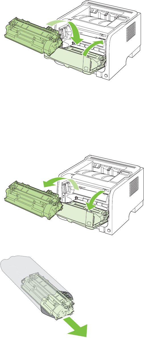
3. Reinsert the print cartridge into the product, and then close the print-cartridge door.
If the print is still light, install a new print cartridge.
Change the print cartridge
When a print cartridge approaches the end of useful life, you are prompted to order a replacement. You
can continue printing with the current cartridge until redistributing the toner no longer yields acceptable
print quality.
1. Push the button to open the print-cartridge door, and then remove the print cartridge.
2. Remove the new print cartridge from the bag. Place the used print cartridge in the bag for recycling.
62 Chapter 4 Manage and maintain ENWW
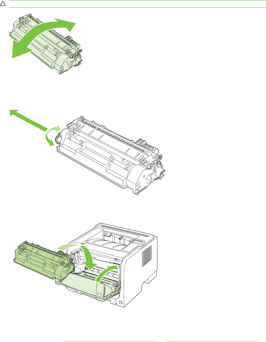
3. Grasp both sides of the print cartridge and distribute the toner by gently rocking the print cartridge.
CAUTION: Do not touch the shutter or the surface of the roller.
4. Bend the tab on the left side of the cartridge until the tab breaks loose. Pull the tab until all the tape
is removed from the cartridge. Place the tab and tape in the print-cartridge box to return for
recycling.
5. Align the print cartridge with the tracks inside the product, insert the print cartridge until it is firmly
seated, and then close the print-cartridge door.
6. Installation is complete. Place the used print cartridge in the box in which the new cartridge arrived.
See the enclosed recycling guide for recycling instructions.
For additional help, go to www.hp.com/support/ljp2050series or www.hp.com/support/ljp2030series .
ENWW Replace supplies and parts 63
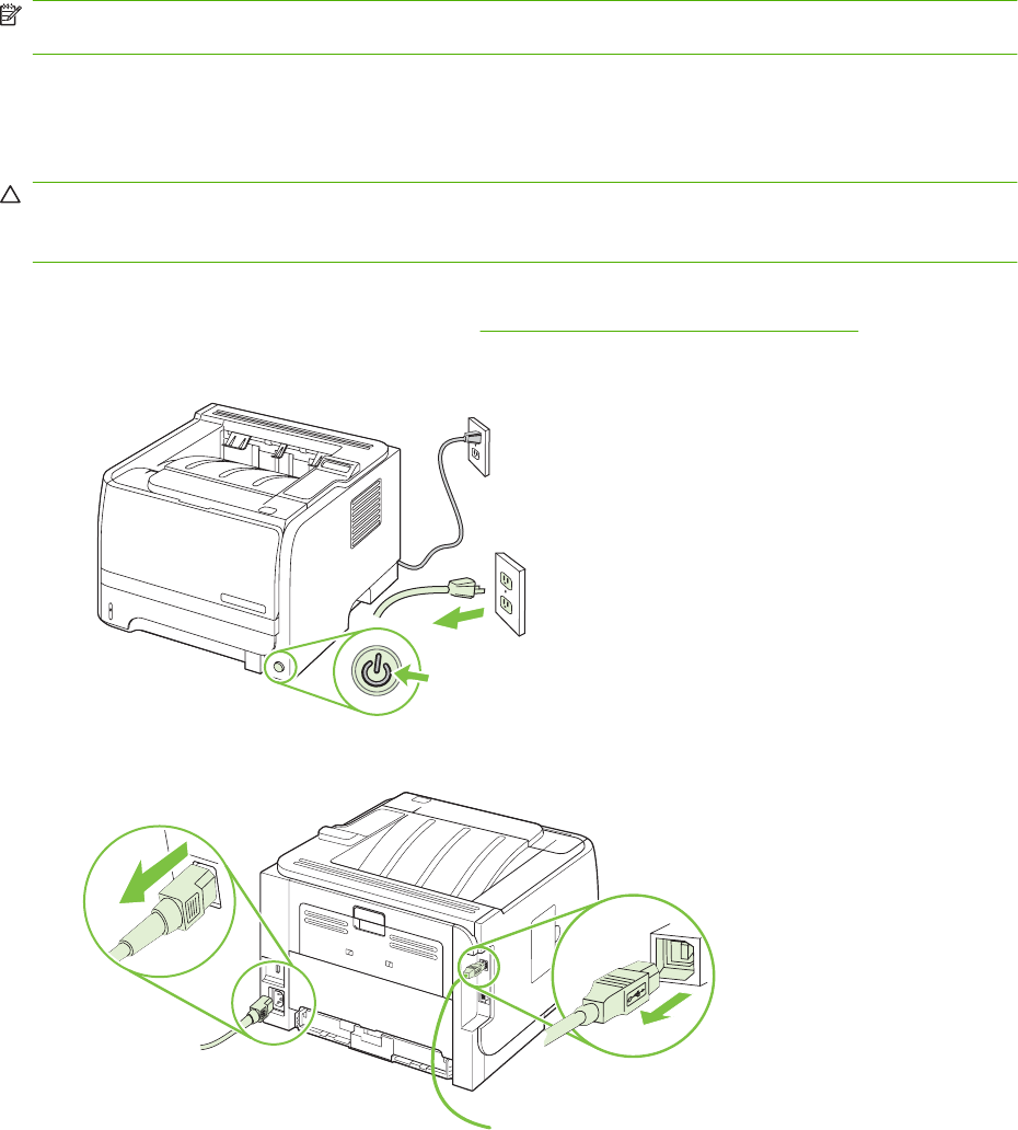
Install memory (HP LaserJet P2050 Series Printers only)
NOTE: Single inline memory modules (SIMMs) used in previous HP LaserJet products are not
compatible with the product.
Install product memory
This product has one DIMM slot.
CAUTION: Static electricity can damage DIMMs. When handling DIMMs, either wear an antistatic
wrist strap or frequently touch the surface of the DIMM antistatic package, then touch bare metal on the
product.
If you have not already done so, print a configuration page to find out how much memory is installed in
the product before adding more memory. See Print the information pages on page 48.
1. After the configuration page has printed, turn the product off and disconnect the power cord.
2. Disconnect all interface cables.
64 Chapter 4 Manage and maintain ENWW
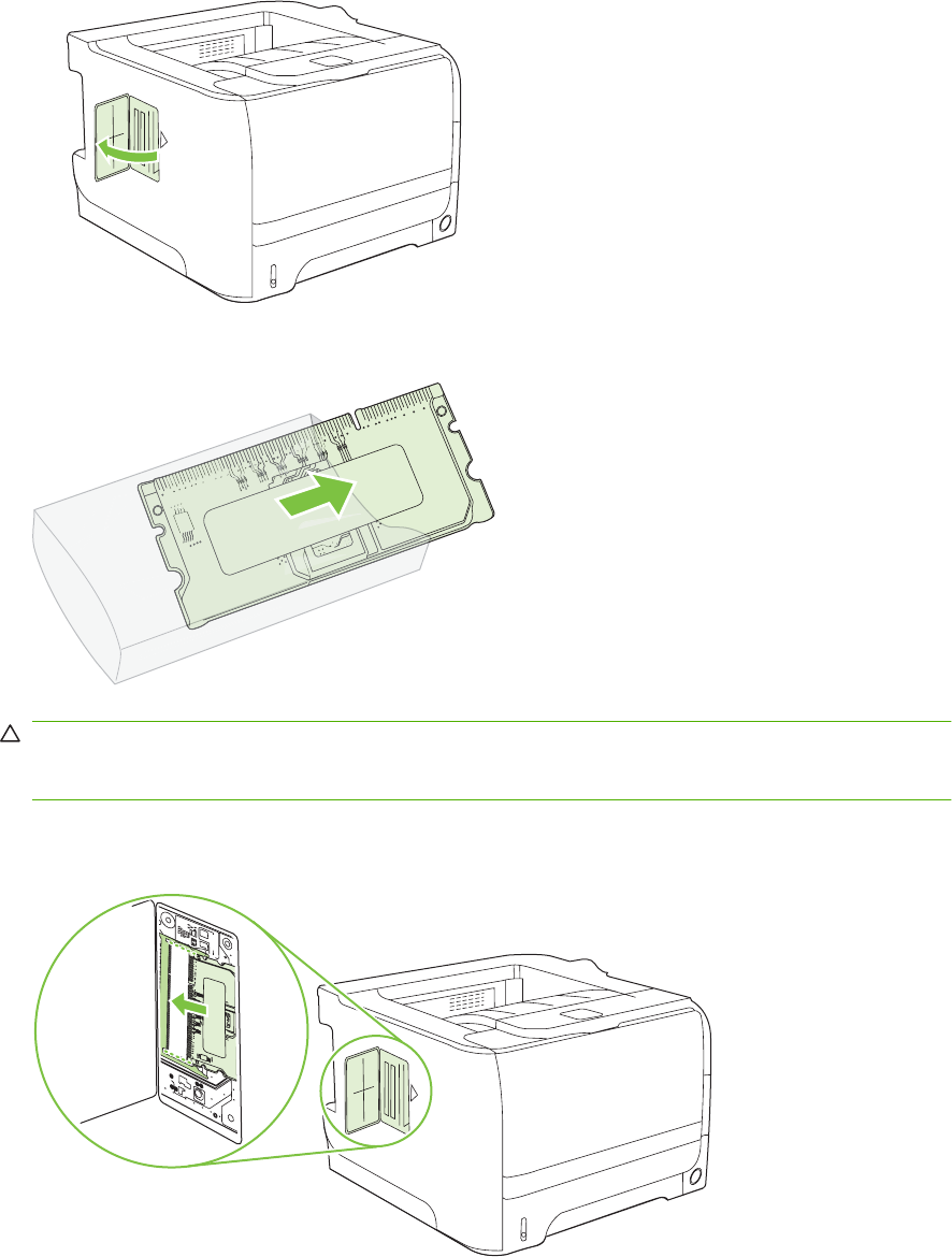
3. Open the DIMM-access door on the left side of the product.
4. Remove the DIMM from the antistatic package.
CAUTION: To reduce the possibility of damage caused by static electricity, always wear an
electrostatic discharge (ESD) wrist strap or touch the surface of the antistatic package before
handling DIMMs.
5. Hold the DIMM by the edges, and align the notches on the DIMM with the DIMM slot. (Check that
the locks on each side of the DIMM slot are open.)
ENWW Install memory (HP LaserJet P2050 Series Printers only) 65
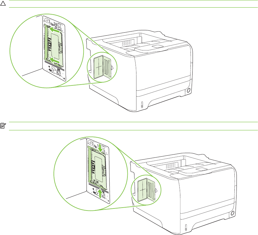
6. Hold the DIMM at a 45-degree angle, and then push the upper contacts of the DIMM firmly into the
slot. Make sure that the locks on each side of the DIMM snap into place.
CAUTION: Pressing the DIMM straight down can damage the contact pins.
NOTE: To remove a DIMM, first release the locks.
66 Chapter 4 Manage and maintain ENWW
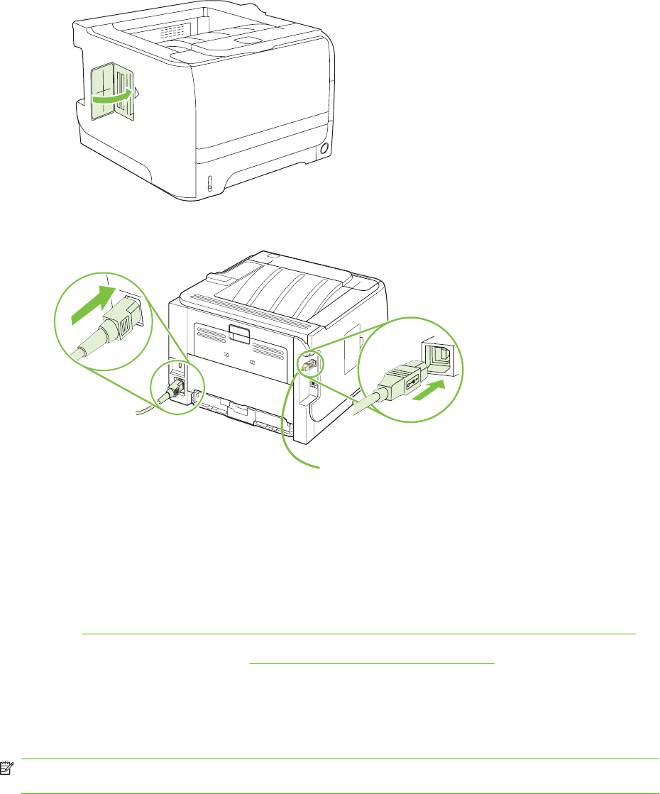
7. Close the access door, and press firmly until it snaps into place.
8. Reconnect the interface cable or cables and the power cord.
9. Turn the product on.
Check DIMM installation
After installing the DIMM, make sure that the installation was successful.
1. Turn the product on. Check that the Ready light is illuminated after the product has gone through
the startup sequence. If an error message appears, a DIMM might have been incorrectly installed.
See Interpret control-panel messages (HP LaserJet P2050 Series Printers only) on page 219.
2. Print a configuration page (see Print the information pages on page 48).
3. Check the memory section on the configuration page and compare it to the configuration page that
was printed before the memory installation. If the amount of memory has not increased, the DIMM
might not be installed correctly, or the DIMM might be defective. Repeat the installation procedure.
If necessary, install a different DIMM.
NOTE: If you installed a product language (personality), check the "Installed Personalities and
Options" section on the configuration page. This area should list the new product language.
Save resources (permanent resources)
Utilities or jobs that you download to the product sometimes include resources (for example, fonts,
macros, or patterns). Resources that are internally marked as permanent remain in the product memory
until you turn the product off.
ENWW Install memory (HP LaserJet P2050 Series Printers only) 67

Use the following guidelines if you use the page description language (PDL) ability to mark resources
as permanent. For technical details, see an appropriate PDL reference for PCL or PS.
●Mark resources as permanent only when it is absolutely necessary that they remain in memory
while the product is turned on.
●Send permanent resources to the product only at the beginning of a print job and not while the
product is printing.
NOTE: Overusing permanent resources or downloading them while the product is printing might affect
product performance or the ability to print complex pages.
Enable memory for Windows
1. Windows XP and Windows Server 2003 (using the default Start menu view): Click Start, click
Settings, and then click Printers and Faxes.
-or-
Windows 2000, Windows XP, and Windows Server 2003 (using the Classic Start menu
view): Click Start, click Settings, and then click Printers.
-or-
Windows Vista: Click Start, click Control Panel, and then in the category for Hardware and
Sound click Printer.
2. Right-click the driver icon, and then select Properties.
3. Click the Device Settings tab.
4. Expand the area for Installable Options.
5. Next to Printer Memory, select the total amount of memory that is installed.
6. Click OK.
68 Chapter 4 Manage and maintain ENWW
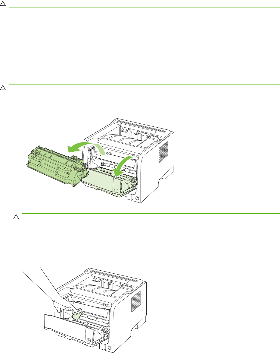
Clean the product
Clean the outside of the printer with a clean, damp cloth when necessary.
CAUTION: Do not use ammonia-based cleaners on or around the printer.
During the printing process, paper, toner, and dust particles can accumulate inside the printer. Over
time, this buildup can cause print quality problems, such as toner specks or smearing, and paper jams.
To correct and prevent these types of problems, you can clean the print cartridge area and the printer
media path.
Clean the print-cartridge area
You do not need to clean the print-cartridge area often. However, cleaning this area can improve the
quality of your printed sheets.
WARNING! To avoid injury, turn the product off, disconnect the power cord, and wait for the product
to cool before cleaning it.
1. Open the print-cartridge door, and then remove the print cartridge.
CAUTION: Do not touch the black sponge-transfer roller inside the product. Doing so can
damage the product.
CAUTION: To prevent damage, do not expose the print cartridge to light. Cover it with a piece
of paper.
2. With a dry, lint-free cloth, wipe any residue from the media-path area and the print-cartridge cavity.
ENWW Clean the product 69
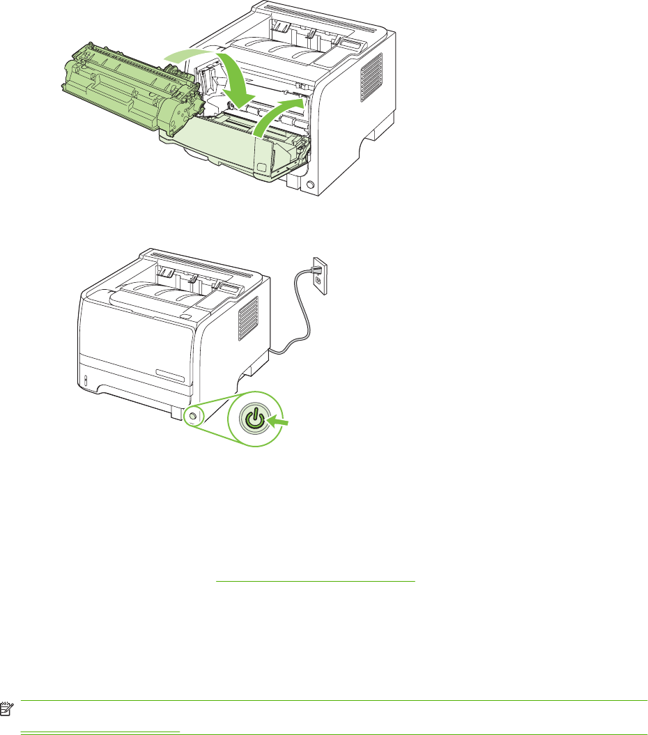
3. Replace the print cartridge, and close the print-cartridge door.
4. Reconnect the power cord, and turn the product on.
Clean the paper path (HP LaserJet P2050 Series Printers only)
During the printing process, paper, toner, and dust particles can accumulate inside the product. Over
time, this buildup can cause print-quality problems such as toner specks or smearing. This product has
a cleaning mode that can correct and prevent these problems.
1. Open HP ToolboxFX. See View HP ToolboxFX on page 50.
2. Click the Device Settings folder, and then click the Troubleshooting page.
3. In the area for Cleaning Mode, click Start to begin the cleaning process.
The product processes a single page, and then returns to the Ready state when the cleaning
process is complete. When possible, use transparencies for this process.
NOTE: You can also access the Cleaning mode from the Service menu on the control panel. See
Service menu on page 27.
Clean the paper path (HP LaserJet P2030 Series Printers only)
If you are experiencing toner specks or dots on the printouts, clean the product media path. This process
uses a transparency to remove dust and toner from the media path. Do not use bond or rough paper.
70 Chapter 4 Manage and maintain ENWW
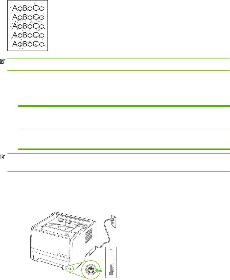
NOTE: For best results use a sheet of transparency. If you do not have any transparencies, you can
use copier grade media (70 to 90 g/m
2
(18 to 24 lb)) with a smooth surface.
1. Make sure that the product is idle and the Ready light is on.
2. Load the transparency in Tray 1.
3. Print a cleaning page.
Windows 1. Open the printer-driver Properties screen, and then click the Device
Settings tab.
2. In the Cleaning Page area, click Start.
Macintosh 1. Open the HP Printer Utility.
2. Select the Cleaning Page option, and click the OK button.
NOTE: The cleaning process takes about 2 minutes. The cleaning page stops periodically during the
cleaning process. Do not turn the product off until the cleaning process has finished. You might need to
repeat the cleaning process several times to thoroughly clean the product.
Clean the Tray 1 pickup roller
If the product is having trouble picking up paper from Tray 1, follow these instructions.
1. Turn the product off, disconnect the power cord, and wait for the product to cool.
–10
10
20
30
40
50
60
70
80
90
100
0
Celcius
°C
ENWW Clean the product 71
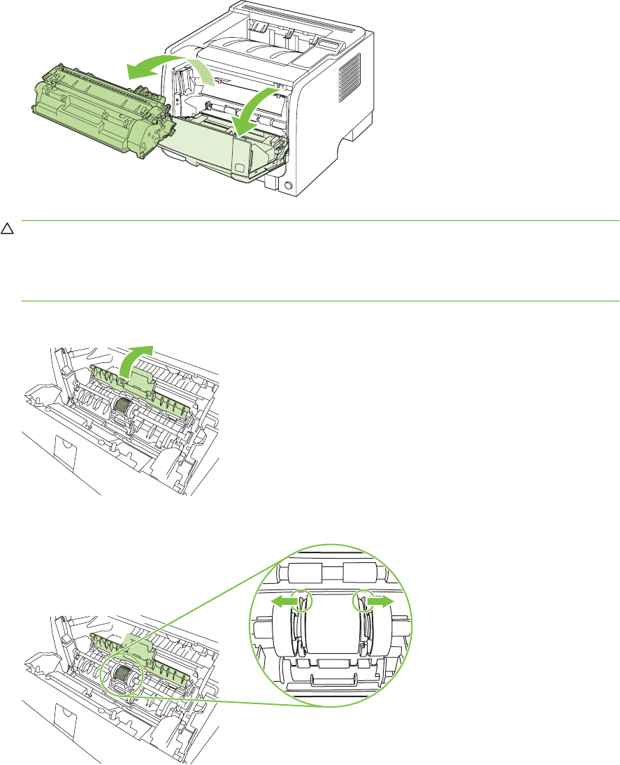
2. Push the button to open the print-cartridge door, and then remove the print cartridge.
CAUTION: Do not touch the black sponge-transfer roller inside the product. Doing so can
damage the product.
CAUTION: To prevent damage, do not expose the print cartridge to light. Cover it with a piece
of paper.
3. Lift the pickup roller cover.
4. Press the two black retaining tabs outward until the pickup roller is released from its seat.
72 Chapter 4 Manage and maintain ENWW
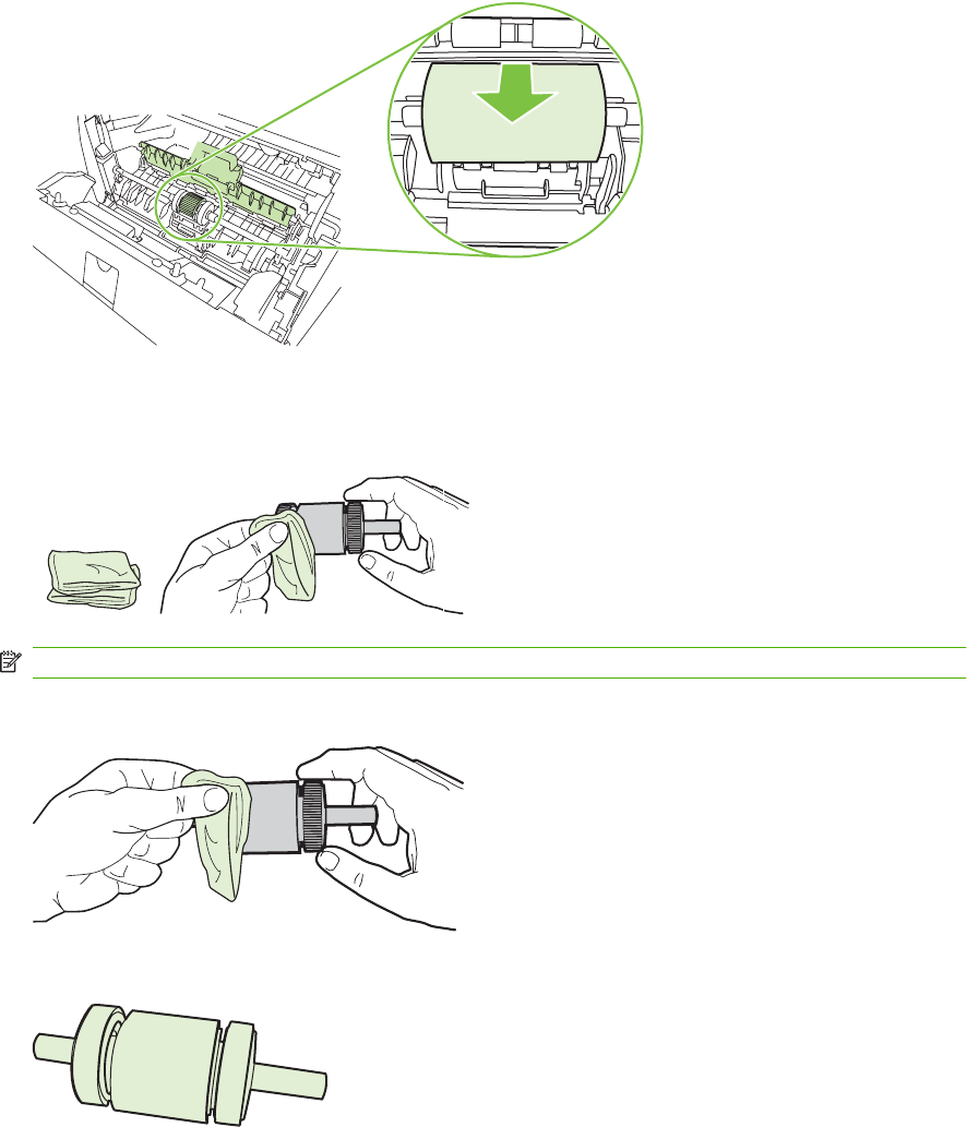
5. Remove the pickup roller from the product.
6. Dab a lint-free cloth in water, and scrub the roller.
NOTE: Do not touch the surface of the roller with bare fingers.
7. Using a dry, lint-free cloth, wipe the pickup roller to remove loosened dirt.
8. Allow the pickup roller to dry completely.
ENWW Clean the product 73
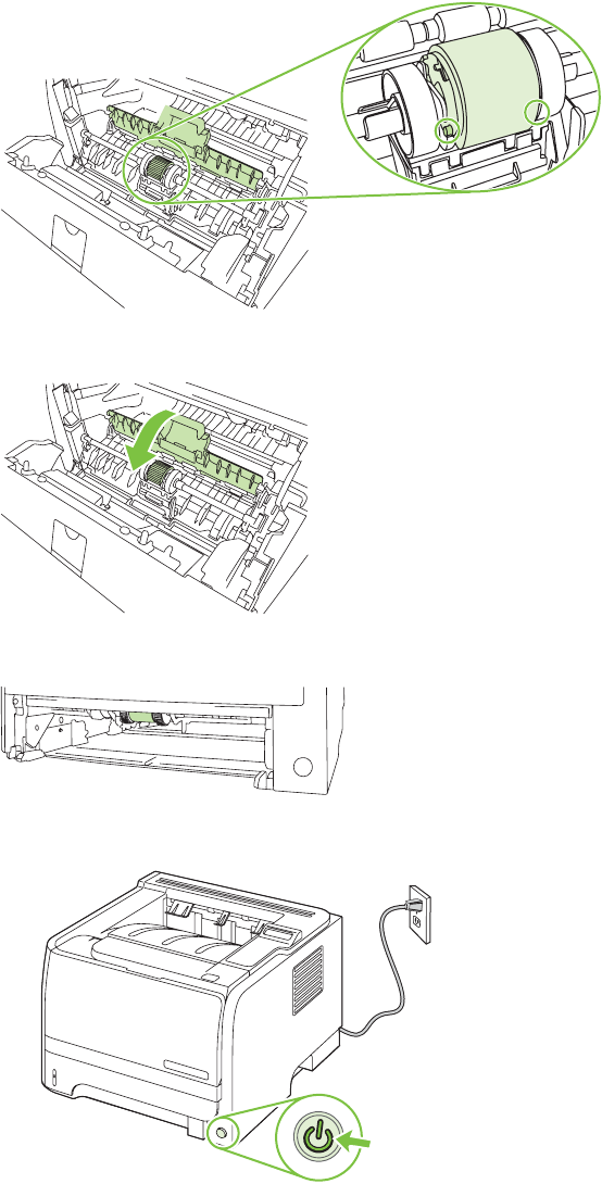
9. Line up the black retaining tabs in the product with the grooves in the pickup roller, and then press
the pickup roller into the pickup roller seat until the retaining tabs click.
10. Close the pickup roller cover.
11. Reinstall the print cartridge, and close the print-cartridge door.
12. Reconnect the power cord, and turn the product on.
74 Chapter 4 Manage and maintain ENWW
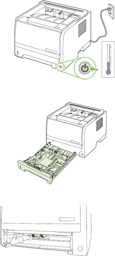
Clean the Tray 2 pickup roller
If the product is having trouble picking up paper from Tray 2, follow these instructions.
1. Turn the product off, disconnect the power cord and wait for the product to cool.
–10
10
20
30
40
50
60
70
80
90
100
0
Celcius
°C
2. Remove Tray 2.
3. Inside the empty tray slot, locate the pickup roller on the top side, near the front of the product.
ENWW Clean the product 75
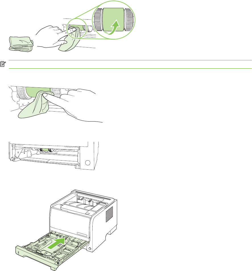
4. Dab a lint-free cloth in water, and then scrub the roller as you rotate it toward the back of the product.
NOTE: Do not touch the surface of the roller with bare fingers.
5. Using a dry, lint-free cloth, wipe the pickup roller to remove loosened dirt.
6. Allow the pickup roller to dry completely.
7. Replace Tray 2.
76 Chapter 4 Manage and maintain ENWW
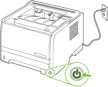
8. Reconnect the power cord, and turn the product on.
ENWW Clean the product 77
78 Chapter 4 Manage and maintain ENWW

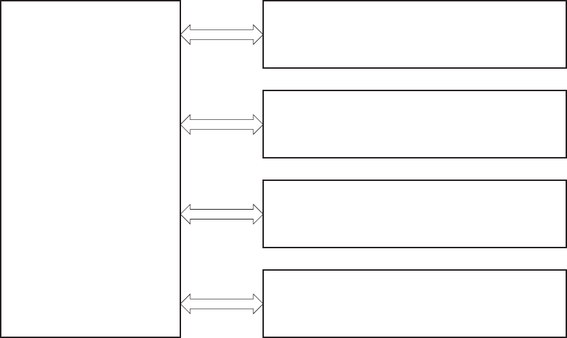
Introduction
This chapter presents an overview of the relationships between major components in the product, and
includes a detailed discussion of the image-formation system. The following systems are discussed:
●Engine control system
●Laser/scanner system
●Image-formation system
●Pickup/feed/delivery system
●Option
Figure 5-1 Block diagram
PICKUP/FEED/DELIVERY SYSTEM
LASER SCANNER SYSTEM
ENGINE CONTROL
SYSTEM
IMAGE-FORMATION SYSTEM
OPTION
80 Chapter 5 Theory of operation ENWW
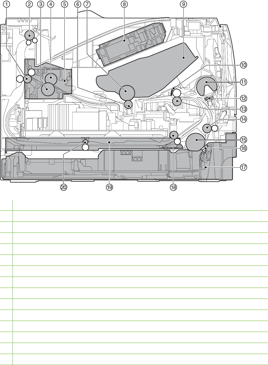
Internal components
Figure 5-2 Cross-section of product
1Fuser delivery roller
2Face-down delivery roller
3Pressure roller
4Fuser film
5Fuser
6Transfer roller
7Photosensitive drum
8Laser scanner
9Print cartridge
10 Registration shutter
11 Tray 1 pickup roller
12 Tray separation pad
13 Registration roller
14 Feed roller
15 Tray 2 pickup roller
ENWW Internal components 81

16 Tray 2 separation pad
17 Tray 2
18 Duplex re-pickup roller (HP LaserJet P2050 Series Printers only)
19 Duplex feed unit (HP LaserJet P2050 Series Printers only)
20 Duplex feed roller (HP LaserJet P2050 Series Printers only)
82 Chapter 5 Theory of operation ENWW

Timing
Sequence of operation
The microprocessor on the DC controller controls the product operation sequences.
Table 5-1 Sequence of operation
Name Timing Purpose
WAIT From power-on or the door is closed until the end of
the main motor initial drive.
Detects presence of a print cartridge.
STBY (standby) From the end of the WAIT or LSTR period until either
a print command is sent from the formatter or the
power is turned off.
Prepares the product to receive print commands
INTR (initial
rotation)
From the time the print command is received from the
formatter until the fuser reached its targeted
temperature.
Starts each high-voltage biases, the laser scanner,
and fuser in preparation for printing.
PRINT From the end of the INTR period until the last media
completes the fusing operation.
Forms the image on the photosensitive drum and
transfers the toner image to the media.
LSTR (last
rotation)
From the end of the PRINT period (when high-voltage
is turned off) until the main motor stops rotating.
Delivers the last page of a print job.
After LSTR, the product either returns to STBY or, if
another print command was sent from the formatter,
enters INTR.
ENWW Timing 83
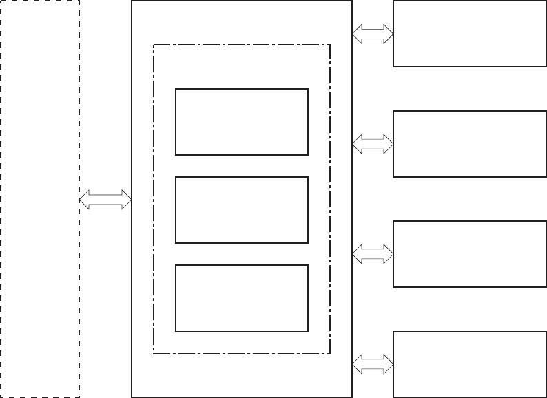
Engine control system
The engine control system coordinates all product functions, according to commands sent from the
formatter. It drives the laser/scanner system, the image-formation system, and the pickup/feed/delivery
system.
The engine control system contains the following components:
●DC controller
●Low-voltage power supply
●High-voltage power supply
Figure 5-3 Engine control system
Engine controller
DC controller
High-voltage
power supply
Low-voltage
power supply
Formatter
LASER SCANNER
SYSTEM
IMAGE-FORMATION
SYSTEM
PICKUP/FEED/DELIVERY
SYSTEM
ENGINE CONTROL SYSTEM
OPTION
84 Chapter 5 Theory of operation ENWW
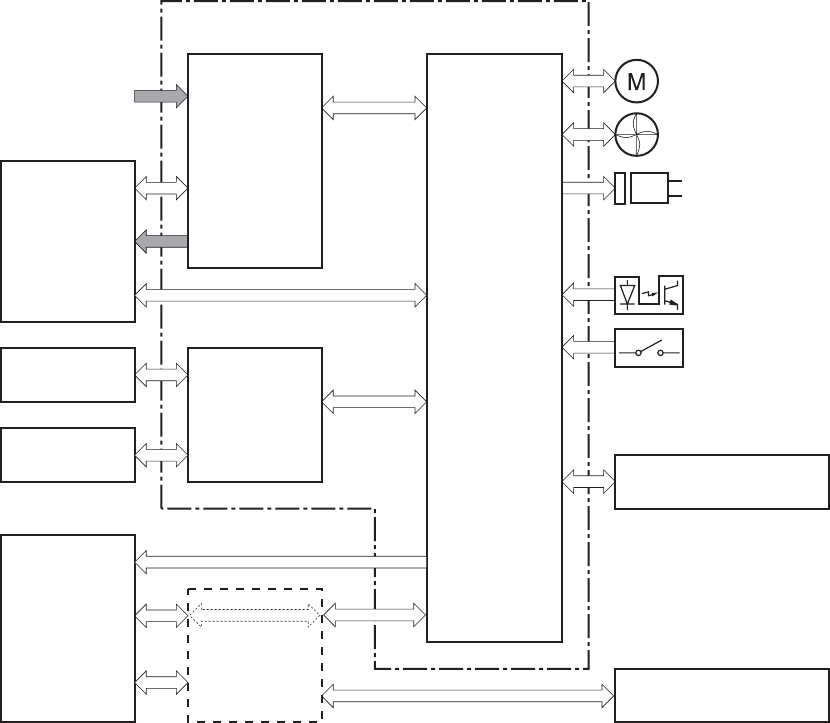
DC controller
The DC controller controls the operational sequence of the product.
Figure 5-4 DC controller
Fuser unit
High-voltage
power supply
Cartridge
Transfer roller
AC input
Low-voltage
power supply
Motor
Solenoid
Photointerrupter
DC controller
Laser
scanner unit
Formatter
Fan
Option
Operation panel
Switch
Engine controller
ENWW Engine control system 85
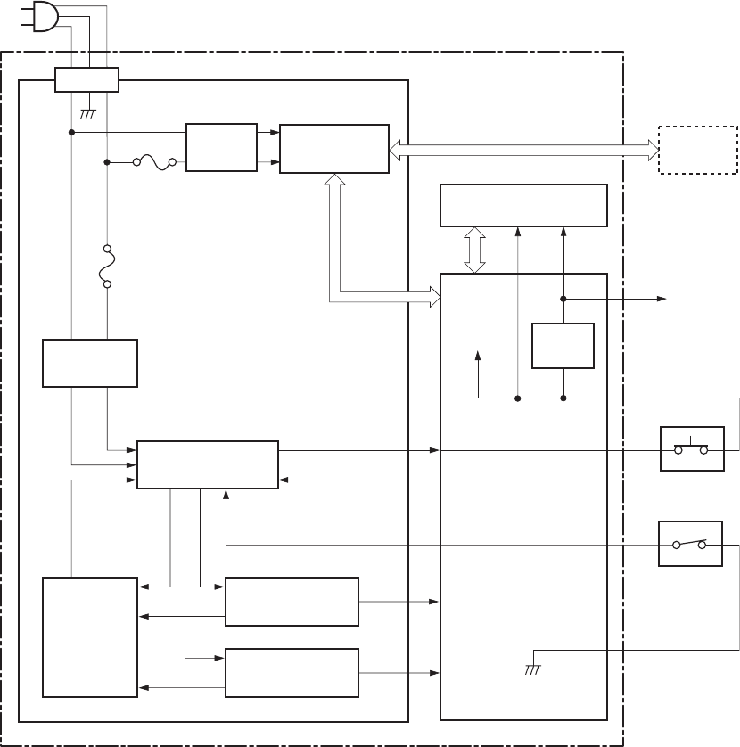
Low-voltage power supply
Figure 5-5 Low-voltage power supply
PWSV
+5V
+3.3V
+24V
+24U
DOORSNS
SWON
Noise
filter
FET
+24P1
Fuse (FU102)
Door switch
(SW301)
Power switch
(SW1001)
+24V
generation circuit
DC controller
Low-voltage power supply
Engine controller
Fusing control
circuit Fuser
+5V
generation circuit
+3.3V
generation circuit
High-voltage power
supply
Noise filter
Protection
circuit
Fuse (FU101)
86 Chapter 5 Theory of operation ENWW
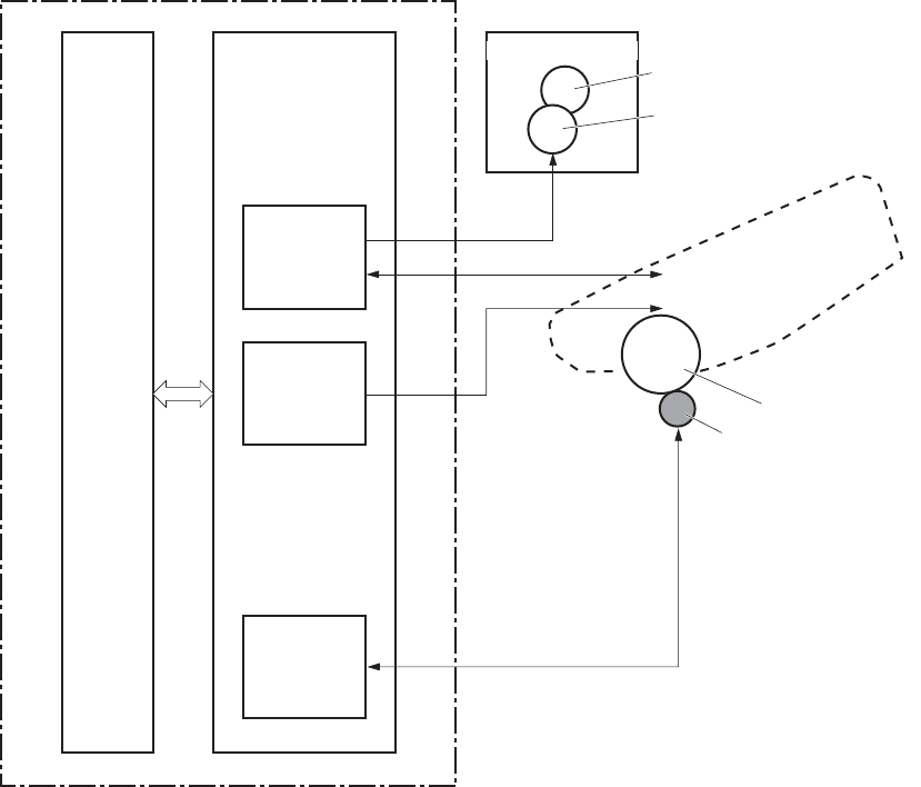
High-voltage power supply
Figure 5-6 High-voltage power supply
TR
PR
DV
FB
High-voltage power supply
Primary
charging
bias circuit
Developing
bias circuit
Transfer
bias circuit
DC controller
Engine controller
Primary charging roller
Cartridge
Photosensitive drum
Transfer roller
Developing roller
Fuser
Pressure roller
Fusing film
ENWW Engine control system 87
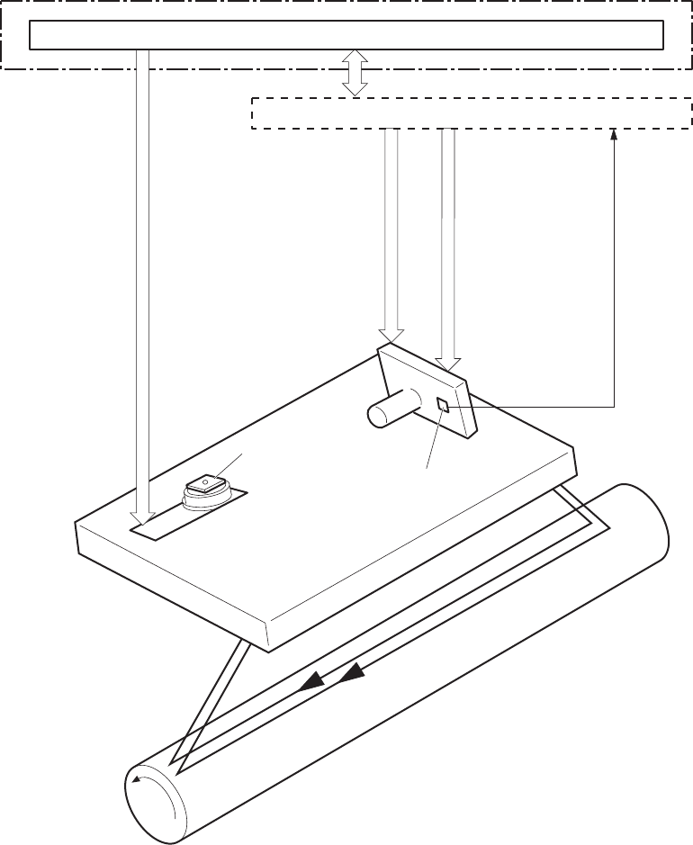
Laser/scanner system
The formatter sends video signals to the DC controller, which controls the laser/scanner. When the laser/
scanner system receives those signals, it converts them to latent images on the photosensitive drum.
Figure 5-7 Laser/scanner system
Formatter
DC controller
Engine controller
Scanner mirror
Scanner motor unit
Photosensitive drum
BD sensor
Laser unit
LASER CONTROL signal
VIDEO signal
SCANNER MOTOR SPEED CONTROL signal
BD INPUT signal
88 Chapter 5 Theory of operation ENWW
Laser failure detection
The optical unit failure detection sensor manages the laser/scanner unit failure-detection functions. The
DC controller identifies the laser/scanner unit failure and notifies the formatter if the laser/scanner unit
encounters the following conditions:
●Scanner motor failure
●BD failure
ENWW Laser/scanner system 89
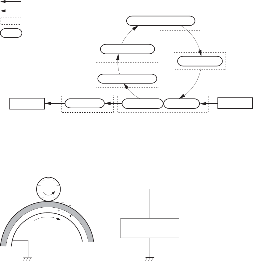
Image-formation system
Laser printing requires the interaction of several different technologies, including electronics, optics, and
electrophotographics, to provide a printed page. Each process functions independently and must be
coordinated with the other product processes. Image formation consists of the following five processes:
●electrostatic latent-image formation
●developing
●transfer
●fusing
●drum cleaning
The five processes contain seven steps.
Figure 5-8 Image-formation system
2. Laser-beam exposure
Fusing
6. Fusing
Delivery
7. Drum cleaning
3. Developing
1. Primary charging
Pickup
4. Transfer
5. Separation
Transfer
Latent image formation
Media path
Direction of the drum rotation
Block
Step
Drum cleaning
Developing
Step 1: Primary charging
DC and AC biases are applied to the primary charging roller, which transfers a uniform negative potential
to the photosensitive drum.
Figure 5-9 Primary charging
Primary charging bias
Photosensitive drum
Primary charging roller
90 Chapter 5 Theory of operation ENWW
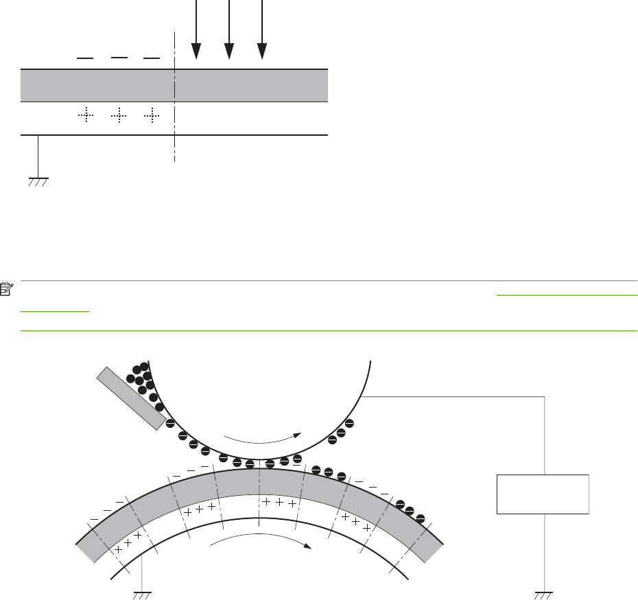
Step 2: Laser beam exposure
The laser beam scans the photosensitive drum to neutralize negative charges on parts of the drum. An
electrostatic latent image is formed on the drum where negative charges were neutralized.
Laser beam
Unexposed area Exposed area
Step 3: Developing
The developing cylinder comes in contact with the photosensitive drum to deposit toner onto the
electrostatic latent image.
NOTE: The charges on the exposed area of the drum are shown as positive in Figure 5-10 Developing
on page 91. The charges are actually negative, but they are more positive than the charges on the
developing cylinder.
Figure 5-10 Developing
Developing bias
Blade
Developing roller
Photosensitive drum
Unexposed area
Exposed area
Exposed area
Unexposed area
Toner acquires a negative charge through friction from the developing cylinder and the blade. When the
negatively charged toner comes in contact with the drum, the toner adheres to the electrostatic latent
image. The image on the drum becomes visible because of the toner.
Step 4: Transfer
The transfer charging roller, to which a dc positive bias is applied, imparts a positive charge on the print
media. When the print media comes in contact with the photosensitive drum, the toner is transferred to
the print media.
ENWW Image-formation system 91
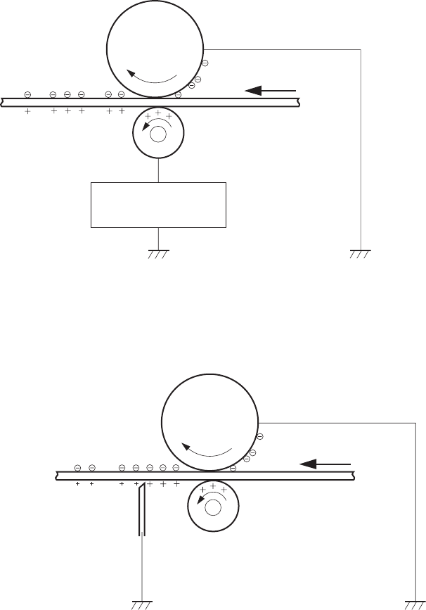
Figure 5-11 Transfer
Transfer bias
Media
Transfer roller
Photosensitive
drum
Step 5: Separation
The elasticity of the print media causes its separation from the photosensitive drum. A static charge
eliminator aids separation by weakening any electrostatic adhesion.
Figure 5-12 Separation
Media
Transfer roller
Photosensitive
drum
Static charge eliminator
Step 6: Fusing
The dc negative bias applied to the fusing film strengthens the holding force of the toner on the print
media and prevents the toner from scattering.
92 Chapter 5 Theory of operation ENWW
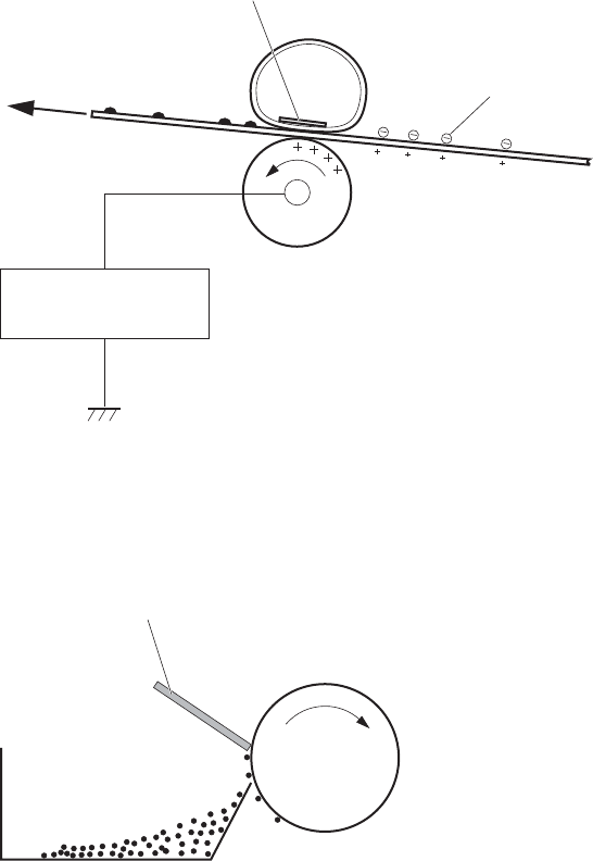
Figure 5-13 Fusing
Fusing bias
Fusing film Toner
Pressure roller
Fusing heater
Media
Step 7: Drum cleaning
The cleaning blade scrapes the residual toner off the photosensitive drum and deposits it into the waste
toner case.
Figure 5-14 Drum cleaning
Toner collection box
Photosensitive
drum
Cleaning blade
ENWW Image-formation system 93
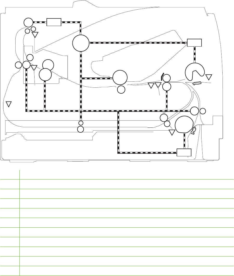
Pickup/feed/delivery system
The pickup/feed/delivery system consists of several types of feed rollers and sensors. The DC controller
uses two motors and two solenoids to drive the rollers. Three media-detection sensors detect media as
it passes through the product. If media does not reach or pass each sensor within a specified period,
the DC controller determines that a jam has occurred and alerts the formatter.
Figure 5-15 Pickup/feed/delivery system
M1 SL1
SL3
SL2
PS912
PS916
PS914
PS913
PS911
PS915
PS918
M1 Main motor
SL1 Tray 1 pickup solenoid
SL2 Tray 2 pickup solenoid
SL3 Duplex solenoid (HP LaserJet P2050 Series Printers only)
PS911 Tray 3 media sensor (HP LaserJet P2050 Series Printers only)
PS912 Top-of-page sensor
PS913 Width-detection sensor
PS914 Tray 2 media sensor
PS915 Fuser delivery sensor
PS916 Tray 1 media presence sensor
PS918 Duplex sensor (HP LaserJet P2050 Series Printers only)
94 Chapter 5 Theory of operation ENWW
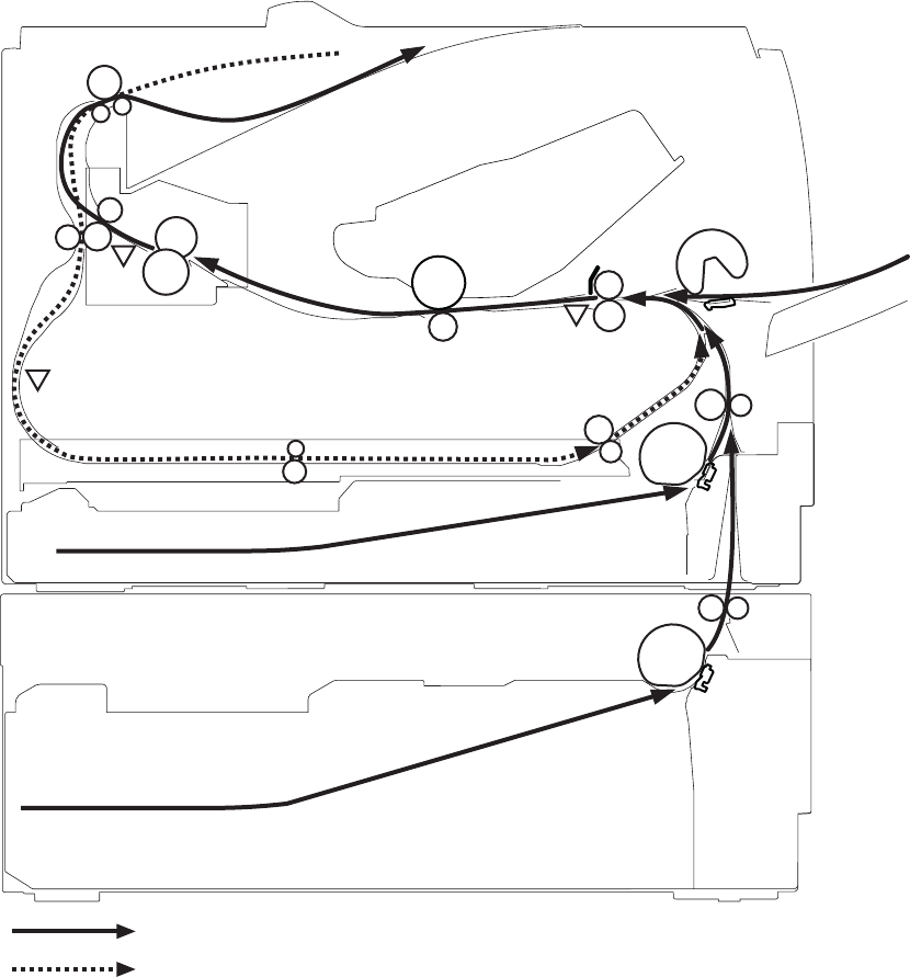
Jam detection
The product uses the following sensors to detect the presence of media and to check whether media is
being fed correctly or has jammed:
●Top sensor (SR912)
●Fuser delivery sensor (SR915)
●Duplex reverse sensor (SR918)
Figure 5-16 Jam detection
PS912
PS915
PS918
: Simplex media path
: Duplex media path (HP LaserJet 2050 series printer only)
ENWW Pickup/feed/delivery system 95
96 Chapter 5 Theory of operation ENWW


Introduction
This chapter describes the removal and replacement of field-replaceable units (FRUs) only.
NOTE: Your product might not appear exactly as the one shown in the photos in this chapter. For
example, the color of the external panels and covers might be different than your product. However, the
procedures in this chapter are valid for both the HP LaserJet P2035 and the HP LaserJet P2055.
Replacing FRUs is generally the reverse of removal. Notes and tips are included to provide directions
for difficult or critical replacement procedures.
HP does not support repairing individual subassemblies or troubleshooting to the component level.
Note the length, diameter, color, type, and placement of each screw. Be sure to return each screw to
its original location during reassembly.
Incorrectly routed or loose wire harnesses can interfere with other internal components and can become
damaged or broken. Frayed or pinched harness wires can be difficult to find. When replacing wire
harnesses, always use the provided wire loops, lance points, or wire-harness guides.
Removal and replacement strategy
WARNING! Turn the product off, wait 5 seconds, and then remove the power cord before attempting
to service the product. If this warning is not followed, severe injury can result, in addition to damage to
the product. The power must be on for certain functional checks during problem solving. However, the
power supply should be disconnected during parts removal.
Never operate or service the product with the protective cover removed from the laser/scanner
assembly. The reflected beam, although invisible, can damage your eyes.
The sheet-metal parts can have sharp edges. Be careful when handling sheet-metal parts.
CAUTION: Do not bend or fold the flat flexible cables (FFCs) during removal or installation. Also, do
not straighten pre-folds in the FFCs. You must Make sure that all FFCs are fully seated in their
connectors. Failure to fully seat an FFC into a connector can cause a short circuit in a PCA.
NOTE: To install a self-tapping screw, first turn it counterclockwise to align it with the existing thread
pattern, and then carefully turn it clockwise to tighten. Do not overtighten. If a self-tapping screw-hole
becomes stripped, repair the screw-hole or replace the affected assembly.
Electrostatic discharge
CAUTION: Some parts are sensitive to electrostatic discharge (ESD). Look for the ESD reminder
when removing product parts. Always perform service work at an ESD-protected workstation or mat. If
an ESD workstation or mat is not available, ground yourself by touching the sheet-metal chassis
before touching an ESD-sensitive part.
Protect the ESD-sensitive parts by placing them in ESD pouches when they are out of the product.
98 Chapter 6 Removal and replacement ENWW

Required tools
●#2 Phillips screwdriver with a magnetic tip and a 152-mm (6-inch) shaft length
●Small flatblade screwdriver
●Needle-nose pliers
●ESD mat (if one is available) or ESD strap
●Penlight (optional)
CAUTION: Always use a Phillips screwdriver (callout 1). Do not use a pozidrive screwdriver (callout 2)
or any motorized screwdriver. These can damage screws or screw threads.
CAUTION: Avoid pulling directly on wires to disconnect wire-harness connectors. Pull on the plastic
body of a connector to avoid damaging the connector wires.
Figure 6-1 Phillips and pozidrive screwdriver comparison
ENWW Required tools 99

Before performing service
●Remove all media from the product.
●Turn off the power using the power switch.
●Unplug the power cable and interface cable or cables.
●Place the product on an ESD mat (if one is available) or use an ESD strap. If an ESD workstation,
mat, or strap is not available, ground yourself by touching the sheet-metal chassis before touching
an ESD-sensitive part.
●Remove the print cartridge. See Print cartridge on page 102.
●Remove the Tray 2 cassette.
After performing service
●Plug in the power cable.
●Reinstall the print cartridge.
●Reinstall the Tray 2 cassette.
100 Chapter 6 Removal and replacement ENWW
Post-service test
When service is complete, use these tests to make sure that the repair or replacement was successful.
Print-quality test
1. Verify that you have completed the necessary reassembly steps.
2. Make sure that the input tray contains clean, unmarked paper.
3. Attach the power cord and interface cable, and then turn on the product.
4. Verify that the expected startup sounds occur.
5. Print a configuration page, and then verify that the expected printing sounds occur.
6. Print a demo page, and then verify that the print quality is as expected.
7. Send a print job from the host computer, and then verify that the output meets expectations. For
HP LaserJet P2050 Series Printers, print a duplex page.
8. If necessary, restore any customer-specified settings.
9. Clean the outside of the product with a damp cloth.
ENWW Post-service test 101
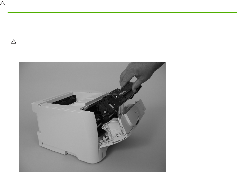
Print cartridge
CAUTION: If toner gets on any clothing, wipe it off with a dry cloth and wash the clothing in cold water.
Hot water sets toner into the fabric.
1. Open the print-cartridge door.
2. Grasp the handle on the print cartridge, and then pull the cartridge up and out of the product.
CAUTION: When the print cartridge is removed, do not expose it to direct or strong light. Protect
the print cartridge by placing a sheet of paper over it.
Figure 6-2 Remove the print cartridge
3. Close the print-cartridge door.
102 Chapter 6 Removal and replacement ENWW
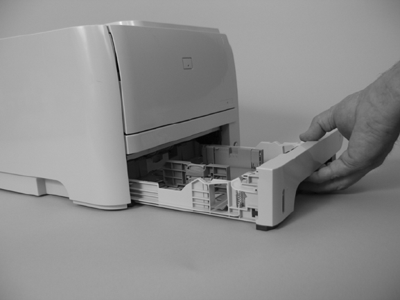
Tray 2 cassette
Pull the tray straight out of the product to remove it.
Figure 6-3 Remove the Tray 2 cassette
ENWW Tray 2 cassette 103
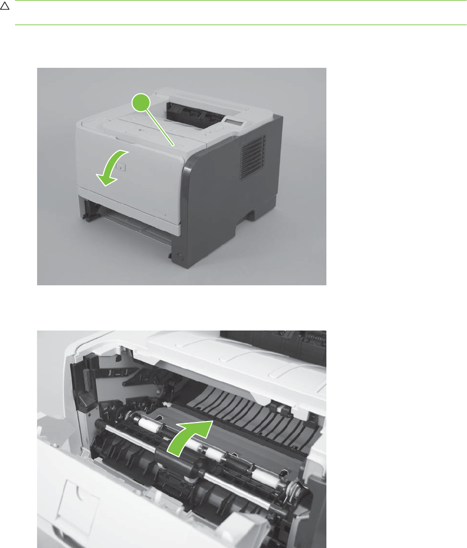
Rollers and pads
Pickup roller; Tray 1
CAUTION: Do not touch the roller surface unless you are replacing the roller. Skin oils on the roller
can cause paper pickup problems.
1. Press the print-cartridge door button (callout 1), and then open the print-cartridge door.
Figure 6-4 Remove the pickup roller; Tray 1 (1 of 5)
1
2. Rotate the roller cover up and away from the roller assembly.
Figure 6-5 Remove the pickup roller; Tray 1 (2 of 5)
104 Chapter 6 Removal and replacement ENWW
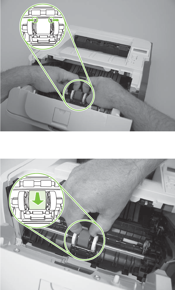
3. Release two tabs.
Figure 6-6 Remove the pickup roller; Tray 1 (3 of 5)
4. Rotate the pickup roller away from the product.
Figure 6-7 Remove the pickup roller; Tray 1 (4 of 5)
ENWW Rollers and pads 105
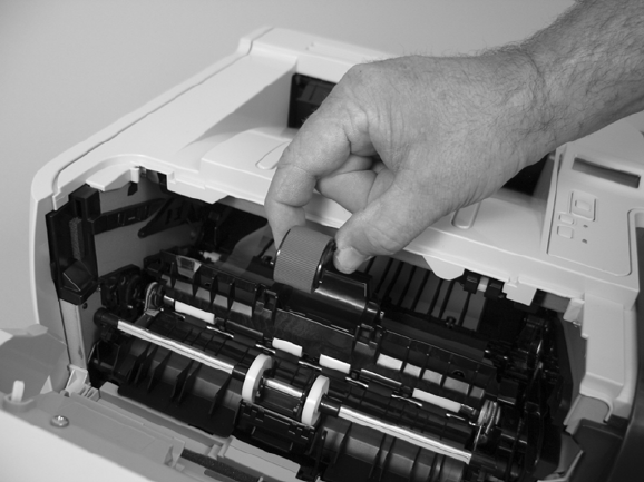
5. Remove the pickup roller.
Figure 6-8 Remove the pickup roller; Tray 1 (5 of 5)
106 Chapter 6 Removal and replacement ENWW
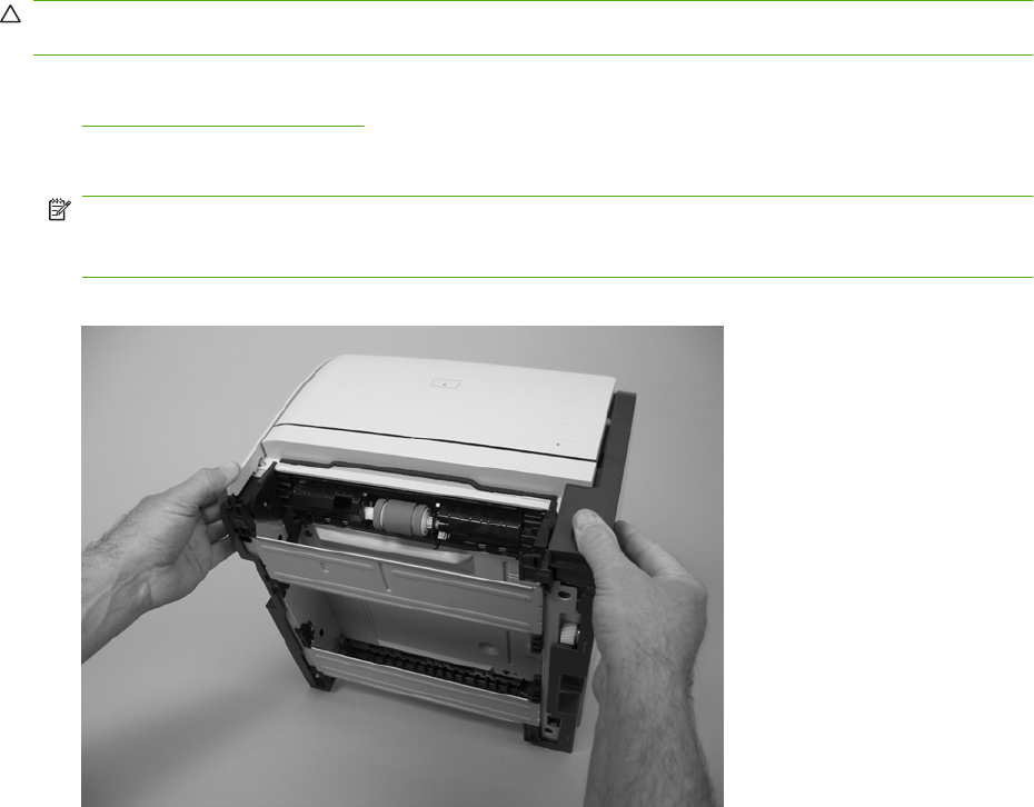
Pickup roller assembly; Tray 2
CAUTION: Do not touch the roller surface unless you are replacing the roller. Skin oils on the roller
can cause paper-pickup problems.
1. If the Tray 2 cassette has not yet been removed to service the product, remove the cassette. See
Tray 2 cassette on page 103.
2. Carefully place the product front-side up.
NOTE: Debris can scratch or damage the back of the product. Before you place the product front-
side up, remove any debris from the work surface. If possible, set the product on a clean, dry cloth
to prevent scratching and damage.
Figure 6-9 Remove the pickup roller assembly; Tray 2 (1 of 5)
ENWW Rollers and pads 107
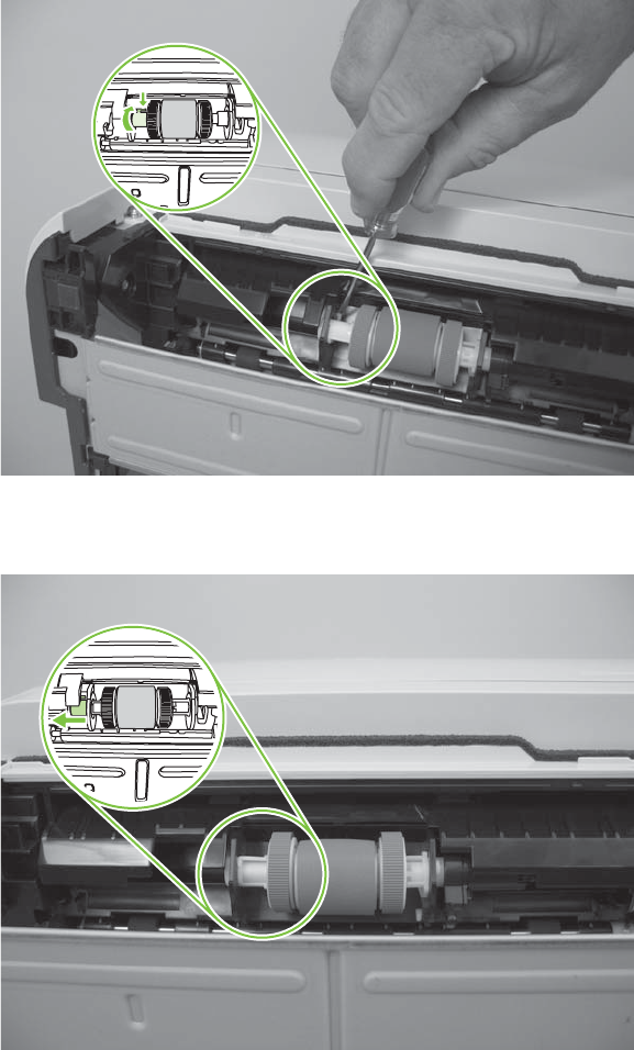
3. Use a small flat blade screwdriver to release one tab (callout 1), and then rotate the locking collar
toward the inside of the product.
Figure 6-10 Remove the pickup roller assembly; Tray 2 (2 of 5)
4. Slide the collar away from the rollers.
Figure 6-11 Remove the pickup roller assembly; Tray 2 (3 of 5)
108 Chapter 6 Removal and replacement ENWW
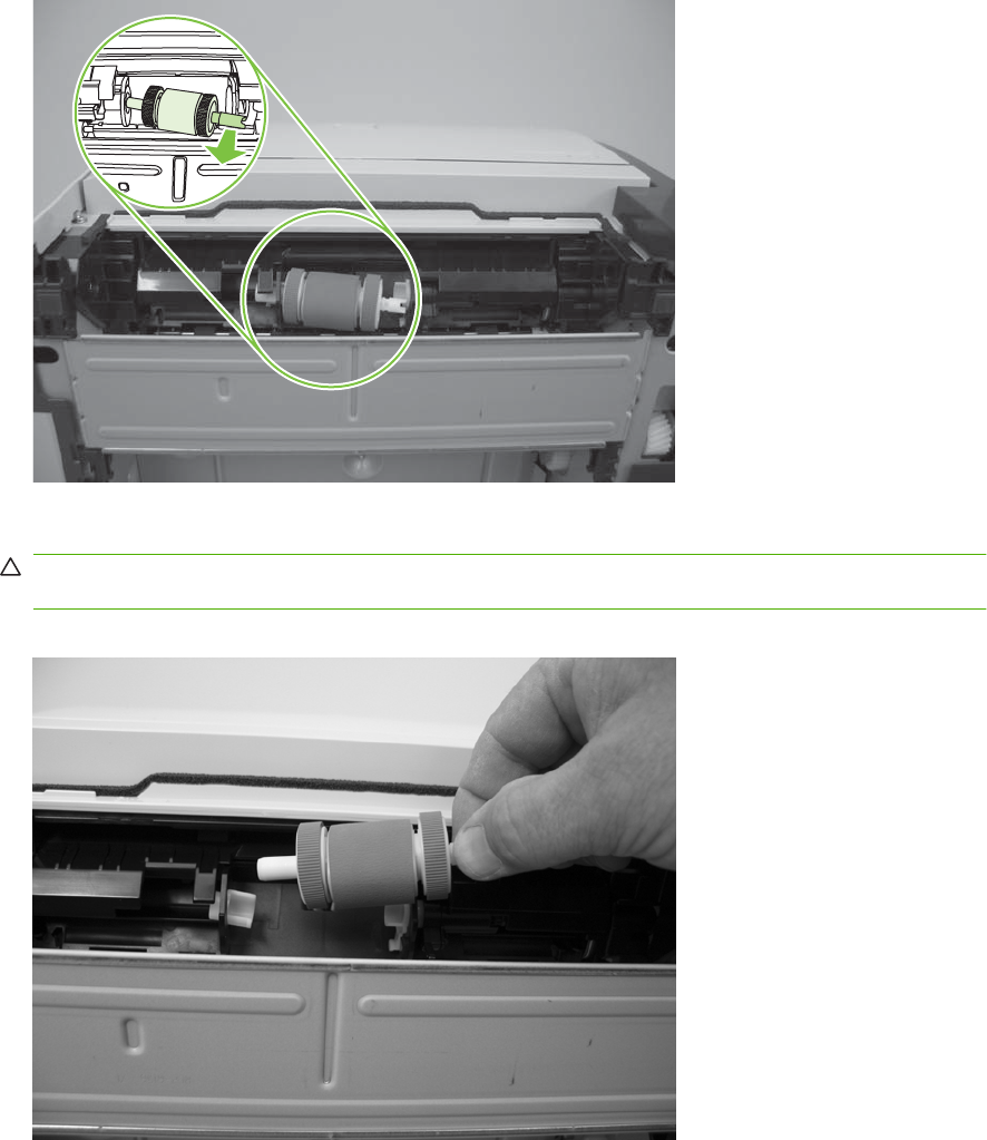
5. Rotate the drive end of the roller assembly out and away from the product.
Figure 6-12 Remove the pickup roller assembly; Tray 2 (4 of 5)
6. Remove the pickup roller.
CAUTION: The two rollers on the end of the assembly are not captive and can slip off of the roller
shaft. Do not lose the rollers when you remove the assembly.
Figure 6-13 Remove the pickup roller; Tray 2 (5 of 5)
ENWW Rollers and pads 109
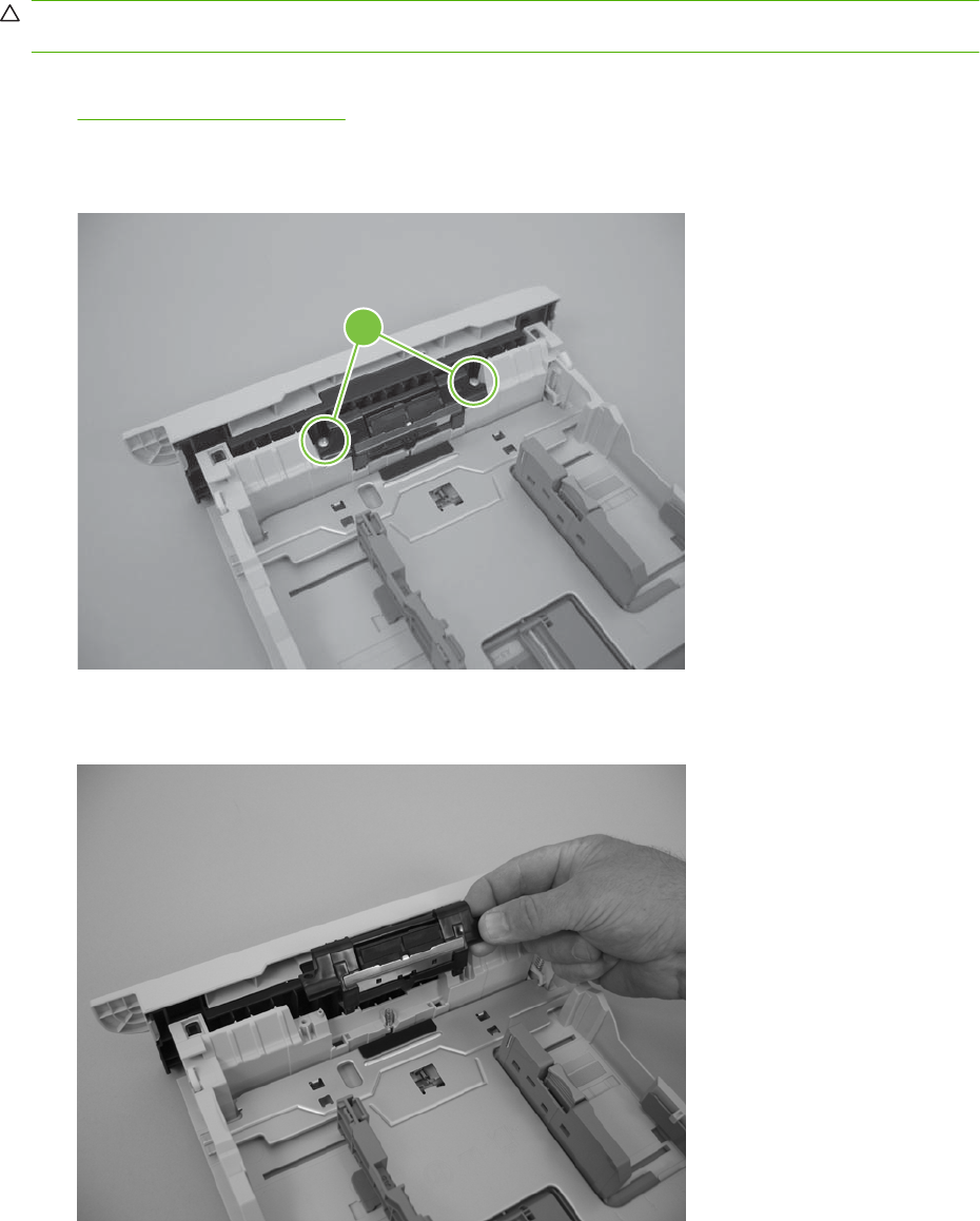
Separation-pad assembly; Tray 2
CAUTION: Do not touch the pad surface unless you are replacing the pad. Skin oils on the pad can
cause paper-pickup problems.
1. If the Tray 2 cassette has not yet been removed to service the product, remove the cassette. See
Tray 2 cassette on page 103.
2. Remove two screws (callout 1)
Figure 6-14 Remove the separation-pad assembly; Tray 2 (1 of 2)
1
3. Remove the separation-pad assembly.
Figure 6-15 Remove the separation-pad assembly; Tray 2 (2 of 2)
110 Chapter 6 Removal and replacement ENWW
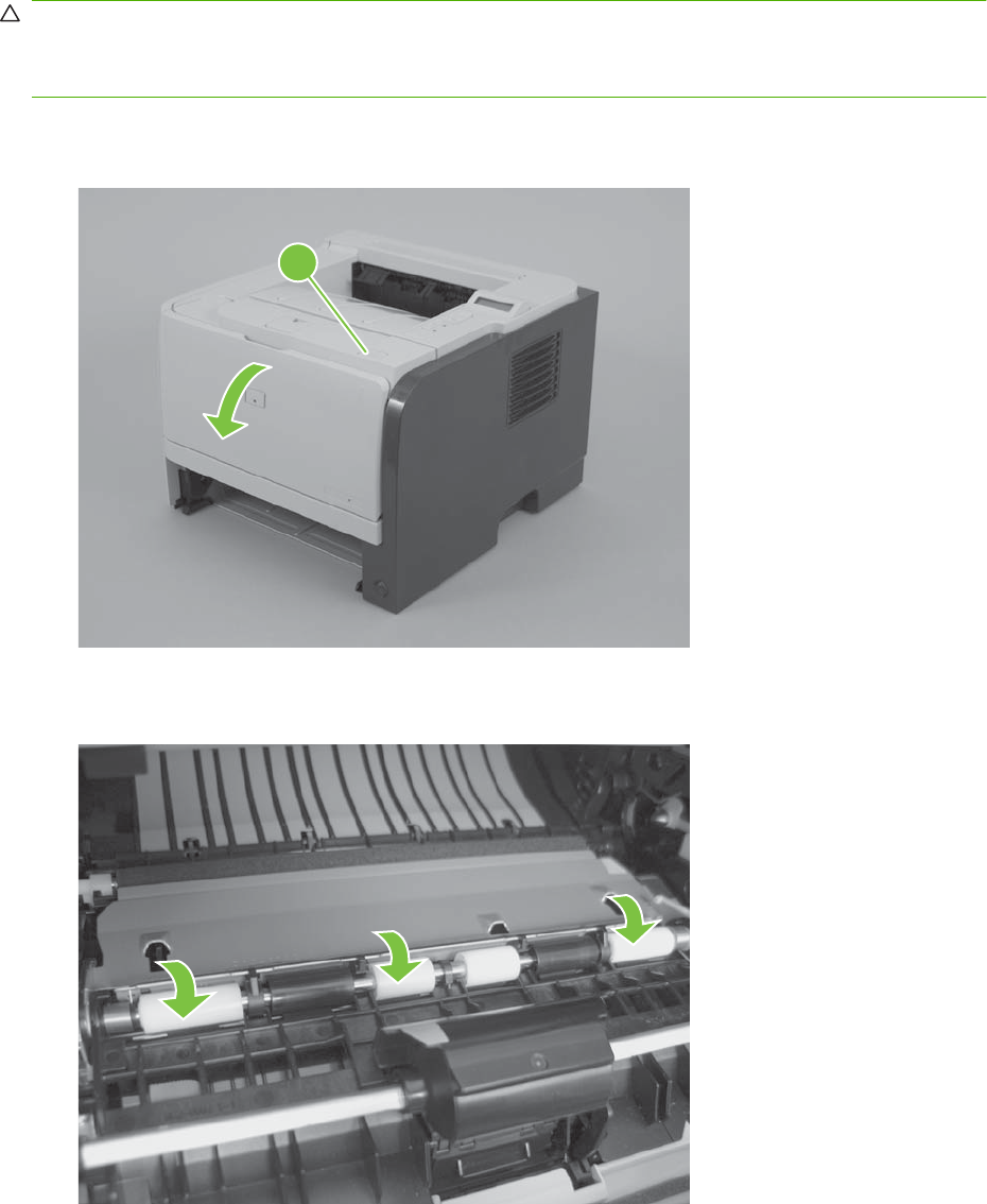
Transfer roller
CAUTION: Do not touch the sponge surface of the roller unless you are replacing the roller. Skin oils
on the roller can cause print-quality problems.
Always wear latex gloves when handling a transfer roller for reinstallation or replacement.
1. Press the print-cartridge door button (callout 1), and then open the print-cartridge door.
Figure 6-16 Remove the transfer roller (1 of 5)
1
2. Use your finger to raise the sheet-metal flap, and then rotate it toward the Tray 1 pickup roller cover.
Figure 6-17 Remove the transfer roller (2 of 5)
ENWW Rollers and pads 111
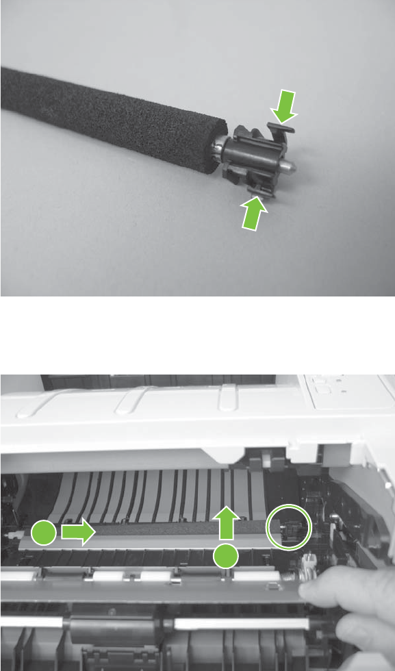
3. Before you proceed, note the location of the two tabs on the transfer-roller right-side locking clip.
Figure 6-18 Remove the transfer roller (3 of 5)
4. Release two tabs on the right-side locking clip, lift the roller up, and then slide it toward the right
side of the product to release the left end of the shaft.
Figure 6-19 Remove the transfer roller (4 of 5)
2
1
112 Chapter 6 Removal and replacement ENWW
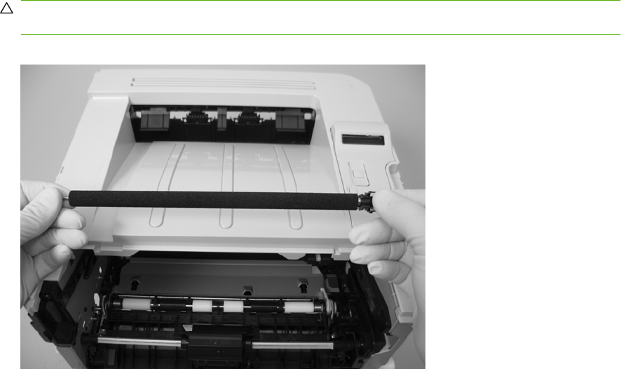
5. Remove the transfer roller.
CAUTION: The black locking clip on the right side of the transfer-roller shaft is not captive. Do
not lose the locking clip when you remove the transfer roller.
Figure 6-20 Remove the transfer roller (5 of 5)
ENWW Rollers and pads 113
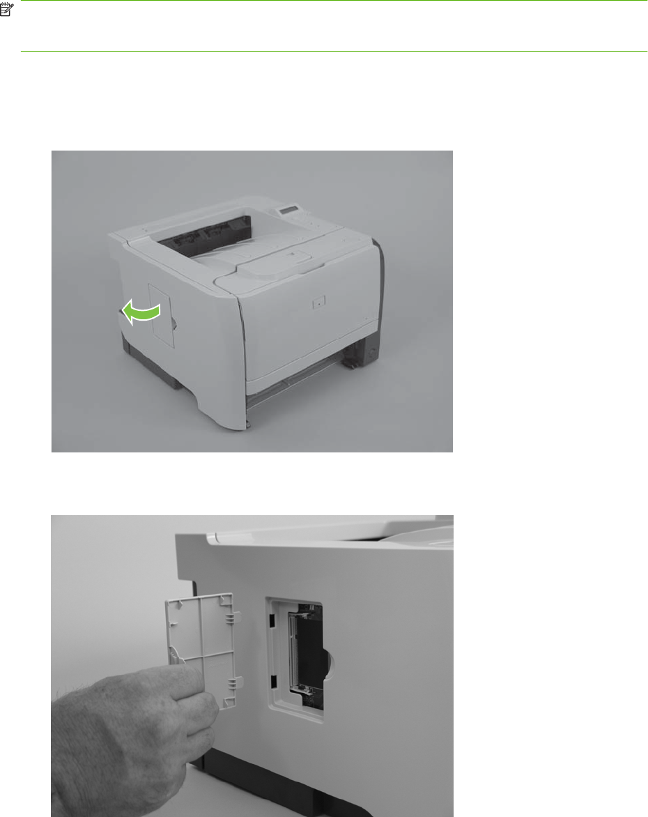
External panels, covers, and doors
NOTE: Your product might not appear exactly as the one shown in the photos in this chapter. For
example, the color of the external panels and covers might be different than your product. However, the
procedures in this chapter are valid for both the HP LaserJet P2035 and the HP LaserJet P2055.
DIMM door (HP LaserJet P2050 Series only)
1. Open the DIMM door.
Figure 6-21 Remove the DIMM door (1 of 2; HP LaserJet P2050 Series only)
2. Pull the DIMM door away from the product to remove it.
Figure 6-22 Remove the DIMM door (2 of 2; HP LaserJet P2050 Series only)
114 Chapter 6 Removal and replacement ENWW
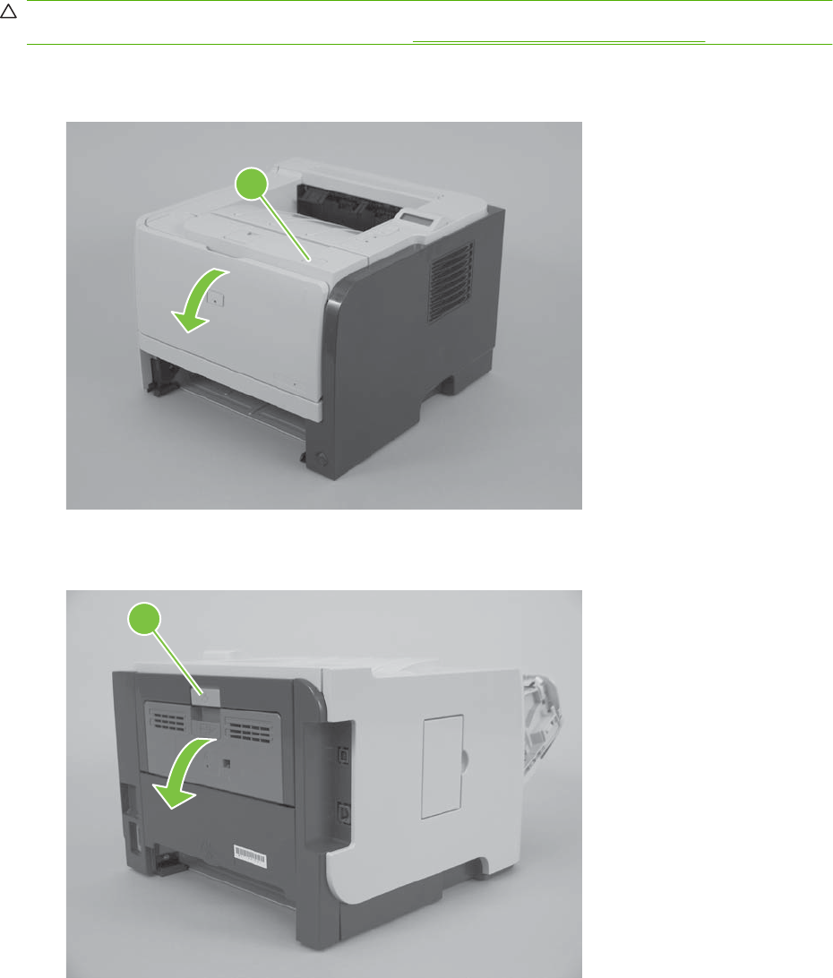
Right cover
CAUTION: The power switch can be dislodged when the right cover is removed. Be careful when you
remove the cover. If the switch is dislodged, see Reinstall the right cover on page 117.
1. Press the print-cartridge door button (callout 1), and then open the print-cartridge door.
Figure 6-23 Remove the right cover (1 of 5)
1
2. Lift the rear door latch (callout 2), and then open the rear door.
Figure 6-24 Remove the right cover (2 of 5)
2
ENWW External panels, covers, and doors 115
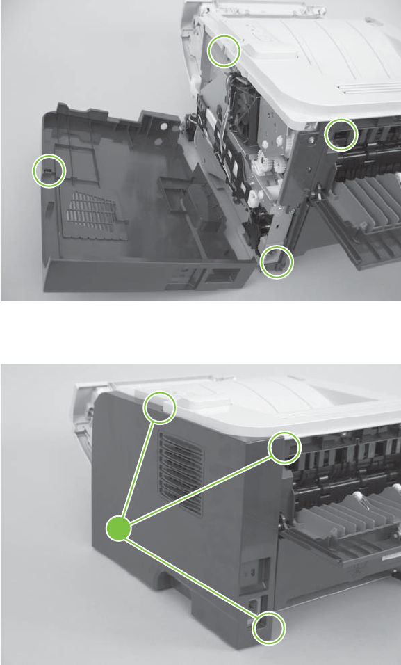
3. Before you proceed, note of the locations of the mounting tabs on the right cover.
Figure 6-25 Remove the right cover (3 of 5)
4. Release three tabs (callout 3).
Figure 6-26 Remove the right cover (4 of 5)
3
116 Chapter 6 Removal and replacement ENWW
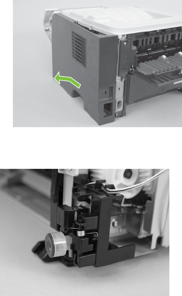
5. Carefully slide the cover toward the front of the product, and then remove it.
Figure 6-27 Remove the right cover (5 of 5)
Reinstall the right cover
If the power switch is dislodged when the cover is removed, replace it before installing the right cover.
Figure 6-28 Reinstall the right cover
ENWW External panels, covers, and doors 117
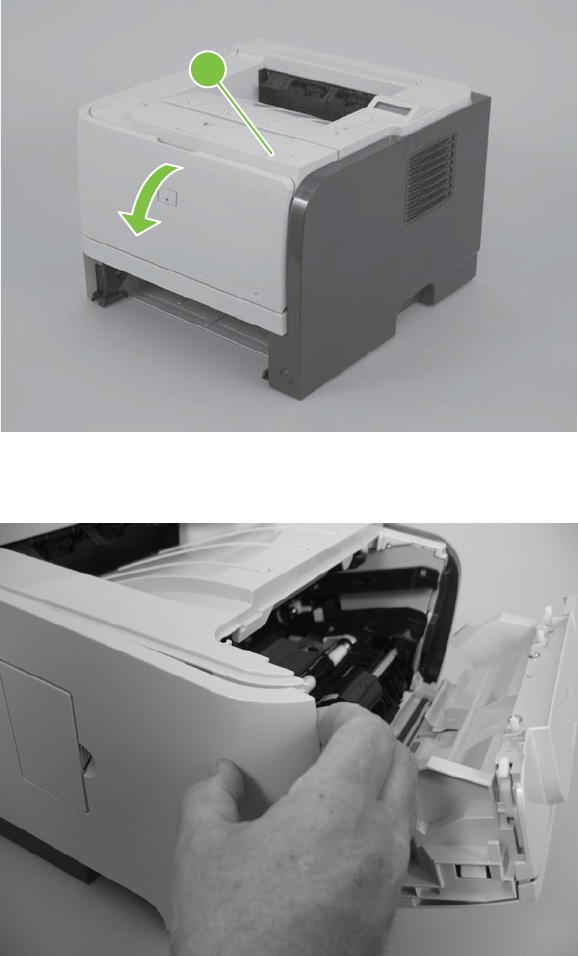
Left cover
1. Press the print-cartridge door button (callout 1), and then open the print-cartridge door.
Figure 6-29 Remove the left cover (1 of 4)
1
2. Grasp the top front of the cover, and then gently separate the cover from the product.
Figure 6-30 Remove the left cover (2 of 4)
118 Chapter 6 Removal and replacement ENWW
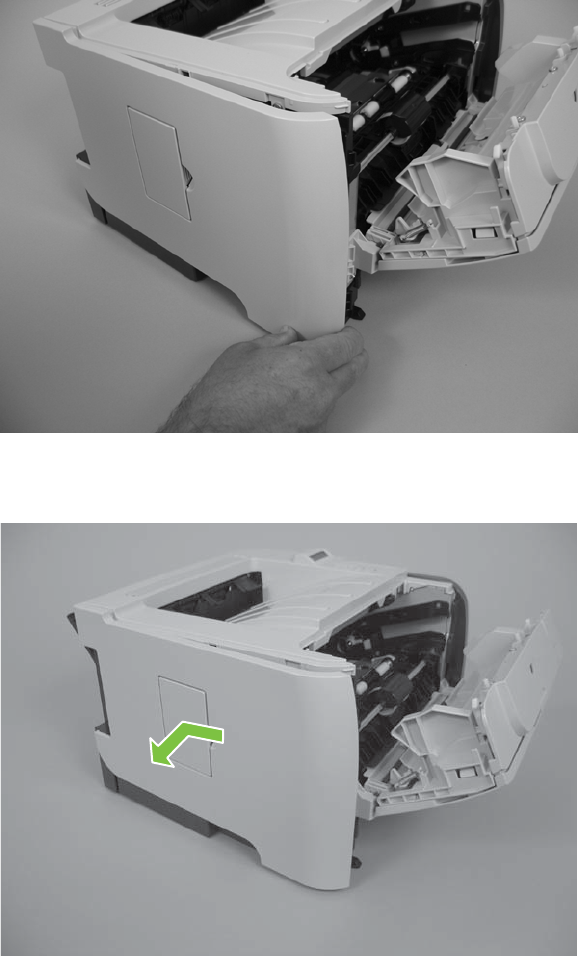
3. Grasp the bottom front of the cover, and then gently separate the cover from the product.
Figure 6-31 Remove the left cover (3 of 4)
4. Carefully slide the cover toward the front of the product, and then remove it.
Figure 6-32 Remove the left cover (4 of 4)
ENWW External panels, covers, and doors 119
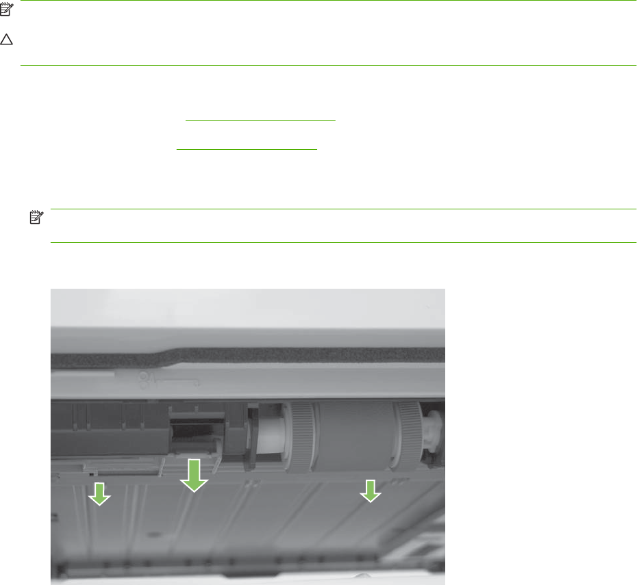
Rear cover, rear door, and duplex-paper-feed assembly
NOTE: Only the HP LaserJet P2050 Series products have a duplex-paper-feed assembly installed.
CAUTION: The fuser can be hot while the product is in use. Wait for the fuser to cool before handling
it.
1. Remove the following components:
●Right cover. See Right cover on page 115.
●Left cover. See Left cover on page 118.
2. HP LaserJet P2050 Series only: Pull down on the green duplex-paper-feed-assembly release tab,
and then lower the assembly.
NOTE: To locate the assembly release tab, look up into the Tray 2 cavity (where the cassette
would be installed).
Figure 6-33 Remove the rear cover, rear door, and duplex-paper-feed assembly (1 of 6; HP
LaserJet P2050 Series only)
120 Chapter 6 Removal and replacement ENWW
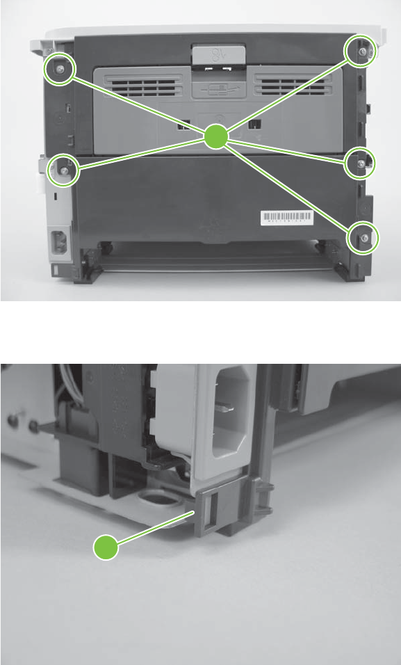
3. Remove five screws (callout 1).
Figure 6-34 Remove the rear cover, rear door, and duplex-paper-feed assembly (2 of 6)
1
4. Release one tab (callout 2).
Figure 6-35 Remove the rear cover, rear door, and duplex-paper-feed assembly (3 of 6)
2
ENWW External panels, covers, and doors 121
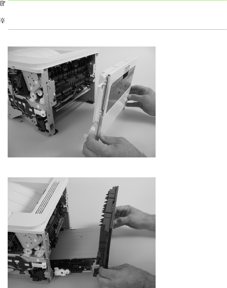
5. Carefully separate the rear cover and rear door from the product, and then remove them.
NOTE: For the HP LaserJet P2050 Series, the duplex-paper-feed assembly is removed with the
cover and door
Reinstallation tip When you reinstall the rear cover assembly, open the rear door to make sure
that the rear cover fits even against the product chassis before you install the mounting screws.
Figure 6-36 Remove the rear cover, rear door, and duplex-paper-feed assembly (4 of 6; HP
LaserJet P2030 Series)
Figure 6-37 Remove the rear cover, rear door, and duplex-paper-feed assembly (5 of 6; HP
LaserJet P2050 Series)
122 Chapter 6 Removal and replacement ENWW
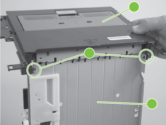
6. HP LaserJet P2050 Series only: Carefully release two hinge pins (callout 3), and then separate
the rear cover and rear door (callout 4) from the duplex-paper-feed assembly (callout 5).
Figure 6-38 Remove the rear cover, rear door, and duplex-paper-feed assembly (6 of 6; HP
LaserJet P2050 Series only)
3
5
4
ENWW External panels, covers, and doors 123

Top-cover assembly
NOTE: The top-cover assembly includes the control panel assembly.
1. Remove the following components:
●Right cover. See Right cover on page 115.
●Left cover. See Left cover on page 118.
●Rear cover, rear door, and duplex-paper-feed assembly. See Rear cover, rear door, and
duplex-paper-feed assembly on page 120.
NOTE: Only the HP LaserJet P2050 Series products have a duplex-paper-feed assembly
installed.
124 Chapter 6 Removal and replacement ENWW
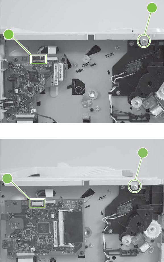
2. Remove one screw (callout 1), and then disconnect one connector (callout 2).
Figure 6-39 Remove the top-cover assembly (1 of 4; HP LaserJet P2030 Series only)
1
2
Figure 6-40 Remove the top-cover assembly (2 of 4; HP LaserJet P2050 Series only)
1
2
ENWW External panels, covers, and doors 125
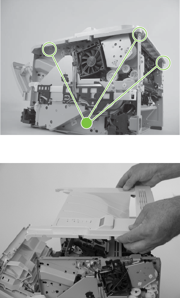
3. Remove three screws (callout 3).
Figure 6-41 Remove the top-cover assembly (3 of 4)
3
4. Lift the top-cover assembly off of the product to remove it.
Figure 6-42 Remove the top-cover assembly (4 of 4)
126 Chapter 6 Removal and replacement ENWW
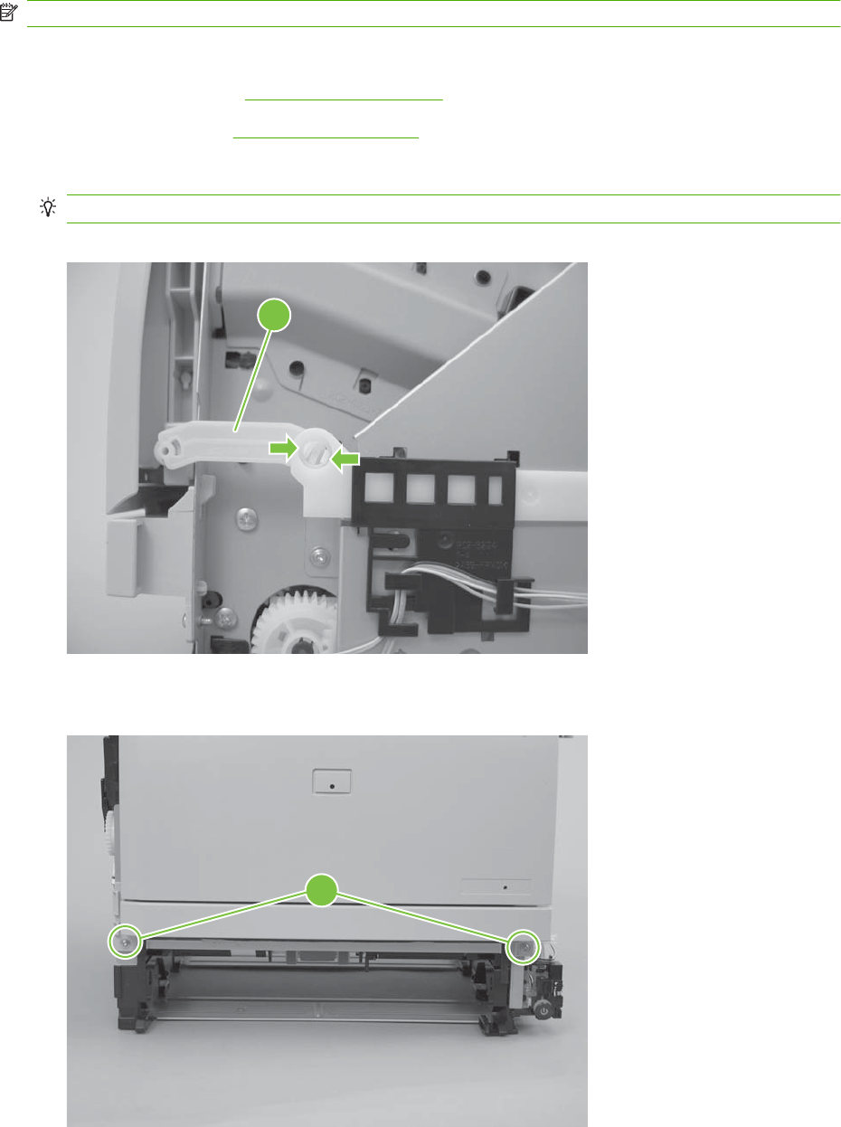
Cartridge-door assembly and front cover
NOTE: The cartridge door assembly includes the cartridge door, Tray 1, and the front cover.
1. Remove the following components:
●Right cover. See Right cover on page 115.
●Left cover. See Left cover on page 118.
2. Release two tabs, and then disengage the cartridge-door assembly link arm (callout 1).
TIP: The link arm releases the fuser-pressure lever when the cartridge door is opened.
Figure 6-43 Remove the cartridge door assembly and front cover (1 of 4)
1
3. Remove two screws (callout 2).
Figure 6-44 Remove the cartridge door assembly and front cover (2 of 4)
2
ENWW External panels, covers, and doors 127
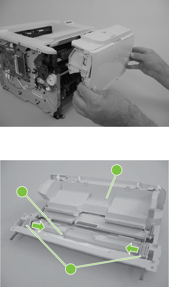
4. Carefully remove the cartridge-door assembly.
Figure 6-45 Remove the cartridge door assembly and front cover (3 of 4)
5. Disengage two hinge pins (callout 3), and then carefully separate the front cover (callout 4) from
the cartridge door assembly (callout 5).
Figure 6-46 Remove the cartridge door assembly and front cover (4 of 4)
3
4
5
128 Chapter 6 Removal and replacement ENWW
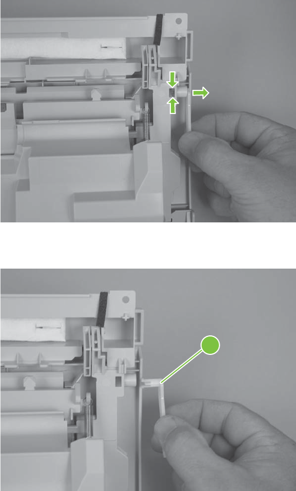
Reinstall the cartridge-door assembly and front cover
Use this procedure if you are installing a replacement cartridge-door assembly.
1. Release two tabs (callout 1).
Figure 6-47 Reinstall the cartridge-door assembly and front cover (1 of 2)
2. Remove the cartridge-door link (callout 2), and then install it on the replacement assembly.
Figure 6-48 Reinstall the cartridge-door assembly and front cover (2 of 2)
2
ENWW External panels, covers, and doors 129
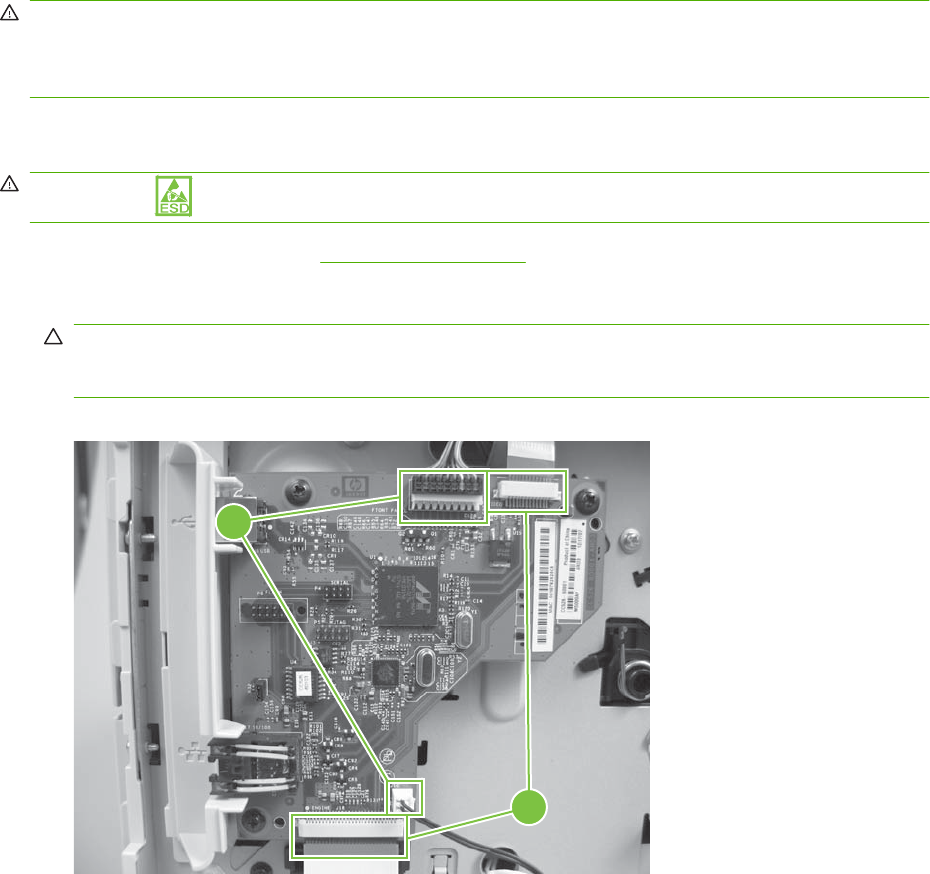
Internal assemblies
WARNING! Turn the product off, wait 5 seconds, and then remove the power cord before attempting
to service the product. If this warning is not followed, severe injury can result, in addition to damage to
the product. The power must be on for certain functional checks during problem solving. However, the
power supply should be disconnected during parts removal.
Formatter PCA; HP LaserJet P2030 Series
WARNING! ESD sensitive component.
1. Remove the left cover. See Left cover on page 118.
2. Disconnect two connectors (callout 1) and two FFCs (callout 2).
CAUTION: Do not bend or fold the flat flexible cables (FFCs) during removal or installation. Also,
do not straighten pre-folds in the FFCs. You must make sure that all FFCs are fully seated in their
connectors. Failure to fully seat an FFC into a connector can cause a short circuit in a PCA.
Figure 6-49 Remove the formatter PCA; HP LaserJet P2030 Series (1 of 2)
1
2
130 Chapter 6 Removal and replacement ENWW
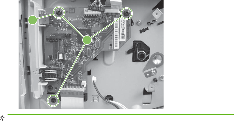
3. Remove three screws (callout 3), and then remove the formatter PCA.
Figure 6-50 Remove the formatter PCA; HP LaserJet P2030 Series (2 of 2)
3
4
Reinstallation tip To correctly position the PCA during reinstallation, install the top screw first (callout
4).
ENWW Internal assemblies 131
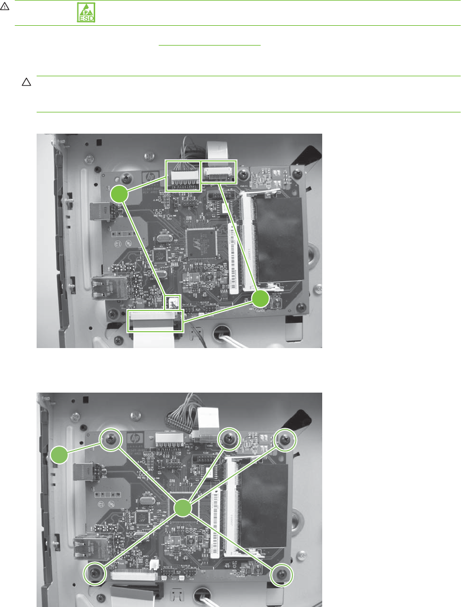
Formatter PCA; HP LaserJet P2050 Series
WARNING! ESD sensitive component.
1. Remove the left cover. See Left cover on page 118.
2. Disconnect two connectors (callout 1) and two FFCs (callout 2).
CAUTION: Do not bend or fold the flat flexible cables (FFCs) during removal or installation. Also,
do not straighten pre-folds in the FFCs. You must make sure that all FFCs are fully seated in their
connectors. Failure to fully seat an FFC into a connector can cause a short circuit in a PCA.
Figure 6-51 Remove the formatter PCA; HP LaserJet P2050 Series (1 of 2)
1
2
3. Remove five screws (callout 3), and then remove the formatter PCA.
Figure 6-52 Remove the formatter PCA; HP LaserJet P2050 Series (2 of 2)
3
4
132 Chapter 6 Removal and replacement ENWW

Reinstallation tip To correctly position the PCA during reinstallation, install the top screw first (callout
4).
ENWW Internal assemblies 133
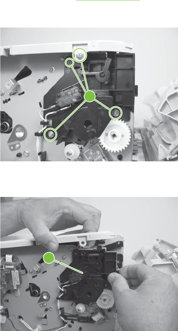
Paper-pickup-gear assembly
1. Remove the left cover. See Left cover on page 118.
2. Remove four screws (callout 1).
Figure 6-53 Remove the paper-pickup-gear assembly (1 of 3)
1
3. Slightly separate the top-cover assembly from the chassis, and then remove the black-plastic
bracket (callout 2).
Figure 6-54 Remove the paper-pickup-gear assembly (2 of 3)
2
134 Chapter 6 Removal and replacement ENWW
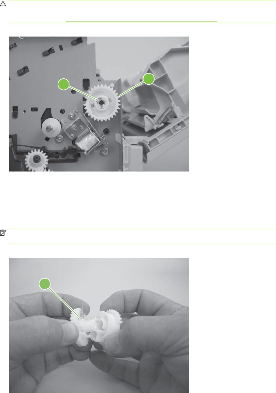
4. Release one tab (callout 3), and then remove the paper-pickup-gear assembly (callout 4).
CAUTION: Be careful when you remove this assembly. The outer gear and spring can easily
become separated from the inner gear. If the gears become separated, make sure that you do not
lose the spring. See Reinstall the paper-pickup-gear assembly on page 135.
Figure 6-55 Remove the paper-pickup-gear assembly (3 of 3)
34
Reinstall the paper-pickup-gear assembly
Use the following procedure to reassemble the outer gear, inner gear, and spring if they become
separated.
1. Make sure the spring (callout 1) is positioned on the pedestal portion of the outer gear.
NOTE: When the outer and inner gears are assembled, the spring rests inside a cavity (callout 2)
in the inner gear.
Figure 6-56 Reinstall the paper-pickup-gear assembly (1 of 3)
1
ENWW Internal assemblies 135
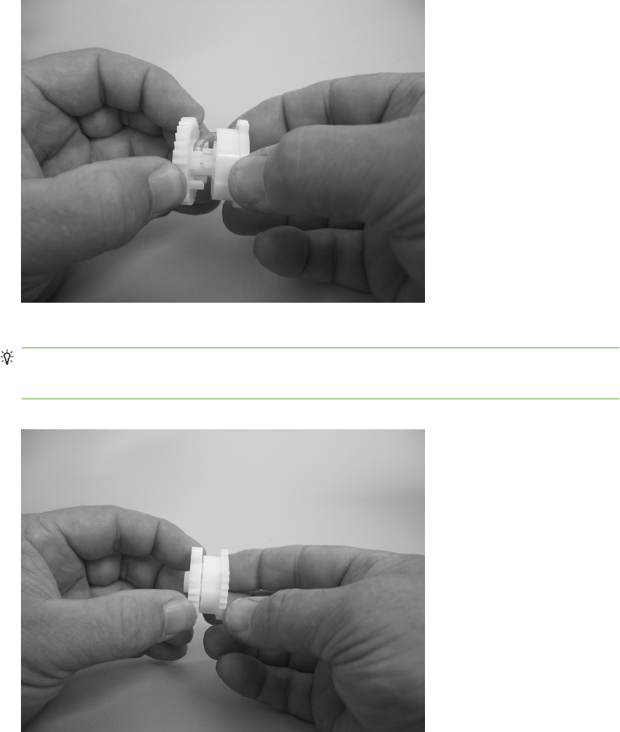
2. Slip the loose end of the spring into the cavity in the inner gear.
Figure 6-57 Reinstall the paper-pickup-gear assembly (2 of 3)
3. Press the two gears together until the gears snap together.
TIP: To test the assembly, hold the inner gear and rotate the outer gear away from you until it
stops (slightly less than one-third of a full rotation). Release the outer gear. The spring should return
the outer gear to its starting position.
Figure 6-58 Reinstall the paper-pickup-gear assembly (3 of 3)
136 Chapter 6 Removal and replacement ENWW
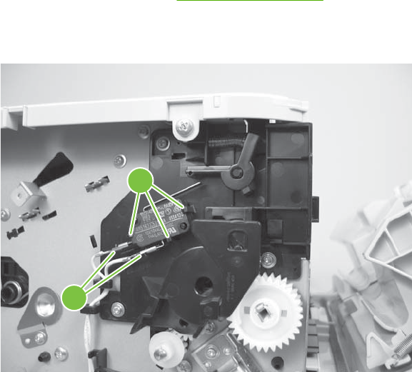
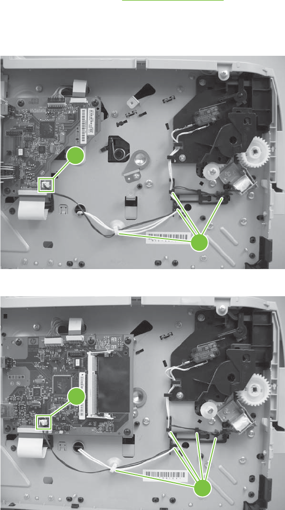
Tray 1 pickup solenoid
1. Remove the left cover. See Left cover on page 118.
2. Disconnect one connector (callout 1), and then release the wire harness from the retainers
(callout 2).
Figure 6-60 Remove the Tray 1 pickup solenoid (1 of 2; HP LaserJet P2030 Series)
1
2
Figure 6-61 Remove the Tray 1 pickup solenoid (2 of 3; HP LaserJet P2050 Series)
1
2
138 Chapter 6 Removal and replacement ENWW
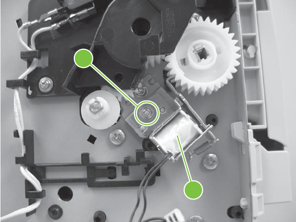
3. Remove one screw (callout 3), and then remove the Tray 1 pickup solenoid.
Figure 6-62 Remove the Tray 1 pickup solenoid (3 of 3)
3
4
ENWW Internal assemblies 139
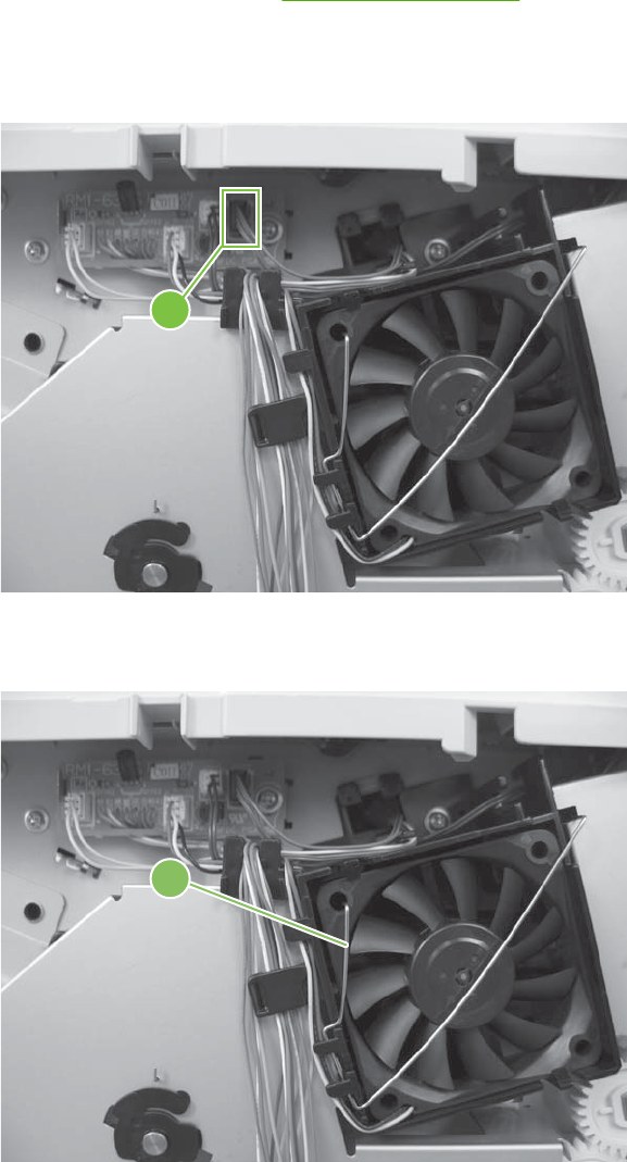
Fan
1. Remove the right cover. See Right cover on page 115.
2. Disconnect one connector (callout 1), and then release the wire harness from the guide along the
fan duct.
Figure 6-63 Remove the fan (1 of 3)
1
3. Remove the fan static spring (callout 2).
Figure 6-64 Remove the fan (2 of 3)
2
140 Chapter 6 Removal and replacement ENWW
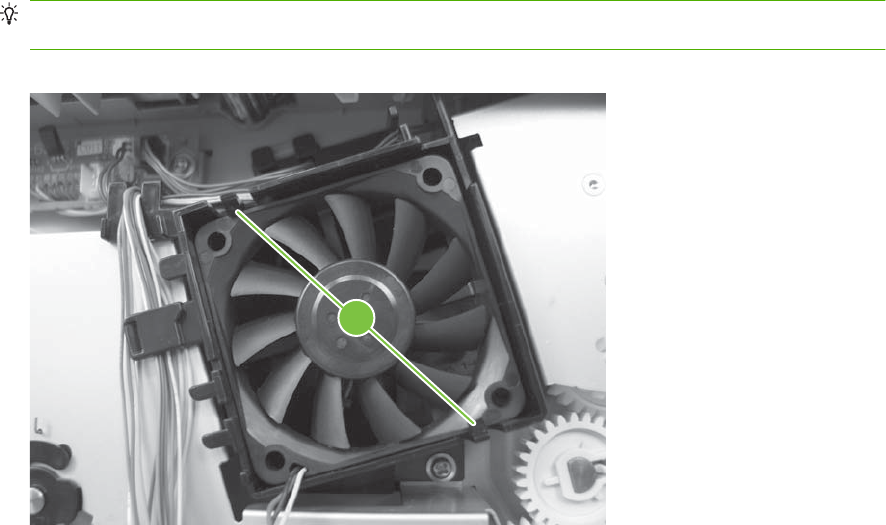
4. Release two tabs (callout 3), and then remove the fan.
Reinstallation tip When the fan is reinstalled, the air must flow into the product. Arrows
embossed on the fan frame indicate air flow direction.
Figure 6-65 Remove the fan (3 of 3)
3
ENWW Internal assemblies 141
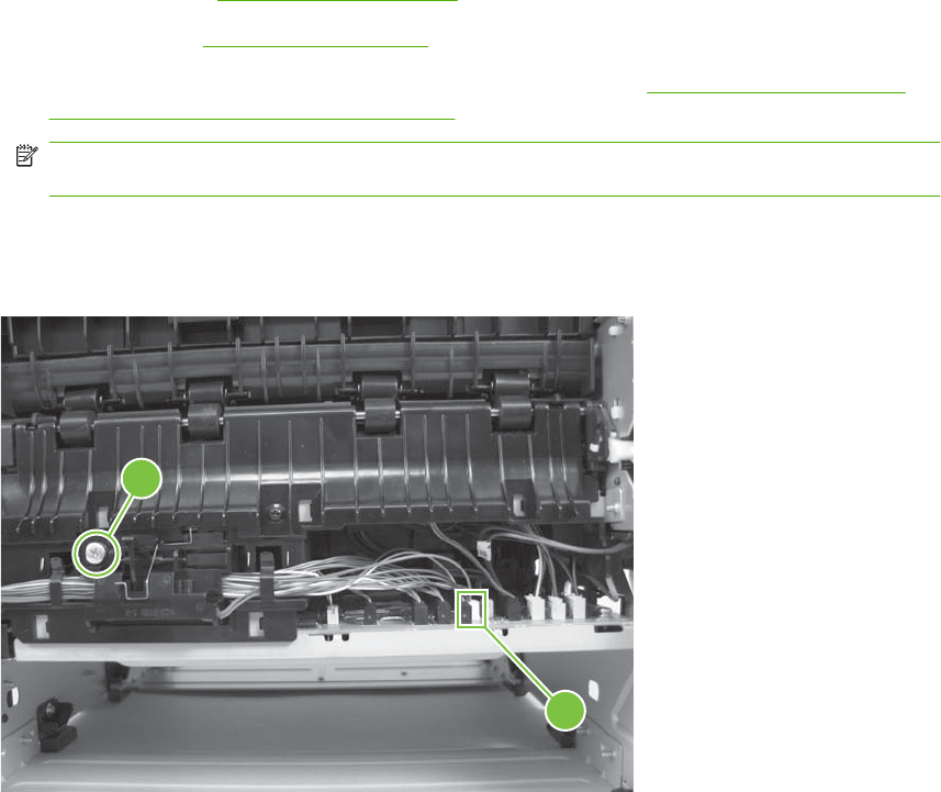
Reverse-sensor assembly; HP LaserJet P2050 Series
1. Remove the following components:
●Right cover. See Right cover on page 115.
●Left cover. See Left cover on page 118.
●Rear cover, rear door, and duplex-paper-feed assembly. See Rear cover, rear door, and
duplex-paper-feed assembly on page 120.
NOTE: Only the HP LaserJet P2050 Series products have a duplex-paper-feed assembly
installed.
2. Disconnect one connector (callout 1), release the wire harness from the guide, and then remove
one screw (callout 2).
Figure 6-66 Remove the reverse-sensor assembly (1 of 2; HP LaserJet P2050 Series)
2
1
142 Chapter 6 Removal and replacement ENWW
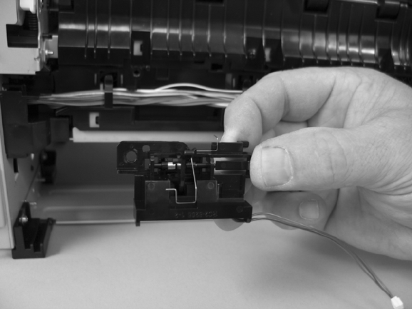
3. Remove the reverse-sensor assembly.
Figure 6-67 Remove the reverse-sensor assembly (2 of 2; HP LaserJet P2050 Series)
ENWW Internal assemblies 143
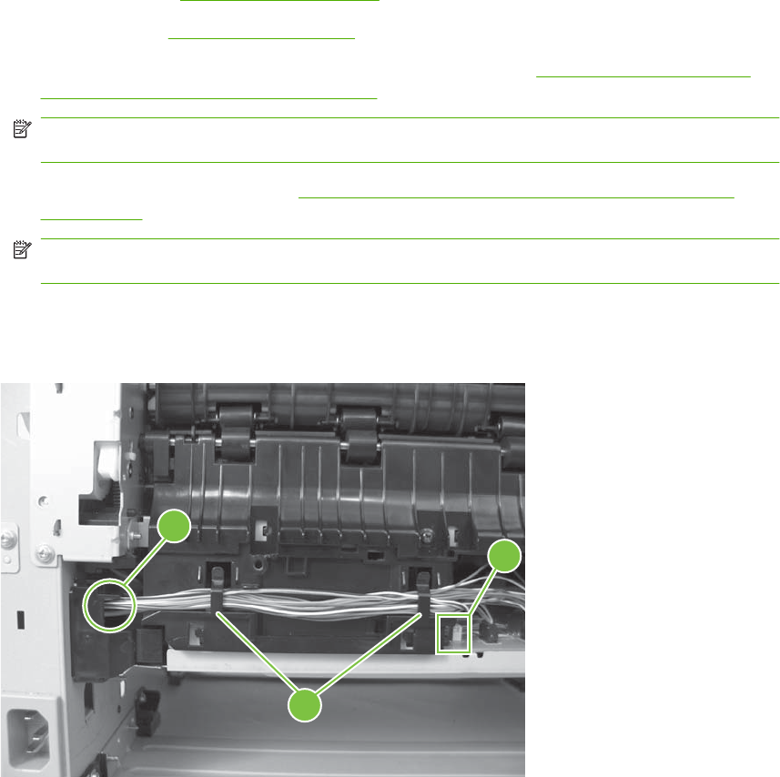
Power-switch assembly
1. Remove the following components:
●Right cover. See Right cover on page 115.
●Left cover. See Left cover on page 118.
●Rear cover, rear door, and duplex-paper-feed assembly. See Rear cover, rear door, and
duplex-paper-feed assembly on page 120.
NOTE: Only the HP LaserJet P2050 Series products have a duplex-paper-feed assembly
installed.
●Reverse-sensor assembly. See Reverse-sensor assembly; HP LaserJet P2050 Series
on page 142.
NOTE: Only the HP LaserJet P2050 Series products have a reverse-sensor assembly
installed.
2. Disconnect one connector (callout 1), release the wire harness from the guide (callout 2), and then
pass the wire harness through the hole in the chassis (callout 3).
Figure 6-68 Remove the power-switch assembly (1 of 4)
3
2
1
144 Chapter 6 Removal and replacement ENWW
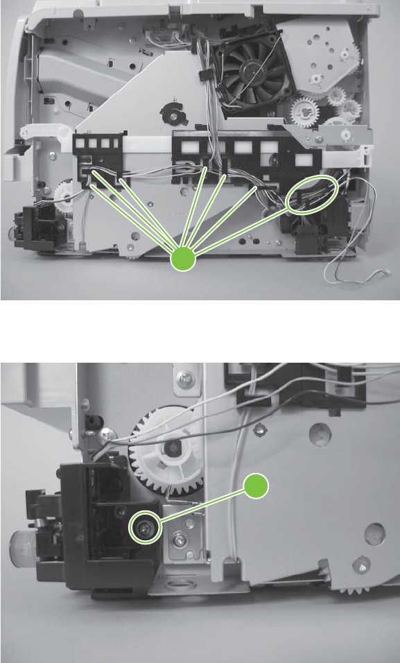
3. Release the wire harness from the guides (callout 4).
Figure 6-69 Remove the power-switch assembly (2 of 4)
4
4. Remove one screw (callout 5).
Figure 6-70 Remove the power-switch assembly (3 of 4)
5
ENWW Internal assemblies 145
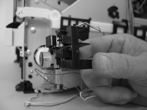
5. Remove the power-switch assembly.
Figure 6-71 Remove the power-switch assembly (4 of 4)
146 Chapter 6 Removal and replacement ENWW
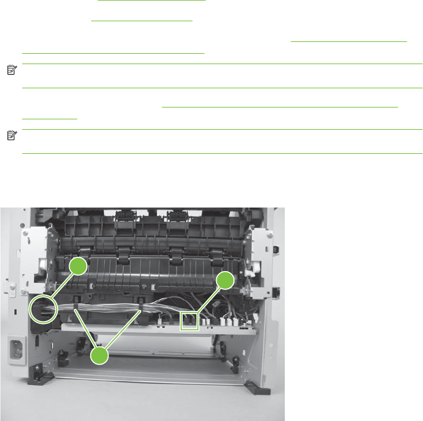
Connecting PCA
1. Remove the following components:
●Right cover. See Right cover on page 115.
●Left cover. See Left cover on page 118.
●Rear cover, rear door, and duplex-paper-feed assembly. See Rear cover, rear door, and
duplex-paper-feed assembly on page 120.
NOTE: Only the HP LaserJet P2050 Series products have a duplex-paper-feed assembly
installed.
●Reverse-sensor assembly. See Reverse-sensor assembly; HP LaserJet P2050 Series
on page 142.
NOTE: Only the HP LaserJet P2050 Series products have a reverse-sensor assembly
installed.
2. Disconnect one connector (callout 1), release the wire harness from the guide (callout 2), and then
pass the wire harness through the hole in the chassis (callout 3).
Figure 6-72 Remove the connecting PCA (1 of 4)
3
2
1
ENWW Internal assemblies 147
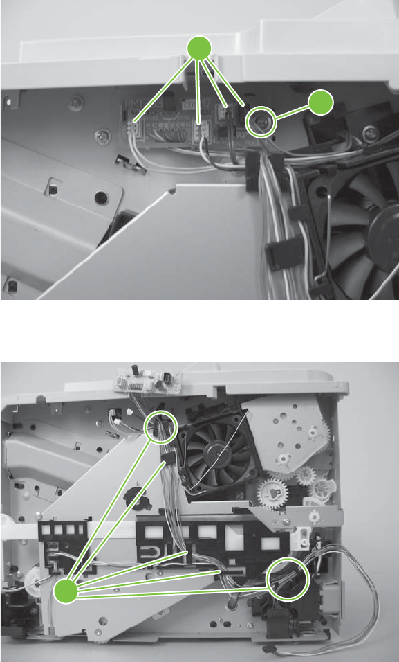
3. Disconnect four connectors (callout 4), and then remove one screw (callout 5).
Figure 6-73 Remove the connecting PCA (2 of 4)
4
5
4. Release the wire harnesses from the guides and retainers (callout 6).
Figure 6-74 Remove the connecting PCA (3 of 4)
6
148 Chapter 6 Removal and replacement ENWW
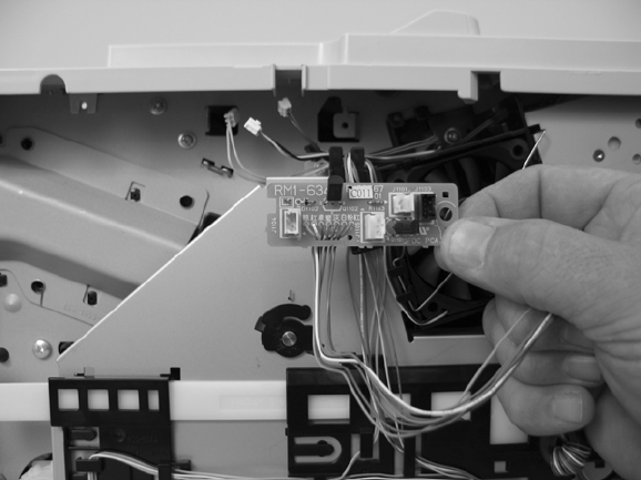
5. Remove the connecting PCA.
Figure 6-75 Remove the connecting PCA (4 of 4)
ENWW Internal assemblies 149
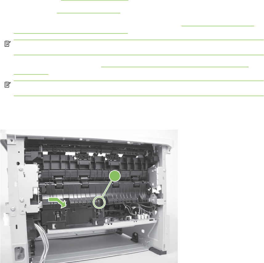
Inlet-cable assembly
1. Remove the following components:
●Right cover. See Right cover on page 115.
●Left cover. See Left cover on page 118.
●Rear cover, rear door, and duplex-paper-feed assembly. See Rear cover, rear door, and
duplex-paper-feed assembly on page 120.
NOTE: Only the HP LaserJet P2050 Series products have a duplex-paper-feed assembly
installed.
●Reverse-sensor assembly. See Reverse-sensor assembly; HP LaserJet P2050 Series
on page 142.
NOTE: Only the HP LaserJet P2050 Series products have a reverse-sensor assembly
installed.
2. Remove one screw (callout 1), and then slide the media-feed guide toward the formatter side of
the product to remove it.
Figure 6-76 Remove the inlet-cable assembly (1 of 3)
1
150 Chapter 6 Removal and replacement ENWW
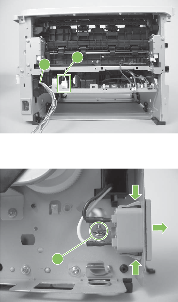
3. Disconnect one connector (callout 2), and then pass the wire harness through the hole in the
chassis (callout 3).
Figure 6-77 Remove the inlet-cable assembly (2 of 3)
2
3
4. Remove one screw (callout 4), squeeze two tabs, and then push the inlet cable assembly out of
the chassis.
Figure 6-78 Remove the inlet-cable assembly (3 of 3)
4
ENWW Internal assemblies 151
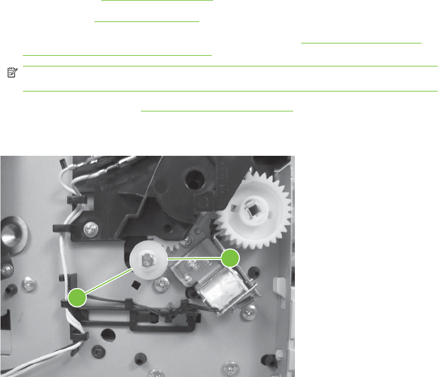
Registration assembly
1. Remove the following components:
●Right cover. See Right cover on page 115.
●Left cover. See Left cover on page 118.
●Rear cover, rear door, and duplex-paper-feed assembly. See Rear cover, rear door, and
duplex-paper-feed assembly on page 120.
NOTE: Only the HP LaserJet P2050 Series products have a duplex-paper-feed assembly
installed.
●Top cover assembly. See Top-cover assembly on page 124.
2. Release one tab (callout 1), and then remove one gear (callout 2).
Figure 6-79 Remove the registration assembly (1 of 7)
2
1
152 Chapter 6 Removal and replacement ENWW
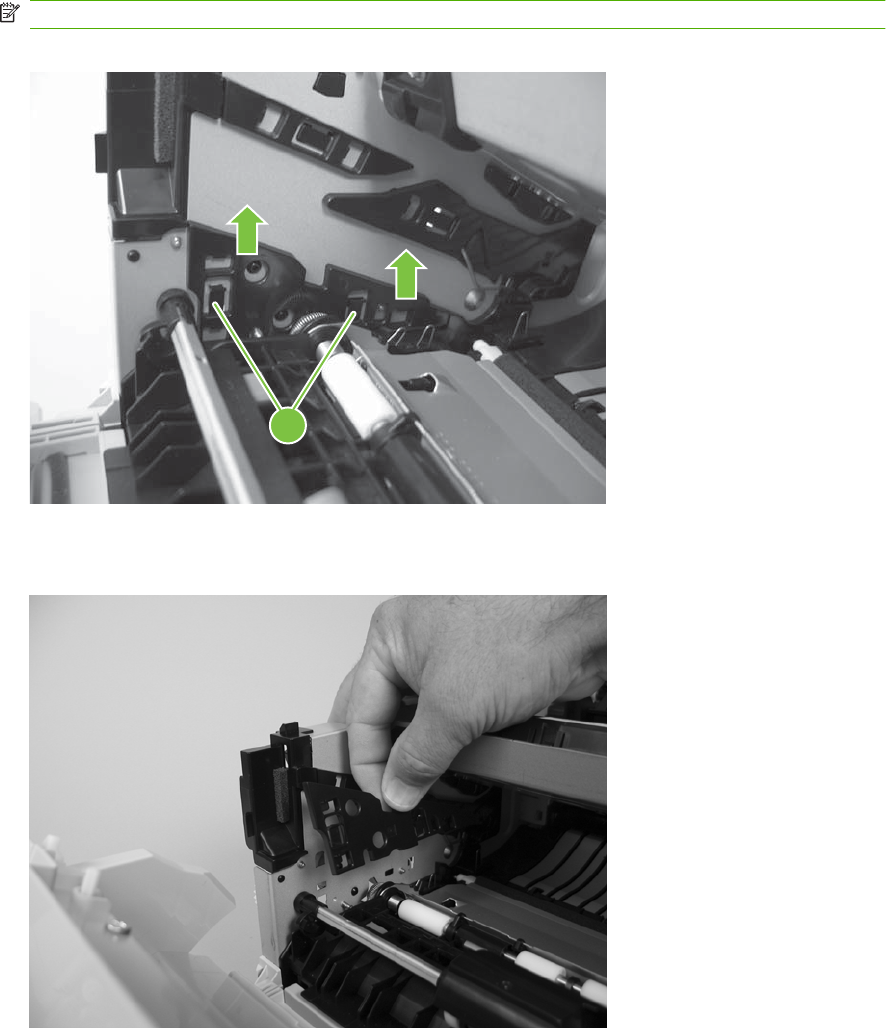
3. Release two tabs (callout 3), and then lift up on the guide to release it.
NOTE: The guide is inside the product on the formatter side.
Figure 6-80 Remove the registration assembly (2 of 7)
3
4. Remove the guide.
Figure 6-81 Remove the registration assembly (3 of 7)
ENWW Internal assemblies 153
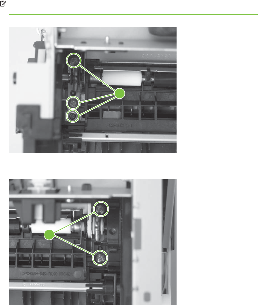
5. Remove three screws (callout 4) near the guide removed in the previous step.
NOTE: The front-most screw is different than the other two screws. Make sure this screw is
replaced in the mounting hole it is removed from when you reinstall the assembly.
Figure 6-82 Remove the registration assembly (4 of 7)
4
6. Remove two screws (callout 5) at the other end of the assembly.
Figure 6-83 Remove the registration assembly (5 of 7)
5
154 Chapter 6 Removal and replacement ENWW
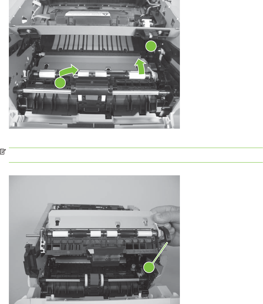
7. Slightly raise the right end of the assembly, and then slide it to the right and lift it up to release it.
Figure 6-84 Remove the registration assembly (6 of 7)
1
2
8. Remove the assembly.
NOTE: The retainer (callout 6) at the right side of the assembly is not captive. Do not lose the
retainer when the assembly is removed.
Figure 6-85 Remove the registration assembly (7 of 7)
6
ENWW Internal assemblies 155
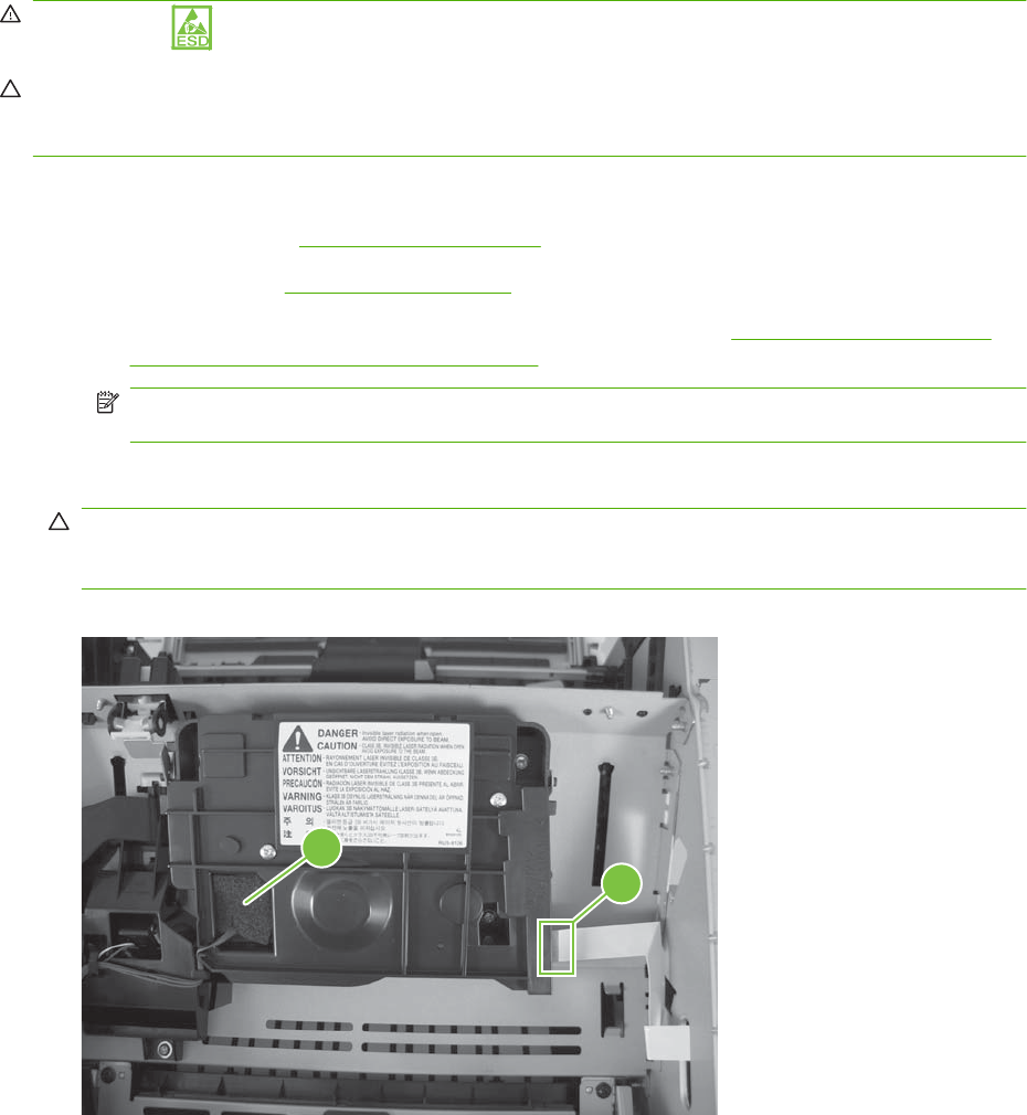
Laser/scanner assembly
WARNING! ESD sensitive component.
CAUTION: Do not bend or fold the flat flexible cables (FFCs) during removal or installation. Also, do
not straighten pre-folds in the FFCs. You must make sure that all FFCs are fully seated in their
connectors. Failure to fully seat an FFC into a connector can cause a short circuit in a PCA.
1. Remove the following components:
●Right cover. See Right cover on page 115.
●Left cover. See Left cover on page 118.
●Rear cover, rear door, and duplex-paper-feed assembly. See Rear cover, rear door, and
duplex-paper-feed assembly on page 120.
NOTE: Only the HP LaserJet P2050 Series products have a duplex-paper-feed assembly
installed.
2. Disconnect one FFC (callout 1), and then remove the antistatic foam pad (callout 2).
CAUTION: Do not bend or fold the flat flexible cables (FFCs) during removal or installation. Also,
do not straighten pre-folds in the FFCs. You must make sure that all FFCs are fully seated in their
connectors. Failure to fully seat an FFC into a connector can cause a short circuit in a PCA.
Figure 6-86 Remove the laser/scanner assembly (1 of 2)
2
1
156 Chapter 6 Removal and replacement ENWW
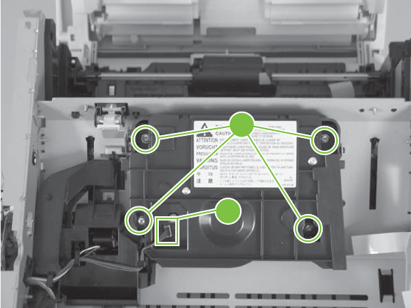
3. Disconnect one connector (callout 3), remove four screws (callout 4), and then remove the laser/
scanner assembly.
Figure 6-87 Remove the laser/scanner assembly (2 of 2)
4
3
ENWW Internal assemblies 157
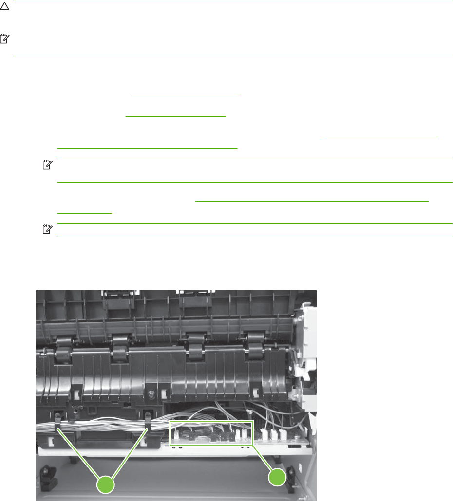
Fuser
CAUTION: The fuser might be hot. Allow enough time for the fuser to cool after the product power is
turned off.
NOTE: The cartridge-door assembly should be in the closed position when the fuser is removed to
make sure that the fuser-drive gear is correctly aligned for reinstallation.
1. Remove the following components:
●Right cover. See Right cover on page 115.
●Left cover. See Left cover on page 118.
●Rear cover, rear door, and duplex-paper-feed assembly. See Rear cover, rear door, and
duplex-paper-feed assembly on page 120.
NOTE: Only the HP LaserJet P2050 Series products have a duplex-paper-feed assembly
installed.
●Reverse-sensor assembly. See Reverse-sensor assembly; HP LaserJet P2050 Series
on page 142.
NOTE: Only the HP LaserJet P2050 Series products have a reverse-feed sensor installed.
2. Disconnect six connectors (callout 1), and then release the wire harnesses from the guide
(callout 2).
Figure 6-88 Remove the fuser (1 of 7)
21
158 Chapter 6 Removal and replacement ENWW
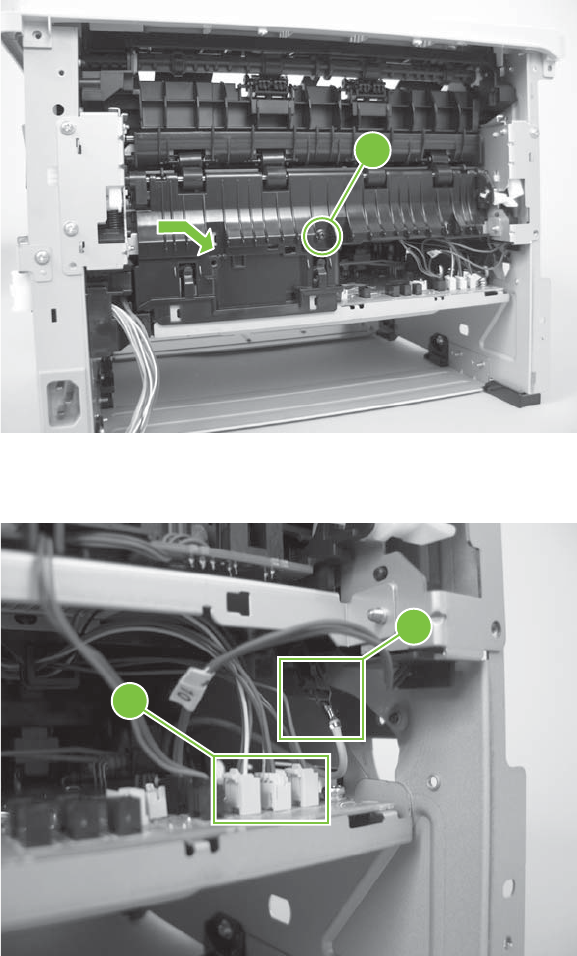
3. Remove one screw (callout 3), and then slide the media-feed guide toward the formatter side of
the product to remove it.
Figure 6-89 Remove the fuser (2 of 7)
3
4. Disconnect three connectors (callout 4) and one ground connector (callout 5).
Figure 6-90 Remove the fuser (3 of 7)
4
5
ENWW Internal assemblies 159
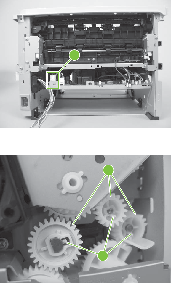
5. Disconnect one connector (callout 6).
Figure 6-91 Remove the fuser (4 of 7)
6
6. Release three tabs (callout 7), and then remove three gears (callout 8).
Figure 6-92 Remove the fuser (5 of 7)
8
7
160 Chapter 6 Removal and replacement ENWW
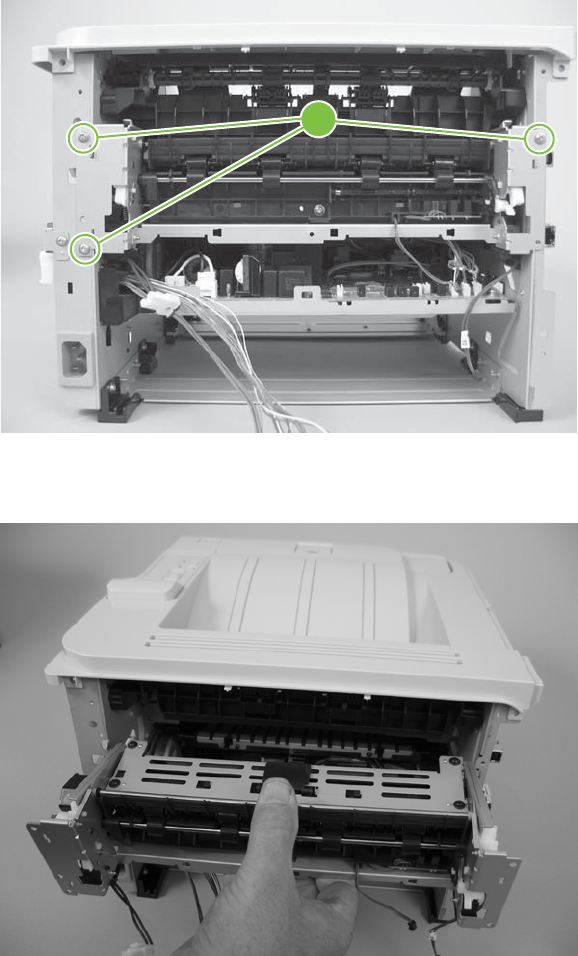
7. Remove three screws (callout 9).
Figure 6-93 Remove the fuser (6 of 7)
9
8. Carefully remove the fuser.
Figure 6-94 Remove the fuser (7 of 7)
ENWW Internal assemblies 161
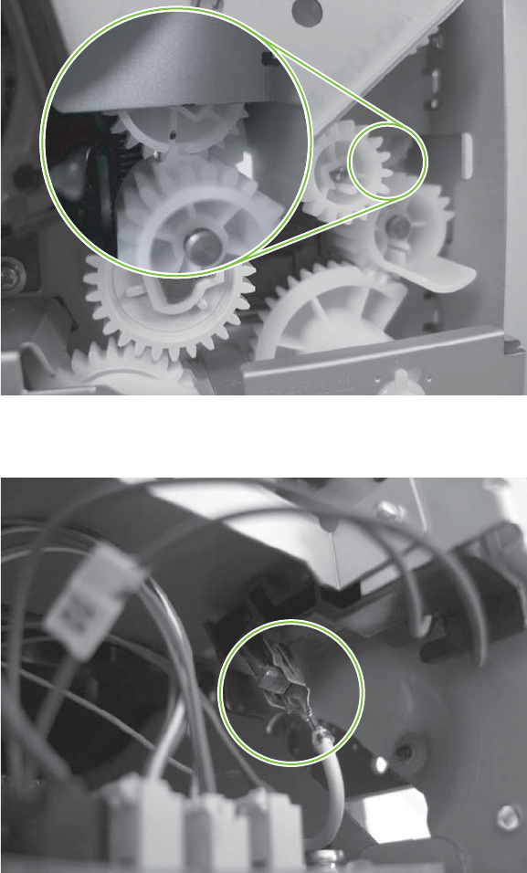
Reinstall the fuser
1. The drive gears must be correctly aligned when the fuser is reinstalled or replaced. The gears are
keyed and can only be installed when they are correctly aligned.
Figure 6-95 Reinstall the fuser (1 of 2)
2. Make sure that the ground connector is correctly fastened and fully seated on the connector lug.
Figure 6-96 Reinstall the fuser (2 of 2)
162 Chapter 6 Removal and replacement ENWW
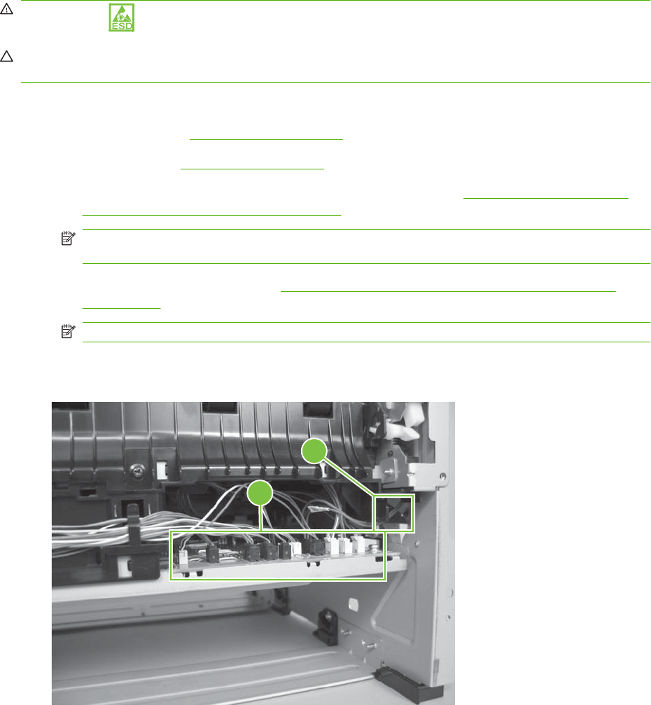
Engine controller unit (ECU)
WARNING! ESD sensitive component.
CAUTION: The ECU might be hot. Allow enough time for the ECU to cool after the product power is
turned off.
1. Remove the following components:
●Right cover. See Right cover on page 115.
●Left cover. See Left cover on page 118.
●Rear cover, rear door, and duplex-paper-feed assembly. See Rear cover, rear door, and
duplex-paper-feed assembly on page 120.
NOTE: Only the HP LaserJet P2050 Series products have a duplex-paper-feed assembly
installed.
●Reverse-sensor assembly. See Reverse-sensor assembly; HP LaserJet P2050 Series
on page 142.
NOTE: Only the HP LaserJet P2050 Series products have a reverse-feed sensor installed.
2. Disconnect eleven connectors (callout 1) and one ground connector (callout 2).
Figure 6-97 Remove the ECU (1 of 14)
1
2
ENWW Internal assemblies 163
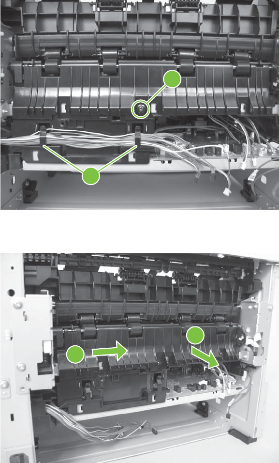
3. Remove one screw (callout 3) and release the wire harnesses from the retainers (callout 4).
Figure 6-98 Remove the ECU (2 of 14)
3
4
4. Slide the media-feed guide toward the formatter side of the product to remove it.
Figure 6-99 Remove the ECU (3 of 14)
1
2
164 Chapter 6 Removal and replacement ENWW
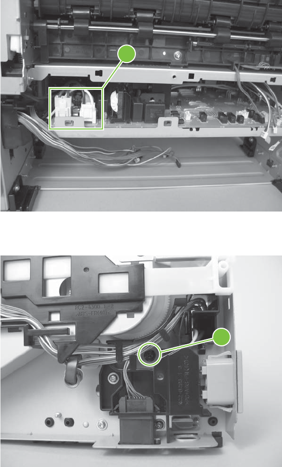
5. Disconnect two connectors (callout 5).
Figure 6-100 Remove the ECU (4 of 14)
5
6. Remove one screw (callout 6).
Figure 6-101 Remove the ECU (5 of 14)
6
ENWW Internal assemblies 165
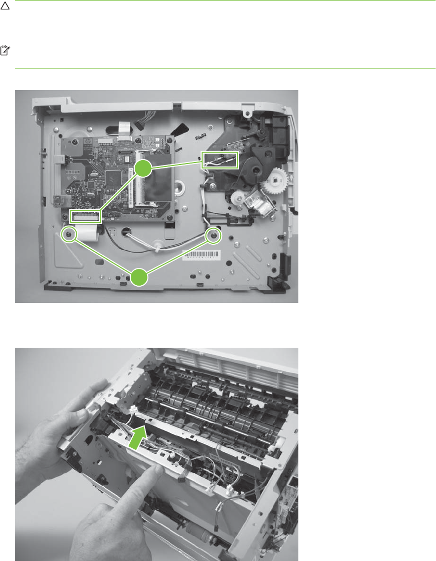
7. Disconnect one FFC (callout 7) and two connectors (callout 7), and then remove two screws
(callout 8).
CAUTION: Do not bend or fold the flat flexible cables (FFCs) during removal or installation. Also,
do not straighten pre-folds in the FFCs. You must make sure that all FFCs are fully seated in their
connectors. Failure to fully seat an FFC into a connector can cause a short circuit in a PCA.
NOTE: Place a mark on one of the cartridge-door interlock switch wires before you disconnect
them, so that you can reconnect the connectors to the same switch lugs.
Figure 6-102 Remove the ECU (6 of 14)
8
7
8. Slightly raise the power-inlet side of the ECU.
Figure 6-103 Remove the ECU (7 of 14)
166 Chapter 6 Removal and replacement ENWW
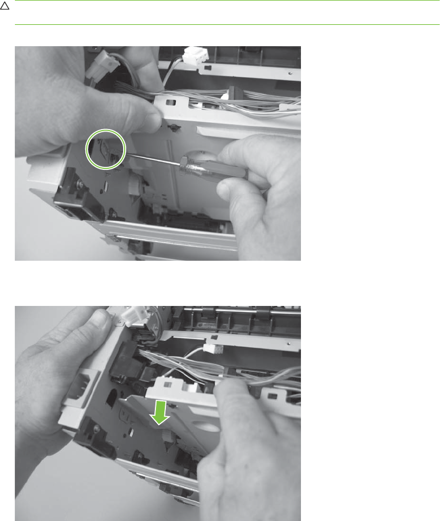
9. Use a small flat blade screwdriver to release the sheet-metal tab in the product chassis.
CAUTION: Carefully push the tab toward the outside of the product to release it. Do not bend the
tab so much that it will not engage the ECU mounting bracket when the ECU is reinstalled.
Figure 6-104 Remove the ECU (8 of 14)
10. Pull the ECU down until the mounting bracket is below the sheet-metal tab.
Figure 6-105 Remove the ECU (9 of 14)
ENWW Internal assemblies 167
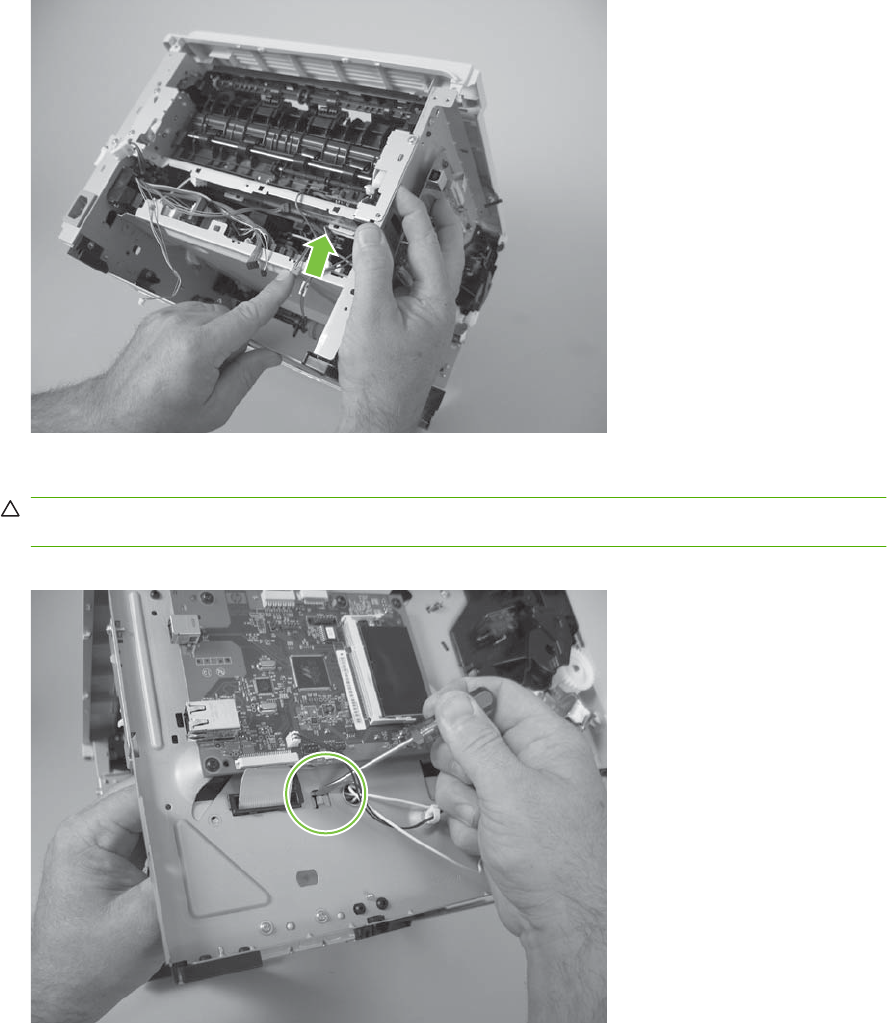
11. Slightly raise the formatter side of the ECU.
Figure 6-106 Remove the ECU (10 of 14)
12. Use a small flat blade screwdriver to release the sheet-metal tab in the product chassis.
CAUTION: Carefully pull the tab toward the outside of the product to release it. Do not bend the
tab so much that it will not engage the ECU mounting bracket when the ECU is reinstalled.
Figure 6-107 Remove the ECU (11 of 14)
168 Chapter 6 Removal and replacement ENWW
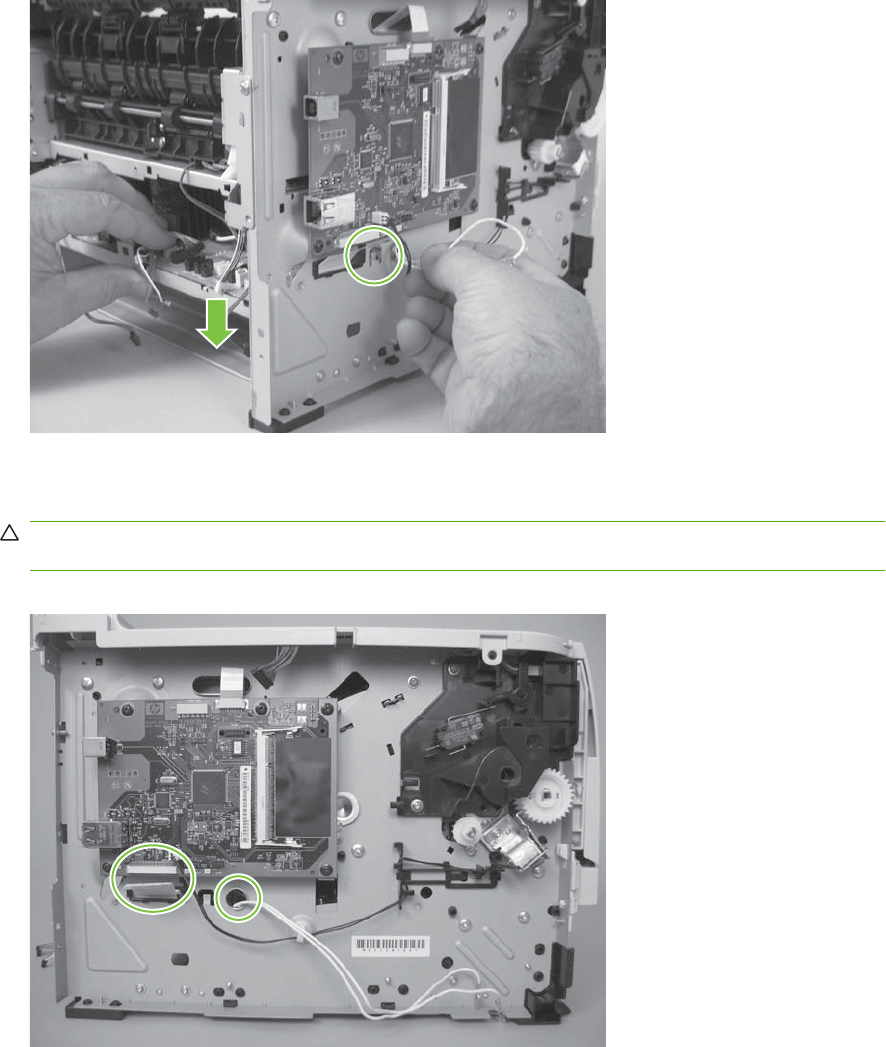
13. Pull the ECU down until the mounting bracket is below the sheet-metal tab.
Figure 6-108 Remove the ECU (12 of 14)
14. When the ECU is removed, you must carefully pass the FFC and wire harness through the holes
in the chassis.
CAUTION: Do not bend or fold the flat flexible cables (FFCs) during removal or installation. Also,
do not straighten pre-folds in the FFCs.
Figure 6-109 Remove the ECU (13 of 14)
ENWW Internal assemblies 169
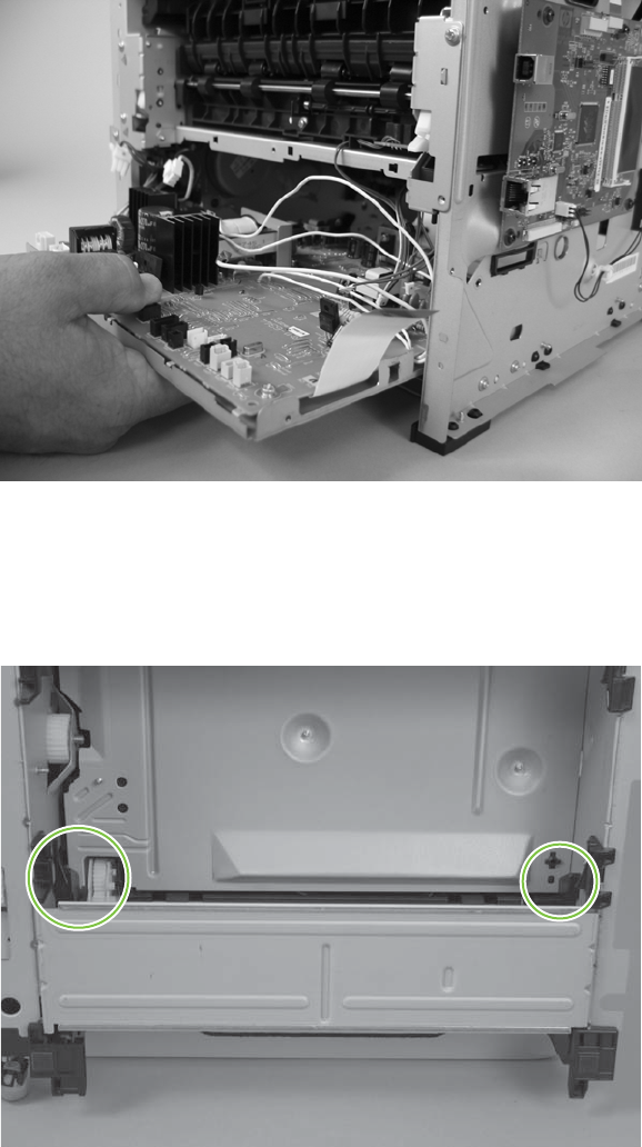
15. Carefully slide the ECU out of the product.
Figure 6-110 Remove the ECU (14 of 14)
Reinstall the ECU
1. When you reinstall the ECU, look into the Tray 2 cavity, and make sure that the corners of the ECU
mounting bracket are engaged with the product chassis.
Figure 6-111 Reinstall the fuser (1 of 2)
170 Chapter 6 Removal and replacement ENWW
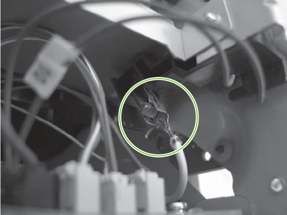
2. Make sure that the ground connector is correctly fastened and fully seated on the connector lug.
Figure 6-112 Reinstall the fuser (2 of 2)
ENWW Internal assemblies 171
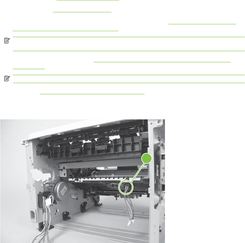
Paper-feed-guide assembly
1. Remove the following components:
●Right cover. See Right cover on page 115.
●Left cover. See Left cover on page 118.
●Rear cover, rear door, and duplex-paper-feed assembly. See Rear cover, rear door, and
duplex-paper-feed assembly on page 120.
NOTE: Only the HP LaserJet P2050 Series products have a duplex-paper-feed assembly
installed.
●Reverse-sensor assembly. See Reverse-sensor assembly; HP LaserJet P2050 Series
on page 142.
NOTE: Only the HP LaserJet P2050 Series products have a reverse-feed sensor installed.
●ECU. See Engine controller unit (ECU) on page 163.
2. Release all of the wire harnesses from the retainer (callout 1).
Figure 6-113 Remove the paper-feed-guide assembly (1 of 2)
1
172 Chapter 6 Removal and replacement ENWW
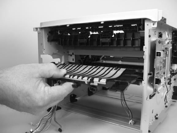
3. Remove the paper-feed-guide assembly.
Figure 6-114 Remove the paper-feed-guide assembly (2 of 2)
ENWW Internal assemblies 173
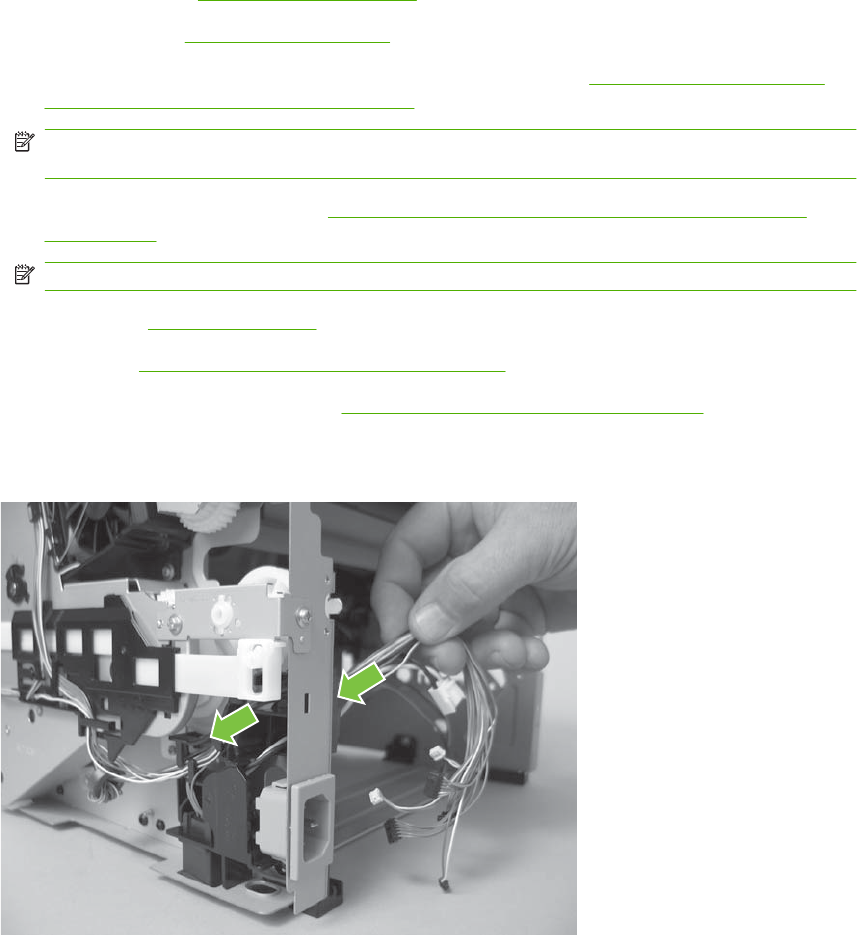
Main motor
1. Remove the following components:
●Right cover. See Right cover on page 115.
●Left cover. See Left cover on page 118.
●Rear cover, rear door, and duplex-paper-feed assembly. See Rear cover, rear door, and
duplex-paper-feed assembly on page 120.
NOTE: Only the HP LaserJet P2050 Series products have a duplex-paper-feed assembly
installed.
●Reverse-sensor assembly. See Reverse-sensor assembly; HP LaserJet P2050 Series
on page 142.
NOTE: Only the HP LaserJet P2050 Series products have a reverse-feed sensor installed.
●Fuser. See Fuser on page 158.
●ECU. See Engine controller unit (ECU) on page 163.
●Paper-feed-guide assembly. See Paper-feed-guide assembly on page 172.
2. Pass the wire harness through the opening in the chassis.
Figure 6-115 Remove the main motor (1 of 5)
174 Chapter 6 Removal and replacement ENWW
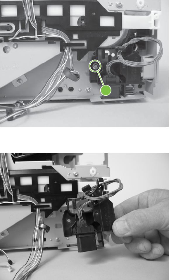
3. Release the wire harnesses from the guide, and then remove one screw (callout 1).
Figure 6-116 Remove the main motor (2 of 5)
1
4. Remove the guide.
Figure 6-117 Remove the main motor (3 of 5)
ENWW Internal assemblies 175
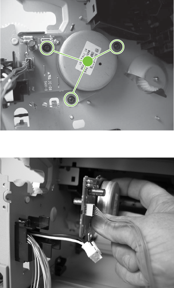
5. Remove three screws (callout 2).
Figure 6-118 Remove the main motor (4 of 5)
2
6. Remove the main motor.
Figure 6-119 Remove the main motor (5 of 5)
176 Chapter 6 Removal and replacement ENWW
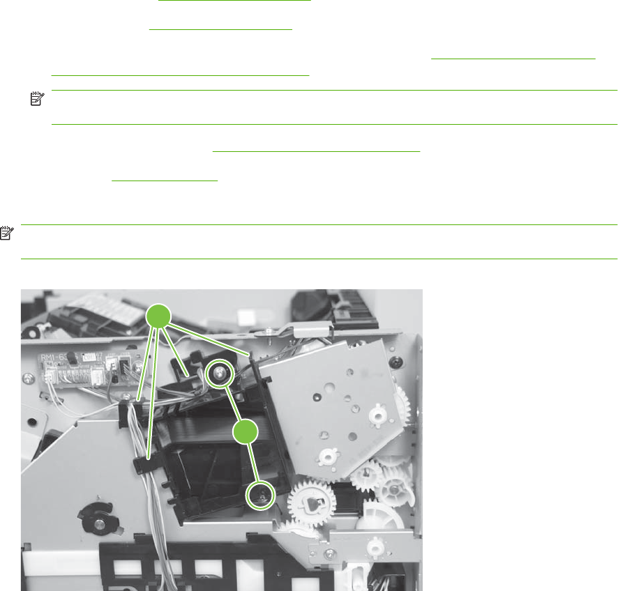
Face-down-drive or duplexing-paper-feed assembly
The HP LaserJet P2030 Series products have a face-down-drive assembly installed.
The HP LaserJet P2050 Series products have a duplexing-paper-feed assembly installed.
These components appear identical from the outside, but they have different internal gears and
functions. The same procedure is used to remove either component.
1. Remove the following components:
●Right cover. See Right cover on page 115.
●Left cover. See Left cover on page 118.
●Rear cover, rear door, and duplex-paper-feed assembly. See Rear cover, rear door, and
duplex-paper-feed assembly on page 120.
NOTE: Only the HP LaserJet P2050 Series products have a duplex-paper-feed assembly
installed.
●Top cover assembly. See Top-cover assembly on page 124.
●Fan. See Fan on page 140.
2. Remove two screws (callout 1), and then release the wire harnesses from the guide (callout 2).
NOTE: You might have to disconnect some of the connectors on the sub PCA to gain enough
slack in the wire harnesses to release them from the guide.
Figure 6-120 Remove the face-down-drive or duplexing-paper-feed assembly (1 of 4)
2
1
ENWW Internal assemblies 177
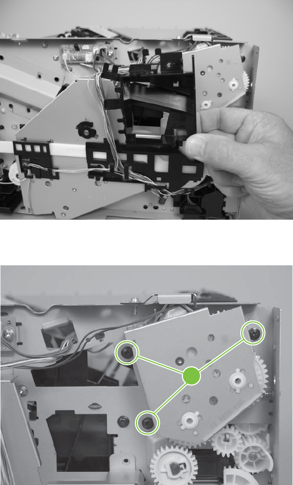
3. Remove the fan duct.
Figure 6-121 Remove the face-down-drive or duplexing-paper-feed assembly (2 of 4)
4. Remove three screws (callout 3).
Figure 6-122 Remove the face-down-drive or duplexing-paper-feed assembly (3 of 4)
3
178 Chapter 6 Removal and replacement ENWW
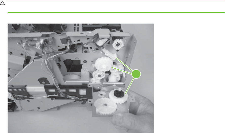
5. Remove the face-down-drive or duplexing-paper-feed assembly.
CAUTION: Some of the gears and the solenoid arm are not captive (callout 4). Do not lose the
gears or arm when you remove the assembly.
Figure 6-123 Remove the face-down-drive or duplexing-paper-feed assembly (4 of 4)
4
ENWW Internal assemblies 179
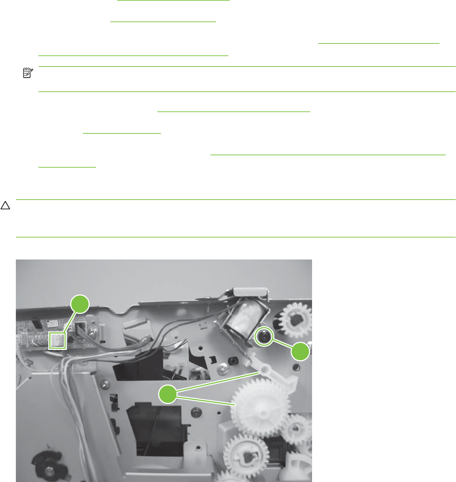
Duplex solenoid; HP LaserJet P2050 Series
1. Remove the following components:
●Right cover. See Right cover on page 115.
●Left cover. See Left cover on page 118.
●Rear cover, rear door, and duplex-paper-feed assembly. See Rear cover, rear door, and
duplex-paper-feed assembly on page 120.
NOTE: Only the HP LaserJet P2050 Series products have a duplex-paper-feed assembly
installed.
●Top cover assembly. See Top-cover assembly on page 124.
●Fan. See Fan on page 140.
●Duplexing-paper-feed assembly. See Face-down-drive or duplexing-paper-feed assembly
on page 177.
2. Disconnect one connector (callout 1), and then remove one screw (callout 2).
CAUTION: The gear and the solenoid arm that are exposed when the duplexing-paper-feed
assembly is removed are not captive (callout 3). Do not lose the gear or arm when you remove the
solenoid.
Figure 6-124 Remove the duplex solenoid; HP LaserJet P2050 Series
3
1
2
180 Chapter 6 Removal and replacement ENWW
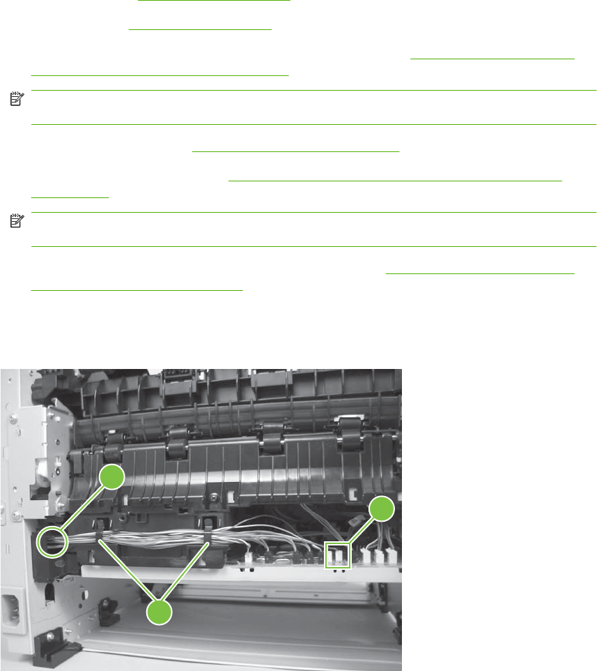
Paper-retaining-delivery assembly
1. Remove the following components:
●Right cover. See Right cover on page 115.
●Left cover. See Left cover on page 118.
●Rear cover, rear door, and duplex-paper-feed assembly. See Rear cover, rear door, and
duplex-paper-feed assembly on page 120.
NOTE: Only the HP LaserJet P2050 Series products have a duplex-paper-feed assembly
installed.
●Top cover assembly. See Top-cover assembly on page 124.
●Reverse-sensor assembly. See Reverse-sensor assembly; HP LaserJet P2050 Series
on page 142.
NOTE: Only the HP LaserJet P2050 Series products have a reverse-sensor assembly
installed.
●Face-down-drive or duplexing-paper-feed assembly. See Face-down-drive or duplexing-
paper-feed assembly on page 177.
2. Disconnect one connector (callout 1), release the wire harness from the retainers (callout 2), and
then pass the wire harness though the hole in the chassis (callout 3).
Figure 6-125 Remove the paper-retaining-delivery assembly (1 of 6)
3
2
1
ENWW Internal assemblies 181
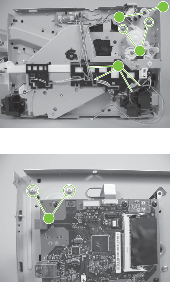
3. Release one tab (callout 4), and then remove one gear (callout 5).
Remove two screws (callout 6), and then release the wire harness from the guides (callout 7).
Figure 6-126 Remove the paper-retaining-delivery assembly (2 of 6)
4
6
5
7
4. Remove two screws (callout 8).
Figure 6-127 Remove the paper-retaining-delivery assembly (3 of 6)
8
182 Chapter 6 Removal and replacement ENWW
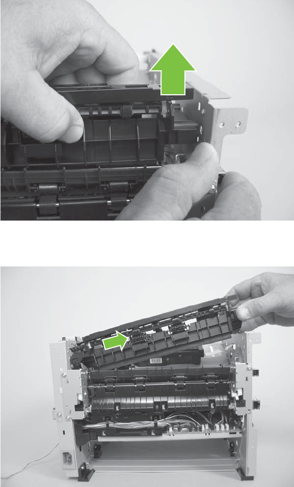
5. Carefully separate the assembly from the chassis, and then raise the end of the assembly to release
it.
Figure 6-128 Remove the paper-retaining-delivery assembly (4 of 6)
6. Slide the assembly toward the formatter side of the product to release it.
Figure 6-129 Remove the paper-retaining-delivery assembly (5 of 6)
ENWW Internal assemblies 183
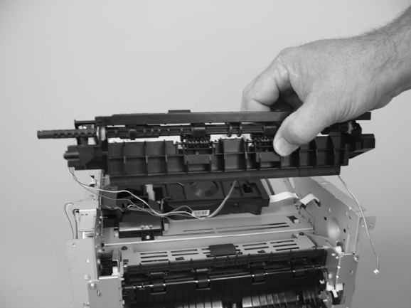
7. Remove the paper-retaining-delivery assembly
Figure 6-130 Remove the paper-retaining-delivery assembly (6 of 6)
184 Chapter 6 Removal and replacement ENWW

7 Solve problems
To use the information in this chapter, you should have a basic understanding of the HP LaserJet printing
process. Explanations of each mechanical assembly, the product systems, and the basic theory of
operation are contained in Theory of operation on page 79. Do not perform any of these troubleshooting
processes unless you understand the function of each product component.
NOTE: Unless otherwise noted, all illustrations depicting the HP LaserJet P2050 Series Printers are
also valid for the HP LaserJet P2030 Series Printers.
●Solve general problems
●Menu map (HP LaserJet P2050 Series Printers only)
●Troubleshooting process
●Tools for troubleshooting
●Problem-solve diagrams
●Status-light patterns (HP LaserJet P2030 Series Printers only)
●Status-alert messages (HP LaserJet P2030 Series Printers only)
●Interpret control-panel messages (HP LaserJet P2050 Series Printers only)
●Event-log messages
●Paper-handling problems
●Solve image-quality problems
●Solve print-quality problems
●Solve performance problems
●Solve connectivity problems
●Service mode functions
ENWW 185

Solve general problems
If the product is not responding correctly, complete the steps in the following checklist, in order. If the
product does not pass a step, follow the corresponding troubleshooting suggestions. If a step resolves
the problem, you can stop without performing the other steps on the checklist.
Troubleshooting checklist
1. Make sure the product Ready light is on. If no lights are on, complete these steps:
a. Check the power-cable connections.
b. Check that the power switch is on.
c. Make sure that the line voltage is correct for the product power configuration. (See the label
that is on the back of the product for voltage requirements.) If you are using a power strip and
its voltage is not within specifications, plug the product directly into the wall. If it is already
plugged into the wall, try a different outlet.
d. Verify that connectors J2 and J7 on the formatter PCA are seated. See Figure 7-3
Components on the left side of the product on page 196.
e. Perform an engine test. If the test is successful, replace the control panel and then the
formatter PCA. See Top-cover assembly on page 124, Formatter PCA; HP LaserJet P2030
Series on page 130, or Formatter PCA; HP LaserJet P2050 Series on page 132.
2. Check the cables.
a. Check the cable connection between the product and the computer or network port. Make
sure that the connection is secure.
b. Make sure that the cable itself is not faulty by using a different cable, if possible.
c. Check the network connection. See Solve network problems on page 249.
3. Check to see if any messages appear on the control-panel display. If any error messages appear,
see Interpret control-panel messages (HP LaserJet P2050 Series Printers only) on page 219.
4. Check to see if any control-panel lights are lit. See Status-light patterns (HP LaserJet P2030 Series
Printers only) on page 209.
5. Make sure that the print media that you are using meets specifications.
6. Print a configuration page. See Print the information pages on page 48.
a. If the pages do not print, check that at least one tray contains print media.
b. If the page jams in the product, see Clear jams on page 230.
7. If the configuration page prints, check the following items.
If the page prints correctly, then the product hardware is working. The problem is with the
computer that you are using, with the printer driver, or with the program.
8. Select one of the following options:
Windows: Click Start, click Settings, and then click Printers, or Printers and Faxes. Double-
click the name of the product.
186 Chapter 7 Solve problems ENWW

-or-
Mac OS X: Open Print Center or Printer Setup Utility, and double-click the line for the product.
9. Verify that you have installed the printer driver for this product. Check the program to make sure
that you are using the printer driver for this product.
10. Print a short document from a different program that has worked in the past. If this solution works,
then the problem is with the program that you are using. If this solution does not work (the document
does not print), complete these steps:
a. Try printing the job from another computer that has the product software installed.
b. If you connected the product to the network, connect the product directly to a computer with
a USB cable. Redirect the product to the correct port, or reinstall the software, selecting the
new connection type that you are using.
Factors that affect product performance
Several factors affect the time it takes to print a job:
●Maximum product speed, measured in pages per minute (ppm)
●The use of special paper (such as transparencies, heavy paper, and custom-size paper)
●Product processing and download time
●The complexity and size of graphics
●The speed of the computer you are using
●The USB connection
●The product I/O configuration
●The amount of memory installed in the product
●The network operating system and configuration (if applicable)
NOTE: Although additional memory can improve how the product handles complex graphics and
improve download times, it will not increase maximum product speed (ppm).
ENWW Solve general problems 187

Basic problem solving
Table 7-1 Basic problem solving
Problem Cause Solution
When the product is connected to a
correctly grounded power source, the
LEDs on the control panel do not
illuminate and the main motor does not
rotate.
The product does not turn on.
No power to the product. 1. Verify that the power switch is
turned on.
2. Verify that the power cable is
correctly plugged into the outlet and
the product.
3. Verify that the power outlet has the
correct voltage.
The power inlet/switch cable assembly is
defective.
Replace the power inlet/switch cable
assembly. See Inlet-cable assembly
on page 150.
The ECU is defective. Replace the ECU. See Engine controller
unit (ECU) on page 163.
When turned on, the LEDs on the control
panel light up, but the main motor does
not rotate.
The product turns on, but the motor does
not rotate.
The print-cartridge door is open. Close the print-cartridge door.
Media is jammed in the paper path. Clear all media from the paper path, and
make sure that all sensors are working
correctly.
The cable is not connected correctly. Reconnect the motor cable.
The motor is not mounted correctly in the
product chassis.
Verify that the motor is connected
correctly and that it rotates freely.
A gear is damaged or jammed. Replace the gear assembly. See Paper-
pickup-gear assembly on page 134.
The ECU is defective. Replace the ECU. See Engine controller
unit (ECU) on page 163.
The main motor is defective. Replace the motor. See Main motor
on page 174.
The product turns on and the motor
rotates, but none of the control-panel
lights turn on, and pressing the control-
panel buttons has no effect.
The product is unresponsive.
The control-panel cable is not connected
correctly.
Reconnect the control panel cable.
The control panel is defective. Replace the control panel. See Top-
cover assembly on page 124.
The formatter is defective. Replace the formatter. See Formatter
PCA; HP LaserJet P2030 Series
on page 130 or Formatter PCA; HP
LaserJet P2050 Series on page 132.
The product is on, but the control-panel
lights indicate that the product is not in
the "ready" state.
The product is not "ready."
The product has an internal error that
was detected during the Power-On Self-
Test sequence.
Consult the list of control-panel light
patterns to identify and correct the error.
188 Chapter 7 Solve problems ENWW

Problem Cause Solution
The product turns on, the motor rotates,
and the control panel indicates the
"ready" state, but the product does not
print.
The product does not print.
A component is defective. Perform an engine test to verify print-
engine components.
1. Print an engine test page. See
Engine test page on page 251.
2. If the engine test page does not
print, check all the connectors on
the ECU, and reconnect any cables
that are connected incorrectly.
3. If, after checking the connectors,
the error persists, replace the ECU.
See Engine controller unit (ECU)
on page 163.
The formatter is defective. Press the Go button to print a Demo
page. If the Demo page does not print,
replace the formatter. See Formatter
PCA; HP LaserJet P2030 Series
on page 130 or Formatter PCA; HP
LaserJet P2050 Series on page 132.
The product prints the engine test and
the Demo page, but does not print jobs
sent from a computer.
The product does not print from a
computer.
The cable is not connected correctly. Reconnect the cable.
An incorrect driver is selected. Select the correct printer driver.
The printer driver is not installed
correctly.
Remove and then reinstall the product
software. Make sure that you use the
correct procedure and port setting.
Other devices are connected to the
product (for example, through a switch or
hub) that are interfering with the
computer-product communications.
Disconnect the other devices, switches,
or hubs.
There is a computer-port
communications problem.
Reset the computer port settings (see
the computer user guide for more
information).
The formatter is defective. Replace the formatter. See Formatter
PCA; HP LaserJet P2030 Series
on page 130 or Formatter PCA; HP
LaserJet P2050 Series on page 132.
Table 7-1 Basic problem solving (continued)
ENWW Solve general problems 189
Menu map (HP LaserJet P2050 Series Printers only)
Print a menu map
1. Press OK to open the menus.
2. Use the arrow buttons to navigate to the Reports submenu, and then press OK.
3. Use the arrow buttons to navigate to the Menu structure submenu, and then press OK to print the
menu structure.
4. Press X to exit the menus.
190 Chapter 7 Solve problems ENWW

Troubleshooting process
When the product malfunctions or encounters an unexpected situation, the product control panel alerts
you to the situation. This chapter contains information to help diagnose and solve problems.
●Use the pre-troubleshooting checklist to evaluate the source of the problem and to reduce the
number of steps that are required to fix the problem.
●Use the troubleshooting flowchart to pinpoint the root cause of hardware malfunctions. The
flowchart guides you to the appropriate section of this chapter that provides steps for correcting
the malfunction.
Before beginning any troubleshooting procedure, check the following conditions:
●Are supply items within their rated life?
●Does the configuration page reveal any configuration errors?
NOTE: The customer is responsible for checking supplies and for using supplies that are in good
condition.
Pre-troubleshooting checklist
The following table includes basic questions to ask the customer to quickly help define the problem or
problems.
General topic Questions
Environment ●Is the product installed on a solid, level surface (+/- 1°)?
●Is the power-supply voltage within ± 10 volts of the specified power source?
●Is the power-supply plug inserted in the product and the outlet?
●Is the operating environment within the specified parameters?
●Is the product exposed to ammonia gas, such as that produced by diazo copiers
or office cleaning materials?
NOTE: Diazo copiers produce ammonia gas as part of the coping processes.
Ammonia gas (from cleaning supplies or a diazo copier) can have an adverse
affect on some product components (for example, the print-cartridge OPC).
●Is the product exposed to direct sunlight?
Media ●Does the customer use only supported media?
●Is the media in good condition (no curls, folds, or distortion)?
●Is the media stored correctly and within environmental limits?
Input trays ●Is the amount of media in the tray within specifications?
●Is the media placed in the tray correctly?
●Are the paper guides aligned with the media?
●Is the cassette correctly installed in the product?
Print cartridges ●Is each print cartridge correctly installed?
Transfer unit and fuser ●Are the transfer unit and fuser installed correctly?
ENWW Troubleshooting process 191

General topic Questions
Covers ●Is the front cover closed?
Condensation ●Does condensation occur following a temperature change (particularly in winter
following cold storage)? If so, wipe affected area dry or leave the product on
for 10 to 20 minutes.
●Was a print cartridge installed soon after being moved from a cold to a warm
room? If so, allow the print cartridge to sit at room temperature for 1 to 2 hours.
Miscellaneous ●Check for and remove any non-HP components (print cartridges, memory
modules, and EIO cards) from the product.
●Remove the product from the network and make sure that the failure is
associated with the product before beginning troubleshooting.
●For any print-quality issues, calibrate the product.
192 Chapter 7 Solve problems ENWW

Tools for troubleshooting
The section describes the tools that can help you solve problems with your device.
Continuous self-test (HP LaserJet P2050 Series only)
The continuous self-test puts the device into a continuous printing mode without having to send jobs to
it.
1. Confirm that the product is in a Ready state. Press OK to enter the main menu.
2. Simultaneously press and hold the down arrow and Cancel button .
3. Press OK to re-enter the main menu.
4. Navigate to the secondary service menu.
5. Select Service Reports and then Cont. Self-Test.
To terminate the continuous self-test, press the Cancel button .
Half self-test functional check
The half self-test check determines which printing process is malfunctioning.
1. Print a Configuration page.
2. Press the print-cartridge-door button after the paper advances halfway through the product (about
five seconds after the motor begins rotating). The leading edge of the paper should have advanced
past the print cartridge.
3. Remove the print cartridge.
4. Open the print cartridge drum shield to view the drum surface. If a dark and distinct toner image is
present on the drum surface, assume that the first two functions of the electrophotographic process
are functioning (image formation and development). Troubleshoot the failure as a transfer or fusing
problem.
If there is no image on the photosensitive drum, perform these checks:
1. Make sure you removed the entire length of the sealing tape from the print cartridge before you
installed the cartridge.
2. Perform a drum rotation functional check to make sure that the drum is rotating.
3. Perform a high-voltage contacts check.
Drum rotation functional check
The photosensitive drum, located in the print cartridge, must rotate for the print process to work. The
photosensitive drum receives its drive from the main drive assembly.
NOTE: This test is especially important if refilled print cartridges have been used.
1. Open the print-cartridge door.
2. Remove the print cartridge.
ENWW Tools for troubleshooting 193

3. Mark the drive gear on the cartridge with a felt-tipped marker. Note the position of the mark.
4. Replace the print cartridge and close the print-cartridge door. The startup sequence should rotate
the drum enough to move the mark.
5. Open the print-cartridge door and inspect the gear that was marked in step 3. Verify that the mark
moved.
If the mark did not move, inspect the main drive assembly to make sure that it is meshing with the print
cartridge gears. If the drive gears appear functional and the drum does not move, replace the print
cartridge. See Print cartridge on page 102.
Heating element check
Paper passes between the heating element and a soft pressure roller to fuse toner to the paper.
1. Unplug the product for at least ten minutes.
2. Verify that the thermistor connector is seated into both the product chassis and the ECU.
3. Remove the heating element connector from the ECU. To measure the continuity of the heating
element, measure the resistance between the two pins at the end of the cable.
NOTE: Normal resistance is 25 ohms +/- 10 ohms for the 110 V product and 80 ohms +/- 20 ohms
for the 220 V product.
If no resistance is measured, replace the fuser. See Fuser on page 158.
4. Remove the thermistor connector, and then measure the resistance between J206 pins one and
two and between J206 pins three and four.
NOTE: Normal resistance between both pairs of pins is 370K ohms +/- 50K ohms at 20° C (68° F).
5. If no resistance is measured, replace the fuser. See Fuser on page 158,
High-voltage contacts check
The high-voltage contacts in the product must have a good connection with the contacts on the print
cartridge to provide the necessary voltages for the electrophotographic processes.
Checking the print cartridge contacts
When the product is turned on, high voltage is placed on the developer roller of the print cartridge. If the
antenna does not detect this voltage, the product displays an Install Black Cartridge message. Remove
the print cartridge and visually inspect the three connection points on the ends of the print cartridge:
primary charging contact (callout 1), developer roller contact (callout 2), and antenna contact (callout 3).
194 Chapter 7 Solve problems ENWW
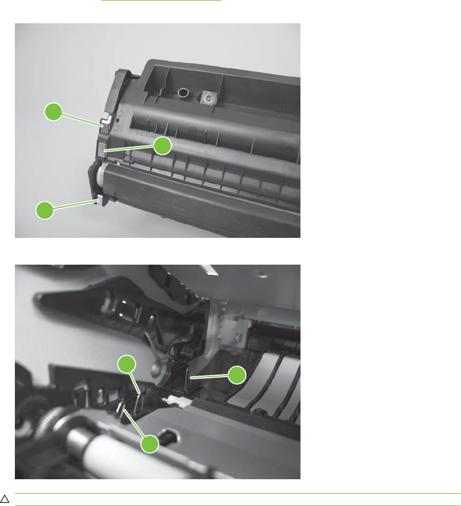
If one is dirty or corroded, clean the connection with isopropyl alcohol. If one is damaged, replace the
print cartridge. See Print cartridge on page 102.
Figure 7-1 High-voltage contact points (on the print cartridge)
2
1
3
Figure 7-2 High-voltage contact points (on the product)
2
3
1
CAUTION: After removing the print cartridge, handle it only on the ends.
ENWW Tools for troubleshooting 195
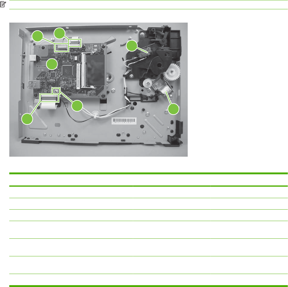
Component locations
NOTE: Control-panel messages appear on HP LaserJet P2050 Series Printers only.
Figure 7-3 Components on the left side of the product
23
1
7
65
4
Table 7-2 Left-side components
Reference Component Description If disconnected or blocked
1Formatter
2J2 Connector to control panel Blank display
3J1 FFC to laser drive PCA
4SW301 Cartridge door switch Control-panel message: Door
open appears.
5SL1 Tray 1 pickup solenoid (J4) Control-panel message: Jam in
Tray 1 appears.
6J3 Connector to Tray 1 pickup
solenoid
7 J7 FFC to engine controller
196 Chapter 7 Solve problems ENWW
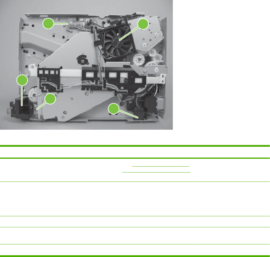
Figure 7-4 Components on the right side of the product
12
3
4
5
Table 7-3 Right-side components
Reference Component Description If disconnected or blocked
1Connector PCA See Figure 7-5 Components on
the connector PCA on page 198
for more information.
2FM1 Main fan Control-panel message: 57 Fan
error appears.
Fan rotates about 30 seconds
after being turned on.
3Paper feeder connector Connector to optional Tray 3
4SL2 Tray 2 solenoid (J1104) Control-panel message: Jam in
Tray 2 appears.
5 SW1001 Power switch
ENWW Tools for troubleshooting 197
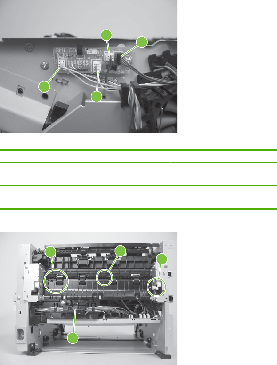
Figure 7-5 Components on the connector PCA
12
3
4
Table 7-4 Connector PCA components
Reference Component Description
1J1101 Duplex reverse solenoid (SL3)
2J1103 Connector to scanner motor
3J1105 Connector to main cooling fan
4 J1104 Connector to Tray 2 solenoid (SL2)
Figure 7-6 Components on the rear side of the product
12
3
4
198 Chapter 7 Solve problems ENWW
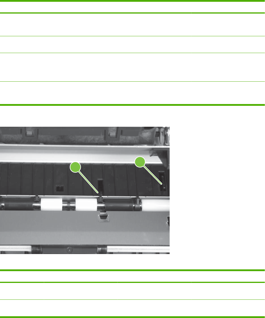
Table 7-5 Rear-side components
Reference Component Description If disconnected or blocked
1PS918 Duplex reverse sensor flag (J208)
(HP LaserJet P2050 Series
Printers only)
Control-panel message: Jam in
output bin appears.
2PS915 Photosensor flag for fuser (J206) Control-panel message: Jam in
output bin appears.
3White lever When the rear door is closed, this
lever positions the photosensor
flag for the fuser (PS915) to
detect paper exiting the fuser.
4 Reverse sensor assembly Detects paper during the
duplexing process (HP LaserJet
P2050 Series Printers only)
Figure 7-7 Components in the print cartridge cavity
12
Table 7-6 Print cartridge components
Reference Component Description If disconnected or blocked
1 PS912 Top of page photosensor flag
(J203)
Control-panel message: Jam in
cartridge area appears.
2 PS913 Paper-width photosensor flag
(J203)
Control-panel message: Jam in
cartridge area appears.
ENWW Tools for troubleshooting 199
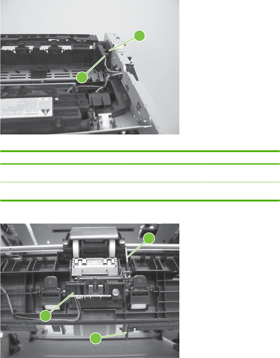
Figure 7-8 Components on the top of the product
1
2
Table 7-7 Top components
Reference Component Description If disconnected or blocked
1 PS911 Output bin media full sensor Control-panel message: Output
bin full appears.
2 Flag Rotates to block sensor as the
output bin fills
Figure 7-9 Components on Tray 1 and Tray 2
2
1
3
200 Chapter 7 Solve problems ENWW

Table 7-8 Tray 1 and Tray 2 components
Reference Component Description
1Flag Photosensor flag for Tray 1 paper present sensor
(PS916)
2Flag Photosensor flag for Tray 2 paper present sensor
(PS914)
3 PS916 Photosensor (J205)
ENWW Tools for troubleshooting 201

Problem-solve diagrams
●Repetitive image defect ruler
●Engine controller PCA
●Major components
●PCAs
●General timing chart
●Circuit diagram
Repetitive image defect ruler
Defects on product rollers can cause image defects to appear at regular intervals on the page,
corresponding to the circumference of the roller that is causing the defect. Measure the distance between
defects that recur on a page. Use the following table or the repetitive-defect ruler to determine which
roller is causing the defect. To resolve the problem, try cleaning the roller first. If the roller remains dirty
after cleaning or if it is damaged, replace the part that is indicated in Table 7-9 Repetitive defects
on page 202.
CAUTION: Do not use solvents or oils to clean rollers. Instead, rub the roller with lint-free paper. If dirt
is difficult to remove, rub the roller with lint-free paper that has been dampened with water.
NOTE: The following table replaces the graphical repetitive defect ruler. You can make your own ruler
by using these measurements. For the most accurate results, use a metric ruler.
Table 7-9 Repetitive defects
Component Distance between defects
Primary charging roller 38 mm (1.5 in)
Transfer roller 39 mm (1.54 in)
Developer roller 42 mm (1.65 in)
Registration roller 43 mm (1.69 in)
Fuser film 57 mm (2.24 in)
Pressure roller 63 mm (2.48 in)
Photosensitive drum 75 mm (2.95 in)
202 Chapter 7 Solve problems ENWW
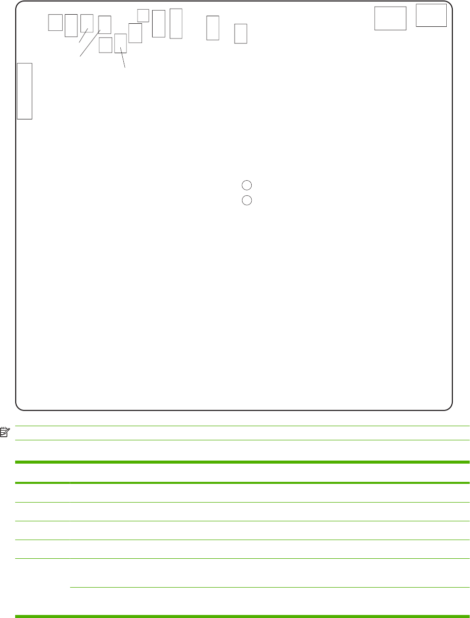
Engine controller PCA
Figure 7-10 Engine controller connectors
J102
J101
J215
J202
J207
J211
J208
J581
J205
J204
J203
J206 J210
J213
J201
J2142
J2141
NOTE: Control-panel messages appear on HP LaserJet P2050 Series Printers only.
Table 7-10 Engine controller connectors
Item Description When disconnected
J101 AC voltage to engine controller No AC voltage to engine controller
J102 AC voltage to fuser No AC voltage to fuser
J201 Formatter PCA
J202 Main motor (M1) Control-panel message: Initializing... appears
1
J203 Top of page (PS912) Control-panel message: Jam in cartridge area
appears
1
Media width sensors (PS913) Control-panel message: Open door and clear jam
appears
1
ENWW Problem-solve diagrams 203

Item Description When disconnected
J204 Tray 2 paper present sensor (PS914) Control-panel message:Load paper appears
1
J205 Tray 1 paper present sensor (PS916) No message appears unless you request paper from
Tray 1.
J206 Fusing assembly exit sensor (PS915) Product attempts to pull paper.
Control-panel message: Jam in cartridge area or
Open door and clear jam appear
1
J207 Connecting PCA Control-panel message: Initializing... appears
1
J208 Duplex reverse sensor (PS918) (HP LaserJet P2050
Series Printers only)
Print simplex, but not duplex.
J210 Thermistor (TH1) Control-panel message: Initializing... appears
1
J211 Optional paper feeder accessory (PS911)
J213 Media tray full sensor (PS911) Control-panel message: Output bin full appears
1
J215 Power switch LED (LED1001) The product stays on. You cannot turn it off.
J581 Toner memory reader A page prints and then the control-panel message:
10.X Supply memory error appears
1
J2141 Voltage in top cover switch (+24 V) No voltage to top cover switch
J2142 Voltage out top cover switch (+24 V) No voltage from top cover switch
1
Control-panel messages appear on HP LaserJet P2050 Series Printers only.
Table 7-10 Engine controller connectors (continued)
204 Chapter 7 Solve problems ENWW
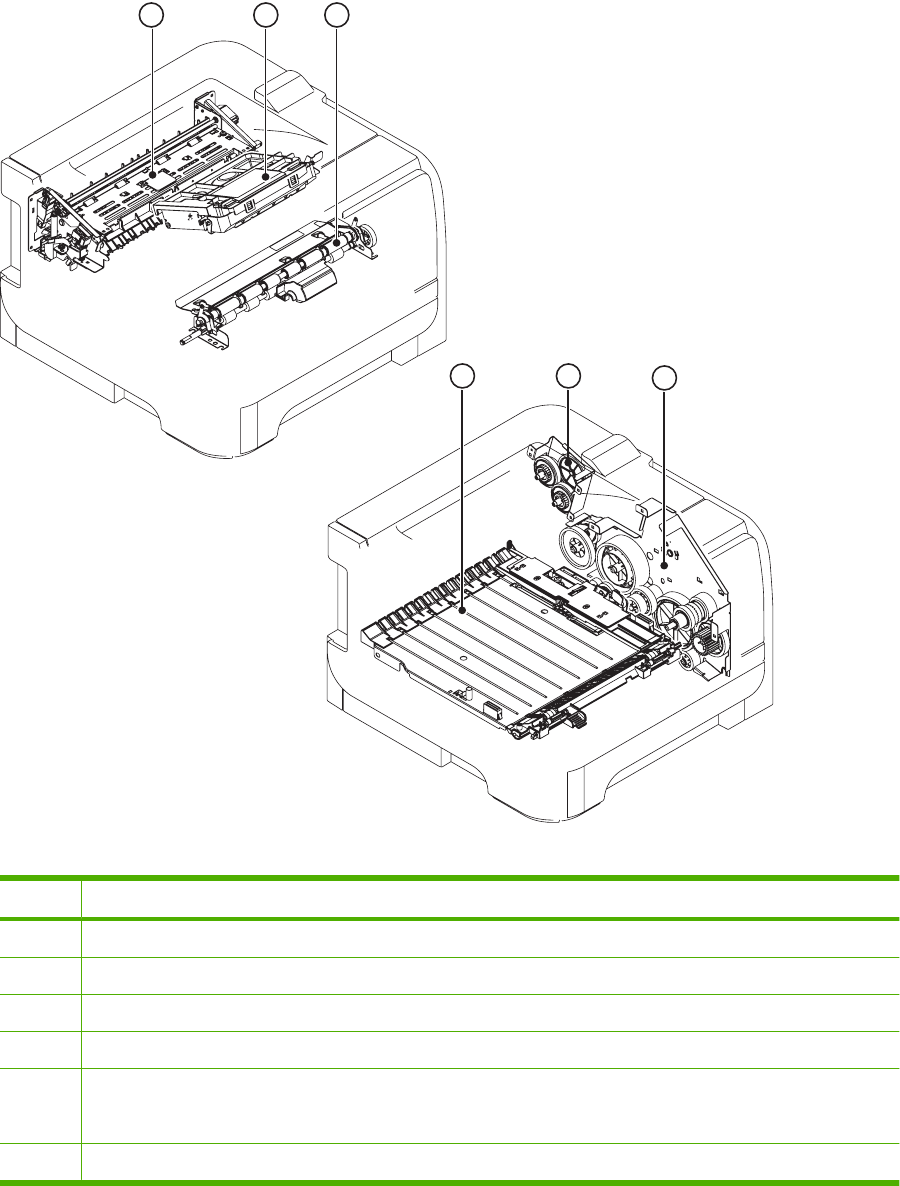
Major components
Figure 7-11 Major components
13
4
2
6
5
Table 7-11 Major components
Item Description
1Fuser
2Laser/scanner assembly
3Registration assembly
4Duplex feed unit (HP LaserJet P2050 Series Printers only)
5Duplex-drive-unit assembly (HP LaserJet P2050 Series Printers only)
Face-down-drive assembly (HP LaserJet P2030 Series Printers only)
6Main drive unit
ENWW Problem-solve diagrams 205
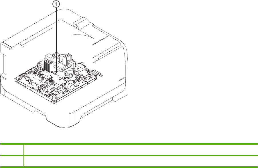
PCAs
Figure 7-12 PCAs
Table 7-12 PCAs
Item Description
1Engine controller unit
206 Chapter 7 Solve problems ENWW
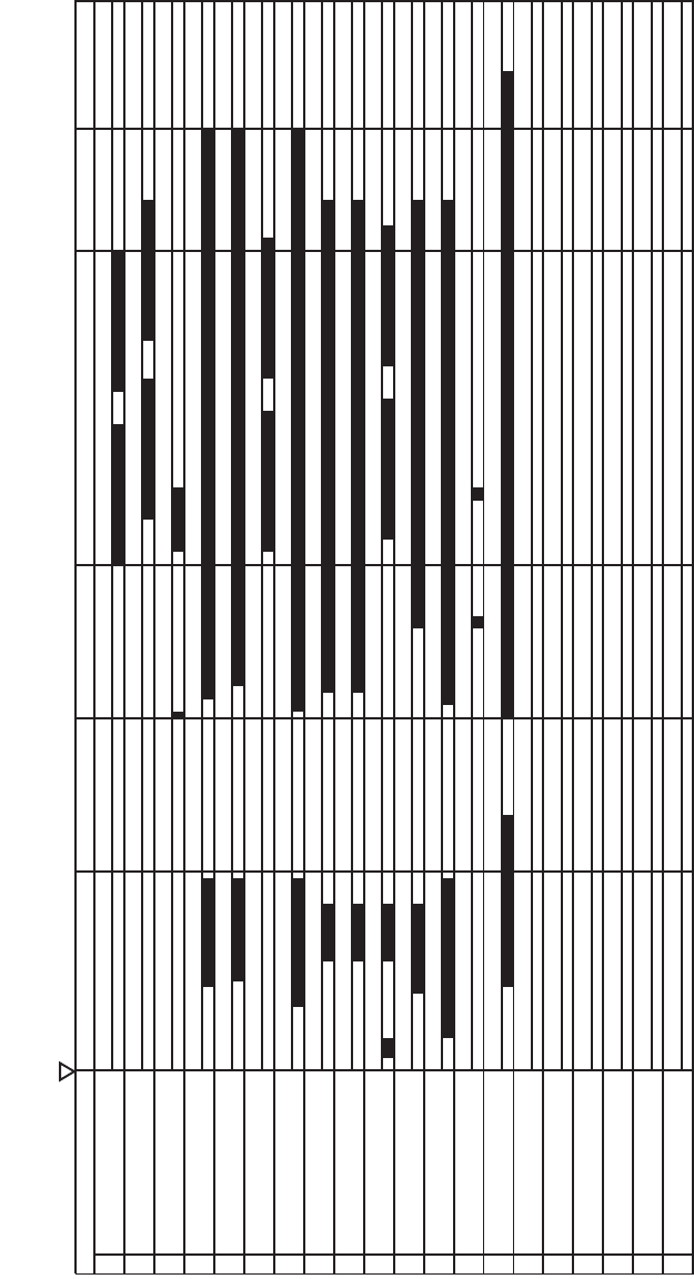
General timing chart
Figure 7-13 General timing chart
I. GENERAL TIMING CHART
Timing chart for two consecutive prints on letter paper
STBYRTSLTNIRPRTNI
YBTSTIAW
19
20
17
18
15
16
13 Tray 2 pickup solenoid (SL2)
14 Main Fan (FM1)
11 Transfer Charging Bias
12 Fusing Heater
9Primary Charging Bias (DC)
10 Developing Bias
7Main Motor (M1)
8Primary Charging Bias (AC)
5Laser Diode
6BD Output signal (BDO)
3Print start command (EEC12)
4Scanner Motor
Operation
1TOP sensor (PS912)
2Fusing delivery sensor (PS915)
Power switch ON
ENWW Problem-solve diagrams 207
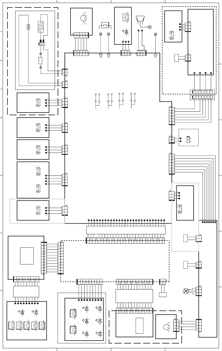
Circuit diagram
Figure 7-14 Circuit diagram
A
65 4 3
B
C
D
SL
21
345621
1234 56
12
12
1234567
1234567
21
12
12
4
2
1
3
123
321
123
321
1
23
23 1
3
2
1
312
1
2
3
123
2
1
M
12345
23154
12345
12345
12345
2121
12 12
MT1
12
21
21
END1
END2
12
MT2
123
321
123
321
321
123
321
123
321
123
123
321
4213
321
321
4123
1234
123
321
321
123
1110987654321
11 10 9 8 2345617
1
2
3
4
5
6
7
8
9
23456781910
11
11
10982345617
2018
16
1
2
3
4
5
6
7
8
9
10
11 13 15 17 19 21
12 14 24 28
26
23 25 27
22
1
2
4
5
9
3
8
7
6
10
11
12
13
14
15
16
17
18
19
20
21
22
23
24
25
26
27
28
1234567
1234567
123
321
123
4213
1234
4213
1234
1234
12
M
SL
12
12
1
2
3
4
5
6
7
8
9
10
11
13
12
1
2
3
4
5
6
7
8
9
21
123
321
123
123
SL
21
12
12
1
2
3
4
5
6
7
8
9
12
12
12
SL
M1
Main motor
SW301
1
2
1
2
1
2
Laser Drive
PCA
Scanner motor
Laser scanner unit
MP tray
pickup solenoid
Fuser heater
Thermoswitch
Themistor
Fuser unit
Fuser film unit
Engine Controller PCA
PF
pickup solenoid
Paper feeder
(Option)
Main fan
1
2
1
2
1
2
1
2
Formatter
SW70 2
1
SW71 2
1
SW72 2
1
SW73 2
1
SW74 2
1
1
2
1
2
2
12
1
2
1
1
2
1
2
3
4
5
6
7
8
9
10
11 13
12
J73
J71
J71F
LCD
J72
+3.3V
GND
LCD_DATA
FP_CLK
SR_DATA
SR_NCS
LCD_NCS
FP_RSLD
NRESET
FP_LED2
FP_LED1
J1M
J1F
GND(DCOM)
/VDO2
VDO2
GND(DCOM)
VDO1
/VDO1
GND(DCOM)
CNT2
CNT1
CNT0
GND(5)(*)
+5V(*)
/BDI(*)
J3
J7
J801
J4M
+24P1
MPSOL(*)
J4F
J802M
J802F
M2
+24P1
GND
FANLOCK
J1105M
J1103M
/ACC
/DEC
GND
+24P1
J1103F
FM1
J1105F
J201
J207M
J207F
+3.3V
+3.3V
FANLOCK
DUPSOL
CSTSOL
GND
/DEC
/ACC
+24P1
N.C.
+3.3V
/BD0
/SC
/SCLK
/RST0
GND
GND
GND
GND
GND
GND
+3.3V
+3.3V
+3.3V
+3.3V
N.C.
/BDI
N.C.
/WDSNS
MPSOL
CNT0
CNT1
CNT2
GND
+5V
+3.3V
/PISNS
GND
+24P1
J912
J203M
J203F
PS913
PS912
+3.3V
J206M
J206F
GND
FSRTH
J915
/POSNS
GND
J210M J102M
J102F
J210F
PS915
J202M
ACN
ACH
J202F
J1202M
J1202F
MFG
GND
/MACC
/MDEC
+24U
+24V
+24P1
J2142
J2141
FT2
FT1
GND
J215M
SWON
LED
J1001 LED1001 SW1001
J215F
AC-N
AC-H
FB
J101M
J302
J101F
FT3
INL101
JP301
JP302
JP303
JP304
JP305
JP306
JP111
JP112
DV
PR
TR
ANT
J211M
J211F
/SI
GND
/SO
/CLK
+24V
/TESTP
TAG2
TAG1
J581M
COILA
COILB
J581F
J1205F
J1205D
Operation panel (P2050 series)
LED1
LED2
FFC
Cassette
pickup solenoid
CSTSOL(*)
J1104M
+24P1
J1104F
SL2
SL1
TP
J4
H1
TP1
TH1
+3.3V
J205M
J205F
J916
/MPSNS
GND
PS916
+3.3V
J204M
J204F
J914
/CSTSNS
GND
PS914
+3.3V
J213M
J213F
J911
/FULSNS
GND
PS911
LEDDRV
J1203M
J1203F
J1204
OPTSNS
GND
PS1201
OPTSLON
J1202M
+24V
J1202F
SL4
FFC
FFC
J1201
J951
SW951 SW952
LED951
LED954
LED952
LED955
Operation panel (P2030 series)
LED953
LED956
Door switch
Power switch
Fuser delivery
sensor
Cassette
media
presence
sensor
Media full
sensor
Media width
sensor
Top sensor
PF intermediate PCA
PF media
feed sensor
Connecting PCA
J2100
J208M
+3.3V
GND
/DUPSNS
J208F
PS918
Duplex reverse
sensor
J911
J1M
J1F
BD sensor
P2050 series only
MP tray
media
presence
sensor
P2050 series only
Duplex reverse
solenoid
J1101M
J1101F
DUPSOL(*)
J1102
+24P1
SL3
208 Chapter 7 Solve problems ENWW
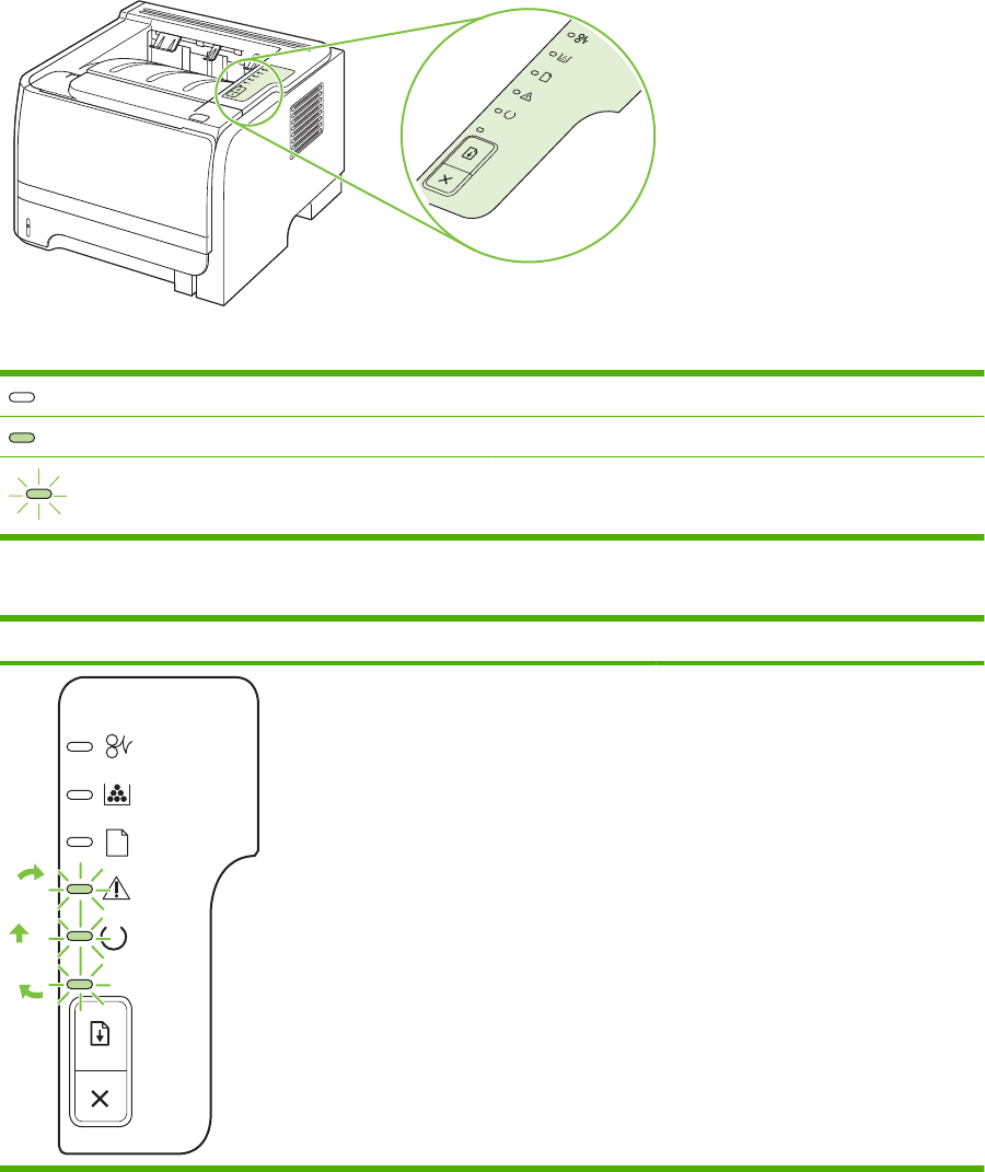
Status-light patterns (HP LaserJet P2030 Series Printers
only)
Table 7-13 Status-light legend
Symbol for "light off"
Symbol for "light on"
Symbol for "light blinking"
Table 7-14 Control-panel light messages
Light status State of the product Action
Initialization/Startup
While in the Startup state, the Go, Ready,
and Attention lights cycle (at the rate of
500 ms) one after another.
Reconfiguration Initialization
During the product start up, you can
request special initialization sequences
that reconfigure the product. When one of
the sequences is requested, such as cold
reset, the lights cycle as in the
Initialization/Startup state.
Job Cancel
After the cancellation process has been
completed, the product returns to the
Ready state.
During the Initialization, Reconfiguration,
and Job Cancel processes, pressing
buttons has no effect.
ENWW Status-light patterns (HP LaserJet P2030 Series Printers only) 209
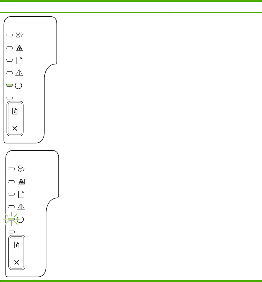
Light status State of the product Action
Ready
The product is ready with no job activity.
To print a Configuration page, press and
hold the Go button for 5 seconds while
the device Ready light is on and no other
jobs are printing.
Processing Data
The product is processing or receiving
data.
To cancel the current job, press the
Cancel button.
Table 7-14 Control-panel light messages (continued)
210 Chapter 7 Solve problems ENWW
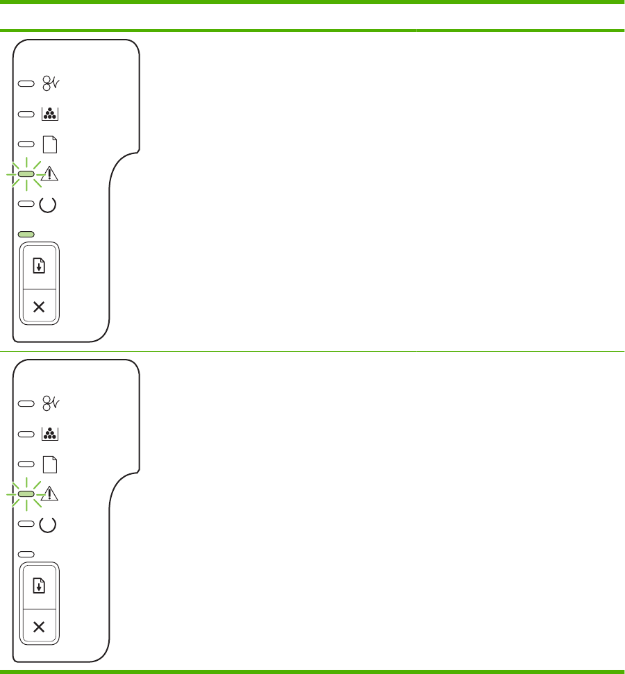
Light status State of the product Action
Manual Feed or Continuable Error
This state can be reached in the following
circumstances:
●Manual feed
●General continuable error
●Memory configuration error
●Personality/Job related error
To recover from the error and print
whatever data is possible, press the Go
button.
If the recovery is successful, the product
goes to the Processing Data state and
completes the job.
If the recovery is unsuccessful, the
product returns to the Continuable Error
state.
Attention
The print-cartridge door is open.
Close the print-cartridge door.
Table 7-14 Control-panel light messages (continued)
ENWW Status-light patterns (HP LaserJet P2030 Series Printers only) 211
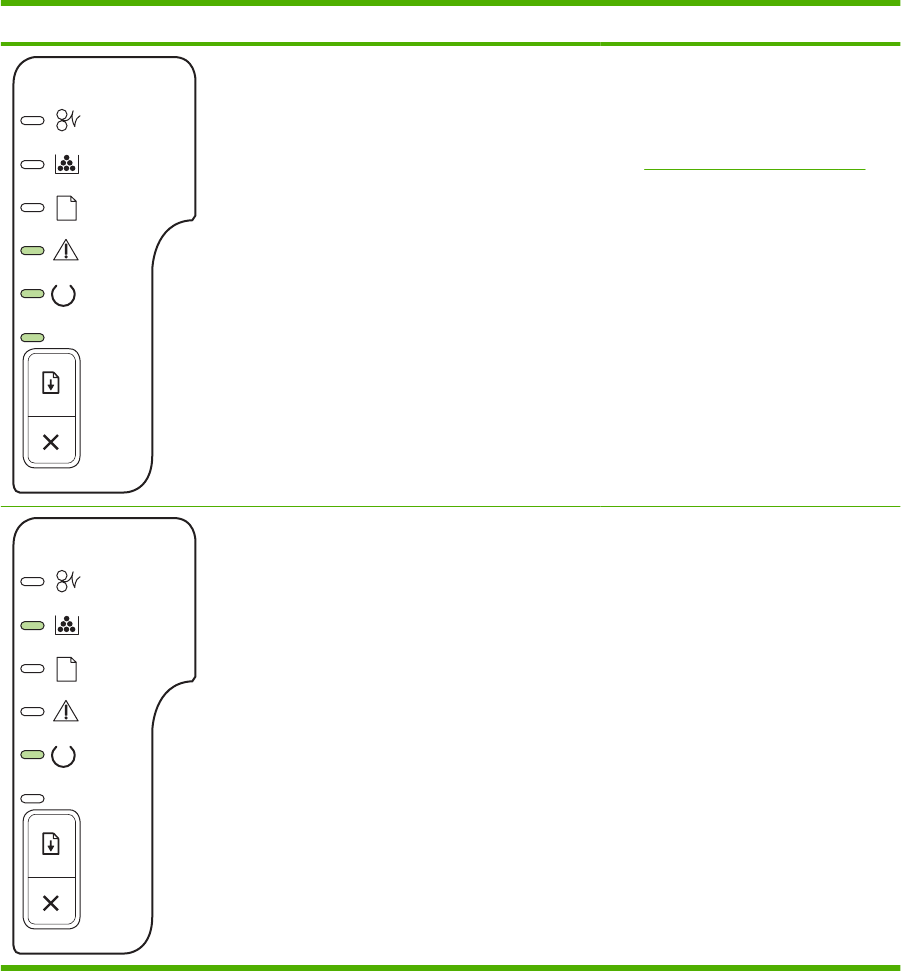
Light status State of the product Action
Fatal Error ●Turn off the product, wait 10
seconds, and turn on the product.
●If you are unable to resolve the
problem, contact HP. See
Customer support on page 287.
Toner Low
The Go, Ready, and Attention lights act
independently of the Toner Low state.
Order a new print cartridge.
Table 7-14 Control-panel light messages (continued)
212 Chapter 7 Solve problems ENWW
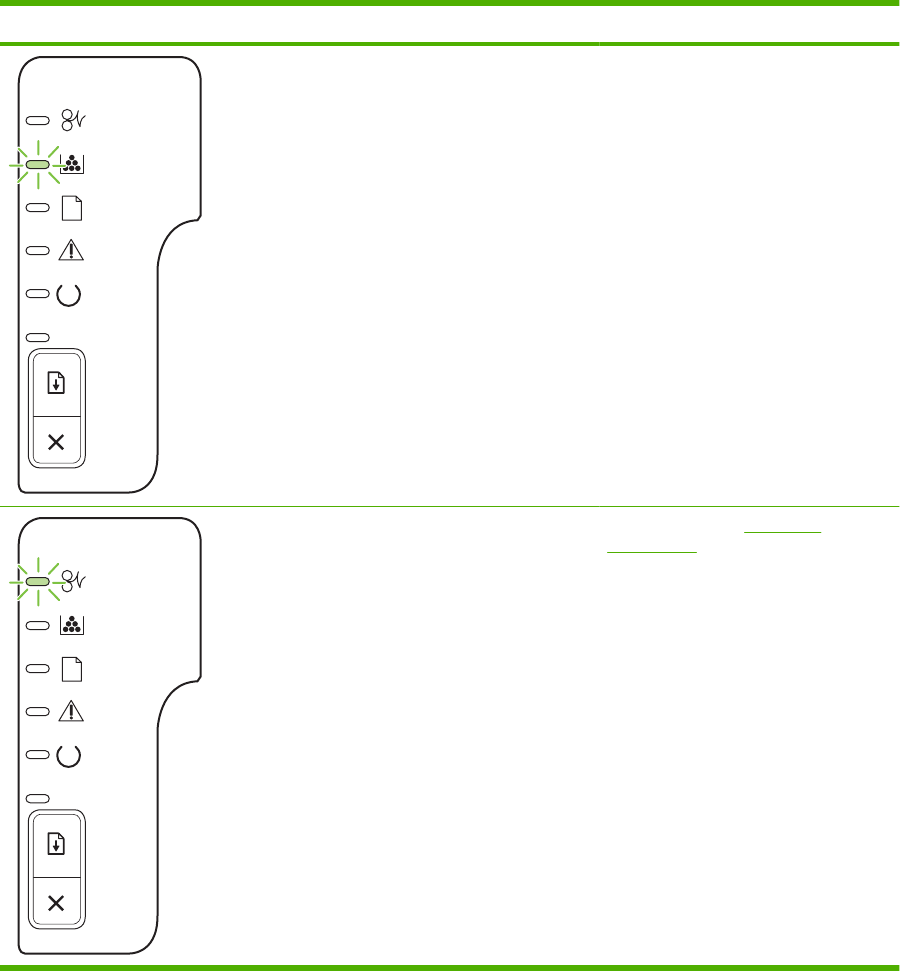
Light status State of the product Action
Toner Missing
The print cartridge has been removed
from the product.
Reinsert the print cartridge in the
product.
Jam Clear the jam. See Clear jams
on page 230.
Table 7-14 Control-panel light messages (continued)
ENWW Status-light patterns (HP LaserJet P2030 Series Printers only) 213
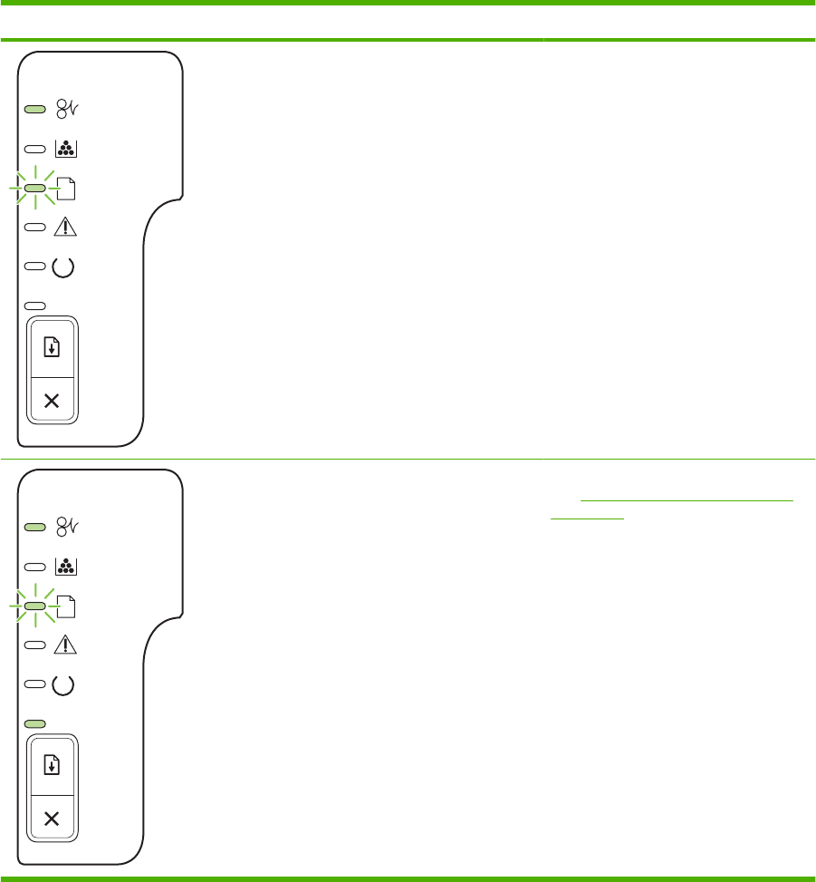
Light status State of the product Action
Paper Out Load paper or other media.
Paper Mount
The loaded paper or other media is not
supported.
Load acceptable paper or other media.
See Supported paper and print media
on page 32.
Press the Go button to override the
condition.
Table 7-14 Control-panel light messages (continued)
214 Chapter 7 Solve problems ENWW

Status-alert messages (HP LaserJet P2030 Series Printers
only)
Status-alert messages appear on the computer screen when the product has certain problems. Use the
information in the following table to solve these problems.
Alert message Description Recommended action
10.X Supply memory error The product has experienced a print cartridge
error.
The two cartridge memory contacts on the
right-rear side of the print cartridge contact
the reader contacts on the product.
1. Make sure that a genuine HP print
cartridge is installed.
2. When installing the print cartridge, make
sure that the memory contacts on the
print cartridge and reader contacts on
the product make a solid connection.
3. Verify that connector J581 on the engine
controller PCA is seated.
4. Replace the print cartridge. See Print
cartridge on page 102.
13.XX Jam in <location>
(<location> indicates the area where the jam
has occurred)
The product has detected a jam. Clear the jam from the area indicated in the
message. The job should continue to print. If
it does not, try reprinting the job. See Jams
on page 229.
50.X Fuser error The product has experienced an error with
the fuser.
1. Turn the product power off and then on.
2. If you have replaced the fuser, make
sure that the correct voltage version is
installed (110 V or 220 V).
3. Make sure the following connectors are
seated:
◦J102 on the engine controller PCA
(AC voltage)
◦J210 on the engine controller PCA
(TH1)
4. Replace the fuser. See Fuser
on page 158.
52.0 Scanner Error An internal error has occurred. Turn off the power by using the power switch,
wait at least 30 seconds, and then turn on the
power and wait for the product to initialize.
If you are using a surge protector, remove it.
Plug the product directly into the wall socket.
Use the power switch to turn the product on.
ENWW Status-alert messages (HP LaserJet P2030 Series Printers only) 215

Alert message Description Recommended action
Door Open Opening the front door opens the front door
switch (SW301) and disables the +24 V to the
high-voltage contacts on the print cartridges.
1. Remove the left cover, and then open
and close the front door. Determine if
SW301 closes when the door closes.
2. Make sure that the two connectors from
the engine control PCA to the switch are
securely installed on the switch
contacts.
3. Replace the front door switch (SW301).
if the message persists. See Cartridge-
door switch on page 137.
Engine communication error The product experienced an internal
communication error.
Turn off the power by using the power switch,
wait at least 30 seconds, and then turn on the
power and wait for the product to initialize.
If you are using a surge protector, remove it.
Plug the product directly into the wall socket.
Use the power switch to turn the product on.
Install black cartridge The product checks for the presence of a print
cartridge at start up and anytime the top cover
is closed. At start up or when the top cover is
closed, a high voltage bias is placed on the
print cartridge's developer roller. This
message appears if the print cartridge's
antenna is unable to detect the high voltage
bias.
1. Make sure that the sealing tape on the
print cartridge has been removed.
2. Verify that the print cartridge is correctly
installed.
3. Inspect the high voltage contact on the
print cartridge and in the print cartridge
cavity to make sure that they are not
damaged.
4. If the messages persists, install another
HP print cartridge.
5. Make sure that the engine controller
PCA is correctly installed.
Jam in cartridge area Photosensors PS913 (media width sensor),
PS912 (top of page sensor), and PS915
(fusing assembly exit sensor) detect paper in
the cartridge area of the product. See Figure
7-7 Components in the print cartridge cavity
on page 199 and Figure 7-6 Components on
the rear side of the product on page 198. If
paper arrives at these sensors too early,
leaves the sensors too late, or is present at
the sensor when not expected, an error
message is displayed.
1. Make sure that the paper meets
specifications. See Supported paper
and print media on page 32. See
Common causes of jams on page 229.
2. Open the top cover, and remove the
print cartridge. Remove any paper or
paper fragments present.
3. Lift the registration flap. Make sure
sensors PS913 and PS912 move freely.
See Figure 7-7 Components in the print
cartridge cavity on page 199.
4. Open the straight-through output door
and verify that PS915 moves freely. See
Figure 7-6 Components on the rear side
of the product on page 198.
5. Make sure that the connector at J203
and J206 on the engine controller PCA
are seated.
216 Chapter 7 Solve problems ENWW

Alert message Description Recommended action
Jam in output bin This error occurs if the duplex reverse
photosensor (PS918) or fusing exit sensor
(PS915) detect unexpected paper.
1. Make sure that the paper meets
specifications. See Specifications
on page 291.
2. Open the rear duplex jam-release door
and clear any visible paper. Verify that
the duplex-release sensor flag moves
freely. You might need a pen light to
observe the flags.
3. Open the face-up output door, and verify
that the exit sensor flag in the fusing
assembly moves freely. You might need
a pen light to observe the flag.
4. Verify that the following connectors are
seated on the engine controller PCA:
◦J208 duplex reverse
◦J206 fusing exit
Jam in Tray 1 The Tray 1 pickup solenoid (SL1) controls the
feeding of paper from Tray 1. When the
solenoid is engaged, the Tray 1 pickup roller
makes one rotation and advances paper into
the paper path. See Figure 7-3 Components
on the left side of the product on page 196).
1. Inspect the Tray 1 pick roller. Verify that
the roller is installed correctly and in
good condition.
2. Print from Tray 1. Determine if the Tray 1
roller rotates. Listen to determine if the
solenoid (SL1) is engaged.
3. Remove the left cover. Determine if the
solenoid (SL1) is correctly installed.
Make sure that the connectors on the
solenoid and at J4 on the formatter PCA
are seated.
4. If the error persists, replace the Tray 1
pickup solenoid (SL1). See Tray 1
pickup solenoid on page 138.
Jam in Tray 2 Solenoid (SL2) controls the feeding of paper
from Tray 1. When the solenoid is engaged,
the Tray 1 pick roller makes one rotation and
advances paper into the paper path. See
Figure 7-3 Components on the left side of the
product on page 196).
1. Inspect the Tray 2 pick roller. Verify that
the roller is installed correctly and in
good condition.
2. Remove Tray 2. Lift the Tray 2 paper
present sensor flag while printing from
Tray 2. Determine if the Tray 2 roller
rotates. Listen to determine if the
solenoid (SL2) is engaged.
3. Remove the left cover. Determine if the
solenoid (SL2) is correctly installed.
Make sure that the connectors on the
solenoid and at J1104 on the connector
PCA are seated.
4. If the error persists, replace the solenoid
(SL2).
ENWW Status-alert messages (HP LaserJet P2030 Series Printers only) 217

Alert message Description Recommended action
Load paper The product did not detect paper in Tray 1 or
Tray 2. PS916 detects paper in Tray 1.
PS914 detects paper in Tray 2. See Figure
7-7 Components in the print cartridge cavity
on page 199.
1. Verify that paper is loaded in the input
tray.
2. Make sure that the photosensor flags
are not hindered.
3. Make sure that connectors J205 (for
Tray 1) and J204 (for Tray 2) on the
engine controller PCA are seated.
Manual feed The product is set for manual feed mode. Load the correct paper into the tray, and then
press the OK button to clear the message.
No paper pickup The print engine has failed to pick up a piece
of paper.
Reload the paper in the input tray and press
the OK button to continue the job.
Non-HP supply installed A new, non-HP supply has been installed.
This message appears until an HP supply is
installed or you press the OK button.
If you believe you purchased an HP supply,
go to www.hp.com/go/anticounterfeit.
Service or repairs that are required as a result
of using non-HP supplies are not covered
under HP warranty.
To continue printing, press the OK button.
Not Connected The product software cannot communicate
with the product.
1. Make sure the product is turned on.
2. Make sure the USB cable is connected
securely to the product and the
computer.
Order black cartridge The identified print cartridge is nearing the
end of its useful life.
Order a new print cartridge. You can continue
printing with the current print cartridge until
redistributing the toner no longer yields
acceptable print quality.
Page too complex The product cannot process the page. Press the OK button to continue printing the
job, but output might be affected.
Printing The product is printing a document. Wait for printing to finish.
218 Chapter 7 Solve problems ENWW

Interpret control-panel messages (HP LaserJet P2050
Series Printers only)
The control-panel messages indicate the current product status or situations that might require action.
Control-panel messages appear temporarily and might require that you acknowledge the message by
pressing OK to resume printing or by pressing X to cancel the job. With certain messages, the job might
not finish printing or the print quality might be affected. If the message is related to printing and the auto-
continue feature is on, the product will try to resume printing after the message has appeared for 10
seconds without acknowledgment.
For some messages, restarting the product might fix the problem. If a critical error persists, the product
might require service.
Control-panel messages
Control-panel message Event code Description Recommended action
10.X Supply memory error The product has experienced a
print cartridge error.
The two cartridge memory
contacts on the right-rear side of
the print cartridge contact the
reader contacts on the product.
1. Make sure that a genuine
HP print cartridge is
installed.
2. When installing the print
cartridge, make sure that
the memory contacts on the
print cartridge and reader
contacts on the product
make a solid connection.
3. Verify that connector J581
on the engine controller
PCA is seated.
4. Replace the print cartridge.
See Print cartridge
on page 102.
13.XX Jam in <location> 13.0000 The product has detected a jam. Clear the jam from the location
indicated. The job should
continue to print. If it does not, try
reprinting the job.
21.X Print failure
Press [OK]
If error repeats turn off then on
21.0000 The product cannot process the
page.
Press OK to continue printing the
job, but output might be affected.
If the error persists, turn the
power off and then on. Resend
the print job.
41.2 Engine error
Press [OK]
The product experienced an
internal error.
Turn the product power off, wait
at least 30 seconds, and then turn
the product power on and wait for
it to initialize.
If you are using a surge protector,
remove it. Plug the product
directly into the wall socket. Turn
the product power on.
41.3 Unexpected size in tray x
Load <SIZE>
41.3000 The product has detected print
media in the tray that does not
Load the correct media into the
tray, or configure the tray for the
ENWW Interpret control-panel messages (HP LaserJet P2050 Series Printers only) 219

Control-panel message Event code Description Recommended action
Press [OK] match the configuration for the
tray.
size that you have loaded. See
Load trays on page 38.
41.X.Error A temporary printing error has
occurred.
1. Make sure that the paper
meets specifications. See
Supported paper and print
media on page 32. If pages
stick together, the paper
sensors might detect a
sheet of paper longer than
expected.
2. Verify that the paper size
settings in the control panel,
printer driver, and software
program match.
3. Verify that the correct paper
size is loaded in the product.
49 Error
Turn off then on
The product experienced an
internal error.
Turn the product off, wait at least
30 seconds, and then turn the
product on and wait for it to
initialize.
If you are using a surge protector,
remove it. Plug the product
directly into the wall socket. Turn
the product power on.
50.X Fuser error
Turn off then on
50.0000
50.1000
50.3000
50.4000
50.7000
50.8000
50.9000
The product has experienced an
error with the fuser.
1. Turn the product power off
and then on.
2. If you have replaced the
fuser, make sure that the
correct voltage version is
installed (110 V or 220 V).
3. Make sure that the following
connectors are seated:
◦J102 on the engine
controller PCA (AC
voltage)
◦J210 on the engine
controller PCA (TH1)
4. Replace the fuser. See
Fuser on page 158.
220 Chapter 7 Solve problems ENWW

Control-panel message Event code Description Recommended action
51.XX Error
Turn off then on
51.0000 The product has experienced a
laser/scanner assembly error.
1. Turn the product power off,
wait at least 30 seconds,
and then turn the product
power on and wait for it to
initialize.
2. Make sure that the following
connectors are seated:
◦J1103. See Figure 7-5
Components on the
connector PCA
on page 198.
◦J1. See Figure 7-3
Components on the
left side of the product
on page 196.
◦All connectors on the
laser/scanner
assembly
3. If all connectors are seated
and the error persists,
replace the laser/scanner
assembly. See Laser/
scanner assembly
on page 156.
57 Fan error
Turn off then on
57.0000 The cooling fan (FM1) rotates for
approximately 35 seconds at
initial start up and during a print
job. The fan rotates about 30
seconds after a print job
concludes.
1. Turn the product on. Listen
to determine if the fan is
operating. The fan is located
on the upper right-side of
the product. See Figure 7-4
Components on the right
side of the product
on page 197.
2. Make sure that the fan
connector is security
connected to J1105 on the
connector PCA. See Figure
7-5 Components on the
connector PCA
on page 198.
3. Replace the fan. See Fan
on page 140.
59.X Error A malfunction has been detected
with the product's main motor.
During normal operation, the
main motor should rotate for
about six seconds after the
product is turned on.
1. Turn the product off and
then on.
2. Make sure that connector
J202 on the engine
controller PCA is seated.
3. If the error persists, replace
the main motor. See Main
motor on page 174.
ENWW Interpret control-panel messages (HP LaserJet P2050 Series Printers only) 221

Control-panel message Event code Description Recommended action
79 Service error
Turn off then on
79.0000
79.0001
An incompatible DIMM is
installed.
1. Turn the product power off.
2. Install a DIMM that the
product supports. See Parts
and diagrams on page 253
for a list of supported
DIMMs. See Install memory
(HP LaserJet P2050 Series
Printers only) on page 64 for
DIMM installation
instructions.
3. Turn the product on.
Device error
Press [OK]
An internal error occurred. Press OK to resume the job.
Door open Opening the cartridge door
opens the cartridge door switch
(SW301) and disables the +24 V
to the high-voltage contacts on
the print cartridges.
1. Remove the left cover, and
then open and close the
cartridge door. Determine if
SW301 closes when the
door closes.
2. Make sure that the two
connectors from the engine
control PCA to the switch
are securely installed on the
switch contacts.
3. Replace SW301 if the
message persists.
Genuine HP supply installed A genuine HP supply was
installed. This message appears
briefly after the supply is installed
and then is replaced by the
message Ready.
No action necessary.
Install black cartridge The product checks for the
presence of a print cartridge at
start up and anytime the top
cover is closed. At start up or
when the top cover is closed, a
high-voltage bias is placed on the
print cartridge's developer roller.
This message appears if the print
cartridge's antenna is unable to
detect the high-voltage bias.
1. Make sure that the sealing
tape on the print cartridge
has been removed.
2. Verify that the print cartridge
is correctly installed.
3. Inspect the high-voltage
contact on the print
cartridge and in the print-
cartridge cavity to make
sure that they are not
damaged.
4. If the messages persists,
install another HP print
cartridge.
5. Make sure that the engine
controller PCA is correctly
installed.
222 Chapter 7 Solve problems ENWW

Control-panel message Event code Description Recommended action
Jam in cartridge area Photosensors PS913 (media
width sensor), PS912 (top of
page sensor) and PS915 (fusing
assembly exit sensor) detect
paper in the cartridge area of the
product. See Figure 7-7
Components in the print cartridge
cavity on page 199 and Figure
7-6 Components on the rear side
of the product on page 198. If
paper arrives at these sensors
too early, leaves the sensors too
late, or is present at the sensor
when not expected, an error
message is displayed.
1. Make sure that the paper
meets specifications. See
Specifications
on page 291. See Common
causes of jams
on page 229.
2. Open the top cover and
remove the print cartridge.
Remove any paper or paper
fragments present.
3. Lift the registration flap.
Make sure sensors PS913
and PS912 move freely.
See Figure 7-7
Components in the print
cartridge cavity
on page 199.
4. Open the straight-through
output door and verify that
PS915 moves freely. See
Figure 7-6 Components on
the rear side of the product
on page 198.
5. Make sure that the
connector at J203 and J206
on the engine controller
PCA are seated.
Jam in output bin This error occurs if the duplex
reverse photosensor (PS918) or
fusing exit sensor (PS915) detect
unexpected paper.
1. Make sure that the paper
meets specifications. See
Supported paper and print
media on page 32.
2. Open the rear duplex jam-
release door and clear any
visible paper. Verify the
duplex-release sensor flag
moves freely. You might
need a pen light to observe
the flags.
3. Open the face-up output
door and the verify the exit
sensor flag in the fusing
assembly moves freely. You
might need a pen light to
observe the flag.
4. Verify that the following
connectors are seated on
the engine controller PCA:
◦J208 duplex reverse
◦J206 fusing exit
ENWW Interpret control-panel messages (HP LaserJet P2050 Series Printers only) 223

Control-panel message Event code Description Recommended action
Jam in Tray 1 Solenoid (SL1) controls the
feeding of paper from Tray 1.
When the solenoid is engaged,
the Tray 1 pick roller makes one
rotation and advances paper into
the paper path. See Figure 7-3
Components on the left side of
the product on page 196).
1. Inspect the Tray 1 pick
roller. Verify the roller is
installed correctly and in
good condition.
2. Print from Tray 1. Determine
if the Tray 1 roller rotates.
Listen to determine if the
solenoid (SL1) is engaged.
3. Remove the left cover.
Determine if solenoid (SL1)
is correctly installed. Make
sure that the connectors on
the solenoid and at J4 of the
formatter PCA are seated.
4. If the error persists, replace
the solenoid (SL1).
Jam in Tray 2 Solenoid (SL2) controls the
feeding of paper from Tray 1.
When the solenoid is engaged,
the Tray 1 pick roller makes one
rotation and advances paper into
the paper path. See Figure 7-3
Components on the left side of
the product on page 196.
1. Inspect the Tray 2 pick
roller. Verify the roller is
installed correctly and in
good condition.
2. Remove Tray 2. Lift the Tray
2 paper present sensor flag
while printing from Tray 2.
Determine if the Tray 2 roller
rotates. Listen to determine
if the solenoid (SL2) is
engaged.
3. Remove the right cover.
Determine if solenoid (SL2)
is correctly installed. Make
sure that the connectors on
the solenoid and at J1104 of
the connector PCA are
seated.
4. If the error persists, replace
the product. See Whole unit
replacement on page 256.
Load paper The product did not detect paper
in Tray 1 or Tray 2. PS916
detects paper in Tray 1. PS914
detects paper in Tray 2. See
Figure 7-7 Components in the
print cartridge cavity
on page 199.
1. Make sure that paper is
loaded in the tray.
2. Make sure that the
photosensor flags are not
hindered.
3. Make sure that connectors
J205 (for Tray 1) and J204
(for Tray 2) on the engine
controller PCA are seated.
Load tray # <TYPE> <SIZE>
Press [OK] for available media
A tray is configured for the media
type and size that the print job is
requesting, but that tray is empty.
Load the correct media into the
tray, or press OK to use media in
a different tray.
Load tray 1 plain <SIZE>
Cleaning mode [OK] to start
The product is ready to process
the cleaning operation.
Load Tray 1 with plain paper in
the size indicated, and then press
OK.
224 Chapter 7 Solve problems ENWW

Control-panel message Event code Description Recommended action
Load tray 1 <TYPE> <SIZE>
Press [OK] for available media
No trays are configured for the
media type and size that the print
job is requesting.
Load the correct media into
tray 1, or press OK to use media
in a different tray.
Manual duplex
Load tray x
Press [OK]
The first side of a manual duplex
job has printed, and the page
needs to be loaded to process the
second side.
Load the page in the indicated
tray with the side to be printed
face up, and the top of the page
away from you and then press
OK.
Manual feed <TYPE> <SIZE>
Press [OK] for available media
The product is set for manual
feed mode.
Press OK to clear the message
or load the correct media into
tray 1.
Memory is low
Press [OK]
The product memory is almost
full.
Press OK to finish the job, or
press the Cancel button to
cancel the job.
For information about increasing
the product memory, see Install
memory (HP LaserJet P2050
Series Printers only) on page 64.
Misprint
Press [OK]
Print media has been delayed as
it moves through the product.
Press OK to clear the message.
Non-HP supply installed A non-HP supply is installed. If you believe you purchased an
HP supply, go to www.hp.com/
go/anticounterfeit.
Service or repairs that are
required as a result of using non-
HP supplies are not covered
under HP warranty.
Order black cartridge
Ready
The print cartridge is nearing the
end of its useful life.
Order a new print cartridge. You
can continue printing with the
current print cartridge until
redistributing the toner no longer
yields acceptable print quality.
See Parts and diagrams
on page 253 for more
information.
Output bin full
Remove all paper from bin
As the output bin accumulates
paper, the output bin delivery flap
rises until a flag blocks the
photosensor (PS911). When the
photosensor is blocked, this
message appears.
1. Rotate the output bin
delivery flap up and down.
The flap must move freely. If
the top cover has been
replaced, make sure that it
has been installed correctly.
2. Make sure that the
connector at J213 on the
engine controller PCA are
seated.
Remove all paper from the bin.
Rear door open The product rear door is open. Close the door.
Remove shipping lock from
black cartridge
A print cartridge shipping lock is
installed.
Be sure that the print cartridge
shipping lock has been removed.
ENWW Interpret control-panel messages (HP LaserJet P2050 Series Printers only) 225

Control-panel message Event code Description Recommended action
Used cartridge in use A refilled print cartridge was
detected and accepted.
No action necessary.
Used cartridge installed
To accept press [OK]
A refilled print cartridge is
installed.
Press OK to continue.
226 Chapter 7 Solve problems ENWW

Event-log messages
Print the event log (HP LaserJet P2050 Series Printers only)
1. Open the secondary service menu. See Open the secondary service menu on page 250.
2. Use the arrow buttons to select Service Reports, and then press OK.
3. Use the arrow buttons to select Error Report, and then press OK.
NOTE: You can use HP ToolboxFX to view the event log from a computer. See Event log
on page 51.
Print an event log (HP LaserJet P2030 Series Printers only)
The configuration page displays the last five events. To print a configuration page, see Print the
information pages (HP LaserJet P2030 Series Printers only) on page 48.
Event log messages
The following table contains all event log codes for this product.
Table 7-15 Event-log messages
Event code Description
10.0000 Black label error
10.1000 Black e-label missing
10.3000 Non-HP black
10.3100 Non-HP cloned black
10.3200 Unauthorized black supply
13.0000 Paper jam
20.0000 Memory out
21.0000 Page misfeed or mispick
41.2000 Beam detect malfunction
41.3000 Unexpected size
49 Firmware asserts
50.0000 Fuser error
50.1000 Low fuser temperature error
50.2000 Slow fuser error
50.3000 High fuser temperature error
50.4000 Fuser drive circuit error
50.7000 Fuser open error
50.8000 Low sub-thermistor fuser error
50.9000 High sub-thermistor fuser error
ENWW Event-log messages 227

Event code Description
51.0000 Beam detect or laser error
52.0000 Scanner error
55.0000 Engine internal communication error
55.3000 Engine formatter/communication error
55.4000 Engine communication timeout error
57.0000 Fan motor error
79.0000 79 service, firmware exception
79.0001 79 service, firmware ASIC fault
84.0000 JDI FW assert
Table 7-15 Event-log messages (continued)
228 Chapter 7 Solve problems ENWW

Paper-handling problems
Jams
Common causes of jams
Many jams are caused by using paper that does not meet HP specifications. For complete paper
specifications for all HP LaserJet products, see the HP LaserJet Printer Family Print Media Guide. This
guide is available at www.hp.com/support/ljpaperguide.
The product is jammed.
1
Cause Solution
The paper does not meet specifications. Use only paper that meets HP specifications. See Supported
paper and print media on page 32.
A component is installed incorrectly. Verify that the print cartridge is correctly installed.
You are using paper that has already passed through a product
or copier.
Do not use paper that has been previously printed on or copied.
A tray is loaded incorrectly. Remove any excess paper from the tray. Make sure that the
stack is below the maximum stack height mark in the tray. See
Load trays on page 38.
The paper is skewed. The tray guides are not adjusted correctly. Adjust them so they
hold the stack firmly in place without bending it.
The paper is binding or sticking together. Remove the paper, flex it, rotate it 180°, or flip it over. Reload
the paper into the tray.
NOTE: Do not fan paper. Fanning can create static
electricity, which can cause paper to stick together.
The paper is removed before it settles into the output bin. Reset the product. Wait until the page completely settles in the
output bin before removing it.
During two-sided printing, you removed the paper before the
second side of the document was printed.
Reset the product and print the document again. Wait until the
page completely settles in the output bin before removing it.
The paper is in poor condition. Replace the paper.
The internal rollers from the tray are not picking up the paper. Remove the top sheet of paper. If the paper is too heavy, it
might not be picked from the tray.
The paper has rough or jagged edges. Replace the paper.
The paper is perforated or embossed. Perforated or embossed paper does not separate easily. Feed
single sheets from Tray 1.
Product supply items have reached the end of their useful life. Check the product control panel for messages prompting you
to replace supplies, or print a supplies status page to verify the
remaining life of the supplies. See Print the information pages
on page 48.
Paper was not stored correctly. Replace the paper in the trays. Paper should be stored in the
original packaging in a controlled environment.
1
If the product continues to jam, contact HP Customer Support or your authorized HP service provider.
ENWW Paper-handling problems 229
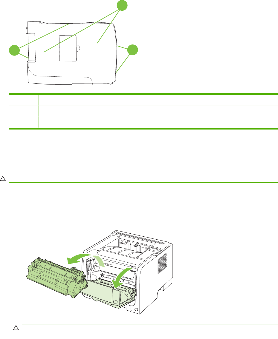
Jam locations
Jams can occur at the following locations in the product.
1
32
1Internal areas
2Input trays
3Output bins
Clear jams
When clearing jams, be careful not to tear jammed paper. If a small piece of paper remains in the product,
it could cause additional jams.
CAUTION: Before clearing jams, turn the product off and disconnect the power cord.
Internal areas
Print-cartridge area and paper path
1. Push the button to open the print-cartridge door, and then remove the print cartridge.
CAUTION: To prevent damage, do not expose the print cartridge to light. Cover it with a piece
of paper.
230 Chapter 7 Solve problems ENWW
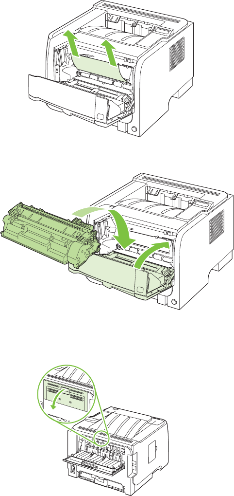
2. If jammed paper is visible, grasp it with both hands and slowly pull it out of the product.
3. Replace the print-cartridge, and close the print-cartridge door.
4. If no paper was jammed inside the print-cartridge door, open the jam-release door at the back of
the product.
ENWW Paper-handling problems 231
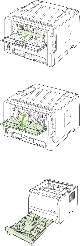
5. If jammed paper is visible, grasp it with both hands and slowly pull it out of the product.
6. Close the jam-release door.
Duplex paper path (HP LaserJet P2050 Series Printers only)
1. At the front of the product, remove Tray 2.
232 Chapter 7 Solve problems ENWW
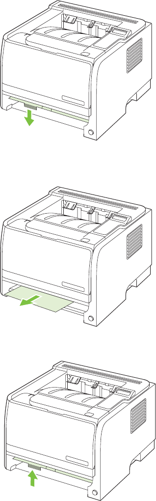
2. Push down on the green lever to release the duplex paper-path door on the front of the product.
3. Check for jammed paper at the front of the product. With both hands, grasp the jammed paper and
slowly pull it out of the product.
4. Push up on the duplex paper-path door to close it.
ENWW Paper-handling problems 233
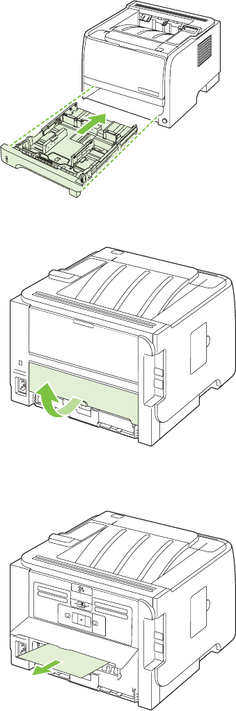
5. Replace Tray 2.
6. Open the duplex jam-release door on the back of the product.
7. Check for jammed paper at the back of the product. With both hands, grasp the jammed paper and
slowly pull it out of the product.
234 Chapter 7 Solve problems ENWW
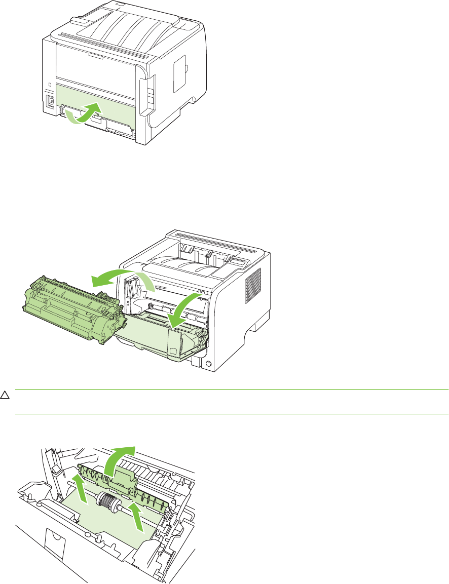
8. Close the jam-release door.
Input trays
Tray 1
1. Push the button to open the print-cartridge door, and then remove the print cartridge.
CAUTION: To prevent damage, do not expose the print cartridge to light. Cover it with a piece
of paper.
2. Lift the Tray 1 roller cover, grasp the jammed paper, and slowly pull it out of the product.
ENWW Paper-handling problems 235
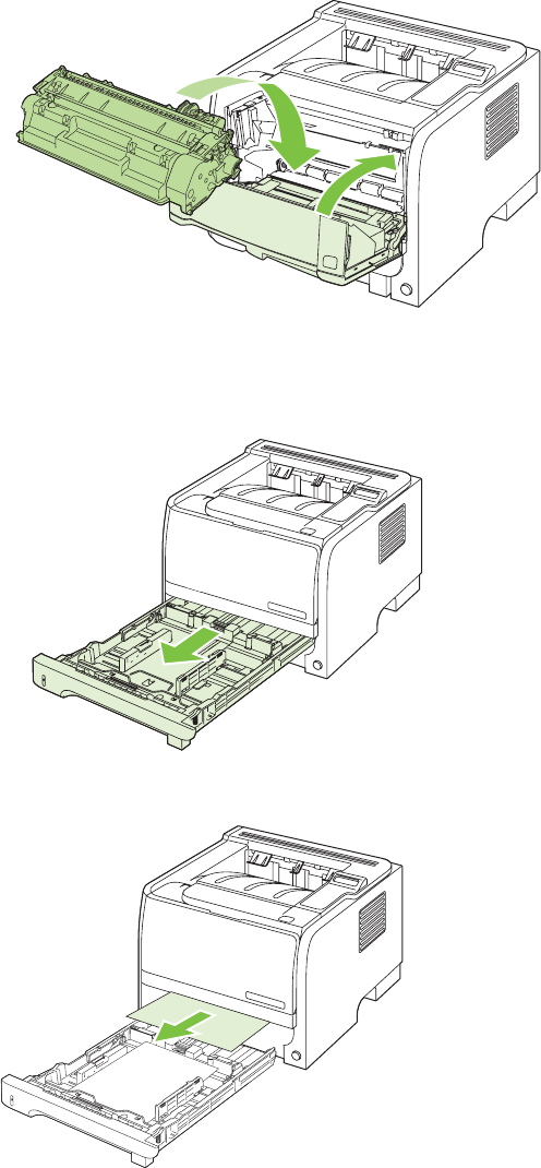
3. Replace the print-cartridge, and close the print-cartridge door.
Tray 2
1. Open the tray.
2. With both hands, grasp the jammed paper and slowly pull it out of the product.
236 Chapter 7 Solve problems ENWW
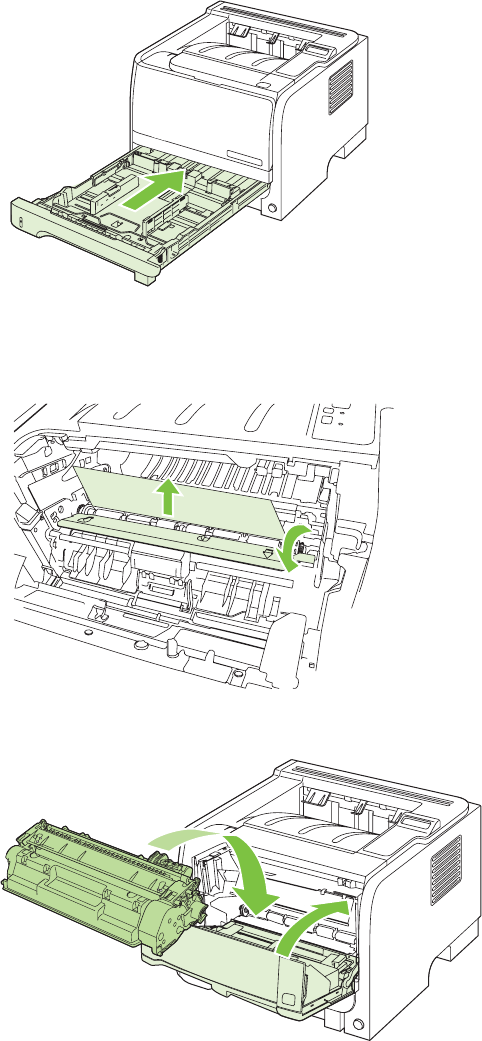
3. Close the tray.
4. If no jammed paper is visible in the tray area, open the print-cartridge door, remove the print
cartridge, and pull down the upper media guide. With both hands, grasp the jammed paper and
slowly pull it out of the product.
5. Replace the print-cartridge, and close the print-cartridge door.
ENWW Paper-handling problems 237
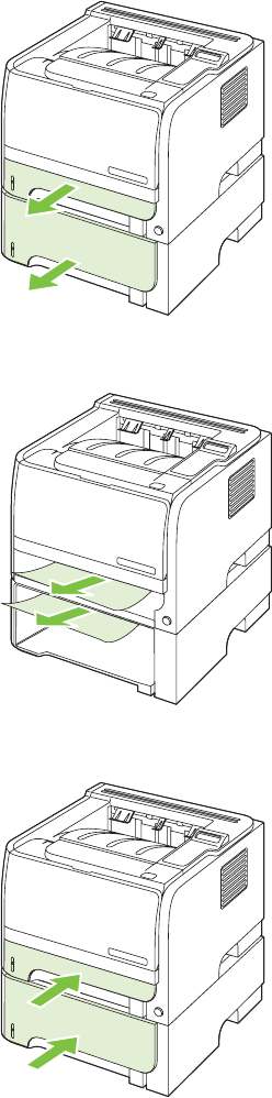
Tray 3 (HP LaserJet P2050 Series Printers only)
1. Remove Tray 2 and Tray 3.
2. With both hands, grasp the jammed paper and slowly pull it out of the product.
3. Replace the trays.
238 Chapter 7 Solve problems ENWW
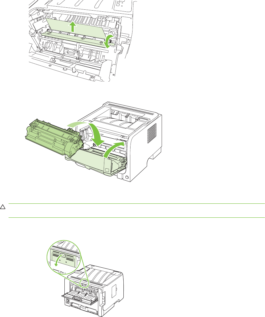
4. If no jammed paper is visible in the tray area, open the print-cartridge door, remove the print
cartridge, and pull down the upper media guide. With both hands, grasp the jammed paper and
slowly pull it out of the product.
5. Replace the print-cartridge, and close the print-cartridge door.
Output bins
CAUTION: To avoid damaging the product, do not attempt to clear a jam in the top output bin by pulling
the paper straight out.
1. At the back of the product, open the jam-release door.
ENWW Paper-handling problems 239
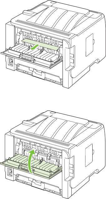
2. With both hands, grasp the jammed paper and slowly pull it out of the product.
3. Close the jam-release door.
240 Chapter 7 Solve problems ENWW

Solve image-quality problems
Printed page is different from what appeared onscreen
Table 7-16 Printed page is different from what appeared onscreen
Problem Cause Solution
Garbled, incorrect, or incomplete text The wrong printer driver might have been
selected when the software was
installed.
Make sure that the appropriate printer
driver is selected.
If a specific file prints garbled text, there
might be a problem with that specific file.
Try printing from another file.
If a specific program prints garbled text,
there might be a problem with that
program.
Try printing from another software
program.
The USB cable might be loose or
defective.
●Disconnect the cable and
reconnect it at both ends.
●Try a print job that you know works.
●If possible, attach the cable and
product to another computer, and
try printing a job that you know
works.
●Try using a new USB 2.0 cable that
is 3 m (10 ft) or less in length.
●Turn off the product and the
computer. Remove the USB cable,
and inspect both ends of the cable
for damage. Reconnect the cable,
making sure that the connections
are tight. Make sure that the product
is directly connected to the
computer. Remove any
switchboxes, tape backup drives,
security keys, or any other devices
that are attached between the USB
port on the computer and the
product. These devices can
sometimes interfere with
communication between the
computer and the product. Restart
the product and the computer.
ENWW Solve image-quality problems 241

Problem Cause Solution
Missing graphics or text, or blank pages The file may contain blank pages. Make sure that your file does not contain
blank pages.
The sealing tape might still be in the print
cartridge.
Remove the print cartridge, and pull the
tab on the end of the cartridge until the
entire length of the tape is removed.
Reinstall the print cartridge. To check the
product, print a Demo page.
The graphic settings in the product
Properties might not be correct for the
type of job that you are printing.
Try a different graphic setting in the
product Properties.
The product may require cleaning. Clean the product, particularly the
contacts between the print cartridge and
the power supply.
Page format is different from another
HP LaserJet product
If you used an older or different
HP LaserJet printer driver (product
software) to create the document, or if
the product Properties settings in the
software are different, the page format
might change when you try to print using
your new printer driver or settings.
●Create documents and print them
using the same printer driver
(product software) and product
Properties settings regardless of
which HP LaserJet product you use
to print them.
●Change the resolution, paper size,
font settings, and other settings.
Graphics quality The graphics settings might be
unsuitable for your print job. Check the
graphic settings, such as resolution, in
the product Properties and adjust them
as necessary.
Check the graphic settings, such as
resolution, in the product Properties and
adjust them as necessary.
NOTE: You might lose some resolution
when converting from one graphics
format to another.
Image defect examples
This section provides information about identifying and correcting print defects.
NOTE: If these steps do not correct the problem, contact an HP-authorized dealer or service
representative.
Light print or faded
●The print cartridge is nearing end of life.
●Redistribute the toner to extend the life.
●The media might not meet Hewlett-Packard's media
specifications (for example, the media is too moist or too
rough).
●If the whole page is light, the print density adjustment is
too light or EconoMode might be turned on. Adjust the
print density, and disable EconoMode in the printer
Properties.
Table 7-16 Printed page is different from what appeared onscreen (continued)
242 Chapter 7 Solve problems ENWW
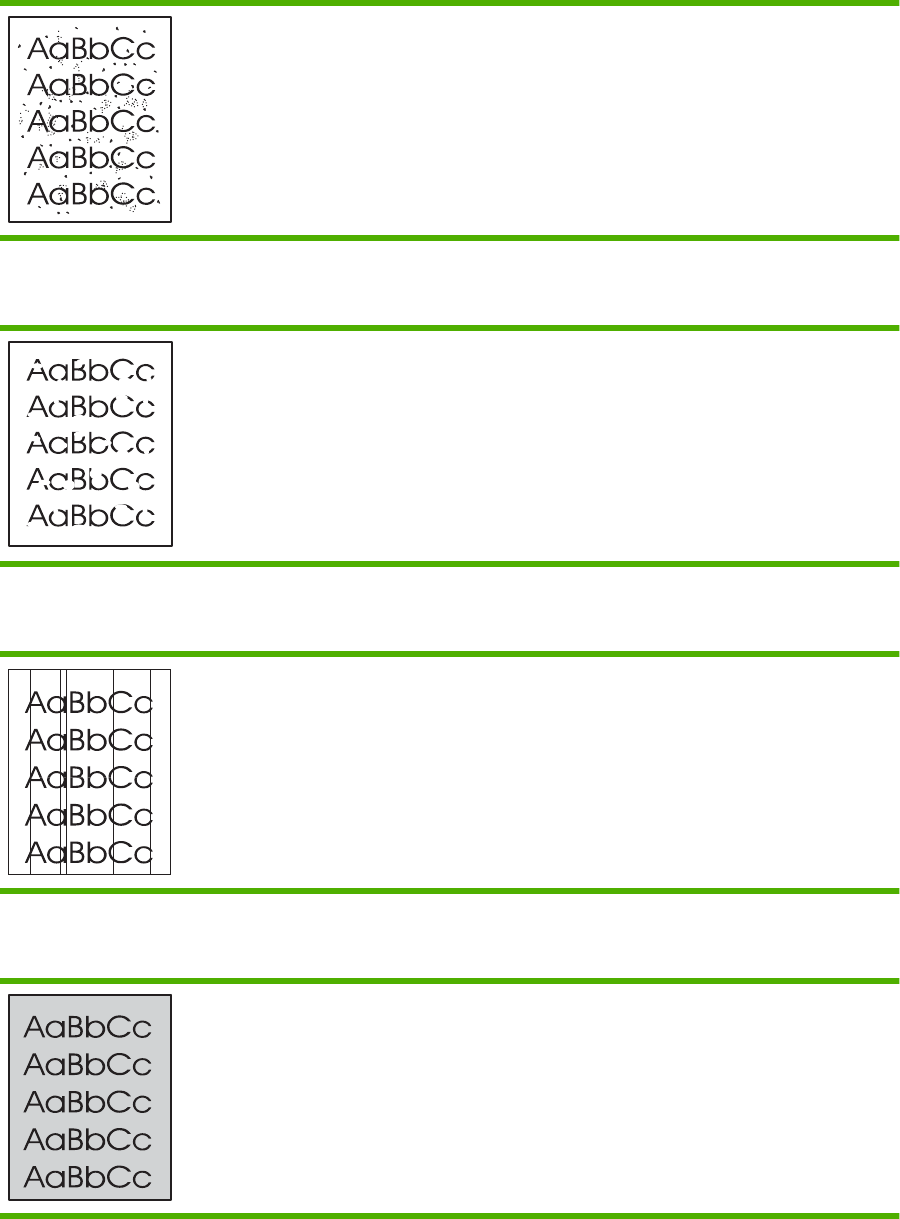
Toner specks
●The media might not meet Hewlett-Packard's media
specifications (for example, the media is too moist or too
rough).
●The printer might need to be cleaned.
●The print cartridge might be defective.
Dropouts
●A single sheet of media might be defective. Try reprinting
the job.
●The media moisture content is uneven or the media has
moist spots on its surface. Try printing with new media.
●The media lot is bad. The manufacturing processes can
cause some areas to reject toner. Try a different type or
brand of media.
●The print cartridge might be defective.
Vertical lines
The photosensitive drum inside the print cartridge has probably
been scratched. Install a new HP print cartridge.
Gray background
●Change the media to a lighter basis weight.
●Check the printer's environment. Very dry (low humidity)
conditions can increase the amount of background
shading.
●The density setting might be too high. Adjust the density
setting.
●Install a new HP print cartridge.
ENWW Solve image-quality problems 243
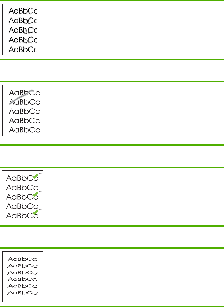
Toner smear
●If toner smears appear on the leading edge of the media,
the media guides might be dirty. Wipe the media guides
with a dry, lint-free cloth.
●Check the media type and quality.
●The fuser temperature might be too low. In your printer
driver, make sure the appropriate media type is selected.
●Try installing a new HP print cartridge.
Loose toner
●The fuser temperature might be too low. In your printer
driver, make sure the appropriate media type is selected.
●Clean the inside of the printer.
●Check the media type and quality.
●In your printer driver, make sure the appropriate media
type is selected.
●Plug the printer directly into an AC outlet instead of into a
power strip.
Vertical repetitive defects
●The print cartridge might be damaged. If a repetitive mark
occurs at the same spot on the page, install a new
HP print cartridge.
●The internal parts might have toner on them. If the defects
occur on the back of the page, the problem will probably
correct itself after a few more printed pages.
●In your printer driver, make sure the appropriate media
type is selected.
Misformed characters
●If characters are improperly formed, producing hollow
images, the media stock might be too slick. Try a different
media.
●If characters are improperly formed, producing a wavy
effect, the printer might need service. Print a configuration
page. If the characters are improperly formed, contact an
HP-authorized dealer or service representative.
244 Chapter 7 Solve problems ENWW
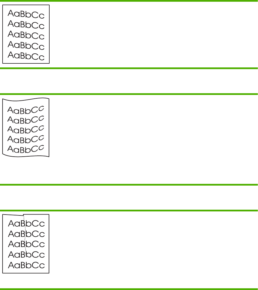
Page skew
●Make sure that the media is loaded correctly and the
media guides are not too tight or too loose against the
media stack.
●The input bin might be too full.
●Check the media type and quality.
Curl or wave
●Check the media type and quality. Both high temperature
and high humidity cause media to curl.
●The media might have been in the input tray too long.
Turn over the stack of media in the tray. Also, try rotating
the media 180° in the input tray.
●Open the straight-through output door and try printing
straight through.
●The fuser temperature might be too high. In your printer
driver, make sure the appropriate media type is selected.
If the problem persists, select a media type that uses a
lower fuser temperature, such as transparencies or light
media.
Wrinkles or creases
●Make sure that media is loaded properly.
●Check the media type and quality.
●Open the straight-through output door and try printing
straight through.
●Turn over the stack of media in the tray. Also, try rotating
the media 180° in the input tray.
●For envelopes, this can be caused by air pockets inside
the envelope. Remove the envelope, flatten the
envelope, and try printing again.
ENWW Solve image-quality problems 245

Toner scatter outline
●If large amounts of toner have scattered around the
characters, the media might be resisting the toner. (A
small amount of toner scatter is normal for laser printing.)
Try a different media type.
●Turn over the stack of media in the tray.
●Use media that is designed for laser printers.
246 Chapter 7 Solve problems ENWW

Solve print-quality problems
You can prevent most print-quality problems by following these guidelines.
●Configure the trays for the correct paper-type setting. See Configure trays (HP LaserJet P2050
Series Printers only) on page 43.
●Use paper that meets HP specifications. See Supported paper and print media on page 32.
●Clean the product as necessary. See Clean the paper path (HP LaserJet P2050 Series Printers
only) on page 70.
Print-quality problems associated with paper
Some print-quality problems arise from using paper that does not meet HP specifications.
●The surface of the paper is too smooth.
●The moisture content of the paper is uneven, too high, or too low. Use paper from a different source
or from an unopened ream.
●Some areas of the paper reject toner. Use paper from a different source or from an unopened ream.
●The letterhead you are using is printed on rough paper. Use a smoother, xerographic paper. If this
solves your problem, ask the supplier of your letterhead to use paper that meets HP specifications.
●The paper is excessively rough. Use a smoother, xerographic paper.
●The paper is too heavy for the paper-type setting that you selected, so the toner is not fusing to
the paper.
For complete paper specifications for all HP LaserJet products, see the HP LaserJet Printer Family Print
Media Guide. This guide is available at www.hp.com/support/ljpaperguide.
Print-quality problems associated with the environment
If the product is operating in excessively humid or dry conditions, verify that the printing environment is
within specifications. See Operating environment on page 293.
Print-quality problems associated with jams
Make sure that all sheets are cleared from the paper path.
●If the product recently jammed, print two to three pages to clean the paper path.
●If the sheets do not pass through the fuser and cause image defects on subsequent documents,
print two to three pages to clean the paper path. If the problem persists, print and process a cleaning
page. See Clean the paper path (HP LaserJet P2050 Series Printers only) on page 70.
ENWW Solve print-quality problems 247

Solve performance problems
Problem Cause Solution
Pages print but are totally blank. The sealing tape might still be in the print
cartridges.
Verify that the sealing tape has been
completely removed from the print
cartridges.
The document might contain blank
pages.
Check the document that you are printing
to see if content appears on all of the
pages.
The product might be malfunctioning. To check the product, print a
Configuration page.
Pages print very slowly. Heavier paper types can slow the print
job.
Print on a different type of paper.
Complex pages can print slowly. Proper fusing may require a slower print
speed to ensure the best print quality.
Pages did not print. The product might not be pulling paper
correctly.
Make sure paper is loaded in the tray
correctly.
The paper is jamming in the product. Clear the jam. See Jams on page 229.
The USB cable might be defective or
incorrectly connected.
●Disconnect the USB cable at both
ends and reconnect it.
●Try printing a job that has printed in
the past.
●Try using a different USB cable.
Other devices are running on your
computer.
The product might not share a USB port.
If you have an external hard drive or
network switchbox that is connected to
the same port as the product, the other
device might be interfering. To connect
and use the product, you must
disconnect the other device or you must
use two USB ports on the computer.
248 Chapter 7 Solve problems ENWW

Solve connectivity problems
Solve direct-connect problems
If you have connected the product directly to a computer, check the cable.
●Verify that the cable is connected to the computer and to the product.
●Verify that the cable is not longer than 2 meters (6 feet). Replace the cable if necessary.
●Verify that the cable is working correctly by connecting it to another product. Replace the cable if
necessary.
Solve network problems
Check the following items to verify that the product is communicating with the network. Before beginning,
print a configuration page. See Print the information pages on page 48.
1. Are there any physical connection problems between the workstation or file server and the product?
Verify that the network cables, connections, and router configurations are correct. Verify that the
network cable lengths meet network specifications.
2. Are the network cables connected properly?
Make sure that the product is attached to the network using the appropriate port and cable. Check
each cable connection to make sure that it is secure and in the right place. If the problem continues,
try a different cable or ports on the hub or transceiver. The amber activity light and the green link
status light next to the port connection on the back of the product should be lit.
3. Are the product link speed and duplex settings set correctly?
Hewlett-Packard recommends leaving this setting in automatic mode (the default setting).
4. Can you "ping" the product?
Use the command prompt to ping the product from the computer. For example:
ping 192.168.45.39
Make sure that the ping displays round-trip times.
If you are able to ping the product, verify that the IP address configuration for the product is correct
on the computer. If it is correct, delete and then add the product again.
If the ping command failed, verify that the network hubs are on, and then verify that the network
settings, the product, and the computer are all configured for the same network.
5. Have any software programs been added to the network?
Make sure they are compatible and that they are installed correctly with the correct printer drivers.
6. Are other users able to print?
The problem might be workstation-specific. Check the workstation network drivers, printer drivers,
and redirection (capture in Novell NetWare).
7. If other users are able to print, are they using the same network operating system?
ENWW Solve connectivity problems 249

Check your system for proper network operating system setup.
8. Is your protocol enabled?
Check the status of your protocol on the Configuration page. You can also use the embedded Web
server to check the status of other protocols. See Embedded Web server (HP LaserJet P2055dn,
HP LaserJet P2055x, and HP LaserJet P2035n only) on page 57.
9. Does the product appear in HP Web Jetadmin or other management program?
●Verify network settings on the Network configuration page.
●Confirm the network settings for the product using the product control panel (for products with
control panels).
Service mode functions
Secondary service menu (HP LaserJet P2050 Series Printers only)
Use the secondary service menu to print service-related reports and to run special tests. Customers do
not have access to this menu.
Open the secondary service menu
1. Make sure that the product is in the Ready state. Press OK to enter the main menu.
2. Simultaneously press and hold the down arrow and Cancel button .
3. Press OK to re-enter the main menu.
4. Navigate to the secondary service menu.
Secondary service menu structure
Table 7-17 Secondary Service menu
Menu item Sub-menu item Description
Service Reports Cont. Self-Test Print a continuous configuration page.
Error report Print an error report.
Location A list of available locations
appears
This item sets certain product parameters that are dependent on the
location, such as the default paper size and the symbol set.
Scroll to the desired location and select Yes to set the location. The
product automatically restarts after you change the location.
Display test Use this test to verify that the LEDs and characters on the control-panel
display function correctly.
At the beginning of the test, each of the LEDs is turned on one-at-time.
Press OK to continue to the next LED.
After the LED test is complete, the character test begins by testing the
pixels on each line. Then, each of the 255 characters is displayed in
groups of 16. Press OK to continue to the next group of 16 characters.
You can cancel the test at any time by pressing X.
Button test Use this test to verify that the control-panel buttons function correctly. The
display prompts you to press each button.
250 Chapter 7 Solve problems ENWW

Menu item Sub-menu item Description
Show FW Version This item shows the current date code of the firmware.
Ethernet reset This item resets the ethernet hardware and causes it to reacquire an IP
address.
Engine resets
Engine test page
Simplex engine test page
1. Open and close the print-cartridge door three times within 2 seconds.
2. The engine-test page prints with a test pattern on one side of the paper.
Duplex engine test page (HP LaserJet P2050 Series Printers only)
1. Open and close the print-cartridge door five times within 2 seconds.
2. The engine-test page prints with a test pattern on both sides of the paper.
Restore defaults
●For HP LaserJet P2050 Series Printers, restore defaults from the service menu. See Service menu
on page 27.
●For HP LaserJet P2030 Series Printers, restore defaults by pressing and holding the Go button
and Cancel button for 10 seconds while turning on the product.
NVRAM initialization (HP LaserJet P2050 Series Printers only)
CAUTION: Only perform the following procedure if absolutely necessary. Performing an NVRAM
initialization resets some parameters that cannot be restored later.
NVRAM initialization does the following:
●Resets all customer-accessible menu settings via the control panel and software back to the factory
default settings
●Resets the language to the value set at the factory or through the generic product prompts
●Resets the default media size to cold reset media size
●Resets the symbol set to PC-8
Use the following procedure to perform an NVRAM initialization.
1. Turn the product off.
2. Simultaneously press and hold the up arrow and Cancel button .
3. Turn on the product.
4. When the message Permanent storage init displays, release the buttons. When the NVRAM
initialization is completed, the product goes to a Ready state.
Table 7-17 Secondary Service menu (continued)
ENWW Service mode functions 251
252 Chapter 7 Solve problems ENWW


Order parts, accessories, and supplies
You can obtain the following items directly from HP:
●Replacement parts: To order replacement parts in the U.S., go to www.hp.com/go/hpparts.
Outside the United States, order parts by contacting your local authorized HP service center.
●Supplies and accessories: To order supplies in the U.S., go to www.hp.com/go/ljsupplies. To
order supplies worldwide, go to www.hp.com/ghp/buyonline.html. To order accessories, go to
www.hp.com/support/ljp2050series or www.hp.com/support/ljp2030series .
254 Chapter 8 Parts and diagrams ENWW

Part numbers
The following list of accessories was current at the time of printing. Ordering information and availability
of the accessories might change during the life of the product.
Paper-handling accessories
Item Description Part number
Optional 500-sheet tray and feeder unit Optional tray to increase paper capacity. CE464A
Print cartridges
Item Description Part number
HP LaserJet print cartridge Standard-capacity cartridge CE505A
High-capacity cartridge CE505X
Memory
Item Description Part number
44 x 32-pin DDR2 memory DIMM (dual
inline memory module)
Boosts the ability of the product to handle
large or complex print jobs.
32 MB CB420A
64 MB CB421A
128 MB CB422A
256 MB CB423A
Cables and interfaces
Item Description Part number
HP Jetdirect external print server
accessories
HP Jetdirect en1700 J7942G
HP Jetdirect en3700 J7942G
HP Jetdirect ew2400 USB wireless print
server
J7951G
HP Jetdirect 175x J6035G
HP USB network print adapter Q6275A (worldwide)
HP wireless printing upgrade kit Q6236A (North America)
Q6259A (Europe, Middle East, Africa,
and Asia-Pacific countries/regions)
USB cable 2-meter A to B cable C6518A
ENWW Part numbers 255

Whole unit replacement
Product Model Voltage Description Part number
HP LaserJet P2035 CE461A 110 V Exchange engine with formatter CE461-69001
HP LaserJet P2035 CE461A 220 V Exchange engine with formatter CE461-69002
HP LaserJet P2035n CE462A 110 V Exchange engine with formatter CE462-69001
HP LaserJet P2035n CE462A 220 V Exchange engine with formatter CE462-69002
HP LaserJet P2055d CE457A 110 V Exchange engine with formatter CE457-69001
HP LaserJet P2055d CE457A 220 V Exchange engine with formatter CE457-69002
HP LaserJet
P2055dn
CE459A 110 V Exchange engine with formatter CE459-69001
HP LaserJet
P2055dn
CE459A 220 V Exchange engine with formatter CE459-69002
256 Chapter 8 Parts and diagrams ENWW
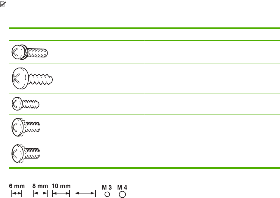
Screws
NOTE: The screw illustrations in the following table are for reference only. Screws might vary in size
and appearance from those shown in this table.
Table 8-1 Common fasteners
Example Description Size Part Number
Screw, with washer M3X8 XA9-1420-000CN
Screw, tapping, truss head M4X10 XB4-7401-005CN
Screw, tap M3X6 XA9-1503-000CN
Screw, D M3X8 XA9-1671-000CN
Screw, tooth washer M4X6 XB2–7400-606CN
12 mm
12 mm
ENWW Screws 257

How to use the parts lists and diagrams
The figures in this chapter show the major subassemblies in the product and their component parts. A
parts list table follows each exploded view assembly diagram. Each table lists the item number, the
associated part number, and the description of each part. If a part is not listed in the table, then it is not
a field replacement unit (FRU).
CAUTION: Be sure to order the correct part. When looking for part numbers for electrical components,
pay careful attention to the voltage that is listed in the description column. Doing so will ensure that the
part number selected is for the correct all-in-one model.
NOTE: In this manual, the abbreviation “PCA” stands for “printed circuit-board assembly.”
Components described as a PCA might consist of a single circuit board or a circuit board plus other
parts, such as cables and sensors.
258 Chapter 8 Parts and diagrams ENWW
ENWW How to use the parts lists and diagrams 259
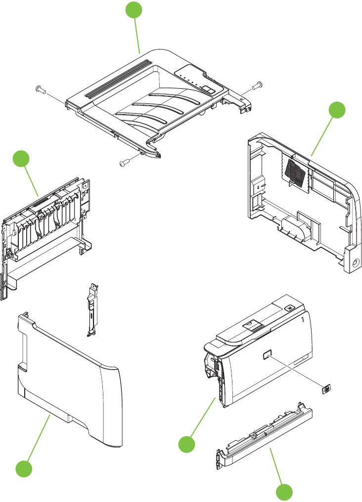
External covers, panels, and doors
HP LaserJet P2035
Figure 8-1 External covers, panels, and doors; HP LaserJet P2035
5
6
1
2
4
8
260 Chapter 8 Parts and diagrams ENWW

Table 8-2 External covers, panels, and doors; HP LaserJet P2035
Ref Description Part number Qty
1 Top-cover assembly (HP LaserJet P2035) RM1-6435-000CN 1
2 Cover, right (HP LaserJet P2035) RC2-8280-000CN 1
4 Cover, front (HP LaserJet P2035 and HP LaserJet P2055) RL1-2124-000CN 1
5 Cartridge-door assembly (HP LaserJet P2035) RM1-6434-000CN 1
6 Cover, left assembly (HP LaserJet P2035) RM1-6437-000CN 1
8 Cover, rear assembly (HP LaserJet P2035) RM1-6440-000CN 1
ENWW External covers, panels, and doors 261
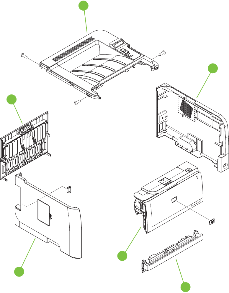
HP LaserJet P2055
Figure 8-2 External covers, panels, and doors; HP LaserJet P2055
5
6
1
2
4
8
262 Chapter 8 Parts and diagrams ENWW

Table 8-3 External covers, panels, and doors; HP LaserJet P2055
Ref Description Part number Qty
1 Top-cover assembly (HP LaserJet P2055) RM1-6429-000CN 1
2 Cover, right (HP LaserJet P2055) RC2-6254-000CN 1
4 Cover, front (HP LaserJet P2035 and HP LaserJet P2055) RL1-2124-000CN 1
5 Cartridge-door assembly (HP LaserJet P2055) RM1-6425-000CN 1
6 Cover, left assembly (HP LaserJet P2055) RM1-6428-000CN 1
8 Cover, rear assembly (HP LaserJet P2055) RM1-6444-000CN 1
ENWW External covers, panels, and doors 263
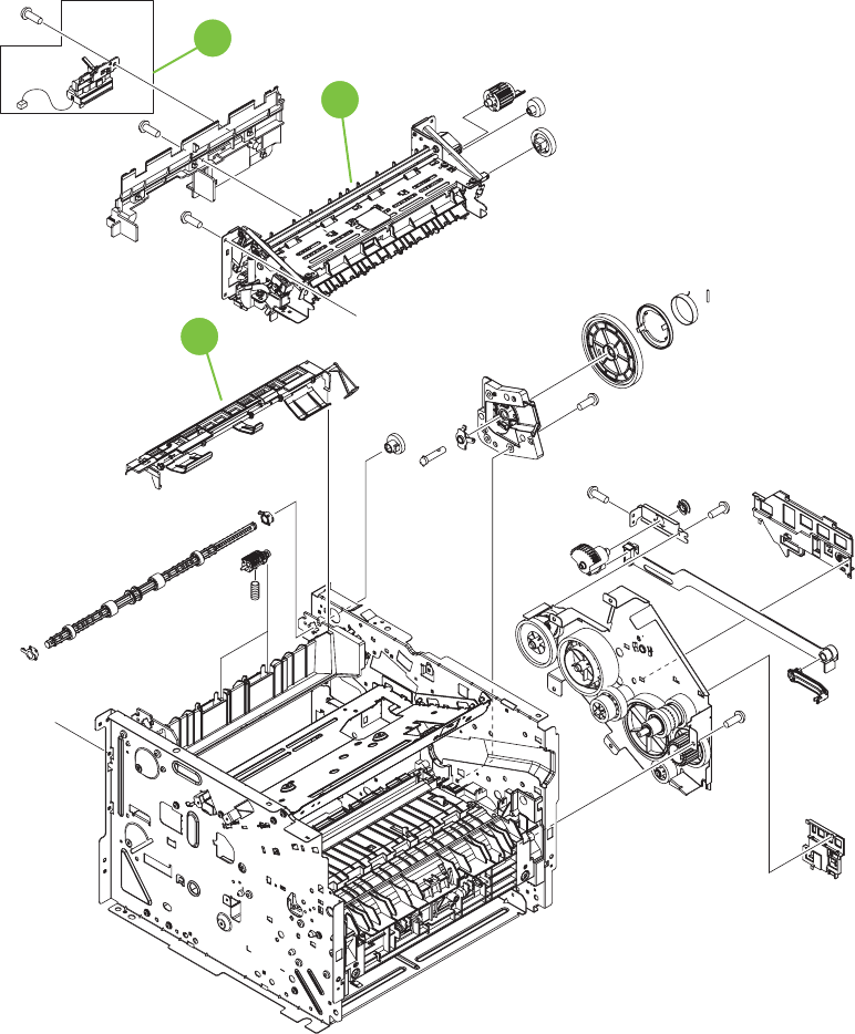
Internal components
Internal components 1 of 5
Figure 8-3 Internal components 1 of 5
A
A
(J208)
(PS918)
1
2
3
HPLJ 2050 Series only
264 Chapter 8 Parts and diagrams ENWW

Table 8-4 Internal components (1 of 5)
Ref Description Part number Qty
1 Reverse-sensor assembly (HP LaserJet P2055) RM1-6445-000CN 1
2 Fuser assembly (110 V to 127 V) RM1-6405-000CN 1
2 Fuser assembly (220 V to 240 V) RM1-6406-000CN 1
3 Paper-retaining-delivery assembly RM1-6401-000CN 1
ENWW Internal components 265
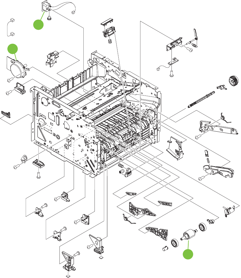
Internal components 2 of 5
Figure 8-4 Internal components 2 of 5
(M1)
(J1202) (PS916)
(J205)
(J101)
(J202)
(J1202)
6
1
2
266 Chapter 8 Parts and diagrams ENWW

Table 8-5 Internal components (2 of 5)
Ref Description Part number Qty
1 Main-motor RM1-6378-000CN 1
2 Inlet-cable assembly RM1-6375-000CN 1
6 Paper-pickup roller assembly RM1-6414-000CN 1
ENWW Internal components 267
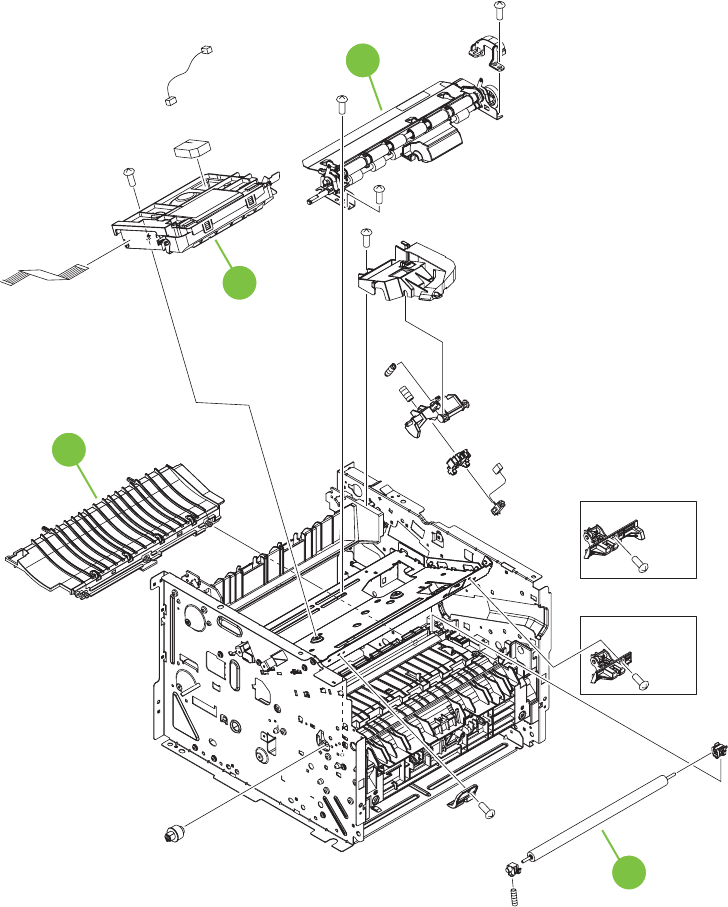
Internal components 3 of 5
Figure 8-5 Internal components 3 of 5
(J801)
(J802)
(J1103)
(J581)
(J3)
5
2
3
4
HPLJ 2050 Series only
HPLJ 2030 Series only
268 Chapter 8 Parts and diagrams ENWW

Table 8-6 Internal components (3 of 5)
Ref Description Part number Qty
2 Paper-feed-guide assembly RM1-6402-000CN 1
3 Laser/scanner assembly RM1-6424-000CN 1
4 Registration assembly RM1-6419-000CN 1
5 Transfer-roller assembly RM1-6450-000CN 1
ENWW Internal components 269
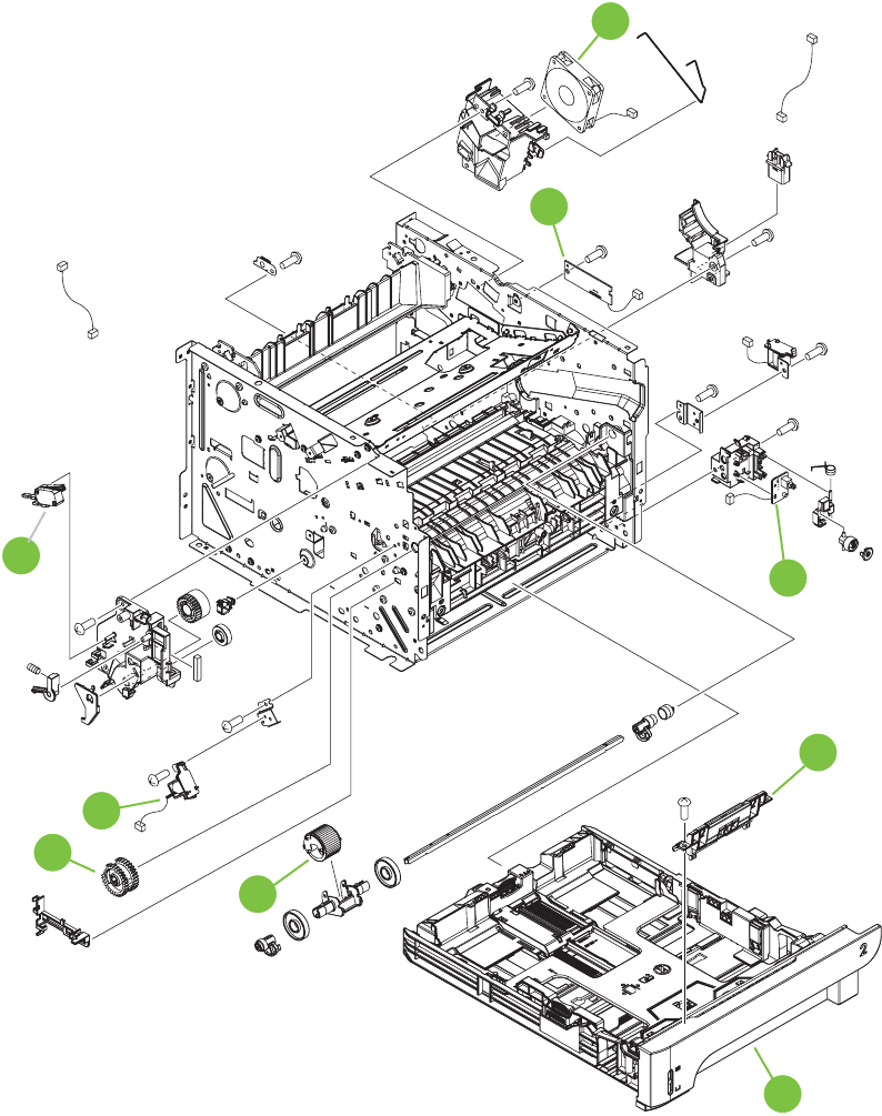
Internal components 4 of 5
Figure 8-6 Internal components 4 of 5
(SL1)
(SW301)
(J4)
(SL2)
(J1100)
(SW1001)
(J215)
(FM1)
(J1105)
(J207)
(J1)
(J71)
(J1205D)
(J1205F)
(J211)
5
6
1
2
4
8
7
9
10
270 Chapter 8 Parts and diagrams ENWW

Table 8-7 Internal components (4 of 5)
Ref Description Part number Qty
1 Fan RK2-2727-000CN 1
2 Connecting PCA RM1-6346-000CN 1
4 Power-switch PCA RM1-6348-000CN 1
5 Separation-pad assembly (Tray 2) RM1-6397-000CN 1
6 Cassette assembly (Tray 2; HP LaserJet P2035) RM1-6446-000CN 1
6 Cassette assembly (Tray 2; HP LaserJet P2055) RM1-6394-000CN 1
7 Roller, multipurpose pickup (Tray 1) RM1-6394-000CN 1
8 Paper-pickup-gear assembly RM1-4275-000CN 1
9 Solenoid (SL1; Tray 1) RK2-2731-000CN 1
10 Switch, push (SW301; cartridge-door interlock) WC4-5171-000CN 1
ENWW Internal components 271
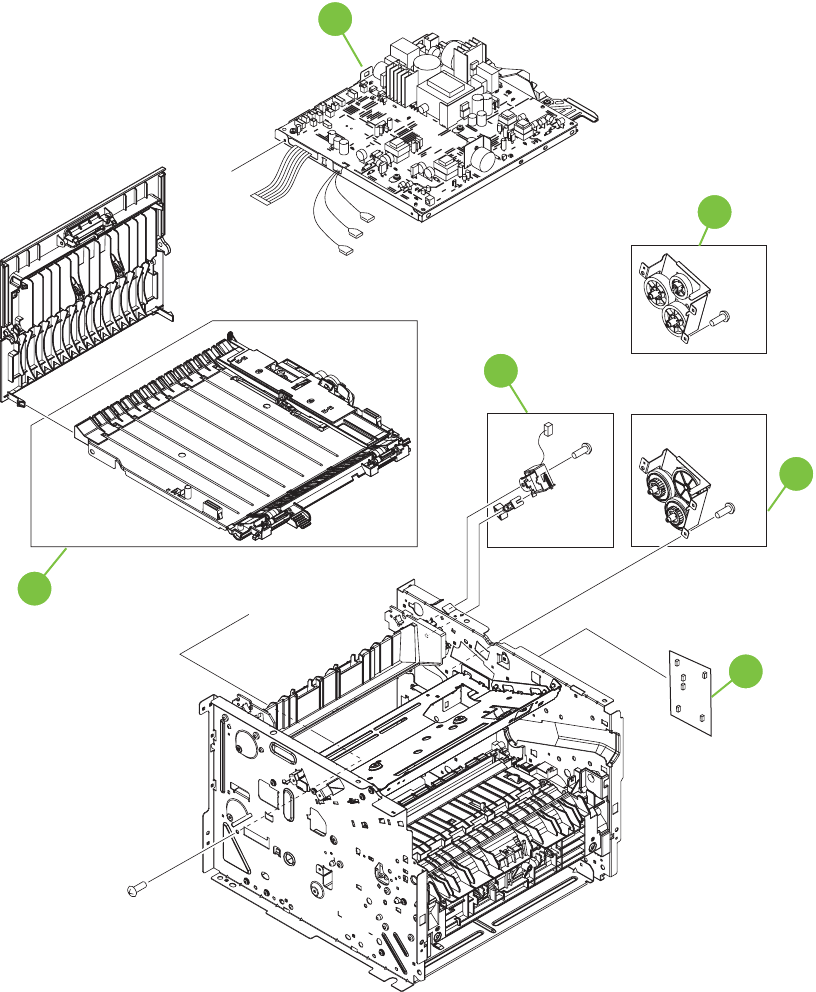
Internal components 5 of 5
Figure 8-7 Internal components 5 of 5
A
A
(FT3)
(SL3)
(J1101)
(J7)
(FT2)
(FT1)
5
1
2
3
4
6
HPLJ 2030 Series only
HPLJ 2050
Series only
HPLJ 2050 Series only HPLJ 2050
Series only
272 Chapter 8 Parts and diagrams ENWW

Table 8-8 Internal components (5 of 5)
Ref Description Part number Qty
1 Engine-controller unit (ECU; 110 V to 127 V) RM1-6392-000CN 1
1 Engine-controller unit (ECU; 220 V to 240 V) RM1-6393-000CN 1
2 Duplexing-paper-feed assembly (HP LaserJet P2055) RM1-6346-000CN 1
3 Face-down-drive assembly (HP LaserJet P2035) RM1-6447-000CN 1
4 Solenoid (SL3; HP LaserJet P2055) RK2-27337-000CN 1
5 Reverse-drive assembly (HP LaserJet P2055) RM1-6423-000CN 1
6 Formatter (HP LaserJet P2035) CC525-60001 1
6 Formatter (HP LaserJet P2035n) CC526-60001 1
6 Formatter (HP LaserJet P2055d) CC527-60001 1
6 Formatter (HP LaserJet P2055dn and HP LaserJet P2055x) CC528-60001 1
ENWW Internal components 273

Alphabetical parts list
Table 8-9 Alphabetical parts list
Description Part number Table and page
Cartridge-door assembly (HP LaserJet P2055) RM1-6425-000CN External covers, panels, and
doors; HP LaserJet P2055
on page 263
Cartridge-door assembly (HP LaserJet P2035) RM1-6434-000CN External covers, panels, and
doors; HP LaserJet P2035
on page 261
Cassette assembly (Tray 2; HP LaserJet P2055) RM1-6394-000CN Internal components (4 of 5)
on page 271
Cassette assembly (Tray 2; HP LaserJet P2035) RM1-6446-000CN Internal components (4 of 5)
on page 271
Connecting PCA RM1-6346-000CN Internal components (4 of 5)
on page 271
Cover, front (HP LaserJet P2035 and HP LaserJet P2055) RL1-2124-000CN External covers, panels, and
doors; HP LaserJet P2035
on page 261
Cover, front (HP LaserJet P2035 and HP LaserJet P2055) RL1-2124-000CN External covers, panels, and
doors; HP LaserJet P2055
on page 263
Cover, left assembly (HP LaserJet P2055) RM1-6428-000CN External covers, panels, and
doors; HP LaserJet P2055
on page 263
Cover, left assembly (HP LaserJet P2035) RM1-6437-000CN External covers, panels, and
doors; HP LaserJet P2035
on page 261
Cover, rear assembly (HP LaserJet P2055) RM1-6444-000CN External covers, panels, and
doors; HP LaserJet P2055
on page 263
Cover, rear assembly (HP LaserJet P2035) RM1-6440-000CN External covers, panels, and
doors; HP LaserJet P2035
on page 261
Cover, right (HP LaserJet P2055) RC2-6254-000CN External covers, panels, and
doors; HP LaserJet P2055
on page 263
Cover, right (HP LaserJet P2035) RC2-8280-000CN External covers, panels, and
doors; HP LaserJet P2035
on page 261
Duplexing-paper-feed assembly (HP LaserJet P2055) RM1-6346-000CN Internal components (5 of 5)
on page 273
Engine-controller unit (ECU; 110 V to 127 V) RM1-6392-000CN Internal components (5 of 5)
on page 273
Engine-controller unit (ECU; 220 V to 240 V) RM1-6393-000CN Internal components (5 of 5)
on page 273
Face-down-drive assembly (HP LaserJet P2035) RM1-6447-000CN Internal components (5 of 5)
on page 273
274 Chapter 8 Parts and diagrams ENWW

Description Part number Table and page
Fan RK2-2727-000CN Internal components (4 of 5)
on page 271
Formatter (HP LaserJet P2055d) CC527-60001 Internal components (5 of 5)
on page 273
Formatter (HP LaserJet P2055dn and HP LaserJet P2055x) CC528-60001 Internal components (5 of 5)
on page 273
Formatter (HP LaserJet P2035) CC525-60001 Internal components (5 of 5)
on page 273
Formatter (HP LaserJet P2035n) CC526-60001 Internal components (5 of 5)
on page 273
Fuser assembly (110 V to 127 V) RM1-6405-000CN Internal components (1 of 5)
on page 265
Fuser assembly (220 V to 240 V) RM1-6406-000CN Internal components (1 of 5)
on page 265
Inlet-cable assembly RM1-6375-000CN Internal components (2 of 5)
on page 267
Laser/scanner assembly RM1-6424-000CN Internal components (3 of 5)
on page 269
Main-motor RM1-6378-000CN Internal components (2 of 5)
on page 267
Paper-feed-guide assembly RM1-6402-000CN Internal components (3 of 5)
on page 269
Paper-pickup roller assembly RM1-6414-000CN Internal components (2 of 5)
on page 267
Paper-pickup-gear assembly RM1-4275-000CN Internal components (4 of 5)
on page 271
Paper-retaining-delivery assembly RM1-6401-000CN Internal components (1 of 5)
on page 265
Power-switch PCA RM1-6348-000CN Internal components (4 of 5)
on page 271
Registration assembly RM1-6419-000CN Internal components (3 of 5)
on page 269
Reverse-drive assembly (HP LaserJet P2055) RM1-6423-000CN Internal components (5 of 5)
on page 273
Reverse-sensor assembly (HP LaserJet P2055) RM1-6445-000CN Internal components (1 of 5)
on page 265
Roller, multipurpose pickup (Tray 1) RM1-6394-000CN Internal components (4 of 5)
on page 271
Separation-pad assembly (Tray 2) RM1-6397-000CN Internal components (4 of 5)
on page 271
Solenoid (SL1; Tray 1) RK2-2731-000CN Internal components (4 of 5)
on page 271
Solenoid (SL3; HP LaserJet P2055) RK2-27337-000CN Internal components (5 of 5)
on page 273
Table 8-9 Alphabetical parts list (continued)
ENWW Alphabetical parts list 275

Description Part number Table and page
Switch, push (SW301; cartridge-door interlock) WC4-5171-000CN Internal components (4 of 5)
on page 271
Top-cover assembly (HP LaserJet P2055) RM1-6429-000CN External covers, panels, and
doors; HP LaserJet P2055
on page 263
Top-cover assembly (HP LaserJet P2035) RM1-6435-000CN External covers, panels, and
doors; HP LaserJet P2035
on page 261
Transfer-roller assembly RM1-6450-000CN Internal components (3 of 5)
on page 269
Table 8-9 Alphabetical parts list (continued)
276 Chapter 8 Parts and diagrams ENWW

Numerical parts list
Table 8-10 Numerical parts list
Part number Description Table and page
CC525-60001 Formatter (HP LaserJet P2035) Internal components (5 of 5)
on page 273
CC526-60001 Formatter (HP LaserJet P2035n) Internal components (5 of 5)
on page 273
CC527-60001 Formatter (HP LaserJet P2055d) Internal components (5 of 5)
on page 273
CC528-60001 Formatter (HP LaserJet P2055dn and HP LaserJet P2055x) Internal components (5 of 5)
on page 273
RC2-6254-000CN Cover, right (HP LaserJet P2055) External covers, panels, and
doors; HP LaserJet P2055
on page 263
RC2-8280-000CN Cover, right (HP LaserJet P2035) External covers, panels, and
doors; HP LaserJet P2035
on page 261
RK2-2727-000CN Fan Internal components (4 of 5)
on page 271
RK2-2731-000CN Solenoid (SL1; Tray 1) Internal components (4 of 5)
on page 271
RK2-27337-000CN Solenoid (SL3; HP LaserJet P2055) Internal components (5 of 5)
on page 273
RL1-2124-000CN Cover, front (HP LaserJet P2035 and HP LaserJet P2055) External covers, panels, and
doors; HP LaserJet P2035
on page 261
RL1-2124-000CN Cover, front (HP LaserJet P2035 and HP LaserJet P2055) External covers, panels, and
doors; HP LaserJet P2055
on page 263
RM1-4275-000CN Paper-pickup-gear assembly Internal components (4 of 5)
on page 271
RM1-6346-000CN Connecting PCA Internal components (4 of 5)
on page 271
RM1-6346-000CN Duplexing-paper-feed assembly (HP LaserJet P2055) Internal components (5 of 5)
on page 273
RM1-6348-000CN Power-switch PCA Internal components (4 of 5)
on page 271
RM1-6375-000CN Inlet-cable assembly Internal components (2 of 5)
on page 267
RM1-6378-000CN Main-motor Internal components (2 of 5)
on page 267
RM1-6392-000CN Engine-controller unit (ECU; 110 V to 127 V) Internal components (5 of 5)
on page 273
RM1-6393-000CN Engine-controller unit (ECU; 220 V to 240 V) Internal components (5 of 5)
on page 273
ENWW Numerical parts list 277

Part number Description Table and page
RM1-6394-000CN Cassette assembly (Tray 2; HP LaserJet P2055) Internal components (4 of 5)
on page 271
RM1-6394-000CN Roller, multipurpose pickup (Tray 1) Internal components (4 of 5)
on page 271
RM1-6397-000CN Separation-pad assembly (Tray 2) Internal components (4 of 5)
on page 271
RM1-6401-000CN Paper-retaining-delivery assembly Internal components (1 of 5)
on page 265
RM1-6402-000CN Paper-feed-guide assembly Internal components (3 of 5)
on page 269
RM1-6405-000CN Fuser assembly (110 V to 127 V) Internal components (1 of 5)
on page 265
RM1-6406-000CN Fuser assembly (220 V to 240 V) Internal components (1 of 5)
on page 265
RM1-6414-000CN Paper-pickup roller assembly Internal components (2 of 5)
on page 267
RM1-6419-000CN Registration assembly Internal components (3 of 5)
on page 269
RM1-6423-000CN Reverse-drive assembly (HP LaserJet P2055) Internal components (5 of 5)
on page 273
RM1-6424-000CN Laser/scanner assembly Internal components (3 of 5)
on page 269
RM1-6425-000CN Cartridge-door assembly (HP LaserJet P2055) External covers, panels, and
doors; HP LaserJet P2055
on page 263
RM1-6428-000CN Cover, left assembly (HP LaserJet P2055) External covers, panels, and
doors; HP LaserJet P2055
on page 263
RM1-6429-000CN Top-cover assembly (HP LaserJet P2055) External covers, panels, and
doors; HP LaserJet P2055
on page 263
RM1-6434-000CN Cartridge-door assembly (HP LaserJet P2035) External covers, panels, and
doors; HP LaserJet P2035
on page 261
RM1-6435-000CN Top-cover assembly (HP LaserJet P2035) External covers, panels, and
doors; HP LaserJet P2035
on page 261
RM1-6437-000CN Cover, left assembly (HP LaserJet P2035) External covers, panels, and
doors; HP LaserJet P2035
on page 261
RM1-6440-000CN Cover, rear assembly (HP LaserJet P2035) External covers, panels, and
doors; HP LaserJet P2035
on page 261
RM1-6444-000CN Cover, rear assembly (HP LaserJet P2055) External covers, panels, and
doors; HP LaserJet P2055
on page 263
Table 8-10 Numerical parts list (continued)
278 Chapter 8 Parts and diagrams ENWW

Part number Description Table and page
RM1-6445-000CN Reverse-sensor assembly (HP LaserJet P2055) Internal components (1 of 5)
on page 265
RM1-6446-000CN Cassette assembly (Tray 2; HP LaserJet P2035) Internal components (4 of 5)
on page 271
RM1-6447-000CN Face-down-drive assembly (HP LaserJet P2035) Internal components (5 of 5)
on page 273
RM1-6450-000CN Transfer-roller assembly Internal components (3 of 5)
on page 269
WC4-5171-000CN Switch, push (SW301; cartridge-door interlock) Internal components (4 of 5)
on page 271
Table 8-10 Numerical parts list (continued)
ENWW Numerical parts list 279
280 Chapter 8 Parts and diagrams ENWW


Hewlett-Packard limited warranty statement
HP PRODUCT DURATION OF LIMITED WARRANTY
HP LaserJet P2055d, P2055dn, P2055x, P2035, P2035n One year from date of purchase
HP warrants to you, the end-user customer, that HP hardware and accessories will be free from defects
in materials and workmanship after the date of purchase, for the period specified above. If HP receives
notice of such defects during the warranty period, HP will, at its option, either repair or replace products
which prove to be defective. Replacement products may be either new or equivalent in performance to
new.
HP warrants to you that HP software will not fail to execute its programming instructions after the date
of purchase, for the period specified above, due to defects in material and workmanship when properly
installed and used. If HP receives notice of such defects during the warranty period, HP will replace
software which does not execute its programming instructions due to such defects.
HP does not warrant that the operation of HP products will be uninterrupted or error free. If HP is unable,
within a reasonable time, to repair or replace any product to a condition as warranted, you will be entitled
to a refund of the purchase price upon prompt return of the product.
HP products may contain remanufactured parts equivalent to new in performance or may have been
subject to incidental use.
Warranty does not apply to defects resulting from (a) improper or inadequate maintenance or calibration,
(b) software, interfacing, parts or supplies not supplied by HP, (c) unauthorized modification or misuse,
(d) operation outside of the published environmental specifications for the product, or (e) improper site
preparation or maintenance.
TO THE EXTENT ALLOWED BY LOCAL LAW, THE ABOVE WARRANTIES ARE EXCLUSIVE AND
NO OTHER WARRANTY OR CONDITION, WHETHER WRITTEN OR ORAL, IS EXPRESSED OR
IMPLIED AND HP SPECIFICALLY DISCLAIMS ANY IMPLIED WARRANTIES OR CONDITIONS OF
MERCHANTABILITY, SATISFACTORY QUALITY, AND FITNESS FOR A PARTICULAR PURPOSE.
Some countries/regions, states or provinces do not allow limitations on the duration of an implied
warranty, so the above limitation or exclusion might not apply to you. This warranty gives you specific
legal rights and you might also have other rights that vary from country/region to country/region, state
to state, or province to province.
HP's limited warranty is valid in any country/region or locality where HP has a support presence for this
product and where HP has marketed this product. The level of warranty service you receive may vary
according to local standards. HP will not alter form, fit or function of the product to make it operate in a
country/region for which it was never intended to function for legal or regulatory reasons.
TO THE EXTENT ALLOWED BY LOCAL LAW, THE REMEDIES IN THIS WARRANTY STATEMENT
ARE YOUR SOLE AND EXCLUSIVE REMEDIES. EXCEPT AS INDICATED ABOVE, IN NO EVENT
WILL HP OR ITS SUPPLIERS BE LIABLE FOR LOSS OF DATA OR FOR DIRECT, SPECIAL,
INCIDENTAL, CONSEQUENTIAL (INCLUDING LOST PROFIT OR DATA), OR OTHER DAMAGE,
WHETHER BASED IN CONTRACT, TORT, OR OTHERWISE. Some countries/regions, states or
provinces do not allow the exclusion or limitation of incidental or consequential damages, so the above
limitation or exclusion may not apply to you.
THE WARRANTY TERMS CONTAINED IN THIS STATEMENT, EXCEPT TO THE EXTENT
LAWFULLY PERMITTED, DO NOT EXCLUDE, RESTRICT OR MODIFY AND ARE IN ADDITION TO
THE MANDATORY STATUTORY RIGHTS APPLICABLE TO THE SALE OF THIS PRODUCT TO YOU.
282 Appendix A Service and support ENWW
Print cartridge limited warranty statement
This HP product is warranted to be free from defects in materials and workmanship.
This warranty does not apply to products that (a) have been refilled, refurbished, remanufactured or
tampered with in any way, (b) experience problems resulting from misuse, improper storage, or
operation outside of the published environmental specifications for the printer product or (c) exhibit wear
from ordinary use.
To obtain warranty service, please return the product to place of purchase (with a written description of
the problem and print samples) or contact HP customer support. At HP's option, HP will either replace
products that prove to be defective or refund your purchase price.
TO THE EXTENT ALLOWED BY LOCAL LAW, THE ABOVE WARRANTY IS EXCLUSIVE AND NO
OTHER WARRANTY OR CONDITION, WHETHER WRITTEN OR ORAL, IS EXPRESSED OR
IMPLIED AND HP SPECIFICALLY DISCLAIMS ANY IMPLIED WARRANTIES OR CONDITIONS OF
MERCHANTABILITY, SATISFACTORY QUALITY, AND FITNESS FOR A PARTICULAR PURPOSE.
TO THE EXTENT ALLOWED BY LOCAL LAW, IN NO EVENT WILL HP OR ITS SUPPLIERS BE
LIABLE FOR DIRECT, SPECIAL, INCIDENTAL, CONSEQUENTIAL (INCLUDING LOST PROFIT OR
DATA), OR OTHER DAMAGE, WHETHER BASED IN CONTRACT, TORT, OR OTHERWISE.
THE WARRANTY TERMS CONTAINED IN THIS STATEMENT, EXCEPT TO THE EXTENT
LAWFULLY PERMITTED, DO NOT EXCLUDE, RESTRICT OR MODIFY AND ARE IN ADDITION TO
THE MANDATORY STATUTORY RIGHTS APPLICABLE TO THE SALE OF THIS PRODUCT TO YOU.
ENWW Print cartridge limited warranty statement 283
End User License Agreement
PLEASE READ CAREFULLY BEFORE USING THIS SOFTWARE PRODUCT: This End-User License
Agreement (“EULA”) is a contract between (a) you (either an individual or the entity you represent) and
(b) Hewlett-Packard Company (“HP”) that governs your use of the software product (“Software”). This
EULA does not apply if there is a separate license agreement between you and HP or its suppliers for
the Software, including a license agreement in online documentation. The term “Software” may include
(i) associated media, (ii) a user guide and other printed materials, and (iii) “online” or electronic
documentation (collectively “User Documentation”).
RIGHTS IN THE SOFTWARE ARE OFFERED ONLY ON THE CONDITION THAT YOU AGREE TO
ALL TERMS AND CONDITIONS OF THIS EULA. BY INSTALLING, COPYING, DOWNLOADING, OR
OTHERWISE USING THE SOFTWARE, YOU AGREE TO BE BOUND BY THIS EULA. IF YOU DO
NOT ACCEPT THIS EULA, DO NOT INSTALL, DOWNLOAD, OR OTHERWISE USE THE
SOFTWARE. IF YOU PURCHASED THE SOFTWARE BUT DO NOT AGREE TO THIS EULA, PLEASE
RETURN THE SOFTWARE TO YOUR PLACE OF PURCHASE WITHIN FOURTEEN DAYS FOR A
REFUND OF THE PURCHASE PRICE; IF THE SOFTWARE IS INSTALLED ON OR MADE
AVAILABLE WITH ANOTHER HP PRODUCT, YOU MAY RETURN THE ENTIRE UNUSED
PRODUCT.
1. THIRD PARTY SOFTWARE. The Software may include, in addition to HP proprietary software
(“HP Software”), software under licenses from third parties (“Third Party Software” and “Third Party
License”). Any Third Party Software is licensed to you subject to the terms and conditions of the
corresponding Third Party License. Generally, the Third Party License is located in a file such as
license.txt; you should contact HP support if you cannot find any Third Party License. If the Third Party
Licenses include licenses that provide for the availability of source code (such as the GNU General
Public License) and the corresponding source code is not included with the Software, then check the
product support pages of HP’s website (hp.com) to learn how to obtain such source code.
2. LICENSE RIGHTS. You will have the following rights provided you comply with all terms and
conditions of this EULA:
a. Use. HP grants you a license to Use one copy of the HP Software. “Use” means installing, copying,
storing, loading, executing, displaying, or otherwise using the HP Software. You may not modify the
HP Software or disable any licensing or control feature of the HP Software. If this Software is provided
by HP for Use with an imaging or printing product (for example, if the Software is a printer driver,
firmware, or add-on), the HP Software may only be used with such product (“HP Product”). Additional
restrictions on Use may appear in the User Documentation. You may not separate component parts of
the HP Software for Use. You do not have the right to distribute the HP Software.
b. Copying. Your right to copy means you may make archival or back-up copies of the HP Software,
provided each copy contains all the original HP Software’s proprietary notices and is used only for back-
up purposes.
3. UPGRADES. To Use HP Software provided by HP as an upgrade, update, or supplement (collectively
“Upgrade”), you must first be licensed for the original HP Software identified by HP as eligible for the
Upgrade. To the extent the Upgrade supersedes the original HP Software, you may no longer use such
HP Software. This EULA applies to each Upgrade unless HP provides other terms with the Upgrade. In
case of a conflict between this EULA and such other terms, the other terms will prevail.
4. TRANSFER.
a. Third Party Transfer. The initial end user of the HP Software may make a one-time transfer of the
HP Software to another end user. Any transfer will include all component parts, media, User
Documentation, this EULA, and if applicable, the Certificate of Authenticity. The transfer may not be an
indirect transfer, such as a consignment. Prior to the transfer, the end user receiving the transferred
284 Appendix A Service and support ENWW
Software will agree to this EULA. Upon transfer of the HP Software, your license is automatically
terminated.
b. Restrictions. You may not rent, lease or lend the HP Software or Use the HP Software for commercial
timesharing or bureau use. You may not sublicense, assign or otherwise transfer the HP Software except
as expressly provided in this EULA.
5. PROPRIETARY RIGHTS. All intellectual property rights in the Software and User Documentation are
owned by HP or its suppliers and are protected by law, including applicable copyright, trade secret,
patent, and trademark laws. You will not remove any product identification, copyright notice, or
proprietary restriction from the Software.
6. LIMITATION ON REVERSE ENGINEERING. You may not reverse engineer, decompile, or
disassemble the HP Software, except and only to the extent that the right to do so is allowed under
applicable law.
7. CONSENT TO USE OF DATA. HP and its affiliates may collect and use technical information you
provide in relation to (i) your Use of the Software or the HP Product, or (ii) the provision of support
services related to the Software or the HP Product. All such information will be subject to HP’s privacy
policy. HP will not use such information in a form that personally identifies you except to the extent
necessary to enhance your Use or provide support services.
8. LIMITATION OF LIABILITY. Notwithstanding any damages that you might incur, the entire liability of
HP and its suppliers under this EULA and your exclusive remedy under this EULA will be limited to the
greater of the amount actually paid by you for the Product or U.S. $5.00. TO THE MAXIMUM EXTENT
PERMITTED BY APPLICABLE LAW, IN NO EVENT WILL HP OR ITS SUPPLIERS BE LIABLE FOR
ANY SPECIAL, INCIDENTAL, INDIRECT, OR CONSEQUENTIAL DAMAGES (INCLUDING
DAMAGES FOR LOST PROFITS, LOST DATA, BUSINESS INTERRUPTION, PERSONAL INJURY,
OR LOSS OF PRIVACY) RELATED IN ANY WAY TO THE USE OF OR INABILITY TO USE THE
SOFTWARE, EVEN IF HP OR ANY SUPPLIER HAS BEEN ADVISED OF THE POSSIBILITY OF SUCH
DAMAGES AND EVEN IF THE ABOVE REMEDY FAILS OF ITS ESSENTIAL PURPOSE. Some states
or other jurisdictions do not allow the exclusion or limitation of incidental or consequential damages, so
the above limitation or exclusion may not apply to you.
9. U.S. GOVERNMENT CUSTOMERS. If you are a U.S. Government entity, then consistent with FAR
12.211 and FAR 12.212, Commercial Computer Software, Computer Software Documentation, and
Technical Data for Commercial Items are licensed under the applicable HP commercial license
agreement.
10. COMPLIANCE WITH EXPORT LAWS. You will comply with all laws, rules, and regulations (i)
applicable to the export or import of the Software, or (ii) restricting the Use of the Software, including
any restrictions on nuclear, chemical, or biological weapons proliferation.
11. RESERVATION OF RIGHTS. HP and its suppliers reserve all rights not expressly granted to you
in this EULA.
(c) 2007 Hewlett-Packard Development Company, L.P.
Rev. 11/06
ENWW End User License Agreement 285
Customer self-repair warranty service
HP products are designed with many Customer Self Repair (CSR) parts to minimize repair time and
allow for greater flexibility in performing defective parts replacement. If during the diagnosis period, HP
identifies that the repair can be accomplished by the use of a CSR part, HP will ship that part directly to
you for replacement. There are two categories of CSR parts: 1) Parts for which customer self repair is
mandatory. If you request HP to replace these parts, you will be charged for the travel and labor costs
of this service. 2) Parts for which customer self repair is optional. These parts are also designed for
Customer Self Repair. If, however, you require that HP replace them for you, this may be done at no
additional charge under the type of warranty service designated for your product.
Based on availability and where geography permits, CSR parts will be shipped for next business day
delivery. Same-day or four-hour delivery may be offered at an additional charge where geography
permits. If assistance is required, you can call the HP Technical Support Center and a technician will
help you over the phone. HP specifies in the materials shipped with a replacement CSR part whether
a defective part must be returned to HP. In cases where it is required to return the defective part to HP,
you must ship the defective part back to HP within a defined period of time, normally five (5) business
days. The defective part must be returned with the associated documentation in the provided shipping
material. Failure to return the defective part may result in HP billing you for the replacement. With a
customer self repair, HP will pay all shipping and part return costs and determine the courier/carrier to
be used.
286 Appendix A Service and support ENWW

Customer support
Get telephone support, free during your warranty period, for
your country/region
Have the product name, serial number, date of purchase, and
problem description ready.
Country/region phone numbers are on the flyer that was in the
box with your product or at www.hp.com/support/.
Get 24-hour Internet support www.hp.com/support/ljp2050series or www.hp.com/support/
ljp2030series
Get support for products used with a Macintosh computer www.hp.com/go/macosx
Download software utilities, drivers, and electronic information www.hp.com/go/ljp2050series_software or www.hp.com/go/
ljp2030series_software
Order supplies and paper www.hp.com/go/suresupply
Order genuine HP parts or accessories www.hp.com/buy/parts
Order additional HP service or maintenance agreements www.hp.com/go/carepack
ENWW Customer support 287

HP maintenance agreements
HP has several types of maintenance agreements that meet a wide range of support needs.
Maintenance agreements are not part of the standard warranty. Support services might vary by area.
Check with your local HP dealer to determine the services available to you.
On-site service agreements
To provide you with the level of support best suited to your needs, HP has on-site service agreements
with a selection of response times.
Next-day on-site service
This agreement provides support by the next working day following a service request. Extended
coverage hours and extended travel beyond HP’s designated service zones are available on most on-
site agreements (for additional charges).
Weekly (volume) on-site service
This agreement provides scheduled weekly on-site visits for organizations with many HP products. This
agreement is designated for sites using 25 or more workstation products, including devices, plotters,
computers, and disk drives.
Repack the product
If HP Customer Care determines that your product needs to be returned to HP for repair, follow these
steps to repack the product before shipping it.
CAUTION: Shipping damage as a result of inadequate packing is the customer’s responsibility.
1. Remove and retain any DIMMs cards that you have purchased and installed in the device. Do not
remove the DIMM that came with the device.
CAUTION: Static electricity can damage DIMMs. When handling DIMMs, either wear an antistatic
wrist strap, or frequently touch the surface of the DIMM antistatic package and then touch bare
metal on the device. To remove the DIMMs, see Install memory (HP LaserJet P2050 Series Printers
only) on page 64.
2. Remove and retain the print cartridge.
CAUTION: It is extremely important to remove the print cartridge before shipping the product. A
print cartridge that remains in the product during shipping can leak and cover the product engine
and other parts with toner.
To prevent damage to the print cartridge, avoid touching the roller on it, and store the print cartridge
in its original packing material or so that it is not exposed to light.
3. Remove and retain the power cable, interface cable, and optional accessories.
4. If possible, include print samples and 50 to 100 sheets of paper or other print media that did not
print correctly.
5. In the U.S., call HP Customer Care to request new packing material. In other areas, use the original
packing material, if possible. Hewlett-Packard recommends insuring the equipment for shipment.
288 Appendix A Service and support ENWW
Extended warranty
HP Support provides coverage for the HP hardware product and all HP-supplied internal components.
The hardware maintenance covers a 1- to 3-year period from date of the HP product purchase. The
customer must purchase HP Support within the stated factory warranty. For more information, contact
the HP Customer Care Service and Support group.
ENWW HP maintenance agreements 289
290 Appendix A Service and support ENWW


Physical specifications
Table B-1 Product dimensions and weights
Product model Height Depth Width Weight
HP LaserJet P2050 Series d model 268 mm (10.6 in) 368 mm (14.5 in) 360 mm (14.2 in) 10.6 kg (23.4 lb)
HP LaserJet P2050 Series dn model 268 mm (10.6 in) 368 mm (14.5 in) 360 mm (14.2 in) 10.6 kg (23.4 lb)
HP LaserJet P2050 Series x model 405 mm (15.9 in) 368 mm (14.5 in) 360 mm (14.2 in) 14.7 kg (32.4 lb)
Optional 500-sheet feeder 140 mm (5.5 in) 368 mm (14.5 in) 360 mm (14.2 in) 4.1 kg (9.0 lb)
Table B-2 Product dimensions with all doors and trays fully opened
Product model Height Depth Width
HP LaserJet P2050 Series d model 268 mm (10.6 in) 455 mm (17.9 in) 360 mm (14.2 in)
HP LaserJet P2050 Series dn model 268 mm (10.6 in) 455 mm (17.9 in) 360 mm (14.2 in)
HP LaserJet P2050 Series x model 405 mm (15.9 in) 455 mm (17.9 in) 360 mm (14.2 in)
Table B-3 Product dimensions and weights
Product model Height Depth Width Weight
HP LaserJet P2030 Series Printers 256 mm (10.1 in) 368 mm (14.5 in) 360 mm (14.2 in) 9.9 kg (21.8 lb)
Table B-4 Product dimensions with all doors and trays fully opened
Product model Height Depth Width
HP LaserJet P2030 Series Printers 256 mm (10.1 in) 455 mm (17.9 in) 360 mm (14.2 in)
Electrical specifications
WARNING! Power requirements are based on the country/region where the product is sold. Do not
convert operating voltages. This might damage the product and void the product warranty.
Table B-5 Electrical specifications
Item 110-volt models 220-volt models
Power requirements 100 to 127 V (+/-10%)
50 to 60 Hz (+/-2 Hz)
220 to 240 V (+/-10%)
50 to 60 Hz (+/-2 Hz)
Minimum recommended circuit capacity 6.0 A 3.0 A
292 Appendix B Specifications ENWW

Table B-6 Power consumption (average, in watts)
1
,
4
Product Model Printing
2,3
Ready/Sleep
2
Off
2
HP LaserJet P2050 Series Printers 570 80.4
HP LaserJet P2030 Series Printers 550 7 0.4
1
Values are based on preliminary data. Go to www.hp.com/support/ljp2050series or www.hp.com/support/ljp2030series for
current information.
2
The power reported is the highest values measured for all product models using all standard voltages.
3
Ready and Sleep mode power consumption is the same with Instant On Fusing technology.
4
Maximum heat dissipation for all models in Ready mode = 28 BTU/Hour.
Acoustic emissions
Table B-7 HP LaserJet P2050 Series Printers
1
,
2
Sound power level Declared per ISO 9296
Printing L
WAd
= 6.8 Bels (A) [68 dB (A)]
Ready L
WAd
= Inaudible
Sound pressure level - bystander position Declared per ISO 9296
Printing L
pAm
= 55 dB (A)
Ready L
pAm
= Inaudible
1
Values are based on preliminary data. Go to www.hp.com/support/ljp2050series for current information.
2
Configuration tested: HP LaserJet P2055dn printing simplex on A4 paper.
Table B-8 HP LaserJet P2030 Series Printers
1
,
2
Sound power level Declared per ISO 9296
Printing L
WAd
= 6.8 Bels (A) [68 dB (A)]
Ready L
WAd
= Inaudible
Sound pressure level - bystander position Declared per ISO 9296
Printing L
pAm
= 54 dB (A)
Ready L
pAm
= Inaudible
1
Values are based on preliminary data. Go to www.hp.com/support/ljp2030series for current information.
2
Configuration tested: HP LaserJet P2035 printer printing on A4 paper.
Operating environment
Table B-9 Necessary conditions
Environmental condition Printing Storage/standby
Temperature (product and print
cartridge)
7.5° to 32.5°C (45.5° to 90.5°F) 0° to 35°C (32° to 95°F)
Relative humidity 10% to 80% 10% to 90%
ENWW Acoustic emissions 293
294 Appendix B Specifications ENWW


FCC regulations
This equipment has been tested and found to comply with the limits for a Class B digital device, pursuant
to Part 15 of the FCC rules. These limits are designed to provide reasonable protection against harmful
interference in a residential installation. This equipment generates, uses, and can radiate radio
frequency energy. If this equipment is not installed and used in accordance with the instructions, it may
cause harmful interference to radio communications. However, there is no guarantee that interference
will not occur in a particular installation. If this equipment does cause harmful interference to radio or
television reception, which can be determined by turning the equipment off and on, the user is
encouraged to try to correct the interference by one or more of the following measures:
●Reorient or relocate the receiving antenna.
●Increase separation between equipment and receiver.
●Connect equipment to an outlet on a circuit different from that to which the receiver is located.
●Consult your dealer or an experienced radio/TV technician.
NOTE: Any changes or modifications to the printer that are not expressly approved by HP could void
the user’s authority to operate this equipment.
Use of a shielded interface cable is required to comply with the Class B limits of Part 15 of FCC rules.
296 Appendix C Regulatory information ENWW

Declaration of conformity
Declaration of conformity
Declaration of Conformity
according to ISO/IEC 17050-1 and EN 17050-1, DoC#: BOISB-0801-00-rel.1.0
Manufacturer's Name: Hewlett-Packard Company
Manufacturer's Address: 11311 Chinden Boulevard,
Boise, Idaho 83714-1021, USA
declares, that the product
Product Name: HP LaserJet P2050 Series
Regulatory Model Number
2)
:BOISB-0801-00
Including CE464A — Optional 500-sheet input tray
Product Options: ALL
Print Cartridges: CE505A, CE505X
conforms to the following Product Specifications:
Safety: IEC 60950-1:2001 / EN60950-1: 2001 +A11
IEC 60825-1:1993 +A1 +A2 / EN 60825-1:1994 +A1 +A2 (Class 1 Laser/LED Product)
GB4943-2001
EMC: CISPR22:2005 / EN 55022:2006 - Class B
1)
EN 61000-3-2:2000 +A2
EN 61000-3-3:1995 +A1
EN 55024:1998 +A1 +A2
FCC Title 47 CFR, Part 15 Class B / ICES-003, Issue 4
GB9254-1998, GB17625.1-2003
Supplementary Information:
The product herewith complies with the requirements of the EMC Directive 2004/108/EC and the Low Voltage Directive 2006/95/EC, and
carries the CE-Marking accordingly.
This Device complies with Part 15 of the FCC Rules. Operation is subject to the following two conditions: (1) this device may not cause harmful
interference, and (2) this device must accept any interference received, including interference that may cause undesired operation.
1) The product was tested in a typical configuration with Hewlett-Packard Personal Computer Systems.
2) For regulatory purposes, this product is assigned a Regulatory model number. This number should not be confused with the marketing
name or the product number(s).
Boise, Idaho , USA
October 22, 2007
For regulatory topics only:
European Contact: Your Local Hewlett-Packard Sales and Service Office or Hewlett-Packard GmbH, Department HQ-TRE / Standards
Europe,, Herrenberger Strasse 140, , D-71034, Böblingen, (FAX: +49-7031-14-3143), http://www.hp.com/go/certificates
USA Contact: Product Regulations Manager, Hewlett-Packard Company,, PO Box 15, Mail Stop 160, Boise, ID 83707-0015, , (Phone:
208-396-6000)
ENWW Declaration of conformity 297
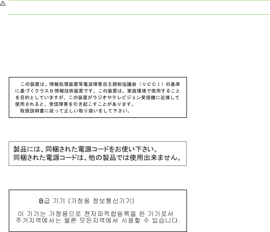
Safety statements
Laser safety
The Center for Devices and Radiological Health (CDRH) of the U.S. Food and Drug Administration has
implemented regulations for laser products manufactured since August 1, 1976. Compliance is
mandatory for products marketed in the United States. The device is certified as a “Class 1” laser product
under the U.S. Department of Health and Human Services (DHHS) Radiation Performance Standard
according to the Radiation Control for Health and Safety Act of 1968. Since radiation emitted inside the
device is completely confined within protective housings and external covers, the laser beam cannot
escape during any phase of normal user operation.
WARNING! Using controls, making adjustments, or performing procedures other than those specified
in this user guide may result in exposure to hazardous radiation.
Canadian DOC regulations
Complies with Canadian EMC Class B requirements.
« Conforme à la classe B des normes canadiennes de compatibilité électromagnétiques. « CEM ». »
VCCI statement (Japan)
Power cord statement (Japan)
EMI statement (Korea)
298 Appendix C Regulatory information ENWW
Laser statement for Finland
Luokan 1 laserlaite
Klass 1 Laser Apparat
HP LaserJet P2055d, P2055dn, P2055x , laserkirjoitin on käyttäjän kannalta turvallinen luokan 1
laserlaite. Normaalissa käytössä kirjoittimen suojakotelointi estää lasersäteen pääsyn laitteen
ulkopuolelle. Laitteen turvallisuusluokka on määritetty standardin EN 60825-1 (1994) mukaisesti.
VAROITUS !
Laitteen käyttäminen muulla kuin käyttöohjeessa mainitulla tavalla saattaa altistaa käyttäjän
turvallisuusluokan 1 ylittävälle näkymättömälle lasersäteilylle.
VARNING !
Om apparaten används på annat sätt än i bruksanvisning specificerats, kan användaren utsättas för
osynlig laserstrålning, som överskrider gränsen för laserklass 1.
HUOLTO
HP LaserJet P2055d, P2055dn, P2055x - kirjoittimen sisällä ei ole käyttäjän huollettavissa olevia
kohteita. Laitteen saa avata ja huoltaa ainoastaan sen huoltamiseen koulutettu henkilö. Tällaiseksi
huoltotoimenpiteeksi ei katsota väriainekasetin vaihtamista, paperiradan puhdistusta tai muita käyttäjän
käsikirjassa lueteltuja, käyttäjän tehtäväksi tarkoitettuja ylläpitotoimia, jotka voidaan suorittaa ilman
erikoistyökaluja.
VARO !
Mikäli kirjoittimen suojakotelo avataan, olet alttiina näkymättömällelasersäteilylle laitteen ollessa
toiminnassa. Älä katso säteeseen.
VARNING !
Om laserprinterns skyddshölje öppnas då apparaten är i funktion, utsättas användaren för osynlig
laserstrålning. Betrakta ej strålen. Tiedot laitteessa käytettävän laserdiodin säteilyominaisuuksista:
Aallonpituus 775-795 nm Teho 5 m W Luokan 3B laser.
ENWW Safety statements 299
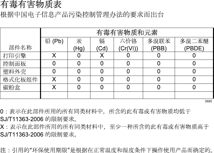
Substances Table (China)
300 Appendix C Regulatory information ENWW

Index
Symbols/Numerics
2ndary service menu 250
A
A6-size paper loading 40, 41
accessibility features 4, 5
accessories
available 4, 5
cables and interfaces 255
memory 255
ordering 254
paper-handling 255
part numbers 255
print cartridges 255
screws 257
whole units 256
acoustic specifications 293
after service checklist 100
alerts
E-mail 52
setting up 51
status 52, 215
viewing with HP
ToolboxFX 52
Alerts tab, HP ToolboxFX 52
anticounterfeit supplies 59
archive setting 27
automatic crossover, setting 28
B
bins, output
capacity 34, 37
locating 6, 9
selecting 44
blank pages
troubleshooting 248
block diagram 80
buttons, control panel 22
C
cables
USB, troubleshooting 248
Canadian DOC regulations 298
card stock
output bin, selecting 45
cartridge door
removing 127
replacing switch 137
cartridges
authentication 59
clean the area 69
drum rotation check 193
features 4, 5
genuine HP 59
non-HP 59, 218
order message 218, 225
part numbers 255
removing 102
replace message 218, 225
replacement intervals 59
replacing 62
status messages 22
status, viewing with HP
ToolboxFX 51
storage 59
supplies status page 24
warranty 283
cassette (Tray 2)
removing 103
checklists
after service 100
pre-troubleshooting 191
preservice 100
checks
components 196
drum rotation 193
half self-test 193
heating element 194
high-voltage power
supply 194
print-cartridge contacts 194
circuit diagram 208
cleaning
high-voltage contacts 194
paper path 70
pickup roller (Tray 1) 71
pickup roller (Tray 2) 75
print-cartridge area 69
printer 69
product 69
clearing jams
detection operations 94
duplex paper path 232
input trays 235
internal areas 230
locations 230
paper path 230
print-cartridge area 230
straight-through path 239
top output bin 239
Tray 1 235
Tray 2 236
Tray 3 238
See also jams
components
diagram 205
configuration page 24, 49, 193
connecting PCA
replacing 147
connectors
Engine controller 203
continuous self-test 193
control panel
about 22, 30
about messages 219
button test 250
buttons 22
ENWW Index 301
cleaning page, printing 70
display 22
display test 250
Ethernet reset 251
language 25
lights 22
locating 6, 9
menu map, printing 24
menus 23
messages 219
Network config. menu 28
Reports menu 24
Service menu 27
status-light patterns 209
System Setup menu 25
counterfeit supplies 59
Courier font settings 26
covers, removing
front 127
left 118
rear 120
right 115
top 124
curl, paper
settings 27
customer support
online 287
repacking product 288
D
DC controller 84
declaration of conformity 297
default settings, restoring 27,
251
Demo page 24, 48, 189
Device Information page
HP ToolboxFX 53
Device Settings tab, HP
ToolboxFX 53
diagrams
troubleshooting 202
See also part lists and diagrams
dimensions, product 292
DIMM door, removing 114
DIMMs
accessing 6
part numbers 255
verifying installation 67
doors, removing
cartridge 127
DIMM 114
rear 120
double-sided printing
paper loading orientation 38
drive components
diagrams 205
drivers
included 4, 5
paper types 33, 36
supported 13, 14
usage page 24
drum
rotation functional check 193
dual inline memory module (DIMM).
See DIMMs
duplex
paper loading orientation 38
paper path, jams 232
paper-feed assembly (duplex
model) replacing 177
paper-feed assembly,
removing 120
replacing solenoid (duplex
models) 180
E
E-mail alerts tab, HP
ToolboxFX 52
e-mail alerts, setting up 51
electrical specifications 292
electrostatic discharge (ESD) 98
embedded Web server (EWS)
about 14
links 58
Networking tab 58
opening 57
order supplies 58
product support 58
security 58
Settings tab 58
Status tab 57
using 57
engine
communication error
message 216
control system 80, 84
duplex test page 251
resets 251
simplex test page 251
test page 251
Engine controller
connectors 203
reinstalling 170
replacing unit 163
envelopes
loading orientation 38
output bin, selecting 45
environment for the product
problem-solving 247
specifications 293
error messages
error report 227
event log 227
lights, control panel 22
product 222
ESD (electrostatic discharge)
precaution during parts
removal 98
Ethernet cards, part
numbers 255
Event log
HP ToolboxFX 51
event log
messages 227
printing 227
EWS. See embedded Web server
(EWS)
extended warranty 289
F
face-down-drive assembly (base
model)
replacing 177
factory defaults, restoring 27
fan
error message 221
replacing 140
FastRes 4, 5
features
front view 6, 9
locate interface ports 8, 11
locate model and serial-number
label 8, 12
operations 80
product 4, 5
rear view 7, 10
user interface 4, 5
walkaround 6
Finnish laser safety
statement 299
302 Index ENWW
firmware version 251
fonts
Courier settings 26
included 4, 5
lists, printing 24
permanent resources 67
formatter PCA
replacing 132
replacing (base model) 130
fraud hotline 59
front cover, removing 127
fuser
assembly diagrams 205
errors 215, 220
reinstalling 162
replacing 158
G
garbled text 241
graphics
missing 242
poor quality 242
H
half self-test check 193
heating element check 194
heavy paper
output bin, selecting 45
Help tab, HP ToolboxFX 52
high-voltage PCA 84
high-voltage power supply,
checking 194
HP Customer Care 287
HP fraud hotline 59
HP Jetdirect print server
part numbers 255
HP postscript emulation Universal
Print Driver 13
HP Printer Utility
about 13
supported software 13, 14
HP SupportPack 289
HP ToolboxFX
about 14
Alerts tab 52
Device Information page 53
Device Settings tab 53
E-mail alerts tab 52
Event log 51
Help tab 52
Network Settings tab 55
opening 50
Paper Types settings 55
PCL5c settings 54
PCL6 settings 54
PostScript settings 54
Printing settings 54
Set up Status Alerts 52
Status tab 51
System Setup tab 55
Troubleshooting tab 55
using with product 50
HP Web Jetadmin
about 58
HP-UX software 15
humidity
problem-solving 247
specifications 293
I
image quality
archive setting 27
HP ToolboxFX settings 54
troubleshooting defects 202,
241
See also solving
image-formation system
block diagram 80
operations 90
testing 193
improve print quality 242
information pages
configuration page 49
Demo page 48
printing 48
product 48
Supplies Status page 49
inlet-cable assembly
replacing 150
input tray
loading media 40, 41
install supplies message 216,
222
installing
Macintosh software 13
product memory 64
Windows software 13
internal components 81
IP address
protocols supported 18, 19
ITB assembly
diagrams 205
J
jams
about 229
common causes of 229
detection operations 94, 95
error messages 215
location error messages 219
locations 230
print quality after 247
tracking number of 24
See also clearing jams
Japanese VCCI statement 298
Jetadmin, HP Web 14, 58
Jetdirect print server
part numbers 255
K
Korean EMI statement 298
L
labels
output bin, selecting 45
language, control panel 25
laser safety statements 298, 299
laser/scanner
failure detection 89
operations 80, 88
replacing assembly 156
left cover, removing 118
license, software 284
light patterns 209
lights, control panel 22
Linux software 15
loading media
A6-size paper 40, 41
error messages 225
optional Tray 3 41
Tray 1 39
Tray 2 40
location
settings dependant on 250
M
Macintosh
drivers supported 13, 14
support 287
main motor
replacing 174
ENWW Index 303
maintenance agreements 288
manual-feed printing 42
media
about using 31
curl settings 27
default settings 25, 54
feeding operations 94
HP ToolboxFX settings 53
loading 38
printing manually 42
supported by product 32, 34
supported sizes 32, 34
supported types 32, 34
media jams. See jams
memory
error messages 225
NVRAM initialization 251
part numbers 255
permanent resources 67
verifying installation 67
menus, control panel
accessing 23
map, printing 24, 190
Network config. 28
Reports 24
Service 27
System Setup 25
messages
lights, control panel 22
mispick error message 218
misprint error message 225
missing
graphics 242
text 242
model number 8, 12
models, feature comparison 2
N
Network config. menu 28
Network Settings tab, HP
ToolboxFX 55
Networking tab (embedded Web
server) 58
networks
configuration page 24
connectivity 17
HP Web Jetadmin 58
product discovery 17, 19
product management 57
protocols supported 17, 18
settings 28
settings report 24
software 14
supported port 5
next-day on-site service 288
noise specifications 293
non-HP supplies 59, 218
NVRAM initialization 251
O
on-site service agreements 288
on/off switch, locating 6, 9
online support 287
operating
environment 293
environment
specifications 293
system requirements 16
operations
block diagram 80
DC controller 85
engine control system 84
image-formation system 90
laser/scanner system 88
pickup/feed/delivery
system 94
product overview 80
sequence of 83
theory of 79
order supplies message 225
ordering
part numbers for 255
supplies and accessories 254
supplies message 218
orientation
paper, while loading 38
output quality
archive setting 27
HP ToolboxFX settings 54
P
packaging product 288
pad, removing separation 104
page count 24
page too complex error
message 218
pages
blank 248
not printing 248
printing slowly 248
paper
A6-size, tray adjustment 40,
41
about using 31
curl settings 27
default settings 25, 54
feeding operations 94
HP ToolboxFX settings 55
loading 38
loading orientation 38
problem-solving 247
size, selecting 43
supported by product 32, 34
supported sizes 32, 34
supported types 32, 33, 34,
36
type, selecting 43
paper jams. See jams
paper path
cleaning 70
paper jams 230
paper-feed-guide assembly
replacing 172
paper-pickup-gear assembly
reinstalling 135
replacing 134
paper-retaining-delivery assembly
replacing 181
parallel port
supported 5
part numbers
memory 255
print cartridges 255
screws 257
trays 255
parts 253
parts lists and diagrams
covers, panels, and doors 260
HP LaserJet P2035 260
HP LaserJet P2055 262
internal components 264,
266, 268, 270, 272
troubleshooting with 202
using 258
PCAs, diagrams 206
PCL
drivers 13
font list 24
settings, HP ToolboxFX 54
permanent resources 67
304 Index ENWW
photosensitive drum
rotation functional checks 193
physical specifications 292
pickup roller
Tray 1 71
Tray 1, removing 104
Tray 2 75
Tray 2, removing 107
pickup/feed/delivery system 80,
94
pliers, required 99
ports
supported 4, 5, 8, 11
post-service tests 101
postcards
output bin, selecting 45
PostScript settings, HP
ToolboxFX 54
power
high voltage supply 87
high-voltage PCA 84
low voltage supply 86
supplies diagrams 205
switch, locating 6, 9
testing high-voltage 194
troubleshooting 186, 188
power specifications 292
power-switch assembly
replacing 144
pre-troubleshooting checklist 191
preservice checklist 100
print cartridges
authentication 59
clean the area 69
features 4, 5
genuine HP 59
non-HP 59, 218
order message 218, 225
paper jams in area 230
part numbers 255
redistributing toner 61
removing 102
replace message 218, 225
replacement intervals 59
replacing 62
status messages 22
status, viewing with HP
ToolboxFX 51
storage 59
supplies status page 24
warranty 283
print failure error message 219
print quality
archive setting 27
creases 245
curl 245
different from onscreen 241
dropouts 243
environment 247
gray background 243
HP ToolboxFX settings 54
improve 242
jams, after 247
light or faded print 242
loose toner 244
misformed characters 244
page skew 245
paper 247
problem-solving 247
toner scatter outline 246
toner smear 244
toner specks 243
troubleshooting image
defects 241
vertical lines 243
vertical repetitive defects 244
wave 245
wrinkles 245
print-quality test 101
printing
configuration page 49
Demo page 48
manual feed 42
Supplies Status page 49
troubleshooting 248
Printing settings
HP ToolboxFX 54
problem-solving
environment 247
paper 247
See also troubleshooting
processor speed 4, 5
product
about removal and
replacement 98
comparison 2, 3
declaration of conformity 297
maintenance 47
management 47
registration 55
regulatory information 295
removal of parts 97
replacement of parts 97
safety statements 298
service 281
specifications 291
support 281
product discovery over
network 17, 19
product error message 222
ProRes 4
protocols, networks 17, 18
PS font list 24
Q
quality
archive setting 27
HP ToolboxFX settings 54
troubleshooting repetitive image
defects 202
quiet mode
enabling 25
R
rear cover, removing 120
rear door, removing 120
rear output
bin, locating 6, 9
printing to 45
redistributing toner 61
registration
product 55
replacing assembly 152
removing parts
cartridge door 127
cartridge door, reinstall
after 129
cautions for 98
checklists 100
DIMM door 114
duplex-paper-feed
assembly 120
front cover 127
front cover, reinstall after 129
left cover 118
panels, covers, and doors 114
pickup roller (Tray 1) 104
pickup roller (Tray 2) 107
print cartridges 102
ENWW Index 305
rear cover 120
rear door 120
right cover 115
right cover, reinstall after 117
separation pad assembly 110
tools, required 99
top-cover assembly 124
transfer roller 111
Tray 2 cassette 103
repacking product 288
repetitive defects,
troubleshooting 202
replace supplies message 218,
225
replacing
cartridge-door switch 137
connecting PCA 147
duplex solenoid (duplex
models) 180
duplexing-paper-feed assembly
(duplex model) 177
engine controller unit 163
face-down-drive assembly
(base model) 177
fan 140
formatter PCA 132
formatter PCA, base
model 130
fuser 158
guidelines 61
inlet-cable assembly 150
internal assemblies 130
laser/scanner assembly 156
main motor 174
paper-feed-guide
assembly 172
paper-pickup-gear
assembly 134
paper-retaining-delivery
assembly 181
parts 98
power-switch assembly 144
registration assembly 152
reverse-sensor assembly
(duplex models) 142
Tray 1 pickup solenoid 138
whole units 256
replacing printing cartridges 62
reports
error 227, 250
information pages, status, and
lists 48
printing 48
service 250
Reports menu 24
resolution
features 4, 5
problem-solving quality 247
resource saving 67
restoring default settings 27,
251
reverse-sensor assembly (duplex
models)
replacing 142
right cover, removing 115
rollers, pickup
locating 81
removing 104
rotation check, drum 193
rough paper
output bin, selecting 45
S
safety statements 298, 299
saving resources, memory 67
scanner error message 215
screwdrivers, required 99
screws
part numbers 257
replacing 98
secondary service menu 250
security features 58
sensors, media detection 94
separation pad assembly,
removing 110
sequence of operations 83
serial number 8, 12
service
agreements 288
error message 222
page 24
repacking product 288
tools, required 99
Service menu
about 250
functions 250
opening 250
secondary 250
settings
HP ToolboxFX 53
network report 24
restoring defaults 27, 251
System Setup menu 25
Settings tab (embedded Web
server) 58
shipping
lock error message 225
product 288
SIMMs, incompatibility 64
single inline memory module
(SIMM), incompatibility 64
sizes, media
default, setting 25
small paper, printing on 45
software
additional provided 14
components 13
embedded Web server 14
HP Web Jetadmin 14, 58
Macintosh 13
network 14
requirements (Macintosh) 16
requirements (Windows) 16
software license
agreement 284
status alerts 14
supported by product 13
Windows 14
Solaris software 15
solving
creases 245
curl 245
dropouts 243
gray background 243
light or faded print 242
loose toner 244
misformed characters 244
page skew 245
toner scatter outline 246
toner smear 244
toner specks 243
vertical lines 243
vertical repetitive defects 244
wave 245
wrinkles 245
specifications
acoustic 293
electrical 292
features 4, 5
operating environment 293
306 Index ENWW
physical 292
product 291
static precautions 98
status
alerts, HP ToolboxFX 51
light patterns 209
page 193
supplies, control panel
messages 22
supplies, printing report 24
viewing with HP
ToolboxFX 51
Status tab (embedded Web
server) 57
Status tab, HP ToolboxFX 51
storing
print cartridges 59
straight-through paper path
paper jams 239
supplies
authentication 59
counterfeit 59
management 59
non-HP 59, 218
order message 218, 225
ordering 55, 254
part numbers 255
print cartridge 59
replace message 218, 225
replacement intervals 59
replacing parts 61
replacing print cartridges 62
shipping lock error
message 225
status page 24
status, control panel
messages 22
status, viewing with HP
ToolboxFX 51
Supplies Status page 49
support
online 55, 287
repacking product 288
supported media 32, 34
SupportPack, HP 289
System Setup menu 25
System Setup tab, HP
ToolboxFX 55
T
table, repetitive defect 202
TCP/IP
protocols supported 17, 18
settings 28
technical support
online 287
repacking product 288
temperature specifications 293
tests
button 250
continuous self-test 193
display 250
drum rotation 193
duplex engine 251
engine 251
half self-test check 193
heating element 194
high-voltage power
supply 194
post-service 101
print-quality 101
simplex engine 251
text
garbled 241
missing 242
timing chart 207
toner
loose toner 244
low 242
redistributing 61
scatter outline 246
smear 244
specks 70, 243
toner cartridges. See print
cartridges
tools, required 99
top output bin
capacity 34, 37
locating 6, 9
paper jams 239
printing to 44
top-cover assembly,
removing 124
transfer roller
removing 111
transparencies
output bin 44
Tray 1
capacity 34, 37
loading 39
paper jams 235
replacing pickup solenoid 138
settings 25
Tray 2
capacity 34, 37
cassette, removing 103
loading 40
paper jams 236
settings 25
Tray 2 cassette
removing 103
Tray 3
capacity 34
loading 41
paper jams 238
physical specifications 292
trays
capacity 34, 37
configuring 43
feeding operations 94
load error messages 225
loading print media 38
locating 6, 9
paper orientation 38
part numbers 255
settings 25, 54
troubleshooting
basic steps 188
blank pages 242, 248
checklist 186, 191
cleaning product 69
configuration page 193
Demo page 189
diagrams 202
direct-connect
problems 249
drum rotation check 193
event log 193
garbled text 241
general problems 186
half self-test 193
heating element 194
image defects 241
image formation 193
image quality 247
incomplete text 241
missing graphics or text 242
network problems 249
output quality 247
ENWW Index 307
overview 185
pages not printing 248
pages printing slowly 248
paper 247
paper jams 229, 230, 235,
236, 239
paper pickup (Tray 1) 71
paper pickup (Tray 2) 75
poor graphics quality 242
power 188
process 191
product environment 247
product performance 187
reports and tools 193
status page 193
status-light patterns 209
toner specks 70
USB cables 248
See also solving; tests; checks
Troubleshooting tab
HP ToolboxFX settings 55
types, media
HP ToolboxFX settings 55
U
UNIX software 15
usage page 24
USB cable, part number 255
USB port
speed settings 27
supported 4, 5
troubleshooting 248
W
warranty
customer self repair 286
extended 289
license 284
print cartridges 283
product 282
Web server, embedded. See
embedded Web server (EWS)
Web sites
customer support 287
fraud reports 59
HP Web Jetadmin,
downloading 58
Macintosh customer
support 287
ordering supplies 254
weekly on-site service 288
weight, product 292
Windows
drivers supported 13
software for 14
308 Index ENWW

© 2008 Hewlett-Packard Development Company, L.P.
www.hp.com
*CE457-90980*
*CE457-90980*
CE457-90980
