HP LaserJet Pro 200 Color MFP Troubleshooting Manual ENWW Laser Jet M276 Service (2463K)
User Manual: HP LaserJet Pro 200 color MFP M276 - Troubleshooting Service Manual (2463K) shared.swissparts.ch - /Manuals/HP/LaserJet/Mono Laserjet/
Open the PDF directly: View PDF ![]() .
.
Page Count: 186 [warning: Documents this large are best viewed by clicking the View PDF Link!]
- Theory of operation
- Basic operation
- Engine control system
- Laser/scanner system
- Image-formation system
- Pickup-and-feed system
- Scanner system (base models)
- Fax functions and operation (fax models only)
- USB Flash Drive
- Solve problems
- Solve problems checklist
- Menu map
- Troubleshooting process
- Tools for troubleshooting
- Component diagnostics
- Diagrams
- Internal print-quality test pages
- Print-quality troubleshooting tools
- Control panel menus
- Interpret control panel messages
- Control panel message types
- Control panel messages
- 10.X00Y Supply Error
- 49 Error, Turn off then on
- 50.x Fuser Error
- 51.XX Error
- 54.XX Error
- 55.X Error
- 57 Fan Error, Turn off then on
- 59.X Error
- 79 Error Turn off then on
- Black Cartridge Low
- Black in wrong position
- Black Very Low
- Cleaning
- Cyan Cartridge Low
- Cyan in wrong position
- Cyan Very Low
- Device error, press OK
- Door open
- Genuine HP supply installed
- Incompatible <color>
- Incorrect supplies
- Install <color> cartridge
- Invalid driver Press [OK]
- Jam in Tray 1, Clear jam and then press OK
- Load tray 1 Press [OK] for available media
- Load Tray 1 <TYPE> <SIZE>, Press OK to use available media
- Load Tray 1, <PLAIN> <SIZE> / Cleaning mode, OK to start
- Magenta Cartridge Low
- Magenta in wrong position
- Magenta Very Low
- Manual Duplex Load Tray 1, Press OK
- Memory is low. Press OK.
- Misprint, Press OK
- Print failure, press OK. If error repeats, turn off then on.
- Rear door open
- Remove shipping lock from <color> cartridge
- Remove shipping locks from cartridges
- Replace <color>
- Supplies low
- Unexpected size in tray 1 Load <size> Press [OK]
- Unsupported <color> Press [OK] to continue
- Used <color> in use
- Used <color> installed, to accept press OK
- Used supplies in use
- Yellow Cartridge Low
- Yellow in wrong position
- Yellow Very Low
- Event-log messages
- Clear jams
- Solve paper-handling problems
- Solve image quality problems
- Solve performance problems
- Solve product connectivity problems
- Solve direct-connect problems
- Solve network problems
- Poor physical connection
- The computer is using the incorrect IP address for the product
- The computer is unable to communicate with the product
- The product is using incorrect link and duplex settings for the network
- New software programs might be causing compatibility problems
- The computer or workstation might be set up incorrectly
- The product is disabled, or other network settings are incorrect
- Solve wireless network problems
- Wireless connectivity checklist
- The control panel displays the message: The wireless feature on this product has been turned off
- The product does not print after the wireless configuration completes
- The product does not print, and the computer has a third-party firewall installed
- The wireless connection does not work after moving the wireless router or product
- Cannot connect more computers to the wireless product
- The wireless product loses communication when connected to a VPN
- The network does not appear in the wireless networks list
- The wireless network is not functioning
- Service mode functions
- Solve fax problems
- Fax troubleshooting checklist
- Solve problems receiving faxes
- The fax does not respond
- The fax has a dedicated phone line
- An answering machine is connected to the product
- A telephone handset is connected to the product
- The Answer Mode setting is set to the Manual setting
- Voice mail is available on the fax line
- The product is connected to a DSL phone service
- The product uses a fax over IP or VoIP phone service
- An error message displays on the control panel
- A fax is received but does not print
- Sender receives a busy signal
- No dial tone
- Fax cuts off or prints on two pages
- The fax does not respond
- Solve problems sending faxes
- An error message displays on the control panel
- The control panel displays a Ready message with no attempt to send the fax
- The control panel displays the message "Storing page 1" and does not progress beyond that message
- Faxes can be received, but not sent
- Unable to use fax functions from the control panel
- Unable to use speed dials
- Unable to use group dials
- Receive a recorded error message from the phone company when trying to send a fax
- Unable to send a fax when a phone is connected to the product
- Solve fax performance problems
- Solve DSL problems
- Product updates
- Service and support
- Product specifications
- Regulatory information
- FCC regulations
- Environmental product stewardship program
- Protecting the environment
- Ozone production
- Power consumption
- Paper use
- Plastics
- HP LaserJet print supplies
- Return and recycling instructions
- Paper
- Material restrictions
- Disposal of waste equipment by users in private households in the European Union
- Chemical substances
- Material Safety Data Sheet (MSDS)
- For more information
- Declaration of conformity
- Declaration of conformity (wireless model)
- Certificate of Volatility
- Safety statements
- Additional statements for telecom (fax) products
- Additional statements for wireless products
- Index
LASERJET PRO 200 COLOR MFP
Troubleshooting Manual
M276

HP LaserJet Pro 200 color MFP M276
Series
Troubleshooting Manual
Copyright and License
© 2012 Copyright Hewlett-Packard
Development Company, L.P.
Reproduction, adaptation, or translation
without prior written permission is
prohibited, except as allowed under the
copyright laws.
The information contained herein is subject
to change without notice.
The only warranties for HP products and
services are set forth in the express warranty
statements accompanying such products and
services. Nothing herein should be
construed as constituting an additional
warranty. HP shall not be liable for technical
or editorial errors or omissions contained
herein.
Part number: CF144-90996
Edition 1, 9/2012
Trademark Credits
Microsoft®, Windows®, Windows® XP,
and Windows Vista® are U.S. registered
trademarks of Microsoft Corporation.
ENERGY STAR and the ENERGY STAR mark
are registered U.S. marks.

Conventions used in this guide
TIP: Tips provide helpful hints or shortcuts.
NOTE: Notes provide important information to explain a concept or to complete a task.
CAUTION: Cautions indicate procedures that you should follow to avoid losing data or damaging
the product.
WARNING! Warnings alert you to specific procedures that you should follow to avoid personal
injury, catastrophic loss of data, or extensive damage to the product.
ENWW iii
iv Conventions used in this guide ENWW

Table of contents
1 Theory of operation .......................................................................................................... 1
Basic operation ........................................................................................................................ 2
Major product systems ............................................................................................... 2
Product components .................................................................................................. 3
Sequence of operation ............................................................................................... 4
Engine control system ............................................................................................................... 5
DC controller ............................................................................................................ 6
Low-voltage power supply .......................................................................................... 7
High-voltage power supply ......................................................................................... 8
Laser/scanner system ............................................................................................................... 9
Laser failure detection ................................................................................................ 9
Image-formation system ........................................................................................................... 10
Image-formation process .......................................................................................... 10
Latent-image formation stage .................................................................................... 11
Step 1: primary charging .......................................................................... 12
Step 2: laser-beam exposure ..................................................................... 12
Developing stage .................................................................................................... 12
Step 3: development ................................................................................. 13
Transfer stage ......................................................................................................... 14
Step 4: primary transfer ............................................................................ 14
Step 5: secondary transfer ......................................................................... 14
Step 6: separation from the ITB .................................................................. 15
Fusing stage ........................................................................................................... 15
Step 7: fusing .......................................................................................... 15
ITB cleaning stage ................................................................................................... 16
Step 8: ITB cleaning ................................................................................. 16
Drum cleaning stage ................................................................................................ 17
Step 9: drum cleaning .............................................................................. 17
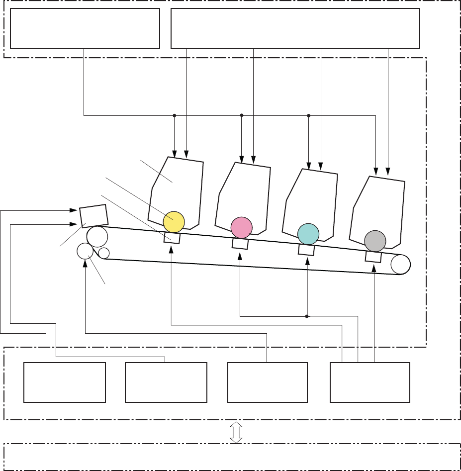
Pickup-and-feed system ........................................................................................................... 18
Jam detection ......................................................................................................... 19
Scanner system (base models) ................................................................................................. 20
Scanner power-on sequence of events ....................................................................... 20
ENWW v
Copy or scan-to-computer sequence of events ............................................................. 21
Fax functions and operation (fax models only) ........................................................................... 22
Computer and network security features ..................................................................... 22
PSTN operation ...................................................................................................... 22
Receive faxes when you hear fax tones ...................................................................... 22
Distinctive ring function ............................................................................................ 23
Fax by using Voice over IP services ........................................................................... 23
The fax subsystem ................................................................................................... 24
Fax card in the fax subsystem ................................................................................... 24
Safety isolation ........................................................................................ 24
Safety-protection circuitry .......................................................................... 25
Data path ................................................................................................ 25
Hook state ............................................................................................... 25
Downstream device detection .................................................................... 26
Hook switch control .................................................................................. 26
Ring detect .............................................................................................. 26
Line current control ................................................................................... 26
Billing- (metering-) tone filters ..................................................................... 26
Fax page storage in flash memory ............................................................................ 26
Stored fax pages ...................................................................................... 27
Advantages of flash memory storage .......................................................... 27
USB Flash Drive ..................................................................................................................... 28
2 Solve problems ............................................................................................................... 29
Solve problems checklist ......................................................................................................... 30
Menu map ............................................................................................................................ 32
Troubleshooting process .......................................................................................................... 32
Pre-troubleshooting checklist ..................................................................................... 32
Power-on checks ..................................................................................................... 34
Tools for troubleshooting ......................................................................................................... 35
Component diagnostics ............................................................................................ 35
LED diagnostics ........................................................................................ 35
Network LEDs ........................................................................... 35
Control panel LEDs .................................................................... 36
Control-panel diagnostics .......................................................................... 37
Engine Diagnostics ................................................................................... 37
Engine test ................................................................................ 37
Diagrams ............................................................................................................... 38
Plug/jack locations ................................................................................... 38
DC controller PCA .................................................................................... 39
Locations of major components .................................................................. 41
vi ENWW
General timing charts ............................................................................... 43
General circuit diagram ............................................................................ 44
Internal print-quality test pages .................................................................................. 44
Interpret the Print Quality Page ................................................................... 44
Print a cleaning page ............................................................................... 45
Print a cleaning page ................................................................ 45
Configuration page .................................................................................. 46
Print a configuration page .......................................................... 46
Print-quality troubleshooting tools .............................................................................. 46
Repetitive image defects ............................................................................ 46
Calibrate the product to align the colors ...................................................... 47
Control panel menus ................................................................................................ 48
Setup Menu ............................................................................................. 48
HP Web Services ...................................................................... 48
Reports menu ............................................................................ 49
Self Diagnostics menu ................................................................ 50
Fax Setup menu ........................................................................ 50
System Setup menu .................................................................... 53
Service menu ............................................................................ 57
Network Setup menu ................................................................. 59
Quick Forms menu .................................................................... 60
Function specific menus ............................................................................. 61
USB Flash Drive ........................................................................ 61
Fax Menu ................................................................................. 61
Copy Menu .............................................................................. 63
Scan Menu ............................................................................... 65
Apps ....................................................................................... 66
Interpret control panel messages ............................................................................... 67
Control panel message types ..................................................................... 67
Control panel messages ............................................................................ 67
10.X00Y Supply Error ................................................................ 67
49 Error, Turn off then on ........................................................... 68
50.x Fuser Error ........................................................................ 68
51.XX Error .............................................................................. 68
54.XX Error .............................................................................. 68
55.X Error ................................................................................ 69
57 Fan Error, Turn off then on ..................................................... 69
59.X Error ................................................................................ 69
79 Error Turn off then on ............................................................ 70
Black Cartridge Low .................................................................. 70
Black in wrong position .............................................................. 70
ENWW vii
Black Very Low ......................................................................... 70
Cleaning .................................................................................. 71
Cyan Cartridge Low .................................................................. 71
Cyan in wrong position .............................................................. 71
Cyan Very Low ......................................................................... 71
Device error, press OK .............................................................. 72
Door open ................................................................................ 72
Genuine HP supply installed ....................................................... 72
Incompatible <color> ................................................................. 72
Incorrect supplies ...................................................................... 72
Install <color> cartridge ............................................................. 73
Invalid driver Press [OK] ............................................................ 73
Jam in Tray 1, Clear jam and then press OK ................................ 73
Load tray 1 Press [OK] for available media .................................. 73
Load Tray 1 <TYPE> <SIZE>, Press OK to use available media ....... 73
Load Tray 1, <PLAIN> <SIZE> / Cleaning mode, OK to start ......... 73
Magenta Cartridge Low ............................................................. 74
Magenta in wrong position ........................................................ 74
Magenta Very Low .................................................................... 74
Manual Duplex Load Tray 1, Press OK ........................................ 74
Memory is low. Press OK. .......................................................... 75
Misprint, Press OK ..................................................................... 75
Print failure, press OK. If error repeats, turn off then on. ................. 75
Rear door open ......................................................................... 75
Remove shipping lock from <color> cartridge ............................... 76
Remove shipping locks from cartridges ........................................ 76
Replace <color> ....................................................................... 76
Supplies low ............................................................................. 76
Unexpected size in tray 1 Load <size> Press [OK] ........................ 76
Unsupported <color> Press [OK] to continue ................................. 77
Used <color> in use .................................................................. 77
Used <color> installed, to accept press OK .................................. 77
Used supplies in use .................................................................. 77
Yellow Cartridge Low ................................................................ 77
Yellow in wrong position ............................................................ 78
Yellow Very Low ....................................................................... 78
Event-log messages ................................................................................................. 79
Clear jams ............................................................................................................................ 85
Jam locations .......................................................................................................... 85
Clear jams from the document feeder ........................................................................ 86
Clear jams in the paper input tray ............................................................................. 87
viii ENWW
Clear jams from the output bin .................................................................................. 89
Clear jams from the rear door ................................................................................... 89
Solve paper-handling problems ................................................................................................ 91
The product picks up multiple sheets of paper ............................................................. 91
The product does not pick up paper .......................................................................... 91
Solve image quality problems .................................................................................................. 92
Use the correct paper type setting in the printer driver ................................................. 92
Change the paper type setting for Windows ................................................ 92
Change the paper type setting for Mac ....................................................... 92
Adjust color settings in the printer driver ..................................................................... 93
Change the color theme for a print job ....................................................... 93
Change the color options .......................................................................... 94
Use paper that meets HP specifications ...................................................................... 94
Print a cleaning page .............................................................................................. 95
Calibrate the product to align the colors .................................................................... 95
Check the toner cartridges ........................................................................................ 96
Print the Supplies Status page .................................................................... 96
Inspect the print cartridge for damage ........................................................ 96
Repeating defects ..................................................................................... 97
Use the printer driver that best meets your printing needs ............................................. 97
Solve performance problems ................................................................................................... 99
Factors affecting print performance ........................................................................... 99
Print speeds ........................................................................................... 100
The product does not print or it prints slowly ............................................................. 101
The product does not print ....................................................................... 101
The product prints slowly ......................................................................... 102
Solve product connectivity problems ....................................................................................... 103
Solve direct-connect problems ................................................................................. 103
Solve network problems ......................................................................................... 103
Poor physical connection ......................................................................... 103
The computer is using the incorrect IP address for the product ...................... 103
The computer is unable to communicate with the product ............................ 104
The product is using incorrect link and duplex settings for the network .......... 104
New software programs might be causing compatibility problems ................ 104
The computer or workstation might be set up incorrectly .............................. 104
The product is disabled, or other network settings are incorrect .................... 104
Solve wireless network problems ............................................................................. 105
Wireless connectivity checklist ................................................................. 105
The control panel displays the message: The wireless feature on this product
has been turned off ................................................................................ 106
The product does not print after the wireless configuration completes ............ 106
ENWW ix
The product does not print, and the computer has a third-party firewall
installed ................................................................................................ 106
The wireless connection does not work after moving the wireless router or
product ................................................................................................. 106
Cannot connect more computers to the wireless product .............................. 107
The wireless product loses communication when connected to a VPN ........... 107
The network does not appear in the wireless networks list ........................... 107
The wireless network is not functioning ...................................................... 108
Service mode functions ......................................................................................................... 109
Secondary service menu ........................................................................................ 109
Open the secondary service menu ............................................................ 109
Secondary service menu structure ............................................................. 109
Product resets ....................................................................................................... 110
Restore the factory-set defaults ................................................................. 111
NVRAM initialization .............................................................................. 111
Solve fax problems ............................................................................................................... 112
Fax troubleshooting checklist .................................................................................. 112
Solve problems receiving faxes ............................................................................... 114
The fax does not respond ........................................................................ 114
The fax has a dedicated phone line ........................................... 114
An answering machine is connected to the product ..................... 114
A telephone handset is connected to the product ......................... 115
The Answer Mode setting is set to the Manual setting ................... 115
Voice mail is available on the fax line ........................................ 115
The product is connected to a DSL phone service ........................ 116
The product uses a fax over IP or VoIP phone service ................... 116
An error message displays on the control panel ......................................... 117
The No fax detected. message displays ..................................... 117
The Communication error. message displays .............................. 117
The Fax storage is full. message displays ................................... 118
The Fax is busy. message displays ............................................ 118
A fax is received but does not print .......................................................... 119
The Private Receive feature is on ............................................... 119
Sender receives a busy signal .................................................................. 119
A handset is connected to the product ........................................ 119
A phone line splitter is being used ............................................. 119
No dial tone .......................................................................................... 119
Fax cuts off or prints on two pages ........................................................... 120
Solve problems sending faxes ................................................................................. 120
An error message displays on the control panel ......................................... 121
The Communication error. message displays .............................. 121
xENWW
No dial tone. .......................................................................... 121
The Fax is busy. message displays ............................................ 122
The No fax answer. message displays ....................................... 122
Document feeder paper jam ..................................................... 123
The Fax storage is full. message displays ................................... 123
Scanner error ......................................................................... 123
The control panel displays a Ready message with no attempt to send the fax . 124
The control panel displays the message "Storing page 1" and does not
progress beyond that message ................................................................. 124
Faxes can be received, but not sent .......................................................... 124
Unable to use fax functions from the control panel ...................................... 125
Unable to use speed dials ....................................................................... 125
Unable to use group dials ....................................................................... 125
Receive a recorded error message from the phone company when trying to
send a fax ............................................................................................. 126
Unable to send a fax when a phone is connected to the product .................. 126
Solve fax performance problems ............................................................................. 127
Faxes are sending slowly ........................................................................ 127
Fax quality is poor ................................................................................. 128
Solve DSL problems ............................................................................................... 128
Cannot send or receive a fax on a PBX line ............................................... 128
Product updates ................................................................................................................... 128
Appendix A Service and support ..................................................................................... 129
Hewlett-Packard limited warranty statement ............................................................................. 130
HP's Premium Protection Warranty: LaserJet print cartridge limited warranty statement .................. 132
Data stored on the print cartridge ........................................................................................... 133
End User License Agreement .................................................................................................. 134
OpenSSL ............................................................................................................................. 136
Customer support ................................................................................................................. 136
Repack the product .............................................................................................................. 137
Appendix B Product specifications ................................................................................... 139
Physical specifications .......................................................................................................... 140
Power consumption, electrical specifications, and acoustic emissions .......................................... 140
Environmental specifications .................................................................................................. 140
Appendix C Regulatory information ................................................................................. 141
FCC regulations ................................................................................................................... 142
Environmental product stewardship program ........................................................................... 143
Protecting the environment ...................................................................................... 143
ENWW xi
Ozone production ................................................................................................. 143
Power consumption ............................................................................................... 143
Paper use ............................................................................................................. 143
Plastics ................................................................................................................. 143
HP LaserJet print supplies ....................................................................................... 143
Return and recycling instructions ............................................................................. 144
United States and Puerto Rico .................................................................. 144
Multiple returns (more than one cartridge) .................................. 144
Single returns .......................................................................... 144
Shipping ................................................................................ 144
Non-U.S. returns .................................................................................... 145
Paper .................................................................................................................. 145
Material restrictions ............................................................................................... 145
Disposal of waste equipment by users in private households in the European Union ...... 146
Chemical substances ............................................................................................. 146
Material Safety Data Sheet (MSDS) ......................................................................... 146
For more information ............................................................................................. 146
Declaration of conformity ...................................................................................................... 147
Declaration of conformity (wireless model) .............................................................................. 149
Certificate of Volatility .......................................................................................................... 151
Safety statements ................................................................................................................. 152
Laser safety .......................................................................................................... 152
Canadian DOC regulations .................................................................................... 152
VCCI statement (Japan) .......................................................................................... 152
Power cord instructions .......................................................................................... 152
Power cord statement (Japan) ................................................................................. 152
EMC statement (Korea) .......................................................................................... 153
Laser statement for Finland ..................................................................................... 153
GS statement (Germany) ........................................................................................ 153
Substances Table (China) ....................................................................................... 154
Restriction on Hazardous Substances statement (Turkey) ............................................. 154
Additional statements for telecom (fax) products ....................................................................... 155
EU Statement for Telecom Operation ....................................................................... 155
New Zealand Telecom Statements ........................................................................... 155
Additional FCC statement for telecom products (US) .................................................. 155
Telephone Consumer Protection Act (US) .................................................................. 156
Industry Canada CS-03 requirements ...................................................................... 156
Additional statements for wireless products .............................................................................. 158
FCC compliance statement—United States ................................................................ 158
Australia statement ................................................................................................ 158
Brazil ANATEL statement ........................................................................................ 158
xii ENWW
Canadian statements ............................................................................................. 158
European Union regulatory notice ........................................................................... 158
Notice for use in France ......................................................................................... 159
Notice for use in Russia ......................................................................................... 159
Korean statement .................................................................................................. 159
Taiwan statement .................................................................................................. 160
Index ............................................................................................................................... 161
ENWW xiii
xiv ENWW

List of tables
Table 1-1 Sequence of operation ............................................................................................................ 4
Table 2-1 DC controller connectors ....................................................................................................... 39
Table 2-2 Major components ............................................................................................................... 41
Table 2-3 Repetitive image defects ........................................................................................................ 46
Table 2-4 Event-log messages ............................................................................................................... 79
Table 2-5 Fax event log codes .............................................................................................................. 84
Table 2-6 Secondary service menu ...................................................................................................... 109
Table B-1 Physical specifications ......................................................................................................... 140
Table B-2 Environmental specifications
1
............................................................................................... 140
ENWW xv
xvi ENWW

List of figures
Figure 1-1 Product systems ..................................................................................................................... 2
Figure 1-2 Product components ............................................................................................................... 3
Figure 1-3 Engine control system components ........................................................................................... 5
Figure 1-4 DC controller circuit diagram .................................................................................................. 6
Figure 1-5 Low-voltage power supply ...................................................................................................... 7
Figure 1-6 High-voltage power supply ..................................................................................................... 8
Figure 1-7 Laser/scanner system ............................................................................................................. 9
Figure 1-8 Image-formation system ........................................................................................................ 10
Figure 1-9 Image-formation process ...................................................................................................... 11
Figure 1-10 Primary charging ............................................................................................................... 12
Figure 1-11 Laser-beam exposure ......................................................................................................... 12
Figure 1-12 Development ..................................................................................................................... 13
Figure 1-13 Primary transfer ................................................................................................................. 14
Figure 1-14 Secondary transfer ............................................................................................................ 14
Figure 1-15 Separation from the ITB ...................................................................................................... 15
Figure 1-16 Fusing .............................................................................................................................. 15
Figure 1-17 ITB cleaning ...................................................................................................................... 16
Figure 1-18 Drum cleaning .................................................................................................................. 17
Figure 1-19 Pickup-and-feed system ....................................................................................................... 18
Figure 2-1 DC controller connectors ...................................................................................................... 39
Figure 2-2 Major components .............................................................................................................. 41
Figure 2-3 Timing diagram ................................................................................................................... 43
Figure 2-4 Circuit diagram ................................................................................................................... 44
ENWW xvii
xviii ENWW

1 Theory of operation
This chapter presents an overview of the major components of the product, and includes a detailed
discussion of the image-formation system.
●Basic operation
●Engine control system
●Laser/scanner system
●Image-formation system
●Pickup-and-feed system
●Scanner system (base models)
●Fax functions and operation (fax models only)
●USB Flash Drive
ENWW 1

Basic operation
Major product systems
The product includes the following systems:
●Engine control system
●Laser/scanner system
●Image-formation system
●Pickup-and-feed system
Figure 1-1 Product systems
PICKUP-AND-FEED SYSTEM
LASER/SCANNER SYSTEM
ENGINE CONTROL
SYSTEM IMAGE-FORMATION SYSTEM
2 Chapter 1 Theory of operation ENWW
Product components
Figure 1-2 Product components
123 4
6
7
8
10
12
13
5
14 9
11
Item Description Item Description
1 Fuser unit 8 Cassette
2 Delivery roller 9 Pickup roller
3 ITB drive roller 10 Separation roller
4 Photosensitive drum 11 Registration roller
5 Laser scanner assembly 12 Secondary transfer roller
6 Transfer pad 13 Fusing film
7 Intermediate transfer belt (ITB) 14 Pressure roller
ENWW Basic operation 3

Sequence of operation
Table 1-1 Sequence of operation
Period Duration Purpose Remarks
WAIT From the time the power is
turned on or the door is
closed, until the printer is
ready for a print operation
Clears the potential from the
drum surface, adjusts the
drum phase, and cleans the
ITB
Detects the cartridge
presence and environment;
completes any required
calibration (color registration
control and image stability)
STBY (Standby period) From end of the WAIT or
LSTR period until either the
print command is received
from the formatter or the
power is turned off
Maintains the printer in
readiness for a print
command
The printer enters sleep mode
when the formatter sends a
sleep command, and
performs color registration
and image stability control
when the formatter sends
those commands
INTR (Initial rotation) From the time the print
command is received until the
media is picked up
Prepares the photosensitive
drum for printing
PRINT From the end of INTR period
until the fuser paper sensor
detects the trailing edge of
paper
Forms the images on the
photosensitive drum and
transfers the toner image to
the print media
Performs image stabilization
at a specified print interval or
at specified times
LSTR (Last rotation) From the end of the PRINT
period until the delivery motor
stops rotating
Moves the printed sheet out
of the printer
The printer enters the INTR
period as soon as the
formatter sends another print
command
4 Chapter 1 Theory of operation ENWW

Engine control system
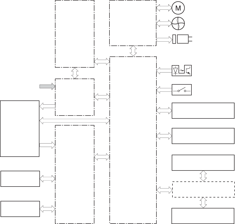
The engine control system coordinates all printer functions and drives the other three systems.
The engine control system contains the DC controller, high-voltage power-supply PCA, low-voltage
power-supply unit, and fuser control.
Figure 1-3 Engine control system components
DC controller
Image-formation system
Low-voltage power supply
Fuser control
High-voltage power supply
Formatter
Engine-control system Laser scanner system
Pickup, feed and delivery
system
ENWW Engine control system 5
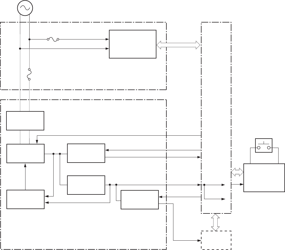
DC controller
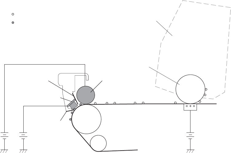
Figure 1-4 DC controller circuit diagram
Motor
Fan
Solenoid
Photointerrupter
ITB assembly
DC controller
Driver
AC input
Fuser
T2 roller
Cartridge
Low-voltage
power supply
Fuser
power supply
High-voltage
power supply
Laser scanner assembly
Formatter
USB (NOTE)
Control panel
Switch
6 Chapter 1 Theory of operation ENWW
Low-voltage power supply
Figure 1-5 Low-voltage power supply
+24VA
+24VR REM24V
+24VA
DC controller
+24V
generation
circuit
+3.3V
generation
circuit
Protection
circuit
Rectifying
circuit
Fuser control
circuit
Power switch
control circuit
AC input
Low-voltage power supply
Fuser power supply
Fuse
FU901
Fuse
FU801
Power switch
SW801
Formatter
PWSV
+3.3VA+3.3VA
VCTRLOFF +3.3VB
+3.3VC
+3.3V
control circuit
+24V
control circuit
ENWW Engine control system 7
High-voltage power supply
Figure 1-6 High-voltage power supply
Cartridge
T1 pad
ITB
Primary charging bias circuit Developing bias circuit
ITB cleaning brush
bias circuit T1 bias circuit
T2 bias circui
DC controller
High-voltage power supply
ITB cleaning roller
bias circuit
T2 roller
ITB cleaning
ass’y
Photosensitive drum
8 Chapter 1 Theory of operation ENWW
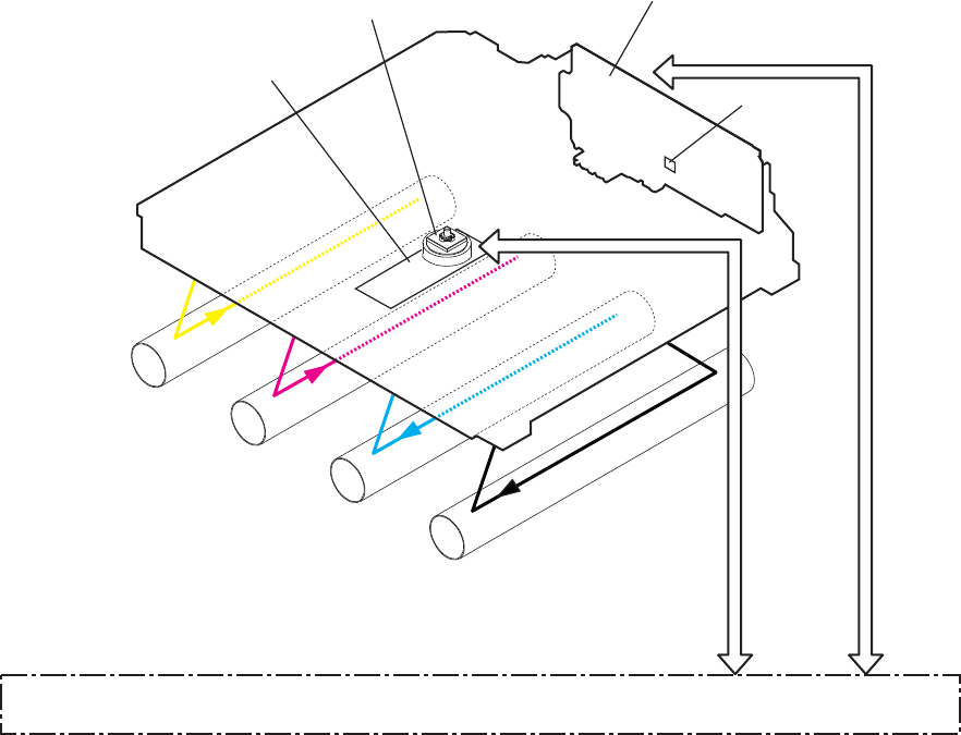
Laser/scanner system
The formatter sends video signals to the DC controller, which controls the laser/scanner. When the
laser/scanner system receives those signals, it converts them to latent images on the photosensitive
drum.
Figure 1-7 Laser/scanner system
DC controller
BD sensor
Photosensitive drum
(Y)
Laser assembly
Scanner mirror
Scanner motor assembly
Photosensitive drum
(M)
Photosensitive drum
(C)
Photosensitive drum
(K)
Laser failure detection
The optical unit failure detection sensor manages the laser/scanner unit failure-detection functions. The
DC controller identifies the laser/scanner unit failure and notifies the formatter if the laser/scanner unit
encounters the following conditions:
●Scanner motor failure
●BD failure
ENWW Laser/scanner system 9
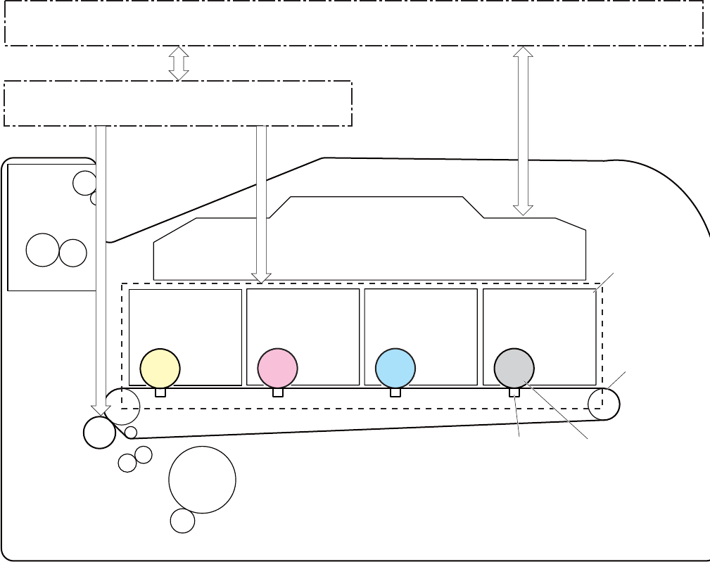
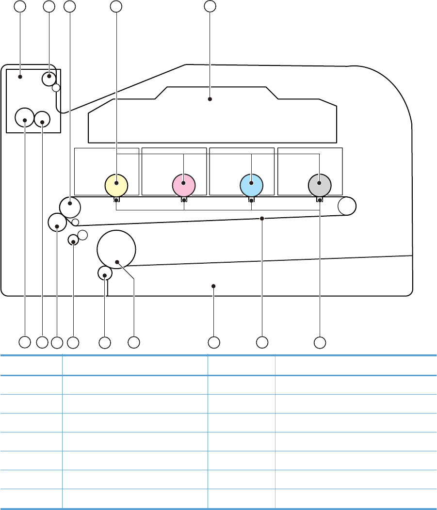
Image-formation system
The image-formation system forms a toner image on media. The product includes four toner cartridges
that contain the toner. Toner is applied in the following order, using only the colors necessary for a
specific image: yellow (Y), magenta (M), cyan (C), and black (K).
Figure 1-8 Image-formation system
DC controller
Photosensitive drum
MCYK
High-voltage power supply
Fuser
Laser scanner assembly
T1 pad
ITB
Cartridge
T2 roller
Image-formation process
Laser printing requires the interaction of several different technologies including electronics, optics, and
electrographics to provide a printed page. Each process functions independently and must be
coordinated with the other processes. Image formation consists of the following processes:
●Latent-image formation
●Development
●Transfer
10 Chapter 1 Theory of operation ENWW
●Fuser
●ITB cleaning
●Drum cleaning
These processes are divided into nine steps, which are shown in Figure 1-9 Image-formation process
on page 11 and described in the following sections.
Figure 1-9 Image-formation process
Latent image formation
Transfer
Fuser
ITB cleaning
Development
Pickup
Registration
5. Secondary transfer
6. Separation
7. Fusing
Delivery
4. Primary transfer
2. Laser beam exposure
3. Development
8. ITB cleaning
9. Drum cleaning
1. Primary charging
: Media path
: Direction of drum rotation
: Block
: Step
Photosensitive drum cleaning
Latent-image formation stage
During the two steps that comprise this stage, a latent image is formed by applying a negative charge
to the photosensitive drum. You cannot see this image on the drum.
ENWW Image-formation system 11
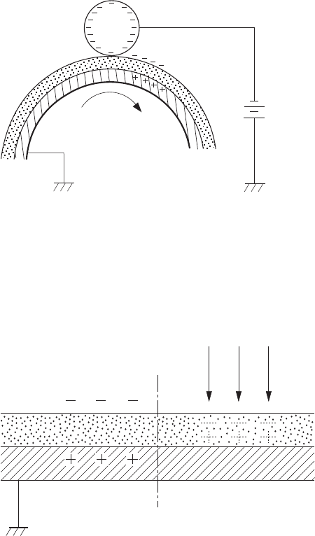
Step 1: primary charging
A high-voltage DC bias is applied to the primary charging roller, which is made of conductive rubber
and is in contact with the drum surface. As the roller moves across the drum, it applies the negative
charge to that surface.
Figure 1-10 Primary charging
DC bias
Photosensitive drum
Primary charging roller
Step 2: laser-beam exposure
The laser beam scans the photosensitive drum to neutralize the negative charge on portions of the drum
surface. An electrostatic latent image is formed where the negative charge was neutralized.
Figure 1-11 Laser-beam exposure
Laser beam
Unexposed area Exposed area
Developing stage
The developer roller comes in contact with the photosensitive drum and deposits toner on the
electrostatic latent image.
12 Chapter 1 Theory of operation ENWW
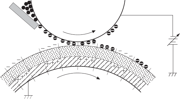
Step 3: development
Toner acquires a negative charge as a result of the friction from the developer roller rotating against the
developer blade. When the negatively charged toner comes in contact with the drum, it adheres to the
electrostatic latent image. When the toner is on the drum, the image becomes visible.
Figure 1-12 Development
Developer blade
Developer roller
DC negative bias
Photosensitive drum
Unexposed area
Exposed area
Exposed area
Unexposed area
ENWW Image-formation system 13
Transfer stage
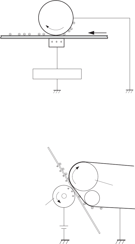
Step 4: primary transfer
The toner image on the photosensitive drum is transferred to the ITB. The DC positive bias is applied to
the primary transfer pad. The negatively charged toner transfers to the ITB from the drum surface.
Figure 1-13 Primary transfer
Photosensitive
drum
ITB
T1 bias
T1 pad
Step 5: secondary transfer
The toner image on the ITB is transferred to the print media. The DC positive bias is applied to the
secondary transfer roller. As the media passes between the secondary transfer roller and the ITB, the
toner image is transferred to the media.
Figure 1-14 Secondary transfer
ITB
Secondary transfer roller
Media
ITB drive roller
DC bias
14 Chapter 1 Theory of operation ENWW
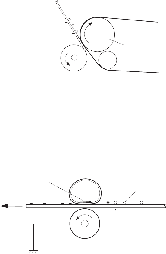
Step 6: separation from the ITB
The elasticity of the print media and the curvature of the ITB drive roller cause the media to separate
from the ITB.
Figure 1-15 Separation from the ITB
ITB
Secondary transfer roller
Media
ITB drive roller
Fusing stage
Until the fusing stage is complete, the image is not permanently affixed to the print media. The toner
can be easily smudged until the heat and pressure of the fusing process fix the image to the sheet.
Step 7: fusing
The product uses an on-demand fixing method to fix the toner image onto the media. The toner image
is permanently affixed to the print media by heat and pressure.
Figure 1-16 Fusing
Fuser film
Toner
Paper
Fuser heater
Pressure roller
ENWW Image-formation system 15
ITB cleaning stage
Step 8: ITB cleaning
The ITB cleaning roller and the cleaning brush are applied with the DC positive bias to charge the
residual toner positive. Because the primary transfer pad is also applied with the DC positive bias, the
positively charged residual toner is reverse-transferred to the photosensitive drum from the ITB surface.
Figure 1-17 ITB cleaning
ITB cleaning brush
Sweeper strip
ITB cleaning roller
IT B
DC bias DC bias
Partition sheet
Positive potential waste toner
Negative potential waste toner
Cartridge
Photosensitive drum
16 Chapter 1 Theory of operation ENWW

Drum cleaning stage
Not all of the toner is removed from the photosensitive drum during the transfer stage. During the
cleaning stage, the residual, or waste, toner is cleared from the drum surface to prepare the surface for
the next latent-image formation.
Step 9: drum cleaning
The cleaning blade scrapes the residual toner off the surface of the photosensitive drum and deposits it
in the waste-toner container. The drum is now clear and is ready for the next image-formation process.
Figure 1-18 Drum cleaning
Photosensitive
drum
Cleaning blade Blowout seal
ENWW Image-formation system 17

Pickup-and-feed system
The pickup-and-feed system picks up and feeds the print media. It consists of several types of feed
rollers.
Figure 1-19 Pickup-and-feed system
SR602
SR603
SR609
SR610 SR611
SR601
SR607
SW1
Number Description Number Description
Cassette paper out sensor SR601 CASSETTE PAPER OUT signal
Registration sensor SR602 REGISTRATION signal
Loop sensor SR603 LOOP signal
Fuser output sensor SR609 FUSER OUTPUT signal
Rear door open detection sensor SR607 REAR DOOR OPEN DETECTION signal
Paper width sensor (L) SR610 PAPER WIDTH (L) signal
Paper width sensor (R) SR611 PAPER WIDTH (R) signal
Front door open detection switch SW1 FRONT DOOR OPEN DETECTION signal
18 Chapter 1 Theory of operation ENWW
Jam detection
The product uses the following sensors to detect the presence of media and to check whether media is
being fed correctly or has jammed:
●Cassette media-presence sensor
●Top-of-page sensor
●Loop sensor
●Fuser delivery sensor
The product detects the following jams:
●Pickup delay jam
●Pickup stationary jam
●Delivery delay jam
●Delivery stationary jam
●Fixing wrapping jam
●Residual media jam
ENWW Pickup-and-feed system 19
Scanner system (base models)
The flatbed image scanner captures an electronic image of the document on the glass. The scanner
does this by illuminating the document with LEDs (red, green, and blue) and capturing the image in the
image sensor to create an electronic format of the document. The flatbed scanner consists of three main
elements
●CIS scanner. The CIS (contact image sensor) scanner captures an image using the product's
optical path. Red, green, and blue LEDs sequentially illuminate a small strip of the document (often
called a raster line), and the optical system captures each color in a single row of CCD sensors
that cover the entire page width. Because only one color is captured for each line per exposure,
the three colors are recombined electronically to create the full color image. For monochromatic
scans or copies, all three LEDs are illuminated to create a white light for the scan so the raster line
can be captured in one exposure.
●Mechanical carriage drive. The carriage drive moves the CIS scan head along the document
length to create the image. In this product, a small DC motor with an optical encoder creates this
motion. The speed of the carriage drive is proportional to the scan resolution (300 ppi is much
faster than 1200 ppi) and also proportional to the type of scan (color scans are three-times slower
than monochromatic scans). A 1200 ppi color scan moves so slowly that the product may appear
to not be working, whereas a monochromatic copy scan moves at 50 times that speed and will be
somewhat noisy.
●Image processing system (formatter). The formatter processes the scanner data into either
a copy or a scan to the computer. For copies, the image data is sent directly to the product
without being transmitted to the computer. Depending on user selections for the copy settings, the
formatter enhances the scanner data significantly before sending it to the product. Image data is
captured at 300 ppi for copies and is user selectable for scans to the computer. Each pixel is
represented by 8 bits for each of the three colors (256 levels for each color), for a total of 24 bits
per pixel (24-bit color).
Scanner power-on sequence of events
When the product is turned on, it performs the following tests:
●Motor test. The product moves the motor left and right to confirm operation. It reports a scanner
error 12 if no motion is detected in the motor encoder system.
●Wall find. The scan carriage moves slowly to the left while watching an encoder on the carriage
motor to determine when the carriage has found the side wall or stop. This enables the product to
identify the document origin (position of the original). If the document origin cannot be located, a
default position is used instead.
●LED check. The product moves the carriage to the white calibration label under the left side of
the flatbed image scanner, and it verifies that the minimum and maximum response is acceptable.
It reports a scanner error 14 if the response is unacceptable.
●Home find. The scan carriage uses the optical scanner to find physical reference features that
relate to the document origin at the left side of the image glass. This process ensures accurate
location of the first document pixels so that the user documents will have an accurate placement of
20 Chapter 1 Theory of operation ENWW
the image on scans and copies. It reports a scanner error 6 message if the reference features are
not found.
●Calibration. This test, also known as scanner color calibration, enables the product to identify
the black and white on every pixel in the CCD. Calibration occurs in two major processes: a
broad (analog) adjustment of all pixels to bring them into the target output range, and a pixel-by-
pixel adjustment (digital) to fine tune the actual black and white response. The calibration process
occurs under the left side of flatbed image scanner where there is a special white calibration
label.
Calibration is the most important step in creating a high quality image. Calibration problems can
include color and brightness inaccuracies, and vertical streaks through the image. The calibration
process identifies any bad pixels and enables the image formatter to recreate the lost information
from adjacent pixels. Extreme cases of this problem can appear as large vertical streaks or image
smears. The user has no control over the calibration process itself or this pixel-replacement
process.
Copy or scan-to-computer sequence of events
To create an accurate rendition of a document, the scanner must be calibrated for the requested
operation. If the user selects a scan at 600 ppi color, the flatbed image scanner calibrates for that
specific operational mode. Subsequently, the flatbed image scanner automatically re-calibrates for the
next requested operation. Calibration does not occur for every new copy request.
Normal sequence of operation for a flatbed copy or scan includes:
1. LEDs illuminate.
2. Carriage motion begins moving the CIS scanner toward the right.
3. Image capture continues for the entire page or length requested in a scan-to-computer operation.
4. Carriage returns to the home position on the left.
ENWW Scanner system (base models) 21
Fax functions and operation (fax models only)
The following sections describe the product fax capabilities.
Computer and network security features
The product can send and receive fax data over telephone lines that conform to public switch telephone
network (PSTN) standards. The secure fax protocols make it impossible for computer viruses to be
transferred from the telephone line to a computer or network.
The following product features prevent virus transmission:
●No direct connection exists between the fax line and any devices that are connected to the USB or
Ethernet ports.
●The internal firmware cannot be modified through the fax connection.
●All fax communications go through the fax subsystem, which does not use Internet data-exchange
protocols.
PSTN operation
The PSTN operates through a central office (CO) that generates a constant voltage on the TIP and RING
wires (48 V, usually). A device goes on-hook by connecting impedance (such as 600 ohms for the
U.S.) across the TIP and RING so that a line current can flow. The CO can detect this current and can
send impulses like dial tones. The product generates more signaling tones, such as dialing digits, to tell
the CO how to connect the call. The product can also detect tones, such as a busy tone from the CO,
that tell it how to behave.
When the call is finally connected, the CO behaves like a piece of wire connecting the sender and
receiver. This is the period during which all of the fax signaling and data transfer occurs. When a call
is completed, the circuit opens again and the line-current flow ceases, removing the CO connection
from both the sender and the receiver.
On most phone systems, the TIP and RING signals appear on pins 3 and 4 of the RJ-11 modular jack
(the one on the fax card, as defined in the common 6 wire RJ standard). These two signals do not have
to be polarized because all of the equipment works with either TIP or RING on one pin and the other
signal on the other pin. This means that cables of either polarity can interconnect and still work.
These basic functions of PSTN operation are assumed in the design of the fax subsystem. The product
generates and detects the signaling tones, currents, and data signals that are required to transmit and
receive faxes using the PSTN.
Receive faxes when you hear fax tones
In general, incoming faxes to the product are automatically received. However, if other devices are
connected to the same phone line, the product might not be set to answer automatically.
22 Chapter 1 Theory of operation ENWW

If the product is connected to a phone line that receives both fax and phone calls, and you hear fax
tones when you answer the extension phone, receive the fax in one of two ways:
●If you are near the product, press Start Fax on the control panel.
●Press 1-2-3 in sequence on the extension phone keypad, listen for fax transmission sounds, and
then hang up.
NOTE: In order for the 1-2-3 sequence to work, the extension phone setting must be set to On in the
Fax Setup menu.
Distinctive ring function
Distinctive ring is a service that a telephone company provides. The distinctive ring service allows three
phone numbers to be assigned to one phone line. Each phone number has a distinctive ring. The first
phone number has a single ring, the second phone number has a double ring, and the third phone
number has a triple ring.
NOTE: The product has not been tested with all of the distinctive-ring services that telephone
companies provide in all countries/regions. HP does not guarantee that the distinctive-ring function will
operate correctly in all countries/regions. Contact the local phone service provider for assistance.
Set up the distinctive ring function
1. Press Setup .
2. Use the arrow buttons to select Fax Setup, and then press Enter.
3. Use the arrow buttons to select Basic Setup, and then press Enter.
4. Use the arrow buttons to select Distinctive Ring, and then press Enter.
5. Use the arrow buttons to select one of the following options:
NOTE: The control-panel display might show some of these options as abbreviations.
●All Rings (default setting)
●Single
●Double
●Triple
●Double and Triple
Press Enter to save the setting.
Fax by using Voice over IP services
Voice over IP (VoIP) services provide normal telephone service, including long distance service through
a broadband Internet connection. These services use packets to break up the voice signal on a
telephone line and transmit it digitally to the receiver, where the packets are reassembled. The VoIP
ENWW Fax functions and operation (fax models only) 23
services are often not compatible with fax machines. The VoIP provider must state that the service
supports fax over IP services.
Because the installation process varies, the VoIP service provider will have to assist in installing the
product fax component.
Although a fax might work on a VoIP network, it can fail when the following events occur:
●Internet traffic becomes heavy and packets are lost.
●Latency (the time it takes for a packet to travel from its point of origin to its point of destination)
becomes excessive.
If you experience problems using the fax feature on a VoIP network, ensure that all of the product
cables and settings are correct. Configuring the Fax Speed setting to Medium(V.17) or Slow(V.
29) can also improve your ability to send a fax over a VoIP network.
If you continue to have problems faxing, contact your VoIP provider.
The fax subsystem
The formatter, fax card, firmware, and software all contribute to the fax functionality. The designs of the
formatter and fax card, along with parameters in the firmware, determine the majority of the regulatory
requirements for telephony on the product.
The fax subsystem is designed to support V.34 fax transmission, low speeds (such as V.17 fax), and
older fax machines.
Fax card in the fax subsystem
Two versions of the fax card are used in the product. One is used in the North American, South
American, and Asian countries/regions. The other is used primarily in European countries/regions.
The fax card contains the modem chipset (DSP and CODEC) that controls the basic fax functions of tone
generation and detection, along with channel control for fax transmissions. The CODEC and its
associated circuitry act as the third-generation silicon data access arrangement (DAA) to comply with
worldwide regulatory requirements.
The only difference between the two versions is that each version is compliant with the 2/4-wire phone
jack system from the respective country/region.
Safety isolation
The most important function of the fax card is the safety isolation between the high-voltage, transient-
prone environment of the telephone network (TNV [telephone network voltage]) and the low-voltage
analog and digital circuitry of the formatter (SELV [secondary extra-low voltage]). This safety isolation
provides both customer safety and product reliability in the telecom environment.
Any signals that cross the isolation barrier do so magnetically. The breakdown voltage rating of barrier-
critical components is greater than 5 kV.
24 Chapter 1 Theory of operation ENWW
Safety-protection circuitry
In addition to the safety barrier, the fax card protects against over-voltage and over-current events.
Telephone over-voltage events can be either differential mode or common mode. The event can be
transient in nature (a lightning-induced surge or ESD) or continuous (a power line crossed with a phone
line). The fax card protection circuitry provides margin against combinations of over-voltage and over-
current events.
Common mode protection is provided by the selection of high-voltage-barrier critical components
(transformer and relay). The safety barrier of the fax card PCB traces and the clearance between the
fax card and surrounding components also contribute to common mode protection.
A voltage suppressor (a crowbar-type thyristor) provides differential protection. This device becomes
low impedance at approximately 300 V differential, and crowbars to a low voltage. A series thermal
switch works in conjunction with the crowbar for continuous telephone line events, such as crossed
power lines.
All communications cross the isolation barrier magnetically. The breakdown voltage rating of barrier-
critical components is greater than 5 kV.
Data path
TIP and RING are the two-wire paths for all signals from the telephone network. All signaling and data
information comes across them, including fax tones and fax data.
The telephone network uses DC current to determine the hook state of the telephone, so line current
must be present during a call. The silicon DAA provides a DC holding circuit to keep the line current
constant during a fax call.
The silicon DAA converts the analog signal to a digital signal for DSP processing, and also converts the
digital signal to an analog signal for transmitting data through a telephone line.
The magnetically coupled signals that cross the isolation barrier go through either a transformer or a
relay.
The DSP in the fax card communicates with the ASIC in the formatter using the high-speed serial
interface.
Hook state
Another magnetically coupled signal is the control signal that disconnects the downstream telephone
devices (such as a phone or answering machine). A control signal originating on the DSP can change
the relay state, causing the auxiliary jack (downstream jack) to be disconnected from the telephone
circuit.
The product takes control of calls that it recognizes as fax calls. If the product does not directly pick up
the call, it monitors incoming calls for the fax tone or for the user to direct it to receive a fax. This idle
mode is also called eavesdropping. This mode is active when the product is on-hook but current exists
in the downstream phone line because another device is off-hook. During eavesdropping, the receive
circuit is enabled but has a different gain from the current that is generated during normal fax
transmissions.
ENWW Fax functions and operation (fax models only) 25
The product does not take control of the line unless it detects a fax tone or the user causes it to connect
manually. This feature allows the user to make voice calls from a phone that is connected to the product
without being cut off if a fax is not being received.
Downstream device detection
The line voltage monitoring module of the silicon DAA can detect the line state as well as the
downstream device. It tells DSP via DIB that an active device (telephone, modem, or answering
machine) is connected to the auxiliary port on the product (the right side of the dual RJ-11 jack). The
DSP uses the signal to ensure that the product does not go off-hook (and disconnects a downstream
call) until it has been authorized to do so (by a manual fax start or the detection of the appropriate
tones).
Hook switch control
In the silicon DAA the CODEC controls the hook switch directly. The CODEC is activated when it
receives commands from the DSP. When the circuit is drawing DC current from the central office it is
considered off-hook. When no DC current flows the state is considered on-hook.
Ring detect
Ring detect is performed by the line voltage monitoring module of the silicon DAA, and is a
combination of voltage levels and cadence (time on and time off). Both must be present to detect a
valid ring. The CODEC works with DSP as well as the firmware to determine if an incoming signal is an
answerable ring.
Line current control
The DC current from the CO needs to have a path to flow from TIP to RING. The DC impedance
emulation line modulator and DC terminations modules in the silicon DAA act as a DC holding circuit,
and work with the firmware to achieve the voltage-current characteristic between TIP and RING. The
impedance (the current-voltage characteristic) changes corresponding to certain special events, such as
pulse dialing or when the product goes on-hook.
Billing- (metering-) tone filters
Switzerland and Germany provide high-frequency AC signals on the phone line in order to bill
customers.
A filter in a special fax cable (for certain countries/regions), can filter these signals. Because these
billing signals are not used in the U.S., these filters are not present in the U.S. fax cable.
To obtain a special fax cable, contact your local telephone service provider.
Fax page storage in flash memory
Fax pages are the electronic images of the document page. They can be created in any of three ways:
scanned to be sent to another fax machine, generated to be sent by the computer, or received from a
fax machine to be printed.
26 Chapter 1 Theory of operation ENWW
The product stores all fax pages in flash memory automatically. After these pages are written into flash
memory, they are stored until the pages are sent to another fax machine, printed on the product,
transmitted to the computer, or erased by the user.
These pages are stored in flash memory, which is the nonvolatile memory that can be repeatedly read
from, written to, and erased. The product has 8 MB of flash memory, of which 7.5 MB is available for
fax storage. The remaining 0.5 MB is used for the file system and reclamation. Adding RAM does not
affect the fax page storage because the product does not use RAM for storing fax pages.
Stored fax pages
The user can reprint stored fax receive pages in case of errors. For a fax send, the product will resend
the fax in case of errors. The product will resend stored fax pages after a busy signal, communication
error, no answer, or power failure. Other fax devices store fax pages in either normal RAM or short-
term RAM. Normal RAM immediately loses its data when power is lost, while short-term RAM loses its
data about 60 minutes after power failure. Flash memory maintains its data for years without any
applied power.
Advantages of flash memory storage
Fax pages that are stored in flash memory are persistent. They are not lost as a result of a power
failure, no matter how long the power is off. Users can reprint faxes in case the print cartridge runs out
of toner or the product experiences other errors while printing faxes.
The product also has scan-ahead functionality that makes use of flash memory. Scan-ahead
automatically scans pages into flash memory before a fax job is sent. This allows the sender to pick up
the original document immediately after it is scanned, eliminating the need to wait until the fax
transmission is complete.
Because fax pages are stored in flash memory rather than RAM, more RAM is available to handle
larger and more complicated copy and print jobs.
ENWW Fax functions and operation (fax models only) 27
USB Flash Drive
This product features printing the following types of files from the USB flash drive.
●PDF
●RGB JPEG
When a USB flash drive is inserted into the front of the product, the control panel will display the USB
Flash Drive Menu. The files present on the USB flash drive can be accessed from the control panel using
the touch screen. Any RGB jpeg or pdf files on the USB flash drive can be printed directly from the
product control panel. Pages also can be scanned and saved to the USB flash drive from the control
panel.
28 Chapter 1 Theory of operation ENWW

Solve problems checklist
1. Ensure that the product is set up correctly.
a. Press the power button to turn on the product or to deactivate the Auto-Off mode.
b. Check the power-cable connections.
c. Ensure that the line voltage is correct for the product power configuration. (See the label that
is on the back of the product for voltage requirements.) If you are using a power strip and its
voltage is not within specifications, plug the product directly into the wall. If it is already
plugged into the wall, try a different outlet.
2. Check the cable connections.
a. Check the cable connection between the product and the computer. Ensure that the
connection is secure.
b. Ensure that the cable itself is not faulty, by using a different cable if possible.
c. Check the network connection: Ensure the network light is lit. The network light is next to the
network port on the back of the product.
If the product remains unable to connect to the network, uninstall and then reinstall the
product. If the error persists, contact a network administrator.
3. Check to see if any messages appear on the control panel.
4. Ensure that the paper you are using meets specifications.
5. Ensure that the paper is loaded correctly in the input tray.
6. Ensure that the product software is installed correctly.
7. Verify that you have installed the printer driver for this product, and that you are selecting this
product from the list of available printers.
8. Print a configuration page.
a. If the page does not print, verify that the input tray contains paper and that the paper is
properly loaded.
b. Ensure that the toner cartridge is installed correctly.
30 Chapter 2 Solve problems ENWW
c. If the page jams in the product, clear the jam.
d. If the print quality is unacceptable, complete the following steps:
●Verify that the print settings are correct for the paper you are using.
●Solve print-quality problems.
9. Print a small document from a different program that has printed in the past. If this solution works,
then the problem is with the program you are using. If this solution does not work (the document
does not print), complete these steps:
a. Try printing the job from another computer that has the product software installed.
b. Check the cable connection. Direct the product to the correct port, or reinstall the software,
selecting the connection type you are using.
ENWW Solve problems checklist 31

Menu map
Use the following procedure to print a control-panel menu layout map.
1. From the Home screen, touch the Setup button.
2. Touch the Reports button.
3. Touch the Menu Structure button.
Troubleshooting process
When the product malfunctions or encounters an unexpected situation, the product control panel alerts
you to the situation. This chapter contains information to help diagnose and solve problems.
●Use the pre-troubleshooting checklist to evaluate the source of the problem and to reduce the
number of steps that are required to fix the problem.
●Use the troubleshooting flowchart to pinpoint the root cause of the hardware malfunction. The
flowchart guides you to the section of this chapter that contains steps for correcting the
malfunction.
Before beginning any troubleshooting procedure, check the following issues:
●Are supply items within their rated life?
●Does the configuration page reveal any configuration errors?
NOTE: The customer is responsible for checking supplies and for using supplies that are in good
condition.
Pre-troubleshooting checklist
The following table includes basic questions to ask the customer to quickly help define the problem(s).
General topic Questions
Environment ●Is the product installed on a solid, level surface (+/- 1°)?
●Is the power-supply voltage within ± 10 volts of the specified power source?
●Is the power-supply plug inserted in the product and the outlet?
●Is the operating environment within the specified parameters?
●Is the product exposed to ammonia gas, such as that produced by diazo
copiers or office cleaning materials?
NOTE: Diazo copiers produce ammonia gas as part of the copying
processes. Ammonia gas (from cleaning supplies or a diazo copier) can have
an adverse affect on some product components (for example, the print-
cartridge OPC).
●Is the product exposed to direct sunlight?
32 Chapter 2 Solve problems ENWW

General topic Questions
Media ●Does the customer use only supported media?
●Is the media in good condition (no curls, folds, or distortion)?
●Is the media stored correctly and within environmental limits?
Input trays ●Is the amount of media in the tray within specifications?
●Is the media correctly placed in the tray?
●Are the paper guides aligned with the stack?
●Is the cassette correctly installed in the product?
Toner cartridges ●Is each toner cartridge installed correctly?
Transfer unit and fuser ●Are the transfer unit and fuser installed correctly?
Covers ●Is the front cover closed?
Condensation ●Does condensation occur following a temperature change (particularly in
winter following cold storage)? If so, wipe affected parts dry or leave the
product on for 10 to 20 minutes.
●Was the toner cartridge opened soon after being moved from a cold to a
warm room? If so, allow the toner cartridge to sit at room temperature for 1 to
2 hours.
Miscellaneous ●Check for and remove any non-HP components (toner cartridges, memory
modules, and EIO cards) from the product.
●If the hardware or software configuration has not changed or the problem is
not associated with any specific software, see the complete service manual for
this product.
●Remove the product from the network and ensure that the failure is associated
with the product before beginning troubleshooting.
●For any print-quality issues, calibrate the product.
ENWW Troubleshooting process 33
Power-on checks
When you turn on the product, if it does not make any sound or if the control-panel display is blank,
check the following items:
●Verify that the product is plugged directly into an active electrical outlet that has the correct
voltage. Do not plug the product into a surge protector or power strip.
●Press the power button.
●Verify that the formatter is seated and operating correctly.
●Remove any HP Jetdirect accessories or other devices, and then try to turn the product on again.
●Ensure that the control-panel display is connected.
●Check the two fuses on the power supply.
●If necessary, replace the power supply.
●If necessary, replace the DC controller.
34 Chapter 2 Solve problems ENWW

Tools for troubleshooting
Component diagnostics
LED diagnostics
Network LEDs
The onboard network solution has two network port LEDs. When the product is connected to a properly
working network through a network cable, the yellow LED indicates network activity, and the green LED
indicates the link status. A blinking yellow LED indicates network traffic. If the green LED is off, a link
has failed.
For link failures, check all of the network cable connections. In addition, you can try to manually
configure the link settings on the onboard network solution by using the product control-panel menus.
1. Touch the Setup button.
2. Scroll to and touch the Network Setup menu.
3. Touch the Link Speed menu.
4. Select one of the following options.
Setting Description
Automatic The print server automatically configures itself for the highest link speed and
communication mode allowed on the network.
10T Half 10 megabytes per second (Mbps), half-duplex operation
10T Full 10 Mbps, full-duplex operation
100TX Half 100 Mbps, half-duplex operation
100TX Full 100 Mbps, full-duplex operation
5. Touch the OK button. The product turns off and then on.
ENWW Tools for troubleshooting 35

Control panel LEDs
The state of the Ready light and the Attention light on the product signal the product status. The
following table outlines the possible control-panel light states.
NOTE: Wireless models have a blue LED that illuminates when the product wireless function is
enabled and available.
Product state Ready light state Attention light state
Initializing Blinking Blinking
Ready On Off
Receiving data/processing job or
cancelling job
Blinking Off
Error message Off Blinking
Fatal error (49 or 79 error)
1
On On
1
The product restarts after one of these errors occurs.
36 Chapter 2 Solve problems ENWW

Control-panel diagnostics
The product includes diagnostic tests for the control panel.
Test the control-panel display
1. Touch the Setup button.
2. Touch the left arrow button , and then quickly touch the Cancel button.
3. Touch the Setup button to return to the main menus.
4. Open the 2ndary Service menu.
5. Open the Display test menu.
Test the control-panel buttons
1. Touch the Setup button.
2. Touch the left arrow button , and then quickly touch the Cancel button.
3. Touch the Setup button to return to the main menu.
4. Open the 2ndary Service menu.
5. Open the Button test menu.
Engine Diagnostics
Engine test
1. With the product off, open the front and rear doors.
2. Turn the power on, and close both doors within ten seconds.
3. An engine test page (a page containing multiple horizontal colored lines) will print.
ENWW Tools for troubleshooting 37

Diagrams
Plug/jack locations
1
2
3
1 Network port
2 Hi-Speed USB 2.0 port
3 Fax ports
38 Chapter 2 Solve problems ENWW
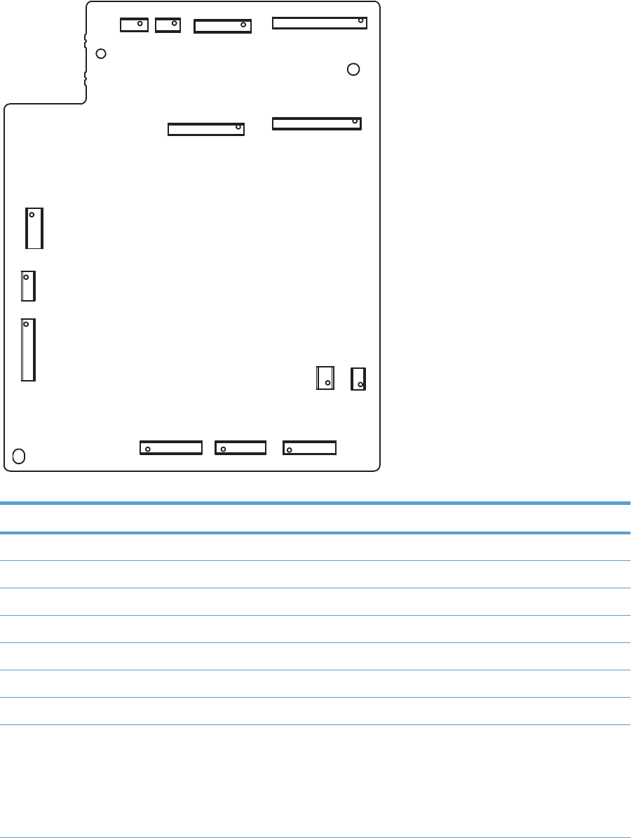
DC controller PCA
Figure 2-1 DC controller connectors
J108
1
29
2
28
J124
1
8
J109J120
1313
J115
1
27
2
26
J107
1
2
23
22
J105 1
2
3
4
J116
19
28
J104
13
J103
16
J119
1
2
15
14
J127
1
2
5
4
J126
16
J140
16
Table 2-1 DC controller connectors
Item Description
J103 Low-voltage power supply (+3.3 V)
J104 Thermistor (TH802)
J105 Fuser power supply
J107 Formatter
J108 Laser driver PCA
J109 Scanner motor (M704)
J115 High-voltage power supply
J116 Pickup assembly
●Loop sensor (SR603)
●Top-of-page sensor (SR602)
●Cassette media present sensor (SR601)
ENWW Tools for troubleshooting 39

Table 2-1 DC controller connectors (continued)
Item Description
J119 ITB assembly density and perimeter sensors
J120 Developing home position sensor (SR606)
J124 Memory tags (e-labels)
J126 IOT
127 Flash
J130 Front door (cartridge access door) switch
J131 Power switch
J140 Motor driver
40 Chapter 2 Solve problems ENWW
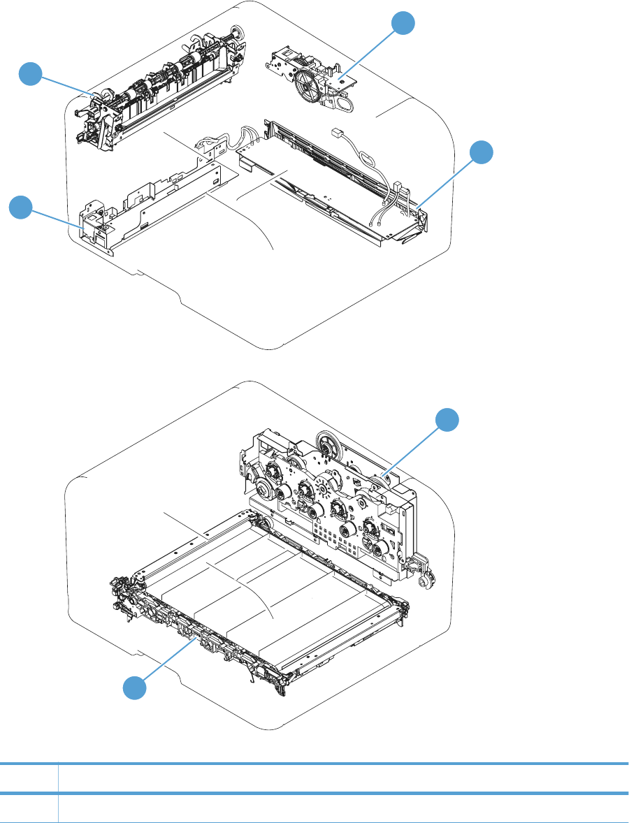
Locations of major components
Figure 2-2 Major components
1
3
2
4
5
6
Table 2-2 Major components
Item Description
1 Fuser power supply
ENWW Tools for troubleshooting 41

Table 2-2 Major components (continued)
Item Description
2 Fuser assembly
3 Sub-drive assembly
4 Low-voltage power suppy
5 Main drive assembly
6 ITB assembly
42 Chapter 2 Solve problems ENWW

General timing charts
The following chart list the approximate timing for this product, specified in seconds.
Figure 2-3 Timing diagram
I. GENERAL TIMING CHART
Two consecutive prints on LTR paper
4 Fuser output sensor
5 TOP signal
1 Print command
2 Cassette pickup solenoid
3 Registration sensor
6 Scanner motor
7 Pickup motor
8 Main motor
11 Charging bias
9 Fuser motor
10 Fuser heater
Developer bias (K)
14 Developer bias (C)
12 Developer bias (Y)
15
13 Developer bias (M)
LSTR STBYPRINTSTBY INTR
T1 bias (M and C)
T1 bias (K)
T2 bias
16
20 Main fan
T1 bias (Y)
18
19
17
23
22
21
ENWW Tools for troubleshooting 43
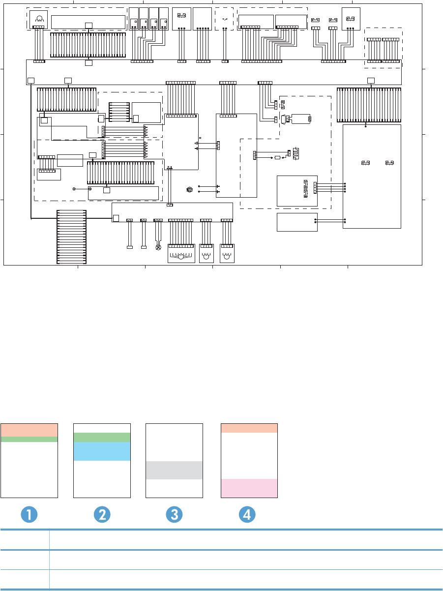
General circuit diagram
Figure 2-4 Circuit diagram
SL
29
29
SL
23
M
TP
25
M MM
21
8
8
21
26
23
26
GND
GND
GND
GND
GND
(GY)
(SB)
(OR)
SGND
+3.3V
(GN)
(GN)
(GN)
(GN)
(GN)
(GN)
(GN)
+3.3VB
PGND
+24VA
VIN
VIN
VIN
(GY)
+3.3VB
+3.3VB
ITBLSNS
RD_PWM
SGND
+24VA
R_DIFA
R_PWM
SGND
+24VA
DHPSNS
LOOPSNS
REGSNS
CSTSNS
/SCNDEC
/SCNACC
/VDO10
CNT121
CNT120
/VDO2
VDO2
/VDO3
VDO3
/VDO4
VDO4
SGND
PGND
SGND
SGND
SGND
/MAINMACC
/MAINMDEC
/MAINMFG
RLD-
RD_DIFA
RD_REGA
RD_GAIN0
RD_GAIN1
LD4PWM
SGND
VDO10
LD1PWM
SGND
SGND
LD2PWM
SGND
/BDI
SGND
LD3PWM
CNT30
CNT31
FSRD+
FSRD-
Registration density
sensor
BLD1:J2321-J2322
DEV1:J2221-J2222
BLD2:J2341-J2342
DEV2:J2241-J2242
TR1_1 :J2401-J2402
TR1_4 :J2551-J2552
ICLB:J2701-J2702
ICLR:J2801-J2802
RS1 :J221-J222
RS2 :J241-J242
RS3 :J261-J262
RS4 :J281-J282
+3.3VB
/VDOEN
+3.3VB
+3.3VB
+3.3VB
FREQSNS
SGND
SGND
TEMPSNS
FDSNS
FPRSNS
ICLRSNS
ICLBSNS
TR1S
TR2S
TNR4
TNR3
TNR2
TNR1
DEVCLK
HVDALD
HVDACLK
HVDATA1
PGND
PGND
+24VA
+24VA
PWLSNS
DOPENR
+3.3VB
/CCRT
SC
SCLK
/TOP
SGND
/BD0
WAKEENG
WAKE VC
SGND
VDO4
/VDO4
SGND
VDO3
/VDO3
SGND
VDO2
/VDO2
SGND
VDO1
/VDO1
SGND
+3.3VB
+3.3VB
+3.3VB
+24VA
DEVSL
+24VA
FEEDSL
PGND
FEEDAOUT
/FEEDAOUT
FEEDBOUT
/FEEDBOUT
TR1_23:J2451-J2452
RLD+
RTC3V
CNT41
CNT40
FU LIVE
PR I : J2101- J210 2
TR2 :J2601-J2602
TAG
3rd TAG TAG
2nd
TAG
4th 1st
DEV3:J2261-J2262
BLD3:J2361-J2362
Laser driver PCA
ITB assembly
Laser scanner assembly
(GY)
+3.3VB
SGND
(GY)
BLD4:J2381-J2382
DEV4 :J2281-J2282
SGND
TEMPSNS
Fuser sensor PCA
FANP WM
FANL K
PGND
FU NEUTRAL
(BK)
(W)
SGND
/HVRESET
Registration ITB-perimeter
sensor
VIN
VSS1
VSS2
VSS3
VSS4
DOPENF
SGND
(BL)
LIVE2
NEUTRAL2
(R)
+24VA
+24VA
PGND
/FSRMAOUT
FSRMAO UT
FSRMB OUT
/FSRMBOUT
+3.3VA
+3.3VA
SGND
SGND
PGND
PGND
+24VA
+24VA
FEEDI0B
FEEDI1B
FEEDI1A
FEEDI0A
FEEDPB
FEEDPA
FEEDSL
FSRMPB
FSRMI 1A
FSRMI 0A
FSRMI 0B
FSRMI 1B
/MAINMFG
/MAINMACC
/MAINMDEC
SGND
FANLK
REM24V
VCTRLOFF
PWSV
FDSNS
SGND
/PWRSWON
CPOUT
+3.3VB
SGND
SGND
PWLSNS
IOT
FLASH
/TESTPRT
TCK
P81
P80
MODE2
MODE0
IOTT
SGND
SGND
IOTR
+3.3VA
PWRSNS
MAINTH
SGND
Environment sensor PCA
Fuser power supply PCA
PWR_LED
+3.3VB
+3.3VA
LED-CLK
High-voltage power supply PCA
(W)
(R)
(W)
(R)
(W)
(R)
(W)
(R)
(BL)
(W)
(R)
(BL)
(W)
(R)
(GN)
(GN)
+24VA
(V)
(GY)
Driver PCA
+24VA
NEUTRAL1
LIVE1
/CPRESET
3.3V
GND
/INT
CPIN
5V
Control panel
CPCLK
SGND
DC controller PCA
Low-voltage
power supply PCA
Fuser
(V)
(GN)
+3.3V
+3.3V
(Y)
(SB)
(OR)
+3.3V
SGND
(Y)
(BR)
SGND
DEVSL
DCLK
GND
VSYNC
HSYNC
D0
D1
D2
D3
D4
D5
D6
D7
24V
5V
NIRQ
SCLK
CPIN
3.3V
NRESET
CPOUT
PGND
(W)
(BK)
(GY)
(OR)
(GN)
(GN)
(BL)
(BK)
(R)
(W)
(GN)
(BL)
connector
+24V
PGND
GND
Wireless
USB
SGND
Module
Formatter
Formatter
Control panel
Board to Board
(GR)
<MF model>
<LCD model>
FSRMPA
SGND
FAN_ON
J202_BUS[0:21]
J906_BUS[0:26]
J906
J901_BUS[0:23]
J901
MT1MT2
J905
J905_BUS[0:26]
123456
J9999
123456
J9998
J107_BUS[0:23]
12
J130
J408
J408_BUS[0:21]
J801_BUS[0:8]
J904
J115_BUS[0:25]
J1001_BUS[0:25]
1
J1001
234 1
J902B
3
1
2
J290
J334
J333
J332
J331
J335
J336
1110982345617
J103
345
612
J902
J903
J903_BUS[0:8]
12345678
J124
J311
J312
21
J401
J108_BUS[0:29]
4321
J109
J140
J802
J801
J803
12345
J131
12345
J104
SR608
J802H
SR611
123
J951
12
J802L
21
J802D
4321
J404
J1024
J1023
J1022
J1021
J151
J804
1
32
J202
J302
J301
982345617
J403
98 2345617
J701
M701
12
3
4
J810
J172 J1011
M702
1
2
TH802
11 10 9 8 2345617
J320
123456
J105
SR603 SR602 SR601
J163
J162
J161
J805
SW1
TAG1
J152
J153
SR606
21
12345678
J611
12
J406
M703
SR610
J115
1234567
J621
15 14 13 12 1110 9 8 2345617
J119
TB2A
12
TP1A
TB1A
21
J801A
J332B
J331B
J335B
J336B
321
FM1
1234
J703
123
J603
321
J602
M704
1234
J704
123456
J203 MMI2-6P
J107
SR609
21
H801A
18
14
231
J402
12
13
14
1
3
2
123456
J126
20
12
SL706
J501
123
J120
TAG4 TAG3 TA G2
S2
S1
J1012
98 2345617
J116
12345
J112 7
54321
J127
4321
J702
1234
J405
J108
21
SL705
S8
S7
23
22
21
20
19
18
17
16
15
14
12
11
10
9
8
7
6
5
3
2
1
4
23
22
21
20
19
18
17
16
15
13
12
11
10
9
8
7
6
5
3
2
1
4
S5
S6
S4
S3
654321
J112 6
4
1
2
3
5
6
7
8
9
10
11
12
13
14
15
16
17
18
19
20
21
22
23
24
25
26
27
28
29
29
28
27
26
25
24
23
22
21
20
19
18
17
16
15
14
13
12
11
10
9
8
7
6
5
3
2
1
4
4
1
2
3
5
6
7
8
9
10
11
13
15
16
17
18
19
20
21
22
23
24
25
25
24
23
22
21
20
19
17
16
15
14
13
12
11
10
9
8
7
6
5
3
2
4
21
19
18
17
16
15
14
13
12
11
10
9
8
7
6
5
4
J501_BUS[0:29]
231
J201A
S10
S9
SOLD90
SOLD93
J211
J212
12
J407
J171
4
1
2
3
5
6
7
8
4
1
2
3
5
6
7
8
SR607
1
3
2
20
21
19
18
17
16
15
14
13
12
11
10
9
8
7
6
5
4
4
1
2
3
5
6
7
8
9
10
11
12
13
14
15
16
17
18
19
20
21
22
23
24
25
26
4
1
2
3
5
6
7
8
9
10
11
12
13
14
15
16
17
18
19
20
21
22
23
24
25
26
COR1
SW801
Internal print-quality test pages
Interpret the Print Quality Page
1. On the product control panel, open the Reports menu.
2. Select the Print Quality Page item to print it.
This page contains five bands of color, which are divided into four groups as indicated in the following
illustration. By examining each group, you can isolate the problem to a particular print cartridge.
Section Print-cartridge
1Yellow
2Cyan
44 Chapter 2 Solve problems ENWW

Section Print-cartridge
3Black
4Magenta
●If dots or streaks appear in only one of the groups, replace the print cartridge that correlates with
that group.
●If dots appear in more than one group, print a cleaning page. If this does not solve the problem,
determine if the dots are always the same color; for example, if magenta dots appear in all five
color bands. If the dots are all the same color, replace that print cartridge.
●If streaks appear in multiple color bands, contact HP. A component other than the print cartridge is
probably causing the problem.
Print a cleaning page
Print a cleaning page to remove dust and excess toner from the paper path if you are having any of the
following problems:
●Specks of toner are on the printed pages.
●Toner is smearing on the printed pages.
●Repeated marks occur on the printed pages.
Print a cleaning page
1. From the Home screen on the product control panel, touch the Setup button.
2. Touch the Service menu.
3. Touch the Cleaning Page button.
4. Load plain letter or A4 paper when you are prompted.
5. Touch the OK button to begin the cleaning process.
6. The product prints the first side and then prompts you to remove the page from the output bin and
reload it in Tray 1, keeping the same orientation (the side with the black stripe should be face-
down with the arrow toward the back of the product).
7. Press the OK button to continue the cleaning process. Wait until the process is complete. Discard
the page that prints.
ENWW Tools for troubleshooting 45

Configuration page
Print a configuration page
NOTE: This section applies to the HP LaserJet Pro 200 color M276nw MFP model only.
1. From the Home screen on the product control panel, touch the Setup button.
2. Touch the Reports button.
3. Touch Configuration Report.
Print-quality troubleshooting tools
Repetitive image defects
If the product output has a consistent, repetitive defect, use the table in this section to determine which
part needs to be replaced based on the measured distance between the repetitions of the defect.
NOTE: The following table replaces the graphical repetitive defect ruler. You can make your own
ruler by using these measurements. For the most accurate results, use a metric ruler.
Table 2-3 Repetitive image defects
Distance between
identical defects
Component Notes
22.3 mm (0.87 in) Developer roller (one rotation) Appears in a single color plane.
26.7 mm (1.05 in) Charge roller (one rotation) Appears in a single color plane.
28.5 mm (1.12 in) RS roller (one rotation) Appears in a single color plane.
44.0 mm (1.73 in) Registration roller
56.5 mm (2.22 in) Fuser film (one rotation) Appears in all color planes.
59.7 mm (2.35 in) Fuser pressure roller (one
rotation)
Appears in all color planes.
56.5 mm (2.22 in) Transfer roller Appears in all color planes.
69.0 mm (2.71 in) Cartridge-to-cartridge spacing Distance between each color image drum
75.8 mm (2.98 in) Image drum (one rotation) Appears in a single color plane.
633.6 mm (24.94 in) ITB Because the ITB is longer than a page, you might have to
look at multiple pages to determine if a repetitive defect is
present.
46 Chapter 2 Solve problems ENWW
Calibrate the product to align the colors
If the printed output has colored shadows, blurry graphics, or areas that have poor color, you might
need to calibrate the product to align the colors. Print the Diagnostics Page from the Reports menu on
the control panel to check the color alignment. If the blocks of color on that page are not aligned with
each other, you need to calibrate the product.
1. On the product control panel, open the System Setup menu.
2. Open the Print Quality menu, and select the Color Calibration item.
3. Select the Calibrate Now option.
ENWW Tools for troubleshooting 47

Control panel menus
Setup Menu
To open this menu, touch the Setup button. The following sub menus are available:
●HP Web Services
●Reports
●Self Diagnostics
●Fax Setup
●System Setup
●Service
●Network Setup
HP Web Services
Menu item Description
Enable Web Services Use Enable Web Services to set up Web Services on the
product.
NOTE: You must be connected to a network to enable
HP Web Services.
Proxy Settings The Proxy Settings sub-menu includes the following:
●Proxy Server
●Proxy Port
●Username
●Password
48 Chapter 2 Solve problems ENWW

Reports menu
Menu item Description
Demo Page Prints a page that demonstrates print quality
Menu Structure Prints a control-panel menu layout map.
Configuration Report Prints a list of the product settings
Supplies Status Prints the toner cartridge status. Includes the following information:
●Approximate pages remaining
●Supply level
●Serial number
●Number of pages printed
●First install date
●Last used date
Network Summary Displays status for:
●Network hardware configuration
●Enabled features
●TCP/IP and SNMP information
●Network statistics
●Wireless network configuration (wireless models only)
Usage Page Displays the number of pages printed, faxed, copied, and scanned by the product
PCL Font List Prints a list of all installed PCL 5 fonts
PS Font List Prints a list of all installed PS fonts
PCL6 Font List Prints a list of all installed PCL 6 fonts
Color Usage Log Prints information about the color supply usage
Service Page Prints the service page
The service page includes information about supported paper types, copy settings, and other
settings that are not included on the configuration page.
Diagnostics Page Prints diagnostic information about calibration and color quality
Print Quality Page Prints a page that helps solve problems with print quality
ENWW Tools for troubleshooting 49

Self Diagnostics menu
Menu item Description
Run Network Test The network test provides information on the following:
●Diagnostics summary
●Troubleshooting
●Configuration summary
Run Fax Test Test the product's fax capabilities
Fax Setup menu
In the following table, items that have an asterisk (*) indicate the factory default setting.
Menu item Sub-menu item Sub-menu item Description
Fax Set-Up Utility This is a tool for configuring the fax settings. Follow the on-
screen prompts and select the appropriate response for
each question.
Basic Setup Time/Date (Settings for time
format, current
time, date format,
and current date.)
Sets the time and date setting for the product.
Fax Header Enter your fax
number.
Enter company
name.
Sets the identifying information that is sent to the receiving
product.
Identifies the fax sender (optional)
Answer Mode Automatic*
Manual
TAM
Fax/Tel
Sets the type of answer mode. The following options are
available:
●Automatic: The product automatically answers an
incoming call on the configured number of rings.
●Manual: The user must touch the Start Fax button or
use an extension phone number to make the product
answer the incoming call.
●TAM: A telephone answering machine (TAM) is
attached to the Auxilary phone port of the product.
The product will not pick up any incoming call, but will
listen for fax tones after the answering machine has
picked up the call.
●Fax/Tel: The product must automatically pick up the
call and determine if the call is a voice or fax call. If
the call is a fax call, the product handles the call as
usual. If the call is a voice call, an audible synthesized
ring is generated to alert the user of an incoming voice
call.
50 Chapter 2 Solve problems ENWW

Menu item Sub-menu item Sub-menu item Description
Rings to Answer Sets the number of rings that must occur before the fax
modem answers. The default setting is 5.
Distinctive Ring All Rings*
Single
Double
Triple
Double and Triple
If you have distinctive ring phone service, use this item to
configure how the product responds to incoming calls.
●All Rings: The product answers any calls that come
through the telephone line.
●Single: The product answers any calls that produce a
single-ring pattern.
●Double: The product answers any calls that produce a
double-ring pattern.
●Triple: The product answers any calls that produce a
triple-ring pattern.
●Double and Triple: The product answers any calls that
produce a double-ring or triple-ring pattern.
Dial Prefix On
Off*
Specifies a prefix number that must be dialed when sending
faxes from the product. If this feature is turned on, the
product prompts you for the number and then it
automatically includes that number every time a fax is sent.
Advanced Setup Fax Resolution Standard
Fine*
Superfine
Photo
Sets the resolution for sent documents. Higher resolution
images have more dots per inch (dpi), so they show more
detail. Lower resolution images have fewer dots per inch
and show less detail, but the file size is smaller and the fax
takes less time to transmit.
Lighter/Darker Sets the darkness for outgoing faxes.
Fit to Page On*
Off
Shrinks incoming faxes that are larger than the paper size
set for the tray.
Glass Size Letter
A4
Sets the default paper size for documents being scanned
from the flatbed scanner.
NOTE: The default setting is determined by the choice of
location during the initial product setup.
Dialing Mode Tone*
Pulse
Sets whether the product should use tone or pulse dialing.
Redial if Busy On*
Off
Sets whether the product should attempt to redial if the line
is busy.
Redial if No Answer On
Off*
Sets whether the product should attempt to redial if the
recipient fax number does not answer.
Redial if Comm.
Error
On*
Off
Sets whether the product should attempt to redial the
recipient fax number if a communication error occurs.
ENWW Tools for troubleshooting 51

Menu item Sub-menu item Sub-menu item Description
Detect Dial Tone On
Off*
Sets whether the product should check for a dial tone
before sending a fax.
Billing Codes On
Off*
Enables the use of billing codes when set to On. A prompt
appears for the billing code for an outgoing fax.
Extension Phone On*
Off
When this feature is enabled, the 1-2-3 buttons on the
extension phone may be pressed to cause the product to
answer an incoming fax call.
Stamp Faxes On
Off*
Sets the product to print the date, time, sender's phone
number, and page number on each page of incoming
faxes.
Private Receive On
Off*
Setting Private Receive to On requires you to set a
product password. After setting the password, the following
options are set:
●Private Receive is turned on.
●All old faxes are deleted from memory.
●Fax forwarding is set to Off and is not allowed to be
changed.
●All incoming faxes are stored in memory.
Confirm Fax
Number
On
Off*
Confirm a fax number by entering it a second time.
Allow Fax Reprint On*
Off
Sets whether incoming faxes are stored in memory for
reprinting later.
Fax/Tel Ring Time 20
30
40
70
Sets the time, in seconds, after which the product should
stop sounding the Fax/Tel audible ring to notify the user of
an incoming voice call.
Fax Speed Fast(V.34)*
Medium(V.17)
Slow(V.29)
Sets the allowed fax communication speed.
52 Chapter 2 Solve problems ENWW

System Setup menu
In the following table, items that have an asterisk (*) indicate the factory default setting.
Menu item Sub-menu item Sub-menu item Description
Language (List of available
control-panel
display languages.)
Sets the language in which the control panel displays
messages and product reports.
Paper Setup Default Paper Size Letter
A4
Legal
Sets the size for printing internal reports, faxes, or any print
job that does not specify a size.
NOTE: The default setting is determined by the choice of
location during the initial product setup.
Default Paper Type Lists available
paper types.
Sets the type for printing internal reports, faxes, or any print
job that does not specify a type.
Tray 1 Paper Type
Paper Size
Configures the size and type for the tray.
Paper Out Action Wait forever*
Cancel
Override
Determines how the product reacts when a print job
requires a paper size or type that is unavailable or when
the tray is empty.
●Wait forever: The product waits until you load the
correct paper.
●Override: Print on a different size paper after a
specified delay.
●Cancel: Automatically cancel the print job after a
specified delay.
●If you select either the Override or Cancel item, the
control panel prompts you for the number of seconds
to delay.
Print Quality Color Calibration Calibrate Now
Power-On
Calibration
Performs a full calibration.
●Calibrate Now: Performs an immediate calibration.
●Power-On Calibration: Specify the length of time the
product should wait after you turn it on before it
calibrates.
ENWW Tools for troubleshooting 53

Menu item Sub-menu item Sub-menu item Description
Energy Settings Sleep Delay Off
1 Minute
15 Minutes*
30 Minutes
1 Hour
2 Hours
Specifies the amount of idle time before the product enters
sleep mode.
Auto Power Down Power Down Delay Set the amount of elapsed time before the product turns
itself off. The options are:
●Never
●30 Minutes
●1 Hour
●2 Hours
●4 Hours
●8 Hours
●24 Hours
Wake Events Select the events that bring the product out of sleep mode.
The following events are available for selection:
●USB Job
●LAN Job
●Wireless Job
●Control Panel Touch
●Fax Ring
●Paper in ADF
●USB Drive Insert
54 Chapter 2 Solve problems ENWW

Menu item Sub-menu item Sub-menu item Description
Supply Settings Black Cartridge Very Low Setting Stop: The product stops printing until you replace the print
cartridge.
Prompt*: The product stops printing and prompts you to
replace the print cartridge. You can acknowledge the
prompt and continue printing.
Continue: The product alerts you that the print cartridge is
very low, but it continues printing.
Low Threshold Enter a percentage for the low threshold setting.
Color Cartridges Very Low Setting Stop: The product stops printing until you replace the print
cartridge.
Prompt*: The product stops printing and prompts you to
replace the print cartridge. You can acknowledge the
prompt and continue printing.
Continue: The product alerts you that the print cartridge is
very low, but it continues printing.
Print Black: When a color print cartridge becomes very low,
the product prints in black only to prevent fax interruptions.
When you choose to replace the very low print cartridge,
color printing resumes automatically. To configure the
product to print in color and use the remaining toner in the
print cartridge past very low, follow these steps:
NOTE: Prompt is the default setting, but if you install the
fax wizard on your first incoming fax, the setting switches
automatically to Print Black.
1. On the product control panel, touch the Setup
button, and then touch the System Setup button.
2. Touch the At Very Low button, and then touch the
Color Cartridges button. Touch the Continue button.
Low Threshold Set a low threshold percentage setting for the following
colors:
●Cyan
●Magenta
●Yellow
Store Usage Data Select where to store the product's usage data, either on the
supplies or not on the supplies.
Volume Settings Alarm Volume
Ring Volume
Key-Press Volume
Phone Line Volume
Set the volume levels for the product. The following options
are available for each volume setting:
●Off
●Soft
●Medium*
●Loud
ENWW Tools for troubleshooting 55

Menu item Sub-menu item Sub-menu item Description
Time/Date 12 Hour
24 Hour
Sets the time and date setting for the product.
Administration Product Security On
Off
Sets the product-security feature. If you select the On setting,
you must set a password.
USB Flash Drive On*
Off
Enables or disables the USB flash drive.
Disable Fax Yes
No*
Enable, or disable, faxing to and from the product.
Scan to Network
Folder
On*
Off
Enable, or disable, the product's scan to folder capability.
Scan to E-mail On*
Off
Enable, or disable, the product's scan to email feature.
Color Copy On*
Off
Enable, or disable, the product's color copying feature.
Courier Font Regular*
Dark
Sets Courier font values.
56 Chapter 2 Solve problems ENWW

Service menu
In the following table, items that have an asterisk (*) indicate the factory default setting.
Menu item Sub-menu item Sub-menu item Description
Fax Service Clear Saved Faxes Clears all faxes in memory.
Run Fax Test Performs a fax test to verify that
the phone cord is plugged in
the correct outlet and that there
is a signal on the phone line. A
fax test report is printed
indicating the results.
Print T.30 Trace Now
Never*
If Error
At End of Call
Prints or schedules a report that
is used to troubleshoot fax
transmission issues.
Error Correction On*
Off
The error correction mode
allows the sending device to
re-transmit data if it detects an
error signal.
Fax Service Log The fax service log prints out
the last 40 entries in the fax
log.
Cleaning Page Cleans the product when
specks or other marks appear
on printed output. The cleaning
process removes dust and
excess toner from the paper
path.
When selected, the product
prompts you to load plain
Letter or A4 paper in Tray 1.
Touch the OK button to begin
the cleaning process. Wait
until the process completes.
Discard the page that prints.
USB Speed High*
Full
Sets the USB speed for the USB
connection to the computer.
For the product to actually
operate at high speed, it must
have high speed enabled and
be connected to an EHCI host
controller that is also operating
at high speed. This menu item
does not reflect the current
operating speed of the
product.
ENWW Tools for troubleshooting 57

Menu item Sub-menu item Sub-menu item Description
Less Paper Curl On
Off*
When printed pages are
consistently curled, this option
sets the product to a mode that
reduces curl.
Archive Print On
Off*
When printing pages that will
be stored for a long time, this
option sets the product to a
mode that reduces toner
smearing and dusting.
Firmware
Datecode
Displays the current firmware
datecode
Restore Defaults Sets all settings to the factory
default values
Signature Check Cancel if Invalid*
Prompt if Invalid
Validates HP firmware
downloads.
HP Smart Install On*
Off
Enable, or disable, the
HP Smart Install feature on the
product.
LaserJet Update Check for Updates Now Install Now
Remind Me Later
Skip this Update
Manage Updates Allow Downgrade
Check Automatically
Prompt Before Install
Allow Updates
SMTP Comm.
Report
The SMTP Communication
Report contains the SMTP
communication to and from the
device from the last Scan to E-
mail job.
58 Chapter 2 Solve problems ENWW

Network Setup menu
In the following table, items that have an asterisk (*) indicate the factory default setting.
Menu item Sub-menu item Description
Wireless Menu (wireless
models only)
Wireless Direct Settings Manage the product's wireless direct settings.
Wireless Setup Wizard Guides you through the steps to set up the product on a wireless
network
Wi-Fi Protected Setup If your wireless router supports this feature, use this method to set
up the product on a wireless network. This is the simplest method.
Run Network Test Tests the wireless network and prints a report with the results.
Turn Wireless On/Off Enables or disables the wireless network feature.
TCP/IP Config Automatic*
Manual
Automatic: The product automatically configures all the TCP/IP
settings via DHCP, BootP or AutoIP.
Manual: You can manually configure the IP address, subnet mask,
and default gateway. The control panel prompts you to specify
values for each address section. As each address is completed,
the product prompts for address confirmation before moving to the
next one. After all three addresses are set, the network
reinitializes.
Network Services IPv4
IPv6
Enable or disable the IPv4 and IPv6 protocols. By default, each
protocol is enabled.
Link Speed Automatic*
10T Full
10T Half
100TX Full
100TX Half
Sets the link speed manually if needed.
After setting the link speed, the product automatically restarts.
HTTPS Enforcement Yes
*No
An encrypted communication and secure identification of a
network web server. Only enabled if printer is password
protected.
Restore Defaults Resets all network configurations to their factory defaults.
ENWW Tools for troubleshooting 59

Quick Forms menu
Menu item Sub-menu item Description
Notebook Paper Narrow Rule
Wide Rule
Child Rule
Prints pages that have preprinted lines
Graph Paper 1/8 inch
5 mm
Prints pages that have preprinted graph lines
Checklist 1-Column
2-Column
Prints pages that have preprinted lines with check boxes
Music Paper Portrait
Landscape
Prints pages that have preprinted lines for writing music
60 Chapter 2 Solve problems ENWW

Function specific menus
The product features function-specific menus for copying, faxing, scanning, and using a USB flash
drive. To open these menus, touch the button for that function on the control panel.
USB Flash Drive
The following types are supported:
●.PDF
●.JPG
Menu item Description
Print Documents Prints documents stored on the USB flash drive. Use the arrow
buttons to scroll through the documents. Touch the names of
documents to print.
Touch the summary screen to change settings such as the
number of copies, the paper size, or the paper type.
Touch the Print button to print the documents.
View and Print Photos Previews photos on the USB flash drive. Use the arrow buttons
to scroll through the photos. Touch the preview image for each
photo to print. Adjust the settings and save the changes as the
new default settings. To print the photos, touch the Print
button.
Scan to USB Drive Scans a document and stores it as a .PDF file or .JPEG image
on the USB flash drive.
Fax Menu
To open this menu, touch the Fax button, and then touch the Fax Menu button.
Menu item Sub-menu item Sub-menu item Description
Fax Reports Fax Confirmation On Every Fax
On Send Fax Only
On Receive Fax Only
Never*
Sets whether the product
prints a confirmation report
after a successful fax job.
Include First Page On*
Off
Sets whether the product
includes a thumbnail image
of the first page of the fax on
the report.
ENWW Tools for troubleshooting 61

Menu item Sub-menu item Sub-menu item Description
Fax Error Report On Every Error*
On Send Error
On Receive Error
Never
Sets whether the product
prints a report after a failed
fax job.
Print Last Call Report Prints a detailed report of the
last fax operation, either sent
or received.
Fax Activity Log Print Log Now
Auto Log Print
Print Log Now: Prints a list of
the faxes that have been sent
from or received by this
product.
Auto Log Print: Automatically
prints a report after every fax
job.
Print Phone Book Prints a list of the speed dials
that have been set up for this
product.
Print Junk Fax list Prints a list of phone numbers
that are blocked from sending
faxes to this product.
Print Billing Report Prints a list of billing codes
that have been used for
outgoing faxes. This report
shows how many sent faxes
were billed to each code.
This menu item appears only
when the billing codes
feature is turned on.
Print All fax Reports Prints all fax-related reports.
Send Options Send Fax Later Allows a fax to be sent at a
later time and date.
Broadcast Fax Sends a fax to multiple
recipients.
Fax Job Status Displays pending fax jobs,
and allows you to cancel
pending fax jobs.
Fax Resolution Standard
Fine*
Superfine
Photo
Sets the resolution for sent
documents. Higher resolution
images have more dots per
inch (dpi), so they show more
detail. Lower resolution
images have fewer dots per
inch and show less detail, but
the file size is smaller.
62 Chapter 2 Solve problems ENWW

Menu item Sub-menu item Sub-menu item Description
Receive Options Print Private Faxes Prints stored faxes when the
private-receive feature is
turned on. The product
prompts you for the system
password.
Block Junk Faxes Add Number
Delete Number
Delete All Numbers
Print Junk Fax list
Modifies the junk fax list. The
junk fax list can contain up to
30 numbers. When the
product receives a call from
one of the junk fax numbers,
it deletes the incoming fax. It
also logs the junk fax in the
activity log along with job-
accounting information.
Reprint Faxes Prints the received faxes
stored in available memory.
This item is available only if
you have turned on the Allow
Fax Reprint feature in the Fax
Setup menu.
Forward Fax On
Off*
Sets product to send all
received faxes to another fax
machine.
Polling Receive Allows the product to call
another fax machine that has
polling send enabled.
Phone Book Setup Individual Setup Edits the fax phone book
speed dials and group-dial
entries. The product supports
up to 120 phone book
entries, which can be either
individual or group entries.
Group Setup
Delete Entry Deletes a specific phone
book entry
Delete All Entries Deletes all entries in the
phone book
Print Report Now Prints a list of all the
individual and group dial
entries in the phone book
Change Defaults Opens the Fax Setup menu.
Copy Menu
To open this menu, touch the Copy button, and then touch the Settings button.
NOTE: Settings that you change with this menu expire 2 minutes after the last copy completes.
ENWW Tools for troubleshooting 63

Menu item Sub-menu item Sub-menu item Description
ID Copy
NOTE: This item is
available from the main Copy
screen. You do not need to
touch the Settings button to
access it.
Copies both sides of
identification cards, or other
small-size documents, onto
the same side of one sheet of
paper.
Number of Copies (1–99) Specifies the number of
copies
Reduce/Enlarge Original=100%
Legal to Letter=78%
Legal to A4=83%
A4 to Letter=94%
Letter to A4=97%
Full Page=91%
Fit to Page
2 Pages per Sheet
4 Pages per Sheet
Custom: 25 to 400%
Specifies the size of the copy.
Lighter/Darker Specifies the contrast of the
copy.
Optimize Describe Original Auto Select*
Mixed
Text
Picture
Specifies the type of content
in the original document, so
the copy is the best match for
the original.
Paper Letter*
Legal
A4
Specifies the paper size.
NOTE: The default paper
size setting is determined by
the choice of location during
the initial product setup.
Multi-Page Copy Off*
On
When this feature is on, the
product prompts you to load
another page onto the
scanner glass or to indicate
that the job is complete.
Collation On*
Off
Specifies whether to collate
copy jobs.
64 Chapter 2 Solve problems ENWW

Menu item Sub-menu item Sub-menu item Description
Draft Mode Off*
On
Specifies whether to use draft-
quality printing for copies
Image Adjustment Lightness
Contrast
Sharpen
Background Removal
Color Balance
Grayness
Adjusts the image quality
settings for copies
Set as New Defaults Saves any changes you have
made to this menu as the new
defaults
Restore Defaults Restores the factory defaults
for this menu
Scan Menu
Menu item Description
Scan to USB Drive Scans a document and stores it as a .PDF file or .JPEG image
on the USB flash drive.
Scan to Network Folder Scans a document to a network folder.
Scan to E-mail Scans a document and sends as an email attachment.
ENWW Tools for troubleshooting 65
Apps
Use the Apps menu to install HP Web Services applications.
66 Chapter 2 Solve problems ENWW

Interpret control panel messages
Control panel message types
The control panel messages indicate the current product status or situations that might require action.
Alert and warning messages appear temporarily and might require you to acknowledge the messages
by touching the OK button to resume the job or by touching the Cancel button to cancel the job.
With certain warnings, the job might not complete or the print quality might be affected. If the alert or
warning message is related to printing and the auto-continue feature is on, the product will attempt to
resume the printing job after the message has appeared for 10 seconds without acknowledgement.
Critical error messages can indicate some kind of failure. Turning off and then turning on the power
might fix the problem. If a critical error persists, the product might require service.
Control panel messages
10.X00Y Supply Error
Description
The memory chip for one of the toner cartridges cannot be read or is missing.
◦10.0000 = black memory chip error
◦10.0001 = cyan memory chip error
◦10.0002 = magenta memory chip error
◦10.0003 = yellow memory chip error
◦10.1000 = black memory chip is missing
◦10.1001 = cyan memory chip is missing
◦10.1002 = magenta memory chip is missing
◦10.1003 = yellow memory chip is missing
Recommended action
Reinstall the toner cartridge.
Turn the product off and then on.
If the problem is not solved, replace the toner cartridge.
If the problem is still not solved, verify that the connector J124 on the DC controller is firmly seated.
Replace the DC controller.
ENWW Tools for troubleshooting 67
49 Error, Turn off then on
Description
The product experienced an internal error.
Recommended action
Turn the product off, wait at least 30 seconds, and then turn the product on and wait for it to initialize.
If you are using a surge protector, remove it. Plug the product directly into the wall socket. Turn the
product power on.
If the message persists, contact HP support.
50.x Fuser Error
Description
The product has experienced an error with the fuser.
Recommended action
Turn the product power off, wait at least 30 seconds, and then turn the product power on and wait for
it to initialize.
Turn off the product, wait at least 25 minutes, and then turn on the product.
If you are using a surge protector, remove it. Plug the product directly into the wall socket. Turn the
product power on.
If the message persists, contact HP support.
51.XX Error
Description
The product has experienced an internal hardware error.
Recommended action
Turn the product power off, wait at least 30 seconds, and then turn the product power on and wait for
it to initialize.
If you are using a surge protector, remove it. Plug the product directly into the wall socket. Turn the
product on.
If the message persists, contact HP support.
54.XX Error
Description
The product has experienced an error with one of the internal sensors.
68 Chapter 2 Solve problems ENWW
Recommended action
Turn the product power off, wait at least 30 seconds, and then turn the product power on and wait for
it to initialize.
If you are using a surge protector, remove it. Plug the product directly into the wall socket. Turn the
product power on.
If the message persists, contact HP support.
55.X Error
Description
The product has experienced an internal error.
Recommended action
Turn the product power off, wait at least 30 seconds, and then turn the product power on and wait for
it to initialize.
If you are using a surge protector, remove it. Plug the product directly into the wall socket. Turn the
product power on.
If the message persists, contact HP support.
57 Fan Error, Turn off then on
Description
The product has experienced a problem with its internal fan.
Recommended action
Turn the product power off, wait at least 30 seconds, and then turn the product power on and wait for
it to initialize.
If you are using a surge protector, remove it. Plug the product directly into the wall socket. Turn the
product power on.
If the message persists, contact HP support.
59.X Error
Description
The product has experienced a problem with one of the motors.
Recommended action
Turn the product power off, wait at least 30 seconds, and then turn the product power on and wait for
it to initialize.
If you are using a surge protector, remove it. Plug the product directly into the wall socket. Turn the
product power on.
ENWW Tools for troubleshooting 69
If the message persists, contact HP support.
79 Error Turn off then on
Description
The product has experienced an internal firmware error.
Recommended action
Turn the product power off, wait at least 30 seconds, and then turn the product power on and wait for
it to initialize.
If you are using a surge protector, remove it. Plug the product directly into the wall socket. Turn the
product power on.
If the message persists, contact HP support.
Black Cartridge Low
Description
The toner cartridge is nearing the end of its useful life.
Recommended action
Printing can continue, but consider having a replacement supply on hand.
Black in wrong position
Description
The toner cartridge is installed in the incorrect slot.
Recommended action
Ensure that each toner cartridge is installed in the correct slot. From front to back, the toner cartridges
are installed in this order: black, cyan, magenta, and yellow.
Black Very Low
Description
The toner cartridge is at the end of its useful life. A customer configurable option on this product is
"Prompt to Remind Me in 100 pages, 200 pages, 300 pages, 400 pages, or never." This option is
provided as a customer convenience and is not an indication these pages will have acceptable print
quality.
Recommended action
To ensure optimal print quality, HP recommends replacing the toner cartridge at this point. You can
continue printing until you notice a decrease in print quality. Actual cartridge life might vary.
Once an HP supply has reached Very Low, HP’s Premium Protection Warranty on that supply has
ended. All print defects or cartridge failures incurred when an HP supply is used in Continue at very
70 Chapter 2 Solve problems ENWW
low mode will not be considered to be defects in materials or workmanship in the supply under the
HP Print Cartridge Warranty Statement.
Cleaning
Description
The product periodically performs a cleaning procedure to maintain the best print quality.
Recommended action
Wait for the cleaning process to finish.
Cyan Cartridge Low
Description
The toner cartridge is nearing the end of its useful life.
Recommended action
Printing can continue, but consider having a replacement supply on hand.
Cyan in wrong position
Description
The toner cartridge is installed in the incorrect slot.
Recommended action
Ensure that each toner cartridge is installed in the correct slot. From front to back, the toner cartridges
are installed in this order: black, cyan, magenta, and yellow.
Cyan Very Low
Description
The toner cartridge is at the end of its useful life. A customer configurable option on this product is
"Prompt to Remind Me in 100 pages, 200 pages, 300 pages, 400 pages, or never." This option is
provided as a customer convenience and is not an indication these pages will have acceptable print
quality.
Recommended action
To ensure optimal print quality, HP recommends replacing the toner cartridge at this point. You can
continue printing until you notice a decrease in print quality. Actual cartridge life might vary.
Once an HP supply has reached Very Low, HP’s Premium Protection Warranty on that supply has
ended. All print defects or cartridge failures incurred when an HP supply is used in Continue at very
low mode will not be considered to be defects in materials or workmanship in the supply under the
HP Print Cartridge Warranty Statement.
ENWW Tools for troubleshooting 71
Device error, press OK
Description
An internal error occurred.
Recommended action
Touch the OK button to resume the job.
Door open
Description
The product front door is open.
Recommended action
Close the door.
Genuine HP supply installed
Description
A genuine HP supply was installed.
Recommended action
No action necessary.
Incompatible <color>
Description
You have installed a toner cartridge that is intended for use in a different HP product model. The
product might not function correctly with this toner cartridge installed.
Recommended action
Install the correct toner cartridge for this product.
Incorrect supplies
Description
More than one toner cartridge is installed in the incorrect slot.
Recommended action
Be sure that each toner cartridge is in the correct slot. From front to back, the toner cartridges are
installed in this order: black, cyan, magenta, yellow.
72 Chapter 2 Solve problems ENWW
Install <color> cartridge
Description
The toner cartridge is either not installed or not correctly installed in the product.
Recommended action
Install the toner cartridge.
Invalid driver Press [OK]
Description
You are using an incorrect printer driver.
Recommended action
Select the correct printer driver.
Jam in Tray 1, Clear jam and then press OK
Description
The product has detected a jam.
Recommended action
Clear the jam from the tray, and then touch OK.
If the message persists, contact HP support.
Load tray 1 Press [OK] for available media
Description
The tray is empty.
Recommended action
Load paper into the tray to continue printing. Touch the OK button to select a different tray.
Load Tray 1 <TYPE> <SIZE>, Press OK to use available media
Description
The tray is not configured for the paper type and size that the print job is requesting.
Recommended action
Load the correct paper into Tray 1. Or touch the OK button to use the paper currently in the tray.
Load Tray 1, <PLAIN> <SIZE> / Cleaning mode, OK to start
Description
The product is ready to process the cleaning operation.
ENWW Tools for troubleshooting 73
Recommended action
Load Tray 1 with plain paper in the size indicated, and then touch the OK button.
Magenta Cartridge Low
Description
The toner cartridge is nearing the end of its useful life.
Recommended action
Printing can continue, but consider having a replacement supply on hand.
Magenta in wrong position
Description
The toner cartridge is installed in the incorrect slot.
Recommended action
Ensure that each toner cartridge is installed in the correct slot. From front to back, the toner cartridges
are installed in this order: black, cyan, magenta, and yellow.
Magenta Very Low
Description
The toner cartridge is at the end of its useful life. A customer configurable option on this product is
"Prompt to Remind Me in 100 pages, 200 pages, 300 pages, 400 pages, or never." This option is
provided as a customer convenience and is not an indication these pages will have acceptable print
quality.
Recommended action
To ensure optimal print quality, HP recommends replacing the toner cartridge at this point. You can
continue printing until you notice a decrease in print quality. Actual cartridge life might vary.
Once an HP supply has reached Very Low, HP’s Premium Protection Warranty on that supply has
ended. All print defects or cartridge failures incurred when an HP supply is used in Continue at very
low mode will not be considered to be defects in materials or workmanship in the supply under the
HP Print Cartridge Warranty Statement.
Manual Duplex Load Tray 1, Press OK
Description
The first side of a manual duplex job has printed, and the page needs to be loaded to process the
second side.
Recommended action
Load the page in the indicated tray with the side to be printed face up, and the top of the page away
from you, and then touch the OK button.
74 Chapter 2 Solve problems ENWW

Memory is low. Press OK.
Description
The product memory is almost full.
Recommended action
Touch the OK button to finish the job, or touch the Cancel button to cancel the job.
Break the job into smaller jobs that contain fewer pages.
Misprint, Press OK
Description
Paper has been delayed as it moves through the product.
Recommended action
Touch the OK button to clear the message.
To avoid this problem, try the following solutions:
1. Adjust the paper guides in the tray. Ensure the front paper guide is pushing the paper against the
back edge of the tray.
2. Use paper that meets HP specifications. Store paper unopened in its original packaging.
3. Use the product in an area that meets the environmental specifications for this product.
Print failure, press OK. If error repeats, turn off then on.
Description
The product cannot process the page.
Recommended action
Touch the OK button to continue printing the job, but output might be affected.
If the error persists, turn the power off and then on. Resend the print job.
Rear door open
Description
The product rear door is open.
Recommended action
Close the door.
ENWW Tools for troubleshooting 75
Remove shipping lock from <color> cartridge
Description
A toner cartridge shipping lock is installed.
Recommended action
Pull the orange tab to remove the shipping lock from the cartridge.
Remove shipping locks from cartridges
Description
A toner cartridge shipping lock is installed on one or more toner cartridges.
Recommended action
Pull the orange tab to remove the shipping lock from the cartridge.
Replace <color>
Description
The toner cartridge is at the end of its useful life, and the product is customer-configured to stop printing
when it reaches the very low state.
Recommended action
To ensure optimal print quality, HP recommends replacing the toner cartridge at this point. You can
continue printing until you notice a decrease in print quality. Actual cartridge life might vary. Once an
HP supply has reached Very Low, HP’s Premium Protection Warranty on that supply has ended. All
print defects or cartridge failures incurred when an HP supply is used in Continue at very low mode will
not be considered to be defects in materials or workmanship in the supply under the HP Print Cartridge
Warranty Statement.
Supplies low
Description
More than one toner cartridge is nearing the end of its useful life.
Recommended action
Check the supply level gauges on the control panel, or print a supplies status page to determine which
toner cartridges are low.
Printing will continue until a Very Low message displays. Consider having replacement supplies on
hand.
Unexpected size in tray 1 Load <size> Press [OK]
Description
The product has detected paper in the tray that does not match the configuration for the tray.
76 Chapter 2 Solve problems ENWW

Recommended action
Load the correct paper into the tray, or configure the tray for the size that you have loaded.
Unsupported <color> Press [OK] to continue
Description
The product has detected a toner cartridge that was not made by HP.
Recommended action
Touch the OK button to continue printing.
If you believe you purchased an HP supply, go to www.hp.com/go/anticounterfeit. Service or repairs
that are required as a result of using unsupported supplies is not covered under HP warranty.
Used <color> in use
Description
You are using a toner cartridge that reached the default low threshold while it was installed in a
product.
Recommended action
Printing can continue, but consider having a replacement supply on hand.
Used <color> installed, to accept press OK
Description
You have installed a toner cartridge that reached the default low threshold while it was installed in
another product.
Recommended action
Touch the OK button to continue.
Used supplies in use
Description
You are using more than one toner cartridge that reached the default low threshold while it was
installed in a product.
Recommended action
Printing can continue, but consider having replacement supplies on hand.
Yellow Cartridge Low
Description
The toner cartridge is nearing the end of its useful life.
ENWW Tools for troubleshooting 77
Recommended action
Printing can continue, but consider having a replacement supply on hand.
Yellow in wrong position
Description
The toner cartridge is installed in the incorrect slot.
Recommended action
Ensure that each toner cartridge is installed in the correct slot. From front to back, the toner cartridges
are installed in this order: black, cyan, magenta, and yellow.
Yellow Very Low
Description
The toner cartridge is at the end of its useful life. A customer configurable option on this product is
"Prompt to Remind Me in 100 pages, 200 pages, 300 pages, 400 pages, or never." This option is
provided as a customer convenience and is not an indication these pages will have acceptable print
quality.
Recommended action
To ensure optimal print quality, HP recommends replacing the toner cartridge at this point. You can
continue printing until you notice a decrease in print quality. Actual cartridge life might vary.
Once an HP supply has reached Very Low, HP’s Premium Protection Warranty on that supply has
ended. All print defects or cartridge failures incurred when an HP supply is used in Continue at very
low mode will not be considered to be defects in materials or workmanship in the supply under the
HP Print Cartridge Warranty Statement.
78 Chapter 2 Solve problems ENWW

Event-log messages
The following product events do not produce a message that appears on the control panel. Instead,
they are recorded in the event log. To print the event log, open the secondary service menu, select
Service Reports, and then select Error Report.
Table 2-4 Event-log messages
Event code Description
10.0000 Black e-label error
10.0001 Cyan e-label error
10.0002 Magenta e-label error
10.0003 Yellow e-label error
10.0004 Imaging drum e-label error
10.1000 Black e-label missing
10.1001 Cyan e-label missing
10.1002 Magenta e-label missing
10.1003 Yellow e-label missing
10.1004 Imaging drum e-label missing
10.3000 Non-HP black
10.3001 Non-HP cyan
10.3002 Non-HP magenta
10.3003 Non-HP yellow
10.3004 Non-HP drum
10.3100 Non-HP cloned black
10.3101 Non-HP cloned cyan
10.3102 Non-HP cloned magenta
10.3103 Non-HP cloned yellow
10.3104 Non-HP cloned imaging drum
10.3200 Unauthorized black supply
10.3201 Unauthorized cyan supply
10.3202 Unauthorized magenta supply
10.3203 Unauthorized yellow supply
10.3300 Used (moved) black supply
10.3301 Used (moved) cyan supply
10.3302 Used (moved) magenta supply
10.3303 Used (moved) yellow supply
ENWW Tools for troubleshooting 79

Table 2-4 Event-log messages (continued)
Event code Description
10.3400 Used (beyond life) black supply
10.3401 Used (beyond life) cyan supply
10.3402 Used (beyond life) magenta supply
10.3403 Used (beyond life) yellow supply
10.3500 Incompatible black supply
10.3501 Incompatible cyan supply
10.3502 Incompatible magenta supply
10.3503 Incompatible yellow supply
10.4000 Genuine HP supplies installed (transition caused by black)
10.4001 Genuine HP supplies installed (transition caused by cyan)
10.4002 Genuine HP supplies installed (transition caused by magenta)
10.4003 Genuine HP supplies installed (transition caused by yellow)
10.4100 Unsupported black supply
10.4101 Unsupported cyan supply
10.4102 Unsupported magenta supply
10.4103 Unsupported yellow supply
10.7000 Printing past very low black
10.7001 Printing past very low cyan
10.7002 Printing past very low magenta
10.7003 Printing past very low yellow
10.7100 Printing black only
10.8100 Not printing black only
10.9531 Unspecified supply error in Toner Collection Unit
10.9800 Waste Toner Out (full) black
10.9801 Waste Toner Out (full) cyan
10.9802 Waste Toner Out (full) magenta
10.9803 Waste Toner Out (full) yellow
13.0000 Paper jam
13.1200 External device paper jam (13.12XX)
19.0000 Fax modem reset and power cycle
20.0000 Memory out in print
20.0001 Memory out in copy
80 Chapter 2 Solve problems ENWW

Table 2-4 Event-log messages (continued)
Event code Description
20.0002 Memory out in scan
20.0003 Memory out in photo
20.0004 Memory out in fax
20.0005 Memory out in fax flash
20.0006 Memory out in scan calibration
21.0000 Page punt
25.0000 SMTP error
30.0012 Scanner motor test failure
41.2000 Beam detect malfunction
41.3000 Unexpected size
50.0000 Fuser error
50.1000 Low fuser temperature error
50.1100 High subthermistor area 3 fuser error
50.1200 Low subthermistor area 3 fuser error
50.2000 Slow fuser error
50.3000 High fuser temperature error
50.4000 Fuser drive circuit error
50.7000 Fuser open error
50.8000 Low subthermistor fuser error
50.9000 High subthermistor fuser error
51.0000 Beam detect or laser error
51.2000 Black scanner laser error (inline devices only)
51.2100 Cyan scanner laser error (inline devices only)
51.2200 Magenta scanner laser error (inline devices only)
51.2300 Yellow scanner laser error (inline devices only)
52.0000 Scanner error
54.0100 Environmental sensor error
54.0600 Density sensor error
54.0700 Yellow drum phase control sensor error
54.0800 Magenta drum phase control sensor error
54.0900 Cyan drum phase control sensor error
54.1000 Black drum phase control sensor error
ENWW Tools for troubleshooting 81

Table 2-4 Event-log messages (continued)
Event code Description
54.1100 Black density out of range
54.1101 Cyan density out of range
54.1102 Magenta density out of range
54.1103 Yellow density out of range
54.1200 Black density measurement abnormality
54.1201 Cyan density measurement abnormality
54.1202 Magenta density measurement abnormality
54.1203 Yellow density measurement abnormality
54.1400 Color plane registration sensor error (inline devices only)
54.1599 Black CPR pattern can't be read
54.1501 Cyan CPR pattern can't be read
54.1502 Magenta CPR pattern can't be read
54.1503 Yellow CPR pattern can't be read
54.1500 Yellow toner level sensor error
54.1600 Magenta toner level sensor error
54.1700 Cyan toner level sensor error
54.1800 Black toner level sensor error
54.1900 Bad TOP sensor
54.2000 Carousel rotation error
54.2100 BD error
54.2500 TOP sensor error
54.2800 Density sensor or CPR contamination warning (54.1C)
55.0000 Engine internal communication error
55.0601 DC controller NVRAM data error
55.0602 DC controller NVRAM access error
55.1000 DC controller memory error
55.3000 Engine/ formatter communication error
55.4000 Engine communication timeout error
55.9028 DC controller NVRAM restore
56.0100 Illegal input
57.0000 Fan motor error
57.0100 Fan motor error
82 Chapter 2 Solve problems ENWW

Table 2-4 Event-log messages (continued)
Event code Description
57.0200 Fan error
57.0600 Fan motor error
58.0400 Low voltage power supply error
59.0160 Main motor rotation error (59.A0)
59.0192 Developer motor rotation error (59.C0)
59.0240 Transfer alientation failure (59.F0)
59.3000 Fuser motor startup error
59.4000 Fuser motor error
59.5000 Image drum motor startup error- black
59.5100 Image drum motor startup error- cyan
59.5200 Image drum motor startup error- magenta
59.5300 Image drum motor startup error- yellow
59.6000 Image drum motor rotation error- black
59.6100 Image drum motor rotation error- cyan
59.6200 Image drum motor rotation error- magenta
59.6300 Image drum motor rotation error- yellow
59.7000 Black developer motor startup error
59.7300 Yellow developer motor startup error
59.8000 Black developer motor rotation error
59.8300 Yellow developer motor rotation error
59.9000 ETB motor start error
59.9900 T2 Clutch error
65.1200 External device operation error (65.12XX)
66.1200 External device critical error (66.12XX)
66.0015 External device communication error
79.0000 79 service, firmware exception
79.0001 79 service, firmware ASIC fault
79.0003 79 service, firmware Boba ASIC fault
79.0004 79 service, firmware memory interface fault
79.0005 79 service, firmware text write fault
49.<line #> Firmware asserts
ENWW Tools for troubleshooting 83

Table 2-4 Event-log messages (continued)
Event code Description
99.0028 Download error - bad signature accepted
99.0029 Download error - bad signature canceled
Table 2-5 Fax event log codes
Event code Description
20.0016 Receive fax directory missing
20.0032 Send fax directory missing
20.0048 Send ID file is corrupted
20.0064 Receive ID file is corrupted
20.0080 Flash log corrupted
20.0096 Flash init due to firmware upgrade
20.0119 Fax flash sec store missing
20.2467 Write to flash failed
84 Chapter 2 Solve problems ENWW
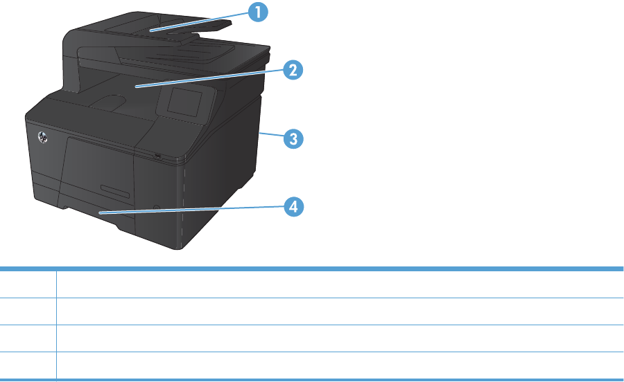
Clear jams
Jam locations
Jams can occur in these locations:
1 Document feeder
2 Output bin
3Rear door
4Input tray
Loose toner might remain in the product after a jam. This problem typically resolves itself after a few
sheets have been printed.
ENWW Clear jams 85
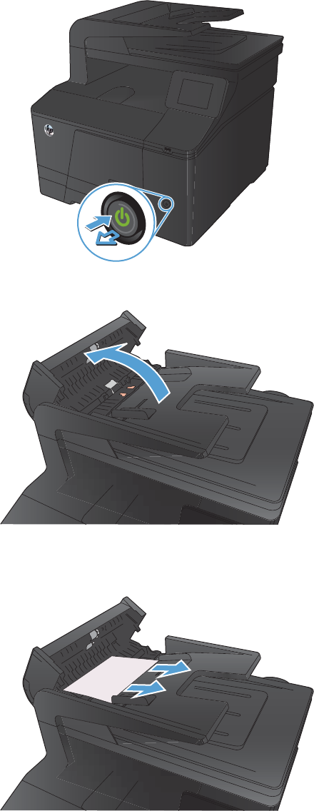
Clear jams from the document feeder
1. Turn the product off.
2. Open the document feeder cover.
3. Lift the document feeder roller assembly, and
gently pull the jammed paper out.
86 Chapter 2 Solve problems ENWW
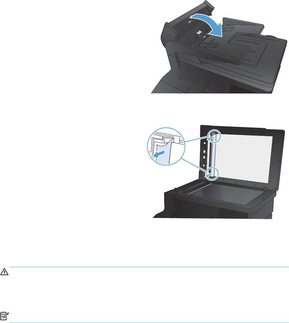
4. Close the document feeder roller assembly,
and then close the document feeder cover.
5. Open the scanner lid. If paper is jammed
behind the white plastic backing, gently pull it
out.
Clear jams in the paper input tray
CAUTION: Do not use sharp objects, such as tweezers or needle-nose pliers, to remove jams.
Damage caused by sharp objects is not covered by the warranty.
When removing jammed paper, pull it straight out from the product. Pulling jammed paper out of the
product at an angle can damage the product.
NOTE: Depending on where the jam is located, some of the following steps might not be necessary.
ENWW Clear jams 87
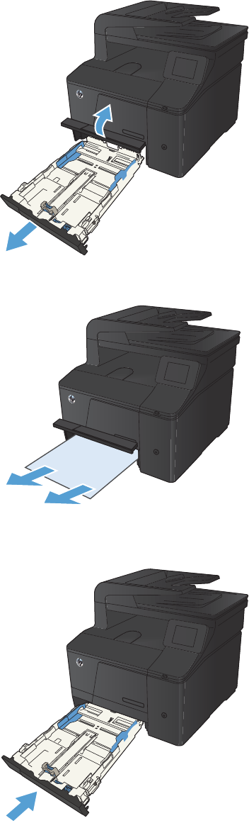
1. Pull out the tray, and lift the jam access door
above the tray.
2. With both hands, grasp the paper, and
carefully pull it free from the product.
3. Replace the tray.
4. Press the OK button to continue printing.
88 Chapter 2 Solve problems ENWW
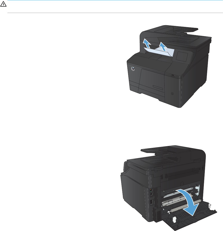
Clear jams from the output bin
CAUTION: Do not use sharp objects, such as tweezers or needle-nose pliers, to remove jams.
Damage caused by sharp objects will not be covered by the warranty.
1. With both hands, grasp the paper, and
carefully pull it free from the product.
Clear jams from the rear door
1. Open the rear door.
CAUTION: The fuser is located above the
rear door, and it is hot. Do not attempt to
reach into the area above the rear door until
the fuser is cool.
ENWW Clear jams 89
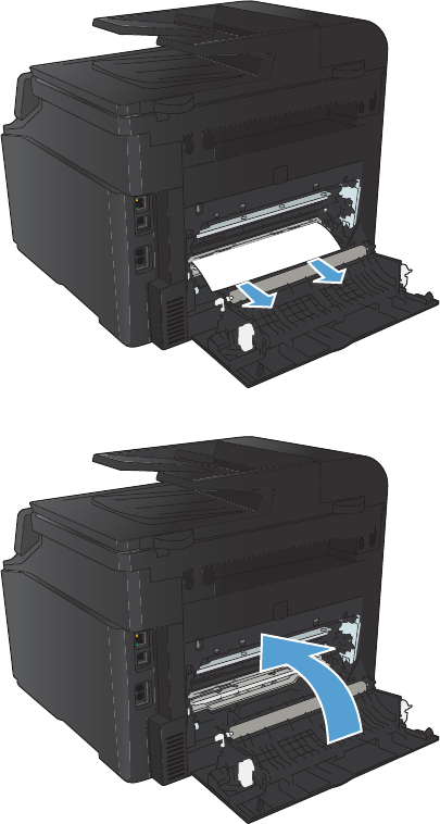
2. With both hands, grasp the paper, and
carefully pull it free from the product.
NOTE: If the sheet tears, remove all
fragments before continuing. Do not use sharp
objects to remove fragments.
3. Close the rear door.
90 Chapter 2 Solve problems ENWW
Solve paper-handling problems
The product picks up multiple sheets of paper
If the product picks up multiple sheets of paper from the tray, try these solutions.
1. Remove the stack of paper from the tray and flex it, rotate it 180 degrees, and flip it over. Do not
fan the paper. Return the stack of paper to the tray.
2. Use only paper that meets HP specifications for this product.
3. Use paper that is not wrinkled, folded, or damaged. If necessary, use paper from a different
package.
4. Make sure the tray is not overfilled. If it is, remove the entire stack of paper from the tray,
straighten the stack, and then return some of the paper to the tray.
5. Make sure the paper guides in the tray are adjusted correctly for the size of paper. Align the
guides with the paper-size markings in the bottom of the tray.
The product does not pick up paper
If the product does not pick up paper from the tray, try these solutions.
1. Open the product and remove any jammed sheets of paper.
2. Load the tray with the correct size of paper for your job.
3. Make sure the paper guides in the tray are adjusted correctly for the size of paper. Align the
guides with the paper-size markings in the bottom of the tray.
4. Check the product control panel to see if the product is waiting for you to acknowledge a prompt
to feed the paper manually. Load paper, and continue.
ENWW Solve paper-handling problems 91

Solve image quality problems
You can prevent most print-quality problems by following these guidelines.
●Use the correct paper type setting in the printer driver
●Adjust color settings in the printer driver
●Use paper that meets HP specifications
●Print a cleaning page
●Calibrate the product to align the colors
●Check the toner cartridges
●Use the printer driver that best meets your printing needs
Use the correct paper type setting in the printer driver
Check the paper type setting if you are having any of the following problems:
●Toner is smearing on the printed pages.
●Repeated marks occur on the printed pages.
●Printed pages are curled.
●Toner flakes off the printed pages.
●Printed pages have small unprinted areas.
Change the paper type setting for Windows
1. On the File menu in the software program, click Print.
2. Select the product, and then click the Properties or Preferences button.
3. Click the Paper/Quality tab.
4. From the Paper type drop-down list, click the More... option.
5. Expand the list of Type is: options.
6. Expand each category of paper types until you find the paper type that you are using.
7. Select the option for the type of paper you are using, and click the OK button.
Change the paper type setting for Mac
1. On the File menu in the software program, click the Print option.
2. In the Copies & Pages menu, click the Page Setup button.
3. Select a size from the Paper Size drop-down list, and then click the OK button.
92 Chapter 2 Solve problems ENWW
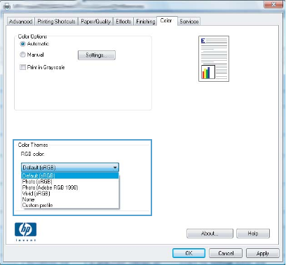
4. Open the Finishing menu.
5. Select a type from the Media-type drop-down list.
6. Click the Print button.
Adjust color settings in the printer driver
Change the color theme for a print job
1. On the File menu in the software program, click Print.
2. Click Properties or Preferences.
3. Click the Color tab.
4. Select a color theme from the Color Themes drop-down list.
●Default (sRGB): This theme sets the product to print RGB data in raw device mode. When
using this theme, manage color in the software program or in the operating system for correct
rendering.
●Vivid: The product increases the color saturation in the midtones. Use this theme when
printing business graphics.
●Photo: The product interprets RGB color as if it were printed as a photograph using a digital
mini lab. The product renders deeper, more saturated colors differently than with the Default
(sRBG) theme. Use this theme when printing photos.
●Photo (Adobe RGB 1998): Use this theme with printing digital photos that use the
AdobeRGB color space rather than sRGB. Turn off color management in the software
program when using this theme.
●None
ENWW Solve image quality problems 93
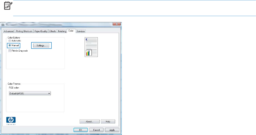
Change the color options
Change the color options settings for the current print job from the color tab of the printer driver.
1. On the File menu in the software program, click Print.
2. Click Properties or Preferences.
3. Click the Color tab.
4. Click the Automatic or Manual setting.
●Automatic setting: Select this setting for most color print jobs
●Manual setting: Select this setting to adjust the color settings independent from other
settings.
NOTE: Changing color settings manually can impact output. HP recommends that only
color graphics experts change these settings.
5. Click the Print in Grayscale option to print a color document in black and white. Use this
option to print color documents for photocopying or faxing.
6. Click the OK button.
Use paper that meets HP specifications
Use different paper if you are having any of the following problems:
●The printing is too light or seems faded in areas.
●Specks of toner are on the printed pages.
●Toner is smearing on the printed pages.
●Printed characters seem misformed.
●Printed pages are curled.
94 Chapter 2 Solve problems ENWW

Always use a paper type and weight that this product supports. In addition, follow these guidelines
when selecting paper:
●Use paper that is of good quality and free of cuts, nicks, tears, spots, loose particles, dust,
wrinkles, voids, staples, and curled or bent edges.
●Use paper that has not been previously printed on.
●Use paper that is designed for use in laser printers. Do not use paper that is designed only for use
in Inkjet printers.
●Use paper that is not too rough. Using smoother paper generally results in better print quality.
Print a cleaning page
Print a cleaning page to remove dust and excess toner from the paper path if you are having any of the
following problems:
●Specks of toner are on the printed pages.
●Toner is smearing on the printed pages.
●Repeated marks occur on the printed pages.
1. From the Home screen on the product control panel, touch the Setup button.
2. Touch the Service menu.
3. Touch the Cleaning Page button.
4. Load plain letter or A4 paper when you are prompted.
5. Touch the OK button to begin the cleaning process.
6. The product prints the first side and then prompts you to remove the page from the output bin and
reload it in Tray 1, keeping the same orientation (the side with the black stripe should be face-
down with the arrow toward the back of the product).
7. Press the OK button to continue the cleaning process. Wait until the process is complete. Discard
the page that prints.
Calibrate the product to align the colors
If the printed output has colored shadows, blurry graphics, or areas that have poor color, you might
need to calibrate the product to align the colors. Print the Diagnostics Page from the Reports menu on
the control panel to check the color alignment. If the blocks of color on that page are not aligned with
each other, you need to calibrate the product.
1. On the product control panel, open the System Setup menu.
2. Open the Print Quality menu, and select the Color Calibration item.
3. Select the Calibrate Now option.
ENWW Solve image quality problems 95

Check the toner cartridges
Check each toner cartridge, and replace them if necessary, if any of the following problems occur:
●The printing is too light or seems faded in areas.
●Printed pages have small unprinted areas.
●Printed pages have streaks or bands.
If a toner cartridge must be replaced, print the supplies status page to find the part number for the
correct genuine HP toner cartridge.
Type of toner cartridge Steps to resolve the problem
Refilled or remanufactured toner
cartridge
Hewlett Packard Company cannot recommend the use of non-HP supplies, either
new or remanufactured. Because they are not HP products, HP cannot influence
their design or control their quality. If you are using a refilled or remanufactured
toner cartridge and are not satisfied with the print quality, replace the toner
cartridge with a genuine HP toner cartridge that includes “HP” or “Hewlett-
Packard”, or has the HP logo on it.
Genuine HP toner cartridge 1. The product control panel or the Supplies Status page indicates Very Low
status when the toner cartridge has reached the end of its estimated life.
Replace the toner cartridge if print quality is no longer acceptable.
2. Print a Print Quality Page from the Reports menu on the control panel. If
streaks or marks are in one color on the page, the color cartridge may be
defective. See the instructions in this document for interpreting the page.
Replace the toner cartridge if necessary.
3. Visually inspect the toner cartridge for damage. See the instructions that
follow. Replace the toner cartridge if necessary.
4. If printed pages have marks that repeat several times at the same distance
apart, print a cleaning page. If this does not solve the problem, use the
repetitive defects ruler in this document to identify the cause of the problem.
Print the Supplies Status page
The Supplies Status page indicates the estimated life remaining in print cartridges. It also lists the part
number for the correct genuine HP print cartridge for your product so you can order a replacement
print cartridge, as well as other useful information.
1. On the product control panel, open the Reports menu.
2. Select the Supplies Status page to print it.
Inspect the print cartridge for damage
1. Remove the print cartridge from the product, and verify that the sealing tape has been removed.
2. Check the memory chip for damage.
96 Chapter 2 Solve problems ENWW
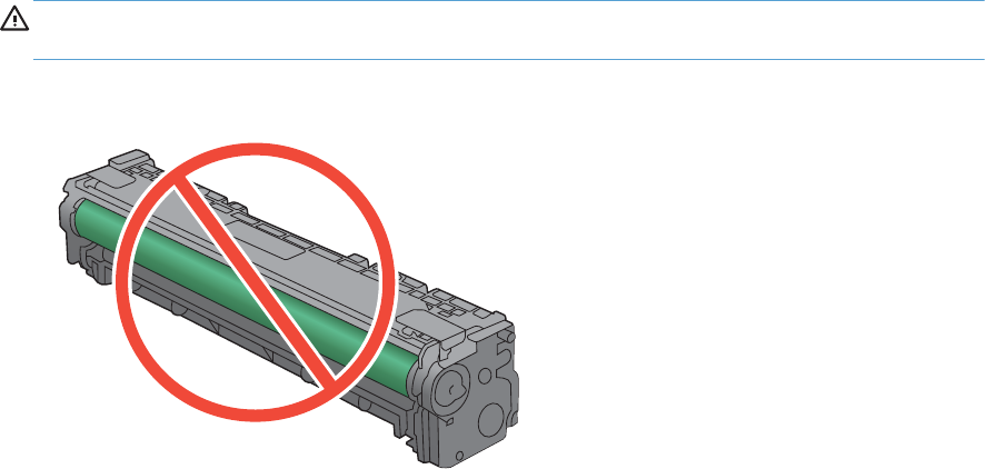
3. Examine the surface of the green imaging drum on the bottom of the print cartridge.
CAUTION: Do not touch the green roller (imaging drum) on the bottom of the cartridge.
Fingerprints on the imaging drum can cause print-quality problems.
4. If you see any scratches, fingerprints, or other damage on the imaging drum, replace the print
cartridge.
5. If the imaging drum does not appear to be damaged, rock the print cartridge gently several times
and reinstall it. Print a few pages to see if the problem has resolved.
Repeating defects
If defects repeat at any of the following intervals on the page, a print cartridge might be damaged.
●22 mm
●27 mm
●29 mm
●76 mm
Use the printer driver that best meets your printing needs
You might need to use a different printer driver if the printed page has unexpected lines in graphics,
missing text, missing graphics, incorrect formatting, or substituted fonts.
ENWW Solve image quality problems 97

HP PCL 6 driver ●Provided as the default driver. This driver is automatically installed unless you
select a different one.
●Recommended for all Windows environments
●Provides the overall best speed, print quality, and product-feature support for
most users
●Developed to align with the Windows Graphic Device Interface (GDI) for the
best speed in Windows environments
●Might not be fully compatible with third-party and custom software programs
that are based on PCL 5
HP UPD PS driver ●Recommended for printing with Adobe
®
software programs or with other
highly graphics-intensive software programs
●Provides support for printing from postscript emulation needs, or for postscript
flash font support
HP UPD PCL 5 ●Recommended for general office printing in Windows environments
●Compatible with previous PCL versions and older HP LaserJet products
●The best choice for printing from third-party or custom software programs
●The best choice when operating with mixed environments, which require the
product to be set to PCL 5 (UNIX, Linux, mainframe)
●Designed for use in corporate Windows environments to provide a single
driver for use with multiple printer models
●Preferred when printing to multiple printer models from a mobile Windows
computer
Download additional printer drivers from this Web site: www.hp.com/support/ljcolorm276series.
98 Chapter 2 Solve problems ENWW

Solve performance problems
Factors affecting print performance
Problem Cause Solution
Pages print but are totally blank. The sealing tape might still be in the
toner cartridges.
Verify that the sealing tape has been
completely removed from the toner
cartridges.
The document might contain blank
pages.
Check the document that is printing to
see if content appears on all of the
pages.
The product might be malfunctioning. To check the product, print a
Configuration page.
Pages print very slowly.
NOTE: The product print speed is
effected by various factors (for example,
media size or page complexity).
Heavier media types can slow the print
job.
Print on a different type of media.
Complex pages can print slowly. Proper fusing might require a slower
print speed to ensure the best print
quality.
Paper type not set correctly. Select the type to match the paper.
Pages did not print. The product might not be pulling media
correctly.
Ensure paper is loaded correctly in the
tray.
If the problem persists, the pickup rollers
and the separation pad may need to be
replaced.
The media is jamming in the device. Clear the jam.
The USB cable might be defective or
incorrectly connected.
●Disconnect the USB cable at both
ends and reconnect it.
●Try printing a job that has printed
in the past.
●Try using a different USB cable.
Other devices are running on your
computer.
The product might not share a USB port.
If an external hard drive or network
switchbox is connected to the same port
as the product, the other device might
be interfering. To connect and use the
product, disconnect the other device or
use two USB ports on the computer.
ENWW Solve performance problems 99
Print speeds
Print speed is the number of pages that print in one minute. Print speed depends on different engine-
process speeds or operational pauses between printed pages during normal product operation. Factors
that determine the print speed of the product include the following:
●Page formatting time
The product must pause for each page to be formatted before it prints. Complex pages take more
time to format, resulting in reduced print speed. However, most jobs print at full engine speed
(21 ppm on Letter-size media or 20 ppm on A4-size media).
●Color mode
Monochrome printing (black only) provides the maximum print speed. Full color print jobs cause a
reduction in print speed.
●Media size
Legal-size media reduces print speed because it is longer than the standard Letter- or A4–size
media. A reduced print speed is used when printing on narrow media to prevent the edges of the
fuser from overheating.
●Media mode
Some media types require a reduced print speed to achieve maximum print quality on that media.
For example, glossy, heavy, and specialty media (for example, envelopes or photos) require a
reduced print speed. To maximize the print speed for special media types, ensure the correct
media type is selected in the print driver.
●Product temperature
To prevent product damage, print speed is reduced if the product reaches a specific internal
temperature (thermal slow down). The starting temperature of the product, the ambient
environment temperature, and the print job size affect the number of pages that can be printed
before the product reduces the print speed. Thermal slow-down reduces print speed by printing
four pages and then pausing for an amount of time before printing continues.
●Other print speed reduction factors
Other factors (especially during large print jobs) that can cause reduced print speeds include:
◦ITB cleaning and lubrication; occurs every 50 to 80 pages and takes about 60 seconds.
◦CPR control sequence; occurs every 450 pages and takes about 90 seconds.
◦Density control sequence; occurs every 150 pages and takes about 120 seconds.
100 Chapter 2 Solve problems ENWW
The product does not print or it prints slowly
The product does not print
If the product does not print at all, try the following solutions.
1. Make sure the product is turned on and that the control panel indicates it is ready.
◦If the control panel does not indicate the product is ready, turn the product off and then on
again.
◦If the control panel indicates the product is ready, try sending the job again.
2. If the control panel indicates the product has an error, resolve the error and then try sending the
job again.
3. Make sure the cables are all connected correctly. If the product is connected to a network, check
the following items:
◦Check the light next to the network connection on the product. If the network is active, the
light is green.
◦Make sure that you are using a network cable and not a phone cord to connect to the
network.
◦Make sure the network router, hub, or switch is turned on and that it is working correctly.
4. Install the HP software from the CD that came with the product. Using generic printer drivers can
cause delays clearing jobs from the print queue.
5. From the list of printers on your computer, right-click the name of this product, click Properties,
and open the Ports tab.
◦If you are using a network cable to connect to the network, make sure the printer name listed
on the Ports tab matches the product name on the product configuration page.
◦If you are using a USB cable and are connecting to a wireless network, make sure the box is
checked next to Virtual printer port for USB.
6. If you are using a personal firewall system on the computer, it might be blocking communication
with the product. Try temporarily disabling the firewall to see if it is the source of the problem.
7. If your computer or the product is connected to a wireless network, low signal quality or
interference might be delaying print jobs.
ENWW Solve performance problems 101

The product prints slowly
If the product prints, but it seems slow, try the following solutions.
1. Make sure the computer meets the minimum specifications for this product. For a list of
specifications, go to this Web site: www.hp.com/support/ljcolorm276series.
2. When you configure the product to print on some paper types, such as heavy paper, the product
prints more slowly so it can correctly fuse the toner to the paper. If the paper type setting is not
correct for the type of paper you are using, change the setting to the correct paper type.
3. If your computer or the product is connected to a wireless network, low signal quality or
interference might be delaying print jobs.
102 Chapter 2 Solve problems ENWW

Solve product connectivity problems
Solve direct-connect problems
If you have connected the product directly to a computer, check the cable.
●Verify that the cable is connected to the computer and to the product.
●Verify that the cable is not longer than 5 m (16.4 ft). Try using a shorter cable.
●Verify that the cable is working correctly by connecting it to another product. Replace the cable if
necessary.
Solve network problems
Check the following items to verify that the product is communicating with the network. Before
beginning, print a configuration page from the product control panel and locate the product IP address
that is listed on this page.
●Poor physical connection
●The computer is using the incorrect IP address for the product
●The computer is unable to communicate with the product
●The product is using incorrect link and duplex settings for the network
●New software programs might be causing compatibility problems
●The computer or workstation might be set up incorrectly
●The product is disabled, or other network settings are incorrect
Poor physical connection
1. Verify that the product is attached to the correct network port using a cable of the correct length.
2. Verify that cable connections are secure.
3. Look at the network port connection on the back of the product, and verify that the amber activity
light and the green link-status light are lit.
4. If the problem continues, try a different cable or port on the hub.
The computer is using the incorrect IP address for the product
1. Open the printer properties and click the Ports tab. Verify that the current IP address for the
product is selected. The product IP address is listed on the product configuration page.
2. If you installed the product using the HP standard TCP/IP port, select the box labeled Always
print to this printer, even if its IP address changes.
ENWW Solve product connectivity problems 103
3. If you installed the product using a Microsoft standard TCP/IP port, use the hostname instead of
the IP address.
4. If the IP address is correct, delete the product and then add it again.
The computer is unable to communicate with the product
1. Test network communication by pinging the network.
a. Open a command-line prompt on your computer. For Windows, click Start, click Run, and
then type cmd.
b. Type ping followed by the IP address for your product.
c. If the window displays round-trip times, the network is working.
2. If the ping command failed, verify that the network hubs are on, and then verify that the network
settings, the product, and the computer are all configured for the same network.
The product is using incorrect link and duplex settings for the network
Hewlett-Packard recommends leaving this setting in automatic mode (the default setting). If the settings
are changed, they must also be changed for the network.
New software programs might be causing compatibility problems
Verify that any new software programs are correctly installed and that they use the correct printer
driver.
The computer or workstation might be set up incorrectly
1. Check the network drivers, printer drivers, and the network redirection.
2. Verify that the operating system is configured correctly.
The product is disabled, or other network settings are incorrect
1. Review the configuration page to check the status of the network protocol. Enable it if necessary.
2. Reconfigure the network settings if necessary.
104 Chapter 2 Solve problems ENWW

Solve wireless network problems
●Wireless connectivity checklist
●The control panel displays the message: The wireless feature on this product has been turned off
●The product does not print after the wireless configuration completes
●The product does not print, and the computer has a third-party firewall installed
●The wireless connection does not work after moving the wireless router or product
●Cannot connect more computers to the wireless product
●The wireless product loses communication when connected to a VPN
●The network does not appear in the wireless networks list
●The wireless network is not functioning
Wireless connectivity checklist
●The product and the wireless router are turned on and have power. Also make sure the wireless
radio in the product is turned on.
●The service set identifier (SSID) is correct. Print a configuration page to determine the SSID. If you
are not sure the SSID is correct, run the wireless setup again.
●With secured networks, make sure the security information is correct. If the security information is
incorrect, run the wireless setup again.
●If the wireless network is working correctly, try accessing other computers on the wireless network.
If the network has Internet access, try connecting to the Internet over a wireless connection.
●The encryption method (AES or TKIP) is the same for the product as it is for the wireless access
point (on networks using WPA security).
●The product is within the range of the wireless network. For most networks, the product must be
within 30 m (100 ft) of the wireless access point (wireless router).
●Obstacles do not block the wireless signal. Remove any large metal objects between the access
point and the product. Make sure poles, walls, or support columns containing metal or concrete
do not separate the product and wireless access point.
●The product is located away from electronic devices that might interfere with the wireless signal.
Many devices can interfere with the wireless signal including motors, cordless phones, security
system cameras, other wireless networks, and some Bluetooth devices.
●The printer driver is installed on the computer.
●You have selected the correct printer port.
●The computer and product connect to the same wireless network.
ENWW Solve product connectivity problems 105
The control panel displays the message: The wireless feature on this product
has been turned off
▲Press the wireless button on the product to open the Wireless menu, and then turn the wireless
radio on.
The product does not print after the wireless configuration completes
1. Make sure the product is turned on and in the ready state.
2. Make sure you are connecting to the correct wireless network.
3. Make sure that the wireless network is working correctly.
a. Open the Network Setup menu, and then open the Wireless Menu item.
b. Select the Run Network Test item to test the wireless network. The product prints a report with
the results.
4. Make sure that the correct port or product is selected.
a. From the list of printers on your computer, right-click the name of this product, click
Properties, and then open the Ports tab.
b. Make sure the box is checked next to Virtual printer port for USB.
5. Make sure that your computer is working correctly. If necessary, restart your computer.
The product does not print, and the computer has a third-party firewall
installed
1. Update the firewall with the most recent update available from the manufacturer.
2. If programs request firewall access when you install the product or try to print, make sure you
allow the programs to run.
3. Temporarily turn off the firewall, and then install the wireless product on the computer. Enable the
firewall when you have completed the wireless installation.
The wireless connection does not work after moving the wireless router or
product
Make sure that the router or product connects to the same network that your computer connects to.
1. Open the Reports menu, and select the Configuration Report item to print the report.
2. Compare the service set identifier (SSID) on the configuration report to the SSID in the printer
configuration for your computer.
3. If the SSIDs are not the same, the devices are not connecting to the same network. Reconfigure the
wireless setup for your product.
106 Chapter 2 Solve problems ENWW
Cannot connect more computers to the wireless product
1. Make sure that the other computers are within the wireless range and that no obstacles block the
signal. For most networks, the wireless range is within 30 m (100 ft) of the wireless access point.
2. Make sure the product is turned on and in the ready state.
3. Turn off any third-party firewalls on your computer.
4. Make sure that the wireless network is working correctly.
a. On the product control panel, open the Network Setup menu, and then open the Wireless
Menu item.
b. Select the Run Network Test item to test the wireless network. The product prints a report with
the results.
5. Make sure that the correct port or product is selected.
a. From the list of printers on your computer, right-click the name of this product, click
Properties, and then open the Ports tab.
b. Click the Configure Port button to verify that the IP address matches the IP address listed
on the Run Network Test report.
6. Make sure that your computer is working correctly. If necessary, restart your computer.
The wireless product loses communication when connected to a VPN
●Typically, you cannot connect to a VPN and other networks at the same time.
The network does not appear in the wireless networks list
●Make sure the wireless router is turned on and has power.
●The network might be hidden. However, you can still connect to a hidden network.
ENWW Solve product connectivity problems 107
The wireless network is not functioning
1. To verify if the network has lost communication, try connecting other devices to the network.
2. Test network communication by pinging the network.
a. Open a command-line prompt on your computer. For Windows, click Start, click Run, and
then type cmd.
b. Type ping followed by the service set identifier (SSID) for your network.
c. If the window displays round-trip times, the network is working.
3. Make sure that the router or product connects to the same network that your computer connects to.
a. Open the Reports menu, and select the Configuration Report item to print the report.
b. Compare the service set identifier (SSID) on the configuration report to the SSID in the printer
configuration for your computer.
c. If the SSIDs are not the same, the devices are not connecting to the same network.
Reconfigure the wireless setup for your product.
108 Chapter 2 Solve problems ENWW
Service mode functions
Secondary service menu
Use the secondary service menu to print service-related reports and to run special tests. Customers do
not have access to this menu.
Open the secondary service menu
1. Touch the Setup button.
2. Touch the middle of the screen along the left-hand edge (callout 1), and then immediately touch
the lower-right corner (callout 2) of the screen.
1
2
3. When the Home screen appears, touch the Setup button.
4. Touch the 2ndary Service button to open the menu.
TIP: When you are finished with the 2ndary Service menu, touch the lower-right corner of the
screen until the Job settings cleared. message appears on the Home screen. This step removes
the 2ndary Service option from the Setup Menu.
Secondary service menu structure
Table 2-6 Secondary service menu
Menu item Sub-menu item Description
Service Reports Cont. Self-Test This item prints a continuous configuration
page.
Error report This item prints an error report that contains
the last 5 instances of 49 Error, Turn off
then on or 79 Error Turn off then on
errors.
ENWW Service mode functions 109

Table 2-6 Secondary service menu (continued)
Menu item Sub-menu item Description
Location A list of available locations appears This item sets certain product parameters that
are dependent on the location, such as the
default paper size and the symbol set.
Scroll to the appropriate location and select
Yes to set the location. The product
automatically restarts after you change the
location.
Display test This test verifies that the LEDs and characters
on the control-panel display function
correctly.
At the beginning of the test, each of the LEDs
turns on one-at-a-time. Touch the OK button
to continue to the next LED.
After the LED test is complete, the character
test begins by testing the pixels on each line.
Then, each of the 255 characters is
displayed in groups of 16. Touch the OK
button to continue to the next group of 16
characters. You can cancel the test at any
time by touching the Cancel button.
Button test This test verifies that the control-panel buttons
function correctly. The display prompts you
to touch each button.
Color Cal. Adjust color This item adjusts density settings for contrast,
highlights, midtones, and shadows. Adjust
each color individually.
Timing This item specifies how frequently the product
should automatically perform a color
calibration. The default setting is 48 hours.
You can turn automatic calibration off.
PBX ring detect On or Off Configure the PBX ring detect setting.
Clean Belt This item runs additional belt-cleaning cycles.
Pick roller This item puts the pickup roller in position for
replacement.
Product resets
The product resets—Restore Defaults and the NVRAM initialization—perform the same function. If
possible, use the Restore Defaults function in the Service menu. If that menu is not accessible, use
the NVRAM sequence.
From the Home screen, touch the Setup button.
110 Chapter 2 Solve problems ENWW

Restore the factory-set defaults
CAUTION: Restoring the factory-set defaults returns all of the product and network settings to the
factory defaults, and it also clears the fax header name, phone number, and any stored faxes in the
product memory. This procedure also clears the fax phone book, and deletes any pages that are stored
in the memory. The procedure then automatically restarts the product.
1. On the product control panel, touch the Setup button.
2. Scroll to and touch the Service menu.
3. Scroll to and touch the Restore Defaults button, and then touch the OK button.
The product automatically restarts.
NVRAM initialization
Performing an NVRAM initialization resets the following settings and information:
●All menu settings are reset to factory default values.
●All localization settings, including language and country/region, are reset.
CAUTION: All onboard network settings are also reset. Be sure to print a configuration page before
restoring defaults. Make note of the IP address that is listed on the HP Jetdirect configuration page. You
might need to restore the IP address after an NVRAM initialization.
After performing an NVRAM initialization, reconfigure any computers that print to this product.
Uninstall and then reinstall the product software on the computers.
1. Turn the product off.
2. Touch the right arrow button. Hold this button as you turn the product on.
NOTE: The right arrow button is not visible when the product is off, but it is still active. Note its
position before you turn off the product.
3. When Permanent storage init. appears on the display, release the right arrow button.
When the product has finished the NVRAM initialization, it returns to the Ready state.
ENWW Service mode functions 111

Solve fax problems
Fax troubleshooting checklist
●Several possible fixes are available. After each recommended action, retry faxing to see if the
problem is resolved.
●For best results during fax problem solving, make sure the line from the product is plugged directly
into the wall phone port. Disconnect all other devices that are connected to the product.
1. Verify that the telephone cord is plugged into the correct port on the back of the product.
2. Check the phone line by using the fax test:
a. From the Home screen on the product control panel, touch the Setup button, and then open
the Service menu.
b. Select the Fax Service option.
c. Select the Run Fax Test option. The product prints a fax test report.
The report contains the following possible results:
●Pass: The report contains all of the current fax settings for review.
●Fail: The cord is in the wrong port. The report contains suggestions for how to resolve
the issue.
●Fail : The phone line is not active. The report contains suggestions for how to resolve
the issue.
3. Verify that the product firmware is current:
a. Print a configuration page from the control panel Reports menu to obtain the current firmware
date code.
b. Go to www.hp.com.
1. Click the Support & Drivers link.
2. Click the Download drivers and software (and firmware) link option.
3. In the For product box, type the product model number, and then click the Go button.
112 Chapter 2 Solve problems ENWW

4. Click the link for your operating system.
5. Scroll to the Firmware section of the table.
◦If the listed version matches the version on the configuration page, you have the
most current version.
◦If the versions are different, download the firmware upgrade and update the
firmware on the product following the instructions onscreen.
NOTE: The product must be connected to a computer with internet access to
upgrade firmware.
◦Resend the fax.
4. Verify that the fax was set up when the product software was installed.
From the computer, in the HP program folder, run the Fax Setup Utility.
5. Verify that the telephone service supports analog fax.
●If using ISDN or digital PBX, contact your service provider for information about configuring
to an analog fax line.
●If using a VoIP service, change the Fax Speed setting to Slow(V.29) or disable Fast(V.34)
from the control panel. Ask if your service provider supports fax and for the recommended
fax modem speed. Some companies might require an adapter.
●If using a DSL service, ensure that a filter is included on the phone line connection to the
product. Contact the DSL service provider or purchase a DSL filter if you do not have one. If a
DSL filter is installed, try another because these filters can be defective.
6. If the error persists, find more detailed problem-solving solutions in the sections that follow this one.
ENWW Solve fax problems 113

Solve problems receiving faxes
●The fax does not respond
●An error message displays on the control panel
●A fax is received but does not print
●Sender receives a busy signal
●No dial tone
●Fax cuts off or prints on two pages
The fax does not respond
The fax has a dedicated phone line
●Set the Answer Mode option to the Automatic setting from the control panel.
a. Touch the Setup button.
b. Open the Fax Setup menu.
c. Open the Basic Setup menu.
d. Open the Answer Mode menu.
e. Select the Automatic setting.
An answering machine is connected to the product
●Set the Answer Mode option to the TAM setting and plug the answering machine into the
“telephone” port.
a. Touch the Setup button.
b. Open the Fax Setup menu.
c. Open the Basic Setup menu.
d. Open the Answer Mode menu.
e. Select the TAM setting.
If the TAM setting is unavailable, set the Answer Mode option to the Automatic setting.
●Set the Rings to Answer setting to at least one ring more than the number of rings for which the
answering machine is set.
a. Touch the Setup button.
b. Open the Fax Setup menu.
c. Open the Basic Setup menu.
114 Chapter 2 Solve problems ENWW

d. Open the Rings to Answer menu.
e. Select the correct setting.
●Connect the answering machine into the “telephone” port.
●If the product has a telephone handset connected, set the Answer Mode option to the Fax/Tel
setting to route calls to the correct device. When detecting a voice call, the product generates a
ring tone that alerts you to pick up the telephone handset.
a. Touch the Setup button.
b. Open the Fax Setup menu.
c. Open the Basic Setup menu.
d. Open the Answer Mode menu.
e. Select the Fax/Tel setting.
A telephone handset is connected to the product
Set the Answer Mode option to the Automatic setting.
1. Touch the Setup button.
2. Open the Fax Setup menu.
3. Open the Basic Setup menu.
4. Open the Answer Mode menu.
5. Select the Automatic setting.
The Answer Mode setting is set to the Manual setting
●Touch the Start Fax button on the control panel.
Voice mail is available on the fax line
●Add a distinctive ring service to your telephone line and change the Distinctive Ring setting on the
product to match the ring pattern supplied by the telephone company. Contact your telephone
company for information.
a. Verify that the answer mode is set to the Automatic setting.
b. Touch the Setup button.
c. Open the Fax Setup menu.
d. Open the Basic Setup menu.
ENWW Solve fax problems 115

e. Open the Distinctive Ring menu.
f. Select the correct setting.
●Buy a dedicated line for faxing.
●Set the Answer Mode option to the Manual setting.
a. Touch the Setup button.
b. Open the Fax Setup menu.
c. Open the Basic Setup menu.
d. Open the Answer Mode menu.
e. Select the Manual setting.
NOTE: You must be present to receive faxes.
The product is connected to a DSL phone service
●Check the installation and features. A DSL modem requires a high-pass filter on the phone line
connection to the product. Contact your DSL service provider for a filter or buy a filter.
●Verify that the filter is plugged in.
●Replace the existing filter to make sure that it is not defective.
The product uses a fax over IP or VoIP phone service
●Set the Fax Speed option to the Slow(V.29) or Medium(V.17) setting, or disable the Fast(V.34)
setting.
a. Touch the Setup button.
b. Open the Fax Setup menu.
c. Open the Advanced Setup menu.
d. Open the Fax Speed menu.
e. Select the correct setting.
●Contact your service provider to make sure that fax is supported and for a recommended fax
speed settings. Some companies might require an adapter.
116 Chapter 2 Solve problems ENWW

An error message displays on the control panel
The No fax detected. message displays
NOTE: This error does not always refer to a missed fax. If a voice call is made to a fax number by
mistake and the caller hangs up, the No fax detected. message displays on the control panel.
●Ask the sender to resend the fax.
●Make sure that the telephone cord from the product is plugged into the wall telephone jack.
●Try a different phone cord.
●Connect the product phone cord into a jack for another phone line.
●Make sure the telephone line and phone wall jack are active by plugging in a telephone and
checking for a dial tone.
●Make sure that the telephone cord is plugged into the “line” port on the product.
●Check the phone line by running a fax test from the control panel.
●If the error persists, contact HP. See www.hp.com/support/ljcolorm276series or the support flyer
that came in the product box.
The Communication error. message displays
●Ask the sender to send the fax again or send at a later time when line conditions have improved.
●Unplug the product telephone cord from the wall, connect a telephone, and try making a call.
Connect the product phone cord into a jack for another phone line.
●Try a different phone cord.
●Set the Fax Speed option to the Slow(V.29) or Medium(V.17) setting, or disable the Fast(V.34)
setting.
a. Touch the Setup button.
b. Open the Fax Setup menu.
c. Open the Advanced Setup menu.
d. Open the Fax Speed menu.
e. Select the correct setting.
●Turn off the Error Correction feature to prevent automatic error correction.
NOTE: Turning off the Error Correction feature can reduce image quality.
a. Touch the Setup button.
b. Open the Service menu.
c. Open the Fax Service menu.
ENWW Solve fax problems 117

d. Open the Error Correction menu.
e. Select the Off setting.
●Print the Fax Activity Log report from the control panel to determine if the error occurs with a
specific fax number.
a. Touch the Fax button, and then touch the Fax Menu button.
b. Open the Fax Reports menu.
c. Open the Fax Activity Log menu.
d. Select the Print Log Now option.
●If the error persists, contact HP. See www.hp.com/support/ljcolorm276series or the support flyer
that came in the product box.
The Fax storage is full. message displays
●Turn the product off then on.
●Print all of the faxes, and then have the sender resend the fax.
●Ask the sender to divide a large fax job into smaller sections, and then fax them individually.
●Make sure that the resolution of the sending fax machine is not set to the Photo setting or the
Superfine setting.
a. Touch the Setup button.
b. Open the Fax Setup menu.
c. Open the Advanced Setup menu.
d. Open the Fax Resolution menu.
e. Select the correct setting.
●Cancel all fax jobs or clear the faxes from memory.
The Fax is busy. message displays
●The product cannot receive a fax while attempting to send one. Cancel the fax send and try
sending at a later time.
●Allow the product to try sending the fax again.
118 Chapter 2 Solve problems ENWW

A fax is received but does not print
The Private Receive feature is on
●When the Private Receive feature is activated, received faxes are stored in memory. A password is
required to print the stored faxes.
●Enter the password to print the fax. If you do not know the password, contact the product
administrator.
NOTE: Memory errors might occur if the faxes are not printed. The product will not answer if the
memory is full.
Sender receives a busy signal
A handset is connected to the product
●Make sure the phone is hung up.
●Change the Answer Mode option to match the product setup.
a. Touch the Setup button.
b. Open the Fax Setup menu.
c. Open the Basic Setup menu.
d. Open the Answer Mode menu.
e. Select the setting that matches the product setup.
Set the Answer Mode option to the Fax/Tel setting to automatically receive faxes. The Fax/
Tel setting automatically detects whether the incoming transmission is a fax or a voice call
and routes the call to the appropriate device.
A phone line splitter is being used
●If you are using a phone line splitter, remove the splitter and set up the phone as a downstream
phone.
●Make sure the phone is hung up.
●Make sure the phone is not being used for a voice call when faxing.
No dial tone
●If using a phone line splitter, remove the phone line splitter and set up the phone as a downstream
phone.
ENWW Solve fax problems 119

Fax cuts off or prints on two pages
●Set the Default Paper Size setting. Faxes print on a single size of paper based on the Default
Paper Size settings.
a. Open the Setup Menu menu.
b. Open the System Setup menu.
c. Open the Paper Setup menu.
d. Open the Default Paper Size menu.
e. Select the correct setting.
●Set the paper type and size for the tray used for faxes.
●Turn on the Fit to Page setting to print longer length faxes on letter or A4 size paper.
a. Open the Setup Menu menu.
b. Open the Fax Setup menu.
c. Open the Advanced Setup menu.
d. Open the Fit to Page menu.
e. Select the On setting.
NOTE: If the Fit to Page setting is off and the Default Paper Size setting is set to letter, a legal size
original prints on two pages.
Solve problems sending faxes
●An error message displays on the control panel
●The control panel displays a Ready message with no attempt to send the fax
●The control panel displays the message "Storing page 1" and does not progress beyond that
message
●Faxes can be received, but not sent
●Unable to use fax functions from the control panel
●Unable to use speed dials
●Unable to use group dials
●Receive a recorded error message from the phone company when trying to send a fax
●Unable to send a fax when a phone is connected to the product
120 Chapter 2 Solve problems ENWW

An error message displays on the control panel
The Communication error. message displays
●Allow the product to retry sending the fax. Re-sending temporarily reduces the fax speed.
●Unplug the product telephone cord from the wall, connect a telephone, and try making a call.
Connect the product phone cord into a jack for another phone line.
If the product is connected to a digital phone line, verify that you are using the correct filter and
settings provided by the digital service provider.
●Try a different phone cord.
●From the control panel, change the Fax Speed option to the Medium(V.17) setting or Slow(V.29)
setting.
a. Touch the Setup button.
b. Open the Fax Setup menu.
c. Open the Advanced Setup menu.
d. Open the Fax Speed menu.
e. Select the correct setting.
●Turn off the Error Correction option.
a. Touch the Setup button.
b. Open the Service menu.
c. Open the Fax Service menu.
d. Open the Error Correction menu.
e. Touch the Off setting.
NOTE: Turning off the Error Correction option can reduce image quality.
●If the error persists, contact HP. See www.hp.com/support/ljcolorm276series or the support flyer
that came in the product box.
No dial tone.
●Make sure that the telephone cord is plugged into the correct port on the product.
●Make sure that the telephone cord from the product is plugged directly into the wall telephone
jack.
●Check for a dial tone on the phone line by using the Start Fax button.
●Unplug the product telephone cord from the wall, connect a telephone, and try making a voice
call.
ENWW Solve fax problems 121

●Unplug the telephone cord from both the product and the wall and replug the cord.
●Make sure that you are using the telephone cord that came with the product.
●Connect the product phone cord into a jack for another phone line.
●Check the phone line by using the Run Fax Test option from the Service menu on the control panel.
a. Touch the Setup button.
b. Open the Service menu.
c. Open the Fax Service menu.
d. Select the Run Fax Test item.
The Fax is busy. message displays
●Try sending the fax again.
●Call the recipient to ensure that the fax machine is on and ready.
●Check that you are dialing the correct fax number.
●Check for a dial tone on the phone line by using the Start Fax button.
●Make sure that the phone is working by disconnecting the product, plugging in a telephone to the
phone line, and making a voice call.
●Connect the product phone cord into a jack for another phone line, and try sending the fax again.
●Try a different phone cord.
●Send the fax at a later time.
●If the error persists, contact HP. See www.hp.com/support/ljcolorm276series or the support flyer
that came in the product box.
The No fax answer. message displays
●Try to resend the fax.
●Call the recipient to ensure that the fax machine is on and ready.
●Check that you are dialing the correct fax number.
●Unplug the product telephone cord from the wall, connect a telephone, and try making a voice
call.
●Connect the product phone cord into a jack for another phone line.
●Try a different phone cord.
●Make sure that the phone cord from the wall telephone jack is plugged into the line port.
122 Chapter 2 Solve problems ENWW

●Check the phone line by using the Run Fax Test option from the Service menu on the control panel.
a. Touch the Setup button.
b. Open the Service menu.
c. Open the Fax Service menu.
d. Select the Run Fax Test item.
●If the error persists, contact HP. See www.hp.com/support/ljcolorm276series or the support flyer
that came in the product box.
Document feeder paper jam
●Verify that the paper meets product size requirements. The product does not support pages longer
than 381 mm (15 in) for faxing.
●Copy or print the original to letter, A4, or legal size paper, and then resend the fax.
The Fax storage is full. message displays
●Turn the product off then on.
●Print stored faxes that have not been printed.
a. Touch the Fax button, and then open the Fax Menu menu.
b. Open the Receive Options menu.
c. Select the Print Private Faxes item.
d. Provide the password when the product prompts you.
●Delete stored faxes from memory.
a. Touch the Setup button.
b. Open the Service menu.
c. Open the Fax Service menu.
d. Select the Clear Saved Faxes item.
●Divide the large fax job into smaller sections, and then fax them individually.
Scanner error
●Verify that the paper meets product size requirements. The product does not support pages longer
than 381 mm (15 in) for faxing.
●Copy or print the original onto letter, A4, or legal size paper and then resend the fax.
ENWW Solve fax problems 123

The control panel displays a Ready message with no attempt to send the fax
●Check the fax activity log for errors.
a. Touch the Fax button, and then open the Fax Menu item.
b. Open the Fax Reports menu.
c. Open the Fax Activity Log menu.
d. Select the Print Log Now option.
●If a phone is connected to the product, make sure that the phone is hung up.
●Disconnect all other lines between the fax and the product.
●Connect the product directly into the wall telephone jack and resend the fax.
The control panel displays the message "Storing page 1" and does not
progress beyond that message
●Delete stored faxes from memory.
a. Touch the Setup button.
b. Open the Service menu.
c. Open the Fax Service menu.
d. Select the Clear Saved Faxes item.
Faxes can be received, but not sent
Send fax and nothing happens.
1. Check for a dial tone on the phone line by using the Start Fax button.
2. Turn the product off then on.
3. Use the control panel or the HP Fax Setup Wizard to configure the fax time, date, and fax header
information.
a. Touch the Setup button.
b. Open the Fax Setup menu.
c. Open the Basic Setup menu.
d. Open the Fax Header menu.
e. Enter the correct settings.
4. Verify that any extension phones on the line are hung up.
5. If using a DSL service, make sure that the phone line connection to the product includes a high-
pass filter.
124 Chapter 2 Solve problems ENWW

Unable to use fax functions from the control panel
●The product might be password protected. Use the HP Embedded Web Server, HP Toolbox
software, or the control panel to set a password.
●If you do not know the password for the product, contact your system administrator.
●Verify with the system administrator that the fax functionality has not been disabled.
Unable to use speed dials
●Make sure that the fax number is valid.
●If an outside line requires a prefix, turn on the Dial Prefix option or include the prefix in the speed
dial number.
a. Touch the Setup button.
b. Open the Fax Setup menu.
c. Open the Basic Setup menu.
d. Open the Dial Prefix menu.
e. Select the On setting.
Unable to use group dials
●Make sure that the fax number is valid.
●If an outside line requires a prefix, turn on the Dial Prefix option or include the prefix in the speed
dial number.
a. Touch the Setup button.
b. Open the Fax Setup menu.
c. Open the Basic Setup menu.
d. Open the Dial Prefix menu.
e. Select the On setting.
●Set up all entries in the group with speed dial entries.
a. Open an unused speed dial entry.
b. Enter the fax number for the speed dial.
c. Touch the OK button to save the speed dial.
ENWW Solve fax problems 125

Receive a recorded error message from the phone company when trying to
send a fax
●Make sure you dial the fax number correctly, and make sure that the phone service is not blocked.
For example, some phone services might prevent long distance calling.
●If an outside line requires a prefix, turn on the Dial Prefix option or include the prefix in the speed
dial number.
a. Touch the Setup button.
b. Open the Fax Setup menu.
c. Open the Basic Setup menu.
d. Open the Dial Prefix menu.
e. Select the On setting.
NOTE: To send a fax without a prefix, when the Dial Prefix option is turned on, send the fax
manually.
●Send a fax to an international number
a. If a prefix is required, manually dial the telephone number with the prefix.
b. Enter the country/region code before dialing the phone number.
c. Wait for pauses as you hear the tones on the phone.
d. Send the fax manually from the control panel.
Unable to send a fax when a phone is connected to the product
●Make sure that the telephone is hung up.
●Make sure that the telephone is not being used for a voice call when faxing.
●Unplug the phone from the line, and then try sending the fax.
126 Chapter 2 Solve problems ENWW

Solve fax performance problems
●Faxes are sending slowly
●Fax quality is poor
Faxes are sending slowly
The product is experiencing poor phone line quality.
●Retry sending the fax when the line conditions have improved.
●Check with the phone service provider that the line supports fax.
●Turn off the Error Correction setting.
a. Open the Setup Menu menu.
b. Open the Service menu.
c. Open the Fax Service menu.
d. Open the Error Correction menu.
e. Select the Off setting.
NOTE: This can reduce image quality.
●Use white paper for the original. Do not use colors such as gray, yellow, or pink.
●Increase the Fax Speed setting.
a. Open the Setup Menu menu.
b. Open the Fax Setup menu.
c. Open the Advanced Setup menu.
d. Open the Fax Speed menu.
e. Select the correct setting.
●Divide large fax jobs into smaller sections, and then fax them individually.
●Change the fax settings on the control panel to a lower resolution.
a. Open the Setup Menu menu.
b. Open the Fax Setup menu.
c. Open the Advanced Setup menu.
d. Open the Fax Resolution menu.
e. Select the correct setting.
ENWW Solve fax problems 127

Fax quality is poor
If the fax is blurry or light, try the following steps to correct the problem.
●Increase fax resolution when sending faxes. Resolution does not affect received faxes.
a. Open the Setup Menu menu.
b. Open the Fax Setup menu.
c. Open the Advanced Setup menu.
d. Open the Fax Resolution menu.
e. Select the correct setting.
NOTE: Increasing resolution slows transmission speed.
●Turn on the Error Correction setting from the control panel.
a. Open the Setup Menu menu.
b. Open the Service menu.
c. Open the Fax Service menu.
d. Open the Error Correction menu.
e. Select the On setting.
●Check the toner cartridge. Replace it if necessary.
●Ask the sender to darken the contrast setting on the sending fax machine, and then resend the fax.
Solve DSL problems
Cannot send or receive a fax on a PBX line
●If you are using a PBX phone line, contact your PBX administrator to configure an analog fax line
for your product.
Product updates
Software and firmware updates and installation instructions for this product are available at
www.hp.com/support/ljcolorm276series. Click Support & Drivers, click the operating system, and
then select the download for the product.
128 Chapter 2 Solve problems ENWW


Hewlett-Packard limited warranty statement
HP PRODUCT DURATION OF LIMITED WARRANTY
HP Color LaserJet Pro 200 color M276 One-year product exchange
HP warrants to you, the end-user customer, that HP hardware and accessories will be free from defects
in materials and workmanship after the date of purchase, for the period specified above. If HP receives
notice of such defects during the warranty period, HP will, at its option, either repair or replace
products which prove to be defective. Replacement products may be either new or equivalent in
performance to new.
HP warrants to you that HP software will not fail to execute its programming instructions after the date
of purchase, for the period specified above, due to defects in material and workmanship when
properly installed and used. If HP receives notice of such defects during the warranty period, HP will
replace software which does not execute its programming instructions due to such defects.
HP does not warrant that the operation of HP products will be uninterrupted or error free. If HP is
unable, within a reasonable time, to repair or replace any product to a condition as warranted, you
will be entitled to a refund of the purchase price upon prompt return of the product.
HP products may contain remanufactured parts equivalent to new in performance or may have been
subject to incidental use.
Warranty does not apply to defects resulting from (a) improper or inadequate maintenance or
calibration, (b) software, interfacing, parts or supplies not supplied by HP, (c) unauthorized
modification or misuse, (d) operation outside of the published environmental specifications for the
product, or (e) improper site preparation or maintenance.
TO THE EXTENT ALLOWED BY LOCAL LAW, THE ABOVE WARRANTIES ARE EXCLUSIVE AND NO
OTHER WARRANTY OR CONDITION, WHETHER WRITTEN OR ORAL, IS EXPRESSED OR IMPLIED
AND HP SPECIFICALLY DISCLAIMS ANY IMPLIED WARRANTIES OR CONDITIONS OF
MERCHANTABILITY, SATISFACTORY QUALITY, AND FITNESS FOR A PARTICULAR PURPOSE. Some
countries/regions, states or provinces do not allow limitations on the duration of an implied warranty,
so the above limitation or exclusion might not apply to you. This warranty gives you specific legal rights
and you might also have other rights that vary from country/region to country/region, state to state, or
province to province.
HP's limited warranty is valid in any country/region or locality where HP has a support presence for
this product and where HP has marketed this product. The level of warranty service you receive may
vary according to local standards. HP will not alter form, fit or function of the product to make it
operate in a country/region for which it was never intended to function for legal or regulatory reasons.
TO THE EXTENT ALLOWED BY LOCAL LAW, THE REMEDIES IN THIS WARRANTY STATEMENT ARE
YOUR SOLE AND EXCLUSIVE REMEDIES. EXCEPT AS INDICATED ABOVE, IN NO EVENT WILL HP OR
ITS SUPPLIERS BE LIABLE FOR LOSS OF DATA OR FOR DIRECT, SPECIAL, INCIDENTAL,
CONSEQUENTIAL (INCLUDING LOST PROFIT OR DATA), OR OTHER DAMAGE, WHETHER BASED
IN CONTRACT, TORT, OR OTHERWISE. Some countries/regions, states or provinces do not allow the
exclusion or limitation of incidental or consequential damages, so the above limitation or exclusion may
not apply to you.
130 Appendix A Service and support ENWW
THE WARRANTY TERMS CONTAINED IN THIS STATEMENT, EXCEPT TO THE EXTENT LAWFULLY
PERMITTED, DO NOT EXCLUDE, RESTRICT OR MODIFY AND ARE IN ADDITION TO THE
MANDATORY STATUTORY RIGHTS APPLICABLE TO THE SALE OF THIS PRODUCT TO YOU.
ENWW Hewlett-Packard limited warranty statement 131
HP's Premium Protection Warranty: LaserJet print
cartridge limited warranty statement
This HP product is warranted to be free from defects in materials and workmanship.
This warranty does not apply to products that (a) have been refilled, refurbished, remanufactured or
tampered with in any way, (b) experience problems resulting from misuse, improper storage, or
operation outside of the published environmental specifications for the printer product or (c) exhibit
wear from ordinary use.
To obtain warranty service, please return the product to place of purchase (with a written description of
the problem and print samples) or contact HP customer support. At HP's option, HP will either replace
products that prove to be defective or refund your purchase price.
TO THE EXTENT ALLOWED BY LOCAL LAW, THE ABOVE WARRANTY IS EXCLUSIVE AND NO
OTHER WARRANTY OR CONDITION, WHETHER WRITTEN OR ORAL, IS EXPRESSED OR IMPLIED
AND HP SPECIFICALLY DISCLAIMS ANY IMPLIED WARRANTIES OR CONDITIONS OF
MERCHANTABILITY, SATISFACTORY QUALITY, AND FITNESS FOR A PARTICULAR PURPOSE.
TO THE EXTENT ALLOWED BY LOCAL LAW, IN NO EVENT WILL HP OR ITS SUPPLIERS BE LIABLE
FOR DIRECT, SPECIAL, INCIDENTAL, CONSEQUENTIAL (INCLUDING LOST PROFIT OR DATA), OR
OTHER DAMAGE, WHETHER BASED IN CONTRACT, TORT, OR OTHERWISE.
THE WARRANTY TERMS CONTAINED IN THIS STATEMENT, EXCEPT TO THE EXTENT LAWFULLY
PERMITTED, DO NOT EXCLUDE, RESTRICT OR MODIFY AND ARE IN ADDITION TO THE
MANDATORY STATUTORY RIGHTS APPLICABLE TO THE SALE OF THIS PRODUCT TO YOU.
132 Appendix A Service and support ENWW

Data stored on the print cartridge
The HP print cartridges used with this product contain a memory chip that assists in the operation of the
product.
In addition, this memory chip collects a limited set of information about the usage of the product, which
might include the following: the date when the print cartridge was first installed, the date when the print
cartridge was last used, the number of pages printed using the print cartridge, the page coverage, the
printing modes used, any printing errors that might have occurred, and the product model. This
information helps HP design future products to meet our customers' printing needs.
The data collected from the print cartridge memory chip does not contain information that can be used
to identify a customer or user of the print cartridge or their product.
HP collects a sampling of the memory chips from print cartridges returned to HP's free return and
recycling program (HP Planet Partners: www.hp.com/recycle). The memory chips from this sampling
are read and studied in order to improve future HP products. HP partners who assist in recycling this
print cartridge might have access to this data, as well.
Any third party possessing the print cartridge might have access to the anonymous information on the
memory chip. If you prefer to not allow access to this information, you can render the chip inoperable.
However, after you render the memory chip inoperable, the memory chip cannot be used in an HP
product.
ENWW Data stored on the print cartridge 133
End User License Agreement
PLEASE READ CAREFULLY BEFORE USING THIS SOFTWARE PRODUCT: This End-User License
Agreement (“EULA”) is a contract between (a) you (either an individual or the entity you represent) and
(b) Hewlett-Packard Company (“HP”) that governs your use of the software product (“Software”). This
EULA does not apply if there is a separate license agreement between you and HP or its suppliers for
the Software, including a license agreement in online documentation. The term “Software” may include
(i) associated media, (ii) a user guide and other printed materials, and (iii) “online” or electronic
documentation (collectively “User Documentation”).
RIGHTS IN THE SOFTWARE ARE OFFERED ONLY ON THE CONDITION THAT YOU AGREE TO ALL
TERMS AND CONDITIONS OF THIS EULA. BY INSTALLING, COPYING, DOWNLOADING, OR
OTHERWISE USING THE SOFTWARE, YOU AGREE TO BE BOUND BY THIS EULA. IF YOU DO NOT
ACCEPT THIS EULA, DO NOT INSTALL, DOWNLOAD, OR OTHERWISE USE THE SOFTWARE. IF
YOU PURCHASED THE SOFTWARE BUT DO NOT AGREE TO THIS EULA, PLEASE RETURN THE
SOFTWARE TO YOUR PLACE OF PURCHASE WITHIN FOURTEEN DAYS FOR A REFUND OF THE
PURCHASE PRICE; IF THE SOFTWARE IS INSTALLED ON OR MADE AVAILABLE WITH ANOTHER
HP PRODUCT, YOU MAY RETURN THE ENTIRE UNUSED PRODUCT.
1. THIRD PARTY SOFTWARE. The Software may include, in addition to HP proprietary software
(“HP Software”), software under licenses from third parties (“Third Party Software” and “Third Party
License”). Any Third Party Software is licensed to you subject to the terms and conditions of the
corresponding Third Party License. Generally, the Third Party License is located in a file such as
license.txt; you should contact HP support if you cannot find any Third Party License. If the Third Party
Licenses include licenses that provide for the availability of source code (such as the GNU General
Public License) and the corresponding source code is not included with the Software, then check the
product support pages of HP’s website (hp.com) to learn how to obtain such source code.
2. LICENSE RIGHTS. You will have the following rights provided you comply with all terms and
conditions of this EULA:
a. Use. HP grants you a license to Use one copy of the HP Software. “Use” means installing, copying,
storing, loading, executing, displaying, or otherwise using the HP Software. You may not modify the
HP Software or disable any licensing or control feature of the HP Software. If this Software is provided
by HP for Use with an imaging or printing product (for example, if the Software is a printer driver,
firmware, or add-on), the HP Software may only be used with such product (“HP Product”). Additional
restrictions on Use may appear in the User Documentation. You may not separate component parts of
the HP Software for Use. You do not have the right to distribute the HP Software.
b. Copying. Your right to copy means you may make archival or back-up copies of the HP Software,
provided each copy contains all the original HP Software’s proprietary notices and is used only for
back-up purposes.
3. UPGRADES. To Use HP Software provided by HP as an upgrade, update, or supplement (collectively
“Upgrade”), you must first be licensed for the original HP Software identified by HP as eligible for the
Upgrade. To the extent the Upgrade supersedes the original HP Software, you may no longer use such
HP Software. This EULA applies to each Upgrade unless HP provides other terms with the Upgrade. In
case of a conflict between this EULA and such other terms, the other terms will prevail.
4. TRANSFER.
134 Appendix A Service and support ENWW
a. Third Party Transfer. The initial end user of the HP Software may make a one-time transfer of the
HP Software to another end user. Any transfer will include all component parts, media, User
Documentation, this EULA, and if applicable, the Certificate of Authenticity. The transfer may not be an
indirect transfer, such as a consignment. Prior to the transfer, the end user receiving the transferred
Software will agree to this EULA. Upon transfer of the HP Software, your license is automatically
terminated.
b. Restrictions. You may not rent, lease or lend the HP Software or Use the HP Software for commercial
timesharing or bureau use. You may not sublicense, assign or otherwise transfer the HP Software
except as expressly provided in this EULA.
5. PROPRIETARY RIGHTS. All intellectual property rights in the Software and User Documentation are
owned by HP or its suppliers and are protected by law, including applicable copyright, trade secret,
patent, and trademark laws. You will not remove any product identification, copyright notice, or
proprietary restriction from the Software.
6. LIMITATION ON REVERSE ENGINEERING. You may not reverse engineer, decompile, or
disassemble the HP Software, except and only to the extent that the right to do so is allowed under
applicable law.
7. CONSENT TO USE OF DATA. HP and its affiliates may collect and use technical information you
provide in relation to (i) your Use of the Software or the HP Product, or (ii) the provision of support
services related to the Software or the HP Product. All such information will be subject to HP’s privacy
policy. HP will not use such information in a form that personally identifies you except to the extent
necessary to enhance your Use or provide support services.
8. LIMITATION OF LIABILITY. Notwithstanding any damages that you might incur, the entire liability of
HP and its suppliers under this EULA and your exclusive remedy under this EULA will be limited to the
greater of the amount actually paid by you for the Product or U.S. $5.00. TO THE MAXIMUM EXTENT
PERMITTED BY APPLICABLE LAW, IN NO EVENT WILL HP OR ITS SUPPLIERS BE LIABLE FOR ANY
SPECIAL, INCIDENTAL, INDIRECT, OR CONSEQUENTIAL DAMAGES (INCLUDING DAMAGES FOR
LOST PROFITS, LOST DATA, BUSINESS INTERRUPTION, PERSONAL INJURY, OR LOSS OF PRIVACY)
RELATED IN ANY WAY TO THE USE OF OR INABILITY TO USE THE SOFTWARE, EVEN IF HP OR
ANY SUPPLIER HAS BEEN ADVISED OF THE POSSIBILITY OF SUCH DAMAGES AND EVEN IF THE
ABOVE REMEDY FAILS OF ITS ESSENTIAL PURPOSE. Some states or other jurisdictions do not allow
the exclusion or limitation of incidental or consequential damages, so the above limitation or exclusion
may not apply to you.
9. U.S. GOVERNMENT CUSTOMERS. If you are a U.S. Government entity, then consistent with FAR
12.211 and FAR 12.212, Commercial Computer Software, Computer Software Documentation, and
Technical Data for Commercial Items are licensed under the applicable HP commercial license
agreement.
10. COMPLIANCE WITH EXPORT LAWS. You will comply with all laws, rules, and regulations (i)
applicable to the export or import of the Software, or (ii) restricting the Use of the Software, including
any restrictions on nuclear, chemical, or biological weapons proliferation.
11. RESERVATION OF RIGHTS. HP and its suppliers reserve all rights not expressly granted to you in
this EULA.
(c) 2007 Hewlett-Packard Development Company, L.P.
Rev. 11/06
ENWW End User License Agreement 135

OpenSSL
This product includes software developed by the OpenSSL Project for use in the OpenSSL Toolkit
(http://www.openssl.org/)
THIS SOFTWARE IS PROVIDED BY THE OpenSSL PROJECT ``AS IS'' AND ANY EXPRESSED OR
IMPLIED WARRANTIES, INCLUDING, BUT NOT LIMITED TO, THE IMPLIED WARRANTIES OF
MERCHANTABILITY AND FITNESS FOR A PARTICULAR PURPOSE ARE DISCLAIMED. IN NO EVENT
SHALL THE OpenSSL PROJECT OR ITS CONTRIBUTORS BE LIABLE FOR ANY DIRECT, INDIRECT,
INCIDENTAL, SPECIAL, EXEMPLARY, OR CONSEQUENTIAL DAMAGES (INCLUDING, BUT NOT
LIMITED TO, PROCUREMENT OF SUBSTITUTE GOODS OR SERVICES;
LOSS OF USE, DATA, OR PROFITS; OR BUSINESS INTERRUPTION) HOWEVER CAUSED AND ON
ANY THEORY OF LIABILITY, WHETHER IN CONTRACT, STRICT LIABILITY, OR TORT (INCLUDING
NEGLIGENCE OR OTHERWISE) ARISING IN ANY WAY OUT OF THE USE OF THIS SOFTWARE,
EVEN IF ADVISED OF THE POSSIBILITY OF SUCH DAMAGE.
This product includes cryptographic software written by Eric Young (eay@cryptsoft.com). This product
includes software written by Tim Hudson (tjh@cryptsoft.com).
Customer support
Get telephone support for your country/region
Have the product name, serial number, date of purchase, and
problem description ready.
Country/region phone numbers are on the flyer that was in
the box with your product or at www.hp.com/support/.
Get 24-hour Internet support www.hp.com/support/ljcolorm276series
Get support for products used with a Macintosh computer www.hp.com/go/macosx
Download software utilities, drivers, and electronic
information
www.hp.com/support/ljcolorm276series
Order additional HP service or maintenance agreements www.hp.com/go/carepack
Register your product www.register.hp.com
136 Appendix A Service and support ENWW

Repack the product
If HP Customer Care determines that your product needs to be returned to HP for repair, follow these
steps to repack the product before shipping it.
CAUTION: Shipping damage as a result of inadequate packing is the customer’s responsibility.
1. Remove and retain the print cartridges.
CAUTION: It is extremely important to remove the print cartridges before shipping the product.
A print cartridge that remains in the product during shipping can leak and cover the product
engine and other parts with toner.
To prevent damage to the print cartridges, avoid touching the rollers on them, and store the print
cartridges so that they are not exposed to light.
2. Remove and retain the power cable, interface cable, and any optional accessories.
3. If possible, include print samples and 50 to 100 sheets of paper that did not print correctly.
4. In the U.S., call HP Customer Care to request new packing material. In other areas, use the
original packing material, if possible.
ENWW Repack the product 137
138 Appendix A Service and support ENWW


Physical specifications
Table B-1 Physical specifications
Product Height Depth Width Weight
HP LaserJet Pro 200
color MFP M276 Series
414 mm (16.3 in) 476 mm (18.7 in) 449 mm (17.7 in) Without toner
cartridges installed: 21
kg (46.3 lb)
With toner cartridges
installed: 23.6 kg
(52.0 lb)
Power consumption, electrical specifications, and
acoustic emissions
See www.hp.com/support/ljcolorm276series for current information.
CAUTION: Power requirements are based on the country/region where the product is sold. Do not
convert operating voltages. This will damage the product and void the product warranty.
Environmental specifications
Table B-2 Environmental specifications1
Recommended Operating Storage
Temperature 15° to 32.5° C
(59° to 90.5° F)
15° to 32.5° C
(59° to 90.5° F)
–20° to 40° C
(–4° to 104° F)
Relative humidity 20 to 70% 10 to 80% 95% or less
Altitude 0 to 3048 m (0 to 10,000 ft)
1Values are subject to change.
140 Appendix B Product specifications ENWW


FCC regulations
This equipment has been tested and found to comply with the limits for a Class B digital device,
pursuant to Part 15 of the FCC rules. These limits are designed to provide reasonable protection
against harmful interference in a residential installation. This equipment generates, uses, and can
radiate radio frequency energy. If this equipment is not installed and used in accordance with the
instructions, it may cause harmful interference to radio communications. However, there is no guarantee
that interference will not occur in a particular installation. If this equipment does cause harmful
interference to radio or television reception, which can be determined by turning the equipment off and
on, the user is encouraged to try to correct the interference by one or more of the following measures:
●Reorient or relocate the receiving antenna.
●Increase separation between equipment and receiver.
●Connect equipment to an outlet on a circuit different from that to which the receiver is located.
●Consult your dealer or an experienced radio/TV technician.
NOTE: Any changes or modifications to the printer that are not expressly approved by HP could void
the user’s authority to operate this equipment.
Use of a shielded interface cable is required to comply with the Class B limits of Part 15 of FCC rules.
142 Appendix C Regulatory information ENWW

Environmental product stewardship program
Protecting the environment
Hewlett-Packard Company is committed to providing quality products in an environmentally sound
manner. This product has been designed with several attributes to minimize impacts on our
environment.
Ozone production
This product generates no appreciable ozone gas (O
3
).
Power consumption
Power usage drops significantly while in Ready or Sleep mode, which saves natural resources and
saves money without affecting the high performance of this product. Hewlett-Packard printing and
imaging equipment marked with the ENERGY STAR
®
logo is qualified to the U.S. Environmental
Protection Agency's ENERGY STAR specifications for imaging equipment. The following mark will
appear on ENERGY STAR qualified imaging products:
Additional ENERGY STAR qualified imaging product model information is listed at:
www.hp.com/go/energystar
Paper use
This product’s manual duplex feature (two-sided printing) and N-up printing (multiple pages printed on
one page) capability can reduce paper usage and the resulting demands on natural resources.
Plastics
Plastic parts over 25 grams are marked according to international standards that enhance the ability to
identify plastics for recycling purposes at the end of the product’s life.
HP LaserJet print supplies
It’s easy to return and recycle your HP LaserJet print cartridges after use—free of charge—with
HP Planet Partners. Multilingual program information and instructions are included in every new
HP LaserJet print cartridge and supplies package. You help reduce the toll on the environment further
when you return multiple cartridges together rather than separately.
HP is committed to providing inventive, high-quality products and services that are environmentally
sound, from product design and manufacturing to distribution, customer use and recycling. When you
ENWW Environmental product stewardship program 143

participate in the HP Planet Partners program, we ensure your HP LaserJet print cartridges are recycled
properly, processing them to recover plastics and metals for new products and diverting millions of tons
of waste from landfills. Since this cartridge is being recycled and used in new materials, it will not be
returned to you. Thank you for being environmentally responsible!
NOTE: Use the return label to return original HP LaserJet print cartridges only. Please do not use this
label for HP inkjet cartridges, non-HP cartridges, refilled or remanufactured cartridges or warranty
returns. For information about recycling your HP inkjet cartridges please go to http://www.hp.com/
recycle.
Return and recycling instructions
United States and Puerto Rico
The enclosed label in the HP LaserJet toner cartridge box is for the return and recycling of one or more
HP LaserJet print cartridges after use. Please follow the applicable instructions below.
Multiple returns (more than one cartridge)
1. Package each HP LaserJet print cartridge in its original box and bag.
2. Tape the boxes together using strapping or packaging tape. The package can weigh up to 31 kg
(70 lb).
3. Use a single pre-paid shipping label.
OR
1. Use your own suitable box, or request a free bulk collection box from www.hp.com/recycle or
1-800-340-2445 (holds up to 31 kg (70 lb) of HP LaserJet print cartridges).
2. Use a single pre-paid shipping label.
Single returns
1. Package the HP LaserJet print cartridge in its original bag and box.
2. Place the shipping label on the front of the box.
Shipping
For all HP LaserJet print cartridge recycling returns, give the package to UPS during your next delivery
or pickup, or take it to an authorized UPS drop-off center. For the location of your local UPS drop-off
center, call 1-800-PICKUPS or visit www.ups.com. If you are returning via USPS label, give the
package to a U.S. Postal Service carrier or drop off at a U.S. Postal Service Office. For more
information, or to order additional labels or boxes for bulk returns, visit www.hp.com/recycle or call
1-800-340-2445. Requested UPS pickup will be charged normal pickup rates. Information subject to
change without notice.
144 Appendix C Regulatory information ENWW
Residents of Alaska and Hawaii
Do not use the UPS label. Call 1-800-340-2445 for information and instructions. The U.S. Postal
Service provides no-cost cartridge return transportation services under an arrangement with HP for
Alaska and Hawaii.
Non-U.S. returns
To participate in HP Planet Partners return and recycling program, just follow the simple directions in
the recycling guide (found inside the packaging of your new product supply item) or visit
www.hp.com/recycle. Select your country/region for information on how to return your HP LaserJet
printing supplies.
Paper
This product is capable of using recycled papers when the paper meets the guidelines outlined in the
HP LaserJet Printer Family Print Media Guide. This product is suitable for the use of recycled paper
according to EN12281:2002.
Material restrictions
This HP product does not contain added mercury.
This HP product contains a battery that might require special handling at end-of-life. The batteries
contained in or supplied by Hewlett-Packard for this product include the following:
HP LaserJet Pro 200 color MFP M276 Series
Type Carbon monofluoride lithium
Weight 0.8 g
Location On formatter board
User-removable No
For recycling information, you can go to www.hp.com/recycle, or contact your local authorities or the
Electronics Industries Alliance: www.eiae.org.
ENWW Environmental product stewardship program 145

Disposal of waste equipment by users in private households in the
European Union
This symbol on the product or on its packaging indicates that this product must not be disposed of with
your other household waste. Instead, it is your responsibility to dispose of your waste equipment by
handing it over to a designated collection point for the recycling of waste electrical and electronic
equipment. The separate collection and recycling of your waste equipment at the time of disposal will
help to conserve natural resources and ensure that it is recycled in a manner that protects human health
and the environment. For more information about where you can drop off your waste equipment for
recycling, please contact your local city office, your household waste disposal service or the shop
where you purchased the product.
Chemical substances
HP is committed to providing our customers with information about the chemical substances in our
products as needed to comply with legal requirements such as REACH (Regulation EC No 1907/2006
of the European Parliament and the Council). A chemical information report for this product can be
found at: www.hp.com/go/reach.
Material Safety Data Sheet (MSDS)
Material Safety Data Sheets (MSDS) for supplies containing chemical substances (for example, toner)
can be obtained by accessing the HP Web site at www.hp.com/go/msds or www.hp.com/hpinfo/
community/environment/productinfo/safety.
For more information
To obtain information about these environmental topics:
●Product environmental profile sheet for this and many related HP products
●HP’s commitment to the environment
●HP’s environmental management system
●HP’s end-of-life product return and recycling program
●Material Safety Data Sheets
Visit www.hp.com/go/environment or www.hp.com/hpinfo/globalcitizenship/environment.
146 Appendix C Regulatory information ENWW

Declaration of conformity
Declaration of Conformity
according to ISO/IEC 17050-1 and EN 17050-1
Manufacturer's Name: Hewlett-Packard Company DoC#: BOISB-1104-02 Rel.1.0
Manufacturer's Address: 11311 Chinden Boulevard
Boise, Idaho 83714-1021, USA
declares, that the product
Product Name: HP LaserJet Pro 200 color MFP M276n
Regulatory Model Numbers:
2)
BOISB-1104-02
BOISB-1102-00 – (US-Fax Module LIU)
BOISB-1102-01 – (EURO-Fax Module LIU)
Product Options: All
Print Cartridges: CF210A, CF210X , CF211A, CF212A, CF213A
conforms to the following Product Specifications:
SAFETY: IEC 60950-1:2005 +A1 / EN60950-1: 2006 +A11:2009 +A1:2010 +A12:2011
IEC 60825-1:2007 / EN 60825-1:2007 (Class 1 Laser/LED Product)
IEC 62479:2010/EN 62479:2010
GB4943-2001
EMC: CISPR22:2005 +A1/ EN55022:2006 +A1 - Class B
1)
EN 61000-3-2 :2006 +A1:2009 +A2:2009
EN 61000-3-3:2008
EN 55024:1998 +A1 +A2
FCC Title 47 CFR, Part 15 Class B
1)
/ ICES-003, Issue 4
GB9254-2008, GB17625.1-2003
TELECOM: ES 203 021; FCC Title 47 CFR, Part 68
3)
ENERGY USE: Regulation (EC) No. 1275/2008
ENERGY STAR® Qualified Imaging Equipment Typical Electricity Consumption (TEC) Test Procedure
Supplementary Information:
The product herewith complies with the requirements of the R&TTE Directive 1999/5/EC, EMC Directive 2004/108/EC, the Low Voltage
Directive 2006/95/EC and the Ecodesign Directive 2009/125/EC, and carries the CE-Marking accordingly.
ENWW Declaration of conformity 147

This Device complies with Part 15 of the FCC Rules. Operation is subject to the following two Conditions: (1) this device may not cause
harmful interference, and (2) this device must accept any interference received, including interference that may cause undesired operation.
1. The product was tested in a typical configuration with Hewlett-Packard Personal Computer Systems.
2. For regulatory purposes, these products are assigned a Regulatory model number. This number should not be confused with the product
name or the product number(s).
3. Telecom approvals and standards appropriate for the target countries/regions have been applied to this product, in addition to those
listed above.
4. This product uses an analog fax accessory module which Regulatory Model numbers are: BOISB-1102-00 (US-LIU) or BOISB-1102-01
(EURO LIU), as needed to meet technical regulatory requirements for the countries/regions this product will be sold.
Boise, Idaho USA
January 2012
For Regulatory Topics only, contact:
European Contact: Your Local Hewlett-Packard Sales and Service Office or Hewlett-Packard GmbH, Department HQ-
TRE / Standards Europe, Herrenberger Straße 140, D-71034, Böblingen (Fax: +49-7031-14-3143)
www.hp.eu/certificates
USA Contact: Product Regulations Manager, Hewlett-Packard Company, PO Box 15, Mail Stop 160, Boise, Idaho
83707-0015 (Phone: 208-396-6000)
148 Appendix C Regulatory information ENWW
Declaration of conformity (wireless model)
Declaration of Conformity
according to ISO/IEC 17050-1 and EN 17050-1
Manufacturer's Name: Hewlett-Packard Company DoC#: BOISB-1104-03 Rel.1.0
Manufacturer's Address: 11311 Chinden Boulevard
Boise, Idaho 83714-1021, USA
declares, that the product
Product Name: HP LaserJet Pro 200 color MFP M276nw
Regulatory Model:
2)
BOISB-1104-03
BOISB-1102-00 – (US-Fax Module LIU)
BOISB-1102-01 – (EURO-Fax Module LIU)
SDGOB – 0892 – (Radio Module)
Product Options: All
Toner Cartridges: CF210A, CF211A, CF212A, CF213A, CF210X
conforms to the following Product Specifications:
SAFETY: IEC 60950-1:2005 +A1 / EN60950-1: 2006 +A11:2009 +A1:2010 +A12:2011
IEC 60825-1:2007 / EN 60825-1:2007 (Class 1 Laser/LED Product)
IEC 62479:2010/EN 62479:2010
GB4943-2001
EMC: CISPR22:2005 +A1/ EN55022:2006 +A1 - Class B
1)
EN 61000-3-2 :2006 +A1:2009 +A2:2009
EN 61000-3-3:2008
EN 55024:1998 +A1 +A2
FCC Title 47 CFR, Part 15 Class B
1)
/ ICES-003, Issue 4
GB9254-2008, GB17625.1-2003
TELECOM ES 203 021; FCC Title 47 CFR, Part 68
3)
Radio:
5)
EN 301 489-1 v1.8.1 (2008-04) / EN 301 489-17 v2.1.1 (2009-05)
EN 300 328: V1.7.1 (2006-10)
FCC Title 47 CFR, Part 15 Subpart C (Section 15.247) / IC: RSS-210
IEC 62311: 2007/ EN62311: 2008
ENERGY USE: Regulation (EC) No. 1275/2008
ENERGY STAR® Qualified Imaging Equipment Typical Electricity Consumption (TEC) Test Procedure
ENWW Declaration of conformity (wireless model) 149

Supplementary Information:
The product herewith complies with the requirements of the R&TTE Directive 1999/5/EC, EMC Directive 2004/108/EC, the Low Voltage
Directive 2006/95/EC and the Ecodesign Directive 2009/125/EC, and carries the CE-Marking accordingly.
This Device complies with Part 15 of the FCC Rules. Operation is subject to the following two Conditions: (1) this device may not cause
harmful interference, and (2) this device must accept any interference received, including interference that may cause undesired operation.
1. The product was tested in a typical configuration with Hewlett-Packard Personal Computer Systems.
2. For regulatory purposes, this product is assigned a Regulatory model number. This number should not be confused with the product
name or the product number(s).
3. Telecom approvals and standards appropriate for the target countries/regions have been applied to this product, in addition to those
listed above.
4. This product uses an analog fax accessory module which Regulatory Model numbers are: BOISB-1102-00 (US-LIU) or BOISB-1102-01
(EURO LIU), as needed to meet technical regulatory requirements for the countries/regions this product will be sold.
5. This product uses a radio module device which Regulatory Model number is SDGOB-0892 as needed to meet technical regulatory
requirements for the countries/regions this product will be sold.
Boise, Idaho USA
January 2012
For Regulatory Topics only, contact:
European Contact: Your Local Hewlett-Packard Sales and Service Office or Hewlett-Packard GmbH, Department HQ-
TRE / Standards Europe, Herrenberger Straße 140, D-71034, Böblingen (FAX: +49-7031-14-3143)
www.hp.eu/certificates
USA Contact: Product Regulations Manager, Hewlett-Packard Company, PO Box 15, Mail Stop 160, Boise, Idaho
83707-0015 (Phone: 208-396-6000)
150 Appendix C Regulatory information ENWW

Certificate of Volatility
HewleƩ Packard CerƟficate of VolaƟlity
Model:
M276n MFP
M276nw MFP
Part Number:
CF144A
CF145A
Address:
11311 Chinden Blvd.
Boise, ID 83714
VolaƟle Memory
Does the device contain volale memory (Memory whose contents are lost when power is removed)?
Yes No If Yes, please describe the type, size, funcon, and steps to clear the memory below.
Type (SRAM, DRAM, etc):
DDR3
Size:
256 MB
Funcon:
Run-me firmware
image, print job info
during prinng
Steps to clear Memory:
Power off printer
Non-VolaƟle Memory
Does the device contain non-volale memory (Memory whose contents are retained when power is removed)?
Yes No If Yes, please describe the type, size, funcon, and steps to clear the memory below.
Type (Flash, EEPROM, etc):
EEPROM
Size:
16 kB
Funcon:
Printer Specific Data
Steps to clear memory:
NVRAM Inializaon
Type (Flash, EEPROM, etc):
NAND Flash
Size:
256 MB
Funcon:
Firmware and Smart
Install
Steps to clear memory:
Preferred method: Clear Saved
Faxes (Go to
SetupÆServiceÆFax
ServiceÆClear Saved Faxes
Alternate Method: NVRAM init
Steps to clear memory:
Mass Storage
Does the device contain mass storage memory (Hard Disk Drive, Tape Backup)?
Yes No If Yes, please describe the type, size, funcon, and steps to clear the memory below.
Type (HDD, Tape, etc):
Size:
Funcon:
Steps to clear memory:
Type (HDD, Tape, etc):
Size:
Funcon:
Steps to clear memory:
Author InformaƟon
Name:
Title:
Technical
Markeng
Engineer
Email:
Business Unit:
LaserJet Business
Date Prepared: 4/1/2012
ENWW Certificate of Volatility 151

Safety statements
Laser safety
The Center for Devices and Radiological Health (CDRH) of the U.S. Food and Drug Administration has
implemented regulations for laser products manufactured since August 1, 1976. Compliance is
mandatory for products marketed in the United States. The device is certified as a “Class 1” laser
product under the U.S. Department of Health and Human Services (DHHS) Radiation Performance
Standard according to the Radiation Control for Health and Safety Act of 1968. Since radiation
emitted inside the device is completely confined within protective housings and external covers, the
laser beam cannot escape during any phase of normal user operation.
WARNING! Using controls, making adjustments, or performing procedures other than those
specified in this user guide may result in exposure to hazardous radiation.
Canadian DOC regulations
Complies with Canadian EMC Class B requirements.
« Conforme à la classe B des normes canadiennes de compatibilité électromagnétiques. « CEM ». »
VCCI statement (Japan)
Power cord instructions
Make sure your power source is adequate for the product voltage rating. The voltage rating is on the
product label. The product uses either 100-127 Vac or 220-240 Vac and 50/60 Hz.
Connect the power cord between the product and a grounded AC outlet.
CAUTION: To prevent damage to the product, use only the power cord that is provided with the
product.
Power cord statement (Japan)
152 Appendix C Regulatory information ENWW

EMC statement (Korea)
Laser statement for Finland
Luokan 1 laserlaite
Klass 1 Laser Apparat
HP Color LaserJet Pro 200 color M276, laserkirjoitin on käyttäjän kannalta turvallinen luokan 1
laserlaite. Normaalissa käytössä kirjoittimen suojakotelointi estää lasersäteen pääsyn laitteen
ulkopuolelle. Laitteen turvallisuusluokka on määritetty standardin EN 60825-1 (2007) mukaisesti.
VAROITUS !
Laitteen käyttäminen muulla kuin käyttöohjeessa mainitulla tavalla saattaa altistaa käyttäjän
turvallisuusluokan 1 ylittävälle näkymättömälle lasersäteilylle.
VARNING !
Om apparaten används på annat sätt än i bruksanvisning specificerats, kan användaren utsättas för
osynlig laserstrålning, som överskrider gränsen för laserklass 1.
HUOLTO
HP Color LaserJet Pro 200 color M276 - kirjoittimen sisällä ei ole käyttäjän huollettavissa olevia
kohteita. Laitteen saa avata ja huoltaa ainoastaan sen huoltamiseen koulutettu henkilö. Tällaiseksi
huoltotoimenpiteeksi ei katsota väriainekasetin vaihtamista, paperiradan puhdistusta tai muita käyttäjän
käsikirjassa lueteltuja, käyttäjän tehtäväksi tarkoitettuja ylläpitotoimia, jotka voidaan suorittaa ilman
erikoistyökaluja.
VARO !
Mikäli kirjoittimen suojakotelo avataan, olet alttiina näkymättömällelasersäteilylle laitteen ollessa
toiminnassa. Älä katso säteeseen.
VARNING !
Om laserprinterns skyddshölje öppnas då apparaten är i funktion, utsättas användaren för osynlig
laserstrålning. Betrakta ej strålen.
Tiedot laitteessa käytettävän laserdiodin säteilyominaisuuksista: Aallonpituus 775-795 nm Teho 5 m W
Luokan 3B laser.
GS statement (Germany)
Das Gerät ist nicht für die Benutzung im unmittelbaren Gesichtsfeld am Bildschirmarbeitsplatz
vorgesehen. Um störende Reflexionen am Bildschirmarbeitsplatz zu vermeiden, darf dieses Produkt
nicht im unmittelbaren Gesichtsfeld platziert warden.
ENWW Safety statements 153
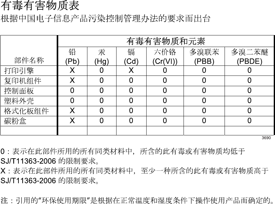
Substances Table (China)
Restriction on Hazardous Substances statement (Turkey)
Türkiye Cumhuriyeti: EEE Yönetmeliğine Uygundur
154 Appendix C Regulatory information ENWW
Additional statements for telecom (fax) products
EU Statement for Telecom Operation
This product is intended to be connected to the analog Public Switched Telecommunication Networks
(PSTN) of European Economic Area (EEA) countries/regions.
It meets requirements of EU R&TTE Directive 1999/5/EC (Annex II) and carries appropriate CE
conformity marking.
For more details see Declaration of Conformity issued by the manufacturer in another section of this
manual.
However due to differences between individual national PSTNs the product may not guarantee
unconditional assurance of successful operation on every PSTN termination point. Network
compatibility depends on the correct setting being selected by the customer in preparation of its
connection to the PSTN. Please follow the instructions provided in the user manual.
If you experience network compatibility issues, please contact your equipment supplier or Hewlett-
Packard help desk in the country/region of operation.
Connecting to a PSTN termination point may be the subject of additional requirements set out by the
local PSTN operator.
New Zealand Telecom Statements
The grant of a Telepermit for any item of terminal equipment indicates only that Telecom has accepted
that the item complies with minimum conditions for connection to its network. It indicates no
endorsement of the product by Telecom, nor does it provide any sort of warranty. Above all, it provides
no assurance that any item will work correctly in all respects with another item of Telepermitted
equipment of a different make or model, nor does it imply that any product is compatible with all of
Telecom’s network services.
This equipment may not provide for the effective hand-over of a call to another device connected to the
same line.
This equipment shall not be set up to make automatic calls to the Telecom “111” Emergency Service.
This product has not been tested to ensure compatibility with the FaxAbility distinctive ring service for
New Zealand.
Additional FCC statement for telecom products (US)
This equipment complies with Part 68 of the FCC rules and the requirements adopted by the ACTA. On
the back of this equipment is a label that contains, among other information, a product identifier in the
format US:AAAEQ##TXXXX. If requested, this number must be provided to the telephone company.
The REN is used to determine the quantity of devices, which may be connected to the telephone line.
Excessive RENs on the telephone line may result in the devices not ringing in response to an incoming
call. In most, but not all, areas, the sum of the RENs should not exceed five (5.0). To be certain of the
ENWW Additional statements for telecom (fax) products 155
number of devices that may be connected to the line, as determined by the total RENs, contact the
telephone company to determine the maximum REN for the calling area.
This equipment uses the following USOC jacks: RJ11C.
An FCC-compliant telephone cord and modular plug is provided with this equipment. This equipment is
designed to be connected to the telephone network or premises wiring using a compatible modular
jack, which is Part 68 compliant. This equipment cannot be used on telephone company-provided coin
service. Connection to Party Line Service is subject to state tariffs.
If this equipment causes harm to the telephone network, the telephone company will notify you in
advance that temporary discontinuance of service may be required. If advance notice is not practical,
the telephone company will notify the customer as soon as possible. Also, you will be advised of your
right to file a complaint with the FCC if you believe it is necessary.
The telephone company may make changes in its facilities, equipment, operations, or procedures that
could affect the operation of the equipment. If this happens, the telephone company will provide
advance notice in order for you to make the necessary modifications in order to maintain uninterrupted
service.
If trouble is experienced with this equipment, please see the numbers in this manual for repair and (or)
warranty information. If the trouble is causing harm to the telephone network, the telephone company
may request you remove the equipment from the network until the problem is resolved.
The customer can do the following repairs: Replace any original equipment that came with the device.
This includes the print cartridge, the supports for trays and bins, the power cord, and the telephone
cord. It is recommended that the customer install an AC surge arrestor in the AC outlet to which this
device is connected. This is to avoid damage to the equipment caused by local lightning strikes and
other electrical surges.
Telephone Consumer Protection Act (US)
The Telephone Consumer Protection Act of 1991 makes it unlawful for any person to use a computer or
other electronic device, including fax machines, to send any message unless such message clearly
contains, in a margin at the top or bottom of each transmitted page or on the first page of the
transmission, the date and time it is sent and an identification of the business, other entity, or individual
sending the message and the telephone number of the sending machine or such business, or other
entity, or individual. (The telephone number provided cannot be a 900 number or any other number for
which charges exceed local or long distance transmission charges).
Industry Canada CS-03 requirements
Notice: The Industry Canada label identifies certified equipment. This certification means the
equipment meets certain telecommunications network protective, operational, and safety requirements
as prescribed in the appropriate Terminal Equipment Technical Requirement document(s). The
Department does not guarantee the equipment will operate to the user’s satisfaction. Before installing
this equipment, users should ensure that it is permissible for the equipment to be connected to the
facilities of the local telecommunications company. The equipment must also be installed using an
acceptable method of connection. The customer should be aware that compliance with the above
conditions may not prevent degradation of service in some situations. Repairs to certified equipment
should be coordinated by a representative designated by the supplier. Any repairs or alterations made
by the user to this equipment, or equipment malfunctions, may give the telecommunications company
156 Appendix C Regulatory information ENWW

cause to request the user to disconnect the equipment. Users should ensure for their own protection that
the electrical ground connections of the power utility, telephone lines, and internal metallic water pipe
system, if present, are connected together. This precaution can be particularly important in rural areas.
CAUTION: Users should not attempt to make such connections themselves, but should contact the
appropriate electric inspection authority, or electrician, as appropriate. The Ringer Equivalence
Number (REN) of this device is 0.0.
Notice: The Ringer Equivalence Number (REN) assigned to each terminal device provides an indication
of the maximum number of terminals allowed to be connected to a telephone interface. The termination
on an interface may consist of any combination of devices subject only to the requirement that the sum
of the Ringer Equivalence Number of all the devices does not exceed five (5.0). The standard
connecting arrangement code (telephone jack type) for equipment with direct connections to the
telephone network is CA11A.
ENWW Additional statements for telecom (fax) products 157

Additional statements for wireless products
FCC compliance statement—United States
Exposure to radio frequency radiation
CAUTION: The radiated output power of this device is far below the FCC radio frequency exposure
limits. Nevertheless, the device shall be used in such a manner that the potential for human contact
during normal operation is minimized.
In order to avoid the possibility of exceeding the FCC radio frequency exposure limits, human proximity
to the antenna shall not be less than 20 cm ( (8 in)) during normal operation.
This device complies with Part 15 of the FCC Rules. Operation is subject to the following two
conditions: (1) this device may not cause interference, and (2) this device must accept any interference,
including interference that may cause undesired operation of the device.
CAUTION: Based on Section 15.21 of the FCC rules, changes of modifications to the operation of
this product without the express approval by Hewlett-Packard Company may invalidate its authorized
use.
Australia statement
This device incorporates a radio-transmitting (wireless) device. For protection against radio transmission
exposure, it is recommended that this device be operated no less than 20 cm from the head, neck, or
body.
Brazil ANATEL statement
Este equipamento opera em caráter secundário, isto é, não tem direito à proteção contra interferência
prejudicial, mesmo de estações do mesmo tipo, e não pode causar interferência a sistemas operando
em caráter primário.
Canadian statements
For Indoor Use. This digital apparatus does not exceed the Class B limits for radio noise emissions
from digital apparatus as set out in the radio interference regulations of the Canadian Department of
Communications. The internal wireless radio complies with RSS 210 of Industry Canada.
Pour l´usage d´intérieur. Le présent appareil numérique n´émet pas de bruits radioélectriques
dépassant les limites applicables aux appareils numériques de Classe B prescribes dans le règlement
sur le brouillage radioélectrique édicté par le Ministère des Communications du Canada. Le composant
RF interne est conforme à la norme CNR-210 d´Industrie Canada.
European Union regulatory notice
The telecommunications functionality of this product may be used in the following EU and EFTA
countries/regions:
158 Appendix C Regulatory information ENWW

Austria, Belgium, Bulgaria, Cyprus, Czech Republic, Denmark, Estonia, Finland, France, Germany,
Greece, Hungary, Iceland, Ireland, Italy, Latvia, Liechtenstein, Lithuania, Luxembourg, Malta,
Netherlands, Norway, Poland, Portugal, Romania, Slovak Republic, Slovenia, Spain, Sweden,
Switzerland, and United Kingdom.
Notice for use in France
For 2.4 GHz Wireless LAN operation of this product certain restrictions apply: This equipment may be
used indoor for the entire 2400-2483.5 MHz frequency band (channels 1-13). For outdoor use, only
2400-2454 MHz frequency band (channels 1-9) may be used. For the latest requirements, see
www.arcep.fr.
L'utilisation de cet equipement (2.4 GHz Wireless LAN) est soumise à certaines restrictions : Cet
équipement peut être utilisé à l'intérieur d'un bâtiment en utilisant toutes les fréquences de
2400-2483.5 MHz (Chaine 1-13). Pour une utilisation en environnement extérieur, vous devez utiliser
les fréquences comprises entre 2400-2454 MHz (Chaine 1-9). Pour les dernières restrictions, voir,
www.arcep.fr.
Notice for use in Russia
Существуют определенные ограничения по использованию беспроводных сетей (стандарта
802.11 b/g) с рабочей частотой 2,4 ГГц: Данное оборудование может использоваться внутри
помещений с использованием диапазона частот 2400-2483,5 МГц (каналы 1-13). При
использовании внутри помещений максимальная эффективная изотропно–излучаемая мощность
(ЭИИМ) должна составлять не более 100мВт.
Korean statement
ENWW Additional statements for wireless products 159
Taiwan statement
160 Appendix C Regulatory information ENWW

Index
Symbols/Numerics
2ndary service menu 109
A
acoustic specifications 140
advanced setup
fax 51
B
batteries included 145
billing filters
fax 26
tone 26
bin, output
jams, clearing 89
blank pages, troubleshooting 99
C
cables
USB, troubleshooting 99
calibrating color 110
Canadian DOC regulations 152
cartridges
image-formation system 10
recycling 143
warranty 132
cautions iii
certificate of volatility 151
checklist
fax troubleshooting 112
checklists
pre-troubleshooting 32
checklists, printing 60
cleaning
paper path 45, 95
cleaning stage, image formation
operations 17
CO operations 22
color
calibrating 110
color alignment, calibrating 47,
95
color settings
adjusting 93
Configuration page 46
configuration page 46
connectivity
solving problems 103
connectors
DC controller 39
control panel
blank, troubleshooting 34
button test 110
Configuration page 46
display test 110
menus 48
message types 67
messages, troubleshooting 67
controls
hook switch control 26
conventions, document iii
copy menu 63
copying
sequence 21
current control, fax line 26
customer support
online 136
repacking product 137
D
data path
fax 25
DC controller
connectors 39
engine control system 5
laser/scanner system
operations 9
pickup-and-feed system
operations 18
defaults
NVRAM initialization 111
defaults, restoring 111
defects, repeating 97
defects, repetitive 46
developing stage 12
device
downstream detection, fax 26
dialing
pulse 26
dimensions 140
disposal, end-of-life 145
distinctive ring 23
document conventions iii
document feeder
jams 86
downstream device detection
fax 26
dpi (dots per inch)
faxing 51
drum, image formation
operations 11
E
electrical specifications 140
end-of-life disposal 145
environmental specifications 140
environmental stewardship
program 143
error messages
event log 79
error messages, control panel 67
error messages, fax 114, 120
European Union, waste disposal
146
ENWW Index 161
F
factory defaults, restoring
NVRAM initialization 111
factory-set defaults, restoring 111
fax
answer mode 50
billing (metering) tone filters
26
card 24
data path 25
distinctive ring 23
downstream current detection
26
factory-set defaults, restoring
111
flash memory storage 27
functions 22
hook state 25
hook switch control 26
line current control 26
operations 22
page storage 26, 27
PSTN operations 22
pulse dialing 26
receiving 22
reports 61
ring detect 26
ring type 51
safety isolation 24
safety protection circuitry 25
solve performance problems
127
subsystem 24
unable to receive 114
unable to send 120
voice over IP (VoIP) services
23
fax card
CODEC 24
DSP 24
fax subsystem 24
hook switch control 26
pulse dialing 26
regional versions 24
ring detect 26
fax menu 61
fax reports, printing 61
fax security
security features, computer 22
security features, network 22
fax subsystem
fax card 24
operations 24
fax troubleshooting
checklist 112
Finnish laser safety statement 153
flash memory, fax 27
fusing stage 15
G
graph paper, printing 60
H
hook state
fax 25
hook switch control 26
HP Customer Care 136
HP Jetdirect print server
NVRAM initialization 111
humidity specifications
environment 140
I
image formation
cleaning stage 17
developing stage 12
fusing stage 15
latent-image stage 11
process 10
systems 10
transfer stage 14
image quality
repetitive image defects 46
solving 92
image transfer stage 14
information pages
configuration page 46
initialization
NVRAM 111
J
jams
detection operations 19
document feeder, clearing 86
locating 85
output bin, clearing 89
rear door, clearing 89
Japanese VCCI statement 152
Jetdirect print server
NVRAM initialization 111
K
Korean EMC statement 153
L
laser safety statements 152, 153
laser-beam exposure stage 12
laser/scanner system operations
9
latent-image formation stage 11
LEDs, troubleshooting 35
license, software 134
line current control, fax 26
location
setting 110
M
Macintosh
support 136
material restrictions 145
Material Safety Data Sheet
(MSDS) 146
media
jam detection operations 19
media feed stage 14
memory
flash, fax 27
NVRAM initialization 111
memory chip, print cartridge
description 133
menu
control panel, access 48
copy 63
fax 61
Fax setup 50
Network config 59
Quick Forms 60
Reports 49
Service 57
System setup 53
USB 61
menu map, printing 32
mercury-free product 145
messages, control panel 67
music paper, printing 60
N
network
configuring 59
Network config menu 59
networks
security features 22
162 Index ENWW
notebook paper, printing 60
notes iii
NVRAM initialization 111
O
off-hook 26
on-hook 26
online support 136
operating environment,
specifications 140
operations
engine control system 4
fax 22
fax card in subsystem 24
fax subsystem 24
fax, PSTN 22
image-formation system 10
jam detection 19
laser/scanner system 9
pickup-and-feed system 18
product systems 5
PSTN 22
scanner system 20
sequence of 4
output quality
repetitive image defects 46
P
packaging product 137
pages
blank 99
not printing 99
printing slowly 99
paper
jam detection operations 19
selecting 94
paper pickup problems
solving 91
paper type
changing 92
PBX ring detect 110
photosensitive drum
image formation operations
11
physical specifications 140
pickup-and-feed system
operations 18
power
consumption 140
fax line current control 26
power-on
scanner sequence 20
troubleshooting 34
pre-troubleshooting checklist 32
primary charging stage 12
print cartridges
checking for damage 96
memory chips 133
recycling 143
warranty 132
print quality
improving 92
repetitive image defects 46
print quality page
interpreting 44
printing 44
printer drivers
choosing 97
printing
configuration page 46
troubleshooting 99
problem-solving
no response 101
slow response 102
product
fax, functions 22
PSTN operations 22
pulse dialing 26
Q
quality
repetitive image defects 46
R
rear door
jams 89
receiving faxes 22
distinctive ring 23
recycling 143
HP printing supplies returns and
environmental program 144
regional versions
fax card 24
repacking product 137
repeating defects,
troubleshooting 97
repetitive defects, troubleshooting
46, 97
reports
configuration page 49
demo page 49
diagnostics page 49
error 79, 109
fax 61
menu map 49
network report 49
PCL 6 font list 49
PCL font list 49
print quality page 49
PS font list 49
service 109
service page 49
supplies status page 49
usage page 49
resets
NVRAM initialization 111
restoring
default settings 111
NVRAM initialization 111
restoring factory-set defaults 111
ring detect
fax card 26
RING operations 22
rollers
image formation operations
11
repetitive image defects 46
S
safety
-protection circuitry, fax 25
isolation, fax 24
safety statements 152, 153
secondary service menu 109
security features
computer 22
network 22
sensors
jam detection 19
separation stage, image
formation 15
sequence of operations 4
service
repacking product 137
Service menu 57
secondary 109
settings
factory-set defaults, restoring
111
shipping product 137
ENWW Index 163
size 140
software
software license agreement
134
solve
fax problems 120
solve problems
fax 127
solving
direct-connect problems 103
network problems 103
specifications
electrical and acoustic 140
environmental 140
physical 140
storing
environmental specifications
140
fax pages in flash memory 26
supplies
recycling 143
supplies status page
printing 96
support
online 136
repacking product 137
System setup menu 53
systems 5
T
technical support
online 136
repacking product 137
temperature specifications
environment 140
TIP operations 22
tips iii
toner cartridges
image-formation system 10
transfer stage 14
trays
jams, clearing 87
troubleshooting
about 32
blank pages 99
checklist 32
control panel messages 67
control-panel diagnostics 37
direct-connect problems 103
faxes 112
LED diagnostics 35
network problems 103
NVRAM initialization 111
pages not printing 99
pages printing slowly 99
power-on 34
receive fax 114
repeating defects 97
send fax 120
USB cables 99
U
USB menu 61
USB port
troubleshooting 99
V
voice over IP (VoIP) services 23
volume
settings 55
W
warnings iii
warranty
license 134
print cartridges 132
product 130
Web sites
customer support 136
Macintosh customer support
136
Material Safety Data Sheet
(MSDS) 146
weight 140
wireless
configuring 59
164 Index ENWW

© 2012 Hewlett-Packard Development Company, L.P.
www.hp.com
*CF144-90996*
*CF144-90996*
CF144-90996
