HP Laser Jet Professional P1560 And P1600 Series Printer
User Manual: HP LaserJet Professional P1560 and P1600 Series Printer shared.swissparts.ch - /Manuals/HP/LaserJet/Mono Laserjet/
Open the PDF directly: View PDF ![]() .
.
Page Count: 226 [warning: Documents this large are best viewed by clicking the View PDF Link!]
- Theory of operation
- Basic operation
- Formatter-control system
- Engine-control system
- Image-formation system
- Pickup, feed, and delivery system
- Main-input tray or priority input slot
- Removal and replacement
- Introduction
- Removal and replacement strategy
- Electrostatic discharge
- Required tools
- Before performing service
- After performing service
- Post-service test
- Parts removal order
- Pickup roller
- Separation pad
- Transfer roller
- Covers
- Main assemblies
- Solve problems
- Solve problems checklist
- Troubleshooting process
- Tools for troubleshooting
- Clear jams
- Solve paper-handling problems
- Solve image-quality problems
- Clean the product
- Solve performance problems
- Solve connectivity problems
- Service mode functions
- Product updates
- Parts and diagrams
- Service and support
- Specifications
- Regulatory information
- Index
LASERJET PROFESSIONAL P1560 and P1600
SERIES PRINTER
Service Manual
www.hp.com/support/ljp1560series
www.hp.com/support/ljp1600series

HP LaserJet Professional P1560 and
P1600 Series Printer
Service Manual
Copyright and License
© 2010 Copyright Hewlett-Packard
Development Company, L.P.
Reproduction, adaptation, or translation
without prior written permission is prohibited,
except as allowed under the copyright laws.
The information contained herein is subject
to change without notice.
The only warranties for HP products and
services are set forth in the express warranty
statements accompanying such products
and services. Nothing herein should be
construed as constituting an additional
warranty. HP shall not be liable for technical
or editorial errors or omissions contained
herein.
Part number: CE663-90939
Edition 1, 4/2010
Trademark Credits
Microsoft®, Windows®, Windows® XP, and
Windows Vista® are U.S. registered
trademarks of Microsoft Corporation.

Conventions used in this guide
TIP: Tips provide helpful hints or shortcuts.
NOTE: Notes provide important information to explain a concept or to complete a task.
CAUTION: Cautions indicate procedures that you should follow to avoid losing data or damaging the
product.
WARNING! Warnings alert you to specific procedures that you should follow to avoid personal injury,
catastrophic loss of data, or extensive damage to the product.
ENWW iii
iv Conventions used in this guide ENWW

Table of contents
1 Theory of operation ........................................................................................................................................ 1
Basic operation ..................................................................................................................................... 2
Major product systems ......................................................................................................... 2
Product block diagram ......................................................................................................... 2
Sequence of operation ......................................................................................................... 3
Normal sequence of operation ............................................................................ 3
Formatter-control system ..................................................................................................................... 4
Sleep mode .......................................................................................................................... 4
Input/output .......................................................................................................................... 4
CPU ..................................................................................................................................... 4
Memory ................................................................................................................................ 4
Firmware ............................................................................................................. 5
Memory use ........................................................................................................ 5
PJL overview ....................................................................................................................... 5
LEDM overview .................................................................................................................... 5
ACL overview ....................................................................................................................... 5
Control panel ....................................................................................................................... 6
Engine-control system .......................................................................................................................... 7
Motors, fans, clutches, solenoids, switches, and sensors ................................................... 8
DC controller operations .................................................................................................... 13
Fuser-control circuit ........................................................................................................... 15
Fuser failure detection ....................................................................................... 16
Fuser temperature control ................................................................................. 17
Fuser protective function ................................................................................... 18
Pressure roller cleaning .................................................................................... 18
Low-voltage power supply ................................................................................................. 19
Overcurrent/overvoltage protection ................................................................... 20
High-voltage power supply ................................................................................................ 21
Laser/scanner system ........................................................................................................ 22
Laser failure detection ....................................................................................... 23
Image-formation system ..................................................................................................................... 24
Electrophotographic process ............................................................................................. 24
Image formation process ................................................................................................... 26
Latent-image formation stage ........................................................................... 27
ENWW v
Primary charging .............................................................................. 27
Laser beam exposure ....................................................................... 27
Developing stage .............................................................................................. 28
Print cartridge ................................................................................... 28
Transfer stage ................................................................................................... 29
Fusing stage ..................................................................................... 29
Cleaning stage .................................................................................. 30
Pickup, feed, and delivery system ...................................................................................................... 31
Photo sensors and switches .............................................................................................. 32
Main-input tray or priority input slot .................................................................................................... 34
Jam detection .................................................................................................................... 34
2 Removal and replacement ........................................................................................................................... 35
Introduction ......................................................................................................................................... 36
Removal and replacement strategy ................................................................................................... 36
Electrostatic discharge ....................................................................................................................... 37
Required tools ................................................................................................................................... 37
Before performing service .................................................................................................................. 37
After performing service ..................................................................................................................... 38
Post-service test ................................................................................................................................. 38
Print-quality test ................................................................................................................. 38
Parts removal order ............................................................................................................................ 39
Pickup roller ........................................................................................................................................ 40
Separation pad ................................................................................................................................... 41
Transfer roller ..................................................................................................................................... 42
Covers ................................................................................................................................................ 43
Main-input tray ................................................................................................................... 43
Output bin tray extension ................................................................................................... 44
Left cover, simplex product ................................................................................................ 45
Remove the left cover, simplex product ............................................................ 45
Left cover, duplex product ................................................................................................. 47
Remove the left cover, duplex product .............................................................. 47
Right cover, simplex product ............................................................................................. 50
Remove the right cover, simplex product .......................................................... 50
Right cover, duplex product ............................................................................................... 52
Remove the right cover, duplex product ........................................................... 52
Duplex door, duplex product .............................................................................................. 55
Duplex frame, duplex product ............................................................................................ 56
Remove the duplex frame ................................................................................. 56
Cartridge door .................................................................................................................... 57
Control panel ..................................................................................................................... 59
Front cover ......................................................................................................................... 61
Remove the front cover ..................................................................................... 61
vi ENWW
Rear cover, simplex product .............................................................................................. 63
Remove the rear cover, simplex product .......................................................... 63
Face-down cover ............................................................................................................... 65
Remove the face-down cover ........................................................................... 65
Main assemblies ................................................................................................................................. 67
Formatter PCA ................................................................................................................... 67
Laser/scanner assembly .................................................................................................... 68
Remove the laser/scanner assembly ................................................................ 68
Reinstall the laser/scanner assembly ................................................................ 71
Pickup assembly ................................................................................................................ 72
Remove the pickup assembly ........................................................................... 72
Reinstall the pickup assembly ........................................................................... 78
Fuser .................................................................................................................................. 80
Remove the fuser .............................................................................................. 80
Reinstall the fuser ............................................................................................. 86
Main motor ......................................................................................................................... 87
Remove the main motor .................................................................................... 87
Reinstall the main-motor drive belt .................................................................... 92
Pickup solenoid .................................................................................................................. 93
Remove the pickup solenoid ............................................................................. 93
Engine controller PCA ....................................................................................................... 97
Remove the engine controller PCA ................................................................... 97
Reinstall the engine controller PCA ................................................................ 102
Duplex-reverse solenoid, duplex product ........................................................................ 104
Remove the duplex-reverse solenoid .............................................................. 104
Main fan, duplex product ................................................................................................. 107
Remove the main fan ...................................................................................... 107
Reinstall the main fan ...................................................................................... 109
Duplex-connector PCA, duplex product ........................................................................... 110
Remove the duplex-connector PCA ................................................................ 110
3 Solve problems ........................................................................................................................................... 113
Solve problems checklist .................................................................................................................. 114
Troubleshooting process .................................................................................................................. 116
Determine the problem source ....................................................................................... 116
Power subsystem ............................................................................................................ 117
Power-on checks ............................................................................................. 117
Tools for troubleshooting .................................................................................................................. 118
Individual component diagnostics .................................................................................... 118
Engine diagnostics .......................................................................................... 118
Engine-test button .......................................................................... 118
Components tests ........................................................................................... 119
Drum rotation functional check ...................................................... 119
ENWW vii
Half self-test functional check ......................................................... 119
Diagrams ......................................................................................................................... 120
Plug/jack locations .......................................................................................... 120
Location of connectors .................................................................................... 121
Locations of major components ...................................................................... 122
General timing charts ...................................................................................... 125
General circuit diagram ................................................................................... 126
Internal print-quality test pages ........................................................................................ 127
Cleaning page ................................................................................................. 127
Configuration page .......................................................................................... 127
Print-quality troubleshooting tools .................................................................................... 128
Repetitive defect ruler ..................................................................................... 128
Interpret control-panel light patterns ................................................................................ 128
Clear jams ........................................................................................................................................ 133
Common causes of jams ................................................................................................. 133
Jam locations ................................................................................................................... 133
Clear jams from the input trays ........................................................................................ 134
Clear jams from the duplexer ........................................................................................... 136
Clear jams from the output areas .................................................................................... 138
Clear jams from inside the product .................................................................................. 139
Solve repeated jams ........................................................................................................ 141
Change jam recovery ...................................................................................................... 142
Solve paper-handling problems ........................................................................................................ 143
Solve image-quality problems .......................................................................................................... 144
Image defect table ........................................................................................................... 144
Light print or faded .......................................................................................... 144
Toner specks ................................................................................................... 144
Dropouts .......................................................................................................... 145
Vertical lines .................................................................................................... 145
Gray background ............................................................................................. 145
Toner smear .................................................................................................... 146
Loose toner ..................................................................................................... 146
Vertical repetitive defects ................................................................................ 146
Misformed characters ...................................................................................... 146
Page skew ....................................................................................................... 147
Curl or wave .................................................................................................... 147
Wrinkles or creases ......................................................................................... 147
Toner scatter outline ....................................................................................... 148
Moisture .......................................................................................................... 148
Change print density ........................................................................................................ 149
Clean the product ............................................................................................................................. 150
Clean the pickup roller ..................................................................................................... 150
Clean the paper path ....................................................................................................... 151
Clean the print-cartridge area .......................................................................................... 153
viii ENWW
Clean the exterior ............................................................................................................ 154
Solve performance problems ........................................................................................................... 155
Solve connectivity problems ............................................................................................................. 156
Solve direct-connect problems ........................................................................................ 156
Solve network problems .................................................................................................. 156
Service mode functions .................................................................................................................... 158
Product resets .................................................................................................................. 158
Product updates ............................................................................................................................... 158
Firmware updates ............................................................................................................ 158
4 Parts and diagrams ..................................................................................................................................... 159
Order parts by authorized service providers .................................................................................... 160
Order replacement parts .................................................................................................. 160
Related documentation and software .............................................................................. 160
Supplies part numbers ..................................................................................................... 160
Customer self repair parts ............................................................................................... 161
Service parts .................................................................................................................... 161
Whole-unit replacement part numbers ............................................................................. 161
How to use the parts lists and diagrams .......................................................................................... 162
Assembly locations ........................................................................................................................... 163
Base product (no optional trays or accessories) .............................................................. 163
Covers .............................................................................................................................................. 164
Simplex model ................................................................................................................. 164
Duplex model ................................................................................................................... 16 6
Internal assemblies .......................................................................................................................... 168
Internal assemblies (1 of 3) ............................................................................................. 168
Internal assemblies (2 of 3) ............................................................................................. 170
Internal assemblies (3 of 3) ............................................................................................. 172
PCAs ................................................................................................................................................ 174
Alphabetical parts list ....................................................................................................................... 176
Numerical parts list ........................................................................................................................... 179
Appendix A Service and support ................................................................................................................. 183
Hewlett-Packard limited warranty statement .................................................................................... 184
HP's Premium Protection Warranty: LaserJet print cartridge limited warranty statement ................ 185
End User License Agreement .......................................................................................................... 186
Customer self-repair warranty service .............................................................................................. 188
Customer support ............................................................................................................................. 188
Repack the product .......................................................................................................................... 189
Service information form .................................................................................................................. 190
Appendix B Specifications ............................................................................................................................ 191
Physical specifications ..................................................................................................................... 192
ENWW ix
Power consumption .......................................................................................................................... 192
Acoustic specifications ..................................................................................................................... 192
Environmental specifications ............................................................................................................ 193
Appendix C Regulatory information ............................................................................................................ 195
FCC regulations ............................................................................................................................... 196
Declaration of conformity .................................................................................................................. 197
Certificate of Volatility ....................................................................................................................... 198
Safety statements ............................................................................................................................. 200
Laser safety ..................................................................................................................... 200
Canadian DOC regulations .............................................................................................. 200
VCCI statement (Japan) .................................................................................................. 200
Power cord instructions ................................................................................................... 200
Power cord statement (Japan) ......................................................................................... 200
EMC statement (Korea) ................................................................................................... 200
Laser statement for Finland ............................................................................................. 201
GS statement (Germany) ................................................................................................. 201
Substances Table (China) ............................................................................................... 202
Restriction on Hazardous Substances statement (Turkey) ............................................. 202
Index ................................................................................................................................................................. 203
xENWW

List of tables
Table 1-1 Sequence of operation ....................................................................................................................... 3
Table 1-2 Motors ................................................................................................................................................ 8
Table 1-3 Fans ................................................................................................................................................... 9
Table 1-4 Solenoids and clutches .................................................................................................................... 10
Table 1-5 Switches ........................................................................................................................................... 11
Table 1-6 Sensors ............................................................................................................................................ 11
Table 1-7 DC controller controlled components ............................................................................................... 13
Table 1-8 Photo sensors, motor, and solenoid ................................................................................................ 32
Table 3-1 Basic problem solving .................................................................................................................... 114
Table 3-2 Status-light legend ......................................................................................................................... 128
Table 3-3 Control-panel lights ........................................................................................................................ 129
Table 4-1 Order parts, accessories, and supplies .......................................................................................... 160
Table 4-2 Related documentation and software ............................................................................................ 160
Table 4-3 Supplies part numbers ................................................................................................................... 160
Table 4-4 Customer replaceable units (CRU) kit part numbers ..................................................................... 161
Table 4-5 Whole-unit replacement part numbers ........................................................................................... 161
Table 4-6 Base product .................................................................................................................................. 163
Table 4-7 Simplex model ................................................................................................................................ 165
Table 4-8 Duplex model ................................................................................................................................. 167
Table 4-9 Internal assemblies (1 of 3) ............................................................................................................ 169
Table 4-10 Internal assemblies (2 of 3) .......................................................................................................... 171
Table 4-11 Internal assemblies (3 of 3) .......................................................................................................... 173
Table 4-12 PCAs ............................................................................................................................................ 175
Table 4-13 Alphabetical parts list ................................................................................................................... 176
Table 4-14 Numerical parts list ....................................................................................................................... 179
Table B-1 Physical specifications
1
.................................................................................................................. 192
Table B-2 HP LaserJet Professional P1560 and P1600 Printer series (average in watts)
123
......................... 192
Table B-3 HP LaserJet Professional P1560 and P1600 Printer series
12
........................................................ 192
Table B-4 Environmental specifications ......................................................................................................... 193
ENWW xi
xii ENWW

List of figures
Figure 1-1 Product block diagram ...................................................................................................................... 2
Figure 1-2 Engine-control system ...................................................................................................................... 7
Figure 1-3 Motors ............................................................................................................................................... 8
Figure 1-4 Fans .................................................................................................................................................. 9
Figure 1-5 Solenoids and clutches ................................................................................................................... 10
Figure 1-6 Switches .......................................................................................................................................... 11
Figure 1-7 Sensors ........................................................................................................................................... 11
Figure 1-8 DC controller block diagram ............................................................................................................ 13
Figure 1-9 Fuser control circuit ......................................................................................................................... 15
Figure 1-10 Fuser-heater control circuit ........................................................................................................... 17
Figure 1-11 Low-voltage power supply (LVPS) ................................................................................................ 19
Figure 1-12 High-voltage power supply ............................................................................................................ 21
Figure 1-13 Laser/scanner system ................................................................................................................... 22
Figure 1-14 Electrophotographic process block diagram (1 of 2) .................................................................... 24
Figure 1-15 Electrophotographic process block diagram (2 of 2) .................................................................... 25
Figure 1-16 Image formation process .............................................................................................................. 26
Figure 1-17 Primary charging ........................................................................................................................... 27
Figure 1-18 Laser beam exposure ................................................................................................................... 27
Figure 1-19 Print cartridge ................................................................................................................................ 28
Figure 1-20 Transfer ......................................................................................................................................... 29
Figure 1-21 Separation ..................................................................................................................................... 29
Figure 1-22 Fusing ........................................................................................................................................... 30
Figure 1-23 Drum cleaning ............................................................................................................................... 30
Figure 1-24 Pickup, feed, and delivery system block diagram ......................................................................... 31
Figure 1-25 Photo sensors, motor, and solenoid ............................................................................................. 32
Figure 2-1 Phillips and pozidrive screwdriver comparison ............................................................................... 37
Figure 2-2 Parts removal order ........................................................................................................................ 39
Figure 2-3 Remove the pickup roller (1 of 2) .................................................................................................... 40
Figure 2-4 Remove the pickup roller (2 of 2) .................................................................................................... 40
Figure 2-5 Remove the separation pad assembly ........................................................................................... 41
Figure 2-6 Remove the transfer roller .............................................................................................................. 42
Figure 2-7 Remove the tray .............................................................................................................................. 43
Figure 2-8 Remove the output bin tray extension ............................................................................................ 44
Figure 2-9 Remove the left cover, simplex product (1 of 4) ............................................................................. 45
ENWW xiii
Figure 2-10 Remove the left cover, simplex product (2 of 4) ........................................................................... 45
Figure 2-11 Remove the left cover, simplex product (3 of 4) ........................................................................... 46
Figure 2-12 Remove the left cover, simplex product (4 of 4) ........................................................................... 46
Figure 2-13 Remove the left cover, duplex product (1 of 5) ............................................................................. 47
Figure 2-14 Remove the left cover, duplex product (2 of 5) ............................................................................. 47
Figure 2-15 Remove the left cover, duplex product (3 of 5) ............................................................................. 48
Figure 2-16 Remove the left cover, duplex product (4 of 5) ............................................................................. 48
Figure 2-17 Remove the left cover, duplex product (5 of 5) ............................................................................. 49
Figure 2-18 Remove the right cover, simplex product (1 of 4) ......................................................................... 50
Figure 2-19 Remove the right cover, simplex product (2 of 4) ......................................................................... 50
Figure 2-20 Remove the right cover, simplex product (4 of 4) ......................................................................... 51
Figure 2-21 Remove the right cover, duplex product (1 of 5) ........................................................................... 52
Figure 2-22 Remove the right cover, duplex product (2 of 5) ........................................................................... 52
Figure 2-23 Remove the right cover, duplex product (3 of 5) ........................................................................... 53
Figure 2-24 Remove the right cover, duplex product (4 of 5) ........................................................................... 53
Figure 2-25 Remove the right cover, duplex product (5 of 5) ........................................................................... 54
Figure 2-26 Remove the duplex door, duplex product ..................................................................................... 55
Figure 2-27 Remove the duplex frame (1 of 2) ................................................................................................ 56
Figure 2-28 Remove the duplex frame (2 of 2) ................................................................................................ 56
Figure 2-29 Remove the cartridge door (1 of 3) ............................................................................................... 57
Figure 2-30 Remove the cartridge door (2 of 3) ............................................................................................... 57
Figure 2-31 Remove the cartridge door (3 of 3) ............................................................................................... 58
Figure 2-32 Remove the control panel (1 of 3) ................................................................................................ 59
Figure 2-33 Remove the control panel (2 of 3) ................................................................................................ 59
Figure 2-34 Remove the control panel (3 of 3) ................................................................................................ 60
Figure 2-35 Remove the front cover (1 of 3) .................................................................................................... 61
Figure 2-36 Remove the front cover (2 of 3) .................................................................................................... 62
Figure 2-37 Remove the front cover (3 of 3) .................................................................................................... 62
Figure 2-38 Remove the rear cover, simplex product (1 of 3) .......................................................................... 63
Figure 2-39 Remove the rear cover, simplex product (2 of 3) .......................................................................... 64
Figure 2-40 Remove the rear cover, simplex product (2 of 3) .......................................................................... 64
Figure 2-41 Remove the face-down cover (1 of 2) ........................................................................................... 65
Figure 2-42 Remove the face-down cover (2 of 2) ........................................................................................... 66
Figure 2-43 Remove the formatter PCA (1 of 2) .............................................................................................. 67
Figure 2-44 Remove the formatter PCA (2 of 2) .............................................................................................. 67
Figure 2-45 Remove the laser/scanner assembly (1 of 5) ............................................................................... 68
Figure 2-46 Remove the laser/scanner assembly (2 of 5) ............................................................................... 69
Figure 2-47 Remove the laser/scanner assembly (3 of 5) ............................................................................... 69
Figure 2-48 Remove the laser/scanner assembly (4 of 5) ............................................................................... 70
Figure 2-49 Remove the laser/scanner assembly (5 of 5) ............................................................................... 70
Figure 2-50 Reinstall the laser/scanner assembly ........................................................................................... 71
Figure 2-51 Remove the pickup assembly (1 of 10) ........................................................................................ 72
Figure 2-52 Remove the pickup assembly (2 of 10) ........................................................................................ 73
Figure 2-53 Remove the pickup assembly (3 of 10) ........................................................................................ 73
xiv ENWW
Figure 2-54 Remove the pickup assembly (4 of 10) ........................................................................................ 74
Figure 2-55 Remove the pickup assembly (5 of 10) ........................................................................................ 74
Figure 2-56 Remove the pickup assembly (6 of 10) ........................................................................................ 75
Figure 2-57 Remove the pickup assembly (7 of 10) ........................................................................................ 75
Figure 2-58 Remove the pickup assembly (8 of 10) ........................................................................................ 76
Figure 2-59 Remove the pickup assembly (9 of 10) ........................................................................................ 76
Figure 2-60 Remove the pickup assembly (10 of 10) ...................................................................................... 77
Figure 2-61 Reinstall the pickup assembly (1 of 4; correct ground spring position) ......................................... 78
Figure 2-62 Reinstall the pickup assembly (2 of 4; incorrect ground spring position) ...................................... 78
Figure 2-63 Reinstall the pickup assembly (3 of 4; lift plate in raised position) ................................................ 79
Figure 2-64 Reinstall the pickup assembly (4 of 4; lift plate in lowered position) ............................................. 79
Figure 2-65 Remove the fuser (1 of 10) ........................................................................................................... 80
Figure 2-66 Remove the fuser (2 of 10) ........................................................................................................... 81
Figure 2-67 Remove the fuser (3 of 10) ........................................................................................................... 81
Figure 2-68 Remove the fuser (4 of 10) ........................................................................................................... 82
Figure 2-69 Remove the fuser (5 of 10) ........................................................................................................... 82
Figure 2-70 Remove the fuser (6 of 10) ........................................................................................................... 83
Figure 2-71 Remove the fuser (7 of 10) ........................................................................................................... 83
Figure 2-72 Remove the fuser (8 of 10) ........................................................................................................... 84
Figure 2-73 Remove the fuser (9 of 10) ........................................................................................................... 84
Figure 2-74 Remove the fuser (10 of 10) ......................................................................................................... 85
Figure 2-75 Reinstall the fuser; correct wire harness installation ..................................................................... 86
Figure 2-76 Reinstall the fuser; incorrect wire harness installation .................................................................. 86
Figure 2-77 Remove the main motor (1 of 9) ................................................................................................... 87
Figure 2-78 Remove the main motor (2 of 9) ................................................................................................... 88
Figure 2-79 Remove the main motor (3 of 9) ................................................................................................... 88
Figure 2-80 Remove the main motor (4 of 9) ................................................................................................... 89
Figure 2-81 Remove the main motor (5 of 9) ................................................................................................... 89
Figure 2-82 Remove the main motor (6 of 9) ................................................................................................... 90
Figure 2-83 Remove the main motor (7 of 9) ................................................................................................... 90
Figure 2-84 Remove the main motor (8 of 9) ................................................................................................... 91
Figure 2-85 Remove the main motor (9 of 9) ................................................................................................... 91
Figure 2-86 Main-motor drive belt: correctly installed ...................................................................................... 92
Figure 2-87 Main-motor drive belt: incorrectly installed .................................................................................... 92
Figure 2-88 Remove the pickup solenoid (1 of 7) ............................................................................................ 93
Figure 2-89 Remove the pickup solenoid (2 of 7) ............................................................................................ 94
Figure 2-90 Remove the pickup solenoid (3 of 7) ............................................................................................ 94
Figure 2-91 Remove the pickup solenoid (4 of 7) ............................................................................................ 95
Figure 2-92 Remove the solenoid (5 of 7) ........................................................................................................ 95
Figure 2-93 Remove the pickup solenoid (6 of 7) ............................................................................................ 96
Figure 2-94 Remove the pickup solenoid (7 of 7) ............................................................................................ 96
Figure 2-95 Remove the engine controller PCA (1 of 9) .................................................................................. 97
Figure 2-96 Remove the engine controller PCA (2 of 9) .................................................................................. 98
Figure 2-97 Remove the engine controller PCA (3 of 9) .................................................................................. 98
ENWW xv
Figure 2-98 Remove the engine controller PCA (4 of 9) .................................................................................. 99
Figure 2-99 Remove the engine controller PCA (5 of 9) .................................................................................. 99
Figure 2-100 Remove the engine controller PCA (6 of 9) .............................................................................. 100
Figure 2-101 Remove the engine controller PCA (7 of 9) .............................................................................. 100
Figure 2-102 Remove the engine controller PCA (8 of 9) .............................................................................. 101
Figure 2-103 Remove the engine controller PCA (10 of 9) ............................................................................ 101
Figure 2-104 Reinstall the engine controller PCA (1 of 4) .............................................................................. 102
Figure 2-105 Reinstall the engine controller PCA (2 of 4) .............................................................................. 102
Figure 2-106 Reinstall the engine controller PCA (3 of 4) .............................................................................. 103
Figure 2-107 Reinstall the engine controller PCA (4 of 4) .............................................................................. 103
Figure 2-108 Remove the duplex-reverse solenoid (1 of 5) ........................................................................... 104
Figure 2-109 Remove the duplex-reverse solenoid (2 of 5) ........................................................................... 105
Figure 2-110 Remove the duplex-reverse solenoid (3 of 5) ........................................................................... 105
Figure 2-111 Remove the duplex-reverse solenoid (4 of 5) ........................................................................... 106
Figure 2-112 Remove the duplex-reverse solenoid (5 of 5) ........................................................................... 106
Figure 2-113 Remove the main fan (1 of 4) ................................................................................................... 107
Figure 2-114 Remove the main fan (2 of 4) ................................................................................................... 108
Figure 2-115 Remove the main fan (3 of 4) ................................................................................................... 108
Figure 2-116 Remove the main fan (4 of 4) ................................................................................................... 109
Figure 2-117 Reinstall the main fan ............................................................................................................... 109
Figure 2-118 Remove the duplex-connector PCA (1 of 5) ............................................................................. 110
Figure 2-119 Remove the duplex-connector PCA (2 of 5) ............................................................................. 111
Figure 2-120 Remove the duplex-connector PCA (3 of 5) ............................................................................. 111
Figure 2-121 Remove the duplex-connector PCA (4 of 5) ............................................................................. 112
Figure 2-122 Remove the duplex-connector PCA (5 of 5) ............................................................................. 112
Figure 3-1 Sample engine test page .............................................................................................................. 118
Figure 3-2 Plug/jack locations ........................................................................................................................ 120
Figure 3-3 Engine controller PCA connectors ................................................................................................ 121
Figure 3-4 External view ................................................................................................................................. 122
Figure 3-5 Cross section view ........................................................................................................................ 123
Figure 3-6 General timing diagram ................................................................................................................. 125
Figure 3-7 Circuit diagram .............................................................................................................................. 126
Figure 4-1 Base product (no optional trays or accessories) ........................................................................... 163
Figure 4-2 Simplex model .............................................................................................................................. 164
Figure 4-3 Duplex model ................................................................................................................................ 166
Figure 4-4 Internal assemblies (1 of 3) ........................................................................................................... 168
Figure 4-5 Internal assemblies (2 of 3) ........................................................................................................... 170
Figure 4-6 Internal assemblies (3 of 3) ........................................................................................................... 172
Figure 4-7 PCAs ............................................................................................................................................. 174
xvi ENWW


Basic operation
Major product systems
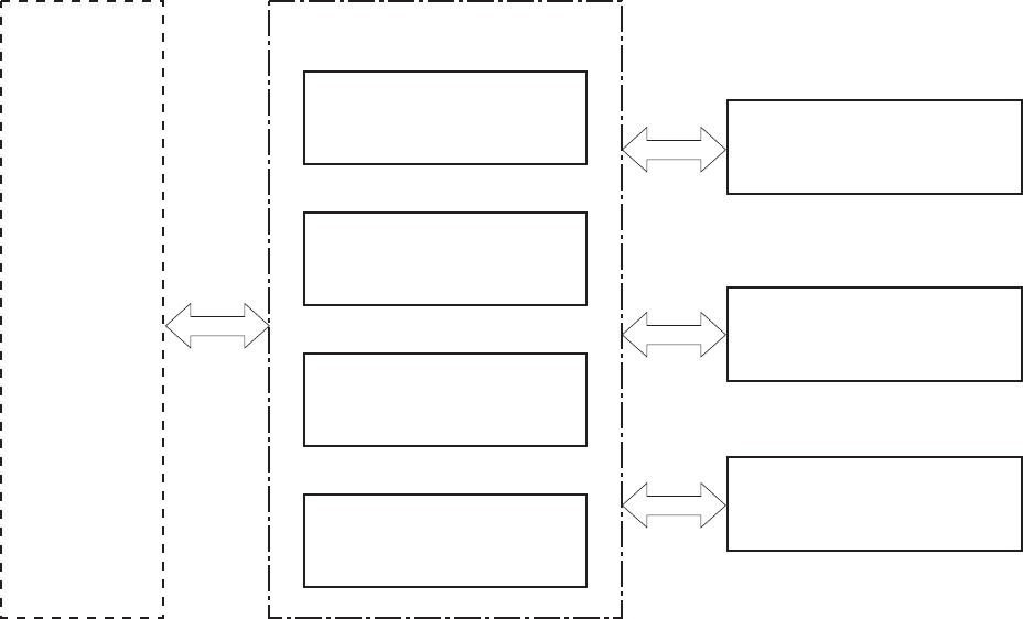
The product contains the following major systems:
●Engine-control system
●Laser/scanner system
●Image-formation system
●Pickup-and-feed system
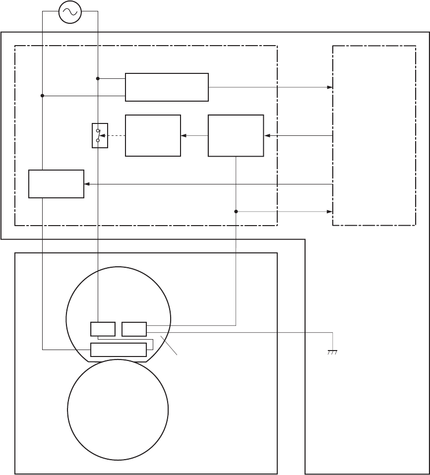
Product block diagram
Figure 1-1 Product block diagram
PICKUP-AND-FEED SYSTEM
LASER/SCANNER SYSTEM
ENGINE CONTROL
SYSTEM
IMAGE-FORMATION SYSTEM
2 Chapter 1 Theory of operation ENWW

Sequence of operation
The DC controller in the engine-control system controls the operational sequences of the product. The
table below describes durations and operations for each period of a print operation from when the
product is turned on until the motor stops rotating.
Normal sequence of operation
Table 1-1 Sequence of operation
Name Timing Purpose
WAIT From the time the power switch is turned on, the door
is closed or the product exits Sleep mode until the
product gets ready for a print operation.
Brings the product to ready state. The product
performs the following during the operations:
●Detects the print cartridge
●Heats the fuser film in the fuser
●Rotates, and the stops, the main motor
STBY (standby) From the end of the WAIT or LSTR period until either
a print command is sent or the power switch is turned
off.
Maintains the product in printable condition. The
product performs the following during the operation:
●Enters Auto-Off mode if Auto-Off command is
received
INTR (initial
rotation)
From the time a print command is received until the
paper is picked up.
The product performs the following during the
operations:
●Drives the main motor
●Activates the high-voltage power supply
●Activates the laser/scanner
●Warms the fuser heater
PRINT From the end of the INTR period until the last sheet
completes the fuser operation.
Forms the image on the photosensitive drum based
on the VIDEO signals from the formatter. Transfers
and fuses the toner image to the paper.
LSTR (last
rotation)
From the end of the PRINT period until the main motor
stops rotating.
Moves the last printed sheet out of the product. The
product performs the following during the operations:
●Stops the main motor
●Deactivates the high-voltage power supply
●Deactivates the laser/scanner
●Deactivates the fuser heater
The product enters the INTR period as the LSTR
period is completed, if the formatter sends another
print command.
ENWW Basic operation 3

Formatter-control system
The formatter is responsible for the following procedures:
●Controlling sleep mode
●Receiving and processing print data from the various product interfaces
●Monitoring control-panel functions and relaying product-status information (through the control
panel and the network or bidirectional interface)
●Developing and coordinating data placement and timing with the DC controller PCA
●Storing font information
●Communicating with the host computer through the network or the bidirectional interface
The formatter receives a print job from the network or bidirectional interface and separates it into image
information and instructions that control the printing process. The DC controller PCA synchronizes the
image-formation system with the paper-input and -output systems, and then signals the formatter to
send the print-image data.
Sleep mode
NOTE: This product uses an Auto-Off feature for sleep mode.
After a user-specified time, the Auto-Off feature automatically conserves electricity by substantially
reducing power consumption when the product is not printing. After a user-specified time, the product
automatically reduces its power consumption (Auto-Off). The product returns to the ready state when a
button is pressed, a print job is received, or a door is opened. When the product is in Auto-Off mode,
all of the control-panel LEDs and the power button backlight LED are off.
NOTE: Although the product lights are off in Auto-Off mode, the product functions normally when it
receives a print job.
Input/output
The product receives print data primarily from the following:
●Hi-Speed USB 2.0 port
●802.11b/g wireless networking (wireless models only)
CPU
The formatter incorporates a 400 MHz Helium processor.
Memory
The random access memory (RAM) on the formatter PCA contains the page, I/O buffers, and the font
storage area. RAM stores printing and font information received from the host system, and can also
serve to temporarily store a full page of print-image data before the data is sent to the print engine.
4 Chapter 1 Theory of operation ENWW

Firmware
●HP LaserJet Professional P1560 Printer series
◦The product has 8 MB of Synchronous DRAM, which is used for run-time firmware imaging
and specific print job information for the print job.
●HP LaserJet Professional P1600 Printer series
◦The product has 32 MB of Synchronous DRAM, which is used for run-time firmware imaging
and specific print job information for the print job.
Memory use
●HP LaserJet Professional P1560 Printer series
◦The product has a 2 KB EEPROM and 64 MB of NAND Flash Memory, which is used for
product configuration information and printer driver firmware.
●HP LaserJet Professional P1600 Printer series
◦The product has a 8 KB EEPROM and 64 MB of NAND Flash Memory, which is used for
product configuration information and printer driver firmware.
PJL overview
The printer job language (PJL) is an integral part of configuration, in addition to the standard printer
command language (PCL). With standard cabling, the product can use PJL to perform a variety of
functions such as these:
●Two-way communication with the host computer through a network connection or a USB
connection. The product can inform the host about such things as the control-panel settings, and
the control-panel settings can be changed from the host.
●Dynamic I/O switching. The product uses this switching to be configured with a host on each I/O.
The product can receive data from more than one I/O simultaneously, until the I/O buffer is full.
This can occur even when the product is offline.
●Context-sensitive switching. The product can automatically recognize the personality (PS or PCL)
of each job and configure itself to serve that personality.
●Isolation of print environment settings from one print job to the next. For example, if a print job is
sent to the product in landscape mode, the subsequent print jobs print in landscape mode only if
they are formatted for landscape printing.
LEDM overview
NOTE: HP LaserJet Professional P1600 Printer series
The low-end data model (LEDM) provides one consistent data representation method and defines the
dynamic and capabilities tickets shared between clients and devices, as well as the access protocol,
event, security, and discovery methods.
ACL overview
The advanced control language (ACL) is a language that supports product control and firmware
downloads in printers that support both PJL/PCL and host-based printing. Each sequence of ACL
ENWW Formatter-control system 5
commands must be preceded by a unified exit command (UEL) and an @PJL ENTER LANGUAGE=ACL
command. The ACL sequence is always followed by a UEL. Any number of commands can be placed
between the UELs. The only exception to these rules is the download command. If a firmware download
is done, the download command must be the last command in the sequence. It will not be followed by
a UEL.
The firmware searches for the UEL sequence when parsing commands. However, while downloading
binary data such as host-based code or NVRAM data the firmware suspends UEL parsing. To handle
hosts that “disappear” during binary sequences, the firmware times out all ACL command sessions. If
a timeout occurs during a non-download command sequence, it is treated as the receipt of a UEL. If a
timeout occurs during firmware download the product resets.
Control panel
The formatter sends and receives product status and command data to and from the control-panel PCA.
6 Chapter 1 Theory of operation ENWW
Engine-control system
The engine-control system coordinates all product functions, according to commands that the formatter
sends. The engine-control system drives the laser/scanner system, the image-formation system, and
the pickup/feed/delivery system.
The engine control system contains the following major components:
●Engine-control unit (ECU)
◦DC controller
◦Low-voltage power supply
●High-voltage power supply
●Fuser control
Figure 1-2 Engine-control system
MEDIA-FEED SYSTEM
ENGINE CONTROL SYSTEM
DC controller
LASER/SCANNER SYSTEM
IMAGE-FORMATION SYSTEM
Formatter
High-voltage power supply
Low-voltage power supply
Fuser control
ENWW Engine-control system 7
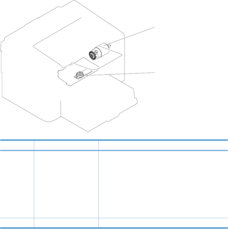
Motors, fans, clutches, solenoids, switches, and sensors
Figure 1-3 Motors
M1
M2
Table 1-2 Motors
Item Description Components driven
M1 Main motor ●Pickup roller
●Feed roller
●Photosensitive drum
●Developing roller
●Pressure roller
●Delivery roller
●Duplex feed roller
M2 Scanner motor ●Scanner mirror
8 Chapter 1 Theory of operation ENWW
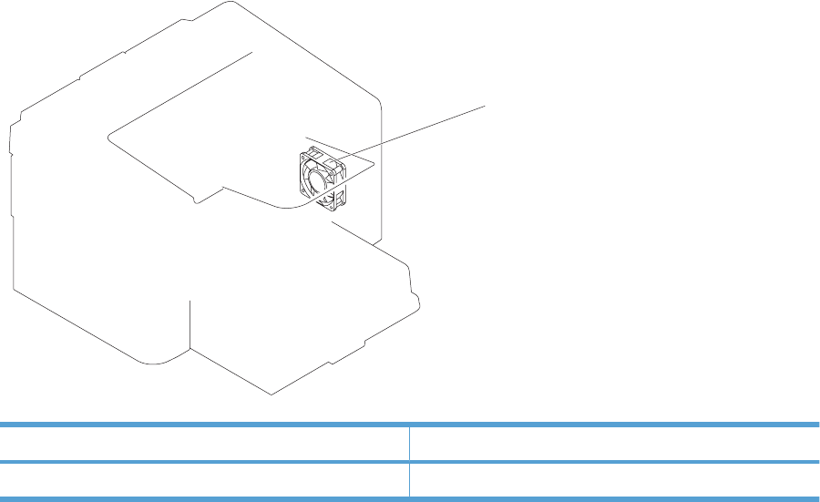
Figure 1-4 Fans
FM1
Table 1-3 Fans
Item Description
FM1 Main fan
ENWW Engine-control system 9
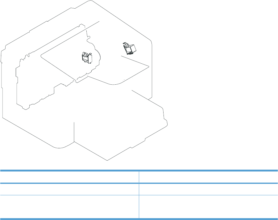
Figure 1-5 Solenoids and clutches
SL1
SL2
Table 1-4 Solenoids and clutches
Item Description
SL1 Pickup solenoid
SL2 Duplex reverse solenoid
NOTE: Duplex models only.
10 Chapter 1 Theory of operation ENWW
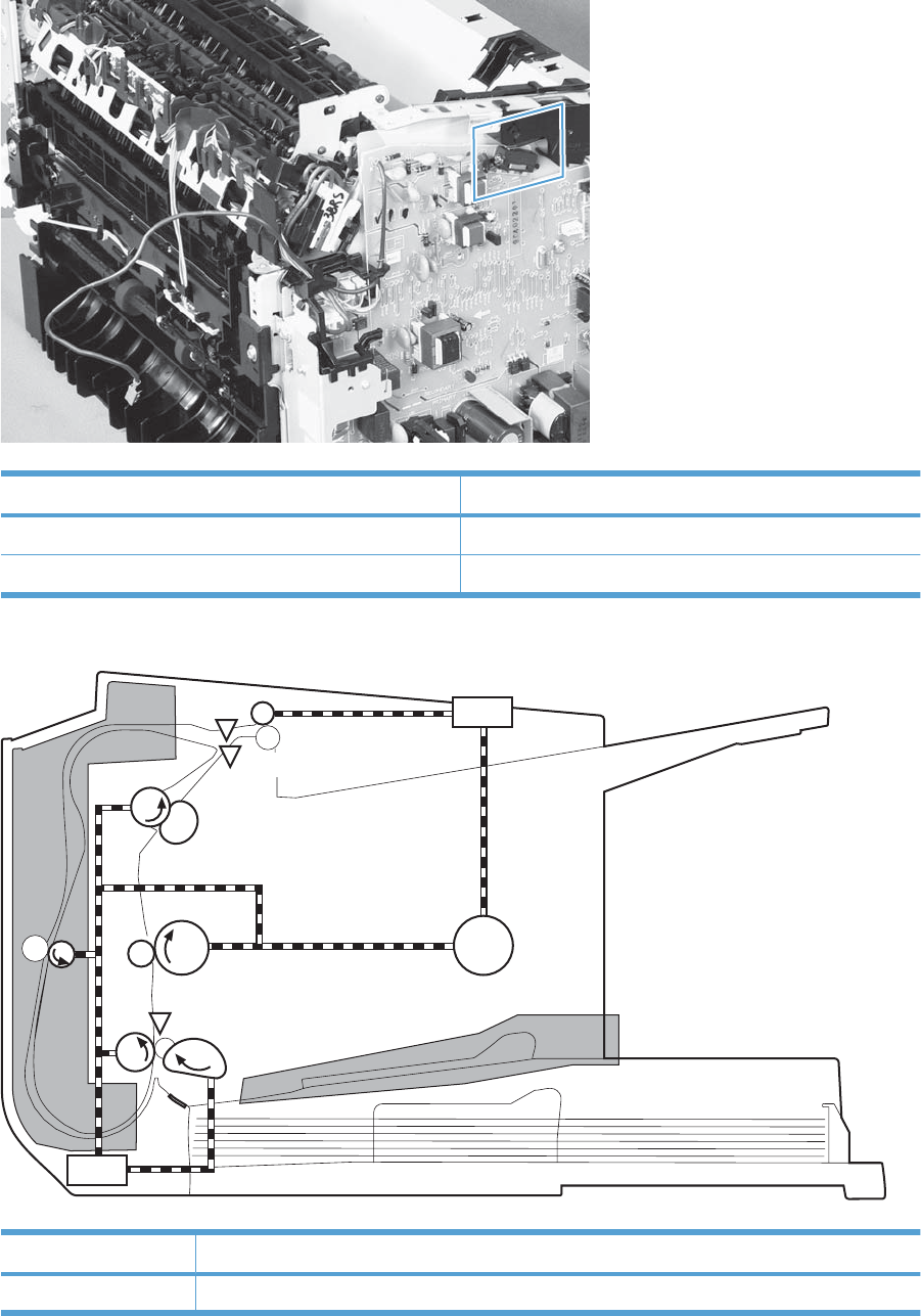
Figure 1-6 Switches
Table 1-5 Switches
Item Description
SW501 Cartridge-door switch
SW502 Power switch; not shown
Figure 1-7 Sensors
PS751
PS701
PS702
Table 1-6 Sensors
Item Description
PS701 Fuser delivery sensor
ENWW Engine-control system 11

Item Description
PS702 Media-width sensor
PS751 Top-of-Page (TOP) sensor
PS901 Main-motor rotation-number sensor; not shown
Table 1-6 Sensors (continued)
12 Chapter 1 Theory of operation ENWW
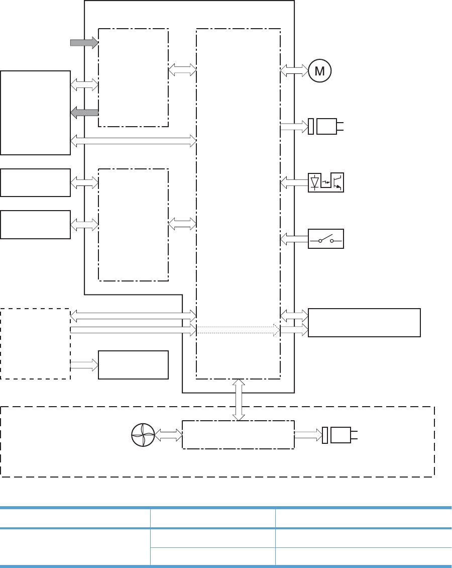
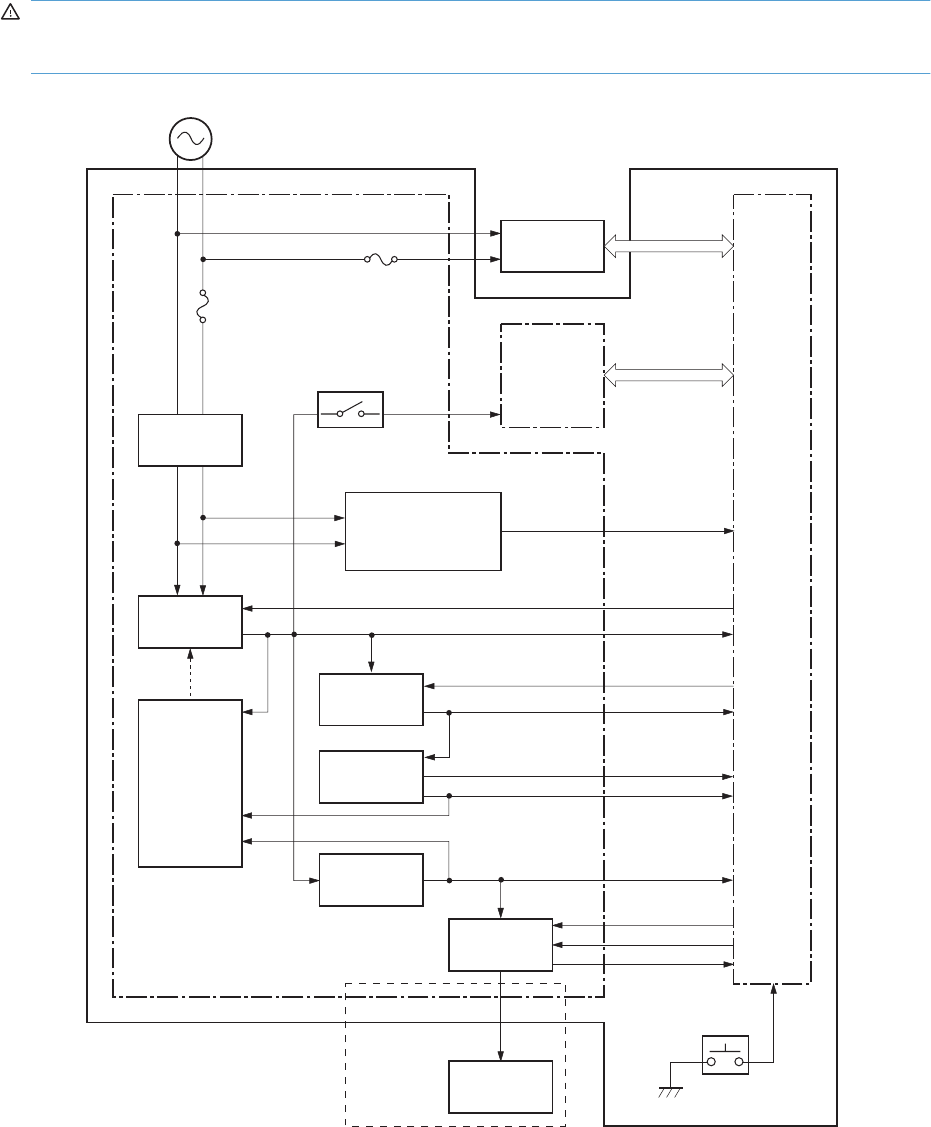
DC controller operations
The DC controller controls the operational sequences of the product systems.
Figure 1-8 DC controller block diagram
Duplex model only
Duplex connector PCA
Transfer roller
Motor
Solenoid
Photointerrupter
Laser scanner
Formatter
Switch
Solenoid
Operation panel
Engine controller
Fuser unit
High-voltage
power supply
Cartridge
AC input
Low-voltage
power supply
DC controller
Fan
Table 1-7 DC controller controlled components
Component Designator Description
Motor M1 Main motor
M2 Scanner motor
ENWW Engine-control system 13

Component Designator Description
Solenoid SL1 Pickup solenoid
SL2 Duplex reverse solenoid
NOTE: Duplex models only.
Photointerrupter PS701 Fuser delivery sensor
PS702 Media-width sensor
PS751 Top-of-Page (TOP) sensor
PS901 Main-motor rotation-number sensor
Switch SW501 Cartridge-door switch
SW502 Power switch
Fan FM1 Main Fan
Table 1-7 DC controller controlled components (continued)
14 Chapter 1 Theory of operation ENWW
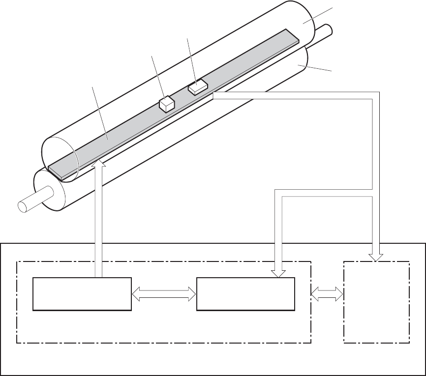
Fuser-control circuit
The fuser-control circuit monitors and controls the temperature in the fuser. The product uses on-
demand fusing. The fuser-control circuit consists of the following major components:
●Fuser heater (H1); heats the fusing film
●Thermistor (TH1); detects the fuser temperature (contact type)
●Thermoswitch (TP1); prevents abnormal temperature rise in the fuser (contact type)
Figure 1-9 Fuser control circuit
Fuser heater safety
circuit
TH1
TP1
H1
DC controller
Fuser heater control
circuit
Engine controller
FUSER TEMPERATURE signal
FUSER HEATER CONTROL signal
Pressure roller
Fuser film
Fuser control
ENWW Engine-control system 15
Fuser failure detection
The DC controller determines a fuser unit failure, releases the relay to interrupt power supply to the
fuser heater, and notifies the formatter of a failure state when it encounters the following conditions:
●Start up failure
◦If the main thermistor does not detect a specified temperature during the start up process of
the heater in the wait period.
◦If the main thermistor does not detect a specified temperature during the heater temperature
control in the initial rotation period.
●Abnormal low temperature
◦If the main thermistor detects an abnormal low temperature of the fuser unit during the printing
operation.
●Abnormal high temperature
◦If the main thermistor detects an abnormal high temperature of the fuser unit.
●Frequency detection circuit failure
◦If a specified frequency of the FREQUENCY signal is not detected within a specified period
after the product is turned on.
16 Chapter 1 Theory of operation ENWW
Fuser temperature control
The fuser temperature control maintains the temperature of the fuser heater at its targeted temperature.
The DC controller monitors the FIXING TEMPERATURE (FSRTH) signals and sends the FIXING
HEATER CONTROL (FSRD) signal according to the detected temperature. The fuser heater control
circuit controls the fuser heater depending on the signal so that the heater remains at the targeted
temperature.
Figure 1-10 Fuser-heater control circuit
FSRTH
DC controller
RLYD
FREQSNS
AC input
H1
TH1
TP1
Pressure roller
FSRD
RL101
Engine controller
Fuser film unit
Fuser heater
control circuit
Fuser heater
safety circuit
Fixing control
Fuser unit
Relay control
circuit
Frequency detection
circuit
(220-240V model only)
ENWW Engine-control system 17
Fuser protective function
The protective function detects an abnormal temperature rise of the fuser unit and interrupts power
supply to the fuser heater.
The following three protective components prevent an abnormal temperature rise of the fuser heater:
●DC controller
◦The DC controller interrupts power supply to the fuser heater when it detects an abnormal
temperature of the fuser heater.
●Fuser heater safety circuit
◦The fuser heater safety circuit interrupts power supply to the fuser heater when the detected
temperature of the main thermistor is abnormal.
●Thermoswitch
◦The contact of the thermal fuse is broken to interrupt power supply to the fuser heater when
the thermal fuse detects an abnormal temperature of the fuser heater.
Pressure roller cleaning
The pressure roller cleaning process is initiated by the formatter. The process removes toner that has
accumulated on the pressure roller by transferring it to a sheet of paper.
●The product feeds a sheet of paper after receiving the cleaning command from the formatter.
●Main motor rotation is stopped when the trailing edge of the paper passes through the transfer
roller.
●The main motor rotation is repeatedly started and then stopped. The fuser heater is turned on and
then off at the same interval as main motor rotation.
●Toner adhered to the pressure roller is fused to the paper.
●The paper is ejected from the product.
18 Chapter 1 Theory of operation ENWW
Low-voltage power supply
The low-voltage power supply (LVPS) converts ac input voltage to dc voltage. The LVPS has two fuses
on the PCA. The LVPS 24 V output is interrupted to the fuser and the high-voltage power supply if the
cartridge-door interlock switch (SW501) is in the off position (cover open).
WARNING! The product power switch only interrupts dc voltage from the LVPS. The ac voltage is
present in the product when the power cord is plugged into a power receptacle and the power switch is
in the off position. You must unplug the product power cord before servicing the product.
Figure 1-11 Low-voltage power supply (LVPS)
BSTSIG
FREQSNS
AC input
DC controller
+24V ON/OFF
circuit
+5V
+24U
+3.3V ON/OFF
circuit
+24V
24VON
+24P
+3.3U
+3.3V
+5R
+3.3R
Fuse (FU201)
Fuse (FU101)
Protection
circuit
Low-voltage power supply
+5V
generation
circuit
Fuser unit
Cartridge-door switch
(SW501)
Engine controller
Power switch
(SW502)
+3.3V
generation
circuit
+24V
generation
circuit
High-voltage
power supply
Frequency
detection circuit
(220-240V model only)
Rectifying
circuit
Formatter
+3.3UON
+3.3VON
ENWW Engine-control system 19

Overcurrent/overvoltage protection
The low-voltage power supply has a protective function against overcurrent and overvoltage to prevent
failures in the power supply circuit. If an overcurrent or overvoltage condition occurs, the system
automatically cuts off the output voltage.
If the dc power is not being supplied from the low-voltage power supply, the protective function might
be running. In such case, turn off the power switch and unplug the power cord. Do not plug in the power
cord or turn on the power switch again until the cause is found.
WARNING! If you believe the overcurrent or overvoltage protection circuits have been activated, do
not plug in the product power cord or turn on the product power until the cause of the failure is found
and corrected.
In addition, two fuses in the low-voltage power supply protect against overcurrent. If overcurrent flows
into the ac line, the fuses melt and cut off the power distribution.
20 Chapter 1 Theory of operation ENWW
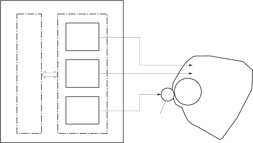
High-voltage power supply
The high-voltage power supply (HVPS) applies biases to the following components:
●Primary charging roller
●Developing roller
●Transfer roller
Figure 1-12 High-voltage power supply
Primary
charging bias
circuit
Developing
bias circuit
Transfer bias
circuit
Engine controller
To primary charging roller
To developing roller
Photosensitive drum
Transfer roller
High-voltage power supply
DC controller
Cartridge
ENWW Engine-control system 21
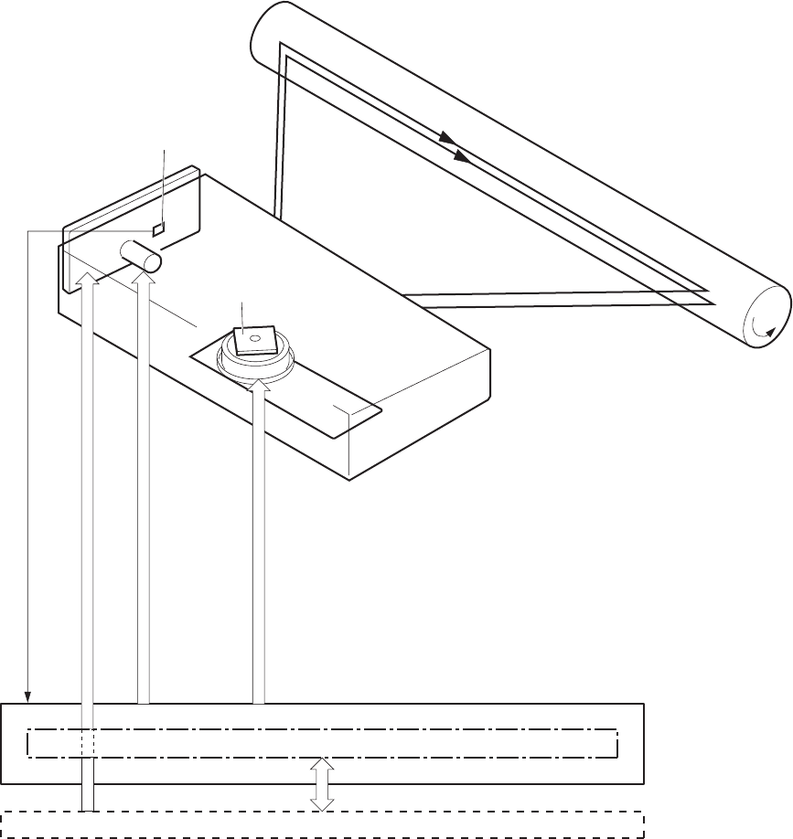
Laser/scanner system
The laser/scanner system receives VIDEO signals from the ECU and formatter and converts the signals
into latent images on the photosensitive drum.
The main components of the laser/scanner are the laser unit and the scanner motor unit. The DC
controller sends signals to the laser/scanner to control the functions of these components.
Figure 1-13 Laser/scanner system
Formatter
DC controlle r
BDI signal
VIDEO signal
LASER CONTROL signal
SCANNER MOTOR CONTROL signal
Engine controller
Photosensitive drum
Scanning mirror
BD sensor
Laser unit
Scanner motor unit
22 Chapter 1 Theory of operation ENWW
Laser failure detection
The DC controller determines an optical unit failure and notifies the formatter, if the laser/scanner
encounters the following conditions:
●The scanner motor does not reach a specified rotation within a specified period of the scanner
motor start up.
●The rotation of the scanner motor is out of specified range for a specified period during the scanner
motor drive.
●The BD interval is out of a specified value during a print operation.
ENWW Engine-control system 23
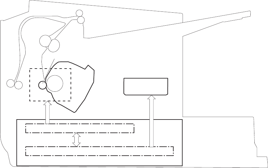
Image-formation system
Electrophotographic process
The electrophotographic process forms an image on the paper. Following are the major components
used in the process:
●Print cartridge
●Transfer roller
●Fuser
●Laser/scanner
●High-voltage power supply
The DC controller uses the laser/scanner and HVPS to form the toner image on the photosensitive drum.
The image is transferred to the paper and then fused onto the paper.
Figure 1-14 Electrophotographic process block diagram (1 of 2)
High-voltage power supply
DC controller
Engine controller
Laser scanner
Cartridge
Transfer roller
The DC controller rotates the main motor to drive the following components:
●Photosensitive drum
●Developing drum
●Primary charging roller (follows the rotation of the photosensitive drum)
●Transfer roller (follows the rotation of the photosensitive drum)
24 Chapter 1 Theory of operation ENWW
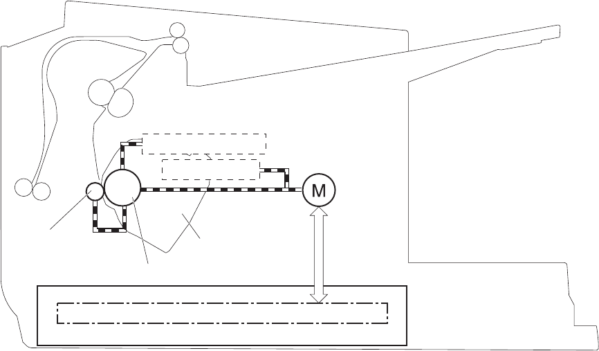
Figure 1-15 Electrophotographic process block diagram (2 of 2)
DC controller
Engine controller
Cartridge
Transfer roller
Developing roller Main motor
Photosensitive drum
Primary charging roller
ENWW Image-formation system 25
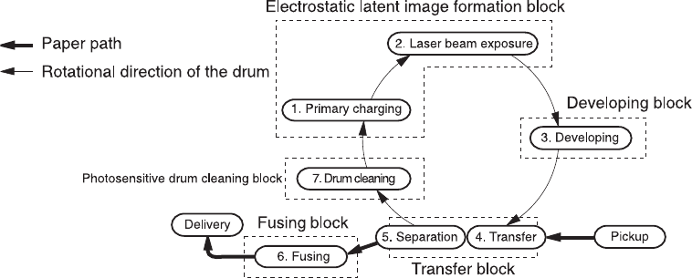
Image formation process
Each of the following process function independently and must be coordinated with the other product
processes. Image formation consists of the following processes:
●Latent-image formation block
◦Step 1: primary charging
◦Step 2: laser-beam exposure
●Developing block
◦Step 3: developing
●Transfer block
◦Step 4: transfer
◦Step 5: separation
●Fusing block
◦Step 6: fusing
●Drum cleaning block
◦Step 7: drum cleaning
Figure 1-16 Image formation process
26 Chapter 1 Theory of operation ENWW
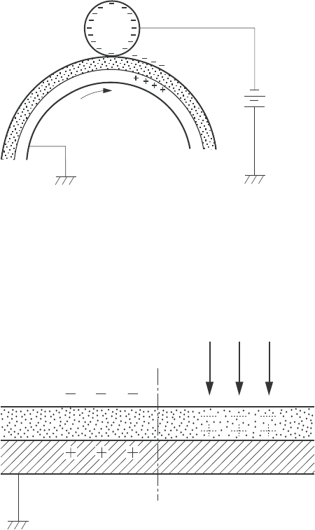
Latent-image formation stage
During the latent-image formation stage, the laser/scanner forms an invisible image on the
photosensitive drum in the print cartridge.
Primary charging
Step 1: DC and AC biases are applied to the primary charging roller, which transfers a uniform negative
potential to the photosensitive drum.
Figure 1-17 Primary charging
DC bias
Photosensitive drum
Primary charging roller
Laser beam exposure
Step 2: The laser beam scans the photosensitive drum to neutralize negative charges on parts of the
drum surface. An electrostatic latent image is formed on the drum where negative charges were
neutralized.
Figure 1-18 Laser beam exposure
Laser beam
Unexposed area Exposed area
ENWW Image-formation system 27
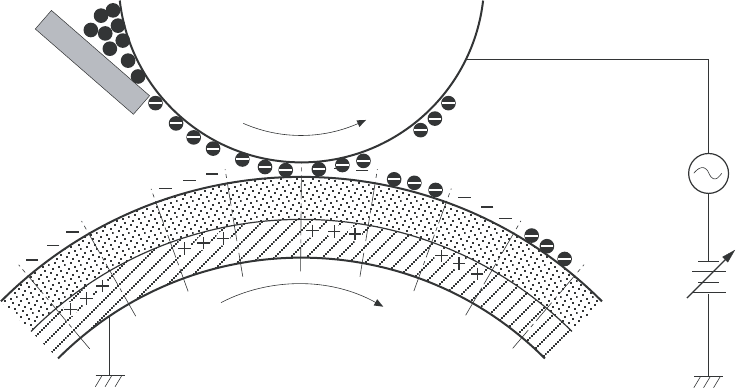
Developing stage
Print cartridge
Step 3: In the print cartridge, the developing cylinder transfers toner onto the electrostatic latent image
on the photosensitive drum.
Figure 1-19 Print cartridge
Blade
Developing cylinder
AC bias
DC bias
Photosensitive drum
Unexposed area
Exposed area
Exposed area
Unexposed area
Toner acquires a negative charge from the friction that occurs when the developing roller rotates against
the developing blade. The developing bias is applied to the developing roller to make a potential
difference between the developing roller and the photosensitive drum. The negatively charged toner is
attracted to the latent image on the photosensitive drum because the drum surface has a higher
potential.
28 Chapter 1 Theory of operation ENWW
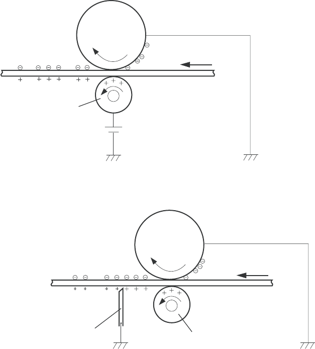
Transfer stage
Step 4: The transfer charging roller, to which a DC positive bias is applied, imparts a positive charge
on the paper. When the page comes in contact with the photosensitive drum, the toner is transferred to
the paper.
Figure 1-20 Transfer
Media
Transfer roller
Photosensitive
drum
DC bias
Step 5: The elasticity of the paper causes its separation from the photosensitive drum. A static charge
eliminator aids separation by weakening any electrostatic adhesion.
Figure 1-21 Separation
Media
Transfer roller
Photosensitive
drum
Static charge eliminator
Fusing stage
Step 6: The DC negative bias applied to the fusing film strengthens the holding force of the toner on the
paper and prevents the toner from scattering.
ENWW Image-formation system 29
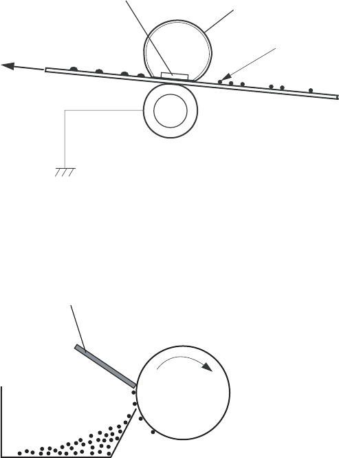
The product uses an on-demand fuser method. The toner image is permanently affixed to the paper by
heat and pressure.
Figure 1-22 Fusing
Fuser film
Toner
Pressure roller
Fuser heater
Media
Cleaning stage
Step 7: The cleaning blade scrapes the residual toner off of the photosensitive drum and deposits it into
the waste toner case.
Figure 1-23 Drum cleaning
Waste toner container
Photosensitive
drum
Cleaning blade
30 Chapter 1 Theory of operation ENWW
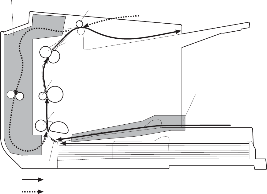
Pickup, feed, and delivery system
The media feed system picks up, feeds, and delivers the page.
Figure 1-24 Pickup, feed, and delivery system block diagram
Duplex media path
Simplex media path
Pickup roller
Feed roller
Duplex
feed roller
Single-sheet-feed slot
Separation pad
Photosensitive drum
Transfer roller
Fuserfilm
Pressure roller
Delivery roller
Duplex feed unit
ENWW Pickup, feed, and delivery system 31
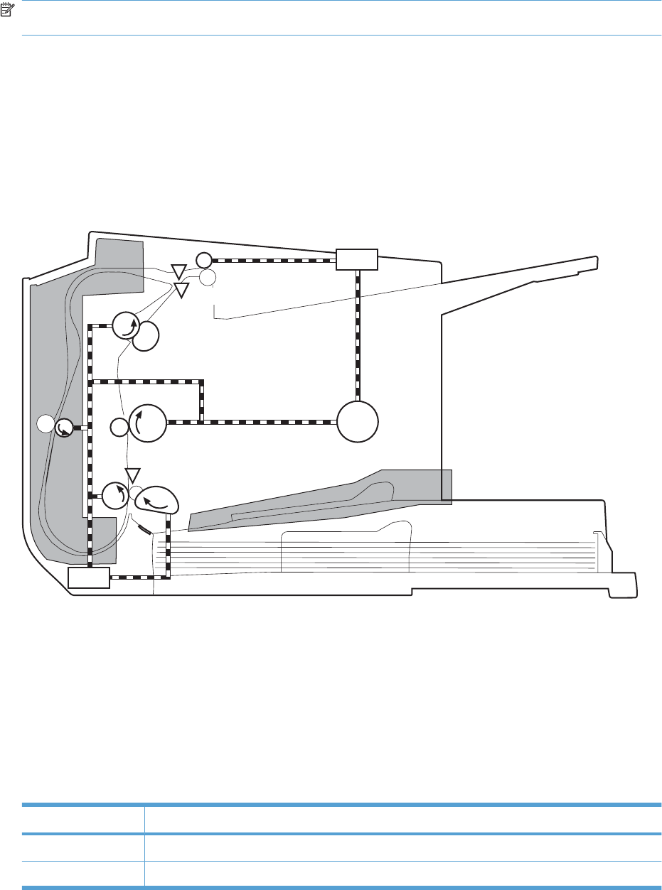
Photo sensors and switches
NOTE: The illustration in this section also shows the product motor, photo sensors, and solenoid. The
power switch is not shown.
Figure 1-25 Photo sensors, motor, and solenoid
M1
PS751
PS701
PS702 SL2
SL1
Table 1-8 Photo sensors, motor, and solenoid
Item Description
M1 Main motor
SL1 Pickup solenoid
32 Chapter 1 Theory of operation ENWW

Item Description
SL2 Duplex feed solenoid
NOTE: Duplex models only.
PS701 Fuser delivery sensor
PS702 Media-width sensor
PS751 TOP sensor
Table 1-8 Photo sensors, motor, and solenoid (continued)
ENWW Pickup, feed, and delivery system 33

Main-input tray or priority input slot
Jam detection
The product uses the following sensors to detect the presence of paper and to check for jams. The page
must pass each sensor within a specified time.
NOTE: To find the following components, see Photo sensors and switches on page 32.
●PS701; fuser delivery sensor
●PS702; TOP sensor
NOTE: The product automatically ejects paper if the TOP sensor detects residual paper within
the product when the power is turned on or the door is closed.
The product detects the following jams:
●Pickup stationary jam
●Delivery delay jam
●Delivery stationary jam
●Fuser wrapping jam
●Door open jam
●Residual media jam
●Duplex reverse delay jam (duplex models only)
●Duplex reverse stationary jam (duplex models only)
●Duplex re-pickup delay jam (duplex models only)
34 Chapter 1 Theory of operation ENWW


Introduction
This chapter describes the removal and replacement of field-replaceable units (FRUs) only.
Replacing FRUs is generally the reverse of removal. Occasionally, notes and tips are included to provide
directions for difficult or critical replacement procedures.
HP does not support repairing individual subassemblies or troubleshooting to the component level.
Note the length, diameter, color, type, and location of each screw. Be sure to return each screw to its
original location during reassembly.
Incorrectly routed or loose wire harnesses can interfere with other internal components and can become
damaged or broken. Frayed or pinched harness wires can be difficult to find. When replacing wire
harnesses, always use the provided wire loops, lance points, or wire-harness guides and retainers.
Removal and replacement strategy
WARNING! Turn the product off, wait 5 seconds, and then remove the power cord before attempting
to service the product. If this warning is not followed, severe injury can result, in addition to damage to
the product. The power must be on for certain functional checks during troubleshooting. However,
disconnect the power supply during parts removal.
Never operate or service the product with the protective cover removed from the laser/scanner
assembly. The reflected beam, although invisible, can damage your eyes.
The sheet-metal parts can have sharp edges. Be careful when handling sheet-metal parts.
CAUTION: Do not bend or fold the flat flexible cables (FFCs) during removal or installation. Also, do
not straighten pre-folds in the FFCs. You must fully seat all FFCs in their connectors. Failure to fully
seat an FFC into a connector can cause a short circuit in a PCA.
NOTE: To install a self-tapping screw, first turn it counterclockwise to align it with the existing thread
pattern, and then carefully turn it clockwise to tighten. Do not overtighten. If a self-tapping screw-hole
becomes stripped, repair the screw-hole or replace the affected assembly.
TIP: For clarity, some photos in this chapter show components removed that would not be removed
to service the product. If necessary, remove the components listed at the beginning of a procedure
before proceeding to service the product.
36 Chapter 2 Removal and replacement ENWW
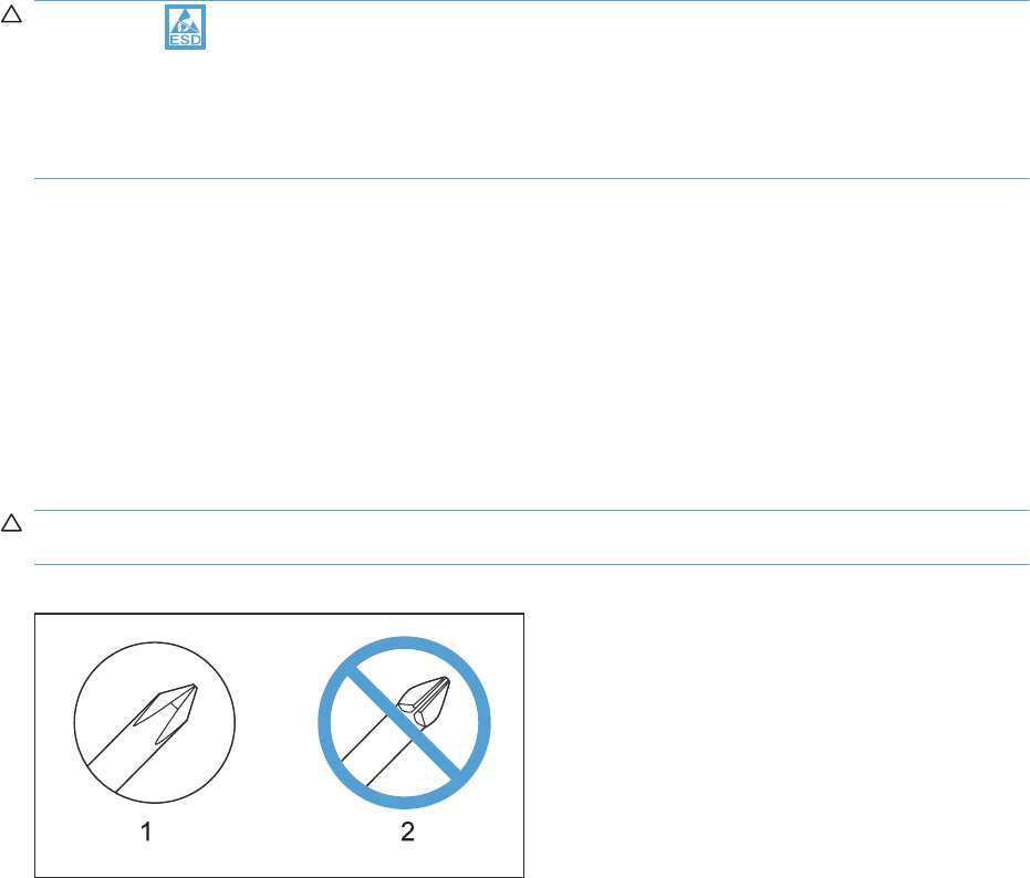
Electrostatic discharge
CAUTION: Some parts are sensitive to electrostatic discharge (ESD). Look for the ESD reminder
when removing product parts. Always perform service work at an ESD-protected workstation or mat, or
use an ESD strap. If an ESD workstation, mat, or strap is not available, ground yourself by touching the
sheet-metal chassis before touching an ESD-sensitive part.
Protect the ESD-sensitive parts by placing them in ESD pouches when they are out of the product.
Required tools
●#2 Phillips screwdriver with a magnetic tip and a 152-mm (6-inch) shaft length
●Small flat-blade screwdriver
●Needle-nose pliers
●ESD mat or ESD strap (if one is available)
●Penlight (optional)
CAUTION: Always use a Phillips screwdriver (callout 1). Do not use a pozidrive screwdriver (callout 2)
or any motorized screwdriver. These can damage screws or screw threads.
Figure 2-1 Phillips and pozidrive screwdriver comparison
Before performing service
●Remove all paper from the product.
●Turn off the power using the power switch.
●Unplug the power cable and interface cable or cables.
●Place the product on an ESD workstation or mat, or use an ESD strap (if one is available). If an
ESD workstation, mat, or strap is not available, ground yourself by touching the sheet-metal chassis
before touching an ESD-sensitive part.
●Remove the print cartridge.
ENWW Electrostatic discharge 37
After performing service
●Plug in the power cable.
●Reinstall the print cartridge.
●Load paper in the product.
Post-service test
Perform the following test to verify that the repair or replacement was successful.
Print-quality test
1. Verify that you have completed the necessary reassembly steps.
2. Make sure that the tray contains clean, unmarked paper.
3. Attach the power cord and interface cable or interface cables, and then turn on the product.
4. Verify that the expected startup sounds occur.
5. Print a configuration page, and then verify that the expected printing sounds occur.
6. Print a demo page, and then verify that the print quality is as expected.
7. Send a print job from the host computer, and then verify that the output meets expectations.
8. Clean the outside of the product with a damp cloth.
38 Chapter 2 Removal and replacement ENWW

Parts removal order
Figure 2-2 Parts removal order
Front cover
Pickup roller
Separation pad
Transfer roller
Cartridge door
Duplex door (duplex models)
Duplex frame (duplex models)
Left and right covers
Control panel
Rear cover (simplex models)
Formatter PCA
Main motor
Face-down cover
Laser/scanner asssembly
Duplex-reverse solenoid (duplex models)
Main fan (duplex models)
Duplex-connector PCA (duplex models)
Pickup assembly
Fuser
Pickup solenoid
Engine controller PCA
Main input tray and output tray
Left and right covers
Rear cover (simplex models),
or Duplex door (duplex models)
and Duplex frame (duplex models)
ENWW Parts removal order 39
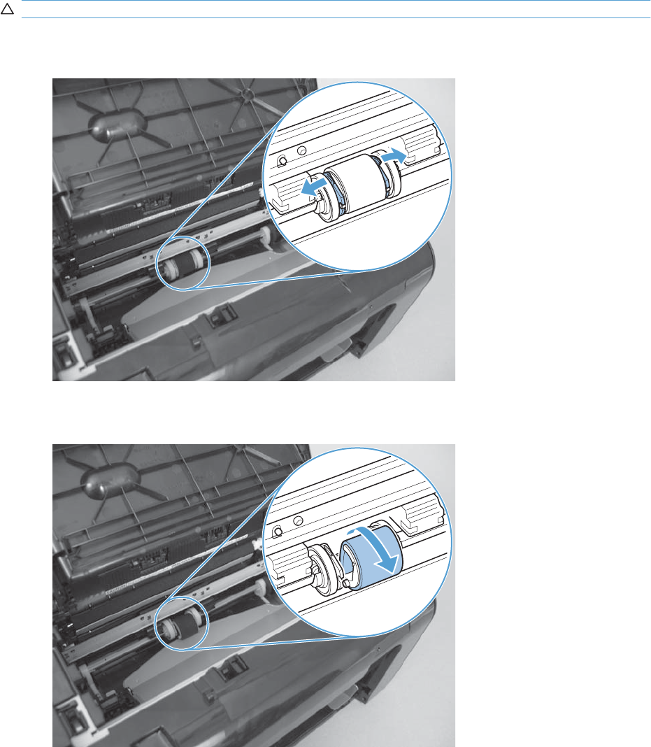
Pickup roller
CAUTION: Do not touch the sponge portion of the roller. Skin oils can cause paper handling problems.
1. Release two tabs.
Figure 2-3 Remove the pickup roller (1 of 2)
2. Rotate the roller away from the product to remove it.
Figure 2-4 Remove the pickup roller (2 of 2)
40 Chapter 2 Removal and replacement ENWW
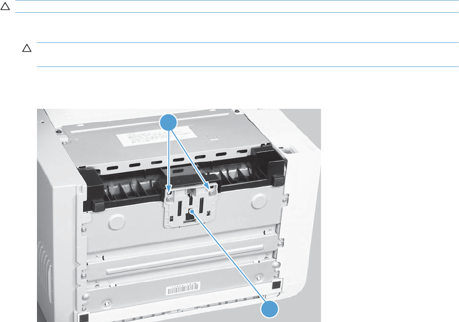
Separation pad
CAUTION: Do not touch the sponge portion of the pad. Skin oils can cause paper handling problems.
1. Place the product rear-side up to access the separation pad assembly.
CAUTION: Dirt and debris can scratch the product covers. Place the product on a cloth or other
clean surface.
2. Remove two screws (callout 1) and then remove the separation pad assembly (callout 2).
Figure 2-5 Remove the separation pad assembly
2
1
ENWW Separation pad 41
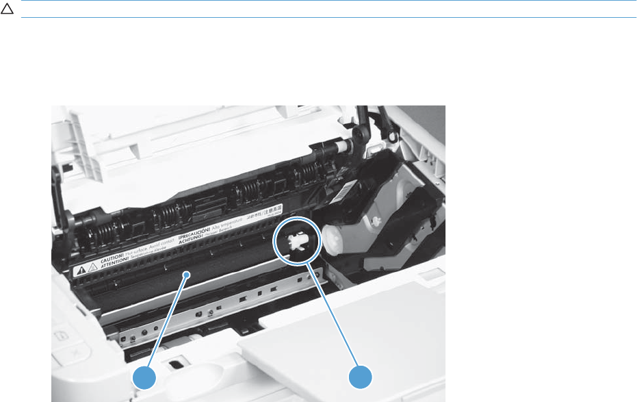
Transfer roller
CAUTION: Do not touch the sponge portion of the roller. Skin oils can cause print quality problems.
1. Open the print-cartridge door.
2. Release two tabs (callout 1), and then remove the transfer roller (callout 2).
Figure 2-6 Remove the transfer roller
1
2
42 Chapter 2 Removal and replacement ENWW
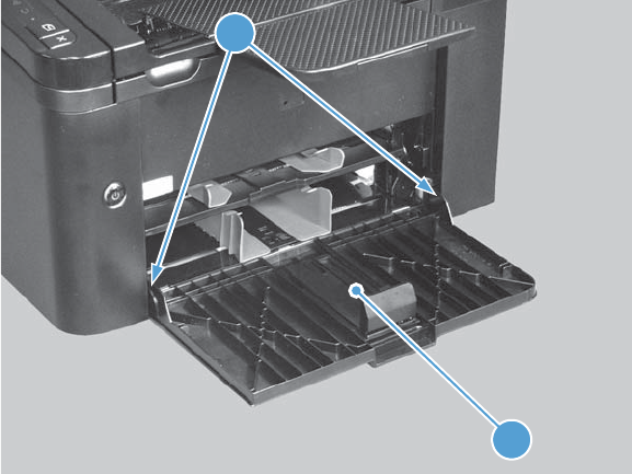
Covers
Main-input tray
Open the tray (callout 1), release two tabs (callout 2), and then remove the tray.
Figure 2-7 Remove the tray
2
1
ENWW Covers 43
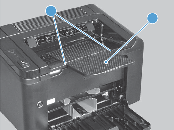
Output bin tray extension
Release two pins (callout 1), and then remove the tray extension (callout 2)
Figure 2-8 Remove the output bin tray extension
1
2
44 Chapter 2 Removal and replacement ENWW
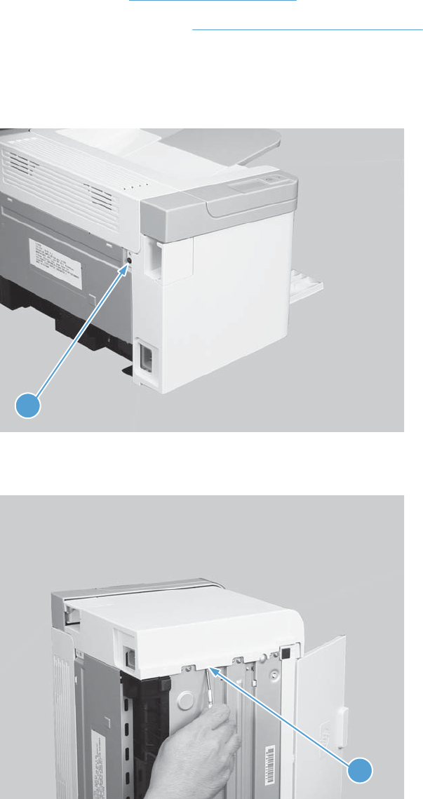
Left cover, simplex product
Before proceeding, remove the following components:
●Main-input tray. See Main-input tray on page 43.
●Output bin tray extension. See Output bin tray extension on page 44.
Remove the left cover, simplex product
1. Remove one screw (callout 1).
Figure 2-9 Remove the left cover, simplex product (1 of 4)
1
2. Release one tab (callout 1) at the bottom edge of the cover.
Figure 2-10 Remove the left cover, simplex product (2 of 4)
1
ENWW Covers 45
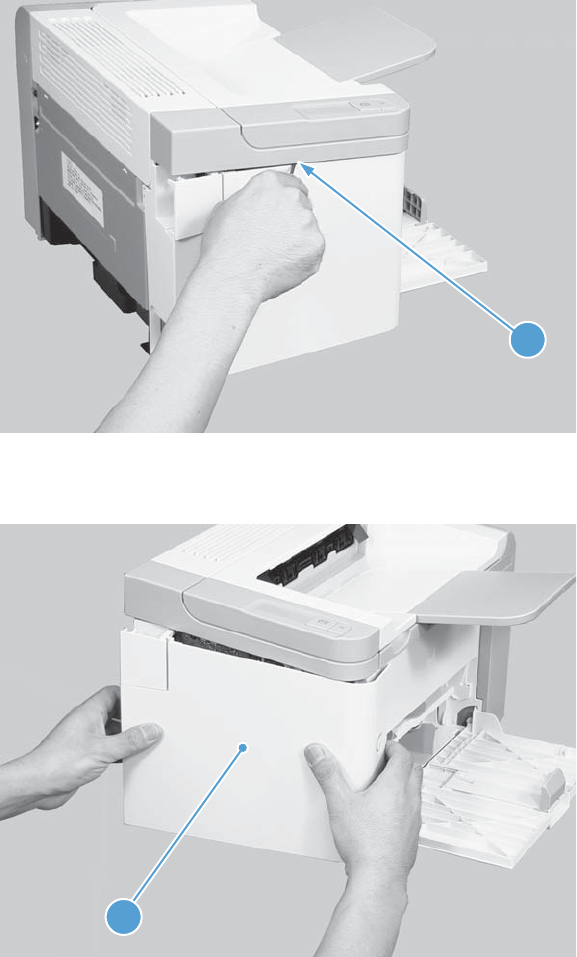
3. Release one tab (callout 1) at the top edge of the cover.
Figure 2-11 Remove the left cover, simplex product (3 of 4)
1
4. Rotate the back edge of the cover away from the product, and then remove the cover (callout 1).
Figure 2-12 Remove the left cover, simplex product (4 of 4)
1
46 Chapter 2 Removal and replacement ENWW
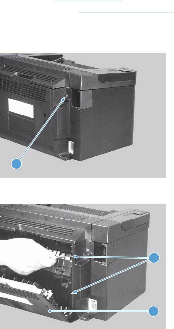
Left cover, duplex product
●Main-input tray. See Main-input tray on page 43.
●Output bin tray extension. See Output bin tray extension on page 44.
Remove the left cover, duplex product
1. Remove one screw (callout 1).
Figure 2-13 Remove the left cover, duplex product (1 of 5)
1
2. Open the duplex door (callout 1), and then release two tabs (callout 2).
Figure 2-14 Remove the left cover, duplex product (2 of 5)
1
2
ENWW Covers 47
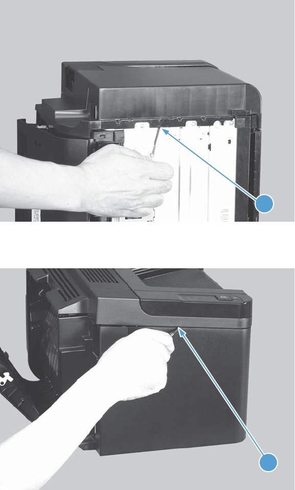
3. Release one tab (callout 1) at the bottom edge of the cover.
Figure 2-15 Remove the left cover, duplex product (3 of 5)
1
4. Release one tab (callout 1) at the top edge of the cover.
Figure 2-16 Remove the left cover, duplex product (4 of 5)
1
48 Chapter 2 Removal and replacement ENWW
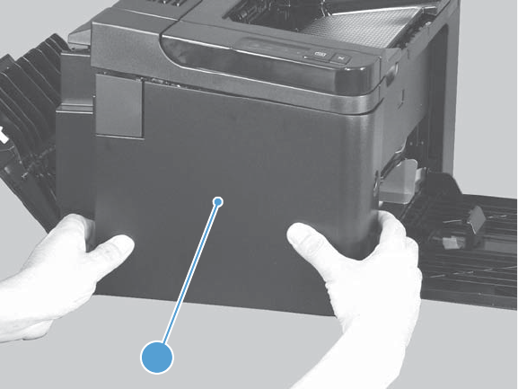
5. Rotate the back edge of the cover away from the product, and then remove the cover (callout 1).
Figure 2-17 Remove the left cover, duplex product (5 of 5)
1
ENWW Covers 49
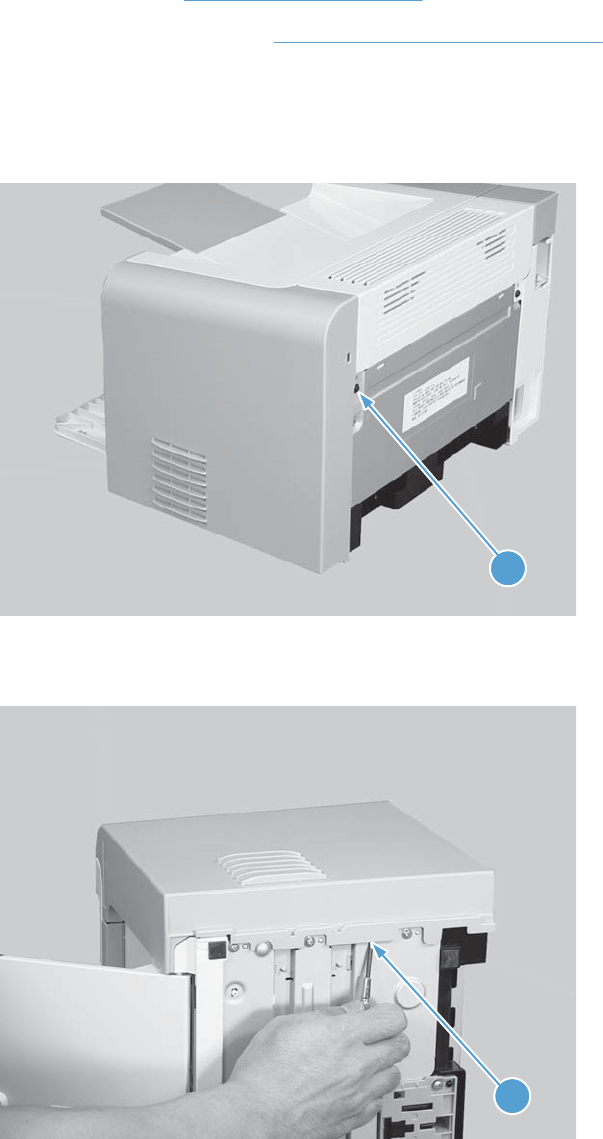
Right cover, simplex product
Before proceeding, remove the following components:
●Main-input tray. See Main-input tray on page 43.
●Output bin tray extension. See Output bin tray extension on page 44.
Remove the right cover, simplex product
1. Remove one screw (callout 1).
Figure 2-18 Remove the right cover, simplex product (1 of 4)
1
2. Release one tab (callout 1) at the bottom edge of the cover.
Figure 2-19 Remove the right cover, simplex product (2 of 4)
1
50 Chapter 2 Removal and replacement ENWW
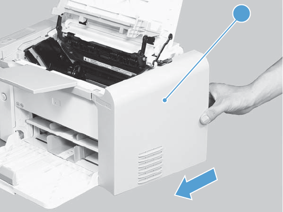
3. Slide the cover toward the front of the product to release it, and then remove the cover (callout 1).
Figure 2-20 Remove the right cover, simplex product (4 of 4)
1
ENWW Covers 51
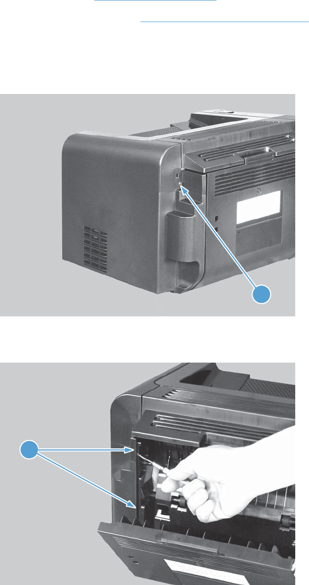
Right cover, duplex product
●Main-input tray. See Main-input tray on page 43.
●Output bin tray extension. See Output bin tray extension on page 44.
Remove the right cover, duplex product
1. Remove one screw (callout 1).
Figure 2-21 Remove the right cover, duplex product (1 of 5)
1
2. Open the duplex door (callout 1), and then release two tabs (callout 2).
Figure 2-22 Remove the right cover, duplex product (2 of 5)
1
52 Chapter 2 Removal and replacement ENWW
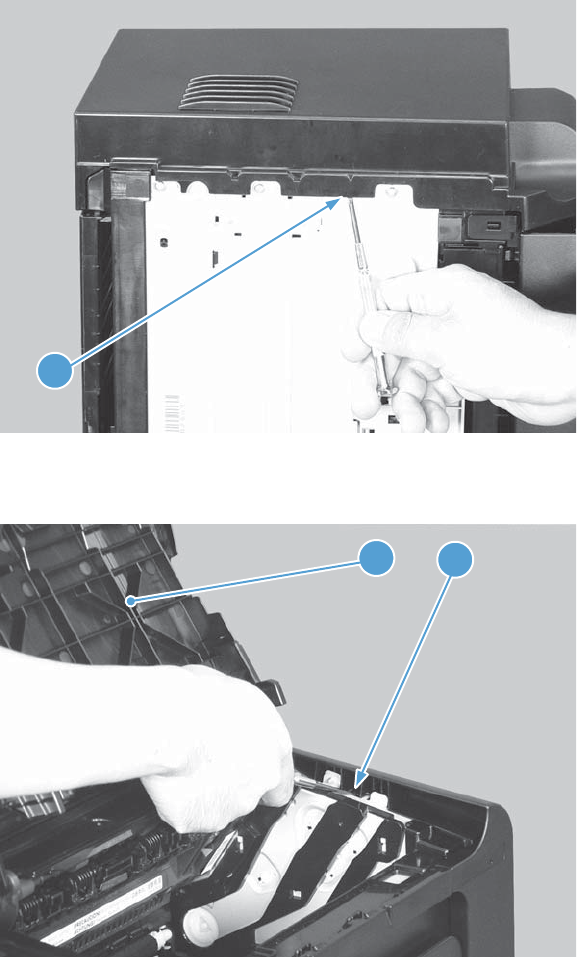
3. Release one tab (callout 1) at the bottom edge of the cover.
Figure 2-23 Remove the right cover, duplex product (3 of 5)
1
4. Open the cartridge door (callout 1), and then release one tab (callout 2) at the top edge of the cover.
Figure 2-24 Remove the right cover, duplex product (4 of 5)
12
ENWW Covers 53
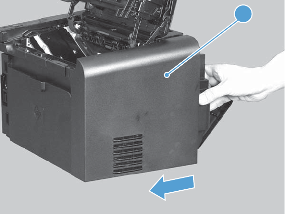
5. Slide the cover toward the front of the product to release it, and then remove the cover (callout 1).
Figure 2-25 Remove the right cover, duplex product (5 of 5)
1
54 Chapter 2 Removal and replacement ENWW
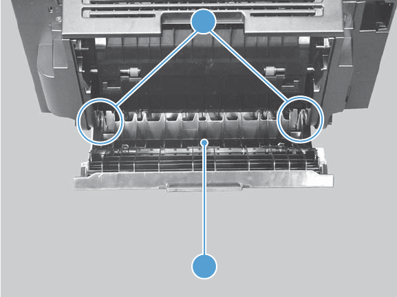
Duplex door, duplex product
Open the duplex door (callout 1), release two tabs (callout 2), and then remove the door.
Figure 2-26 Remove the duplex door, duplex product
1
2
ENWW Covers 55
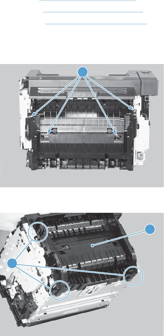
Duplex frame, duplex product
Before proceeding, remove the following components:
●Left cover. See Left cover, duplex product on page 47.
●Right cover. See Right cover, duplex product on page 52.
●Duplex door. See Duplex door, duplex product on page 55
Remove the duplex frame
1. Remove four screws (callout 1).
Figure 2-27 Remove the duplex frame (1 of 2)
1
2. Release three tabs (callout 1), and then remove the duplex frame (callout 2).
Figure 2-28 Remove the duplex frame (2 of 2)
1
2
56 Chapter 2 Removal and replacement ENWW
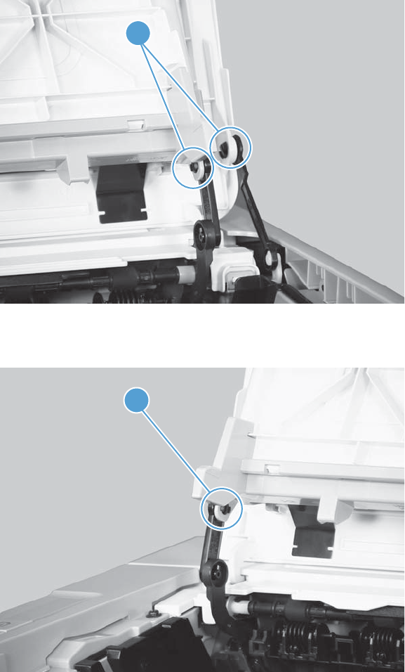
Cartridge door
1. Open the cartridge door, and then release two tabs (callout 1) on the right-side link arms.
Figure 2-29 Remove the cartridge door (1 of 3)
1
2. Release one tab (callout 1) on the left-side link arm.
Figure 2-30 Remove the cartridge door (2 of 3)
1
ENWW Covers 57
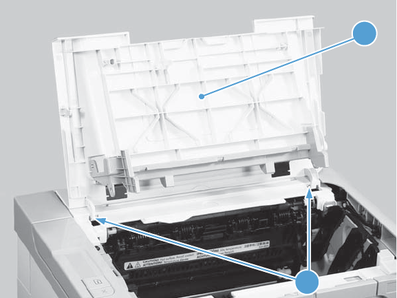
3. Release two pins (callout 1), and then remove the cartridge door (callout 2).
Figure 2-31 Remove the cartridge door (3 of 3)
1
2
58 Chapter 2 Removal and replacement ENWW
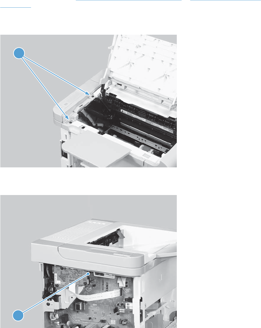
Control panel
1. Remove the left cover. See Left cover, simplex product on page 45 or Left cover, duplex product
on page 47.
2. Open the cartridge door, and then remove two screws (callout 1).
Figure 2-32 Remove the control panel (1 of 3)
1
3. Disconnect one connector (callout 1).
Figure 2-33 Remove the control panel (2 of 3)
1
ENWW Covers 59
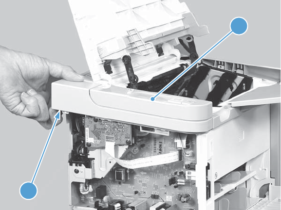
4. Release one tab (callout 1), and then remove the control panel (callout 2).
Figure 2-34 Remove the control panel (3 of 3)
1
2
60 Chapter 2 Removal and replacement ENWW
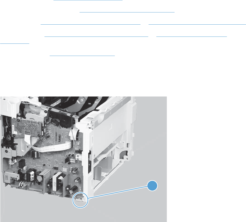
Front cover
Before proceeding, remove the following components:
●Main-input tray. See Main-input tray on page 43.
●Output bin tray extension. See Output bin tray extension on page 44.
●Left cover. See Left cover, simplex product on page 45 or Left cover, duplex product on page 47.
●Right cover. See Right cover, simplex product on page 50 or Right cover, duplex product
on page 52.
●Control panel. See Control panel on page 59.
Remove the front cover
1. Release one tab (callout 1).
Figure 2-35 Remove the front cover (1 of 3)
1
ENWW Covers 61
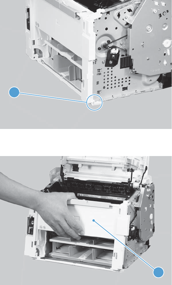
2. Release one tab (callout 1).
Figure 2-36 Remove the front cover (2 of 3)
1
3. Remove the front cover (callout 1).
Figure 2-37 Remove the front cover (3 of 3)
1
62 Chapter 2 Removal and replacement ENWW
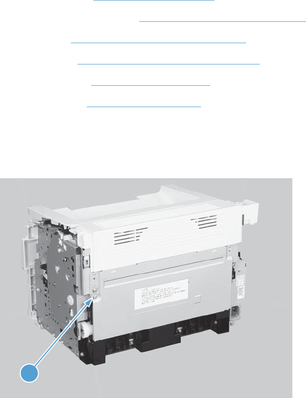
Rear cover, simplex product
Before proceeding, remove the following components:
●Main-input tray. See Main-input tray on page 43.
●Output bin tray extension. See Output bin tray extension on page 44.
●Left cover. See Left cover, simplex product on page 45.
●Right cover. See Right cover, simplex product on page 50.
●Cartridge door. See Cartridge door on page 57.
●Control panel. See Control panel on page 59.
Remove the rear cover, simplex product
1. Remove one screw (callout 1).
Figure 2-38 Remove the rear cover, simplex product (1 of 3)
1
ENWW Covers 63
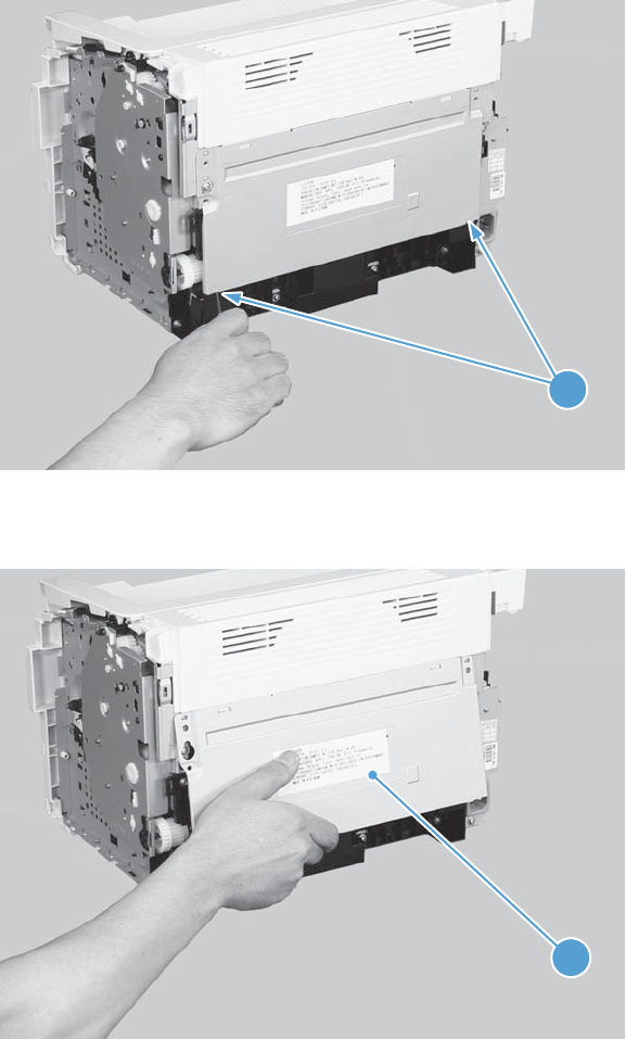
2. Release two tabs (callout 1).
Figure 2-39 Remove the rear cover, simplex product (2 of 3)
1
3. Rotate the bottom of the rear cover (callout 1) away from the product to remove it.
Figure 2-40 Remove the rear cover, simplex product (2 of 3)
1
64 Chapter 2 Removal and replacement ENWW
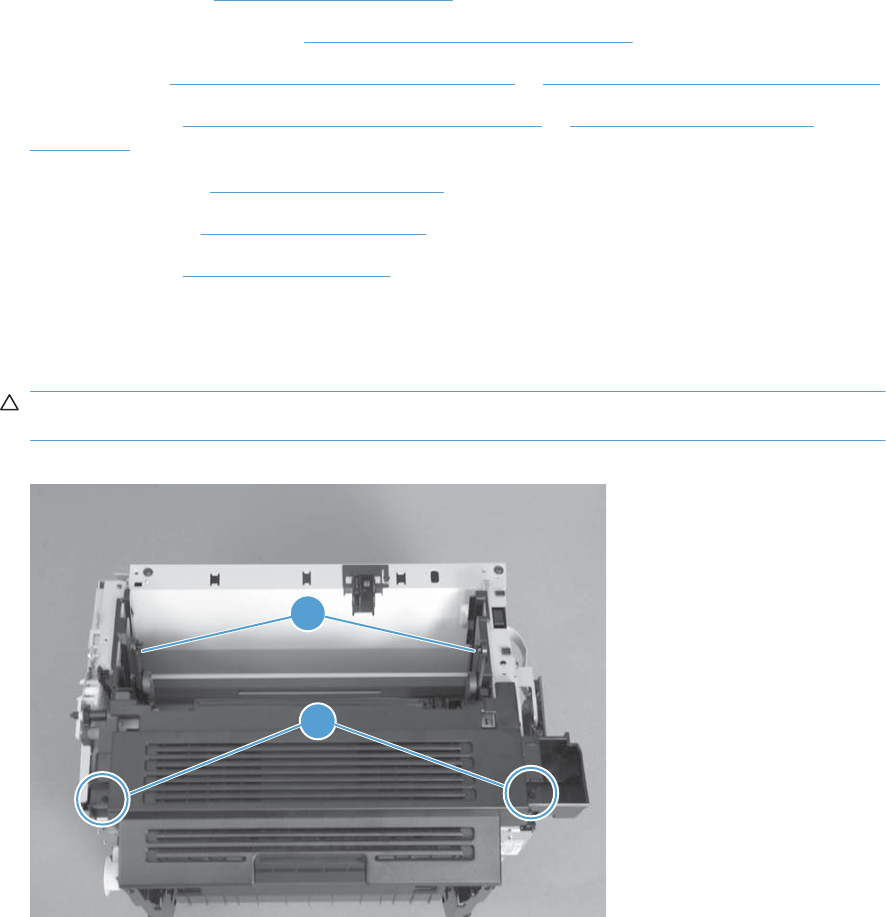
Face-down cover
Before proceeding, remove the following components:
●Main-input tray. See Main-input tray on page 43.
●Output bin tray extension. See Output bin tray extension on page 44.
●Left cover. See Left cover, simplex product on page 45 or Left cover, duplex product on page 47.
●Right cover. See Right cover, simplex product on page 50 or Right cover, duplex product
on page 52.
●Cartridge door. See Cartridge door on page 57.
●Control panel. See Control panel on page 59.
●Front cover. See Front cover on page 61.
Remove the face-down cover
1. Remove two screws (callout 1).
CAUTION: The upper-cartridge door arms (callout 2) can become easily be dislodged from the
lower arms. Do not lose the upper-cartridge door arms while servicing the product.
Figure 2-41 Remove the face-down cover (1 of 2)
2
1
ENWW Covers 65
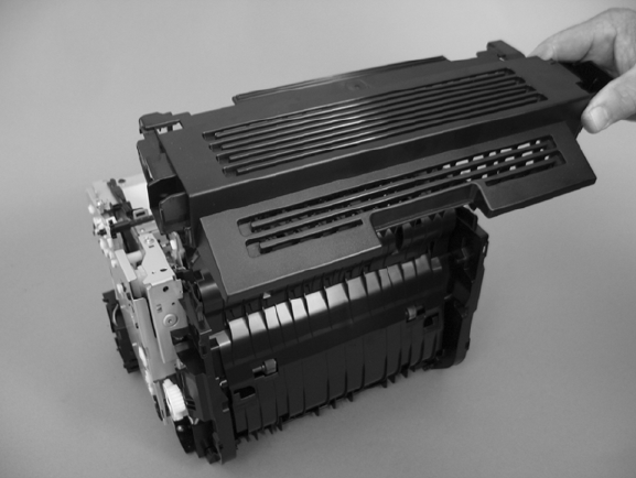
2. Lift the cover up and off the product to remove it.
Figure 2-42 Remove the face-down cover (2 of 2)
66 Chapter 2 Removal and replacement ENWW
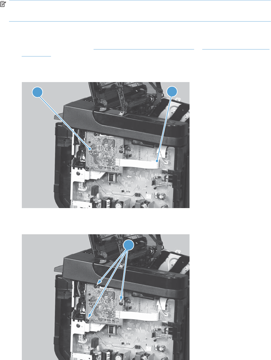
Main assemblies
NOTE: Some photos in this section show components that might not be installed or removed from
your product; however, the procedures for replacement and repair in this chapter are correct for your
product.
Formatter PCA
1. Remove the left cover. See Left cover, simplex product on page 45 or Left cover, duplex product
on page 47.
2. Disconnect one FFC (callout 1) and one connector (callout 2).
Figure 2-43 Remove the formatter PCA (1 of 2)
1
2
3. Remove three screws (callout 1), and then remove the formatter PCA.
Figure 2-44 Remove the formatter PCA (2 of 2)
1
ENWW Main assemblies 67
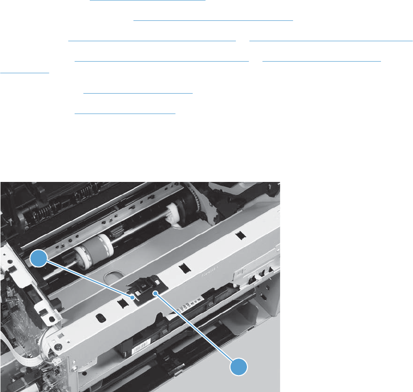
Laser/scanner assembly
Before proceeding, remove the following components:
●Main-input tray. See Main-input tray on page 43.
●Output bin tray extension. See Output bin tray extension on page 44.
●Left cover. See Left cover, simplex product on page 45 or Left cover, duplex product on page 47.
●Right cover. See Right cover, simplex product on page 50 or Right cover, duplex product
on page 52.
●Control panel. See Control panel on page 59.
●Front cover. See Front cover on page 61.
Remove the laser/scanner assembly
1. Release one tab (callout 1), and then remove the holder (callout 2).
Figure 2-45 Remove the laser/scanner assembly (1 of 5)
1
2
68 Chapter 2 Removal and replacement ENWW
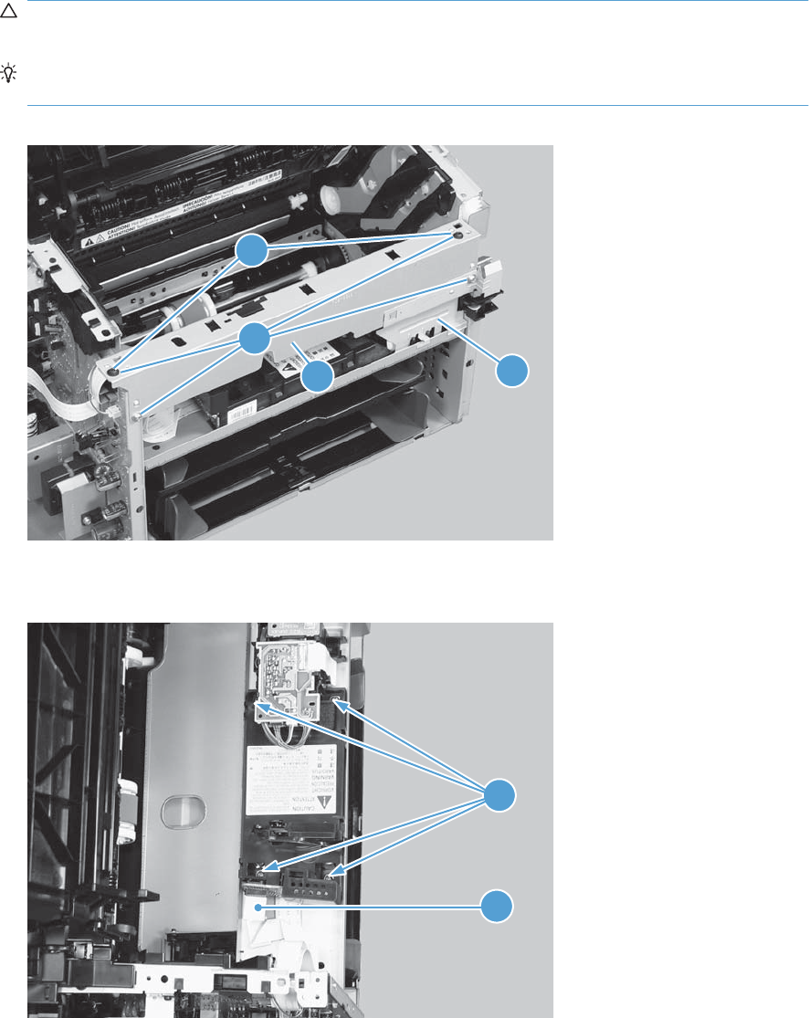
2. Remove four screws (callout 1), and then remove the scanner cover (callout 2) and the sheet-metal
plate (callout 3) together.
CAUTION: The scanner cover (callout 2) and sheet-metal plate (callout 3) can be easily
separated. Do not lose the plate while servicing the product.
TIP: When the cover is reinstalled, make sure that the black screws (callout 4) are installed in
the correct screw holes.
Figure 2-46 Remove the laser/scanner assembly (2 of 5)
1
23
4
3. Disconnect one FFC (callout 1), and then remove four screws (callout 2).
Figure 2-47 Remove the laser/scanner assembly (3 of 5)
1
2
ENWW Main assemblies 69
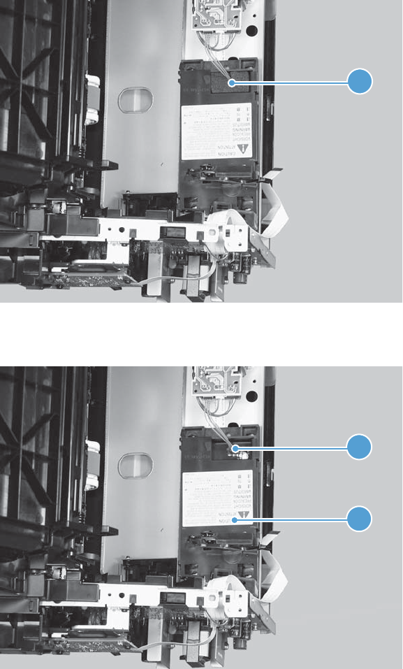
4. Remove the dust-proof sponge (callout 1).
Figure 2-48 Remove the laser/scanner assembly (4 of 5)
1
5. Disconnect one connector (callout 1), and then remove the laser/scanner assembly (callout 2).
Figure 2-49 Remove the laser/scanner assembly (5 of 5)
1
2
70 Chapter 2 Removal and replacement ENWW
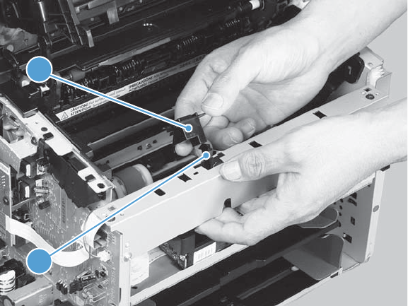
Reinstall the laser/scanner assembly
▲When the holder is reinstalled (callout 1), make sure that the lever arm (callout 2) is correctly
positioned in the slot in the holder.
Figure 2-50 Reinstall the laser/scanner assembly
1
2
ENWW Main assemblies 71
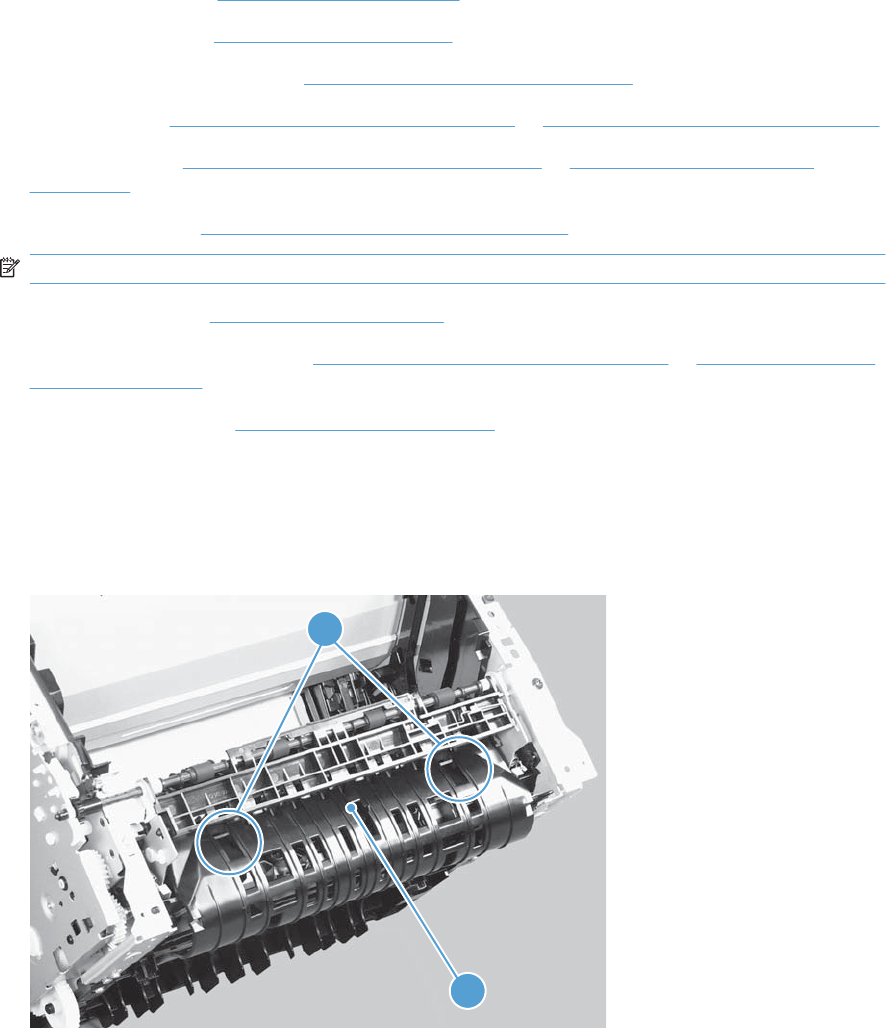
Pickup assembly
Before proceeding, remove the following components:
●Separation pad. See Separation pad on page 41.
●Main-input tray. See Main-input tray on page 43.
●Output bin tray extension. See Output bin tray extension on page 44.
●Left cover. See Left cover, simplex product on page 45 or Left cover, duplex product on page 47.
●Right cover. See Right cover, simplex product on page 50 or Right cover, duplex product
on page 52.
●Duplex frame. See Duplex frame, duplex product on page 56.
NOTE: Duplex models only.
●Cartridge door. See Cartridge door on page 57
●Rear cover or duplex door. See Rear cover, simplex product on page 63 or Duplex door, duplex
product on page 55.
●Face-down cover. See Face-down cover on page 65.
Remove the pickup assembly
1. Duplex models only: Release two tabs (callout 1), and then remove the duplex reverse guide
(callout 2).
Figure 2-51 Remove the pickup assembly (1 of 10)
1
2
72 Chapter 2 Removal and replacement ENWW

2. Remove two screws (callout 1), and then remove the sheet-metal corner brace (callout 2).
Figure 2-52 Remove the pickup assembly (2 of 10)
1
2
3. Remove one FFC (callout 1), remove three screws (callout 2), and then remove the formatter
(callout 3).
Figure 2-53 Remove the pickup assembly (3 of 10)
1
2
3
ENWW Main assemblies 73

4. Remove three screws (callout 1), and then remove the sheet-metal plate (callout 2).
Figure 2-54 Remove the pickup assembly (4 of 10)
1
2
5. Disconnect one connector (callout 1), and then release the wire harness (callout 2) from the guide
(callout 3).
Figure 2-55 Remove the pickup assembly (5 of 10)
1
2
3
74 Chapter 2 Removal and replacement ENWW
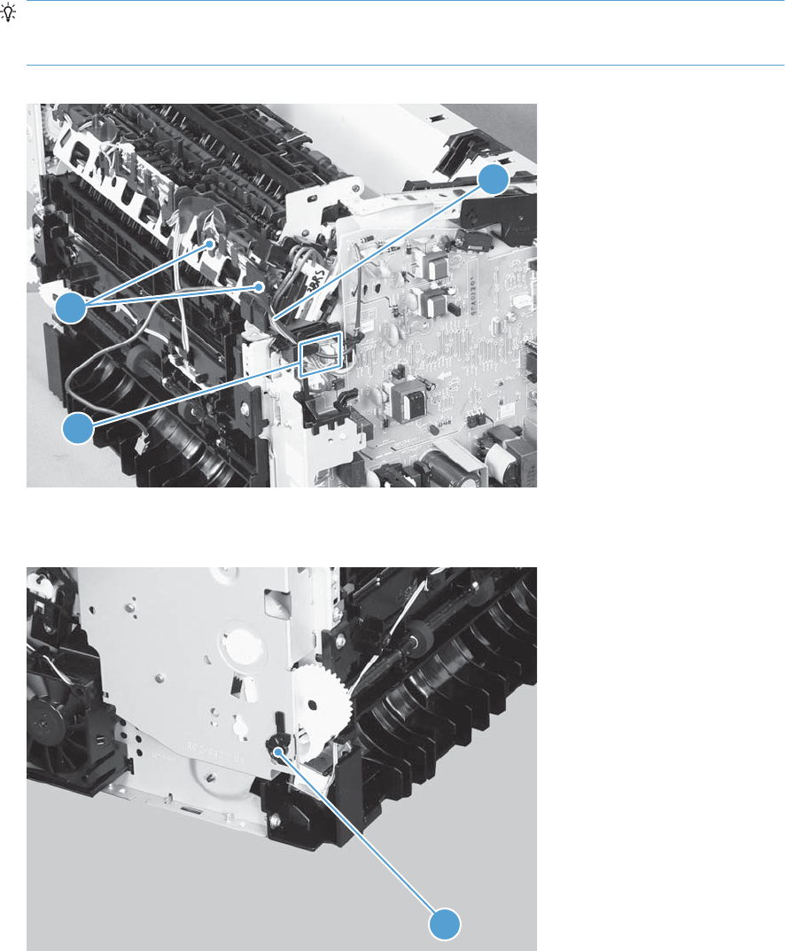
6. Disconnect three connectors (callout 1), and then remove the wire harness (callout 2) from the
guide (callout 3).
Reinstallation tip When the pickup assembly is reinstalled, place these wire harnesses in the
guide first, and then the wire harness from the ground connector in the previous step. This ensures
that the harnesses are long enough for the connectors to reach the engine controller PCA.
Figure 2-56 Remove the pickup assembly (6 of 10)
2
3
1
7. Remove one bushing (callout 1).
Figure 2-57 Remove the pickup assembly (7 of 10)
1
ENWW Main assemblies 75
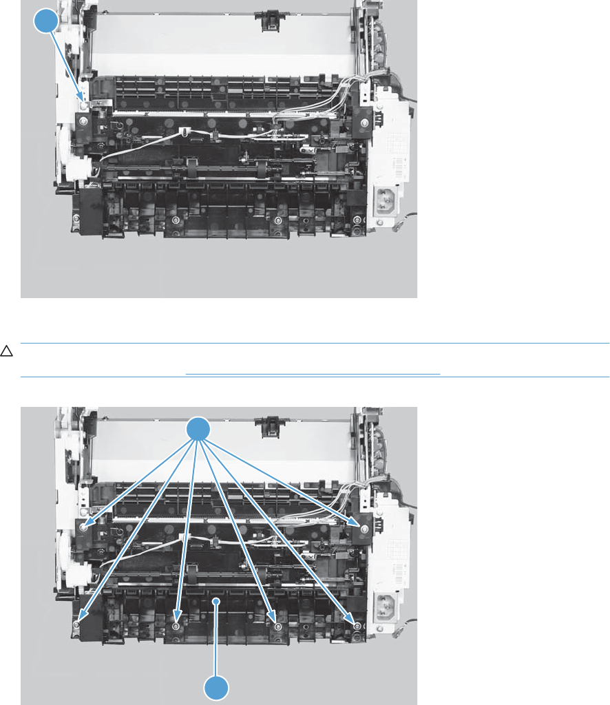
8. Remove one screw with washer (callout 1).
Figure 2-58 Remove the pickup assembly (8 of 10)
1
9. Remove six screws (callout 1), and then remove the pickup assembly (callout 2).
CAUTION: The ground spring on the assembly is not captive. Do not lose the spring when the
assembly is removed. See Reinstall the pickup assembly on page 78.
Figure 2-59 Remove the pickup assembly (9 of 10)
1
2
76 Chapter 2 Removal and replacement ENWW
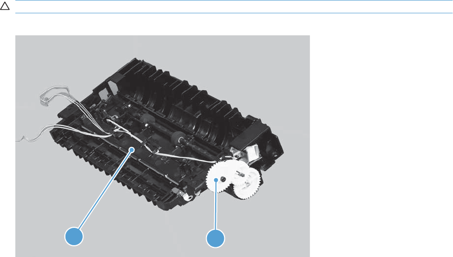
10. Duplex models only: Remove one gear (callout 1) from the pickup assembly (callout 2).
CAUTION: The gear is not captive. Do not lose the gear while servicing the product.
Figure 2-60 Remove the pickup assembly (10 of 10)
1
2
ENWW Main assemblies 77
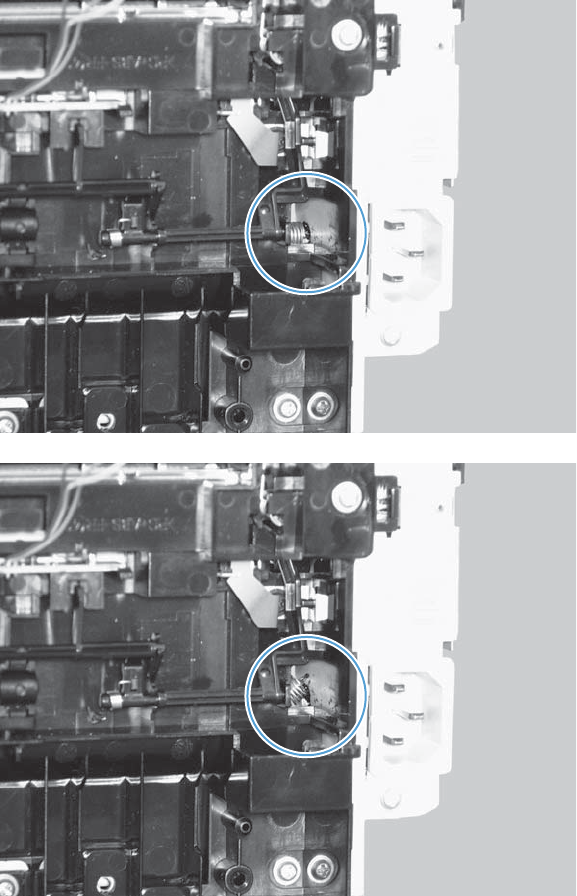
Reinstall the pickup assembly
1. Make sure that the pickup assembly ground spring is correctly positioned when the assembly is
reinstalled.
Figure 2-61 Reinstall the pickup assembly (1 of 4; correct ground spring position)
Figure 2-62 Reinstall the pickup assembly (2 of 4; incorrect ground spring position)
78 Chapter 2 Removal and replacement ENWW
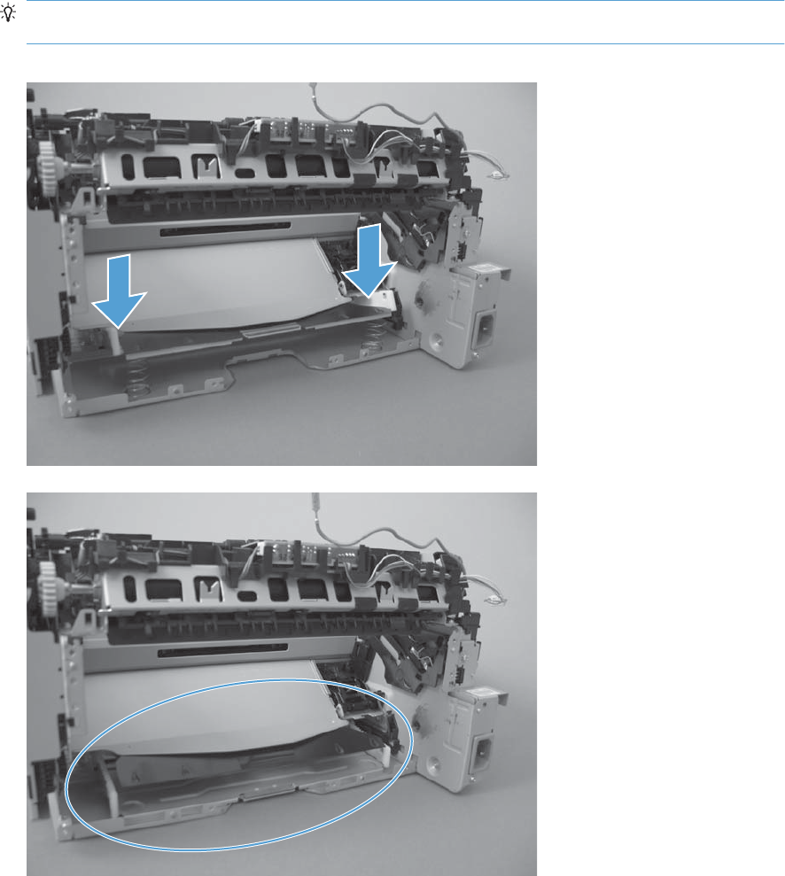
2. Push down the lift plate before installing the pickup assembly.
TIP: Reach in from the front of the product to push and hold the plate down as the pickup unit is
installed.
Figure 2-63 Reinstall the pickup assembly (3 of 4; lift plate in raised position)
Figure 2-64 Reinstall the pickup assembly (4 of 4; lift plate in lowered position)
ENWW Main assemblies 79
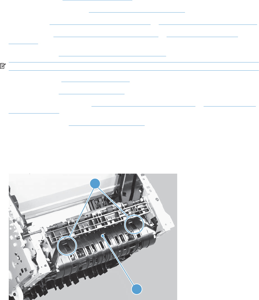
Fuser
Before proceeding, remove the following components:
●Main-input tray. See Main-input tray on page 43.
●Output bin tray extension. See Output bin tray extension on page 44.
●Left cover. See Left cover, simplex product on page 45 or Left cover, duplex product on page 47.
●Right cover. See Right cover, simplex product on page 50 or Right cover, duplex product
on page 52.
●Duplex frame. See Duplex frame, duplex product on page 56.
NOTE: Duplex models only.
●Cartridge door. See Cartridge door on page 57
●Control panel. See Control panel on page 59.
●Rear cover or duplex door. See Rear cover, simplex product on page 63 or Duplex door, duplex
product on page 55.
●Face-down cover. See Face-down cover on page 65.
Remove the fuser
1. Duplex models only: Release two tabs (callout 1), and then remove the duplex reverse guide
(callout 2).
Figure 2-65 Remove the fuser (1 of 10)
1
2
80 Chapter 2 Removal and replacement ENWW

2. Remove two screws (callout 1), and then remove the sheet-metal corner brace (callout 2).
Figure 2-66 Remove the fuser (2 of 10)
1
2
3. Remove one FFC (callout 1), remove three screws (callout 2), and then remove the formatter
(callout 3).
Figure 2-67 Remove the fuser (3 of 10)
1
2
3
ENWW Main assemblies 81
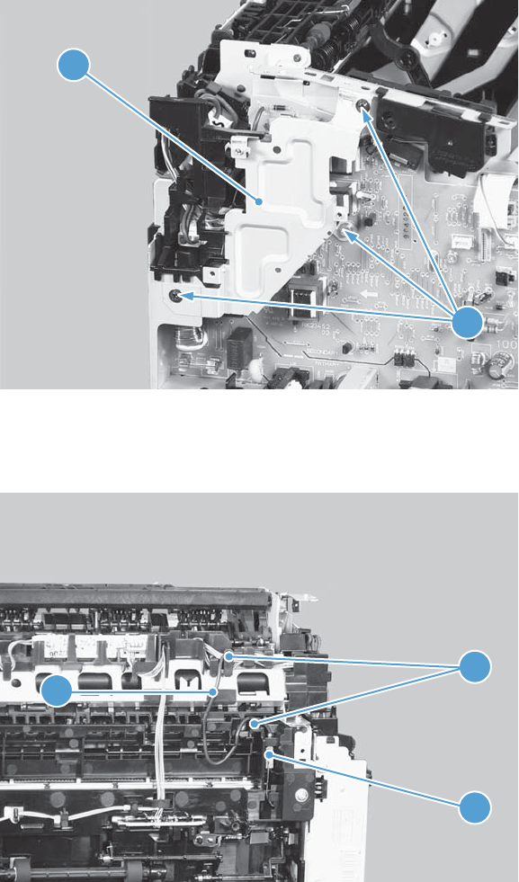
4. Remove three screws (callout 1), and then remove the sheet-metal plate (callout 2).
Figure 2-68 Remove the fuser (4 of 10)
1
2
5. Disconnect one connector (callout 1), and then release the wire harness (callout 2) from the guides
(callout 3).
Figure 2-69 Remove the fuser (5 of 10)
1
2
3
82 Chapter 2 Removal and replacement ENWW
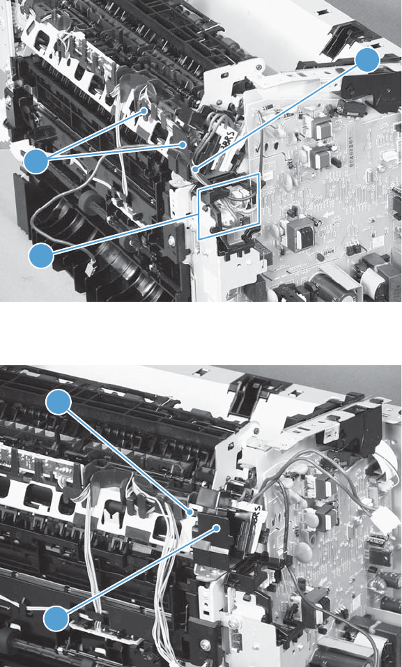
6. Disconnect four connectors (callout 1), and then release the wire harnesses (callout 2) from the
guide (callout 3).
Figure 2-70 Remove the fuser (6 of 10)
3
1
2
7. Disconnect one tab (callout 1), and then remove the guide (callout 2).
Figure 2-71 Remove the fuser (7 of 10)
1
2
ENWW Main assemblies 83
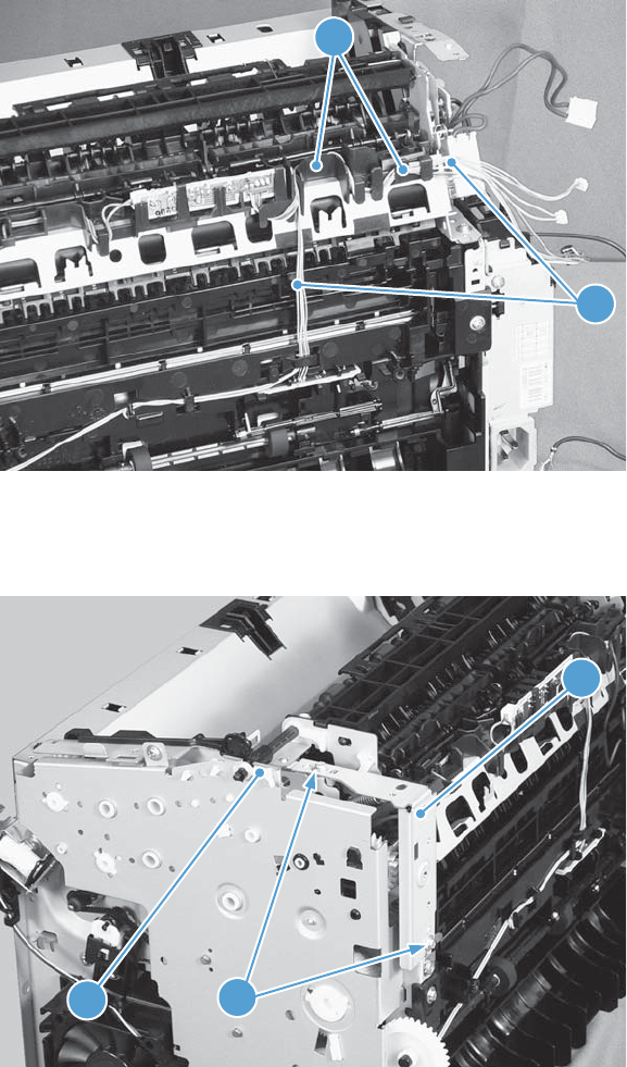
8. Release the wire harnesses (callout 1) from the guide (callout 2).
Figure 2-72 Remove the fuser (8 of 10)
2
1
9. Remove two screws (callout 1) and the sheet-metal brace (callout 2), and then remove one bushing
(callout 3).
Figure 2-73 Remove the fuser (9 of 10)
1
3
2
84 Chapter 2 Removal and replacement ENWW
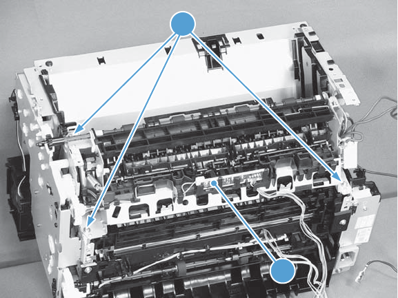
10. Remove three screws (callout 1) and then remove the fuser (callout 2).
Figure 2-74 Remove the fuser (10 of 10)
1
2
ENWW Main assemblies 85
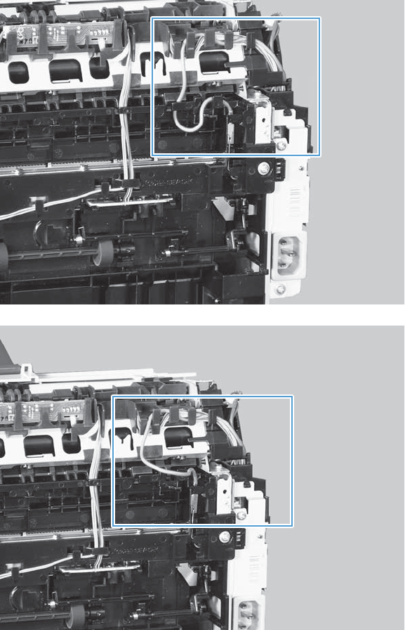
Reinstall the fuser
▲To avoid damage to the wire harnesses, make sure that they are correctly installed in the guides
when the fuser is reinstalled.
Figure 2-75 Reinstall the fuser; correct wire harness installation
Figure 2-76 Reinstall the fuser; incorrect wire harness installation
86 Chapter 2 Removal and replacement ENWW
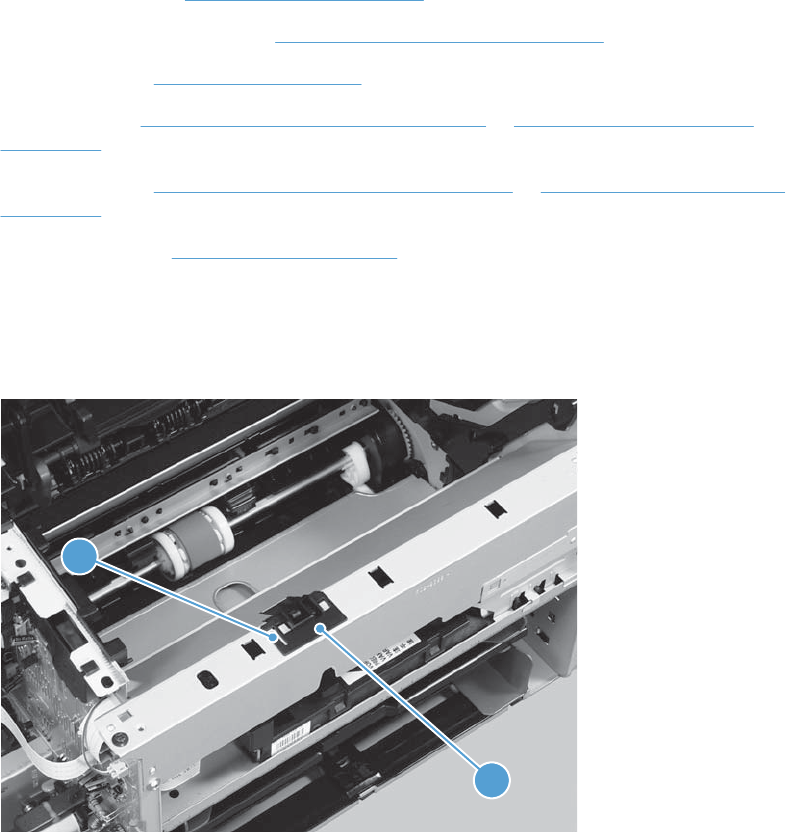
Main motor
Before proceeding, remove the following components:
●Main-input tray. See Main-input tray on page 43.
●Output bin tray extension. See Output bin tray extension on page 44.
●Front cover. See Front cover on page 61.
●Left cover. See Left cover, simplex product on page 45 or Left cover, simplex product
on page 45.
●Right cover. See Right cover, simplex product on page 50 or Right cover, duplex product
on page 52.
●Control panel. See Control panel on page 59.
Remove the main motor
1. Release one tab (callout 1), and then remove the holder (callout 2).
Figure 2-77 Remove the main motor (1 of 9)
1
2
ENWW Main assemblies 87
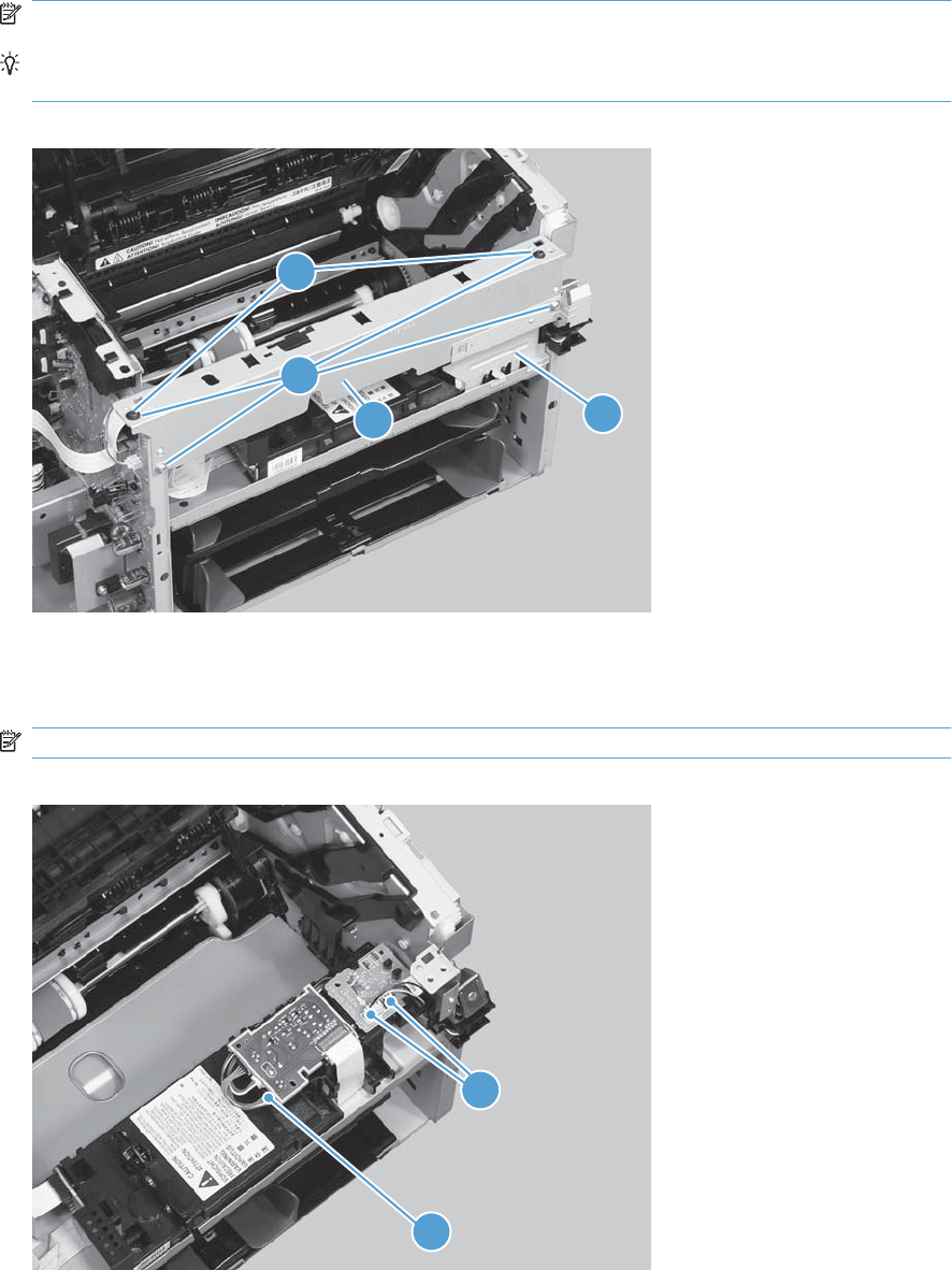
2. Remove four screws (callout 1), the scanner cover (callout 2) and the sheet-metal plate (callout 3).
NOTE: The scanner cover and plate are removed as one assembly.
TIP: When the cover is reinstalled, make sure that the black screws (callout 4) are installed in
the correct screw holes.
Figure 2-78 Remove the main motor (2 of 9)
1
23
4
3. Simplex models only: Disconnect one connector (callout 1).
Duplex models only: Disconnect three connectors (callout 1 and callout 2).
NOTE: Simplex models do not have the duplex-connector PCA installed.
Figure 2-79 Remove the main motor (3 of 9)
1
2
88 Chapter 2 Removal and replacement ENWW
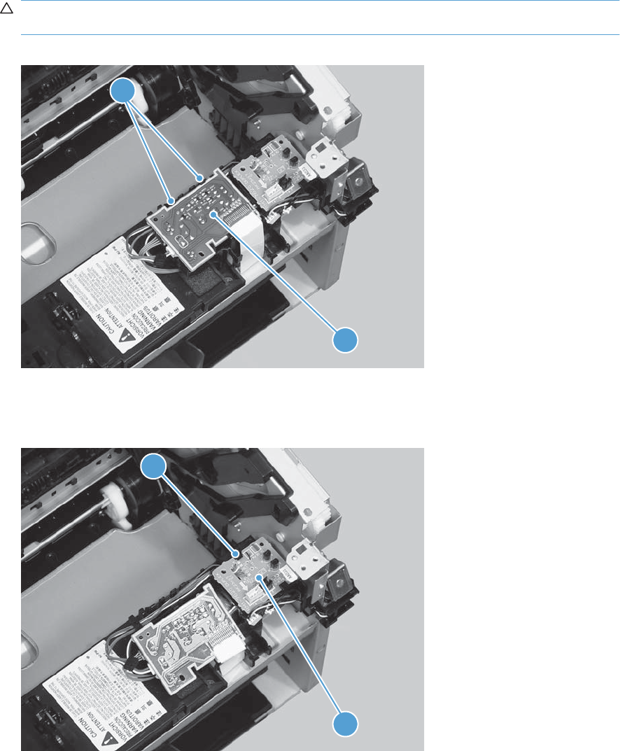
4. Release two tabs (callout 1), and then slightly separate the motor driver PCA (callout 2) from the
product.
CAUTION: The motor driver PCA is still connected to the product by the wire harnesses and a
FFC.
Figure 2-80 Remove the main motor (4 of 9)
2
1
5. Duplex models only: Release one tab (callout 1), and then remove the duplex-connector PCA
(callout 2).
Figure 2-81 Remove the main motor (5 of 9)
1
2
ENWW Main assemblies 89
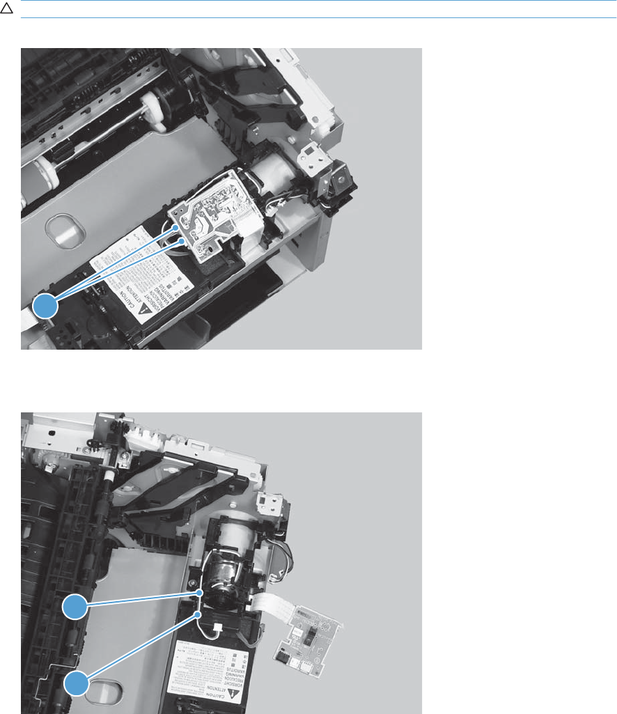
6. Disconnect two connectors (callout 1) and carefully set the PCA out of the way.
CAUTION: The motor driver PCA is still connected to the product by the FFC.
Figure 2-82 Remove the main motor (6 of 9)
1
7. Release the wire harness (callout 1) from the guide (callout 2).
Figure 2-83 Remove the main motor (7 of 9)
1
2
90 Chapter 2 Removal and replacement ENWW
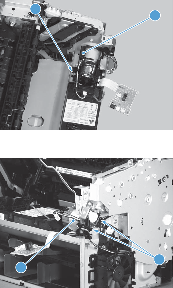
8. Remove one screw (callout 1), and then remove the motor cover (callout 2).
Figure 2-84 Remove the main motor (8 of 9)
12
9. Remove two screws (callout 1), and then remove the motor (callout 2).
Figure 2-85 Remove the main motor (9 of 9)
2
1
ENWW Main assemblies 91
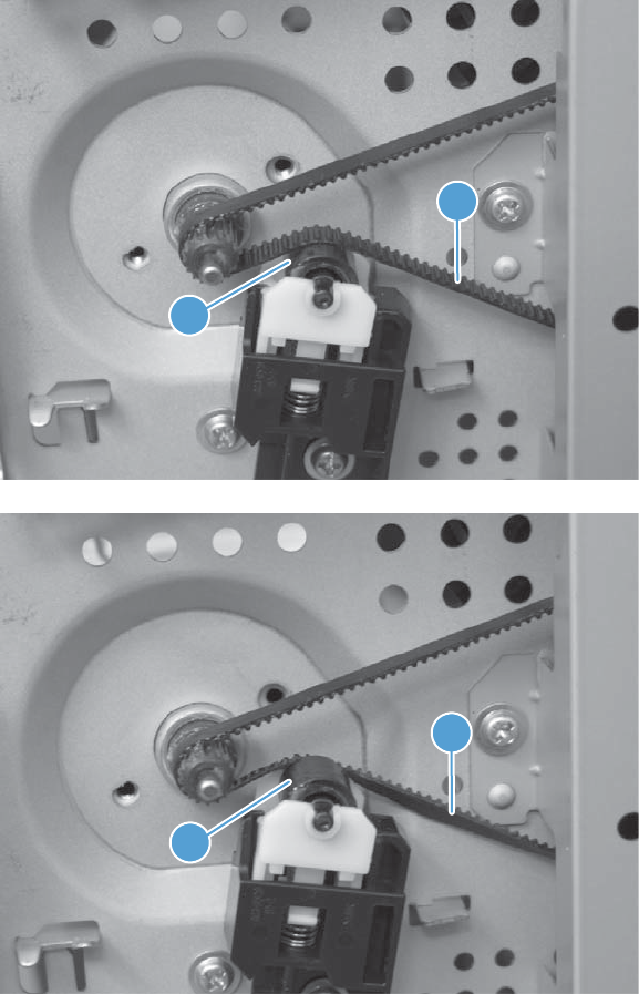
Reinstall the main-motor drive belt
▲When the main motor is reinstalled, make sure that the drive belt (callout 1) is correctly positioned
over the roller (callout 2).
Figure 2-86 Main-motor drive belt: correctly installed
1
2
Figure 2-87 Main-motor drive belt: incorrectly installed
1
2
92 Chapter 2 Removal and replacement ENWW

Pickup solenoid
Before proceeding, remove the following components:
●Main-input tray. See Main-input tray on page 43.
●Output bin tray extension. See Output bin tray extension on page 44.
●Left cover. See Left cover, simplex product on page 45 or Left cover, duplex product on page 47.
●Right cover. See Right cover, simplex product on page 50 or Right cover, duplex product
on page 52.
●Duplex frame. See Duplex frame, duplex product on page 56.
NOTE: Duplex models only.
●Cartridge door. See Cartridge door on page 57
●Control panel. See Control panel on page 59.
●Rear cover or duplex door. See Rear cover, simplex product on page 63 or Duplex door, duplex
product on page 55.
●Face-down cover. See Face-down cover on page 65.
Remove the pickup solenoid
1. Duplex models only: Release two tabs (callout 1), and then remove the duplex reverse guide
(callout 2).
Figure 2-88 Remove the pickup solenoid (1 of 7)
1
2
ENWW Main assemblies 93
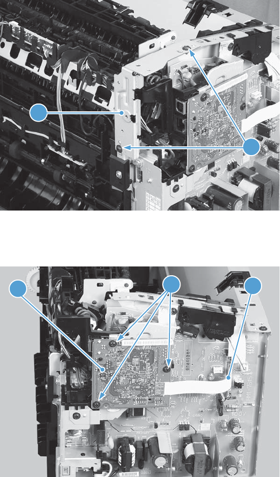
2. Remove two screws (callout 1), and then remove the sheet-metal corner brace (callout 2).
Figure 2-89 Remove the pickup solenoid (2 of 7)
1
2
3. Remove one FFC (callout 1), remove three screws (callout 2), and then remove the formatter
(callout 3).
Figure 2-90 Remove the pickup solenoid (3 of 7)
1
2
3
94 Chapter 2 Removal and replacement ENWW
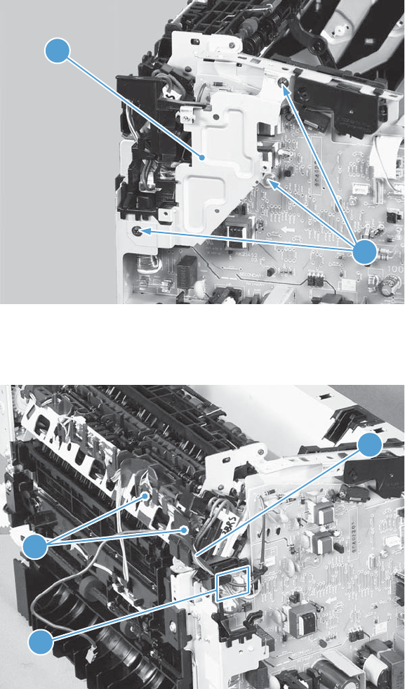
4. Remove three screws (callout 1), and then remove the sheet-metal plate (callout 2).
Figure 2-91 Remove the pickup solenoid (4 of 7)
1
2
5. Disconnect one connector (callout 1), and then remove the wire harness (callout 2) from the guide
(callout 3).
Figure 2-92 Remove the solenoid (5 of 7)
2
3
1
ENWW Main assemblies 95
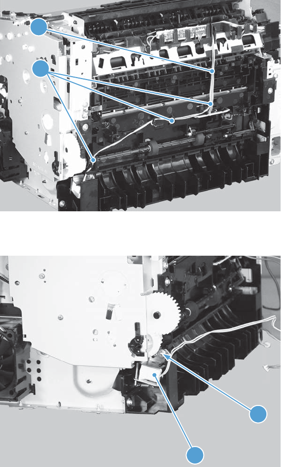
6. Release the wire harness (callout 1) from the guide (callout 2).
Figure 2-93 Remove the pickup solenoid (6 of 7)
1
2
7. Remove one screw (callout 1), and then remove the pickup solenoid (callout 2).
Figure 2-94 Remove the pickup solenoid (7 of 7)
1
2
96 Chapter 2 Removal and replacement ENWW
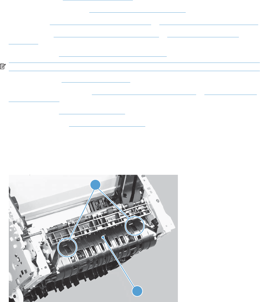
Engine controller PCA
Before proceeding, remove the following components:
●Main-input tray. See Main-input tray on page 43.
●Output bin tray extension. See Output bin tray extension on page 44.
●Left cover. See Left cover, simplex product on page 45 or Left cover, duplex product on page 47.
●Right cover. See Right cover, simplex product on page 50 or Right cover, duplex product
on page 52.
●Duplex frame. See Duplex frame, duplex product on page 56.
NOTE: Duplex models only.
●Cartridge door. See Cartridge door on page 57
●Rear cover or duplex door. See Rear cover, simplex product on page 63 or Duplex door, duplex
product on page 55.
●Control panel. See Control panel on page 59.
●Face-down cover. See Face-down cover on page 65.
Remove the engine controller PCA
1. Duplex models only: Release two tabs (callout 1), and then remove the duplex reverse guide
(callout 2).
Figure 2-95 Remove the engine controller PCA (1 of 9)
1
2
ENWW Main assemblies 97
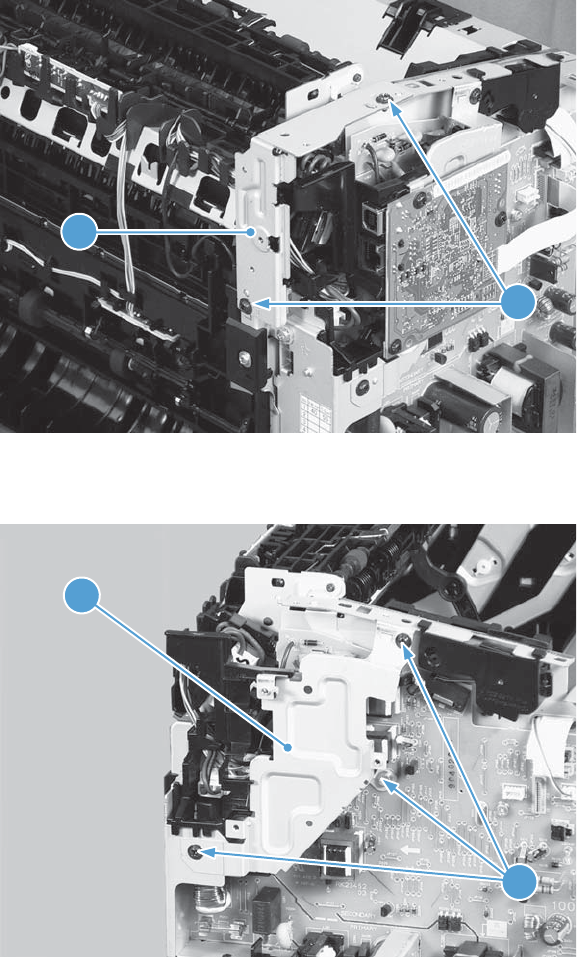
2. Remove two screws (callout 1), and then remove the sheet-metal corner brace (callout 2).
Figure 2-96 Remove the engine controller PCA (2 of 9)
1
2
3. Remove three screws (callout 1), and then remove the sheet-metal plate (callout 2).
Figure 2-97 Remove the engine controller PCA (3 of 9)
1
2
98 Chapter 2 Removal and replacement ENWW
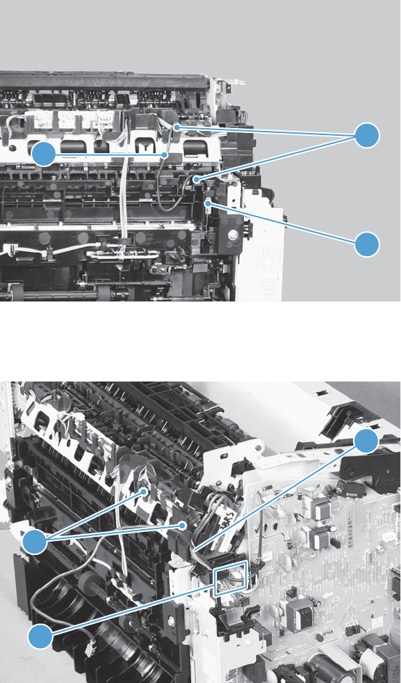
4. Disconnect one connector (callout 1), and then release the wire harness (callout 2) from the guides
(callout 3).
Figure 2-98 Remove the engine controller PCA (4 of 9)
1
2
3
5. Disconnect four connectors (callout 1), and then remove the wire harnesses (callout 2) from the
guide (callout 3).
Figure 2-99 Remove the engine controller PCA (5 of 9)
2
3
1
ENWW Main assemblies 99
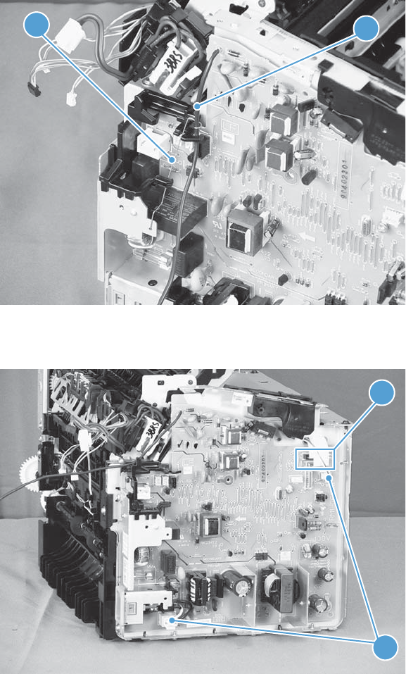
6. Release the wire harness (callout 1) from the ground spring (callout 2).
Figure 2-100 Remove the engine controller PCA (6 of 9)
1
2
7. Disconnect two connectors (callout 1) and two FFCs (callout 2).
Figure 2-101 Remove the engine controller PCA (7 of 9)
1
2
100 Chapter 2 Removal and replacement ENWW
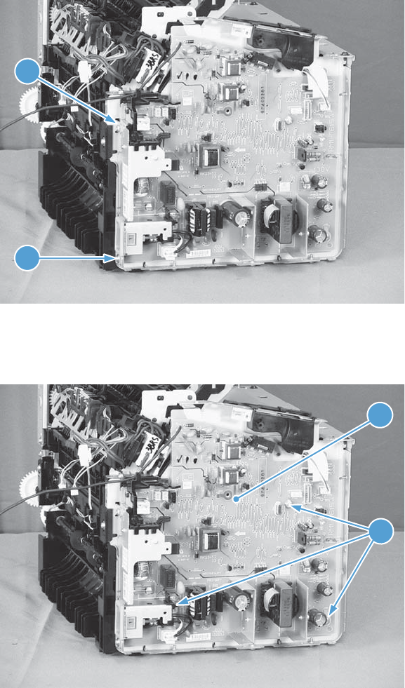
8. Remove one screw with washer (callout 1), and then remove one more screw (callout 2).
Figure 2-102 Remove the engine controller PCA (8 of 9)
1
2
9. Remove three screws with washers (callout 1), and then remove the engine controller PCA
(callout 2).
Figure 2-103 Remove the engine controller PCA (10 of 9)
1
2
ENWW Main assemblies 101
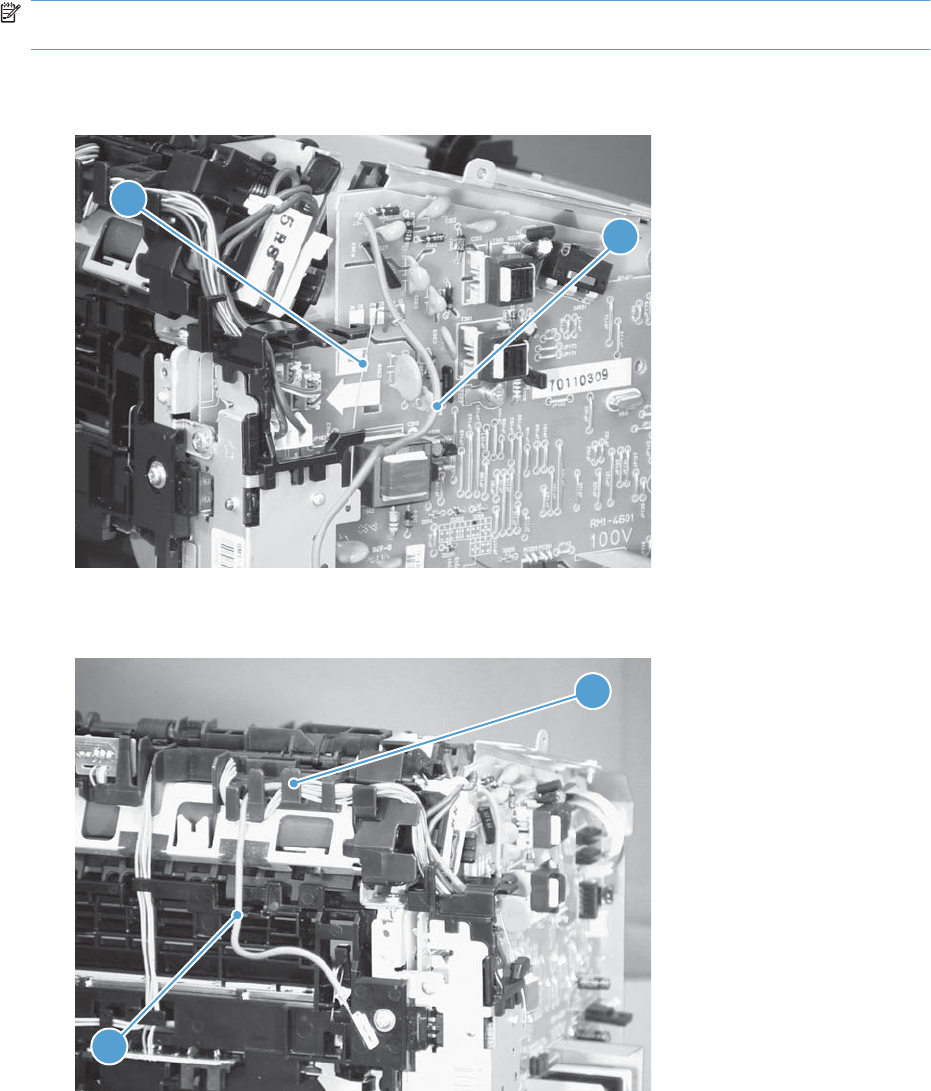
Reinstall the engine controller PCA
NOTE: In addition to following the reverse order of removal, make sure that you complete these steps
to correctly install the transfer-wire harness.
1. Set the ground spring (callout 1) on the transfer-wire harness (callout 2).
Figure 2-104 Reinstall the engine controller PCA (1 of 4)
2
1
2. Position the transfer-wire harness (callout 1) in the guide (callout 2).
Figure 2-105 Reinstall the engine controller PCA (2 of 4)
1
2
102 Chapter 2 Removal and replacement ENWW
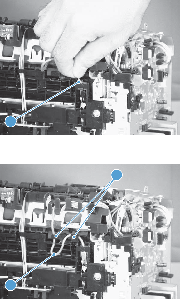
3. Connect one connector (callout 1).
Figure 2-106 Reinstall the engine controller PCA (3 of 4)
1
4. Position the transfer-wire harness (callout 1) in the guides (callout 2).
Figure 2-107 Reinstall the engine controller PCA (4 of 4)
1
2
ENWW Main assemblies 103

Duplex-reverse solenoid, duplex product
Before proceeding, remove the following components:
●Main-input tray. See Main-input tray on page 43.
●Output bin tray extension. See Output bin tray extension on page 44.
●Left cover. See Left cover, duplex product on page 47.
●Right cover. See Right cover, duplex product on page 52.
●Control panel. See Control panel on page 59.
●Front cover. See Front cover on page 61.
Remove the duplex-reverse solenoid
1. Release one tab (callout 1), and then remove the holder (callout 2).
Figure 2-108 Remove the duplex-reverse solenoid (1 of 5)
1
2
104 Chapter 2 Removal and replacement ENWW
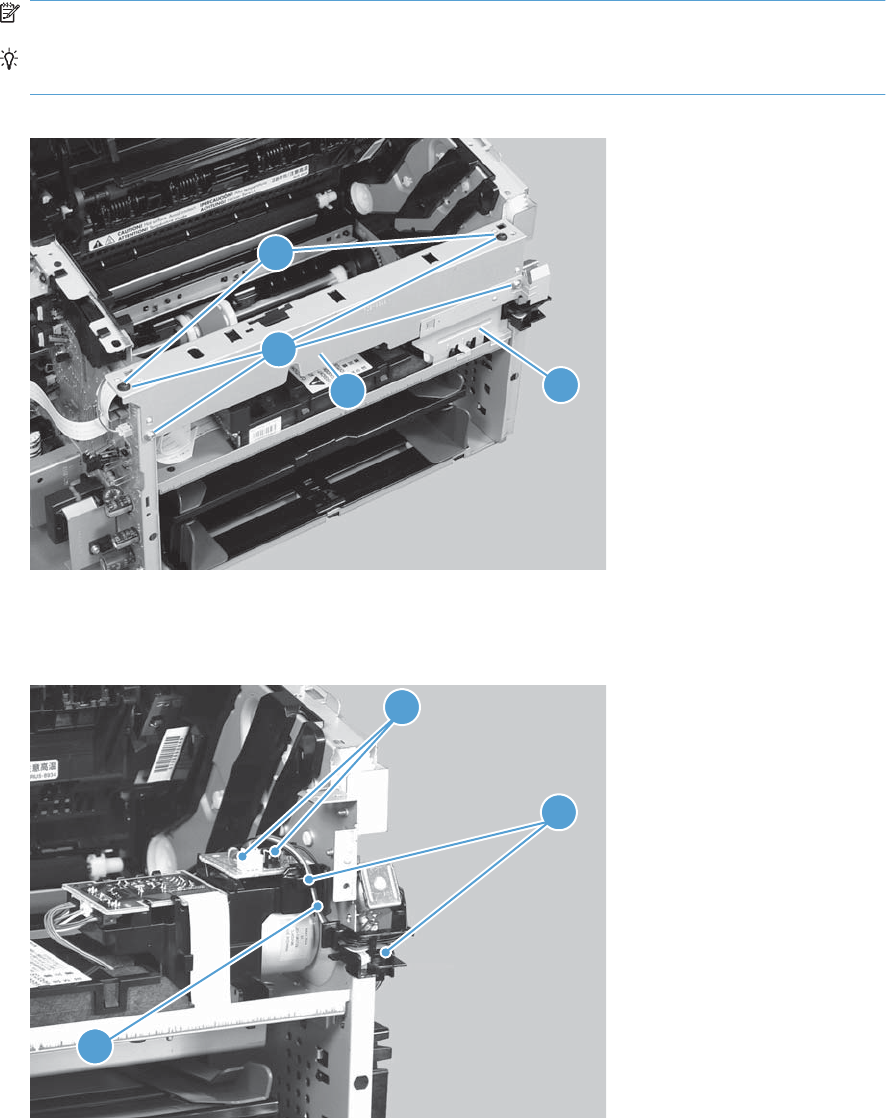
2. Remove four screws (callout 1), the scanner cover (callout 2) and the sheet-metal plate (callout 3).
NOTE: The scanner cover and plate are removed as one assembly.
TIP: When the cover is reinstalled, make sure that the black screws (callout 4) are installed in
the correct screw holes.
Figure 2-109 Remove the duplex-reverse solenoid (2 of 5)
1
23
4
3. Disconnect two connectors (callout 1), and then release the wire harness (callout 2) from the guides
(callout 3).
Figure 2-110 Remove the duplex-reverse solenoid (3 of 5)
1
3
2
ENWW Main assemblies 105
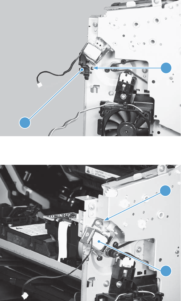
4. Release one tab (callout 1), and then remove the guides (callout 2).
Figure 2-111 Remove the duplex-reverse solenoid (4 of 5)
1
2
5. Remove one screw (callout 1), and then remove the duplex-reverse solenoid (callout 2).
Figure 2-112 Remove the duplex-reverse solenoid (5 of 5)
1
2
106 Chapter 2 Removal and replacement ENWW

Main fan, duplex product
Before proceeding, remove the following components:
●Main-input tray. See Main-input tray on page 43.
●Output bin tray extension. See Output bin tray extension on page 44.
●Left cover. See Left cover, duplex product on page 47.
●Right cover. See Right cover, duplex product on page 52.
●Control panel. See Control panel on page 59.
●Front cover. See Front cover on page 61.
Remove the main fan
1. Release one tab (callout 1), and then remove the holder (callout 2).
Figure 2-113 Remove the main fan (1 of 4)
1
2
ENWW Main assemblies 107
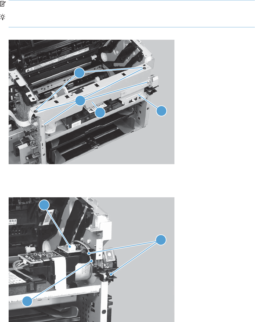
2. Remove four screws (callout 1), the scanner cover (callout 2) and the sheet-metal plate (callout 3).
NOTE: The scanner cover and plate are removed as one assembly.
TIP: When the cover is reinstalled, make sure that the black screws (callout 4) are installed in
the correct screw holes.
Figure 2-114 Remove the main fan (2 of 4)
1
23
4
3. Disconnect one connector (callout 1), and then release the wire harness (callout 2) from the guides
(callout 3).
Figure 2-115 Remove the main fan (3 of 4)
3
2
1
108 Chapter 2 Removal and replacement ENWW
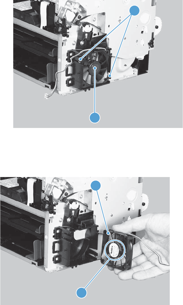
4. Release two tabs (callout 1), and then remove the main fan (callout 2).
Figure 2-116 Remove the main fan (4 of 4)
1
2
Reinstall the main fan
When the main fan is reinstalled, make sure that the wire harness (callout 1) is correctly positioned, and
that the label (callout 2) on the fan faces the inside of the product.
Figure 2-117 Reinstall the main fan
1
2
ENWW Main assemblies 109
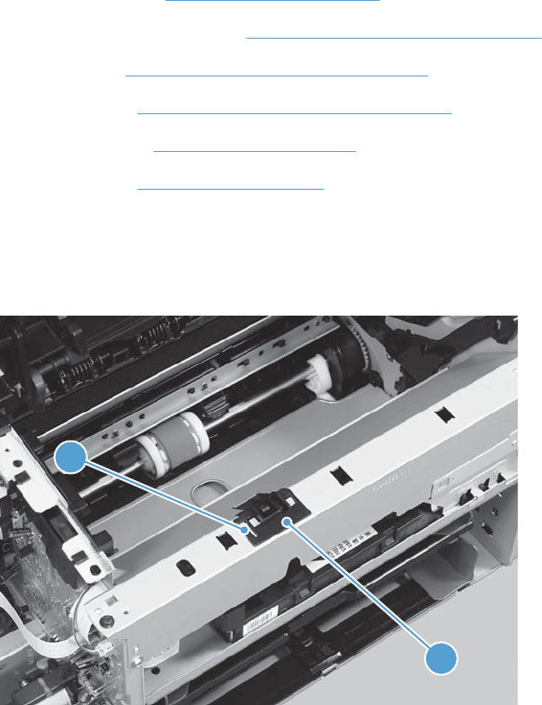
Duplex-connector PCA, duplex product
Before proceeding, remove the following components:
●Main-input tray. See Main-input tray on page 43.
●Output bin tray extension. See Output bin tray extension on page 44.
●Left cover. See Left cover, duplex product on page 47.
●Right cover. See Right cover, duplex product on page 52.
●Control panel. See Control panel on page 59.
●Front cover. See Front cover on page 61.
Remove the duplex-connector PCA
1. Release one tab (callout 1), and then remove the holder (callout 2).
Figure 2-118 Remove the duplex-connector PCA (1 of 5)
1
2
110 Chapter 2 Removal and replacement ENWW
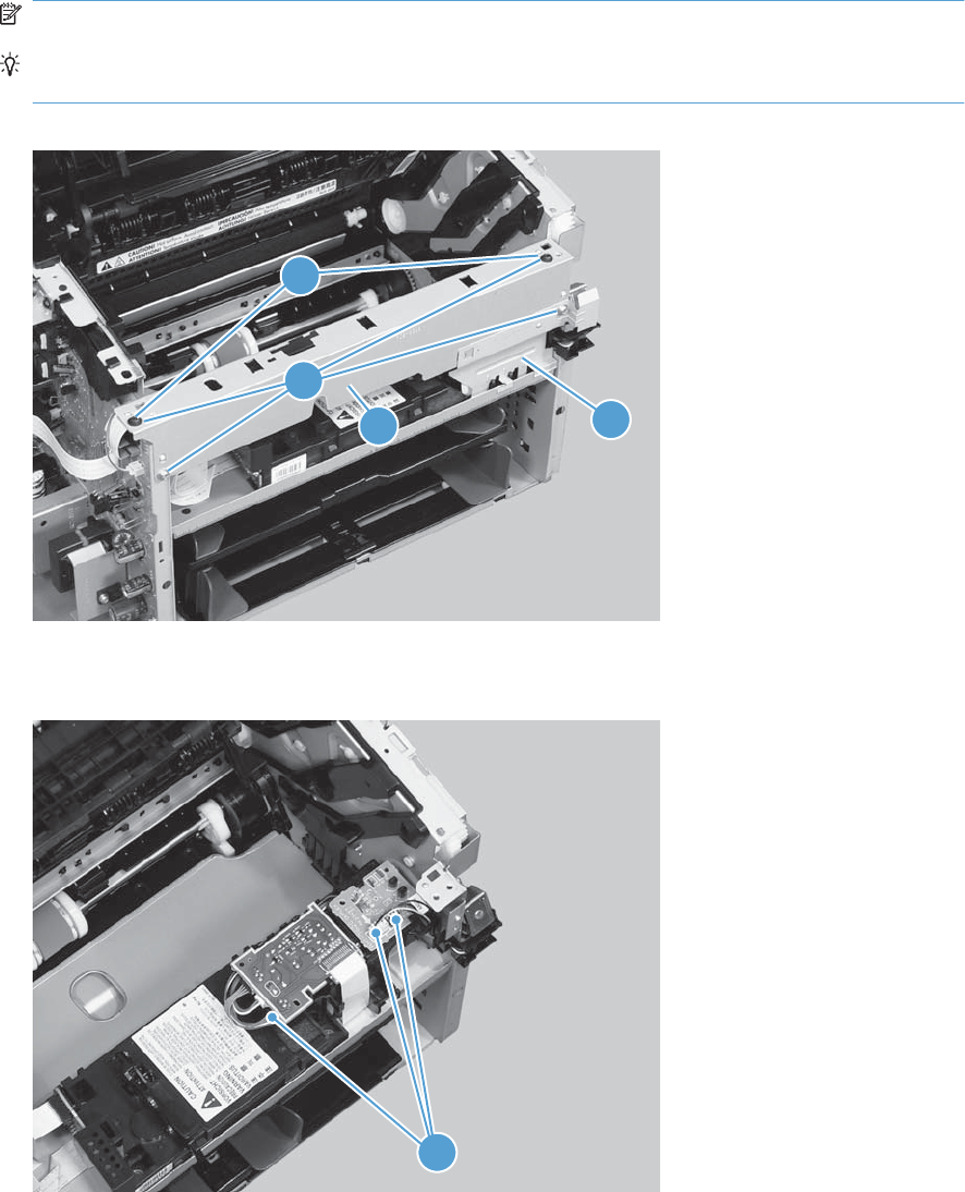
2. Remove four screws (callout 1), the scanner cover (callout 2) and the sheet-metal plate (callout 3).
NOTE: The scanner cover and plate are removed as one assembly.
TIP: When the cover is reinstalled, make sure that the black screws (callout 4) are installed in
the correct screw holes.
Figure 2-119 Remove the duplex-connector PCA (2 of 5)
1
23
4
3. Disconnect three connectors (callout 1)
Figure 2-120 Remove the duplex-connector PCA (3 of 5)
1
ENWW Main assemblies 111
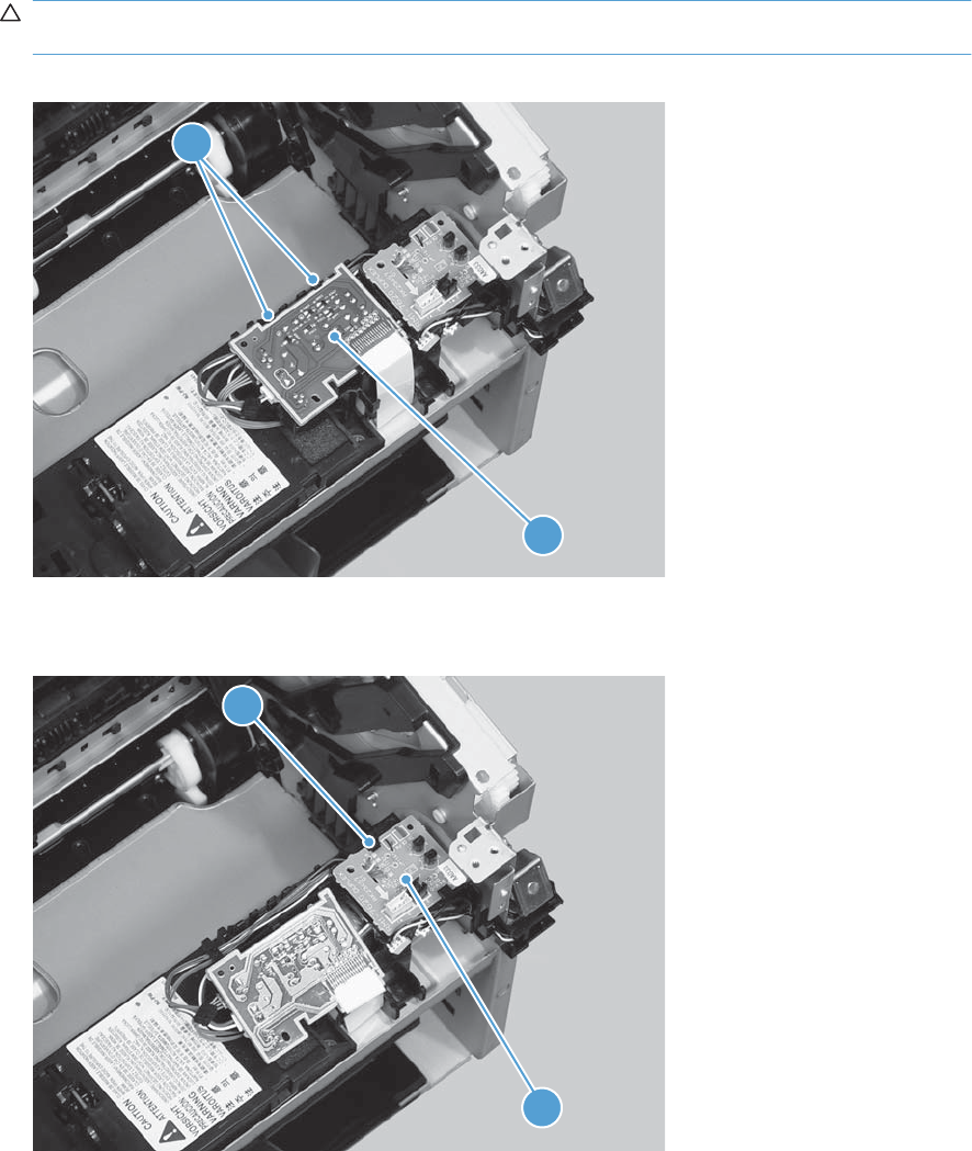
4. Release two tabs (callout 1), and then slightly separate the motor driver PCA (callout 2) from the
product.
CAUTION: The motor driver PCA is still connected to the product by the wire harnesses and a
FFC.
Figure 2-121 Remove the duplex-connector PCA (4 of 5)
2
1
5. Release one tab (callout 1), and then remove the duplex-connector PCA (callout 2).
Figure 2-122 Remove the duplex-connector PCA (5 of 5)
1
2
112 Chapter 2 Removal and replacement ENWW


Solve problems checklist
Table 3-1 Basic problem solving
Problem Cause Solution
When the product is
connected to a correctly
grounded power source, the
LEDs on the control panel do
not illuminate and the main
motor does not rotate.
The product does not turn on.
No power to the product. 1. Verify that the power
switch is turned on.
2. Verify that the power
cable is correctly
plugged into the outlet
and the product.
3. Verify that the power
outlet has the correct
voltage.
The formatter is defective. Replace the formatter. See
Formatter PCA on page 67.
The engine controller PCA is
defective.
Replace the engine controller
PCA. See Engine controller
PCA on page 97.
When turned on, the LEDs on
the control panel light up, but
the main motor does not
rotate.
The product turns on, but the
motor does not rotate.
The print-cartridge door is
open.
Close the print-cartridge door.
A page is jammed in the paper
path.
Clear all paper from the paper
path, and make sure that all
sensors are working correctly.
The cable is not connected
correctly.
Reconnect the motor cable.
The motor is not mounted
correctly in the product
chassis.
Verify that the motor is
connected correctly and that it
rotates freely.
The engine controller is
defective.
Replace the engine controller
PCA. See Engine controller
PCA on page 97.
The main motor is defective. Replace the motor. See Main
motor on page 87.
The product turns on and the
motor rotates, but none of the
control-panel lights turn on
and the control-panel buttons
are unresponsive.
The product is unresponsive.
The formatter is defective. Replace the formatter. See
Formatter PCA on page 67 .
The product is on, but the
control-panel lights indicate
that the product is not in the
"ready" state.
The product is not "ready."
The product has an internal
error that was detected during
the Power-On Self-Test
sequence.
Consult the list of control-
panel light patterns to identify
and correct the error.
114 Chapter 3 Solve problems ENWW

Problem Cause Solution
The product turns on, the
motor rotates, and the control
panel indicates the "ready"
state, but the product does not
print.
The product does not print.
A component is defective. Perform an engine test to
verify print-engine
components.
1. Print an engine test
page. See Engine-test
button on page 118.
2. If the engine test page
does not print, check all
the connectors on the
engine controller PCA,
and reconnect any
cables that are
connected incorrectly.
3. If, after checking the
connectors, the error
persists, replace the
engine controller PCA.
See Engine controller
PCA on page 97.
The formatter is defective. Print a demo page. Select
Demo Page from the Print
Information Pages drop-
down on the Services tab in
the printer driver.
If the Demo page does not
print, replace the formatter.
See Formatter PCA
on page 67.
The product prints the engine
test or a configuration page,
but does not print jobs from a
computer.
The product does not print
from a computer.
The cable is not connected
correctly.
Reconnect the cable.
Try using a new USB cable
that is 3 m (10 ft) or less in
length.
An incorrect driver is selected. Select the correct printer
driver.
The printer driver is not
installed correctly.
Remove and then reinstall the
product software. Make sure
that you use the correct
procedure and port setting.
Other devices are connected
to the product (for example,
through a switch or hub) that
are interfering with the
computer-product
communications.
Disconnect the other devices,
switches, or hubs.
There is a computer-port
communications problem.
Reset the computer port
settings (see the computer
user guide for more
information).
The formatter is defective. Replace the formatter. See
Formatter PCA on page 67 .
Table 3-1 Basic problem solving (continued)
ENWW Solve problems checklist 115

Troubleshooting process
Determine the problem source
The following table includes basic questions to ask the customer to quickly help define the problem or
problems.
General topic Questions
Environment ●Is the product installed on a solid, level surface (± 1°)?
●Is the power-supply voltage within ± 10 volts of the specified power source?
●Is the power-supply plug inserted in the product and the outlet?
●Is the operating environment within the specified parameters?
●Is the product exposed to ammonia gas, such as that produced by diazo copiers
or office cleaning materials?
NOTE: Diazo copiers produce ammonia gas as part of the coping processes.
Ammonia gas (from cleaning supplies or a diazo copier) can have an adverse
affect on some product components (for example, the print-cartridge OPC).
●Is the product exposed to direct sunlight?
Paper ●Does the customer use only supported paper?
●Is the paper in good condition (no curls, folds, or distortion)?
●Is the paper stored correctly and within environmental limits?
Input trays ●Is the amount of paper in the tray within specifications?
●Is the paper correctly placed in the tray?
●Are the paper guides aligned with the stack?
Print cartridge ●Is the print cartridge installed correctly?
Transfer roller and fuser ●Are the transfer roller and fuser installed correctly?
Print-cartridge door and duplex door
(duplex models only)
●Is the print-cartridge or duplex door closed?
Condensation ●Does condensation occur following a temperature change (particularly in winter
following cold storage)? If so, wipe affected parts dry or leave the product on
for 10 to 20 minutes.
●Was a print cartridge opened soon after being moved from a cold to a warm
room? If so, allow the print cartridge to sit at room temperature for 1 to 2 hours.
Miscellaneous ●Check for and remove any non-HP components (for example, a print cartridge)
from the product.
●Remove the product from the network and make sure that the failure is with the
product before beginning troubleshooting.
116 Chapter 3 Solve problems ENWW

Power subsystem
Power-on checks
Turn on the power. If the control-panel LEDs do not illuminate, perform the power-on checks to find the
cause of the problem.
1. Verify that the product is plugged into an active electrical outlet that delivers the correct voltage.
2. Verify that the power switch is in the on position.
3. Make sure that the product makes the expected start-up sounds.
NOTE: The overcurrent/overvoltage protection circuit in the low-voltage power supply unit might
be functioning. Turn the product off, unplug the power cord, and turn the product on. If the product
does not function, the fuse melts, or the power supply is malfunctioning, replace the engine
controller unit. See Engine controller PCA on page 97.
ENWW Troubleshooting process 117

Tools for troubleshooting
Individual component diagnostics
Engine diagnostics
Printing test pages helps you determine whether or not the product engine and the formatter are
functioning. If the formatter is damaged, it might interfere with the engine test. If the engine-test page
does not print, try removing the formatter and then performing the engine test again. If the engine test
is then successful, the problem is almost certainly with the formatter.
NOTE: Information pages also can be used to solve product issues. For information about printing
information pages, see the product user guide.
Engine-test button
NOTE: The product has a firmware engine-test button that is activated by opening and closing the
print-cartridge door in a specific pattern.
HP LaserJet Professional P1560 Printer series
1. Make sure that paper is correctly loaded in the tray.
2. Make sure that the output bin tray extension is in the open position.
3. Turn the product on. Wait for the product to reach the ready state.
4. Open, and then close the print-cartridge door six times at an interval of about two seconds to start
the engine-test.
5. If the engine test is successful, an engine-test page prints with a series of vertical lines across the
page.
Figure 3-1 Sample engine test page
HP LaserJet Professional P1600 Printer series
1. Make sure that paper is correctly loaded in the tray.
2. Make sure that the output bin tray extension is in the open position.
3. Turn the product on. Wait for the product to reach the ready state.
4. Open, and then close the print-cartridge door five times at an interval of about two seconds to
activate the internal engine-test button.
5. If the engine test is successful, an engine-test page prints with a series of vertical lines across the
page.
118 Chapter 3 Solve problems ENWW

Components tests
Drum rotation functional check
The photosensitive drum, located in the print cartridge, must rotate for the print process to work. The
photosensitive drum receives its drive from the main drive assembly.
NOTE: This test is especially important if refilled print cartridges have been used.
1. Open the print-cartridge door.
2. Remove the print cartridge.
3. Mark the drive gear on the cartridge with a felt-tipped marker. Note the position of the mark.
4. Replace the print cartridge and close the print-cartridge door. The startup sequence should rotate
the drum enough to move the mark.
5. Open the print-cartridge door and inspect the gear that was marked in step 3. Verify that the mark
moved.
If the mark did not move, inspect the main drive assembly to make sure that it is meshing with the print
cartridge gears. If the drive gears appear functional and the drum does not move, replace the print
cartridge.
Half self-test functional check
The half self-test check determines which printing process is malfunctioning.
1. Print a Configuration page.
2. Open the print-cartridge-door after the paper advances halfway through the product (about five
seconds after the motor begins rotating). The leading edge of the paper should have advanced
past the print cartridge.
3. Remove the print cartridge.
4. Open the print cartridge drum shield to view the drum surface. If a dark and distinct toner image is
present on the drum surface, assume that the first two functions of the electrophotographic process
are functioning (image formation and development). Troubleshoot the failure as a transfer or fusing
problem.
If there is no image on the photosensitive drum, perform these checks:
1. Make sure you removed the entire length of the sealing tape from the print cartridge before you
installed the cartridge.
2. Perform a drum rotation functional check to make sure that the drum is rotating.
3. Make sure that the high-voltage contacts are clean and not damaged.
ENWW Tools for troubleshooting 119
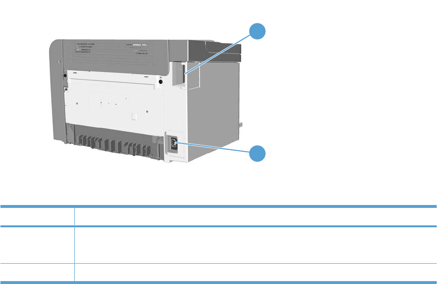
Diagrams
Plug/jack locations
Figure 3-2 Plug/jack locations
2
1
Item Description
1USB port
HP internal network port (HP LaserJet Professional P1600 Printer series)
2Power connector
120 Chapter 3 Solve problems ENWW
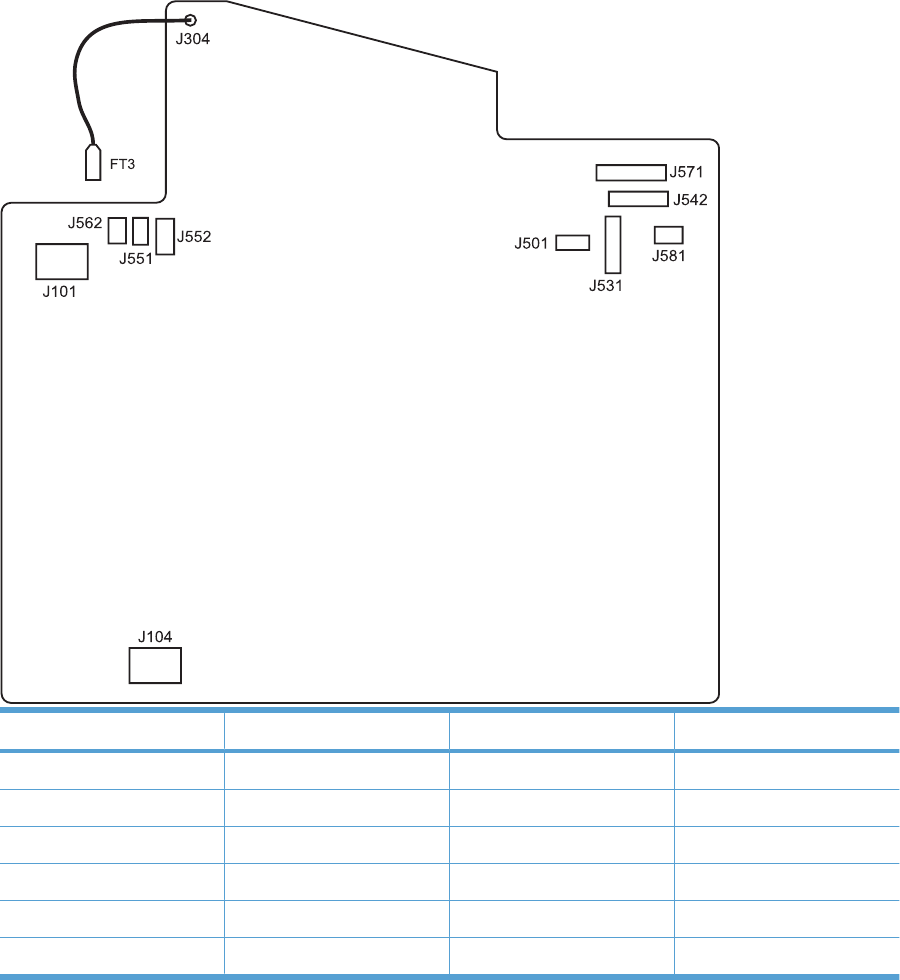
Location of connectors
Figure 3-3 Engine controller PCA connectors
Item Description Item Description
J101 Fuser J551 Top sensor PCA
J104 Power inlet J552 Paper-pickup PCA
J304 High voltage J562 Pickup solenoid
J501 Test point J571 Motor drive PCA
J531 Formatter J581 Cartridge memory tag
J542 Laser/scanner
ENWW Tools for troubleshooting 121
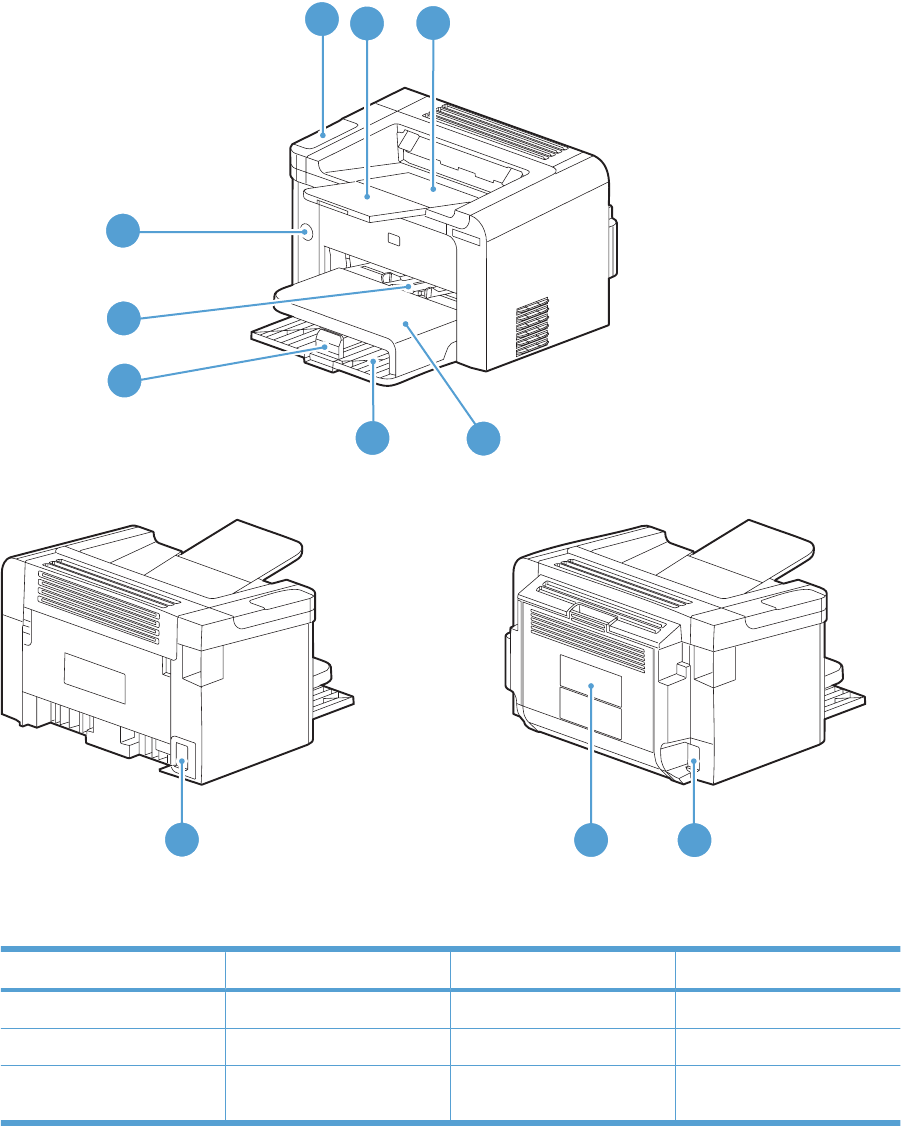
Locations of major components
Figure 3-4 External view
Simplex model Duplex model
1
8
54
10 9
9
7
6
23
Item Description Item Description
1Control panel 6Media-end plate
2Output bin tray extension 7Priority input slot
3Output bin tray (face-down
tray)
8Power switch
122 Chapter 3 Solve problems ENWW
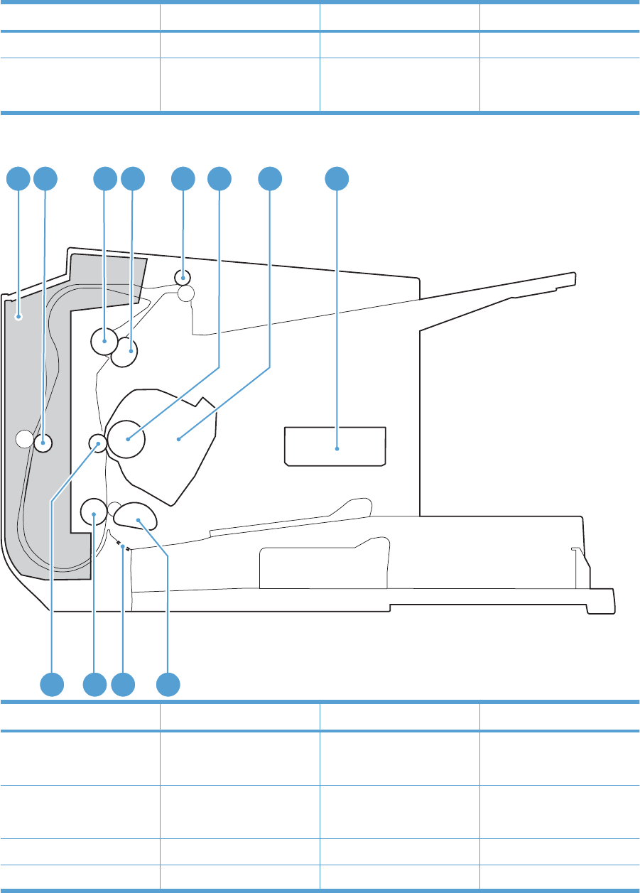
Item Description Item Description
4Dust cover 9Power receptacle
5Main-input tray 10 Duplex door
NOTE: Duplex models only.
Figure 3-5 Cross section view
1
12 11 10 9
2 3 4 5 6 7 8
Item Description Item Description
1Duplex feed assembly
NOTE: Duplex models only.
7Print cartridge
2Duplex feed roller
NOTE: Duplex models only.
8Laser/scanner
3Pressure roller 9Pickup roller
4Fuser film assembly 10 Separation pad
ENWW Tools for troubleshooting 123

Item Description Item Description
5Delivery roller 11 Feed roller
6Photo sensitive drum 12 Transfer roller
124 Chapter 3 Solve problems ENWW
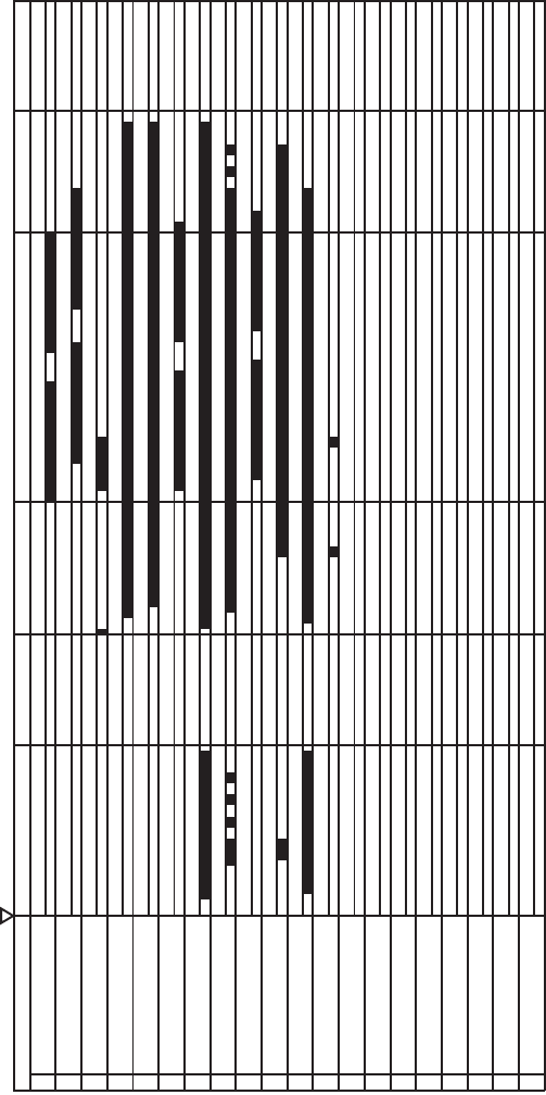
General timing charts
Figure 3-6 General timing diagram
Timing chart two consecutive prints on LTR paper
LSTRTNIRPRTNIYBTSTIAW
6BD Output signal (BDO)
STBY
1TOP sensor (PS751)
2Fuser delivery sensor (PS701)
3Print start command (EEC12)
Operation
4Scanner Motor (M2)
5Laser Diode
12 Pickup solenoid (SL1)
7Main Motor (M1)
8Primary Charging Bias
9Developing Bias
10 Transfer Charging Bias
11 Fuser Heater
18
13
14
15
16
17
19
20
Power switch ON
ENWW Tools for troubleshooting 125
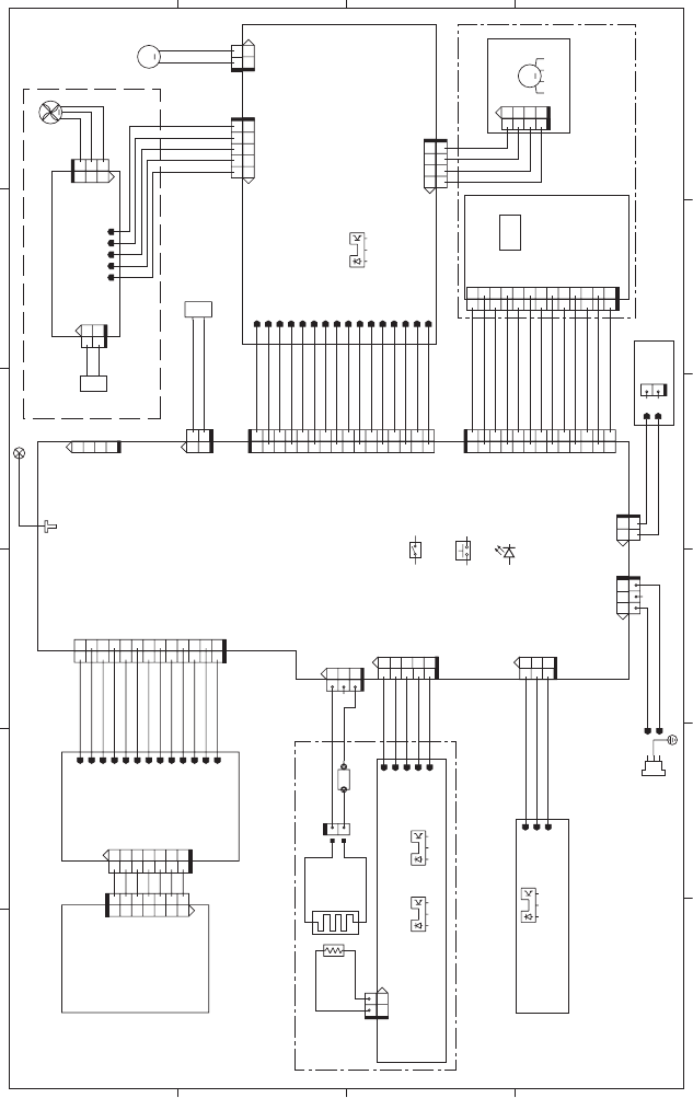
General circuit diagram
Figure 3-7 Circuit diagram
A
65 4 3
21
B
C
D
12
J1102
12
J1101
3512 4
J1103
FANON
GND
32 1
GND
SI
SO
TEST
J501
4
3
2
1
321
+24P2
MTRPWM
12
J902
21
GND_24P2F
24P2F
12345
J904
321
+24P2
ACC
DEC
GND
1
2
3
4
J903
2
3
4
6
7
8
9
10
11
12
13
14
15
5
16
1
J901
1 2 3 4
J1
1234
J801
13
12
11
10
9
8
7
6
5
4
31
2
VDO2
/VDO2
VDO1
/VDO1
GND
+5V
/BDIR
GND
CNT0
GND
GND
CNT1
CNT2
1
2
TAG
12
J3
1
2
3
4
5
6
7
8
9
10
11 13
12
J542
TAGOUT
1
2J581
1
2
ACH
ACN
231
J104
/PISNS
+3.3U
GND
J551
123
+3.3U
GND
FSRTH
/PWSNS
/POSNS
J552
12345
3
1
J751
321 2
3
2
1
FSRTH
GND
2
1
J702
321321
J701
5
4
2
1
3
12
21
J1011
1
2
21
ACH
ACN
J101
23
1
2
1
HV
+24P2
+24P2
+24P2
GND
GND
GND
GND
+5R
ACC
DEC
/MTRPWM
DUPSOL
MFG
FANLOCK
FANON
+24P2
J571
16
1
2
3
4
5
6
7
8
9
10
11 13 15
12 14
J304
FT1
J562
SL
+24U
1
2
1
2
1234567
J1001
1234567
J4
(G)LED1003
(G)LED1001
(Y)LED1002
(Y)LED1004
+3.3R
SW1002
SW1001 7
5
4
3
2
1
10
11
8
6
12
9
13
J531
10
1
2
3
4
5
6
7
8
911 13
12
GND
+3.3R
SCLK
/VDO2
VDO2
VDO1
/RSTO
GND
GND
SC
/VDO1
/BDO
GND
2
1
SW502
LED401
Duplex reverse
solenoid Duplex connector PCA
M
M
PS901
M2
M1
FM1
SW501
SL2
TH1 H1
TP1
TP
PS702PS701
PS751
SL
SL1
SL
INL101
Formatter
Laser Drive PCA
BD
sensor
Scanner motor
Motor Drive PCA
Main motor
Main-motor rotation
number sensor
Laser/scanner unit
Engine Controller PCA
Fuser heater
Thermistor
Fuser-delivery
sensor
Pickup solenoid
Top sensor
Fuser unit
Paper sensor PCA
Top sensor PCA
Cartridge-door
switch
Power switch
Operation panel
Thermoswitch
Media-width
sensor
Main fan
Duplex model only
FANON M
DUPSOL M
FANLOCK M
FANLOCK M
TAGIN
126 Chapter 3 Solve problems ENWW
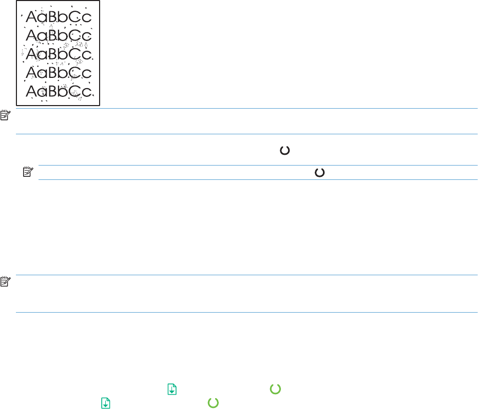
Internal print-quality test pages
Cleaning page
If you are experiencing toner specks or dots on the printouts, clean the paper path. This process uses
a transparency to remove dust and toner from the paper path. Do not use bond or rough paper.
NOTE: For best results use a sheet of transparency. If you do not have any transparencies, you can
use copier-grade paper (60 to 163 g/m
2
(16 to 43 lb)) that has a smooth surface.
1. Make sure that the product is idle and the ready light is on.
NOTE: If the product is in the auto-off state, the ready light is off.
2. Load paper in the input tray.
3. Open the product Properties.
4. Click the Device Settings tab.
5. In the Cleaning Page area, click the Start button to process the cleaning page.
NOTE: The cleaning process takes about 2 minutes. The cleaning page stops periodically during the
cleaning process. Do not turn the product off until the cleaning process has finished. You might need to
repeat the cleaning process several times to thoroughly clean the product.
Configuration page
The configuration page lists current product settings and properties. This page also contains a status
log report. To print a configuration page, do one of the following:
●Press and hold the go button when the ready light is on and no other jobs are printing. Release
the go button when the ready light begins blinking. The configuration page prints.
●Select Config Page from the Print Information Pages drop-down on the Services tab in the
product Preferences.
●HP LaserJet Professional P1600 Printer series series only: Open the embedded Web server,
click the Information tab, and then select Print Info Pages. Click the Print button next to Print
Configuration Page.
ENWW Tools for troubleshooting 127

Print-quality troubleshooting tools
Repetitive defect ruler
If the product output has a consistent, repetitive defect, then use the table in this section to determine
which part needs to be replaced based on the measured distance between the repetitions of the defect.
Component Distance between defects (mm) Type of defects
Primary charging roller About 27 Dirt on page
Dropouts
Photosensitive drum About 75 Dirt on page
Dropouts
Developing roller About 34 Dirt on page
Dropouts
Transfer roller About 39 Dropouts
Dirt on the back of page
Fuser film About 57 Dirt on page
Dropouts
Loose toner
Pressure roller About 56 Dirt on the back of page
Loose toner
Interpret control-panel light patterns
Table 3-2 Status-light legend
Symbol for “light off”
Symbol for “light on”
Symbol for “light blinking”
128 Chapter 3 Solve problems ENWW
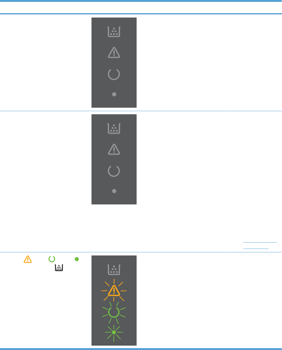
Table 3-3 Control-panel lights
Light status Light pattern State of the product Action
All lights are off
NOTE: The power button backlight is
off.
The product is in
Auto-Off mode or is
turned off.
Press the power
button to deactivate
the Auto-Off mode or
turn on the product
All lights are off
NOTE: The power button backlight is
on.
The formatter is not
connected to the
product correctly.
1. Turn off the
product.
2. Wait
30 seconds, and
then turn on the
product.
3. Wait for the
product to
initialize.
4. Make sure that
the formatter
connectors are
fully seated. If
the error
persists,
replace the
formatter. See
Formatter PCA
on page 67.
Attention , ready , and go
lights cycle. Toner light is off.
NOTE: The power button backlight is
on.
The formatter is
initializing.
No action required.
Wait for the
initialization period to
end. The product
enters the Ready
state when the
initialization period is
finished.
ENWW Tools for troubleshooting 129
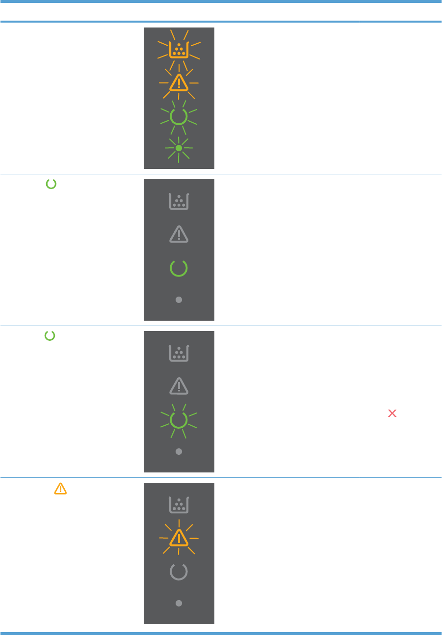
Light status Light pattern State of the product Action
All lights cycle.
NOTE: The power button backlight is
on.
The product is
processing a cleaning
page.
No action required.
Wait for the cleaning
process to end. The
product enters the
Ready state when the
cleaning process is
finished.
Ready light is on, and all other
lights are off.
NOTE: The power button backlight is
on.
The product is in the
Ready state.
No action required.
The product is ready
to receive a print job.
Ready light is blinking, and all other
lights are off.
NOTE: The power button backlight is
on.
The product is
receiving or
processing data.
No action required.
The product is
receiving or
processing a print
job.
To cancel the current
job, press the cancel
button .
Attention light is blinking, and all
other lights are off.
NOTE: The power button backlight is
on.
The product has
experienced an error
that can be corrected
at the product, such
as a jam, an open
door, or the absence
of paper in the proper
tray.
Inspect the product,
determine the error,
and then correct the
error. If the error is
the absence of paper
in the proper tray or
the product is in a
manual feed mode,
put the proper paper
in the tray and follow
the on-screen
instructions, or open
and close the print-
cartridge door to
resume printing.
Table 3-3 Control-panel lights (continued)
130 Chapter 3 Solve problems ENWW
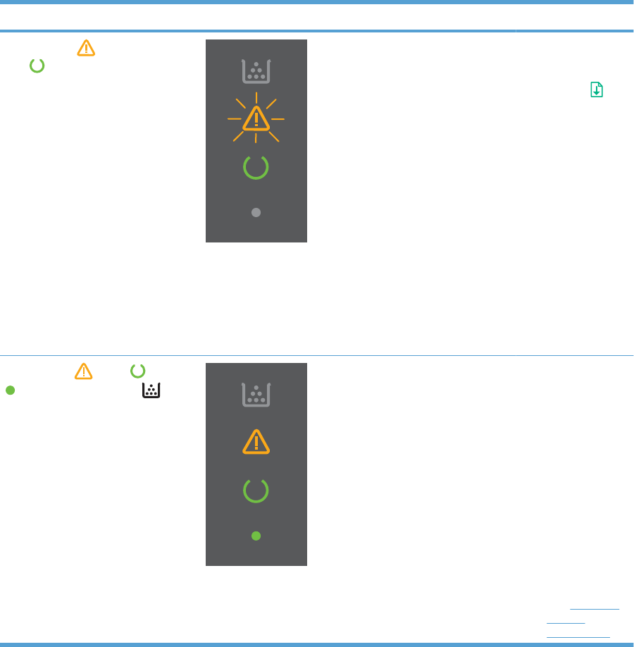
Light status Light pattern State of the product Action
Attention light is blinking, ready
light is on, and other lights are off.
NOTE: The power button backlight is
on.
The product has
experienced a
continual error from
which it can recover
on its own.
To recover from the
error and print the
available data, press
the go button .
If the recovery is
successful, the
product continues to
the processing data
state and completes
the job.
If the recovery is
unsuccessful, the
product continues to
the continuable error
state. Try removing
any paper from the
paper path and
turning the product
power off, and then
on again.
The attention , ready , and go
lights are on. Toner light is off.
NOTE: The power button backlight is
on.
The product has
experienced a fatal
error from which it
cannot recover.
1. Turn off the
product.
2. Wait
30 seconds, and
then turn on the
product.
3. Wait for the
product to
initialize.
4. If the error
persists, contact
customer
support for more
information.
See Customer
support
on page 188.
Table 3-3 Control-panel lights (continued)
ENWW Tools for troubleshooting 131
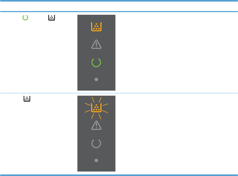
Light status Light pattern State of the product Action
The ready and toner lights are
on.
NOTE: The power button backlight is
on.
The print cartridge is
near the estimated
end of life.
Order a new print
cartridge and have it
ready.
Toner light is blinking.
NOTE: The power button backlight is
on.
The print cartridge
has been removed
from the product.
Reinsert the print
cartridge in the
product.
Table 3-3 Control-panel lights (continued)
132 Chapter 3 Solve problems ENWW
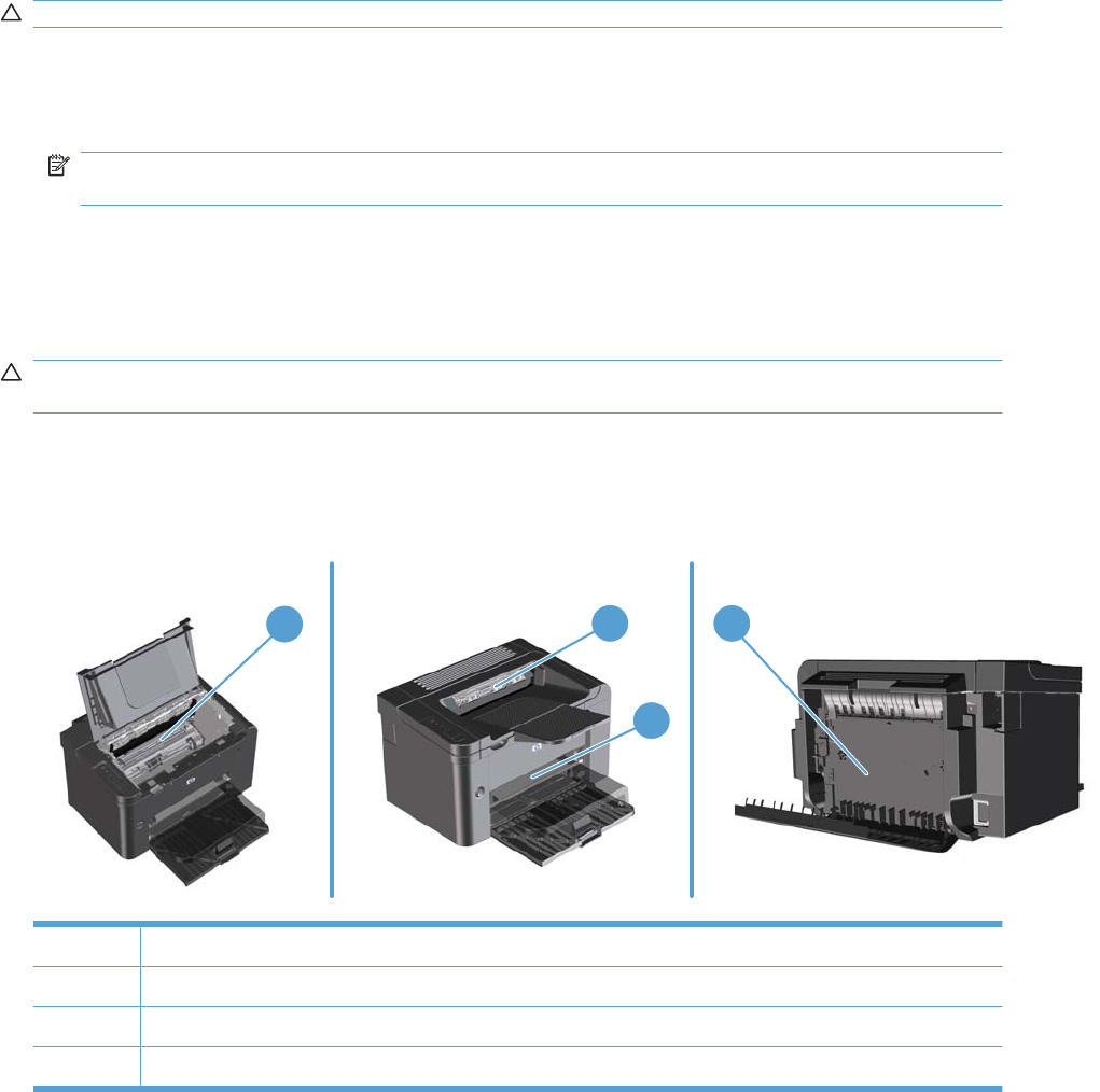
Clear jams
When clearing jams, be careful not to tear jammed paper. If a small piece of paper remains in the product,
it could cause more jams.
CAUTION: Before clearing jams, turn the product off and disconnect the power cord.
Common causes of jams
●The input trays are loaded incorrectly or are too full.
NOTE: When you add new paper, always remove the paper from the tray and straighten the
entire stack. This helps prevent multiple feeds and reduces jams.
●The paper does not meet HP-recommended specifications.
●The product needs to be cleaned to remove paper dust and other particles from the paper path.
Loose toner might remain in the product after a jam. This toner clears up after a few sheets print.
CAUTION: If you get any toner on your clothes or hands, wash them in cold water. Hot water sets
toner into the fabric.
Jam locations
Jams can occur at the following locations in the product.
13 4
2
1Internal areas
2Input trays
3Output bins
4Rear door and duplexer (duplex models only)
ENWW Clear jams 133
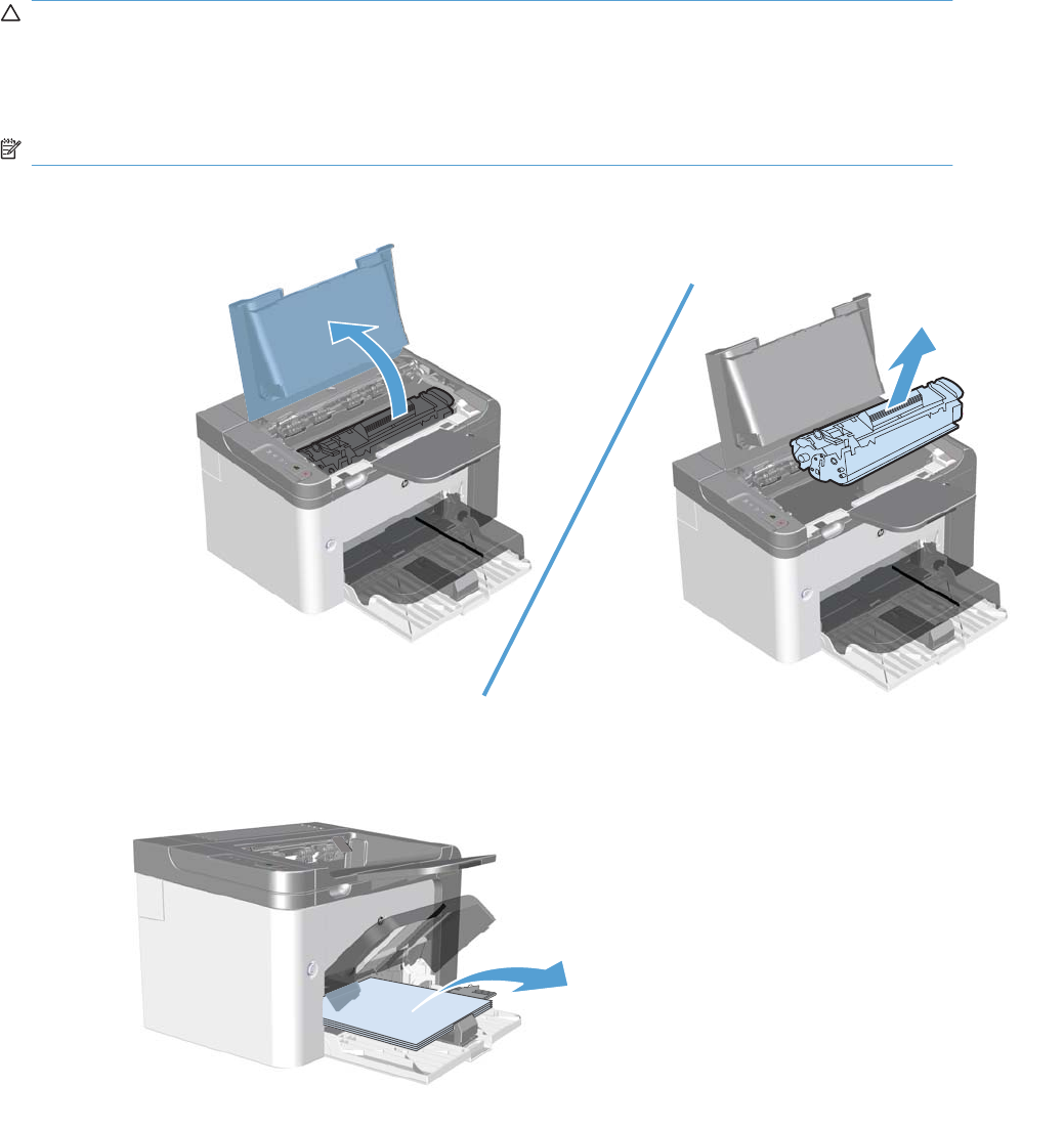
Clear jams from the input trays
CAUTION: Do not use sharp objects, such as tweezers or needle-nose pliers, to remove jams.
Damage caused by sharp objects will not be covered by the warranty.
When removing jammed paper, pull the jammed paper straight away from the product. Pulling jammed
paper out of the product at an angle can damage the product.
NOTE: Depending on where the jam is located, some of the following steps might not be necessary.
1. Open the print-cartridge door, and then remove the print cartridge.
2. In the main-input tray or the priority input slot, remove the paper stack.
134 Chapter 3 Solve problems ENWW
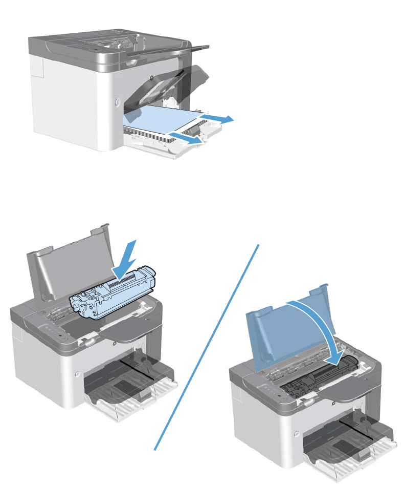
3. With both hands, grasp the side of the jammed paper that is most visible (this includes the middle),
and carefully pull it free from the product.
4. Reinstall the print cartridge and close the print-cartridge door.
ENWW Clear jams 135
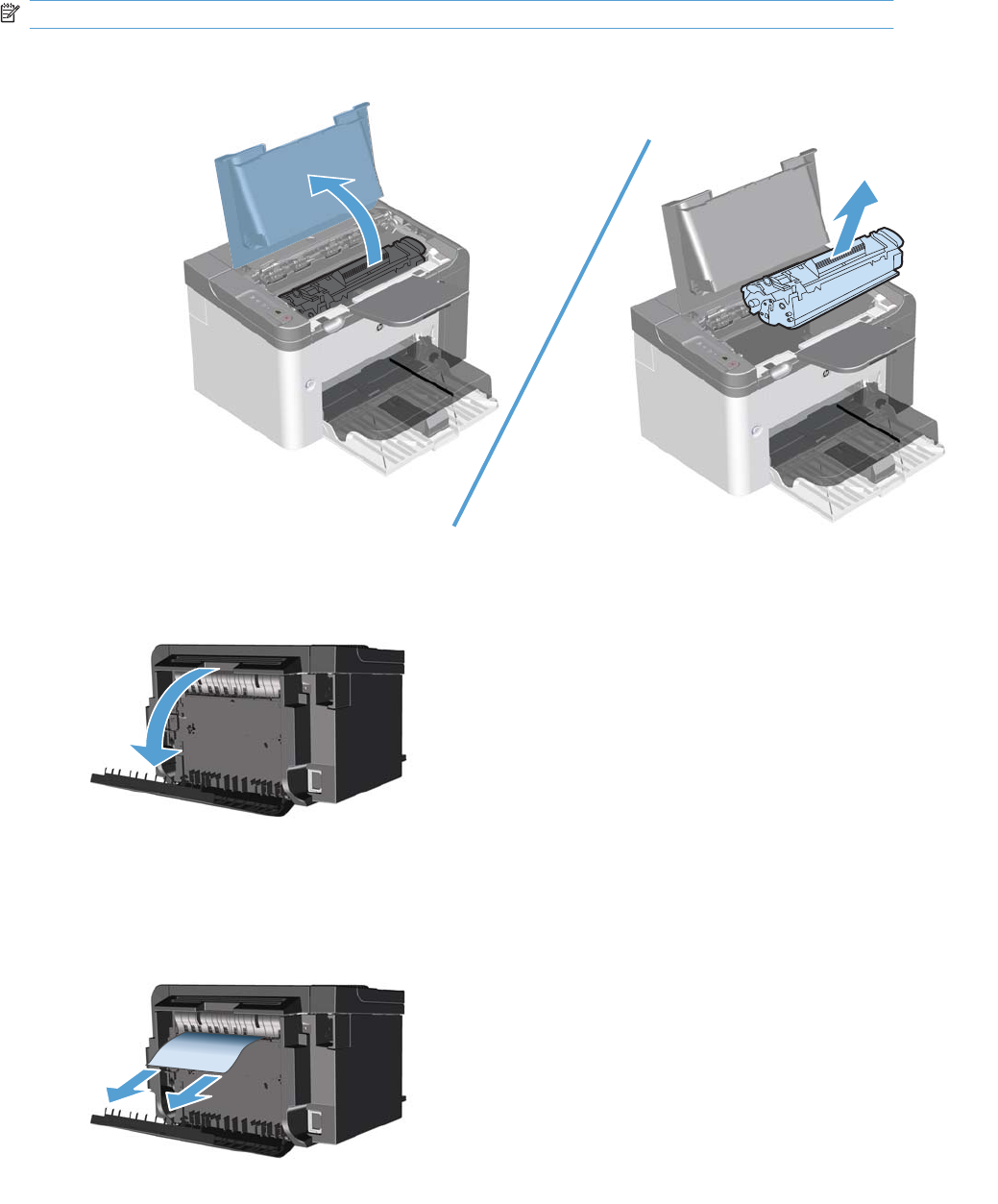
Clear jams from the duplexer
NOTE: Duplex models only.
1. Open the print-cartridge door, and then remove the print cartridge.
2. Open the rear door.
3. Carefully grasp the jammed paper, and slowly pull it out of the product
136 Chapter 3 Solve problems ENWW
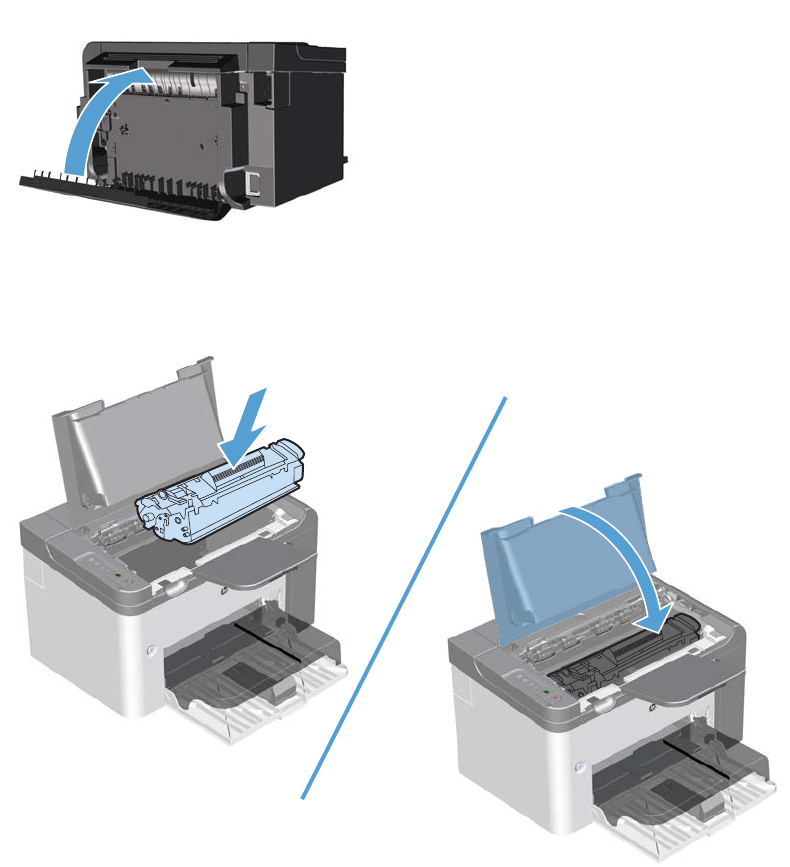
4. Close the rear door.
5. Reinstall the print cartridge and close the print-cartridge door.
ENWW Clear jams 137
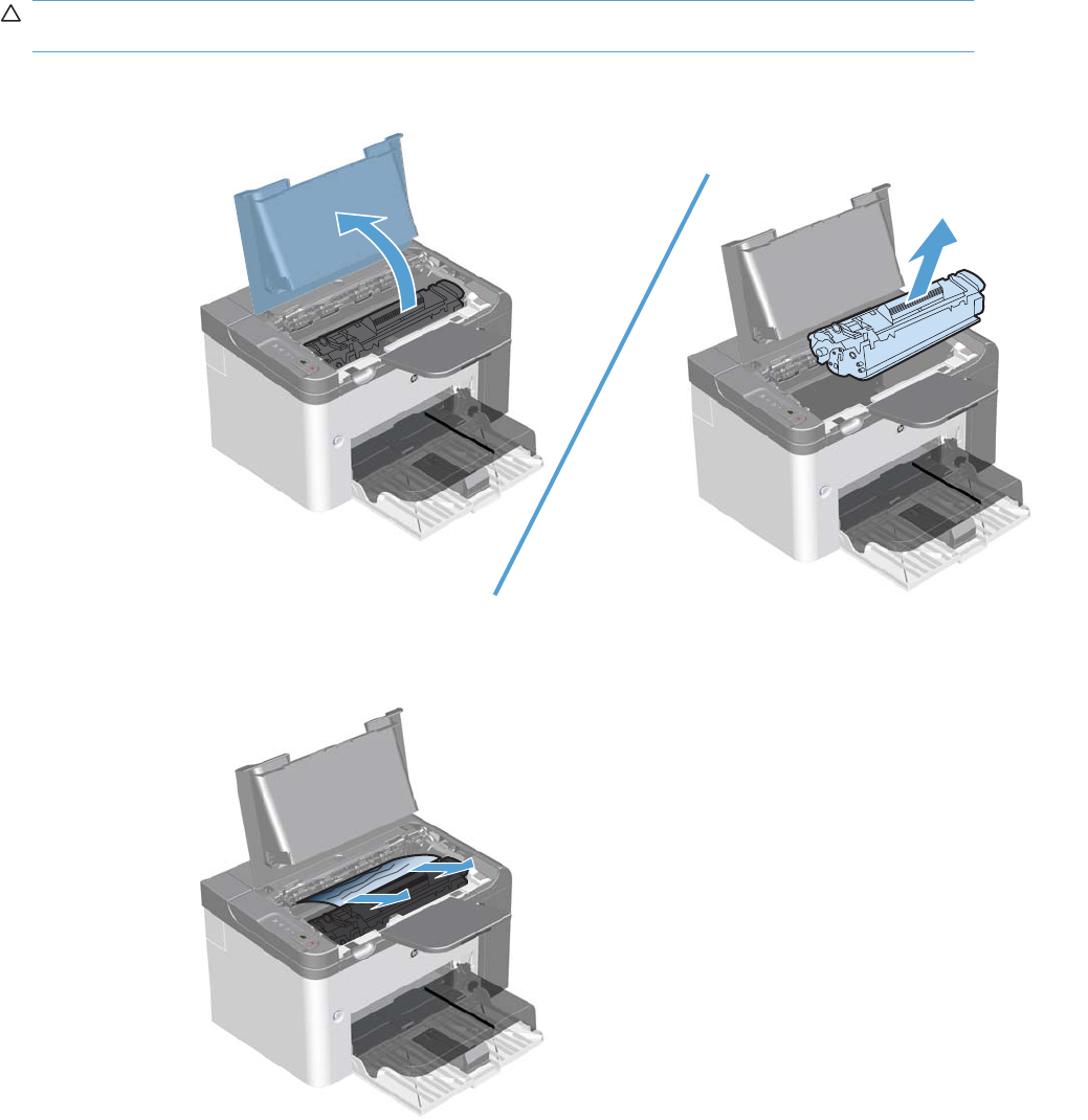
Clear jams from the output areas
CAUTION: Do not use sharp objects, such as tweezers or needle-nose pliers, to remove jams.
Damage caused by sharp objects will not be covered by the warranty.
1. Open the print-cartridge door, and then remove the print cartridge.
2. Keep the print cartridge door open, and then with both hands, grasp the side of the jammed paper
that is most visible (this includes the middle), and carefully pull it free from the product.
138 Chapter 3 Solve problems ENWW
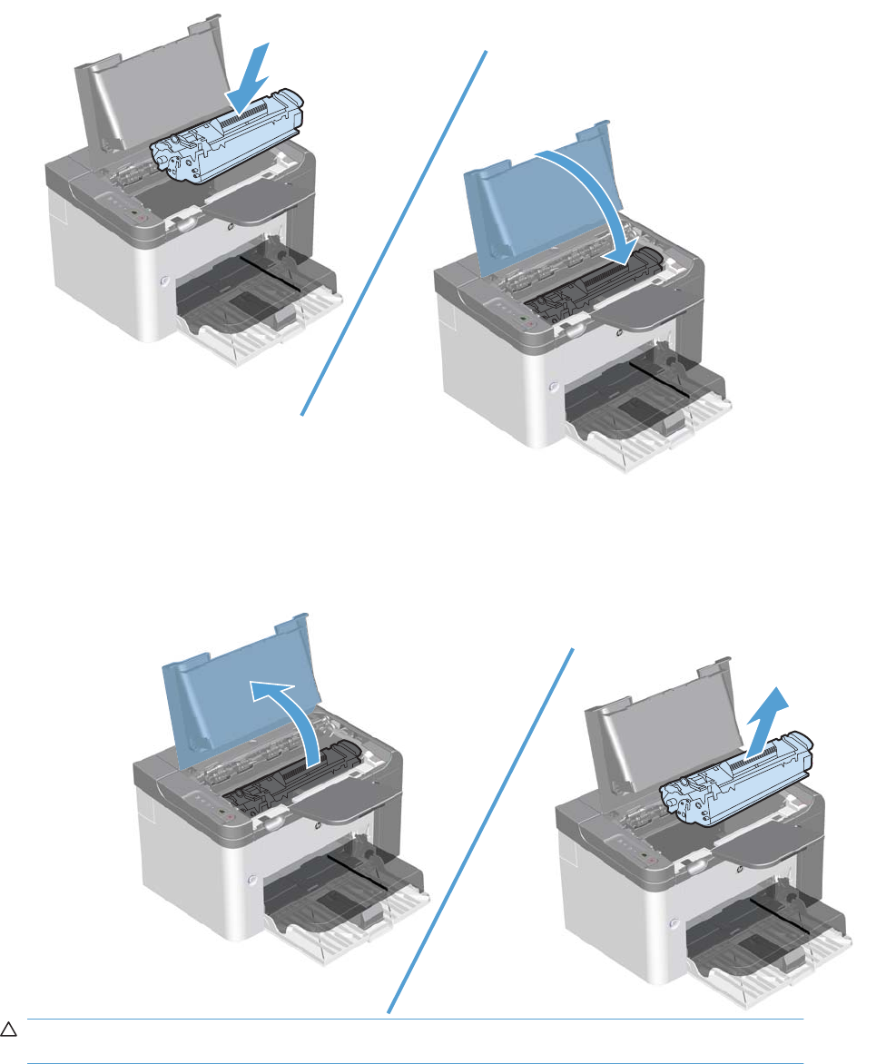
3. Reinstall the print cartridge, and then close the print-cartridge door.
Clear jams from inside the product
1. Open the print-cartridge door, and remove the print cartridge.
CAUTION: To prevent damage, do not expose the print cartridge to light. Cover it with a piece
of paper.
ENWW Clear jams 139
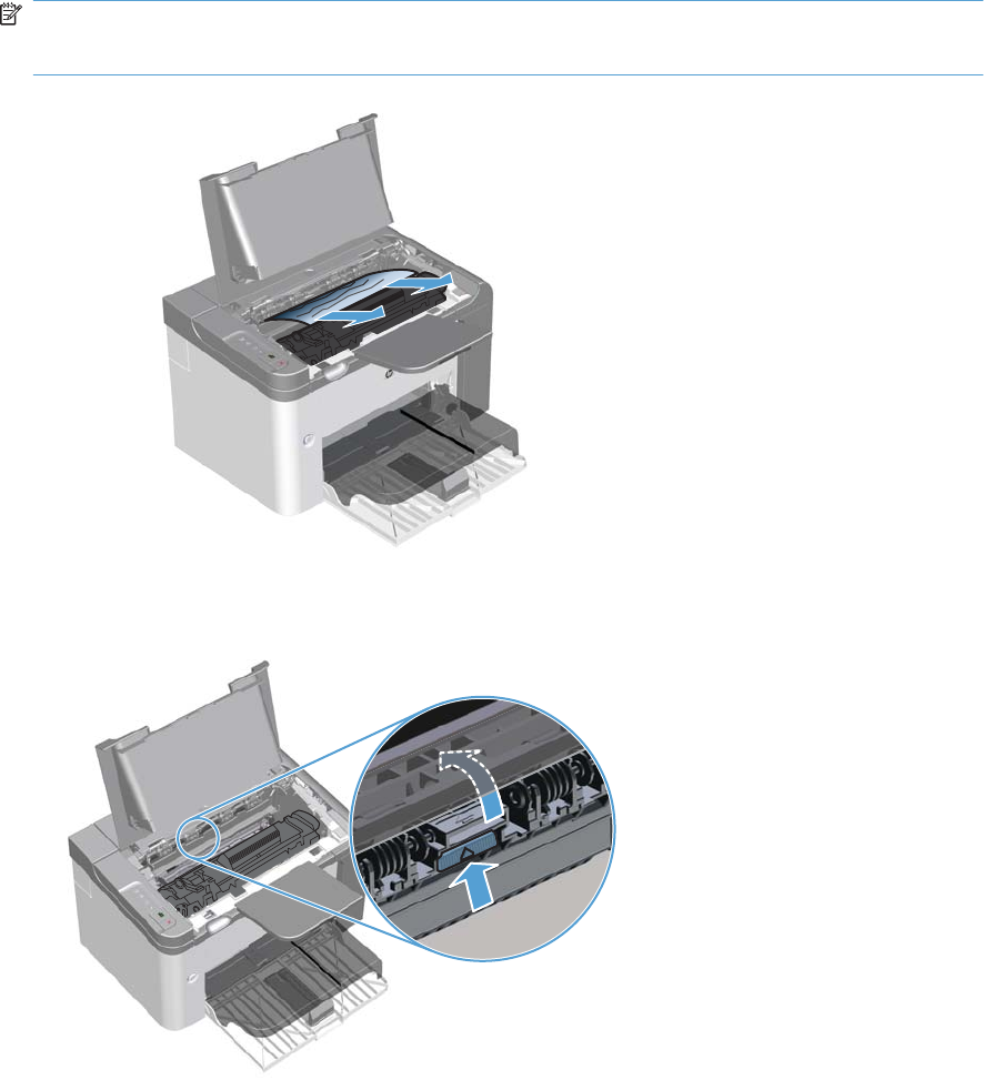
2. If you can see the jammed paper, carefully grasp the jammed paper, and slowly pull it out of the
product.
NOTE: If you can not see the jammed paper, go to the next step.
If you successfully removed the jammed paper, skip the next step.
3. Press the green tab and then open the jam-access door, carefully grasp the jammed paper and
slowly pull it out of the product.
140 Chapter 3 Solve problems ENWW
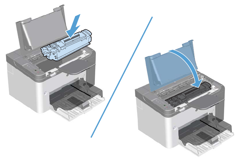
4. Reinstall the print cartridge, and then close the print-cartridge door.
Solve repeated jams
●Verify that the input tray is not overfilled. The input tray capacity varies depending on the type of
print paper that you are using.
●Verify that the paper guides are properly adjusted.
●Check that the input tray is securely in place.
●Do not add paper into the input tray while the product is printing.
●Use only HP-recommended paper types and sizes.
●Do not fan paper prior to loading it in a tray. To loosen the ream, hold it firmly in both hands and
twist the paper by rotating your hands in the opposite direction.
●Do not let print paper stack up in the output bin. The print paper type and the amount of toner used
affect the output bin capacity.
●Check the power connection. Make sure that the power cord is firmly connected to both the product
and the power supply box. Plug the power cord into a grounded power outlet.
ENWW Clear jams 141

Change jam recovery
When the Jam Recovery feature is turned on, the product reprints any pages that are damaged during
a jam.
1. Use the printer driver to change the default settings. Follow the appropriate procedure, depending
on the operating system you are using.
Windows XP, Windows Server 2003, and Windows Server 2008 (using the default Start menu
view)
a. Click Start, and then click Printers and Faxes.
b. Right-click the driver icon, and then select Properties.
c. Click the Device Settings tab.
Windows XP, Windows Server 2003, and Windows Server 2008 (using the Classic Start menu
view)
a. Click Start, click Settings, and then click Printers.
b. Right-click the driver icon, and then select Properties.
c. Click the Device Settings tab.
Windows Vista and Windows 7
a. Click Start, click Control Panel, and then in the category for Hardware and Sound click
Printer.
b. Right-click the driver icon, and then select Properties.
c. Click the Device Settings tab.
Mac OS X 10.4
a. From the Apple menu , click the System Preferences menu and then click the Print &
Fax icon.
b. Click the Printer Setup button.
Mac OS X 10.5 and 10.6
a. From the Apple menu , click the System Preferences menu and then click the Print &
Fax icon.
b. Select the product in the left side of the window.
c. Click the Options & Supplies button.
d. Click the Driver tab.
2. Click the Auto option or the Off option under Jam Recovery.
142 Chapter 3 Solve problems ENWW

Solve paper-handling problems
The following problems with paer cause print-quality deviations, jams, or damage to the product.
Problem Cause Solution
Poor print quality or toner adhesion The paper is too moist, too rough, too
heavy, too smooth, or it is embossed or
from a faulty paper lot.
Try another kind of paper, between 100
and 250 Sheffield, with 4% to 6%
moisture content.
Dropouts, jamming, or curl The paper has been stored incorrectly. Store paper flat in its moisture-proof
wrapping.
The paper has variability from one side
to the other.
Turn the paper over.
Excessive curl The paper is too moist, has the wrong
grain direction, or is of short-grain
construction.
Use long-grain paper.
The paper varies from side to side. Turn the paper over.
Jams, damage to product The paper has cutouts or perforations. Use paper that is free of cutouts or
perforations.
Problems with feeding The paper has ragged edges. Use high-quality paper that is made for
laser printers.
The paper varies from side to side. Turn the paper over.
The paper is too moist, too rough, too
heavy or too smooth, has the wrong grain
direction, or is of short-grain construction
or it is embossed or from a faulty paper
lot.
Try another kind of paper, between 100
and 250 Sheffield, 4% to 6% moisture
content.
Use long-grain paper.
Print is skewed (crooked). The paper guides might be incorrectly
adjusted.
Remove all paper from the tray,
straighten the stack, and then load the
paper in the tray again. Adjust the paper
guides to the width and length of the
paper that you are using and try printing
again.
More than one sheet feeds at one time. The tray might be overloaded. Remove some of the paper from the tray.
The paper might be wrinkled, folded, or
damaged.
Verify that the paper is not wrinkled,
folded, or damaged. Try printing on
paper from a new or different package.
The product does not pull paper from the
tray.
The product might be in manual-feed
mode.
Verify that the product is not in manual
feed mode, and then print the job again.
The pickup roller might be dirty or
damaged.
Clean the roller if it is dirty. Replace the
roller if it is damaged. See Pickup roller
on page 40.
The paper-length adjustment control in
the main-input tray is set at a length that
is greater than the paper size.
Set the paper-length adjustment control
to the correct length.
ENWW Solve paper-handling problems 143
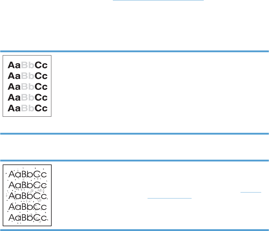
Solve image-quality problems
You can prevent most print-quality problems by following these guidelines.
●Use paper that meets HP specifications.
●Clean the product as necessary. See Clean the paper path on page 151.
Image defect table
This section provides information about identifying and correcting print defects.
Light print or faded
●The print cartridge is nearing end of life.
●Redistribute the toner to extend the life. Remove the print
cartridge, and tip it from side to side lengthwise.
●The paper might not meet Hewlett-Packard's paper
specifications (for example, the paper is too moist or too
rough).
●If the whole page is light, the print density adjustment is
too light or EconoMode might be turned on. Adjust the
print density, and disable EconoMode in the product
Properties.
Toner specks
●The paper might not meet Hewlett-Packard's paper
specifications (for example, the paper is too moist or too
rough).
●The product might need to be cleaned. See Clean the
product on page 150.
●The print cartridge might be defective. Install a new
genuine HP print cartridge.
144 Chapter 3 Solve problems ENWW
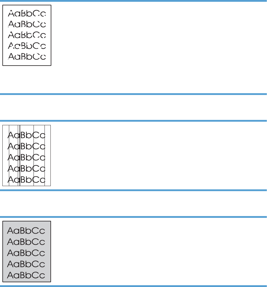
Dropouts
●A single sheet of paper might be defective. Try reprinting
the job.
●The paper moisture content is uneven or the paper has
moist spots on its surface. Try printing with new paper.
●The paper lot is bad. The manufacturing processes can
cause some areas to reject toner. Try a different type or
brand of paper.
●Place the product in quiet mode, and send the print job
again.
●The print cartridge might be defective. Install a new
genuine HP print cartridge.
Vertical lines
The photosensitive drum inside the print cartridge has probably
been scratched. Install a new genuine HP print cartridge.
Gray background
●Change the paper to a lighter basis weight.
●Check the product's environment. Very dry (low humidity)
conditions can increase the amount of background
shading.
●The density setting might be too high. Adjust the density
setting.
●Install a new genuine HP print cartridge.
ENWW Solve image-quality problems 145
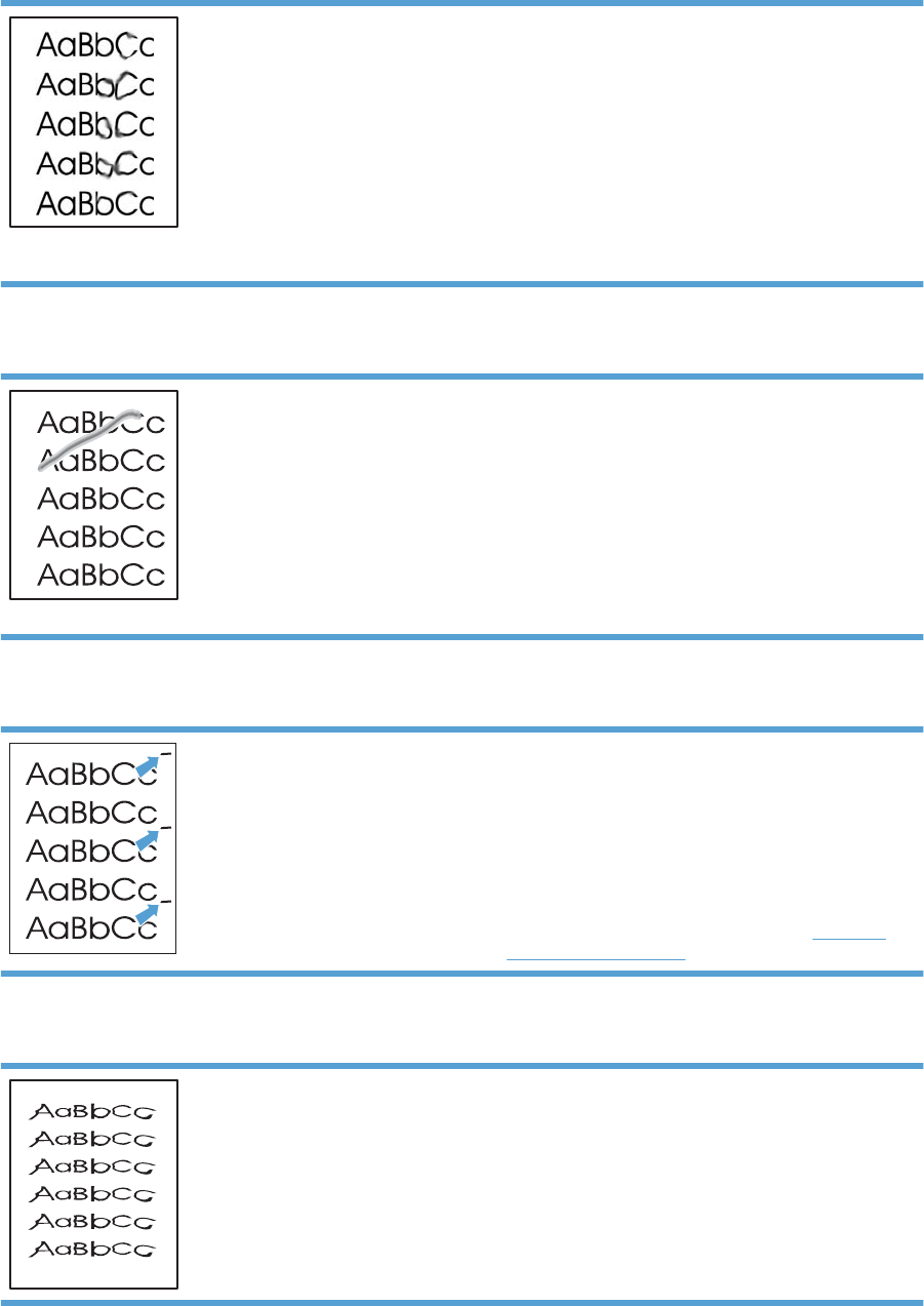
Toner smear
●If toner smears appear on the leading edge of the paper,
the media guides might be dirty. Wipe the paper guides
with a dry, lint-free cloth.
●Check the paper type and quality.
●The fuser temperature might be too low. In your printer
driver, make sure the appropriate paper type is selected.
●Place the product in quiet mode, and send the print job
again. See the product user guide.
●Install a new genuine HP print cartridge.
Loose toner
●The fuser temperature might be too low. In your printer
driver, make sure the appropriate paper type is selected.
●Clean the inside of the product.
●Check the paper type and quality.
●Place the product in quiet mode, and send the print job
again. See the product user guide.
●Plug the product directly into an AC outlet instead of into
a power strip.
Vertical repetitive defects
●The internal parts might have toner on them. If the defects
occur on the back of the page, the problem will probably
correct itself after a few more printed pages.
●In your printer driver, make sure the appropriate paper
type is selected.
●A component might be damaged. If a repetitive mark
occurs at the same spot on the page, use the repetitive
defect ruler table to find the problem. See Repetitive
defect ruler on page 128.
Misformed characters
●If characters are improperly formed, producing hollow
images, the paper stock might be too slick. Try a different
paper.
146 Chapter 3 Solve problems ENWW
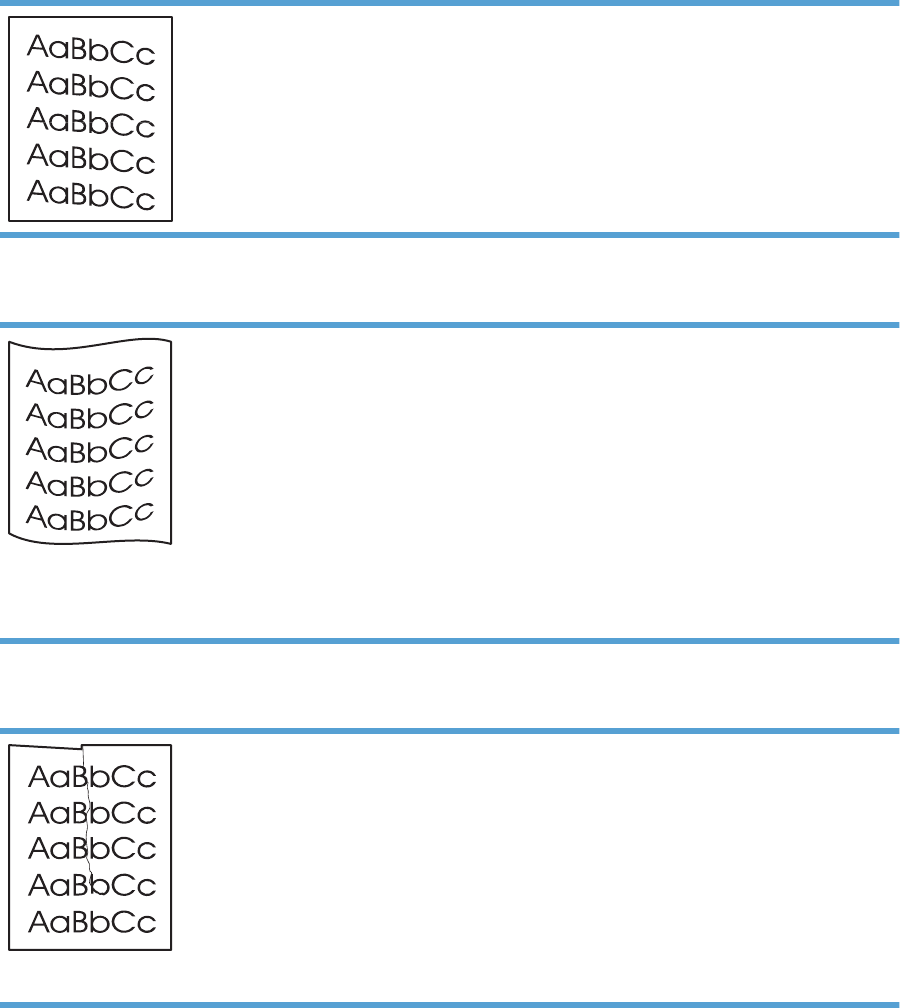
Page skew
●Make sure that the paper is loaded correctly and the
paper guides are not too tight or too loose against the
paper stack.
●The input bin might be too full.
●Check the paper type and quality.
Curl or wave
●Check the paper type and quality. Both high temperature
and high humidity cause paper to curl.
●The paper might have been in the input tray too long. Turn
over the stack of paper in the tray. Also, try rotating the
paper 180° in the input tray.
●Place the product in quiet mode, and send the print job
again. See the product user guide.
●The fuser temperature might be too high. In your printer
driver, make sure the appropriate paper type is selected.
If the problem persists, select a paper type that uses a
lower fuser temperature, such as transparencies or light
paper.
Wrinkles or creases
●Make sure that paper is loaded properly.
●Check the paper type and quality.
●Turn over the stack of paper in the tray. Also, try rotating
the paper 180° in the input tray.
●Place the product in quiet mode, and send the print job
again. See the product user guide.
●For envelopes, this can be caused by air pockets inside
the envelope. Remove the envelope, flatten the
envelope, and try printing again.
ENWW Solve image-quality problems 147
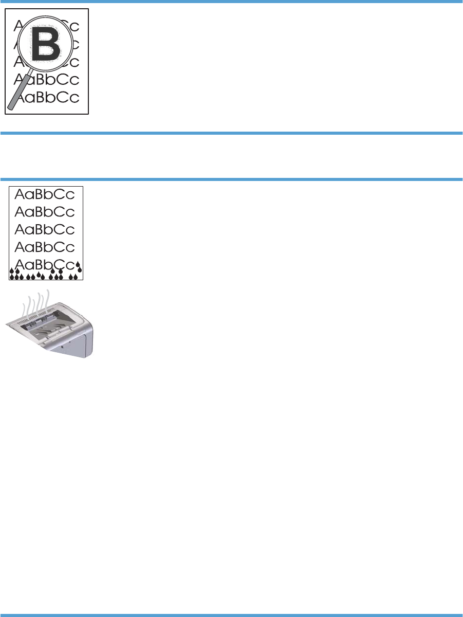
Toner scatter outline
●If large amounts of toner have scattered around the
characters, the transfer of toner to the paper is not optimal
(a small amount of toner scatter is normal for laser
printing). Try a different paper type setting in the printer
driver, or use a different paper type.
●Turn over the paper of media in the tray.
●Use paper that is designed for laser printers.
●Place the product in quiet mode, and send the print job
again. See the product user guide.
Moisture
NOTE: This product dissipates heat by using convective
cooling. The heat and moisture generated by the printing
process escape through vents in the product exterior or
through the output bin area.
Water droplets from the convective cooling process will not
damage the product.
Verify normal product operation
The release of moisture is a result of normal product operation.
However, HP recommends using the following steps to verify
that the product is releasing steam and does not have a
functional problem.
1. Turn the product off, and then on.
2. Send a print job to the product, and then verify that the
product is operating correctly.
3. When printing a job and vapor is visible, immediately
reprint the job using the same sheet of paper. There
should be either no visible vapor, or much less vapor
during the printing process.
Limit or reduce steam or vapor
●Make sure that the product is placed in a well-ventilated
area that meets the environmental specifications.
●Do not place the product, or store paper, near an outside
entrance where temperature changes can increase
humidity.
●Use an unopened ream of paper that has not been
exposed to high humidity.
●Store paper in an airtight container, where it will be less
likely to absorb moisture.
●Place the product in quiet mode, and send the print job
again. See the product user guide.
148 Chapter 3 Solve problems ENWW
Change print density
You can change the print density setting by from the product properties dialog box.
1. Windows XP, Windows Server 2008, and Windows Server 2003 (using the default Start menu
view): Click Start, and then click Printers and Faxes.
-or-
Windows XP, Windows Server 2008, and Windows Server 2003 (using the Classic Start menu
view): Click Start, and then click Printers.
-or-
Windows Vista: Click Start, click Control Panel, and then in the category for Hardware and
Sound click Printer.
-or-
Windows 7: Click Start, and then click Devices and Printers.
2. In the list of printers, right-click the name of this product, and then click the Properties menu item
to open the printer properties dialog box.
3. Click the Device settings tab, and then move the Print Density slider to the desired setting.
4. Click the Apply button to accept the setting, and then click the OK button to close the dialog box.
ENWW Solve image-quality problems 149
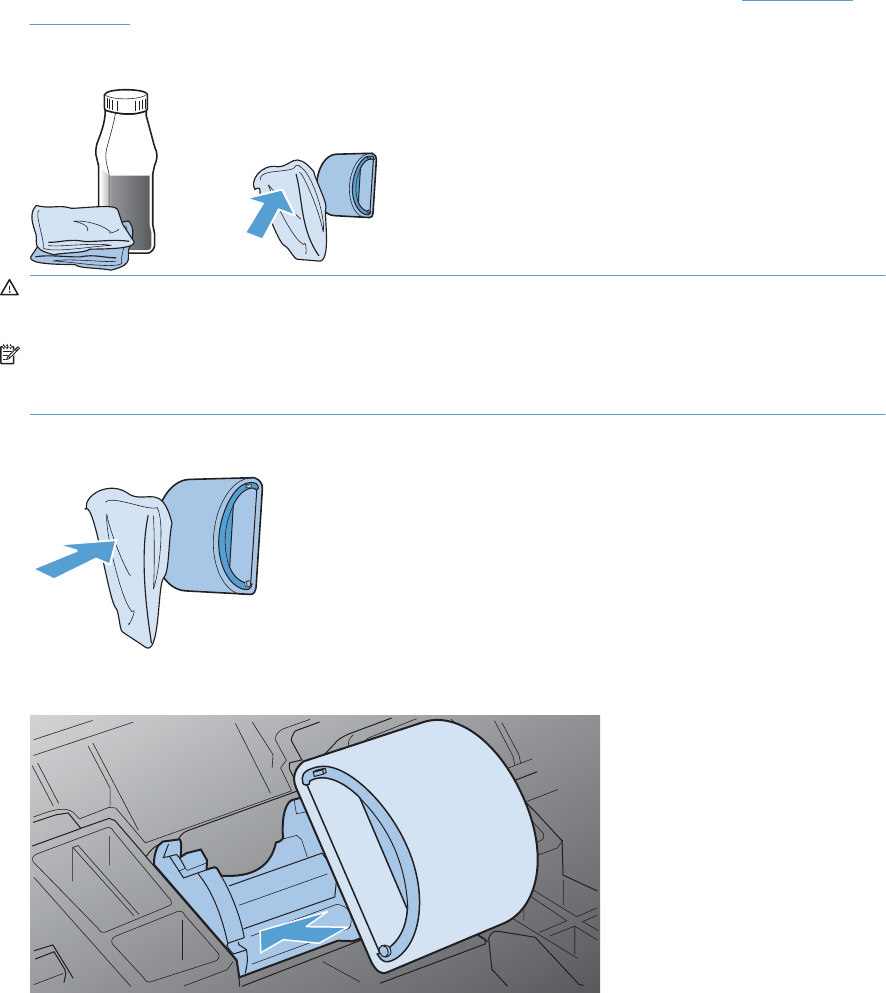
Clean the product
Clean the pickup roller
If you want to clean the pickup roller before deciding to replace it, follow these instructions:
1. Unplug the power cord from the product, and then remove the pickup roller. See Pickup roller
on page 40.
2. Dab a lint-free cloth in isopropyl alcohol, and then scrub the roller.
WARNING! Alcohol is flammable. Keep the alcohol and cloth away from an open flame. Before
you close the product and plug in the power cord, allow the alcohol to dry completely.
NOTE: In certain areas of California, air pollution control regulations restrict the use of liquid
isopropyl alcohol (IPA) as a cleaning agent. In those areas of California, disregard the previous
recommendations and use a dry, lint-free cloth, moistened with water, to clean the pickup roller.
3. Use a dry, lint-free cloth, to wipe the pickup roller to remove loose dirt.
4. Allow the pickup roller to dry completely before you reinstall it in the product.
5. Plug the power cord into the product.
150 Chapter 3 Solve problems ENWW
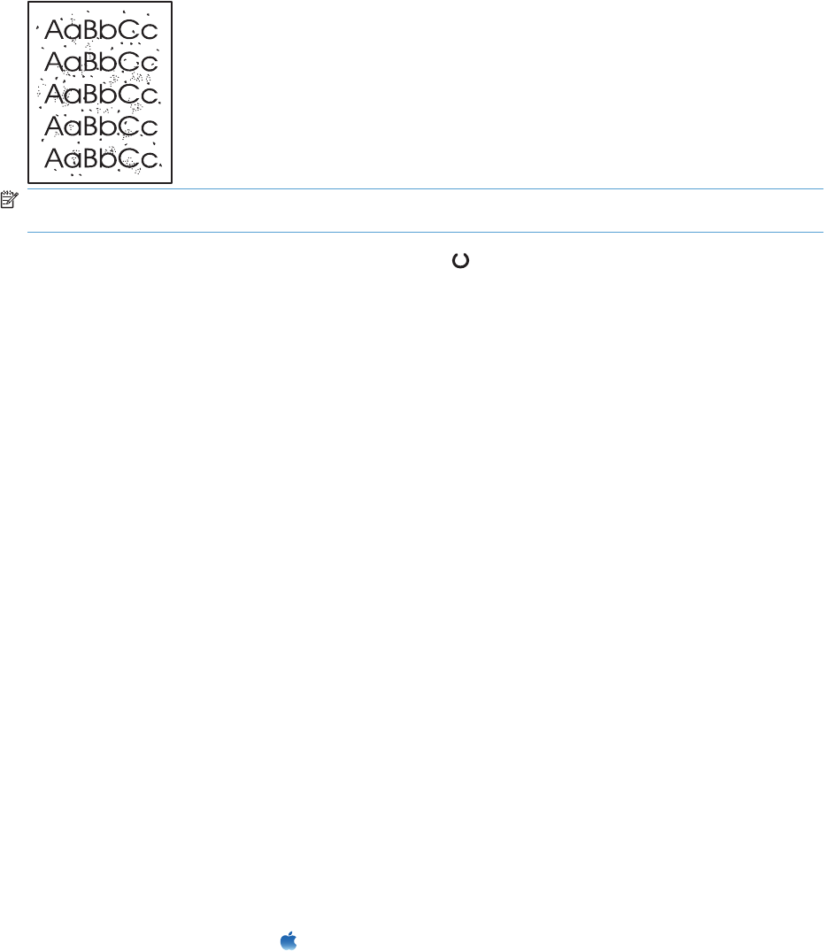
Clean the paper path
If you are experiencing toner specks or dots on the printouts, clean the paper path. This process uses
a transparency to remove dust and toner from the paper path. Do not use bond or rough paper.
NOTE: For best results use a sheet of transparency. If you do not have any transparencies, you can
use copier-grade paper (60 to 163 g/m
2
(16 to 43 lb)) that has a smooth surface.
1. Make sure that the product is idle and the Ready light is on.
2. Load paper in the input tray.
3. Use the printer driver to process the cleaning page. Follow the appropriate procedure, depending
on the operating system you are using.
Windows XP, Windows Server 2003, and Windows Server 2008 (using the default Start menu
view)
a. Click Start, and then click Printers and Faxes.
b. Right-click the driver icon, and then select Properties.
c. Click the Device Settings tab.
Windows XP, Windows Server 2003, and Windows Server 2008 (using the Classic Start menu
view)
a. Click Start, click Settings, and then click Printers.
b. Right-click the driver icon, and then select Properties.
c. Click the Device Settings tab.
Windows Vista and Windows 7
a. Click Start, click Control Panel, and then in the category for Hardware and Sound click
Printer.
b. Right-click the driver icon, and then select Properties.
c. Click the Device Settings tab.
Mac OS X 10.4
a. From the Apple menu , click the System Preferences menu and then click the Print &
Fax icon.
b. Click the Printer Setup button.
ENWW Clean the product 151

Mac OS X 10.5 and 10.6
a. From the Apple menu , click the System Preferences menu and then click the Print &
Fax icon.
b. Select the product in the left side of the window.
c. Click the Options & Supplies button.
d. Click the Driver tab.
4. In the Cleaning Page area, click the Start button to process the cleaning page.
NOTE: The cleaning process takes about 2 minutes. The cleaning page stops periodically during the
cleaning process. Do not turn the product off until the cleaning process has finished. You might need to
repeat the cleaning process several times to thoroughly clean the product.
152 Chapter 3 Solve problems ENWW
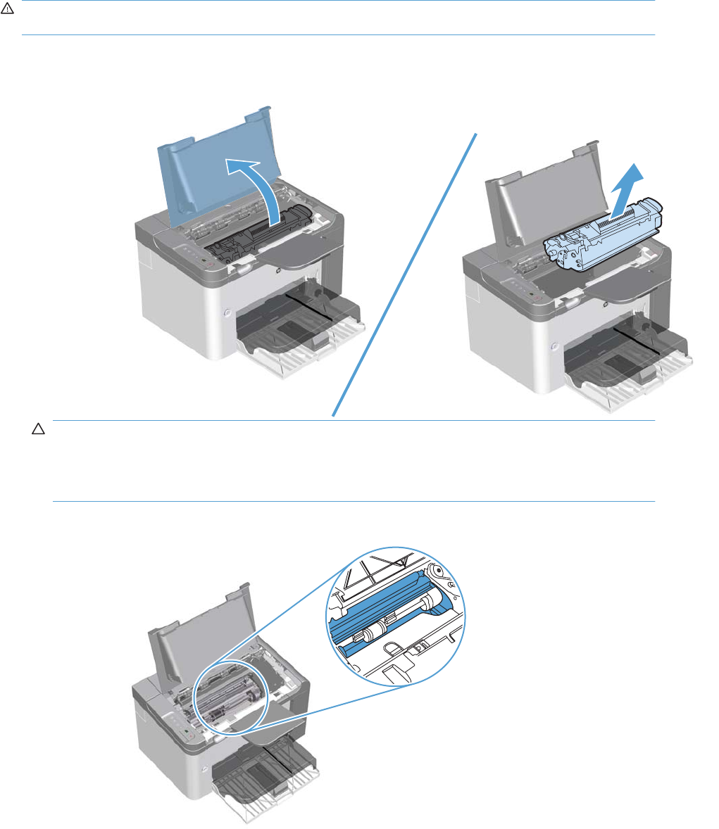
Clean the print-cartridge area
You do not need to clean the print-cartridge area often. However, cleaning this area can improve the
quality of the printed sheets.
WARNING! Before cleaning the product, turn the product off by unplugging the power cord, and wait
for the product to cool.
1. Unplug the power cord from the product. Open the print-cartridge door, and remove the print
cartridge.
CAUTION: Do not touch the black-sponge transfer roller inside the product. Doing so can
damage the product.
CAUTION: To prevent damage, do not expose the print cartridge to light for an extended time.
Cover it with a piece of paper.
2. Use a dry, lint-free cloth, to wipe any residue from the paper-path area and the print-cartridge cavity.
ENWW Clean the product 153
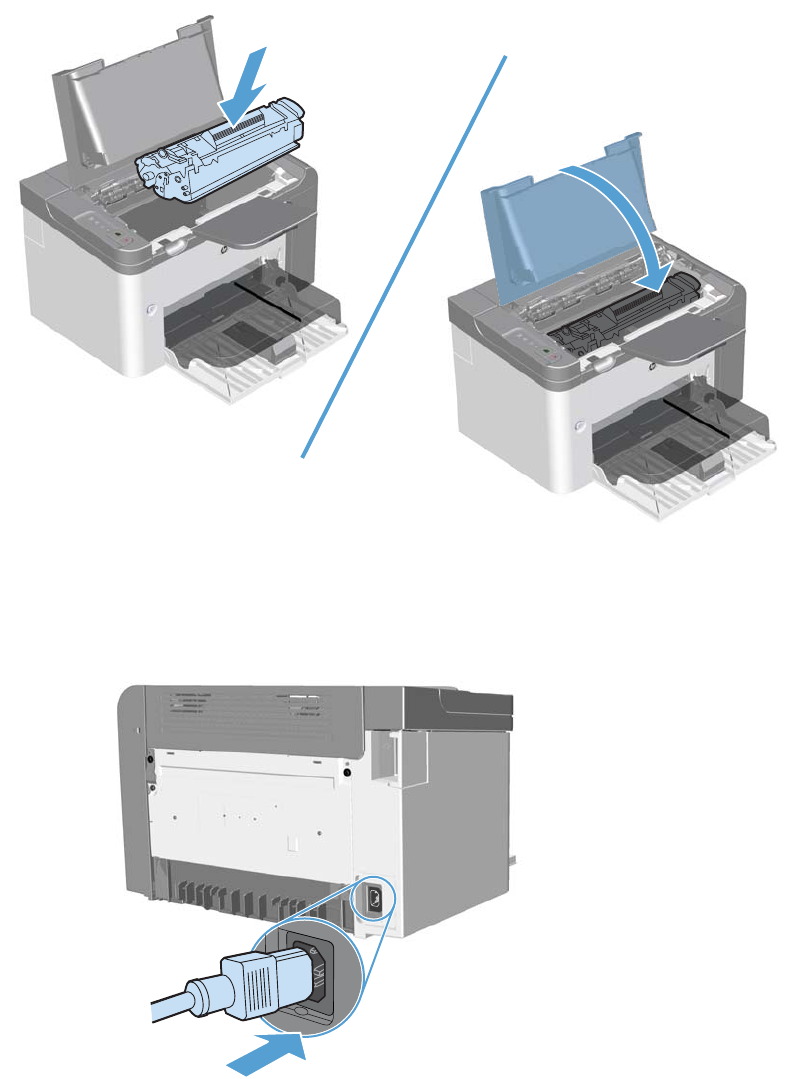
3. Replace the print cartridge, and close the print-cartridge door.
4. Plug the power cord into the product.
Clean the exterior
Use a soft, damp, lint-free cloth to wipe dust, smudges, and stains off of the exterior of the product.
154 Chapter 3 Solve problems ENWW

Solve performance problems
Problem Cause Solution
Pages print, but are totally blank. The sealing tape might still be in the print
cartridges.
Verify that the sealing tape has been
completely removed from the print
cartridges.
The document might contain blank
pages.
Check the document that you are printing
to see if content appears on all of the
pages.
The product might be malfunctioning. To check the product, print a
Configuration page.
Pages print very slowly. Heavier paper types can slow the print
job.
Print on a different type of paper.
Complex pages can print slowly.
Narrow or small paper can print slowly.
Proper fusing might require a slower print
speed to make sure that the best print
quality is achieved.
Pages did not print. The product might not be pulling paper
correctly.
Make sure paper is loaded in the tray
correctly.
The paper is jamming in the product. Clear the jam. See Clear jams
on page 133.
The USB cable might be defective or
incorrectly connected.
●Disconnect the USB cable at both
ends and reconnect it.
●Try printing a job that has printed in
the past.
●Try using a different USB cable.
Other devices are running on your
computer.
The product might not share a USB port.
If you have an external hard drive or
network switchbox that is connected to
the same port as the product, the other
device might be interfering. To connect
and use the product, you must
disconnect the other device or you must
use two USB ports on the computer.
ENWW Solve performance problems 155

Solve connectivity problems
NOTE: Restore the factory default settings for the product. See Product resets on page 158. If the
problem persists, try the solutions in this section.
Solve direct-connect problems
If you have connected the product directly to a computer, check the cable.
●Verify that the cable is connected to the computer and to the product.
●Verify that the cable is not longer than 2 meters (6 feet). Replace the cable if necessary.
●Verify that the cable is working correctly by connecting it to another product. Replace the cable if
necessary.
Solve network problems
NOTE: Before performing the procedures in this section, restore the product factory-default settings.
See Product resets on page 158.
Check the following items to verify that the product is communicating with the network. Before beginning,
print a configuration page.
1. Are there any physical connection problems between the workstation or file server and the product?
Verify that the network cabling, connections, and router configurations are correct. Verify that the
network cable lengths meet network specifications.
2. Are your network cables connected properly?
Make sure that the product is attached to the network using the appropriate port and cable. Check
each cable connection to make sure it is secure and in the right place. If the problem continues,
try a different cable or ports on the hub or transceiver. The amber activity light and the green link
status light next to the port connection on the back of the product should be lit.
3. Are the link speed and duplex settings set correctly?
Hewlett-Packard recommends leaving this setting in automatic mode (the default setting).
4. Can you "ping" the product?
Use the command prompt to ping the product from your computer. For example:
ping 192.168.45.39
Ensure that the ping displays round-trip times.
If you are able to ping the product, verify that the IP address configuration for the product is correct
on the computer. If it is correct, delete and then add the product again.
If the ping command failed, verify that the network hubs are on, and then verify that the network
settings, the product, and the computer are all configured for the same network.
Verify that the ping command is successful for other devices on the network (if not, a firewall might
be blocking the ping command).
Try opening the embedded Web server to verify that the computer is communicating with the
product.
156 Chapter 3 Solve problems ENWW
5. Have any software applications been added to the network?
Make sure they are compatible and that they are installed correctly with the correct printer drivers.
6. Are other users able to print?
The problem may be workstation-specific. Check the workstation network drivers, printer drivers,
and redirection (capture in Novell NetWare).
7. If other users are able to print, are they using the same network operating system?
Check your system for proper network operating system setup.
8. Is your protocol enabled?
Check the status of your protocol on the configuration page. You can also use the embedded Web
server to check the status of other protocols. See the product user guide.
9. Does the product appear in HP Web Jetadmin or other management application?
●Verify network settings on the configuration page.
●Confirm the network settings for the product using the product control panel (for products with
control panels).
ENWW Solve connectivity problems 157

Service mode functions
Product resets
To restore the product to the factory-default settings, follow these steps.
1. Turn the product off.
2. Turn the product on, and while it is initializing press and hold both control-panel buttons at the same
time until all lights blink in unison.
Product updates
Firmware updates
Firmware and software updates and installation instructions for this product are available at
www.hp.com/support/ljp1560series or www.hp.com/support/ljp1600series. Click Downloads and
drivers, click the operating system, and then select the download for the product.
158 Chapter 3 Solve problems ENWW


Order parts by authorized service providers
Order replacement parts
Table 4-1 Order parts, accessories, and supplies
Order supplies and paper www.hp.com/go/suresupply
Order genuine HP parts or accessories www.hp.com/buy/parts
Order through service or support providers Contact an HP-authorized service or support provider.
Related documentation and software
Table 4-2 Related documentation and software
Item Description Part number
HP LaserJet P1560 and P1600 Printer series User Guide Product user guide. CE663-90901
HP LaserJet P1560 and P1600 Printer series Service Manual English service manual (this
manual)
CE663-90939
Supplies part numbers
Table 4-3 Supplies part numbers
Item Description Part number
HP LaserJet print cartridge Print cartridge CE278A (new)
CE278-67901 (service)
160 Chapter 4 Parts and diagrams ENWW

Customer self repair parts
Table 4-4 Customer replaceable units (CRU) kit part numbers
Item Description Part number
Kit, separation pad Separation pad
Installation instructions
CE663-67901
Kit, pickup roller Pickup roller
Installation instructions
CE663-67902
Service parts
NOTE: The parts in the following table are not shown in the assembly illustrations in this chapter.
Item Description Part number
HP jewel HP logo 7121-8266
Regulatory label Blank label 5969-9497
Whole-unit replacement part numbers
NOTE: Whole-unit replacement products include the formatter PCA.
Table 4-5 Whole-unit replacement part numbers
Item Description Part number
HP LaserJet Professional
P1560 Printer series
220 V CE663-67002 (new)
CE663-69002 (exchange)
HP LaserJet Professional
P1600 Printer series
110 V CE749-67001(new)
CE749-69001(exchange)
220 V CE749-67002 (new)
CE749-69002 (exchange)
ENWW Order parts by authorized service providers 161

How to use the parts lists and diagrams
CAUTION: Be sure to order the correct part. When looking for part numbers for electrical components,
pay careful attention to the voltage that is listed. Doing so will make sure that the part number selected
is for the correct model.
NOTE: In this manual, the abbreviation “PCA” stands for “printed circuit-board assembly.”
Components described as a PCA might consist of a single circuit board or a circuit board plus other
parts, such as cables and sensors.
The figures in this chapter show the major subassemblies in the product and their component parts. A
parts list table follows each exploded view assembly diagram. Each table lists the item number, the
associated part number, and the description of each part. If a part is not listed in the table, then it is not
a field replacement unit (FRU).
162 Chapter 4 Parts and diagrams ENWW
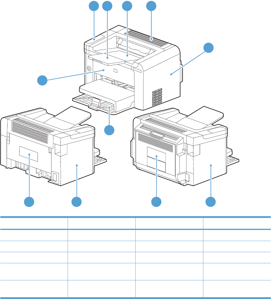
Assembly locations
Base product (no optional trays or accessories)
Figure 4-1 Base product (no optional trays or accessories)
Simplex model
Duplex model
1
5
6
8
9
8
10
7
2 3 4
Table 4-6 Base product
Item Description Item Description
1Control panel 6Main-input tray
2Output bin tray extension 7Front cover
3Print-cartridge door 8Left cover
4Face-down cover 9Duplex door (duplex models
only)
5Right cover 10 Rear cover (simplex models
only)
ENWW Assembly locations 163
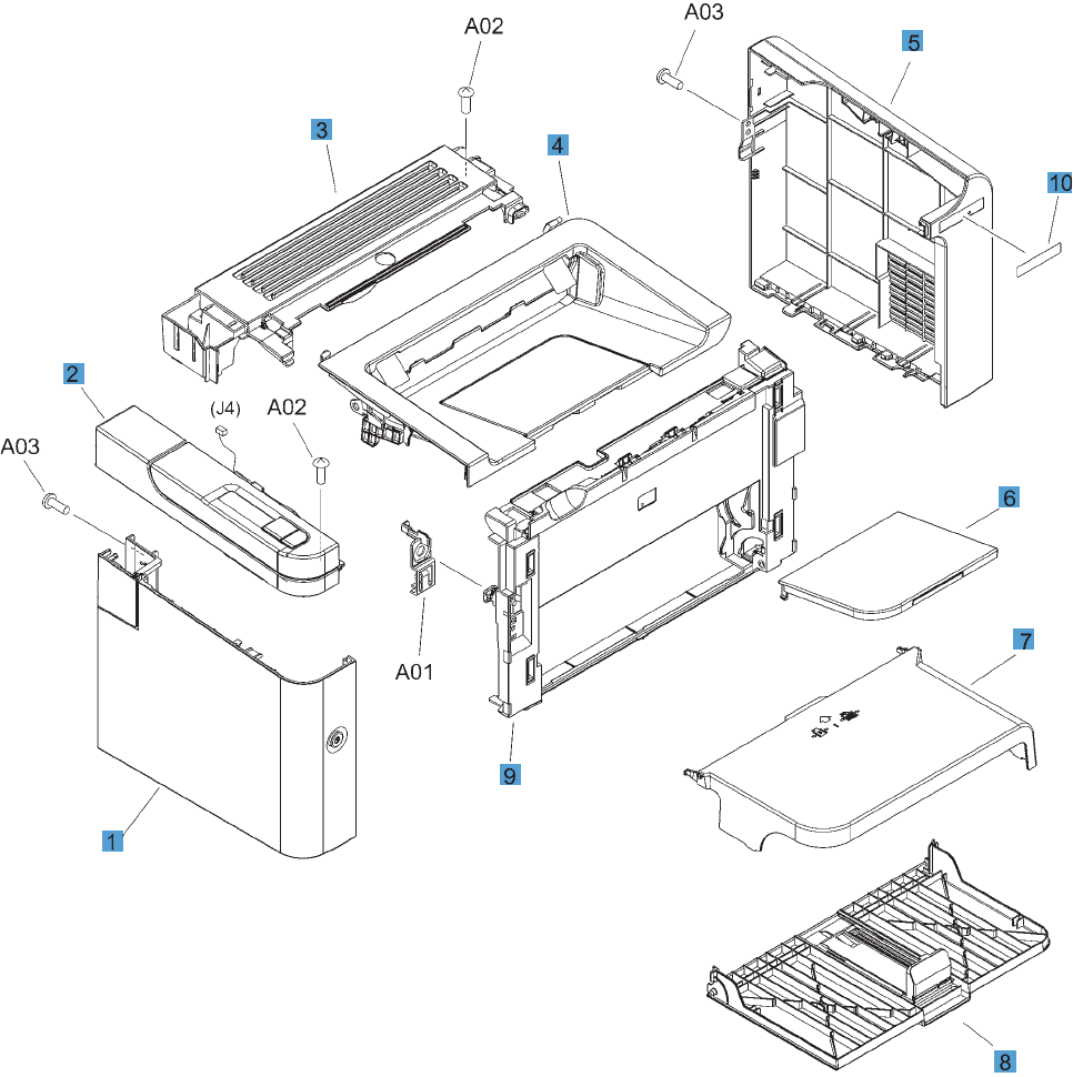
Covers
Simplex model
Figure 4-2 Simplex model
164 Chapter 4 Parts and diagrams ENWW

Table 4-7 Simplex model
Ref Description Part number Qty
1 Left cover RM1-7533-000CN 1
2 Control-panel assembly RM1-7530-000CN 1
3 Cover, face-down RC2-9464-000CN 1
4 Cartridge door RM1-7528-000CN 1
5 Cover, right RC2-9462-000CN 1
6 Paper delivery tray RM1-7499-000CN 1
7 Cover, dust RC2-9582-000CN 1
8 Paper pickup tray RM1-7535-000CN 1
9 Cover, front RL1-2871-000CN 1
10 Plate, name RC3-0623-000CN 1
ENWW Covers 165
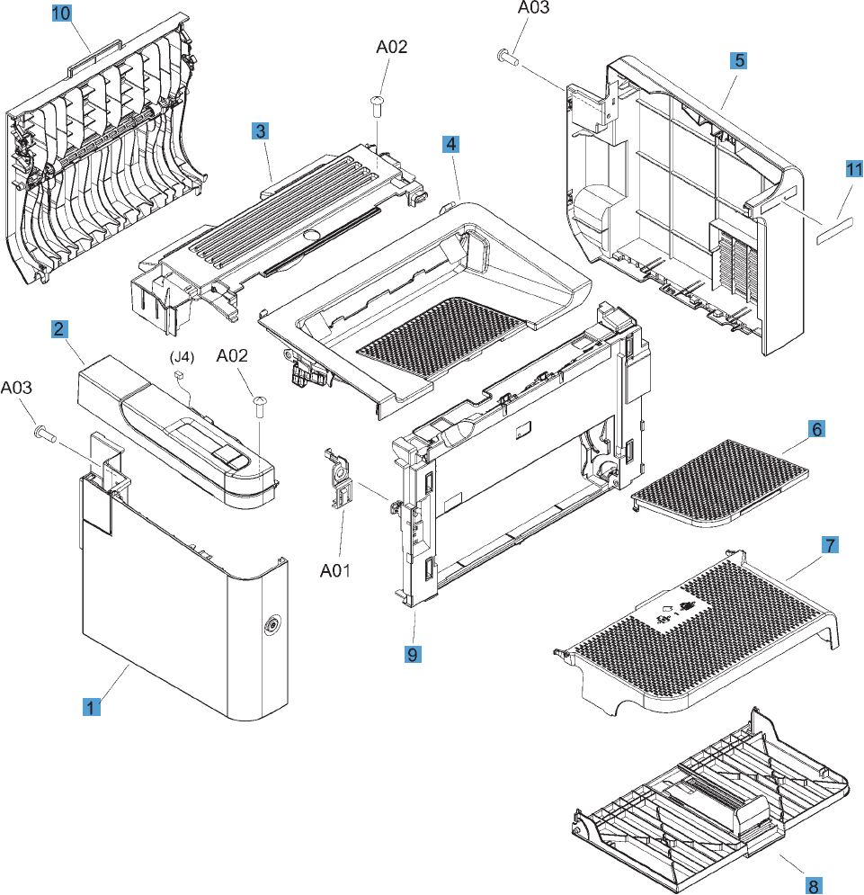
Duplex model
Figure 4-3 Duplex model
166 Chapter 4 Parts and diagrams ENWW

Table 4-8 Duplex model
Ref Description Part number Qty
1 Left cover RM1-7532-000CN 1
2 Control-panel assembly RM1-7529-000CN 1
3 Cover, face-down RC2-9436-000CN 1
4 Cartridge door RM1-7527-000CN 1
5 Cover, right RC2-9458-000CN 1
6 Paper delivery tray RM1-7498-000CN 1
7 Cover, dust RC2-9578-000CN 1
8 Paper pickup tray RM1-7534-000CN 1
9 Cover, front RL1-2870-000CN 1
10 Duplexing door assembly RM1-7526-000CN 1
11 Plate, name RC3-0622-000CN 1
ENWW Covers 167

Internal assemblies
Internal assemblies (1 of 3)
Figure 4-4 Internal assemblies (1 of 3)
168 Chapter 4 Parts and diagrams ENWW

Table 4-9 Internal assemblies (1 of 3)
Ref Description Part number Qty
1 Fuser assembly (110 V) RM1-7546-000CN 1
1 Fuser assembly (220 V) RM1-7547-000CN 1
2 Engine controller PCA (110 V) RM1-7615-000CN 1
2 Engine controller PCA (220 V) RM1-7616-000CN 1
3 Formatter PCA, simplex model RM1-7622-000CN 1
3 Formatter PCA, duplex model RM1-7623-000CN 1
4 Delivery sensor PCA assembly RM1-7440-000CN 1
5 Fuser film assembly (110 V) RM1-7541-000CN 1
5 Fuser film assembly (220 V) RM1-7542-000CN 1
6 Link, pressure release RC2-9512-000CN 2
7 Switch lever assembly RM1-7531-000CN 1
ENWW Internal assemblies 169
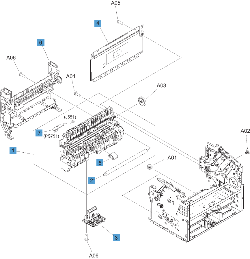
Internal assemblies (2 of 3)
Figure 4-5 Internal assemblies (2 of 3)
170 Chapter 4 Parts and diagrams ENWW

Table 4-10 Internal assemblies (2 of 3)
Ref Description Part number Qty
1 Paper pickup assembly, simplex model RM1-7517-000CN 1
1 Paper pickup assembly, duplex model RM1-7516-000CN 1
2 Transfer roller RM1-4023-000CN 1
3 Separation pad RM1-4227-000CN 1
4 Panel, rear, simplex model RC2-9583-000CN 1
5 Roller, pickup RL1-1497-000CN 1
6 Duplex frame assembly, duplex model RM1-7525-000CN 1
7 Paper pickup sensor PCA assembly RM1-7618-000CN 1
ENWW Internal assemblies 171
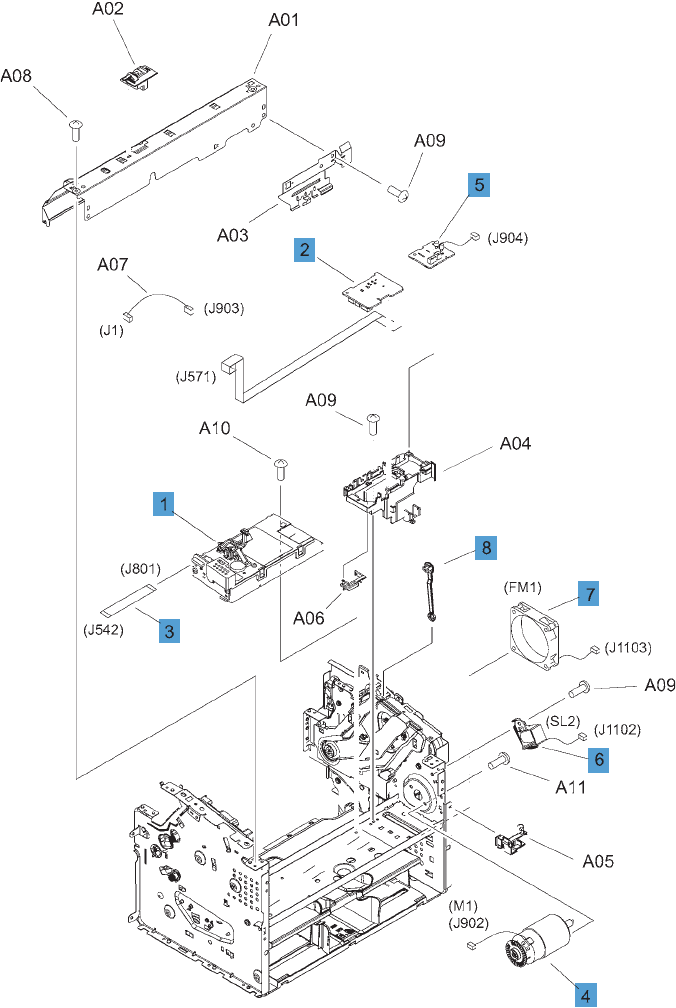
Internal assemblies (3 of 3)
Figure 4-6 Internal assemblies (3 of 3)
172 Chapter 4 Parts and diagrams ENWW

Table 4-11 Internal assemblies (3 of 3)
Ref Description Part number Qty
1 Laser/scanner assembly, simplex model RM1-7561-000CN 1
1 Laser/scanner assembly, duplex model RM1-7560-000CN 1
2 Motor PCA RM1-7619-000CN 1
3 Cable, flat RM1-7739-000CN 1
4 Motor, DC24V RM1-7544-000CN 1
5 Duplex PCA, duplex model RM1-7620-000CN 1
6 Solenoid, duplex model RK2-0420-000CN 1
7 Fan, duplex model RK2-3238-000CN 1
8 Link, cartridge door RC2-9425-000CN 1
ENWW Internal assemblies 173
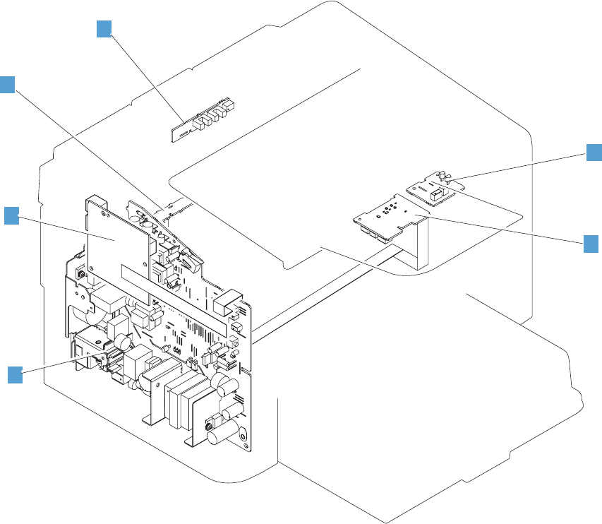
PCAs
Figure 4-7 PCAs
2
1
3
5
6
4
174 Chapter 4 Parts and diagrams ENWW

Table 4-12 PCAs
Ref Description Part number Qty
1 Engine controller PCA (110 V) RM1-7615-000CN 1
1 Engine controller PCA (220 V) RM1-7616-000CN 1
2 Formatter PCA, simplex model RM1-7622-000CN 1
2 Formatter PCA, duplex model RM1-7623-000CN 1
3 Motor, DC24V RM1-7502-000CN 1
4 Duplex PCA, duplex model RM1-7620-000CN 1
5 Delivery sensor PCA assembly RM1-7440-000CN 1
6 Paper pickup sensor PCA assembly RM1-7618-000CN 1
ENWW PCAs 175

Alphabetical parts list
Table 4-13 Alphabetical parts list
Description Part number Table and page
Cable, flat RM1-7739-000CN Internal assemblies (3 of 3)
on page 173
Cartridge door RM1-7528-000CN Simplex model on page 165
Cartridge door RM1-7527-000CN Duplex model on page 167
Control-panel assembly RM1-7530-000CN Simplex model on page 165
Control-panel assembly RM1-7529-000CN Duplex model on page 167
Cover, dust RC2-9582-000CN Simplex model on page 165
Cover, dust RC2-9578-000CN Duplex model on page 167
Cover, face-down RC2-9464-000CN Simplex model on page 165
Cover, face-down RC2-9436-000CN Duplex model on page 167
Cover, front RL1-2871-000CN Simplex model on page 165
Cover, front RL1-2870-000CN Duplex model on page 167
Cover, right RC2-9462-000CN Simplex model on page 165
Cover, right RC2-9458-000CN Duplex model on page 167
Delivery sensor PCA assembly RM1-7440-000CN Internal assemblies (1 of 3)
on page 169
Delivery sensor PCA assembly RM1-7440-000CN PCAs on page 175
Duplex frame assembly, duplex model RM1-7525-000CN Internal assemblies (2 of 3)
on page 171
Duplex PCA, duplex model RM1-7620-000CN Internal assemblies (3 of 3)
on page 173
Duplex PCA, duplex model RM1-7620-000CN PCAs on page 175
Duplexing door assembly RM1-7526-000CN Duplex model on page 167
Engine controller PCA (110 V) RM1-7615-000CN Internal assemblies (1 of 3)
on page 169
Engine controller PCA (110 V) RM1-7615-000CN PCAs on page 175
Engine controller PCA (220 V) RM1-7616-000CN Internal assemblies (1 of 3)
on page 169
Engine controller PCA (220 V) RM1-7616-000CN PCAs on page 175
Fan, duplex model RK2-3238-000CN Internal assemblies (3 of 3)
on page 173
Formatter PCA, duplex model RM1-7623-000CN Internal assemblies (1 of 3)
on page 169
Formatter PCA, duplex model RM1-7623-000CN PCAs on page 175
Formatter PCA, simplex model RM1-7622-000CN Internal assemblies (1 of 3)
on page 169
176 Chapter 4 Parts and diagrams ENWW

Description Part number Table and page
Formatter PCA, simplex model RM1-7622-000CN PCAs on page 175
Fuser assembly (110 V) RM1-7546-000CN Internal assemblies (1 of 3)
on page 169
Fuser assembly (220 V) RM1-7547-000CN Internal assemblies (1 of 3)
on page 169
Fuser film assembly (110 V) RM1-7541-000CN Internal assemblies (1 of 3)
on page 169
Fuser film assembly (220 V) RM1-7542-000CN Internal assemblies (1 of 3)
on page 169
Laser/scanner assembly, duplex model RM1-7560-000CN Internal assemblies (3 of 3)
on page 173
Laser/scanner assembly, simplex model RM1-7561-000CN Internal assemblies (3 of 3)
on page 173
Left cover RM1-7533-000CN Simplex model on page 165
Left cover RM1-7532-000CN Duplex model on page 167
Link, cartridge door RC2-9425-000CN Internal assemblies (3 of 3)
on page 173
Link, pressure release RC2-9512-000CN Internal assemblies (1 of 3)
on page 169
Motor PCA RM1-7619-000CN Internal assemblies (3 of 3)
on page 173
Motor, DC24V RM1-7544-000CN Internal assemblies (3 of 3)
on page 173
Motor, DC24V RM1-7502-000CN PCAs on page 175
Panel, rear, simplex model RC2-9583-000CN Internal assemblies (2 of 3)
on page 171
Paper delivery tray RM1-7499-000CN Simplex model on page 165
Paper delivery tray RM1-7498-000CN Duplex model on page 167
Paper pickup assembly, duplex model RM1-7516-000CN Internal assemblies (2 of 3)
on page 171
Paper pickup assembly, simplex model RM1-7517-000CN Internal assemblies (2 of 3)
on page 171
Paper pickup sensor PCA assembly RM1-7618-000CN Internal assemblies (2 of 3)
on page 171
Paper pickup sensor PCA assembly RM1-7618-000CN PCAs on page 175
Paper pickup tray RM1-7535-000CN Simplex model on page 165
Paper pickup tray RM1-7534-000CN Duplex model on page 167
Plate, name RC3-0623-000CN Simplex model on page 165
Plate, name RC3-0622-000CN Duplex model on page 167
Roller, pickup RL1-1497-000CN Internal assemblies (2 of 3)
on page 171
Table 4-13 Alphabetical parts list (continued)
ENWW Alphabetical parts list 177

Description Part number Table and page
Separation pad RM1-4227-000CN Internal assemblies (2 of 3)
on page 171
Solenoid, duplex model RK2-0420-000CN Internal assemblies (3 of 3)
on page 173
Switch lever assembly RM1-7531-000CN Internal assemblies (1 of 3)
on page 169
Transfer roller RM1-4023-000CN Internal assemblies (2 of 3)
on page 171
Table 4-13 Alphabetical parts list (continued)
178 Chapter 4 Parts and diagrams ENWW

Numerical parts list
Table 4-14 Numerical parts list
Part number Description Table and page
RC2-9425-000CN Link, cartridge door Internal assemblies (3 of 3)
on page 173
RC2-9436-000CN Cover, face-down Duplex model on page 167
RC2-9458-000CN Cover, right Duplex model on page 167
RC2-9462-000CN Cover, right Simplex model on page 165
RC2-9464-000CN Cover, face-down Simplex model on page 165
RC2-9512-000CN Link, pressure release Internal assemblies (1 of 3)
on page 169
RC2-9578-000CN Cover, dust Duplex model on page 167
RC2-9582-000CN Cover, dust Simplex model on page 165
RC2-9583-000CN Panel, rear, simplex model Internal assemblies (2 of 3)
on page 171
RC3-0622-000CN Plate, name Duplex model on page 167
RC3-0623-000CN Plate, name Simplex model on page 165
RK2-0420-000CN Solenoid, duplex model Internal assemblies (3 of 3)
on page 173
RK2-3238-000CN Fan, duplex model Internal assemblies (3 of 3)
on page 173
RL1-1497-000CN Roller, pickup Internal assemblies (2 of 3)
on page 171
RL1-2870-000CN Cover, front Duplex model on page 167
RL1-2871-000CN Cover, front Simplex model on page 165
RM1-4023-000CN Transfer roller Internal assemblies (2 of 3)
on page 171
RM1-4227-000CN Separation pad Internal assemblies (2 of 3)
on page 171
RM1-7440-000CN Delivery sensor PCA assembly Internal assemblies (1 of 3)
on page 169
RM1-7440-000CN Delivery sensor PCA assembly PCAs on page 175
RM1-7498-000CN Paper delivery tray Duplex model on page 167
RM1-7499-000CN Paper delivery tray Simplex model on page 165
RM1-7502-000CN Motor, DC24V PCAs on page 175
RM1-7516-000CN Paper pickup assembly, duplex model Internal assemblies (2 of 3)
on page 171
RM1-7517-000CN Paper pickup assembly, simplex model Internal assemblies (2 of 3)
on page 171
ENWW Numerical parts list 179

Part number Description Table and page
RM1-7525-000CN Duplex frame assembly, duplex model Internal assemblies (2 of 3)
on page 171
RM1-7526-000CN Duplexing door assembly Duplex model on page 167
RM1-7527-000CN Cartridge door Duplex model on page 167
RM1-7528-000CN Cartridge door Simplex model on page 165
RM1-7529-000CN Control-panel assembly Duplex model on page 167
RM1-7530-000CN Control-panel assembly Simplex model on page 165
RM1-7531-000CN Switch lever assembly Internal assemblies (1 of 3)
on page 169
RM1-7532-000CN Left cover Duplex model on page 167
RM1-7533-000CN Left cover Simplex model on page 165
RM1-7534-000CN Paper pickup tray Duplex model on page 167
RM1-7535-000CN Paper pickup tray Simplex model on page 165
RM1-7541-000CN Fuser film assembly (110 V) Internal assemblies (1 of 3)
on page 169
RM1-7542-000CN Fuser film assembly (220 V) Internal assemblies (1 of 3)
on page 169
RM1-7544-000CN Motor, DC24V Internal assemblies (3 of 3)
on page 173
RM1-7546-000CN Fuser assembly (110 V) Internal assemblies (1 of 3)
on page 169
RM1-7547-000CN Fuser assembly (220 V) Internal assemblies (1 of 3)
on page 169
RM1-7560-000CN Laser/scanner assembly, duplex model Internal assemblies (3 of 3)
on page 173
RM1-7561-000CN Laser/scanner assembly, simplex model Internal assemblies (3 of 3)
on page 173
RM1-7615-000CN Engine controller PCA (110 V) Internal assemblies (1 of 3)
on page 169
RM1-7615-000CN Engine controller PCA (110 V) PCAs on page 175
RM1-7616-000CN Engine controller PCA (220 V) Internal assemblies (1 of 3)
on page 169
RM1-7616-000CN Engine controller PCA (220 V) PCAs on page 175
RM1-7618-000CN Paper pickup sensor PCA assembly Internal assemblies (2 of 3)
on page 171
RM1-7618-000CN Paper pickup sensor PCA assembly PCAs on page 175
RM1-7619-000CN Motor PCA Internal assemblies (3 of 3)
on page 173
RM1-7620-000CN Duplex PCA, duplex model Internal assemblies (3 of 3)
on page 173
Table 4-14 Numerical parts list (continued)
180 Chapter 4 Parts and diagrams ENWW

Part number Description Table and page
RM1-7620-000CN Duplex PCA, duplex model PCAs on page 175
RM1-7622-000CN Formatter PCA, simplex model Internal assemblies (1 of 3)
on page 169
RM1-7622-000CN Formatter PCA, simplex model PCAs on page 175
RM1-7623-000CN Formatter PCA, duplex model Internal assemblies (1 of 3)
on page 169
RM1-7623-000CN Formatter PCA, duplex model PCAs on page 175
RM1-7739-000CN Cable, flat Internal assemblies (3 of 3)
on page 173
Table 4-14 Numerical parts list (continued)
ENWW Numerical parts list 181
182 Chapter 4 Parts and diagrams ENWW


Hewlett-Packard limited warranty statement
HP PRODUCT DURATION OF LIMITED WARRANTY
HP LaserJet Professional P1566, P1606dn One year from date of purchase
HP warrants to you, the end-user customer, that HP hardware and accessories will be free from defects
in materials and workmanship after the date of purchase, for the period specified above. If HP receives
notice of such defects during the warranty period, HP will, at its option, either repair or replace products
which prove to be defective. Replacement products may be either new or equivalent in performance to
new.
HP warrants to you that HP software will not fail to execute its programming instructions after the date
of purchase, for the period specified above, due to defects in material and workmanship when properly
installed and used. If HP receives notice of such defects during the warranty period, HP will replace
software which does not execute its programming instructions due to such defects.
HP does not warrant that the operation of HP products will be uninterrupted or error free. If HP is unable,
within a reasonable time, to repair or replace any product to a condition as warranted, you will be entitled
to a refund of the purchase price upon prompt return of the product.
HP products may contain remanufactured parts equivalent to new in performance or may have been
subject to incidental use.
Warranty does not apply to defects resulting from (a) improper or inadequate maintenance or calibration,
(b) software, interfacing, parts or supplies not supplied by HP, (c) unauthorized modification or misuse,
(d) operation outside of the published environmental specifications for the product, or (e) improper site
preparation or maintenance.
TO THE EXTENT ALLOWED BY LOCAL LAW, THE ABOVE WARRANTIES ARE EXCLUSIVE AND
NO OTHER WARRANTY OR CONDITION, WHETHER WRITTEN OR ORAL, IS EXPRESSED OR
IMPLIED AND HP SPECIFICALLY DISCLAIMS ANY IMPLIED WARRANTIES OR CONDITIONS OF
MERCHANTABILITY, SATISFACTORY QUALITY, AND FITNESS FOR A PARTICULAR PURPOSE.
Some countries/regions, states or provinces do not allow limitations on the duration of an implied
warranty, so the above limitation or exclusion might not apply to you. This warranty gives you specific
legal rights and you might also have other rights that vary from country/region to country/region, state
to state, or province to province.
HP's limited warranty is valid in any country/region or locality where HP has a support presence for this
product and where HP has marketed this product. The level of warranty service you receive may vary
according to local standards. HP will not alter form, fit or function of the product to make it operate in a
country/region for which it was never intended to function for legal or regulatory reasons.
TO THE EXTENT ALLOWED BY LOCAL LAW, THE REMEDIES IN THIS WARRANTY STATEMENT
ARE YOUR SOLE AND EXCLUSIVE REMEDIES. EXCEPT AS INDICATED ABOVE, IN NO EVENT
WILL HP OR ITS SUPPLIERS BE LIABLE FOR LOSS OF DATA OR FOR DIRECT, SPECIAL,
INCIDENTAL, CONSEQUENTIAL (INCLUDING LOST PROFIT OR DATA), OR OTHER DAMAGE,
WHETHER BASED IN CONTRACT, TORT, OR OTHERWISE. Some countries/regions, states or
provinces do not allow the exclusion or limitation of incidental or consequential damages, so the above
limitation or exclusion may not apply to you.
THE WARRANTY TERMS CONTAINED IN THIS STATEMENT, EXCEPT TO THE EXTENT
LAWFULLY PERMITTED, DO NOT EXCLUDE, RESTRICT OR MODIFY AND ARE IN ADDITION TO
THE MANDATORY STATUTORY RIGHTS APPLICABLE TO THE SALE OF THIS PRODUCT TO YOU.
184 Appendix A Service and support ENWW
HP's Premium Protection Warranty: LaserJet print
cartridge limited warranty statement
This HP product is warranted to be free from defects in materials and workmanship.
This warranty does not apply to products that (a) have been refilled, refurbished, remanufactured or
tampered with in any way, (b) experience problems resulting from misuse, improper storage, or
operation outside of the published environmental specifications for the printer product or (c) exhibit wear
from ordinary use.
To obtain warranty service, please return the product to place of purchase (with a written description of
the problem and print samples) or contact HP customer support. At HP's option, HP will either replace
products that prove to be defective or refund your purchase price.
TO THE EXTENT ALLOWED BY LOCAL LAW, THE ABOVE WARRANTY IS EXCLUSIVE AND NO
OTHER WARRANTY OR CONDITION, WHETHER WRITTEN OR ORAL, IS EXPRESSED OR
IMPLIED AND HP SPECIFICALLY DISCLAIMS ANY IMPLIED WARRANTIES OR CONDITIONS OF
MERCHANTABILITY, SATISFACTORY QUALITY, AND FITNESS FOR A PARTICULAR PURPOSE.
TO THE EXTENT ALLOWED BY LOCAL LAW, IN NO EVENT WILL HP OR ITS SUPPLIERS BE
LIABLE FOR DIRECT, SPECIAL, INCIDENTAL, CONSEQUENTIAL (INCLUDING LOST PROFIT OR
DATA), OR OTHER DAMAGE, WHETHER BASED IN CONTRACT, TORT, OR OTHERWISE.
THE WARRANTY TERMS CONTAINED IN THIS STATEMENT, EXCEPT TO THE EXTENT
LAWFULLY PERMITTED, DO NOT EXCLUDE, RESTRICT OR MODIFY AND ARE IN ADDITION TO
THE MANDATORY STATUTORY RIGHTS APPLICABLE TO THE SALE OF THIS PRODUCT TO YOU.
ENWW HP's Premium Protection Warranty: LaserJet print cartridge limited warranty statement 185
End User License Agreement
PLEASE READ CAREFULLY BEFORE USING THIS SOFTWARE PRODUCT: This End-User License
Agreement (“EULA”) is a contract between (a) you (either an individual or the entity you represent) and
(b) Hewlett-Packard Company (“HP”) that governs your use of the software product (“Software”). This
EULA does not apply if there is a separate license agreement between you and HP or its suppliers for
the Software, including a license agreement in online documentation. The term “Software” may include
(i) associated media, (ii) a user guide and other printed materials, and (iii) “online” or electronic
documentation (collectively “User Documentation”).
RIGHTS IN THE SOFTWARE ARE OFFERED ONLY ON THE CONDITION THAT YOU AGREE TO
ALL TERMS AND CONDITIONS OF THIS EULA. BY INSTALLING, COPYING, DOWNLOADING, OR
OTHERWISE USING THE SOFTWARE, YOU AGREE TO BE BOUND BY THIS EULA. IF YOU DO
NOT ACCEPT THIS EULA, DO NOT INSTALL, DOWNLOAD, OR OTHERWISE USE THE
SOFTWARE. IF YOU PURCHASED THE SOFTWARE BUT DO NOT AGREE TO THIS EULA, PLEASE
RETURN THE SOFTWARE TO YOUR PLACE OF PURCHASE WITHIN FOURTEEN DAYS FOR A
REFUND OF THE PURCHASE PRICE; IF THE SOFTWARE IS INSTALLED ON OR MADE
AVAILABLE WITH ANOTHER HP PRODUCT, YOU MAY RETURN THE ENTIRE UNUSED
PRODUCT.
1. THIRD PARTY SOFTWARE. The Software may include, in addition to HP proprietary software
(“HP Software”), software under licenses from third parties (“Third Party Software” and “Third Party
License”). Any Third Party Software is licensed to you subject to the terms and conditions of the
corresponding Third Party License. Generally, the Third Party License is located in a file such as
license.txt; you should contact HP support if you cannot find any Third Party License. If the Third Party
Licenses include licenses that provide for the availability of source code (such as the GNU General
Public License) and the corresponding source code is not included with the Software, then check the
product support pages of HP’s website (hp.com) to learn how to obtain such source code.
2. LICENSE RIGHTS. You will have the following rights provided you comply with all terms and
conditions of this EULA:
a. Use. HP grants you a license to Use one copy of the HP Software. “Use” means installing, copying,
storing, loading, executing, displaying, or otherwise using the HP Software. You may not modify the
HP Software or disable any licensing or control feature of the HP Software. If this Software is provided
by HP for Use with an imaging or printing product (for example, if the Software is a printer driver,
firmware, or add-on), the HP Software may only be used with such product (“HP Product”). Additional
restrictions on Use may appear in the User Documentation. You may not separate component parts of
the HP Software for Use. You do not have the right to distribute the HP Software.
b. Copying. Your right to copy means you may make archival or back-up copies of the HP Software,
provided each copy contains all the original HP Software’s proprietary notices and is used only for back-
up purposes.
3. UPGRADES. To Use HP Software provided by HP as an upgrade, update, or supplement (collectively
“Upgrade”), you must first be licensed for the original HP Software identified by HP as eligible for the
Upgrade. To the extent the Upgrade supersedes the original HP Software, you may no longer use such
HP Software. This EULA applies to each Upgrade unless HP provides other terms with the Upgrade. In
case of a conflict between this EULA and such other terms, the other terms will prevail.
4. TRANSFER.
a. Third Party Transfer. The initial end user of the HP Software may make a one-time transfer of the
HP Software to another end user. Any transfer will include all component parts, media, User
Documentation, this EULA, and if applicable, the Certificate of Authenticity. The transfer may not be an
indirect transfer, such as a consignment. Prior to the transfer, the end user receiving the transferred
186 Appendix A Service and support ENWW
Software will agree to this EULA. Upon transfer of the HP Software, your license is automatically
terminated.
b. Restrictions. You may not rent, lease or lend the HP Software or Use the HP Software for commercial
timesharing or bureau use. You may not sublicense, assign or otherwise transfer the HP Software except
as expressly provided in this EULA.
5. PROPRIETARY RIGHTS. All intellectual property rights in the Software and User Documentation are
owned by HP or its suppliers and are protected by law, including applicable copyright, trade secret,
patent, and trademark laws. You will not remove any product identification, copyright notice, or
proprietary restriction from the Software.
6. LIMITATION ON REVERSE ENGINEERING. You may not reverse engineer, decompile, or
disassemble the HP Software, except and only to the extent that the right to do so is allowed under
applicable law.
7. CONSENT TO USE OF DATA. HP and its affiliates may collect and use technical information you
provide in relation to (i) your Use of the Software or the HP Product, or (ii) the provision of support
services related to the Software or the HP Product. All such information will be subject to HP’s privacy
policy. HP will not use such information in a form that personally identifies you except to the extent
necessary to enhance your Use or provide support services.
8. LIMITATION OF LIABILITY. Notwithstanding any damages that you might incur, the entire liability of
HP and its suppliers under this EULA and your exclusive remedy under this EULA will be limited to the
greater of the amount actually paid by you for the Product or U.S. $5.00. TO THE MAXIMUM EXTENT
PERMITTED BY APPLICABLE LAW, IN NO EVENT WILL HP OR ITS SUPPLIERS BE LIABLE FOR
ANY SPECIAL, INCIDENTAL, INDIRECT, OR CONSEQUENTIAL DAMAGES (INCLUDING
DAMAGES FOR LOST PROFITS, LOST DATA, BUSINESS INTERRUPTION, PERSONAL INJURY,
OR LOSS OF PRIVACY) RELATED IN ANY WAY TO THE USE OF OR INABILITY TO USE THE
SOFTWARE, EVEN IF HP OR ANY SUPPLIER HAS BEEN ADVISED OF THE POSSIBILITY OF SUCH
DAMAGES AND EVEN IF THE ABOVE REMEDY FAILS OF ITS ESSENTIAL PURPOSE. Some states
or other jurisdictions do not allow the exclusion or limitation of incidental or consequential damages, so
the above limitation or exclusion may not apply to you.
9. U.S. GOVERNMENT CUSTOMERS. If you are a U.S. Government entity, then consistent with FAR
12.211 and FAR 12.212, Commercial Computer Software, Computer Software Documentation, and
Technical Data for Commercial Items are licensed under the applicable HP commercial license
agreement.
10. COMPLIANCE WITH EXPORT LAWS. You will comply with all laws, rules, and regulations (i)
applicable to the export or import of the Software, or (ii) restricting the Use of the Software, including
any restrictions on nuclear, chemical, or biological weapons proliferation.
11. RESERVATION OF RIGHTS. HP and its suppliers reserve all rights not expressly granted to you
in this EULA.
(c) 2007 Hewlett-Packard Development Company, L.P.
Rev. 11/06
ENWW End User License Agreement 187

Customer self-repair warranty service
HP products are designed with many Customer Self Repair (CSR) parts to minimize repair time and
allow for greater flexibility in performing defective parts replacement. If during the diagnosis period, HP
identifies that the repair can be accomplished by the use of a CSR part, HP will ship that part directly to
you for replacement. There are two categories of CSR parts: 1) Parts for which customer self repair is
mandatory. If you request HP to replace these parts, you will be charged for the travel and labor costs
of this service. 2) Parts for which customer self repair is optional. These parts are also designed for
Customer Self Repair. If, however, you require that HP replace them for you, this may be done at no
additional charge under the type of warranty service designated for your product.
Based on availability and where geography permits, CSR parts will be shipped for next business day
delivery. Same-day or four-hour delivery may be offered at an additional charge where geography
permits. If assistance is required, you can call the HP Technical Support Center and a technician will
help you over the phone. HP specifies in the materials shipped with a replacement CSR part whether
a defective part must be returned to HP. In cases where it is required to return the defective part to HP,
you must ship the defective part back to HP within a defined period of time, normally five (5) business
days. The defective part must be returned with the associated documentation in the provided shipping
material. Failure to return the defective part may result in HP billing you for the replacement. With a
customer self repair, HP will pay all shipping and part return costs and determine the courier/carrier to
be used.
Customer support
Get telephone support for your country/region
Have the product name, serial number, date of purchase, and
problem description ready.
Country/region phone numbers are on the flyer that was in the
box with your product or at www.hp.com/support/.
Get 24-hour Internet support www.hp.com/support/ljp1560series or www.hp.com/support/
ljp1600series
Get support for products used with a Macintosh computer www.hp.com/go/macosx
Download software utilities, drivers, and electronic information www.hp.com/go/ljp1560series or www.hp.com/go/
ljp1600series
Order additional HP service or maintenance agreements www.hp.com/go/carepack
188 Appendix A Service and support ENWW

Repack the product
If HP Customer Care determines that your product needs to be returned to HP for repair, follow these
steps to repack the product before shipping it.
CAUTION: Shipping damage as a result of inadequate packing is the customer’s responsibility.
1. Remove and retain the print cartridge.
CAUTION: It is extremely important to remove the print cartridge before shipping the product. A
print cartridge that remains in the product during shipping can leak and cover the product engine
and other parts with toner.
To prevent damage to the print cartridge, avoid touching the roller on it, and store the print cartridge
in its original packing material or so that it is not exposed to light.
2. Remove and retain the power cable, interface cable, and optional accessories, such as an EIO
card.
3. If possible, include print samples and 50 to 100 sheets of paper or other print media that did not
print correctly.
4. In the U.S., call HP Customer Care to request new packing material. In other areas, use the original
packing material, if possible. Hewlett-Packard recommends insuring the equipment for shipment.
ENWW Repack the product 189

Service information form
WHO IS RETURNING THE EQUIPMENT? Date:
Person to contact: Phone:
Alternate contact: Phone:
Return shipping address:
Special shipping instructions:
WHAT ARE YOU SENDING?
Model name: Model number: Serial number:
Please attach any relevant printouts. Do NOT ship accessories (manuals, cleaning supplies, and so on) that are not required to complete
the repair.
HAVE YOU REMOVED THE PRINT CARTRIDGES?
You must remove them before shipping the product, unless a mechanical problem prevents you from doing so.
[ ] Yes. [ ] No, I cannot remove them.
WHAT NEEDS TO BE DONE? (Attach a separate sheet if necessary.)
1. Describe the conditions of the failure. (What was the failure? What were you doing when the failure occurred? What software were you
running? Is the failure repeatable?)
2. If the failure is intermittent, how much time elapses between failures?
3. If the unit connected to any of the following, give the manufacturer and model number.
Personal computer: Modem: Network:
4. Additional comments:
HOW WILL YOU PAY FOR THE REPAIR?
[ ] Under warranty Purchase/received date:
(Attach proof of purchase or receiving document with original received date.)
[ ] Maintenance contract number:
[ ] Purchase order number:
Except for contract and warranty service, a purchase order number and/or authorized signature must accompany any request for
service. If standard repair prices do not apply, a minimum purchase order is required. Standard repair prices can be obtained by contacting
an HP-authorized repair center.
Authorized signature: Phone:
Billing address:
Special billing instructions:
190 Appendix A Service and support ENWW


Physical specifications
Table B-1 Physical specifications
1
Specification HP LaserJet Professional P1560
Printer series series
HP LaserJet Professional P1600
Printer series series
Product weight 5.9 kg (13.0 lb) 6.5 kg (14.3 lb)
Product height 245 mm (9.65 in) 245 mm (9.65 in)
Product depth minimum 239 mm (9.41 in) 280 mm (11.02 in)
Product depth maximum 369 mm (14.53 in) 410 mm (16.14 in)
Product width 382 mm (15.04 in) 382 mm (15.04 in)
1Values are based on preliminary data. See www.hp.com/support/ljp1560series or www.hp.com/support/ljp1600series.
Power consumption
Table B-2 HP LaserJet Professional P1560 and P1600 Printer series (average in watts)
123
Product Printing Ready HP Auto Off Manual Off
HP LaserJet Professional P1560
Printer series
45
420 1.2 0.9 0.5
HP LaserJet Professional P1600
Printer series
45
440 2.2 1.6 0.4
1Values are based on preliminary data. See www.hp.com/go/ljp1560_regulatory or www.hp.com/go/ljp1600_regulatory for
current information.
2Power reported is highest values measured for all product models using all standard voltages.
3Default time from Ready Mode to HP Auto Off = 5 minutes
4Typical Electricity Consumption (TEC) = 0.668 kWh/week (HP LaserJet Professional P1560 Printer series); 0.895 kWh/week
(HP LaserJet Professional P1600 Printer series)
5Maximum heat dissipation for all models in Ready Mode = 5 BTU/Hour (HP LaserJet Professional P1560 Printer series); 8
BTU/Hour (HP LaserJet Professional P1600 Printer series)
Acoustic specifications
Table B-3 HP LaserJet Professional P1560 and P1600 Printer series
12
Sound power level Declared per ISO 9296
Printing ●HP LaserJet Professional P1560 Printer series
◦LWAd= 6.4 Bels (A) [64 dB(A)]
●HP LaserJet Professional P1600 Printer series
◦LWAd= 6.6 Bels (A) [66 dB(A)]
Ready ●HP LaserJet Professional P1560 Printer series
◦Inaudible
●HP LaserJet Professional P1600 Printer series
◦Inaudible
192 Appendix B Specifications ENWW

Sound power level Declared per ISO 9296
Sound pressure level - bystander position Declared per ISO 9296
Printing ●HP LaserJet Professional P1560 Printer series
◦LpAm=53 dB (A)
●HP LaserJet Professional P1600 Printer series
◦LpAm=53 dB (A)
Ready ●HP LaserJet Professional P1560 Printer series
◦Inaudible
●HP LaserJet Professional P1600 Printer series
◦Inaudible
1Values are based on preliminary data. See www.hp.com/go/ljp1560_regulatory or www.hp.com/go/ljp1600_regulatory for
current information.
2Configuration tested: HP LaserJet P1566 product printing on A4-size paper in simplex mode; HP LaserJet P1606dn product
printing on A4-size paper in simplex mode
Environmental specifications
Table B-4 Environmental specifications
Operating
1
Storage
1
Temperature 10° to 32.5°C (50° to 91°F) 0° to 35°C (32° to 95°F)
Relative Humidity 10% to 80% 10% to 80%
1Values are based on preliminary data. See www.hp.com/support/ljp1560series or www.hp.com/support/ljp1600series.
Table B-3 HP LaserJet Professional P1560 and P1600 Printer series
12
(continued)
ENWW Environmental specifications 193
194 Appendix B Specifications ENWW


FCC regulations
This equipment has been tested and found to comply with the limits for a Class B digital device, pursuant
to Part 15 of the FCC rules. These limits are designed to provide reasonable protection against harmful
interference in a residential installation. This equipment generates, uses, and can radiate radio
frequency energy. If this equipment is not installed and used in accordance with the instructions, it may
cause harmful interference to radio communications. However, there is no guarantee that interference
will not occur in a particular installation. If this equipment does cause harmful interference to radio or
television reception, which can be determined by turning the equipment off and on, the user is
encouraged to try to correct the interference by one or more of the following measures:
●Reorient or relocate the receiving antenna.
●Increase separation between equipment and receiver.
●Connect equipment to an outlet on a circuit different from that to which the receiver is located.
●Consult your dealer or an experienced radio/TV technician.
NOTE: Any changes or modifications to the printer that are not expressly approved by HP could void
the user’s authority to operate this equipment.
Use of a shielded interface cable is required to comply with the Class B limits of Part 15 of FCC rules.
196 Appendix C Regulatory information ENWW

Declaration of conformity
according to ISO/IEC 17050-1 and EN 17050-1; DoC#: BOISB-0902-00-rel. 1.0
Manufacturer’s Name: Hewlett-Packard Company
Manufacturer's Address: 11311 Chinden Boulevard,
Boise, Idaho 83714-1021, USA
declares, that the product
Product Name: HP LaserJet Professional P1566/P1606 Printer series
Regulatory Model:2) BOISB-0902-00
Product Options: All
Toner Cartridges: CE278A
conforms to the following Product Specifications:
SAFETY: IEC 60950-1:2001 / EN60950-1: 2001 +A11
IEC 60825-1:1993 +A1 +A2 / EN 60825-1:1994 +A1 +A2 (Class 1 Laser/LED Product)
GB4943-2001
EMC: CISPR22:2005 +A1:2005 / EN55022:2006 +A1:2007 - Class B1)
EN 61000-3-2:2006
EN 61000-3-3:1995 +A1 +A2
EN 55024:1998 +A1 +A2
FCC Title 47 CFR, Part 15 Class B / ICES-003, Issue 4
GB9254-1998, GB17625.1-2003
Supplementary Information:
The product herewith complies with the requirements of the EMC Directive 2004/108/EC and the Low Voltage Directive 2006/95/EC, and
carries the CE-Marking accordingly.
This Device complies with Part 15 of the FCC Rules. Operation is subject to the following two Conditions: (1) this device may not cause
harmful interference, and (2) this device must accept any interference received, including interference that may cause undesired operation.
1) The product was tested in a typical configuration with Hewlett-Packard Personal Computer Systems.
2) For regulatory purposes, these products are assigned a Regulatory model number. This number should not be confused with the product
name or the product number(s).
Boise, Idaho 83713, USA
March 2010
For Regulatory Topics Only:
European Contact Your Local Hewlett-Packard Sales and Service Office or Hewlett-Packard Gmbh, Department HQ-TRE / Standards
Europe, Herrenberger Straße 140, D-71034 Böblingen, Germany, (FAX: +49-7031-14-3143), http://www.hp.com/go/
certificates
USA Contact Product Regulations Manager, Hewlett-Packard Company, PO Box 15, Mail Stop 160, Boise, ID 83707-0015, USA,
(Phone: 208-396-6000)
ENWW Declaration of conformity 197

Certificate of Volatility
Hewlett-Packard Certificate of Volatility
Model: Part Number: Address: 11311 Chinden Blvd. Boise, ID. 83714
LJ P1566 CE663A
Volatile Memory
Does the device contain volatile memory (Memory whose contents are lost when power is removed)?
Yes No If Yes please describe the type, size, function, and steps to clear the memory below
:yromem raelc ot spetS :noitcnuF :eziS :)cte ,MARD ,MARS( epyT
Synchronous DRAM 8MB Run-time firmware image, print
job info during printing
Power off printer
:yromem raelc ot spetS :noitcnuF :eziS :)cte ,MARD ,MARS( epyT
:yromem raelc ot spetS :noitcnuF :eziS :)cte ,MARD ,MARS( epyT
Non-Volatile Memory
Does the device contain non-volatile memory (Memory whose contents are retained when power is removed)?
Yes No If Yes please describe the type, size, function, and steps to clear the memory below
:yromem raelc ot spetS :noitcnuF :eziS :)cte ,MORPEE ,hsalF( epyT
EEPROM 2KB Printer Specific Data User cannot, service tools can.
:yromem raelc ot spetS :noitcnuF :eziS :)cte ,MORPEE ,hsalF( epyT
NAND Flash 64MB Printer Driver and Firmware User cannot, service tools can.
:yromem raelc ot spetS :noitcnuF :eziS :)cte ,MORPEE ,hsalF( epyT
Mass Storage
Does the device contain mass storage memory (Hard Disk Drive, Tape Backup)?
Yes No If Yes please describe the type, size, function, and steps to clear the memory below
:yromem raelc ot spetS :noitcnuF :eziS :)cte ,epaT ,DDH( epyT
:yromem raelc ot spetS :noitcnuF :eziS :)cte ,epaT ,DDH( epyT
Author Information
:tinU ssenisuB :liamE :eltiT :emaN
Technical Marketing
Engineer
LaserJet Business
Date Prepared:
08/28/2009
198 Appendix C Regulatory information ENWW

Hewlett-Packard Certificate of Volatility
Model: Part Number: Address: 11311 Chinden Blvd. Boise, ID. 83714
LJ P1606 CE749A
Volatile Memory
Does the device contain volatile memory (Memory whose contents are lost when power is removed)?
Yes No If Yes please describe the type, size, function, and steps to clear the memory below
:yromem raelc ot spetS :noitcnuF :eziS :)cte ,MARD ,MARS( epyT
Synchronous DRAM 32MB Run-time firmware image, print
job info during printing
Power off printer
:yromem raelc ot spetS :noitcnuF :eziS :)cte ,MARD ,MARS( epyT
:yromem raelc ot spetS :noitcnuF :eziS :)cte ,MARD ,MARS( epyT
Non-Volatile Memory
Does the device contain non-volatile memory (Memory whose contents are retained when power is removed)?
Yes No If Yes please describe the type, size, function, and steps to clear the memory below
:yromem raelc ot spetS :noitcnuF :eziS :)cte ,MORPEE ,hsalF( epyT
EEPROM 8KB Printer Specific Data User cannot, service tools can.
:yromem raelc ot spetS :noitcnuF :eziS :)cte ,MORPEE ,hsalF( epyT
NAND Flash 64MB Printer Driver and Firmware User cannot, service tools can.
:yromem raelc ot spetS :noitcnuF :eziS :)cte ,MORPEE ,hsalF( epyT
Mass Storage
Does the device contain mass storage memory (Hard Disk Drive, Tape Backup)?
Yes No If Yes please describe the type, size, function, and steps to clear the memory below
:yromem raelc ot spetS :noitcnuF :eziS :)cte ,epaT ,DDH( epyT
:yromem raelc ot spetS :noitcnuF :eziS :)cte ,epaT ,DDH( epyT
Author Information
:tinU ssenisuB :liamE :eltiT :emaN
Technical Marketing
Engineer
LaserJet Business
Date Prepared:
08/28/2009
ENWW Certificate of Volatility 199

Safety statements
Laser safety
The Center for Devices and Radiological Health (CDRH) of the U.S. Food and Drug Administration has
implemented regulations for laser products manufactured since August 1, 1976. Compliance is
mandatory for products marketed in the United States. The device is certified as a “Class 1” laser product
under the U.S. Department of Health and Human Services (DHHS) Radiation Performance Standard
according to the Radiation Control for Health and Safety Act of 1968. Since radiation emitted inside the
device is completely confined within protective housings and external covers, the laser beam cannot
escape during any phase of normal user operation.
WARNING! Using controls, making adjustments, or performing procedures other than those specified
in this user guide may result in exposure to hazardous radiation.
Canadian DOC regulations
Complies with Canadian EMC Class B requirements.
« Conforme à la classe B des normes canadiennes de compatibilité électromagnétiques. « CEM ». »
VCCI statement (Japan)
Power cord instructions
Make sure your power source is adequate for the product voltage rating. The voltage rating is on the
product label. The product uses either 110-127 Vac or 220-240 Vac and 50/60 Hz.
Connect the power cord between the product and a grounded AC outlet.
CAUTION: To prevent damage to the product, use only the power cord that is provided with the
product.
Power cord statement (Japan)
EMC statement (Korea)
200 Appendix C Regulatory information ENWW
Laser statement for Finland
Luokan 1 laserlaite
Klass 1 Laser Apparat
HP LaserJet Professional P1566, P1606dn, laserkirjoitin on käyttäjän kannalta turvallinen luokan 1
laserlaite. Normaalissa käytössä kirjoittimen suojakotelointi estää lasersäteen pääsyn laitteen
ulkopuolelle. Laitteen turvallisuusluokka on määritetty standardin EN 60825-1 (1994) mukaisesti.
VAROITUS !
Laitteen käyttäminen muulla kuin käyttöohjeessa mainitulla tavalla saattaa altistaa käyttäjän
turvallisuusluokan 1 ylittävälle näkymättömälle lasersäteilylle.
VARNING !
Om apparaten används på annat sätt än i bruksanvisning specificerats, kan användaren utsättas för
osynlig laserstrålning, som överskrider gränsen för laserklass 1.
HUOLTO
HP LaserJet Professional P1566, P1606dn - kirjoittimen sisällä ei ole käyttäjän huollettavissa olevia
kohteita. Laitteen saa avata ja huoltaa ainoastaan sen huoltamiseen koulutettu henkilö. Tällaiseksi
huoltotoimenpiteeksi ei katsota väriainekasetin vaihtamista, paperiradan puhdistusta tai muita käyttäjän
käsikirjassa lueteltuja, käyttäjän tehtäväksi tarkoitettuja ylläpitotoimia, jotka voidaan suorittaa ilman
erikoistyökaluja.
VARO !
Mikäli kirjoittimen suojakotelo avataan, olet alttiina näkymättömällelasersäteilylle laitteen ollessa
toiminnassa. Älä katso säteeseen.
VARNING !
Om laserprinterns skyddshölje öppnas då apparaten är i funktion, utsättas användaren för osynlig
laserstrålning. Betrakta ej strålen. Tiedot laitteessa käytettävän laserdiodin säteilyominaisuuksista:
Aallonpituus 775-795 nm Teho 5 m W Luokan 3B laser.
GS statement (Germany)
Das Gerät ist nicht für die Benutzung im unmittelbaren Gesichtsfeld am Bildschirmarbeitsplatz
vorgesehen. Um störende Reflexionen am Bildschirmarbeitsplatz zu vermeiden, darf dieses Produkt
nicht im unmittelbaren Gesichtsfeld platziert werden.
ENWW Safety statements 201
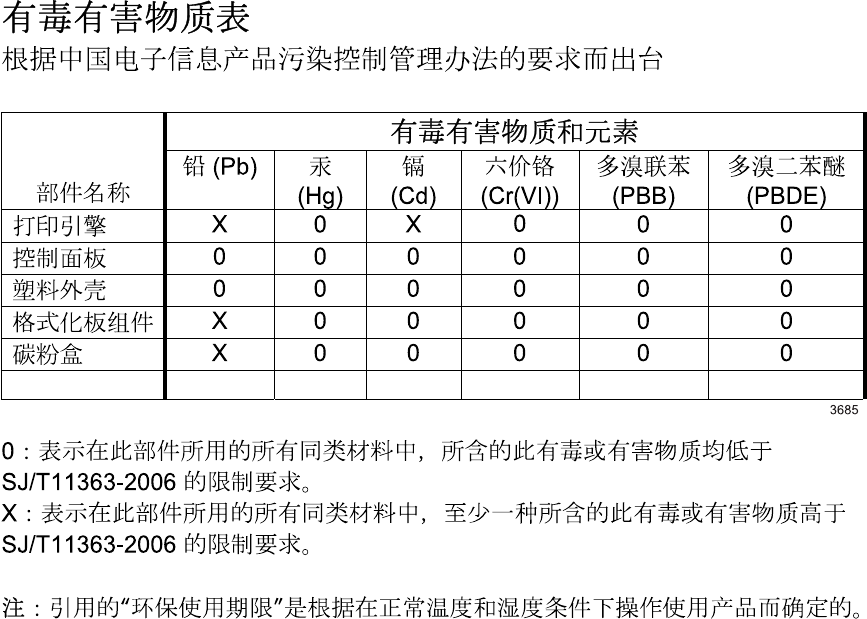
Substances Table (China)
Restriction on Hazardous Substances statement (Turkey)
Türkiye Cumhuriyeti: EEE Yönetmeliğine Uygundur
202 Appendix C Regulatory information ENWW

Index
A
accessories
ordering 160
acoustic specifications 192
after-service checklist 38
altitude specifications 193
B
bin, output
jams, clearing 138
blank pages
troubleshooting 155
C
cables
USB, troubleshooting 155
Canadian DOC regulations 200
cartridge
ordering xi
part number xi
cartridges
drum rotation check 119
warranty 185
cautions iii
certificate of volatility 198
checklists
after-service 38
preservice 37
problem source 116
checks
drum rotation 119
half self-test 119
clean
pickup roller 150
cleaning
exterior 154
paper path 144
product 144
clearing jams
locations 133
configuration page 127
control panel
status-light patterns 128
conventions, document iii
crooked pages 143
customer support
online 131
repacking product 189
service information form 190
D
declaration of conformity 197
Demo page 115
developing stage 28
document conventions iii
drum
rotation functional check 119
drum cleaning stage 30
E
electrostatic discharge (ESD) 37
engine test
test, engine 118
engine-control system 7
environment specifications 193
ESD (electrostatic discharge) 37
F
feeding problems, solving 143
Finnish laser safety
statement 201
firmware updates 158
fusing stage 29
H
half self-test check 119
HP Customer Care 131
humidity specifications 193
I
image quality
problem-solving 144
image-formation system
testing 119
improve print quality 144
information pages
configuration page 127
J
jams
common causes of 133
locations 133
output-bin, clearing 138
preventing 141
trays, clearing 134
Japanese VCCI statement 200
K
Korean EMC statement 200
L
laser beam exposure stage 27
laser safety statements 200, 201
laser/scanner
operations 22
license, software 186
light patterns 128
location
assemblies (base product) xi
M
Macintosh
support 188
N
noise specifications 192
notes iii
ENWW Index 203
O
online support 131
operating environment
specifications 193
operations
engine-control system 7
laser/scanner 22
ordering
print cartridge xi
product documents xi
supplies and accessories 160
whole-unit replacement xi
output quality. See print quality
P
packaging product 189
pages
blank 155
not printing 155
printing slowly 155
pages, skewed 143
paper handling
problem-solving 143
paper input trays
feeding problems, solving 143
paper jams. See jams
paper path, cleaning 144
part number
print cartridge xi
whole-unit replacement xi
parts
assemblies (base product) xi
photosensitive drum
rotation functional checks 119
physical specifications 192
pickup roller
clean 150
pliers, required 37
post-service tests 38
power
troubleshooting 114
preservice checklist 37
primary charging stage 27
print cartridge
ordering xi
part number xi
print cartridges
warranty 185
print density 149
print quality
creases 147
curl 147
dropouts 145
gray background 145
improve 144
light or faded print 144
loose toner 146
misformed characters 146
moisture on trailing edge 148
page skew 147
steam or vapor from the
product 148
test 38
toner scatter outline 148
toner smear 146
toner specks 144
vertical lines 145
vertical repetitive defects 146
wave 147
wrinkles 147
printing
configuration page 127
troubleshooting 155
priority input tray
jams, clearing 134
problem-solving
output quality 144
paper handling 143
status-light patterns 128
Q
quality. See image quality
R
removing parts
cautions for 36
checklists 37
tools, required 37
repacking product 189
replacing
parts 36
resolution
problem-solving quality 144
rotation check, drum 119
S
safety statements 200, 201
screwdrivers, required 37
screws
replacing 36
separation stage 29
service
information form 190
repacking product 189
tools, required 37
shipping product 189
size specifications, product 192
skewed pages 143
software
software license
agreement 186
solving
creases 147
curl 147
direct-connect problems 156
dropouts 145
feeding problems 143
gray background 145
light or faded print 144
loose toner 146
misformed characters 146
moisture on trailing edge 148
network problems 156
page skew 147
skewed pages 143
steam or vapor from the
product 148
toner scatter outline 148
toner smear 146
toner specks 144
vertical lines 145
vertical repetitive defects 146
wave 147
wrinkles 147
specifications
acoustic 192
environment 193
physical 192
static precautions 37
status-light patterns 128
storing
product 193
supplies
ordering 160
support
online 131
repacking product 189
service information form 190
204 Index ENWW
T
technical support
online 131
repacking product 189
service information form 190
temperature specifications 193
tests
drum rotation 119
half self-test check 119
post-service 38
print-quality 38
tips iii
toner
loose toner 146
low 144
scatter outline 148
smear 146
specks 144
toner cartridges. See print
cartridges
tools, required 37
transfer stage 29
tray 1
jams, clearing 134
trays
jams, clearing 134
troubleshooting
basic steps 114
blank pages 155
checklist 114
Demo page 115
direct-connect problems 156
drum rotation check 119
half self-test 119
image formation 119
network problems 156
pages not printing 155
pages printing slowly 155
power 114
problem source 116
USB cables 155
U
USB port
troubleshooting 155
W
warnings iii
warranty
customer self repair 188
license 186
print cartridges 185
product 184
Web sites
customer support 131
Macintosh customer
support 188
ENWW Index 205
206 Index ENWW

© 2010 Hewlett-Packard Development Company, L.P.
www.hp.com
*CE663-90939*
*CE663-90939*
CE663-90939
