HP Color LaserJet CM3530 MFP Series Service Manual ENWW
HP Color LaserJet CM3530 MFP HP Color LaserJet CM3530 MFP shared.swissparts.ch - /Manuals/HP/LaserJet/Color Laserjet/
hp_color_laserjet_cm3530_mfp_series_service_manual Multi-functional printer HP Color LaserJet CM3530 MFP - Service manuals and Schematics, Disassembly / Assembly. Free.
User Manual: HP Laserjet CM3530 shared.swissparts.ch - /Manuals/HP/LaserJet/Mono Laserjet/
Open the PDF directly: View PDF ![]() .
.
Page Count: 630 [warning: Documents this large are best viewed by clicking the View PDF Link!]
- Product basics
- Control panel
- Paper and print media
- Manage and maintain
- Print information pages
- HP Easy Printer Care
- Embedded Web server
- Use HP Web Jetadmin software
- Product security features
- Manage supplies
- Clean the product
- Product updates
- Theory of operation
- Basic operation
- Engine-control system
- Laser/scanner system
- Image-formation system
- Pickup, feed, and delivery system
- Jam detection
- Optional paper feeder
- Scanning/image capture system system
- Removal and replacement
- Introduction
- Removal and replacement strategy
- Electrostatic discharge
- Required tools
- Before performing service
- After performing service
- Post-service test
- DC controller PCA
- Parts removal order
- Customer self repair (CSR) components
- Print cartridges
- Stapler cartridge
- Duplex-reverse guide
- Toner-collection unit
- Formatter PCA
- Memory DIMM
- Hard drive and Serial Advanced Technology Attachment (SATA) cable
- Fax PCA and cable
- Tray cassette
- Fuser
- Pickup roller (Tray 2)
- Pickup and feed rollers (Tray 3)
- Separation roller (Tray 2)
- Secondary transfer roller
- Secondary transfer assembly
- Intermediate transfer belt (ITB)
- Front-door assembly
- Automatic document feeder (ADF)
- ADF roller assembly and separation pad
- Control-panel overlay
- Control-panel assembly
- Right door (optional paper feeder)
- External panels, covers, doors, and scanner assembly
- Internal assemblies
- Stapler assembly
- Stapler power supply
- Interconnect board (ICB)
- DC controller PCA and tray
- Low-voltage power supply (LVPS)
- Scanner-control board (SCB)
- Pickup roller (Tray 1)
- Delivery fan, cartridge fan, and environmental sensor
- Toner-collection sensor
- Residual-toner-feed motor
- Registration density (RD) sensor assembly
- Power-supply fan and fan duct
- Registration assembly
- High-voltage power supply lower
- Developing-disengagement motor
- Pickup motor
- Lifter-drive assembly
- Cassette-pickup drive assembly
- Cassette-pickup assembly
- Laser/scanner assembly (Y/M)
- Laser/scanner assembly (C/Bk)
- High-voltage power supply upper
- Drum motor 1
- Drum motor 2 or drum motor 3
- Fuser motor
- Main-drive assembly
- Fuser-drive assembly
- Delivery assembly
- Duplex-drive assembly
- Optional paper feeder assembly (Tray 3)
- Solve problems
- Solve problems checklist
- Menu map
- Troubleshooting process
- Tools for troubleshooting
- Individual component diagnostics
- LED diagnostics
- Engine diagnostics
- Paper-path test
- Manual sensor test (special-mode test)
- A TOP (top of page) sensor
- B and C loop sensors
- D fuser (fixing) delivery sensor
- E duplex re-pickup sensor
- F output bin full sensor
- G developing home-position sensor
- H fuser (fixing) pressure-release sensor
- I primary transfer-roller disengagement sensor
- K right and front door interlock switches
- L Tray 1 media present sensor
- M Tray 2 paper out sensor
- N Tray 2 closed sensor
- O Tray 2 stack-surface sensor
- P optional Tray 3-empty sensor
- Q optional Tray 3 media-feed sensor (Q)
- R optional Tray 3 stack-surface sensor (R)
- S, T, and U optional Tray 3 media-size sensors
- Paper-path sensors test
- Print/Stop test
- Component tests
- Diagrams
- Print-quality troubleshooting tools
- Internal print-quality test pages
- Individual component diagnostics
- Control-panel messages
- Event log messages
- Clear paper jams
- Solve paper-handling problems
- Product feeds multiple sheets
- Product feeds incorrect page size
- Product pulls from incorrect tray
- Paper does not feed automatically
- Paper does not feed from Tray 2 or 3
- Transparencies or glossy paper will not feed
- Envelopes jam or will not feed in the product
- Output is curled or wrinkled
- Product will not duplex or duplexes incorrectly
- Use manual print modes
- Solve image-quality problems
- Solve performance problems
- Solve connectivity problems
- Service mode functions
- Solve fax problems
- Solve e-mail problems
- Parts and diagrams
- Service and support
- Product specifications
- Regulatory information
- Index
HP Color LaserJet CM3530 MFP Series
Service Manual
Theory of operation
Removal and replacement
Solve problems
Parts list
Additional product information:
www.hp.com/support/cljcm3530mfp
www.hp.com/go/usemyMFP

HP Color LaserJet CM3530 MFP Series
Service Manual
Copyright and License
© 2008 Copyright Hewlett-Packard
Development Company, L.P.
Reproduction, adaptation, or translation
without prior written permission is prohibited,
except as allowed under the copyright laws.
The information contained herein is subject
to change without notice.
The only warranties for HP products and
services are set forth in the express warranty
statements accompanying such products
and services. Nothing herein should be
construed as constituting an additional
warranty. HP shall not be liable for technical
or editorial errors or omissions contained
herein.
Part number: CC519-91013
Edition 2, 10/2008
Trademark Credits
Adobe®, Acrobat®, and PostScript® are
trademarks of Adobe Systems Incorporated.
Corel® is a trademark or registered
trademark of Corel Corporation or Corel
Corporation Limited.
Intel® Core™ is a trademark of Intel
Corporation in the U.S. and other countries.
Java™ is a US trademark of Sun
Microsystems, Inc.
Microsoft®, Windows®, and Windows®XP
are U.S. registered trademarks of Microsoft
Corporation.
Windows Vista® is either a registered
trademark or trademark of Microsoft
Corporation in the United States and/or other
countries.
PANTONE® is Pantone, Inc's check-
standard trademark for color.
UNIX® is a registered trademark of The Open
Group.
ENERGY STAR and the ENERGY STAR
mark are registered U.S. marks.

Table of contents
1 Product basics
Conventions used in this guide ............................................................................................................ 2
Product comparison ............................................................................................................................. 3
Product features ................................................................................................................................... 4
Product view ......................................................................................................................................... 7
Product front view ................................................................................................................ 7
Product back view ................................................................................................................ 8
Interface ports ...................................................................................................................... 9
Serial number and model number location ........................................................................ 10
2 Control panel
Use the control panel ......................................................................................................................... 12
Control-panel layout ........................................................................................................... 12
Home screen ..................................................................................................................... 14
Buttons on the touchscreen ............................................................................................... 15
Control-panel help system ................................................................................................. 15
Navigate the Administration menu ..................................................................................................... 16
Information menu ............................................................................................................................... 17
Default Job Options menu .................................................................................................................. 19
Default Options for Originals .............................................................................................. 19
Image adjustment .............................................................................................................. 20
Default Copy Options ......................................................................................................... 21
Default Fax Options ........................................................................................................... 22
Default E-mail Options ....................................................................................................... 23
Default Send to Folder Options ......................................................................................... 24
Default Print Options .......................................................................................................... 25
Time/Scheduling menu ....................................................................................................................... 26
Management menu ............................................................................................................................ 28
Initial Setup menu ............................................................................................................................... 31
Networking and I/O ............................................................................................................ 31
Fax Setup .......................................................................................................................... 38
E-mail Setup ...................................................................................................................... 41
Send Setup menu .............................................................................................................. 41
Device Behavior menu ....................................................................................................................... 42
ENWW iii
Print Quality menu .............................................................................................................................. 46
Troubleshooting menu ........................................................................................................................ 50
Resets menu ...................................................................................................................................... 53
Service menu ..................................................................................................................................... 54
3 Paper and print media
Supported paper and print media ....................................................................................................... 56
Supported paper and print media types ............................................................................................. 58
Tray and bin capacity ......................................................................................................................... 60
Custom paper sizes ............................................................................................................................ 61
Load paper and print media ............................................................................................................... 62
Paper orientation for loading trays ..................................................................................... 62
Tray 1 ................................................................................................................ 63
Tray 2 or optional Tray 3 ................................................................................... 65
Load Tray 1 ........................................................................................................................ 66
Print envelopes ................................................................................................. 68
Load Tray 2 ........................................................................................................................ 68
Load the optional 500-sheet paper and heavy media tray (Tray 3) ................................... 70
Load standard-sized paper into Tray 3 ............................................................ 70
Load custom-size paper into Tray 3 .................................................................. 72
Configure trays ................................................................................................................................... 75
Configure a tray when loading paper ................................................................................. 75
Configure a tray to match print job settings ....................................................................... 75
Automatic overhead transparency sensing (auto sense mode) ......................................... 75
Auto-sense settings ........................................................................................... 76
Select the paper by source, type, or size ........................................................................... 76
Source ............................................................................................................... 76
Type and Size ................................................................................................... 76
Choose an output bin ......................................................................................................................... 77
4 Manage and maintain
Print information pages ...................................................................................................................... 80
HP Easy Printer Care ......................................................................................................................... 82
Open the HP Easy Printer Care software .......................................................................... 82
HP Easy Printer Care software sections ............................................................................ 82
Embedded Web server ....................................................................................................................... 85
Open the embedded Web server by using a network connection ..................................... 85
Embedded Web server sections ........................................................................................ 86
Use HP Web Jetadmin software ........................................................................................................ 89
Product security features .................................................................................................................... 90
Secure the embedded Web server .................................................................................... 90
HP Encrypted High Performance Hard Disks .................................................................... 90
Secure Disk Erase ............................................................................................................. 90
iv ENWW
Data affected ..................................................................................................... 90
Additional Information ....................................................................................... 91
Job storage ....................................................................................................... 91
DSS authentication ............................................................................................................ 91
Lock the control-panel menus ............................................................................................ 91
Lock the formatter cage ..................................................................................................... 92
Manage supplies ................................................................................................................................ 93
Print-cartridge storage ....................................................................................................... 93
HP policy on non-HP print cartridges ................................................................................. 93
HP fraud hotline and Web site ........................................................................................... 93
Replace supplies ............................................................................................................... 93
Supplies life ....................................................................................................... 93
Locate supplies ................................................................................................. 94
Supply replacement guidelines ......................................................................... 94
Change print cartridges ..................................................................................... 94
Change the toner collection unit ........................................................................ 98
Install memory ................................................................................................. 100
Install DDR memory DIMMs ........................................................... 100
Enable memory for Windows .......................................................... 104
Install an HP Jetdirect or EIO print server card or EIO hard disk ... 105
Clean the product ............................................................................................................................. 108
Clean the outside of the product ...................................................................................... 108
Clean the touchscreen ..................................................................................................... 108
Clean the scanner glass .................................................................................................. 108
Clean the document feeder ............................................................................................. 108
Clean the document-feeder backing ............................................................... 109
Clean the document-feeder rollers .................................................................. 110
Clean the fuser ................................................................................................................ 111
Product updates ............................................................................................................................... 112
Determine the current firmware version ........................................................................... 112
Download new firmware from the HP Web site ............................................................... 112
Transfer the new firmware to the product ........................................................................ 112
Use the flash executable file to update the firmware ...................................... 112
Use FTP to upload the firmware through a browser ....................................... 113
Use FTP to upgrade the firmware on a network connection ........................... 113
Use HP Web Jetadmin to upgrade the firmware ............................................. 114
Use Microsoft Windows commands to upgrade the firmware ......................... 114
5 Theory of operation
Basic operation ................................................................................................................................. 116
Sequence of operation ..................................................................................................... 116
Engine-control system ...................................................................................................................... 118
DC controller .................................................................................................................... 119
ENWW v
Solenoids ........................................................................................................ 119
Clutches .......................................................................................................... 120
Switches .......................................................................................................... 120
Sensors ........................................................................................................... 121
Motors and fans .............................................................................................. 122
High-voltage power supply .............................................................................................. 123
Low-voltage power supply ............................................................................................... 125
Overcurrent/overvoltage protection ................................................................. 126
Safety .............................................................................................................. 126
Voltage detection ............................................................................................ 126
Sleep (powersave) mode ................................................................................ 126
Low-voltage power supply failure .................................................................... 126
Fuser (fixing) control ........................................................................................................ 127
Fuser (fixing) temperature-control circuit ........................................................ 128
Fuser (fixing) over-temperature protection ...................................................... 128
Fuser (fixing)-failure detection ......................................................................... 129
Laser/scanner system ...................................................................................................................... 131
Image-formation system ................................................................................................................... 133
Image-formation process ................................................................................................. 134
Step 1: Pre-exposure ...................................................................................... 135
Step 2: Primary charging ................................................................................. 135
Step 3: Laser-beam exposure ......................................................................... 136
Step 4: Development ....................................................................................... 136
Step 5: Primary transfer .................................................................................. 136
Step 6: Secondary transfer ............................................................................. 137
Step 7: Separation .......................................................................................... 138
Step 8: Fusing ................................................................................................. 138
Step 9: ITB cleaning ........................................................................................ 139
Step 10: Drum cleaning ................................................................................... 139
Print cartridge .................................................................................................................. 139
Developing-roller engagement and disengagement ........................................................ 141
Intermediate transfer belt (ITB) unit ................................................................................. 142
Primary-transfer-roller engagement and disengagement ................................ 143
ITB cleaning .................................................................................................... 144
Calibration ........................................................................................................................ 145
Color-misregistration control ........................................................................... 146
Image-stabilization control .............................................................................. 147
Pickup, feed, and delivery system .................................................................................................... 148
Pickup-and-feed unit ........................................................................................................ 151
Cassette pickup ............................................................................................... 151
Cassette-presence detection .......................................................... 153
Cassette lift operation ..................................................................... 153
Cassette paper-presence detection ................................................ 154
Multifeed prevention ....................................................................... 155
vi ENWW
Multipurpose tray pickup ................................................................................. 156
Paper feed ....................................................................................................... 157
Skew-feed prevention ..................................................................... 158
OHT detection ................................................................................ 158
Fusing and delivery unit ................................................................................................... 159
Loop control .................................................................................................... 159
Pressure-roller pressurization control ............................................................. 160
Duplexing unit ................................................................................................................. 162
Duplexing reverse and feed control ................................................................ 163
Duplex pickup operation .................................................................................. 163
Jam detection ................................................................................................................................... 164
Optional paper feeder ....................................................................................................................... 166
Paper-feeder pickup and feed operation ......................................................................... 168
Paper-size detection and cassette-presence detection ................................................... 168
Paper-feeder cassette lift operation ................................................................................. 170
Paper-feeder presence detection .................................................................................... 171
Paper-feeder multiple feed prevention ............................................................................. 172
Paper feeder jam detection .............................................................................................. 173
Scanning/image capture system system .......................................................................................... 174
Optical assembly ............................................................................................................. 174
Automatic document feed system .................................................................................... 174
Control panel ................................................................................................... 174
Sensors in the ADF ......................................................................................... 174
ADF paper path ............................................................................................... 175
Stapler ............................................................................................................. 176
6 Removal and replacement
Introduction ....................................................................................................................................... 178
Removal and replacement strategy ................................................................................................. 178
Electrostatic discharge ..................................................................................................................... 178
Required tools ................................................................................................................................. 179
Before performing service ................................................................................................................ 180
After performing service ................................................................................................................... 181
Post-service test ............................................................................................................................... 182
Print-quality test ............................................................................................................... 182
Copy-quality test .............................................................................................................. 182
DC controller PCA ............................................................................................................................ 183
Parts removal order .......................................................................................................................... 184
Customer self repair (CSR) components ......................................................................................... 186
Print cartridges ................................................................................................................. 186
Stapler cartridge .............................................................................................................. 188
Duplex-reverse guide ....................................................................................................... 189
Toner-collection unit ........................................................................................................ 190
ENWW vii
Formatter PCA ................................................................................................................. 192
Memory DIMM ................................................................................................................. 193
Remove the memory DIMM ............................................................................ 193
Enable memory for Windows .......................................................... 194
Hard drive and Serial Advanced Technology Attachment (SATA) cable ......................... 195
Remove the hard drive and SATA cable ......................................................... 195
Fax PCA and cable .......................................................................................................... 197
Remove the fax PCA and cable ...................................................................... 197
Tray cassette ................................................................................................................... 199
Fuser ............................................................................................................................... 200
Pickup roller (Tray 2) ....................................................................................................... 201
Pickup and feed rollers (Tray 3) ....................................................................................... 203
Separation roller (Tray 2) ................................................................................................. 204
Secondary transfer roller ................................................................................................. 205
Reinstall the transfer roller .............................................................................. 206
Secondary transfer assembly .......................................................................................... 207
Reinstall the secondary transfer assembly ..................................................... 208
Intermediate transfer belt (ITB) ........................................................................................ 209
Front-door assembly ........................................................................................................ 211
Automatic document feeder (ADF) .................................................................................. 212
Calibrate a replacement ADF assembly .......................................................... 214
ADF roller assembly and separation pad ......................................................................... 215
Reinstall the ADF roller assembly ................................................................... 217
Control-panel overlay ....................................................................................................... 218
Control-panel assembly ................................................................................................... 219
Remove the control-panel assembly ............................................................... 219
Right door (optional paper feeder) ................................................................................... 221
External panels, covers, doors, and scanner assembly ................................................................... 223
Identification and location ................................................................................................ 223
Front-upper cover ............................................................................................................ 225
Right-door assembly ........................................................................................................ 227
Right-rear cover ............................................................................................................... 231
Left cover ......................................................................................................................... 233
Rear-upper cover ............................................................................................................. 236
Rear cover ....................................................................................................................... 238
Remove the rear cover .................................................................................... 238
Right-front cover .............................................................................................................. 239
Remove the right-front cover ........................................................................... 239
Reinstall the power button .............................................................. 241
Scanner assembly ........................................................................................................... 242
Remove the scanner assembly ....................................................................... 242
Delivery cover .................................................................................................................. 245
Remove the delivery cover .............................................................................. 245
Left-upper cover ............................................................................................................... 247
viii ENWW
Remove the left-upper cover ........................................................................... 247
Front stapler cover and right-side stapler cover .............................................................. 249
Remove the front stapler cover and right-side stapler cover ........................... 249
Reinstall the right-side stapler cover .............................................. 256
Right-top cover ................................................................................................................ 258
Remove the right-top cover ............................................................................. 258
Front-top cover ................................................................................................................ 261
Remove the front-top cover ............................................................................. 261
Rear-top cover ................................................................................................................. 262
Remove the rear-top cover ............................................................................. 262
Internal assemblies .......................................................................................................................... 264
Stapler assembly ............................................................................................................. 264
Remove the stapler assembly ......................................................................... 264
Reinstall the stapler assembly ........................................................ 265
Stapler power supply ....................................................................................................... 266
Remove the stapler power supply ................................................................... 266
Interconnect board (ICB) ................................................................................................. 267
Remove the ICB .............................................................................................. 267
Reinstall the ICB ............................................................................. 269
DC controller PCA and tray ............................................................................................. 270
Remove the DC controller PCA and tray ........................................................ 270
Low-voltage power supply (LVPS) ................................................................................... 273
Remove the LVPS ........................................................................................... 273
Scanner-control board (SCB) .......................................................................................... 279
Remove the SCB ............................................................................................ 279
Reinstall the SCB ........................................................................... 283
Pickup roller (Tray 1) ....................................................................................................... 284
Delivery fan, cartridge fan, and environmental sensor .................................................... 285
Remove the delivery fan, cartridge fan, and environmental sensor ................ 285
Toner-collection sensor .................................................................................................. 290
Remove the toner-collection sensor ................................................................ 290
Residual-toner-feed motor ............................................................................................... 292
Remove the residual-toner-feed motor ........................................................... 292
Reinstall the residual-toner collection door ..................................... 296
Registration density (RD) sensor assembly ..................................................................... 297
Remove the RD sensor assembly ................................................................... 297
Power-supply fan and fan duct ........................................................................................ 300
Remove the power-supply fan and fan duct .................................................... 300
Registration assembly ..................................................................................................... 303
Remove the registration assembly .................................................................. 303
High-voltage power supply lower ..................................................................................... 308
Remove the high-voltage power supply lower ................................................ 308
Reinstall the high-voltage power supply lower ............................... 310
Developing-disengagement motor ................................................................................... 311
ENWW ix
Remove the developing-disengagement motor .............................................. 311
Pickup motor .................................................................................................................... 313
Remove the pickup motor ............................................................................... 313
Lifter-drive assembly ........................................................................................................ 314
Remove the lifter-drive assembly .................................................................... 314
Cassette-pickup drive assembly ...................................................................................... 316
Remove the cassette-pickup drive assembly .................................................. 316
Reinstall the cassette-pickup drive assembly ................................. 321
Cassette-pickup assembly ............................................................................................... 323
Remove the cassette-pickup assembly ........................................................... 323
Laser/scanner assembly (Y/M) ........................................................................................ 325
Remove the laser/scanner assembly (Y/M) .................................................... 325
Laser/scanner assembly (C/Bk) ....................................................................................... 332
Remove the laser/scanner assembly (C/Bk) ................................................... 332
Reinstall the protective glass cleaner (PGC) actuators .................. 336
High-voltage power supply upper .................................................................................... 339
Remove the high-voltage power supply upper ................................................ 339
Reinstall the high-voltage power supply upper ............................... 342
Drum motor 1 ................................................................................................................... 343
Remove the drum motor 1 .............................................................................. 343
Drum motor 2 or drum motor 3 ........................................................................................ 344
Remove the drum motor 2 or drum motor 3 .................................................... 344
Fuser motor ..................................................................................................................... 345
Remove the fuser motor .................................................................................. 345
Main-drive assembly ........................................................................................................ 346
Remove the main-drive assembly ................................................................... 346
Reinstall the main-drive assembly .................................................. 350
Fuser-drive assembly ...................................................................................................... 356
Remove the fuser-drive assembly ................................................................... 357
Reinstall the fuser-drive assembly .................................................. 360
Delivery assembly ............................................................................................................ 361
Remove the delivery assembly ....................................................................... 362
Reinstall the delivery assembly ...................................................... 365
Duplex-drive assembly .................................................................................................... 366
Remove the duplex-drive assembly ................................................................ 367
Optional paper feeder assembly (Tray 3) ........................................................................ 368
Drawer connector ........................................................................................... 368
7 Solve problems
Solve problems checklist .................................................................................................................. 370
Menu map ........................................................................................................................................ 372
Troubleshooting process .................................................................................................................. 373
Determine the problem source ........................................................................................ 373
xENWW
Pre-troubleshooting checklist .......................................................................... 373
Troubleshooting flowchart ............................................................................... 375
Power subsystem ............................................................................................................ 376
Power-on checks ............................................................................................. 376
Power-on troubleshooting overview ............................................... 376
Tools for troubleshooting .................................................................................................................. 378
Individual component diagnostics .................................................................................... 378
LED diagnostics .............................................................................................. 378
Understand lights on the formatter ................................................. 378
Engine diagnostics .......................................................................................... 381
Troubleshooting menu .................................................................... 381
Defeating interlocks ........................................................................ 384
Disable cartridge check .................................................................. 385
Engine-test button .......................................................................... 386
Paper-path test ................................................................................................ 386
Manual sensor test (special-mode test) .......................................................... 387
A TOP (top of page) sensor ............................................................ 389
B and C loop sensors ..................................................................... 390
D fuser (fixing) delivery sensor ....................................................... 391
E duplex re-pickup sensor .............................................................. 392
F output bin full sensor ................................................................... 393
G developing home-position sensor .............................................. 394
H fuser (fixing) pressure-release sensor ....................................... 395
I primary transfer-roller disengagement sensor .............................. 396
K right and front door interlock switches ......................................... 398
L Tray 1 media present sensor ...................................................... 400
M Tray 2 paper out sensor ............................................................. 401
N Tray 2 closed sensor ................................................................... 402
O Tray 2 stack-surface sensor ...................................................... 403
P optional Tray 3-empty sensor ...................................................... 404
Q optional Tray 3 media-feed sensor (Q) ....................................... 405
R optional Tray 3 stack-surface sensor (R) .................................... 406
S, T, and U optional Tray 3 media-size sensors ............................ 407
Paper-path sensors test .................................................................................. 408
Print/Stop test .................................................................................................. 409
Component tests ............................................................................................. 409
Component test (special mode test) ............................................... 409
Diagrams ......................................................................................................................... 411
Formatter PCA ................................................................................................ 411
Location of connectors .................................................................................... 412
DC controller PCA .......................................................................... 412
Paper feeder driver PCA ................................................................ 413
PCAs, motors, fans, switches, solenoids, and clutches .................................. 414
Base product .................................................................................. 414
ENWW xi
1 x 500 paper feeder ...................................................................... 420
Sensors ........................................................................................................... 421
General timing chart ........................................................................................ 423
Circuit diagrams .............................................................................................. 423
Print-quality troubleshooting tools .................................................................................... 427
Repetitive defects ruler ................................................................................... 428
Calibrate the product ....................................................................................... 430
Internal print-quality test pages ........................................................................................ 431
Print-quality-troubleshooting pages ................................................................. 431
Diagnostics page ............................................................................................. 434
Cleaning page ................................................................................................. 435
Configuration pages ........................................................................................ 436
Configuration page ......................................................................... 436
HP embedded Jetdirect page ......................................................... 438
Embedded protocol page ............................................................... 439
Finding important information on the configuration pages .............. 440
Color-band test ................................................................................................ 440
Control-panel messages .................................................................................................................. 441
Event log messages ......................................................................................................................... 468
Print an event log ............................................................................................................. 468
Show an event log ........................................................................................................... 468
Clear the event log ........................................................................................................... 468
Event log message table ................................................................................................. 468
Clear paper jams .............................................................................................................................. 472
Common causes of jams ................................................................................................. 472
Jam locations ................................................................................................................... 473
Clear jams ........................................................................................................................ 473
Clear jams in the right door ............................................................................. 475
Clear jams in the output bin area .................................................................... 479
Clear jams in Tray 1 ........................................................................................ 480
Clear jams in Tray 2 ........................................................................................ 482
Clear jams in the optional 500-sheet paper and heavy media tray
(Tray 3) ............................................................................................................ 483
Clear jams in the lower right door (Tray 3) ...................................................... 484
Clear jams in the document feeder ................................................................. 485
Jam recovery ................................................................................................................... 486
Solve paper-handling problems ........................................................................................................ 487
Product feeds multiple sheets .......................................................................................... 487
Product feeds incorrect page size ................................................................................... 487
Product pulls from incorrect tray ...................................................................................... 487
Paper does not feed automatically .................................................................................. 488
Paper does not feed from Tray 2 or 3 .............................................................................. 488
Transparencies or glossy paper will not feed .................................................................. 489
Envelopes jam or will not feed in the product .................................................................. 489
xii ENWW
Output is curled or wrinkled ............................................................................................. 490
Product will not duplex or duplexes incorrectly ................................................................ 490
Use manual print modes .................................................................................................................. 492
Solve image-quality problems .......................................................................................................... 494
Image defects table ......................................................................................................... 494
Solve performance problems ........................................................................................................... 500
Solve connectivity problems ............................................................................................................. 501
Solve direct-connect problems ........................................................................................ 501
Solve network problems .................................................................................................. 501
Service mode functions .................................................................................................................... 503
Service menu ................................................................................................................... 503
Product resets .................................................................................................................. 505
Restore factory settings .................................................................................. 505
Hard disk initialization (optional) ..................................................................... 505
NVRAM initialization ........................................................................................ 506
Restore factory settings (cold reset) .............................................................. 506
Solve fax problems ........................................................................................................................... 507
Solve e-mail problems ...................................................................................................................... 507
Validate the SMTP gateway address ............................................................................... 507
Validate the LDAP gateway address ............................................................................... 507
8 Parts and diagrams
Order parts, accessories, and supplies ............................................................................................ 510
Part numbers .................................................................................................................................... 511
Customer self-repair (CSR) components ......................................................................... 511
Accessories and products ................................................................................................ 512
Print cartridges and toner collection unit .......................................................................... 513
Memory ............................................................................................................................ 513
Cables and interfaces ...................................................................................................... 514
Service kits ...................................................................................................................... 515
Service manuals and user documentation ....................................................................... 518
Screws .............................................................................................................................................. 519
How to use the parts lists and diagrams .......................................................................................... 519
ADF and scanner assemblies .......................................................................................................... 520
External covers, panels, and doors .................................................................................................. 522
Right door assembly ......................................................................................................................... 524
Internal components ......................................................................................................................... 526
Internal components (1 of 5) ............................................................................................ 526
Internal components (2 of 5) ............................................................................................ 528
Internal components (3 of 5) ............................................................................................ 530
Internal components (4 of 5) ............................................................................................ 532
Internal components (5 of 5) ............................................................................................ 534
Fuser ................................................................................................................................ 536
ENWW xiii
250-sheet cassette .......................................................................................................... 538
250-sheet cassette paper pickup assembly ..................................................................... 540
Registration assembly ..................................................................................................... 542
Paper-delivery assembly ................................................................................................. 544
PCAs ................................................................................................................................ 546
Formatter components ..................................................................................................... 548
Accessories ...................................................................................................................................... 550
500-sheet paper feeder ................................................................................................... 550
Paper feeder main body .................................................................................................. 552
Alphabetical parts list ....................................................................................................................... 554
Numerical parts list ........................................................................................................................... 561
Appendix A Service and support
Hewlett-Packard limited warranty statement .................................................................................... 570
Print cartridge limited warranty statement ........................................................................................ 571
HP Color LaserJet Fuser Kit Limited Warranty Statement ............................................................... 572
End User License Agreement .......................................................................................................... 573
Customer self-repair warranty service .............................................................................................. 575
Customer support ............................................................................................................................. 576
Appendix B Product specifications
Physical specifications ..................................................................................................................... 578
Electrical specifications .................................................................................................................... 578
Acoustic specifications ..................................................................................................................... 578
Environmental specifications ............................................................................................................ 579
Appendix C Regulatory information
FCC regulations ............................................................................................................................... 582
Declaration of Conformity ................................................................................................................. 583
Safety statements ............................................................................................................................. 584
Laser safety ..................................................................................................................... 584
Canadian DOC regulations .............................................................................................. 584
VCCI statement (Japan) .................................................................................................. 584
Power cord statement (Japan) ......................................................................................... 584
EMC statement (Korea) ................................................................................................... 584
Laser statement for Finland ............................................................................................. 584
Substances Table (China) ............................................................................................... 585
Index ................................................................................................................................................................. 587
xiv ENWW

List of tables
Table 1-1 Product models .................................................................................................................................. 3
Table 1-2 Features ............................................................................................................................................. 4
Table 2-1 Information menu ............................................................................................................................. 17
Table 2-2 Default Options For Originals menu ................................................................................................. 19
Table 2-3 Image Adjustment menu .................................................................................................................. 20
Table 2-4 Default Copy Options menu ............................................................................................................. 21
Table 2-5 Fax Send menu ................................................................................................................................ 22
Table 2-6 Fax Receive menu ........................................................................................................................... 22
Table 2-7 Default Print Options menu .............................................................................................................. 25
Table 2-8 Time/Scheduling menu .................................................................................................................... 26
Table 2-9 Management menu .......................................................................................................................... 28
Table 2-10 Networking and I/O ........................................................................................................................ 31
Table 2-11 Jetdirect menus .............................................................................................................................. 31
Table 2-12 Fax Setup menu ............................................................................................................................. 38
Table 2-13 E-mail Setup menu ......................................................................................................................... 41
Table 2-14 Send Setup menu .......................................................................................................................... 41
Table 2-15 Device Behavior menu ................................................................................................................... 42
Table 2-16 Print Quality menu .......................................................................................................................... 46
Table 2-17 Troubleshooting menu ................................................................................................................... 50
Table 2-18 Resets menu .................................................................................................................................. 53
Table 3-1 Supported paper and print media sizes ........................................................................................... 56
Table 5-1 Sequence of operation ................................................................................................................... 117
Table 5-2 Solenoids ....................................................................................................................................... 119
Table 5-3 Switches ......................................................................................................................................... 120
Table 5-4 Sensors .......................................................................................................................................... 121
Table 5-5 Motors ............................................................................................................................................ 122
Table 5-6 Fans ............................................................................................................................................... 123
Table 5-7 High-voltage power supply circuits ................................................................................................. 124
Table 5-8 Converted DC voltages .................................................................................................................. 125
Table 5-9 Fuser (fixing) components .............................................................................................................. 127
Table 5-10 Primary-transfer-roller engagement states ................................................................................... 143
Table 5-11 Image-stabilization controls .......................................................................................................... 147
Table 5-12 Switches and sensors for the pickup, feed, and delivery system ................................................. 148
Table 5-13 Motors and solenoids for the pickup, feed, and delivery system ................................................. 149
ENWW xv
Table 5-14 Jams that the product detects ...................................................................................................... 164
Table 5-15 Electrical components for the paper feeder ................................................................................. 167
Table 6-1 DC controller connectors ................................................................................................................ 183
Table 6-2 External panels, covers, doors, and scanner assembly; identification and location ...................... 223
Table 7-1 Pre-troubleshooting checklist ......................................................................................................... 373
Table 7-2 Troubleshooting flowchart .............................................................................................................. 375
Table 7-3 Manual sensor diagnostic tests ...................................................................................................... 387
Table 7-4 Paper-path sensors diagnostic tests .............................................................................................. 408
Table 7-5 Component test details .................................................................................................................. 409
Table 7-6 Formatter PCA ............................................................................................................................... 411
Table 7-7 DC controller connectors ................................................................................................................ 412
Table 7-8 Paper feeder driver PCA connectors ............................................................................................. 413
Table 7-9 PCAs, motors, fans, switches, solenoids, and clutches ................................................................. 418
Table 7-10 Sensors ........................................................................................................................................ 421
Table 7-11 Important information on the configuration pages ........................................................................ 440
Table 7-12 Control-panel messages .............................................................................................................. 441
Table 7-13 MP modes under the Adjust paper types> sub menu .................................................................. 492
Table 7-14 MP modes under the Optimize submenu ..................................................................................... 492
Table 8-1 Customer self-repair (CSR) components ....................................................................................... 511
Table 8-2 Accessories .................................................................................................................................... 512
Table 8-3 Print cartridges and toner collection unit ........................................................................................ 513
Table 8-4 Memory .......................................................................................................................................... 513
Table 8-5 Cables and interfaces .................................................................................................................... 514
Table 8-6 Service kit contents ........................................................................................................................ 515
Table 8-7 Service manuals and user documentation ..................................................................................... 518
Table 8-8 Common fasteners ........................................................................................................................ 519
Table 8-9 ADF/scanner assembly .................................................................................................................. 521
Table 8-10 External covers, panels, and doors; ............................................................................................ 523
Table 8-11 Right door assembly .................................................................................................................... 525
Table 8-12 Internal components (1 of 5) ........................................................................................................ 527
Table 8-13 Internal components (2 of 5) ........................................................................................................ 529
Table 8-14 Internal components (3 of 5) ........................................................................................................ 531
Table 8-15 Internal components (4 of 5) ........................................................................................................ 533
Table 8-16 Internal components (5 of 5) ........................................................................................................ 535
Table 8-17 Fuser ............................................................................................................................................ 537
Table 8-18 250-sheet cassette ....................................................................................................................... 539
Table 8-19 250-sheet cassette paper pickup assembly ................................................................................. 541
Table 8-20 Registration assembly .................................................................................................................. 543
Table 8-21 Paper-delivery assembly .............................................................................................................. 545
Table 8-22 PCAs ............................................................................................................................................ 547
Table 8-23 Formatter components ................................................................................................................. 549
Table 8-24 500-sheet paper feeder ................................................................................................................ 551
Table 8-25 Paper feeder main body ............................................................................................................... 553
Table 8-26 Alphabetical parts list ................................................................................................................... 554
xvi ENWW
Table 8-27 Numerical parts list ....................................................................................................................... 561
Table B-1 Product dimensions ....................................................................................................................... 578
Table B-2 Product dimensions, with all doors and trays fully opened ............................................................ 578
Table B-3 Power requirements ....................................................................................................................... 578
Table B-4 Power consumption (average, in watts) ........................................................................................ 578
Table B-5 HP Color LaserJet CM3530 MFP Series ....................................................................................... 578
ENWW xvii
xviii ENWW

List of figures
Figure 4-1 Slot for the security cable ................................................................................................................ 92
Figure 4-2 Supply item locations ...................................................................................................................... 94
Figure 5-1 Relationship between the main product systems ......................................................................... 116
Figure 5-2 Engine-control system .................................................................................................................. 118
Figure 5-3 DC controller block diagram .......................................................................................................... 119
Figure 5-4 High-voltage power supply circuits ............................................................................................... 123
Figure 5-5 Low-voltage power-supply circuit .................................................................................................. 125
Figure 5-6 Fuser (fixing) components ............................................................................................................ 127
Figure 5-7 Fuser temperature-control circuit .................................................................................................. 128
Figure 5-8 Laser/scanner system ................................................................................................................... 131
Figure 5-9 Image-formation system ............................................................................................................... 133
Figure 5-10 Image-formation process ............................................................................................................ 134
Figure 5-11 Pre-exposure .............................................................................................................................. 135
Figure 5-12 Primary charging ......................................................................................................................... 135
Figure 5-13 Laser-beam exposure ................................................................................................................. 136
Figure 5-14 Development ............................................................................................................................... 136
Figure 5-15 Primary transfer .......................................................................................................................... 137
Figure 5-16 Secondary transfer ...................................................................................................................... 137
Figure 5-17 Separation ................................................................................................................................... 138
Figure 5-18 Fusing ......................................................................................................................................... 138
Figure 5-19 ITB cleaning ................................................................................................................................ 139
Figure 5-20 Drum cleaning ............................................................................................................................. 139
Figure 5-21 Print-cartridge system ................................................................................................................. 140
Figure 5-22 Developing-roller engagement and disengagement control ....................................................... 141
Figure 5-23 ITB unit ........................................................................................................................................ 142
Figure 5-24 Three states of primary-transfer-roller engagement and disengagement ................................... 144
Figure 5-25 ITB cleaning process .................................................................................................................. 145
Figure 5-26 Toner patterns for calibration ...................................................................................................... 146
Figure 5-27 Switches and sensors for the pickup, feed, and delivery system ............................................... 148
Figure 5-28 Motors and solenoids for the pickup, feed, and delivery system ................................................ 149
Figure 5-29 Three main units of the pickup, feed, and delivery system ......................................................... 150
Figure 5-30 Pickup and feed unit ................................................................................................................... 151
Figure 5-31 Cassette-pickup mechanism ....................................................................................................... 152
Figure 5-32 Cassette presence sensor .......................................................................................................... 153
ENWW xix
Figure 5-33 Cassette lift mechanism .............................................................................................................. 154
Figure 5-34 Paper-level-detection mechanism .............................................................................................. 155
Figure 5-35 Multifeed prevention .................................................................................................................... 155
Figure 5-36 Multipurpose tray pickup mechanism .......................................................................................... 156
Figure 5-37 Paper-feed mechanism ............................................................................................................... 157
Figure 5-38 Skew-feed prevention ................................................................................................................. 158
Figure 5-39 Fuser and delivery unit ................................................................................................................ 159
Figure 5-40 Loop-control mechanism ............................................................................................................. 160
Figure 5-41 Pressure-roller pressurization control ......................................................................................... 161
Figure 5-42 Duplexing unit ............................................................................................................................. 162
Figure 5-43 Jam detection sensors ................................................................................................................ 164
Figure 5-44 Optional paper feeder ................................................................................................................. 166
Figure 5-45 Signals for the paper feeder ....................................................................................................... 167
Figure 5-46 Paper-feeder pickup and feed operation .................................................................................... 168
Figure 5-47 Paper size detection ................................................................................................................... 169
Figure 5-48 Paper-feeder cassette lift ........................................................................................................... 171
Figure 5-49 Paper-feeder multiple feed prevention ........................................................................................ 172
Figure 5-50 Jam detection .............................................................................................................................. 173
Figure 5-51 ADF path for single-sided documents ......................................................................................... 175
Figure 5-52 ADF path for two-sided documents ............................................................................................ 176
Figure 6-1 Phillips and pozidrive screwdriver comparison ............................................................................. 179
Figure 6-2 DC controller PCA ......................................................................................................................... 183
Figure 6-3 Parts removal order (1 of 2) .......................................................................................................... 184
Figure 6-4 Parts removal order (2 of 2) .......................................................................................................... 185
Figure 6-5 Remove the print cartridge (1 of 2) ............................................................................................... 186
Figure 6-6 Remove the print cartridge (2 of 2) ............................................................................................... 187
Figure 6-7 Remove the stapler cartridge ........................................................................................................ 188
Figure 6-8 Remove the duplex-reverse guide (1 of 2) ................................................................................... 189
Figure 6-9 Remove the duplex-reverse guide (2 of 2) ................................................................................... 189
Figure 6-10 Remove the toner-collection unit (1 of 4) .................................................................................... 190
Figure 6-11 Remove the toner-collection unit (2 of 4) .................................................................................... 190
Figure 6-12 Remove the toner-collection unit (3 of 4) .................................................................................... 191
Figure 6-13 Remove the toner-collection unit (4 of 4) .................................................................................... 191
Figure 6-14 Remove the formatter ................................................................................................................. 192
Figure 6-15 Remove the memory DIMM (1 of 2) ............................................................................................ 193
Figure 6-16 Remove the memory DIMM (2 of 2) ............................................................................................ 194
Figure 6-17 Remove the hard drive and SATA cable (1 of 3) ........................................................................ 195
Figure 6-18 Remove the hard drive and SATA cable (2 of 3) ........................................................................ 196
Figure 6-19 Remove the hard drive and SATA cable (3 of 3) ........................................................................ 196
Figure 6-20 Remove the fax PCA and cable (1 of 2) ..................................................................................... 197
Figure 6-21 Remove the fax PCA and cable (2 of 2) ..................................................................................... 198
Figure 6-22 Remove the tray cassette (1 of 2) ............................................................................................... 199
Figure 6-23 Remove the tray cassette (2 of 2) ............................................................................................... 199
Figure 6-24 Remove the fuser (1 of 2) ........................................................................................................... 200
xx ENWW
Figure 6-25 Remove the fuser (2 of 2) ........................................................................................................... 200
Figure 6-26 Remove the pickup roller (Tray 2) (1 of 4) .................................................................................. 201
Figure 6-27 Remove the pickup roller (Tray 2) (2 of 4) .................................................................................. 201
Figure 6-28 Remove the pickup roller (Tray 2) (3 of 4) .................................................................................. 202
Figure 6-29 Remove the pickup roller (Tray 2) (4 of 4) .................................................................................. 202
Figure 6-30 Remove the Pickup and feed rollers (Tray 3) (1 of 2) ................................................................. 203
Figure 6-31 Remove the Pickup and feed rollers (Tray 3) (2 of 2) ................................................................. 203
Figure 6-32 Remove the separation roller (Tray 2) ........................................................................................ 204
Figure 6-33 Remove the transfer roller (1 of 3) .............................................................................................. 205
Figure 6-34 Remove the transfer roller (2 of 3) .............................................................................................. 205
Figure 6-35 Remove the transfer roller (3 of 3) .............................................................................................. 206
Figure 6-36 Reinstall the transfer roller .......................................................................................................... 206
Figure 6-37 Remove the transfer roller (2 of 3) .............................................................................................. 207
Figure 6-38 Remove the secondary transfer assembly (1 of 2) ..................................................................... 207
Figure 6-39 Remove the secondary transfer assembly (2 of 2) ..................................................................... 208
Figure 6-40 Reinstall the secondary transfer assembly ................................................................................. 208
Figure 6-41 Remove the intermediate transfer belt (1 of 3) ........................................................................... 209
Figure 6-42 Remove the intermediate transfer belt (2 of 3) ........................................................................... 209
Figure 6-43 Remove the intermediate transfer belt (3 of 3) ........................................................................... 210
Figure 6-44 Remove the front-door assembly (1 of 2) ................................................................................... 211
Figure 6-45 Remove the front-door assembly (2 of 2) ................................................................................... 211
Figure 6-46 Remove the ADF assembly (1 of 4) ............................................................................................ 212
Figure 6-47 Remove the ADF assembly (2 of 4) ............................................................................................ 212
Figure 6-48 Remove the ADF assembly (3 of 4) ............................................................................................ 213
Figure 6-49 Remove the ADF assembly (4 of 4) ............................................................................................ 213
Figure 6-50 Remove the ADF roller assembly and separation pad (1 of 5) ................................................... 215
Figure 6-51 Remove the ADF roller assembly and separation pad (2 of 5) ................................................... 215
Figure 6-52 Remove the ADF roller assembly and separation pad (3 of 5) ................................................... 216
Figure 6-53 Remove the ADF roller assembly and separation pad (4 of 5 ) .................................................. 216
Figure 6-54 Remove the ADF roller assembly and separation pad (5 of 5) ................................................... 217
Figure 6-55 Reinstall the ADF roller assembly ............................................................................................... 217
Figure 6-56 Remove the control-panel overlay (1 of 2) .................................................................................. 218
Figure 6-57 Remove the control-panel overlay (2 of 2) .................................................................................. 218
Figure 6-58 Remove the control-panel assembly (1 of 3) .............................................................................. 219
Figure 6-59 Remove the control-panel assembly (2 of 3) .............................................................................. 219
Figure 6-60 Remove the control-panel assembly (3 of 3) .............................................................................. 220
Figure 6-61 Remove the right door; optional paper feeder (1 of 3) ................................................................ 221
Figure 6-62 Remove the right door; optional paper feeder (2 of 3) ................................................................ 221
Figure 6-63 Remove the right door; optional paper feeder (3 of 3) ................................................................ 222
Figure 6-64 External panels, covers, doors, and scanner assembly; identification and location ................... 223
Figure 6-65 Remove the front-upper cover (1 of 4) ........................................................................................ 225
Figure 6-66 Remove the front-upper cover (2 of 4) ........................................................................................ 225
Figure 6-67 Remove the front-upper cover (3 of 4) ........................................................................................ 226
Figure 6-68 Remove the front-upper cover (4 of 4) ........................................................................................ 226
ENWW xxi
Figure 6-69 Remove the right-door assembly (1 of 8) ................................................................................... 227
Figure 6-70 Remove the right-door assembly (2 of 8) ................................................................................... 227
Figure 6-71 Remove the right-door assembly (3 of 8) ................................................................................... 228
Figure 6-72 Remove the right-door assembly (4 of 8) ................................................................................... 228
Figure 6-73 Remove the right-door assembly (5 of 8) ................................................................................... 229
Figure 6-74 Remove the right-door assembly (6 of 8) ................................................................................... 229
Figure 6-75 Remove the right-door assembly (7 of 8) ................................................................................... 230
Figure 6-76 Remove the right-door assembly (8 of 8) ................................................................................... 230
Figure 6-77 Remove the right-rear cover (1 of 3) ........................................................................................... 231
Figure 6-78 Remove the right-rear cover (2 of 3) ........................................................................................... 231
Figure 6-79 Remove the right-rear cover (3 of 3) ........................................................................................... 232
Figure 6-80 Remove the left cover (1 of 5) ..................................................................................................... 233
Figure 6-81 Remove the left cover (2 of 5) ..................................................................................................... 233
Figure 6-82 Remove the left cover (3 of 5) ..................................................................................................... 234
Figure 6-83 Remove the left cover (4 of 5) ..................................................................................................... 234
Figure 6-84 Remove the left cover (5 of 5) ..................................................................................................... 235
Figure 6-85 Remove the rear-upper cover (1 of 4) ........................................................................................ 236
Figure 6-86 Remove the rear-upper cover (2 of 4) ........................................................................................ 236
Figure 6-87 Remove the rear-upper cover (3 of 4) ........................................................................................ 237
Figure 6-88 Remove the rear-upper cover (4 of 4) ........................................................................................ 237
Figure 6-89 Remove the rear cover (1 of 2) ................................................................................................... 238
Figure 6-90 Remove the rear cover (2 of 2) ................................................................................................... 238
Figure 6-91 Remove the right-front cover (1 of 5) .......................................................................................... 239
Figure 6-92 Remove the right-front cover (2 of 5) .......................................................................................... 239
Figure 6-93 Remove the right-front cover (3 of 5) .......................................................................................... 240
Figure 6-94 Remove the right-front cover (4 of 5) .......................................................................................... 240
Figure 6-95 Remove the right-front cover (5 of 5) .......................................................................................... 241
Figure 6-96 Reinstall the power button .......................................................................................................... 241
Figure 6-97 Remove the scanner assembly (1 of 6) ...................................................................................... 242
Figure 6-98 Remove the scanner assembly (2 of 6) ...................................................................................... 242
Figure 6-99 Remove the scanner assembly (3 of 6) ...................................................................................... 243
Figure 6-100 Remove the scanner assembly (4 of 6) .................................................................................... 243
Figure 6-101 Remove the scanner assembly (5 of 6) .................................................................................... 244
Figure 6-102 Remove the scanner assembly (6 of 6) .................................................................................... 244
Figure 6-103 Remove the delivery cover (1 of 3) ........................................................................................... 245
Figure 6-104 Remove the delivery cover (2 of 3) ........................................................................................... 246
Figure 6-105 Remove the delivery cover (3 of 3) ........................................................................................... 246
Figure 6-106 Remove the left-upper cover (1 of 2) ........................................................................................ 247
Figure 6-107 Remove the left-upper cover (2 of 2) ........................................................................................ 248
Figure 6-108 Remove the front stapler cover and right-side stapler cover (1 of 13) ...................................... 249
Figure 6-109 Remove the front stapler cover and right-side stapler cover (2 of 13) ...................................... 250
Figure 6-110 Remove the front stapler cover and right-side stapler cover (3 of 13) ...................................... 250
Figure 6-111 Remove the front stapler cover and right-side stapler cover (4 of 13) ...................................... 251
Figure 6-112 Remove the front stapler cover and right-side stapler cover (5 of 13) ...................................... 251
xxii ENWW
Figure 6-113 Remove the front stapler cover and right-side stapler cover (6 of 13) ...................................... 252
Figure 6-114 Remove the front stapler cover and right-side stapler cover (7 of 13) ...................................... 252
Figure 6-115 Remove the front stapler cover and right-side stapler cover (8 of 13) ...................................... 253
Figure 6-116 Remove the front stapler cover and right-side stapler cover (9 of 13) ...................................... 253
Figure 6-117 Remove the front stapler cover and right-side stapler cover (10 of 13) .................................... 254
Figure 6-118 Remove the front stapler cover and right-side stapler cover (11 of 13) .................................... 254
Figure 6-119 Remove the front stapler cover and right-side stapler cover (12 of 13) .................................... 255
Figure 6-120 Remove the front stapler cover and right-side stapler cover (13 of 13) .................................... 255
Figure 6-121 Reinstall the right-side stapler cover (1 of 3) ............................................................................ 256
Figure 6-122 Reinstall the right-side stapler cover (2 of 3) ............................................................................ 256
Figure 6-123 Reinstall the right-side stapler cover (3 of 3) ............................................................................ 257
Figure 6-124 Remove the right-top cover (1 of 5) .......................................................................................... 258
Figure 6-125 Remove the right-top cover (2 of 5) .......................................................................................... 259
Figure 6-126 Remove the right-top cover (3 of 5) .......................................................................................... 259
Figure 6-127 Remove the right-top cover (4 of 5) .......................................................................................... 260
Figure 6-128 Remove the right-top cover (5 of 5) .......................................................................................... 260
Figure 6-129 Remove the front-top cover (1 of 2) .......................................................................................... 261
Figure 6-130 Remove the front-top cover (2 of 2) .......................................................................................... 261
Figure 6-131 Remove the rear-top cover (1 of 2) ........................................................................................... 262
Figure 6-132 Remove the rear-top cover (2 of 2) ........................................................................................... 263
Figure 6-133 Remove the stapler assembly (1 of 2) ...................................................................................... 264
Figure 6-134 Remove the stapler assembly (2 of 2) ...................................................................................... 265
Figure 6-135 Reinstall the stapler assembly .................................................................................................. 265
Figure 6-136 Remove the stapler power supply ............................................................................................ 266
Figure 6-137 Remove the ICB (1 of 3) ........................................................................................................... 267
Figure 6-138 Remove the ICB (2 of 3) ........................................................................................................... 268
Figure 6-139 Remove the ICB (3 of 3) ........................................................................................................... 268
Figure 6-140 Reinstall the ICB ....................................................................................................................... 269
Figure 6-141 Remove the DC controller PCA and tray (1 of 4) ...................................................................... 270
Figure 6-142 Remove the DC controller PCA and tray (2 of 4) ...................................................................... 271
Figure 6-143 Remove the DC controller PCA and tray (3 of 4) ...................................................................... 271
Figure 6-144 Remove the DC controller PCA and tray (4 of 4) ...................................................................... 272
Figure 6-145 Remove the LVPS (1 of 10) ...................................................................................................... 273
Figure 6-146 Remove the LVPS (2 of 10) ...................................................................................................... 274
Figure 6-147 Remove the LVPS (3 of 10) ...................................................................................................... 274
Figure 6-148 Remove the LVPS (4 of 10) ...................................................................................................... 275
Figure 6-149 Remove the (5 of 10) ................................................................................................................ 275
Figure 6-150 Remove the (6 of 10) ................................................................................................................ 276
Figure 6-151 Remove the LVPS (7 of 10) ...................................................................................................... 276
Figure 6-152 Remove the LVPS (8 of 10) ...................................................................................................... 277
Figure 6-153 Remove the LVPS (9 of 10) ...................................................................................................... 277
Figure 6-154 Remove the LVPS (10 of 10) .................................................................................................... 278
Figure 6-155 Remove the SCB (1 of 8) .......................................................................................................... 279
Figure 6-156 Remove the SCB (2 of 8) .......................................................................................................... 280
ENWW xxiii
Figure 6-157 Remove the SCB (3 of 8) .......................................................................................................... 280
Figure 6-158 Remove the SCB (4 of 8) .......................................................................................................... 281
Figure 6-159 Remove the (5 of 8) .................................................................................................................. 281
Figure 6-160 Remove the SCB (6 of 8) .......................................................................................................... 282
Figure 6-161 Remove the SCB (7 of 8) .......................................................................................................... 282
Figure 6-162 Remove the SCB (8 of 8) .......................................................................................................... 283
Figure 6-163 Reinstalling the SCB ................................................................................................................. 283
Figure 6-164 Remove the pickup roller (Tray 1) (1 of 2) ................................................................................ 284
Figure 6-165 Remove the pickup roller (Tray 1) (2 of 2) ................................................................................ 284
Figure 6-166 Remove the delivery fan, cartridge fan, and environmental sensor (1 of 9) ............................. 285
Figure 6-167 Remove the delivery fan, cartridge fan, and environmental sensor (2 of 9) ............................. 285
Figure 6-168 Remove the delivery fan, cartridge fan, and environmental sensor (3 of 9) ............................. 286
Figure 6-169 Remove the delivery fan, cartridge fan, and environmental sensor (4 of 9) ............................. 286
Figure 6-170 Remove the delivery fan, cartridge fan, and environmental sensor (5 of 9) ............................. 287
Figure 6-171 Remove the delivery fan, cartridge fan, and environmental sensor (6 of 9) ............................. 287
Figure 6-172 Remove the delivery fan, cartridge fan, and environmental sensor (7 of 9) ............................. 288
Figure 6-173 Remove the delivery fan, cartridge fan, and environmental sensor (8 of 9) ............................. 288
Figure 6-174 Remove the delivery fan, cartridge fan, and environmental sensor (9 of 9) ............................. 289
Figure 6-175 Remove the toner-collection sensor (1 of 4) ............................................................................. 290
Figure 6-176 Remove the toner-collection sensor (2 of 4) ............................................................................. 290
Figure 6-177 Remove the toner-collection sensor (3 of 4) ............................................................................. 291
Figure 6-178 Remove the toner-collection sensor (4 of 4) ............................................................................. 291
Figure 6-179 Remove the residual-toner-feed motor (1 of 7) ......................................................................... 292
Figure 6-180 Remove the residual-toner-feed motor (2 of 7) ......................................................................... 293
Figure 6-181 Remove the residual-toner-feed motor (3 of 7) ......................................................................... 293
Figure 6-182 Remove the residual-toner-feed motor (4 of 7) ......................................................................... 294
Figure 6-183 Remove the residual-toner-feed motor (5 of 7) ......................................................................... 294
Figure 6-184 Remove the residual-toner-feed motor (6 of 7) ......................................................................... 295
Figure 6-185 Remove the residual-toner-feed motor (7 of 7) ......................................................................... 295
Figure 6-186 Reinstall the residual-toner collection door ............................................................................... 296
Figure 6-187 Remove the RD sensor assembly (1 of 6) ................................................................................ 297
Figure 6-188 Remove the RD sensor assembly (2 of 6) ................................................................................ 297
Figure 6-189 Remove the RD sensor assembly (3 of 6) ................................................................................ 298
Figure 6-190 Remove the RD sensor assembly (4 of 6) ................................................................................ 298
Figure 6-191 Remove the RD sensor assembly (5 of 6) ................................................................................ 299
Figure 6-192 Remove the RD sensor assembly (6 of 6) ................................................................................ 299
Figure 6-193 Remove the power-supply fan (1 of 4) ...................................................................................... 300
Figure 6-194 Remove the power-supply fan (2 of 4) ...................................................................................... 301
Figure 6-195 Remove the power-supply fan (3 of 4) ...................................................................................... 301
Figure 6-196 Remove the power-supply fan (4 of 4) ...................................................................................... 302
Figure 6-197 Remove the registration assembly (1 of 8) ............................................................................... 303
Figure 6-198 Remove the registration assembly (2 of 8) ............................................................................... 304
Figure 6-199 Remove the registration assembly (3 of 8) ............................................................................... 304
Figure 6-200 Remove the registration assembly (4 of 8) ............................................................................... 305
xxiv ENWW
Figure 6-201 Remove the registration assembly (5 of 8) ............................................................................... 305
Figure 6-202 Remove the registration assembly (6 of 8) ............................................................................... 306
Figure 6-203 Remove the registration assembly (7 of 8) ............................................................................... 306
Figure 6-204 Remove the registration assembly (8 of 8) ............................................................................... 307
Figure 6-205 Remove the high-voltage power supply lower (1 of 4) .............................................................. 308
Figure 6-206 Remove the high-voltage power supply lower (2 of 4) .............................................................. 309
Figure 6-207 Remove the high-voltage power supply lower (3 of 4) .............................................................. 309
Figure 6-208 Remove the high-voltage power supply lower (4 of 4) .............................................................. 310
Figure 6-209 Reinstall the high-voltage power supply lower .......................................................................... 310
Figure 6-210 Remove the developing-disengagement motor (1 of 2) ............................................................ 311
Figure 6-211 Remove the developing-disengagement motor (2 of 2) ............................................................ 312
Figure 6-212 Remove the pickup motor ......................................................................................................... 313
Figure 6-213 Remove the lifter-drive assembly (1 of 2) ................................................................................. 314
Figure 6-214 Remove the lifter-drive assembly (2 of 2) ................................................................................. 315
Figure 6-215 Remove the cassette-pickup drive assembly (1 of 10) ............................................................. 316
Figure 6-216 Remove the cassette-pickup drive assembly (2 of 10) ............................................................. 317
Figure 6-217 Remove the cassette-pickup drive assembly (3 of 10) ............................................................. 317
Figure 6-218 Remove the cassette-pickup drive assembly (4 of 10) ............................................................. 318
Figure 6-219 Remove the cassette-pickup drive assembly (5 of 10) ............................................................. 318
Figure 6-220 Remove the cassette-pickup drive assembly (6 of 10) ............................................................. 319
Figure 6-221 Remove the cassette-pickup drive assembly (7 of 10) ............................................................. 319
Figure 6-222 Remove the cassette-pickup drive assembly (8 of 10) ............................................................. 320
Figure 6-223 Remove the cassette-pickup drive assembly (9 of 10) ............................................................. 320
Figure 6-224 Remove the cassette-pickup drive assembly (10 of 10) ........................................................... 321
Figure 6-225 Reinstall the cassette-pickup drive assembly (1 of 3) ............................................................... 321
Figure 6-226 Reinstall the cassette-pickup drive assembly (2 of 3) ............................................................... 322
Figure 6-227 Reinstall the cassette-pickup drive assembly (3 of 3) ............................................................... 322
Figure 6-228 Remove the cassette-pickup assembly (1 of 3) ........................................................................ 323
Figure 6-229 Remove the cassette-pickup assembly (2 of 3) ........................................................................ 324
Figure 6-230 Remove the cassette-pickup assembly (3 of 3) ........................................................................ 324
Figure 6-231 Remove the laser/scanner assembly (Y/M) (1 of 12) ............................................................... 325
Figure 6-232 Remove the laser/scanner assembly (Y/M) (2 of 12) ............................................................... 326
Figure 6-233 Remove the laser/scanner assembly (Y/M) (3 of 12) ............................................................... 326
Figure 6-234 Remove the laser/scanner assembly (Y/M) (4 of 12) ............................................................... 327
Figure 6-235 Remove the laser/scanner assembly (Y/M) (5 of 12) ............................................................... 327
Figure 6-236 Remove the laser/scanner assembly (Y/M) (6 of 12) ............................................................... 328
Figure 6-237 Remove the laser/scanner assembly (Y/M) (7 of 12) ............................................................... 328
Figure 6-238 Remove the laser/scanner assembly (Y/M) (8 of 12) ............................................................... 329
Figure 6-239 Remove the laser/scanner assembly (Y/M) (9 of 12) ............................................................... 329
Figure 6-240 Remove the laser/scanner assembly (Y/M) (10 of 12) ............................................................. 330
Figure 6-241 Remove the laser/scanner assembly (Y/M) (11 of 12) ............................................................. 330
Figure 6-242 Remove the laser/scanner assembly (Y/M) (12 of 12) ............................................................. 331
Figure 6-243 Remove the laser/scanner assembly (C/Bk) (1 of 7) ................................................................ 332
Figure 6-244 Remove the laser/scanner assembly (C/Bk) (2 of 7) ................................................................ 333
ENWW xxv
Figure 6-245 Remove the laser/scanner assembly (C/Bk) (3 of 7) ................................................................ 333
Figure 6-246 Remove the laser/scanner assembly (C/Bk) (4 of 7) ................................................................ 334
Figure 6-247 Remove the laser/scanner assembly (C/Bk) (5 of 7) ................................................................ 334
Figure 6-248 Remove the laser/scanner assembly (C/Bk) (6 of 7) ................................................................ 335
Figure 6-249 Remove the laser/scanner assembly (C/Bk) (7 of 7) ................................................................ 335
Figure 6-250 Reinstall the PGC actuators (1 of 5) ......................................................................................... 336
Figure 6-251 Reinstall the PGC actuators (2 of 5) ......................................................................................... 336
Figure 6-252 Reinstall the PGC actuators (3 of 5) ......................................................................................... 337
Figure 6-253 Reinstall the PGC actuators (4 of 5) ......................................................................................... 337
Figure 6-254 Reinstall the PGC actuators (5 of 5) ......................................................................................... 338
Figure 6-255 Remove the high-voltage power supply upper (1 of 5) ............................................................. 339
Figure 6-256 Remove the high-voltage power supply upper (2 of 5) ............................................................. 340
Figure 6-257 Remove the high-voltage power supply upper (3 of 5) ............................................................. 340
Figure 6-258 Remove the high-voltage power supply upper (4 of 5) ............................................................. 341
Figure 6-259 Remove the high-voltage power supply upper (5 of 5) ............................................................. 341
Figure 6-260 Reinstall the high-voltage power supply upper ......................................................................... 342
Figure 6-261 Remove the drum motor 1 ........................................................................................................ 343
Figure 6-262 Remove the drum motor 2 or drum motor 3 .............................................................................. 344
Figure 6-263 Remove the fuser motor ........................................................................................................... 345
Figure 6-264 Remove the main-drive assembly (1 of 7) ................................................................................ 346
Figure 6-265 Remove the main-drive assembly (2 of 7) ................................................................................ 347
Figure 6-266 Remove the main-drive assembly (3 of 7) ................................................................................ 347
Figure 6-267 Remove the main-drive assembly (4 of 7) ................................................................................ 348
Figure 6-268 Remove the main-drive assembly (5 of 7) ................................................................................ 348
Figure 6-269 Remove the main-drive assembly (6 of 7) ................................................................................ 349
Figure 6-270 Remove the main-drive assembly (7 of 7) ................................................................................ 349
Figure 6-271 Reinstall the main-drive assembly (1 of 11) .............................................................................. 350
Figure 6-272 Reinstall the main-drive assembly (2 of 11) .............................................................................. 350
Figure 6-273 Reinstall the main-drive assembly (3 of 11) .............................................................................. 351
Figure 6-274 Reinstall the main-drive assembly (4 of 11) .............................................................................. 351
Figure 6-275 Reinstall the main-drive assembly (5 of 11) .............................................................................. 352
Figure 6-276 Reinstall the main-drive assembly (6 of 11) .............................................................................. 352
Figure 6-277 Reinstall the main-drive assembly (7 of 11) .............................................................................. 353
Figure 6-278 Reinstall the main-drive assembly (8 of 11) .............................................................................. 353
Figure 6-279 Reinstall the main-drive assembly (9 of 11) .............................................................................. 354
Figure 6-280 Reinstall the main-drive assembly (10 of 11) ............................................................................ 354
Figure 6-281 Reinstall the main-drive assembly (11 of 11) ............................................................................ 355
Figure 6-282 Remove the fuser-drive assembly (1 of 6) ................................................................................ 357
Figure 6-283 Remove the fuser-drive assembly (2 of 6) ................................................................................ 357
Figure 6-284 Remove the fuser-drive assembly (3 of 6) ................................................................................ 358
Figure 6-285 Remove the fuser-drive assembly (4 of 6) ................................................................................ 358
Figure 6-286 Remove the fuser-drive assembly (5 of 6) ................................................................................ 359
Figure 6-287 Remove the fuser-drive assembly (6 of 6) ................................................................................ 359
Figure 6-288 Reinstall the fuser-drive assembly ............................................................................................ 360
xxvi ENWW
Figure 6-289 Remove the delivery assembly (1 of 5) .................................................................................... 362
Figure 6-290 Remove the delivery assembly (2 of 5) .................................................................................... 362
Figure 6-291 Remove the delivery assembly (3 of 5) .................................................................................... 363
Figure 6-292 Remove the delivery assembly (4 of 5) .................................................................................... 363
Figure 6-293 Remove the delivery assembly (5 of 5) .................................................................................... 364
Figure 6-294 Reinstall the delivery assembly (1 of 2) .................................................................................... 365
Figure 6-295 Reinstall the delivery assembly (2 of 2) .................................................................................... 365
Figure 6-296 Remove the duplex-drive assembly (1 of 2) ............................................................................. 367
Figure 6-297 Remove the duplex-drive assembly (2 of 2) ............................................................................. 367
Figure 6-298 Remove the drawer connector; optional paper feeder .............................................................. 368
Figure 7-1 Front-door interlock ....................................................................................................................... 384
Figure 7-2 Right-door interlock ....................................................................................................................... 384
Figure 7-3 Engine-test button ......................................................................................................................... 386
Figure 7-4 Test the TOP sensor ..................................................................................................................... 389
Figure 7-5 Test the loop sensors .................................................................................................................... 390
Figure 7-6 Test the fuser delivery sensor (1 of 2) .......................................................................................... 391
Figure 7-7 Test the fuser (fixing) delivery sensor (2 of 2) ............................................................................... 391
Figure 7-8 Test the duplex re-pickup sensor .................................................................................................. 392
Figure 7-9 Test the output-bin-full sensor ...................................................................................................... 393
Figure 7-10 Test the fuser (fixing) pressure-release sensor (1 of 2) .............................................................. 395
Figure 7-11 Test the fuser (fixing) pressure-release sensor (2 of 2) .............................................................. 395
Figure 7-12 Test the primary transfer-roller disengagement sensor (1 of 2) .................................................. 396
Figure 7-13 Test the primary transfer-roller disengagement sensor (2 of 2) .................................................. 397
Figure 7-14 Test the right- and front-door interlock switches (1 of 4) ............................................................ 398
Figure 7-15 Test the right- and front-door interlock switches (2 of 4) ............................................................ 398
Figure 7-16 Test the right- and front-door interlock switches (3 of 4) ............................................................ 399
Figure 7-17 Test the right- and front-door interlock switches (4 of 4) ............................................................ 399
Figure 7-18 Test the Tray 1 media-present sensor ....................................................................................... 400
Figure 7-19 Test the tray 2 paper-out sensor ................................................................................................ 401
Figure 7-20 Test the Tray 2 closed sensor (1 of 2) ........................................................................................ 402
Figure 7-21 Test the Tray 2 closed sensor (2 of 2) ........................................................................................ 402
Figure 7-22 Test the Tray 2 stack-surface sensor .......................................................................................... 403
Figure 7-23 Test the optional Tray 3-empty sensor ....................................................................................... 404
Figure 7-24 Test the optional Tray 3 media-feed sensor .............................................................................. 405
Figure 7-25 Test the optional Tray 3 stack-surface sensor ........................................................................... 406
Figure 7-26 Test the optional Tray 3 media-size sensors .............................................................................. 407
Figure 7-27 Formatter PCA ............................................................................................................................ 411
Figure 7-28 DC controller PCA ....................................................................................................................... 412
Figure 7-29 Paper feeder driver PCA ............................................................................................................ 413
Figure 7-30 Component locations (1 of 5) ...................................................................................................... 414
Figure 7-31 Component locations (2 of 5) ...................................................................................................... 415
Figure 7-32 Component locations (3 of 5) ...................................................................................................... 415
Figure 7-33 Component locations (4 of 5) ...................................................................................................... 416
Figure 7-34 Component locations (5 of 5) ...................................................................................................... 417
ENWW xxvii
Figure 7-35 1 x 500 paper feeder ................................................................................................................... 420
Figure 7-36 Sensors ...................................................................................................................................... 421
Figure 7-37 General timing chart .................................................................................................................... 423
Figure 7-38 General circuit diagram (1 of 2) .................................................................................................. 424
Figure 7-39 General circuit diagram (2 of 2) .................................................................................................. 425
Figure 7-40 Product circuit block diagram ...................................................................................................... 425
Figure 7-41 Paper feeder circuit diagram ....................................................................................................... 426
Figure 7-42 Repetitive defects ruler ............................................................................................................... 428
Figure 7-43 Print-quality troubleshooting procedure ...................................................................................... 431
Figure 7-44 Yellow print-quality troubleshooting page ................................................................................... 432
Figure 7-45 Yellow comparison page ............................................................................................................. 432
Figure 7-46 Black print-quality troubleshooting page ..................................................................................... 433
Figure 7-47 Configuration page ..................................................................................................................... 436
Figure 7-48 HP embedded Jetdirect page ..................................................................................................... 438
Figure 7-49 Embedded protocol page ........................................................................................................... 439
Figure 7-50 Jam locations .............................................................................................................................. 473
Figure 8-1 ADF/scanner assembly ................................................................................................................. 520
Figure 8-2 External covers, panels, and doors .............................................................................................. 522
Figure 8-3 Right door assembly ..................................................................................................................... 524
Figure 8-4 Internal components (1 of 5) ......................................................................................................... 526
Figure 8-5 Internal components (2 of 5) ......................................................................................................... 528
Figure 8-6 Internal components (3 of 5) ......................................................................................................... 530
Figure 8-7 Internal components (4 of 5) ......................................................................................................... 532
Figure 8-8 Internal components (5 of 5) ......................................................................................................... 534
Figure 8-9 Fuser ............................................................................................................................................. 536
Figure 8-10 250-sheet cassette ...................................................................................................................... 538
Figure 8-11 250-sheet cassette paper pickup assembly ................................................................................ 540
Figure 8-12 Registration assembly ................................................................................................................. 542
Figure 8-13 Paper-delivery assembly ............................................................................................................. 544
Figure 8-14 PCAs ........................................................................................................................................... 546
Figure 8-15 Formatter components ................................................................................................................ 548
Figure 8-16 500-sheet paper feeder .............................................................................................................. 550
Figure 8-17 Paper feeder main body ............................................................................................................. 552
xxviii ENWW


Conventions used in this guide
TIP: Tips provide helpful hints or shortcuts.
NOTE: Notes provide important information to explain a concept or to complete a task.
CAUTION: Cautions indicate procedures that you should follow to avoid losing data or damaging the
product.
WARNING! Warnings alert you to specific procedures that you should follow to avoid personal injury,
catastrophic loss of data, or extensive damage to the product.
2 Chapter 1 Product basics ENWW
Product comparison
Table 1-1 Product models
Model Features
HP Color LaserJet CM3530 MFP ●100-sheet multipurpose input tray (Tray 1)
●250-sheet input tray (Tray 2)
●Automatic duplex printing
●Automatic document feeder (ADF) that holds up to 50 pages, face-up
●250-sheet, face-down output bin
●Hi-speed USB 2.0 port
●HP Jetdirect embedded print server for connecting to a 10/100Base-TX network
●512 megabytes (MB) of random access memory (RAM)
●Hard drive
HP Color LaserJet CM3530fs MFP ●100-sheet multipurpose input tray (Tray 1)
●250-sheet input tray (Tray 2)
●Automatic duplex printing
●Automatic document feeder (ADF) that holds up to 50 pages, face-up
●250-sheet, face-down output bin
●Hi-speed USB 2.0 port
●HP Jetdirect embedded print server for connecting to a 10/100Base-TX network
●512 megabytes (MB) of random access memory (RAM)
●Hard drive
●Analog fax
●Convenience stapler that can staple up to 20 sheets of paper
ENWW Product comparison 3

Product features
Table 1-2 Features
Speed and throughput ●Print up to 31 pages per minute (ppm) on letter-size paper and 30 ppm on A4-size paper.
●Less than 11 seconds to print the first page
●Recommended maximum monthly print volume of 2,000 to 6,000 pages
●A 515 megahertz (MHz) microprocessor
●Duplex at 75% speed from Tray 2 and 50% speed from Tray 1
Resolution ●600 dots per inch (dpi) with Image Resolution Enhancement technology 3600 for optimum
overall imaging
●1200 x 600 dpi for detailed line work and small text
Memory ●512 MB of random-access memory (RAM), expandable to 1 gigabyte (GB) by using 200-
pin small outline dual inline memory modules (SODIMM) that support 128, 256, or 512 MB
of RAM.
●Memory Enhancement technology (MEt) automatically compresses data to use RAM more
efficiently.
User interface ●HP Easy Select full color control panel
●An embedded Web server to gain access to support and order supplies (for network-
connected products)
●HP Easy Printer Care software (a Web-based status and troubleshooting tool)
●Internet-enabled supply-ordering capabilities through HP Easy Printer Care software and
embedded Web server
Languages and fonts ●HP Printer Control Language (PCL) 6
●HP PCL 5
●HP postscript level 3 emulation
●Printer Management Language
●80 scalable TrueType PS typefaces
Print cartridges ●For information regarding print cartridges, see www.hp.com/go/learnaboutsupplies.
●Authentic HP print cartridge detection
●Automatic toner strip remover
Paper-handling ●Tray 1 (multipurpose tray): A multipurpose tray for paper, transparencies, labels,
envelopes and other paper types. The tray holds up to 100 sheets of paper, 50
transparencies, or 10 envelopes.
●Tray 2: 250-sheet tray. This tray automatically detects common paper sizes. Holds
standard and custom-size paper.
●Optional Tray 3: 500-sheet paper and heavy media tray.
●Automatic document feeder (ADF): Holds up to 50 sheets of paper.
●Duplex printing: Provides automatic two-sided printing (printing on both sides of the
paper).
4 Chapter 1 Product basics ENWW

●ADF duplex scanning: The ADF has an automatic duplexer for scanning two-sided
documents.
●Standard output bin: The standard output bin is located beneath the scanner. This bin
can hold up to 250 sheets of paper. The product has a sensor that indicates when the bin
is full.
For information about supported paper sizes, see Supported paper and print media
on page 56.
For information about supported paper types, see Supported paper and print media types
on page 58.
Supported operating
systems
NOTE: IPv4 and IPsec on
IPv4 available on all listed
Windows operating systems
IPv6 and IPsec on IPv6 only
supported on Windows Vista
and Windows Server 2008.
●Windows 2000®
●Windows XP® Home
●Windows XP® Professional
●Windows XP® Professional x64
●Windows Server 2003® (32/64 bit)
●Windows Vista™ (compatible)
●Windows Vista™ Premium
●Windows Server 2008® (32/64 bit)
●Macintosh OS X V10.3 and later
●Novell 5.1 and later
●Red Hat Linux 7.x and later
●SuSE Linux 8.x and later
●HP-UX 10.20, 11.x, and 11.i
●Solaris 2.5 and later (SPARC systems only)
●IBM AIX 3.2.5 and later (requires software from the NOS vendor)
●MPE-iX
●Citrix MetaFrame Server
●Windows Terminal Services
Connectivity ●Local area network (LAN) connector (RJ-45) for the embedded HP Jetdirect print server
●One enhanced input/output (EIO) slot
●USB 2.0 connection
●Host USB port for third-party solutions
●A Foreign Interface Harness (FIH) connection (AUX) for connecting other devices
●Optional analog fax card (included with the HP Color LaserJet CM3530fs MFP)
●Optional HP Digital Sending Software (DSS)
Environmental features ●Sleep setting saves energy.
●High content of recyclable components and materials.
●Instant-on technology
Table 1-2 Features (continued)
ENWW Product features 5

●Energy Star® compliance (except in EMEA)
●Blue Angel certification (EMEA)
●Cartridge and toner collection unit recycling with HP Planet Partners
●Automatic color sensing
Security features ●Secure Disk Erase
●Security lock (optional)
●Job storage
●User PIN authentication for stored jobs
●Digital Send Software (DSS) authentication
●IPsec security
●Support for HP High Performance hard disks
Copying and sending ●Automatic color sensing for copies
●Modes for text, graphics, and mixed text and graphics formats
●Job-interrupt feature
●Multiple pages per sheet
●Control panel animations (for example, jam recovery)
●Scan and send to e-mail
◦Local address book for e-mail and fax
◦LDAP addressing
●Send to folder
●Automatic duplex (two-sided) scanning
Table 1-2 Features (continued)
6 Chapter 1 Product basics ENWW
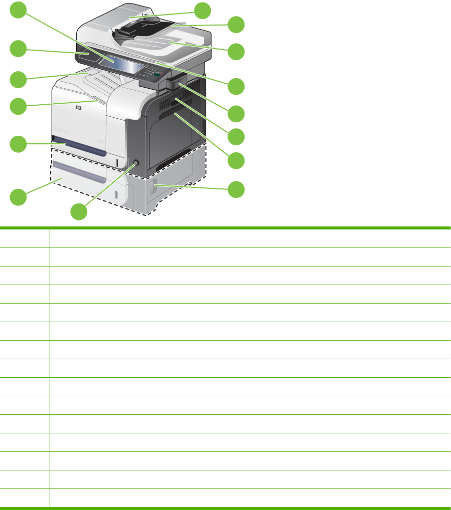
Product view
Product front view
1
14
15
13
2
4
5
6
7
8
9
3
12
11
10
1Color control panel
2Document-feeder top-cover (lift open to clear jams)
3Automatic document-feeder (ADF)
4Document-feeder output bin
5Scanner
6Convenience stapler (only for the HP Color LaserJet CM3530fs MFP)
7Right-side door (access for clearing jams)
8Tray 1 (pull the handle to open the tray)
9Lower-right door (access for clearing jams)
10 On/off button
11 Optional Tray 3
12 Tray 2
13 Front door (access to print cartridges and toner collection unit)
14 Standard output bin
15 Hardware integration port
ENWW Product view 7
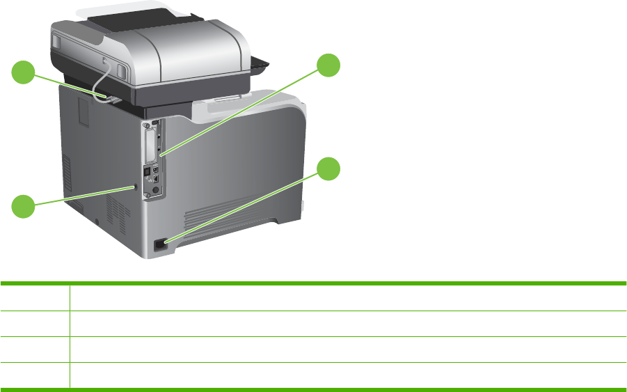
Product back view
12
4
3
1Connector for the ADF
2Interface ports
3Power connection
4Slot for a cable-type security lock
8 Chapter 1 Product basics ENWW
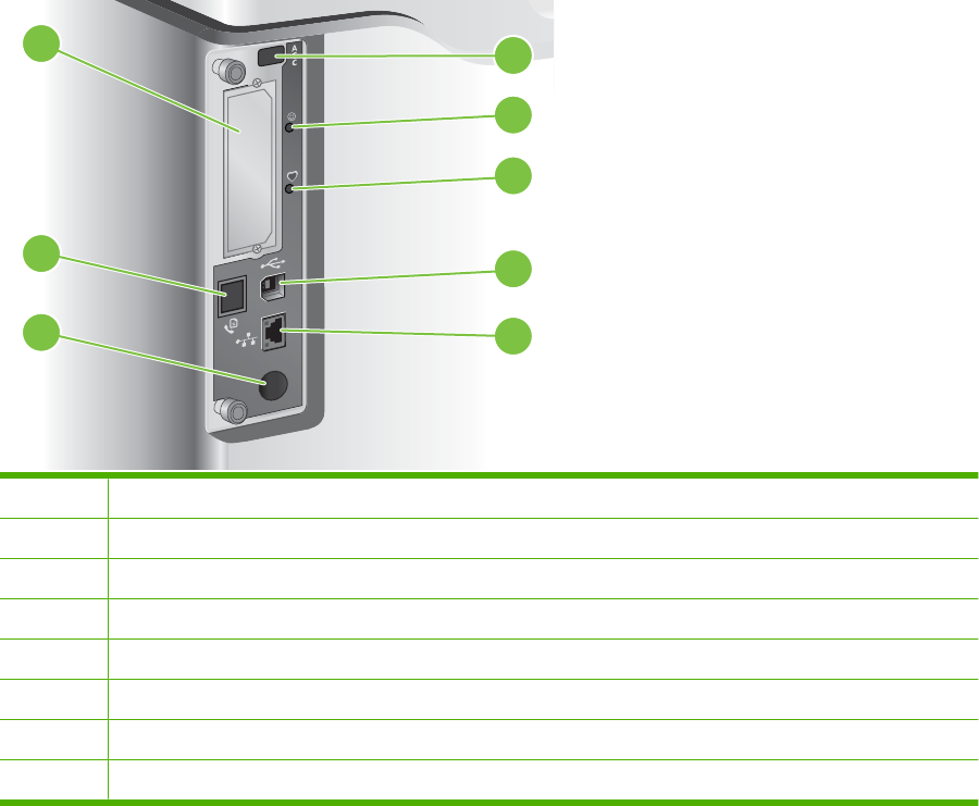
Interface ports
8
2
1
3
4
5
6
7
1EIO interface expansion slot
2Host USB port (for third-party solutions)
3Formatter connectivity LED (lit when the formatter is properly seated)
4Heartbeat LED (blinks when the formatter is working correctly)
5Hi-Speed USB 2.0 port
6RJ-45 network port (includes HP Jetdirect LEDs)
7Foreign-interface harness (for connecting third-party solutions)
8Fax connection (only for the HP Color LaserJet CM3530fs MFP)
ENWW Product view 9

Serial number and model number location
Model name Model number
HP Color LaserJet CM3530 MFP CC519A
HP Color LaserJet CM3530fs MFP CC520A
10 Chapter 1 Product basics ENWW

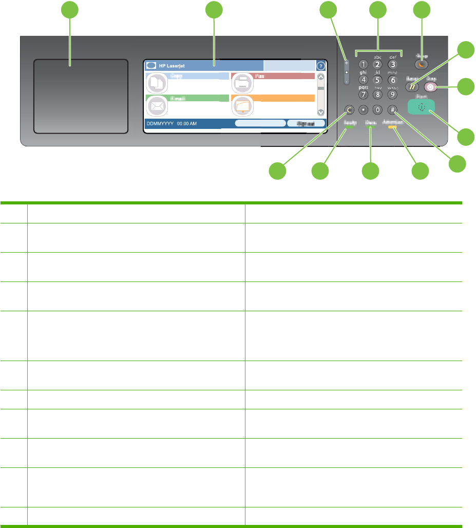
Use the control panel
The control panel has a VGA touchscreen that provides access to all product functions. Use the buttons
and numeric keypad to control jobs and the product status. The LEDs indicate overall product status.
Control-panel layout
The control panel includes a touchscreen graphical display, job-control buttons, a numeric keypad, and
three light-emitting diode (LED) status lights.
hp
7
5
8
6
31 4
9
10
2
111213
1Hardware integration port Area for adding third-party security devices
2Touchscreen graphical display Use the touchscreen to open and set up all product
functions.
3Brightness-adjustment button Use this button to increase or decrease the brightness of
the touchscreen display.
4Numeric keypad Use this area to specify the number of copies and other
numeric values.
5Sleep button If the product is inactive for a long period of time, it
automatically enters a sleep mode. To place the product
into sleep mode or to reactivate the product, press the
Sleep button.
6Reset button Resets the job settings to factory or user-defined default
values.
7Stop button Stops the active job and opens the Job Status screen.
8Start button Begins a copy job, starts digital sending, starts a fax job,
or continues a job that has been interrupted.
9# button Use this button to indicate a required pause for a fax
number.
10 Attention light The Attention light indicates that the product has a
condition that requires intervention. Examples include an
empty paper tray or an error message on the touchscreen.
11 Data light The Data light indicates that the product is receiving data.
12 Chapter 2 Control panel ENWW

12 Ready light The Ready light indicates that the product is ready to begin
processing any job.
13 Clear button Return values to their defaults.
ENWW Use the control panel 13

Home screen
The home screen provides access to the product features, and it indicates the current status of the
product.
NOTE: Depending on how the product has been configured, the features that appear on the home
screen can vary.
HP LaserJet
DDMMYYYY 00.00 AM
2 3 45
6
789
1
1Features Depending on how the product is configured, the features that appear in this area can include
any of the following items:
●Copy
●Fax
●E-mail
●Secondary E-Mail
●Job Status
●Network Folder
●Job Storage
●Workflow
●Supplies Status
●Administration
2Product status line The status line provides information about the overall product status. Various buttons appear
in this area, depending on the current status. For a description of each button that can appear
in the status line, see Buttons on the touchscreen on page 15.
3Copy type Shows whether copies are color.
4Copy count The copy count box indicates the number of copies that the product is set to make.
5Help button Touch the Help button to open the embedded help system.
6Scroll bar Touch the up or down arrows on the scroll bar to see the complete list of available features.
7Sign Out Touch Sign Out to sign out of the product if you have signed in for access to restricted features.
After you sign out, the product restores all options to the default settings.
8Network Address Touch Network Address to find information about the network connection.
9 Date and time The current date and time appear here. You can select the format that the product uses to show
the date and time, for example 12-hour format or 24-hour format.
14 Chapter 2 Control panel ENWW
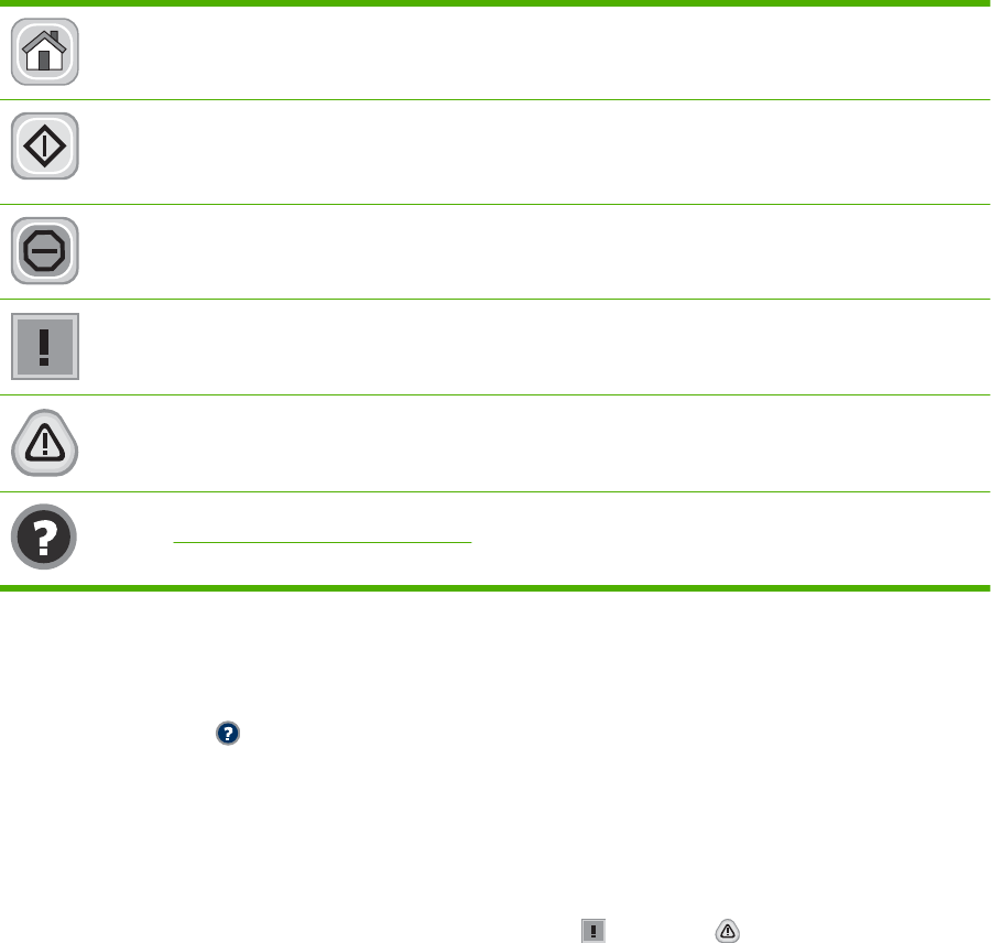
Buttons on the touchscreen
The status line on the touchscreen provides information about the product status. Various buttons can
appear in this area. The following table describes each button.
Home button. Touch the home button to go to the Home screen from any other screen.
Start button. Touch the Start button to begin the action for the feature that you are using.
NOTE: The name of this button changes for each feature. For example, in the Copy feature, the button
is named Start Copy.
Stop button. If the product is processing a print or fax job, the Stop button appears instead of the Start
button. Touch the Stop button to halt the current job. The product prompts you to cancel the job or to
resume it.
Error button. The error button appears whenever the product has an error that requires attention before
it can continue. Touch the error button to see a message that describes the error. The message also has
instructions for solving the problem.
Warning button. The warning button appears when the product has a problem but can continue
functioning. Touch the warning button to see a message that describes the problem. The message also
has instructions for solving the problem.
Help button. Touch the help button to open the built-in online Help system. For more information, see
Control-panel help system on page 15.
Control-panel help system
The product has a built-in Help system that explains how to use each screen. To open the Help system,
touch the Help button in the upper-right corner of the screen.
For some screens, the Help opens to a global menu where you can search for specific topics. You can
browse through the menu structure by touching the buttons in the menu.
For screens that contain settings for individual jobs, the Help opens to a topic that explains the options
for that screen.
If the product alerts you of an error or warning, touch the error or warning button to open a message
that describes the problem. The message also contains instructions to help solve the problem.
ENWW Use the control panel 15

Navigate the Administration menu
From the Home screen, touch Administration to open the menu structure. You might need to scroll to
the bottom of the Home screen to see this feature.
The Administration menu has several sub-menus, which are listed on the left side of the screen. Touch
the name of a menu to expand the structure. A plus sign (+) next to a menu name means that it contains
sub-menus. Continue opening the structure until you reach the option that you want to configure. To
return to the previous level, touch Back.
To exit the Administration menu, touch the Home button in the upper-left corner of the screen.
The product has built-in Help that explains each of the features that are available through the menus.
Help is available for many menus on the right-hand side of the touchscreen. Or, to open the global Help
system, touch the Help button in the upper-right corner of the screen.
The tables in the sections that follow indicate the overall structure of each menu under the Administration
menu.
16 Chapter 2 Control panel ENWW

Information menu
Administration > Information
Use this menu to print information pages and reports that are stored internally on the product.
Table 2-1 Information menu
Menu item Sub-menu item Sub-menu item Values Description
Configuration/Status
Pages
Administration Menu
Map
Print Shows the basic structure of the
Administration menu and current
administration settings.
Configuration Page Print A set of configuration pages that show the
current product settings.
Supplies Status
Page
Print Shows the status of supplies such as
cartridges, maintenance kits, and staples.
Usage Page Print Shows information about the number of
pages that have been printed on each paper
type and size.
Color Usage Job Log Print A directory page that contains job-by-job
color usage information. Page content
includes the user name, application name,
and number of black-only pages and color
pages.
File Directory Print A directory page that contains information for
any mass-storage devices, such as flash
drives, memory cards, or hard disks, that are
installed in this product.
Fax Reports Fax Activity Log Print Contains a list of the faxes that have been
sent from or received by this product.
Fax Call Report Fax Call Report Print A detailed report of the last fax operation,
either sent or received.
Thumbnail on Report Yes
No (default)
Choose whether or not to include a thumbnail
of the first page of the fax on the call report.
When to Print Report Never auto print
Print after any fax job
Print after fax send jobs
Print after any fax error (default)
Print after send errors only
Print after receive errors only
Billing Codes Report Print A list of billing codes that have been used for
outgoing faxes. This report shows how many
sent faxes were billed to each code.
Blocked Fax List Print A list of phone numbers that are blocked from
sending faxes to this product.
Speed Dial List Print Shows the speed dials that have been set up
for this product.
ENWW Information menu 17

Menu item Sub-menu item Sub-menu item Values Description
Sample Pages/Fonts Demonstration Page Print Printout of a page highlighting the print
capabilities of the product.
RGB Samples Print Printout of color samples for different RGB
values. The samples act as a guide for color
matching.
CMYK Samples Print Printout of color samples for different CMYK
values. The samples act as a guide for color
matching.
PCL Font List Print A list of printer control language (PCL) fonts
that are currently available on the product.
PS Font List Print A list of PostScript (PS) fonts that are
currently available on the product.
Table 2-1 Information menu (continued)
18 Chapter 2 Control panel ENWW

Default Job Options menu
Administration > Default Job Options
Use this menu to define the default job options for each function. These are used if the user does not
specify other options when creating the job.
Default Options for Originals
Administration > Default Job Options > Default Options For Originals
Table 2-2 Default Options For Originals menu
Menu item Values Description
Paper Size Select a paper size from the list. Select the paper size that is most often used for copy or scan
originals.
Number of Sides 1Select whether copy or scan originals are most often single-sided or
double-sided.
2
Orientation Portrait Select the orientation that is most often used for copy or scan
originals. Select Portrait if the short edge is at the top or select
Landscape if the long edge is at the top.
Landscape
Optimize Text/Picture Manually Adjust Optimize the output for a particular type of original: text, pictures, or
a mixture of both.
If you select Manually Adjust, specify the mix of text and pictures that
is used most often.
Text
Printed Picture
Photograph
ENWW Default Job Options menu 19

Image adjustment
Administration > Default Job Options > Image Adjustment
Table 2-3 Image Adjustment menu
Menu item Values Description
Darkness Select a value. Select the level of density (darkness) for the output.
Background Cleanup Adjust the value within the range. Increase the Background Cleanup setting to remove faint images
from the background or to remove a light background color.
Sharpness Adjust the value within the range. Adjust the Sharpness setting to clarify or soften the image.
20 Chapter 2 Control panel ENWW

Default Copy Options
Administration > Default Job Options > Default Copy Options
Table 2-4 Default Copy Options menu
Menu item Sub-menu item Values Description
Number of Copies Type the number of
copies. The factory
default setting is 1.
Set the default number of copies for a copy job.
Number of Sides 1
2
Set the default number of sides for copies.
Color/Black Auto Detect
Color
Black (default)
Choose whether the default copy mode is color, black,
or automatically detected, based on the original.
Collate Off
On (default)
Set up the option for collating sets of copies.
If On is selected, the product prints a complete copy of
the print job before starting on the next copy.
Otherwise, the product prints the first page of all copies
before printing the second page, and so on.
Edge-To-Edge Normal (recommended)
(default)
Edge-To-Edge Output
If the original document is printed close to the edges,
use the Edge-To-Edge feature to avoid shadows along
the edges. Combine this feature with the Reduce/
Enlarge feature to ensure that the entire page appears
on the copies.
Auto Include Margins Off (default)
On
This feature automatically reduces the image size
during scanning so the margins are included.
ENWW Default Job Options menu 21

Default Fax Options
Administration > Default Job Options > Default Fax Options
NOTE: This menu is available only for the HP Color LaserJet CM3530fs MFP.
Table 2-5 Fax Send menu
Menu item Sub-menu item Values Description
Resolution Standard (100x200dpi)
(default)
Fine (200x200dpi)
Superfine (300x300dpi)
Set the resolution for sent documents. Higher
resolution images have more dots per inch (dpi), so
they show more detail. Lower resolution images have
fewer dots per inch and show less detail, but the file
size is smaller.
Fax Header Prepend (default)
Overlay
Select the position of the fax header on the page.
Select Prepend to print the fax header above the fax
content and move the fax content down on the page.
Select Overlay to print the fax header over the top of
the fax contents without moving the contents down.
Using this option could prevent a single-page fax from
flowing onto another page.
Table 2-6 Fax Receive menu
Menu item Sub-menu item Values Description
Fax Forwarding Fax Forwarding Off (default)
Custom
To forward received faxes to another fax device, select
Fax Forwarding and Custom. Then type the number of
the other fax device into the Fax Forwarding Number
field. When you select the Fax Forwarding menu item
for the first time, you are prompted to set up a PIN. Type
that PIN every time you use this menu. This PIN is also
used to access the Fax Printing menu.
Change PIN Use this option to change the PIN for the Fax
Forwarding menu.
Stamp Received Faxes Enabled
Disabled (default)
Add the date, time, senders phone number, and page
number to each page of the faxes that this product
receives.
Fit to Page Enabled (default)
Disabled
Shrink faxes that are larger than Letter-size or A4-size
so that they can fit onto a Letter-size or A4-size page.
If it this feature set to Disabled, faxes larger than Letter
or A4 will flow across multiple pages.
Fax Paper Tray Select from the list of
trays. The default setting
is Automatic.
Select the tray that holds the size and type of paper that
you want to use for incoming faxes.
22 Chapter 2 Control panel ENWW

Default E-mail Options
Administration > Default Job Options > Default E-mail Options
Menu item Values Description
Document File Type PDF (default)
JPEG
TIFF
M-TIFF
Select the file format for the e-mail.
Output Quality High (large file)
Medium (default)
Low (small file)
Selecting higher quality for output increases the size of the
output file.
Resolution 300 DPI
200 DPI
150 DPI (default)
75 DPI
Select the resolution. Use a lower setting to create smaller
files.
Color/Black Color scan (default)
Black/white scan
Specify whether the e-mail will be in black or in color.
TIFF Version TIFF 6.0 (default)
TIFF (Post 6.0)
Specify the TIFF version to use when saving scanned files.
ENWW Default Job Options menu 23

Default Send to Folder Options
Administration > Default Job Options > Default Send To Folder Options
Menu item Values Description
Color/Black Color scan
Black/white scan (default)
Specify whether the file will be in black or in color.
Document File Type PDF (default)
M-TIFF
TIFF
JPEG
Select the file format for the file.
TIFF Version TIFF 6.0 (default)
TIFF (Post 6.0)
Specify the TIFF version to use when saving scanned files.
Output Quality High (large file)
Medium (default)
Low (small file)
Selecting higher quality for output increases the size of the
output file.
Resolution 75 DPI
150 DPI (default)
200 DPI
300 DPI
400 DPI
600 DPI
Select the resolution. Use a lower setting to create smaller
files.
24 Chapter 2 Control panel ENWW

Default Print Options
Administration > Default Job Options > Default Print Options
Table 2-7 Default Print Options menu
Menu item Sub-menu item Values Description
Copies Per Job Type a value. Set the default number of copies for print jobs.
Default Paper Size (List of supported sizes) Select a paper size.
Default Custom Paper
Size
Unit of measure Millimeters
Inches
Configure the default paper size that is used when the
user selects Custom as the paper size for a print job.
X Dimension Configure the width measurement for the Default
Custom Paper Size.
Y Dimension Configure the height measurement for the Default
Custom Paper Size.
Print Sides 1-sided
2-sided
Select whether print jobs are single-sided or double-
sided by default.
2-Sided Format Long Edge (Default)
Short Edge
Use this feature to configure the default style for 2-
sided print jobs.
If Long Edge is selected and the job has a portrait
orientation, the job will result in a book style. If the job
is landscape, a calendar style (flipping up the pages)
will result.
If Short Edge is selected and the job has a portrait
orientation, the job will result in a calendar style. If the
job is landscape, a booklet style will result.
ENWW Default Job Options menu 25

Time/Scheduling menu
Administration > Time/Scheduling
Use this menu to set options for setting the time and for setting the product to enter and exit sleep mode.
NOTE: Values shown with "(default)" are the factory-default values. Some menu items have no default.
Table 2-8 Time/Scheduling menu
Menu item Sub-menu item Sub-menu item Values Description
Date/Time Date Format YYYY/MMM/DD
(default)
MMM/DD/YYYY
DD/MMM/YYYY
Use this feature to set the current date and
time, and to set the date format and time
format that are used to time-stamp outgoing
faxes.
Date Month
Day
Year
Time Format 12 hour (AM/PM)
(default)
24 hour
Time Hour
Minute
AM
PM
Time Zone Select a time zone
from the list.
Select the time zone where the product is
located.
Adjust for Daylight
Savings
Enabled
Disabled
Sleep Delay 1 Minute
15 Minutes
20 minutes
30 minutes (default)
45 minutes
1 hour (60 minutes)
90 minutes
2 hours
4 Hours
Use this feature to select the time interval that
the product should remain inactive before
entering Sleep Mode.
Wake Time Monday
Tuesday
Off (default)
Custom
Select Custom to set a wake time for each
day of the week. The product exits sleep
mode according to this schedule. Using a
sleep schedule helps conserve energy and
26 Chapter 2 Control panel ENWW

Menu item Sub-menu item Sub-menu item Values Description
Wednesday
Thursday
Friday
Saturday
Sunday
prepares the product for use so that users do
not have to wait for it to warm up.
Sleep Time Monday
Tuesday
Wednesday
Thursday
Friday
Saturday
Sunday
Off (default)
Custom
Use this feature to set a sleep time for each
day of the week for periods when the product
will not likely be in use (for example, at a
certain time each evening). Setting a sleep
time makes the product automatically go into
a low-power mode. Select a day and then
select Custom to set up a custom sleep time
schedule.
Fax Printing Fax Printing Mode Store all received
faxes
If you have concerns about the security of
private faxes, use this feature to store faxes
rather than having them automatically print by
creating a printing schedule. When you select
this menu item for the first time, you are
prompted to set up a PIN. Type that PIN every
time you use this menu.
Print all received
faxes (default)
Select Print all received faxes to print all
incoming received faxes at the time they are
received.
Use Fax Printing
Schedule
Create Fax Printing
Schedule
Select Use Fax Printing Schedule to get to
the Create Fax Printing Schedule menu
options that allow you to set up a schedule for
printing received faxes.
Change PIN Select Change PIN to change the PIN
number that users must provide to print faxes.
Table 2-8 Time/Scheduling menu (continued)
ENWW Time/Scheduling menu 27

Management menu
Administration > Management
Use this menu to set up global product-management options.
NOTE: Values shown with "(default)" are the factory-default values. Some menu items have no default.
Table 2-9 Management menu
Menu item Sub-menu item Values Description
Network Address Button Display
Hide (default)
Use this feature to display the Network Address button
on the Home screen.
Stored Job Management Quick Copy Job Storage
Limit
Select the maximum
number of jobs to store
Use this menu to view and manage any jobs that are
stored on the product.
Quick Copy Job Held
Timeout
Off (default)
1 Hour
4 Hours
1 Day
1 Week
Stored Jobs List Order Alphabetical
Chronological
Sleep mode Disable
Use Sleep Delay (default)
Use this feature to customize the sleep mode settings
for this product.
Select Use Sleep Delay to set the product to enter
sleep mode after the delay that is specified in the Time/
Scheduling menu.
Manage Supplies Replace Supplies Sets the product behavior for when a supply item is low.
The product displays an "Order supplies" message
when a supply item is running low and a "Replace
supplies" message when a supply item has reached its
estimated end of life. To ensure optimal print quality,
HP recommends replacing a supply item when the
"Replace supplies" message is displayed. The supply
does not have to be replaced at this point unless the
print quality is no longer acceptable. Printing beyond
this point is possible using Override at out 1 or Override
at out 2. The Override options allow the product to
continue using a supply item that has reached its
estimated end of life.
Stop at low Choose Stop at low to stop printing when a supply
reaches a low condition.
Stop at out (default) Choose Stop at out to stop printing when the estimated
end of life has been reached for a supply. Printing
beyond this point is possible using Override at out 1 or
Override at out 2. The supply does not need to be
replaced now unless the print quality is no longer
acceptable.
28 Chapter 2 Control panel ENWW

Menu item Sub-menu item Values Description
Override at out 1
Override at out 2
Choose Override at out 1 to allow the product to
continue printing when supply items, other than the
toner collection unit, have reached the end of their
estimated life. Using this option will eventually result in
unacceptable print quality. Consider having a
replacement cartridge available for when the print
quality becomes unacceptable.
Choose Override at out 2 to allow the product to
continue printing when any color supply is past the end
of its estimated capacity, including the toner collection
unit. This option is not recommended because of the
risk of overfilling the toner collection unit, which could
result in the need to service the product.
Information about the remaining toner is not available
when printing in Override mode.
Once an HP supply has reached the end of its
estimated life, HP's Premium Protection Warranty on
that supply has ended. For Warranty information, see
Print cartridge limited warranty statement
on page 571.
The Override options can be enabled or disabled at any
time, and they do not have to be re-enabled for each
supply item. The product automatically continues
printing when a supply item reaches the end of its
estimated life. The message “Replace supply Override
in use” displays on the control panel while a supply is
used in Override mode. When the supply item is
replaced with a new supply, Override is de-activated
until another supply item reaches the end of its
estimated life.
Page Limit
Range of 0 to 100000
This menu displays if you select Yes, Use Override for
either override option. Select the number of pages the
product continues to print while in override mode. The
default is 1500.
Supply Low/Order
Threshold
Select a value in the
range. The default is 5%.
Use this menu to carry out administrative supply
management tasks such as changing the threshold
when supplies should be ordered.
Color Supply Out Stop (default)
Auto-continue black
This menu sets the product behavior when a color
supply has reached its estimated end of life. When
Auto-continue black is selected, the product will
continue printing using black toner only.
Restrict Color Use Color printing access Enable Color (default)
Color If Allowed
Disable Color
This item allows the administrator to disable or restrict
color printing. To use the Color If Allowed setting, set
up user permissions and/or application permissions in
the embedded Web server, HP Easy Printer Care
software, or Web Jetadmin.
Color copying access Enable Color (default)
Disable Color
This item allows the administrator to disable or restrict
color copying.
Color/Black Mix Auto (default)
Mostly color pages
Mostly black pages
This item controls how the engine switches from color
mode to monochrome mode for maximum
performance and print cartridge life.
Table 2-9 Management menu (continued)
ENWW Management menu 29

Menu item Sub-menu item Values Description
Select Auto to reset the product to the factory default
setting.
Select Mostly color pages if nearly all your print jobs
are color with high page coverage.
Select Mostly black pages if you print mostly
monochrome jobs or a combination of color and
monochrome jobs.
Table 2-9 Management menu (continued)
30 Chapter 2 Control panel ENWW

Initial Setup menu
Administration > Initial Setup
NOTE: Values shown with "(default)" are the factory-default values. Some menu items have no default.
Networking and I/O
Administration > Initial Setup > Networking and I/O
Table 2-10 Networking and I/O
Menu item Sub-menu item Values Description
I/O Timeout Select a value in the
range. The factory default
setting is 15 seconds.
I/O timeout refers to the elapsed time before a print job
fails. If the stream of data that the product receives for
a print job gets interrupted, this setting indicates how
long the product will wait before it reports that the job
has failed.
Parallel Input
NOTE: This item
appears only if an EIO
accessory is installed.
High Speed No
Yes (default)
Use the High Speed setting to configure the speed that
the parallel port uses to communicate with the host.
Advanced Functions Enabled (default)
Disabled
Use the Advanced Functions setting to enable or
disable bidirectional parallel communication.
Embedded Jetdirect See Table 2-11 Jetdirect menus on page 31 for the list of options.
EIO <X> Jetdirect
Table 2-11 Jetdirect menus
Menu item Sub-menu item Sub-menu item Values and Description
TCP/IP Enable Off: Disable the TCP/IP protocol.
On (default): Enable the TCP/IP protocol.
Host Name An alphanumeric string, up to 32 characters, used to
identify the product. This name is listed on the
HP Jetdirect configuration page. The default host name
is NPIxxxxxx, where xxxxxx is the last six digits of the
LAN hardware (MAC) address.
IPV4 Settings Config Method Specifies the method that TCP/IPv4 parameters will be
configured on the HP Jetdirect print server.
Bootp: Use BootP (Bootstrap Protocol) for automatic
configuration from a BootP server.
DHCP: Use DHCP (Dynamic Host Configuration
Protocol) for automatic configuration from a DHCPv4
server. If selected and a DHCP lease exists, DHCP
Release and DHCP Renew menus are available to set
DHCP lease options.
Auto IP: Use automatic link-local IPv4 addressing. An
address in the form 169.254.x.x is assigned
automatically.
ENWW Initial Setup menu 31

Menu item Sub-menu item Sub-menu item Values and Description
Manual: Use the Manual Settings menu to configure
TCP/IPv4 parameters.
Default IP Specify the IP address to default to when the print
server is unable to obtain an IP address from the
network during a forced TCP/IP reconfiguration (for
example, when manually configured to use BootP or
DHCP).
Auto IP: A link-local IP address 169.254.x.x is set.
Legacy: The address 192.0.0.192 is set, consistent
with older HP Jetdirect products.
DHCP Release This menu appears if Config Method was set to
DHCP and a DHCP lease for the print server exists.
No (default): The current DHCP lease is saved.
Yes: The current DHCP lease and the leased IP
address are released.
DHCP Renew This menu appears if Config Method was set to
DHCP and a DHCP lease for the print server exists.
No (default): The print server does not request to renew
the DHCP lease.
Yes: The print server requests to renew the current
DHCP lease.
Manual Settings (Available only if Config Method is set to Manual)
Configure parameters directly from the printer control
panel:
IP Address: The unique IP address of the printer
(n.n.n.n), where n is a value from 0 to 255.
Subnet Mask: The subnet mask for the printer
(m.m.m.m), where m is a value from 0 to 255.
Syslog Server: The IP address of the syslog server
used to receive and log syslog messages.
Default Gateway: The IP address of the gateway or
router used for communications with other networks.
Idle Timeout: The time period, in seconds, after which
an idle TCP print data connection is closed (default is
270 seconds, 0 disables the timeout).
Primary DNS Specify the IP address (n.n.n.n) of a Primary DNS
Server.
Secondary DNS Specify the IP address (n.n.n.n) of a Secondary
Domain Name System (DNS) Server.
IPV6 Settings Enable Use this item to enable or disable IPv6 operation on the
print server.
Off: IPv6 is disabled.
On (default): IPv6 is enabled.
Table 2-11 Jetdirect menus (continued)
32 Chapter 2 Control panel ENWW

Menu item Sub-menu item Sub-menu item Values and Description
Address Manual Settings: Use this item to manually set IPv6
addresses on the print server.
Enable: Select this item and choose On to enable
manual configuration, or Off to disable manual
configuration.
Address: Use this item to type a 32 hexadecimal digit
IPv6 node address that uses the colon hexadecimal
syntax.
DHCPV6 Policy Router Specified: The stateful auto-configuration
method to be used by the print server is determined by
a router. The router specifies whether the print server
obtains its address, its configuration information, or
both from a DHCPv6 server.
Router Unavailable: If a router is not available, the print
server should attempt to obtain its stateful
configuration from a DHCPv6 server.
Always: Whether or not a router is available, the print
server always attempts to obtain its stateful
configuration from a DHCPv6 server.
Primary DNS Use this item to specify an IPv6 address for a primary
DNS server that the print server should use.
Secondary DNS Use this item to specify an IPv6 address for a
secondary DNS server that the print server should use.
Proxy Server Specifies the proxy server to be used by embedded
applications in the product. A proxy server is typically
used by network clients for Internet access. It caches
Web pages, and provides a degree of Internet security,
for those clients.
To specify a proxy server, enter its IPv4 address or
fully-qualified domain name. The name can be up to
255 octets.
For some networks, you may need to contact your
Independent Service Provider (ISP) for the proxy
server address.
Proxy Port Type the port number used by the proxy server for
client support. The port number identifies the port
reserved for proxy activity on your network, and can be
a value from 0 to 65535.
Idle Timeout This is the time period, in seconds, after which an idle
TCP print data connection is closed. The default is 270
seconds. To disable the timeout, specify 0.
IPX/SPX Enable Off: Disable the IPX/SPX protocol.
On (default): Enable the IPX/SPX protocol.
Frame Type Selects the frame-type setting for your network.
Auto: Automatically sets and limits the frame type to
the first one detected.
EN_8023, EN_II, EN_8022, and EN_SNAP: Frame-
type selections for Ethernet networks.
Table 2-11 Jetdirect menus (continued)
ENWW Initial Setup menu 33

Menu item Sub-menu item Sub-menu item Values and Description
AppleTalk Enable Off: Disable the AppleTalk protocol.
On (default): Enable the AppleTalk protocol.
DLC/LLC Enable Off: Disable the DLC/LLC protocol.
On (default): Enable the DLC/LLC protocol.
Security Print Sec Page Yes (default): Prints a page that contains the current
security settings on the HP Jetdirect print server.
No: A security settings page is not printed.
Secure Web For configuration management, specify whether the
embedded Web server will accept communications
using HTTPS (Secure HTTP) only, or both HTTP and
HTTPS.
HTTPS Required (default): For secure, encrypted
communications, only HTTPS access is accepted. The
print server will appear as a secure site.
HTTPS Optional: Access using either HTTP or HTTPS
is permitted.
IPSec Specify the IPSec status on the print server.
Keep: IPSec status remains the same as currently
configured.
Disable: IPSec operation on the print server is
disabled.
Reset Security Specify whether the current security settings on the
print server will be saved or reset to factory defaults.
No: The current security settings are maintained.
Yes: Security settings are reset to factory defaults.
Diagnostics Embedded Tests This menu provides tests to help diagnose network
hardware or TCP/IP network connection problems.
Embedded tests help to identify whether a network fault
is internal or external to the product. Use an embedded
test to check hardware and communication paths on
the print server. After you select and enable a test and
set the execution time, you must select Execute to
initiate the test.
Depending on the execution time, a selected test runs
continuously until either the product is turned off, or an
error occurs and a diagnostic page is printed.
LAN HW Test CAUTION: Running this embedded test will erase
your TCP/IP configuration.
This test performs an internal loopback test. An internal
loopback test will send and receive packets only on the
internal network hardware. There are no external
transmissions on your network.
Select Yes to choose this test, or No to not choose it.
Table 2-11 Jetdirect menus (continued)
34 Chapter 2 Control panel ENWW

Menu item Sub-menu item Sub-menu item Values and Description
HTTP Test This test checks operation of HTTP by retrieving
predefined pages from the product, and tests the
embedded Web server.
Select Yes to choose this test, or No to not choose it.
SNMP Test This test checks operation of SNMP communications
by accessing predefined SNMP objects on the product.
Select Yes to choose this test, or No to not choose it.
Data Path Test This test helps to identify data path and corruption
problems on an HP postscript level 3 emulation
product. It sends a predefined PS file to the product,
However, the test is paperless; the file will not print.
Select Yes to choose this test, or No to not choose it.
Select All Tests Use this item to select all available embedded tests.
Select Yes to choose all tests. Select No to select
individual tests.
Execution Time [H] Use this item to specify the length of time (in hours) that
an embedded test will be run. You can select a value
from 1 to 60 hours. If you select zero (0), the test runs
indefinitely until an error occurs or the product is turned
off.
Data gathered from the HTTP, SNMP, and Data Path
tests is printed after the tests have completed.
Execute No: Do not initiate the selected tests.
Yes: Initiate the selected tests.
Ping Test This test is used to check network communications.
This test sends link-level packets to a remote network
host, then waits for an appropriate response. To run a
ping test, set the following items:
Dest Type Specify whether the target product is an IPv4 or IPv6
node.
Dest IPv4 Type the IPv4 address.
Dest IPv6 Type the IPv6 address.
Packet Size Specify the size of each packet, in bytes, to be sent to
the remote host. The minimum is 64 (default) and the
maximum is 2048.
Timeout Specify the length of time, in seconds, to wait for a
response from the remote host. The default is 1 and
the maximum is 100.
Count Specify the number of ping test packets to send for this
test. Select a value from 1 to 100. To configure the test
to run continuously, select 0.
Print Results If the ping test was not set for continuous operation,
you can choose to print the test results. Select Yes to
print results. If you select No (default), results are not
printed.
Table 2-11 Jetdirect menus (continued)
ENWW Initial Setup menu 35

Menu item Sub-menu item Sub-menu item Values and Description
Execute Specify whether to initiate the ping test. Select Yes to
initiate the test, or No to not run the test.
Ping Results Use this item to view the ping test status and results
using the control panel display. You can select the
following items:
Packets Sent Shows the number of packets (0 - 65535) sent to the
remote host since the most recent test was initiated or
completed.
Packets Received Shows the number of packets (0 - 65535) received from
the remote host since the most recent test was initiated
or completed.
Percent Lost Shows the percent of ping test packets that were sent
with no response from the remote host since the most
recent test was initiated or completed.
RTT Min Shows the minimum detected roundtrip- time (RTT),
from 0 to 4096 milliseconds, for packet transmission
and response.
RTT Max Shows the maximum detected roundtrip- time (RTT),
from 0 to 4096 milliseconds, for packet transmission
and response.
RTT Average Shows the average round-trip-time (RTT), from 0 to
4096 milliseconds, for packet transmission and
response.
Ping In Progress Shows whether a ping test is in progress. Yes indicates
a test in progress, and No indicates that a test
completed or was not run.
Refresh When viewing the ping test results, this item updates
the ping test data with current results. Select Yes to
update the data, or No to maintain the existing data.
However, a refresh automatically occurs when the
menu times out or you manually return to the main
menu.
Link Speed The link speed and communication mode of the print
server must match the network. The available settings
depend on the product and installed print server. Select
one of the following link configuration settings:
CAUTION: If you change the link setting, network
communications with the print server and network
product might be lost.
Auto (default): The print server uses auto-negotiation
to configure itself with the highest link speed and
communication mode allowed. If auto-negotiation fails,
either 100TX Half or 10T Half is set depending on the
detected link speed of the hub/switch port. (A 1000T
half-duplex selection is not supported.)
10T Half: 10 Mbps, half-duplex operation.
10T Full: 10 Mbps, Full-duplex operation.
100TX Half: 100 Mbps, half-duplex operation.
100TX Full: 100 Mbps, full-duplex operation.
Table 2-11 Jetdirect menus (continued)
36 Chapter 2 Control panel ENWW

Menu item Sub-menu item Sub-menu item Values and Description
100TX Auto: Limits auto-negotiation to a maximum link
speed of 100 Mbps.
1000TX Full: 1000 Mbps, full-duplex operation.
Print Protocols Use this item to print a page that lists the configuration
of the following protocols: IPX/SPX, Novell NetWare,
AppleTalk, DLC/LLC.
Table 2-11 Jetdirect menus (continued)
ENWW Initial Setup menu 37

Fax Setup
Administration > Initial Setup > Fax Setup
NOTE: This menu is available only for the HP Color LaserJet CM3530fs MFP.
Table 2-12 Fax Setup menu
Menu item Sub-menu item Sub-menu item Values Description
Fax Setup Wizard Use this wizard to set up options for sending
faxes if the analog fax accessory is installed.
Required Settings Country/Region (Countries/regions
listed)
Configure the settings that are legally
required for outgoing faxes.
Date/Time
Fax Header
Information
Telephone Number
Company Name
PC Fax Send Disabled
Enabled (default)
Use this feature to enable or disable PC Fax
Send. PC Fax Send enables users to send
faxes through the product from their
computers if they have the Send Fax driver
installed on their PC.
38 Chapter 2 Control panel ENWW

Menu item Sub-menu item Sub-menu item Values Description
Fax Send Settings Fax Dial Volume Off
Low (default)
High
Use this feature to set the volume of the tones
that you hear while the product dials the fax
number.
Error Correction
Mode
Enabled (default)
Disabled
When Error Correction Mode is enabled and
an error occurs during fax transmission, the
product sends or receives the error portion
again.
JBIG Compression Enabled (default)
Disabled
JBIG compression reduces fax-transmission
time, which can result in lower phone
charges. However, using JBIG compression
sometimes causes compatibility problems
with older fax machines. If this occurs, turn off
JBIG compression.
Maximum Baud Rate Select a value from
the list. The default is
33.6K.
Use this feature to set the maximum baud
rate for receiving faxes. This can be used as
a diagnostic tool for troubleshooting fax
problems.
TCF T.30 Delay
Timer
Default (default)
Custom
This setting should be left at the default value
and only changed when directed by an HP
technical support agent. Adjustment
procedures associated with this setting are
beyond the scope of this guide.
TCF Extend Default (default)
Custom
This setting should be left at the default value
and only changed when directed by an HP
technical support agent. Adjustment
procedures associated with this setting are
beyond the scope of this guide.
Dialing Mode Tone (default)
Pulse
Select whether the product should use tone
or pulse dialing.
Redial On Busy The range is between
0 and 9. The factory
default is 3 times.
Type the number of times the product should
attempt to redial if the line is busy.
Redial On No Answer Never (default)
Once
Twice
Use this feature to specify the number of
times the product should attempt to dial if the
recipient fax number does not answer.
NOTE: Twice is available in locations other
than the United States and Canada.
Table 2-12 Fax Setup menu (continued)
ENWW Initial Setup menu 39

Menu item Sub-menu item Sub-menu item Values Description
Redial Interval The range is between
1 and 5 minutes. The
factory default is 5
minutes.
Use this feature to specify the number of
minutes between dialing attempts if the
recipient number is busy or not answering.
Detect Dial Tone Enabled
Disabled (default)
Use this feature to specify whether the
product should check for a dial tone before
sending a fax.
Dialing Prefix Off (default)
Custom
Use this feature to specify a prefix number
that must be dialed when sending faxes from
the product.
Billing Codes Off (default)
Custom
When billing codes are enabled, a prompt
appears that asks the user to enter the billing
code for an outgoing fax.
The range is between 1 and 16 digits. The
default is 1 digit.
Fax Receive Settings Rings To Answer The range varies by
location. The factory
default is 2 rings.
Use this feature to specify the number of rings
that must occur before the fax modem
answers.
Ring Interval Default (default)
Custom
This setting is used to adjust for some PBX
ring signals. Change this setting only when
directed by an HP technical support agent.
Ring Frequency Default (default)
Custom
This setting should be left at the default value
and only changed when directed by an HP
technical support agent. Adjustment
procedures associated with this setting are
beyond the scope of this guide.
Ringer Volume Off
Low (default)
High
Set the volume for the fax ring-tone.
Blocked Fax
Numbers
Add Blocked
Numbers
Type the fax number
to add.
Use this feature to add or delete numbers
from the blocked fax list. The blocked fax list
can contain up to 30 numbers. When the
product receives a call from one of the
blocked fax numbers, it deletes the incoming
fax. It also logs the blocked fax in the activity
log along with job-accounting information.
Remove Blocked
Numbers
Select a fax number
to remove.
Clear All Blocked
Numbers
No (default)
Yes
Table 2-12 Fax Setup menu (continued)
40 Chapter 2 Control panel ENWW

E-mail Setup
Administration > Initial Setup > E-mail Setup
Use this menu to enable the e-mail feature and to configure basic e-mail settings.
NOTE: To configure advanced e-mail settings, use the embedded Web server. For more information,
see Embedded Web server on page 85.
Table 2-13 E-mail Setup menu
Menu item Values Description
E-mail Setup Wizard Use this wizard to set up basic options for the e-mail feature.
Address Validation On (default)
Off
This option enables the product to check e-mail syntax when you type
an e-mail address. Valid e-mail addresses require the "@" sign and
a ".".
Find Send Gateways Find Search the network for SMTP gateways that the product can use to
send e-mail.
SMTP Gateway Enter a value. Specify the IP address of the SMTP gateway that is used to send e-
mail from the product.
Test Send Gateway Test Test the configured SMTP gateway to see if it is functional.
Send Setup menu
Administration > Initial Setup > Send Setup
Table 2-14 Send Setup menu
Menu item Values Description
Replicate MFP Enter a value (IP Address). Copy the local Send settings from one product to another.
Allow Transfer to New DSS Off
On (default)
Use this feature to allow the transfer of the product from one
HP Digital Sending Software (DSS) server to another.
HP DSS is a software package that handles digital sending tasks such
as faxing, e-mail, and sending a scanned document to a network
folder.
Allow Use of Digital Send Service Off
On (default)
This feature allows you to configure the product for use with an
HP Digital Sending Software (DSS) server.
Fax Number Confirmation Disable (default)
Enable
When fax number confirmation is enabled, you are prompted to enter
the fax number twice to verify that it has been typed correctly.
Fax Number Speed Dial
Matching
Disable (default)
Enable
If set to Enable, a screen is displayed if the fax numbers entered
match a speed dial that is configured to that number. The numbers
do not have to match as a group; the number must match individually.
That is, if one of the fax numbers matches speed dial 2 and speed
dial 6, then the screen is displayed for that fax number. When you
touch Yes on the dialog, then the fax is sent or the fax number is
added to the distribution list.
ENWW Initial Setup menu 41

Device Behavior menu
Administration > Device Behavior
Table 2-15 Device Behavior menu
Menu item Sub-menu item Sub-menu item Values Description
Language Select the language
from the list.
Select a different language for control-panel
messages. When you select a new language,
the keyboard layout might also change.
Keyboard Layout Select the keyboard
layout from the list
Select a keyboard layout regardless of the
Language setting.
Select Default if you want the keyboard layout
to change when the Language setting
changes. This is the default setting.
Keyboard Layout
Button
Display
Hide
When displayed, you can use this option to
select an alternate keyboard layout. The
keyboard returns to the default layout after
the product returns to the Ready state or if
you press the Reset button.
Key Press Sound On (default)
Off
Use this feature to specify whether you hear
a sound when you touch the screen or press
buttons on the control panel.
Inactivity Timeout Type a value
between 10 and 300
seconds. The factory
default is 60
seconds.
Specify the amount of time that elapses
between any activity on the control panel and
the product resetting to the default settings.
Warning/Error
Behavior
Clearable Warnings On
Job (default)
Set the amount of time that a clearable
warning appears on the control panel.
Continuable Events Auto continue (10
seconds) (default)
Touch OK to
continue
Configure the product behavior when the
product encounters certain errors.
Jam Recovery Auto (default)
Off
On
Configure how the product handles pages
that are lost during a jam.
42 Chapter 2 Control panel ENWW

Menu item Sub-menu item Sub-menu item Values Description
Tray Behavior Use Requested Tray Exclusively (default)
First
Control how the product handles jobs that
have specified a specific input tray.
Manually Feed
Prompt
Always (default)
Unless Loaded
Specify how a prompt should appear when
the type or size for a job does not match the
specified tray and the product pulls from the
multipurpose tray instead.
PS Defer Media Enabled (default)
Disabled
Select either the PostScript (PS) or HP
paper-handling model.
Use Another Tray Enabled (default)
Disabled
Turn on or off the control-panel prompt to
select another tray when the specified tray is
empty.
Alternative
Letterhead Mode
On
Off (default)
Use this feature so that you can load
letterhead or preprinted paper into the tray
the same way for all print or copy jobs,
whether you are printing or copying to one
side of the sheet or to both sides of the sheet.
Size/Type Prompt Display (default)
Do not display
Control whether the tray configuration
message appears whenever a tray is opened
or closed.
Duplex Blank Pages Auto (default)
Yes
Control how the product handles two-sided
jobs (duplexing).
General Copy
Behavior
Hold off print job On
Off
Prevents print jobs from beginning to print
while a walk-up user is setting up a job.
Hold off time Prevents non-copy print jobs from starting for
a specified time after a copy job is completely
printed.
Scan Ahead Enabled (default)
Disabled
Turn on no-wait scanning. With Scan Ahead
enabled, the pages in the original document
are scanned to disk and held until the product
becomes available.
Auto Print Interrupt Enabled
Disabled (default)
When this feature is enabled, copy jobs can
interrupt print jobs that are set to print multiple
copies.
The copy job is inserted into the print queue
at the end of one copy of the print job. After
the copy job is complete, the product
continues printing the remaining copies of the
print job.
Copy Interrupt Enabled
Disabled (default)
When this feature is enabled, a copy job that
is currently printing can be interrupted when
a new copy job is started. You are prompted
to confirm that you want to interrupt the
current job.
Alternative
Letterhead Mode
Off (default)
On
This option allows loading of letterhead or
preprinted paper the same way for all copy
jobs, whether copying to one side of the
paper or to both sides of the paper.
Table 2-15 Device Behavior menu (continued)
ENWW Device Behavior menu 43

Menu item Sub-menu item Sub-menu item Values Description
General Printing
Behavior
Override A4/Letter No
Yes (default)
When this feature is enabled, the job prints
on letter-size paper when an A4 job is sent
but no A4-size paper is loaded in the product
(or prints on A4 paper when a letter-size job
is sent but no letter-size paper is loaded).
This option also overrides A3 with ledger-size
paper and ledger with A3-size paper.
Manual Feed Enabled
Disabled (default)
When this feature is enabled, the user can
select manual feed from the control panel as
the paper source for a job.
Courier Font Regular (default)
Dark
Select which version of the Courier font you
want to use.
Wide A4 Enabled
Disabled (default)
Change the printable area of A4-size paper.
If you enable this option, eighty 10-pitch
characters can be printed on a single line of
A4 paper.
Print PS Errors Enabled
Disabled (default)
Select whether a PostScript (PS) error page
is printed when the product encounters a PS
error.
Print PDF Errors Enabled
Disabled (default)
Select whether a PDF error page is printed
when the product encounters a PDF error.
Personality Auto (default)
PCL
PDF
PS
Select the printer language that the product
should use.
Normally, you should not change the
language. If you change the setting to a
specific language, the product does not
automatically switch from one language to
another unless specific software commands
are sent to the product.
Table 2-15 Device Behavior menu (continued)
44 Chapter 2 Control panel ENWW

Menu item Sub-menu item Sub-menu item Values Description
PCL Form Length Type a value
between 5 and 128
lines. The factory
default is 60 lines.
PCL is a set of printer commands that
Hewlett-Packard developed to provide
access to printer features.
Orientation Portrait (default)
Landscape
Select the orientation that is most often used
for print jobs. Select Portrait if the short edge
is at the top or Landscape if the long edge is
at the top.
Font Source Select the source
from the list.
Select the font source for the user-soft default
font.
Font Number Type the font
number. The range is
between 0 and 102.
The factory default is
0.
Specify the font number for the user soft
default font by using the source that is
specified in the Font Source menu item. The
product assigns a number to each font and
lists it on the PCL font list (available from the
Administration menu).
Font Pitch Type a value
between 0.44 and
99.99. The factory
default is 10.00.
If Font Source and Font Number indicate a
contour font, use this feature to select a
default pitch (for a fixed-spaced font).
Font Point Size Type a value
between 4.00 and
999.75. The factory
default is 12.00.
If Font Source and Font Number indicate a
contour font, use this feature to select a
default point size (for a proportional-spaced
font).
Symbol Set PC-8 (default)
(50 additional
symbol sets from
which to choose)
Select any one of several available symbol
sets from the control panel. A symbol set is a
unique grouping of all the characters in a font.
Append CR to LF No (default)
Yes
Configure whether a carriage return (CR) is
appended to each line feed (LF) encountered
in backwards-compatible PCL jobs (pure text,
no job control).
Suppress Blank
Pages
No (default)
Yes
This option is for users who are generating
their own PCL, which could include extra form
feeds that cause blank pages to be printed.
When Yes is selected, form feeds are ignored
if the page is blank.
Media Source
Mapping
Standard (default)
Classic
Select and maintain input trays by number
when you are not using the printer driver, or
when the software program has no option for
tray selection.
Table 2-15 Device Behavior menu (continued)
ENWW Device Behavior menu 45

Print Quality menu
Administration > Print Quality
Table 2-16 Print Quality menu
Menu item Sub-menu item Values Description
Adjust Color Highlights Cyan Density. Magenta
Density. Yellow Density.
Black Density
+5 to –5. Default is 0.
Adjust the darkness or lightness of highlights on a
printed page. Lower values represent lighter highlights
on a printed page, and higher values represent darker
highlights on a printed page.
Midtones Cyan Density. Magenta
Density. Yellow Density.
Black Density
+5 to –5. Default is 0.
Adjust the darkness or lightness of midtones on a
printed page. Lower values represent lighter midtones
on a printed page, and higher values represent darker
midtones on a printed page.
Shadows Cyan Density. Magenta
Density. Yellow Density.
Black Density
+5 to –5. Default is 0.
Adjust the darkness or lightness of shadows on a
printed page. Lower values represent lighter shadows
on a printed page, and higher values represent darker
shadows on a printed page.
Restore Color Values Restore Sets all the density values back to the factory default
settings.
Set Registration Test Page Print Shift the margin alignment to center the image on the
page from top to bottom and from left to right. You can
also align the image on the front with the image printed
on the back.
Print a test page for setting the registration.
Source All trays
Tray <X>: <contents>
(choose a tray)
Select the source input tray for printing the Set
Registration page.
Adjust Tray <X> Shift from -20 to 20 along
the X or Y axes. 0 is the
default.
Perform the alignment procedure for each tray.
When it creates an image, the product scans across the
page from side to side as the sheet feeds from top to
bottom into the product.
The scan direction is referred to as X. X1 is the scan
direction for the first side of a 2-sided page. X2 is the
scan direction for the second side of a 2-sided page.
The feed direction is referred to as Y.
Print Modes <Paper Type> Configure which mode is associated with which paper
type.
Restore Modes Restore Return all print-mode settings to the factory-default
settings.
Auto Sense Mode Tray 1 Sensing Full Sensing (default)
Transparency Only
Sets the sensing option for Tray 1 for paper types when
using Auto Sense Mode.
When Full Sensing is selected, the product senses
every page and switches modes accordingly. The
product recognizes overhead transparency and non-
overhead transparency types.
46 Chapter 2 Control panel ENWW

Menu item Sub-menu item Values Description
When Transparency Only is selected, the product
senses only the first page and recognizes only
overhead transparency types.
Optimize Background Normal (default)
Alternate 1
Alternate 2
Alternate 3
Adjust this setting if you are having problems with an
overall gray background on pages.
Registration Normal (default)
Alternate
Adjust this setting if you are having problems with color
misregistration.
Transfer Control Normal (default)
Alternate 1
Alternate 2
Alternate 3
Adjust this setting if you are having problems with faint
images repeated on the page.
Tray 1 Normal (default)
Alternate
Select the Alternate setting if you are having problems
with marks on the back side of the paper when printing
from Tray 1. This increases the frequency of the
cleaning cycle.
Environment Normal (default)
Low Temp
Adjust this setting if you are having problems printing
in low temperature and low humidity environments.
Line Voltage Normal (default)
Low Voltage
Adjust this setting if the product is operating in a low-
voltage environment and you are having problems with
print quality such as blisters in the printed image.
Tracking Control On (default)
Off
Do not adjust this setting unless an HP-authorized
support person recommends it.
Uniformity Control Normal (default)
Alternate 1
Alternate 2
Alternate 3
Adjust this setting if printed images have a mottled
appearance.
Normal Paper Standard (default)
Smooth
Adjust this setting if you are printing on normal-weight
paper that is very smooth.
Heavy Paper Standard (default)
Smooth
Adjust this setting if you are printing on heavy-weight
paper that is very smooth.
Envelope Mode Normal (default)
Reduced Temp
Adjust this setting if envelopes are partially sealed after
printing.
Resistance Mode Normal (default)
Up
Down
Adjust this setting if you are in a low-humidity
environment and you are having problems with loose
toner particles after printing.
Table 2-16 Print Quality menu (continued)
ENWW Print Quality menu 47

Menu item Sub-menu item Values Description
Humidity Mode Normal (default)
High
Adjust this setting if you are in a high-humidity
environment and you are having problems with light
density in the printed image.
Pre-rotation Off (default)
On
Adjust this setting if you are having problems with
horizontal streaks on printed pages. Using this feature
increases the warm-up time for the product.
Fuser Temp Normal (default)
Up
Down
Adjust this setting upward if toner is not fusing well.
Adjust it downward if you are seeing a faint image of
the page repeated at the bottom of the page or on the
next page.
Paper Curl Normal (default)
Reduced
Adjust this setting if paper is curling in a high-
temperature and high-humidity environment.
Restore Optimize Return all the settings in the Optimize menu to the
factory-default values.
Resolution Image REt 3600
1200x600dpi
Select Image REt 3600 to produce fast, high-quality
printing that is appropriate for most print jobs
Select 1200x600dpi to produce the highest-quality
printing available, but it may slow print speed. This
setting may be useful for jobs that contain very thin lines
or fine graphics.
Color REt Enabled (default)
Disabled
Enable or disable Resolution Enhancement technology
(REt), which produces print output with smooth angles,
curves, and edges.
Calibration/Cleaning Auto Cleaning Enabled
Disabled (default)
When auto-cleaning is on, the product prints a cleaning
page when the page count reaches the value that is set
in Cleaning Interval.
Cleaning Interval 1000 (default)
2000
5000
10000
20000
Use this feature to set the interval when the cleaning
page is printed. The interval is measured by the number
of pages printed.
Auto Cleaning Size Letter
A4
Use this feature to select the size of paper used for the
cleaning page.
Process Cleaning Page Process Use this feature to create and process a cleaning page
for cleaning excess toner off the pressure roller in the
fuser. The process takes up to 2.5 minutes.
Quick Calibration Calibrate Performs partial product calibrations.
Table 2-16 Print Quality menu (continued)
48 Chapter 2 Control panel ENWW

Menu item Sub-menu item Values Description
Full Calibration Calibrate Performs all product calibrations.
Delay Calibration at
Wake/Power On
No
Yes (default)
This menu controls the timing of the calibration when
the printer wakes up or is turned on.
●Select No to have the printer calibrate immediately
when it wakes up or is turned on. The product will
not print any jobs until it finishes calibrating.
●Select Yes to enable a product that is asleep to
accept print jobs before it calibrates. The product
only accepts new jobs for a short time. It may start
calibrating before it has printed all the jobs it has
received.
NOTE: For the best results, allow the product to
calibrate before printing. Print jobs performed before
calibration may not be of the highest quality.
Table 2-16 Print Quality menu (continued)
ENWW Print Quality menu 49

Troubleshooting menu
Administration > Troubleshooting
NOTE: Many of the menu items under the Troubleshooting menu are for advanced troubleshooting
purposes.
Table 2-17 Troubleshooting menu
Menu item Sub-menu item Sub-menu item Values Description
Event Log Print This shows the event codes and their
corresponding engine cycles on the control-
panel display.
Calibrate Scanner Calibrate Use this feature to compensate for offsets in
the scanner imaging system (carriage head)
for ADF and flatbed scans.
You might need to calibrate the scanner if it
is not capturing the correct sections of
scanned documents.
PQ Troubleshooting Print Print various diagnostic pages that help solve
print-quality problems.
Fax T.30 Trace T.30 Report Print Print or configure the fax T.30 trace report. T.
30 is the standard that specifies
handshaking, protocols, and error correction
between fax machines.
When to Print Report Never auto print
(default)
Print after any fax job
Print after fax send
jobs
Print after any fax
error
Print after send
errors only
Print after receive
errors only
Fax Transmit Signal
Loss
A value between 0
and 30. The default is
0.
Set loss levels to compensate for phone-line
signal loss. Do not modify this setting unless
requested to do so by an HP service
representative because it could cause the fax
to stop functioning.
Fax V.34 Normal (default)
Off
Disable V.34 mode if several fax failures have
occurred or if phone line conditions require it.
Fax Speaker Mode Normal (default)
Diagnostic
A technician can use this feature technician
to evaluate and diagnose fax issues by
listening to the sounds of fax modulations.
Diagnostic Page Print Print a diagnostic page that includes color
swatches and the EP parameters table.
Disable Cartridge
Check
Use this item to enter a mode where a
cartridge (or color pair of cartridge and drum)
can be removed to determine which particular
50 Chapter 2 Control panel ENWW

Menu item Sub-menu item Sub-menu item Values Description
color is the source of a problem. In this mode,
all consumable-related errors are ignored.
Paper Path Sensors Initiate a test of the paper-path sensors.
Paper Path Test Test Page Print Generate a test page for testing the paper-
handling features. Define the path for the test
in order to test specific paper paths.
Source All trays
Tray 1
Tray 2
(Additional trays are
shown, if applicable.)
Specify whether the test page is printed from
all trays or from a specific tray.
Duplex Off (default)
On
Select whether the duplexer should be
included in the test.
Copies Range: 1-500,
Default is 1.
Select how many pages should be sent from
the specified source as part of the test.
Manual Sensor Test This item performs tests to determine
whether the paper-path sensors are
operating correctly.
Component Test A list of available
components
appears.
Exercise individual parts independently to
isolate noise, leaking, or other issues. To start
the test, select one of the components. The
test runs the number of times specified in the
Repeat option. You might be prompted to
remove parts from the product during the test.
Press the Stop button to abort the test.
Repeat Once (default)
Continuous
Determines the number of times the test runs.
Print/Stop Test Continuous value
from 0 to 60,000
milliseconds.
Default: 0
Isolate faults by stopping the product during
the print cycle and observing where in the
process the image degrades. To run the test,
specify a stop time. The next job that is sent
to the product stops at the specified time in
the process.
Color Band Test Test Page Print Prints a page that helps identify arcing in the
high-voltage power supplies.
Copies Continuous value
from 1 to 30.
Default: 1
Specify the number of copies to print for the
Color Band test.
Scanner Tests A list of available
scanner tests
appears.
A service technician can use this menu item
to diagnose potential problems with the
product scanner.
Table 2-17 Troubleshooting menu (continued)
ENWW Troubleshooting menu 51

Menu item Sub-menu item Sub-menu item Values Description
Control Panel LEDs Verify that the components of the control
panel are functioning correctly.
Display
Buttons
Touchscreen
Table 2-17 Troubleshooting menu (continued)
52 Chapter 2 Control panel ENWW

Resets menu
Administration > Resets
Table 2-18 Resets menu
Menu item Values Description
Clear Local Address Book Clear Use this feature to clear all addresses from the address books that
are stored on the product.
Clear Fax Activity Log Yes
No (default)
Use this feature to clear all events from the Fax Activity Log.
Restore Factory Telecom Setting Restore Use this option to restore the following settings to their factory default
settings: Transmit Signal Loss, V34, Maximum Baud Rate, Speaker
Mode.
Restore Factory Settings Restore Use this feature to restore all product settings to their factory defaults.
Reset Supplies New Fuser Kit (Yes/No) Notify the product that a new fuser kit has been installed.
ENWW Resets menu 53


Supported paper and print media
This product supports a number of paper sizes, and it adapts to various media.
NOTE: To obtain best results, select the correct paper size and type in the printer driver before printing.
Table 3-1 Supported paper and print media sizes
Size and dimensions Tray 1 Tray 2 Tray 3 (optional)
Letter
216 x 279 mm (8.5 x 11 in)
Legal
216 x 356 mm (8.5 x 14 in)
A4
210 x 297 mm (8.27 x 11.69 in)
RA4
215 x 305 mm (8.5 x 12.0 in)
A5
148 x 210 mm (5.83 x 8.27 in)
B5 (JIS)
182 x 257 mm (7.17 x 10.12 in)
B6 (JIS)
128 x 182 mm (5.04 x 7.17 in)
Executive
184 x 267 mm (7.24 x 10.51 in)
Statement
140 x 216 mm (5.5 x 8.5 in)
5x7
127 x 178 mm (5 x 7 in)
5x8
127 x 203 mm (5 x 8 in)
A6
105 x 148 mm (4.13 x 5.83 in)
Postcard (JIS)
100 x 148 mm (3.9 x 5.8 in)
Double Postcard (JIS)
148 x 200 mm (5.8 x 7.9 in)
16K
56 Chapter 3 Paper and print media ENWW

Size and dimensions Tray 1 Tray 2 Tray 3 (optional)
184 x 260 mm (7.2 x 10.2 in)
16K
195 x 270 mm (7.7 x 10.6 in)
16K
197 x 273 mm (7.8 x 10.8 in)
8.5 x 13
216 x 330 mm (8.5 x 13 in)
Envelope Commercial #10
105 x 241 mm (4.13 x 9.49 in)
Envelope #9
100 mm x 226 mm (3.9 x 8.9 in)
Envelope B5
176 x 250 mm (6.93 x 9.84 in)
Envelope C5 ISO
162 x 229 mm (6.93 x 9.84 in)
Envelope C6
114 x 162 mm (4.49 x 6.38 in)
Envelope DL ISO
110 x 220 mm (4.33 x 8.66 in)
Envelope Monarch
98 x 191 mm (3.9 x 7.5 in)
Custom
98.4 x 148 mm to 216 x 356 mm (3.9 x 5.8 in to 8.5 x 14 in)
Custom
148 x 210 mm to 216 x 297 mm (5.83 x 8.27 in to 8.5 x 11.69
in)
Custom
148 x 210 mm to 216 x 356 mm (5.83 x 8.27 in to 8.5 x 14 in)
Table 3-1 Supported paper and print media sizes (continued)
ENWW Supported paper and print media 57

Supported paper and print media types
For a complete list of specific HP-brand paper that this product supports, go to www.hp.com/support/
cljcm3530mfp.
Paper type Tray 1 Tray 2 Tray 3 (optional)
Plain Paper
Light 60–74 g/m2
Midweight (96–110 g/m2)
Heavy (111–130 g/m2)
Extra Heavy (131–175 g/m2)
Color Transparency
Labels
Letterhead
Preprinted
Prepunched
Colored
Rough
Bond
Recycled
Envelope
Cardstock
Mid-weight glossy (96–110 g/m2)
Heavy glossy (111–130 g/m2)
Extra-heavy glossy (131–175 g/m2)
Card glossy (176–220 g/m2)
Opaque film
HP Tough Paper
HP Soft Gloss (120 g/m2)
58 Chapter 3 Paper and print media ENWW

Paper type Tray 1 Tray 2 Tray 3 (optional)
HP Glossy (130 g/m2)
HP Glossy (160 g/m2)
HP Glossy (220 g/m2)
ENWW Supported paper and print media types 59

Tray and bin capacity
Tray or bin Paper type Specifications Quantity
Tray 1 Paper Range:
60 g/m2 (16 lb) bond to 220 g/m2
(59 lb) bond
Maximum stack height: 10 mm
(0.39 in)
Equivalent to 100 sheets of 75
g/m2 (20 lb) bond
Envelopes Less than 60 g/m2 (16 lb) bond to
90 g/m2 (24 lb) bond
Up to 10 envelopes
Labels Maximum 0.102 mm (0.004 in)
thick
Maximum stack height: 10 mm
(0.39 in)
Transparencies Minimum 0.102 mm (0.004 in)
thick
Maximum stack height: 10 mm
(0.39 in)
Up to 50 sheets
Glossy paper Range:
96 g/m2 (26 lb) bond to 220 g/m2
(59 lb) bond
Maximum stack height: 10 mm
(0.39 in)
Up to 50 sheets
Tray 2 Paper Range:
60 g/m2 (16 lb) bond to 220 g/m2
(59 lb) bond
Maximum stack height: 25 mm
(0.98 in)
Equivalent to 250 sheets of 75
g/m2 (20 lb) bond
Maximum stack height for A6
paper: 15 mm (0.59 in)
Transparencies Minimum 0.102 mm (0.004 in)
thick
Maximum stack height: 25 mm
(0.98 in)
Glossy paper Range:
96 g/m2 (26 lb) bond to 220 g/m2
(59 lb) bond
Maximum stack height: 25 mm
(0.98 in)
Tray 3 (optional) Paper Range:
60 g/m2 (16 lb) bond to 220 g/m2
(59 lb) bond
Equivalent to 500 sheets of 75
g/m2 (20 lb) bond
Maximum stack height: 56 mm
(2.2 in)
Transparencies Minimum 0.102 mm (0.004 in)
thick
Maximum stack height: 56 mm
(2.2 in)
Glossy paper Range:
96 g/m2 (26 lb) bond to 220 g/m2
(59 lb) bond
Maximum stack height: 56 mm
(2.2 in)
Output bin Paper Up to 250 sheets of 75 g/m2
(20 lb) bond
60 Chapter 3 Paper and print media ENWW
Custom paper sizes
This product supports a variety of custom paper sizes. Supported custom sizes are sizes that are within
the minimum- and maximum-size guidelines for the product but are not listed in the supported paper
sizes table. When using a supported custom size, specify the custom size in the print driver, and load
the paper in a tray that supports custom sizes.
ENWW Custom paper sizes 61

Load paper and print media
You can load different media in the trays and then request media by type or size by using the control
panel.
Paper orientation for loading trays
If you are using paper that requires a specific orientation, load it according to the information in the
following tables.
NOTE: The Alternative Letterhead Mode setting affects the way you load letterhead or preprinted
paper. This setting is turned off by default. For more information, see Device Behavior menu
on page 42.
62 Chapter 3 Paper and print media ENWW
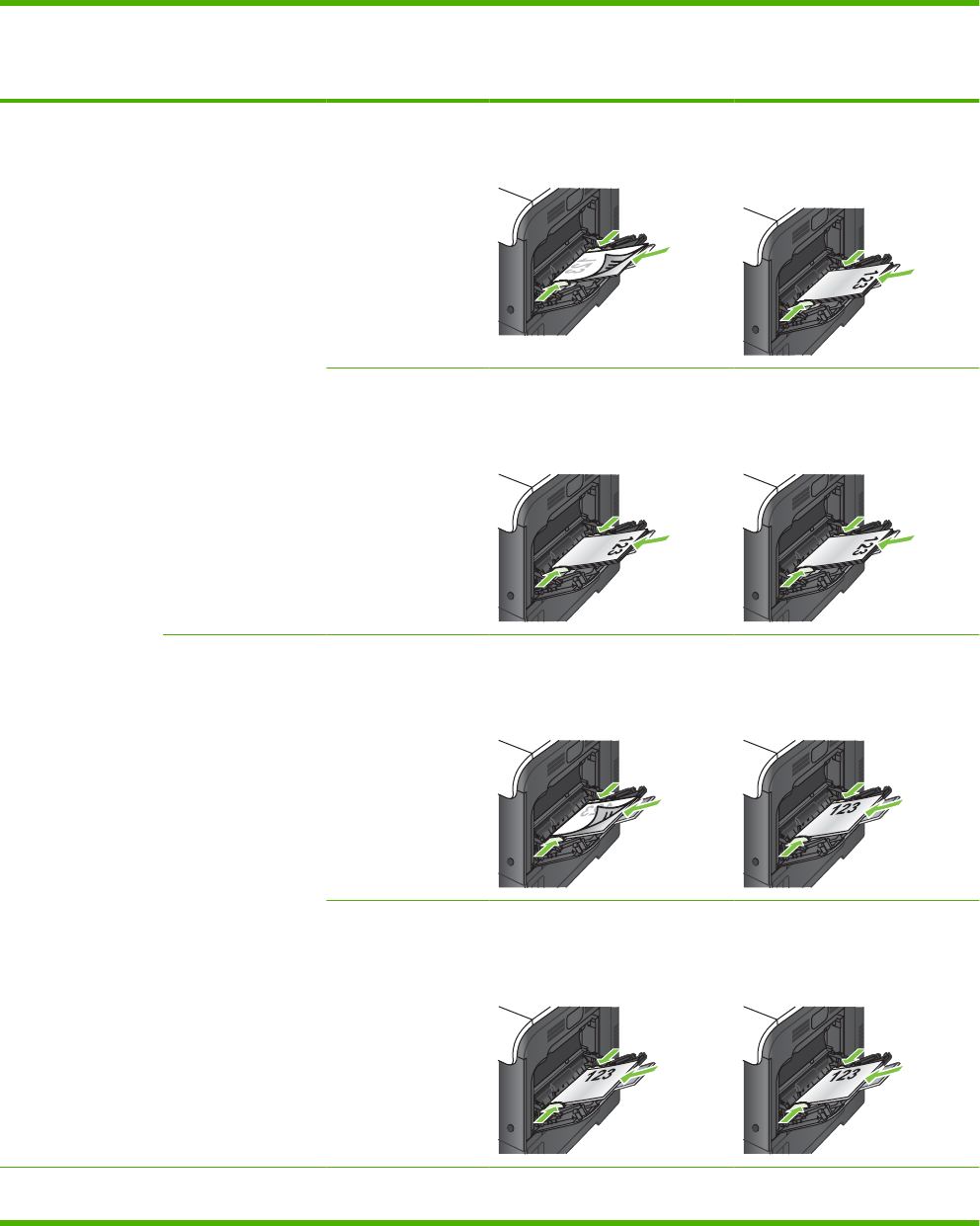
Tray 1
Paper type Image orientation Duplex mode How to load paper
Alternative Letterhead Mode =
Off
How to load paper
Alternative Letterhead Mode =
On
Preprinted or
letterhead
Portrait 1-sided printing Face down
Top edge leading into the product
Face up
Bottom edge leading into the
product
2-sided printing Face up
Bottom edge leading into the
product
Face up
Bottom edge leading into the
product
Landscape 1-sided printing Face down
Top edge toward the back of the
product
Face up
Top edge toward the back of the
product
2-sided printing Face up
Top edge toward the back of the
product
Face up
Top edge toward the back of the
product
Prepunched Portrait or landscape 1- or 2-sided printing Holes toward the back of the
product
Not applicable
ENWW Load paper and print media 63
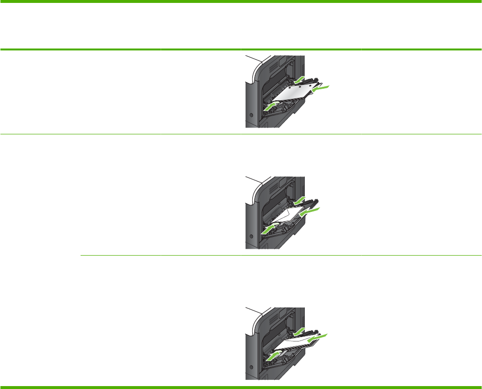
Paper type Image orientation Duplex mode How to load paper
Alternative Letterhead Mode =
Off
How to load paper
Alternative Letterhead Mode =
On
Envelopes Long edge of the
envelope feeding into
the product
1-sided printing Face down
Top edge leading into the product
Not applicable
Short edge of the
envelope feeding into
the product
1-sided printing Face down
Top edge toward the back of the
product
Not applicable
64 Chapter 3 Paper and print media ENWW
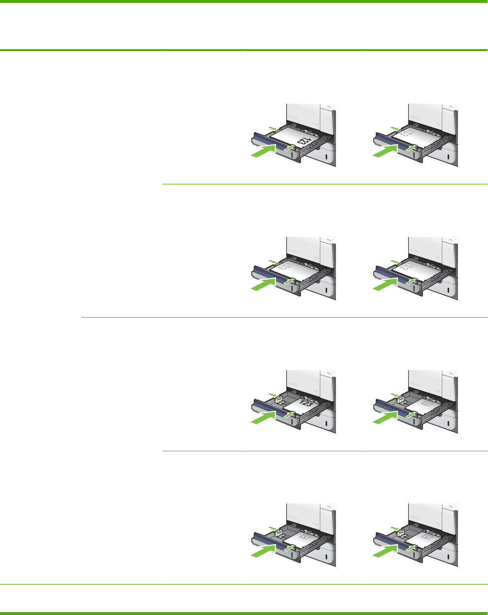
Tray 2 or optional Tray 3
Paper type Image orientation Duplex mode How to load paper
Alternative Letterhead Mode =
Off
How to load paper
Alternative Letterhead Mode =
On
Preprinted or
letterhead
Portrait 1-sided printing Face up
Top edge at the right side of the
tray
Face down
Top edge at the left side of the
tray
2-sided printing Face down
Top edge at the left side of the
tray
Face down
Top edge at the left side of the
tray
Landscape 1-sided printing Face up
Top edge toward the back of the
product
Face down
Top edge toward the back of the
product
2-sided printing Face down
Top edge toward the back of the
product
Face down
Top edge toward the back of the
product
Prepunched Portrait or landscape 1- or 2-sided printing Holes toward the back of the
product
Not applicable
ENWW Load paper and print media 65
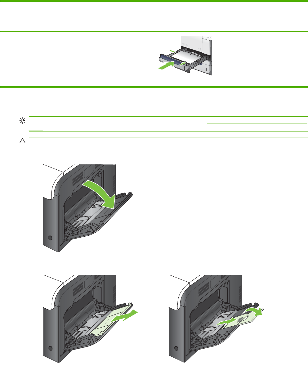
Paper type Image orientation Duplex mode How to load paper
Alternative Letterhead Mode =
Off
How to load paper
Alternative Letterhead Mode =
On
Load Tray 1
TIP: To see an animation of this procedure go to this Web site: www.hp.com/go/cljcm3530mfp-load-
tray1.
CAUTION: To avoid jams, never add or remove paper from Tray 1 during printing.
1. Open Tray 1.
2. Fold out the tray extension to support the paper and set the side guides to the correct width.
66 Chapter 3 Paper and print media ENWW
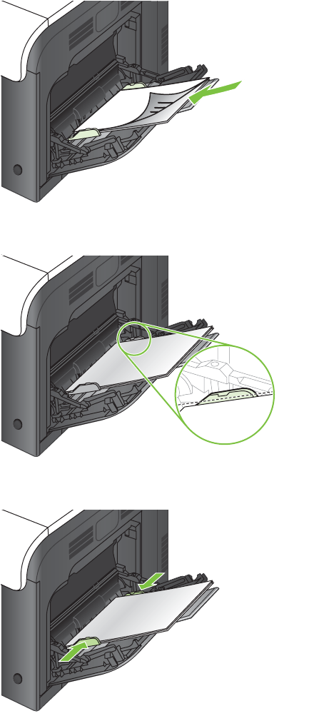
3. Load paper in the tray face down and the short, top edge going into the product first.
4. Make sure the stack fits under the tabs on the guides and does not exceed the load-level indicators.
5. Adjust the side guides so that they lightly touch the paper stack but do not bend it.
ENWW Load paper and print media 67
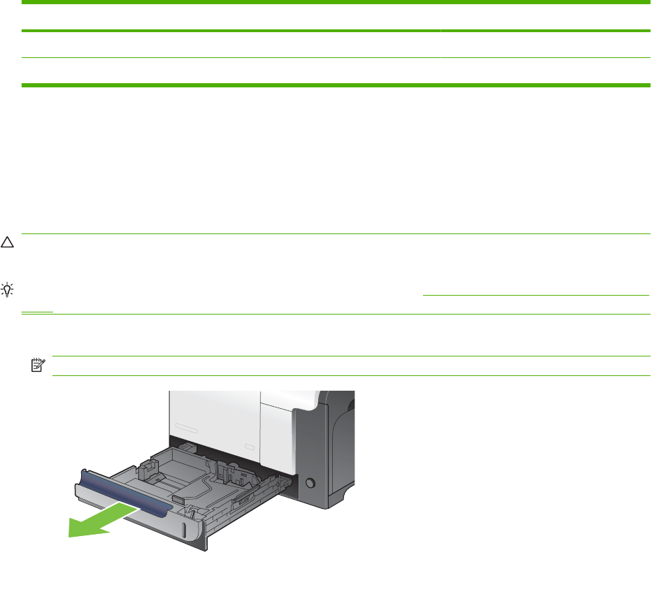
Print envelopes
If your software does not automatically format an envelope, specify Landscape for page orientation in
your software program or printer driver. Use the following guidelines to set margins for return and
destination addresses on Commercial #10 or DL envelopes:
Address type Left margin Top margin
Return 15 mm (0.6 in) 15 mm (0.6 in)
Destination 102 mm (4 in) 51 mm (2 in)
For envelopes of other sizes, adjust the margin settings accordingly.
Load Tray 2
This tray holds up to 250 sheets of 75 g/m
2
(20 lb) paper. If the paper is heavier, the tray does not hold
as many sheets. Do not overfill the tray.
CAUTION: Do not print envelopes, labels, postcards, or unsupported sizes of paper from the Tray 2.
Print these types of paper only from Tray 1.
TIP: To see an animation of this procedure go to this Web site: www.hp.com/go/cljcm3530mfp-load-
tray2.
1. Slide open the tray.
NOTE: Do not open the tray while it is in use.
68 Chapter 3 Paper and print media ENWW
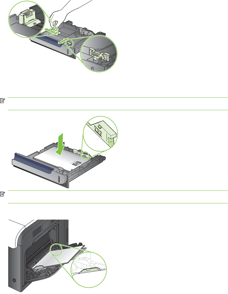
2. Adjust the paper-length and paper-width guides by squeezing the adjustment latch and sliding the
guides to the size of the paper being used.
3. Load paper into the tray face up. Check the paper to verify the guides lightly touch the stack, but
do not bend it.
NOTE: To prevent jams, do not overfill the tray. Be sure the top of the stack is below the tray full
indicator.
NOTE: If the tray is not adjusted correctly, an error message might appear during printing or the
paper might jam.
4. Slide the tray into the product.
ENWW Load paper and print media 69
5. The control panel shows the tray’s paper type and size. If the configuration is not correct, follow
the instructions on the control panel to change the size or type.
HP LaserJet
DDMMYYYY 00.00 AM
Load the optional 500-sheet paper and heavy media tray (Tray 3)
Tray 3 holds up to 500 sheets of standard paper.
The product automatically detects the following standard sizes of paper in Tray 3: Letter, Legal,
Executive, A4, A5, and B5 (JIS).
CAUTION: Do not print envelopes or unsupported sizes of paper from Tray 3. Print these types of
paper only from Tray 1.
Load standard-sized paper into Tray 3
TIP: To see an animation of this procedure go to this Web site: www.hp.com/go/cljcm3530mfp-load-
tray3.
1. Slide open the tray.
NOTE: Do not open the tray while it is in use.
70 Chapter 3 Paper and print media ENWW
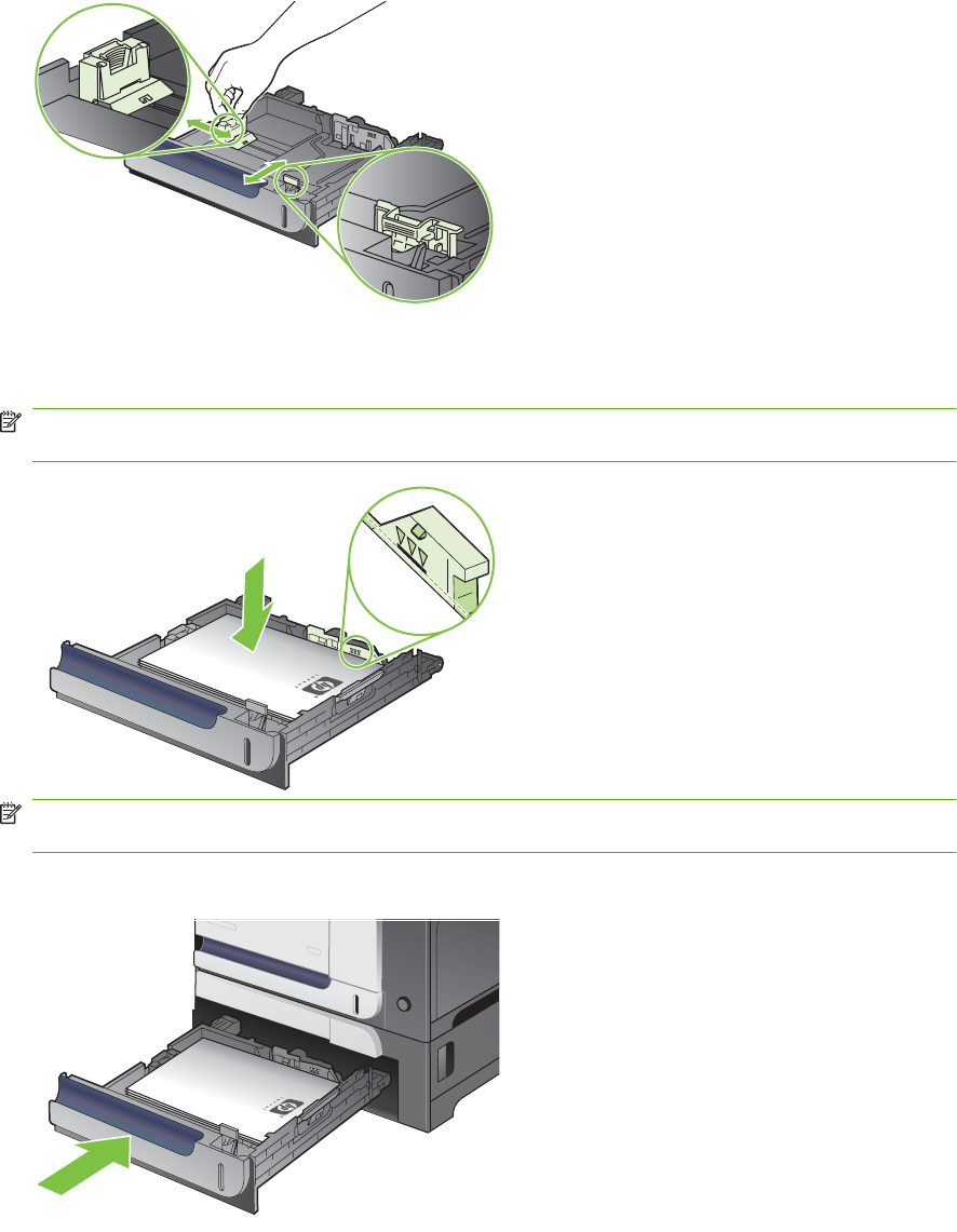
2. Adjust the paper-length and paper-width guides by squeezing the adjustment latches and sliding
the guides to the size of the paper being used.
3. Load paper into the tray face up. Check the paper to verify the guides lightly touch the stack, but
do not bend it.
NOTE: To prevent jams, do not overfill the tray. Be sure the top of the stack is below the tray full
indicator.
NOTE: If the tray is not adjusted correctly, an error message might appear during printing or the
paper might jam.
4. Slide the tray into the product.
ENWW Load paper and print media 71
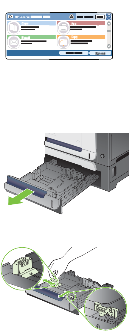
5. The control panel shows the tray’s paper type and size. If the configuration is not correct, follow
the instructions on the control panel to change the size or type.
HP LaserJet
DDMMYYYY 00.00 AM
Load custom-size paper into Tray 3
To use custom media, change the size setting on the control panel to Custom and set the unit of
measure, X Dimension and Y Dimension.
1. Slide open the tray.
2. Adjust the paper-length and paper-width guides by squeezing the adjustment latches and sliding
the guides to the size of the paper being used.
72 Chapter 3 Paper and print media ENWW
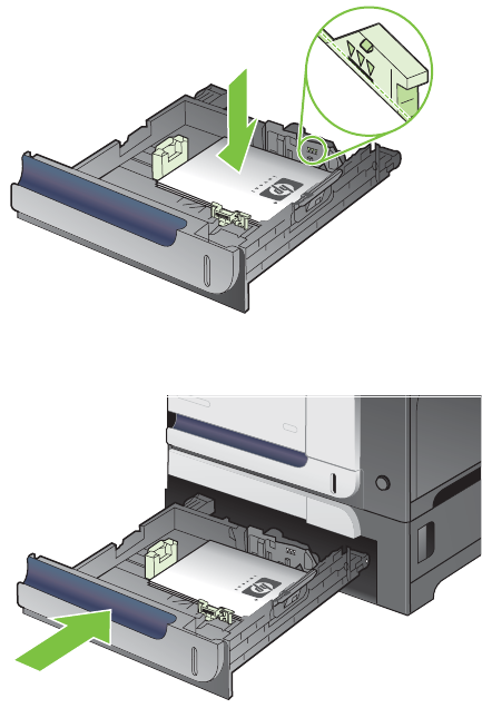
3. Load paper into the tray face up. Check the paper to verify the guides lightly touch the stack, but
do not bend it.
4. Slide the tray into the product. The control panel shows the paper type and size.
ENWW Load paper and print media 73

5. The control panel prompts you to set the paper size and type. Select the Custom setting, and then
configure the X and Y dimensions of the custom paper size.
HP LaserJet
DDMMYYYY 00.00 AM
NOTE: See the label in the paper tray, or the following illustration, to determine the X and Y
dimensions.
Y
X
74 Chapter 3 Paper and print media ENWW

Configure trays
The product automatically prompts you to configure a tray for type and size in the following situations:
●When you load paper into the tray
●When you specify a particular tray or media type for a print job through the printer driver or a
software program and the tray is not configured to match the print-job’s settings
The following message appears on the control panel: Tray <x> [type] [size] To change size or type,
touch “Modify”. To accept, touch “OK”.
NOTE: The prompt does not appear if you are printing from Tray 1 and Tray 1 is configured for Any
Custom and Any Type.
NOTE: If you have used other HP LaserJet product models, you might be accustomed to configuring
Tray 1 to First mode or Cassette mode. For this product, setting Tray 1 size to Any Custom is equivalent
to First mode. Setting size for Tray 1 to a setting other than Any Custom is equivalent to Cassette
mode.
Configure a tray when loading paper
1. Load paper in the tray. Close the tray if you are using Tray 2 or 3.
2. The tray configuration message appears.
3. Touch OK to accept the detected size and type, or touch Modify to choose a different paper size
or type.
4. Select the correct size and type and then touch OK.
Configure a tray to match print job settings
1. In the software program, specify the source tray, the paper size, and the paper type.
2. Send the job to the product.
If the tray needs to be configured, the tray configuration message appears.
3. Load the tray with the specified type and size of paper, and then close the tray.
4. Touch OK to accept the detected size and type, or touch Modify to choose a different paper size
or type.
5. Select the correct size and type and then touch OK.
Automatic overhead transparency sensing (auto sense mode)
The automatic media type sensor functions only when that tray is configured to the Any Type setting.
Configuring a tray to any other type, such as Bond or Glossy, deactivates the media sensor in that tray.
The product can automatically classify paper types into one of two categories:
●Non-transparency
●Transparency
For more control, a specific type must be selected in the job or configured in a tray.
ENWW Configure trays 75

Auto-sense settings
Full sensing (Tray 1 only)
●The product distinguishes between transparencies (Transparency mode) and paper (Normal
mode).
●Each time the product prints a page, it senses transparencies or non-transparencies.
●This is the slowest mode.
Transparency only
●The product distinguishes between transparencies (Transparency mode) and paper (Normal
mode).
●The product assumes that the second and all subsequent pages are of the same media type as
the first page.
●This is the fastest mode and is useful for high-volume printing in Normal mode.
For more information about setting these options, see Print Quality menu on page 46.
Select the paper by source, type, or size
In the Microsoft Windows operating system, three settings affect how the printer driver tries to pull media
when you send a print job. Source, Type, and Size settings appear in the Page Setup, Print, or Print
Properties dialog boxes in most software programs. Unless you change these settings, the product
automatically selects a tray using the default settings.
Source
To print by Source select a specific tray for the product to pull from. If you select a tray that is configured
for a type or size that does not match your print job, the product prompts you to load the tray with the
type or size of print media for your print job before printing it. When you load the tray, the product begins
printing.
Type and Size
Printing by Type or Size means that you want the product to pull from the tray that is loaded with the
correct type and size of media. Selecting media by type rather than source is similar to locking out trays
and helps protect special media from accidental use. For example, if a tray is configured for letterhead
and you select plain paper, the product will not pull the letterhead from that tray. Instead, it will pull from
a tray that has plain paper loaded and is configured for plain paper on the product control panel. Selecting
media by Type and Size results in significantly better print quality for heavy paper, glossy paper, and
transparencies. Using the wrong setting might result in unsatisfactory print quality. Always print by Type
for special print media, such as labels or transparencies. Print by Size for envelopes, if possible.
●To print by Type or Size, select the Type or Size from the Page Setup dialog box, the Print dialog
box, or the Print Properties dialog box, depending on the software program.
●If you often print on a certain type or size of media, configure a tray for that type or size. Then,
when you select that type or size as you print a job, the product automatically pulls media from the
tray that is configured for that type or size.
76 Chapter 3 Paper and print media ENWW

Choose an output bin
The product has an ADF output bin and the standard output bin for printed pages.
1
2
1Standard output bin
2ADF output bin (for copy originals)
When you scan or copy documents by using the ADF, the originals are automatically delivered to the
ADF output bin.
When you send print jobs to the product from a computer, the output is to the standard output bin.
ENWW Choose an output bin 77
78 Chapter 3 Paper and print media ENWW


Print information pages
Information pages provide details about the product and its current configuration. The following table
provides the instructions for printing the information pages.
Page description How to print the page from the product control panel
Administration Menu Map
Shows the control-panel menus and
available settings.
1. At the product control panel, touch the down arrow until the Administration menu
displays.
2. Touch the Administration menu to open it.
3. Touch the Information menu to open it.
4. Touch the Configuration/Status Pages menu to open it.
5. Touch the Administration Menu Map option, and then touch the Print button.
The content of the menu map varies, depending on the options currently installed in
the product.
For a complete list of control panel menus and possible values, see Control panel
on page 11.
Configuration Page
Shows product settings and installed
accessories.
1. At the product control panel, touch the down arrow until the Administration menu
displays.
2. Touch the Administration menu to open it.
3. Touch the Information menu to open it.
4. Touch the Configuration/Status Pages menu to open it.
5. Touch the Configuration Page option, and then touch the Print button.
NOTE: If the product contains an HP Jetdirect print server or an optional hard disk
drive, additional configuration pages print that provide information about those
devices.
Supplies Status Page
Shows print-cartridge toner levels.
1. At the product control panel, touch the down arrow until the Administration menu
displays.
2. Touch the Administration menu to open it.
3. Touch the Information menu to open it.
4. Touch the Configuration/Status Pages menu to open it.
5. Touch the Supplies Status Page option, and then touch the Print button.
NOTE: If you are using non-HP supplies, the supplies status page might not show
the remaining life for those supplies.
Usage Page
Shows a page count for each size of
paper printed, the number of one-sided
(simplexed) or two-sided (duplexed)
pages, and the average percentage of
coverage.
1. At the product control panel, touch the down arrow until the Administration menu
displays.
2. Touch the Administration menu to open it.
3. Touch the Information menu to open it.
4. Touch the Configuration/Status Pages menu to open it.
5. Touch the Usage Page option, and then touch the Print button.
80 Chapter 4 Manage and maintain ENWW

Page description How to print the page from the product control panel
Color Usage Job Log
Shows job-by-job color usage
information.
1. At the product control panel, touch the down arrow until the Administration menu
displays.
2. Touch the Administration menu to open it.
3. Touch the Information menu to open it.
4. Touch the Configuration/Status Pages menu to open it.
5. Touch the Color Usage Job Log option, and then touch the Print button.
File Directory
Contains information for any mass
storage devices, such as flash drives,
memory cards, or hard disks, that are
installed in the product.
1. At the product control panel, touch the down arrow until the Administration menu
displays.
2. Touch the Administration menu to open it.
3. Touch the Information menu to open it.
4. Touch the Configuration/Status Pages menu to open it.
5. Touch the down arrow until the File Directory option displays.
6. Touch the File Directory option, and then touch the Print button.
Fax Reports
Five reports show fax activity, fax calls,
billing codes, blocked fax numbers, and
speed-dial numbers.
NOTE: Fax reports are available only
on product models that have fax
capabilities.
1. At the product control panel, touch the down arrow until the Administration menu
displays.
2. Touch the Administration menu to open it.
3. Touch the Information menu to open it.
4. Touch the Fax Reports menu to open it.
5. Touch one of the following buttons to print the corresponding report:
◦Fax Activity Log
◦Fax Call Report
◦Billing Codes Report
◦Blocked Fax List
◦Speed Dial List
6. Touch thePrint button.
For more information, see the fax guide that came with the product.
Sample Pages/Fonts
Shows which fonts are installed in the
product.
1. At the product control panel, touch the down arrow until the Administration menu
displays.
2. Touch the Administration menu to open it.
3. Touch the Information menu to open it.
4. Touch Sample Pages/Fonts.
5. Touch the down arrow to scroll to the PCL Font List or PS Font List option.
6. Touch the PCL Font List or PS Font List option, and then touch thePrint button.
NOTE: The font lists also show which fonts reside on a hard disk accessory or
DIMM.
ENWW Print information pages 81

HP Easy Printer Care
Open the HP Easy Printer Care software
Use one of the following methods to open the HP Easy Printer Care software:
●On the Start menu, select Programs, select Hewlett-Packard, select HP Easy Printer Care, and
then click Start HP Easy Printer Care.
●In the Windows system tray (in the lower-right corner of the desktop), double-click the HP Easy
Printer Care icon.
●Double-click the desktop icon.
HP Easy Printer Care software sections
HP Easy Printer Care software can provide information about multiple HP products that are on your
network as well as any products that are directly connected to your computer. Some of the items that
are in the following table might not be available for every product.
The Help button (?) in the upper-right corner of each page provides more detailed information about the
options on that page.
Section Options
Device List tab
When you open the software, this is the
first page that appears.
NOTE: To return to this page from any
tab, click My HP Printers in the left side
of the window.
●Devices list: Shows the products that you can select.
NOTE: The product information appears either in list form or as icons,
depending on the setting for the View as option.
●The information on this tab includes current alerts for the product.
●If you click a product in the list, the HP Easy Printer Care opens the
Overview tab for that product.
Compatible Printers Provides a list of all the HP products that support HP Easy Printer Care software.
Find Other Printers window
Add more products to the
My HP Printers list
Click the Find Other Printers link in the Devices list to open the Find Other
Printers window. The Find Other Printers window provides a utility that detects
other network printers so that you can add them to the My HP Printers list and then
monitor those products from your computer.
Overview tab
Contains basic status information for the
product
●Device Status section: This section shows product-identification information
and the product status. It indicates product-alert conditions, such as when a
print cartridge has reached is estimated end of life. After you correct a problem
with the product, click the refresh button in the upper-right corner of the
window to update the status.
●Supplies Status section: Shows detailed supplies status, such as the
estimated life remaining in the print cartridge and the status of the paper that
is loaded in each tray.
●Supplies Details link: Opens the supplies status page to view more detailed
information about product supplies, ordering information, and recycling
information.
82 Chapter 4 Manage and maintain ENWW

Section Options
Support tab
Provides links to support information
●Device Status section: This section shows product-identification information
and the product status. It indicates product-alert conditions, such as a print
cartridge that is at its estimated end of life. After you correct a problem with the
product, click the refresh button in the upper-right corner of the window to
update the status.
●Device Management section: Provides links to information about HP Easy
Printer Care, to advanced product settings, and to product usage reports.
●Troubleshooting and Help: Provides links to tools that you can use to resolve
problems, to online product support information, and to online HP experts.
Settings tab
Configure product settings, adjust print-
quality settings, and find information
about specific product features
NOTE: This tab is not available for
some products.
●About: Provides general information about this tab.
●General: Provides information about the product, such as the model number,
serial number, and the settings for date and time, if they are available.
●Information Pages: Provides links to print the information pages that are
available for the product.
●Capabilities: Provides information about product features, such as duplexing,
the available memory, and the available printing personalities. Click Change
to adjust the settings.
●Print Quality: Provides information about print-quality settings. Click
Change to adjust the settings.
●Trays / Paper: Provides information about the trays and how they are
configured. Click Change to adjust the settings.
●Restore Defaults: Provides a way to restore the product settings to the factory
defaults. Click Restore to restore the settings to the defaults.
HP Proactive Support
NOTE: This item is available from the
Overview and Support tabs.
When enabled, HP Proactive Support routinely scans your printing system to identify
potential problems. Click the more info link to configure how frequently the scans
occur. This page also provides information about available updates for product
software, firmware, and HP printer drivers. You can accept or decline each
recommended update.
Supplies Ordering button
Click the Supplies Ordering button on
any tab to open the Supplies Ordering
window, which provides access to online
supplies ordering.
NOTE: This item is available from the
Overview and Support tabs.
●Ordering list: Shows the supplies that you can order for each product. To order
a certain item, click the Order check box for that item in the supplies list. You
can sort the list by product, or by the supplies that need to be ordered the
soonest. The list contains supplies information for every product that is in the
My HP Printers list.
●Shop Online for Supplies button: Opens the HP SureSupply Web site in a
new browser window. If you have checked the Order check box for any items,
the information about those items can be transferred to the Web site, where
you will receive information on options for purchasing your selected supplies.
●Print Shopping List button: Prints the information for the supplies that have
the Order check box selected.
ENWW HP Easy Printer Care 83

Section Options
Alert Settings link
NOTE: This item is available from the
Overview and Support tabs.
Click Alert Settings to open the Alert Settings window, in which you can configure
alerts for each product.
●Alerting is on or off: Activates or deactivates the alerts feature.
●Printer Alerts: Select the option to receive alerts for critical errors only, or for
any error.
●Job Alerts: For products that support it, you can receive alerts for specific print
jobs.
Color Access Control
NOTE: This item is available only for
HP color products that support Color
Access Control.
NOTE: This item is available from the
Overview and Support tabs.
Use this feature to permit or restrict color printing.
84 Chapter 4 Manage and maintain ENWW

Embedded Web server
Use the embedded Web server to view product and network status and to manage printing functions
from your computer instead of from the product control panel. The following are examples of what you
can do using the embedded Web server:
NOTE: When the printer is directly connected to a computer, use the HP Easy Printer Care to view
the printer status.
●View product status information.
●Set the type of media that is loaded in each tray.
●Determine the remaining life for all supplies and order new ones.
●View and change tray configurations.
●View and change the product control-panel menu configuration.
●View and print internal pages.
●Receive notification of product and supplies events.
●View and change network configuration.
To use the embedded Web server, you must have Microsoft Internet Explorer 5.01 or later or Netscape
6.2 or later for Windows, Mac OS, and Linux (Netscape only). Netscape Navigator 4.7 is required for
HP-UX 10 and HP-UX 11. The embedded Web server works when the product is connected to an IP-
based network. The embedded Web server does not support IPX-based product connections. You do
not have to have Internet access to open and use the embedded Web server.
When the product is connected to the network, the embedded Web server is automatically available.
NOTE: For complete information about using the embedded Web server, see the Embedded Web
Server User Guide, which is on the product Administrator CD.
Open the embedded Web server by using a network connection
1. In a supported Web browser on your computer, type the product IP address or host name in the
address/URL field. To find the IP address or host name, print a configuration page. See Print
information pages on page 80.
NOTE: After you open the URL, you can bookmark it so that you can return to it quickly in the
future.
2. The embedded Web server has four tabs that contain settings and information about the product:
the Information tab, the Settings tab, the Networking tab, and the Digital Sending tab. Click the
tab that you want to view.
See Embedded Web server sections on page 86 for more information about each tab.
ENWW Embedded Web server 85

Embedded Web server sections
Tab or section Options
Information tab
Provides product, status, and
configuration information
●Device Status: Shows the product status and shows the life remaining of
HP supplies, with 0% indicating that a supply is empty. The page also shows the type
and size of print paper set for each tray. To change the default settings, click Change
Settings.
●Configuration Page: Shows the information found on the configuration page.
●Supplies Status: Shows the life remaining of HP supplies, with 0% indicating that a
supply has reached its estimated end of life. This page also provides supplies part
numbers. To order new supplies, click Shop for Supplies in the Other Links area
on the left side of the window.
●Event Log: Shows a list of all product events and errors.
●Usage Page: Shows a summary of the number of pages the product has printed,
grouped by size and type.
●Diagnostics Page: Allows you to name the product, show the company name,
assign an asset number to the product, and name the primary contact who manages
the product. An HP-authorized support person might ask for this information.
●Device Information: Shows the product network name, address, and model
information. To customize these entries, click Device Information on the Settings
tab.
●Control Panel: Shows messages from the control panel, such as Ready or Sleep
mode on.
●Color Usage Job Log: Shows the total pages printed, the number of pages printed
in color, and the number of pages printed in black only.
●Print: Allows you to send print-ready jobs to the product.
Settings tab
Provides the ability to configure the
product from your computer
●Configure Device: Allows you to configure product default settings. This page
contains the traditional menus found on the control-panel display.
●Tray Sizes/Types: Shows the size and type of paper and print media allowed for
each input tray.
●E-mail Server: Network only. Used in conjunction with the Alerts page to set up e-
mail alerts.
●Alerts: Network only. Allows you to set up to receive e-mail alerts for various product
and supplies events.
●AutoSend: Allows you to configure the product to send automated e-mails regarding
product configuration and supplies to specific e-mail addresses.
●Security: Allows you to set a password that must be entered to gain access to the
Settings and Networking tabs. Enable and disable certain features of the
embedded Web server.
●Authentication Manager: Allows you to determine which product functions will
require a user to provide log-in information in order to use those functions.
●LDAP Authentication: Allows you to configure a Lightweight Directory Access
Protocol (LDAP) server to limit product access to certain users. The LDAP server will
require a user to provide log-in information in order to gain access to the product.
●Kerberos Authentication: Allows you to configure a Kerberos network
authentication protocol, which provides strong authentication for client/server
applications by using secret-key cryptography.
86 Chapter 4 Manage and maintain ENWW

Tab or section Options
●Device PIN: Allows you to configure the PIN numbers that are required to access
various product functions. Use the Authentication Manager page to select Group
1 PIN or Group 2 PIN for the various functions. For example, you could configure
the Copy option to require Group 1 PIN and configure the Send to E-mail option to
require Group 2 PIN.
●User PIN: Allows you to add, edit, or delete individual users who are allowed to use
various product functions such as copy, fax, and digital sending.
●Edit Other Links: Allows you to add or customize a link to another Web site. This
link is displayed in the Other Links area on all embedded Web server pages.
●Device Information: Allows you to name the product and assign an asset number
to it. Enter the name and e-mail address for the primary contact who will receive
information about the product.
●Language: Allows you to determine the language in which to display the embedded
Web server information.
●Date & Time: Allows time synchronization with a network time server.
●Sleep Schedule: Allows you to set or edit a wake time, sleep time, and sleep delay
for the product.
●Restrict Color: Allows you to permit or restrict color printing. You can specify
permissions for individual users or for jobs that are sent from specific software
programs.
●Home Screen Setup: Allows you to configure which features display on the Home
screen and the order in which they display.
NOTE: The Settings tab can be password-protected. If this product is on a network,
always consult with the system administrator before changing settings on this tab.
Digital Sending tab Use the pages on the Digital Sending tab to configure the digital-sending features.
NOTE: If the product is configured to use the optional HP Digital Sending Software, the
options on these tabs are not available. Instead, all digital-sending configuration is
performed by using the HP Digital Sending Software.
●General. Set up contact information for the system administrator.
●Send to Folder. Allows you to enable, disable, and configure the Send to Folder
capabilities on the product. It is also used to link the product to individual folder
destinations that exist in the network. As a first step, you must create and configure
destination folders. These destination folders need to be operational before using
this page to add the destinations to the product.
●E-mail Settings. Configure the e-mail settings for digital sending. You can specify
the SMTP server, the default "From" address, and the default subject. You can also
set the maximum file size that is allowed for attachments.
●E-mail Address Book. The E-mail Address Book page enables you to add e-mail
addresses into the product one at a time, and to edit e-mail addresses that have
already been saved in the product. You can also use the Import/Export tab to load
a large list of frequently-used e-mail addresses on to the product all at once, rather
than adding them one at a time.
●LDAP Settings. Allows you to configure the e-mail addresses where scanned
documents can be sent.
●Import/Export. Use this tab to import or export .CSV files containing e-mail
addresses, fax numbers, or user records, so that they can be accessed on this
product. You can also export e-mail, fax, or user records from the product into a file
ENWW Embedded Web server 87

Tab or section Options
on your computer. You can then use this file as a data backup, or you can use it to
import the records onto another HP product.
●Log. View the digital-sending activity log for the product. The log contains digital-
sending job information, including any errors that occur.
●Preferences. Configure digital-sending defaults such as the default page-size and
the default settings-reset delay. You can also configure these settings by using the
product control-panel menus.
Fax tab The Fax tab contains options to configure and use the fax capabilities of the product. For
additional information about fax functions, see the Fax User Guide.
NOTE: This tab is available only for the HP Color LaserJet CM3530fs MFP.
●Use the Fax Settings screen to configure the send-to-fax features for the product.
●The Fax Address Book page enables you to add fax numbers into the product one
at a time, and to edit fax numbers that have already been saved in the product. You
can also use the Import/Export feature on the Digital Sending tab to load a large
list of frequently-used fax numbers on to the product all at once, rather than adding
them one at a time.
●Use the Fax Speed Dials screen to add, edit, or delete fax speed dial entries to and
from the product. You can use fax speed dials to store frequently used fax numbers
or lists of up to 100 fax numbers. Up to 100 speed dial entries can be configured.
Networking tab
Provides the ability to change
network settings from your
computer
Network administrators can use this tab to control network-related settings for the product
when it is connected to an IP-based network. This tab does not appear if the product is
directly connected to a computer, or if the product is connected to a network using anything
other than an HP Jetdirect print server.
NOTE: The Networking tab can be password-protected.
Other Links
Contains links that connect you to
the Internet
●hp instant support: Connects you to the HP Web site to help you find solutions to
product problems.
●Shop for Supplies: Connects to the HP SureSupply Web site, where you will receive
information on options for purchasing original HP supplies, such as print cartridges
and paper.
●Product Support: Connects to the support site for the product, from which you can
search for help regarding various topics.
●Show Me How: Connects to information that demonstrates specific tasks for the
product.
NOTE: You must have Internet access in order to use any of these links. If you use a
dial-up connection and did not connect when you first opened the embedded Web server,
you must connect before you can visit these Web sites. Connecting might require that you
close the embedded Web server and reopen it.
88 Chapter 4 Manage and maintain ENWW

Use HP Web Jetadmin software
HP Web Jetadmin is a Web-based software solution for remotely installing, monitoring, and
troubleshooting network-connected peripherals. Management is proactive, allowing network
administrators the ability to resolve issues before users are affected. Download this free, enhanced-
management software at www.hp.com/go/webjetadmin.
Device plug-ins can be installed into HP Web Jetadmin to provide support for specific product features.
The HP Web Jetadmin software can automatically notify you when new plug-ins are available. On the
Product Update page, follow the directions to automatically connect to the HP Web site and install the
latest device plug-ins for your product.
NOTE: Browsers must be Java™-enabled. Browsing from an Apple PC is not supported.
ENWW Use HP Web Jetadmin software 89

Product security features
Secure the embedded Web server
Assign a password for access to the embedded Web server so that unauthorized users cannot change
the product settings.
1. Open the embedded Web server. See Embedded Web server on page 85.
2. Click the Settings tab.
3. On the left side of the window, click the Security menu.
4. Click the Device Security Settings button.
5. In the Device Password area, type the password next to New Password, and type it again next
to Verify Password.
6. Click Apply. Make note of the password and store it in a safe place.
HP Encrypted High Performance Hard Disks
This product supports an optional encrypted hard disk that you can install in the EIO accessory slot.
This hard disk provides hardware-based encryption so you can securely store sensitive print, copy, and
scan data without impacting product performance. This hard disk uses the latest Advanced Encryption
Standard (AES) and has versatile time-saving features and robust functionality.
For information about ordering these accessories see Part numbers on page 511.
Secure Disk Erase
To protect deleted data from unauthorized access on the product hard drive, use the Secure Disk Erase
feature in the HP Web Jetadmin software. This feature can securely erase print jobs from the hard
drive.
Secure Disk Erase offers the following levels of disk security:
●Non-Secure Fast Erase. This is a simple file-table erase function. Access to the file is removed,
but actual data is retained on the disk until it is overwritten by subsequent data-storage operations.
This is the fastest mode. Non-Secure Fast Erase is the default erase mode.
●Secure Fast Erase. Access to the file is removed, and the data is overwritten with a fixed identical
character pattern. This is slower than Non-Secure Fast Erase, but all data is overwritten. Secure
Fast Erase meets the U.S. Department of Defense 5220-22.M requirements for the clearing of disk
media.
●Secure Sanitizing Erase. This level is similar to the Secure Fast Erase mode. In addition, data is
repetitively overwritten by using an algorithm that prevents any residual data persistence. This
mode will impact performance. Secure Sanitizing Erase meets the U.S. Department of Defense
5220-22.M requirements for the sanitization of disk media.
Data affected
Data affected (covered) by the Secure Disk Erase feature includes temporary files that are created
during the print process, stored jobs, proof and hold jobs, disk-based fonts, disk-based macros (forms),
address books, and HP and third-party applications.
90 Chapter 4 Manage and maintain ENWW

NOTE: Stored jobs will be securely overwritten only when they have been deleted through the
Retrieve Job menu on the product after the appropriate erase mode has been set.
This feature will not impact data that is stored on flash-based product non-volatile RAM (NVRAM) that
is used to store default settings, page counts, and similar data. This feature does not affect data that is
stored on a system RAM disk (if one is used). This feature does not impact data that is stored on the
flash-based system boot RAM.
Changing the Secure Disk Erase mode does not overwrite previous data on the disk, nor does it
immediately perform a full-disk sanitization. Changing the Secure Disk Erase mode changes how the
product cleans up temporary data for jobs after the erase mode has been changed.
Additional Information
For additional information about the HP Secure Disk Erase feature, see the HP support flyer or go to
www.hp.com/go/webjetadmin.
Job storage
To securely print a private job, use the personal job feature. The job can only be printed when the correct
PIN is entered at the control panel.
DSS authentication
Optional Digital Sending Software (DSS) for the product is available for purchase separately. The
software provides an advanced sending program that contains an authentication process. This process
requires users to type a user identification and a password before they can use any of the DSS features
that require authentication.
Lock the control-panel menus
To prevent someone from changing the product configuration, you can lock the control-panel menus.
This prevents unauthorized users from changing the configuration settings such as the SMTP server.
You can use HP Web Jetadmin to lock the control-panel menus on several products simultaneously.
Browse to www.hp.com/go/webjetadmin to access white papers discussing security features, such as
control-panel lock, that allow you to secure the product against unwanted access.
1. Open the HP Web Jetadmin program.
2. Open the DEVICE MANAGEMENT folder in the drop-down list in the Navigation panel. Navigate
to the DEVICE LISTS folder.
3. Select the product.
4. In the Device Tools drop-down list, select Configure.
5. Select Security from the Configuration Categories list.
6. Type a Device Password.
7. In the Control Panel Access section, select Maximum Lock. This prevents unauthorized users
from gaining access to configuration settings.
ENWW Product security features 91
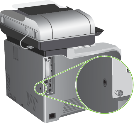
Lock the formatter cage
The formatter cage, on the back of the product, has a slot that you can use to attach a security cable.
Locking the formatter cage prevents someone from removing valuable components from the formatter.
Figure 4-1 Slot for the security cable
92 Chapter 4 Manage and maintain ENWW

Manage supplies
Use genuine HP print cartridges for the best printing results.
Print-cartridge storage
Do not remove the print cartridge from its package until you are ready to use it.
CAUTION: To prevent damage to the print cartridge, do not expose it to light for more than a few
minutes.
HP policy on non-HP print cartridges
Hewlett-Packard Company cannot recommend the use of non-HP print cartridges, either new or
remanufactured.
NOTE: Any damage caused by a non-HP print cartridge is not covered under the HP warranty and
service agreements.
To install a new HP print cartridge, see Change print cartridges on page 94. To recycle the used
cartridge, follow the instructions included with the new cartridge. For more information about recycling,
see the product user guide.
HP fraud hotline and Web site
Call the HP fraud hotline (1-877-219-3183, toll-free in North America) or go to www.hp.com/go/
anticounterfeit when you install an HP print cartridge and the control-panel message says the cartridge
is non-HP. HP will help determine if the cartridge is genuine and take steps to resolve the problem.
Your print cartridge might not be a genuine HP print cartridge if you notice the following:
●You are experiencing a high number of problems with the print cartridge.
●The cartridge does not look like it usually does (for example, the orange pull tab is missing, or the
packaging differs from HP packaging).
Replace supplies
When you use genuine HP supplies, the product automatically notifies you when supplies are reaching
their estimated end of life. The notification to order supplies allows ample time to order new supplies
before they need to be replaced. For more information about ordering supplies, see Order parts,
accessories, and supplies on page 510
Supplies life
For information regarding specific product yield, see www.hp.com/go/learnaboutsupplies.
To order supplies, see Parts and diagrams on page 509.
ENWW Manage supplies 93
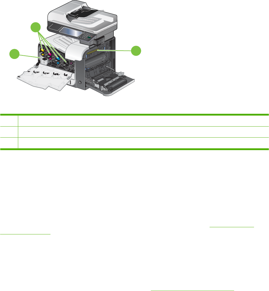
Locate supplies
Supplies are identified by their labeling and their blue plastic handles.
The following figure illustrates the location of each supply item.
Figure 4-2 Supply item locations
2
3
1
1Toner collection unit
2Print cartridges
3Fuser
Supply replacement guidelines
To facilitate the replacement of supplies, keep the following guidelines in mind when setting up the
product.
●Allow sufficient space in the front and on the right side of the product for removing supplies.
●The product should be located on a flat, sturdy surface.
For instructions on installing supplies, see the label on each supply item or see www.hp.com/go/
learnaboutsupplies.
Change print cartridges
When a print cartridge approaches the end of its estimated useful life, the control panel displays a
message recommending that you order a replacement. The product can continue to print using the
current print cartridge until the control panel displays a message instructing you to replace the cartridge,
unless you have selected the option to override the message by using the Replace Supplies menu. For
more information about the Replace Supplies menu, see Management menu on page 28.
The product uses four colors and has a different print cartridge for each color: black (K), magenta (M),
cyan (C), and yellow (Y).
You can replace a print cartridge when the control panel displays a Replace <color> Cartridge
message. The control panel display also indicates the color of the cartridge that has reached the end
94 Chapter 4 Manage and maintain ENWW

of its estimated useful life (if a genuine HP cartridge is currently installed). Replacement instructions are
provided on the label on the print cartridge.
CAUTION: If toner gets on clothing, wipe it off with a dry cloth and wash the clothes in cold water. Hot
water sets toner into fabric.
NOTE: Information about recycling used print cartridges is on the print-cartridge box. See the product
user guide.
TIP: To see an animation of this procedure go to this Web site: www.hp.com/go/cljcm3530mfp-
replace-print-cartridges.
Replace print cartridges
1. Open the front door. Make sure that the door is completely open.
2. Grasp the handle of the used print cartridge and pull out to remove.
3. Store the used print cartridge in a protective bag. Information about recycling used print cartridges
is on the print-cartridge box.
ENWW Manage supplies 95
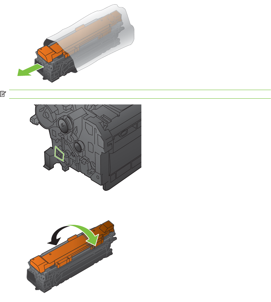
4. Remove the new print cartridge from its protective bag.
NOTE: Be careful not to damage the memory tag on the print cartridge.
5. Grasp both sides of the print cartridge and distribute the toner by gently rocking the print cartridge.
96 Chapter 4 Manage and maintain ENWW
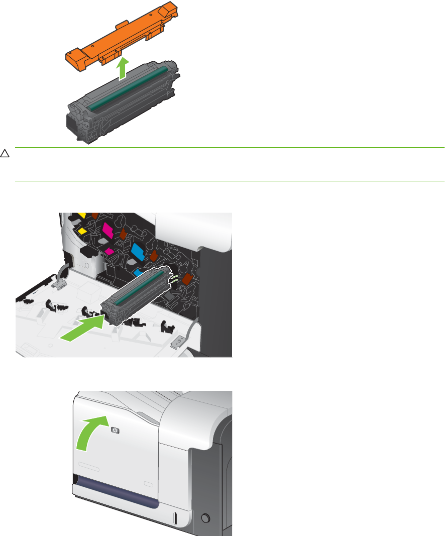
6. Remove the orange protective cover from the print cartridge.
CAUTION: Avoid prolonged exposure to light.
CAUTION: Do not touch the green roller. Doing so can damage the cartridge.
7. Align the print cartridge with its slot and insert the print cartridge until it clicks into place.
8. Close the front door.
ENWW Manage supplies 97
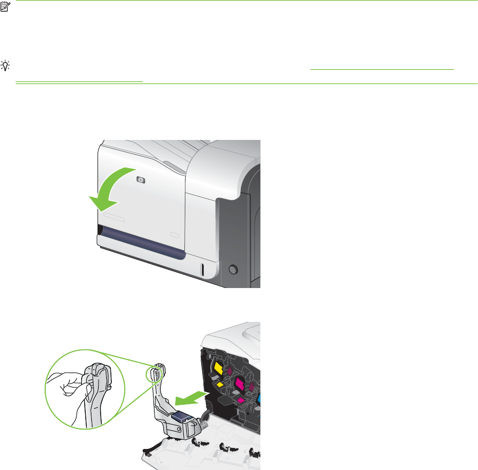
Change the toner collection unit
Replace the toner collection unit when the control panel prompts you.
NOTE: The toner collection unit is designed for a single use. Do not attempt to empty the toner
collection unit and reuse it. Doing so could lead to toner being spilled inside the product, which could
result in reduced print quality. After use, return the toner collection unit to HP’s Planet Partners program
for recycling.
TIP: To see an animation of this procedure go to this Web site: www.hp.com/go/cljcm3530mfp-
replace-toner-collection-unit.
Replace the toner collection unit
1. Open the front door. Make sure that the door is completely open.
2. Grasp the blue label at the top of the toner collection unit and remove it from the product.
98 Chapter 4 Manage and maintain ENWW
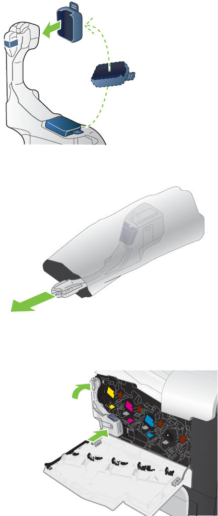
3. Place the attached blue cap over the blue opening at the top of the unit.
4. Remove the new toner collection unit from its packaging.
5. Insert the bottom of the new unit into the product first and then push the top of the unit until it clicks
into place.
ENWW Manage supplies 99
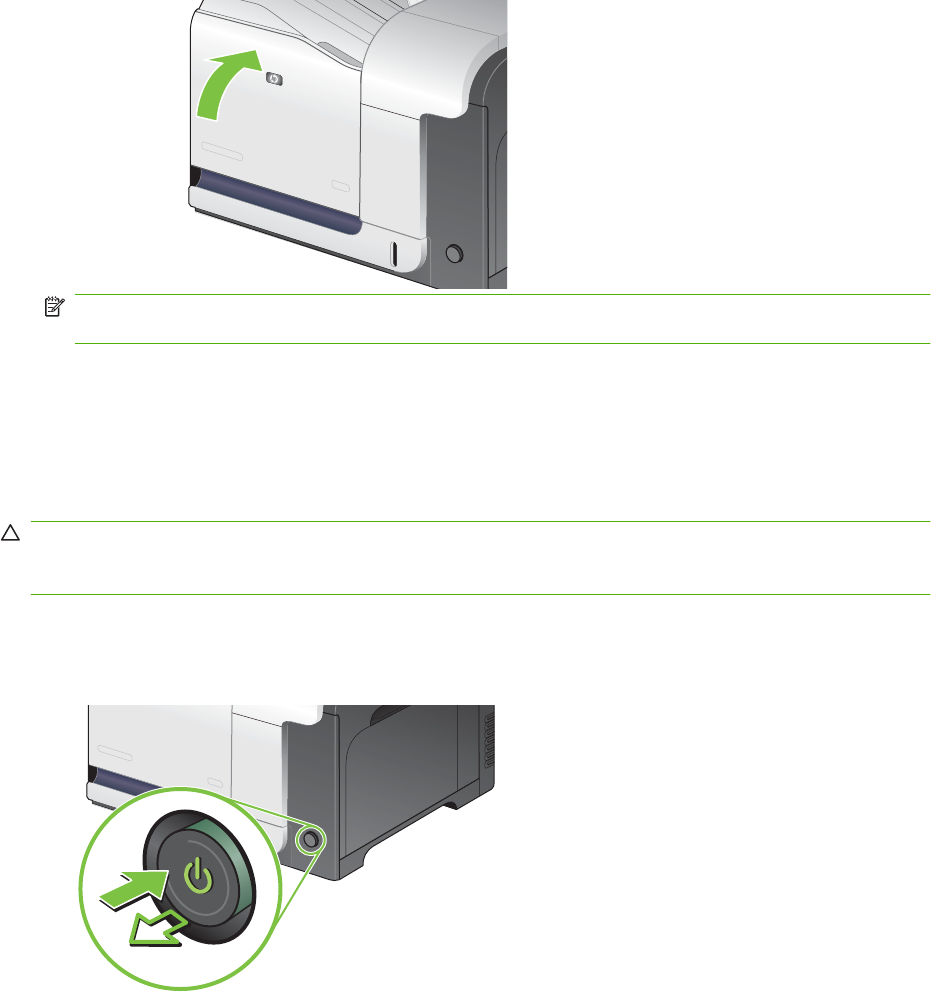
6. Close the front door.
NOTE: If the toner collection unit is not installed correctly, the front door does not close
completely.
To recycle the used toner collection unit, follow the instructions included with the new toner collection
unit.
Install memory
You can install more memory for the product.
CAUTION: Static electricity can damage DIMMs. When handling DIMMs, either wear an antistatic
wrist strap, or frequently touch the surface of the DIMM antistatic package and then touch bare metal
on the product.
Install DDR memory DIMMs
1. Turn the product off.
100 Chapter 4 Manage and maintain ENWW
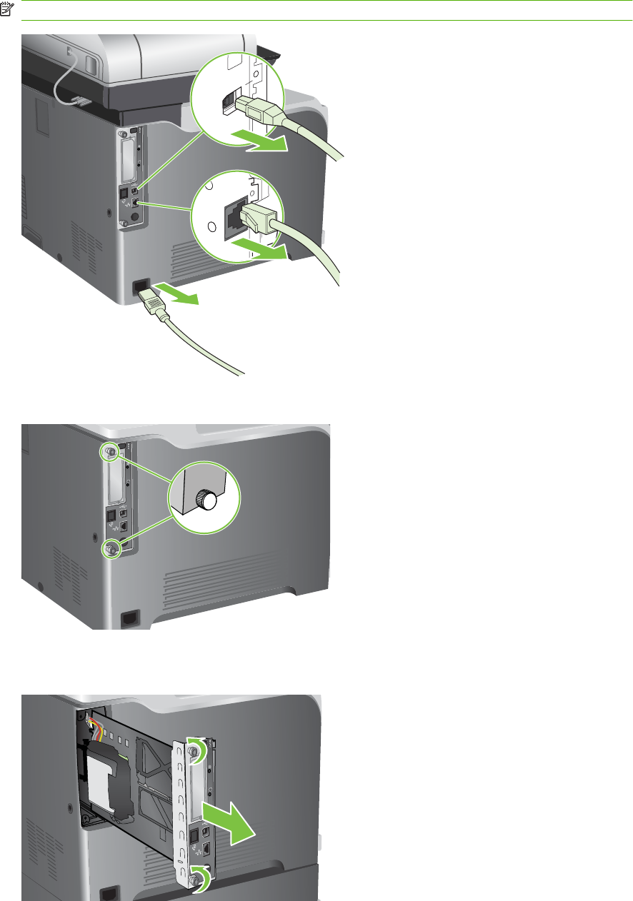
2. Disconnect all power and interface cables.
NOTE: This illustration might not show all the cables.
3. Locate the thumb screws on the formatter board in the rear of the product.
4. Unscrew the thumb screws and then pull the formatter board from the product. Place the formatter
board on a clean, flat, grounded surface.
ENWW Manage supplies 101
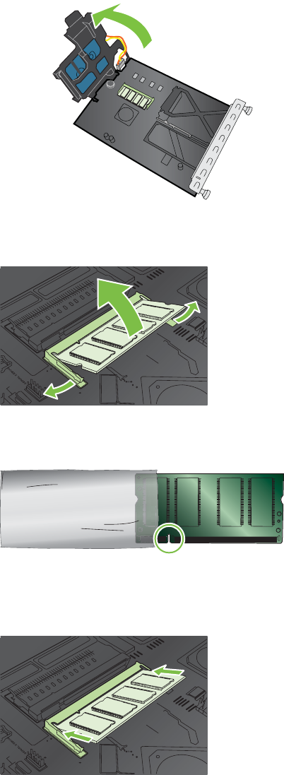
5. Release bracket that holds the hard drive, and swing it open.
XIOXIOXIXO
OXIXO
XIOXIO
XIOXIOXIXO
OXIXO
XIOXIO
XIOXIOXIXO
OXIXO
XIOXIO
XIOXIOXIXO
OXIXO
XIOXIO
6. To replace a DIMM that is currently installed, spread the latches apart on each side of the DIMM
slot, lift the DIMM up at an angle, and pull it out.
XOXOXO
XOXOXO
XOXOXOXOXOXO
XOXOXOXOXO
XOXOXOXOXO
XOXOXOXOXO
XOXOXOXOXO
XOXOXOXOXOXO
XOXO
XOXOXO
XOXOXO
XOXOXO
XOXOXO
XOXOXO
XOXOXO
XOXOXO
XOXOXO
XOXOXO
XOXOXO
XOXOXO
XOXOXO
XOXOXOXO
XOXOXO
XOXOXO
XOXOXO
7. Remove the new DIMM from the antistatic package. Locate the alignment notch on the bottom
edge of the DIMM.
8. Holding the DIMM by the edges, align the notch on the DIMM with the bar in the DIMM slot at an
angle and firmly press the DIMM into the slot until it is fully seated. When installed correctly, the
metal contacts are not visible.
XOXOXO
XOXOXO
XOXOXOXOXOXO
XOXOXOXOXO
XOXOXOXOXO
XOXOXOXOXO
XOXOXOXOXO
XOXOXOXOXOXO
XOXO
XOXOXO
XOXOXO
XOXOXO
XOXOXO
XOXOXO
XOXOXO
XOXOXO
XOXOXO
XOXOXO
XOXOXO
XOXOXO
XOXOXO
XOXOXOXO
XOXOXO
XOXOXO
XOXOXO
102 Chapter 4 Manage and maintain ENWW
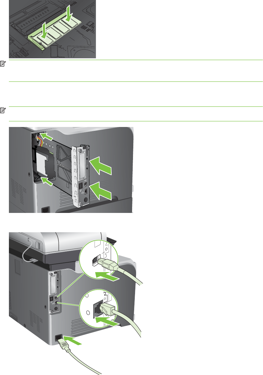
9. Push down on the DIMM until both latches engage the DIMM.
XOXOXO
XOXOXO
XOXOXOXOXOXO
XOXOXOXOXOXO
XOXO
XOXOXO
XOXOXO
XOXOXO
XOXOXO
XOXOXO
XOXOXO
XOXOXO
XOXOXO
XOXOXO
XOXOXO
XOXOXO
XOXOXO
XOXOXOXO
XOXOXO
XOXOXO
XOXOXO
XIOXIOXIXO
OXIXO
XIOXIO
XIOXIOXIXO
OXIXO
XIOXIO
XIOXIOXIXO
OXIXO
XIOXIO
XIOXIOXIXO
OXIXO
XIOXIO
NOTE: If you have difficulty inserting the DIMM, make sure the notch on the bottom of the DIMM
is aligned with the bar in the slot. If the DIMM still does not go in, make sure you are using the
correct type of DIMM.
10. Align the formatter board in the tracks at the bottom of the slot, and then slide the board back into
the product.
NOTE: To prevent damage to the formatter board, ensure the formatter board is aligned in the
tracks at the top and the bottom of the opening.
11. Reconnect the power cable and interface cables, and turn the product on.
ENWW Manage supplies 103
Enable memory for Windows
1. Windows XP and Windows Server 2003 (using the default Start menu view): Click Start, click
Settings, and then click Printers and Faxes.
-or-
Windows 2000, Windows XP, and Windows Server 2003 (using the Classic Start menu
view): Click Start, click Settings, and then click Printers.
-or-
Windows Vista: Click Start, click Control Panel, and then in the category for Hardware and
Sound click Printer.
2. Right-click the driver icon, and then select Properties.
3. Click the Device Settings tab.
4. Expand the area for Installable Options.
5. Next to Printer Memory, select the total amount of memory that is installed.
6. Click OK.
104 Chapter 4 Manage and maintain ENWW
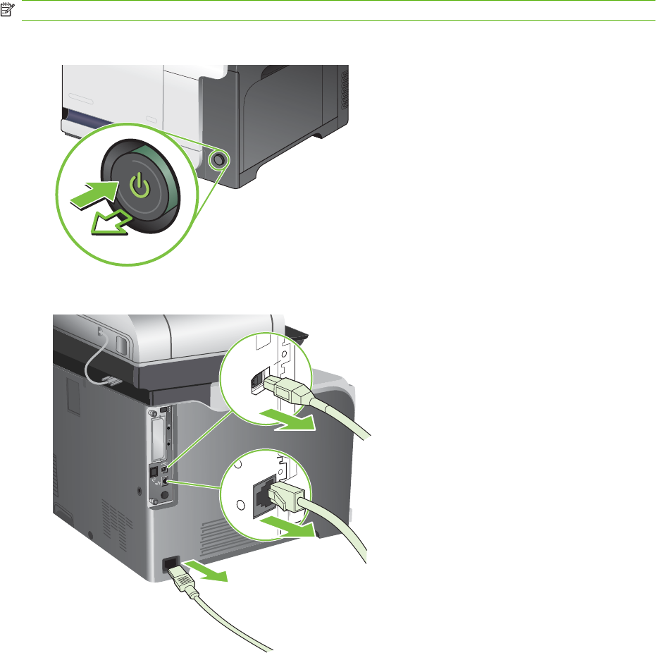
Install an HP Jetdirect or EIO print server card or EIO hard disk
This product is equipped with an external I/O (EIO) slot. You can install an additional HP Jetdirect print
server card or external EIO hard drive in the available EIO slot.
NOTE: This example shows installing an HP Jetdirect print server card.
1. Turn the product off.
2. Disconnect all power and interface cables.
ENWW Manage supplies 105
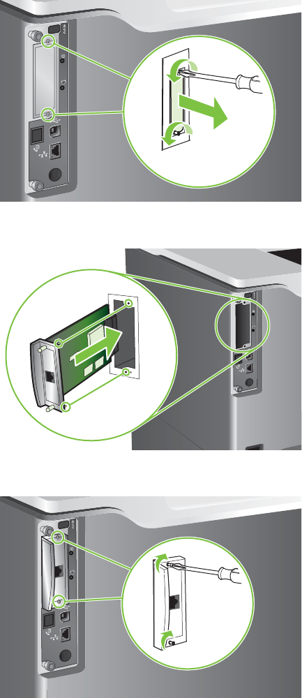
3. Loosen and remove the two retaining screws holding the cover for the EIO slot, and then remove
the cover. You will not need these screws and the cover again. They can be discarded.
4. Firmly insert the HP Jetdirect print server card into the EIO slot.
5. Insert and tighten the retaining screws that came with the print server card.
106 Chapter 4 Manage and maintain ENWW
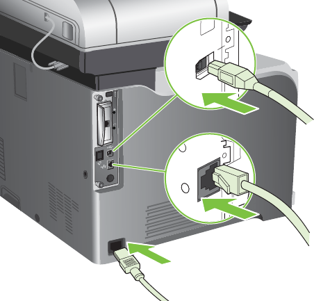
6. Reconnect the power cable and remaining interface cables, and turn the product on.
7. Print a configuration page. An HP Jetdirect configuration page that contains network configuration
and status information should also print.
If it does not print, turn the product off, and then uninstall and reinstall the print server card to ensure
that it is completely seated in the slot.
8. Perform one of these steps:
●Choose the correct port. See the computer or operating system documentation for
instructions.
●Reinstall the software, choosing the network installation this time.
ENWW Manage supplies 107

Clean the product
To maintain print quality, clean the product thoroughly every time you replace the print cartridge and
whenever print-quality problems occur.
WARNING! Avoid touching the fusing area when cleaning the product. It can be hot.
CAUTION: To avoid permanent damage to the print cartridge, do not use ammonia-based cleaners
on or around the product except as directed.
Clean the outside of the product
●Clean the outside of the product if it is visibly marked.
●Use a soft, lint-free cloth dampened with water, or water and a mild detergent.
Clean the touchscreen
Clean the touchscreen whenever it is necessary to remove fingerprints or dust. Wipe the touchscreen
gently with a clean, water-dampened, lint-free cloth.
CAUTION: Use water only. Solvents or cleaners can damage the touchscreen. Do not pour or spray
water directly onto the touchscreen.
Clean the scanner glass
●Clean the scanner glass only if dirt is visible, or if you are experiencing a decrease in copy quality,
such as streaking.
●Clean the scanner glass by wiping it gently with a clean, slightly damp, lint-free cloth. Use an
ammonia-based surface cleaner only when a water-dampened cloth does not clean the scanner
glass.
CAUTION: Do not pour or spray liquids directly onto the scanner glass. Do not press hard on the glass
surface. (You could break the glass).
Clean the document feeder
Ink and corrrection fluid can leave residue on the narrow glass strip to the left of the large scanner glass.
If you are having problems with streaks on copies, clean the narrow glass strip.
108 Chapter 4 Manage and maintain ENWW
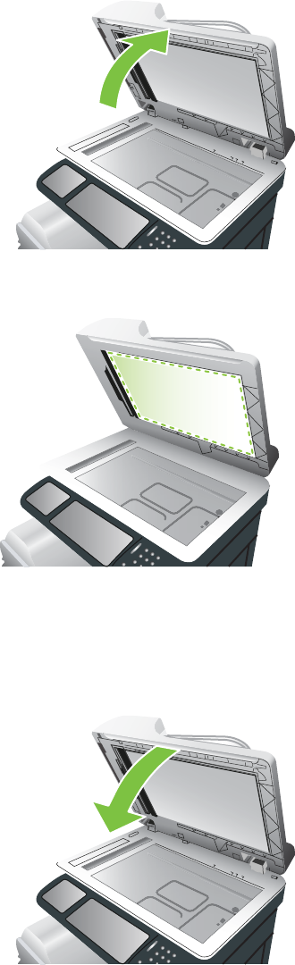
Clean the document-feeder backing
1. Open the scanner lid.
2. Locate the white, vinyl document-feeder backing.
3. Clean the document-feeder backing by wiping it with a clean, damp, lint-free cloth. Use an
ammonia-based surface cleaner only when a water-dampened cloth does not clean the
components.
4. Close the scanner lid.
ENWW Clean the product 109
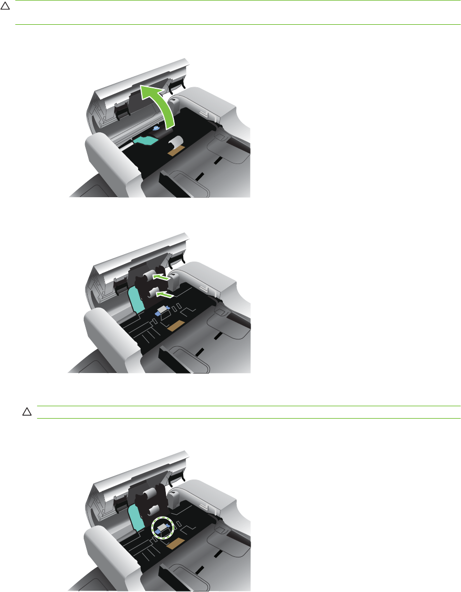
Clean the document-feeder rollers
You should clean the rollers in the document feeder if you are experiencing misfeeds or if your originals
show marks as they exit the document feeder.
CAUTION: Clean the rollers only if you experience misfeeds or marks on the originals, and you notice
dust on the rollers. Cleaning the rollers frequently could introduce dust into the product.
1. Pull the release lever to open the document-feeder cover.
2. Locate the rollers.
3. Wipe the rollers with a clean, water-dampened, lint-free cloth.
CAUTION: Do not pour water directly onto the rollers. Doing so might damage the product.
4. Locate the separation pad.
110 Chapter 4 Manage and maintain ENWW
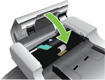
5. Wipe the pad with a clean, water-dampened, lint-free cloth.
6. Close the document-feeder cover.
Clean the fuser
Run the product cleaning page to keep the fuser free of toner and paper particles that can sometimes
accumulate. Accumulation of toner and particles can cause specks to appear on the front or back side
of your print jobs.
HP recommends that you use the cleaning page when there is a print quality issue.
A Cleaning message appears on the product control panel display while the cleaning is taking place.
In order for the cleaning page to work correctly, print the page on copier-grade paper (not bond, heavy,
or rough paper).
Create and use the cleaning page
1. Scroll to and touch Administration.
2. Scroll to and touch Print Quality
3. Touch Calibration/cleaning.
4. Touch Process cleaning page.
ENWW Clean the product 111

Product updates
This product has remote firmware update (RFU) capability. Use this information to upgrade the product
firmware.
Determine the current firmware version
1. At the product control panel, touch the down arrow until the Administration menu displays.
2. Touch the Administration menu to open it.
3. Touch the Information menu to open it.
4. Touch the Configuration Page option, and then touch the Print button.
The firmware datecode is listed on the Configuration page in the section called Device Information.
The firmware datecode has this format: YYYYMMDD XX.XXX.X.
●The first string of numbers is the date, where YYYY represents the year, MM represents the month,
and DD represents the date. For example, a firmware datecode that begins with 20061125
represents November 25, 2006.
●The second string of numbers is the firmware version number, in decimal format.
Download new firmware from the HP Web site
To find the most recent firmware upgrade for the product, go to www.hp.com/go/
cljcm3530mfp_firmware. This page provides instructions for downloading the new firmware version.
Transfer the new firmware to the product
NOTE: The product can receive an .RFU file update when it is in a "ready" state.
The following conditions can affect the time required to transfer the file.
●The speed of the host computer that is sending the update.
●Any jobs that are ahead of the .RFU job in the queue are completed before the update is processed.
●If the process is interrupted before the firmware is downloaded, you must send the firmware file
again.
●If power is lost during the firmware update, the update is interrupted and the message Resend
upgrade appears (in English only) on the control-panel display. In this case, you must send the
upgrade by using the USB port.
NOTE: The firmware update involves a change in the format of nonvolatile random-access memory
(NVRAM). Any menu settings that are changed from the default settings might return to default settings
and must be changed again if you want settings that are different from the defaults.
Use the flash executable file to update the firmware
This product has flash-based memory, so you can use the flash firmware executable (.EXE) file to
upgrade the firmware. Download this file from www.hp.com/go/cljcm3530mfp_firmware.
112 Chapter 4 Manage and maintain ENWW

NOTE: To use this method, connect the product directly to your computer through a USB cable, and
install the printer driver for this product on your computer.
1. Print a configuration page and note the TCP/IP address.
2. Find the .EXE file on your computer, and double-click it to open the file.
3. From the Select Printer to Update drop-down list, select this product. Click the Start button to
begin the update process.
CAUTION: Do not turn the product off or try to send a print job during this process.
4. When the process is complete, a smiling face icon displays in the dialog box. Click the Exit button
to close the dialog box.
5. Turn the product off and then on.
6. Print another configuration page and verify that the new firmware datecode is listed.
Use FTP to upload the firmware through a browser
1. Make sure the Internet browser you are using is configured for viewing folders from FTP sites.
These instructions are for Microsoft Internet Explorer.
a. Open the browser and click Tools, and then click Internet Options.
b. Click the Advanced tab.
c. Select the box labeled Enable folder view for FTP sites.
d. Click OK.
2. Print a configuration page and note the TCP/IP address.
3. Open a browser window.
4. In the address line of the browser, type ftp://<ADDRESS>, where <ADDRESS> is the address
of the product. For example, if the TCP/IP address is 192.168.0.90, type ftp://
192.168.0.90.
5. Locate the downloaded .RFU file for the product.
6. Drag and drop the .RFU file onto the PORT icon in the browser window.
NOTE: The product turns off and then on automatically to activate the update. When the update
process is complete, a Ready message displays on the product control panel.
Use FTP to upgrade the firmware on a network connection
1. Take note of the IP address on the HP Jetdirect page. The HP Jetdirect page is the second page
that prints when you print the configuration page.
NOTE: Before upgrading the firmware, make sure that the product is not in Sleep mode. Also
make sure that any error messages are cleared from the control-panel display.
2. Click Start, click Run, and then type cmd to open the command window.
3. Type: ftp <TCP/IP ADDRESS>. For example, if the TCP/IP address is 192.168.0.90, type ftp
192.168.0.90.
ENWW Product updates 113

4. Go to the folder where the firmware file is stored.
5. Press Enter on the keyboard.
6. When prompted for the user name, press Enter.
7. When prompted for the password, press Enter.
8. Type bin at the command prompt.
9. Press Enter. The message 200 Types set to I, Using binary mode to transfer files appears in
the command window.
10. Type put and then the file name. For example, if the file name is cljcm3530.rfu, type put
cljcm3530.rfu.
11. The download process begins and the firmware is updated on the product. This can take several
minutes. Let the process finish without further interaction with the product or computer.
NOTE: The product automatically turns off and then on again after processing the upgrade.
12. At the command prompt, type: bye to exit the ftp command.
13. At the command prompt, type: exit to return to the Windows interface.
Use HP Web Jetadmin to upgrade the firmware
To learn how to use HP Web Jetadmin to upgrade the product firmware, go to www.hp.com/go/
webjetadmin
Use Microsoft Windows commands to upgrade the firmware
To update the firmware by using a network connection, follow these instructions.
1. Click Start, click Run, and then type cmd to open the command window.
2. Type the following: copy /B <FILENAME> \\<COMPUTERNAME>\<SHARENAME>, where
<FILENAME> is the name of the .RFU file (including the path), <COMPUTERNAME> is the name
of the computer from which the product is being shared, and <SHARENAME> is the product share
name. For example: C:\>copy /b C:\cljcm3530.rfu \\YOUR_SERVER
\YOUR_COMPUTER.
NOTE: If the file name or path includes a space, you must enclose the file name or path in
quotation marks. For example, type: C:\>copy /b "C:\MY DOCUMENTS\cljcm3530.rfu"
\\YOUR_SERVER\YOUR_COMPUTER.
3. Press Enter on the keyboard. The control panel shows a message that indicates the progress of
the firmware upgrade. At the end of the upgrade process, the control panel shows the Ready
message. The message One File Copied appears on the computer screen.
114 Chapter 4 Manage and maintain ENWW


Basic operation
The product routes all high-level processes through the formatter, which stores font information,
processes the print image, and communicates with the host computer.
The basic product operation comprises the following systems:
●The engine-control system, which includes the power supply and the DC controller printed circuit
assembly (PCA)
●The laser/scanner system, which forms the latent image on the photosensitive drum
●The image-formation system, which transfers a toner image onto the paper
●The media feed system, which uses a system of rollers and belts to transport the paper through
the product
●Option (optional paper feeder)
Figure 5-1 Relationship between the main product systems
Laser/scanner system
Image-formation system
Media-feed system
Option
Engine control system
Sequence of operation
The DC controller PCA controls the operating sequence, as described in the following table.
NOTE: The terms fusing and fixing are synonymous.
116 Chapter 5 Theory of operation ENWW

Table 5-1 Sequence of operation
Period Duration Description
Waiting From the time the power is turned on, the
door is closed, or when the product exits
Sleep mode until the product is ready for
printing
●Heats the fuser sleeve
●Pressurizes the fuser pressure
roller
●Detects the print cartridges
●Detects the home position for the
primary transfer roller and the
developing unit
●Cleans the secondary transfer roller
Standby From the end of the waiting sequence or
the last rotation until the formatter
receives a print command or until the
product is turned off
●The product is in the READY state.
●The product enters Sleep mode
after the specified length of time.
●The product calibrates if it is time for
an automatic calibration.
Initial rotation From the time the formatter receives a
print command until the paper enters the
paper path
●Activates the high-voltage power
supply
●Prepares each laser/scanner unit
●Warms the fuser to the correct
temperature
Printing From the time the first sheet of paper
enters the paper path until the last sheet
has passed through the fuser
●Forms the image on the
photosensitive drums
●Transfers the toner to the paper
●Fuses the toner image onto the
paper
●Performs calibration after a
specified number of pages
Last rotation From the time the last sheet of paper
exits the fuser until the motors stop
rotating
●Moves the last printed sheet into the
output bin
●Stops each laser/scanner unit
●Discharges the bias from the high-
voltage power supply
ENWW Basic operation 117
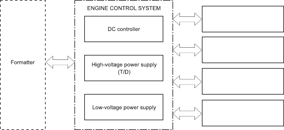
Engine-control system
The engine-control system receives commands from the formatter and interacts with the other main
systems to coordinate all product functions. The engine-control system consists of the following
components:
●DC controller
●High-voltage power supply
●Low-voltage power supply
Figure 5-2 Engine-control system
Laser/scanner system
Image-formation system
Media-feed system
Option
118 Chapter 5 Theory of operation ENWW

DC controller
The DC controller controls the operational sequence of the printer.
Figure 5-3 DC controller block diagram
Fuser
Laser/scanner
Solenoids
Table 5-2 Solenoids
Component abbreviation Component name
SL1 Primary transfer roller disengagement solenoid
SL2 Duplex reverse solenoid
SL3 Multipurpose-tray pickup solenoid
SL4 Cassette pickup solenoid
ENWW Engine-control system 119

Clutches
Component abbreviation Component name
CL1 Duplex re-pickup clutch
Switches
Table 5-3 Switches
Component abbreviation Component name
SW1, SW2 5V interlock switch
SW3 24V interlock switch
SW4 Power switch
Test print switch
120 Chapter 5 Theory of operation ENWW

Sensors
Table 5-4 Sensors
Component abbreviation Component name
SR1 Drum home position sensor 1
SR2 Drum home position sensor 2
SR3 Drum home position sensor 3
SR5 Fuser (fixing) delivery sensor
SR6 Delivery tray media full sensor
SR7 Fuser (fixing) pressure release sensor
SR8 TOP (top of page) sensor
SR9 Cassette-media-stack surface sensor
SR11 Developing home position sensor
SR13 Cassette presence sensor
SR14 Loop sensor 1
SR15 Loop sensor 2
SR17 Primary-transfer-roller disengagement sensor
SR20 Cassette-media presence sensor
SR21 MP-tray-media-presence sensor
SR22 Duplex re-pickup sensor
OHT sensor (in)
OHT sensor (out)
RD sensor (front)
RD sensor (rear)
Environmental sensor (temperature and humidity)
Yellow toner-level sensor
Magenta toner-level sensor
Cyan toner-level sensor
Black toner-level sensor
Toner collection-box-full sensor
Fuser (fixing) home-position sensor
ENWW Engine-control system 121

Motors and fans
The product has 11 motors and three fans. The motors drive the components in the paper-feed and
image-formation systems. The fan motors cool the inside of the product.
Table 5-5 Motors
Abbreviation Name Purpose Type Failure detection
M2 Fuser (fixing) motor Drives the Fuser
(fixing) roller, the
delivery roller, and the
Fuser (fixing) pressure
roller
DC motor Yes
M3 Drum motor 1 Drives the
photosensitive drum
(yellow/magenta),
developing unit
(yellow), and primary
charging roller (yellow/
magenta)
DC motor Yes
M4 Drum motor 2 Drives the
photosensitive drum
(cyan), developing unit
(magenta/cyan), and
primary charging roller
(cyan)
DC motor Yes
M5 Drum motor 3 Drives the
photosensitive drum
(black), developing unit
(black), and ITB drive
roller, and secondary
transfer roller
DC motor Yes
M7 Lifter motor Drives the lifter for the
cassette
DC motor Yes
M8 Cyan/black scanner
motor
Drives the scanner
mirror in the cyan/black
laser scanner
DC motor Yes
M9 Yellow/magenta
scanner motor
Drives the scanner
mirror in the yellow/
magenta laser scanner
DC motor Yes
M10 Developing
disengagement motor
Drives the developing
unit disengagement
Stepping motor No
M11 Duplex reverse motor Drives the duplex
reverse roller and
duplex feed roller
Stepping motor No
M12 Residual toner-feed
motor
Drives the residual
toner feed screw
DC motor Yes
M13 Pickup motor Drives the cassette
pickup roller, MP tray
pickup roller, feed
roller, registration
roller, and re-pickup
roller
Stepping motor No
122 Chapter 5 Theory of operation ENWW
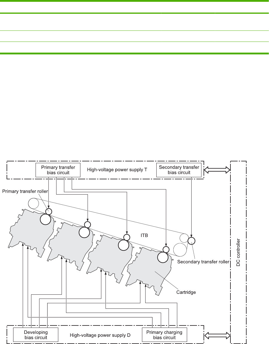
Table 5-6 Fans
Abbreviation Name Cooling area Type Speed
FM1 Power supply fan Around the power
supply unit
Intake Full/half
FM2 Cartridge fan Around the cartridges Intake Full/half
FM3 Delivery fan Around the delivery unit Intake Full/half
High-voltage power supply
The high-voltage power supply delivers the high-voltage biases to the following components used to
transfer toner during the image-formation process:
●Primary-charging roller (in the cartridge)
●Developing roller (in the cartridge)
●Primary-transfer roller
●Secondary-transfer roller
Figure 5-4 High-voltage power supply circuits
Y
M
C
K
The high-voltage power supply contains several separate circuits.
ENWW Engine-control system 123

Table 5-7 High-voltage power supply circuits
Circuit Description
Primary-charging-bias generation DC negative bias is applied to the surface of the photosensitive drum to prepare it
for image formation.
Developing-bias generation DC negative bias adheres the toner to each photosensitive drum during the image-
formation process.
Primary-transfer-bias generation DC positive bias transfers the latent toner image from each photosensitive drum onto
the ITB.
Secondary-transfer-bias generation Two DC biases, one positive and one negative, transfer the toner from the ITB onto
the paper.
124 Chapter 5 Theory of operation ENWW
Low-voltage power supply
The low-voltage power-supply circuit converts the AC power from the wall receptacle into the DC voltage
that the product components use. The product has two low-voltage power-supplies for 110 Volt or 220
Volt input.
Figure 5-5 Low-voltage power-supply circuit
Fuser control
circuit
The low-voltage power supply converts the AC power into three DC voltages, which it then subdivides,
as described in the following table.
Table 5-8 Converted DC voltages
Main DC voltage Sub-voltage Behavior
+24 V +24VA Constantly supplied
ENWW Engine-control system 125

Main DC voltage Sub-voltage Behavior
+24VB Interrupted when the front door or right
door open
Stopped during Sleep (powersave)
mode
+5 V +5VA Constantly supplied
+5VC Interrupted when the front door or right
door open
+3.3 V 3.3V Constantly supplied
3.3VS Stopped during Sleep (powersave)
mode
Overcurrent/overvoltage protection
The low-voltage power supply stops supplying the DC voltage to the product components whenever it
detects excessive current or abnormal voltage from the power source.
Safety
For personal safety, the low-voltage power supply interrupts power to the fuser, the high-voltage power
supply, and the motors when the front door or right door open.
Voltage detection
The printer detects the power supply voltage that is connected to the printer. The DC controller monitors
the input voltage from the power source so it can control the voltage to the fuser.
Sleep (powersave) mode
Sleep mode conserves energy by stopping the power to several components when the product is idle.
If the DC controller detects voltage that is too high when the product is in Sleep mode, it determines
that the low-voltage power supply has failed, and it notifies the formatter.
Low-voltage power supply failure
The DC controller determines a low-voltage power supply failure and notifies the formatter when the
low-voltage power supply does not supply +24 V.
Table 5-8 Converted DC voltages (continued)
126 Chapter 5 Theory of operation ENWW
Fuser (fixing) control
The fuser-control circuit controls the fuser temperature. The product uses an on-demand fusing method.
Figure 5-6 Fuser (fixing) components
Fuser control
circuit
Fuser heater
safety circuit
Fuser sleeve
FUSER TEMPERATURE signal
FUSER HEATING
CONTROL signal
Table 5-9 Fuser (fixing) components
Type of component Abbreviation Name Function
Heaters H1 Fuser heater Heats the fuser sleeve.
Thermistors
(Contact type)
TH1 Main thermistor Each thermistor detects the center
temperature of the fuser sleeve.
TH2
TH3
Sub thermistor Each thermistor detects the side
temperature of the fuser heater.
Thermoswitches
(Non-contact type)
TP1 For the fuser heater Controls the fuser-roller main
heater
ENWW Engine-control system 127
Fuser (fixing) temperature-control circuit
The temperatures of the two rollers in the fuser fluctuate according to the stage of the printing process.
The DC controller sends commands to the fuser-control circuit to adjust temperatures.
Figure 5-7 Fuser temperature-control circuit
Fuser
Fuser sleeve unit
Fuser Fuser heater safety circuit
Fuser control circuit Fuser
Fuser heater safety
circuit
Fuser heater
control circuit
128 Chapter 5 Theory of operation ENWW

Fuser (fixing) over-temperature protection
To protect the fuser from excessive temperatures, the product has four layers of protective functions. If
one function fails, the subsequent functions should detect the problem.
●DC controller: When a thermistor or thermopile detects a temperature above a certain threshold,
the DC controller interrupts power to the specific heater. Following are the thresholds for each
component:
◦TH1: 230° C (446° F) or higher
◦TH2: 285° C (545° F) or higher
◦TH3: 285° C (545° F) or higher
●Fuser (fixing)-heater safety circuit: If the DC controller fails to interrupt the power to the heaters
at the prescribed temperatures, the fuser-heater safety circuit deactivates the triac-drive circuit and
releases the relay, which causes the heaters to stop at slightly higher temperature thresholds.
◦TH2: 290° C (554° F) or higher
◦TH3: 290° C (554° F) or higher
●Current-detection protection circuit: If current flowing in each triac exceeds a specific value, the
current-detection protection circuit deactivates the triac-drive circuit and releases the relay, which
interrupts the power supply to the heaters.
●Thermoswitch: If the temperature in the heaters is abnormally high, and the temperature in the
thermoswitches exceeds a specified value, the contact to the thermoswitch breaks. Breaking this
contact deactivates the triac-drive circuit and releases the relay, which interrupts the power supply
to the heaters. Following are the thresholds for each thermoswitch:
◦TP1: 270° C (518° F) or higher
NOTE: When the thermoswitches reach this temperature, the temperature on the fuser rollers is about
320° C (608° F).
Fuser (fixing)-failure detection
When the DC controller detects any of the following conditions, it determines that the fuser has failed.
The DC controller then interrupts power to the fuser heaters and notifies the formatter.
●Abnormally high temperatures: Temperatures are too high for any of the following components,
at any time:
◦TH1: 230° C (446° F) or higher
◦TH2: 285° C (545° F) or higher
◦TH3: 285° C (545° F) or higher
●Abnormally low temperatures: Temperatures are too low at any of the following components
after the product has initialized.
◦TH1: 120° C (248° F) or lower
◦TP2 or TP3: 100° C (212° F) or lower
Or, the temperature drops in either of the thermopiles (TP1 and TP2) by 30° C (86° F) or more
within a specified length of time.
ENWW Engine-control system 129
●Abnormal temperature rise: The DC controller determines an abnormal temperature rise if the
detected temperature of TH1 does not rise 2° C within a specified time period after the fuser (fixing)
motor is turned on, or if the detected temperature of the thermistors does not rise to a specified
temperature for a specified time after the fuser (fixing) motor is turned on.
●Thermistor open: The DC controller determines a thermistor open if:
◦The detected temperature of TH1 is kept at 12° C (53° F) or lower for a specified time after
the fuser (fixing) motor is turned on.
◦The detected temperature of TH2 is kept at 4° C (39° F) or lower for a specified time.
◦The detected temperature of TH3 is kept at 4° C (39° F) or lower for a specified time.
●Drive-circuit failure: The DC controller determines a drive-circuit failure:
◦If the detected power supply frequency is out of a specified range when the printer is turned
on or during the standby period
◦If the current detection circuit detects an out of specified current value
●Fuser (fixing) discrepancy: The DC controller determines a fuser type mismatch when it detects
an unexpected fuser (fixing) unit presence signal. The product has two fusers for 110 V or 220 V
input power.
130 Chapter 5 Theory of operation ENWW
Laser/scanner system
The laser/scanner system forms the latent electrostatic image on the photosensitive drums according
to the VIDEO signals sent from the formatter. The product has two laser/scanners: one for yellow and
magenta and the other for cyan and black.
The formatter sends the DC controller instructions for the image of the page to be printed. The DC
controller signals the lasers to emit light, and the laser beams pass through lenses and onto the scanner
mirror, which rotates at a constant speed. The mirror reflects the beam onto the photosensitive drum in
the pattern necessary for the image, exposing the surface of the drum so it can receive toner.
Figure 5-8 Laser/scanner system
ENWW Laser/scanner system 131
The DC controller determines that a laser/scanner has failed when any of the following conditions
occurs:
●Laser failure: The detected laser intensity does not match a specified value when the product
initializes.
●Beam-detect (BD) failure: The BD interval is outside a specified range during printing.
●Scanner-motor failure: The scanner motor does not reach a specified rotation speed within a
certain time after it begins rotating.
132 Chapter 5 Theory of operation ENWW
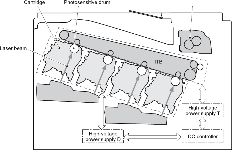
Image-formation system
The image-formation system creates the printed image on the paper. The system consists of the laser/
scanners, print cartridges, imaging drums, ITB, and fuser.
Figure 5-9 Image-formation system
Laser/scanner
Laser/scanner
Fuser
Y
M
C
K
ENWW Image-formation system 133
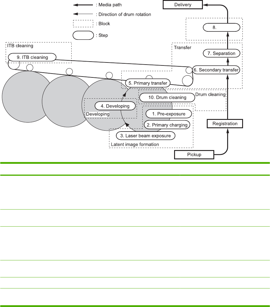
Image-formation process
The image-formation system consists of ten steps divided into six functional blocks.
Figure 5-10 Image-formation process
Fusing
Fuser
YMCK
Functional block Steps Description
Latent image formation 1. Pre-exposure
2. Primary charging
3. Laser-beam exposure
An invisible latent image forms on the
surface of the photosensitive drums.
Development 4. Development Toner adheres to the electrostatic latent
image on the photosensitive drums.
Transfer 5. Primary transfer
6. Secondary transfer
7. Separation
The toner image transfers to the ITB and
subsequently to the paper.
Fusing 8. Fusing The toner fuses to the paper to make a
permanent image.
ITB cleaning 9. ITB cleaning Residual toner is removed from the ITB.
Drum cleaning 10. Drum cleaning Residual toner is removed from the
photosensitive drums.
134 Chapter 5 Theory of operation ENWW
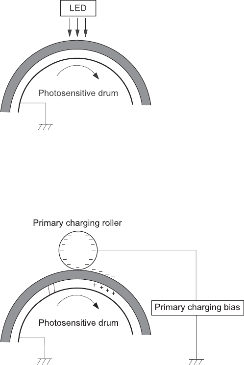
Step 1: Pre-exposure
Light from the pre-exposure LED strikes the surface of the photosensitive drum to remove any residual
electrical charges from the drum surface.
Figure 5-11 Pre-exposure
Step 2: Primary charging
The primary-charging roller contacts the photosensitive drum and charges the drum with negative
potential.
Figure 5-12 Primary charging
ENWW Image-formation system 135
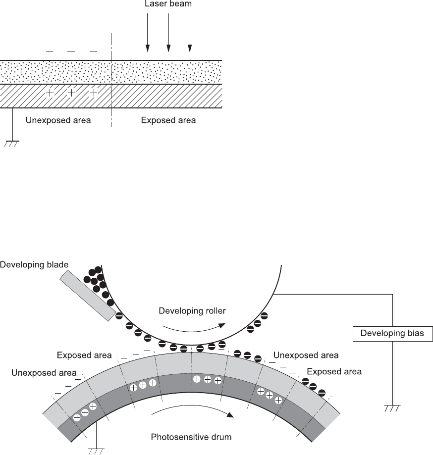
Step 3: Laser-beam exposure
The laser beam strikes the surface of the photosensitive drum in the areas where the image will form.
The negative charge neutralizes in those areas, which are then ready to accept toner.
Figure 5-13 Laser-beam exposure
Step 4: Development
Toner acquires a negative charge as the developing cylinder contacts the developing blade. Because
the negatively charged surface of the photosensitive drums have been neutralized where they have
been struck by the laser beam, the toner adheres to those areas on the drums. The latent image
becomes visible on the surface of each drum.
Figure 5-14 Development
Step 5: Primary transfer
The positively charged primary-transfer rollers contact the ITB, giving the ITB a positive charge. The
ITB attracts the negatively charged toner from the surface of each photosensitive drum, and the
136 Chapter 5 Theory of operation ENWW
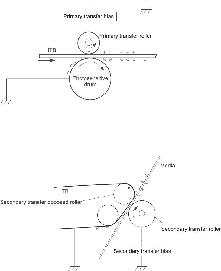
complete toner image transfers onto the ITB, beginning with yellow, followed by magenta, cyan, and
black.
Figure 5-15 Primary transfer
Step 6: Secondary transfer
The paper acquires a positive charge from the secondary-transfer roller, and so it attracts the negatively
charged toner from the surface of the ITB. The complete toner image transfers onto the paper.
Figure 5-16 Secondary transfer
ENWW Image-formation system 137
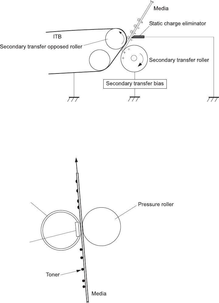
Step 7: Separation
The stiffness of the paper causes it to separate from the ITB as the ITB bends. The static-charge
eliminator removes excess charge from the paper to ensure that the toner fuses correctly.
Figure 5-17 Separation
Step 8: Fusing
To create the permanent image, the paper passes through heated, pressurized rollers to melt the toner
onto the page.
Figure 5-18 Fusing
Fuser sleeve
Fuser heater
138 Chapter 5 Theory of operation ENWW
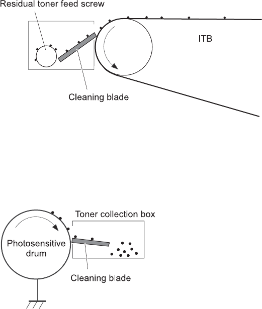
Step 9: ITB cleaning
The cleaning blade scrapes the residual toner off the surface of the ITB. The residual toner feed screw
deposits residual toner in the toner collection box.
Figure 5-19 ITB cleaning
Step 10: Drum cleaning
Inside the print cartridge, the cleaning blade removes residual toner from the surface of the drum to
prepare it for the next image. The waste toner falls into the hopper in the print cartridge.
Figure 5-20 Drum cleaning
Print cartridge
The product has four print cartridges, one for each color. Each print cartridge contains a reservoir of
toner and the following components:
●Photosensitive drum
●Developing roller
●Primary-charging roller
ENWW Image-formation system 139
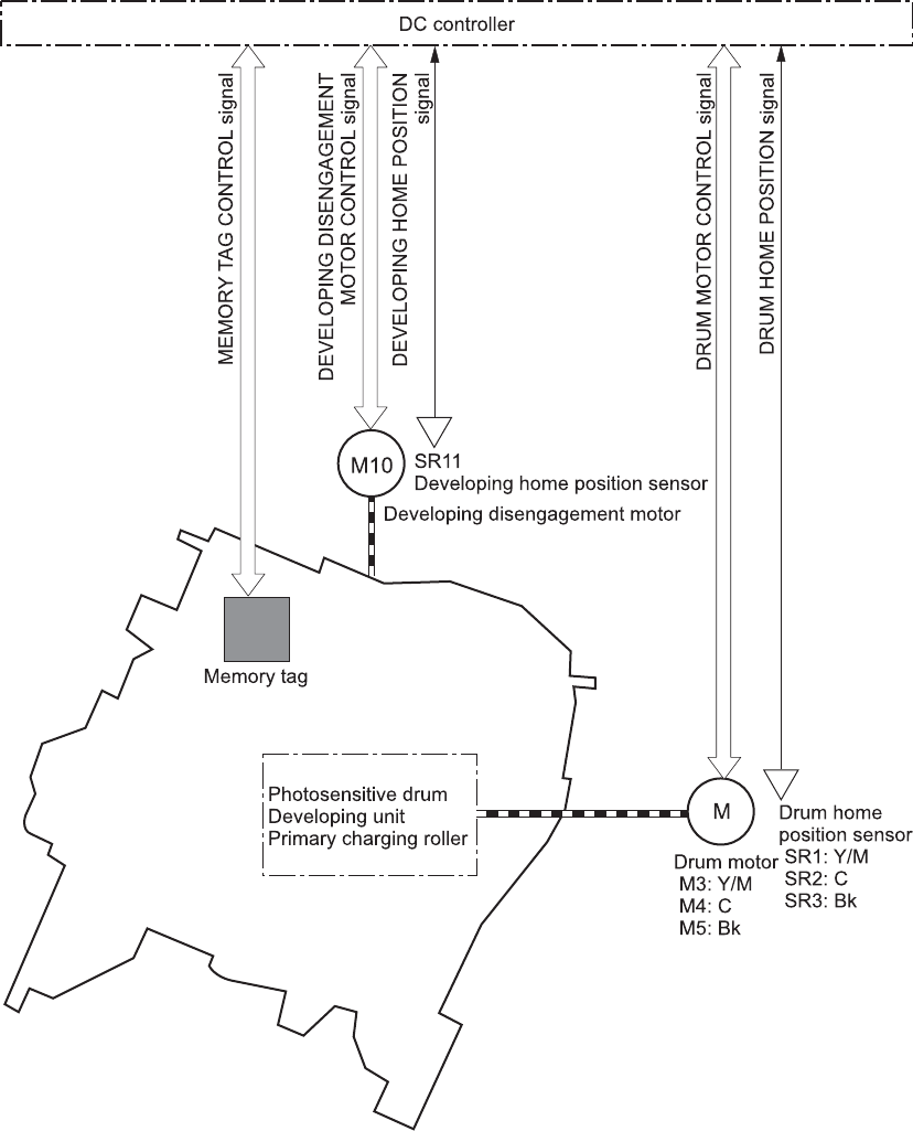
The DC controller rotates the drum motor to drive the photosensitive drum, developing roller, and the
primary-charging roller.
Figure 5-21 Print-cartridge system
The DC controller rotates the drum motor to drive the photosensitive drum, developing unit, and primary
charging roller.
The memory tag is a non-volatile memory chip that stores information about the usage for the print
cartridge.
140 Chapter 5 Theory of operation ENWW
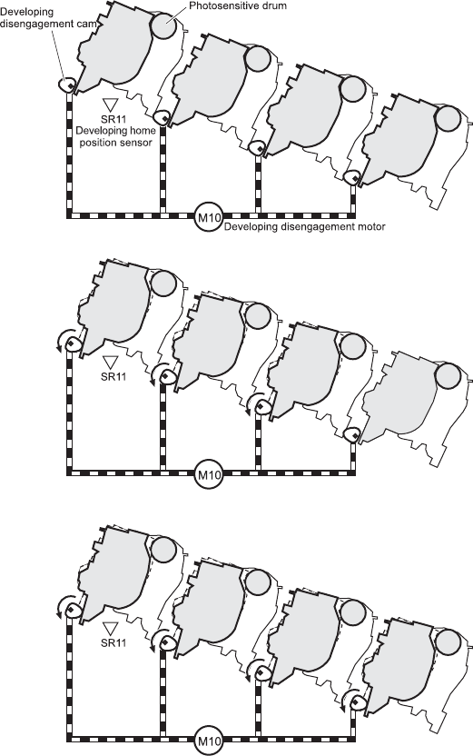
The DC controller notifies the formatter of an error if any of the following conditions exist:
●The memory tag fails to either read to or write from the DC controller
●The RD sensors detect a missing or incorrectly installed print cartridge.
●The accumulated print time reaches a specified time period or the cartridge runs out of toner.
●The toner level in any of the print cartridges drops below a certain level
Developing-roller engagement and disengagement
The product can print in full-color mode or in black-only mode. To print in black-only mode, the product
disengages the developing rollers in the cyan, magenta, and yellow print cartridges. This maximizes the
life of the cartridges.
Figure 5-22 Developing-roller engagement and disengagement control
Four developing units engaged
Only the Bk developing unit engaged
Four developing units disengaged
Y
M
C
K
Y
M
C
K
Y
M
C
K
Y
M
C
K
Y
M
C
K
Y
M
C
K
The DC controller rotates the developing disengagement motor and changes the direction of the cam
according to the instructions from the formatter for each print job.
ENWW Image-formation system 141
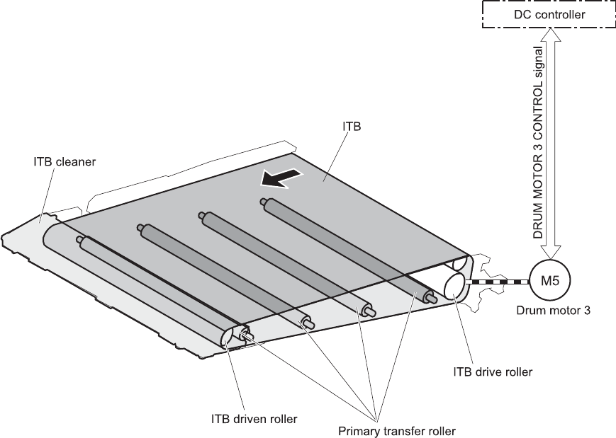
When the product is turned on and at the end of each print job, all four of the developing rollers disengage
from the photosensitive drums. If the next print job is full-color mode, each of the developing rollers
engage. If the next print job is black-only mode, only the black developing roller engages.
If the DC controller does not detect any output from the developing home-position sensor, it determines
that the developing-disengagement motor has failed.
Intermediate transfer belt (ITB) unit
The ITB unit accepts the toner images from the photosensitive drums and transfers the completed image
to the paper. The ITB unit has these main components:
●ITB
●ITB drive roller
●ITB-driven roller
●Primary-transfer rollers
●ITB cleaner
The ITB motor drives the ITB drive roller, which rotates the ITB. The motion of the ITB causes the primary
transfer rollers to rotate. The ITB cleaner cleans the ITB surface.
Figure 5-23 ITB unit
YMCK
142 Chapter 5 Theory of operation ENWW

Primary-transfer-roller engagement and disengagement
Depending on the requirements of the print job, the primary-transfer rollers engage with the ITB so it
can receive toner from the photosensitive drums.
Table 5-10 Primary-transfer-roller engagement states
All rollers disengaged The home position for the ITB unit
All rollers engaged The state for a full-color print job
Black roller engaged The state for a black-only print job
The primary-transfer-roller disengagement motor rotates or reverses to place the primary-transfer-roller
disengagement cam into one of three positions. The cam causes the transfer-roller slide plate to move
to the right or left. This movement causes the primary-transfer rollers to move up to engage the ITB with
the photosensitive drum or down to disengage it.
If the DC controller does not receive the expected signal from the ITB home-position sensor when the
primary-transfer-roller engages or disengages, but the primary-transfer-roller disengagement motor is
ENWW Image-formation system 143
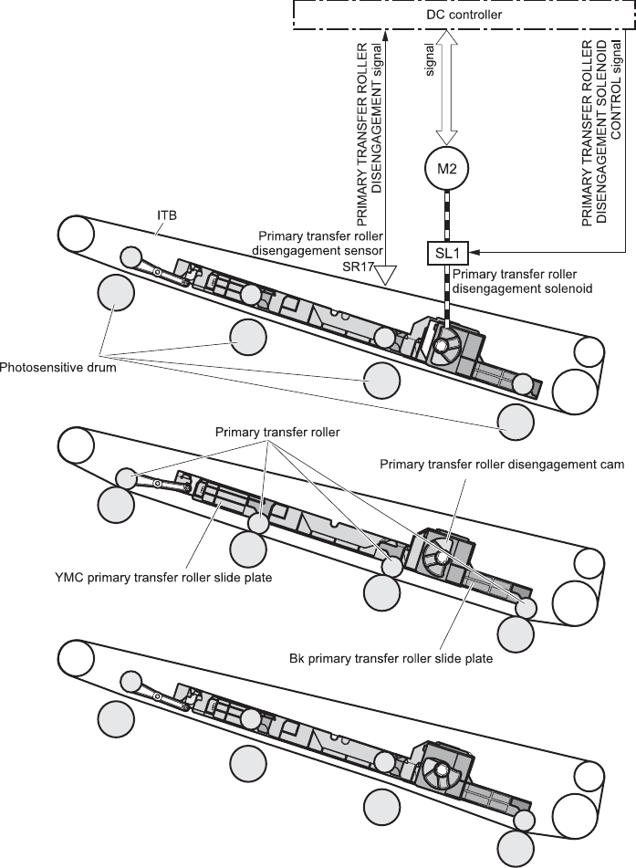
rotating, the DC controller determines that the primary-transfer-disengagement mechanism has failed,
and notifies the formatter.
Figure 5-24 Three states of primary-transfer-roller engagement and disengagement
Four colors are disengaged
Four colors are engaged
Only black is engaged
Y
M
C
K
Y
M
C
K
Y
M
C
K
Y
M
C
K
Y
M
C
K
Y
M
C
K
Fuser motor
FUSER MOTOR CONTROL
ITB cleaning
The cleaning blade in the ITB cleaner scrapes the residual toner off the ITB surface. The drum motor
(M5) drives the residual toner feed screw. The screw feeds the residual toner to the residual toner feed
unit. The residual toner feed motor (M12) drives the residual toner feed screw. The residual toner feed
144 Chapter 5 Theory of operation ENWW
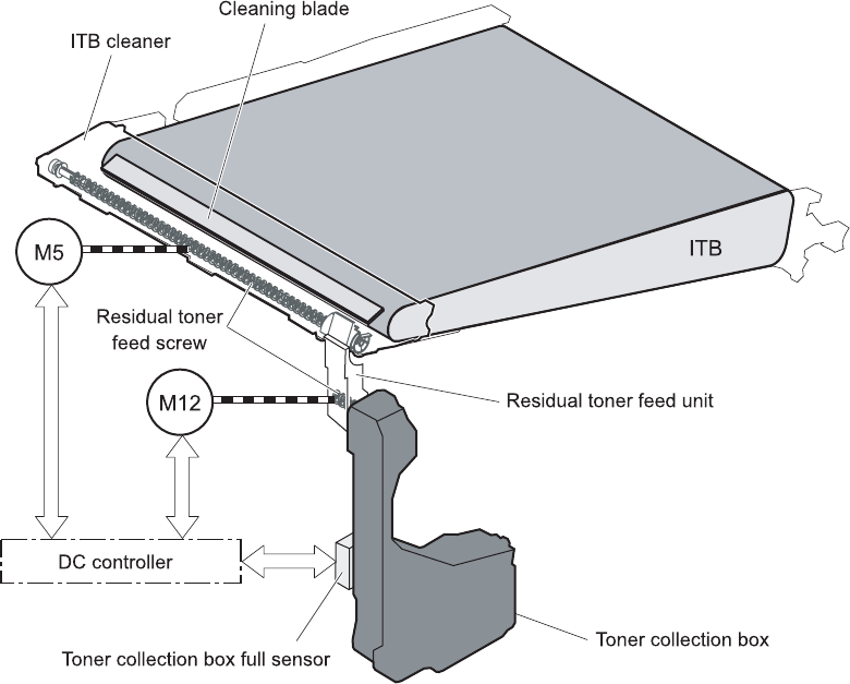
screw deposits the residual toner in the toner collection box. The DC control detects whether the toner
collection box is full, using the toner collection-box-full sensor, and then notifies the formatter.
Figure 5-25 ITB cleaning process
Calibration
The product calibrates itself to maintain excellent print quality. Calibration corrects color-misregistration
and color-density variation.
ENWW Image-formation system 145
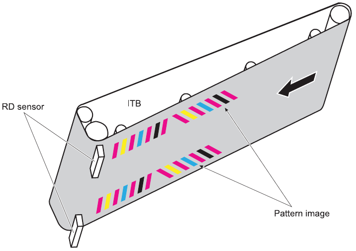
During calibration, the product places a specific pattern of toner on the surface of the ITB. Sensors at
the end of the ITB read the toner pattern to determine if adjustments are necessary.
Figure 5-26 Toner patterns for calibration
Color-misregistration control
Internal variations in the laser/scanners can cause the toner images to become misaligned. The color-
misregistration control corrects the following problems:
●Horizontal scanning start position
●Horizontal scanning magnification
●Vertical scanning start position
The calibration occurs when any of the following occurs:
●A cartridge is replaced
●The temperature of the sub thermistor is 50 C (122 F) or lower when the product recovers from
sleep mode after a specific number of pages print.
●A specified number of pages have printed.
●The formatter sends a command.
●The user requests a calibration by using the control-panel menus.
If data from the color-misregistration and image-density sensors is outside a specified range when the
product is turned on or when it is beginning the calibration sequence, the DC controller determines that
these sensors have failed, and it notifies the formatter.
146 Chapter 5 Theory of operation ENWW

Image-stabilization control
Environmental changes or deterioration of the photosensitive drums and toner can cause variations in
the image density. The image-stabilization control reduces these fluctuations.
Table 5-11 Image-stabilization controls
Environment change control The DC controller monitors environmental information from internal temperature and
humidity sensors. The DC controller adjusts the high-voltage bias to accommodate
environmental changes. This control occurs under the following circumstances:
●The product is turned on.
●The print cartridge is replaced.
●A change in environmental conditions occurs.
The DC controller notifies the formatter when it encounters a communication error
with the environmental sensor.
Image density control (DMAX) This control corrects variations in image density related to deterioration of the
photosensitive drum or the toner. The DC controller adjusts the high-voltage biases
to correct the problem under the following conditions:
●The sub thermistor detects a temperature that is too low when the product is
turned on.
●A print cartridge is replaced.
●A specified number of pages print after replacing the print cartridge.
●A specified number of pages have printed.
●The formatter sends a command
●The product recovers from sleep mode
●After a specific period of the completion of a print operation
●The environment is relatively charged.
Image halftone control (DHALF) The formatter performs this control to calibrate the halftone, based on the halftone-
density measurements, under the following conditions:
●The formatter sends a command.
●DMAX is completed.
The DC controller determines a RD sensor failure and notifies the formatter if it detects an out-of-
specified-data value from the RD sensor when the product is turned on or when the color misregistration
control starts.
ENWW Image-formation system 147
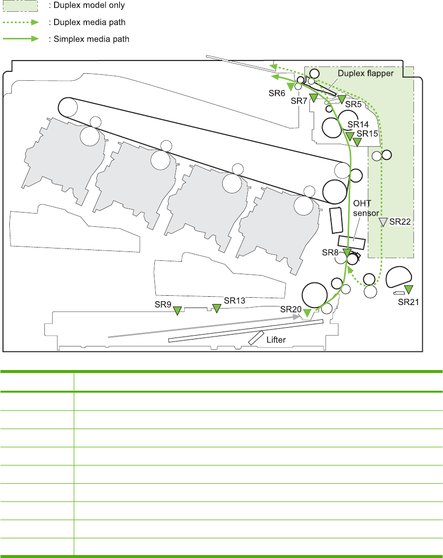
Pickup, feed, and delivery system
The pickup, feed, and delivery system uses a series of rollers to move the paper through the product.
Figure 5-27 Switches and sensors for the pickup, feed, and delivery system
Y
M
C
K
Table 5-12 Switches and sensors for the pickup, feed, and delivery system
Abbreviation Component
SR5 Fuser (fixing) delivery sensor
SR6 Delivery tray media full sensor
SR7 Fuser (fixing) pressure release sensor
SR8 TOP (top of page) sensor
SR9 Cassette-media stack-surface sensor
SR13 Cassette presence sensor
SR14 Loop sensor 1
SR15 Loop sensor 2
SR20 Cassette media-presence sensor
148 Chapter 5 Theory of operation ENWW
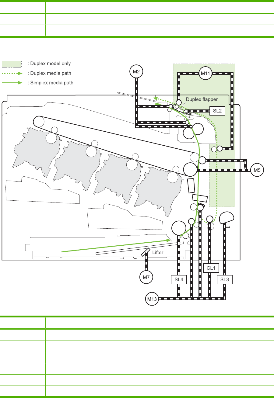
Abbreviation Component
SR21 MP tray media-presence sensor
SR22 Duplex re-pickup sensor (duplex models only)
Figure 5-28 Motors and solenoids for the pickup, feed, and delivery system
Y
M
C
K
Table 5-13 Motors and solenoids for the pickup, feed, and delivery system
Abbreviation Component
M2 Fuser (fixing) motor
M5 Drum motor 3
M7 Lifter motor
M11 Duplex reverse motor (duplex models only)
M13 Pickup motor
CL1 Duplex re-pickup clutch (duplex models only)
Table 5-12 Switches and sensors for the pickup, feed, and delivery system (continued)
ENWW Pickup, feed, and delivery system 149
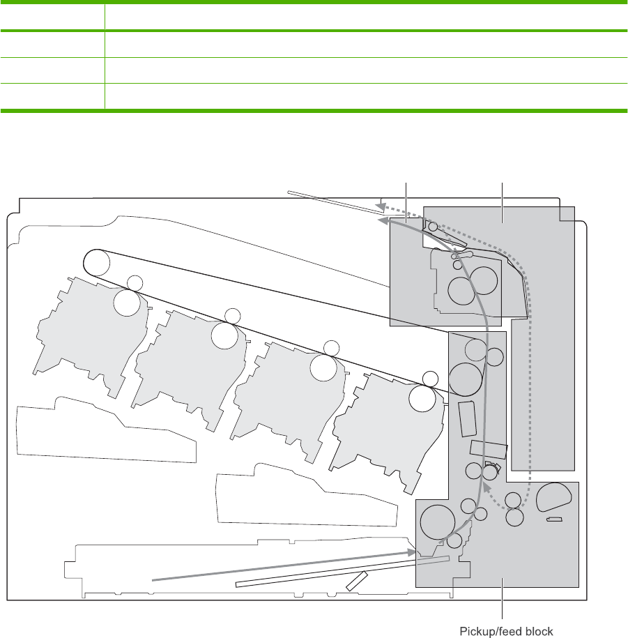
Abbreviation Component
SL2 Duplex reverse solenoid (duplex models only)
SL3 Multipurpose tray pickup solenoid
SL4 Cassette pickup solenoid
Figure 5-29 Three main units of the pickup, feed, and delivery system
Fuser/delivery block Duplex block
Y
M
C
K
Table 5-13 Motors and solenoids for the pickup, feed, and delivery system (continued)
150 Chapter 5 Theory of operation ENWW
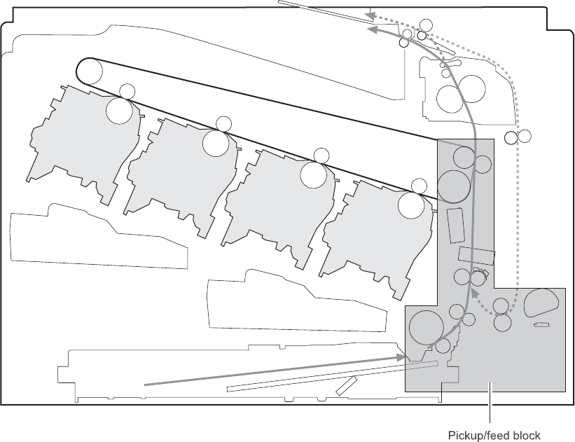
Pickup-and-feed unit
The pickup-and-feed unit picks an individual sheet of paper from the multipurpose tray or the cassettes,
carries it through the secondary-transfer unit, and feeds it into the fuser.
Figure 5-30 Pickup and feed unit
Y
M
C
K
ENWW Pickup, feed, and delivery system 151
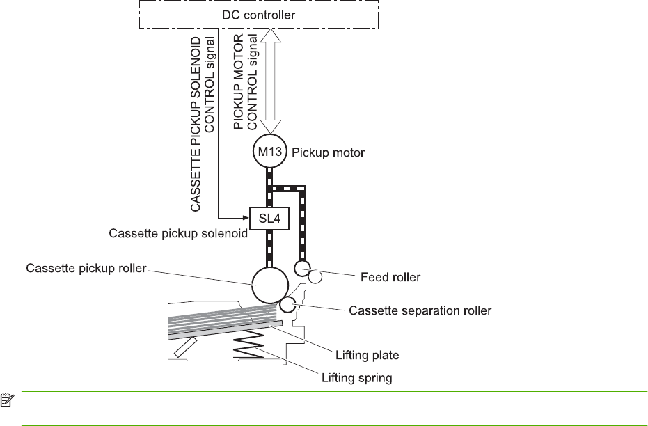
Cassette pickup
The sequence of steps for the cassette-tray pickup operation is the following:
1. When the product starts or the tray closes, the lifting mechanism lifts the paper stack so it is ready.
2. After receiving a print command from the formatter, the DC controller rotates the pickup motor,
which causes the cassette pickup roller, cassette feed roller, and cassette separation roller to
rotate.
3. The DC controller drives the cassette pickup solenoid, which rotates the cassette pickup cam. As
the pickup cam rotates, the pickup arm moves down, and the cassette pickup roller touches the
surface of the paper stack. The cassette pickup roller then picks up one sheet of paper.
Figure 5-31 Cassette-pickup mechanism
NOTE: The lift-up operation lifts the lifting plate to keep the stack surface of the media at a pickup
position. The lifting spring helps support the lifting plate depending on the media size and amount.
152 Chapter 5 Theory of operation ENWW
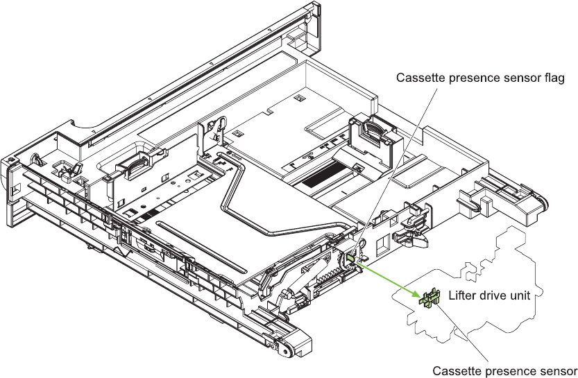
Cassette-presence detection
The cassette presence sensor is in the lifter drive unit. The sensor detects the cassette-presence sensor
flag and determines whether the cassette is installed correctly.
Figure 5-32 Cassette presence sensor
Cassette lift operation
The DC controller rotates the lifter motor (M7) and moves the lifter rack until the cassette media-stack
surface sensor (SR9) detects it. The lifter lifts, and the lifting plate moves up to the position where the
media can be picked up. The lift operation is performed by monitoring the cassette media-stack-surface
sensor when the printer is turned on, when the cassette is installed, or as needed during a print operation.
If the paper-stack surface sensor does not detect the paper within a specified time after the lifter motor
begins rotating, the DC controller notifies the formatter that the lifter motor has failed.
ENWW Pickup, feed, and delivery system 153
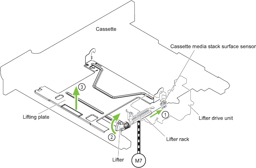
The DC controller lowers the lifting plate when no printing occurs to prevent media damage and pickup
failure. If a print operation does not occur for a specified time, the DC controller reverses the lifter motor
and moves the lifter rack until the cassette media-stack surface sensor stops detecting it.
Figure 5-33 Cassette lift mechanism
154 Chapter 5 Theory of operation ENWW
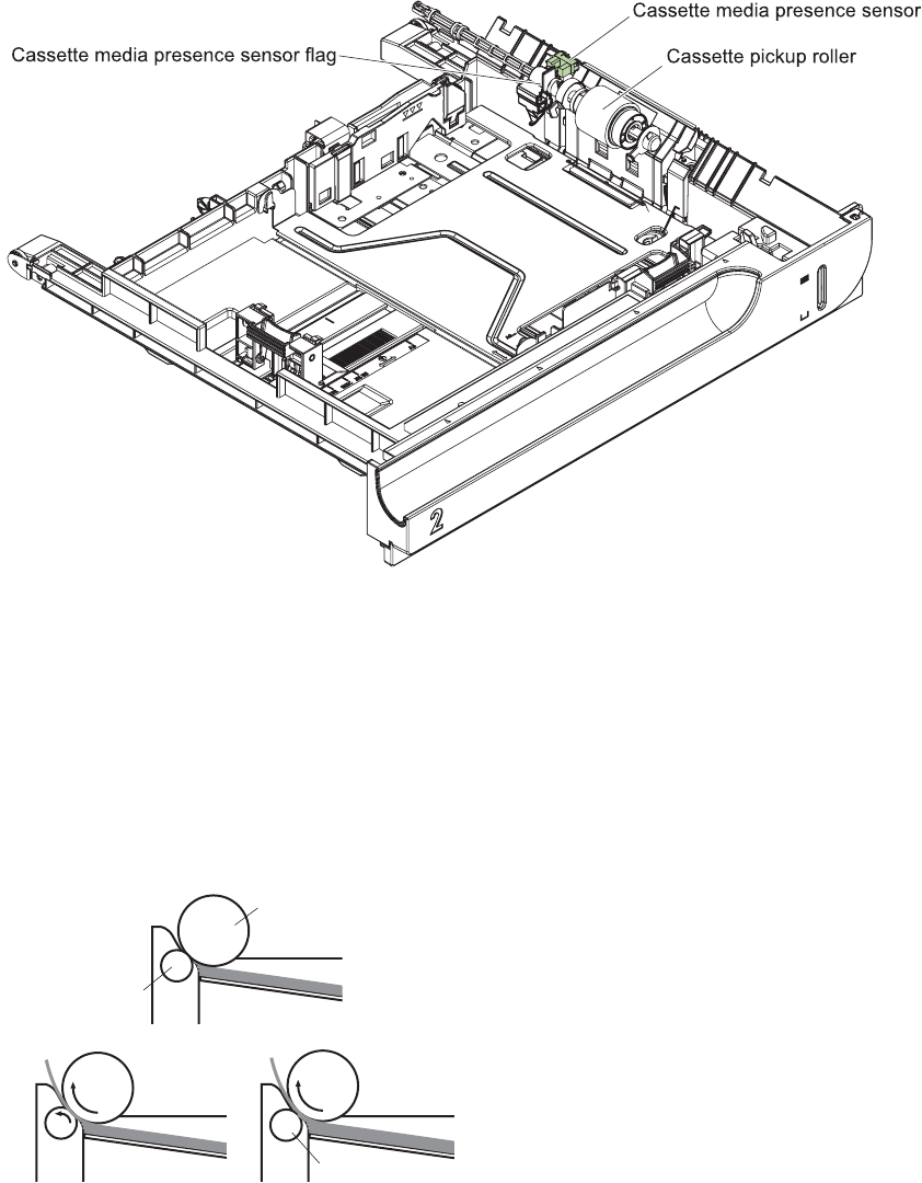
Cassette paper-presence detection
The cassette media-presence sensor detects whether paper is in the cassette.
Figure 5-34 Paper-level-detection mechanism
Multifeed prevention
In the cassette, a separation roller prevents multiple sheets of paper from entering the paper path. The
cassette pickup roller drives the separation roller through a sheet of paper.
The low friction force between the sheets weakens the driving force from the cassette pickup roller.
Because some braking force is applied to the cassette separation roller, the weak rotational force of the
pickup roller is not enough to rotate the separation roller. Therefore, the separation roller holds back
any multiple-fed sheets, and one sheet of media is fed into the printer.
Figure 5-35 Multifeed prevention
Cassette pickup
roller
Media
Lifting plate
Cassette
separation
roller
Normal feed Multiple feed
Separation roller does not rotate
ENWW Pickup, feed, and delivery system 155
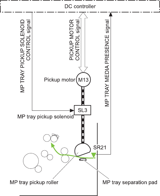
Multipurpose tray pickup
The multipurpose tray paper-presence sensor detects whether paper is in the tray. If no paper is present,
the DC controller notifies the formatter. Printing does not occur until paper is in the tray.
The sequence of steps for the multipurpose tray pickup operation as follows:
1. After receiving a print command from the formatter, the DC controller reverses the pickup motor,
which causes the multipurpose tray separation roller to rotate.
2. The DC controller turns on the multipurpose tray pickup solenoid (SL3), causing the multipurpose
tray pickup roller to rotate.
3. The multipurpose tray separation roller isolates a single sheet of paper in case more than one sheet
was picked. The single sheet of paper feeds into the product.
The MP-tray media-presence sensor (SR21) detects whether the media is present in the MP tray. No
printing occurs if no media is loaded.
Figure 5-36 Multipurpose tray pickup mechanism
156 Chapter 5 Theory of operation ENWW
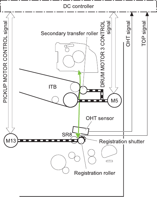
Paper feed
After the pickup operation, the paper feeds through the product and into the fuser.
1. The paper passes through the feed rollers. The registration shutter aligns the paper correctly to
prevent skewed printing.
2. The DC controller detects the leading edge of paper by the Top sensor (SR8) and controls the
rotational speed of the pickup motor to align with the leading edge of image on the ITB.
3. The DC controller detects whether or not the media is overhead transparency, using the OHT
sensor.
4. The toner image on the ITB transfers onto the media, which feeds to the fuser.
Figure 5-37 Paper-feed mechanism
ENWW Pickup, feed, and delivery system 157
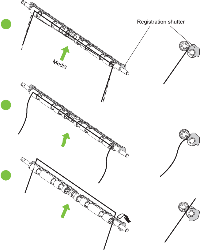
Skew-feed prevention
The product can straighten the paper without slowing the feed operation.
1. As the paper enters the paper path, the leading edge strikes the registration shutter, which
straightens the paper. The paper does not pass through the shutter .
2. The feed rollers keep pushing the paper, which creates a force on the leading edge against the
registration shutter.
3. When the force is great enough, the registration shutter opens and the paper passes through.
Figure 5-38 Skew-feed prevention
1
2
3
OHT detection
The OHT sensor detects overhead transparencies. The OHT sensor is a transmission sensor that uses
an LED. The DC controller determines a media mismatch and notifies the formatter when the media
type differs from the media type detected by the OHT sensor. The DC controller turns the LED in the
158 Chapter 5 Theory of operation ENWW
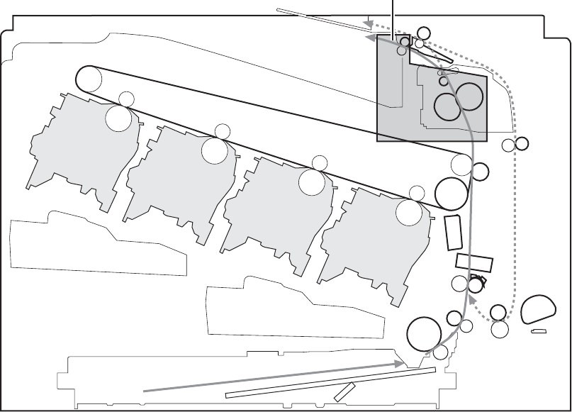
OHT sensor on and off during the wait or initial rotation period. If the intensity of the light does not match
the specified value, the DC controller determines that the OHT sensor has failed.
Fusing and delivery unit
The fusing and delivery unit fuses the toner onto the paper and delivers the printed page into the output
bin. The following controls ensure optimum print quality:
●Loop control
●Pressure roller pressurization/depressurization control
A sensor detects when the output bin is full, and the DC controller notifies the formatter.
Figure 5-39 Fuser and delivery unit
Fuser/delivery block
Y
M
C
K
Loop control
The loop control monitors the tension of the paper between the second-transfer roller and the fuser.
●If the fuser rollers rotate more slowly than the secondary transfer rollers, the paper warp increases
and an image defect or paper crease occurs.
●If the fuser rollers rotate faster than the secondary transfer rollers, the paper warp decreases and
the toner image fails to transfer to the paper correctly, causing color misregistration.
ENWW Pickup, feed, and delivery system 159
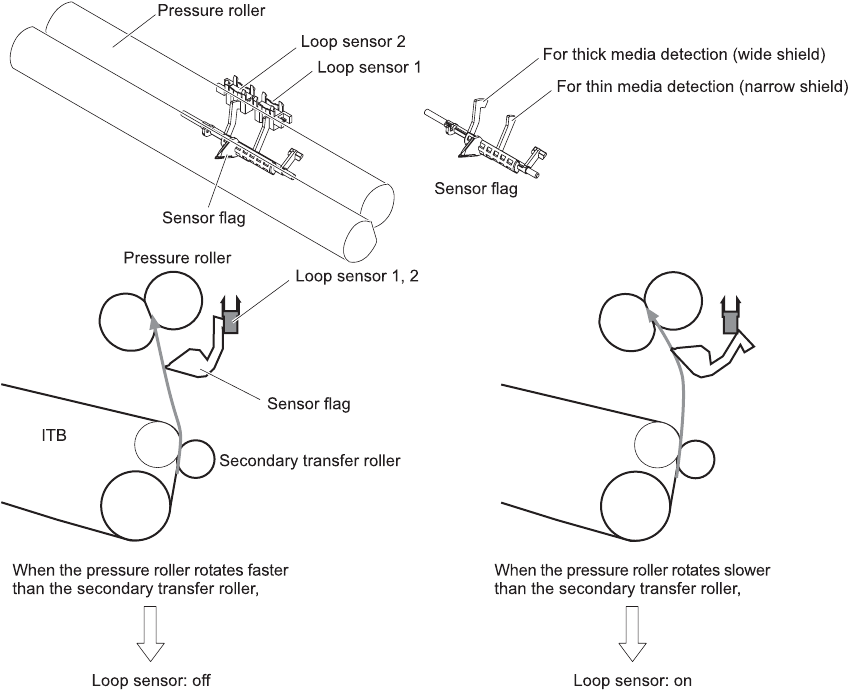
To prevent these problems, the loop sensors, which are located between the secondary transfer rollers
and the fuser rollers, detect whether the paper is sagging or is too taut. The DC controller adjusts the
speed of the fuser motor.
Figure 5-40 Loop-control mechanism
160 Chapter 5 Theory of operation ENWW
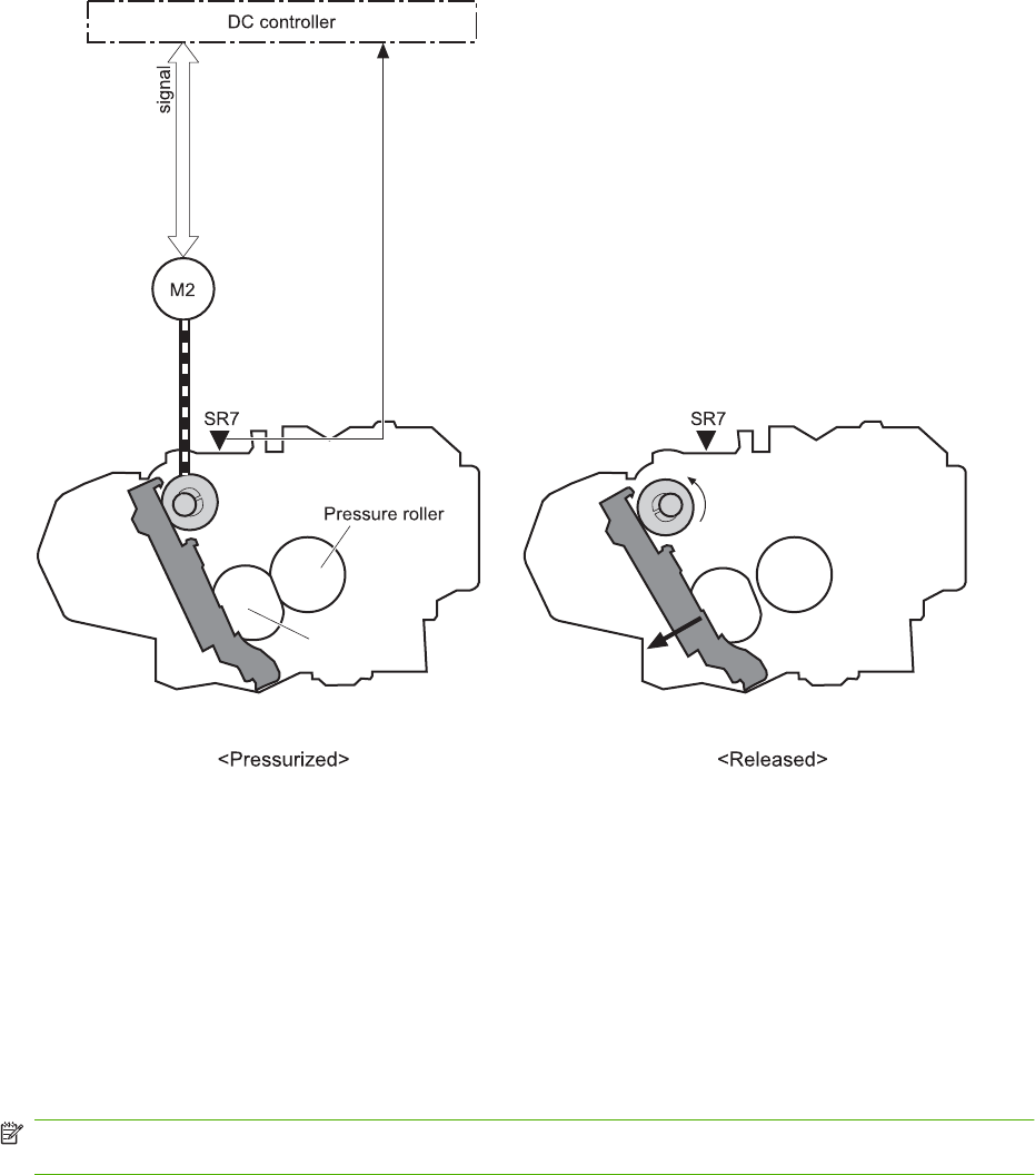
Pressure-roller pressurization control
To prevent excessive wear on the pressure roller and help with jam-clearing procedures, the pressure
roller pressurizes only during printing and standby. The DC controller reverses the fuser motor. The
fuser motor rotates the fuser pressure-release cam.
Figure 5-41 Pressure-roller pressurization control
Fuser motor
FUSER PRESSURE RELEASE signal
FUSER MOTOR CONTROL
Fuser pressure release cam
Fuser sleeve
The pressure roller depressurizes under the following conditions:
●The product is turned off with the on/off switch
●Any failure occurs other than a fuser pressure-release mechanism failure
●During powersave mode
●When a paper jam is detected
If the DC controller does not sense the fuser pressure-release sensor for a specified period after it
reverses the fuser motor, it notifies the formatter that a fuser pressure-release mechanism failure has
occurred.
NOTE: The fuser remains pressurized if the power is interrupted when the power cord is removed or
the surge protector is turned off, or if the fuser is removed without turning off the product.
ENWW Pickup, feed, and delivery system 161
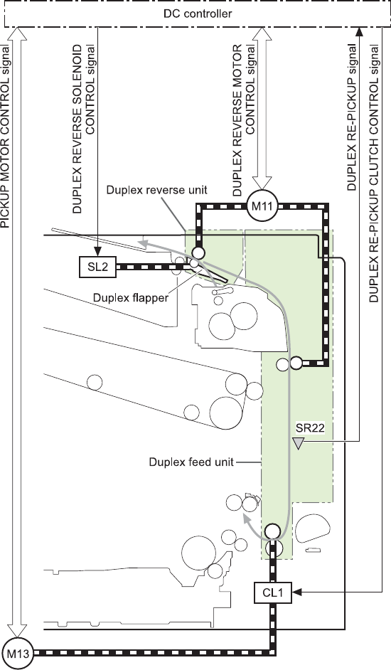
Duplexing unit
The duplexing unit reverses the paper and feeds it through the paper path to print the second side. The
duplexing unit consists of the following components:
●Duplexing-reverse unit: Installed on top of the product
●Duplexing-feed unit: Along the right side
The DC controller controls the operational sequence of the duplex block. The DC controller drives each
load, such as motors, solenoid, and clutch, depending on the duplex reverse unit and duplex feed unit
controls.
Figure 5-42 Duplexing unit
162 Chapter 5 Theory of operation ENWW
Duplexing reverse and feed control
The duplexing reverse procedure pulls the paper into the duplexing unit after it exits the fuser. The
duplexing feed procedure moves the paper through the duplexer so it can enter the product paper path
to print the second side of the page.
1. After the first side has printed, the duplexing flapper solenoid opens, which creates a paper path
into the duplexing-reverse unit.
2. After the paper has fully entered the duplexing-reverse unit, the duplexing-reverse motor reverses
and directs the paper into the duplexing-feed unit.
3. The duplexing re-pickup motor and duplexing feed motor move the paper into the duplexing re-
pickup unit.
4. To align the paper with the toner image on the ITB, the duplexing re-pickup motor stops and the
paper pauses.
5. The paper re-enters the paper path, and the second side prints.
Duplex pickup operation
The product has the following two duplex-media-feed modes depending on the media sizes:
●One-sheet mode: Prints one sheet that is printed on two sides in one duplex print operation
●Two-sheet mode: Prints two sheets that are printed on two-sides in one duplex print operation
(maximum paper size is A4)
The formatter specifies the duplex-media-feed mode.
ENWW Pickup, feed, and delivery system 163
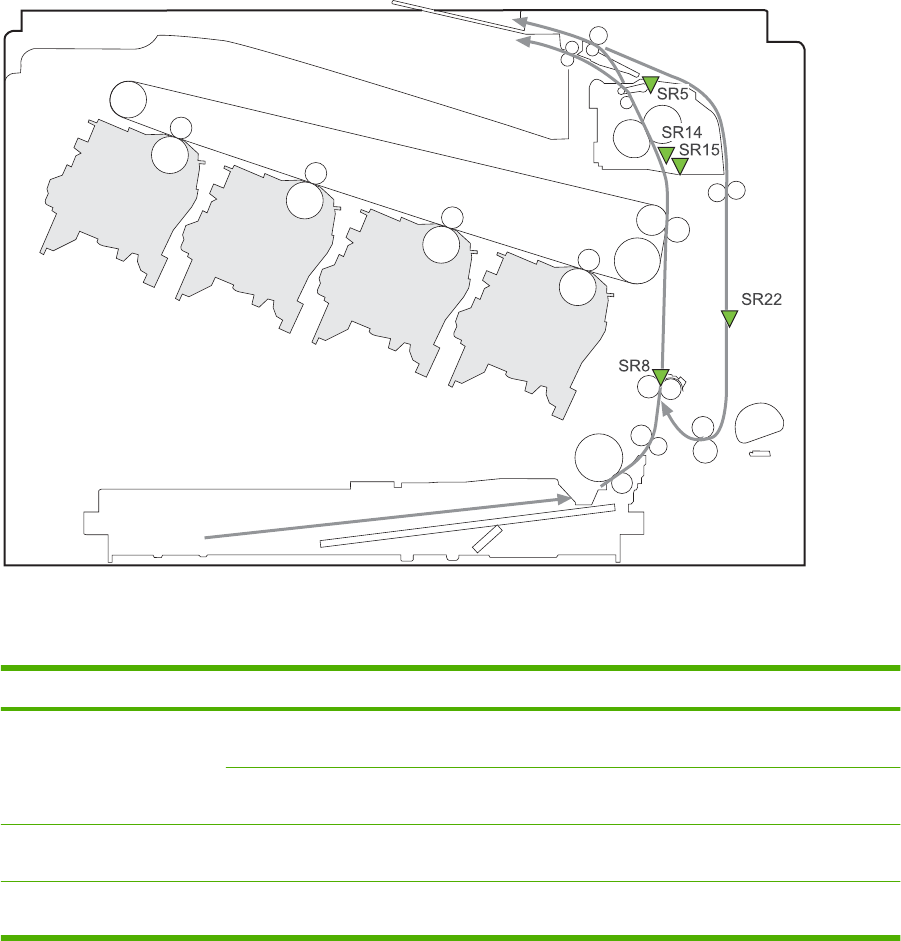
Jam detection
The product uses the following sensors to detect the paper as it moves through the paper path and to
report to the DC controller if the paper has jammed.
●Fuser (fixing) delivery sensor (SR5)
●TOP (top of page) sensor (SR8)
●Loop sensor 1 (SR14)
●Loop sensor 2 (SR15)
●Duplex re-pickup sensor (SR22)
Figure 5-43 Jam detection sensors
Y
M
C
K
The product determines that a jam has occurred if one of these sensors detects paper at an inappropriate
time. The DC controller stops the print operation and notifies the formatter.
Table 5-14 Jams that the product detects
Jam Description
Pickup delay jam 1 Cassette pickup: The TOP sensor does not detect the leading edge of the paper within a
specified period after the cassette pickup solenoid has turned on.
Multipurpose tray pickup: The TOP sensor does not detect the leading edge of the paper
within a specified period after the multipurpose tray solenoid has turned on.
Pickup stationary jam The TOP sensor does not detect the trailing edge of the paper within a specified time from when
it detects the leading edge.
Fuser delivery delay jam The fuser delivery paper-feed sensor does not detect the leading edge of the paper within a
specified period after the TOP sensor detects the leading edge.
164 Chapter 5 Theory of operation ENWW

Jam Description
Fuser delivery stationary jam The fuser delivery paper-feed sensor does not detect the trailing edge of the paper within a
specified period after it detects the leading edge.
Wrapping jam After detecting the leading edge of the paper, the fuser delivery paper-feed sensor detects the
absence of paper, and it has not yet detected the trailing edge.
Residual paper jam One of the following sensors detects paper presence during the initialization sequence:
●Fuser delivery paper-feed sensor
●TOP senosor
●Loop sensor 1
●Loop sensor 2
Door open jam A door is open while paper is moving through the product.
Duplexing re-pickup jam 1 The duplex re-pickup sensor does not detect the leading edge of the paper within a specified
period after the media reverse operation starts in the duplex reverse unit.
Duplexing re-pickup jam 2 The TOP sensor does not detect the leading edge of the paper within a specified period after
the paper is re-picked.
After a jam, some sheets of paper might remain inside the product. If the DC controller detects residual
paper after a door closes or after the product is turned on, the product automatically clears itself of those
residual sheets.
Table 5-14 Jams that the product detects (continued)
ENWW Jam detection 165
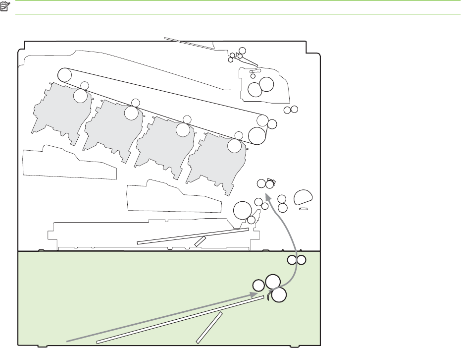
Optional paper feeder
The 1x500-sheet paper feeder is optionally installed at bottom of the printer. The paper feeder picks up
the print media and feeds it to the printer.
NOTE: These optional trays are not identical to the main cassette (Tray 2).
Figure 5-44 Optional paper feeder
Y
M
C
K
The paper-deck drivers contain a microcomputer and control the paper feeder. The paper-deck drivers
receive commands from the DC controller. If the DC controller is unable to communicate with a paper-
deck driver, it notifies the formatter that the optional paper feeders is not connected correctly.
166 Chapter 5 Theory of operation ENWW
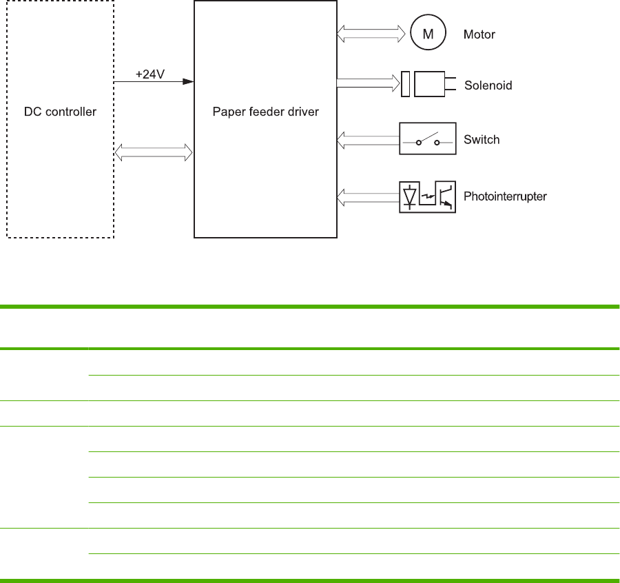
Figure 5-45 Signals for the paper feeder
The input trays contain several motors, solenoids, sensors, and switches, as described in the following
table.
Table 5-15 Electrical components for the paper feeder
Component
type
Abbreviation Component name
Motors M1 Paper feeder motor
M2 Paper feeder lift motor
Solenoids SL1 Paper feeder pickup solenoid
Sensors SR1 Paper-feeder media-stack surface sensor 1
SR2 Paper-feeder media-stack surface sensor 2
SR3 Paper-feeder cassette media-presence sensor
SR4 Paper-feeder media-feed sensor
Switches SW1 Paper feeder cassette media-size switch
SW2 Paper-feeder door switch
ENWW Optional paper feeder 167
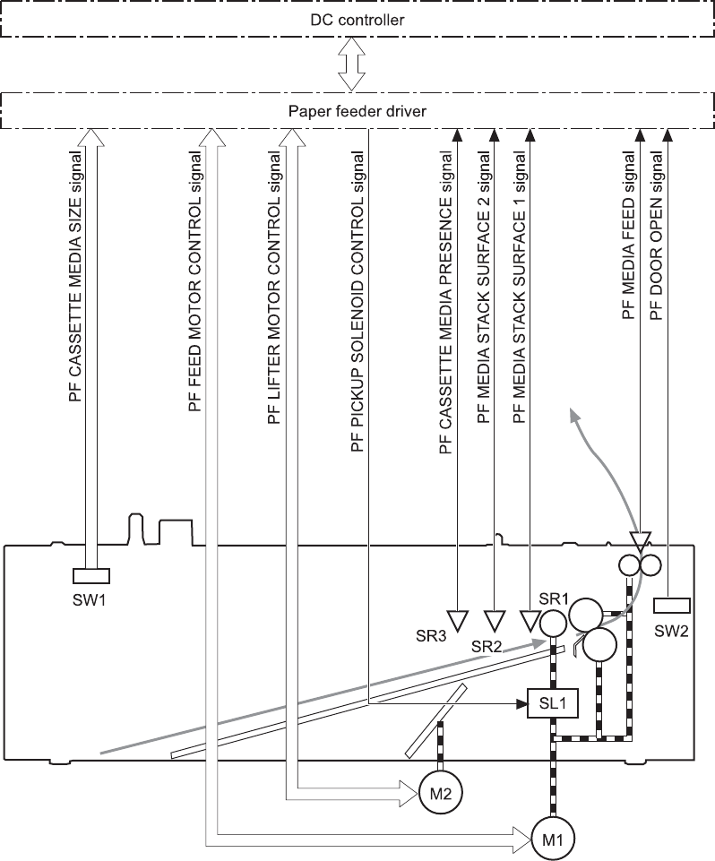
Paper-feeder pickup and feed operation
The paper feeder picks up one sheet from the paper-feeder cassette and feeds it to the product.
Figure 5-46 Paper-feeder pickup and feed operation
168 Chapter 5 Theory of operation ENWW
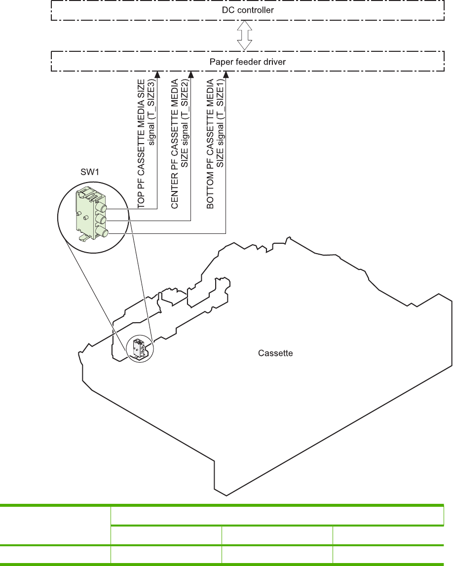
Paper-size detection and cassette-presence detection
The paper-feeder cassette media-size switch (SW1) detects the size of paper loaded in the paper-feeder
cassette. The paper-feeder driver determines the media size by monitoring the combination of the
switches.
Figure 5-47 Paper size detection
Paper size Paper-feeder cassette media-size switch settings
Top switch Center switch Bottom switch
Universal On On On
ENWW Optional paper feeder 169

Paper size Paper-feeder cassette media-size switch settings
Top switch Center switch Bottom switch
A5 On Off Off
B5 Off On On
Executive On Off On
Letter Off On Off
A4 Off Off On
Legal On On Off
No cassette Off Off Off
The paper-feeder cassette media size switch (SW1) detects whether the paper-feeder cassette is
installed correctly. The paper-feeder driver determines if a cassette is absent when all three switches
are turned off. The paper-feeder driver determines a cassette presence when one of the switches is
turned on.
Paper-feeder cassette lift operation
The cassette lift operation keeps the stack surface of paper at a specified height to maintain stable media
feeding. The paper-feeder driver controls the paper-feeder lifter motor (M2) and monitors the paper-
feeder media stack surface sensors (SR1, SR2) to adjust the stack height when the printer is turned on,
when the printer recovers from sleep mode, when the paper-feeder cassette is installed or as needed
during a print operation. The paper feeder has two paper-feeder media-stack surface sensors. The
paper-feeder media stack surface sensor 1 detects the stack height during a print operation. The paper-
feeder media-stack surface sensor 2 detects the stack height when the printer is turned on, when the
170 Chapter 5 Theory of operation ENWW
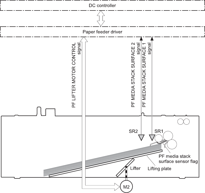
printer recovers from sleep mode and when the paper-feeder cassette is installed. The operational
sequence of the lift operation is as follows:
1. The paper-feeder driver rotates the paper-feeder lifter motor to lift the lifting plate.
2. The paper-feeder driver stops the paper-feeder lifter motor when the paper-feeder media-stack
surface sensor 2 detects the stack surface.
3. The paper-feeder driver rotates the lifter motor again when paper-feeder media stack surface 1
detects that the media surface is lowered during a print operation.
Figure 5-48 Paper-feeder cassette lift
The paper-feeder driver notifies the formatter if either of the paper-feeder media-stack surface sensors
fails to detect the stack surface within a specified period from when a lift-up operation starts.
Paper-feeder presence detection
The paper-feeder cassette media-presence sensor (SR3) detects whether the paper is present in the
paper-feeder cassette.
ENWW Optional paper feeder 171
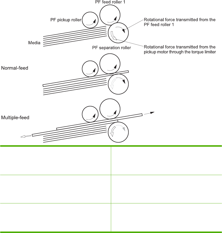
Paper-feeder multiple feed prevention
The paper-feeder uses a separation roller to prevent multiple sheets of paper from entering the printer.
The separation roller prevents multiple feeds of paper by allowing the paper-feeder separation roller to
rotate in the same direction as the paper-feeder feed roller 1. The paper-feeder separation roller is
equipped with the torque limiter. If multiple sheets of paper are picked up, the torque limiter takes control
of the paper-feeder separation roller, and pushes the extra sheets back to the paper-feeder cassette.
That way, only the top sheet is fed to the printer.
Figure 5-49 Paper-feeder multiple feed prevention
No-load Rotational force for paper-feeder separation roller: Pushes
back the media into the paper-feeder cassette
Rotational force for paper-feeder feed roller 1: Feeds media
into the printer
Normal feed Rotational force for paper-feeder separation roller: Pushes
back the media into the paper-feeder cassette
Rotational force for paper-feeder feed roller 1: Feeds media
into the printer
Multiple-feed The low friction force between the sheets weakens the
rotational force from the paper-feeder feed roller 1.
The paper-feeder separation roller rotates by its own rotational
force and removes the extra sheet.
172 Chapter 5 Theory of operation ENWW
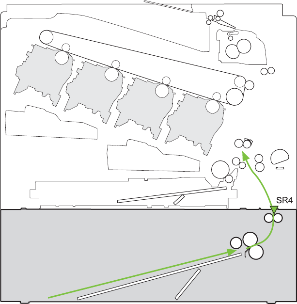
Paper feeder jam detection
The paper feeder uses the paper-feeder media-feed sensor (SR4) to detect the presence of paper and
to check whether paper has jammed.
Figure 5-50 Jam detection
Y
M
C
K
The paper-feeder driver identifies a jam if the sensor detects paper at a specified timing stored in the
paper-feeder driver. The paper-feeder driver stops printing and notifies the formatter through the DC
controller of the jam. The paper feeder detects the following jams:
●Pickup delay jam: The paper-feeder media-feed sensor does not detect the leading edge of media
within a specified period from when the paper-feeder pickup solenoid is turned on.
●Pickup stationary jam: The paper-feeder media-feed sensor does not detect the trailing edge of
media within a specified time period from when the sensor detects the leading edge.
ENWW Optional paper feeder 173
Scanning/image capture system system
Optical assembly
The scanner is a carriage-type platen scanner which includes the frame, glass, LED optics, and a
scanner controller board (SCB) attached to the bottom of the assembly. The scanner has a sensor to
detect legal-sized media and a switch to indicate when the ADF is opened.
The ADF and control-panel assembly are attached to the scanner assembly. If the scanner fails, it can
be replaced as a whole unit. The scanner replacement part does not include the ADF, SCB, or control-
panel assembly.
The HP Color LaserJet CM3530 contains an interconnect board (ICB) which has an NVRAM component
that is used to store critical engines values and formatter data. This NVRAM allows for simpler save/
restore process. When a formatter or DC controller is replaced, the critical engine values are copied
from NVRAM on the ICB to the new component.
Automatic document feed system
If the ADF fails, it can be replaced as a whole-unit replacement part.
Control panel
The control panel is a USB connected device with its own diagnostic capabilities. Calibration of the
control-panel touch screen does not require a special boot-key sequence. See .
The control panel also includes a hardware integration pocket where third-party USB solutions, such as
card readers, can be installed.
Sensors in the ADF
The ADF contains the following sensors:
●ADF-cover sensor. Detects whether the ADF cover is open or closed.
●Top-of-page sensor. Detects the top of the page before sending a page through the ADF and the
end of the page after feeding/scanning is complete.
●Paper-present sensor. Detects whether a document is present in the ADF. If paper is present in
the ADF when copies are made, the product scans the document using the ADF. If no paper is
present when copies are made, the product scans the document using the scanner glass.
174 Chapter 5 Theory of operation ENWW
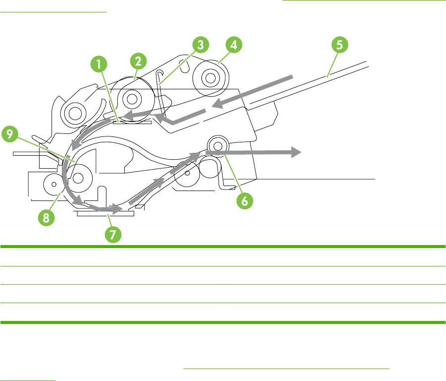
ADF paper path
The ADF feeds documents past the ADF glass for scanning. See Figure 5-51 ADF path for single-sided
documents on page 175.
Figure 5-51 ADF path for single-sided documents
1Separation pad 5ADF input tray
2Pickup roller 6Delivery/duplex-feed rollers
3Stack stop 7ADF glass
4 Pre-pick roller 8 ADF feed rollers
For two-sided documents, the delivery rollers reverse the direction of each page to feed the second side
of the document past the ADF glass. See Figure 5-52 ADF path for two-sided documents
on page 176.
ENWW Scanning/image capture system system 175
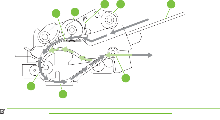
Figure 5-52 ADF path for two-sided documents
12
3 4 5
6
7
8
NOTE: Callouts in Figure 5-52 ADF path for two-sided documents on page 176 are identical to callouts
in Figure 5-51 ADF path for single-sided documents on page 175 .
Stapler
The HP Color LaserJet CM3530fs MFP includes a stapler capable of stapling 20 sheets of (80 g/m
2
)
(20 lb) paper. The stapler has an AC power connection to the LVPS. Because there are no logic
connections to the product, error conditions or out-of-staples indications are not displayed on the control
panel.
176 Chapter 5 Theory of operation ENWW

6 Removal and replacement
NOTE: Your product might not appear exactly as the one shown in the photos in this chapter. Although
some photos do not show the ADF/scanner unit, the procedures in this chapter are appropriate for your
product.
●Introduction
●Removal and replacement strategy
●Electrostatic discharge
●Required tools
●Before performing service
●After performing service
●Post-service test
●DC controller PCA
●Parts removal order
●Customer self repair (CSR) components
●External panels, covers, doors, and scanner assembly
●Internal assemblies
ENWW 177

Introduction
This chapter describes the removal and replacement of field-replaceable units (FRUs) only.
Replacing FRUs is generally the reverse of removal. Occasionally, notes and tips are included to provide
directions for difficult or critical replacement procedures.
HP does not support repairing individual subassemblies or troubleshooting to the component level.
Note the length, diameter, color, type, and location of each screw. Be sure to return each screw to its
original location during reassembly.
Incorrectly routed or loose wire harnesses can interfere with other internal components and can become
damaged or broken. Frayed or pinched harness wires can be difficult to find. When replacing wire
harnesses, always use the provided wire loops, lance points, or wire-harness guides and retainers.
Removal and replacement strategy
WARNING! Turn the product off, wait 5 seconds, and then remove the power cord before attempting
to service the product. If this warning is not followed, severe injury can result, in addition to damage to
the product. The power must be on for certain functional checks during troubleshooting. However,
disconnect the power supply during parts removal.
Never operate or service the product with the protective cover removed from the laser/scanner
assembly. The reflected beam, although invisible, can damage your eyes.
The sheet-metal parts can have sharp edges. Be careful when handling sheet-metal parts.
CAUTION: Do not bend or fold the flat flexible cables (FFCs) during removal or installation. Also, do
not straighten pre-folds in the FFCs. You must fully seat all FFCs in their connectors. Failure to fully
seat an FFC into a connector can cause a short circuit in a PCA.
NOTE: To install a self-tapping screw, first turn it counterclockwise to align it with the existing thread
pattern, and then carefully turn it clockwise to tighten. Do not overtighten. If a self-tapping screw-hole
becomes stripped, repair the screw-hole or replace the affected assembly.
TIP: For clarity, some photos in this chapter show components removed that would not be removed
to service the product. If necessary, remove the components listed at the beginning of a procedure
before proceeding to service the product.
Electrostatic discharge
CAUTION: Some parts are sensitive to electrostatic discharge (ESD). Look for the ESD reminder
when removing product parts. Always perform service work at an ESD-protected workstation or mat, or
use an ESD strap. If an ESD workstation, mat, or strap is not available, ground yourself by touching the
sheet-metal chassis before touching an ESD-sensitive part.
Protect the ESD-sensitive parts by placing them in ESD pouches when they are out of the product.
178 Chapter 6 Removal and replacement ENWW

Required tools
●#1 Phillips screwdriver with a magnetic tip and a 152-mm (6-inch) shaft length
●#2 Phillips screwdriver with a magnetic tip and a 152-mm (6-inch) shaft length
●Small flat blade screwdriver
●Needle-nose pliers
●ESD mat or ESD strap (if one is available)
●Penlight (optional)
CAUTION: Always use a Phillips screwdriver (callout 1). Do not use a pozidrive screwdriver (callout 2)
or any motorized screwdriver. These can damage screws or screw threads.
Figure 6-1 Phillips and pozidrive screwdriver comparison
ENWW Required tools 179

Before performing service
●Remove all media from the product.
●Turn off the power using the power switch.
●Unplug the power cable and interface cable or cables.
●Place the product on an ESD workstation or mat, or use an ESD strap (if one is available). If an
ESD workstation, mat, or strap is not available, ground yourself by touching the sheet-metal chassis
before touching an ESD-sensitive part.
●Remove the print cartridges. See Print cartridges on page 186.
●Remove the tray cassette or cassettes. See Tray cassette on page 199.
180 Chapter 6 Removal and replacement ENWW

After performing service
●Plug in the power cable.
●Reinstall the print cartridges.
●Reinstall the tray cassette or cassettes.
●If the optional paper feeder was installed, place the product on the feeder.
NOTE: Your product might not appear exactly as the one shown in the photos in this chapter. Although
some photos do not show the ADF/scanner unit, the procedures in this chapter are appropriate for your
product.
ENWW After performing service 181

Post-service test
Perform the following test to verify that the repair or replacement was successful.
NOTE: Your product might not appear exactly as the one shown in the photos in this chapter. Although
some photos do not show the ADF/scanner unit, the procedures in this chapter are appropriate for your
product.
Print-quality test
1. Verify that you have completed the necessary reassembly steps.
2. Make sure that the tray contains clean, unmarked paper.
3. Attach the power cord and interface cable or interface cables, and then turn on the product.
4. Verify that the expected startup sounds occur.
5. Print a configuration page, and then verify that the expected printing sounds occur.
6. Print a demo page, and then verify that the print quality is as expected.
7. Send a print job from the host computer, and then verify that the output meets expectations.
8. If necessary, restore any customer-specified settings.
9. Clean the outside of the product with a damp cloth.
Copy-quality test
1. Verify that you have completed the necessary reassembly steps.
2. Ensure that the input tray contains clean, unmarked paper.
3. Attach the power cord, and then turn on the product.
4. Verify that the expected start-up sounds occur.
5. Print a configuration page, and then verify that the expected printing sounds occur.
6. Place the configuration page in the ADF.
7. Print a copy job, and then verify the results.
8. Place the configuration page on the scanner glass.
9. Print a copy job, and then verify the results.
10. Clean the outside of the product with a damp cloth.
182 Chapter 6 Removal and replacement ENWW

DC controller PCA
Figure 6-2 DC controller PCA
J126
Table 6-1 DC controller connectors
J100: 24 v from low-voltage power
supply (LVPS) and interlock
J114: HVPS lower J126: memory tag connector
J101: LVPS J115: fuser sensors J127: pre-exposure LEDs (rear), SR17,
SL1
J105: interconnect board (ICB) J116: HVPS upper J130: registration density (RD) sensors
(front and rear)
J106: 500-sheet feeder, developing
home position, laser motors
J117: fuser motor J131: pickup motor
J107: duplex sensor, tray 1 solenoid,
paper present sensor
J118: 5 v interlock J133: not used
J108: environmental sensor J119: LVPS fan J134: not used
J109: duplex clutch, overhead
transparency (OHT) in, top-of-page
sensor
J120: drum motor 1 and drum motor 2 J137: toner collection unit (TCU) full,
TCU motor, toner level detection
J110: YM laser J121: drum motor 3, drum position 1,2,3 J138: 24 v to HVPS lower
J111: CK laser J122: OHT out J139: fuser sensors
J112: pre-exposure LEDs (front) J123: pressure release, bin full, fuser
delivery
J140: lift motor, tray present, stack
surface
J113: 24 v to high-voltage power supply
(HVPS) upper
J124: 24 v to scanner-control board
(SCB)
J143: 24 v present from LVPS
ENWW DC controller PCA 183
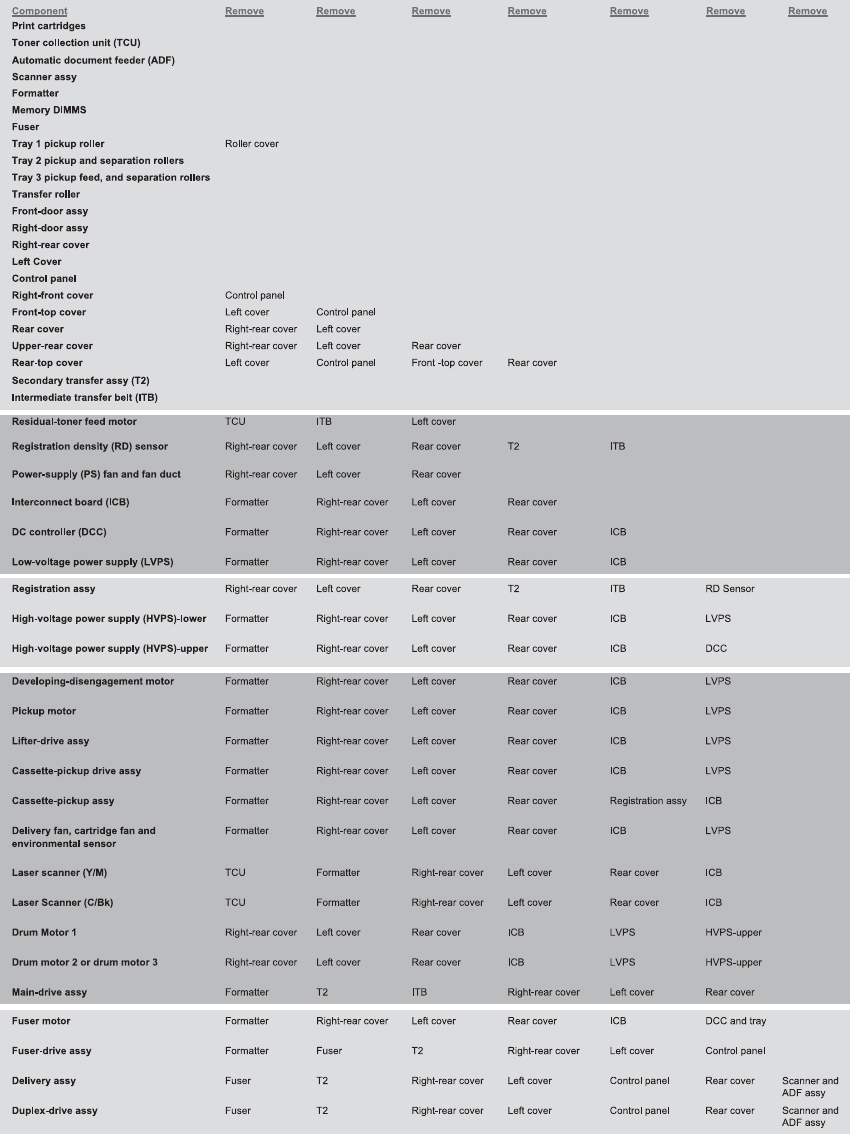
Parts removal order
Figure 6-3 Parts removal order (1 of 2)
184 Chapter 6 Removal and replacement ENWW

Figure 6-4 Parts removal order (2 of 2)
ENWW Parts removal order 185
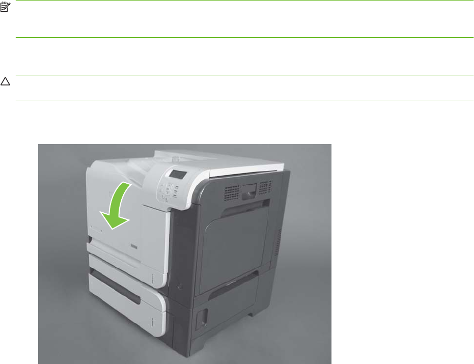
Customer self repair (CSR) components
NOTE: Your product might not appear exactly as the one shown in the photos in this chapter. Although
some photos do not show the ADF/scanner unit, the procedures in this chapter are appropriate for your
product.
Print cartridges
CAUTION: If toner gets on your clothing, wipe it off with a dry cloth and wash clothing in cold water.
Hot water sets toner into fabric.
1. Open the front door. Make sure that the door is completely open.
Figure 6-5 Remove the print cartridge (1 of 2)
186 Chapter 6 Removal and replacement ENWW
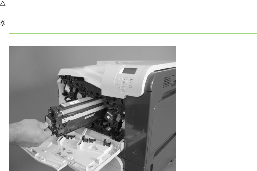
2. Grasp the print-cartridge handle and pull out to remove.
CAUTION: Do not touch the green roller. Doing so can damage the cartridge. Do not expose the
cartridge to strong light. Cover the cartridge with a sheet of paper to protect it from light.
Reinstallation tip Align the print cartridge with its slot and insert the print cartridge until it clicks
into place.
Figure 6-6 Remove the print cartridge (2 of 2)
ENWW Customer self repair (CSR) components 187
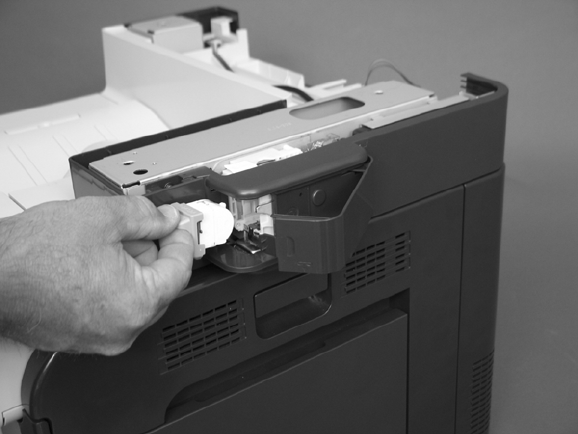
Stapler cartridge
Open the stapler door, and then remove the stapler cartridge.
Figure 6-7 Remove the stapler cartridge
188 Chapter 6 Removal and replacement ENWW
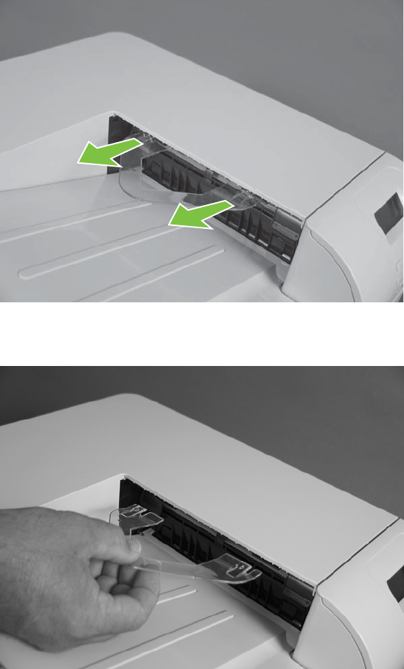
Duplex-reverse guide
1. Grasp the duplex-reverse guide and pull it away from the product to release it.
Figure 6-8 Remove the duplex-reverse guide (1 of 2)
2. Remove the guide.
Figure 6-9 Remove the duplex-reverse guide (2 of 2)
ENWW Customer self repair (CSR) components 189
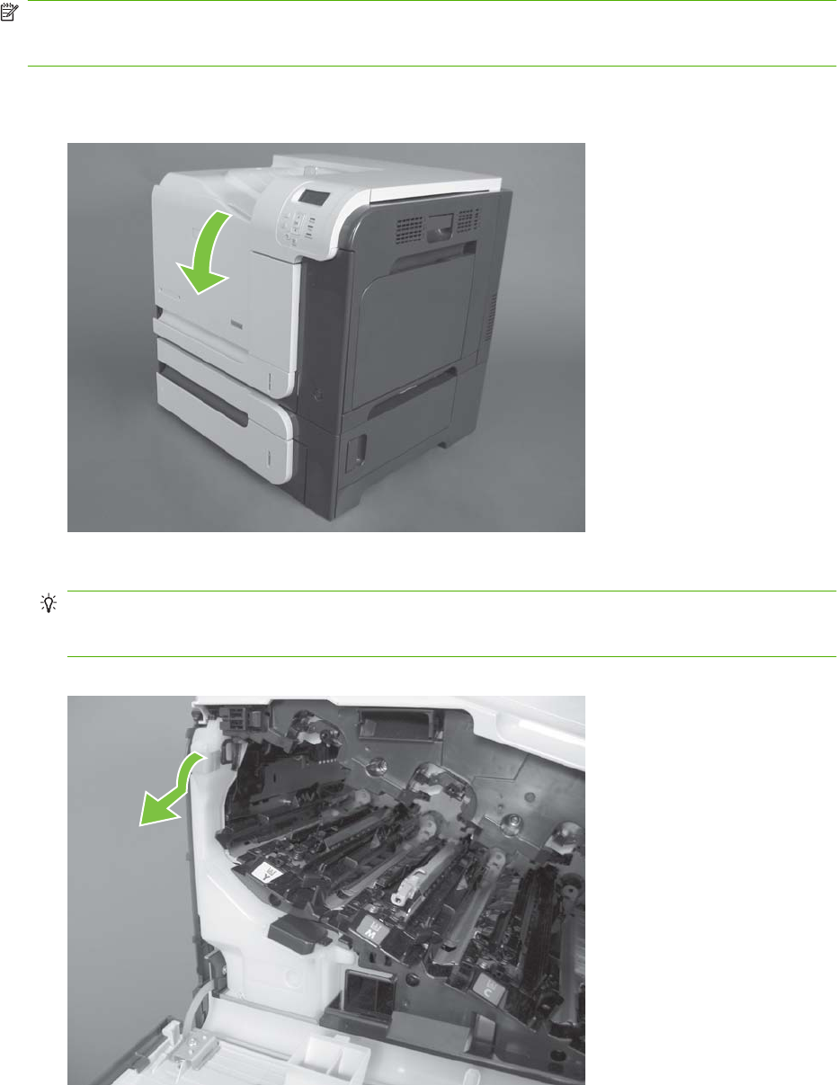
Toner-collection unit
NOTE: The toner-collection unit is designed for a single use. Do not try to empty the toner-collection
unit and reuse it. Doing so could cause toner to spill inside the product and result in reduced print quality.
For recycling information, see the product user guide.
1. Open the front door. Make sure that the door is completely open.
Figure 6-10 Remove the toner-collection unit (1 of 4)
2. Grasp the blue label at the top of the toner-collection unit and remove it from the product.
Reinstallation tip Insert the bottom of the replacement unit into the product first and then push
the top of the unit until it clicks into place. If the toner-collection unit is installed incorrectly, the front
door will not close completely.
Figure 6-11 Remove the toner-collection unit (2 of 4)
190 Chapter 6 Removal and replacement ENWW
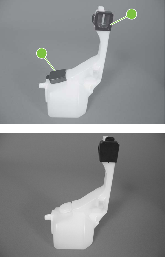
3. To prevent toner spills, place the blue cap (callout 1) over the blue opening at the top of the unit
(callout 2).
Figure 6-12 Remove the toner-collection unit (3 of 4)
1
2
Figure 6-13 Remove the toner-collection unit (4 of 4)
ENWW Customer self repair (CSR) components 191
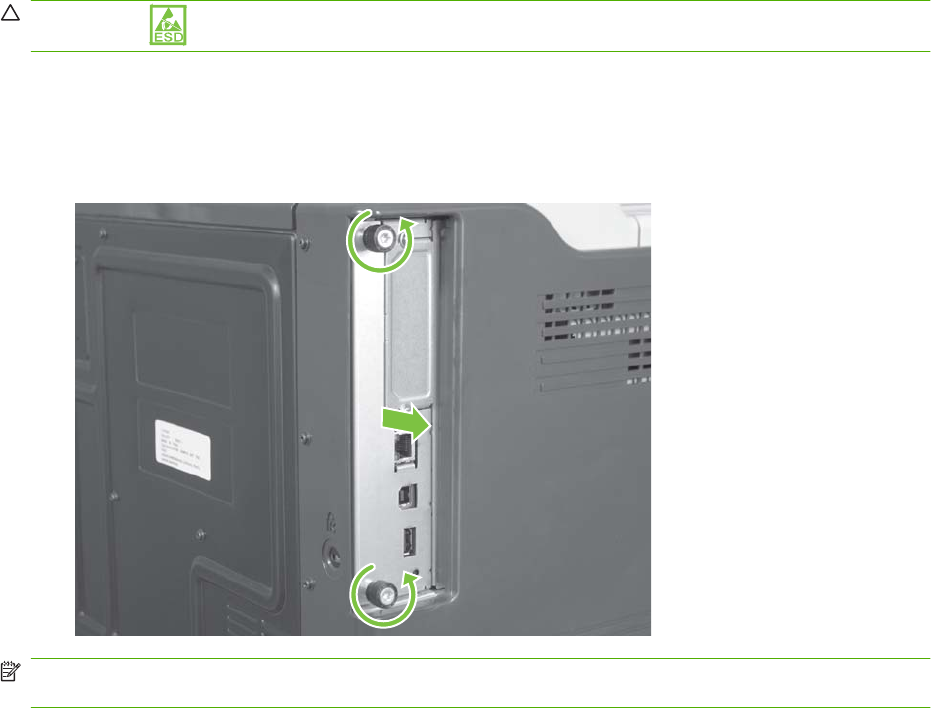
Formatter PCA
CAUTION: ESD sensitive component.
1. Turn the product off and disconnect the power and interface cable or interface cables.
2. Unscrew the formatter thumb screws, and then firmly pull the formatter from the product. Place the
formatter on a clean, flat, grounded surface.
Figure 6-14 Remove the formatter
NOTE: When reinstalling the formatter, push firmly on the right side to make sure the formatter is
seated.
192 Chapter 6 Removal and replacement ENWW
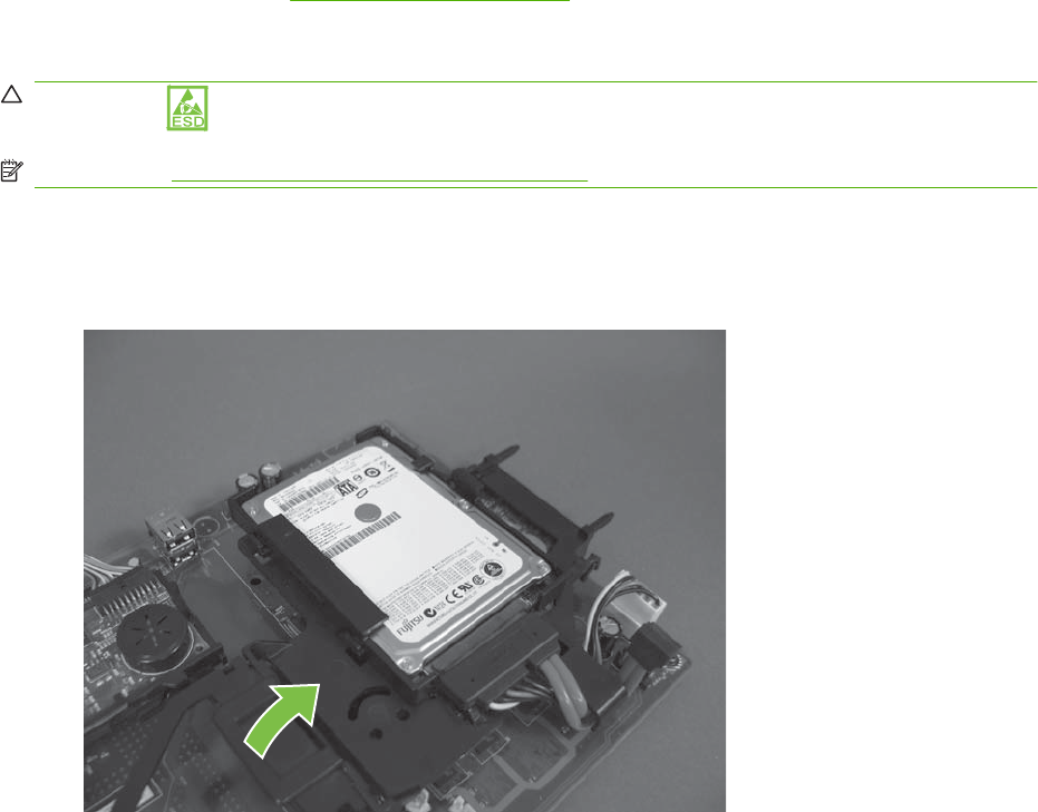
Memory DIMM
Before proceeding, remove the following components:
●Formatter PCA. See Formatter PCA on page 192.
Remove the memory DIMM
CAUTION: ESD sensitive component.
NOTE: See Enable memory for Windows on page 194 after installing a new memory DIMM.
1. Place the formatter on a clean, flat, grounded surface.
2. Release on tab, and raise the hard drive mounting bracket to access the memory DIMM.
Figure 6-15 Remove the memory DIMM (1 of 2)
ENWW Customer self repair (CSR) components 193
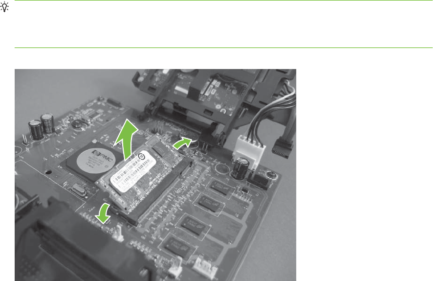
3. Spread the latches apart on each side of the DIMM slot. Lift the DIMM up at an angle, and pull it
out.
Reinstallation tip Hold the DIMM by the edges. Align the notch on the DIMM with the bar in the
DIMM slot at an angle and firmly press the DIMM into the slot until it is fully seated. When installed
correctly, the metal contacts are not visible. Push down on the DIMM until both latches engage the
DIMM.
Figure 6-16 Remove the memory DIMM (2 of 2)
Enable memory for Windows
Use the following procedure to enable the memory if you are installing a new DIMM.
1. Windows XP, Windows Server 2003, and Windows Server 2008 (using the default Start
menuview): Click Start, click Settings, and then click Printers and Faxes.
-or-
Windows XP, Windows Server 2003, and Windows Server 2008 (using the Classic Start
menuview): Click Start, click Settings, and then click Printers.
-or-
Windows Vista: Click Start, click Control Panel, and then in the category for Hardware and
Sound click Printer.
2. Right-click the driver icon, and then select Properties.
3. Click the Device Settings tab.
4. Expand the area for Installable Options.
5. Select the total amount of memory installed in the product.
6. Next to Automatic Configuration, select Update Now.
7. Click OK.
194 Chapter 6 Removal and replacement ENWW
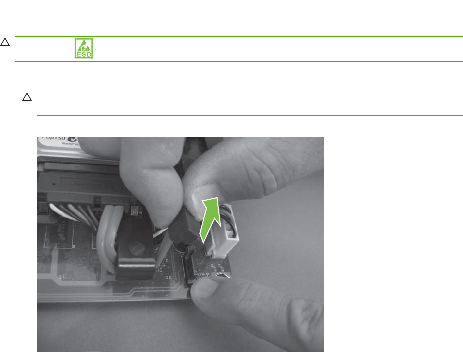
Hard drive and Serial Advanced Technology Attachment (SATA) cable
Before proceeding, remove the following components:
●Formatter PCA. See Formatter PCA on page 192.
Remove the hard drive and SATA cable
CAUTION: ESD sensitive component.
1. Disconnect one connector.
CAUTION: Use your finger to secure the connector base to the PCA. The connector base can
be dislodged and damaged when the connector is removed.
Figure 6-17 Remove the hard drive and SATA cable (1 of 3)
ENWW Customer self repair (CSR) components 195
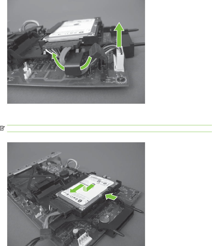
2. Disconnect one connector and release the wire harnesses from the guide.
Figure 6-18 Remove the hard drive and SATA cable (2 of 3)
3. Release one tab and then slide the hard drive toward the bottom of the formatter to release it.
Remove the hard drive.
NOTE: If necessary, disconnect the SATA cable from the hard drive.
Figure 6-19 Remove the hard drive and SATA cable (3 of 3)
196 Chapter 6 Removal and replacement ENWW

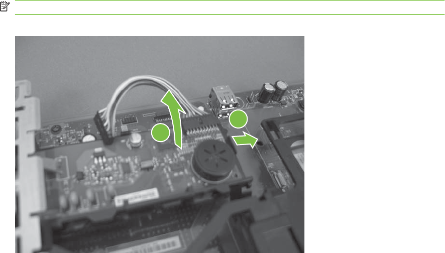
2. Release one tab, and then rotate the fax PCA away from the formatter to release it. Remove the
fax PCA.
NOTE: If necessary, disconnect the cable from the fax PCA.
Figure 6-21 Remove the fax PCA and cable (2 of 2)
1
2
198 Chapter 6 Removal and replacement ENWW
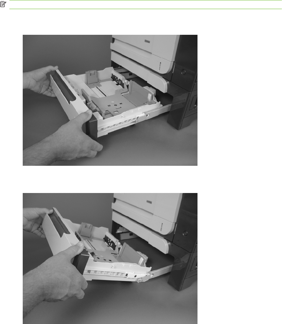
Tray cassette
NOTE: Use this procedure to remove the Tray 2 or optional Tray 3 cassette.
1. Pull the tray straight out of the product until it stops.
Figure 6-22 Remove the tray cassette (1 of 2)
2. Carefully lift up on the tray to release it, and then remove the tray.
Figure 6-23 Remove the tray cassette (2 of 2)
ENWW Customer self repair (CSR) components 199
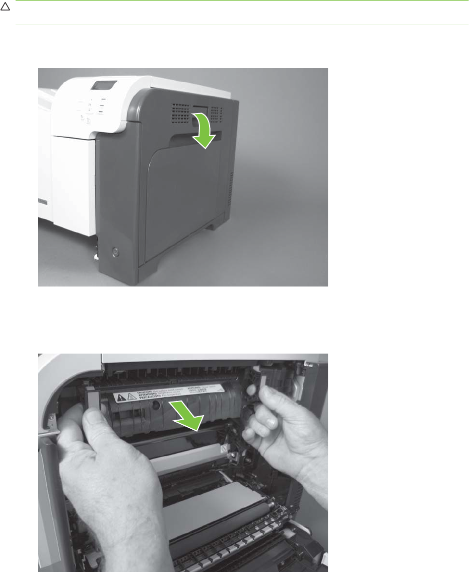
Fuser
CAUTION: The fuser might be hot. Allow enough time after turning off the product power for the fuser
to cool.
1. Open the right-door assembly.
Figure 6-24 Remove the fuser (1 of 2)
2. Grasp the handles and squeeze the blue release levers.
Pull the fuser straight out of the product to remove it.
Figure 6-25 Remove the fuser (2 of 2)
200 Chapter 6 Removal and replacement ENWW
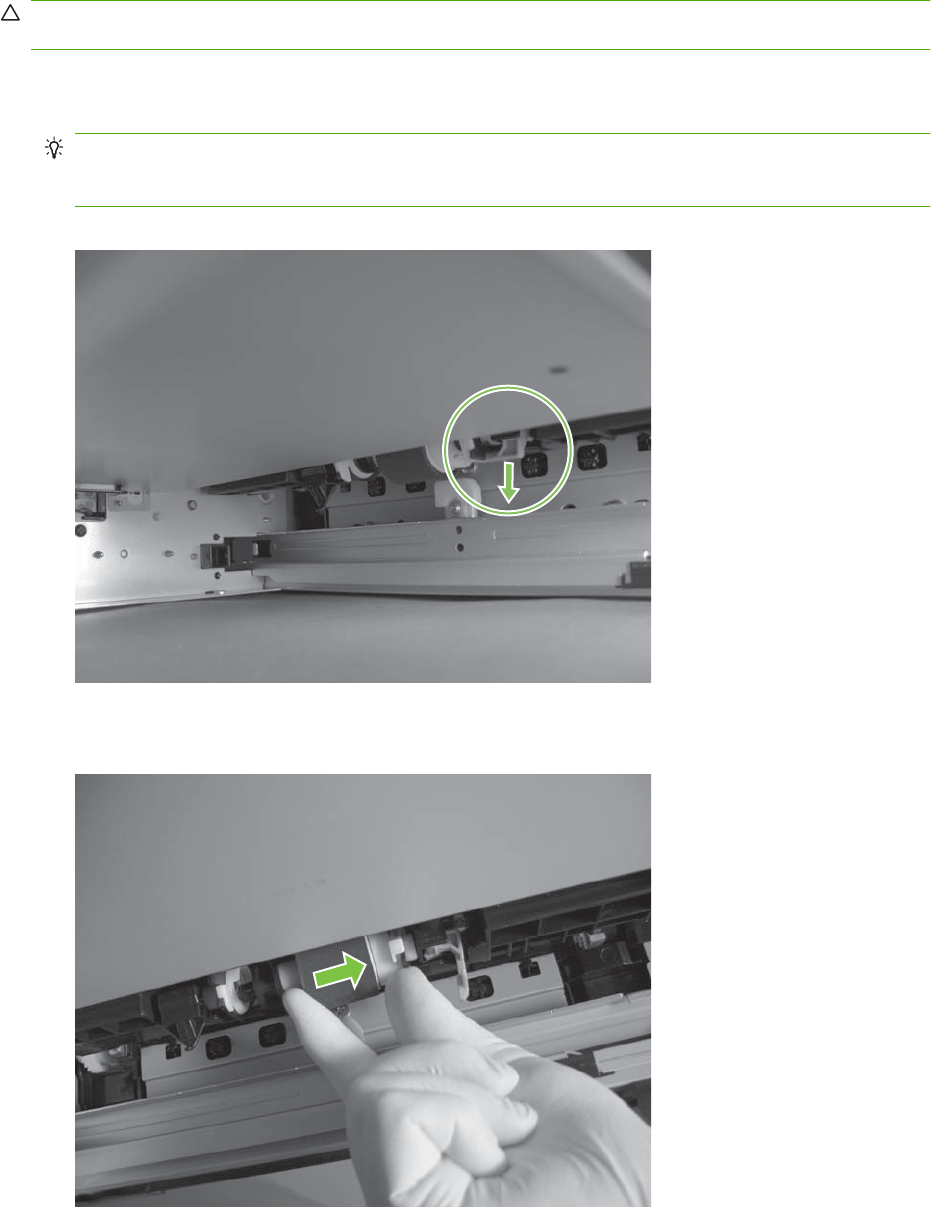
Pickup roller (Tray 2)
CAUTION: Do not touch the spongy roller surface unless you are replacing the roller. Skin oils on the
roller can cause paper pickup problems.
1. Look up into the Tray 2 cavity (where the cassette would be installed), and pull down to release
the blue roller-locking lever.
Reinstallation tip When the roller is reinstalled, rotate the roller shaft several times to make sure
that the shaft correctly engages the drive mechanism. You should hear a click when the shaft
engages the drive mechanism.
Figure 6-26 Remove the pickup roller (Tray 2) (1 of 4)
2. Pull the roller toward the front of the product to release the rear of the roller shaft.
Figure 6-27 Remove the pickup roller (Tray 2) (2 of 4)
ENWW Customer self repair (CSR) components 201
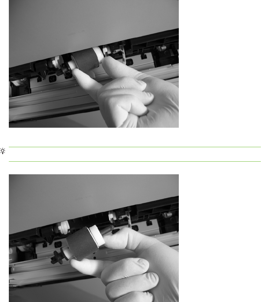
3. Rotate the roller shaft down and away from the product, and then slide the roller toward the rear
of the product to release the front of the roller shaft.
Figure 6-28 Remove the pickup roller (Tray 2) (3 of 4)
4. Remove the pickup roller.
Reinstallation tip Make sure that the roller is orientated correctly when it is reinstalled (the large
white collar should be positioned toward the front of the product.
Figure 6-29 Remove the pickup roller (Tray 2) (4 of 4)
202 Chapter 6 Removal and replacement ENWW
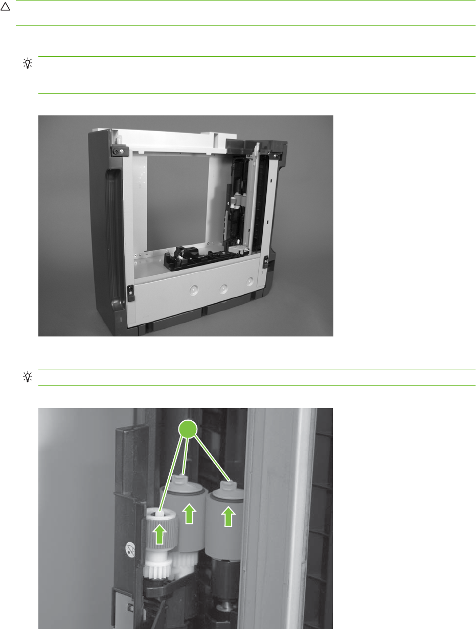
Pickup and feed rollers (Tray 3)
CAUTION: Do not touch the spongy roller surface unless you are replacing the roller. Skin oils on the
roller can cause paper pickup problems.
1. Locate the Tray 3 pickup and feed rollers.
TIP: The feeder is shown front side up in this procedure for clarity. You do not have to separate
the product from the feeder to remove these rollers. Remove the cassette, and then reach up into
the cavity to remove the rollers.
Figure 6-30 Remove the Pickup and feed rollers (Tray 3) (1 of 2)
2. Release three tabs (callout 1), and then remove the rollers.
Reinstallation tip When you reinstall the rollers, make sure that the rollers snap into place.
Figure 6-31 Remove the Pickup and feed rollers (Tray 3) (2 of 2)
1
ENWW Customer self repair (CSR) components 203
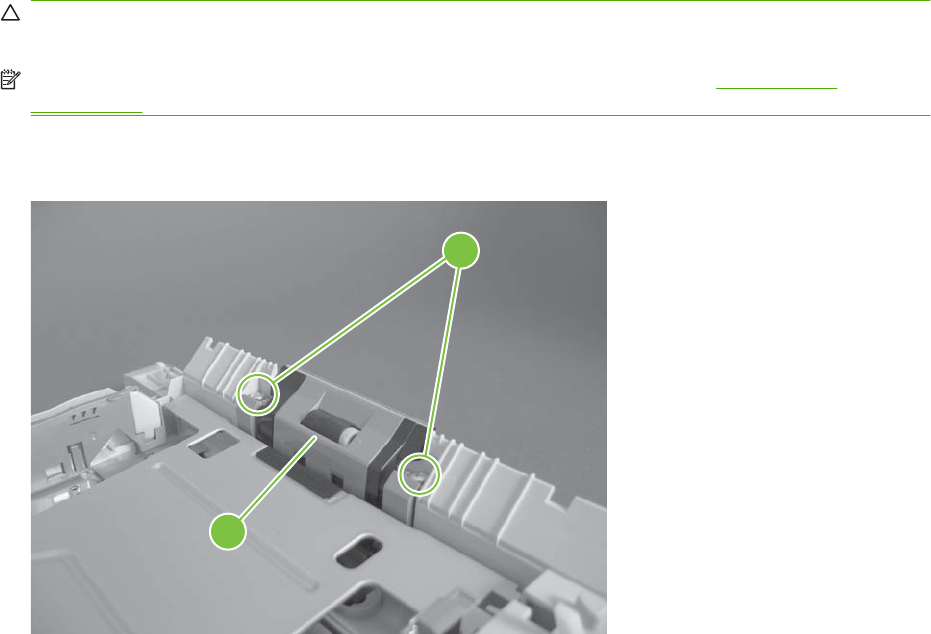
Separation roller (Tray 2)
CAUTION: Do not touch the spongy roller surface unless you are replacing the roller. Skin oils on the
roller can cause paper pickup problems.
NOTE: Remove the Tray 2 cassette if not already removed for service. See Tray cassette
on page 199.
Remove two screws (callout 1), and then remove the separation roller assembly (callout 2).
Figure 6-32 Remove the separation roller (Tray 2)
2
1
204 Chapter 6 Removal and replacement ENWW
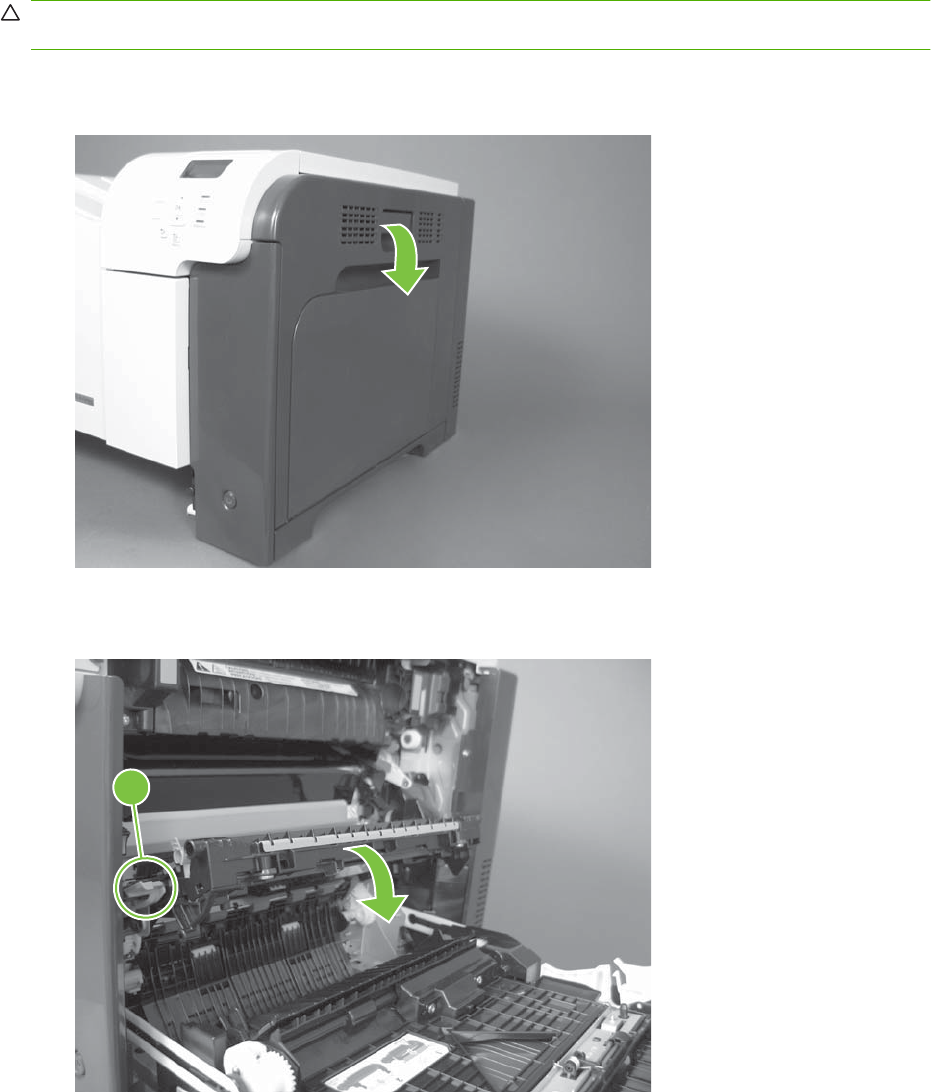
Secondary transfer roller
CAUTION: Do not touch the spongy roller surface unless you are replacing the roller. Skin oils on the
roller can cause image quality problems.
1. Open the right-door assembly.
Figure 6-33 Remove the transfer roller (1 of 3)
2. Use the blue lever (callout 1) to lower the secondary transfer assembly.
Figure 6-34 Remove the transfer roller (2 of 3)
1
ENWW Customer self repair (CSR) components 205
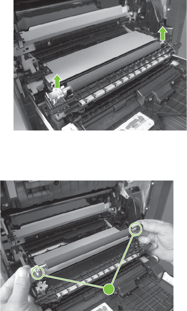
3. Grasp the roller shaft collars, and lift the transfer roller off of the product.
Figure 6-35 Remove the transfer roller (3 of 3)
Reinstall the transfer roller
When you reinstall the transfer roller, make sure that the pins on the shaft collars (callout 1) align with
the holes in the mounting assembly.
Figure 6-36 Reinstall the transfer roller
1
206 Chapter 6 Removal and replacement ENWW
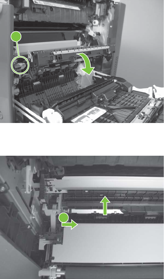
Secondary transfer assembly
The secondary transfer assembly includes the transfer roller.
1. Open the right-door assembly.
2. Use the blue lever (callout 1) to lower the secondary transfer assembly.
Figure 6-37 Remove the transfer roller (2 of 3)
1
3. Push the pin on the release-lever side of the assembly toward the inside of the product to release
it, and then lift the assembly up.
Figure 6-38 Remove the secondary transfer assembly (1 of 2)
1
ENWW Customer self repair (CSR) components 207
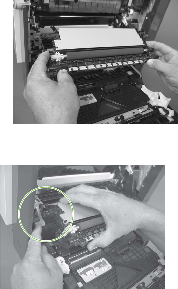
4. Pull the assembly straight out of the product to remove it.
Figure 6-39 Remove the secondary transfer assembly (2 of 2)
Reinstall the secondary transfer assembly
Press and hold down the blue release lever when you reinstall the assembly.
Figure 6-40 Reinstall the secondary transfer assembly
208 Chapter 6 Removal and replacement ENWW
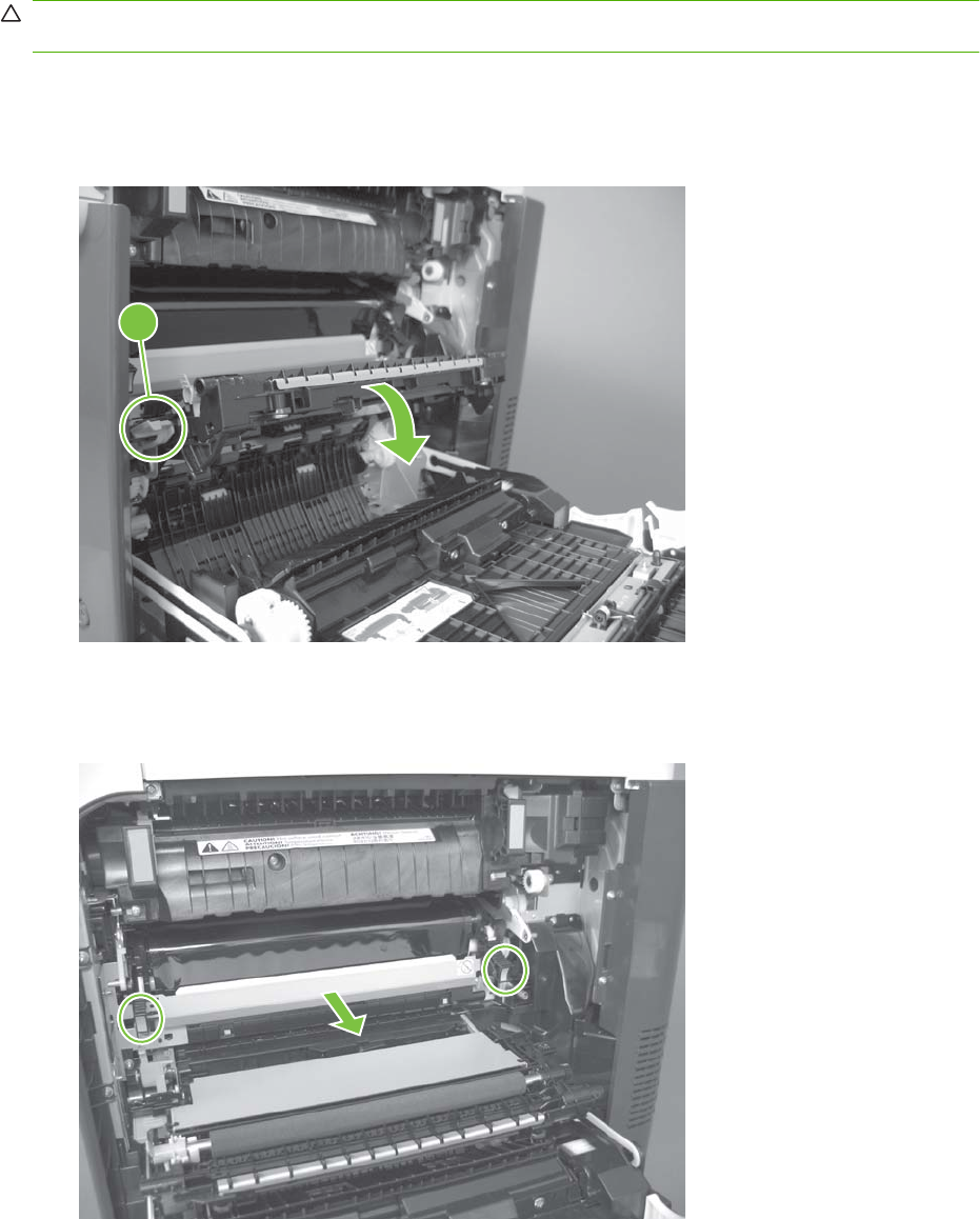
Intermediate transfer belt (ITB)
CAUTION: Do not touch the black-plastic belt. Skin oils and fingerprints on the belt can cause print-
quality problems. Always place the ITB on a flat surface in a safe and protected location.
1. Open the right-door assembly.
2. Use the blue lever (callout 1) to lower the secondary transfer assembly.
Figure 6-41 Remove the intermediate transfer belt (1 of 3)
1
3. Grasp the small handles on the ITB and then pull the ITB out of the product until two large handles
expand along the right- and left-side of the ITB.
Figure 6-42 Remove the intermediate transfer belt (2 of 3)
ENWW Customer self repair (CSR) components 209
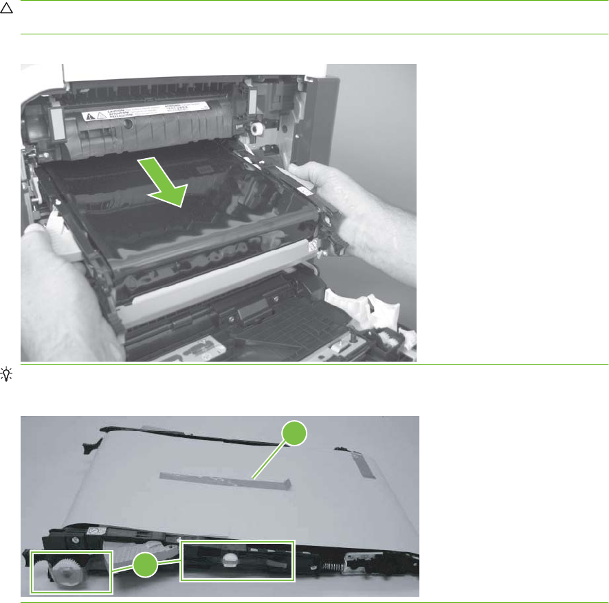
4. Grasp the large handles on the ITB and then pull the ITB straight out of the product to remove it.
CAUTION: The ITB is a sensitive component. Be careful when handling the ITB so that it is not
damaged. Always place the ITB in a safe and protected location.
Figure 6-43 Remove the intermediate transfer belt (3 of 3)
Reinstallation tip If you are installing a replacement ITB, make sure that you remove all of the
packing tape (callout 1) and the protective cover sheet (callout 2).
1
2
210 Chapter 6 Removal and replacement ENWW
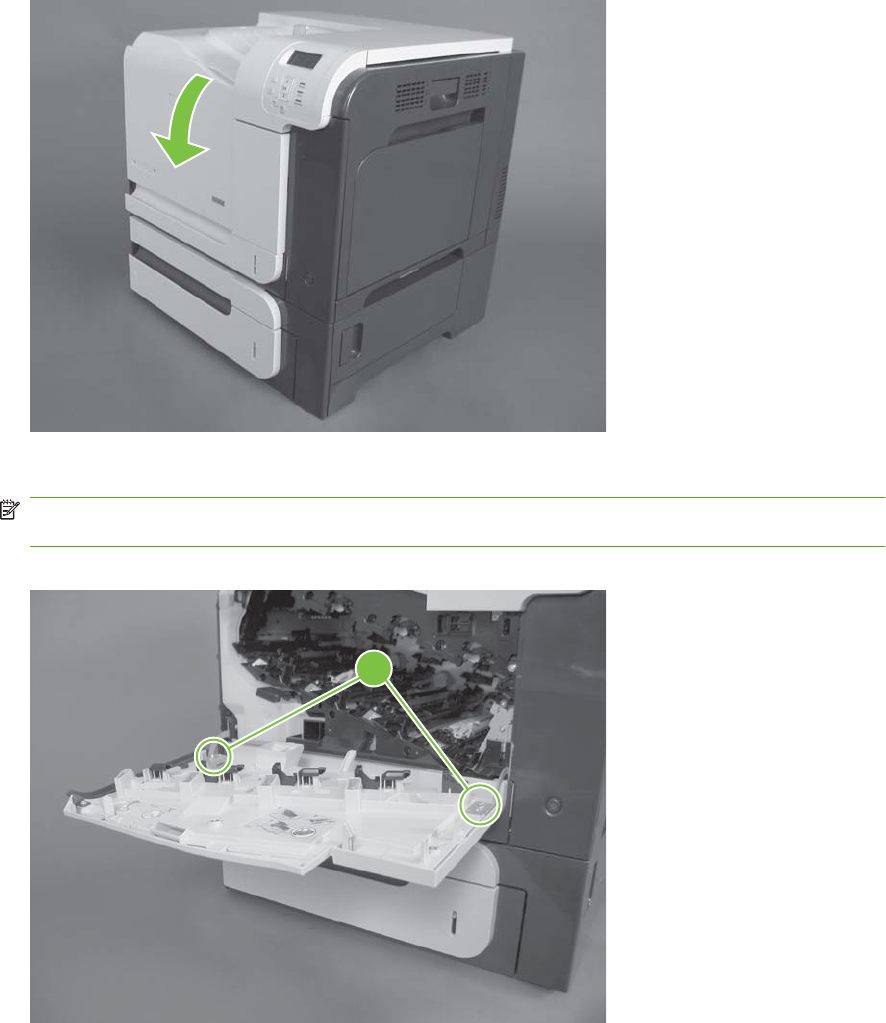
Front-door assembly
1. Open the front door.
Figure 6-44 Remove the front-door assembly (1 of 2)
2. Remove two screws (callout 1), and then remove the front-door assembly.
NOTE: A small sheet-metal bracket on the left side of the door is not captive. Do not lose the
bracket when you remove the screw.
Figure 6-45 Remove the front-door assembly (2 of 2)
1
3. If you are installing a replacement front-door assembly, install the HP name tag and the appropriate
product model number tag on the assembly.
ENWW Customer self repair (CSR) components 211
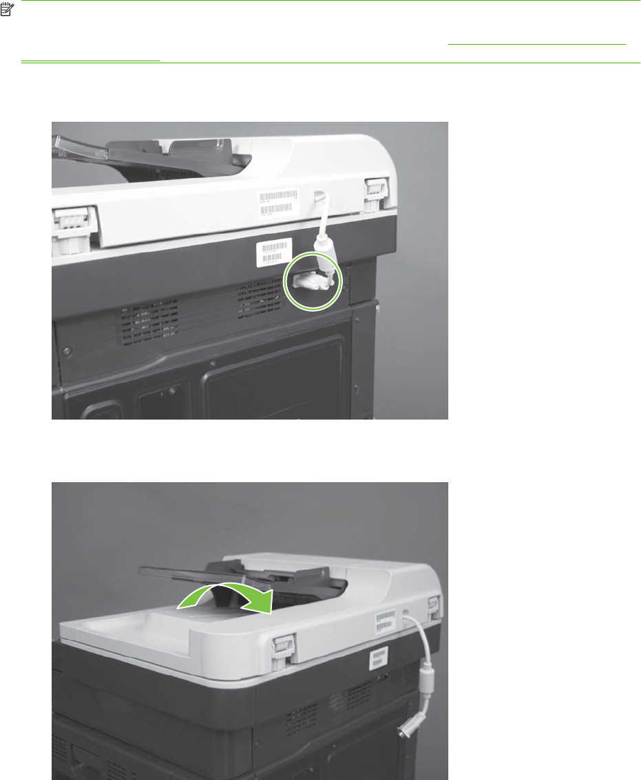
Automatic document feeder (ADF)
NOTE: After removing the ADF assembly, place it on a clean, dry, and smooth surface.
You must calibrate the ADF and scanner after installing the ADF. See Calibrate a replacement ADF
assembly on page 214.
1. Release two thumb screws, and then disconnect one connector.
Figure 6-46 Remove the ADF assembly (1 of 4)
2. Open the ADF.
Figure 6-47 Remove the ADF assembly (2 of 4)
212 Chapter 6 Removal and replacement ENWW
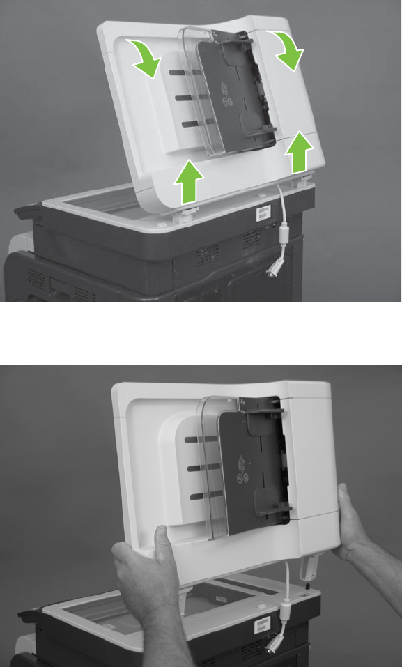
3. Lift the ADF straight up until it stops, and then slightly tilt it toward the rear of the product. Continue
lifting the ADF straight up to remove it.
Figure 6-48 Remove the ADF assembly (3 of 4)
4. Remove the ADF.
Figure 6-49 Remove the ADF assembly (4 of 4)
ENWW Customer self repair (CSR) components 213

Calibrate a replacement ADF assembly
1. On the control-panel Home screen, scroll to and touch Administration.
2. Touch Troubleshooting.
3. Touch Calibrate Scanner.
4. Touch Calibrate to print the first pass of the calibration target.
5. Follow the instructions on the control-panel display. For more information, see Calibrate the product
on page 430.
214 Chapter 6 Removal and replacement ENWW
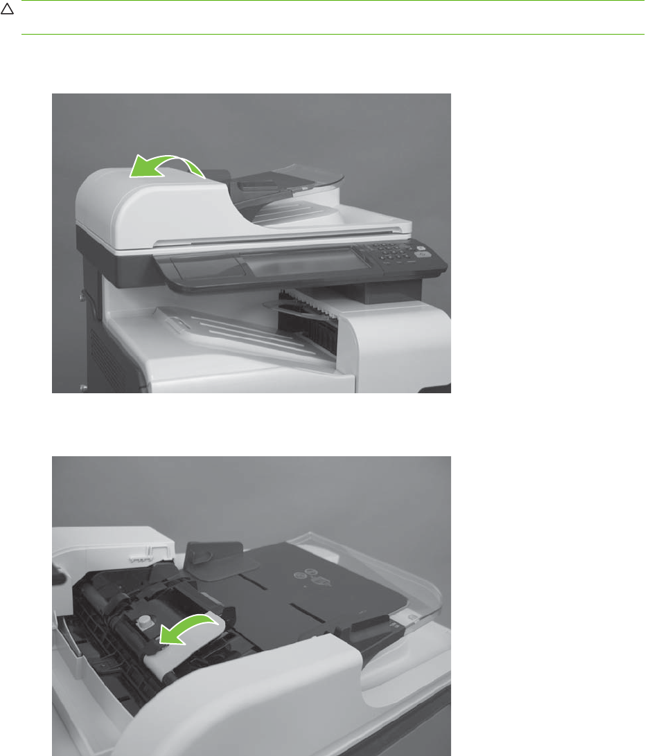
ADF roller assembly and separation pad
CAUTION: Do not touch the spongy roller surface unless you are replacing the roller. Skin oils on the
roller can cause paper pickup problems.
1. Open the ADF jam door.
Figure 6-50 Remove the ADF roller assembly and separation pad (1 of 5)
2. Lift the green handle.
Figure 6-51 Remove the ADF roller assembly and separation pad (2 of 5)
ENWW Customer self repair (CSR) components 215
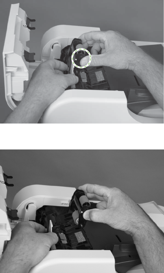
3. Push the blue button.
Figure 6-52 Remove the ADF roller assembly and separation pad (3 of 5)
4. Remove the ADF roller assembly.
Figure 6-53 Remove the ADF roller assembly and separation pad (4 of 5 )
216 Chapter 6 Removal and replacement ENWW
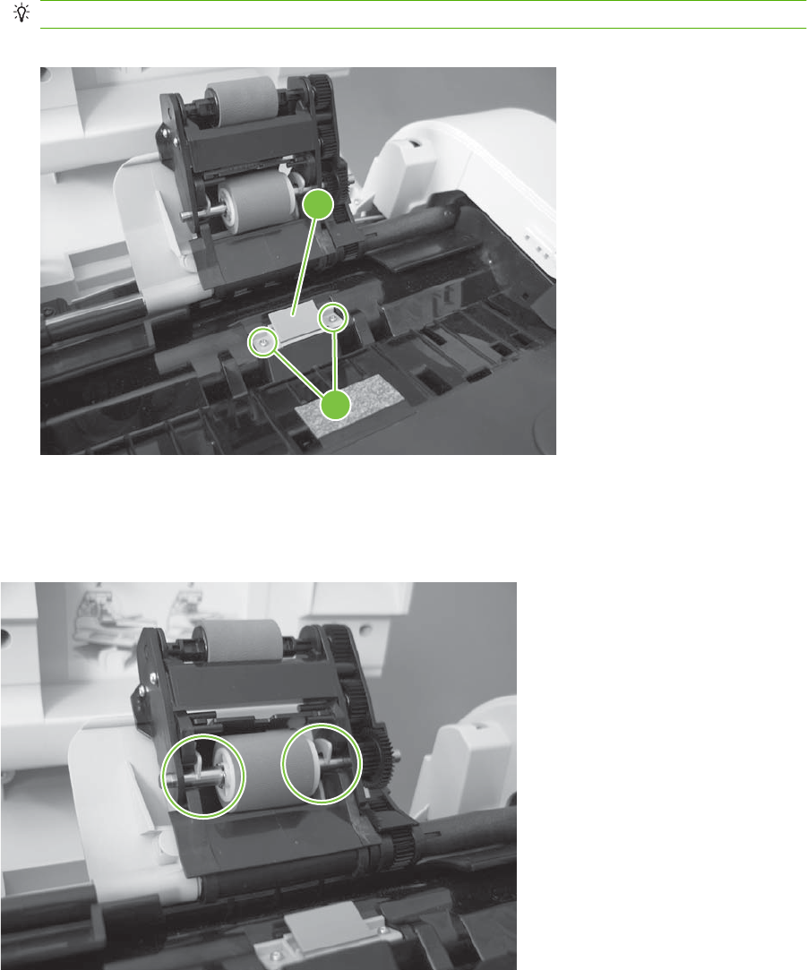
5. Remove two screws (callout 1), and then remove the separation-pad assembly (callout 2).
TIP: Use a #1 Phillips screwdriver to remove these screws.
Figure 6-54 Remove the ADF roller assembly and separation pad (5 of 5)
2
1
Reinstall the ADF roller assembly
Securely attach the ADF roller assembly to the blue hooks.
Figure 6-55 Reinstall the ADF roller assembly
ENWW Customer self repair (CSR) components 217

Control-panel overlay
1. Gently pull up on the control-panel overlay.
Figure 6-56 Remove the control-panel overlay (1 of 2)
2. Remove the control-panel overlay.
Figure 6-57 Remove the control-panel overlay (2 of 2)
218 Chapter 6 Removal and replacement ENWW
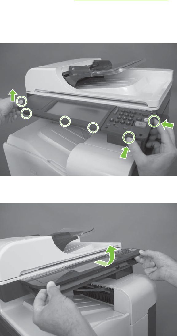
Control-panel assembly
Before proceeding, remove the following components:
●Control-panel overlay. See Control-panel overlay on page 218.
Remove the control-panel assembly
1. Release six tabs.
Figure 6-58 Remove the control-panel assembly (1 of 3)
2. Pull the control-panel assembly toward the front of the product and rotate it up.
Figure 6-59 Remove the control-panel assembly (2 of 3)
ENWW Customer self repair (CSR) components 219
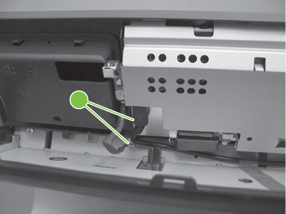
3. Disconnect two connectors (callout 1), and then remove the control-panel assembly.
Figure 6-60 Remove the control-panel assembly (3 of 3)
1
220 Chapter 6 Removal and replacement ENWW
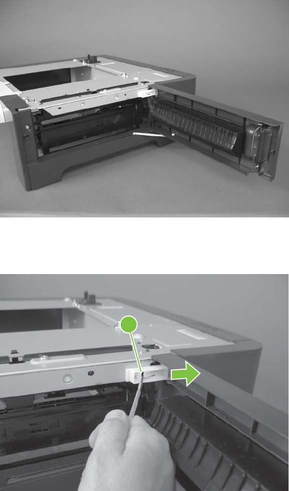
Right door (optional paper feeder)
1. Open the right door.
Figure 6-61 Remove the right door; optional paper feeder (1 of 3)
2. Release one tab (callout 1), and then slide the stopper toward the right side of the product to remove
it.
Figure 6-62 Remove the right door; optional paper feeder (2 of 3)
1
ENWW Customer self repair (CSR) components 221
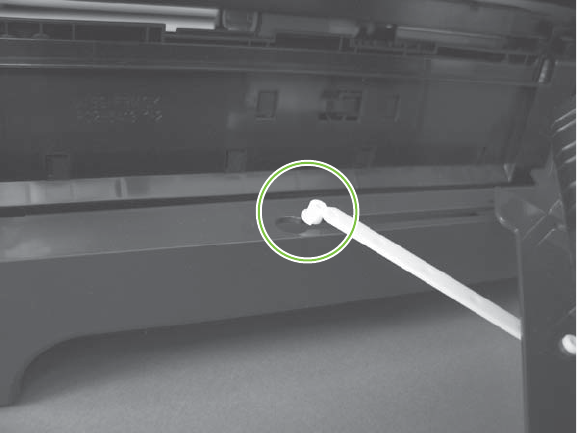
3. Support the door, and then release the door-retainer arm at the bottom of the door. Raise the door
to release the lower hinge pin, and then remove the door.
Figure 6-63 Remove the right door; optional paper feeder (3 of 3)
222 Chapter 6 Removal and replacement ENWW
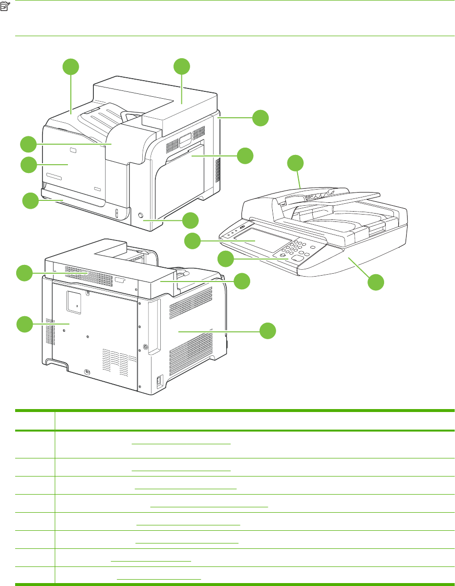
External panels, covers, doors, and scanner assembly
Identification and location
NOTE: Your product might not appear exactly as the one shown in the photos in this chapter. Although
some photos do not show the ADF/scanner unit, the procedures in this chapter are appropriate for your
product.
Figure 6-64 External panels, covers, doors, and scanner assembly; identification and location
8
9
10
11
12
5
6
3
4
14
13
15
16
7
12
Table 6-2 External panels, covers, doors, and scanner assembly; identification and location
Item Description
1Front-top cover (see Front-top cover on page 261)
2Right-top cover (see Right-top cover on page 258)
3Right-rear cover (see Right-rear cover on page 231)
4Right-door assembly (see Right-door assembly on page 227)
5Right-front cover (see Right-front cover on page 239)
6Left-upper cover (see Left-upper cover on page 247)
7Left cover (seeLeft cover on page 233)
8Rear cover (see Rear cover on page 238)
ENWW External panels, covers, doors, and scanner assembly 223

Item Description
9Rear-upper cover (see Rear-upper cover on page 236)
10 Tray cassette (see Tray cassette on page 199)
11 Front-door assembly (see Front-door assembly on page 211)
12 Front-upper cover (see Front-upper cover on page 225)
13 Control-panel assembly (see Control-panel assembly on page 219)
14 Control-panel overlay (see Control-panel overlay on page 218)
15 Automatic Document Feeder (see ADF roller assembly and separation pad on page 215)
16 Scanner (see Scanner assembly on page 242)
Table 6-2 External panels, covers, doors, and scanner assembly; identification and location (continued)
224 Chapter 6 Removal and replacement ENWW
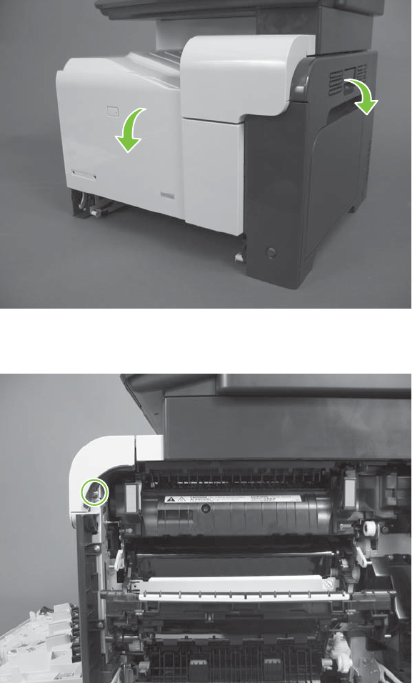
Front-upper cover
1. Open the right door and front door.
Figure 6-65 Remove the front-upper cover (1 of 4)
2. Remove one screw.
Figure 6-66 Remove the front-upper cover (2 of 4)
ENWW External panels, covers, doors, and scanner assembly 225
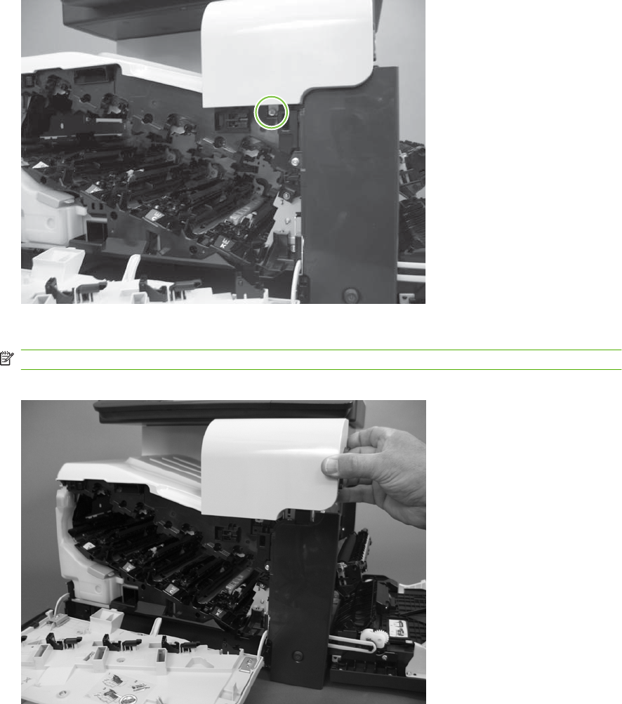
3. Remove one screw.
Figure 6-67 Remove the front-upper cover (3 of 4)
4. Lift the cover up, and then remove the front-upper cover.
NOTE: The cover might be difficult to remove. It might require some flexing to release it.
Figure 6-68 Remove the front-upper cover (4 of 4)
226 Chapter 6 Removal and replacement ENWW
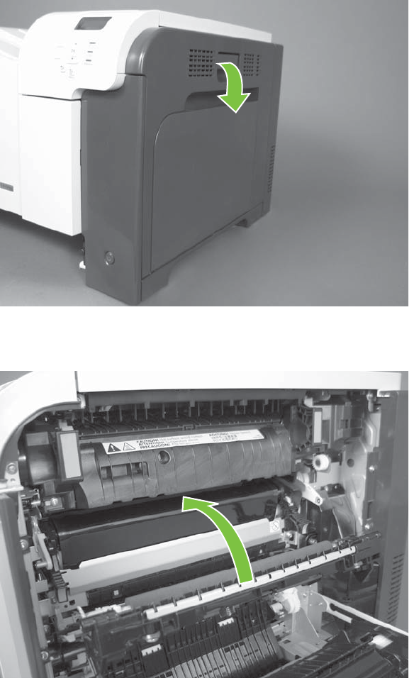
Right-door assembly
1. Open the right-door assembly
Figure 6-69 Remove the right-door assembly (1 of 8)
2. Close the secondary transfer assembly.
Figure 6-70 Remove the right-door assembly (2 of 8)
ENWW External panels, covers, doors, and scanner assembly 227
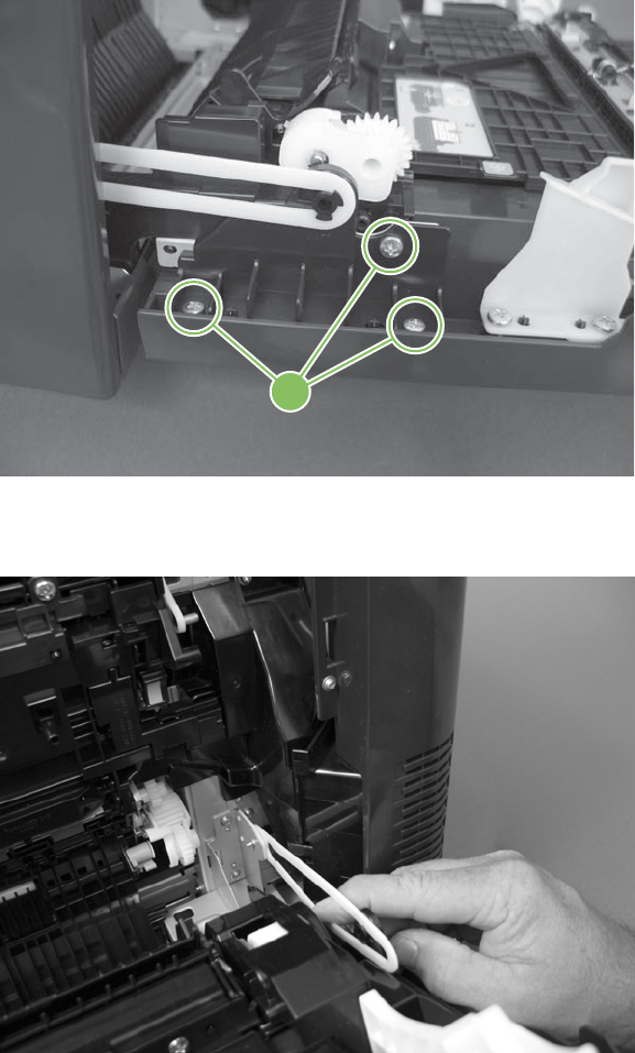
3. Remove three screws (callout 1).
Figure 6-71 Remove the right-door assembly (3 of 8)
1
4. Carefully release one link arm.
Figure 6-72 Remove the right-door assembly (4 of 8)
228 Chapter 6 Removal and replacement ENWW
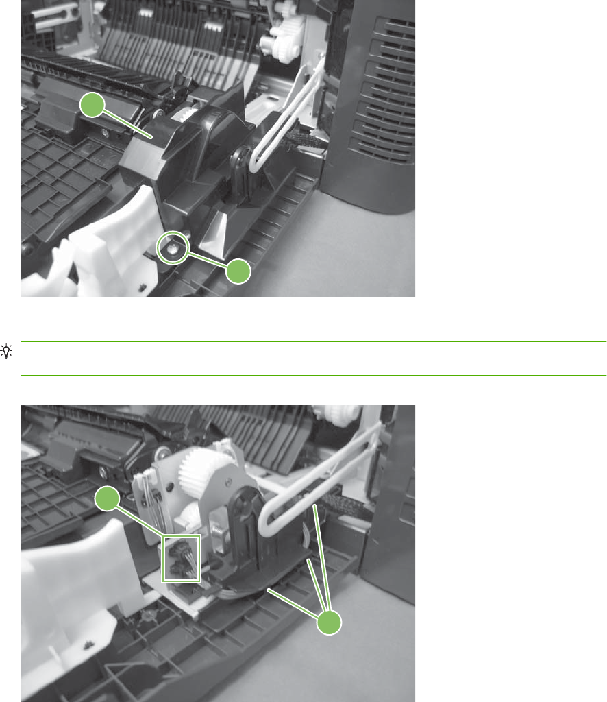
5. Remove one screw (callout 2), and then remove the cover (callout 3).
Figure 6-73 Remove the right-door assembly (5 of 8)
2
3
6. Disconnect two connectors (callout 4), and then release the wire harness from the guide (callout 5).
TIP: It is easier to disconnect the lower connector if you first remove the wire harnesses from the
guide.
Figure 6-74 Remove the right-door assembly (6 of 8)
4
5
ENWW External panels, covers, doors, and scanner assembly 229
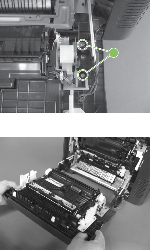
7. Remove two screws (callout 6).
Figure 6-75 Remove the right-door assembly (7 of 8)
6
8. Remove the right-door assembly.
Figure 6-76 Remove the right-door assembly (8 of 8)
230 Chapter 6 Removal and replacement ENWW
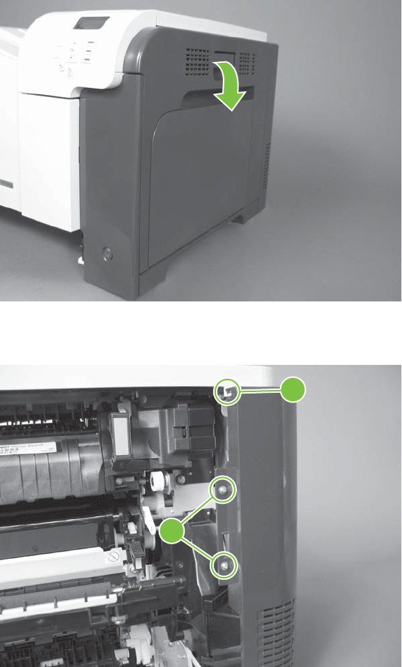
Right-rear cover
1. Open the right-door assembly.
Figure 6-77 Remove the right-rear cover (1 of 3)
2. Remove two screws (callout 1) and release one tab (callout 2).
Figure 6-78 Remove the right-rear cover (2 of 3)
1
2
ENWW External panels, covers, doors, and scanner assembly 231
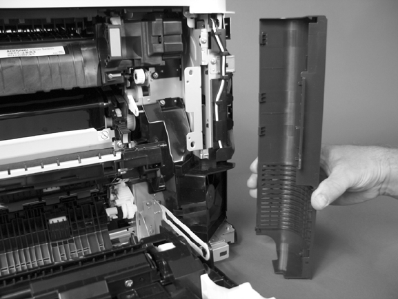
3. Rotate the bottom of the cover away from the product, and then remove the cover.
Figure 6-79 Remove the right-rear cover (3 of 3)
232 Chapter 6 Removal and replacement ENWW
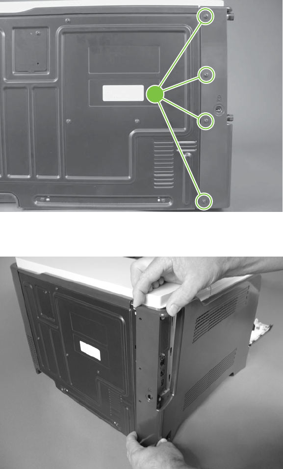
Left cover
1. Remove four screws (callout 1).
Figure 6-80 Remove the left cover (1 of 5)
1
2. Release the rear edge of the cover, and slightly separate the cover from the product.
Figure 6-81 Remove the left cover (2 of 5)
ENWW External panels, covers, doors, and scanner assembly 233
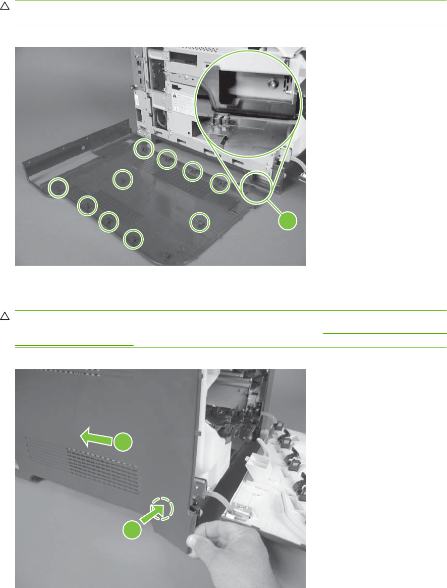
3. The figure below shows the cover removed so that you can see the tab locations. Before
proceeding, note the location of the mounting tabs.
CAUTION: One tab (callout 2) is easily damaged when removing the cover. Be careful when
removing the cover.
Figure 6-82 Remove the left cover (3 of 5)
2
4. Use your thumb to press in on the lower-front portion of the cover (near the dashed circle in the
figure below), and then slightly slide the cover away from the front door to release one tab.
CAUTION: You must flex the cover enough to release the front edge of the cover, but do not
damage the tab at the bottom-front edge of the cover. See callout 2 in Figure 6-82 Remove the left
cover (3 of 5) on page 234.
Figure 6-83 Remove the left cover (4 of 5)
1
2
234 Chapter 6 Removal and replacement ENWW
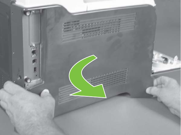
5. Slide the cover toward the rear of the product and rotate it away from the product and then remove
the cover.
Figure 6-84 Remove the left cover (5 of 5)
ENWW External panels, covers, doors, and scanner assembly 235
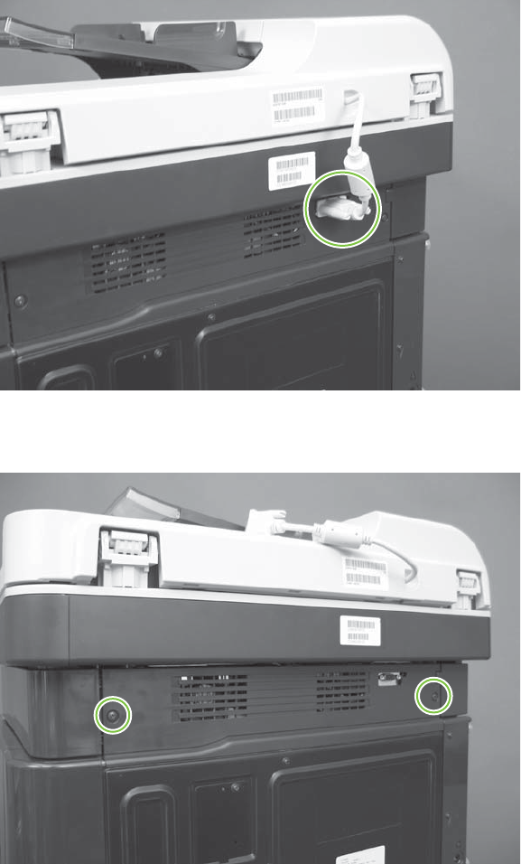
Rear-upper cover
1. Release two thumb screws, and then disconnect one connector.
Figure 6-85 Remove the rear-upper cover (1 of 4)
2. Remove two screws.
Figure 6-86 Remove the rear-upper cover (2 of 4)
236 Chapter 6 Removal and replacement ENWW
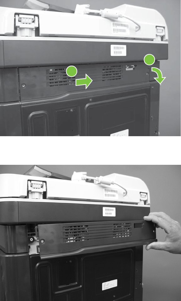
3. Rotate the rear-upper cover away from the product (callout 1), and then slide it toward the right
(callout 2) to release one tab.
Figure 6-87 Remove the rear-upper cover (3 of 4)
2
1
4. Remove the rear-upper cover.
Figure 6-88 Remove the rear-upper cover (4 of 4)
ENWW External panels, covers, doors, and scanner assembly 237
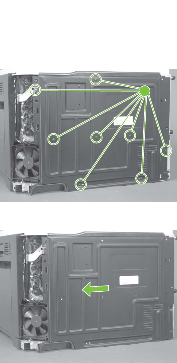
Rear cover
Before proceeding, remove the following components:
●Right-rear cover. See Right-rear cover on page 231.
●Left cover. See Left cover on page 233.
●Rear-upper cover. See Rear-upper cover on page 236.
Remove the rear cover
1. Remove eight screws (callout 1).
Figure 6-89 Remove the rear cover (1 of 2)
1
2. Slide the cover toward the fan side of the product, and then remove the rear cover.
Figure 6-90 Remove the rear cover (2 of 2)
238 Chapter 6 Removal and replacement ENWW
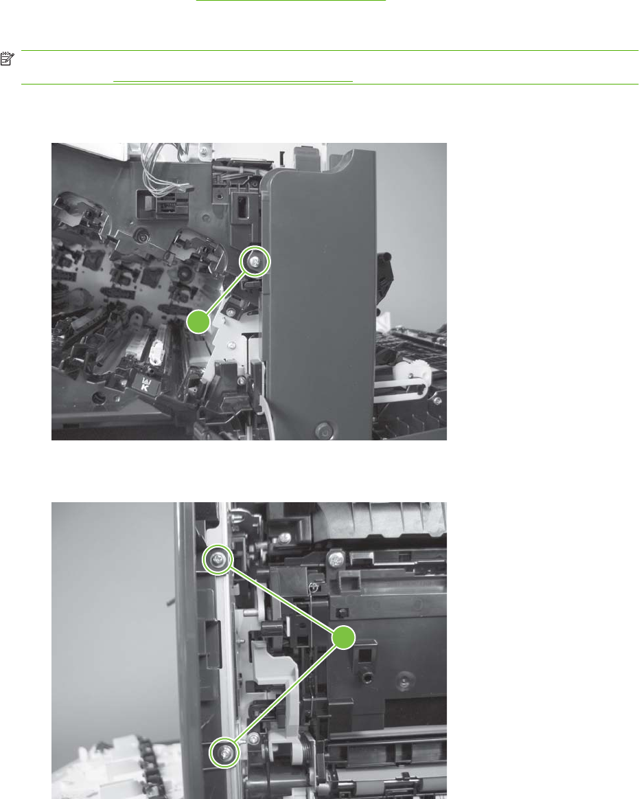
Right-front cover
Before proceeding, remove the following components:
●Front-upper cover. See Front-upper cover on page 225.
Remove the right-front cover
NOTE: Be careful. When removing the cover, do not dislodge the power button. If the button is
dislodged, see Reinstall the power button on page 241 to reinstall it.
1. Remove one screw (callout 1).
Figure 6-91 Remove the right-front cover (1 of 5)
1
2. Remove two screws (callout 2).
Figure 6-92 Remove the right-front cover (2 of 5)
2
ENWW External panels, covers, doors, and scanner assembly 239
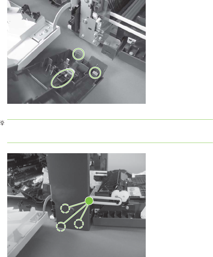
3. Before you proceed, take note of the tab locations at the bottom of the cover.
Figure 6-93 Remove the right-front cover (3 of 5)
4. Pull down on the cover to release three tabs (callout 3).
TIP: It might be easier if you position the product at the edge of the work surface so that there is
a space for the cover to slide downward. Or, you might try inserting a small flat blade screwdriver
behind the cover, and carefully pry the cover away from the product as you pull down on the cover
to release the tabs.
Figure 6-94 Remove the right-front cover (4 of 5)
3
240 Chapter 6 Removal and replacement ENWW
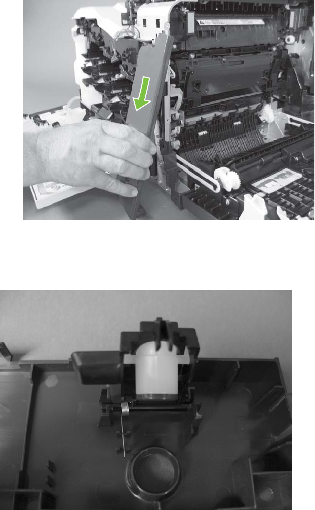
5. Rotate the bottom of the cover away from the product, and then pull down on the cover to remove
it.
Figure 6-95 Remove the right-front cover (5 of 5)
Reinstall the power button
Snap the power button into the holders on the cover. Make sure that the spring is correctly installed.
Figure 6-96 Reinstall the power button
ENWW External panels, covers, doors, and scanner assembly 241
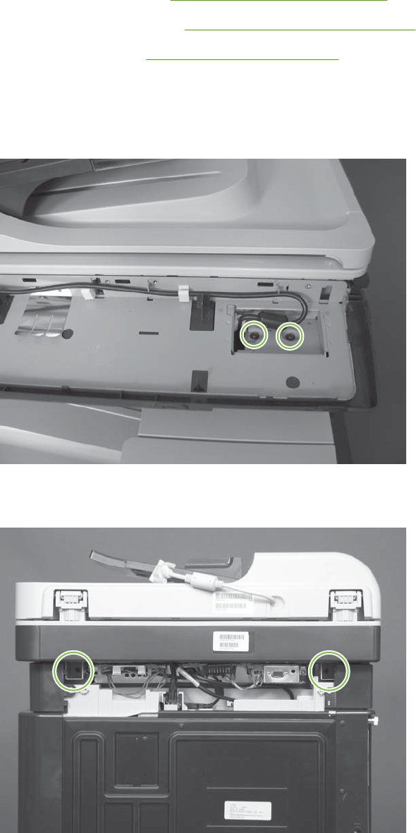
Scanner assembly
Before proceeding, remove the following components:
●Control-panel overlay. See Control-panel overlay on page 218
●Control-panel assembly. See Control-panel assembly on page 219.
●Rear-upper cover. See Rear-upper cover on page 236.
Remove the scanner assembly
1. Remove two screws.
Figure 6-97 Remove the scanner assembly (1 of 6)
2. Remove two screws.
Figure 6-98 Remove the scanner assembly (2 of 6)
242 Chapter 6 Removal and replacement ENWW
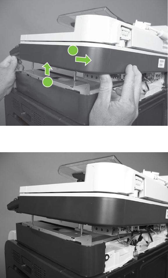
3. Lift the right side of the scanner assembly, and then move it slightly to the rear.
Figure 6-99 Remove the scanner assembly (3 of 6)
1
2
4. Place the scanner assembly on top of the base.
Figure 6-100 Remove the scanner assembly (4 of 6)
ENWW External panels, covers, doors, and scanner assembly 243
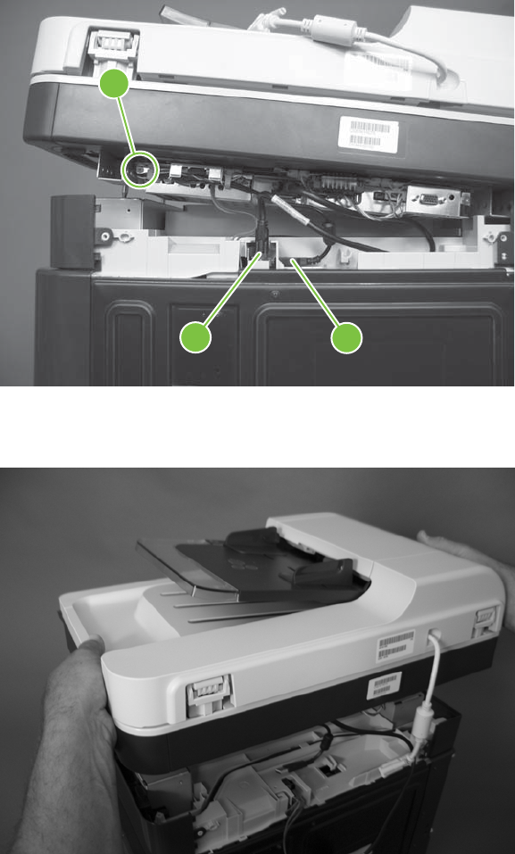
5. Disconnect one connector (callout 1), remove two thumb screws (callout 2), and then release one
cable (callout 3).
Figure 6-101 Remove the scanner assembly (5 of 6)
1
23
6. Remove the scanner assembly.
Figure 6-102 Remove the scanner assembly (6 of 6)
244 Chapter 6 Removal and replacement ENWW
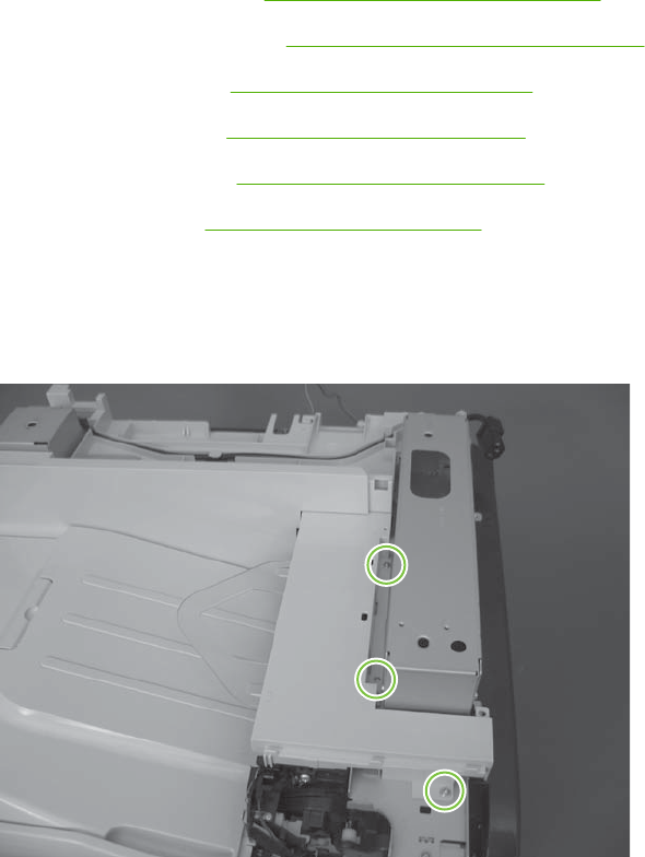
Delivery cover
Before proceeding, remove the following components:
●Control-panel overlay. See Control-panel overlay on page 218.
●Control-panel assembly. See Control-panel assembly on page 219.
●Front-upper cover. See Front-upper cover on page 225.
●Rear-upper cover. See Rear-upper cover on page 236.
●Scanner assembly. See Scanner assembly on page 242.
●Right-top cover. See Right-top cover on page 258.
Remove the delivery cover
1. Remove three screws.
Figure 6-103 Remove the delivery cover (1 of 3)
ENWW External panels, covers, doors, and scanner assembly 245
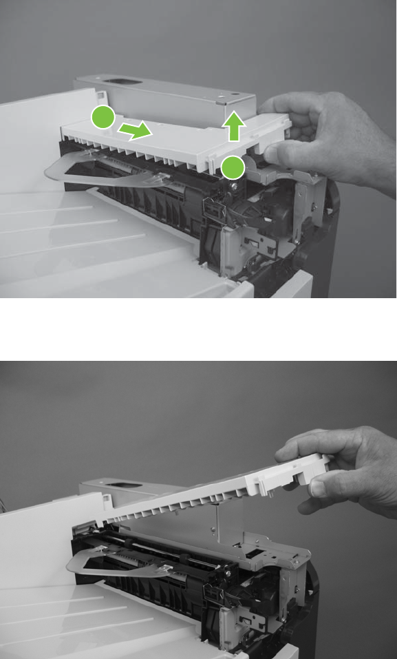
2. Lift up (callout 1) and slide the delivery cover (callout 2).
Figure 6-104 Remove the delivery cover (2 of 3)
1
2
3. Remove the delivery cover.
Figure 6-105 Remove the delivery cover (3 of 3)
246 Chapter 6 Removal and replacement ENWW

Left-upper cover
Before proceeding, remove the following components:
●Formatter PCA. See Formatter PCA on page 192.
●Control-panel overlay. See Control-panel overlay on page 218.
●Control-panel assembly. See Control-panel assembly on page 219.
●Left cover. See Left cover on page 233.
●Rear-upper cover. See Rear-upper cover on page 236.
●Scanner assembly. See Scanner assembly on page 242.
Remove the left-upper cover
1. Remove one screw (callout 1) and one tab (callout 2).
Figure 6-106 Remove the left-upper cover (1 of 2)
1
2
ENWW External panels, covers, doors, and scanner assembly 247
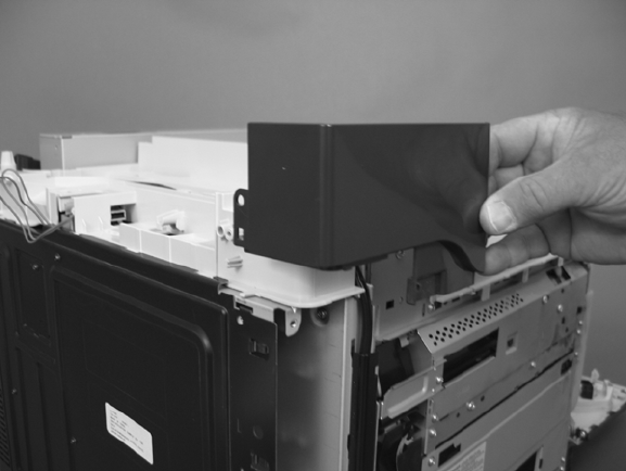
2. Remove the left-upper cover.
Figure 6-107 Remove the left-upper cover (2 of 2)
248 Chapter 6 Removal and replacement ENWW
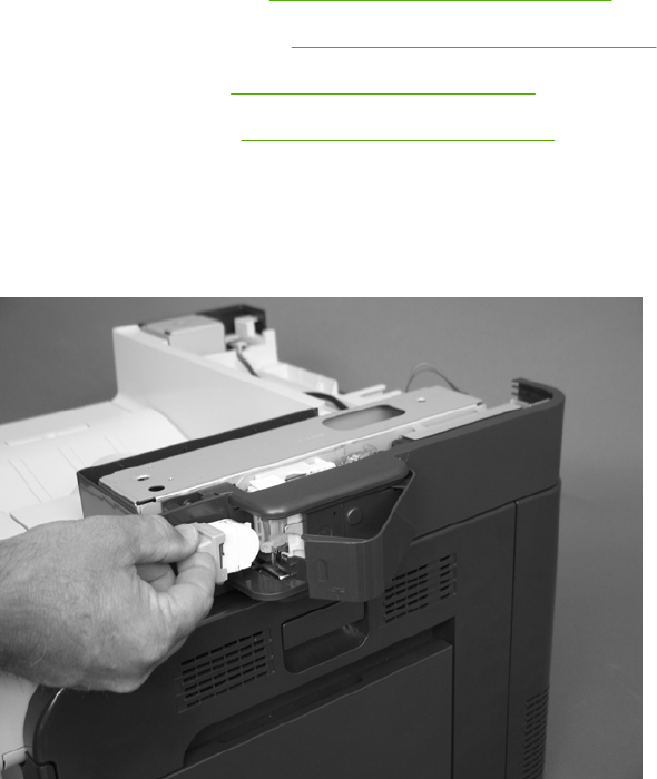
Front stapler cover and right-side stapler cover
Before proceeding, remove the following components:
●Control-panel overlay. See Control-panel overlay on page 218.
●Control-panel assembly. See Control-panel assembly on page 219.
●Rear-upper cover. See Rear-upper cover on page 236.
●Scanner assembly. See Scanner assembly on page 242.
Remove the front stapler cover and right-side stapler cover
1. Open the stapler door, and then remove the stapler cartridge.
Figure 6-108 Remove the front stapler cover and right-side stapler cover (1 of 13)
ENWW External panels, covers, doors, and scanner assembly 249
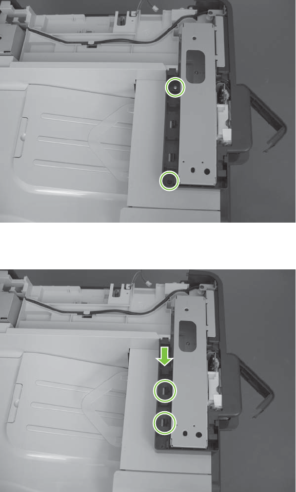
2. Remove two screws.
Figure 6-109 Remove the front stapler cover and right-side stapler cover (2 of 13)
3. Slide the cover toward the front of the product while releasing two tabs.
Figure 6-110 Remove the front stapler cover and right-side stapler cover (3 of 13)
250 Chapter 6 Removal and replacement ENWW
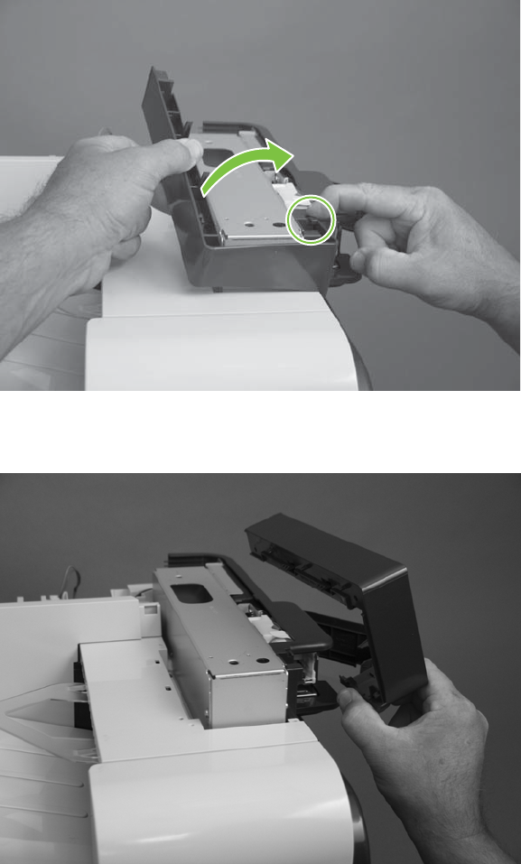
4. Slighty raise the cover and then release one tab.
Figure 6-111 Remove the front stapler cover and right-side stapler cover (4 of 13)
5. Rotate the cover up, and then remove the cover.
Figure 6-112 Remove the front stapler cover and right-side stapler cover (5 of 13)
ENWW External panels, covers, doors, and scanner assembly 251
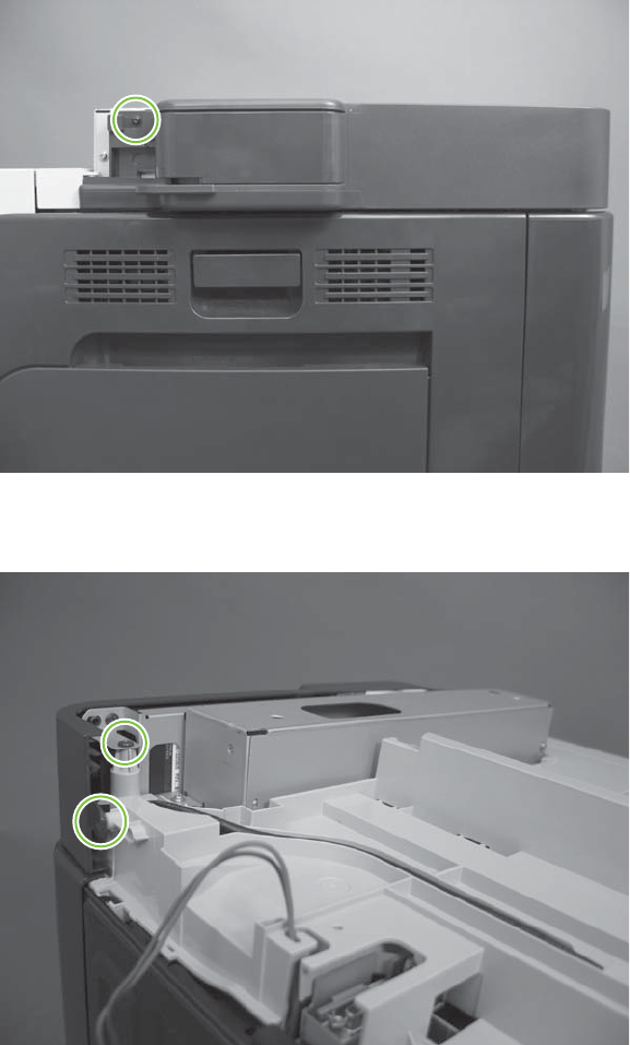
6. Remove one screw.
Figure 6-113 Remove the front stapler cover and right-side stapler cover (6 of 13)
7. Remove two screws.
Figure 6-114 Remove the front stapler cover and right-side stapler cover (7 of 13)
252 Chapter 6 Removal and replacement ENWW
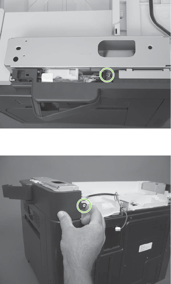
8. Remove one screw.
Figure 6-115 Remove the front stapler cover and right-side stapler cover (8 of 13)
9. Release one tab.
Figure 6-116 Remove the front stapler cover and right-side stapler cover (9 of 13)
ENWW External panels, covers, doors, and scanner assembly 253
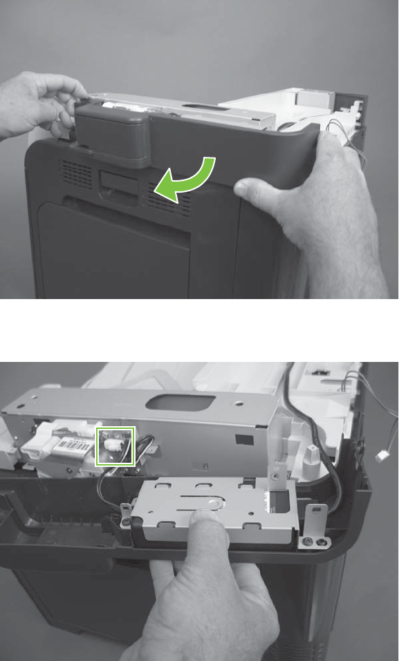
10. Rotate the cover.
Figure 6-117 Remove the front stapler cover and right-side stapler cover (10 of 13)
11. Disconnect one connector.
Figure 6-118 Remove the front stapler cover and right-side stapler cover (11 of 13)
254 Chapter 6 Removal and replacement ENWW
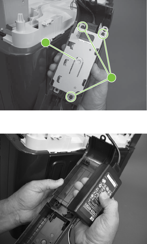
12. Remove three screws (callout 1), and then remove the sheet-metal cover (callout 2).
Figure 6-119 Remove the front stapler cover and right-side stapler cover (12 of 13)
2
1
13. Separate the stapler power supply from the cover, and then remove the cover.
Figure 6-120 Remove the front stapler cover and right-side stapler cover (13 of 13)
ENWW External panels, covers, doors, and scanner assembly 255
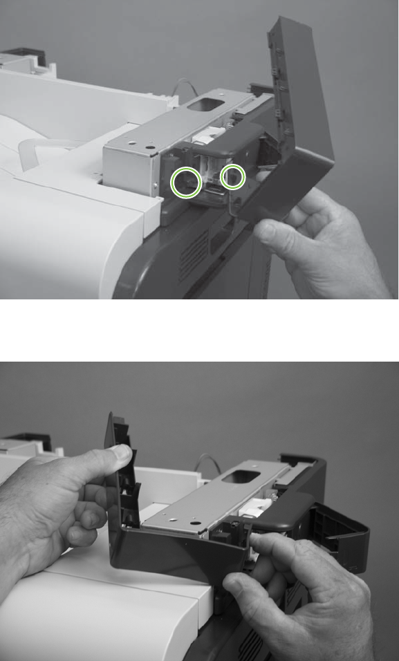
Reinstall the right-side stapler cover
1. Insert one tab.
Figure 6-121 Reinstall the right-side stapler cover (1 of 3)
2. Carefully bend the right-upper cover A around the chassis.
Figure 6-122 Reinstall the right-side stapler cover (2 of 3)
256 Chapter 6 Removal and replacement ENWW
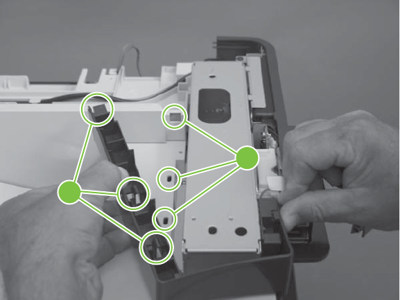
3. Insert three tabs (callout 1) into three slots (callout 2).
Figure 6-123 Reinstall the right-side stapler cover (3 of 3)
2
1
ENWW External panels, covers, doors, and scanner assembly 257
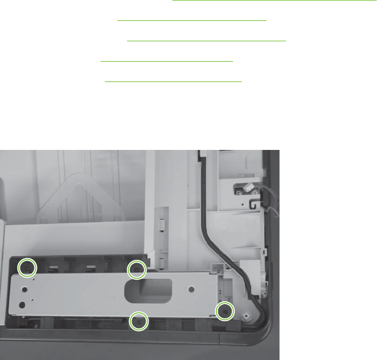
Right-top cover
Before proceeding, remove the following components:
●Automatic document feeder (ADF). See Automatic document feeder (ADF) on page 212
●Control-panel overlay. See Control-panel overlay on page 218.
●Control-panel assembly. See Control-panel assembly on page 219.
●Rear-upper cover. See Rear-upper cover on page 236.
●Scanner assembly. See Scanner assembly on page 242.
Remove the right-top cover
1. Remove four screws.
Figure 6-124 Remove the right-top cover (1 of 5)
258 Chapter 6 Removal and replacement ENWW

2. Release one tab.
Figure 6-125 Remove the right-top cover (2 of 5)
3. Release three tabs.
Figure 6-126 Remove the right-top cover (3 of 5)
ENWW External panels, covers, doors, and scanner assembly 259
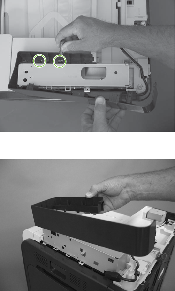
4. Release two tabs.
Figure 6-127 Remove the right-top cover (4 of 5)
5. Remove the right-top cover.
Figure 6-128 Remove the right-top cover (5 of 5)
260 Chapter 6 Removal and replacement ENWW
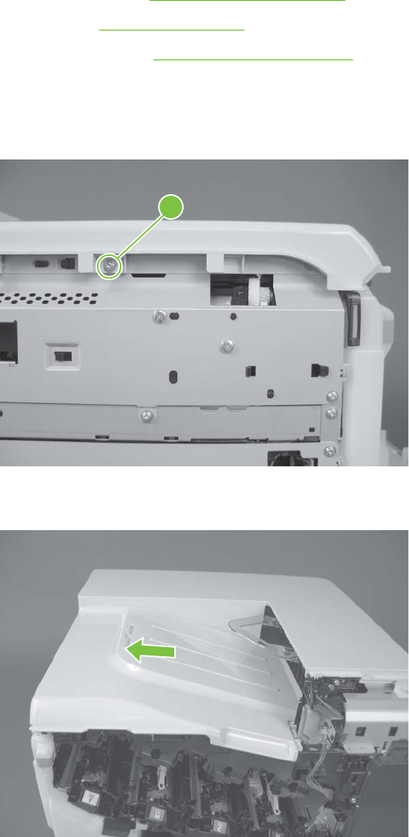
Front-top cover
Before proceeding, remove the following components:
●Front-upper cover. See Front-upper cover on page 225.
●Left cover. See Left cover on page 233.
●Scanner assembly. See Scanner assembly on page 242.
Remove the front-top cover
1. Remove one screw (callout 1).
Figure 6-129 Remove the front-top cover (1 of 2)
1
2. Slide the cover toward the left side of the product to release it, and then remove the cover.
Figure 6-130 Remove the front-top cover (2 of 2)
ENWW External panels, covers, doors, and scanner assembly 261
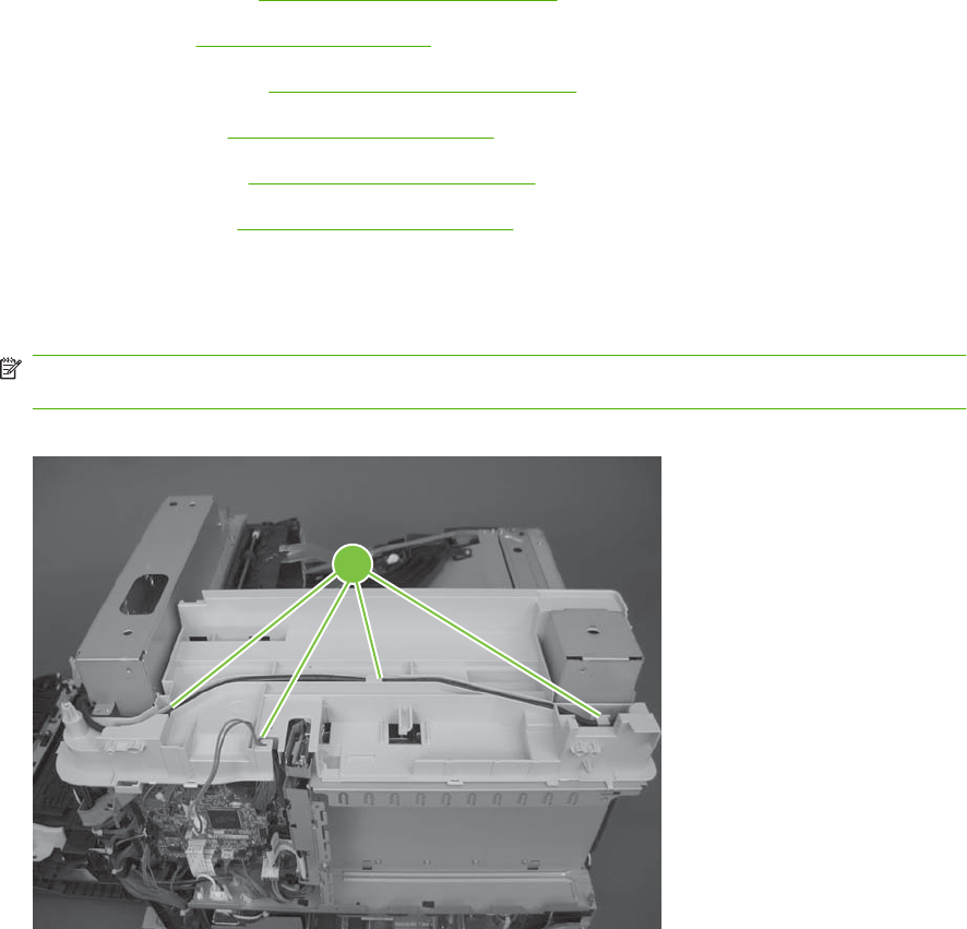
Rear-top cover
Before proceeding, remove the following components:
●Rear-upper cover. See Rear-upper cover on page 236.
●Rear cover. See Rear cover on page 238.
●Scanner assembly. See Scanner assembly on page 242.
●Delivery cover. See Delivery cover on page 245.
●Left-upper cover. See Left-upper cover on page 247.
●Front-top cover. See Front-top cover on page 261.
Remove the rear-top cover
1. Release the stapler power supply cable and one wire harness from the retainers (callout 1).
NOTE: You might have to disconnect one end of the power supply cable to release it from the
retainers.
Figure 6-131 Remove the rear-top cover (1 of 2)
1
262 Chapter 6 Removal and replacement ENWW
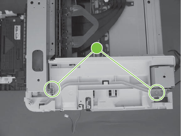
2. Remove two screws (callout 2), and then remove the cover.
Figure 6-132 Remove the rear-top cover (2 of 2)
2
ENWW External panels, covers, doors, and scanner assembly 263
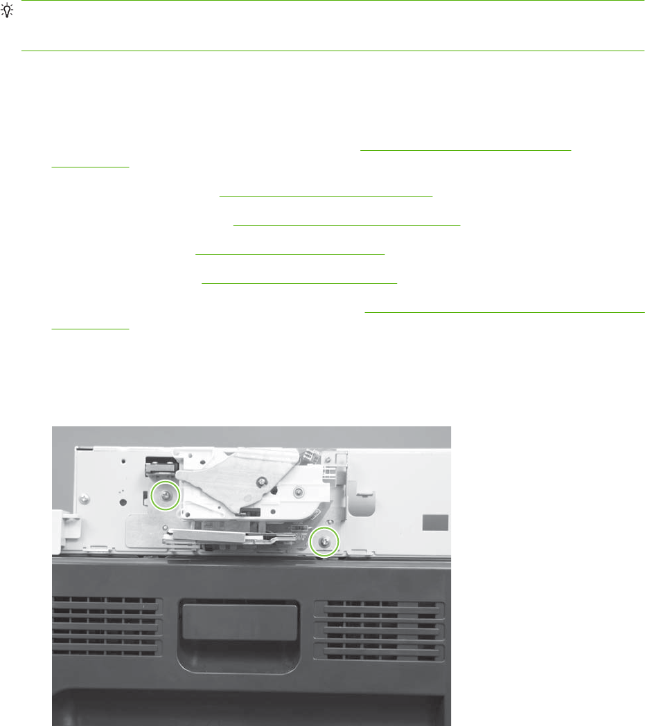
Internal assemblies
TIP: For clarity, some photos in this chapter show components removed that would not be removed
to service the product. If necessary, remove the components listed at the beginning of a procedure
before proceeding to service the product.
Stapler assembly
Before proceeding, remove the following components:
●Automatic document feeder (ADF) assembly. See Automatic document feeder (ADF)
on page 212.
●Control-panel overlay. See Control-panel overlay on page 218.
●Control-panel assembly. See Control-panel assembly on page 219.
●Rear-upper cover. See Rear-upper cover on page 236.
●Scanner assembly. See Scanner assembly on page 242.
●Front stapler cover and right-side stapler cover. See Front stapler cover and right-side stapler cover
on page 249.
Remove the stapler assembly
1. Remove two screws.
Figure 6-133 Remove the stapler assembly (1 of 2)
264 Chapter 6 Removal and replacement ENWW
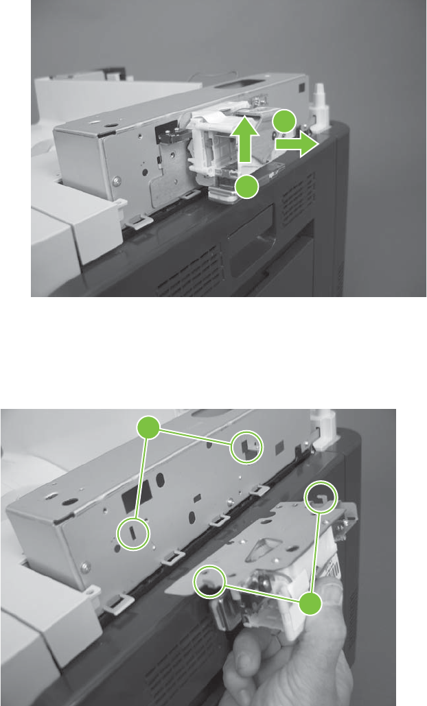
2. Lift up (callout 1) and remove the stapler assembly (callout 2).
Figure 6-134 Remove the stapler assembly (2 of 2)
1
2
Reinstall the stapler assembly
Insert the hooks on the stapler assembly (callout 1) into the chassis (callout 2), and then slide the stapler
assembly down to engage the hooks.
Figure 6-135 Reinstall the stapler assembly
2
1
ENWW Internal assemblies 265
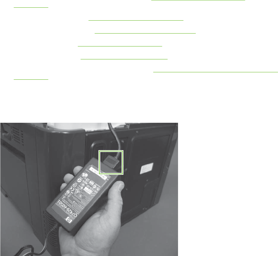
Stapler power supply
Before proceeding, remove the following components:
●Automatic document feeder (ADF) assembly. See Automatic document feeder (ADF)
on page 212.
●Control-panel overlay. See Control-panel overlay on page 218.
●Control-panel assembly. See Control-panel assembly on page 219.
●Rear-upper cover. See Rear-upper cover on page 236.
●Scanner assembly. See Scanner assembly on page 242.
●Front stapler cover and right-side stapler cover. See Front stapler cover and right-side stapler cover
on page 249.
Remove the stapler power supply
Disconnect one connector, and then remove the power supply.
Figure 6-136 Remove the stapler power supply
266 Chapter 6 Removal and replacement ENWW
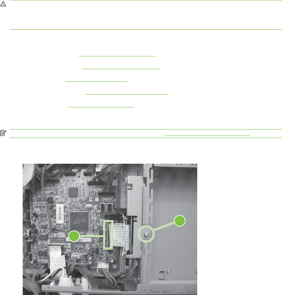
Interconnect board (ICB)
WARNING! Do not remove the ICB from a product and then install it into a different product. Failure
to follow this warning will result in severe damage to that product and cause it to be unusable. HP
recommends that if you remove and replace the ICB, you should destroy the discarded ICB so that it
can not accidentally be installed in a different product.
Before proceeding, remove the following components:
●Formatter PCA. See Formatter PCA on page 192.
●Right-rear cover. See Right-rear cover on page 231.
●Left cover. See Left cover on page 233.
●Rear-upper cover. See Rear-upper cover on page 236.
●Rear cover. See Rear cover on page 238.
Remove the ICB
NOTE: To locate DC controller connector locations, see DC controller PCA on page 183.
1. Disconnect one connector (callouts 1; J105), and then remove one screw (callout 2).
Figure 6-137 Remove the ICB (1 of 3)
2
1
ENWW Internal assemblies 267
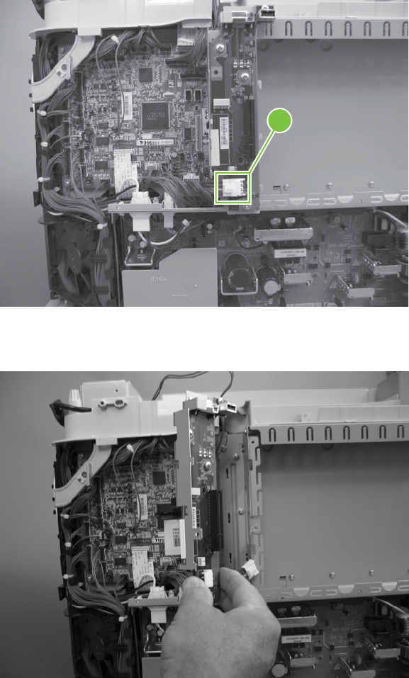
2. Carefully rotate and slide the ICB up and away from the chassis, and then disconnect one connector
(callout 3).
Figure 6-138 Remove the ICB (2 of 3)
3
3. Remove the ICB.
Figure 6-139 Remove the ICB (3 of 3)
268 Chapter 6 Removal and replacement ENWW
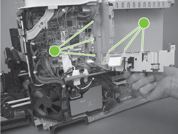
Reinstall the ICB
The ICB bracket (callout 1) must be properly engaged on the chassis (callout 2).
Figure 6-140 Reinstall the ICB
2
1
ENWW Internal assemblies 269
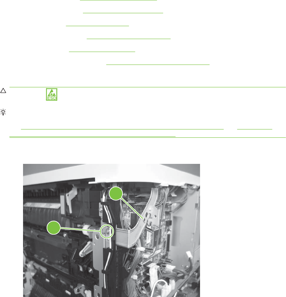
DC controller PCA and tray
Before proceeding, remove the following components:
●Formatter PCA. See Formatter PCA on page 192.
●Right-rear cover. See Right-rear cover on page 231.
●Left cover. See Left cover on page 233.
●Rear-upper cover. See Rear-upper cover on page 236.
●Rear cover. See Rear cover on page 238.
●Interconnect board (ICB). See Interconnect board (ICB) on page 267.
Remove the DC controller PCA and tray
CAUTION: ESD-sensitive part.
TIP: To access components behind the DC controller PCA, remove the PCA and the sheet-metal tray
together. Disconnect all of the connectors on the PCA, and then remove five screws and the bracket,
see Figure 6-141 Remove the DC controller PCA and tray (1 of 4) on page 270 and Figure 6-144
Remove the DC controller PCA and tray (4 of 4) on page 272.
1. Remove one screw (callout 1), and then remove the sheet-metal bracket (callout 2).
Figure 6-141 Remove the DC controller PCA and tray (1 of 4)
1
2
270 Chapter 6 Removal and replacement ENWW

2. Disconnect all the connectors.
Reinstallation tip The connector locations J133 and J134 are not used.
Figure 6-142 Remove the DC controller PCA and tray (2 of 4)
3. Remove four screws (callout 3), and then remove the DC controller PCA.
Figure 6-143 Remove the DC controller PCA and tray (3 of 4)
3
ENWW Internal assemblies 271
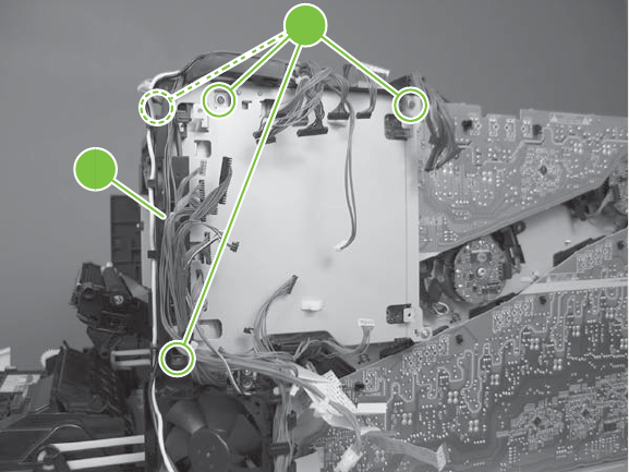
4. If necessary, remove four screws (callout 4), remove the wire guide (callout 5), and then remove
the sheet-metal tray.
Figure 6-144 Remove the DC controller PCA and tray (4 of 4)
5
4
272 Chapter 6 Removal and replacement ENWW
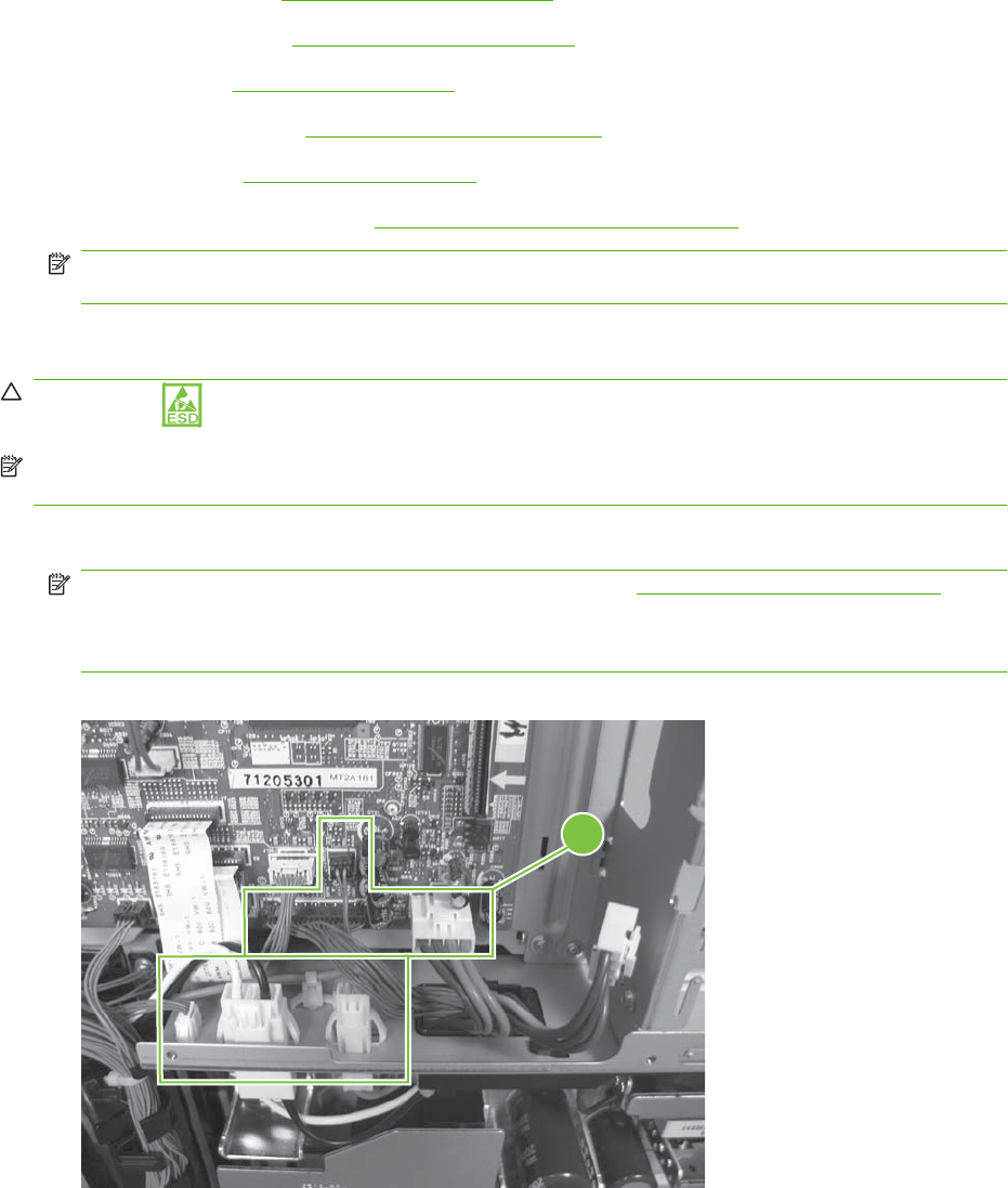
Low-voltage power supply (LVPS)
Before proceeding, remove the following components:
●Formatter PCA. See Formatter PCA on page 192.
●Right-rear cover. See Right-rear cover on page 231.
●Left cover. See Left cover on page 233.
●Rear-upper cover. See Rear-upper cover on page 236.
●Rear cover. See Rear cover on page 238.
●Interconnect board (ICB). See Interconnect board (ICB) on page 267.
NOTE: If you are removing the power supply for internal product access, it is recommended that
you leave the ICB installed on the power supply assembly.
Remove the LVPS
CAUTION: ESD-sensitive part.
NOTE: The formatter cage is attached to the LVPS. Both components are removed as an assembly,
and then the formatter cage is removed from the LVPS.
1. Disconnect six connectors (callout 1; J100, J101, J143 on the DC controller PCA).
NOTE: To locate DC controller connector locations, see DC controller PCA on page 183.
NOTE: If you are removing the power supply for internal product access, it is recommended that
you leave the ICB installed on the power-supply assembly.
Figure 6-145 Remove the LVPS (1 of 10)
1
ENWW Internal assemblies 273
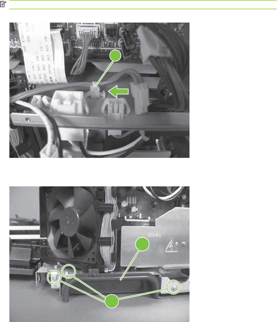
2. Push in on the locking tab to release the retainer (callout 2), and then separate the retainer from
the assembly.
NOTE: The retainer remains attached to the wire harness, and is disengaged from the assembly.
Figure 6-146 Remove the LVPS (2 of 10)
2
3. Remove three screws (callout 3), and then remove the handle (callout 4).
Figure 6-147 Remove the LVPS (3 of 10)
3
4
274 Chapter 6 Removal and replacement ENWW
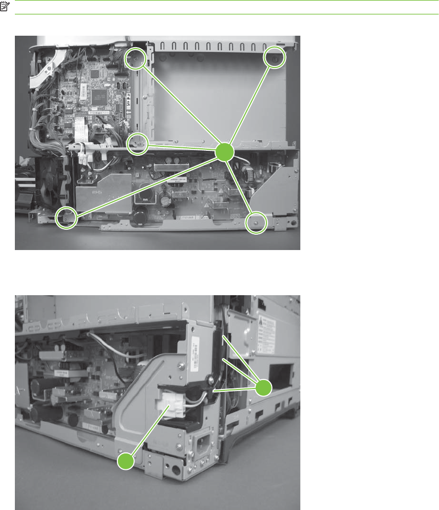
4. Remove five screws (callout 5).
NOTE: The illustration below shows the ICB removed.
Figure 6-148 Remove the LVPS (4 of 10)
5
5. Disconnect one connector (callout 6), and then remove the wire from the guide (callout 7).
Figure 6-149 Remove the (5 of 10)
6
7
ENWW Internal assemblies 275
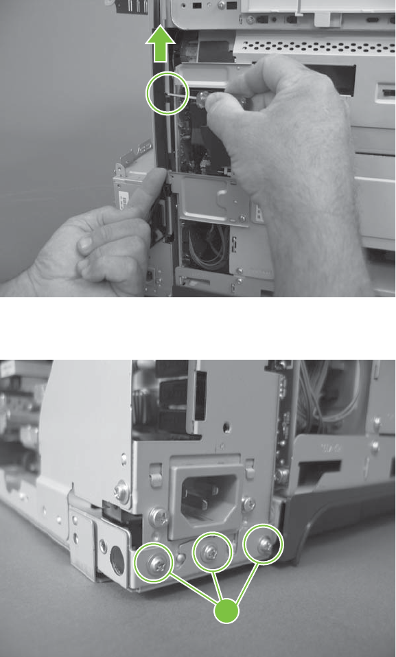
6. Release one tab and lift up the wire cover.
Figure 6-150 Remove the (6 of 10)
7. Remove three screws (callout 8).
Figure 6-151 Remove the LVPS (7 of 10)
8
276 Chapter 6 Removal and replacement ENWW
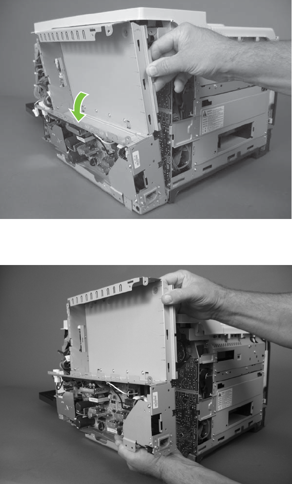
8. Rotate the formatter cage away from the top of the product.
Figure 6-152 Remove the LVPS (8 of 10)
9. Remove the assembly.
Figure 6-153 Remove the LVPS (9 of 10)
ENWW Internal assemblies 277
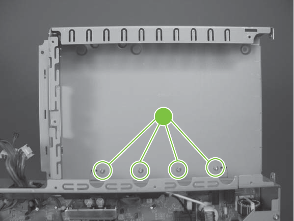
10. Remove four screws (callout 9), and then separate the formatter cage from the low-voltage power
supply.
Figure 6-154 Remove the LVPS (10 of 10)
9
278 Chapter 6 Removal and replacement ENWW
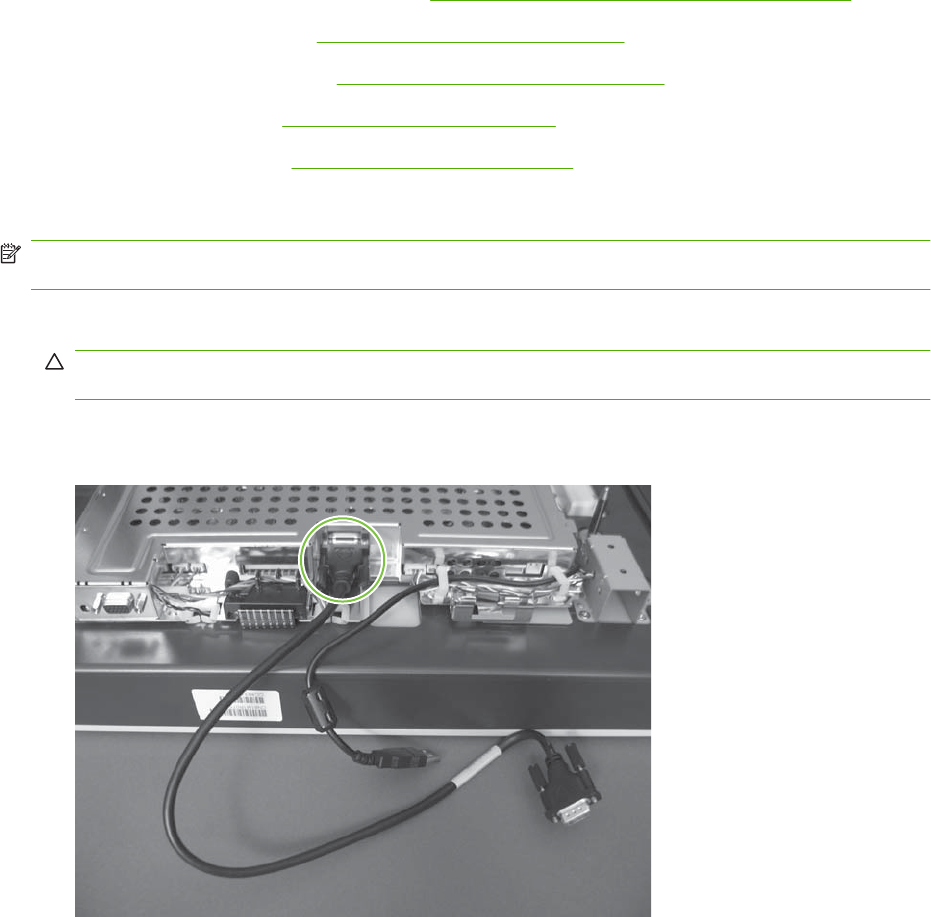
Scanner-control board (SCB)
Before proceeding, remove the following components:
●Automatic document feeder (ADF). See Automatic document feeder (ADF) on page 212.
●Control-panel overlay. See Control-panel overlay on page 218.
●Control-panel assembly. See Control-panel assembly on page 219.
●Rear-upper cover. See Rear-upper cover on page 236.
●Scanner assembly. See Scanner assembly on page 242.
Remove the SCB
NOTE: To replace the Peripheral Component Interconnect Express (PCI-E) cable, locate and remove
the cable that connects the SCB to the ICB.
1. Place the scanner assembly glass-side down on a clean surface or piece of paper.
CAUTION: Dust or debris can scratch the scanner glass and cause print-quality problems. If
possible, place the scanner on a clean lint-free cloth.
2. Release two thumb screws, and then remove one cable.
Figure 6-155 Remove the SCB (1 of 8)
ENWW Internal assemblies 279
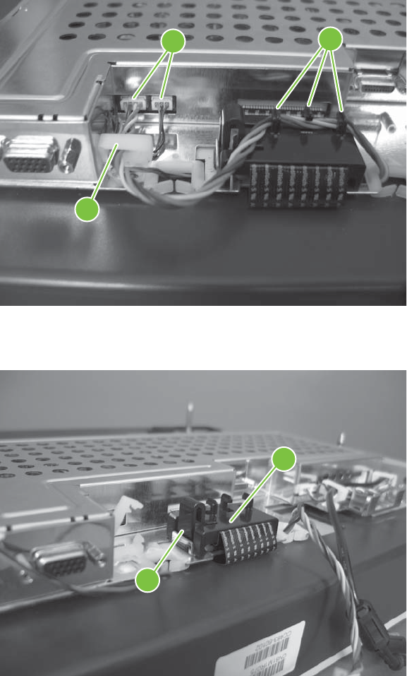
3. Release one retainer (callout 1), disconnect two connectors (callout 2), and then release the wires
from the guides (callout 3).
Figure 6-156 Remove the SCB (2 of 8)
1
3
2
4. Release one tab (callout 1), and then disengage the ferrite assembly (callout 2).
Figure 6-157 Remove the SCB (3 of 8)
1
2
280 Chapter 6 Removal and replacement ENWW
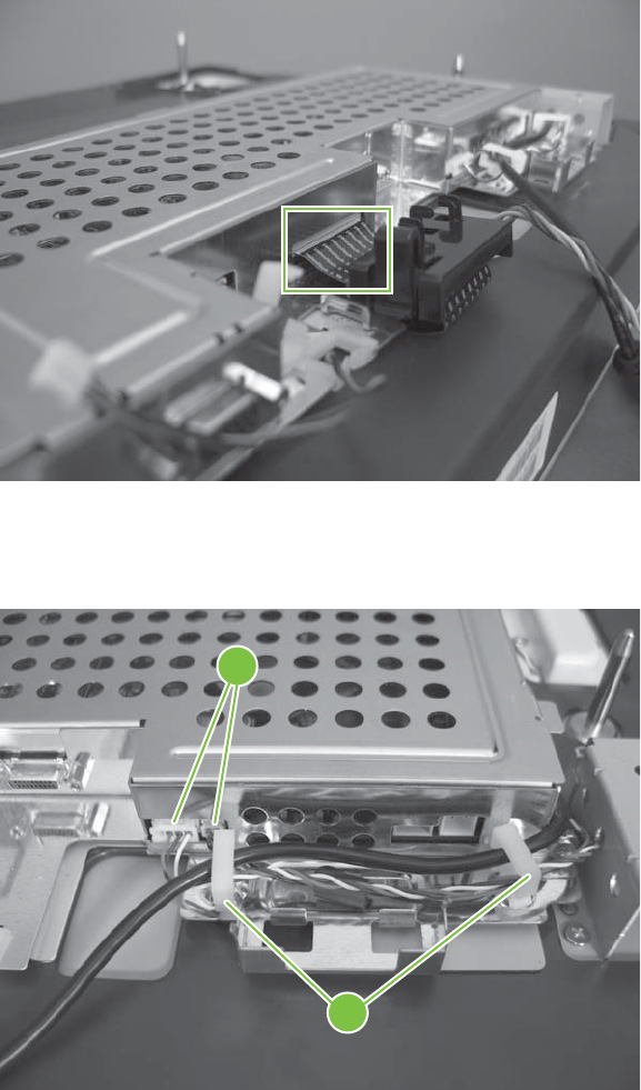
5. Disconnect one FFC, and then remove the ferrite assembly from the FFC.
Figure 6-158 Remove the SCB (4 of 8)
6. Release two retainers (callout 1), disconnect two connectors (callout 2), and then move the wires
to the side.
Figure 6-159 Remove the (5 of 8)
1
2
ENWW Internal assemblies 281
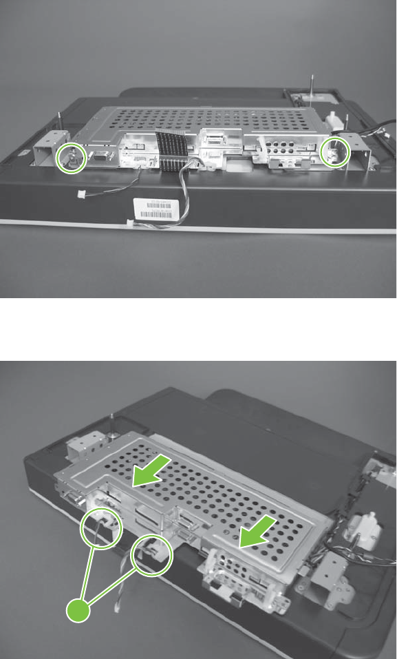
7. Remove two screws.
Figure 6-160 Remove the SCB (6 of 8)
8. Gently slide the SCB, and then release two wire harnesses (callout 1).
Figure 6-161 Remove the SCB (7 of 8)
1
282 Chapter 6 Removal and replacement ENWW
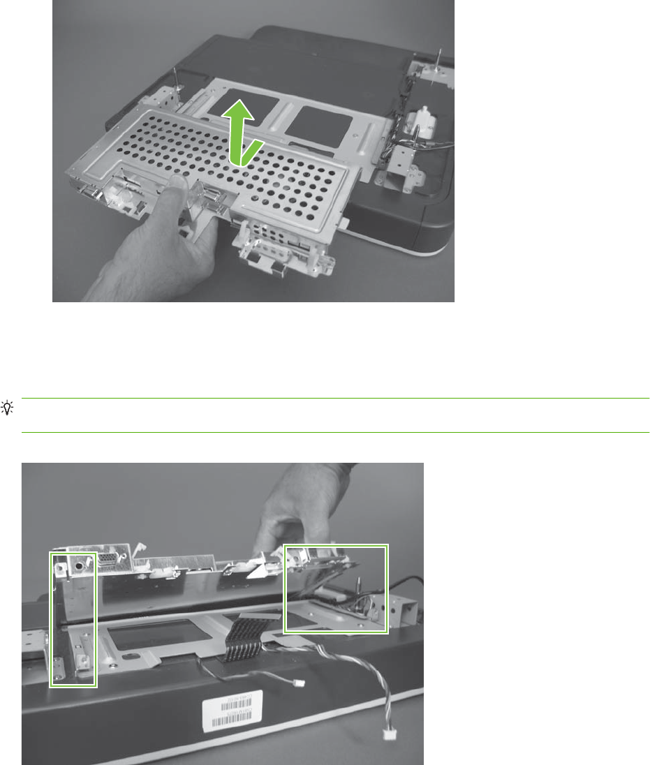
9. Remove the SCB.
Figure 6-162 Remove the SCB (8 of 8)
Reinstall the SCB
When reinstalling the SCB, fully engage the guides on both sides of the SCB with the slots on the scanner
assembly.
Reinstallation tip Make sure that the control-panel USB cable is properly routed. The scanner
assembly will not correctly seat on the product if the cable is not properly routed.
Figure 6-163 Reinstalling the SCB
ENWW Internal assemblies 283
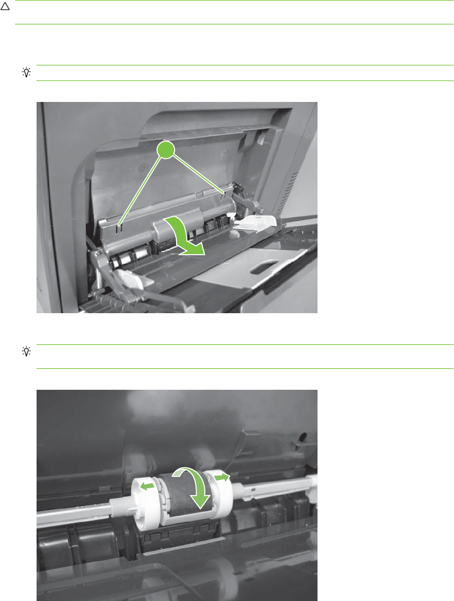
Pickup roller (Tray 1)
CAUTION: Do not touch the spongy roller surface unless you are replacing the roller. Skin oils on the
roller can cause paper pickup problems.
1. Open Tray 1, release two tabs (callout 1), and then rotate the roller cover away from the product
to remove it.
TIP: Push down along the top edge of the cover to easily release the tabs.
Figure 6-164 Remove the pickup roller (Tray 1) (1 of 2)
1
2. Release two tabs and rotate the roller body away from the product to remove it.
TIP: It might be easier to release the Tray 1 pickup-roller solenoid plate, and then manually rotate
the roller into the correct position to remove the roller.
Figure 6-165 Remove the pickup roller (Tray 1) (2 of 2)
284 Chapter 6 Removal and replacement ENWW
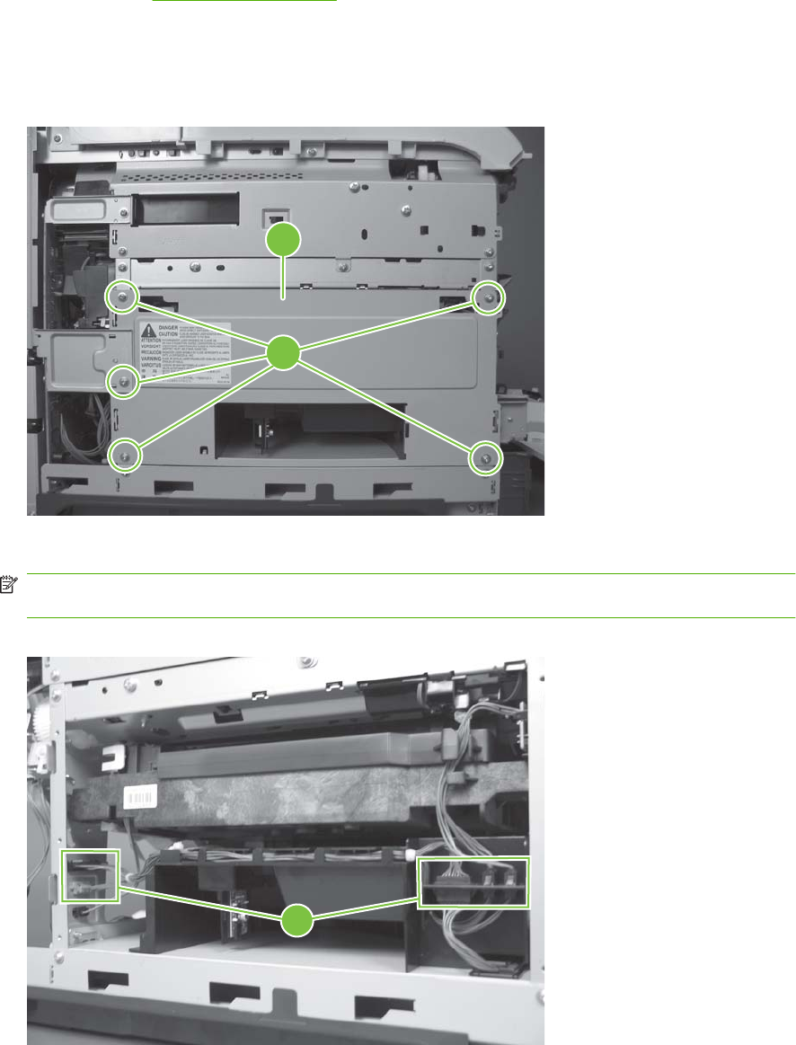
Delivery fan, cartridge fan, and environmental sensor
Before proceeding, remove the following components:
●Left cover. See Left cover on page 233.
Remove the delivery fan, cartridge fan, and environmental sensor
1. Remove five screws (callout 1), and then remove the sheet-metal plate (callout 2).
Figure 6-166 Remove the delivery fan, cartridge fan, and environmental sensor (1 of 9)
2
1
2. Disconnect five connectors (callout 3).
NOTE: Disconnect the larger connector on the right side from the bottom. Disconnect the two
smaller connectors on the right side from the top.
Figure 6-167 Remove the delivery fan, cartridge fan, and environmental sensor (2 of 9)
3
ENWW Internal assemblies 285
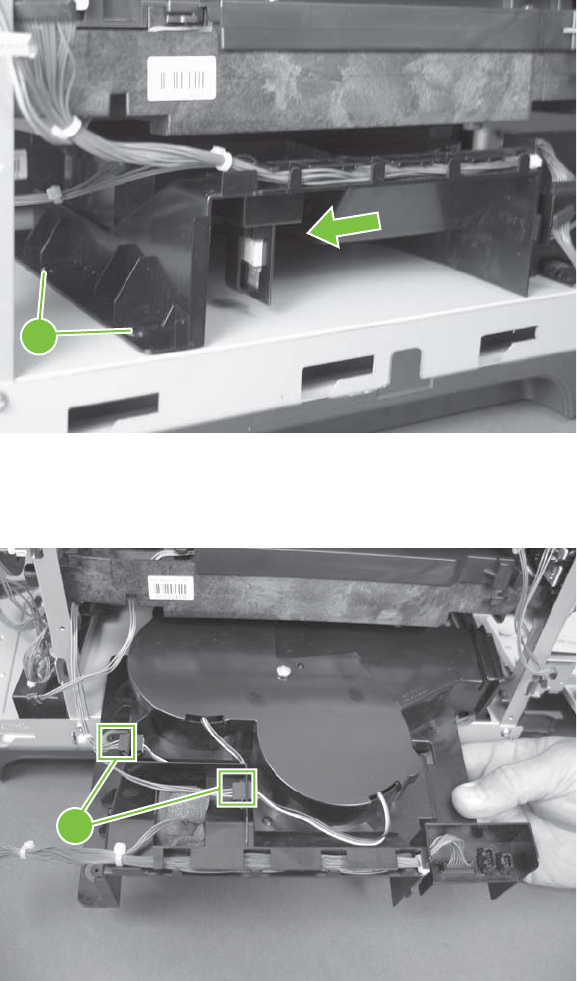
3. Release two tabs (callout 4), and then slide the delivery-fan and cartridge-fan assembly toward the
power-supply side of the product to release it.
Figure 6-168 Remove the delivery fan, cartridge fan, and environmental sensor (3 of 9)
4
4. Pull the assembly slightly out of the product, disconnect two connectors (callout 5), and then to
remove the assembly.
Figure 6-169 Remove the delivery fan, cartridge fan, and environmental sensor (4 of 9)
5
286 Chapter 6 Removal and replacement ENWW
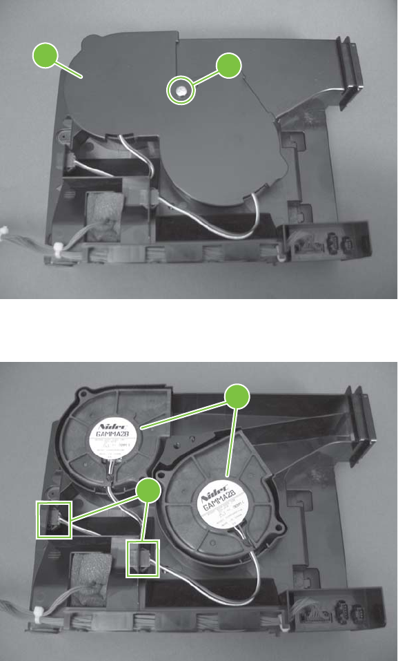
5. Remove one screw (callout 6), and then remove the cover (callout 7).
Figure 6-170 Remove the delivery fan, cartridge fan, and environmental sensor (5 of 9)
76
6. Disconnect two connectors (callout 8), and then remove the fans (callout 9).
Figure 6-171 Remove the delivery fan, cartridge fan, and environmental sensor (6 of 9)
9
8
ENWW Internal assemblies 287
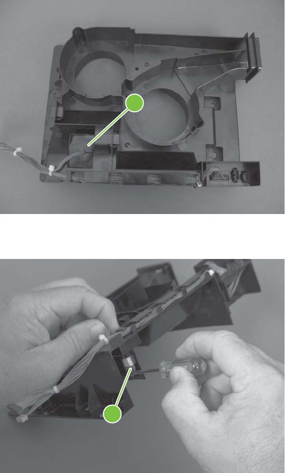
7. Remove the antistatic foam (callout 10).
Figure 6-172 Remove the delivery fan, cartridge fan, and environmental sensor (7 of 9)
10
8. Release one tab (callout 11).
Figure 6-173 Remove the delivery fan, cartridge fan, and environmental sensor (8 of 9)
11
288 Chapter 6 Removal and replacement ENWW
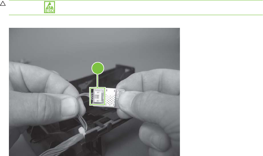
9. Disconnect one connector (callout 12), and then remove the environmental sensor.
CAUTION: ESD-sensitive part.
Figure 6-174 Remove the delivery fan, cartridge fan, and environmental sensor (9 of 9)
12
ENWW Internal assemblies 289
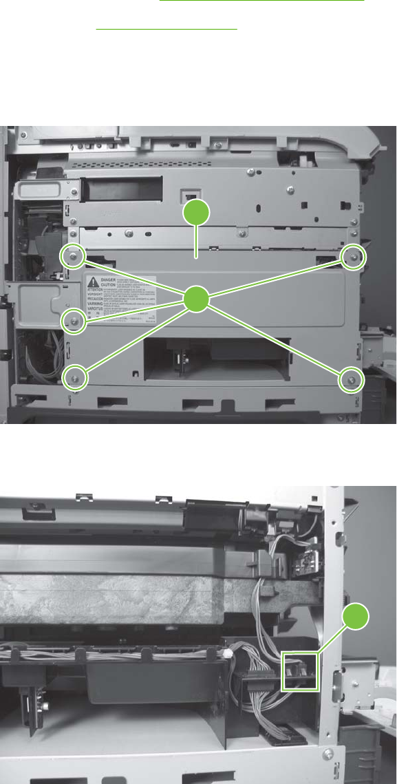
Toner-collection sensor
Before proceeding, remove the following components:
●Toner-collection unit. See Toner-collection unit on page 190.
●Left cover. See Left cover on page 233.
Remove the toner-collection sensor
1. Remove five screws (callout 1), and then remove the sheet-metal plate (callout 2).
Figure 6-175 Remove the toner-collection sensor (1 of 4)
2
1
2. Disconnect one connector (callout 3).
Figure 6-176 Remove the toner-collection sensor (2 of 4)
3
290 Chapter 6 Removal and replacement ENWW
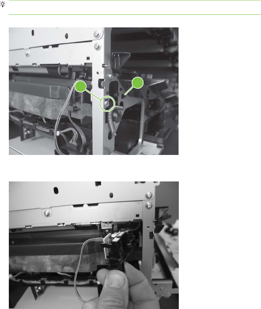
3. Remove one screw (callout 4).
Reinstallation tip When you reinstall the sensor, make sure that the tab (callout 5) on the sensor
body completely engages the slot in the product chassis.
Figure 6-177 Remove the toner-collection sensor (3 of 4)
45
4. Remove the toner-collection sensor.
Figure 6-178 Remove the toner-collection sensor (4 of 4)
ENWW Internal assemblies 291
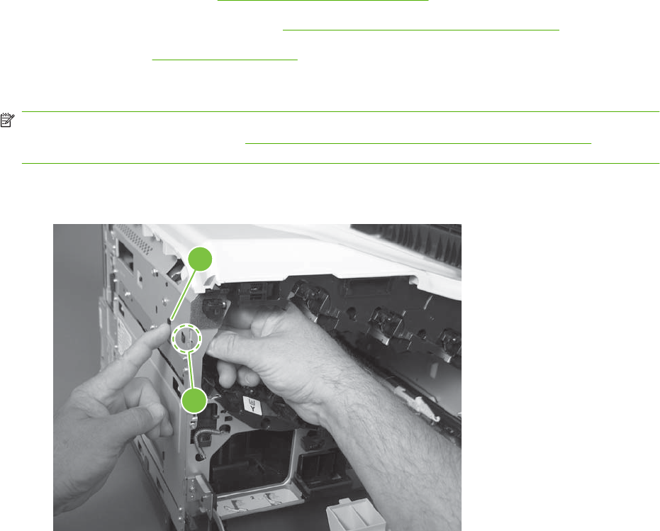
Residual-toner-feed motor
Before proceeding, remove the following components:
●Toner-collection unit. See Toner-collection unit on page 190.
●Intermediate transfer belt (ITB). See Intermediate transfer belt (ITB) on page 209.
●Left cover. See Left cover on page 233.
Remove the residual-toner-feed motor
NOTE: Be careful. Do not dislodge the residual-toner collection door when you remove the assembly.
If the door becomes dislodged, see Reinstall the residual-toner collection door on page 296 to reinstall
it.
1. Release one tab (callout 1) while you support the cover (callout 2).
Figure 6-179 Remove the residual-toner-feed motor (1 of 7)
1
2
292 Chapter 6 Removal and replacement ENWW
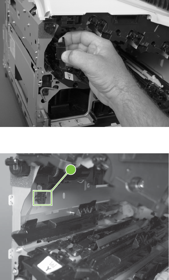
2. Remove the cover.
Figure 6-180 Remove the residual-toner-feed motor (2 of 7)
3. Disconnect one connector (callout 3).
Figure 6-181 Remove the residual-toner-feed motor (3 of 7)
3
ENWW Internal assemblies 293
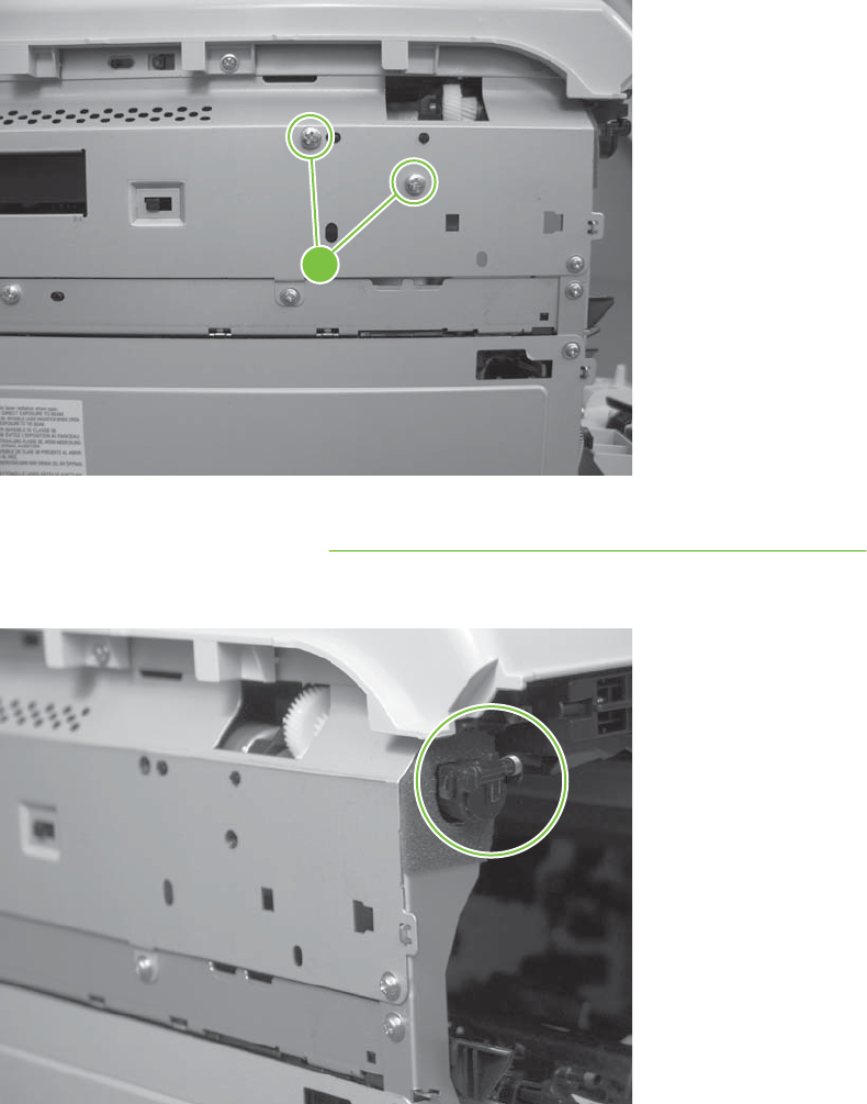
4. Support the assembly, and then remove two screws (callout 4).
Figure 6-182 Remove the residual-toner-feed motor (4 of 7)
4
5. Be careful. Do not dislodge the residual-toner collection door when you remove the assembly. If
the door becomes dislodged, see Reinstall the residual-toner collection door on page 296 to
reinstall it.
Figure 6-183 Remove the residual-toner-feed motor (5 of 7)
294 Chapter 6 Removal and replacement ENWW
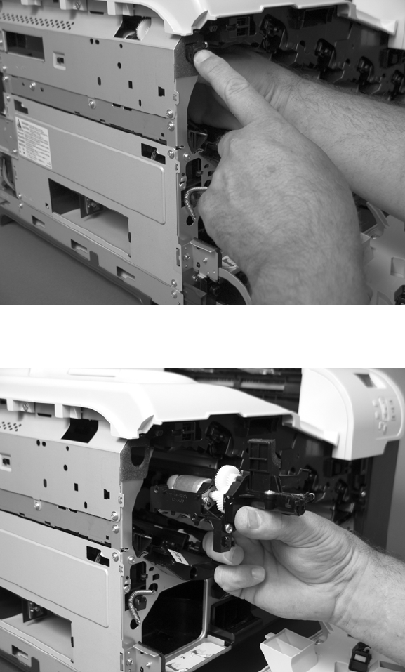
6. Push the assembly into the product to release it.
Figure 6-184 Remove the residual-toner-feed motor (6 of 7)
7. Remove the motor.
Figure 6-185 Remove the residual-toner-feed motor (7 of 7)
ENWW Internal assemblies 295

Reinstall the residual-toner collection door
Snap the residual-toner collection door into the holders on the assembly. Make sure that the spring is
correctly installed.
Figure 6-186 Reinstall the residual-toner collection door
296 Chapter 6 Removal and replacement ENWW
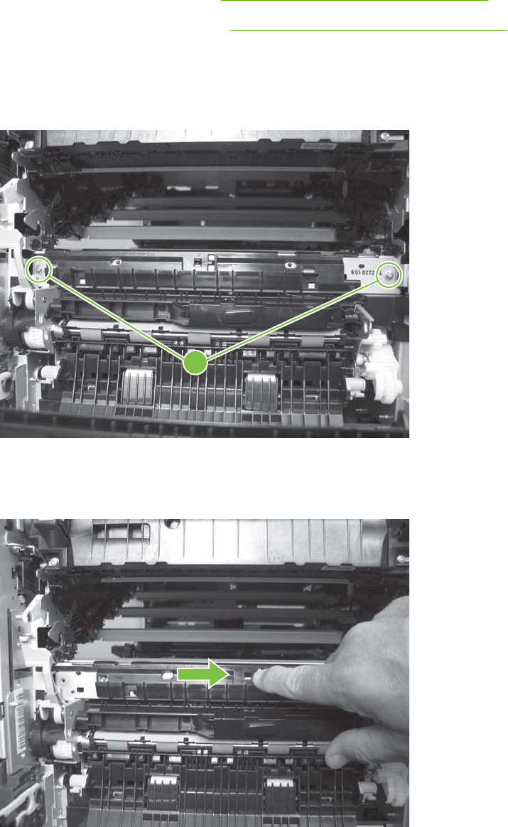
Registration density (RD) sensor assembly
Before proceeding, remove the following components:
●Secondary transfer assembly. See Secondary transfer assembly on page 207.
●Intermediate transfer belt (ITB). See Intermediate transfer belt (ITB) on page 209.
Remove the RD sensor assembly
1. Remove two screws (callout 1).
Figure 6-187 Remove the RD sensor assembly (1 of 6)
1
2. Slide the shutter toward the right side of the product. Keep the shutter in this position for the
following step.
Figure 6-188 Remove the RD sensor assembly (2 of 6)
ENWW Internal assemblies 297
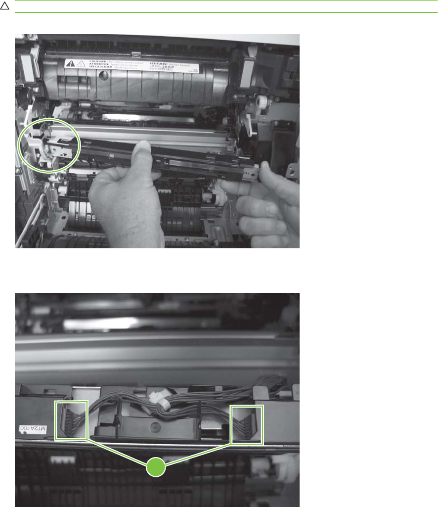
3. Carefully separate the assembly from the product. The assembly wire harnesses are still attached
to the product.
CAUTION: Do not damage the shutter as it passes through the chassis.
Figure 6-189 Remove the RD sensor assembly (3 of 6)
4. Disconnect two connectors (callout 2) on the back side of the assembly.
Figure 6-190 Remove the RD sensor assembly (4 of 6)
2
298 Chapter 6 Removal and replacement ENWW
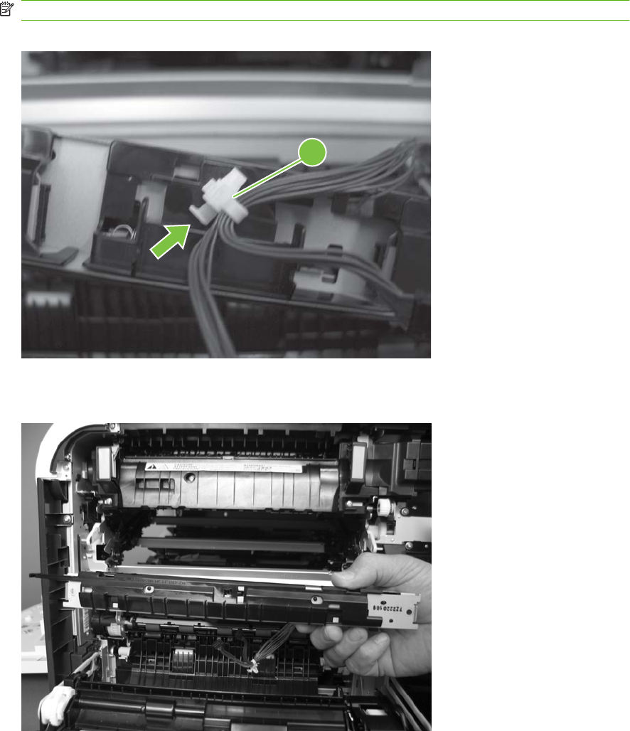
5. Push in on the locking tab to release the retainer (callout 3), and then separate the retainer from
the assembly.
NOTE: The retainer remains attached to the wire harness, and disengages from the assembly.
Figure 6-191 Remove the RD sensor assembly (5 of 6)
3
6. Remove the assembly.
Figure 6-192 Remove the RD sensor assembly (6 of 6)
ENWW Internal assemblies 299
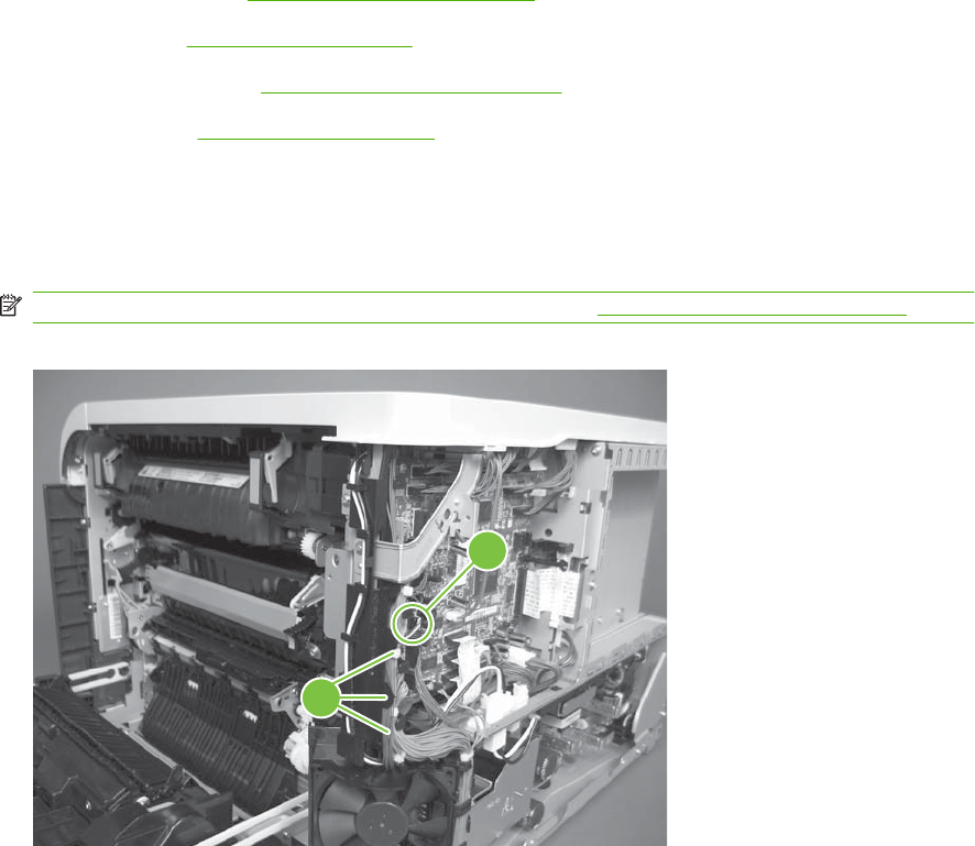
Power-supply fan and fan duct
Before proceeding, remove the following components:
●Right-rear cover. See Right-rear cover on page 231.
●Left cover. See Left cover on page 233.
●Rear-upper cover. See Rear-upper cover on page 236.
●Rear cover. See Rear cover on page 238.
Remove the power-supply fan and fan duct
1. Disconnect one connector (callout 1; J119) and release the wire harnesses from the guide
(callout 2).
NOTE: To locate DC controller connector locations, see DC controller PCA on page 183.
Figure 6-193 Remove the power-supply fan (1 of 4)
1
2
300 Chapter 6 Removal and replacement ENWW
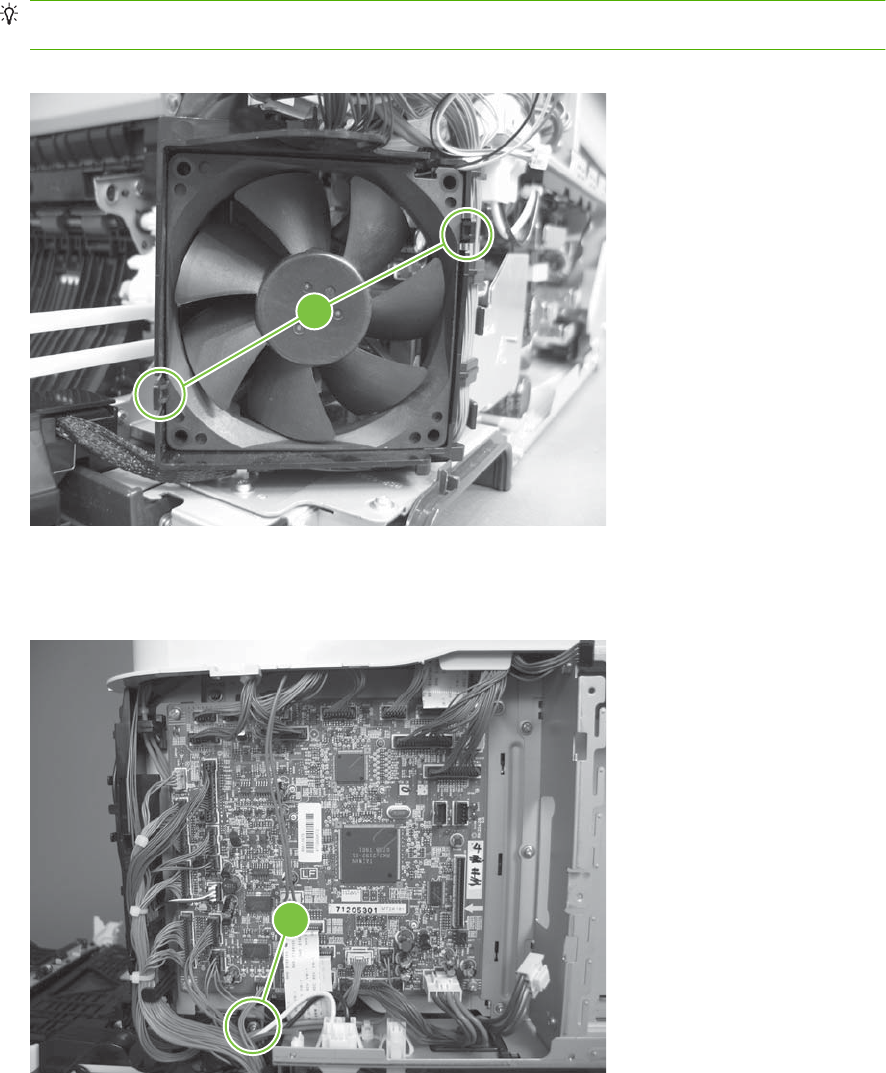
2. To remove the fan only: Release two tabs (callout 3), and then remove the fan from the fan duct.
Reinstallation tip When the fan is reinstalled, the air must flow into the product. Look at the
arrows embossed on the fan frame that indicate air flow direction.
Figure 6-194 Remove the power-supply fan (2 of 4)
3
3. To remove the fan and fan duct: Remove one screw (callout 4), and then release the wire
harnesses from the guides on the fan duct.
Figure 6-195 Remove the power-supply fan (3 of 4)
4
ENWW Internal assemblies 301
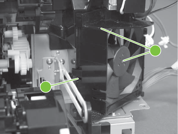
4. To remove the fan and fan duct: Release one tab (callout 5), and then remove the fan and fan
duct (callout 6).
Figure 6-196 Remove the power-supply fan (4 of 4)
5
6
302 Chapter 6 Removal and replacement ENWW
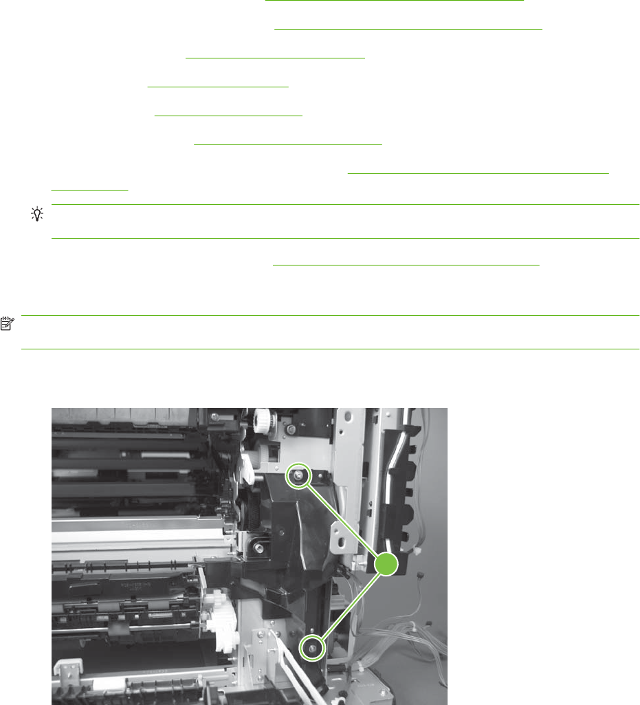
Registration assembly
Before proceeding, remove the following components:
●Secondary transfer assembly. See Secondary transfer assembly on page 207.
●Intermediate transfer belt (ITB). See Intermediate transfer belt (ITB) on page 209.
●Right-rear cover. See Right-rear cover on page 231.
●Left cover. See Left cover on page 233.
●Rear cover. See Rear cover on page 238.
●Rear-upper cover. See Rear-upper cover on page 236.
●Registration density (RD) sensor assembly. See Registration density (RD) sensor assembly
on page 297.
TIP: Removing the RD sensor assembly makes it much easier to reinstall the registration
assembly.
●Power-supply fan and fan duct. See Power-supply fan and fan duct on page 300.
Remove the registration assembly
NOTE: If a replacement registration assembly is installed, you must use the control-panel menus to
reset the registration-roller count.
1. Remove two screws (callout 1).
Figure 6-197 Remove the registration assembly (1 of 8)
1
ENWW Internal assemblies 303
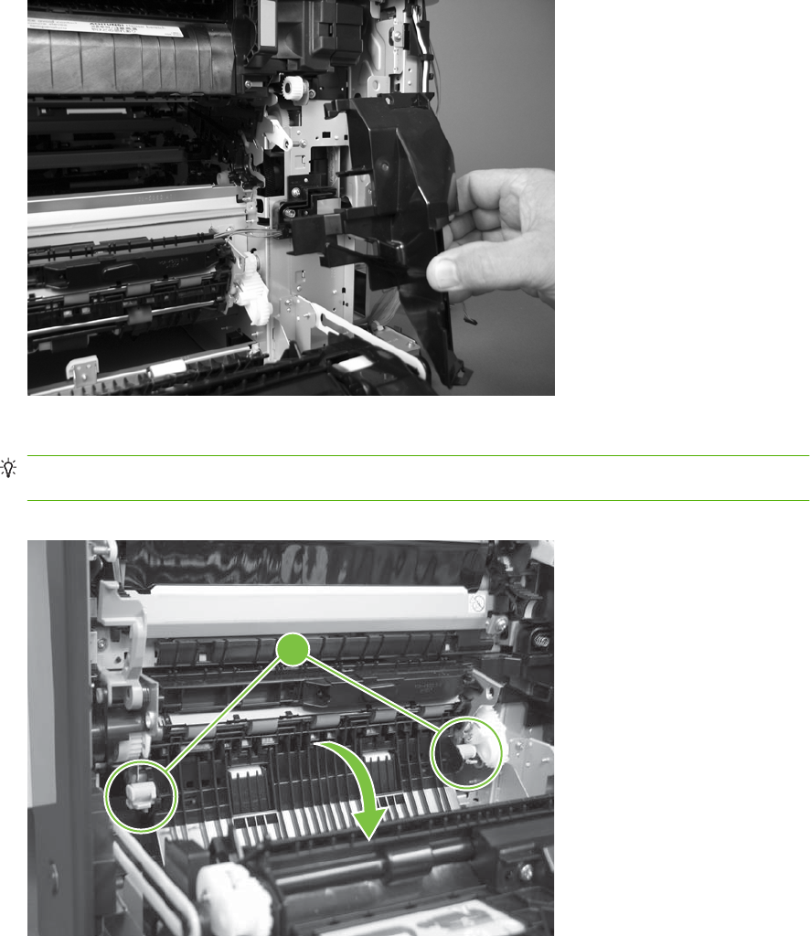
2. Pull down on the cover to release one tab, and then rotate the cover away from the product to
remove it.
Figure 6-198 Remove the registration assembly (2 of 8)
3. Release two green latches (callout 2), and then lower the feed guide.
Reinstallation tip Make sure that the feed guide snaps into the closed position when you reinstall
the registration assembly.
Figure 6-199 Remove the registration assembly (3 of 8)
2
304 Chapter 6 Removal and replacement ENWW
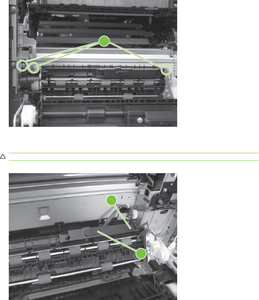
4. Remove three screws (callout 3).
Figure 6-200 Remove the registration assembly (4 of 8)
3
5. Separate the assembly from the product, release one tab (callout 4), and then remove the cover
(callout 5).
CAUTION: The assembly is still attached to the product by the wire harnesses.
Figure 6-201 Remove the registration assembly (5 of 8)
4
5
ENWW Internal assemblies 305
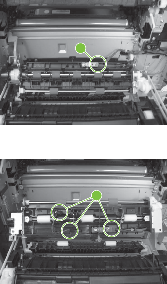
6. Disconnect one connector (callout 6), and then release the wire harness from the retainer.
Figure 6-202 Remove the registration assembly (6 of 8)
6
7. Disconnect three connectors (callout 7) on the back side of the assembly, and then release the
wires from the retainers.
Figure 6-203 Remove the registration assembly (7 of 8)
7
306 Chapter 6 Removal and replacement ENWW
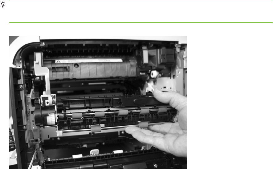
8. Remove the assembly.
Reinstallation tip When you reinstall the registration assembly, make sure that it is correctly
positioned in the product. The tabs on the assembly must fit into the slots in the product chassis
and the assembly should fit securely up against the product chassis.
Figure 6-204 Remove the registration assembly (8 of 8)
ENWW Internal assemblies 307
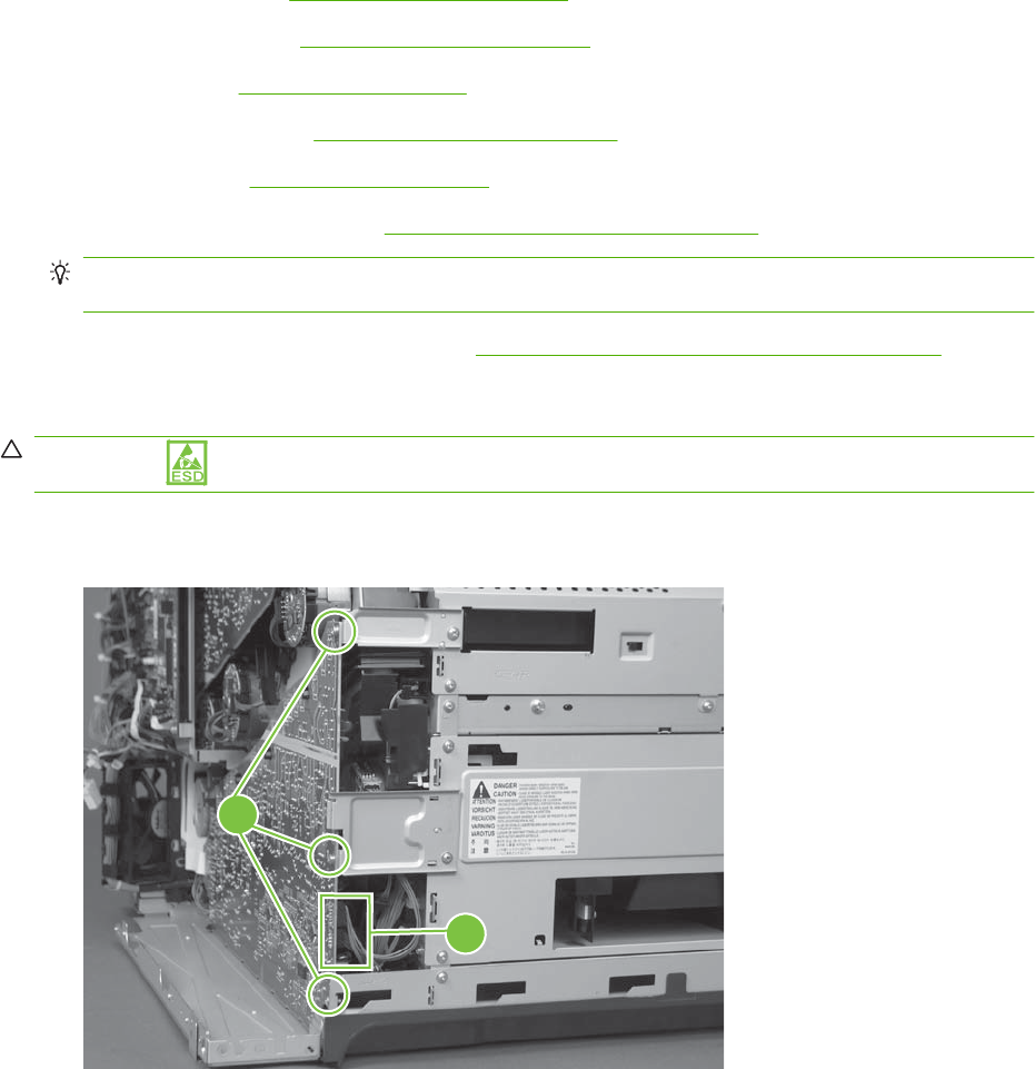
High-voltage power supply lower
Before proceeding, remove the following components:
●Formatter PCA. See Formatter PCA on page 192.
●Right-rear cover. See Right-rear cover on page 231.
●Left cover. See Left cover on page 233.
●Rear-upper cover. See Rear-upper cover on page 236.
●Rear cover. See Rear cover on page 238.
●Interconnect board (ICB). See Interconnect board (ICB) on page 267.
TIP: For internal product access, you can remove the ICB and the low-voltage power supply as
a single component.
●Low-voltage power supply (LVPS). See Low-voltage power supply (LVPS) on page 273.
Remove the high-voltage power supply lower
CAUTION: ESD-sensitive part.
1. Disconnect two connectors (callout 1), and then remove three screws (callout 2).
Figure 6-205 Remove the high-voltage power supply lower (1 of 4)
2
1
308 Chapter 6 Removal and replacement ENWW
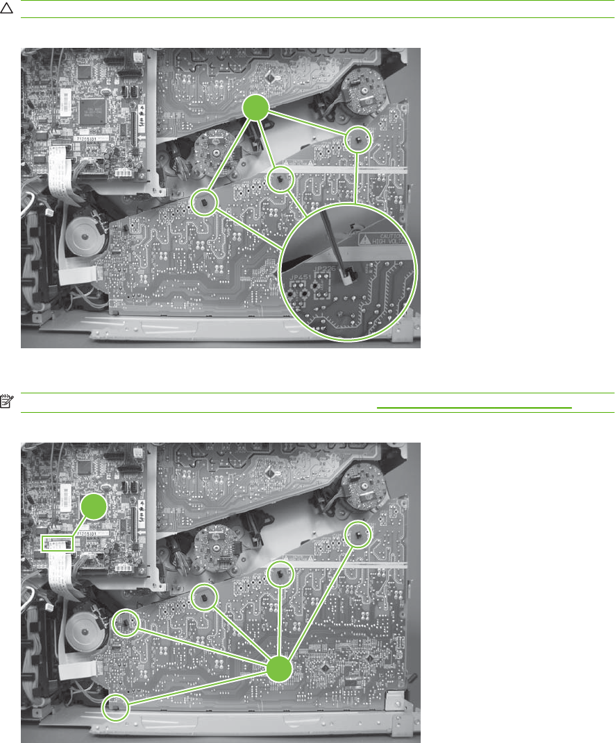
2. Use a small flat blade screwdriver to carefully remove three locking clips (callout 3).
CAUTION: Do not damage the PCA with the screwdriver.
Figure 6-206 Remove the high-voltage power supply lower (2 of 4)
3
3. Disconnect one connector (callout 4; J114), and then release five clips (callout 5).
NOTE: To locate DC controller connector locations, see DC controller PCA on page 183.
Figure 6-207 Remove the high-voltage power supply lower (3 of 4)
5
4
ENWW Internal assemblies 309
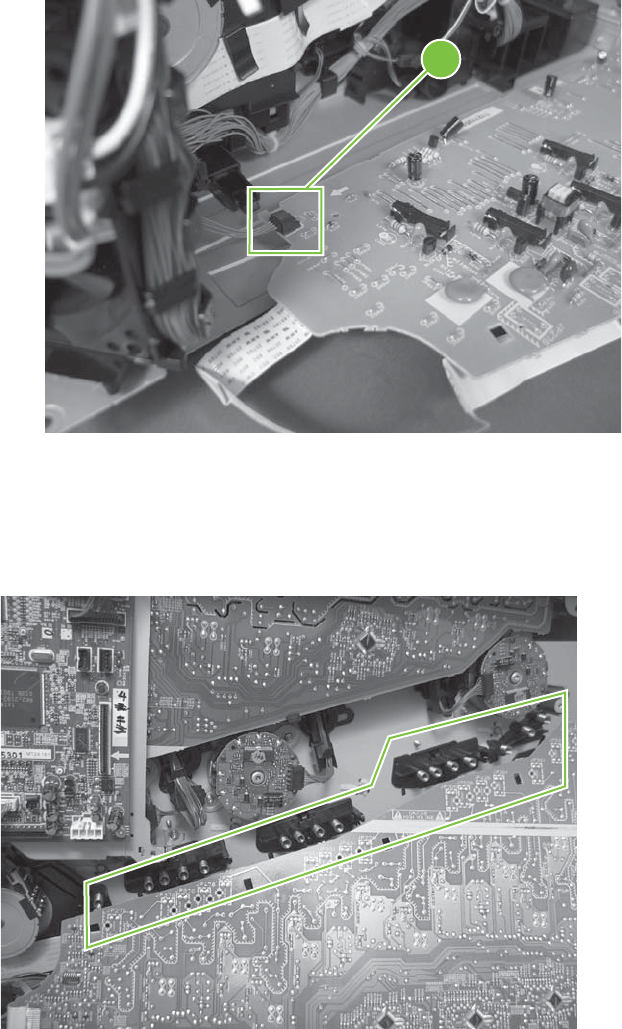
4. Rotate the top of the power supply away from the chassis, and then disconnect one connector
(callout 6). Remove the power supply
Figure 6-208 Remove the high-voltage power supply lower (4 of 4)
6
Reinstall the high-voltage power supply lower
When you reinstall the power supply, look through the holes in the PCA and make sure that the high-
voltage contact springs are correctly seated against the PCA.
Figure 6-209 Reinstall the high-voltage power supply lower
310 Chapter 6 Removal and replacement ENWW
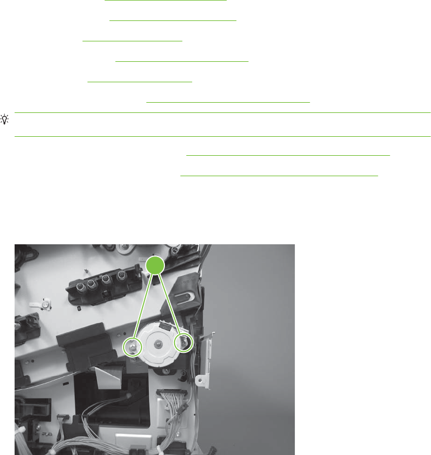
Developing-disengagement motor
Before proceeding, remove the following components:
●Formatter PCA. See Formatter PCA on page 192.
●Right-rear cover. See Right-rear cover on page 231.
●Left cover. See Left cover on page 233.
●Rear-upper cover. See Rear-upper cover on page 236.
●Rear cover. See Rear cover on page 238.
●Interconnect board (ICB). See Interconnect board (ICB) on page 267.
TIP: For internal product access, you can remove the ICB and the low-voltage power supply as
a single component.
●Low-voltage power supply (LVPS). See Low-voltage power supply (LVPS) on page 273.
●High-voltage power supply lower. See High-voltage power supply lower on page 308.
Remove the developing-disengagement motor
1. Remove two screws (callout 1).
Figure 6-210 Remove the developing-disengagement motor (1 of 2)
1
ENWW Internal assemblies 311
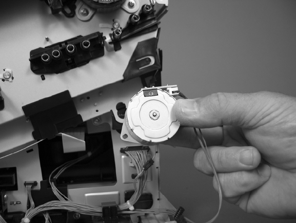
2. Remove the motor.
Figure 6-211 Remove the developing-disengagement motor (2 of 2)
312 Chapter 6 Removal and replacement ENWW
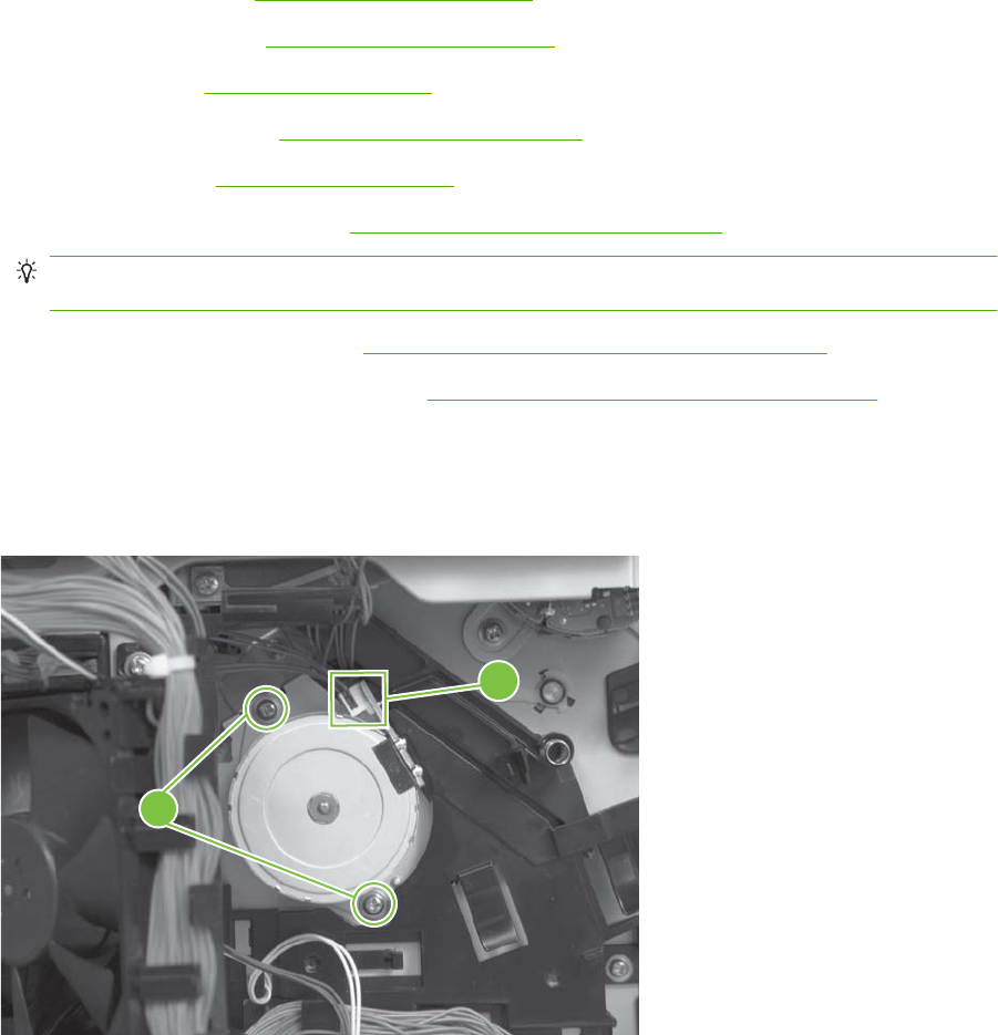
Pickup motor
Before proceeding, remove the following components:
●Formatter PCA. See Formatter PCA on page 192.
●Right-rear cover. See Right-rear cover on page 231.
●Left cover. See Left cover on page 233.
●Rear-upper cover. See Rear-upper cover on page 236.
●Rear cover. See Rear cover on page 238.
●Interconnect board (ICB). See Interconnect board (ICB) on page 267.
TIP: For internal product access, you can remove the ICB and the low-voltage power supply as
a single component.
●Low-voltage power supply. See Low-voltage power supply (LVPS) on page 273.
●High-voltage power supply lower. See High-voltage power supply lower on page 308.
Remove the pickup motor
Disconnect one connector (callout 1), remove two screws (callout 2), and then remove the motor.
Figure 6-212 Remove the pickup motor
1
2
ENWW Internal assemblies 313
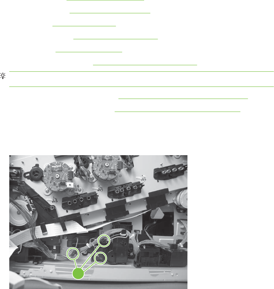
Lifter-drive assembly
Before proceeding, remove the following components:
●Formatter PCA. See Formatter PCA on page 192.
●Right-rear cover. See Right-rear cover on page 231.
●Left cover. See Left cover on page 233.
●Rear-upper cover. See Rear-upper cover on page 236.
●Rear cover. See Rear cover on page 238.
●Interconnect board (ICB). See Interconnect board (ICB) on page 267.
TIP: For internal product access, you can remove the ICB and the low-voltage power supply as
a single component.
●Low-voltage power supply (LVPS). See Low-voltage power supply (LVPS) on page 273.
●High-voltage power supply lower. See High-voltage power supply lower on page 308.
Remove the lifter-drive assembly
1. Disconnect three connectors (callout 1), and then release the wire harness from the retainers.
Figure 6-213 Remove the lifter-drive assembly (1 of 2)
1
314 Chapter 6 Removal and replacement ENWW
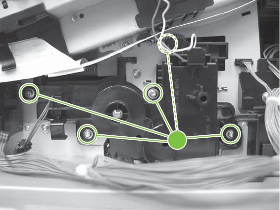
2. Remove five screws (callout 2), and then remove the assembly.
Figure 6-214 Remove the lifter-drive assembly (2 of 2)
2
ENWW Internal assemblies 315
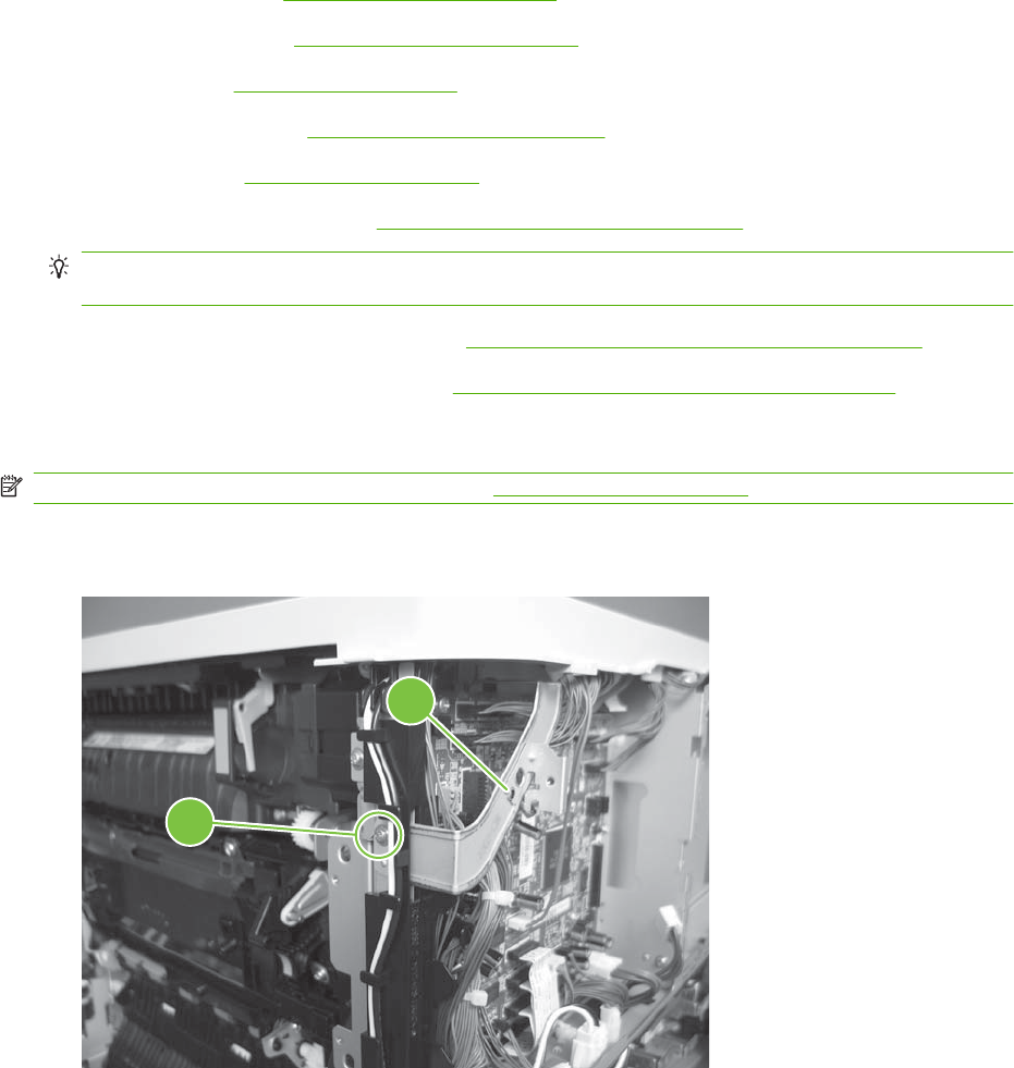
Cassette-pickup drive assembly
Before proceeding, remove the following components:
●Formatter PCA. See Formatter PCA on page 192.
●Right-rear cover. See Right-rear cover on page 231.
●Left cover. See Left cover on page 233.
●Rear-upper cover. See Rear-upper cover on page 236.
●Rear cover. See Rear cover on page 238.
●Interconnect board (ICB). See Interconnect board (ICB) on page 267.
TIP: For internal product access, you can remove the ICB and the low-voltage power supply as
a single component.
●Low-voltage power supply (LVPS). See Low-voltage power supply (LVPS) on page 273.
●High-voltage power supply lower. See High-voltage power supply lower on page 308.
Remove the cassette-pickup drive assembly
NOTE: To remove the pickup motor only, see Pickup motor on page 313.
1. Remove one screw (callout 1), and then remove the sheet-metal bracket (callout 2).
Figure 6-215 Remove the cassette-pickup drive assembly (1 of 10)
1
2
316 Chapter 6 Removal and replacement ENWW
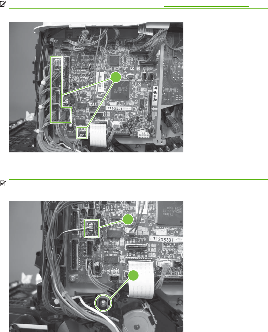
2. Disconnect six connectors (callout 3; J106, J107, J108, J137, J138, J140).
NOTE: To locate DC controller connector locations, see DC controller PCA on page 183.
Figure 6-216 Remove the cassette-pickup drive assembly (2 of 10)
3
3
3. Disconnect one connector (callout 4; J119), remove one screw (callout 5), and then release the
wire harness from the guides.
NOTE: To locate DC controller connector locations, see DC controller PCA on page 183.
Figure 6-217 Remove the cassette-pickup drive assembly (3 of 10)
4
5
ENWW Internal assemblies 317
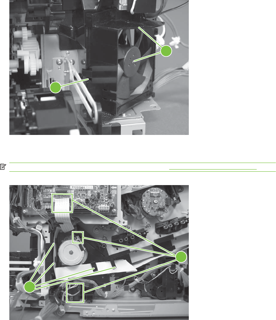
4. Release one tab (callout 6), and then remove the fan and fan duct (callout 7).
Figure 6-218 Remove the cassette-pickup drive assembly (4 of 10)
6
7
5. Disconnect five connectors (callout 8; J110, J111 on the DC controller PCA), release the FFCs
from the guide (callout 9), and then release the wire harnesses from the guides.
NOTE: To locate DC controller connector locations, see DC controller PCA on page 183.
Figure 6-219 Remove the cassette-pickup drive assembly (5 of 10)
9
8
318 Chapter 6 Removal and replacement ENWW
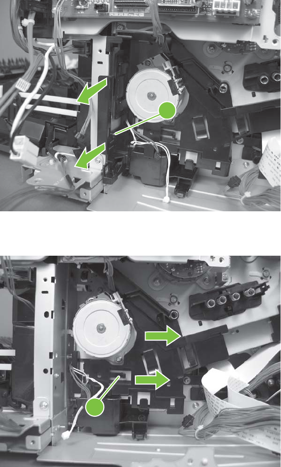
6. Release one tab (callout 10), and then remove the guide.
Figure 6-220 Remove the cassette-pickup drive assembly (6 of 10)
10
7. Release one tab (callout 11), and then remove the guide.
Figure 6-221 Remove the cassette-pickup drive assembly (7 of 10)
11
ENWW Internal assemblies 319
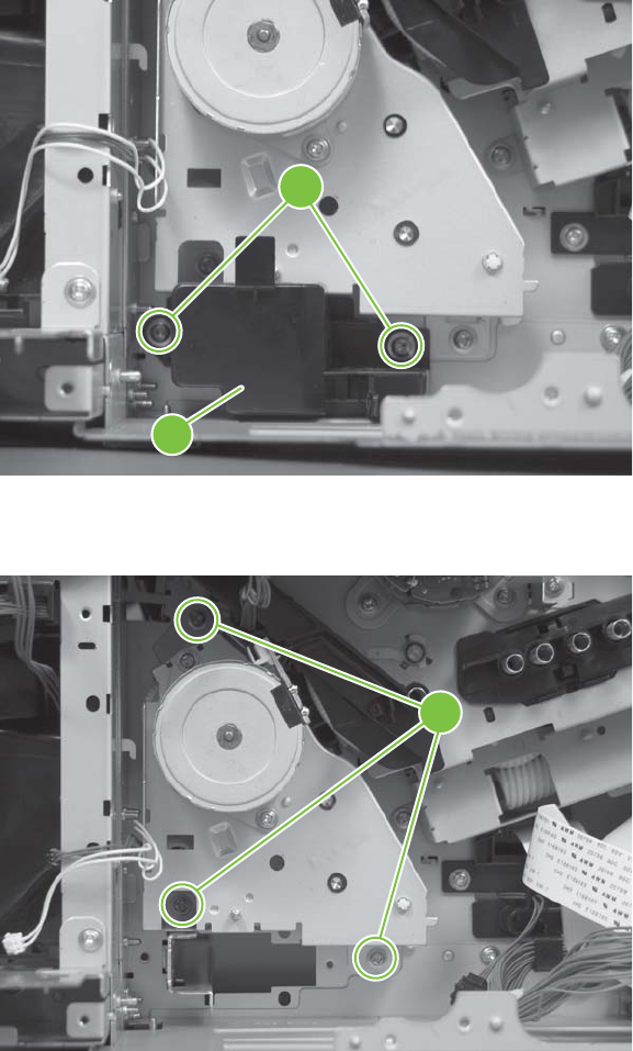
8. Remove two screws (callout 12), and then remove the high-voltage bracket (callout 13).
Figure 6-222 Remove the cassette-pickup drive assembly (8 of 10)
13
12
9. Remove three screws (callout 14).
Figure 6-223 Remove the cassette-pickup drive assembly (9 of 10)
14
320 Chapter 6 Removal and replacement ENWW
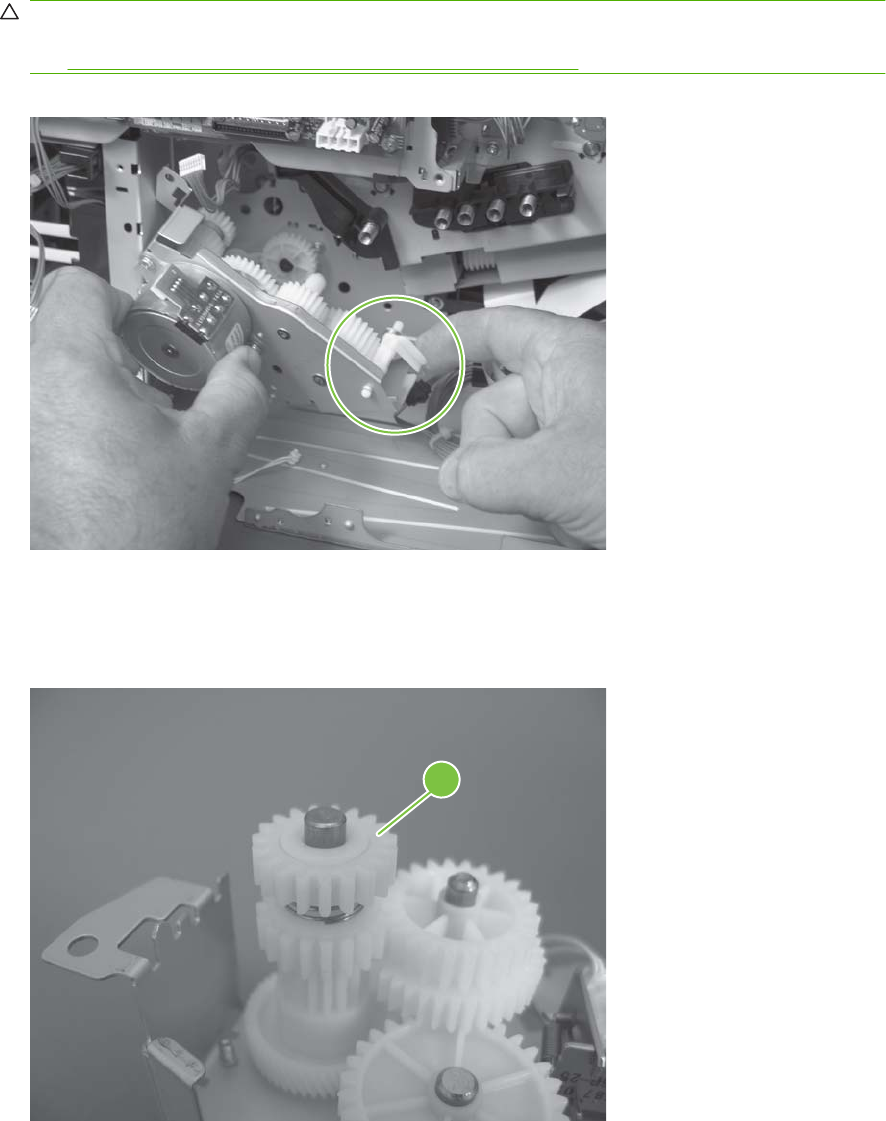
10. Carefully remove the assembly.
CAUTION: The gears, arm, and spring on the assembly are not captive. Use your finger to secure
the arm and spring as you remove the assembly. If the gears, arm, or spring become dislodged,
see Reinstall the cassette-pickup drive assembly on page 321.
Figure 6-224 Remove the cassette-pickup drive assembly (10 of 10)
Reinstall the cassette-pickup drive assembly
1. Make sure that the spring-loaded gear (callout 1) is correctly installed.
Figure 6-225 Reinstall the cassette-pickup drive assembly (1 of 3)
1
ENWW Internal assemblies 321
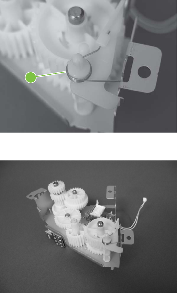
2. Make sure that the spring (callout 2) is correctly installed.
Figure 6-226 Reinstall the cassette-pickup drive assembly (2 of 3)
2
3. Make sure that the gears, arm, and spring are correctly installed.
Figure 6-227 Reinstall the cassette-pickup drive assembly (3 of 3)
322 Chapter 6 Removal and replacement ENWW
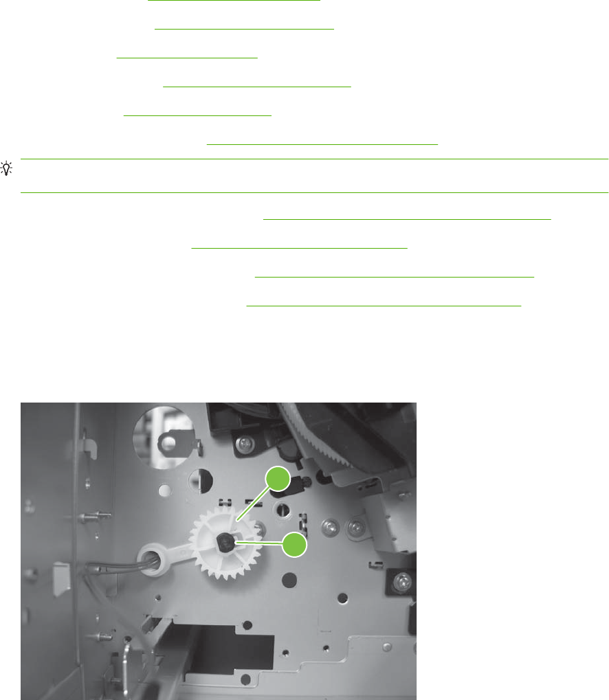
Cassette-pickup assembly
Before proceeding, remove the following components:
●Formatter PCA. See Formatter PCA on page 192.
●Right-rear cover. See Right-rear cover on page 231.
●Left cover. See Left cover on page 233.
●Rear-upper cover. See Rear-upper cover on page 236.
●Rear cover. See Rear cover on page 238.
●Interconnect board (ICB). See Interconnect board (ICB) on page 267.
TIP: For internal product access, you can remove the ICB and the low-voltage power supply as
a single component.
●Low-voltage power supply (LVPS). See Low-voltage power supply (LVPS) on page 273.
●Registration assembly. See Registration assembly on page 303.
●High-voltage power supply lower. See High-voltage power supply lower on page 308.
●Cassette-pickup drive assembly. SeeCassette-pickup drive assembly on page 316.
Remove the cassette-pickup assembly
1. Release one tab (callout 1), and then remove the gear (callout 2).
Figure 6-228 Remove the cassette-pickup assembly (1 of 3)
2
1
ENWW Internal assemblies 323
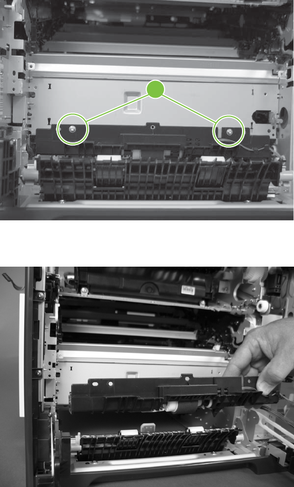
2. Remove two screws (callout 3).
Figure 6-229 Remove the cassette-pickup assembly (2 of 3)
3
3. Remove the assembly.
Figure 6-230 Remove the cassette-pickup assembly (3 of 3)
324 Chapter 6 Removal and replacement ENWW
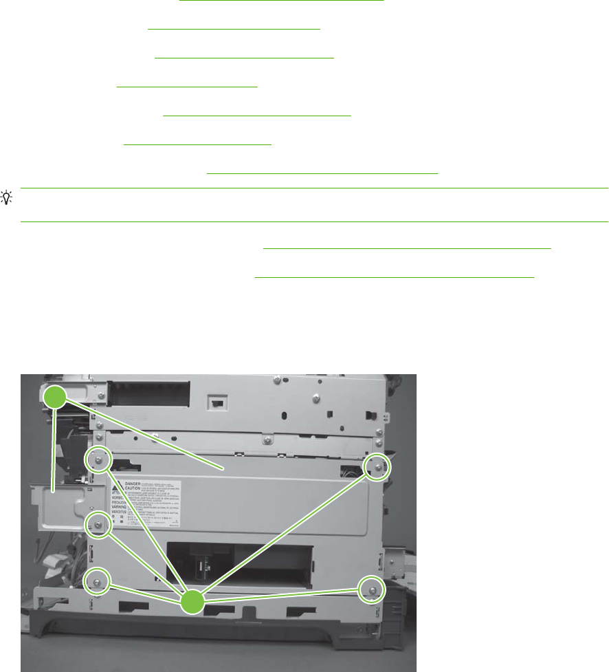
Laser/scanner assembly (Y/M)
Before proceeding, remove the following components:
●Toner collection unit. See Toner-collection unit on page 190.
●Formatter PCA. See Formatter PCA on page 192.
●Right-rear cover. See Right-rear cover on page 231.
●Left cover. See Left cover on page 233.
●Rear-upper cover. See Rear-upper cover on page 236.
●Rear cover. See Rear cover on page 238.
●Interconnect board (ICB). See Interconnect board (ICB) on page 267.
TIP: For internal product access, you can remove the ICB and the low-voltage power supply as
a single component.
●Low-voltage power supply (LVPS). See Low-voltage power supply (LVPS) on page 273.
●High-voltage power supply lower. See High-voltage power supply lower on page 308.
Remove the laser/scanner assembly (Y/M)
1. Remove five screws (callout 1), and then remove the sheet-metal plate (callout 2).
Figure 6-231 Remove the laser/scanner assembly (Y/M) (1 of 12)
1
2
ENWW Internal assemblies 325
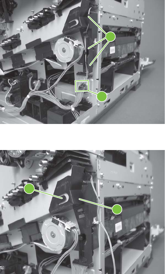
2. Disconnect in-line one connector (callout 3), and then release the wire harnesses from the guide
(callout 4).
Figure 6-232 Remove the laser/scanner assembly (Y/M) (2 of 12)
4
3
3. Release one tab (callout 5), and then remove the guide (callout 6).
Figure 6-233 Remove the laser/scanner assembly (Y/M) (3 of 12)
6
5
326 Chapter 6 Removal and replacement ENWW
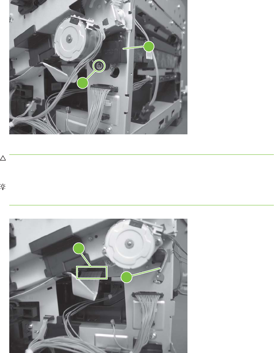
4. Remove one screw (callout 7), and then remove the cover (callout 8).
Figure 6-234 Remove the laser/scanner assembly (Y/M) (4 of 12)
8
7
5. Disconnect one FFC (callout 9), and then release one spring (callout 10).
CAUTION: The spring is not captive. Do not lose the spring when it is removed. Use a pair of
needle-nose pliers to safely retain the spring when it is removed. Do not use a flat blade screwdriver
to remove the spring; the spring could forcibly leave the product and strike you.
Reinstallation tip When you reinstall the spring, make sure that the laser/scanner fits tightly up
against the product chassis, and make sure that the FFC is fully seated in the connector. The
locator tabs on the front and rear of the scanner must be firmly seated in the slots in the chassis.
Figure 6-235 Remove the laser/scanner assembly (Y/M) (5 of 12)
10
9
ENWW Internal assemblies 327
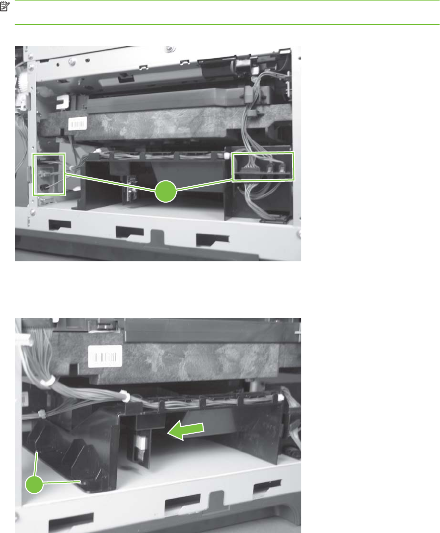
6. Disconnect six connectors (callout 11).
NOTE: Disconnect the larger connector on the right side from the bottom. Disconnect the two
smaller connectors on the right side from the top.
Figure 6-236 Remove the laser/scanner assembly (Y/M) (6 of 12)
11
7. Release two tabs (callout 12), and then slide the fan assembly toward the power-supply side of the
product to release it.
Figure 6-237 Remove the laser/scanner assembly (Y/M) (7 of 12)
12
328 Chapter 6 Removal and replacement ENWW
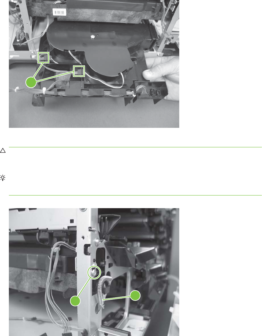
8. Pull the fan assembly slightly out of the product, disconnect two connectors (callout 13), and then
remove the assembly.
Figure 6-238 Remove the laser/scanner assembly (Y/M) (8 of 12)
13
9. Remove one screw (callout 14), and then release one spring (callout 15).
CAUTION: The spring is not captive. Do not lose the spring when it is removed. Use a pair of
needle-nose pliers to safely retain the spring when it is removed. Do not use a flat blade screwdriver
to remove the spring; the spring could forcibly leave the product and strike you.
Reinstallation tip When the laser/scanner is properly positioned in the chassis, the plastic parts
which protrude at the front and rear of the product will be firmly seated against the locator tabs on
the chassis. Verify that the assembly is correctly seated, and then install the spring.
Figure 6-239 Remove the laser/scanner assembly (Y/M) (9 of 12)
15
14
ENWW Internal assemblies 329
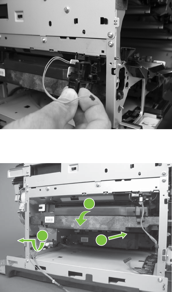
10. Remove the toner collection sensor.
Figure 6-240 Remove the laser/scanner assembly (Y/M) (10 of 12)
11. Rotate the front of the laser/scanner assembly down (callout 1), and then slide it toward the right
(callout 2). Lower the left corner, and then rotate the left corner out of the product (callout 3).
Figure 6-241 Remove the laser/scanner assembly (Y/M) (11 of 12)
1
2
3
330 Chapter 6 Removal and replacement ENWW
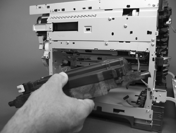
12. Pull the laser/scanner assembly straight out of the product to remove it.
Figure 6-242 Remove the laser/scanner assembly (Y/M) (12 of 12)
ENWW Internal assemblies 331
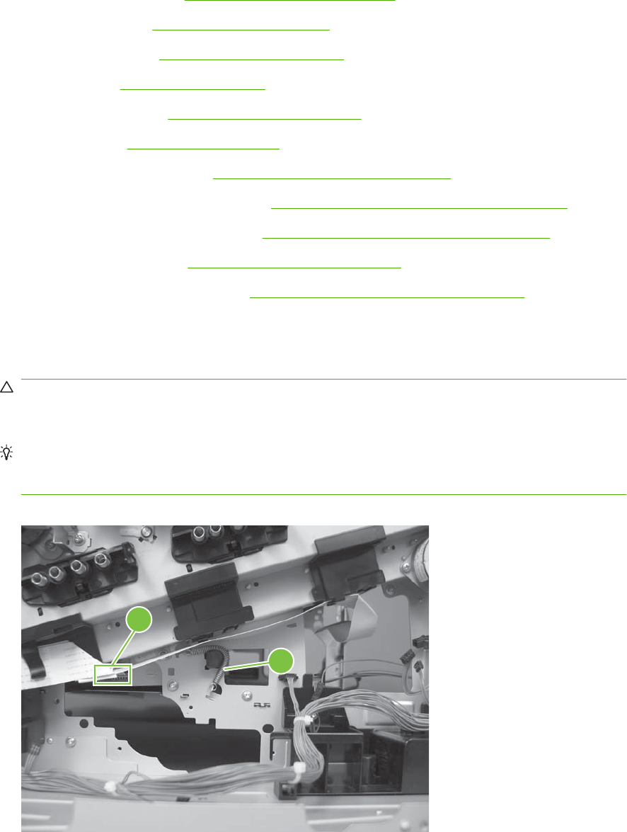
Laser/scanner assembly (C/Bk)
Before proceeding, remove the following components:
●Toner collection unit. See Toner-collection unit on page 190.
●Formatter PCA. See Formatter PCA on page 192.
●Right-rear cover. See Right-rear cover on page 231.
●Left cover. See Left cover on page 233.
●Rear-upper cover. See Rear-upper cover on page 236.
●Rear cover. See Rear cover on page 238.
●Interconnect board (ICB). See Interconnect board (ICB) on page 267.
●Low-voltage power supply (LVPS). See Low-voltage power supply (LVPS) on page 273.
●High-voltage power supply lower. See High-voltage power supply lower on page 308.
●Lifter drive assembly. See Lifter-drive assembly on page 314.
●Laser/scanner assembly (Y/M). See Laser/scanner assembly (Y/M) on page 325.
Remove the laser/scanner assembly (C/Bk)
1. Release one spring (callout 1), and then disconnect one connector (callout 2).
CAUTION: The spring is not captive. Do not lose the spring when it is removed. Use a pair of
needle-nose pliers to safely retain the spring when it is removed. Do not use a flat blade screwdriver
to remove the spring; the spring could forcibly leave the product and strike you.
Reinstallation tip When you reinstall the spring, make sure that the laser/scanner fits tightly up
against the product chassis, and make sure that the FFC is fully seated in the connector. The
locator tabs on the front of the scanner must be firmly seated in the slots in the chassis.
Figure 6-243 Remove the laser/scanner assembly (C/Bk) (1 of 7)
1
2
332 Chapter 6 Removal and replacement ENWW
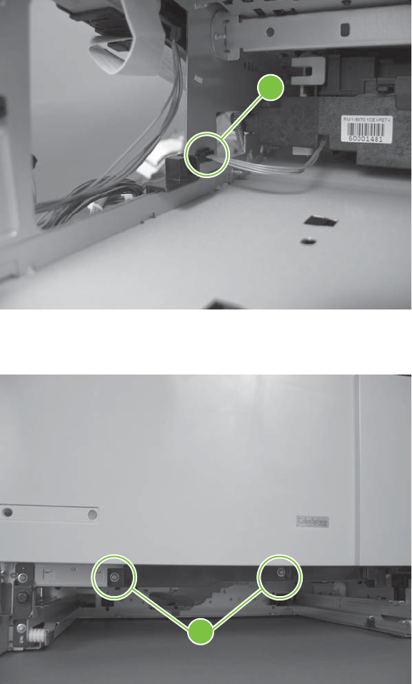
2. Disconnect one connector (callout 3).
Figure 6-244 Remove the laser/scanner assembly (C/Bk) (2 of 7)
3
3. Remove two screws (callout 4) located below the front door.
Figure 6-245 Remove the laser/scanner assembly (C/Bk) (3 of 7)
4
ENWW Internal assemblies 333
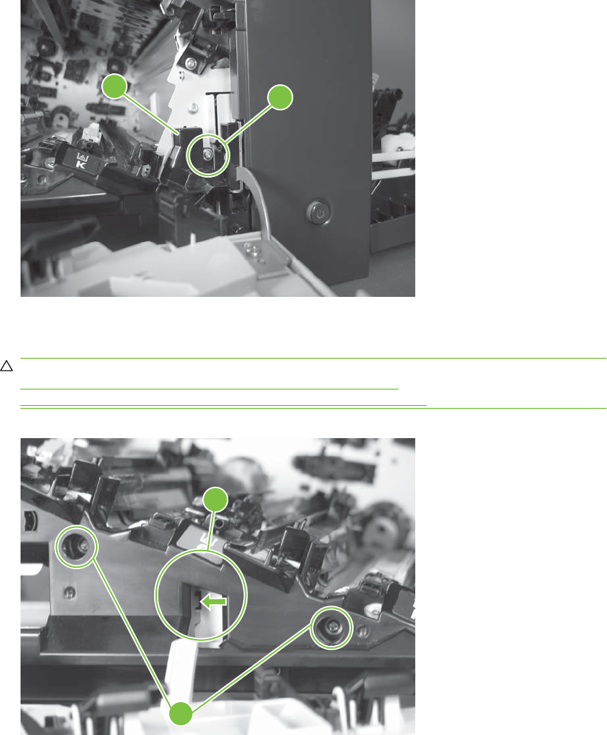
4. Open the front door, and then remove one screw (callout 5) and the cover (callout 6).
Figure 6-246 Remove the laser/scanner assembly (C/Bk) (4 of 7)
5
6
5. Remove two screws (callout 7). Use your finger to release the locking tab (callout 8), and then
remove the cover.
CAUTION: Be careful. The PGC actuators are easily dislodged when the cover is removed. See
Figure 6-250 Reinstall the PGC actuators (1 of 5) on page 336. To reinstall the actuators, see
Reinstall the protective glass cleaner (PGC) actuators on page 336.
Figure 6-247 Remove the laser/scanner assembly (C/Bk) (5 of 7)
7
8
334 Chapter 6 Removal and replacement ENWW
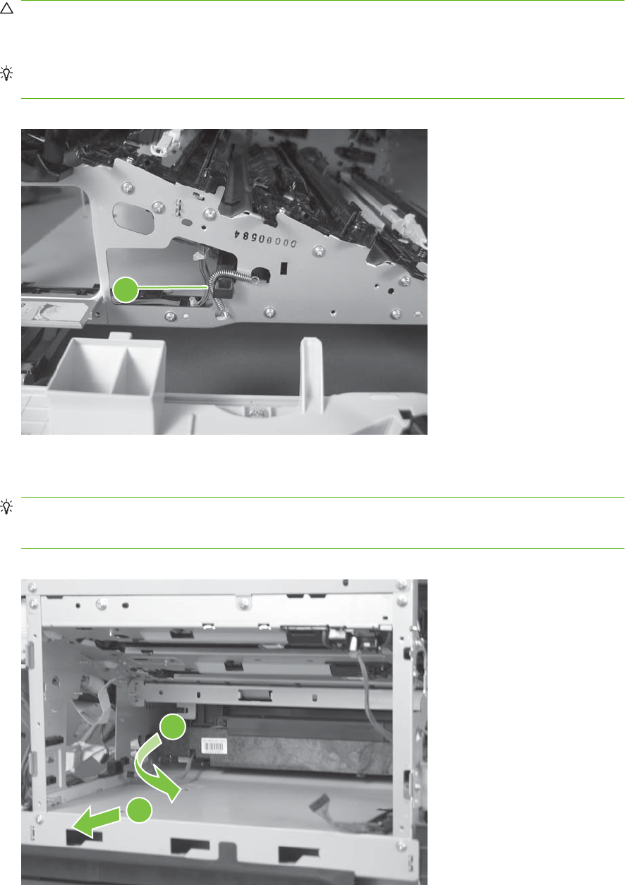
6. Release one spring (callout 9).
CAUTION: The spring is not captive. Do not lose the spring when it is removed. Use a pair of
needle-nose pliers to safely retain the spring when it is removed. Do not use a flat blade screwdriver
to remove the spring; the spring could forcibly leave the product and strike you.
Reinstallation tip When you reinstall the spring, make sure that the laser/scanner fits tightly up
against the product chassis.
Figure 6-248 Remove the laser/scanner assembly (C/Bk) (6 of 7)
9
7. Rotate the corner of the assembly away from the product until you can see the PCA, and then
remove the assembly from the product.
Reinstallation tip When the laser/scanner is properly positioned in the chassis, the plastic parts
which protrude at the front and rear of the product will be firmly seated against the locator tabs on
the chassis. Verify that the assembly is correctly seated, and then install the spring.
Figure 6-249 Remove the laser/scanner assembly (C/Bk) (7 of 7)
1
2
ENWW Internal assemblies 335
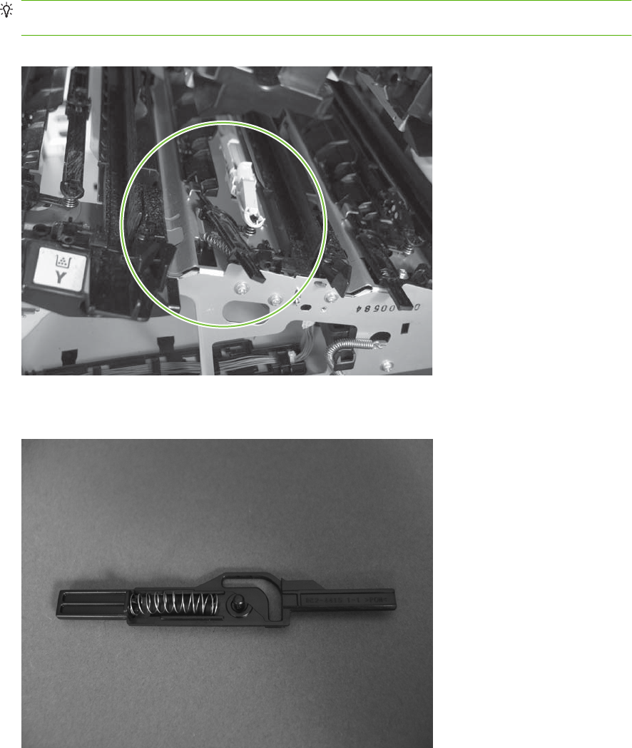
Reinstall the protective glass cleaner (PGC) actuators
1. The following figure shows a dislodged PGC actuator.
TIP: If the actuator and spring are only slightly dislodged, you might be able to easily push them
back into place.
Figure 6-250 Reinstall the PGC actuators (1 of 5)
2. Remove the actuator and spring from the product. Install the spring on the actuator.
Figure 6-251 Reinstall the PGC actuators (2 of 5)
336 Chapter 6 Removal and replacement ENWW

3. Before proceeding, take note of the following:
●Callout 1: The pin on the actuator will be installed into the slot in the chassis.
●Callout 2: The pin on the pivot arm will be installed into the slot on the actuator.
●Callout 3: The end of the spring will be installed onto the tab on the chassis.
Figure 6-252 Reinstall the PGC actuators (3 of 5)
3
1
2
4. Place the end of the actuator into the PGC rod, and then use a small flat blade screw driver to
fasten the end of the spring on the tab on the chassis.
Figure 6-253 Reinstall the PGC actuators (4 of 5)
ENWW Internal assemblies 337
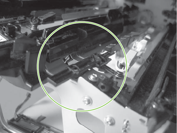
5. Push down on the actuator to seat it into place. Verify that the actuators is correctly installed. The
PGC actuator should freely move when you push in on the actuator.
Figure 6-254 Reinstall the PGC actuators (5 of 5)
338 Chapter 6 Removal and replacement ENWW
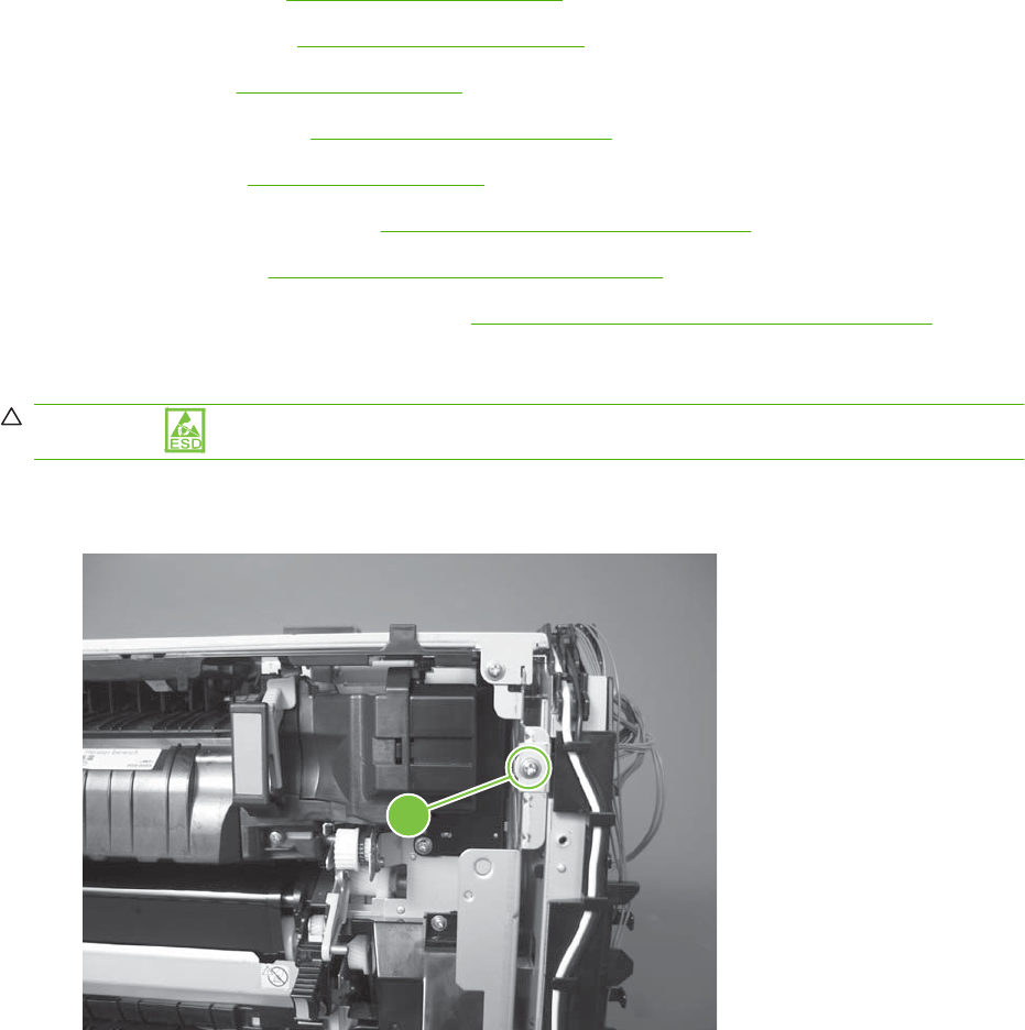
High-voltage power supply upper
Before proceeding, remove the following components:
●Formatter PCA. See Formatter PCA on page 192.
●Right-rear cover. See Right-rear cover on page 231.
●Left cover. See Left cover on page 233.
●Rear-upper cover. See Rear-upper cover on page 236.
●Rear cover. See Rear cover on page 238.
●Interconnect board (ICB). See Interconnect board (ICB) on page 267.
●DC controller. See DC controller PCA and tray on page 270.
●Low-voltage power supply (LVPS). See Low-voltage power supply (LVPS) on page 273.
Remove the high-voltage power supply upper
CAUTION: ESD-sensitive part.
1. Remove one screw (callout 1).
Figure 6-255 Remove the high-voltage power supply upper (1 of 5)
1
ENWW Internal assemblies 339
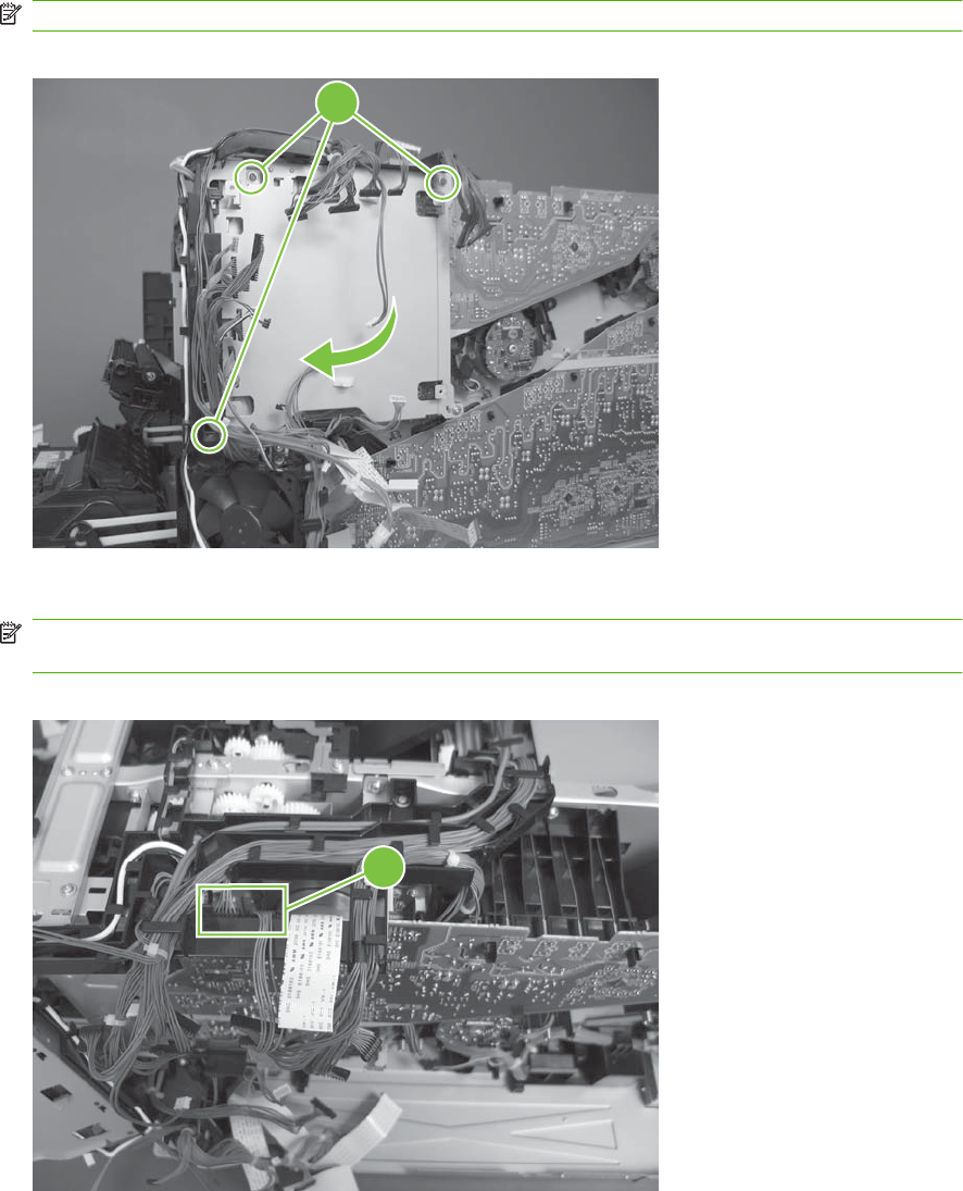
2. Remove four screws (callout 2), and then rotate the sheet-metal plate away from the power supply.
NOTE: You do not need to completely remove the sheet-metal plate to access the power supply.
Figure 6-256 Remove the high-voltage power supply upper (2 of 5)
2
3. Disconnect two connectors (J201, J202; callout 3) from the back side of the power supply.
NOTE: For clarity, the figure in this step shows the ADF and scanner removed. Carefully reach
under these components to access the two connectors.
Figure 6-257 Remove the high-voltage power supply upper (3 of 5)
3
340 Chapter 6 Removal and replacement ENWW
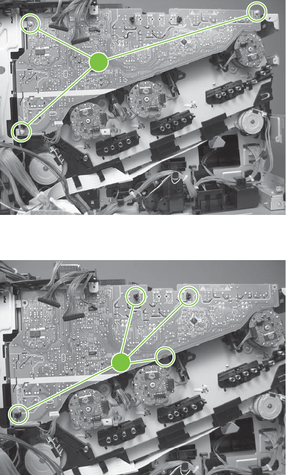
4. Remove three screws (callout 4).
Figure 6-258 Remove the high-voltage power supply upper (4 of 5)
4
5. Release four tabs (callout 5), and then remove the power supply.
Figure 6-259 Remove the high-voltage power supply upper (5 of 5)
5
ENWW Internal assemblies 341
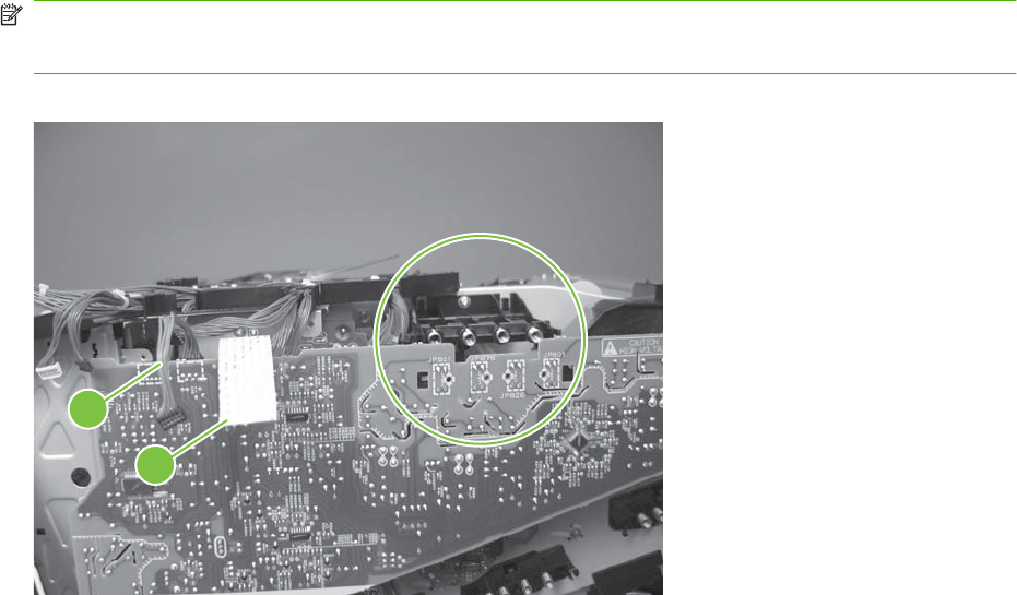
Reinstall the high-voltage power supply upper
When you reinstall the power supply, look through the holes in the PCA and make sure that the high-
voltage contact springs are correctly seated against the PCA.
NOTE: One wire harness (callout 1) is disconnected at both ends. Do not lose the wire harness.
Position the FFC (callout 2) over the cable guide when you reinstall the power supply.
Figure 6-260 Reinstall the high-voltage power supply upper
1
2
342 Chapter 6 Removal and replacement ENWW
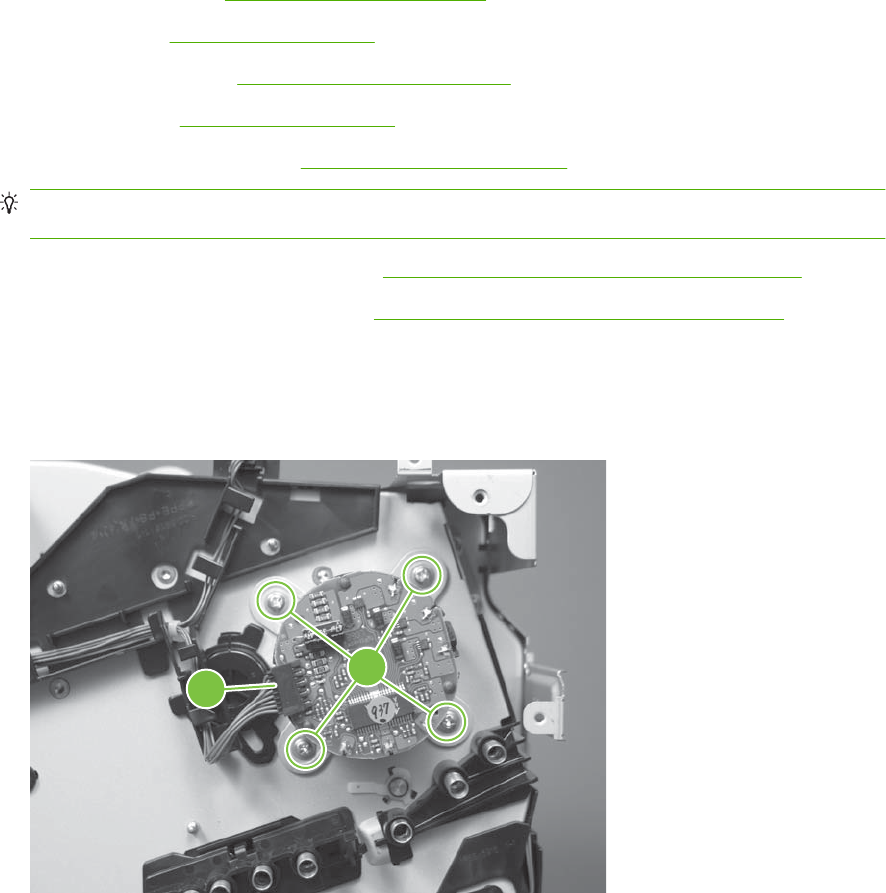
Drum motor 1
Before proceeding, remove the following components:
●Right-rear cover. See Right-rear cover on page 231.
●Left cover. See Left cover on page 233.
●Rear-upper cover. See Rear-upper cover on page 236.
●Rear cover. See Rear cover on page 238.
●Interconnect board (ICB). See Reinstall the ICB on page 269.
TIP: For internal product access, you can remove the ICB and the low-voltage power supply as
a single component.
●Low-voltage power supply (LVPS). See Low-voltage power supply (LVPS) on page 273.
●High-voltage power supply upper. See High-voltage power supply upper on page 339.
Remove the drum motor 1
▲Disconnect one connector (callout 1), remove four screws (callout 2), and then remove the motor.
Figure 6-261 Remove the drum motor 1
2
1
ENWW Internal assemblies 343
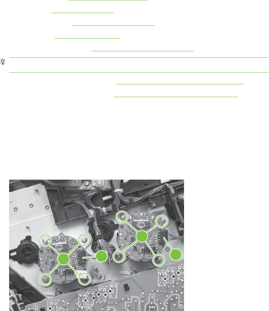
Drum motor 2 or drum motor 3
Before proceeding, remove the following components:
●Right-rear cover. See Right-rear cover on page 231.
●Left cover. See Left cover on page 233.
●Rear-upper cover. See Rear-upper cover on page 236.
●Rear cover. See Rear cover on page 238.
●Interconnect board (ICB). See Interconnect board (ICB) on page 267.
TIP: For internal product access, you can remove the ICB and the low-voltage power supply as
a single component.
●Low-voltage power supply (LVPS). See Low-voltage power supply (LVPS) on page 273.
●High-voltage power supply upper. See High-voltage power supply upper on page 339.
Remove the drum motor 2 or drum motor 3
▲Do one of the following:
●Remove drum motor 2: Disconnect one connector (callout 1), remove four screws (callout 2),
and then remove the motor.
●Remove drum motor 3: Disconnect one connector (callout 3), remove four screws (callout 4),
and then remove the motor.
Figure 6-262 Remove the drum motor 2 or drum motor 3
431
2
344 Chapter 6 Removal and replacement ENWW
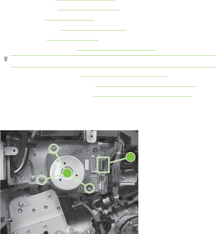
Fuser motor
Before proceeding, remove the following components:
●Formatter PCA. See Formatter PCA on page 192
●Right-rear cover. See Right-rear cover on page 231.
●Left cover. See Left cover on page 233.
●Rear-upper cover. See Rear-upper cover on page 236.
●Rear cover. See Rear cover on page 238.
●Interconnect board (ICB). See Interconnect board (ICB) on page 267.
TIP: For internal product access, you can remove the ICB and the low-voltage power supply as
a single component.
●DC controller PCA and tray. See DC controller PCA and tray on page 270.
●Low-voltage power supply (LVPS). See Low-voltage power supply (LVPS) on page 273.
●High-voltage power supply upper. See High-voltage power supply upper on page 339.
Remove the fuser motor
Disconnect one connector (callout 1), remove three screws (callout 2), and then remove the motor.
Figure 6-263 Remove the fuser motor
2
1
ENWW Internal assemblies 345
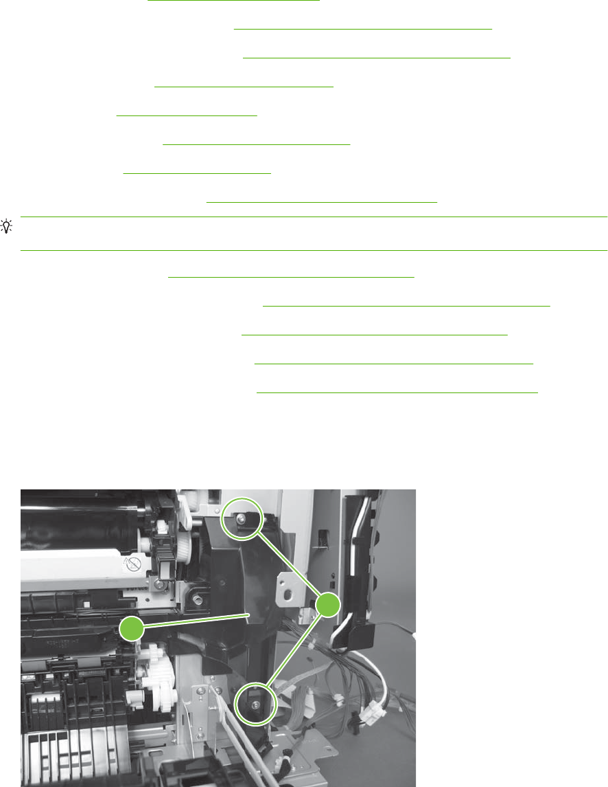
Main-drive assembly
Before proceeding, remove the following components:
●Formatter PCA. See Formatter PCA on page 192.
●Secondary transfer assembly. See Secondary transfer assembly on page 207.
●Intermediate transfer belt (ITB). See Intermediate transfer belt (ITB) on page 209.
●Right-rear cover. See Right-rear cover on page 231.
●Left cover. See Left cover on page 233.
●Rear-upper cover. See Rear-upper cover on page 236.
●Rear cover. See Rear cover on page 238.
●Interconnect board (ICB). See Interconnect board (ICB) on page 267.
TIP: For internal product access, you can remove the ICB and the low-voltage power supply as
a single component.
●DC controller PCA. See DC controller PCA and tray on page 270.
●Low-voltage power supply (LVPS). See Low-voltage power supply (LVPS) on page 273.
●Power-supply fan and fan duct. See Power-supply fan and fan duct on page 300.
●High-voltage power supply lower. See High-voltage power supply lower on page 308.
●High-voltage power supply upper. See High-voltage power supply upper on page 339.
Remove the main-drive assembly
1. Remove two screws (callout 1), and then remove the cover (callout 2).
Figure 6-264 Remove the main-drive assembly (1 of 7)
1
2
346 Chapter 6 Removal and replacement ENWW
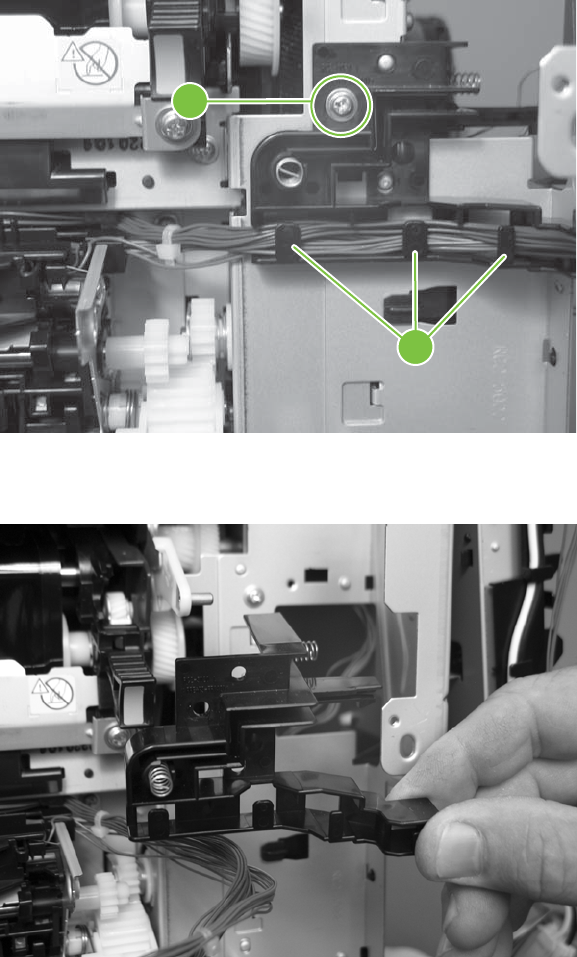
2. Release the wire harnesses from the guide (callout 3), and then remove one screw (callout 4).
Figure 6-265 Remove the main-drive assembly (2 of 7)
4
3
3. Lift the high-voltage bracket up to release it, and then remove the bracket.
Figure 6-266 Remove the main-drive assembly (3 of 7)
ENWW Internal assemblies 347
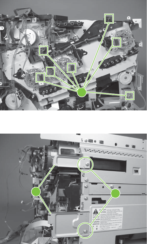
4. Disconnect seven connectors (callout 5), and then release the wire harnesses from the guides.
Figure 6-267 Remove the main-drive assembly (4 of 7)
5
5. Remove two screws (callout 6), and then remove the sheet-metal plates (callout 7).
Figure 6-268 Remove the main-drive assembly (5 of 7)
6
7
348 Chapter 6 Removal and replacement ENWW
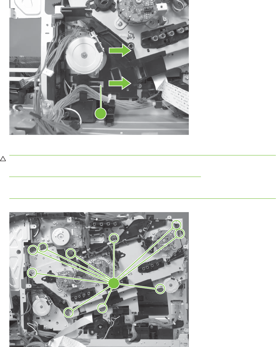
6. Release the FFCs and lower wiring harness from the guide, and then release one tab (callout 8)
and remove the guide.
Figure 6-269 Remove the main-drive assembly (6 of 7)
8
7. Remove ten screws (callout 9), and then carefully remove the assembly.
CAUTION: Be careful when you remove the assembly. The cams on the backside of the
assembly can be dislodged. If the cams become dislodged, install them on the shafts as shown in
Figure 6-272 Reinstall the main-drive assembly (2 of 11) on page 350.
The black cam must be installed on the shaft furthest away from the developing-disengagement
motor. The white cams are interchangeable.
Figure 6-270 Remove the main-drive assembly (7 of 7)
9
ENWW Internal assemblies 349
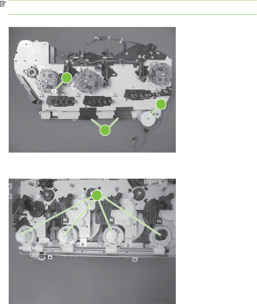
Reinstall the main-drive assembly
1. Remove the bracket (callout 1), two guides (callout 2), and the developing-disengagement motor
(callout 3).
Install the bracket and guides on the replacement main-drive assembly.
NOTE: Do not install the developing-disengagement motor on the assembly (this motor must be
removed from the assembly to align the main-drive cams).
Figure 6-271 Reinstall the main-drive assembly (1 of 11)
3
2
1
2. Locate the cams (callout 4) on the back side of the assembly.
Figure 6-272 Reinstall the main-drive assembly (2 of 11)
4
350 Chapter 6 Removal and replacement ENWW
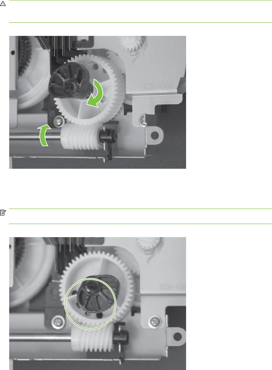
3. Slowly rotate the shaft near the black cam.
WARNING! Do not touch the plastic gears or cams. You must not wipe away any of the grease
that is applied to these components. Always rotate the gears and cams by rotating the metal drive
shaft.
Figure 6-273 Reinstall the main-drive assembly (3 of 11)
4. Continue to rotate the shaft until the holes in the black-cam gear align as shown below.
When correctly aligned, the bottom-most hole in the gear is aligned with a hole in the sheet-metal
chassis.
NOTE: The holes in the other cam gears have a different alignment. You must make sure that
the holes in the black-cam gear are correctly aligned.
Figure 6-274 Reinstall the main-drive assembly (4 of 11)
ENWW Internal assemblies 351
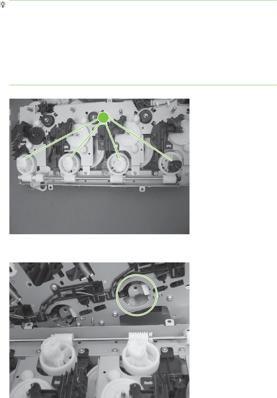
5. Verify that the cams (callout 5) align correctly.
TIP: The second cam in from the right (the white cam to the left of the black cam), should have
the second hole aligned with the hole in the sheet-metal chassis.
The third cam in from the right, should have the third hole aligned with the hole in the sheet-metal
chassis.
The fourth cam in from the right (the cam nearest the developing-disengagement motor), should
have the fourth hole aligned with the hole in the sheet-metal chassis.
If the second, third, or fourth cams do not correctly align, do the following. Hold the long drive shaft,
gently tilt the cam and gear away from the shaft to allow clearance to rotate the gear until the correct
hole in the gear aligns with the hole in the chassis.
Figure 6-275 Reinstall the main-drive assembly (5 of 11)
5
6. When the cams align correctly, they easily fit into the holes in the chassis.
Figure 6-276 Reinstall the main-drive assembly (6 of 11)
352 Chapter 6 Removal and replacement ENWW
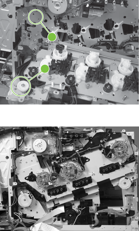
7. When the assembly is placed on the chassis, the pin on the swing gear and on the bracket
(callout 6), must align with the holes in the chassis (callout 7).
Figure 6-277 Reinstall the main-drive assembly (7 of 11)
6
7
8. Position the assembly on the chassis.
Figure 6-278 Reinstall the main-drive assembly (8 of 11)
ENWW Internal assemblies 353
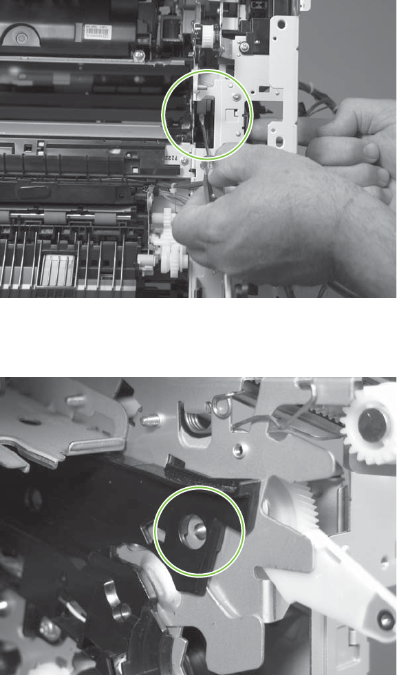
9. Use your finger to push in on the assembly, and use a small flat blade screwdriver to align the pin
on the swing gear with the hole in the chassis.
Figure 6-279 Reinstall the main-drive assembly (9 of 11)
10. When the assembly is correctly installed against the chassis, the pin above the swing gear
protrudes through the hole in the chassis.
Figure 6-280 Reinstall the main-drive assembly (10 of 11)
354 Chapter 6 Removal and replacement ENWW
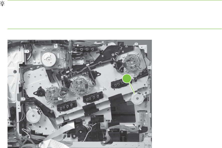
11. Install the main-drive assembly mounting screws, and then reinstall the developing-disengagement
motor (callout 8).
TIP: After reassembling the product, use the Diagnostics menu to print a Color Band Test page.
If the test page shows one or more color planes are not printing (usually in the upper left corner of
the page), the cam or cams for the missing color plane are not correctly aligned. Repeat the reinstall
the main-drive assembly procedure.
Figure 6-281 Reinstall the main-drive assembly (11 of 11)
8
ENWW Internal assemblies 355

Fuser-drive assembly
Before proceeding, remove the following components:
●Formatter PCA. Formatter PCA on page 192.
●Fuser. See Fuser on page 200.
●Secondary transfer assembly. See Secondary transfer assembly on page 207.
●Front-upper cover. See Front-upper cover on page 225
●Right-rear cover. See Right-rear cover on page 231.
●Left cover. See Left cover on page 233.
●Rear-upper cover. See Rear-upper cover on page 236.
●Rear cover. See Rear cover on page 238.
●Scanner assembly. See Scanner assembly on page 242.
●Front-top cover. See Front-top cover on page 261.
●Rear-top cover. See Rear-top cover on page 262
●Interconnect board (ICB). See Interconnect board (ICB) on page 267.
TIP: For internal product access, you can remove the ICB and the low-voltage power supply as
a single component.
●DC controller PCA. See DC controller PCA and tray on page 270.
●Low-voltage power supply (LVPS). See Low-voltage power supply (LVPS) on page 273.
●Power-supply fan and fan duct. See Power-supply fan and fan duct on page 300.
●High-voltage power supply lower. See High-voltage power supply lower on page 308.
●High-voltage power supply upper. See High-voltage power supply upper on page 339.
●Main-drive assembly. See Main-drive assembly on page 346.
356 Chapter 6 Removal and replacement ENWW
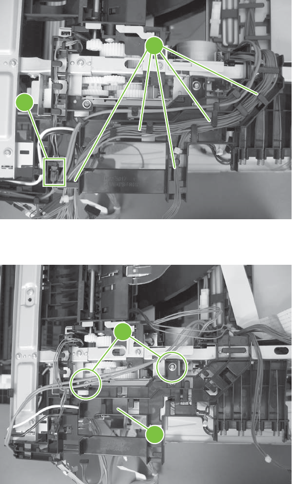
Remove the fuser-drive assembly
1. Disconnect one connector (callout 1), and then release the wire harnesses from the guide
(callout 2).
Figure 6-282 Remove the fuser-drive assembly (1 of 6)
2
1
2. Remove two screws (callout 3), and then remove the guide (callout 4).
Figure 6-283 Remove the fuser-drive assembly (2 of 6)
3
4
ENWW Internal assemblies 357
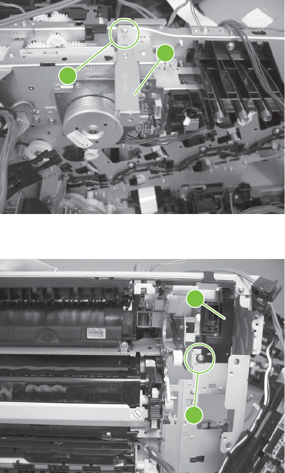
3. Remove one screw (callout 5), and then remove the sheet-metal plate (callout 6).
Figure 6-284 Remove the fuser-drive assembly (3 of 6)
6
5
4. Remove one screw (callout 7), and then remove the cover (callout 8).
Figure 6-285 Remove the fuser-drive assembly (4 of 6)
8
7
358 Chapter 6 Removal and replacement ENWW
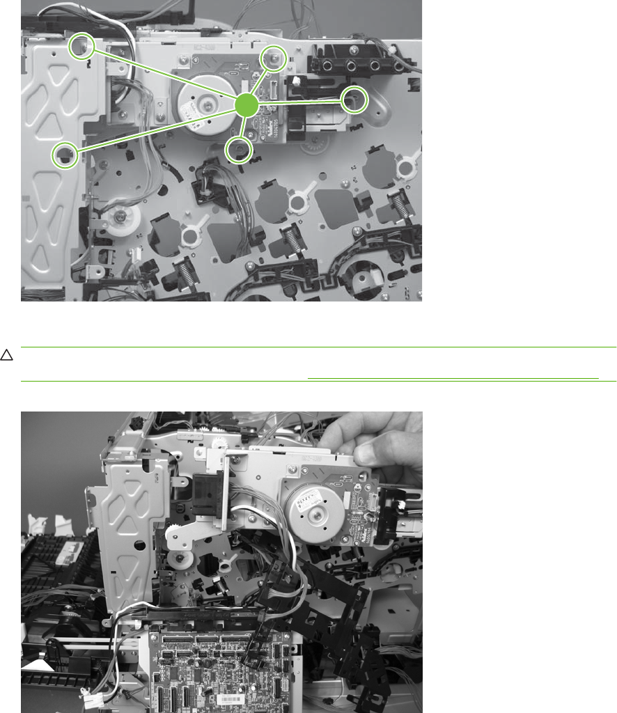
5. Remove five screws (callout 9).
Figure 6-286 Remove the fuser-drive assembly (5 of 6)
9
6. Carefully remove the assembly.
CAUTION: A gear on the assembly is not captive. Do not lose the gear when you remove the
assembly. If the gear becomes dislodged, see Reinstall the fuser-drive assembly on page 360.
Figure 6-287 Remove the fuser-drive assembly (6 of 6)
ENWW Internal assemblies 359
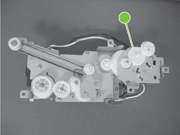
Reinstall the fuser-drive assembly
If the gear (callout 1) is dislodged when the assembly is removed, use the figure below to correctly install
it on the assembly.
Figure 6-288 Reinstall the fuser-drive assembly
1
360 Chapter 6 Removal and replacement ENWW

Delivery assembly
Before proceeding, remove the following components:
●Fuser. See Fuser on page 200.
●Secondary transfer assembly. See Secondary transfer assembly on page 207.
●Front-upper cover. See Front-upper cover on page 225
●Right-rear cover. See Right-rear cover on page 231.
●Left cover. See Left cover on page 233.
●Rear-upper cover. See Rear-upper cover on page 236.
●Rear cover. See Rear cover on page 238.
●Scanner assembly. See Scanner assembly on page 242.
●Front-top cover. See Front-top cover on page 261.
●Rear-top cover. See Rear-top cover on page 262
●Interconnect board (ICB). See Interconnect board (ICB) on page 267.
●DC controller PCA. See DC controller PCA and tray on page 270.
●Low-voltage power supply (LVPS). See Low-voltage power supply (LVPS) on page 273.
●Power-supply fan and fan duct. See Power-supply fan and fan duct on page 300.
●High-voltage power supply lower. See High-voltage power supply lower on page 308.
●High-voltage power supply upper. See High-voltage power supply upper on page 339.
●Main-drive assembly. See Main-drive assembly on page 346.
●Fuser-drive assembly. See Fuser-drive assembly on page 356.
ENWW Internal assemblies 361
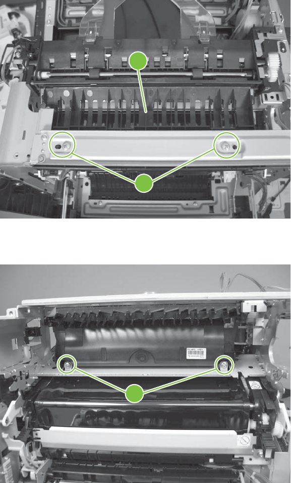
Remove the delivery assembly
1. Remove two screws (callout 1), and then remove the guide (callout 2).
Figure 6-289 Remove the delivery assembly (1 of 5)
1
2
2. Remove two screws (callout 3).
Figure 6-290 Remove the delivery assembly (2 of 5)
3
362 Chapter 6 Removal and replacement ENWW
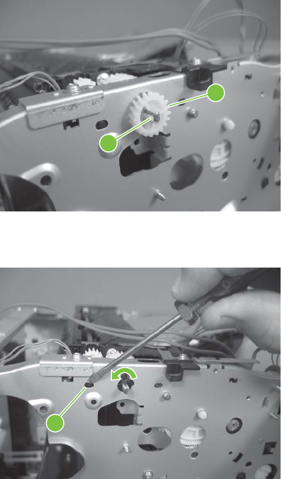
3. Release one tab (callout 4), and then remove the gear (callout 5).
Figure 6-291 Remove the delivery assembly (3 of 5)
5
4
4. Release one tab (callout 6), and then rotate the locking clip until the tab on the clip aligns with the
slot in the chassis.
Figure 6-292 Remove the delivery assembly (4 of 5)
6
ENWW Internal assemblies 363
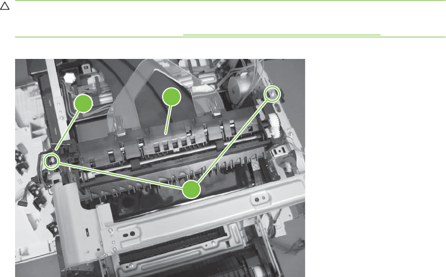
5. Disconnect one connector (callout 7), remove two screws (callout 8), and then carefully lift the
assembly (callout 9) off of the product to remove it.
CAUTION: A solenoid arm (on the right side) and a spring (on the left side) on the assembly are
not captive. Do not lose the solenoid arm or spring when you remove the assembly. If the solenoid
arm or spring become dislodged, see Reinstall the delivery assembly on page 365.
Figure 6-293 Remove the delivery assembly (5 of 5)
79
8
364 Chapter 6 Removal and replacement ENWW
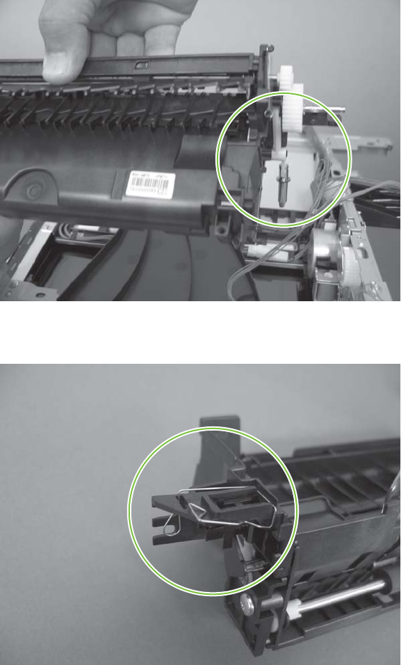
Reinstall the delivery assembly
1. Make sure that the solenoid arm is correctly installed on the assembly.
Figure 6-294 Reinstall the delivery assembly (1 of 2)
2. Make sure that the spring is correctly installed on the assembly.
Figure 6-295 Reinstall the delivery assembly (2 of 2)
ENWW Internal assemblies 365

Duplex-drive assembly
Before proceeding, remove the following components:
●Fuser. See Fuser on page 200.
●Secondary transfer assembly. See Secondary transfer assembly on page 207.
●Intermediate transfer belt. See Intermediate transfer belt (ITB) on page 209
●Front-upper cover. See Front-upper cover on page 225
●Right-rear cover. See Right-rear cover on page 231.
●Left cover. See Left cover on page 233.
●Rear-upper cover. See Rear-upper cover on page 236.
●Rear cover. See Rear cover on page 238.
●Scanner assembly. See Scanner assembly on page 242.
●Front-top cover. See Front-top cover on page 261.
●Rear-top cover. See Rear-top cover on page 262
●Interconnect board (ICB). See Interconnect board (ICB) on page 267.
●DC controller PCA. See DC controller PCA and tray on page 270.
●Low-voltage power supply (LVPS). See Low-voltage power supply (LVPS) on page 273.
●Power-supply fan and fan duct. See Power-supply fan and fan duct on page 300.
●High-voltage power supply lower. See High-voltage power supply lower on page 308.
●High-voltage power supply upper. See High-voltage power supply upper on page 339.
●Main-drive assembly. See Main-drive assembly on page 346.
●Fuser-drive assembly. See Fuser-drive assembly on page 356.
●Delivery assembly. See Delivery assembly on page 361.
366 Chapter 6 Removal and replacement ENWW
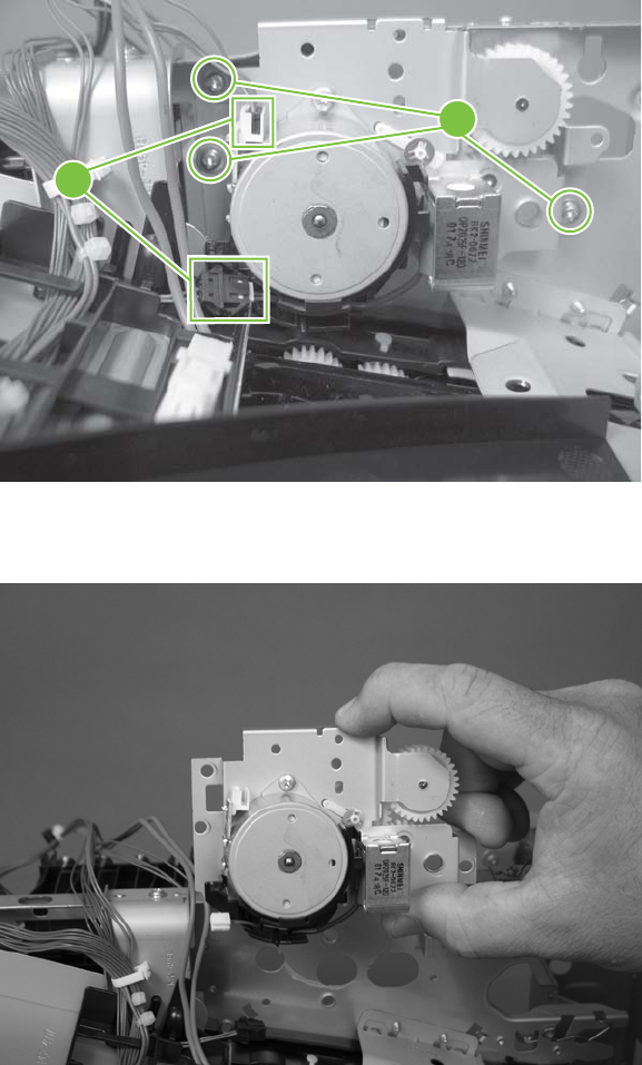
Remove the duplex-drive assembly
1. Disconnect two connectors (callout 1), and then remove three screws (callout 2).
Figure 6-296 Remove the duplex-drive assembly (1 of 2)
2
1
2. Remove the assembly.
Figure 6-297 Remove the duplex-drive assembly (2 of 2)
ENWW Internal assemblies 367
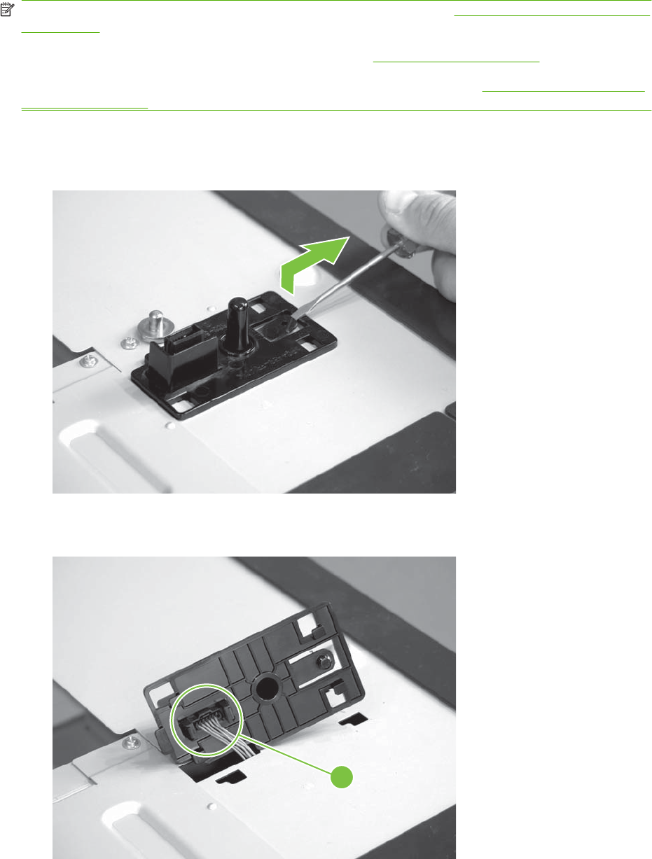
Optional paper feeder assembly (Tray 3)
NOTE: For information about removing the Tray 3 pickup roller, see Pickup and feed rollers (Tray 3)
on page 203.
For information about removing the Tray 3 cassette, see Tray cassette on page 199.
For information about removing the right door (optional paper feeder), see Right door (optional paper
feeder) on page 221
Drawer connector
1. With a small screwdriver, lift one tab and then slide the drawer connector to release.
2. Remove one connector (callout 1).
Figure 6-298 Remove the drawer connector; optional paper feeder
1
368 Chapter 6 Removal and replacement ENWW

7 Solve problems
To use the information in this chapter, you should have a basic understanding of the HP LaserJet printing
process. Explanations of each mechanical assembly, the product systems, and the basic theory of
operation are contained in Theory of operation on page 115. Do not perform any of these troubleshooting
processes unless you understand the function of each product component.
●Solve problems checklist
●Menu map
●Troubleshooting process
●Tools for troubleshooting
●Control-panel messages
●Event log messages
●Clear paper jams
●Solve paper-handling problems
●Use manual print modes
●Solve image-quality problems
●Solve performance problems
●Solve connectivity problems
●Service mode functions
●Solve fax problems
●Solve e-mail problems
ENWW 369

Solve problems checklist
If the product is not responding correctly, complete the steps in the following checklist, in order. If the
product does not pass a step, follow the corresponding troubleshooting suggestions. If a step resolves
the problem, you can stop without performing the other steps on the checklist.
1. Make sure one of the following messages display on the control panel: Ready, Paused, or Sleep
Mode On. If no lights are on or the display does not say Ready, Paused, or Sleep Mode On, see
Power subsystem on page 376.
2. Check the cables.
a. Check the cable connection between the product and the computer or network port. Make
sure that the connection is secure.
b. Make sure that the cable itself is not faulty by using a different cable, if possible.
c. Check the network connection. See Solve connectivity problems on page 501.
3. Ensure that the print media that you are using meets specifications. See Supported paper and print
media on page 56.
4. Print a configuration page. See Configuration pages on page 436. If the product is connected to
a network, an HP Jetdirect page also prints.
a. If the pages do not print, check that at least one tray contains print media.
b. If the page jams in the product, see Clear paper jams on page 472.
5. If the configuration page prints, check the following items.
a. If the page prints correctly, then the product hardware is working. The problem is with the
computer you are using, with the printer driver, or with the program.
b. If the page does not print correctly, the problem is with the product hardware.
6. Does the image quality meet the user's requirements? If yes, go to step 7. If no, check the following
items:
●Print the print-quality (PQ) troubleshooting pages See Print-quality-troubleshooting pages
on page 431 in this chapter.
●Solve the print-quality problems, and then go to step 7.
7. At the computer, check to see if the print queue is stopped, paused, or set to print offline.
Windows: Click Start, click Settings, and then click Printers or Printers and Faxes. Double-click
HP Color LaserJet CM3530.
-or-
Mac OS X: Open Printer Setup Utility, and then double-click the line for the HP Color LaserJet
CM3530.
370 Chapter 7 Solve problems ENWW
8. Verify that you have installed the HP Color LaserJet CM3530 MFP Series printer driver. Check the
program to make sure that you are using the HP Color LaserJet CM3530 MFP Series printer driver.
9. Print a short document from a different program that has worked in the past. If this solution works,
then the problem is with the program you are using. If this solution does not work (the document
does not print) complete these steps:
a. Try printing the job from another computer that has the product software installed.
b. If you connected the product to the network, connect the product directly to a computer with
a USB cable. Redirect the product to the correct port, or reinstall the software, selecting the
new connection type that you are using.
ENWW Solve problems checklist 371
Menu map
The menu map can be an important troubleshooting tool. It shows each control-panel menu and
submenu to aid navigation through the menu system. Print the menu map from the control panel by
completing the following steps.
1. Touch Administration.
2. Touch Information.
3. Touch Configuration/Status Pages.
4. Touch Administration Menu Map.
5. Touch Print.
372 Chapter 7 Solve problems ENWW

Troubleshooting process
Determine the problem source
When the product malfunctions or encounters an unexpected situation, the product control panel alerts
you to the situation. This section contains a pre-troubleshooting checklist to filter out many possible
causes of the problem. A troubleshooting flowchart helps you diagnose the root cause of the problem.
The remainder of this chapter provides steps for correcting problems.
●Use the pre-troubleshooting checklist to evaluate the source of the problem and to reduce the
number of steps that are required to fix the problem.
●Use the troubleshooting flowchart to pinpoint the root cause of hardware malfunctions. The
flowchart guides you to the section of this chapter that contains steps for correcting the malfunction.
Before beginning any troubleshooting procedure, check the following issues:
●Are supply items within their rated life?
●Does the configuration page reveal any configuration errors?
NOTE: The customer is responsible for checking supplies and for using supplies that are in good
condition.
Pre-troubleshooting checklist
The list below describes basic questions to ask the customer to help quickly define the problem.
Table 7-1 Pre-troubleshooting checklist
Environment ●Is the product installed on a solid, level surface?
●Is the product exposed to particle matter or dust?
●Is the power-supply voltage within ± 10 volts of the
specified power source?
●Is the power supply plug inserted in the product and
directly to the wall outlet (not a power strip)?
●Is the operating environment within the specified
parameters, as listed in the appendix of this manual?
●Is the product exposed to ammonia gas, such as that
produced by diazo copiers or office cleaning materials?
●Is the product exposed to direct sunlight?
Media ●Does the customer use only supported media?
●Is the media in good condition (contains no curls, folds,
and so forth)?
●Is the media stored correctly and within environmental
limits?
Input trays ●Is the amount of media in the tray within specifications?
●Is the media correctly placed in the tray?
ENWW Troubleshooting process 373

●Are the paper guides aligned with the stack?
●Is the paper tray correctly installed in the product?
Print cartridges ●Is each print cartridge installed correctly?
●Are original HP print cartridges installed?
●Are the cartridges damaged?
ITB and fuser ●Are the ITB and fuser correctly installed?
●Is the ITB or fuser damaged?
Covers ●Are the top cover and front cover closed?
Condensation ●Does condensation occur following a temperature
change (particularly in winter following cold storage)? If
so, wipe the affected area dry or leave the product on for
10 to 20 minutes.
●Was a print cartridge opened soon after being moved
from a cold to a warm room? If so, allow the product to
sit at room temperature for one to two hours.
Miscellaneous ●Check for and remove any non-HP components (print
cartridges, memory modules, and EIO cards) from the
product.
●Remove the product from the network, and ensure that
the failure is associated with the product before
beginning troubleshooting.
●For any print-quality issues, calibrate the product. See
Calibrate the product on page 430.
Table 7-1 Pre-troubleshooting checklist (continued)
374 Chapter 7 Solve problems ENWW

Troubleshooting flowchart
This flowchart highlights the general processes that you can follow to quickly isolate and solve product
hardware problems.
Each row depicts a major troubleshooting step. A “yes” answer to a question allows you to proceed to
the next major step. A “no” answer indicates that additional testing is needed. Proceed to the appropriate
section in this chapter, and follow the instructions there. After completing the instructions, proceed to
the next major step in this troubleshooting flowchart.
Table 7-2 Troubleshooting flowchart
1
Power on
Is the product on and does a readable
message display?
Follow the power-on troubleshooting checks. See Power
subsystem on page 376.
After the control-panel display is functional, go to step 2.
Yes No
2
Control panel
messages
Does the message Ready display on the
control panel?
If an error message appears, see Control-panel messages
on page 441.
After the errors have been corrected, go to step 3.
Yes No
3
Event log
Open the Troubleshooting menu and print
an event log to see the history of errors with
this product.
Does the event log print?
If the event log does not print, see Print an event log
on page 468.
If paper jams inside the product, see Clear paper jams
on page 472.
If error messages appear on the control-panel display when you try
to print an event log, see Control-panel messages on page 441.
After successfully printing and evaluating the event log, go to step 4.
Yes No
4
Information pages
Open the Information menu and print the
configuration pages to verify that all of the
accessories are installed.
Are all the accessories installed?
If accessories that are installed are not listed on the configuration
page, remove the accessory and reinstall it.
After evaluating the configuration pages, go to step 5.
Yes No
5
Image quality
Does the print quality meet the customer's
requirements?
Compare the images with the sample defects in the image defect
tables. See Image defects table on page 494.
After the print quality is acceptable, go to step 6.
Yes No
6
Interface
Can the customer print successfully from the
host computer?
Verify that all I/O cables are connected correctly and that a valid IP
address is listed on the Jetdirect configuration page.
If error messages display on the control panel, see Control-panel
messages on page 441.
When the customer can print from the host computer, this is the end
of the troubleshooting process.
Yes. This is the end of
the troubleshooting
process.
No
ENWW Troubleshooting process 375

Power subsystem
Power-on checks
The basic product functions should start up when the product is plugged into an electrical outlet and the
power switch is pushed to the on position. If the product does not start, use the information in this section
to isolate and solve the problem.
Power-on troubleshooting overview
Turn on the product power. If the control panel display remains blank, random patterns display, or the
normal initialization display does not appear, perform power-on checks to find the cause of the problem.
Power-on sequence
●00 seconds: power on button LED (+5 VA from LVPS)
●02 seconds: control-panel display with HP logo (check USB cable from ICB, 12 v from formatter)
●04 seconds: output bin LED (+5 v from SCB)
●06 seconds: scanner lamp and initialization (24 v from LVPS)
●10 seconds: ADF initialization (check ADF cable)
●12 seconds: LVPS fan (right rear corner, 24 v from LVPS)
●22 seconds: engine initialization
NOTE: The LVPS includes an over current and over voltage crowbar circuit. If the power supply does
not come on, unplug the power cord, wait five minutes, and then plug the power cord in and try turning
the product on again.
If the fan and main motor are operating correctly, the next troubleshooting step is to isolate print engine,
formatter, and control panel problems. Perform an engine test (see Engine-test button on page 386).
If the formatter is damaged, it might interfere with the engine test. If the engine-test page does not print,
try removing the formatter and then performing the engine test again. If the engine test is then successful,
the problem is almost certainly with the formatter, the control panel, or the cable that connects them.
If the control panel is blank when you turn on the product, check the following items.
1. Make sure that the product is plugged directly into an active electrical outlet (not a power strip) that
delivers the correct voltage.
2. Make sure that the power switch is in the on position.
3. Make sure that the fan runs briefly, which indicates that the power supply is operational.
4. Make sure that the control panel display wire harness is connected.
5. Make sure that the formatter is seated and operating correctly. Turn off the product and remove
the formatter. Reinstall the formatter, and then verify that the heartbeat LED is flashing.
6. Remove any HP Jetdirect or other EIO cards, and then try to turn the product on again.
376 Chapter 7 Solve problems ENWW

NOTE: If the control panel remains blank, lift the control and verify the USB cable is seated. Next,
remove the rear upper cover and check the other end of the control panel USB cable where it connects
to the ICB.
The control panel operates on +12 v which originates on the formatter and is delivered through
connections on the ICB.
The control panel diagnostic mode can be accessed to verify functionality. Touching “+” and “*” together
at any time accesses the diagnostic mode.
ENWW Troubleshooting process 377
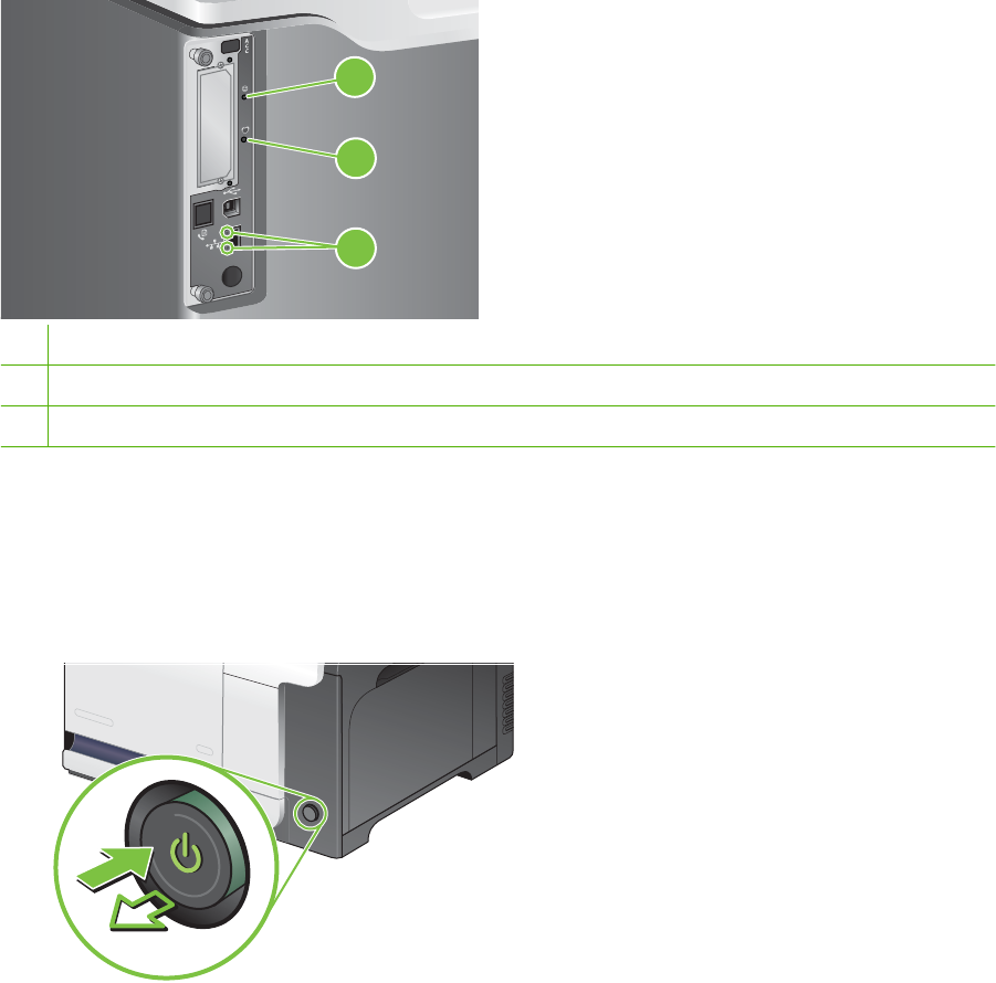
Tools for troubleshooting
The section describes the tools that can help you solve problems with the product.
Individual component diagnostics
LED diagnostics
LED, engine, and individual diagnostics can identify and troubleshoot product problems.
Understand lights on the formatter
Three LEDs on the formatter indicate that the product is functioning correctly.
1
2
3
1Formatter connectivity LED (lit when formatter is correctly seated)
2Heartbeat LED
3HP Jetdirect LEDs
Formatter connectivity LED
The formatter connectivity LED indicates when the formatter is correctly seated in the product. If the
LED is not lit, follow this procedure to correct the problem.
1. Turn the product off.
378 Chapter 7 Solve problems ENWW
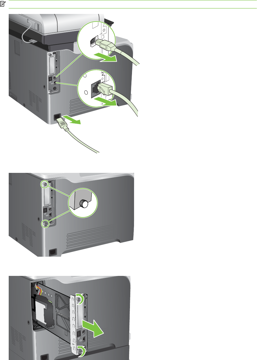
2. Disconnect all power and interface cables.
NOTE: This illustration might not show all the cables.
3. Locate the thumb screws on the formatter in the rear of the product.
4. Unscrew the thumb screws and pull the formatter from the product.
ENWW Tools for troubleshooting 379
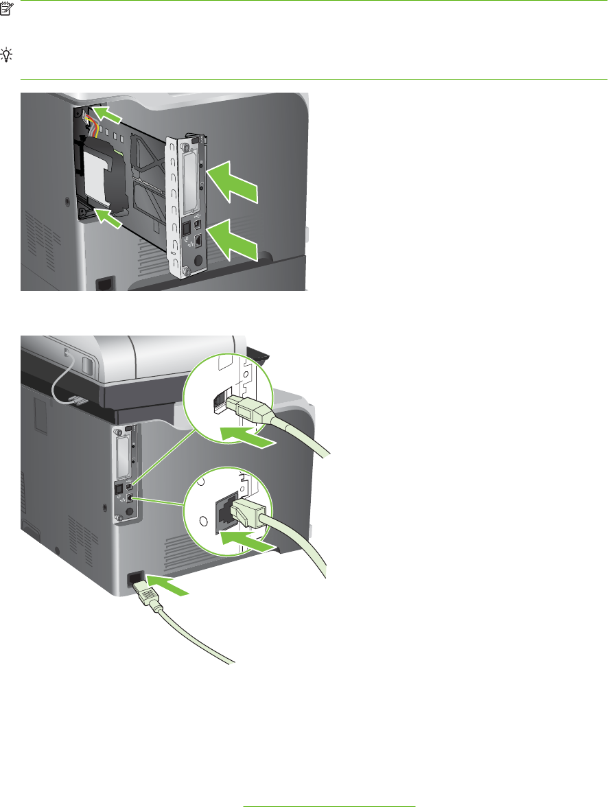
5. Align the formatter in the tracks at the bottom of the slot, and then slide it back into the product.
Push firmly on the right side of the formatter to make sure it is fully inserted.
NOTE: To prevent damage to the formatter, ensure the formatter is aligned in the tracks at the
top and the bottom of the opening.
Reinstallation tip To prevent the formatter from flexing and not fully seating, firmly push in on
the formatter along the edge opposite of the thumb screws.
6. Reconnect the power cable and interface cables, and turn the product on.
Heartbeat LED
The heartbeat LED indicates that the formatter is functioning correctly. While the product is initializing
after you turn it on, the LED blinks rapidly, and then turns off. When the product has finished the
initialization sequence, the heartbeat LED pulses on and off.
If the heartbeat LED is off, the formatter might have a problem. Turn the product off and then on. If the
LED is still off, replace the formatter. See Formatter PCA on page 192.
380 Chapter 7 Solve problems ENWW

HP Jetdirect LEDs
The embedded HP Jetdirect print server has two LEDs. The yellow LED indicates network activity, and
the green LED indicates the link status. A blinking yellow LED indicates network traffic. If the green LED
is off, a link has failed.
For link failures, check all the network cable connections. In addition, you can try to manually configure
the link settings on the embedded print server by using the product control-panel menus.
1. Scroll to and touch Administration.
2. Touch Initial Setup.
3. Touch Networking and I/O.
4. Touch Embedded Jetdirect or EIO <X> Jetdirect.
5. Touch Link Speed.
6. Select the appropriate link speed.
7. Touch Save.
Engine diagnostics
This section provides an overview of the engine diagnostics that are available in the HP Color LaserJet
CM3530 MFP Series product. The product contains extensive internal diagnostics that help in
troubleshooting print quality, paper path, noise, component, and timing issues.
Troubleshooting menu
The Troubleshooting menu allows you to run tests that can help you identify and solve problems with
the product.
Menu item Description
Event Log This shows the event codes and their corresponding engine cycles on the
control-panel display. See Event log messages on page 468.
Calibrate Scanner Use this feature to compensate for offsets in the scanner imaging system
(carriage head) for ADF and flatbed scans. You might need to calibrate the
scanner if it is not capturing the correct sections of scanned documents.
PQ Troubleshooting This item prints a series of eight pages that include instructions, pages for
each color, a demo page, and a configuration page. These pages can help
isolate print-quality problems. See Solve image-quality problems
on page 494.
Fax T.30 Trace Print or configure the fax T.30 trace report. T.30 is the standard that specifies
handshaking, protocols, and error correction between fax machines. See
Solve fax problems on page 507.
Fax Transmit Signal Loss Set loss levels to compensate for phone-line signal loss. Do not modify this
setting unless requested to do so by an HP service representative because
it could cause the fax to stop functioning. See Solve fax problems
on page 507.
Fax V.34 Disable V.34 mode if several fax failures have occurred or if phone line
conditions require it. See Solve fax problems on page 507.
ENWW Tools for troubleshooting 381

Menu item Description
Fax Speaker Mode A technician can use this feature to evaluate and diagnose fax issues by
listening to the sounds of fax modulations. See Solve fax problems
on page 507 .
Diagnostic Page Print a diagnostic page that includes color swatches and the EP parameters
table. See Diagnostics page on page 434.
Disable Cartridge Check This item allows you to remove a print cartridge to help determine which
cartridge is the source of a problem. See Disable cartridge check
on page 385.
Paper Path Sensors This item displays the status of each sensor in the paper path. See Paper-
path sensors test on page 408.
Paper Path Test This item tests the paper handling features of the product, such as the
configuration of the trays. See Paper-path test on page 386.
Manual Sensor Test This item displays the status of each sensor, and allows manual testing of the
sensors. See Manual sensor test (special-mode test) on page 387.
Component Test This item activates individual parts independently to isolate noise, leaking,
and other hardware issues. See Component tests on page 409.
Print/Stop Test This item isolates print-quality faults more accurately by stopping the product
in mid-print cycle. Stopping the product in mid print cycle allows you to see
where the image begins to degrade. It also causes a jam that might need to
be manually removed. A service representative should perform this test. See
Print/Stop test on page 409.
Color Band Test Print a color-band test page to identify arcing in the high-voltage power
supply. See Color-band test on page 440.
Scanner Tests Use this item to diagnose potential problems with the product scanner. See
Troubleshooting menu on page 50.
●Lower-lamp
●ADF read motor
●Sensors
◦ADF empty sensor
◦Top-of-page sensor
◦Register/deskew sensor
◦ADF width sensor
◦ADF jam cover sensor
◦ADF length sensor
◦Flatbed cover sensor
◦Flatbed width sensor
◦Flatbed length sensor
●ADF read motor reverse
●ADF input motor
●ADF duplex solenoid
●ADF input reverse
382 Chapter 7 Solve problems ENWW

Menu item Description
●ADF indicator light
●Flatbed motor
Control Panel Use this item to make sure that the control-panel is functioning. See
Troubleshooting menu on page 50.
●test control-panel LEDs by turning them on and off
●display a test pattern on the display (if the test pattern does not display
the control panel is not correctly functioning)
●test the functionality of the control-panel buttons
●display a test grid on the touch screen (touch each section of the grid to
verify touch screen sensitivity)
PTT test mode Manufacturing test only. Not a service test.
ENWW Tools for troubleshooting 383
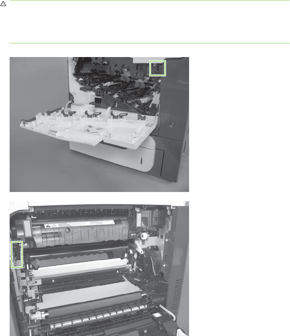
Defeating interlocks
Different tests can be used to isolate different types of issues. For component or noise isolation, you
can run the diagnostic test after removing the covers for a better view of the areas that are being tested.
To operate the product with the covers removed, the door-switch levers (SW1, callout 1) must be
depressed (this is the door-closed position) with a folded piece of paper.
WARNING! Be careful when performing product diagnostics to avoid the risk of injury. Only trained
service personnel should open and run the diagnostics with the covers removed or with the door switch
levers depressed. Never touch any of the power supplies when the product is turned on.
WARNING! If the front- or right-door switch levers are depressed, the laser/scanners can be activated
while a door is open.
Figure 7-1 Front-door interlock
Figure 7-2 Right-door interlock
384 Chapter 7 Solve problems ENWW

NOTE: Anytime that a cartridge is installed or removed while the covers are removed, the door
interlock must be manually cycled to simulate opening and closing the top cover in order for the engine
to recognize the change. When the covers are installed, the door switch and fuser interlock are
automatically operated.
Disable cartridge check
Use this diagnostic test to print internal pages or send an external job to the product when one or more
print cartridges or image drum pairs are removed or exchanged. While the product is in this diagnostics
mode, consumable supply errors are ignored, and you can navigate the menus. This test can be used
to isolate problems, such as noise, and to isolate print-quality problems that are related to individual
print cartridges.
NOTE: Do not remove or exchange print cartridges until after you start the disable cartridge check
diagnostic.
NOTE: Anytime a print cartridge is installed or removed while the covers are removed, the front door
interlock must be manually cycled to simulate opening and closing the front door in order for the engine
to recognize the change. When the covers are installed, the front-door switch is automatically operated.
1. Touch Administration.
2. Scroll to and touch Troubleshooting.
3. Touch Disable Cartridge Check.
ENWW Tools for troubleshooting 385
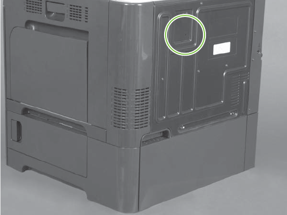
Engine-test button
To verify that the product engine is functioning, print an engine-test page. Use a small pointed object to
depress the test-page switch located on the back of the product. The test page should have a series of
horizontal lines. The test page can use only Tray 2 as the paper source, so make sure that paper is
loaded in Tray 2.
Figure 7-3 Engine-test button
Paper-path test
This diagnostic test generates one or more test pages that you can use to isolate the cause of jams.
To isolate a problem, specify which input tray to use, specify whether to use the duplex path, and specify
the number of copies to print. Multiple copies can be printed to help isolate intermittent problems. The
following options become available after you open the diagnostic feature:
●Print Test Page. Run the paper-path test from the default settings: Tray 2, no duplex, and one copy.
To specify other settings, scroll down the menu and select the setting, and then scroll back up and
select Print Test Page to start the test.
●Source. Select Tray 1, Tray 2, or the optional trays.
●Duplex. Enable or disable 2-sided printing.
●Copies. Set the number of copies to be printed; the choices are 1,10, 50, 100, or 500.
1. Touch Administration.
2. Scroll to and touch Troubleshooting.
3. Touch Paper Path Test.
4. Select the paper-path test options for the test you want to run.
386 Chapter 7 Solve problems ENWW

Manual sensor test (special-mode test)
Use this diagnostic test to test the product sensors and switches. Each sensor is represented by a letter
and number on the control panel display. Following is the default state of the sensors when the test is
accessed (J is not used on this product).
●A1 B1 C1 D1 E0 F0 G0 H1 I0 K0 L1 M0 N1 O0 P0 Q0 R0 S0 T0 U0
NOTE: For the K right and front door interlock switches test: Sensor K displays as 0 when both the
front and side doors are closed. When either door is opened, sensor K displays as 1.
There is only one interlock switch for both doors. If sensor K displays as 1, check both door actuators.
If the actuators are not damaged, check connector J118 on the DC controller.
TIP: If a sensor test fails and the solution is to replace an assembly, try the following. Before you
replace the entire assembly, try replacing the failed sensor with the sensor from a replacement
assembly. If the problem persists, replace the indicated assembly.
1. Touch Administration.
2. Scroll to and touch Troubleshooting.
3. Scroll to and touch Manual Sensor Test.
4. To exit this test, touch Exit on the touchscreen.
Table 7-3 Manual sensor diagnostic tests
Sensor or switch name Sensor or switch number
Top (A) SR8
Loop 1 (B) SR14
Loop 2 (C) SR15
Fuser delivery (D) SR5
Duplex re-feed (E) SR22
Output bin full (F) SR6
Developing home position sensor (G) SR11
Fuser pressure release sensor (H) SR7
ITB alienation sensor (I) SR17
Front and side door switchs (K) SW1, SW2
Tray 1 (L) SR9
Tray 2 paper present (M) SR3
Tray 2 installed (N) SR4
Tray 2 lift motor (O) SR1
Tray 3 paper present (P) SR3
Tray 3 feed (Q) SR4
Tray 3 installed (R) SR1
Tray 3 size (bottom) button (S) SW1
ENWW Tools for troubleshooting 387

Sensor or switch name Sensor or switch number
Tray 3 (middle) button (T) SW1
Tray 3 (top) button (U) SW1
Table 7-3 Manual sensor diagnostic tests (continued)
388 Chapter 7 Solve problems ENWW
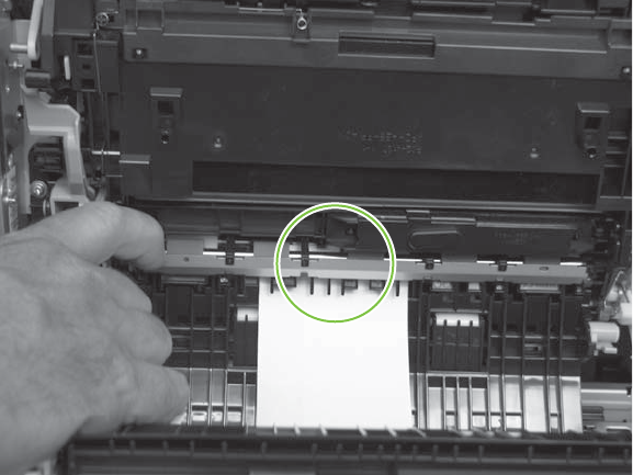
A TOP (top of page) sensor
1. Open the right door.
2. Lower the secondary transfer assembly.
3. Open the registration shutter.
4. Insert a piece of paper to activate the TOP sensor.
Figure 7-4 Test the TOP sensor
5. Check the control-panel display for sensor response.
6. If no response, replace the registration assembly.
ENWW Tools for troubleshooting 389

B and C loop sensors
1. Open the right door.
2. Lower the secondary transfer assembly.
3. Slowly insert a piece of paper to activate the B and C loop sensors underneath the fuser.
Figure 7-5 Test the loop sensors
4. Check the control-panel display for a sensor response.
5. If there is no response, replace fuser. See Fuser on page 200.
390 Chapter 7 Solve problems ENWW
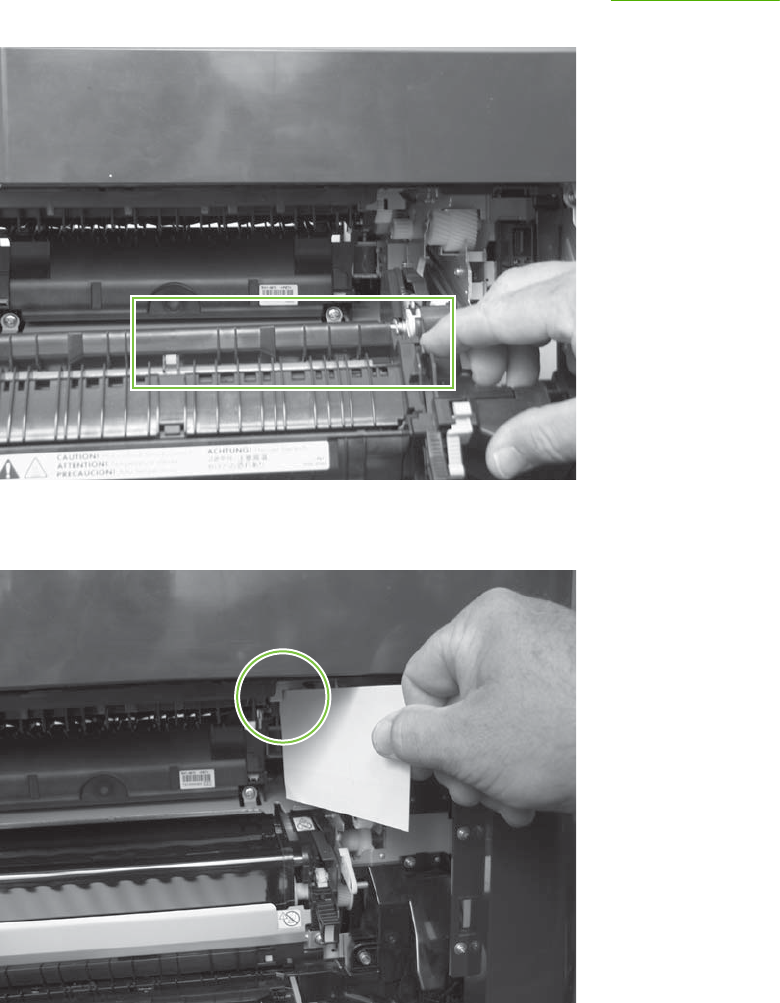
D fuser (fixing) delivery sensor
1. Open the right door.
2. Lower the secondary transfer assembly.
3. Remove the fuser assembly, and then verify that the sensor flag on the fuser assembly moves
freely. If the sensor flag does not move freely, replace the fuser. See Fuser on page 200.
Figure 7-6 Test the fuser delivery sensor (1 of 2)
4. Insert a piece of paper to activate the fuser (fixing) delivery sensor.
Figure 7-7 Test the fuser (fixing) delivery sensor (2 of 2)
5. Check the control-panel display for a sensor response.
6. If there is no response, replace the fuser (fixing) delivery sensor.
ENWW Tools for troubleshooting 391
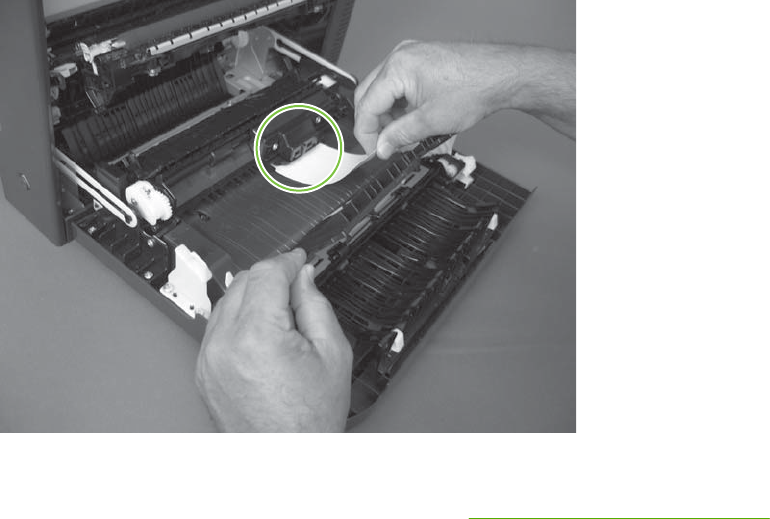
E duplex re-pickup sensor
1. Open the right door.
2. Use the green handle to lift the duplex jam cover.
3. Insert a piece of paper to activate the duplex re-pickup sensor (8492).
Figure 7-8 Test the duplex re-pickup sensor
4. Check the control-panel display for sensor response.
5. If no response, replace the right door assembly. See Right-door assembly on page 227.
392 Chapter 7 Solve problems ENWW
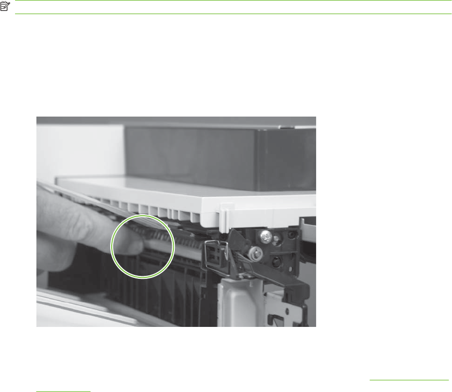
F output bin full sensor
NOTE: Upper-front cover has been removed for clarity.
1. Open the right door.
2. Lower the secondary transfer assembly.
3. Remove the fuser.
4. Move the output-bin full sensor flag.
Figure 7-9 Test the output-bin-full sensor
5. Check the control-panel display for sensor response.
6. If no response, remove the control panel and verify that the flag is moving. If not, replace the delivery
assembly. If the sensor is malfunctioning, replace the delivery assembly. See Delivery assembly
on page 361.
ENWW Tools for troubleshooting 393

G developing home-position sensor
The normal status of sensor G is 0. Testing the sensor requires the following steps:
1. Turn off the product and then remove the formatter and left side cover.
2. Reinstall the formatter and turn on the product. Resume the manual sensor test.
3. Disconnect the 3-pin connector to the right of the power cord connection. Sensor G should change
to 1.
4. Reconnect the connector. Sensor G should change to 0.
5. If sensor G does not change, replace the main drive assembly. See Main-drive assembly
on page 346.
394 Chapter 7 Solve problems ENWW
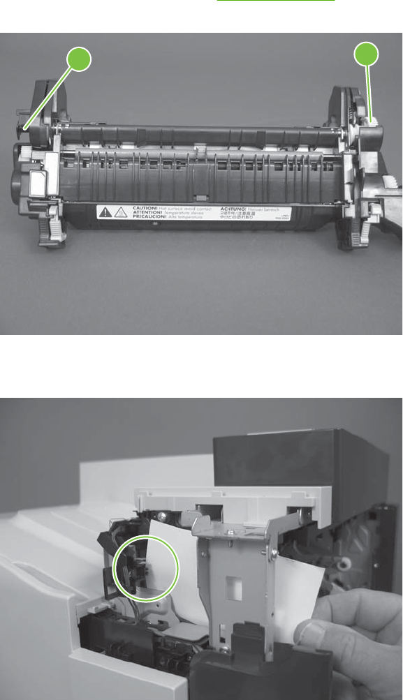
H fuser (fixing) pressure-release sensor
1. Open the right door.
2. Lower the secondary transfer assembly.
3. Remove the fuser, and then rotate the gear (callout 1) to move the flag (callout 2). If the flag does
not actuate, replace the fuser. See Fuser on page 200.
Figure 7-10 Test the fuser (fixing) pressure-release sensor (1 of 2)
21
4. Insert a piece of paper to activate the fuser (fixing) pressure-release sensor.
Figure 7-11 Test the fuser (fixing) pressure-release sensor (2 of 2)
5. Check the control-panel display for sensor response.
6. If there is no response, replace fuser (fixing) pressure-release sensor.
ENWW Tools for troubleshooting 395
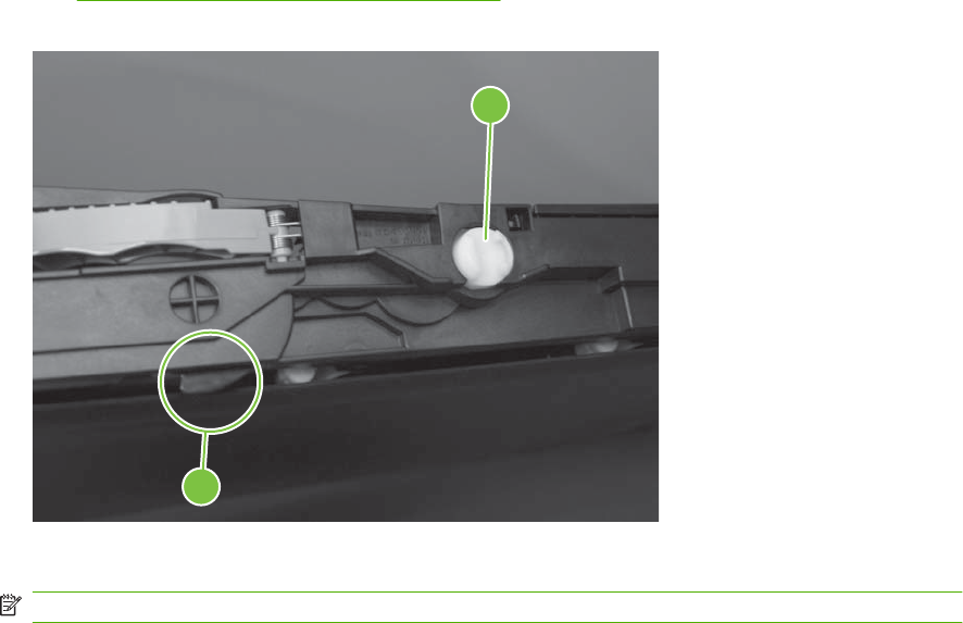
I primary transfer-roller disengagement sensor
1. Open the right door.
2. Lower the secondary transfer assembly.
3. Remove the ITB.
4. Rotate the gear (callout 1) to move the flag (callout 2). If the flag does not actuate, replace the ITB.
See Intermediate transfer belt (ITB) on page 209.
Figure 7-12 Test the primary transfer-roller disengagement sensor (1 of 2)
1
2
5. Remove all print cartridges.
NOTE: Cover all removed print cartridges with paper.
6. Locate the sensor behind the cyan OPC drum position.
396 Chapter 7 Solve problems ENWW
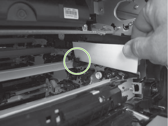
7. Insert a piece of paper to activate the primary transfer-roller disengagement sensor.
Figure 7-13 Test the primary transfer-roller disengagement sensor (2 of 2)
8. Check the control-panel display for sensor response.
9. If no response, replace the sensor.
ENWW Tools for troubleshooting 397
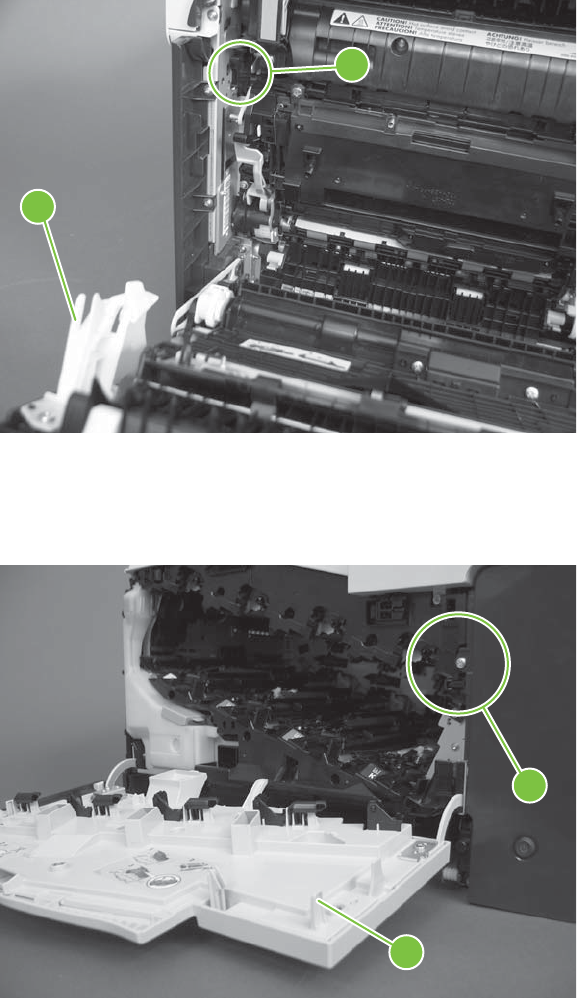
K right and front door interlock switches
1. Open the right door (callout 1) to disengage the right-door switch (callout 2).
Figure 7-14 Test the right- and front-door interlock switches (1 of 4)
2
1
2. Close the right door and check the control panel on the product for sensor response.
3. Open the front door (callout 3) to disengage the front-door switch (callout 4).
Figure 7-15 Test the right- and front-door interlock switches (2 of 4)
3
4
4. Close the front door and check the control panel on the product for sensor response.
5. If either interlock switch failed to respond, remove the upper-front cover and right-front cover. By
removing the right-front cover, you can tell if the linkages are properly closing the switches.
398 Chapter 7 Solve problems ENWW
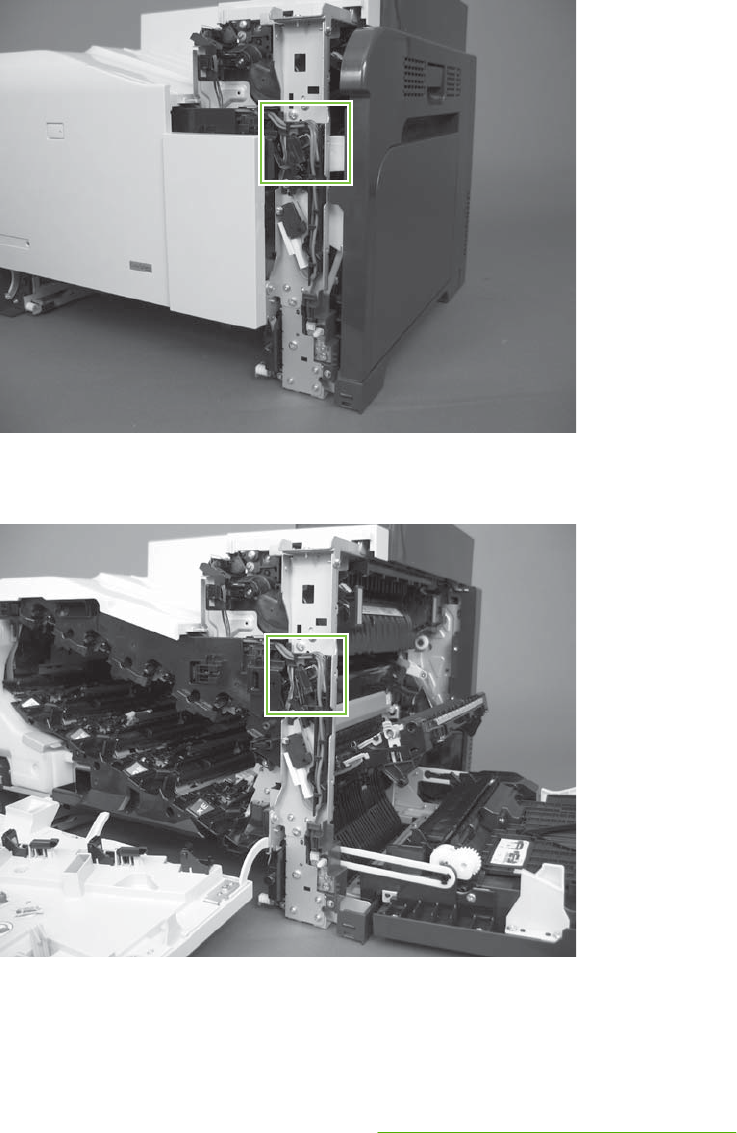
6. Close the right door and front door to verify that the switches close.
Figure 7-16 Test the right- and front-door interlock switches (3 of 4)
7. Open the right door and front door to verify that the switches open.
Figure 7-17 Test the right- and front-door interlock switches (4 of 4)
8. If the switches do not close, check the connectors on the DC controller PCA.
9. If the switches are opening/closing correctly when either door is open or closed, then check J118
on the DC controller.
10. If the connectors are securely connected to the DC controller PCA and the switches still do not
close, replace the DC controller PCA. See DC controller PCA and tray on page 270.
ENWW Tools for troubleshooting 399
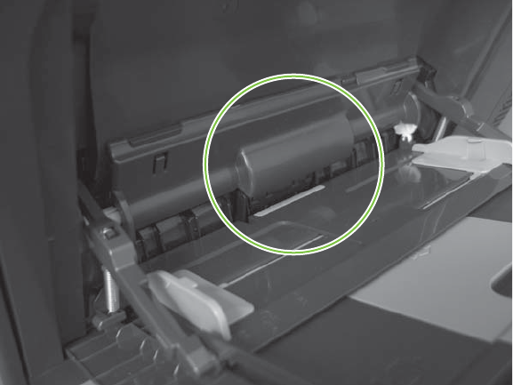
L Tray 1 media present sensor
1. Open Tray 1.
2. Move the Tray 1 media-present sensor flag.
Figure 7-18 Test the Tray 1 media-present sensor
3. Check the control-panel display for sensor response.
4. If no response, replace Tray 1.
400 Chapter 7 Solve problems ENWW
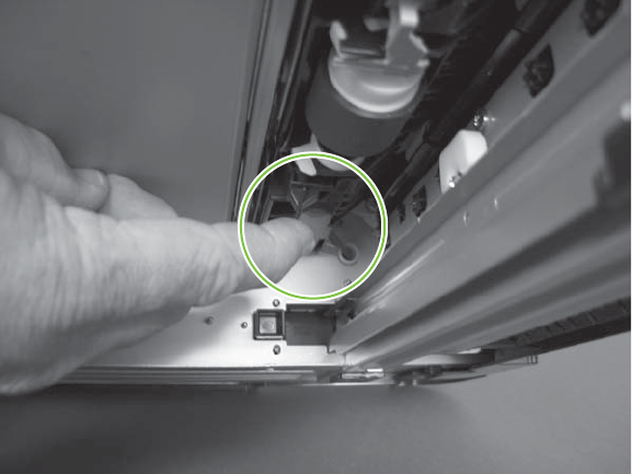
M Tray 2 paper out sensor
1. Remove Tray 2.
2. Move the tray 2 paper-out sensor flag.
Figure 7-19 Test the tray 2 paper-out sensor
3. Check the control-panel display for sensor response.
4. If there is no response, replace the tray 2 paper-out sensor.
ENWW Tools for troubleshooting 401
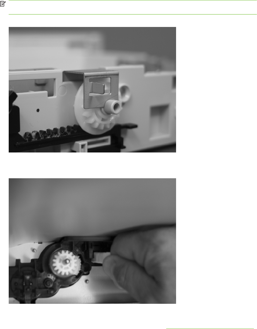
N Tray 2 closed sensor
1. Remove Tray 2.
NOTE: The Tray 2 closed sensor flag is on the back of Tray 2. Inspect the flag to verify that it is
aligned correctly. If it is bent upward, it might miss the sensor when installed.
Figure 7-20 Test the Tray 2 closed sensor (1 of 2)
2. Insert a piece of paper in the Tray 2 closed sensor.
Figure 7-21 Test the Tray 2 closed sensor (2 of 2)
3. Check the control-panel display for sensor response.
4. If there is no response, replace the lifter-drive assembly. See Lifter-drive assembly on page 314.
402 Chapter 7 Solve problems ENWW
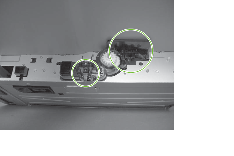
O Tray 2 stack-surface sensor
1. Remove Tray 2.
2. Move the Tray 2 stack-surface sensor flag.
Figure 7-22 Test the Tray 2 stack-surface sensor
3. Check the control-panel display for sensor response.
4. If no response, replace the lifter-drive assembly. See Lifter-drive assembly on page 314.
ENWW Tools for troubleshooting 403
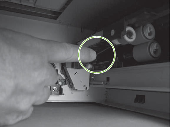
P optional Tray 3-empty sensor
1. Remove the optional Tray 3 cassette.
2. Move the optional Tray 3-empty sensor flag.
Figure 7-23 Test the optional Tray 3-empty sensor
3. Check the control-panel display for sensor response.
4. If no response, replace the optional Tray 3.
404 Chapter 7 Solve problems ENWW
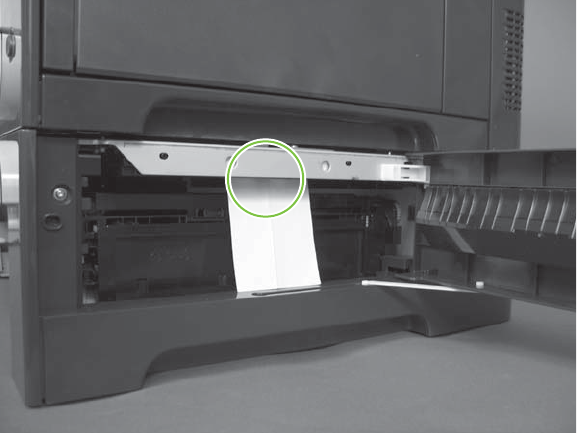
Q optional Tray 3 media-feed sensor (Q)
1. Open the right door on optional Tray 3.
2. Insert a piece of paper to activate the optional Tray 3 media-feed sensor
Figure 7-24 Test the optional Tray 3 media-feed sensor
3. Check the control-panel display for sensor response.
4. If there is no response, replace the optional Tray 3.
ENWW Tools for troubleshooting 405
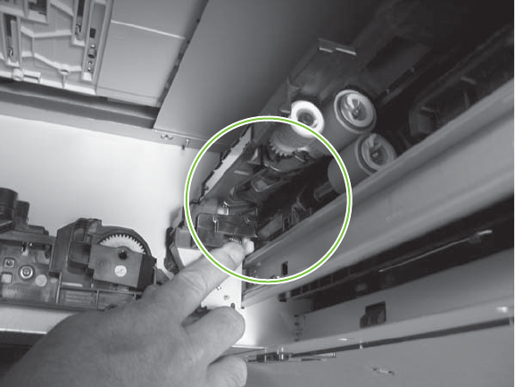
R optional Tray 3 stack-surface sensor (R)
1. Remove the optional Tray 3 cassette.
2. Push the lever to activate the sensor arms.
Figure 7-25 Test the optional Tray 3 stack-surface sensor
3. If there is no response, replace the optional Tray 3.
406 Chapter 7 Solve problems ENWW
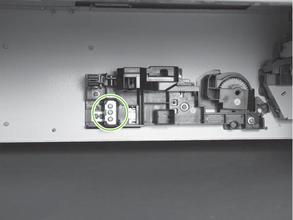
S, T, and U optional Tray 3 media-size sensors
1. Push any of the three buttons to see if the control panel changes for sensors S, T or U.
●S: top button on size switch
●T: middle button on size switch
●U: bottom button on size switch
Figure 7-26 Test the optional Tray 3 media-size sensors
2. If any of the tests fail, replace the 500-sheet feeder
ENWW Tools for troubleshooting 407

Paper-path sensors test
This test displays the status of each paper-path sensor and allows viewing of sensor status while printing
internal pages.
1. Touch Administration.
2. Scroll to and touch Troubleshooting.
3. Touch Paper Path Test.
4. Select the paper-path test options for the test you want to run.
NOTE: The default state of the sensors when first entering the test is shown below. Sensor J is not
used on this product.
A1 B1 C1 D1 E0 F0 G0 H1 I0 K0 L1 M0 N1 O0 P0 Q0 R0 S0 T0 U0
Table 7-4 Paper-path sensors diagnostic tests
Sensor name Sensor number
TOP (A) SR8
Loop 1 (B) SR14
Loop 2 (C) SR15
Fusing delivery (D) SR5
Duplex re-feed (E) SR22
Output bin full (F) SR6
Developing home position sensor (G) SR11
Fuser pressure release sensor (H) SR7
Alienation sensor (I) SR17
Front and side door switches (K) SW1, SW2
MP Tray 1 (L) SR21
Tray 2 paper present (M) SR20
Tray 2 installed (N) SR13
Tray 2 lift motor (O) SR9
Tray 3 paper present (P) SR3
Tray 3 feed (Q) SR4
Tray 3 installed (R) SR1
Tray 3 size (bottom) button (S)
Tray 3 (middle) button (T)
Tray 3 (top) button (U)
408 Chapter 7 Solve problems ENWW

Print/Stop test
Use this diagnostic test to isolate the cause of problems such as image-formation defects and jams in
the engine. During this test you can stop the paper anywhere along the product-paper path. The test
can be programmed to stop printing internal pages or an external print job when the paper reaches a
certain position. The test can also be programmed to stop from 0 to 60,000 mS. If the timer is set to a
value that is greater than the job-print time, you can recover the product in one of two ways.
1. Touch Administration.
2. Scroll to and touch Troubleshooting.
3. Scroll to and touch Print/Stop Test.
4. Select the number of milliseconds and then touch OK.
Component tests
Component test (special mode test)
This test activates individual parts independently to isolate problems.
Each component test can be performed once or repeatedly. If you select CONTINUOUS from the drop-
down menu as the repeat option, the test cycles the component on and off. This process continues for
two minutes, and then the test ends.
NOTE: The door interlock switch must be defeated to run any of the component tests. If covers are
removed, the door switch must be manually cycled during some tests in order for the engine to recognize
a change. Print cartridges can be installed or removed during certain tests. The control-panel display
prompts you to remove some or all cartridges during certain tests to rotate and isolate certain
components, and to protect the cartridges and ITB.
1. Touch Administration.
2. Scroll to and touch Troubleshooting.
3. Touch Component Test.
4. Select the component test options for the test you want to run.
Table 7-5 Component test details
Component test Motor or solenoid number Comments
TRANSFER MOTOR M5
BELT ONLY M10 Rotates the transfer belt.
CARTRIDGE MOTOR ●M3: yellow
●M4: magenta and cyan
●M5: black
Activates three drum motors at a
specified speed for 10 seconds.
BLACK LASER SCANNER M8 Activates the black/cyan scanner motor
for 10 seconds.
CYAN LASER SCANNER M8 Activates the black/cyan scanner motor
for 10 seconds.
MAGENTA LASER SCANNER M9 Activates the yellow/magenta scanner
motor for 10 seconds.
ENWW Tools for troubleshooting 409

Component test Motor or solenoid number Comments
YELLOW LASER SCANNER M9 Activates the yellow/magenta scanner
motor for 10 seconds.
FUSER MOTOR M2 Activate the fuser motor at a specified
speed for 10 seconds.
FUSER PRESSURE RELEASE
MOTOR
M2 reverse Reverses the fuser motor and
pressurizes or depressurizes the
pressure release motor.
ALIENATION MOTOR M10 Disengages the developer from the
primary charge roller.
ITB CONTACT ALIENATION MOTOR M2 Activates the ITB drive motor at a
specified speed for 10 seconds.
TCU MOTOR M12 Activates the motor at a specified speed
for 10 seconds.
TRAY 1 PICKUP SOLENOID SL3 Activates the solenoid for 10 seconds.
TRAY 2 PICKUP MOTOR M13 Activates the motor at a specified speed
for 10 seconds.
TRAY 2 PICKUP SOLENOID SL4 Activates the solenoid for 10 seconds.
TRAY 3 PICKUP MOTOR M1 Activates the motor at a specified speed
for 10 seconds.
TRAY 3 PICKUP SOLENOID SL1 Activates the solenoid for 10 seconds.
DUPLEX PICKUP MOTOR M11 Activates the motor at a specified speed
for 10 seconds.
DUPLEX REFEED CLUTCH
SOLENOID
CL1, SL2 Activates the clutch for 10 seconds.
Table 7-5 Component test details (continued)
410 Chapter 7 Solve problems ENWW
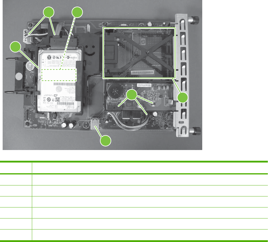
Diagrams
Formatter PCA
Figure 7-27 Formatter PCA
3
1
5
6
2
4
Table 7-6 Formatter PCA
Item Description
1Hard drive
2Hard drive cable
3DIMM slot (under the hard drive)
4Fax card and cable
5EIO slot
6Internal USB ports
ENWW Tools for troubleshooting 411

Location of connectors
DC controller PCA
Figure 7-28 DC controller PCA
J126
Table 7-7 DC controller connectors
J100: 24 v from low-voltage power
supply (LVPS) and interlock
J114: HVPS lower J126: memory tag connector
J101: LVPS J115: fuser sensors J127: pre-exposure LEDs (rear), SR17,
SL1
J105: interconnect board (ICB) J116: HVPS upper J130: registration density (RD) sensors
(front and rear)
J106: 500-sheet feeder, developing
home position, laser motors
J117: fuser motor J131: pickup motor
J107: duplex sensor, tray 1 solenoid,
paper present sensor
J118: 5 v interlock J133: not used
J108: environmental sensor J119: LVPS fan J134: not used
J109: duplex clutch, overhead
transparency (OHT) in, top-of-page
sensor
J120: drum motor 1 and drum motor 2 J137: toner collection unit (TCU) full,
TCU motor, toner level detection
J110: YM laser J121: drum motor 3, drum position 1,2,3 J138: 24 v to HVPS lower
J111: CK laser J122: OHT out J139: fuser sensors
J112: pre-exposure LEDs (front) J123: pressure release, bin full, fuser
delivery
J140: lift motor, tray present, stack
surface
J113: 24 v to high-voltage power supply
(HVPS) upper
J124: 24 v to scanner-control board
(SCB)
J143: 24 v present from LVPS
412 Chapter 7 Solve problems ENWW
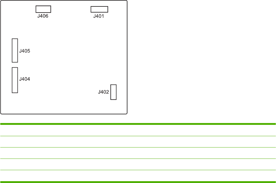
Paper feeder driver PCA
Figure 7-29 Paper feeder driver PCA
Table 7-8 Paper feeder driver PCA connectors
J401: engine connector
J402: not used
J404: SW1, SW2, lifter motor
J405: SR1, SR2, SR3, SR4, SL1
J406: feed motor
ENWW Tools for troubleshooting 413
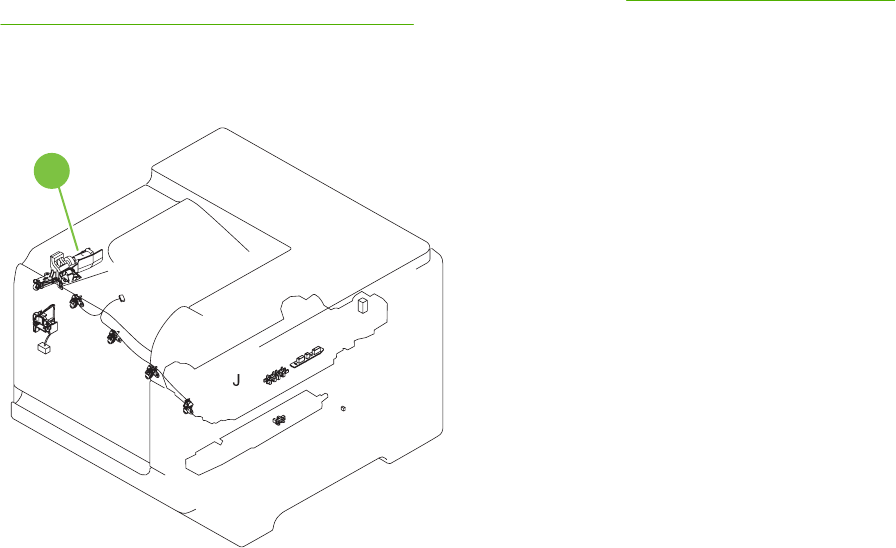
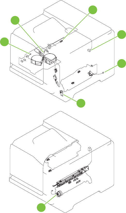
Figure 7-31 Component locations (2 of 5)
2
3
4
5
6
7
8
ENWW Tools for troubleshooting 415
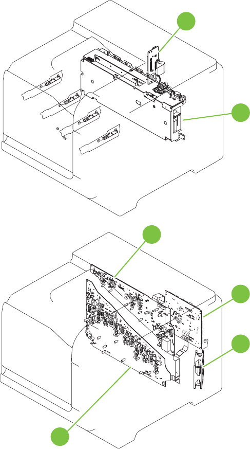
Figure 7-32 Component locations (3 of 5)
10
9
11
12
13
14
416 Chapter 7 Solve problems ENWW
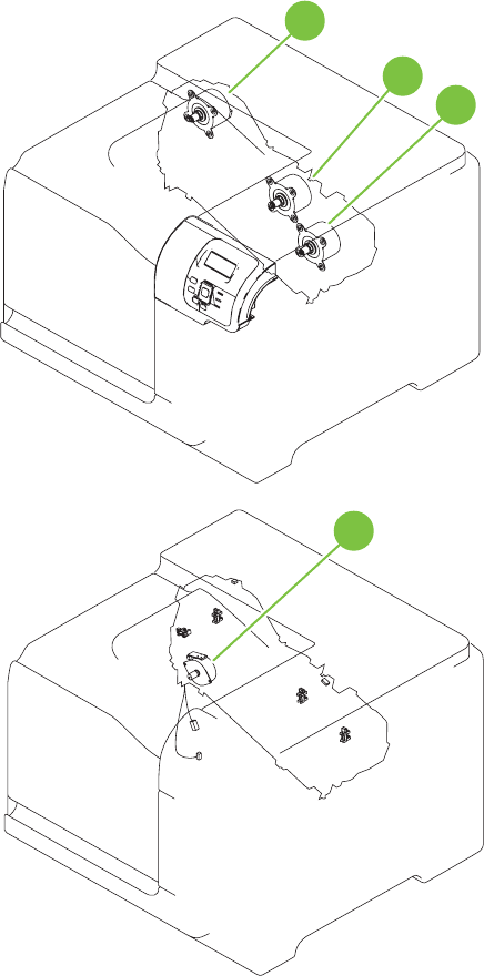
Figure 7-33 Component locations (4 of 5)
16 17
15
18
ENWW Tools for troubleshooting 417
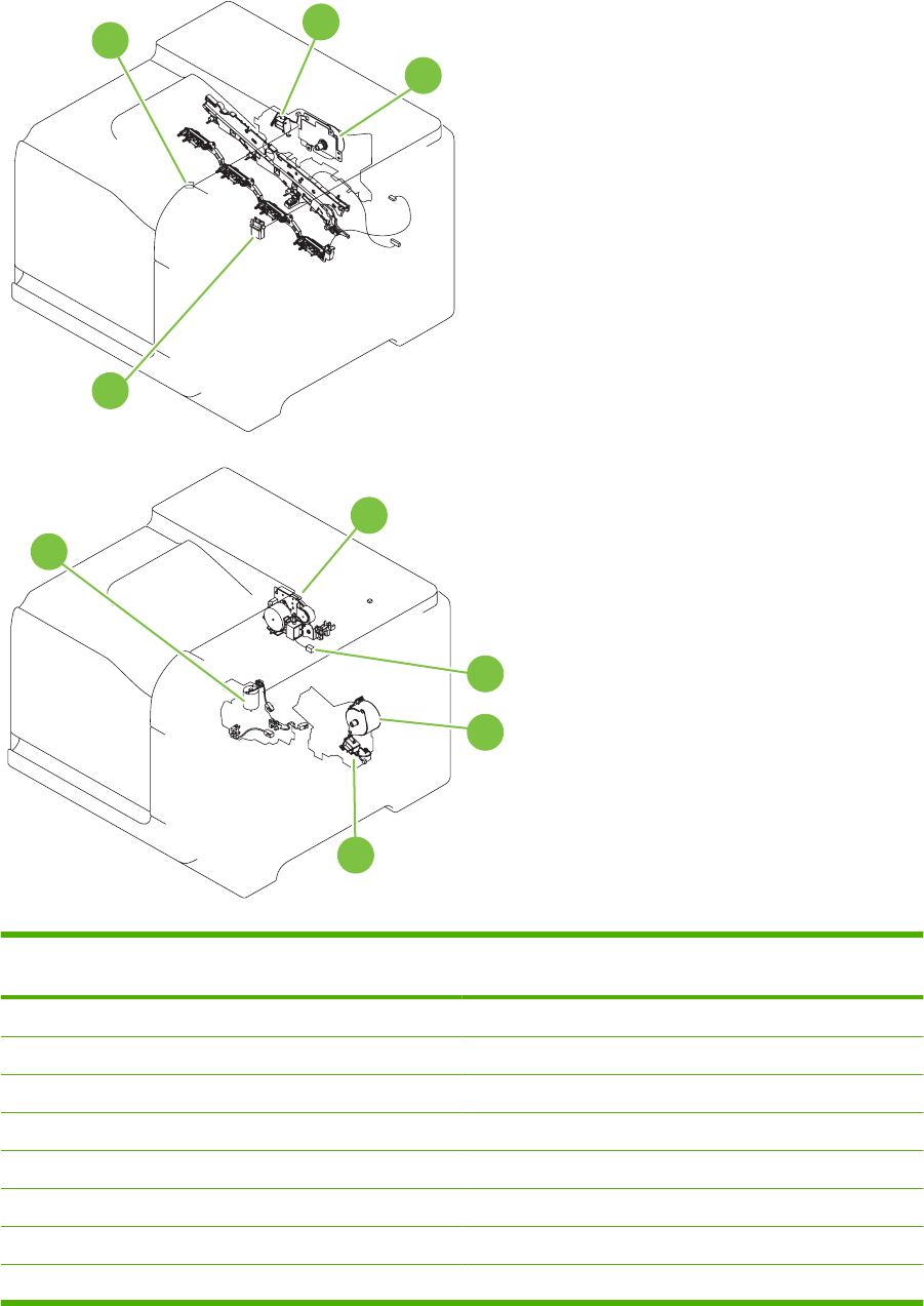
Figure 7-34 Component locations (5 of 5)
22 19
20
21
23
24
25
26
27
Table 7-9 PCAs, motors, fans, switches, solenoids, and clutches
Location Connector Component
abbreviation
Component name
1J89 M12 Residual toner-feed motor
2J26 FM2 Cartridge fan
3J27 FM3 Delivery fan
4J62 SW3 24V interlock switch
5J118 SW1, SW2 5V interlock switch
6J84 SL3 Multipurpose-tray pickup solenoid
7J780 SW4 Power switch
8 J86 CL1 Duplex re-pick clutch
418 Chapter 7 Solve problems ENWW

Location Connector Component
abbreviation
Component name
9 ICB Interconnect board (ICB)
10 LVPS Low-voltage power supply
11 HVPS (t) HVPS-T upper
12 DCC DC Controller
13 J119 FM1 Power-supply fan
14 HVPS (d) HVPS-D (lower)
15 J41 M3 Drum motor 1
16 J40 M4 Drum motor 2
17 J42 M5 Drum motor 3
18 J25 M10 Development-disengagement motor
19 J8 SL1 Primary transfer roller disengagement solenoid
20 J15 M2 Fuser motor
21 J55 M9 Yellow/magenta scanner motor
22 J56 M8 Cyan/black scanner motor
23 J20 M11 Duplex reverse motor
24 J21 SL2 Duplex reverse solenoid
25 J6 M13 Pickup motor
26 J83 SL4 Cassette-pickup solenoid
27 J79 M7 Tray 2 lifter motor
Table 7-9 PCAs, motors, fans, switches, solenoids, and clutches (continued)
ENWW Tools for troubleshooting 419
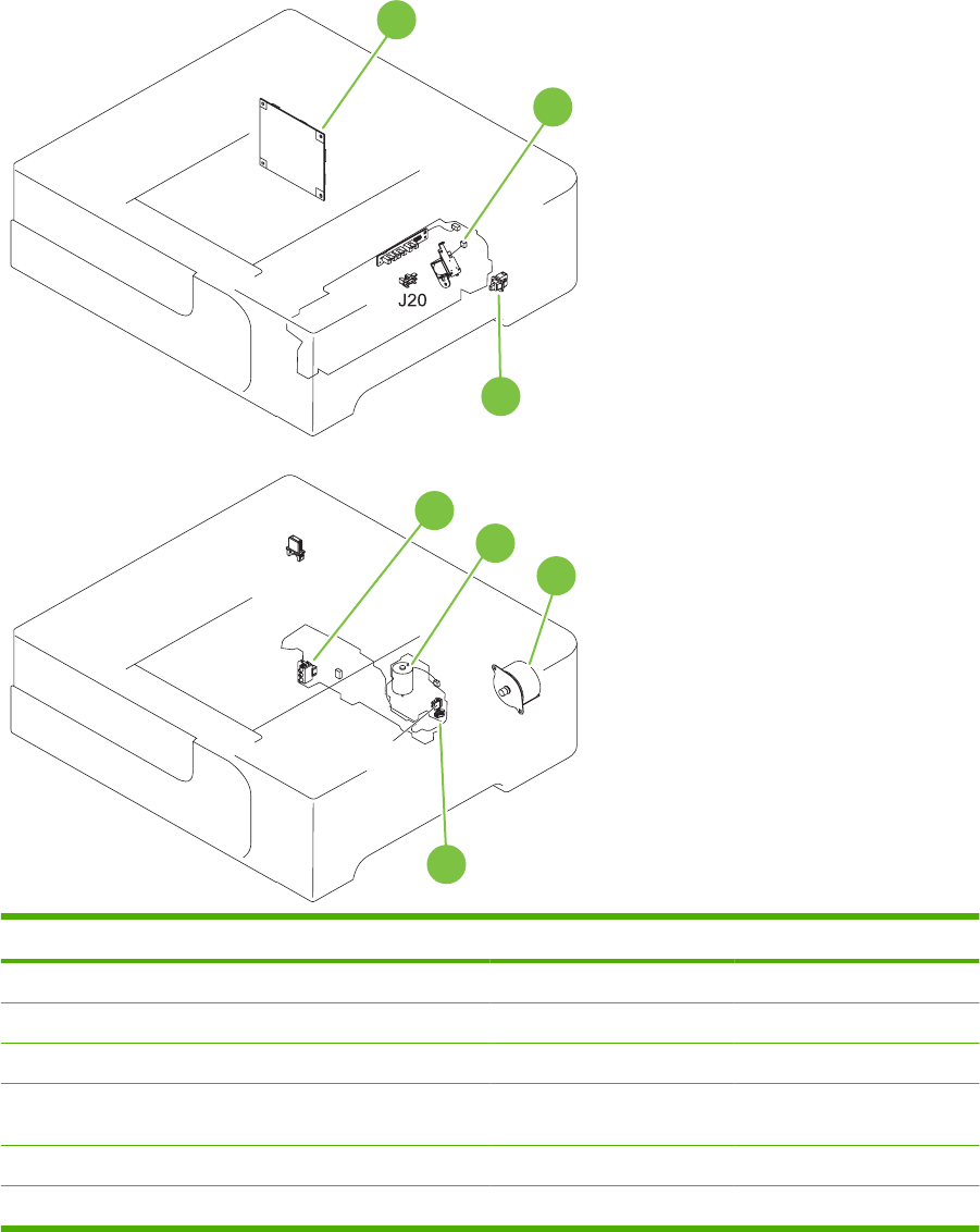
1 x 500 paper feeder
Figure 7-35 1 x 500 paper feeder
28
29
31
30
32
34
33
Location Connector Component abbreviation Component name
28 PF PCA Paper-feeder driver PCA
29, 34 J18 SL1 Paper-feeder pickup solenoid
30 J21 SW2 Paper-feeder door switch
31 J16 SW1 Paper feeder cassette media
size switch
32 J15 M2 Paper-feeder lifter motor
33 J14 M1 Paper-feeder motor
420 Chapter 7 Solve problems ENWW
Sensors
Figure 7-36 Sensors
Table 7-10 Sensors
Component abbreviation Component name
SR1 Tray 3 paper surface sensor 1
SR2 Tray 3 paper surface sensor 2
SR3 Tray 3 paper sensor
SR4 Tray 3 feed sensor
SR5 Fuser (fixing) output sensor
SR6 Output bin full sensor
SR7 Fuser (fixing) pressure release sensor
SR8 TOP sensor
ENWW Tools for troubleshooting 421

Component abbreviation Component name
SR9 Tray 2 lift sensor
SR11 Developing home position sensor
SR13 Cassette presence sensor
SR14 Loop sensor 1
SR15 Loop sensor 2
SR17 ITB disengagement sensor
SR20 Cassette-media presence sensor
SR21 MP-tray-media-presence sensor
SR22 Duplex re-pickup sensor
Table 7-10 Sensors (continued)
422 Chapter 7 Solve problems ENWW

General timing chart
Figure 7-37 General timing chart
Timing chart is two consecutive print jobs on letter-size paper (full color using one-to-one speed mode)
STBY STBY
3Fixing delivery sensor
4Fixing motor
Primary transfer bias Y
10 Pickup motor
15 Developing bias Y
13 Primary charging bias C
18 Developing bias Bk
TOP sensor
23 Secondary transfer bias
6TOP signal
21 Primary transfer bias C
22 Primary transfer bias Bk
19
20 Primary transfer bias M
5Scanner motor
11 Primary charging bias Y
14 Primary charging bias Bk
12 Primary charging bias M
Operation
Drum motor 17
PRINTINTR LSTR
1Cassette pickup solenoid
2
8 Drum motor 2
9 Drum motor 3
16 Developing bias M
17 Developing bias C
Print command
ENWW Tools for troubleshooting 423
Circuit diagrams
Figure 7-38 General circuit diagram (1 of 2)
Fuser pressure
release sensor Fuser delivery
sensor
424 Chapter 7 Solve problems ENWW
Figure 7-39 General circuit diagram (2 of 2)
Fuser
Fuser
motor
ENWW Tools for troubleshooting 425
Figure 7-40 Product circuit block diagram
Control Panel
Pocket
Motor
Size Sensor
Home position
Optics LED array
Cave light
ADF open/close
switch
Scanner
ADF
FFC
SCB
Engine
Stapler
Formatter
ICB
DCC
LVPS
3.3v/5v
AC
110/220v
USB + 12v
5v
5v
FFC
Backplane
24v
PCI-E
12v to 5v
hub
24v
426 Chapter 7 Solve problems ENWW
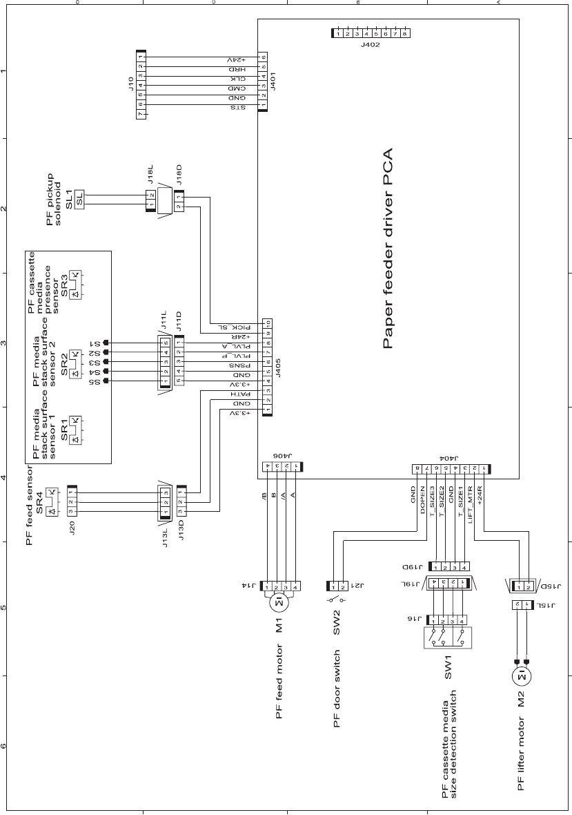
Figure 7-41 Paper feeder circuit diagram
ENWW Tools for troubleshooting 427

Print-quality troubleshooting tools
Repetitive defects ruler
If defects repeat at regular intervals on the page, use this ruler to identify the cause of the defect. Place
the top of the ruler at the first defect. The marking that is beside the next occurrence of the defect
indicates which component needs to be replaced.
Figure 7-42 Repetitive defects ruler
0 mm
27 mm
32 mm
44 mm
66 mm
63 mm
92 mm
105 mm
76 m m
77 mm
78 mm
80 mm
49 mm
75.5 mm
50 mm
Distance between defects Product components that cause the defect
27 mm Print cartridge: primary charge roller
32 mm Print cartridge: developer roller
44 mm Printer: primary transfer roller
49 mm Print cartridge: RS roller
50 mm Printer: secondary transfer roller
63 mm ITB: secondary transfer backing roller
66 mm Printer: distance from secondary transfer roller to fuser
75.5 mm Print cartridge: OPC drum
76 mm ITB: driven roller
77 mm Fuser sleeve
78 mm Fuser pressure roller
428 Chapter 7 Solve problems ENWW

Distance between defects Product components that cause the defect
80 mm Printer: distance from primary transfer roller to secondary transfer roller for black
92 mm Print cartridge station to station pitch: distance from the centerline of one OPC to the
centerline of the adjacent OPC
ITB: drive roller
105 mm Printer: distance from registration to secondary transfer roller
ENWW Tools for troubleshooting 429

Calibrate the product
NOTE: The procedure below is used to calibrate the scanner portion of the product. To perform an
internal print-quality calibration from the control panel, open the Print Quality menu.
Calibrate the scanner to compensate for offsets in the scanner imaging system (carriage head) for ADF
and flatbed scans. Because of mechanical tolerances, the scanner's carriage head might not read the
position of the image accurately. During the calibration procedure, scanner offset values are calculated
and stored. The offset values are then used when producing scans so that the correct portion of the
document is captured.
Scanner calibration should be carried out only if you notice offset problems with the scanned images.
The scanner is calibrated before it leaves the factory. It needs to be calibrated again only rarely.
Before calibrating the scanner, print the calibration target.
1. Place letter- or A4-size paper in tray 1, and adjust the side guides.
2. On the control-panel Home screen, scroll to and touch Administration.
3. Touch Troubleshooting.
4. Touch Calibrate Scanner.
5. Touch Calibrate to print the first pass of the calibration target.
6. Place the first pass of the calibration target face-down in tray 1 so that the arrows are facing into
the product.
7. Touch Start to print the second pass. The final calibration target must look similar to the following
figure.
CAUTION: If the calibration target does not look similar to the figure shown here, the calibration
process will fail and the quality of scans will be degraded. The black areas must extend completely
to the short edges of the page. If they do not, use a black marker to extend the black areas to the
edge of the page. Make sure that the paper is loaded correctly.
8. Place the calibration target face-up into the ADF, and adjust the side guides.
9. After the calibration target has passed through the ADF once, reposition it face down in the ADF
and touch Start.
10. Place the calibration target face-down on the scanner glass, touch Start, and scan the page. After
this pass, the calibration is complete.
430 Chapter 7 Solve problems ENWW

Internal print-quality test pages
Print-quality-troubleshooting pages
Use the built-in print-quality-troubleshooting pages to help diagnose and solve print-quality problems.
1. Scroll to and touch Administration.
2. Scroll to and touch Troubleshooting.
3. Touch PQ Troubleshooting.
4. Touch Print.
The product returns to the Ready state after printing the print-quality-troubleshooting pages. Follow the
instructions on the pages that print out.
Figure 7-43 Print-quality troubleshooting procedure
hp color LaserJet CP 3530 MFP Printers
Print Quality Troubleshooting Procedure
1
ENWW Tools for troubleshooting 431
Figure 7-44 Yellow print-quality troubleshooting page
Yellow
Green
Figure 7-45 Yellow comparison page
Green
Yellow
Yellow cannot be easily seen unless combined with cyan, so half of each page is yellow and the other
half is an amplified version of yellow problems (green half). Compare the yellow on page one with the
corresponding green on page two for defects. You can also check the cyan page for defects.
432 Chapter 7 Solve problems ENWW
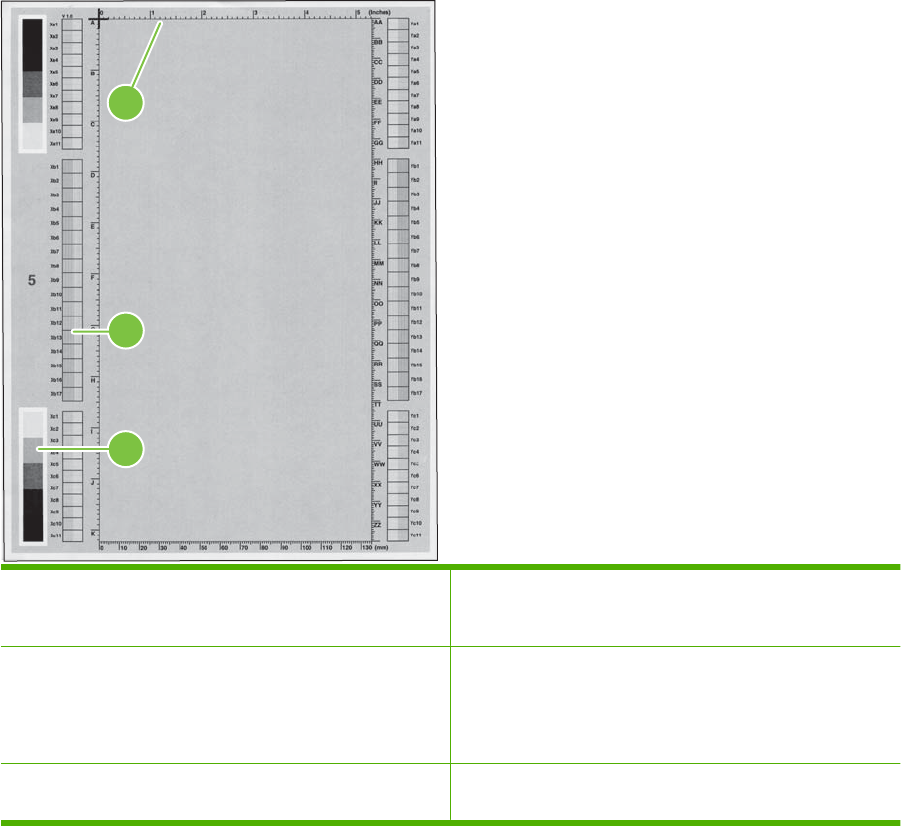
Figure 7-46 Black print-quality troubleshooting page
1
3
2
1. Grids The grids are in inches and millimeters. They are label with
letters and numbers so that defects can be described by
position and by distance between repeats.
2. Color plane registration (CPR) bars After printing, the box with no extra color in each area on each
page shows how far off the CPR of that color is. Each page
has two process direction areas and three scan direction areas
that are labeled x and y and 1–11. The page should be fed by
the long edge. Each square from the center equals 42 microns.
3. Color ramp patches Used to detect offset for the OPC or developer in the image
drum or offset in the fuser.
ENWW Tools for troubleshooting 433
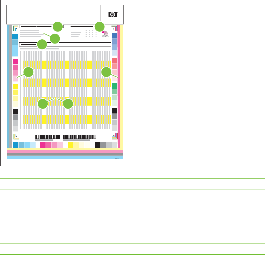
Diagnostics page
Use the diagnostics page to evaluate problems with color-plane registration, EP parameters, and print
quality.
1. Touch Administration.
2. Touch Troubleshooting.
3. Touch Diagnostics Page.
Diagnostics Page
Page 1
DD MMM YYYY XX:XX
1 3
24
5 6
87
HP Color LaserJet CP 3530 MFP Printers
1Calibration information
2Parameters
3Color density
4Color-plane registration
5Primary colors
6Secondary colors
7Temperature values (22 M)
8Humidity values (22 N)
434 Chapter 7 Solve problems ENWW
Cleaning page
Run the product cleaning page to keep the fuser free of toner and paper particles that can sometimes
accumulate and cause specks to appear on the front or back side of your print jobs.
HP recommends that you use the cleaning page when there is a print-quality issue.
A Cleaning message appears on the product control-panel display while the cleaning is taking place.
In order for the cleaning page to work correctly, print the page on copier-grade paper (not bond, heavy,
or rough paper).
Create and use the cleaning page
1. Scroll to and touch Administration.
2. Scroll to and touch Print Quality.
3. Touch Calibration/cleaning.
4. Touch Process cleaning page.
ENWW Tools for troubleshooting 435
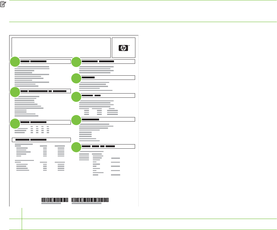
Configuration pages
Depending on the model, up to three pages print when you select PRINT CONFIGURATION. In addition
to the main configuration page, an embedded Jetdirect configuration page also prints.
Configuration page
Use the configuration page to view current product settings, to help troubleshoot product problems, or
to verify installation of optional accessories, such as memory (DIMMs), paper trays, and printer
languages.
1. Touch Administration.
2. Touch Information.
3. Touch Configuration/Status Pages.
4. Touch Configuration Page.
5. Touch Print.
The message Printing Configuration displays on the control panel until the product finishes printing
the configuration page. The product returns to the Ready state after printing the configuration page.
NOTE: If the product is configured with EIO cards (for example, an HP Jetdirect Print Server) or an
optional hard-disk drive, an additional configuration page will print that provides information about those
devices.
Figure 7-47 Configuration page
ENGLISH
HP Color LaserJet CP 3530 MFP Printers
Configuration Page
Page 1
2
3
14
5
6
7
8
1Printer information
2Installed personalities and options
436 Chapter 7 Solve problems ENWW

3Color density
4Calibration information
5Memory
6Event log
7Security
8Paper trays and options
ENWW Tools for troubleshooting 437
HP embedded Jetdirect page
The second configuration page is the HP embedded Jetdirect page, which contains the following
information:
Figure 7-48 HP embedded Jetdirect page
HP Color LaserJet CP 3530 MFP Printers
Embedded Jetdirect Page
Page 1
2
3
14
5
6
1HP Jetdirect Configuration indicates the product status, model number, hardware firmware version, port select, port
configuration, auto negotiation, manufacturing identification, and manufactured date.
2Security Settings information
3Network Statistics indicates the total packets received, unicast packets received, bad packets received, framing errors
received, total packets transmitted, unsendable packets, transmit collisions, and transmit late collisions.
4TCP/IP information, including the IP address
5IPv4 information
6IPv6 information
Always make sure the status line under the HP Jetdirect configuration lines indicates "I/O Card Ready".
438 Chapter 7 Solve problems ENWW
Embedded protocol page
The embedded protocol page contains the following information:
Figure 7-49 Embedded protocol page
HP Color LaserJet CP 3530 MFP Printers
Embedded Protocol Page
Page 1
2
1
4
3
1IPX/SPX
2Novell/NetWare
3 AppleTalk
4DLC/LLC
ENWW Tools for troubleshooting 439

Finding important information on the configuration pages
Certain information, such as the firmware date codes, the IP address, and the e-mail gateways, is
especially helpful while servicing the product. This information is on the various configuration pages.
Table 7-11 Important information on the configuration pages
Type of information Specific information Configuration page
Firmware date codes
When you use the remote firmware upgrade
procedure, all of these firmware components
are upgraded.
DC controller Look on the main configuration page,
under “Device Information.”
Firmware datecode Look on the main configuration page,
under “Device Information.”
Embedded Jetdirect firmware version Look on the embedded Jetdirect page,
under “HP Jetdirect Configuration.”
Accessories and internal storage
All optional devices that are installed on the
product should be listed on the main
configuration page.
In addition, separate pages print for the
optional paper handling devices and the fax
accessory. These pages list more-detailed
information for those devices.
External disk (optional) Look on the main configuration page,
under “Installed Personalities and
Options.” Shows model and capacity.
Embedded HP Jetdirect Look on the main configuration page,
under “Installed Personalities and
Options.” Shows model and ID.
Total RAM Look on the main configuration page,
under “Memory.”
Duplex unit Look on the main configuration page,
under “Paper Trays and Options.”
Additional 500-sheet feeders Additional 500-sheet feeders Look on the main configuration page,
under “Paper Trays and Options.”
Engine cycles and event logs
Total page counts and maintenance kit
counts are important for ongoing product
maintenance.
The configuration page lists only the three
most recent errors. To see a list of the 50
most recent errors, print an event log from the
Diagnostics menu.
Engine cycles Look on the main configuration page,
under “Device Information.”
Pages since last maintenance (print engine
maintenance count)
Pages since last maintenance (print
engine maintenance count)
Look on the main configuration page,
under “Device Information.”
Event-log information Event-log information Look on the main configuration page,
under “Event log.”
Color-band test
The color-band test page shows bands of colors that can indicate whether or not the product is producing
colors correctly.
1. Scroll to and touch Administration.
2. Touch Troubleshooting.
3. Touch Color Band Test.
4. Touch Print.
440 Chapter 7 Solve problems ENWW

Control-panel messages
Table 7-12 Control-panel messages
Control panel message Description Recommended action
Output Bin Full Remove all paper from bin The output bin is full and must be emptied for
printing to continue.
Empty the bin to continue printing.
10.00.YY Supply memory error The product is unable to read the cartridge
data. The print cartridge is present but
defective.
●10.00.00 Supply memory error (black
print cartridge)
●10.00.01 Supply memory error (cyan
print cartridge)
●10.00.02 Supply memory error
(magenta print cartridge)
●10.00.03 Supply memory error (yellow
print cartridge)
●10.10.00 Supply memory error (e-label
for the black print cartridge)
●10.10.01 Supply memory error (e-label
for the cyan print cartridge)
●10.10.02 Supply memory error (e-label
for the magenta print cartridge)
●10.10.03 Supply memory error (e-label
for the yellow print cartridge)
●10.10.05 Supply memory error (e-label
for the black image drum)
●10.10.06 Supply memory error (e-label
for the cyan image drum)
●10.10.07 Supply memory error (e-label
for the magenta image drum)
●10.10.08 Supply memory error (e-label
for the yellow image drum)
1. Open the front door and remove the
print cartridge, and then reinsert it.
2. Close the front door. If the message
reappears, turn the product off and then
on.
3. If the error reappears, replace the print
cartridge.
11.XX Internal clock error To continue
touch OK
The product's real time clock experienced an
error.
Whenever the product is turned off and then
turned on again, set the time and date at the
control panel. See the user guide for more
information.
If the error persists, you might need to replace
the formatter.
13.01 Jam In Tray 3 The leading edge of the paper fed from Tray
3 stopped before reaching the media feed
sensor (SR4).
Follow the onscreen instructions to locate
and remove the paper or obstruction.
13.04 Jams inside right door The paper stopped at the registration sensor
(A).
Follow the onscreen instructions to locate
and remove the paper or obstruction.
13.05 Fuser area jam The leading edge of the paper stopped
between registration and the input to the
Follow the onscreen instructions to locate
and remove the paper or obstruction.
ENWW Control-panel messages 441

Control panel message Description Recommended action
fuser. The paper did not reach the loop
sensors (SR14, SR15)
13.06 Fuser area jam The paper stopped at the fuser-delivery
sensor (D).
Follow the onscreen instructions to locate
and remove the paper or obstruction.
13.12 Jam inside right door The duplex refeed paper stopped before it
reached duplex re-pickup sensor (SR22).
Follow the onscreen instructions to locate
and remove the paper or obstruction.
13.13 Jam inside right door The duplex refeed paper stopped between
the duplex re-pickup sensor (SR22) and
registration.
Follow the onscreen instructions to locate
and remove the paper or obstruction.
13.1C Fuser Wrap Jam The paper is stopped in the fuser. Follow the onscreen instructions to locate
and remove the paper or obstruction.
13.20 Jams inside right door The paper is stopped at either the registration
sensor (SR8), the loop sensors (SR14,SR15)
or the fuser-delivery sensor (SR5).
Follow the onscreen instructions to locate
and remove the paper or obstruction.
13.21 Jams inside right door Either the front or right side door was opened
while paper was in the path.
Follow the onscreen instructions to locate
and remove the paper or obstruction.
13.2E Paper Late Jam Near Fuser at
Sensors F - J
The paper stopped between the fuser-output
sensor (F) and the output-bin-full sensor (J).
Follow the onscreen instructions to locate
and remove the paper or obstruction.
13.30.00 Jam in Tray 1 Paper being fed from Tray 1 did not reach
registration sensor.
Follow the onscreen instructions to locate
and remove the paper or obstruction.
13.30.00 Jam in Tray 2 Paper from Tray 2 did not reach registration
sensor (SR8).
Follow the onscreen instructions to locate
and remove the paper or obstruction.
13.30.00 Jam inside lower right door Paper being fed from Tray 3 did not reach
registration sensor.
Follow the onscreen instructions to locate
and remove the paper or obstruction.
20 INSUFFICIENT MEMORY To continue
touch OK
The product does not have enough memory
to print the page.
Touch OK to print a partial page. Reduce the
page complexity or add product memory.
22 - USB I/O buffer overflow To continue
touch OK
The product's USB buffer overflowed during
a busy state.
Touching OK resumes printing but results in
a loss of data.
22 EMBEDDED I/O BUFFER OVERFLOW
To continue touch OK
Too much data was sent to the embedded HP
Jetdirect print server. An incorrect
communications protocol might be in use.
Touch OK to print the transferred data. Some
data might be lost. Check the host
configuration.
30.01.02 Scanner failure The document feeder is jammed. 1. Remove all originals from the document
feeder.
2. Open the document feeder top cover
and check for torn paper or other
objects, such as paper clips.
30.01.03 Scanner failure An ADF pickup failure occurred. 1. Verify that the original documents are
not damaged. If one edge is damaged,
try rotating the originals.
2. Verify that the document feeder guides
are not too tight against the stack of
originals.
3. Clean or replace the document feeder
rollers and the separation pad.
Table 7-12 Control-panel messages (continued)
442 Chapter 7 Solve problems ENWW

Control panel message Description Recommended action
30.01.08 Scanner failure The scanner carriage is locked or it has not
returned to the home position within the
expected time.
1. Verify that the scanner is not locked.
2. Verify that the scanner carriage can
move freely. If it cannot move, replace
the scanner. See Scanner assembly
on page 242.
30.01.14 Scanner failure The SCB firmware failed. 1. Turn the product off and then on.
2. Replace the SCB. See Scanner-control
board (SCB) on page 279.
30.01.18 Scanner failure The SCB ASIC failed. 1. Turn the product off and then on.
2. Replace the SCB. See Scanner-control
board (SCB) on page 279.
30.01.19 Scanner failure The scanner lamp failed. 1. Turn the product off and then on.
2. Replace the scanner. See Scanner
assembly on page 242.
30.01.23 Scanner failure A scanner calibration error has occurred. 1. Turn the product off and then on.
2. Replace the scanner. See Scanner
assembly on page 242.
30.01.25 Scanner failure The scanner-control board (SCB) cannot
communicate with the product.
1. Turn the product off and then on.
2. Check the SCB LED.
3. Verify that the SCB connections are
correct.
4. Verify the cable from the scanner to the
formatter is not plugged in backwards.
5. Replace the SCB. See Scanner-control
board (SCB) on page 279.
30.01.36 Scanner failure An error occurred during the SCB firmware
upgrade.
1. Turn the product off and then on.
2. Resend the firmware upgrade.
3. Replace the SCB. See Scanner-control
board (SCB) on page 279.
30.01.39 Scanner failure There was an AFE1 (analog front-end)
failure.
1. Turn the product off and then on.
2. Replace the scanner. See Scanner
assembly on page 242.
30.01.40 Scanner failure The scanner AFE 2 failed. 1. Turn the product off and then on.
2. Replace the scanner. See Scanner
assembly on page 242.
30.01.41 Scanner failure There was a SCB error. 1. Turn the product off and then on.
2. Replace the SCB. See Scanner-control
board (SCB) on page 279.
Table 7-12 Control-panel messages (continued)
ENWW Control-panel messages 443

Control panel message Description Recommended action
30.01.42 Scanner failure The PCI-E (peripheral component
interconnect express) cable is faulty or
disconnected.
1. Turn the product off and then on.
2. Check the PCI-E cable connections at
the SCB and the ICB.
3. Replace the PCI-E cable. See Scanner-
control board (SCB) on page 279.
30.01.43 Scanner failure The SCB memory has failed. 1. Turn the product off and then on.
2. Replace the SCB. See Scanner-control
board (SCB) on page 279.
30.01.44 Scanner failure Communication failed on the SCB. 1. Turn the product off and then on.
2. Replace the SCB. See Scanner-control
board (SCB) on page 279.
30.01.45 Scanner failure The SCB has failed. 1. Turn the product off and then on.
2. Replace the SCB. See Scanner-control
board (SCB) on page 279.
30.01.46 Scanner failure The SCB enumeration failed. 1. Turn the product off and then on.
2. Check the PCI cable at the scanner and
formatter.
3. Check the SCB connections.
4. Replace the SCB. See Scanner-control
board (SCB) on page 279.
40 Embedded I/O Bad Transmission To
continue touch OK
A temporary printing error occurred. The
connection between the product and the EIO
card in the specified slot has been broken.
Touch OK to clear the error message and
continue printing. Turn the product off and
then on.
41.3 Load Tray <XX>: [Type] [Size] The specified tray is loaded with media that
is longer or shorter in the feed direction than
the size adjusted for the tray. This message
also appears if two or more sheets of media
stick together in the product or if the tray is
not adjusted correctly. If using glossy paper,
ensure that it has been acclimated.
Touch OK to use another tray. Reconfigure
the size in a tray so that the product will use
a tray that is loaded with the correct media
size. If the message does not clear
automatically from the control-panel display,
turn the product off and then on.
41.5 Load Tray <XX>: [Type], [Size] To use
another tray, touch OK
The product detected an unexpected paper
size. There is a tray type mismatch.
The tray is a cassette and there is another
tray available for use.
To continue, load the tray with the size and
type indicated. Or, if another tray is available,
touch OK to use it. This problem affects
printing, but some scan functions might still
be available.
41.X ERROR A temporary printing error occurred. Touch OK to clear the error. If the error is not
cleared, turn the product off and then on.
49.XXXXX ERROR To continue turn off
then on
A firmware error has occurred.
This type of error can be caused by corrupted
print jobs or software program issues, non
product-specific printer drivers, poor-quality
USB or network cables, bad network
connections or incorrect network
configurations, invalid firmware operations,
or unsupported accessories.
The following steps should help to identify
possible causes and a resolution to the error
condition:
1. Turn the product off then on. If the error
returns, disconnect all interface cables
and turn the product off and then on
again.
Table 7-12 Control-panel messages (continued)
444 Chapter 7 Solve problems ENWW

Control panel message Description Recommended action
If the error recurs only after connecting
one of the interface cables or it happens
randomly, go to step 2.
If the error returns after the second time
you turn the product off and on, follow
these steps:
a. The error has been isolated to
when the product is in stand-alone
condition. Turn the product off and
remove the hard drive, fax card (if
equipped), any HP paper-handling
accessories, all third-party DIMMs
(leave the minimum HP memory
installed), and all third-party
accessories.
b. After you have removed all
components, turn the product on
and print a configuration page.
If the configuration page prints, the
error has been isolated to one or
more components you removed.
Go to step c.
If the configuration page does not
print, go to step e.
c. Turn the product off, reinstall one
of the components onto the
formatter, and turn the product on.
Print the configuration page after
the individual component is added.
d. Continue reinstalling one
component at a time and printing
the configuration page until you
identify the faulty component.
Replace the faulty component, or
contact the third-party accessory
supplier.
e. If the configuration page did not
print in step b, turn the product off
and reinstall all components
removed from the formatter.
Reinstall the formatter.
f. Perform a Cold Reset, Disk INIT
and NVRAM INIT.
NOTE: Customer settings or
data from the disk might be lost.
g. If the product does not come to a
ready state after performing all
steps listed above, contact your
Hewlett Packard support center.
Table 7-12 Control-panel messages (continued)
ENWW Control-panel messages 445

Control panel message Description Recommended action
NOTE: HP LaserJet formatter
PCAs are rarely the cause of 49
service errors. Do not replace the
formatter unless troubleshooting
identifies it as the cause.
2. If the error clears after turning the
product off and then on, it is possible
that a print job, an action performed on
the product, or a connectivity issue is
responsible for the error.
a. If the error recurs only after
connecting an interface cable try
the following actions, if applicable:
●Try a new cable.
●Move the product to a new
network port, fax-line port, or
USB port.
●Verify that all unused network
protocols are disabled and
that all settings are correctly
set for the network
configuration being used.
●Reset the fax settings to
factory defaults. Configure
only the basic settings
needed to operate: country/
region, company name, and
fax number.
●Verify that the fax card
firmware revision is the
correct version for the
formatter firmware version on
the product.
b. If the error happens only when
performing certain actions, such as
making a copy, sending an e-mail,
or sending a fax, try the following
actions, if applicable:
●Try different configuration
settings
●Increase or decrease the file
resolution
●Use black and white file
format instead of color, or
vice-versa.
●Use different file formats, for
example .PDF or .TIFF.
●Use different copy settings,
such as eliminating duplex
printing or printing multiple
pages on one sheet.
Table 7-12 Control-panel messages (continued)
446 Chapter 7 Solve problems ENWW

Control panel message Description Recommended action
●Reduce the number of
originals.
●Reset the fax settings to
factory defaults. Configure
only the basic settings
needed to operate: country/
region, company name, and
fax number.
●Verify that the fax card
firmware revision is the
correct version for the
formatter firmware version on
the product.
c. If the error occurs only when
printing a job, try the following
actions:
●Verify that the printer driver is
correct for your product.
●Try printing another file from
the same software program
or from another software
program.
●Reduce the number of
features being used in the
print job, such as printing
watermarks, printing multiple
pages on one sheet, or using
job-storage features.
●If other files or software
programs are successful, try
making changes to the file,
such using different fonts,
changing driver settings, or
printing with another driver
language, such as PCL 6.
d. If the error continues to occur,
update the product firmware.
Obtain the latest firmware from
www.hp.com/go/
cljcm3530mfp_firmware.
3. If the error persists after performing
these steps, contact your Hewlett
Packard support center.
50.1 FUSER ERROR The fuser has experienced a low-
temperature error.
1. Remove any paper jams from the fuser
area.
2. Remove the fuser. Check the connector
(J50) between the fuser and the
product. Replace the cable or fuser if the
connector is damaged.
3. If the problem persists, replace the
fuser. See Fuser on page 200.
Table 7-12 Control-panel messages (continued)
ENWW Control-panel messages 447

Control panel message Description Recommended action
50.2 FUSER ERROR The fuser has experienced a warm-up error. 1. Reinstall the fuser. Check the connector
(J50) between the fuser and the
product. Replace the cable or fuser if the
connector is damaged.
2. Reconnect the connectors (J138, J115)
of the DC controller PCA˙. Reconnect
connector (J60), on the power line
between the low voltage power supply
and the fuser.
3. If the problem persists, replace the
fuser. See Fuser on page 200.
50.3 FUSER ERROR The fuser has experienced a high-
temperature error.
1. Reinstall the fuser. Check the connector
(J50) between the fuser and the
product. Replace the cable or fuser if the
connector is damaged.
2. If the problem persists, replace the
fuser. See Fuser on page 200.
50.4 FUSER ERROR The fuser driver circuit has experienced an
error.
1. Check the power source. If a power
generator is used, improve the situation.
NOTE: If the product does not meet
the power requirement of 43 to 67Hz
frequency, the fuser temperature control
does not work, which causes a
malfunction.
2. Reconnect connector (J101) on the DC
controller PCA.
3. If the problem persists, replace the low-
voltage power supply. See Low-voltage
power supply (LVPS) on page 273.
50.5 FUSER ERROR The fuser has experienced a type-mismatch
error.
1. Reinstall the fuser. Check the connector
(J50) between the fuser and the
product. Replace the cable or fuser if the
connector is damaged.
2. Reconnect the connector (J139) on the
DC controller PCA.
3. If the problem persists, replace the
fuser. See Fuser on page 200.
50.7 FUSER ERROR The fuser has experienced a pressure
release mechanism error.
1. Reconnect the connectors (J117, J123)
on the DC controller PCA.
2. Run the sensor test to test the fuser
pressure-release sensor (H) SR7. If the
sensor is defective, replace the fuser.
See Fuser on page 200.
Table 7-12 Control-panel messages (continued)
448 Chapter 7 Solve problems ENWW

Control panel message Description Recommended action
50.8 FUSER ERROR The fuser has experienced a low-
temperature error.
1. Remove any paper jams from the fuser
area.
2. Reinstall the fuser. Check the connector
(J50) between the fuser and the
product. Replace the cable or fuser if the
connector is damaged.
3. If the problem persists, replace the
fuser. See Fuser on page 200.
50.9 FUSER ERROR The fuser has experienced a high-
temperature error.
1. Reinstall the fuser. Check the connector
(J150) between the fuser and the
product. Replace the cable or fuser if the
connector is damaged.
2. If the problem persists, replace the
fuser. See Fuser on page 200.
51.1Y Error To continue turn off and then
on
There is a beam detect error.
●51.10=black
●51.11=cyan
●51.12=magenta
●51.13=yellow
1. Turn the product off and then on.
2. Check the flat flexible cable (FFC)
connections to the laser scanners. Also
check connectors J111 and J110 at the
DC controller, and check connectors
J503 and J501 at the laser scanners
3. Replace the specific laser scanner. See
Laser/scanner assembly (C/Bk)
on page 332 or Laser/scanner assembly
(Y/M) on page 325.
51.2Y Error To continue turn off and then
on
There is a laser error.
●51.20=black
●51.21=cyan
●51.22=magenta
●51.23=yellow
1. Turn the product off and then on.
2. Check the connectors on the laser
scanner.
3. Replace the specific laser scanner. See
Laser/scanner assembly (C/Bk)
on page 332 or Laser/scanner assembly
(Y/M) on page 325.
52.00 Error To continue turn off and then
on
The laser scanner experienced a startup
error.
1. Perform the laser scanner component
tests in the Troubleshooting menu.
2. Depending on the test results, perform
one of the following steps:
◦If the cyan or black component
tests showed a startup failure,
reconnect the connectors of the
cyan/black scanner motor (J56
and J58) and the DC controller
PCA (J106).
◦If the yellow or magenta
component tests showed a startup
failure, reconnect the connectors
of the yellow/magenta scanner
motor (J55 and J57) and the DC
controller PCA (J106).
3. Replace the cyan/black laser scanner
unit or the yellow/magenta laser
Table 7-12 Control-panel messages (continued)
ENWW Control-panel messages 449

Control panel message Description Recommended action
scanner unit. See Laser/scanner
assembly (C/Bk) on page 332 or Laser/
scanner assembly (Y/M) on page 325.
52.20 Error To continue turn off and then
on
The laser scanner experienced a rotational
error.
1. Perform the laser scanner component
tests in the Troubleshooting menu.
2. Depending on the test results, perform
one of the following steps:
◦If the cyan or black component
tests showed a startup failure,
reconnect the connectors of the
cyan/black scanner motor (J56
and J58) and the DC controller
PCA (J106).
◦If the yellow or magenta
component tests showed a startup
failure, reconnect the connectors
of the yellow/magenta scanner
motor (J55 and J57) and the DC
controller PCA (J106).
3. Replace the cyan and black laser-
scanner assembly or the yellow and
magenta laser-scanner assembly. See
Laser/scanner assembly (C/Bk)
on page 332 or Laser/scanner assembly
(Y/M) on page 325.
53.10.0X Unsupported DIMM An unsupported DIMM is installed. Turn the product off, and then replace the
DIMM that caused the error.
54.01 Error The environmental sensor experienced an
error.
1. Reconnect the connector of the DC
controller PCA (J108).
2. Replace the environmental sensor. See
Delivery fan, cartridge fan, and
environmental sensor on page 285.
55.00.YY DC Controller Communication
Error To continue turn off and then on
The DC controller experienced a
communication error.
1. Turn the product off and then on.
2. Perform an engine test. See Engine-test
button on page 386.
3. Verify the connectors on the DC
controller.
4. Replace the DC controller. See DC
controller PCA and tray on page 270.
55.01.YY DC Controller Memory Error To
continue turn off and then on
There is an error with the DC controller
memory.
1. Turn the product off and then on.
2. Perform an engine test. See Engine-test
button on page 386..
3. Verify the connectors on the DC
controller.
4. Replace the DC controller. See DC
controller PCA and tray on page 270.
Table 7-12 Control-panel messages (continued)
450 Chapter 7 Solve problems ENWW

Control panel message Description Recommended action
55.02.YY Outgoing Parity Error To
continue turn off and then on
There is a DC controller outgoing parity error. 1. Turn the product off and then on.
2. Perform an engine test. See Engine-test
button on page 386.
3. Verify the connectors on the DC
controller.
4. Replace the DC controller. See DC
controller PCA and tray on page 270.
55.03.YY No Engine Response To
continue turn off and then on
DC controller no response error. 1. Turn the product off and then on.
2. Perform an engine test. See Engine-test
button on page 386.
3. Verify the connectors on the DC
controller.
4. Replace the DC controller. See DC
controller PCA and tray on page 270.
55.04.YY Communications Timeout To
continue turn off and then on
There was a DC controller communications
time out.
1. Turn the product off and then on.
2. Perform an engine test. See Engine-test
button on page 386.
3. Verify the connectors on the DC
controller.
4. Replace the DC controller. See DC
controller PCA and tray on page 270.
55.05 ENGINE FIRMWARE RFU ERROR Firmware upgrade failed. 1. Turn the product off and then on.
2. Remove any third-party hardware.
3. Resend the firmware upgrade.
56.01 - Illegal input To continue turn off
and then on
There was an illegal input. 1. Turn the product off and then on.
2. Remove any third-party hardware.
3. Attempt the remote firmware update
again.
4. Replace the DC controller.
56.02 - Illegal output To continue turn off
and then on
There was an illegal output. Turn the product off and then on.
57.03 Error To continue turn off and then
on
The cartridge area cooling fan (FM2)
experienced an error.
1. Reconnect the connector J26 of the
cartridge fan, connector J262 on the
high voltage power supply D PCA, and
connector J114 on the DC controller
PCA.
2. Immediately after turning on the
product, measure the voltage between
the connector J262-1 and J262-3 on the
high-voltage power supply D PCA. If the
voltage changes from 0 V to
approximately 24 V, replace the
cartridge fan.
Table 7-12 Control-panel messages (continued)
ENWW Control-panel messages 451

Control panel message Description Recommended action
57.04 Error To continue turn off and then
on
The low-voltage power-supply fan (FM1)
experienced an error.
1. Reconnect the connector J119 on the
DC controller PCA.
2. Immediately after turning on the
product, measure the voltage between
the connector J119-1 and J119-3 on the
DC controller PCA. If the voltage
changes from 0 V to approximately 24 V,
replace the power-supply fan.
57.07 Error To continue turn off and then
on
The delivery area cooling fan (FM3)
experienced an error.
1. Reconnect the connector J27 of the
delivery fan, connector J262 on the high
voltage power supply D PCA, and
connector J114 on the DC controller
PCA.
2. Immediately after turning on the
product, measure the voltage between
the connector J262-4 and J262-6 on the
high-voltage power supply D PCA. If the
voltage changes from 0 V to
approximately 24 V, replace the delivery
fan.
59.30 Error To continue turn off and then
on
The fuser motor experienced a startup error. 1. Perform the fuser motor component test
in the Troubleshooting menu.
2. Reconnect the connector J117 on the
DC controller PCA.
3. Replace the fuser motor. See Fuser
motor on page 345.
59.40 Error To continue turn off and then
on
The fuser motor experienced a rotational
error.
1. Perform the fuser motor component test
in the Troubleshooting menu.
2. Reconnect the connector J117 on the
DC controller PCA.
3. Replace the fuser motor. See Fuser
motor on page 345.
59.5Y ERROR
To continue turn off then on
A drum motor has experienced a startup
error.
●Y=0: Black (drum motor 3) (M5) (J121)
●Y=1: Cyan (drum motor 2) (M4) (J120)
●Y=2: Magenta (drum motor 1) (M3) (M4)
(J120)
●Y=3: Yellow (drum motor 1) (M3) (J120)
1. Perform the drum-motors component
test in the DIAGNOSTICS menu.
2. Reconnect the connectors J120 or J121
on the DC controller PCA.
3. Replace the appropriate drum motor.
See Drum motor 1 on page 343 or Drum
motor 2 or drum motor 3 on page 344.
59.6Y ERROR
To continue turn off then on
A drum motor has experienced a rotational
error.
●Y=0: Black (drum motor 3) (M5) (J121)
●Y=1: Cyan (drum motor 2) (M4) (J120)
1. Perform the drum-motors component
test in the DIAGNOSTICS menu.
2. Reconnect the connectors J120 or J121
on the DC controller PCA.
3. Replace the appropriate drum motor.
See Drum motor 1 on page 343 or Drum
motor 2 or drum motor 3 on page 344.
Table 7-12 Control-panel messages (continued)
452 Chapter 7 Solve problems ENWW

Control panel message Description Recommended action
●Y=2: Magenta (drum motor 1) (M3) (M4)
(J120)
●Y=3: Yellow (drum motor 1) (M3) (J120)
59.B0 ERROR
To continue turn off then on
The toner-collection unit is full. Replace the toner-collection unit. See Toner-
collection unit on page 190
59.BO CLEANING MOTOR ERROR
REPLACE TONER COLLECTION UNIT
This message displays for one of the
following reasons:
●The cleaning motor is stuck.
●The toner-collection unit is full.
●The chute at the top of the toner
collection unit is clogged.
Replace the toner-collection unit. See Toner-
collection unit on page 190.
59.C0 Error To continue turn off and then
on
The developer-disengagement motor
experienced a rotational error.
1. Perform the Alienation Motor test in the
Component Tests menu in the
Troubleshooting menu. Verify that the
cartridges are being correctly alienated.
2. Check the following connectors: J25 at
the motor (M10), J261 and J251 on the
high voltage power supply-D PCA, and
connectors J138 and J106 on the DC
controller PCA.
3. Perform the Manual Sensor Test and
observe item G. The normal state is “0”.
Locate the in-line connector J70 in the
cable that is connected to developing-
home-position sensor (SR11). To find
this connector, remove the left-side
cover and look in the area below the
support plate. Disconnect the in-line
connector. The state of item G should
change to “1”.
4. If the motor is defective, replace motor
M10. If the sensor is defective, replace
the main-drive assembly.
59.F0 ERROR The transfer unit is missing or a motor error
has occurred.
1. Verify that the ITB is installed correctly.
Remove the ITB and manually test the
alienation mechanism.
2. The position of the alienation
mechanism in the ITB is monitored by
the primary transfer roller
disengagement sensor (SR17), which is
located in the rear of the black cartridge
slot. Perform the manual sensor test
while the ITB is removed, and observe
the state of sensor “I”. The normal state
is “0”. When you insert a piece of paper
into the sensor, the state should change
to “1.”
3. Open the right door and defeat the
interlock. Perform the ITB Contact/
Alienation test in the Component
Table 7-12 Control-panel messages (continued)
ENWW Control-panel messages 453

Control panel message Description Recommended action
Test menu. Observe the alienation-
drive hub, which is above the cyan
cartridge.
4. If the sensor (SR17) fails, order the rear
pre-exposure assembly and replace the
faulty sensor with the new sensor from
the assembly.
5. If the alienation drive hub does not
rotate, the problem could be the fuser
motor or the fuser-drive assembly.
59.XY ERROR To continue turn off then on A temporary printing error occurred. Turn the product off and then on.
60.02 Tray 2 lifting error The Tray 2 lifter motor experienced an error. 1. Check the Tray-2 paper-surface sensor
in the Manual Sensor Test 2 menu in the
Troubleshooting menu.
2. Reconnect the connectors of the
cassette lifter motor (J1920) and the DC
controller PCA (J112).
3. Replace the lifter drive unit. See Lifter-
drive assembly on page 314.
60.03 Tray 3 lifting error The Tray 3 lifter motor experienced an error. 1. Check the Tray-3 paper-surface sensor
in the Manual Sensor Test 2 menu in the
Troubleshooting menu.
2. Reconnect the connectors of the
cassette lifter motor (J1920) and the DC
controller PCA (J112).
3. Replace the lifter drive unit. See Lifter-
drive assembly on page 314.
68.X Storage error settings changed To
continue, touch OK.
At least one of the settings saved in the non-
volatile storage device is invalid and was
reset to its factory default. Printing can
continue, but there may be some unexpected
behavior because an error occurred in
permanent storage.
●68.0: The onboard NVRAM failed.
●68.1: The removable disk (flash or hard)
failed.
Touch OK to clear the message.
69.X Error To continue, touch OK. A duplex error occurred. Turn the product off and then on. This
problem affects printing, but some scan
functions might still be available. Touch
Hide to remove this message and use other
features.
79.XXXX - ERROR To continue turn off and
then on
A critical hardware error occurred. Turn the product off and then on.
Table 7-12 Control-panel messages (continued)
454 Chapter 7 Solve problems ENWW

Control panel message Description Recommended action
8X.YYYY EIO ERROR To continue turn off
and then on
The EIO accessory card encountered a
critical error, as specified by YYYY.
Try the following actions to clear the
message:
1. Turn the product off and then on.
2. Turn the product off, reseat the EIO
accessory, and then turn the product on.
3. Replace the EIO accessory. See
Formatter PCA on page 192.
8X.YYYY EMBEDDED JETDIRECT ERROR The embedded HP Jetdirect print server
encountered a critical error, as specified by
YYYY.
Turn the product off and then on.
ABCDEFGHIJK 100000000000 The product is performing the paper path test. To exit press the Stop button.
ACTION NOT CURRENTLY AVAILABLE
FOR TRAY X TRAY SIZE CANNOT BE ANY
SIZE/ANY CUSTOM
A duplexed (2-sided) document was
requested from a tray that is set to Any Size
or Any Custom. Duplexing is not allowed
from a tray configured to Any Size or Any
Custom.
Select another tray or reconfigure the tray.
Authentication required Authentication is enabled for this feature or
destination. A user name and password are
required.
Type the user name and password, or contact
the network administrator.
Authentication required to use this
feature
A user name and password are required. Type the user name and password, or contact
the network administrator.
Bad optional tray connection The optional tray is not connected properly
and must be reconnected before printing can
continue.
1. Turn the product off.
2. Remove and then reinstall optional tray.
Calibrating... The product is calibrating. No action is necessary.
Cancelling The product is canceling a job. No action is necessary.
Card Slot Device Failure - To Clear Touch
OK
The specified device failed. Touch OK to clear.
Card Slot file operation failed To clear
touch OK
A PJL file system command was received
that attempted to perform an illogical
operation, such as downloading a file to a
non-existent directory.
Touch OK to clear.
Card Slot is write protected To clear touch
OK
The device is protected and no new files can
be written to it.
Touch OK to clear message.
Card Slot Not Initialized The file system device must be initialized
before it can be used.
Initialize the device.
Cartridge Error – Replace Black Cartridge Toner has settled in the black print cartridge
and the auger cannot turn.
Replace the black cartridge. After replacing
the cartridge, turn the power off and then on
to continue
Cartridge Error-Replace color cartridges
Reinstall, then turn off and then on
The cyan, magenta, or yellow print cartridges
are defective and need to be replaced.
Replace the defective print cartridges and
turn the product off and then on.
Checking engine The product is checking the engine. No action is necessary.
Checking paper path The engine is checking the rollers for possible
paper jams.
No action is necessary.
Table 7-12 Control-panel messages (continued)
ENWW Control-panel messages 455

Control panel message Description Recommended action
Chosen personality not available. To
continue touch OK.
A print job requested a product language
(personality) that is not available for this
product. The job will not print and will be
cleared from memory.
Print the job by using a printer driver for a
different printer language, or add the
requested language to the product (if
possible). To see a list of available
personalities, print a configuration page.
Cleaning The cleaning page is being processed. No action is necessary.
Cleaning disk <X>% complete Do not
power off
A storage device is being sanitized or
cleaned.
Do not turn off the product. The product's
functions are unavailable. The product will
automatically restart when finished.
Clearing activity log The corresponding fax menu item has been
triggered.
No action is necessary.
Clearing all blocked numbers The corresponding fax menu item has been
triggered.
No action is necessary.
Clearing event log The event log is being cleared. No action is necessary.
Clearing paper path The product jammed or was turned on and
paper was detected where it should not be. It
is attempting to eject these pages
automatically.
No action is necessary.
Close front or right doors Either the front or right door is open. 1. Close the door.
2. Inspect the interlock on both the front
and right doors.
3. Use the manual sensor test to verify that
the interlock switches are working
correctly.
Close lower-right door The lower-right door is open. Close the lower-right door.
Cooling device This product recently experienced a period of
heavy usage. In order to maintain a
supported operating temperature, the
product cycles through intervals of printing
and pausing.
No action is necessary.
Creating cleaning page A two-step page is being processed after
having been created. This message is also
used for products with duplexers that create
and process the cleaning page in one step.
No action is necessary.
Data received The product is waiting for the command to
print the last page. The last page will print in
a few moments.
No action is necessary.
Deleting... The product is currently deleting a stored job. No action is necessary.
Disk spinning up The EIO disk product in slot <X> is spinning
up.
No action is necessary.
Document feeder cover open The document feeder cover is open. Close the document feeder cover. Follow the
instructions in the onscreen dialog box.
DOCUMENT FEEDER EMPTY The document feeder is empty. 1. Place originals in the document feeder
or on the glass.
2. Press the Start button.
Table 7-12 Control-panel messages (continued)
456 Chapter 7 Solve problems ENWW

Control panel message Description Recommended action
Document feeder pick error The document feeder experienced an error
while picking media.
1. Open the document feeder cover.
2. If necessary, roll the green wheel to the
left to advance the paper. Remove all
paper found.
3. Lift the green tab to open the paper
guide. Remove all paper found.
4. Close the paper guide. Close the
document feeder cover.
5. Reinsert the original pages into the
document feeder. Align the paper
guides with the edges of the paper.
6. To continue, press the Start button.
NOTE: If this jam occurs frequently, try
scanning from the flatbed glass. Some paper
types cause jams in the document feeder. If
the original document contains both Letter
and Legal size pages, select “Mixed Letter/
Legal” as the original size.
Duplexing... do not grab paper The product is printing a duplex job, and the
paper is accessible.
No action is necessary.
E-MAIL GATEWAY DID NOT ACCEPT THE
JOB BECAUSE THE ATTACHMENT WAS
TOO LARGE
The scanned documents have exceeded the
size limit of the server.
Send the job again using a lower resolution,
smaller file size setting, or fewer pages.
Contact the network administrator to enable
sending the scanned documents by using
multiple e-mails.
E-MAIL GATEWAY DID NOT RESPOND A gateway exceeded the time-out value. Validate the SMTP IP address.
E-MAIL GATEWAY REJECTED THE JOB
BECAUSE OF THE ADDRESSING
INFORMATION
One or more of the e-mail addresses is
incorrect.
Send the job again with the correct
addresses.
EIO <X> Disk initializing The EIO disk product in slot <X> is initializing. No action is necessary.
EIO <X> disk not functional The EIO disk in slot <X> is not working
correctly.
Turn the product off. Remove the disk from
the slot indicated, and replace it with a new
disk. Turn the product on.
EIO Device Failure - To Clear Touch OK The specified device failed. Touch OK to clear.
EIO file operation failed To clear touch OK A PJL file system command attempted to
perform an illogical operation, such as
downloading a file to a directory that does not
exist.
Touch OK to clear.
EIO is write protected To clear touch OK The device is protected and no new files can
be written to it.
Touch OK to clear message.
EIO Not initialized The file system device must be initialized
before it can be used.
Initialize the device.
Entering internal application <X> The product is opening an internal program. No action is necessary.
Error The directory or file is not readable. To activate a fax, complete the required fax
settings available through the Administration
menu.
Table 7-12 Control-panel messages (continued)
ENWW Control-panel messages 457

Control panel message Description Recommended action
ERROR EXECUTING DIGITAL SEND JOB A digital send job failed and cannot be
delivered.
Try to send the job again.
External device initializing An external product is initializing. No action is necessary.
Fax is disabled ignoring call The product received a call, but the fax
feature was not configured with the required
settings (country/region, date/time, company
name, fax number, etc.). The fax icon on the
control panel is grayed out.
Configure the fax with the required settings
from the Administration menu on the control
panel.
Flatbed cover open The flatbed scanner cover is open. Close the flatbed cover.
Found SMTP gateway The Find SMTP Gateway menu has been
selected.
No action is necessary
Gateways failed The gateway configuration is incorrect. See Solve connectivity problems
on page 501.
Gateways OK
The gateway configuration is correct.
No action is necessary.
Genuine HP supplies installed A new HP cartridge has been installed. This
message appears for approximately 6
seconds before the returns to the Ready
state.
No action is necessary.
HP DIGITAL SENDING: DELIVERY ERROR A digital send job failed and cannot be
delivered.
Try to send the job again.
HP SECURE HARD DRIVE DISABLED The HP high-performance hard disk is
disabled, or the product does not recognize
the hard disk.
After an encrypted hard disk is paired with a
specific product, it cannot be used in another
product unless it is reinitialized.
NOTE: After the encrypted hard disk is
paired to the product, all other hard disks are
disabled.
Use the embedded Web server to configure
the hard disk.
1. Open the embedded Web Server by
typing the product IP address into a Web
browser.
2. Click the Digital Sending tab.
3. Select the Security link from the left
navigation menu, and open the Hard
Disk and Mass Storage Security
Settings section.
4. The following options are available:
◦Disk Init: This option does not
affect the disk encryption status.
◦NVram Init: This option does not
affect the disk encryption status.
◦Disable Hard Disk Encryption
and Reboot: This option
completely erases the hard disk
including all stored jobs, digital-
send settings, and authentication
settings. All pre-loaded fonts, after-
market fonts, and other programs
must be reloaded.
◦Reinitialize Hard Disk: This
option has the same effect as the
Disable Hard Disk Encryption
Table 7-12 Control-panel messages (continued)
458 Chapter 7 Solve problems ENWW

Control panel message Description Recommended action
and Reboot, but it does not restart
the product.
Image CRC error This message is displayed before the
firmware is loaded at startup when an error
occurs during a firmware upgrade.
Resend the upgrade.
Incompatible fuser The wrong fuser is installed. The product will
not print, even though the fuser fits the
product.
Install the correct fuser. See Fuser
on page 200.
Incompatible supplies Two or more incompatible supplies are
installed. The product will not print, even
though the supplies fit the product.
Install the correct supply.
INFLATE FAILURE An error occurred during the firmware
upgrade.
Resend the upgrade.
Initializing permanent storage Product is initializing permanent storage. No action is necessary.
Initializing scanner The scanner is initializing. Wait until the scanner is Ready before
proceeding to scan.
Install <color> cartridge The print cartridge has been removed or has
been installed incorrectly.
Replace or reinstall the print cartridge
correctly to continue printing.
Install fuser The fuser is either not installed or not installed
correctly.
Install the fuser. See Fuser on page 200.
Install supplies At least two supplies are missing. Replace the missing supplies or make sure
the installed supplies are fully seated.
Install transfer unit The ITB is either not installed or not installed
correctly.
Replace the ITB. See Intermediate transfer
belt (ITB) on page 209.
Insufficient memory to load fonts/data
<device> To continue touch OK
The product does not have enough memory
to load the data (for example, fonts or
macros) from the location specified.
Touch OK to continue without this
information. If the message persists, add
memory.
Internal Disk Device Failure - To Clear
Touch OK
The specified device failed. Touch OK to clear the message.
Internal disk file operation failed To clear
touch OK
A PJL file system command attempted to
perform an illogical operation, such as
downloading a file to a non-existent directory.
Touch OK to clear.
Internal Disk Initializing The internal disk is initializing. No action is necessary.
Internal disk is write protected To clear
touch OK
The product is protected and no new files can
be written to it.
Touch OK to clear the message.
Internal disk not found Internal disk not found. Turn the product off and then on.
Internal disk not functional The internal disk is not functional. Copy and send is disabled. Turn the product
off and then on.
Internal disk not initialized The internal disk is not initialized. Initialize the disk.
Internal disk spinning up The internal disk is spinning up its platter. It
usually shows for approximately 15 seconds
when the product comes out of power-save
mode. Jobs can still print, but jobs that require
disk access (i.e., stored jobs) must wait.
No action is necessary.
Table 7-12 Control-panel messages (continued)
ENWW Control-panel messages 459

Control panel message Description Recommended action
Jam in document feeder Paper is jammed in the document feeder. 1. Open the document feeder cover.
2. If necessary, roll the green wheel to the
left to advance the paper. Remove all
paper found. Lift the green tab to open
the paper guide. Remove all paper
found. Close the paper guide. Close the
document feeder cover.
3. Reinsert the original pages into the
document feeder. Align the paper
guides with the edges of the paper. To
continue, press the Start button.
NOTE: If this jam occurs frequently, try
scanning from the flatbed glass. Some paper
types cause jams in the document feeder. If
the original document contains both letter-
and legal-size pages, select Mixed Letter/
Legal as the original size.
Job is being saved to disk Job is being saved. No action is necessary.
LED is on To continue, touch OK This message appears when the LED is
component tested.
Touch OK to continue.
Load Tray 1 <type> <size> The tray is empty or configured for a different
size than the size requested.
Follow the instructions in the onscreen dialog
box.
Load Tray 1: [Type], [Size] To continue,
touch OK
Tray 1 is empty. Load Tray 1 with the requested paper. Or, if
paper is already in Tray 1, touch OK to print.
If paper is in another tray, remove the paper
and insert it in Tray 1, and then touch OK.
Load Tray <XX> <type> <size> To use
another tray, touch OK
A cassette tray is empty, and there is another
tray available.
Load the tray with the requested paper or
adjust the paper guides.
If another tray is available, touch OK to select.
Load Tray <XX>: [type], [size] A cassette tray is empty, and there is no other
tray available.
Load the tray with the requested paper or
adjust the paper guides.
Loading program <XX> Do not power off Programs and fonts are being loaded into the
product’s file system.
No action is necessary.
Manually feed <type> <size> The specified job requires manual feed from
Tray 1.
Load the requested media into Tray 1.
Touch OK to use paper in another tray.
Manually feed output stack Then touch
OK to print second sides
The first side of a manual duplex job printed
and the product is waiting for the user to insert
the output stack to complete the second side.
For the normal Manually Feed message,
printing continues automatically when the
paper is reinserted. With this message,
printing stops until the user touches the OK
button, which allows time for straightening the
output stack.
The even-numbered pages of the two-sided
document have printed. Follow the next steps
to print the odd-numbered pages.
1. Maintaining the same orientation,
remove the document from the output
bin. Do not discard blank pages.
2. Flip the document over so it is face up.
3. Load Tray 1 with the face-up document.
4. To continue printing, touch OK.
Table 7-12 Control-panel messages (continued)
460 Chapter 7 Solve problems ENWW

Control panel message Description Recommended action
Manually Feed: [Type], [Size] To continue,
touch OK
A job has specified manual feed, and Tray 1
is loaded.
Touch OK to resume printing.
Manually Feed: [Type], [Size] To use
another tray, touch OK
The job specified manual feed, the MP-tray is
empty, and there is another tray available to
use.
Touch OK to switch to another tray and
resume printing.
Moving solenoid To exit press STOP The solenoid and a motor are moving as part
of a component test.
No action is necessary.
No job to cancel This message appears when the Stop button
is pressed.
No action is necessary.
Non-HP supply installed A refilled color or a cloned color/mono
cartridge was installed, and the product
previously used all genuine HP supplies. Or,
an unauthorized cartridge was installed, and
the product previously used all genuine
supplies.
Install a genuine HP cartridge, or touch OK to
override the condition.
Non-HP supply in use This message appears when the override
button is pressed (on the non-HP supply
installed error).
No action is necessary.
Order <color> Cartridge The identified print cartridge is nearing the
end of its useful life. The product is ready and
will continue for the estimated number of
pages indicated. Estimated pages remaining
is based upon the historical page coverage of
this product.
Printing will continue until a supply needs to
be replaced.
Order a replacement print cartridge.
Order Fuser Kit The fuser is near the end of life. The product
is ready and will continue for the estimated
number of pages indicated. Printing will
continue until a supply needs to be replaced.
Order a replacement fuser kit.
Order roller kit-Less than XXXX pages The roller kit is low due to rotations. Order a replacement roller kit.
Order Supplies One or more supplies need to be replaced. Replace the supply.
Order toner collection unit The toner collection unit is almost full. Order a replacement toner collection unit.
Order Transfer Kit The transfer kit is near the end of life. Printing
can continue.
Order a replacement transfer kit.
Order transfer kit Less than XXXX pages The number of pages remaining for this
supply has reached the low threshold.
Printing can continue.
Order a replacement transfer kit.
Approximate pages remaining will vary
depending on the types of documents
printed.
Performing Color Band Test The color-band test is being performed. No action is necessary.
Performing paper path test Press stop to
cancel
The product is performing a paper-path test. No action is necessary.
Performing upgrade <Device> The product is performing a product upgrade. Do not turn the product off or press any
buttons. The product will automatically restart
when the upgrade is finished.
Please wait The product is going offline. No action is necessary.
Printing The page is being printed. No action is necessary.
Table 7-12 Control-panel messages (continued)
ENWW Control-panel messages 461

Control panel message Description Recommended action
Printing CMYK Samples The CMYK-samples page is being
generated. The product will return to the
ready state when the page is complete.
No action is necessary.
PRINTING COLOR USAGE LOG The color-usage-log page is being
generated. The product will return to the
ready state when the page is complete.
No action is necessary.
Printing configuration The product is generating the internal
configuration page.
No action is necessary.
PRINTING DEMONSTRATION The demo page is being generated. The
product will return to the ready state when the
page is complete.
No action is necessary.
PRINTING DIAGNOSTICS PAGE The diagnostics page is being generated.
The product will return to the ready state
when the page is complete.
No action is necessary.
Printing event log The event log page is being generated. No action is necessary.
Printing file directory The product is generating the file directory
page.
No action is necessary.
Printing font list The product is generating the font list. No action is necessary.
Printing menu map The product is generating the menu map. No action is necessary.
Printing mopy status The product is generating the mopy status
report.
No action is necessary.
PRINTING PQ TROUBLESHOOTING The print-quality troubleshooting test is being
generated. The product will return to the
ready state when the test completes.
No action is necessary.
Printing registration page The product is generating the registration
page.
No action is necessary.
PRINTING RGB SAMPLES The print-quality troubleshooting test is being
generated. The product will return to the
ready state when the test completes.
No action is necessary.
Printing stopped To continue, touch OK A Print/Stop test is running. No action is necessary.
Printing supplies status The product is generating the supplies status
page.
No action is necessary.
Printing usage page The product is generating the usage page. No action is necessary.
Processing copy <X> of <Y>... The product is currently processing or
printing collated copies.
No action is necessary.
Processing digital send job The product is processing a digital send job. No action is necessary.
Processing duplex job The product is processing a duplex job. No action is necessary.
Processing from tray <X> The product is processing a job. The <X>
stands for the chosen paper tray.
No action is necessary.
Processing-intermittent mode The internal temperature of the product is too
hot, and the product is processing a job(s).
No action is necessary.
Processing. . . The product is processing the current job but
has not begun to pick up pages yet.
No action is necessary.
Table 7-12 Control-panel messages (continued)
462 Chapter 7 Solve problems ENWW

Control panel message Description Recommended action
RAM Disk Device Failure - To Clear Touch
OK
The specified device failed. Touch OK to clear the message.
RAM Disk file operation failed To clear
touch OK
A PJL file system command was received
that attempted to perform an illogical
operation, such as downloading a file to a
non-existent directory.
Touch OK to clear the message.
RAM Disk is write protected To clear touch
OK
The device is protected and no new files can
be written to it.
Touch OK to clear the message.
RAM disk not initialized The file system device must be initialized
before it can be used.
Initialize the device.
Ready The product is online and ready to receive
data.
No action is necessary.
Receiving upgrade The product is receiving a firmware update. No action is necessary.
Remove All Print Cartridges The product is executing a component test
and the component selected is belt only.
Remove all print cartridges.
Remove At Least One Print Cartridge The product is executing a disable-cartridge
check or component test and the component
selected is the cartridge motor.
Remove one print cartridge.
REMOVE CARTRIDGE LOCKS At least one print-cartridge lock is installed. 1. Open the front door.
2. Remove the cartridge locks from the
front of each cartridge.
3. Close the front door.
Replace <color> Cartridge The identified print cartridge has reached the
end of life. Printing can continue.
Replace the specified print cartridge.
Replace <color> cartridge - To continue,
touch “OK”
A print cartridge has reached the low
threshold, and the Replace Supplies menu is
set to stop at low.
Order a replacement print cartridge. Touch
OK to continue printing.
Replace DIMM <X> MEM test failure The listed DIMM is not functioning properly
and must be replaced.
Replace the DIMM.
Replace document feeder kit This warning message appears one month
before the end of life when the maintenance
interval has been reached.
Follow instructions included with the
document feeder kit to install.
Replace fuser kit The fuser kit has reached the low threshold. Replace the fuser. See Fuser on page 200.
Replace fuser kit To continue, touch OK The fuser is nearing the end of its useful life.
Printing can continue.
Replace the fuser kit. See Fuser
on page 200.
Replace roller kit The roller kit has reached the low threshold. Replace the roller kit. Secondary transfer
assembly on page 207.
Replace Supplies - Override in Use The product is set to continue printing even
though a supply has reached the end of life.
CAUTION: Using the override mode can
result in unsatisfactory print quality.
HP recommends replacing the supply when
this message appears. The HP Supplies
Premium Protection Warranty coverage ends
when a supply is used in override mode.
No action is necessary.
Table 7-12 Control-panel messages (continued)
ENWW Control-panel messages 463

Control panel message Description Recommended action
Replace Supplies - Using black A color supply (or supplies) has reached the
out condition and the Color Supply Out menu
item is set to Autocontinue black.
No user input is required for printing to
continue. Printing continues in black.
Replace transfer kit The supply has reached the end of life.
Printing can continue.
Replace transfer kit. See Intermediate
transfer belt (ITB) on page 209.
Replace transfer kit To continue, touch
OK
The transfer kit is at the end of life. Printing
can continue, but print quality might be
reduced.
The product is set to stop printing when a
supply needs to be ordered. To continue
printing, touch OK.
Replace the ITB. See Intermediate transfer
belt (ITB) on page 209.
Request Accepted Please Wait This message appears when a request to
print an internal page is accepted but cannot
print.
Wait for the internal page to print.
Resend external accessory firmware An external accessory requires a firmware
upgrade. Printing can continue, but jams may
occur if the job uses the external accessory.
Perform a firmware upgrade.
Resend upgrade A firmware upgrade did not complete
successfully.
Upgrade the firmware again.
Restoring factory settings A Restore Factory Settings reset is being
performed.
No action is necessary.
Restoring… A Restore Last Saved State, Restore Print
Modes, Restore Optimization, or Restore
Color Values operation is being performed.
No action is necessary.
Restricted from printing in color The print job is being forced to print in black
either because the product is set to print only
in black or because the user ID and
application ID do not have color printing
permissions.
No action is necessary.
RFU LOAD ERROR A failure occurred during the remote firmware
upgrade.
Resend the upgrade.
ROM Disk Device Failure - To Clear Touch
OK
The specified device failed. Touch OK to clear.
ROM Disk file operation failed To clear
touch OK
A PJL file system command was received
that attempted to perform an illogical
operation, such as downloading a file to a
non-existent directory.
Touch OK to clear the message.
ROM Disk is write protected To clear
touch OK
The device is protected and no new files can
be written to it.
Touch OK to clear the message.
ROM Disk Not Initialized The file system device must be initialized
before it can be used.
Initialize the device.
Rotating <color> Motor A component test is in progress; the
component selected is the <color> cartridge
motor.
Press Stop to stop the test.
Rotating Motor - To exit press STOP The product is executing a component test
and the component selected is a motor.
Press Stop to stop the test.
Sanitizing Disk <X>% Complete Do not
power off
The hard disk is being cleaned. Contact the network administrator.
Table 7-12 Control-panel messages (continued)
464 Chapter 7 Solve problems ENWW

Control panel message Description Recommended action
SCAN FAILURE The scan was unsuccessful and the
document needs to be scanned again.
If necessary, reposition the document to scan
again, and then press Start.
Scanning...page <X> The product is scanning a job in the ADF. No action is necessary.
Scanning...page from glass The product is scanning from the glass. No action is necessary.
Searching... please wait The product is searching. No action is necessary.
Send complete The send process is complete. No action is necessary.
Sending digital send job The product is sending a digital-send job. No action is necessary.
Sending to external destinations The product is sending a digital-send job. No action is necessary.
Size mismatch in tray XX The media in the listed tray does not match
the size specified for that tray.
Load the correct media.
Sleep mode on The product is in sleep mode. No action is necessary.
SMTP Gateways OK The status of the SMTP gateways is normal. No action is necessary.
Testing Please wait The product is temporarily unavailable. No action is necessary.
To return to ready press STOP The product is paused, and there are no error
messages pending at the display.
No action is necessary.
Total images: <X> The product has processed the number of
images indicated by <X>.
No action is necessary.
Tray <X>: [Type], [Size] The tray is closed if the Size/Type Prompt
menu is set to Display.
No action is necessary.
Tray <XX> empty: [type], [size] The specified tray is empty and needs to be
loaded, but the current job does not need this
tray to print.
Load the tray.
Tray <XX> open The specified tray is open or not closed
completely; the tray is not required to print
and is not blocking the paper path of a tray
required for printing.
Close the tray.
Type Mismatch In Tray <XX> The specified tray contains a media type that
does not match the configured type.
The specified tray will not be used until this
condition is addressed. Printing can continue
from other trays.
Unable to connect To temporarily hide this message in order to
fax or send to e-mail, touch Hide.
UNABLE TO COPY The product was unable to copy the
document.
To temporarily hide this message in order to
fax or send to e-mail, touch Ignore.
Unable to mopy job Because of a memory, disk, or configuration
problem, a mopy job cannot be mopied. Only
one copy will be produced.
Try increasing the product memory or
reducing the complexity of the job.
UNABLE TO SEND To temporarily hide this message in order to
fax or send to e-mail, touch Ignore.
UNABLE TO SEND FAX The product was unable to send the fax. Contact the network administrator.
Unauthorized supply in use The product is using a non-HP supply. Any product repair required as a result of
using non-HP or unauthorized supplies is not
covered under warranty. HP cannot ensure
the accuracy or the availability of certain
features.
Table 7-12 Control-panel messages (continued)
ENWW Control-panel messages 465

Control panel message Description Recommended action
Unsupported data on [FS] DIMM in slot The data on the DIMM is not supported. The DIMM may need to be replaced. Turn off
the product before removing it. To clear this
warning, touch OK.
Unsupported USB accessory detected The USB accessory is not recognized and
cannot be used by this product.
Remove the USB accessory. To clear this
message, touch OK.
Upgrade complete To continue, turn off
and then on
Upgrade complete. Turn the product off and then on.
USB ACCESSORY UNAVAILABLE The USB accessory was installed after the
product was turned on. The product does not
support plug-and-play operation.
1. Remove the USB accessory.
2. Turn the product off, and then plug in the
USB accessory.
3. Turn the product on.
USB Device Failure - To Clear Touch OK The specified device failed. Touch OK to clear.
USB file operation failed To clear touch
OK
A PJL file system command was received
that attempted to perform an illogical
operation, such as downloading a file to a
non-existent directory.
Touch OK to clear the message.
USB HUBS NOT FULLY SUPPORTED Some USB hubs require more power than the
product has available.
1. Remove the USB hub.
USB is write protected To clear touch OK The device is protected and no new files can
be written to it.
Touch OK to clear the message.
USB needs too much power Power requirements for the USB accessory
attached to this product are beyond
supported limits.
Detach the accessory, and then turn the
product off and then on. Try a similar
accessory that has its own power supply or
requires less power.
USB Not Initialized The file system device must be initialized
before it can be used.
Initialize the device.
USB storage <X> is initializing The designated USB storage unit is
initializing.
No action is necessary.
USB storage <X> is not functional A parameter in the USB storage is not
working correctly.
Turn the product off. Disconnect the USB
storage accessory, and replace with a new
USB storage accessory.
USB storage <X> removed A USB storage accessory has been
disconnected since the product was turned
on.
To continue using the USB accessory, turn
the product off and reconnect it. Turn the
product off and then on to clear the message.
USED SUPPLY IN USE One or more used supplies have been
installed.
1. Install new supplies.
2. If you believe you purchased a genuine
HP supply, visit us at www.hp.com/go/
anticounterfeit. Any repair required as a
result of using used cartridges is not
covered under warranty. Supply status
and features depending on supply
status are not available.
Wait for printer to reinitialize The user changed the RAMDISK settings.
The product automatically restarts.
No action is necessary.
Waiting for tray <XX> to lift The tray number specified by <XX> is in the
process of lifting the paper to the top of the
tray for proper feeding.
No action is necessary.
Table 7-12 Control-panel messages (continued)
466 Chapter 7 Solve problems ENWW

Control panel message Description Recommended action
Warming up The product is coming out of sleep-delay
mode. Printing will continue once the product
completely warms up.
No action is necessary.
Warming up scanner The scanner is warming up. No action is necessary.
Windows login required to use this feature A Windows login is required. Enter a Windows login.
Table 7-12 Control-panel messages (continued)
ENWW Control-panel messages 467

Event log messages
Print an event log
Print the event log
1. Touch Administration.
2. Scroll to and touch Troubleshooting.
3. Touch Print Event Log.
Show an event log
View the event log from the control panel
1. Touch Administration.
2. Scroll to and touch Troubleshooting.
3. Touch Show Event Log.
Clear the event log
Use the Service menu to clear the event log.
Clear the event log
1. Touch Administration.
2. Scroll to and touch Service.
3. Touch Clear Event Log.
Event log message table
Event log message Description Comments
10.40.00 Genuine HP Supplies Installed Transition from at least one non-HP to all
genuine HP supplies. (no control panel
message)
10.50.23 Fuser kit life reset above order threshold. For products without fusible link
10.80.YY Override not in use due to user limit
●YY = 00 black print cartridge (K)
●YY = 01 cyan print cartridge (C)
●YY = 02 magenta print cartridge (M)
●YY = 03 yellow print cartridge (Y)
The cartridge out override is deactivated
because the user limit was reached on at
least one cartridge.
10.81.00 Not printing black only Printing monochrome after the color
cartridge out was deactivated
468 Chapter 7 Solve problems ENWW

Event log message Description Comments
10.88.YY
10.89.YY
Override not in use
●YY = 00 black print cartridge (K)
●YY = 01 cyan print cartridge (C)
●YY = 02 magenta print cartridge (M)
●YY = 03 yellow print cartridge (Y)
The cartridge out override was
deactivated because the limit was
reached on at least one cartridge.
13.02.00 PAPER STOP JAM IN TRAY 2 AT
SENSOR D
13.05.00 PAPER LATE JAM BETWEEN
SENSORS D AND F
13.06.00 PAPER JAM IN FUSER
13.10.00 PAPER LATE JAM IN DUPLEX AREA
SENSORS F-G
13.11.00 PAPER STOP JAM IN DUPLEX AREA
AT SENSOR G
13.12.00 PAPER LATE JAM IN DUPLEX AREA
SENSORS H-D
13.13.00 PAPER STOP JAM IN DUPLEX AREA
SENSORS G-H
13.1C.00 FUSER WRAP JAM, PAPER IN FUSER
13.20.00 PAPER EJECT JAM AT SENSORS E, F-
G
13.21.00 DOOR OPEN JAM
13.2B.00 NON-SPECIFIC PAPER JAM
13.2C.00 NON-SPECIFIC PAPER JAM
13.2D.00 NON-SPECIFIC PAPER JAM
13.2E.00 PAPER LATE JAM NEAR FUSER AT
SENSORS F-J
13.30.00 PAPER LATE JAM, JAM IN CASSETTE
14.X Feed roller error
●X = 2 Tray 2 (upper cassette)
●X = 3 Tray 3 (lower cassette)
Feed roller life warning
54.05 Printer error
OHT sensor out of range
Waste toner sensor failure
54.0D.XX Halftone calibration errors
●XX=00: Black density-
measurement abnormality
●XX=01: Cyan density-measurement
abnormality
1. Scroll to and touch Administration.
2. Scroll to and touch Print Quality.
3. Touch Calibration/Cleaning.
ENWW Event log messages 469

Event log message Description Comments
●XX=02: Magenta density-
measurement abnormality
●XX=03: Yellow density-
measurement abnormality
4. Touch Full Calibration.
5. Touch Calibrate.
54.0F.XX ●XX=00: Black misregistration is out
of range.
●XX=01: Cyan misregistration is out
of range.
●XX=02: Magenta misregistration is
out of range.
●XX=03: Yellow misregistration is out
of range.
1. Scroll to and touch Administration.
2. Scroll to and touch Print Quality.
3. Touch Calibration/Cleaning.
4. Touch Full Calibration.
5. Touch Calibrate.
54.14 CPR sensor abnormality 1. Scroll to and touch Administration.
2. Scroll to and touch Print Quality.
3. Touch Calibration/Cleaning.
4. Touch Full Calibration.
5. Touch Calibrate.
54.1E.XX Halftone calibration error. 1. Scroll to and touch Administration.
2. Scroll to and touch Print Quality.
3. Touch Calibration/Cleaning.
4. Touch Full Calibration.
5. Touch Calibrate.
55.06.01 The DC controller NVRM has an
abnormal read/write.
1. Turn the product off then on.
2. If the error persists, replace the DC
Controller. See DC controller PCA
and tray on page 270.
55.06.02 The DC controller NVRM is not
accessible.
1. Turn the product off then on.
2. If the error persists, replace the DC
Controller. See DC controller PCA
and tray on page 270.
55.901C DCC restored DCC NVRAM was restored from the
formatter.
61.00.01 Color table error This event occurs when the color table
cannot read a table from the disk and the
component reverts to the version in
RAM. The file could be corrupt, missing,
or the disk could have failed. No
messages display on the control panel.
67.XX.00 A system variable (XX) is out of range.
68 8X01 Permanent storage was reset to factory
default because the current value was not
valid.
470 Chapter 7 Solve problems ENWW

Event log message Description Comments
68 8X02 The permanent storage is full.
8x7345 Disk was successfully cleaned or
sanitized.
8x7346 The disk cleaning or sanitization failed.
88.00 The engine self-test failed.
99.00.01 Upgrade not performed, file is corrupt. CRC error in the firmware image (bad
image)
99.00.02 Upgrade not performed, timeout during
receive.
IO timeout when reading header number
and size
99.00.03 Upgrade not performed, error writing to
disk
Disk error: write operation failed
99.00.04 Upgrade not performed, timeout during
receive.
IO timeout when reading rest of header
99.00.05 Upgrade not performed, timeout during
receive.
IO timeout when reading image data
99.00.06 Upgrade not performed, error reading
upgrade.
Unexpected read error when reading
header number and size
99.00.07 Upgrade not performed, error reading
upgrade.
Unexpected read error when reading rest
of header
99.00.14 Upgrade not performed, the file is invalid The header number is greater than 2, but
the header size is too small for this future
header version.
ENWW Event log messages 471

Clear paper jams
Common causes of jams
The product is jammed.
Cause Solution
The paper does not meet specifications. Use only paper that meets HP specifications. See Supported
paper and print media on page 56.
A component is installed incorrectly. Verify that the transfer belt and transfer roller are correctly
installed.
You are using paper that has already passed through a product
or copier.
Do not use paper that has been previously printed on or copied.
An input tray is loaded incorrectly. Remove any excess paper from the input tray. Make sure that
the stack is below the maximum stack height mark in the tray.
See Load paper and print media on page 62.
The paper is skewed. The input-tray guides are not adjusted correctly. Adjust them
so they hold the stack firmly in place without bending it.
The paper is binding or sticking together. Remove the paper, flex it, rotate it 180°, or flip it over. Reload
the paper into the input tray.
The paper is removed before it settles into the output bin. Reset the product. Wait until the page completely settles in the
output bin before removing it.
During two-sided printing, you removed the paper before the
second side of the document was printed.
Reset the product and print the document again. Wait until the
page completely settles in the output bin before removing it.
The paper is in poor condition. Replace the paper.
The internal tray rollers are not picking up the paper. If the paper is heavier than 220 g/m2 (58 lb), it might not be
picked from the tray.
The rollers are worn. Replace the rollers.
The paper has rough or jagged edges. Replace the paper.
The paper is perforated or embossed. Perforated or embossed paper does not separate easily. Feed
single sheets from Tray 1.
Paper was not stored correctly. Replace the paper in the trays. Paper should be stored in the
original packaging in a controlled environment.
Not all product packing material was removed. Verify that the packing tape, cardboard, and plastic shipping
locks have been removed from the product.
472 Chapter 7 Solve problems ENWW
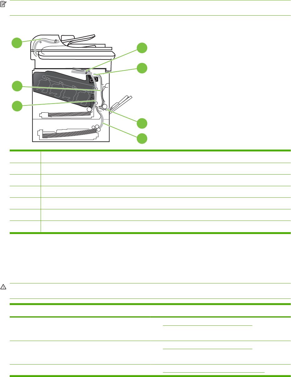
Jam locations
Use this illustration to identify locations of jams. In addition, instructions appear on the control panel to
direct you to the location of jammed paper and how to clear it.
NOTE: Internal areas of the product that might need to be opened to clear jams have green handles
or green labels.
Figure 7-50 Jam locations
7
3
1
2
4
5
6
1Output-bin area
2Fuser area
3Tray 1 area
4Optional 500-sheet paper and heavy media tray (Tray 3)
5Tray 2 pickup area
6Duplexing area
7Document feeder area
Clear jams
When a jam occurs, a message appears on the control-panel display that describes the location of the
jam.
WARNING! To avoid electrical shock, remove any necklaces, bracelets, or other metal items before
reaching into the inside of the product.
Type of jam Procedure
13.XX.YY - Jam inside right door
13.XX.YY - Jams inside right door
See Clear jams in the right door on page 475
13.XX.YY - Fuser area jam
13.XX.YY - Fuser wrap jam
See Clear jams in the right door on page 475.
13.XX.YY - Jam below control panel See Clear jams in the output bin area on page 479.
ENWW Clear paper jams 473

Type of jam Procedure
13.XX.YY - Jam in tray 1 See Clear jams in Tray 1 on page 480.
13.XX.YY - Jam in tray 2 See Clear jams in Tray 2 on page 482.
13.XX.YY - Jam in tray 3 See Clear jams in the optional 500-sheet paper and heavy
media tray (Tray 3) on page 483
13.XX.YY - Jam inside lower-right door See Clear jams in the lower right door (Tray 3) on page 484.
474 Chapter 7 Solve problems ENWW
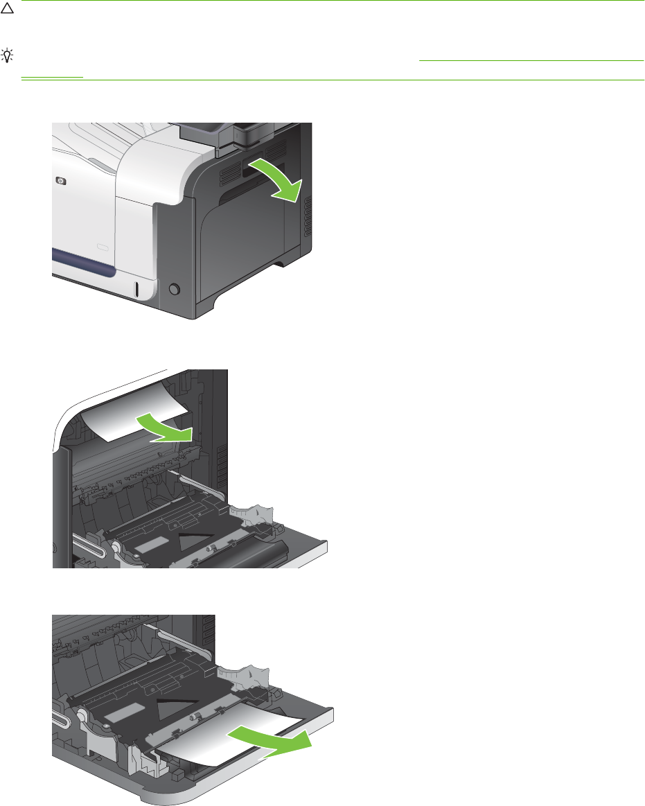
Clear jams in the right door
CAUTION: The fuser can be hot while the product is in use. Wait for the fuser to cool before handling
it.
TIP: To see an animation of this procedure go to this Web site: www.hp.com/go/cljcm3530mfp-right-
door-jams.
1. Open the right door.
2. If paper is jammed as it enters the output bin, gently pull the paper downward to remove it.
3. If paper is jammed inside the right door, gently pull the paper to remove it.
ENWW Clear paper jams 475
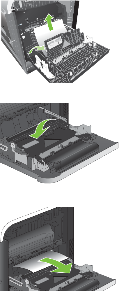
4. Lift the paper-feed cover on the inside of the right door. If jammed paper is present, gently pull the
paper straight out to remove it.
1
2
5. Close the paper-feed cover.
6. Gently pull the paper out of the pickup area.
476 Chapter 7 Solve problems ENWW
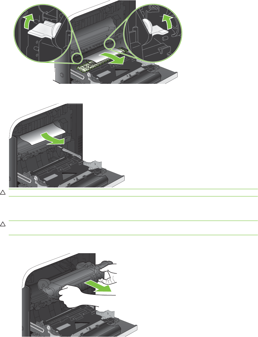
7. Look for paper in the Tray 2 roller area. Near the bottom of the right side, squeeze the two green
levers upward to release the jam-access door. Remove any jammed paper, and close the door.
8. If paper is visible entering the bottom of the fuser, gently pull downward to remove it.
CAUTION: Do not touch the rollers on the transfer roller. Contaminates can affect print quality.
9. Paper could be jammed inside the fuser where it would not be visible. Remove the fuser to check
for jammed paper inside.
CAUTION: The fuser can be hot while the product is in use. Wait for the fuser to cool before
handling it.
a. Grasp the fuser handles, lift up slightly, and pull straight out to remove the fuser.
ENWW Clear paper jams 477
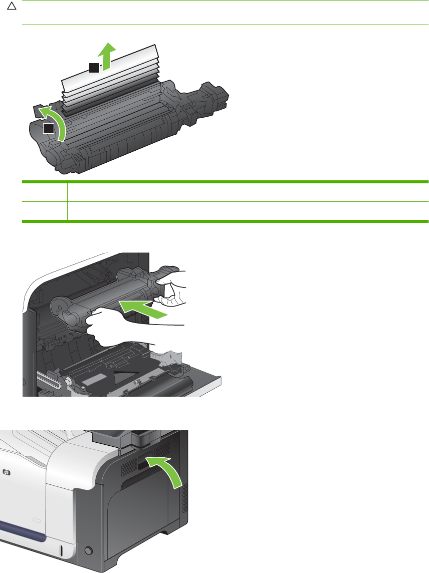
b. Open the jam-access door. If paper is jammed inside the fuser, gently pull it straight up to
remove it. If the paper tears, remove all paper fragments.
CAUTION: Even if the body of the fuser has cooled, the rollers that are inside could still be
hot. Do not touch the fuser rollers until they have cooled.
1
2
1Open the jam-access door.
2Remove the jammed paper.
c. Close the jam-access door, and push the fuser completely into the product.
10. Close the right door.
478 Chapter 7 Solve problems ENWW
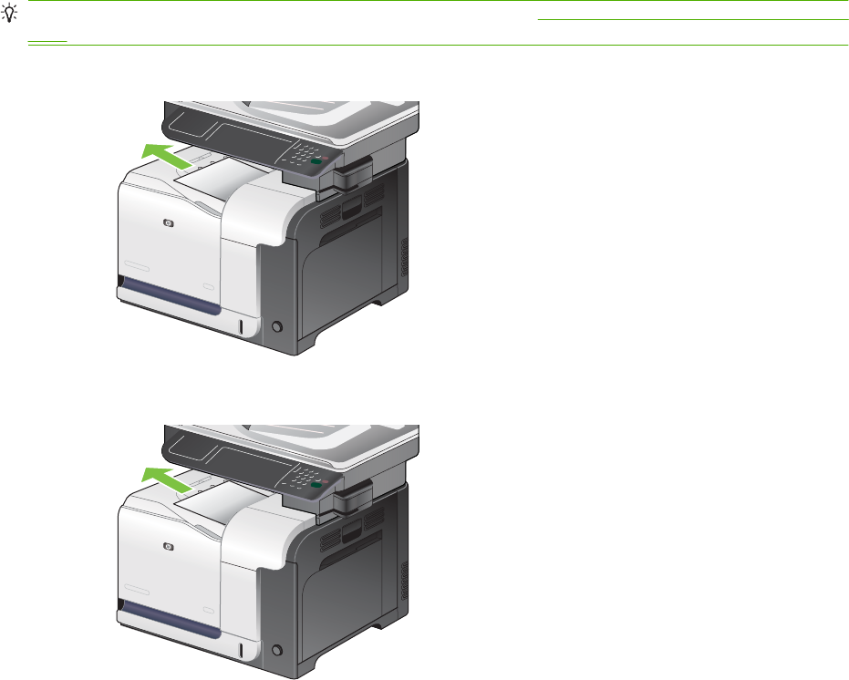
Clear jams in the output bin area
TIP: To see an animation of this procedure go to this Web site: www.hp.com/go/cljcm3530mfp-output-
jams.
1. If paper is visible from the output bin, grasp the leading edge and remove it.
2. If jammed paper is visible in the duplex output area, gently pull it to remove it.
ENWW Clear paper jams 479
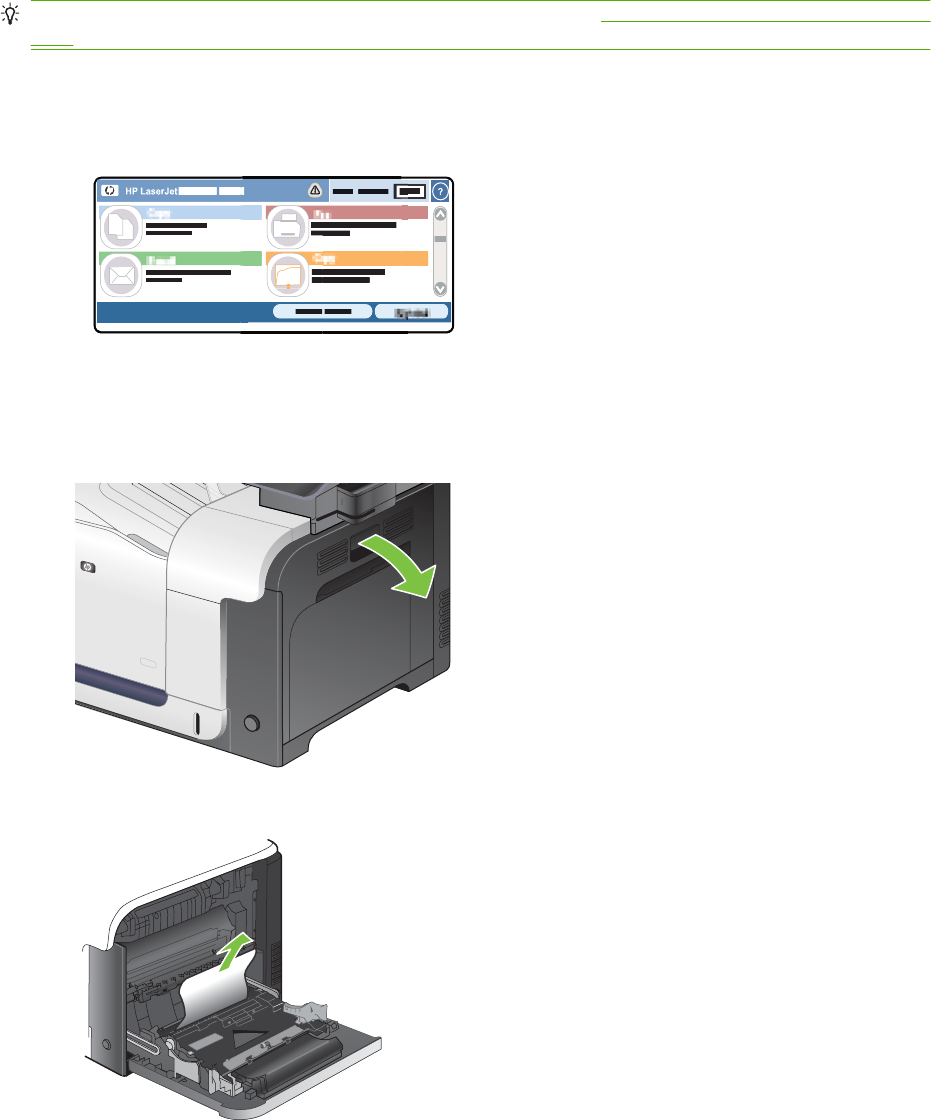
Clear jams in Tray 1
TIP: To see an animation of this procedure go to this Web site: www.hp.com/go/cljcm3530mfp-tray1-
jams.
1. If jammed paper is visible in Tray 1, clear the jam by gently pulling the paper straight out. Touch
the OK button to clear the message.
HP LaserJet
DDMMYYYY 00.00 AM
2. If you cannot remove the paper, or if no jammed paper is visible in Tray 1, close Tray 1 and open
the right door.
3. If paper is visible inside the right door, gently pull the trailing edge to remove it.
480 Chapter 7 Solve problems ENWW
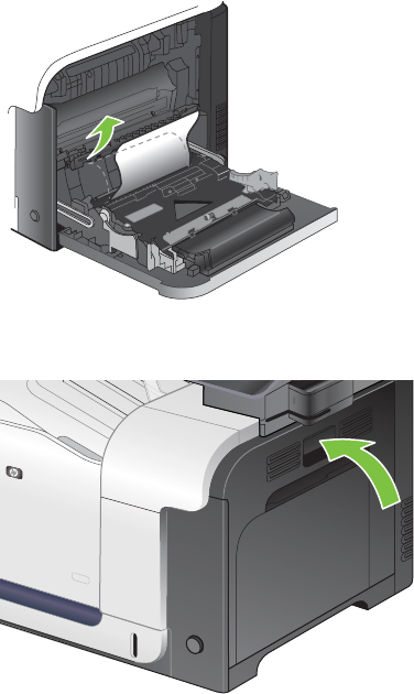
4. Gently pull the paper out of the pick up area.
5. Close the right door.
ENWW Clear paper jams 481
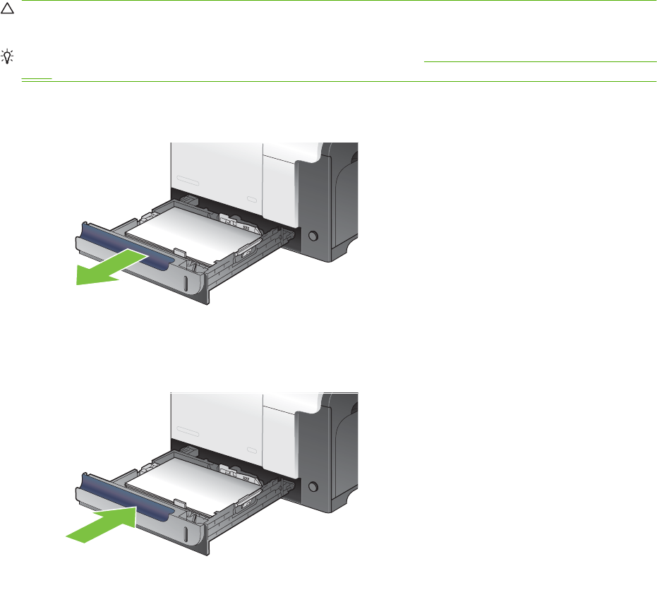
Clear jams in Tray 2
CAUTION: Opening a tray when paper is jammed can cause the paper to tear and leave pieces of
paper in the tray, which might cause another jam. Be sure to clear jams before opening the tray.
TIP: To see an animation of this procedure go to this Web site: www.hp.com/go/cljcm3530mfp-tray2-
jams.
1. Open Tray 2 and make sure that the paper is stacked correctly. Remove any jammed or damaged
sheets of paper.
2. Close the tray.
482 Chapter 7 Solve problems ENWW
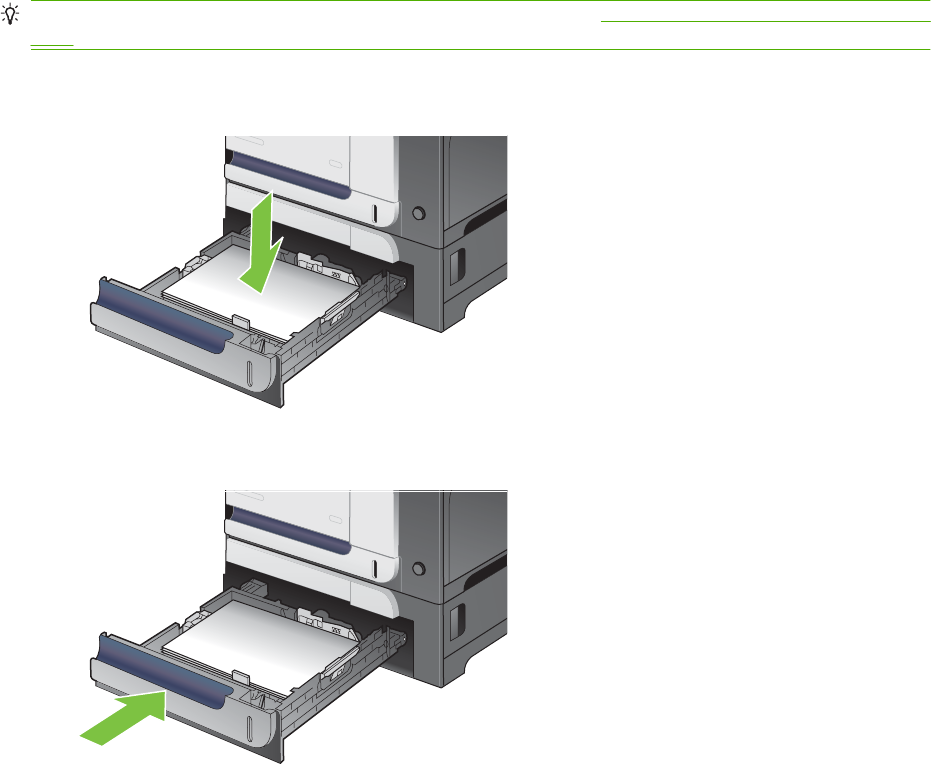
Clear jams in the optional 500-sheet paper and heavy media tray (Tray 3)
TIP: To see an animation of this procedure go to this Web site: www.hp.com/go/cljcm3530mfp-tray3-
jams.
1. Open Tray 3 and make sure that the paper is stacked correctly. Remove any damaged or jammed
sheets of paper.
2. Close Tray 3.
ENWW Clear paper jams 483
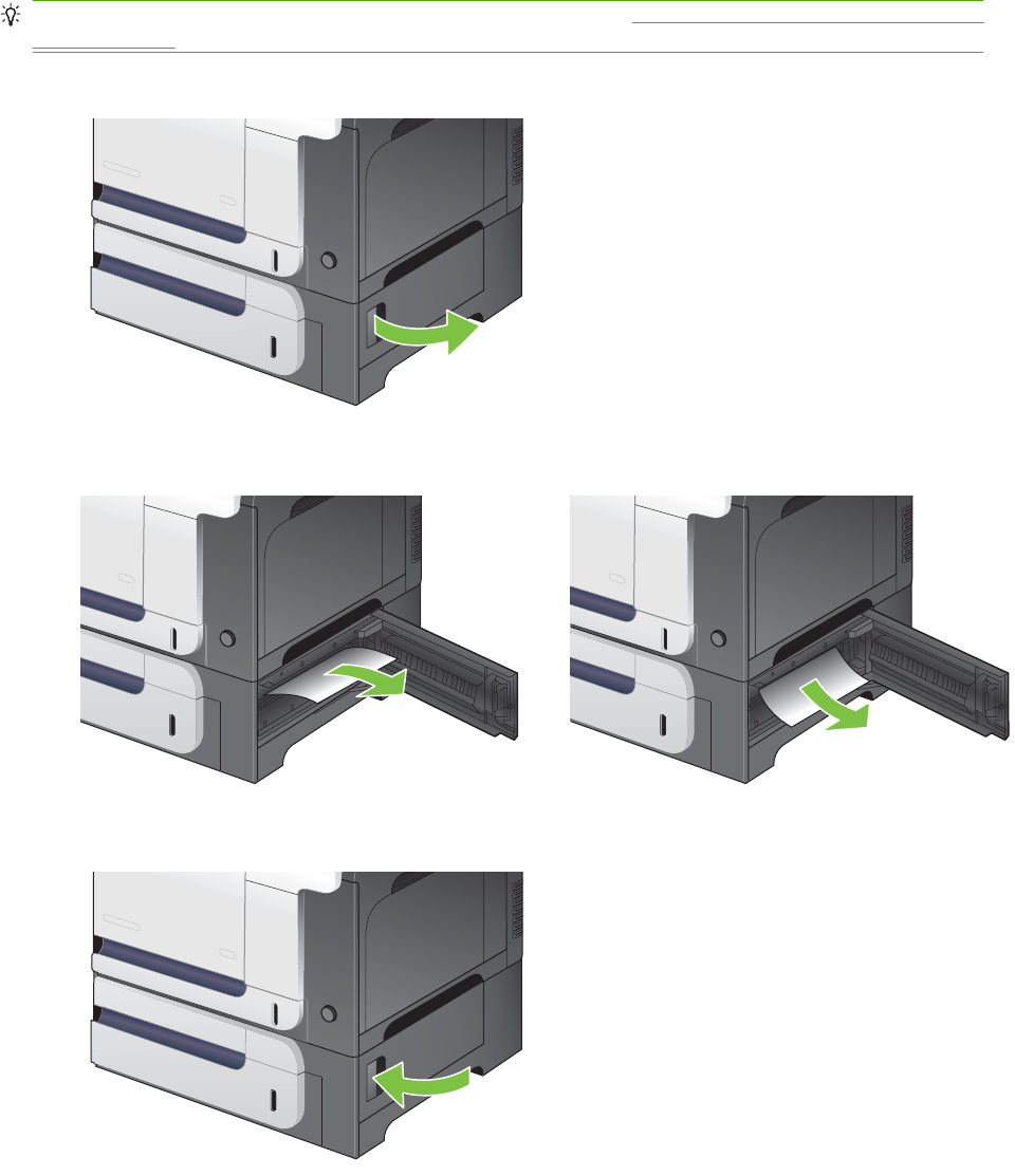
Clear jams in the lower right door (Tray 3)
TIP: To see an animation of this procedure go to this Web site: www.hp.com/go/cljcm3530mfp-lower-
right-door-jams.
1. Open the lower right door.
2. If paper is visible, gently pull the jammed paper up or down to remove it.
3. Close the lower right door.
484 Chapter 7 Solve problems ENWW
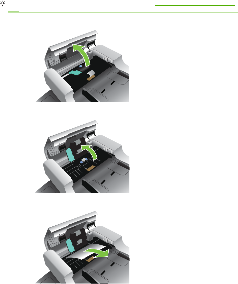
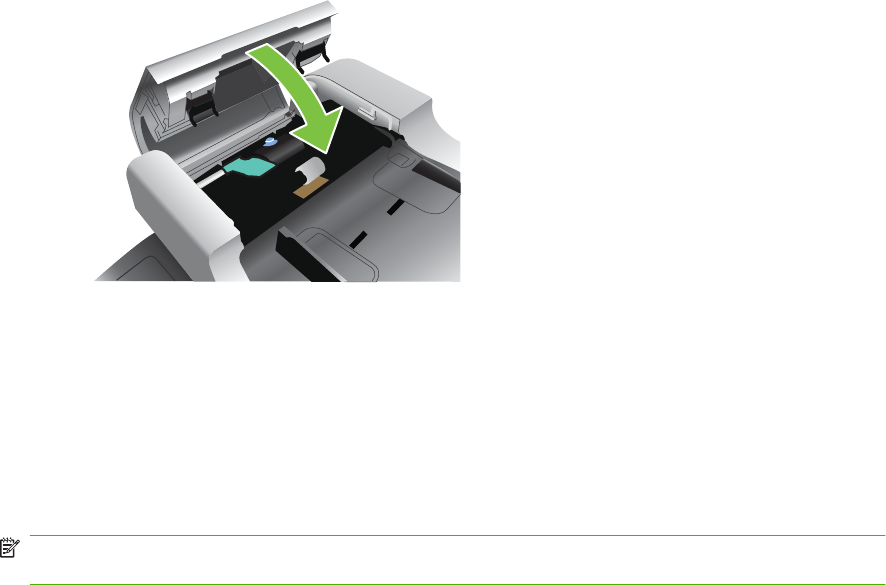
4. Close the document feeder cover.
Jam recovery
This product provides jam recovery, a feature that reprints jammed pages. The following options are
available:
●Auto setting — The product attempts to reprint jammed pages when sufficient memory is available.
●Off setting — The product does not attempt to reprint jammed pages. Because no memory is used
to store the most recent pages, performance is optimal.
NOTE: When using this option, if the product runs out of paper and the job is being printed on
both sides, some pages can be lost.
●On setting — The product always reprints jammed pages. Additional memory is allocated to store
the last few pages printed. This might cause overall performance to suffer.
Set the jam recovery feature
1. Touch the Administration menu and then touch the Device Behavior setting.
2. Touch the Warning/Error Behavior setting and then touch the Jam Recovery setting.
3. Touch an option and then touch the Save button.
486 Chapter 7 Solve problems ENWW

Solve paper-handling problems
Use only paper that meets the specifications outlined in the HP LaserJet Printer Family Print Media
Guide. Always configure the paper type on the control panel to match the type of paper that is loaded
in the tray.
Product feeds multiple sheets
Product feeds multiple sheets
Cause Solution
The input tray is overfilled. Open the tray and verify that the
paper stack is below the maximum stack height mark.
Remove excess paper from the input tray.
Print paper is sticking together. Remove paper, flex it, rotate it 180 degrees or flip it over, and
then reload it into the tray.
NOTE: Do not fan paper. Fanning can cause static electricity,
which can cause paper to stick together.
Paper does not meet the specifications for this product. Use only paper that meets HP paper specifications for this
product.
Trays are not properly adjusted. Make sure that the paper guides match the size of paper being
used.
Product feeds incorrect page size
Product feeds incorrect page size
Cause Solution
The correct size paper is not loaded in the input tray. Load the correct size paper in the input tray.
The correct size paper is not selected in the software program
or printer driver.
Confirm that the settings in the software program and printer
driver are correct, because the software program settings
override the printer driver and control panel settings, and the
printer driver settings override the control panel settings.
The correct size paper for the tray is not selected in the product
control panel.
From the control panel, select the correct size paper for the
tray.
The paper size is not configured correctly for the input tray. Print a configuration page or use the control panel to determine
the paper size for which the tray is configured.
The guides in the tray are not against the paper. Verify that the paper guides are touching the paper.
Product pulls from incorrect tray
Product pulls from incorrect tray
Cause Solution
You are using a driver for a different product. Use a driver for this product.
The specified tray is empty. Load paper in the specified tray.
ENWW Solve paper-handling problems 487

Product pulls from incorrect tray
Cause Solution
The paper size is not configured correctly for the input tray. Print a configuration page or use the control panel to determine
the paper size for which the tray is configured.
The guides in the tray are not against the paper. Verify that the guides are touching the paper.
Paper does not feed automatically
Paper does not feed automatically
Cause Solution
Manual feed is selected in the software program. Load Tray 1 with paper, or, if the paper is loaded, press the
checkmark button .
The correct size paper is not loaded. Load the correct size paper.
The input tray is empty. Load paper into the input tray.
Paper from a previous jam has not been completely removed. Open the product and remove any paper in the paper path.
The paper size is not configured correctly for the input tray. Print a configuration page or use the control panel to determine
the paper size for which the tray is configured.
The guides in the tray are not against the paper. Verify that the rear and width paper guides are touching the
paper.
The manual-feed prompt is set to ALWAYS. The product
always prompts for manual feed, even if the tray is loaded.
Open the tray, reload the media, and then close the tray.
Or, change the manual-feed prompt setting to UNLESS
LOADED, so that the product prompts for manual feed only
when the tray is empty.
The USE REQUESTED TRAY setting on the product is set to
EXCLUSIVELY, and the requested tray is empty. The product
will not use another tray.
Load the requested tray.
Or, change the setting from EXCLUSIVELY to FIRST on the
CONFIGURE DEVICE menu. The product can use other trays
if no media is loaded in the specified tray.
Paper does not feed from Tray 2 or 3
Paper does not feed from Tray 2 or 3
Cause Solution
The correct size paper is not loaded. Load the correct size paper.
The input tray is empty. Load paper in the input tray.
The correct paper type for the input tray is not selected in the
product control panel.
From the product control panel, select the correct paper type
for the input tray.
Paper from a previous jam has not been completely removed. Open the product and remove any paper in the paper path.
Closely inspect the fuser area for jams.
None of the optional trays appear as input tray options. The optional trays only display as available if they are installed.
Verify that any optional trays are correctly installed. Verify that
488 Chapter 7 Solve problems ENWW

Paper does not feed from Tray 2 or 3
Cause Solution
the printer driver has been configured to recognize the optional
trays.
An optional tray is incorrectly installed. Print a configuration page to confirm that the optional tray is
installed. If not, verify that the tray is correctly attached to the
product.
The paper size is not configured correctly for the input tray. Print a configuration page or use the control panel to determine
the paper size for which the tray is configured.
The guides in the tray are not against the paper. Verify that the guides are touching the paper.
Transparencies or glossy paper will not feed
Transparencies or glossy paper will not feed
Cause Solution
The correct paper type is not specified in the software or printer
driver.
Verify that the correct paper type is selected in the software or
printer driver.
The input tray is overfilled. Remove excess paper from the input tray. Do not exceed the
maximum stack height marks for the tray.
Paper in another input tray is the same size as the
transparencies, and the product is defaulting to the other tray.
Make sure that the input tray containing the transparencies or
glossy paper is selected in the software program or printer
driver. Use the product control panel to configure the tray to
the paper type loaded.
The tray containing the transparencies or glossy paper is not
configured correctly for type.
Make sure that the input tray containing the transparencies or
glossy paper is selected in the software program or printer
driver. Use the product control panel to configure the tray to
the paper type loaded.
Transparencies or glossy paper might not meet supported
paper specifications.
Use only paper that meets the HP paper specifications for this
product.
High-humidity environments may cause glossy paper not to
feed, or to feed too many sheets.
Avoid printing glossy paper in high humidity conditions. When
printing glossy paper, removing the paper from the wrapper
and letting it rest for a few hours can improve feeding into the
product. However, letting paper rest in humid environments
may also cause blisters.
Envelopes jam or will not feed in the product
Envelopes jam or will not feed in the product
Cause Solution
Envelopes are loaded in an unsupported tray. Only Tray 1 can
feed envelopes.
Load envelopes into Tray 1.
Envelopes are curled or damaged. Try using different envelopes. Store envelopes in a controlled
environment.
Envelopes are sealing because the moisture content is too
high.
Try using different envelopes. Store envelopes in a controlled
environment.
ENWW Solve paper-handling problems 489

Envelopes jam or will not feed in the product
Cause Solution
Envelope orientation is incorrect. Verify that the envelope is loaded correctly.
This product does not support the envelopes being used. Refer to the HP LaserJet Printer Family Print Media Guide.
Tray 1 is configured for a size other than envelopes. Configure Tray 1 size for envelopes.
Output is curled or wrinkled
Output is curled or wrinkled
Cause Solution
Paper does not meet the specifications for this product. Use only paper that meets the HP paper specifications for this
product.
Paper is damaged or in poor condition. Remove paper from the input tray and load paper that is in
good condition.
Product speed needs to be reduced. Set the PAPER CURL option in the Print Quality menu to
REDUCED to decrease full speed to 10 ppm (instead of 40
ppm) and 3/4 speed to 7.5 ppm (instead of 30 ppm).
Product is operating in an excessively humid environment. Verify that the printing environment is within humidity
specifications.
You are printing large, solid-filled areas. Large, solid-filled areas can cause excessive curl. Try using a
different pattern.
Paper used was not stored correctly and might have absorbed
moisture.
Remove paper and replace it with paper from a fresh,
unopened package.
Paper has poorly cut edges. Remove paper, flex it, rotate it 180 degrees or turn it over, and
then reload it into the input tray. Do not fan paper. If the problem
persists, replace the paper.
The specific paper type was not configured for the tray or
selected in the software.
Configure the software for the paper (see the software
documentation). Configure the tray for the paper, see Load
paper and print media on page 62.
The paper has previously been used for a print job. Do not re-use paper.
Product will not duplex or duplexes incorrectly
Product will not duplex (print 2-sided jobs) or duplexes incorrectly
Cause Solution
You are trying to duplex on unsupported paper. Verify that the paper is supported for duplex printing.
The printer driver is not set up for duplex printing. Set up the printer driver to enable duplex printing.
490 Chapter 7 Solve problems ENWW

Product will not duplex (print 2-sided jobs) or duplexes incorrectly
Cause Solution
The first page is printing on the back of preprinted forms or
letterhead.
Load preprinted forms and letterhead in Tray 1 with the
letterhead or printed side down, with the top of the page leading
into the product. For Tray 2 and 3, load the paper printed side
up with the top of the page toward the right of the product.
The product configuration is not set for duplexing. In Windows, run the automatic configuration feature:
1. Click the Start button, point to Settings, and then click
Printers (for Windows 2000) or Printers and Faxes (for
Windows XP).
2. Right-click the HP product icon, and then click
Properties or Printing Preferences.
3. Click the Device Settings tab.
4. Under Installable Options, click Update Now in the
Automatic Configuration list.
ENWW Solve paper-handling problems 491

Use manual print modes
Try the following multi-purpose (MP) modes to see if they solve the image-quality problems. At the
control panel, touch Administration, and then Print Quality, and then scroll to the Print Modes or
Optimize submenus.
If you are having print-quality problems when using a specific paper type, use the Print Modes submenu
to override the factory-default mode setting can sometimes resolve the print quality problems. You can
associate a different print mode with each paper type.
Use the Optimize submenu to optimize print engine parameters to get the best possible print quality for
all the jobs rather than printing by media type. Use the Restore Optimize option to reset all of the
Optimize parameters back to the factory default settings
Table 7-13 MP modes under the Adjust paper types> sub menu
PRINT MODE
●Plain
●Light 60-74g
●Intermediate 85-95g
●Bond
●Recycled
●Mid-Weight 96-110g
●Heavy 111-130g
●Mid-Wt Glossy 96-110
●Hvy Glossy 111-130g
●Extra Heavy 131-175
●Xhvy Glossy 131-175g
●Card Stock 176-220g
●Card Glossy 176-220
●Transparency
●Labels
NOTE: Not all print modes are available for all paper types.
Table 7-14 MP modes under the Optimize submenu
BACKGROUND Set to ALTERNATIVE 1 when a background occurs all over
the page. Set to ALTERNATIVE 2 when thin vertical lines
appear on the page. Set to ALTERNATIVE 3 when the other
alternatives do not correct the problem.
REGISTRATION Set to ALTERNATIVE when color misregistration occurs.
TRANSFER CONTROL Set to ALTERNATIVE 1 to reduce primary transfer bias and to
resolve low density or blotchy images. Set to ALTERNATIVE
2 to resolve ghosting outlines that look like a finger or fingers.
Set to ALTERNATIVE 3 when the other alternatives do not
correct the problem.
492 Chapter 7 Solve problems ENWW

TRAY1 Set the mode to ALTERNATE if you are seeing marks on the
back side of the paper when printing from Tray 1. This sets the
product to initiate a clean sequence every time a job finishes
when the product is set for Any Size and Any Type for Tray 1.
ENVIRONMENT Set to LOW TEMP if the product is operating in a low-
temperature environment and you are having problems with
print quality such as blisters in the printed image.
LINE VOLTAGE Set to LOW VOLTAGE if the product is operating in a low-
voltage environment and you are having problems with print
quality such as blisters in the printed image.
TRACKING CONTROL Improves color stability by adjusting the bias voltage. Make
sure this mode is set to ON.
UNIFORMITY CONTROL Set to ALTERNATIVE 1 to improve uniformity on any paper
type. Set to ALTERNATIVE 2 to improve uniformity on normal
and light paper types. Set to ALTERNATIVE 3 when the other
alternatives do not correct the problem.
NORMAL PAPER Set to SMOOTH when printing on smooth paper of normal
weight.
HEAVY PAPER Set to SMOOTH when printing on smooth, heavy media types.
ENVELOPE MODE Set to REDUCED TEMP if envelopes are sticking due to
moisture in the envelop adhesive.
RESISTANCE MODE Set to Up to resolve print-quality issues caused by poor
secondary transfer in low-humidity environments with resistive
or rough surface media.
HUMIDITY MODE With glossy film, set to High when the product is in a high-
humidity environment and print-quality defects occur on HP
Tough Paper or Opaque film.
With transparencies, set to High when the product is in a high-
humidity environment and print-quality defects occur on color
transparencies on the first page of a print job.
With all other paper types, set to High when the product is in a
high-humidity environment and light density occurs on the first
page of a print job.
PRE-ROTATION MODE Set this feature to ON if horizontal banding occurs on pages.
FUSER TEMP MODE If you are seeing a faint image of the page repeated at the
bottom of the page or on the following page, first make sure
the Paper Type and Print Mode settings are correct for the type
of paper you are using. If you continue to see ghost images on
your print jobs, set the Fuser Temp feature to one of the
Alternate settings . Try the ALTERNATE 1 setting first and see
if it solves the problem. If you continue to see the problem, try
ALTERNATE 2 and then ALTERNATE 3. Using the
ALTERNATE 2 and ALTERNATE 3 settings might cause an
extra delay between jobs.
PAPER CURL MODE Use in high-humidity and high-temperature environments. The
REDUCED setting decreases fuser temperature and
increases the interpage gap.
RESTORE OPTIMIZE Return all settings to the factory-default settings.
Table 7-14 MP modes under the Optimize submenu (continued)
ENWW Use manual print modes 493

Solve image-quality problems
This section helps you define print-quality problems and what to do to correct them. Often print-quality
problems can be handled easily by making sure that the product is properly maintained, using paper
that meets HP specifications, or running a cleaning page.
Image defects table
The following examples depict letter-size paper that has passed through the product short-edge first.
These examples illustrate problems that would affect all of the pages that you print, whether you print
in color or in black only. The topics that follow list the typical cause and solution for each of these
examples.
For ADF image-quality problems, verify that the scanner is scanning from the ADF and not the scanner
glass. If it is scanning from the glass, you should see the scanner illuminate and the optical head move
the entire length of the glass. If no document is on the glass, a blank page is produced.
Problem Cause Solution
Print is light or faded on entire page. Poor contacts exist on the ITB unit
and the product grounding unit.
Clean the grounding contacts. If the problem
remains after cleaning, check the contacts
for damage. Replace any deformed or
damaged parts.
Poor secondary transfer contacts
with exist on the secondary transfer
roller and the ITB.
Clean the contacts. If the problem remains
after cleaning, check the contacts for
damage. Replace any deformed or damaged
parts.
Print is light or faded in a particular color. Poor primary transfer bias contacts
on the ITB unit and product.
Clean the contacts of the color that produces
the light print. If the problem remains after
cleaning, check the contacts for damage.
Replace any deformed or damaged parts.
Poor primary charging bias contacts
with the print cartridge and product.
Poor developing bias contacts with
the print cartridge and product.
Image is too dark. The image-density sensor is
defective.
Replace the color misregistration/image-
density sensor unit.
494 Chapter 7 Solve problems ENWW

Problem Cause Solution
Page is blank. The source document was not placed
in the ADF input tray face-up.
Verify that the source document is face-up in
the ADF input tray.
The source document was not
detected in the ADF input tray.
Remove and then reinsert the source
document into the ADF, making sure that it
is placed face-up.
A source document was not picked
up when attempting to feed multiple
documents.
Inspect the ADF pickup and feed rollers and
the ADF separation pad for damage. Clean
the rollers if they are dirty. If the ADF
separation pad or rollers are warn, replace
them. See ADF roller assembly and
separation pad on page 215.
The high-voltage power-supply lower
is defective (no developing bias
output).
Replace the high-voltage power-supply
lower. See High-voltage power supply lower
on page 308.
The page is all black or a solid color. Poor contact exists in the primary
charging bias or developing bias
contacts between the print cartridge
and the product.
Clean each contact of the color that produces
the all black or solid color. If the problem
remains after cleaning, check the contacts
for damage. Replace any deformed or
damaged parts.
White spots appear in an image The static charge eliminator is dirty. Clean the static charge eliminator.
The primary transfer roller is
deformed or has deteriorated.
Replace the ITB. See Intermediate transfer
belt (ITB) on page 209.
The secondary transfer roller is
deformed or has deteriorated.
Replace the secondary-transfer-roller. See
Secondary transfer roller on page 205.
The back of the page is dirty. The secondary transfer roller is dirty. Replace the secondary transfer roller. See
Secondary transfer roller on page 205.
The fuser inlet guide or separation
guide is dirty.
Clean the dirty parts. If the dirt does not come
off, replace the guide.
The pressure roller is dirty. Execute the cleaning page. If the dirt does
not come off, replace the fuser.
ENWW Solve image-quality problems 495

Problem Cause Solution
Vertical streaks or bands appear on the
page.
The ADF small glass might be dirty. Clean the ADF small glass.
Scratches are present on the
circumference of the photosensitive
drum.
Replace the print cartridge of the color that
matches the defect.
Scratches are present on the
circumference of the fuser roller.
Replace the fuser. See Fuser on page 200.
Scratches are present on the
circumference of the ITB.
Replace the ITB. See Intermediate transfer
belt (ITB) on page 209.
The ITB drive roller is deformed or
has deteriorated.
The ITB cleaning mechanism is
malfunctioning.
Vertical white lines appear in a particular
color.
The laser beam window is dirty. Clean the window and remove any foreign
substances.
Scratches are present on the
circumference of the developing
cylinder or photosensitive drum.
Replace the print cartridge of the color that
matches the defect.
The laser/scanner-unit mirror is dirty. Replace the laser/scanner assembly. See
Laser/scanner assembly (Y/M) on page 325
or Laser/scanner assembly (C/Bk)
on page 332.
Vertical white lines appear in all colors. Horizontal scratches on the fuser
roller.
Replace the fuser. See Fuser on page 200.
Scratches are present on the
circumference of the ITB.
Replace the ITB. See Intermediate transfer
belt (ITB) on page 209.
Horizontal lines appear on the page. Repetitive horizontal lines appear. Use the repetitive defects ruler to identify the
dirty roller. Clean the roller. If the roller
cannot be cleaned, replace the roller.
Horizontal scratches are present on
the photosensitive drum.
Replace the print cartridge of the color that
matches the defect.
Horizontal scratches are present on
the fuser roller.
Replace the fuser. See Fuser on page 200.
A horizontal white line appears on the
page.
Repetitive horizontal white lines
appear.
Use the repetitive defects ruler to identify the
dirty roller. Clean the roller. If the roller
cannot be cleaned, replace the roller.
Horizontal scratches are present on
the photosensitive drum.
Replace the print cartridge of the color that
matches the defect.
Scratches are present on the
circumference of the ITB.
Replace the ITB. See Intermediate transfer
belt (ITB) on page 209.
496 Chapter 7 Solve problems ENWW
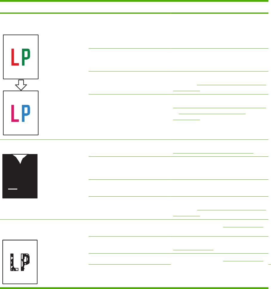
Problem Cause Solution
Image in a particular color does not print
in the correct color.
Poor contact exists in the primary
charging bias or developing bias
contacts between the print cartridge
and the product.
Clean each contact of the color that produces
the missing color. If the problem remains
after cleaning, check the contacts for
damage. Replace any deformed or damaged
parts.
The print cartridge (primary charging
roller, developing roller, or
photosensitive drum) is defective.
Replace the print cartridge of the color that
matches the defect.
The high-voltage power-supply lower
is defective (no primary charging bias
or developing bias output).
Replace the high-voltage power-supply
lower. See High-voltage power supply lower
on page 308.
The laser/scanner unit is defective. Replace the laser/scanner assembly. See
Laser/scanner assembly (Y/M) on page 325
or Laser/scanner assembly (C/Bk)
on page 332.
Dropouts appear. The secondary transfer roller is
deformed or has deteriorated.
Replace the secondary-transfer-roller. See
Secondary transfer roller on page 205.
The primary charging roller,
developing roller,, or photosensitive
drum is deformed or has deteriorated.
Replace the print cartridge of the color that
matches the defect.
The fuser roller is deformed or has
deteriorated.
Replace the fuser.
The high-voltage power-supply T
PCA is defective (no transfer bias
output).
Replace the high-voltage power-supply
upper. See High-voltage power supply upper
on page 339.
The toner is not fully fused to the
paper.
The fuser roller or pressure roller is
scarred or deformed.
Replace the fuser. See Fuser on page 200.
The fuser control PCA is defective. Replace the low-voltage power supply. See
Fuser on page 200.
The thermistor is defective. Replace the fuser. See Fuser on page 200.
The fuser heater is defective.
ENWW Solve image-quality problems 497
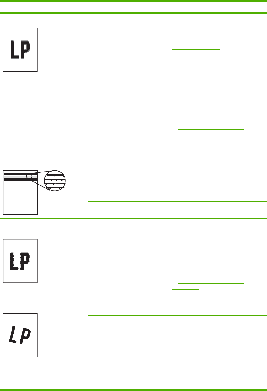
Problem Cause Solution
Some color is misregistered. The product is incorrectly calibrated. Calibrate the product.
The ITB unit is defective. If the ITB does not rotate smoothly or a
cleaning malfunction occurs (ITB is dirty),
replace the ITB. See Intermediate transfer
belt (ITB) on page 209.
The drive gear of the ITB motor is
worn or chipped.
Check each drive gear between the ITB drive
roller and the ITB motor. If the gear is worn
or chipped, replace the drive unit.
The RD sensor is defective. Open the close the front door several times
to clean the RD sensor. If the problem
persists, replace the RD sensor. See
Registration density (RD) sensor assembly
on page 297.
The laser/scanner unit is defective. Replace the laser/scanner assembly. See
Laser/scanner assembly (Y/M) on page 325
or Laser/scanner assembly (C/Bk)
on page 332.
The print cartridge is defective. Replace the print cartridge of the affected
color.
Toner smears appear on the media. The product has residual media. Remove the residual media.
Poor grounding contacts exist
between each print cartridge and the
product.
Clean the grounding contacts on each print
cartridge and the product. If the problem
remains after cleaning, check the contacts
for damage. Replace any deformed or
damaged parts.
The fuser inlet guide is dirty. Clean the fuser inlet guide.
The printed page contains misformed
characters.
The ADF white backing is not
uniformly pressing the source
document against the flatbed glass.
Check the ADF white backing for damage or
warping. Replace the ADF if necessary. See
Automatic document feeder (ADF)
on page 212.
The product is experiencing page
skew.
See the “Text or graphics are skewed on the
printed page” row in this table.
The laser/scanner unit is defective. Replace the laser/scanner assembly. See
Laser/scanner assembly (Y/M) on page 325
or Laser/scanner assembly (C/Bk)
on page 332.
Text or graphics are skewed on the
printed page.
The ADF input tray guides are not
correctly adjusted.
Make sure that the ADF input tray guides are
adjusted so that they are lightly touching the
sides of the paper stack.
A source document was not picked
up when attempting to feed multiple
documents.
Inspect the ADF pickup and feed rollers and
the ADF separation pad for damage. Clean
the rollers if they are dirty. If the ADF
separation pad or rollers are warn, replace
them. See ADF roller assembly and
separation pad on page 215.
The registration shutter spring is
unhooked.
Check the spring and place it in the correct
position.
The registration shutter spring is
deformed.
Replace the registration assembly. See
Registration assembly on page 303.
498 Chapter 7 Solve problems ENWW

Problem Cause Solution
The printed page contains wrinkles or
creases.
The roller or media feed guide is dirty. Clean any dirty components.
A roller is deformed or has
deteriorated.
Replace any deformed or deteriorated
rollers.
The paper feed guide is damaged. Replace the paper-feed-guide unit.
The front of the page is dirty. The photosensitive drum is dirty. Replace the print cartridge.
The fuser roller or pressure roller is
dirty.
Execute a Pressure roller clean mode. If
the dirt does not come off, replace the fuser.
See Fuser on page 200.
Unexpected image The copied image does not look like
the source document.
If the copy was made using the ADF, make
sure that no media is on the flatbed glass
from a previous copy job.
The scanner-control board (SCB) has
failed.
Replace the SCB. See Scanner-control
board (SCB) on page 279.
ENWW Solve image-quality problems 499

Solve performance problems
Problem Cause Solution
Pages print but are totally blank. The document might contain blank
pages.
Check the document that you are printing
to see if content appears on all of the
pages.
The product might be malfunctioning. To check the product, print a
Configuration page.
Pages print very slowly. Heavier paper types can slow the print
job.
Print on a different type of paper.
Complex pages can print slowly. Proper fusing may require a slower print
speed to ensure the best print quality.
Pages did not print. The product might not be pulling paper
correctly.
Make sure paper is loaded in the tray
correctly.
The paper is jamming in the product. Clear the jam. See Clear paper jams
on page 472.
The USB cable might be defective or
incorrectly connected.
●Disconnect the USB cable at both
ends and reconnect it.
●Try printing a job that has printed in
the past.
●Try using a different USB cable.
Other devices are running on your
computer.
The product might not share a USB port.
If you have an external hard drive or
network switchbox that is connected to
the same port as the product, the other
device might be interfering. To connect
and use the product, you must
disconnect the other device or you must
use two USB ports on the computer.
500 Chapter 7 Solve problems ENWW

Solve connectivity problems
Solve direct-connect problems
If you have connected the product directly to a computer, check the cable.
●Verify that the cable is connected to the computer and to the product.
●Verify that the cable is not longer than 2 meters (6 feet). Replace the cable if necessary.
●Verify that the cable is working correctly by connecting it to another product. Replace the cable if
necessary.
Solve network problems
Check the following items to verify that the product is communicating with the network. Before beginning,
print a configuration page. See Print information pages on page 80.
1. Are there any physical connection problems between the workstation or file server and the product?
Verify that the network cabling, connections, and router configurations are correct. Verify that the
network cable lengths meet network specifications.
2. Are your network cables connected properly?
Make sure that the product is attached to the network using the appropriate port and cable. Check
each cable connection to make sure it is secure and in the right place. If the problem continues,
try a different cable or ports on the hub or transceiver. The amber activity light and the green link
status light next to the port connection on the back of the product should be lit.
3. Are the link speed and duplex settings set correctly?
Hewlett-Packard recommends leaving this setting in automatic mode (the default setting). See
Networking and I/O on page 31.
4. Can you "ping" the product?
Use the command prompt to ping the product from your computer. For example:
ping 192.168.45.39
Ensure that the ping displays round-trip times.
If you are able to ping the product, verify that the IP address configuration for the product is correct
on the computer. If it is correct, delete and then add the product again.
If the ping command failed, verify that the network hubs are on, and then verify that the network
settings, the product, and the computer are all configured for the same network.
5. Have any software applications been added to the network?
Make sure they are compatible and that they are installed correctly with the correct printer drivers.
6. Are other users able to print?
The problem may be workstation-specific. Check the workstation network drivers, printer drivers,
and redirection (capture in Novell NetWare).
7. If other users are able to print, are they using the same network operating system?
ENWW Solve connectivity problems 501

Check your system for proper network operating system setup.
8. Is your protocol enabled?
Check the status of your protocol on the Configuration page. You can also use the embedded Web
server to check the status of other protocols. See Embedded Web server on page 85.
9. Does the product appear in HP Web Jetadmin or other management application?
●Verify network settings on the Network configuration page.
●Confirm the network settings for the product using the product control panel (for products with
control panels).
502 Chapter 7 Solve problems ENWW

Service mode functions
Service menu
The Service menu is PIN-protected for added security. Only authorized service people have access to
the Service menu. When you select Service from the list of menus, the product prompts you to type an
eight-digit PIN number. The PIN for the HP Color LaserJet CM3530 MFP Series is 11353008.
NOTE: The product automatically exits the Service menu after about one minute if no items are
selected or changed.
1. Scroll to and touch Administration.
2. Scroll to and touch Service.
3. Touch the Service use only: text box near the center of the control-panel display. The touchscreen
numeric keypad appears.
4. Touch the touchscreen numeric keypad buttons to type the PIN (11353008).
5. Touch OK to save the PIN or Cancel to exit the screen.
6. The PIN displays in the Service use only: text box as ********.
7. Touch OK to open the Service menu or Cancel to exit the screen.
The following menu items appear in the Service menu:
Menu item Sub-menu item Description
Clear Event Log Use this item to clear the product event log.
Mono Cycle Count The page count that is stored in NVRAM and printed on the
configuration page represents the number of pages that the
formatter has formatted (not including engine-test prints).
Color Cycle Count The page count that is stored in NVRAM and printed on the
configuration page represents the number of pages that the
formatter has formatted (not including engine-test prints).
Refurbish Cycle Count Use this item to record the page count when the product
was refurbished.
Document Feeder Kit Count: Set the total number of pages that have been fed through
the ADF.
Document Feeder Kit Interval Total number of pages since the document feeder kit was
replaced.
ADF Count Set the total pages fed through the ADF.
Flatbed Count Set the total pages scanned from the flatbed.
ADF Simplex Count Set the total single-sided pages fed through the ADF.
ADF Duplex Count Set the total two-sided pages fed through the ADF.
Copy Scan Count Set the total copy pages that have been scanned.
Send Scan Count Set the number of scanned pages sent to e-mail.
Copy Pages Count Set the number of scanned pages that have been printed.
ENWW Service mode functions 503

Menu item Sub-menu item Description
Scanner Settings ADF Settings Set the calibration values.
Glass Settings Set the calibration values.
Serial number Set the serial number.
SERVICE ID Use this item to show the date that the product was first
used on the control panel. This eliminates the need for users
to keep paper receipts for proof of warranty.
Restore the service ID
If you replace the formatter, the date is lost. Use this menu
item to reset the date to the original date that the product
was first used. The date format is YYDDD. Use the following
formula to calculate the dates:
1. To calculate YY, subtract 1990 from the calendar year.
For instance, if the product was first used in 2002,
calculate YY as follows: 2002 - 1990 = 12. YY = 12.
2. Subtract 1 from 10 (October is the tenth month of the
year): 10 - 1 = 9.
◦Multiply 9 by 30: 9 x 30 = 270 or add 17 to 270:
270 + 17 = 287. Thus, DDD = 287.
Convert the service ID to an actual date
You can use the product Service ID number to determine
whether the product is still under warranty. Use the following
formula to convert the Service ID into the installation date
as follows:
1. Add 1990 to YY to get the actual year that the product
was installed.
2. Divide DDD by 30. If there is a remainder, add 1 to the
result. This is the month.
3. The remainder from the calculation in step 2 is the
date.
Using the Service ID 12287 as an example, the date
conversion is as follows:
1. 12 + 1990 = 2002, so the year is 2002.
2. 287 divided by 30 = 9 with a remainder of 17. Since
there is a remainder, add 1 to 9 to get 10, which
represents October.
3. The remainder in step 2 is 17, so that is the date.
4. The complete date is 17-October-2002.
NOTE: A six-day grace period is built into the date system.
Cold Reset Paper When you perform a cold reset, the paper size that is stored
in NVRAM is reset to the default factory setting. If you
replace a formatter board in a country/region that uses A4
as the standard paper size, use this menu to reset the
default paper size to A4. LETTER and A4 are the only
available values.
504 Chapter 7 Solve problems ENWW

Product resets
Restore factory settings
Use the Resets menu to restore factory settings.
1. Scroll to and touch Administration and then touch Resets.
2. Touch Restore Factory Settings and then touch Reset.
For more information, see Resets menu on page 53.
Hard disk initialization (optional)
A hard disk initialization will erase and reformat the product's hard disk. Perform hard disk initialization
only if an error code displays on the control panel indicating a disk error. Always try initializing the hard
disk before replacing it.
1. Turn the product on.
2. As the product performs its power-on sequence, press and hold the Start button until all lights on
the control panel are lit.
3. Press the 5 key. The INITIALIZE DISKS menu item appears.
4. Press the 6 key. The product initializes the hard disk and continues its power-on sequence.
ENWW Service mode functions 505

NVRAM initialization
CAUTION: Initializing NVRAM resets the serial number, the event log, the page counts, the calibration
settings, and the EIO card. Use the Service menu to restore the serial number and page counts. You
also need to reconfigure any computers that print to this product to recognize the product. Initialize
NVRAM only when absolutely necessary. In most situations, use a cold reset to reset product variables
but still retain the needed values in the Service menu.
NOTE: Before performing an NVRAM initialization, print a menu map and a configuration page. Use
the information on these pages to reset any customer-specific settings.
From the configuration page and supplies status page, gather the following information:
●Total page count and color page count
●Serial number
1. Turn the product off.
2. Press and hold 9, turn the power on, wait for all three LEDs to stay on. This might take up to 20
seconds (release the 9 key).
3. Press and release 3, and then press and release Start.
4. Use the 3 and 9 keys to scroll to NVRAM INIT (this message appears in the upper-left corner of
the display).
5. Press and release 6 to start the initialization.
Restore factory settings (cold reset)
Before beginning, print a configuration page and supplies status page. Use these pages to verify that
the resets have occurred.
1. Turn the product offn.
2. Press and hold 6, turn the power on, wait for all three LEDs to stay on. This might take up to 20
seconds (release the 6 key).
3. Use the 3 and 9 keys to scroll to Cold Reset (this message appears in the upper-left corner of the
display).
4. Press the 6 key to start the cold reset.
506 Chapter 7 Solve problems ENWW

Solve fax problems
See the HP LaserJet MFP Analog Fax Accessory 500 Fax Guide and the HP LaserJet MFP Analog Fax
Accessory 500 Send Fax Driver Guide, which are included on the product User CD. The guides are also
available for download from www.hp.com/go/mfpfaxaccessory500.
Solve e-mail problems
If you are unable to send e-mails by using the digital-send feature, you might need to reconfigure the
SMTP gateway address or the LDAP gateway address. Print a configuration page to find the current
SMTP and LDAP gateway addresses. See Print information pages on page 80. Use the following
procedures to check if the SMTP and LDAP gateway addresses are valid.
Validate the SMTP gateway address
NOTE: This procedure is for Windows operating systems.
1. Open an MS-DOS command prompt: click Start, click Run, and then type cmd.
2. Type telnet followed by the SMTP gateway address and then the number 25, which is the port
over which the product is communicating. For example, type telnet 123.123.123.123 25
where "123.123.123.123" represents the SMTP gateway address.
3. Press Enter. If the SMTP gateway address is not valid, the response contains the message Could
not open connection to the host on port 25: Connect Failed.
4. If the SMTP gateway address is not valid, contact the network administrator.
Validate the LDAP gateway address
NOTE: This procedure is for Windows operating systems.
1. Open Windows Explorer. In the address bar, type LDAP:// immediately followed by the LDAP
gateway address. For example, type LDAP://12.12.12.12 where "12.12.12.12" represents the
LDAP gateway address.
2. Press Enter. If the LDAP gateway address is valid, the Find People dialog box opens.
3. If the LDAP gateway address is not valid, contact the network administrator.
ENWW Solve fax problems 507
508 Chapter 7 Solve problems ENWW


Order parts, accessories, and supplies
You can obtain the following items directly from HP:
●Replacement parts: To order replacement parts in the U.S., go to www.hp.com/go/hpparts/.
Outside the United States, order parts by contacting your local authorized HP service center.
●Supplies and accessories: To order supplies in the U.S., go to www.hp.com/go/ljsupplies. To
order supplies worldwide, go to www.hp.com/ghp/buyonline.html. To order accessories, go to
www.hp.com/support/cljcm3530mfp.
510 Chapter 8 Parts and diagrams ENWW

Part numbers
The following list of accessories was current at the time of printing. Ordering information and availability
of the accessories might change during the life of the product.
Customer self-repair (CSR) components
Table 8-1 Customer self-repair (CSR) components
Item Part number
Formatter kit CC519-67903
128 MB memory kit CC519-67910
256 MB memory kit CC519-67911
512 MB memory kit CC519-67912
Hard drive kit CC519-67904
Hard drive cable kit CC519-67905
Fax PCA CC456-60001
Fax cable kit CC519-67907
Toner collection unit kit CC468-67910
Pick/feed and separation pad kit CC468-67911
ITB kit CC468-67907
110V fuser kit CC519-67901
220V fuser kit CC519-67902
Duplex reverse guide kit CC468-67913
Secondary transfer roller kit CC468-67914
Secondary transfer assembly kit (duplex) CC468-67915
Fuser cleaning kit (letter) CC468-67919
Front door assembly and nameplate CC519-67916
500 sheet feeder replacement kit CC468-67905
500 sheet feeder right door kit CC468-67906
Control panel kit CC519-67908
ADF kit CC483-67902
ADF roller kit CC519-67909
Stapler cartridge Q7432-67901
250-sheet cassette RM1-4962-000CN
500-sheet cassette RM1-6198-000CN
Control panel overlay—English CC519-40003
Control panel overlay—French CC519-40004
Control panel overlay—Italian CC519-40005
ENWW Part numbers 511

Item Part number
Control panel overlay—German CC519-40006
Control panel overlay—Spanish CC519-40007
Control panel overlay—Portuguese CC519-40009
Control panel overlay—Norwegian CC519-40010
Control panel overlay—Swedish CC519-40011
Control panel overlay—Finnish CC519-40012
Control panel overlay—Danish CC519-40013
Control panel overlay—Polish CC519-40014
Control panel overlay—Russian CC519-40015
Control panel overlay—Czech CC519-40016
Control panel overlay—Hungarian CC519-40017
Control panel overlay—Turkish CC519-40018
Control panel overlay—Hebrew CC519-40019
Control panel overlay—Greek CC519-40020
Control panel overlay—Arabic CC519-40021
Control panel overlay—Croatian CC519-40022
Control panel overlay—Romanian CC519-40023
Control panel overlay—Slovak CC519-40024
Control panel overlay—Slovenian CC519-40025
Control panel overlay—Catalan CC519-40026
Control panel overlay—Chinese, traditional CC519-40027
Control panel overlay—Chinese, simplified CC519-40028
Control panel overlay—Korean CC519-40030
Control panel overlay—Japanese CC519-40031
Control panel overlay—Thai CC519-40032
Control panel overlay—Bahasa Indonesian CC519-40033
Accessories and products
Table 8-2 Accessories
Item Description Part number Product part number
Stapler cartridge Replacement staple cartridge Q7432-67901 Q7432A
1 x 500 paper feeder 500-sheet paper and heavy
media tray
CC468-67905 CE522A
Table 8-1 Customer self-repair (CSR) components (continued)
512 Chapter 8 Parts and diagrams ENWW

Item Description Part number Product part number
Fax PCA HP LaserJet MFP analog fax
accessory 500
CC456-60001 CC487A
Digital send software HP Digital Sending Software 4 NA T1936AA
Print server HP Jetdirect 630n IPv6
Gigabit Ethernet print server
NA J7997G
HP Jetdirect 635n IPv6/IPSec
print server
NA J7961G
Parallel card HP 1284B parallel card NA J7972G
Print cartridges and toner collection unit
Table 8-3 Print cartridges and toner collection unit
Item Description
1
Part number Product part number
HP Color LaserJet black print
cartridge
Standard black cartridge CE250-67901 CE250A
HP Color LaserJet black print
cartridge
High-capacity black cartridge CE250-67902 CE250X
HP Color LaserJet cyan print
cartridge
Cyan cartridge CE251-67901 CE251A
HP Color LaserJet yellow print
cartridge
Yellow cartridge CE252-67901 CE252A
HP Color LaserJet magenta
print cartridge
Magenta cartridge CE253-67901 CE253A
Toner collection unit Waste toner box assembly
Waste toner installation
instructions
Toner cleaning cloth
CC468-67910 CE254A
1For more information, go to www.hp.com/go/learnaboutsupplies
Memory
Table 8-4 Memory
Item Description Product part number
200-pin DDR DIMM
Boosts the ability of the product to handle
large or complex print jobs.
128MB CC409AX
256MB CC410AX
512MB CC411AX
HP Encrypted High Performance hard
disks
HP high-performance secure hard disk J8018A
HP Encrypted High Performance hard
disks
HP high-performance secure EIO hard
disk
J8019A
Table 8-2 Accessories (continued)
ENWW Part numbers 513

Cables and interfaces
Table 8-5 Cables and interfaces
Item Description Part number
Enhanced I/O (EIO) card HP Jetdirect 635n IPv6/IPsec Print
Server
J7961G
USB cable 2-meter standard USB-compatible
device connector
C6518A
Power cord
North America
PWR-CORD OPT-903 3-COND 1.9-M-
LG ROHS
8121-0740
Power cord
Taiwan
PWR-CORD OPT-934 3-COND 1.9-M-
LG ROHS
8121-0964
Power cord
Europe (generic)
PWR-CORD OPT-902 3-COND 1.9-M-
LG ROHS
8121-0731
Power cord
China
PWR-CORD OPT-922 3-COND 1.9-M-
LG ROHS
8121-0943
Power cord PWR-CORD OPT-901 3-COND 1.9-M-
LG ROHS
8121-0837
Power cord
Japan (7A)
PWR-CORD OPT-918 3-COND 1.9-M-
LG ROHS
8121-0736
Power cord
United Kingdom; Singapore; Hong Kong
SAR; Malaysia
PWR-CORD OPT-900 3-COND 1.9-M-
LG 5A ROHS
8121-0739
Power cord
Denmark
PWR-CORD OPT-912 3-COND 1.9-M-
LG ROHS
8121-0733
Power cord
Argentina
PWR-CORD OPT-920 3-COND 1.9-M-
LG ROHS
8121-0729
Power cord
India (<= 6 A)
PWR-CORD OPT-923 3-COND 1.9-M-
LG ROHS
8121-0564
Power cord
Chile
PWR-CORD OPT-921 3-COND 1.9-M-
LG ROHS
8121-0735
Power cord
South Africa
PWR-CORD OPT-917 3-COND 1.9-M-
LG ROHS
8121-0737
Power cord
Israel
PWR-CORD OPT-919 3-COND 1.9-M-
LG ROHS
8121-1004
Power cord
Switzerland
PWR-CORD OPT-906 3-COND 1.9-M-
LG ROHS
8121-0738
514 Chapter 8 Parts and diagrams ENWW

Item Description Part number
Power cord
Thailand; Philippine Islands
PWR-CORD OPT-927 3-COND 1.9-M-
LG ROHS
8121-0734
Phone cord
United States
PHN-CORD OPT-501 US 3.0-M-LG
ROHS
8121-0811
Phone cord
Republic of Korea
PHN-CORD OPT-516 KR 3.0-M-LG
ROHS
8120-8908
Phone cord
Turkey
PHN-CORD OPT-507 TR 3.0-M-LG
ROHS
8120-8920
Phone cord
Estonia
PHN-CORD OPT-520 EE 3.0-M-LG
ROHS
8120-8922
Phone cord
Australia
PHN-CORD OPT-519 AU 3.0-M-LG
ROHS
8120-8907
Phone cord
United Kingdom; Hong Kong SAR; New
Zealand
PHN-CORD OPT-505 UK/HK/NZ 3.0-M-
LG ROHS
8120-8921
Phone cord
Denmark
PHN-CORD OPT-506 DK 3.0-M-LG
ROHS
8120-8911
Phone cord
Australia
PHN-CORD OPT-515 AT 3.0-M-LG
ROHS
8120-8909
Phone cord
Italy
PHN-CORD OPT-514 IT 3.0-M-LG
ROHS
8120-8914
Phone cord
Switzerland
PHN-CORD OPT-512 CH 3.0-M-LG
ROHS
8121-0844
Phone cord
Norwegian; Finnish
PHN-CORD OPT-510 NO/FI 3.0-M-LG
ROHS
8120-8916
Phone cord
Sweden
PHN-CORD OPT-511 SE 3.0-M-LG
ROHS
8120-8918
Service kits
Table 8-6 Service kit contents
Item Description Part number
500 sheet feeder replacement kit 500 sheet feeder assembly (CE222A)
500 sheet feeder instructions
CC468-67905
500 sheet feeder right door kit Door stopper CC468-67906
Table 8-5 Cables and interfaces (continued)
ENWW Part numbers 515

Item Description Part number
Right door link
Right door assembly
Right door installation instructions
ADF kit ADF assembly
ADF installation instructions
CC483-67903
ADF roller kit ADF roller assembly
ADF separation pad
ADF roller kit installation instructions
CC519-67909
128MB memory kit 128MB DDR DIMM
Installation instructions
CC519-67910
256MB memory kit 256MB DDR DIMM
Installation instructions
CC519-67911
512MB memory kit 512MB DDRDIMM
Installation instructions
CC519-67912
Toner collection unit kit
(Maintenance kit)
Waste toner box assembly
Waste toner installation instructions
Toner cleaning cloth
●Part number: CC468-67910
●Product number: TCU CE254A
Hard drive kit Hard Drive, 80GB disc 2.5" SATA ROHS
Left rail, plastic
Right rail, snap plastic
Hard drive installation instructions
CC519-67904
Hard drive cable kit SATA hard drive power/data cable
Hard drive installation instructions
CC519-67905
Fax cable kit Fax cable
Fax cable installation instructions
CC519-67907
Control panel kit Control-panel assembly
Installation instructions
CC519-67908
Duplex reverse guide kit Duplexing reverse guide
Duplexing guide installation instructions
CC468-67913
Front door kit Front door
Nameplate CLJ CM3530 MFP
Nameplate CLJ CM3530fs MFP
HP logo
CC519-67916
Table 8-6 Service kit contents (continued)
516 Chapter 8 Parts and diagrams ENWW

Item Description Part number
Front door assembly installation
instructions
Fuser cleaning kit (letter) 50 sheets of HP Tough Paper
Cleaning instructions
CC468-67919
Fuser kit
(Maintenance kit)
110V service fuser kit
●Fuser assembly, 110V
●Fuser installation instructions
●Recycle flyer
●Return label
●Part number: CC519-67901
●Product number: CE484A
220V service fuser kit
●Fuser assembly, 220V
●Fuser installation instructions
●Recycle flyer
●Return label
●Part number: CC519-67902
●Product number: CE506A
ITB kit Intermediate transfer belt assembly
ITB installation instructions
Secondary transfer roller assembly
Secondary transfer roller installation
instructions
CC468-67907
Main drive assembly kit Main drive assembly
Main drive assembly installation
instructions
CC468-67918
Formatter kit Formatter assembly
Formatter sheet metal tray assembly
Screw, M3 x 0.5
EIO card guide
Disk drive cradle
Fax cable
Formatter installation instructions
CC519-67903
Pick/feed and separation pad kit 250-sheet tray paper pickup roller
Paper feed roller assembly (500 SF)
Paper pickup roller (500 SF)
Replacement and installation
instructions
CC468-67911
Laser/scanner assembly kit Laser/scanner assembly CC468-67917
Table 8-6 Service kit contents (continued)
ENWW Part numbers 517

Item Description Part number
Scanner installation instructions
Secondary transfer assembly kit Secondary transfer assembly
Secondary transfer assembly installation
instructions
CC468-67915
Secondary transfer (T2) roller kit Secondary transfer roller assembly
Secondary transfer roller installation
instructions
CC468-67914
Preventative maintenance kit 110 v CE484A
220 v CE506A
Service manuals and user documentation
Table 8-7 Service manuals and user documentation
Item Part number
Service manual—English (entire manual) CC519-91013
Service manual—French (troubleshooting and replacement only) CC519-91014
Service manual—Italian (troubleshooting and replacement only) CC519-91015
Service manual—German (troubleshooting and replacement only) CC519-91016
Service manual—Spanish (troubleshooting and replacement only) CC519-91017
Service manual—Korean (troubleshooting and replacement only) CC519-91018
Service manual—Chinese, simplified (troubleshooting and replacement only) CC519-91019
Administrator guide CC519-60105
User guide CC519-60106
Table 8-6 Service kit contents (continued)
518 Chapter 8 Parts and diagrams ENWW
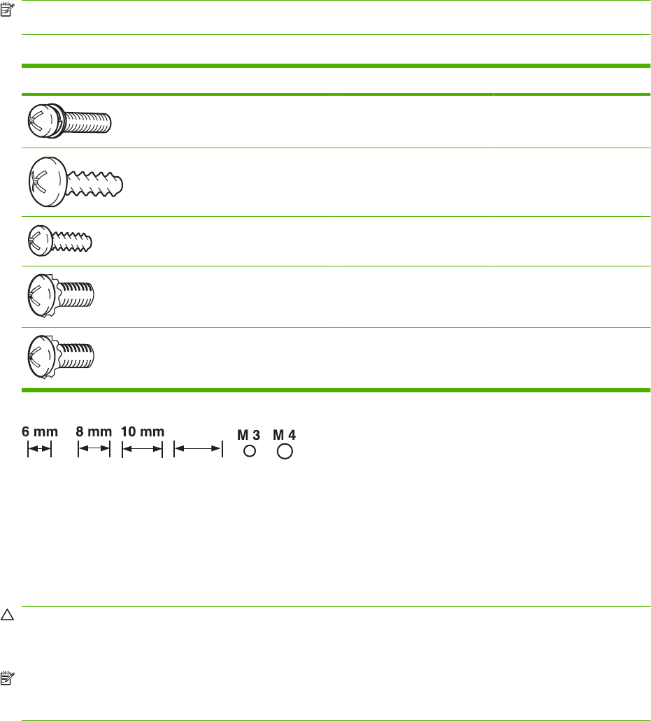
Screws
NOTE: The screw illustrations in the following table are for reference only. Screws might vary in size
and appearance from those shown in this table.
Table 8-8 Common fasteners
Example Description Size Part Number
Screw, with washer M3x8 XA9-1420-000CN
Screw, tapping, truss head M4x10 XB4-7401-005CN
Screw, tap M3x6 XA9-1503-000CN
Screw, D M3x8 XA9-1671-000CN
Screw, tooth washer M4x6 XB2–7400-606CN
12 mm
12 mm
How to use the parts lists and diagrams
The figures in this chapter show the major subassemblies in the product and their component parts. A
parts list table follows each exploded view assembly diagram. Each table lists the item number, the
associated part number, and the description of each part. If a part is not listed in the table, then it is not
a field replacement unit (FRU).
CAUTION: Be sure to order the correct part. When looking for part numbers for electrical components,
pay careful attention to the voltage that is listed in the description column. Doing so will ensure that the
part number selected is for the correct all-in-one model.
NOTE: In this manual, the abbreviation “PCA” stands for “printed circuit-board assembly.”
Components described as a PCA might consist of a single circuit board or a circuit board plus other
parts, such as cables and sensors.
ENWW Screws 519
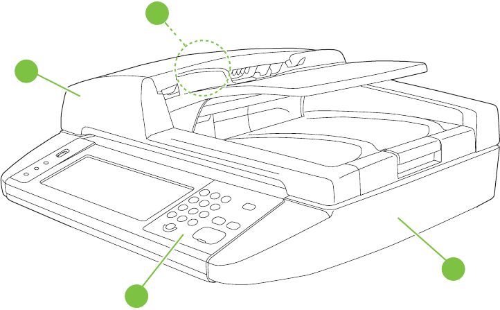
ADF and scanner assemblies
Figure 8-1 ADF/scanner assembly
2
3
4
1
520 Chapter 8 Parts and diagrams ENWW

Table 8-9 ADF/scanner assembly
Ref Description Part number Qty
1 Control panel assembly CC519-60115 1
Not shown Control-panel cable CC519-60107 1
2 ADF feed roller kit CC519-67909 1
3 ADF assembly CC483-60103 1
4 Scanner assembly (ADF assembly and SCB PCA are not
included)
CC519-67914 1
Not shown Scanner controller board (SCB) CC454-60002 1
Not shown PCI express RoHS cable 5851-3141 1
ENWW ADF and scanner assemblies 521
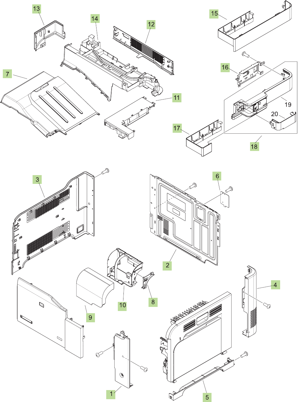
External covers, panels, and doors
Figure 8-2 External covers, panels, and doors
522 Chapter 8 Parts and diagrams ENWW

Table 8-10 External covers, panels, and doors;
Ref Description Part number Qty
1 Cover, right front RC2-5056-000CN 1
2 Cover, rear RC2-5048-000CN 1
3 Cover, left RC2-5052-000CN 1
4 Cover, rear right RC2-5057-000CN 1
5 Cover, right lower RC2-5059-000CN 1
6 Plate, blanking RC2-5938-000CN 1
7 Tray, paper delivery RL1-1941-000CN 1
8 Rib, Control panel RC2-5179-000CN 1
9 Cover, control panel RC2-5180-000CN 1
10 Cover, control panel, rear RC2-5181-000CN 1
11 Cover, upper right RC2-5182-000CN 1
12 Cover, rear, upper RC2-5185-000CN 1
13 Cover, left rear RC2-5188-000CN 1
14 Cover, upper rear RL1-1953-000CN 1
15 Cover, right (without stapler) RC2-5189-000CN 1
16 Holder, AC RC2-5194-000CN 1
17 Cover, right (with stapler) RC2-5192-000CN 1
18 Stapler, right cover assembly RM1-5033-000CN 1
ENWW External covers, panels, and doors 523

Right door assembly
Figure 8-3 Right door assembly
1
1a
2
SEE DUPLEX
FEED ASSEMBLY
524 Chapter 8 Parts and diagrams ENWW

Table 8-11 Right door assembly
Ref Description Part number Qty
1 Right door assembly RM1-4957-000CN 1
Not shown Tray 1 pickup roller RL1-1928-000CN 1
ENWW Right door assembly 525
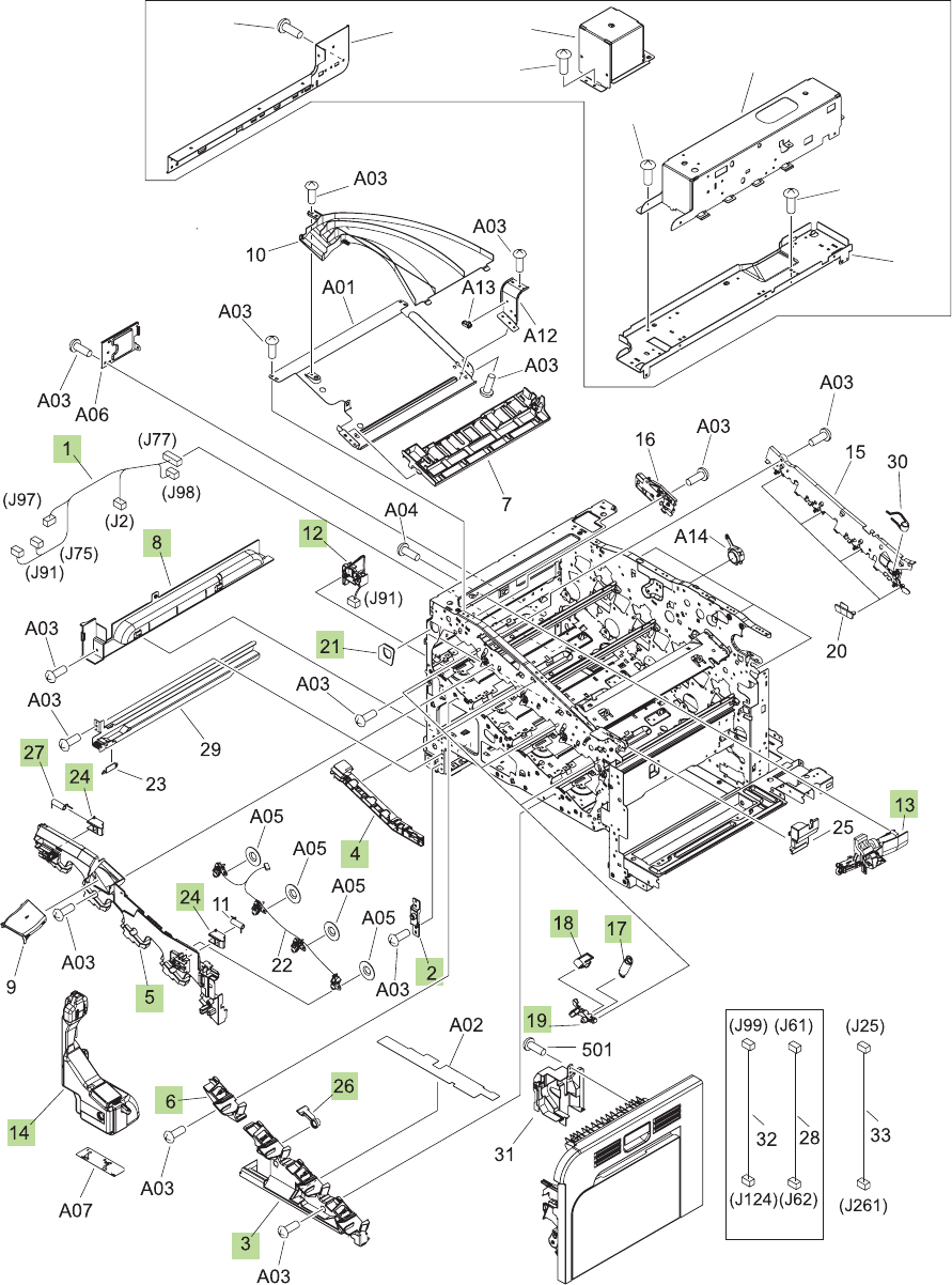
Internal components
Internal components (1 of 5)
Figure 8-4 Internal components (1 of 5)
A12
A14
A15
A13
A03
A03
A03
A03
526 Chapter 8 Parts and diagrams ENWW

Table 8-12 Internal components (1 of 5)
Ref Description Part number Qty
1 Lifter cable assembly RM1-5742-000CN 1
3 Cover, front inner lower RL1-1914-000CN 1
5 Cover, front inner upper RC2-5006-000CN 1
6 Cover, front inner lower RL1-1915-000CN 1
8 Cover, left lower RC2-5069-000CN 1
12 Waste toner detect assembly RM1-5696-000CN 1
13 Waste toner duct assembly (motor) RM1-4977-000CN 1
17 Spring, tension RU6-2236-000CN 4
18 Spring, ground RU6-2237-000CN 4
19 Lever, cartridge pressure front RC2-3983-000CN 4
21 Seal, waste toner box RC2-4780-000CN 1
24 Lock, door RC2-5937-000CN 1
26 Lever, box presence detect RC2-5951-000CN 1
27 Spring, compression RU6-2568-000CN 1
ENWW Internal components 527
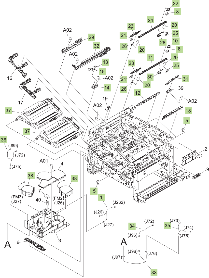
Internal components (2 of 5)
Figure 8-5 Internal components (2 of 5)
528 Chapter 8 Parts and diagrams ENWW

Table 8-13 Internal components (2 of 5)
Ref Description Part number Qty
1 Fan cable assembly RM1-5746-000CN 1
5 Spring, tension RU6-2436-000CN 4
8 Spring, leaf RC2-5970-000CN 4
10 Tab RC2-5909-000CN 2
11 Shutter RC2-5910-000CN 2
12 Cover RC2-5912-000CN 3
13 Spring, torsion RC2-5958-000CN 3
14 Holder, cartridge lock lever RC2-5955-000CN 3
15 Lever, cartridge lock RC2-5954-000CN 3
18 Cover RC2-5962-000CN 3
20 Spring, compression RU6-2318-000CN 8
21 Spring, compression RU6-2316-000CN 4
22 Tab RC2-4428-000CN 2
23 Lever, shutter RU6-4415-000CN 4
24 Shutter RC2-4413-000CN 2
25 Shutter rear arm RC2-4407-000CN 4
26 Shutter front arm RC2-4406-000CN 4
27 Sensor unit, Tmp/Hum sensor RK2-2229-000CN 1
28 Base RL1-2144-000CN 2
29 Toner sensor holder assembly RM1-5700-000CN 4
30 Base RL1-1923-000CN 2
31 Base assembly RM1-4979-000CN 4
32 Lower cartridge guide assembly RM1-4984-000CN 4
33 Connecting cable assembly RM1-5749-000CN 1
34 Sensor cable assembly RM1-5740-000CN 1
35 Sensor cable assembly RM1-5741-000CN 1
36 Motor/sensor cable assembly RM1-5752-000CN 1
38 Fan RK2-2418-000CN 2
ENWW Internal components 529
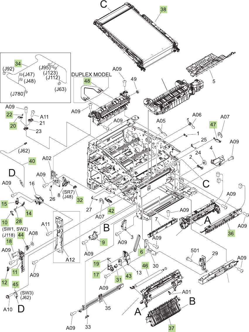
Internal components (3 of 5)
Figure 8-6 Internal components (3 of 5)
SEE
REGISTRATION
ASSEMBLY
SEE FUSER
SEE CASSETTE
PAPER PICKUP
ASSEMBLY
SEE SECONDARY
TRANSFER ASSEMBLY
530 Chapter 8 Parts and diagrams ENWW

Table 8-14 Internal components (3 of 5)
Ref Description Part number Qty
6 Link, door stopper right RC2-4916-000CN 1
9 Cover, right lower inner RC2-5019-000CN 1
10 Interlock link RC2-5120-000CN 1
11 Interlock switch mount RC2-5123-000CN 1
12 Interlock link switch arm RC2-5121-000CN 1
14 Interlock link RC2-5119-000CN 1
15 Interlock link RC2-5118-000CN 1
17 Switch lever RC2-5124-000CN 1
18 Shaft RC2-5913-000CN 1
19 Spring, torsion RC2-5934-000CN 1
20 Cartridge lock lever RC2-5954-000CN 1
22 Spring, torsion RC2-5958-000CN 1
28 Interlock link RC2-5122-000CN 1
31 Power supply button RL1-1947-000CN 1
32 Photo interrupter, TLP1243 WG8-5696-000CN 1
34 Front cable assembly RM1-6998-000CN 1
36 Density detect sensor assembly RM1-4953-000CN 1
37 Lower pick up guide assembly RM1-4980-000CN 1
38 ITB assembly service kit CC468-67907 1
40 Switch cable assembly RM1-5718-000CN 1
42 Front lock arm assembly RM1-5532-000CN 1
43 Power supply switch assembly RM1-5697-000CN 1
44 Door switch assembly RM1-5732-000CN 1
45 Switch WC4-5171-000CN 1
46 Transfer roller assembly service kit CC468-67914
47 Rear lock arm assembly RM1-5533-000CN 1
ENWW Internal components 531
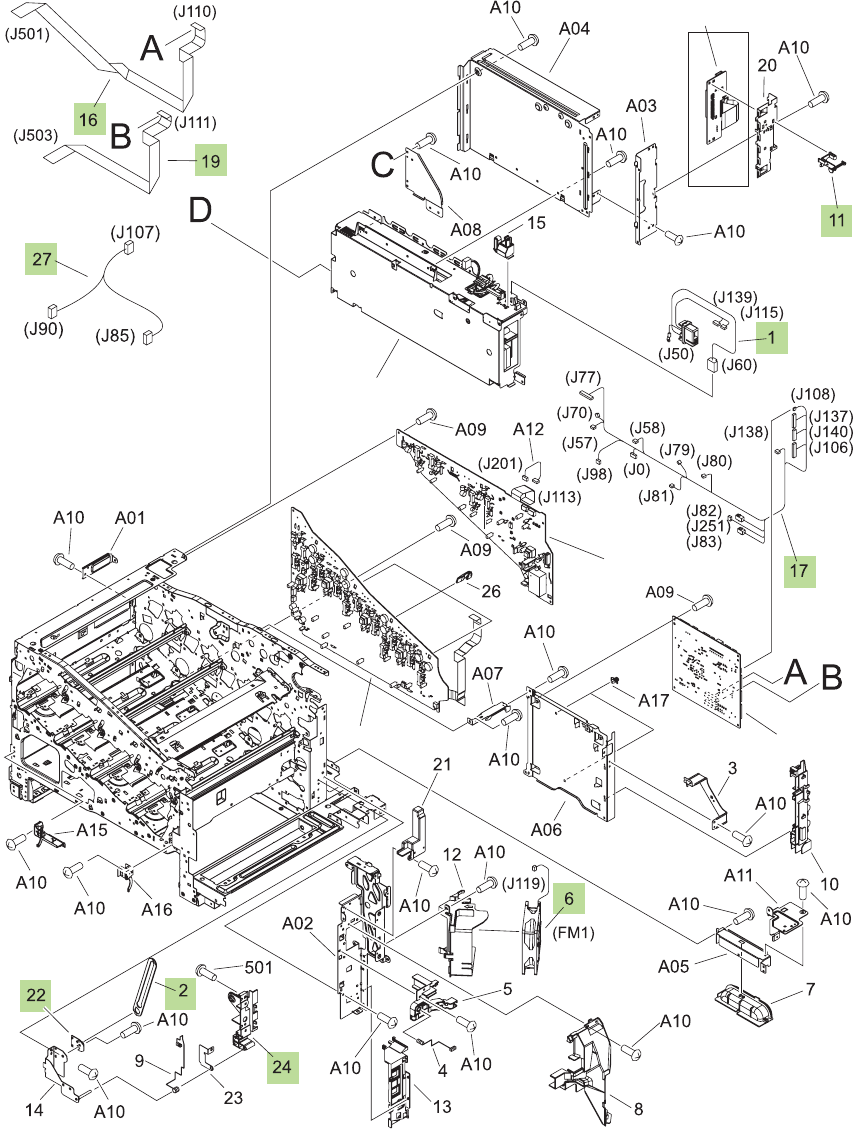
Internal components (4 of 5)
Figure 8-7 Internal components (4 of 5)
SEE PCAs
SEE PCAs
SEE PCAs
SEE PCAs
SEE PCAs
532 Chapter 8 Parts and diagrams ENWW

Table 8-15 Internal components (4 of 5)
Ref Description Part number Qty
1 Fusing connecting cable assembly RM1-5714-000CN 1
2 Door stopper right link RC2-4916-000CN 2
6 Fan RK2-2416-000CN 1
11 Switch arm RC2-5943-000CN 1
16 Scanner flat cable (FFC) RK2-2506-000CN 1
17 Rear cable assembly RM1-5721-000CN 1
19 Scanner flat cable (FFC) RK2-2508-000CN 1
24 Right door rear hinge RC2-4895-000CN 1
27 Multipurpose tray sensor cable assembly RM1-5737-000CN 1
28 Cable, AC (stapler power) RK2-2501-000CN 1
Not shown Stapler mechanism CC483-60107 1
Not shown Stapler power supply Q7429-60501 1
ENWW Internal components 533
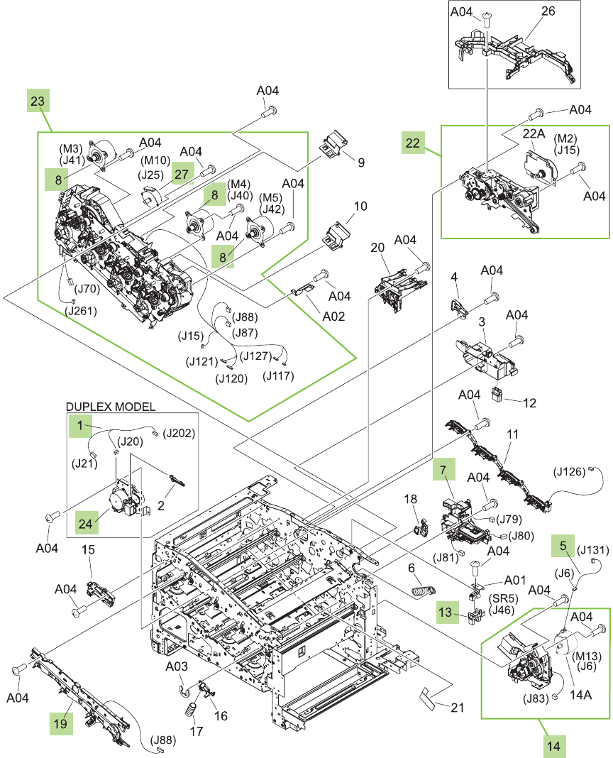
Internal components (5 of 5)
Figure 8-8 Internal components (5 of 5)
534 Chapter 8 Parts and diagrams ENWW

Table 8-16 Internal components (5 of 5)
Ref Description Part number Qty
1 Duplexing unit cable assembly RM1-5730-000CN 1
5 Pickup motor cable assembly RM1-5731-000CN 1
7 Lifter drive assembly RM1-4976-000CN 1
8 Drum motor assembly RM1-4988-000CN 3
13 Photo interrupter, TLP1243 WG8-5696-000CN 1
14 Cassette paper pick up drive assembly with motor RM1-4975-000CN 1
19 Rear pre-exposure PCA RM1-5705-000CN 1
22 Fusing drive assembly with motor RM1-4974-000CN 1
24 Duplexing drive assembly RM1-4973-000CN 1
27 Stepping motor, DC (developing disengagement) RK2-2415-000CN 1
ENWW Internal components 535
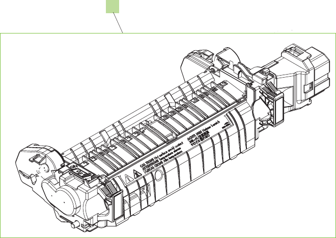
Fuser
Figure 8-9 Fuser
1
536 Chapter 8 Parts and diagrams ENWW

Table 8-17 Fuser
Ref Description Part number Qty
1 Fuser/Fixing service kit110 v CC519-67901 1
1 Fuser/Fixing service kit 220 v CC519-67902 1
ENWW Internal components 537
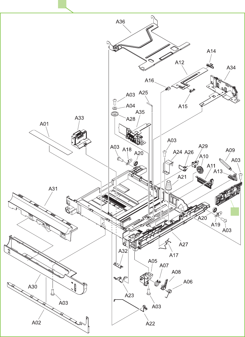
250-sheet cassette
Figure 8-10 250-sheet cassette
1
2
538 Chapter 8 Parts and diagrams ENWW

Table 8-18 250-sheet cassette
Ref Description Part number Qty
1 250-sheet cassette RM1-4962-000CN 1
2 Separation roller assy RM1-4966-000CN 1
ENWW Internal components 539
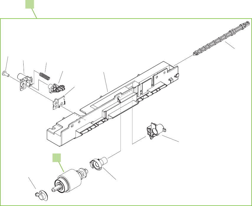
250-sheet cassette paper pickup assembly
Figure 8-11 250-sheet cassette paper pickup assembly
1
2
A10
A09
A08
A07
A06
A05
A04
A03
A02
A01
540 Chapter 8 Parts and diagrams ENWW

Table 8-19 250-sheet cassette paper pickup assembly
Ref Description Part number Qty
1 250-sheet cassette paper pickup assembly RM1-4967-000CN 1
2 250-sheet cassette paper pickup roller RM1-4968-000CN
ENWW Internal components 541
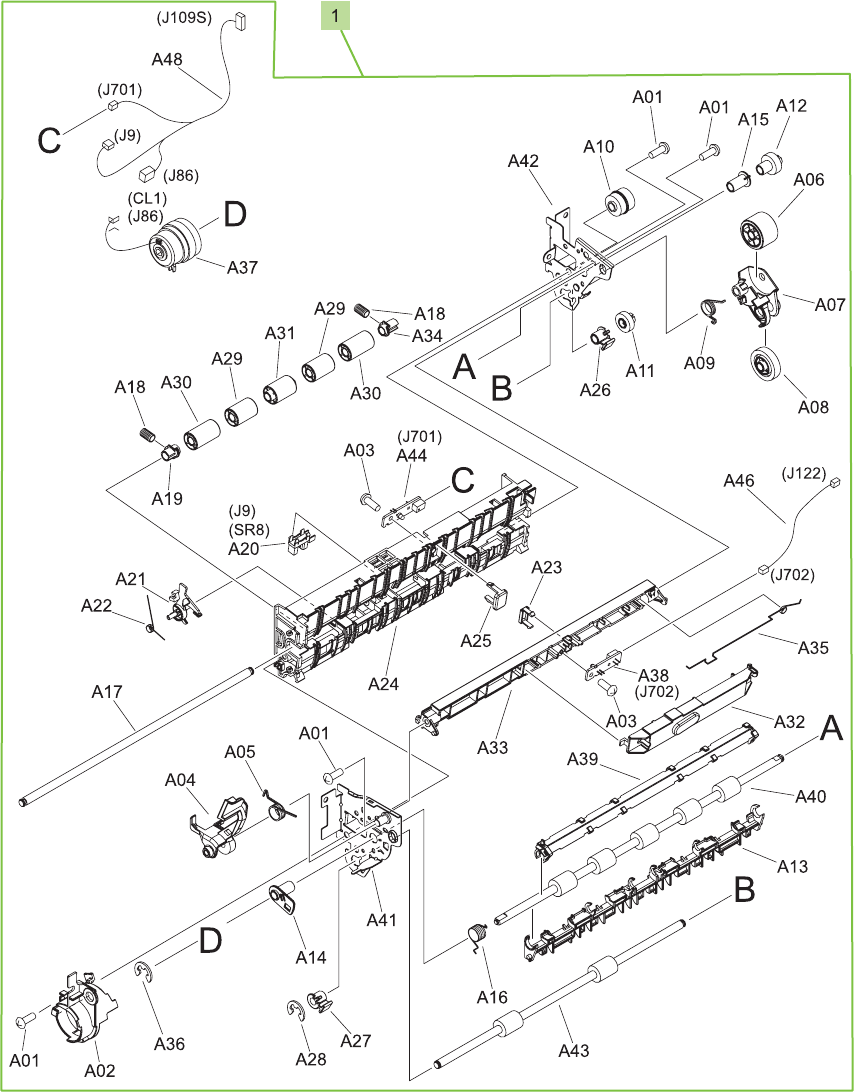
Registration assembly
Figure 8-12 Registration assembly
542 Chapter 8 Parts and diagrams ENWW

Table 8-20 Registration assembly
Ref Description Part number Qty
1 Registration assembly RM1-4969-000CN 1
ENWW Internal components 543
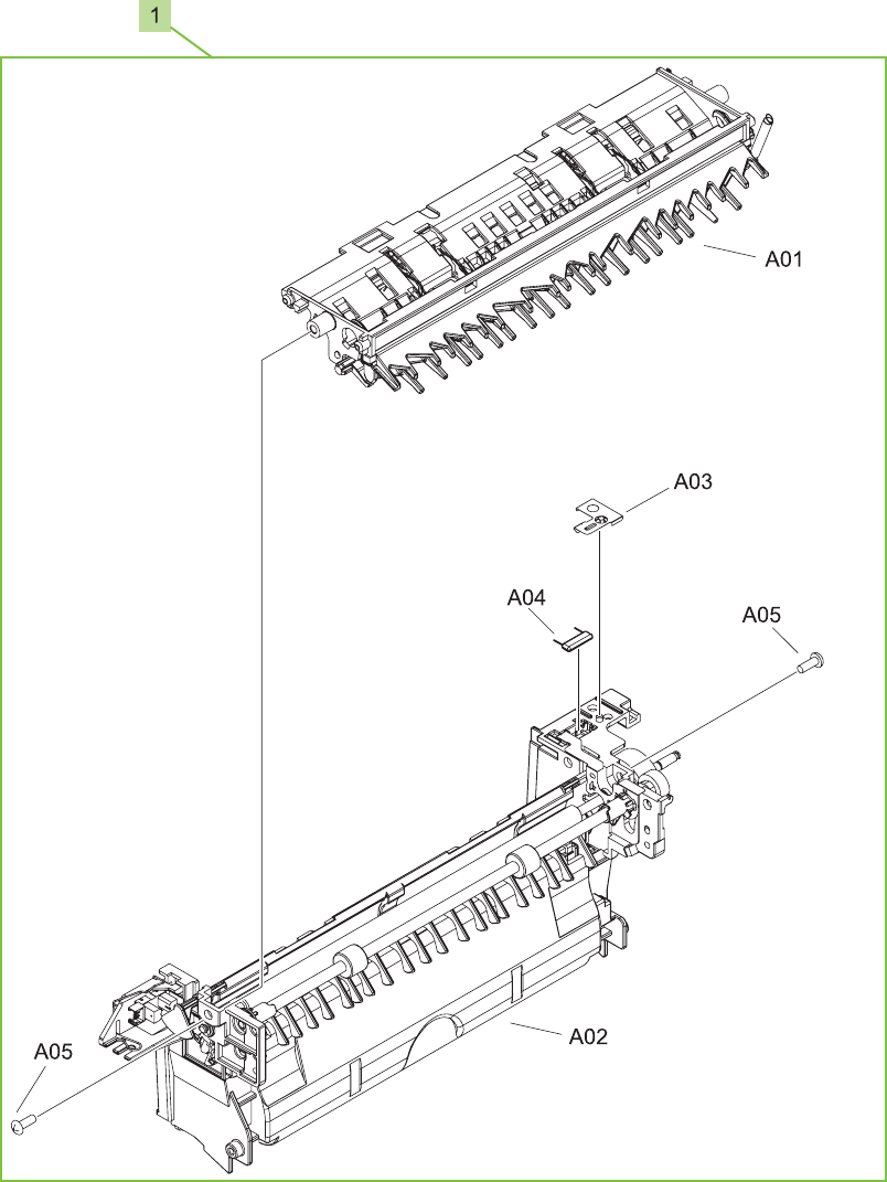
Paper-delivery assembly
Figure 8-13 Paper-delivery assembly
544 Chapter 8 Parts and diagrams ENWW

Table 8-21 Paper-delivery assembly
Ref Description Part number Qty
1 Paper-delivery assembly RM1-4970-000CN 1
ENWW Internal components 545
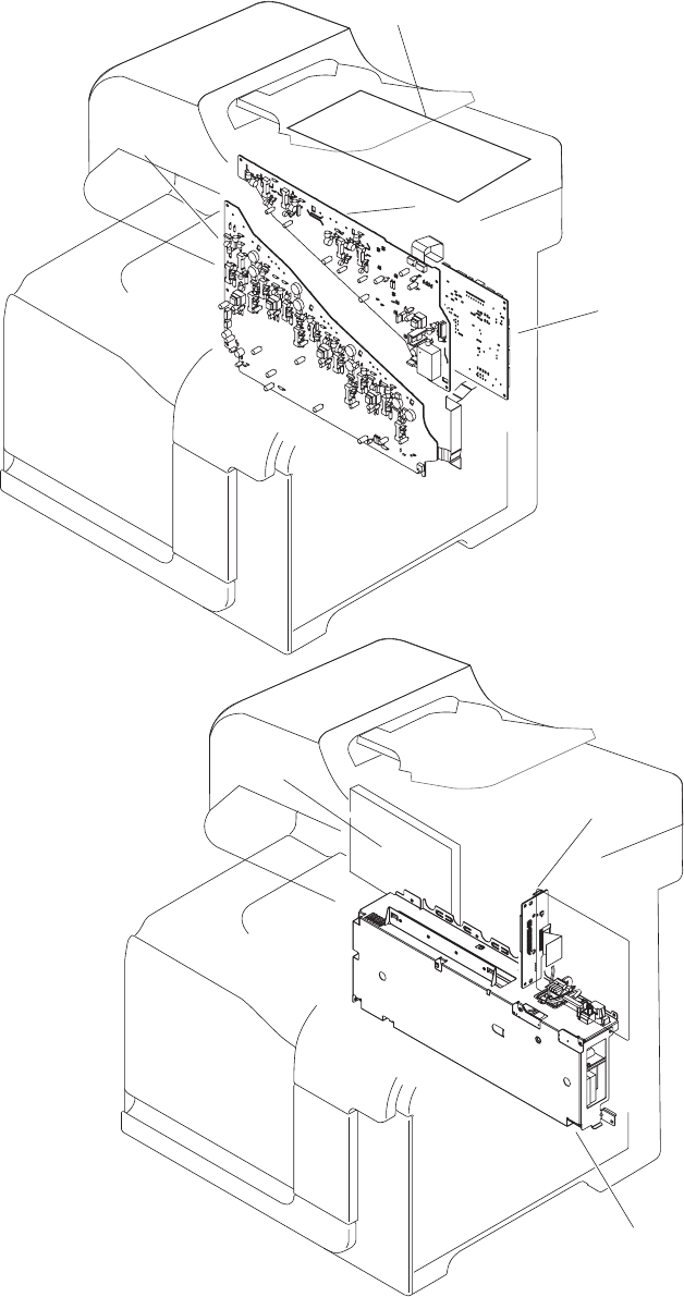
PCAs
Figure 8-14 PCAs
6
2
3
4
5
1
7
546 Chapter 8 Parts and diagrams ENWW

Table 8-22 PCAs
Ref Description Part number Qty
1 High-voltage power supply lower PCA (HVPS-D) RM1-5680-000CN 1
2 High-voltage power supply upper PCA (HVPS-T) RM1-5681-000CN 1
3 DC controller PCA RM1-5678-000CN 1
4 Low-voltage power supply PCA(110 v) RM1-5689-000CN 1
4 Low-voltage power supply PCA(220 v) RM1-5690-000CN 1
5 Interconnect board (ICB) CC453-60001 1
6 Formatter PCA CC452-60001 1
7 Scanner controller board (SCB) CC454-60002 1
ENWW Internal components 547
Formatter components
Figure 8-15 Formatter components
1
2
3
4
548 Chapter 8 Parts and diagrams ENWW

Table 8-23 Formatter components
Ref Description Part number Qty
1 Hard drive, 80GB 2.5-inch SATA ROHS CC519-67904 1
2 SATA hard drive cable power/data CC519-67905 1
3 Fax controller PCA CC456-60001 1
4 Fax cable CC519-67907 1
ENWW Internal components 549
Accessories
500-sheet paper feeder
Figure 8-16 500-sheet paper feeder
550 Chapter 8 Parts and diagrams ENWW

Table 8-24 500-sheet paper feeder
Ref Description Part number Qty
1 500-sheet feeder replacement CE222-67901 1
Not shown 500-sheet paper feeder right door kit CC468-67906 1
Not shown 500-sheet cassette RM1-6198-000CN 1
ENWW Accessories 551
Paper feeder main body
Figure 8-17 Paper feeder main body
552 Chapter 8 Parts and diagrams ENWW

Table 8-25 Paper feeder main body
Ref Description Part number Qty
13 Drawer connector (Tray 3) VS1-7257-007CN 1
14 Drawer connector holder (Tray 3) RC2-5416-000CN 1
ENWW Accessories 553

Alphabetical parts list
Table 8-26 Alphabetical parts list
Description Part number Table and page
250-sheet cassette RM1-4962-000CN 250-sheet cassette
on page 539
250-sheet cassette paper pickup assembly RM1-4967-000CN 250-sheet cassette paper
pickup assembly on page 541
250-sheet cassette paper pickup roller RM1-4968-000CN 250-sheet cassette paper
pickup assembly on page 541
500-sheet cassette RM1-6198-000CN 500-sheet paper feeder
on page 551
500-sheet feeder replacement CE222-67901 500-sheet paper feeder
on page 551
500-sheet paper feeder right door kit CC468-67906 500-sheet paper feeder
on page 551
ADF assembly CC483-60103 ADF/scanner assembly
on page 521
ADF feed roller kit CC519-67909 ADF/scanner assembly
on page 521
Base RL1-2144-000CN Internal components (2 of 5)
on page 529
Base RL1-1923-000CN Internal components (2 of 5)
on page 529
Base assembly RM1-4979-000CN Internal components (2 of 5)
on page 529
Cable, AC (stapler power) RK2-2501-000CN Internal components (4 of 5)
on page 533
Cartridge lock lever RC2-5954-000CN Internal components (3 of 5)
on page 531
Cassette paper pick up drive assembly with motor RM1-4975-000CN Internal components (5 of 5)
on page 535
Connecting cable assembly RM1-5749-000CN Internal components (2 of 5)
on page 529
Control panel assembly CC519-60115 ADF/scanner assembly
on page 521
Control-panel cable CC519-60107 ADF/scanner assembly
on page 521
Cover RC2-5912-000CN Internal components (2 of 5)
on page 529
Cover RC2-5962-000CN Internal components (2 of 5)
on page 529
Cover, control panel RC2-5180-000CN External covers, panels, and
doors; on page 523
Cover, control panel, rear RC2-5181-000CN External covers, panels, and
doors; on page 523
554 Chapter 8 Parts and diagrams ENWW

Description Part number Table and page
Cover, front inner lower RL1-1914-000CN Internal components (1 of 5)
on page 527
Cover, front inner lower RL1-1915-000CN Internal components (1 of 5)
on page 527
Cover, front inner upper RC2-5006-000CN Internal components (1 of 5)
on page 527
Cover, left RC2-5052-000CN External covers, panels, and
doors; on page 523
Cover, left lower RC2-5069-000CN Internal components (1 of 5)
on page 527
Cover, left rear RC2-5188-000CN External covers, panels, and
doors; on page 523
Cover, rear RC2-5048-000CN External covers, panels, and
doors; on page 523
Cover, rear right RC2-5057-000CN External covers, panels, and
doors; on page 523
Cover, rear, upper RC2-5185-000CN External covers, panels, and
doors; on page 523
Cover, right (with stapler) RC2-5192-000CN External covers, panels, and
doors; on page 523
Cover, right (without stapler) RC2-5189-000CN External covers, panels, and
doors; on page 523
Cover, right front RC2-5056-000CN External covers, panels, and
doors; on page 523
Cover, right lower RC2-5059-000CN External covers, panels, and
doors; on page 523
Cover, right lower inner RC2-5019-000CN Internal components (3 of 5)
on page 531
Cover, upper rear RL1-1953-000CN External covers, panels, and
doors; on page 523
Cover, upper right RC2-5182-000CN External covers, panels, and
doors; on page 523
DC controller PCA RM1-5678-000CN PCAs on page 547
Density detect sensor assembly RM1-4953-000CN Internal components (3 of 5)
on page 531
Door stopper right link RC2-4916-000CN Internal components (4 of 5)
on page 533
Door switch assembly RM1-5732-000CN Internal components (3 of 5)
on page 531
Drawer connector (Tray 3) VS1-7257-007CN Paper feeder main body
on page 553
Drawer connector holder (Tray 3) RC2-5416-000CN Paper feeder main body
on page 553
Table 8-26 Alphabetical parts list (continued)
ENWW Alphabetical parts list 555

Description Part number Table and page
Drum motor assembly RM1-4988-000CN Internal components (5 of 5)
on page 535
Duplexing drive assembly RM1-4973-000CN Internal components (5 of 5)
on page 535
Duplexing unit cable assembly RM1-5730-000CN Internal components (5 of 5)
on page 535
Fan RK2-2418-000CN Internal components (2 of 5)
on page 529
Fan RK2-2416-000CN Internal components (4 of 5)
on page 533
Fan cable assembly RM1-5746-000CN Internal components (2 of 5)
on page 529
Fax cable CC519-67907 Formatter components
on page 549
Fax controller PCA CC456-60001 Formatter components
on page 549
Formatter PCA CC452-60001 PCAs on page 547
Front cable assembly RM1-6998-000CN Internal components (3 of 5)
on page 531
Front lock arm assembly RM1-5532-000CN Internal components (3 of 5)
on page 531
Fuser/Fixing service kit 220 v CC519-67902 Fuser on page 537
Fuser/Fixing service kit110 v CC519-67901 Fuser on page 537
Fusing connecting cable assembly RM1-5714-000CN Internal components (4 of 5)
on page 533
Fusing drive assembly with motor RM1-4974-000CN Internal components (5 of 5)
on page 535
Hard drive, 80GB 2.5-inch SATA ROHS CC519-67904 Formatter components
on page 549
High-voltage power supply lower PCA (HVPS-D) RM1-5680-000CN PCAs on page 547
High-voltage power supply upper PCA (HVPS-T) RM1-5681-000CN PCAs on page 547
Holder, AC RC2-5194-000CN External covers, panels, and
doors; on page 523
Holder, cartridge lock lever RC2-5955-000CN Internal components (2 of 5)
on page 529
Interconnect board (ICB) CC453-60001 PCAs on page 547
Interlock link RC2-5120-000CN Internal components (3 of 5)
on page 531
Interlock link RC2-5119-000CN Internal components (3 of 5)
on page 531
Interlock link RC2-5118-000CN Internal components (3 of 5)
on page 531
Table 8-26 Alphabetical parts list (continued)
556 Chapter 8 Parts and diagrams ENWW

Description Part number Table and page
Interlock link RC2-5122-000CN Internal components (3 of 5)
on page 531
Interlock link switch arm RC2-5121-000CN Internal components (3 of 5)
on page 531
Interlock switch mount RC2-5123-000CN Internal components (3 of 5)
on page 531
ITB assembly service kit CC468-67907 Internal components (3 of 5)
on page 531
Lever, box presence detect RC2-5951-000CN Internal components (1 of 5)
on page 527
Lever, cartridge lock RC2-5954-000CN Internal components (2 of 5)
on page 529
Lever, cartridge pressure front RC2-3983-000CN Internal components (1 of 5)
on page 527
Lever, shutter RU6-4415-000CN Internal components (2 of 5)
on page 529
Lifter cable assembly RM1-5742-000CN Internal components (1 of 5)
on page 527
Lifter drive assembly RM1-4976-000CN Internal components (5 of 5)
on page 535
Link, door stopper right RC2-4916-000CN Internal components (3 of 5)
on page 531
Lock, door RC2-5937-000CN Internal components (1 of 5)
on page 527
Low-voltage power supply PCA(110 v) RM1-5689-000CN PCAs on page 547
Low-voltage power supply PCA(220 v) RM1-5690-000CN PCAs on page 547
Lower cartridge guide assembly RM1-4984-000CN Internal components (2 of 5)
on page 529
Lower pick up guide assembly RM1-4980-000CN Internal components (3 of 5)
on page 531
Motor/sensor cable assembly RM1-5752-000CN Internal components (2 of 5)
on page 529
Multipurpose tray sensor cable assembly RM1-5737-000CN Internal components (4 of 5)
on page 533
Paper-delivery assembly RM1-4970-000CN Paper-delivery assembly
on page 545
PCI express RoHS cable 5851-3141 ADF/scanner assembly
on page 521
Photo interrupter, TLP1243 WG8-5696-000CN Internal components (3 of 5)
on page 531
Photo interrupter, TLP1243 WG8-5696-000CN Internal components (5 of 5)
on page 535
Pickup motor cable assembly RM1-5731-000CN Internal components (5 of 5)
on page 535
Table 8-26 Alphabetical parts list (continued)
ENWW Alphabetical parts list 557

Description Part number Table and page
Plate, blanking RC2-5938-000CN External covers, panels, and
doors; on page 523
Power supply button RL1-1947-000CN Internal components (3 of 5)
on page 531
Power supply switch assembly RM1-5697-000CN Internal components (3 of 5)
on page 531
Rear cable assembly RM1-5721-000CN Internal components (4 of 5)
on page 533
Rear lock arm assembly RM1-5533-000CN Internal components (3 of 5)
on page 531
Rear pre-exposure PCA RM1-5705-000CN Internal components (5 of 5)
on page 535
Registration assembly RM1-4969-000CN Registration assembly
on page 543
Rib, Control panel RC2-5179-000CN External covers, panels, and
doors; on page 523
Right door assembly RM1-4957-000CN Right door assembly
on page 525
Right door rear hinge RC2-4895-000CN Internal components (4 of 5)
on page 533
SATA hard drive cable power/data CC519-67905 Formatter components
on page 549
Scanner assembly (ADF assembly and SCB PCA are not
included)
CC519-67914 ADF/scanner assembly
on page 521
Scanner controller board (SCB) CC454-60002 ADF/scanner assembly
on page 521
Scanner controller board (SCB) CC454-60002 PCAs on page 547
Scanner flat cable (FFC) RK2-2506-000CN Internal components (4 of 5)
on page 533
Scanner flat cable (FFC) RK2-2508-000CN Internal components (4 of 5)
on page 533
Seal, waste toner box RC2-4780-000CN Internal components (1 of 5)
on page 527
Sensor cable assembly RM1-5740-000CN Internal components (2 of 5)
on page 529
Sensor cable assembly RM1-5741-000CN Internal components (2 of 5)
on page 529
Sensor unit, Tmp/Hum sensor RK2-2229-000CN Internal components (2 of 5)
on page 529
Separation roller assy RM1-4966-000CN 250-sheet cassette
on page 539
Shaft RC2-5913-000CN Internal components (3 of 5)
on page 531
Table 8-26 Alphabetical parts list (continued)
558 Chapter 8 Parts and diagrams ENWW

Description Part number Table and page
Shutter RC2-5910-000CN Internal components (2 of 5)
on page 529
Shutter RC2-4413-000CN Internal components (2 of 5)
on page 529
Shutter front arm RC2-4406-000CN Internal components (2 of 5)
on page 529
Shutter rear arm RC2-4407-000CN Internal components (2 of 5)
on page 529
Spring, compression RU6-2568-000CN Internal components (1 of 5)
on page 527
Spring, compression RU6-2318-000CN Internal components (2 of 5)
on page 529
Spring, compression RU6-2316-000CN Internal components (2 of 5)
on page 529
Spring, ground RU6-2237-000CN Internal components (1 of 5)
on page 527
Spring, leaf RC2-5970-000CN Internal components (2 of 5)
on page 529
Spring, tension RU6-2236-000CN Internal components (1 of 5)
on page 527
Spring, tension RU6-2436-000CN Internal components (2 of 5)
on page 529
Spring, torsion RC2-5958-000CN Internal components (2 of 5)
on page 529
Spring, torsion RC2-5934-000CN Internal components (3 of 5)
on page 531
Spring, torsion RC2-5958-000CN Internal components (3 of 5)
on page 531
Stapler mechanism CC483-60107 Internal components (4 of 5)
on page 533
Stapler power supply Q7429-60501 Internal components (4 of 5)
on page 533
Stapler, right cover assembly RM1-5033-000CN External covers, panels, and
doors; on page 523
Stepping motor, DC (developing disengagement) RK2-2415-000CN Internal components (5 of 5)
on page 535
Switch WC4-5171-000CN Internal components (3 of 5)
on page 531
Switch arm RC2-5943-000CN Internal components (4 of 5)
on page 533
Switch cable assembly RM1-5718-000CN Internal components (3 of 5)
on page 531
Switch lever RC2-5124-000CN Internal components (3 of 5)
on page 531
Table 8-26 Alphabetical parts list (continued)
ENWW Alphabetical parts list 559

Description Part number Table and page
Tab RC2-5909-000CN Internal components (2 of 5)
on page 529
Tab RC2-4428-000CN Internal components (2 of 5)
on page 529
Toner sensor holder assembly RM1-5700-000CN Internal components (2 of 5)
on page 529
Transfer roller assembly service kit CC468-67914 Internal components (3 of 5)
on page 531
Tray, paper delivery RL1-1941-000CN External covers, panels, and
doors; on page 523
Tray 1 pickup roller RL1-1928-000CN Right door assembly
on page 525
Waste toner detect assembly RM1-5696-000CN Internal components (1 of 5)
on page 527
Waste toner duct assembly (motor) RM1-4977-000CN Internal components (1 of 5)
on page 527
Table 8-26 Alphabetical parts list (continued)
560 Chapter 8 Parts and diagrams ENWW

Numerical parts list
Table 8-27 Numerical parts list
Part number Description Table and page
5851-3141 PCI express RoHS cable ADF/scanner assembly
on page 521
CC452-60001 Formatter PCA PCAs on page 547
CC453-60001 Interconnect board (ICB) PCAs on page 547
CC454-60002 Scanner controller board (SCB) ADF/scanner assembly
on page 521
CC454-60002 Scanner controller board (SCB) PCAs on page 547
CC456-60001 Fax controller PCA Formatter components
on page 549
CC468-67906 500-sheet paper feeder right door kit 500-sheet paper feeder
on page 551
CC468-67907 ITB assembly service kit Internal components (3 of 5)
on page 531
CC468-67914 Transfer roller assembly service kit Internal components (3 of 5)
on page 531
CC483-60103 ADF assembly ADF/scanner assembly
on page 521
CC483-60107 Stapler mechanism Internal components (4 of 5)
on page 533
CC519-60107 Control-panel cable ADF/scanner assembly
on page 521
CC519-60115 Control panel assembly ADF/scanner assembly
on page 521
CC519-67901 Fuser/Fixing service kit110 v Fuser on page 537
CC519-67902 Fuser/Fixing service kit 220 v Fuser on page 537
CC519-67904 Hard drive, 80GB 2.5-inch SATA ROHS Formatter components
on page 549
CC519-67905 SATA hard drive cable power/data Formatter components
on page 549
CC519-67907 Fax cable Formatter components
on page 549
CC519-67909 ADF feed roller kit ADF/scanner assembly
on page 521
CC519-67914 Scanner assembly (ADF assembly and SCB PCA are not
included)
ADF/scanner assembly
on page 521
CE222-67901 500-sheet feeder replacement 500-sheet paper feeder
on page 551
Q7429-60501 Stapler power supply Internal components (4 of 5)
on page 533
ENWW Numerical parts list 561

Part number Description Table and page
RC2-3983-000CN Lever, cartridge pressure front Internal components (1 of 5)
on page 527
RC2-4406-000CN Shutter front arm Internal components (2 of 5)
on page 529
RC2-4407-000CN Shutter rear arm Internal components (2 of 5)
on page 529
RC2-4413-000CN Shutter Internal components (2 of 5)
on page 529
RC2-4428-000CN Tab Internal components (2 of 5)
on page 529
RC2-4780-000CN Seal, waste toner box Internal components (1 of 5)
on page 527
RC2-4895-000CN Right door rear hinge Internal components (4 of 5)
on page 533
RC2-4916-000CN Link, door stopper right Internal components (3 of 5)
on page 531
RC2-4916-000CN Door stopper right link Internal components (4 of 5)
on page 533
RC2-5006-000CN Cover, front inner upper Internal components (1 of 5)
on page 527
RC2-5019-000CN Cover, right lower inner Internal components (3 of 5)
on page 531
RC2-5048-000CN Cover, rear External covers, panels, and
doors; on page 523
RC2-5052-000CN Cover, left External covers, panels, and
doors; on page 523
RC2-5056-000CN Cover, right front External covers, panels, and
doors; on page 523
RC2-5057-000CN Cover, rear right External covers, panels, and
doors; on page 523
RC2-5059-000CN Cover, right lower External covers, panels, and
doors; on page 523
RC2-5069-000CN Cover, left lower Internal components (1 of 5)
on page 527
RC2-5118-000CN Interlock link Internal components (3 of 5)
on page 531
RC2-5119-000CN Interlock link Internal components (3 of 5)
on page 531
RC2-5120-000CN Interlock link Internal components (3 of 5)
on page 531
RC2-5121-000CN Interlock link switch arm Internal components (3 of 5)
on page 531
RC2-5122-000CN Interlock link Internal components (3 of 5)
on page 531
Table 8-27 Numerical parts list (continued)
562 Chapter 8 Parts and diagrams ENWW

Part number Description Table and page
RC2-5123-000CN Interlock switch mount Internal components (3 of 5)
on page 531
RC2-5124-000CN Switch lever Internal components (3 of 5)
on page 531
RC2-5179-000CN Rib, Control panel External covers, panels, and
doors; on page 523
RC2-5180-000CN Cover, control panel External covers, panels, and
doors; on page 523
RC2-5181-000CN Cover, control panel, rear External covers, panels, and
doors; on page 523
RC2-5182-000CN Cover, upper right External covers, panels, and
doors; on page 523
RC2-5185-000CN Cover, rear, upper External covers, panels, and
doors; on page 523
RC2-5188-000CN Cover, left rear External covers, panels, and
doors; on page 523
RC2-5189-000CN Cover, right (without stapler) External covers, panels, and
doors; on page 523
RC2-5192-000CN Cover, right (with stapler) External covers, panels, and
doors; on page 523
RC2-5194-000CN Holder, AC External covers, panels, and
doors; on page 523
RC2-5416-000CN Drawer connector holder (Tray 3) Paper feeder main body
on page 553
RC2-5909-000CN Tab Internal components (2 of 5)
on page 529
RC2-5910-000CN Shutter Internal components (2 of 5)
on page 529
RC2-5912-000CN Cover Internal components (2 of 5)
on page 529
RC2-5913-000CN Shaft Internal components (3 of 5)
on page 531
RC2-5934-000CN Spring, torsion Internal components (3 of 5)
on page 531
RC2-5937-000CN Lock, door Internal components (1 of 5)
on page 527
RC2-5938-000CN Plate, blanking External covers, panels, and
doors; on page 523
RC2-5943-000CN Switch arm Internal components (4 of 5)
on page 533
RC2-5951-000CN Lever, box presence detect Internal components (1 of 5)
on page 527
RC2-5954-000CN Lever, cartridge lock Internal components (2 of 5)
on page 529
Table 8-27 Numerical parts list (continued)
ENWW Numerical parts list 563

Part number Description Table and page
RC2-5954-000CN Cartridge lock lever Internal components (3 of 5)
on page 531
RC2-5955-000CN Holder, cartridge lock lever Internal components (2 of 5)
on page 529
RC2-5958-000CN Spring, torsion Internal components (2 of 5)
on page 529
RC2-5958-000CN Spring, torsion Internal components (3 of 5)
on page 531
RC2-5962-000CN Cover Internal components (2 of 5)
on page 529
RC2-5970-000CN Spring, leaf Internal components (2 of 5)
on page 529
RK2-2229-000CN Sensor unit, Tmp/Hum sensor Internal components (2 of 5)
on page 529
RK2-2415-000CN Stepping motor, DC (developing disengagement) Internal components (5 of 5)
on page 535
RK2-2416-000CN Fan Internal components (4 of 5)
on page 533
RK2-2418-000CN Fan Internal components (2 of 5)
on page 529
RK2-2501-000CN Cable, AC (stapler power) Internal components (4 of 5)
on page 533
RK2-2506-000CN Scanner flat cable (FFC) Internal components (4 of 5)
on page 533
RK2-2508-000CN Scanner flat cable (FFC) Internal components (4 of 5)
on page 533
RL1-1914-000CN Cover, front inner lower Internal components (1 of 5)
on page 527
RL1-1915-000CN Cover, front inner lower Internal components (1 of 5)
on page 527
RL1-1923-000CN Base Internal components (2 of 5)
on page 529
RL1-1928-000CN Tray 1 pickup roller Right door assembly
on page 525
RL1-1941-000CN Tray, paper delivery External covers, panels, and
doors; on page 523
RL1-1947-000CN Power supply button Internal components (3 of 5)
on page 531
RL1-1953-000CN Cover, upper rear External covers, panels, and
doors; on page 523
RL1-2144-000CN Base Internal components (2 of 5)
on page 529
RM1-4953-000CN Density detect sensor assembly Internal components (3 of 5)
on page 531
Table 8-27 Numerical parts list (continued)
564 Chapter 8 Parts and diagrams ENWW

Part number Description Table and page
RM1-4957-000CN Right door assembly Right door assembly
on page 525
RM1-4962-000CN 250-sheet cassette 250-sheet cassette
on page 539
RM1-4966-000CN Separation roller assy 250-sheet cassette
on page 539
RM1-4967-000CN 250-sheet cassette paper pickup assembly 250-sheet cassette paper
pickup assembly on page 541
RM1-4968-000CN 250-sheet cassette paper pickup roller 250-sheet cassette paper
pickup assembly on page 541
RM1-4969-000CN Registration assembly Registration assembly
on page 543
RM1-4970-000CN Paper-delivery assembly Paper-delivery assembly
on page 545
RM1-4973-000CN Duplexing drive assembly Internal components (5 of 5)
on page 535
RM1-4974-000CN Fusing drive assembly with motor Internal components (5 of 5)
on page 535
RM1-4975-000CN Cassette paper pick up drive assembly with motor Internal components (5 of 5)
on page 535
RM1-4976-000CN Lifter drive assembly Internal components (5 of 5)
on page 535
RM1-4977-000CN Waste toner duct assembly (motor) Internal components (1 of 5)
on page 527
RM1-4979-000CN Base assembly Internal components (2 of 5)
on page 529
RM1-4980-000CN Lower pick up guide assembly Internal components (3 of 5)
on page 531
RM1-4984-000CN Lower cartridge guide assembly Internal components (2 of 5)
on page 529
RM1-4988-000CN Drum motor assembly Internal components (5 of 5)
on page 535
RM1-5033-000CN Stapler, right cover assembly External covers, panels, and
doors; on page 523
RM1-5532-000CN Front lock arm assembly Internal components (3 of 5)
on page 531
RM1-5533-000CN Rear lock arm assembly Internal components (3 of 5)
on page 531
RM1-5678-000CN DC controller PCA PCAs on page 547
RM1-5680-000CN High-voltage power supply lower PCA (HVPS-D) PCAs on page 547
RM1-5681-000CN High-voltage power supply upper PCA (HVPS-T) PCAs on page 547
RM1-5689-000CN Low-voltage power supply PCA(110 v) PCAs on page 547
RM1-5690-000CN Low-voltage power supply PCA(220 v) PCAs on page 547
Table 8-27 Numerical parts list (continued)
ENWW Numerical parts list 565

Part number Description Table and page
RM1-5696-000CN Waste toner detect assembly Internal components (1 of 5)
on page 527
RM1-5697-000CN Power supply switch assembly Internal components (3 of 5)
on page 531
RM1-5700-000CN Toner sensor holder assembly Internal components (2 of 5)
on page 529
RM1-5705-000CN Rear pre-exposure PCA Internal components (5 of 5)
on page 535
RM1-5714-000CN Fusing connecting cable assembly Internal components (4 of 5)
on page 533
RM1-5718-000CN Switch cable assembly Internal components (3 of 5)
on page 531
RM1-5721-000CN Rear cable assembly Internal components (4 of 5)
on page 533
RM1-5730-000CN Duplexing unit cable assembly Internal components (5 of 5)
on page 535
RM1-5731-000CN Pickup motor cable assembly Internal components (5 of 5)
on page 535
RM1-5732-000CN Door switch assembly Internal components (3 of 5)
on page 531
RM1-5737-000CN Multipurpose tray sensor cable assembly Internal components (4 of 5)
on page 533
RM1-5740-000CN Sensor cable assembly Internal components (2 of 5)
on page 529
RM1-5741-000CN Sensor cable assembly Internal components (2 of 5)
on page 529
RM1-5742-000CN Lifter cable assembly Internal components (1 of 5)
on page 527
RM1-5746-000CN Fan cable assembly Internal components (2 of 5)
on page 529
RM1-5749-000CN Connecting cable assembly Internal components (2 of 5)
on page 529
RM1-5752-000CN Motor/sensor cable assembly Internal components (2 of 5)
on page 529
RM1-6198-000CN 500-sheet cassette 500-sheet paper feeder
on page 551
RM1-6998-000CN Front cable assembly Internal components (3 of 5)
on page 531
RU6-2236-000CN Spring, tension Internal components (1 of 5)
on page 527
RU6-2237-000CN Spring, ground Internal components (1 of 5)
on page 527
RU6-2316-000CN Spring, compression Internal components (2 of 5)
on page 529
Table 8-27 Numerical parts list (continued)
566 Chapter 8 Parts and diagrams ENWW

Part number Description Table and page
RU6-2318-000CN Spring, compression Internal components (2 of 5)
on page 529
RU6-2436-000CN Spring, tension Internal components (2 of 5)
on page 529
RU6-2568-000CN Spring, compression Internal components (1 of 5)
on page 527
RU6-4415-000CN Lever, shutter Internal components (2 of 5)
on page 529
VS1-7257-007CN Drawer connector (Tray 3) Paper feeder main body
on page 553
WC4-5171-000CN Switch Internal components (3 of 5)
on page 531
WG8-5696-000CN Photo interrupter, TLP1243 Internal components (3 of 5)
on page 531
WG8-5696-000CN Photo interrupter, TLP1243 Internal components (5 of 5)
on page 535
Table 8-27 Numerical parts list (continued)
ENWW Numerical parts list 567
568 Chapter 8 Parts and diagrams ENWW


Hewlett-Packard limited warranty statement
HP PRODUCT DURATION OF LIMITED WARRANTY
HP Color LaserJet CM3530 Series MFP One-year limited warranty
HP warrants to you, the end-user customer, that HP hardware and accessories will be free from defects
in materials and workmanship after the date of purchase, for the period specified above. If HP receives
notice of such defects during the warranty period, HP will, at its option, either repair or replace products
which prove to be defective. Replacement products may be either new or equivalent in performance to
new.
HP warrants to you that HP software will not fail to execute its programming instructions after the date
of purchase, for the period specified above, due to defects in material and workmanship when properly
installed and used. If HP receives notice of such defects during the warranty period, HP will replace
software which does not execute its programming instructions due to such defects.
HP does not warrant that the operation of HP products will be uninterrupted or error free. If HP is unable,
within a reasonable time, to repair or replace any product to a condition as warranted, you will be entitled
to a refund of the purchase price upon prompt return of the product.
HP products may contain remanufactured parts equivalent to new in performance or may have been
subject to incidental use.
Warranty does not apply to defects resulting from (a) improper or inadequate maintenance or calibration,
(b) software, interfacing, parts or supplies not supplied by HP, (c) unauthorized modification or misuse,
(d) operation outside of the published environmental specifications for the product, or (e) improper site
preparation or maintenance.
TO THE EXTENT ALLOWED BY LOCAL LAW, THE ABOVE WARRANTIES ARE EXCLUSIVE AND
NO OTHER WARRANTY OR CONDITION, WHETHER WRITTEN OR ORAL, IS EXPRESSED OR
IMPLIED AND HP SPECIFICALLY DISCLAIMS ANY IMPLIED WARRANTIES OR CONDITIONS OF
MERCHANTABILITY, SATISFACTORY QUALITY, AND FITNESS FOR A PARTICULAR PURPOSE.
Some countries/regions, states or provinces do not allow limitations on the duration of an implied
warranty, so the above limitation or exclusion might not apply to you. This warranty gives you specific
legal rights and you might also have other rights that vary from country/region to country/region, state
to state, or province to province.
HP's limited warranty is valid in any country/region or locality where HP has a support presence for this
product and where HP has marketed this product. The level of warranty service you receive may vary
according to local standards. HP will not alter form, fit or function of the product to make it operate in a
country/region for which it was never intended to function for legal or regulatory reasons.
TO THE EXTENT ALLOWED BY LOCAL LAW, THE REMEDIES IN THIS WARRANTY STATEMENT
ARE YOUR SOLE AND EXCLUSIVE REMEDIES. EXCEPT AS INDICATED ABOVE, IN NO EVENT
WILL HP OR ITS SUPPLIERS BE LIABLE FOR LOSS OF DATA OR FOR DIRECT, SPECIAL,
INCIDENTAL, CONSEQUENTIAL (INCLUDING LOST PROFIT OR DATA), OR OTHER DAMAGE,
WHETHER BASED IN CONTRACT, TORT, OR OTHERWISE. Some countries/regions, states or
provinces do not allow the exclusion or limitation of incidental or consequential damages, so the above
limitation or exclusion may not apply to you.
THE WARRANTY TERMS CONTAINED IN THIS STATEMENT, EXCEPT TO THE EXTENT
LAWFULLY PERMITTED, DO NOT EXCLUDE, RESTRICT OR MODIFY AND ARE IN ADDITION TO
THE MANDATORY STATUTORY RIGHTS APPLICABLE TO THE SALE OF THIS PRODUCT TO YOU.
570 Appendix A Service and support ENWW
Print cartridge limited warranty statement
This HP product is warranted to be free from defects in materials and workmanship.
This warranty does not apply to products that (a) have been refilled, refurbished, remanufactured or
tampered with in any way, (b) experience problems resulting from misuse, improper storage, or
operation outside of the published environmental specifications for the printer product or (c) exhibit wear
from ordinary use.
To obtain warranty service, please return the product to place of purchase (with a written description of
the problem and print samples) or contact HP customer support. At HP's option, HP will either replace
products that prove to be defective or refund your purchase price.
TO THE EXTENT ALLOWED BY LOCAL LAW, THE ABOVE WARRANTY IS EXCLUSIVE AND NO
OTHER WARRANTY OR CONDITION, WHETHER WRITTEN OR ORAL, IS EXPRESSED OR
IMPLIED AND HP SPECIFICALLY DISCLAIMS ANY IMPLIED WARRANTIES OR CONDITIONS OF
MERCHANTABILITY, SATISFACTORY QUALITY, AND FITNESS FOR A PARTICULAR PURPOSE.
TO THE EXTENT ALLOWED BY LOCAL LAW, IN NO EVENT WILL HP OR ITS SUPPLIERS BE
LIABLE FOR DIRECT, SPECIAL, INCIDENTAL, CONSEQUENTIAL (INCLUDING LOST PROFIT OR
DATA), OR OTHER DAMAGE, WHETHER BASED IN CONTRACT, TORT, OR OTHERWISE.
THE WARRANTY TERMS CONTAINED IN THIS STATEMENT, EXCEPT TO THE EXTENT
LAWFULLY PERMITTED, DO NOT EXCLUDE, RESTRICT OR MODIFY AND ARE IN ADDITION TO
THE MANDATORY STATUTORY RIGHTS APPLICABLE TO THE SALE OF THIS PRODUCT TO YOU.
ENWW Print cartridge limited warranty statement 571
HP Color LaserJet Fuser Kit Limited Warranty Statement
This HP product is warranted to be free from defects in materials and workmanship until the printer
provides a low-life indicator on the control panel.
This warranty does not apply to products that (a) have been refurbished, remanufactured or tampered
with in any way, (b) experience problems resulting from misuse, improper storage, or operation outside
of the published environmental specifications for the printer product or (c) exhibit wear from ordinary
use.
To obtain warranty service, please return the product to place of purchase (with a written description of
the problem) or contact HP customer support. At HP’s option, HP will either replace products that prove
to be defective or refund your purchase price.
TO THE EXTENT ALLOWED BY LOCAL LAW, THE ABOVE WARRANTY IS EXCLUSIVE AND NO
OTHER WARRANTY OR CONDITION, WHETHER WRITTEN OR ORAL, IS EXPRESSED OR
IMPLIED AND HP SPECIFICALLY DISCLAIMS ANY IMPLIED WARRANTIES OR CONDITIONS OF
MERCHANTABILITY, SATISFACTORY QUALITY, AND FITNESS FOR A PARTICULAR PURPOSE.
TO THE EXTENT ALLOWED BY LOCAL LAW, IN NO EVENT WILL HP OR ITS SUPPLIERS BE
LIABLE FOR DIRECT, SPECIAL, INCIDENTAL, CONSEQUENTIAL (INCLUDING LOST PROFIT OR
DATA), OR OTHER DAMAGE, WHETHER BASED IN CONTRACT, TORT, OR OTHERWISE.
THE WARRANTY TERMS CONTAINED IN THIS STATEMENT, EXCEPT TO THE EXTENT
LAWFULLY PERMITTED, DO NOT EXCLUDE, RESTRICT OR MODIFY AND ARE IN ADDITION TO
THE MANDATORY STATUTORY RIGHTS APPLICABLE TO THE SALE OF THIS PRODUCT TO YOU.
572 Appendix A Service and support ENWW
End User License Agreement
PLEASE READ CAREFULLY BEFORE USING THIS SOFTWARE PRODUCT: This End-User License
Agreement (“EULA”) is a contract between (a) you (either an individual or the entity you represent) and
(b) Hewlett-Packard Company (“HP”) that governs your use of the software product (“Software”). This
EULA does not apply if there is a separate license agreement between you and HP or its suppliers for
the Software, including a license agreement in online documentation. The term “Software” may include
(i) associated media, (ii) a user guide and other printed materials, and (iii) “online” or electronic
documentation (collectively “User Documentation”).
RIGHTS IN THE SOFTWARE ARE OFFERED ONLY ON THE CONDITION THAT YOU AGREE TO
ALL TERMS AND CONDITIONS OF THIS EULA. BY INSTALLING, COPYING, DOWNLOADING, OR
OTHERWISE USING THE SOFTWARE, YOU AGREE TO BE BOUND BY THIS EULA. IF YOU DO
NOT ACCEPT THIS EULA, DO NOT INSTALL, DOWNLOAD, OR OTHERWISE USE THE
SOFTWARE. IF YOU PURCHASED THE SOFTWARE BUT DO NOT AGREE TO THIS EULA, PLEASE
RETURN THE SOFTWARE TO YOUR PLACE OF PURCHASE WITHIN FOURTEEN DAYS FOR A
REFUND OF THE PURCHASE PRICE; IF THE SOFTWARE IS INSTALLED ON OR MADE
AVAILABLE WITH ANOTHER HP PRODUCT, YOU MAY RETURN THE ENTIRE UNUSED
PRODUCT.
1. THIRD PARTY SOFTWARE. The Software may include, in addition to HP proprietary software
(“HP Software”), software under licenses from third parties (“Third Party Software” and “Third Party
License”). Any Third Party Software is licensed to you subject to the terms and conditions of the
corresponding Third Party License. Generally, the Third Party License is located in a file such as
license.txt; you should contact HP support if you cannot find any Third Party License. If the Third Party
Licenses include licenses that provide for the availability of source code (such as the GNU General
Public License) and the corresponding source code is not included with the Software, then check the
product support pages of HP’s website (hp.com) to learn how to obtain such source code.
2. LICENSE RIGHTS. You will have the following rights provided you comply with all terms and
conditions of this EULA:
a. Use. HP grants you a license to Use one copy of the HP Software. “Use” means installing, copying,
storing, loading, executing, displaying, or otherwise using the HP Software. You may not modify the
HP Software or disable any licensing or control feature of the HP Software. If this Software is provided
by HP for Use with an imaging or printing product (for example, if the Software is a printer driver,
firmware, or add-on), the HP Software may only be used with such product (“HP Product”). Additional
restrictions on Use may appear in the User Documentation. You may not separate component parts of
the HP Software for Use. You do not have the right to distribute the HP Software.
b. Copying. Your right to copy means you may make archival or back-up copies of the HP Software,
provided each copy contains all the original HP Software’s proprietary notices and is used only for back-
up purposes.
3. UPGRADES. To Use HP Software provided by HP as an upgrade, update, or supplement (collectively
“Upgrade”), you must first be licensed for the original HP Software identified by HP as eligible for the
Upgrade. To the extent the Upgrade supersedes the original HP Software, you may no longer use such
HP Software. This EULA applies to each Upgrade unless HP provides other terms with the Upgrade. In
case of a conflict between this EULA and such other terms, the other terms will prevail.
4. TRANSFER.
a. Third Party Transfer. The initial end user of the HP Software may make a one-time transfer of the
HP Software to another end user. Any transfer will include all component parts, media, User
Documentation, this EULA, and if applicable, the Certificate of Authenticity. The transfer may not be an
indirect transfer, such as a consignment. Prior to the transfer, the end user receiving the transferred
ENWW End User License Agreement 573
Software will agree to this EULA. Upon transfer of the HP Software, your license is automatically
terminated.
b. Restrictions. You may not rent, lease or lend the HP Software or Use the HP Software for commercial
timesharing or bureau use. You may not sublicense, assign or otherwise transfer the HP Software except
as expressly provided in this EULA.
5. PROPRIETARY RIGHTS. All intellectual property rights in the Software and User Documentation are
owned by HP or its suppliers and are protected by law, including applicable copyright, trade secret,
patent, and trademark laws. You will not remove any product identification, copyright notice, or
proprietary restriction from the Software.
6. LIMITATION ON REVERSE ENGINEERING. You may not reverse engineer, decompile, or
disassemble the HP Software, except and only to the extent that the right to do so is allowed under
applicable law.
7. CONSENT TO USE OF DATA. HP and its affiliates may collect and use technical information you
provide in relation to (i) your Use of the Software or the HP Product, or (ii) the provision of support
services related to the Software or the HP Product. All such information will be subject to HP’s privacy
policy. HP will not use such information in a form that personally identifies you except to the extent
necessary to enhance your Use or provide support services.
8. LIMITATION OF LIABILITY. Notwithstanding any damages that you might incur, the entire liability of
HP and its suppliers under this EULA and your exclusive remedy under this EULA will be limited to the
greater of the amount actually paid by you for the Product or U.S. $5.00. TO THE MAXIMUM EXTENT
PERMITTED BY APPLICABLE LAW, IN NO EVENT WILL HP OR ITS SUPPLIERS BE LIABLE FOR
ANY SPECIAL, INCIDENTAL, INDIRECT, OR CONSEQUENTIAL DAMAGES (INCLUDING
DAMAGES FOR LOST PROFITS, LOST DATA, BUSINESS INTERRUPTION, PERSONAL INJURY,
OR LOSS OF PRIVACY) RELATED IN ANY WAY TO THE USE OF OR INABILITY TO USE THE
SOFTWARE, EVEN IF HP OR ANY SUPPLIER HAS BEEN ADVISED OF THE POSSIBILITY OF SUCH
DAMAGES AND EVEN IF THE ABOVE REMEDY FAILS OF ITS ESSENTIAL PURPOSE. Some states
or other jurisdictions do not allow the exclusion or limitation of incidental or consequential damages, so
the above limitation or exclusion may not apply to you.
9. U.S. GOVERNMENT CUSTOMERS. If you are a U.S. Government entity, then consistent with FAR
12.211 and FAR 12.212, Commercial Computer Software, Computer Software Documentation, and
Technical Data for Commercial Items are licensed under the applicable HP commercial license
agreement.
10. COMPLIANCE WITH EXPORT LAWS. You will comply with all laws, rules, and regulations (i)
applicable to the export or import of the Software, or (ii) restricting the Use of the Software, including
any restrictions on nuclear, chemical, or biological weapons proliferation.
11. RESERVATION OF RIGHTS. HP and its suppliers reserve all rights not expressly granted to you
in this EULA.
(c) 2007 Hewlett-Packard Development Company, L.P.
Rev. 11/06
574 Appendix A Service and support ENWW
Customer self-repair warranty service
HP products are designed with many Customer Self Repair (CSR) parts to minimize repair time and
allow for greater flexibility in performing defective parts replacement. If during the diagnosis period, HP
identifies that the repair can be accomplished by the use of a CSR part, HP will ship that part directly to
you for replacement. There are two categories of CSR parts: 1) Parts for which customer self repair is
mandatory. If you request HP to replace these parts, you will be charged for the travel and labor costs
of this service. 2) Parts for which customer self repair is optional. These parts are also designed for
Customer Self Repair. If, however, you require that HP replace them for you, this may be done at no
additional charge under the type of warranty service designated for your product.
Based on availability and where geography permits, CSR parts will be shipped for next business day
delivery. Same-day or four-hour delivery may be offered at an additional charge where geography
permits. If assistance is required, you can call the HP Technical Support Center and a technician will
help you over the phone. HP specifies in the materials shipped with a replacement CSR part whether
a defective part must be returned to HP. In cases where it is required to return the defective part to HP,
you must ship the defective part back to HP within a defined period of time, normally five (5) business
days. The defective part must be returned with the associated documentation in the provided shipping
material. Failure to return the defective part may result in HP billing you for the replacement. With a
customer self repair, HP will pay all shipping and part return costs and determine the courier/carrier to
be used.
ENWW Customer self-repair warranty service 575

Customer support
Get telephone support, free during your warranty period, for
your country/region
Have the product name, serial number, date of purchase, and
problem description ready.
Country/region phone numbers are on the flyer that was in the
box with your product or at www.hp.com/support/.
Get 24-hour Internet support www.hp.com/support/cljcm3530mfp
Get support for products used with a Macintosh computer www.hp.com/go/macosx
Download software utilities, drivers, and electronic information www.hp.com/go/cljcm3530mfp_software
Order additional HP service or maintenance agreements www.hp.com/go/carepack
576 Appendix A Service and support ENWW


Physical specifications
Table B-1 Product dimensions
Product Height Depth Width Weight
HP Color LaserJet CM3530n 358 mm (14.1 in) 491 mm (19.3 in) 514 mm (20.2 in) 47.6 kg (105.0 lb)
HP Color LaserJet CM3530dn 358 mm (14.1 in) 491 mm (19.3 in) 514 mm (20.2 in) 47.6 kg (105.0 lb)
HP Color LaserJet CM3530x 520 mm (20.5 in) 491 mm (19.3 in) 514 mm (20.2 in) 48.4 kg (106.6 lb)
Table B-2 Product dimensions, with all doors and trays fully opened
Product Height Depth Width
HP Color LaserJet CM3530n 358 mm (14.1 in) 739 mm (29.1 in) 822 mm (32.4 in)
HP Color LaserJet CM3530dn 358 mm (14.1 in) 739 mm (29.1 in) 822 mm (32.4 in)
HP Color LaserJet CM3530x 520 mm (20.5 in) 739 mm (29.1 in) 822 mm (32.4 in)
Electrical specifications
WARNING! Power requirements are based on the country/region where the product is sold. Do not
convert operating voltages. This can damage the product and void the product warranty.
Table B-3 Power requirements
Specification 110-volt models 220-volt models
Power requirements 115 to 127 volts (± 10%)
50/60 Hz (± 2 Hz)
220 to 240 volts (± 10%)
50/60 Hz (± 2 Hz)
Rated current 8.5 Amps 4.5 Amps
Table B-4 Power consumption (average, in watts)
1246
Product model Copy/scan Printing Ready Sleep 1 Sleep 2 Off
HP Color LaserJet CM3530 models 666 W 652 W 87.4 W 72.2 W 18.1 W 0.84 W
1Values subject to change. See www.hp.com/support/cljcm3530mfp for current information.
2Power numbers are the highest values measured using all standard voltages.
3Default time from Ready mode to Sleep 2 = 30 minutes.
4Heat dissipation in Ready mode = 298.3 BTU/hour.
6HP Color LaserJet CM3530 speed is 31 ppm Letter size.
Acoustic specifications
Table B-5 HP Color LaserJet CM3530 MFP Series
13
Sound power level Declared per ISO 9296
Printing LWAd= 6.8 Bels (A) [68 dB(A)]
578 Appendix B Product specifications ENWW

Sound power level Declared per ISO 9296
ADF copying LWAd= 7.0 Bels (A) [70 dB(A)]
Ready LWAd= 4.8 Bels (A) [48 dB(A)]
Sound pressure level - bystander position Declared per ISO 9296
Printing LpAm=53 dB (A)
ADF copying LpAm=55 dB (A)
Ready LpAm=34 dB (A)
1Values are based on preliminary data. See www.hp.com/support/cljcm3530mfp for current information.
3Configuration tested: HP Color LaserJet CM3530 printer printing on A4-size paper in simplex mode
Environmental specifications
Environmental condition Recommended Storage
Temperature (product and print
cartridge)
15° to 27°C (59° to 80.6°F) 0° to 35°C (32° to 95°F)
Relative humidity 20% to 60% relative humidity (RH) 10% to 90% RH
Altitude N/A 0 meters (0 feet) to 2500 meters (8000
feet)
Table B-5 HP Color LaserJet CM3530 MFP Series (continued)
ENWW Environmental specifications 579
580 Appendix B Product specifications ENWW


FCC regulations
This equipment has been tested and found to comply with the limits for a Class B digital device, pursuant
to Part 15 of the FCC rules. These limits are designed to provide reasonable protection against harmful
interference in a residential installation. This equipment generates, uses, and can radiate radio
frequency energy. If this equipment is not installed and used in accordance with the instructions, it may
cause harmful interference to radio communications. However, there is no guarantee that interference
will not occur in a particular installation. If this equipment does cause harmful interference to radio or
television reception, which can be determined by turning the equipment off and on, the user is
encouraged to try to correct the interference by one or more of the following measures:
●Reorient or relocate the receiving antenna.
●Increase separation between equipment and receiver.
●Connect equipment to an outlet on a circuit different from that to which the receiver is located.
●Consult your dealer or an experienced radio/TV technician.
NOTE: Any changes or modifications to the printer that are not expressly approved by HP could void
the user’s authority to operate this equipment.
Use of a shielded interface cable is required to comply with the Class B limits of Part 15 of FCC rules.
582 Appendix C Regulatory information ENWW

Declaration of Conformity
Declaration of Conformity
according to ISO/IEC 17050–1 and EN 17050–1, DoC#: BOISB-0802-00-rel.1.0
Manufacturer's Name: Hewlett-Packard Company
Manufacturer's Address: 11311 Chinden Boulevard,
Boise, Idaho 83714-1021, USA
declares that the product
Product Name: HP Color LaserJet CM3530 series
Regulatory Model Number:2) BOISB-0802-00
Including: CE522A — Optional 500-Sheet Paper and Heavy Media Tray
Product Options: ALL
Print Cartridges: CE250X, CE250A, CE251A, CE252A, CE253A
conforms to the following Product Specifications:
Safety: IEC 60950-1:2001 / EN60950-1: 2001 + A11
IEC 60825-1:1993 +A1 +A2 / EN 60825-1:1994 +A1 +A2 (Class 1 Laser/LED Product)
GB4943-2001
EMC: CISPR 22:2005 / EN 55022:2006 – Class B1)
EN 61000-3-2:2000 +A2
EN 61000-3-3:1995 + A1
EN 55024:1998 +A1 + A2
FCC Title 47 CFR, Part 15 Class B/ ICES-003, Issue 4
GB9254-1998, GB17625.1–2003
Supplementary Information:
The product herewith complies with the requirements of the EMC Directive 2004/108/EC and the Low Voltage Directive 2006/95/EC, and
carries the CE-Marking accordingly.
This Device complies with Part 15 of the FCC Rules. Operation is subject to the following two Conditions: (1) this device may not cause
harmful interference, and (2) this device must accept any interference received, including interference that may cause undesired operation.
1) The product was tested in a typical configuration with Hewlett-Packard Personal Computer Systems.
2) For regulatory purposes, this product is assigned a Regulatory model number. This number should not be confused with the product name
or the product number(s).
Boise, Idaho , USA
December 19, 2007
For regulatory topics only:
European Contact: Your Local Hewlett-Packard Sales and Service Office or Hewlett-Packard GmbH, Department HQ-TRE / Standards
Europe, Herrenberger Straße 140, D-71034 Böblingen, Germany, (FAX: +49-7031-14-3143), http://www.hp.com/go/
certificates
USA Contact: Product Regulations Manager, Hewlett-Packard Company, PO Box 15, Mail Stop 160, Boise, Idaho 83707-0015, USA,
(Phone: 208-396-6000)
ENWW Declaration of Conformity 583
Safety statements
Laser safety
The Center for Devices and Radiological Health (CDRH) of the U.S. Food and Drug Administration has
implemented regulations for laser products manufactured since August 1, 1976. Compliance is
mandatory for products marketed in the United States. The device is certified as a “Class 1” laser product
under the U.S. Department of Health and Human Services (DHHS) Radiation Performance Standard
according to the Radiation Control for Health and Safety Act of 1968. Since radiation emitted inside the
device is completely confined within protective housings and external covers, the laser beam cannot
escape during any phase of normal user operation.
WARNING! Using controls, making adjustments, or performing procedures other than those specified
in this user guide may result in exposure to hazardous radiation.
Canadian DOC regulations
Complies with Canadian EMC Class B requirements.
« Conforme à la classe B des normes canadiennes de compatibilité électromagnétiques. « CEM ». »
VCCI statement (Japan)
Power cord statement (Japan)
EMC statement (Korea)
Laser statement for Finland
Luokan 1 laserlaite
Klass 1 Laser Apparat
HP Color LaserJet CM3530, CM3530fs, laserkirjoitin on käyttäjän kannalta turvallinen luokan 1
laserlaite. Normaalissa käytössä kirjoittimen suojakotelointi estää lasersäteen pääsyn laitteen
ulkopuolelle. Laitteen turvallisuusluokka on määritetty standardin EN 60825-1 (1994) mukaisesti.
VAROITUS !
584 Appendix C Regulatory information ENWW
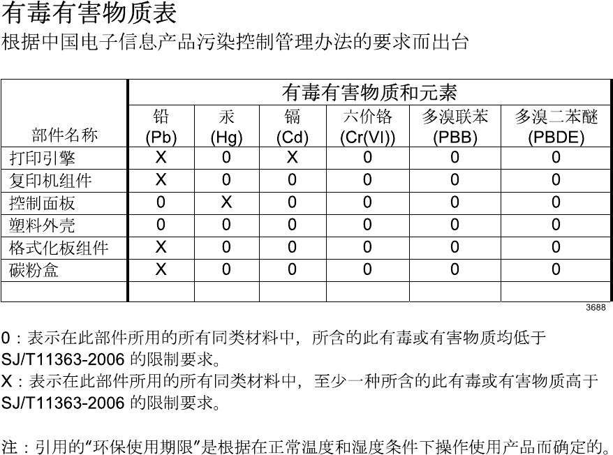
Laitteen käyttäminen muulla kuin käyttöohjeessa mainitulla tavalla saattaa altistaa käyttäjän
turvallisuusluokan 1 ylittävälle näkymättömälle lasersäteilylle.
VARNING !
Om apparaten används på annat sätt än i bruksanvisning specificerats, kan användaren utsättas för
osynlig laserstrålning, som överskrider gränsen för laserklass 1.
HUOLTO
HP Color LaserJet CM3530, CM3530fs - kirjoittimen sisällä ei ole käyttäjän huollettavissa olevia
kohteita. Laitteen saa avata ja huoltaa ainoastaan sen huoltamiseen koulutettu henkilö. Tällaiseksi
huoltotoimenpiteeksi ei katsota väriainekasetin vaihtamista, paperiradan puhdistusta tai muita käyttäjän
käsikirjassa lueteltuja, käyttäjän tehtäväksi tarkoitettuja ylläpitotoimia, jotka voidaan suorittaa ilman
erikoistyökaluja.
VARO !
Mikäli kirjoittimen suojakotelo avataan, olet alttiina näkymättömällelasersäteilylle laitteen ollessa
toiminnassa. Älä katso säteeseen.
VARNING !
Om laserprinterns skyddshölje öppnas då apparaten är i funktion, utsättas användaren för osynlig
laserstrålning. Betrakta ej strålen. Tiedot laitteessa käytettävän laserdiodin säteilyominaisuuksista:
Aallonpituus 775-795 nm Teho 5 m W Luokan 3B laser.
Substances Table (China)
ENWW Safety statements 585
586 Appendix C Regulatory information ENWW

Index
Symbols/Numerics
500-sheet paper and heavy media
tray
models including 3
A
AC to DC conversion 125
accessories
ordering 510
part numbers 511
screws 519
accessories installed,
information 440
acoustic specifications 578
activity log, fax 81
address books, e-mail
clearing 53
importing 87
ADF
capacity 4
clean delivery system 108
operations 174
part numbers 520
sensors 174
ADF output bin
selecting 77
ADF roller assembly,
removing 215
ADF separation pad,
removing 215
ADF, removing 212
Administration menu, control
panel 16
after service checklist 181
anticounterfeit supplies 93
AppleTalk information 439
AppleTalk settings 34
Attention light
locating 12
automatic overhead transparency
sensing 75
B
bands, troubleshooting 496
beam-detect (BD) failure 132
bias generation
high-voltage power
supply 124
billing codes report, fax 81
bins
locating 7
selecting 77
bins, output
capacity 60
black-only printing mode
developing roller state 141
primary transfer roller
state 143
blank pages
troubleshooting 500
blank pages, troubleshooting 495
blocked fax list, printing 81
browser requirements
embedded Web server 85
buffer overflow errors 442
buttons, control panel
locating 12
touchscreen 15
C
cable, USB
part number 514
cables
USB, troubleshooting 500
calibrate scanner 430
calibrating scanner 50
calibration
information, printed 434
reset by NVRAM
initialization 506
call report, fax 81
Canadian DOC regulations 584
capacity
ADF 4
cartridges
management menu 29
non-HP 93
ordering through embedded
Web server 88
removing 186
replace 93
replacement intervals 93
storage 93
warranty 571
cartridges, print
part numbers 513
cassette
lift operation 153, 170
paper-level detection 155
paper-presence
detection 155, 171
pickup assembly,
removing 323
pickup drive assembly,
removing 316
pickup operations 152
presence detection 153, 169
tray 2, removing 199
tray 3, removing 199
See also trays
cautions 2
characters, troubleshooting 498
checklists
after service 181
preservice 180
ENWW Index 587
circuit diagrams
fuser temperature-control 128
general 424
high-voltage power
supply 123
low-voltage power supply 125
clean
about 108, 110
ADF delivery system 108
document-feeder rollers 110
fuser 111
glass 108
outside of product 108
touchscreen 108
clean page, printing 111
clock
error message 441
clutches
DC controller 120
cold reset 504
color
calibration 145
diagnostic test 440
disengagement for black-only
printing 141
misregistration control 146
page count, reset 503
primary transfer roller
state 143
troubleshooting 434, 497
color usage job log, printing 81
components
DC controller 119
diagnostic tests 409
diagrams of 411
duplexing unit 162
engine-control system 118
fuser 127
image formation, use
during 133
intermediate transfer belt
(ITB) 142
paper feeder 167
pickup, feed, and delivery 148
print cartridge 139
protection for 126, 128
Registration density (RD) sensor
assembly, removing 297
residual-toner-feed motor,
removing 292
toner-collection sensor,
removing 290
configuration page
Information menu 17
printing 80
configuration pages
information 440
printing 436
configurations, models 3
configure
trays 75
connectivity features 5
connectors
DC controller PCA 412
product base 414
control panel
Administration menu 16
buttons 12
clean touchscreen 108
E-mail Setup menu 41
Fax Setup menu 38
help 15
Home screen 14
Information menu 17
Initial Setup menu 31
layout 12
lights 12
locating 7
locking menus 91
Management menu 28
messages, listed
alphabetically 441
messages, listed
numerically 441
Resets menu 53
Send Setup menu 41
Service menu 54
Time/Scheduling menu 26
touchscreen buttons 15
control-panel assembly,
removing 219
control-panel overlay,
removing 218
controlling print jobs 76
conventions, document 2
cooling
areas and fans 123
copying
features 6
quality, troubleshooting 494
speed specifications 4
counterfeit supplies 93
counts
ADF 503
ADF duplex 503
ADF simplex 503
color cycle 503
copy pages 503
copy scan 503
flatbed cycle 503
mono cycle 503
page, reset 503
print engine maintenance 440
refurbish cycle 503
reset after replacing
formatter 503
reset by NVRAM
initialization 506
send scan 503
See also pages counts
covers
delivery cover, removing 245
front stapler and right-side
stapler covers,
removing 249
front-door assembly,
removing 211
front-top, removing 261
front-upper cover,
removing 225
left, removing 233
left-upper cover,
removing 247
rear cover, removing 238
rear-toptop, removing 262
rear-upper cover,
removing 236
right-door assembly,
removing 227
right-front, removing 239
right-rear, removing 231
right-top cover, removing 258
covers, locating 7
creases, troubleshooting 499
crooked pages
troubleshooting 498
588 Index ENWW
current-detection protection
circuit 129
custom paper sizes 61
customer support
embedded Web server
links 88
online 576
D
dark image, troubleshooting 494
Data light
locating 12
date
codes for firmware 440
manufacture 438
product first used 504
date, setting 26
DC controller
clutches 120
components 119
fans 122
motors 122
PCA, connectors 412
sensors 121
solenoids 119
switches 120
temperature controls 129
voltage detection 126
DC controller PCA and tray,
removing 270
DC motors 122
DC voltages converted from
AC 125
Declaration of Conformity 583
default job options menu 19
default settings
Resets menu 53
defects, repeating 428
delivery assembly
removing 361
delivery cover, removing 245
demo page 378
density control 147
development process 136
Device Behavior menu 42
diagnostics
component 409
engine 381
LED 378
networks 34
page, printing 434
See also tests; troubleshooting
diagrams 509
digital sending
embedded Web server
settings 87
Setup menu 41
validating gateway
addresses 507
Digital Sending tab, embedded
Web server 87
DIMM
memory, removing 193
DIMMs (dual inline memory
modules)
installing 100
part numbers 513
Disk Erase feature 90
disk initialization 505
DLC/LLC information 439
DLC/LLC settings 34
document conventions 2
document feeder
jams 485
document feeder count
ADF pages 503
document feeder interval 503
double-sided printing
paper loading orientation 62
drawer connector
drawer connector,
removing 368
drive circuit
power-supply frequency
range 130
drivers
paper types 58
duplex printing
paper loading orientation 62
duplexing unit
components 162
duplex-drive assembly,
removing 366
motors 122
pickup operation 163
See also pickup, feed, and
delivery
duty cycle 4
E
EIO accessory
settings 31
EIO cards
buffer overflow 442
errors 455
installing 105
part number 514
reset by NVRAM
initialization 506
electrical specifications 578
electrostatic discharge
(ESD) 178
embedded protocol page 439
embedded Web server
assigning a password 90
Digital Sending tab 87
features 85
energy specifications 578
engine
diagnostics 381
test page 386
engine-control system
components 118
Enhanced I/O card
part number 514
envelopes
jams 489
loading in Tray 1 66
loading orientation 62
environment change control 147
environment, specifications 579
erasing hard disk 90
Error button, control panel
touchscreen 15
error messages
control panel, listed
alphabetically 441
control panel, listed
numerically 441
event log, listed
numerically 468
See also troubleshooting
ESD (electrostatic
discharge) 178
Ethernet cards 5
event log
clear 468, 503
information 440
ENWW Index 589
messages, listed
numerically 468
reset by NVRAM
initialization 506
view or print 468
EWS
features 85
exhaust fans 123
Explorer, versions supported
embedded Web server 85
e-mail
embedded Web server
settings 87
problem solving 507
validating gateway
addresses 507
E-mail Setup menu 41
F
faded print 494
failure detection
drive circuit 130
fuser 129
lasers and scanners 132
low-voltage power supply 126
motors 122
See also jams
fans
cartridge, removing 285
DC controller 122
delivery, removing 285
exhaust 123
intake 123
power-supply fan and fan duct,
removing 300
fax accessory
printing schedule 27
solve problems 507
Fax Activity Log
clearing 53
fax PCA, removing 197
fax reports, printing 17, 81
Fax Setup menu 38
features 3, 4
feed, paper. See pickup, feed, and
delivery
file directory, printing 81
Finnish laser safety
statement 584
firmware
date codes 440
version information 438
firmware, upgrading 112
fixing
definition 116
flowcharts
troubleshooting 375
fonts
included 4
list, printing 18, 81
Foreign Interface Harness
(FIH) 9
formatter
operations 116
PCA, removing 192
resets after replacing 503
security 92
formatter lights 378
fraud hotline 93
front-door assembly,
removing 211
front-top cover, removing 261
front-upper cover, removing 225
fuser
clean 111
components 127
control-circuit function 127
discrepancy detection 130
drive assembly, removing 356
failure detection 129
jams 475
motor, removing 345
temperature control 128
See also fusing and delivery unit
fusing
definition 116
fusing and delivery unit
operations 159
See also fuser; pickup, feed, and
delivery
G
gateways
validating addresses 507
glass
clean 108
graphical display, control
panel 12
H
halftone control 147
hard disk
erasing 90
initialization 505
part numbers 513
hard disk EIO
part numbers 513
hard disks
encrypted 90
hard drive, removing 195
heartbeat LED 380
heat control for fuser 128
heaters, fuser 127
Help button, control panel
touchscreen 15
help, control panel 15
high-voltage power supply
bias generation 124
circuits 124
operations 123
removing, lower 308
removing, upper 339
See also power supply
Home button, control panel
touchscreen 15
Home screen, control panel 14
HP Customer Care 576
HP Easy Printer Care
opening 82
options 82
using 82
HP fraud hotline 93
HP Jetdirect print server
configuration page 438
installing 105
lights 378
models including 3
settings 31
HP Jetdirect print servers
installing 105
HP Web Jetadmin
firmware updates 114
humidity requirements 579
I
I/O configuration
settings 31
ICB, removing 267
590 Index ENWW
image quality issues
examples and solutions 494
image stabilization controls 147
image-formation process 133
imaging drums
color drums
disengagement 141
diagnostic test 385
Information menu 17
information pages 80
Information tab, embedded Web
server 86
initial rotation period 117
Initial Setup menu 31
initializing
hard disk 505
NVRAM 506
input trays
optional, operations 166
installation
date calculation 504
verify for optional
accessories 436
installing
EIO cards 105
intake fans 123
interface ports
included 5
locating 9
intermediate transfer belt (ITB)
components 142
home position 143
operations 142
Internet Explorer, versions
supported
embedded Web server 85
IPv4 information 438
IPv6 information 438
IPX/SPX information 439
IPX/SPX setting 33
J
jams
common causes of 472
detection in paper feeder 173
detection sensors 164
diagnostic test for 386
document feeder 485
envelopes 489
fuser 475
lower right door 484
output bin 479
recovery 486
right door 475
Tray 1 480
Tray 2 482
Tray 3 483, 484
types detected 164
Japanese VCCI statement 584
Jetadmin
firmware updates 114
Jetadmin, HP Web 89
Jetdirect print server
installing 105
lights 378
models including 3
settings 31
job storage
settings 28
K
keys, control panel
locating 12
touchscreen 15
Korean EMC statement 584
L
LAN-connector 5
languages, printer 4
laser safety statements 584
laser/scanner
assembly (C/Bk),
removing 332
assembly (Y/M),
removing 325
failure conditions 132
operations 131
last rotation period 117
latent image formation 134
LDAP servers
embedded Web server
settings 87
validating gateway
addresses 507
LEDs. See lights
left cover, removing 233
left-upper cover, removing 247
license, software 573
lifter-drive assembly
removing 314
light print, troubleshooting 494
lights
control panel 12
formatter 378
troubleshooting with 378
lines, troubleshooting 496
link speed settings 36
loading
Tray 1 66
Tray 2 68
loading media
configuring 62
locking
control panel menus 91
log of events
clear 468
messages, listed
numerically 468
view or print 468
loop control 159
loose toner, troubleshooting 497
low-voltage power supply
converted DC voltages 125
failure detection 126
operations 125
protection for
components 126
safety provided by 126
stops and interruptions 125
See also power supply
lower right door
jams 484
LVPS, removing 273
M
Macintosh
AppleTalk settings 34
support 576
main-drive assembly
removing 346
manage
EWS 85
information pages 80
supplies 93
Management menu 28
manual print modes 492
Media 55
media
supported sizes 56
ENWW Index 591
memory
features 4
included 3
information 436
insufficient 442, 459
NVRAM initialization 506
part numbers 513
memory DIMM, removing 193
memory DIMMs
security 92
Menu button 12
menu map
Information menu 17
print 372
printing 80
menus, control panel
Administration 16
E-mail Setup 41
Fax Setup 38
Information 17
Initial Setup 31
locking 91
Management 28
Resets 53
Send Setup 41
Service 54
Time/Scheduling 26
messages
control panel, listed
alphabetically 441
control panel, listed
numerically 441
event log, listed
numerically 468
model number 438
models 3
monthly duty cycle 4
motors
DC controller 122
developing-disengagement,
removing 311
drum motor 1, removing 343
drum motor 2 or 3,
removing 344
failure detection 122
fuser, removing 345
paper feeder 167
pickup, feed, and delivery 149
pickup, removing 313
stepping 122
movement of paper through
product. See pickup, feed, and
delivery
multiple paper feed
prevention 155, 172
multipurpose tray. See trays
N
Netscape Navigator, versions
supported
embedded Web server 85
Networking tab, embedded Web
server 88
networks
AppleTalk settings 34
connectivity features 5
diagnostics 34
DLC/LLC settings 34
HP embedded Jetdirect
configuration page 438
HP Web Jetadmin 89
installing EIO cards 105
IPX/SPX settings 33
link speed settings 36
print servers included 3
protocol configuration page,
printing 37
security 34
TCP/IP settings 31
validating gateway
addresses 507
noise specifications 578
non-HP supplies 93
notes 2
Novell/NetWare information 439
NVRAM (nonvolatile memory)
initialization 506
O
on/off switch, locating 7
online help, control panel 15
online support 576
operating environment
specifications 579
operation sequence 117
operations
ADF 174
scanner 174
ordering
part numbers for 511
supplies and accessories 510
supplies through embedded
Web server 88
orientation
paper, while loading 62
output bin
jams 479
locating 7
output bins
selecting 77
overcurrent or overvoltage
protection 126
overhead transparency (OHT)
detection 158
P
pages
blank 500
not printing 500
printing slowly 500
skewed 498
pages count
from product ADF 503
from product copy 503
from product copy scan
count 503
from product flatbed 503
from product refurbish
date 503
from product send scan 503
reset 503
reset by NVRAM
initialization 506
since last maintenance 440
See also counts
pages per minute 4
paper
cassette-presence
detection 153, 169
custom sizes 61
default size reset 504
jam detection 173
level detection 155
load 66
loading orientation 62
loading Tray 3 72
movement sensors 148, 164
multifeed prevention 172
presence detection 155, 171
selecting 76
592 Index ENWW
size detection 169
source 76
stop in path for testing 409
supported sizes 56
supported types 58
type 76
type and size 76
type detection 158
wrinkled 499
paper feeder
cassette lift operation 170
electrical components 167
feed operations 157
jam detection 173
multifeed prevention 155,
172
optional 1 x 500-sheet 166
pickup and feed
operation 168
skew feed prevention 158
See also pickup, feed, and
delivery
paper jams. See jams
paper path
diagnostic test 386
stop movement for
testing 409
paper-path
test, sensors 408
parameters, EP,
troubleshooting 434
part numbers
ADF/scanner assembly 520
hard disk 513
hard disk EIO 513
memory 513
print cartridges 513
screws 519
parts 509
parts lists and diagrams
covers, panels, and doors 522
internal components 526,
528, 530, 532, 534
using 519
password
Service menu PIN 503
periods of the operation
sequence 116
physical specifications 577
pickup, feed, and delivery
components 148
multipurpose tray pickup 156
overview 148
paper-feed operations 157
paper-feeder pickup and
feed 168
pickup-and-feed unit
operations 151
See also paper feeder; fusing
and delivery unit; duplexing
unit
pliers, required 179
port configuration
information 438
ports
included 5
locating 9
post-service tests 182
power specifications 578
power supply
frequency range for drive
circuit 130
troubleshooting 376
See also low-voltage power
supply; high-voltage power
supply
power switch, locating 7
power-save mode. See sleep
settings
pre-troubleshooting checklist 373
preservice checklist 180
pressure-roller pressurization
control 161
print cartridge
managing 93
print cartridges
components 139
diagnostic test 385
error conditions 141
management menu 29
non-HP 93
operations 140
ordering through embedded
Web server 88
part numbers 513
removing 186
replacement intervals 93
replacing 94
storage 93
warranty 571
print media
loading in Tray 1 66
print quality
built-in troubleshooting
pages 431
color misregistration
control 146
image stabilization
controls 147
manual print modes 492
menu 46
test pages 431
troubleshooting 494
Print Quality menu options 492
print server card
installing 105
print-quality test 182
printer languages 4
printing
modes, manual 492
output bin, selecting 77
period in operation
sequence 117
process explained 133
speed specifications 4
stop for testing 409
troubleshooting 500
printing from Tray 2 68
problem-solving
Error button, control panel
touchscreen 15
e-mail 507
jams 472
networks 34
processor speed 4
product info 1
product status
HP Easy Printer Care 82
protocol configuration page,
printing 37
Q
quality. See print quality
R
Ready light
locating 12
rear cover, removing 238
ENWW Index 593
rear-top cover, removing 262
rear-upper cover, removing 236
reformat product hard disk 505
registration assembly
removing 303
Registration density (RD) sensor
assembly, removing 297
regulatory statements
Declaration of Conformity 583
remote firmware update
(RFU) 112
removing parts
ADF 212
ADF roller assembly 215
ADF separation pad 215
cartridge fan 285
cassette-pickup assembly 323
cassette-pickup drive
assembly 316
cautions for 178
checklists 180
control-panel assembly 219
control-panel overlay 218
DC controller PCA and
tray 270
delivery assembly 361
delivery cover 245
delivery fan 285
developing-disengagement
motor 311
drawer connector 368
drum motor 1 343
drum motor 2 or 3 344
duplex-drive assembly 366
environmental sensor 285
fax PCA 197
formatter PCA 192
front stapler and right-side
stapler covers 249
front-door assembly 211
front-top cover 261
front-upper cover 225
fuser 200
fuser motor 345
fuser-drive assembly 356
hard drive 195
high-voltage power supply
lower 308
high-voltage power supply
upper 339
ICB 267
intermediate transfer belt 209
laser/scanner assembly (C/
Bk) 332
laser/scanner assembly (Y/
M) 325
left cover 233
left-upper cover 247
lifter-drive assembly 314
LVPS 273
main-drive assembly 346
memory DIMM 193
pickup motor 313
pickup roller (tray 1) 284
pickup roller (tray 2) 201
power-supply fan and fan
duct 300
print cartridges 186
rear cover 238
rear-top cover 262
rear-upper cover 236
registration assembly 303
Registration density (RD) sensor
assembly 297
residual-toner-feed motor 292
right-door assembly 227
right-front cover 239
right-rear cover 231
right-top cover 258
scanner assembly 242
SCB 279
secondary transfer
assembly 207
secondary transfer roller 205
separation roller (tray 2) 204
stable cartridge 188
stapler assembly 264
stapler power supply 266
toner-collection sensor 290
toner-collection unit 190
tools, required 179
tray cassette 199
repeating defects,
troubleshooting 428
replace
memory 100
supplies 93
replacing
parts 178
reset button 12
Resets menu, control panel 53
residual-toner-feed motor,
removing 292
resolution
specifications 4
troubleshooting quality 494
restore factory settings 505
reverse and feed control,
duplexer 163
right door
jams 475
right-front cover, removing 239
right-top cover, removing 258
roller
pickup roller (Tray 1),
removing 284
pickup roller (Tray 2),
removing 201
rollers
clean document-feeder 110
secondary transfer roller,
removing 207
separation roller (Tray 2),
removing 204
ruler, repetitive defect 428
S
safety features
when front door is open 126
safety statements 584
scanner
operations 174
part numbers 520
scanner assembly, removing 242
scanner calibration 50, 430
scanner glass
clean 108
scanner settings 504
scanner-motor failure 132
scanning
speed specifications 4
scanning to e-mail
embedded Web server
settings 87
validating addresses 507
SCB, removing 279
screwdrivers, required 179
screws
part numbers 519
replacing 178
594 Index ENWW
secondary transfer roller,
removing 205
Secure Disk Erase 90
security
disk erase 90
encrypted hard disk 90
locking control panel
menus 91
settings 34
security features 6
security settings information 438
Send Setup menu 41
sending to e-mail
embedded Web server
settings 87
validating gateway
addresses 507
sensor tests manual
developing home-position
sensor 394
door (front and right) interlock
switches sensor 398
duplex re-pickup sensor
(E) 392
fuser delivery sensor 391
fuser pressure release
sensor 395
loop sensors 390
output bin full sensor 393
primary transfer roller
disengagement sensor 396
TOP sensor (A) 389
tray 1 media present
sensor 400
tray 2 closed sensor 402
tray 2 paper-out sensor
(M) 401
tray 2 stack surface
sensor 403
tray 3 (optional) empty sensor
(P) 404
tray 3 (optional) media feed
sensor 405
tray 3 (optional) media size
sensors 407
tray 3 (optional) stack surface
sensor (R) 406
sensors
ADF 174
DC controller 121
diagnostic tests 408
environmental, removing 285
jam detection 164
paper feeder 167
pickup, feed, and delivery 148
product base 421
tests, manual 387
sequence of operation 116
serial number
locate 10
reset by NVRAM
initialization 506
service
tools, required 179
Service ID
convert to date 504
restore 504
Service menu options 503
Service menu, control panel 54
settings
restore factory 505
Settings tab, embedded Web
server 86
skew-feed prevention 158
skewed pages
troubleshooting 498
Sleep button 12
Sleep mode
power specifications 578
settings 26, 28
sleep settings
voltage for 126
voltage too high during 126
smeared toner,
troubleshooting 498
SMTP servers
validating gateway
addresses 507
software
HP Easy Printer Care 82
software license
agreement 573
solenoids
DC controller 119
paper feeder 167
pickup, feed, and delivery 149
solve problems 369
solving
direct-connect problems 501
network problems 501
space requirements 577
specifications
acoustic 578
electrical 578
features 4
operating environment 579
physical 577
speed dial list, printing 81
speed specifications 4
stable cartridge, removing 188
standard output bin
locating 7
selecting 77
standby period 117
stapler assembly, removing 264
stapler power supply,
removing 266
Start button 12
Start button, control panel
touchscreen 15
static precautions 178
status
embedded Web server 86
Home screen, control
panel 14
HP Easy Printer Care 82
Status button 12
status page 378
stepping motors 122
Stop button 12
Stop button, control panel
touchscreen 15
stop printing for test 409
storage, job
settings 28
storing
print cartridges 93
streaks, troubleshooting 496
subvoltage
low-voltage power supply
circuit 125
supplies
counterfeit 93
locating 94
management menu 29
non-HP 93
ordering 510
ordering through embedded
Web server 88
part numbers 511, 513
ENWW Index 595
replace 93
replacement intervals 93
replacing 94
Resets menu 53
status page, printing 80
status, viewing with embedded
Web server 86
supplies 93
supplies, status
HP Easy Printer Care 82
support
embedded Web server
links 88
online 576
supported media 56
switches
DC controller 120
paper feeder 167, 169
pickup, feed, and delivery 148
system requirements
embedded Web server 85
T
TCP/IP information 438
TCP/IP settings 31
technical support
online 576
temperature
control for fuser 128
thresholds for fuser
components 129
temperature requirements 579
tests
color band 440
component tests list and
descriptions 409
disable cartridge check 385
engine 386
manual sensor 387
networks 34
paper path 386
paper-path sensors 408
post-service 182
print-quality 182
print/stop 409
text, troubleshooting 498
thermistors
fuser 127, 129
open detection 130
thermopiles
fuser 129
thermoswitches
fuser 127, 129
thresholds
power-supply frequency, drive
circuit 130
temperature, fuser
components 129
time, setting 26
Time/Scheduling menu, control
panel 26
timeout settings 31
timing chart 423
tips 2
toner
image formation, use
during 134
loose, troubleshooting 497
patterns for calibration 146
smeared, troubleshooting 498
toner cartridges. See print
cartridges
toner collection unit
removing 190
replacing 98
toner-collection sensor,
removing 290
tools, required 179
touchscreen, clean 108
transfer processes 136
Tray 1
capacity 60
jams 480
Tray 2
capacity 60
jams 482
Tray 3
jams 483, 484
trays
automatic overhead
transparency sensing 75
capacity 60
configure 75
included 3
load 62
multipurpose, pickup
operation 156
paper orientation 62
removing 199
select paper 76
See also cassette
trays, status
HP Easy Printer Care 82
triac-drive circuit
deactivation 129
troubleshooting
blank pages 500
checklist 370, 373
color 434
configuration page 378
configuration pages for 436
control-panel messages,
alphabetical list 441
control-panel messages,
numerical list 441
demo page 378
direct-connect problems 501
duplexing 490
EP parameters 434
event log 378
event log, use for 468
event-log messages, numerical
list 468
flowchart 375
gateway addresses 507
jams 472
lights, using 378
lines, printed pages 496
menu 50
messages, alphabetical list
of 441
network problems 501
pages not printing 500
pages printing slowly 500
paper handling problems 487
power 376
print quality issues 494
process 373
repeating defects 428
reports and tools 378
skewed pages 498
status page 378
text 498
toner smear 498
transparencies 489
USB cables 500
wrinkles 499
596 Index ENWW
See also diagnostics; error
messages
Troubleshooting menu
options 381
TrueType fonts included 4
typefaces
included 4
U
upgrading firmware 112
usage page, printing 80
USB port
troubleshooting 500
V
validating gateway
addresses 507
version, hardware firmware 438
vertical lines,
troubleshooting 496
voltage detection
DC controller 126
voltage specifications 578
W
waiting period 117
wake time, setting 27
Warning button, control panel
touchscreen 15
warnings 2
warranty
customer self repair 575
license 573
print cartridges 571
product 570
warranty date information 504
Web browser requirements
embedded Web server 85
Web Jetadmin
firmware updates 114
Web sites
customer support 576
fraud reports 93
HP Web Jetadmin,
downloading 89
Macintosh customer
support 576
ordering supplies 510
white spots, troubleshooting 495
wrinkles, troubleshooting 499
ENWW Index 597
598 Index ENWW

© 2008 Hewlett-Packard Development Company, L.P.
www.hp.com
*CC519-91013*
*CC519-91013*
CC519-91013
