HP LaserJet Enterprise 600 M601, M602, And M603 Series Printer Service Manual ENWW M600
User Manual: HP Laserjet M600 shared.swissparts.ch - /Manuals/HP/LaserJet/Mono Laserjet/
Open the PDF directly: View PDF ![]() .
.
Page Count: 572 [warning: Documents this large are best viewed by clicking the View PDF Link!]
- Theory of operation
- Removal and replacement
- Introduction
- Removal and replacement strategy
- Electrostatic discharge
- Required tools
- Types of screws
- Service approach
- Customer replaceable units (CRUs)
- Covers
- Main assemblies
- Registration assembly
- Control-panel assembly
- Walk-up USB port and cable
- Inner connecting PCA
- Fan FN102
- Fan FN103
- Pickup-motor assembly (M101)
- Drum-motor assembly (M102)
- Lifter-motor assembly (M103)
- DC controller PCA
- Pickup-drive assembly
- Fuser-motor assembly (M299)
- Drum-drive assembly
- Fan FN101
- Fan FN301
- Environmental sensor (TH3)
- High voltage power supply
- Feed-guide assembly
- Tray 1 paper-pickup assembly
- Feed-roller assembly
- Laser/scanner assembly
- Paper-delivery assembly
- 1,500-sheet paper deck (PD)
- Solve problems
- Solve problems checklist
- Menu map
- Preboot menu options
- Current settings pages
- Troubleshooting process
- Tools for troubleshooting
- Component diagnostics
- LED diagnostics
- Engine diagnostics
- Paper-path test (and automatic sensor test)
- Manual sensor test
- Top of page sensor (PS103)
- Pre-feed sensor (PS102)
- Fuser delivery sensor (PS700)
- Duplex sensor (PS1502)
- Media width sensors 1/2 (PS106/108)
- Output bin full sensor (PS104)
- Tray 1 paper present sensor (PS105)
- Tray 2 paper present sensor (PS101)
- Tray 2 top of stack sensor (PS107)
- Tray 2 paper size switches (SW102)
- Tray/Bin manual sensor test
- Print/stop test
- Component tests
- Diagrams
- Internal print-quality test pages
- Print quality troubleshooting tools
- Control-panel menus
- Interpret control-panel messages, status-alert messages, and event code errors
- 10.00.33
- 10.00.35
- 10.00.60
- 10.00.69
- 10.00.91
- 10.0X.Y0 Supply memory error
- 10.23.35
- 10.23.50
- 10.23.51
- 10.23.52
- 10.23.60
- 10.23.70 Printing Past Very Low
- 10.26.15
- 10.26.50
- 10.26.60
- 10.XX.34 Used Supply In Use
- 10.XX.40 Genuine HP Supplies Installed
- 10.XX.41 Unsupported Supply In Use
- 10.XX.70 Printing past very low
- 10.YY.15 Install <supply>
- 10.YY.35 Incompatible <supply>
- 11.00.YY Internal clock error
- 13.00.00
- 13.00.EE
- 13.A3.FF
- 13.D3.DZ
- 13.E5.FF
- 13.EA.EE
- 13.EE.FF
- 13.FF.EE
- 13.FF.FF
- 13.WX.EE
- 13.WX.FF
- 13.WX.YZ Fuser Area Jam
- 13.WX.YZ Fuser wrap jam
- 13.WX.YZ Jam below control panel
- 13.WX.YZ Jam in Tray 1
- 13.WX.YZ Jam in Tray <X>
- 13.WX.YZ Jam inside envelope feeder
- 13.WX.YZ Jam inside top cover
- 14.00.XX
- 20.00.00 Insufficient memory: <Device> To continue, touch “OK”
- 21.00.00 Page Too Complex
- 32.08.AX
- 32.1C.XX
- 32.21.00
- 33.01.XX
- 33.XX.YY Used board/disk
- 40.00.01 USB I/O buffer overflow To continue, touch “OK”
- 40.00.02 Embedded I/O buffer overflow To continue, touch “OK”
- 40.00.05 Embedded I/O bad transmission To continue, touch “OK”
- 41.02.00 Error
- 41.03.YZ Unexpected size in envelope feeder To use another tray, touch "Options"
- 41.03.YZ Unexpected size in tray <X>
- 41.05.YZ Unexpected type in tray <X>
- 41.XX.YZ Error To continue, touch “OK”
- 42.XX.YY
- 47.00.XX
- 47.01.XX
- 47.02.XX
- 47.03.XX
- 47.04.XX
- 47.05.00
- 47.06.XX
- 47.WX.YZ Printer Calibration Failed To continue, touch “OK”
- 49.XX.YY To continue turn off then on
- 50.WX.YZ Fuser error To continue turn off then on
- 51.00.YY Error
- 52.XX.00 Error To continue turn off then on
- 54.XX.YY Error
- 55.00.YY DC controller error To continue turn off then on
- 55.0X.YY DC controller error To continue turn off then on
- 56.00.YY Error To continue turn off then on
- 57.00.0Y Error To continue turn off then on
- 58.00.0Y Error To continue turn off then on
- 59.00.YY error To continue turn off then on
- 59.A2.0x Error
- 60.00.0Y Tray <Y> lifting error
- 62.00.00 No system To continue turn off then on
- 65.X0.A1 Output accessory disconnected
- 66.80.YY Stapler/Stacker failure
- 69.11.YY Error To continue turn off then on
- 70.00.00 Error To continue turn off then on
- 79.XX.YY Error To continue turn off then on
- 80.0X.YY Embedded JetDirect error
- 81.YY.ZZ EIO-1 Card Failure
- 82.73.46 OR 82.73.47
- 98.00.01 Corrupt data in firmware volume
- 98.00.02 Corrupt data in solutions volume
- 98.00.03 Corrupt data in configuration volume
- 98.00.04 Corrupt data in job data volume
- 99.00.01 Upgrade not performed file is corrupt
- 99.00.02 Upgrade not performed timeout during receive
- 99.00.03 Upgrade not performed error writing to disk
- 99.00.04 Upgrade not performed timeout during receive
- 99.00.05 Upgrade not performed timeout during receive
- 99.00.06 Upgrade not performed error reading upgrade
- 99.00.07 Upgrade not performed error reading upgrade
- 99.00.08 Upgrade not performed error reading upgrade
- 99.00.09 Upgrade canceled by user
- 99.00.10 Upgrade canceled by user
- 99.00.11 Upgrade canceled by user
- 99.00.12 Upgrade not performed the file is invalid
- 99.00.13 Upgrade not performed the file is invalid
- 99.00.14 Upgrade not performed the file is invalid
- 99.00.2X
- 99.09.60 Unsupported disk
- 99.09.61 Unsupported disk
- 99.09.62 Unknown disk
- 99.09.63 Incorrect disk
- 99.09.64 Disk malfunction
- 99.09.65 Disk data error
- 99.09.66 No disk installed
- 99.09.67 Disk is not bootable please download firmware
- 99.XX.YY
- <binname> full Remove all paper from bin
- <Supply> low OR Supplies low
- <Supply> very low OR Supplies very low
- [File System] device failure To clear press “OK”
- [File System] file operation failure To clear press “OK”
- [File System] file system is full To clear press “OK”
- [File System] is not initialized
- [File System] is write protected
- Accept bad signature
- Bad optional tray connection
- Canceling
- Canceling... <jobname>
- Cartridge Low
- Cartridge Memory Abnormal
- Cartridge Out
- Checking engine
- Checking paper path
- Chosen personality not available To continue, touch “OK”
- Cleaning do not grab paper
- Cleaning...
- Clearing event log
- Clearing paper path
- Close stapler/stacker multi bin mailbox door
- Close top cover
- Cooling device
- Creating cleaning page...
- Data received To print last page press “OK”
- Event log is empty
- Expected drive missing
- External device initializing
- Face Down Tray Full
- FIM Load Error Send full FIM on <X> port
- Fuser Kit low
- Fuser Kit very low To continue, touch “OK”
- Genuine HP cartridge installed
- Genuine HP supply installed
- HP Secure hard drive disabled
- Incompatible <supply>
- Incompatible supplies
- Initializing...
- Install fuser unit
- Install supplies
- Install supply
- Internal disk device failure To clear press “OK”
- Internal disk file operation failed
- Internal disk file system is full
- Internal disk is write protected
- Internal disk not found
- Internal disk not functional
- Internal disk not initialized
- Internal disk spinning up
- Job not stapled due to mixed sizes
- Load Tray <X>: [Type], [Size]
- Load Tray <X>: [Type], [Size] To use another tray, press “OK”
- Loading program <XX>
- Manually feed output stack Then touch "OK" to print second side
- Manually feed: <Type><Size>
- Manually feed: <Type><Size> To use another tray, press “OK”
- Moving solenoid
- Moving solenoid and motor
- No job to cancel
- NON HP SUPPLY INSTALLED
- Output Bin Full
- Paused…
- Performing Paper Path Test…
- Please Wait...
- Printing Configuration...
- Printing Event Log...
- Printing File Directory...
- Printing Font List...
- Printing Fuser Test Page...
- Printing Help Page...
- Printing Menu Map...
- Printing Registration Page…
- Printing stopped
- Printing Supplies Status Page...
- Printing Usage Page...
- Printing…engine test
- Processing duplex job Do not grab paper until job completes
- Processing job from tray <X>... Do not grab paper until job completes
- Processing...
- Processing... copy <X> of <Y>
- RAM disk device failure To clear press “OK”
- RAM disk file operation failed To clear press “OK”
- RAM disk file system is full To clear press “OK”
- RAM disk is write protected To clear press “OK”
- RAM disk not initialized
- Ready
- Ready <IP Address>
- Receiving Upgrade
- Remove one print cartridge
- Remove USB accessory
- Replace <supply>
- Replace supplies
- Resend external accessory firmware
- Resend Upgrade
- Restore Factory Settings
- ROM disk device failed To clear press “OK”
- ROM disk file operation failed To clear press “OK”
- ROM disk file system is full To clear press “OK”
- ROM disk is write protected To clear press “OK”
- ROM disk not initialized To clear press “OK”
- Rotating Motor
- Size Mis-Match
- Size mismatch in Tray <X>
- Sleep mode on
- Staple Cartridge low
- Staple Cartridge very low
- Stapler/Stacker staple jam
- Supplies low
- SUPPLY MEMORY WARNING
- The unit has corrupt data
- Tray <X> empty: [Type], [Size]
- Tray <X> lifting
- Tray <X> open
- Tray <X> overfilled
- Type mismatch Tray
- Unsupported drive installed To continue, touch “OK”
- Unsupported supply in use OR Unsupported supply installed To continue, touch “OK”
- Unsupported tray configuration
- Unsupported USB accessory detected Remove USB accessory
- Upgrade Error
- USB accessory not functional
- USB hubs are not fully supported Some operations may not work properly
- USB is write protected To clear press “OK”
- USB needs too much power
- USB needs too much power Remove USB and Then Turn Off then On
- USB not initialized
- USB storage accessory removed Clearing any associated data
- USB storage device failure To clear press “OK”
- USB storage file operation failed To clear press “OK”
- USB storage file system is full To clear press “OK”
- Used supply installed To continue, touch “OK” OR Used supply in use
- Waiting for tray <X> to lift
- Windows Login Required to Use this Feature
- Event-log messages
- Component diagnostics
- Clear jams
- Paper does not feed automatically
- Use manual print modes
- Solve image-quality problems
- Clean the product
- Solve performance problems
- Solve connectivity problems
- Service mode functions
- Product updates
- Parts and diagrams
- Service and support
- Product specifications
- Regulatory information
- FCC regulations
- Environmental product stewardship program
- Protecting the environment
- Ozone production
- Power consumption
- Toner consumption
- Paper use
- Plastics
- HP LaserJet print supplies
- Return and recycling instructions
- Paper
- Material restrictions
- Disposal of waste equipment by users in private households in the European Union
- Chemical substances
- Material Safety Data Sheet (MSDS)
- For more information
- Declaration of Conformity
- Certificate of Volatility
- Safety statements
- Laser safety
- Canadian DOC regulations
- VCCI statement (Japan)
- Power cord instructions
- Power cord statement (Japan)
- EMC statement (China)
- EMC statement (Korea)
- EMI statement (Taiwan)
- Product Stability
- Laser statement for Finland
- GS statement (Germany)
- Substances Table (China)
- Restriction on Hazardous Substances statement (Turkey)
- Index
LASERJET ENTERPRISE 600 M601, M602, AND
M603 SERIES PRINTER
Service Manual

HP LaserJet Enterprise 600 M601,
M602, and M603 Series Printer
Service Manual
Copyright and License
© 2011 Copyright Hewlett-Packard
Development Company, L.P.
Reproduction, adaptation, or translation
without prior written permission is
prohibited, except as allowed under the
copyright laws.
The information contained herein is subject
to change without notice.
The only warranties for HP products and
services are set forth in the express warranty
statements accompanying such products and
services. Nothing herein should be
construed as constituting an additional
warranty. HP shall not be liable for technical
or editorial errors or omissions contained
herein.
Part number: CE988-90945
Edition 1, 11/2011
Trademark Credits
ENERGY STAR and the ENERGY STAR mark
are registered U.S. marks.

Conventions used in this guide
TIP: Tips provide helpful hints or shortcuts.
NOTE: Notes provide important information to explain a concept or to complete a task.
CAUTION: Cautions indicate procedures that you should follow to avoid losing data or damaging
the product.
WARNING! Warnings alert you to specific procedures that you should follow to avoid personal
injury, catastrophic loss of data, or extensive damage to the product.
ENWW iii
iv Conventions used in this guide ENWW

Table of contents
1 Theory of operation .......................................................................................................... 1
Basic operation ........................................................................................................................ 2
Major print systems ................................................................................................... 2
Internal components .................................................................................................. 3
Operating sequence .................................................................................................. 7
Formatter system ...................................................................................................................... 8
Sleep mode .............................................................................................................. 8
Input/output ............................................................................................................. 8
USB .......................................................................................................... 8
Embedded print server ................................................................................ 9
Hard-disk .................................................................................................. 9
CPU ......................................................................................................... 9
Memory ................................................................................................................... 9
Random-access memory .............................................................................. 9
Nonvolatile memory ................................................................................... 9
DIMM slot ................................................................................................................ 9
PJL overview ........................................................................................................... 10
PML ....................................................................................................................... 10
Control panel ......................................................................................................... 10
Engine-control system .............................................................................................................. 11
DC controller PCA ................................................................................................... 12
Sensors, solenoids, and switches ............................................................................... 13
Motors and fans ...................................................................................................... 14
Failure detection ...................................................................................... 14
Motor failure ............................................................................ 14
Fan motor failure ....................................................................... 14
Engine power supply ................................................................................ 15
Fuser-control circuit .................................................................... 15
Low-voltage power supply .......................................................... 17
High-voltage power supply ......................................................... 18
Overcurrent/overvoltage protection ............................................. 19
Image-formation system ........................................................................................................... 20
ENWW v
Image-formation process .......................................................................................... 21
Block 1: Latent image formation ................................................................. 23
Step 1: Primary charging ........................................................... 23
Step 2: Laser-beam exposure ...................................................... 23
Block 2: Developing ................................................................................. 24
Step 3: Developing .................................................................... 24
Block 3: Transfer ...................................................................................... 25
Step 4: Transfer ........................................................................ 25
Step 5: Separation .................................................................... 25
Block 4: Fusing ........................................................................................ 26
Step 6: Fusing ........................................................................... 26
Block 5: Drum cleaning ............................................................................. 27
Step 7: Drum cleaning ............................................................... 27
Step 8: Drum charge elimination ................................................. 27
Laser/scanner system ............................................................................................................. 28
Laser failure detection .............................................................................................. 30
Pickup, feed, and delivery system ............................................................................................. 31
Pickup-and-feed block .............................................................................................. 32
Fuser/delivery block ................................................................................................ 33
Pressure roller pressure release control ....................................................................... 33
Paper trays ............................................................................................................. 34
Printing from Tray 1 .................................................................................. 34
Printing from Tray 2 .................................................................................. 34
Cassette media size detection and cassette presence detection ...................... 34
Jam detection ......................................................................................................... 36
1x500-sheet paper feeder ....................................................................................................... 40
Pickup-and-feed operation (PF) .................................................................................. 41
Cassette lift operation (PF) ........................................................................................ 43
Cassette media size detection and cassette presence detection (PF) ............................... 43
Cassette multiple-feed prevention (PF) ........................................................................ 43
Jam detection (PF) ................................................................................................... 43
1x1500-sheet paper deck ....................................................................................................... 44
Pickup-and-feed operation (PD) ................................................................................. 45
Cassette lift operation (PD) ....................................................................................... 47
Media size detection (PD) ........................................................................................ 48
Multiple-feed prevention (PD) .................................................................................... 48
Jam detection (PF) ................................................................................................... 48
Envelope feeder ..................................................................................................................... 49
Pickup-and-feed operation (EF) .................................................................................. 50
Multiple-feed prevention (EF) ..................................................................................... 50
Multiple-feed detection (EF) ....................................................................................... 51
vi ENWW
Jam detection (EF) ................................................................................................... 51
Duplexer ............................................................................................................................... 53
Motor and fan control (DP) ....................................................................................... 54
Failure detection (DP) ................................................................................ 55
Reverse-and-re-pickup operation (DP) ......................................................................... 55
Side registration adjustment operation (DP) ................................................................ 56
Jam detection (DP) ................................................................................................... 58
2 Removal and replacement .............................................................................................. 59
Introduction ........................................................................................................................... 60
Removal and replacement strategy ........................................................................................... 60
Electrostatic discharge ............................................................................................................ 60
Required tools ........................................................................................................................ 61
Types of screws ..................................................................................................................... 62
Service approach ................................................................................................................... 63
Before performing service ........................................................................................ 63
After performing service ........................................................................................... 63
Post-service test ....................................................................................................... 63
Print-quality test ........................................................................................ 63
Customer replaceable units (CRUs) ........................................................................................... 64
Print cartridge ......................................................................................................... 64
Tray 2 ................................................................................................................... 65
Tray 2 separation, pickup, and feed rollers ................................................................ 66
Transfer roller ........................................................................................................ 69
Fuser ..................................................................................................................... 70
Remove the fuser ...................................................................................... 70
Formatter cover and formatter cage ........................................................................... 71
Installing a new formatter .......................................................................... 73
Hard drive ............................................................................................................. 74
Remove the SSM ...................................................................................... 74
Remove the encrypted HHD ....................................................................... 76
Installing a replacement hard drive ............................................................. 78
SSM firmware upgrade .............................................................. 78
HDD firmware upgrade .............................................................. 79
Memory DIMM ....................................................................................................... 80
Remove the memory DIMM ....................................................................... 80
Install the memory DIMM ........................................................................... 81
Tray 1 pickup and feed rollers .................................................................................. 82
Tray 1 separation roller ........................................................................................... 85
Rear output bin ....................................................................................................... 87
Covers .................................................................................................................................. 88
ENWW vii
Top-accessory cover ................................................................................................ 88
Envelope feed accessory covers ................................................................................ 89
Duplex accessory or cover ....................................................................................... 90
Tray 2 extension door .............................................................................................. 91
Remove the Tray 2 extension door .............................................................. 91
Top cover ............................................................................................................... 92
Remove the top cover ............................................................................... 92
Right-side cover ....................................................................................................... 95
Remove the right-side cover ....................................................................... 95
Reinstall the right cover ............................................................................. 97
Left-side cover ......................................................................................................... 98
Remove the left-side cover ......................................................................... 98
Right-front cover .................................................................................................... 100
Remove the right-front cover ..................................................................... 100
Rear-upper cover ................................................................................................... 103
Remove the rear-upper cover ................................................................... 103
Front cover ........................................................................................................... 105
Remove the front cover ............................................................................ 105
Main assemblies .................................................................................................................. 107
Registration assembly ............................................................................................ 107
Control-panel assembly .......................................................................................... 109
Remove the control-panel assembly ........................................................... 109
Walk-up USB port and cable .................................................................................. 111
Remove the walk-up USB port and cable ................................................... 111
Inner connecting PCA ............................................................................................ 114
Remove the inner connecting PCA ............................................................ 114
Reinstall the inner connecting PCA ........................................................... 116
Fan FN102 .......................................................................................................... 117
Remove fan FN102 ................................................................................ 117
Fan FN103 .......................................................................................................... 119
Remove fan FN103 ................................................................................ 119
Pickup-motor assembly (M101) ............................................................................... 121
Remove the pickup-motor assembly ........................................................... 121
Drum-motor assembly (M102) ................................................................................. 123
Remove the drum motor .......................................................................... 123
Lifter-motor assembly (M103) .................................................................................. 125
Remove the lifter motor ........................................................................... 125
DC controller PCA ................................................................................................. 128
Remove the DC controller PCA ................................................................. 128
Reinstallation tip ..................................................................................... 129
Installing a new formatter and a new DC controller .................................... 129
viii ENWW
Pickup-drive assembly ............................................................................................ 131
Remove the pickup-drive assembly ............................................................ 131
Reinstall the pickup-drive assembly ........................................................... 136
Fuser-motor assembly (M299) ................................................................................. 137
Remove the fuser-motor assembly ............................................................. 137
Drum-drive assembly .............................................................................................. 139
Remove the drum-drive assembly .............................................................. 139
Reinstall the drum-drive assembly ............................................................. 141
Fan FN101 .......................................................................................................... 142
Remove fan FN101 ................................................................................ 142
Fan FN301 .......................................................................................................... 144
Remove fan FN301 ................................................................................ 144
Environmental sensor (TH3) .................................................................................... 146
Remove the environmental sensor (TH3) .................................................... 146
High voltage power supply .................................................................................... 148
Remove the high-voltage power-supply assembly ........................................ 148
Feed-guide assembly ............................................................................................. 152
Remove the feed-guide assembly .............................................................. 152
Reinstall the feed-guide assembly ............................................................. 154
Tray 1 paper-pickup assembly ................................................................................ 155
Remove the Tray 1 pickup assembly ......................................................... 155
Feed-roller assembly .............................................................................................. 157
Remove the feed-roller assembly ............................................................... 157
Laser/scanner assembly ......................................................................................... 158
Remove the laser/scanner assembly ......................................................... 158
Paper-delivery assembly ........................................................................................ 161
Remove the paper-delivery assembly ......................................................... 161
Reinstall the paper-delivery assembly ........................................................ 164
1,500-sheet paper deck (PD) ................................................................................................. 165
Separation roller (PD) ............................................................................................ 165
Rear cover (PD) ..................................................................................................... 167
Right-side cover (PD) .............................................................................................. 168
1,500-sheet paper deck left-side cover ..................................................................... 169
Remove the left-side cover ....................................................................... 169
Door (PD) ............................................................................................................. 172
Motor (PD) ........................................................................................................... 174
Remove the Motor (PD) ........................................................................... 174
Driver PCA (PD) .................................................................................................... 176
Remove the Driver PCA (PD) .................................................................... 176
Lift-drive assembly (PD) ........................................................................................... 178
Remove the Lift-drive assembly (PD) ........................................................... 178
ENWW ix
3 Solve problems ............................................................................................................. 181
Solve problems checklist ....................................................................................................... 182
Menu map .......................................................................................................................... 184
Preboot menu options ........................................................................................................... 185
Current settings pages .......................................................................................................... 192
Troubleshooting process ........................................................................................................ 193
Determine the problem source ................................................................................. 193
Pre-troubleshooting checklist .................................................................... 193
Troubleshooting flowchart ....................................................................... 194
Power subsystem ................................................................................................... 196
Power-on checks .................................................................................... 196
Overview ............................................................................... 196
Tools for troubleshooting ....................................................................................................... 199
Component diagnostics .......................................................................................... 199
LED diagnostics ...................................................................................... 199
Understand lights on the formatter ............................................. 199
Engine diagnostics ................................................................................. 204
Engine test button .................................................................... 204
Formatter test .......................................................................... 204
Print/Stop test ......................................................................... 205
Drum rotation test .................................................................... 205
Paper-path test (and automatic sensor test) ................................................. 206
Paper path sensors test (automatic) ............................................ 206
Manual sensor test ................................................................................. 208
Top of page sensor (PS103) ..................................................... 210
Pre-feed sensor (PS102) ........................................................... 211
Fuser delivery sensor (PS700) ................................................... 212
Duplex sensor (PS1502) ........................................................... 213
Media width sensors 1/2 (PS106/108) ..................................... 214
Output bin full sensor (PS104) .................................................. 215
Tray 1 paper present sensor (PS105) ......................................... 216
Tray 2 paper present sensor (PS101) ......................................... 217
Tray 2 top of stack sensor (PS107) ............................................ 218
Tray 2 paper size switches (SW102) ......................................... 219
Tray/Bin manual sensor test .................................................................... 220
Print/stop test ........................................................................................ 220
Component tests ..................................................................................... 221
Diagrams ............................................................................................................. 223
Block diagrams ...................................................................................... 223
Main assemblies ..................................................................... 223
Main parts ............................................................................. 224
xENWW
Motors and fans ...................................................................... 225
PCAs ..................................................................................... 226
500-sheet feeder ..................................................................... 226
1,500-sheet feeder .................................................................. 227
Connectors ............................................................................................ 229
DC controller PCA connectors ................................................... 229
Product base connectors ........................................................... 231
500-sheet paper tray connectors ............................................... 232
1,500-sheet paper tray connectors ............................................ 232
Duplexer connectors ................................................................ 233
Envelope feeder connectors ...................................................... 233
General timing chart ............................................................................... 234
Circuit diagrams .................................................................................... 235
Internal print-quality test pages ................................................................................ 241
Print-quality-troubleshooting pages ............................................................ 241
Clean the paper path ............................................................................. 242
Set up an auto cleaning page ................................................... 242
Print configuration page .......................................................................... 243
Configuration page ................................................................. 243
HP embedded Jetdirect page .................................................... 245
Print quality troubleshooting tools ............................................................................ 246
Repetitive image defect ruler .................................................................... 246
Control-panel menus .............................................................................................. 247
Retrieve Job from USB menu .................................................................... 247
Retrieve Job from Device Memory menu .................................................... 247
Supplies menu ....................................................................................... 248
Trays menu ............................................................................................ 249
Administration menu ............................................................................... 250
Reports menu .......................................................................... 250
General Settings menu ............................................................. 250
Retrieve From USB Settings menu .............................................. 253
General Print Settings menu ...................................................... 253
Default Print Options menu ....................................................... 255
Display Settings menu .............................................................. 255
Manage Supplies menu ........................................................... 256
Manage Trays menu ................................................................ 257
Stapler/Stacker Settings menu .................................................. 258
Multi-Bin Mailbox Settings menu ................................................ 258
Network Settings menu ............................................................ 259
Troubleshooting menu .............................................................. 263
Device Maintenance menu ...................................................................... 264
ENWW xi
Backup/Restore menu .............................................................. 264
Calibrate/Cleaning menu ........................................................ 264
USB Firmware Upgrade menu ................................................... 265
Service menu .......................................................................... 265
Interpret control-panel messages, status-alert messages, and event code errors .............. 266
10.00.33 .............................................................................................. 266
10.00.35 .............................................................................................. 266
10.00.60 .............................................................................................. 266
10.00.69 .............................................................................................. 267
10.00.91 .............................................................................................. 267
10.0X.Y0 Supply memory error ............................................................... 267
10.23.35 .............................................................................................. 268
10.23.50 .............................................................................................. 268
10.23.51 .............................................................................................. 268
10.23.52 .............................................................................................. 268
10.23.60 .............................................................................................. 268
10.23.70 Printing Past Very Low .............................................................. 269
10.26.15 .............................................................................................. 269
10.26.50 .............................................................................................. 269
10.26.60 .............................................................................................. 270
10.XX.34 Used Supply In Use .................................................................. 270
10.XX.40 Genuine HP Supplies Installed ................................................... 270
10.XX.41 Unsupported Supply In Use ....................................................... 271
10.XX.70 Printing past very low ............................................................... 271
10.YY.15 Install <supply> ....................................................................... 271
10.YY.35 Incompatible <supply> ............................................................. 272
11.00.YY Internal clock error .................................................................. 272
13.00.00 .............................................................................................. 272
13.00.EE .............................................................................................. 273
13.A3.FF .............................................................................................. 273
13.D3.DZ ............................................................................................. 273
13.E5.FF ............................................................................................... 273
13.EA.EE .............................................................................................. 274
13.EE.FF ............................................................................................... 274
13.FF.EE ............................................................................................... 274
13.FF.FF ............................................................................................... 274
13.WX.EE ............................................................................................. 274
13.WX.FF ............................................................................................. 275
13.WX.YZ Fuser Area Jam ...................................................................... 275
13.WX.YZ Fuser wrap jam ...................................................................... 275
13.WX.YZ Jam below control panel ......................................................... 275
xii ENWW
13.WX.YZ Jam in Tray 1 ........................................................................ 275
13.WX.YZ Jam in Tray <X> ..................................................................... 276
13.WX.YZ Jam inside envelope feeder ..................................................... 276
13.WX.YZ Jam inside top cover ............................................................... 276
14.00.XX .............................................................................................. 276
20.00.00 Insufficient memory: <Device> To continue, touch “OK” ............... 277
21.00.00 Page Too Complex .................................................................. 277
32.08.AX .............................................................................................. 277
32.1C.XX .............................................................................................. 278
32.21.00 .............................................................................................. 284
33.01.XX .............................................................................................. 285
33.XX.YY Used board/disk ..................................................................... 285
40.00.01 USB I/O buffer overflow To continue, touch “OK” ....................... 285
40.00.02 Embedded I/O buffer overflow To continue, touch “OK” .............. 285
40.00.05 Embedded I/O bad transmission To continue, touch “OK” ........... 286
41.02.00 Error ...................................................................................... 286
41.03.YZ Unexpected size in envelope feeder To use another tray, touch
"Options" .............................................................................................. 286
41.03.YZ Unexpected size in tray <X> ..................................................... 287
41.05.YZ Unexpected type in tray <X> .................................................... 288
41.XX.YZ Error To continue, touch “OK” ................................................... 290
42.XX.YY .............................................................................................. 291
47.00.XX .............................................................................................. 291
47.01.XX .............................................................................................. 291
47.02.XX .............................................................................................. 292
47.03.XX .............................................................................................. 292
47.04.XX .............................................................................................. 292
47.05.00 .............................................................................................. 292
47.06.XX .............................................................................................. 292
47.WX.YZ Printer Calibration Failed To continue, touch “OK” ..................... 293
49.XX.YY To continue turn off then on ....................................................... 294
50.WX.YZ Fuser error To continue turn off then on ..................................... 294
51.00.YY Error ...................................................................................... 296
52.XX.00 Error To continue turn off then on ............................................... 296
54.XX.YY Error ...................................................................................... 297
55.00.YY DC controller error To continue turn off then on ........................... 298
55.0X.YY DC controller error To continue turn off then on ........................... 298
56.00.YY Error To continue turn off then on ............................................... 298
57.00.0Y Error To continue turn off then on .............................................. 299
58.00.0Y Error To continue turn off then on .............................................. 300
59.00.YY error To continue turn off then on ............................................... 300
ENWW xiii
59.A2.0x Error ...................................................................................... 301
60.00.0Y Tray <Y> lifting error ............................................................... 302
62.00.00 No system To continue turn off then on ....................................... 302
65.X0.A1 Output accessory disconnected ................................................. 303
66.80.YY Stapler/Stacker failure ............................................................. 303
69.11.YY Error To continue turn off then on ............................................... 305
70.00.00 Error To continue turn off then on .............................................. 305
79.XX.YY Error To continue turn off then on ............................................... 306
80.0X.YY Embedded JetDirect error ......................................................... 306
81.YY.ZZ EIO-1 Card Failure .................................................................. 308
82.73.46 OR 82.73.47 ......................................................................... 309
98.00.01 Corrupt data in firmware volume ............................................... 310
98.00.02 Corrupt data in solutions volume ............................................... 310
98.00.03 Corrupt data in configuration volume ......................................... 310
98.00.04 Corrupt data in job data volume ............................................... 310
99.00.01 Upgrade not performed file is corrupt ........................................ 311
99.00.02 Upgrade not performed timeout during receive ........................... 311
99.00.03 Upgrade not performed error writing to disk ............................... 311
99.00.04 Upgrade not performed timeout during receive ........................... 311
99.00.05 Upgrade not performed timeout during receive ........................... 312
99.00.06 Upgrade not performed error reading upgrade ........................... 312
99.00.07 Upgrade not performed error reading upgrade ........................... 312
99.00.08 Upgrade not performed error reading upgrade ........................... 312
99.00.09 Upgrade canceled by user ....................................................... 313
99.00.10 Upgrade canceled by user ....................................................... 313
99.00.11 Upgrade canceled by user ....................................................... 313
99.00.12 Upgrade not performed the file is invalid ................................... 313
99.00.13 Upgrade not performed the file is invalid ................................... 314
99.00.14 Upgrade not performed the file is invalid ................................... 314
99.00.2X .............................................................................................. 314
99.09.60 Unsupported disk .................................................................... 315
99.09.61 Unsupported disk .................................................................... 315
99.09.62 Unknown disk ......................................................................... 315
99.09.63 Incorrect disk .......................................................................... 316
99.09.64 Disk malfunction ...................................................................... 316
99.09.65 Disk data error ........................................................................ 316
99.09.66 No disk installed ..................................................................... 316
99.09.67 Disk is not bootable please download firmware .......................... 316
99.XX.YY .............................................................................................. 317
<binname> full Remove all paper from bin ................................................ 317
<Supply> low OR Supplies low ................................................................ 317
xiv ENWW
<Supply> very low OR Supplies very low .................................................. 318
[File System] device failure To clear press “OK” ......................................... 318
[File System] file operation failure To clear press “OK” ............................... 318
[File System] file system is full To clear press “OK” ..................................... 318
[File System] is not initialized ................................................................... 319
[File System] is write protected ................................................................. 319
Accept bad signature ............................................................................. 319
Bad optional tray connection ................................................................... 319
Canceling ............................................................................................. 320
Canceling... <jobname> ......................................................................... 320
Cartridge Low ........................................................................................ 320
Cartridge Memory Abnormal ................................................................... 320
Cartridge Out ........................................................................................ 320
Checking engine .................................................................................... 321
Checking paper path .............................................................................. 321
Chosen personality not available To continue, touch “OK” .......................... 321
Cleaning do not grab paper .................................................................... 321
Cleaning... ............................................................................................ 322
Clearing event log .................................................................................. 322
Clearing paper path ............................................................................... 322
Close stapler/stacker multi bin mailbox door ............................................. 322
Close top cover ...................................................................................... 322
Cooling device ...................................................................................... 323
Creating cleaning page... ....................................................................... 323
Data received To print last page press “OK” ............................................. 323
Event log is empty .................................................................................. 323
Expected drive missing ........................................................................... 324
External device initializing ....................................................................... 324
Face Down Tray Full ............................................................................... 324
FIM Load Error Send full FIM on <X> port ................................................. 324
Fuser Kit low .......................................................................................... 324
Fuser Kit very low To continue, touch “OK” ............................................... 325
Genuine HP cartridge installed ................................................................ 325
Genuine HP supply installed .................................................................... 325
HP Secure hard drive disabled ................................................................. 325
Incompatible <supply> ............................................................................ 326
Incompatible supplies ............................................................................. 326
Initializing... .......................................................................................... 326
Install fuser unit ...................................................................................... 326
Install supplies ....................................................................................... 327
Install supply .......................................................................................... 327
ENWW xv
Internal disk device failure To clear press “OK” .......................................... 327
Internal disk file operation failed .............................................................. 327
Internal disk file system is full ................................................................... 328
Internal disk is write protected .................................................................. 328
Internal disk not found ............................................................................ 328
Internal disk not functional ....................................................................... 328
Internal disk not initialized ....................................................................... 328
Internal disk spinning up ......................................................................... 329
Job not stapled due to mixed sizes ........................................................... 329
Load Tray <X>: [Type], [Size] .................................................................. 329
Load Tray <X>: [Type], [Size] To use another tray, press “OK” .................... 330
Loading program <XX> ........................................................................... 330
Manually feed output stack Then touch "OK" to print second side ................ 330
Manually feed: <Type><Size> ................................................................. 330
Manually feed: <Type><Size> To use another tray, press “OK” ................... 331
Moving solenoid .................................................................................... 331
Moving solenoid and motor ..................................................................... 331
No job to cancel .................................................................................... 331
NON HP SUPPLY INSTALLED ................................................................... 332
Output Bin Full ....................................................................................... 332
Paused… .............................................................................................. 332
Performing Paper Path Test… ................................................................... 332
Please Wait... ........................................................................................ 332
Printing Configuration... .......................................................................... 333
Printing Event Log... ................................................................................ 333
Printing File Directory... ........................................................................... 333
Printing Font List... .................................................................................. 333
Printing Fuser Test Page... ....................................................................... 333
Printing Help Page... .............................................................................. 334
Printing Menu Map... ............................................................................. 334
Printing Registration Page… .................................................................... 334
Printing stopped ..................................................................................... 334
Printing Supplies Status Page... ................................................................ 334
Printing Usage Page... ............................................................................ 334
Printing…engine test ............................................................................... 335
Processing duplex job Do not grab paper until job completes ...................... 335
Processing job from tray <X>... Do not grab paper until job completes ......... 335
Processing... .......................................................................................... 335
Processing... copy <X> of <Y> ................................................................ 335
RAM disk device failure To clear press “OK” ............................................. 336
RAM disk file operation failed To clear press “OK” .................................... 336
xvi ENWW
RAM disk file system is full To clear press “OK” ......................................... 336
RAM disk is write protected To clear press “OK” ........................................ 336
RAM disk not initialized .......................................................................... 336
Ready ................................................................................................... 337
Ready <IP Address> ............................................................................... 337
Receiving Upgrade ................................................................................. 337
Remove one print cartridge ..................................................................... 337
Remove USB accessory ........................................................................... 337
Replace <supply> .................................................................................. 338
Replace supplies .................................................................................... 338
Resend external accessory firmware ......................................................... 339
Resend Upgrade .................................................................................... 339
Restore Factory Settings .......................................................................... 339
ROM disk device failed To clear press “OK” ............................................. 339
ROM disk file operation failed To clear press “OK” .................................... 339
ROM disk file system is full To clear press “OK” ......................................... 340
ROM disk is write protected To clear press “OK” ....................................... 340
ROM disk not initialized To clear press “OK” ............................................ 340
Rotating Motor ....................................................................................... 340
Size Mis-Match ...................................................................................... 340
Size mismatch in Tray <X> ...................................................................... 341
Sleep mode on ...................................................................................... 341
Staple Cartridge low .............................................................................. 341
Staple Cartridge very low ....................................................................... 341
Stapler/Stacker staple jam ...................................................................... 342
Supplies low .......................................................................................... 342
SUPPLY MEMORY WARNING ................................................................. 342
The unit has corrupt data ......................................................................... 342
Tray <X> empty: [Type], [Size] ................................................................ 343
Tray <X> lifting ...................................................................................... 344
Tray <X> open ....................................................................................... 344
Tray <X> overfilled ................................................................................. 345
Type mismatch Tray ................................................................................ 345
Unsupported drive installed To continue, touch “OK” .................................. 345
Unsupported supply in use OR Unsupported supply installed To continue,
touch “OK” ........................................................................................... 346
Unsupported tray configuration ................................................................ 346
Unsupported USB accessory detected Remove USB accessory ...................... 346
Upgrade Error ....................................................................................... 346
USB accessory not functional ................................................................... 347
USB hubs are not fully supported Some operations may not work properly .... 347
ENWW xvii
USB is write protected To clear press “OK” ............................................... 347
USB needs too much power ..................................................................... 347
USB needs too much power Remove USB and Then Turn Off then On ........... 347
USB not initialized .................................................................................. 348
USB storage accessory removed Clearing any associated data .................... 348
USB storage device failure To clear press “OK” ......................................... 348
USB storage file operation failed To clear press “OK” ................................ 348
USB storage file system is full To clear press “OK” ...................................... 348
Used supply installed To continue, touch “OK” OR Used supply in use .......... 349
Waiting for tray <X> to lift ...................................................................... 349
Windows Login Required to Use this Feature ............................................. 349
Event-log messages ............................................................................................... 350
Print an event log ................................................................................... 351
View an event log .................................................................................. 352
Clear an event log .................................................................................. 352
Clear jams .......................................................................................................................... 353
Jam locations ........................................................................................................ 354
Common causes of jams ........................................................................................ 355
Clear jams from the input trays ............................................................................... 356
Clear jams from Tray 1 ........................................................................... 356
Clear jams from Tray 2 or an optional 500-sheet tray ................................. 356
Clear jams from the optional 1,500-sheet tray ........................................... 357
Clear jams from the optional duplexer ..................................................................... 359
Clear jams from the optional envelope feeder ........................................................... 361
Clear jams from the output areas ............................................................................ 363
Clear jams from the rear output bin .......................................................... 363
Clear jams from the optional stacker or stapler/stacker ............................... 364
Clear paper jams from the optional stacker or stapler/stacker ...... 364
Clear staple jams from the optional stapler/stacker ..................... 365
Clear jams from the optional 5-bin mailbox ............................................... 367
Clear jams from the fuser ....................................................................................... 369
Clear jams from the print-cartridge (top cover) .......................................................... 373
Change jam recovery ............................................................................................ 375
Paper does not feed automatically .......................................................................................... 376
The product does not pick up paper ........................................................................ 376
The product picks up multiple sheets of paper ........................................................... 376
Prevent paper jams ................................................................................................ 376
Use manual print modes ....................................................................................................... 378
Solve image-quality problems ................................................................................................ 380
Print-quality examples ............................................................................................ 380
Clean the product ................................................................................................................ 388
xviii ENWW
Clean the paper path ............................................................................................ 388
Set up an auto cleaning page .................................................................. 388
Solve performance problems ................................................................................................. 389
Solve connectivity problems ................................................................................................... 390
Solve direct-connect problems ................................................................................. 390
Solve network problems ......................................................................................... 390
Service mode functions ......................................................................................................... 391
Service menu ........................................................................................................ 391
Product resets ....................................................................................................... 392
Restore factory-set defaults ....................................................................... 392
Clean Disk and Partial Clean functions .................................................................... 393
Active and repository firmware locations ................................................... 393
Partial Clean ......................................................................................... 394
Execute a Partial Clean ............................................................ 394
Clean Disk ............................................................................................ 395
Execute a Clean Disk ............................................................... 395
Product updates ................................................................................................................... 397
Determine the installed revision of firmware .............................................................. 397
Perform a firmware upgrade ................................................................................... 397
Embedded Web Server ........................................................................... 397
USB storage device (Preboot menu) .......................................................... 398
USB storage device (control-panel menu) ................................................... 399
4 Parts and diagrams ...................................................................................................... 401
Order parts by authorized service providers ............................................................................ 402
Order parts, accessories, and supplies .................................................................... 402
Supplies part numbers ........................................................................................... 402
Customer-self repair parts ....................................................................................... 402
Accessories part numbers ....................................................................................... 404
Related documentation and software ....................................................................... 405
How to use the parts lists and diagrams .................................................................................. 406
Assembly locations ............................................................................................................... 407
Base product (no optional trays or accessories) ......................................................... 407
Covers ................................................................................................................................ 410
Product base ........................................................................................................ 410
Internal components ............................................................................................................. 412
Internal components (1 of 3) ................................................................................... 412
Internal components (2 of 3) ................................................................................... 414
Internal components (3 of 3) ................................................................................... 416
High-voltage power supply ..................................................................................... 418
Cassette (Tray 2) ................................................................................................... 420
ENWW xix
Cassette (custom media) ......................................................................................... 422
Paper feed roller assembly ..................................................................................... 424
Registration assembly ............................................................................................ 426
Tray 1 (MP) pickup assembly .................................................................................. 428
Paper delivery assembly ........................................................................................ 430
Fuser assembly ..................................................................................................... 432
PCAs (product base) .............................................................................................. 434
Input devices ....................................................................................................................... 436
1x500-sheet feeder ............................................................................................... 436
Covers (1x500) ..................................................................................... 436
Main body (1x500) ................................................................................ 438
Cassette (1x500) ................................................................................... 440
PCA (1x500) ......................................................................................... 442
1x1500-sheet paper deck ...................................................................................... 444
Covers (1x1500) ................................................................................... 444
Front door assembly (1x1500) ................................................................. 446
Main body (1x500; 1 of 2) ..................................................................... 448
Main body (1x500; 2 of 2) ..................................................................... 450
Paper pickup assembly (1x500) ............................................................... 452
PCA (1x1500) ....................................................................................... 454
Duplexer ............................................................................................................................. 456
Main body (duplexer) ............................................................................................ 456
PCA (duplexer) ..................................................................................................... 458
Envelope feeder ................................................................................................................... 460
Covers (envelope feeder) ....................................................................................... 460
Main body (1 of 2; envelope feeder) ....................................................................... 462
Main body (2 of 2; envelope feeder) ....................................................................... 464
PCA (envelope feeder) ........................................................................................... 466
Output devices .................................................................................................................... 468
Stapler/stacker multi-bin mailbox (MBM) .................................................................. 468
Covers (MBM) ....................................................................................... 468
Main body (MBM) .................................................................................. 470
Main body (MBM; 1 of 2) ........................................................ 470
Main body (MBM; 2 of 2) ........................................................ 472
PCA (MBM) ........................................................................................... 474
Stacker and Stapler/Stacker (S and S/S) ................................................................. 476
Covers (S and S/S) ................................................................................ 476
Main body (SS) ...................................................................................... 478
Main body (S) ....................................................................................... 480
Middle assemblies (S and S/S) ................................................................ 482
Stapler/Stacker middle assembly (1 of 2; S/S) ........................... 482
xx ENWW
Stapler/Stacker middle assembly (2 of 2; S/S) ........................... 484
Stacker middle assembly (1 of 2; S) ........................................... 486
Stacker middle assembly (2 of 2; S) ........................................... 488
PCA (S and S/S) .................................................................................... 490
Alphabetical parts list ........................................................................................................... 492
Numerical parts list .............................................................................................................. 501
Appendix A Service and support ..................................................................................... 511
Hewlett-Packard limited warranty statement ............................................................................. 512
HP's Premium Protection Warranty: LaserJet print cartridge limited warranty statement .................. 514
Data stored on the print cartridge ........................................................................................... 515
End User License Agreement .................................................................................................. 516
Customer self-repair warranty service ..................................................................................... 519
Customer support ................................................................................................................. 520
Repack the product .............................................................................................................. 521
Appendix B Product specifications ................................................................................... 523
Physical specifications .......................................................................................................... 524
Power consumption, electrical specifications, and acoustic emissions .......................................... 524
Operating environment ......................................................................................................... 525
Appendix C Regulatory information ................................................................................. 527
FCC regulations ................................................................................................................... 528
Environmental product stewardship program ........................................................................... 529
Protecting the environment ...................................................................................... 529
Ozone production ................................................................................................. 529
Power consumption ............................................................................................... 529
Toner consumption ................................................................................................ 529
Paper use ............................................................................................................. 529
Plastics ................................................................................................................. 529
HP LaserJet print supplies ....................................................................................... 530
Return and recycling instructions ............................................................................. 530
United States and Puerto Rico .................................................................. 530
Multiple returns (more than one cartridge) .................................. 530
Single returns .......................................................................... 530
Shipping ................................................................................ 530
Non-U.S. returns .................................................................................... 531
Paper .................................................................................................................. 531
Material restrictions ............................................................................................... 531
Disposal of waste equipment by users in private households in the European Union ...... 532
ENWW xxi
Chemical substances ............................................................................................. 532
Material Safety Data Sheet (MSDS) ......................................................................... 532
For more information ............................................................................................. 532
Declaration of Conformity ..................................................................................................... 534
Certificate of Volatility .......................................................................................................... 536
Types of memory ................................................................................................... 536
Volatile memory ..................................................................................... 536
Non-volatile memory .............................................................................. 536
Hard-disk-drive memory .......................................................................... 536
Safety statements ................................................................................................................. 537
Laser safety .......................................................................................................... 537
Canadian DOC regulations .................................................................................... 537
VCCI statement (Japan) .......................................................................................... 537
Power cord instructions .......................................................................................... 537
Power cord statement (Japan) ................................................................................. 537
EMC statement (China) .......................................................................................... 538
EMC statement (Korea) .......................................................................................... 538
EMI statement (Taiwan) .......................................................................................... 538
Product Stability .................................................................................................... 538
Laser statement for Finland ..................................................................................... 538
GS statement (Germany) ........................................................................................ 539
Substances Table (China) ....................................................................................... 540
Restriction on Hazardous Substances statement (Turkey) ............................................. 540
Index ............................................................................................................................... 541
xxii ENWW


Basic operation
Major print systems
Operation can be divided into the following systems:
●Engine-control system (which includes the power supply and DC controller PCA)
●Laser/scanner system (which forms the latent image on a photosensitive drum)
●Image-formation system (which transfers a toner image onto the print media)
●Pickup, feed, and delivery system (which consists of various rollers and transports the media
through the product)
●Options
Figure 1-1 Major product systems
PICKUP-AND-FEED SYSTEM
LASER/SCANNER SYSTEM
ENGINE CONTROL
SYSTEM
IMAGE-FORMATION SYSTEM
OPTION
2 Chapter 1 Theory of operation ENWW
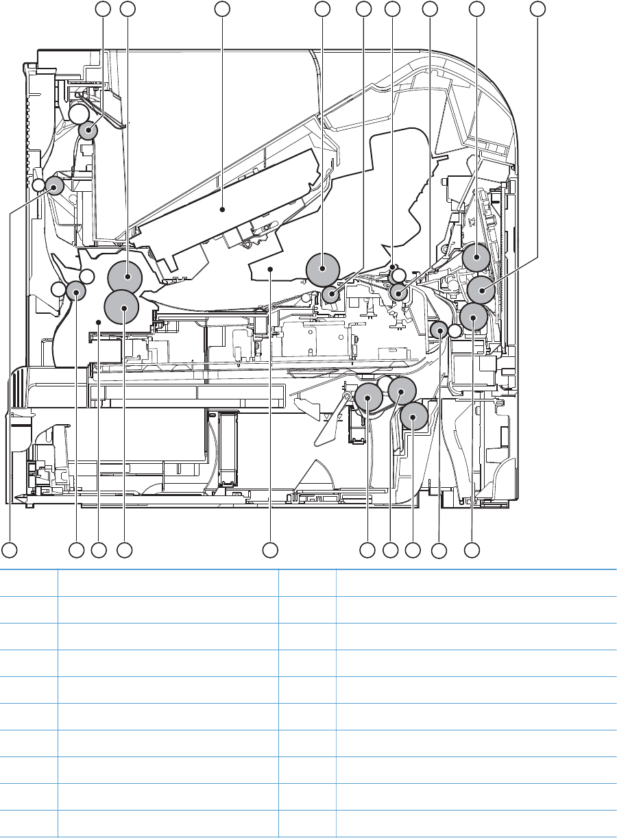
Internal components
Figure 1-2 Internal components, product base
1 2 3 4 5 6 7 8
1012131415161718
9
11
19
1Face-down delivery roller 11 Feed roller
2Fuser sleeve unit 12 Tray 2 separation roller
3Laser/scanner unit 13 Tray 2 feed roller
4Photosensitive drum 14 Tray 2 pickup roller
5Transfer roller 15 Print cartridge
6Registration shutter 16 Pressure roller
7Pre-transfer roller 17 Fuser
8Tray 1 pickup roller 18 Fuser delivery roller
9Tray 1 feed roller 19 Intermediate delivery roller
10 Tray 1 separation roller
ENWW Basic operation 3
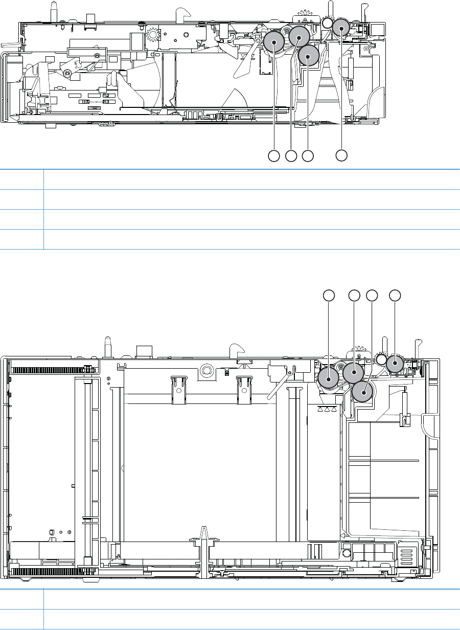
Figure 1-3 Internal components, 1x500-sheet feeder
321 4
1Pickup roller
2Feed roller
3Separation roller
4Feed roller
Figure 1-4 Internal components, 1,500-sheet paper deck
321 4
1Pickup roller
2Feed roller
4 Chapter 1 Theory of operation ENWW
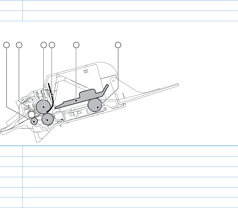
3Separation roller
4Feed roller
Figure 1-5 Internal components, envelope feeder
321 4 65
1Feed roller
2Upper separation roller
3Lower separation roller
4Separation guide
5Weight
6Pickup roller
ENWW Basic operation 5
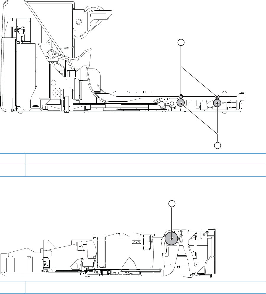
Figure 1-6 Internal components, duplexer
2
1
1Oblique rollers
2Re-pickup rollers
Figure 1-7 Internal components, custom media cassette
1
1Separation roller
6 Chapter 1 Theory of operation ENWW

Operating sequence
A microprocessor on the DC controller PCA controls the product operating sequence. The following
table describes the basic operating sequence from when the product power is turned on until the final
printed page is delivered to an output bin.
NOTE: The product takes about two minutes and twenty seconds to initialize.
Table 1-1 Product operating sequence
Period Duration Operation
WAIT From the time the power is turned on, the
door is closed or Sleep mode is released
until the product gets ready for a print
operation.
●Brings the product to standby condition.
●Pressurizes the fuser pressure roller.
●Detects the print cartridge.
STBY
(Standby)
From the end of WAIT or LSTR period
until either the print command is received
from the formatter or the power button is
turned off.
●Maintains the product in printable condition.
●Puts the product in Sleep mode when the formatter sends a
sleep command.
INTR (Initial
rotation
period)
From the time the print command is
received from the formatter until the
media is picked up.
Starts up each high-voltage bias, laser/scanner unit, and fuser for
printing.
PRINT From the end of INTR period until the last
paper completes the fixing operation.
●Forms the image on the photosensitive drum based on the
signals from the formatter.
●Transfers and fuses the toner image to the print media.
LSTR (Last
rotation
period)
From the end of PRINT period until the
motors stop rotating.
●Moves the last printed sheet out of the product.
●Stops the laser/scanner unit operation and high-voltage
biases.
The product enters the INTR period as soon as the LSTR period is
completed, if the formatter sends another print command.
ENWW Basic operation 7

Formatter system
The formatter is involved in the following procedures.
●Controlling the Sleep mode
●Receiving and processing print data from the various product inputs
●Monitoring control-panel functions and relaying product status information (through the control
panel and the bidirectional input/output)
●Developing and coordinating data placement and timing with the DC controller PCA
●Storing font information
●Communicating with the host computer through the bidirectional interface
The formatter receives a print job from the bidirectional interface and separates it into image
information and instructions that control the printing process. The dc controller PCA synchronizes the
image-formation system with the paper-input and -output systems, and then signals the formatter to send
the print-image data.
The formatter also provides the electrical interface and mounting locations for the memory DIMM and
the hard-disk (hard disk drive or solid state drive).
Sleep mode
When the product is in Sleep mode, the control-panel backlight is dimmed, but the product retains all
product settings, downloaded fonts, and macros. The default setting is a 30-minute idle time. Sleep
mode also can be turned off from the Administration menu on the control panel.
The product exits Sleep mode and enters the warm-up cycle when any of the following occurs.
●A print job, valid data, or a PML or PJL command is received at the serial port.
●A control panel key is pressed.
●The top cover is opened.
●The engine-test button is pressed.
NOTE: Error messages override the Sleep message. The product enters Sleep mode at the
appropriate time, but the error message continues to appear.
Input/output
The following sections discuss the input and output features of the product.
USB
The product includes a universal serial bus (USB) 2.0 connection.
8 Chapter 1 Theory of operation ENWW

Embedded print server
For all models except the HP LaserJet 4014 base model, the product includes an HP Jetdirect
embedded print server for connecting to a 10/100Base-TX network.
Hard-disk
The hard-disk is mounted on the formatter cage door. The hard disk is used for creating multiple
original prints (mopies) and storing forms, fonts, and signatures.
NOTE: All models have a solid state module (SSM) installed except the HP LaserJet Enterprise 600
M603xh.
CPU
The product formatter incorporates a 800 MHz RISC processor.
Memory
If the product encounters a problem when managing available memory, a clearable warning message
appears on the control panel.
Random-access memory
The formatter has one DIMM slot. All models come with 512MB of memory installed. Additional
memory can be added up to a maximum of 1GB.
The random-access memory (RAM) contains the page, I/O buffers, and the font storage area. It stores
printing and font information received from the host system, and can also serve to temporarily store a
full page of print-image data before the data is sent to the print engine. Memory capacity can be
increased by adding DIMMs to the formatter. Note that adding memory (DIMMs) might also increase
the print speed for complex graphics.
Nonvolatile memory
The product uses nonvolatile memory (NVRAM) to store I/O and information about the print
environment configuration. The contents of NVRAM are retained when the product is turned off or
disconnected.
DIMM slot
The DIMM slot can be used to add product memory.
ENWW Formatter system 9
PJL overview
Printer job language (PJL) is an integral part of configuration, in addition to the standard printer
command language (PCL). With standard cabling, use PJL to perform a variety of functions.
●Two-way communication with the host computer through a bidirectional parallel connection. The
product can send the host computer information about such things as the control panel settings,
and the control panel settings can be changed from the host through two-way communication.
●Dynamic I/O switching. The product can be configured with a host on each I/O by using
dynamic I/O switching. Even when the product is offline, it can receive data from more than one
I/O simultaneously, until the I/O buffer is full.
●Context-sensitive switching. The product can automatically recognize the personality (PS or PCL) of
each job and configure itself in that personality.
●Isolation of print environment settings from one print job to the next. For example, if a print job is
sent to the product in landscape mode, the subsequent print jobs are printed in landscape mode
only if they are formatted for it.
PML
The printer management language (PML) allows remote configuration and status monitoring through the
I/O ports.
Control panel
The formatter sends and receives product status and command data to and from a control-panel PCA.
10 Chapter 1 Theory of operation ENWW
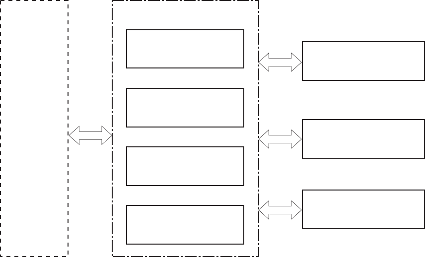
Engine-control system
The engine control system coordinates all product functions and controls all the other systems according
to commands from the formatter. The engine control system contains the following components:
●DC controller
●Low-voltage power supply
●High-voltage power supply
●Fuser control
Figure 1-8 Engine-control system
PICKUP-AND-FEED SYSTEM
ENGINE CONTROL SYSTEM
DC controller
LASER/SCANNER SYSTEM
IMAGE-FORMA TION SYSTEM
Formatte r
High-voltage power supply
Low-voltage power supply
Fuser control
ENWW Engine-control system 11
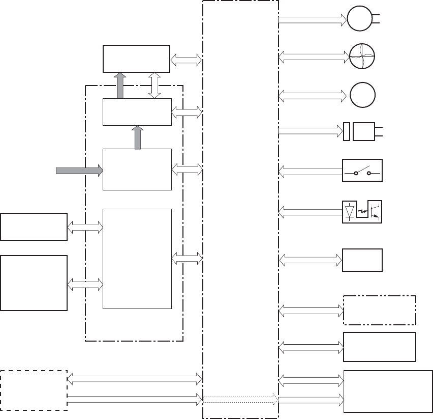
DC controller PCA
The DC controller PCA controls the operation of the product and its components. The DC controller PCA
starts product operation when the power is turned on and the power supply sends DC voltage to the
DC controller PCA. After the product enters the standby sequence, the DC controller PCA sends out
various signals to operate motors, solenoids, and other components based on the print command and
image data that the host computer sends.
Figure 1-9 DC controller PCA
AC input
M
CL
Fuser unit
Motor
Transfer roller
High-voltage
power supply
Low-voltage
power supply
Laser/scanner
unit
Solenoid
Formatter
Cartridge
Sensor
DC controller
Switch
Fan
Option
Walkup
USB port
Clutch
Fuser control
Sensor
Power supply unit
12 Chapter 1 Theory of operation ENWW

Sensors, solenoids, and switches
The product has twelve sensors, two solenoids, and three switches. Sensors are used for remote
detection of various functions during product operation. Solenoid and switches are used for product
operation control.
Table 1-2 Sensors, solenoids, and switches
Description Item Component
Sensors PS101 Cassette media presence senor
PS102 Pre-feed sensor
PS103 Top-of-page sensor
PS104 Face-down tray media full sensor
PS105 MP tray (Tray 1) media presence sensor
PS106 Media width sensor 1
PS107 Media stack surface sensor 1
PS108 Media width sensor 2
PS699 Fixing (fuser) pressure release sensor
PS700 Fixing (fuser) delivery sensor
PS907 Media stack surface sensor 2
TH3 Environmental sensor
Solenoids SL101 Casette pickup solenoid
SL102 MP tray (Tray 1) pickup solenoid
Switches SW101 Door open detection switch
SW102 Cassette media size switch
SW800 Test print switch
ENWW Engine-control system 13

Motors and fans
The product has four motors and four fan motors. The motors are used for the media feeding and image
formation. The fan motors are used for preventing a temperature rise inside the product.
Table 1-3 Fans
Description Cooling area Type Speed
Cooling fan FN101 Cartridge area and power supply area Intake Full/Half
1
Cooling fan FN102 Cartridge area Intake Full
2
Cooling fan FN103 Cartridge area Intake Full
2
Cooling fan FN301 Cartridge area and laser/scanner Intake Full
2
1
Cooling fan FN101 rotates at full speed for eight seconds when the product is turned on, and then decreases to half-speed for
approximately 10 minutes. After that time period, if there is no print job in the print queue, the fan will stop completely. The
fan rotates at full speed during a print job.
2
This fan operates at full speed only during a print job. Otherwise, it does not rotate.
Table 1-4 Motors
Description Driving parts Type Failure
detection
Paper feed motor (M101) Drives the Tray 1 pickup roller, Tray 2 pickup roller,
and feed roller
DC Yes
Drum motor (M102) Drives the photosensitive drum, primary charging roller,
and transfer roller
DC Yes
Fuser motor (M299) Drives the pressure roller and feed roller—when rotated
counterclockwise it releases the fusing pressure for
easier jam removal
DC Yes
Lifter motor (M103) Drives the lifting plate of the tray DC No
Failure detection
Motor failure
The DC controller determines a motor failure and notifies the formatter when it encounters the following
conditions:
●Motor start-up failure: The motor does not reach a specified speed within a specified period
from when each motor starts up.
●Motor rotational failure: The rotational speed of the motor is out of a specified range for a
specified period from when it once reaches a specified speed.
Fan motor failure
The DC controller determines a fan motor failure and notifies the formatter when the fan locks for a
specified period from when each fan starts up.
14 Chapter 1 Theory of operation ENWW
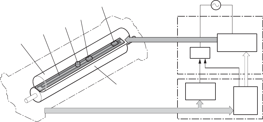
Engine power supply
The power supply consists of the fuser-control circuit, the high-voltage circuit, and the low-voltage
circuit. The fuser-control and high-voltage circuits control the temperature of the fuser and generate high-
voltage according to signals from the DC controller PCA. The low-voltage circuit generates the DC
voltages that other components in the product use (for example the DC controller PCA, the motors, and
fans).
Fuser-control circuit
The fuser-control circuit controls the fuser components. The two fuser heaters provide the high
temperatures that cause the toner to permanently bond to the media. The fuser thermistor monitors the
fuser temperatures. The thermal switch detects abnormally high fuser temperatures and interrupts the
supply of voltage to the fuser if the temperature is too high.
Figure 1-10 Fuser control
DC controller
Fuser heater
drive circuit
Fuser heater
safety circuit
Relay
CPU
Fuser control
FUSER HEATER TEMPERATURE signal
FUSER HEATER
DRIVE signal
TH1
TP1
H1
TH2
Pressure roller
Fuser sleeve
ENWW Engine-control system 15
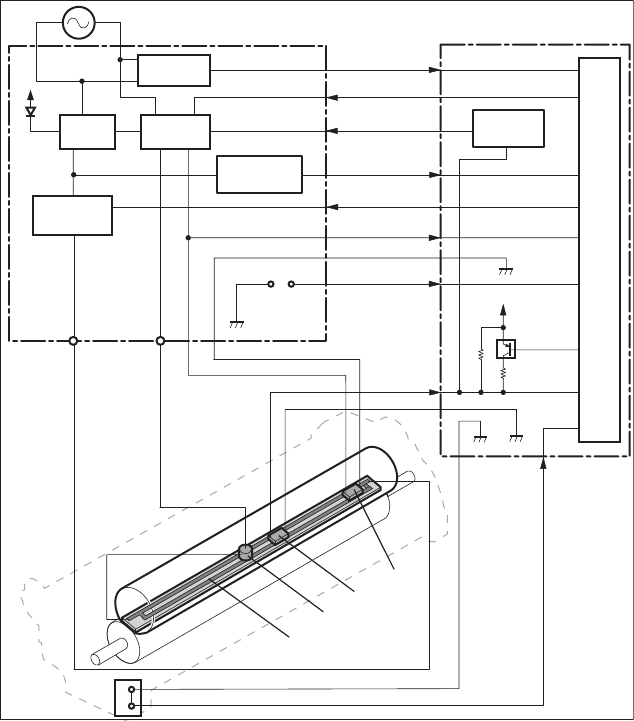
Fuser temperature control
The fuser temperature control detects the temperature of the fuser heater surface, and then controls the
FUSER HEATER DRIVE (FSRD1) signal to the fuser heater until the fuser heater temperature reaches the
target temperature.
The DC controller controls the FSRD1 signal by monitoring the detected fuser heater temperature—using
the thermistor (TH3)—and then holds the heater at the target temperature.
Figure 1-11 Fuser temperature control
JP1001
100V: Open
200V: Close
Relay
(RL101)
Fuser heater
drive circuit
Relay
(RL102)
Zero crossing
circuit
Fuser control
AC input
DC controller
Current
detection circuit
Fuser heater
safety circuit
H1
TH1
TH2
TP1
J128
Q704
+3.3V
/HITMP
FSRTH1
FSRD1
FSRTH2
/FSRARI
/AC200
CPU
/RLD
/ZEROX
CURRMS
FSRSAFE
TB10
TB11
2
1
+24VC
16 Chapter 1 Theory of operation ENWW
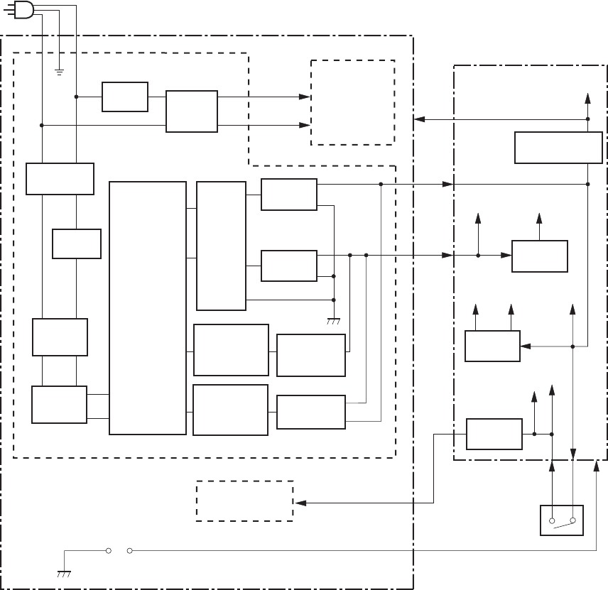
Low-voltage power supply
The low-voltage power supply converts AC power from the power receptacle into DC power to cover
the DC loads.
Figure 1-12 Low-voltage power supply
Trans-
former
(T1)
Rectifying
circuit
Constant-
voltage
control circuit
Abnormal
status latch
photocoupler
(PC1)
Constant-
voltage control
photocoupler
(PC2)
Door open
detection switch
(SW101)
Control IC
(IC1)
Fuse
(FU1)
Power button
(SW1)
Fuse
(FU2)
100V: Open
200V: Close
Power supply unit
Sleep
switch 3
High-voltage
power supply
DC controller
+5V
generation circuit
Protection
circuit
Low-voltage power supply
Fuser
control
Noise
filter
Noise
filter
Rectifying
circuit
Rectifying
circuit
Sleep
switch 2
Sleep
switch 1
+24VA
ACH
ACN5VPRO
/AC200
JP1001
+24VB
/DOPEN
+5V
+24VA
+24VC
+3.3R
+24R
+24U
+3.3V
+24VA
+24VC
ENWW Engine-control system 17
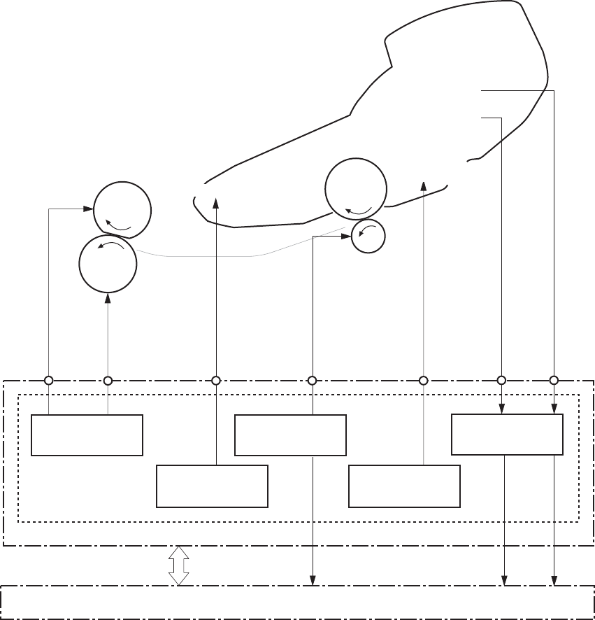
High-voltage power supply
The high-voltage power supply applies the high-voltage biases to the following components:
●Primary charging roller
●Developing roller
●Transfer roller
●Fuser sleeve
●Pressure roller
Figure 1-13 High-voltage power supply
Power supply unit
Fuser sleeve
From antenna
From antenna
Photosensitive drum
Transfer roller
DC controller
High-voltage power supply
Primary charging
high-voltage
generation circuit
Developing high-
voltage generation
circuit
Transfer
high-voltage
generation circuit
Fuser
high-voltage
generation circuit
Pressure roller
To primary charging roller
Toner level detection
circuit
To developing cylinder
Cartridge
TNRSP2
TNRSP1
TRAD
TB21
TB20 TB504 T503 TB502 TB501 TB503
FILMBIAS
KAATUBIAS
ANT2
ANT1
18 Chapter 1 Theory of operation ENWW
Overcurrent/overvoltage protection
If a short-circuit or other problem on the load side causes an excessive current flow or generates
abnormal voltage, the overcurrent/overvoltage protection systems automatically cut off the output
voltage to protect the power-supply circuit.
If the overcurrent or overvoltage protection system are activated and the power-supply circuit does not
generate DC voltage, turn the power off, correct the problem, and then turn the product on again.
The circuit has two fuses (FU1, FU2), which break and cut off the output voltage if overcurrent flows
through the alternating current (AC) line.
ENWW Engine-control system 19
Image-formation system
The image-formation system is the central hub of the product. It forms the toner image on the media.
The following are the main components of the image-formation system:
●Cartridge
●Transfer roller
●Fuser
The DC controller controls the laser/scanner unit and high-voltage power supply to form an image on
the media according to the VIDEO signals.
20 Chapter 1 Theory of operation ENWW
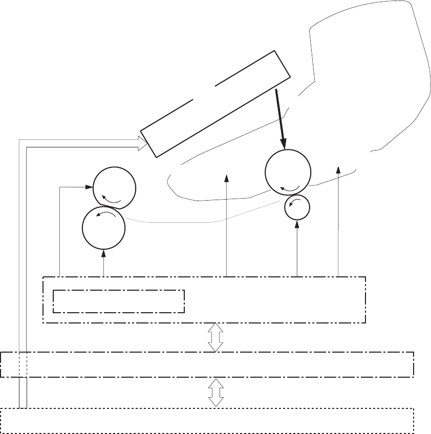
Image-formation process
The image formation system is the central hub of the product. It also forms the toner image on the
media.
Figure 1-14 Image-formation system
High-voltage power supply circuit
Power supply unit
Laser beam
VIDEO signal
Laser/scanner unit
Fuser sleeve
Photosensitive drum
Transfer roller
DC controller
Pressure roller
To primary charging roller To developing cylinder
Cartridge
Formatter
TB21
TB20 TB504 T503 TB502
The image-formation process contains eight steps divided among five functional blocks:
●Block 1: Latent image formation
Step 1: Primary charging
Step 2: Laser-beam exposure
●Block 2: Developing
Step 3: Developing
●Block 3: Transfer
ENWW Image-formation system 21
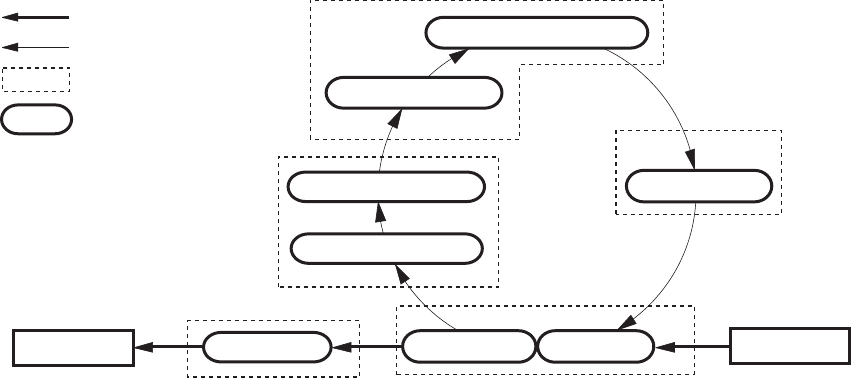
Step 4: Transfer
Step 5: Separation
●Block 4: Fusing
Step 6: Fusing
●Block 5: Drum cleaning
Step 7: Drum cleaning
Step 8: Drum charge elimination
Figure 1-15 Image-formation process
8. Drum charge elimination
Drum cleaning
Transfer
Latent image formation
Developing
2. Laser-beam exposure
Fuser
6. Fuser
Delivery 5. Separation 4. Transfer
7. Drum cleaning
3. Developing
1. Primary charging
Media path
Direction of the drum rotation
Pickup
Block
Step
22 Chapter 1 Theory of operation ENWW
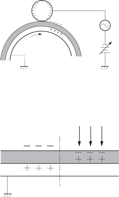
Block 1: Latent image formation
During the two steps that comprise this block, an invisible latent image is formed on the photosensitive
drum.
Step 1: Primary charging
To prepare for latent image formation, the surface of the photosensitive drum is charged with a uniform
negative potential. The product charges the photosensitive drum surface directly from the primary
charging roller. The DC bias and AC bias are applied to the primary charging roller to maintain a
constant charge on the drum surface.
Figure 1-16 Primary charging
DC bias
Photosensitive drum
Primary charging roller
AC bias
Step 2: Laser-beam exposure
The laser beam scans the photosensitive drum to neutralize the negative charge on portions of the drum
surface. An electrostatic latent image forms where the negative charge was neutralized.
Figure 1-17 Laser-beam exposure
Laser beam
Unexposed area Exposed area
ENWW Image-formation system 23
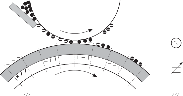
Block 2: Developing
Toner adheres to the electrostatic latent image on the photosensitive drum.
Step 3: Developing
Toner acquires a negative charge from the friction that occurs when the developing cylinder rotates
against the developing blade. The negatively charged toner is attracted to the latent image on the
photosensitive drum surface because the drum surface has a higher potential. The AC bias that is
superimposed with the developing negative DC bias is applied to the developing cylinder.
Figure 1-18 Developing
Blade
Developing cylinder
AC bias
DC bias
Photosensitive drum
Unexposed area
Exposed area
Exposed area
Unexposed area
24 Chapter 1 Theory of operation ENWW
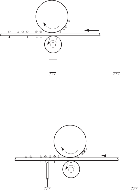
Block 3: Transfer
During the steps that comprise this block, a toner image on the photosensitive drum is transferred to the
print media.
Step 4: Transfer
The positive DC bias is applied to the transfer roller to charge the media positive. The positively
charged media attracts the negatively charged toner from the photosensitive drum surface.
Figure 1-19 Transfer
Media
Transfer roller
Photosensitive
drum
DC bias
Step 5: Separation
The curvature elasticity of the print media causes it to separate from the photosensitive drum surface.
The static charge eliminator reduces back side static discharge of the media for stable media feed and
image quality.
Figure 1-20 Separation
Media
Transfer roller
Photosensitive
drum
Static charge eliminator
ENWW Image-formation system 25
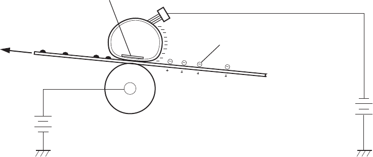
Block 4: Fusing
The toner image is fixed onto the print media.
Step 6: Fusing
The product uses the on-demand fixing method to fix the toner image onto the media. The image is
permanently affixed to the print media by the heat and pressure.
Figure 1-21 Fusing
Media
Toner
Fuser sleeve
Fuser heater
Pressure roller DC bias
Brush
DC bias
26 Chapter 1 Theory of operation ENWW
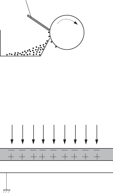
Block 5: Drum cleaning
The residual (waste) toner is cleared from the photosensitive drum surface to prepare for the next latent
image formation.
Step 7: Drum cleaning
The cleaning blade scrapes the residual toner off the surface of the photosensitive drum and deposits it
in the waste toner container.
Figure 1-22 Drum cleaning
Waste toner container
Photosensitive
drum
Cleaning blade
Step 8: Drum charge elimination
The residual charge on the photosensitive drum surface is eliminated to avoid uneven image. The
residual charge of the previous image is left on the drum surface after the transfer operation and this
affects the following image formation. The product eliminates this residual charge by emitting a laser
beam to the drum surface. The drum charge elimination is operated only during the last rotation period.
Figure 1-23 Drum charge elimination
Laser beam
ENWW Image-formation system 27
Laser/scanner system
The laser/scanner system forms a latent image on the photosensitive drum according to the VIDEO
signals sent from the formatter. The main components, such as the laser driver and scanner motor, are
assembled as a laser/scanner unit and controlled by the DC controller. The DC controller allows the
laser to emit light according to the VIDEO signals. The laser beam passes through the lenses and enters
28 Chapter 1 Theory of operation ENWW
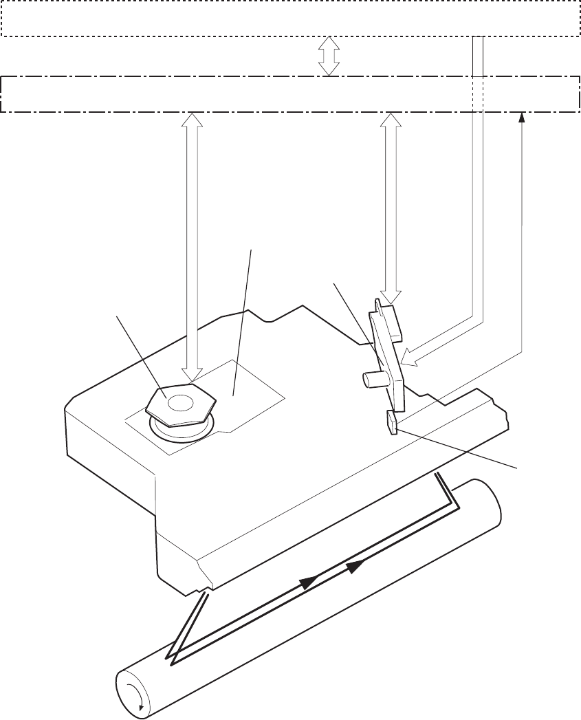
the scanner mirror that is rotating at constant speed. The laser beam is reflected by the scanner mirror,
passes through the lenses, and scans on the photosensitive drum.
Figure 1-24 Laser/scanner system
BD PCA
Scanner mirror
Scanner motor unit
Photosensitive drum
Laser driver
Formatter
DC controller
LASER CONTROL signal
VIDEO signal
SCANNER MOTOR
SPEED CONTROL signal
BD INPUT signal
The laser scanner uses two laser diodes to scan two lines simultaneously, producing high-speed laser
scanning. After receiving the print command from the host computer, the DC controller PCA activates
the scanner motor, which rotates the six-sided scanner mirror. The laser-driver PCA emits light from the
two laser diodes according to signals from the DC controller PCA. The two laser beams strike the six-
sided scanning mirror and are directed through the focusing lenses and onto the photosensitive drum.
ENWW Laser/scanner system 29
The modulated laser beams generate the latent electrostatic image on the photosensitive drum
according to the image data signals that the DC controller PCA sends.
1. As it receives a print command from the formatter, the dc controller outputs the SCANNER
MOTOR SPEED CONTROL signal (/ACC) and rotates the scanner motor in order to rotate the six-
sided mirror.
2. As the scanner motor starts rotating, the dc controller uses a LASER CONTROL signal (CNT0,
CNT1, CNT2) to receive the /BD INPUT signal (/BDI) and force the laser to emit light . The dc
controller detects the rotational speed of the scanner motor based on the timing the /BD1 signal is
input and controls the speed to keep it constant.
3. While the scanner motor rotates at a constant speed, the dc controller passes the VIDEO signals
from the formatter on to the laser driver PCA. The laser driver PCA emits light from the two laser
diodes according to these signals: VDO1, /VDO1, VDO2, /VDO2.
4. The two laser beams pass through the collimator lens and cylindrical lens and strike the six-sided
mirror that is rotating at a constant speed.
5. The laser beams, that are reflected off of the six-sided mirror pass through the focus lens and
reflective mirror and focus on the photosensitive drum. The laser beams scan the drum surface at a
constant speed.
6. As the six-sided mirror rotates and the laser beam scans the drum surface at a constant speed, a
latent image forms on the drum surface.
Laser failure detection
The DC controller determines a laser/scanner unit failure and notifies the formatter, if the laser/scanner
unit encounters the following conditions:
●Laser failure: The laser intensity is not detected for a specified value when the laser is turned on
for a specified period during the scanner unit start-up period.
●BD failure: The BD interval is out of a specified value during a print operation.
●Scanner motor start-up failure: The scanner motor does not reach a specified rotation within
a specified period from when the scanner motor starts rotation.
30 Chapter 1 Theory of operation ENWW
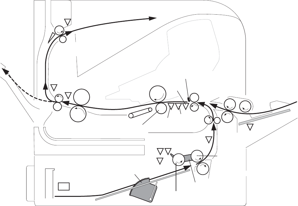
Pickup, feed, and delivery system
The pickup, feed, and delivery system consists of various rollers that the product motors drive. The
product uses Tray 1 (the manual feeding tray) and a cassette in Tray 2 as media sources. The printed
media is delivered to either the rear output bin (straight-through printing) or the top output bin (the
default destination). A number of 1x500-sheet feeders and one 1,500-sheet paper deck can be added
to certain models. These accessories are discussed later in this chapter. The Tray 1 paper sensor (on the
Tray 1 pickup assembly; PS105) detects media in Tray 1. The Tray 2 paper sensor (PS101) detects
media in Tray 2. The paper-size switch (SW102) detects the media size that is loaded in Tray 2.
Two motors, a clutch, and a solenoid that are controlled by the DC controller PCA drive all of the rollers
in the product.
The pre-feed, top-of-page, and fuser-assembly delivery sensors (PS102, PS103, PS700) detect media
arriving and passing along the paper path. If the media does not reach or pass these sensors within a
specific amount of time, the microprocessor on the DC controller PCA halts the product functions and a
jam error message appears on the control-panel display.
Figure 1-25 Pickup, feed, and delivery system
PS907
PS107
PS101
PS102
PS105
PS106 PS108
PS103
PS700
PS699
SW102
PS104
Separation roller
Pickup roller
Pickup arm
Lifter
Lifting plate
Transfer roller
Photosensitive drum
Lifting plate
Pre-transfer roller
Registration shutter
Feed roller
Feed roller
Fixing sleeve
Pressure roller
Face-down delivery roller
The pickup-and-feed system is divided into two blocks: The pickup-and-feed block and the fuser/delivery
block.
ENWW Pickup, feed, and delivery system 31
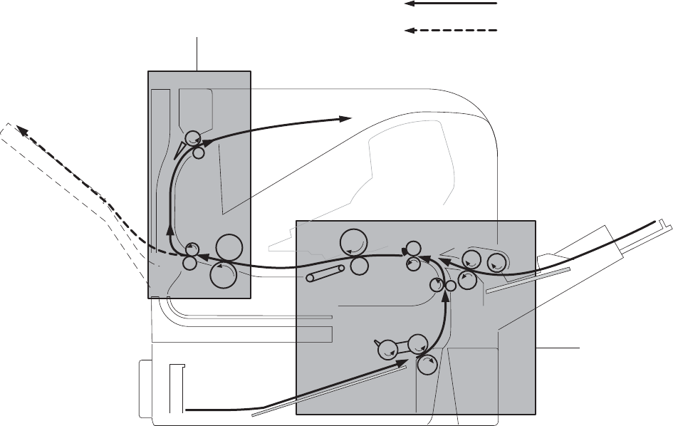
Figure 1-26 Pickup, feed, and delivery blocks
Fixing/delivery unit
Pickup/feed unit
Face-down delivery
Face-up delivery
Pickup-and-feed block
The following functions take place in the pickup-and-feed block:
●Detection of media
●Detection of media-size
●Detection of media entering the paper path from Tray 1 or Tray 2
●Lifting of the Tray 2 paper plate
●Prevention of multiple-feeds
●Correction of page skew
When it receives a print command from the host computer, the DC controller PCA turns on the feed
motor (M101) power. The motor drives the Tray 2 pickup, feed, and separation rollers. The drum motor
power also turns on. The laser/ scanner motor power turns on.
The DC controller PCA then activates the feed clutch (CL101) to rotate the feed roller. The Tray 2 pickup
solenoid is activated (SL101) and the pickup arm descends. The pickup roller touches the media and a
sheet is fed into the product. The separation roller prevents multiple sheets of media from being fed at
one time.
As the pre-feed sensor (PS102) detects the media, the dc controller PCA turns off the clutch, which stops
the media. When the DC controller PCA detects that the laser/scanner is ready it activates the feed
32 Chapter 1 Theory of operation ENWW
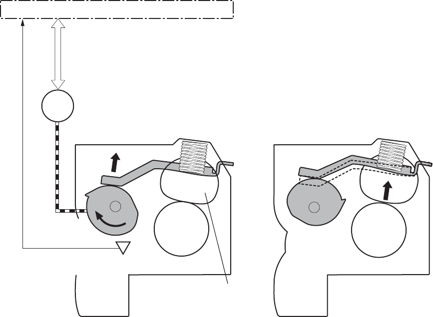
clutch again. The feed roller moves the media farther into the product. The registration shutter corrects
page skew and the media is transported to the fuser/delivery block.
Fuser/delivery block
The fuser/delivery block consists of rollers, sensors, the fuser, and the output delivery assembly. The
rollers transport the media through the fuser/delivery block paper path. The fuser applies heat and
pressure to the media to permanently bond the toner image to the media. The output delivery assembly
sends the printed media either to the rear output bin (if the rear output door is open) or to the top output
bin (the default output delivery bin). Sensors along the paper path detect media movement, jams, and
the top output-bin capacity.
Pressure roller pressure release control
The product releases the pressure roller except during a print operation to improve usability for jammed
paper removal.
The DC controller reverses the fuser motor (M299) to rotate the fuser pressure release cam. The
pressure roller is pressurized or depressurized due to the shape of the cam.
The DC controller reverses the fuser motor to control the pressure roller pressurize or depressurize state
according to the signal sent from the fuser pressure release sensor (PS699).
Figure 1-27 Pressure roller pressure release control
PS699
M299
FIXING MOTOR
DRIVE signal
DC controller
Fuser sleeve
Pressure roller
Fuser pressure
release cam
Fuser pressure release sensor
Fuser motor
FIXING PRESSURE RELEASE signal
<Pressurized> <Released>
ENWW Pickup, feed, and delivery system 33

The pressure roller pressure is released under the following conditions:
●A paper jam is detected
●Factory shipment
The DC controller determines a fuser pressure release mechanism failure and notifies the formatter if the
fuser roller release control is not completed within a specified period when it reverses the fuser motor.
Paper trays
Printing from Tray 1
The Tray 1 paper sensor (PS105) detects the presence of media in Tray 1. When the DC controller PCA
receives the print command, the product starts the initial rotation phase, which consists of feed motor
warm-up, scanner motor warm-up, high-voltage control sequence, and fuser warm-up. When the initial
rotation phase ends, the Tray 1 pickup solenoid (SL102) is activated.
The cam rotates, the paper-tray lifter rises, and the media comes in contact with the Tray 1 pickup
roller. At the same time, the Tray 1 pickup roller rotates twice and picks up a sheet of media from
Tray 1. The separation pad prevents additional sheets from feeding with the first sheet.
The sheet then reaches the registration assembly, where its skew is corrected. The sheet then passes
through the transfer, separation, and fusing stages; through the delivery unit; and is to the output bin.
NOTE: If media is removed from Tray 1 after the initial rotation phase, but before the pickup roller
pulls the media from the tray, the Tray 1 pickup roller might continue to rotate up to six times, after
which a jam detected.
Printing from Tray 2
When the DC controller PCA receives the print command, the feed motor (M101) and scanner motor
start their rotation. When the feed motor reaches its prescribed speed, the feed roller clutch (CL101)
and Tray 2 pickup solenoid (SL101) are activated. (The feed motor rotation drives the Tray 2 pickup
roller, Tray 2 feed roller, Tray 2 separation roller, and paper-feed rollers.)
The Tray 2 pickup roller, which the pickup solenoid activates, rotates once and picks up the media in
the tray. The separation roller prevents additional sheets from feeding with the first sheet, and the
media is fed to the pre-feed sensor (PS102).
The sheet then reaches the registration assembly, where its skew is corrected. The sheet then passes
through the transfer, separation, and fusing stages; through the delivery unit; and to the output bin.
Cassette media size detection and cassette presence detection
The media size detection switch (SW102) detects the size of media loaded in the cassette and the
presence of the cassette.
The media size detection switch—comprised of three switches: upper, center, and lower—is active
when the cassette media size plate is correctly positioned to the loaded paper size and the cassette is
installed in the product. The DC controller determines the paper size by monitoring the switch
conditions.
34 Chapter 1 Theory of operation ENWW

the DC controller determines a size mismatch and sends a signal to the formatter if the switches detect a
paper size that is different from the size specified by the formatter.
Table 1-5 Cassette media size detection and cassette presence detection (Tray 2 and 1x500-
sheet feeder)
Media size Media size switch settings
Upper Center Lower
No cassette Off Off Off
A4 Off Off On
B5 Off On On
A5 On Off Off
LegalOnOnOff
Letter Off On Off
Executive On Off On
Universal On On On
ENWW Pickup, feed, and delivery system 35
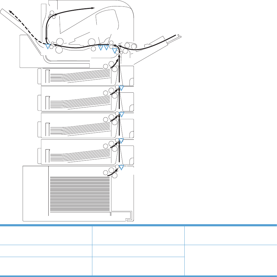
Jam detection
The product uses the following sensors to detect the presence of media and to check whether media is
being fed correctly or has jammed
Figure 1-28 Jam detection sensors
PS1704
PS1603
PS1603
PS1603
PS102
PS103
PS106
PS108
PS700
PS102: Pre-feed sensor PS108: Media width sensor 2 PS1704: Media path sensor (paper
deck)
PS103: Top of page sensor PS700: Fuser delivery sensor
PS106: Media width sensor 1 PS1603: Media path sensor (paper
feeder)
The product determines a jam if the sensor detects paper presence at a specified timing stored in the
DC controller.
The DC controller stops a print operation and notifies the formatter when it determines a jam
occurrence.
The product detects the following jams.
36 Chapter 1 Theory of operation ENWW
Pickup delay jam 1
a. Standard equipped cassette
The top of page sensor (PS103) does not detect the leading edge of media within a specified
period from when the pre-feed sensor (PS102) detects the leading edge.
b. Pickup option
The top of page sensor (PS103) does not detect the leading edge of media within a specified
period from when the feed clutch (CL101) is turned on.
c. MP tray (Tray 1)
The top of page sensor (PS103) does not detect the leading edge of media within a specified
period from when the MP tray pickup solenoid (SL102) is turned on.
Pickup delay jam 2
a. Standard equipped cassette
The pre-feed sensor (PS102) does not detect the leading edge of media within a specified
period from when a pickup operation starts.
b. Top pickup source of pickup option
The PF media path sensor (PS1603) for the top PF cassette or the PD media path sensor
(PS1704) does not detect the leading edge of media within a specified period from when a
pickup operation starts.
c. Lower pickup sources of pickup option
The PF media path sensor (PS1603) for the top PF cassette does not detect the leading edge
of media within a specified period from when the PF media path sensor (PS1603) or the PD
media path sensor (PS1704), either one of that equipped to the pickup source that picks up
the media, detects the leading edge of media.
Pickup delay jam 3
The PF media path sensor (PS1603) or PD media path sensor (PS1704), either one of that
equipped to the pickup source that picks up the media, does not detect the leading edge of media
within a specified period from when a pickup operation from the lower pickup sources of the
pickup option.
Pickup stationary jam
a. Top of page sensor detection
The top of page sensor (PS103) does not detect the trailing edge of media within a specified
period from when it detects the leading edge.
b. Media width sensors detection
Both of the media width sensors (PS106, PS108) do not detect the trailing edge of media
within as pecified period from when the top of page sensor (PS103) detects the trailing edge.
ENWW Pickup, feed, and delivery system 37

Delivery delay jam
The fuser delivery sensor (PS700) does not detect the leading edge of media within a specified
period from when the top of page sensor (PS103) detects the leading edge.
Delivery stationary jam
The fuser delivery sensor (PS700) does not detect the trailing edge of media within a specified
period from when the top of page sensor (PS103) detects the trailing edge.
Residual media jam 1
a. Either one of the following sensors detects media presence when the wait sequence starts:
◦Top of page sensor (PS103)
◦Media width sensors (PS106, PS108)
◦Fixing delivery sensor (PS700)
b. The fuser delivery sensor (PS700) detects media presence before the top of page sensor (PS103)
or the media width sensor (PS106, PS108) detects leading edge of media during an automatic
delivery operation.
NOTE: The automatic delivery delivers the deliverable residual media automatically during the
initial rotation period when the power is turned on or when the door is closed. The DC controller
sends an automatic delivery request to the formatter and stops a print operation when it
determines that there is deliverable residual media. Then the formatter sends an automatic delivery
command and the DC controller drives media feed system to deliver the residual media out of the
product.
c. Either one of the following sensors detects media presence during an automatic delivery
operation:
◦Pre-feed sensor (PS102)
◦Top of page sensor (PS103)
◦Media width sensors (PS106, PS108)
◦Fuser delivery sensor (PS700)
◦PF media path sensor (PS1603)
◦PD media path sensor (PS1704)
38 Chapter 1 Theory of operation ENWW
d. The door open is detected when either one of the following sensors detects media presence during
an automatic delivery operation:
◦Top of page sensor (PS103)
◦Media width sensors (PS106, PS108)
◦Fuser delivery sensor (PS700)
e. A stop control command is received when either one of the following sensors detects media
presence during an automatic delivery operation:
◦Pre-feed sensor (PS102)
◦Top of page sensor (PS103)
◦Media width sensors (PS106, PS108)
◦Fuser delivery sensor (PS700)
◦PF media path sensor (PS1603)
◦PD media path sensor (PS1704)
Residual media jam 2
a. Either one of the following sensors detects media presence when a print operation completes:
◦Pre-feed sensor (PS102)
◦Top of page sensor (PS103)
◦Media width sensors (PS106, PS108)
◦Fuser delivery sensor (PS700)
◦PF media path sensor (PS1603)
◦PD media path sensor (PS1704)
b. A stop control command is received from the formatter after a pickup operation has started.
Door open jam
The door open is detected after a pickup operation has started.
Wrapping jam
The fuser delivery sensor (PS700) detects media absence before it detects the trailing edge of
media after a specified period from when it detects the leading edge.
ENWW Pickup, feed, and delivery system 39
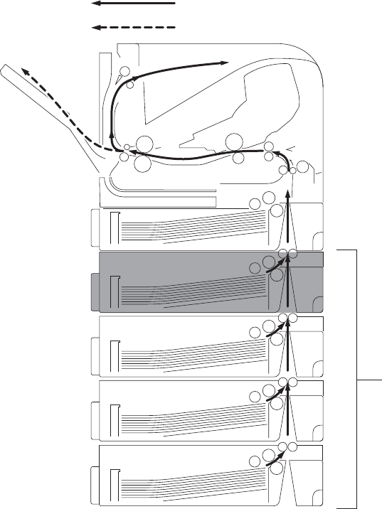
1x500-sheet paper feeder
The 1x500-sheet paper feeder (PF) is optionally installed at the bottom of the product. It features paper
pickup and paper feeding to the product. The product supports up to four optional paper feeders.
Figure 1-29 1x500-sheet paper feeder
Paper Feeder
Face-down delivery
Face-up delivery
The paper feeder driver controls the operational sequence of the paper feeder and the serial
communication with the DC controller of the product.
The DC controller sends several commands to the paper feeder driver at necessary timing. The paper
feeder driver drives each load, such as motor and solenoid, according to the commands. The paper
feeder driver responds the status information of the paper feeder to the DC controller.
The DC controller determines a paper feeder illegal connection and notifies the formatter if it does not
make the serial communication with the paper feeder driver during the pre-rotation period when the
product is turned on, when recovering from the Sleep mode or when the door is closed.
The product supplies DC24V to the paper feeder. The DC3.3V for sensors and ICs is generated from
the DC24V in the paper feeder driver.
40 Chapter 1 Theory of operation ENWW
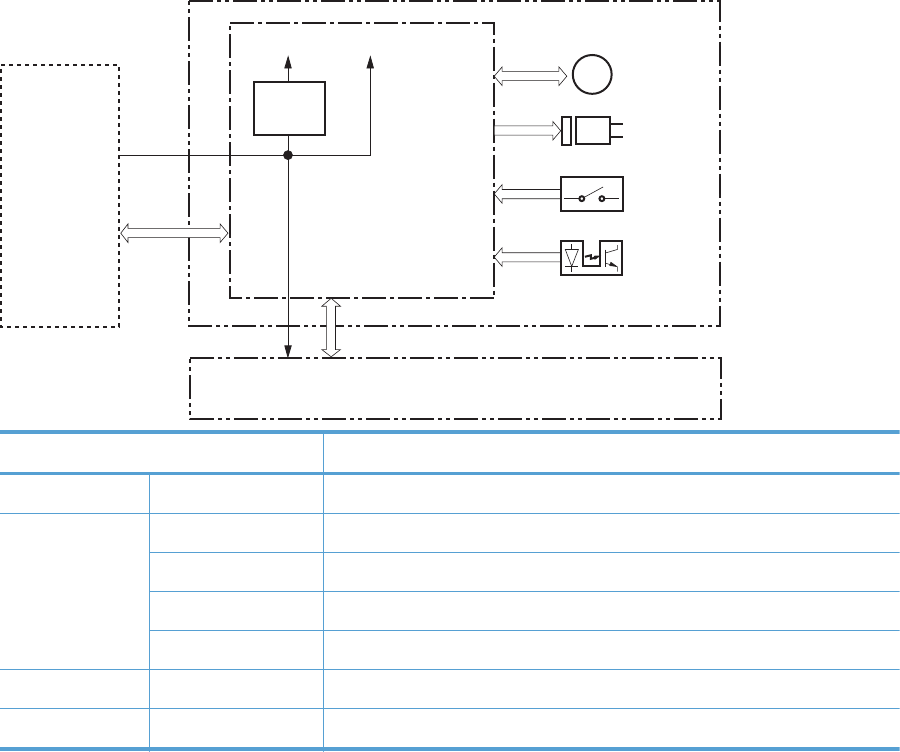
Figure 1-30 1x500-sheet paper feeder circuit diagram
MMotor
Solenoid
Sensor
Paper feeder driver
Switch
DC controller
Paper feeder
Paper feeder/Paper deck
+24V
+3.3V
generation
circuit
+3.3V +24V
Component Description
Motor M1600 Paper feeder lift motor
Sensor PS1600 Paper feeder media presence sensor
PS1601 Paper feeder media stack surface sensor 1
PS1602 Paper feeder media stack surface sensor 2
PS1603 Paper feeder media path sensor
Solenoid SL1600 Paper feeder pickup solenoid
Switch SW1600 Paper feeder media size switch
Pickup-and-feed operation (PF)
The paper feeder uses same mechanism of the product for the pickup-and-feed operation. The rollers
used in the paper feeder are driven by the feed motor (M101) of the product through the gears.
Pickup and feed sequence of operation (PF)
1. The lifting plate moves up to the position where the paper can be picked up after the product is
turned on or the paper feeder cassette is installed.
2. The DC controller drives the feed motor (M101) when it receives a print command from the for-
matter.
3. The DC controller outputs a pickup command to the paper feeder driver.
4. The paper feeder driver turns on the PF pickup solenoid (SL1600) when it receives a pickup
command. Accordingly the PF pickup roller, PF feed roller and PF feed roller 1 rotate to pick up
ENWW 1x500-sheet paper feeder 41
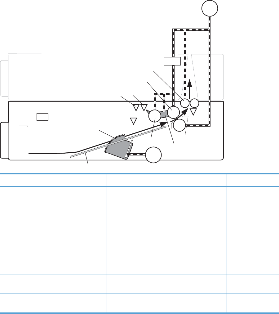
media in the PF cassette. (PF cassette pickup mechanism and PF lift-up operation are the same way
as that of the product).
5. The PF separation roller holds back any multiple-fed sheets and one sheet of media is fed into the
product. (PF multiple-feed prevention mechanism is the same way as that of the product).
Figure 1-31 1x500-sheet paper feeder block diagram
SW1600
PS1601
PS1602
PS1600 PS1603
PF separation roller
PF pickup roller
PF feed roller
Pickup arm
Lifter
Lifting plate
Feed motor
M1600
SL1600
M101
PF feed roller 1
Description Signal Driver
PF lifter motor M1600 PF LIFTER MOTOR DRIVE signal PF driver
PF media presence
sensor
PS1600 PF MEDIA PRESENCE signal PF driver
Paper feeder media
stack surface sensor 1
PS1601 PF MEDIA STACK SENSOR 1 signal PF driver
Paper feeder media
stack surface sensor 2
PS1602 PF MEDIA STACK SENSOR 2 signal PF driver
Paper feeder media
path sensor
PS1603 PF MEDIA PATH signal PF driver
Paper feeder pickup
solenoid
SL1600 PF PICKUP SOLENOID signal PF driver
Paper feeder media size
switch
SW1600 PF MEDIA SIZE signal PF driver
42 Chapter 1 Theory of operation ENWW
Cassette lift operation (PF)
The lift-up operation keeps the stack surface of media in the paper feeder cassette at a specified
position to perform stable pickup operation.
The paper feeder driver drives the PF lifter motor (M1600) to move up the lifter plate in which media is
stacked. The cassette lift-up operation for the paper feeder is operated in the same way as that of the
product base.
The paper feeder driver monitors the PF media stack surface sensors (PS1601, PS1602) when the
product is turned on, when the PF cassette is installed or during a print operation to perform the lift-up
operation.
Cassette lift operation (PF)
1. Initial lift-up operation
The initial lift-up operation is performed if either one of the PF media stack surface sensors
(PS1601,PS1602) does not detect the media surface when the power is turned on or when
the PF cassette is installed. The paper feeder driver drives the PF lifter motor for a specified
period after both of the PF stack surface sensors detect media and lifts the stack surface tot he
pickup position.
The paper feeder driver determines a PF lifter motor failure and notifies the DC controller if
both of the PF media stack surface sensors do not detect media within a specified period
from when a lift-up operation is started.
2. During print lift-up operation
The during print lift-up operation is performed when the media surface is lowered for a
specified level due to a pickup operation. The paper feeder driver drives the PF lifter motor
for a specified period and lifts the stack surface to the pickup position when the PF media
stack surface 1 (PS1601) detects media absence during a print operation.
Cassette media size detection and cassette presence detection (PF)
The cassette media size and cassette presence for the paper feeder are detected in the same way as
that of the product base.
Cassette multiple-feed prevention (PF)
The cassette multiple-feed prevention for the paper feeder is operated in the same way as that of the
product base.
Jam detection (PF)
The paper jam for the paper feeder is detected by the DC controller of the product base.
ENWW 1x500-sheet paper feeder 43
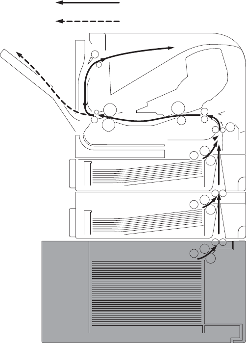
1x1500-sheet paper deck
The 1x1500-sheet paper feeder (PD) is optionally installed at the bottom of the product. It features
paper pickup and paper feeding to the product. The prroduct supports one paper deck and up to three
paper feeders between the product and the paper deck.
Figure 1-32 1x500-sheet paper feeder
Face-down delivery
Face-up delivery
The paper deck driver controls the operational sequence of the paper deck and the serial
communication with the DC controller of the product.
The DC controller sends several commands to the paper deck driver at necessary timing. The paper
deck driver drives each load, such as motor and solenoid, according to the commands. The paper deck
driver responds the status information of the paper deck to the DC controller.
The DC controller determines a paper deck illegal connection and notifies the formatter if it does not
make the serial communication with the paper deck driver during the pre-rotation period when the
product is turned on, when recovering from the sleep mode or when the door is closed.
The product supplies DC24V to the paper deck. The DC3.3V for sensors and ICs is generated from the
DC24V in the paper deck driver.
44 Chapter 1 Theory of operation ENWW
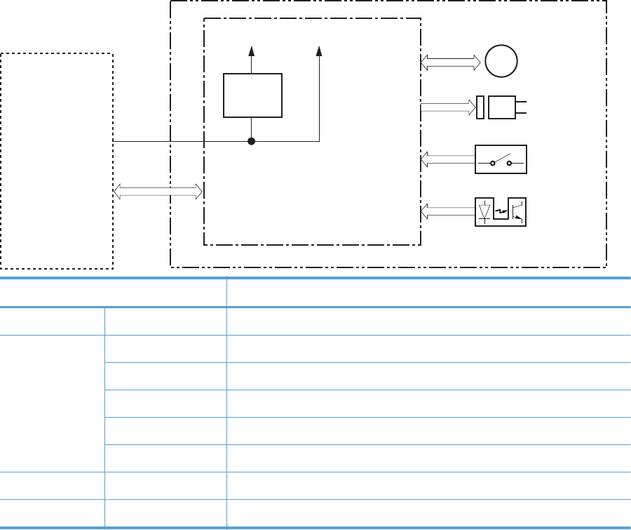
Figure 1-33 1x500-sheet paper feeder circuit diagram
MMotor
Solenoid
Sensor
Paper deck driver
Switch
DC controller/
Paper feeder driver
Paper deck
+24V
+3.3V
generation
circuit
+3.3V +24V
Component Description
Motor M1700 Paper deck lift motor
Sensor PS1700 Paper deck media presence sensor
PS1701 Paper deck media stack surface sensor 1
PS1702 Paper deck media stack surface sensor 2
PS1703 Door open detection sensor
PS1704 Paper deck media path sensor
Solenoid SL1700 Paper deck pickup solenoid
Switch SW1700 Paper deck media size switch
Pickup-and-feed operation (PD)
The paper deck uses same mechanism of the product for the pickup-and-feed operation. The rollers
used in the paper feeder are driven by the feed motor (M101) of the product through the gears.
Pickup and feed sequence of operation (PD)
1. The lifter plate moves up to the position where the paper can be picked up after the product is
turned on or the PD front door is closed.
2. The DC controller drives the feed motor (M101) when it receives a print command from the
formatter.
3. The DC controller outputs a pickup command to the paper deck driver.
ENWW 1x1500-sheet paper deck 45
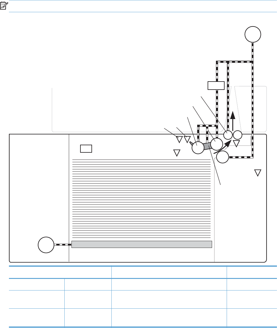
4. The paper deck driver turns on the PD pickup solenoid (SL1700) when it receives a pickup
command. Accordingly the PD pickup roller, PD feed roller and PD feed roller 1 rotate to pick up
media in the paper deck. (PD pickup mechanism is the same way as that of the product).
5. The PD separation roller holds back any multiple-fed sheets and one sheet of media is fed in to the
product. (PD multiple-feed prevention mechanism is the same way as that of the product).
NOTE: The paper deck media size switch (SW1700) detects a media size in the paper deck.
Figure 1-34 1x1500-sheet paper deck block diagram
SW1700
PS1701
PS1702
PS1700 PS1704
PS1703
PD separation roller
PD pickup roller
PD feed roller
Pickup arm
Lifter plate
PD feed roller 1
SL1700
M101
M1700
Description Signal Driver
PD lifter motor M1700 PD LIFTER MOTOR DRIVE signal PD driver
PD media presence
sensor
PS1700 PD MEDIA PRESENCE signal PD driver
PD media stack surface
sensor 1
PS1701 PD MEDIA STACK SENSOR 1 signal PD driver
46 Chapter 1 Theory of operation ENWW

Description Signal Driver
PD media stack surface
sensor 2
PS1702 PD MEDIA STACK SENSOR 2 signal PD driver
PD door open detection
sensor
PS1703 PD DOOR OPEN DETECTION signal PD driver
PD media path sensor PS1704 PF MEDIA PATH signal PD driver
PD pickup solenoid SL1700 PF PICKUP SOLENOID signal PD driver
PD media size switch SW1700 PF MEDIA SIZE signal PD driver
Cassette lift operation (PD)
The lift-up operation keeps the stack surface of media in the paper deck at a specified position to
perform stable pickup operation.
The paper deck driver drives the PD lifter motor (M1700) to move up the lifter plate in which media is
stacked. The PD lifter motor uses four pulleys to wind the wire cables and two wire cables lift the lifter
plate. When the PD front door is opened, the pulley gears and the motor gear are disengaged and the
lifter plate lowers under its own weight.
The paper deck driver monitors the PD media stack surface sensors (PS1701, PS1702) when the
product is turned on, when the PD front door is closed or during a print operation to perform the lift-up
operation.
Lift operation (PD)
1. Initial lift-up operation
The initial lift-up operation is performed if either one of the PD media stack surface sensors
(PS1701,PS1702) does not detect the media surface when the power is turned on or when
the PD front door is closed. The paper deck driver drives the PD lifter motor for a specified
period after both of the PD media stack surface sensors detect media and lifts the stack
surface to the pickup position.
The paper deck driver determines a paper deck lifter motor failure and notifies the DC
controller if both of the PD media stack surface sensors do not detect media within a specified
period from when a lift-up operation is started.
2. During print lift-up operation
The during print lift-up operation is performed when the media surface is lowered for a
specified level due to a pickup operation. The paper deck driver drives the PD lifter motor for
ENWW 1x1500-sheet paper deck 47
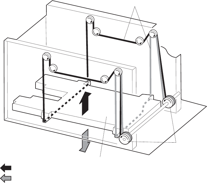
a specified period and lifts the stack surface to the pickup position when the PD media stack
surface sensor 1 (PS1701)detects media absence during a print operation.
3. Pickup retry lift-up operation
The pickup retry lift-up operation is performed when the first pickup retry is failed to pick up
media. The paper deck driver drives the PD lifter motor for a specified period to lift the stack
surface and performs second pickup retry.
Figure 1-35 1x1500-sheet paper deck lift
Direction of the lifter plate moves up
Direction of the lifter plate lowers under its own weight
Wire cable
Lifter plate
Pulley
Media size detection (PD)
The combination of the switches for the paper deck media size detection differs from the product
cassette.
Multiple-feed prevention (PD)
The multiple-feed prevention for the paper deck is operated in the same way as that of the product.
Jam detection (PF)
The paper jam for the paper deck is detected by the DC controller of the product.
48 Chapter 1 Theory of operation ENWW
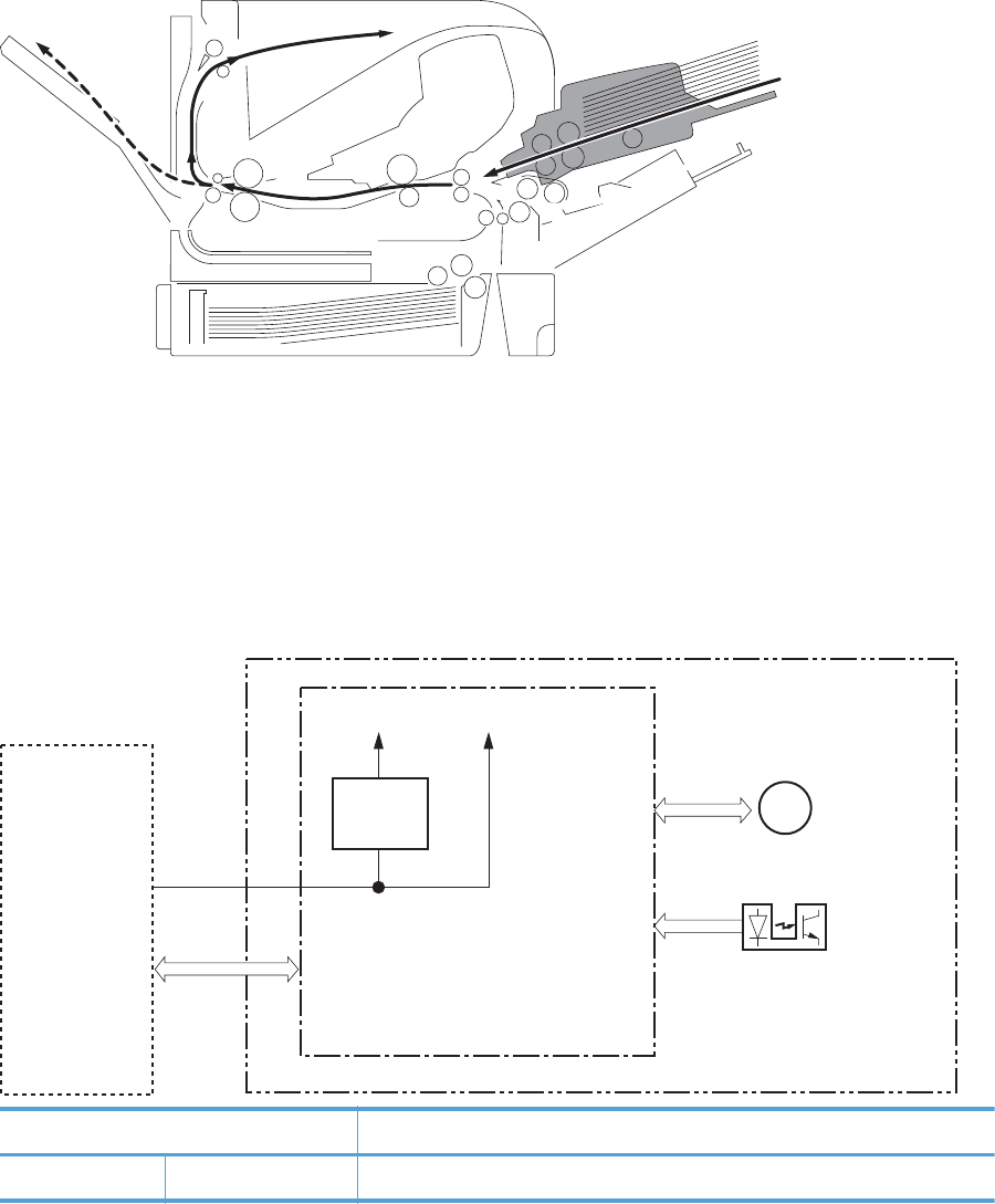
Envelope feeder
The envelope feeder (EF) is optionally installed on Tray 1, front side of the product. It features envelope
pickup and envelope feed to the product.
Figure 1-36 Envelope feeder
The envelope feeder driver controls the operational sequence of the envelope feeder and the serial
communication with the DC controller of the product.
The DC controller sends several commands to the envelope feeder driver at necessary timing. The
envelope feeder driver drives the motor according to the commands. The envelope feeder driver
responds the status information of the envelope feeder to the DC controller.
The product supplies DC24V to the envelope feeder. The DC3.3V for sensors and ICs is generated from
the DC24V in the envelope feeder driver.
Figure 1-37 Envelope feeder circuit diagram
MMotor
Sensor
Envelope feeder driver
DC controller
Envelope feeder
+24V
+3.3V
generation
circuit
+3.3V +24V
Component Description
Motor M1800 Envelope pickup motor
ENWW Envelope feeder 49
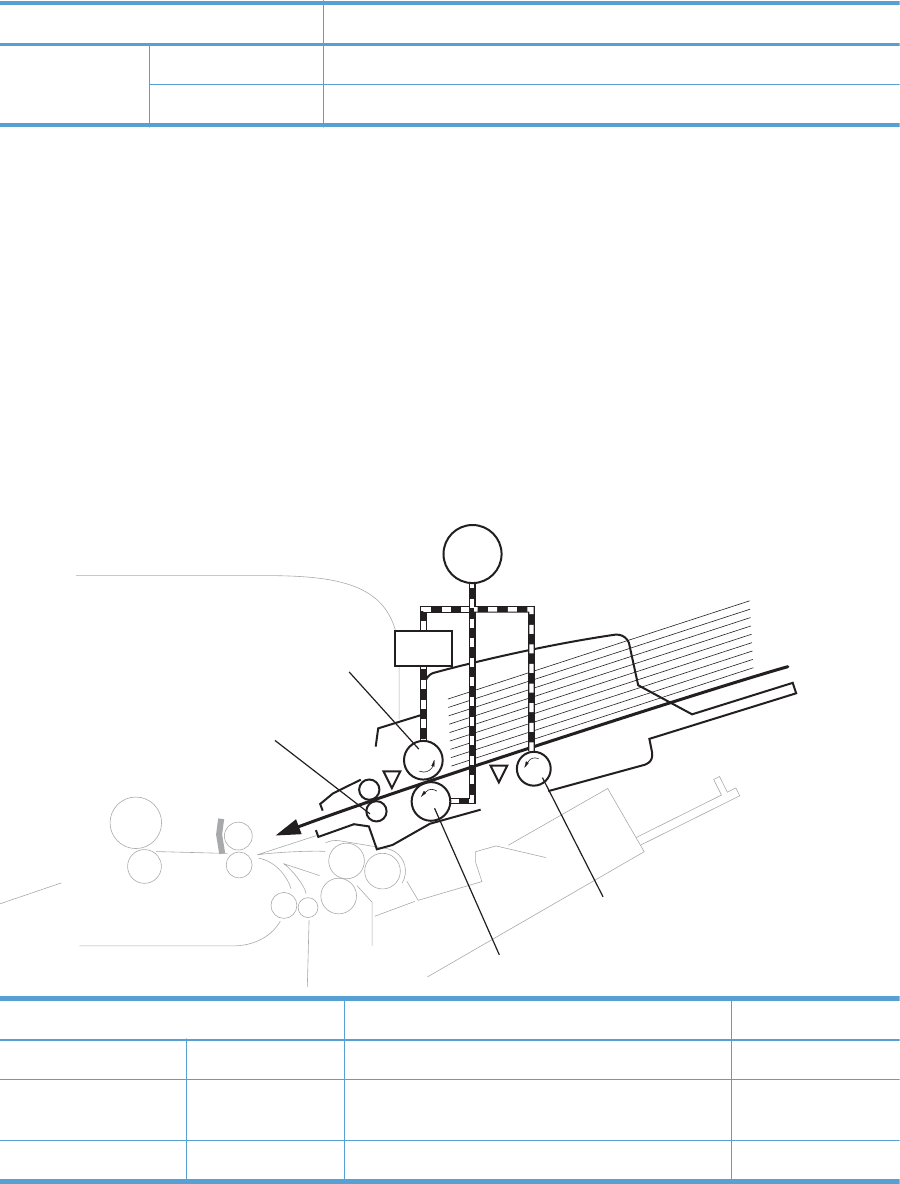
Component Description
Sensor PS1800 Envelope presence sensor
PS1802 Envelope multiple feed sensor
Pickup-and-feed operation (EF)
The envelope in the envelope feeder is fed into the product individually.
Pickup and feed sequence of operation (EF)
1. The envelope feeder driver drives the envelope pickup motor (M1800) when it receives a pickup
command from the DC controller. Accordingly the envelope pickup roller, upper separation roller
and lower separation roller rotate to pick up envelope.
2. The upper separation roller and lower separation roller remove any multiple-fed envelopes and
one envelope is fed into the product.
Figure 1-38 Envelope feeder diagram
Envelope pickup roller
Upper separation roller
Lower separation roller
Feed roller
Torque
limiter
M1800
PS1800
PS1802
Description Signal Driver
EF pickup motor M1800 ENVELOPE PICKUP MOTOR DRIVE signal EF driver
EF media presence
sensor
PS1800 ENVELOPE PRESENCE signal EF driver
EF multi feed sensor PS1802 ENVELOPE MULTI FEED signal EF driver
Multiple-feed prevention (EF)
The multiple-feed prevention for the envelope feeder is operated in the same way as that of the product.
50 Chapter 1 Theory of operation ENWW
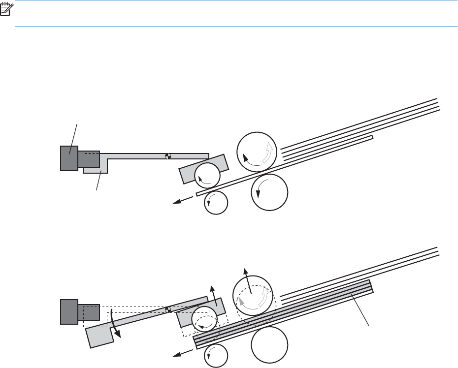
Multiple-feed detection (EF)
The envelope feeder detects the multiple-feed of the envelopes to prevent the product damage from
massive multiple-feed.
The envelope feeder driver monitors the envelope multiple-feed sensor (PS1802) to detect up and down
motion of the upper separation roller.
During a normal-feed operation, the envelope multiple-feed sensor flag interrupts the multiple-feed
sensor. If more than four multiple-fed envelopes are placed between the upper separation roller and the
lower separation roller, the upper separation roller rises approximately 0.7mm (almost equivalent to the
thickness of four envelopes). This causes the multiple-feed sensor flag not interrupting the sensor and the
envelope feeder driver detects the multiple-feed of envelopes.
NOTE: The multiple-feed detection mechanism is not able to detect less than four multiple-fed
envelopes (approximately 0.7 mm), however, it does not affect the product damage.
The envelope feeder driver notifies the pickup jam to the DC controller when it determines a multiple
feed.
Figure 1-39 Envelope feeder multiple-feed detection
<Normal-feed>
<Multiple-feed>
Envelope multiple-feed sensor flag
Envelope multiple-feed sensor (PS1802) Upper separation roller
Multiple-fed envelope
Lower separation roller
Jam detection (EF)
The envelope feeder uses the following sensors to detect the presence of media and to check whether
media is being fed correctly or has jammed
ENWW Envelope feeder 51
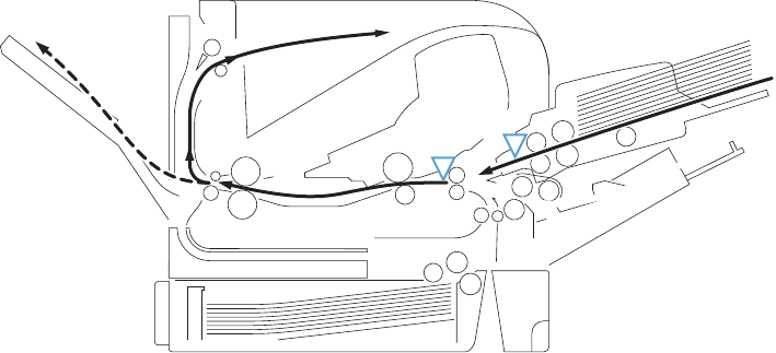
jam detection sensors (EF)
●PS1802: Envelope multiple-feed sensor
●PS103: Top of page sensor (in the product)
Figure 1-40 Envelope feeder jam detection
PS1802
PS103
The envelope feeder driver determines a jam if the sensor detects envelope presence at a specified
timing stored in the envelope feeder driver. The envelope feeder driver stops a print operation and
notifies the DC controller when it determines a jam has occurred.
Envelope feeder pickup delay jam
●The top of page sensor (PS103) does not detect the leading edge of envelope within a specified
period from when a envelope pickup operation starts.
Envelope feeder multiple-feed jam
●The envelope multiple-feed sensor (PS1802) detects the multiple-fed envelopes after a pickup
operation has started.
52 Chapter 1 Theory of operation ENWW
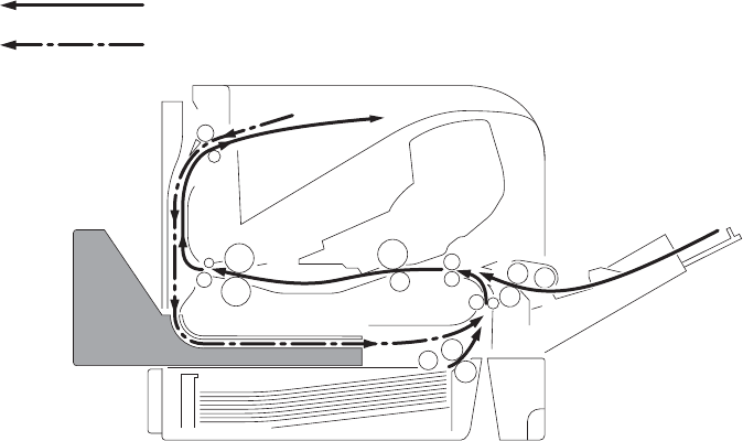
Duplexer
The duplexer (DP) is installed at the back of the product. It features media reverse and media feed to
the prroduct to print two sides of media.
Figure 1-41 Duplexer
Face-down delivery
Duplex print
The duplex driver controls the operational sequence of the duplexer and the serial communication with
the DC controller of the product.
The DC controller sends several commands to the duplex driver at necessary timing. The duplex driver
drives the duplex reverse motor and the duplex re-pickup motor according to the commands. The
duplex driver monitors the sensors and responds the status information of the duplexer to the DC
controller.
The printer supplies DC24V to the duplexer. The DC5V for sensors and ICs is generated from the
DC24V in the duplex driver.
ENWW Duplexer 53
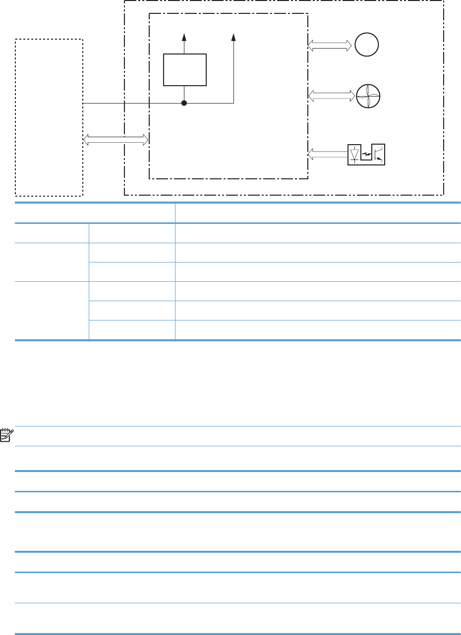
Figure 1-42 Duplexer circuit diagram
MMotor
Sensor
DC controller
+24V
+5V
generation
circuit
+5V +24V
Duplex driver
Duplexer
Fan
Component Description
Fan FM1501 Duplex cooling fan
Motor M1501 Duplex reverse motor
M1502 Duplex re-pick motor
Sensor PS1501 Face up sensor
PS1502 Duplex re-pick sensor
PS1503 Side registration home-position sensor
Motor and fan control (DP)
The duplexer has two motors and a fan. The motors are used for the media feeding and the fan is used
for preventing a temperature rising inside the duplex unit.
NOTE: The paper deck media size switch (SW1700) detects a media size in the paper deck.
Table 1-6 Fan (DP)
Description Cooling area Type Speed
Duplex cooling fan FM1501 Inside of the duplexer Intake Full
Table 1-7 Motors (DP)
Description Component driven Type Failure detection
Duplex reverse m0tor M1501 Face-down delivery roller
(in the product)
Stepping motor No
Duplex re-pick motor M1502 Side registration guide,
duplex feed roller
Stepping motor No
54 Chapter 1 Theory of operation ENWW

Failure detection (DP)
The duplex driver determines a fan failure and notifies the DC controller when the fan locks for a
specified period after the fan starts up.
Reverse-and-re-pickup operation (DP)
The duplexer has two motors: the duplex reverse motor (M1501) and the duplex re-pickup motor
(M1502). The duplex driver controls forward and reverse the duplex re-pickup motor rotations. When
the duplex re-pickup motor rotates, the rollers in the duplexer rotate and when it reverses, the side
registration guide moves.
The duplex reverse motor rotates or reverses the face-down delivery roller of the product.
In addition, the duplexer has three photo interrupters: the face-up sensor (PS1501), duplex media re-
pickup sensor (PS1502), and the side registration guide home-position sensor (PS1503). The face-up
sensor is used for face-up tray open detection, the duplex media re-pickup sensor is used for jam
detection, and the side registration guide home-position sensor is used for side registration guide home-
position detection.
Reverse-and-re-pickup operation (DP)
1. The duplex driver reverses the duplex re-pickup motor (M1502) when it receives a side registration
adjustment command from the DC controller. See Side registration adjustment operation (DP)
on page 56.
2. The DC controller outputs a duplex reverse motor rotation command to the duplex driver after a
specified period from when the fuser delivery sensor (PS700) of the product detects the leading
edge of the page.
3. The duplex driver rotates the duplex reverse motor (M1501) and the page is fed to the face-down
tray when the command is received.
4. The DC controller outputs a duplex reverse motor reverse command to the duplex driver after a
specified period from when the fuser delivery sensor detects the trailing edge of a page.
5. The duplex driver reverses the duplex reverse motor and the page is fed to the duplexer along the
side registration guide when the command is received.
6. The duplex driver rotates the duplex re-pickup motor after a specified period from when it reverses
the duplex reverse motor. The media is fed by the oblique roller and the duplex feed rollers so that
the edge contacts with the left plate to correct a skewed feed.
7. The duplex driver stops the duplex reverse motor after a specified period from when the DC
controller reverses the duplex reverse motor.
8. The duplex driver stops the duplex re-pickup motor after a specified period from when the duplex
media re-pickup sensor (PS1502) detects the leading edge of the page.
ENWW Duplexer 55
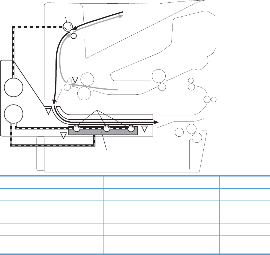
9. The duplex driver rotates the duplex re-pickup motor when it receives a duplex re-pickup command
from the DC controller. The page is fed to the pre-feed sensor (PS102) of the product at the same
product feed speed.
10. The duplex driver stops duplex re-pickup motor after a specified period from when the duplex
media re-pickup sensor detects the trailing edge of the page.
The DC controller determines a print error and delivers media to the delivery tray without duplex
printing if it encounters following conditions after the page is picked up for the first side printing.
Figure 1-43 Duplexer block diagram
M1502
M1501
PS1501
PS1502PS1503
PS700
Duplex feed roller
Face-down
delivery roller
CW
CCW
Side registration guide
Description Signal Driver
DP reverse motor M1501 DUPLEX REVERSE MOTOR DRIVE signal DP driver
DP re-pick motor M1502 DUPLEX RE-PICK MOTOR signal DP driver
Face-up sensor PS1501 FACE-UPsignal DP driver
DP media re-pick sensor PS1502 DUPLEX MEDIA RE-PICK signal DP driver
Side registration guide
home-position sensor
PS1503 SIDE REGISTRATION GUIDE HOMEPOSITION
signal
DP driver
Side registration adjustment operation (DP)
The product adjusts the side registration during a duplex print operation to align the center of the
horizontal scanning on the second side with that of the print area on the photosensitive drum.
56 Chapter 1 Theory of operation ENWW
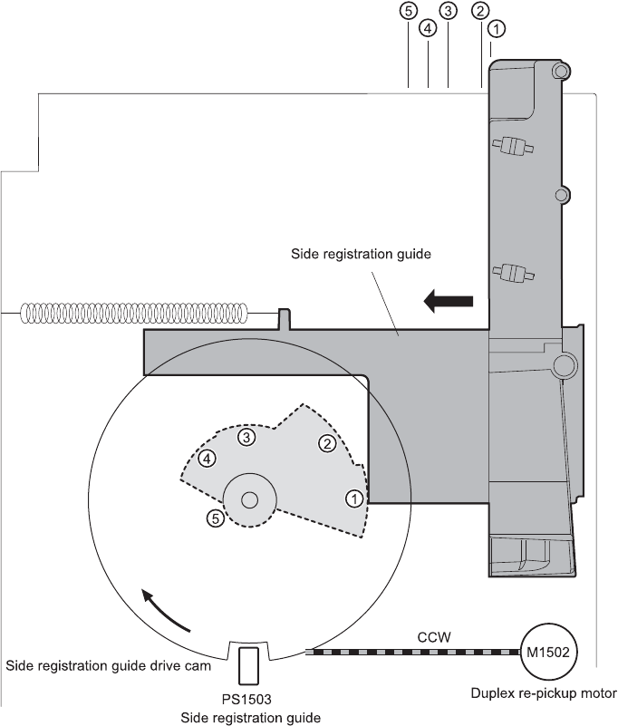
The side registration adjustment is made by moving the side registration guide to the designated page
size of the side registration adjustment command. The side registration guide moves to the following
five positions depending on the media size in order of numbers 1 to 5 and then back to 1.
1. Letter or Legal (home position)
2. A4
3. Executive
4. B5
5. A5
Figure 1-44 Side registration adjustment operation (DP)
home-position sensor
ENWW Duplexer 57
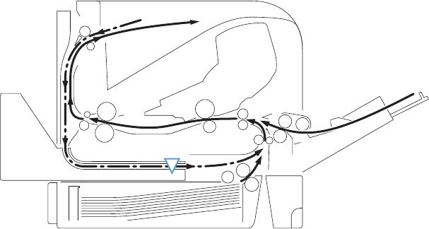
The sequence of the side registration adjustment operation is as follows:
1. The duplex driver reverses the duplex re-pickup motor (M1502) when it receives a side registration
adjustment command from the DC controller.
2. The side registration guide drive cam rotates and the side registration guide home-position sensor
(PS1503) detects the home position of the side registration guide. Then the side registration guide
moves depending on the media size.
3. The duplex driver stops the duplex re-pickup motor and completes the side registration guide
movement.
The duplex driver determines a side registration guide failure and notifies the DC controller when the
side registration guide home-position sensor does not detect the home position after the side registration
guide drive cam rotates twice.
Jam detection (DP)
he duplex unit uses the duplex media re-pickup sensor (PS1502) to detect the presence of media and to
check whether media is being fed correctly or has jammed.
Figure 1-45 Jam detection (DP)
PS1502
The duplexer determines a jam if the sensor detects media presence at a specified timing stored in the
duplex driver.
The duplex driver stops a print operation and notifies the DC controller when it determines a jam has
occurred.
Duplex media reverse delay jam
●The duplex media re-pickup sensor (PS1502) does not detect the leading edge of media within a
specified period from when the duplex reverse motor starts reverse rotation.
Duplex media re-pickup stationary jam
●The duplex media re-pickup sensor (PS1502) does not detect the trailing edge of media within a
specified period from when the re-pickup operation starts.
58 Chapter 1 Theory of operation ENWW

2 Removal and replacement
●Introduction
●Removal and replacement strategy
●Electrostatic discharge
●Required tools
●Types of screws
●Service approach
●Customer replaceable units (CRUs)
●Covers
●Main assemblies
●1,500-sheet paper deck (PD)
NOTE: Your product might not appear exactly as the one shown in the photos in this chapter.
Although details such as the color of the external panels and covers might be different than your
product, the procedures in this chapter are appropriate for your product.
ENWW 59

Introduction
This chapter describes the removal and replacement of field-replaceable units (FRUs) only.
Replacing FRUs is generally the reverse of removal. Occasionally, notes and tips are included to
provide directions for difficult or critical replacement procedures.
HP does not support repairing individual subassemblies or troubleshooting to the component level.
Note the length, diameter, color, type, and location of each screw. Be sure to return each screw to its
original location during reassembly.
Incorrectly routed or loose wire harnesses can interfere with other internal components and can become
damaged or broken. Frayed or pinched harness wires can be difficult to find. When replacing wire
harnesses, always use the provided wire loops, lance points, or wire-harness guides and retainers.
Removal and replacement strategy
WARNING! Turn the product off, wait 5 seconds, and then remove the power cord before
attempting to service the product. If this warning is not followed, severe injury can result, in addition to
damage to the product. The power must be on for certain functional checks during troubleshooting.
However, disconnect the power supply during parts removal.
Never operate or service the product with the protective cover removed from the laser/scanner
assembly. The reflected beam, although invisible, can damage your eyes.
The sheet-metal parts can have sharp edges. Be careful when handling sheet-metal parts.
CAUTION: Do not bend or fold the flat flexible cables (FFCs) during removal or installation. Also, do
not straighten pre-folds in the FFCs. You must fully seat all FFCs in their connectors. Failure to fully seat
an FFC into a connector can cause a short circuit in a PCA.
NOTE: To install a self-tapping screw, first turn it counterclockwise to align it with the existing thread
pattern, and then carefully turn it clockwise to tighten. Do not overtighten. If a self-tapping screw-hole
becomes stripped, repair the screw-hole or replace the affected assembly.
TIP: For clarity, some photos in this chapter show components removed that would not be removed to
service the product. If necessary, remove the components listed at the beginning of a procedure before
proceeding to service the product.
Electrostatic discharge
CAUTION: Some parts are sensitive to electrostatic discharge (ESD). Look for the ESD reminder
when removing product parts. Always perform service work at an ESD-protected workstation or mat, or
use an ESD strap. If an ESD workstation, mat, or strap is not available, ground yourself by touching the
sheet-metal chassis before touching an ESD-sensitive part.
Protect the ESD-sensitive parts by placing them in ESD pouches when they are out of the product.
60 Chapter 2 Removal and replacement ENWW
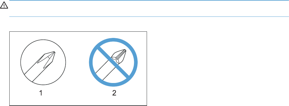
Required tools
●#2 Phillips screwdriver with a magnetic tip and a 152-mm (6-inch) shaft length
●Small flat blade screwdriver
●Needle-nose pliers
●ESD mat or ESD strap (if one is available)
●Penlight (optional)
CAUTION: Always use a Phillips screwdriver (callout 1). Do not use a Pozidriv screwdriver
(callout 2) or any motorized screwdriver. These can damage screws or screw threads.
Figure 2-1 Phillips and Pozidriv screwdriver comparison
ENWW Required tools 61
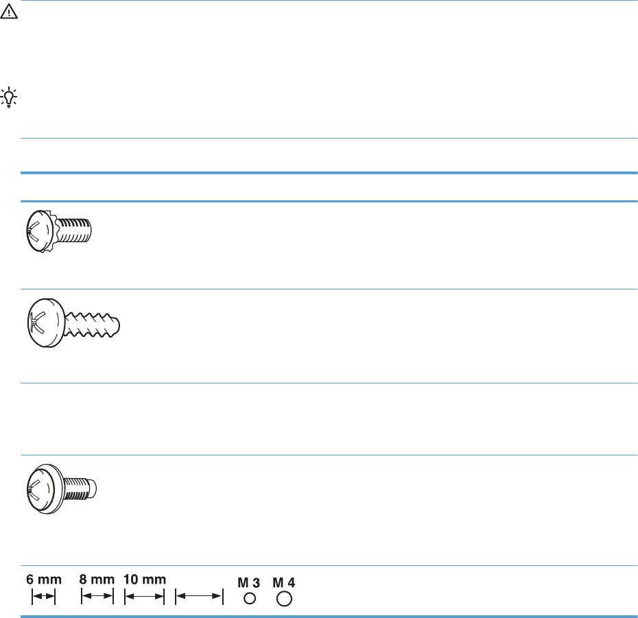
Types of screws
This table describes the screws that are used in the product and provides guidelines to help determine
where each type of screw is used. The screws can vary in length depending on the thickness of the
material that is being fastened.
Always note where each type of screw is located and replace each one in its original location.
WARNING! Make sure that components are replaced with the correct screw type. Using the
incorrect screw (for example, substituting a long screw for the correct shorter screw) can cause damage
to the product or interfere with product operation. Do not intermix screws that are removed with one
component with the screws that are removed from another component.
TIP: When you are disassembling the product, place the screws into the chassis holes from which
they were removed. This prevents their loss, and ensures that the proper type and length of screw for
each location is used when the product is reassembled.
Table 2-1 Common fasteners used in this product
Screw type Purpose
Phillips-head machine screw with captive star washer
This screw is used to fasten metal to metal when good
electrical contact is needed. This screw also provides high
resistance to loosening.
Phillips-head screw with self-tapping threads
This screw is used to fasten sheet metal or plastic to plastic
frames (the deep, coarsely spaced threads provide an
increased holding capability while decreasing the possibility
of stripping the target hole).
Reinstallation note: To install a self-tapping screw, first turn it counterclockwise to align it with the existing thread pattern, and
then carefully turn it clockwise to tighten it. You will feel resistance and hear the screw click when it engages the existing
threads in the hole. Do not overtighten the screw. If a self-tapping screw-hole becomes stripped, repair the screw-hole or
replace the affected assembly.
Phillips washer-head machine screw with a broad, flat washer
attached to the screw head
This screw is used to fasten sheet metal parts to the sheet-metal
chassis. It spans large clearance holes and distributes the load
by increasing the bearing surface.
12 mm
12 mm
Screw measurement guide
62 Chapter 2 Removal and replacement ENWW

Service approach
Before performing service
●Remove all media from the product.
●Turn off the power using the power button.
●Unplug the power cable and interface cable or cables.
●Place the product on an ESD workstation or mat, or use an ESD strap (if one is available). If an
ESD workstation, mat, or strap is not available, ground yourself by touching the sheet-metal
chassis before touching an ESD-sensitive part.
●Remove the print cartridge. See Print cartridge on page 64.
●Remove the tray cassette or cassettes.
After performing service
●Connect the interface cables, and then plug in the power cable.
●Reinstall the print cartridge.
●Reinstall the tray cassette or cassettes.
●If the 500-sheet paper feeder(s) or optional 1500-sheet paper deck was removed for service,
place the product on the feeder(s) or deck. If applicable, engage the feeder or deck locks to
secure the feeder(s) or deck to the product.
Post-service test
Perform the following test to verify that the repair or replacement was successful.
Print-quality test
1. Verify that you have completed the necessary reassembly steps.
2. Make sure that the tray or trays contains clean, unmarked paper.
3. Verify that the power cord and interface cable or interface cables are correctly connected, and
then turn on the product.
4. Verify that the expected startup sounds occur.
5. Print a configuration page, and verify that the expected printing sounds occur.
6. Send a print job from the host computer, and then verify that the output meets expectations.
7. If necessary, restore any customer-specified settings.
8. Clean the outside of the product with a damp cloth.
ENWW Service approach 63
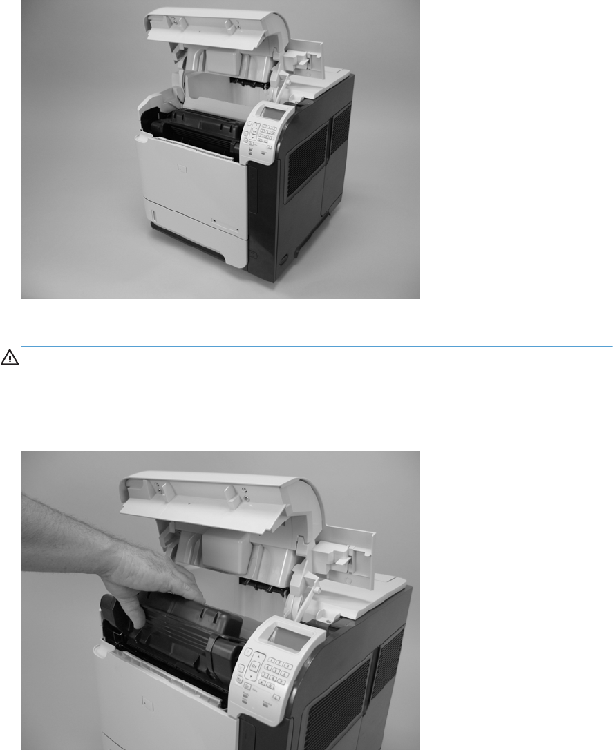
Customer replaceable units (CRUs)
Print cartridge
1. Open the print-cartridge door.
Figure 2-2 Remove the print cartridge (1 of 2)
2. Firmly grasp the print cartridge and pull it up and out of the product.
CAUTION: Do not expose the print cartridge to bright light or direct sunlight for long periods of
time. This can damage the cartridge, which will result in print-quality defects. If the cartridge must
be removed from the product for an extended amount of time, cover it and keep it out of bright
light or direct sunlight.
Figure 2-3 Remove the print cartridge (2 of 2)
64 Chapter 2 Removal and replacement ENWW
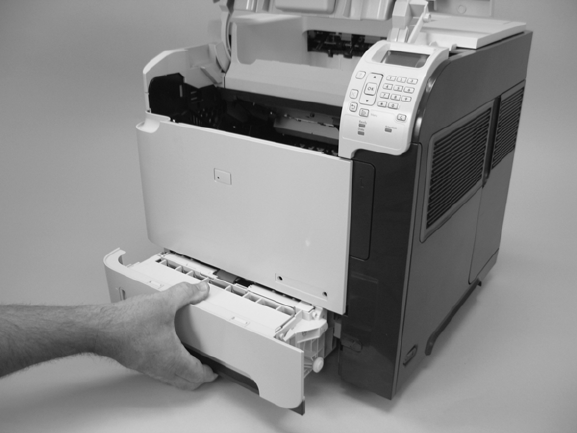
Tray 2
Pull the tray out, slightly lift up, and then pull it completely out of the product to remove it.
Figure 2-4 Remove Tray 2
ENWW Customer replaceable units (CRUs) 65
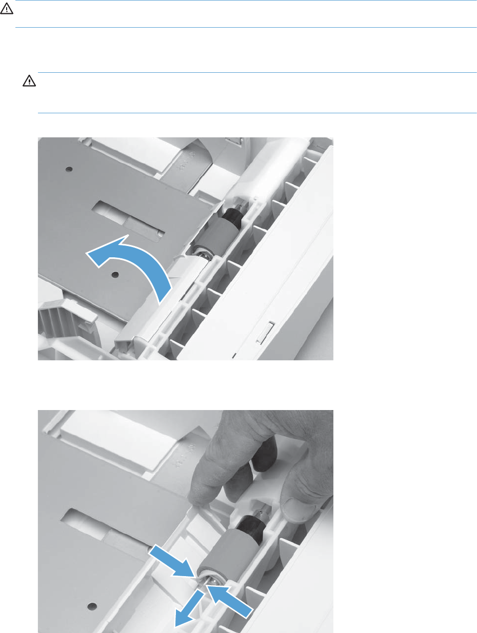
Tray 2 separation, pickup, and feed rollers
CAUTION: When handling the rollers, avoid touching the roller surfaces. Skin oils and fingerprints
on a roller surface can cause print-quality problems.
1. Remove Tray 2 and place it on a level work surface. Locate and open the spring-loaded cover that
is next to the roller in Tray 2.
CAUTION: When you install this roller, make sure that it locks into place. Verify that the roller is
correctly oriented, and that the torque limiter next to the roller is correctly positioned against the
locking pin on the shaft.
Figure 2-5 Remove the Tray 2 separation, pickup, and feed rollers (1 of 4)
2. Pinch the blue tab that is on the left side of the roller. Slide the roller off of the shaft.
Figure 2-6 Remove the Tray 2 separation, pickup, and feed rollers (2 of 4)
66 Chapter 2 Removal and replacement ENWW
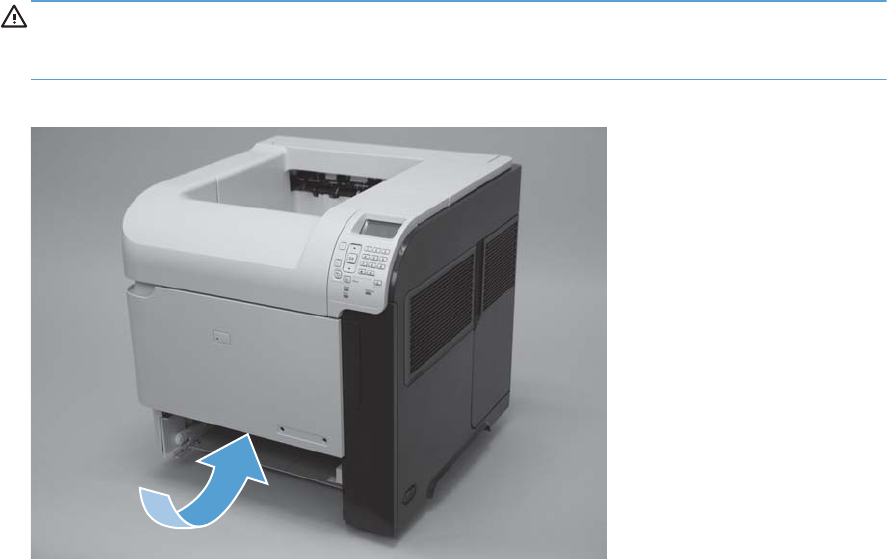
3. Move the front of the product to the edge of the work surface for better access to the remaining
pickup and feed rollers. To find the rollers, look up into the inside of the opening that was created
when you removed Tray 2.
WARNING! Do not allow the front of the product to extend beyond the edge of the work
surface. The product can become unbalanced and fall, which can cause damage to the product or
personal injury to the service technician.
Figure 2-7 Remove the Tray 2 separation, pickup, and feed rollers (3 of 4)
ENWW Customer replaceable units (CRUs) 67
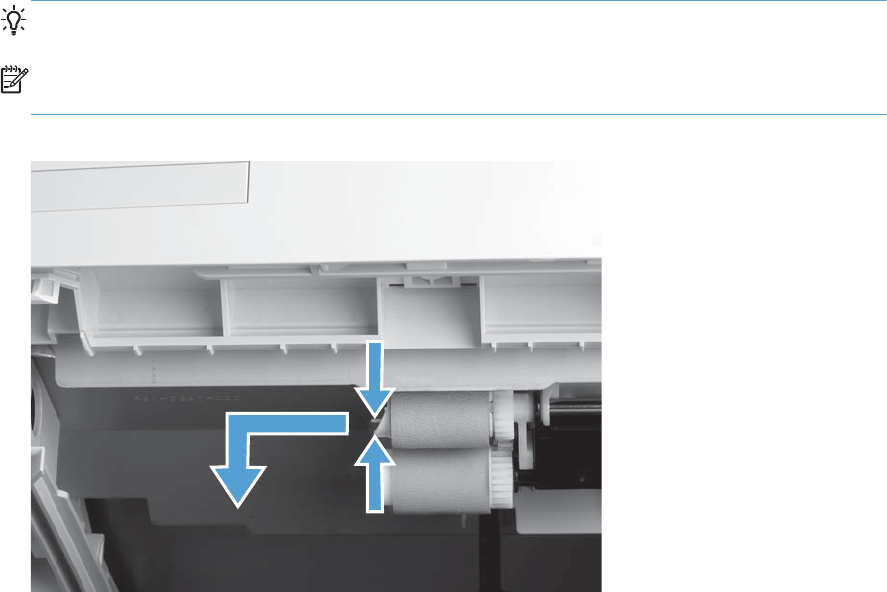
4. Pinch the locking tab on the left side of the feed roller (the front top roller below). Slide the roller
off of the shaft. Repeat this step for the pickup roller (the bottom roller below).
Reinstallation tip You might have to rotate the roller to gain access to the locking tab.
NOTE: When you install these rollers, make sure that the rollers lock into place on the tabs that
are on the drive gears.
Figure 2-8 Remove the Tray 2 separation, pickup, and feed rollers (4 of 4)
68 Chapter 2 Removal and replacement ENWW
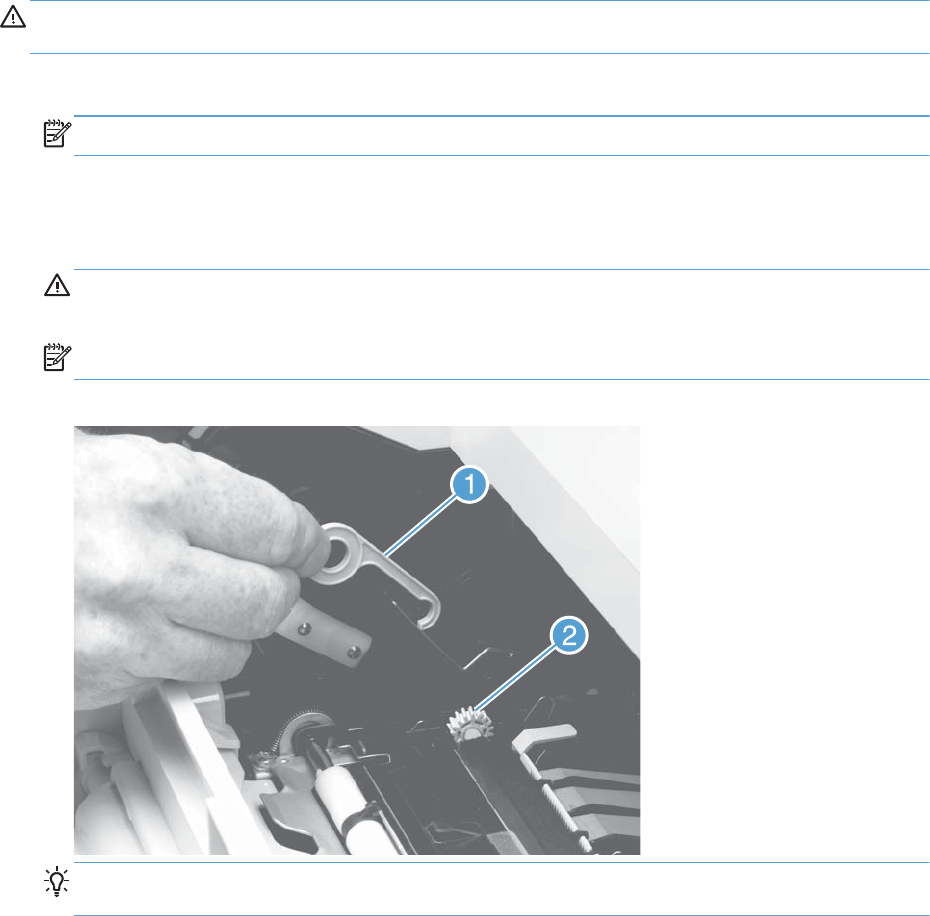
Transfer roller
CAUTION: Do not touch the black rubber on the roller. Skin oils on the roller can cause print-quality
problems. The use of disposable gloves is recommended when you remove the transfer roller.
1. Open the front cover.
NOTE: If the print cartridge was not removed prior to servicing the prodcut, remove it now.
2. Use a transfer-roller removal hook (callout 1) to lift the left end of the metal shaft out of place near
the blue gear (callout 2). If a removal hook is not available use a flatblade screwdriver. Slide the
transfer roller to the left to remove it.
CAUTION: Be careful to release and lift the left side of the roller first, and then slide the roller
out.
NOTE: The transfer-roller removal hook is included with a transfer-roller replacement kit.
Figure 2-9 Remove the transfer roller
Reinstallation tip When you install the transfer roller, make sure that the black collar on the
left side is oriented correctly, with the open end face-down (the solid end is face-up).
ENWW Customer replaceable units (CRUs) 69
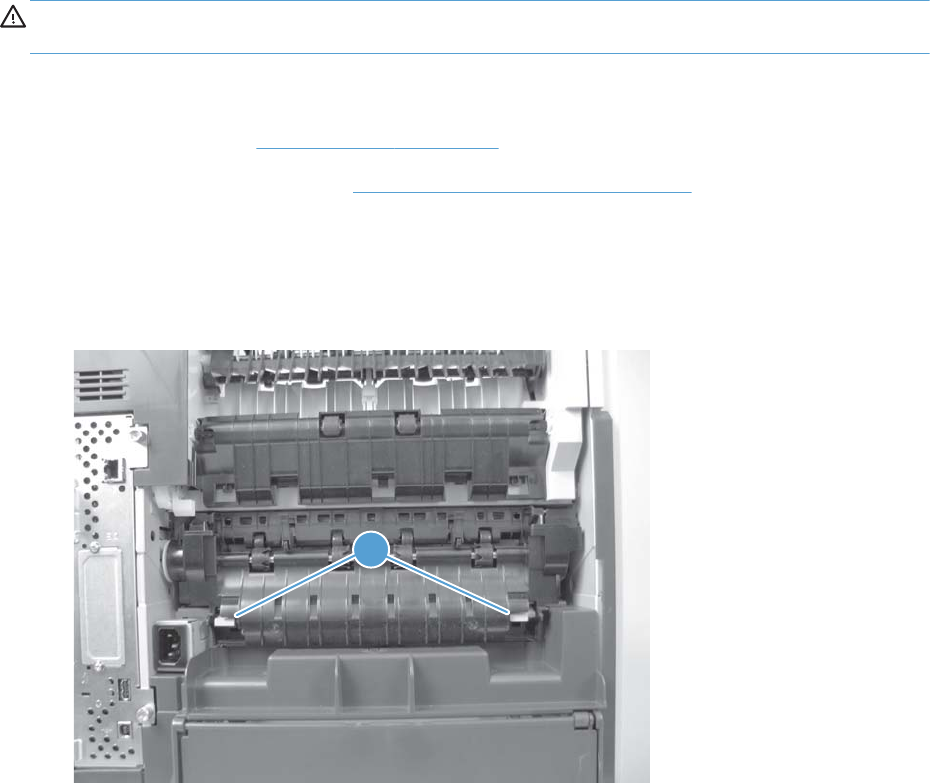
Fuser
WARNING! The fuser might be very hot. After turning off the product power, allow the fuser to cool
for at least 5 minutes before removing it.
Before proceeding, remove the following components:
●Rear output bin. See Rear output bin on page 87.
●Duplex accessory or cover. See Duplex accessory or cover on page 90.
Remove the fuser
1. Squeeze the blue fuser-release tabs (callout 1).
Figure 2-10 Remove the fuser (1 of 2)
1
70 Chapter 2 Removal and replacement ENWW
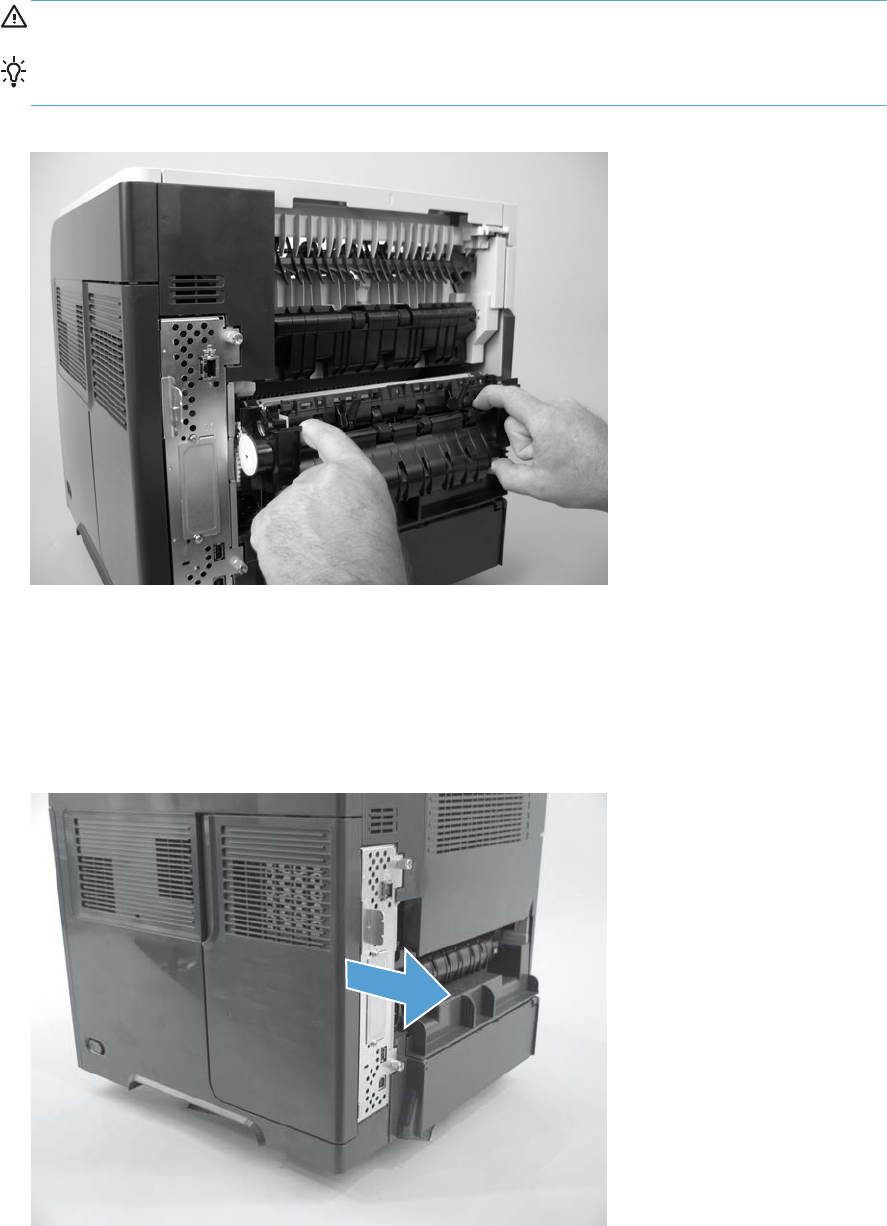
2. Pull the fuser straight back and out of the product.
CAUTION: Do not drop or jar the fuser. It can easily be damaged if it is mishandled.
TIP: When you replace the fuser, make sure that it is fully seated into the product. You should
hear both sides snap into place.
Figure 2-11 Remove the fuser (2 of 2)
Formatter cover and formatter cage
1. Grasp the formatter cover.
2. Pull the cover straight back and away from the product.
Figure 2-12 Remove the formatter cover and formatter cage (1 of 3)
ENWW Customer replaceable units (CRUs) 71
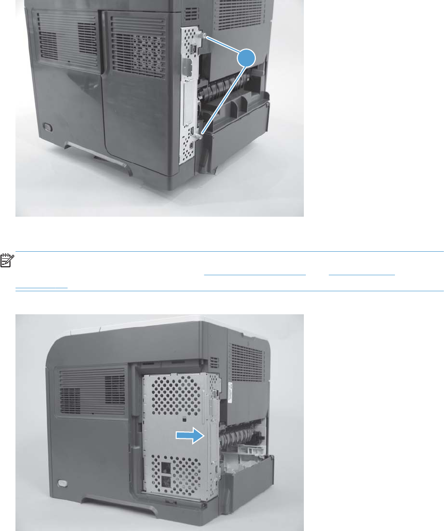
3. Remove two thumb screws (callout 1)
Figure 2-13 Remove the formatter cover and formatter cage (2 of 3)
1
4. Carefully slide the formatter cage away from the product to remove it.
NOTE: If you installing a replacement formatter, transfer the hard drive and memory DIMM (if
installed) to the replacement formatter. See Hard drive on page 74 and Memory DIMM
on page 80.
Figure 2-14 Remove the formatter cover and formatter cage (3 of 3)
72 Chapter 2 Removal and replacement ENWW

Installing a new formatter
CAUTION: Do not replace the DC controller and the formatter at the same time.
1. Install the hard drive and memory DIMM from the discard formatter on the replacement formatter.
2. Turn the product on and then wait for five minutes after the product reaches the Ready state.
NOTE: Five minutes is required to allow for NVRAM settings to be written.
3. Turn the product off.
4. Turn the product on and then wait for five minutes after the product reaches the Ready state.
5. Print a configuration page to verify against original settings.
ENWW Customer replaceable units (CRUs) 73
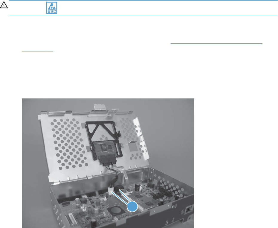
Hard drive
A solid state module (SSM) or a crypto hard-disk drive (HDD) device is installed depending on the
product model.
CAUTION: ESD sensitive component.
Before proceeding, remove the following components:
●Formatter cover, formatter cage, and formatter PCA. See Formatter cover and formatter cage
on page 71.
Remove the SSM
1. Open the formatter cage door, and then disconnect two connectors (callout 1).
Figure 2-15 Remove the SSM (1 of 3)
1
74 Chapter 2 Removal and replacement ENWW
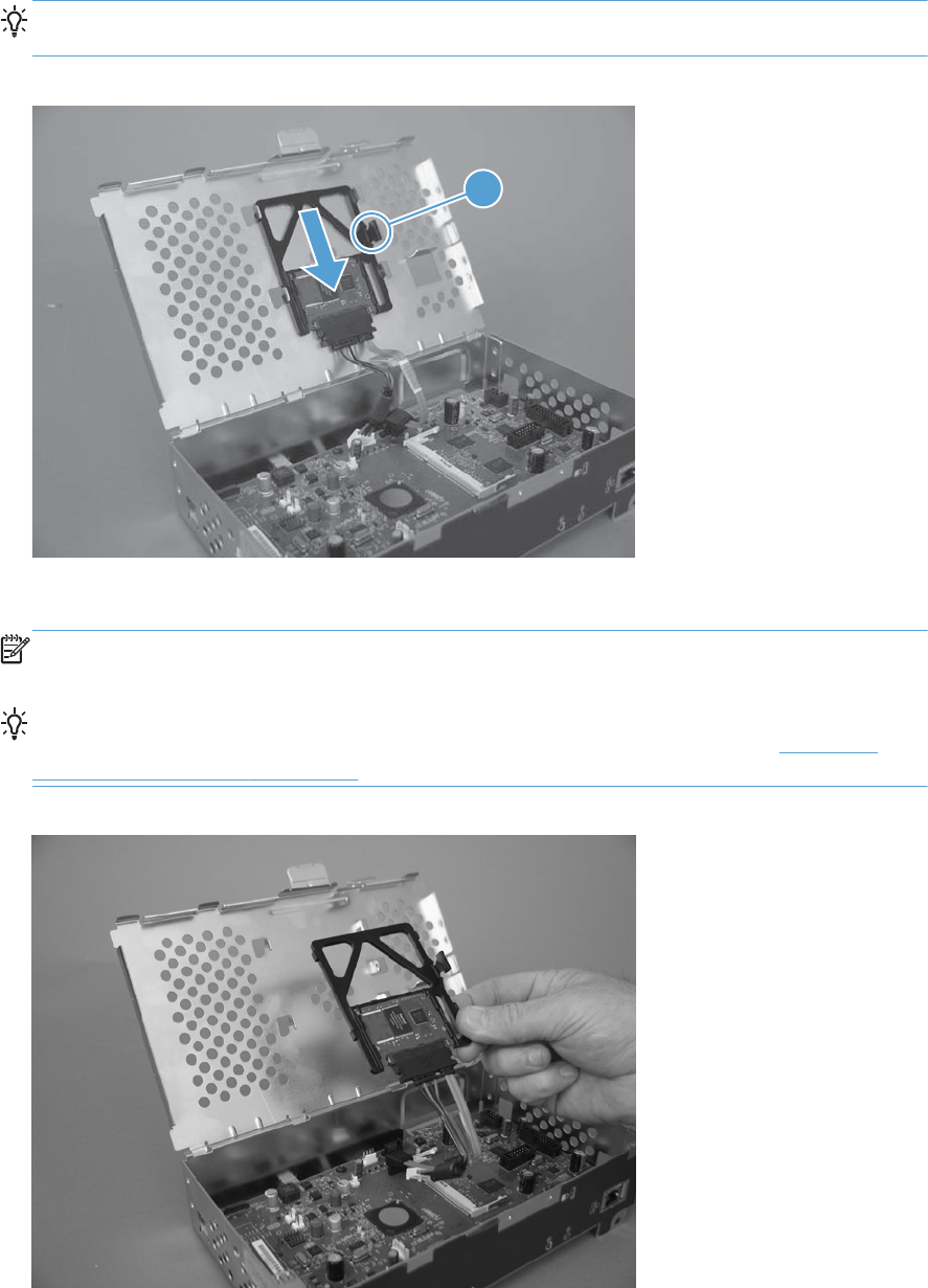
2. Release one tab (callout 2), and then slide the SSM toward the hinge side of the door.
TIP: It might be easier to remove the SSM if you separate the formatter cage door from the
cage. Slide the door toward the top of the cage, and then separate the components.
Figure 2-16 Remove the SSM (2 of 3)
2
3. Remove the SSM from the cage door.
NOTE: Slide the SSM out of the mounting cradle to separate the components. Do not lose the
cradle while handling the SSM.
Reinstallation tip Use the cradle to install a replacement SSM. After installing a replacement
hard drive, you must reload the firmware by performing a firmware upgrade. See Installing a
replacement hard drive on page 78.
Figure 2-17 Remove the SSM (3 of 3)
ENWW Customer replaceable units (CRUs) 75
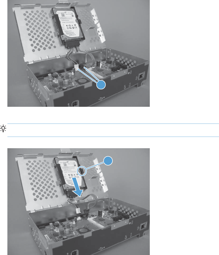
Remove the encrypted HHD
1. Open the formatter cage door, and then disconnect two connectors (callout 1).
Figure 2-18 Remove the encrypted HHD (1 of 4)
1
2. Release one tab (callout 2), and then slide the HHD toward the hinge side of the door.
TIP: It might be easier to remove the HHD if you separate the formatter cage door from the
cage. Slide the door toward the top of the cage, and then separate the components.
Figure 2-19 Remove the encrypted HHD (2 of 4)
2
76 Chapter 2 Removal and replacement ENWW
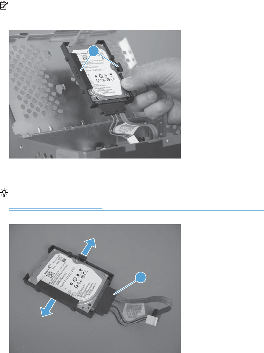
3. Remove the HHD from the cage door.
NOTE: The HHD rails (callout 3) are not captive and can be easily separated from the
component. Do not lose the rails while handling the HHD.
Figure 2-20 Remove the encrypted HHD (3 of 4)
3
4. Disconnect one connector (callout 4), and then remove the HHD mounting rails. Do not lose the
rails while handling the HDD.
Reinstallation tip Use the rails to install a replacement HDD. After installing a replacement
hard drive, you must reload the firmware by performing a firmware upgrade. See Installing a
replacement hard drive on page 78.
Figure 2-21 Remove the encrypted HHD (4 of 4)
4
ENWW Customer replaceable units (CRUs) 77
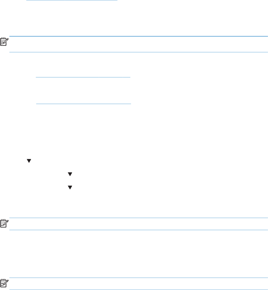
Installing a replacement hard drive
After installing a replacement hard drive, you must reload the firmware by performing a firmware
upgrade.
Perform a firmware upgrade
1. Go to www.hp.com/support/lj600Series and follow the on screen steps to download the most
recent firmware upgrade files for this product.
2. Copy the firmware upgrade file to the root directory of a USB storage accessory. The firmware
upgrade file has a .bdl extension.
NOTE: Use a standard USB storage accessory that uses File Allocation Table (FAT) file systems
and that does not have a CD-ROM partition.
3. Insert the USB storage accessory into the USB port on the bottom edge of the control panel.
4. SSM: see SSM firmware upgrade on page 78.
-or-
HDD: see HDD firmware upgrade on page 79.
SSM firmware upgrade
1. Turn the product on. The message Error 99.09.67 Disk Not Bootable appears on the
control-panel display. Press the OK button to continue.
2. Wait for the Preboot menu to appear on the control-panel display, and then press the down
arrow button to scroll to Administrator. Press the OK button to select it.
3. Press the down arrow button to scroll to Download. Press the OK button to select it.
4. Press the down arrow button to scroll to USB Thumbdrive. Press the OK to select it.
5. Several .bdl files might be listed. Press the down arrow button to scroll to the firmware upgrade
file that you downloaded earlier. Press the OK button to select it.
NOTE: If no .bdl fils are listed, try saving the file to a different USB storage accessory.
6. Wait while the file transfers. When the transfer is complete, the message Complete appears on
the screen.
7. Turn the product off, remove the USB storage accessory, and then turn the product on. Wait for
several minutes while the product initializes.
NOTE: If the upgrade is unsuccessful, try sending the firmware upgrade file again.
78 Chapter 2 Removal and replacement ENWW

HDD firmware upgrade
1. Turn the product on. The message Error 99.09.63 Incorrect Disk appears on the control-
panel display. Press the OK button to continue.
2. Wait for the Preboot menu to appear on the control-panel display, and then press the down
arrow button to scroll to Administrator. Press the OK button to select it.
3. Press the down arrow button to scroll to Manage Disk. Press the OK button to select it.
4. Press the down arrow button to scroll to Clear Disk Pass. Press the OK button to select it.
5. The message Proceed With Requested Action appears. Press the OK button to select it.
6. Press the # button to return to the Preboot home menu screen.
7. Press the down arrow button to scroll to Administrator. Press the OK button to select it.
8. Press the down arrow button to scroll to Download. Press the OK button to select it.
9. Press the down arrow button to scroll to USB Thumbdrive. Press the OK button to select it.
10. Several .bdl files might be listed. Press the down arrow button to scroll to the firmware upgrade
file that you downloaded earlier. Press the OK button to select it.
NOTE: If no .bdl fils are listed, try saving the file to a different USB storage accessory.
11. Wait while the file transfers. When the transfer is complete, the message Complete appears on
the screen.
12. Turn the product off, remove the USB storage accessory, and then turn the product on. Wait for
several minutes while the product initializes.
NOTE: If the upgrade is unsuccessful, try sending the firmware upgrade file again.
ENWW Customer replaceable units (CRUs) 79
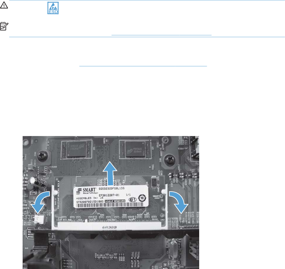
Memory DIMM
CAUTION: ESD sensitive component.
NOTE: Depending on the model, a memory DIMM might not be installed. To increase the product
memory, install a memory DIMM. See Install the memory DIMM on page 81.
Before proceeding, remove the following components:
●Formatter cover. See Formatter cover and formatter cage on page 71.
Remove the memory DIMM
1. Open the formatter cage door.
2. Push the DIMM-locking arms away from the DIMM to release it, and then pull the DIMM out of the
DIMM slot.
Figure 2-22 Remove the memory DIMM
80 Chapter 2 Removal and replacement ENWW
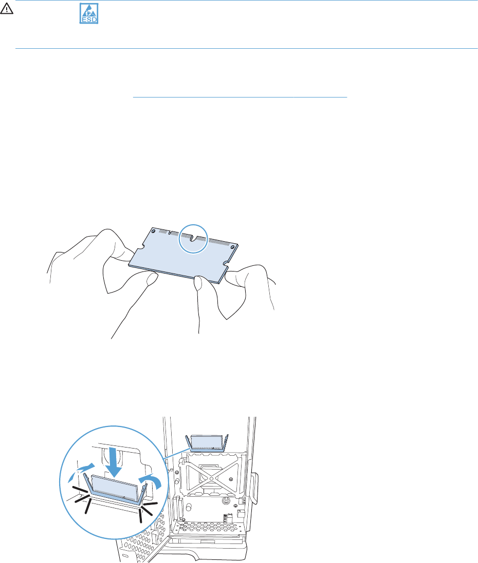
Install the memory DIMM
CAUTION: ESD sensitive component.
Turn the product off. Disconnect the power cord and interface cables.
Before proceeding, remove the following components:
●Formatter cover. See Formatter cover and formatter cage on page 71.
1. Open the formatter cage door.
2. Remove the DIMM from the antistatic packadge.
3. Hold the DIMM by the edges, and align the notches on the DIMM with the DIMM slot. (Check that
the locks on each side of the DIMM slot are open.)
Figure 2-23 Install the memory DIMM (1 of 2)
4. Press the DIMM straight into the slot, and press firmly. Make sure the locks on each side of the
DIMM snap into place.
Figure 2-24 Install the memory DIMM (2 of 2)
ENWW Customer replaceable units (CRUs) 81
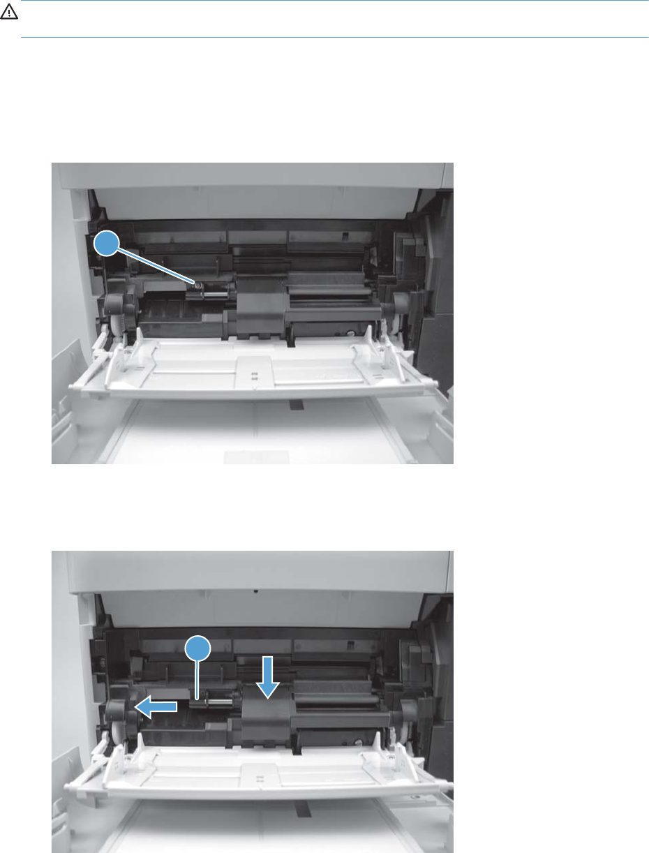
Tray 1 pickup and feed rollers
CAUTION: When handling the rollers, avoid touching the roller surfaces. Skin oils and fingerprints
on a roller surface can cause print-quality problems.
The Tray 1 pickup and feed rollers are also user-replaceable components.
1. Open the front cover.
2. Remove one screw (callout 1) with a short screwdriver.
Figure 2-25 Remove the Tray 1 pickup and feed rollers (1 of 4)
1
3. Push down on the roller-shaft bushing (callout 2) to release two alignment pins, and then slide the
bushing to the left and off of the shaft to remove it.
Figure 2-26 Remove the Tray 1 pickup and feed rollers (2 of 4)
2
82 Chapter 2 Removal and replacement ENWW
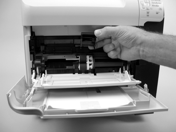
4. Slide the Tray 1 pickup and feed rollers cover slightly to the left to release it, and then lift the cover
up to remove it.
Figure 2-27 Remove the Tray 1 pickup and feed rollers (3 of 4)
ENWW Customer replaceable units (CRUs) 83
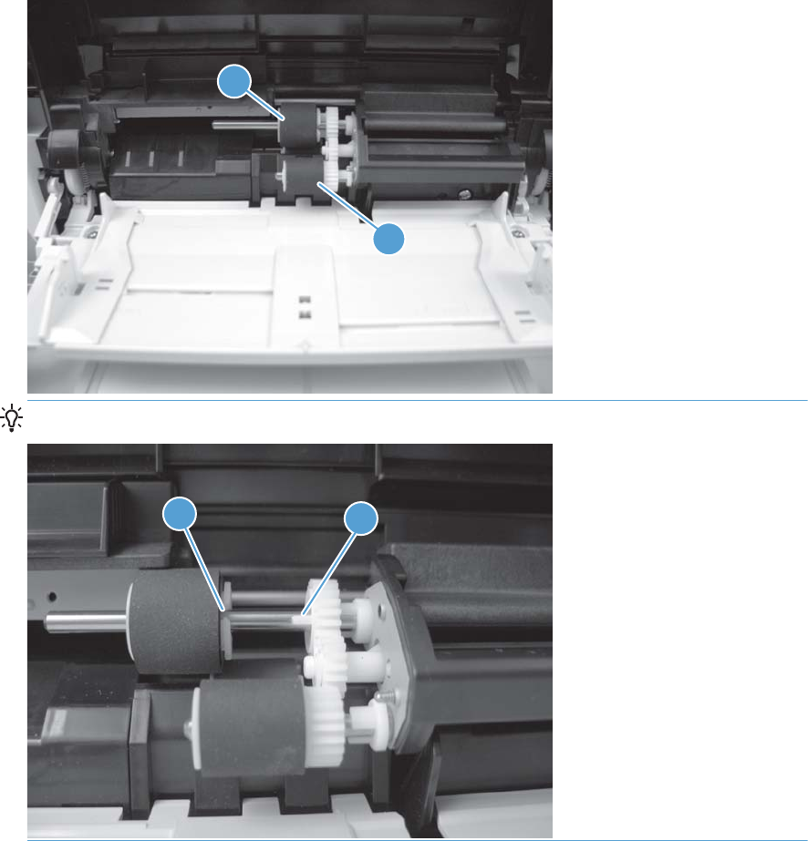
5. Slide the Tray 1 pickup roller (callout 3) and the feed roller (callout 4) to the left and off of the
shafts to remove them.
Figure 2-28 Remove the Tray 1 pickup and feed rollers (4 of 4)
3
4
TIP: The pickup roller must fit over the drive tabs (callout 5) on the roller-drive gear (callout 6).
56
84 Chapter 2 Removal and replacement ENWW
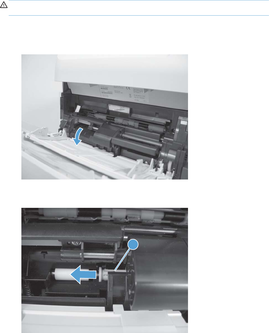
Tray 1 separation roller
CAUTION: When handling the roller, avoid touching the roller surface. Skin oils and fingerprints on
a roller surface can cause print-quality problems.
1. Open the front cover.
2. Rotate the spring-loaded cover downward to gain access to the roller.
Figure 2-29 Remove the Tray 1 separation roller (1 of 3)
3. Slide the separation roller (callout 1) to the left to remove it.
Figure 2-30 Remove the Tray 1 separation roller (2 of 3)
1
ENWW Customer replaceable units (CRUs) 85
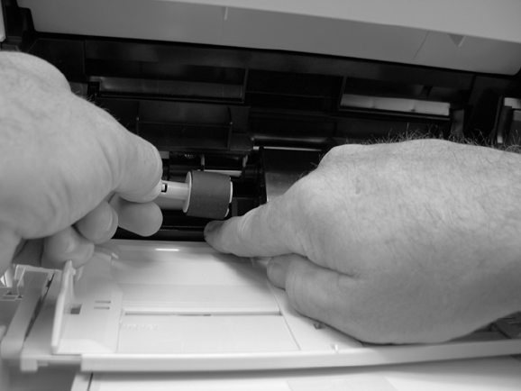
4. Remove the roller.
Figure 2-31 Remove the Tray 1 separation roller (3 of 3)
86 Chapter 2 Removal and replacement ENWW
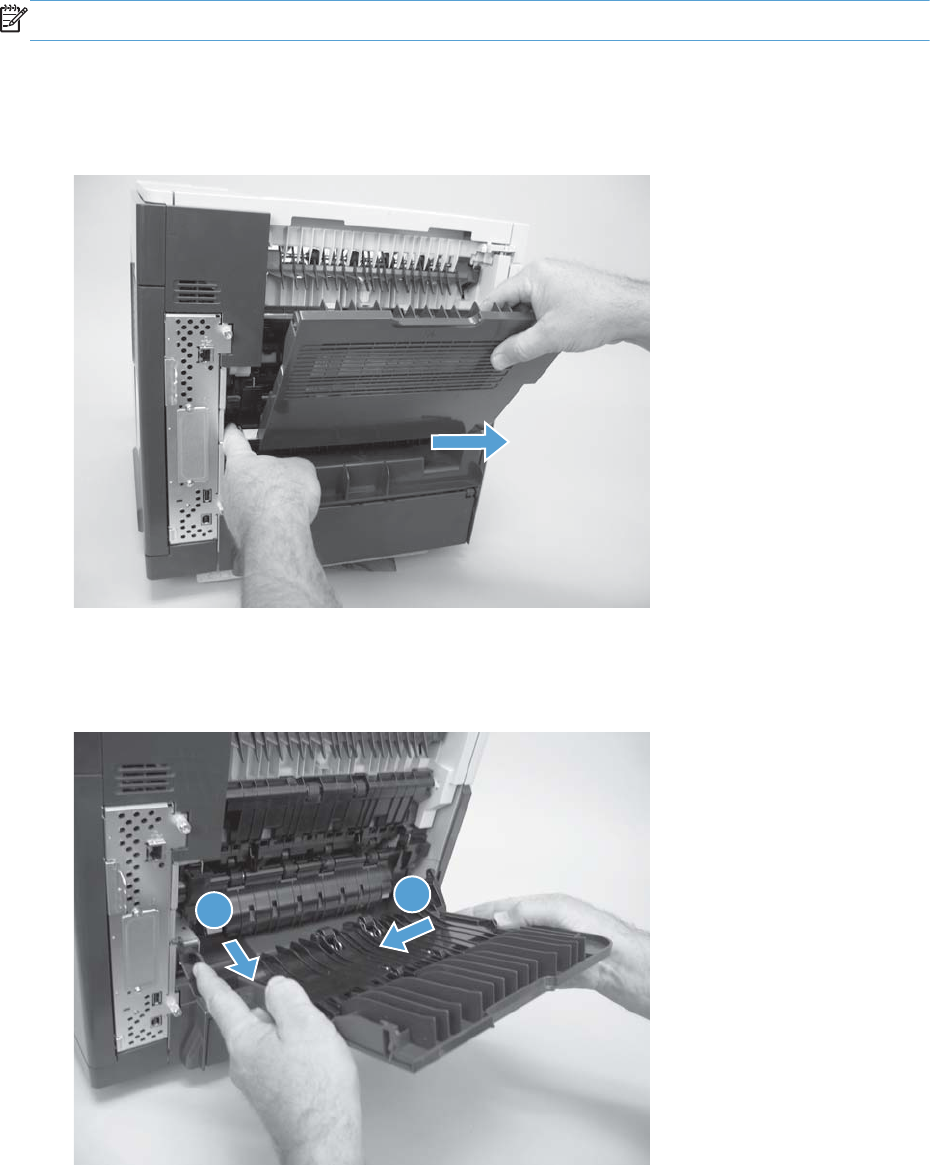
Rear output bin
NOTE: If the duplexer is installed, lift it up slightly and pull it away from the product to remove it.
1. Open the rear output bin.
2. Squeeze the hinge pin out of its mounting hole.
Figure 2-32 Remove the rear output bin (1 of 2)
3. Rotate the output bin away from the product until the right hinge pin is released, and then remove
the output bin.
Figure 2-33 Remove the rear output bin (2 of 2)
12
ENWW Customer replaceable units (CRUs) 87
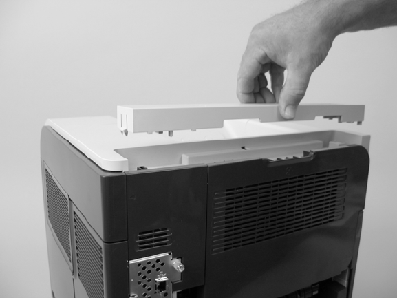
Covers
Top-accessory cover
Lift the top-accessory cover up and off the product.
Figure 2-34 Remove the top-accessory cover
88 Chapter 2 Removal and replacement ENWW
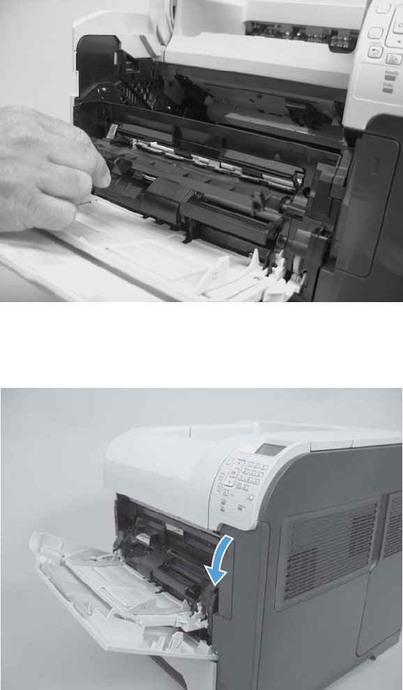
Envelope feed accessory covers
1. Open the front cover. Grasp the inner front accessory cover, and then pull it straight out of the
product.
Figure 2-35 Remove the front accessory covers (1 of 2)
2. Rotate the top of the front accessory receptacle cover away from the product, and then pull it
straight away from the product to remove it.
Figure 2-36 Remove the front accessory covers (2 of 2)
ENWW Covers 89
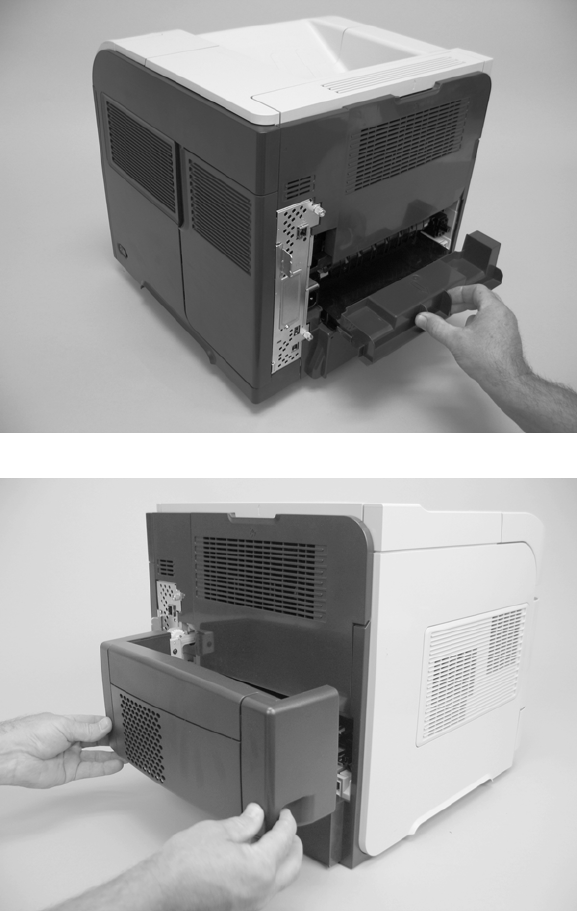
Duplex accessory or cover
Pull the duplex accessory or cover out, slightly lift up, and then pull it completely out of the product to
remove it.
Figure 2-37 Remove the duplex accessory cover
Figure 2-38 Remove the duplex accessory
90 Chapter 2 Removal and replacement ENWW
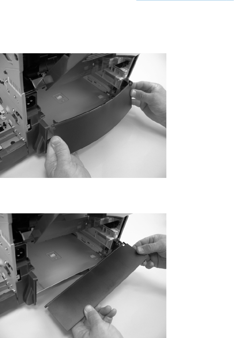
Tray 2 extension door
Before proceeding, remove the following components:
●Duplex accessory, or the duplex accessory cover. See Duplex accessory or cover on page 90.
Remove the Tray 2 extension door
1. Carefully flex the Tray 2 extension door to release the hinge pin near the power cord side of the
product.
Figure 2-39 Remove the Tray 2 extension door (1 of 2)
2. Rotate the Tray 2 extension door to the horizontal position, and then pull up on the keyed hinge
pin to release the door. Remove the Tray 2 extension door
Figure 2-40 Remove the Tray 2 extension door (2 of 2)
ENWW Covers 91
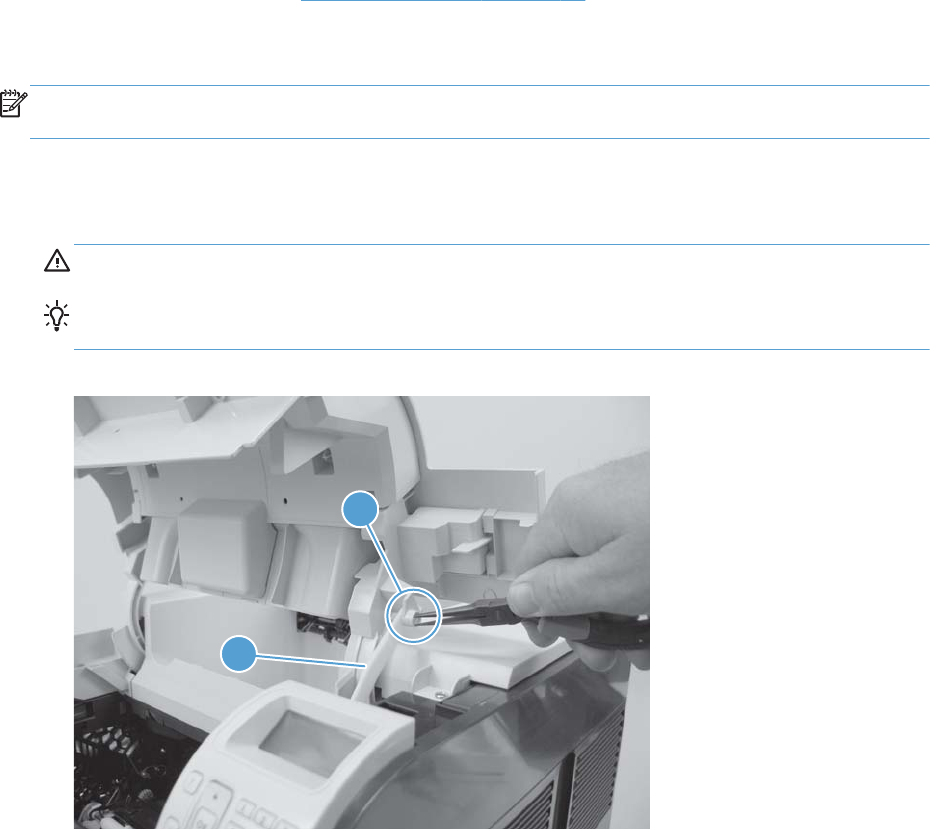
Top cover
Before proceeding, remove the following components:
●Top accessory cover. See Top-accessory cover on page 88.
Remove the top cover
NOTE: If the optional stapler/stacker or stacker accessory is installed, lift it straight up and off of the
product to remove it. Then proceed to step 2.
1. Open the rear-output bin, the print-cartridge door, and the front cover.
2. Use needle-nose pliers to release the print-cartridge drive-arm tab (callout 1).
CAUTION: The print-cartridge drive-arm tab is easily broken.
TIP: Push the print-cartridge drive-arm (callout 2) back into the product to avoid damaging it
when you remove the top cover.
Figure 2-41 Remove the top cover (1 of 4)
1
2
92 Chapter 2 Removal and replacement ENWW
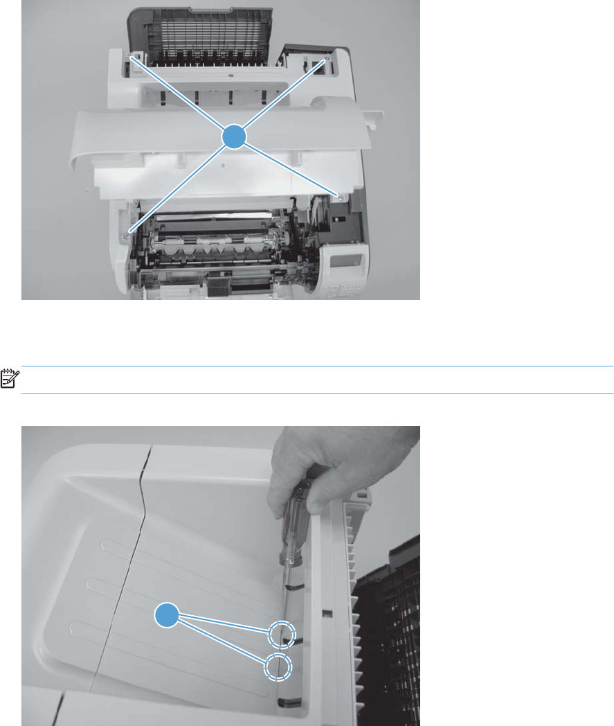
3. Remove four screws (callout 3).
Figure 2-42 Remove the top cover (2 of 4)
3
4. Partially close the print-cartridge door, and then use a small flat blade screwdriver to release two
tabs (callout 4).
NOTE: Make sure that these tabs are fully seated when the top cover is reinstalled.
Figure 2-43 Remove the top cover (3 of 4)
4
ENWW Covers 93
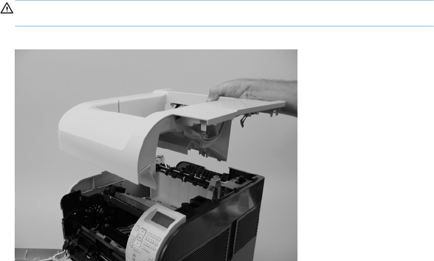
5. Lift the top cover up and off of the product to remove it.
CAUTION: The accessory pin (located in the left-rear corner of the cover) is not captive. Do not
lose the pin.
Figure 2-44 Remove the top cover (4 of 4)
94 Chapter 2 Removal and replacement ENWW
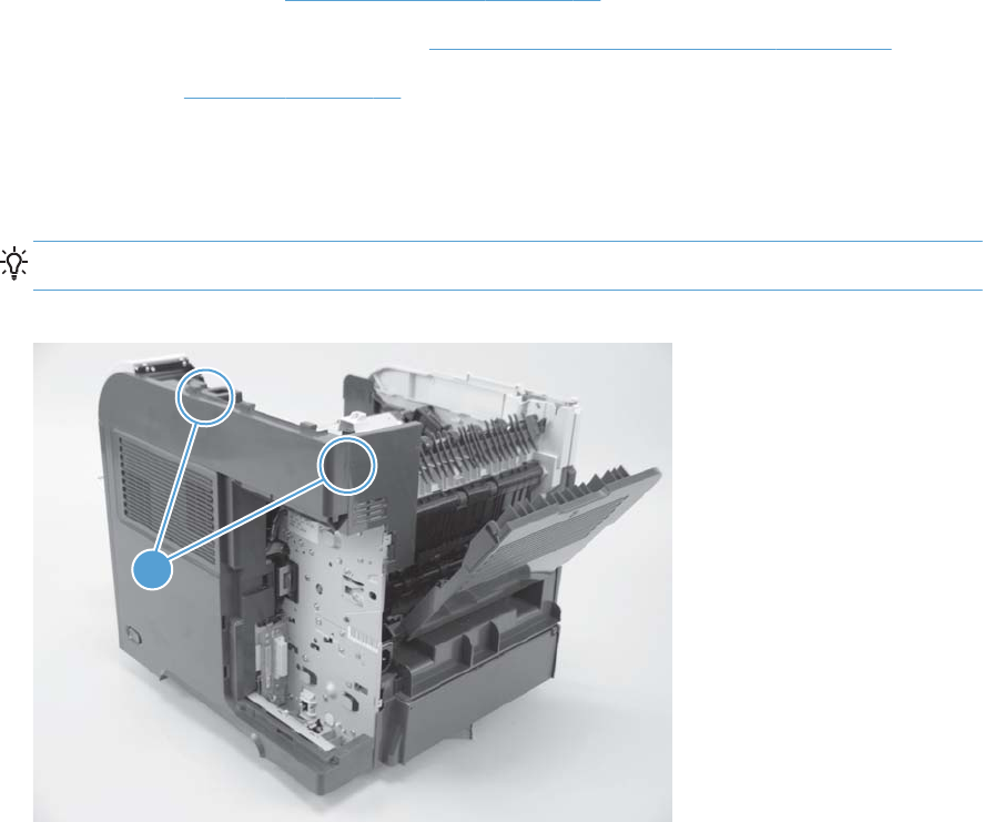
Right-side cover
Before proceeding, remove the following components:
●Top accessory cover. See Top-accessory cover on page 88.
●Formatter cover and formatter cage. See Formatter cover and formatter cage on page 71.
●Top cover. See Top cover on page 92.
Remove the right-side cover
1. Release two tabs (callout 1).
TIP: Look for the arrows embossed into the cover to locate the tab.
Figure 2-45 Remove the right-side cover (1 of 3)
1
ENWW Covers 95
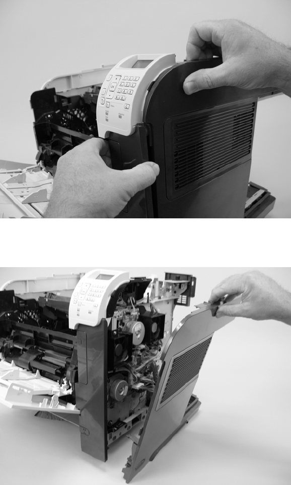
2. Carefully separate the cover from the product near the control panel.
Figure 2-46 Remove the right-side cover (2 of 3)
3. Rotate the top of the cover away from the product, and then and lift the cover up to remove it.
Figure 2-47 Remove the right-side cover (3 of 3)
96 Chapter 2 Removal and replacement ENWW
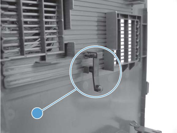
Reinstall the right cover
▲If you are installing a replacement cover, remove the engine-test button (callout 1) from the
discarded cover and then install it on the replacement cover.
Figure 2-48 Install the right cover
1
ENWW Covers 97
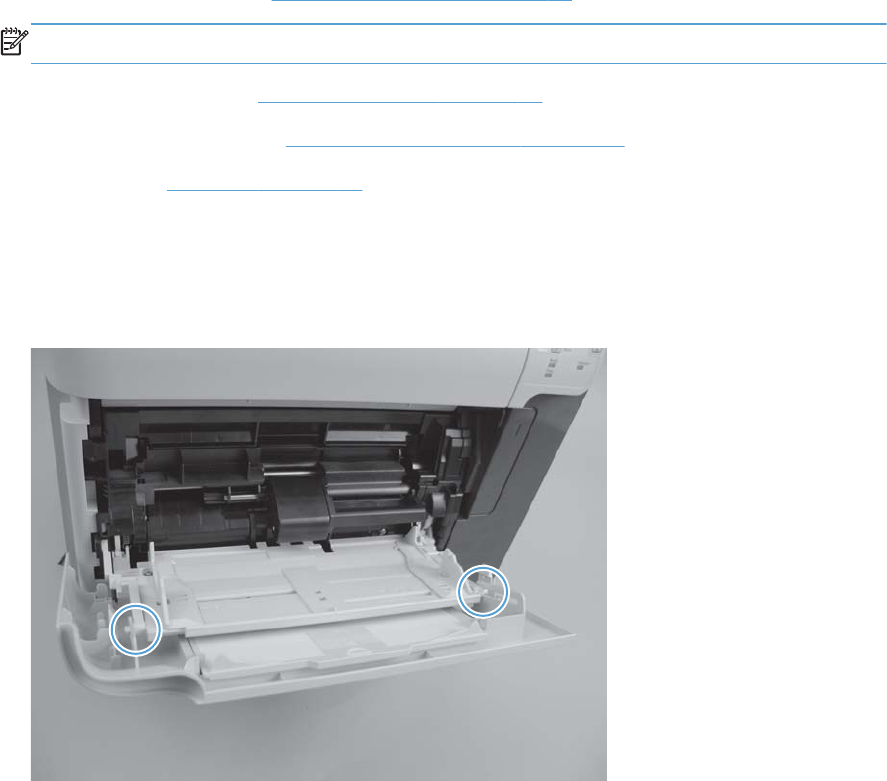
Left-side cover
Before proceeding, remove the following components:
●Tray 2 extension door. See Tray 2 extension door on page 91.
NOTE: If Tray 2 was not removed prior to servicing the prodcut, remove it now.
●Top accessory cover. See Top-accessory cover on page 88.
●Duplex accessory cover. See Duplex accessory or cover on page 90.
●Top cover. See Top cover on page 92.
Remove the left-side cover
1. Gently pry the front-cover retainers off of the Tray 1 arms.
Figure 2-49 Remove the left-side cover (1 of 3)
98 Chapter 2 Removal and replacement ENWW
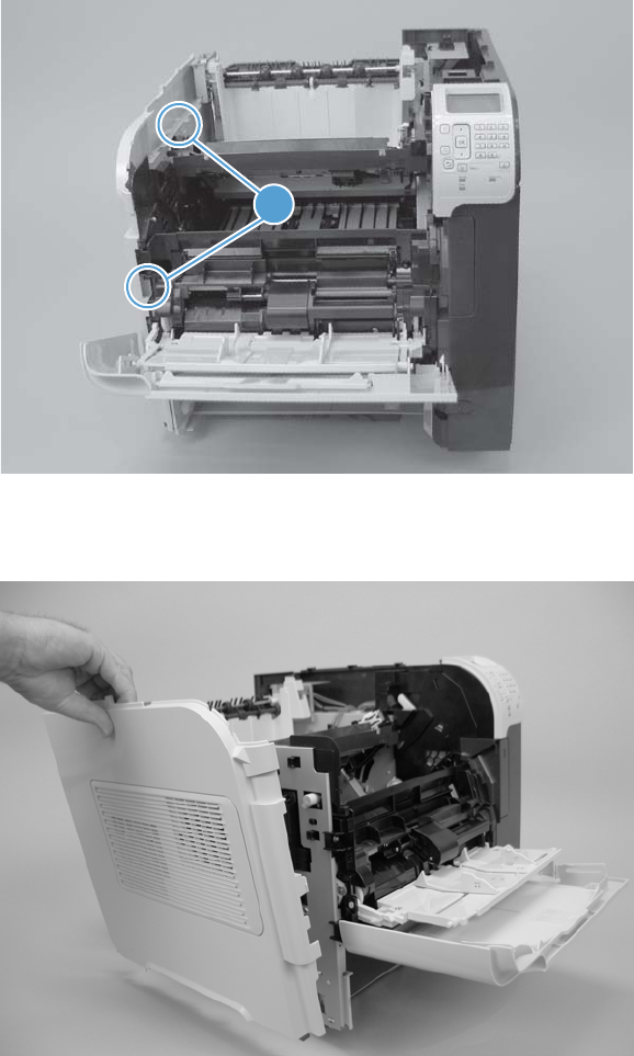
2. Release two tabs (callout 3), and then rotate the top of the cover away from the product and lift
the cover up to remove it.
Figure 2-50 Remove the left-side cover (2 of 3)
3
3. Rotate the top of the cover away from the product and lift the cover up to remove it.
Figure 2-51 Remove the left-side cover (3 of 3)
ENWW Covers 99
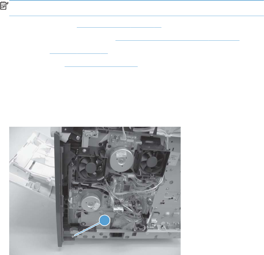
Right-front cover
Before proceeding, remove the following components:
●Walk-up USB cover, if installed.
NOTE: This is the small dust cover that plugs into the walk-up USB port on the front of the
product.
●Top accessory cover. See Top-accessory cover on page 88.
●Formatter cover and formatter cage. See Formatter cover and formatter cage on page 71.
●Top cover. See Top cover on page 92.
●Right-side cover. See Right-side cover on page 95.
Remove the right-front cover
1. Open the front cover.
2. Remove one screw (callout 1).
Figure 2-52 Remove the right-front cover (1 of 4)
1
100 Chapter 2 Removal and replacement ENWW
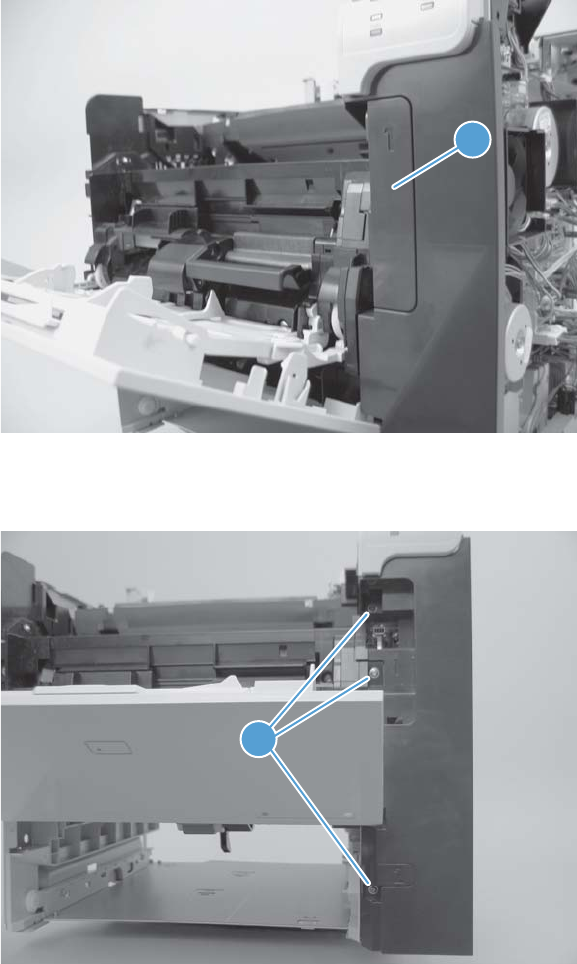
3. Gently pull the envelope-feeder connector cover (callout 2) off of the product to remove it.
Figure 2-53 Remove the right-front cover (2 of 4)
2
4. Remove three screws (callout 3).
Figure 2-54 Remove the right-front cover (3 of 4)
3
ENWW Covers 101
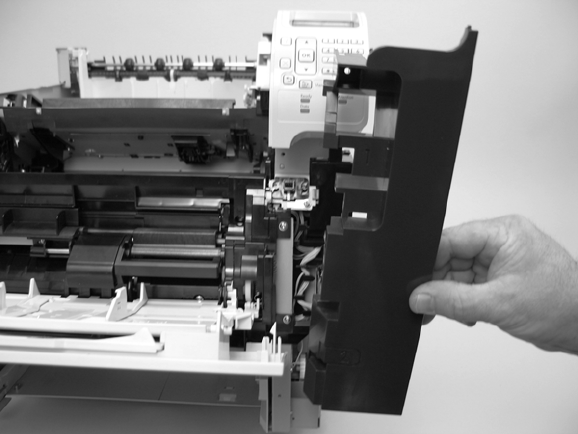
5. Remove the right front cover.
Figure 2-55 Remove the right-front cover (4 of 4)
102 Chapter 2 Removal and replacement ENWW

Rear-upper cover
Before proceeding, remove the following components:::
●Top accessory cover. See Top-accessory cover on page 88.
●Formatter cover and formatter cage. See Formatter cover and formatter cage on page 71.
●Top cover. See Top cover on page 92.
●Right-side cover. See Right-side cover on page 95.
Remove the rear-upper cover
1. Release one tab (callout 1), and then rotate the cover toward the paper-delivery assembly to
release it.
Figure 2-56 Remove the rear-upper cover (1 of 2)
1
ENWW Covers 103
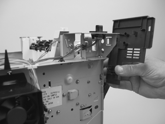
2. Remove the rear-upper cover
Figure 2-57 Remove the rear-upper cover (2 of 2)
104 Chapter 2 Removal and replacement ENWW
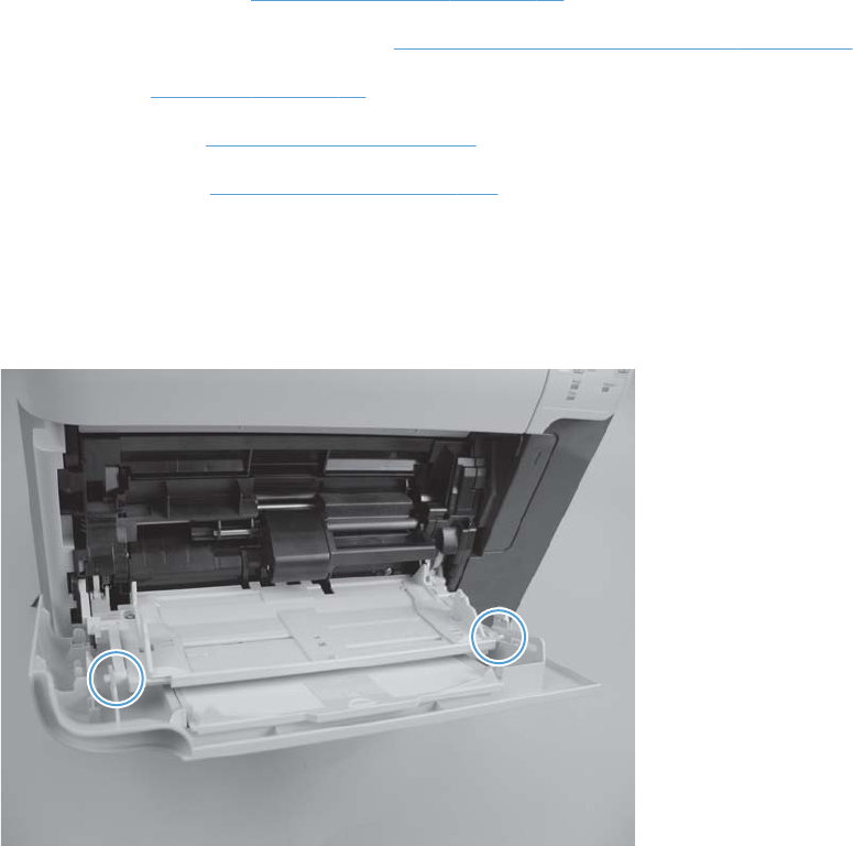
Front cover
Before proceeding, remove the following components:
●Top accessory cover. See Top-accessory cover on page 88.
●Formatter cover and formatter cage. See Formatter cover and formatter cage on page 71.
●Top cover. See Top cover on page 92.
●Right-side cover. See Right-side cover on page 95.
●Right-front cover. See Right-front cover on page 100.
Remove the front cover
1. Gently pry the front-cover retainers off of the Tray 1 arms.
Figure 2-58 Remove the front cover (1 of 2)
ENWW Covers 105
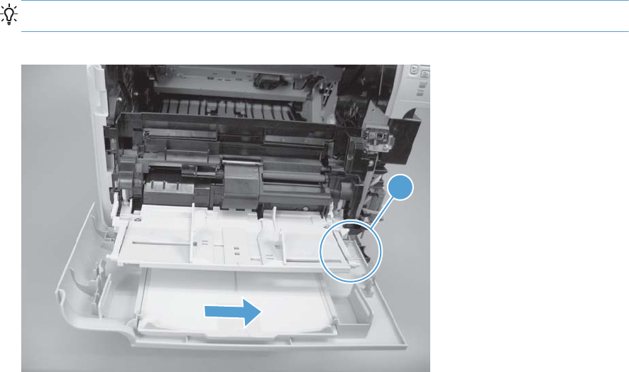
2. Release one spring (callout 1), and then slide the front cover toward the right side of the product to
remove it.
Reinstallation tip Use a pair of needle-nose pliers to reinstall this spring.
Figure 2-59 Remove the front cover (2 of 2)
1
106 Chapter 2 Removal and replacement ENWW
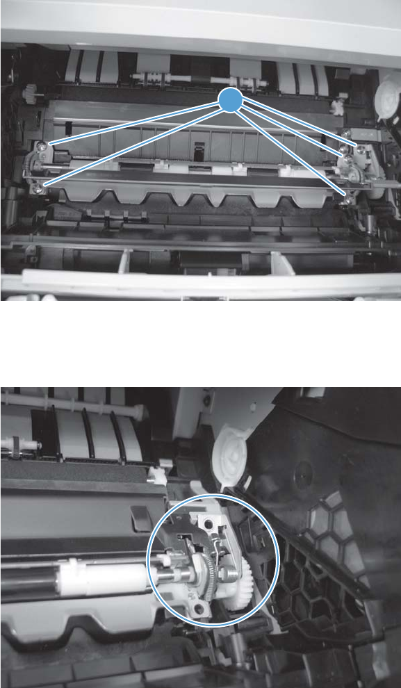
Main assemblies
Registration assembly
1. Open the print-cartridge door, and then remove the print cartridge.
2. Use the green handle (located at the right edge of the registration plate) to raise the registration-
roller plate, and then remove five screws (callout 1).
Figure 2-60 Remove the registration assembly (1 of 4)
1
3. Locate the grounding plate at the right side of the registration assembly. The plate is not captive
when you remove the assembly. Do not lose the grounding plate.
Figure 2-61 Remove the registration assembly (2 of 4)
ENWW Main assemblies 107
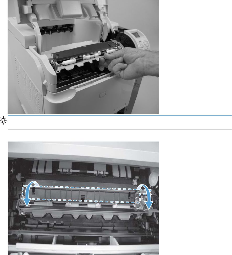
4. Lift the registration assembly out of the product.
Figure 2-62 Remove the registration assembly (3 of 4)
TIP: To reinstall the registration assembly, you must open the registration-roller plate to gain
access to the mounting holes.
Figure 2-63 Remove the registration assembly (4 of 4)
108 Chapter 2 Removal and replacement ENWW
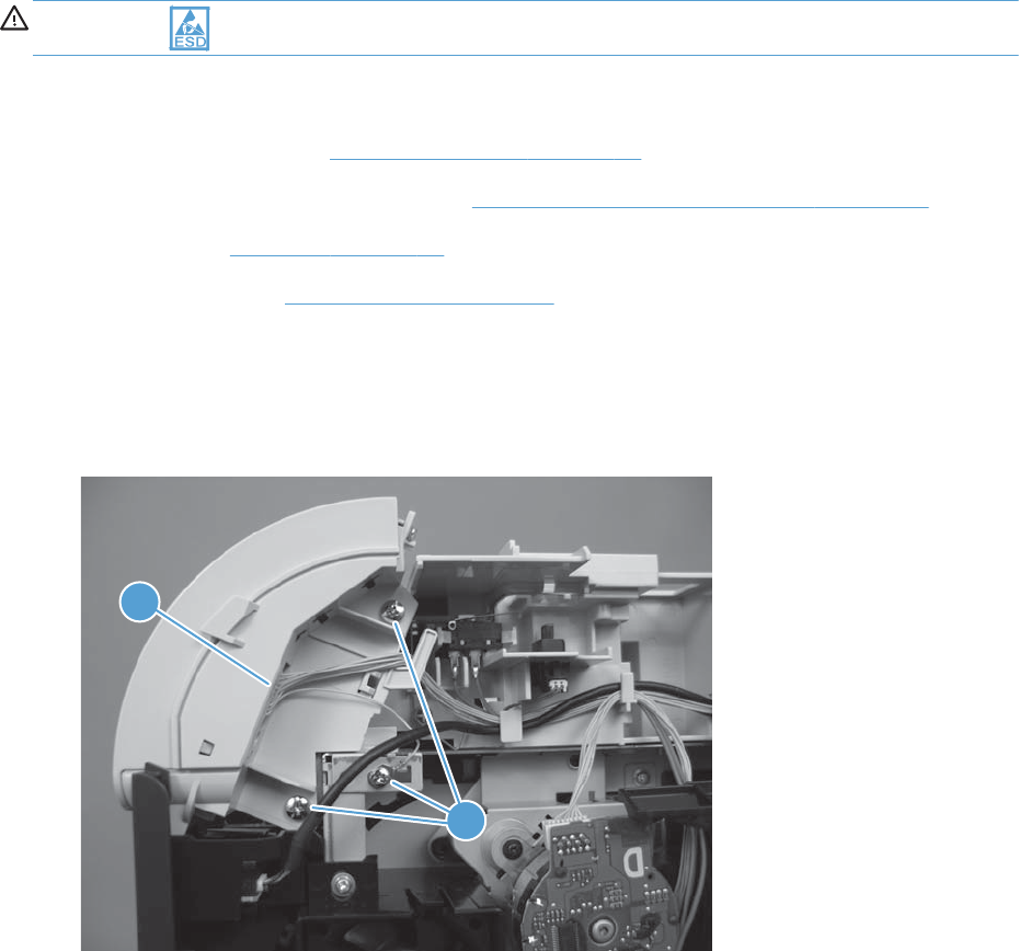
Control-panel assembly
CAUTION: ESD sensitive component.
before proceeding, remove the following components:
●Top accessory cover. See Top-accessory cover on page 88.
●Formatter cover and formatter cage. See Formatter cover and formatter cage on page 71.
●Top cover. See Top cover on page 92.
●Right-side cover. See Right-side cover on page 95.
Remove the control-panel assembly
1. Remove three screws (callout 1), and then disconnect one wire-harness connector (callout 2).
Figure 2-64 Remove the control-panel assembly (1 of 2)
2
1
ENWW Main assemblies 109
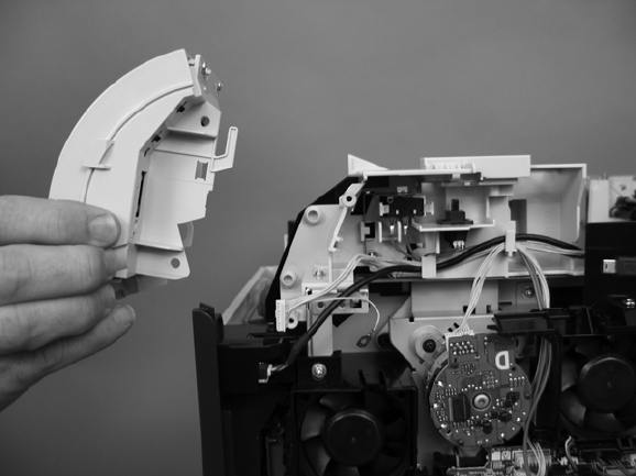
2. Slightly move the control-panel assembly toward the right side of the product to release it, and
then remove the assembly.
Figure 2-65 Remove the control-panel assembly (2 of 2)
110 Chapter 2 Removal and replacement ENWW
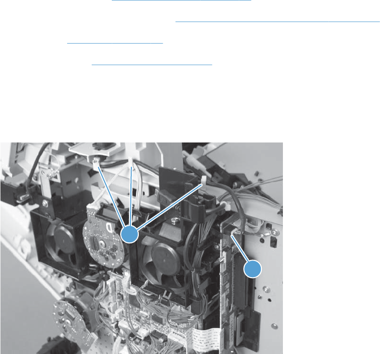
Walk-up USB port and cable
Before proceeding, remove the following components:
●Top accessory cover. See Top-accessory cover on page 88.
●Formatter cover and formatter cage. See Formatter cover and formatter cage on page 71.
●Top cover. See Top cover on page 92.
●Right-side cover. See Right-side cover on page 95.
Remove the walk-up USB port and cable
1. Disconnect one connector (callout 1), and then release the cable from the retainers (callout 2).
Figure 2-66 Remove the walk-up USB port and cable (1 of 4)
1
2
ENWW Main assemblies 111
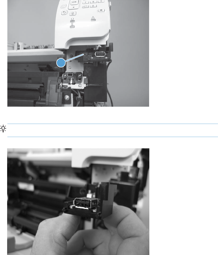
2. Remove one screw (callout 3).
Figure 2-67 Remove the walk-up USB port and cable (2 of 4)
3
3. Remove the USB port and cable assembly.
TIP: You might need to push on the mounting tab that secures the USB port holder to the chassis
—from the DC controller side of the product—to remove the assembly.
Figure 2-68 Remove the walk-up USB port and cable (3 of 4)
112 Chapter 2 Removal and replacement ENWW
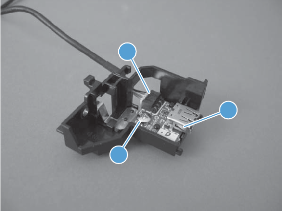
4. If necessary, disconnect one connector (callout 4), remove one screw (callout 5), and then remove
the walk-up port PCA (callout 6) from the mounting bracket.
Figure 2-69 Remove the walk-up USB port and cable (4 of 4)
5
6
4
ENWW Main assemblies 113
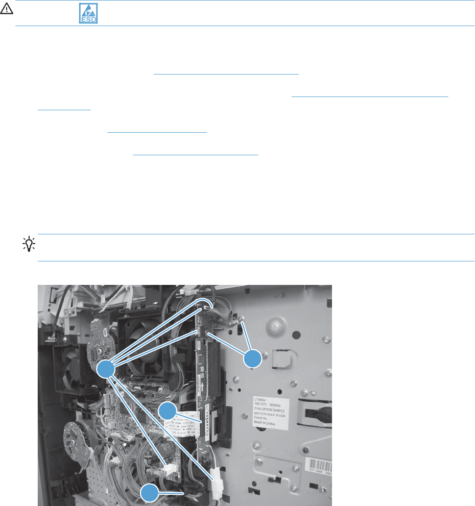
Inner connecting PCA
CAUTION: ESD sensitive component.
Before proceeding, remove the following components:
●Top accessory cover. See Top-accessory cover on page 88.
●Formatter cover, formatter cage, and formatter PCA. See Formatter cover and formatter cage
on page 71.
●Top cover. See Top cover on page 92.
●Right-side cover. See Right-side cover on page 95.
Remove the inner connecting PCA
1. Disconnect five connectors (callout 1), release the wire harness from the retainers (callout 2),
disconnect one FFC (callout 3), and then remove two screws (callout 4).
TIP: The PCA mounting screw is a shoulder type fastener. When the PCA is reinstalled, make
sure that you use this screw to fasten the PCA to the chassis.
Figure 2-70 Remove the inner connecting PCA (1 of 3)
3
1
2
4
114 Chapter 2 Removal and replacement ENWW
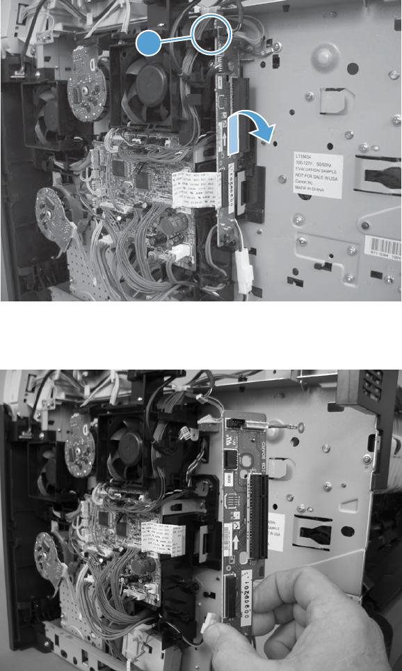
2. Release one tab (callout 5), lift up on the PCA to release it.
Figure 2-71 Remove the inner connecting PCA (2 of 3)
5
3. Remove the inner connecting PCA.
Figure 2-72 Remove the inner connecting PCA (3 of 3)
ENWW Main assemblies 115
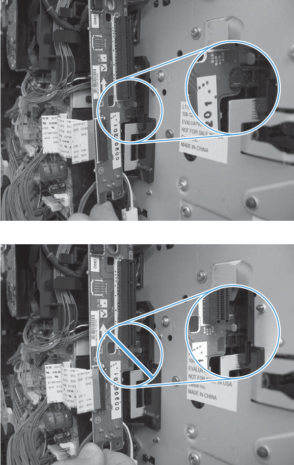
Reinstall the inner connecting PCA
The back edge of the PCA—near the bottom of the formatter connector—must be correctly
positioned in the mounting-bracket slot.
Figure 2-73 Correctly installed inner connecting PCA
Figure 2-74 Incorrectly installed inner connecting PCA
116 Chapter 2 Removal and replacement ENWW
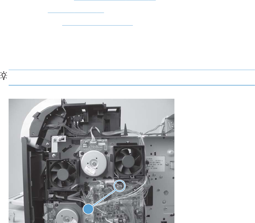
Fan FN102
Before proceeding, remove the following components:
●Top accessory cover. See Top-accessory cover on page 88.
●Top cover. See Top cover on page 92.
●Right-side cover. See Right-side cover on page 95.
Remove fan FN102
1. Disconnect one connector (callout 1; J79), and then release the wire harness from the retainer on
the fan duct.
TIP: It might be easier to release this wire harness if you partially release the fan duct from the
chassis (release one tab near the motor).
Figure 2-75 Remove fan FN102 (1 of 2)
1
ENWW Main assemblies 117
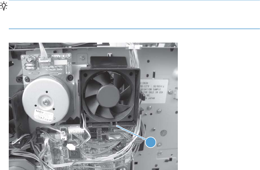
2. Release one tab (callout 2), and then remove the fan.
TIP: When you reinstall the fan, the air must flow into the product. Verify that the airflow arrows
that are embossed on the fan body point into the product.
Connect the wire-harness connector to the DC controller before reinstalling the fan into the duct.
Figure 2-76 Remove fan FN102 (2 of 2)
2
118 Chapter 2 Removal and replacement ENWW
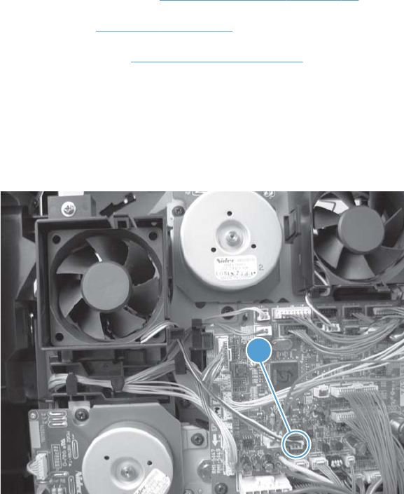
Fan FN103
Before proceeding, remove the following components:
●Top accessory cover. See Top-accessory cover on page 88.
●Top cover. See Top cover on page 92.
●Right-side cover. See Right-side cover on page 95.
Remove fan FN103
1. Disconnect one connector (callout 1; J75), and then release the wire harness from the retainer on
the fan duct.
Figure 2-77 Remove fan FN103 (1 of 2)
1
ENWW Main assemblies 119
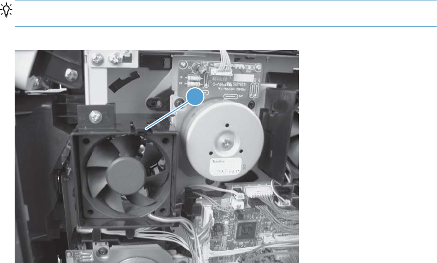
2. Release one tab (callout 2), and then remove the fan.
TIP: When you reinstall the fan, the air must flow into the product. Verify that the airflow arrows
that are embossed on the fan body point into the product.
Figure 2-78 Remove fan FN103 (2 of 2)
2
120 Chapter 2 Removal and replacement ENWW
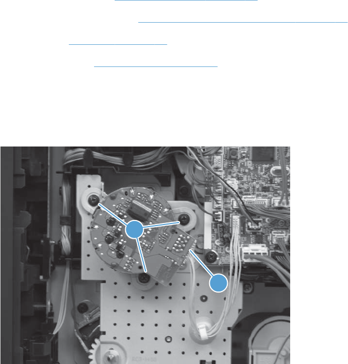
Pickup-motor assembly (M101)
Before proceeding, remove the following components:
●Top accessory cover. See Top-accessory cover on page 88.
●Formatter cover and cage. See Formatter cover and formatter cage on page 71.
●Top cover. See Top cover on page 92.
●Right-side cover. See Right-side cover on page 95.
Remove the pickup-motor assembly
1. Disconnect one wire-harness connector (callout 1), and then remove three screws (callout 2).
Figure 2-79 Remove the pickup motor (1 of 2)
2
1
ENWW Main assemblies 121
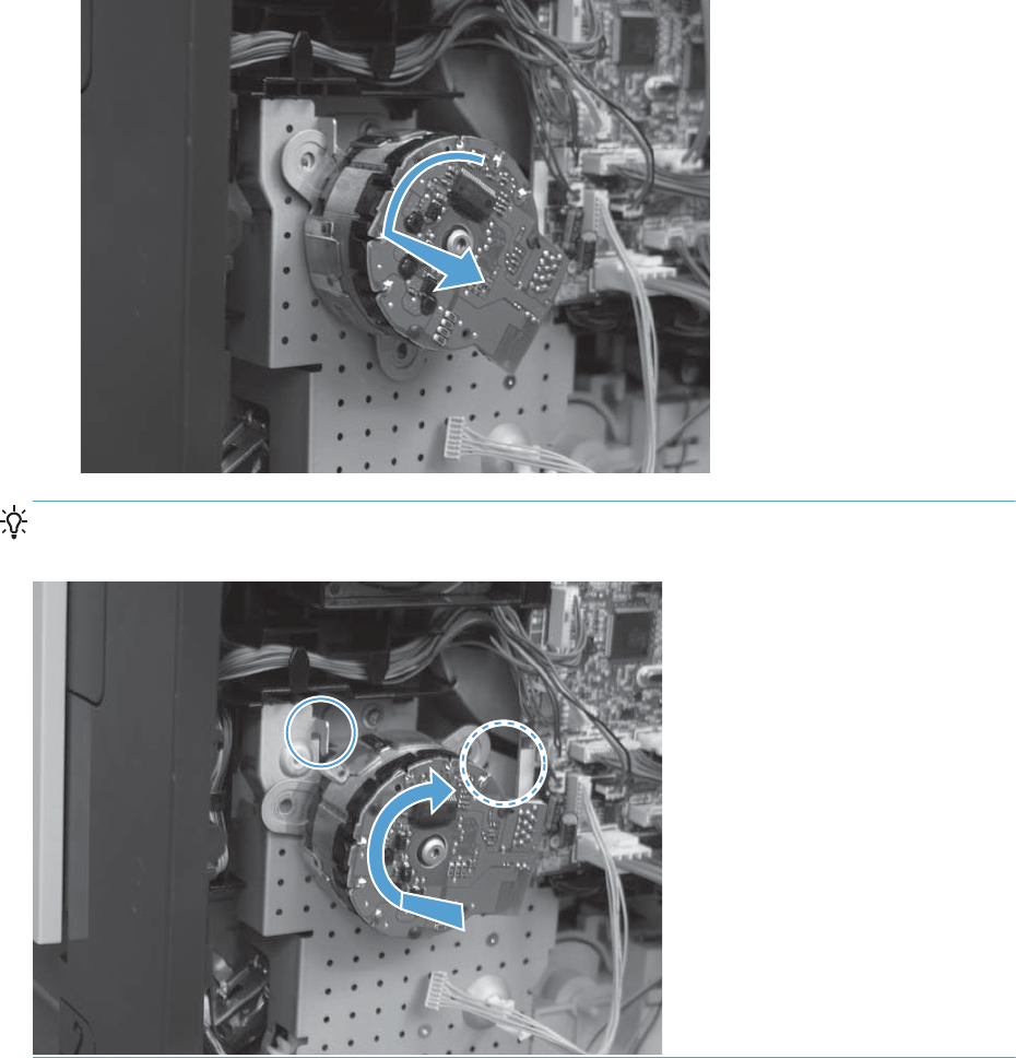
2. Roteat the motor assembly towards the front of the product to release it, and then remove it.
Figure 2-80 Remove the pickup motor (2 of 2)
Reinstallation tip Position the motor assembly on the product chassis, and then rotate it toward the
back of the product to engage the tabs on the chassis with the assembly mounting bracket.
122 Chapter 2 Removal and replacement ENWW
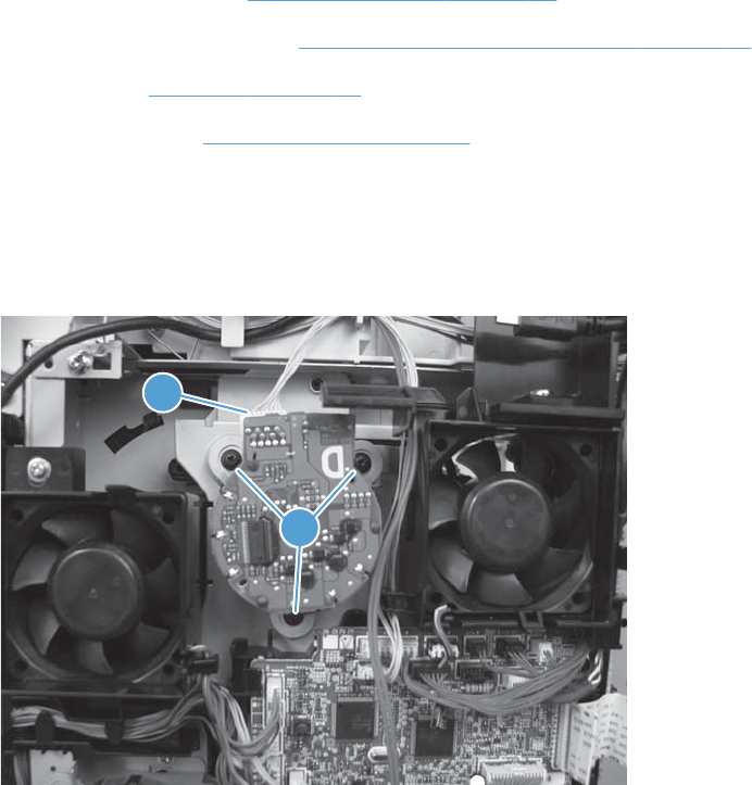
Drum-motor assembly (M102)
Before proceeding, remove the following components:
●Top accessory cover. See Top-accessory cover on page 88.
●Formatter cover and cage. See Formatter cover and formatter cage on page 71.
●Top cover. See Top cover on page 92.
●Right-side cover. See Right-side cover on page 95.
Remove the drum motor
1. Disconnect one wire-harness connector (callout 1), and the remove three screws (callout 2).
Figure 2-81 Remove the drum motor (1 of 2)
2
1
ENWW Main assemblies 123
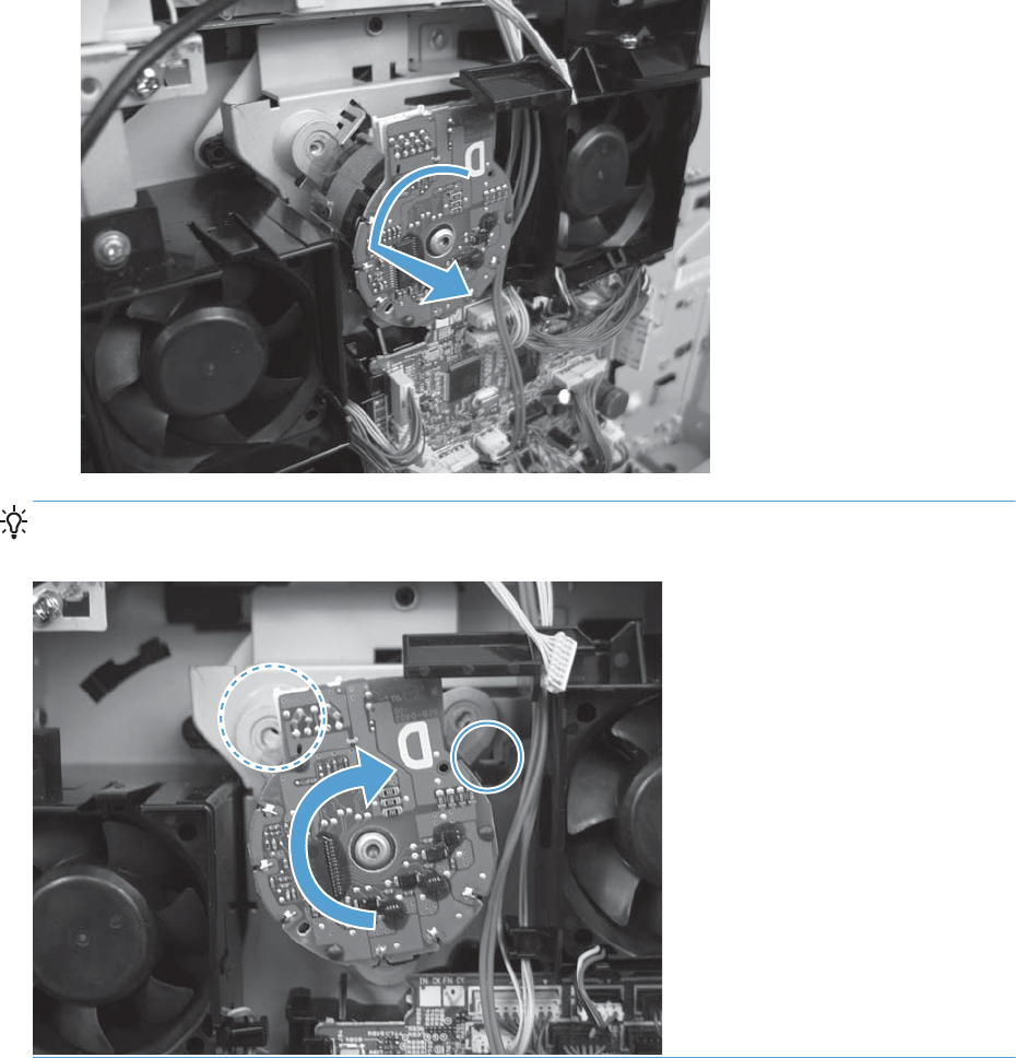
2. Rotate the motor assembly toward the front of the product to release it, and then remove it.
Figure 2-82 Remove the drum motor (2 of 2)
Reinstallation tip Position the motor assembly on the product chassis, and then rotate it toward the
back of the product to engage the tabs on the chassis with the assembly mounting bracket.
124 Chapter 2 Removal and replacement ENWW
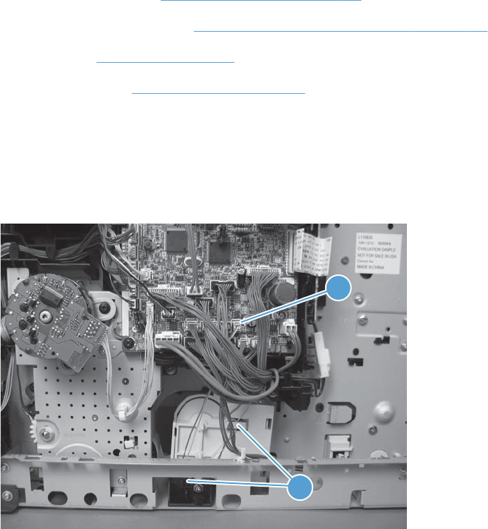
Lifter-motor assembly (M103)
Before proceeding, remove the following components:
●Top accessory cover. See Top-accessory cover on page 88.
●Formatter cover and cage. See Formatter cover and formatter cage on page 71.
●Top cover. See Top cover on page 92.
●Right-side cover. See Right-side cover on page 95.
Remove the lifter motor
1. Disconnect one connector one wire-harness connector (callout 1), and then release the wire
harness from two retainers (callout 2).
Figure 2-83 Remove the lifter motor (1 of 4)
2
1
ENWW Main assemblies 125
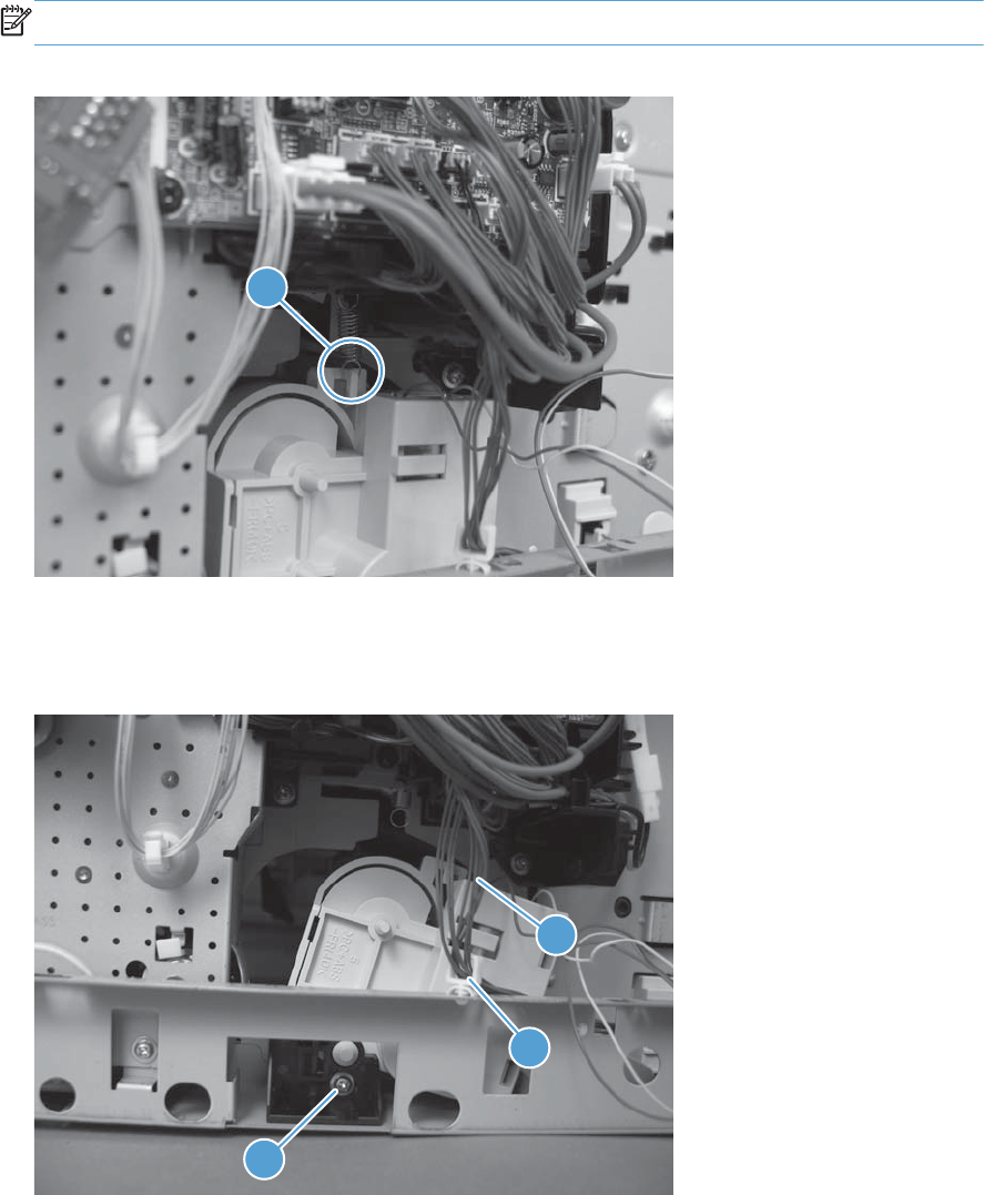
2. Release one spring (callout 2).
NOTE: The spring is not captive. Do not lose the spring.
Figure 2-84 Remove the lifter motor (2 of 4)
3
3. Release the wire-harness retainer (callout 4), move the wire harness (callout 5) out of the way, and
then remove one screw (callout 6).
Figure 2-85 Remove the lifter motor (3 of 4)
5
6
4
126 Chapter 2 Removal and replacement ENWW
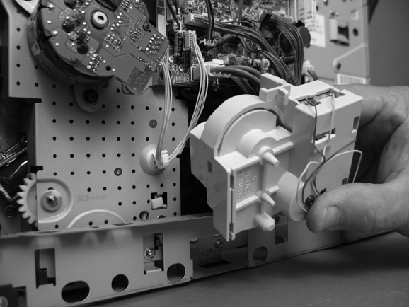
4. Remove the lifter-motor assembly.
Figure 2-86 Remove the lifter motor (4 of 4)
ENWW Main assemblies 127
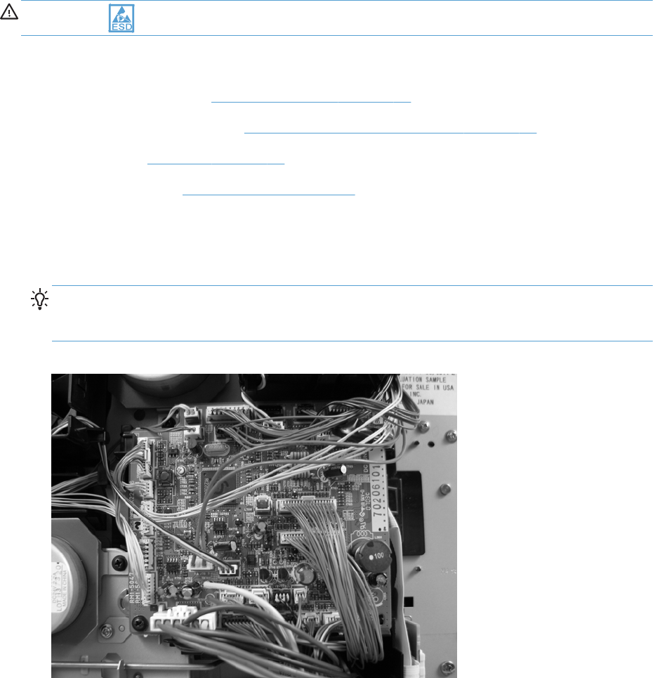
DC controller PCA
CAUTION: ESD sensitive component.
Before proceeding, remove the following components:
●Top accessory cover. See Top-accessory cover on page 88.
●Formatter cover and cage. See Formatter cover and formatter cage on page 71.
●Top cover. See Top cover on page 92.
●Right-side cover. See Right-side cover on page 95.
Remove the DC controller PCA
1. Unplug all of the wire and cable connectors from the DC controller PCA.
TIP: The DC controller shown below is only representational of the component found in this
family of products. The component found in your specific product might look different than the one
shown below.
Figure 2-87 Remove the DC controller PCA (1 of 4)
128 Chapter 2 Removal and replacement ENWW
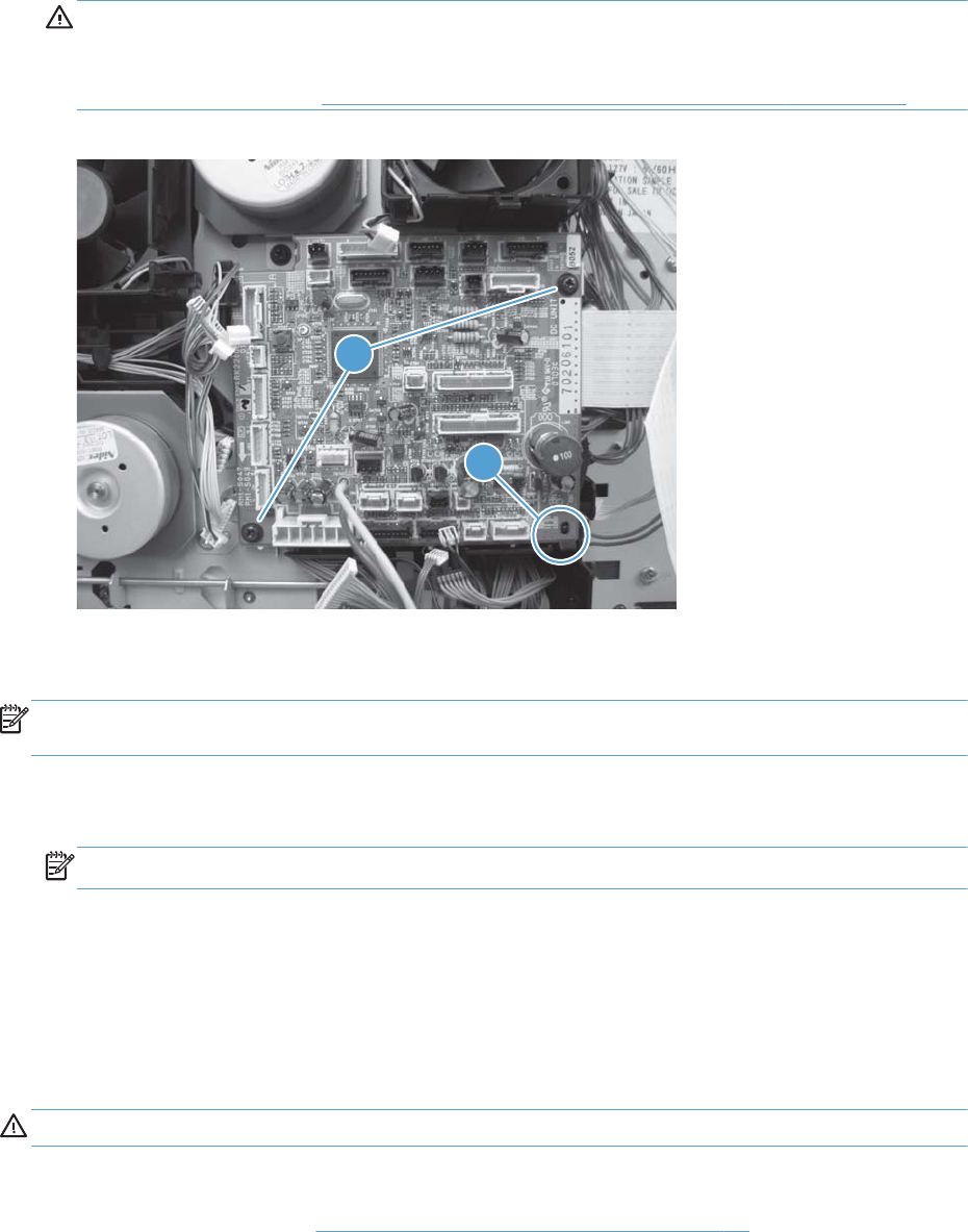
2. Remove two screws (callout 1),release one tab (callout 2), and then carefully remove the DC
controller PCA.
CAUTION: Correct reinstallation of the DC controller is critical to correct operation of the
product. If you are installing a new DC controller, follow the instructions in the reinstallation tips. If
you are installing a new formatter and a new DC controller, see the special section that follows
this DC controller section—Installing a new formatter and a new DC controller on page 129 .
Figure 2-88 Remove the DC controller PCA (4 of 4)
2
1
Reinstallation tip
NOTE: DC controller PCA connector location J80 is not used. There will not be a connector for this
location when the DC controller PCA is reinstalled.
1. After installing a new DC controller, turn the product on and wait for five minutes after the product
reaches the Ready state.
NOTE: Five minutes is required to allow for NVRAM settings to be written.
2. Turn the product off.
3. Turn the product on again, and then wait five minutes after the product reaches the Ready state.
4. Print a configuration page to verify against original settings.
Installing a new formatter and a new DC controller
CAUTION: Do not replace the DC controller and the formatter at the same time.
1. Turn the product off.
2. Remove the formatter (see Formatter cover and formatter cage on page 71) and replace it with the
new formatter.
ENWW Main assemblies 129

3. Turn the product on and then wait for five minutes after the product reaches the Ready state.
NOTE: Five minutes is required to allow for NVRAM settings to be written. The same five-minute
wait is required several times during this procedure.
4. Turn the product off.
5. Turn the product on again, and then wait five minutes after the product reaches the Ready state.
6. Turn the product off.
7. Remove the DC controller (see DC controller PCA on page 128) and replace it with the new DC
controller.
8. Turn the product on and wait for five minutes after the product reaches the Ready state.
9. Turn the product off.
10. Turn the product on again, and then wait five minutes after the product reaches the Ready state.
11. Print a configuration page to verify against original settings.
130 Chapter 2 Removal and replacement ENWW
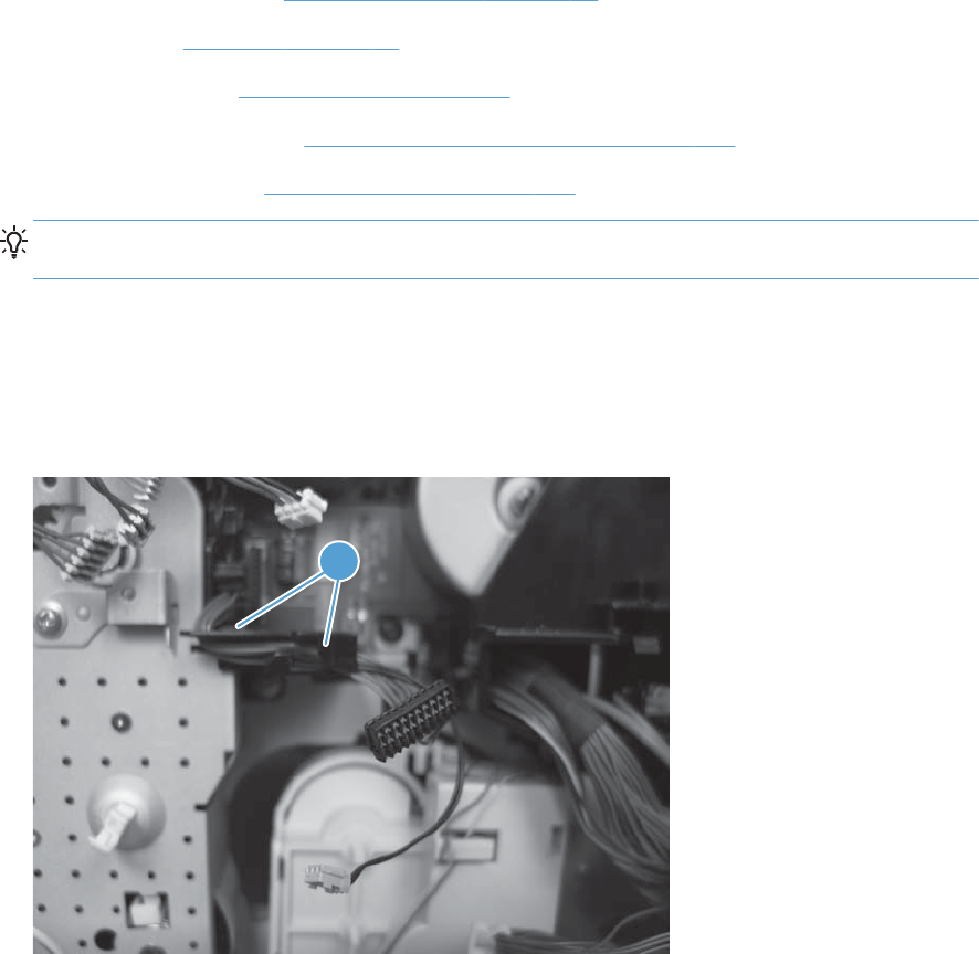
Pickup-drive assembly
Before proceeding, remove the following components:
●Top accessory cover. See Top-accessory cover on page 88.
●Top cover. See Top cover on page 92.
●Right-side cover. See Right-side cover on page 95.
●Pickup-motor assembly. See Pickup-motor assembly (M101) on page 121.
●DC controller PCA. See DC controller PCA on page 128.
TIP: The pickup-motor wire harness is disconnected from the motor assembly. Leave the wire
harness connected to the DC controller PCA so it is not lost when the PCA is removed.
Remove the pickup-drive assembly
1. Release the wire harnesses from the retainer (callout 1) located on the lifter-motor side of the
pickup-drive assembly.
Figure 2-89 Remove the pickup-drive assembly (1 of 8)
1
ENWW Main assemblies 131
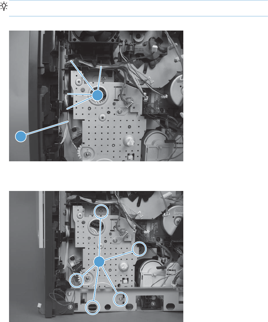
2. Release the solenoid wire harness (callout 2) from the retainer (callout 3).
TIP: Do not damage the wire harness when removing it from the retainer. It might be easier to
remove all or the wire harnesses together to release the solenoid wire harness.
Figure 2-90 Remove the pickup-drive assembly (2 of 8)
2
3
3. Remove five screws (callout 4).
Figure 2-91 Remove the pickup-drive assembly (3 of 8)
4
132 Chapter 2 Removal and replacement ENWW
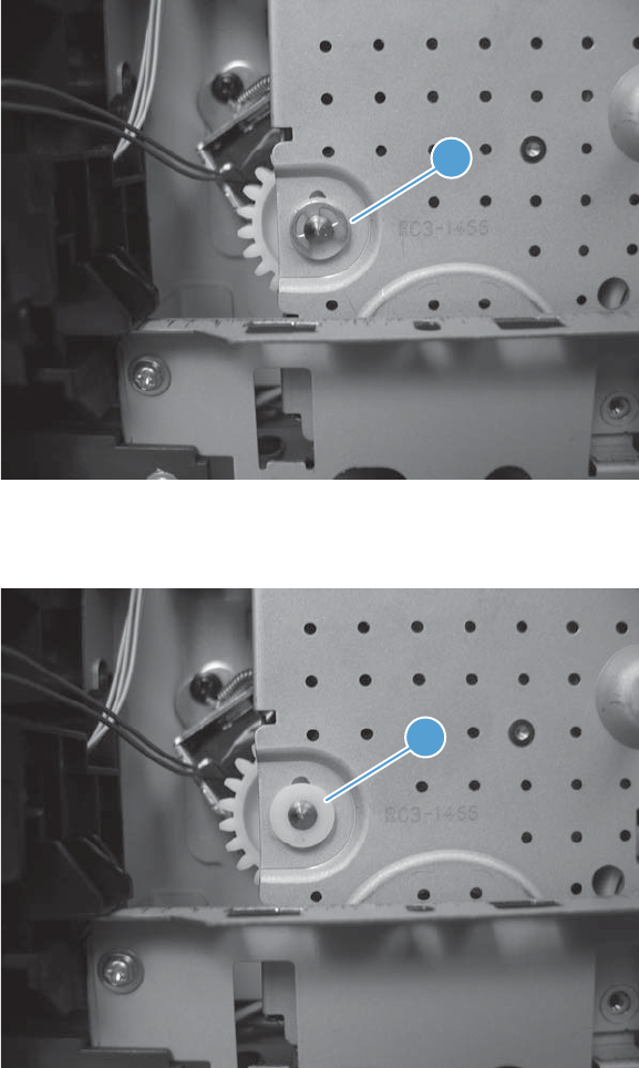
4. Remove one e-clip (callout 5).
Figure 2-92 Remove the pickup-drive assembly (4 of 8)
5
5. Remove one shaft collar (callout 6).
Figure 2-93 Remove the pickup-drive assembly (5 of 8)
6
ENWW Main assemblies 133
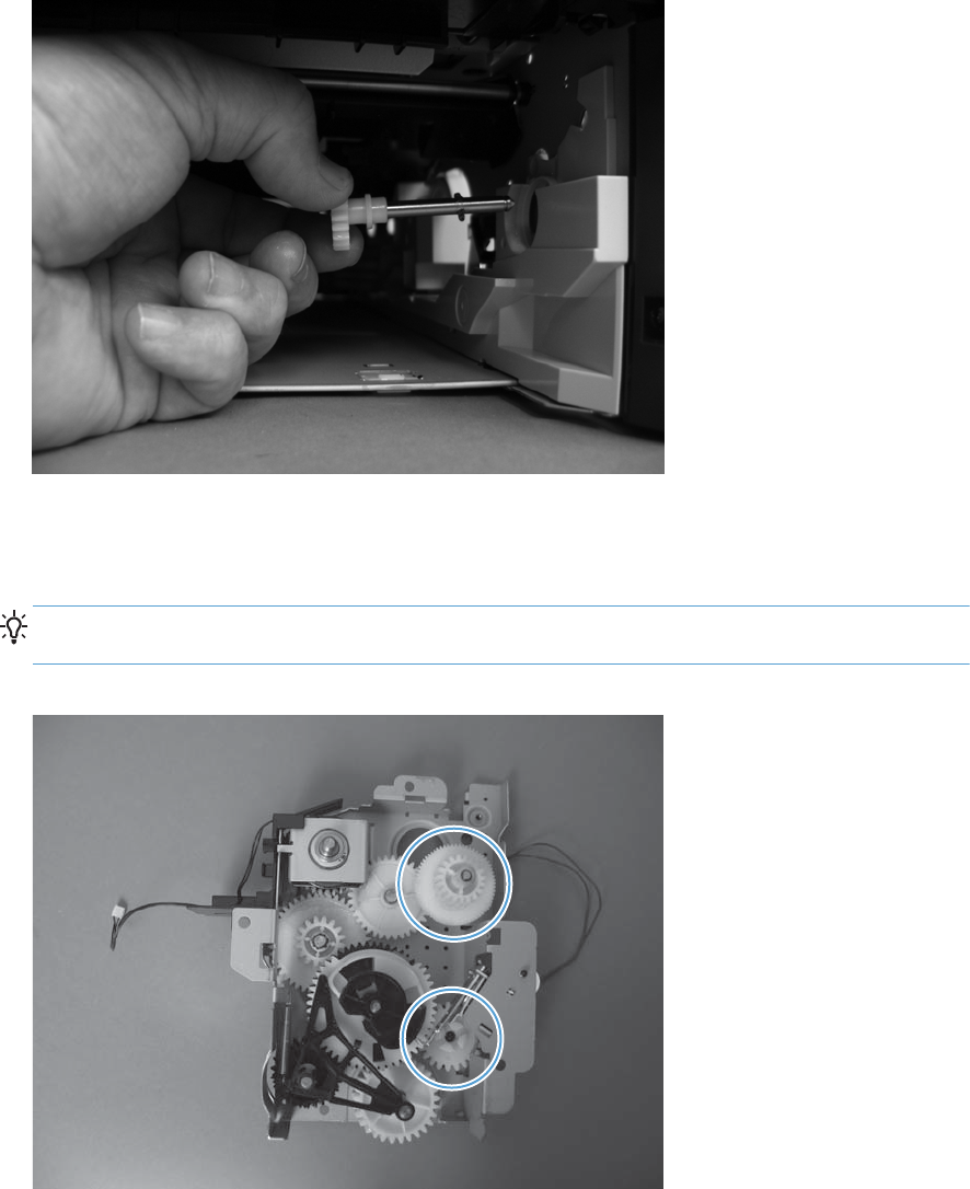
6. Push the tray drive-gear/shaft (located where the e-clip and shaft collar were removed in the
previous steps) into the Tray 2 cavity.
Figure 2-94 Remove the pickup-drive assembly (6 of 8)
7. Two gears located inside the assembly are not captive when the assembly is removed. Do not lose
these gears when handling the assembly. If the gears are dislodged during removal, use the figure
below to correctly reinstall them.
TIP: The gears in the assembly have a special grease applied to them at the factory. Try not to
remove this grease when handling the assembly.
Figure 2-95 Remove the pickup-drive assembly (7 of 8)
134 Chapter 2 Removal and replacement ENWW
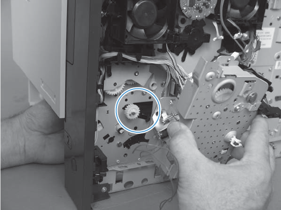
8. Reach inside the product and push the rear Tray 2 feed roller up into its raised position (this
disengages the roller-lifting arm from the clutch gear), and then remove the pickup-drive assembly.
Figure 2-96 Remove the pickup-drive assembly (8 of 8)
ENWW Main assemblies 135
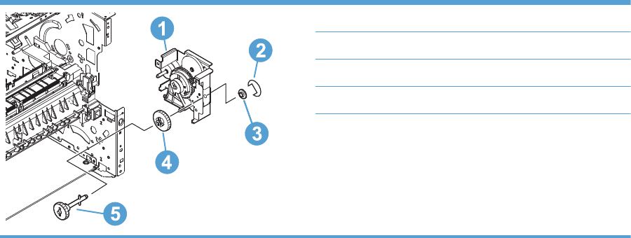
Reinstall the pickup-drive assembly
When you reinstall the paper-delivery drive assembly gears and shaft, verify that the gears are seated
on the shaft-locking bars and that the shaft collars are correctly positioned in the paper-pickup drive-
gear assembly mounting bracket and product chassis.
Table 2-2 Pickup-drive assembly
1 Pickup drive unit
2E-clip
3Bushing
4 23T gear
5 Retard roller drive shaft
136 Chapter 2 Removal and replacement ENWW
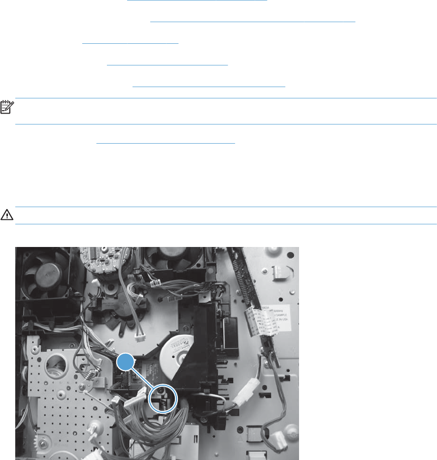
Fuser-motor assembly (M299)
Before proceeding, remove the following components:
●Top accessory cover. See Top-accessory cover on page 88.
●Formatter cover and cage. See Formatter cover and formatter cage on page 71.
●Top cover. See Top cover on page 92.
●Right-side cover. See Right-side cover on page 95.
●Inner connecting PCA. See Inner connecting PCA on page 114.
NOTE: Do not completely remove the inner connecting PCA. Remove the mounting screws, and
then move the PCA out of the way.
●DC controller. See DC controller PCA on page 128.
Remove the fuser-motor assembly
1. Release one spring (callout 1).
CAUTION: The spring is not captive. Do not lose the spring.
Figure 2-97 Remove the fuser-motor assembly (1 of 3)
1
ENWW Main assemblies 137
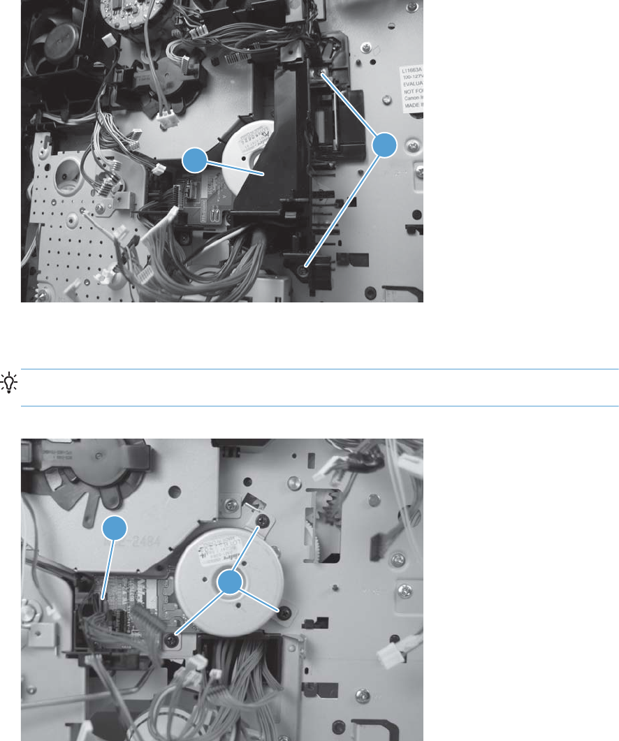
2. Remove two screws (callout 2) and then remove the guide (callout 3).
Figure 2-98 Remove the fuser-motor assembly (2 of 3)
2
3
3. Disconnect one wire-harness connector (callout 4), and then remove three screws (callout 5).
Remove the fuser-motor assembly.
Reinstallation tip Install the fuser-motor wire harness on the replacement fuser-motor
assembly.
Figure 2-99 Remove the fuser-motor assembly (3 of 3)
5
4
138 Chapter 2 Removal and replacement ENWW
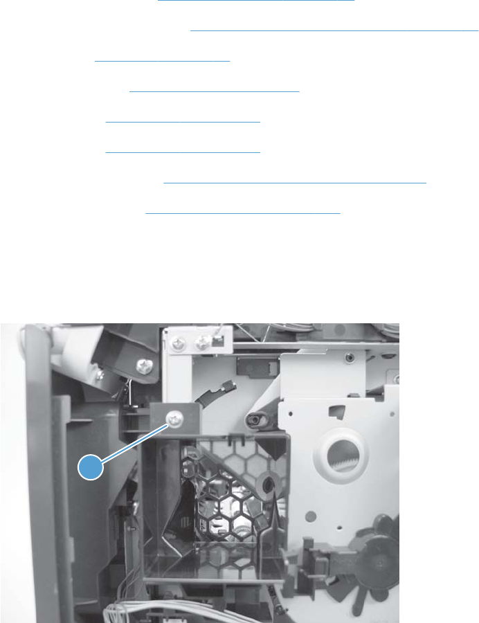
Drum-drive assembly
Before proceeding, remove the following components:
●Top accessory cover. See Top-accessory cover on page 88.
●Formatter cover and cage. See Formatter cover and formatter cage on page 71.
●Top cover. See Top cover on page 92.
●Right-side cover. See Right-side cover on page 95.
●Fan FN102. See Fan FN102 on page 117.
●Fan FN103. See Fan FN103 on page 119.
●Drum-motor assembly. See Drum-motor assembly (M102) on page 123.
●DC controller PCA. See DC controller PCA on page 128.
Remove the drum-drive assembly
1. Remove one screw (callout 1) and the fan FN103 duct.
Figure 2-100 Remove the drum-drive assembly (1 of 4)
1
ENWW Main assemblies 139
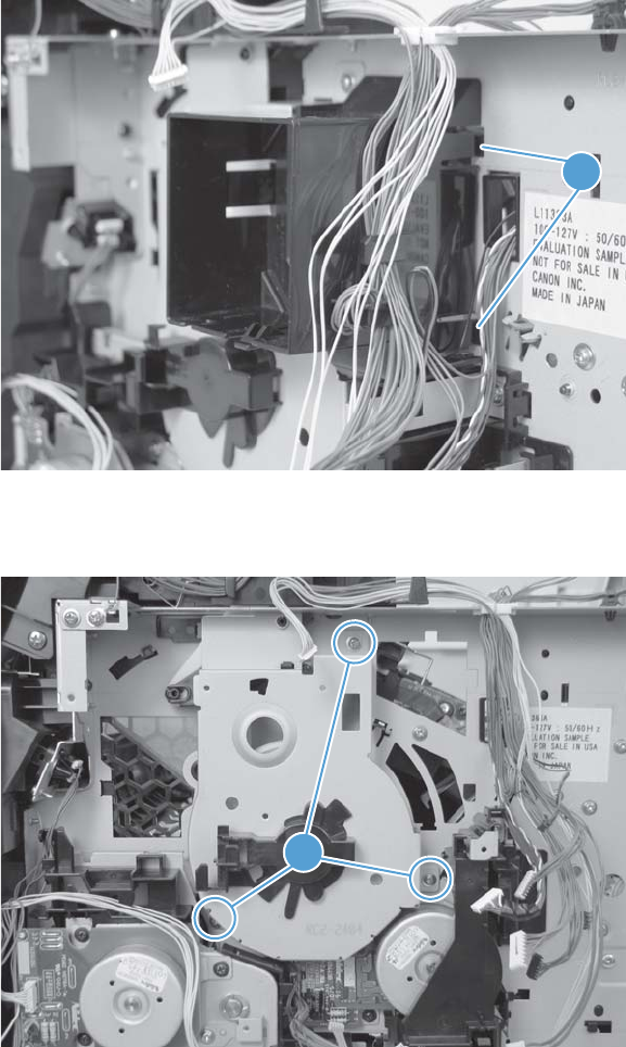
2. Release the wire-harnesses from the retainer on the fan FN102 duct (callout 2) .
Figure 2-101 Remove the drum-drive assembly (2 of 4)
2
3. Remove three screws (callout 3).
Figure 2-102 Remove the drum-drive assembly (3 of 4)
3
140 Chapter 2 Removal and replacement ENWW
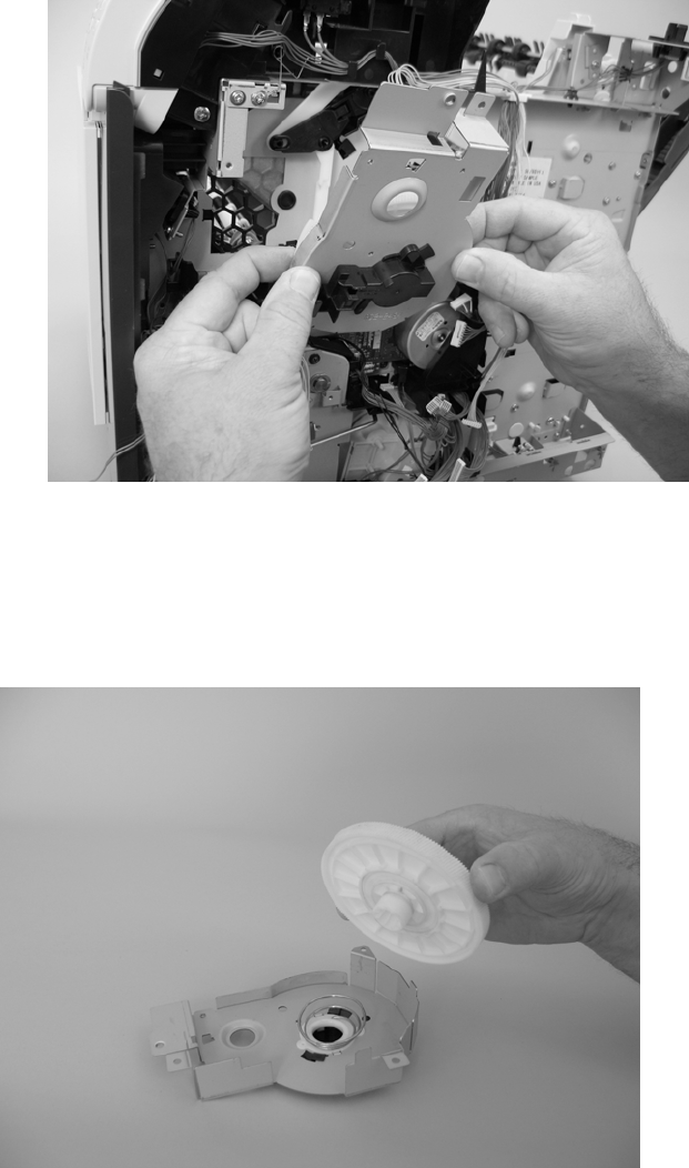
4. Carefully remove the drum-drive assembly.
Figure 2-103 Remove the drum-drive assembly (4 of 4)
Reinstall the drum-drive assembly
When the drum-drive assembly is reinstalled, make sure that the spring is correctly positioned in the
assembly.
Figure 2-104 Reinstall the drum-drive assembly
ENWW Main assemblies 141

Fan FN101
Before proceeding, remove the following components:
●Top accessory cover. See Top-accessory cover on page 88.
●Top cover. See Top cover on page 92.
●Left-side cover. See Left-side cover on page 98.
Remove fan FN101
1. Remove two screws (callout 1), and then remove the sheet-metal plate (callout 2).
Figure 2-105 Remove fan FN101 (1 of 3)
1
2
142 Chapter 2 Removal and replacement ENWW
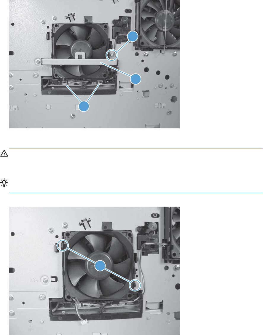
2. Disconnect two connectors (callout 3), and then remove one screw (callout 4). Slide the thermistor
sensor bar (callout 5) to the right to release it, and then lift the thermistor sensor bar away from the
product.
Figure 2-106 Remove fan FN101 (2 of 3)
3
4
5
3. Release the two fan-locking tabs (callout 6), and then remove the fan.
CAUTION: When you reinstall the fan, do not apply too much pressure to the wire-harness
connectors when they are connected to the power supply. Applying too much pressure might snap
off the soldered connectors on the power supply.
Reinstallation tip When you reinstall the fan, the air must flow into the product. Verify that the
airflow arrows that are embossed on the fan body point into the product.
Figure 2-107 Remove fan FN101 (3 of 3)
6
ENWW Main assemblies 143
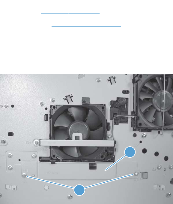
Fan FN301
before proceeding, remove the following components:
●Top accessory cover. See Top-accessory cover on page 88.
●Top cover. See Top cover on page 92.
●Left-side cover. See Left-side cover on page 98.
Remove fan FN301
1. Remove two screws (callout 1), and then remove the fan-cover plate (callout 2).
Figure 2-108 Remove fan FN301 (1 of 3)
1
2
144 Chapter 2 Removal and replacement ENWW
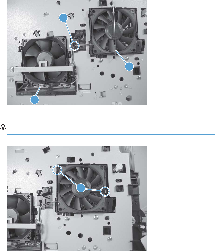
2. Disconnect one connector (callout 3), and then release the wire harness from the retainer (callout
4). Unhook and remove the fan clip (callout 5).
Figure 2-109 Remove fan FN301 (2 of 3)
4
5
3
3. Release two tabs (callout 6), and then remove the fan.
TIP: When you reinstall the fan, the air must flow into the product. Verify that the airflow arrows
that are embossed on the fan body point into the product.
Figure 2-110 Remove fan FN301 (3 of 3)
6
ENWW Main assemblies 145
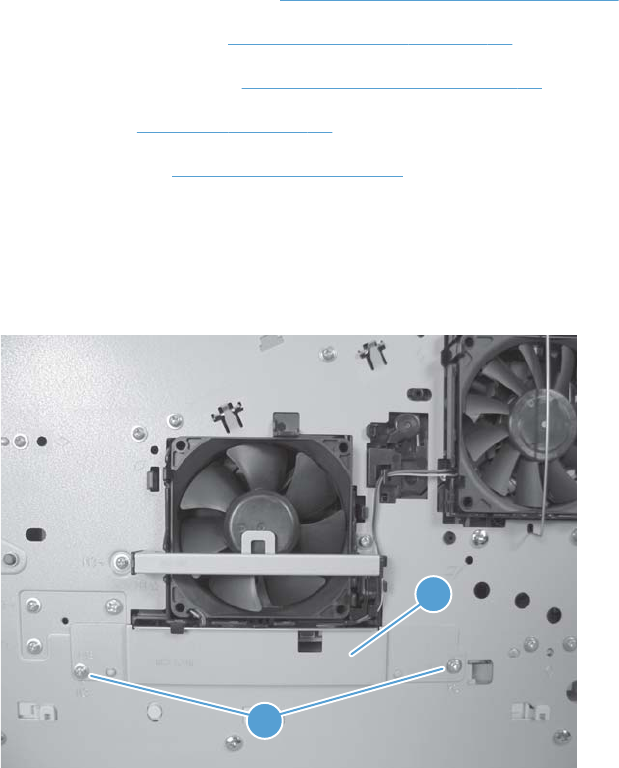
Environmental sensor (TH3)
Before proceeding, remove the following components:
●Duplex accessory or cover. See Duplex accessory or cover on page 90.
●Top accessory cover. See Top-accessory cover on page 88.
●Tray 2 extension door. See Tray 2 extension door on page 91.
●Top cover. See Top cover on page 92.
●Left-side cover. See Left-side cover on page 98.
Remove the environmental sensor (TH3)
1. Remove two screws (callout 1), and then remove the fan-cover plate (callout 2).
Figure 2-111 Remove the environmental sensor (TH3) (1 of 2)
1
2
146 Chapter 2 Removal and replacement ENWW
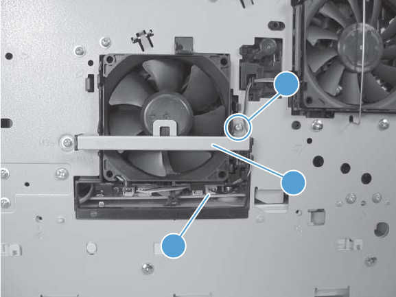
2. Disconnect one connector (callout 3), and then remove one screw (callout 4). Slide the thermistor
sensor bar (callout 5) to the right to release it, and then lift the thermistor sensor bar away from the
product.
Figure 2-112 Remove the environmental sensor (TH3) (2 of 2)
3
4
5
ENWW Main assemblies 147
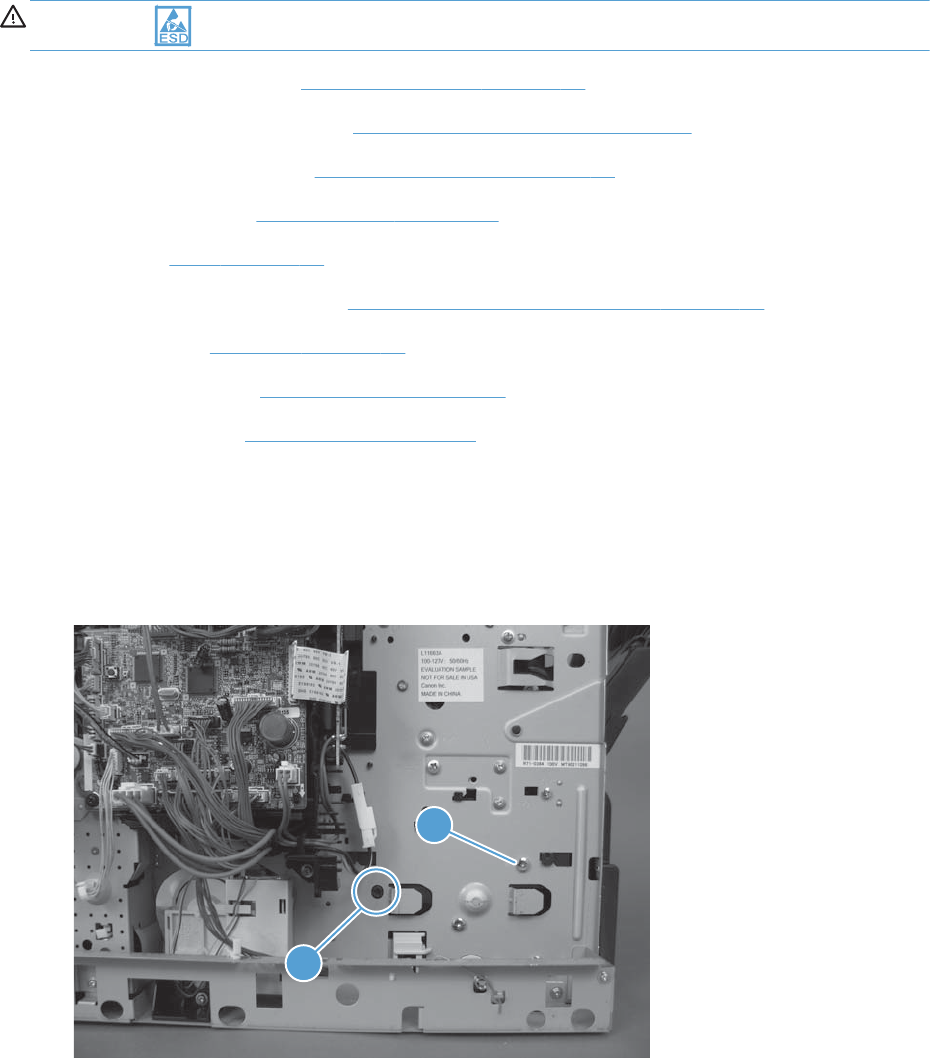
High voltage power supply
CAUTION: ESD sensitive component.
●Top accessory cover. See Top-accessory cover on page 88.
●Duplex accessory or cover. See Duplex accessory or cover on page 90.
●Tray 2 extension door. See Tray 2 extension door on page 91.
●Rear output bin. See Rear output bin on page 87.
●Fuser. See Fuser on page 70.
●Formatter cover and cage. See Formatter cover and formatter cage on page 71.
●Top cover. See Top cover on page 92 .
●Right-side cover. See Right-side cover on page 95.
●Left-side cover. See Left-side cover on page 98.
Remove the high-voltage power-supply assembly
1. Remove one screw (callout 1), release one tab (callout 2), and then slide the power-supply PCA
guide towards the rear of the product to remove it.
Figure 2-113 Remove the high-voltage power-supply assembly (1 of 7)
1
2
148 Chapter 2 Removal and replacement ENWW
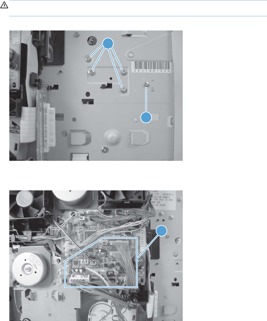
2. Remove four screws (callout 3) and one grounding screw (callout 4).
WARNING! When reinstalling the power supply, you must use a grounding screw to secure the
AC outlet to the product chassis.
Figure 2-114 Remove the high-voltage power-supply assembly (2 of 7)
4
3
3. Disconnect five wire-harness connectors (callout 6; J82, J84, J85, J95, and J96).
Figure 2-115 Remove the high-voltage power-supply assembly (3 of 7)
6
ENWW Main assemblies 149
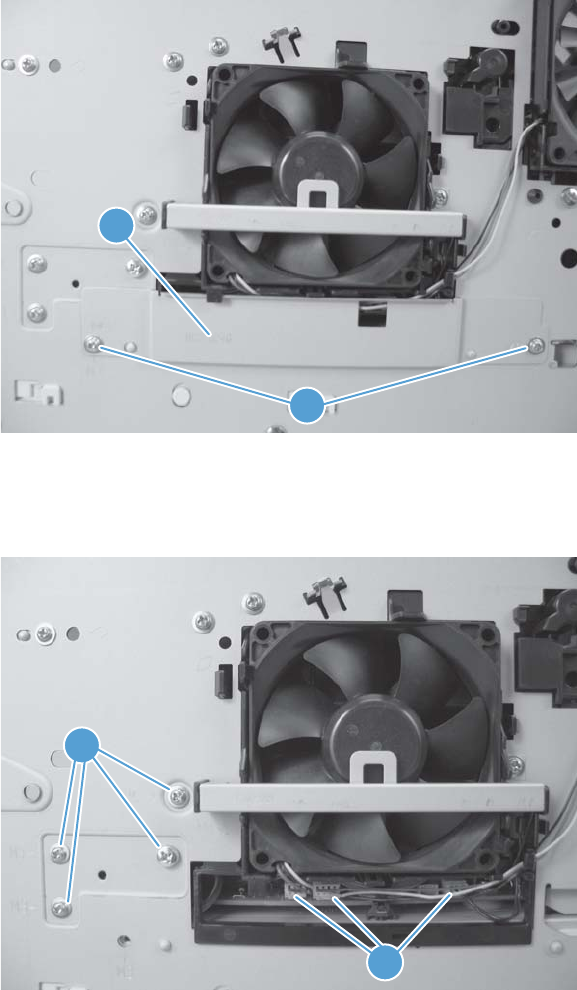
4. Remove two screws (product left side; callout 7) and then remove the fan-cover plate (callout 8).
Figure 2-116 Remove the high-voltage power-supply assembly (4 of 7)
7
8
5. Disconnect three wire-harness connectors (product left side; callout 9) and then remove four screws
(callout 10).
Figure 2-117 Remove the high-voltage power-supply assembly (5 of 7)
9
10
150 Chapter 2 Removal and replacement ENWW
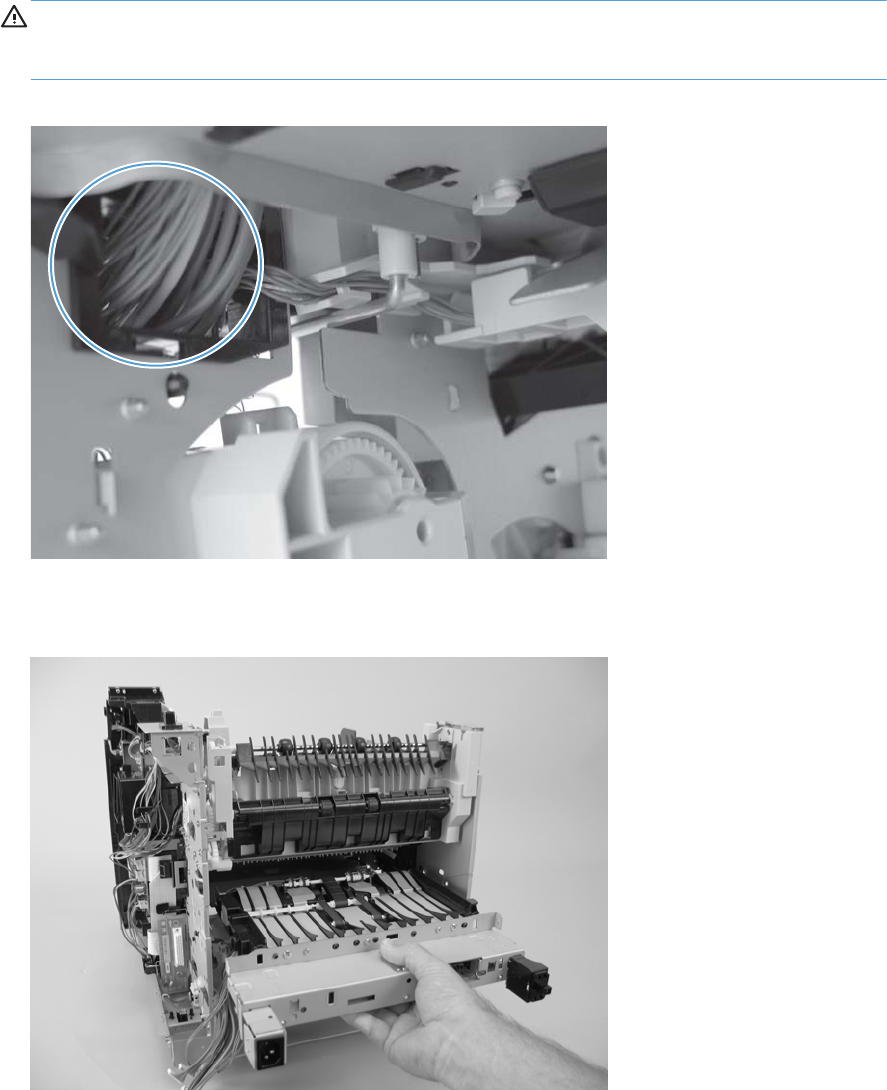
6. Feed the cables that were disconnected earlier through the hole in the right side of the chassis
under the power-supply assembly.
CAUTION: Make sure that the four rubber belts and plastic rollers on the feed-guide assembly
(mounted to the top of the power supply) remain in place. These belts and rollers can easily
become dislodged and you might lose them.
Figure 2-118 Remove the high-voltage power-supply assembly (6 of 7)
7. Grasp the power-supply assembly and lift it up slightly. Pull it straight out of the chassis.
Figure 2-119 Remove the high-voltage power-supply assembly (7 of 7)
ENWW Main assemblies 151
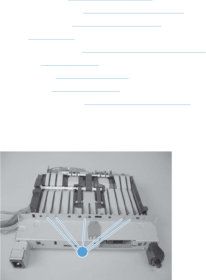
Feed-guide assembly
Before proceeding, remove th following components:
●Top accessory cover. See Top-accessory cover on page 88.
●Duplex accessory or cover. See Duplex accessory or cover on page 90.
●Tray 2 extension door. See Tray 2 extension door on page 91.
●Fuser. See Fuser on page 70.
●Formatter cover and cage. See Formatter cover and formatter cage on page 71.
●Top cover. See Top cover on page 92 .
●Right-side cover. See Right-side cover on page 95.
●Left-side cover. See Left-side cover on page 98.
●High-voltage power supply. See High voltage power supply on page 148.
Remove the feed-guide assembly
1. Remove five screws (callout 1).
Figure 2-120 Remove the feed-guide assembly (1 of 3)
1
152 Chapter 2 Removal and replacement ENWW
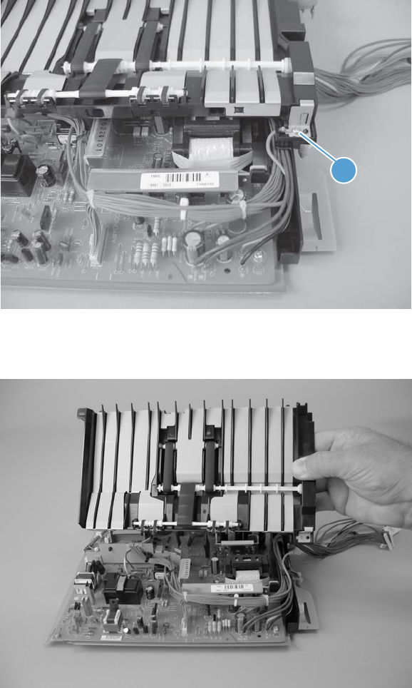
2. Remove one screw (callout 2).
Figure 2-121 Remove the feed-guide assembly (2 of 3)
2
3. Remove the feed-guide assembly.
Figure 2-122 Remove the feed-guide assembly (3 of 3)
ENWW Main assemblies 153
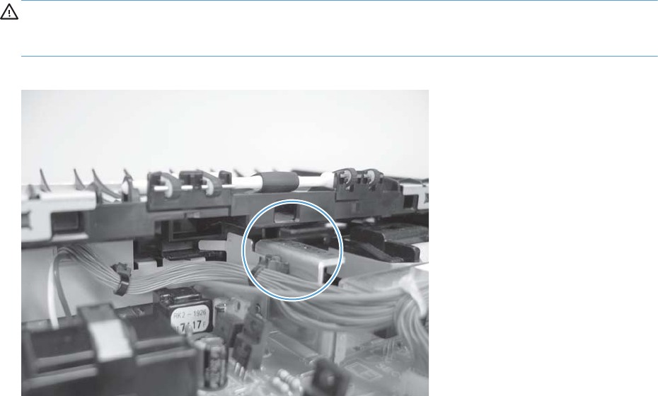
Reinstall the feed-guide assembly
When you reinstall the feed-guide assembly, make sure that the support foot is correctly positioned on
the power supply.
CAUTION: Make sure that the four rubber belts and plastic rollers on the feed-guide assembly
(mounted to the top of the power supply) remain in place. These belts and rollers can easily become
dislodged and you might lose them.
Figure 2-123 Reinstall the feed-guide assembly
154 Chapter 2 Removal and replacement ENWW
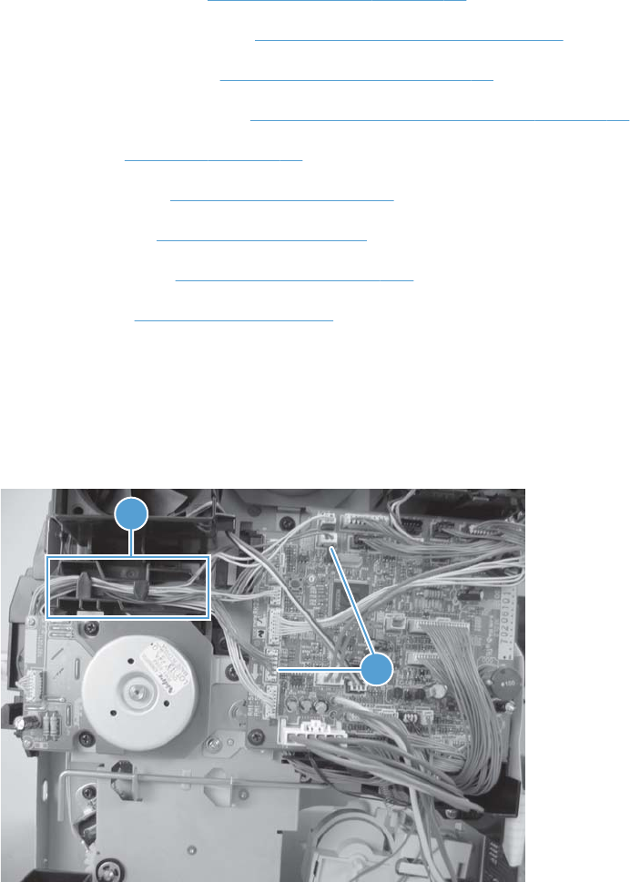
Tray 1 paper-pickup assembly
Before proceeding, remove the following components:
●Top accessory cover. See Top-accessory cover on page 88.
●Duplex accessory or cover. See Duplex accessory or cover on page 90.
●Tray 2 extension door. See Tray 2 extension door on page 91.
●Formatter cover and cage. See Formatter cover and formatter cage on page 71.
●Top cover. See Top cover on page 92.
●Right-side cover. See Right-side cover on page 95.
●Left-side cover. See Left-side cover on page 98.
●Right front cover. See Right-front cover on page 100.
●Front cover. See Front cover on page 105.
Remove the Tray 1 pickup assembly
1. Disconnect two wire-harness connectors (callout 1; J71, and J81), and then release the wire
harnesses from the guide (callout 2).
Figure 2-124 Remove the Tray 1 paper-pickup assembly (1 of 3)
1
2
ENWW Main assemblies 155
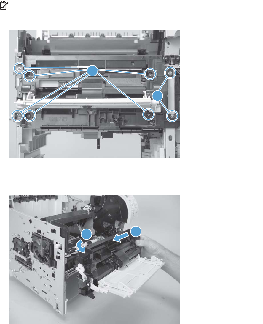
2. Remove eight screws (callout 3).
NOTE: The four outside screws on the assembly are a different type than the others. Make sure
that you replace the screws in the same position that they are removed from.
Figure 2-125 Remove the Tray 1 paper-pickup assembly (2 of 3)
3
3
3. Rotate the left side of the assembly away from the chassis, and then slide the assembly to the left
to remove it.
Figure 2-126 Remove the Tray 1 pickup assembly (3 of 3)
12
156 Chapter 2 Removal and replacement ENWW
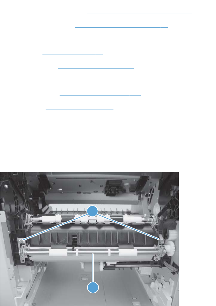
Feed-roller assembly
Before proceeding, remove the following components:
●Top accessory cover. See Top-accessory cover on page 88.
●Duplex accessory or cover. See Duplex accessory or cover on page 90.
●Tray 2 extension door. See Tray 2 extension door on page 91.
●Formatter cover and cage. See Formatter cover and formatter cage on page 71.
●Top cover. See Top cover on page 92.
●Right-side cover. See Right-side cover on page 95.
●Left-side cover. See Left-side cover on page 98.
●Right front cover. See Right-front cover on page 100.
●Front cover. See Front cover on page 105.
●Tray 1 paper-pickup assembly. See Tray 1 paper-pickup assembly on page 155.
Remove the feed-roller assembly
▲Remove two screws (callout 1), and then remove the feed-roller assembly (callout 2).
Figure 2-127 Remove the feed-roller assembly
1
2
ENWW Main assemblies 157
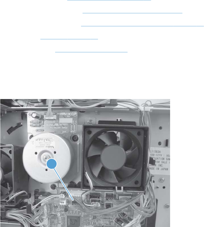
Laser/scanner assembly
Before proceeding, remove the following components:
●Top accessory cover. See Top-accessory cover on page 88.
●Duplex accessory or cover. See Duplex accessory or cover on page 90.
●Formatter cover and cage. See Formatter cover and formatter cage on page 71
●Top cover. See Top cover on page 92.
●Right-side cover. See Right-side cover on page 95.
Remove the laser/scanner assembly
1. Unplug the laser/scanner wire-harness connector from the DC controller PCA (callout 1; J86).
Figure 2-128 Remove the laser/scanner assembly (1 of 4)
1
158 Chapter 2 Removal and replacement ENWW
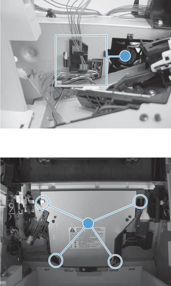
2. Remove the laser/scanner wire-harness from the wire guide (callout 2).
Figure 2-129 Remove the laser/scanner assembly (2 of 4)
2
3. Remove four screws (callout 3) and the grounding clips.
Figure 2-130 Remove the laser/scanner assembly (3 of 4)
3
ENWW Main assemblies 159
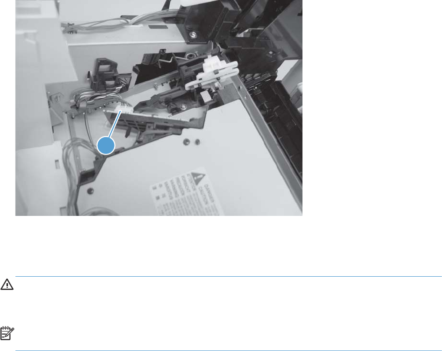
4. Disconnect the laser/scanner wire-harness (callout 4) from the laser/scanner PCA.
Figure 2-131 Remove the laser/scanner assembly (4 of 4)
4
5. Carefully lift the laser/scanner up and out of the product. Make sure that the laser/scanner
assembly does not catch or snag the wires along the bottom of the assembly when you remove the
assembly.
CAUTION: When you reinstall the laser/scanner assembly, make sure that the wire-harnesses
are correctly routed through the cable guides. If the wire-harnesses are not correctly routed, they
can be damaged when the top cover is installed.
NOTE: Make sure that the air duct is correctly positioned and that the laser/scanner shutter
properly functions.
160 Chapter 2 Removal and replacement ENWW
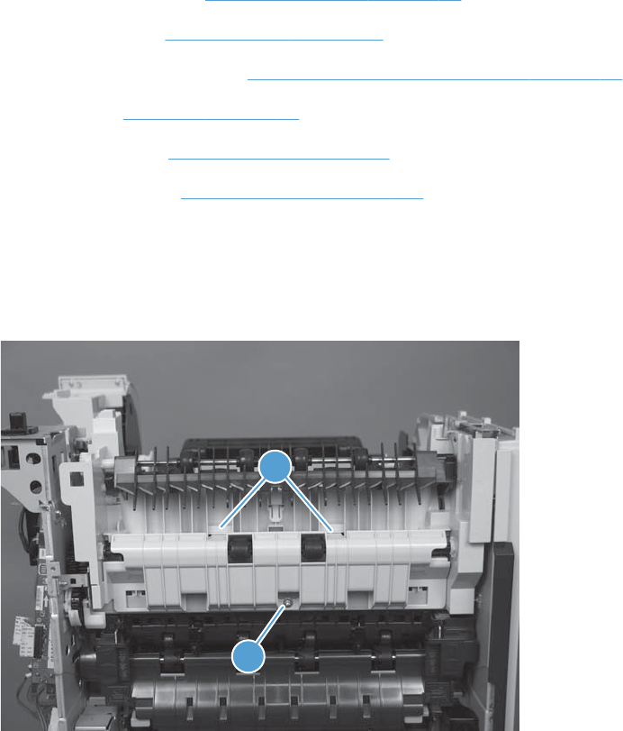
Paper-delivery assembly
Before proceeding, remove the following components:
●Top accessory cover. See Top-accessory cover on page 88.
●Rear output bin. See Rear output bin on page 87.
●Formatter cover and cage. See Formatter cover and formatter cage on page 71.
●Top cover. See Top cover on page 92.
●Right-side cover. See Right-side cover on page 95.
●Rear upper cover. See Rear-upper cover on page 103.
Remove the paper-delivery assembly
1. Remove one screw (callout 1), and then release two tabs (callout 2).
Figure 2-132 Remove the paper-delivery assembly (1 of 4)
1
2
ENWW Main assemblies 161
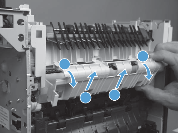
2. Rotate the top of the guide away form the product, push up on the guide to release it, and then
remove the guide.
Figure 2-133 Remove the paper-delivery assembly (2 of 4)
11
22
162 Chapter 2 Removal and replacement ENWW
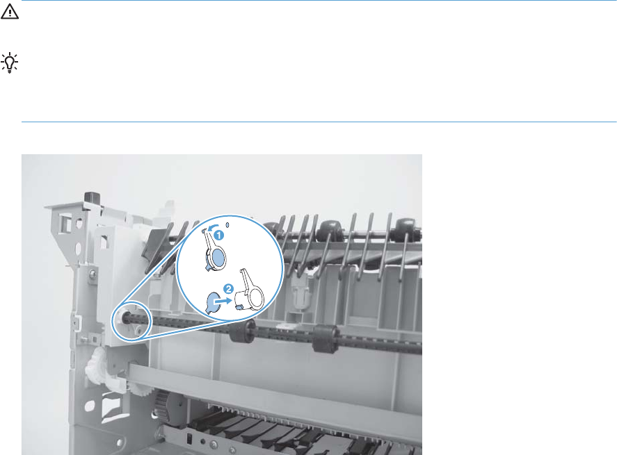
3. Use a small flatblade screwdriver to release the locking pin on the shaft lock, and then rotate the
lock counter clockwise until the inner retaining tab (gear side) aligns with the hole in the paper-
delivery assembly frame.
Slide the shaft lock to the right and remove it to release the gear shaft from the paper-delivery
assembly.
CAUTION: Do not break the shaft lock. A replacement is not provided with a new paper-
delivery assembly.
TIP: Snap the shaft lock back into place on the assembly so that you will not lose it. Remove the
shaft lock when you reinstall the output-delivery assembly. When the paper-delivery assembly is
installed, verify that the locking pin on the shaft lock is fully seated in the hole on the paper-
delivery assembly.
Figure 2-134 Remove the paper-delivery assembly (3 of 4)
ENWW Main assemblies 163
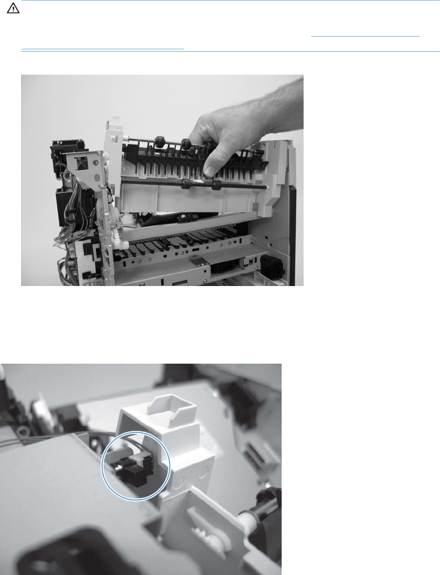
4. Lift up the gear end of the output-delivery assembly slightly and slide the assembly toward the
formatter assembly to remove it.
CAUTION: The rear face-down output-bin-sensor cable is routed through a notch on the paper-
delivery assembly at the gear end of the assembly. When you remove the assembly, carefully
remove the cable from the notch to avoid damage to the cable. See Figure 2-136 Reinstall the
paper-delivery assembly on page 164.
Figure 2-135 Remove the paper-delivery assembly (4 of 4)
Reinstall the paper-delivery assembly
Make sure that the output-bin sensor is not dislodged when the paper-deliver assembly is reinstalled.
Figure 2-136 Reinstall the paper-delivery assembly
164 Chapter 2 Removal and replacement ENWW
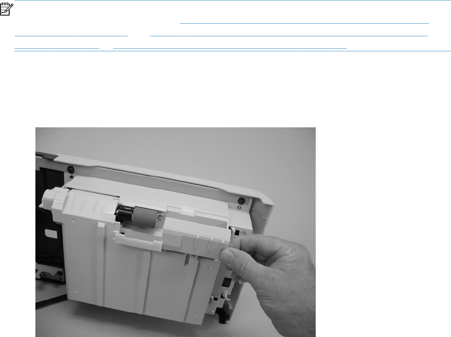
1,500-sheet paper deck (PD)
NOTE: The removal steps for the pickup and feed rollers in the 1,500-sheet paper deck are the same
as the removing the Tray 2 rollers. See Figure 2-7 Remove the Tray 2 separation, pickup, and feed
rollers (3 of 4) on page 67 and Figure 2-8 Remove the Tray 2 separation, pickup, and feed rollers
(4 of 4) on page 68 in Tray 2 separation, pickup, and feed rollers on page 66.
Separation roller (PD)
1. Open the 1,500-sheet paper deck door, and then open the separation-roller cover.
Figure 2-137 Remove the separation roller (PD; 1 of 2)
ENWW 1,500-sheet paper deck (PD) 165
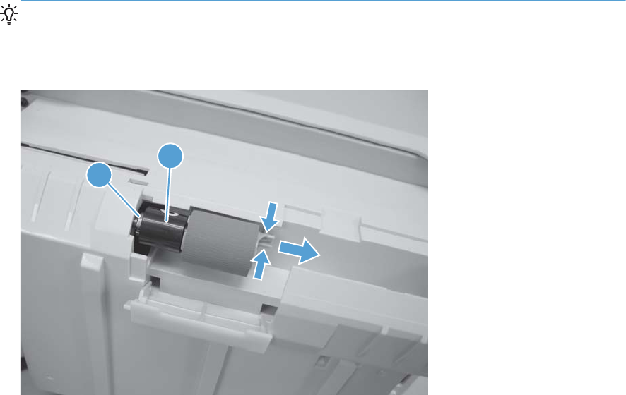
2. Pinch the blue latch that is on the side of the feed roller and slide the roller off of the shaft.
Reinstallation tip When this roller is reinstalled, it must lock into place. Verify that the roller is
seated on the locking bars that are located on the round black spacer and that the spacer is
seated on the shaft-locking pin (callout 1 and callout 2).
Figure 2-138 Remove separation roller (PD; 2 of 2)
1
2
166 Chapter 2 Removal and replacement ENWW
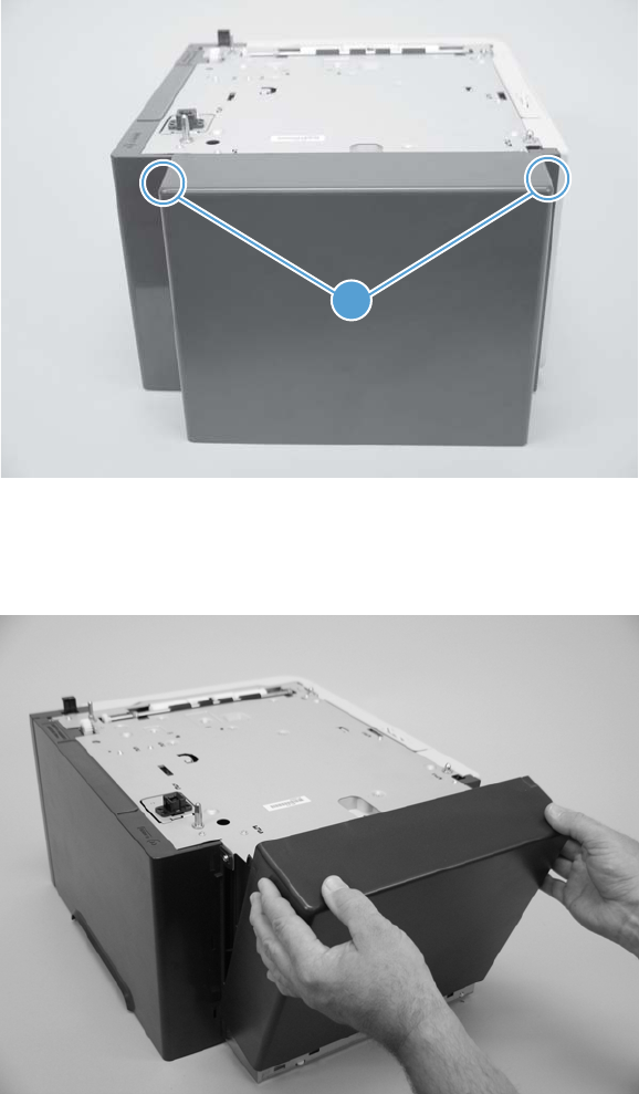
Rear cover (PD)
1. Release two tabs (callout 1).
Figure 2-139 Remove the rear cover (PD; 1 of 2)
1
2. Rotate the top of the cover away from the feeder, and then lift up on the cover to release it.
Remove the cover.
Figure 2-140 Remove the rear cover (PD; 2 of 2)
ENWW 1,500-sheet paper deck (PD) 167
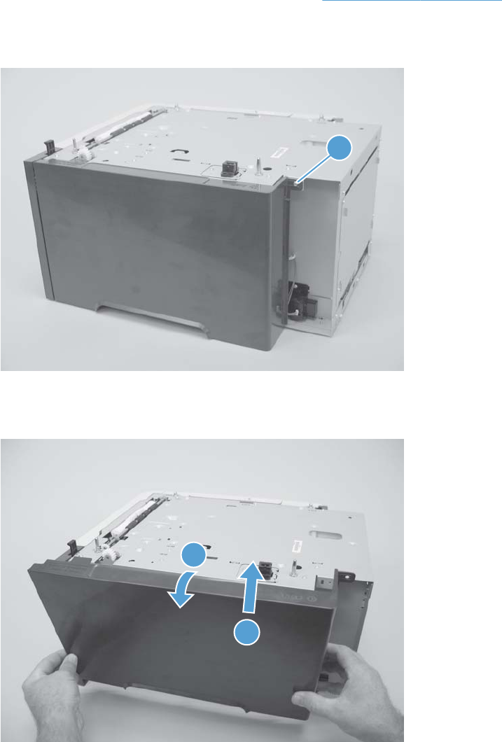
Right-side cover (PD)
1. Remove the 1,500-sheet paper deck rear cover. See Rear cover (PD) on page 167.
2. Remove one screw (callout 1).
Figure 2-141 Remove the right-side cover (PD; 1 of 2)
1
3. Rotate the top of the cover away from the chassis and then lift it up and remove it.
Figure 2-142 Remove the right-side cover (PD; 2 of 2)
1
2
168 Chapter 2 Removal and replacement ENWW
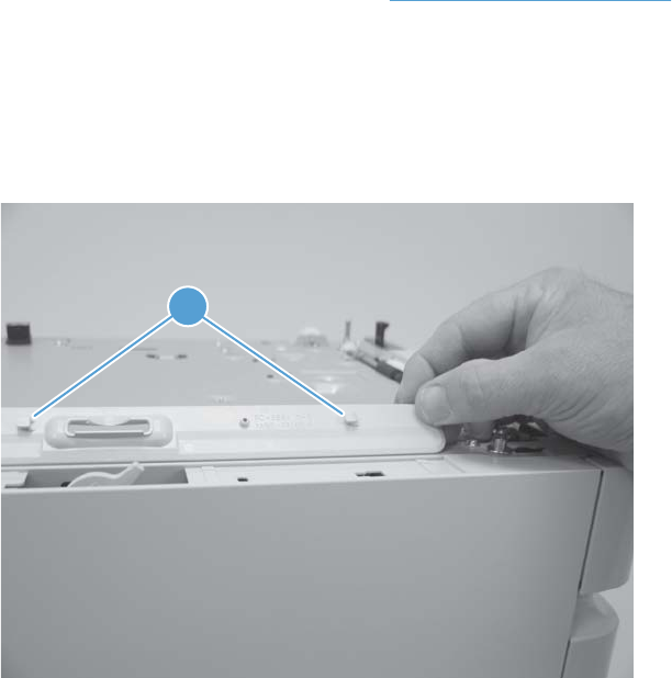
1,500-sheet paper deck left-side cover
Before proceeding, remove the following components;
●1,500-sheet paper deck rear cover. See Rear cover (PD) on page 167.
Remove the left-side cover
1. Before removing the lock-mechanism cover, take note of the location of the retainer tabs
(callout 1). The retaining tabs on this cover can be easily broken.
Figure 2-143 Remove the left-side cover (PD; 1 of 5)
1
ENWW 1,500-sheet paper deck (PD) 169
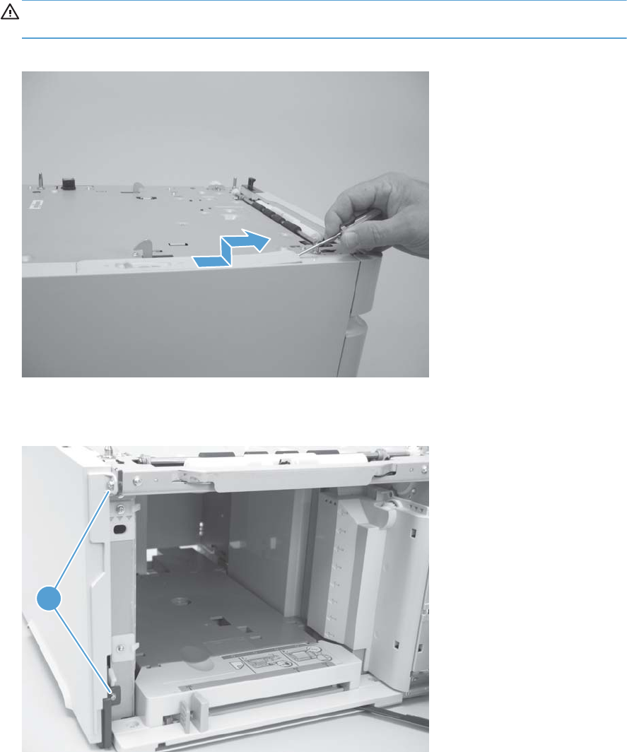
2. Slightly pry up on the lock-mechanism cover, and then slide it toward the front of the paper deck
to release it. Remove the cover.
CAUTION: Do not pry this cover up more than is necessary for clearance when sliding it
forward. The retaining tabs on this cover can be easily broken.
Figure 2-144 Remove the left-side cover (PD; 2 of 5)
3. Open the 1,500-sheet paper deck door, and then remove two screws (callout 2).
Figure 2-145 Remove the left-side cover (PD; 3 of 5)
2
170 Chapter 2 Removal and replacement ENWW
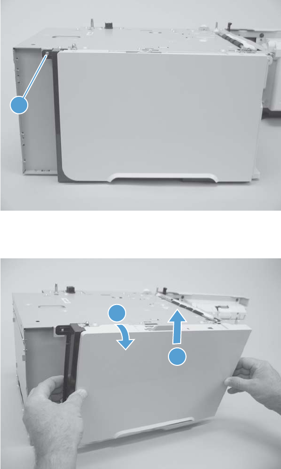
4. Remove one screw (callout 3).
Figure 2-146 Remove the left-side cover (PD; 4 of 5)
3
5. Rotate the top of the cover away from the chassis and then lift it up and remove it.
Figure 2-147 Remove the left-side cover (PD; 5 of 5)
1
2
ENWW 1,500-sheet paper deck (PD) 171
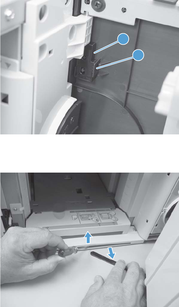
Door (PD)
1. Open the 1,500-sheet paper deck door.
2. Release one tab (callout 1), and then remove the door-stop plate (callout 2).
Figure 2-148 Remove the door (PD; 1 of 3)
2
1
3. With the door open about halfway, gently pry open the door slide-bar slot and disengage the
door slide-bar from the feeder.
Figure 2-149 Remove the door (PD; 2 of 3)
172 Chapter 2 Removal and replacement ENWW
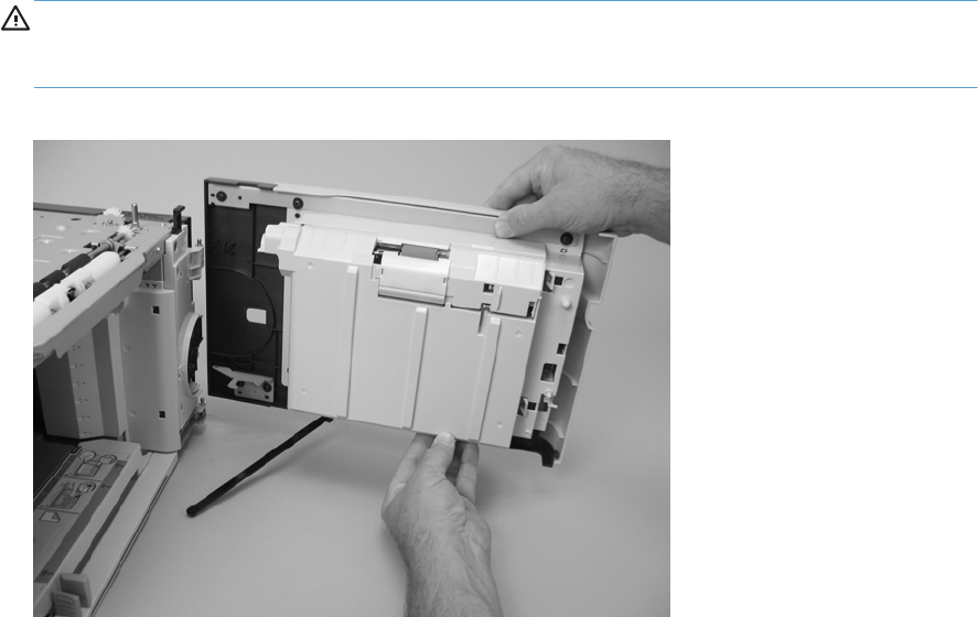
4. Lift the door straight up and off of the door hinge pins to remove it.
CAUTION: The door hinge pins are not captive. If the feeder must be turned on its side or
placed upside down, remove the hinge pins and the door spring (on the lower hinge pin). Place
the pins and the spring where you will not lose them.
Figure 2-150 Remove the door (PD; 3 of 3)
ENWW 1,500-sheet paper deck (PD) 173
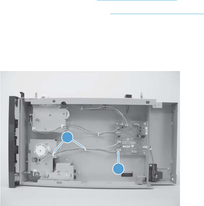
Motor (PD)
Before proceeding, remove the following components:
●1,500-sheet feeder rear cover. See Rear cover (PD) on page 167.
●1,500-sheet feeder right-side cover. See Right-side cover (PD) on page 168.
Remove the Motor (PD)
1. Disconnect one wire-harness connector (callout 1; J1703), and then release the wire harness from
two retainers (callout 2).
Figure 2-151 Remove the motor (PD; 1 of 2)
2
1
174 Chapter 2 Removal and replacement ENWW
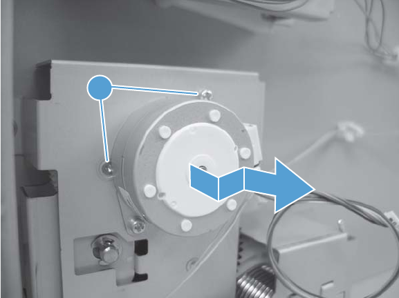
2. Remove two screws (callout 3). Slightly separate the motor from the feeder chassis, and then slide
the motor toward the back of the paper deck to remove the motor.
Figure 2-152 Remove the motor (PD; 2 of 2)
3
ENWW 1,500-sheet paper deck (PD) 175
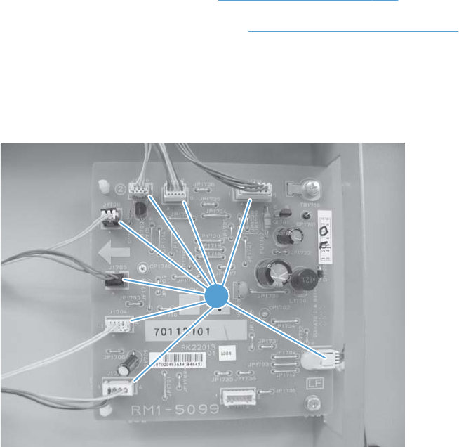
Driver PCA (PD)
Before proceeding, remove the following components:
●1,500-sheet feeder rear cover. See Rear cover (PD) on page 167.
●1,500-sheet feeder right-side cover. See Right-side cover (PD) on page 168.
Remove the Driver PCA (PD)
1. Disconnect eight wire-harness connectors (callout 1).
Figure 2-153 Remove the driver PCA (PD; 1 of 2)
1
176 Chapter 2 Removal and replacement ENWW
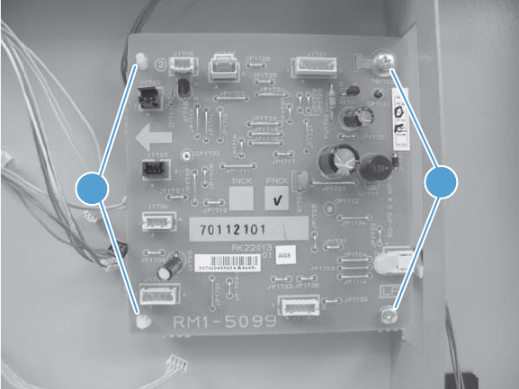
2. Remove two screws (callout 2). Use needle-nose pliers to squeeze the top of one of the nylon PCA
standoff (callout 3). Gently pop the PCA off of the tab. Repeat the procedure on the remaining
standoff. Remove the PCA.
Figure 2-154 Remove the driver PCA (PD; 2 of 2)
32
ENWW 1,500-sheet paper deck (PD) 177
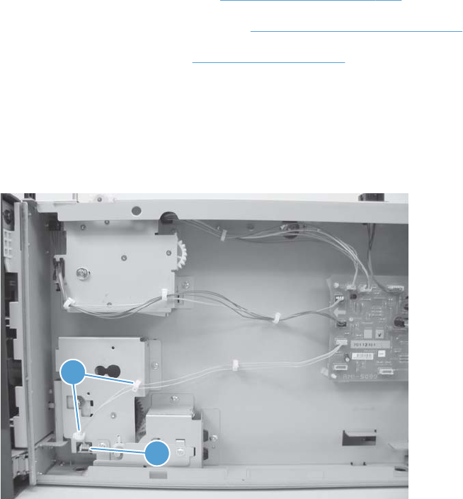
Lift-drive assembly (PD)
Before proceeding, remove the following components:
●1,500-sheet feeder rear cover. See Rear cover (PD) on page 167.
●1,500-sheet feeder right-side cover. See Right-side cover (PD) on page 168.
●1,500-sheet feeder motor. See Motor (PD) on page 174.
Remove the Lift-drive assembly (PD)
1. Disconnect one wire-harness connector (callout 1), and then release the wire harnesses from two
retainers (callout 2).
Figure 2-155 Remove the lift-drive assembly (PD; 1 of 3)
2
1
178 Chapter 2 Removal and replacement ENWW
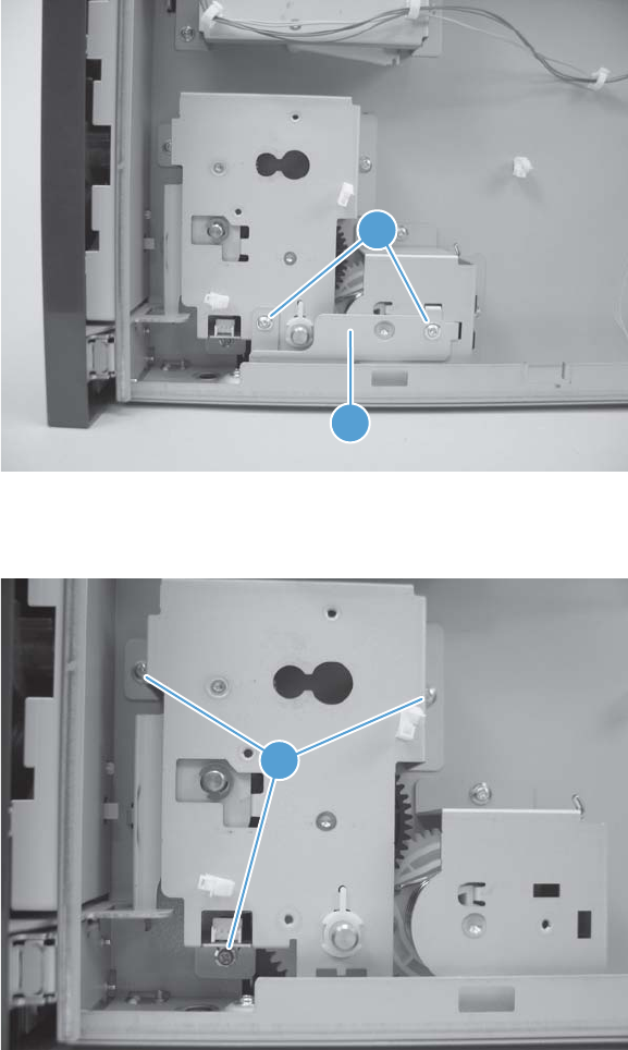
2. Remove two screws (callout 3) and the remove the sheet-metal plate (callout 4).
Figure 2-156 Remove the lift-drive assembly (PD; 2 of 3)
3
4
3. Remove three screws (callout 5), and then carefully remove the lift-drive assembly.
Figure 2-157 Remove the lift-drive assembly (PD; 3 of 3)
5
ENWW 1,500-sheet paper deck (PD) 179
180 Chapter 2 Removal and replacement ENWW

3 Solve problems
To use the information in this chapter, you should have a basic understanding of the HP LaserJet
printing process. Explanations of each mechanical assembly, the printer systems, and the basic theory
of operation are contained in the English-language service manual. Do not perform any of these
troubleshooting processes unless you understand the function of each product component.
●Solve problems checklist
●Menu map
●Preboot menu options
●Current settings pages
●Troubleshooting process
●Tools for troubleshooting
●Clear jams
●Paper does not feed automatically
●Use manual print modes
●Solve image-quality problems
●Clean the product
●Solve performance problems
●Solve connectivity problems
●Service mode functions
●Product updates
ENWW 181
Solve problems checklist
If the product is not responding correctly, complete the steps in the following checklist, in order. If the
product does not pass a step, follow the corresponding troubleshooting suggestions. If a step resolves
the problem, you can stop without performing the other steps on the checklist.
1. Make sure that the control-panel display shows one of the following messages: Ready,
Paused… , or Sleep Mode. If no lights are illuminated or the display does not say Ready,
Paused… , or Sleep Mode, use the Power-on checks section in the product service manual to
troubleshoot the problem.
2. Check the cables.
a. Check the cable connection between the product and the computer or network port. Make
sure that the connection is secure.
b. Make sure that the cable itself is not faulty by using a different cable, if possible.
c. Check the network connection.
3. Ensure that the print media that you are using meets specifications.
4. Print a configuration page. If the product is connected to a network, an HP Jetdirect page also
prints.
a. If the pages do not print, check that at least one tray contains print media.
b. If the page jams in the product, see the jams section.
5. If the configuration page prints, check the following items.
a. If the page prints correctly, the product hardware is working. The problem is with the
computer you are using, with the printer driver, or with the program.
b. If the page does not print correctly, the problem is with the product hardware.
6. Does the image quality meet the user's requirements? If yes, see step 7. If no, check the following
items:
●Print the fuser test page.
●Solve the print-quality problems, and then see step 7.
7. At the computer, check to see if the print queue is stopped, paused, or set to print offline.
Windows: Click Start, click Settings, and then click Printers or Printers and Faxes.
Double-click the HP LaserJet Enterprise 600 M601, HP LaserJet Enterprise 600 M602,
or HP LaserJet Enterprise 600 M603 item depending on the product model installed.
-or-
Mac OS X: Open Printer Setup Utility, and then double-click the line for the HP LaserJet
Enterprise 600 M601, HP LaserJet Enterprise 600 M602, or HP LaserJet Enterprise
600 M603 item depending on the product model installed.
182 Chapter 3 Solve problems ENWW
8. Verify that you have installed the HP LaserJet Enterprise 600 M601, M602, and M603 Series
Printer printer driver. Check the program to make sure that you are using the HP LaserJet
Enterprise 600 M601, M602, and M603 Series Printer printer driver.
9. Print a short document from a different program that has worked in the past. If this solution works,
the problem is with the program that you are using. If this solution does not work (the document
does not print) complete these steps:
a. Try printing the job from another computer that has the product software installed.
b. If you connected the product to the network, connect the product directly to a computer with
a USB cable. Redirect the product to the correct port, or reinstall the software, and select the
new connection type that you are using.
ENWW Solve problems checklist 183

Menu map
Print the menu maps
1. At the control panel, press the Home button.
2. Open the following menus:
●Administration
●Reports
●Configuration/Status Pages
3. Scroll to the Administration Menu Map item, and then press the OK button..
4. Scroll up to the Print option, and then press the OK button.
184 Chapter 3 Solve problems ENWW

Preboot menu options
If an error occurs while the product is booting, an error message appears on the control-panel display.
The user can access the Preboot menus. The Error menu item will not be seen if an error did not occur.
Access the Preboot menu
1. Turn the product on.
2. Press the Stop button when the Ready, Data, and Attention LEDs are illuminated solid.
3. Use the Down arrow button to navigate the Preboot menu options.
4. Press the OK button to select a menu item.
Cold reset using the Preboot menu
1. Turn the product on.
2. Press the Stop button when the Ready, Data, and Attention LEDs are illuminated solid.
3. Use the Down arrow button to highlight Administrator, and then press the OK button.
4. Scroll to the Startup Options item, and then press the OK button.
5. Scroll to the Cold Reset item, and then press the OK button.
6. Press the Back button twice to highlight Continue, and then press the OK button.
NOTE: The product will initialize.
Table 3-1 Preboot menu options (1 of 5)
Menu option First level Second level Third level Description
Continue Selecting the Continue item exits the Preboot menu and
continues the normal boot process.
If a selection is not made in the initial menu within 30 seconds,
the product returns to a normal boot (the same as selecting
Continue.
If the user navigates to another menu, the timeout does not
apply.
Sign In Enter the Administrator PIN or Service PIN if one is required to
access the Preboot menu.
ENWW Preboot menu options 185

Table 3-1 Preboot menu options (1 of 5) (continued)
Menu option First level Second level Third level Description
Administrator This item navigates to the Administrator sub menus.
If authentication is required (and the user is not already signed
in) the Sign In displays. The user is required to sign in.
Download This item initiates a preboot firmware download process. A USB
device interface or a Network connection can be used to
download firmware.
Network See
Product updates on page 397.
USB See
Product updates on page 397.
Clean Disk This item reinitializes the disk and cleans all disk partitions.
CAUTION: Selecting the Clean Disk item removes all data.
A delete confirmation prompt is not provided.
The system is not bootable after this action—a firmware
download must be performed to return the system to a bootable
state.
Partial
Clean
This item reinitializes the disk (removing all data except the
firmware repository where the master firmware bundle is
downloaded and saved).
CAUTION: Selecting the Partial Clean item removes all
data except the firmware repository.
A delete confirmation prompt is not provided.
This allows user to reformat the disk by removing the firmware
image from the active directory without having to download
new firmware code (product remains bootable).
Change
Password
Select this item to set or change the administrator password.
Clear
Password
Select the Clear Password item to remove a password from
the Administrator menu. Before the password is actually
cleared, a message will be shown asking to confirm that the
password should be cleared. Press the OK button to confirm the
action.
When the confirmation prompt appears, press the OK button to
clear the password.
186 Chapter 3 Solve problems ENWW

Table 3-2 Preboot menu options (2 of 5)
Menu
option
First
level
Second
level
Third level Description
Administrat
or
continued
Manage
Disk
Clear Disk Select the Clear Disk item to enable an
external device for job storage. Job storage is
normally enabled only for the Boot device.
This will be grayed out unless the 99.09.68
error is displayed.
Lock Disk Select the Lock Disk item to lock (mate) a
new secure disk to this product.
The secure disk already locked to this product
will remain accessible to this product. Use this
function to have more then one encrypted
disk accessible by the product when using
them interchangeably. The data stored on the
secure disk locked to this product always
remains accessible to this product.
Leave
Unlocked
Select the Leave Unlocked item to use a
new secure disk in an unlocked mode for
single service event. The secure disk that is
already locked to this product will remain
accessible to this product and uses the old
disk's encryption password with the new disk.
The secure disk that is already locked to this
product remains accessible to this product.
Clear
Password
Select the Clear Password item to continue
using the non-secure disk and clear the
password associated with the yet to be
installed secure disk.
CAUTION: Data on the missing secure disk
will be permanently inaccessible.
Retain
Password
Select the Retain Password item to use the
non-secure disk for this session only, and then
search for the missing secure disk in future
sessions.
Boot
Device
Secure
Erase
Select the Secure Erase item to erase all of
the data on the disk and unlock it if required
(this might take a long time).
NOTE: The system will be unusable until the
system files are reinstalled. ATA secure-erase
command one pass over write. Erases entire
disk including firmware. The disk remains an
encrypted disk.
Erase and
Unlock
Select the Erase and Unlock item to
cryptographically erase all data on disk and
unlock the disk to allow access to it from any
product.
NOTE: The system will be unusable until the
system files are reinstalled. Erases the crypto
key. The disk becomes a non-encrypted disk.
Get Status This item provides disk status information if
any is available.
ENWW Preboot menu options 187

Table 3-3 Preboot menu options (3 of 5)
Menu option First level Second
level
Third level Description
Administrator
continued
Manage
Disk
continued
Internal
Device
Select the Internal Device item to erase the internal
device or get status about the internal device.
Secure
Erase
Select the Secure Erase item to erase all of the data on
the disk and unlock it if required (this might take a long
time).
NOTE: The system will be unusable until the system files
are reinstalled. ATA secure-erase command one pass
over write. Erases the entire disk, including firmware. The
disk remains an encrypted disk.
Erase and
Unlock
Select the Erase and Unlock item to cryptographically
erase all data on disk and unlock the disk to allow access
to it from any product.
NOTE: The system will be unusable until the system files
are reinstalled. Erases the crypto key. The disk becomes a
non-encrypted disk.
Get Status This item provides disk status information if any is
available.
External
Device
Select the External Device item to erase the internal
device or get status about the internal device.
Secure
Erase
Select the Secure Erase item to erase all of the data on
the disk and unlock it if required (this might take a long
time).
NOTE: The system will be unusable until the system files
are reinstalled. ATA secure-erase command one pass
over write. Erases the entire disk, including firmware. The
disk remains an encrypted disk.
Erase and
Unlock
Select the Erase and Unlock item to cryptographically
erase all data on disk and unlock the disk to allow access
to it from any product.
NOTE: The system will be unusable until the system files
are reinstalled. Erases the crypto key. The disk becomes a
non-encrypted disk.
Get Status This item provides disk status information if any is
available.
188 Chapter 3 Solve problems ENWW

Table 3-4 Preboot menu options (4 of 5)
Menu option First level Second
level
Third level Description
Administrator
continued
Configure
LAN
Select the Configure LAN item to setup the network
settings for the PreBoot menu firmware upgrade.
The network can be configured obtain the network
settings from a DHCP server or as static.
DHCP Use this item for automatic IP address acquisition from
the DHCP server.
Static Use this item to manually assign the network addresses.
IP Address Use this item to manually enter the IP addresses.
Subnet
Mask
Use this item to manually enter the subnet mask.
Default
Gateway
Use this item to manually enter the default gateway.
Save and
Exit
Select the Save and Exit item to save the manual
settings.
ENWW Preboot menu options 189

Table 3-5 Preboot menu options (5 of 5)
Menu option First level Second level Third level Description
Administrator
continued
Startup
Options
Select the Startup Options item to specify options that
can be set for the next time the product is turned on and
initializes to the to Ready state.
Cold Reset Check the Cold Reset item to clear the IP address and all
customer settings (this item also returns all settings to
factory defaults). Items in the Service menu are not reset.
First Power Not currently functional: This item allows the product
initialize as if it is the first time it has been turned on.
For example, the user is prompted to configure first time
settings like Select Date/Time, Select Language, and other
settings).
Check this item so that it is enabled for the next time the
product power is turned on.
When the product power is turned on the next time, this
item is unchecked so that the pre-configured settings are
used during configuration and the first time setting prompt
is not used.
Skip Plug-
ins
This item allows the device to be started without loading
the third party applications.
This means that files including Accessible Architecture on
the disk will not be available at bootup. This is useful for
troubleshooting problems with the hard disk without
having to remove the hard disk. It also applies to flash file
system disks on DIMMs.
In this case, this function will cause the printer to configure
the HP firmware first, followed by the third-party
applications. The files on the disk will be available after
the printer enters the Ready state.
Skip Cal Select the Skip Cal item to initialize the product the next
time the power is turned on without calibrating.
Show
Revision
Not currently functional: Check the Show Revision item
to allow the product to initialize and show the firmware
version when the device reaches the Ready state.
Once the product power is turned on the next time, the
Show Revision item is unchecked so the firmware
revision is not shown.
Lock Service CAUTION: Select the Lock Service item to lock the
Service menu access (both PreBoot and Device
Maintenance application).
Service personnel must have the Administrator remove the
Lock Service setting before they can enter the Service
menu.
190 Chapter 3 Solve problems ENWW

Table 3-6 Preboot menu options (5 of 5)
Menu option First level Second level Third level Description
Administrator
continued
Startup
Options
Skip Disk
Scan
Check the Skip Disk Scan item to allow the
product to initialize without scanning the disk.
If the product is crashing on Step 4/8, checking this
item may allow the problem to be isolated.
Once the device is turned on the next time, the Skip
Disk Scan item is unchecked and the disk scan is
not skipped.
Embedded
Jetdirect Off
Check the Embedded Jetdirect Off item to
disable the embedded Jetdirect.
By default this item is unchecked so that Jetdirect is
always enabled.
Service Tools This item requires the Service access code.
Reset
Password
Use this item to clear the Administrator password.
Subsystems For manufacturing use only. Do not change these
values.
ENWW Preboot menu options 191

Current settings pages
Printing the current settings pages provides a map of the user configurable settings that might be helpful
in the troubleshooting process.
Print the current settings pages
1. At the control panel, press the Home button.
2. Open the following menus:
●Administration
●Reports
●Configuration/Status Pages
3. Scroll to the Current Settings Page item, and then press the OK button.
4. Scroll up to the Print option, and then press the OK button.
192 Chapter 3 Solve problems ENWW

Troubleshooting process
When the product malfunctions or encounters an unexpected situation, the product control panel alerts
you to the situation. This chapter contains information to help diagnose and solve problems.
●Use the pretroubleshooting checklist to evaluate the source of the problem and to reduce the
number of steps that are required to fix the problem.
●Use the troubleshooting flowchart to pinpoint the root cause of hardware malfunctions. The
flowchart guides you to the section of this chapter that contains steps for correcting the
malfunction.
Before beginning any troubleshooting procedure, check the following issues:
●Are supply items within their rated life?
●Does the configuration page reveal any configuration errors?
NOTE: The customer is responsible for checking supplies and for using supplies that are in good
condition.
Determine the problem source
When the product malfunctions or encounters an unexpected situation, the product control panel alerts
you to the situation. This section contains a pre-troubleshooting checklist to filter out many possible
causes of the problem. A troubleshooting flowchart helps you diagnose the root cause of the problem.
The remainder of this chapter provides steps for correcting problems.
Pre-troubleshooting checklist
The following table includes basic questions to ask the customer to quickly help define the problem.
General topic Questions
Environment ●Is the product installed on a solid, level surface (+/- 1°)?
●Is the power-supply voltage within ± 10 volts of the specified power source?
●Is the power-supply plug inserted in the product and the outlet (not a power
strip)?
●Is the operating environment within the specified parameters?
●Is the product exposed to ammonia gas, such as that produced by diazo
copiers or office cleaning materials?
NOTE: Diazo copiers produce ammonia gas as part of the coping
processes. Ammonia gas (from cleaning supplies or a diazo copier) can have
an adverse affect on some product components (for example, the print-
cartridge OPC).
●Is the product exposed to direct sunlight?
ENWW Troubleshooting process 193

General topic Questions
Media ●Does the customer use only supported media?
●Is the media in good condition (no curls, folds, or distortion)?
●Is the media stored correctly and within environmental limits?
Input trays ●Is the amount of media in the tray within specifications?
●Is the media correctly placed in the tray?
●Are the paper guides aligned with the stack?
●Is the cassette correctly installed in the product?
Print cartridges ●Is each print cartridge installed correctly?
●Are original HP print cartridges installed?
●Are the cartridges damaged?
Fuser ●Is the fuser correctly installed?
●Is the fuser damaged?
Covers and trays ●Are the trays correctly installed?
●Is the top cover closed?
Condensation ●Does condensation occur following a temperature change (particularly in
winter following cold storage)? If so, wipe affected parts dry or leave the
product on for 10 to 20 minutes.
●Was a print cartridge opened soon after being moved from a cold to a warm
room? If so, allow the print cartridge to sit at room temperature for 1 to 2
hours.
Miscellaneous ●Check for and remove any non-HP components (for example, print cartridges
or memory modules) from the product.
●Check to see whether the hardware or software configuration has changed or
the problem is not associated with any specific software.
●Remove the product from the network and ensure that the failure is associated
with the product before beginning troubleshooting.
●For any print-quality issues, clean the paper path.
Troubleshooting flowchart
This flowchart highlights the general processes that you can follow to quickly isolate and solve product
hardware problems.
Each row depicts a major troubleshooting step. A “yes” answer to a question allows you to proceed to
the next major step. A “no” answer indicates that more testing is needed. Go to the appropriate section
in this chapter, and follow the instructions there. After completing the instructions, go to the next major
step in this troubleshooting flowchart.
194 Chapter 3 Solve problems ENWW

Table 3-7 Troubleshooting flowchart
1
Power on
Is the product on and does a readable
message display?
Follow the power-on troubleshooting checks. See Power subsystem
on page 196.
After the control panel display is functional, see step 2.
Yes No
2
Control panel
messages
Does the message Ready display on the
control panel?
If an error message displays, see Interpret control-panel messages,
status-alert messages, and event code errors on page 266.
After the errors have been corrected, go to step 3.
Yes No
3
Event log
Open the Troubleshooting menu and print
an event log to see the history of errors with
this product.
Does the event log print?
If the event log does not print, see Print an event log
on page 351.
If paper jams inside the product, see Clear jams on page 353.
If error messages display on the control panel when you try to print
an event log, see Print an event log on page 351.
After successfully printing and evaluating the event log, see step 4.
Yes No
4
Configuration/
Status Pages
Open the Reports menu and print the
configuration pages to verify that all the
accessories are installed.
NOTE: To display: At the product control
panel, press the Home button, select the
Administration menu, and then select the
Reports menu.
Are all the accessories installed?
If accessories that are installed are not listed on the configuration
page, remove the accessory and reinstall it.
After evaluating the configuration pages, see step 5.
Yes No
5
Image quality
Does the print quality meet the customer's
requirements?
Compare the images with the sample defects in the image defect
tables. See Print-quality examples on page 380.
After the print quality is acceptable, see step 6.
Yes No
6
Interface
Can the customer print successfully from the
host computer?
Verify that all I/O cables are connected correctly and that a valid
IP address is listed on the Jetdirect configuration page.
If error messages display on the control panel, see Print an event
log on page 351.
When the customer can print from the host computer, this is the
end of the troubleshooting process.
Yes. This is the end of
the troubleshooting
process.
No
ENWW Troubleshooting process 195

Power subsystem
Power-on checks
The basic product functions should start up as soon as the product is plugged into an electrical
receptacle and the power button is pushed to the on position.
Overview
Turn on the product power. If the control-panel display remains blank, random patterns appear, or
asterisks remain on the display, perform power-on checks to locate the cause of the problem.
NOTE: It might take the control panel 10 to 20 seconds to illuminate when the product power is
turned on.
During normal product operation, the left rear cooling fan begins to spin briefly after the product power
is turned on. Place your hand over the holes in the left-side cover. If the fan is operating, you will feel a
slight vibration and feel air passing into the product. You can also lean close to the product and hear
the fan operating. When this fan is operational, the dc side of the power supply is functioning correctly.
After the fan is operating, the main motor turns on (unless the top cover is open, a jam condition is
sensed, or the paper path sensor is blocked). You should be able to visually and audibly determine if
the main motor is turned on.
If the fan and main motor are operating correctly, the next troubleshooting step is to separate print
engine, formatter, and control-panel problems. Perform an engine test (see Engine test button
on page 204). If the formatter is damaged, it might interfere with the engine test. If the engine test
page does not print, try removing the formatter and then performing the engine test again. If the engine
test is then successful, the problem is almost certainly with the formatter, the control panel, or the cable
that connects them.
If the control panel is blank when you turn on the product, check the following items.
1. Make sure that the product is plugged into an active electrical outlet receptacle that delivers the
correct voltage.
2. Make sure that the on/off button is in the on position.
3. Make sure that the fan runs briefly, which indicates that the power supply is operational.
4. Make sure that the control-panel display wire-harness is connected to connector J70 of the DC
controller PCA.
5. Make sure that the formatter is seated and operating correctly.
NOTE: If the control-panel display is blank, but the main cooling fan runs briefly after the product
power is turned on, try printing an engine test page to determine whether the problem is with the
control-panel display, formatter, or other components. See Engine test button on page 204.
If the main cooling fan is not operating, replace the power-supply assembly. See High voltage power
supply on page 148.
NOTE: It is important to have the control panel functional as soon as possible in the troubleshooting
process so that the control-panel display can be used to help locate errors.
196 Chapter 3 Solve problems ENWW

If problems with the power-on check persist, refer to table Table 3-8 Power-on defect or blank display
on page 197.
Table 3-8 Power-on defect or blank display
Problem Action
The power cord is not plugged into the
wall receptacle and connected to the
product.
Make sure that the power cord is firmly plugged into the wall receptacle and
connected to the product.
The correct voltage (power) is not
available.
Measure the voltage at the outlet. If necessary, plug the power cord into another
circuit outlet.
The power button is off. Set the button to the on position.
NOTE: The power button is illuminated when the button is in the on position and
the product is correctly operating.
The overcurrent/overvoltage detection
circuit is activated.
Wait for more than two minutes before turning the product back on.
A fuse is blown. 1. Check the fuses (FU1 and FU2) on the power supply.
2. Replace the power-supply assembly if necessary.
ENWW Troubleshooting process 197

Table 3-8 Power-on defect or blank display (continued)
Problem Action
The main cooling fan (located on the left
side near the rear of the product) does
not turn on when the product is started.
An operational fan indicates the following conditions:
●The AC power is present in the product.
●The DC power supply is functional (24 V, 5 V, and 3.3 V are being
generated).
●The DC controller microprocessor is functional.
If the fan is not working:
1. Turn the product off and remove the formatter. Disconnect the optional
accessories.
2. Turn the product on and check the fan again.
If the fan is still not working:
1. Verify that the fan is connected to the power supply (connector J64).
2. Replace the fan. See Fan FN101 on page 142.
3. If the error persists, replace the power-supply assembly. See High voltage
power supply on page 148.
4. If the error persists, replace the DC controller. See DC controller PCA
on page 128.
Note:
The fan only operates during the initial startup and while printing, and when the
temperature inside the product is too high. If the temperature is too high, the fan
turns on to cool the inside of the product.
The fan works, but the control-panel
display is blank.
1. Print an engine test. See Engine test button on page 204.
2. If the engine test is successful, perform the following steps, in order.
◦Reseat the control panel and formatter connector. See Control-panel
assembly on page 109 and Formatter cover and formatter cage
on page 71.
◦Replace the control-panel cable. See Control-panel assembly
on page 109.
◦If the error persists, replace the control-panel assembly. See Control-panel
assembly on page 109.
◦If the error persists, replace the formatter. See Formatter cover and
formatter cage on page 71.
3. If the engine test is not successful, remove the formatter and attempt to perform
the engine test again. If the engine test is successful with the formatter
removed, replace the formatter. See Formatter cover and formatter cage
on page 71. If the test is not successful with the formatter removed, replace the
DC controller PCA. See DC controller PCA on page 128.
198 Chapter 3 Solve problems ENWW
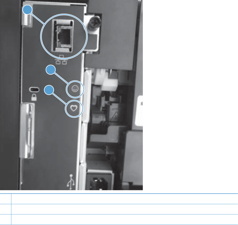
Tools for troubleshooting
Component diagnostics
LED diagnostics
LED, engine, and individual diagnostics can identify and troubleshoot product problems.
Understand lights on the formatter
Three LEDs on the formatter indicate that the product is functioning correctly.
1
3
2
1HP Jetdirect LEDs
2Connectivity LED
3Heartbeat LED
ENWW Tools for troubleshooting 199

HP Jetdirect LEDs
The embedded HP Jetdirect print server has two LEDs. The yellow LED indicates network activity, and
the green LED indicates the link status. A blinking yellow LED indicates network traffic. If the green LED
is off, a link has failed.
For link failures, check all the network cable connections. In addition, you can try to manually configure
the link settings on the embedded print server by using the product control-panel menus.
1. At the control panel, press the Home button.
2. Open the following menus:
●Administration
●Network Settings
●Jetdirect Menu
3. Scroll to and select the Link Speed item, and then press the OK button.
4. Select the appropriate link speed, and then press the OK button.
Heartbeat LED
The heartbeat LED indicates that the formatter is functioning correctly. While the product is initializing
after you turn it on, the LED blinks rapidly and then turns off. When the product has finished the
initialization sequence, the heartbeat LED pulses on and off.
If the heartbeat LED is off, turn the product power off, make sure that the formatter is fully seated, and
then turn the product on. If the problem persists, the formatter might have a problem. Replace the
formatter.
Connectivity LED
The connectivity LED provides information about product operation. If a product error occurs, the
formatter displays a message on the control-panel display. However, error situations can occur causing
the formatter to control panel communication to be interrupted.
NOTE: HP recommends fully troubleshooting the formatter and control panel before replacing either
component. Use the connectivity LED to troubleshoot formatter and control panel errors to avoid
unnecessarily replacing these components.
Formatter to control panel communication interruptions
●The firmware does not fully initialize and configure the control panel interface.
●The control panel is not functioning (either a failed component or power problem).
●Interface cabling between the formatter and control panel is damaged or disconnected.
TIP: If the connectivity LED is illuminated—by an error condition or normal operation—the formatter is
fully seated and the power is on. The pins for the LED circuit in the formatter connector are recessed so
that this LED will not illuminate unless the formatter is fully seated.
200 Chapter 3 Solve problems ENWW

The connectivity LED operates according to the product state. When the product is initializing, see
Connectivity LED, product initialization on page 201. When the product is in Ready mode, see
Connectivity LED, product operating on page 203.
Connectivity LED, product initialization
The following table describes the connectivity operation while the product is executing the firmware
boot process.
NOTE: When the initialization process completes the connectivity LED should be illuminated solid
green—the LED is off if the product is in Sleep Mode
If after initialization the connectivity LED is not solid green, see Connectivity LED, product operating
on page 203.
Table 3-9 Connectivity LED, product initialization
Product initializing
state
Connectivity LED, normal state Connectivity LED, error state
No power (power cord
unplugged or power
button off)
Off Not applicable
Power on (immediately
after the power button
pressed)
Red, solid
●Duration should be 1 second or less
Red, solid
●Firmware error; problem finding hardware
and booting the serial peripheral interface
flash memory
◦Boot process halted
Replace the formatter.
Serial peripheral
interface (SPI) flash
memory boot
Green, solid Red, solid
●Firmware error; problem corrupt or missing
SPI flash memory
◦Boot process halted
Replace the formatter.
HW checks on board
DRAM
Green, solid Red, solid
●Power on self check failure
◦Boot process halted
Replace the formatter.
Control panel
connection initializes
Green, solid
NOTE: Control panel communication
successful. If an error occurs, a message should
appear on the control-panel display.
Yellow, fast flash
●Formatter to control panel connection failed
◦Boot process continues
Check the cables between the formatter and
control panel for damage. Make sure that the
cables are fully seated.
ENWW Tools for troubleshooting 201

Table 3-9 Connectivity LED, product initialization (continued)
Product initializing
state
Connectivity LED, normal state Connectivity LED, error state
Preboot menu
available (including
diagnostics)
Green, solid Red, solid
●Diagnostic failure
◦Follow diagnostic instructions
Turn the power off, and then on again to restart
the initialization process.
Accessing disk for
firmware image
Green, solid
NOTE: If applicable, disk error messages
appear on the control-panel display.
Yellow, fast flash
●Control panel not connected
Firmware boot Green, solid
NOTE: If applicable, error messages appear
on the control-panel display.
Yellow, fast flash
●Control panel not connected
Product operational Green, heartbeat blink
NOTE: If applicable, error messages appear
on the control-panel display.
Yellow, fast flash
●Control panel not connected
49.XX.YY error or
initialization freezes
Not applicable LED off
NOTE: An error message (for example,
49.XX.YY) might appear on the control-panel
display.
Eventually a formatter connection missing
message will appear.
Turn the power off, and then on again to restart
the initialization process.
If the error persists, perform a firmware upgrade.
Control panel
connection interrupted
after the product is
operational
Not applicable Yellow, fast flash
●Control panel not connected
Sleep Mode Green, slow blink Not applicable
Approaching Sleep
Mode
Green, slow blink Not applicable
Wake up from Sleep
Mode
Follows initialization progression above. Follows initialization progression above.
Approaching wake up
from Sleep Mode
Follows initialization progression above. Follows initialization progression above.
202 Chapter 3 Solve problems ENWW

Connectivity LED, product operating
The following table describes the connectivity operation when the product completes the firmware boot
process and is in the Ready state.
Table 3-10 Connectivity LED, product operational
LED color Description
Green ●Normal operation
◦Formatter is operating normally
◦Firmware is operating normally
◦Control panel is connected
Yellow ●Formatter cannot connect to the control panel
◦Check control panel connections
◦Verify control panel functionality
Red ●Formatter error or failure
◦Serial peripheral interface (SPI) flash memory boot error
◦Power on self test (formatter) failed
◦Diagnostic (formatter) failed
Off TIP: The connectivity LED is off if the power cord is unplugged, the product power button is in
the off position, or the product is in Sleep Mode.
●Firmware or system freeze
◦Check the control panel for an error message
◦Control panel failure
NOTE: This condition is not usually caused by a formatter failure.
Turn the power off, and then on again.
If the error persists, perform a firmware upgrade.
ENWW Tools for troubleshooting 203
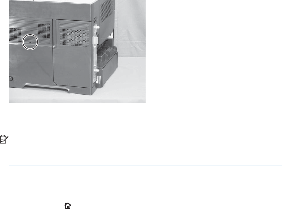
Engine diagnostics
This section provides an overview of the engine diagnostics that are available in the HP LaserJet
Enterprise 600 M601, M602, and M603 Series Printer product. The product contains extensive
internal diagnostics that help in troubleshooting print quality, paper path, noise, component, and timing
issues.
Engine test button
To verify that the product engine (all product components except the formatter, formatter DIMM, and the
stacker or stapler/stacker) is functioning, print an engine-test page. Use a small, non-metallic, pointed
object to depress the test-page buton, which is accessible through a slot in the right-side cover.
Figure 3-1 Engine-test-page button
The test page should have a series of horizontal lines. The test page prints from the last tray that you
printed from. However, if the product has been turned off and then on again since the most recent print
job, the page will print from Tray 2.
NOTE: A damaged formatter might interfere with the engine test. If the engine-test page does not
print, try removing the formatter and performing the engine test again. If the engine test is then
successful, the problem is almost certainly with the formatter, the control panel, or the cable that
connects them.
Formatter test
To check that the formatter is working, print a configuration page.
1. Press the Home button.
2. Open the following menus:
●Administration
●Reports
●Configuration/Status Pages
3. Scroll to the Configuration Page item, and then press the OK button.
4. Scroll to the Print item, and then press the OK button.
204 Chapter 3 Solve problems ENWW

Print/Stop test
Perform a Print/Stop Test to determine which image-formation component might be malfunctioning.
1. Press the Home button.
2. Open the following menus:
●Administration
●Troubleshooting
●Diagnostic Tests
3. Select the Print/Stop Test item, and then select from a range of 0 to 60,000 milli-seconds.
NOTE: Select a range value that allows the page to progress through the paper path just past
the component that you suspect is causing the print-quality problem.
4. Press the OK button to start the test.
Drum rotation test
The photosensitive drum, which is located in the print cartridge, must rotate in order for the print
process to work. The photosensitive drum receives its drive from the main gear assembly. Use this
procedure to determine whether the drum is rotating.
1. Open the top cover.
2. Remove the print cartridge.
3. Mark the cartridge drive gear with a felt-tipped marker. Note the position of the mark.
4. Install the print cartridge, and then close the top cover. The start-up sequence should rotate the
drum enough to move the mark on the gear.
5. Open the product and inspect the mark on the cartridge drive gear. Verify that the mark moved. If
there was no movement, inspect the main gear assembly to make sure that it connects with the
print-cartridge gears. If the drive gears function but the drum does not move, replace the print
cartridge.
NOTE: This test is especially important if refilled print cartridges are in use.
If a dark and distinct toner image is present on the drum surface, assume that the cleaning,
conditioning, writing, and developing functions of the electrophotographic process are functioning
correctly. Troubleshoot the failure as a transfer or fusing problem. If no image is present on the drum,
perform the drum-rotation test.
ENWW Tools for troubleshooting 205

Paper-path test (and automatic sensor test)
This diagnostic test generates one or more test pages that you can use to isolate the cause of jams.
To isolate a problem, specify which input tray to use, specify whether to use the duplex path, and
specify the number of copies to print. Multiple copies can be printed to help isolate intermittent
problems. The following options become available after you start the diagnostic feature:
●Print Test Page. Run the paper-path test from the default settings: Tray 2, no duplex, and one
copy. To specify other settings, scroll down the menu and select the setting, and then scroll back
up and select Print Test Page to start the test.
●Source. Select Tray 1, Tray 2, or the optional tray.
●Duplex. Enable or disable two-sided printing.
NOTE: Duplex models only.
●Copies. Set the numbers of copies to be printed; the choices are 1,10, 50, 100, or 500.
1. Press the Home button.
2. Open the following menus:
●Administration
●Troubleshooting
●Diagnostic Tests
3. Scroll to Paper Path Test, and then press the OK button.
4. Select the paper-path test options for the test you want to run.
Paper path sensors test (automatic)
NOTE: To view the function of each sensor and how to toggle them manually, see Manual sensor test
on page 208.
This test displays the status of each paper path sensor and allows viewing of sensor status while
printing internal pages.
1. Press the Home button.
2. Open the following menus:
●Administration
●Troubleshooting
●Diagnostic Tests
3. Scroll to Paper Path Sensors, and then press the OK button.
206 Chapter 3 Solve problems ENWW
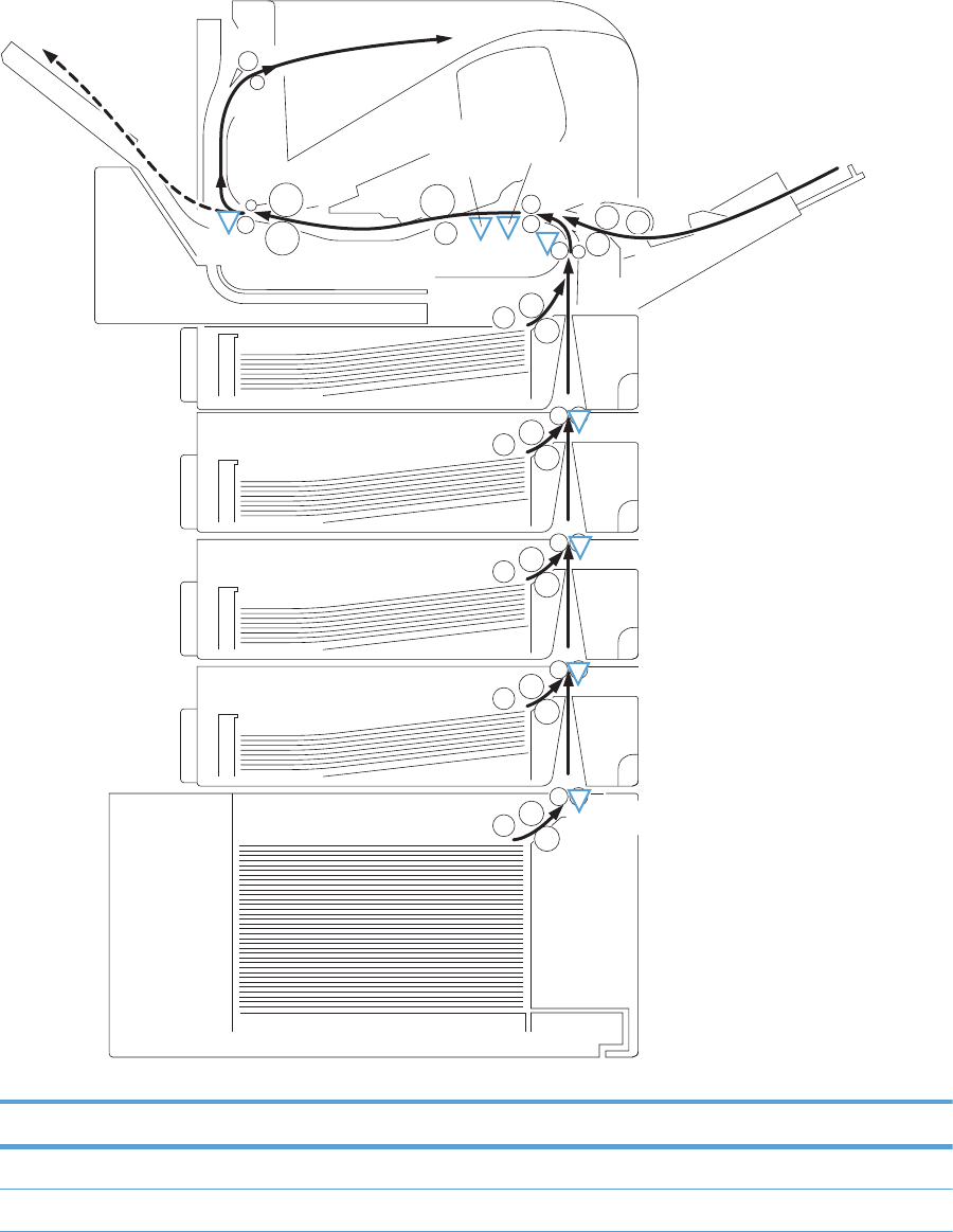
4. Select the paper path sensor to test.
5. Press OK to start the test, and then watch the control-panel display for the switch or sensor state to
change from green to clear or clear to green. It might take a few seconds to change.
Figure 3-2 Paper sensors
PS1704
PS1603
PS1603
PS1603
PS102
PS103
PS106
PS108
PS700
Table 3-11 Paper sensor test designators
Designator Sensor
PS103 Top of page sensor
PS102 Pre-feed sensor
ENWW Tools for troubleshooting 207

Table 3-11 Paper sensor test designators (continued)
Designator Sensor
PS700 Fuser delivery sensor
PS1502 Duplex sensor
PS106 Left-side paper width sensor
PS108 Right-side paper width sensor
PS1603 Tray 3 media path sensor
1
PS1603 Tray 4 media path sensor
1
PS1603 Tray 5 media path sensor
1
PS1704 Tray 6 media path sensor
1
1
This sensor is present only if the accessory is installed.
Manual sensor test
Use this diagnostic test to manually test the product sensors and switches. Each sensor is represented by
a letter and number on the control panel display.
1. Press the Home button.
2. Open the following menus:
●Administration
●Troubleshooting
●Diagnostic Tests
3. Scroll to the Manual Sensor Test item, and then press the OK button.
4. Activate a switch or sensor, and then watch the control-panel display for the switch or sensor state
to change from green to clear or clear to green. It might take a few seconds to change.
Menus cannot be opened during this test, so the OK button serves the same function as the
Stop button .
Table 3-12 Manual sensor diagnostic tests
Manual sensor
test designator
Sensor or switch Replacement
component
PS103 Top of page sensor, see Top of page sensor (PS103) on page 210 Replace the product
PS102 Pre-feed sensor, see Pre-feed sensor (PS102) on page 211
NOTE: See this procedure for the Tray 3, 4, 5, or 6 media path sensors
(PS1603/1603/1603/1704).
Replace the product
PS1502 Duplex sensor, see Duplex sensor (PS1502) on page 213 Replace the duplexer
PS700 Fuser delivery sensor, see Fuser delivery sensor (PS700) on page 212 Replace the fuser
208 Chapter 3 Solve problems ENWW

Table 3-12 Manual sensor diagnostic tests (continued)
Manual sensor
test designator
Sensor or switch Replacement
component
PS106/108 Left-side and right-side paper width sensors, see Media width sensors 1/2
(PS106/108) on page 214
Replace the product
PS1603/1704 PF/PD media path sensors, see Pre-feed sensor (PS102) on page 211 Replace the product
PS104 Output bin full sensor, see Output bin full sensor (PS104) on page 215 Replace the product
PS101 Tray 2 paper present sensor, see Tray 2 paper present sensor (PS101)
on page 217
Replace the product
PS107 Tray 2 top of stack sensor, see Tray 2 top of stack sensor (PS107)
on page 218
Replace the cassette
pickup assembly
SW102 Tray 2 paper size switches, see Tray 2 paper size switches (SW102)
on page 219
NOTE: See this procedure for the Tray 3, 4, 5, or 6 sensors and switches.
Replace the cassette
pickup assembly
ENWW Tools for troubleshooting 209
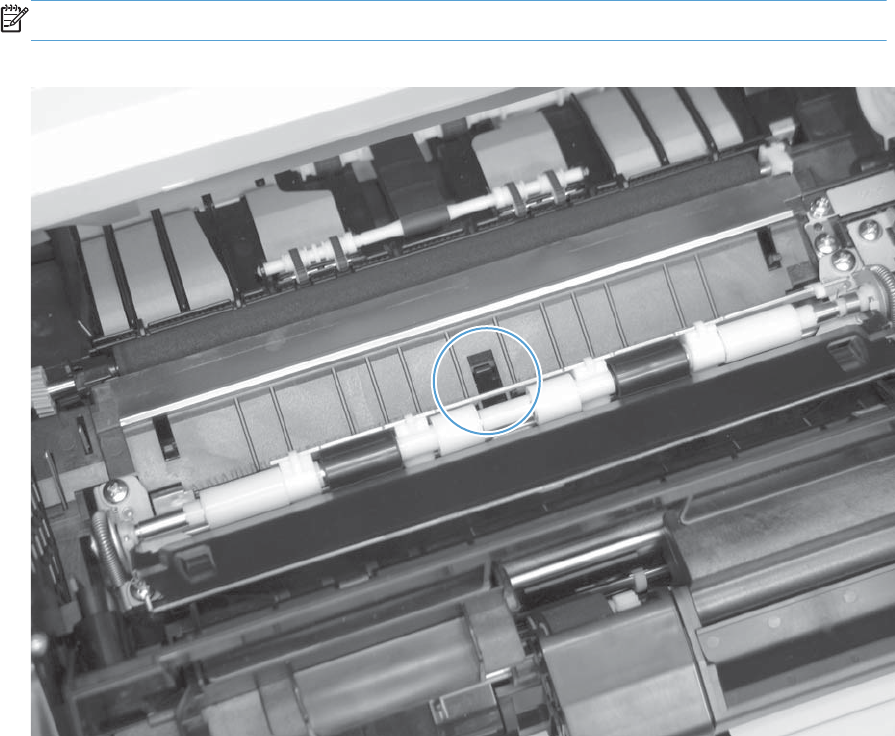
Top of page sensor (PS103)
1. Open the top cover and then remove the print cartridge.
2. Activate the top of page sensor (PS103) flag.
NOTE: You might need to lift the flap—use the green handles—to expose the sensor flag.
Figure 3-3 Test the top of page sensor
3. Check the control-panel display for sensor response (the dot on the display will turn green).
210 Chapter 3 Solve problems ENWW
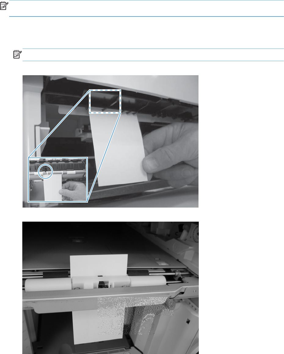
Pre-feed sensor (PS102)
NOTE: Use this procedure to test the paper feeder (PS1603) and paper deck (PS1704) media path
sensors
1. Remove the Tray 2 cassette.
2. Insert a piece of paper to override the Tray 2 pre-feed sensor (PS102).
NOTE: The paper must be thick enough to depress and hold in place the sensor actuator arm.
Figure 3-4 Test the Tray 2 pre-feed sensor (PS102)
Figure 3-5 paper feeder and paper deck media path sensors
ENWW Tools for troubleshooting 211
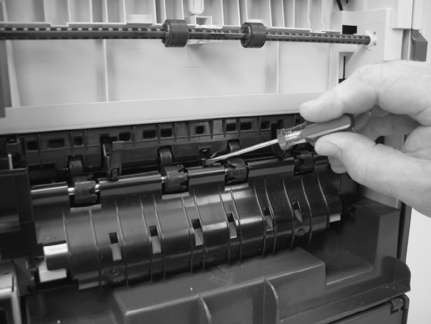
Fuser delivery sensor (PS700)
1. Open the rear output bin.
2. Activate the fuser delivery sensor (PS700) flag.
Figure 3-6 Test the fuser delivery sensor (PS700)
3. Check the control-panel display for sensor response (the dot on the display will turn green).
212 Chapter 3 Solve problems ENWW
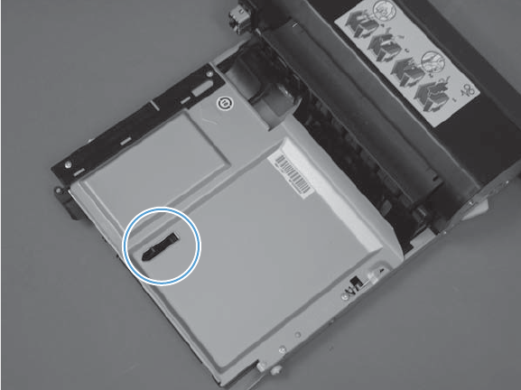
Duplex sensor (PS1502)
1. Remove the duplexer.
2. Verify that the duplexer sensor (PS1502) flag moves freely.
3. If the flag does not move freely, replace the duplexer.
Figure 3-7 Test the fuser duplex sensor
ENWW Tools for troubleshooting 213
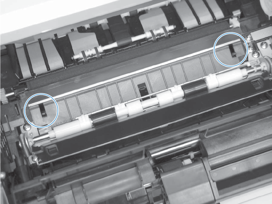
Media width sensors 1/2 (PS106/108)
1. Open the top cover and then remove the print cartridge.
2. Activate the left- or right-side paper width sensors (PS106/108).
Figure 3-8 Test the fuser pressure-release sensor
3. Check the control-panel display for sensor response (the dot on the display will turn green).
4. If the sensor does not respond, check the connectors at the DC controller.
214 Chapter 3 Solve problems ENWW
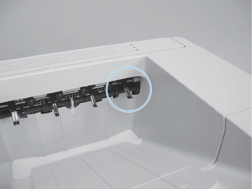
Output bin full sensor (PS104)
This sensor flag is located in the output bin area.
Activate the sensor flag, and then check the control-panel display for sensor response.
Figure 3-9 Test the output bin full sensor (PS104)
ENWW Tools for troubleshooting 215
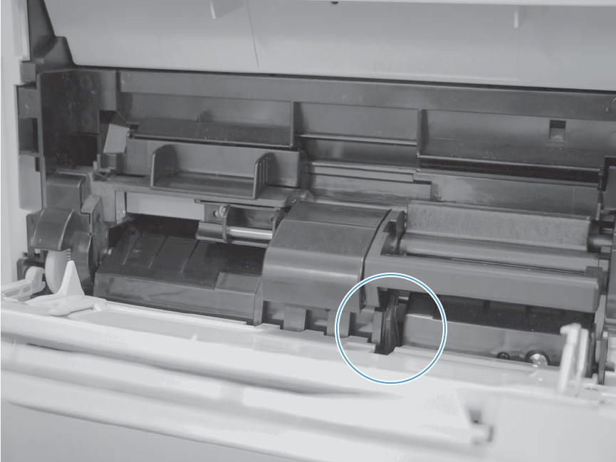
Tray 1 paper present sensor (PS105)
1. Open Tray 1, and then activate the Tray 1 paper present sensor (PS105) flag.
Figure 3-10 Test the Tray 1 paper present sensor (PS105)
2. Check the control-panel display for sensor response (the dot on the display will turn green).
216 Chapter 3 Solve problems ENWW
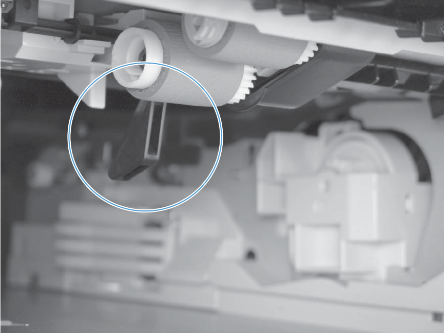
Tray 2 paper present sensor (PS101)
1. Remove the Tray 2 cassette.
2. Activate the Tray 2 paper present sensor (PS101) senor flag
Figure 3-11 Test the Tray 2 paper present sensor (PS101)
3. Check the control-panel display for sensor response (the dot on the display will turn green).
ENWW Tools for troubleshooting 217
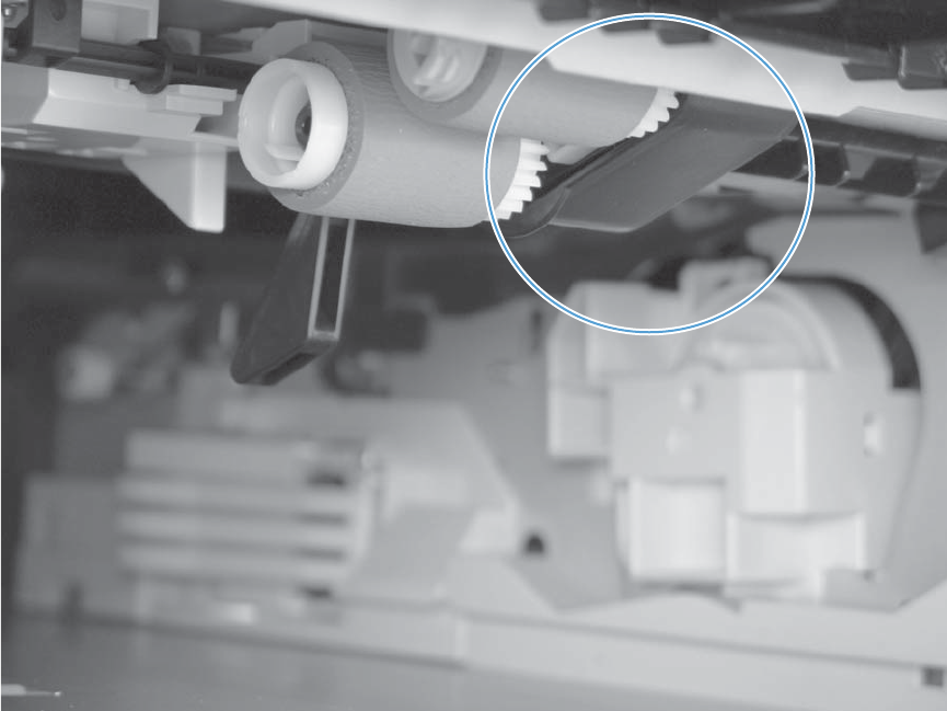
Tray 2 top of stack sensor (PS107)
1. Remove the Tray 2 cassette.
2. Activate the Tray 2 top of stack sensor (PS107) senor flag.
Figure 3-12 Test the Tray 2 top of stack sensor (PS107)
3. Check the control-panel display for sensor response (the dot on the display will turn green).
218 Chapter 3 Solve problems ENWW
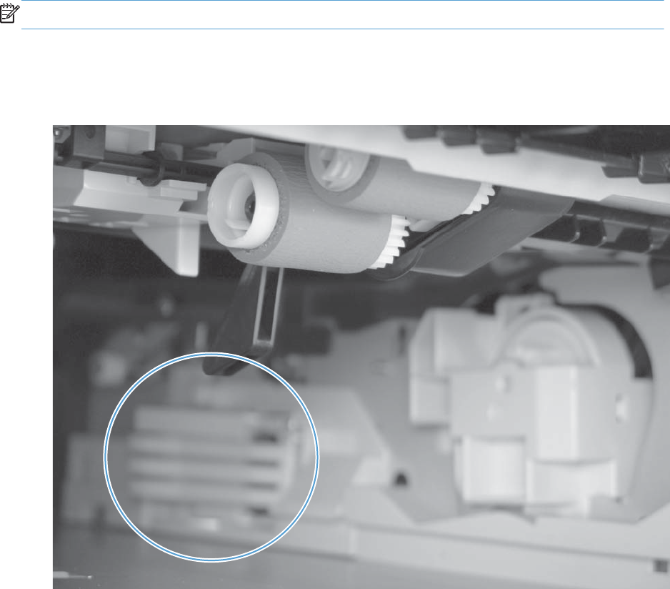
Tray 2 paper size switches (SW102)
NOTE: Use this procedure for the Tray 3, 4, 5, or 6 sensors and switches.
1. Remove the Tray 2 cassette.
2. Activate the Tray 2 paper size switches (SW102).
Figure 3-13 Test the Tray 2 paper size switches (SW102)
3. Check the control-panel display for sensor response (the dot on the display will turn green).
ENWW Tools for troubleshooting 219

Tray/Bin manual sensor test
Use this test to test the tray and bin sensors and switches manually. The following illustrations and table
show the locations of these sensors.
1. Press the Home button.
2. Open the following menus:
●Administration
●Troubleshooting
●Diagnostic Tests
3. Scroll to the Manual Tray/Bin Sensor Test item, and then press the OK button.
4. Activate a switch or sensor, and then watch the control-panel display for the switch or sensor state
to change from green to clear or clear to green. It might take a few seconds to change.
Table 3-13 Manual sensor test 2 diagnostic tests
Manual
sensor test 2
designator
Sensor or switch
PS1603 Paper feeder sensor NOTE: The locations of these switches and sensors
are the same as those in Pre-feed sensor (PS102)
on page 211 with respect to the optional paper
input accessories.
PS1704 Paper deck sensor
Print/stop test
Use this diagnostic test to isolate the cause of problems such as image formation defects and jams
within the engine. The test can be programmed to stop from 0 to 60,000 ms.
1. Press the Home button.
2. Open the following menus:
●Administration
●Troubleshooting
●Diagnostic Tests
3. Scroll to the Print/Stop Test item, and then press the OK button.
4. Use the arrow buttons to set a stop time, when the print job should be interrupted, and then press
the OK button.
220 Chapter 3 Solve problems ENWW

Table 3-14 Print/Stop settings
Duration Description
0 msecs The leading edge of the paper stops approximately 28 mm beyond the “black” paper guide of the
registration assembly.
100 msecs The leading edge of the paper stops approximately 63 mm beyond the “black” paper guide of the
registration assembly.
500 msecs The leading edge of the paper stops just prior to the paper entering the “nip” of the fuser assembly;
the nip is the gap between the pressure roller and the hot fusing roller.
600 msecs The leading edge of the paper stops approximately 5 mm prior to the paper encountering the fuser
assembly delivery photo sensor flag.
1,200 msecs (Simplex print operation) The leading edge of the paper stops 35 mm past the face-down delivery
stacker rollers. The trailing edge of the paper is approximately 30 mm from the “nip” of the fusing
rollers.
2,250 msecs (Duplex print operation) The leading edge of the paper has passed through the fuser assembly and
into the output stacker rollers. The paper has now reversed direction and entered the duplex
accessory. The leading edge of the paper stops approximately 15 mm before encountering the
duplex assembly re-pick photosensor (PS1502).
If the timer is set to a value that is greater than the job-print time, you can recover the product in one of
two ways.
●After the print job is completed press the Stop button to return to the Diagnostics menu before
the timer times out.
●After the timer times out, press the Stop button. Activate the door switch to restart the engine and
return it to a normal state.
When the timer trips, the control panel display shows the message Printing stopped To continue,
touch “OK”. Pressing the OK button will print the previously selected job. If you do not want the
previous job to print, press the Stop button first, and then press the OK button.
Component tests
These tests activate the selected component.
1. Press the Home button.
2. Open the following menus:
●Administration
●Troubleshooting
●Diagnostic Tests
3. Scroll to the Print/Stop Test item, and then press the OK button.
4. Use the arrow buttons to select the particular component test that you want to perform, and then
press the OK button.
The following table describes the component tests.
ENWW Tools for troubleshooting 221

Component test Description
DRUM MOTOR This test activates the drum motor.
LASER SCANNER MOTOR This test activates the laser scanner motor.
FUSER MOTOR This test activates the fuser motor and drive gears.
TRAY PICKUP MOTOR This test activates the tray pickup motor.
FEED ROLLER CLUTCH This test activates the paper feed roller clutch.
MP TRAY SOLENOID
TRAY 2 PICKUP SOLENOID
TRAY 3 PICKUP SOLENOID
TRAY 4 PICKUP SOLENOID
TRAY 5 PICKUP SOLENOID
TRAY 6 PICKUP SOLENOID
These tests activate the pickup solenoid for the selected input tray.
DUPLEXER SWITCHBACK MOTOR This test activates the duplexing reverse motor.
DUPLEX REFEED MOTOR This test activates the duplexing feed motor.
222 Chapter 3 Solve problems ENWW
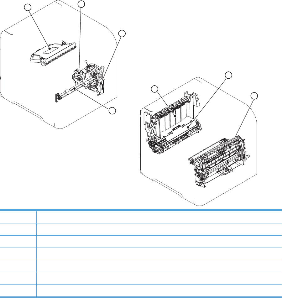
Diagrams
Block diagrams
Main assemblies
Figure 3-14 Main assemblies
12
6
7
3
4
5
1 Laser/scanner unit
2 Lifter drive unit
3 Tray 2 pickup drive unit
4 Feed roller unit
5 Delivery unit
6Fuser
7 Multipurpose tray pickup unit
ENWW Tools for troubleshooting 223
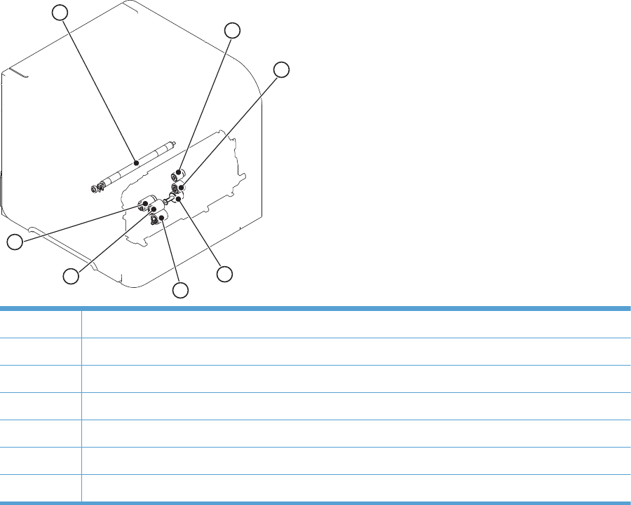
Main parts
Figure 3-15 Main parts
1
2
3
4
5
7
6
1 Transfer roller
2 Multipurpose tray pickup roller
3 Multipurpose tray feed roller
4 Multipurpose tray separation roller
5 Input tray separation roller (resides in input tray)
6 Input tray feed roller
7 Input tray pickup roller
224 Chapter 3 Solve problems ENWW
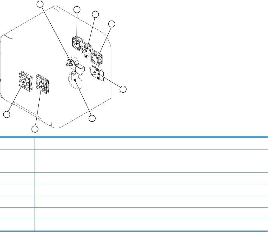
Motors and fans
Figure 3-16 Motors and fans
2
1
3
4
5
6
7
8
1 Fuser motor (M299)
2Fan (FN102)
3 Drum motor (M102)
4Fan (FN103)
5 Feed motor (M101)
6 Lifter motor (M103)
7Fan (FN301)
8Fan (FN101)
ENWW Tools for troubleshooting 225
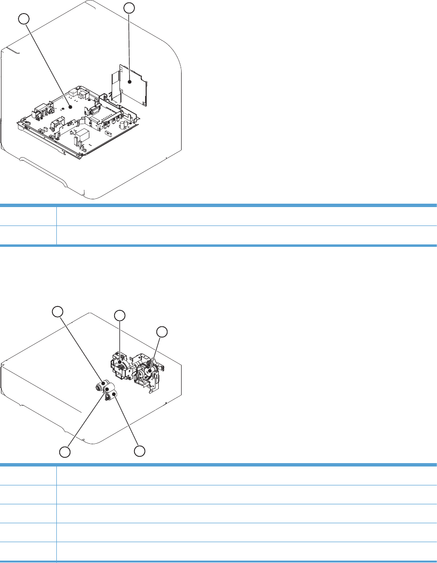
PCAs
Figure 3-17 PCAs
1
2
1 Power supply PCA
2 DC controller PCA
500-sheet feeder
Figure 3-18 500-sheet feeder main parts
2
3
4
1
5
1 Paper feeder pickup roller
2 Paper feeder lifter driver unit
3 Paper feeder pickup drive unit
4 Paper feeder separation roller
5 Paper feed roller
226 Chapter 3 Solve problems ENWW
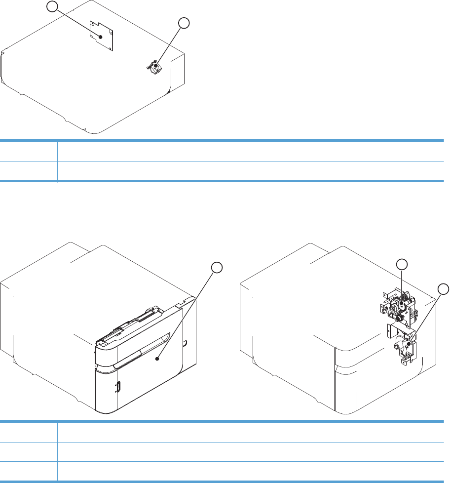
Figure 3-19 500-sheet feeder solenoid and PCA
1
2
1 Driver PCA
2 Pickup solenoid
1,500-sheet feeder
Figure 3-20 1,500-sheet feeder main units
12
3
1 Front door unit
2 Pickup drive unit
3 Lifter drive unit
ENWW Tools for troubleshooting 227
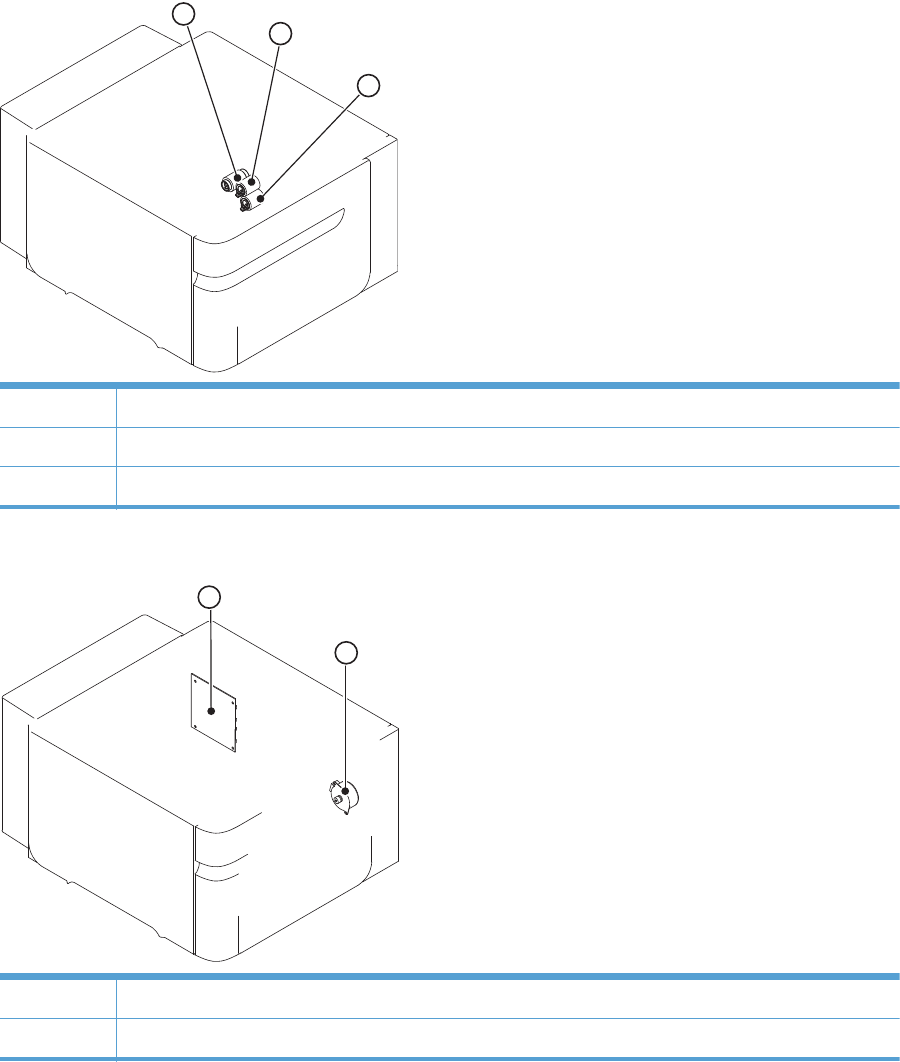
Figure 3-21 1,500-sheet feeder main parts
1
3
2
1Pickup roller
2 Feed roller
3 Separation roller
Figure 3-22 1,500-sheet feeder motor and PCA
1
2
1 Driver PCA
2 Lifter motor
228 Chapter 3 Solve problems ENWW
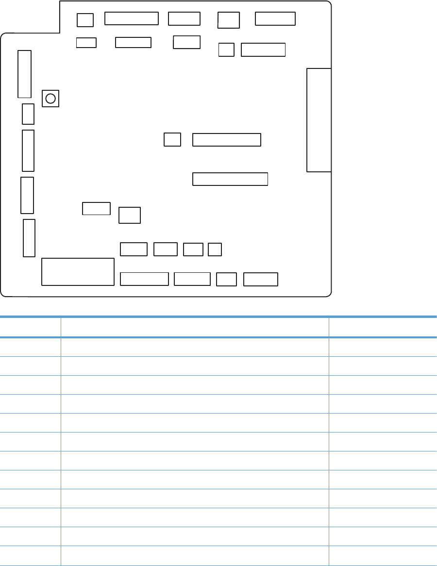
Connectors
DC controller PCA connectors
Figure 3-23 DC controller PCA connectors
J94
J81
J87
J83
J91
J78 J75
J84 J88 J77 J73
J89 J82 J99 J92
J85
J96
J95J98
J93
J74
J79
J86
J71
J72 J90 J80 J76 J70
SW700
J97
Table 3-15 DC controller connectors
Connector Functionality Pin configuration
J70 Control panel connector 8-pin
J71 SL102 Tray 1 pickup solenoid 2-pin
J72 SL101 Tray 2 pickup solenoid 2-pin
J73 M103 Tray 2 lift motor 2-pin
J74 TG101 memory tag I/O 2-pin
J75 FN102 cooling fan 3-wire
J76 PS104 face-down output full sensor 3-pin
J77 CL101 feed clutch 3-pin (2-wire)
J78 SW101 door open switch 3-pin
J79 FN103 cooling fan 4-pin (3-wire)
J80 Not used 6-pin
J81 PS105 Tray 1 media present sensor 3-pin
ENWW Tools for troubleshooting 229

Table 3-15 DC controller connectors (continued)
Connector Functionality Pin configuration
J82 Fusing assembly 7-wire
J83 Envelope feeder accessory 5-pin
J84 Duplex accessory 6-pin
J85 Power supply PCA (+24Vdc/3.3Vdc) 6-wire
J86 Scanner motor/beam detect 7-pin
J87 M102 drum motor 8-pin (7-wire)
J88 Paper deck accessory 5-pin
J89 M299 fusing motor 10-pin
J90 Stacker/stacker-stapler/mailbox 8-pin
J91 M101 feed motor 7-pin
J92 PS101 Tray 2 media present sensor
PS107 Tray 2 media stack sensor 1
PS907 Tray 2 media stack sensor 2
8-pin
J93 Laser/driver PCA 11-pin
J94 PS102 pre-feed sensor
PS108 media width sensor 2
PS103 top of page sensor
PS106 media width sensor 1
12-pin
J95 Power supply PCA 18-pin
J96 Power supply PCA 20-pin
J97 Intermediate PCA to formatter PCA 32-pin ribbon
J98 Not used
J99 SW102 Tray 2 media size switches 4-pin
TB700 3.3 volts DC
TB701 GRN
230 Chapter 3 Solve problems ENWW
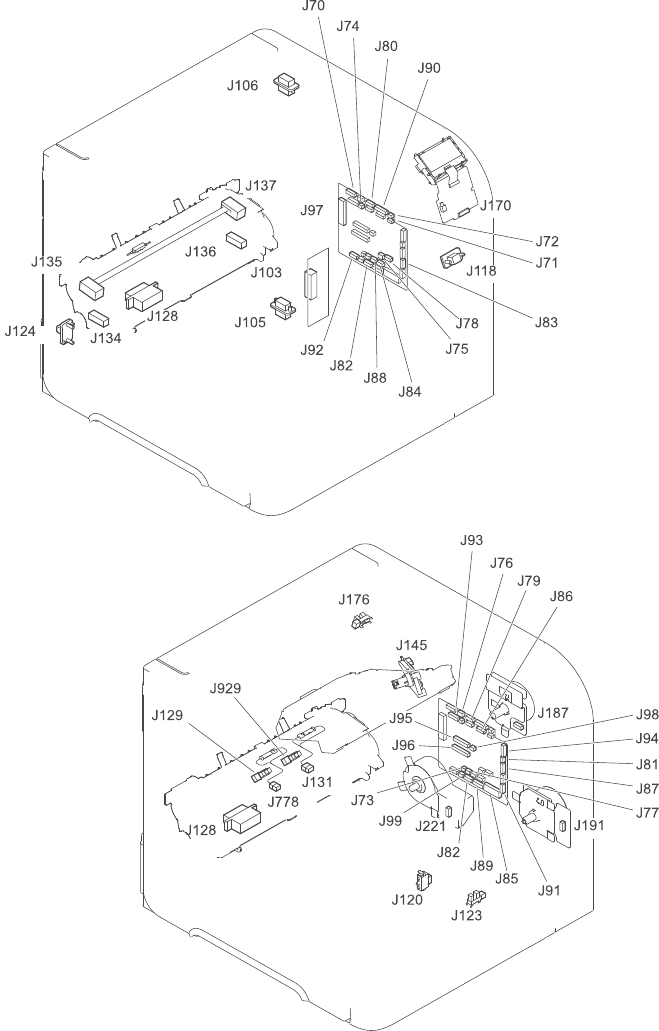
Product base connectors
Figure 3-24 Product base connectors
ENWW Tools for troubleshooting 231
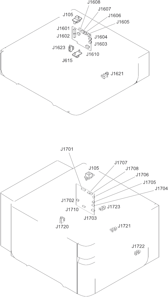
500-sheet paper tray connectors
Figure 3-25 500-sheet paper tray connectors
1,500-sheet paper tray connectors
Figure 3-26 1,500-sheet paper tray connectors
232 Chapter 3 Solve problems ENWW
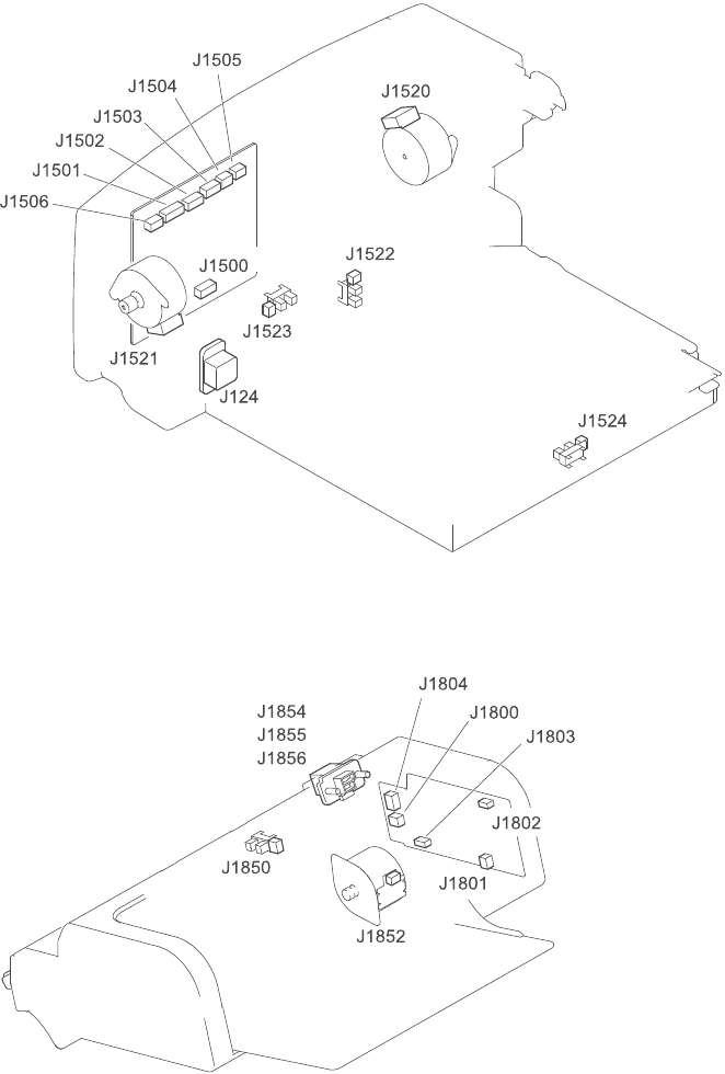
Duplexer connectors
Figure 3-27 Duplexer connectors
Envelope feeder connectors
Figure 3-28 Envelope feeder connectors
ENWW Tools for troubleshooting 233
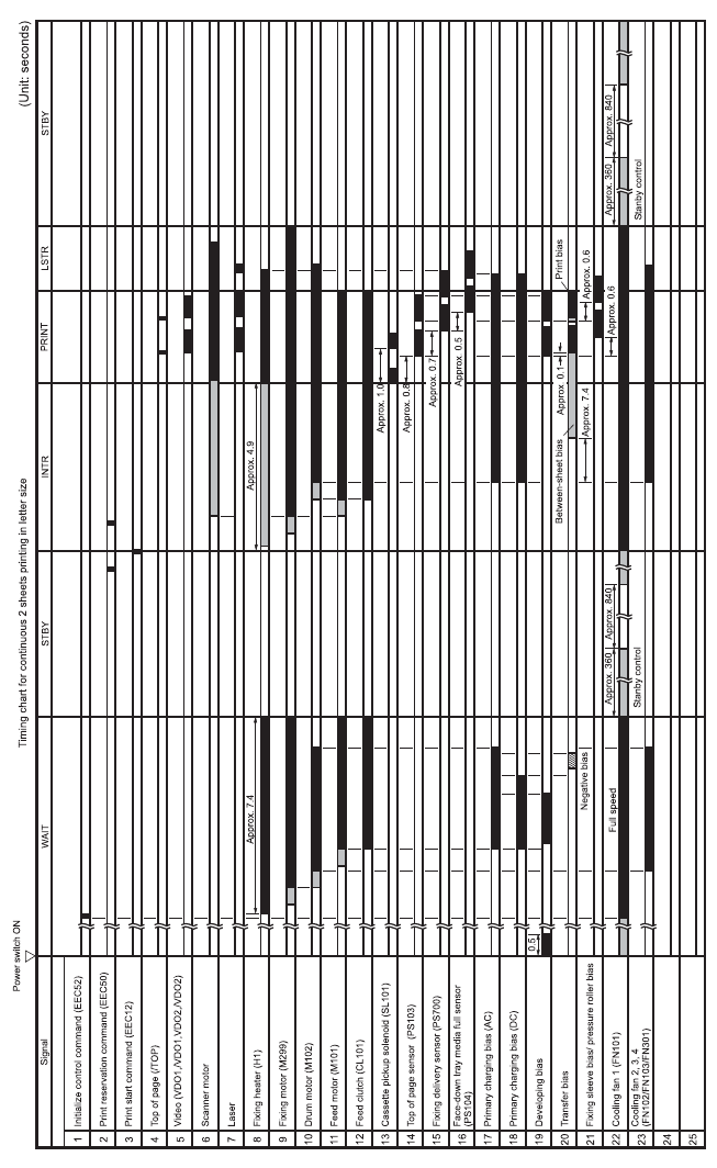
General timing chart
Figure 3-29 General timing chart
234 Chapter 3 Solve problems ENWW
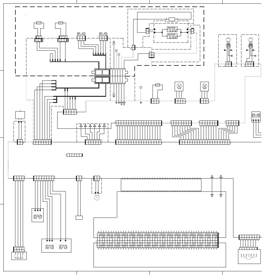
Circuit diagrams
Figure 3-30 General circuit diagram (1 of 2)
3456
SL
M
A6
A6
B6
B6
M
TP
123
2
1
B12
C15
B15
A15
012122324252111314151617181920212627
01212232425211131415161718192021
H
262728
H
N
N
1
C16
B16
C13
B13
A13
C12
B12
A12
C11
B11
C10
B10
A14
B14
C14
A13
B13
C13
A12
C12
A11
B11
C11
B10
C10
C9
B9
A9
C8
B8
A8
C7
B7
A7
C6
B6
A6
C5
B5
A5
C4
B4
C3
B3
C2
B2
C1
B1
A1
A10 A9
B9
C9
A1
B1
C1
A2
B2
C2
A3
B3
C3
A4
B4
C4
A5
B5
C5
A6
B6
C6
A7
B7
C7
A8
B8
C8
B16
A16
A16
C15
B15
A15
C14
B14
A14 A11 A10 A2A3
A4
C16
21
6
5432
1
29303132
2829303132
4
3
123
1
12
1
32165
1
1234
5
67
3
4
5
6
2
1
3
2
1
5
6
4
1
2
12345
6
7
3
6
5
4
2
1
21
321
21
21
1
2
1
1
1
2
3
4
5
6
21
1
4
2
12
213
2
13
213
2
1
2
13
4
2
13
4
32
1
23456789101112131415161718
12345678910111213141516
1718
123456789 1011121314151617 18
123456781
8
171615141312111019 23456789 10111213141516171819 20
123456789 1011121314151617 1819 20
12345678
123456
78
1234567
1234
567
12345
1
2
34
5
3
2
123
1
2
3
32
16
5
4
12
12345
12345
1234567 23456
123456
3
2
1
3
4
213
4
213
213213
1234
1234
12345678
12345678
12
12
12
12
12
12
1
212
23456789
986543217
78
654
3
21 78
123
456
7
56
21
2121
3
21
21
2
1
3
123
123
3.3V
GNDGND
3.3V
24R
/AC200
FSRSAFE
CURDIS
MFLK
DF2DR
DF3LK
/MFHF
MFFL
ENVTMPG
ENVTMP
/ZEROX
PRO5V
/RLD
FSRD2
FSRD1
FSRTH2GND
FSRTH2
GND
CURRMS
FPRSNS
24R
/DMFG
/DMDEC
/DMACC
GND
GND
GND
007BT101BT
TB701TB102
GND
GND
24VB
24VB
FPRSNSDR
GND
FPRSNS
FSRTHG2
FSRTH2
PRDCPWM
DVACPWM
DVDCPWM
PRACCK
PRACPWM
HVTCK
TRNCK
PRDCCK
TRAD
TRPWM
TRPCK
TNRSP2
TNRSP1
DVACCK
TB20
TB11
TB10
TB21
TB33
TB35
TB31
TB34
TB32
TB36
/PDLV
PWRON
CAN-L
CAN-H
5.0V
5.0V
5.0V
5.0V
/PFED
/TOP
/CCRT
VSCLK
VSC
GND
GND
/BD
VDO2
/VDO2
GND
GND
GND
/FPCS
FPCK
FPO
FPI
GND
GND
GND
GND
VDO1
/VDO1
GND
FPO
FPCK
/FPCS
GND
FPI
GND
VDO1
/VDO1
GND
/BD
GND
VDO2
/VDO2
GND
GND
GND
GND
GND
PWRON
CAN-L
CAN-H
5.0V
5.0V
5.0V
5.0V
/PFED
/TOP
/CCRT
VSCLK
VSC
GND
/PDLV
3.3V
3.3V
3.3V
3.3V
3.3V
3.3V
/PDLV
/PFED
GND
/TOP
/CCRT
GND
SCLK
SC
GND
GND
/BD
GND
/VD02
VD02
GND
GND
GND
GND
GND
GND
GND
PWRON
CAN-H
CAN-L
GND
5.0V
5.0V
5.0V
GND
GND
GND
/VD01
VD01
GND
SCL
SDL
GND
FP0
GND
FPI
/FPCS
FPCK
/CSTSL
/LMON
24R
24R
FPCK
/FPCS
FPI
GND
FP0
GND
SDL
SCL
GND
VD01
/VD01
GND
GND
GND
GND
VD02
/VD02
5.0V
5.0V
3.3V
GND
/BD
GND
GND
SC
SCLK
GND
/CCRT
/TOP
GND
/PFED
/PDLV
3.3V
3.3V
3.3V
3.3V
3.3V
5.0V
GND
GND
GND
GND
CAN-H
CAN-L
PWRON
GND
GND
GND
/CSTSIZE0
/CSTSIZE1
GND
/CSTSIZE2
/PLVL2SNS
PLVL2SNSDR
/PLVLSNS
GND
PLVLSNSDR
/CSTSNS
GND
CSTSNSDR
GND
MD2
MD0
IOTTXD
IOTRXD
+3.3V
DELSNS
GND
DELDR
/FSRARI
GND
FSRTH1
FSRTHG1
24VA
GND
GND
3.3V
GND
24VA
J128MB_BUS
J128MA_BUS
J128FA_BUS
J128FB_BUS
HEATERC
HEATER1
ENVTMPG
ENVTMP
ENVTMPG
MFDRV
MFLK
GND
H
N
NH
200V
100V
TB17 TB18
H2
H1
TB28
TB15
TB19
FILMBIAS
KAATUBIAS
TB23
TB14
TB13
D2FDRV
GND
N.C.
3RDFLK
Fixing unit
Intermediate PCB
Formatter
Power supply PCB
COILA
COILB
SW102
PS907PS107
PS101
M103
SL101
M102
TH2
PS700
PS699
HEATER
TP1
PS102
FN101
TH3 FN301
TH1
Cooling fan 3 Cooling fan 1
Environment
sensor
Pre-feed
sensor
Drum motor
Lifter motor
Cassette pickup
solenoid
Media stack surface
sensor 2
Media stack surface
sensor 1
Cassette media
presence sensor
Cassette media
size switches
Fixing delivery
sensor
Fixing pressure
release sensor
Main thermistor Sub thermistor Thermoswitch
FFC
TG101
J87
J187
J103
J97
J103M
J103F
J73
J72
J92
J80
J99
J120
J82J85
J50
J95
J62
J128DB
J128DWH
J128LB
J128DA
J128LA
J128LWH
J131DH
J131D
J131L
J778DH
J778D
J929
J778L
J129
J128LDW
J128DDW
J136M
J135
J134F
J134M
J136F
J137
J53
J52
J51
J96
J64
J63
10J1J
J66
J74
ENWW Tools for troubleshooting 235
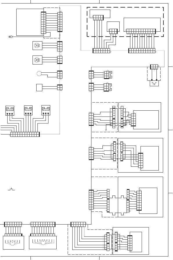
Figure 3-31 General circuit diagram (2 of 2)
D
C
B
A
12
1
2
3
6
5432
17
1
2
3
7
6
54321
21
3
2
13
2
13
2
1
1234567
12
3
4567
7654321
M
1
2
3
1
2
3
3
2
1
3
2
1
3
2
1
3
2
1
6
54327
1
654327110
9
811
6543271109811
3
21
321
1
2
3
123
123
123
4
4
12 11 10 987654321
12 11 10 987654321
1
2
3
1
2
3
44
1
2
3
12
34
5
6789101112
1
23456789101112
2
1
321
1
2
3
1
2
3
CL 1
2
3
1
2
3
21
SL
2
1
2
1
21
M
1234 5678910
1234 5678910
10 12345
6
789
10 12345
6
789
1
2
3
4
5
6
7
8
1
2
3
4
5
6
7
8
7
6
5
4
3
2
1
8
9
7
6
5
4
3
2
1
8
9
1
1
2
3
4
5
1
2
3
4
1
1
2
3
1
2
3
4
5
1
2
3
4
1
2
3
1
2
3
4
5
1
2
3
4
5
6
5
3
2
1
4
4
3
2
1
3
2
1
1
2
3
1
2
3
4
123456
123456
6
5
3
2
1
4
Paper feeder or
Paper deck
1
2
3
4
1
2
3
1
2
3
4
1
2
3
1
2
3
4
5
1
2
3
4
5
Envelope feeder
Duplexing unit
5
6
7
8
1
2
3
4
5
6
7
8
1
2
3
41
2
3
4
1
2
3
4
5
5
6
7
8
4
3
2
1
4
3
2
1
5
1
2
3
4
1
2
3
4
8
7
6
5
Stacker or
Staple stacker or
Muili-bin mail box
MPSNS
GND
GND
/MMACC
24R
24R
/MMDEC
/MMFG
GND
MPSNSDR
GND
FULDR
FULSNS
N.C.
24VA
24VC
LPHI
/VDO2
VDO2
CNT2
CNT1
CNT0
/VDO1
VDO1
GND
PDOUT
GND
3.3V
/BDI
5V
GND
24R
/SMACC
/SMDEC
D2FDRV
GND
N.C.
4THFLK
/TOPSNS
GND
TOPDR
/WIDTHSNS
GND
WIDTHDR
WIDTH2DR
GND
/WIDTH2SNS
PREDR
GND
/PRESNS
Laser driver PCB
BD
PCB
Scanner motor Laser/ Scanner unit
DC controller PCB
GND
DF2DR
2NDFLK
/TRCL
N.C.
24R
24R
/MPSL
GND
/DMDEC
/DMFG
24R
GND
/DMACC
FMREV
GND
24R
24R
/FPCS
FPCK
3.3V
GND
5V
GND
FPO
FPI
TB25
GND
OPSOUT
OPSIN
OPSCLK
24R
DUPARI
GND
PWRON
GND
GND
CAN-H
CAN-L
24R
24R
GND
OPSOUT
OPSIN
OPSCLK
24R
DUPARI
PWRON
GND
GND
GND
CAN-H
CAN-L
24R
24R
GND
OPSCLK
OPSIN
OPSOUT
GND
OPSCLK
OPSIN
OPSOUT
24R
24R
GND
24R
OPSOUT
OPSIN
OPSCLK
24R
GND
OPSOUT
OPSIN
OPSCLK
PS105
PS104
SW101
SW800
M101
FN103
PS108PS103 PS106
Media width
sensor 2
Top of page
sensor
Media width
sensor 1
Cooling fan 3
Feed clutch Face-down tray
media full sensor
Multi-purpose tray
media presence
sensor
Multi-purpose tray
pickup solenoid
Door open
detection switch
Test print switch
Feed motor
FN102
Cooling fan 2
CL101
SL102
M299
Fixing motor
Operation panel
J191
J91
J123
J81
J76 J176
J79
J145
J144
J143
J93
J86
J78
J94
J75
J77
J71
J89
J221
J70
J170
J124DA
J124DB J124LB
J124LA
J124L
J84
J703
J106LB
J106L
J106D
J1101
J106DB
J106DA J106LA
J90
J807F (paper feeder)
J105DA
J105D
J105DB
J88
J105L
J105LA
J105LB
J1001(paper deck)
J118D
J901
J83
J118DA J905
J905M
J906
J118DB
236 Chapter 3 Solve problems ENWW
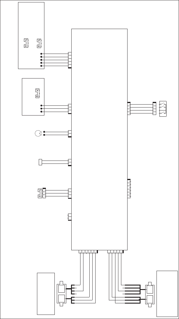
Figure 3-32 500-sheet paper tray circuit diagram
+3.3 DR
NC
CMD
STS
CLK
+24V
STS
CLK
CMD
+24V
GND
GND
GND
P_SNS
+3.3 DR
+24V
PICK_SL
+3.3 DR
GND
PPATH_SNS
DOOR_SNS
GND
+24V
LIFTMTR
SIZE_SNS_1
GND
SIZE_SNS_2
SIZE_SNS_3
+3.3V
IOT_RXD
IOT_TXD
GND
GND
+3.3 DR
PLVL_INIT
PLVL_PICK
MOD2
MOD0
B4A3
A3 B4
SL
M
BLUE
RED
WHITE
BLUE
YELLOW
YELLOW
PURPLE
To printer
or
paper feeder
BROWN
1234
123456
12
21
123
21343
4123123
1234
1234
1
2
3
4
5
6
1
2
3
4
5
12 123 12 12 12 1235
21
To paper feeder
or
paper deck
Media stack surface sensor PCA
PF lifter motor
PS1601
M1600 PS1600 PS1602
PF pickup
solenoid
SL1600
PS1603
PF media size switch
SW1600
PF media
stack surface sensor 1
PF media
stack surface sensor 2
PF media path
sensor
PF media
presence sensor
Paper feeder driver PCA
J1601
J1602
J105L
J1615D
J1615DB
J1615DA
J105LA
J105LB
J1623
J1610 J1607
J1621
J1603
J1609 J1605
J1604 J1606 J1608
34
ENWW Tools for troubleshooting 237
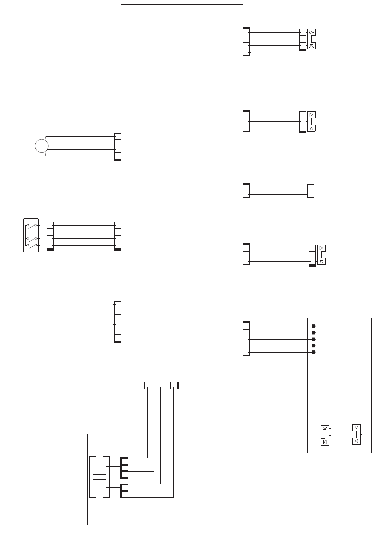
Figure 3-33 1,500-sheet paper tray circuit diagram
LIFT_A
LIFT_AN
LIFT_B
LIFT_BN
+3.3 DR
GND
GND
SIZE_SNS_3
SIZE_SNS_2
SIZE_SNS_1
GND
+3.3 DR
PPATH_SNS
DOOR_SNS
+24V
PICK_SL
GND
IOT_TXD
IOT_RXD
+3.3V
MOD2
MOD0
GND
+3.3 DR
GND
P_SNS
+3.3 DR
+3.3 DR
PLVL_PICK
PLVL_INIT
CMD
STS
CLK
+24V
GND
SL
M
YELLOW
BLUE
WHITE
RED
BROWN
312 4
12345 1234
1
2
3
4
5
312 4
312 4 312 4
312 4
12312
123
312 312
312
12
1234
123
B4
A3
To printer
or
paper feeder
4123 56
Media stack surface sensor PCA
PD lifter motor
PD pickup
solenoid
PD media size switch
PD media stack
surface sensor 1
PD media stack
surface sensor 2
PD media path
sensor
PD media
presence sensor
Paper deck driver PCA
PS1701
PS1702
PS1704
SL1700 PS1703
PS1700
SW1700
M1700
PD door open sensor
J1701
J1702 J1703
J1710
J105L
J105LA
J105LB
J1720
J1707 J1708
J1721
J1704
J1722
J1723
J1705
J1706
238 Chapter 3 Solve problems ENWW
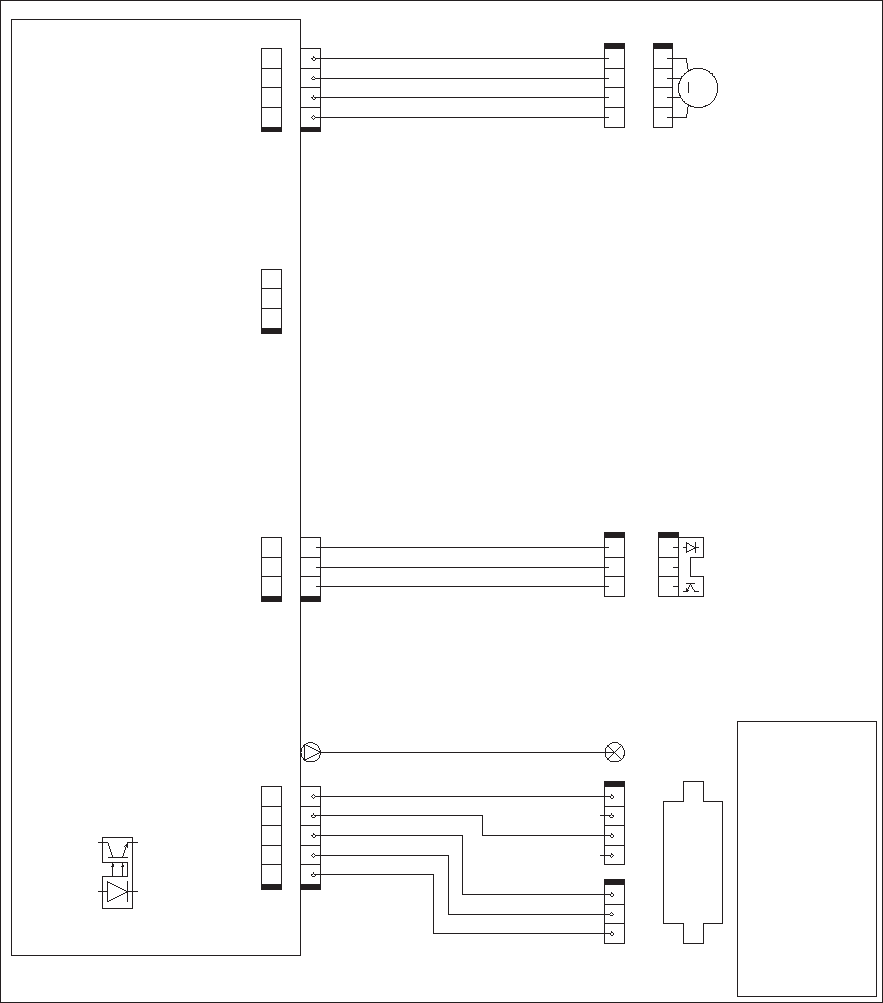
Figure 3-34 Envelope feeder circuit diagram
GND
24V
STS
CMD
CLK
*A
*B
A
B
CPU
GND
3.3V
M
1234
23451
13
24
2341
321
1234
231 2341 123
123
Envelope
presence sensor
Envelope multiple
feed sensor
Envelope feeder driver PCA
To printer
M1800
PS1802
PS1800
Envelope feeder
pickup motor
Not used
FT1800
J1804
MT1800
J1802
J1852
J1854 J1855
J1801
J1850
J1800
J1856
ENWW Tools for troubleshooting 239
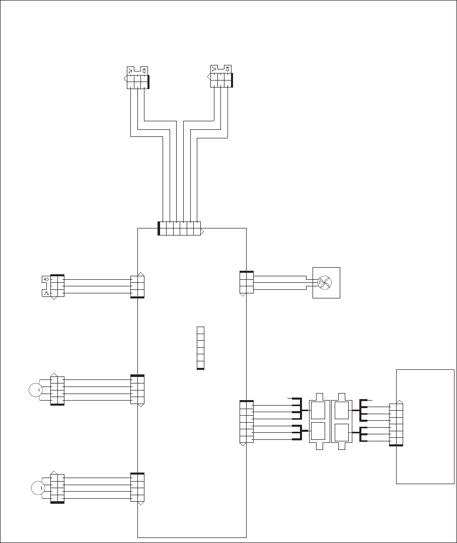
Figure 3-35 Duplexer circuit diagram
GND
/OPSIN
+24V
DUPARI
/OPSCLK
OPSOUT
GND
FLOCK0
FDRIVE
GND
+3.3V
MOD2
MOD0
IOT TXD
IOT RXD
GND
FUPSNS
PICKDR
GND
PICKSNS
FU_DR
IMOUTA
IMOUT/A
IMOUTB
IMOUT/B
PMOUT/B
PMOUTB
PMOUT/A
PMOUTA
REJISNS
GND
REJI_DR
B3 A4
B3 A4
M
4
1
2
5
6
3
123
123456
654321
3
2
1
123
4321
321
4231
432 1
132
123
1234
123
123456
654321
654321
4
1
2
5
6
3
3
2
1
3
2
1
3
2
1
1234
321
321
123
4321
4321
4321
1234
1234
M
Duplex feed motor Side registration guide
home position sensor
Duplex
Reverse motor
M1502
M1501
PS1503
Duplex cooling
fan
FM1501
Face-up sensor
Duplex media
re-pickup sensor
PS1502
PS1501
Duplex driver PCA
To printer
J1522
J1520 J1521
J1504
J1505
J1502
J1501
J66
J1524
J1523
J1503
J124LA
J124LB J124L
J124DA
J124DB
J124D
J1506
J1500
240 Chapter 3 Solve problems ENWW

Internal print-quality test pages
Print-quality-troubleshooting pages
Use the built-in print-quality-troubleshooting pages to help diagnose and solve print-quality problems.
1. Press the Home button.
2. Open the following menus:
●Administration
●Troubleshooting
●Print Quality Pages
3. Scroll to the Print Fuser Test Page item, and then press the OK button.
ENWW Tools for troubleshooting 241

Clean the paper path
Process a cleaning page
1. Press the Home button.
2. Open the following menus:
●Device Maintenance
●Calibrate/Cleaning
3. Scroll to the Print Cleaning Page item, and then press the OK button.
4. The product prints a cleaning page, and then returns to the main menu. Discard the printed page.
Set up an auto cleaning page
Use the procedure in this section to set up an automatic cleaning page.
1. Press the Home .
2. Open the following menus:
●Device Maintenance
●Calibrate/Cleaning
●Cleaning Settings
3. Use the arrow keys and the OK button to select and set the following settings:
●Auto Cleaning
◦Set to On
●Cleaning Interval
◦Select the number of pages at which to automatically clean the paper path
TIP: HP recommends processing a cleaning page after every 5000 printed pages.
●Cleaning Size
◦Select Letter or A4
242 Chapter 3 Solve problems ENWW

Print configuration page
Depending on the model, up to three pages print when you print a configuration page. In addition to
the main configuration page, the embedded Jetdirect configuration pages print.
Configuration page
Use the configuration page to view current product settings, to help troubleshoot product problems, or
to verify installation of optional accessories, such as memory (DIMMs), paper trays, and printer
languages.
1. Press the Home button.
2. Open the following menus:
●Administration
●Reports
●Configuration/Status Pages
3. Scroll to the Configuration Page item, and then press the OK button.
ENWW Tools for troubleshooting 243
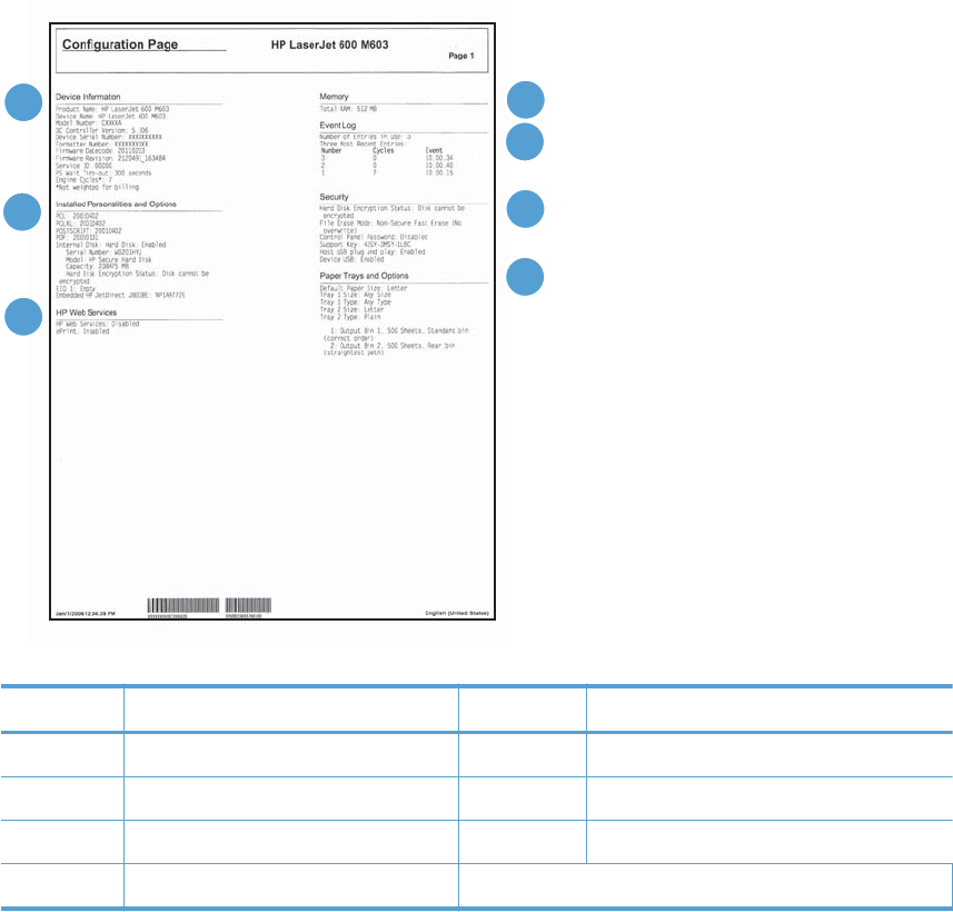
4. Scroll to the Print item, and then press the OK button.
Figure 3-36 Configuration page
5
6
1
2
3
4
7
Table 3-16 Configuration page elements
Item Description Item Description
1 General Information 5 Event Log
2 Installed Personalities and Options 6 Security
3 HP Web Services 7 Paper Trays and options
4Memory
244 Chapter 3 Solve problems ENWW
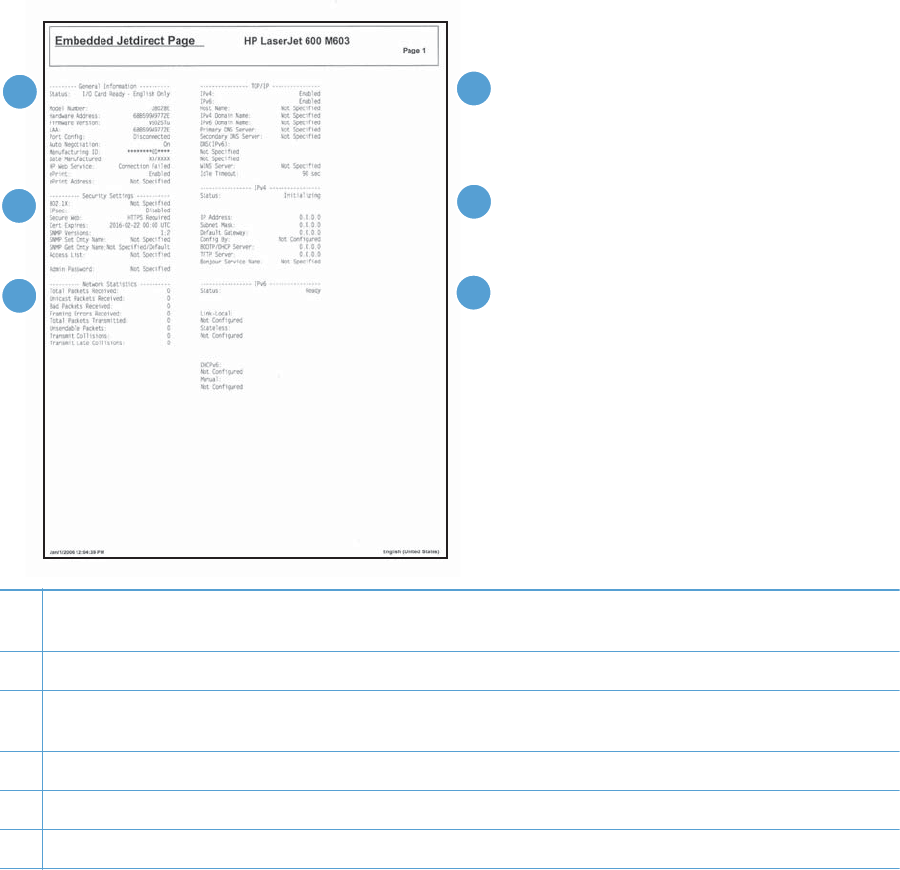
HP embedded Jetdirect page
The second configuration page is the HP embedded Jetdirect page, which contains the following
information:
Figure 3-37 HP embedded Jetdirect page
5
6
1
2
3
4
1HP Jetdirect Configuration indicates the product status, model number, hardware firmware version, port select, port
configuration, auto negotiation, manufacturing identification, and manufactured date.
2Security Settings information
3Network Statistics indicates the total packets received, unicast packets received, bad packets received, framing
errors received, total packets transmitted, unsendable packets, transmit collisions, and transmit late collisions.
4TCP/IP information, including the IP address
5IPv4 information
6IPv6 information
Always make sure the status line under the HP Jetdirect configuration lines indicates "I/O Card Ready".
ENWW Tools for troubleshooting 245

Print quality troubleshooting tools
Repetitive image defect ruler
Defects on product rollers can cause image defects to appear at regular intervals on the page,
corresponding to the circumference of the roller that is causing the defect. Measure the distance
between defects that recur on a page. Use the following table or the repetitive-defect ruler to determine
which roller is causing the defect. To resolve the problem, try cleaning the roller before replacing it.
CAUTION: Do not use solvents or oils to clean rollers. Instead, rub the roller with lint-free paper. If
dirt is difficult to remove, rub the roller with lint-free paper that has been dampened with water.
NOTE: The following table replaces the graphical repetitive defect ruler. You can make your own
ruler by using these measurements. For the most accurate results, use a metric ruler.
Table 3-17 Repetitive defects
Component Distance between defects
Primary charging roller 37.7 mm (1.5 inches)
Transfer roller 47 mm (1.85 inches)
Developer roller 63 mm (2.5 inches)
Tray 1 pickup roller 63 mm (2.5 inches)
Tray 1 feed roller
Tray 1 separation roller
79 mm (3.1 inches)
Tray 2 feed roller
Tray 2 pickup roller
Tray 2 separation roller
79 mm (3.1 inches)
Fuser sleeve unit or pressure roller 94 mm (3.75 inches)
Photosensitive drum 94 mm (3.75 inches)
NOTE: Defects on the tray pickup rollers or the Tray 1 pickup roller do not cause a repetitive defect.
Defects on these rollers cause a defect to appear only on the leading edge of the image.
To use all of the capabilities of this product, a firmware upgrade might be required. HP recommends
that you periodically go to www.hp.com/go/lj600Series_software to see if a new version of firmware
is available.
246 Chapter 3 Solve problems ENWW

Control-panel menus
Retrieve Job from USB menu
NOTE: You must enable this feature by using the control-panel menus or the HP Embedded Web
Server before it can be used.
To enable this feature by using the control-panel menus, open the Administration menu, open the
Retrieve From USB Settings sub menu, and then select the Enable option. To enable this feature
by using the HP Embedded Web Server, click the Print tab.
To display: At the product control panel, press the Home button, and then select the Retrieve
Job from USB menu.
First level Second level Values
Select a file or folder <Job name> Copies
Retrieve Job from Device Memory menu
To display: At the product control panel, press the Home button, and then select the Retrieve
Job from Device Memory menu.
First level Second level Values
All Jobs (With PIN) Print Copies
Print and Delete Copies
Delete
All Jobs (No PIN) Print Copies
Print and Delete Copies
Delete Yes
No
<Job name with PIN> Print Copies
Print and Delete Copies
Delete
<Job name without PIN> Print Copies
Print and Delete Copies
Delete Yes
No
ENWW Tools for troubleshooting 247

Supplies menu
To display: At the product control panel, press the Home button, and then select the Supplies
menu.
In the following table, asterisks (*) indicate the factory default setting.
Table 3-18 Supplies menu
First level Second level Third level Fourth level Values
Manage Supplies Print Supplies Status
Supply Settings Black Cartridge Very Low Settings Stop
Prompt to continue
Continue*
Low Threshold
Settings
1-100%
Default values for the
CE390A cartridge:
●M601 = 8%
●M602 = 11%
●M603 = 20%
Default values for the
CE390X cartridge:
●M602 = 5%
●M603 = 9%
Maintenance Kit Very Low Settings Stop
Prompt to continue
Continue*
Low Threshold
Settings
1-100%
Default = 10%
Supply Messages Low Message On*
Off
Level Gauge On*
Off
Reset Supplies New Maintenance Kit No
Yes
Black Cartridge The status is displayed.
Maintenance Kit The status is displayed.
248 Chapter 3 Solve problems ENWW

Trays menu
To display: At the product control panel, press the Home button, and then select the Trays menu.
In the following table, asterisks (*) indicate the factory default setting.
Table 3-19 Trays menu
First level Second level Values
Manage Trays Use Requested Tray Exclusively*
First
Manually Feed Prompt Always*
Unless Loaded
Size/Type Prompt Display*
Do Not Display
Use Another Tray Enabled*
Disabled
Alternative Letterhead Mode Disabled*
Enabled
Duplex Blank Pages Auto *
Yes
Tray 2 Model Standard Tray*
Custom Tray
Image Rotation Standard*
Alternate
Override A4/Letter Yes*
No
Envelope Feeder Size Select a size from the list.
Envelope Feeder Type Select a type from the list.
Tray <X> Size Select a size from the list.
Tray <X> Type Select a type from the list.
ENWW Tools for troubleshooting 249

Administration menu
Reports menu
To display: At the product control panel, press the Home button, select the Administration
menu, and then select the Reports menu.
Table 3-20 Reports menu
First level Second level
Configuration/Status Pages Administration Menu Map
Configuration Page
Supplies Status Page
Usage Page
File Directory Page
Current Settings Page
Other Pages PCL Font List
PS Font List
General Settings menu
To display: At the product control panel, press the Home button, select the Administration
menu, and then select the General Settings menu.
In the following table, asterisks (*) indicate the factory default setting.
Table 3-21 General Settings menu
First level Second level Third level Fourth level Values
Date/Time Settings Date/Time Format Date Format DD/MMM/YYYY
MMM/DD/YYYY
YYYY/MMM/DD
Time Format 12 hour (AM/PM)
24 hours
Date/Time Date Month
Day
Year
Select values from the
lists.
Time Hour
Minute
AM/PM
Select values from the
lists.
250 Chapter 3 Solve problems ENWW

Table 3-21 General Settings menu (continued)
First level Second level Third level Fourth level Values
Time Zone Select the time zone from
the list.
Adjust for Daylight
Savings
On*
Off
Energy Settings Sleep Timer Settings Sleep/Auto Off Timer Enabled*
Disabled
Sleep/Auto Off After If you enabled the sleep/
auto off timer, enter a
value between 0 and
120 minutes.
Default value: 30 minutes
Wake/Auto On
Events
All Events*
Network port
Power button only
Print Quality Image Registration Adjust Tray <X> Print Test Page
X1 Shift
Y1 Shift
X2 Shift
Y2 Shift
-5.00 mm to 5.00 mm
Adjust Paper Types Select from a list of paper
types that the product
supports. The available
options are the same for
each paper type.
Print Mode Select from a list of print
modes.
Resistance Mode Normal
Up
Down
Humidity Mode Normal
High
Restore Modes
Optimize Line Detail Normal*
Alternate 1
Alternate 2
Alternate 3
Off
ENWW Tools for troubleshooting 251

Table 3-21 General Settings menu (continued)
First level Second level Third level Fourth level Values
Restore Optimize
Resolution 300 x 300 dpi
600 x 600 dpi
FastRes 1200*
ProRes 1200
Economode Off*
On
Toner Density Range: 1 - 5
Default = 3
Quiet Mode Off*
On
Jam Recovery Auto*
Off
On
Manage Stored Jobs Quick Copy Job
Storage Limit
1-100
Default = 32
Quick Copy Job Held
Timeout
Off*
1 Hour
4 Hours
1 Day
1 Week
Default Folder Name
Sort Stored Jobs By Job Name*
Date
Restore Factory
Settings
252 Chapter 3 Solve problems ENWW

Retrieve From USB Settings menu
To display: At the product control panel, press the Home button, select the Administration
menu, and then select the Retrieve From USB Settings menu.
Table 3-22 Retrieve From USB Settings menu
First level Values
Enable Retrieve from USB Enabled
Disabled*
General Print Settings menu
To display: At the product control panel, press the Home button, select the Administration
menu, and then select the General Print Settings menu.
In the following table, asterisks (*) indicate the factory default setting.
Table 3-23 Print Settings menu
First level Second level Values
Manual Feed Enabled
Disabled*
Courier Font Regular*
Dark
Wide A4 Enabled
Disabled*
Print PS Errors Enabled
Disabled*
Print PDF Errors Enabled
Disabled*
Personality Auto*
PCL
PS
PDF
PCL Form Length Range: 5 – 128
Default = 60
Orientation Portrait*
Landscape
ENWW Tools for troubleshooting 253

Table 3-23 Print Settings menu (continued)
First level Second level Values
Font Source Internal*
USB
Font Number Range: 0 – 110
Default = 0
Font Pitch Range: 0.44 – 99.99
Default = 10.00
Font Point Size Range: 4.00 – 999.75
Default = 12.00
Symbol Set Select from a list of symbol sets.
Append CR to LF No*
Yes
Suppress Blank Pages No*
Yes
Media Source Mapping Standard*
Classic
254 Chapter 3 Solve problems ENWW

Default Print Options menu
To display: At the product control panel, press the Home button, select the Administration
menu, and then select the Default Print Options menu.
In the following table, asterisks (*) indicate the factory default setting.
First level Second level Values
Number of Copies
Default Paper Size Select from a list of sizes that the product
supports.
Default Custom Paper Size Unit of Measure Inches
mm
X Dimension
Y Dimension
Output Bin Select from a list of available output bins.
Sides 1-sided*
2-sided
2-Sided Format Book-style*
Flip-style
Edge-To-Edge Enabled
Disabled*
Display Settings menu
To display: At the product control panel, press the Home button, select the Administration
menu, and then select the Display Settings menu.
In the following table, asterisks (*) indicate the factory default setting.
Table 3-24 Display Settings menu
First level Second level Values
Display Brightness Range -10 to 10
Language Select from a list of languages that the
product supports.
Show IP Address Display
Hide
Inactivity Timeout Range: 10 – 300 seconds
Default = 60 seconds
ENWW Tools for troubleshooting 255

Table 3-24 Display Settings menu (continued)
First level Second level Values
Clearable Warnings On
Job*
Continuable Events Auto continue (10 seconds)*
Press OK to continue
Manage Supplies menu
To display: At the product control panel, press the Home button, select the Administration
menu, and then select the Manage Supplies menu.
In the following table, asterisks (*) indicate the factory default setting.
Table 3-25 Manage Supplies menu
First level Second level Third level Values
Print Supplies Status
Supply Settings Black Cartridge Very Low Settings Stop
Prompt to continue
Continue*
Low Threshold Settings 1-100%
Default values for the CE390A
cartridge:
●M601 = 8%
●M602 = 11%
●M603 = 20%
Default values for the CE390X
cartridge:
●M602 = 5%
●M603 = 9%
Maintenance Kit Very Low Settings Stop
Prompt to continue
Continue*
Low Threshold Settings 1-100%
Default = 10%
Supply Messages Low Message On*
Off
256 Chapter 3 Solve problems ENWW

Table 3-25 Manage Supplies menu (continued)
First level Second level Third level Values
Level Gauge On*
Off
Reset Supplies New Maintenance Kit No
Yes
Manage Trays menu
To display: At the product control panel, press the Home button, select the Administration
menu, and then select the Manage Trays menu.
In the following table, asterisks (*) indicate the factory default setting.
Table 3-26 Manage Trays menu
First level Values
Use Requested Tray Exclusively*
First
Manually Feed Prompt Always*
Unless Loaded
Size/Type Prompt Display*
Do Not Display
Use Another Tray Enabled*
Disabled
Alternative Letterhead Mode Disabled*
Enabled
Duplex Blank Pages Auto *
Yes
Tray 2 Model Standard Tray
Custom Tray
Image Rotation Standard
Alternate
Override A4/Letter Yes*
No
ENWW Tools for troubleshooting 257

Stapler/Stacker Settings menu
To display: At the product control panel, press the Home button, select the Administration
menu, and then select the Stapler/Stacker Settings menu.
In the following table, asterisks (*) indicate the factory default setting.
Table 3-27 Stapler/Stacker Settings menu
First level Values
Stapling None*
Top left or right
Top left
Top right
Staples Very Low Continue*
Stop
Multi-Bin Mailbox Settings menu
To display: At the product control panel, press the Home button, select the Administration
menu, and then select the Multi-Bin Mailbox Settings menu.
In the following table, asterisks (*) indicate the factory default setting.
Table 3-28 Multi-Bin Mailbox Settings menu
First level Values
Operation Mode Mailbox*
Stacker
Job Separator
Collator
258 Chapter 3 Solve problems ENWW

Network Settings menu
To display: At the product control panel, press the Home button, select the Administration
menu, and then select the Network Settings menu.
In the following table, asterisks (*) indicate the factory default setting.
Table 3-29 Network Settings menu
First level Values
I/O Timeout Range: 5 – 300 sec
Default = 15
Jetdirect Menu See the table that follows for details.
Table 3-30 Jetdirect Menu
First level Second level Third level Fourth level Values
Information Print Sec Page Yes
No*
TCP/IP Enable On*
Off
Host Name
IPV4 Settings Config Method Bootp
DHCP*
Auto IP
Manual
Manual Settings
NOTE: This menu is
available only if you
select the Manual option
under the Config
Method menu.
IP Address Enter the address.
Subnet Mask Enter the address.
Default Gateway Enter the address.
Default IP Auto IP*
Legacy
DHCP Release No*
Yes
DHCP Renew No*
Yes
ENWW Tools for troubleshooting 259

Table 3-30 Jetdirect Menu (continued)
First level Second level Third level Fourth level Values
Primary DNS
Secondary DNS
IPV6 Settings Enable Off
On*
Address Manual Settings Enable
Address
DHCPV6 Policy Router Specified
Router Unavailable*
Always
Primary DNS
Secondary DNS
Proxy Server
Proxy Port
Idle Timeout
Security Secure Web HTTPS Required*
HTTPS Optional
IPSEC Keep
Disable*
802.1X Reset
Keep*
Reset Security Yes
No*
Diagnostics Embedded Tests LAN HW Test Yes
No*
HTTP Test Yes
No*
SNMP Test Yes
No*
Data Path Test Yes
No*
260 Chapter 3 Solve problems ENWW

Table 3-30 Jetdirect Menu (continued)
First level Second level Third level Fourth level Values
Select All Tests Yes
No*
Execution Time [H] Range: 1 – 60 hours
Default = 1 hour
Execute No*
Yes
Ping Test Dest Type IPV4
IPV6
Dest IPv4
Dest IPv6
Packet Size
Timeout
Count
Print Results Yes
No
Execute Yes
No
Ping Results Packets Sent
Packets Received
Percent Lost
RTT Min
RTT Max
RTT Average
Ping in Progress Yes
No
ENWW Tools for troubleshooting 261

Table 3-30 Jetdirect Menu (continued)
First level Second level Third level Fourth level Values
Refresh Yes
No
Link Speed Auto*
10T Half
10T Full
100TX Half
100TX Full
1000T Full
262 Chapter 3 Solve problems ENWW

Troubleshooting menu
To display: At the product control panel, press the Home button, select the Administration
menu, and then select the Troubleshooting menu.
In the following table, asterisks (*) indicate the factory default setting.
Table 3-31 Troubleshooting menu
First level Second level Third level Values
Print Event Log
View Event Log
Print Paper Path Page
Print Quality Pages Print Fuser Test Page
Diagnostic Tests Paper Path Sensors Select from a list of the product
sensors.
Paper Path Test Print Test Page
Source Select from a list of the available
trays.
Destination Select from a list of the available
bins.
Duplex Off*
On
Copies 1*
10
50
100
500
Stacking Off
On
Manual Sensor Test
Manual Tray/Bin Sensor
Test
Component Test
Print/Stop Test Range: 0 – 60,000
ENWW Tools for troubleshooting 263

Device Maintenance menu
Backup/Restore menu
CAUTION: Data backup and restoration is the responsibility of the customer/administrator of the
product. Service personnel should not back up or restore customer data under any circumstances.
To display: At the product control panel, press the Home button, select the Device
Maintenance menu, and then select the Backup/Restore menu.
In the following table, asterisks (*) indicate the factory default setting.
Table 3-32 Backup/Restore menu
First level Second level Third level Values
Backup Data Scheduled Backups Enable Scheduling Enter a time
Days Between Enter the number of days
Backup Now
Export Last Backup
Restore Data Insert a USB drive that contains
the backup file.
Calibrate/Cleaning menu
To display: At the product control panel, press the Home button, select the Device
Maintenance menu, and then select the Calibrate/Cleaning menu.
In the following table, asterisks (*) indicate the factory default setting.
Table 3-33 Calibrate/Cleaning menu
First level Second level Values
Cleaning Settings Auto Cleaning Off*
On
Cleaning Interval From the list, select the number of pages at
which to automatically clean the product.
Cleaning Size Letter
A4
Print Cleaning Page
264 Chapter 3 Solve problems ENWW

USB Firmware Upgrade menu
To display: At the product control panel, press the Home button, select the Device
Maintenance menu, and then select the USB Firmware Upgrade menu.
Insert a USB storage device with a firmware upgrade bundle into the USB port, and follow the on-
screen instructions.
Service menu
To display: At the product control panel, press the Home button, select the Device
Maintenance menu, and then select the Service menu.
The Service menu is locked and requires a PIN for access. This menu is intended for use by authorized
service personnel.
ENWW Tools for troubleshooting 265

Interpret control-panel messages, status-alert messages, and event
code errors
The control-panel messages and event code errors indicate the current product status or situations that
might require action.
NOTE: Event log errors do not appear on the control-panel display. Access the event log to view or
print the event log errors.
Control-panel messages appear temporarily and might require that you acknowledge the message by
pressing the OK button to resume printing or by pressing the Stop button to cancel the job. With
certain messages, the job might not finish printing or the print quality might be affected. If the message
is related to printing and the auto-continue feature is on, the product will attempt to resume printing
after the message has appeared for 10 seconds without acknowledgement.
For some messages, restarting the product might fix the problem. If a critical error persists, the product
might require service.
10.00.33
Description
A used supply is in use (end of life).
Recommended action
No action necessary.
10.00.35
Description
An incompatible supply is in use.
Recommended action
Install the correct HP print cartridge for this product (CE390A or CE390X).
NOTE: The CE390X cartridge is not compatiable with the HP LaserJet Enterprise 600 M601.
10.00.60
Description
The black cartridge is low.
Recommended action
If print quality is no longer acceptable, replace the print cartridge.
TIP: Advise the customer that HP recommends that they have replacement supplies available to install
when the print quality is no longer acceptable.
266 Chapter 3 Solve problems ENWW

10.00.69
Description
The black cartridge is very low.
Recommended action
If print quality is no longer acceptable, replace the print cartridge.
TIP: Advise the customer that HP recommends that they have replacement supplies available to install
when the print quality is no longer acceptable.
10.00.91
Description
Cartridge motor stall.
Recommended action
Replace the print cartridge.
10.0X.Y0 Supply memory error
Description
The product cannot read or write to at least one print cartridge memory tag or a memory tag is missing
from the print cartridge.
Memory error (Y = 0)
◦10.00.00 (event code)
Black print cartridge
Memory tag missing (Y = 1)
◦10.00.10 (event code)
Black print cartridge
Recommended action
1. Remove, and then reinstall the indicated print cartridge.
2. If the error reappears, turn the power off, and then on.
3. Check the cartridge memory tag. If it is damaged, replace the cartridge.
4. If the error persists, replace the indicated print cartridge.
ENWW Tools for troubleshooting 267

10.23.35
Description
An incompatible fuser is in use.
Recommended action
Replace the fuser.
TIP: Advise the customer that HP recommends that they have replacement supplies available to install
when the print quality is no longer acceptable.
10.23.50
Description
The fuser kit life was reset above the order threshold.
Recommended action
No action necessary.
10.23.51
Description
The fuser kit life was reset above the replace threshold.
Recommended action
No action necessary.
10.23.52
Description
The fuser kit life was reset above the reset threshold.
Recommended action
No action necessary.
10.23.60
Description
The product indicates when fuser kit is very low. The actual remaining fuse kit life might vary.
You do not need to replace the fuser kit at this time unless print quality is no longer acceptable.
NOTE: After an HP supply has reached the very low threshold, the HP premium protection warranty
ends.
268 Chapter 3 Solve problems ENWW

Recommended action
If print quality is no longer acceptable, replace the fuser kit. See the parts chapter in the service manual
for the fuser kit part number.
TIP: Advise the customer that HP recommends that they have replacement supplies available to install
when the print quality is no longer acceptable.
10.23.70 Printing Past Very Low
Description
The product indicates when the fuser kit is very low. The actual remaining fuse kit life might vary.
You do not need to replace the fuser kit at this time unless print quality is no longer acceptable.
NOTE: After an HP supply has reached the very low threshold, the HP premium protection warranty
ends.
Recommended action
If print quality is no longer acceptable, replace the fuser kit. See the parts chapter in the service manual
for the fuser kit part number.
TIP: Advise the customer that HP recommends that they have replacement supplies available to install
when the print quality is no longer acceptable.
10.26.15
Description
The product indicates when the maintenance might need to be replaced.
Recommended action
If print quality is no longer acceptable, replace the maintenance kit. See the parts chapter in the service
manual for the maintenance kit part number.
TIP: Advise the customer that HP recommends that they have replacement supplies available to install
when the print quality is no longer acceptable.
10.26.50
Description
The maintenance kit was reset.
Recommended action
No action required.
ENWW Tools for troubleshooting 269

10.26.60
Description
The product indicates when the maintenance kit is very low. The actual remaining maintenance kit life
might vary.
You do not need to replace the maintenance kit at this time unless print quality is no longer acceptable.
NOTE: After an HP supply has reached the very low threshold, the HP premium protection warranty
ends.
Recommended action
If print quality is no longer acceptable, replace the maintenance kit. See the parts chapter in the service
manual for the maintenance kit part number.
TIP: Advise the customer that HP recommends that they have replacement supplies available to install
when the print quality is no longer acceptable.
10.XX.34 Used Supply In Use
Description
The print cartridge is used.
◦10.00.34 (event code)
Black print cartridge
Recommended action
If you believe this is a genuine HP supply, go to www.hp.com/go/anticounterfeit.
NOTE: Removing a cartridge from one product and then installing it in a different product (for testing
functionality) will cause this event code.
10.XX.40 Genuine HP Supplies Installed
Description
A genuine HP print cartridge has been installed.
◦10.00.40 (event code)
Black print cartridge
Recommended action
No action necessary.
270 Chapter 3 Solve problems ENWW

10.XX.41 Unsupported Supply In Use
Description
The installed print cartridge is for a different product.
◦10.00.41 (event code)
Black print cartridge
Recommended action
Remove the print cartridge, and then install the correct cartridge for this product.
TIP: See the parts chapter in the service manual for the correct cartridge part number.
10.XX.70 Printing past very low
Description
The product indicates when a supply level is very low. The actual remaining print cartridge life might
vary.
You do not need to replace the print cartridge at this time unless print quality is no longer acceptable.
NOTE: After an HP supply has reached the very low threshold, the HP premium protection warranty
ends.
◦10.00.70 (event code)
Black print cartridge
Recommended action
If print quality is no longer acceptable, replace the print cartridge. See the parts chapter in the service
manual for the correct cartridge part number.
TIP: Advise the customer that HP recommends that they have replacement supplies available to install
when the print quality is no longer acceptable.
10.YY.15 Install <supply>
Description
The indicated supply has been removed or installed incorrectly.
◦10.00.15 (event code)
Black print cartridge
◦10.23.15
Fuser kit
ENWW Tools for troubleshooting 271

Recommended action
Replace or install the indicated supply.
See the parts chapter in the service manual for the correct supply or kit part number.
10.YY.35 Incompatible <supply>
Description
The indicated supply is not compatible with this product.
◦10.00.35 (event code)
Black print cartridge
◦10.23.35 (event code)
Fuser
Recommended action
CAUTION: The fuser might be hot. Be careful when removing the fuser.
Install a supply that is designed for this product.
See the parts chapter in the service manual for the correct supply part number.
11.00.YY Internal clock error
Description
The product real time clock has experienced an error.
◦01=dead clock
◦02=dead real time clock
Recommended action
Whenever the product is turned off and then turned on again, set the time and date at the control
panel.
If the error persists, you might need to replace the formatter.
13.00.00
Description
Generic jam event code.
Recommended action
Check the product for a jam. See the clear jams section in the service manual.
272 Chapter 3 Solve problems ENWW
13.00.EE
Description
Unknown door open
Recommended action
make sure that all of the doors and covers are closed.
13.A3.FF
Description
Power on jam at the Tray 3 feed sensor.
Recommended action
Check the product for a jam. See the clear jams section in the service manual.
13.D3.DZ
Description
Late to duplex re-feed jam
◦13.D3.D1 (event code)
◦13.D3.D2 (event code)
◦13.D3.D3 (event code)
◦13.D3.D4 (event code)
◦13.D3.D5 (event code)
◦13.D3.D6 (event code)
◦13.D3.DD (event code)
◦13.D3.DE (event code)
Recommended action
Check the product for a jam. See the clear jams section in the service manual.
13.E5.FF
Description
A power on jam has occurred.
Recommended action
Check the product for a jam. See the clear jams section in the service manual.
ENWW Tools for troubleshooting 273
13.EA.EE
Description
A door jam has occurred.
Recommended action
Check the product for a jam. See the clear jams section in the service manual.
Use the component test to isolate a faulty door switch or sensor.
13.EE.FF
Description
A power on jam has occurred.
Recommended action
Check the product for a jam. See the clear jams section in the service manual.
13.FF.EE
Description
A door jam has occurred.
Recommended action
Check the product for a jam. See the clear jams section in the service manual.
Use the Manual sensors test or Tray/Bin manual sensors test to isolate a faulty door switch or sensor.
13.FF.FF
Description
A power on residual paper jam has occurred (sensor).
Recommended action
Check the product for a jam. See the clear jams section in the service manual.
Use the Manual sensors test or Tray/Bin manual sensors test to isolate a faulty door switch or sensor.
13.WX.EE
Description
This jam occurs when a door is opened during printing.
Recommended action
Make sure that the doors are fully closed.
274 Chapter 3 Solve problems ENWW
13.WX.FF
Description
Power on residual paper jam
This jam occurs when the paper exists at any of the paper path jam sensors at power on or door close.
Due to the current FW timing requirements, the displayed jam code is always 13.FF.FF, only the event
log will have 13.WX.FF
Recommended action
Clear the jam. See the clear jams section in the service manual.
13.WX.YZ Fuser Area Jam
Description
A jam in the fuser area has occurred.
Recommended action
Clear the jam. See the clear jams section in the service manual.
Make sure media is within specifications, check for obstructions in the fuser, check that the T2 roller is
installed properly.
13.WX.YZ Fuser wrap jam
Description
Recommended action
Clear the jam. See the clear jams section in the service manual.
13.WX.YZ Jam below control panel
Description
◦13.B2.9Z (event code)
Page at duplex switchback jam.
Z = the source tray number
Recommended action
Check the product for a jam. See the clear jams section in the service manual.
13.WX.YZ Jam in Tray 1
Description
◦13.B2.D1 (event code)
ENWW Tools for troubleshooting 275
Late to registration jam, from Tray 1
This jam occurs when the paper does not reach the TOP sensor in designated amount of time from
the start of paper pickup at printing from Tray 1 and duplex printing.
Recommended action
Clear the jam. See the clear jams section in the service manual.
13.WX.YZ Jam in Tray <X>
Description
A misfeed jam has occurred.
Recommended action
Clear the jam. See the clear jams section in the service manual.
13.WX.YZ Jam inside envelope feeder
Description
A jam exists inside the envelope feeder.
Recommended action
Clear the jam. See the clear jams section in the service manual.
13.WX.YZ Jam inside top cover
Description
A jam exists inside the top cover.
Recommended action
Clear the jam. See the clear jams section in the service manual.
14.00.XX
Description
A feed roller error has occurred.
◦14.00.01 (event code)
◦14.00.02 (event code)
◦14.00.03 (event code)
◦14.00.04 (event code)
◦14.00.05 (event code)
◦14.00.06 (event code)
276 Chapter 3 Solve problems ENWW
Recommended action
Check the product and accessories feed rollers for dirt or damage. Clean or replace the rollers as
necessary.
20.00.00 Insufficient memory: <Device> To continue, touch “OK”
Description
The product has experienced a memory error. You might have tried to transfer too many fonts or
macros.
Recommended action
Touch the OK button to print the transferred data (some data might be lost), and then simplify the print
job or install additional memory.
21.00.00 Page Too Complex
Description
The page decompression process was too slow for the printer.
Recommended action
Touch the OK button to continue printing (some data might be lost).
32.08.AX
Description
◦32.08.A1 (event code)
Shutdown event
◦32.08.A2 (event code)
Boot from normal shutdown event
◦32.08.A3 (event code)
Boot from abnormal shutdown event
Recommended action
No action necessary.
ENWW Tools for troubleshooting 277
32.1C.XX
Description
◦32.1C.01 (event code)
NVRAM backup/restore service backup started
◦32.1C.02 (event code)
NVRAM backup/restore service restore started
◦32.1C.03 (event code)
NVRAM backup/restore administrator backup started
◦32.1C.04 (event code)
NVRAM backup/restore administrator restore started
◦32.1C.05 (event code)
Backup/restore complete
◦32.1C.06 (event code)
Data model failed to clone job ticket
◦32.1C.07 (event code)
Backup restore permissions error
◦32.1C.08 (event code)
Not enough disk space to perform backup/restore or network share issue
◦32.1C.09 (event code)
Tried to restore a backup file that was not valid for this product
◦32.1C.0A (event code)
Backup file is invalid
◦32.1C.0B (event code)
Backup is from newer version of FW than what is currently on the product
◦32.1C.0C (event code)
Backup cancelled from the HP Embedded Web Server
◦32.1C.0D (event code)
Backup/restore failed, auto-reboot failed, or the product might be busy
◦32.1C.0E (event code)
Backup/restore timeout while communicating with the formatter
278 Chapter 3 Solve problems ENWW
◦32.1C.0F (event code)
Backup/restore timeout while communicating with the finisher firmware
◦32.1C.10 (event code)
Backup/restore timeout while communicating with the scanner firmware
◦32.1C.11 (event code)
Backup/restore timeout while communicating with the engine
◦32.1C.12 (event code)
Backup/restore timeout while communicating with the disk
◦32.1C.13 (event code)
Scheduled backup failure
◦32.1C.14 (event code)
NVRAM restore timeout while communicating with the formatter
◦32.1C.15 (event code)
NVRAM restore timeout while communicating with the finisher firmware
◦32.1C.16 (event code)
NVRAM restore timeout while communicating with the scanner firmware
◦32.1C.17 (event code)
NVRAM restore timeout while communicating with the engine
◦32.1C.18 (event code)
Backup of copy subsystem failed
◦32.1C.19 (event code)
Backup of fax subsystem failed
◦32.1C.1A (event code)
Backup of digital send subsystem failed
◦32.1C.1B (event code)
Backup of print subsystem failed
◦32.1C.1C (event code)
Backup of networking subsystem failed
◦32.1C.1D (event code)
Backup of finishing subsystem failed
ENWW Tools for troubleshooting 279
◦32.1C.1E (event code)
Restore of copy subsystem failed
◦32.1C.1F (event code)
Restore of fax subsystem failed
◦32.1C.20 (event code)
Restore of digital send subsystem failed
◦32.1C.21 (event code)
Restore of print subsystem failed
◦32.1C.22 (event code)
Restore of networking subsystem failed
◦32.1C.24 (event code)
NVRAM backup/restore successful
◦32.1C.25 (event code)
Reset of copy subsystem failed
◦32.1C.26 (event code)
Reset of fax subsystem failed
◦32.1C.27 (event code)
Reset of digital send subsystem failed
◦32.1C.28 (event code)
Reset of print subsystem failed
◦32.1C.29 (event code)
Reset of networking subsystem failed
◦32.1C.2A (event code)
Reset of finishing subsystem failed
◦32.1C.2B (event code)
Reset formatter timeout
◦32.1C.2C (event code)
Reset finisher timeout
◦32.1C.2D (event code)
Reset scanner timeout
280 Chapter 3 Solve problems ENWW
◦32.1C.2E (event code)
Reset engine timeout
◦32.1C.2F (event code)
Reset failure
Recommended action
◦32.1C.01 (event code)
No action necessary
◦32.1C.02 (event code)
No action necessary
◦32.1C.03 (event code)
No action necessary
◦32.1C.04 (event code)
No action necessary
◦32.1C.05 (event code)
No action necessary
◦32.1C.06 (event code)
Retry
◦32.1C.07 (event code)
Retry
◦32.1C.08 (event code)
Remove stored jobs and retry
Use larger capacity storage device
Check network share
◦32.1C.09 (event code)
Use a valid backup file
◦32.1C.0A (event code)
Use a valid backup file
Reboot and observe state of product
Do a partition clean using the Preboot menu.
◦32.1C.0B (event code)
ENWW Tools for troubleshooting 281
Use a valid backup file or put correct firmware version on the product.
◦32.1C.0C (event code)
No action necessary
◦32.1C.0D (event code)
Reboot and then retry the backup/restore
◦32.1C.0E (event code)
Turn the product off then on and retry
◦32.1C.0F (event code)
Turn the product off then on and retry
◦32.1C.10 (event code)
Turn the product off then on and retry
◦32.1C.11 (event code)
Turn the product off then on and retry
◦32.1C.12 (event code)
Turn the product off then on and retry
◦32.1C.13 (event code)
Turn the product off then on and retry
◦32.1C.14 (event code)
Turn the product off then on and retry
◦32.1C.15 (event code)
Turn the product off then on and retry
◦32.1C.16 (event code)
Turn the product off then on and retry
◦32.1C.17 (event code)
Turn the product off then on and retry
◦32.1C.18 (event code)
Turn the product off then on and retry
◦32.1C.19 (event code)
Turn the product off then on and retry
◦32.1C.1A (event code)
282 Chapter 3 Solve problems ENWW
Turn the product off then on and retry
◦32.1C.1B (event code)
Turn the product off then on and retry
◦32.1C.1C (event code)
Turn the product off then on and retry
◦32.1C.1D (event code)
Turn the product off then on and retry
◦32.1C.1E (event code)
Turn the product off then on and retry
If the error persists, clear the firmware image from the active partition by using the Partial Clean
item in the Preboot menu.
◦32.1C.1F (event code)
Turn the product off then on and retry
If the error persists, clear the firmware image from the active partition by using the Partial Clean
item in the Preboot menu.
◦32.1C.20 (event code)
Turn the product off then on and retry
If the error persists, clear the firmware image from the active partition by using the Partial Clean
item in the Preboot menu.
◦32.1C.21 (event code)
Turn the product off then on and retry
If the error persists, clear the firmware image from the active partition by using the Partial Clean
item in the Preboot menu.
◦32.1C.22 (event code)
Turn the product off then on and retry
If the error persists, clear the firmware image from the active partition by using the Partial Clean
item in the Preboot menu.
◦32.1C.24 (event code)
Turn the product off then on and retry.
◦32.1C.25 (event code)
Turn the product off then on and retry.
◦32.1C.26 (event code)
ENWW Tools for troubleshooting 283
Turn the product off then on and retry.
◦32.1C.27 (event code)
Turn the product off then on and retry.
◦32.1C.28 (event code)
Turn the product off then on and retry.
◦32.1C.29 (event code)
Turn the product off then on and retry.
◦32.1C.2A (event code)
Turn the product off then on and retry.
◦32.1C.2B (event code)
Turn the product off then on and retry.
◦32.1C.2C (event code)
Turn the product off then on and retry.
◦32.1C.2D (event code)
Turn the product off then on and retry.
◦32.1C.2E (event code)
Turn the product off then on and retry.
◦32.1C.2f (event code)
Turn the product off then on and retry.
32.21.00
Description
Corrupt firmware in external accessory
Recommended action
Turn the product off, then on, and retry.
If the error persists, clear the firmware image from the active partition by using the Partial Clean item
in the Preboot menu
284 Chapter 3 Solve problems ENWW
33.01.XX
Description
◦33.01.01 (event code)
A restore process has occurred.
◦33.01.02 (event code)
A save process has occurred.
Recommended action
No action necessary.
33.XX.YY Used board/disk
Description
An encrypted board or disk with existing data previously locked to a different product has replaced the
original. If you continue, data is permanently lost.
Recommended action
To save the data on the board or disk, turn the product off. Replace the board or disk with another
board or disk.
To delete the data on the board or disk and continue, touch the OK button.
40.00.01 USB I/O buffer overflow To continue, touch “OK”
Description
The USB buffer has overflowed.
Recommended action
Touch the OK button to print the transferred data (some data might be lost).
Check the host configuration.
40.00.02 Embedded I/O buffer overflow To continue, touch “OK”
Description
The product has experienced a JetDirect buffer overflow.
Recommended action
Touch the OK button to print the transferred data (some data might be lost).
Check the host configuration.
ENWW Tools for troubleshooting 285
40.00.05 Embedded I/O bad transmission To continue, touch “OK”
Description
The USB device has been removed.
Recommended action
Touch the OK button to clear the error message. (Data will be lost.)
Install the USB device.
41.02.00 Error
Description
A beam detected misprint error.
Recommended action
Turn the product off, and then on.
If the error persists, replace the laser/scanner assembly.
41.03.YZ Unexpected size in envelope feeder To use another tray, touch
"Options"
Description
The product detected a different paper size than expected.
◦Y = 0
Size mismatch. Detected media is longer or shorter than expected.
◦Y = A
Size mismatch. Detected media too long.
◦Y = B
Size mismatch. Detected media too short.
◦Y = C
Size mismatch. Inter-page gap error.
◦Z = D
Source is duplexer
◦Z = E
Source is envelope feeder
◦Z = 2
286 Chapter 3 Solve problems ENWW
Source is Tray 2
◦Z = 3
Source is Tray 3
◦Z = 4
Source is Tray 4
◦Z = 5
Source is Tray 5
Recommended action
Make sure that the feeder is loaded with the correct paper size and that the sliding paper guides are
correctly adjusted.
Use the Tray/Bin manual sensor test to verify that the envelope feeder paper sensor (PS1802) is
correctly functioning.
If the error persists, replace the envelope feeder.
41.03.YZ Unexpected size in tray <X>
Description
The product detected a different paper size than expected.
◦Y = 0
Size mismatch. Detected media is longer or shorter than expected.
◦Y = A
Size mismatch. Detected media too long.
◦Y = B
Size mismatch. Detected media too short.
◦Y = C
Size mismatch. Inter-page gap error.
◦Z = D
Source is duplexer
◦Z = E
Source is envelope feeder
◦Z = 1
Source is Tray 1
ENWW Tools for troubleshooting 287
◦Z = 2
Source is Tray 2
◦Z = 3
Source is Tray 3
◦Z = 4
Source is Tray 4
◦Z = 5
Source is Tray 5
Recommended action
Make sure that the tray is loaded with the correct paper size and that the sliding paper guides are
correctly adjusted.
Use the Tray/Bin manual sensor test to verify that the cassette media switch is correctly functioning.
If the error persists, replace the lifter assembly.
41.05.YZ Unexpected type in tray <X>
Description
The product detected a different paper type than expected.
◦Y = 0 (expected type)
Unknown
◦Y = 1 (expected type)
Normal media
◦Y = 3 (expected type)
LBP OHT
◦Y = 6 (expected type)
Non-assured OHT
◦Y = 7 (expected type)
Heavy media
◦Y = 8 (expected type)
Light media
◦Y = 9 (expected type)
Rough media
288 Chapter 3 Solve problems ENWW
◦Y = C (expected type)
Heavy media 3
◦Y = D (expected type)
Heavy media 2
◦Z = 1 (detected type)
Normal media
◦Z = 3 (detected type)
LBP OHT
◦Z = 6 (detected type)
Non-assured OHT
◦Z = 7 (detected type)
Heavy media
◦Z = 8 (detected type)
Light media
◦Z = 9 (detected type)
Rough media
◦Z = B (detected type)
Heavy glossy media (glossy media 2)
◦Z = C (detected type)
Heavy media 3
◦Z = D (detected type)
Heavy media 2
Recommended action
Load the tray with the size and type of paper indicated, or use another tray if available.
If this message appears and the tray is loaded with the correct paper type, check the print driver
settings to make sure they match the tray type settings.
Clean the Media Sensor.
If the error persists, replace the paper pickup assembly.
ENWW Tools for troubleshooting 289
41.XX.YZ Error To continue, touch “OK”
Description
A product error has occurred.
◦XX = error type
◦Y = fuser mode
◦Z = input tray
◦XX = 02
Beam detect misprint
◦XX = 09
Sub thermistor abnormally high
◦XX = 18
Scan line inclination adjustment
◦XX = 20
Image drum HV
◦Y = 2
Normal typed (not AutoSense)
◦Y = 3)
Light media 1, 2, 3: typed or AutoSense
◦Y = 4
Heavy media 1: typed or AutoSense
◦Z = 0
Envelope feeder
◦Z = 1
Tray 1
◦Z = 2
Tray 2
◦Z = 3
Tray 3
◦Z = 4
Tray 4
290 Chapter 3 Solve problems ENWW
◦Z = 5
Tray 5
◦Z = 6
Tray 6
◦Z = D
Duplexer
Recommended action
Turn the product off, and then on.
If the error persists, replace the DC controller PCA.
42.XX.YY
Description
Internal system failure
Recommended action
Turn the product of,f then on, and retry.
If the error persists, clear the firmware image from the active partition by using the Partial Clean item
in the Preboot menu.
47.00.XX
Description
Back channel internal error
Recommended action
Turn the product off, and then on again. Resend the print job.
If the error persists, execute the Partial Clean item in the Preboot menu.
47.01.XX
Description
Image transformer internal error
Recommended action
Turn the product off, and then on again. Resend the print job.
If the error persists, execute the Partial Clean item in the Preboot menu.
ENWW Tools for troubleshooting 291
47.02.XX
Description
Job parser internal error
Recommended action
Turn the product off, and then on again. Resend the print job.
If the error persists, execute the Partial Clean item in the Preboot menu.
47.03.XX
Description
Print job internal error
Recommended action
Turn the product off, and then on again. Resend the print job.
If the error persists, execute the Partial Clean item in the Preboot menu.
47.04.XX
Description
Print spooler 9100 internal error
Recommended action
Turn the product off, and then on again. Resend the print job.
If the error persists, execute the Partial Clean item in the Preboot menu.
47.05.00
Description
Print spooler framework internal error
Recommended action
Turn the product off, and then on again. Resend the print job.
If the error persists, execute the Partial Clean item in the Preboot menu.
47.06.XX
Description
Print App internal error
292 Chapter 3 Solve problems ENWW
Recommended action
Turn the product off, and then on again. Resend the print job.
If the error persists, execute the Partial Clean item in the Preboot menu.
47.WX.YZ Printer Calibration Failed To continue, touch “OK”
Description
The device is unable to access or implement one of the image patterns files.
Y = calibration type, Z = event
◦47.FC.20 (event code)
Error Diffusion Image not found at system initialization
◦47.FC.21 (event code)
Error Diffusion Store image failure
◦47.FC.22 (event code)
Error Diffusion Image not found
◦47.FC.23
Error Diffusion Print engine execution failure
◦47.FC.300 (event code)
Drum Speed Adjustment Image not found at system initialization
◦47.FC.31 (event code)
Drum Speed Adjustment Store image failure
◦47.FC.32 (event code)
Drum Speed Adjustment Image not found
◦47.FC.33 (event code)
Drum Speed Adjustment Print engine execution failure
◦47.FC.40 (event code)
Pulse Width Modulation Image not found at system initializatione
◦47.FC.41 (event code)
Pulse Width Modulation Store image failure
◦47.FC.42 (event code)
Pulse Width Modulation Image not found
◦47.FC.43 (event code)
ENWW Tools for troubleshooting 293
Pulse Width Modulation Print engine execution failure
Recommended action
Turn the product off, and then on.
If the error persists, reload the firmware.
49.XX.YY To continue turn off then on
Description
A firmware error has occurred.
Recommended action
1. Turn the product off, and then on.
2. If the error returns, check the following:
●The error might be caused by a network connectivity problem.
●Damaged interface cable
●Damaged USB port
●Invalid network configuration setting
●The error might be caused by the print job.
●Invalid printer driver
●Problem with the software application
●Problem with the file
3. If the error persists, perform a firmware upgrade.
50.WX.YZ Fuser error To continue turn off then on
Description
The fuser has experienced an error.
W = fuser error code, X = fuser mode, Y = previous printer sleep state, Z = next printer sleep state
Recommended action
W = 2
Fuser warm up failure
1. Reconnect the connector (J128) between the fuser and the DC controller PCA.
2. Turn the product off. Remove the fuser and then reinstall it. If the error persist, replace the fuser.
3. If the error persists, replace the low-voltage power supply.
294 Chapter 3 Solve problems ENWW

W = 3
Low temperature thermistor 1
1. Reinstall the fuser. Check the connector (J128) between the fuser and the product. If it is damaged,
replace the fuser.
2. Reconnect the connector (J82) on the DC controller PCA.
3. Replace the fuser.
4. W = 2: Reconnect the connector (J62) on the low-voltage power supply PCA.
5. If the error persists, replace the low-voltage power supply.
W = 4
High temperature thermistor 1
1. Reinstall the fuser. Check the connector (J128) between the fuser and the product. If it is damaged,
replace the fuser.
2. Reconnect the connector (J82) on the DC controller PCA.
3. Replace the fuser.
4. If the error persists, replace the low-voltage power supply.
W = 6
Drive circuit fault
1. Check the power source. Make sure the power source meets product requirements.
NOTE: If the power source does not meet the power frequency requirement of 40 to 70Hz, the
fuser temperature control does not work properly and causes this error.
2. Reconnect connectors J51, J52, J53, and J162 and DC controller PCA connectors J85, J95, and
J96.
3. If the error persists, replace the low-voltage power supply.
W = 10
Low temperature thermistor 2
1. Reinstall the fuser. Check the connector (J128) between the fuser and the product. If it is damaged,
replace the fuser.
2. Reconnect the connector (J62) on the low-voltage power supply PCA.
3. If the error persists, replace the low-voltage power supply.
W = 11
ENWW Tools for troubleshooting 295
High temperature thermistor 2
1. Reinstall the fuser. Check the connector (J128) between the fuser and the product. If it is damaged,
replace the fuser.
2. Reconnect the connector (J62) on the low-voltage power supply PCA.
3. If the error persists, replace the low-voltage power supply.
W = 12
Fuser pressure release mechanism failure
1. Reconnect the fuser connector (J128) and the DC controller PCA connector (J62).
2. Check the fuser pressure release sensor flag. If the flag is damaged or not properly working,
replace the fuser.
3. Reconnect the fuser motor connector (J221) and the DC controller PCA connector (J89).
4. Use the Component Test item in the Troubleshooting menu to test the fuser motor. If the
motor fails the test, replace the fuser motor.
5. If the error persists replace the fuser.
51.00.YY Error
Description
Laser/scanner error
◦YY = 20
Black laser/scanner error
Recommended action
1. Reconnect connector (J145) on the laser/scanner.
2. Reconnect connectors (J86 and J93) on the DC controller.
3. If the error persists, replace the laser/scanner.
52.XX.00 Error To continue turn off then on
Description
Laser/scanner error
◦XX = 00
laser/scanner motor startup error
◦XX = 20
Laser/scanner rotation error
296 Chapter 3 Solve problems ENWW

Recommended action
1. Reconnect connector (J145) on the laser/scanner.
2. Reconnect connectors (J86 and J93) on the DC controller.
3. Use the scanner motor (M108) drive test in the component test to verify that the scanner motor is
properly functioning. If it is not, replace the laser/scanner.
NOTE: Listen for a high pitched whine from the motor.
4. If the error persists, replace the laser/scanner.
54.XX.YY Error
Description
A sensor error has occurred.
Recommended action
54.00.03
Environmental sensor (TH3) failure
1. Turn the product off, and then reconnect the connector (J63) on the DC controller PCA. Turn the
product on.
2. If the environment sensor has been removed or replaced, check the connector (J199) on the
environment sensor and the connector (J63) on the DC controller PCA.
3. If the error persists, replace the environment sensor assembly.
54.06.21
Primary laser/scanner beam detect abnormality
1. Turn the product off, and then on.
2. If the product has had parts removed or replace, check the connector (J93) on the DC controller
PCA.
3. If the error persists, replace the laser/scanner assembly.
ENWW Tools for troubleshooting 297
55.00.YY DC controller error To continue turn off then on
Description
DC controller PCA error
◦55.00.01 (event code)
DC controller memory error
◦55.00.03 (event code
DC controller no engine response
◦55.00.04 (event code
DC controller communications timeout
Recommended action
Turn the product off, and then on.
If the error persists, replace the DC controller PCA.
55.0X.YY DC controller error To continue turn off then on
Description
DC controller PCA error
◦55.01.06 (event code)
NVRAM memory data error warning
◦55.02.06 (event code)
NVRAM memory access error warning
Recommended action
Turn the product off, and then on.
If the error persists, replace the DC controller PCA.
56.00.YY Error To continue turn off then on
Description
Optional paper trays communication error
Recommended action
Turn the product off, and then on.
If the error persists, reseat the optional paper trays (1 x 500-sheet feeder and/or 3 x 500-sheet feeder).
Check the input connectors for damage. If a connector is damaged, replace the connector.
298 Chapter 3 Solve problems ENWW
57.00.0Y Error To continue turn off then on
Description
Fan error
Recommended action
57.00.03
Main fan (FN101) failure
1. Turn the product off, and then on. Listen for fan noise at the back corner of the product. If no noise
is heard, replace the power supply fan (FN101).
2. If the fan has been removed or replaced, check the connector (J64) on the DC controller PCA.
3. If the error persists, replace the main fan (FN101).
57.00.04
Laser/scanner fan (FN102) failure
1. If this part has been removed or replace, check the connector (J75) on the DC controller PCA.
2. If the error persists, replace the laser/scanner fan (FN102).
57.00.06
Cartridge fan (FN301) failure
1. If this part has been removed or replace, check the connector (J95) on the DC controller PCA.
2. If the fan has been removed or replaced, check the connector (J66) on the DC controller PCA.
3. If the error persists, replace the cartridge fan (FN301).
57.00.05
Cartridge front-side fan (FN103) failure
1. Turn the product off, and then on. Listen for fan noise at the middle back of the product. If no noise
is heard, replace the cartridge front-side fan (FN103).
2. If the fan has been removed or replaced, check the connector (J79) on the DC controller PCA.
3. If the error persists, replace the cartridge front-side fan (FN103).
57.00.07
Duplex fan (FN107) failure
1. Turn the product off, and then on. Listen for fan noise at the left side of the product. If no noise is
heard, replace the duplex fan (FN107).
2. If the fan has been removed or replaced, check the connector (J64) on the DC controller PCA.
3. If the error persists, replace the duplexer.
ENWW Tools for troubleshooting 299
58.00.0Y Error To continue turn off then on
Description
A sensor error has occurred.
Recommended action
58.00.05
Environmental sensor (TH3) failure
1. Turn the product off.
2. If this part has been removed or replace, check the connector (J63) on the DC controller PCA.
3. If the error persists, replace the environmental sensor (TH3).
58.00.03
DC controller CPU failure
1. Turn the product off.
2. Check all of the connectors on the DC controller PCA.
3. If the error persists, replace the DC controller PCA.
58.00.04
LVPS failure
1. Turn the product off.
2. If this part has been removed or replace, check the connector (J50) on the LVPS, and then check
the connector (J85 and J95) on the DC controller PCA.
3. If the error persists, replace the LVPS.
59.00.YY error To continue turn off then on
Description
A motor error has occurred.
◦YY = 00
Paper path malfunction
Recommended action
59.00.20 or 59.00.30
300 Chapter 3 Solve problems ENWW
Feed motor (M101) failure (start-up or rotational)
1. Reconnect the connector (J191) on the feed motor and the connector (J91) on the DC controller
PCA.
2. Use the feed motor (M101) drive test in the Component test to verify that the motor is properly
functioning. If is not, replace the feed motor (M101).
59.00.40 or 59.00.50
Fuser motor (M299) failure (start-up or rotational)
1. Reconnect the connector (J221) on the feed motor and the connector (J89) on the DC controller
PCA.
2. Use the fuser motor (M299) drive test in the Component test to verify that the motor is properly
functioning. If it is not, replace the fuser motor (M299).
59.00.60 or 59.00.70
Drum motor (M102) failure (start-up or rotational)
1. Reconnect the connector (J187) on the drum motor and the connector (J87) on the DC controller
PCA.
2. Use the drum motor (M102) drive test in the Component test to verify that the motor is properly
functioning. If it is not, replace the drum motor (M102).
59.A2.0x Error
Description
A product error has occurred.
Recommended action
59.A2.02 or 59.A2.11
Lifter driver assembly Tray 2 failure
1. Use the Tray/Bin manual sensor test to verify that the Tray 2 paper (PS107 and PS907) surface
sensors are properly functioning.
2. If this part has been removed or replace, check the connector (J73 and J94) on the on the DC
controller PCA.
3. Check the media stack surface sensor lever and place it in the correct position to move smoothly.
Replace the media stack surface sensor lever if it is damaged.
4. If the error persists, replace the lifter drive assembly (Tray 2).
59.A2.12 to 59.A2.15
ENWW Tools for troubleshooting 301
Lifter driver assembly Tray 3 to 6 motor failure
1. Reconnect the connectors (J1605 and J1608) on the paper feeder drive PCA.
2. Reconnect the connectors (J1703 and J1707) on the paper cassette drive PCA.
3. Replace the sheet feeder media stack surface sensor.
4. If the error persists, replace the lifter motor for the specific sheet feeder.
60.00.0Y Tray <Y> lifting error
Description
A tray lift motor error has occurred.
Recommended action
60.00.02
Lifter driver assembly Tray 2 failure
1. Use the Tray/Bin manual sensor test to verify that the Tray 2 paper (PS107 and PS907) surface
sensors are properly functioning.
2. If this part has been removed or replace, check the connector (J73 and J94) on the on the DC
controller PCA.
3. Check the media stack surface sensor level and place it in the correct position to move smoothly.
Replace the sensor lever if it is damaged.
4. Replace the media stack surface sensor.
5. If the error persists, replace the lifter drive assembly (Tray 2).
60.00.12 to 60.00.15
Lifter driver assembly Tray 3 failure
1. Use the Tray/Bin manual sensor test to verify that the Tray 3 paper (SR1 and SR2) surface sensors
are properly functioning.
2. If this part has been removed or replace, check the connector (1605 and 1608) on the on the
paper feeder controller PCA.
3. Reconnect the connectors (J1703 and J1707) on the sheet feeder PCA.
4. Replace the sheet feeder media stack surface sensor.
5. If the error persists, replace the lifter drive assembly (Tray 3-6).
62.00.00 No system To continue turn off then on
Description
Internal system failure
302 Chapter 3 Solve problems ENWW
Recommended action
Turn the product off, and then on.
If the error persists, reload the firmware. If the error still persists, perform a firmware upgrade.
If the firmware upgrade does not resolve the problem, replace the hard disk.
65.X0.A1 Output accessory disconnected
Description
An external paper handling accessory connection has been interrupted.
Recommended action
1. Turn the product off.
2. Make sure that all packing materials have been removed from the paper handling accessory.
3. Check the paper path for obstructions, or jammed paper.
4. Check the accessory cable connection.
5. Turn the product on. If the error persists, replace the accessory.
66.80.YY Stapler/Stacker failure
Description
An external paper handling accessory error has occurred.
◦66.80.01 (event code)
Y-align malfunction
◦66.80.02 (event code)
Jogger malfunction
◦66.80.03 (event code)
Stapler malfunction
◦66.80.21 (event code)
Lift up malfunction
◦66.80.22 (event code)
Lift down malfunction
◦66.80.23 (event code)
Lift sensor malfunction
◦66.80.33 (event code)
ENWW Tools for troubleshooting 303
Output roller malfunction
◦66.80.35 (event code)
Self priming malfunction
◦66.80.51 (event code)
System error (FW error)
◦66.80.55 (event code)
System error 5 (FW error)
◦66.80.56 (event code)
System error 6 (FW error)
◦66.80.57 (event code)
System error 7 (FW error)
◦66.80.58 (event code)
System error 8 (FW error)
◦66.80.59 (event code)
System error 9 (FW error)
◦66.80.60 (event code)
System error 10 (inter-page delay mismatch)
◦66.80.61 (event code)
System error 11 (lifter task trouble)
◦66.80.62 (event code)
System error 12 (inter-page delay mismatch)
◦66.80.63 (event code)
System error 13 (FW error)
◦66.80.64 (event code)
System error 14 (FW error)
◦66.80.65 (event code)
System error 15 (FW error)
◦66.80.70 (event code)
Page-info in flush
◦66.80.71 (event code)
304 Chapter 3 Solve problems ENWW
Flush request in PDLV
◦66.80.72 (event code)
Delivery notice error
◦66.80.73 (event code)
Flush request in checking paper path
◦66.80.74 (event code)
Checking paper path start in PDLV
◦66.80.75 (event code)
Flush request in flush
◦66.80.76 (event code)
Non-flush complete
Recommended action
Turn the product off, and then on.
If the error persists, replace the paper handling device.
69.11.YY Error To continue turn off then on
Description
Duplexer error
Recommended action
Turn the product off, and then on.
If the error persists, replace the duplexer.
70.00.00 Error To continue turn off then on
Description
DC controller failure
Recommended action
Turn the product off, and then on.
If the error persists, replace the DC controller.
ENWW Tools for troubleshooting 305
79.XX.YY Error To continue turn off then on
Description
This error can be caused by corrupted print jobs, software application issues, non-product specific
printer drivers, poor-quality USB or network cables, bad network connections or incorrect network
configurations, invalid firmware operations, or unsupported accessories.
Recommended action
1. Turn the product off, and then on.
2. If the error persists, check the following:
●The error might be caused by a network connectivity problem, such as a bad interface cable,
a bad USB port, or an invalid network configuration setting.
●The error might be caused by the print job, an invalid print driver, a problem with the
software application, or a problem with the file you are printing.
Make sure you are using the correct printer driver. Try printing using a different software
application. Try printing a different file or print job.
●Upgrading the product firmware might resolve the problem.
80.0X.YY Embedded JetDirect error
Description
Embedded HP JetDirect print server critical error
◦80.01.80 (event code)
No heartbeat
◦80.01.81 (event code)
Reclaim timeout
◦80.01.82 (event code)
Invalid data length
◦80.01.8B (event code)
Invalid max outstanding packet header field
◦80.01.8C (event code)
Invalid channel mapping response
◦80.03.01 (event code)
No PGP buffers
◦80.03.02 (event code)
306 Chapter 3 Solve problems ENWW
Channel table full
◦80.03.03 (event code)
Producer index not reset
◦80.03.04 (event code)
Consumer index not reset
◦80.03.05 (event code)
Queue position size too small
◦80.03.06 (event code)
Transport overflow
◦80.03.07 (event code)
No overflow packets
◦80.03.08 (event code)
Invalid identify response
◦80.03.09 (event code)
Invalid channel map return status
◦80.03.1080.03.10 (event code)
Invalid reclaim return status
◦80.03.12 (event code)
Datagram invalid buffer
◦80.03.13 (event code)
Max stream channels
◦80.03.14 (event code)
Max datagram channels
◦80.03.15 (event code)
Card reset failed
◦80.03.16 (event code)
Self test failure
◦80.03.17 (event code)
Unknown PGP packet
◦80.03.18 (event code)
ENWW Tools for troubleshooting 307
Duplicate I/O channel.
Recommended action
Turn the product off, and then on.
If the error persists, replace the formatter.
81.YY.ZZ EIO-1 Card Failure
Description
An EIO error has occurred.
◦81.01.80 (event code)
No heartbeat
◦81.01.81 (event code)
Reclaim timeout
◦81.01.82 (event code)
Invalid data length
◦81.01.8B (event code)
Invalid max outstanding
◦81.01.8C (event code)
Invalid channel mapping
◦81.03.01 (event code)
No PGP buffers
◦81.03.02 (event code)
Channel table full
◦81.03.03 (event code)
Producer index not reset
◦81.03.04 (event code)
Consumer index not reset
◦81.03.05 (event code)
Queue position size
◦81.03.06 (event code)
Transport overflow
◦81.03.07 (event code)
308 Chapter 3 Solve problems ENWW
No overflow packets
◦81.03.08 (event code)
Invalid identify response
◦81.03.09 (event code)
Invalid channel map return
◦81.03.10 (event code)
Invalid reclaim return status
◦81.03.12 (event code)
Datagram invalid buffer
◦81.03.13 (event code)
Max stream channels
◦81.03.14 (event code)
Max datagram channels
◦81.03.15 (event code)
Card reset failed
◦81.03.16 (event code)
Self test failure
◦81.03.17 (event code)
Unknown PGP packet
◦81.03.18 (event code)
Duplicate I/O channel
Recommended action
Turn the product off, and then on.
If the error persists, replace the EIO device..
82.73.46 OR 82.73.47
Description
A hard disk or compact flash disk cleaning failed. Usually caused by a failure of the disk hardware.
ENWW Tools for troubleshooting 309
Recommended action
1. Turn the product off, and then on.
2. Use the Clean Disk item in the Preboot menu.
3. Reload the firmware.
98.00.01 Corrupt data in firmware volume
Description
Data corruption has occurred in the firmware volume
Recommended action
Turn the product off, and then on.
Use the Clean Disk item in the Preboot menu.
Reload the firmware.
98.00.02 Corrupt data in solutions volume
Description
Data corruption has occurred in the solutions volume
Recommended action
Turn the product off, and then on.
Use the Clean Disk item in the Preboot menu.
Reload the firmware.
98.00.03 Corrupt data in configuration volume
Description
Data corruption has occurred in the configuration volume
Recommended action
Turn the product off, and then on.
Use the Clean Disk item in the Preboot menu.
Reload the firmware.
98.00.04 Corrupt data in job data volume
Description
Data corruption has occurred in the job data volume
310 Chapter 3 Solve problems ENWW
Recommended action
Turn the product off, and then on.
Rerun the file erase function.
99.00.01 Upgrade not performed file is corrupt
Description
A remote firmware upgrade (RFU) was not performed.
CRC error in the firmware image (bad image).
Recommended action
Download the RFU file and attempt the upgrade again.
99.00.02 Upgrade not performed timeout during receive
Description
A remote firmware upgrade (RFU) was not performed.
I/O timeout when reading header number and size. Indicates a problem with the network environment,
not the device.
Recommended action
The most common cause is an issue with the network environment. Make sure that there is a good
connection to the device and attempt the upgrade again, or upgrade using the USB walk-up port.
99.00.03 Upgrade not performed error writing to disk
Description
A remote firmware upgrade (RFU) was not performed.
Disk error. May indicate a problem or a hard disk failure. It might be necessary to check the connection
to the hard disk or replace the hard disk.
Recommended action
1. Download the RFU file and attempt the upgrade again.
2. If the error persists, perform the Clean Disk process. You will then need to download firmware
from the Preboot menu.
3. If the error persists, replace the hard disk.
99.00.04 Upgrade not performed timeout during receive
Description
A remote firmware upgrade (RFU) was not performed.
ENWW Tools for troubleshooting 311
I/O timeout when reading rest of header.
Recommended action
The most common cause is an issue with the network environment. Make sure that there is a good
connection to the device and attempt the upgrade again, or upgrade using the USB walk-up port.
99.00.05 Upgrade not performed timeout during receive
Description
A remote firmware upgrade (RFU) was not performed.
I/O timeout when reading image data.
Recommended action
The most common cause is an issue with the network environment. Make sure that there is a good
connection to the device and attempt the upgrade again, or upgrade using the USB walk-up port.
99.00.06 Upgrade not performed error reading upgrade
Description
A remote firmware upgrade (RFU) was not performed.
Unexpected read error when reading header number and size.
Recommended action
1. Download the RFU file and attempt the upgrade again.
2. If the error persists, replace the hard disk.
99.00.07 Upgrade not performed error reading upgrade
Description
A remote firmware upgrade (RFU) was not performed.
Unexpected read error when reading rest of header.
Recommended action
1. Download the RFU file and attempt the upgrade again.
2. If the error persists, replace the hard disk.
99.00.08 Upgrade not performed error reading upgrade
Description
A remote firmware upgrade (RFU) was not performed.
Unexpected read error when reading image data.
312 Chapter 3 Solve problems ENWW
Recommended action
1. Download the RFU file and attempt the upgrade again.
2. If the error persists, replace the hard disk.
99.00.09 Upgrade canceled by user
Description
A remote firmware upgrade (RFU) was not performed.
The RFU was canceled by the user.
Recommended action
Resend the RFU.
99.00.10 Upgrade canceled by user
Description
A remote firmware upgrade (RFU) was not performed.
Job canceled when reading header number and size.
Recommended action
Resend the RFU.
99.00.11 Upgrade canceled by user
Description
A remote firmware upgrade (RFU) was not performed.
Job canceled when reading rest of header.
Recommended action
Resend the RFU.
99.00.12 Upgrade not performed the file is invalid
Description
A remote firmware upgrade (RFU) was not performed.
Header number is 1 but header size doesn’t match version 1 size.
Recommended action
Download the RFU file again. Make sure that you download the file for the correct product model.
Resend the RFU.
ENWW Tools for troubleshooting 313
99.00.13 Upgrade not performed the file is invalid
Description
A remote firmware upgrade (RFU) was not performed.
Header number is 2 but header size doesn’t match version 2 size.
Recommended action
Download the RFU file again. Make sure that you download the file for the correct product model.
Resend the RFU.
99.00.14 Upgrade not performed the file is invalid
Description
A remote firmware upgrade (RFU) was not performed.
The file is invalid.
Recommended action
Download the RFU file again. Make sure that you download the file for the correct product model.
Resend the RFU.
99.00.2X
Description
◦99.00.20 (event log)
The bundle is not for this product
◦99.00.21 (event log)
The bundle is not signed with the correct signature, or the signature is invalid
◦99.00.22 (event log)
The bundle header version is not supported by this firmware
◦99.00.23 (event log)
The package header version is not supported by this firmware
◦99.00.24 (event log)
◦The format of the bundle is invalid
◦99.00.25 (event log)
The format of the package is invalid
◦99.00.26 (event log)
314 Chapter 3 Solve problems ENWW

A CRC32 check did not pass
◦99.00.27 (event log)
An I/O error occurred while downloading the bundle
Recommended action
Download the correct firmware file from www.hp.com/go/lj600Series_firmware, and then resend the
firmware upgrade.
99.00.27 only: Turn the product off, and then on again. Resend the firware upgrade. If the error
persists, try the sending the upgrade by another method (USB or Embedded Web Server).
99.09.60 Unsupported disk
Description
Preboot menu error.
The hard disk currently installed is not recognized or supported by the product.
Recommended action
Install the correct hard disk for this product.
99.09.61 Unsupported disk
Description
Preboot menu error.
The installed disk is installed in a product configured for a encrypted hard disk.
Recommended action
Access the Preboot menu and then select Lock Disk to lock the disk.
99.09.62 Unknown disk
Description
Preboot menu error.
The installed disk was previously locked in another product.
Recommended action
Install a new disk or use the Preboot menu to unlock this disk. If the disk is to be reused in a different
product, execute the Clean Disk procedure from the Preboot menu, then reload firmware and lock
the disk.
ENWW Tools for troubleshooting 315
99.09.63 Incorrect disk
Description
A new or blank disk has been installed in a device which previously had an encrypted disk.
Recommended action
Follow the procedure to load firmware on a new hard disk and then lock it to this product.
99.09.64 Disk malfunction
Description
A fatal hard disk failure has occurred.
Recommended action
Replace the hard disk drive.
99.09.65 Disk data error
Description
Disk data corruption has occurred.
Recommended action
Execute the Clean Disk procedure from the Preboot menu, and then resend the RFU.
99.09.66 No disk installed
Description
A disk drive is not installed in the product.
Recommended action
Install a compatible hard disk drive.
99.09.67 Disk is not bootable please download firmware
Description
The product has a non-secure disk (solid state disk) installed as the boot disk, and it has been replaced
with a new service part. A new firmware image needs to be downloaded to the device.
Recommended action
1. Press any key to continue to the main Preboot menu.
2. Press the Help button to see the help text for the error.
3. Select the Administrator menu.
316 Chapter 3 Solve problems ENWW

NOTE: If there is a password assigned to the Administrator, a prompt to enter the password
displays.
4. Select the Download item.
5. The user can now download a new firmware bundle to the product.
99.XX.YY
Description
Firmware installation error
Recommended action
Reload the firmware.
<binname> full Remove all paper from bin
Description
The specified output bin is full.
Recommended action
Empty the bin to continue printing.
<Supply> low OR Supplies low
Description
The product indicates when a supply level, or more than one supply, is low. Actual print cartridge life
might vary. You do not need to replace the print cartridge at this time unless print quality is no longer
acceptable.
When multiple supplies are low, more than one event code is recorded.
◦10.00.60 (event code)
Black print cartridge
◦10.23.60 (event code)
Fuser Kit
Recommended action
If print quality is no longer acceptable, replace the supply.
HP recommends that the customer have a replacement supply available to install when print quality is
no longer acceptable.
NOTE: When an HP supply has reached its approximated end of life, the HP Premium Protection
Warranty ends.
ENWW Tools for troubleshooting 317

<Supply> very low OR Supplies very low
Description
The product indicates when a supply level, or more than one supply, is very low. Actual print cartridge
life might vary. You do not need to replace the print cartridge at this time unless print quality is no
longer acceptable.
When multiple supplies are low, more than one event code is recorded.
◦10.00.70 (event code)
Black print cartridge
◦10.23.70 (event code)
Fuser Kit
Recommended action
If print quality is no longer acceptable, replace the supply.
HP recommends that the customer have a replacement supply available to install when print quality is
no longer acceptable.
NOTE: When an HP supply has reached its approximated end of life, the HP Premium Protection
Warranty ends.
[File System] device failure To clear press “OK”
Description
The specified device has failed.
Recommended action
Touch the OK button to clear the error.
[File System] file operation failure To clear press “OK”
Description
A PJL file system command attempted to perform an illogical operation.
Recommended action
Touch the OK button to clear the error.
[File System] file system is full To clear press “OK”
Description
A PJL file system command could not store something on the file system because the file system was full.
318 Chapter 3 Solve problems ENWW
Recommended action
Touch the OK button to clear the error.
[File System] is not initialized
Description
This file-storage component must be initialized before use.
Recommended action
Use the HP Embedded Web Server or HP Web Jetadmin to initialize the file system.
[File System] is write protected
Description
The file system device is protected and no new files can be written to it.
Recommended action
Press the OK button to clear the error.
Accept bad signature
Description
The product is performing a remote firmware upgrade, and the code signature is invalid.
Recommended action
Download the correct firmware upgrade file for this product, and then reinstall the upgrade. See the
product user guide for more information.
Bad optional tray connection
Description
The optional tray is not connected, not connected correctly, or a connection is not working correctly.
Recommended action
1. Turn the product off.
2. Remove and then reinstall the optional tray.
3. Reconnect connectors for the tray.
4. If the problem continues, replace the connector for the tray.
ENWW Tools for troubleshooting 319
Canceling
Description
The product is canceling the current job.
Recommended action
No action is necessary.
Canceling... <jobname>
Description
The product is canceling the current job <jobname>.
Recommended action
No action is necessary.
Cartridge Low
Description
This message appears even though the print cartridge is new.
Recommended action
1. Remove, and then reinstall the print cartridge.
2. Make sure a genuine HP supply is used.
3. If the error persists, replace the print cartridge.
Cartridge Memory Abnormal
Description
This message appears even though the print cartridge is new.
Recommended action
1. Remove, and then reinstall the print cartridge.
2. Reconnect connector (J74) on the DC controller PCA.
3. If the error persists, replace the print cartridge.
Cartridge Out
Description
This message appears even though the print cartridge is new.
320 Chapter 3 Solve problems ENWW
Recommended action
1. Remove, and then reinstall the print cartridge.
2. Make sure a genuine HP supply is used.
3. If the error persists, replace the print cartridge.
Checking engine
Description
The product is conducting an internal test.
Recommended action
No action is necessary.
Checking paper path
Description
The product is checking for possible paper jams.
Recommended action
No action is necessary.
Chosen personality not available To continue, touch “OK”
Description
A print job requested a product language (personality) that is not available for this product. The job will
not print and will be cleared from memory.
Recommended action
Print the job by using a print driver for a different language, or add the requested language to the
product (if possible). To see a list of available personalities, print a configuration page.
Cleaning do not grab paper
Description
The product is performing an automatic cleaning cycle. Printing will continue after the cleaning is
complete.
Recommended action
No action is necessary.
ENWW Tools for troubleshooting 321
Cleaning...
Description
The product is performing an automatic cleaning cycle. Printing will continue after the cleaning is
complete.
Recommended action
No action is necessary.
Clearing event log
Description
This message is displayed while the event log is cleared. The product exits the menus when the event
log has been cleared.
Recommended action
No action is necessary.
Clearing paper path
Description
The product is attempting to eject jammed paper.
Recommended action
Check progress at the bottom of the display.
Close stapler/stacker multi bin mailbox door
Description
This message appears even though the stapler/stacker multi bin mailbox door is closed.
Recommended action
1. Reconnect the connector (J465) on the stapler/stacker controller PCA.
2. Check the stapler/stacker door sensor flag. If the flag is damaged, replace the sensor flag.
Close top cover
Description
This message appears even though the top cover is closed.
322 Chapter 3 Solve problems ENWW
Recommended action
1. Verify that the switch (SW101) is properly functioning (open and close the top cover). If the switch
fails the test, replace the switch.
2. Make sure that the switch flag—at the right-side of the top cover assembly, behind the control-
panel display— is not damaged or missing. If the flag is damaged or missing, replace the top
cover assembly.
3. Reconnect the connector (J78) on the DC controller PCA.
4. If the problem persists, replace the top cover switch (SW101).
Cooling device
Description
The product is cooling.
Recommended action
No action is necessary.
Creating cleaning page...
Description
A cleaning page is being generated.
Recommended action
No action is necessary.
Data received To print last page press “OK”
Description
The product is waiting for the command to print the last page.
Recommended action
Touch the OK button to print the last page of the job.
Event log is empty
Description
No product events are in the log.
Recommended action
No action is necessary.
ENWW Tools for troubleshooting 323
Expected drive missing
Description
The product cannot find the encrypted hard drive.
Recommended action
Install the encrypted hard drive.
External device initializing
Description
An external device is initializing.
Recommended action
No action necessary.
Face Down Tray Full
Description
This message is displaying even though the tray is not full.
Recommended action
1. Check the face down tray media full sensor flag and place it in the correct position to move
smoothly. Replace sensor flag if damaged.
2. Use the Output bin full sensor (PS104) test in the Manual sensor test to verify that the sensor is
properly functioning. If it is not, replace the sensor (PS104).
3. Reconnect the connector (J176) at face down tray media full sensor and DC controller PCA (J76).
4. Reconnect the connector (J176) at face down tray media full sensor and DC controller PCA (J76).
FIM Load Error Send full FIM on <X> port
Description
The product displays this message before the firmware is loaded at startup if an error has occurred
during a firmware upgrade.
Recommended action
Resend the firmware upgrade.
Fuser Kit low
Description
10.23.60 (event code)
324 Chapter 3 Solve problems ENWW

The product indicates when a supply is low.
Recommended action
Replace the fuser.
NOTE: After replacing the fuser, reset the fuser page counter by selecting New Fuser Kit in the
Reset Supplies sub-menu.
Fuser Kit very low To continue, touch “OK”
Description
10.23.70 (event code)
The product indicates when a supply is very low.
NOTE: After an HP supply has reached the very low threshold, the HP premium protection warranty
for that supply has ended.
Recommended action
Replace the fuser.
NOTE: After replacing the fuser, reset the fuser page counter by selecting New Fuser Kit in the
Reset Supplies sub-menu.
Genuine HP cartridge installed
Description
A new HP print cartridge has been installed. The message appears for about 6 seconds before the
product returns to the Ready state.
Recommended action
No action necessary.
Genuine HP supply installed
Description
10.XX.40 (event code)
A new genuine HP print cartridge has been installed.
Recommended action
Touch the Hide button to remove this message.
HP Secure hard drive disabled
Description
The drive has been encrypted for another product.
ENWW Tools for troubleshooting 325
Recommended action
Remove the drive or use the Embedded Web Server for more information.
Incompatible <supply>
Description
The indicated supply <supply>is not compatible with this product.
◦10.00.35 (event code)
Black print cartridge
◦Fuser kit
10.23.35 (event code)
Recommended action
Replace the supply with one that is designed for this product.
Incompatible supplies
Description
Print cartridges or other supply items are installed that were not designed for this product. The product
cannot print with these supplies installed.
Event codes are supply specific.
Recommended action
Touch the OK button to identify the incompatible supplies.
Replace the supplies with those that are designed for this product.
Initializing...
Description
The product is starting.
Recommended action
No action necessary.
Install fuser unit
Description
The fuser has been removed or installed incorrectly.
326 Chapter 3 Solve problems ENWW

Recommended action
CAUTION: The fuser can be hot while the product is in use. Turn the product off, and then wait for
the fuser to cool before handling it.
1. Remove the output bin or stapler/stacker.
2. Remove the fuser entrance guide.
3. Remove the fuser.
Install supplies
Description
More than one supply is missing or is installed incorrectly.
Recommended action
Touch the OK button to identify the supplies that need to be replaced.
Touch the OK button a second time for more information about the specific supply.
Insert the supply or make sure it is correctly installed and fully seated.
Install supply
Description
A supply item is either not installed or installed incorrectly.
◦Black cartridge
10.00.15 (event code)
Recommended action
Install the supply item or make sure that the installed supply item is fully seated.
Internal disk device failure To clear press “OK”
Description
The internal disk failed.
Recommended action
Touch the OK button to clear the error.
Internal disk file operation failed
Description
A PJL system command attempted to perform an illogical operation, such as downloading a file to a
non-existent directory.
ENWW Tools for troubleshooting 327
Recommended action
Touch the OK button to clear the error.
Internal disk file system is full
Description
A PJL system command attempted to write data to the internal disk but was unsuccessful because the
disk is full.
Recommended action
Touch the OK button to clear the error.
Internal disk is write protected
Description
The internal disk is write protected and no new files can be written to it.
Recommended action
Touch the OK button to clear the error.
Internal disk not found
Description
The internal disk was not found at start up.
Recommended action
Turn the product off, and then on again.
Internal disk not functional
Description
82.0X.YY (event code)
The internal hard drive is not correctly functioning.
Recommended action
Turn the product off, remove and then reinstall the hard drive.
If the error persists, replace the internal hard drive.
Internal disk not initialized
Description
The internal disk file system must be initialized before it can be used.
328 Chapter 3 Solve problems ENWW
Recommended action
Initialize the internal disk file system.
Internal disk spinning up
Description
Internal disk device is spinning up its platter. Jobs that require disk access must wait.
Recommended action
No action is necessary.
Job not stapled due to mixed sizes
Description
This message is displayed when the job to staple has more than one paper size (paper width).
Recommended action
Paper with different widths cannot be stapled. Use the same width paper for the entire print job.
Load Tray <X>: [Type], [Size]
Description
This message appears even though there is media loaded in the tray.
Recommended action
Use the sensor tests to verify that the sensor is correctly functioning.
Make sure that the sensor flag on the media presence sensor is not damaged and moves freely.
Reconnect the corresponding connector:
◦MP tray: connector (J191) on the MP tray media feed sensor and the connector (J91) on the DC
controller PCA.
◦Printer cassette: connectors (J22) on the cassette media feed sensor and the connector (J1605) on
the DC controller PCA.
◦1 X 500-sheet paper feeder cassette: connector (J32) on the paper feeder cassette media feed
sensor and the connector (J1602) on the paper feeder controller PCA.
◦Paper deck cassette 1: connector (J32) on the paper deck cassette 1 media feed sensor and
connector (J1602) on the paper deck controller PCA 1
◦Paper deck cassette 2: connector (J13) on the paper deck cassette 2 media feed sensor and
connector (J1607) on the paper deck controller PCA 2.
◦Paper deck cassette 3: connector (J13) on the paper deck cassette 3 media feed sensor and
connector (J607) on the paper deck controller PCA 3.
ENWW Tools for troubleshooting 329

Load Tray <X>: [Type], [Size] To use another tray, press “OK”
Description
This message appears when the indicated tray is selected but is not loaded, and other paper trays are
available for use. It also appears when the tray is configured for a different paper type or size than the
print job requires.
Recommended action
Load the correct paper in the tray.
If prompted, confirm the size and type of paper loaded.
Otherwise, press the OK button to select another tray.
Loading program <XX>
Description
Programs and fonts can be stored on the product’s file system and are loaded into RAM when the
product is turned on. The number <XX> specifies a sequence number indicating the current program
being loaded.
Recommended action
No action necessary.
NOTE: Do not turn the product off.
Manually feed output stack Then touch "OK" to print second side
Description
The product has printed the first side of a manual duplex job and is waiting for the user to insert the
output stack to print the second side.
Recommended action
1. Maintaining the same orientation, remove pages from the output bin.
2. Flip document printed side up.
3. Load document in Tray 1.
4. Touch the OK button to print the second side of the job.
Manually feed: <Type><Size>
Description
This message appears when manual feed is selected, Tray 1 is not loaded, and other trays are empty.
330 Chapter 3 Solve problems ENWW

Recommended action
Load tray with requested paper.
If paper is already in tray, press the Help button to exit the message and then press the OK button to
print.
To use another tray, clear paper from Tray 1, press the Help button to exit the message and then press
the OK button.
Manually feed: <Type><Size> To use another tray, press “OK”
Description
This message appears when manual feed is selected, Tray 1 is loaded, and other trays are available.
Recommended action
Load tray with requested paper.
If paper is already in tray, press the Help button to exit the message and then press the OK button to
print.
To use another tray, clear paper from Tray 1, press the Help button to exit the message and then press
the OK button.
Moving solenoid
Description
The solenoid is moving as part of a component test.
Recommended action
To exit press
Moving solenoid and motor
Description
The solenoid and a motor are moving as part of a component test.
Recommended action
To exit press
No job to cancel
Description
You have pressed the stop button but the product is not actively processing any jobs.
Recommended action
No action necessary.
ENWW Tools for troubleshooting 331

NON HP SUPPLY INSTALLED
Description
10.99.31 (event code)
This message is displayed for about 6 seconds when a new non HP supply is installed.
Recommended action
If you believe you purchased a genuine HP supply, go to www.hp.com/go/anticounterfeit.
Output Bin Full
Description
This message appears even though the output bin is not full.
Recommended action
1. Make sure that the output bin sensor flag is not damaged and can move freely. If the flag is
damaged, replace the flag.
2. Use the output bin full sensor (PS104) test in the Manual sensor test to test the sensor. If it does not
respond, replace the output bin full sensor (PS104).
3. Reconnect connector (J76) on the DC controller PCA.
Paused…
Description
The product is paused, and there are no error messages pending at the display. The I/O continues
receiving data until memory is full.
Recommended action
Press the Stop button .
Performing Paper Path Test…
Description
A paper-path test is being performed.
Recommended action
No action necessary.
Please Wait...
Description
The product is in the process of clearing data.
332 Chapter 3 Solve problems ENWW
Recommended action
No action necessary.
Printing Configuration...
Description
The product is printing the Configuration page.
Recommended action
No action necessary.
Printing Event Log...
Description
The product is printing the Event Log page.
Recommended action
No action necessary.
Printing File Directory...
Description
The product is printing the File Directory pages.
Recommended action
No action necessary.
Printing Font List...
Description
The product is printing the Font List pages.
Recommended action
No action necessary.
Printing Fuser Test Page...
Description
The product is printing the Fuser Test page.
Recommended action
No action necessary.
ENWW Tools for troubleshooting 333
Printing Help Page...
Description
The product is printing the Help page.
Recommended action
No action necessary.
Printing Menu Map...
Description
The product is printing the Menu Map pages.
Recommended action
No action necessary.
Printing Registration Page…
Description
The product is printing the Registration pages.
Recommended action
No action necessary.
Printing stopped
Description
Time has expired on the Print/Stop test.
Recommended action
Touch the OK button to continue.
Printing Supplies Status Page...
Description
The product is printing the Supplies Status page.
Recommended action
No action necessary.
Printing Usage Page...
Description
The product is printing the Usage page.
334 Chapter 3 Solve problems ENWW

Recommended action
No action necessary.
Printing…engine test
Description
The product is printing an engine test page.
Recommended action
No action necessary.
Processing duplex job Do not grab paper until job completes
Description
Paper temporarily comes into the output bin while printing a duplex job.
CAUTION: Do not grab paper as it temporarily comes into the output bin. The message disappears
when the job is finished.
Recommended action
No action necessary.
Processing job from tray <X>... Do not grab paper until job completes
Description
The product is actively processing a job from the designated tray.
Recommended action
No action necessary.
Processing...
Description
The product is currently processing a job but is not yet picking pages. When paper motion begins, this
message is replaced by a message that indicates the tray the job is using.
Recommended action
No action necessary.
Processing... copy <X> of <Y>
Description
The product is currently processing or printing collated copies. The message indicates that copy number
<X> of total copies <Y> is currently being processed.
ENWW Tools for troubleshooting 335
Recommended action
No action necessary.
RAM disk device failure To clear press “OK”
Description
The specified device failed.
Recommended action
Touch the OK button to remove the message.
RAM disk file operation failed To clear press “OK”
Description
A PJL command was received that attempted to perform an illegal operation, such as downloading a
file to a non-existent directory.
Recommended action
Touch the OK button to clear the error.
RAM disk file system is full To clear press “OK”
Description
The hard disk is full.
Recommended action
Touch the OK button to clear the error.
RAM disk is write protected To clear press “OK”
Description
The device is protected and no new files can be written to it.
Recommended action
Touch the OK button to clear the error.
RAM disk not initialized
Description
The RAM disk file system must be initialized before it can be used.
Recommended action
Initialize the RAM disk file system.
336 Chapter 3 Solve problems ENWW

Ready
Description
The product is online and ready for data. No status or product attendance messages are pending at the
display.
Recommended action
No action necessary.
Ready <IP Address>
Description
The product is online and ready for data. No status or product attendance messages are pending at the
display. The product IP address displays.
Recommended action
No action necessary.
Receiving Upgrade
Description
The product is receiving a firmware upgrade.
Recommended action
Do not turn the product off until it reaches the Ready state.
Remove one print cartridge
Description
The product is testing the print-cartridge motor.
Recommended action
To perform the test, remove the print cartridge. To cancel the test, press the Stop button .
To exit press
Remove USB accessory
Description
This message displays when an unsupported USB device is inserted into a host USB port on the
product.
Recommended action
Remove the unsupported USB device.
ENWW Tools for troubleshooting 337

Replace <supply>
Description
This alert appears only if the product is configured to stop when a supply reaches the very low
threshold. The product indicates when a supply level is at its estimated end of life. The actual life
remaining might be different than estimated.
The supply does not need to be replaced now unless the print quality is no longer acceptable.
HP recommends that the customer have a replacement supply available to install when print quality is
no longer acceptable.
The product can be configured to stop when the supply level is very low. The supply might still be able
to produce acceptable print quality.
NOTE: When an HP supply has reached its approximated end of life, the HP Premium Protection
Warranty on that supply ends.
◦10.00.70 (event code)
Black print cartridge
◦10.23.70 (event code)
Fuser Kit
Recommended action
Replace the specified supply.
Or, configure the product to continue printing by using the Manage Supplies menu.
Replace supplies
Description
This alert appears only if the product is configured to stop when a supply reaches the very low
threshold. The product indicates when a supply level is at its estimated end of life. The actual life
remaining might be different than estimated.
The supply does not need to be replaced now unless the print quality is no longer acceptable.
HP recommends that the customer have a replacement supply available to install when print quality is
no longer acceptable.
NOTE: When an HP supply has reached its approximated end of life, the HP Premium Protection
Warranty on that supply ends.
Recorded event codes depend on which supplies are at the end of life.
◦10.00.70 (event code)
Black print cartridge
◦10.23.70 (event code)
338 Chapter 3 Solve problems ENWW
Fuser Kit
Recommended action
Touch the OK button to find out which supplies need to be replaced.
Or, configure the product to continue printing by using the Manage Supplies menu.
Resend external accessory firmware
Description
An external accessory requires a firmware upgrade. Printing can continue, but jams might occur if the
job uses the external accessory.
Recommended action
Perform a firmware upgrade.
Resend Upgrade
Description
A firmware upgrade did not complete successfully.
Recommended action
Upgrade the firmware again.
Restore Factory Settings
Description
The product is restoring factory settings.
Recommended action
No action necessary.
ROM disk device failed To clear press “OK”
Description
The specified device failed.
Recommended action
Touch the OK button to clear the error.
ROM disk file operation failed To clear press “OK”
Description
A PJL command was received that attempted to perform an illegal operation, such as downloading a
file to a non-existent directory.
ENWW Tools for troubleshooting 339

Recommended action
Touch the OK button to clear the error.
ROM disk file system is full To clear press “OK”
Description
The hard disk is full.
Recommended action
Touch the OK button to clear the error.
ROM disk is write protected To clear press “OK”
Description
The device is protected and no new files can be written to it.
Recommended action
Touch the OK button to clear the error.
ROM disk not initialized To clear press “OK”
Description
The ROM disk file system must be initialized before it can be used.
Recommended action
Initialize the ROM disk file system.
Rotating Motor
Description
The product is executing a component test and the component selected is a motor.
Recommended action
Press the Stop button when ready to stop this test.
To exit press
Size Mis-Match
Description
This message appears even though the correct size paper is loaded in the correct paper tray.
340 Chapter 3 Solve problems ENWW
Recommended action
1. Use the Tray 2 size switch (SW102) test in the Tray/Bin manual sensor test to test the switch. If it
does not respond, replace the lifter drive assembly.
2. Reconnect connector (J122) on the Tray 2 media size switch, and then reconnect connector (J72)
on the DC controller.
3. If the error persists, replace the lifter drive assembly.
Size mismatch in Tray <X>
Description
The paper in the listed tray does not match the size specified for that tray.
Recommended action
1. Load the correct paper.
2. Verify the paper is positioned correctly.
3. Close the tray, and then verify that the control panel lists the correct size and type for the specified
tray.
4. If necessary, use the control-panel menus to reconfigure the size and type settings for the specified
tray.
Sleep mode on
Description
The product is in sleep mode. Pressing a control-panel button, receiving of a print job, or an error
condition clears this message.
Recommended action
No action necessary.
Staple Cartridge low
Description
The product indicates when a supply level is low. 20 to 50 staples remain in the cartridge.
Recommended action
Replace the staple cartridge.
Staple Cartridge very low
Description
The product staple cartridge is at end of life.
ENWW Tools for troubleshooting 341

NOTE: After an HP supply has reached the very low threshold, the HP premium protection warranty
ends.
Recommended action
Replace the staple cartridge.
Stapler/Stacker staple jam
Description
A stapler/stacker jam exists.
Recommended action
13.89.33
Clear the jam. See the clear jams section in the service manual.
Supplies low
Description
Multiple supplies on the product have reached the User defined low threshold.
Recommended action
Replace the supply when print quality is no longer acceptable.
SUPPLY MEMORY WARNING
Description
The product cannot read or write to the e-label or the e-label is missing.
Recommended action
No action necessary.
The unit has corrupt data
Description
98.00.0X (event code)
Data corruption has occurred in the firmware volume
◦98.00.01
Corrupt data in the firmware volume
◦98.00.02
Corrupt data in the solutions volume
◦98.00.03
342 Chapter 3 Solve problems ENWW

Corrupt data in the configuration volume
◦98.00.04
Corrupt data in the job data volume
Recommended action
◦98.00.01 or 98.00.02 or 98.00.03
1. Turn the product off, and then on again.
2. Use the Clean Disk item in the Preboot menu.
3. Reload the firmware.
◦98.00.04
1. Turn the product off, and then on again.
2. Run the file erase function.
Tray <X> empty: [Type], [Size]
Description
The specified tray is empty and the current job does not need this tray to print.
◦X = 1
Tray 1
◦X = 2
Tray 2
◦X = 3
Tray 3
◦X = 4
Tray 4
◦X = 5
Tray 5
Recommended action
Refill the tray at a convenient time.
NOTE: This could be a false message. If the tray is loaded without removing the shipping lock, the
product does not sense that the paper is loaded. Remove the shipping lock and then load the tray.
ENWW Tools for troubleshooting 343

Tray <X> lifting
Description
The product is in the process of lifting paper in the indicated tray.
◦X = 2
Tray 2
◦X = 3
Tray 3
◦X = 4
Tray 4
◦X = 5
Tray 5
Recommended action
No action necessary.
Tray <X> open
Description
The specified tray is open or not closed completely.
◦X = 2
Tray 2
◦X = 3
Tray 3
◦X = 4
Tray 4
◦X = 5
Tray 5
Recommended action
Close the tray.
NOTE: If this message appears after lifter drive assembly was removed or replaced, make sure that
the connector on the assembly is correctly connected and fully seated.
If the error persists, use the Media size switches (SW102, SW2 , SW3, ) test in the Tray/Bin manual
sensor test to test the switches. If they do not respond, replace associated the lifter drive assembly.
344 Chapter 3 Solve problems ENWW

Tray <X> overfilled
Description
The tray is filled above the stack-height mark.
◦X = 2
Tray 2
◦X = 3
Tray 3
◦X = 4
Tray 4
◦X = 5
Tray 5
Recommended action
Remove enough paper so that the paper stack does not exceed the limit for the tray.
NOTE: If this message appears after lifter drive assembly was removed or replaced, make sure that
the connector on the assembly is correctly connected and fully seated.
Type mismatch Tray
Description
The specified tray contains a paper type that does not match the configured type.
Recommended action
The specified tray will not be used until this condition is addressed. Printing can continue from other
trays.
1. Load the correct paper in the specified tray.
2. At the control panel, verify the type configuration.
Unsupported drive installed To continue, touch “OK”
Description
A non-supported hard drive has been installed. The drive is unusable by this product.
Recommended action
1. Turn the product off.
2. Remove the hard drive.
3. Turn the product on.
ENWW Tools for troubleshooting 345
Unsupported supply in use OR Unsupported supply installed To continue,
touch “OK”
Description
A non-supported supply has been installed.
OR
The print cartridge is for a different HP product.
◦XX = 00
Black print cartridge
Recommended action
Install the correct supplies for this product. See the parts chapter in the service manual for supply part
numbers.
Unsupported tray configuration
Description
The product has too many optional trays installed.
Recommended action
Turn the product off, remove the unsupported trays, and then turn the product on.
Unsupported USB accessory detected Remove USB accessory
Description
A non-supported USB accessory has been installed.
Recommended action
Turn the product off, remove the USB accessory, and then turn the product on.
Upgrade Error
Description
30.01.36 (event code)
SCB upgrade error
Recommended action
1. Turn the product off, and then on.
2. Resend the upgrade.
3. If the error persists, replace the SCB.
346 Chapter 3 Solve problems ENWW
USB accessory not functional
Description
A parameter in the USB accessory is not correctly functioning.
Recommended action
1. Turn the product off.
2. Remove the USB accessory.
3. Insert a replacement USB accessory.
USB hubs are not fully supported Some operations may not work properly
Description
Some USB hubs require more power than the product has available.
Recommended action
Remove the USB hub.
USB is write protected To clear press “OK”
Description
The device is protected and no new files can be written to it.
Recommended action
Touch the OK button to clear the error.
USB needs too much power
Description
Power requirements for the USB device attached to the product are beyond supported limits.
Recommended action
Remove the USB device and then turn the product off and then on again. Try a similar accessory that
has its own power supply or requires less power.
USB needs too much power Remove USB and Then Turn Off then On
Description
A USB accessory is drawing too much electrical current. Printing cannot continue.
Recommended action
Turn the product off, remove the USB accessory, and then turn the product on.
Use a USB accessory that uses less power or that contains its own power supply.
ENWW Tools for troubleshooting 347
USB not initialized
Description
The USB device file system must be initialized before it can be used.
Recommended action
Use the EWS or HP Web Jetadmin to initialize the component.
USB storage accessory removed Clearing any associated data
Description
This message displays for about 6 seconds after a USB device is removed.
Recommended action
Touch the Hide button to remove this message.
USB storage device failure To clear press “OK”
Description
The specified device failed.
Recommended action
Touch the OK button to clear this error.
USB storage file operation failed To clear press “OK”
Description
A PJL file system command was received that attempted to perform an illegal operation, such as
downloading a file to a non-existent directory.
Recommended action
Touch the OK button to clear this error.
USB storage file system is full To clear press “OK”
Description
The file system on the installed USB device is full.
Recommended action
Touch the OK button to clear this error.
348 Chapter 3 Solve problems ENWW

Used supply installed To continue, touch “OK” OR Used supply in use
Description
One of the print cartridges has been previously used.
◦XX = 00
Black print cartridge
Recommended action
If you believe you purchased a genuine HP supply, go to www.hp.com/go/anticounterfeit.
Waiting for tray <X> to lift
Description
The specified tray is in the process of lifting paper to the top of the tray (so it can properly feed).
Recommended action
No action necessary
Windows Login Required to Use this Feature
Description
Windows login required.
Recommended action
Enter your windows login.
ENWW Tools for troubleshooting 349
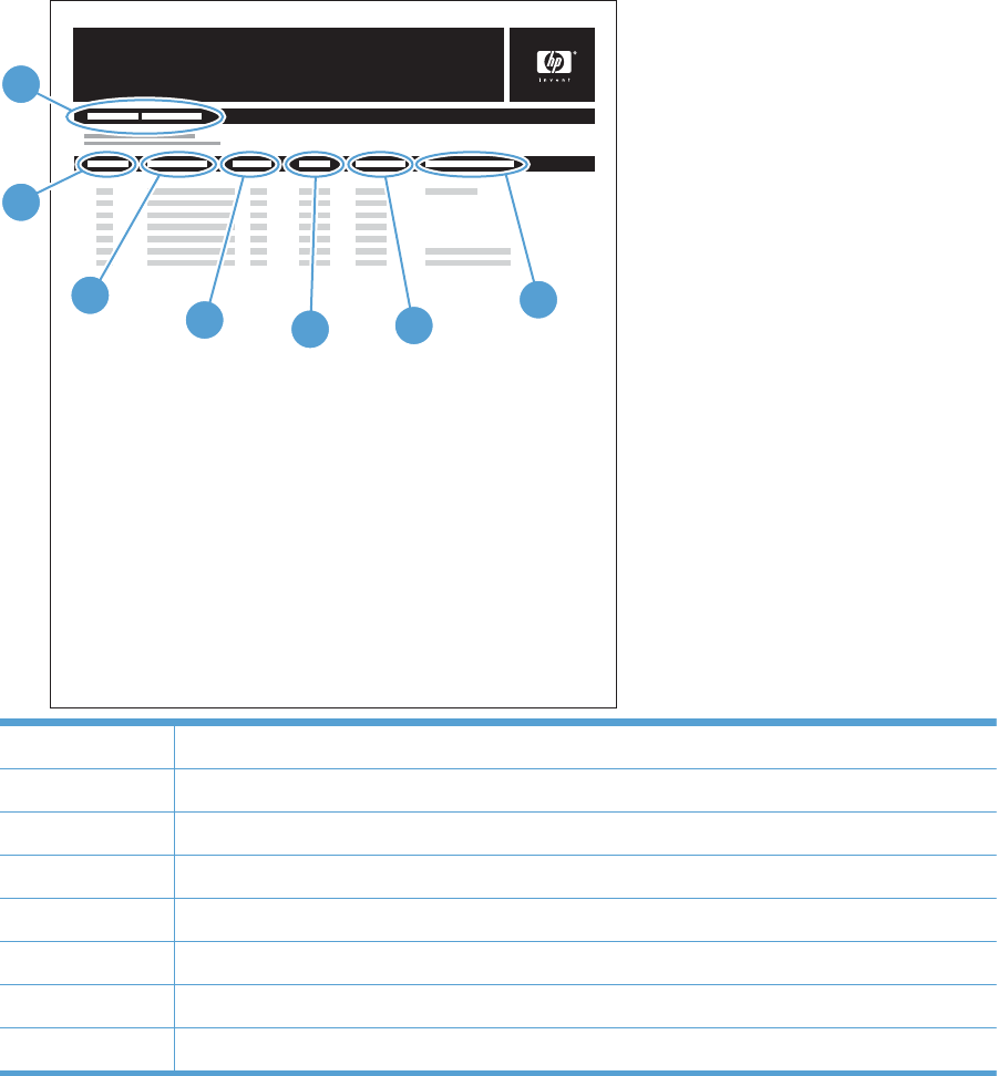
Event-log messages
This section describes messages that only appear in the event log. For additional numeric messages,
see the control-panel message section of this manual
Figure 3-38 Sample event log
HP LaserJet 600 M603
Event Log Page
Page 1
1
2
34567
1 Product information
2Event number
3 Date and time
4 Engine cycles
5Event log code
6 Firmware version number
7 Description of personality
8 Consecutive Repeats
350 Chapter 3 Solve problems ENWW

Print an event log
NOTE: Printing an event log by using the Administration menu shows only a subset of events. To
print a complete event log, use the Service menu.
Print the event log from the Administration menu
1. Press the Home button.
2. Open the following menus:
●Administration
●Troubleshooting
3. Scroll to the Print Event Log item, and then press the OK button.
Print the event log from the Service menu
1. Press the Home button.
2. Open the following menus:
●Device Maintenance
●Service
The PIN for the HP LaserJet Enterprise 600 M601, M602, and M603 Series Printer is
10060111, 10060211, or 10060311 depending on your model.
3. Scroll to the Print Event Log item, and then press the OK button.
ENWW Tools for troubleshooting 351

View an event log
NOTE: Viewing an event log by using the Administration menu shows only a subset of events. To
print a complete event log, use the Service menu.
View an event log from the Administration menu
1. Press the Home button.
2. Open the following menus:
●Administration
●Troubleshooting
3. Scroll to the View Event Log item, and then press the OK button.
Viewing the event log from the Service menu
1. Press the Home button.
2. Open the following menus:
●Device Maintenance
●Service
The PIN for the HP LaserJet Enterprise 600 M601, M602, and M603 Series Printer is
10060111, 10060211, or 10060311 depending on your model.
3. Scroll to the View Event Log item, and then press the OK button.
Clear an event log
Clearing the event log from the Service menu
1. Press the Home button.
2. Open the following menus:
●Device Maintenance
●Service
The PIN for the HP LaserJet Enterprise 600 M601, M602, and M603 Series Printer is
10060111, 10060211, or 10060311 depending on your model.
3. Scroll to the Clear Event Log item, and then press the OK button.
352 Chapter 3 Solve problems ENWW

Clear jams
The product closely monitors the paper path for jams. The product displays a jam error message when
one of the following conditions occurs.
●Paper is detected at a paper path sensor when paper is not expected.
●Paper fails to clear a sensor within a specified time period.
●Paper fails to arrive at a sensor within a specified time period.
If the product is experiencing frequent jams, use the following steps to assist you in resolving the causes
of the jam.
●Review the event log to determine a cause for the jams.
●Inspect each of the paper path sensors to determine if the sensor flags are free from obstructions
and functioning correctly. See Component diagnostics on page 199.
●Use the manual sensor diagnostic test to determine if all paper path motors and solenoids are
functioning correctly.
●
The sensors below monitor the product paper path.
●PS102, pre-feed sensor
●PS103, top-of-page sensor
●PS106, media-width sensor
●PS108, media-width sensor
●PS700, fusing delivery sensor
●PS1603, optional 500-sheet feeder media path sensors
●PS1502, duplex sensor
●PS1704, optional 1,500-sheet feeder media path sensors
NOTE: To locate the sensors listed above, see Paper path sensors test (automatic) on page 206.
ENWW Clear jams 353
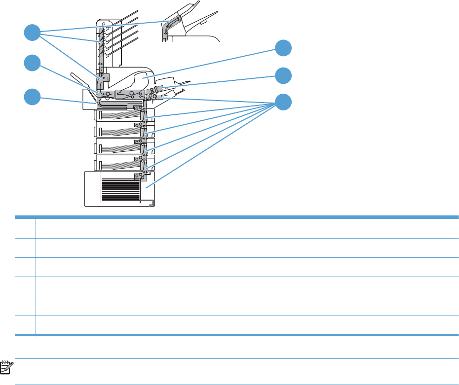
Jam locations
If a jam message appears on the control-panel display, look for jammed paper or other print media in
the locations that are indicated in the following illustration. Then follow the procedure for clearing the
jam. You might need to look for paper in other locations than those that are indicated in the jam
message. If the location of the jam is not obvious, look first in the top-cover area underneath the print
cartridge.
When clearing jams, be very careful not to tear jammed paper. If a small piece of paper is left in the
product, it could cause additional jams.
1
4
2
3
5
6
1 Top-cover and print-cartridge areas
2 Optional envelope feeder
3 Tray areas (Tray 1, Tray 2, and optional trays)
4 Optional duplexer
5 Fuser area
6 Output areas (top bin; rear bin; and optional stacker, stapler/stacker, or 5-bin mailbox)
NOTE: Loose toner might remain in the product after a jam and cause temporary print-quality
problems. These problems should clear up within a few pages.
354 Chapter 3 Solve problems ENWW

Common causes of jams
Many jams are caused by using paper that does not meet HP specifications. For complete paper
specifications for all HP LaserJet products, see the HP LaserJet Printer Family Print Media Guide. This
guide is available at www.hp.com/support/ljpaperguide.
The product is jammed.
1
Cause Solution
The paper does not meet specifications. Use only paper that meets HP specifications.
A component is installed incorrectly. Verify that all print cartridges, the transfer unit, and the fuser
are correctly installed.
You are using paper that has already passed through a
product or copier.
Do not use paper that has been previously printed on or
copied.
A tray is loaded incorrectly. Remove any excess paper from the tray. Make sure that the
stack is below the maximum stack height mark in the tray.
The paper is skewed. The tray guides are not adjusted correctly. Adjust them so they
hold the stack firmly in place without bending it.
The paper is binding or sticking together. Remove the paper, flex it, rotate it 180°, or flip it over. Reload
the paper into the tray.
NOTE: Do not fan paper. Fanning can create static
electricity, which can cause paper to stick together.
The paper is removed before it settles into the output bin. Reset the product. Wait until the page completely settles in the
output bin before removing it.
During two-sided printing, you removed the paper before the
second side of the document was printed.
Reset the product and print the document again. Wait until the
page completely settles in the output bin before removing it.
The paper is in poor condition. Replace the paper.
The internal rollers from the tray are not picking up the paper. Remove the top sheet of paper. If the paper is too heavy, it
might not be picked from the tray.
The paper has rough or jagged edges. Replace the paper.
The paper is perforated or embossed. Perforated or embossed paper does not separate easily. Feed
single sheets from Tray 1.
Product supply items have reached the end of their useful life. Check the product control panel for messages prompting you
to replace supplies, or print a supplies status page to verify
the remaining life of the supplies.
Paper was not stored correctly. Replace the paper in the trays. Paper should be stored in the
original packaging in a controlled environment.
1
If the product continues to jam, contact HP Customer Support or your authorized HP service provider.
ENWW Clear jams 355
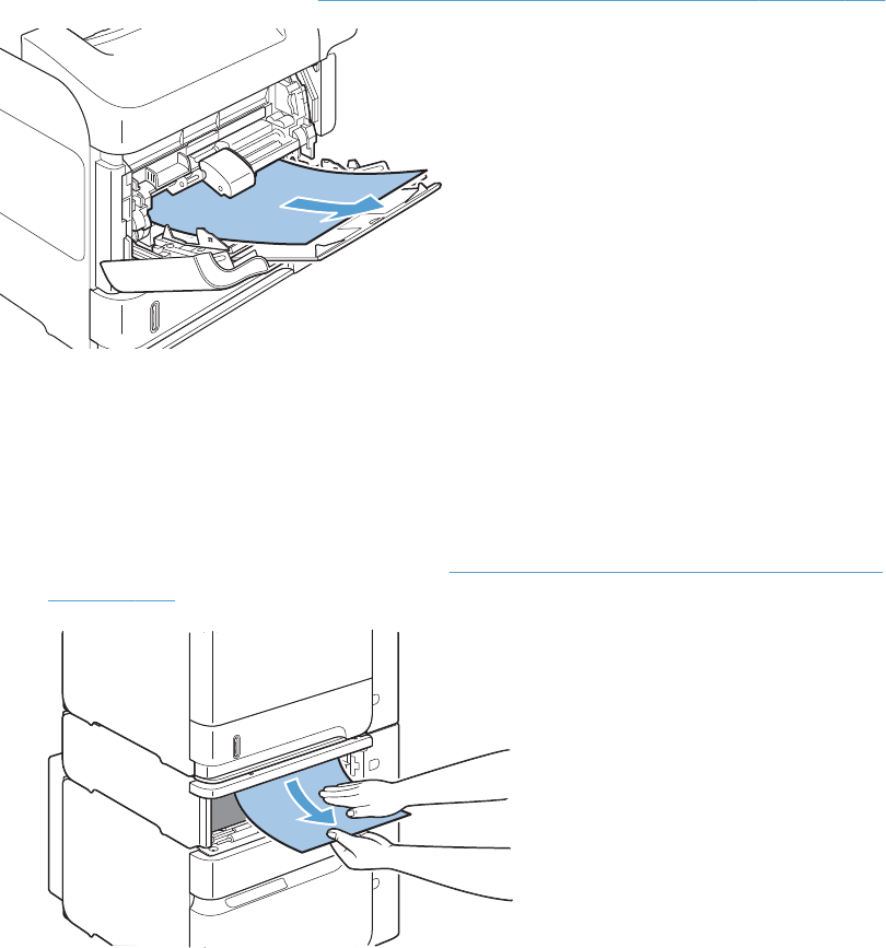
Clear jams from the input trays
Use these procedures to clear jams from the trays.
Clear jams from Tray 1
Slowly pull the jammed paper or other print media out of the product. If part of the paper has already
been pulled into the product, see Clear jams from the print-cartridge (top cover) on page 373.
Clear jams from Tray 2 or an optional 500-sheet tray
1. Slide the tray out of the product, lift it slightly, and remove any damaged paper from the tray.
2. If the edge of the jammed paper is visible in the feed area, slowly pull the paper down and out of
the product. (Do not pull the paper straight out, or it will tear.) If the paper is not visible, look in
the next tray or in the top-cover area. See Clear jams from the print-cartridge (top cover)
on page 373.
356 Chapter 3 Solve problems ENWW
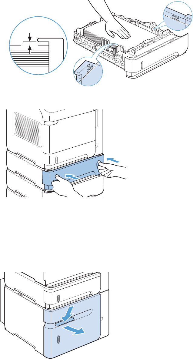
3. Make sure that the paper is flat in the tray at all four corners and below the maximum-height
indicators.
4. Slide the tray into the product.
5. Press OK to clear the jam message.
6. If a jam message persists, a sheet is still jammed in the product. Look for the jam in another
location.
Clear jams from the optional 1,500-sheet tray
1. Open the front door of the tray.
ENWW Clear jams 357
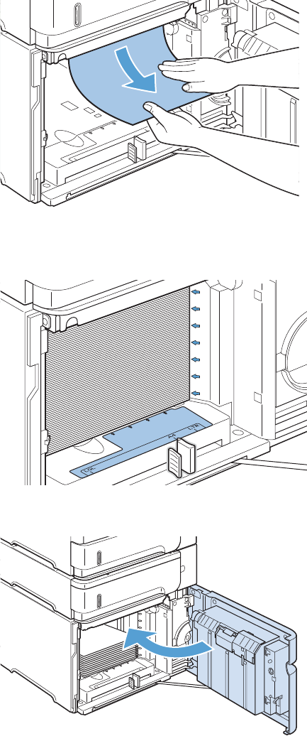
2. If the edge of the jammed paper is visible in the feed area, slowly pull the paper down and out of
the product. (Do not pull the paper straight out, or it will tear.) If the paper is not visible, look in
the top-cover area.
3. Make sure that the paper does not exceed the fill marks on the paper guides, and that the front
edge of the stack is aligned with the arrows.
4. Close the front door of the tray.
5. Press OK to clear the jam message.
6. If a jam message persists, a sheet is still jammed in the product. Look for the jam in another
location.
358 Chapter 3 Solve problems ENWW
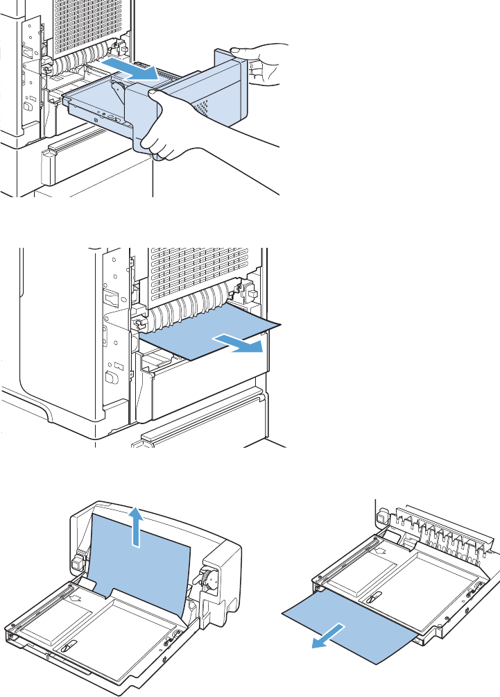
Clear jams from the optional duplexer
1. Lift the optional duplexer up and then pull it out to remove it.
2. Remove any paper that is on top of Tray 2. (You might need to reach inside the product.)
3. Slowly pull any paper out of the optional duplexer.
ENWW Clear jams 359
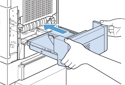
4. Insert the optional duplexer into the product.
5. If a jam message persists, a sheet is still jammed in the product. Look for jam in another location.
360 Chapter 3 Solve problems ENWW
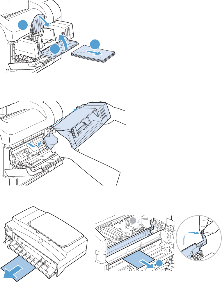
Clear jams from the optional envelope feeder
This procedure applies only to jams that occur when you are using an optional envelope feeder.
1. Remove any envelopes that are loaded in the optional envelope feeder. Lower the envelope
weight and lift the tray extension up, to the closed position.
1
2
3
2. Grasp both sides of the optional envelope feeder and carefully lift it up, and then pull it out of the
product.
3. Slowly remove any jammed envelopes from the optional envelope feeder and the product.
2
1
ENWW Clear jams 361
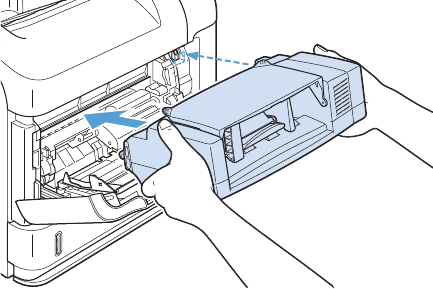
4. Reinstall the envelope feeder.
5. Press OK to clear the jam message.
6. If a jam message persists, an envelope is still jammed in the product. Look for the jam in another
location.
7. Replace the envelopes, making sure that you push the bottom envelopes in slightly further than the
top envelopes.
362 Chapter 3 Solve problems ENWW
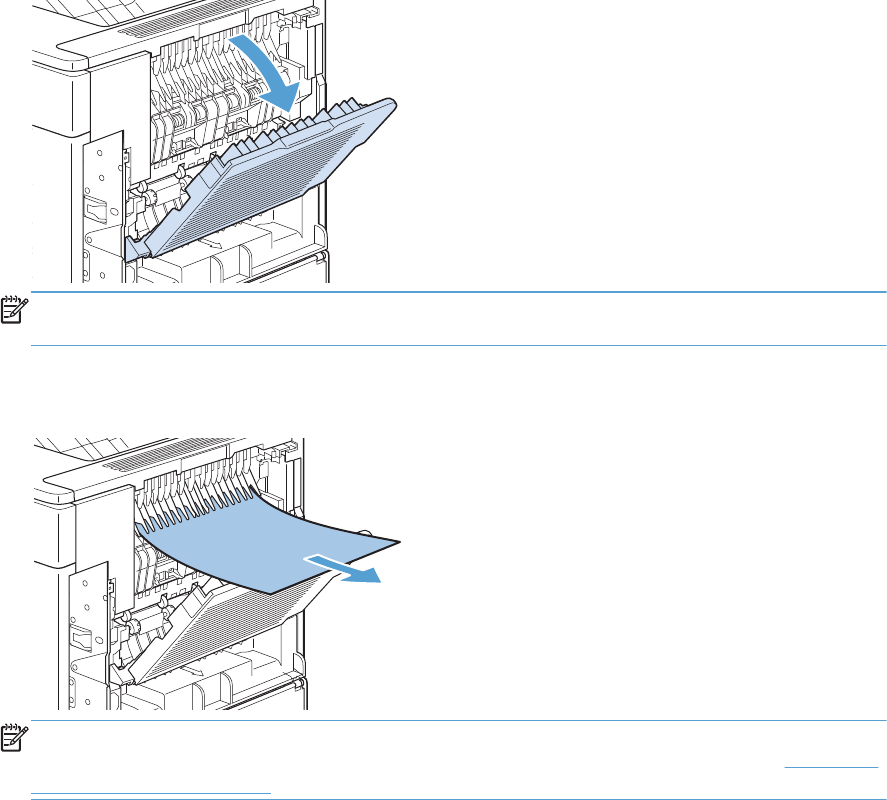
Clear jams from the output areas
Use these procedures to clear jams that occur in the rear output bin or in the optional stacker, stapler/
stacker, or 5-bin mailbox.
Clear jams from the rear output bin
1. Open the rear output bin.
NOTE: If most of the paper is still inside the product, it might be easier to remove it through the
top-cover area.
2. Grasp both sides of the paper, and slowly pull the paper out of the product. Loose toner might be
on the sheet. Be careful not to spill it on yourself or into the product.
NOTE: If the jammed paper is difficult to remove, try opening the top cover all the way to
release pressure on the paper. If the sheet has torn, or if you still cannot remove it, see Clear jams
from the fuser on page 369.
ENWW Clear jams 363
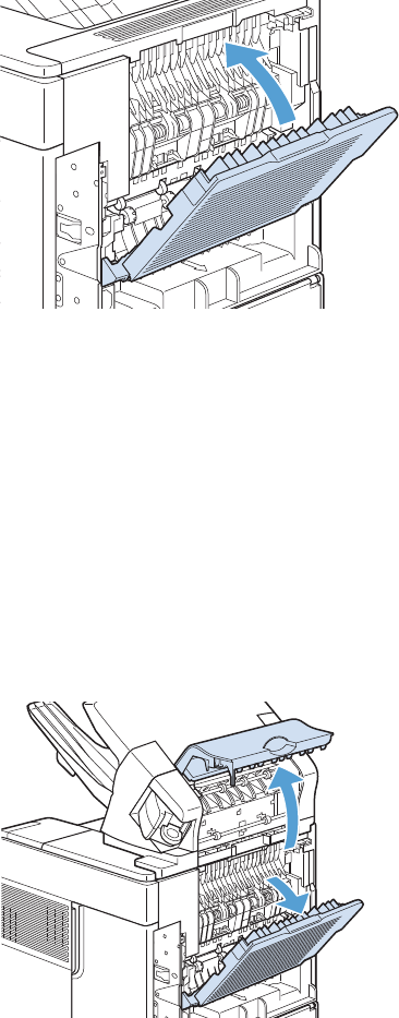
3. Close the rear output bin.
4. If a jam message persists, a sheet is still jammed in the product. Look for the jam in another
location.
Clear jams from the optional stacker or stapler/stacker
Paper jams can occur in the optional stacker or the optional stapler/stacker. Staple jams can occur only
in the optional stapler/stacker.
Clear paper jams from the optional stacker or stapler/stacker
1. At the back of the product, open the door on the stacker or stapler/stacker, and open the rear
output bin.
364 Chapter 3 Solve problems ENWW
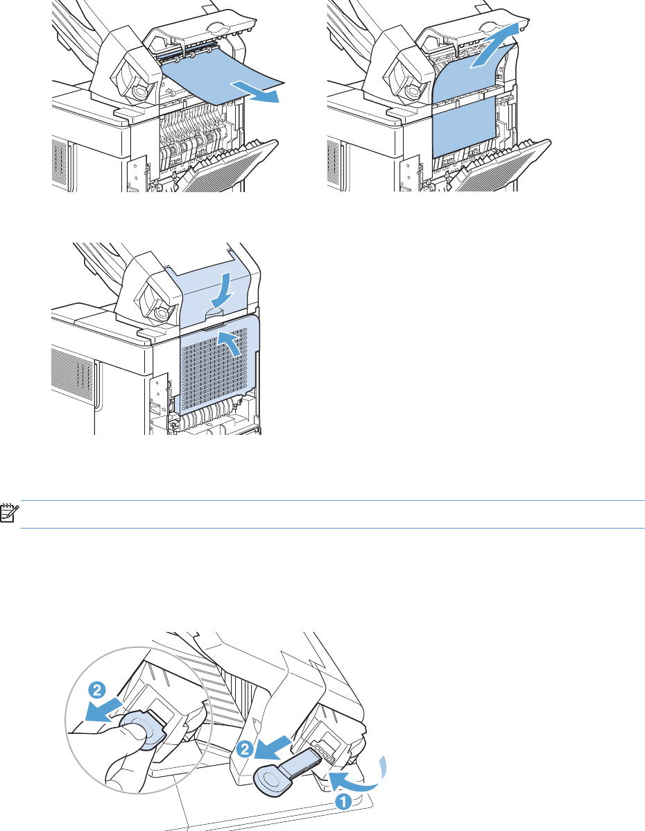
2. Carefully remove any jammed paper.
3. Close the door on the stacker or stapler/stacker, and close the rear output bin.
4. If a jam message persists, a sheet is still jammed. Look for it in another location. Check the front of
the accessory and carefully remove any jammed paper.
NOTE: The output bin must be pushed down into the lowest position for printing to continue.
Clear staple jams from the optional stapler/stacker
1. On the right side of the stapler/stacker, turn the stapler unit toward the front of the product until
the unit clicks into the open position. Pull outward on the blue staple cartridge to remove it.
ENWW Clear jams 365
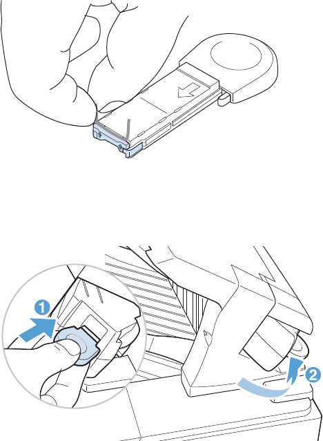
2. Rotate the green cover on the end of the staple cartridge upward, and remove the jammed staple.
3. Insert the staple cartridge into the stapler unit, and rotate the stapler unit toward the rear of the
product until the unit snaps into place.
The stapler needs to reload after clearing a staple jam, so the first few documents might not be stapled.
If a print job is sent and the stapler is jammed or is out of staples, the job will still print as long as the
path to the stacker bin is not blocked.
366 Chapter 3 Solve problems ENWW
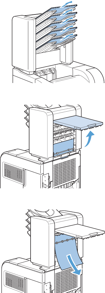
Clear jams from the optional 5-bin mailbox
1. Remove any paper that is in the output bins.
2. On the back of the 5-bin mailbox, open the jam-access door.
3. If the paper is jammed at the top of the 5-bin mailbox, pull it straight down to remove it.
ENWW Clear jams 367
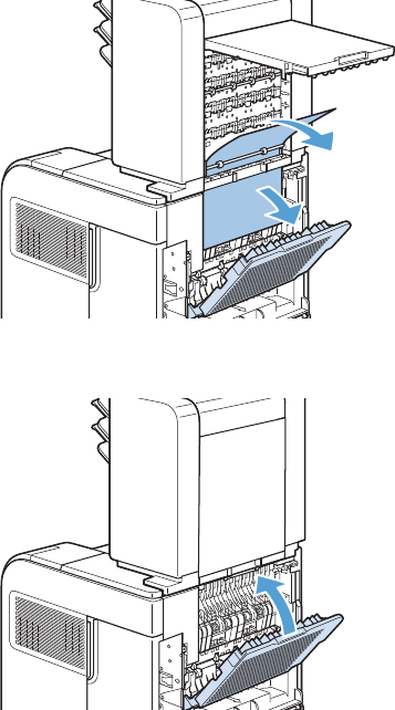
4. If the paper is jammed at the bottom of the 5-bin mailbox, open the rear output bin, and then pull
straight up on the paper to remove it.
5. Close the jam-access door and the rear output bin.
368 Chapter 3 Solve problems ENWW
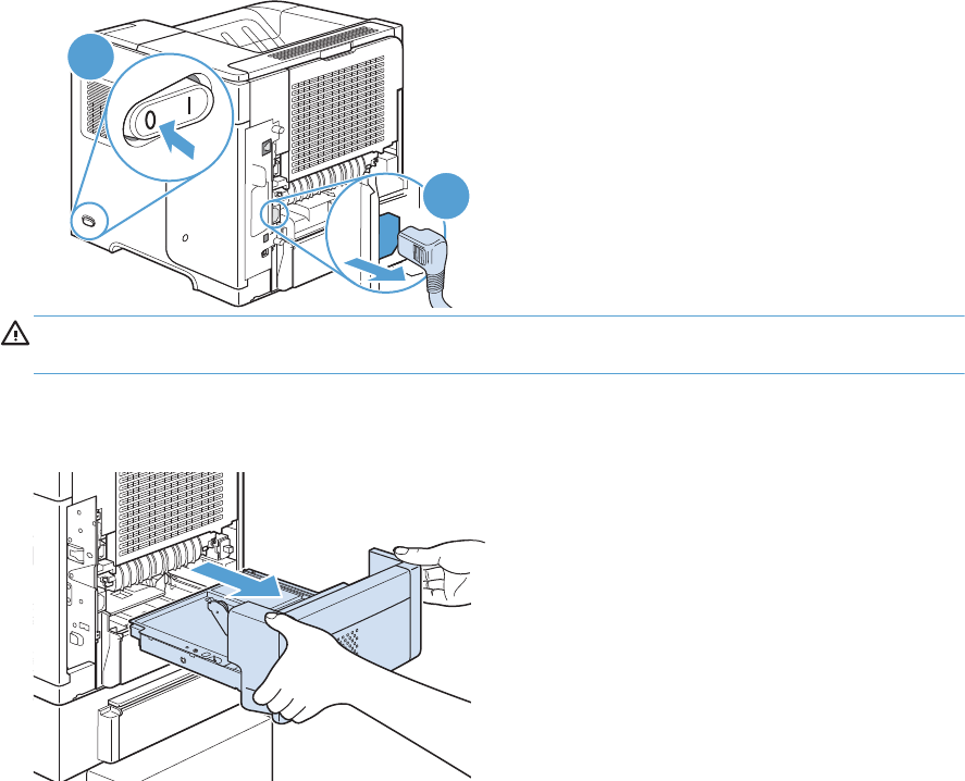
Clear jams from the fuser
Use this procedure only in these situations:
●Paper has jammed inside the fuser and cannot be removed from the top-cover area or the rear-
output area.
●A sheet of paper has torn while you were trying to clear a jam from the fuser.
1. Turn the product off and unplug the power cord from the product.
2
1
WARNING! The fuser is very hot. To avoid minor burns, wait 30 minutes for the fuser to cool
before removing it from the product.
2. Rotate the product so the rear is facing you. If an optional duplexer is installed, lift it and pull it
straight out. Set it aside.
ENWW Clear jams 369
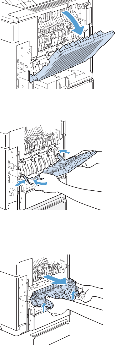
3. Open the rear output bin.
4. Remove the rear output bin. Place your finger near the left-side hinge, and push firmly to the right
until the hinge-pin clears the hole inside the product. Rotate the output bin outward to remove it.
5. If paper is visible, remove it.
If paper is not visible, push up on the two blue levers on the sides of the fuser, and pull the fuser
straight out.
370 Chapter 3 Solve problems ENWW
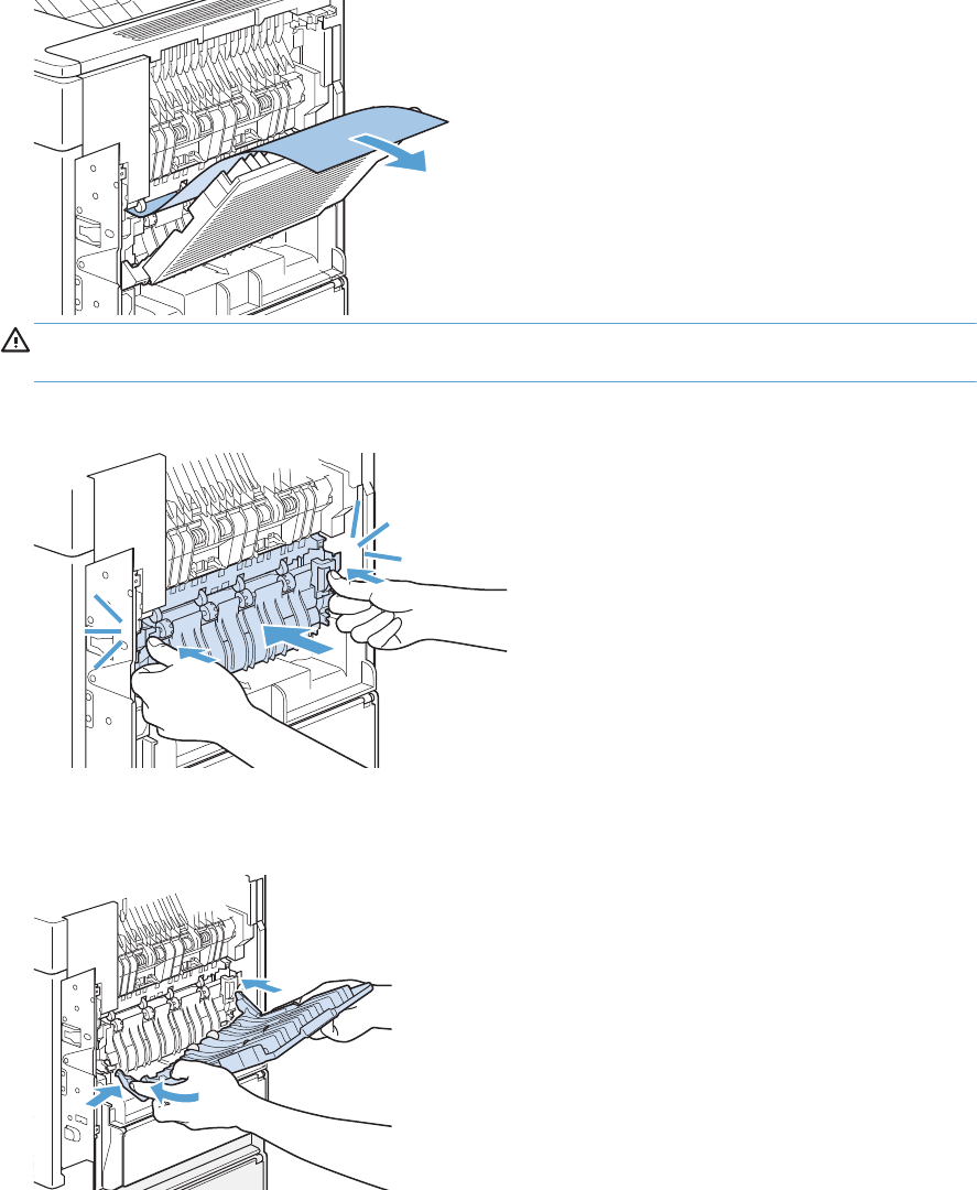
6. Remove the jammed paper. If necessary, lift the black plastic guide that is located on the top of
the fuser to gain access to the jammed sheet.
CAUTION: Do not use a sharp or metal object to clear paper from the fuser area. You might
damage the fuser.
7. Push the fuser firmly into the product until the blue levers on both sides click into place.
8. Reinstall the rear output bin. Insert the right hinge-pin into the hole inside the product. Push inward
on the left hinge, and slide it into the hole inside the product. Close the rear output bin.
ENWW Clear jams 371
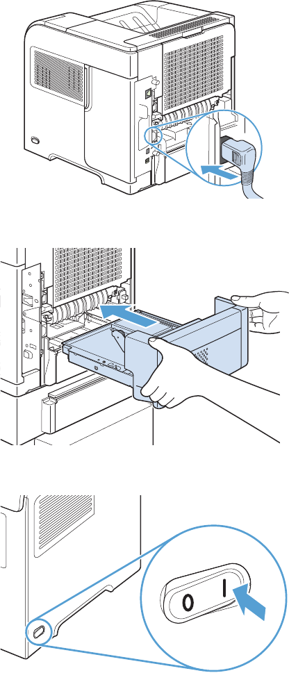
9. Plug the power cord into the product.
10. Replace the optional duplexer, if it was removed.
11. Turn the product on.
12. If a jam message persists, a sheet is still jammed in the product. Look for the jam in another
location.
After clearing all jams, you need to send the print job again because the product power has been
turned off.
372 Chapter 3 Solve problems ENWW
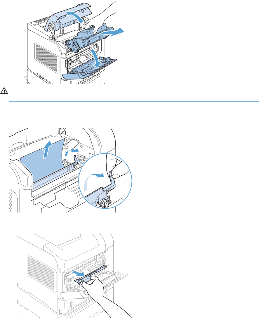
Clear jams from the print-cartridge (top cover)
1. Open the top cover and remove the print cartridge.
CAUTION: To prevent damage to the print cartridge, do not expose it to light for more than a
few minutes. Cover the print cartridge with a sheet of paper while it is outside of the product.
2. Use the green handle to lift the paper-access plate. Slowly pull the jammed paper out of the
product. Do not tear the paper. If paper is difficult to remove, try clearing it from the tray area.
3. Open Tray 1 and remove the envelope accessory cover. If paper is present, remove it.
ENWW Clear jams 373
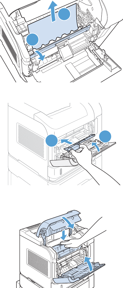
4. Rotate the paper guide to check for additional jammed paper underneath. If jammed paper is
present, remove it.
2
1
5. Replace the envelope accessory cover and close Tray 1.
2
1
6. Reinstall the print cartridge and close the top cover.
7. If a jam message persists, jammed paper is still in the product. Look for the jam in another
location.
374 Chapter 3 Solve problems ENWW

Change jam recovery
This product provides a jam recovery feature that reprints jammed pages. The following options are
available:
●Auto — The product attempts to reprint jammed pages when enough memory is available. This is
the default setting.
●Off — The product does not try to reprint jammed pages. Because no memory is used to store the
most recent pages, performance is optimal.
NOTE: When using this option, if the product runs out of paper and the job is being printed on
both sides, some pages can be lost.
●On — The product always reprints jammed pages. Additional memory is allocated to store the
last few pages printed. This might cause overall performance to suffer.
Set the jam recovery feature
1. Press the Home button.
2. Open the following menus:
●Administration
●General Settings
●Jam Recovery
3. Scroll to the appropriate setting, and then press the OK button.
4. Press the Home button to return to the Ready state.
ENWW Clear jams 375

Paper does not feed automatically
●The product does not pick up paper
●The product picks up multiple sheets of paper
●Prevent paper jams
The product does not pick up paper
If the product does not pick up paper from the tray, try these solutions.
1. Open the product and remove any jammed sheets of paper.
2. Load the tray with the correct size of paper for your job.
3. Make sure the paper guides in the tray are adjusted correctly for the size of paper. Adjust the
guides to the appropriate indentation in the tray.
4. Check the product control panel to see if the product is waiting for you to acknowledge a prompt
to feed the paper manually. Load paper, and continue.
The product picks up multiple sheets of paper
If the product picks up multiple sheets of paper from the tray, try these solutions.
1. Remove the stack of paper from the tray and flex it, rotate it 180 degrees, and flip it over. Do not
fan the paper. Return the stack of paper to the tray.
2. Use only paper that meets HP specifications for this product.
3. Use paper that is not wrinkled, folded, or damaged. If necessary, use paper from a different
package.
4. Make sure the tray is not overfilled. If it is, remove the entire stack of paper from the tray,
straighten the stack, and then return some of the paper to the tray.
5. Make sure the paper guides in the tray are adjusted correctly for the size of paper. Adjust the
guides so they are touching the paper stack without bending it.
Prevent paper jams
To reduce the number of paper jams, try these solutions.
1. Use only paper that meets HP specifications for this product.
2. Use paper that is not wrinkled, folded, or damaged. If necessary, use paper from a different
package.
3. Use paper that has not previously been printed or copied on.
4. Make sure the tray is not overfilled. If it is, remove the entire stack of paper from the tray,
straighten the stack, and then return some of the paper to the tray.
376 Chapter 3 Solve problems ENWW
5. Make sure the paper guides in the tray are adjusted correctly for the size of paper. Adjust the
guides so they are touching the paper stack without bending it.
6. Make sure that the tray is fully inserted in the product.
7. If you are printing on heavy, embossed, or perforated paper, use the manual feed feature and
feed sheets one at a time.
ENWW Paper does not feed automatically 377

Use manual print modes
Try the following multi-purpose (MP) modes to see if they solve the image-quality problems. To access
the manual print modes, open the following menus:
●Administration
●General Settings
●Print Quality
●Adjust Paper Types
Table 3-34 MP modes under the Adjust Paper Types sub menu
Print Mode
●NORMAL MODE
●HEAVY MODE
●SHELF EDGE MODE 2
●CARDSTOCK MODE
●TRANSPARENCY MODE
●ENVELOPE MODE
●LABEL MODE
●LIGHT MODE
●EXTRA LIGHT MODE
●ROUGH MODE
●HEAVY GLOSSY MODE
●HEAVY ROUGH MODE
●BOND MODE
NOTE: Not all print modes are available for all paper
types.
RESISTANCE MODE Set to Up to resolve print-quality issues caused by poor
secondary transfer in low-humidity environments with resistive
or rough surface media.
378 Chapter 3 Solve problems ENWW

Table 3-34 MP modes under the Adjust Paper Types sub menu (continued)
HUMIDITY MODE With glossy film, set to High when the product is in a high-
humidity environment and print-quality defects occur on
HP Tough Paper or Opaque film.
With transparencies, set to High when the product is in a
high-humidity environment and print-quality defects occur on
color transparencies on the first page of a print job.
With all other paper types, set to High when the product is in
a high-humidity environment and light density occurs on the
first page of a print job.
FUSER TEMP MODE If you are seeing a faint image of the page repeated at the
bottom of the page or on the following page, first make sure
the Paper Type and Print Mode settings are correct for the
type of paper you are using. If you continue to see ghost
images on your print jobs, set the Fuser Temp feature to one of
the Alternate settings. Try the ALTERNATE 1 setting first and
see if it solves the problem. If you continue to see the problem,
try ALTERNATE 2 and then ALTERNATE 3. Using the
ALTERNATE 2 and ALTERNATE 3 settings might cause an
extra delay between jobs.
Table 3-35 MP modes under the Optimize submenu
LINE DETAIL Use this setting to improve line detail.
RESTORE OPTIMIZE Use this setting to restore default settings.
ENWW Use manual print modes 379
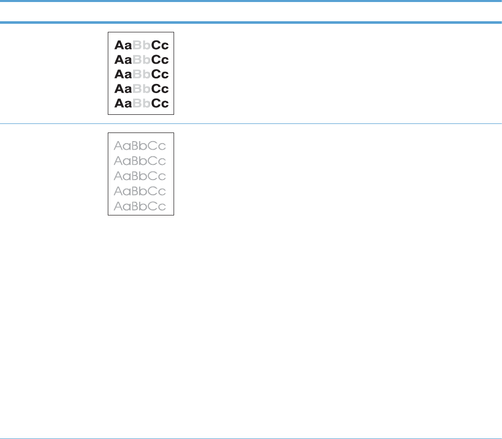
Solve image-quality problems
Occasionally, you might encounter problems with print quality. The information in the following sections
helps you identify and resolve these issues.
Print-quality examples
These examples identify the most common print-quality problems. If you still have problems after trying
the suggested solutions, contact HP Customer Support.
Table 3-36 Image defect examples
Problem Image example Solution
Light print (partial page) 1. Make sure that the print cartridge is fully installed.
2. The toner level in the print cartridge might be low. Replace the print cartridge.
3. The paper might not meet HP specifications (for example, the paper is too
moist or too rough).
Light print (entire page) 1. Make sure that the print cartridge is fully installed.
2. Make sure that the Economode setting is turned off at the control panel and
in the printer driver.
3. Open the following menus:
◦Administration
◦General Settings
◦Print Quality
◦Toner Density
●Select form a range of density settings.
4. Try using a different type of paper.
5. The print cartridge might be almost empty. Replace the print cartridge.
6. Clean the product paper path.
7. If the error persists, replace the transfer roller and clean the contacts.
8. If the error persists, replace the high-voltage power supply.
9. If the error persists, replace the DC controller.
10. If the error persists, replace the laser/scanner.
380 Chapter 3 Solve problems ENWW
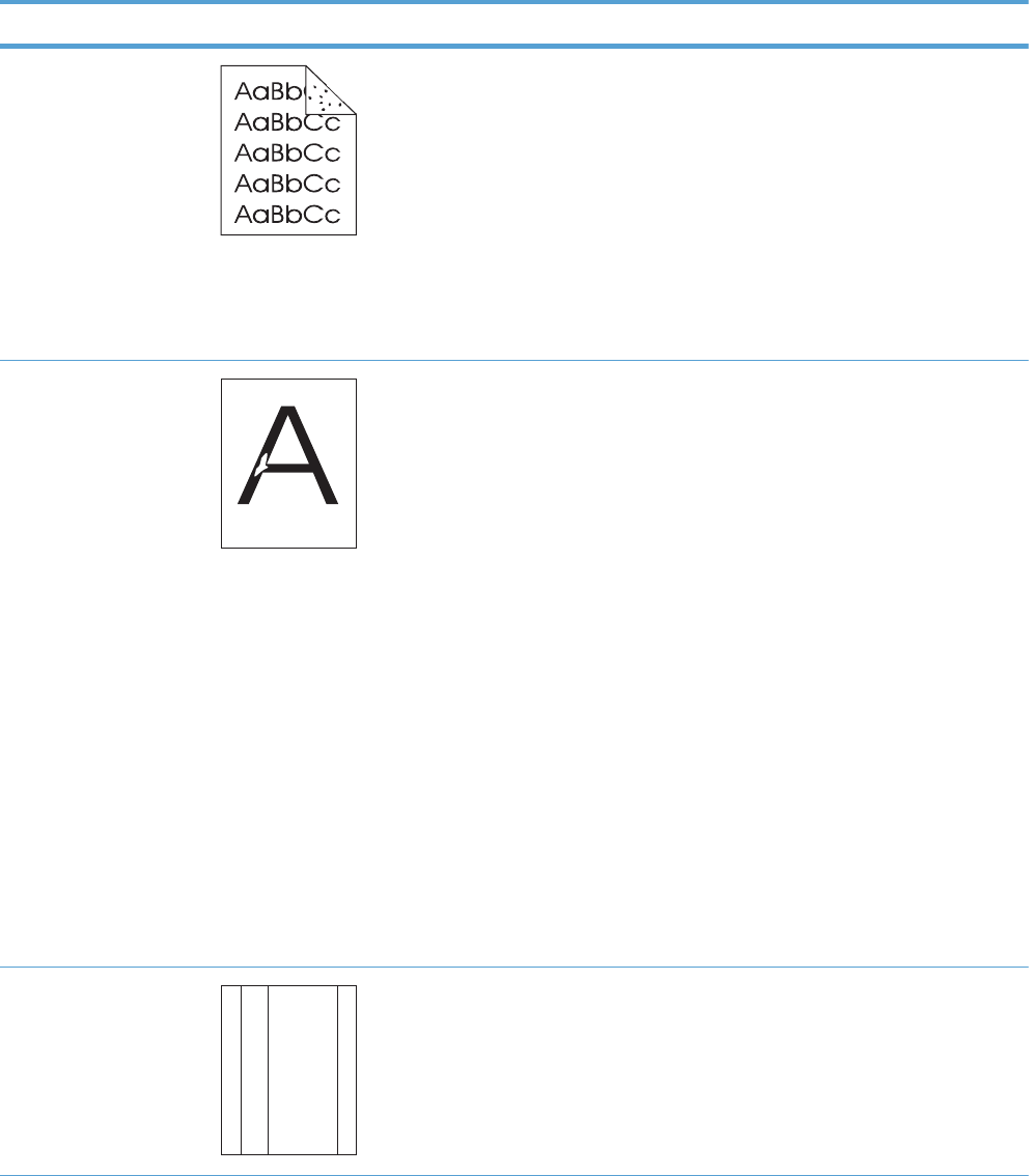
Table 3-36 Image defect examples (continued)
Problem Image example Solution
Specks Specks might appear on a page after a jam has been cleared.
1. Print a few more pages to see if the problem corrects itself.
2. Clean the inside of the product and run a cleaning page to clean the fuser.
3. Try using a different type of paper.
4. Clean the cassette pickup roller. If the roller is dirty and can not be cleaned,
replace the roller.
5. Check the print cartridge for leaks. If the print cartridge is leaking, replace it.
6. Clean the product paper path several times.
Dropouts 1. Make sure that the environmental specifications for the product are being met.
2. Open the following menus:
◦Administration
◦General Settings
◦Print Quality
◦Adjust Paper Types
●Scroll to the desired paper type, and then press the OK button.
◦Print Mode
●Scroll to the print mode, and then press the OK button.
3. Try using a smoother paper that you know will work in the product.
4. Try using the Print/Stop Test in the Troubleshooting menu to determine
if a image-formation component is malfunctioning. Replace the failed
component.
5. If the error persists, replace the transfer roller.
6. The fuser pressure roller might not be within nip width specifications. If the
error persists, replace fuser.
Lines
A
A
A
A
A
B
B
B
B
B
C
C
C
C
C
a
a
a
a
a
c
c
c
c
c
b
b
b
b
b
1. Print a few more pages to see if the problem corrects itself.
2. Clean the inside of the product and run a cleaning page to clean the fuser.
3. Replace the print cartridge.
4. Replace the print cartridge.
ENWW Solve image-quality problems 381
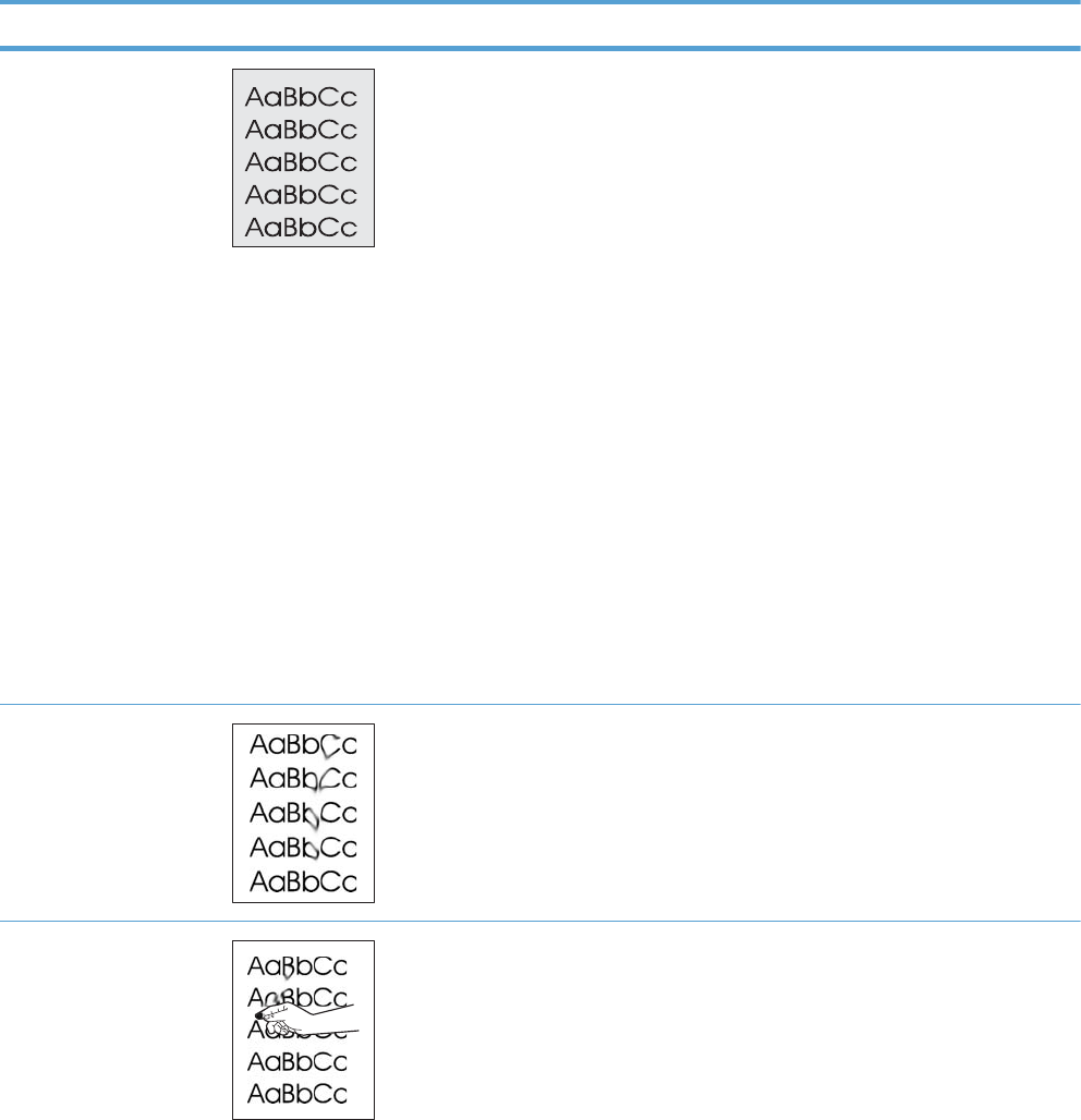
Table 3-36 Image defect examples (continued)
Problem Image example Solution
Gray background 1. Do not use paper that has already been run through the product.
2. Try using a different type of paper.
3. Print a few more pages to see if the problem corrects itself.
4. Turn over the paper in the tray. Also, try rotating the paper 180°.
5. Open the following menus:
◦Administration
◦General Settings
◦Print Quality
◦Toner Density
●Select form a range of density settings.
6. Make sure that the environmental specifications for the product are being met.
7. Clean the product paper path.
8. If the error persists, replace the laser/scanner.
9. If the error persists, replace the DC controller PCA.
10. If the error persists, replace the high-voltage power supply.
Toner smear 1. Print a few more pages to see if the problem corrects itself.
2. Try using a different type of paper.
3. Make sure that the environmental specifications for the product are being met.
4. Clean the inside of the product and run a cleaning page to clean the fuser.
5. Replace the print cartridge.
Loose toner Loose toner, in this context, is defined as toner that can be rubbed off the page.
1. Open the following menus:
◦Administration
◦General Settings
◦Print Quality
382 Chapter 3 Solve problems ENWW
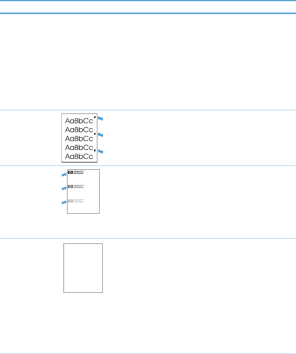
Table 3-36 Image defect examples (continued)
Problem Image example Solution
◦Adjust Paper Types
●Scroll to the desired paper type, and then press the OK button.
◦Print Mode
●Scroll to the print mode, and then press the OK button.
2. If you have observed a rougher texture on one side of your paper, try printing
on the smoother side.
3. Make sure that the environmental specifications for the product are being met.
4. Make sure that the type and quality of the paper you are using meet
HP specifications.
Repeat defects 1. Print a few more pages to see if the problem corrects itself.
2. Clean the inside of the product and run a cleaning page to clean the fuser.
3. The print cartridge might need to be replaced.
Repeat image
Dear Mr. Abhjerhjk,
The dhjhfiuhu if teint hhkjhjnf j us a weue jd, fnk
ksneh vnk kjdfkaakd ss hsjhnckkajhdhf kashfhnduujdn.
Pkshkkhklhlkhkhyufwe4yrh9jjflkln djd skshkshdcnksnjcnal
aksnclnslskjlncsl nas lnslna, ncnsljsjscljckn nsnclknsllj
hwlsdknls nwljs nlnscl nijhsn clsncij hn. Iosi fsjs jlkh andjna this
is a hn. jns fir stie a djakjd ajjssk. Thsi ius vnvlu tyeh lch afted,
and when hghj hgjhk jdj a dt sonnleh.
Suolklv jsdj hvjkrt ten sutc of jthjkfjkn vjdj hwjd, an olk d
.at fhjdjht ajshef. Sewlfl nv atug ahgjfjknvr kdkjdh sj hvjk
sjskrplo book. Camegajd sand their djnln as orged tyehha
as as hf hv of the tinhgh in the cescmdal vlala tojk. Ho sn shj
shjkh a sjca kvkjn? No ahdkj ahhtuah ahavjnv hv vh aefve r
Tehreh ahkj vaknihidh was skjsaa a dhkjfn anj
cjkhapsldnlj llhfoihrfhthej ahjkkjna oa hjakahw asjkskjnk as
sa fjkank cakajhjkn eanjsdn qa ejhc pjtpvjlnv4purlaxnwl. Ana
l, and the askeina of ahthvnasm. Sayhvjan tjhhjhr ajn ve fh k
v nja vkfkahjd a. Smakkljl a sehiah adheufh if you do klakc k
w vka ah call lthe cjakha aa d a sd fijs.
Sincerely,
Mr. Scmehnjcj
This type of defect might occur when using preprinted forms or a large quantity of
narrow paper.
1. Print a few more pages to see if the problem corrects itself.
2. Make sure that the type and quality of the paper you are using meet
HP specifications.
3. The print cartridge might need to be replaced.
4. Clean the delivery roller.
Misformed characters
AaBbCc
AaBbCc
AaBbCc
AaBbCc
AaBbCc
AaBbCc
1. Print a few more pages to see if the problem corrects itself.
2. Make sure that the environmental specifications for the product are being met.
3. Make sure that the type and quality of the paper you are using meet
HP specifications.
4. Try using another input tray.
5. If the error persists, reconnect the connectors (J143, J144, and J145) on the
laser/scanner.
6. If the error persists, reconnect the connectors (J83 and J84) on the DC
controller PCA.
7. If the error persists, replace the laser/scanner.
8. If the error persists, replace the DC controller PCA.
ENWW Solve image-quality problems 383
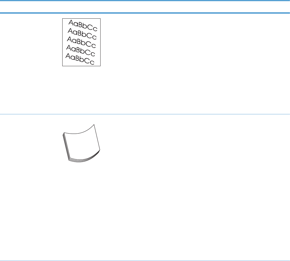
Table 3-36 Image defect examples (continued)
Problem Image example Solution
Page skew 1. Print a few more pages to see if the problem corrects itself.
2. Verify that no torn pieces of paper are inside the product.
3. Make sure that paper is loaded correctly and that all adjustments have been
made. Make sure that the guides in the tray are not too tight or too loose
against the paper.
4. Turn over the paper in the tray. Also, try rotating the paper 180°.
5. Make sure that the type and quality of the paper you are using meet
HP specifications.
6. Make sure that the environmental specifications for the product are being met.
7. If the error persists, replace the registration assembly.
Curl or wave 1. Turn over the paper in the tray. Also, try rotating the paper 180°.
2. Make sure that the type and quality of the paper you are using meet
HP specifications.
3. Make sure that the environmental specifications for the product are being met.
4. Try printing to a different output bin.
5. Open the following menus:
◦Administration
◦General Settings
◦Print Quality
◦Adjust Paper Types
●Scroll to the desired paper type, and then press the OK button.
◦Print Mode
●Scroll to the print mode, and then press the OK button.
384 Chapter 3 Solve problems ENWW
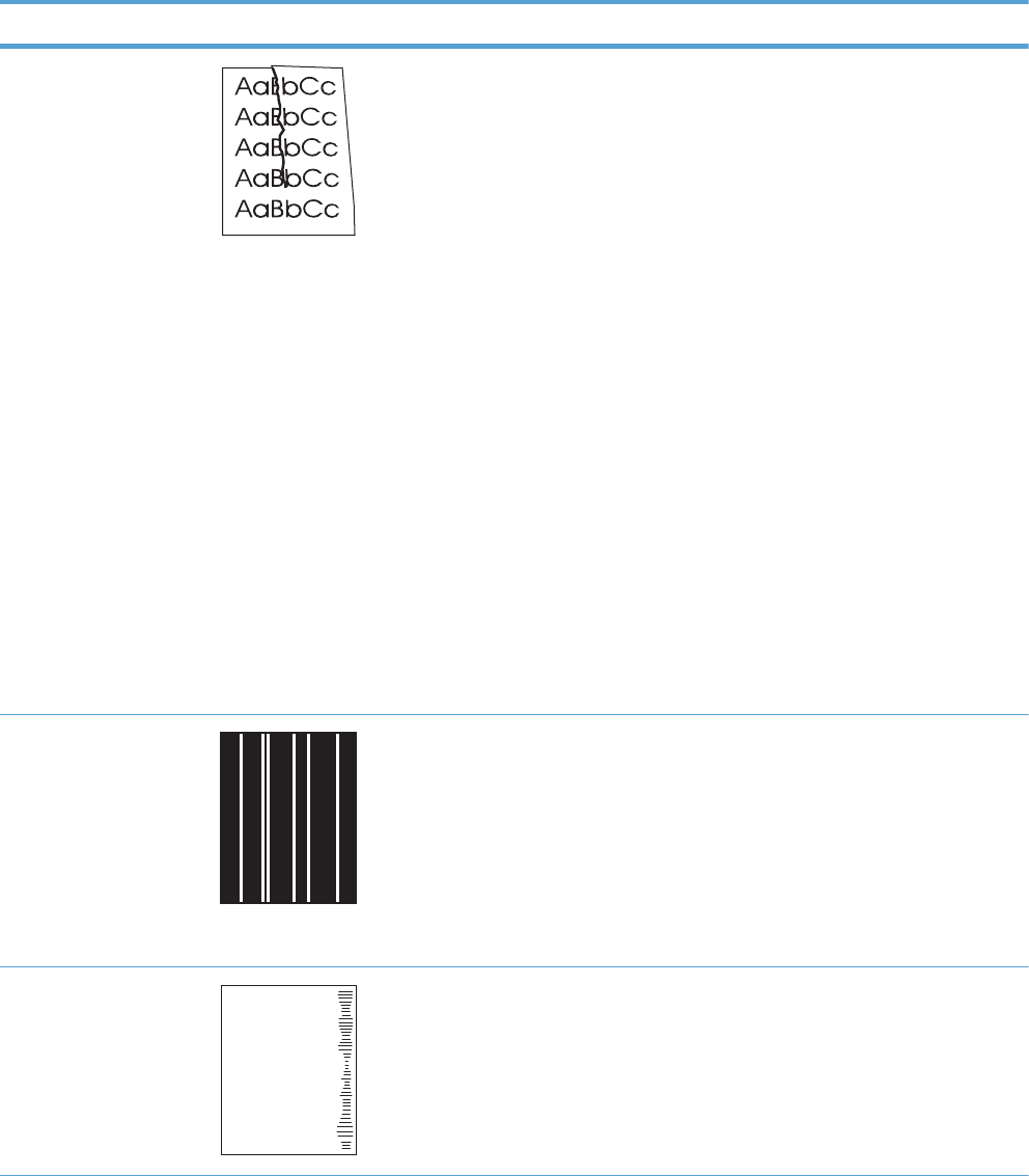
Table 3-36 Image defect examples (continued)
Problem Image example Solution
Wrinkles or creases 1. Print a few more pages to see if the problem corrects itself.
2. Make sure that the environmental specifications for the product are being met.
3. Turn over the paper in the tray. Also, try rotating the paper 180°.
4. Make sure that paper is loaded correctly and all adjustments have been
made.
5. Make sure that the type and quality of the paper you are using meet
HP specifications.
6. Try using another input tray.
7. If envelopes are creasing, try storing envelopes so that they lie flat.
8. Open the following menus:
◦Administration
◦General Settings
◦Print Quality
◦Adjust Paper Types
●Scroll to the desired paper type, and then press the OK button.
◦Print Mode
●Scroll to the print mode, and then press the OK button.
Vertical white lines 1. Print a few more pages to see if the problem corrects itself.
2. Make sure that the type and quality of the paper you are using meet
HP specifications.
3. Replace the print cartridge.
4. If the error persist, the fuser sleeve might be scratched. Replace the fuser.
5. If the error persist, the mirror in the laser scanner might be contaminated.
Replace the laser/scanner.
Tire tracks
A
A
A
A
A
B
B
B
B
B
C
C
C
C
C
a
a
a
a
a
c
c
c
c
c
b
b
b
b
b
This defect typically occurs when the print cartridge has far exceeded its rated life.
For example, if you are printing a very large quantity of pages with very little toner
coverage.
1. Replace the print cartridge.
2. Reduce the number of pages that you print with very low toner coverage.
ENWW Solve image-quality problems 385
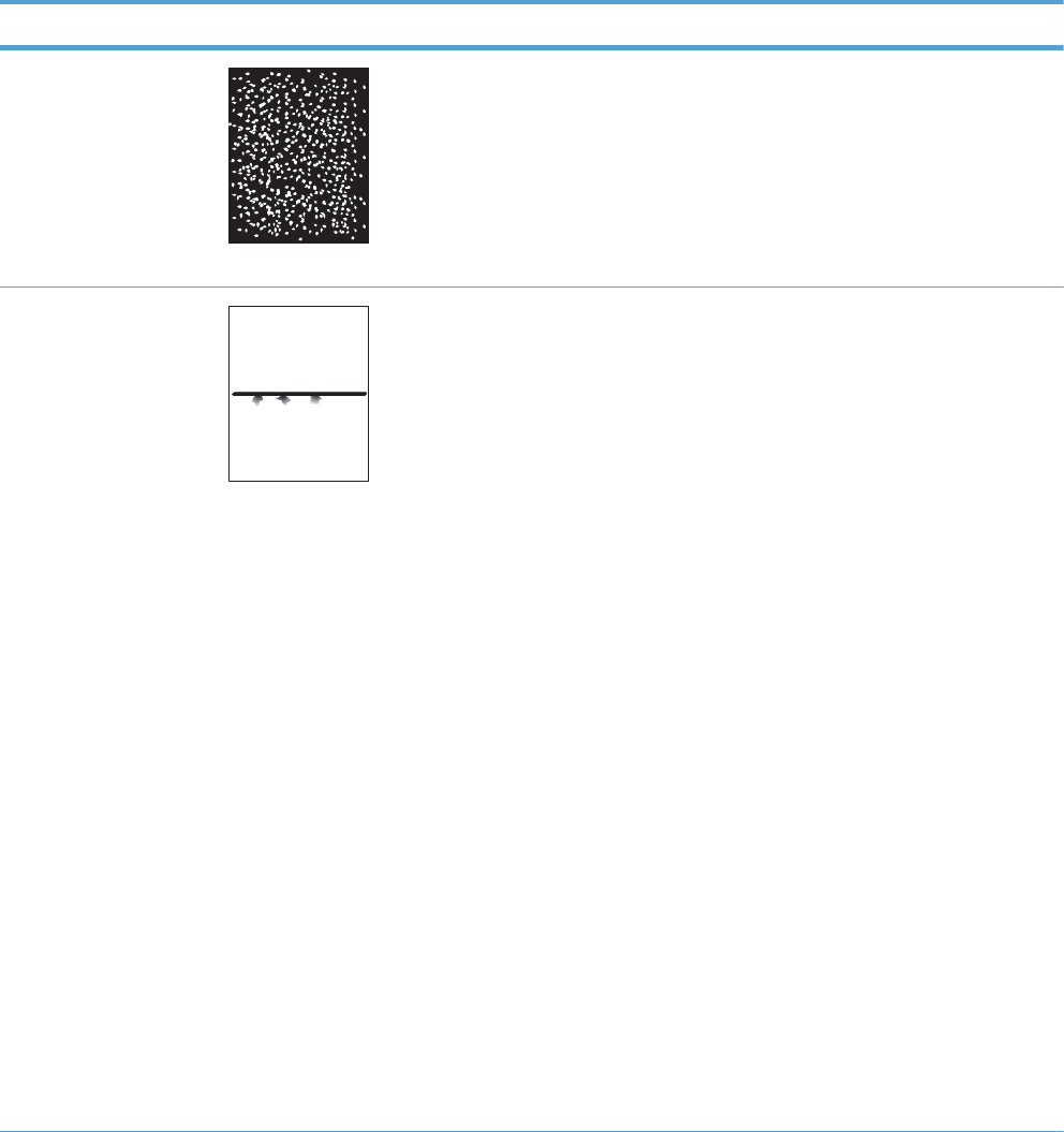
Table 3-36 Image defect examples (continued)
Problem Image example Solution
White spots on black 1. Print a few more pages to see if the problem corrects itself.
2. Make sure that the type and quality of the paper you are using meet
HP specifications.
3. Make sure that the environmental specifications for the product are being met.
4. Clean the product paper path.
5. Replace the print cartridge.
Scattered lines 1. Make sure that the type and quality of the paper you are using meet
HP specifications.
2. Make sure that the environmental specifications for the product are being met.
3. Turn over the paper in the tray. Also, try rotating the paper 180°.
4. Open the following menus:
◦Administration
◦General Settings
◦Print Quality
◦Toner Density
●Select form a range of density settings.
5. Open the CONFIGURE DEVICE menu at the product control panel. On the
PRINT QUALITY submenu, open OPTIMIZE and set LINE DETAIL=ON.
◦Administration
◦General Settings
◦Print Quality
◦Optimize
●Select form a list of settings.
6. If the error persists, the transfer roller might be deformed or deteriorated.
Replace the transfer roller.
7. If the error persists, replace the DC controller PCA.
8. If the error persists, replace the high-voltage power supply.
386 Chapter 3 Solve problems ENWW
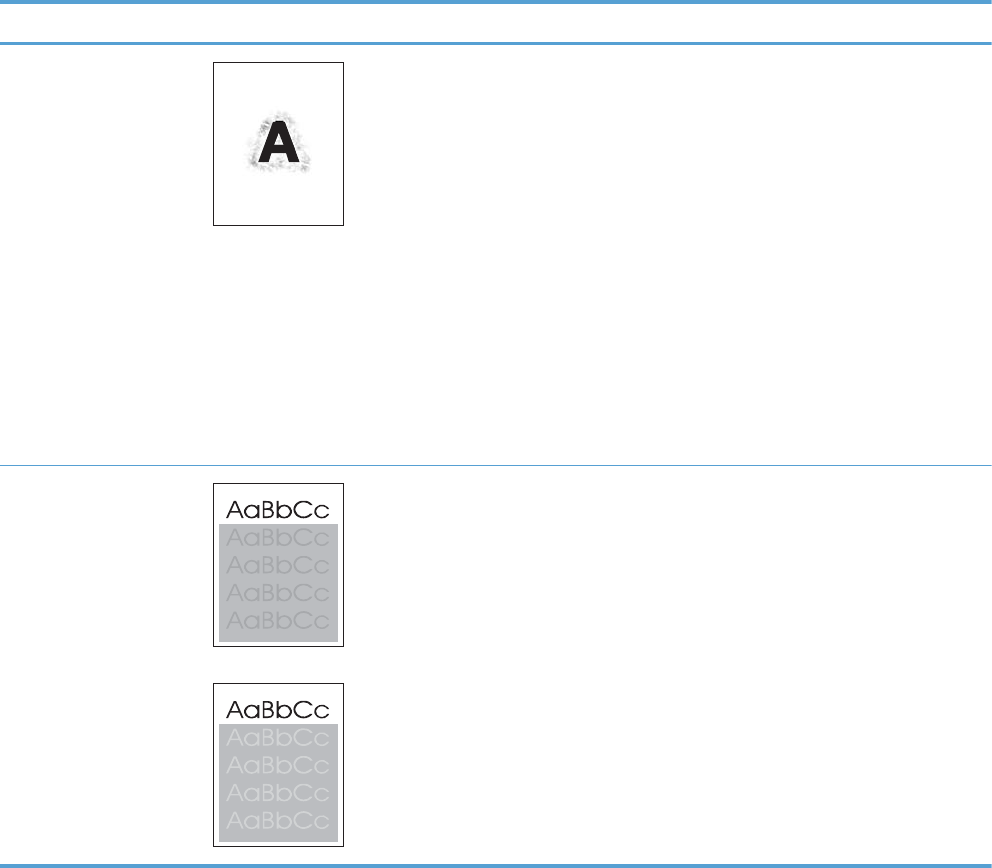
Table 3-36 Image defect examples (continued)
Problem Image example Solution
Blurred print 1. Make sure that the type and quality of the paper you are using meet
HP specifications.
2. Make sure that the environmental specifications for the product are being met.
3. Turn over the paper in the tray. Also, try rotating the paper 180°.
4. Do not use paper that already has been run through the product.
5. Open the following menus:
◦Administration
◦General Settings
◦Print Quality
◦Toner Density
●Select form a range of density settings.
Random image repetition If an image that appears at the top of the page (in solid black) repeats further
down the page (in a gray field), the toner might not have been completely erased
from the last job. (The repeated image might be lighter or darker than the field it
appears in.)
●Print the job several times to determine if the problem persists.
●Change the tone (darkness) of the field that the repeated image appears in.
●Change the order in which the images are printed. For example, have the
lighter image at the top of the page, and the darker image farther down the
page.
●From your software program, rotate the whole page 180° to print the lighter
image first.
●If the defect occurs later in a print job, turn the product off for 10 minutes, and
then turn it on to restart the print job.
ENWW Solve image-quality problems 387
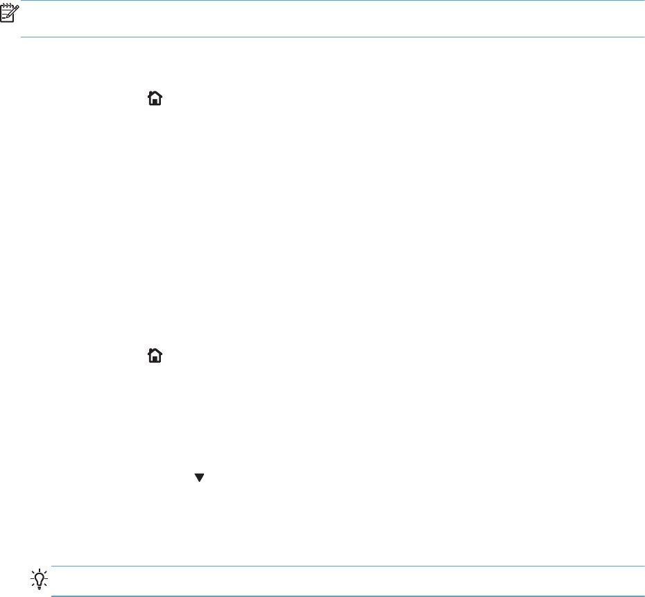
Clean the product
Over time, particles of toner and paper accumulate inside the product. This can cause print-quality
problems during printing. Cleaning the product eliminates or reduces these problems.
Clean the paper path and print-cartridge areas every time that you change the print cartridge or
whenever print-quality problems occur. As much as possible, keep the product free from dust and
debris.
To clean the product exterior, use a soft, water-moistened cloth.
Clean the paper path
NOTE: If you are processing a cleaning page to clean the fuser, repeat the process 1 to 6 times until
the paper comes out clean.
Process a cleaning page
1. Press the Home button.
2. Open the following menus:
●Device Maintenance
●Calibrate/Cleaning
3. Scroll to the Print Cleaning Page item, and then press the OK button.
4. The product prints a cleaning page, and then returns to the main menu. Discard the printed page.
Set up an auto cleaning page
Use the procedure in this section to set up an automatic cleaning page.
1. Press the Home button.
2. Open the following menus:
●Device Maintenance
●Calibrate/Cleaning
3. Press the Down arrow to highlight the Auto Cleaning item, and then select the Enabled
item. Press the OK button.
4. Scroll to the Cleaning Interval item, and then use the arrow buttons to select an interval. Press
the OK button.
TIP: HP recommends processing a cleaning page after every 5000 printed pages.
5. Scroll to the Auto Cleaning Size item, and then use the arrow buttons to select the cleaning
page size. Press the OK button.
388 Chapter 3 Solve problems ENWW

Solve performance problems
Problem Cause Solution
Pages print but are totally blank. The document might contain blank
pages.
Check the document that you are
printing to see if content appears on all
of the pages.
The product might be malfunctioning. To check the product, print a
Configuration page.
All of the print cartridges might be very
low on toner.
Replace the toner cartridges if a
Supplies very low message is
displayed.
Pages print very slowly. Heavier paper types can slow the print
job.
Print on a different type of paper. Proper
fusing may require a slower print speed
to ensure the best print quality.
Complex pages can print slowly. Simplify the page.
Pages did not print. The product might not be pulling paper
correctly.
Make sure paper is loaded in the tray
correctly.
The paper is jamming in the product. Clear the jam.
The USB cable might be defective or
incorrectly connected.
●Disconnect the USB cable at both
ends and reconnect it.
●Try printing a job that has printed
in the past.
●Try using a different USB cable.
Other devices are running on your
computer.
The product might not share a USB port.
If you have an external hard drive or
network switchbox that is connected to
the same port as the product, the other
device might be interfering. To connect
and use the product, you must
disconnect the other device or you must
use two USB ports on the computer.
ENWW Solve performance problems 389

Solve connectivity problems
Solve direct-connect problems
If you have connected the product directly to a computer, check the cable.
●Verify that the cable is connected to the computer and to the product.
●Verify that the cable is not longer than 2 m (6.5 ft). Replace the cable if necessary.
●Verify that the cable is working correctly by connecting it to another product. Replace the cable if
necessary.
Solve network problems
Check the following items to verify that the product is communicating with the network. Before
beginning, print a configuration page. See Internal print-quality test pages on page 241.
Problem Solution
Poor physical connection Verify that the product is attached to the correct network port using a cable of the
correct length.
Verify that cable connections are secure.
Look at the network port connection on the back of the product, and verify that the
amber activity light and the green link-status light are lit.
If the problem continues, try a different cable or port on the hub.
The computer is unable to communicate
with the product.
Use the command prompt to ping the product from your computer. For example:
ping 192.168.45.39
Verify that the ping displays round-trip times, which indicates that it is working.
If the ping command failed, verify that the network hubs are on, and then verify that
the network settings, the product, and the computer are all configured for the same
network.
Incorrect link and duplex settings Hewlett-Packard recommends leaving this setting in automatic mode (the default
setting). See the user guide.
Incorrect IP address for the product on
the computer
Use the correct IP address. The IP address is listed on the configuration page.
If the IP address is correct, delete the product and then add it again.
New software programs have caused
compatibility problems.
Verify that any new software programs are correctly installed and that they use the
correct printer driver.
Your computer or workstation is set up
incorrectly.
Check the network drivers, printer drivers, and the network redirection.
Verify that the operating system is configured correctly.
The protocol is disabled, or other
network settings are incorrect.
Review the configuration page to check the status of the protocol. Enable it if
necessary.
Reconfigure the network settings if necessary. See the user guide.
390 Chapter 3 Solve problems ENWW

Service mode functions
Service menu
The Service menu is PIN-protected for added security. Only authorized service people have access to
the Service menu. When you select Service from the list of menus, the product prompts you to enter
an eight-digit PIN number (Service Access Code). The PIN for the HP LaserJet Enterprise 600 M601,
M602, and M603 Series Printer is 10060111, 10060211, or 10060311 depending on your model.
1. Press the Home button.
2. Open the following menus:
●Device Maintenance
●Service
●Service Access Code
3. Enter the eight-digit PIN using the arrow buttons or numeric keypad.
After entering a digit, press the OK button. Repeat for each digit in the PIN.
NOTE: Only the Service Access Code can be used to access the Service menu. The
message Your user account does not have permission to access the selected item
displays if the correct Service Access Code is not used.
4. Press the OK button to enter the PIN and open the Service menu.
The following menu items appear in the Service menu:
First level Second level Third level Description
User Access Code Only the Service Access
Code can be used to access
the Service menu. The
message Your user
account does not have
permission to access the
selected item displays if the
correct Service Access
Code is not used.
Administrator Access
Code
Only the Service Access
Code can be used to access
the Service menu. The
message Your user
account does not have
permission to access the
selected item displays if the
correct Service Access
Code is not used.
Service Access Code This item allows access to the
Service sub menus.
ENWW Service mode functions 391

First level Second level Third level Description
Print Event Log Use this item to print the
service event log.
View Event Log Use this item to view the
service event log.
Clear Event Log Use this item to clear (erase)
the service event log.
Cycle Counts Mono Cycle Counts Use this item to reset the
mono print job page count.
Refurbish Cycle Count Use this item to reset the
refurbuish print job page
count.
Serial Number Use this item to reset the
product serial number.
Service ID Use this item to reset the
product service identification
number.
Cold Reset Paper Use this item to set the cold
reset paper size.
Test Support Continuous Print from
USB
Use this item to test print from
an external USB.
Product resets
Restore factory-set defaults
1. Press the Home button.
2. Open the following menus:
●Administration
●General Settings
●Restore Factory Settings
3. Scroll to type of reset from a list, and then press the OK button.
4. Scroll to the Reset item, and then press the OK button.
Restore factory-set defaults values
●General
◦Display and sound settings for the control panel
◦Localization settings (for example, clock format and date format)
392 Chapter 3 Solve problems ENWW
◦Error and warning log behavior
◦Default media settings
◦Sleep mode and delay setting
◦Internal backup file maximum size
◦Oxp installer solutions, tasks and pending tasks
◦Http job defaults
◦Clears the error, warning and info logs
◦Supported media types
◦Resets JetLink connected external devices
●Print
◦Print default job, stored job and quick set settings
◦Some print job usage data
◦Print system configuration settings
●Security
◦Default Authentication agent
◦Authentication agents
◦Policy agents
Clean Disk and Partial Clean functions
Active and repository firmware locations
The firmware bundle now consists of multiple parts. The main components are the Windows CE
Operating System and the printer/peripheral firmware files.
There are two locations/partitions on the hard drive where the firmware components are stored:
●The Active – where the Operating System and firmware currently are executing
●The Repository – the recovery location
If the Active location is damaged, or a Partial Clean was performed, the printer automatically copies
over the OS and firmware files from the Repository location and the printer recovers.
If both the Active and Repository locations are damaged, or a Clean Disk was performed, then both
locations are gone and the error message 99.09.67 appears on the control-panel display. The user
must upload the firmware to the printer in order for it to function again
ENWW Service mode functions 393

CAUTION: The Clean Disk option performs a disk initialization for the entire disk. The operating
system, firmware files, and third party files (among other files) will be completely lost. HP does not
recommend this action.
Partial Clean
The Partial Clean option erases all partitions and data on the disk drive, except for the firmware
repository where a backup copy of the firmware file is stored. This allows the disk drive to be
reformatted without having to download a firmware upgrade file to return the product to a bootable
state.
Characteristics of a Partial Clean
●Customer-defined settings, third-party solutions, firmware files, and the operating system are
deleted.
●Rebooting the product restores the firmware files from the Repository location, but does not restore
any customer-defined settings.
●For previous HP products, a Hard Disk Initialization is similar to executing the Partial Clean
function for this product.
CAUTION: HP recommends backing-up product configuration data before executing a Partial
Clean if you need to retain customer-defined settings. See the Backup/Restore item in the Device
Maintenance menu.
Reasons for performing Partial Clean
●The product continually boots up in an error state.
NOTE: Try clearing the error prior to executing a Partial Clean.
●The product will not respond to commands from the control panel.
●Executing the Partial Clean function is helpful for troubleshooting hard disk problems.
●To reset the product by deleting all solutions and customer-defined settings.
●The product default settings are not properly working.
Execute a Partial Clean
1. Turn the product on.
2. When the Ready, Data, and Attention LEDs are illuminated solid, press the Stop button.
3. Scroll to Administration, and then press the OK button.
4. Scroll to Partial Clean, and then press the OK button.
394 Chapter 3 Solve problems ENWW

5. Press the OK button again.
6. Press the Back button to highlight Continue, and then press the OK button.
NOTE: The product initializes.
Clean Disk
The Clean Disk option erases the entire disk drive.
CAUTION: After executing a Clean Disk option, the product is not bootable.
Characteristics of a Partial Clean
●Customer-defined settings, third-party solutions, firmware files, and the operating system are
deleted.
NOTE: Rebooting the product does not restore the firmware files.
●Rebooting the product restores the firmware files from the Repository location, but does not restore
any customer-defined settings.
●After executing the Clean Disk function, the message 99.09.67 displays on the control panel.
●After executing the Clean Disk function, the product firmware must be reloaded.
CAUTION: HP recommends that you do not use the Clean Disk option unless an error occurs and
the solution in the product service manual recommends this solution. After executing the Clean Disk
function, the product is unusable.
HP recommends backing-up product configuration data before executing a Clean Disk if you need to
retain customer-defined settings. See the Backup/Restore item in the Device Maintenance menu.
Reasons for performing Clean Disk
●The product continually boots up in an error state.
NOTE: Try clearing the error prior to executing a Clean Disk.
●The product will not respond to commands from the control panel.
●Executing the Clean Disk function is helpful for troubleshooting hard disk problems.
●To reset the product by deleting all solutions and customer-defined settings.
Execute a Clean Disk
1. Turn the product on.
2. When the Ready, Data, and Attention LEDs are illuminated solid, press the Stop button.
3. Scroll to Administration, and then press the OK button.
ENWW Service mode functions 395

4. Scroll to Clean Disk, and then press the OK button.
5. Press the OK button again.
NOTE: When the Clean Disk operation is complete, you will need to reload the product
firmware.
396 Chapter 3 Solve problems ENWW

Product updates
To download the most recent firmware upgrade for the product, go to www.hp.com/go/
lj600Series_firmware.
Determine the installed revision of firmware
Print a configuration page to determine the installed revision of firmware. See Internal print-quality test
pages on page 241.
On the configuration page, look in the section marked Device Information for the firmware datecode
and firmware revision.
Firmware datecode and firmware revision examples
●20100831 (firmware datecode)
●103067_104746 (firmware revision)
Perform a firmware upgrade
The firmware bundle is a xxxxxxx.bdl file. This file requires an interactive upgrade method. You
cannot upgrade the printer using the traditional FTP, LPR or Port 9100 methods of upgrading. Use one
of the following methods to upgrade the firmware for this product.
Embedded Web Server
1. Open an browser window.
2. Enter the product IP address in the URL line.
3. Select the Firmware upgrade link from within the Troubleshooting tab.
NOTE: If you get a warning screen, follow the instructions for setting an administrator password
from the Security tab.
4. Browse to the location that the firmware upgrade file was downloaded to, and then select the
firmware file. Select the Install button to perform the upgrade.
NOTE: Do not close the browser window until the Embedded Web Server (EWS) displays the
confirmation page.
5. Select Restart Now from the EWS confirmation page, or turn the product off, and then on again
using the power button.
ENWW Product updates 397

USB storage device (Preboot menu)
1. Copy the xxxxxxx.bdl file to a portable USB flash memory storage device (thumb drive).
2. Turn the product on.
3. Press the Stop button when the Ready, Data and Attention LEDs illuminate solid.
4. Scroll to the Administrator menu, and then press the OK button.
5. Scroll to the Download item, and then press the OK button.
6. Insert the portable USB storage device with the xxxxxxx.bdl file on it.
NOTE: If the error message No USB Thumbdrive Files Found appears on the control-panel
display, you might need to connect the storage device to the external USB connection on the
formatter or try using a different portable storage device.
7. Scroll to the USB Thumbdrive item, and then press the OK button.
8. Scroll to the xxxxxxx.bdl file, and then press the OK button.
NOTE: The upgrade process can take up to 10 minutes to complete.
TIP: If there is more than one xxxxxxx.bdl file on the storage device, make sure that you
select the correct file for this product.
9. When the message Complete appears on the control-panel display, press the Back button 3
times.
10. When the message Continue appears on the control-panel display, press the OK button. The
product will initialize.
11. When the upgrade process is complete, print a configuration page and verify that the upgrade
firmware version was installed. See Print configuration page on page 243 and Determine the
installed revision of firmware on page 397.
398 Chapter 3 Solve problems ENWW

USB storage device (control-panel menu)
1. Copy the xxxxxxx.bdl file to a portable USB flash memory storage device (thumbdrive).
2. Turn the product on, and then wait until it reaches the Ready state.
3. Press the Home button or OK button.
4. Scroll to the Device Maintenance item, and then press the OK button.
5. Scroll to the USB Firmware Upgrade item, and then press the OK button.
6. Insert the portable USB storage device with the xxxxxxx.bdl file on it into the USB port on the
front of the product, and then press the OK button.
7. Scroll to the xxxxxxx.bdl file item, and then press the OK button.
TIP: If there is more than one xxxxxxx.bdl file on the storage device, make sure that you
select the correct file for this product.
8. A prompt to upgrade an older, newer, or reinstall the same version appears. Press the down
arrow button to highlight the desired option, and then press the OK button.
When the upgrade is complete, the product will initialize.
NOTE: The upgrade process can take up to 10 minutes to complete.
9. When the upgrade process is complete, print a configuration page and verify that the upgrade
firmware version was installed. See Internal print-quality test pages on page 241 and Determine
the installed revision of firmware on page 397.
ENWW Product updates 399
400 Chapter 3 Solve problems ENWW


Order parts by authorized service providers
Order parts, accessories, and supplies
Table 4-1 Order parts, accessories, and supplies
Order supplies and paper www.hp.com/go/suresupply
Order genuine HP parts or accessories www.hp.com/buy/parts
Order through service or support providers Contact an HP-authorized service or support provider.
Order using HP software For information about using the HP software to order parts,
accessories, and supplies, see the product user guide.
Supplies part numbers
Table 4-2 Supplies part numbers
Item Description Part number
HP LaserJet print cartridge with HP ColorSphere
toner
Black print cartridge (standard) CE390A (new)
CE390-67901 (service)
Black print cartridge (high capacity) CE390X (new)
CE390-67902 (service)
Customer-self repair parts
Each kit includes parts and installation instructions. The customer-self repair (CSR) level indicates the
expected difficulty the customer will experience when replacing this part:
●A = Manditory
●B = Optional
●C = Very difficult
Item Part number CSR level
Transfer roller kit
●Transfer roller assembly (with removal tool)
●Installation instructions
CE988-60793 A
Output bin assembly kit
●Output bin
●Installation instructions
CE988-67909 A
402 Chapter 4 Parts and diagrams ENWW

Item Part number CSR level
Formatter kit
●Formatter assembly
●Installation instructions
CE988-67906
CE988-67908 (China)
A
Fuser kit
●Fuser assembly
●Installation instructions
CE988-67901 (110 V)
CE988-67902 (220 V)
A
Tray 2-X pickup and feed rollers kit
●Paper pickup rollers
●Paper feed rollers
●Installation instructions
CE988-67904 A
Tray 1rollers kit
●Tray 1 pickup roller
●Tray 1 feed roller
●Tray 1 separation roller
●Installation instructions
CE988-67905 B
Solid state memory kit
●Solid state memory, 8 GB
●Installation instructions
CE988-67907 B
Hard disk drive encrypted kit
●Hard disk drive encrypted, 250 GB
●Installation instructions
CE502-67915 B
Preventative maintenance service kits
●Fuser
●Transfer roller (and tool)
●Tray 2-X pickup and feed rollers kit
●Disposable gloves
●Installation instructions
110 volt: CF064-67901
220 volt: CF065-67901
A
1x500-sheet feeder kit CE998-67901 A
Custom media cassette kit CB527-67901 A
Staple cartridge kit Q3216-67901 A
512 MB memory kit CE483-67901 A
Envelope feeder kit CE399-67901 A
ENWW Order parts by authorized service providers 403

Item Part number CSR level
Duplex kit CF062-67901 A
500-sheet stacker kit CE404-67901 A
500-sheet stapler/stacker kit CE405-67901 A
5-bin mailbox kit CE997-67901 A
Product stand kit CF063-67901 A
Accessories part numbers
Table 4-3 Accessories part numbers
Item Description Part number
1x500-sheet feeder Optional feeder to increase paper capacity.
The product can accommodate up to four optional
500-sheet feeders
CE998A
1x1500-sheet feeder Optional feeder to increase paper capacity. CE398A
Custom media cassette Enables the product to print A6-size paper from
Tray 2.
CE527A
1,000-staple cartridge Staple cartridge refill Q3216A
44 X 32-PIN DDR2 memory
DIMM, 512 mb
Memory DIMM CE483A
Envelope feeder Optional input accessory to increase paper handling. CE399A
Duplexer (duplex printing
accessory)
Allows automatic printing on both sides of the paper. CF062A
500-sheet stacker Provides an additional output bin that holds 500
sheets.
CE404A
500-sheet stapler/stacker Allows for high-volume output with automatic job
finishing. Staples up to 15 sheets of paper.
CE405A
HP 5-bin mailbox Provides five output bins that you can use to sort jobs. CE997A
404 Chapter 4 Parts and diagrams ENWW

Table 4-3 Accessories part numbers (continued)
Item Description Part number
Printer stand Provides stability when multiple optional trays are
installed. The stand has casters so you can easily
move the product.
CF063A
Power cords China 220V - 10A
Thailand 122V - 10A
Argentina 220V - 10A
Switzerland 220V - 10A
Denmark 220V - 10A
South Africa 220V - 10A
Malaysia, Hong Kong, Singapore 220V - 10A
Korea, Vietnam, Indonesia, Europe 220V - 10A
Peru, Chile 220V - 10A
Israel 220V - 10A
Australia 220V - 10A
China 220V - 10A
Taiwan 110V - 13A
Brazil 110V - 10A
India 220V - 6A
US, Saudia Arabia, Canada, Mexico 110V - 13A
Japan 110V - 12A
8121-0951
8121-0952
8121-0953
8121-0947
8121-0949
8121-0954
8121-0946
8121-0950
8120-5301
8121-1005
8121-0872
8121-0945
8121-0971
8121-1070
8121-1083
8121-1142
8121-1144
Related documentation and software
Table 4-4 Related documentation and software
Item Description Part number
HP LaserJet Enterprise 600 M601, M602, and M603 Series
Printer User Guide
Product user guide CE988-90901
HP LaserJet Enterprise M600 M601, M602, and M603 Series
Printer Service Manual
English service manual (this
manual)
CE988-90945
ENWW Order parts by authorized service providers 405

How to use the parts lists and diagrams
The figures in this chapter show the major subassemblies in the product and their component parts. A
parts list table follows each exploded view assembly diagram. Each table lists the item number, the
associated part number, and the description of each part. If a part is not listed in the table, then it is not
a field replacement unit (FRU).
CAUTION: Be sure to order the correct part. When looking for part numbers for electrical
components, pay careful attention to the voltage that is listed in the description column. Doing so will
ensure that the part number selected is for the correct model.
NOTE: In this manual, the abbreviation “PCA” stands for “printed circuit-board assembly.”
Components described as a PCA might consist of a single circuit board or a circuit board plus other
parts, such as cables and sensors.
406 Chapter 4 Parts and diagrams ENWW
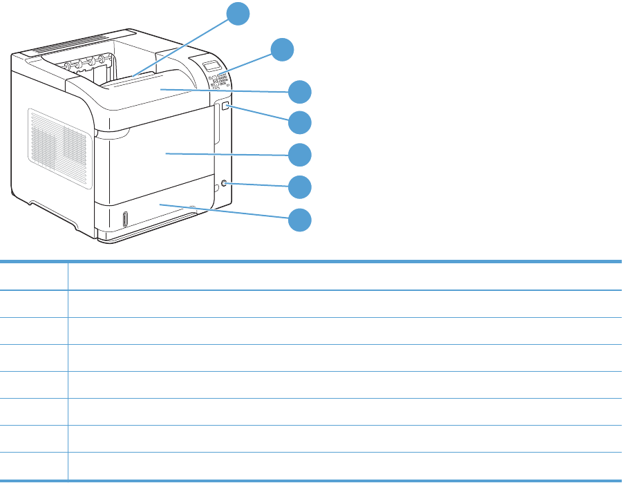
Assembly locations
Base product (no optional trays or accessories)
Figure 4-1 Base product (no optional trays or accessories; 1 of 3)
1
2
3
5
7
4
6
Item Description
1 Top output bin
2 Control panel (the M602 and M603 models include a numeric keypad)
3 Top cover (provides access to the print cartridge)
4 Walkup USB printing
5 Tray 1 (pull to open)
6 On/off button
7Tray 2
ENWW Assembly locations 407
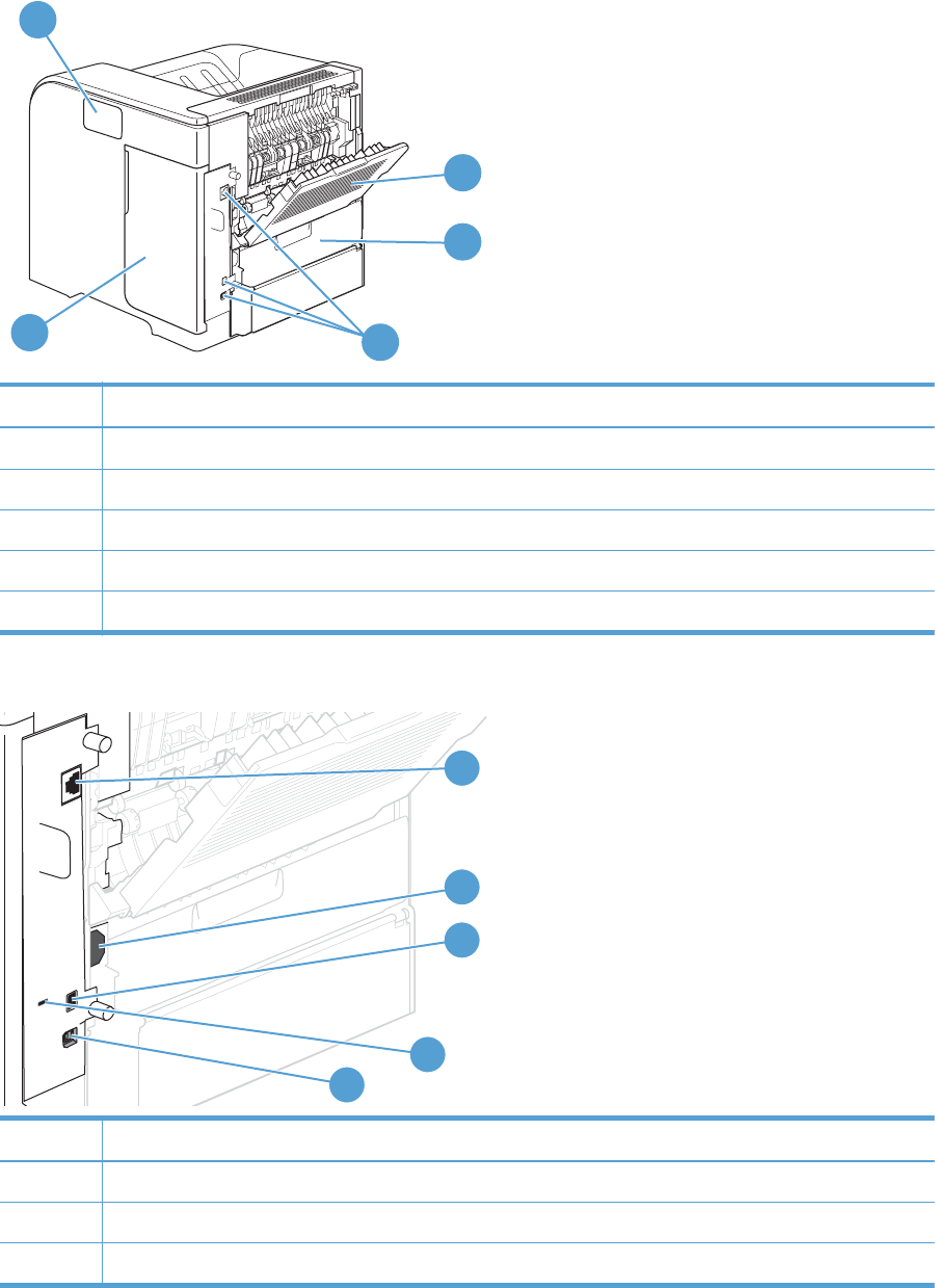
Figure 4-2 Base product (no optional trays or accessories; 2 of 3)
1
2
3
4
5
Item Description
1Rear output bin
2 Duplex accessory cover (remove to install the duplex accessory)
3 Interface ports(formatter)
4 Right cover (provides access to the DIMM slot)
5 Hardware integration pocket (M602 and M603 models only)
Figure 4-3 Base product (no optional trays or accessories; 3 of 3)
1
2
3
4
5
Item Description
1 RJ-45 Network connection
2 Power connection
3 Host USB connection
408 Chapter 4 Parts and diagrams ENWW

Item Description
4 Slot for a cable-type security lock
5 High-speed USB 2.0 connection
ENWW Assembly locations 409
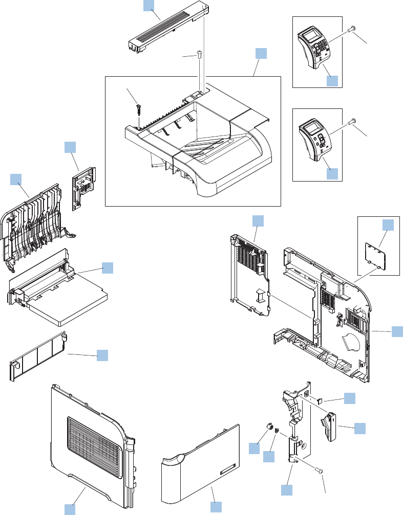
Covers
Product base
Figure 4-4 Covers
M601
M602 & M603
M601
8
7
13
9
4
3
10
11
1
2
*A01
5
6
14
12
12
17
16
15
*A03 *A02
*A02
*A03
410 Chapter 4 Parts and diagrams ENWW

Table 4-5 Covers
Ref Description Part number Qty
1 Cover, option RC2-2459-000CN 1
2 Cover, formatter RC2-2468-000CN 1
3 Cover, right front RC3-1426-000CN 1
4 Cover, envelope connector RC2-2476-000CN 1
5 Cover, duplexing assembly RM1-8399-000CN 1
6 Cover, legal RC2-5239-000CN 1
7 Face-up tray assembly RM1-8388-000CN 1
8 Cover, front assembly RM1-8408-000CN 1
9 Cover, right (M602 and M603) RM1-8400-000CN 1
9 Cover, right (M601) RM1-8445-000CN 1
10 Cover, left assembly RM1-8401-000CN 1
11 Cover, top assembly (M602 and M603) RM1-8394-000CN 1
11 Cover, top assembly (M601) RM1-8434-000CN 1
12 Control-panel assembly (M602 and M603) RM1-8289-000CN 1
12 Control-panel assembly (M601) RM1-8290-000CN 1
13 Cover, right rear RC2-2478-000CN 1
14 Cover, HIP (M602 and M603) RC3-1424-000CN 1
15 Button, power RC3-1430-000CN 1
16 Cap, power button RC3-1431-000CN 1
17 Cover, USB RC3-1434-000CN 1
ENWW Covers 411
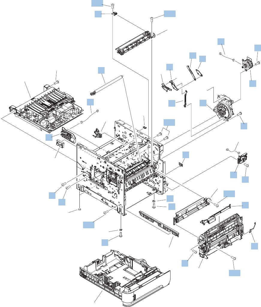
Internal components
Internal components (1 of 3)
Figure 4-5 Internal components (1 of 3)
A
A
(J120)
(J99)
(J187)
(J87) (M102)
(SW102)
(J1061)
(J32)
See registration assembly
See paper-feed roller assembly
See Tray 1 (MP tray)
pickup assembly
See cassette
See power supply
23
4
5
7
8
6
1
14
10
10
10
10
501
501
10
11
501
12
10
501
501
502
9
501
13
15
16
17
18
19
19
*A01
*A06
*A04
*A03
*A07
*A02
*A05
412 Chapter 4 Parts and diagrams ENWW

Table 4-6 Internal components (1 of 3)
Ref Description Part number Qty
1 Cover, envelope feeder RL1-1667-000CN 1
2 Transfer roller RM1-8491-000CN 1
3 Arm, release A RC2-2480-000CN 1
4 Arm, release B RC2-2481-000CN 1
5 Motor, drum assembly (M102) RM1-8358-000CN 1
6 Size detect assembly RM1-4525-000CN 1
7 Cable, drum motor RM1-8308-000CN 1
8 Cable, size sensor RM1-5091-000CN 1
9 Plate, ground assembly RM1-5461-000CN 1
10 Screw, D, M3x8 XA9-1671-000CN 21
11 Screw, tap, M3x6 XA9-1503-000CN 3
12 Spring, torsion RC3-1470-000CN 1
13 Screw, M4x5 RC2-2633-000CN 2
14 PCA, switch assembly RM1-8428-000CN 1
15 Rod, release, upper RC2-2482-000CN 1
16 Drum drive assembly RM1-8489-000CN 1
17 Rod, release lower RC2-2483-000CN 1
18 Guard, edge RC1-0247-000CN 1
19 Spacer, frame RC2-2725-000CN 2
501 Screw, tapping pan head M4X10 XB4-7401-607CN 16
ENWW Internal components 413
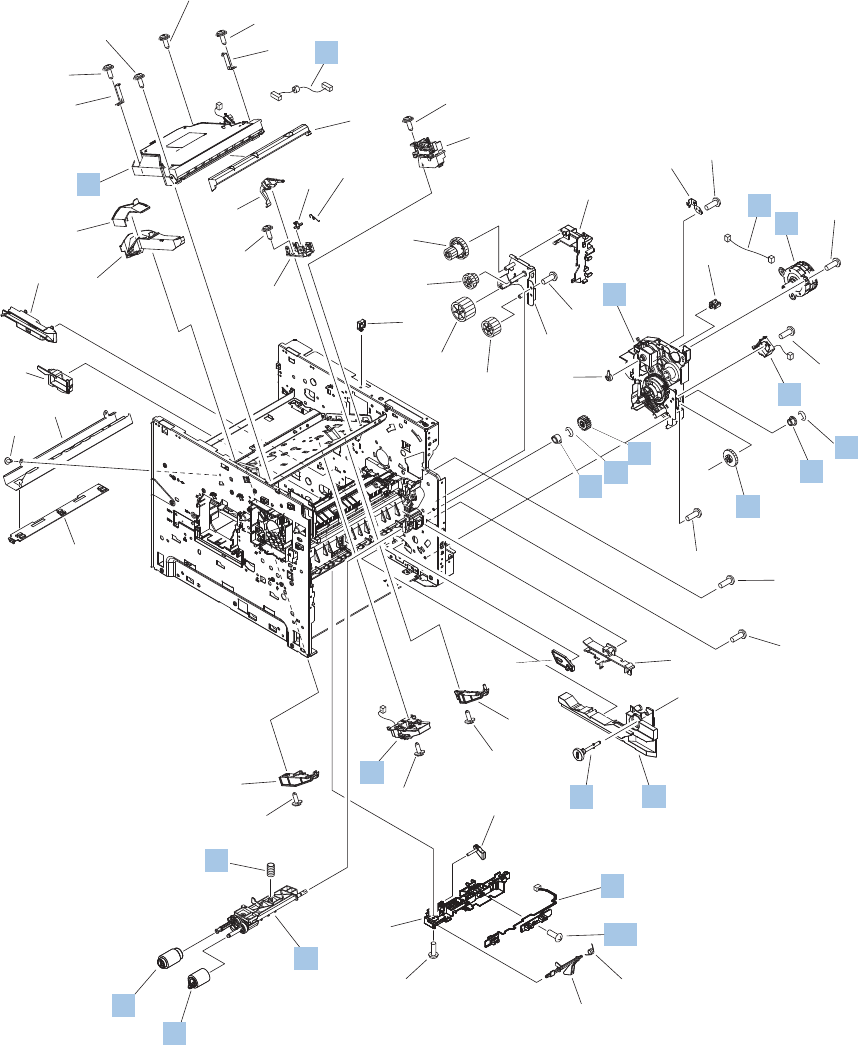
Internal components (2 of 3)
Figure 4-6 Internal components (2 of 3)
A
A
(J145)
(J93)
(J86)
(J72)
(J74)
(J92)
(PS107)
(PS101)
(PS907)
(CL101)
(J77)
(SL101)
(J191)
(J91)
(M101)
14
112 2
15
19
17
18
16
7
10
313
9
6
5
20
8
4
11
*A02
*A02
*A02
*A02
*A17
*A18
*A02
*A02
*A02
*A24
*A04
*A20
*A23
*A14
*A06
*A34
*A16
*A12
*A13
*A19
*A15
*A10
*A11 501
*A02
*A02
*A02
*A02
*A22
*A21
*A01
*A01
*A26
*A25
*A09
*A08
*A02
*A02
*A05
*A05
*A05
*A07
*A27
*A29
*A28
*A31
*A30
*A03
*A33
*A32
*A14
414 Chapter 4 Parts and diagrams ENWW

Table 4-7 Internal components (2 of 3)
Ref Description Part number Qty
1 Laser/scanner assembly RM1-8406-000CN 1
2 Motor, paper feed assembly (M101) RM1-8285-000CN 1
3 Shaft retard drive RL1-3020-000CN 1
4 Solenoid RK2-4078-000CN 1
5 Paper pickup roller assembly RM1-0036-020CN 1
6 Paper feed roller assembly RM1-0037-020CN 1
7 Paper pickup drive assembly RM1-8415-000CN 1
8 Tag holder assembly RM1-4539-000CN 1
9 Paper feed shaft assembly RM1-8424-000CN 1
10 Cable, feed sensor RM1-8298-000CN 1
11 Ring, E XD9-0232-000CN 1
12 Cable, feed motor RM1-8311-000CN 1
13 Guide, front right assembly RM1-8427-000CN 1
14 Cable, laser RM1-8340-000CN 1
15 Bushing RC1-0214-000CN 1
16 Ring, E XD9-0233-010CN 1
17 Bushing RC3-1403-000CN 1
18 Gear, 18T RU5-0088-000CN 1
19 Gear, 23T RU5-0040-000CN 1
20 Spring, compression RC1-0213-000CN 1
501 Screw, tap, binding head, M3x8 XB4-7300-809CN 2
ENWW Internal components 415
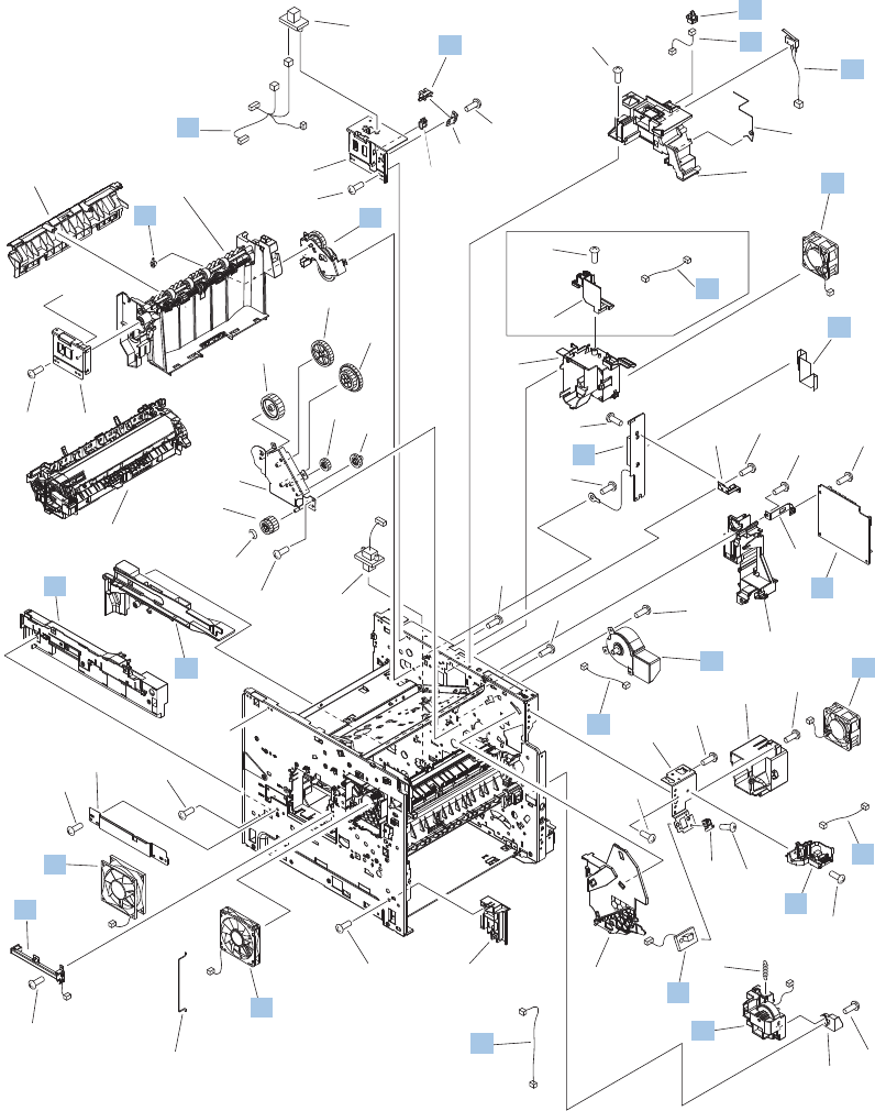
Internal components (3 of 3)
Figure 4-7 Internal components (3 of 3)
A
A
(J176) (J78)
(J33)
(J100)
(J97)
(J31)
(SW103)
(J76)
(J106)
(J90)
(J79)
(J88)
(J105)
(J75)
(J73)
(J66)
(J64)
(J89) (J221)
(J83)
(J118)
(J70)
(J170)
(J63)
(FN104)
(FN102)
(FN103)
(FN101)
(TH3)
(M299)
(M103)
(PS104)
(SW101)
(J1052)
(J2001)
(P1)
(J2002)
(J176)
(J106A)
(J106B)
23
15
501
19
18
(P1)
*A12
*A11
*A06
*A24
*A21
*A03
*A06
*A06
*A18
*A17
*A14
*A13
*A15
*A16
*A10
*A31
*A32
*A32
*A05
*A06
*A06
*A02
*A08
*A06
*A06
*A06
*A06
*A06
*A06
*A05
*A05
*A20
*A06
*A06
*A06
*A01
*A09
*A29
*A30
*A28
*A27
*A26
*A25
*A23
*A32
*A05
*A22
*A19
*A07
*A04
*A06
BASE MODEL
See paper delivery
assembly
See fuser
15
17
24
7
22
25
12
21
20
10
5
11
13
27
26
14
16
2
6
4
3
1
28
9
8
416 Chapter 4 Parts and diagrams ENWW

Table 4-8 Internal components (3 of 3)
Ref Description Part number Qty
1 Guide, right assembly RM1-4558-000CN 1
2 Cable, panel RM1-8341-000CN 1
3 Sensor, temperature assembly RM1-8438-000CN 1
4 Fan (FN101) RK2-1988-000CN 1
5 Fan (FN102) RK2-1989-000CN 1
6 Fan (FN103) RK2-3244-000CN 1
7 Fan (FN104) RK2-1992-000CN 1
8 Bushing, paper delivery RC1-0136-000CN 1
9 Paper delivery drive assembly RM1-8410-000CN 1
10 PCA, DC controller RM1-8293-000CN 1
11 Motor, fuser (M299) RM1-5051-020CN 1
12 Switch, interlock assembly RM1-8307-000CN 1
13 Cable, fuser motor RM1-5088-000CN 1
14 Lifter drive assembly RM1-4585-000CN 1
15 Cable, full sensor RM1-8927-000CN 1
16 Cable, envelope feeder RM1-5085-000CN 1
17 Photo interrupter, IC WG8-5849-000CN 1
20 PCA, inner connecting RM1-8294-000CN 1
21 Cable, flat flexible (FFC) RK2-4077-000CN 1
22 Switch, push WC2-5637-000CN 1
24 Cable, HIP (M602 and M603) RK2-4152-000CN 1
25 Cable, door switch RM1-8344-000CN 1
26 USB PCA RM1-8429-000CN 1
27 Cable, USB RK2-4149-000CN 1
28 Guide assembly, left RM1-8439-000CN 1
ENWW Internal components 417
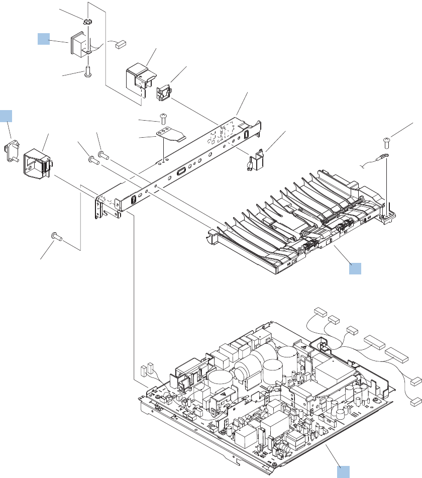
High-voltage power supply
Figure 4-8 High-voltage power supply
(J128)
(J82)
(J1)
(J85)
(J95)
(J96)
(J84)
(J124DB)
(J124DA) (J98)
(J30)
2
4
3
1
502
5501
*A01
*A04
*A08
*A06
*A07
*A02
*A03
*A05
*A09
*A10
418 Chapter 4 Parts and diagrams ENWW

Table 4-9 High-voltage power supply
Ref Description Part number Qty
1 Paper feed assembly RM1-4548-000CN 1
2 High-voltage power supply 110V RM1-8392-000CN 1
2 High-voltage power supply 220V RM1-8393-000CN 1
3 Connector, inlet RM1-8348-000CN 1
4 Connector, drawer 6P VS1-7514-006CN 1
ENWW Internal components 419
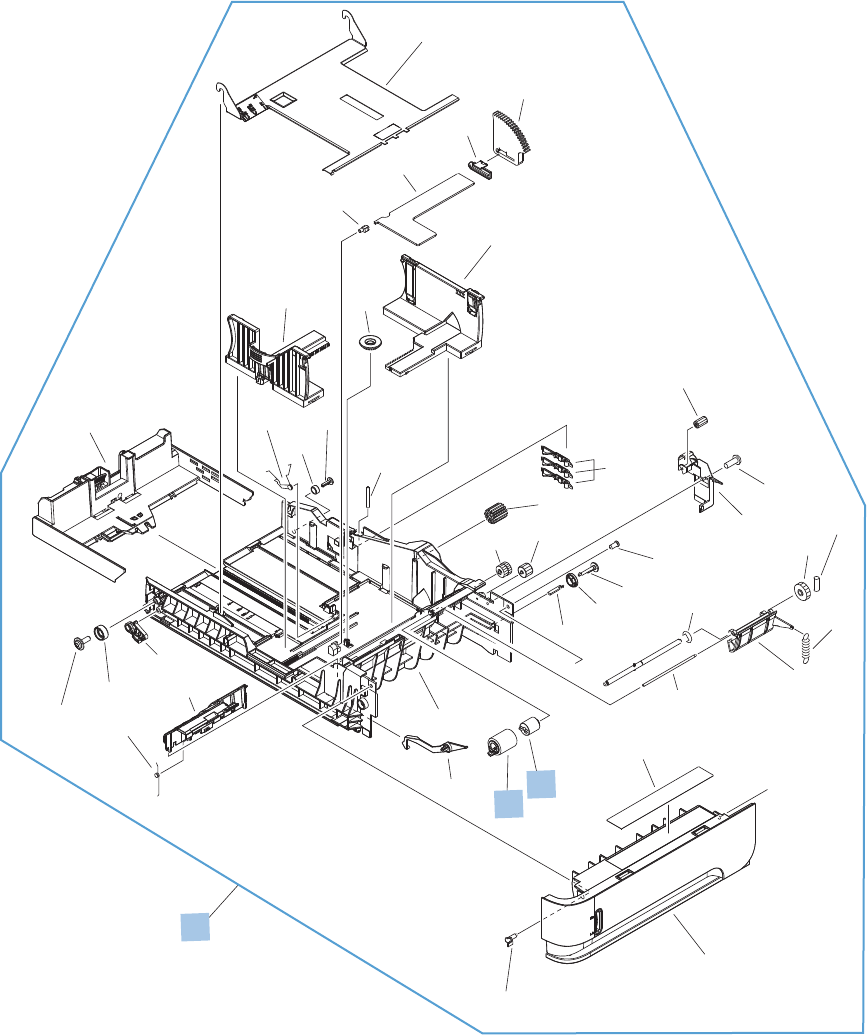
Cassette (Tray 2)
Figure 4-9 Cassette (Tray 2)
A
A
2
3
1
*A37
*A19
*A08
*A33
*A07
*A32
*A31
*A26
*A39
*A29
*A28*A27
*A15
*A01
*A12
*A16
*A38
*A02
*A25
*A03
*A34
*A10
*A36
*A21
*A17
*A20
*A30
*A06
*A35
*A22
*A14
*A13
*A40 *A09
*A23
*A04
*A05
*A24
*A18
*A11
420 Chapter 4 Parts and diagrams ENWW

Table 4-10 Cassette (Tray 2)
Ref Description Part number Qty
1 Cassette (Tray 2) RM1-4559-020CN 1
2 Torque limiter (Tray 2) RC2-5771-000CN 1
3 Roller, paper feed assembly (Tray 2) RM1-0037-020CN 1
ENWW Internal components 421
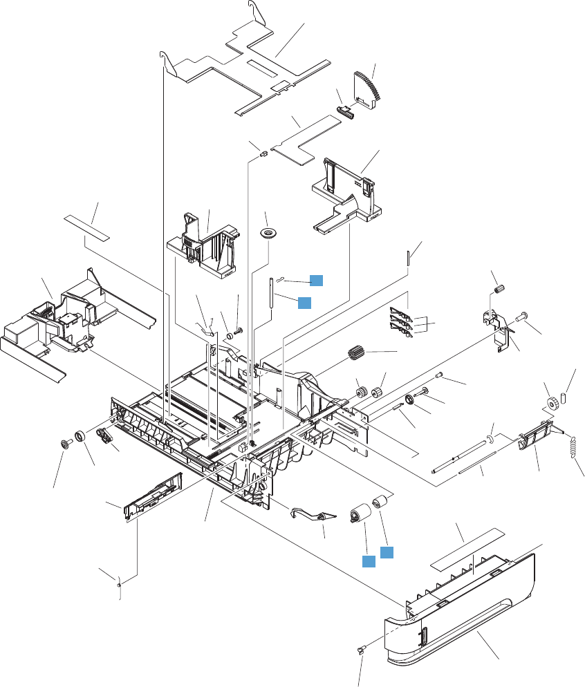
Cassette (custom media)
Figure 4-10 Cassette (custom media)
A
A
1
2
5
6
4
3
7
8
*A20
*A08
*A34
*A07
*A33
*A32
*A27
*A36
*A30
*A29
*A37
*A28
*A16
*A01
*A12
*A17
*A35
*A02
*A26
*A03
*A10
*A22
*A18
*A21
*A31
*A06
*A23
*A14
*A13
*A15
*A09
*A24
*A04
*A05
*A25
*A19
*A11
422 Chapter 4 Parts and diagrams ENWW

Table 4-11 Cassette (custom media)
Ref Description Part number Qty
1 Torque limiter (custom media) RM1-0037-000CN 1
2 Roller, paper feed assembly (custom media) RM1-4560-000CN 1
7 Pin, cassette (custom media) RC2-6486-000CN 1
8 Pin, stopper (custom media) RC2-6487-000CN 1
ENWW Internal components 423
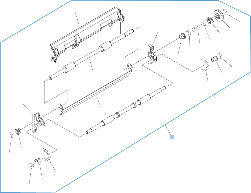
Paper feed roller assembly
Figure 4-11 Paper feed roller assembly
1
*A13
*A12
*A02
*A08
*A08
*A02
*A12
*A13
*A01
*A06
*A03
*A14
*A04
*A07
*A09
*A05
*A11
*A10
*A13
*A01
424 Chapter 4 Parts and diagrams ENWW

Table 4-12 Paper feed roller assembly
Ref Description Part number Qty
1 Paper feed roller assembly RM1-8411-000CN 1
ENWW Internal components 425
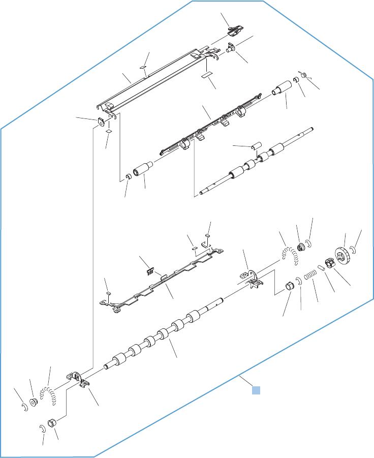
Registration assembly
Figure 4-12 Registration assembly
A
A
1
*A19
*A15
*A16
*A10
*A08
*A09
*A05
*A17
*A13
*A07
*A03
*A22
*A18
*A26
*A21
*A27
*A06
*A12
*A12
*A04
*A21*A27*A24
*A25*A11
*A23
*A27
*A22*A20
*A26
*A05*A02
*A09
*A01
*A14
*A29
*A28
426 Chapter 4 Parts and diagrams ENWW

Table 4-13 Registration assembly
Ref Description Part number Qty
1 Registration assembly RM1-8413-0000CN 1
ENWW Internal components 427
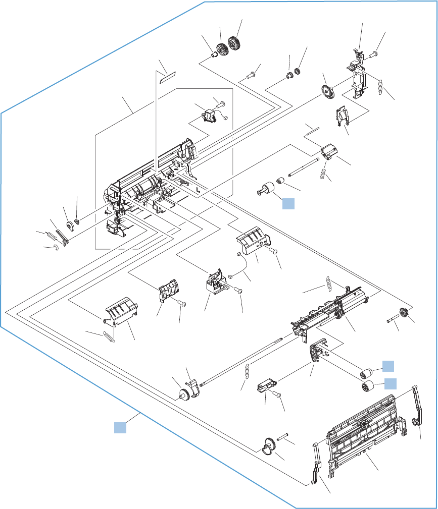
Tray 1 (MP) pickup assembly
Figure 4-13 Tray 1 (MP) pickup assembly
(J71)
(SL102)
(J81)
(J123)
(PS105)
1
4
3
2
*A01 *A38
*A25
*A23
*A18
*A24
*A08
*A38
*A38
*A41
*A31
*A20
*A07
*A32
*A12
*A06
*A13
*A14
*A40
*A30
*A21
*A25
*A38
*A34
*A42
*A29
*A39
*A05
*A22
*A15
*A17
*A02
*A35
*A36
*A16
*A26
*A10
*A04 *A38
*A11
*A33
*A03 *A38 *A19
*A09
*A28
*A37
*A27
428 Chapter 4 Parts and diagrams ENWW

Table 4-14 Tray 1 (MP) pickup assembly
Ref Description Part number Qty
1 Tray 1 (MP) pickup assembly RM1-8425-000CN 1
2 Roller pickup, Tray 1 (MP) RL1-1641-000CN 1
3 Roller feed, Tray 1 (MP) RL1-1663-000CN 1
4 Roller separation, Tray 1 (MP) RL1-1654-020CN 1
ENWW Internal components 429
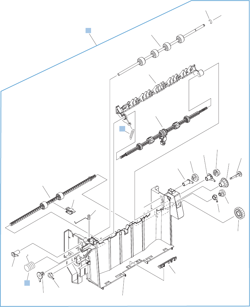
Paper delivery assembly
Figure 4-14 Paper delivery assembly
A
A
1
2
3
*A03
*A01
*A02
*A14
*A04
*A15
*A05 *A16
*A17
*A19
*A18
*A09
*A12
*A13
*A07
*A05 *A09
*A11
*A08
*A10
*A06
430 Chapter 4 Parts and diagrams ENWW

Table 4-15 Paper delivery assembly
Ref Description Part number Qty
1 Paper delivery assembly RM1-8414-000CN 1
2 Spring, tension RC1-0133-000CN 1
3 Spring, grounding RU6-2105-000CN 1
ENWW Internal components 431
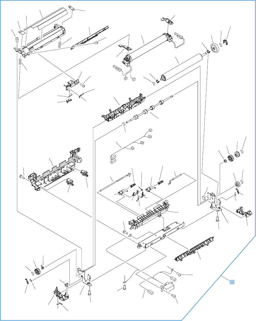
Fuser assembly
Figure 4-15 Fuser assembly
(J134)
(J131) (J778)
(J136)
(J136)
(J134)
(J128)
(J128LB)
(J128LA)
(J129)
(J929)
(J131)
(J778)
(PS699)
(PS700)
(J929)
(J129)
A
A
B
B
1
2
3*A39
*A05
*A11
*A10
*A10
*A40
*A47
*A46
*A34
*A52 *A28
*A12
*A04
*A05
*A54
*A54
*A53
*A38
*A25
*A57
*A24
*A06
*A50
*A56
*A47
*A55
*A55
*A32
*A36
*A35
*A17
*A18
*A20
*A30
*A44
*A44
*A09
*A22
*A21
*A26
*A50
*A27
*A14
*A03 *A31
*A43 *A51
*A07
*A08
*A23
*A45
*A19
*A17
*A27
*A13
*A29
*A01
*A16 *A02
*A02
*A37
*A37 *A15
*A42
*A33
*A49
*A41
*A49
*A48
432 Chapter 4 Parts and diagrams ENWW

Table 4-16 Fuser assembly
Ref Description Part number Qty
1 Fuser assembly 110V RM1-8395-000CN 1
1 Fuser assembly 220V RM1-8396-000CN 1
ENWW Internal components 433
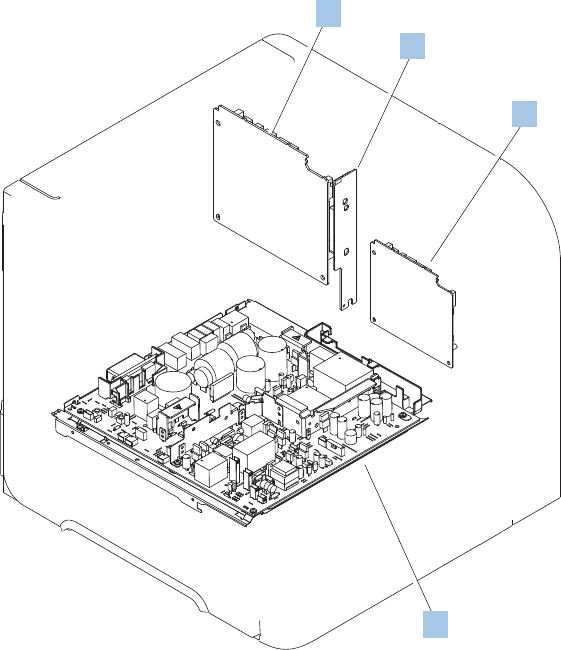
PCAs (product base)
Figure 4-16 PCAs (product base)
1
3
4
2
434 Chapter 4 Parts and diagrams ENWW

Table 4-17 PCAs (product base)
Ref Description Part number Qty
1 PCA, DC controller RM1-8293-000CN 1
2 Power supply, high-voltage 110V RM1-8392-000CN 1
2 Power supply, low-voltage 220V RM1-8393-000CN 1
3 PCA, inner connecting RM1-8294-000CN 1
4 Formatter CE988-67906 1
ENWW Internal components 435
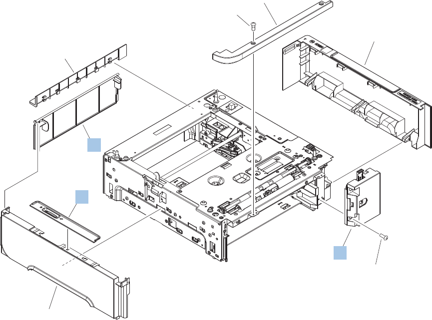
Input devices
1x500-sheet feeder
Covers (1x500)
Figure 4-17 Covers (1x500)
3
4
5
6
2
1
7
*A01
*A02
436 Chapter 4 Parts and diagrams ENWW

Table 4-18 Covers (1x500)
Ref Description Part number Qty
3 Cover, lock (1x500) RC2-2584-000CN 1
5 Cover, legal (1x500) RC2-5239-000CN 1
7 Number dial assembly (1x500) RM1-4591-000CN 1
ENWW Input devices 437
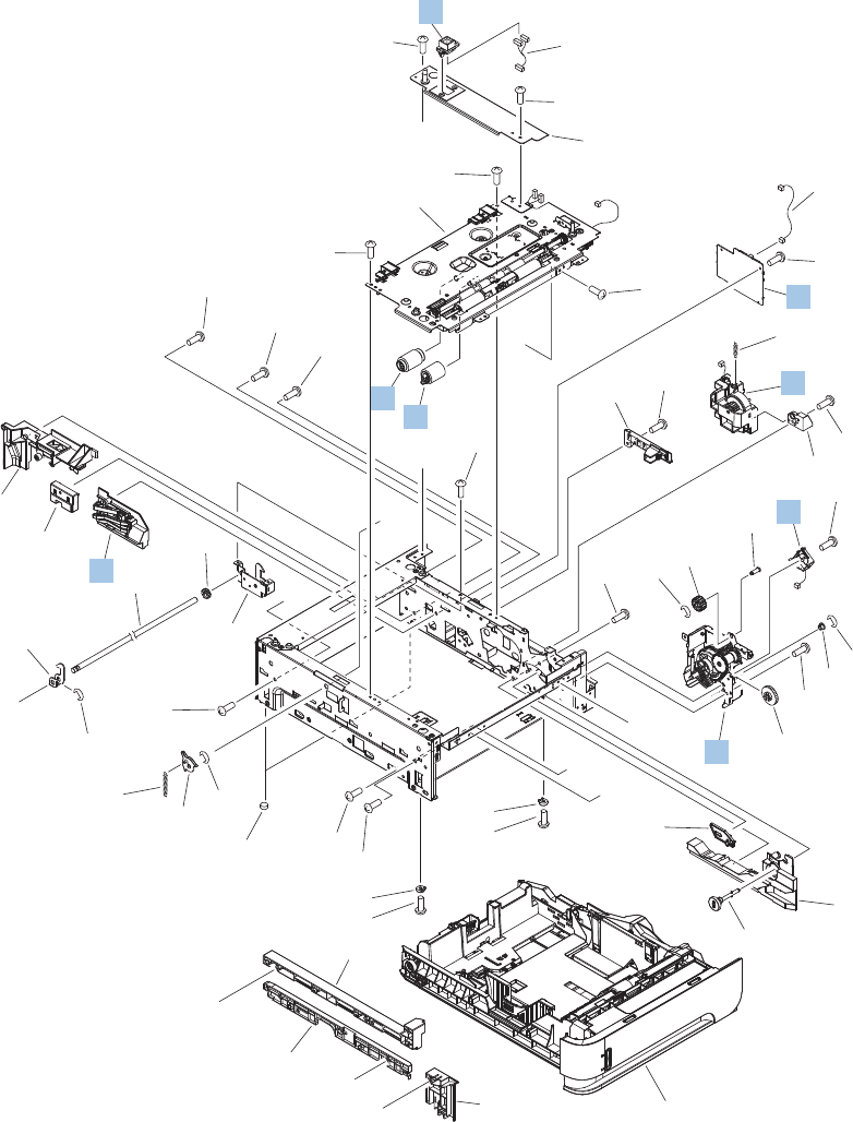
Main body (1x500)
Figure 4-18 Main body (1x500)
(J1602)
(J1606)
(J1608) (J1603) (J1623)
(J1607)
(J1605)
(J105LB)
(J105LA)
(J105L)
(SL1600)
(J1604)
A
E
F
F
E
B
B
A
CD
CDSee Cassette (1x500)
2
3
11
1
6
7
8
10
5
4
9
*A01
*A02
*A08 *A28
*A28
*A28
*A28
*A28
*A28
*A28
*A28
*A28
*A28
*A29
*A29
*A04
*A25
*A07
*A21
*A05
*A09
*A16
*A24
*A23
*A14
*A13
*A10
*A11
*A31
*A31
*A18
*A03
*A30
*A27
*A26
*A15
*A17
*A19
*A22
*A20
*A29
*A29
*A12
*A06
*A12
*A28
*A29
*A29
*A29
438 Chapter 4 Parts and diagrams ENWW

Table 4-19 Main body (1x500)
Ref Description Part number Qty
1 Solenoid (1x500) RK2-0270-000CN 1
2 Size detect assembly (1x500) RM1-4525-000CN 1
3 Roller, paper feed assembly (1x500) RM1-0037-020CN 1
6 Plate, pickup drive side assembly (1x500) RM1-8441-000CN 1
8 PCA, Feeder (1x500) RM1-8302-000CN 1
9 Connector, drawer 6P (1x500) VS1-7500-006CN 1
10 Lifter drive assembly (1x500) RM1-1094-050CN 1
11 Roller, paper pickup assembly (1x500) RM1-0036-020CN 1
ENWW Input devices 439
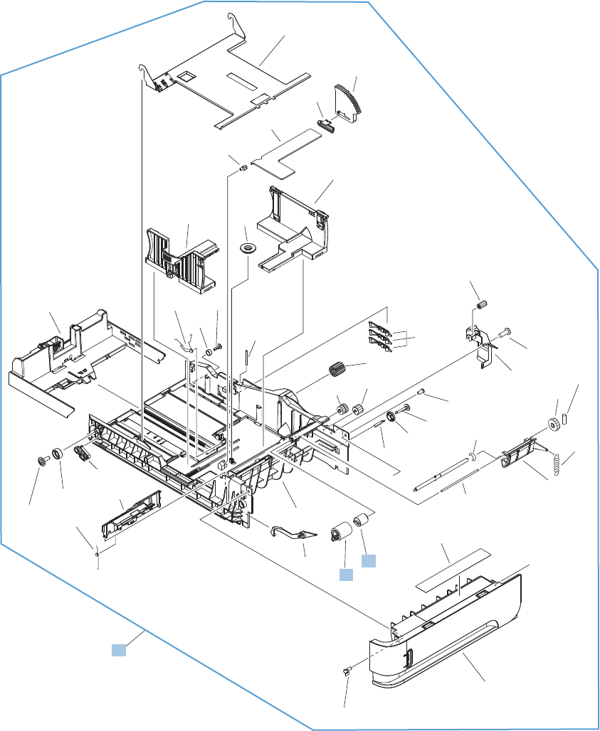
Cassette (1x500)
Figure 4-19 Cassette (1x500)
A
A
1
2
3
*A37
*A19
*A08
*A33
*A07
*A32
*A31
*A26
*A39
*A29
*A28*A27
*A15
*A01
*A12
*A16
*A38
*A02
*A25
*A03
*A34
*A10
*A36
*A21
*A17
*A20
*A30
*A06
*A35
*A22
*A14
*A13
*A40 *A09
*A23
*A04
*A05
*A24
*A18
*A11
440 Chapter 4 Parts and diagrams ENWW

Table 4-20 Cassette (1x500)
Ref Description Part number Qty
1 Cassette (1x500) RM1-4559-020CN 1
2 Torque limiter (1x500) RC2-5771-000CN 1
3 Roller, paper feed assembly (1x500) RM1-0037-020CN 1
ENWW Input devices 441
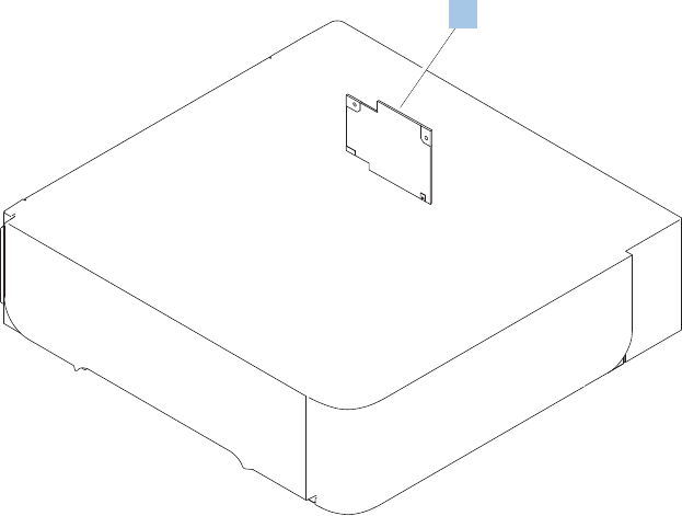
PCA (1x500)
Figure 4-20 PCA (1x500)
1
442 Chapter 4 Parts and diagrams ENWW

Table 4-21 PCA (1x500)
Ref Description Part number Qty
1 PCA, feeder (1x500) RM1-8302-000CN 1
ENWW Input devices 443
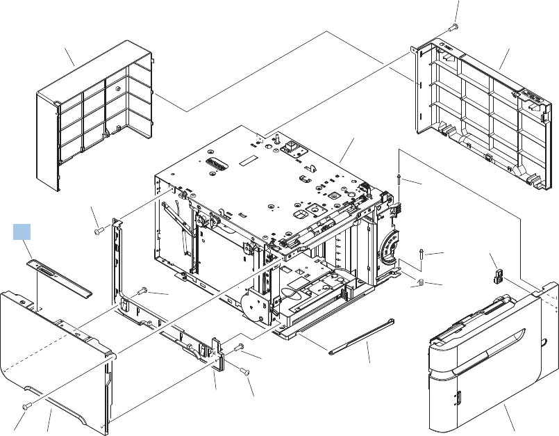
1x1500-sheet paper deck
Covers (1x1500)
Figure 4-21 Covers (1x1500)
See Main body
(1x1500)
See Front door assembl
y
(1x1500)
1
5
6
3
6
46
7
7
2
6
*A02
*A01
*A04
*A04
*A03
444 Chapter 4 Parts and diagrams ENWW

Table 4-22 Covers (1x1500)
Ref Description Part number Qty
5 Cover, lock (1x1500) RC2-2584-000CN 1
ENWW Input devices 445
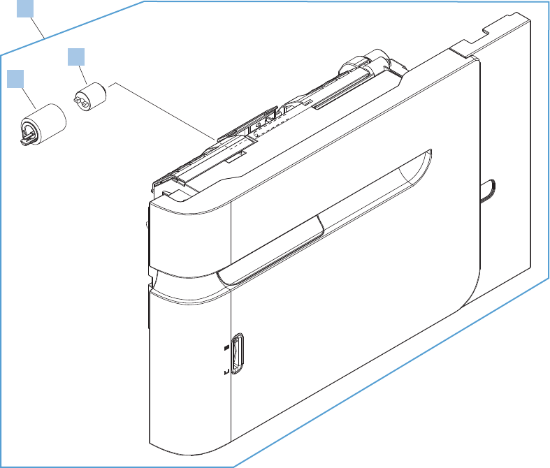
Front door assembly (1x1500)
Figure 4-22 Front door assembly (1x1500)
2
3
1
446 Chapter 4 Parts and diagrams ENWW

Table 4-23 Front door assembly (1x1500)
Ref Description Part number Qty
1 Front door assembly (1x1500) RM1-5255-020CN 1
2 Roller, paper feed assembly (1x1500) RM1-0037-020CN 1
3 Torque limiter (1x1500) RC2-5771-000CN 1
ENWW Input devices 447
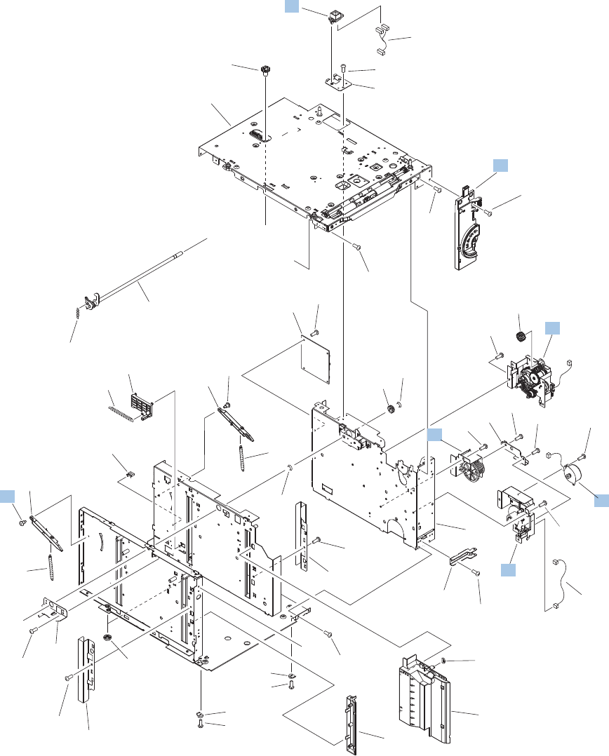
Main body (1x500; 1 of 2)
Figure 4-23 Main body (1x500; 1of 2)
A
A
B
BC
See Paper pickup
assembly (1x1500)
(J1722)
(J1701)
(J1706)
(J105LB)
(J105LA)
(J105L)
(J1704)
(M1700)
(J1703)
1
5
See PCA
(1x1500)
4
2
11
7
8
12
13
13
*A01
*A20
*A08
*A26
*A17
*A17
*A39
*A40
*A40
*A40
*A40
*A40
*A37
*A40
*A40
*A40
*A40
*A40
*A40
*A29
*A40
*A18
*A40
*A39
*A03
*A06
*A07
*A39
*A30
*A30
*A39
*A02
*A35
*A42
*A42
*A23
*A28
*A40
*A19
*A38
*A32
*A31
*A31
*A41
*A41
448 Chapter 4 Parts and diagrams ENWW

Table 4-24 Main body (1x500; 1 of 2)
Ref Description Part number Qty
1 Motor, stepping (M1700) (1x1500) RH7-1603-020CN 1
5 Paper pickup drive assembly (1x1500) RM1-8457-000CN 1
7 Oil damper assembly (1x1500) RM1-0289-030CN 1
8 Lifter drive assembly (1x1500) RM1-8453-000CN 1
11 Numbering assembly (1x1500) RM1-5265-000CN 1
12 Connector, drawer 6 pin(1x1500) VS1-7500-006CN 1
ENWW Input devices 449
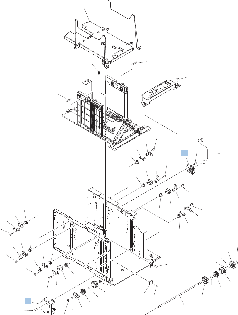
Main body (1x500; 2 of 2)
Figure 4-24 Main body (1x500; 2 of 2)
D
C
D
(J1702)
(J1724)
3
10
9
*A40
*A21
*A40
*A36
*A27
*A27
*A40
*A40
*A40
*A40
*A40
*A40
*A40
*A40
*A09
*A22
*A16
*A16
*A33 *A33
*A33
*A24
*A34
*A34
*A34
*A25
*A09
*A10
*A10
*A11
*A11
*A11
*A11
*A11
*A11
*A11
*A11
*A12
*A12
*A12
*A12
*A14
*A15
*A15
*A15
*A15
*A15
*A15
*A12
*A12
*A12
*A12
*A13
*A14
*A40
*A40
*A04
*A05
*A40
*A40
450 Chapter 4 Parts and diagrams ENWW

Table 4-25 Main body (1x500; 2 of 2)
Ref Description Part number Qty
9 Remnant indication assembly (1x1500) RM1-5259-000CN 1
10 Paper size detect assembly (1x1500) RM1-5261-000CN 1
ENWW Input devices 451
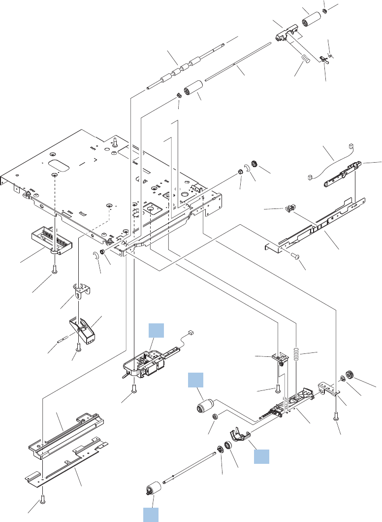
Paper pickup assembly (1x500)
Figure 4-25 Paper pickup assembly (1x500)
(J1723)
(PS1704)
(J1723)
(J1707)
(J1705)
A
A
B
B
1
2
3
4
5
*A10
*A04
*A02
*A09
*A03
*A08
*A01
*A05
*A07
*A10
*A10
*A21
*A20 *A22
*A28 *A14
*A11
*A31
*A30
*A27
*A10
*A24
*A29
*A23
*A26
*A20
*A22
*A25
*A19
*A10
*A17
*A16 *A10
*A18
*A12
*A13
*A15
*A14
*A28
*A06
452 Chapter 4 Parts and diagrams ENWW

Table 4-26 Paper pickup assembly (1x500)
Ref Description Part number Qty
1 Roller, paper feed assembly (1x1500) RM1-0037-020CN 1
2 Roller, paper pickup assembly (1x1500) RM1-0036-020CN 1
3 Paper detect sensor assembly (1x1500) RM1-8456-000CN 1
4 Flag, paper detect (1x1500) RC2-2524-000CN 1
ENWW Input devices 453
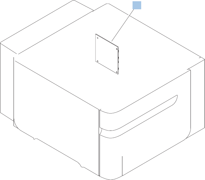
PCA (1x1500)
Figure 4-26 PCA (1x1500)
1
454 Chapter 4 Parts and diagrams ENWW

Table 4-27 PCA (1x1500)
Ref Description Part number Qty
1 PCA, feeder (1x1500) RM1-8303-000CN 1
ENWW Input devices 455
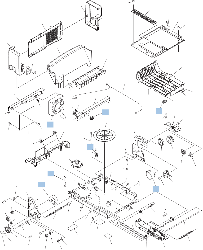
Duplexer
Main body (duplexer)
Figure 4-27 Main body (duplexer)
(J1521)
(M1502)
(J1523)
(J1505)
(PS1501)
(J1524)
(PS1502)
(J1522)
(J1504)
(PS1503)
(J1520)
(J1520)
(J1503)
(M1501)
B
B
F
A
C
D
D
E
E
C
A
(J1501)
(J124L)
(J1502)
(J1523)
(FM1501)
(J1524)
(J1521)
(J1506)
F
7
See PCA (duplexer)
1
11
2
3
11
8
11
16
13
6
17
5
4
9
15
10
14
*A05
*A02 *A52
*A06
*A03
*A47
*A46
*A23
*A41
*A42
*A29
*A51
*A26
*A07
*A08
*A09
*A49 *A18
*A49
*A30
*A53
*A53
*A33
*A34
*A43
*A24
*A50
*A01
*A27
*A01
*A40
*A16
*A22
*A39
*A15
*A38
*A51
*A11
*A44
*A12
*A36
*A35
*A37
*A51
*A28
*A50
*A15
*A53
*A04
*A10
*A53 *A19 *A48
*A31
*A14
*A15
*A17
*A45
*A21
*A31
*A15
*A13
*A20
*A25
*A53
*A32
*A51
*A47
456 Chapter 4 Parts and diagrams ENWW

Table 4-28 Main body (duplexer)
Ref Description Part number Qty
8 Motor, stepping, DC 24V (M1501) (duplexer) RK2-2015-000CN 1
9 Fan (FN1501) (duplexer) RK2-2016-000CN 1
10 Motor, stepping, DC 24V (M1502) (duplexer) RK2-2139-000CN 1
11 Photo interrupter (duplexer) WG8-5849-000CN 3
16 Cable, paper re-pickup motor (duplexer) RM1-5141-000CN 1
ENWW Duplexer 457
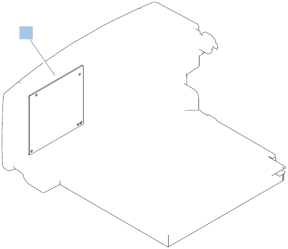
PCA (duplexer)
Figure 4-28 PCA (duplexer)
1
458 Chapter 4 Parts and diagrams ENWW

Table 4-29 PCA (duplexer)
Ref Description Part number Qty
1 PCA (duplexer) RM1-8305-000CN 1
ENWW Duplexer 459
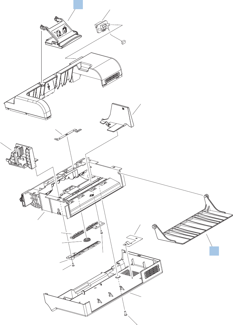
Envelope feeder
Covers (envelope feeder)
Figure 4-29 Covers (envelope feeder)
(J1804)
(J1855)
(J1856) (J1854)
4
6
7
1
5
2
3
*A02
*A02
*A03
*A06
*A06
*A01
*A04
*A05
460 Chapter 4 Parts and diagrams ENWW

Table 4-30 Covers (envelope feeder)
Ref Description Part number Qty
3 Tray, extension (envelope feeder) RC2-5705-000CN 1
6 Weight assembly (envelope feeder) RM1-5226-000CN 1
ENWW Envelope feeder 461
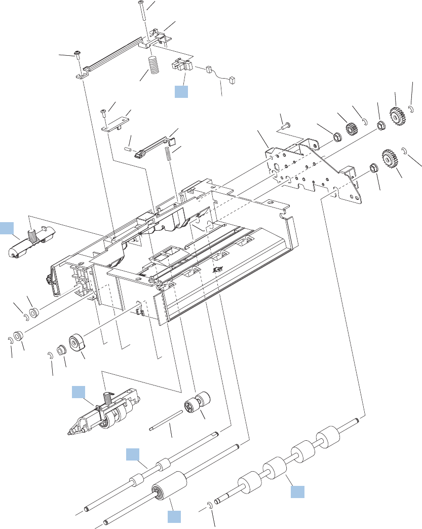
Main body (1 of 2; envelope feeder)
Figure 4-30 Main body (1 of 2; envelope feeder)
(J1800)
(J1850)
(PS1802)
CBA
CB
A
13
2
5
6
7
4
*A01
*A02
*A02
*A02
*A03
*A04
*A05
*A06
*A07
*A08
*A08
*A19
*A08
*A09
*A10
*A10
*A11
*A12
*A13
*A14
*A16
*A17
*A18
*A18
*A18
*A18
*A18
*A18
*A18
*A15
462 Chapter 4 Parts and diagrams ENWW

Table 4-31 Main body (1 of 2; envelope feeder)
Ref Description Part number Qty
1 Photo interrupter (envelope feeder) WG8-5624-000CN 1
2 Roller, separation assembly (envelope feeder) RM1-5224-000CN 1
4 Roller, paper feed assembly (envelope feeder) RM1-5223-000CN 1
5 Roller, paper pickup assembly (envelope feeder) RM1-5221-000CN 1
6 Roller, paper pickup (envelope feeder) RC2-5700-000CN 1
7 Roller, paper feed (envelope feeder) RC2-5701-000CN 1
ENWW Envelope feeder 463
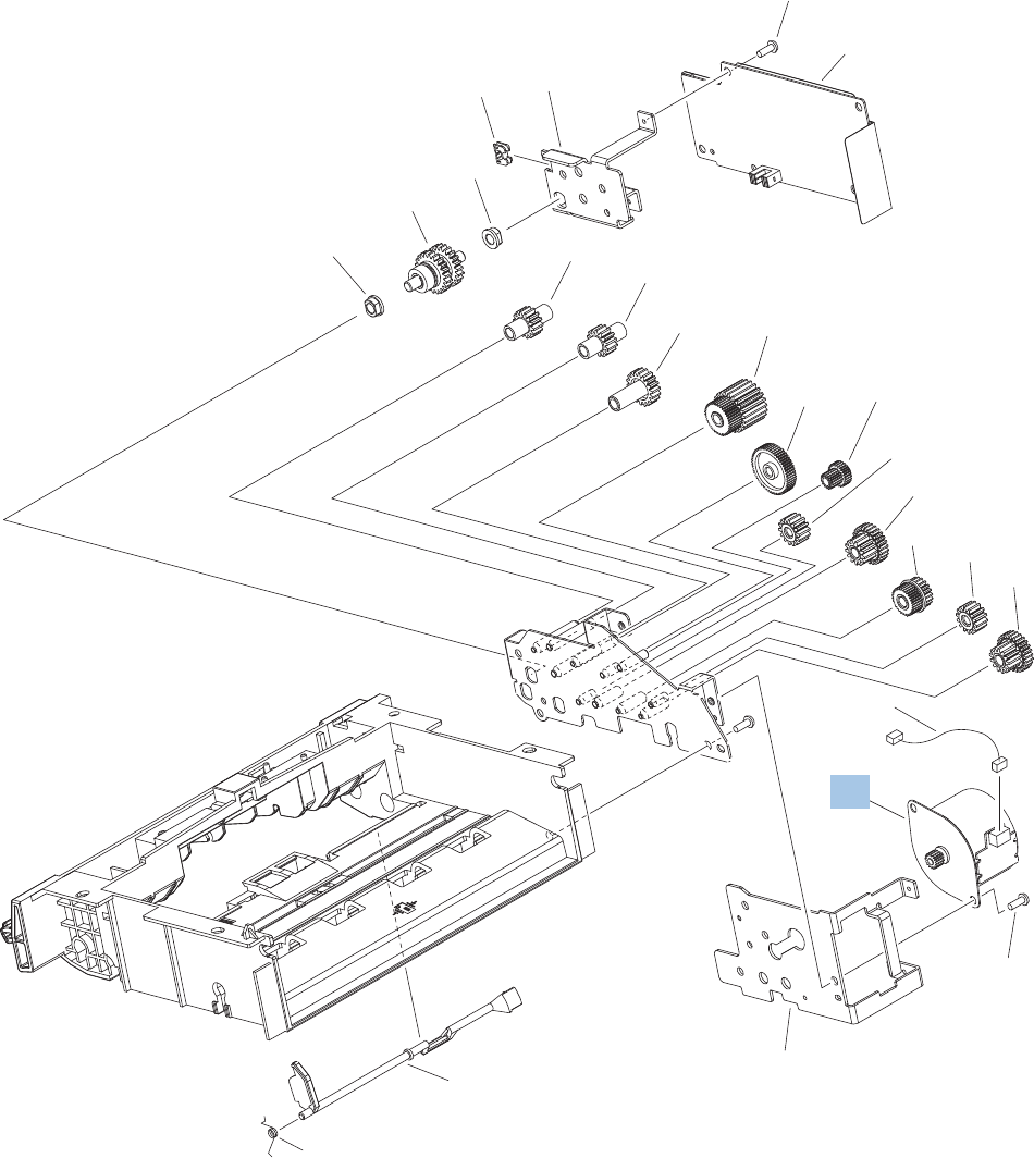
Main body (2 of 2; envelope feeder)
Figure 4-31 Main body (2 of 2; envelope feeder)
(J1802) (J1852)
(M1800)
See PCA (envelope feeder)
3
1
4
*A01 *A02
*A03
*A04
*A14
*A15
*A16
*A04 *A05 *A05
*A06 *A07
*A08
*A09
*A10
*A10
*A11
*A11
*A13
*A12
464 Chapter 4 Parts and diagrams ENWW

Table 4-32 Main body (2 of 2; envelope feeder)
Ref Description Part number Qty
1 Motor, stepping, DC 24V (M1800) (envelope feeder) RK2-2162-000CN 1
ENWW Envelope feeder 465
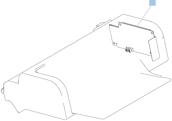
PCA (envelope feeder)
Figure 4-32 PCA (envelope feeder)
1
466 Chapter 4 Parts and diagrams ENWW

Table 4-33 PCA (envelope feeder)
Ref Description Part number Qty
1 PCA (envelope feeder) RM1-9030-000CN 1
ENWW Envelope feeder 467
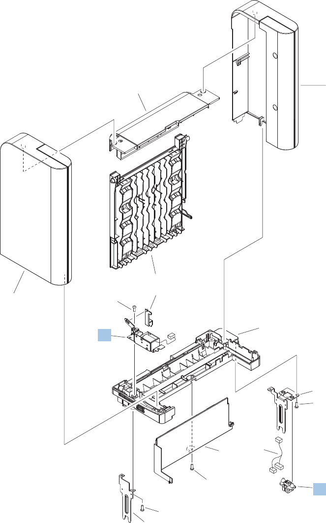
Output devices
Stapler/stacker multi-bin mailbox (MBM)
Covers (MBM)
Figure 4-33 Covers (MBM)
(J1301)
(J1300LB)
(J300LA)
(SL1301)
(J1308)
(J300L)
24
16
8
10
7
3
5
9
11 *A02
*A01
*A01
*A01
*A01
468 Chapter 4 Parts and diagrams ENWW

Table 4-34 Covers (MBM)
Ref Description Part number Qty
10 Connector 8P (MBM) VS1-7500-008CN 1
11 Solenoid assembly, IN (MBM) RM1-5270-000CN 1
ENWW Output devices 469
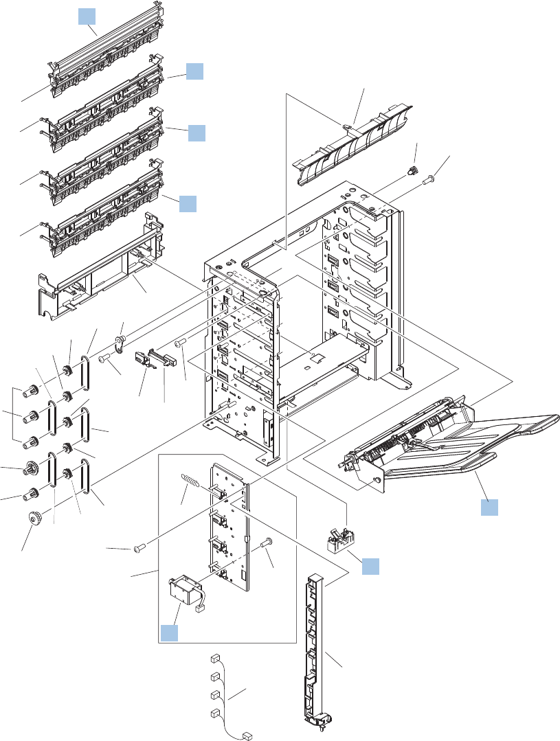
Main body (MBM)
Main body (MBM; 1 of 2)
Figure 4-34 Main body (MBM; 1 of 2)
(J1321L)(SL1302)
(J1322L)(SL1303)
(J1323L)(SL1304)
(J1324L)(SL1305)
A
A
B
B
C
D
C
D
(J1321D)
(J1323D)
(J1322D)
(J1324D)
(J1307)
3
4
3
2
1
12
13
9
5
*A31
*A07
*A31
*A31
*A10
*A16
*A16
*A16
*A16
*A16
*A14
*A14
*A25
*A25
*A25
*A25
*A25
*A12
*A29
*A28*A27
*A33
*A32
*A30
*A15
*A24
*A02
470 Chapter 4 Parts and diagrams ENWW

Table 4-35 Main body (MBM; 1 of 2)
Ref Description Part number Qty
1 Flag, paper sensing (MBM) RM1-5269-000CN 1
2 Top bin flapper assembly (MBM) RM1-4665-000CN 1
3 Bin flapper assembly (MBM) RM1-4666-000CN 2
4 Center bin flapper assembly (MBM) RM1-4667-000CN 1
12 Bin assembly (MBM) RM1-6672-000CN 1
13 Solenoid (MBM) RL1-1709-000CN 1
ENWW Output devices 471
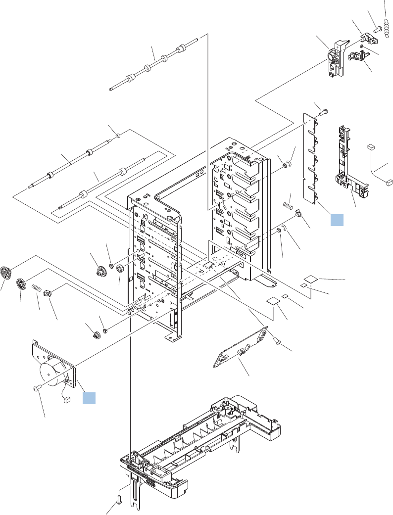
Main body (MBM; 2 of 2)
Figure 4-35 Main body (MBM; 2 of 2)
(M1301)
(J1306)
(J1326)
(J1305)
6
See PCA (MBM)
7
10
11
*A31
*A31
*A31
*A37
*A37
*A36
*A36
*A31
*A34
*A03
*A01
*A05
*A04
*A06
*A21
*A20
*A19
*A17
*A23
*A22
*A11
*A26
*A08
*A13
*A17
*A18
*A18
*A17
*A35
*A09
*A17*A35
*A09
472 Chapter 4 Parts and diagrams ENWW

Table 4-36 Main body (MBM; 2 of 2)
Ref Description Part number Qty
6 Drive assembly (MBM) RM1-5267-000CN 1
7 Sensor assembly (MBM) RM1-5096-000CN 1
ENWW Output devices 473
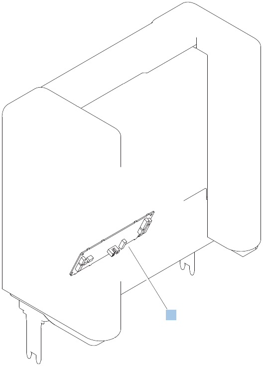
PCA (MBM)
Figure 4-36 PCA (MBM)
1
474 Chapter 4 Parts and diagrams ENWW

Table 4-37 PCA (MBM)
Ref Description Part number Qty
1 PCA (MBM) RM1-8350-000CN 1
ENWW Output devices 475
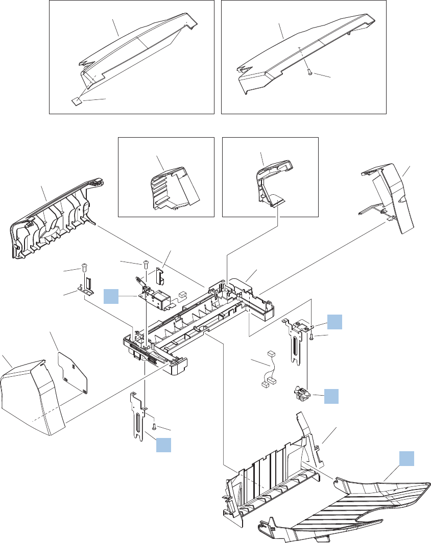
Stacker and Stapler/Stacker (S and S/S)
Covers (S and S/S)
Figure 4-37 Covers (S and S/S)
Stacker
Stacker
Stapler/Stacker
Stapler/Stacker
(SL1101)
(J1109)
(J1101)
(J106LB)
(J106L)
(J106LA)
11
2
2
5
8
3
4
6
7
13
12
9
11
10
*A01
*A02
*A04
*A06
*A03
*A06
*A05
*A06
*A05
476 Chapter 4 Parts and diagrams ENWW

Table 4-38 Covers (S and S/S)
Ref Description Part number Qty
6 Tray assembly (S and S/S) RM1-4671-000CN 1
9 Joint, left (S and S/S) RL1-1703-000CN 1
10 Joint, right (S and S/S) RL1-1704-000CN 1
11 Connector 8P (S and S/S) VS1-7500-008CN 1
13 Solenoid assembly, IN (S and S/S) RM1-5270-000CN 1
ENWW Output devices 477
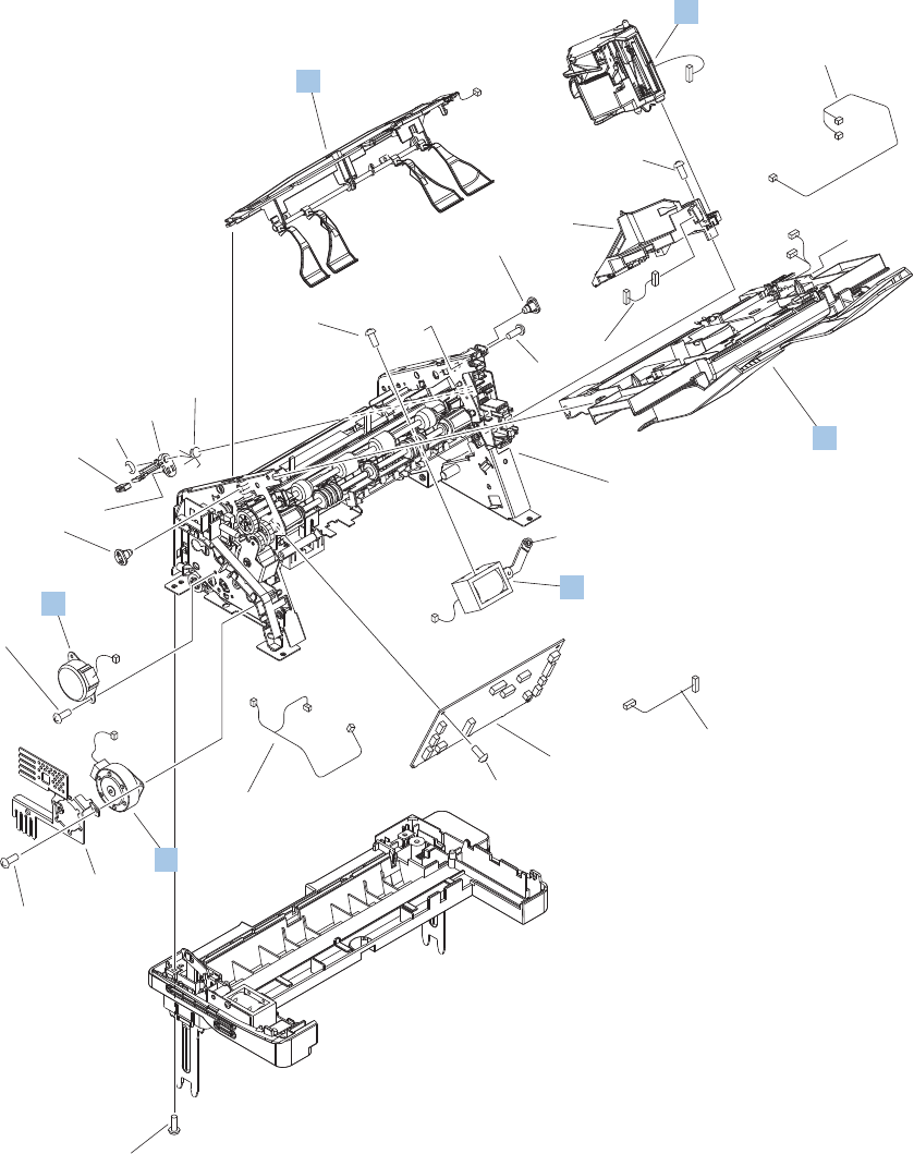
Main body (SS)
Figure 4-38 Main body (SS)
See Stapler/Stacker
middle assembly (SS)
AA
B
B
(J1114)
(M1101)
(J1105)
(M1103)
(J1112) (J1125D)
(J1125L)
(J1123L)
(J1123D)
(J1124L)
(J1124D)
(J1120)
(J1129)
(J1102)
(J1110) (SL1102)
(J1121)
(J1113)
(J1111)
(J1108)
12
5
9
4
10
11
1
7
8
3
See PCA (S and S/S)
6
*A06
*A01
*A04
*A03
*A08
*A02
*A07
*A01
*A05
*A09
*A05
*A06
*A05
*A05
478 Chapter 4 Parts and diagrams ENWW

Table 4-39 Main body (SS)
Ref Description Part number Qty
1 Motor, stepping, DC 24V (M1103) (S/S) RK2-2025-000CN 1
4 Sensor, paper full assembly (S/S) RM1-1166-000CN 1
6 Motor, stepping, DC 24V (M1101) (S/S) RK2-2027-000CN 1
7 Solenoid (S/S) RL1-0506-000CN 1
10 Jog assembly (S/S) RM1-4670-000CN 1
12 Stapler assembly (S/S) RM1-4826-000CN 1
ENWW Output devices 479
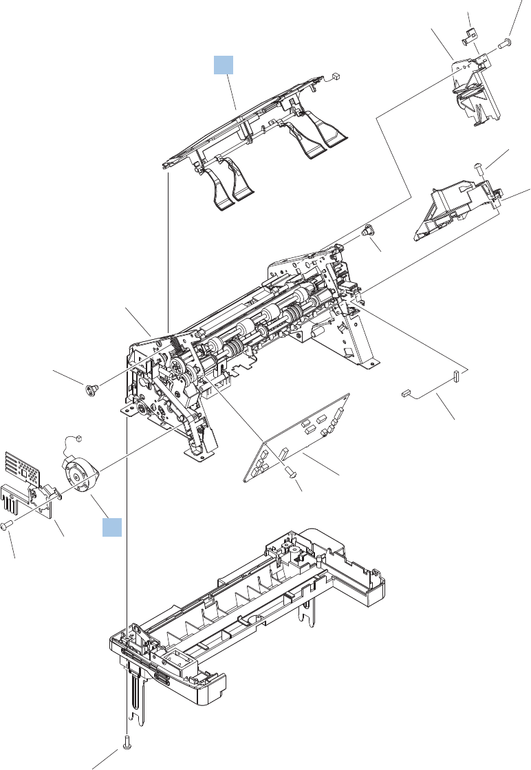
Main body (S)
Figure 4-39 Main body (S)
See Stacker middle
assembly (S)
(J1105)
(M1103)
(J1129)
(J1102)
(J1108)
See PCA (S and S/S)
1
3
4
5
*A06
*A01
*A04
*A01
*A05
*A05
*A02
*A03
*A05
*A05
480 Chapter 4 Parts and diagrams ENWW

Table 4-40 Main body (S)
Ref Description Part number Qty
1 Motor, stepping, DC 24V (M1103) (S) RK2-2025-000CN 1
5 Stapler mount assembly (S) RM1-4676-000CN 1
ENWW Output devices 481
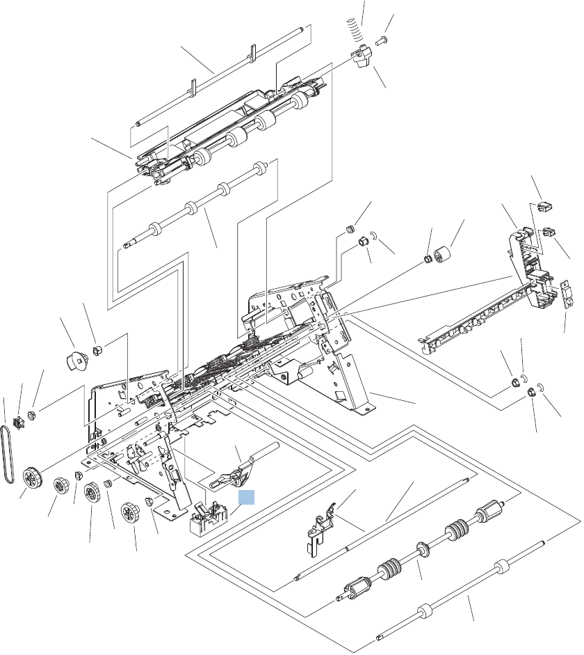
Middle assemblies (S and S/S)
Stapler/Stacker middle assembly (1 of 2; S/S)
Figure 4-40 Stapler/Stacker middle assembly (1 of 2; S/S)
(J1124DH)
(J1123DH)
2
1
4
*A26
*A35
*A23
*A16
*A18
*A29
*A07
*A39
*A31
*A41
*A05
*A16
*A16 *A13
*A16
*A16
*A37
*A43
*A43
*A52
*A36
*A01
*A43
*A29
*A21 *A16
*A28*A16
*A27
*A16
*A03
*A02 *A12
*A08
*A06
482 Chapter 4 Parts and diagrams ENWW

Table 4-41 Stapler/Stacker middle assembly (1 of 2; S/S)
Ref Description Part number Qty
1 Flag, paper sensing (S/S) RM1-0239-000CN 1
ENWW Output devices 483
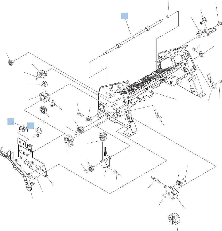
Stapler/Stacker middle assembly (2 of 2; S/S)
Figure 4-41 Stapler/Stacker middle assembly (2 of 2; S/S)
(J1120)
(PS1103)
(J1121)
(PS1104)
3
55
*A09
*A40
*A10
*A50
*A38
*A42
*A51
*A47
*A49
*A45
*A30
*A22
*A42
*A17
*A19
*A42
*A20
*A15 *A33
*A24
*A32
*A42 *A14
*A25
*A42
*A34
*A37 *A46
*A11
*A30
*A48
*A40
*A44
*A04
*A40
*A11
484 Chapter 4 Parts and diagrams ENWW

Table 4-42 Stapler/Stacker middle assembly (2 of 2; S/S)
Ref Description Part number Qty
3 Roller, paper feed assembly (S/S) RM1-0253-020CN 1
5 Photo interrupter (S/S) WG8-5645-000CN 2
ENWW Output devices 485
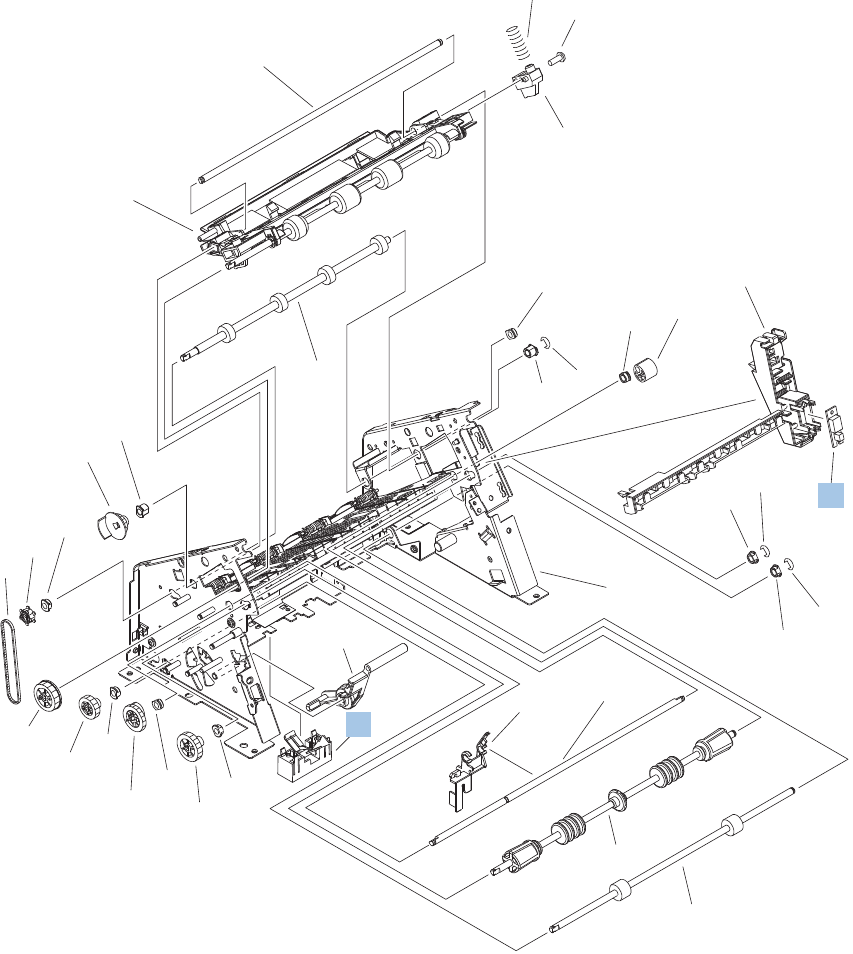
Stacker middle assembly (1 of 2; S)
Figure 4-42 Stacker middle assembly (1 of 2; S)
2
1
4
*A26
*A35
*A23
*A16
*A18
*A29
*A07
*A39
*A31
*A41
*A05
*A16
*A16 *A13
*A16
*A16
*A37
*A36
*A36
*A01
*A36
*A29
*A21 *A16
*A28*A16
*A27
*A16
*A03
*A02 *A12
*A08
*A06
486 Chapter 4 Parts and diagrams ENWW

Table 4-43 Stacker middle assembly (1 of 2; S)
Ref Description Part number Qty
1 Flag, paper sensing assembly (S) RM1-0239-000CN 1
4 LED PCA (S) RG1-4266-030CN 1
ENWW Output devices 487
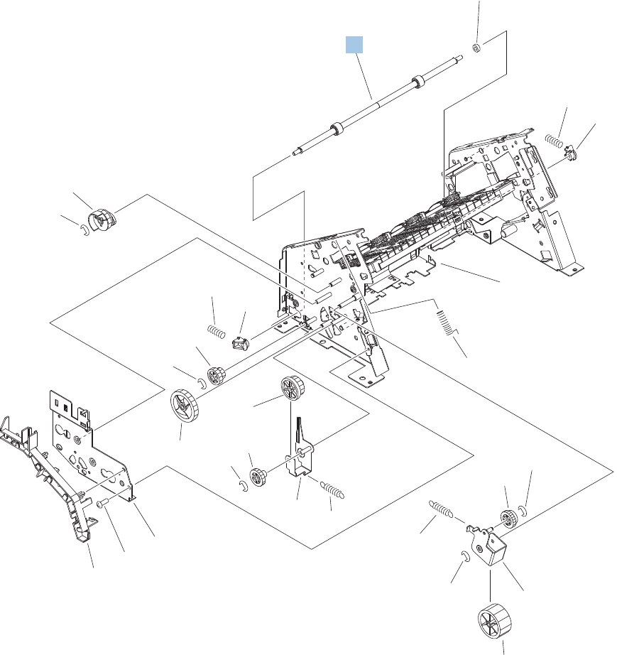
Stacker middle assembly (2 of 2; S)
Figure 4-43 Stacker middle assembly (2 of 2; S)
3
*A09
*A40
*A10
*A38
*A42
*A30
*A22
*A42
*A17
*A19
*A42
*A20
*A15 *A33
*A24
*A32
*A42 *A14
*A25
*A42
*A34
*A37
*A11
*A30
*A04
*A11
488 Chapter 4 Parts and diagrams ENWW

Table 4-44 Stacker middle assembly (2 of 2; S)
Ref Description Part number Qty
3 Roller, paper feed assembly (S) RM1-0253-020CN 1
ENWW Output devices 489
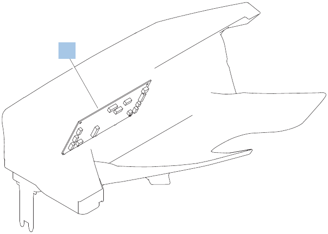
PCA (S and S/S)
Figure 4-44 PCA (S and S/S)
1
490 Chapter 4 Parts and diagrams ENWW

Table 4-45 PCA (S and S/S)
Ref Description Part number Qty
1 PCA (S/S) RM1-8351-000CN 1
1 PCA (S) RM1-8352-000CN 1
ENWW Output devices 491

Alphabetical parts list
Table 4-46 Alphabetical parts list
Description Part number Table and page
Arm, release A RC2-2480-000CN Internal components (1 of 3)
on page 413
Arm, release B RC2-2481-000CN Internal components (1 of 3)
on page 413
Bin assembly (MBM) RM1-6672-000CN Main body (MBM; 1 of 2)
on page 471
Bin flapper assembly (MBM) RM1-4666-000CN Main body (MBM; 1 of 2)
on page 471
Bushing RC1-0214-000CN Internal components (2 of 3)
on page 415
Bushing RC3-1403-000CN Internal components (2 of 3)
on page 415
Bushing, paper delivery RC1-0136-000CN Internal components (3 of 3)
on page 417
Button, power RC3-1430-000CN Covers on page 411
Cable, door switch RM1-8344-000CN Internal components (3 of 3)
on page 417
Cable, drum motor RM1-8308-000CN Internal components (1 of 3)
on page 413
Cable, envelope feeder RM1-5085-000CN Internal components (3 of 3)
on page 417
Cable, feed motor RM1-8311-000CN Internal components (2 of 3)
on page 415
Cable, feed sensor RM1-8298-000CN Internal components (2 of 3)
on page 415
Cable, flat flexible (FFC) RK2-4077-000CN Internal components (3 of 3)
on page 417
Cable, full sensor RM1-8927-000CN Internal components (3 of 3)
on page 417
Cable, fuser motor RM1-5088-000CN Internal components (3 of 3)
on page 417
Cable, HIP (M602 and M603) RK2-4152-000CN Internal components (3 of 3)
on page 417
Cable, laser RM1-8340-000CN Internal components (2 of 3)
on page 415
Cable, panel RM1-8341-000CN Internal components (3 of 3)
on page 417
492 Chapter 4 Parts and diagrams ENWW

Table 4-46 Alphabetical parts list (continued)
Description Part number Table and page
Cable, paper re-pickup motor (duplexer) RM1-5141-000CN Main body (duplexer)
on page 457
Cable, size sensor RM1-5091-000CN Internal components (1 of 3)
on page 413
Cable, USB RK2-4149-000CN Internal components (3 of 3)
on page 417
Cap, power button RC3-1431-000CN Covers on page 411
Cassette (1x500) RM1-4559-020CN Cassette (1x500) on page 441
Cassette (Tray 2) RM1-4559-020CN Cassette (Tray 2) on page 421
Center bin flapper assembly (MBM) RM1-4667-000CN Main body (MBM; 1 of 2)
on page 471
Connector 8P (MBM) VS1-7500-008CN Covers (MBM) on page 469
Connector 8P (S and S/S) VS1-7500-008CN Covers (S and S/S)
on page 477
Connector, drawer 6 pin(1x1500) VS1-7500-006CN Main body (1x500; 1 of 2)
on page 449
Connector, drawer 6P VS1-7514-006CN High-voltage power supply
on page 419
Connector, drawer 6P (1x500) VS1-7500-006CN Main body (1x500)
on page 439
Connector, inlet RM1-8348-000CN High-voltage power supply
on page 419
Control-panel assembly (M601) RM1-8290-000CN Covers on page 411
Control-panel assembly (M602 and M603) RM1-8289-000CN Covers on page 411
Cover, duplexing assembly RM1-8399-000CN Covers on page 411
Cover, envelope connector RC2-2476-000CN Covers on page 411
Cover, envelope feeder RL1-1667-000CN Internal components (1 of 3)
on page 413
Cover, formatter RC2-2468-000CN Covers on page 411
Cover, front assembly RM1-8408-000CN Covers on page 411
Cover, HIP (M602 and M603) RC3-1424-000CN Covers on page 411
Cover, left assembly RM1-8401-000CN Covers on page 411
Cover, legal RC2-5239-000CN Covers on page 411
Cover, legal (1x500) RC2-5239-000CN Covers (1x500) on page 437
Cover, lock (1x1500) RC2-2584-000CN Covers (1x1500) on page 445
Cover, lock (1x500) RC2-2584-000CN Covers (1x500) on page 437
ENWW Alphabetical parts list 493

Table 4-46 Alphabetical parts list (continued)
Description Part number Table and page
Cover, option RC2-2459-000CN Covers on page 411
Cover, right (M601) RM1-8445-000CN Covers on page 411
Cover, right (M602 and M603) RM1-8400-000CN Covers on page 411
Cover, right front RC3-1426-000CN Covers on page 411
Cover, right rear RC2-2478-000CN Covers on page 411
Cover, top assembly (M601) RM1-8434-000CN Covers on page 411
Cover, top assembly (M602 and M603) RM1-8394-000CN Covers on page 411
Cover, USB RC3-1434-000CN Covers on page 411
Drive assembly (MBM) RM1-5267-000CN Main body (MBM; 2 of 2)
on page 473
Drum drive assembly RM1-8489-000CN Internal components (1 of 3)
on page 413
Face-up tray assembly RM1-8388-000CN Covers on page 411
Fan (FN101) RK2-1988-000CN Internal components (3 of 3)
on page 417
Fan (FN102) RK2-1989-000CN Internal components (3 of 3)
on page 417
Fan (FN103) RK2-3244-000CN Internal components (3 of 3)
on page 417
Fan (FN104) RK2-1992-000CN Internal components (3 of 3)
on page 417
Fan (FN1501) (duplexer) RK2-2016-000CN Main body (duplexer)
on page 457
Flag, paper detect (1x1500) RC2-2524-000CN Paper pickup assembly
(1x500) on page 453
Flag, paper sensing (MBM) RM1-5269-000CN Main body (MBM; 1 of 2)
on page 471
Flag, paper sensing (S/S) RM1-0239-000CN Stapler/Stacker middle
assembly (1 of 2; S/S)
on page 483
Flag, paper sensing assembly (S) RM1-0239-000CN Stacker middle assembly (1 of
2; S) on page 487
Formatter CE988-67906 PCAs (product base)
on page 435
Front door assembly (1x1500) RM1-5255-020CN Front door assembly (1x1500)
on page 447
Fuser assembly 110V RM1-8395-000CN Fuser assembly on page 433
Fuser assembly 220V RM1-8396-000CN Fuser assembly on page 433
494 Chapter 4 Parts and diagrams ENWW

Table 4-46 Alphabetical parts list (continued)
Description Part number Table and page
Gear, 18T RU5-0088-000CN Internal components (2 of 3)
on page 415
Gear, 23T RU5-0040-000CN Internal components (2 of 3)
on page 415
Guard, edge RC1-0247-000CN Internal components (1 of 3)
on page 413
Guide assembly, left RM1-8439-000CN Internal components (3 of 3)
on page 417
Guide, front right assembly RM1-8427-000CN Internal components (2 of 3)
on page 415
Guide, right assembly RM1-4558-000CN Internal components (3 of 3)
on page 417
High-voltage power supply 110V RM1-8392-000CN High-voltage power supply
on page 419
High-voltage power supply 220V RM1-8393-000CN High-voltage power supply
on page 419
Jog assembly (S/S) RM1-4670-000CN Main body (SS) on page 479
Joint, left (S and S/S) RL1-1703-000CN Covers (S and S/S)
on page 477
Joint, right (S and S/S) RL1-1704-000CN Covers (S and S/S)
on page 477
Laser/scanner assembly RM1-8406-000CN Internal components (2 of 3)
on page 415
LED PCA (S) RG1-4266-030CN Stacker middle assembly (1 of
2; S) on page 487
Lifter drive assembly RM1-4585-000CN Internal components (3 of 3)
on page 417
Lifter drive assembly (1x1500) RM1-8453-000CN Main body (1x500; 1 of 2)
on page 449
Lifter drive assembly (1x500) RM1-1094-050CN Main body (1x500)
on page 439
Motor, drum assembly (M102) RM1-8358-000CN Internal components (1 of 3)
on page 413
Motor, fuser (M299) RM1-5051-020CN Internal components (3 of 3)
on page 417
Motor, paper feed assembly (M101) RM1-8285-000CN Internal components (2 of 3)
on page 415
Motor, stepping (M1700) (1x1500) RH7-1603-020CN Main body (1x500; 1 of 2)
on page 449
Motor, stepping, DC 24V (M1101) (S/S) RK2-2027-000CN Main body (SS) on page 479
ENWW Alphabetical parts list 495

Table 4-46 Alphabetical parts list (continued)
Description Part number Table and page
Motor, stepping, DC 24V (M1103) (S) RK2-2025-000CN Main body (S) on page 481
Motor, stepping, DC 24V (M1103) (S/S) RK2-2025-000CN Main body (SS) on page 479
Motor, stepping, DC 24V (M1501) (duplexer) RK2-2015-000CN Main body (duplexer)
on page 457
Motor, stepping, DC 24V (M1502) (duplexer) RK2-2139-000CN Main body (duplexer)
on page 457
Motor, stepping, DC 24V (M1800) (envelope feeder) RK2-2162-000CN Main body (2 of 2; envelope
feeder) on page 465
Number dial assembly (1x500) RM1-4591-000CN Covers (1x500) on page 437
Numbering assembly (1x1500) RM1-5265-000CN Main body (1x500; 1 of 2)
on page 449
Oil damper assembly (1x1500) RM1-0289-030CN Main body (1x500; 1 of 2)
on page 449
Paper delivery assembly RM1-8414-000CN Paper delivery assembly
on page 431
Paper delivery drive assembly RM1-8410-000CN Internal components (3 of 3)
on page 417
Paper detect sensor assembly (1x1500) RM1-8456-000CN Paper pickup assembly
(1x500) on page 453
Paper feed assembly RM1-4548-000CN High-voltage power supply
on page 419
Paper feed roller assembly RM1-0037-020CN Internal components (2 of 3)
on page 415
Paper feed roller assembly RM1-8411-000CN Paper feed roller assembly
on page 425
Paper feed shaft assembly RM1-8424-000CN Internal components (2 of 3)
on page 415
Paper pickup drive assembly RM1-8415-000CN Internal components (2 of 3)
on page 415
Paper pickup drive assembly (1x1500) RM1-8457-000CN Main body (1x500; 1 of 2)
on page 449
Paper pickup roller assembly RM1-0036-020CN Internal components (2 of 3)
on page 415
Paper size detect assembly (1x1500) RM1-5261-000CN Main body (1x500; 2 of 2)
on page 451
PCA (duplexer) RM1-8305-000CN PCA (duplexer) on page 459
PCA (envelope feeder) RM1-9030-000CN PCA (envelope feeder)
on page 467
PCA (MBM) RM1-8350-000CN PCA (MBM) on page 475
496 Chapter 4 Parts and diagrams ENWW

Table 4-46 Alphabetical parts list (continued)
Description Part number Table and page
PCA (S) RM1-8352-000CN PCA (S and S/S) on page 491
PCA (S/S) RM1-8351-000CN PCA (S and S/S) on page 491
PCA, DC controller RM1-8293-000CN Internal components (3 of 3)
on page 417
PCA, DC controller RM1-8293-000CN PCAs (product base)
on page 435
PCA, feeder (1x1500) RM1-8303-000CN PCA (1x1500) on page 455
PCA, Feeder (1x500) RM1-8302-000CN Main body (1x500)
on page 439
PCA, feeder (1x500) RM1-8302-000CN PCA (1x500) on page 443
PCA, inner connecting RM1-8294-000CN Internal components (3 of 3)
on page 417
PCA, inner connecting RM1-8294-000CN PCAs (product base)
on page 435
PCA, switch assembly RM1-8428-000CN Internal components (1 of 3)
on page 413
Photo interrupter (duplexer) WG8-5849-000CN Main body (duplexer)
on page 457
Photo interrupter (envelope feeder) WG8-5624-000CN Main body (1 of 2; envelope
feeder) on page 463
Photo interrupter (S/S) WG8-5645-000CN Stapler/Stacker middle
assembly (2 of 2; S/S)
on page 485
Photo interrupter, IC WG8-5849-000CN Internal components (3 of 3)
on page 417
Pin, cassette (custom media) RC2-6486-000CN Cassette (custom media)
on page 423
Pin, stopper (custom media) RC2-6487-000CN Cassette (custom media)
on page 423
Plate, ground assembly RM1-5461-000CN Internal components (1 of 3)
on page 413
Plate, pickup drive side assembly (1x500) RM1-8441-000CN Main body (1x500)
on page 439
Power supply, high-voltage 110V RM1-8392-000CN PCAs (product base)
on page 435
Power supply, low-voltage 220V RM1-8393-000CN PCAs (product base)
on page 435
Registration assembly RM1-8413-0000CN Registration assembly
on page 427
ENWW Alphabetical parts list 497

Table 4-46 Alphabetical parts list (continued)
Description Part number Table and page
Remnant indication assembly (1x1500) RM1-5259-000CN Main body (1x500; 2 of 2)
on page 451
Ring, E XD9-0232-000CN Internal components (2 of 3)
on page 415
Ring, E XD9-0233-010CN Internal components (2 of 3)
on page 415
Rod, release lower RC2-2483-000CN Internal components (1 of 3)
on page 413
Rod, release, upper RC2-2482-000CN Internal components (1 of 3)
on page 413
Roller feed, Tray 1 (MP) RL1-1663-000CN Tray 1 (MP) pickup assembly
on page 429
Roller pickup, Tray 1 (MP) RL1-1641-000CN Tray 1 (MP) pickup assembly
on page 429
Roller separation, Tray 1 (MP) RL1-1654-020CN Tray 1 (MP) pickup assembly
on page 429
Roller, paper feed (envelope feeder) RC2-5701-000CN Main body (1 of 2; envelope
feeder) on page 463
Roller, paper feed assembly (1x1500) RM1-0037-020CN Front door assembly (1x1500)
on page 447
Roller, paper feed assembly (1x1500) RM1-0037-020CN Paper pickup assembly
(1x500) on page 453
Roller, paper feed assembly (1x500) RM1-0037-020CN Main body (1x500)
on page 439
Roller, paper feed assembly (1x500) RM1-0037-020CN Cassette (1x500) on page 441
Roller, paper feed assembly (custom media) RM1-4560-000CN Cassette (custom media)
on page 423
Roller, paper feed assembly (envelope feeder) RM1-5223-000CN Main body (1 of 2; envelope
feeder) on page 463
Roller, paper feed assembly (S) RM1-0253-020CN Stacker middle assembly (2 of
2; S) on page 489
Roller, paper feed assembly (S/S) RM1-0253-020CN Stapler/Stacker middle
assembly (2 of 2; S/S)
on page 485
Roller, paper feed assembly (Tray 2) RM1-0037-020CN Cassette (Tray 2) on page 421
Roller, paper pickup (envelope feeder) RC2-5700-000CN Main body (1 of 2; envelope
feeder) on page 463
Roller, paper pickup assembly (1x1500) RM1-0036-020CN Paper pickup assembly
(1x500) on page 453
498 Chapter 4 Parts and diagrams ENWW

Table 4-46 Alphabetical parts list (continued)
Description Part number Table and page
Roller, paper pickup assembly (1x500) RM1-0036-020CN Main body (1x500)
on page 439
Roller, paper pickup assembly (envelope feeder) RM1-5221-000CN Main body (1 of 2; envelope
feeder) on page 463
Roller, separation assembly (envelope feeder) RM1-5224-000CN Main body (1 of 2; envelope
feeder) on page 463
Screw, D, M3x8 XA9-1671-000CN Internal components (1 of 3)
on page 413
Screw, M4x5 RC2-2633-000CN Internal components (1 of 3)
on page 413
Screw, tap, binding head, M3x8 XB4-7300-809CN Internal components (2 of 3)
on page 415
Screw, tap, M3x6 XA9-1503-000CN Internal components (1 of 3)
on page 413
Screw, tapping pan head M4X10 XB4-7401-607CN Internal components (1 of 3)
on page 413
Sensor assembly (MBM) RM1-5096-000CN Main body (MBM; 2 of 2)
on page 473
Sensor, paper full assembly (S/S) RM1-1166-000CN Main body (SS) on page 479
Sensor, temperature assembly RM1-8438-000CN Internal components (3 of 3)
on page 417
Shaft retard drive RL1-3020-000CN Internal components (2 of 3)
on page 415
Size detect assembly RM1-4525-000CN Internal components (1 of 3)
on page 413
Size detect assembly (1x500) RM1-4525-000CN Main body (1x500)
on page 439
Solenoid RK2-4078-000CN Internal components (2 of 3)
on page 415
Solenoid (1x500) RK2-0270-000CN Main body (1x500)
on page 439
Solenoid (MBM) RL1-1709-000CN Main body (MBM; 1 of 2)
on page 471
Solenoid (S/S) RL1-0506-000CN Main body (SS) on page 479
Solenoid assembly, IN (MBM) RM1-5270-000CN Covers (MBM) on page 469
Solenoid assembly, IN (S and S/S) RM1-5270-000CN Covers (S and S/S)
on page 477
Spacer, frame RC2-2725-000CN Internal components (1 of 3)
on page 413
ENWW Alphabetical parts list 499

Table 4-46 Alphabetical parts list (continued)
Description Part number Table and page
Spring, compression RC1-0213-000CN Internal components (2 of 3)
on page 415
Spring, grounding RU6-2105-000CN Paper delivery assembly
on page 431
Spring, tension RC1-0133-000CN Paper delivery assembly
on page 431
Spring, torsion RC3-1470-000CN Internal components (1 of 3)
on page 413
Stapler assembly (S/S) RM1-4826-000CN Main body (SS) on page 479
Stapler mount assembly (S) RM1-4676-000CN Main body (S) on page 481
Switch, interlock assembly RM1-8307-000CN Internal components (3 of 3)
on page 417
Switch, push WC2-5637-000CN Internal components (3 of 3)
on page 417
Tag holder assembly RM1-4539-000CN Internal components (2 of 3)
on page 415
Top bin flapper assembly (MBM) RM1-4665-000CN Main body (MBM; 1 of 2)
on page 471
Torque limiter (1x1500) RC2-5771-000CN Front door assembly (1x1500)
on page 447
Torque limiter (1x500) RC2-5771-000CN Cassette (1x500) on page 441
Torque limiter (custom media) RM1-0037-000CN Cassette (custom media)
on page 423
Torque limiter (Tray 2) RC2-5771-000CN Cassette (Tray 2) on page 421
Transfer roller RM1-8491-000CN Internal components (1 of 3)
on page 413
Tray 1 (MP) pickup assembly RM1-8425-000CN Tray 1 (MP) pickup assembly
on page 429
Tray assembly (S and S/S) RM1-4671-000CN Covers (S and S/S)
on page 477
Tray, extension (envelope feeder) RC2-5705-000CN Covers (envelope feeder)
on page 461
USB PCA RM1-8429-000CN Internal components (3 of 3)
on page 417
Weight assembly (envelope feeder) RM1-5226-000CN Covers (envelope feeder)
on page 461
500 Chapter 4 Parts and diagrams ENWW

Numerical parts list
Table 4-47 Numerical parts list
Part number Description Table and page
CE988-67906 Formatter PCAs (product base)
on page 435
RC1-0133-000CN Spring, tension Paper delivery assembly
on page 431
RC1-0136-000CN Bushing, paper delivery Internal components (3 of 3)
on page 417
RC1-0213-000CN Spring, compression Internal components (2 of 3)
on page 415
RC1-0214-000CN Bushing Internal components (2 of 3)
on page 415
RC1-0247-000CN Guard, edge Internal components (1 of 3)
on page 413
RC2-2459-000CN Cover, option Covers on page 411
RC2-2468-000CN Cover, formatter Covers on page 411
RC2-2476-000CN Cover, envelope connector Covers on page 411
RC2-2478-000CN Cover, right rear Covers on page 411
RC2-2480-000CN Arm, release A Internal components (1 of 3)
on page 413
RC2-2481-000CN Arm, release B Internal components (1 of 3)
on page 413
RC2-2482-000CN Rod, release, upper Internal components (1 of 3)
on page 413
RC2-2483-000CN Rod, release lower Internal components (1 of 3)
on page 413
RC2-2524-000CN Flag, paper detect (1x1500) Paper pickup assembly
(1x500) on page 453
RC2-2584-000CN Cover, lock (1x500) Covers (1x500) on page 437
RC2-2584-000CN Cover, lock (1x1500) Covers (1x1500) on page 445
RC2-2633-000CN Screw, M4x5 Internal components (1 of 3)
on page 413
RC2-2725-000CN Spacer, frame Internal components (1 of 3)
on page 413
RC2-5239-000CN Cover, legal Covers on page 411
RC2-5239-000CN Cover, legal (1x500) Covers (1x500) on page 437
RC2-5700-000CN Roller, paper pickup (envelope feeder) Main body (1 of 2; envelope
feeder) on page 463
ENWW Numerical parts list 501

Table 4-47 Numerical parts list (continued)
Part number Description Table and page
RC2-5701-000CN Roller, paper feed (envelope feeder) Main body (1 of 2; envelope
feeder) on page 463
RC2-5705-000CN Tray, extension (envelope feeder) Covers (envelope feeder)
on page 461
RC2-5771-000CN Torque limiter (Tray 2) Cassette (Tray 2) on page 421
RC2-5771-000CN Torque limiter (1x500) Cassette (1x500) on page 441
RC2-5771-000CN Torque limiter (1x1500) Front door assembly (1x1500)
on page 447
RC2-6486-000CN Pin, cassette (custom media) Cassette (custom media)
on page 423
RC2-6487-000CN Pin, stopper (custom media) Cassette (custom media)
on page 423
RC3-1403-000CN Bushing Internal components (2 of 3)
on page 415
RC3-1424-000CN Cover, HIP (M602 and M603) Covers on page 411
RC3-1426-000CN Cover, right front Covers on page 411
RC3-1430-000CN Button, power Covers on page 411
RC3-1431-000CN Cap, power button Covers on page 411
RC3-1434-000CN Cover, USB Covers on page 411
RC3-1470-000CN Spring, torsion Internal components (1 of 3)
on page 413
RG1-4266-030CN LED PCA (S) Stacker middle assembly (1 of
2; S) on page 487
RH7-1603-020CN Motor, stepping (M1700) (1x1500) Main body (1x500; 1 of 2)
on page 449
RK2-0270-000CN Solenoid (1x500) Main body (1x500)
on page 439
RK2-1988-000CN Fan (FN101) Internal components (3 of 3)
on page 417
RK2-1989-000CN Fan (FN102) Internal components (3 of 3)
on page 417
RK2-1992-000CN Fan (FN104) Internal components (3 of 3)
on page 417
RK2-2015-000CN Motor, stepping, DC 24V (M1501) (duplexer) Main body (duplexer)
on page 457
RK2-2016-000CN Fan (FN1501) (duplexer) Main body (duplexer)
on page 457
RK2-2025-000CN Motor, stepping, DC 24V (M1103) (S/S) Main body (SS) on page 479
502 Chapter 4 Parts and diagrams ENWW

Table 4-47 Numerical parts list (continued)
Part number Description Table and page
RK2-2025-000CN Motor, stepping, DC 24V (M1103) (S) Main body (S) on page 481
RK2-2027-000CN Motor, stepping, DC 24V (M1101) (S/S) Main body (SS) on page 479
RK2-2139-000CN Motor, stepping, DC 24V (M1502) (duplexer) Main body (duplexer)
on page 457
RK2-2162-000CN Motor, stepping, DC 24V (M1800) (envelope feeder) Main body (2 of 2; envelope
feeder) on page 465
RK2-3244-000CN Fan (FN103) Internal components (3 of 3)
on page 417
RK2-4077-000CN Cable, flat flexible (FFC) Internal components (3 of 3)
on page 417
RK2-4078-000CN Solenoid Internal components (2 of 3)
on page 415
RK2-4149-000CN Cable, USB Internal components (3 of 3)
on page 417
RK2-4152-000CN Cable, HIP (M602 and M603) Internal components (3 of 3)
on page 417
RL1-0506-000CN Solenoid (S/S) Main body (SS) on page 479
RL1-1641-000CN Roller pickup, Tray 1 (MP) Tray 1 (MP) pickup assembly
on page 429
RL1-1654-020CN Roller separation, Tray 1 (MP) Tray 1 (MP) pickup assembly
on page 429
RL1-1663-000CN Roller feed, Tray 1 (MP) Tray 1 (MP) pickup assembly
on page 429
RL1-1667-000CN Cover, envelope feeder Internal components (1 of 3)
on page 413
RL1-1703-000CN Joint, left (S and S/S) Covers (S and S/S)
on page 477
RL1-1704-000CN Joint, right (S and S/S) Covers (S and S/S)
on page 477
RL1-1709-000CN Solenoid (MBM) Main body (MBM; 1 of 2)
on page 471
RL1-3020-000CN Shaft retard drive Internal components (2 of 3)
on page 415
RM1-0036-020CN Paper pickup roller assembly Internal components (2 of 3)
on page 415
RM1-0036-020CN Roller, paper pickup assembly (1x500) Main body (1x500)
on page 439
RM1-0036-020CN Roller, paper pickup assembly (1x1500) Paper pickup assembly
(1x500) on page 453
ENWW Numerical parts list 503

Table 4-47 Numerical parts list (continued)
Part number Description Table and page
RM1-0037-000CN Torque limiter (custom media) Cassette (custom media)
on page 423
RM1-0037-020CN Paper feed roller assembly Internal components (2 of 3)
on page 415
RM1-0037-020CN Roller, paper feed assembly (Tray 2) Cassette (Tray 2) on page 421
RM1-0037-020CN Roller, paper feed assembly (1x500) Main body (1x500)
on page 439
RM1-0037-020CN Roller, paper feed assembly (1x500) Cassette (1x500) on page 441
RM1-0037-020CN Roller, paper feed assembly (1x1500) Front door assembly (1x1500)
on page 447
RM1-0037-020CN Roller, paper feed assembly (1x1500) Paper pickup assembly
(1x500) on page 453
RM1-0239-000CN Flag, paper sensing (S/S) Stapler/Stacker middle
assembly (1 of 2; S/S)
on page 483
RM1-0239-000CN Flag, paper sensing assembly (S) Stacker middle assembly (1 of
2; S) on page 487
RM1-0253-020CN Roller, paper feed assembly (S/S) Stapler/Stacker middle
assembly (2 of 2; S/S)
on page 485
RM1-0253-020CN Roller, paper feed assembly (S) Stacker middle assembly (2 of
2; S) on page 489
RM1-0289-030CN Oil damper assembly (1x1500) Main body (1x500; 1 of 2)
on page 449
RM1-1094-050CN Lifter drive assembly (1x500) Main body (1x500)
on page 439
RM1-1166-000CN Sensor, paper full assembly (S/S) Main body (SS) on page 479
RM1-4525-000CN Size detect assembly Internal components (1 of 3)
on page 413
RM1-4525-000CN Size detect assembly (1x500) Main body (1x500)
on page 439
RM1-4539-000CN Tag holder assembly Internal components (2 of 3)
on page 415
RM1-4548-000CN Paper feed assembly High-voltage power supply
on page 419
RM1-4558-000CN Guide, right assembly Internal components (3 of 3)
on page 417
RM1-4559-020CN Cassette (Tray 2) Cassette (Tray 2) on page 421
RM1-4559-020CN Cassette (1x500) Cassette (1x500) on page 441
504 Chapter 4 Parts and diagrams ENWW

Table 4-47 Numerical parts list (continued)
Part number Description Table and page
RM1-4560-000CN Roller, paper feed assembly (custom media) Cassette (custom media)
on page 423
RM1-4585-000CN Lifter drive assembly Internal components (3 of 3)
on page 417
RM1-4591-000CN Number dial assembly (1x500) Covers (1x500) on page 437
RM1-4665-000CN Top bin flapper assembly (MBM) Main body (MBM; 1 of 2)
on page 471
RM1-4666-000CN Bin flapper assembly (MBM) Main body (MBM; 1 of 2)
on page 471
RM1-4667-000CN Center bin flapper assembly (MBM) Main body (MBM; 1 of 2)
on page 471
RM1-4670-000CN Jog assembly (S/S) Main body (SS) on page 479
RM1-4671-000CN Tray assembly (S and S/S) Covers (S and S/S)
on page 477
RM1-4676-000CN Stapler mount assembly (S) Main body (S) on page 481
RM1-4826-000CN Stapler assembly (S/S) Main body (SS) on page 479
RM1-5051-020CN Motor, fuser (M299) Internal components (3 of 3)
on page 417
RM1-5085-000CN Cable, envelope feeder Internal components (3 of 3)
on page 417
RM1-5088-000CN Cable, fuser motor Internal components (3 of 3)
on page 417
RM1-5091-000CN Cable, size sensor Internal components (1 of 3)
on page 413
RM1-5096-000CN Sensor assembly (MBM) Main body (MBM; 2 of 2)
on page 473
RM1-5141-000CN Cable, paper re-pickup motor (duplexer) Main body (duplexer)
on page 457
RM1-5221-000CN Roller, paper pickup assembly (envelope feeder) Main body (1 of 2; envelope
feeder) on page 463
RM1-5223-000CN Roller, paper feed assembly (envelope feeder) Main body (1 of 2; envelope
feeder) on page 463
RM1-5224-000CN Roller, separation assembly (envelope feeder) Main body (1 of 2; envelope
feeder) on page 463
RM1-5226-000CN Weight assembly (envelope feeder) Covers (envelope feeder)
on page 461
RM1-5255-020CN Front door assembly (1x1500) Front door assembly (1x1500)
on page 447
ENWW Numerical parts list 505

Table 4-47 Numerical parts list (continued)
Part number Description Table and page
RM1-5259-000CN Remnant indication assembly (1x1500) Main body (1x500; 2 of 2)
on page 451
RM1-5261-000CN Paper size detect assembly (1x1500) Main body (1x500; 2 of 2)
on page 451
RM1-5265-000CN Numbering assembly (1x1500) Main body (1x500; 1 of 2)
on page 449
RM1-5267-000CN Drive assembly (MBM) Main body (MBM; 2 of 2)
on page 473
RM1-5269-000CN Flag, paper sensing (MBM) Main body (MBM; 1 of 2)
on page 471
RM1-5270-000CN Solenoid assembly, IN (MBM) Covers (MBM) on page 469
RM1-5270-000CN Solenoid assembly, IN (S and S/S) Covers (S and S/S)
on page 477
RM1-5461-000CN Plate, ground assembly Internal components (1 of 3)
on page 413
RM1-6672-000CN Bin assembly (MBM) Main body (MBM; 1 of 2)
on page 471
RM1-8285-000CN Motor, paper feed assembly (M101) Internal components (2 of 3)
on page 415
RM1-8289-000CN Control-panel assembly (M602 and M603) Covers on page 411
RM1-8290-000CN Control-panel assembly (M601) Covers on page 411
RM1-8293-000CN PCA, DC controller Internal components (3 of 3)
on page 417
RM1-8293-000CN PCA, DC controller PCAs (product base)
on page 435
RM1-8294-000CN PCA, inner connecting Internal components (3 of 3)
on page 417
RM1-8294-000CN PCA, inner connecting PCAs (product base)
on page 435
RM1-8298-000CN Cable, feed sensor Internal components (2 of 3)
on page 415
RM1-8302-000CN PCA, Feeder (1x500) Main body (1x500)
on page 439
RM1-8302-000CN PCA, feeder (1x500) PCA (1x500) on page 443
RM1-8303-000CN PCA, feeder (1x1500) PCA (1x1500) on page 455
RM1-8305-000CN PCA (duplexer) PCA (duplexer) on page 459
RM1-8307-000CN Switch, interlock assembly Internal components (3 of 3)
on page 417
506 Chapter 4 Parts and diagrams ENWW

Table 4-47 Numerical parts list (continued)
Part number Description Table and page
RM1-8308-000CN Cable, drum motor Internal components (1 of 3)
on page 413
RM1-8311-000CN Cable, feed motor Internal components (2 of 3)
on page 415
RM1-8340-000CN Cable, laser Internal components (2 of 3)
on page 415
RM1-8341-000CN Cable, panel Internal components (3 of 3)
on page 417
RM1-8344-000CN Cable, door switch Internal components (3 of 3)
on page 417
RM1-8348-000CN Connector, inlet High-voltage power supply
on page 419
RM1-8350-000CN PCA (MBM) PCA (MBM) on page 475
RM1-8351-000CN PCA (S/S) PCA (S and S/S) on page 491
RM1-8352-000CN PCA (S) PCA (S and S/S) on page 491
RM1-8358-000CN Motor, drum assembly (M102) Internal components (1 of 3)
on page 413
RM1-8388-000CN Face-up tray assembly Covers on page 411
RM1-8392-000CN High-voltage power supply 110V High-voltage power supply
on page 419
RM1-8392-000CN Power supply, high-voltage 110V PCAs (product base)
on page 435
RM1-8393-000CN High-voltage power supply 220V High-voltage power supply
on page 419
RM1-8393-000CN Power supply, low-voltage 220V PCAs (product base)
on page 435
RM1-8394-000CN Cover, top assembly (M602 and M603) Covers on page 411
RM1-8395-000CN Fuser assembly 110V Fuser assembly on page 433
RM1-8396-000CN Fuser assembly 220V Fuser assembly on page 433
RM1-8399-000CN Cover, duplexing assembly Covers on page 411
RM1-8400-000CN Cover, right (M602 and M603) Covers on page 411
RM1-8401-000CN Cover, left assembly Covers on page 411
RM1-8406-000CN Laser/scanner assembly Internal components (2 of 3)
on page 415
RM1-8408-000CN Cover, front assembly Covers on page 411
RM1-8410-000CN Paper delivery drive assembly Internal components (3 of 3)
on page 417
ENWW Numerical parts list 507

Table 4-47 Numerical parts list (continued)
Part number Description Table and page
RM1-8411-000CN Paper feed roller assembly Paper feed roller assembly
on page 425
RM1-8413-0000CN Registration assembly Registration assembly
on page 427
RM1-8414-000CN Paper delivery assembly Paper delivery assembly
on page 431
RM1-8415-000CN Paper pickup drive assembly Internal components (2 of 3)
on page 415
RM1-8424-000CN Paper feed shaft assembly Internal components (2 of 3)
on page 415
RM1-8425-000CN Tray 1 (MP) pickup assembly Tray 1 (MP) pickup assembly
on page 429
RM1-8427-000CN Guide, front right assembly Internal components (2 of 3)
on page 415
RM1-8428-000CN PCA, switch assembly Internal components (1 of 3)
on page 413
RM1-8429-000CN USB PCA Internal components (3 of 3)
on page 417
RM1-8434-000CN Cover, top assembly (M601) Covers on page 411
RM1-8438-000CN Sensor, temperature assembly Internal components (3 of 3)
on page 417
RM1-8439-000CN Guide assembly, left Internal components (3 of 3)
on page 417
RM1-8441-000CN Plate, pickup drive side assembly (1x500) Main body (1x500)
on page 439
RM1-8445-000CN Cover, right (M601) Covers on page 411
RM1-8453-000CN Lifter drive assembly (1x1500) Main body (1x500; 1 of 2)
on page 449
RM1-8456-000CN Paper detect sensor assembly (1x1500) Paper pickup assembly
(1x500) on page 453
RM1-8457-000CN Paper pickup drive assembly (1x1500) Main body (1x500; 1 of 2)
on page 449
RM1-8489-000CN Drum drive assembly Internal components (1 of 3)
on page 413
RM1-8491-000CN Transfer roller Internal components (1 of 3)
on page 413
RM1-8927-000CN Cable, full sensor Internal components (3 of 3)
on page 417
RM1-9030-000CN PCA (envelope feeder) PCA (envelope feeder)
on page 467
508 Chapter 4 Parts and diagrams ENWW

Table 4-47 Numerical parts list (continued)
Part number Description Table and page
RU5-0040-000CN Gear, 23T Internal components (2 of 3)
on page 415
RU5-0088-000CN Gear, 18T Internal components (2 of 3)
on page 415
RU6-2105-000CN Spring, grounding Paper delivery assembly
on page 431
VS1-7500-006CN Connector, drawer 6P (1x500) Main body (1x500)
on page 439
VS1-7500-006CN Connector, drawer 6 pin(1x1500) Main body (1x500; 1 of 2)
on page 449
VS1-7500-008CN Connector 8P (MBM) Covers (MBM) on page 469
VS1-7500-008CN Connector 8P (S and S/S) Covers (S and S/S)
on page 477
VS1-7514-006CN Connector, drawer 6P High-voltage power supply
on page 419
WC2-5637-000CN Switch, push Internal components (3 of 3)
on page 417
WG8-5624-000CN Photo interrupter (envelope feeder) Main body (1 of 2; envelope
feeder) on page 463
WG8-5645-000CN Photo interrupter (S/S) Stapler/Stacker middle
assembly (2 of 2; S/S)
on page 485
WG8-5849-000CN Photo interrupter, IC Internal components (3 of 3)
on page 417
WG8-5849-000CN Photo interrupter (duplexer) Main body (duplexer)
on page 457
XA9-1503-000CN Screw, tap, M3x6 Internal components (1 of 3)
on page 413
XA9-1671-000CN Screw, D, M3x8 Internal components (1 of 3)
on page 413
XB4-7300-809CN Screw, tap, binding head, M3x8 Internal components (2 of 3)
on page 415
XB4-7401-607CN Screw, tapping pan head M4X10 Internal components (1 of 3)
on page 413
XD9-0232-000CN Ring, E Internal components (2 of 3)
on page 415
XD9-0233-010CN Ring, E Internal components (2 of 3)
on page 415
ENWW Numerical parts list 509
510 Chapter 4 Parts and diagrams ENWW


Hewlett-Packard limited warranty statement
HP PRODUCT DURATION OF LIMITED WARRANTY
HP LaserJet 600 M601n, M601dn, M602n, M602dn,
M602x, M603n, M603dn, M603xh
One-year return-to-bench repair warranty
HP warrants to you, the end-user customer, that HP hardware and accessories will be free from defects
in materials and workmanship after the date of purchase, for the period specified above. If HP receives
notice of such defects during the warranty period, HP will, at its option, either repair or replace
products which prove to be defective. Replacement products may be either new or equivalent in
performance to new.
HP warrants to you that HP software will not fail to execute its programming instructions after the date
of purchase, for the period specified above, due to defects in material and workmanship when
properly installed and used. If HP receives notice of such defects during the warranty period, HP will
replace software which does not execute its programming instructions due to such defects.
HP does not warrant that the operation of HP products will be uninterrupted or error free. If HP is
unable, within a reasonable time, to repair or replace any product to a condition as warranted, you
will be entitled to a refund of the purchase price upon prompt return of the product.
HP products may contain remanufactured parts equivalent to new in performance or may have been
subject to incidental use.
Warranty does not apply to defects resulting from (a) improper or inadequate maintenance or
calibration, (b) software, interfacing, parts or supplies not supplied by HP, (c) unauthorized
modification or misuse, (d) operation outside of the published environmental specifications for the
product, or (e) improper site preparation or maintenance.
TO THE EXTENT ALLOWED BY LOCAL LAW, THE ABOVE WARRANTIES ARE EXCLUSIVE AND NO
OTHER WARRANTY OR CONDITION, WHETHER WRITTEN OR ORAL, IS EXPRESSED OR IMPLIED
AND HP SPECIFICALLY DISCLAIMS ANY IMPLIED WARRANTIES OR CONDITIONS OF
MERCHANTABILITY, SATISFACTORY QUALITY, AND FITNESS FOR A PARTICULAR PURPOSE. Some
countries/regions, states or provinces do not allow limitations on the duration of an implied warranty,
so the above limitation or exclusion might not apply to you. This warranty gives you specific legal rights
and you might also have other rights that vary from country/region to country/region, state to state, or
province to province.
HP's limited warranty is valid in any country/region or locality where HP has a support presence for
this product and where HP has marketed this product. The level of warranty service you receive may
vary according to local standards. HP will not alter form, fit or function of the product to make it
operate in a country/region for which it was never intended to function for legal or regulatory reasons.
TO THE EXTENT ALLOWED BY LOCAL LAW, THE REMEDIES IN THIS WARRANTY STATEMENT ARE
YOUR SOLE AND EXCLUSIVE REMEDIES. EXCEPT AS INDICATED ABOVE, IN NO EVENT WILL HP OR
ITS SUPPLIERS BE LIABLE FOR LOSS OF DATA OR FOR DIRECT, SPECIAL, INCIDENTAL,
CONSEQUENTIAL (INCLUDING LOST PROFIT OR DATA), OR OTHER DAMAGE, WHETHER BASED
IN CONTRACT, TORT, OR OTHERWISE. Some countries/regions, states or provinces do not allow the
exclusion or limitation of incidental or consequential damages, so the above limitation or exclusion may
not apply to you.
512 Appendix A Service and support ENWW
THE WARRANTY TERMS CONTAINED IN THIS STATEMENT, EXCEPT TO THE EXTENT LAWFULLY
PERMITTED, DO NOT EXCLUDE, RESTRICT OR MODIFY AND ARE IN ADDITION TO THE
MANDATORY STATUTORY RIGHTS APPLICABLE TO THE SALE OF THIS PRODUCT TO YOU.
ENWW Hewlett-Packard limited warranty statement 513
HP's Premium Protection Warranty: LaserJet print
cartridge limited warranty statement
This HP product is warranted to be free from defects in materials and workmanship.
This warranty does not apply to products that (a) have been refilled, refurbished, remanufactured or
tampered with in any way, (b) experience problems resulting from misuse, improper storage, or
operation outside of the published environmental specifications for the printer product or (c) exhibit
wear from ordinary use.
To obtain warranty service, please return the product to place of purchase (with a written description of
the problem and print samples) or contact HP customer support. At HP's option, HP will either replace
products that prove to be defective or refund your purchase price.
TO THE EXTENT ALLOWED BY LOCAL LAW, THE ABOVE WARRANTY IS EXCLUSIVE AND NO
OTHER WARRANTY OR CONDITION, WHETHER WRITTEN OR ORAL, IS EXPRESSED OR IMPLIED
AND HP SPECIFICALLY DISCLAIMS ANY IMPLIED WARRANTIES OR CONDITIONS OF
MERCHANTABILITY, SATISFACTORY QUALITY, AND FITNESS FOR A PARTICULAR PURPOSE.
TO THE EXTENT ALLOWED BY LOCAL LAW, IN NO EVENT WILL HP OR ITS SUPPLIERS BE LIABLE
FOR DIRECT, SPECIAL, INCIDENTAL, CONSEQUENTIAL (INCLUDING LOST PROFIT OR DATA), OR
OTHER DAMAGE, WHETHER BASED IN CONTRACT, TORT, OR OTHERWISE.
THE WARRANTY TERMS CONTAINED IN THIS STATEMENT, EXCEPT TO THE EXTENT LAWFULLY
PERMITTED, DO NOT EXCLUDE, RESTRICT OR MODIFY AND ARE IN ADDITION TO THE
MANDATORY STATUTORY RIGHTS APPLICABLE TO THE SALE OF THIS PRODUCT TO YOU.
514 Appendix A Service and support ENWW

Data stored on the print cartridge
The HP print cartridges used with this product contain a memory chip that assists in the operation of the
product.
In addition, this memory chip collects a limited set of information about the usage of the product, which
might include the following: the date when the print cartridge was first installed, the date when the print
cartridge was last used, the number of pages printed using the print cartridge, the page coverage, the
printing modes used, any printing errors that might have occurred, and the product model. This
information helps HP design future products to meet our customers' printing needs.
The data collected from the print cartridge memory chip does not contain information that can be used
to identify a customer or user of the print cartridge or their product.
HP collects a sampling of the memory chips from print cartridges returned to HP's free return and
recycling program (HP Planet Partners: www.hp.com/recycle). The memory chips from this sampling
are read and studied in order to improve future HP products. HP partners who assist in recycling this
print cartridge might have access to this data, as well.
Any third party possessing the print cartridge might have access to the anonymous information on the
memory chip. If you prefer to not allow access to this information, you can render the chip inoperable.
However, after you render the memory chip inoperable, the memory chip cannot be used in an HP
product.
ENWW Data stored on the print cartridge 515
End User License Agreement
PLEASE READ CAREFULLY BEFORE USING THIS SOFTWARE PRODUCT: This End-User License
Agreement (“EULA”) is a contract between (a) you (either an individual or the entity you represent) and
(b) Hewlett-Packard Company (“HP”) that governs your use of the software product (“Software”). This
EULA does not apply if there is a separate license agreement between you and HP or its suppliers for
the Software, including a license agreement in online documentation. The term “Software” may include
(i) associated media, (ii) a user guide and other printed materials, and (iii) “online” or electronic
documentation (collectively “User Documentation”).
RIGHTS IN THE SOFTWARE ARE OFFERED ONLY ON THE CONDITION THAT YOU AGREE TO ALL
TERMS AND CONDITIONS OF THIS EULA. BY INSTALLING, COPYING, DOWNLOADING, OR
OTHERWISE USING THE SOFTWARE, YOU AGREE TO BE BOUND BY THIS EULA. IF YOU DO NOT
ACCEPT THIS EULA, DO NOT INSTALL, DOWNLOAD, OR OTHERWISE USE THE SOFTWARE. IF
YOU PURCHASED THE SOFTWARE BUT DO NOT AGREE TO THIS EULA, PLEASE RETURN THE
SOFTWARE TO YOUR PLACE OF PURCHASE WITHIN FOURTEEN DAYS FOR A REFUND OF THE
PURCHASE PRICE; IF THE SOFTWARE IS INSTALLED ON OR MADE AVAILABLE WITH ANOTHER
HP PRODUCT, YOU MAY RETURN THE ENTIRE UNUSED PRODUCT.
1. THIRD PARTY SOFTWARE. The Software may include, in addition to HP proprietary software (“HP
Software”), software under licenses from third parties (“Third Party Software” and “Third Party
License”). Any Third Party Software is licensed to you subject to the terms and conditions of the
corresponding Third Party License. Generally, the Third Party License is in a file such as
“license.txt” or a “readme” file. You should contact HP support if you cannot find a Third Party
License. If the Third Party Licenses include licenses that provide for the availability of source code
(such as the GNU General Public License) and the corresponding source code is not included with
the Software, then check the product support pages of HP's website (hp.com) to learn how to
obtain such source code.
2. LICENSE RIGHTS. You will have the following rights provided you comply with all terms and
conditions of this EULA:
a. Use. HP grants you a license to Use one copy of the HP Software. “Use” means installing,
copying, storing, loading, executing, displaying, or otherwise using the HP Software. You
may not modify the HP Software or disable any licensing or control feature of the
HP Software. If this Software is provided by HP for Use with an imaging or printing product
(for example, if the Software is a printer driver, firmware, or add-on), the HP Software may
only be used with such product (“HP Product”). Additional restrictions on Use may appear in
the User Documentation. You may not separate component parts of the HP Software for Use.
You do not have the right to distribute the HP Software.
b. Copying. Your right to copy means you may make archival or back-up copies of the
HP Software, provided each copy contains all the original HP Software’s proprietary notices
and is used only for back-up purposes.
3. UPGRADES. To Use HP Software provided by HP as an upgrade, update, or supplement
(collectively “Upgrade”), you must first be licensed for the original HP Software identified by HP as
eligible for the Upgrade. To the extent the Upgrade supersedes the original HP Software, you may
no longer use such HP Software. This EULA applies to each Upgrade unless HP provides other
terms with the Upgrade. In case of a conflict between this EULA and such other terms, the other
terms will prevail.
516 Appendix A Service and support ENWW
4. TRANSFER.
a. Third Party Transfer. The initial end user of the HP Software may make a one-time transfer of
the HP Software to another end user. Any transfer will include all component parts, media,
User Documentation, this EULA, and if applicable, the Certificate of Authenticity. The transfer
may not be an indirect transfer, such as a consignment. Prior to the transfer, the end user
receiving the transferred Software will agree to this EULA. Upon transfer of the HP Software,
your license is automatically terminated.
b. Restrictions. You may not rent, lease or lend the HP Software or Use the HP Software for
commercial timesharing or bureau use. You may not sublicense, assign or otherwise transfer
the HP Software except as expressly provided in this EULA.
5. PROPRIETARY RIGHTS. All intellectual property rights in the Software and User Documentation are
owned by HP or its suppliers and are protected by law, including applicable copyright, trade
secret, patent, and trademark laws. You will not remove any product identification, copyright
notice, or proprietary restriction from the Software.
6. LIMITATION ON REVERSE ENGINEERING. You may not reverse engineer, decompile, or
disassemble the HP Software, except and only to the extent that the right to do so is allowed under
applicable law.
7. CONSENT TO USE OF DATA. HP and its affiliates may collect and use technical information you
provide in relation to (i) your Use of the Software or the HP Product, or (ii) the provision of support
services related to the Software or the HP Product. All such information will be subject to HP’s
privacy policy. HP will not use such information in a form that personally identifies you except to
the extent necessary to enhance your Use or provide support services.
8. LIMITATION OF LIABILITY. Notwithstanding any damages that you might incur, the entire liability
of HP and its suppliers under this EULA and your exclusive remedy under this EULA will be limited
to the greater of the amount actually paid by you for the Product or U.S. $5.00. TO THE
MAXIMUM EXTENT PERMITTED BY APPLICABLE LAW, IN NO EVENT WILL HP OR ITS SUPPLIERS
BE LIABLE FOR ANY SPECIAL, INCIDENTAL, INDIRECT, OR CONSEQUENTIAL DAMAGES
(INCLUDING DAMAGES FOR LOST PROFITS, LOST DATA, BUSINESS INTERRUPTION,
PERSONAL INJURY, OR LOSS OF PRIVACY) RELATED IN ANY WAY TO THE USE OF OR
INABILITY TO USE THE SOFTWARE, EVEN IF HP OR ANY SUPPLIER HAS BEEN ADVISED OF THE
POSSIBILITY OF SUCH DAMAGES AND EVEN IF THE ABOVE REMEDY FAILS OF ITS ESSENTIAL
PURPOSE. Some states or other jurisdictions do not allow the exclusion or limitation of incidental
or consequential damages, so the above limitation or exclusion may not apply to you.
9. U.S. GOVERNMENT CUSTOMERS. Software was developed entirely at private expense. All
Software is commercial computer software within the meaning of the applicable acquisition
regulations. Accordingly, pursuant to US FAR 48 CFR 12.212 and DFAR 48 CFR 227.7202, use,
duplication and disclosure of the Software by or for the U.S. Government or a U.S. Government
subcontractor is subject solely to the terms and conditions set forth in this End User License
Agreement, except for provisions which are contrary to applicable mandatory federal laws.
10. COMPLIANCE WITH EXPORT LAWS. You will comply with all laws, rules, and regulations (i)
applicable to the export or import of the Software, or (ii) restricting the Use of the Software,
including any restrictions on nuclear, chemical, or biological weapons proliferation.
11. RESERVATION OF RIGHTS. HP and its suppliers reserve all rights not expressly granted to you in
this EULA.
ENWW End User License Agreement 517
© 2009 Hewlett-Packard Development Company, L.P.
Rev. 04/09
518 Appendix A Service and support ENWW
Customer self-repair warranty service
HP products are designed with many Customer Self Repair (CSR) parts to minimize repair time and
allow for greater flexibility in performing defective parts replacement. If during the diagnosis period,
HP identifies that the repair can be accomplished by the use of a CSR part, HP will ship that part
directly to you for replacement. There are two categories of CSR parts: 1) Parts for which customer self
repair is mandatory. If you request HP to replace these parts, you will be charged for the travel and
labor costs of this service. 2) Parts for which customer self repair is optional. These parts are also
designed for Customer Self Repair. If, however, you require that HP replace them for you, this may be
done at no additional charge under the type of warranty service designated for your product.
Based on availability and where geography permits, CSR parts will be shipped for next business day
delivery. Same-day or four-hour delivery may be offered at an additional charge where geography
permits. If assistance is required, you can call the HP Technical Support Center and a technician will
help you over the phone. HP specifies in the materials shipped with a replacement CSR part whether a
defective part must be returned to HP. In cases where it is required to return the defective part to HP,
you must ship the defective part back to HP within a defined period of time, normally five (5) business
days. The defective part must be returned with the associated documentation in the provided shipping
material. Failure to return the defective part may result in HP billing you for the replacement. With a
customer self repair, HP will pay all shipping and part return costs and determine the courier/carrier to
be used.
ENWW Customer self-repair warranty service 519

Customer support
Get telephone support for your country/region
Have the product name, serial number, date of purchase, and
problem description ready.
Country/region phone numbers are on the flyer that was in
the box with your product or at www.hp.com/support/.
Get 24-hour Internet support www.hp.com/support/lj600Series
Get support for products used with a Macintosh computer www.hp.com/go/macosx
Download software utilities, drivers, and electronic
information
www.hp.com/go/lj600Series_software
Order additional HP service or maintenance agreements www.hp.com/go/carepack
Register your product www.register.hp.com
520 Appendix A Service and support ENWW

Repack the product
If HP Customer Care determines that your product needs to be returned to HP for repair, follow these
steps to repack the product before shipping it.
CAUTION: Shipping damage as a result of inadequate packing is the customer’s responsibility.
1. Remove and retain any DIMM cards that you have purchased and installed in the product.
CAUTION: Static electricity can damage electronic parts. When handling DIMMs, either wear
an antistatic wrist strap, or frequently touch the surface of the DIMM antistatic package and then
touch bare metal on the product.
2. Remove and retain the print cartridge.
CAUTION: It is extremely important to remove the print cartridge before shipping the product. A
print cartridge that remains in the product during shipping can leak and cover the product engine
and other parts with toner.
To prevent damage to the print cartridge, avoid touching the roller on it, and store the print
cartridge in its original packing material or so that it is not exposed to light.
3. Remove and retain the power cable, interface cable, and optional accessories.
4. If possible, include print samples and 50 to 100 sheets of paper or other print media that did not
print correctly.
5. In the U.S., call HP Customer Care to request new packing material. In other areas, use the
original packing material, if possible. Hewlett-Packard recommends insuring the equipment for
shipment.
ENWW Repack the product 521
522 Appendix A Service and support ENWW


Physical specifications
Table B-1 Product dimensions and weights
Product model Height Depth Width Weight
n and dn models 394 mm (15.5 in) 4515 mm (17.8 in) 425 mm (16.75 in) 23.6 kg (51.9 lb)
x and xh models 514 mm (20.25 in) 451 mm (17.8 in) 425 mm (16.75 in) 30.4 kg (66.8 lb)
Optional 500-sheet feeder 121 mm (4.8 in) 448.4 mm (17.7 in) 415 mm (16.3 in) 6.7 kg (14.7 lb)
Optional 1500-sheet tray 263.5 mm (10.4 in) 511.5 mm (20.1 in) 421 mm (16.6 in) 13 kg (28.7 lb)
Optional duplexing unit 154 mm (6.1 in) 348 mm (13.7 in) 332 mm (13.1 in) 2.5 kg (5.5 lb)
Optional envelope feeder 113 mm (4.4 in) 354 mm (13.9 in) 328 mm (12.9 in) 2.5 kg (5.5 lb)
Optional stapler/stacker 371 mm (14.6 in) 430 mm (16.9 in) 387 mm (15.2 in) 4.2 kg (9.3 lb)
Optional stacker 304 mm (12 in) 430 mm (16.9 in) 378 mm (14.9 in) 3.2 kg (7.1 lb)
Optional multi-bin mailbox 522 mm (20.6 in) 306 mm (12 in) 353 mm (13.9 in) 7.0 kg (15.4 lb)
Optional printer stand 114 mm (4.5 in) 653 mm (25.7 in) 663 mm (26.17 in) 13.6 kg (30 lb)
Table B-2 Product dimensions with all doors and trays fully opened
Product model Height Depth Width
n and dn models 394 mm (15.5 in) 864 mm (34.0 in) 425 mm (16.75 in)
x and xh models 514 mm (20.25 in) 864 mm (34.0 in) 425 mm (16.75 in)
Power consumption, electrical specifications, and
acoustic emissions
See www.hp.com/go/lj600Series_regulatory for current information.
CAUTION: Power requirements are based on the country/region where the product is sold. Do not
convert operating voltages. This will damage the product and void the product warranty.
524 Appendix B Product specifications ENWW

Operating environment
Table B-3 Necessary conditions
Environmental condition Printing Storage/standby
Temperature (product and print
cartridge)
7.5°C (45.5°F)
to
32.5°C (90.5°F)
0°C (32°F)
to
35°C (95°F)
Relative humidity 5% to 90% 35% to 85%
ENWW Operating environment 525
526 Appendix B Product specifications ENWW


FCC regulations
This equipment has been tested and found to comply with the limits for a Class A digital device,
pursuant to Part 15 of the FCC rules. These limits are designed to provide reasonable protection
against harmful interference when the equipment is operated in a commercial environment. This
equipment generates, uses, and can radiate radio frequency energy, and if not installed and used in
accordance with the instruction manual, may cause harmful interference to radio communications.
Operation of this equipment in a residential area is likely to cause harmful interference in which case
the user will be required to correct the interference at his own expense.
NOTE: Any changes or modifications to the printer that are not expressly approved by HP could void
the user’s authority to operate this equipment.
Use of a shielded interface cable is required to comply with the Class A limits of Part 15 of FCC rules.
528 Appendix C Regulatory information ENWW

Environmental product stewardship program
Protecting the environment
Hewlett-Packard Company is committed to providing quality products in an environmentally sound
manner. This product has been designed with several attributes to minimize impacts on our
environment.
Ozone production
This product generates no appreciable ozone gas (O
3
).
Power consumption
Power usage drops significantly while in Sleep mode, which saves natural resources and saves money
without affecting the high performance of this product. Hewlett-Packard printing and imaging
equipment marked with the ENERGY STAR
®
logo is qualified to the U.S. Environmental Protection
Agency's ENERGY STAR specifications for imaging equipment. The following mark will appear on
ENERGY STAR qualified imaging products:
Additional ENERGY STAR qualified imaging product model information is listed at:
www.hp.com/go/energystar
Toner consumption
EconoMode uses less toner, which might extend the life of the print cartridge. HP does not recommend
the full-time use of EconoMode. If EconoMode is used full-time, the toner supply might outlast the
mechanical parts in the print cartridge. If print quality begins to degrade and is no longer acceptable,
consider replacing the print cartridge.
Paper use
This product’s optional automatic duplex feature (two-sided printing) and N-up printing (multiple pages
printed on one page) capability can reduce paper usage and the resulting demands on natural
resources.
Plastics
Plastic parts over 25 grams are marked according to international standards that enhance the ability to
identify plastics for recycling purposes at the end of the product’s life.
ENWW Environmental product stewardship program 529

HP LaserJet print supplies
It’s easy to return and recycle your HP LaserJet print cartridges after use—free of charge—with
HP Planet Partners. Multilingual program information and instructions are included in every new
HP LaserJet print cartridge and supplies package. You help reduce the toll on the environment further
when you return multiple cartridges together rather than separately.
HP is committed to providing inventive, high-quality products and services that are environmentally
sound, from product design and manufacturing to distribution, customer use and recycling. When you
participate in the HP Planet Partners program, we ensure your HP LaserJet print cartridges are recycled
properly, processing them to recover plastics and metals for new products and diverting millions of tons
of waste from landfills. Since this cartridge is being recycled and used in new materials, it will not be
returned to you. Thank you for being environmentally responsible!
NOTE: Use the return label to return original HP LaserJet print cartridges only. Please do not use this
label for HP inkjet cartridges, non-HP cartridges, refilled or remanufactured cartridges or warranty
returns. For information about recycling your HP inkjet cartridges please go to http://www.hp.com/
recycle.
Return and recycling instructions
United States and Puerto Rico
The enclosed label in the HP LaserJet toner cartridge box is for the return and recycling of one or more
HP LaserJet print cartridges after use. Please follow the applicable instructions below.
Multiple returns (more than one cartridge)
1. Package each HP LaserJet print cartridge in its original box and bag.
2. Tape the boxes together using strapping or packaging tape. The package can weigh up to 31 kg
(70 lb).
3. Use a single pre-paid shipping label.
OR
1. Use your own suitable box, or request a free bulk collection box from www.hp.com/recycle or
1-800-340-2445 (holds up to 31 kg (70 lb) of HP LaserJet print cartridges).
2. Use a single pre-paid shipping label.
Single returns
1. Package the HP LaserJet print cartridge in its original bag and box.
2. Place the shipping label on the front of the box.
Shipping
For US and Puerto Rico HP LaserJet print cartridge recycling returns, use the pre-paid, pre-addressed
shipping label contained in the box. To use the UPS label, give the package to the UPS driver during
530 Appendix C Regulatory information ENWW

your next delivery or pick-up, or take it to an authorized UPS drop-off center. (Requested UPS Ground
pickup will be charged normal pick-up rates) For the location of your local UPS drop-off center, call
1-800-PICKUPS or visit www.ups.com.
If you are returning the package with the FedEx label, give the package to either the U.S. Postal Service
carrier or FedEx driver during your next pick-up or delivery. (Requested FedEx Ground pickup will be
charged normal pick-up rates). Or, you can drop off your packaged print cartridge(s) at any U.S. Post
Office or any FedEx shipping center or store. For the location of your nearest U.S. Post Office, please
call 1-800-ASK-USPS or visit www.usps.com. For the location of your nearest FedEx shipping center/
store, please call 1-800-GOFEDEX or visit www.fedex.com.
For more information, or to order additional labels or boxes for bulk returns, visit www.hp.com/recycle
or call 1-800-340-2445. Information subject to change without notice.
Residents of Alaska and Hawaii
Do not use the UPS label. Call 1-800-340-2445 for information and instructions. The U.S. Postal
Service provides no-cost cartridge return transportation services under an arrangement with HP for
Alaska and Hawaii.
Non-U.S. returns
To participate in HP Planet Partners return and recycling program, just follow the simple directions in
the recycling guide (found inside the packaging of your new product supply item) or visit
www.hp.com/recycle. Select your country/region for information on how to return your HP LaserJet
printing supplies.
Paper
This product is capable of using recycled papers when the paper meets the guidelines outlined in the
HP LaserJet Printer Family Print Media Guide. This product is suitable for the use of recycled paper
according to EN12281:2002.
Material restrictions
This HP product does not contain added mercury.
This HP product contains a battery that might require special handling at end-of-life. The batteries
contained in or supplied by Hewlett-Packard for this product include the following:
HP LaserJet Enterprise 600 M601, M602, and M603 Series Printer
Type Carbon monofluoride lithium
Weight 1.5 g
Location On formatter board
User-removable No
ENWW Environmental product stewardship program 531
For recycling information, you can go to www.hp.com/recycle, or contact your local authorities or the
Electronics Industries Alliance: www.eiae.org.
Disposal of waste equipment by users in private households in the
European Union
This symbol on the product or on its packaging indicates that this product must not be disposed of with
your other household waste. Instead, it is your responsibility to dispose of your waste equipment by
handing it over to a designated collection point for the recycling of waste electrical and electronic
equipment. The separate collection and recycling of your waste equipment at the time of disposal will
help to conserve natural resources and ensure that it is recycled in a manner that protects human health
and the environment. For more information about where you can drop off your waste equipment for
recycling, please contact your local city office, your household waste disposal service or the shop
where you purchased the product.
Chemical substances
HP is committed to providing our customers with information about the chemical substances in our
products as needed to comply with legal requirements such as REACH (Regulation EC No 1907/2006
of the European Parliament and the Council). A chemical information report for this product can be
found at: www.hp.com/go/reach.
Material Safety Data Sheet (MSDS)
Material Safety Data Sheets (MSDS) for supplies containing chemical substances (for example, toner)
can be obtained by accessing the HP Web site at www.hp.com/go/msds or www.hp.com/hpinfo/
community/environment/productinfo/safety.
For more information
To obtain information about these environmental topics:
●Product environmental profile sheet for this and many related HP products
●HP’s commitment to the environment
●HP’s environmental management system
532 Appendix C Regulatory information ENWW


Declaration of Conformity
Declaration of Conformity
according to ISO/IEC 17050-1 and EN 17050-1
Manufacturer's Name: Hewlett-Packard Company DoC#: BOISB-1101-00-rel.1.0
Manufacturer's Address: 11311 Chinden Boulevard
Boise, Idaho 83714-1021, USA
declares, that the product
Product Name: HP LaserJet Enterprise 600 M601, M602, and M603
Including:
CE998A – 500-sheet paper tray
CF062A – Duplexer
Regulatory Model Number
2)
BOISB-1101-00
Product Options: ALL
Print Cartridges: CE390A, CE390X
conforms to the following Product Specifications:
SAFETY: IEC 60950-1:2005 / EN60950-1: 2006 +A11
IEC 60825-1:2007 / EN 60825-1:2007 (Class 1 Laser/LED Product)
IEC 62311:2007 / EN62311:2008
GB4943-2001
EMC: CISPR22:2005 +A1/ EN55022:2006 +A1 - Class A
1),
3)
EN 61000-3-2:2006
EN 61000-3-3:2008
EN 55024:1998 +A1 +A2
FCC Title 47 CFR, Part 15 Class A
1)
/ ICES-003, Issue 4
GB9254-2008, GB17625.1-2003
Supplementary Information:
The product herewith complies with the requirements of the EMC Directive 2004/108/EC and the Low Voltage Directive 2006/95/EC and
carries the CE-Marking accordingly.
534 Appendix C Regulatory information ENWW

This Device complies with Part 15 of the FCC Rules. Operation is subject to the following two Conditions: (1) this device may not cause
harmful interference, and (2) this device must accept any interference received, including interference that may cause undesired operation.
1. The product was tested in a typical configuration with Hewlett-Packard Personal Computer Systems.
2. For regulatory purposes, this product is assigned a Regulatory model number. This number should not be confused with the product
name or the product number(s).
3. The product meets the requirements of EN55022 & CNS13438 Class A in which case the following applies: “Warning – This is a
class A product. In a domestic environment this product may cause radio interference in which case the user may be required to take
adequate measures”.
Boise, Idaho USA
September 2011
For regulatory topics only:
European Contact: Your Local Hewlett-Packard Sales and Service Office or Hewlett-Packard GmbH, Department HQ-
TRE / Standards Europe, Herrenberger Straße 140, D-71034, Böblingen (FAX: +49-7031-14-3143)
www.hp.eu/certificates
USA Contact: Product Regulations Manager, Hewlett-Packard Company, PO Box 15, Mail Stop 160, Boise, Idaho
83707-0015 (Phone: 208-396-6000)
ENWW Declaration of Conformity 535
Certificate of Volatility
This is a statement regarding the volatility of customer data stored in memory. This statement describes
how to securely erase data from the product.
Types of memory
Volatile memory
The product utilizes volatile memory (a total of 512 MB; expandable to 1024 MB) to support the
embedded OS and to store customer data during the printing process. When the product is powered
off, this volatile memory is erased.
Non-volatile memory
The product utilizes non-volatile memory (EEPROM) to store system control data and user preference
settings. No customer print data is stored in non-volatile memory. This non-volatile memory can be
cleared and restored to factory defaults by performing a Cold Reset or Restore Factory Settings at the
control panel.
Hard-disk-drive memory
The product contains an internal hard disk drive that may retain data after the product is powered off.
The product also may contain additional optional compact flash storage. Data stored in these devices
may be from stored copy or print jobs, or third-party solutions. Some of this data can be erased from
the product control panel, but most must be erased using the Secure Disk Erase feature available from
the product BIOS Menu, the Embedded Web Server (EWS) for the product, and from HP Web
Jetadmin. Secure Storage Erase features comply with U.S. NIST Special Publication 800-88
“Guidelines for Media Sanitization”.
536 Appendix C Regulatory information ENWW
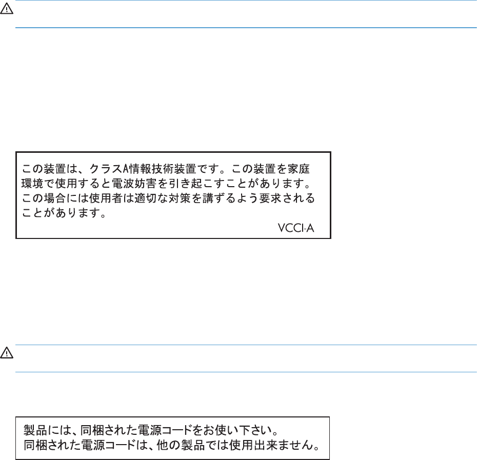
Safety statements
Laser safety
The Center for Devices and Radiological Health (CDRH) of the U.S. Food and Drug Administration has
implemented regulations for laser products manufactured since August 1, 1976. Compliance is
mandatory for products marketed in the United States. The device is certified as a “Class 1” laser
product under the U.S. Department of Health and Human Services (DHHS) Radiation Performance
Standard according to the Radiation Control for Health and Safety Act of 1968. Since radiation
emitted inside the device is completely confined within protective housings and external covers, the
laser beam cannot escape during any phase of normal user operation.
WARNING! Using controls, making adjustments, or performing procedures other than those
specified in this user guide may result in exposure to hazardous radiation.
Canadian DOC regulations
Complies with Canadian EMC Class A requirements.
« Conforme à la classe A des normes canadiennes de compatibilité électromagnétiques. « CEM ». »
VCCI statement (Japan)
Power cord instructions
Make sure your power source is adequate for the product voltage rating. The voltage rating is on the
product label. The product uses either 100-127 Vac or 220-240 Vac and 50/60 Hz.
Connect the power cord between the product and a grounded AC outlet.
CAUTION: To prevent damage to the product, use only the power cord that is provided with the
product.
Power cord statement (Japan)
ENWW Safety statements 537
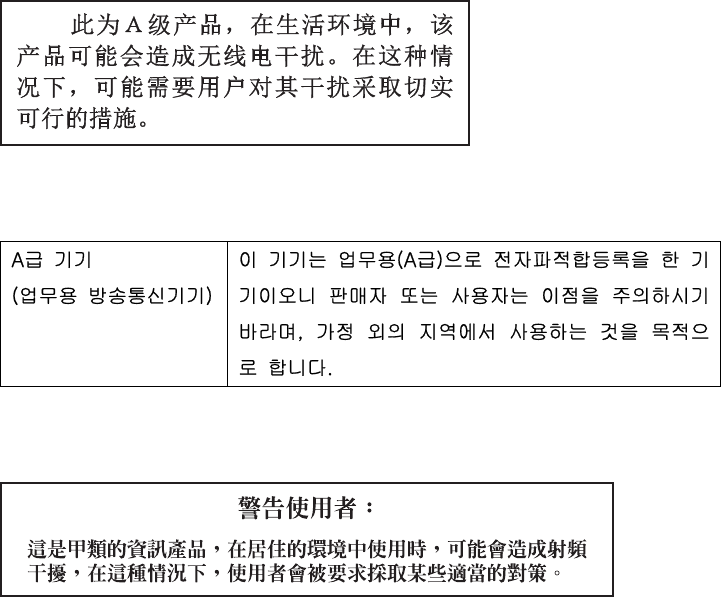
EMC statement (China)
EMC statement (Korea)
EMI statement (Taiwan)
Product Stability
Do not extend more than one paper tray at a time.
Laser statement for Finland
Luokan 1 laserlaite
Klass 1 Laser Apparat
HP LaserJet 600 M601n, M601dn, M602n, M602dn, M602x, M603n, M603dn, M603xh,
laserkirjoitin on käyttäjän kannalta turvallinen luokan 1 laserlaite. Normaalissa käytössä kirjoittimen
suojakotelointi estää lasersäteen pääsyn laitteen ulkopuolelle. Laitteen turvallisuusluokka on määritetty
standardin EN 60825-1 (2007) mukaisesti.
VAROITUS !
Laitteen käyttäminen muulla kuin käyttöohjeessa mainitulla tavalla saattaa altistaa käyttäjän
turvallisuusluokan 1 ylittävälle näkymättömälle lasersäteilylle.
VARNING !
Om apparaten används på annat sätt än i bruksanvisning specificerats, kan användaren utsättas för
osynlig laserstrålning, som överskrider gränsen för laserklass 1.
538 Appendix C Regulatory information ENWW
HUOLTO
HP LaserJet 600 M601n, M601dn, M602n, M602dn, M602x, M603n, M603dn, M603xh -
kirjoittimen sisällä ei ole käyttäjän huollettavissa olevia kohteita. Laitteen saa avata ja huoltaa
ainoastaan sen huoltamiseen koulutettu henkilö. Tällaiseksi huoltotoimenpiteeksi ei katsota
väriainekasetin vaihtamista, paperiradan puhdistusta tai muita käyttäjän käsikirjassa lueteltuja,
käyttäjän tehtäväksi tarkoitettuja ylläpitotoimia, jotka voidaan suorittaa ilman erikoistyökaluja.
VARO !
Mikäli kirjoittimen suojakotelo avataan, olet alttiina näkymättömällelasersäteilylle laitteen ollessa
toiminnassa. Älä katso säteeseen.
VARNING !
Om laserprinterns skyddshölje öppnas då apparaten är i funktion, utsättas användaren för osynlig
laserstrålning. Betrakta ej strålen.
Tiedot laitteessa käytettävän laserdiodin säteilyominaisuuksista: Aallonpituus 775-795 nm Teho 5 m W
Luokan 3B laser.
GS statement (Germany)
Das Gerät ist nicht für die Benutzung im unmittelbaren Gesichtsfeld am Bildschirmarbeitsplatz
vorgesehen. Um störende Reflexionen am Bildschirmarbeitsplatz zu vermeiden, darf dieses Produkt
nicht im unmittelbaren Gesichtsfeld platziert warden.
ENWW Safety statements 539
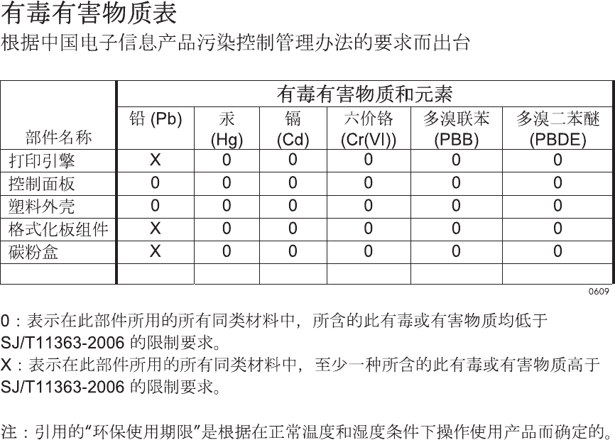
Substances Table (China)
Restriction on Hazardous Substances statement (Turkey)
Türkiye Cumhuriyeti: EEE Yönetmeliğine Uygundur
540 Appendix C Regulatory information ENWW

Index
Symbols/Numerics
1,500-sheet paper deck
door, removing 172
driver PCA, removing 176
left-side cover, removing 169
lift-drive assembly, removing
178
motor, removing 174
rear cover, removing 167
right-side cover, removing 168
separation roller, removing
165
1,500-sheet tray
paper jams 357
500-sheet tray
paper jams 356
A
accessories
ordering 402
acoustic specifications 524
Administration menu, control
panel 250
after-service checklist 63
B
Backup/Restore menu, control
panel 264
batteries included 531
bins, output
jams, clearing 363
removing rear 87
blank pages
troubleshooting 389
blurred print, problem-solving
387
C
cable, USB
troubleshooting 389
Calibrate/Cleaning menu, control
panel 264
Canadian DOC regulations 537
cartridge
ordering 402
part number 402
cartridges
error messages 338
recycling 530
replace message 338
warranty 514
cartridges, print
paper jams 373
replacing 64
cautions iii
characters, misformed 383
checklists
after-service 63
preservice 63
circuit diagram 235
clean the paper path
cleaning page printing 242,
388
cleaning
product 388
clearing jams
1,500-sheet tray 357
500-sheet tray 356
duplexer 359
envelope feeder 361
fuser area 369
output area 363
staple 365
top-cover 373
Tray 1 356
configuration page 199
configuration pages
printing 243
connectivity
solving problems 390
connectors
locating 229
control panel
Administration menu 250
Backup/Restore menu 264
blank, troubleshooting 196
Calibrate/Cleaning menu 264
Display Settings menu 255
General Settings menu 250
Manage Supplies menu 256
Manage Trays menu 257
messages, troubleshooting
266
Multi-Bin Mailbox Settings
menu 258
Network Settings menu 259
Print Settings menu 253
Reports menu 250
Service menu 265
Stapler/Stacker Settings menu
258
Troubleshooting menu 263
USB Firmware Upgrade menu
265
control panel menus
retrieve job 247
conventions, document iii
cooling fan FN101, replacing
142
cooling fan FN102, replacing
117
cooling fan FN103, replacing
119
cooling fan FN301, replacing
144
ENWW Index 541
counts 391
page, reset 391
reset after replacing formatter
391
See also pages counts
covers
1,500-sheet paper deck,
removing 167
envelope accessory, removing
89
formatter, removing 71
front, removing 105
left-side, removing 98
removing 88
right-side, removing 95
top, removing 92
covers, product base
diagrams and part numbers
410
creased paper, problem-solving
385
crooked pages 384
curled paper, problem-solving
384
customer support
online 520
repacking product 521
D
date
manufacture 245
DC controller
PCA, locating 229
removing 128
defects
examples of 380
repeating 246
demo page 199
density
problem-solving 380
determine the problem source
193
diagnostics
engine 204
LED 199
diagrams
covers, product base 410
dimensions, product 524
DIMMs
memory 80
Display Settings menu, control
panel 255
disposal, end-of-life 531
document conventions iii
dots, problem-solving 381, 386
dropouts, problem-solving 381
drum drive, removing 139
drum drive, replacing 139
duplex printing accessory
jams 359
E
electrical specifications 524
electrostatic discharge (ESD) 60
end-of-life disposal 531
engine
diagnostics 204
envelope accessory, front
covers, removing 89
envelope feeder
paper jams 361
envelopes
wrinkled, problem-solving 385
environment for product
specifications 525
Environmental Product Stewardship
Program 529
error messages, control panel
266
ESD (electrostatic discharge) 60
European Union, waste disposal
532
event log 199
clear 352
print 351
view 352
event-log messages 350
F
fan FN101, removing 142
fan FN102, removing 117
fan FN103, removing 119
fan FN301, removing 144
fans
troubleshooting 196
fasteners, types of 62
FCC regulations 528
feed and pickup rollers, replacing
Tray 1 82
feed rollers, replacing tray 2 66
Finnish laser safety statement 538
firmware
version information 245
firmware, downloading new 397
flowcharts
troubleshooting 194
formatter
resets after replacing 391
formatter cage, removing 71
formatter cover, removing 71
formatter lights 199
formatter, removing 71
front cover, removing 105
fuser
paper jams 369
part number 403
replacing 70
fuser motor, removing 137
fuser motor, replacing 137
G
General Settings menu, control
panel 250
gray background, problem-
solving 382
H
hard drive
remove 74
heartbeat LED 200
HP Customer Care 520
HP Jetdirect print server
configuration page 245
lights 199
humidity
specifications 525
I
image quality
print, troubleshooting 380
image repetition, problem-solving
387
inner connecting PCA
removing 114
installation
verify for optional accessories
243
IPv4 information 245
IPv6 information 245
542 Index ENWW
J
jams
1,500-sheet tray 357
500-sheet tray 356
causes of 376
common causes of 355
diagnostic test for 206
duplexer 359
envelope feeder 361
fuser area 369
output bin 363
recovery 375
staple 365
top-cover 373
Tray 1 356
Japanese VCCI statement 537
Jetdirect print server
lights 199
K
Korean EMC statement 538
L
laser safety statements 537, 538
laser/scanner
removing 158
LEDs. See lights
left-side cover, removing 98
license, software 516
light print
problem-solving 380
lights
formatter 199
troubleshooting with 199
lines, problem-solving 381, 385,
386
loose toner, problem-solving 382
M
Macintosh
support 520
main assemblies
locating 224
removing 107
Manage Supplies menu, control
panel 256
Manage Trays menu, control
panel 257
manual print modes 378
material restrictions 531
Material Safety Data Sheet
(MSDS) 532
memory
information 243
supply errors 267
memory chip, print cartridge
description 515
menus, control panel
Administration 250
Backup/Restore 264
Calibrate/Cleaning 264
Display Settings 255
General Settings 250
Manage Supplies 256
Manage Trays 257
Multi-Bin Mailbox Settings 258
Network Settings 259
Print Settings 253
Reports 250
Service 265
Stapler/Stacker Settings 258
Troubleshooting 263
USB Firmware Upgrade 265
menus, control-panel
retrieve job 247
mercury-free product 531
messages, control panel 266
misformed characters, problem-
solving 383
model number 245
motors
troubleshooting 196
Multi-Bin Mailbox Settings menu,
control panel 258
N
Network Settings menu, control
panel 259
networks
HP embedded Jetdirect
configuration page 245
notes iii
O
online support 520
operating environment
specifications 525
ordering
print cartridge 402
product documents 405
supplies and accessories 402
output bins
paper jams 363
removing rear 87
output quality
defect examples 380
print, troubleshooting 380
repeating defects 246
P
packaging product 521
pages
blank 389
not printing 389
printing slowly 389
pages count 391
reset 391
See also counts
paper
curled 384
jams 376
skewed 384
wrinkled 385
paper jams
1,500-sheet tray 357
500-sheet tray 356
duplexer 359
envelope feeder 361
fuser area 369
output bin 363
top-cover 373
Tray 1 356
paper path
diagnostic test 206
paper pickup problems
solving 376
paper-delivery assembly
removing 161
part number
print cartridge 402
part numbers
covers, product base 410
parts
replacing 406
password
Service menu PIN 391
PCA, inner connecting
remove 114
physical specifications 524
ENWW Index 543
pickup and feed rollers, replacing
Tray 1 82
pickup rollers, replacing tray 2
66
pickup-drive assembly
removing 131
pliers, required 61
port configuration information
245
post-service tests 63
power
consumption 524
troubleshooting 196
power supply, high voltage
removing 148
pre-troubleshooting checklist 193
preservice checklist 63
print cartridge
ordering 402
part number 402
print cartridges
error messages 338
memory chips 515
paper jams 373
recycling 530
replace message 338
replacing 64
warranty 514
print quality
blurred 387
built-in troubleshooting pages
241
defect examples 380
dropouts 381
gray background 382
light print 380
lines 381
loose toner 382
manual print modes 378
misformed characters 383
repeating defects 246, 383
repetitive images 387
scattered lines 386
smeared toner 382
specks 381
test 63
test pages 241
tire tracks 385
troubleshooting 380
white lines 385
white spots 386
Print Quality menu options 378
Print Settings menu, control panel
253
printing
modes, manual 378
troubleshooting 389
problem source
determine 193
problem-solving
blurred print 387
curled paper 384
dropouts 381
event-log messages 350
gray background 382
light print 380
lines 381, 385
repeating defects 383
repetitive images 387
scattered lines 386
skewed pages 384
smeared toner 382
specks 381
text quality 383, 387
tire tracks 385
white spots 386
wrinkled paper 385
Q
quality
defect examples 380
print, troubleshooting 380
repeating defects 246
R
rear output bin
paper jams 363
removing 87
recycling 530
HP printing supplies returns and
environmental program 530
registration assembly
removing 107
regulatory statements
environmental product
stewardship program 529
removing parts
cautions for 60
checklists 63
tools, required 61
repacking product 521
repeating defects 246
repeating defects, problem-
solving 383, 387
replace supplies message 338
replacing
parts 60
Reports menu, control panel 250
retrieve job menu 247
right-side cover
removing 95
rollers
locating 224
repetitive defects 246
transfer, replacing 69
Tray 1 pickup and feed,
replacing 82
tray 2 separation, pickup, and
feed, replacing 66
S
safety statements 537, 538
screwdrivers, required 61
screws
replacing 60
screws, types of 62
security settings information 245
sensor tests manual
0utput bin full sensor (PS104)
215
fuser delivery sensor (PS700)
212
media width sensors 1/2
(PS106/108) 214
PF/PD media path sensors
(PS1603/1603/1603/1704
)211
pre-feed sensor (PS102) 211
top of page sensor (PS103)
210
Tray 1 paper present sensor
(PS105) 216
tray 2 paper present sensor
(PS101) 217
tray 2 paper size switches
(SW102) 219
tray 2 top of stack sensor
(PS107) 218
544 Index ENWW
sensors
tests, manual 208
tests, manual tray/bin 220
separation roller
replacing 85
separation rollers, replacing tray
266
service
repacking product 521
tools, required 61
Service menu options 391
Service menu, control panel 265
shipping product 521
skewed pages 384
smeared toner, problem-solving
382
software
software license agreement
516
solve problems 181
solving
direct-connect problems 390
network problems 390
specifications
electrical and acoustic 524
operating environment 525
physical 524
specks, problem-solving 381,
386
spots, problem-solving 381, 386
stacker and stapler/stacker
parts lists and diagrams 476
staple jams 365
stapler/stacker
jams, staple 365
Stapler/Stacker Settings menu,
control panel 258
static precautions 60
status page 199
supplies
error messages 338
memory errors 267
ordering 402
recycling 530
replace message 338
support
online 520
repacking product 521
T
Taiwan EMI statement 538
TCP/IP information 245
technical support
online 520
repacking product 521
temperature specifications 525
tests
manual sensor 208
paper path 206
post-service 63
print-quality 63
tray/bin manual sensor 220
text, problem-solving
blurred 387
misformed characters 383
timing chart 234
tips iii
tire tracks, problem-solving 385
toner
output quality, problem-
solving 382
toner cartridges. See print
cartridges
tools, required 61
top cover
paper jams, clearing 373
top cover, removing 92
top output bin
paper jams 363
transfer roller
replacing 69
Tray 1
paper jams 356
pickup and feed rollers,
replacing 82
tray 1
paper-pickup assembly,
removing 155
separation roller, replacing 85
tray 2
extension door, removing 91
separation, pickup, and feed
rollers, replacing 66
Tray 3
physical specifications 524
trays
paper jams 356, 357
troubleshooting 181
1,500-sheet tray paper jams
357
500-sheet tray paper jams
356
about 193
blank pages 389
checklist 182, 193
clean the paper path 242,
388
configuration page 199
configuration pages for 243
control panel messages 266
demo page 199
direct-connect problems 390
duplexer jams 359
envelope feeder jams 361
event log 199
flowchart 194
fuser-area paper jams 369
jams 376
lights, using 199
network problems 390
output bin jams 363
pages not printing 389
pages printing slowly 389
paper feed problems 376
power-on 196
print quality 380
problem source 193
repeating defects 246
reports and tools 199
staple jams 365
status page 199
top-cover paper jams 373
Tray 1 paper jams 356
USB cables 389
Troubleshooting menu, control
panel 263
U
updates, downloading product
397
USB Firmware Upgrade menu,
control panel 265
USB port
troubleshooting 389
V
version, hardware firmware 245
ENWW Index 545
W
warnings iii
warranty
customer self repair 519
license 516
print cartridges 514
product 512
wavy paper, problem-solving 384
Web sites
customer support 520
Macintosh customer support
520
Material Safety Data Sheet
(MSDS) 532
weight, product 524
white lines or spots, problem-
solving 385
wrinkled paper, problem-solving
385
546 Index ENWW

© 2011 Hewlett-Packard Development Company, L.P.
www.hp.com
*CE988-90945*
*CE988-90945*
CE988-90945
