HP LaserJet Pro M402, M403 And MFP M426, M427 Troubleshooting Manual HP Laserjet M403, M42
User Manual: HP Laserjet Pro M402, M403, Pro MFP M426, M42 Troubleshooting Manual shared.swissparts.ch - /Manuals/HP/LaserJet/Mono Laserjet/
Open the PDF directly: View PDF ![]() .
.
Page Count: 204 [warning: Documents this large are best viewed by clicking the View PDF Link!]
- Theory of operation
- Solve problems
- For additional service and support
- Solve problems checklist
- Troubleshooting process
- Tools for troubleshooting
- Component diagnostics
- Diagrams
- Advanced configuration with HP Embedded Web Server (EWS) and HP Device Toolbox (Windows 7)
- Internal print-quality test pages
- Print-quality troubleshooting tools
- Control panel menus
- Control panel message document (CPMD)
- Control-panel message types
- Control-panel messages and event log entries
- 30.XX Error Messages
- 49.XX.YY Error Messages
- 50.XX fuser errors
- 51.XX and 52 Laser/Scanner Errors
- 55.XXXX Error Messages
- 57.XX Error Messages
- 58.XX Error Messages
- 59.XX Error Messages
- 79 Errors
- Alpha Error Messages
- <COLOR> cartridge is low.
- <COLOR> cartridge is very low.
- Cleaning.
- Device error. Press [OK] to continue.
- Device is busy. Try again later.
- Document feeder jam. Clear and reload.
- Document feeder mispick. Reload.
- Door is open.
- Engine cable connection issue. Contact HP service. Press [OK] to continue.
- Fax is busy. Canceled send.
- Fax receive error.
- Fax Send error.
- Fax storage is full. Canceling the fax send/receive.
- Genuine HP supply installed.
- Install <COLOR> cartridge.
- Jam in output bin. Open rear door and clear jam.
- Jam in Tray 1. Clear jam and then press [OK].
- Jam in Tray 2. Clear jam and then press [OK].
- Jam in Tray 3, Clear jam and then press OK
- Load paper
- Load tray <X> Press [OK] for available media
- Load tray 1. Press [OK] to continue.
- Load tray 1 <TYPE>, <SIZE>. Press [OK] to continue.
- Load tray 1. Plain, <SIZE> / Cleaning mode. Press [OK] to start.
- Manual Duplex. Load Tray <#>. Press [OK] to continue.
- Memory is low. Press [OK] to continue.
- NFC cable connection issue. Contact HP service. Press [OK] to continue.
- No dial tone.
- No fax detected.
- Non-HP supply installed.
- Print failure, press [OK]. If error repeats, turn off then on.
- Protected <COLOR> cartridge.
- Rear door open.
- Replace <COLOR>.
- Supply memory error.
- The product is unable to calibrate. Close the lid and remove paper from the document feeder.
- Unauthorized <COLOR> cartridge.
- Unexpected size in Tray <#>. Load <SIZE>. Press [OK] to continue.
- Used or counterfeit <COLOR> cartridge in use.
- Used or counterfeit <COLOR> cartridge is installed. Press [OK] to continue.
- Wireless cable connection issue. Contact HP service. Press [OK] to continue.
- Event-log messages
- Clear paper jams
- Solve paper-handling problems
- Solve image quality problems
- Clean the printer
- Solve performance problems
- Solve connectivity problems
- Solve direct-connect problems
- Solve network problems
- Poor physical connection
- The computer is using the incorrect IP address for the product
- The computer is unable to communicate with the product
- The product is using incorrect link and duplex settings for the network
- New software programs might be causing compatibility problems
- The computer or workstation might be set up incorrectly
- The product is disabled, or other network settings are incorrect
- Solve wireless network problems
- Wireless connectivity checklist
- The control panel displays the message: The wireless feature on this product has been turned off
- The product does not print after the wireless configuration completes
- The product does not print, and the computer has a third-party firewall installed
- The wireless connection does not work after moving the wireless router or product
- Cannot connect more computers to the wireless product
- The wireless product loses communication when connected to a VPN
- The network does not appear in the wireless networks list
- The wireless network is not functioning
- Service mode functions
- Solve fax problems (fax models only)
- Solve email problems (M426, M427 printes)
- Manually update the firmware
- Printer specifications
- Index
Troubleshooting Manual
www.hp.com/support/ljM402
www.hp.com/support/ljM403
www.hp.com/support/ljM426MFP
www.hp.com/support/ljM427MFP
For printer theory and troubleshooting
information, see the Repair Manual.
HEWLETT-PACKARD
2
1
M402d
M402n
M402dn
M402dw
M403n
M403d
M403dn
M403dw
2
1
M426dw
M426fdn
M426fdw
M427dw
M427fdn
M427fdw
LaserJet Pro MFP M426, M427
LaserJet Pro M402, M403

HP LaserJet Pro M402, M403 and
HP LaserJet Pro MFP M426, M427
Troubleshooting Manual
Copyright and License
© Copyright 2015 HP Development Company,
L.P.
Reproduction, adaptation, or translation
without prior written permission is prohibited,
except as allowed under the copyright laws.
The information contained herein is subject to
change without notice.
The only warranties for HP products and
services are set forth in the express warranty
statements accompanying such products and
services. Nothing herein should be construed
as constituting an additional warranty. HP shall
not be liable for technical or editorial errors or
omissions contained herein.
Edition 1, 9/2015
Trademark Credits
Microsoft®, Windows®, Windows® XP, and
Windows Vista® are U.S. registered trademarks
of Microsoft Corporation.

Conventions used in this guide
TIP: Helpful hints or shortcuts.
Reinstallation tip: Reinstallation helpful hints, shortcuts, or considerations.
NOTE: Information that explains a concept or how to complete a task.
IMPORTANT: Information that help the user to avoid potential printer error conditions.
CAUTION: Procedures that the user must follow to avoid losing data or damaging the printer.
WARNING! Procedures that the user must follow to avoid personal injury, catastrophic loss of data, or
extensive damage to the printer.
ENWW iii
iv Conventions used in this guide ENWW

For additional service and support information
HP service personnel, go to the Service Access Work Bench (SAW) at http://h41302.www4.hp.com/km/saw/
home.do.
Channel partners, go to HP Channel Services Network (CNS) at https://h30125.www3.hp.com/hpcsn.
At these locations, nd information on the following topics:
●Install and congure
●Printer specications
●Up-to-date control panel message (CPMD) troubleshooting
●Solutions for printer issues and emerging issues
●Remove and replace part instructions and videos
●Service advisories
●Warranty and regulatory information
To access HP PartSurfer information from any mobile device, go to http://partsurfermobile.hp.com/ or scan
the Quick Response (QR) code below.
ENWW v
vi For additional service and support information ENWW

Table of contents
1 Theory of operation ....................................................................................................................................... 1
Related documentation and software ................................................................................................................... 2
Basic operation ...................................................................................................................................................... 3
Sequence of operation ........................................................................................................................ 4
Engine-control system .......................................................................................................................................... 5
DC controller ........................................................................................................................................ 6
Motor control ..................................................................................................................... 8
Fan control ........................................................................................................................ 8
Low-voltage power supply .................................................................................................................. 9
Over-current/over-voltage protection ........................................................................... 10
Safety ............................................................................................................ 10
Low-voltage power supply functions ........................................................... 10
High-voltage power supply ............................................................................................................... 11
High-voltage power supply circuits ................................................................................ 12
Fuser bias ........................................................................................................................ 12
Fuser control ..................................................................................................................................... 12
Fuser circuits ................................................................................................................... 13
Fuser control functions ................................................................................................... 14
Fuser heater protection .................................................................................................. 15
Engine laser/scanner system .............................................................................................................................. 16
Laser/scanner failure detection ........................................................................................................ 17
Safety ................................................................................................................................................ 17
Image-formation process ................................................................................................................. 18
Step 1: Primary charging ................................................................................................ 21
Step 2: Laser-beam exposure ......................................................................................... 22
Step 3: Development ...................................................................................................... 22
Step 4: Transfer ............................................................................................................... 23
Step 5: Separation ........................................................................................................... 24
Step 6: Fusing .................................................................................................................. 24
Step 7: Drum cleaning ..................................................................................................... 24
Toner cartridges ................................................................................................................................ 25
Design ............................................................................................................................. 25
ENWW vii
Memory chip .................................................................................................................... 27
Toner level and cartridge life detection .......................................................................... 27
Pickup, feed, and delivery system ....................................................................................................................... 27
Sensors and switches ........................................................................................................................ 29
Motors, clutches, and solenoids ........................................................................................................ 31
Jam detection/prevention ................................................................................................................. 31
Paper feeder (optional Tray 3) ............................................................................................................................. 35
Basic operation .................................................................................................................................. 35
Paper path ....................................................................................................................... 35
Paper feeder controller ................................................................................................... 35
Motor control .................................................................................................................. 36
Pickup and feed operation ................................................................................................................ 36
Electrical components, pickup and feed ......................................................................... 36
Other functions ............................................................................................................... 37
Jam detection .................................................................................................................. 38
2 Solve problems ............................................................................................................................................ 39
For additional service and support ..................................................................................................................... 40
Solve problems checklist ..................................................................................................................................... 41
Solve problems checklist ................................................................................................................... 41
Print the menu map ........................................................................................................ 42
Print a conguration page .............................................................................................. 42
Print the service page (includes the event log) .............................................................. 43
Print the demo page ....................................................................................................... 43
Troubleshooting process ..................................................................................................................................... 44
Determine the problem source ......................................................................................................... 44
Pre-troubleshooting checklist ........................................................................................ 44
Determine the problem source ....................................................................................... 46
Power subsystem .............................................................................................................................. 47
Power-on checks ............................................................................................................. 47
Control panel checks ......................................................................................................................... 47
Tools for troubleshooting .................................................................................................................................... 49
Component diagnostics .................................................................................................................... 49
LED diagnostics ............................................................................................................... 49
Network LEDs (network models only) ......................................................... 49
Control panel LEDs ....................................................................................... 49
Engine diagnostics .......................................................................................................... 50
Engine test .................................................................................................... 50
Diagrams ........................................................................................................................................... 51
Diagrams: Block diagrams .............................................................................................. 51
Cross-sectional view of printer .................................................................... 51
viii ENWW
Cross-sectional view of 550–sheet paper feeder ........................................ 52
Diagrams: Printed circuit assembly (PCA) connector locations ..................................... 53
Diagrams: DC controller connections ........................................................... 53
Paper feeder controller PCA ......................................................................... 54
Diagrams: External plug and port locations ................................................................... 54
Diagrams: Locations of major components ................................................................... 56
Major components (printer base) ................................................................. 56
Motor and fan ............................................................................................... 57
Rollers and pads (printer base) .................................................................... 58
PCAs (printer base) ....................................................................................... 59
Diagrams: Timing chart .................................................................................................. 60
Diagrams: Circuit diagrams ............................................................................................. 61
Advanced conguration with HP Embedded Web Server (EWS) and HP Device Toolbox
(Windows 7) ....................................................................................................................................... 62
Internal print-quality test pages ....................................................................................................... 64
Clean the paper path ....................................................................................................... 64
Clean the paper path (LCD control panel) .................................................... 64
Clean the paper path (touchscreen control panel) ...................................... 65
Print the conguration page ........................................................................................... 65
Print the conguration page from an LCD control panel ............................. 65
Print the conguration page from a touchscreen control panel ................. 65
Print-quality troubleshooting tools .................................................................................................. 66
Repetitive image defect ruler ......................................................................................... 66
Use a ruler to measure between repetitive defects ..................................... 66
Control panel menus ......................................................................................................................... 70
HP Web Services menu ................................................................................................... 70
Reports menu ................................................................................................................. 70
Quick Forms menu .......................................................................................................... 71
USB Flash Drive menu ..................................................................................................... 71
System Setup menu ........................................................................................................ 72
Service menu ................................................................................................................... 74
Network Setup menu ...................................................................................................... 77
Control panel message document (CPMD) ....................................................................................... 79
Control-panel message types ........................................................................................ 79
Control-panel messages and event log entries ............................................................. 79
30.XX Error Messages ................................................................................... 79
49.XX.YY Error Messages ............................................................................. 80
50.XX fuser errors ........................................................................................ 80
51.XX and 52 Laser/Scanner Errors ............................................................. 81
55.XXXX Error Messages .............................................................................. 82
57.XX Error Messages ................................................................................... 83
ENWW ix
58.XX Error Messages ................................................................................... 83
59.XX Error Messages ................................................................................... 84
79 Errors ....................................................................................................... 85
Alpha Error Messages ................................................................................... 85
Event-log messages .......................................................................................................................... 96
Print the event log .......................................................................................................... 96
Print the event log (LCD control panel) ........................................................ 96
Print the event log (touchscreen control panel) .......................................... 97
Show an event log ........................................................................................................... 97
Event-log messages ....................................................................................................... 97
Clear paper jams ................................................................................................................................................ 101
Clear paper jams (M402, M403) ...................................................................................................... 101
Introduction .................................................................................................................. 101
Experiencing frequent or recurring paper jams? ......................................................... 101
Jam locations ................................................................................................................ 102
Clear paper jams in Tray 1 ............................................................................................ 103
Clear paper jams in Tray 2 ............................................................................................ 104
Clear paper jams in optional Tray 3 .............................................................................. 108
Clear paper jams in the fuser ........................................................................................ 111
Clear paper jams in the output bin ............................................................................... 115
Clear paper jams in the duplexer .................................................................................. 117
Clear paper jams (M426, M427) ...................................................................................................... 119
Introduction .................................................................................................................. 119
Experiencing frequent or recurring paper jams? ......................................................... 119
Jam locations ................................................................................................................ 120
Clear paper jams in the document feeder .................................................................... 122
Clear paper jams in Tray 1 ............................................................................................ 125
Clear paper jams in Tray 2 ............................................................................................ 126
Clear paper jams in optional Tray 3 .............................................................................. 130
Clear paper jams in the fuser ........................................................................................ 134
Clear paper jams in the output bin ............................................................................... 137
Clear paper jams in the duplexer .................................................................................. 140
Solve paper-handling problems ........................................................................................................................ 142
The printer picks up multiple sheets of paper ................................................................................ 142
The printer does not pick up paper ................................................................................................. 142
Solve image quality problems ........................................................................................................................... 143
Print quality examples .................................................................................................................... 143
Clean the printer ................................................................................................................................................ 150
Clean the pickup and separation rollers ......................................................................................... 150
Clean the paper path ....................................................................................................................... 150
Clean the paper path (LCD control panel) ..................................................................... 150
x ENWW
Clean the paper path (touchscreen control panel) ....................................................... 150
Clean the touchscreen ..................................................................................................................... 150
Solve performance problems ............................................................................................................................ 152
Factors aecting print performance ............................................................................................... 152
Print speeds .................................................................................................................. 152
The product does not print or it prints slowly ................................................................................ 153
The product does not print ........................................................................................... 153
The product prints slowly ............................................................................................. 154
Solve connectivity problems ............................................................................................................................. 155
Solve direct-connect problems ....................................................................................................... 155
Solve network problems ................................................................................................................. 155
Poor physical connection .............................................................................................. 155
The computer is using the incorrect IP address for the product .................................. 155
The computer is unable to communicate with the product ......................................... 156
The product is using incorrect link and duplex settings for the network .................... 156
New software programs might be causing compatibility problems ........................... 156
The computer or workstation might be set up incorrectly .......................................... 156
The product is disabled, or other network settings are incorrect ............................... 156
Solve wireless network problems ................................................................................................... 157
Wireless connectivity checklist ..................................................................................... 157
The control panel displays the message: The wireless feature on this product has
been turned o ............................................................................................................. 157
The product does not print after the wireless conguration completes ..................... 158
The product does not print, and the computer has a third-party rewall installed ... 158
The wireless connection does not work after moving the wireless router or
product .......................................................................................................................... 158
Cannot connect more computers to the wireless product ........................................... 158
The wireless product loses communication when connected to a VPN ...................... 159
The network does not appear in the wireless networks list ........................................ 159
The wireless network is not functioning ...................................................................... 159
Service mode functions ..................................................................................................................................... 160
Service menu ................................................................................................................................... 160
Service menu settings .................................................................................................. 160
Restore the factory-set defaults .................................................................................. 160
Restore the factory-set defaults (LCD control panel) ................................ 160
Restore the factory-set defaults (touchscreen control panel) .................. 161
Secondary service menu ................................................................................................................. 161
Open the secondary service menu ............................................................................... 161
Open the secondary service menu (LCD control panel) ............................. 161
Open the secondary service menu (touchscreen control panel) ............... 161
Secondary service menu structure ............................................................................... 162
ENWW xi
Developer's menu ............................................................................................................................ 162
Open the Developer's menu (LCD control panel) ......................................................... 162
Open the Developer's menu (touchscreen control panel) ........................................... 163
Product resets ................................................................................................................................. 164
NVRAM initialization ..................................................................................................... 164
Solve fax problems (fax models only) ............................................................................................................... 165
Introduction ..................................................................................................................................... 165
Fax troubleshooting checklist ......................................................................................................... 165
Solve general fax problems ............................................................................................................ 166
Faxes are sending slowly .............................................................................................. 166
Fax quality is poor ......................................................................................................... 167
Fax cuts o or prints on two pages .............................................................................. 168
Solve email problems (M426, M427 printes) .................................................................................................... 169
Cannot connect to the email server ................................................................................................ 169
Validate the SMTP gateway (Windows) .......................................................................................... 169
Validate the LDAP gateway (Windows) ........................................................................................... 169
Manually update the rmware .......................................................................................................................... 170
Manually update the rmware (LCD control panel) ........................................................................ 170
Manually update the rmware (touchscreen control panel) .......................................................... 170
Appendix A Printer specications .................................................................................................................. 171
Printer dimensions M426 and M427 ................................................................................................................. 172
Printer dimensions M402 and M403 ................................................................................................................. 174
Printer space requirements ............................................................................................................................... 176
Power consumption, electrical specications, and acoustic emissions ........................................................... 176
Operating-environment range .......................................................................................................................... 176
Certicate of Volatility ....................................................................................................................................... 177
Index ........................................................................................................................................................... 181
xii ENWW

List of tables
Table 1-1 Sequence of operation .......................................................................................................................................... 4
Table 1-2 Motors ................................................................................................................................................................... 8
Table 1-3 Fans ....................................................................................................................................................................... 8
Table 1-4 List of DC voltages ................................................................................................................................................ 9
Table 1-5 Low-voltage power supply functions ................................................................................................................. 10
Table 1-6 High-voltage power supply circuits .................................................................................................................... 12
Table 1-7 Fuser components .............................................................................................................................................. 13
Table 1-8 Fuser control functions ...................................................................................................................................... 14
Table 1-9 Sensors ............................................................................................................................................................... 20
Table 1-10 Image formation process ................................................................................................................................. 21
Table 1-11 Toner cartridge functions ................................................................................................................................. 26
Table 1-12 Pickup, feed, and delivery system functions ................................................................................................... 28
Table 1-13 Photo sensors and switches ............................................................................................................................. 30
Table 1-14 Motors, solenoids, and clutches ....................................................................................................................... 31
Table 1-15 Jams that the printer detects ........................................................................................................................... 32
Table 1-16 Electrical component list, paper feeder ........................................................................................................... 36
Table 1-17 Motors, paper feeder ........................................................................................................................................ 36
Table 1-18 Electrical components, pickup and feed .......................................................................................................... 37
Table 1-19 Other functions, paper feeder .......................................................................................................................... 37
Table 2-1 DC controller connectors .................................................................................................................................... 53
Table 2-2 Paper feeder controller PCA connectors ............................................................................................................ 54
Table 2-3 M402, M403 external plugs and ports ............................................................................................................... 54
Table 2-4 M426, M427 external plugs and ports ............................................................................................................... 55
Table 2-5 Major components (printer base) ....................................................................................................................... 56
Table 2-6 Motor and fan (printer base) .............................................................................................................................. 57
Table 2-7 Rollers and pads (printer base) .......................................................................................................................... 58
Table 2-8 Main PCAs (printer base) ..................................................................................................................................... 59
Table 2-9 Repetitive defects ............................................................................................................................................... 66
Table 2-10 Event-log messages (X=0: black cartridge) ..................................................................................................... 97
Table 2-11 Fax event log codes ........................................................................................................................................ 100
Table 2-12 Print quality examples ................................................................................................................................... 143
Table 2-13 Secondary Service menu ................................................................................................................................ 162
ENWW xiii

List of gures
Figure 1-1 Relationship between the main printer systems ............................................................................................... 3
Figure 1-2 Engine-control system ........................................................................................................................................ 5
Figure 1-3 DC controller block diagram ................................................................................................................................ 6
Figure 1-4 Low-voltage power-supply circuit ...................................................................................................................... 9
Figure 1-5 High-voltage power supply circuits .................................................................................................................. 12
Figure 1-6 Fuser components ............................................................................................................................................ 13
Figure 1-7 Fuser control ..................................................................................................................................................... 14
Figure 1-8 Laser/scanner system ....................................................................................................................................... 16
Figure 1-9 Image-formation system .................................................................................................................................. 18
Figure 1-10 Fuser motor (M1) and image formation components .................................................................................... 19
Figure 1-11 Toner-level sensor .......................................................................................................................................... 20
Figure 1-12 Image-formation process ............................................................................................................................... 20
Figure 1-13 Primary charging ............................................................................................................................................. 21
Figure 1-14 Laser-beam exposure ..................................................................................................................................... 22
Figure 1-15 Development ................................................................................................................................................... 22
Figure 1-16 Primary transfer .............................................................................................................................................. 23
Figure 1-17 Separation ....................................................................................................................................................... 24
Figure 1-18 Fusing .............................................................................................................................................................. 24
Figure 1-19 Drum cleaning ................................................................................................................................................. 25
Figure 1-20 Toner cartridge system ................................................................................................................................... 26
Figure 1-21 Pickup, feed, and delivery system .................................................................................................................. 28
Figure 1-22 Sensors and switches for the pickup, feed, and delivery system .................................................................. 29
Figure 1-23 Motors, solenoids, and clutches ..................................................................................................................... 31
Figure 1-24 Jam detection sensors .................................................................................................................................... 32
Figure 1-25 Optional Tray 3 paper path ............................................................................................................................. 35
Figure 1-26 Paper feeder controller ................................................................................................................................... 36
Figure 1-27 Electrical components, pickup and feed ......................................................................................................... 37
Figure 2-1 Cross-sectional view of printer ......................................................................................................................... 51
Figure 2-2 Cross-sectional view of 500–sheet paper feeder ............................................................................................ 52
Figure 2-3 DC controller PCA connectors ........................................................................................................................... 53
Figure 2-4 Paper feeder controller PCA connectors ........................................................................................................... 54
Figure 2-5 M402, M403 external plugs and ports locations .............................................................................................. 54
ENWW xv
Figure 2-6 M426, M427 external plug and port locations ................................................................................................. 55
Figure 2-7 Major components (printer base) ..................................................................................................................... 56
Figure 2-8 Motor and fan .................................................................................................................................................... 57
Figure 2-9 Rollers and pads (printer base) ......................................................................................................................... 58
Figure 2-10 Main PCAs (printer base) ................................................................................................................................. 59
Figure 2-11 General timing chart ....................................................................................................................................... 60
Figure 2-12 General circuit diagram (printer base) ............................................................................................................ 61
Figure 2-13 Examples of repetitive defects ....................................................................................................................... 67
Figure 2-14 Place the ruler on the page ............................................................................................................................. 68
Figure 2-15 Locate the next repetitive defect ................................................................................................................... 68
Figure 2-16 Determine the defective assembly ................................................................................................................. 69
Figure A-1 Dimensions for the M426 and M427 models ................................................................................................. 172
Figure A-2 Dimensions for the optional 550-sheet tray .................................................................................................. 172
Figure A-3 Dimensions for the printer with the optional 550-sheet tray ....................................................................... 173
Figure A-4 Dimensions for the M402 and M403 models ................................................................................................. 174
Figure A-5 Dimensions for the optional 550-sheet tray .................................................................................................. 174
Figure A-6 Dimensions for the printer with the optional 550-sheet tray ....................................................................... 175
Figure A-7 Certicate of Volatility M402/M403 (1 of 2) ................................................................................................... 177
Figure A-8 Certicate of Volatility M402/M403 (2 of 2) ................................................................................................... 178
Figure A-9 Certicate of Volatility M426/M427 (1 of 2) ................................................................................................... 179
Figure A-10 Certicate of Volatility M426/M427 (2 of 2) ................................................................................................ 180
xvi ENWW


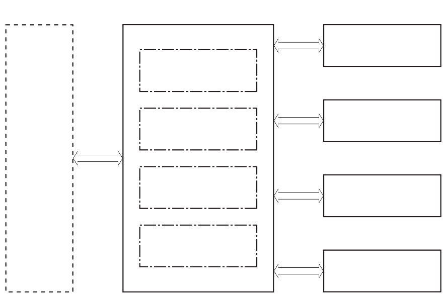
Basic operation
The printer routes all high-level processes through the formatter, which stores font information, processes
the print image, and communicates with the host computer.
The basic printer operation comprises the following systems:
●Engine-control system
●Laser/scanner system
●Image-formation system
●Pickup, feed, and delivery system
●Accessory (optional paper feeder)
Figure 1-1 Relationship between the main printer systems
Engine-control system
Laser scanner system
Image-formation system
Pickup, feed, and delivery system
Accessory
En
g
ine-control s
y
stem
Laser scanner s
y
stem
Ima
g
e-
f
ormation s
y
stem
Pickup,
f
eed, and deliver
y
s
y
stem
Accessor
y
ENWW Basic operation 3

Sequence of operation
The DC controller PCA controls the operating sequence, as described in the following table.
Table 1-1 Sequence of operation
Period Duration Description
Waiting From the time the power is turned on, the door is
closed, or when the printer exits Sleep mode until the
printer is ready for printing.
●Heats the fuser lm in the fuser
●Detects the toner cartridge
●Rotates and stops each motor
●Rotates and stops each fan
●Cleans the transfer roller
Standby From the end of the waiting sequence or the last
rotation until the formatter receives a print command,
or until the printer is turned o.
●Is in the Ready state
●Enters Sleep mode if the formatter sends the
sleep command
●Rotates and stops each fan
Initial rotation From the time the formatter receives a print command
until the paper enters the paper path.
●Rotates each motor
●Rotates each fan
●Activates the high-voltage power supply (high-
voltage bias)
●Prepares the laser/scanner unit
●Warms the fuser to the correct temperature
Printing From the time the rst sheet of paper enters the paper
path until the last sheet passes through the fuser.
●Forms the image on the photosensitive drums
●Transfers the toner to the paper
●Fuses the toner image onto the paper
Last rotation From the time the last sheet of paper exits the fuser
until the motors stop rotating.
●Stops each motor
●Stops each fan
●Stops the high-voltage power supply (high-
voltage bias)
●Stops the laser/scanner unit
●Turns the fuser heater o
●If another print command is received, the printer
enters the initial rotation period when the last
rotation is complete.
4 Chapter 1 Theory of operation ENWW
Engine-control system
The engine-control system receives commands from the formatter and interacts with the other main systems
to coordinate all printer functions. The engine-control system consists of the following components:
●DC controller
●Low-voltage power supply
●High-voltage power supplies
●Fuser power supply
Figure 1-2 Engine-control system
Formatter
Engine-control system
DC controller
Low-voltage power supply
Laser scanner system
Image-formation system
Pickup, feed, and delivery
system
Accessory
High-voltage power supplies
Fuser power supply
F
o
rm
a
tt
e
r
En
g
ine-control s
y
stem
D
C
controller
Low-volta
g
e power suppl
y
Laser scanner s
y
stem
Ima
g
e-
f
ormation s
y
stem
Pickup,
f
eed, and deliver
y
sy
stem
Accessor
y
H
i
g
h-volta
g
e power supplies
Fuser power suppl
y
ENWW Engine-control system 5
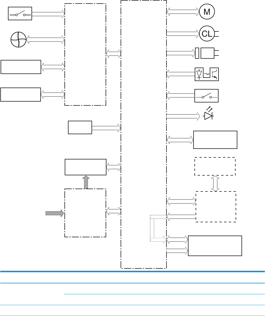
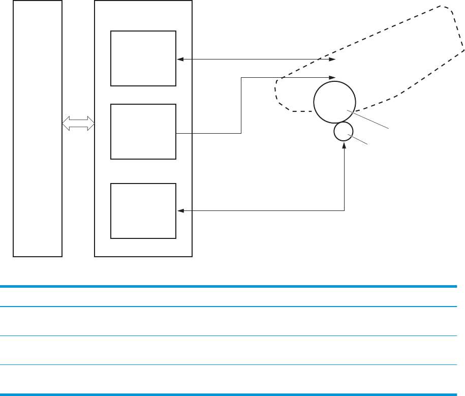
DC controller
The DC controller controls the operation of the printer and its components. The DC controller starts the
printer operation when the printer power is turned on and the power supply sends DC voltage to the DC
controller. After the printer enters the standby period, the DC controller sends out various signals to operate
motors, solenoids, and other printer components based on the print command and image data that the host
computer sends.
Figure 1-3 DC controller block diagram
Transfer roller
High-voltage
power supply
Fan
Cartridge
LED
Motor
Clutch
Solenoid
Switch
Photointerrupter
Formatter
Control panel
Accessory
Laser scanner ass’y
Fuser
AC input Low-voltage
power supply
DC controller
Switch
Sensor
Component type Abbreviation Description
Motor M1 Fuse motor
M3 Scanner motor
Fan Fm1 Main fan
6 Chapter 1 Theory of operation ENWW

Component type Abbreviation Description
Solenoid SL1 Cassette pickup solenoid
SL2 MP tray pickup solenoid
SL3 Duplex switchback solenoid
Clutch CL1 Duplex re-pickup clutch
Switch SW1 Power switch
SW101 Cartridge door switch
Photointerrupter PS1a Media width sensor
PS2b Duplex feed sensor
PS1 Cassette media out sensor
PS2 Top sensor
PS3 MP tray media out sensor
PS4 Output bin media-full sensor
PS13 Fuser output sensor
Sensor TH1 Environment sensor
LED LED1 Power supply LED
1Duplex models only.
ENWW Engine-control system 7

Motor control
The printer has two motors. The motors drive the components in the paper-feed and image-formation
systems.
The DC controller monitors the fuser motor and the scanner motor to determine if a motor has failed. It
noties the formatter when it encounters the following conditions:
●Startup failure: the motor does not reach a specied speed within a specied time from when the motor
starts.
●Rotational failure: the rotational speed of the motor is not in the specied range for a specied time
after the motor reaches a specied speed.
Table 1-2 Motors
Abbreviation Name Purpose Failure detection
M1 Fuser motor Drives the pressure roller and delivery roller;
the pressurization and release of the pressure
roller; and the engagement and
disengagement of the primary and secondary
transfer rollers
Yes
M3 Scanner motor Drives the scanner mirror Yes
Fan control
The printer has one fan for preventing the temperature from rising in the printer and for cooling the printed
pages.
The DC controller determines if there is a fan failure and noties the formatter if the fan locks for a specied
time from when the fan starts.
Table 1-3 Fans
Abbreviation Name Cooling area Type Speed
FM1 Main fan Inside of printer Intake Full
8 Chapter 1 Theory of operation ENWW
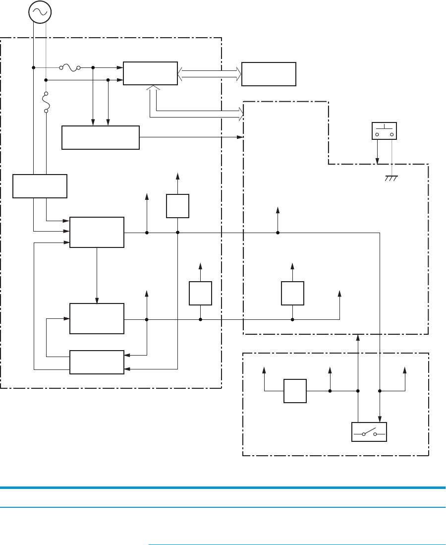
Low-voltage power supply
The low-voltage power-supply (LVPS) circuit converts the AC power from the wall receptacle into the DC
voltage that the printer components use.
Figure 1-4 Low-voltage power-supply circuit
AC input
+24VA
FET
FET
+24VB
+24VC
+24VD
+24VBSNS
+24VA
FET
PWRSW
+3.3VA
FET
+3.3VC +3.3VB
+3.3VA
+24VA
Low-voltage power supply
Rectifying
circuit
Protection
circuit
+24V
generation
circuit
Fuse
FU101
Fuse
FU102
+3.3V
generation
circuit
Fuser
Power switch
SW1
DC controller
High-voltage power supply
Interlock switch
SW101
Fuser control
circuit
FREQSNS_LVT
Frequency
detection circuit
Table 1-4 List of DC voltages
DC power supply Description
+24V +24VA Constantly supplied
Becomes 4.5V during active OFF or inactive OFF
ENWW Engine-control system 9

Table 1-4 List of DC voltages (continued)
DC power supply Description
+24VB Stopped when cartridge door is opened. (SW101)
Stopped during active OFF or inactive OFF
+24VC Stopped when cartridge door is opened. (SW101)
Stopped during active OFF or inactive OFF
+24VD Constantly supplied
Stopped during active OFF or inactive OFF
+3.3V +3.3VA Constantly supplied
+3.3VB Constantly supplied
Stopped during active OFF or inactive OFF
+3.3VC Constantly supplied
Stopped during inactive OFF
Over-current/over-voltage protection
The low-voltage power supply has a protective function against overcurrent and overvoltage conditions to
prevent failures in the power supply circuit. If an overcurrent or overvoltage event occurs, the system
automatically cuts o the output voltage.
If the DC power is not being supplied from the low-voltage power supply, the protective function might have
activated. In this case, turn o the power switch, and then unplug the power cord. Do not plug in the power
cord or turn the power switch on again until the root cause is found.
In addition, two fuses in the low-voltage power supply protect against an overcurrent event. If an overcurrent
event occurs in the AC line, the fuse blows and cuts o the power distribution.
Safety
For personal safety, the printer interrupts +24VB and +24VC power when the cartridge door detection switch
is turned o. This stops DC power supply to the high-voltage power supply (HVPS).
The remote switch control circuit turns on or o the printer power so that the AC power ows even the power
switch is turned o. Unplug the printer power cord before disassembling the printer.
Low-voltage power supply functions
The printer has the following low-voltage power supply functions.
Table 1-5 Low-voltage power supply functions
Failure detective function Applied
Sleep mode NA
Power supply voltage detection NA
Automatic power OFF NA
Automatic power ON/OFF NA
10 Chapter 1 Theory of operation ENWW

Table 1-5 Low-voltage power supply functions (continued)
Failure detective function Applied
Active OFF Yes
Inactive OFF Yes
Network mode NA
Power switch illumination Yes
Low-voltage power supply failure detection Yes
Power save mode NA
High-voltage power supply
The DC controller controls the high-voltage power supply (HVPS) to generate biases. The high-voltage power
supply delivers the high-voltage biases to the following components used to transfer toner during the image-
formation process:
●Primary charging roller (in the toner cartridge)
●Developing roller (in the toner cartridge)
●Transfer roller
●Pressure roller
ENWW Engine-control system 11
High-voltage power supply circuits
The high-voltage power supply contains the following separate circuits.
Figure 1-5 High-voltage power supply circuits
PRI
DEV
TR
DC controller High-voltage power supply
To primary charge roller
To developing roller
Cartridge
Photosensitive drum
Transfer roller
Primary
charging bias
circuit
Developing
bias circuit
Transfer bias
circuit
Table 1-6 High-voltage power supply circuits
Circuit Description
Primary-charging-bias generation The primary charging bias negatively charges the surface of the photosensitive drum to
prepare for image formation.
Developing-bias generation The developing bias adheres toner to an electrostatic latent image formed on the
photosensitive drums.
Transfer-bias generation The primary transfer bias transfers the toner from each photosensitive drum onto the
page.
Fuser bias
The printer uses on-demand fusing. The fuser bias is DC positive for improved print quality. The fuser bias
circuit is located in the high-voltage power supply, HVPS (T).
Fuser control
The DC controller and components in the fuser perform the following functions related to fuser operation:
●Control fuser temperature
●Detect fuser failures
●Prevent excessive temperature rise
12 Chapter 1 Theory of operation ENWW
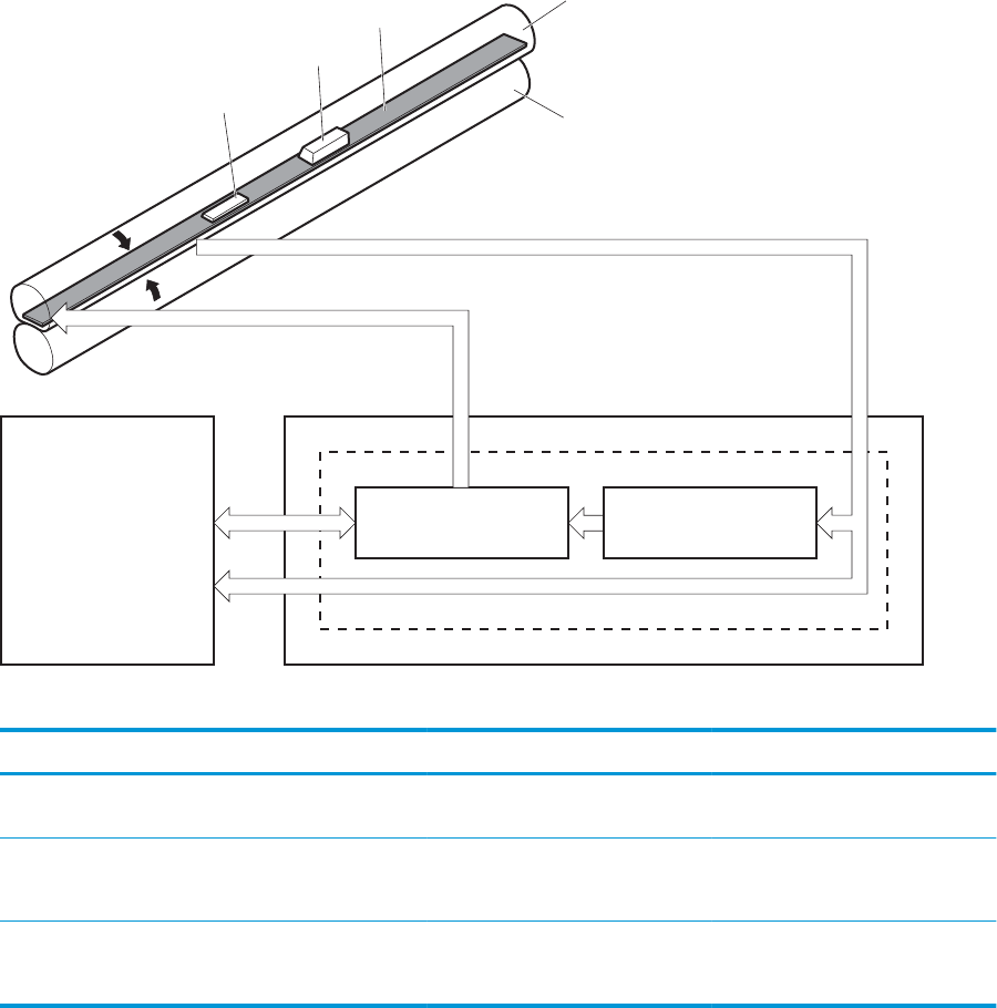
●Detect remaining life in the fuser
●Determine if the correct fuser is installed
Fuser circuits
The fuser heater control circuit and the fuser heater safety circuit control the fuser temperature according to
commands from the DC controller. The fuser consists of the following major components:
Figure 1-6 Fuser components
FUSER TEMPERATURE signal
FUSER HEATER CONTROL signal
DC controller
Low-voltage power supply
Fuser control circuit
TH1
TP1
H1
Pressure roller
Fuser film
Fuser heater
control circuit
Fuser heater
safety circuit
Table 1-7 Fuser components
Type of component Abbreviation Name Function
Heaters H1 Fuser main heater Heats the center of the fuser lm
assembly
Thermistors
(Contact type)
TH1 Main thermistor Detects the center temperature of
the fuser heater
Thermoswitch
(Contact type)
TP1 Thermoswitch Prevents an abnormal temperature
rise in the fuser heater
ENWW Engine-control system 13
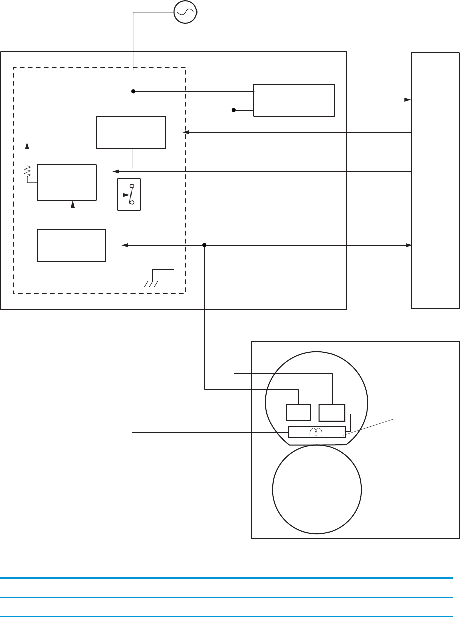
Fuser control functions
Figure 1-7 Fuser control
Fuser heater
safety circuit
FREQSNS
TP1 Fuser heater (H1)
Fuser film ass’y
TP1: Thermal switch
TH1: Thermistor
Fuser
Pressure roller
FSRD
RLYD
FSRTH
+24V
Low-voltage suppry supply
Fuser control
RL101
DC controlle
r
Fuser heater
control circuit
Relay control
circuit
Current detection
circuit
TH1
The printer has the following fuser control functions.
Table 1-8 Fuser control functions
Failure detection function Supported feature
Fuser temperature control Yes
14 Chapter 1 Theory of operation ENWW

Table 1-8 Fuser control functions (continued)
Failure detection function Supported feature
Fuser failure detection Yes
Frequency detection circuit failure detection Yes
Fuser pressure release mechanism failure detection No
Fuser type discrepancy detection No
Fuser type identication detection Yes
Fuser presence detection No
Fuser life detection No
Relay failure detection No
Pressure roller cleaning Yes
Fuser heater protection
Fuser heater protection is a feature that detects excessive temperatures in the fuser and interrupts the power
supply to the fuser heater.
The following three protective components prevent the fuser heater from excessive rising temperature:
●DC controller: When a thermistor or sub-thermistor detects a temperature above a certain threshold,
the DC controller interrupts power to the specic heater.
●Fuser-heater safety circuit: The fuser heater safety circuit monitors the detected temperature of the
sub thermistors.
●Thermoswitch: If the temperature in the heaters is abnormally high, and the temperature in the
thermoswitch exceeds a specied value, the contact to the thermoswitch breaks.
ENWW Engine-control system 15
Engine laser/scanner system
The laser/scanner system forms the latent electrostatic image on the photosensitive drums inside each of the
toner cartridges.
The DC controller receives instructions from the formatter regarding the image of the page to be printed. The
DC controller signals the lasers to emit light, and the laser beams pass through lenses and onto the scanner
mirror, which rotates at a constant speed. The mirror reects the beam onto the photosensitive drum in the
pattern required for the image, exposing the surface of the drum so it can receive toner.
The main components of the laser/scanner system, which are controlled by signals sent from the DC
controller, are:
●Laser assembly
●Scanner motor assembly
●Beam detect (BD) sensor
●Scanner mirror
Figure 1-8 Laser/scanner system
Laser ass’y
BD sensor
Scanner mirror
Scanner motor ass’y
Photosensitive drum
DC controller
16 Chapter 1 Theory of operation ENWW

Laser/scanner failure detection
The DC controller determines an optical unit failure and noties the formatter of the error status for the
following supported conditions:
Failure detection function Supported feature
Beam detect (BD) failure detection: A specied BD interval is not detected within a
specied period during the scanner motor drive.
Yes
Laser/scanner motor startup failure: The scanner motor does not reach a specied
rotation frequency within a specied period of time from when the laser/scanner starts up.
Yes
Laser/scanner motor abnormal rotation: The laser/scanner motor does not reach a
specied rotational frequency within a specied period of time during a print operation.
Yes
Laser scanner failure detection A specied laser intensity is not detected. No
Safety
The laser/scanner assembly has a mechanical laser shutter. For the safety of users and service technicians,
the laser shutter interrupts the optical path of the laser/scanner assembly when the top door is opened
(SW101).
ENWW Engine laser/scanner system 17
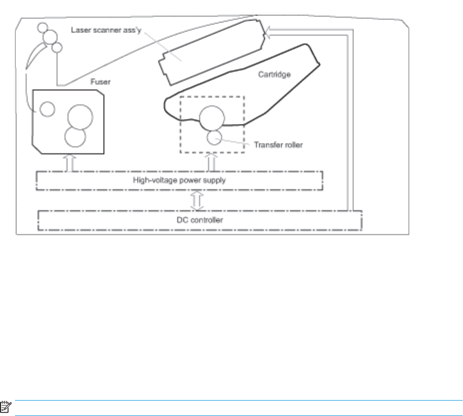
Image-formation process
The image-formation system creates the printed image on the paper. The system consists of the following
components:
●Toner cartridge
●Transfer roller
●Fuser
●Laser/scanner
●High-voltage power supply
The DC Controller controls the internal components of the image formation system (according to commands
received from the formatter) to form the toner image on the photosensitive drum surface. The toner image is
then transferred to the print media and fused.
Figure 1-9 Image-formation system
The fuser motor (M1) drives the following image formation components:
●Photosensitive drum
●Developing roller
●Primary charging roller (follows the photosensitive drum)
●Transfer roller (follows the photosensitive drum)
●Pressure roller
●Fuser lm (follows the pressure roller)
NOTE: The primary charging roller and developer roller are located in the toner cartridge.
18 Chapter 1 Theory of operation ENWW
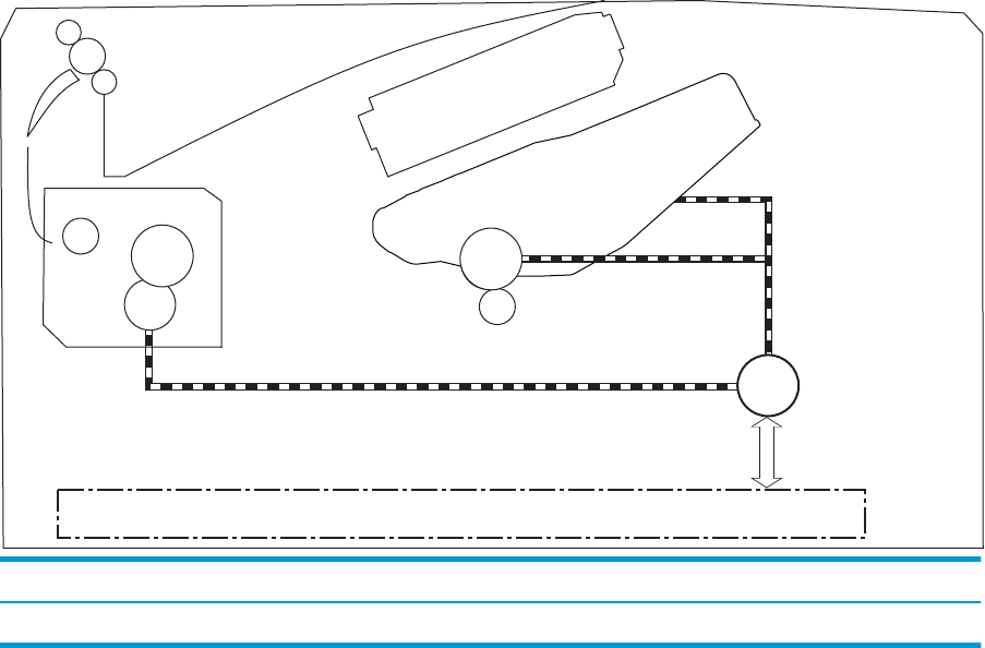
Figure 1-10 Fuser motor (M1) and image formation components
DC controller
M1
Abbreviation Component
M1 Fuser motor
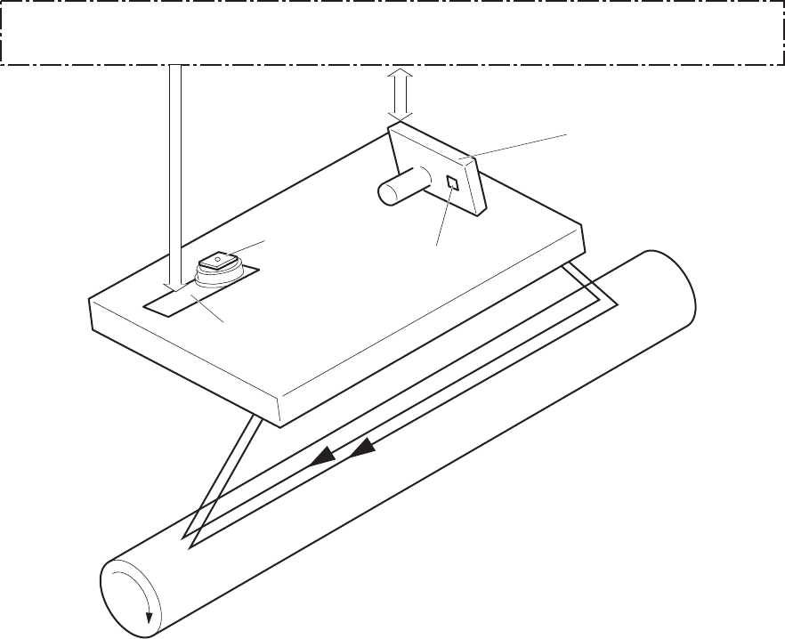
The following gure shows the toner-level sensor for the image-formation system.
ENWW Engine laser/scanner system 19
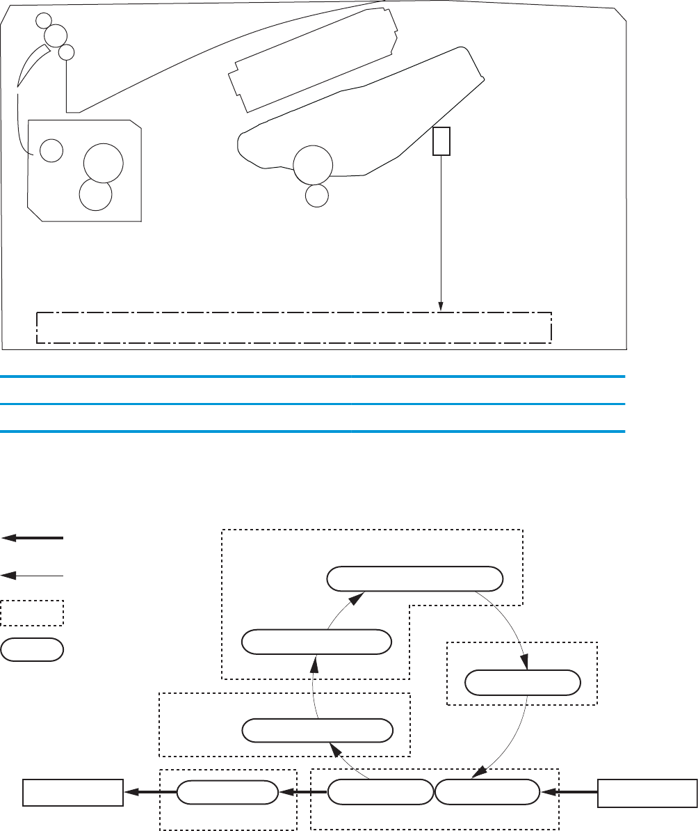
Figure 1-11 Toner-level sensor
DC controller
Toner level
sensor
Table 1-9 Sensors
Abbreviation Component Replacement part number
Toner-level sensor
The image-formation process consists of ten steps divided into ve functional blocks.
Figure 1-12 Image-formation process
: Paper path
: Direction of drum rotation
: Functional block
: Step
Pickup
Delivery
Fusing Transfer
Drum cleaning
Developing
Latent image formation
6. Fusing 5. Separation
7. Drum cleaning
1. Primary charging
2. Laser beam exposure
4. Transfer
3. Developing
20 Chapter 1 Theory of operation ENWW
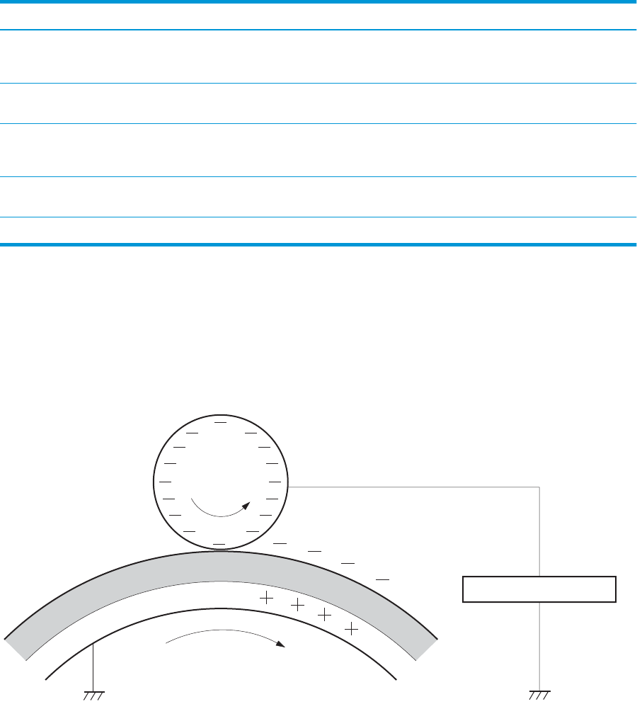
Table 1-10 Image formation process
Functional block Steps Description
Latent image formation 1. Primary charging
2. Laser-beam exposure
An invisible latent image forms on the surface of the
photosensitive drums.
Development 3. Development Toner adheres to the electrostatic latent image on the
photosensitive drum.
Transfer 4. Transfer
5. Separation
The toner image transfers to the paper.
Fusing 6. Fusing The toner fuses to the paper to make a permanent
image.
Drum cleaning 7. Drum cleaning Residual toner is removed from the drum.
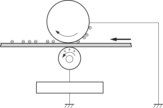
Step 1: Primary charging
To prepare for latent image formation, the surface of the photosensitive drum is charged with a uniform
negative charge. The primary charging roller receives the primary charging bias, and then the roller charges
the drum directly.
Figure 1-13 Primary charging
Photosensitive drum
Primary charging roller
Primary charging bias
ENWW Engine laser/scanner system 21
Step 2: Laser-beam exposure
The laser beam scans the photosensitive drum to neutralize the negative charge on portions of the drum
surface. An electrostatic latent image forms where the negative charge was neutralized.
Figure 1-14 Laser-beam exposure
Photosensitive drum
Laser beam
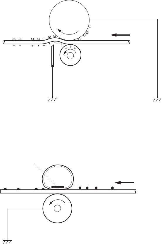
Step 3: Development
Toner acquires a negative charge as a result of the friction from the developing roller rotating against the
developing blade. When the negatively charged toner comes in contact with the drum, it adheres to the
electrostatic latent image. When the toner is on the drum, the image becomes visible. The developing bias is
applied to the developing roller.
Figure 1-15 Development
Developer roller
Developing bias
Photosensitive drum
Developer blade
22 Chapter 1 Theory of operation ENWW
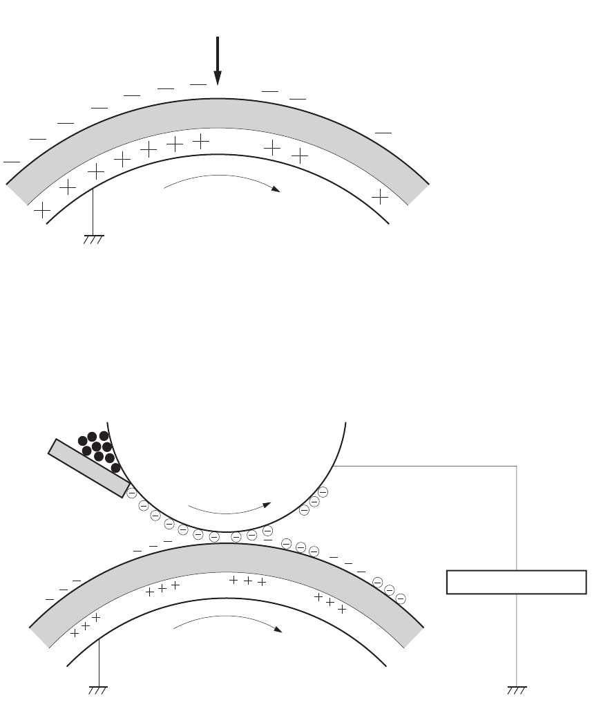
Step 4: Transfer
The transfer bias is applied to the transfer roller to give the paper a positive charge. The positively charged
paper attracts the negatively charged toner from the photosensitive drum surface.
Figure 1-16 Primary transfer
Transfer roller
Paper
Transfer bias
Photosensitive
drum
ENWW Engine laser/scanner system 23
Step 5: Separation
The elasticity of the paper and the curvature of the photosensitive drum cause the paper to separate from the
drum surface. The static charge eliminator reduces back side static discharge of the paper for stable paper
feeding and image quality.
Figure 1-17 Separation
Paper
Transfer roller
Static charge eliminator
Photosensitive
drum
Step 6: Fusing
The product uses an on-demand fusing method to fuse the toner image onto the media. The toner image is
permanently aixed to the print media by the heat and pressure. The fusing bias is applied to the pressure
roller to improve image quality.
Figure 1-18 Fusing
Paper
Fuser film
Fuser heater
Pressure roller
Step 7: Drum cleaning
The cleaning blade scrapes the residual toner o the surface of the photosensitive drum and deposits it in the
toner collection box. The drum is now clear and ready for the next image-formation process.
24 Chapter 1 Theory of operation ENWW

Figure 1-19 Drum cleaning
Cleaning blade
Residual toner collection box
Photosensitive
drum
Toner cartridges
The printer has one toner cartridge.
Design
The toner cartridge is lled with toner and consists of the following components:
●Photosensitive drum
●Developer
●Primary-charging roller
●Memory chip
The DC controller rotates the drum motor to drive the photosensitive drum, developing roller, and the
primary-charging roller.
ENWW Engine laser/scanner system 25
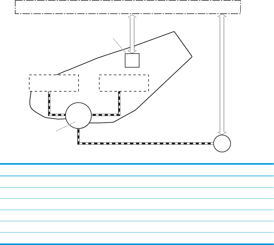
Figure 1-20 Toner cartridge system
DC controller
Cartridge
E-label
Photosensitive drum
Developer roller
M1
Primary charging
roller
Table 1-11 Toner cartridge functions
Function Supported feature
Toner cartridge presence detection Yes
Toner level detection Yes
Toner cartridge life detection Yes
Toner cartridge mis-installation detection No
Drum discharge No
Transfer cleaning Yes
26 Chapter 1 Theory of operation ENWW
Memory chip
The memory chip is non-volatile memory that stores information about the usage of the toner cartridge and
helps protect the customer from counterfeit cartridges. The chip is also used to detect the presence of a
cartridge within the printer or when a cartridge is installed in the wrong slot. The printer reads and writes the
data in the memory chip.
Toner level and cartridge life detection
Toner level detection: The DC controller detects the remaining toner in a cartridge by the optical detection
method and then noties the formatter of the remaining toner level.
Cartridge life detection: The DC controller detects the cartridge life by monitoring the total operating time or
remaining toner level of the toner cartridge. The DC controller determines a cartridge end of life and noties
the formatter when total operating time of the cartridge reaches a specied time or the cartridge runs out of
toner.
Pickup, feed, and delivery system
The DC controller controls the pickup, feed, and delivery system according to commands from the formatter.
The pickup, feed, and delivery system uses a series of rollers to move the paper through the printer.
The pickup, feed, and delivery system consists of the following three functional blocks. The DC controller
controls each block to pick up, feed and deliver the paper.
●Pickup-and-feed-block: Controls the movement of the paper from each pickup source to the fuser inlet
●Fuser-and-delivery-block: Controls the movement of the paper from the fuser to the delivery
destination
●Duplex block: Controls the movement of the paper from the duplex switchback unit to the duplex re-
pickup unit (duplex models only)
ENWW Pickup, feed, and delivery system 27
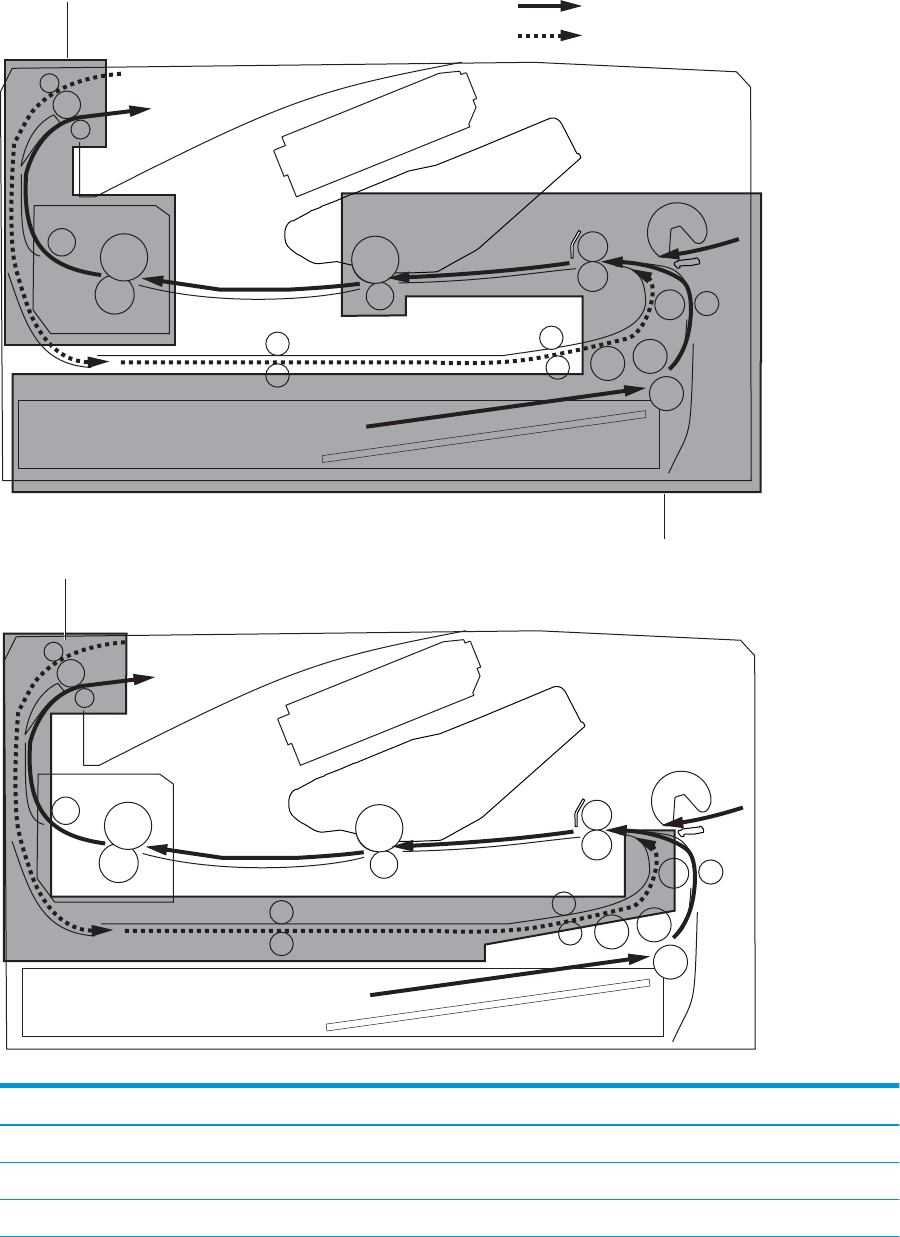
Figure 1-21 Pickup, feed, and delivery system
Duplex paper path
Simplex paper path
Duplex block Pickup-and-feed block
Fuser-and-delivery block
Table 1-12 Pickup, feed, and delivery system functions
Function Supported feature
Cassette media size detection No
Cassette media presence detection Yes
Cassette media level detection No
28 Chapter 1 Theory of operation ENWW
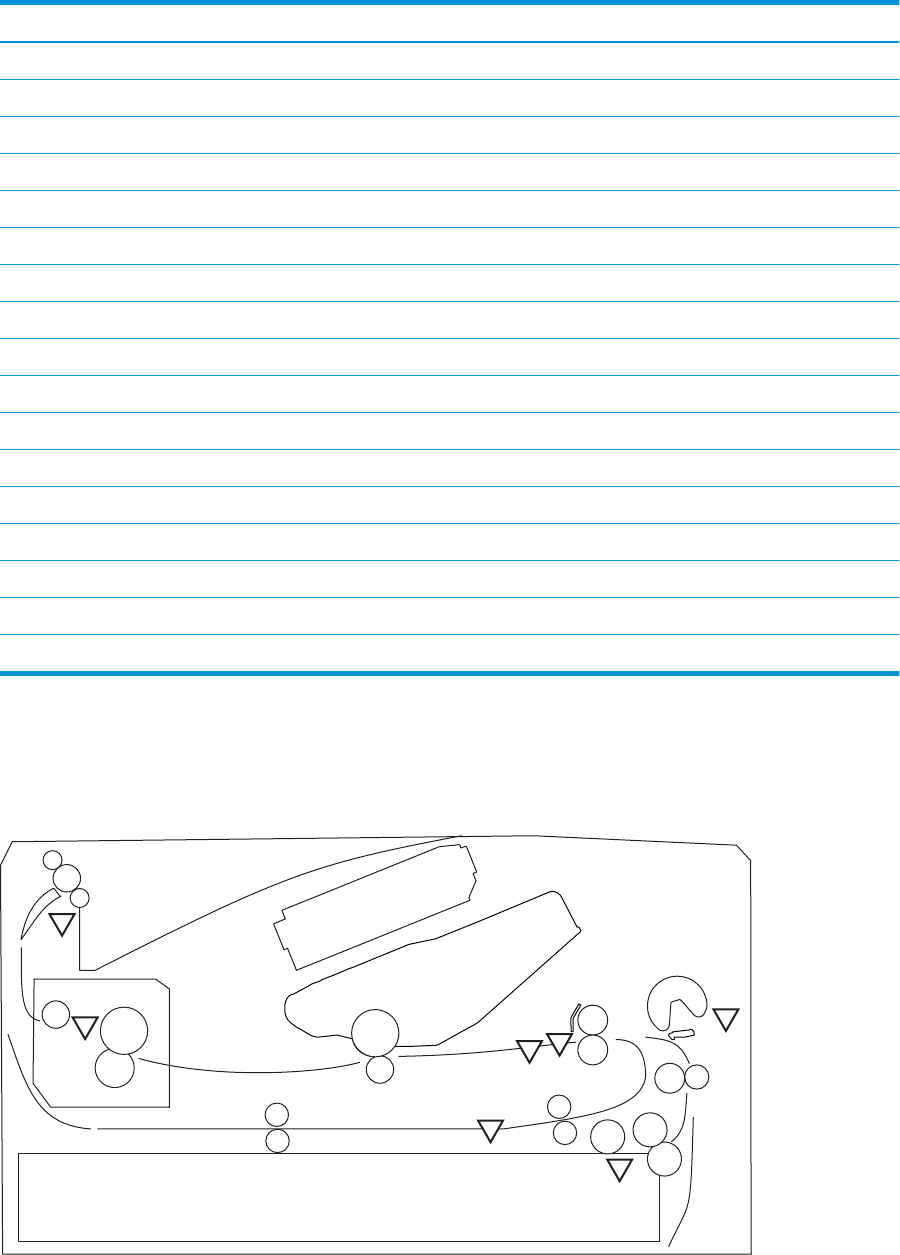
Table 1-12 Pickup, feed, and delivery system functions (continued)
Function Supported feature
Cassette lift-down control No
Cassette multiple-feed prevention mechanism Yes
Multipurpose tray media presence detection Yes
Multipurpose tray media width detection No
Multipurpose tray last-media detection No
Skew-feed prevention mechanism Yes
Loop control No
Media detection No
OHT detection No
Image leading edge positioning Yes
Media length detection Yes
Media width detection Yes
Pressure roller pressure release control No
Output bin media-full detection Yes
Automatic delivery Yes
Duplex switchback control (duplex models only) Yes
Duplex feed control (duplex models only) Yes
Sensors and switches
The following gure shows the sensors and switches for the pickup, feed, and delivery system.
Figure 1-22 Sensors and switches for the pickup, feed, and delivery system
PS1a
PS2a
PS4
PS13
PS2
PS3
PS1
ENWW Pickup, feed, and delivery system 29

Table 1-13 Photo sensors and switches
Abbreviation Component
SR1a Media width sensor
SR2b Duplex feed sensor (duplex models only)
SR1 Cassette media out sensor
SR2 TOP sensor
SR3 Multipurpose tray media out sensor
SR4 Output bin media-full sensor
SR13 Fuser output sensor
30 Chapter 1 Theory of operation ENWW
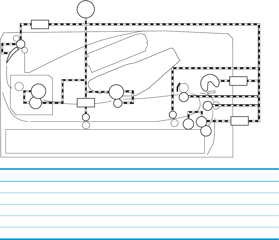
Motors, clutches, and solenoids
The following gure shows the motors, clutches, and solenoids for the pickup, feed, and delivery system.
Figure 1-23 Motors, solenoids, and clutches
CL1
SL3
M1
SL2
SL1
Table 1-14 Motors, solenoids, and clutches
Abbreviation Component
M1 Fuser motor
SL1 Cassette pickup solenoid
SL2 Multipurpose tray pickup solenoid
SL3 Duplex switchback solenoid (duplex models only)
CL1 Duplex re-pickup clutch (duplex models only)
Jam detection/prevention
The printer uses the following sensors to detect the paper as it moves through the paper path and to report
to the DC controller if the paper has jammed.
●Top of page (TOP) sensor (SR2)
●Media width sensor (SR1a)
●Fuser output sensor (SR13)
●Duplex feed sensor (SR2a)
ENWW Pickup, feed, and delivery system 31
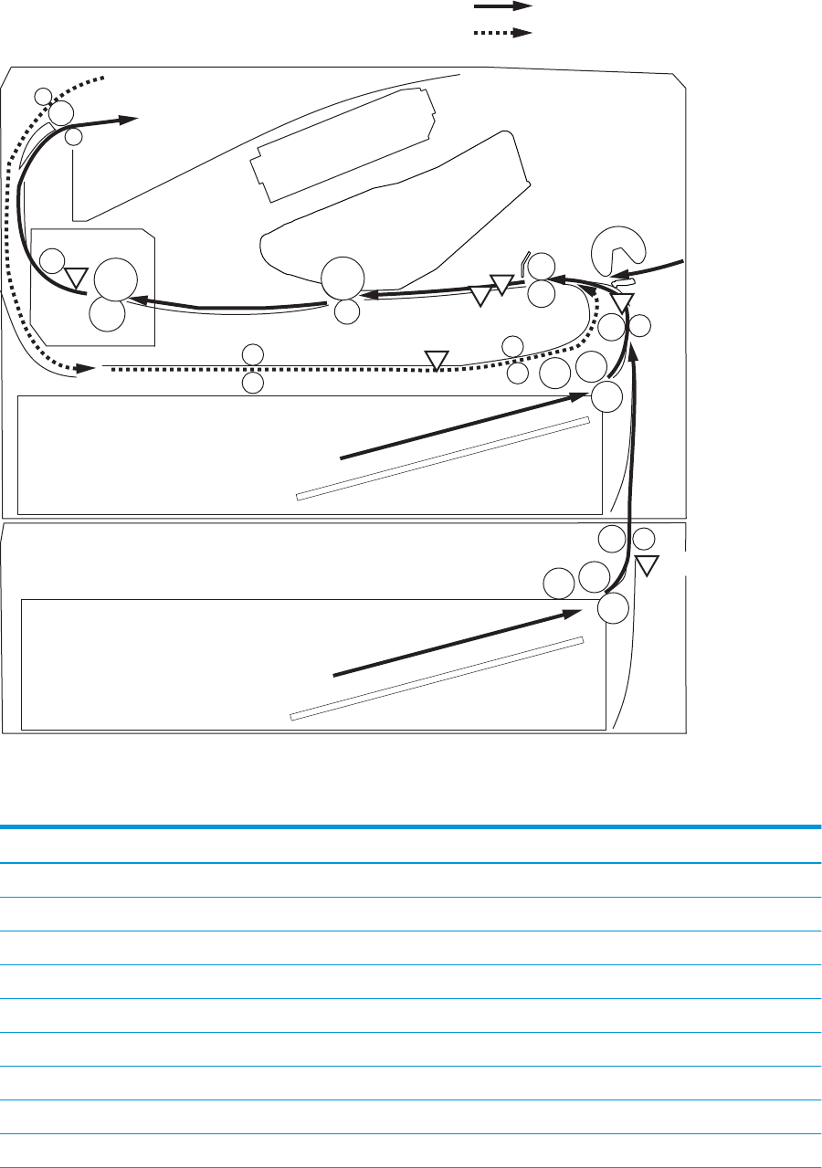
Figure 1-24 Jam detection sensors
PS432
PS13
PS2a
PS2
PS1a
PS11
Duplex paper path
Simplex paper path
The printer determines that a jam has occurred if one of these sensors detects paper at an inappropriate
time. The DC controller stops the print operation and noties the formatter.
Table 1-15 Jams that the printer detects
Jam Supported feature
No pick jam 1 Yes
No pick jam 2 Yes
No pick jam 3 Yes
No pick jam 4 No
Pickup stay jam 1 Yes
Pickup stay jam 2 No
Pickup stay jam 3 No
Pickup stay jam 4 No
Fuser delivery delay jam 1 Yes
32 Chapter 1 Theory of operation ENWW

Table 1-15 Jams that the printer detects (continued)
Jam Supported feature
Fuser delivery delay jam 2 No
Fuser delivery delay jam 3 No
Fuser delivery delay jam 4 No
Fuser delivery stay jam 1 Yes
Fuser delivery stay jam 2 No
Fuser delivery stay jam 3 No
Fuser delivery stay jam 4 No
Residual paper jam 1 Yes
Residual paper jam 2 Yes
Residual paper jam 3 No
Residual paper jam 4 No
Door open jam 1 Yes
Door open jam 2 No
Door open jam 3 No
Door open jam 4 No
Fuser wrap jam1 Yes
Fuser wrap jam2 Yes
Fuser wrap jam3 No
Fuser wrap jam4 No
Duplex switchback jam1 No
Duplex switchback jam2 No
Duplex switchback jam3 No
Duplex switchback jam4 No
Duplex re-pickup jam 1 Yes
Duplex re-pickup jam 2 No
Duplex re-pickup jam 3 No
Duplex re-pickup jam 4 No
Delivery delay jam 1 No
Delivery delay jam 2 No
Delivery delay jam 3 No
Delivery delay jam 4 No
Delivery stay jam 1 No
Delivery stay jam 2 No
ENWW Pickup, feed, and delivery system 33

Table 1-15 Jams that the printer detects (continued)
Jam Supported feature
Delivery stay jam 3 No
Delivery stay jam 4 No
Multiple feed jam 1 No
Multiple feed jam 2 No
Multiple feed jam 3 No
Multiple feed jam 4 No
34 Chapter 1 Theory of operation ENWW
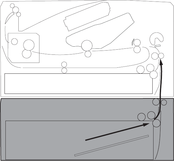
Paper feeder (optional Tray 3)
This section describes the paper feeder (optional Tray 3).
Basic operation
The paper feeder is optionally installed at bottom of the printer. It picks up the print media and feeds it to the
printer. The paper DC controller controls the operational sequence of the paper feeder.
Paper path
The gure below shows the optional Tray 3 paper path.
Figure 1-25 Optional Tray 3 paper path
Paper feeder controller
The gure below shows the paper feeder controller block diagram. The table in this section describes the
paper feeder electrical components.
ENWW Paper feeder (optional Tray 3) 35
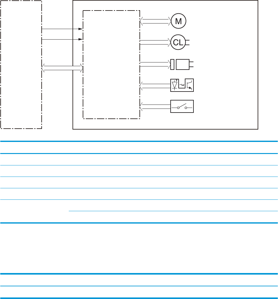
Figure 1-26 Paper feeder controller
DC controller Paper feeder controller
Motor
550-sheet paper feeder
+24VD
+3.3VB
Solenoid
Clutch
Switch
Photointerruptor
Table 1-16 Electrical component list, paper feeder
Component type Abbreviation Component name
Motor M5 Lifter motor
Solenoid SL4 Cassette pickup solenoid
Clutch CL2 Feed clutch (Note)
Switch SW3 Cassette detection switch
Photointerrupter PS460 Media surface sensor
PS461 Cassette media out sensor
Motor control
The paper feeder uses one motor for the cassette lift-up operation.
Table 1-17 Motors, paper feeder
Component name Components driven
M5 Lifter motor1Lifts up the cassette
1The paper feeder does not detect lifter motor failures.
Pickup and feed operation
The paper feeder picks up the sheet of paper one by one in the paper feeder cassette and feeds it to the
printer.
Electrical components, pickup and feed
The gure below shows the paper feeder electrical components. The table in this section describes the
electrical components.
36 Chapter 1 Theory of operation ENWW
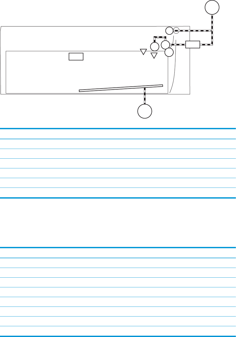
Figure 1-27 Electrical components, pickup and feed
SL4
M1
M5
SW3
PS461
PS460
Table 1-18 Electrical components, pickup and feed
Abbreviation Component name
M1 Fuser motor1
M5 Lifter motor
SL4 Cassette pickup solenoid
SW3 Cassette detection switch
PS460 Media surface sensor
PS461 Cassette media out sensor
1This motor is located in the printer.
Other functions
The paper feeder has the following pickup and feed functions.
Table 1-19 Other functions, paper feeder
Function Supported feature
Cassette lift-up control Yes
Cassette presence detection Yes
Cassette media size detection No
Cassette media stack surface detection Yes
Cassette media out detection Yes
Cassette media level detection No
Multiple-feed prevention Yes
Automatic delivery Yes
ENWW Paper feeder (optional Tray 3) 37


2 Solve problems
●For additional service and support
●Solve problems checklist
●Troubleshooting process
●Tools for troubleshooting
●Clear paper jams
●Solve paper-handling problems
●Solve image quality problems
●Clean the printer
●Solve performance problems
●Solve connectivity problems
●Service mode functions
●Solve fax problems (fax models only)
●Solve email problems (M426, M427 printes)
●Manually update the rmware
ENWW 39

For additional service and support
HP service personnel, go to the Service Access Work Bench (SAW) at http://h41302.www4.hp.com/km/saw/
home.do.
Channel partners, go to HP Channel Services Network (CSN) at https://h30125.www3.hp.com/hpcsn.
At these locations, nd information on the following topics:
●Install and congure
●Printer specications
●Up-to-date control panel message (CPMD) troubleshooting
●Solutions for printer issues and emerging issues
●Remove and replace part instructions and videos
●Service advisories
●Warranty and regulatory information
To access HP PartSurfer information from any mobile device, go to http://partsurfermobile.hp.com/ or scan
the Quick Response (QR) code below.
40 Chapter 2 Solve problems ENWW

Solve problems checklist
●Solve problems checklist
Solve problems checklist
If the printer is not correctly functioning, complete the steps (in the order given) in the following checklist. If
the printer fails a checklist step, follow the corresponding troubleshooting suggestions for that step. If a
checklist step resolves the problem, skip the remaining checklist items.
1. Make sure that the printer is set up correctly.
a. Press the power button to turn on the printer or to deactivate the Auto-O mode.
b. Check the power-cable connections.
c. Make sure that the line voltage is correct for the printer power conguration. See the label that is
on the printer for voltage requirements. If you are using a power strip and its voltage is not within
specications, plug the printer directly into the wall. If it is already plugged into the wall, try a
dierent outlet.
2. Check the cable connections.
a. Check the cable connection between the printer and the computer. Make sure that the connection
is secure.
b. Make sure that the cable itself is not faulty, by using a dierent cable if possible.
c. Check the network connection: Make sure that the network light is lit. The network light is next to
the network port on the back of the printer.
If the printer remains unable to connect to the network, uninstall and then reinstall the printer. If
the error persists, contact a network administrator.
3. Check to see if any messages appear on the control panel.
4. Make sure that the paper you are using meets specications.
5. Make sure that the paper is loaded correctly in the input tray.
6. Make sure that the printer software is installed correctly.
7. Verify that you have installed the printer driver for this printer, and that you are selecting this printer
from the list of available printers.
8. Print a conguration page.
a. 2-line control panels: On the printer control panel, press the OK button.
Touchscreen control panels: From the Home screen on the printer control panel, touch the Setup
button.
b. Open the Reports menu.
c. Select Conguration Report.
ENWW Solve problems checklist 41

After printing the conguration page, check the following:
a. If the page does not print, verify that the input tray contains paper and that the paper is properly
loaded.
b. Make sure that the toner cartridge is installed correctly.
c. If the page jams in the printer, clear the jam.
d. If the print quality is unacceptable, complete the following steps:
●Verify that the print settings are correct for the paper you are using.
●Solve print-quality problems.
9. Print a small document from a dierent program that has printed in the past. If this solution works, then
the problem is with the program you are using. If this solution does not work (the document does not
print), complete these steps:
a. Try printing the job from another computer that has the printer software installed.
b. Check the cable connection. Direct the printer to the correct port, or reinstall the software,
selecting the connection type you are using.
Print the menu map
To more easily navigate individual settings, print a report of the complete printer menus.
1. 2-line control panels: On the printer control panel, press the OK button.
Touchscreen control panels: From the Home screen on the printer control panel, touch the Setup
button.
2. Open the Reports menu.
3. Select Menu Structure.
Print a conguration page
Print a conguration page to test the printer.
1. 2-line control panels: On the printer control panel, press the OK button.
Touchscreen control panels: From the Home screen on the printer control panel, touch the Setup
button.
2. Open the Reports menu.
3. Select Conguration Report.
42 Chapter 2 Solve problems ENWW

Print the service page (includes the event log)
Printing the service page provides a list of printer settings that might be helpful in the troubleshooting
process, as well as the event log, which stores the last 10 error events that the printer experienced.
1. 2-line control panels: On the printer control panel, press the OK button.
Touchscreen control panels: From the Home screen on the printer control panel, touch the Setup
button.
2. Open the Reports menu.
3. Select the Service Page option to print the report.
The event log is located in the lower right-hand corner of the service page.
Print the demo page
Print a product demo page.
2-line control panels
▲With the printer in the Ready state, press the OK button and the Cancel button at the same time.
Touchscreen control panels
1. From the Home screen on the printer control panel, touch the Setup button.
2. Open the Reports menu.
3. Select Demo Page.
ENWW Solve problems checklist 43

Troubleshooting process
●Determine the problem source
●Power subsystem
●Control panel checks
Determine the problem source
When the printer malfunctions or encounters an unexpected situation, the printer control panel alerts the
user to the situation. This section contains a pre-troubleshooting checklist to lter out many possible causes
of the problem. Use the troubleshooting owchart to help diagnose the root cause of the problem. The
remainder of this chapter provides steps for correcting problems.
●Use the troubleshooting owchart to pinpoint the root cause of hardware malfunctions. The owchart
provides guides to the sections of this chapter that contain steps to correct the malfunction.
Before beginning any troubleshooting procedure, check the following issues:
●Are supply items within their rated life?
●Does the conguration page reveal any conguration errors?
NOTE: The customer is responsible for checking supplies and for using supplies that are in good condition.
Pre-troubleshooting checklist
The following table includes basic questions to ask the customer to quickly help dene the problem(s).
General topic Questions
Environment ●Is the printer installed on a solid, level surface (+/- 1°)?
●Is the power-supply voltage within ± 10 volts of the specied power source?
●Is the power-supply plug inserted in the printer and the outlet?
●Is the operating environment within the specied parameters?
●Is the printer exposed to ammonia gas, such as that produced by diazo copiers or
oice cleaning materials?
NOTE: Diazo copiers produce ammonia gas as part of the copying processes.
Ammonia gas (from cleaning supplies or a diazo copier) can have an adverse eect
on some printer components (for example, the toner cartridge OPC).
●Is the printer exposed to direct sunlight?
Media ●Does the customer use only supported media?
●Is the media in good condition (no curls, folds, or distortion)?
●Is the media stored correctly and within environmental limits?
Input trays ●Is the amount of media in the tray within specications?
●Is the media correctly placed in the tray?
●Are the paper guides aligned with the stack?
●Is the tray correctly installed in the printer?
44 Chapter 2 Solve problems ENWW

General topic Questions
Toner cartridge ●Is the toner cartridge installed correctly?
Transfer unit and fuser ●Are the transfer unit and fuser installed correctly?
Covers ●Is the toner cartridge door closed?
Condensation ●Does condensation occur following a temperature change (particularly in winter
following cold storage)? If so, wipe aected parts dry or leave the printer on for 10
to 20 minutes.
●Was a toner cartridge opened soon after being moved from a cold to a warm room?
If so, allow the toner cartridge to sit at room temperature for 1 to 2 hours.
Miscellaneous ●Check for and remove any non-HP components (toner cartridges, memory
modules, and EIO cards) from the printer.
●If the hardware or software conguration has not changed or the problem is not
associated with any specic software, see the complete service manual for this
printer.
●Remove the printer from the network and ensure that the failure is associated with
the printer before beginning troubleshooting.
●For any print-quality issues, calibrate the printer.
ENWW Troubleshooting process 45

Determine the problem source
The following table includes basic questions to ask the customer to quickly help dene the problem or
problems.
General topic Questions
Environment ●Is the printer installed on a solid, level surface (± 1°)?
●Is the power-supply voltage within ± 10 volts of the specied power source?
●Is the power-supply plug inserted in the printer and the outlet?
●Is the operating environment within the specied parameters?
●Is the printer exposed to ammonia gas, such as that produced by diazo copiers or
oice cleaning materials?
NOTE: Diazo copiers produce ammonia gas as part of the coping processes.
Ammonia gas (from cleaning supplies or a diazo copier) can have an adverse aect
on some printer components (for example, the toner cartridge imaging drum).
●Is the printer exposed to direct sunlight?
Paper ●Does the customer use only supported paper?
●Is the paper in good condition (no curls, folds, or distortion)?
●Is the paper stored correctly and within environmental limits?
Input tray ●Is the amount of paper in the tray within specications?
●Is the paper correctly placed in the tray?
●Are the paper guides aligned with the stack?
Supplies ●Is the toner cartridge installed correctly and rmly seated?
●Has the sealing tape been removed from the toner cartridge?
●Is the toner cartridge within its estimated life? (Check the supplies status page.)
Transfer roller and fuser ●Are the transfer roller and fuser installed correctly?
Covers ●Are the front and rear doors rmly closed?
Condensation ●Does condensation occur following a temperature change (particularly in winter
following cold storage)? If so, wipe aected parts dry or leave the printer on for 90
to 120 minutes.
●Was a toner cartridge opened soon after being moved from a cold to a warm room?
If so, allow the toner cartridge to sit at room temperature for 1 to 2 hours.
Miscellaneous ●Check for and remove any non-HP components (for example, a toner cartridge)
from the printer.
●Remove the printer from the network and make sure that the failure is with the
printer before beginning troubleshooting.
46 Chapter 2 Solve problems ENWW

Power subsystem
Power-on checks
When you turn on the printer, if it does not make any sound or if the control-panel display is blank, check the
following items:
●Verify that the printer is plugged directly into an active electrical outlet that has the correct voltage. Do
not plug the printer into a surge protector or power strip.
●Verify that the on/o switch is in the on position.
●Verify that the formatter is seated and operating correctly.
●Remove any HP Jetdirect accessories or other devices, and then try to turn the printer on again.
●Make sure that the control-panel display is connected.
●Check the two fuses on the power supply.
●If necessary, replace the power supply.
●If necessary, replace the DC controller.
Control panel checks
The printer includes diagnostic tests for the control panel. This mode allows for troubleshooting issues with
the LEDs (2-line control panels), display, and the buttons.
1. Open the secondary service menu.
2-line control panels
a. From the printer control panel, press the OK button.
b. Press and hold the left arrow button.
c. Press the Cancel button.
d. Press the OK button to reopen the Setup menu.
e. Scroll to the 2ndary Service menu, and then press the OK button.
Touchscreen control panels
a. From the Home screen on the printer control panel, touch the Setup button.
b. Touch the space between the Home and Help buttons.
c. Touch the Back button.
d. Touch the Setup button.
e. Scroll to and touch the 2ndary Service menu.
2. Select one of the following tests:
ENWW Troubleshooting process 47
●LED test: Test the LED lights on 2-line control panels. The touchscreen control panels do not have
any LEDs.
●Display Test: Test the control panel display.
●Button Test: Test the control panel buttons.
48 Chapter 2 Solve problems ENWW

Tools for troubleshooting
The section describes the tools that can help solve problems with the printer.
Component diagnostics
LED diagnostics
Network LEDs (network models only)
The onboard network solution has two network port LEDs. When the printer is connected to a properly
working network through a network cable, the yellow LED indicates network activity, and the green LED
indicates the link status. A blinking yellow LED indicates network traic. If the green LED is o, a link has
failed.
For link failures, check all of the network cable connections. In addition, you can try to manually congure the
network card link speed setting by using the printer control-panel.
Change the Link Speed setting on an LCD control panel
1. At the printer control panel, press the OK button to open the menus.
2. Select the Network Setup menu, and then press the OK button.
3. Select the Link Speed item, and then press the OK button.
4. Select the appropriate link speed, and then press the OK button.
Change the Link Speed setting on a touchscreen control panel
1. From the Home screen on the printer control panel, touch the Setup button.
2. Scroll to, and then touch the Network Setup menu.
3. Scroll to, and then touch Link Speed item.
4. Touch the appropriate link speed.
Control panel LEDs
The state of the Ready light and Attention light on the printer signal the printer status. The following table
outlines the possible control-panel light states.
Printer state Ready light state Attention light state
Initializing Blinking Blinking
Ready On O
Receiving data/processing job or cancelling
job
Blinking O
Error message O Blinking
Fatal error (49 or 79 error)1On On
1The printer will power o and then power on after one of these errors occurs.
ENWW Tools for troubleshooting 49

Engine diagnostics
Engine test
When the engine test is performed, a test page with horizontal lines prints if the engine is functioning
correctly.
To perform the test do one of the following (with the printer in the Ready state):
●Simplex printers: Depress and hold the cartridge door release button, and then open and shut the
cartridge door three times within a three second time period. A single-sided test page prints.
●Duplex printers: Depress and hold the cartridge door release button, and then open and shut the
cartridge door four times within a three second time period. A double-sided test page prints.
NOTE: A single-sided test page prints if the duplex function is disabled.
50 Chapter 2 Solve problems ENWW
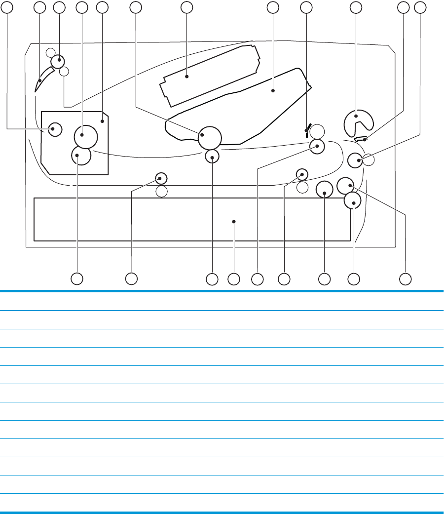
Diagrams
Use the diagrams in this section to identify printer components.
Diagrams: Block diagrams
Cross-sectional view of printer
Figure 2-1 Cross-sectional view of printer
13
15 14
21 17
18
20 19
2
1345 6 7 8 9 11 12
10
16
Item Description Item Description
1 Fuser output roller 12 Feed roller
2 Duplex apper (duplex models only) 13 Cassette feed roller
3 Output roller 14 Cassette separation roller
4 Fuser lm 15 Cassette pickup roller
5 Fuser 16 Duplex re-pickup roller (duplex models only)
6 Photosensitive drum 17 Registration roller
7 Laser scanner assembly 18 Cassette
8 Toner cartridge 19 Transfer roller
9 Registration shutter 20 Duplex feed roller (duplex models only)
10 Multipurpose tray pickup roller 21 Pressure roller
11 Multipurpose tray separation pad
ENWW Tools for troubleshooting 51
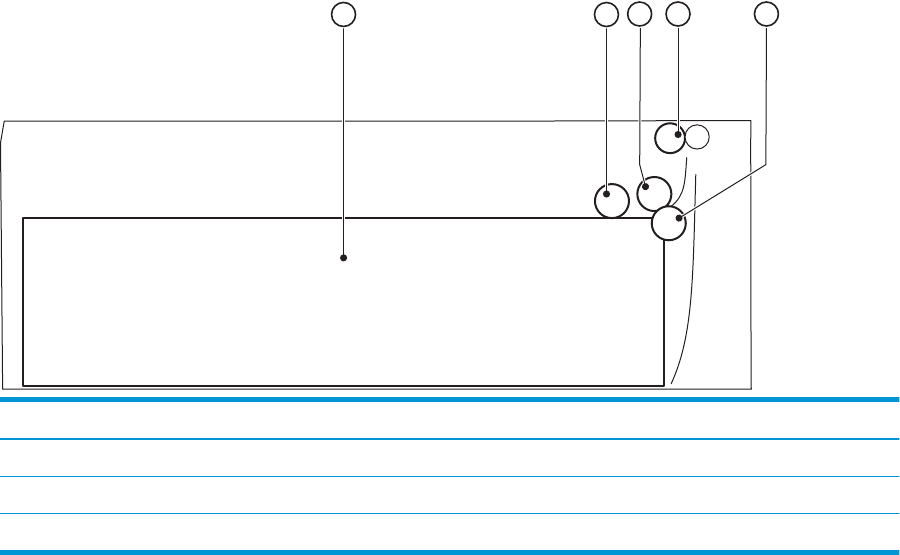
Cross-sectional view of 550–sheet paper feeder
Figure 2-2 Cross-sectional view of 500–sheet paper feeder
2
1345
Item Description Item Description
1 Cassette 4 Feed roller
2 Cassette pickup roller 5 Cassette separation roller
3 Cassette feed roller
52 Chapter 2 Solve problems ENWW
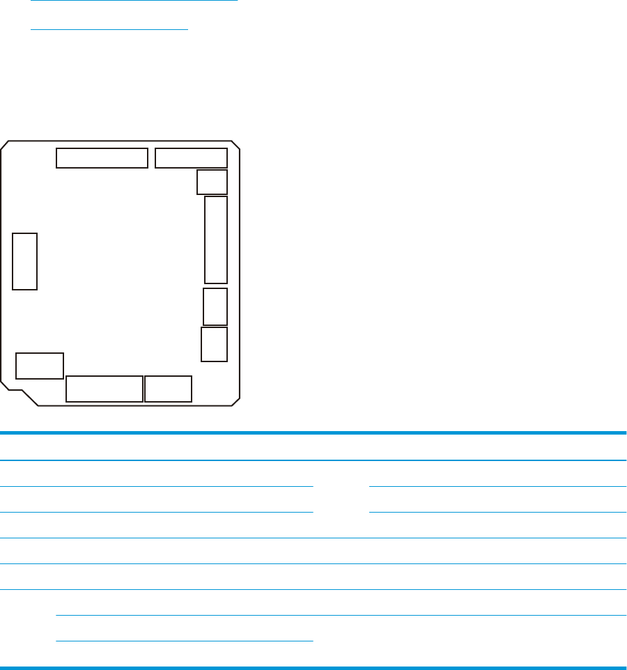
Diagrams: Printed circuit assembly (PCA) connector locations
●Diagrams: DC controller connections
●Paper feeder controller PCA
Diagrams: DC controller connections
Each of the connections on the DC controller PCA is indicated in the following gure.
Figure 2-3 DC controller PCA connectors
J4
J7
J6
J8
J1
J9
J2
J10
J5
J3
Table 2-1 DC controller connectors
Item Description Item Description
J1 Low-voltage power supply assembly J7 Media-width sensor
J2 High-voltage power supply PCA Duplex feed sensor (duplex models only)
J3 Formatter TOP sensor
J4 Laser assembly J8 Cassette media out sensor
J5 Connector PCA J9 Multipurpose tray media out sensor
J6 Output bin media-full sensor J10 Memory tag (E-label)
Fuser output sensor Loop sensor
Thermistor
ENWW Tools for troubleshooting 53
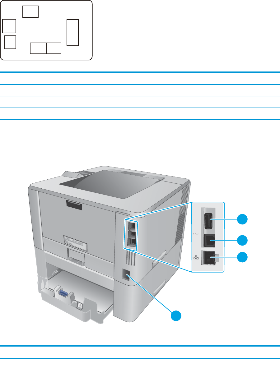
Paper feeder controller PCA
Figure 2-4 Paper feeder controller PCA connectors
J603
J601
J600
J605
J602
J604
Table 2-2 Paper feeder controller PCA connectors
Item Description Item Description
J600 Printer J603 Media surface sensor
J601 Cassette detection switch J604 Cassette pickup solenoid
J602 Cassette media out sensor J605 Lifter motor
Diagrams: External plug and port locations
Figure 2-5 M402, M403 external plugs and ports locations
4
1
2
3
Table 2-3 M402, M403 external plugs and ports
Item Description
1 USB port (for job storage and private printing)
NOTE: This port might be covered
54 Chapter 2 Solve problems ENWW
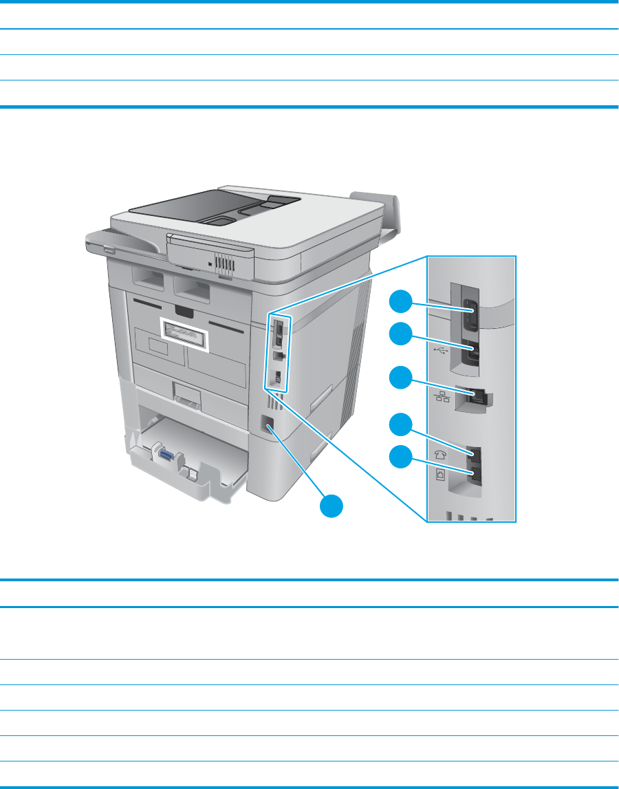
Table 2-3 M402, M403 external plugs and ports (continued)
Item Description
2 USB interface port
3 Ethernet port
4 Power connection
Figure 2-6 M426, M427 external plug and port locations
6
1
2
3
5
4
Table 2-4 M426, M427 external plugs and ports
Item Description
1 USB port (for job storage and private printing)
NOTE: This port might be covered
2 USB interface port
3 Ethernet port
4 Telephone “line out” port (for attaching an extension phone, answering machine, or other device)
5 Fax “line in” port (for attaching the fax phone line to the printer)
6 Power connection
ENWW Tools for troubleshooting 55
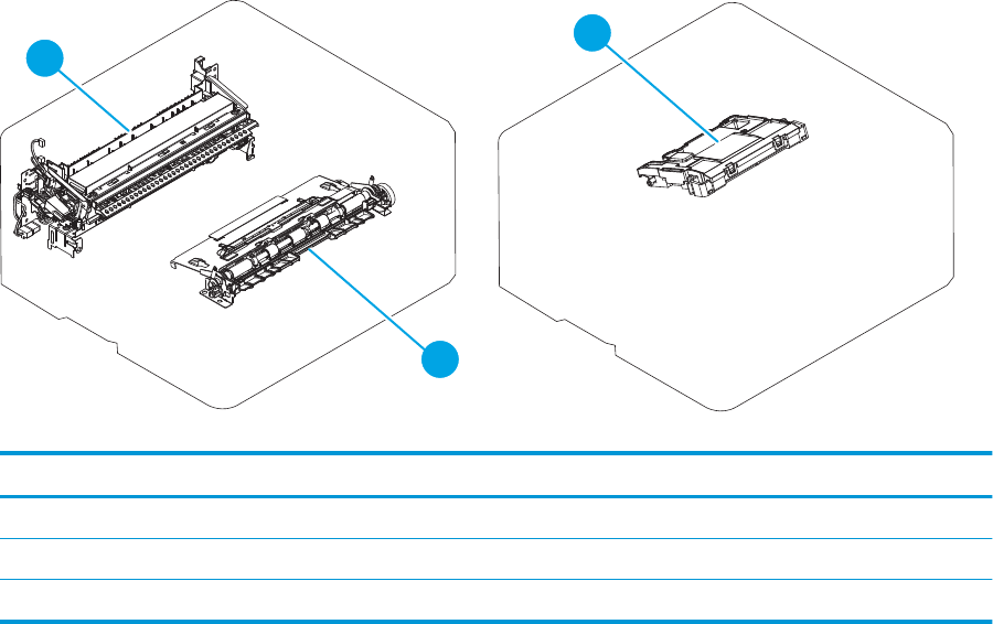
Diagrams: Locations of major components
Major components (printer base)
Figure 2-7 Major components (printer base)
1
2
3
Table 2-5 Major components (printer base)
Item Description
1 Fuser
2 Registration assembly
3 Laser/scanner assembly
56 Chapter 2 Solve problems ENWW

Motor and fan
Figure 2-8 Motor and fan
1
2
Table 2-6 Motor and fan (printer base)
Item Description
1 Fuser motor (M1)
2 Main fan (FM1)
ENWW Tools for troubleshooting 57
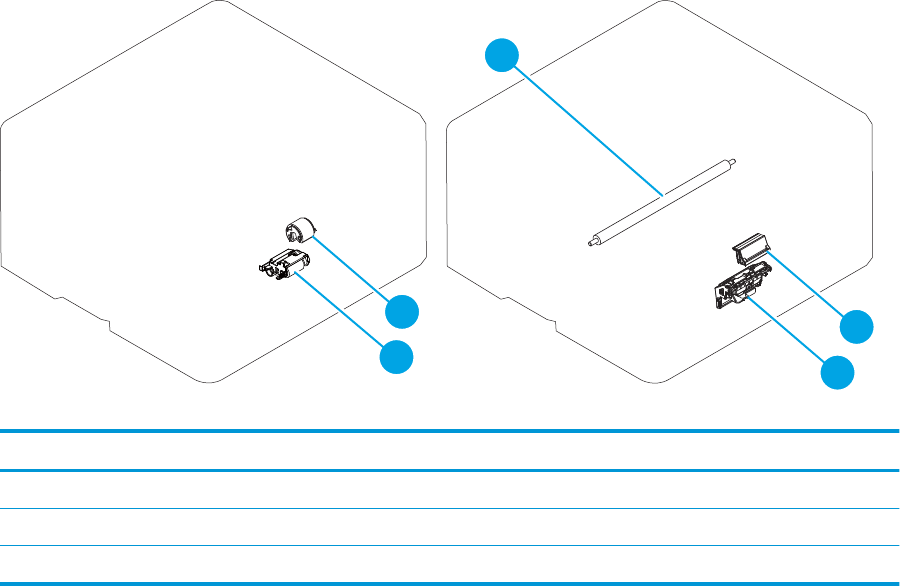
Rollers and pads (printer base)
Figure 2-9 Rollers and pads (printer base)
1
2
3
4
5
Table 2-7 Rollers and pads (printer base)
Item Description Item Description
1 Transfer roller 4 MP tray pickup roller
2 MP tray separation pad 5 Pickup roller assembly
3 Separation roller assembly
58 Chapter 2 Solve problems ENWW
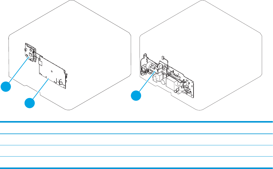
PCAs (printer base)
Figure 2-10 Main PCAs (printer base)
1
2
3
Table 2-8 Main PCAs (printer base)
Item Description Item Description
1 High-voltage power supply assembly Not shown Formatter PCA
2 DC controller PCA Not shown Wireless PCA (wireless models only)
3 Low-voltage power supply assembly Not shown Fax PCA (fax models only)
ENWW Tools for troubleshooting 59
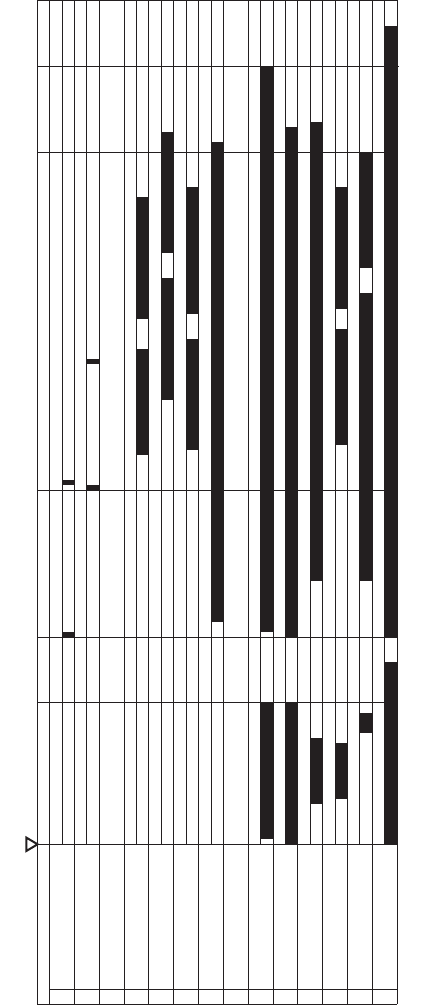
Diagrams: Timing chart
Figure 2-11 General timing chart
Timing chart two consecutive prints on LTR paper
12 Developing bias
13 Transfer bias
14 Main fan (FM1)
9 Fuser motor (M1)
10 Fuser heater
11 Primary charging bias
6 BD signal
7 Scanner motor (M3)
4TOP sensor (PS2)
5 Fuser output sensor (PS13)
LSTR
STBY
1 Print command
2 Cassette pickup solenoid (SL1)
PRINT
WAIT
STBY
INTR
Power ON
60 Chapter 2 Solve problems ENWW
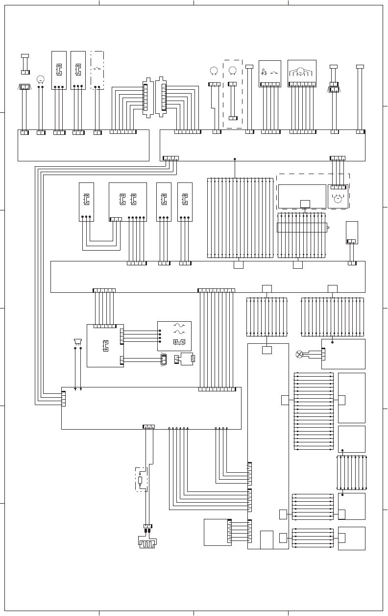
Diagrams: Circuit diagrams
Figure 2-12 General circuit diagram (printer base)
A
6 5 4 3 21
B
C
D
M
SL
12345 123
21
TP
123
CL
SL
M
SL
M
SL
CL
123
1
13
4
2
3
5
6
7
8
9
10
11
12
14
15
16
17
18
19
20
21
22
22
21
20
19
18
17
16
15
14
12
11
10
9
13
8
7
6
5
3
2
4
1
SGND
/VDO1
VDO1
SGND
/VDO2
SGND
VDO2
CLEI
/BDO
SGND
CLEO
GND
PRIACCLK
PRIDCPWM
PRIACPWM
TNR
FANON
FANLOCK
TRPWM
DEVDCSNS
DEVACPWM
DEVACCLK
TRCRNT
TRPCLK
TRNCLK
+5.4V
+24VA
SGND
+24VBSNS
24VCON
345612
J1302A J507
345612
J1302S
345612
345612
USB PCA
J508
J510
22 8
J503
6
J505
WiFi
+5V
/CPRESET
/CPCLK
CPCLK
CPIN
GND
+3.3V
CPOUT
4
1
2
3
5
6
7
8
4
1
2
3
5
6
4
1
2
3
5
6
8
1
2
7
4
3
5
6
8
J504
J44
1
2
3
7
4
5
6
8
9
9
8
7
6
5
3
4
2
1
J33
Contorl panel
(Magic frame)
22
J509
6
J506
SGND
SGND
+3.3VC
+3.3VC
J213
21
H1
12
TP1
SGND
LVPSGND
SGND
+3.3VC
+3.3VC
+24VD
AC-N
AC-H
PS13
21
FU2
2
1
FU1
J4203
J4204
J4202
J4201
J410DH
J410L
J410D
TH1
12
21
12
+3.3VB(GY)
NFCS(BL)
SGND
MAINTH
FSROUTSNS(GN)
SGND(BR)
J407J406
121234
PS4
3
2
1
Inlet
SOLD210
SOLD211
LVPS_GND
LVPS_GND
+24VD
+24VD
1234
J203
AC-H
AC-N
J210
J211
231
J212
J207A
J206A
J204A
J205A
J209A
J208A
J207S
J206S
J204S
J205S
10 98 2
345617
J201
12
J501 FANON
FANLOCK
GND
123
J301
FM1
321
J341
1
2
3
4
5
6
7
8
9
10
11
12
13
14
15
16
17
18
1
2
3
4
5
6
7
8
9
10
11
12
13
14
15
16
17
18
18
J2
4
1
2
3
5
6
7
8
9
10
11
12
4
1
2
3
5
6
7
8
9
10
11
12
12
J3
LVPS_GND
FREQSNS_LVT
/3.3VCON
RLYD
PWRSAVE2
24VDON
24VD
24VA
FSRD
3.3VA
109
8
234561 7
J1
SGND
MAINTH
FSROUTSNS
FULLSNS
+3.3VB
NFCS
1
234
56
J405
123456
J6
TOPSNS(BR)
SGND(W)
+3.3VB(BL)
TAG
MPTPSNS(W)
SGND(BR)
+3.3VB(R)
CSTPSNS(W)
SGND(BR)
+3.3VB(Y)
REFEEDSNS(V)
TOPSNS(GY)
SGND(R)
PWSNSAND(W)
+3.3VB(BR)
J7 J9J8 19
J5
SGND
SGND
SGND
+3.3VB
/LDPWM
/BDI
VDO1
VDO2
/VDO2
SGND
/VDO1
LDCTRL1
LDCTRL0
LDCTRL2
6
7
8
9
10
11
12
13
14
4
1
2
3
5
9
8
7
6
5
4
3
2
1
13
14
12
11
10
14
J4
12
12
J18
J10
VSS(W)
VIN(BL)
1
2
3
4
OPTPLVLSNS(SI)
OPTLIFTMT
+3.3VB
OPTSNSAD
DUPSWBKSL
REFEEDCL
OPTPICKSL(SO)
SGND
PWRLED_ON
PWRLED_PWR
BLMFG
PWRSW
AIRTMP
/BLMACC
/SCNACC
/BLMDEC
CSTSL
MPTSL
/SCNDEC
19
18
17
16
15
14
13
12
11
10
9
8
7
6
5
3
2
4
1
13
12
14
15
16
17
18
19
4
2
3
5
6
7
8
9
10
11
1
J4011
J4121
J4122
J4012
J4013
J4123
PS1
PS3
PS1a
PS2b
123
J700
PS2
J4031
J4033
J4032
J7014
J7013
J7012
J7011
J7015
High-voltage
power supply
PCA
DC controller
1234
J802
M3
14
J811
Laser/scanner ass’y
+24VD
PGND
/SCNDEC
/SCNACC
LVPS_GND
+24VD
+24VD
LVPS_GND
1
12
J13B
(REFEEDCL)
+24VD
2
J111B
J13A
21
CL1
12
SL3
21
21
SW1LED1
12345
J701
1234567
J705
7653
214
M1
J13DH
J13L
J13D
1
2
1
2
12
SL1 SL2
12
(CSTSL)
+24VD
+24VD
(MPTSL)
PGND
PGND
+24VD
BLMFG
/BLMDEC
+24VD
/BLMACC
(DUPSWBKSL)
+24VD
+24VD
(REFEEDCL)
+24VD
+3.3VB
SGND
OPTSNSAD
OPTLIFTMT
OPTPLVLSNS
OPTPICKSL
SGND
AIRTMP
PWRSW
PWRLED_ON
PWRLED_PWR
1234
J105
12
J104
J102 J110
1234567121212345
J107 J109
J101
121234567
1234
J106
J103 J111A
1234567
1234567
Connector PCA
21
OPTCSTPSNS(GN)
+3.3VB(Y)
SGND
OPTCSTSNS
+24VD(BR)
+24VD
OPTPICKSL
OPTLIFTMT(W)
SGND(BR)
+3.3VB(V)
OPTPLVLSNS(GN)
SGND(BR)
J691LH
J691D
J691DH
J691L
PS461
PS460
SOLD6121
SOLD6122
J4611
J4612
J4613
J4601
J4602
J4603
SL4
J692DH
J692L
J692D
12
12
12
21
M5
1234567
1
231
21
21212
3
J601 J600
J602
J603J605J604
Paper feeder controller PCA
SW3
21
CL1
Low-voltage power supply PCA
Formatter
NFC PCA
Contorl panel
LCD PCA
Contorl panel
SW PCA
Laser PCA
ENWW Tools for troubleshooting 61

Advanced conguration with HP Embedded Web Server (EWS) and HP Device
Toolbox (Windows 7)
Use the HP Embedded Web Server to manage printing functions from a computer instead of the printer
control panel.
●View printer status information
●Determine the remaining life for all supplies and order new ones
●View and change tray congurations
●View and change the printer control-panel menu conguration
●View and print internal pages
●Receive notication of printer and supplies events
●View and change network conguration
The HP Embedded Web Server works when the printer is connected to an IP-based network. The HP
Embedded Web Server does not support IPX-based printer connections. Internet access is not needed to open
and use the HP Embedded Web Server.
When the printer is connected to the network, the HP Embedded Web Server is automatically available.
NOTE: HP Device Toolbox is software used to connect to the HP Embedded Web Server when the printer is
connected to a computer via USB. It is available only if a full installation was performed when the printer was
installed on a computer. Depending on how the printer is connected, some features might not be available.
NOTE: The HP Embedded Web Server is not accessible beyond the network rewall.
Method one: Open the HP Embedded Web Server (EWS) from the Start menu
1. Click the Start button, and then click the Programs item.
2. Click the HP printer group, and then click the HP Device Toolbox item.
Method two: Open the HP Embedded Web Server (EWS) from a Web browser
1. Use one of the following methods to obtain the IP address based on your printer model:
M402, M403
●On the printer control panel, press the OK button. Open the Network Setup menu, and then select
Show IP Address to display the IP address or host name.
M426, M427
●From the Home screen on the printer control panel, touch the Connection Information
button, and then touch the Network Connected button or the Network Wi-Fi ON button to
display the IP address or host name.
62 Chapter 2 Solve problems ENWW

2. Open a Web browser, and in the address line, type the IP address or host name exactly as it displays on
the printer control panel. Press the Enter key on the computer keyboard. The EWS opens.
NOTE: If the Web browser displays a There is a problem with this website’s security certicate
message when attempting to open the EWS, click Continue to this website (not recommended).
Choosing Continue to this website (not recommended) will not harm the computer while navigating
within the EWS for the HP printer.
Tab or section Description
Home tab
Provides printer, status, and
conguration information.
●Device Status: Shows the printer status and shows the approximate percent life
remaining of HP supplies.
●Supplies Status: Shows the approximate percent life remaining of HP supplies. Actual
supply life remaining can vary. Consider having a replacement supply available to install
when print quality is no longer acceptable. The supply does not need to be replaced
unless the print quality is no longer acceptable.
●Device Conguration: Shows the information found on the printer conguration page.
●Network Summary: Shows the information found on the printer network conguration
page.
●Reports: Print the conguration and supplies status pages that the printer generates.
●Job Storage Log: Shows a summary of all jobs stored in the printer memory.
●Event Log: Shows a list of all printer events and errors.
System tab
Provides the ability to congure the
printer from your computer.
●Device Information: Provides basic printer and company information.
●Paper Setup: Change the default paper-handling settings for the printer.
●Print Quality: Change the default print-quality settings for the printer.
●Energy Settings: Change the default times for entering Sleep/Auto O mode or
automatic shut down.
●Job Storage Setup: Congure the job storage settings for the printer.
●Print Density: Change the print density of contrasts, highlights, midtones, and shadows
●Paper Types: Congure print modes that correspond to the paper types that the printer
accepts.
●System Setup: Change the system defaults for the printer.
●Supply Settings: Change the settings for Cartridge is low alerts and other supplies
information.
●Service: Perform the cleaning procedure on the printer.
●Save and Restore: Save the current settings for the printer to a le on the computer. Use
this le to load the same settings onto another printer or to restore these settings to this
printer at a later time.
●Administration: Set or change the printer password. Enable or disable printer features.
NOTE: The System tab can be password-protected. If this printer is on a network, always
consult with the administrator before changing settings on this tab.
ENWW Tools for troubleshooting 63

Tab or section Description
Print tab
Provides the ability to change default
print settings from your computer.
●Printing: Change the default printer print settings, such as number of copies and paper
orientation. These are the same options that are available on the control panel.
●PCL5c: View and change the PCL5c settings.
●PostScript: Turn o or on the Print PS Errors feature.
Fax tab
(M426, M427 models only)
●Receive Options: Congure how the printer handles incoming faxes.
●Phone Book: Add or delete entries in the fax phone book.
●Junk Fax List: Set fax numbers to block from sending faxes to the printer.
●Fax Activity Log: Review recent fax activity for the printer.
Scan tab
(M426, M427 models only)
Congure the Scan to Network Folder and Scan to E-mail features.
●Network Folder Setup: Congure folders on the network to which the printer can save a
scanned le.
●Scan to E-mail Setup: Begin the process to set up the Scan to E-mail feature.
●Outgoing E-mail Proles: Set an email address that will appear as the “from” address for
all emails sent from the printer.
●Default SMTP Conguration: Congure the SMTP Server information.
●E-mail Address Book: Add or delete entries in the email address book.
●Network Contacts Setup: Congure the printer to connect to a network address book.
●E-mail Options: Congure a default subject line and body text. Congure default scan
settings for emails.
Networking tab
(Network-connected printers only)
Provides the ability to change
network settings from your
computer.
Network administrators can use this tab to control network-related settings for the printer
when it is connected to an IP-based network. It also allows the network administrator to set up
Wi-Fi Direct functionality. This tab does not appear if the printer is directly connected to a
computer.
HP Web Services tab Use this tab to set up and use various Web tools with the printer.
Internal print-quality test pages
Clean the paper path
During the printing process, paper, toner, and dust particles can accumulate inside the printer. Over time, this
buildup can cause print-quality problems such as toner specks or smearing. This printer has a cleaning mode
that can correct and prevent these types of problems.
Clean the paper path (LCD control panel)
1. On the printer control panel, press the OK button to open the menus.
2. Open the following menus:
64 Chapter 2 Solve problems ENWW

●Service
●Cleaning Page
3. Load plain paper in Tray 1, and then press the OK button to start the cleaning process.
Wait until the process is complete. Discard the page that prints.
Clean the paper path (touchscreen control panel)
1. From the Home screen on the printer control panel, touch the Setup button.
2. Touch the Service menu.
3. Touch the Cleaning Page button.
4. Load plain letter or A4 paper when you are prompted.
5. Touch the OK button to begin the cleaning process.
Wait until the process is complete. Discard the page that prints.
Print the conguration page
The conguration page lists current printer settings and properties. This page also contains a status log
report. To print a conguration page, complete one of the following procedures.
Print the conguration page from an LCD control panel
1. On the printer control panel, press the OK button to open the menus.
2. Use the arrow buttons to select the Reports menu, and then press the OK button.
3. Use the arrow buttons to select the Conguration Report item, and then press the OK button to print the
report.
Print the conguration page from a touchscreen control panel
1. From the Home screen on the printer control panel, touch the Setup button.
2. Touch the Reports menu.
3. Touch the Conguration Report button to print the report.
ENWW Tools for troubleshooting 65

Print-quality troubleshooting tools
Repetitive image defect ruler
Defects on printer rollers can cause image defects to appear at regular intervals on the page, corresponding
to the circumference of the roller that is causing the defect. Measure the distance between defects that recur
on a page (See Use a ruler to measure between repetitive defects on page 66). Use the following table or
the repetitive-defect ruler to determine which roller is causing the defect. To resolve the problem, try cleaning
the roller rst. If the roller remains dirty after cleaning or if it is damaged, replace the part that is indicated in
the following table.
CAUTION: Do not use solvents or oils to clean rollers. Instead, rub the roller with a lint-free cloth. If dirt is
diicult to remove, rub the roller with a lint-free cloth that has been dampened with water.
NOTE: The following table replaces the graphical repetitive defect ruler. You can make your own ruler by
using these measurements. For the most accurate results, use a metric ruler.
Table 2-9 Repetitive defects
Component Distance between defects
Primary charging roller128 mm (1.10 in)
Developer roller131 mm (1.22 in)
Transfer roller 39 mm (1.54 in)
Registration roller 43 mm (1.69 in)
Cassette separation roller 44 mm (1.73 in)
Cassette pickup roller
Cassette feed roller
50 mm (1.97 in)
Fuser lm 57 mm (2.24 in)
Pressure roller263 mm (2.48 in)
Photosensitive drum175 mm (2.95 in)
1The primary charging roller, photosensitive drum and developer roller cannot be cleaned as these rollers are located inside the toner
cartridge. If any of these rollers are indicated, replace the toner cartridge.
2The primary fuser sleeve unit or pressure roller cannot be cleaned because they are internal assemblies in the fuser. If one of these
assemblies is causing the defect, replace the fuser.
Use a ruler to measure between repetitive defects
The gures in this section shows color repetitive defect pages. However, the process for measuring repetitive
defects is valid for mono pages.
1. Identify a repetitive defect on the page.
TIP: Print a cleaning page to see if that resolves the defect.
66 Chapter 2 Solve problems ENWW
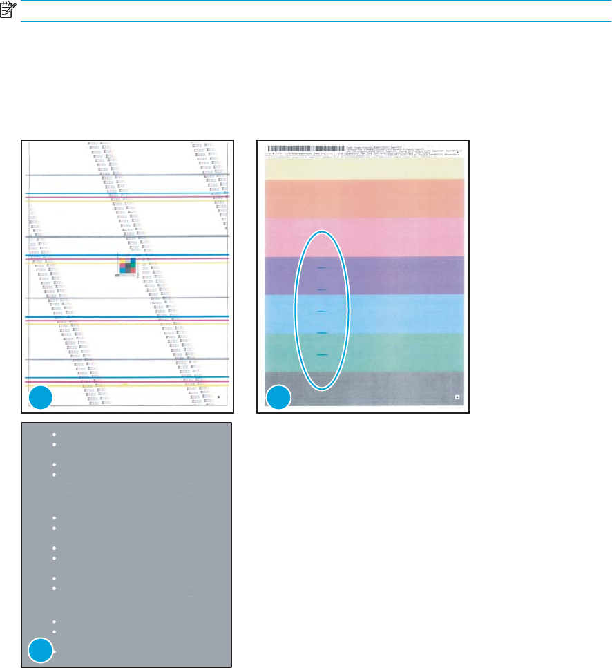
The example pages below show the following types of repetitive defects.
NOTE: These are examples only, other types of repetitive defects might appear on a page.
●Lines (callout 1)
●Smudges (callout 2)
●Dots or spots (callout 3)
Figure 2-13 Examples of repetitive defects
1 2
3
ENWW Tools for troubleshooting 67
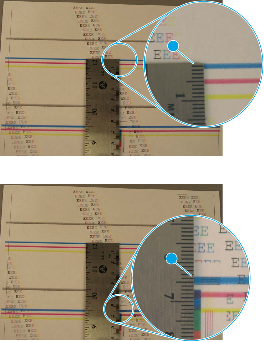
2. Position a metric ruler on the page with the “zero” ruler mark at one occurrence of the defect (callout 1).
Figure 2-14 Place the ruler on the page
1
3. Locate the next occurrence of the defect (callout 1).
Figure 2-15 Locate the next repetitive defect
1
68 Chapter 2 Solve problems ENWW
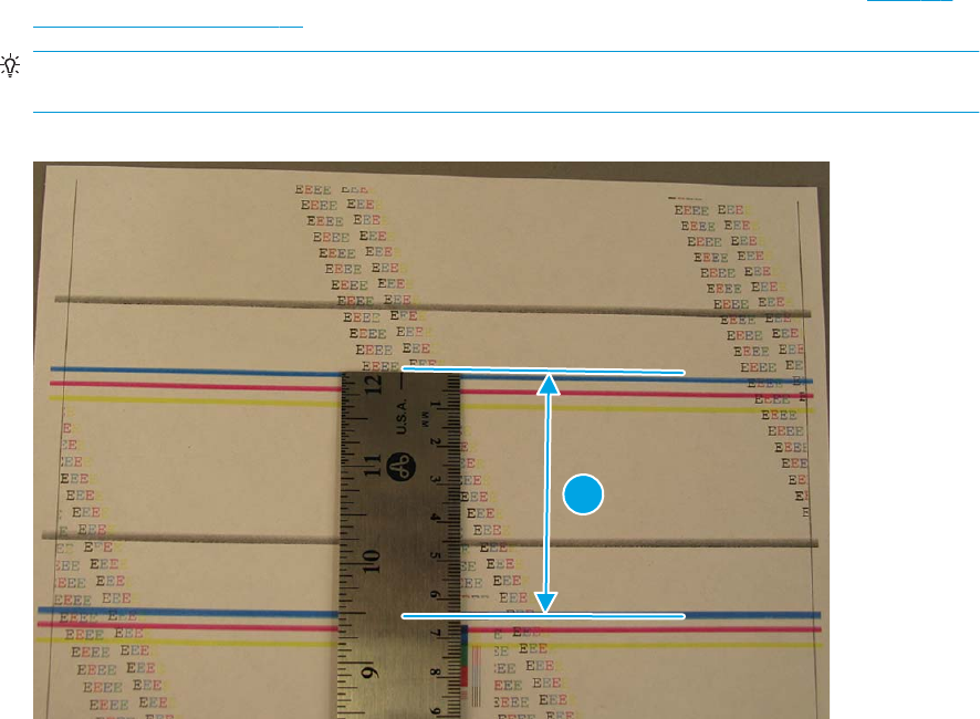
4. Measure the distance (in millimeters) between the two occurrences (callout 1), and then use Table 2-9
Repetitive defects on page 66 to determine the defective assembly.
TIP: Always measure from and to the same point on the defects. For example, if the ruler is “zeroed”
at the top edge of a defect, measure to the top edge of the next occurrence of that defect.
Figure 2-16 Determine the defective assembly
1
ENWW Tools for troubleshooting 69

Control panel menus
●HP Web Services menu
●Reports menu
●Quick Forms menu
●USB Flash Drive menu
●System Setup menu
●Service menu
●Network Setup menu
HP Web Services menu
Use the HP Web Services menu to set up the HP Web Services features.
Menu item Description
Print Information Sheet Prints a report that instructs the user how to set up the HP Web Services features.
Display Address Displays the printer email address.
Turn ePrint On/O Enables or disables the printer HP ePrint functionality.
Turn Apps On/O Enables or disables the printer HP Web Services applications.
Enable Web Services Enables the HP Web Services features.
Remove Services Removes the HP Web Services features from the printer.
Clear Apps History Deletes the stored history of the printer HP Web Services applications.
Proxy Settings Allows you to enter proxy server information for the printer internet connection.
Reports menu
Use the Reports menu to print reports that provide information about the printer.
Menu item Description
Demo Page Prints a sample page that demonstrates print quality.
Menu Structure Prints a map of the control panel-menu layout. The active settings for each menu are
listed.
Conguration Report Prints a list of all the printer settings. Includes network information when the printer is
connected to a network.
70 Chapter 2 Solve problems ENWW

Menu item Description
Supplies Status Prints the status for each toner cartridge, including the following information:
●Estimated percentage of cartridge life remaining
●Approximate pages remaining
●Part numbers for HP toner cartridge
●Number of pages printed
●Information about ordering new HP toner cartridges and recycling used HP toner
cartridges
Network Summary Prints a list of all printer network settings
Usage Page Prints a page that lists PCL pages, PCL 6 pages, PS pages, pages that were jammed or
mispicked in the printer, and reports the page count
PCL Font List Prints a list of all the PCL fonts that are installed
Prints a list of all the PostScript (PS) fonts that are installed
PCL6 Font List Prints a list of all the PCL6 fonts that are installed
Service Page Provides information on supported paper types, copy settings, and other miscellaneous
settings that are not on the conguration page
Quick Forms menu
Menu item Sub-menu item Description
Notebook Paper Narrow Rule
Wide Rule
Child Rule
Prints pages that have preprinted lines
Graph Paper 1/8 inch
5 mm
Prints pages that have preprinted graph lines
Checklist 1 Column
2 Column
Prints pages that have preprinted lines with check boxes
Music Paper Portrait
Landscape
Prints pages that have preprinted lines for writing music
USB Flash Drive menu
Print Documents Prints documents stored on the USB drive. Use the arrow buttons
to scroll through the documents. Touch the names of documents
that you want to print.
Touch the summary screen to change settings such as the number
of copies, the paper size, or the paper type.
Touch the Print button when you are ready to print the
documents.
ENWW Tools for troubleshooting 71

Easy Photo Print Prints photo les directly from the printer.
NOTE: This menu item is available for LCD control panel models
only.
Thumbnail Sheet(s) Prints a page or pages of 30 “thumbnail” graphic images.
NOTE: This menu item is available for LCD control panel models
only.
View and Print Photos Previews photos on the USB drive. Use the arrow buttons to scroll
through the photos. Touch the preview image for each photo that
you want to print. You can adjust the settings, and you can save
the changes as the new default settings. When you are ready to
print the photos, touch the Print button.
Scan to USB Drive Scans a document and stores it as a .PDF document or .JPEG
image on the USB ash drive.
System Setup menu
In the following table, items that have asterisks (*) indicate the factory default setting.
Menu item Sub-menu item Sub-menu item Description
Language Select the language for the control
panel display messages and the
printer reports.
Paper Setup Def. Paper Size Letter
A4
Legal
Sets the size for printing internal
reports or any print job that does
not specify a size.
NOTE: The default setting is
determined by the choice of
location during the initial printer
setup.
Def. Paper Type A list of available
paper types appears.
Select the paper type for printing
internal reports or any print job
that does not specify a type.
Tray 1 Paper Type
Paper Size
Select the default size and type for
Tray 1 from the list of available
sizes and types.
Tray 2 Paper Type
Paper Size
Select the default size and type for
Tray 2 from the list of available
sizes and types.
72 Chapter 2 Solve problems ENWW

Menu item Sub-menu item Sub-menu item Description
Paper Out Action Wait Forever**
Cancel
Override
Select how the printer should react
when a print job requires a size or
type that is not available or when
a specied tray is empty.
Select the Wait Forever option to
make the printer wait until you
load the correct paper and press
the OK button. This is the default
setting.
Select the Override option to print
on a dierent size or type after a
specied delay.
Select the Cancel option to
automatically cancel the print job
after a specied delay.
If you select either the Override or
Cancel options, the control panel
prompts you to specify the
number of seconds to delay. Use
the arrow buttons to increase (up
to 3600 seconds) or decrease the
time.
Energy Settings Sleep Delay O
1 Minute
15 Minutes*
30 Minutes
1 Hour
2 Hours
Sets how long the printer remains
idle before it enters sleep mode.
The printer automatically exits
sleep mode when you send a print
job or press a control panel
button.
Auto Power Down Auto Power Down
Delay
Never
30 Minutes
1 Hour
2 Hours
4 Hours
8 Hours
24 Hours
Sets the period of time that must
elapse before the printer Auto
Power Down feature activates.
Wake Events USB Job
LAN Job
Wireless Job (wireless
models only)
Button Press
USB Drive Insert
Enables or disables certain printer
events (like when a control panel
button is pressed) that will cause
the printer to revert from Auto
Power Down mode to Ready
status.
ENWW Tools for troubleshooting 73

Menu item Sub-menu item Sub-menu item Description
Print Density A range of 1 to 5. Select the print density level. The
default setting is 3
Supply Settings Black Cartridge Very Low Setting Stop
Prompt*
Continue
Set how the printer behaves when
the black toner cartridge reaches
the very low threshold.
●Stop: The printer stops
printing until you replace the
toner cartridge.
●Prompt: The printer stops
printing and prompts you to
replace the toner cartridge.
You can acknowledge the
prompt and continue
printing.
●Continue: The printer alerts
you that the toner cartridge
is very low, but it continues
printing.
Low Threshold A percentage range of
1 to 100.
Set the percentage of estimated
life remaining at which the printer
alerts you that the toner cartridge
is low.
Administration Product Security
(touchscreen control
panel models only)
Enable printer security. If turned
on, the printer prompts you to set
a password. After it is set, the
password will be needed to change
printer settings.
USB Flash Drive On*
O
Enable or disable the walkup USB
port.
Display Contrast Medium*
Darker
Darkest
Lightest
Lighter
Select the level of contrast for the
display.
Courier Font Regular*
Dark
Selects a version of the Courier
font..
Quiet Mode Enable or Disable the printer Quiet
Mode.
Service menu
Use this menu to restore default settings, clean the printer, and activate special modes that aect print
output. Items that have asterisks (*) indicate the factory default setting.
74 Chapter 2 Solve problems ENWW

Menu item Sub-menu item Sub-menu item Description
Cleaning Page Use this option to clean the printer if
you see toner specks or other marks
on the printed output. The cleaning
process removes dust and excess
toner from the paper path.
When you select this item, the printer
prompts you to load plain paper in
Tray 1 and then press the OK button
to start the cleaning process. Wait
until the process is complete. Discard
the page that prints.
USB Speed High*
Full
Sets the USB speed to High or Full.
For the printer to actually operate at
high speed, it must have high speed
enabled and be connected to an EHCI
host controller that is also operating
at high speed. This menu item also
does not reect the current
operating speed of the printer.
Less Paper Curl On
O*
If printed pages are consistently
curled, use this option to set the
printer to a mode that reduces curl.
Archive Print On
O*
If you are printing pages that will be
stored for a long time, use this option
to set the printer to a mode that
reduces toner smearing and dusting.
Firmware Date Displays the current rmware
datecode.
Restore Defaults Sets all customized copy settings to
the factory default values.
Signature Check Cancel if Invalid*
Prompt if Invalid
Congures how the printer proceeds
when a rmware upgrade le does
not have a valid signature.
HP Smart Install On*
O
Enables or disables the HP Smart
Install functionality.
LaserJet Update Check For Updates Now Prompts the printer to search for a
newer rmware upgrade le and
then upload it.
Manage Updates Allow Downgrade Yes*: Allows the rmware upgrade
functionality to upload an older
rmware version.
No: Prevents the printer from loading
older rmware les.
Check Automatically On*: Allows the printer to
automatically search for new
rmware updates.
O: Prevents the printer from loading
new rmware update les.
ENWW Tools for troubleshooting 75

Menu item Sub-menu item Sub-menu item Description
Prompt Before Install Install Automatically: Allows the
printer to automatically load a
rmware update le.
Always Prompt*: Causes the printer
to display a prompt at the control
panel before the printer can load a
rmware update le.
Allow Updates Yes*: Allows the printer to load
rmware update les.
No: Prevents the printer from loading
rmware update les.
76 Chapter 2 Solve problems ENWW

Network Setup menu
Use this menu to establish network conguration settings.
Menu item Sub-menu item Description
Wireless Menu (wireless printers
only)
Wireless Direct Settings
Wireless Setup Wizard
Wi-Fi Protected Setup If your wireless router supports this feature, use this
method to set up the printer on a wireless network. This
is the simplest method.
Run Wireless Test Tests the wireless network and prints a report with the
results.
Turn Wireless On/O Enable or disable the wireless network feature.
TCP/IP Cong Automatic*
Manual
Select Automatic to automatically congure all the
TCP/IP settings.
Select Manual manually congure the IP address,
subnet mask, and default gateway.
IPv4 Cong Method DHCP
BOOTP
Auto IP
Manual
Set the IPv4 conguration method.
Card Sharing On*
O
Enable or disable le sharing of a memory card that has
been inserted into the printer walkup USB port.
Auto Crossover On*
O
This item is used when you are connecting the printer
directly to a personal computer using an Ethernet cable
(you might have to set this to On or O depending on
the computer being used).
Network Services IPv4
IPv6
This item is used by the network administrator to limit
the network services available on this printer.
On
O
The default setting is On.
Show IP Address No*
Yes
No: The printer IP address will not appear on the control
panel display.
Yes: The printer IP address will appear on the control
panel display.
Link Speed Automatic (Default)
10T Full
10T Half
100TX Full
100TX Half
Sets the link speed manually if needed.
After setting the link speed, the printer automatically
restarts.
ENWW Tools for troubleshooting 77

Menu item Sub-menu item Description
Security Product Security (touchscreen
control panel models only)
Enable printer security. If turned on, the printer prompts
you to set a password. After it is set, the password will
be needed to change printer settings.
HTTPS Enforcement Enable or disable the HTTPS Enforcement setting.
The default setting is On.
Firewall Enable, disable, or reset the printer rewall.
Access Control List Enable, disable, or reset the network access control list.
802.1x (wireless models only) Enable or disable the 802.1x wireless authentication
protocol.
Reset All Security Reset the security settings to the factory-set default
values.
Restore Defaults Press the OK button to restore the network
conguration settings to the default values.
USB Flash Drive On
O
Enable or disable the walkup USB port.
78 Chapter 2 Solve problems ENWW

Control panel message document (CPMD)
Control-panel message types
The control-panel messages and event code entries indicate the current printer status or situations that
might require action.
NOTE: Event log errors do not appear on the control-panel display. Open the event log to view or print the
event log errors.
A control-panel message displays temporarily and might require the user to acknowledge the message by
touching the OK button to resume printing or by touching the Cancel button to cancel the job. With certain
messages, the job might not nish printing or the print quality might be aected. If the message is related to
printing and the auto-continue feature is on, the printer will attempt to resume printing after the message
has appeared for 10 seconds without acknowledgement.
For some messages, restarting the printer might x the problem. If a critical error persists, the printer might
require service.
Control-panel messages and event log entries
NOTE: Some of the messages in the following sections only appear in the event log.
TIP: Some control-panel messages and event log entries refer to a specic printer sensor or switch in the
recommended action to solve the problem. See the diagrams in the clear jams section of this manual for
sensor and switch locations.
30.XX Error Messages
30.XXXX Scanner Error
Description
The atbed or ADF scanner is failing to initialize for the following reasons:
●30.0013 = Scanner failed to nd home
●30.0016 = Scan sensor communication error
●30.0017 = Scan motor exceeded max position error
●30.0023 = ADF scanner calibration error
Recommended action
1. Verify that the product has the most recent rmware from hp.com.
2. Verify that the (at exible cables (FFC’s) are seated correctly on the formatter board.
3. If the error persists, replace the Scanner/ADF Assembly:
Scanner/ADF Ass'y, Duplex ADF C5F98-60110
Scanner/ADF Ass'y, Simplex ADF C5F98-60109
4. If the error persists, escalate to Level 3 so that Technical Marketing has visibility to the problem.
ENWW Tools for troubleshooting 79

49.XX.YY Error Messages
49 Error, Turn o then on
Description
The product has experienced an internal embedded software error. Under most conditions, the product
automatically restarts.
Recommended action
1. Reset the printer:
a. Turn o the power by using the power switch, and then wait at least 30 seconds.
b. Turn on the power and wait for the product to initialize.
2. If you are using a surge protector:
a. Power o the printer.
b. Remove the surge protector.
c. Plug the product directly into the wall socket and turn the product power on.
3. If the error persists, disconnect any network or USB cables and power cycle. If the product returns to
Ready, check the FW version and update if a newer version is available.
4. If the error persists, print a Service Page from the Reports menu. Also, print an Error Report from the
2ndary Service Menu. On the Service Page, look at the xxxx portion of the 49.xxxx errors listed:
●If the numbers are all or mostly dierent, then power quality is a possible problem; try a dierent
wall socket.
●If the xxxx portion of 49.xxxx contain repeats of the same numbers or groups of numbers, then
check the 2ndary Service Error Report printed earlier for indications of a failure in a particular area.
The report may indicate whether the error is caused by a network problem or a problem with the
job.
5. If the error persists, replace the product.
NOTE: If the 49 Error is caused by the network or a specic le, do not replace the product; it will not
resolve the issue. Instead, attempt to isolate the issue in a way that demonstrates the error is caused by
something in the environment.
6. If the error persists after product replacement, escalate to Level 3 so that Technical Marketing has
visibility to the problem.
50.XX fuser errors
50.XX Fuser Error, Turn o then on
Description
The product has experienced an internal fuser hardware error:
●50.00 = Generic Fuser error
●50.10 = Low Fuser temperature error
80 Chapter 2 Solve problems ENWW

●50.11 = High sub thermistor area 3 fuser error
●50.12 = Low sub thermistor area 3 fuser error
●50.20 = Slow fuser error
●50.30 = High fuser temperature error
●50.40 = Fuser drive circuit error
●50.70 = Fuser open error
●50.80 = Low sub thermistor fuser error
●50.90 = High sub thermistor fuser error
Recommended action
1. Reset the product:
a. Turn o the power by using the power switch, and then wait at least 30 seconds.
b. Turn on the power and wait for the product to initialize.
2. If you are using a surge protector:
a. Power o the product.
b. Remove the surge protector.
c. Plug the product directly into the wall socket and turn the product power on.
3. If the error persists, replace the Fusing Assembly:
FUSER ASS'Y (110v) RM2-5399-000CN
FUSER ASS'Y (220v) RM2-5425-000CN
4. If the error persists, replace the product.
51.XX and 52 Laser/Scanner Errors
52 Scanner Error, Turn o then on
Description
An error with the laser/scanner assembly has occurred in the product.
Recommended action
1. Reset the printer:
a. Turn o the power by using the power switch, and then wait at least 30 seconds.
b. Turn on the power and wait for the product to initialize.
2. If you are using a surge protector:
ENWW Tools for troubleshooting 81
a. Power o the printer.
b. Remove the surge protector.
c. Plug the product directly into the wall socket and turn the product power on.
3. If the error persists, replace the product.
51.XX Laser Error, Turn o then on
Description
An error with the laser/scanner assembly has occurred in the product.
●51.00 = Laser error
●51.20 = Black laser scanner error
●51.30 = Laser error
Recommended action
1. Reset the printer:
a. Turn o the power by using the power switch, and then wait at least 30 seconds.
b. Turn on the power and wait for the product to initialize.
2. If you are using a surge protector:
a. Power o the printer.
b. Remove the surge protector.
c. Plug the product directly into the wall socket and turn the product power on.
3. If the error persists, replace the product.
55.XXXX Error Messages
55.XXXX Error, Turn o then on
Description
The product has experienced an error with one of the internal sensors.
●55.0 = DC controller communication error
●55.0601 = DC controller NVRAM data error
●55.0602 = DC controller NVRAM access error
●55.1 = DC controller memory error
●55.3 = Engine communication error
Recommended action
1. Reset the printer:
82 Chapter 2 Solve problems ENWW
a. Turn o the power by using the power switch, and then wait at least 30 seconds.
b. Turn on the power and wait for the product to initialize.
2. If you are using a surge protector:
a. Power o the printer.
b. Remove the surge protector.
c. Plug the product directly into the wall socket and turn the product power on.
3. If the error persists, replace the DC Controller PCB Assembly (HP Part #: RM2-8680-000CN).
4. If the error persists, replace the product.
57.XX Error Messages
57 Fan Error, Turn o then on
Description
The product has experienced an error with its internal fan.
●57.01 = Fan 1 error
Recommended action
1. Reset the printer:
a. Turn o the power by using the power switch, and then wait at least 30 seconds.
b. Turn on the power and wait for the product to initialize.
2. If you are using a surge protector:
a. Power o the printer.
b. Remove the surge protector.
c. Plug the product directly into the wall socket and turn the product power on.
3. If the error persists, replace the internal cooling fan (HP Part #: RK2-8068-000CN).
4. If the error persists, replace the product.
58.XX Error Messages
58.XX Error, Turn o then on
Description
The product has experienced an error with the low voltage power supply.
●58.04 = Low voltage power supply malfunction
Recommended action
1. Reset the printer:
ENWW Tools for troubleshooting 83

a. Turn o the power by using the power switch, and then wait at least 30 seconds.
b. Turn on the power and wait for the product to initialize.
2. If you are using a surge protector:
a. Power o the printer.
b. Remove the surge protector.
c. Plug the product directly into the wall socket and turn the product power on.
3. Check the voltage label on the back of the product. If the product is rated 220V and is plugged into a
110V outlet, this error might occur. In most cases, no damage is caused to the product. If a power
transformer is used to convert 220V power to 110V, verify that the transformer power rating is
suicient to operate the product.
4. If the error persists, replace the Low Voltage Power Supply PCB Assembly:
M402, M403 L.V.POWER SUPPLY PCB ASS'Y (110v) RM2-8516-000CN
M402, M403 L.V.POWER SUPPLY PCB ASS'Y (220v) RM2-8517-000CN
M426, M427 L.V.POWER SUPPLY PCB ASS'Y (110v) RM2-8518-000CN
M426, M427 L.V.POWER SUPPLY PCB ASS'Y (220v) RM2-8519-000CN
5. If the error persists, replace the product.
59.XX Error Messages
59.XX Error, Turn o then on
Description
The product has experienced an error with the internal motor.
Recommended action
1. Reset the printer:
a. Turn o the power by using the power switch, and then wait at least 30 seconds.
b. Turn on the power and wait for the product to initialize.
2. If you are using a surge protector:
a. Power o the printer.
b. Remove the surge protector.
c. Plug the product directly into the wall socket and turn the product power on.
3. If the error persists, replace the Main Motor Assembly (HP Part #: RM2-8684-000CN).
84 Chapter 2 Solve problems ENWW

79 Errors
79 Error, Turn o then on
Description
The product has experienced an internal rmware error. Under most conditions, the product automatically
restarts.
Recommended action
1. Reset the printer:
a. Turn o the power by using the power switch, and then wait at least 30 seconds.
b. Turn on the power and wait for the product to initialize.
2. If you are using a surge protector:
a. Power o the printer.
b. Remove the surge protector.
c. Plug the product directly into the wall socket and turn the product power on.
3. If the error is intermittent, attempt to isolate the issue to something specic in the customers
environment.
NOTE: If the 79 Error is caused by the network or a specic le, do not replace the product; it will not
resolve the issue. Instead, attempt to isolate the issue in a way that demonstrates the error is caused by
something in the environment.
4. If the error is persistent, replace the Formatter PCA:
M402/M403 D Formatter PCB Assembly C5F92-60001
M402/M403 N/DN Formatter PCB Assembly C5F93-60001
M402/M403 DW Formatter PCB Assembly C5F94-60001
M426/M427 4in1 Formatter PCB Assembly C5F98-60001
M426/ M426 3in1 Formatter PCB Assembly C5F99-60001
5. If the error persists, replace the product.
6. If the error persists after product replacement, escalate to Level 3 so that Technical Marketing has
visibility to the problem.
Alpha Error Messages
<COLOR> cartridge is low.
Description
The indicated toner cartridge is nearing the end of its useful life.
Recommended action
Printing can continue, but consider having a replacement supply on hand.
ENWW Tools for troubleshooting 85
<COLOR> cartridge is very low.
Description
The indicated toner cartridge is at the end of its useful life. A customer congurable option on this product is
"Prompt to Remind Me in 100 pages, 200 pages, 300 pages, 400 pages, or never." This option is provided as a
customer convenience and is not an indication these pages will have acceptable print quality.
Recommended action
To ensure optimal print quality, HP recommends replacing the toner cartridge at this point. You can continue
printing until you notice a decrease in print quality. Actual cartridge life might vary. Once an HP supply has
reached Very Low, HP’s Premium Protection Warranty on that supply has ended. All print defects or cartridge
failures incurred when an HP supply is used in Continue at very low mode will not be considered to be defects
in materials or workmanship in the supply under the HP Print Cartridge Warranty Statement.
Cleaning.
Description
The product periodically performs a cleaning procedure to maintain the best print quality.
Recommended action
Wait for the cleaning process to nish.
Device error. Press [OK] to continue.
Description
Paper has been delayed as it moves through the product.
Recommended action
Press the OK button to clear the message.
To avoid this problem, try the following solutions:
1. Adjust the paper guides in the tray. Ensure the front paper guide is pushing the paper against the back
edge of the tray.
2. Use paper that meets HP specications. Store paper unopened in its original packaging.
3. Use the product in an area that meets the environmental specications for this product.
Device is busy. Try again later.
Description
The product is currently in use.
Recommended action
1. Wait for the product to nish the current job, or to nish initializing.
2. Turn the product o, then on, to see whether it comes to a Ready state.
3. Restore the device to the factory default settings. (Setup Menu -> Service Menu -> Restore Defaults)
4. If the issue persists, upgrade to the latest rmware version.
86 Chapter 2 Solve problems ENWW

Document feeder jam. Clear and reload.
Description
Paper is jammed in the document feeder tray or a sensor has incorrectly detected media in the document
feeder paper path.
Recommended action
1. Remove the paper from the document feeder. If the paper rips, use a thick piece of paper (such as a
business card) to clean the paper path.
2. Reset the printer:
a. Turn o the power by using the power switch, and then wait at least 30 seconds.
b. Turn on the power and wait for the product to initialize.
3. If the error persists, replace the Scanner/ADF Assembly:
Scanner/ADF Ass'y, Duplex ADF C5F98-60110
Scanner/ADF Ass'y, Simplex ADF C5F98-60109
Document feeder mispick. Reload.
Description
The product did not pick up the paper in the document feeder.
Recommended action
1. Remove the paper from the document feeder tray, and then reload it.
2. Verify there are no staples or paper clips on the stack of originals. Verify the originals are straightened
out from previous folds or curl.
3. If the control panel displays Document Feeder Loaded when the originals are not in the input tray of the
document feeder, the sensor on the document feeder might be malfunctioning. Replace the
Scanner/ADF Assembly:
Scanner/ADF Ass'y, Duplex ADF C5F98-60110
Scanner/ADF Ass'y, Simplex ADF C5F98-60109
Door is open.
Description
The products front door is open.
Recommended action
Close the door.
ENWW Tools for troubleshooting 87

Engine cable connection issue. Contact HP service. Press [OK] to continue.
Description
The print engine cable diagnostics did not pass due to a cable issue.
Recommended action
Press OK to continue to use the device for scanning and faxing, but printing will not be functional.
Either replace the product or send to HP service.
Fax is busy. Canceled send.
Description
The fax line to which you were sending a fax was busy. The product has canceled sending the fax.
Recommended action
1. Call the recipient to ensure that the fax machine is on and ready.
2. Verify that the fax number is correct.
3. Verify that the Redial if Busy option is enabled.
4. Open the Service menu, and then touch the Fax Service button. Touch the Run Fax Test button. This test
veries that the phone cord is connected to the correct port and that the phone line has a signal. The
product prints a report with the results.
5. Additional fax sending/receiving troubleshooting can be found in this document: HP LaserJet Pro MFP -
Solve problems sending or receiving faxes (includes fax error messages)(c03491494) (in English)
available in Service Access Workbench (SAW) or Channel Service Network (CSN).
Fax receive error.
Description
An error occurred while trying to receive a fax.
Recommended action
1. Ask the sender to resend the fax.
2. To verify that the telephone cord is securely connected, disconnect and reconnect the telephone cord.
3. Verify that you are using the telephone cord that came with the product.
4. Open the Service menu, and touch the Fax Service button. Touch the Run Fax Test button. This test
veries that the phone cord is connected to the correct port and that the phone line has a signal. The
product prints a report with the results.
5. Decrease the fax speed. Ask the sender to resend the fax.
6. Turn o error-correction mode. Ask the sender to resend the fax.
NOTE: Turning o error-correction mode might reduce the quality of the fax image.
88 Chapter 2 Solve problems ENWW

7. Connect the product to a dierent phone line.
8. Additional fax sending/receiving troubleshooting can be found in this document: HP LaserJet Pro MFP -
Solve problems sending or receiving faxes (includes fax error messages)(c03491494) (in English)
available in Service Access Workbench (SAW) or Channel Service Network (CSN).
Fax Send error.
Description
An error occurred while trying to send a fax.
Recommended action
1. Resend the fax.
2. Try faxing to another fax number.
3. To verify that the telephone cord is securely connected, disconnect and reconnect the telephone cord.
Check that the telephone cord is securely connected by unplugging and replugging the cord.
4. Verify that you are using the telephone cord that came with the product.
5. Open the Service menu, and touch the Fax Service button. Touch the Run Fax Test button. This test
veries that the phone cord is connected to the correct port and that the phone line has a signal. The
product prints a report with the results.
6. Connect the product to a dierent phone line.
7. Set the fax resolution to Standard instead of the default of Fine .
8. Additional fax sending/receiving troubleshooting can be found in this document: HP LaserJet Pro MFP -
Solve problems sending or receiving faxes (includes fax error messages)(c03491494) (in English)
available in Service Access Workbench (SAW) or Channel Service Network (CSN).
Fax storage is full. Canceling the fax send/receive.
Description
The amount of available memory for storing faxes is insuicient to store an incoming fax.
Recommended action
1. If you are using the Private Receive feature, print all received faxes to regain some memory.
2. If the issue persists, clear faxes from memory:
a. Open the Service menu.
b. Touch the Fax Service button.
c. Touch the Clear Saved Faxes menu item.
Genuine HP supply installed.
Description
A genuine HP supply was just installed.
ENWW Tools for troubleshooting 89
Recommended action
No action necessary.
Install <COLOR> cartridge.
Description
The indicated toner cartridge is missing or not seated correctly.
Recommended action
Remove and reinstall the indicated supply.
Jam in output bin. Open rear door and clear jam.
Description
A paper jam occurred in the output bin area of the printer.
Recommended action
1. Follow the instructions on the control panel to clear the jammed media.
2. If the issue persists:
a. Use paper that meets HP specications. Store paper unopened in its original packaging.
b. Use the product in an area that meets the environmental specications for this product.
Jam in Tray 1. Clear jam and then press [OK].
Description
A paper jam occurred while printing from the Tray 1 slot.
Recommended action
1. Follow the instructions on the control panel to clear the jammed media.
2. If the issue persists:
a. Adjust the side paper guides in the tray 1 slot. Allow the printer to pull the media in when inserted
in the Tray 1 slot.
b. Use paper that meets HP specications. Store paper unopened in its original packaging.
c. Use the product in an area that meets the environmental specications for this product.
3. If the issue persists, check the pick-up rollers for wear or damage and replace if necessary.
Jam in Tray 2. Clear jam and then press [OK].
Description
A paper jam occurred while printing from Tray 2.
90 Chapter 2 Solve problems ENWW
Recommended action
1. Follow the instructions on the control panel to clear the jammed media.
2. If the issue persists:
a. Adjust the paper guides in the tray. Ensure the front paper guide is pushing the paper against the
back edge of the tray.
b. Use paper that meets HP specications. Store paper unopened in its original packaging.
c. Use the product in an area that meets the environmental specications for this product.
3. If the issue persists, check the pick-up rollers for wear or damage and replace if necessary.
Jam in Tray 3, Clear jam and then press OK
Description
The product has detected a jam in Tray 3.
Recommended action
1. Clear the jam from the area indicated on the product control panel, and then follow the control panel
instructions.
2. Make sure the paper guides in the tray are adjusted correctly for the size of paper.
3. If the issue persists, replace the Optional Tray 3 Paper Pick-up Roller (HP Part #: RM2-5741-000CN).
Load paper
Description
The tray is empty.
Recommended action
Load paper in the tray.
Load tray <X> Press [OK] for available media
Description
The tray is empty.
Recommended action
Load paper into the tray to continue printing. Press the OK button to select a dierent tray.
Load tray 1. Press [OK] to continue.
Description
The tray is empty.
Recommended action
Load paper into the tray and press OK to continue printing.
ENWW Tools for troubleshooting 91
Load tray 1 <TYPE>, <SIZE>. Press [OK] to continue.
Description
The tray is not congured for the paper type and size that the print job is requesting.
Recommended action
Load the correct paper into Tray 1 and press OK to continue printing.
Load tray 1. Plain, <SIZE> / Cleaning mode. Press [OK] to start.
Description
The product is ready to process the cleaning operation.
Recommended action
Load Tray 1 with plain paper in the size indicated, and then press the OK button.
Manual Duplex. Load Tray <#>. Press [OK] to continue.
Description
The rst side of a manual duplex job has printed, and the page needs to be loaded to process the second side.
Recommended action
Load the page in the indicated tray with the side to be printed face up, and the top of the page away
from you, and then press the OK button.
Memory is low. Press [OK] to continue.
Description
The product memory is almost full.
Recommended action
Press the OK button to nish the job, or touch the Cancel button to cancel the job. Break the job into smaller
jobs that contain fewer pages.
NFC cable connection issue. Contact HP service. Press [OK] to continue.
Description
The Near Field Communication (NFC) cable diagnostics did not pass due to a cable issue.
Recommended action
Press OK to continue to use the device, but NFC will not be functional.
Either replace the product or send to HP service.
No dial tone.
Description
The product could not detect a dial tone.
92 Chapter 2 Solve problems ENWW

Recommended action
1. Check for a dial tone on the phone line by touching the Start Fax button.
2. Unplug the telephone cord from both the product and the wall and replug the cord.
3. Verify that you are using the telephone cord that came with the product.
4. Open the Service menu, and touch the Fax Service button. Touch the Run Fax Test button. This test
veries that the phone cord is connected to the correct port and that the phone line has a signal. The
product prints a report with the results.
5. Additional fax sending/receiving troubleshooting can be found in this document: HP LaserJet Pro MFP -
Solve problems sending or receiving faxes (includes fax error messages)(c03491494) (in English)
available in Service Access Workbench (SAW) or Channel Service Network (CSN).
No fax detected.
Description
The product answered the incoming call but did not detect that a fax machine was calling.
Recommended action
1. Open the Service menu, and touch the Fax Service button. Touch the Run Fax Test button. This test
veries that the phone cord is connected to the correct port and that the phone line has a signal. The
product prints a report with the results.
2. Additional fax sending/receiving troubleshooting can be found in this document: HP LaserJet Pro MFP -
Solve problems sending or receiving faxes (includes fax error messages)(c03491494) (in English)
available in Service Access Workbench (SAW) or Channel Service Network (CSN).
Non-HP supply installed.
Description
A non-HP supply has been installed.
Recommended action
No action necessary.
NOTE: If customer believes they purchased a new genuine HP supply, direct them to www.hp.com/go/
anticounterfeit to verify
NOTE: Service or repairs that are required as a result of using unsupported supplies is not covered under HP
warranty.
Print failure, press [OK]. If error repeats, turn o then on.
Description
The product cannot process the page.
Recommended action
Press the OK button to continue printing the job, but output might be aected.
If the error persists, turn the power o and then on. Resend the print job.
ENWW Tools for troubleshooting 93

Protected <COLOR> cartridge.
Description
A previously protected cartridge was installed in a printer other than the one that initiated the cartridge
protection.
Recommended action
The cartridge can only be used in the product or eet of products that initially protected it using Cartridge
Protection.
Install a new or unprotected supply.
Rear door open.
Description
The products rear door is open.
Recommended action
Close the door.
Replace <COLOR>.
Description
The indicated toner cartridge is at the end of its useful life, and the product is customer-congured to stop
printing when it reaches the very low state.
Recommended action
Replace the indicated cartridge or change the Very Low Setting for the supply to something other than Stop.
NOTE: To ensure optimal print quality, HP recommends replacing the toner cartridge at this point. You can
continue printing (if Very Low Setting is set to something other than Stop) until you notice a decrease in print
quality. Actual cartridge life might vary. Once an HP supply has reached Very Low, HP’s Premium Protection
Warranty on that supply has ended. All print defects or cartridge failures incurred when an HP supply is used
in Continue at very low mode will not be considered to be defects in materials or workmanship in the supply
under the HP Print Cartridge Warranty Statement.
Supply memory error.
Description
There is an error with one of the installed cartridges. ‘X’ indicates the color of the cartridge.
(X=0: Black, X=1: Cyan, X=2: Magenta, X=3: Yellow)
●10.000X (Event Code) — cartridge memory error
●10.010X (Event Code) — cartridge memory error
●10.020X (Event Code) — cartridge memory error
●10.030X (Event Code) — cartridge memory error
●10.100X (Event Code) — cartridge memory chip is missing
94 Chapter 2 Solve problems ENWW

Recommended action
1. Reset the product:
a. Turn o the power by using the power switch, and then wait at least 30 seconds.
b. Turn on the power and wait for the product to initialize.
2. If the error persists, check the event-log messages to identify the specic cartridge at fault.
3. Verify the indicated cartridge is HP Genuine.
4. If the error persists, replace the cartridge.
5. If the error persists, replace the product.
The product is unable to calibrate. Close the lid and remove paper from the document feeder.
Description
The scanner is unable to calibrate because either the lid is open or there is paper blocking the scan head.
Recommended action
1. Remove any paper from the scanner glass or the ADF and close the lid.
2. If the error persists, replace the scanner/ADF Assembly:
Scanner/ADF Ass'y, Duplex ADF C5F98-60110
Scanner/ADF Ass'y, Simplex ADF C5F98-60109
Unauthorized <COLOR> cartridge.
Description
The administrator has congured this product to use only genuine HP supplies. The product has determined
there is a supply not meeting this criteria
Recommended action
Change the Cartridge Policy to O or replace the cartridge to continue printing.
NOTE: If customer believes they purchased a new genuine HP supply, direct them to www.hp.com/go/
anticounterfeit to verify
NOTE: Service or repairs that are required as a result of using unsupported supplies is not covered under HP
warranty.
Unexpected size in Tray <#>. Load <SIZE>. Press [OK] to continue.
Description
The product has detected paper in the indicated tray that does not match the conguration for the tray.
Recommended action
Load the correct paper into the tray, or congure the tray for the size that you have loaded and press OK to
continue printing.
ENWW Tools for troubleshooting 95

Used or counterfeit <COLOR> cartridge in use.
Description
The indicated cartridge is used or counterfeit.
Recommended action
No action necessary.
NOTE: If customer believes they purchased a new genuine HP supply, direct them to www.hp.com/go/
anticounterfeit to verify
NOTE: Service or repairs that are required as a result of using unsupported supplies is not covered under HP
warranty.
Used or counterfeit <COLOR> cartridge is installed. Press [OK] to continue.
Description
The indicated cartridge is used or counterfeit.
Recommended action
Replace the indicated cartridge with a new genuine HP supply or press OK to continue using the installed
cartridge.
Wireless cable connection issue. Contact HP service. Press [OK] to continue.
Description
The wireless cable diagnostics did not pass due to a cable issue.
Recommended action
Press OK to continue to use the device, but wireless printing will not be functional.
Either replace the product or send to HP service.
Event-log messages
Print the event log
Print the event log (LCD control panel)
1. Make sure the printer is in the ready state.
2. At the printer control panel, press the OK button to open the menus.
3. Press the left arrow button, and then quickly press the Cancel button.
4. The printer returns to the Ready state. Press the OK button to reopen the menus.
5. Select the 2ndary Service menu, and then press the OK button.
6. Select the Service Reports menu, and then press the OK button.
7. Select the Error Report menu, and then press the OK button.
96 Chapter 2 Solve problems ENWW

Print the event log (touchscreen control panel)
1. Make sure the printer is in the ready state.
2. From the Home screen on the printer control panel, touch the Setup button.
3. Touch the left arrow button, and then quickly touch the Cancel button.
4. The printer returns to the Ready state. touch the Setup button to reopen the menus.
5. Touch the 2ndary Service menu.
6. Touch the Service Reports menu.
7. Touch the Error Report item.
Show an event log
You can use HP Device Toolbox to view the event log from a computer.
NOTE: This tool is available only if you performed a full installation when you installed the printer.
1. Click the Start button, and then click the Programs item.
2. Click your HP printer group, and then click the HP Device Toolbox item.
3. Click the Home tab, and then click the Event Log item. The event log shows a list of all printer events
and errors.
Event-log messages
The following product events do not produce a message that appears on the control panel. Instead, they are
recorded in the event log. To print the event log, open the secondary service menu, select Service Reports,
and then select Error Report.
Table 2-10 Event-log messages (X=0: black cartridge)
Event code Description
10.000X Cartridge memory error
10.010X Cartridge memory error
10.020X Cartridge memory error
10.030X Cartridge memory error
10.100X Cartridge memory chip is missing
10.300X Unauthorized cartridge
10.310X Non-HP supply in use
10.330X Used or counterfeit cartridge in use
10.350X Incompatible supply
10.400X All installed cartridges are genuine HP
10.410X Unsupported supply
10.700X Printing past very low
ENWW Tools for troubleshooting 97

Table 2-10 Event-log messages (X=0: black cartridge) (continued)
Event code Description
13.0000 Paper jam
19.0000 Fax modem reset and power cycle
20.0000 Memory out in print
20.0001 Memory out in copy
20.0002 Memory out in scan
20.0003 Memory out in photo
20.0004 Memory out in fax
20.0005 Memory out in fax ash
20.0006 Memory out in scan calibration
21.0000 Page punt
25.0000 SMTP error
31.1301 Document Feeder Mispick
31.1302 Document Feeder Jam
41.2000 Beam detect malfunction
41.3000 Unexpected size
49.<line #> Firmware asserts
50.0000 Fuser error
50.1000 Low fuser temperature error
50.1100 High subthermistor area 3 fuser error
50.1200 Low subthermistor area 3 fuser error
50.2000 Slow fuser error
50.3000 High fuser temperature error
50.4000 Fuser drive circuit error
50.7000 Fuser open error
50.8000 Low subthermistor fuser error
50.9000 High subthermistor fuser error
51.0000 Beam detect or laser error
52.0000 Scanner error
54.0100 Environmental sensor error
54.0600 Density sensor error
54.1000 Black drum phase control sensor error
54.1100 Black density out of range
54.1200 Black density measurement abnormality
98 Chapter 2 Solve problems ENWW

Table 2-10 Event-log messages (X=0: black cartridge) (continued)
Event code Description
54.1599 Black CPR pattern can't be read
54.1800 Black toner level sensor error
54.1900 Bad TOP sensor
54.2000 Carousel rotation error
54.2100 BD error
54.2500 TOP sensor error
54.2800 Density sensor or CPR contamination warning (54.1C)
55.0000 Engine internal communication error
55.0005 Hardware memory error
55.0601 DC controller NVRAM data error
55.0602 DC controller NVRAM access error
55.1000 DC controller memory error
55.3000 Engine/ formatter communication error
55.4000 Engine communication timeout error
55.9028 DC controller NVRAM restore
56.0100 Illegal input
57.0000 Fan motor error
57.0100 Fan motor error
57.0200 Fan error
57.0600 Fan motor error
58.0400 Low voltage power supply error
59.0160 Main motor rotation error (59.A0)
59.0192 Developer motor rotation error (59.C0)
59.0240 Transfer alienation failure (59.F0)
59.3000 Fuser motor startup error
59.4000 Fuser motor error
59.5000 Image drum motor startup error- black
59.6000 Image drum motor rotation error- black
59.7000 Black developer motor startup error
59.8000 Black developer motor rotation error
59.9000 ETB motor start error
59.9900 T2 Clutch error
65.1200 External device operation error (65.12XX)
ENWW Tools for troubleshooting 99

Table 2-10 Event-log messages (X=0: black cartridge) (continued)
Event code Description
66.1200 External device critical error (66.12XX)
66.0015 External device communication error
79.0000 79 service, rmware exception
79.0001 79 service, rmware ASIC fault
90.1101 The cable from the print engine to the formatter is not connected
90.1201 The cable from the fax card to the formatter is not connected
90.1301 The cable from the ADF to the formatter is not connected
90.1401 The cable from the NFC card to the formatter is not connected
90.1501 The cable from the Wireless card to the formatter is not connected
90.1601 The cable from the atbed scanner to the formatter is not connected
95.0001 A thermal event has occurred
99.0028 Download error - bad signature accepted
99.0029 Download error - bad signature canceled
Table 2-11 Fax event log codes
Event code Description
20.0016 Receive fax directory missing
20.0032 Send fax directory missing
20.0080 Flash log corrupted
20.0096 Flash init due to rmware upgrade
20.3001 Fax Hardware non-functional
20.4001 Fax Line surge #1 event was detected and the call aborted
20.4002 Fax Line surge #2 event was detected and the call aborted
20.5000 Fax Diagnostics Test Pass
20.5001 Fax Diagnostics Test Failed in Active line test
20.5002 Fax Diagnostics test Failed in Port test
20.5003 Fax Diagnostics test Failed in Line Current test
20.5004 Fax Diagnostics test Failed in Dialtone test
20.5005 Fax Diagnostics test Failed in Parallel phone ohook test
100 Chapter 2 Solve problems ENWW

Clear paper jams
Clear paper jams (M402, M403)
Introduction
The following information includes instructions for clearing paper jams from the printer.
●Experiencing frequent or recurring paper jams?
●Jam locations
●Clear paper jams in Tray 1
●Clear paper jams in Tray 2
●Clear paper jams in optional Tray 3
●Clear paper jams in the fuser
●Clear paper jams in the output bin
●Clear paper jams in the duplexer
Experiencing frequent or recurring paper jams?
Follow these steps to solve problems with frequent paper jams. If the rst step does not resolve the problem
continue with the next step until you have resolved the problem.
1. If paper has jammed in the printer, clear the jam and then print a conguration page to test the printer.
2. Check that the tray is congured for the correct paper size and type on the printer control panel. Adjust
paper settings if necessary.
a. On the printer control panel, press the OK button.
b. Open the following menus:
●System Setup
●Paper Setup
c. Select the tray from the list.
d. Select Paper Type and then select the type of paper that is in the tray.
e. Select Paper Size and then select the size of paper that is in the tray.
3. Turn the printer o, wait 30 seconds, and then turn it on again.
4. Print a cleaning page to remove excess toner from inside the printer.
a. On the printer control panel, press the OK button.
b. Open the following menus:
ENWW Clear paper jams 101
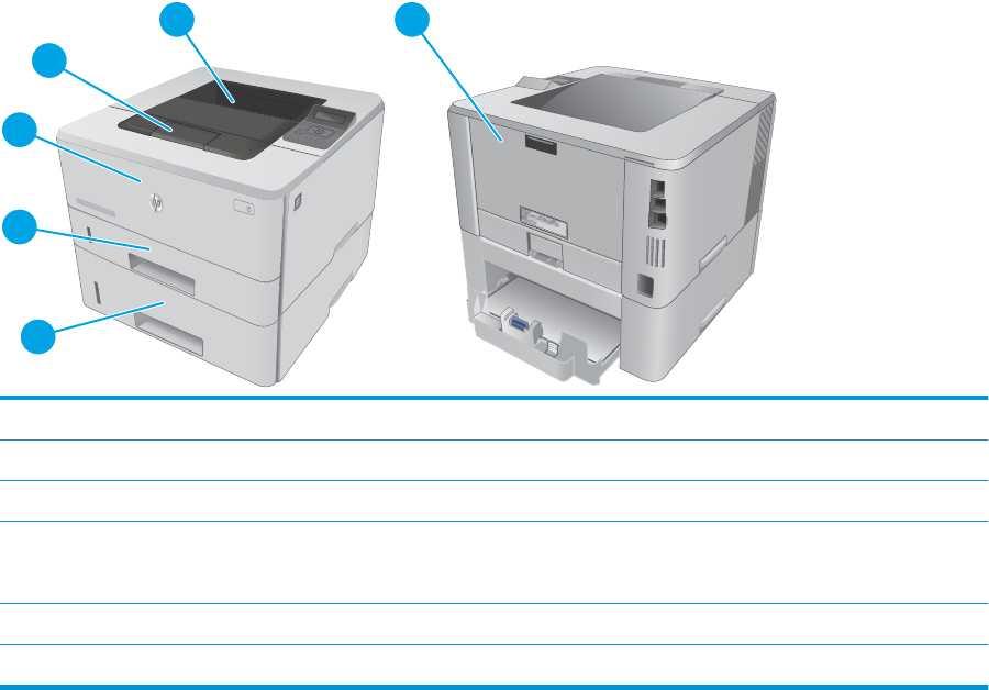
●Service
●Cleaning Page
c. Load plain letter or A4 paper when you are prompted, and then press the OK button.
A Cleaning message displays on the printer control panel. Wait until the process is complete.
Discard the page that prints.
5. Print a conguration page to test the printer.
a. On the printer control panel, press the OK button.
b. Open the Reports menu.
c. Select Conguration Report.
If none of these steps resolves the problem, the printer might need service. Contact HP customer support.
Jam locations
Jams can occur in these locations:
HEWLETT-PACKARD
3
3
2
1
1
5
6
3
2
4
1 Output bin
2 Fuser area
3 Tray 3 (optional)
4 Tray 2
Duplexing area (remove Tray 2 for access)
5 Tray 1
6 Toner cartridge area (open the front door for access)
Loose toner might remain in the printer after a jam. This problem typically resolves itself after a few sheets
have been printed.
102 Chapter 2 Solve problems ENWW
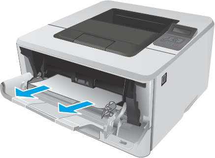
Clear paper jams in Tray 1
Use the following procedure to clear paper jams in Tray 1.
1. Slowly pull the jammed paper out of the printer.
HEWLETT-PACKARD
2
ENWW Clear paper jams 103

Clear paper jams in Tray 2
Use the following procedure to check for paper in all possible jam locations related to Tray 2. When a jam
occurs, the control panel displays an animation that assists in clearing the jam.
1. Remove the tray from the printer.
ETT-PACKARD
1
2
2. Remove the paper from the tray, and discard any
damaged paper.
ETT-PACKARD
1
2
3. Verify that the rear paper guide is adjusted to the
indentation for the correct paper size. If
necessary, pinch the release and move the rear
paper guide to the correct position. It should click
into place.
2
11
B5
A4
104 Chapter 2 Solve problems ENWW

4. Load the paper into the tray. Make sure that the
stack is at at all four corners and that the top of
the stack is below the maximum-height
indicators.
2
5. Reinsert and close the tray.
ETT-PACKARD
1
2
6. Press the front-door-release button.
HEWLETT-PACKARD
2
1
ENWW Clear paper jams 105

7. Open the front door.
HEWLETT-PACKARD
1
2
1
8. Remove the toner cartridge.
1
2
9. Lift the jam-access cover.
106 Chapter 2 Solve problems ENWW

10. Remove any jammed paper.
11. Install the toner cartridge.
1
2
12. Close the front door.
HEWLETT-PACKARD
1
2
1
ENWW Clear paper jams 107
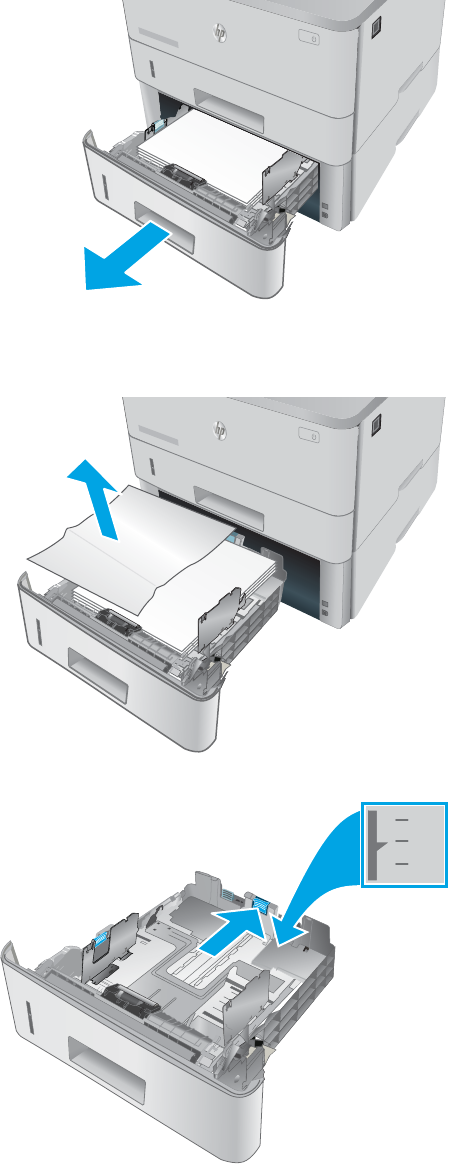
Clear paper jams in optional Tray 3
Use the following procedure to check for paper in all possible jam locations related to Tray 3. When a jam
occurs, the control panel displays an animation that assists in clearing the jam.
1. Remove the tray from the printer.
RD
2
1
3
2. Remove the paper from the tray, and discard any
damaged paper.
RD
2
1
3
3. Verify that the rear paper guide is adjusted to the
indentation for the correct paper size. If
necessary, pinch the release and move the rear
paper guide to the correct position. It should click
into place.
11
B5
A4
3
108 Chapter 2 Solve problems ENWW

4. Load the paper into the tray. Make sure that the
stack is at at all four corners and that the top of
the stack is below the maximum-height
indicators.
3
5. Reinsert and close the tray.
RD
2
1
3
6. Press the front-door-release button.
3
HEWLETT-PACKARD
2
1
ENWW Clear paper jams 109
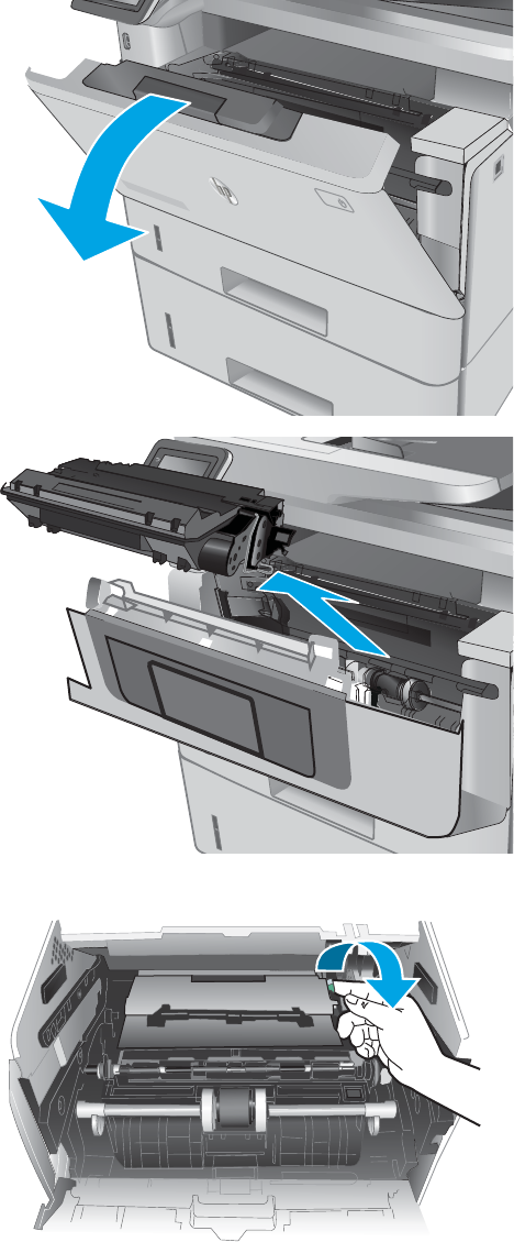
7. Open the front door.
3
HEWLETT-PACKARD
1
2
1
8. Remove the toner cartridge.
1
2
9. Lift the jam-access cover.
110 Chapter 2 Solve problems ENWW
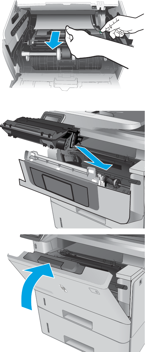
10. Remove any jammed paper.
11. Install the toner cartridge.
1
2
12. Close the front door.
3
HEWLETT-PACKARD
1
2
1
Clear paper jams in the fuser
Use the following procedure to check for paper in all possible jam locations in the fuser area.
ENWW Clear paper jams 111
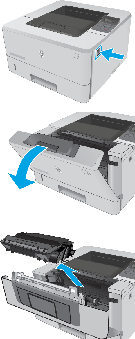
1. Press the front-door-release button.
HEWLETT-PACKARD
2
1
2. Open the front door.
2
HEWLETT-PACKARD
1
HEWLETT-PACKARD
1
3. Remove the toner cartridge.
2
HEWLETT-PACKARD
1
112 Chapter 2 Solve problems ENWW

4. Lift the jam-access cover.
5. Remove any jammed paper.
ENWW Clear paper jams 113
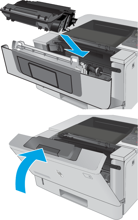
6. Install the toner cartridge.
2
HEWLETT-PACKARD
1
7. Close the front door.
2
HEWLETT-PACKARD
1
HEWLETT-PACKARD
1
114 Chapter 2 Solve problems ENWW
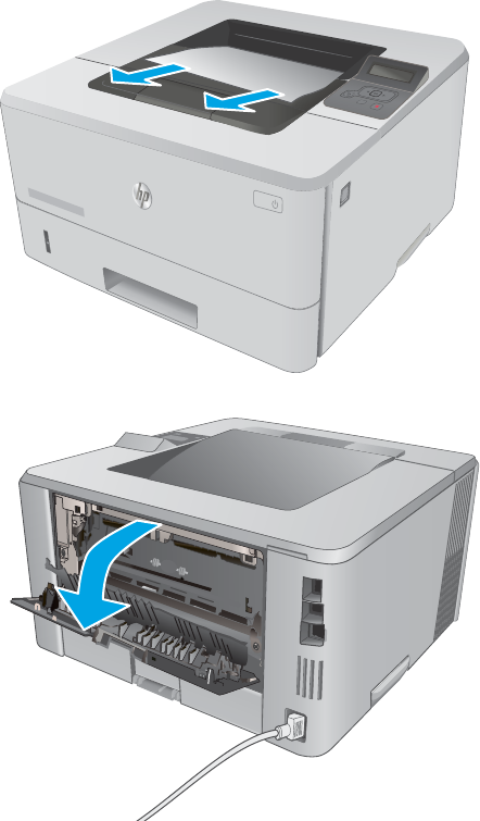
Clear paper jams in the output bin
Use the following procedure to check for paper in all possible jam locations in the output bin.
1. If paper is visible in the output bin, grasp the
leading edge and remove it.
HEWLETT-PACKARD
2
1
2. Open the rear door.
ENWW Clear paper jams 115
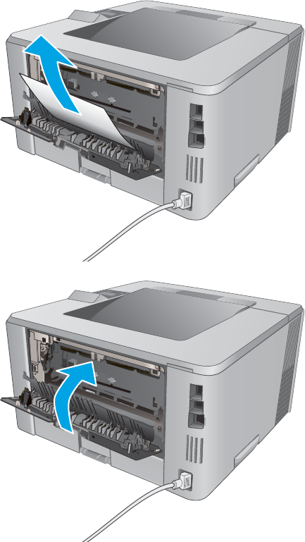
3. Remove any jammed paper from the rear door
area.
4. Close the rear door.
116 Chapter 2 Solve problems ENWW

Clear paper jams in the duplexer
Use the following procedure to check for paper in all possible jam locations in the automatic duplexer.
1. Completely remove Tray 2 from the printer.
ETT-PACKARD
1
2
2. Push the green button to release the duplex pan.
11
3. Remove any jammed paper.
ENWW Clear paper jams 117

4. Close the duplex pan.
5. Reinsert Tray 2.
ETT-PACKARD
1
2
118 Chapter 2 Solve problems ENWW

Clear paper jams (M426, M427)
Introduction
The following information includes instructions for clearing paper jams from the printer.
●Experiencing frequent or recurring paper jams?
●Jam locations
●Clear paper jams in the document feeder
●Clear paper jams in Tray 1
●Clear paper jams in Tray 2
●Clear paper jams in optional Tray 3
●Clear paper jams in the fuser
●Clear paper jams in the output bin
●Clear paper jams in the duplexer
Experiencing frequent or recurring paper jams?
Follow these steps to solve problems with frequent paper jams. If the rst step does not resolve the problem
continue with the next step until you have resolved the problem.
1. If paper has jammed in the product, clear the jam and then print a conguration page to test the
product.
2. Check that the tray is congured for the correct paper size and type on the product control panel. Adjust
paper settings if necessary.
a. From the Home screen on the product control panel, swipe until the Setup menu displays. Touch
the Setup icon to open the menu.
b. Open the following menus:
●System Setup
●Paper setup
c. Select the tray from the list.
d. Select Paper Type and then select the type of paper that is in the tray.
e. Select Paper Size and then select the size of paper that is in the tray.
3. Turn the product o, wait 30 seconds, and then turn it on again.
4. Print a cleaning page to remove excess toner from inside the product.
a. From the Home screen on the product control panel, swipe until the Setup menu displays. Touch
the Setup icon to open the menu.
b. Touch the Service menu.
ENWW Clear paper jams 119
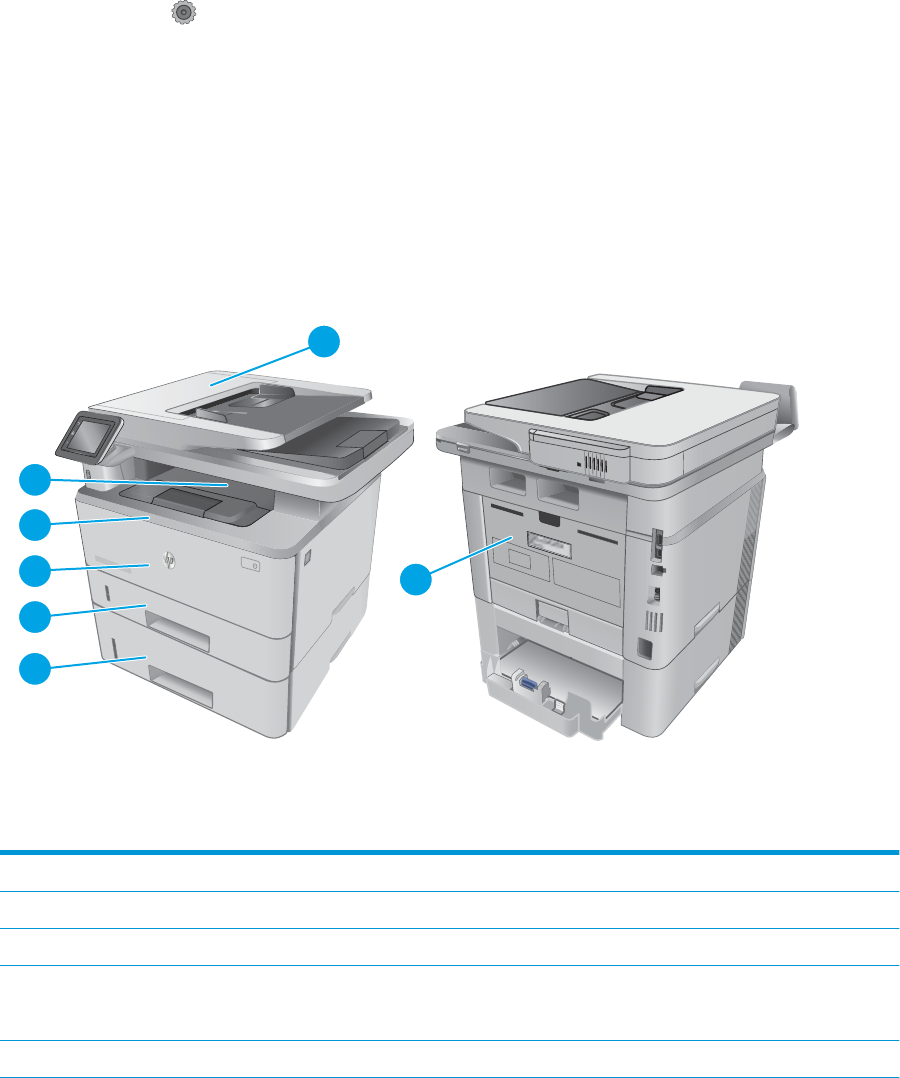
c. Touch the Cleaning Page button.
d. Load plain letter or A4 paper when you are prompted.
Wait until the process is complete. Discard the page that prints.
5. Print a conguration page to test the product.
a. From the Home screen on the product control panel, swipe until the Setup menu displays. Touch
the Setup icon to open the menu.
b. Open the Reports menu.
c. Select Conguration Report.
If none of these steps resolves the problem, the product might need service. Contact HP customer support.
Jam locations
Jams can occur in these locations:
2
2
1
3
2
3
4
5
6
7
1
1 Document feeder
2 Fuser area
3 Tray 3 (optional)
4 Tray 2
Duplexing area (remove Tray 2 for access)
5 Tray 1
120 Chapter 2 Solve problems ENWW

6 Toner cartridge area (open the front door for access)
7 Output bin
Loose toner might remain in the printer after a jam. This problem typically resolves itself after a few sheets
have been printed.
ENWW Clear paper jams 121
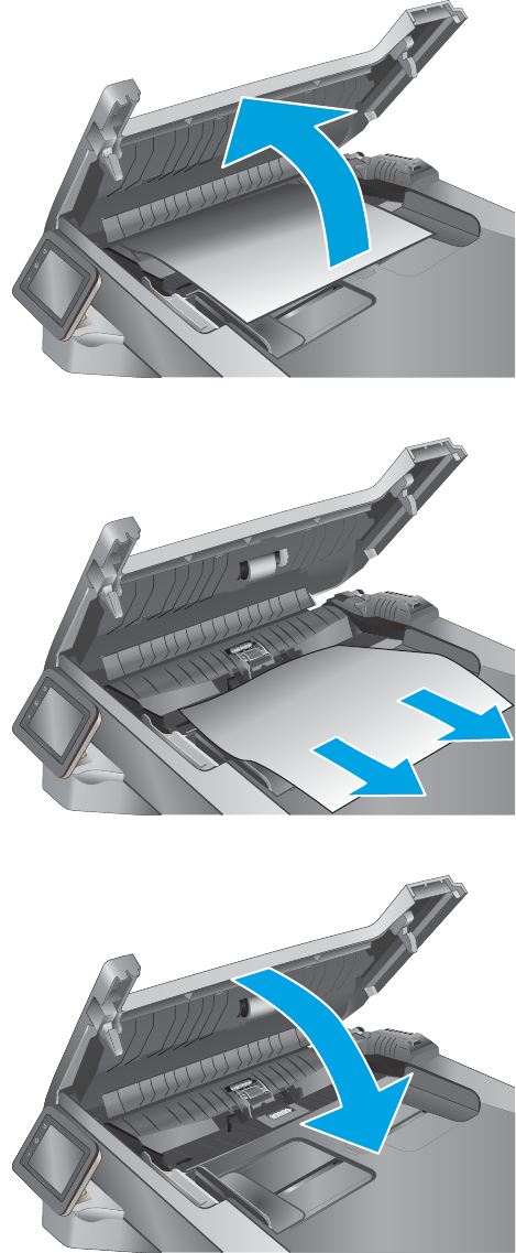
Clear paper jams in the document feeder
The following information describes how to clear paper jams in the document feeder. When a jam occurs, the
control panel displays an animation that assists in clearing the jam.
1. Open the document-feeder cover.
2. Gently pull the jammed paper out.
3. Close the document-feeder cover. Make sure it is
completely closed.
122 Chapter 2 Solve problems ENWW
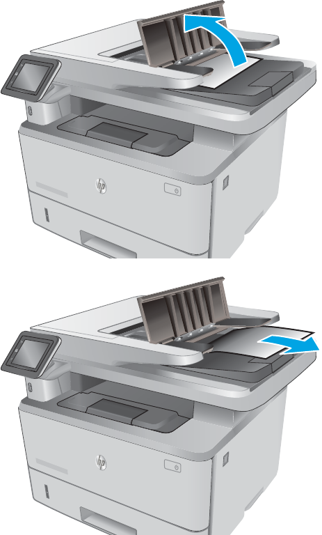
4. Open the document feeder tray cover.
HEWLETT-PACKARD
1
5. Gently pull the jammed paper out.
HEWLETT-PACKARD
1
ENWW Clear paper jams 123
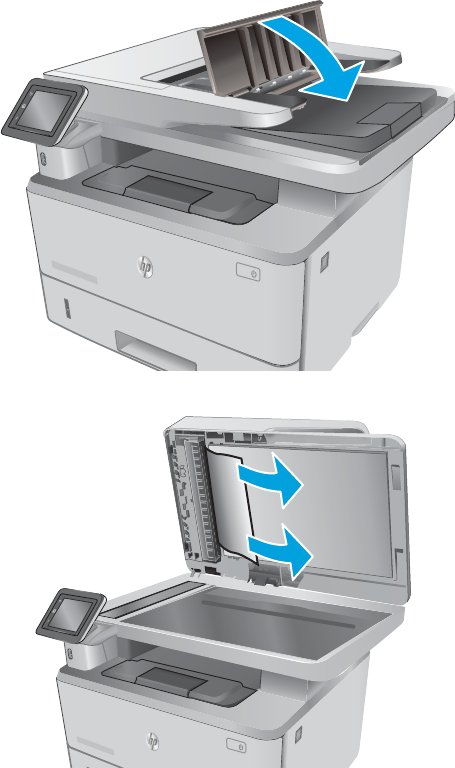
6. Close the document feeder tray cover.
HEWLETT-PACKARD
1
7. Open the scanner lid. If paper is jammed in the
scanner lid, gently pull it out, and then close the
scanner lid.
HEWLETT-PACKARD
124 Chapter 2 Solve problems ENWW
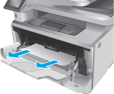
Clear paper jams in Tray 1
Use the following procedure to clear paper jams in Tray 1. When a jam occurs, the control panel displays an
animation that assists in clearing the jam.
1. Slowly pull the jammed paper out of the printer.
HEWLETT-PACKARD
2
ENWW Clear paper jams 125
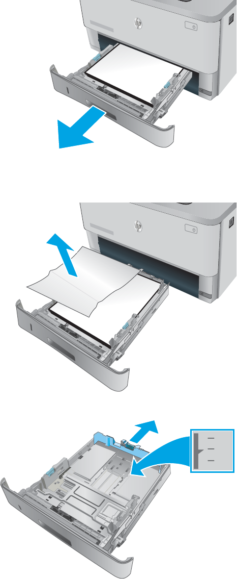
Clear paper jams in Tray 2
Use the following procedure to check for paper in all possible jam locations related to Tray 2. When a jam
occurs, the control panel displays an animation that assists in clearing the jam.
1. Remove the tray from the printer.
ETT-PACKARD
1
2
2. Remove the paper from the tray, and discard any
damaged paper.
ETT-PACKARD
1
2
3. Verify that the rear paper guide is adjusted to the
indentation for the correct paper size. If
necessary, pinch the release and move the rear
paper guide to the correct position. It should click
into place.
2
11
B5
A4
126 Chapter 2 Solve problems ENWW
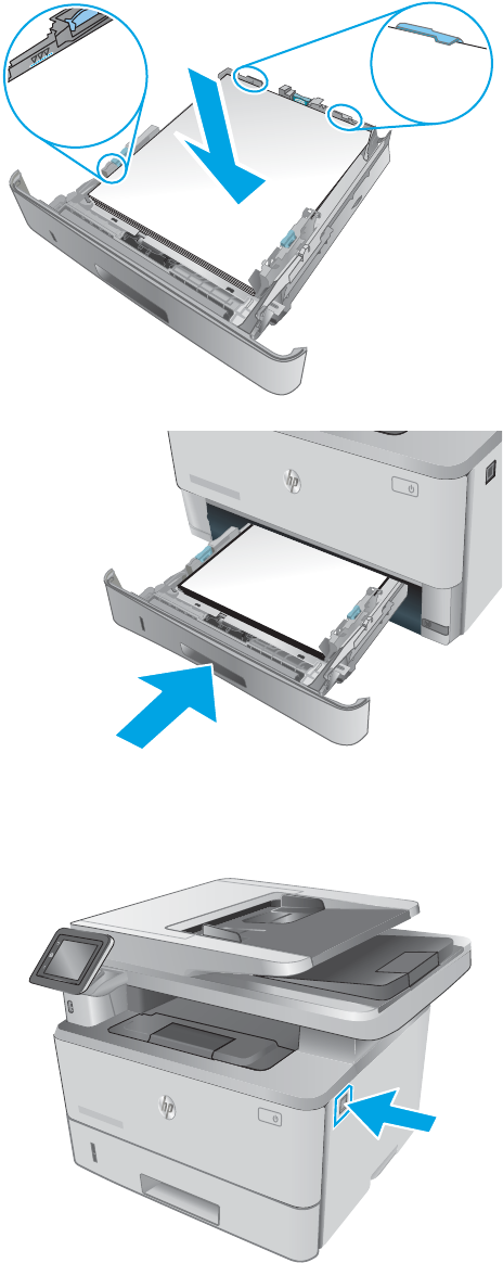
4. Load the paper into the tray. Make sure that the
stack is at at all four corners and that the top of
the stack is below the maximum-height
indicators.
2
5. Reinsert and close the tray.
ETT-PACKARD
1
2
6. Press the front-door-release button.
HEWLETT-PACKARD
2
1
ENWW Clear paper jams 127
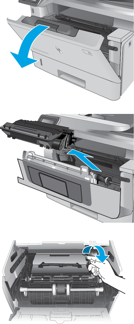
7. Open the front door.
HEWLETT-PACKARD
1
2
1
8. Remove the toner cartridge.
1
2
9. Lift the jam-access cover.
128 Chapter 2 Solve problems ENWW
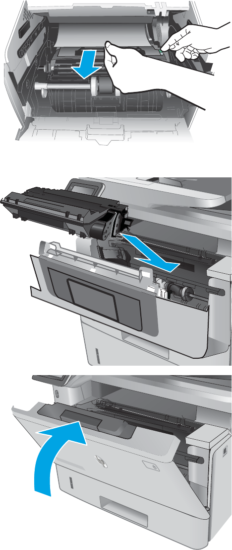
10. Remove any jammed paper.
11. Install the toner cartridge.
1
2
12. Close the front door.
HEWLETT-PACKARD
1
2
1
ENWW Clear paper jams 129

Clear paper jams in optional Tray 3
Use the following procedure to check for paper in all possible jam locations related to Tray 3. When a jam
occurs, the control panel displays an animation that assists in clearing the jam.
1. Remove the tray from the printer.
RD
2
1
3
2. Remove the paper from the tray, and discard any
damaged paper.
RD
2
1
3
3. Verify that the rear paper guide is adjusted to the
indentation for the correct paper size. If
necessary, pinch the release and move the rear
paper guide to the correct position. It should click
into place.
11
B5
A4
3
130 Chapter 2 Solve problems ENWW
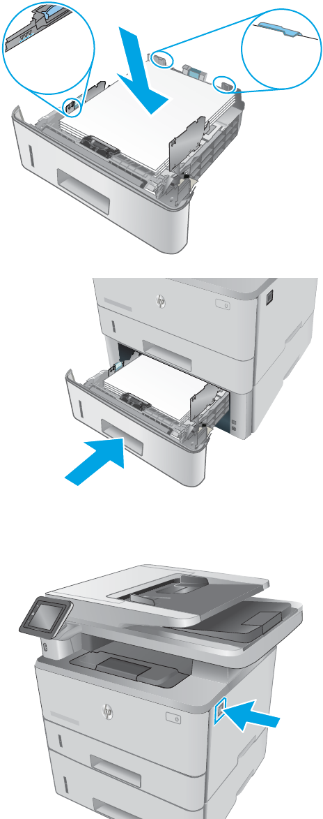
4. Load the paper into the tray. Make sure that the
stack is at at all four corners and that the top of
the stack is below the maximum-height
indicators.
3
5. Reinsert and close the tray.
RD
2
1
3
6. Press the front-door-release button.
3
HEWLETT-PACKARD
2
1
ENWW Clear paper jams 131

7. Open the front door.
3
HEWLETT-PACKARD
1
2
1
8. Remove the toner cartridge.
1
2
9. Lift the jam-access cover.
132 Chapter 2 Solve problems ENWW

10. Remove any jammed paper.
11. Install the toner cartridge.
1
2
12. Close the front door.
3
HEWLETT-PACKARD
1
2
1
ENWW Clear paper jams 133
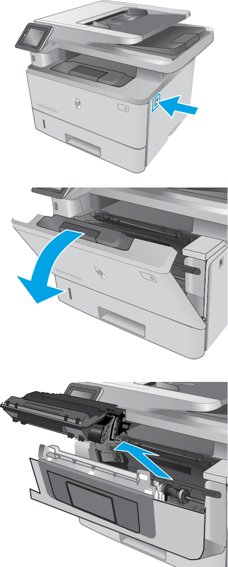
Clear paper jams in the fuser
Use the following procedure to check for paper in all possible jam locations in the fuser area. When a jam
occurs, the control panel displays an animation that assists in clearing the jam.
1. Press the front-door-release button.
HEWLETT-PACKARD
2
1
2. Open the front door.
HEWLETT-PACKARD
1
2
1
3. Remove the toner cartridge.
1
2
134 Chapter 2 Solve problems ENWW
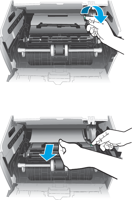
4. Lift the jam-access cover.
5. Remove any jammed paper.
ENWW Clear paper jams 135
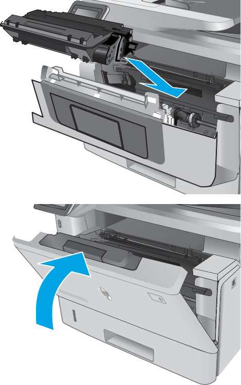
6. Install the toner cartridge.
1
2
7. Close the front door.
HEWLETT-PACKARD
1
2
1
136 Chapter 2 Solve problems ENWW
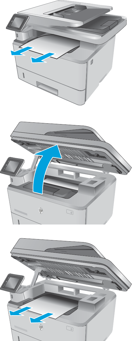
Clear paper jams in the output bin
Use the following procedure to check for paper in all possible jam locations in the output bin. When a jam
occurs, the control panel displays an animation that assists in clearing the jam.
1. If paper is visible in the output bin, grasp the
leading edge and remove it.
2
1
2. Lift the scanner assembly.
3. Remove any jammed paper.
ENWW Clear paper jams 137
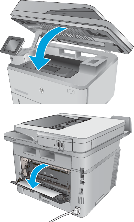
4. Close the scanner assembly.
5. Open the rear door.
138 Chapter 2 Solve problems ENWW
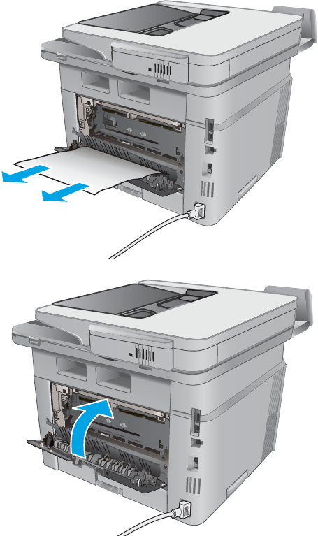
6. Remove any jammed paper from the rear door
area.
7. Close the rear door.
ENWW Clear paper jams 139
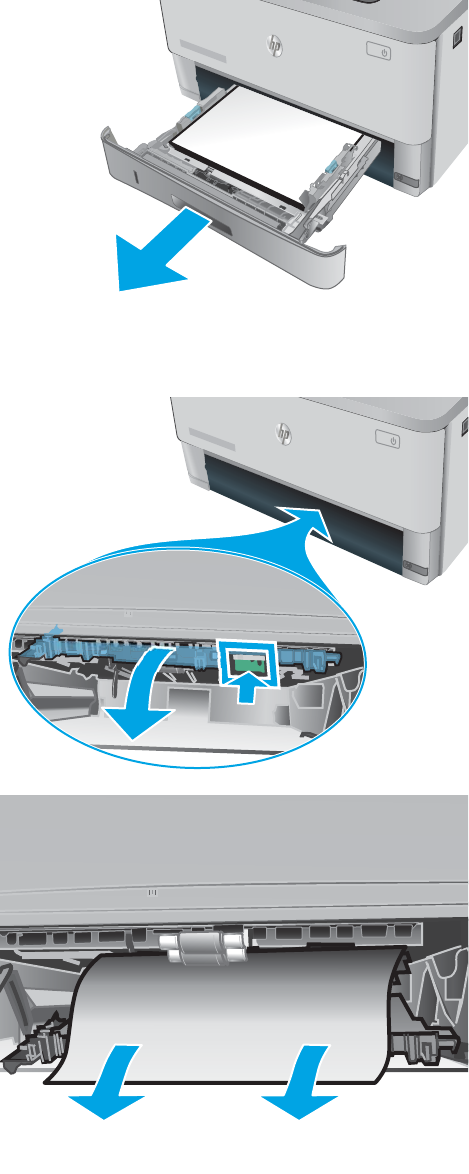
Clear paper jams in the duplexer
Use the following procedure to check for paper in all possible jam locations in the automatic duplexer. When a
jam occurs, the control panel displays an animation that assists in clearing the jam.
1. Completely remove Tray 2 from the printer.
ETT-PACKARD
1
2
2. Push the green button to release the duplex pan.
11
3. Remove any jammed paper.
140 Chapter 2 Solve problems ENWW
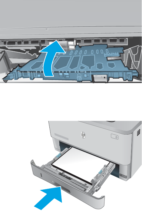
4. Close the duplex pan.
5. Reinsert Tray 2.
ETT-PACKARD
1
2
ENWW Clear paper jams 141
Solve paper-handling problems
The printer picks up multiple sheets of paper
If the printer picks up multiple sheets of paper from the tray, try these solutions.
1. Remove the stack of paper from the tray and ex it, rotate it 180 degrees, and ip it over. Do not fan the
paper. Return the stack of paper to the tray.
2. Use only paper that meets HP specications for this printer.
3. Use paper that is not wrinkled, folded, or damaged. If necessary, use paper from a dierent package.
4. Make sure the tray is not overlled. If it is, remove the entire stack of paper from the tray, straighten the
stack, and then return some of the paper to the tray.
5. Make sure the paper guides in the tray are adjusted correctly for the size of paper. Align the guides with
the paper-size markings in the bottom of the tray.
The printer does not pick up paper
If the printer does not pick up paper from the tray, try these solutions.
1. Open the printer and remove any jammed sheets of paper.
2. Load the tray with the correct size of paper for your job.
3. Make sure the paper guides in the tray are adjusted correctly for the size of paper. Align the guides with
the paper-size markings in the bottom of the tray.
4. Check the printer control panel to see if the printer is waiting for you to acknowledge a prompt to feed
the paper manually. Load paper, and continue.
142 Chapter 2 Solve problems ENWW
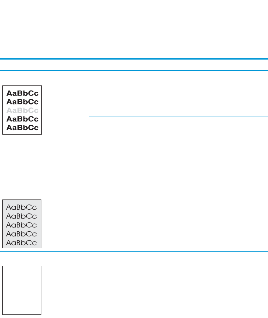
Solve image quality problems
You can prevent most print-quality problems by following these guidelines.
●Print quality examples
Print quality examples
The following examples depict Letter-size paper that has passed through the product short-edge rst. These
examples illustrate problems that would aect all the pages that you print, whether you print in color or in
black only. The topics that follow list the typical cause and solution for each of these examples.
Table 2-12 Print quality examples
Problem Cause Solution
Print is light or faded. The media might not meet
HP specications.
Use media that meets HP specications.
The toner cartridge might be defective. Print the supplies status page to check the
remaining toner cartridge life.
Replace the toner cartridge.
The product is set to override the Replace
black cartridge message and to continue
printing.
Replace the toner cartridge.
The print density setting might have been
changed.
Set the print density setting to 0.
Poor contact exists between the transfer
roller contact and the transfer roller shaft.
Clean the contacts. If the problem remains
after cleaning, check the contacts for
deformation or damage. Replace any
defective parts.
Page has dark print. Poor contact exists between the drum
grounding contact and the toner cartridge.
Clean the grounding contacts. If the
problem remains after cleaning, check the
contacts for deformation or damage.
Replace any defective parts.
Poor contact exists between the primary
charging bias contact and the toner
cartridge.
Clean the contacts. If the problem remains
after cleaning, check the contacts for
deformation or damage. Replace any
defective parts.
The page is blank. The high-voltage power supply is defective
(no developing bias output).
Replace the high-voltage power supply
PCA.
ENWW Solve image quality problems 143
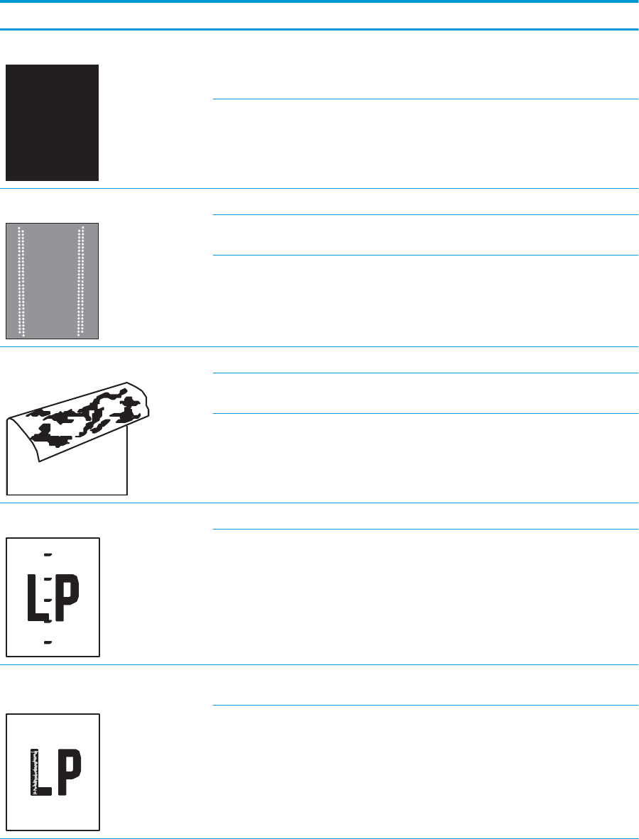
Table 2-12 Print quality examples (continued)
Problem Cause Solution
The page is all black. Poor contact exists between the primary
charging bias contact and the toner
cartridge.
Clean the contacts. If the problem remains
after cleaning, check the contacts for
deformation or damage. Replace any
defective parts.
The primary charging roller is defective. Replace the toner cartridge.
White spots appear on the page. The static charge eliminator is dirty. Clean the static charge eliminator.
The transfer roller is deformed or has
deteriorated.
Replace the transfer roller.
Poor contact exists between the transfer
roller contact and the transfer roller shaft.
Clean the contacts. If the problem remains
after cleaning, check the contacts for
deformation or damage. Replace any
defective parts.
The back of the page is dirty. The transfer roller is dirty. Replace the transfer roller.
The fuser inlet guide or separation guide is
dirty.
Clean the dirty parts. If the dirt does not
come o, replace the fuser.
The pressure roller is dirty. Perform a fuser roller cleaning operation
of the multi-purpose mode. If the dirt does
not come o, replace the fuser.
The front of the page is dirty. The photosensitive drum is dirty. Replace the toner cartridge.
The fuser lm or pressure roller is dirty. Perform a fuser roller cleaning operation
of the multi-purpose mode. If the dirt does
not come o, replace the fuser.
Vertical density variation appears on the
page.
The photosensitive drum surface has
deteriorated.
Replace the toner cartridge.
The laser/scanner assembly is defective. Replace the laser/scanner assembly.
144 Chapter 2 Solve problems ENWW
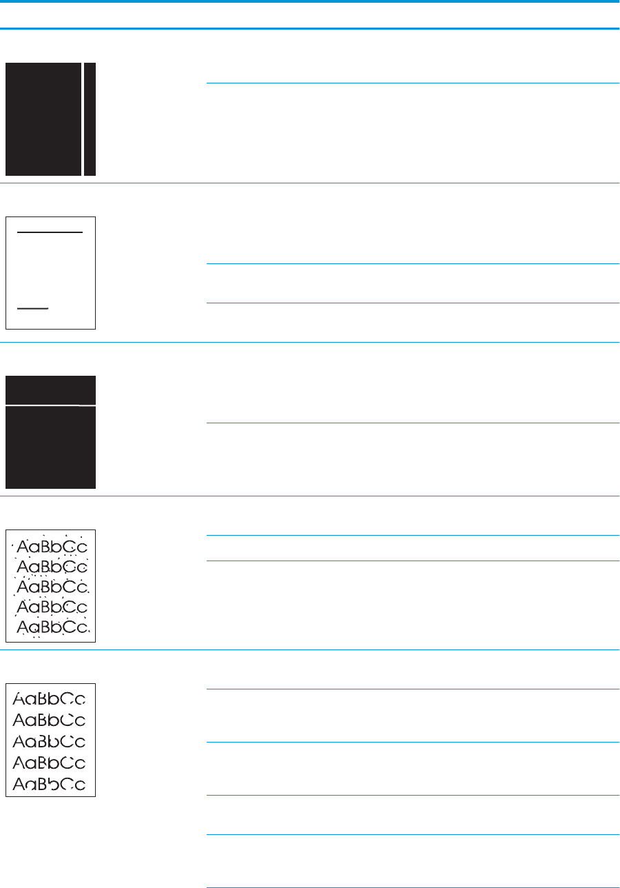
Table 2-12 Print quality examples (continued)
Problem Cause Solution
Vertical white lines appear on the page. Scratches are present on the circumference
of the developer roller or photosensitive
drum.
Replace the toner cartridge.
The laser/scanner mirror is dirty. Replace the laser/scanner assembly.
Horizontal lines appear on the page. Repetitive horizontal lines appear. Identify the dirty roller which causes the
repetitive image defects. Clean the roller. If
the dirt does not come o, replace the
corresponding assembly including aected
rollers.
Horizontal scratches are present on the
photosensitive drum.
Replace the toner cartridge.
Horizontal scratches are present on the
fuser lm.
Replace the fuser.
Horizontal white lines appear on the page. Repetitive horizontal white lines appear. Identify the dirty roller which causes the
repetitive image defects. Clean the roller. If
the dirt does not come o, replace the
corresponding assembly including aected
rollers.
Horizontal scratches are present on the
photosensitive drum.
Replace the toner cartridge.
Toner specks appear. The media might not meet HP
specications.
Use only media that meets
HP specications.
The paper path might need cleaning. Clean the paper path.
The toner cartridge might be leaking. Check the cartridge for leaks.
Dropouts appear. A single sheet of print media might be
defective.
Try reprinting the job.
The moisture content of the paper is
uneven or the paper has moist spots on its
surface.
Try dierent paper, such as high-quality
paper that is intended for laser printers.
The media is awed. The media
manufacturing processes can cause some
areas to reject toner.
Try dierent paper, such as high-quality
paper that is intended for laser printers.
The transfer roller is deformed or has
deteriorated.
Replace the transfer roller.
The primary charging roller, developer
roller or photosensitive drum is deformed
or has deteriorated.
Replace the toner cartridge.
ENWW Solve image quality problems 145
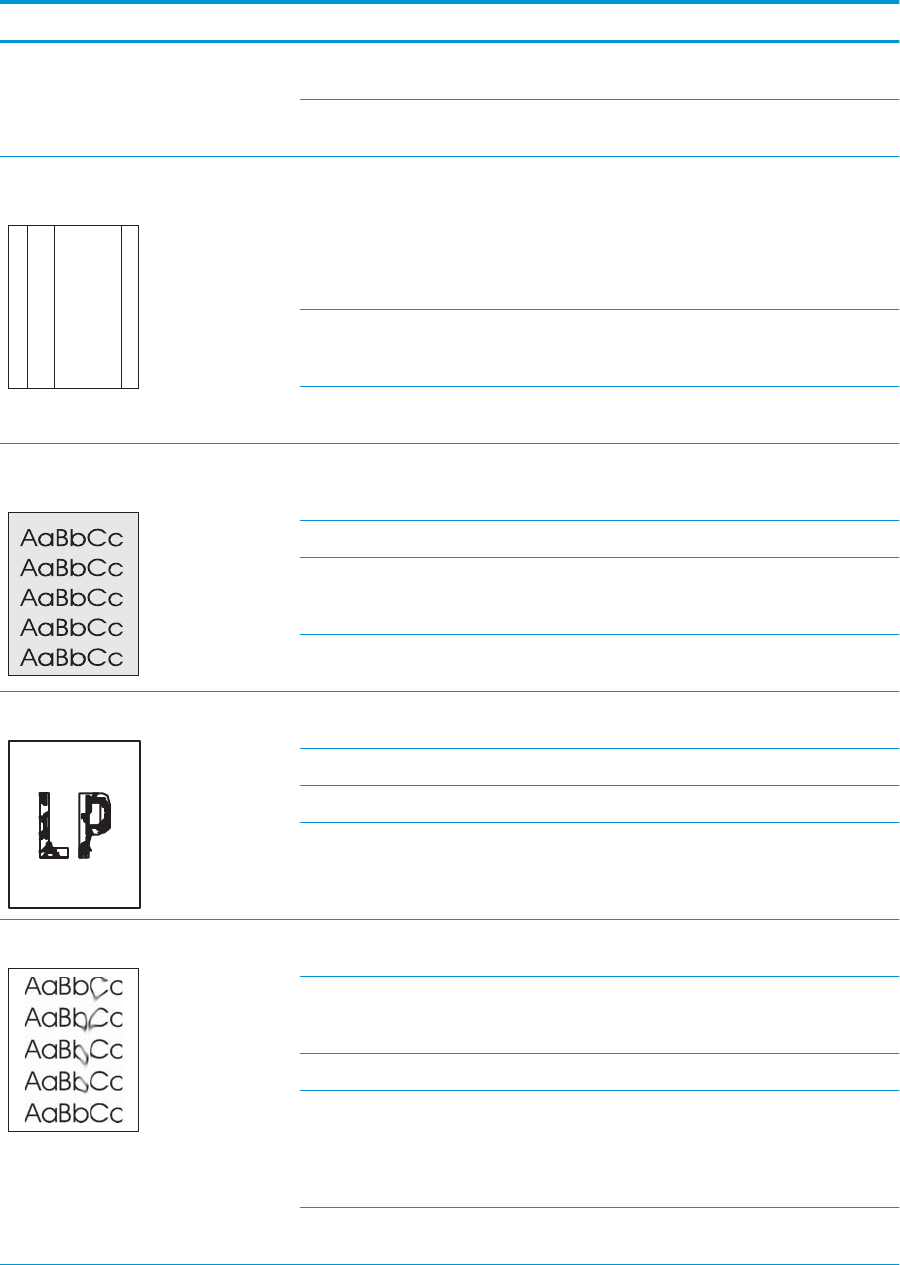
Table 2-12 Print quality examples (continued)
Problem Cause Solution
The fuser lm is deformed or has
deteriorated.
Replace the fuser.
The high-voltage power supply is defective
(no transfer bias output).
Replace the high-voltage power supply
PCA.
Vertical streaks or bands appear on the
page.
A
A
A
A
A
B
B
B
B
B
C
C
C
C
C
a
a
a
a
a
c
c
c
c
c
b
b
b
b
b
The toner cartridge might be defective.
Scratches are present on the circumference
of the photosensitive drum.
Print the supplies status page to check the
remaining life.
Use HP Device Toolbox to check the
supplies status.
Replace the toner cartridge.
The product is set to override the Replace
black cartridge message and to continue
printing.
Replace the toner cartridge.
Scratches are present on the circumference
of the fuser lm.
Replace the fuser.
The amount of background toner shading
becomes unacceptable.
Extremely dry (low humidity) conditions
can increase the amount of background
shading.
Check the product environment.
The toner cartridge might be defective. Replace the toner cartridge.
The product is set to override the Replace
black cartridge message and to continue
printing.
Replace the toner cartridge.
Smooth media shows more background
than plain media
Try using rougher media.
The toner is not fully fused to the media. The fuser lm or pressure roller is scarred
or deformed.
Replace the fuser.
The thermistor is defective. Replace the fuser.
The fuser heater is defective. Replace the fuser.
The fuser control circuit is defective. Replace the low-voltage power supply
assembly.
Toner smears appear on the media. The media might not meet HP
specications.
Use only media that meets
HP specications.
If toner smears appear on the leading edge
of the paper, the media guides are dirty, or
debris has accumulated in the print path.
Clean the media guides.
Clean the paper path.
Residual paper in the paper path. Remove the residual paper.
Poor contact exists in the grounding of the
toner cartridge.
Clean the contacts of both the printer and
the cartridge. If the problem remains after
cleaning, check the contacts for
deformation or damage. Replace any
defective parts.
Foreign substance adheres to the fuser
inlet guide or the guide is dirty.
Clean the fuser inlet guide.
146 Chapter 2 Solve problems ENWW
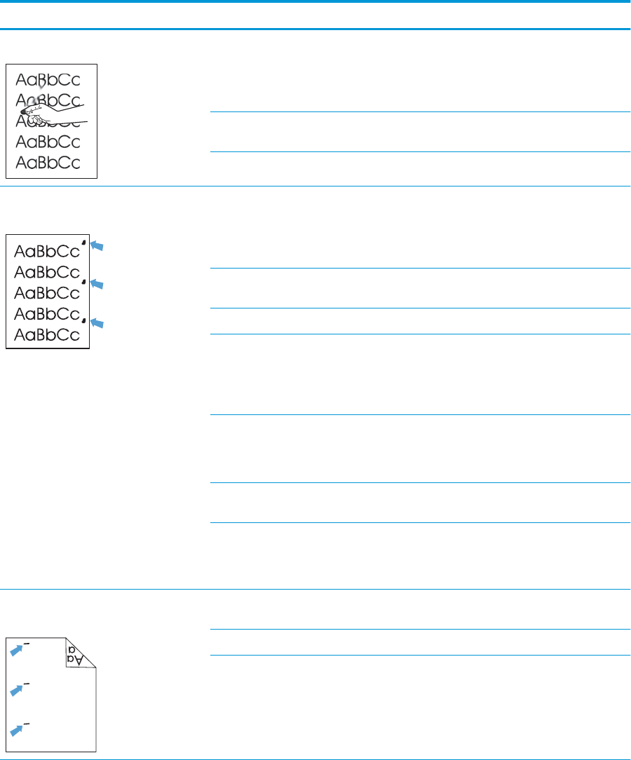
Table 2-12 Print quality examples (continued)
Problem Cause Solution
The toner smears easily when touched. The product is not set to print on the type
of media on which you want to print.
In the printer driver, select the Paper tab
and set Type is to match the type of media
on which you are printing. Print speed
might be slower if you are using heavy
paper.
The media might not meet HP
specications.
Use only media that meets
HP specications.
The paper path might need cleaning. Clean the paper path.
Marks repeatedly appear at even intervals
on the printed side of the page.
The product is not set to print on the type
of media on which you want to print.
In the printer driver, select the Paper tab
and set Type is to match the type of paper
on which you are printing. Print speed
might be slower if you are using heavy
paper.
Internal parts might have toner on them. The problem typically corrects itself after a
few more pages.
The paper path might need cleaning. Clean the paper path.
The fuser might be damaged or dirty. To determine if the fuser has a problem,
open HP Device Toolbox, and print the
print-quality diagnostics page.
Clean the paper path.
Repetitive white spots appear. Identify the dirty roller which causes the
repetitive image defects. Clean the roller. If
the dirt does not come o, replace the
corresponding assembly.
The transfer roller is deformed or has
deteriorated.
Replace the transfer roller.
The toner cartridge might have a problem.
Foreign substance adheres to the primary
charging roller or photosensitive drum.
Replace the toner cartridge.
Marks repeatedly appear at even intervals
on the unprinted side of the page.
Internal parts might have toner on them. The problem typically corrects itself after a
few more pages.
The paper path might need cleaning. Clean the paper path.
The fuser might be damaged or dirty. To determine if the fuser has a problem,
open HP Device Toolbox and print the
print-quality diagnostics page.
Clean the paper path.
ENWW Solve image quality problems 147
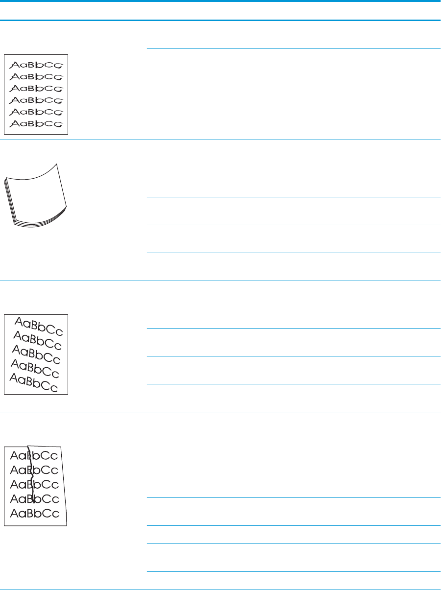
Table 2-12 Print quality examples (continued)
Problem Cause Solution
The printed page contains misformed
characters.
The media might not meet
HP specications.
Use a dierent paper, such as high-quality
paper that is intended for laser printers.
If characters are incorrectly formed so that
they produce a wavy eect, the laser/
scanner might need service.
Verify that the problem also occurs on the
conguration page. Replace the laser
scanner assembly.
The printed page is curled or wavy. The product is not set to print on the type
of media on which you want to print.
In the printer driver, select the Paper tab
and set Type is to match the type of paper
on which you are printing. Print speed
might be slower if you are using heavy
paper.
The Service menu item Less Paper Curl is
set to O.
Use the control-panel menus to change the
setting.
The media might not meet
HP specications.
Use a dierent paper, such as high-quality
paper that is intended for laser printers.
Both high temperature and humidity can
cause paper curl.
Check the product environment.
Text or graphics are skewed on the printed
page.
The media might be loaded incorrectly. Ensure that the paper or other print media
is loaded correctly and that the media
guides are not too tight or too loose
against the stack. See the user guide.
The media might not meet
HP specications.
Use a dierent paper, such as high-quality
paper that is intended for laser printers.
The registration shutter spring is
unhooked.
Check the spring and place it in the correct
position if is disengaged.
The registration shutter spring is
deformed.
Replace the registration assembly.
The printed page contains wrinkles or
creases.
The media might be loaded incorrectly. Verify that the media is loaded correctly
and that the media guides are not too tight
or too loose against the stack. See the user
guide.
Turn over the stack of paper in the input
tray, or try rotating the paper 180° in the
input tray.
The media might not meet
HP specications.
Use a dierent paper, such as high-quality
paper that is intended for laser printers.
The feed roller or paper feed guide is dirty. Clean any dirty parts.
The feed roller is deformed or worn. Replace the feed roller that is deformed or
worn.
The paper feed guide is damaged. Replace the paper feed guide.
148 Chapter 2 Solve problems ENWW

Table 2-12 Print quality examples (continued)
Problem Cause Solution
Toner appears around the printed
characters.
The media might be loaded incorrectly. Turn over the stack of paper in the tray.
If large amounts of toner have scattered
around the characters, the paper might
have high resistivity.
Use a dierent paper, such as high-quality
paper that is intended for laser printers.
An image that appears at the top of the
page (in solid black) repeats farther down
the page (in a gray eld).
Software settings might aect image
printing.
In your software program, change the tone
(darkness) of the eld in which the
repeated image appears.
In your software program, rotate the whole
page 180° to print the lighter image rst.
The order of images printed might aect
printing.
Change the order in which the images are
printed. For example, have the lighter
image at the top of the page, and the
darker image farther down the page.
A power surge might have aected the
product.
If the defect occurs later in a print job, turn
the product o for 10 minutes, and then
turn on the product to restart the print job.
Use non-glossy media to help reduce the
severity of the defect
ENWW Solve image quality problems 149

Clean the printer
Clean the pickup and separation rollers
1. Turn o the printer, unplug the power cable from the printer, and then remove the rollers.
2. Dab a lint-free cloth in isopropyl alcohol, and then scrub the roller.
WARNING! Alcohol is ammable. Keep the alcohol and cloth away from an open ame. Before you
close the printer and connect the power cable, allow the alcohol to dry completely.
NOTE: In certain areas of California (USA), air pollution control regulations restrict the use of liquid
isopropyl alcohol (IPA) as a cleaning agent. In those areas of California, please disregard the previous
recommendations and use a dry, lint free cloth, moistened with water, to clean the pickup roller.
3. Use a dry, lint free cloth, to wipe the rollers and remove loose dirt.
Clean the paper path
During the printing process, paper, toner, and dust particles can accumulate inside the printer. Over time, this
buildup can cause print-quality problems such as toner specks or smearing. This printer has a cleaning mode
that can correct and prevent these types of problems.
Clean the paper path (LCD control panel)
1. On the printer control panel, press the OK button to open the menus.
2. Open the following menus:
●Service
●Cleaning Page
3. Load plain paper in Tray 1, and then press the OK button to start the cleaning process.
Wait until the process is complete. Discard the page that prints.
Clean the paper path (touchscreen control panel)
1. From the Home screen on the printer control panel, touch the Setup button.
2. Touch the Service menu.
3. Touch the Cleaning Page button.
4. Load plain letter or A4 paper when you are prompted.
5. Touch the OK button to begin the cleaning process.
Wait until the process is complete. Discard the page that prints.
Clean the touchscreen
Clean the touch screen whenever it is necessary to remove ngerprints or dust. Wipe the touch screen gently
with a clean, water-dampened, lint-free cloth.
150 Chapter 2 Solve problems ENWW

CAUTION: Use water only. Solvents or cleaners can damage the touch screen. Do not pour or spray water
directly onto the touch screen.
ENWW Clean the printer 151

Solve performance problems
Factors aecting print performance
Problem Cause Solution
Pages print but, are totally blank. The sealing tape might still be in the toner
cartridges.
Verify that the sealing tape has been
completely removed from the toner
cartridges.
The document might contain blank pages. Check the document that you are printing
to see if content appears on all of the
pages.
The product might be malfunctioning. To check the product, print a Conguration
page.
Pages print very slowly.
NOTE: The product print speed is
eected by various factors (for example,
media size or page complexity).
Heavier media types can slow the print job. Print on a dierent type of media.
Complex pages can print slowly. Proper fusing might require a slower print
speed to ensure the best print quality.
Paper type not set correctly. Select the type to match the paper.
Pages did not print. The product might not be pulling media
correctly.
Ensure paper is loaded in the tray
correctly.
If the problem persists, you might need to
replace the pickup rollers and the
separation pad.
The media is jamming in the product. Clear the jam.
The USB cable might be defective or
incorrectly connected.
●Disconnect the USB cable at both
ends and reconnect it.
●Try printing a job that has printed in
the past.
●Try using a dierent USB cable.
Other devices are running on your
computer.
The product might not share a USB port. If
you have an external hard drive or network
switchbox that is connected to the same
port as the product, the other device might
be interfering. To connect and use the
product, you must disconnect the other
device or you must use two USB ports on
the computer.
Print speeds
Print speed is the number of pages that print in one minute. Print speed depends on dierent engine-process
speeds or operational pauses between printed pages during normal product operation. Factors that
determine the print speed of the product include the following:
●Page formatting time
152 Chapter 2 Solve problems ENWW
The product must pause for each page to be formatted before it prints. Complex pages take more time
to format, resulting in reduced print speed. However, most jobs print at full engine speed (35 ppm on
Letter-size media or 33 ppm on A4-size media).
●Media size
Legal-size media reduces print speed because it is longer than the standard Letter- or A4–size media. A
reduce print speed is used when printing on narrow media to prevent the edges of the fuser from
overheating.
●Media mode
Some media types require a reduced print speed to achieve maximum print quality on that media. For
example, glossy, heavy, and specialty media (for example, envelopes or photos) require a reduced print
speed. To maximize the print speed for special media types, ensure that you select the correct media
type in the print driver.
●Product temperature
To prevent product damage, print speed is reduced if the product reaches a specic internal temperature
(thermal slow down). The starting temperature of the product, ambient environment temperature, and
the print job size eect the number of pages that can be printed before the product reduces the print
speed. Thermal slow down reduces print speed by printing four pages and then pausing for an amount
of time before printing continues.
●Other print speed reduction factors
Other factors (especially during large print jobs) that can cause reduced print speeds include:
◦Density control sequence; occurs every 150 pages and takes about 120 seconds.
The product does not print or it prints slowly
The product does not print
If the product does not print at all, try the following solutions.
1. Make sure the product is turned on and that the control panel indicates it is ready.
●If the control panel does not indicate the product is ready, turn the product o and then on again.
●If the control panel indicates the product is ready, try sending the job again.
2. If the control panel indicates the product has an error, resolve the error and then try sending the job
again.
3. Make sure the cables are all connected correctly. If the product is connected to a network, check the
following items:
●Check the light next to the network connection on the product. If the network is active, the light is
green.
●Make sure that you are using a network cable and not a phone cord to connect to the network.
●Make sure the network router, hub, or switch is turned on and that it is working correctly.
4. Install the HP software from the CD that came with the product. Using generic printer drivers can cause
delays clearing jobs from the print queue.
ENWW Solve performance problems 153

5. From the list of printers on your computer, right-click the name of this product, click Properties, and
open the Ports tab.
●If you are using a network cable to connect to the network, make sure the printer name listed on
the Ports tab matches the product name on the product conguration page.
●If you are using a USB cable and are connecting to a wireless network, make sure the box is
checked next to Virtual printer port for USB.
6. If you are using a personal rewall system on the computer, it might be blocking communication with
the product. Try temporarily disabling the rewall to see if it is the source of the problem.
7. If your computer or the product is connected to a wireless network, low signal quality or interference
might be delaying print jobs.
The product prints slowly
If the product prints, but it seems slow, try the following solutions.
1. Make sure the computer meets the minimum specications for this product. For a list of specications,
go to this Web site: www.hp.com/support/ljM402, www.hp.com/support/ljM403 or www.hp.com/
support/ljM426MFP, www.hp.com/support/ljM427MFP.
2. When you congure the product to print on some paper types, such as heavy paper, the product prints
more slowly so it can correctly fuse the toner to the paper. If the paper type setting is not correct for the
type of paper you are using, change the setting to the correct paper type.
3. If your computer or the product is connected to a wireless network, low signal quality or interference
might be delaying print jobs.
154 Chapter 2 Solve problems ENWW

Solve connectivity problems
Solve direct-connect problems
If you have connected the product directly to a computer, check the cable.
●Verify that the cable is connected to the computer and to the product.
●Verify that the cable is not longer than 5 m (16.4 ft). Try using a shorter cable.
●Verify that the cable is working correctly by connecting it to another product. Replace the cable if
necessary.
Solve network problems
Check the following items to verify that the product is communicating with the network. Before beginning,
print a conguration page from the product control panel and locate the product IP address that is listed on
this page.
●Poor physical connection
●The computer is using the incorrect IP address for the product
●The computer is unable to communicate with the product
●The product is using incorrect link and duplex settings for the network
●New software programs might be causing compatibility problems
●The computer or workstation might be set up incorrectly
●The product is disabled, or other network settings are incorrect
Poor physical connection
1. Verify that the product is attached to the correct network port using a cable of the correct length.
2. Verify that cable connections are secure.
3. Look at the network port connection on the back of the product, and verify that the amber activity light
and the green link-status light are lit.
4. If the problem continues, try a dierent cable or port on the hub.
The computer is using the incorrect IP address for the product
1. Open the printer properties and click the Ports tab. Verify that the current IP address for the product is
selected. The product IP address is listed on the product conguration page.
2. If you installed the product using the HP standard TCP/IP port, select the box labeled Always print to
this printer, even if its IP address changes.
3. If you installed the product using a Microsoft standard TCP/IP port, use the hostname instead of the IP
address.
4. If the IP address is correct, delete the port, and then create a new one.
5. If the error persists, delete the product and then add it again.
ENWW Solve connectivity problems 155
The computer is unable to communicate with the product
1. Test network communication by pinging the network.
a. Open a command-line prompt on your computer. For Windows, click Start, click Run, and then type
cmd.
b. Type ping followed by the IP address for your product.
c. If the window displays round-trip times, the network is working.
2. If the ping command failed, verify that the network hubs are on, and then verify that the network
settings, the product, and the computer are all congured for the same network.
The product is using incorrect link and duplex settings for the network
Hewlett-Packard recommends leaving this setting in automatic mode (the default setting). If you change
these settings, you must also change them for your network.
New software programs might be causing compatibility problems
Verify that any new software programs are correctly installed and that they use the correct printer driver.
The computer or workstation might be set up incorrectly
1. Check the network drivers, printer drivers, and the network redirection.
2. Verify that the operating system is congured correctly.
The product is disabled, or other network settings are incorrect
1. Review the conguration page to check the status of the network protocol. Enable it if necessary.
2. Recongure the network settings if necessary.
156 Chapter 2 Solve problems ENWW

Solve wireless network problems
●Wireless connectivity checklist
●The control panel displays the message: The wireless feature on this product has been turned o
●The product does not print after the wireless conguration completes
●The product does not print, and the computer has a third-party rewall installed
●The wireless connection does not work after moving the wireless router or product
●Cannot connect more computers to the wireless product
●The wireless product loses communication when connected to a VPN
●The network does not appear in the wireless networks list
●The wireless network is not functioning
Wireless connectivity checklist
●The product and the wireless router are turned on and have power. Also make sure the wireless radio in
the product is turned on.
●The service set identier (SSID) is correct. Print a conguration page to determine the SSID. If you are
not sure the SSID is correct, run the wireless setup again.
●With secured networks, make sure the security information is correct. If the security information is
incorrect, run the wireless setup again.
●If the wireless network is working correctly, try accessing other computers on the wireless network. If
the network has Internet access, try connecting to the Internet over a wireless connection.
●The encryption method (AES or TKIP) is the same for the product as it is for the wireless access point (on
networks using WPA security).
●The product is within the range of the wireless network. For most networks, the product must be within
30 m (100 ft) of the wireless access point (wireless router).
●Obstacles do not block the wireless signal. Remove any large metal objects between the access point
and the product. Make sure poles, walls, or support columns containing metal or concrete do not
separate the product and wireless access point.
●The product is located away from electronic devices that might interfere with the wireless signal. Many
devices can interfere with the wireless signal including motors, cordless phones, security system
cameras, other wireless networks, and some Bluetooth devices.
●The printer driver is installed on the computer.
●You have selected the correct printer port.
●The computer and product connect to the same wireless network.
The control panel displays the message: The wireless feature on this product has been turned o
▲Press the wireless button on the product to open the Wireless menu, and then turn the wireless radio on.
ENWW Solve connectivity problems 157
The product does not print after the wireless conguration completes
1. Make sure the product is turned on and in the ready state.
2. Make sure you are connecting to the correct wireless network.
3. Make sure that the wireless network is working correctly.
a. Open the Network Setup menu, and then open the Wireless Menu item.
b. Select the Run Network Test item to test the wireless network. The product prints a report with the
results.
4. Make sure that your computer is working correctly. If necessary, restart your computer.
The product does not print, and the computer has a third-party rewall installed
1. Update the rewall with the most recent update available from the manufacturer.
2. If programs request rewall access when you install the product or try to print, make sure you allow the
programs to run.
3. Temporarily turn o the rewall, and then install the wireless product on the computer. Enable the
rewall when you have completed the wireless installation.
The wireless connection does not work after moving the wireless router or product
Make sure that the router or product connects to the same network that your computer connects to.
1. Open the Reports menu, and select the Conguration Report item to print the report.
2. Compare the service set identier (SSID) on the conguration report to the SSID in the printer
conguration for your computer.
3. If the SSIDs are not the same, the devices are not connecting to the same network. Recongure the
wireless setup for your product.
Cannot connect more computers to the wireless product
1. Make sure that the other computers are within the wireless range and that no obstacles block the signal.
For most networks, the wireless range is within 30 m (100 ft) of the wireless access point.
2. Make sure the product is turned on and in the ready state.
3. Turn o any third-party rewalls on your computer.
4. Make sure that the wireless network is working correctly.
a. On the product control panel, and then open the Wireless Menu item.
b. Select the Run Network Test item to test the wireless network. The product prints a report with the
results.
5. Make sure that your computer is working correctly. If necessary, restart your computer.
6. If the product is in Wireless Direct mode, make sure that the computer connection is pointing to the
correct IP address. In Wireless Direct mode, the product has two IP addresses: one assigned by the
router, and the other set by the Wireless Direct function. Use the printer IP address to connect other
computers.
158 Chapter 2 Solve problems ENWW
The wireless product loses communication when connected to a VPN
●Typically, you cannot connect to a VPN and other networks at the same time.
The network does not appear in the wireless networks list
●Make sure the wireless router is turned on and has power.
●The network might be hidden. However, you can still connect to a hidden network. You need to know the
network name and the network security settings.
The wireless network is not functioning
1. Verify that the network is communicating. Find the product IP address on the conguration page, and
then open a Web browser and enter the IP address to see if the HP Embedded Web Server will open.
2. Test network communication by pinging the network.
a. Open a command-line prompt on your computer. For Windows, click Start, click Run, and then type
cmd.
b. Type ping followed by the service set identier (SSID) for your network.
c. If the window displays round-trip times, the network is working.
3. Make sure that the router or product connects to the same network that your computer connects to.
a. Open the Reports menu, and select the Conguration Report item to print the report.
b. Compare the service set identier (SSID) on the conguration report to the SSID in the printer
conguration for your computer.
c. If the SSIDs are not the same, the devices are not connecting to the same network. Recongure the
wireless setup for your product.
ENWW Solve connectivity problems 159

Service mode functions
Service menu
Use the control-panel Service menu to troubleshoot product problems.
Service menu settings
The Service menu is used to adjust print settings, restore factory default settings, and clean the print paper
path.
The following Service menu items are available:
●Cleaning Page—used to remove dust and toner from the print paper path.
●USB Speed—used to set the USB speed to high or full.
●Less Paper Curl—used to put the product into a mode that reduces paper curl.
●Archive Print—used to put the product into a mode that produces output less susceptible to toner
smearing and dusting for preservation and archival.
●Firmware Date—used to display the product's rmware date code.
●Restore Defaults—used to reset all customer-accessible menu settings back to the factory default
settings (except language) via the control panel or software.
NOTE: This Service menu item does not reset factory-settable settings, including formatter number,
page counts, factory paper settings, language, and so on.
●Signature Check—used to congure how the product proceeds when a rmware upgrade le does not
have a valid signature.
●HP Smart Install—used to enable or disable the HP Smart Install functionality.
●LaserJet Update—used to manually update the rmware or to set up automatic rmware updates.
Restore the factory-set defaults
Restore the factory-set defaults (LCD control panel)
1. On the product control panel, press the OK button to open the menus.
2. Open the following menus:
●Service
●Restore Defaults
The product automatically restarts.
160 Chapter 2 Solve problems ENWW

Restore the factory-set defaults (touchscreen control panel)
1. From the Home screen on the product control panel, touch the Setup button.
2. Scroll to and touch the Service menu.
3. Scroll to and touch the Restore Defaults button, and then touch the OK button.
The product automatically restarts.
Secondary service menu
Use the secondary service menu to print service-related reports and to run special tests. Customers do not
have access to this menu.
Open the secondary service menu
Open the secondary service menu (LCD control panel)
1. Make sure the product is in the Ready state.
2. At the product control panel, press the OK button to open the menus.
3. Press the left arrow button, and then quickly press the Cancel button.
4. The product returns to the Ready state. Press the OK button to reopen the menus.
5. Select the 2ndary Service menu, and then press the OK button.
6. Use the arrow buttons to navigate the 2ndary Service menu.
Open the secondary service menu (touchscreen control panel)
1. Make sure the product is in the Ready state.
2. From the Home screen on the product control panel, touch the Setup button.
3. Touch the empty space (callout 1) between the Home button and the Help button, and then quickly
press the Back .
1
4. The product returns to the Ready state. Touch the Setup button to reopen the menus.
5. Touch the 2ndary Service menu.
6. Use the scrollbar to navigate the 2ndary Service menu.
ENWW Service mode functions 161

Secondary service menu structure
Table 2-13 Secondary Service menu
Menu item Sub-menu item Description
Service Reports Cont Self Test Print a continuous conguration page.
Error Report Print an error report.
Location A list of available locations
appears
This item sets certain product parameters that are dependent on the location,
such as the default paper size and the symbol set.
Scroll to the appropriate location and select Yes to set the location. The
printer automatically restarts after you change the location.
Line Frequency This item allows the refresh rate of the touchscreen control panel to be
changed between 50 and 60 Hz.
Display Test Use this test to verify that the LEDs and characters on the control-panel
display function correctly.
At the beginning of the test, each of the LEDs is turned on one-at-time. Press
the OK button to continue to the next LED.
After the LED test is complete, the character test begins by testing the pixels
on each line. Then, each of the 255 characters is displayed in groups of 16.
Press the OK button to continue to the next group of 16 characters. You can
cancel the test at any time by pressing the Cancel button.
Button Test Use this test to verify that the control-panel buttons function correctly. The
display prompts you to press each button.
Calibrate Touch Screen Use this item to adjust the touchscreen control panel.
CP FW Version This item shows the current date code of the rmware.
802.11n (Wireless models only.) Enable or disable the wireless 802.11n functionality.
LED Test This item allows the testing of the dierent LED Displays
NAND Reset This item allows the NAND to be reset.
Speed Use this item to toggle between high and low.
Developer's menu
Only manufacturing engineers, service engineers, and developers should access the developer's menu.
Open the Developer's menu (LCD control panel)
1. Make sure the product is in the Ready state.
2. At the product control panel, press the OK button to open the menus.
3. Press the left arrow button, and then quickly press the Cancel button.
4. The product returns to the Ready state. Press the OK button to reopen the menus.
5. Select the Developer's menu item, and then press the OK button.
6. Use the arrow buttons to navigate the Developer's menu.
162 Chapter 2 Solve problems ENWW
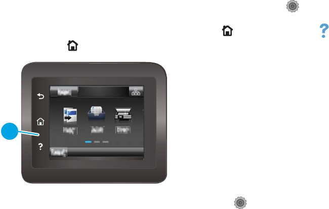
Open the Developer's menu (touchscreen control panel)
1. Make sure the product is in the Ready state.
2. From the Home screen on the product control panel, touch the Setup button.
3. Touch the empty space (callout 1) between the Home button and the Help button, and then quickly
press the Home button.
1
4. The product returns to the Ready state. Touch the Setup button to reopen the menus.
5. Touch the Developer's menu item.
6. Use the scrollbar to navigate the Developer's menu.
ENWW Service mode functions 163

Product resets
NVRAM initialization
CAUTION: All HP Jetdirect settings are also reset. Be sure to print a conguration page before performing an
NVRAM initialization. Make note of the IP address that is listed on the Jetdirect conguration page. You need
to restore the IP address after performing an NVRAM initialization.
An NVRAM initialization erases all data stored in the unprotected NVRAM sections. Performing an NVRAM
initialization resets the following settings and information:
●All menu settings are reset to factory default values.
●All localization settings, including language and country/region, are reset.
After performing an NVRAM initialization, recongure any computers that print to this printer so that the
computers can recognize the printer.
1. Turn the printer o.
2. Perform one of the following steps:
●LCD control panel models: Simultaneously press and hold the right arrow button and the Cancel
button. Keep these buttons depressed as you turn the printer on.
●Touchscreen control panel models: Turn the printer on. When the HP logo appears on the display,
press and hold the lower right quadrant of the touchscreen.
NOTE: It takes about 45 seconds before the NVRAM initialization process begins.
3. When the Permanent Storage Init. message appears on the display, release the buttons.
4. When the printer has nished the NVRAM initialization, it returns to the Ready state.
164 Chapter 2 Solve problems ENWW

Solve fax problems (fax models only)
Introduction
Use the fax troubleshooting information to help resolve issues.
●Fax troubleshooting checklist
●Solve general fax problems
Fax troubleshooting checklist
●Several possible xes are available. After each recommended action, retry faxing to see if the problem is
resolved.
●For best results during fax problem solving, make sure the line from the printer is connected directly to
the wall phone port. Disconnect all other devices that are connected to the printer.
1. Verify that the telephone cord is connected to the correct port on the back of the printer.
2. Check the phone line by using the fax test:
a. From the Home screen on the printer control panel, swipe until the Setup menu displays. Touch the
Setup icon to open the menu.
b. Open the following menus:
●Service
●Fax Service
c. Select the Run Fax Test option. The printer prints a fax test report.
The report contains the following possible results:
●Pass: The report contains all of the current fax settings for review.
●Fail: The report indicates the nature of the error and contains suggestions for how to resolve
the issue.
3. Verify that the printer rmware is current:
a. Print a conguration page from the control panel Reports menu to obtain the current rmware
date code.
b. Go to www.hp.com/go/support, click the Drivers & Software link, type the printer name in the
search eld, press the ENTER button, and then select the printer from the list of search results.
c. Select the operating system.
d. Under the Firmware section, locate the Firmware Update Utility.
NOTE: Make sure to use the rmware update utility that is specic to the printer model.
e. Click Download, click Run, and then click Run again.
f. When the utility launches, select the printer from the drop-down list, and then click Send
Firmware.
ENWW Solve fax problems (fax models only) 165

NOTE: To print a conguration page to verify the installed rmware version before or after the
update process, click Print Cong.
g. Follow the on-screen instructions to complete the installation, and then click the Exit button to
close the utility.
4. Verify that the fax was set up when the printer software was installed.
From the computer, in the HP program folder, run the Fax Setup Utility.
5. Verify that the telephone service supports analog fax.
●If using ISDN or digital PBX, contact your service provider for information about conguring to an
analog fax line.
●If using a VoIP service, change the Fax Speed setting to Slow (V.29) from the control panel. Ask if
your service provider supports fax and for the recommended fax modem speed. Some companies
might require an adapter.
●If you are using a DSL service, make sure that a lter is included on the phone-line connection to
the printer. Contact the DSL service provider, or purchase a DSL lter if you do not have one. If a
DSL lter is installed, try another lter because lters can be defective.
Solve general fax problems
●Faxes are sending slowly
●Fax quality is poor
●Fax cuts o or prints on two pages
Faxes are sending slowly
The printer is experiencing poor phone line quality.
●Retry sending the fax when the line conditions have improved.
●Check with the phone service provider that the line supports fax.
●Turn o the Error Correction setting.
a. Open the Setup Menu menu.
b. Open the Service menu.
c. Open the Fax Service menu.
d. Open the Error Correction menu.
e. Select the O setting.
NOTE: This can reduce image quality.
●Use white paper for the original. Do not use colors such as gray, yellow, or pink.
●Increase the Fax Speed setting.
166 Chapter 2 Solve problems ENWW

a. Open the Setup Menu menu.
b. Open the Fax Setup menu.
c. Open the Advanced Setup menu.
d. Open the Fax Speed menu.
e. Select the correct setting.
●Divide large fax jobs into smaller sections, and then fax them individually.
●Change the fax settings on the control panel to a lower resolution.
a. Open the Setup Menu menu.
b. Open the Fax Setup menu.
c. Open the Advanced Setup menu.
d. Open the Fax Resolution menu.
e. Select the correct setting.
Fax quality is poor
Fax is blurry or light.
●Increase fax resolution when sending faxes. Resolution does not aect received faxes.
a. Open the Setup Menu menu.
b. Open the Fax Setup menu.
c. Open the Advanced Setup menu.
d. Open the Fax Resolution menu.
e. Select the correct setting.
NOTE: Increasing resolution slows transmission speed.
●Turn on the Error Correction setting from the control panel.
a. Open the Setup Menu menu.
b. Open the Service menu.
c. Open the Fax Service menu.
d. Open the Error Correction menu.
e. Select the On setting.
●Check the toner cartridges and replace if necessary.
●Ask the sender to darken the contrast setting on the sending fax machine, and then resend the fax.
ENWW Solve fax problems (fax models only) 167

Fax cuts o or prints on two pages
●Set the Default Paper Size setting. Faxes print on a single size of paper based on the Default Paper Size
settings.
a. Open the Setup Menu menu.
b. Open the System Setup menu.
c. Open the Paper Setup menu.
d. Open the Default Paper Size menu.
e. Select the correct setting.
●Set the paper type and size for the tray used for faxes.
●Turn on the Fit to Page setting to print longer length faxes on letter or A4 size paper.
a. Open the Setup Menu menu.
b. Open the Fax Setup menu.
c. Open the Advanced Setup menu.
d. Open the Fit to Page menu.
e. Select the On setting.
NOTE: If the Fit to Page setting is o and the Default Paper Size setting is set to letter, a legal size original
prints on two pages.
168 Chapter 2 Solve problems ENWW
Solve email problems (M426, M427 printes)
If Scan to E-mail problems occur, try these solutions:
●Make sure this feature has been set up. If this feature has not been set up, use the setup wizard in the
HP Device Toolbox (Windows) or HP Utility for Mac OS X software to set it up.
●Make sure the Scan to Email feature is enabled. If it has been disabled, enable the feature through the
HP Device Toolbox (Windows) or HP Utility for Mac OS X software.
●Make sure that the printer is connected to a computer or to a network.
Cannot connect to the email server
●Make sure the SMTP or LDAP server name is correct. Check this setting with your system administrator
or Internet Service Provider.
●If the printer cannot establish a secure connection to the SMTP or LDAP server, try without the secure
connection or try a dierent server or port. Check this setting with your system administrator or Internet
Service Provider.
●If the SMTP or LDAP server requires authentication, make sure a valid user name and password are used.
●If the SMTP or LDAP server uses an authentication method that is not supported, try a dierent server.
Check this setting with your system administrator or Internet Service Provider.
Validate the SMTP gateway (Windows)
1. Open an MS-DOS command prompt: click Start, click Run, type cmd, and then press the Enter key.
2. In the command prompt window, type telnet followed by the SMTP gateway address and then the
number 25, which is the port over which the printer is communicating. For example, type telnet
123.123.123.123 25 where "123.123.123.123" represents the SMTP gateway address.
3. Press the Enter key. If the SMTP gateway address is not valid, the response contains the message Could
not open connection to the host on port 25: Connect Failed.
4. If the SMTP gateway address is not valid, contact the network administrator.
Validate the LDAP gateway (Windows)
1. Open Windows Explorer. In the address bar, type LDAP:// immediately followed by the LDAP gateway
address. For example, type LDAP://12.12.12.12 where "12.12.12.12" represents the LDAP
gateway address.
2. Press the Enter key. If the LDAP gateway address is valid, the Find People dialog box opens.
3. If the LDAP gateway address is not valid, contact the network administrator.
ENWW Solve email problems (M426, M427 printes) 169

Manually update the rmware
Manually update the rmware (LCD control panel)
1. On the product control panel, press the OK button to open the menus.
2. Open the following menus:
●Service
●LaserJet Update
●Check For Updates Now
3. Select the Yes option, and then press the OK button to prompt the product to search for rmware
updates. If the product detects an upgrade, it will begin the update process.
NOTE: The LaserJet Update menu also contains items that allow you to set up automatic rmware updates
for the product, allow you to upload an earlier rmware version, and enable or disable a prompt prior to a
rmware le upload.
Manually update the rmware (touchscreen control panel)
1. From the Home screen on the product control panel, touch the Setup button.
2. Open the following menus:
●Service
●LaserJet Update
●Check For Updates Now
3. Touch the Yes button to prompt the product to search for rmware updates. If the product detects an
upgrade, it will begin the update process.
NOTE: The LaserJet Update menu also contains items that allow you to set up automatic rmware updates
for the product, allow you to upload an earlier rmware version, and enable or disable a prompt prior to a
rmware le upload.
170 Chapter 2 Solve problems ENWW

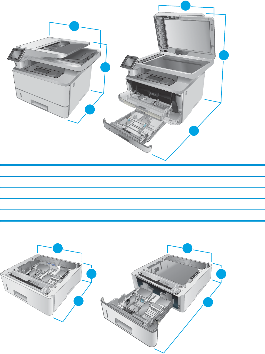
Printer dimensions M426 and M427
Figure A-1 Dimensions for the M426 and M427 models
11
3
2
2
1
HEWLETT-PACKARD
2
2
1
2
3
Printer fully closed Printer fully open
1. Height 323 mm (12.7 in) 577 mm (22.7 in)
2. Depth 390 mm (15.3 in) 839 mm (33 in)
3. Width 420 mm (16.5 in) 453 mm (17.8 in)
Weight (with cartridges) 13.1 kg (28.8 lb)
Figure A-2 Dimensions for the optional 550-sheet tray
2
1
3
2
1
3
3
3
172 Appendix A Printer specications ENWW
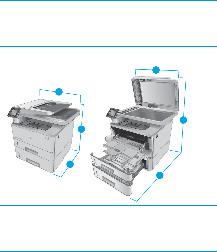
Tray fully closed Tray fully open
1. Height 131 mm (5.1 in) 131 mm (5.1 in)
2. Depth 357 mm (14 in) 781 mm (30.8 in)
3. Width 381 mm (15 in) 381 mm (15 in)
Weight (with cartridges) 3.5 kg (7.7 lb)
Figure A-3 Dimensions for the printer with the optional 550-sheet tray
2
1
3
3
HEWLETT-PACKARD
2
3
2
1
2
1
3
HEWLETT-PACKARD
Printer and tray fully closed Printer and tray fully open
1. Height 452 mm (17.8 in) 706 mm (27.8 in)
2. Depth 390 mm (15.3 in) 839 mm (33 in)
3. Width 420 mm (16.5 in) 453 mm (17.8 in)
Weight (with cartridges) 16.6 kg (36.5 lb)
ENWW Printer dimensions M426 and M427 173
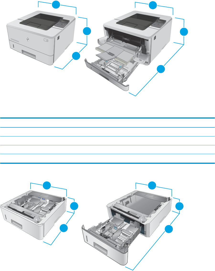
Printer dimensions M402 and M403
Figure A-4 Dimensions for the M402 and M403 models
HEWLETT-PACKARD
1
2
HEWLETT-PACKARD
2
2
2
1
33
1
Printer fully closed Printer fully open
1. Height 216 mm (8.5 in) 241 mm (9.5 in)
2. Depth 357 mm (14 in) 781 mm (30.8 in)
3. Width 381 mm (15 in) 381 mm (15 in)
Weight (with cartridges) 8.8 kg (19.4 lb)
Figure A-5 Dimensions for the optional 550-sheet tray
2
1
3
2
1
3
3
3
174 Appendix A Printer specications ENWW
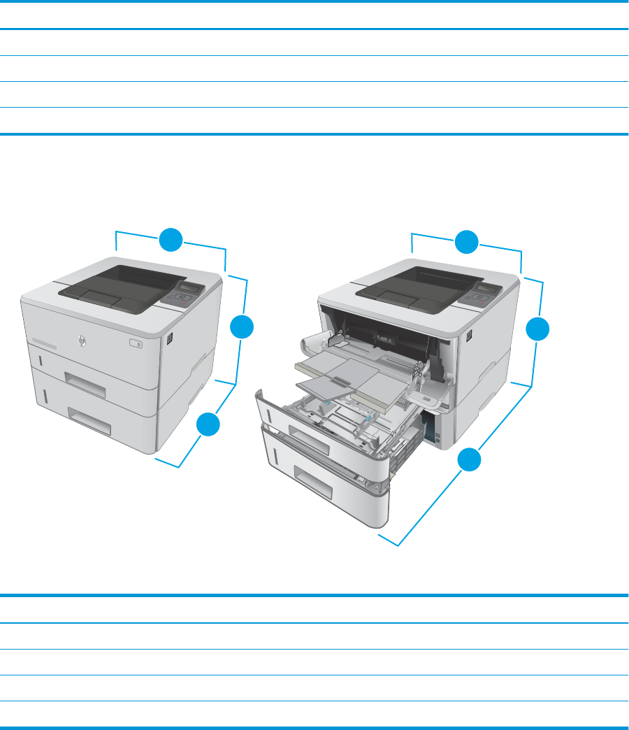
Tray fully closed Tray fully open
1. Height 131 mm (5.1 in) 131 mm (5.1 in)
2. Depth 357 mm (14 in) 781 mm (30.8 in)
3. Width 381 mm (15 in) 381 mm (15 in)
Weight 3.5 kg (7.7 lb)
Figure A-6 Dimensions for the printer with the optional 550-sheet tray
2
1
3
3
HEWLETT-PACKARD
2
3
2
1
2
1
3
Printer and tray fully closed Printer and tray fully open
1. Height 345 mm (13.5 in) 372 mm (14.6 in)
2. Depth 357 mm (14 in) 781 mm (30.8 in)
3. Width 381 mm (15 in) 381 mm (15 in)
Weight (with cartridges) 12.4 kg (27.3 lb)
ENWW Printer dimensions M402 and M403 175

Printer space requirements
HP recommends that 30 mm (1.81 in) be added to the printer dimensions provided in this chapter to make
sure there is suicient space to open doors and covers, and to provide proper ventilation. See Printer
dimensions M426 and M427 on page 172 and/or Printer dimensions M402 and M403 on page 174.
Power consumption, electrical specications, and acoustic
emissions
See www.hp.com/support/ljM402, www.hp.com/support/ljM403 or www.hp.com/support/ljM426MFP,
www.hp.com/support/ljM427MFP for current information.
CAUTION: Power requirements are based on the country/region where the printer is sold. Do not convert
operating voltages. This will damage the printer and void the printer warranty.
Operating-environment range
Table A-1 Operating-environment specications
Environment Recommended Allowed
Temperature 17.5° to 25°C (63.5° to 77°F) 15° to 32°C (59° to 90.5°F)
Relative humidity 30% to 70% relative humidity (RH) 10% to 80% RH
Altitude Not applicable 0 to 3048 m (0 to 10,000 ft)
176 Appendix A Printer specications ENWW
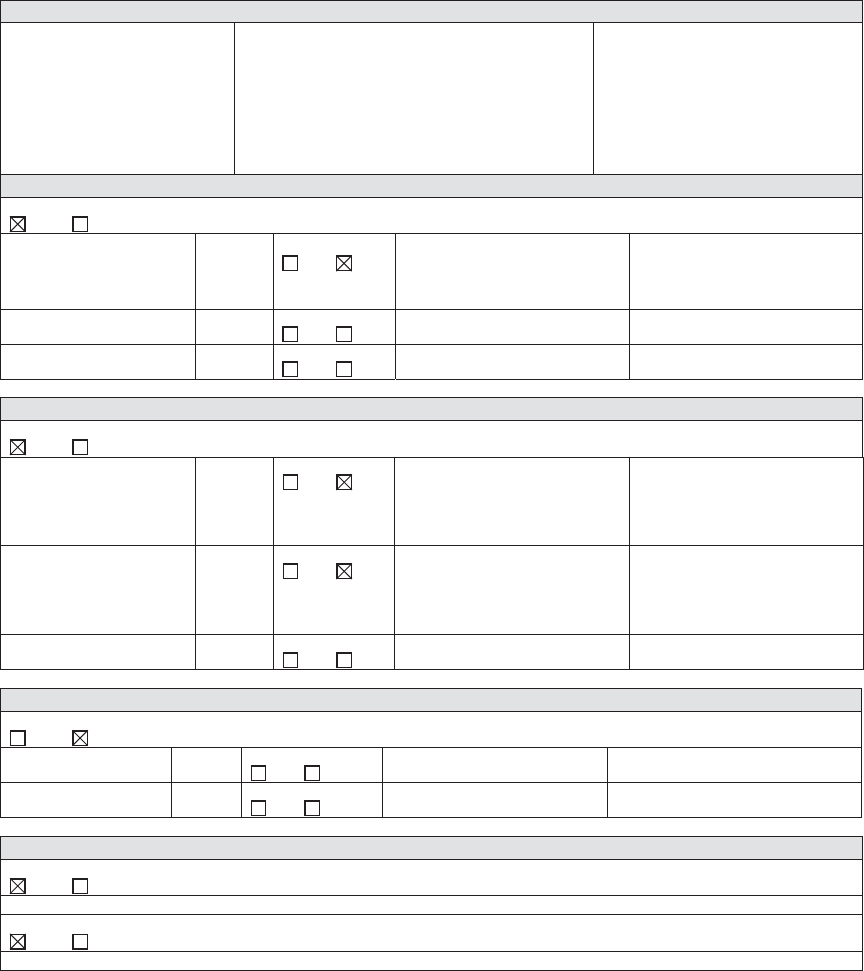
Certicate of Volatility
Figure A-7 Certicate of Volatility M402/M403 (1 of 2)
Hewlett-Packard Certificate of Volatility
Model: Part Number: Address:
HP LaserJet Pro M402
HP LaserJet Pro M403
M402n=C5F93A; M402d=C5F92A
M402dn=C5F94A/G3V21A;
M402dw=C5F95A; M403n=F6J41A;
M403d=F6J42A; M403dn=F6J43a;
M403dw=F6J44A
Hewlett Packard Company
11311 Chinden Blvd
Boise, ID 83714
Volatile Memory
Does the device contain volatile memory (Memory whose contents are lost when power is removed)?
Yes No If Yes please describe the type, size, function, and steps to clear the memory below
Type (SRAM, DRAM, etc): Size: User Modifiable: Function: Steps to clear memory:
SDRAM-DDR3 128MB Yes No Print job specific information,
and information stored in RAM
disk.
When the printer is powered
off, the memory is erased.
Type (SRAM, DRAM, etc): Size: User Modifiable: Function: Steps to clear memory:
Yes No
Type (SRAM, DRAM, etc): Size: User Modifiable: Function: Steps to clear memory:
Yes No
Non-Volatile Memory
Does the device contain non-volatile memory (Memory whose contents are retained when power is removed)?
Yes No If Yes please describe the type, size, function, and steps to clear the memory below
Type (Flash, EEPROM, etc): Size: User Modifiable: Function: Steps to clear memory:
EEPROM 16KB Yes No Printer specific data such as
page count, configuration etc.
Perform a NVRAM initialization
to clear unprotected data as
explained in SM (for service
person to perform only).
Type (Flash, EEPROM, etc): Size: User Modifiable: Function: Steps to clear memory:
NAND Flash 128MB Yes No FW code/partial printer
configuration information
storage.
Perform a NVRAM initialization
to clear unprotected data as
explained in SM (for service
person to perform only).
Type (Flash, EEPROM, etc): Size: User Modifiable: Function: Steps to clear memory:
Yes No
Mass Storage
Does the device contain mass storage memory (Hard Disk Drive, Tape Backup)?
Yes No If Yes please describe the type, size, function, and steps to clear the memory below
Type (HDD, Tape, etc): Size: User Modifiable: Function: Steps to clear memory:
Yes No
Type (HDD, Tape, etc): Size: User Modifiable: Function: Steps to clear memory:
Yes No
USB
Does the item accept USB input and if so, for what purpose (i.e Print Jobs, device firmware updates, scan upload)?
Yes No If Yes please describe below
The front USB host can accept print jobs, scan uploads, photos and can be used to upload printer firmware.
Can any data other than scan upload be sent to the USB device)?
Yes No If Yes please describe below
Rear USB host when configured will accept stored jobs, encrypted files stored and deleted by user.
ENWW Certicate of Volatility 177
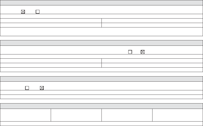
Figure A-8 Certicate of Volatility M402/M403 (2 of 2)
RF/RFID
Does the item use RF or RFID for receive or transmit of any data including remote diagnostics. (e.g. Cellular phone,
Bluetooth) Yes No If Yes please describe below
Purpose: Near field communication
Frequency: 2.4 GHz Bandwidth: 802.11n 20Mhz
Modulation: Effective Radiate Power (ERP): 802.11n 15+-1.5dBm
Specifications: 802.11b/g/n wireless NFC
Other Transmission Capabilities
Does the device employ any other methods of non-wired access to transmit or receive any data whatsoever (e.g. anything
other than standard hard wired TCP/IP, direct USB, or parallel connections)? Yes No If Yes please describe below:
Purpose:
Frequency: Bandwidth:
Modulation: Effective Radiate Power (ERP):
Specifications:
Other Capabilities
Does the device employ any other method of communications such as a Modem to transmit or receive any data
whatsoever? Yes No If Yes please describe below:
Purpose:
Specifications:
Author Information
Name: Title: Email: Business Unit:
Security Technical
Marketing Engineer
IPG
Date Prepared: 06/18/15
178 Appendix A Printer specications ENWW
Figure A-9 Certicate of Volatility M426/M427 (1 of 2)
Hewlett-Packard Certificate of Volatility
Model: Part Number: Address:
HP LaserJet Pro M426
HP LaserJet Pro M427
M426dw=F6W13A; M426fdn=F6W14A
M426fdw=F6W15A; M427dw=C5F97A;
M427fdn=C5F98A; M427fdw=C5F99A
Hewlett Packard Company
11311 Chinden Blvd
Boise, ID 83714
Volatile Memory
Does the device contain volatile memory (Memory whose contents are lost when power is removed)?
Yes No If Yes please describe the type, size, function, and steps to clear the memory below
Type (SRAM, DRAM, etc): Size: User Modifiable: Function: Steps to clear memory:
SDRAM-DDR3 256MB Yes No Print/Scan/Fax job specific
information, and information
stored in RAM disk.
When the printer is powered
off, the memory is erased.
Type (SRAM, DRAM, etc): Size: User Modifiable: Function: Steps to clear memory:
Yes No
Type (SRAM, DRAM, etc): Size: User Modifiable: Function: Steps to clear memory:
Yes No
Non-Volatile Memory
Does the device contain non-volatile memory (Memory whose contents are retained when power is removed)?
Yes No If Yes please describe the type, size, function, and steps to clear the memory below
Type (Flash, EEPROM, etc): Size: User Modifiable: Function: Steps to clear memory:
EEPROM 16KB Yes No Printer specific data such as
page count, configuration etc.
Perform a NVRAM initialization
to clear unprotected data as
explained in SM (for service
person to perform only).
Type (Flash, EEPROM, etc): Size: User Modifiable: Function: Steps to clear memory:
NAND Flash 256MB Yes No FW code/partial printer
configuration information
storage.
Perform a NVRAM initialization
to clear unprotected data as
explained in SM (for service
person to perform only).
Type (Flash, EEPROM, etc): Size: User Modifiable: Function: Steps to clear memory:
Yes No
Mass Storage
Does the device contain mass storage memory (Hard Disk Drive, Tape Backup)?
Yes No If Yes please describe the type, size, function, and steps to clear the memory below
Type (HDD, Tape, etc): Size: User Modifiable: Function: Steps to clear memory:
Yes No
Type (HDD, Tape, etc): Size: User Modifiable: Function: Steps to clear memory:
Yes No
USB
Does the item accept USB input and if so, for what purpose (i.e Print Jobs, device firmware updates, scan upload)?
Yes No If Yes please describe below
The front USB host can accept print jobs, scan uploads, photos and can be used to upload printer firmware.
Can any data other than scan upload be sent to the USB device)?
Yes No If Yes please describe below
Rear USB host when configured will accept stored jobs, encrypted files stored and deleted by user.
ENWW Certicate of Volatility 179
Figure A-10 Certicate of Volatility M426/M427 (2 of 2)
RF/RFID
Does the item use RF or RFID for receive or transmit of any data including remote diagnostics. (e.g. Cellular phone,
Bluetooth) Yes No If Yes please describe below
Purpose: Near field communication
Frequency: 2.4 GHz Bandwidth: 802.11n 20Mhz
Modulation: Effective Radiate Power (ERP): 802.11n 15+-1.5dBm
Specifications: 802.11b/g/n wireless NFC
Other Transmission Capabilities
Does the device employ any other methods of non-wired access to transmit or receive any data whatsoever (e.g. anything
other than standard hard wired TCP/IP, direct USB, or parallel connections)? Yes No If Yes please describe below:
Purpose:
Frequency: Bandwidth:
Modulation: Effective Radiate Power (ERP):
Specifications:
Other Capabilities
Does the device employ any other method of communications such as a Modem to transmit or receive any data
whatsoever? Yes No If Yes please describe below:
Purpose:
Specifications:
Author Information
Name: Title: Email: Business Unit:
Security Technical
Marketing Engineer
IPG
Date Prepared: 06/18/15
180 Appendix A Printer specications ENWW

Index
Symbols/Numerics
2ndary service menu 161
550-sheet feeder (optional Tray 3)
components 35
operation 35
550-sheet paper feeder
controller and electrical
components 35
electrical components, pickup and
feed 36
jam detection 38
motor control 36
other functions, pickup and
feed 37
paper path 35
pickup and feed operation 36
A
AC to DC conversion 9
acoustic specications 176
archive setting 74
automatic crossover, setting 77
B
back page dirty 144
back page dirty,
troubleshooting 144
back page dirty, troubleshooting
144
background, gray 146
bands, troubleshooting 146
basic printer operation 3
bias generation
high-voltage power supply 12
black page 144
black page, troubleshooting 144
black page, troubleshooting 144
blank page 143
blank page, troubleshooting
143
blank page, troubleshooting 143
blank pages, troubleshooting 152
browser requirements
HP Embedded Web Server 62
C
cables
USB, troubleshooting 152
calibrating touchscreen 162
cartridge
life detection 27
memory chip 27
presence detection 27
toner level detection 27
cartridges
supplies status page 71
cautions iii
certicate of volatility 177
characters, troubleshooting 148
checklist
fax troubleshooting 165
problems 41
checklists
pre-troubleshooting 44
problem source 46
checklists, printing 71
circuit diagrams 61
high-voltage power supply 11
low-voltage power supply 9
clean
touch screen 150
cleaning
mode 160
paper path 64, 150
components
550-sheet feeder (optional Tray
3) 35
DC controller 6
engine-control system 5
fuser 13
pickup, feed, and delivery 27
toner cartridge 25
conguration page 65, 70
connectivity
solving problems 155
connectors, DC controller
locating 53
contrast
display, control panel 74
control functions
fuser 14
control panel
blank, troubleshooting 47
button test 162
clean touch screen 150
cleaning page, printing 64, 150
display contrast 74
display test 162
language 72
menu map, printing 70
messages, types of 79
Network Setup menu 77
Reports menu 70
Service menu 74
System Setup menu 72
controller
paper feeder (optional Tray 3)
35
conventions, document iii
cooling
areas and fans 8
Courier font settings 74
creases, troubleshooting 148
ENWW Index 181
crooked pages 148
cross-sectional printer view
block diagram 51
curl, paper
settings 74
curled media 148
D
dark print 143
dark print, troubleshooting 143
darkness
dark print, troubleshooting 143
DC controller
components 6
fans 8
motors 8
DC motors 8
DC voltages converted from AC 9
default settings, restoring 74
NVRAM initialization 164
defaults
restoring 160
demo page 70
determine problem source 44
developer's 162
developer's menu 162
development process 22
diagrams
block 51
circuit 61
cross-sectional printer view 51
fan 57
main assemblies PCAs 59
main PCAs (printer base) 59
major components (printer
base) 56
motor 57
PCA connections 53
rollers (printer base) 58
rollers and pads 58
timing 60
Diagrams: DC controller connectors
locating 53
dimensions, printer, M402 and
M403 174
dimensions, printer, M426 and M427
172
display contrast, setting 74
document conventions iii
document feeder
jams 122
dots, troubleshooting 145
drivers
usage page 71
drum cleaning 24
duplexer
clearing jams 117, 140
duplexing unit
motors 8
E
electrical components
paper feeder (optional Tray 3)
35
electrical components, pickup and
feed
paper feeder (optional Tray 3)
36
electrical specications 176
Embedded Web Server (EWS)
features 62
engine-control system
components 5
error messages
error report 96
event log 96, 97
types of 79
exhaust fans 8
Explorer, versions supported
HP Embedded Web Server 62
F
factory defaults, restoring 74
NVRAM initialization 164
faded print 143
failure detection
laser/scanner 17
motors 8
fan (printer base)
block diagram 57
fans
DC controller 8
exhaust 8
intake 8
fax
solve general problems 166
fax troubleshooting
checklist 165
rmware version 162
fonts
Courier settings 74
lists, printing 71
front page dirty 144
front page dirty,
troubleshooting 144
front page dirty, troubleshooting
144
fuser 12
clearing jams 111, 134
components 13
control functions 14
control-circuit function 12
temperature protection 15
See also fusing and delivery unit
fusing process 24
G
graph paper, printing 71
gray background, troubleshooting
146
H
heaters
fuser 13
high-voltage power supply (HVPS)
bias generation 12
circuits 12
operations 11
horizontal lines 145
horizontal lines,
troubleshooting 145
horizontal lines, troubleshooting
145
horizontal white lines 145
horizontal white lines,
troubleshooting 145
horizontal white lines,
troubleshooting 145
HP Embedded Web Server (EWS)
features 62
HP Jetdirect print server
NVRAM initialization 164
HVPS (high-voltage power supply)
bias generation 12
circuits 12
operations 11
I
image quality
archive setting 74
182 Index ENWW
solving 143
troubleshooting defects 66
image-formation process
development process 22
drum cleaning 24
fusing process 24
laser-beam exposure 22
primary charging 21
primary transfer process 23
separation process 24
image-information process 18
information pages
conguration page 65
initial rotation period 4
initialization
NVRAM 164
intake fans 8
Internet Explorer, versions supported
HP Embedded Web Server 62
interpret control-panel messages and
event log entries 79
J
jam detection
paper feeder (optional Tray 3)
38
jams
causes of 101
document feeder 122
duplexer 117, 140
fuser 111, 134
locating 102, 120
output bin 115, 137
tracking number of 71
Tray 1 103, 125
Tray 2 104, 126
Tray 3 108, 130
Jetdirect print server
NVRAM initialization 164
L
language, control panel 72
laser-beam exposure 22
laser/scanner
failure detection 17
operations 16
safety 17
last rotation period 4
latent image formation 21
LDAP gateway
validating 169
LEDs, troubleshooting 49
light print, troubleshooting 143
lightness
faded print, troubleshooting
143
lines, troubleshooting 146
printed pages 146
location
setting 162
loose toner, troubleshooting 146,
147
low-voltage power supply (LVPS)
operations 9
protection for components 10
safety 10
LVPS (low-voltage power supply)
operations 9
protection for components 10
safety 10
M
main PCAs (printer base)
block diagram 59
major components (printer base)
block diagram 56
media
curled, troubleshooting 148
default settings 72
wrinkled 148
memory
NVRAM initialization 164
toner cartridge 27
menu
Quick Forms 71
menu map 42
menus 162
menus, control panel
map, printing 70
Network Setup 77
Reports 70
Service 74
System Setup 72
messages
types of 79
motor control
paper feeder (optional Tray 3)
36
motors
DC controller 8
failure detection 8
image-formation system 31
stepping 8
movement of paper through printer.
See pickup, feed, and delivery
music paper, printing 71
N
Netscape Navigator, versions
supported
HP Embedded Web Server 62
Network Setup menu 77
networks
conguration page 70
settings 77
settings report 71
notebook paper, printing 71
notes iii
NVRAM initialization 164
O
operation sequence 4
operations
laser/scanner 16
toner cartridge memory 27
other functions, pickup and feed
paper feeder (optional Tray 3)
37
output bin
clearing jams 115, 137
output quality
archive setting 74
over-current protection 10
over-voltage protection 10
P
page count 71
pages
blank 152
not printing 152
printing slowly 152
skewed 148
paper
curl settings 74
curled, troubleshooting 148
default settings 72
jams 101
wrinkled 148
ENWW Index 183
paper feeder
controller and electrical
components 35
electrical components, pickup and
feed 36
jam detection 38
motor control 36
other functions, pickup and
feed 37
paper path 35
pickup and feed operation 36
Paper feeder (optional Tray 3)
operation 35
paper jams
document feeder 122
locating 102, 120
Tray 1 103, 125
Tray 2 104, 126
Tray 3 108, 130
paper movement
operation 27
paper path
550-sheet feeder (optional Tray
3) 35
paper feeder (optional Tray 3)
35
printer 27
paper pickup problems
solving 142
PCL font list 71
periods of the operation sequence
4
pickup and feed operation
paper feeder (optional Tray 3)
36
pickup, feed, and delivery
550-sheet feeder (optional Tray
3) 35
components 27
overview 27
power
consumption 176
power supply 9
See also low-voltage power
supply; high-voltage power
supply
power-on
troubleshooting 47
powersave 160
pre-troubleshooting checklist 44
primary charging process 21
print quality
archive setting 74
printer space requirements 176
printing
conguration page 65
period in operation sequence 4
troubleshooting 152
problem-solving
messages, types of 79
no response 153
slow response 154
PS font list 71
Q
quality
archive setting 74
troubleshooting repetitive image
defects 66
R
repetitive defects, troubleshooting
66, 149
reports
error 96, 97, 162
service 162
Reports menu 70
resets
NVRAM initialization 164
restoring
defaults 160
factory defaults 160
restoring default settings 74
NVRAM initialization 164
rollers and pads (printer base)
block diagram 58
S
safety
laser/scanner 17
low-voltage power supply 10
scatter, troubleshooting 149
secondary service menu 161
sensors
image-formation system 20
pickup, feed, and delivery
system 29, 51
separation process 24
service and support information v,
2, 40
Service menu 74
service menu 160
secondary 161
service menu settings 160
cleaning mode 160
powersave 160
restoring defaults 160
service page 43, 71
settings
network report 71
restoring defaults 74
System Setup menu 72
sizes, media
default, setting 72
skewed pages 148
smeared toner, troubleshooting
146
SMTP gateway
validating 169
solve problems 39
fax 166
solving
direct-connect problems 155
network problems 155
space requirements, printer 176
specications
electrical and acoustic 176
space requirments 176
specks, troubleshooting 145
spots, troubleshooting 145
standby period 4
status
messages, types of 79
supplies, printing report 71
stepping motors 8
streaks, troubleshooting 146
supplies status page 71
switches
pickup, feed, and delivery
system 29, 51
system requirements
HP Embedded Web Server 62
System Setup menu 72
T
table, repetitive defect 66
TCP/IP
settings 77
temperature
fuser heater protection 15
184 Index ENWW
text, troubleshooting
misformed characters 148
thermistors
fuser 13
thermoswitches
fuser 13
timing chart 60
tips iii
toner
image formation, use during 21
loose, troubleshooting 146, 147
scatter, troubleshooting 149
smeared, troubleshooting 146
specks, troubleshooting 145
toner cartridge
life detection 27
memory chip 27
presence detection 27
toner level detection 27
toner cartridges 25
components 25
error conditions 25
operations 25
supplies status page 71
touch screen, clean 150
touchscreen
calibrating 162
transfer processes 23
Tray 1
jams 103, 125
settings 72
Tray 2
jams 104, 126
settings 72
Tray 3
controller and electrical
components 35
electrical components, pickup and
feed 36
jam detection 38
jams 108, 130
motor control 36
operation 35
other functions, pickup and
feed 37
paper path 35
pickup and feed operation 36
trays
settings 72
troubleshooting 39
advanced conguration with HP
Embedded Web Server (EWS)
and HP Device Toolbox
(Windows 7) 49
back page dirty 144
black page 144
blank page 143
blank pages 152
checklist 41, 44
component diagnostics 49
conguration page 49
control panel checks 47
control panel message document
(CPMD) 49
control-panel menus 49
curled media 148
dark print 143
direct-connect problems 155
engine diagnostics 49
event log messages 49
faded print 143
faxes 165
front page dirty 144
horizontal lines 145
horizontal white lines 145
internal print-quality test pages
49
jams 101
LED diagnostics 49
lines, printed pages 146
loose smear 146
loose toner 147
network problems 155
NVRAM initialization 164
pages not printing 152
pages printing slowly 152
power-on 47
print-quality troubleshooting
tools 49
problem source 46
process 44
repetitive defects 149
skewed pages 148
text 148
toner scatter 149
toner smear 146
toner specks 145
USB cables 152
vertical density variation 144
vertical white lines 145
white spots 144
wrinkles 148
U
usage page 71
USB port
speed settings 74
troubleshooting 152
V
vertical density variation 144
vertical density variation,
troubleshooting 144
vertical density variation,
troubleshooting 144
vertical lines, troubleshooting 146
vertical white lines 145
vertical white lines,
troubleshooting 145
vertical white lines,
troubleshooting 145
W
waiting period 4
warnings iii
wavy paper, troubleshooting 148
Web browser requirements
HP Embedded Web Server 62
weight, printer 172, 174
white spots 144
white spots, troubleshooting
144
white spots, troubleshooting 144
wrinkles, troubleshooting 148
ENWW Index 185
186 Index ENWW
