Officejet Enterprise Color X555/X585 Troubleshooting Manual Enww HP MFP X585, X555
User Manual: HP Officejet Enterprise Color MFP X585, X555 Troubleshooting shared.swissparts.ch - /Manuals/HP/Ink/
Open the PDF directly: View PDF ![]() .
.
Page Count: 338 [warning: Documents this large are best viewed by clicking the View PDF Link!]
- Theory of operation
- Solve problems
- Problem-solving checklist
- Step 1: Check that the product power is on
- Step 2: Check the control panel for error messages
- Step 3: Test print functionality
- Step 4: Test copy functionality
- Step 5: Test the fax sending functionality
- Step 6: Test the fax receiving functionality
- Step 7: Try sending a print job from a computer
- Step 8: Test the Plug and Print USB Drive printing functionality
- Factors that affect product performance
- Troubleshooting process
- Tools for troubleshooting
- Print the configuration page
- Event log messages
- Error messages
- 11.XX.YZ Error Messages
- 15.XX.YZ Error Messages
- 17.XX.YZ Error Messages (Supply errors)
- 17.0X.00 Failed Cartridge
- 17.0X.34 Counterfeit or refilled cartridge installed
- 17.0X.35 Incompatible <supply>
- 17.0X.36 Non-Startup cartridge at startup
- 17.0X.37 Startup Cartridge after startup completed
- 17.0X.38 Cartridge might be empty
- 17.0X.39 Use new cartridges
- 17.0X.42 General printing error
- 17.0X.52 Supply upgrade detected
- 17.0X.53 Supply upgrade successful
- 17.0X.54 Supply upgrade problem
- 17.0X.55 Supply upgrade problem
- 17.0X.56 Ink sensor warning
- 17.0X.57 HP Cartridge Protection enabled
- 17.0X.60 Cartridge Low Warning
- 17.0X.65 Install Supply
- 17.0X.69 Cartridge Very Low
- 17.0X.70 Printing past very low
- 17.0X.80 Install Supply
- 17.31.60 Ink Collection Unit Warning
- 17.31.65 Install Supply Ink Collection Unit
- 17.31.69 Ink Collection Unit full
- 17.31.70 Ink Collection Printing past full
- 17.31.71 Reinstall Ink Collection Unit
- 17.31.72 Ink Collection Unit reinstalled
- 17.31.73 New Ink Collection Unit
- 17.31.80 Replace Ink Collection Unit
- 17.99.31 Non-HP supply in use
- 17.99.32 Previously used HP Supply installed
- 17.99.40 Supplies installed
- 17.99.49 Startup Cartridge Override
- 17.99.58 HP Cartridge Protection enabled
- 20.XX.YZ, 21.XX.YZ Error Messages
- 30.XX.YZ Error Messages — X585 only
- 30.01.01
- 30.01.02 Scanner calibration failure
- 30.01.06 Scanner Fan failure
- 30.01.08 Home position error
- 30.01.14 Scan system EEPROM error
- 30.01.15 Scanner error
- 30.01.18 Scanner Error
- 30.01.19 Scanner lamp error
- 30.01.30 or 30.01.32
- 30.01.36 Upgrade Error Try downloading upgrade again
- 30.01.41 Scanner error
- 30.01.42 Scanner error
- 30.01.43 Scanner memory failure
- 30.01.44
- 30.01.45
- 30.01.46 Scanner Error
- 30.01.48 Scanner error
- 30.01.50 Scanner error
- 30.03.14
- 30.03.20
- 30.03.22 Scanner failure
- 30.03.23 Scanner failure
- 30.03.30 Scanner Failure
- 30.03.45 Scanner Error To continue turn off then on
- 31.XX.YZ Error Messages — X585 only
- 31.01.03 Document feeder pick error
- 31.01.47 Document feeder not detected
- 31.03.14
- 31.03.20 backside scanner not detected
- 31.03.22 Scanner calibration failure
- 31.03.30 Document feeder pick motor error
- 31.03.31 Document feeder motor stall
- 31.03.32
- 31.03.33 Backside scanner calibration area dirty
- 31.03.34 Background missing
- 31.13.00 Document feeder multi-pick error
- 31.13.01
- 31.13.02
- 31.13.13
- 31.13.14
- 31.13.15
- 32.08.XX Error Messages
- 33.XX.YZ Error Messages
- 40.XX.YZ Error Messages
- 40.00.01 USB I/O buffer overflow To continue, touch “OK”
- 40.00.02 Embedded I/O buffer overflow To continue, touch “OK”
- 40.00.03 EIO <X> buffer overflow To continue, touch “OK”
- 40.00.04 EIO <X> bad transmission To continue, touch “OK”
- 40.00.05 Embedded I/O bad transmission To continue, touch “OK”
- 40.08.0X USB storage accessory removed
- 40.0X.05 USB storage accessory removed
- 41.XX.YZ Error Messages
- 42.XX.YY Error Messages
- 44.XX.XX Error Messages
- 44.01.XX Error Event log message (Multifunction product only.)
- 44.02.XX Error Event log message (Multifunction product only.)
- 44.03.XX Error Event log message (Multifunction product only.)
- 44.04.XX Error Event log message (Multifunction product only.)
- 44.05.XX Error Event log message (Multifunction product only.)
- 44.07.XX Error Event log message (Multifunction product only.)
- 44.08.XX Error Event log message (Multifunction product only.)
- 44.10.XX Error Event log message (Multifunction product only.)
- 44.11.0E Error Event log message (Multifunction product only.)
- 44.11.XX Error Event log message (Multifunction product only.)
- 44.12.0E Error Event log message (Multifunction product only.)
- 44.12.XX Error Event log message (Multifunction product only.)
- 44.16.01 Error Event log message (Multifunction product only.)
- 44.16.02 Error Event log message (Multifunction product only.)
- 44.16.03 Error Event log message (Multifunction product only.)
- 44.16.04 Error Event log message (Multifunction product only.)
- 44.16.05 Error Event log message (Multifunction product only.)
- 44.16.06 Error Event log message (Multifunction product only.)
- 44.16.07 Error Event log message (Multifunction product only.)
- 44.16.08 Error Event log message (Multifunction product only.)
- 44.16.09 Error Event log message (Multifunction product only.)
- 44.16.0A Error Event log message (Multifunction product only.)
- 44.16.0B Error Event log message (Multifunction product only.)
- 44.16.0D Error Event log message (Multifunction product only.)
- 44.16.0E Error Event log message (Multifunction product only.)
- 44.16.0F Error Event log message (Multifunction product only.)
- 44.16.10 Error Event log message (Multifunction product only.)
- 44.16.FF Error Event log message (Multifunction product only.)
- 44.34.XX Error Event log message (Multifunction product only.)
- 44.90.XX Error Event log message - 44.91.XX Error Event log message - 44.92.XX Error Event log messa ...
- 45.WX.YZ Error Messages
- 47.XX.XX Error Messages
- 48.XX.YY Error Messages
- 49.XX.YY Error Messages
- 54.XX.YZ Error Messages
- 58.XX error messages
- 61.00.0X Error Messages
- 81.XX.YY, 82.XX.YY Error Messages
- 98.0X.0Y Error Messages
- 99.XX.YY Error Messages
- 99.00.01 Upgrade not performed file is corrupt
- 99.00.02 Upgrade not performed timeout during receive
- 99.00.03 Upgrade not performed error writing to disk
- 99.00.04 Upgrade not performed timeout during receive
- 99.00.05 Upgrade not performed timeout during receive
- 99.00.06 Upgrade not performed error reading upgrade
- 99.00.07 Upgrade not performed error reading upgrade
- 99.00.08 Upgrade not performed error reading upgrade
- 99.00.09 Upgrade canceled by user
- 99.00.10 Upgrade canceled by user
- 99.00.11 Upgrade canceled by user
- 99.00.12 Upgrade not performed the file is invalid
- 99.00.13 Upgrade not performed the file is invalid
- 99.00.14 Upgrade not performed the file is invalid
- 99.00.2X
- 99.01.XX
- 99.02.01
- 99.02.09
- 99.09.60 Unsupported disk
- 99.09.61 Unsupported disk
- 99.09.62 Unknown disk
- 99.09.63 Incorrect disk
- 99.09.64 Disk malfunction
- 99.09.65 Disk data error
- 99.09.66 No disk installed
- 99.09.67 Disk is not bootable please download firmware
- 99.09.67 Disk is not bootable please download firmware
- 99.XX.YY
- Alpha Error Messages
- FIM Load Error Send full FIM on <X> port
- <binname> full Remove all paper from bin
- <Supply> almost full
- <Supply> low OR Supplies low
- <Supply> very low OR Supplies very low
- <Tray X> lifting
- [File System] device failure To clear touch “OK”
- [File System] file operation failure To clear touch “OK”
- [File System] file system is full To clear touch “OK”
- [File System] is not initialized
- [File System] is write protected
- Accept bad signature
- Automatic Document Feeder cover open
- Bad optional tray connection
- Calibration reset pending
- Canceling
- Canceling...<jobname>
- Cartridge Problem; Ink cartridge problem
- Checking engine
- Checking paper path
- Chosen personality not available To continue, touch “OK”
- Clear Output Area
- Clearing event log
- Clearing paper path
- Close Ink Access Door
- Close Left door
- Close upper Left door
- Cooling device
- Counterfeit Cartridge Advisory
- Data received To print last page press “OK”
- Do not use startup cartridges
- Document feeder Misfeed
- Document feeder not detected
- Empty Ink Cartridge
- Event log is empty
- Expected drive missing
- Fax is disabled — ignoring call
- Flatbed cover open or Close Flatbed cover
- Gateways failed
- Gateways OK
- Genuine HP cartridge installed
- Genuine HP supply installed
- HP Protected Cartridge Installed
- HP Secure hard drive disabled
- Incompatible ink cartridges
- Initializing...
- Ink cartridges depleted
- Ink Sensor Failure
- Install <supply>
- Internal disk device failure To clear touch “OK”
- Internal disk file operation failed
- Internal disk file system is full
- Internal disk is write protected
- Internal disk not found
- Internal disk not functional
- Internal disk not initialized
- Internal disk spinning up
- Jam in document feeder
- Load Tray <X>: [Type], [Size] To use another tray, press “OK”
- Loading program <XX>
- Low on ink
- Main Tray 2 Missing or Open
- Manually feed output stack Then touch "OK" to print second side
- Manually feed: <Type><Size> To use another tray, press “OK”
- No job to cancel
- Non-HP Cartridge(s) Non-HP ink cartridges installed
- Output Bin Full
- Paper Jam in Automatic Document Feeder
- Paper Jam Paper Jam
- Paper too short Paper too short
- Paper too short to autoduplex
- Paper type mismatch
- Paused...
- Performing Paper Path Test…
- Please Wait...
- Print head Jam
- Printer Failure
- Printer Supply Upgrade
- Printer Supply Upgrade Problem
- Printing Configuration...
- Printing Event Log...
- Printing File Directory...
- Printing Font List...
- Printing Help Page...
- Printing Menu Map...
- Printing stopped
- Printing Supplies Status Page...
- Printing Usage Page...
- Printing…engine test
- Problem with Printer Preparation
- Problem with startup Cartridge(s)
- Processing job from tray <X>...Do not grab paper until job completes
- Processing...
- Processing...copy <X> of <Y>
- RAM disk device failure To clear touch “OK”
- RAM disk file operation failed To clear touch “OK”
- RAM disk file system is full To clear touch “OK”
- RAM disk is write protected To clear touch “OK”
- RAM disk not initialized
- Ready
- Ready <IP Address>
- Receiving Upgrade
- Remove USB accessory
- Resend Upgrade
- Restore Factory Settings
- ROM disk device failed To clear touch “OK”
- ROM disk file operation failed To clear touch “OK”
- ROM disk file system is full To clear touch “OK”
- ROM disk is write protected To clear touch “OK”
- ROM disk not initialized To clear touch “OK”
- Service Ink Capacity Warning
- Size mismatch in Tray <X>
- Sleep mode on
- Startup Routine Ink Alert
- The unit has corrupt data
- Tray <X> [type] [size]
- Tray <X> empty: [Type], [Size] / Tray X Out of Paper
- Tray <X> lifting
- Tray <X> open
- Type mismatch Tray <X>
- Unsupported drive installed To continue, touch “OK”
- Unsupported supply in use OR Unsupported supply installed To continue, touch “OK”
- Unsupported USB accessory detected Remove USB accessory
- Upgrade Error
- USB accessory not functional
- USB hubs are not fully supported Some operations may not work properly
- USB is write protected To clear touch “OK”
- USB needs too much power
- USB needs too much power Remove USB and Then Turn Off then On
- USB not initialized
- USB storage accessory removed Clearing any associated data
- USB storage device failure To clear touch “OK”
- USB storage file operation failed To clear touch “OK”
- USB storage file system is full To clear touch “OK”
- Use startup cartridges
- Used HP Ink Cartridge(s) installed
- Used or Counterfeit Cartridge Detected
- Very Low on Ink
- Windows Login Required to Use this Feature
- Individual component diagnostics
- Diagrams
- Print-quality troubleshooting tools
- Preboot menu options
- Control-panel menus
- Solve image quality problems
- Solve paper jam or feed problems
- Solve performance problems
- Solve connectivity problems
- Solve USB direct-connect problems
- Solve network problems
- Poor physical connection
- The computer is using the incorrect IP address for the product
- The computer is unable to communicate with the product
- The product is using incorrect link and duplex settings for the network
- New software programs might be causing compatibility problems
- The computer or workstation might be set up incorrectly
- The product is disabled, or other network settings are incorrect
- Solve wireless network problems
- Wireless connectivity checklist
- The control panel displays the message: The wireless feature on this product has been turned off
- The product does not print after the wireless configuration completes
- The product does not print, and the computer has a third-party firewall installed
- The wireless connection does not work after moving the wireless router or product
- Cannot connect more computers to the wireless product
- The wireless product loses communication when connected to a VPN
- The network does not appear in the wireless networks list
- The wireless network is not functioning
- Service mode functions
- Solve fax problems
- Product upgrades
- Problem-solving checklist
- Service and support
- Product specifications
- Regulatory information
- FCC regulations
- Environmental product stewardship program
- Protecting the environment
- Ozone production
- Power consumption
- Paper use
- Plastics
- HP Officejet print supplies
- Return and recycling instructions
- Paper
- Material restrictions
- Disposal of waste equipment by users
- Electronic hardware recycling
- Chemical substances
- Material Safety Data Sheet (MSDS)
- EPEAT
- For more information
- Declaration of conformity (X555 models)
- Declaration of conformity (X585dn model)
- Declaration of conformity (X585f and X585z models)
- Certificate of volatility (X555 models)
- Certificate of volatility (X585 models)
- Safety statements
- Canada - Industry Canada ICES-003 Compliance Statement
- VCCI statement (Japan)
- Power cord instructions
- Power cord statement (Japan)
- EMC statement (China)
- EMC statement (Korea)
- EMI statement (Taiwan)
- GS statement (Germany)
- Substances Table (China)
- SEPA Ecolabel User Information (China)
- Restriction on Hazardous Substances statement (India)
- Restriction on Hazardous Substances statement (Turkey)
- Restriction on Hazardous Substances statement (Ukraine)
- Eurasian Conformity (Belarus, Kazakhstan, Russia)
- Additional statements for telecom (fax) products
- Index
caps lock
shift
A S D F G H J K L
Z X C V B N M
@ altalt
shift
enter
,.
?
/
:
;
“
‘
Troubleshooting Manual
Officejet Enterprise Color X555
Officejet Enterprise Color MFP X585
www.hp.com/support/ojcolorX555
www.hp.com/support/ojcolorMFPX585

HP Officejet Enterprise Color X555 and MFP
X585 Series
Troubleshooting Manual
Copyright and License
© 2014 Copyright Hewlett-Packard
Development Company, L.P.
Reproduction, adaptation, or translation
without prior written permission is prohibited,
except as allowed under the copyright laws.
The information contained herein is subject to
change without notice.
The only warranties for HP products and
services are set forth in the express warranty
statements accompanying such products and
services. Nothing herein should be construed
as constituting an additional warranty. HP shall
not be liable for technical or editorial errors or
omissions contained herein.
Edition 1, 4/2014
Trademark Credits
Microsoft®, Windows®, Windows® XP, and
Windows Vista® are U.S. registered trademarks
of Microsoft Corporation.

Conventions used in this guide
TIP: Tips provide helpful hints or shortcuts.
NOTE: Notes provide important information to explain a concept or to complete a task.
CAUTION: Cautions indicate procedures that you should follow to avoid losing data or damaging the
product.
WARNING! Warnings alert you to specific procedures that you should follow to avoid personal injury,
catastrophic loss of data, or extensive damage to the product.
ENWW iii
iv Conventions used in this guide ENWW

Table of contents
1 Theory of operation ....................................................................................................................................... 1
Basic operation ...................................................................................................................................................... 2
Function structure ............................................................................................................................... 2
Operation sequence ............................................................................................................................ 4
System control ....................................................................................................................................................... 7
Formatter and data path ..................................................................................................................... 7
Engine control ..................................................................................................................................... 8
Pen interface (I/F) .............................................................................................................................. 10
Power supply ..................................................................................................................................... 10
Print subsystem ................................................................................................................................................... 12
Printbar .............................................................................................................................................. 13
Printbar lift ........................................................................................................................................ 14
Ink cartridges ..................................................................................................................................... 15
Optical scan carriage ......................................................................................................................... 15
Print system operational states ....................................................................................................... 15
Paper-handling system ....................................................................................................................................... 17
Input trays ......................................................................................................................................... 24
Paper path zones .............................................................................................................................. 24
Servicing system .................................................................................................................................................. 28
Service sled ....................................................................................................................................... 30
Aerosol management system ............................................................................................................................. 31
Document feeder (X585 models) ........................................................................................................................ 33
Document feeder operation .............................................................................................................. 33
Document feeder paper path and sensors ....................................................................................... 33
Document feeder jam detection ....................................................................................................... 34
Scanner system (X585 models) .......................................................................................................................... 35
Scanner power-on sequence of events ............................................................................................ 35
Copy or scan-to-computer sequence of events ............................................................................... 36
Fax functions and operation (X585 models) ....................................................................................................... 37
Computer and network security features ........................................................................................ 37
PSTN operation ................................................................................................................................. 37
The fax subsystem ............................................................................................................................ 37
ENWW v
Fax card in the fax subsystem .......................................................................................................... 37
Fax page storage in flash memory ................................................................................................... 39
2 Solve problems ........................................................................................................................................... 41
Problem-solving checklist ................................................................................................................................... 42
Step 1: Check that the product power is on ...................................................................................... 42
Step 2: Check the control panel for error messages ........................................................................ 42
Step 3: Test print functionality ......................................................................................................... 43
Step 4: Test copy functionality ......................................................................................................... 43
Step 5: Test the fax sending functionality ........................................................................................ 43
Step 6: Test the fax receiving functionality ...................................................................................... 43
Step 7: Try sending a print job from a computer .............................................................................. 43
Step 8: Test the Plug and Print USB Drive printing functionality ..................................................... 44
Factors that affect product performance ......................................................................................... 44
Troubleshooting process .................................................................................................................................... 45
Determine the problem source ......................................................................................................... 45
Power subsystem .............................................................................................................................. 46
Scanning subsystem (X585) ............................................................................................................. 47
Control panel checks ......................................................................................................................... 47
Tools for troubleshooting ................................................................................................................................... 57
Print the configuration page ............................................................................................................. 57
Event log messages .......................................................................................................................... 59
Error messages ................................................................................................................................. 60
Individual component diagnostics .................................................................................................. 149
Diagrams ......................................................................................................................................... 154
Print-quality troubleshooting tools ............................................................................................... 156
Preboot menu options .................................................................................................................... 164
Control-panel menus ........................................................................................................................................ 172
Administration menu ...................................................................................................................... 172
Device Maintenance menu .............................................................................................................. 233
Solve image quality problems .......................................................................................................................... 236
Clean ink smears ............................................................................................................................. 236
Recover the printhead .................................................................................................................... 236
Solve paper jam or feed problems .................................................................................................................... 237
Product does not pick up paper or misfeeds .................................................................................. 237
Clear jams ........................................................................................................................................ 238
Solve performance problems ............................................................................................................................ 254
The product does not print ............................................................................................................. 254
The product prints slowly ............................................................................................................... 254
Solve connectivity problems ............................................................................................................................. 256
Solve USB direct-connect problems ............................................................................................... 256
vi ENWW
Solve network problems ................................................................................................................. 256
Solve wireless network problems .................................................................................................. 257
Service mode functions ..................................................................................................................................... 262
Service menu and Secondary service menu ................................................................................... 262
Product resets ................................................................................................................................. 262
Solve fax problems ............................................................................................................................................ 263
Fax reports ...................................................................................................................................... 263
Possible fax issues .......................................................................................................................... 266
Product upgrades .............................................................................................................................................. 275
Appendix A Service and support .................................................................................................................... 277
Hewlett-Packard limited warranty statement ................................................................................................. 278
UK, Ireland, and Malta ..................................................................................................................... 279
Austria, Belgium, Germany, and Luxemburg .................................................................................. 279
Belgium, France, and Luxemburg ................................................................................................... 279
Italy .................................................................................................................................................. 281
Spain ................................................................................................................................................ 281
Denmark .......................................................................................................................................... 281
Norway ............................................................................................................................................ 281
Sweden ............................................................................................................................................ 282
Portugal ........................................................................................................................................... 282
Greece and Cyprus ........................................................................................................................... 282
Hungary ........................................................................................................................................... 282
Czech Republic ................................................................................................................................ 282
Slovakia ........................................................................................................................................... 283
Poland ............................................................................................................................................. 283
Bulgaria ........................................................................................................................................... 283
Romania .......................................................................................................................................... 283
Belgium and The Netherlands ........................................................................................................ 283
Finland ............................................................................................................................................. 284
Slovenia ........................................................................................................................................... 284
Croatia ............................................................................................................................................. 284
Latvia ............................................................................................................................................... 284
Lithuania .......................................................................................................................................... 284
Estonia ............................................................................................................................................. 285
End User License Agreement ............................................................................................................................ 286
OpenSSL ............................................................................................................................................................. 288
Customer self-repair warranty service ............................................................................................................. 289
Customer support .............................................................................................................................................. 290
ENWW vii
Appendix B Product specifications ................................................................................................................. 291
Physical specifications (X555 models) ............................................................................................................. 292
Physical specifications (X585 models) ............................................................................................................. 292
Power consumption, electrical specifications, and acoustic emissions .......................................................... 292
Environmental specifications ............................................................................................................................ 292
Appendix C Regulatory information ............................................................................................................... 293
FCC regulations .................................................................................................................................................. 294
Environmental product stewardship program ................................................................................................. 295
Protecting the environment ........................................................................................................... 295
Ozone production ............................................................................................................................ 295
Power consumption ........................................................................................................................ 295
Paper use ......................................................................................................................................... 295
Plastics ............................................................................................................................................ 295
HP Officejet print supplies .............................................................................................................. 295
Return and recycling instructions ................................................................................................... 296
Paper ............................................................................................................................................... 297
Material restrictions ........................................................................................................................ 297
Disposal of waste equipment by users ........................................................................................... 297
Electronic hardware recycling ........................................................................................................ 298
Chemical substances ....................................................................................................................... 298
Material Safety Data Sheet (MSDS) ................................................................................................ 298
EPEAT .............................................................................................................................................. 298
For more information ...................................................................................................................... 298
Declaration of conformity (X555 models) ........................................................................................................ 299
Declaration of conformity (X585dn model) ...................................................................................................... 301
Declaration of conformity (X585f and X585z models) ..................................................................................... 303
Certificate of volatility (X555 models) .............................................................................................................. 305
Certificate of volatility (X585 models) .............................................................................................................. 307
Safety statements ............................................................................................................................................. 309
Canada - Industry Canada ICES-003 Compliance Statement ......................................................... 309
VCCI statement (Japan) ................................................................................................................... 309
Power cord instructions .................................................................................................................. 309
Power cord statement (Japan) ....................................................................................................... 309
EMC statement (China) .................................................................................................................... 309
EMC statement (Korea) ................................................................................................................... 309
EMI statement (Taiwan) .................................................................................................................. 310
GS statement (Germany) ................................................................................................................ 311
Substances Table (China) ................................................................................................................ 311
SEPA Ecolabel User Information (China) ........................................................................................ 311
Restriction on Hazardous Substances statement (India) .............................................................. 312
viii ENWW
Restriction on Hazardous Substances statement (Turkey) ........................................................... 312
Restriction on Hazardous Substances statement (Ukraine) .......................................................... 312
Eurasian Conformity (Belarus, Kazakhstan, Russia) ...................................................................... 312
Additional statements for telecom (fax) products ........................................................................................... 313
EU Statement for Telecom Operation ............................................................................................ 313
New Zealand Telecom Statements ................................................................................................. 31 3
Additional FCC statement for telecom products (US) .................................................................... 313
Telephone Consumer Protection Act (US) ...................................................................................... 314
Industry Canada CS-03 requirements ............................................................................................ 314
Vietnam Telecom wired/wireless marking for ICTQC Type approved products ............................ 315
Japan Telecom Mark ....................................................................................................................... 315
Index ........................................................................................................................................................... 317
ENWW ix
xENWW

List of tables
Table 1-1 Operation sequence ............................................................................................................................................. 4
Table 1-2 Power supply module operating modes ............................................................................................................ 11
Table 1-3 Printbar components ......................................................................................................................................... 14
Table 1-4 Product sensors ................................................................................................................................................. 20
Table 1-5 Paper-handling system motors ......................................................................................................................... 23
Table 1-6 Paper path zones ............................................................................................................................................... 26
Table 1-7 Service sled components ................................................................................................................................... 30
Table 1-8 Aerosol management system components ...................................................................................................... 32
Table 2-1 Troubleshooting flowchart ................................................................................................................................ 45
Table 2-2 Control panel diagnostic functions .................................................................................................................... 47
Table 2-3 Important information on the configuration pages .......................................................................................... 59
Table 2-4 Heartbeat LED status ....................................................................................................................................... 150
Table 2-5 Plug/jack locations (X555) ............................................................................................................................... 154
Table 2-6 Plug/jack locations (X585) ............................................................................................................................... 155
Table 2-7 Preboot menu options (1 of 6) ......................................................................................................................... 165
Table 2-8 Preboot menu options (2 of 6) ......................................................................................................................... 167
Table 2-9 Preboot menu options (3 of 6) ......................................................................................................................... 168
Table 2-10 Preboot menu options (4 of 6) ...................................................................................................................... 169
Table 2-11 Preboot menu options (5 of 6) ...................................................................................................................... 169
Table 2-12 Preboot menu options (6 of 6) ...................................................................................................................... 170
Table 2-13 Reports menu ................................................................................................................................................. 172
Table 2-14 General Settings menu .................................................................................................................................. 174
Table 2-15 Copy Settings menu (X585) ........................................................................................................................... 179
Table 2-16 Scan/Digital Send Settings menu (X585) ...................................................................................................... 185
Table 2-17 Fax Settings menu (X585) ............................................................................................................................. 195
Table 2-18 General Print Settings menu ......................................................................................................................... 207
Table 2-19 Print Options menu ........................................................................................................................................ 210
Table 2-20 Display Settings menu ................................................................................................................................... 211
Table 2-21 Manage Supplies menu .................................................................................................................................. 213
Table 2-22 Manage Trays menu ....................................................................................................................................... 217
Table 2-23 Network Settings menu ................................................................................................................................. 219
Table 2-24 Jetdirect Menu ................................................................................................................................................ 219
ENWW xi
Table 2-25 Troubleshooting menu .................................................................................................................................. 230
Table 2-26 Backup/Restore menu ................................................................................................................................... 233
Table 2-27 Calibrate/Cleaning menu ............................................................................................................................... 233
Table B-1 Physical specifications (X555 models), with ink cartridges ............................................................................ 292
Table B-2 Physical specifications (X585 models), with ink cartridges ............................................................................ 292
Table B-3 Operating-environment specifications ........................................................................................................... 292
xii ENWW

List of figures
Figure 1-1 Main components (X555 models) ....................................................................................................................... 2
Figure 1-2 Main components (X585 models) ....................................................................................................................... 3
Figure 1-3 System control .................................................................................................................................................... 7
Figure 1-4 Print subsystem components (X555 models) .................................................................................................. 12
Figure 1-5 Print subsystem components (X585 models) .................................................................................................. 13
Figure 1-6 Printbar components ........................................................................................................................................ 14
Figure 1-7 Paper-handling system paper path (X555 models) ......................................................................................... 17
Figure 1-8 Paper-handling system paper path (X585 models) ......................................................................................... 18
Figure 1-9 Product sensors (X555 models) ....................................................................................................................... 19
Figure 1-10 Product sensors (X585 models) ..................................................................................................................... 20
Figure 1-11 Paper-handling-system motors (X555 models) ............................................................................................ 22
Figure 1-12 Paper-handling-system motors (X585 models) ............................................................................................ 23
Figure 1-13 Paper path zones (X555 models) ................................................................................................................... 25
Figure 1-14 Paper path zones (X585 models) ................................................................................................................... 26
Figure 1-15 Servicing system components (X555 models) ............................................................................................... 28
Figure 1-16 Servicing system components (X585 models) ............................................................................................... 29
Figure 1-17 Service sled components ................................................................................................................................ 30
Figure 1-18 Aerosol management process ........................................................................................................................ 31
Figure 1-19 Aerosol management system components ................................................................................................... 32
Figure 1-20 Document feeder paper path and sensors ..................................................................................................... 34
Figure 2-1 Touchscreen blank, white, or dim (no image) .................................................................................................. 51
Figure 2-2 Touchscreen is slow to respond or requires multiple presses to respond ...................................................... 52
Figure 2-3 Touchscreen has an unresponsive zone .......................................................................................................... 53
Figure 2-4 No control panel sound ..................................................................................................................................... 54
Figure 2-5 Home button is unresponsive ..................................................................................................................... 55
Figure 2-6 Hardware integration pocket (HIP) is not functioning (control panel functional) ........................................... 56
Figure 2-7 Configuration page ........................................................................................................................................... 57
Figure 2-8 HP embedded Jetdirect page ............................................................................................................................ 58
Figure 2-9 LEDs ................................................................................................................................................................. 149
Figure 2-10 Plug/jack locations (X555) ........................................................................................................................... 154
Figure 2-11 Plug/jack locations (X585) ........................................................................................................................... 155
Figure 2-12 Mark the web wipe ........................................................................................................................................ 163
ENWW xiii
Figure C-1 Certificate of volatility (X555 models) (1 of 2) ............................................................................................... 305
Figure C-2 Certificate of volatility (X555 models) (2 of 2) ............................................................................................... 306
Figure C-3 Certificate of volatility (X585 models) (1 of 2) ............................................................................................... 307
Figure C-4 Certificate of volatility (X585 models) (2 of 2) ............................................................................................... 308
xiv ENWW

Basic operation
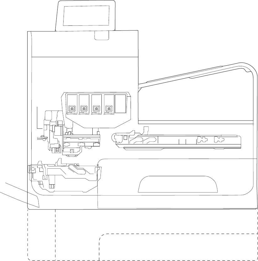
Function structure
The product consists of the following components.
Figure 1-1 Main components (X555 models)
Control panel
Output bin
Printbar
Service sled
Main input tray (Tray 2)
Optional tray (Tray 3)
Multipurpose tray
(Tray 1) Duplex module\
Waste ink module
Optical
scan
carriage
2 Chapter 1 Theory of operation ENWW
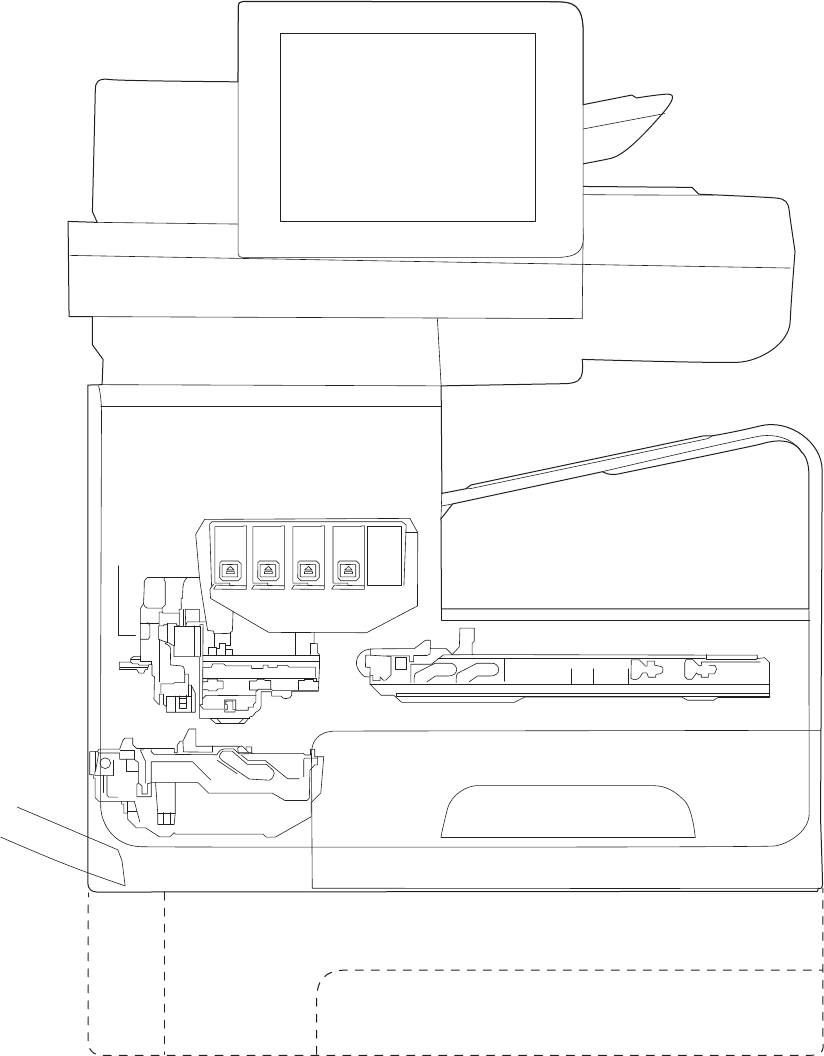
Figure 1-2 Main components (X585 models)
Document feeder
Scanner
Control panel
Output bin
Printbar
Service sled
Main input tray (Tray 2)
Optional tray (Tray 3)
Multipurpose tray
(Tray 1) Duplex module\
Waste ink module
Optical
scan
carriage
The product contains the following systems:
●Engine control system
●Print subsystem
●Paper-handling system
●Servicing system
ENWW Basic operation 3

●Aerosol management system
●Scanner and document feeder system (X585 models)
Two elements influence the product architecture:
●Orienting the printbar with its active face downward and statically located above the print media. This
requires the printbar to move vertically to access its active face.
●Producing face-down output. Rather than ejecting the page face-up immediately after the ink is
applied, as many inkjet printers do, the printed page is routed up and back over the printbar to eject
face-down.
Operation sequence
The engine-control system on the formatter PCA controls the operational sequences. The following table
describes durations and operations for each period of a print operation from when the product is turned on to
when the motors stop rotating.
Table 1-1 Operation sequence
Period Duration Purpose
Initial startup and
calibrations
When the product is set up for
the first time from the factory.
This period gets the product ready to print for the first time.
●The product flushes the shipping and handling fluid out of the
printbar and replaces it with ink.
●Die alignment—The product aligns the 10 die on the printbar
active face.
●Die density leveling—The product measures and compensates
for the drop variation.
Servicing operations When the printbar is entering
the capping state after printing,
when leaving capping state after
a print job is initiated, or during
extended print jobs.
Servicing maintains the print quality by ensuring debris and excess
ink are removed and missing nozzles are replaced.
●Nozzle presence detection—The optical scan carriage detects
and disables inoperable nozzles, and replaces them with
operable nozzles.
●Printbar servicing—The web wipe on the service sled moves
under the printbar to clean the active face and fire the nozzles
into the waste ink module to clear clogs.
4 Chapter 1 Theory of operation ENWW

Table 1-1 Operation sequence (continued)
Period Duration Purpose
Print preparation From the time the product
receives a print command until
paper enters the print zone.
Prepares the product for a print job.
●The printbar leaves the capping state as the service sled
moves away from the printbar.
●If needed, some servicing occurs.
●The printbar lowers to the printing position. The media type
and printing mode determine the print zone height.
●The product picks media from one of the input trays.
●Every page from Tray 1 is scanned. For Tray 2 and optional
Tray 3, the product performs media edge detection after
printing the first sheet after the main or optional tray is
loaded. The last sheet of each job is also scanned if at least
five sheets have been printed.
●The product monitors environmental conditions. The product
can decrease the print speed if conditions are significantly
different from a normal office environment (23 degrees C (73
degrees F), 50% relative humidity).
●The formatter PCA processes print data and transmits the data
to the printbar.
Printing From the end of the preparation
period until the last sheet is
delivered.
Processes the print job.
●As the page travels through the print zone, the printbar
applies ink to the page.
●Simplex print job: the page moves up, over the printbar, and
out to the output bin (face-down).
●Duplex print job: the page moves up until the trailing edge is
40 mm past the star-wheel jam reflective sensor, then
reverses direction down through the duplex path underneath
the waste ink module, and then reenters the print zone where
the printbar applies ink to the second side.
●The process continues until all the pages of the print job are
completed. Occasional nozzle presence detection and
servicing events might occur if the job includes many pages.
ENWW Basic operation 5

Table 1-1 Operation sequence (continued)
Period Duration Purpose
End of print job Performed after the print job is
completed, and continues until
the next job is initiated.
Puts the product in a state where it’s ready for the next print job.
●If needed, some servicing occurs.
●The printbar moves to the capping position after a short dwell
interval.
●The service sled moves to cap the printbar.
Standby The product is sitting idle,
waiting for the next print job to
be initiated.
Conserves energy while the product is sitting idle. Certain functions
might be disabled to save power, then are restarted when needed.
The product has three sleep modes:
●Idle mode—The printbar is capped and the product is ready to
immediately start a new job
●Sleep1 mode—After the product is inactive for about 10
minutes, the control panel dims and the power LED blinks to
indicate the unit is in Sleep1. All product functions are
available. This setting can be adjusted from the control panel.
●Sleep2 mode—After the product is inactive for a longer period
of time (typically 2 hours), the engine controller powers down
to minimize power consumption. This setting can be adjusted
from the control panel.
6 Chapter 1 Theory of operation ENWW
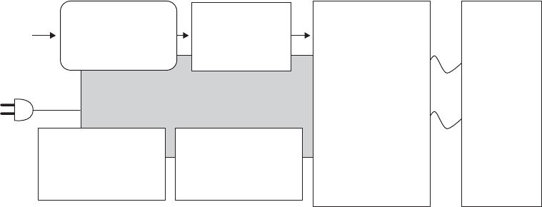
System control
The system control coordinates all the other systems, according to commands from the formatter.
Figure 1-3 System control
Power supply
Engine control
Motor + sensor drive
Scanner/
document feeder
(X585 models)
Formatter
I/O, PDL, UI control
I/O Datapath
ASIC +memory
Printbar
40,000 nozzles
Pen I/F
• Pen energy control
• Pen voltage
sequencing
• Signal integrity
• Ink-short protection
• Printhead
interconnects
• Ink supply
The system consists of the following major sections:
●Formatter
●Data path
●Engine control
●Pen interface
●Scanner/document feeder (X585 models)
●Power supply
The engine control electronics are located on the engine control board (ECB). The formatter PCA is a separate
assembly. The fax module (X585 models) is attached to the formatter PCA.
Formatter and data path
The formatter controller ASIC controls the input/output (I/O) control, the user interface, and the rendering of
page description language files into printer-specific commands.
Input/output (I/O) control
The products support 10/100 Ethernet, a rear USB host port, a rear USB device port, a control panel USB host
port, and analog fax port (some X585 models). For Ethernet networks, the formatter PCA uses a separate
integrated circuit (Broadcom 57761) to provide the physical network interface.
The formatter PCA also controls the USB device and USB host.
User interface
The products contain either a 4.2-in (X555 models) or an 8-in (X585 models) color graphics display. The
control panels include a USB host port for connection to thumb drives.
Formatter digital ASIC
The formatter digital ASIC has an ARM CPÙ (792 MHz) that executes firmware code that provides high-level
device control. The digital ASIC uses a standard PCle interface to pass data to the engine control ASIC. The
ENWW System control 7
formatter firmware is located on either a rotating hard disk drive (HDD) or, on some X555 models, a solid
state drive (SSD).
Additionally, the formatter digital ASIC manages the real-time clock, interfaces to the mass storage
controller ASIC, provides control of USB ports, and interfaces with the Ethernet LAN ASIC and fax module.
Formatter Ethernet ASIC
The formatter Ethernet ASIC connects to the formatter digital ASIC with a PCIe interface to transmit and
receive network packets.
Formatter mass storage ASIC
The formatter mass storage ASIC bridges between the formatter digital ASIC (via PCIe interface) and the mass
storage device (via SATA interface). Both HDD and SSD mass storage media are supported. The X585 models
all use a rotating media HDD, while the X555 models use either HDD or SSD depending upon the bundle
option.
Formatter memory
Formatter memory is installed on-board and there is no support for additional DIMM memory installation.
The size of the memory on the formatter is fixed at 1 GB.
Real-time clock
The real-time clock (RTC) allows the fax module to time-stamp outgoing faxes. It also determines the
elapsed time between printhead and ISS calibration events. The RTC uses a separate device connected to the
formatter digital ASIC, along with a crystal and a battery.
Engine control
The engine controller digital ASIC receives high-level commands from the formatter, and then provides low-
level control to the print mechanism. The engine controller digital ASIC and its firmware control motors,
system sensors, and the printbar. The engine controller analog ASIC integrates motor drivers, voltage
regulators, sensor interfaces, and supervisory circuits.
Engine controller digital ASIC
The engine controller digital ASIC has a high-performance 480 MHz ARM CPU and DSP co-processors that
execute firmware code to provide low-level engine control. It also drives the printbar via 15 high-speed LVDS
transmission lines, which are routed from the engine PCA to the printbar via two large FFC cables. The engine
controller digital ASIC receives pre-rendered data from the formatter digital ASIC over a standard PCle
interface.
In some product sleep modes, the digital ASIC powers down. If a print job is received while the product is in
this mode, power resumes to the digital ASIC, which then must “boot up”. This can take approximately 15
seconds, which will delay the first page out (FPO) time accordingly. This sleep mode typically begins after two
hours of product inactivity.
Engine controller analog ASIC
The engine uses two analog ASICs to generate the system voltages for the engine, drive the engine motors,
control various engine sensors, and monitor printbar power delivery for correct operation.
The engine has seven motors, some of which are shared with other subsystems:
8 Chapter 1 Theory of operation ENWW
●Pick motor
●Feed motor
●Duplex motor
●Lift motor
●Eject motor
●Sensor carriage motor
●Aerosol fan motor
Each one is a DC motor with encoder feedback, to provide precision servo control. These motors are driven
directly by one of the engine analog ASICs. Small DC motors also are used to drive the ISS pump and the
aerosol fan. Solenoids actuate the ejection flap and the ISS priming system.
The product uses many sensors to track the media as it travels through the paper path. Most of these are
optical REDI sensors, which are used in conjunction with mirrors to sense the presence or absence of paper in
a particular location. These are carefully aligned and calibrated at the factory, so care must be taken when
servicing these sensors. See the Remove and Replace chapter in the repair manual for more details.
Other printed circuit-board assemblies (PCAs)
In addition to hosting the system ASICs, the engine PCA is home to many circuits needed to interface to
sensors and other sub-system components. In some cases, this circuitry is located on a smaller remote PCA
(SLB) to optimize cable interconnects.
●Humidity sensor—The humidity sensor causes the product to adjust printing speed if ambient
conditions are outside the optimal humidity range. This sensor is calibrated at the factory to ensure
maximum accuracy.
●Temperature sensor—The temperature sensor causes the product to adjust printing speed if ambient
conditions are outside the optimal temperature range. In some products, this sensor resides on a
separate, remote PCA.
●Main tray presence sensor—The hall-effect sensor that detects if the main tray is properly engaged
resides on the back of the engine PCA. A small magnet on the back of the main tray actuates the sensor.
If the tray is fully engaged, the magnetic field strength is sufficient to trigger the sensor.
Additionally, the product includes the following PCAs:
●Fax PCA—Governs the product fax module.
●Duplex module presence sensor—A hall-effect sensor that detects that the duplex module is properly
seated.
●Power button PCA—Includes the power button and power LED, as well as interface cables to the duplex
module presence sensor and the MP tray empty REDI sensor.
●Accessory tray interconnect PCA—Provides communication to optional Tray 3.
●Pick encoder distribution PCA—Includes the pick motor encoder and the pick motor interconnect cable.
●Eject encoder distribution PCA—Includes the eject motor encoder and the interconnect cables to the
eject motor and the aerosol fan.
ENWW System control 9
●Print zone distribution PCA—Joins interconnect cables to the following sensors: separator REDI, feed
motion encoder, main tray empty sensor, feed roller OOPs REDI sensor, and the starwheel jam REDI
sensor.
●REDI distribution PCA—Includes hall-effect sensors that detect ink cartridge door and left door
positions. It also combines the interconnect cables for the eject jam REDI sensor, the upper drying path
REDI sensor, the lower drying path REDI sensor, and the eject flap opto flag sensor.
●Sensor carriage PCA—Includes a carriage motion encoder, a ZIM sensor, and the BDD sensor.
●Printbar lift encoder distribution PCA—This PCA includes the printbar lift motion encoder, and combines
interconnect cables to the printbar lift motor, carriage motor, and eject flap solenoid.
●Duplex encoder PCA—Contains the motion encoder for the duplex motor.
●SHAID PCA —Contains interfaces to the out-of-ink sensors for the ink cartridges, and combines the
interface cables to the acumen PCA, the ISS pump, and the ISS solenoids.
●Acumen PCA—Contains interfaces to the acumen memory devices for the ink cartridges.
Pen interface (I/F)
The printbar is the key component that differentiates this product from other inkjet printers. The
conventional approach is to print a page in horizontal swaths by moving a “scanning” printhead horizontally
over a fixed sheet of paper, advancing the paper a fixed amount, and then printing the next swath. With this
product, the paper moves underneath a fixed page-wide printhead in a single smooth motion.
Single pass page-wide printing requires that data and power be delivered to the printbar at a very high rate,
while also maintaining good control of paper position as it moves past the printhead nozzles.
The engine PCA sends power and data to the printbar via two large flat flexible cables (36 and 38 pins). The
printbar PCA routes power and data to 10 printhead die, which are attached to the PCA using a flexible tab
circuit and wire-bonding process.
Electronics control the ink supply station (ISS). The SHAID PCA detects low-ink conditions. It gauges ink levels
by electrically sensing the presence of ink and/or ink foam in the X-chamber. The SHAID PCA also collects and
distributes electrical signals that drive the push-prime pump(s), engage the solenoids, and read the ink
supply acumen data. All are routed through a single 17-pin FFC from the SHAID PCA to the engine PCA.
Each ink supply has a memory tag that stores information about its type of ink, the amount of ink remaining,
and other critical data. It uses a special authentication scheme to ensure that only genuine HP supplies are
used and the product is not damaged by using invalid supplies. Acumen uses a two-line serial bus, which,
along with 3.3 V and ground, is cabled via the SHAID PCA to the engine PCA and the engine control digital
ASIC.
Power supply
The power supply module converts 100-240 VAC to 33 VCD and 5.1 VCD to power the system. The 33 V rail
goes to the engine and the scanner/document feeder, and the 5.1 V rail is supplies power to the formatter.
The power supply module has a sleep mode that reduces power consumption in system low-power modes.
The power supply module has four operating modes, depending on certain control signals, as outlined in the
table below. The power supply has a power factor correction (PFC) circuit to improve efficiency when the
system is in the active mode.
10 Chapter 1 Theory of operation ENWW

Table 1-2 Power supply module operating modes
Mode n33V_OFF input signal nPFC_OFF input signal PFC Status 33 V rail status 5.1 V rail status
OFF Low Low Off Off On
Sleep 2 Low Low Off Off On
Sleep 1 High Low Off On On
Active High High On On On
The power supply is a self-contained module that can be replaced if it is defective (see the Remove and
Replace chapter of the Repair Manual).
To ensure safe operation, the power supply will “latch off” if a persistent over-current fault condition exists.
This is typically caused by a short-circuit from 33 V or 5.1 V to ground in the product. Less severe faults also
can cause the power supply to latch off, if present for an extended period of time, or if the product is
operated above the recommended operating range.
ENWW System control 11
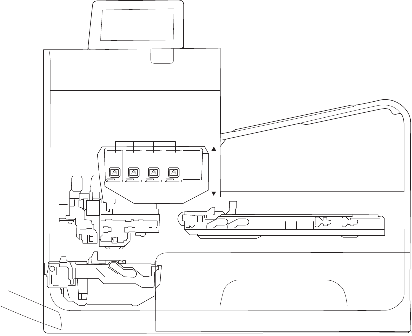
Print subsystem
The print subsystem includes the following components:
●Printbar
●Printbar lift
●Ink cartridges
●Optical scan carriage
Figure 1-4 Print subsystem components (X555 models)
Printbar lift
Ink cartridges
Printbar
Optical
scan
carriage
12 Chapter 1 Theory of operation ENWW

Figure 1-5 Print subsystem components (X585 models)
Printbar lift
Ink cartridges
Printbar
Optical
scan
carriage
Printbar
The printbar converts the digital firing instructions from the product electronics into properly formed and
timed microscopic drops of the four ink colors. The printbar spans the full width of a letter/A4-size sheet
(216 mm (8.5 in)), which allows it to be statically positioned within the product and have the media move
underneath it, printing the entire page in a single motion.
ENWW Print subsystem 13
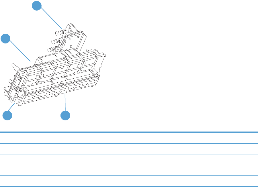
Figure 1-6 Printbar components
1
4
23
Table 1-3 Printbar components
Item Description
1 Ink cartridge connections
2 Thermal inkjet (TIJ) die array
3 Data/power flow and regulation
4 Inkflow channels and pressure regulation
The printbar has a fixed array of 10 thermal inkjet (TIJ) die oriented in two staggered rows. Each die contains
over one thousand nozzles for each of the four ink colors (black (K), cyan (C), magenta (M) and yellow (Y)).
Behind the die array are the ink flow channels and pressure regulation mechanisms that supply the die array
with ink at the proper pressure and flow. Onboard electronic circuitry feeds power and data to the die at the
appropriate levels and rates. Four ink cartridge receptacles, one for each color, are located at the top of the
printbar. Flow connections link these cartridges to the rest of the printbar to supply the ink necessary for its
operation.
A sensor technology called back-scatter drop detect (BDD) monitors printbar health and calibrations. This
system looks at the reflection of the miniscule drops in flight and passes these signals through proprietary,
advanced high-speed, high-gain, bandpass filters. An artificial intelligence (AI) system decides which drop
ejectors are currently in or out of specifications.
After the AI system determines which drop ejectors are out of specification, the product compensates for
them. Some ejectors use neighboring nozzles and at times even tiny amounts of other inks – whichever
combination of methods necessary to deliver the best print quality possible at that moment. Up to half of the
nozzles can be “out” without a noticeable degradation in quality. The compensation is done in real time with
a dedicated high-speed DSP. The system can scan portions of the system after print jobs, but it is fully
interruptible by new incoming print jobs.
Printbar lift
The printbar lift positions the printbar within the product and moves it up and down as required. This vertical
motion establishes proper spacing to the paper during printing. It also raises the printbar to access the active
face or perform necessary calibrations.
14 Chapter 1 Theory of operation ENWW

During printing, the lift mechanism sets the printbar height and paper height depending on the type of paper.
Ink cartridges
This product has new, state-of-the-art pigmented inks. They are filtered using proprietary processes to
prevent printhead contamination. These inks are designed to produce optimal print quality on ColorLok office
papers, but also produce very good print quality on regular office papers and specialty media.
Optical scan carriage
The optical scan carriage has optical sensors used for calibration. Its motion is along the long axis of the
printbar. These sensors are used by a number of in-printer calibration features that are important for proper
subsystem function. The BDD sensor is located on the optical scan carriage.
Print system operational states
The print subsystem has a number of distinct operational states besides active printing.
Startup
As it comes from the factory, the printbar is initially filled with an inert ink-substitute called Shipping and
Handling Fluid (SHF). This fluid, essential for the manufacture and transportation of the printbar, must be
flushed and replaced with actual ink. This is accomplished during the Startup phase. The flushing process
automatically commences when ink supplies are inserted and the unit powered up for the first time. The SHF
is removed by sustained printbar operation and replaced by ink from the supplies. The process terminates
once all the SHF has been flushed from the printbar.
Special host supplies are supplied with the product prior to its first use. These supplies contain additional ink
so that there will be 100 percent ink level after the SHF is replaced with ink. These supplies can be used only
to initialize the product. You cannot use them in another product that has been initialized.
NOTE: The initial startup time is noticeably longer than the following regular startup times.
Die alignment
Die alignment is done by printing a special diagnostic image on a sheet of paper and then scanning it with the
optical scan carriage. It is performed as part of initial unit startup, and can be manually invoked as part of the
print quality recovery tool. Die alignment calibrates the positions of the 10 die. It also allows a uniform
application of ink to the media, without gaps or overlaps between adjacent die.
Die density leveling
A set of diagnostic images is printed and scanned by the optical scan carriage to achieve uniform application
of ink droplets to the media. Die alignment and die density leveling are usually paired together.
Nozzle presence detection
In printing, since all the ink is applied in a single smooth motion of the media past the printbar, any
inoperable nozzle can show up as a streak. The operational state of each of the thousands of nozzles on the
printbar is periodically measured. The printbar is raised by the printbar lift, and the BDD assembly on the
optical scan carriage watches for drop presence as each nozzle is fired. Inoperable nozzles are turned off and
other operable nozzles used on subsequent printed pages to apply the missing ink. Nozzle presence
detection is fully interruptible by new incoming print jobs.
ENWW Print subsystem 15
Media edge position detection
The product uses a learning algorithm to define media center as a function of input source—multipurpose
tray, main tray, or accessory tray. The edge scan is located downstream of the print zone. As media is
scanned, the media center database is updated. The image is registered to the page using the media center
database.
Servicing and capping
When in the capped state, the printbar is fully raised, the service sled is positioned underneath, and the
printbar cap is engaged against the printbar active face. Servicing—the cleaning of the active face and the
firing of the nozzles—can occur either during Sleep2 mode or after extended time in storage. It can also
occur during extended print jobs.
Printing
The printing state begins by the printbar leaving the capping state, and being lowered to the printing position
after the service sled moves out of the way. At the same time, a sheet of media is picked from one of the
three trays and the leading edge staged at the entrance to the print zone. Once the print data has been sent,
the media sheet is fed at a constant velocity through the print zone and the ink applied by the printbar.
In the case of one-sided printing the inked sheet is conducted up, over and out to the output tray. For two-
sided printing the sheet is moved until its trailing edge is past the merge to the vertical path, and then it is
reversed down through the duplex path underneath the waste ink module, and reintroduced into the print
zone for inking of the second side.
This process continues until all the pages of the print job are completed, perhaps being interrupted by
servicing events if the job is many pages.
16 Chapter 1 Theory of operation ENWW
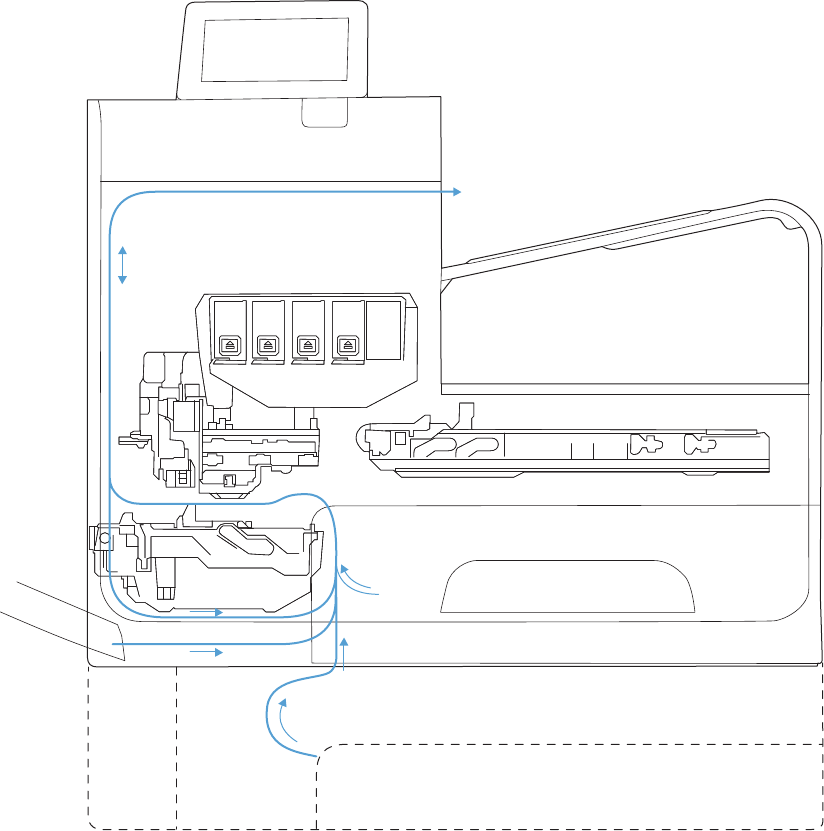
Paper-handling system
The paper-handling system moves paper through the product according to commands from the formatter.
The following figure shows the product paper path.
Figure 1-7 Paper-handling system paper path (X555 models)
ENWW Paper-handling system 17
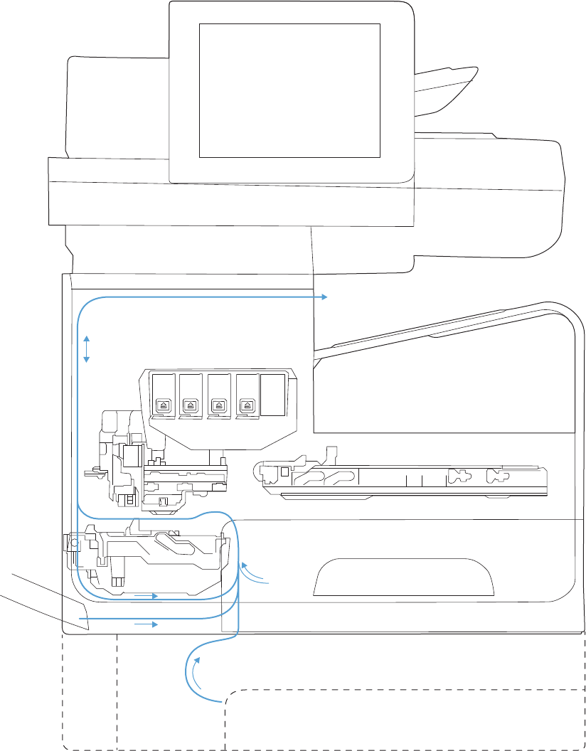
Figure 1-8 Paper-handling system paper path (X585 models)
The paper path consists of the following major components:
●Two integrated input trays plus one optional accessory tray
●Four motors and a solenoid plus two more motors in the accessory tray
●Duplex module
●Fourteen sensors plus four more sensors in the accessory tray
18 Chapter 1 Theory of operation ENWW

●Feed rollers, pinch rollers, star wheels, and media guides
●Transmission components (gears, shafts, levers, swing arms) that interface with other subsystems such
as the printbar and service sled.
Components of the paper path move the paper from the input tray to a position 1 to 2 mm underneath the
printbar, and then deliver the printed result to the output tray. The combined orientations and actions of the
printbar, the printbar lift, and the paper path establish the print-zone, where the ink drops move from the
active face of the printbar to the paper.
The following figure shows the product sensors.
Figure 1-9 Product sensors (X555 models)
1
2
3
13
14
15
16
17
18
19
20
21
22
23
24
12 11 10 89 999997 6 45
ENWW Paper-handling system 19
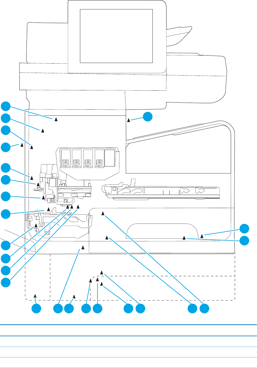
Figure 1-10 Product sensors (X585 models)
1
2
3
13
14
15
16
17
18
19
20
21
22
23
24
12 11 10 89 999997 6 45
Table 1-4 Product sensors
Item Description Item Description
1 Output flap jam sensor 13 Feed roller jam sensor
2 Ambient temperature sensor 14 Feed roller encoder
3 Ambient humidity sensor 15 Feed roller home sensor
20 Chapter 1 Theory of operation ENWW

Table 1-4 Product sensors (continued)
Item Description Item Description
4 Tray 2 pickup tire home sensor 16 Duplex module presence sensor
5 Tray 2 tray presence sensor 17 Star-wheel jam sensor
6 Tray 3 pickup tire home sensor 18 Back-scatter drop detect sensor
7 Tray 3 paper presence sensor 19 Print calibration/Media edge detect sensor
8 Tray 3 separation sensor 20 Lower left door jam sensor
9 Tray 2 paper presence sensor 21 Left door open sensor
10 Tray 3 tray presence sensor 22 Upper left door jam sensor
11 Tray 1 paper presence sensor 23 Ink supply door open sensor
12 Tray 3 cleanout presence sensor 24 Eject jam sensor
There are several motors in the product for pick, feed, duplexing, printbar lift, delivery, and the scanning
sensor carriage.
ENWW Paper-handling system 21
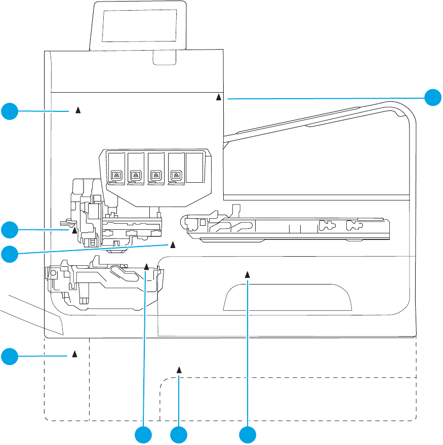
Figure 1-11 Paper-handling-system motors (X555 models)
1
234
5
6
7
8
22 Chapter 1 Theory of operation ENWW
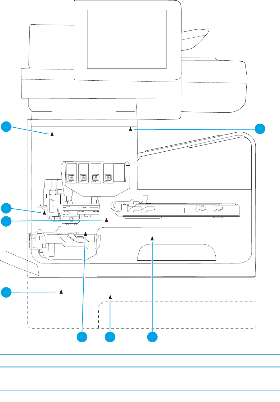
Figure 1-12 Paper-handling-system motors (X585 models)
1
234
5
6
7
8
Table 1-5 Paper-handling system motors
Item Description
1 Eject (or output drive) motor
2 Tray 2 pickup motor
3 Tray 3 pickup motor
ENWW Paper-handling system 23

Table 1-5 Paper-handling system motors (continued)
Item Description
4 Duplex Tray 1 motor
5 Tray 3 feed motor
6 Feed motor
7 Optical carriage motor
8 Printbar lift motor
Input trays
The product comes standard with two input trays, and also accepts an accessory tray.
●50-page multipurpose (MP) tray—Tray 1: The tray shares a motor with the duplex module and has one
sensor. This reflective (REDI) sensor determines if media is present in the tray. The feed roller REDI
sensor determines if a sheet of media is successfully picked from the tray.
●500-sheet letter/A4 size main tray—Tray 2: The tray has a pick motor, which is also moves the service
sled. Both the main tray motor and the duplex MP tray motor operate at the same time when picking
paper from the main tray. The main tray has three sensors:
◦A hall effect sensor determines if the tray is closed.
◦A flag/opto sensor determines if there is media in the tray.
◦A flag/opto sensor determines if the pick roller is in home position.
The feed roller jam sensor determines if a sheet of media is successfully picked from the main tray.
●Optional 500-sheet legal size accessory tray—Tray 3: This optional tray has two motors, one for picking
paper and one for the turn roller. The turn roller receives paper from the pickup roller and transfers it to
the multipurpose tray ITR that is driven by the duplex module/MP tray motor. Both the accessory tray
motor and the duplex module/MP tray motor operate at the same time when picking paper out of the
accessory tray.
The accessory tray has the following sensors:
◦A hall effect sensor detects if the tray is closed.
◦A flag/opto sensor detects if there is media in the tray.
◦A flag/opto sensor detects if the pickup roller is in home position.
◦A hall effect sensor detects if the left door is closed.
◦A separation sensor detects if the product successfully picked media.
Paper path zones
The product paper path includes the following elements.
●Deskew buckle
●Print zone
24 Chapter 1 Theory of operation ENWW
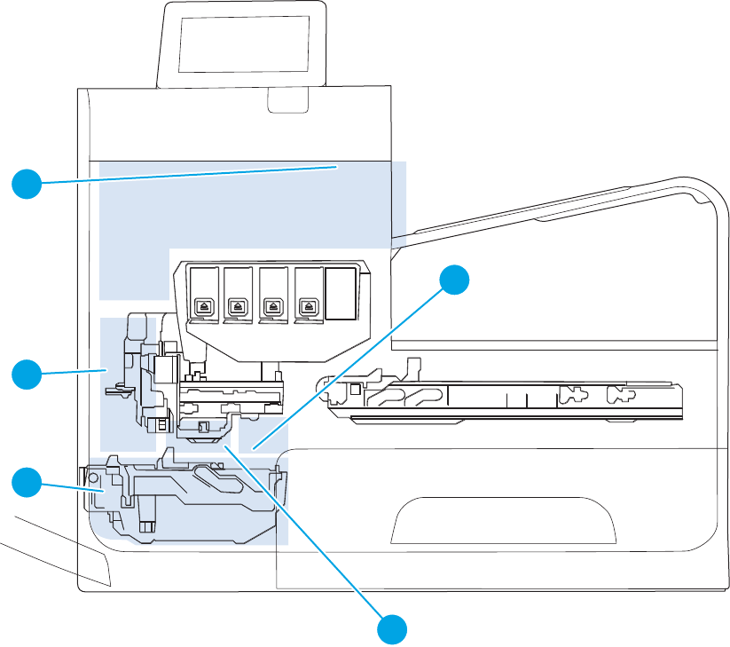
●Duplex
●Output
●Eject
Figure 1-13 Paper path zones (X555 models)
1
2
4
5
3
ENWW Paper-handling system 25
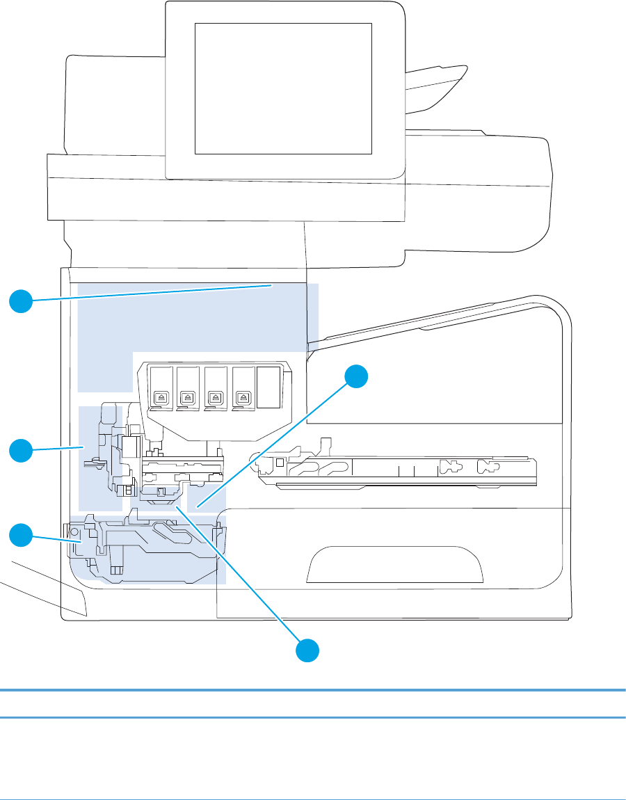
Figure 1-14 Paper path zones (X585 models)
1
2
4
5
3
Table 1-6 Paper path zones
Item Zone Description
1 Deskew buckle This is the area between the turn roller and feed roller. All print job paper passes through this zone.
During the deskew operation, the duplex module/MP tray motor rotates forward, driving the paper
into the feed roller nip while the feed roller is not moving. The feed roller REDI sensor determines the
leading edge for accurate deskew buckle size, jam detection, and if the tray successfully picked
media.
26 Chapter 1 Theory of operation ENWW

Table 1-6 Paper path zones (continued)
Item Zone Description
2 Print zone This is the path between the feed roller and output pinch 1 roller. The feed roller, which has an analog
quadrature encoder, precisely controls the paper in the paper feed direction . In the vertical direction,
a combination of the platen, feed roller, and output pinch roller 1 controls the paper. The user can
rotate the platen down for jam access after removing the duplex module.
There are no paper path sensors in the print zone. If a jam occurs in the print zone, it is not detected
until the leading edge of the paper is determined to be “late” in reaching the jam sensor in the output
path.
When a user pulls on jammed media in the print zone that is still partially in the feed roller nip, the
servo control will detect a slight movement of the feed roller and assist the user by applying a
forward torque to the roller. Also, the motion control system will disengage the duplex module
rectifier (swing arm) so that the turn roller can spin freely. This feature reduces the pulling force
needed by the user and therefore reduces the chance of leaving torn pieces of paper in the path—
especially in the deskew buckle zone.
3 Duplex By opening the left door, the duplex module can be removed to clear jams. The duplex module also
serves as waste collection unit for the print bar and will expose the user to waste ink when it is
removed. Therefore there are warnings on the module to not touch certain areas.
When the user pulls on jammed media from the duplex module (or any of the trays) that is partially in
the feed roller nip, the servo control detects a slight movement of the feed roller and assists the user
by applying a reverse torque to the feed roller and disengages. Also, the motion control system
disengages the duplex module rectifier so the turn roller can spin freely. This feature reduces the
pulling force needed by the user and therefore reduces the chance of leaving torn pieces of paper in
the path—especially in the deskew buckle zone.
In order for the product to determine the duplex module's presence, the duplex module has a magnet
that triggers a hall effect sensor mounted to the structure.
4 Output The output path begins at output pinch roller 1 and continues to output pinch roller 5. There are four
REDI sensors in this path that detect leading and trailing edges and jams.
The feed motor drives the rollers in the output path, except output pinch roller 5. All the pinch rollers
in the output and exit path are star wheels to prevent roller tracking on wet/damp ink. However, the
turn roller pinch is solid and has a high amount of force for deskew buckle formation. Also, the feed
motor drives all output shafts except shafts 5 and 6.
The REDI dry path lower, REDI dry path upper, and eject jam REDI sensor in the output path all track
the leading and trailing edges of media.
The outer and top portions of the vertical path are formed by paper guides molded in and attached to
the left door. The left door can be opened for jam clearance and has a hall effect sensor to determine
if it is closed. Also when the left door is opened, drive rollers that form pinches 3 and 4 disengage
from the feed motor for safety purposes.
5 Eject The eject portion of the paper path includes the zone from output pinch roller 5 to the eject flap.
The eject motor powers output pinch roller 5 and eject pinch roller 6.
The eject flap has 3 positions:
●Closed when not printing.
●Partially open for heavy ink printing in dry environments, to limit severe curl.
●Ofpen for all other printing. This position controls moderately curled media.
The flap is opened and closed by a torque clutch on the eject roller shaft. The flap also has a locking
feature that is controlled by a solenoid. In order for the door to open all the way, or move between
positions, the solenoid must be actuated.
ENWW Paper-handling system 27
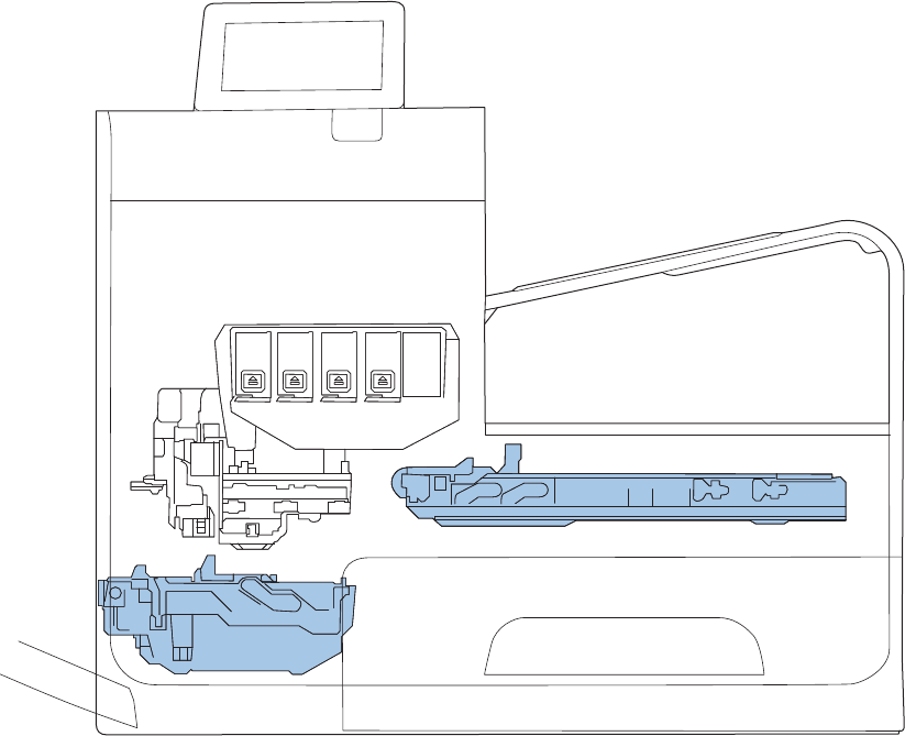
Servicing system
The servicing system comprises the service sled, which maintains print quality by wiping debris and ink off
the print nozzles, and the service ink module, where waste ink is deposited.
Figure 1-15 Servicing system components (X555 models)
Service sled
Duplex module\
Waste ink module
28 Chapter 1 Theory of operation ENWW
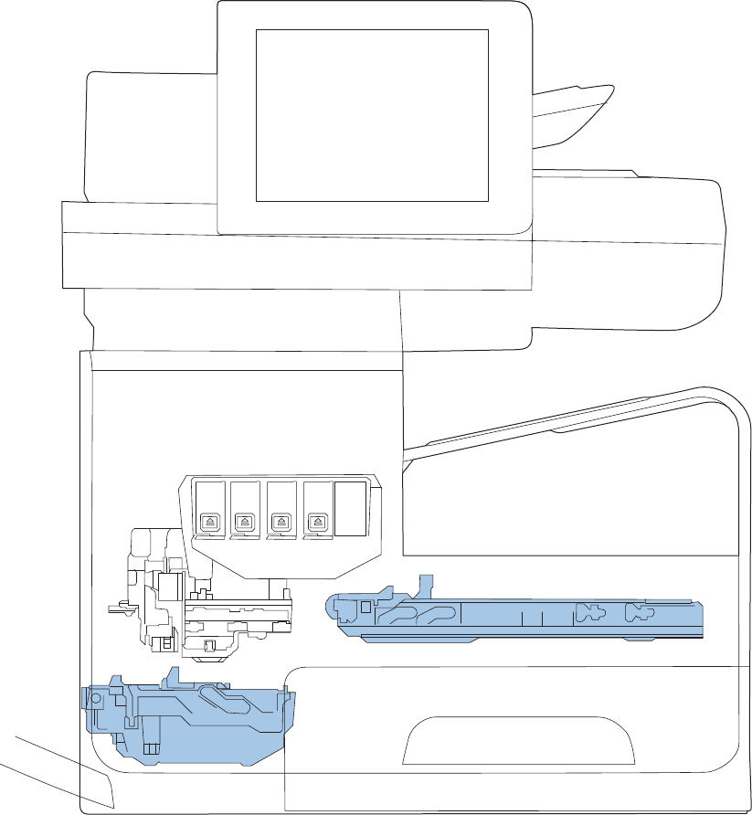
Figure 1-16 Servicing system components (X585 models)
Duplex module\
Waste ink module
Service sled
ENWW Servicing system 29
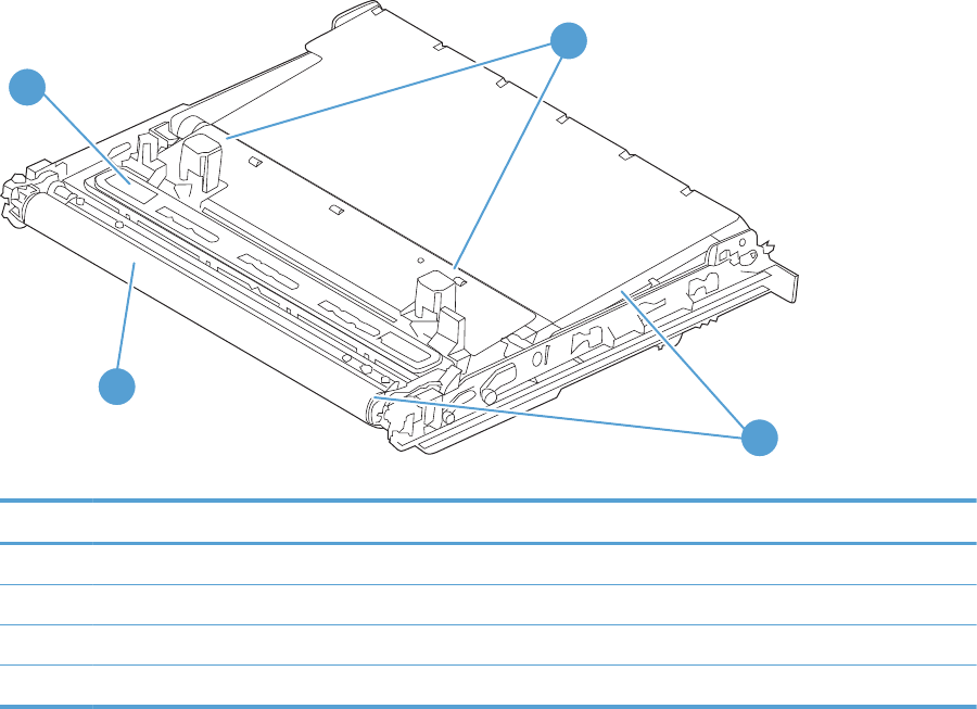
Service sled
Figure 1-17 Service sled components
3
1
4
2
Table 1-7 Service sled components
Item Description
1 Service sled cap
2 Service sled wiping surface
3 Service sled web fabric loop
4 Printbar support posts
The service sled system keeps the printbar nozzles firing correctly throughout the life of the product as it
performs the wiping and capping functions.
●The wiping function cleans the nozzles of ink residue and particulates.
●The capping function keeps the nozzles moist during storage when the product is idle.
The service sled system uses the pick drive system (a component of the paper path) for horizontal motion to
perform its functions.
To perform the wiping function, the product moves the service sled underneath the printbar (which is
elevated from the print position) so that the web fabric makes contact with the ink nozzles. The web fabric is
a looped belt that advances after every wipe. Since the belt is a finite loop, it will eventually reuse previously
used material. The web advances when the web wipe module moves to the right out of the print zone. The
advance mechanism is triggered by a mechanism located on the rear wall of the unit.
To perform the capping function, the service sled moves underneath the printbar (which is elevated from the
print position), which allows the rubber cap to seal the print nozzles from the environment.
30 Chapter 1 Theory of operation ENWW
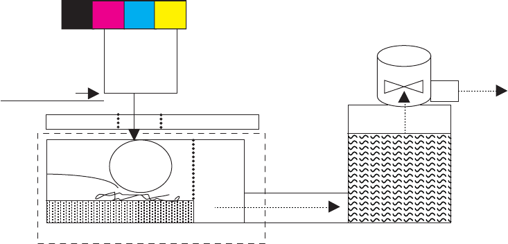
Aerosol management system
The aerosol management system consists of a fan module and filter box to keep ink aerosol from building up
inside the product. The following figure shows the service ink and aerosol capture system components.
Figure 1-18 Aerosol management process
Printbar
Platen
Duct
Duplex
module
Absorbers
Spit
Roller
Aerosol filter
Aerosol blower
Service ink capture (in duplex module)
Paper
Between pages, printed aerosol is drawn though the platen openings. Service ink travels directly through the
platen, impacting and collecting on the spit roller. Aerosol from the service spitting is also collected. Service
ink collects in the duplex module, and a porous filter element captures the aerosol as aerosol-laden air
passes though it. The aerosol blower mounted to the filter housing creates the air motion (suction—lower
pressure—in the print zone).
Most of printbar servicing ink (spit ink) is captured by the spit roller and scraped into the bottom of the
bucket on the duplex module. The service ink spit roller is indexed slowly by the motion of paper though the
product, driven by the swing-arm and turn-roller gear train, with power provided by the duplex motor.
When the product purges the printbar of its shipping fluid at initial startup, absorbers in the duplex module
collect the fluid. These absorbers allow much of the initial water to evaporate from the shipping fluid over
time. Also, they allow service ink coming into contact with the absorbers to leach some of their fluids into
them, assisting with drying and thickening of the sludge.
The blower remains active as long as the printbar is uncapped, and it continues to operate for a few seconds
after capping is complete.
ENWW Aerosol management system 31
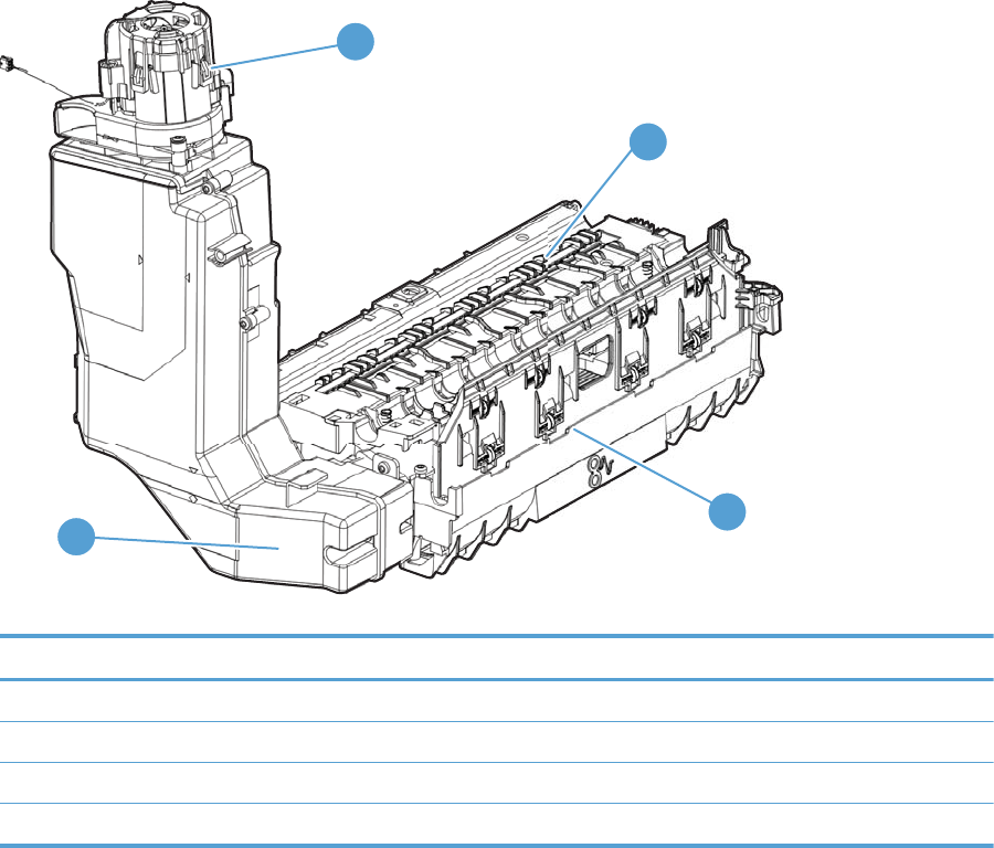
Figure 1-19 Aerosol management system components
1
4
3
2
Table 1-8 Aerosol management system components
Item Description
1Blower
2 Aerosol filter housing
3 Duplex module/waste ink module
4Platen
32 Chapter 1 Theory of operation ENWW
Document feeder (X585 models)
Document feeder operation
Standby (paper-loading) mode: In standby mode, the pickup roller is up and the stack-stop is down,
preventing the user from inserting the original document too far. When a document is inserted correctly, the
paper-present sensor detects its presence.
The standard operation of the document feeder consists of the pick, feed, and lift steps.
Pick: When it receives a copy or scan command, the document feeder motor engages the gear train to lower
the pickup-roller assembly and raise the stack-stop. The pre-pick roller moves the top few sheets forward
into the document feeder. The pickup roller contacts the document feeder separation pad, which separates
multiple pages into single sheets.
Feed: The form sensor, which is a set distance from the document feeder glass, detects the sheet. This alerts
the scanner to start when the page reaches the glass. The scanner acquires the image until it detects the end
of the page. The page is then ejected. The pick and feed steps are repeated as long as paper is detected in the
document feeder input tray.
Duplex: When the product duplexes from the document feeder, the paper passes through the document
feeder three times. During the second instance, the product reverses the page orientation and then scans it.
During the third instance, the product returns the page to the original orientation.
Lift: When no more paper is detected in the document feeder input tray and the form sensor detects the
trailing edge of the last page, the last sheet is ejected and the motor lifts the pick-roller assembly to standby
(paper-loading) mode again.
The document feeder will not function when the document feeder cover is open. When the document feeder
cover is closed, the cover-present sensor detects its presence.
The paper path is incomplete if the scanner lid/document feeder is lifted from the glass, and it will result in a
paper jam error.
Document feeder paper path and sensors
The following diagram shows the document feeder paper path during a duplexed copy job. The paper enters
the product from the document feeder input tray and passes through the paper path for the first time. The
product then pulls the paper back through the path to reorient the page and scan the second side. The paper
then travels back to the end of the paper path, where it is pulled in again to be reoriented and ejected into the
output bin.
ENWW Document feeder (X585 models) 33
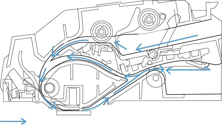
Figure 1-20 Document feeder paper path and sensors
Paper travel direction Scan glass
(1)
(1)
(1) (1)
(1)
(1) (1)
(1)
(1)
(1.2)
(1.2)
(1.2)
(1.2)
(1.2)
(1.2)
(1.2)
(1.2)
(1.2)
Flag TOP
Flag TOP
Flag TOP Prepick roller
Prepick roller
Prepick roller
Document flag
Document flag
Document flag
Paper pulled back
after first side scan
Output roller
Output roller
Output roller Output tray
Output tray
Output tray
Input tray
Input tray
Input tray
Prepick roller
Separation roller
Stack Shop
Stack Shop
Stack shop
(2)
(2)
(2)
The paper-present sensor determines if paper is in the document feeder input tray. The form sensor detects
the top and bottom edges of the document. Another sensor detects an open document feeder cover.
Document feeder jam detection
The document feeder has two sensors that detect paper. The paper-present sensor detects the presence of
media in the document feeder input tray. The form sensor detects media moving through the document
feeder. If a jam is detected, the document feeder immediately stops the paper feeding and initiates a jam
clearing routine. A jam message appears on the control-panel display.
A jam can be detected under any of the following conditions:
●Document-feeder jam:When documents are detected in the document feeder input tray, and a
command to copy, scan or fax is received, the document feeder attempts three times, or for about 10
seconds, to advance the paper to the form sensor. If the paper does not advance, the scan module turns
off and the ADF Misfeed message appears on the control-panel display.
●Long-document jam: If the paper has advanced to trigger the form sensor, but the trailing edge is not
detected within the time allowed for a 381 mm (15 in) document (the maximum allowable page length
for the document feeder), the scan module turns off and the message Paper Jam appears on the
control-panel display.
●Stall jam: When a page that is less than 381 mm (15 in) long has advanced to the form sensor but has
not left it within the expected time, the paper has probably stalled or jammed. The scan module turns
off and the message Paper Jam appears on the control-panel display.
●Other: If the paper stops in the document feeder and the scan module remains under the document
feeder scanner glass, an internal firmware error has probably occurred and the message Cannot Scan,
Copy, or Fax appears on the control-panel display. This is usually remedied by cycling the power.
34 Chapter 1 Theory of operation ENWW
Scanner system (X585 models)
The flatbed image scanner captures an electronic image of the document on the glass. The scanner does this
by illuminating the document with LEDs (red, green, and blue) and capturing the image in the image sensor to
create an electronic image of the document. The flatbed scanner consists of three main elements
●CIS scanner. The CIS (contact image sensor) scanner captures an image using the product's optical path.
Red, green, and blue LEDs sequentially illuminate a small strip of the document (often called a raster
line), and the optical system captures each color in a single row of CCD sensors that cover the entire
page width. Because only one color is captured for each line per exposure, the three colors are
recombined electronically to create the full color image. For monochromatic scans or copies, all three
LEDs are illuminated to create a white light for the scan so the raster line can be captured in one
exposure.
●Mechanical carriage drive. The carriage drive moves the CIS scan head along the document length to
create the image. In this product, a small DC motor with an optical encoder creates this motion. The
speed of the carriage drive is proportional to the scan resolution (300 ppi is much faster than 1200 ppi)
and also proportional to the type of scan (color scans are three times slower than monochromatic
scans). A 1200 ppi color scan moves so slowly that the product might appear to not be working,
whereas a monochromatic copy scan moves at 50 times that speed and will be somewhat noisy.
●Image processing system (formatter). The formatter processes the scanner data into either a copy or a
scan to the computer. For copies, the image data is sent directly to the product without being
transmitted to the computer. Depending on user selections for the copy settings, the formatter
enhances the scanner data before sending it to the product. Image data is captured at 300 ppi for copies
and is user selectable for scans to the computer. Each pixel is represented by 8 bits for each of the three
colors (256 levels for each color), for a total of 24 bits per pixel (24-bit color).
Scanner power-on sequence of events
When the product is turned on, it performs the following tests:
●Motor test. The product moves the motor left and right to confirm operation. It reports a scanner error
12 if no motion is detected in the motor encoder system.
●Wall find. The scan carriage moves slowly to the left while watching an encoder on the carriage motor
to determine when the carriage has found the side wall or stop. This enables the product to identify the
document origin (position of the original). If the document origin cannot be located, a default position is
used instead.
●LED check. The product moves the carriage to the white calibration label under the left side of the
flatbed image scanner, and it verifies that the minimum and maximum response is acceptable. It
reports a scanner error 14 if the response is unacceptable.
●Home find. The scan carriage uses the optical scanner to find physical reference features that relate to
the document origin at the left side of the image glass. This process ensures accurate location of the
first document pixels so that the user documents will have an accurate placement of the image on
scans and copies. It reports a scanner error 6 message if the reference features are not found.
●Calibration. This test, also known as scanner color calibration, enables the product to identify the black
and white on every pixel in the CCD. Calibration occurs in two processes: a broad (analog) adjustment of
all pixels to bring them into the target output range, and a pixel-by-pixel adjustment (digital) to fine
tune the actual black and white response. The calibration process occurs under the left side of flatbed
image scanner where there is a special white calibration label. The calibration code in the product
firmware needs to be updated when the scanner assembly is replaced.
ENWW Scanner system (X585 models) 35
Calibration is the most important step in creating a high quality image. Calibration problems can include
color and brightness inaccuracies and vertical streaks through the image. The calibration process
identifies any bad pixels and enables the image formatter to recreate the lost information from
adjacent pixels. Extreme cases of this problem can appear as large vertical streaks or image smears.
The user has no control over the calibration process itself or this pixel-replacement process.
For best calibration results, make sure that the scanner lid is in the down (closed) position.
Copy or scan-to-computer sequence of events
To create an accurate rendition of a document, the scanner must be calibrated for the requested operation. If
the user selects a scan at 600 ppi color, the flatbed image scanner calibrates for that specific operational
mode. The flatbed image scanner automatically re-calibrates for the next requested operation. Calibration
does not occur for every new copy request.
This is the normal sequence of operation for a flatbed copy or scan.
1. LEDs illuminate.
2. Carriage motion begins moving the CIS scanner toward the right.
3. Image capture continues for the entire page or length requested in a scan-to-computer operation.
4. Carriage returns to the home position on the left.
36 Chapter 1 Theory of operation ENWW
Fax functions and operation (X585 models)
The following sections describe the product fax capabilities.
Computer and network security features
The product can send and receive fax data over telephone lines that conform to public switch telephone
network (PSTN) standards. The secure fax protocols make it impossible for computer viruses to be
transferred from the telephone line to a computer or network.
The following product features prevent virus transmission:
●No direct connection exists between the fax line and any devices that are connected to the USB or
Ethernet ports.
●The internal firmware cannot be modified through the fax connection.
●All fax communications go through the fax subsystem, which does not use Internet data-exchange
protocols.
PSTN operation
The PSTN operates through a central office (CO) that generates a constant voltage on the TIP and RING wires
(usually 48 V). A device goes off-hook by connecting impedance (such as 600 ohms for the U.S.) across the
TIP and RING so that a line current can flow. The CO can detect this current and send impulses like dial tones.
The product generates more signaling tones, such as dialing digits, to tell the CO how to connect the call. The
product can also detect tones, such as a busy tone from the CO, that tell it how to behave.
When the call is connected, the CO behaves like a wire connecting the sender and receiver. This is the period
during which all of the fax signaling and data transfer occurs. When a call is completed, the circuit opens
again and the line-current flow ceases, removing the CO connection from both the sender and the receiver.
On most phone systems, the TIP and RING signals appear on pins 3 and 4 of the RJ-11 modular jack (the one
on the fax card, as defined in the common six-wire RJ standard). These two signals do not have to be
polarized because all of the equipment works with either TIP or RING on one pin and the other signal on the
other pin. This means that cables of either polarity can interconnect and still work.
These basic functions of PSTN operation are assumed in the design of the fax subsystem. The product
generates and detects the signaling tones, currents, and data signals that are required to transmit and
receive faxes using the PSTN.
The fax subsystem
The formatter, fax card, firmware, and software all contribute to the product fax functionality. The designs of
the formatter and fax card, along with parameters in the firmware, determine the majority of the regulatory
requirements for telephony on the product.
The fax subsystem is designed to support V.34 fax transmission, medium speeds (such as V.17 fax), and the
lower speeds of older fax machines.
Fax card in the fax subsystem
The fax card contains the modem chipset (DSP and CODEC) that controls the basic fax functions of tone
generation and detection, along with channel control for fax transmissions. The CODEC and its associated
circuitry act as the third-generation silicon data access arrangement (DAA) to comply with worldwide
regulatory requirements.
ENWW Fax functions and operation (X585 models) 37
Safety isolation
The fax card provides safety isolation between the high-voltage, transient-prone environment of the
telephone network (TNV [telephone network voltage]) and the low-voltage analog and digital circuitry of the
formatter (SELV [secondary extra-low voltage]). This safety isolation provides both customer safety and
product reliability in the telecom environment.
Any signals that cross the isolation barrier do so magnetically. The breakdown voltage rating of barrier-
critical components is greater than 5 kV.
Safety-protection circuitry
In addition to the safety barrier, the fax card protects against over-voltage and over-current events.
Telephone over-voltage events can be either differential mode or common mode. The event can be transient
in nature (a lightning-induced surge or ESD) or continuous (a power line crossed with a phone line). The fax
card protection circuitry provides a margin of safety against combinations of over-voltage and over-current
events.
Common mode protection is provided by the selection of high-voltage-barrier critical components
(transformer and relay). The safety barrier of the fax card PCA and the clearance between the fax card and
surrounding components also contribute to common mode protection.
A voltage suppressor (a crowbar-type thyristor) provides differential protection. This device becomes low
impedance at approximately 300 V differential, and crowbars to a low voltage.
Data path
TIP and RING are the two-wire paths for all signals from the telephone network. All signaling and data
information comes across them, including fax tones and fax data.
The telephone network uses DC current to determine the hook state of the telephone, so line current must be
present during a call. The silicon DAA provides a DC holding circuit to keep the line current constant during a
fax call.
The silicon DAA converts the analog signal to a digital signal for DSP processing, and also converts the digital
signal to an analog signal for transmitting data through a telephone line.
The magnetically coupled signals that cross the isolation barrier go through a transformer.
The DSP in the fax card communicates with the ASIC in the formatter using the high-speed serial interface.
Ring detect
Ring detect is performed by the line voltage monitoring module of the silicon DAA, and is a combination of
voltage levels and cadence (time on and time off). Both must be present to detect a valid ring. The CODEC
works with DSP and the firmware to determine if an incoming signal is an answerable ring.
Line current control
The DC current from the CO needs to have a path to flow from TIP to RING. The DC impedance emulation line
modulator and DC terminations modules in the silicon DAA act as a DC holding circuit, and work with the
firmware to achieve the voltage-current characteristic between TIP and RING. The impedance (the current-
voltage characteristic) changes corresponding to certain special events, such as pulse dialing or when the
product goes on-hook.
38 Chapter 1 Theory of operation ENWW
Fax page storage in flash memory
Fax pages are the electronic images of the document page. They can be created in any of three ways:
scanned to be sent to another fax machine, generated to be sent by the computer, or received from a fax
machine to be printed.
The product automatically stores all fax pages in flash memory. After these pages are written into flash
memory, they are stored until the pages are sent to another fax machine, printed on the product, transmitted
to the computer, or erased by the user.
These pages are stored in flash memory, which is the nonvolatile memory that can be repeatedly read from,
written to, and erased. The product has 2 MB of flash memory, of which 1.5 MB is available for fax storage.
The remaining 0.5 MB is used for the file system and reclamation. Adding RAM does not affect the fax page
storage because the product does not use RAM for storing fax pages.
Advantages of flash memory storage
Fax pages that are stored in flash memory are persistent. They are not lost as a result of a power failure, no
matter how long the power is off. Users can reprint faxes if an ink cartridge runs out of ink or the product
experiences other errors while printing.
The product also has scan-ahead functionality that makes use of flash memory. Scan-ahead automatically
scans pages into flash memory before a fax job is sent. This allows the sender to pick up the original
document immediately after it is scanned, eliminating the need to wait until the fax transmission is complete.
Because fax pages are stored in flash memory rather than RAM, more RAM is available to handle larger and
more complicated copy and print jobs.
ENWW Fax functions and operation (X585 models) 39
40 Chapter 1 Theory of operation ENWW


Problem-solving checklist
Follow these steps when trying to solve a problem with the product.
●Step 1: Check that the product power is on
●Step 2: Check the control panel for error messages
●Step 3: Test print functionality
●Step 4: Test copy functionality
●Step 5: Test the fax sending functionality
●Step 6: Test the fax receiving functionality
●Step 7: Try sending a print job from a computer
●Step 8: Test the Plug and Print USB Drive printing functionality
●Factors that affect product performance
Step 1: Check that the product power is on
1. Make sure that the product is plugged in and turned on. The power button should be lit with a green
light. If it is not, press the power button. It should first glow with an amber color, and then quickly
switch to green as the product initializes. If the power button does not light up, check the following
conditions.
●Make sure that the power cable is connected to the product and the outlet.
●Check the power source by connecting the power cable to a different outlet.
2. If the product motors do not rotate, make sure that the ink cartridges are installed and that the doors
are all closed. The control panel displays messages to indicate these problems.
3. If the document feeder motor does not rotate, open the document feeder cover and remove any
packing material or shipping tape.
4. If the scanner bulb does not light during copying, scanning, or faxing, contact HP support.
Step 2: Check the control panel for error messages
The control panel should indicate ready status. If an error message appears, resolve the error.
Print a supplies status page to ensure that the supplies are not at or over end of life.
●Ink collection unit (B5L09A): estimated life is 115,000 pages.
●Document feeder (ADF) roller kit, X585 models only (L2718A): estimated life is 100,000 pages.
NOTE: HP long-life consumable and maintenance kit life specifications are estimations. Actual individual
life or yield during normal use will vary depending on usage, environment, media, and other factors.
Estimated life is not an implied warranty.
42 Chapter 2 Solve problems ENWW

Step 3: Test print functionality
1. From the control panel Home screen, touch the Administration button.
2. Open the Reports menu, touch the Configuration/Status Pages menu, select the Configuration Page
item, and then touch the Print button to print the report.
3. If the report does not print, make sure that paper is loaded in the tray, and check the control panel to
see if paper is jammed inside the product.
NOTE: Make sure that the paper in the tray meets specifications for this product.
Step 4: Test copy functionality
1. Place the configuration page into the document feeder and make a copy. If paper does not feed
smoothly through the document feeder, you might need to clean the document feeder rollers and
separation pad. Make sure that the paper meets specifications for this product.
2. Place the configuration page onto the scanner glass and make a copy.
3. If the print quality on the copied pages is not acceptable, clean the scanner glass and the small glass
strip.
Step 5: Test the fax sending functionality
1. From the control panel Home screen, touch the Administration button.
2. Open the Fax Setup menu, and then open the Fax Tools menu. Touch the Run Fax Test button to test the
fax functionality.
3. Touch the Fax on the product control panel, and then touch the Start Fax button.
Step 6: Test the fax receiving functionality
1. From the control panel Home screen, touch the Administration button.
2. Touch the Fax Setup menu, and then touch the Fax Tools menu. Touch the Run Fax Test button to test
the fax functionality.
3. Use another fax machine to send a fax to the product.
4. Review and reset the product fax settings.
Step 7: Try sending a print job from a computer
1. Use a word-processing program to send a print job to the product.
2. If the job does not print, make sure that you selected the correct printer driver.
3. Uninstall and then reinstall the product software.
ENWW Problem-solving checklist 43
Step 8: Test the Plug and Print USB Drive printing functionality
1. Load a .PDF document or .JPEG photo onto a USB flash drive, and insert it in the slot on the front of the
product.
2. The USB Flash Drive menu opens. Try printing the document or photo.
3. If no documents are listed, try a different type of USB flash drive.
Factors that affect product performance
Several factors affect the time it takes to print a job:
●The software program that you are using and its settings
●The use of special paper (such as heavy paper or custom-size paper)
●Product processing and download time
●The complexity and size of graphics
●The speed of the computer you are using
●The USB or network connection
●Whether the product is printing in color or in monochrome
●The type of USB drive, if you are using one
●Environmental factors, such as low temperature or high humidity
44 Chapter 2 Solve problems ENWW
Troubleshooting process
Determine the problem source
When the product malfunctions or encounters an unexpected situation, the product control panel alerts you
to the situation. This section contains a pre-troubleshooting checklist to filter out many possible causes of
the problem. A troubleshooting flowchart helps you diagnose the root cause of the problem. The remainder
of this chapter provides steps for correcting problems.
●Use the troubleshooting flowchart to pinpoint the root cause of hardware malfunctions. The flowchart
guides you to the section of this chapter that contains steps for correcting the malfunction.
Before beginning any troubleshooting procedure, check the following issues:
●Are supply items within their rated life?
●Are supply items Genuine HP supplies?
●Does the configuration page reveal any configuration errors?
NOTE: The customer is responsible for checking supplies and for using supplies that are in good condition.
Troubleshooting flowchart
This flowchart highlights the general processes that you can follow to quickly isolate and solve product
hardware problems.
Each row depicts a major troubleshooting step. A “yes” answer to a question allows you to proceed to the
next major step. A “no” answer indicates that more testing is needed. Go to the appropriate section in this
chapter, and follow the instructions there. After completing the instructions, go to the next major step in this
troubleshooting flowchart.
Table 2-1 Troubleshooting flowchart
1
Power on
Is the product on and does a readable message
display?
Follow the power-on troubleshooting checks. See Power subsystem
on page 46.
After the control-panel display is functional, see step 2.
Yes No
2
Control-panel
messages
Does the message Ready display on the control
panel?
After the errors have been corrected, go to step 3. See Error messages
on page 60.
Yes No
3
Event log
Open the Troubleshooting menu and print an
event log to see the history of errors with this
product.
Does the event log print?
If the event log does not print, check for error messages. See Error
messages on page 60.
If paper jams inside the product, clear the jam. See Clear jams
on page 238.
If error messages display on the control panel when you try to print an
event log, see the control-panel message section of the service
manual.
After successfully printing and evaluating the event log, see step 4.
Yes No
ENWW Troubleshooting process 45

Table 2-1 Troubleshooting flowchart (continued)
4
Information pages
Open the Reports menu and print the
configuration pages to verify that all the
accessories are installed.
Are all the accessories installed?
If accessories that are installed are not listed on the configuration
page, remove the accessory and reinstall it.
After evaluating the configuration pages, see step 5.
Yes No
5
Print quality
Does the print quality meet the customer's
requirements?
Compare the images with the print quality report. See Interpret the
print quality report on page 156.
After the print quality is acceptable, see step 6.
Yes No
6
Interface
Can the customer print successfully from the
host computer?
Verify that all I/O cables are connected correctly and that a valid
IP address is listed on the HP Jetdirect configuration page.
If error messages display on the control panel when you try to print an
event log, see the control-panel message section of the service
manual.
When the customer can print from the host computer, this is the end of
the troubleshooting process.
Yes. This is the end of
the troubleshooting
process.
No
Power subsystem
Power-on checks
The basic product functions should start up when the product is connected into an electrical outlet and the
power switch is pushed to the on position. If the product does not start, use the information in this section to
isolate and solve the problem.
If the control-panel display remains blank, random patterns display, or asterisks remain on the control-panel
display, perform power-on checks to find the cause of the problem.
Power-on troubleshooting overview
During normal operation, a cooling fan begins to spin briefly after the product power is turned on. Place your
hand over the vents at the rear of the product, next to the formatter, or on the on the rear of the scanner
(X585 models). If the fan is operating, you will feel air passing out of the product. You can lean close to the
product and hear the fan operating.
After the fan is operating, the main motor turns on (unless the left door or cartridge access door is open, a
jam condition is sensed, or the paper-path sensors are damaged). You might be able to visually and audibly
determine if the main motor is turned on.
If the fan and main motor are operating correctly, the next troubleshooting step is to isolate print engine,
formatter, and control panel problems.
If the control panel is blank when you turn on the product, check the following items:
1. Make sure that the product is connected directly into an active electrical outlet (not a power strip) that
delivers the correct voltage.
2. Make sure that the power switch is in the on position.
3. Make sure that the fan runs briefly, which indicates that the power supply is operational.
4. Make sure that the control-panel display wire harness is connected.
46 Chapter 2 Solve problems ENWW
5. Make sure that the formatter is seated and operating correctly. Turn off the product and remove the
formatter. Reinstall the formatter, make sure the power switch is in the on position, and then verify that
the heartbeat LED is blinking.
6. Remove any external solutions, and then try to turn the product on again.
Scanning subsystem (X585)
Calibrate the scanner
Use this procedure to properly position the copied image on the page.
TIP: This adjustment might be required after the scanner or document feeder is replaced.
1. From the Home screen on the product control panel, scroll to and touch the Device Maintenance button.
2. Touch the Calibration/Cleaning button.
3. Touch the Calibrate Scanner button, and then follow the instructions provided on the screen.
Control panel checks
The product includes a diagnostic test mode for the control panel. This mode allows you to troubleshoot
issues with the touchscreen, the speaker, and the Home button.
NOTE: Some of the diagnostic tests are for factory use only.
TIP: To diagnose control panel problems, see Control panel diagnostic flowcharts on page 50.
Open diagnostic mode
●Tilt the control panel forward. On the back side of the control panel, press the button that is underneath
the round black rubber cover near the center of the control panel to access the diagnostic mode.
Repeatedly pressing the button will scroll through additional screens on the control-panel display.
Continue to press the button to scroll back to the diagnostic-mode main test screen.
Exit diagnostic mode
Do one of the following:
●Touch the Cancel button.
●Wait 20 seconds. The control panel will return to the Home screen.
Table 2-2 Control panel diagnostic functions
Item Description Remarks
Cancel button
Exits a test
ENWW Troubleshooting process 47
Table 2-2 Control panel diagnostic functions (continued)
Item Description Remarks
Keypad
Selects test settings in some of the test windows
Red-grid touch test
Verifies that all areas respond to a touch Use this item to check the accuracy of the touch
screen.
Use a finger or 3 mm (.118 in) conductive stylus to
trace between the grid lines to check the accuracy
of the touchscreen calibration.
NOTE: The gap between the grid lines is 6 mm (.
236 in).
When the screen is touched, a line or a dot displays
on the screen (the X and Y coordinates of the
position on the screen are also displayed).
Calibration touch test
Checks calibration Use this item to determine if the touchscreen
calibration is within the acceptable range.
When selected, ten target points (and the X and Y
coordinates of the position of the target point)
display on the screen.
Touching a target causes the X and Y coordinate of
that target to appear in the middle of the
touchscreen (above the cancel button).
NOTE: The product automatically calibrates the
touchscreen. A manual touchscreen calibration
procedure is not available for this product.
Touchscreen LED display
test
Selects a test pattern to view on the display. Use this item to identify touchscreen LED display
problems.
1. Touch the icon.
2. Touch the up or down arrow buttons to
scroll though touchscreen LED display test
screens.
Speaker test
Tests sounds Use this item to test audio functionality.
1. Touching this item causes the speaker to emit
a tone.
2. Touch the 2 button on the keypad, and then
touch this item to cause the speaker to emit a
more complex tone.
48 Chapter 2 Solve problems ENWW
Table 2-2 Control panel diagnostic functions (continued)
Item Description Remarks
Firmware information
Shows the firmware version Touch this item to display the control panel
firmware version and firmware build date.
Factory use only
Keyboard test
Tests the product keyboard
NOTE: For products with a keyboard feature only.
When this item is selected, pressing a button on the
keyboard causes the corresponding character to
appear on the control-panel display.
1. Touch the icon.
2. Press a button on the keyboard. The
corresponding character should appear on the
control-panel display.
Backlight test
Adjusts the backlight Use this item to adjust the brightness of the
control-panel display.
1. Touch the icon.
2. Touch the up or down arrow buttons to
adjust the backlight level.
Ambient-light sensor
test
Checks the ambient light sensor Use this item to test the ambient-light sensor
functionality.
1. Touch the icon.
2. Shine a flashlight at the control panel to the
left of, and down about 25.4 mm (1 in,) from
the Home button.
3. The numbers displayed below the icon should
be any value other than zero.
Home button test
Tests the Home button Use this item to test the Home button LED and
switch functionality.
1. Touch the icon.
2. Press the Home button on the right side of
the control panel. The LED icon on the control-
panel display illuminates if the button LED and
switch are correctly functioning.
ENWW Troubleshooting process 49

Control panel diagnostic flowcharts
TIP: Tilt the control panel forward. On the back side of the control panel, press the button that is
underneath the round black rubber cover near the center of the control panel to access the diagnostic mode.
Use the flowcharts in this section to troubleshoot the following control panel problems.
●Touchscreen is blank, white, or dim (no image).
●Touchscreen is slow to respond or requires multiple presses to respond.
●Touchscreen has an unresponsive zone.
●No control panel sound.
●Home button is unresponsive.
●Hardware integration pocket (HIP) is not functioning (control panel functional).
50 Chapter 2 Solve problems ENWW
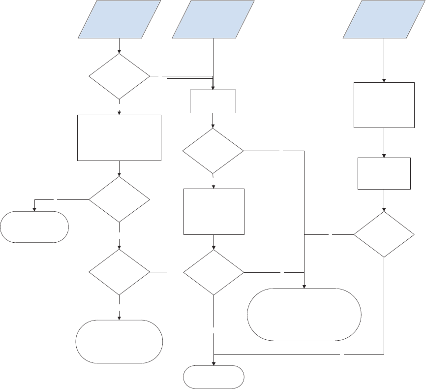
Touchscreen black, white, or dim (no image)
Figure 2-1 Touchscreen blank, white, or dim (no image)
N
N
Y
N
N
Y
Y
N
Y
Y
N
Y
Touch the display or Home button
to exit sleep mode. Make sure that
the product is plugged in and
the power is turned on.
Black display
(no backlight
or image)
White display
(no image)
Dim display
(no image)
Is the Home button
illuminated
(bright white)?
Open the
diagnostic function.
Does an image
appear on the
control panel?
Does the display
turn on?
Problem solved.
Are the formatter
LEDs functioning?
Turn the product power off.
Remove and reseat the formatter.
Troubleshoot the formatter.
Do not replace the control panel.
Turn the product power off.
Inspect and reseat the
control panel cables.
Remove and reseat the
formatter.
Make sure that the
formatter LEDs function.
Problem fixed?
Replace the
control panel.
Do not replace the control panel.
Turn the product power off.
Remove and reseat the formatter.
If the error persists,
troubleshoot the formatter, USB cable,
and the control panel.
Is the backlight
adjustable?
Open the
diagnostic function.
Perform the
backlight test.
Is the product in bright
sunlight?
If yes, move the
product to a
different location.
ENWW Troubleshooting process 51

Touchscreen is slow to respond or requires multiple presses to respond
TIP: Use the red-grid touch test to verify that all areas of the touchscreen are correctly functioning. See
Table 2-2 Control panel diagnostic functions on page 47.
Figure 2-2 Touchscreen is slow to respond or requires multiple presses to respond
Touchscreen slow to
respond or requires
multiple presses
to respond
Not a control-panel problem.
Do not replace the control panel.
Troubleshoot firmware or
software application problems.
52 Chapter 2 Solve problems ENWW
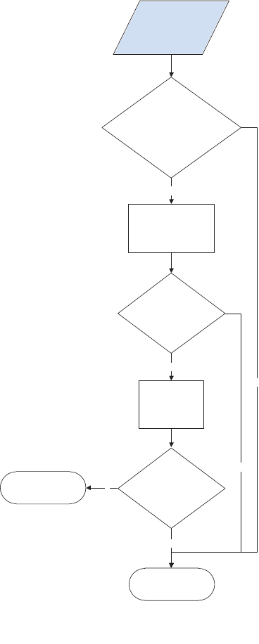
Touchscreen has an unresponsive zone
Figure 2-3 Touchscreen has an unresponsive zone
N
Y
N
Y
N
Y
Touchscreen
has an
unresponsive
zone
Is the area of the
touchscreen you are touching
greyed out (intentionally
deactivated)?
Does the previously
inactive area respond
to a touch?
Open the
diagnostic function.
Perform the
red-grid touch test.
Turn the product
power off,
and then
on again.
Does the previously
inactive area respond
to a touch?
Replace the
control panel.
Do not replace the
control panel.
ENWW Troubleshooting process 53
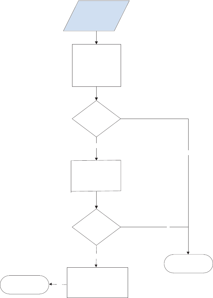
No control panel sound
Figure 2-4 No control panel sound
N
N
Y
Y
Control panel
has no
sound
Turn the product power off.
Remove the control panel.
Check the cables to the speaker.
Reseat the cables to the speaker.
Turn the product power on.
Can sounds be heard?
Can sounds
be heard?
Can sounds
be heard?
Replace the control panel.
Open the following menus:
Administration
Display Settings
Key Press Sound
Select the following:
On
Save
N
Do not replace the
control panel.
Open the
diagnostic function.
Perform the sound test.
54 Chapter 2 Solve problems ENWW
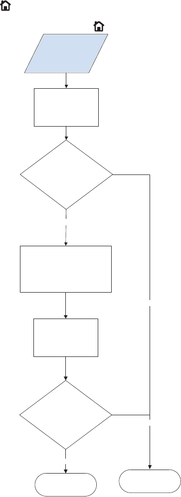
Home button is unresponsive
Figure 2-5 Home button is unresponsive
Y
N
N
Y
Home button
unresponsive
Open the
diagnostic function.
Perform the Home
button test.
Does the virtual LED
illuminate green when
the Home button is pressed?
Turn the product power off,
and then on again.
Open the
diagnostic function.
Perform the
Home button test.
Does the virtual LED
illuminate green when
the Home button is pressed?
Replace the
control panel.
Do not replace the
control panel.
ENWW Troubleshooting process 55

Hardware integration pocket (HIP) is not functioning (control panel functional)
Figure 2-6 Hardware integration pocket (HIP) is not functioning (control panel functional)
Hardware integration
pocket (HIP)
not functional
(control panel
functional)
Check that all installed hardware integration
pocket devices are within HP specifications.
The control panel provides only 0.5 Amps to
the port. If an installed device attempts to draw
more power than is provided, the port is
automatically disabled. Troubleshoot third-party
devices with the device manufacturer.
56 Chapter 2 Solve problems ENWW
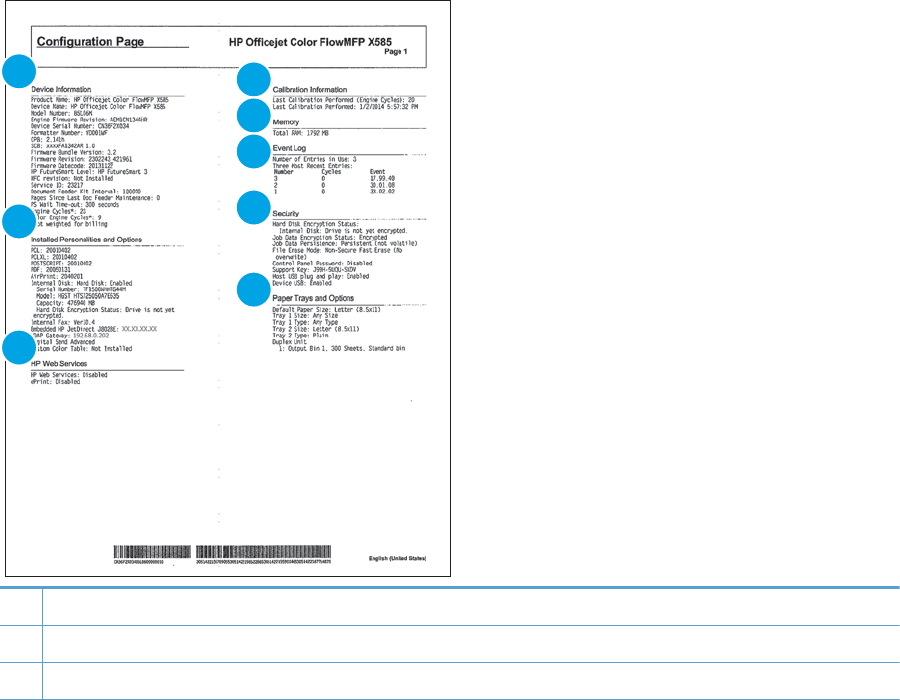
Tools for troubleshooting
Print the configuration page
Depending on the model, up to three pages print when you print a configuration page. In addition to the main
configuration page, the HP embedded Jetdirect configuration pages print.
Configuration page
Use the configuration page to view current product settings, to help troubleshoot product problems, or to
verify installation of optional accessories, such as memory (DIMMs), paper trays, and product languages.
1. From the Home screen on the product control panel, scroll to and touch the Administration button.
2. Open the following menus:
●Reports
●Configuration/Status Pages
3. Touch Configuration Page to select it.
4. Touch the View button to view the information on the control panel, or touch the Print button to print
the pages.
Figure 2-7 Configuration page
14
5
6
7
8
2
3
1Device Information information, including the firmware version, usage statistics, and the service ID.
2Installed Personalities and Options information, including installed printer languages and hard disk information.
3HP Web Services status information
ENWW Tools for troubleshooting 57
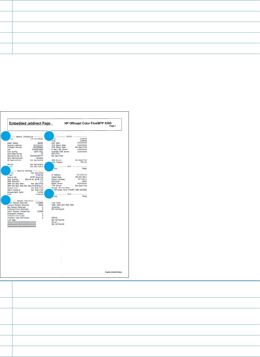
4Calibration Information that shows when the product most recently performed a calibration.
5Memory
6Event Log information that shows the most recent entries in the log.
7Security information that includes encryption information and current security settings.
8Paper Trays and Options information that shows installed trays and current paper size/type settings.
HP embedded Jetdirect page
The second configuration page is the HP embedded Jetdirect page, which contains the following information.
Always make sure the status line under the general information line indicates: I/O Card Ready.
Figure 2-8 HP embedded Jetdirect page
1 4
5
6
2
3
1General Information indicates the product status, model number, hardware firmware version, port select, port configuration,
auto negotiation, manufacturing identification, and manufactured date.
2Security Settings information
3Network Statistics indicates the total packets received, unicast packets received, bad packets received, framing errors
received, total packets transmitted, unsendable packets, transmit collisions, and transmit late collisions.
4TCP/IP information, including the IP address
5IPv4 information
6IPv6 information
58 Chapter 2 Solve problems ENWW

Finding important information on the configuration pages
Certain information, such as the firmware date codes, the IP address, and the email gateways, is especially
helpful while servicing the product. This information is on the various configuration pages.
Table 2-3 Important information on the configuration pages
Type of information Specific information Configuration page
Firmware date codes
When you use the remote firmware upgrade
procedure, all of these firmware components
are upgraded.
Engine firmware revision Look on the main configuration page,
under “Device Information.”
Firmware datecode Look on the main configuration page,
under “Device Information.”
HP embedded Jetdirect firmware version Look on the HP embedded Jetdirect
page, under “General Information.”
Accessories and internal storage
All optional devices that are installed on the
product should be listed on the main
configuration page.
In addition, separate pages print for the
optional paper handling devices and the fax
accessory. These pages list more detailed
information for those devices.
Embedded HP Jetdirect Look on the main configuration page,
under “Installed Personalities and
Options.” Shows model and ID.
Total RAM Look on the main configuration page,
under “Memory.”
Duplex unit Look on the main configuration page,
under “Paper Trays and Options.”
Finishing accessories Installed finishing accessory type Look on the main configuration page,
under “Paper Trays and Options.”
Engine cycles and event logs
Total page counts and maintenance kit counts
are important for ongoing product
maintenance.
The configuration page lists only the three
most recent errors. To see a list of the 50 most
recent errors, print an event log from the
Troubleshooting menu.
Engine cycles Look on the main configuration page,
under “Device Information.”
Event log information Event log information Look on the main configuration page,
under “Event Log.”
Event log messages
See the control-panel message and event-log entries section of the product reoubleshooting manual for
eventl-log entry descriptions and solutions.
Print or view an event log
NOTE: The event log in the Administration menu shows only a subset of events. For a complete event log,
use the Service menu.
Print or view the event log from the Administration menu
1. From the Home screen on the product control panel, scroll to and touch the Administration button.
2. Open the following menus:
ENWW Tools for troubleshooting 59
●Troubleshooting
●Event Log
3. The event log displays on the screen. To print it, touch the Print button.
Print or view the event log from the Device Maintenance menu
1. From the Home screen on the product control panel, scroll to and touch the Device Maintenance button.
2. Open the Service menu.
3. On the sign-in screen, select the Service Access Code option from the drop-down list.
4. Enter one of the following service access code for your product:
●X555: 04055514
●X585: 04058514
5. Touch the Event Log item.
6. The event log displays on the screen. To print it, touch the Print button.
Clear an event log
1. From the Home screen on the product control panel, scroll to and touch the Device Maintenance button.
2. Open the Service menu.
3. On the sign-in screen, select the Service Access Code option from the drop-down list.
4. Enter one of the following service access code for your product:
●X555: 04055514
●X585: 04058514
5. Select the Clear Event Log item, and then touch the OK button.
Error messages
The following control-panel messages and software error messages, which appear on the user's computer
screen, indicate the current product status or situations that might require action.
11.XX.YZ Error Messages
11.00.01 or 11.00.02 Internal clock error
Description
This message indicates a problem with the formatter's real time clock.
The product real time clock has experienced an error.
01=dead clock
02=dead real time clock
60 Chapter 2 Solve problems ENWW
Recommended action
1. Whenever the product is turned off and then turned on again, set the time and date on the control
panel.
2. If the error persists, you might need to replace the formatter.
15.XX.YZ Error Messages
15.00.00 Unknown Jam
Description
A paper jam has occurred in the printer at an unknown location.
Recommended action
1. Follow jam removal instructions on the screen.
2. Open all doors and trays and remove all paper from the paper path.
3. Run Paper Path Diagnostics to move paper from tray to output bin (Administration / Troubleshooting /
Paper Path Page).
15.A0.01 Input Jam, Tray 1
Description
An input jam occurred from Tray 1 but sensor and condition are unknown.
No Pick "Did not pick page from tray 1”.
This jam occurs when the paper does not reach the Feed roller REDI sensor [1] for Tray 1 in designated
amount of time after the start of paper pick-up from Tray 1.
Recommended action
1. Follow jam removal instructions on the screen.
2. Clear all possible paper jam locations (remove paper stack, open left door, remove ICU, lower flap, clear
paper, raise flap, install ICU, close door ).
3. Verify the paper meets the specifications for the tray.
4. Ensure that the tray width setting is set to your paper being installed into the tray.
The arrow on the guide should line up exactly with the line connected to paper size designation.
5. Make sure the tray is not overload above the marking shown on the tray side guide.
6. Check the Tray 1 feed roller for wear, damage or paper dusk. Clean or replace the rollers as needed.
7. Run Paper Path Diagnostics to move paper from tray to output bin (Administration / Troubleshooting /
Paper Path Page).
8. Replace the Mech Kit.
ENWW Tools for troubleshooting 61
15.A0.02 Input Jam, Tray 2
Description
An input jam occurred from Tray 2 but sensor and condition are unknown.
No Pick "Did not pick page from tray 2”.
This jam occurs when the paper does not reach the Feed roller REDI sensor [1] for Tray 2 in designated
amount of time after the start of paper pick-up from Tray 2.
Recommended action
1. Follow jam removal instructions on the screen.
2. Clear all possible paper jam locations (Open paper cassette remove paper, open left door, remove ICU,
lower flap, clear paper, raise flap, install ICU, close door).
3. Verify the paper meets the specifications for the tray.
4. Ensure that the tray width setting is set to your paper being installed into the tray.
The arrow on the guide should line up exactly with the line connected to paper size designation.
5. Make sure the tray is not overload above the marking shown on the tray side guide.
6. Check the Tray 2 pickup and feed rollers for wear, damage or paper dusk. Clean or replace the rollers as
needed.
7. Run Paper Path Diagnostics to move paper from tray to output bin (Administration / Troubleshooting /
Paper Path Page).
8. Replace the Mech Kit.
15.A0.03 Input Jam, Tray 3
Description
An input jam occurred from Tray 3 but sensor and condition are unknown.
No Pick "Did not pick page from tray 3”.
This jam occurs when the paper does not reach the Tray 3 separation REDI sensor in designated amount of
time after the start of paper pick-up from Tray 3.
Recommended action
1. Follow jam removal instructions on the screen.
2. Clear all possible paper jam locations (Open paper cassette remove paper, open left door, remove ICU,
lower flap, clear paper, raise flap, install ICU, close door ).
3. Verify the paper meets the specifications for the tray.
4. Ensure that the tray width setting is set to your paper being installed into the tray.
The arrow on the guide should line up exactly with the line connected to paper size designation.
5. Make sure the tray is not overload above the marking shown on the tray side guide.
62 Chapter 2 Solve problems ENWW
6. Check the Tray 3 pickup and feed rollers for wear, damage or paper dusk. Clean or replace the rollers as
needed.
7. Run Paper Path Diagnostics to move paper from tray to output bin (Administration / Troubleshooting /
Paper Path Page).
8. Replace the Mech Kit.
15.B0.0Z Image Area Jam from Tray X
Description
A Print Zone jam occurred from tray indicated but sensor and condition are unknown.
●15.B0.01 — Image Area from Tray 1
●15.B0.02 — Image Area from Tray 2
●15.B0.03 — Image Area from Tray 3
●15.B0.0D — Image Area from Duplexer
Recommended action
1. Clear all possible paper jam locations (Remove paper from tray, open left door, remove ICU, lower flap,
clear paper, raise flap, install ICU, close door ).
2. Run Paper Path Diagnostics to move paper from tray to output bin (Administration / Troubleshooting /
Paper Path Page).
3. Replace Mech Kit.
15.C0.0Z Switchback area Jam from Tray X
Description
An output jam occurred while printing from indicated tray or area.
●15.C0.01 — Switchback jam from Tray 1
●15.C0.02 — Switchback jam from Tray 2
●15.C0.03 — Switchback from Tray 3
●15.C0.0D — Switchback from Duplexer
Recommended action
1. Clear all possible paper jam locations (Open left door, remove ICU, lower flap, clear paper, raise flap,
install ICU, close door ).
2. Run Paper Path Diagnostics to move paper from tray to output bin (Administration / Troubleshooting /
Paper Path Page).
3. Replace Mech Kit.
15.E0.0Z Output jam from Tray X
Description
An eject jam occurred from the tray designated.
ENWW Tools for troubleshooting 63
●15.E0.01 — Output jam from Tray 1
●15.E0.02 — Output jam from Tray 2
●15.E0.03 — Output jam from Tray 3
●15.E0.0D — Output jam from Duplexer
Recommended action
1. Clear all possible paper jam locations (Open left door, remove ICU, lower flap, clear paper, raise flap,
install ICU, close door ).
2. Run Paper Path Diagnostics to move paper from tray to output bin (Administration / Troubleshooting /
Paper Path Page).
3. Replace Mech Kit.
17.XX.YZ Error Messages (Supply errors)
17.0X.00 Failed Cartridge
Description
The indicated cartridge is detected but its data is corrupt or invalid in some way.
●17.00.00 — Black Cartridge
●17.01.00 — Cyan Cartridge
●17.02.00 — Magenta Cartridge
●17.03.00 — Yellow Cartridge
Recommended action
1. Remove the cartridge, reinstall it and close the ink door.
2. Turn the product off, and then on again.
3. Replace the failing cartridge.
4. Replace the Mech Kit.
17.0X.34 Counterfeit or refilled cartridge installed
Description
The supply being used is either a counterfeit or refilled cartridge.
●17.00.34 — Black Cartridge
●17.01.34 — Cyan Cartridge
●17.02.34 — Magenta Cartridge
●17.03.34 — Yellow Cartridge
Recommended action
To avoid this condition – always use genuine HP cartridges.
64 Chapter 2 Solve problems ENWW

The user must replace with a genuine HP cartridge OR approve the use of refilled cartridges before printing
can continue.
If you believe you purchased a genuine HP supply, go to www.hp.com/go/anticounterfeit. Any print quality
repair required as a result of using used cartridges is not covered under warranty. Supply status and features
depending on supply status are not available.
17.0X.35 Incompatible <supply>
Description
The indicated supply is not compatible with this product.
●17.00.35 — Black Cartridge
●17.01.35 — Cyan Cartridge
●17.02.35 — Magenta Cartridge
●17.03.35 — Yellow Cartridge
Recommended action
To avoid this condition – always use genuine HP cartridges.
The user must replace with a genuine HP cartridge OR approve the use of refilled cartridges before printing
can continue.
17.0X.36 Non-Startup cartridge at startup
Description
Non-Startup cartridge at startup.
A trade cartridge has been installed before purge has been completed.
●17.00.36 — Black Cartridge
●17.01.36 — Cyan Cartridge
●17.02.36 — Magenta Cartridge
●17.03.36 — Yellow Cartridge
Recommended action
To avoid this condition – always use the startup cartridges that shipped with the product.
Do not override and use trade cartridges unless absolutely necessary. If the user later finds the startup
cartridges after initialization, these startup cartridges will be unusable on this device.
17.0X.37 Startup Cartridge after startup completed
Description
Startup cartridge is being used after startup completed.
●17.00.37 — Black Cartridge
●17.01.37 — Cyan Cartridge
ENWW Tools for troubleshooting 65
●17.02.37 — Magenta Cartridge
●17.03.37 — Yellow Cartridge
Recommended action
To avoid this condition, always use trade cartridges after initialization has completed and the original startup
cartridges are spent.
Startup cartridges can only be used the first time the product is initialized.
Once a startup cartridge has been used for initialization it’s memory tag contents are changed to indicate it
will now behave and be detected as a trade cartridge.
17.0X.38 Cartridge might be empty
Description
The cartridge indicated might be empty.
Continuing may cause image quality issues.
This is a transient condition that occurs when the cartridge memory tag indicates empty and the cartridge is
newly inserted into a printer.
●17.00.38 — Black Cartridge
●17.01.38 — Cyan Cartridge
●17.02.38 — Magenta Cartridge
●17.03.38 — Yellow Cartridge
Recommended action
There several possible outcomes when this condition is detected:
1. The user removes the cartridge from the printer and replaces it with a non-empty cartridge.
2. The user touches “OK” and approves the use of the “Possibly Empty” cartridge.
●Printer attempts to pump/prime ink but is unsuccessful. The cartridge is declared as “Empty”.
●Some ink was previously stranded due to tilt and the pump/prime is successful. The cartridge is
declared as “Low” or possibly “Very Low”.
●Cartridge has been refilled and now after printing some number of pages, the cartridge will be
declared as “Refilled”.
17.0X.39 Use new cartridges
Description
The Startup-Trade cartridge override feature has been enabled and a partially used Cyan Cartridge has been
installed before the ink initialization process completed.
The cartridge might not be able to complete the ink initialization.
Using a new cartridge allows the process to complete in one session, preventing the user from leaving and
coming back to find the process incomplete.
66 Chapter 2 Solve problems ENWW

●17.00.39 — Black Cartridge
●17.01.39 — Cyan Cartridge
●17.02.39 — Magenta Cartridge
●17.03.39 — Yellow Cartridge
Recommended action
Touch “OK” to continue or use a new cartridge.
If a “Too Low to Prime” condition occurs, use the following steps.
1. The engine has determined that there is probably not enough ink in the installed trade cartridge to
complete the initialization (ink purge) process.
2. The user can touch “OK” to proceed anyway (they may see this same message again once the current
cartridge is depleted).
3. The user can replace the partially full trade cartridge with a replacement that is full.
17.0X.42 General printing error
Description
Printer failure or the indicated cartridge SHAID too early.
●17.00.42 — Black Cartridge
●17.01.42 — Cyan Cartridge
●17.02.42 — Magenta Cartridge
●17.03.42 — Yellow Cartridge
NOTE: Condition does not distinguish between SHAID Too Early and a failure in the ink delivery system.
Recommended action
1. Turn the product off, and then on again.
2. Replace the cartridge.
3. Replace the Mech kit.
17.0X.52 Supply upgrade detected
Description
The indicated supply upgrade was detected.
●17.00.52 — Black Cartridge
●17.01.52 — Cyan Cartridge
●17.02.52 — Magenta Cartridge
●17.03.52 — Yellow Cartridge
ENWW Tools for troubleshooting 67
Recommended action
Touch “OK” to continue or change cartridge.
17.0X.53 Supply upgrade successful
Description
The indicated supply upgrade was successful.
●17.00.53 — Black Cartridge
●17.01.53 — Cyan Cartridge
●17.02.53 — Magenta Cartridge
●17.03.53 — Yellow Cartridge
Recommended action
No action necessary.
17.0X.54 Supply upgrade problem
Description
The indicated supply encountered an upgrade problem.
The requested upgrade (addition of a new cartridge to the list of supported cartridges stored in the engine
NVRAM) using a “Trade” cartridge did not succeed. The formatter does not know why the failure occurred,
only that it did fail.
●17.00.54 — Black Cartridge
●17.01.54 — Cyan Cartridge
●17.02.54 — Magenta Cartridge
●17.03.54 — Yellow Cartridge
Recommended action
1. Replace the failed cartridge with one that is known good and then reinsert the upgrade cartridge and try
again.
2. Turn the product off, and then on again.
3. Remove the upgrade cartridge and go back to using the cartridge(s) supported at release.
4. Replace the Mech Kit.
17.0X.55 Supply upgrade problem
Description
The indicated supply encountered an upgrade problem.
The requested upgrade (addition of a new cartridge to the list of supported cartridges stored in the engine
NVRAM) using a “Startup” cartridge did not succeed. The formatter does not know why the failure occurred,
only that it did fail.
68 Chapter 2 Solve problems ENWW
●17.00.55 — Black Cartridge
●17.01.55 — Cyan Cartridge
●17.02.55 — Magenta Cartridge
●17.03.55 — Yellow Cartridge
Recommended action
1. Replace the failed cartridge with one that is known good and then reinsert the upgrade cartridge and try
again.
2. Turn the product off, and then on again.
3. Remove the upgrade cartridge and go back to using the cartridge(s) supported at release.
4. Replace the Mech Kit.
17.0X.56 Ink sensor warning
Description
The indicated cartridge has printed past approximately 150% of its expected capacity and there has been no
SHAID event.
The ink sensor might not be able to detect when supplies are empty or the cartridge has been refilled.
●17.00.56 — Black Cartridge
●17.01.56 — Cyan Cartridge
●17.02.56 — Magenta Cartridge
●17.03.56 — Yellow Cartridge
Recommended action
1. If print quality issues exist, replace the cartridge.
2. Check cartridge warranty and manufacture date. Check event log for low on ink code. If user
acknowledges, assume cartridge has been refilled.
17.0X.57 HP Cartridge Protection enabled
Description
The indicated cartridge that has been protected using the HP cartridge protection feature has been detected.
The target cartridge has been locked to a different printer and cannot be used on this device.
●17.00.57 — Black Cartridge
●17.01.57 — Cyan Cartridge
●17.02.57 — Magenta Cartridge
●17.03.57 — Yellow Cartridge
ENWW Tools for troubleshooting 69
Recommended action
1. Replace the indicated cartridge with one that has not been “protected” on another device.
2. Once a cartridge is locked to a given device there is no way to unlock the cartridge.
17.0X.60 Cartridge Low Warning
Description
The indicated cartridge is low.
●17.00.60 — Black Cartridge
●17.01.60 — Cyan Cartridge
●17.02.60 — Magenta Cartridge
●17.03.60 — Yellow Cartridge
Recommended action
No action necessary.
17.0X.65 Install Supply
Description
The indicated cartridge is not installed or missing or has a damaged acumen.
●17.00.65 — Black Cartridge
●17.01.65 — Cyan Cartridge
●17.02.65 — Magenta Cartridge
●17.03.65 — Yellow Cartridge
Recommended action
1. Reinstall the supply.
2. Replace the indicated supply with a replacement.
17.0X.69 Cartridge Very Low
Description
The indicated cartridge is very low.
●17.00.69 — Black Cartridge
●17.01.69 — Cyan Cartridge
●17.02.69 — Magenta Cartridge
●17.03.69 — Yellow Cartridge
70 Chapter 2 Solve problems ENWW
Recommended action
The target cartridge has been depleted and the only ink remaining is in the X chamber and print head. The
cartridge can be replaced in this state without any loss of ink to the system.
No action necessary.
17.0X.70 Printing past very low
Description
The indicated cartridge is printing past very low.
●17.00.70 — Black Cartridge
●17.01.70 — Cyan Cartridge
●17.02.70 — Magenta Cartridge
●17.03.70 — Yellow Cartridge
Recommended action
The print quality should not degrade in any way when the ink cartridge approaches end-of-life as the product
will halt printing when all of the usable ink has been depleted.
Customers should have a spare cartridge on-hand as the indicated cartridge will transition to Empty in just a
few pages.
If print quality is not acceptable replace the indicated cartridge.
17.0X.80 Install Supply
Description
The indicated cartridge is missing.
●17.00.80 — Black Cartridge
●17.01.80 — Cyan Cartridge
●17.02.80 — Magenta Cartridge
●17.03.80 — Yellow Cartridge
Recommended action
Install the indicated cartridge.
17.31.60 Ink Collection Unit Warning
Description
Ink Collection Unit almost full. The percentage of life remaining is 2%.
The product’s Ink Collection Unit (ICU) collects unused ink for later disposal. The life tracking on this supply is
accomplished via a numeric percent life remaining (PLR) that starts at 100% and decreases in 1% increments
as pages are printed. The engine counts the number of ink droplet that go into the ICU and reports this
information to the formatter as a percentage of life remaining. The expected life of the ICU is nominally
120,000 page but this will vary depending on printing patterns.
ENWW Tools for troubleshooting 71

Recommended action
A new ICU should be ordered and printing can continue.
NOTE: There is no sensor that indicates when the ICU has been replaced. For this reason the user will be
asked near end of ICU life if the ICU has been replaced each time the left door closes or a power-on occurs.
17.31.65 Install Supply Ink Collection Unit
Description
The Ink Collection Unit (ICU) is not installed.
Recommended action
Install the ICU, make sure it is aligned and installed correctly.
If message continues to appear, install a replacement ICU.
17.31.69 Ink Collection Unit full
Description
The Ink Collection Unit is full. This is the second warning that the ICU life is almost depleted. The percentage
of life remaining is 1% or less.
The products Ink Collection Unit (ICU) collects unused ink for later disposal. The life tracking on this supply is
accomplished via a numeric percent life remaining (PLR) that starts at 100% and decreases in 1% increments
as pages are printed. The engine counts the number of ink droplet that go into the ICU and reports this
information to the formatter as a percentage of life remaining. The expected life of the ICU is nominally
120,000 page but this will vary depending on printing patterns.
Recommended action
Replace the ICU or continue printing until stop occurs.
17.31.70 Ink Collection Printing past full
Description
Ink Collection Unit (ICU) printing past full.
Recommended action
Replace the ICU.
Replacement can occur at this point or the user can continue until halted.
17.31.71 Reinstall Ink Collection Unit
Description
The product has prompted the user to remove and reinstall the Ink Collection Unit (ICU) to maintain print
quality.
Recommended action
Remove and reinstall ICU, make sure it is aligned and installed correctly.
72 Chapter 2 Solve problems ENWW
17.31.72 Ink Collection Unit reinstalled
Description
The user removed and reinstalled the Ink Collection Unit (ICU) to maintain print quality.
Recommended action
No action necessary.
17.31.73 New Ink Collection Unit
Description
The Ink Collection Unit (ICU) counter has been reset.
Recommended action
There is no sensor that indicates when the ICU has been replaced. For this reason the user will be asked near
end of ICU life if the ICU has been replaced each time the left door closes or a power-on occurs. When “YES” is
selected the reset will be performed.
17.31.80 Replace Ink Collection Unit
Description
Ink Collection Unit (ICU) is full and must be replaced.
Recommended action
Replace the ICU.
17.99.31 Non-HP supply in use
Description
Non-HP supply in use. If any of these bits are set, the event could be posted.
This message does not distinguish between supplies.
Recommended action
No action necessary.
17.99.32 Previously used HP Supply installed
Description
An original HP supply that started its life in another product is in use.
This message does not distinguish between supplies.
Recommended action
No action necessary.
17.99.40 Supplies installed
Description
Transition of at least one non-HP to all genuine.
ENWW Tools for troubleshooting 73
This message does not distinguish between supplies.
Recommended action
No action necessary.
17.99.49 Startup Cartridge Override
Description
User has overridden using Startup cartridges.
This message does not distinguish between supplies.
Recommended action
No action necessary.
17.99.58 HP Cartridge Protection enabled
Description
A user enabled the HP Cartridge Protection Feature, protecting their cartridges and restricting the cartridges
to only be usable in the product that originally protected them.
Recommended action
No action necessary.
20.XX.YZ, 21.XX.YZ Error Messages
20.00.00 Insufficient memory: <Device>
Description
Event log error message 20.00.00.
The product does not have enough memory to print the page.
The product received more data than can fit in the available memory. You might have tried to transfer too
many macros, soft fonts, or complex graphics.
Recommended action
Touch the OK button to print the transferred data. Some data might be lost. Reduce the page complexity or
add product memory.
21.00.00 Page Too Complex
Description
Event log error message 21.00.00.
The product displays this message to indicate that the page decompression process was too slow for the
product.
Recommended action
Touch the OK button to continue. There may be some data loss on the page that was being formatted when
the error occurred.
74 Chapter 2 Solve problems ENWW
21.1C.2D Page complex error
Description
Event log error message 21.1C.2D.
The product displays this message to indicate that the page decompression process was too slow for the
product.
Recommended action
Touch the OK button to continue. There may be some data loss on the page that was being formatted when
the error occurred.
30.XX.YZ Error Messages — X585 only
30.01.01
Description
The flatbed cover sensor was interrupted.
The scanner flatbed cover is open.
Message appears only in the event log and is not posted on the control panel.
The control panel will read Flatbed Cover Open.
Recommended action
No action necessary. This error message should automatically clear.
If the error persists, open the Scanner Tests to test the flatbed cover sensor.
1. If the cover is closed, check the cover sensor at the right rear of the scanner for correct mechanical
functionality, using the scanner sensor test in the Administration / Troubleshooting / Diagnostics /
Scanner Tests Menu.
2. Check the connectors on the scanner control board (SCB) for loose connections.
3. Replace the lid-sensor assembly.
4. Replace the scanner control board (SCB).
5. Replace the integrated scanning assembly (ISA).
30.01.02 Scanner calibration failure
Description
The scanner calibration failed.
Recommended action
1. Turn the product off, and then on again.
2. After the product warms up, repeat the calibration process.
3. If the error persists, replace the Integrated Scanning Assembly (ISA).
ENWW Tools for troubleshooting 75
30.01.06 Scanner Fan failure
Description
Scanner fan error.
The Copy, Fax and Send options will be grayed out or not present on the control panel and message will be
posted in event log.
Recommended action
1. Turn the product off, and then on again.
2. During the product initialization sequence, listen to the fan to determine if it is operating.
3. the error persists, turn the product off and then check the fan wire-harness connectors.
4. If the error persists, replace the scanner control board (SCB).
5. Replace the integrated scanning assembly (ISA).
30.01.08 Home position error
Description
The scanner optic failed to return to the home position.
Recommended action
1. Turn the product off, and then on again.
2. Observe the movement of the optics assembly.
3. If the error persists, run the scanner motor test under component test. Administration/
Troubleshooting/Scanner tests/Flatbed motor test
4. If issue still remains and firmware has been upgraded replace scanner control board (SCB).
5. If the error persists, replace the integrated scanning assembly (ISA).
30.01.14 Scan system EEPROM error
Description
Scanner control board (SCB) EEPROM error.
Recommended action
1. Turn the product off, and then on again.
2. Ensure all connectors on the SCB are connected and properly seated.
3. Ensure the MFP has at latest SCB firmware version.
4. Replace the SCB.
30.01.15 Scanner error
Description
Scanner did not initialize (internal error).
76 Chapter 2 Solve problems ENWW
The scanner failed to be initialized due to an internal error.
Recommended action
1. Turn the product off, and then on again.
2. Verify that all covers are installed correctly and that the ADF and ADF jam cover are closed.
3. Check all sensors on the scanner to ensure they are not blocked.
4. Look through the vents on back of scanner check to see if GREEN SCB LEDs are lit.
5. Check all connections for SCB to print engine and make sure the are properly seated.
6. Replace the SCB.
30.01.18 Scanner Error
Description
Scanner internal optical sensor error.
Recommended action
1. Turn the product off, and then on again.
2. Make sure that all the connectors on the SCB are properly seated.
3. Make sure that the MFP has the latest SCB firmware version.
4. Replace the SCB.
5. If the error persists, replace the integrated scanning assembly (ISA)
30.01.19 Scanner lamp error
Description
Scanner internal lamp sensor error.
Recommended action
1. Turn the product off, and then on again.
2. Determine if the scanner lamp turns on and off approximately 12 second after the product turns on.
3. Test the lower lamp using the scanner test located in the Diagnostics menu.
4. Re-seat the interconnect cables between the optical carriage and the SCB.
5. Replace the integrated scanning assembly (ISA)
30.01.30 or 30.01.32
Description
HP image ASIC error.
Recommended action
Turn the product off, and then on again.
ENWW Tools for troubleshooting 77
Check all connections on the SCB.
Replace the SCB.
30.01.36 Upgrade Error Try downloading upgrade again
Description
Scanner firmware upgrade error.
Recommended action
1. Re-send the scanner firmware upgrade.
2. If the error persists, replace the SCB.
30.01.41 Scanner error
Description
The formatter lost connections with the SCB or communication was corrupted.
Recommended action
1. Turn the product off, and then on.
2. Remove and reinstall the formatter making to verify it is properly seated.
3. Upgrade the firmware.
4. Verify that all cables are connected to the product and to the interconnect board / formatter and SCB.
5. Verify that the scanner control board (SCB) has power.
6. Replace the scanner control board (SCB).
7. Replace the formatter.
30.01.42 Scanner error
Description
Internal product communication error.
Recommended action
1. Turn the product off, and then on again.
2. If the error persists, turn the product off, and then check all scanner control board (SCB) connectors are
fully seated.
3. If this error occurs after a formatter, fax card or hard disk has been replaced, check that the formatter is
fully seated and the “Smiley face” icon on the formatter is illuminated. Check the fax card for proper
seating on the formatter. (If Fax card is not properly seated it can prevent the formatter from seating
properly.
4. If the error persists, replace the scanner control board (SCB).
78 Chapter 2 Solve problems ENWW
30.01.43 Scanner memory failure
Description
Scan memory error.
Recommended action
1. Turn the product off, and then on again.
2. If the error persists, turn the product off, and then re-seat the formatter.
3. If the error persists, replace the formatter.
30.01.44
Description
Copy processor (CPB) / scanner control board (SCB) communication error
Recommended action
1. Turn the product off, and then on again.
2. If the error persists, turn the product off, and then check the scanner cable.
3. Upgrade the firmware.
4. If the error persists, turn the product off, and then re-seat the formatter.
5. If the error persists, replace the scanner control board (SCB) or the formatter.
30.01.45
Description
Internal copy processor board (CPB) communication error.
CPB code assertion error for the copy processor board firmware.
Recommended action
1. Turn the product off, and then on again.
2. If the error persists, turn the product off, and then re-seat the formatter.
3. Upgrade the firmware.
4. If the error persists, replace the scanner control board (SCB).
5. If the error persists, replace the formatter.
30.01.46 Scanner Error
Description
The firmware cannot find the copy processor board (CPB).
ENWW Tools for troubleshooting 79
Recommended action
1. Turn the product off, and then on again.
2. If the error persists, turn the product off, and then re-seat the formatter.
3. If the error persists, replace the scanner control board (SCB).
30.01.48 Scanner error
Description
Scanner error.
Scanner power is not connected.
Recommended action
1. Turn the product off, and then on again.
2. If the error persists, turn the product off, and then check the scanner wire-harness connectors and the
scanner power supply fan.
3. If the error persists, replace integrated scanning assembly (ISA).
30.01.50 Scanner error
Description
Internal scanner control board (SCB) error.
Recommended action
1. Turn the product off, and then on again.
2. Upgrade the firmware (FW).
3. If the error persists, replace the SCB.
30.03.14
Description
A non-fatal error has occurred.
A scanner EEPROM (NVM) error has occurred.
Recommended action
This is an informational message, and no action is required.
30.03.20
Description
The copy processor board firmware cannot communicate with the PCA on the optical assembly.
80 Chapter 2 Solve problems ENWW
Recommended action
1. Turn the product off, and then on again.
2. Verify that the flat flexible cables (FFCs) between scanner and the SCB are connected and properly
seated.
3. Replace the integrated scanning assembly (ISA).
30.03.22 Scanner failure
Description
Front side illumination calibration failure.
The scan module cannot see the illumination module, or marginal illumination.
The optical assembly may not be parked under the calibration strip.
Recommended action
1. Turn the product off, and then on again.
2. Upgrade the firmware.
3. Check the service event log for other scanner errors, and then resolve those errors.
4. Check the scan module flat flexible cable (FFC) connection.
5. Replace the integrated scanning assembly (ISA).
30.03.23 Scanner failure
Description
Flatbed alignment calibration error.
Recommended action
1. Turn the product off, and then on again.
2. Upgrade the firmware.
3. Replace the scanner.
30.03.30 Scanner Failure
Description
Flatbed motor shutdown.
The scanner control board cannot communicate with the flatbed scanner motor.
Recommended action
1. Turn the product off, and then on again. As the product turns on, verify that the scan head moves.
2. Verify that the drive belt is in the correct position.
3. Run diagnostics on the flatbed scanner to see if the scan bar moves.
ENWW Tools for troubleshooting 81
4. Check the cable connection to the SCB.
5. Replace the scanner.
30.03.45 Scanner Error To continue turn off then on
Description
Scanner control board (SCB) firmware assertion failure. SCB firmware assert controls the scan head motor.
Recommended action
1. Turn the product off, and then on again.
2. Upgrade the firmware.
3. Replace the Scanner control board (SCB).
4. Replace the scanner assembly.
31.XX.YZ Error Messages — X585 only
31.01.03 Document feeder pick error
Description
The document feeder cannot pick up paper.
Recommended action
1. Verify that the paper meets the product specifications.
2. Make sure that the input tray is not overloaded and the tray guides are properly aligned to both edges
of the media.
3. Check and clean the rollers and separation pad, and test the registration sensor. If needed, replace
pickup roller assembly and separation pad.
4. Open and close the top cover to see if the pick motor turns without posting this error. If the motor turns,
then the motor is good.
5. Verify that the motor cables are connected.
6. Re-seat the document feeder to the scanner control board (SCB).
7. Replace the document feeder assembly.
31.01.47 Document feeder not detected
Description
The document feeder was not detected, and might not be document feeder connected. The flatbed glass is
still available for scanning.
Recommended action
Turn the product off and then on.
If error persists, replace document feeder
82 Chapter 2 Solve problems ENWW

NOTE: Before replacing the document feeder technicians should check the connections for the unit to make
sure they are correctly and firmly seated.
31.03.14
Description
Backside scanner EEPROM (NVM) error.
A non-fatal error has occurred.
Recommended action
This is an informational message, and no action is required.
31.03.20 backside scanner not detected
Description
Backside scanner not detected.
Recommended action
1. Turn the product off, and then on again.
2. Verify the cables between scanner and scanner control board are connected.
3. Replace the document feeder assembly
31.03.22 Scanner calibration failure
Description
Backside illumination calibration failure.
Recommended action
1. Turn the product off, and then on.
2. Upgrade the firmware.
3. Verify the cables between scanner and scanner control board are connected.
4. Replace the document feeder assembly.
31.03.30 Document feeder pick motor error
Description
The document feeder pick motor is not turning.
Recommended action
1. Verify that the paper meets the product specifications.
2. Make sure that the feed tray is not overloaded.
3. Check the event log for document feeder errors, and then resolve any errors first.
4. Open and close the top cover to see if the pick motor turns without posting this error. If the motor turns,
then the motor is good.
ENWW Tools for troubleshooting 83
5. Verify that the motor cables are connected.
6. Re-seat the document feeder to the scanner control board (SCB).
7. Replace the document feeder assembly.
31.03.31 Document feeder motor stall
Description
The document feeder feed motor is not turning.
Recommended action
1. Verify that the paper meets the product specifications.
2. Make sure that the feed tray is not overloaded.
3. Check the event log for document feeder errors, and then resolve any errors first.
4. Verify that the motor cables are connected.
5. Re-seat the document feeder to the scanner control board (SCB).
6. Replace the document feeder assembly.
31.03.32
Description
The document feeder de-skew motor is not turning.
Recommended action
1. Verify that the paper meets the product specifications.
2. Make sure that the input tray is not overloaded.
3. Check the event log for document feeder errors, and then resolve any errors first.
4. Verify that the motor cables are connected.
5. Re-seat the document feeder to scanner control board (SCB) cables.
6. Replace the document feeder assembly.
31.03.33 Backside scanner calibration area dirty
Description
The white area used for backside scanner calibration is dirty.
Recommended action
1. Remove the white background and clean it.
2. Clean the backside scanner glass.
3. If issue remains replace the document feeder assembly.
84 Chapter 2 Solve problems ENWW
31.03.34 Background missing
Description
The removable background for the backside scanner is either missing or not fully snapped into place.
Recommended action
1. Remove the white background and clean it.
2. Clean the backside scanner glass.
3. If issue remains replace the document feeder assembly.
No action necessary.
31.13.00 Document feeder multi-pick error
Description
A multiple pick error was reported by the document feeder assembly.
Recommended action
1. Open the document feeder cover, pull ALL the sheets back into the tray and then resume the job.
2. Verify that the paper meets the product specifications.
3. Make sure that the input tray is not overloaded and the tray guides are properly aligned to both edges
of the media.
4. Check and clean the rollers and separation pad, and test the registration sensor. If needed, replace
pickup roller assembly and separation pad.
5. Verify that the motor cables are connected.
6. Re-seat the document feeder to the scanner control board (SCB).
7. Replace the document feeder assembly.
31.13.01
Description
Document feeder job error, pick error.
Paper pick was initiated, but the page didn't did not make it to the pick success sensor.
Recommended action
1. Open the document feeder lid, pull sheets back into input tray, and then resume the job.
2. Check the paper guides and make sure that they are set to the correct paper width.
3. Make sure that the input tray is not overloaded and the tray guides are properly aligned to both edges
of the media.
4. Check the document feeder page count for roller life.
5. Verify that the paper meets the product specifications.
ENWW Tools for troubleshooting 85
6. Clean the document feeder pick and feeder rollers and clean separation pad If worn or damage replace
roller kit.
7. Open the following menus:
●Administration
●Troubleshooting
●Diagnostic Tests
●Scanner Tests
8. Actuate the Pick-Success Sensor. If the sensor does not show functionality when tested, replace the
document feeder.
9. If sensor is not available for replacement or does not resolve issue replace the document feeder
assembly.
31.13.02
Description
Document feeder job error, feed jam.
The paper passed the pick success sensor, and then jammed in the document feeder paper path.
Recommended action
1. Clear the paper path and try feeding the page again.
2. Verify that the paper meets the product specifications.
3. Check the paper guides and make sure that they are set to the correct paper width.
4. Verify that the paper path is clear.
5. Clean the document feeder pick and feeder rollers and clean separation pad. If worn or damage replace
roller kit.
6. Open the following menus:
●Administration
●Troubleshooting
●Diagnostic Tests
●Scanner Tests
7. Actuate the Paper-Path Sensor. If the sensor does not show functionality when tested, replace the
sensor.
8. If sensor is not available for replacement or does not resolve issue replace the document feeder
assembly.
31.13.13
Description
The document feeder jam access door is open.
86 Chapter 2 Solve problems ENWW
Recommended action
1. Verify that the jam access cover is closed.
2. Verify that the flag is not broken off.
3. Open the following menus:
●Administration
●Troubleshooting
●Diagnostic Tests
●Scanner Tests
4. Actuate the document feeder Jam Cover Sensor. If the sensor does not show functionality when tested,
replace the Sensor.
5. If not available for replacement or does not resolve issue replace the document feeder assembly.
31.13.14
Description
Document feeder job error, over current.
This is a feed jam in the document feeder, and the motor is not turning.
Recommended action
1. Verify that the paper meets the product specifications.
2. Make sure that the document feeder input tray is not overloaded.
3. Check the event log for document feeder errors, and then resolve any errors first.
4. Open and close the top cover to see if the pick motor turns without posting this error. If there is no
error, then the motor is good.
5. Verify that the motor cables are connected.
6. Re-seat the document feeder to the scanner control board (SCB).
7. Replace the document feeder.
31.13.15
Description
This is a duplex re-feed jam in the document feeder.
The paper jam occurs on the back-side copy. The duplex re-feed does not make it to the deskew sensor.
Recommended action
1. Remove the jammed paper.
2. Verify that there is nothing in the paper path of the duplex refeed area.
ENWW Tools for troubleshooting 87
3. Retry the copy job.
4. Replace the document feeder assembly.
32.08.XX Error Messages
32.08.A1, 32.08.A2, 32.08.A3
Description
32.08.A1 (event code)
Shutdown event-boot after abnormal shutdown.
32.08.A2 (event code)
Boot from normal shutdown event.
32.08.A3 (event code)
Regular boot event.
Recommended action
No action necessary.
32.1C.XX
Description
32.1C.05 (event code)
The restore job ticket was submitted with invalid credentials.
32.1C.06 (event code)
The backup job ticket was submitted with invalid credentials.
32.1C.07(event code)
Backup restore permissions error.
There was an error during the creation, read, or write of the restore file.
32.1C.08 (event code)
Not enough disk space to perform backup/restore or network share issue.
There was an error during the creation, read, or write of the backup file.
32.1C.09 (event code)
Tried to restore a backup file that was not valid for this product.
The data in the backup file specified in the restore job ticket is no longer valid due to a corruption of the data
or no loner present.
32.1C.0A (event code)
Backup file is invalid.
88 Chapter 2 Solve problems ENWW
The data in the backup file specified in the restore job ticket is no longer valid due to a corruption of the data
or no loner present.
32.1C.0D (event code)
Backup/restore failed, auto-reboot failed, or the product might be busy.
32.1C.11 (event code)
Backup/restore timeout while communicating with the engine.
The backup was aborted because the product is busy.
32.1C.13 (event code) and 32.1C.14 (event code)
Not enough space exists to perform the backup.
The backup was aborted because the disk is at a critical level or full.
Scheduled backup failure.
32.1C.15 (event code)
Restore aborted because the backup file was created by a previous version of firmware no longer supported
by the feature.
32.1C.2E (event code)
The restore was aborted because the product is busy.
32.1C.2F (event code)
Reset failure
32.1C.40 (event code)
The backup operation completed successfully (informational).
32.1C.41 (event code)
The backup operation encountered an error (informational).
32.1C.42 (event code)
The backup operation completed, but with a warning message (informational).
32.1C.43 (event code)
A component in the backup file is not supported by the current version of firmware and will not be restored
(informational).
32.1C.44 (event code)
A component in the backup file is not transferable to another product and will not be restored
(informational).
32.1C.45 (event code)
Some data was not included in the backup file (informational).
32.1C.46 (event code)
ENWW Tools for troubleshooting 89
An expected component could not be found and was thus not backed up. Because components should be
known on backups, this code is a warning (informational).
32.1C.47 (event code)
Some data was not restored from the backup file (informational).
32.1C.48 (event code)
The backup job ticket was submitted using an invalid network path.
32.1C.49 (event code)
The backup job ticket was submitted with a bad encryption.
32.1C.4A (event code)
An error occurred when creating the temporary directories used to store the backup files in transition to and
from the compressed (ZIP) file.
32.1C.56 (event code)
Reset aborted. Backup/restore in progress (informational).
32.1C.57 (event code)
Reset aborted (informational).
32.1C.58 (event code)
Unknown reset error (informational).
32.1C.60 (event code)
The restore operation completed successfully (informational).
32.1C.61 (event code)
The restore operation encountered an error.
32.1C.62 (event code)
The restore operation completed, but with a warning message.
32.1C.68 (event code)
The restore job ticket was submitted using an invalid network path.
32.1C.69 (event code)
The restore job ticket was submitted with a bad encryption personal identification number (PIN).
32.1C.6A (event code)
An error occurred when creating the temporary directories used to store the restore files in transition to and
from the compressed (ZIP) file.
32.1C.6D (event code)
An unusual error occurred when running the restore.
90 Chapter 2 Solve problems ENWW
Recommended action
32.1C.05 (event code)
Verify the credentials that were submitted. Check the domain, user name, and password.
32.1C.06 (event code)
Verify the credentials that were submitted. Check the domain, user name, and password.
32.1C.07 (event code)
Retry the job.
32.1C.08 (event code)
●Retry the job.
●Remove stored jobs and retry.
●Use a larger capacity storage device.
●Check the network share.
Remove any stored jobs, and then retry.
If the error persists, try using a larger capacity storage device and check the network share settings.
32.1C.09 (event code)
Use a valid backup file.
32.1C.0A (event code)
Use a valid backup file.
Reboot, and then observe the state of the product.
If the error persists, perform a partition clean from the Preboot menu.
32.1C.0D (event code)
Reboot, and then retry the backup/restore.
32.1C.11 (event code)
Wait until the product is idle, and then try again.
32.1C.13 (event code) and 32.1C.14 (event code)
Free up disk space, and then try again.
32.1C.15 (event code)
- Use the current backup file.
32.1C.2E (event code)
Wait until the product is idle, and then try again.
Turn the product off then on, and then retry.
ENWW Tools for troubleshooting 91
32.1C.2F (event code)
Turn the product off then on, and then retry.
32.1C.40 (event code)
No action necessary.
32.1C.41 (event code)
No action necessary.
32.1C.42 (event code)
No action necessary.
32.1C.43 (event code)
No action necessary.
32.1C.44 (event code)
No action necessary.
32.1C.45 (event code)
No action necessary.
32.1C.46 (event code)
No action necessary.
32.1C.47 (event code)
No action necessary.
32.1C.48 (event code)
Check that a share was provided as part of the network path (not blank).
Check that the server and the share exists.
Check that the user has permission to access the share on the provided server.
32.1C.49 (event code)
Verify that the encryption personal identification number (PIN) meets the restrictions for the product.
32.1C.4A (event code)
Retry the job.
If this does not resolve the issue, turn the product off then on again and retry the job.
If the error persists, perform a Partial Clean using the Preboot menu.
32.1C.56 (event code)
No action necessary.
32.1C.57 (event code)
92 Chapter 2 Solve problems ENWW
No action necessary.
32.1C.58 (event code)
No action necessary.
32.1C.60 (event code)
No action necessary.
32.1C.61 (event code)
Review the error log to see specific details about the failure.
32.1C.62 (event code)
Review the error log to see specific details about the failure.
32.1C.68 (event code)
Check that a share was provided as part of the network path (not blank).
Check that the server and the share exist.
Check that the user has permission to access the share on the provided server.
Check that the path includes the compressed (ZIP) file name as part of the path
32.1C.69 (event code)
Verify the encryption personal identification number (PIN) is the same PIN used to encrypt the backup file.
32.1C.6A (event code)
Retry the job.
32.1C.6D (event code)
Retry the job.
33.XX.YZ Error Messages
33.02.01 Used board/disk installed
Description
Used board disk installed.
An encrypted board or disk with existing data previously locked to a different product has replaced the
original. If you continue, data is permanently lost.
Recommended action
1. Reinstall the used board or disk back into its original printer.
2. To save the data on the board or disk, turn the product off. Replace the board or disk with another board
or disk.
3. To delete the data on the board or disk and continue, touch the OK button.
ENWW Tools for troubleshooting 93

33.03.03 Incompatible formater installed.
Description
This is and EFI BIOS event to prevent booting with the wrong formatter installed.
Recommended action
Power down the printer and install the correct formatter in the device.
NOTE: If it is believed that the formatter is the correct part number and model for this printer, replace the
formatter again and return the formatter in question to HP for evaluation.
33.03.XX
Description
●33.03.01: Save recover engine storage ID unexpected length.
●33.03.02: Data size mismatch unable to reocver DCC MVRAM.
Recommended action
Power the printer off then back on.
If issue is not resolved replace the ICB and return to HP for evaluation.
40.XX.YZ Error Messages
40.00.01 USB I/O buffer overflow To continue, touch “OK”
Description
The USB buffer has overflowed.
Recommended action
1. Touch the OK button to print the transferred date (some data might be lost).
2. Check the host configuration.
40.00.02 Embedded I/O buffer overflow To continue, touch “OK”
Description
The product has experienced a JetDirect buffer overflow.
Recommended action
1. Touch the OK button to print the transferred date (some data might be lost).
2. Check the host configuration.
40.00.03 EIO <X> buffer overflow To continue, touch “OK”
Description
Too much data was sent to the EIO card in the specified slot (x). An incorrect communications protocol might
be in use.
94 Chapter 2 Solve problems ENWW
Recommended action
Touch the OK button to print the transferred date (some data might be lost).
40.00.04 EIO <X> bad transmission To continue, touch “OK”
Description
The connection between the product and the USB device has been broken.
Recommended action
1. Touch the OK button to clear the error message and continue printing.
2. Remove, and then reinstall the USB device.
40.00.05 Embedded I/O bad transmission To continue, touch “OK”
Description
The USB device has been removed.
Recommended action
1. Touch the OK button to clear the error message (data will be lost).
2. Install the USB device.
40.08.0X USB storage accessory removed
Description
X = 0 or ;1 information code.
Secure file erase is enabled.
Recommended action
No action necessary.
40.0X.05 USB storage accessory removed
Description
X = 1, 2, 3, 5, or 6; information code.
The USB storage accessory was removed.
Recommended action
No action necessary.
41.XX.YZ Error Messages
41.03.YZ Unexpected size in tray <X>
Description
The product detected a different paper size than expected.
ENWW Tools for troubleshooting 95
Y = Type, Z = Tray
●Y = 0 Size mismatch. Detected media is longer or shorter than expected.
●Y = A Size mismatch. Detected media too long.
●Y = B Size mismatch. Detected media too short.
●Y = C Size mismatch. Inter-page gap error.
●Z = D Source is the duplexer.
●Z = 1 Source is Tray 1.
●Z = 2 Source is Tray 2.
●Z = 3 Source is Tray 3.
Recommended action
1. Touch OK to use another tray.
2. Make sure that the tray is loaded with the correct paper size and that the sliding paper guides are
correctly adjusted.
3. Use the Tray/Bin manual sensor test to verify that the cassette media switch is correctly functioning.
4. If the issue persists, replace the Mech kit.
42.XX.YY Error Messages
42.XX.YY Error Event Log message
Description
Internal system failure.
Recommended action
1. Turn the product off, then on, and then retry.
2. If the error persists, clear the firmware image from the active partition by using the Partial Clean item
in the Preboot menu.
44.XX.XX Error Messages
44.01.XX Error Event log message (Multifunction product only.)
Description
A digital send error has occurred.
Recommended action
Try to send the job again.
No action necessary. This error message should automatically clear.
96 Chapter 2 Solve problems ENWW
44.02.XX Error Event log message (Multifunction product only.)
Description
Personal address book error has occurred.
Recommended action
Try to send the job again.
Check Digital Send configuration and address book.
44.03.XX Error Event log message (Multifunction product only.)
Description
A digital send error has occurred.
Recommended action
Try to send the job again.
Check the Digital Send configuration.
44.04.XX Error Event log message (Multifunction product only.)
Description
Digital Send Email error has occurred.
Recommended action
Try to send the job again.
Check the Digital Send configuration.
44.05.XX Error Event log message (Multifunction product only.)
Description
Digital Send Folder Job error has occurred.
Recommended action
Try to send the job again.
Check the Digital Send configuration.
44.07.XX Error Event log message (Multifunction product only.)
Description
Digital Send Remote Printer Job Error has occurred.
Recommended action
Try to send the job again.
Check the Digital Send configuration.
ENWW Tools for troubleshooting 97
44.08.XX Error Event log message (Multifunction product only.)
Description
SharePoint Job Error has occurred.
Recommended action
1. If this is the first time the error has occurred, cancel and then restart the job.
2. If the error occurs repeatedly, reboot the engine and retry the job.
3. If error still persists, reset to factory settings. Upgrade to most current firmware.
44.10.XX Error Event log message (Multifunction product only.)
Description
A send to email error has occurred.
Recommended action
Try to send the job again.
Check the Digital Send configuration.
44.11.0E Error Event log message (Multifunction product only.)
Description
The attachment filename already exists at the destination, and the flag to fail on filename collisions was set.
This file will not be sent.
Recommended action
1. If this is the first time the error has occurred, use a different filename or verify that the filename is not
already in use.
2. If the issue persists, use a unique filename or disable the flag to fail on filename collision.
44.11.XX Error Event log message (Multifunction product only.)
Description
A Digital Send error has occurred.
Recommended action
Try to send the job again.
Check the Digital Send configuration.
44.12.0E Error Event log message (Multifunction product only.)
Description
Digital Send, the attachment filename already exists at the destination, and the flag to fail on filename
collisions is set. This file will not be sent.
98 Chapter 2 Solve problems ENWW
Recommended action
1. If this is the first time the error has occurred, use a different filename or verify that the filename is not
already in use.
2. If the issue persists, use a unique filename or disable the flag to fail on filename collision.
44.12.XX Error Event log message (Multifunction product only.)
Description
A Digital Send error has occurred.
Recommended action
Try to send the job again.
Check the Digital Send configuration.
44.16.01 Error Event log message (Multifunction product only.)
Description
A Digital Send error has occurred while trying to create file type.
XX =
●01 – RTF File
●03 – CSV File
●04 – HTML File
●05 – XML File
●06 – XPS File
●07 – PDF File
Recommended action
1. Try to send the job again.
2. Check Digital Send configuration.
44.16.02 Error Event log message (Multifunction product only.)
Description
The destination URL was found to be invalid or unreachable.
Recommended action
1. If this is the first time the error has occurred, cancel and then restart the job.
2. If the error persists, turn the product off and then on and retry the job.
3. If error still persists, reset to factory settings. Upgrade to current version of firmware.
ENWW Tools for troubleshooting 99
44.16.03 Error Event log message (Multifunction product only.)
Description
The destination URL is not a SharePoint site.
Recommended action
1. If this is the first time the error has occurred, verify settings in job configuration and then restart the
job.
2. If the error persists,
●Check network connection settings.
●Verify access to the SharePoint site.
44.16.04 Error Event log message (Multifunction product only.)
Description
Credentials associated with the SharePoint destination were found to be invalid or missing.
Recommended action
1. If this is the first time the error has occurred, verify settings in job configuration and then restart the
job.
2. If the error persists,
●Check network connection settings.
●Verify access to the SharePoint site.
44.16.05 Error Event log message (Multifunction product only.)
Description
Credentials do not have write access to the SharePoint destination.
Recommended action
1. If this is the first time the error has occurred, verify settings in job configuration and then restart the
job.
2. If the error persists,
●Check network connection settings.
●Verify access to the SharePoint site.
44.16.06 Error Event log message (Multifunction product only.)
Description
Upload of image file failed. Reason unknown.
100 Chapter 2 Solve problems ENWW
Recommended action
1. If this is the first time the error has occurred, verify settings in job configuration and then restart the
job.
2. If the error persists, turn the product off then on again and retry the job.
3. If error still persists, reset to factory settings. Upgrade to current firmware version.
44.16.07 Error Event log message (Multifunction product only.)
Description
Upload of image file failed.
The file exceeded the maximum form submission length on the Web server.
Recommended action
1. If this is the first time the error has occurred, send fewer pages in the job, lower the DPI of the scanned
pages, or select a file type that splits pages into separate files (for example, jpeg).
2. If the error persists repeatedly, contact the SharePoint site administrator to increase the Web server's
maximum form submission length.
44.16.08 Error Event log message (Multifunction product only.)
Description
Upload of image file failed. The SharePoint site storage quota limit was exceeded.
Recommended action
1. If this is the first time the error has occurred, make space on the SharePoint site by deleting some files,
and then retry the job.
2. If the error occurs repeatedly, contact the SharePoint site administrator to increase the storage quota
limit.
44.16.09 Error Event log message (Multifunction product only.)
Description
Upload of image file failed. A folder or filename length is too long.
Recommended action
1. If this is the first time the error has occurred, check the destination URL and filename in the SharePoint
job configuration to verify no folder or filename exceeds the maximum of 128 characters.
2. If the error occurs repeatedly, try sending to a different folder on the SharePoint site or changing the
filename (which could include prefix or suffix).
44.16.0A Error Event log message (Multifunction product only.)
Description
Upload of the image file failed. The image file already exists on the server and is checked out for editing by
another user.
ENWW Tools for troubleshooting 101
Recommended action
1. If this is the first time the error has occurred, verify that the filename used by the job is not checked out
on the SharePoint site.
2. If the error occurs persists, use a different filename for the job.
44.16.0B Error Event log message (Multifunction product only.)
Description
Upload of the image file failed. The image file already exists on the server and the job was set to not
overwrite files.
Recommended action
1. If this is the first time the error has occurred, set the job to overwrite existing files.
2. If the error occurs persists, use a different filename for the job.
44.16.0D Error Event log message (Multifunction product only.)
Description
Encountered an unexpected processing error while transferring attachments to the destination SharePoint.
Recommended action
1. If this is the first time the error has occurred, verify settings in job configuration and restart the job.
2. If the error persists, turn the product off, and then on and retry the job.
3. If error continues, reset to factory settings. Upgrade to current version of firmware.
44.16.0E Error Event log message (Multifunction product only.)
Description
The attachment filename already exists at the destination, and the flag to fail on filename collisions was set.
This file will not be sent.
Recommended action
1. If this is the first time the error has occurred, use a different filename or verify that the filename is not
already in use.
2. If the issue persists, use a unique filename or disable the flag to fail on filename collision.
44.16.0F Error Event log message (Multifunction product only.)
Description
Not enough memory to process the current SharePoint Job.
Recommended action
1. If this is the first time the error has occurred, cancel and/or restart the job, breaking it up into small
jobs.
2. Repeat this process if the error persists until job goes through.
102 Chapter 2 Solve problems ENWW
44.16.10 Error Event log message (Multifunction product only.)
Description
SharePoint server is using an invalid certificate.
Recommended action
1. If this is the first time the error has occurred, send the SharePoint job to a non-secure address, or send
the job to a SharePoint server that has a valid certificate.
2. If the error occurs repeatedly, send the job to a different, trusted SharePoint server.
44.16.FF Error Event log message (Multifunction product only.)
Description
Unexpected error occurred in the SharePoint resource device code.
Recommended action
1. If this is the first time the error has occurred, verify settings in job configuration and restart the job.
2. If error persists, turn the product off, and then on and retry the job.
3. If error continues, reset to factory settings. Upgrade to current version of firmware.
44.34.XX Error Event log message (Multifunction product only.)
Description
A fax error has occurred.
Recommended action
1. Try to send the job again.
2. Check the fax configuration
44.90.XX Error Event log message - 44.91.XX Error Event log message - 44.92.XX Error Event log message
(Multifunction product only.)
Description
A fax error has occurred.
Recommended action
1. Try to send the job again.
2. Check the fax configuration.
45.WX.YZ Error Messages
45.00.YZ
Description
Event log entry only
All 45.00.YZ events are OXPd/Webkit informational log entries.
ENWW Tools for troubleshooting 103
Recommended action
No action necessary.
47.XX.XX Error Messages
47.00.XX
Description
Back channel internal error.
Recommended action
1. Turn the product off, and then on again.
2. Resend the print job.
3. If the error persists, clear the active partition by using the Partial Clean item in the Preboot menu.
47.01.XX
Description
Image transformer internal error.
Recommended action
1. Turn the product off, and then on again.
2. Resend the print job.
3. If the error persists, clear the active partition by using the Partial Clean item in the Preboot menu.
47.02.XX
Description
Job parser internal error.
Recommended action
1. Turn the product off, and then on again.
2. Resend the print job.
3. If the error persists, clear the active partition by using the Partial Clean item in the Preboot menu.
47.03.XX
Description
Print job internal error.
Recommended action
1. Turn the product off, and then on again.
2. Resend the print job.
3. If the error persists, clear the active partition by using the Partial Clean item in the Preboot menu.
104 Chapter 2 Solve problems ENWW
47.04.XX
Description
Print spooler 9100 internal error.
Recommended action
1. Turn the product off, and then on again.
2. Resend the print job.
3. If the error persists, clear the active partition by using the Partial Clean item in the Preboot menu.
47.05.00
Description
Print spooler framework internal error.
Recommended action
1. Turn the product off, and then on again.
2. Resend the print job.
3. If the error persists, clear the active partition by using the Partial Clean item in the Preboot menu.
47.06.XX
Description
Print application internal error.
Recommended action
1. Turn the product off, and then on again.
2. Resend the print job.
3. If the error persists, clear the active partition by using the Partial Clean item in the Preboot menu.
47.WX.YZ Printer Calibration Failed To continue, touch “OK”
Description
The device is unable to access or implement one of the image patterns files.
Y = Calibration type, Z = Event
●47.FC.00 (event code) Color plane registration (CPR) Image not found at system initialization
●47.FC.01 (event code) CPR Store Image failure
●47.FC.02 (event code) CPR Image not found
●47.FC.03 (event code) CPR Print engine execution failure
●47.FC.10 (event code) Consecutive Dmax Dhalf Image not found at system initialization
●47.FC.11 (event code) Consecutive Dmax Dhalf Store image failure
ENWW Tools for troubleshooting 105
●47.FC.12 (event code) Consecutive Dmax Dhalf Image not found
●47.FC.13 (event code) Consecutive Dmax Dhalf Print engine execution failure
●47.FC.20 (event code) Error Diffusion Image not found at system initialization
●47.FC.21 (event code) Error Diffusion Store image failure
●47.FC.22 (event code) Error Diffusion Image not found
●47.FC.23 Error Diffusion Print engine execution failure
●47.FC.30 0 (event code) Drum Speed Adjustment Image not found at system initialization
●47.FC.31 (event code) Drum Speed Adjustment Store image failure
●47.FC.32 (event code) Drum Speed Adjustment Image not found
●47.FC.33 (event code) Drum Speed Adjustment Print engine execution failure
●47.FC.40 (event code) Pulse Width Modulation Image not found at system initialization
●47.FC.41 (event code) Pulse Width Modulation Store image failure
●47.FC.42 (event code) Pulse Width Modulation Image not found
●47.FC.43 (event code) Pulse Width Modulation Print engine execution failure
Recommended action
1. Turn the product off, and then on again.
2. If the error persists over multiple power cycles frequently and consistently on a unit then do the
following.
●In the Administration/Troubleshooting/Diagnostics, run the hard disk tests to validate health of
the device. Fix any issue found with the mass storage device
3. If the error persists, reload the firmware.
4. If the error persists, clear the active partition by using the Partial Clean item in the Preboot menu then
reload the firmware.
48.XX.YY Error Messages
48.XX.YY
Description
A job framework internal error has occurred.
Recommended action
1. No action should be necessary.
2. If the error persists, upgrade the product firmware.
3. If the issue persists, continue troubleshooting with the flowcharts for either Intermittent or Persistent
49 error troubleshooting (whichever is appropriate) in document c03122817, “HP LaserJet FutureSmart
Devices - 49 Error Troubleshooting (Persistent and Intermittent)”.
106 Chapter 2 Solve problems ENWW

49.XX.YY Error Messages
49.XX.YY Error To continue turn off then on
Description
A firmware error occurred. Corrupted print jobs, software application issues, non-product specific print
drivers, poor quality USB or network cables, bad network connections or incorrect configurations, invalid
firmware operations, or unsupported accessories can cause this error.
Recommended action
1. Turn the product off, and then on.
2. If the error persists, check the following:
●The error might be caused by a network connectivity problem, such as a bad interface cable, a bad
USB port, or an invalid network configuration setting.
●The error might be caused by the print job, due to an invalid print driver, a problem with the
software application, or a problem with the file being printed.
●Upgrading the product firmware might help resolve the error. See the product user guide for more
information.
When a 49 error occurs, the user sees a 49.XXXX message on the control panel (where XXXX is replaced by a
combination of letters and numbers). A 49 error might happen at any time for multiple reasons. Although
some types of 49 errors can be caused by hardware failures, it is more common for 49 errors to be caused by
printing a specific document or performing some task on the product.
49 errors most often occur when a product is asked to perform an action that the product firmware is not
capable of and might not have been designed to comply with, such as:
●Printing files with unsupported programming commands
●A unique combination of user environment and user interactions with the product
●Interfacing with a third-party solution that was not designed to work with the product
●Specific timing, network traffic, or concurrent processing of jobs
Each of these interactions could cause the product firmware to initiate an action that the product cannot
accomplish. In situations like this, the product might present the error if it has no other option. When these
errors occur, the only way to recover is to turn the product's power off and back on.
NOTE: LaserJet formatter PCAs are rarely the root cause of 49 service errors. Please do not replace the
formatter or flash unless troubleshooting has identified the formatter as the root cause.
If the error persists, continue troubleshooting with the flowcharts for either Intermittent or Persistent 49
error troubleshooting (whichever is appropriate) in document c03122817, “HP LaserJet FutureSmart Devices
- 49 Error Troubleshooting (Persistent and Intermittent)”.
54.XX.YZ Error Messages
54.30.00 Calibration error
Description
An engine calibration has failed.
ENWW Tools for troubleshooting 107

Details of which calibration and failure reason can be found in the payload.
610000AC Sensor_Cms_Calibrate_Unknown_Sensor Tried to start a page calibration scan with an unknown
sensor ID. Only Zim and BDD sensors are recognized.
610000AD Sensor_Cms_Calibrate_Invalid_Sensor A sensor other than Zim was specified for the pen
calibration scan.
610000AE Sensor_Cms_Calibrate_Overshoot The paper advanced too far during a page calibration such that
the printed artifact could not be scanned. This assert could happen if the mech wasn't able to stop the paper
movement accurately.
Recommended action
1. Turn the power off on the product by pressing the power button and holding it for more than 3 seconds.
2. Unplug power cord from back of product and wait 30 seconds.
3. Plug power cord back into product.
4. Turn the power on to the product using power button.
5. If the error condition is cleared then the issue is resolved, if not continue to step 6.
6. Repeat steps 1 & 2.
7. Remove the formatter, check formatter thoroughly for loose any connections and reseat them, then
reinstall the formatter.
8. Repeat steps 3 & 4.
9. If the error condition is cleared then the issue is resolved, if issue is not resolved replace the Mech Kit.
NOTE: It is critical to either print the event log after power cycle clears issue, or access the event log
through EWS and capture the 8 character fail code value corresponding to the 61.00.0X and log it into the
case. Look for the last 61.00.0x error that occurred which also has the 8 character value under the text
description. This value is critical in HP understanding the failure and debugging potential field issues.
58.XX error messages
58.10.02 Ink Sensor Failure
Description
SHAID electrical failure.
Recommended action
1. Turn the power off on the product by pressing the power button and holding it for more than 3 seconds.
2. Unplug power cord from back of product and wait 30 seconds.
3. Plug power cord back into product.
4. Turn the power on to the product using power button.
5. If the error condition is cleared then the issue is resolved, if not continue to step 6.
6. Repeat steps 1 & 2.
108 Chapter 2 Solve problems ENWW
7. Remove the formatter, check formatter thoroughly for loose any connections and reseat them, then
reinstall the formatter.
8. Repeat steps 3 & 4.
9. If the error condition is cleared then the issue is resolved, if issue is not resolved replace the Mech Kit.
61.00.0X Error Messages
61.00.01 Print Engine Error 61.00.02 Print Engine Error 61.00.03 Print Engine Error
Description
The print engine has encountered an error.
The payload data will be included which will be with the error code, and description string.
Service_Station_Cap_Home_Long (6100000D)
Paper_Load_Tray1_Pick_Motor (6100002D)
Paper_Load_Pick_Tire_Index_Sensor (6100002E)
Service_Station_Cap_Home_Short (6100000E)
SS_Restricted_Movement_Error (61000011)
Lift_Restricted_Movement_Error (61000012)
Carriage_Restricted_Movement_Error (61000013)
Service_Move_To_Tranny_State (610000C8)
DPU_Printbar_Crash_Into_Service_Station (610000D3)
DPU_Service_Station_Under_Print_Bar (610000D4)
Printbar_Clutch_Slippage (61000035)
Service_Station_Pen_Too_Cold (6100000B)
Service_Station_Home_Failure (6100000C)
Service_Carriage_Home_Invalid (610000C9)
Pen_Start_Up_Spits_Already_Done (6100004E)
Recommended action
1. Turn the power off on the product by pressing the power button and holding it for more than 3 seconds.
2. Unplug power cord from back of product and wait 30 seconds.
3. Plug power cord back into product.
4. Turn the power on to the product using power button.
5. If the error condition is cleared then the issue is resolved, if not continue to step 6.
6. Repeat steps 1 & 2.
ENWW Tools for troubleshooting 109

7. Remove the formatter, check formatter thoroughly for loose any connections and reseat them, then
reinstall the formatter.
8. Repeat steps 3 & 4.
9. If the error condition is cleared then the issue is resolved, if issue is not resolved replace the Mech Kit.
NOTE: It is critical to either print the event log after power cycle clears issue, or access the event log
through EWS and capture the 8 character fail code value corresponding to the 61.00.0X and log it into the
case. Look for the last 61.00.0x error that occurred which also has the 8 character value under the text
description. This value is critical in HP understanding the failure and debugging potential field issues.
81.XX.YY, 82.XX.YY Error Messages
81.WX.00 Wireless Network Error To continue turn off then on
Description
A wireless network component on the product has failed.
81.02.00 Wireless network Event
81.07.00 Internal Wireless Networking event
Recommended action
1. Turn the product off then on.
2. Turn the product off, reseat the wireless network component and turn the product back on.
3. If error persists, replace the wireless network component.
81.WX.YZ Embedded Jetdirect Error To continue turn off then on
Description
The product experienced an embedded HP Jetdirect print server critical error.
81.01.00 EIO Event
81.03.00 Access Point Wireless Network event
81.04.00 JetDirect inside Network event
81.06.00 Internal EIO Networking event
81.08.00 Internal Access Point Wireless Network event
81.09.00 Internal JetDirect inside Network event
Recommended action
1. Turn the product off then on.
2. Turn the product off, reseat the EIO accessory and turn the product back on.
3. If error persists replace the formatter.
110 Chapter 2 Solve problems ENWW
82.73.45, Disk Successfully cleaned.
Description
Event log only, disk successfully cleaned.
Recommended action
No action necessary.
82.73.46, 82.73.47
Description
A hard disk or compact flash disk cleaning failed. This error is usually caused by a failure of the disk
hardware.
Recommended action
1. Turn the product off, and then on.
2. Use the Clean Disk item in the Preboot menu.
3. Reload the firmware.
98.0X.0Y Error Messages
98.00.01 or 98.01.00 Corrupt data in firmware volume
Description
Data corrupt has occurred in the firmware volume.
Recommended action
1. Turn the product off, and then on.
2. Use the Clean Disk item in the Preboot menu.
3. Reload the firmware.
98.00.02 Corrupt data in the solutions volume
Description
Data corruption has occurred in the solutions volume.
Recommended action
1. Turn the product off, and then on.
2. Use the Clean Disk item in the Preboot menu.
3. Reload the firmware.
98.00.03 Corrupt data in the configuration volume
Description
Data corrupt has occurred in the configuration volume.
ENWW Tools for troubleshooting 111
Recommended action
1. Turn the product off, and then on.
2. Download the firmware again, and then attempt the upgrade again.
3. Use the Clean Disk item in the Preboot menu.
4. Reload the firmware.
98.00.04 Corrupt data in the job data volume
Description
Data corrupt has occurred in the job data volume.
Recommended action
1. Turn the product off, and then on.
2. Rerun the file erase function.
99.XX.YY Error Messages
99.00.01 Upgrade not performed file is corrupt
Description
A remote firmware upgrade (RFU) was not performed.
This is a CRC error in the firmware image (bad image).
Recommended action
Download the RFU file, and then attempt the upgrade again.
99.00.02 Upgrade not performed timeout during receive
Description
A remote firmware upgrade (RFU) was not performed.
The issue is an I/O timeout when reading the header number and size. It indicates a problem with the network
environment, not the product.
Recommended action
The most common cause is an issue with the network environment.
Make sure that there is a good network connection to the product, and then attempt the firmware upgrade
again, or upgrade using the USB walk-up port.
99.00.03 Upgrade not performed error writing to disk
Description
A remote firmware upgrade (RFU) was not performed.
This is a disk error. It might indicate a problem or a hard disk failure. It might be necessary to check the
connection to the hard disk or replace the hard disk.
112 Chapter 2 Solve problems ENWW
Recommended action
1. Download the RFU file, and then attempt the upgrade again.
2. If the error persists, run the Clean Disk process from the Preboot menu.
You will need to download the firmware from the Preboot menu.
3. If the error persists, replace the hard disk.
99.00.04 Upgrade not performed timeout during receive
Description
A remote firmware upgrade (RFU) was not performed.
The issue is an I/O timeout when reading the header.
Recommended action
The most common cause is an issue with the network environment.
Make sure that there is a good network connection to the product, and then attempt the firmware upgrade
again, or upgrade using the USB walk-up port.
99.00.05 Upgrade not performed timeout during receive
Description
A remote firmware upgrade (RFU) was not performed.
The issue is an I/O timeout when reading image data.
Recommended action
The most common cause is an issue with the network environment.
Make sure that there is a good network connection to the product, and then attempt the firmware upgrade
again, or upgrade using the USB walk-up port.
99.00.06 Upgrade not performed error reading upgrade
Description
A remote firmware upgrade (RFU) was not performed.
The issue is an unexpected read error when reading the header number and size.
Recommended action
1. Download the RFU file, and then attempt the upgrade again.
2. If the error persists, replace the hard disk.
99.00.07 Upgrade not performed error reading upgrade
Description
A remote firmware upgrade (RFU) was not performed.
The issue is an unexpected read error when reading the rest of the header.
ENWW Tools for troubleshooting 113
Recommended action
1. Download the RFU file, and then attempt the upgrade again.
2. If the error persists, replace the hard disk.
99.00.08 Upgrade not performed error reading upgrade
Description
A remote firmware upgrade (RFU) was not performed.
The issue is an unexpected read error when reading image data.
Recommended action
1. Download the RFU file, and then attempt the upgrade again.
2. If the error persists, replace the hard disk.
99.00.09 Upgrade canceled by user
Description
A remote firmware upgrade (RFU) was not performed.
The RFU was canceled by the user.
Recommended action
Resend the RFU.
99.00.10 Upgrade canceled by user
Description
A remote firmware upgrade (RFU) was not performed.
The RFU was canceled by the user when reading the header number and size.
Recommended action
Resend the RFU.
99.00.11 Upgrade canceled by user
Description
A remote firmware upgrade (RFU) was not performed.
The RFU was canceled by the user when reading the rest of the header.
Recommended action
Resend the RFU.
99.00.12 Upgrade not performed the file is invalid
Description
A remote firmware upgrade (RFU) was not performed.
114 Chapter 2 Solve problems ENWW
The header number is 1, but the header size does not match version 1 size.
Recommended action
Download the RFU file again.
Make sure that you download the file for the correct product model, and then resend the RFU.
99.00.13 Upgrade not performed the file is invalid
Description
A remote firmware upgrade (RFU) was not performed.
The header number is 2, but the header size does not match version 2 size.
Recommended action
Download the RFU file again.
Make sure that you download the file for the correct product model, and then resend the RFU.
99.00.14 Upgrade not performed the file is invalid
Description
A remote firmware upgrade (RFU) was not performed.
The file is invalid.
Recommended action
Download the RFU file again.
Make sure that you download the file for the correct product model, and then resend the RFU.
99.00.2X
Description
There is a compatibility issue with the firmware. The specific message varies depending on the cause, but the
solution for each message is the same.
●99.00.20 (event log)
The bundle is not for this product.
●99.00.21 (event log)
The bundle is not signed with the correct signature, or the signature is invalid.
●99.00.22 (event log)
The bundle header version is not supported by this firmware.
●99.00.23 (event log)
The package header version is not supported by this firmware.
●99.00.24 (event log)
ENWW Tools for troubleshooting 115
The format of the bundle is invalid.
●99.00.25 (event log)
The format of the package is invalid.
●99.00.26 (event log)
A CRC32 check did not pass.
●99.00.27 (event log)
An I/O error occurred while downloading the bundle.
Recommended action
Download the correct firmware file from www.hp.com, and then resend the firmware upgrade.
99.00.27 only:
1. Turn the product off, and then on.
2. Resend the firmware upgrade.
3. If the error persists, try installing the upgrade by another method (USB or Embedded Web Server).
99.01.XX
Description
A firmware install error has occurred. The specific message varies depending on the cause, but the solution
for each message is the same.
●99.01.00
●99.01.10
●99.01.20
●99.01.21
Recommended action
Reload the firmware.
99.02.01
Description
Firmware installation was successful.
Recommended action
No action necessary.
99.02.09
Description
Firmware upgrade cancelled by user.
116 Chapter 2 Solve problems ENWW
Recommended action
No action necessary.
99.09.60 Unsupported disk
Description
This is a Preboot menu error.
The hard disk currently installed is not recognized or supported by the product.
Recommended action
Install the correct hard disk for this product.
99.09.61 Unsupported disk
Description
This is a Preboot menu error.
The installed disk is installed in a product configured for an encrypted hard disk.
Recommended action
Access the Preboot menu, and then select Lock Disk to lock the disk.
99.09.62 Unknown disk
Description
This error indicates that there is an encryption mismatch between the HDD and the formatter. This typically
happens because an HDD was swapped into a device from another device.
Recommended action
Install a new disk or use the Preboot menu unlock the disk.
If a disk is to be reused in a different product, execute the Clean Disk procedure from the Preboot, and then
reload the firmware and lock the disk.
99.09.63 Incorrect disk
Description
This error indicates that the expected encrypted HDD is not present.
This is expected behavior when installing a new HDD in a device where the previous HDD was encrypted.
Recommended action
Follow the procedure to load firmware on a new hard disk, and then lock the disk to this product.
99.09.64 Disk malfunction
Description
A fatal hard disk failure has occurred.
ENWW Tools for troubleshooting 117

Recommended action
Replace the hard disk.
99.09.65 Disk data error
Description
Disk data corruption has occurred.
Recommended action
Use the Clean Disk procedure from the Preboot menu, and then resend the RFU.
99.09.66 No disk installed
Description
A disk drive is not installed in the product.
Recommended action
1. Install a compatible hard disk drive.
2. If a compatible hard disk is installed, reseat the hard disk to make sure that it is connected correctly.
3. If the error persists, replace the hard disk drive.
99.09.67 Disk is not bootable please download firmware
Description
This is an error indicating that there is no firmware installed on the disk. This is usually the result of installing
a new disk or performing a Clean Disk operation from the Preboot menu.
Recommended action
1. Press any button to continue to the main Preboot menu.
2. Press the Help button to see the help text for the error.
3. Select the Administration menu.
NOTE: If there is a password assigned to the administrator, a prompt to enter the product displays.
Enter the password to proceed.
4. Select the Download item, and then download the latest firmware.
The user can now download a new firmware bundle to the product.
99.09.67 Disk is not bootable please download firmware
Description
This is an error indicating that there is no firmware installed on the disk. This is usually the result of installing
a new disk or performing a Clean Disk operation from the Preboot menu.
118 Chapter 2 Solve problems ENWW

Recommended action
1. Press any button to continue to the main Preboot menu.
2. Press the Help button to see the help text for the error.
3. Select the Administration menu.
NOTE: If there is a password assigned to the administrator, a prompt to enter the product displays.
Enter the password to proceed.
4. Select the Download item, and then download the latest firmware.
The user can now download a new firmware bundle to the product.
99.XX.YY
Description
A message of this form indicates a firmware installation error.
Recommended action
Reload the firmware.
Alpha Error Messages
FIM Load Error Send full FIM on <X> port
Description
The product displays this message before the firmware is loaded at startup if an error has occurred during a
firmware upgrade.
Recommended action
Resend the firmware upgrade.
<binname> full Remove all paper from bin
Description
The specified output bin is full.
Recommended action
Empty the bin to continue printing.
<Supply> almost full
Description
The ink collection unit is almost full.
Recommended action
Replace the ink collection unit.
ENWW Tools for troubleshooting 119

<Supply> low OR Supplies low
Description
The product indicates when a supply level, or more than one supply, is low. Actual ink cartridge life might
vary. You do not need to replace the ink cartridge at this time unless print quality is no longer acceptable.
When multiple supplies are low, more than one event code is recorded.
Recommended action
If print quality is no longer acceptable, replace the supply.
HP recommends that the customer have a replacement supply available to install when print quality is no
longer acceptable.
NOTE: When an HP supply has reached its approximate end of life, the HP Premium protection warrant
ends.
<Supply> very low OR Supplies very low
Description
The product indicates when a supply level, or more than one supply, is low. Actual ink cartridge life might
vary. You do not need to replace the ink cartridge at this time unless print quality is no longer acceptable.
When multiple supplies are low, more than one event code is recorded.
Recommended action
If print quality is no longer acceptable, replace the supply.
HP recommends that the customer have a replacement supply available to install when print quality is no
longer acceptable.
NOTE: When an HP supply has reached its approximate end of life, the HP Premium protection warrant
ends.
<Tray X> lifting
Description
The product is in the process of lifting paper in the indicated tray.
●X = 2: Tray 2
●X = 3: Tray 3
Recommended action
No action necessary.
[File System] device failure To clear touch “OK”
Description
The specified device has failed.
120 Chapter 2 Solve problems ENWW
Recommended action
Touch the OK button to clear the error.
[File System] file operation failure To clear touch “OK”
Description
A PJL file system command attempted to perform an invalid operation.
Recommended action
Touch the OK button to clear the error.
[File System] file system is full To clear touch “OK”
Description
A PJL file system command could not store something on the file system because the file system is full.
Recommended action
Touch the OK button to clear the error.
[File System] is not initialized
Description
This file-storage component must be initialized before use.
Recommended action
Use the HP Embedded Web Server or HP Web Jetadmin to initialize the file system.
[File System] is write protected
Description
The file system device is protected and no new files can be written to it.
Recommended action
Touch the OK button to clear the error.
Accept bad signature
Description
The product is performing a remote firmware upgrade and the code signature is invalid.
Recommended action
Download the correct firmware upgrade file for the product, and then reinstall the upgrade. See the product
user guide for more information.
Automatic Document Feeder cover open
Description
The document feeder cover is open.
ENWW Tools for troubleshooting 121
Recommended action
Close the document feeder cover.
Bad optional tray connection
Description
The optional tray is not connected, not connected correctly, or a connection is not working correctly.
Recommended action
1. Turn the product off.
2. Remove and then reinstall the optional tray.
3. Reconnect the connectors for the tray.
4. Turn the product on.
5. If the error persists, replace the connector for the tray.
Calibration reset pending
Description
A calibration reset occurs when all jobs are processed.
Recommended action
To begin the reset sooner, cancel all jobs by pressing the Stop button.
Canceling
Description
The product is canceling the current job.
Recommended action
No action necessary.
Canceling...<jobname>
Description
The product is canceling the current job <jobname>.
Recommended action
No action necessary.
Cartridge Problem; Ink cartridge problem
Description
The product has detected that a cartridge is missing or damaged.
Recommended action
Replace the cartridge indicated in the error message.
122 Chapter 2 Solve problems ENWW
Checking engine
Description
The product is conducting an internal test.
Recommended action
No action necessary.
Checking paper path
Description
The product is checking for possible paper jams.
Recommended action
No action necessary.
Chosen personality not available To continue, touch “OK”
Description
A print job requested a product language (personality) that is not available for this product. The job will not
print and will be cleared from memory.
Recommended action
Print the job by using a print driver for a different language, or add the requested language to the product (if
possible). To see a list of available personalities, print a configuration page.
Clear Output Area
Description
The product has detected a jam in the output area.
Recommended action
Remove any paper from the output flap area.
Make sure that the flap can open and close. If it cannot, replace the output flap.
Clearing event log
Description
This message is displayed while the event log is cleared. The product exits the menus when the event log has
been cleared.
Recommended action
No action necessary.
Clearing paper path
Description
The product is attempting to eject jammed paper.
ENWW Tools for troubleshooting 123
Media is detected in the paper path. The product will attempt to eject it.
Recommended action
No action necessary. Check the progress at the bottom of the control panel display.
If a jam is not cleared, remove the media.
Close Ink Access Door
Description
The product has detected that the ink cartridge door is open.
Recommended action
1. Close the door.
2. Run the test in the sensor monitor mode to verify that the ink supply door open sensor is functioning
properly. If it is not, replace the front door open detection switch.
3. Check the sensor flag on the front door open detection sensor. If the flag is damaged, replace the ink
supply door.
Close Left door
Description
The product has detected that the left door is open.
Recommended action
1. Close the door.
2. Check the sensor flag on the left door. If the flag is damaged, replace the left door assembly.
Close upper Left door
Description
The product has detected that the left door is open.
Recommended action
1. Close the door.
2. Check the sensor flag on the left door. If the flag is damaged, replace the left door assembly.
Cooling device
Description
The product is cooling.
Recommended action
No action necessary.
124 Chapter 2 Solve problems ENWW
Counterfeit Cartridge Advisory
Description
This is a software message only.
The product has detected a possibly counterfeit cartridge.
Recommended action
At the computer, click the hypertext link to report fraud, or click the Continue button to clear the message.
Data received To print last page press “OK”
Description
The product is waiting for the command to print the last page.
Recommended action
Touch the OK button to print the last page of the job.
Do not use startup cartridges
Description
The startup cartridges that came with the product cannot be used after the product has been initialized.
Recommended action
Remove those cartridges, and then install non-startup cartridges.
Document feeder Misfeed
Description
Document feeder misfeed. The product has detected a failure to feed paper through the document.
Recommended action
Reload the paper and try the job again.
If the error persists, clean the document feeder pickup and feed rollers.
Document feeder not detected
Description
The document feeder was not detected when the product initialized.
Recommended action
Make sure that the document feeder cables are connected and fully seated.
Empty Ink Cartridge
Description
The product cannot detect ink in the indicated cartridge.
ENWW Tools for troubleshooting 125
Recommended action
If ink is still present in the cartridge, touch the OK button to continue printing. If the cartridge is empty,
replace the cartridge.
Event log is empty
Description
No product events are in the log.
Recommended action
No action necessary.
Expected drive missing
Description
The product cannot find the encrypted hard drive.
Recommended action
Install the encrypted hard drive.
Fax is disabled — ignoring call
Description
The product received a call, but the fax feature was not configured with the required settings (country/
region, date/time, company name, fax number, etc.).
Recommended action
Use the Administration menu to configure the required fax settings.
Flatbed cover open or Close Flatbed cover
Description
The platen glass cover is open or the open/closed sensor is not functioning correctly.
Recommended action
1. Close the flatbed cover.
2. If the error persists, perform a sensors diagnostic in the Diagnostics menu on the product control panel
to test the flatbed open/closed sensor.
3. Clean, adjust, or replace the sensor as needed.
Gateways failed
Description
There is an incorrect gateways configuration.
Recommended action
Use the EIO <X> Jetdirect menu to configure the default gateway.
126 Chapter 2 Solve problems ENWW
Gateways OK
Description
The gateways are configured correctly.
Recommended action
No action necessary.
Genuine HP cartridge installed
Description
A new HP cartridge has been installed. The message appears for about 6 seconds before the product returns
to the ready state.
Recommended action
No action necessary.
Genuine HP supply installed
Description
A new genuine HP supply has been installed.
Recommended action
Touch the Hide button to remove this message.
HP Protected Cartridge Installed
Description
The product has detected cartridges that were locked in another product using the HP Cartridge Protection
feature.
●17.00.57 : (event code) Black cartridge
●17.01.57 : (event code) Cyan cartridge
●17.02.57 : (event code) Magenta cartridge
●17.03.57 : (event code) Yellow cartridge
Recommended action
Cartridges locked in another product will not work in this product.
Replace the cartridge indicated in the error message.
HP Secure hard drive disabled
Description
The drive has been encrypted for another product.
Recommended action
Remove the drive or use the HP Embedded Web Server for more information.
ENWW Tools for troubleshooting 127
Incompatible ink cartridges
Description
The product has detected a cartridge or cartridges that are not for use with the product.
●17.00.35 : (event code) Black cartridge
●17.01.35 : (event code) Cyan cartridge
●17.02.35 : (event code) Magenta cartridge
●17.03.35 : (event code) Yellow cartridge
Recommended action
Replace the supply with one that is designed for this product.
Initializing...
Description
The product is starting.
Recommended action
No action necessary.
Ink cartridges depleted
Description
One or more of the ink cartridges is empty.
●17.00.80 : (event code) Black cartridge
17.01.80 : (event code) Cyan cartridge
17.02.80 : (event code) Magenta cartridge
17.03.80 : (event code) Yellow cartridge
Recommended action
Replace the empty cartridge or cartridges indicated in the error message.
Ink Sensor Failure
Description
The product ink sensor has failed and the product no longer prints.
●17.00.42 : (event code) Black cartridge
●17.01.42 : (event code) Cyan cartridge
●17.02.42 : (event code) Magenta cartridge
●17.03.42 : (event code) Yellow cartridge
128 Chapter 2 Solve problems ENWW
Recommended action
The product ink sensor has failed and the product no longer prints.
1. Turn the product off and then on.
2. Replace cartridge.
3. Replace mech kit.
Install <supply>
Description
The indicated cartridge is not installed, missing or has a damaged acumen.
●17.00.65 : (event code) Black cartridge
●17.01.65 : (event code) Cyan cartridge
●17.02.65 : (event code) Magenta cartridge
●17.03.65 : (event code) Yellow cartridge
Recommended action
Install the supply item or make sure that the installed supply item is fully seated.
Internal disk device failure To clear touch “OK”
Description
82.0X.YY (event code)
The internal disk failed.
Recommended action
1. Touch the OK button to clear the error.
2. If the error persists, turn off the product, and then remove and reinstall the hard drive.
3. Turn on the product.
4. If the error persists, replace the internal hard drive.
Internal disk file operation failed
Description
A PJL system command attempted to perform an invalid operation, such as downloading a file to a
nonexistent directory.
Recommended action
Touch the OK button to clear the error.
ENWW Tools for troubleshooting 129
Internal disk file system is full
Description
A PJL system command attempted to write data to the internal disk, but failed because the disk is full.
Recommended action
Touch the OK button to clear the error.
Internal disk is write protected
Description
The internal disk is write protected and no new files can be written to it.
Recommended action
Touch the OK button to clear the error.
Internal disk not found
Description
The internal disk was not found at start up.
Recommended action
Turn the product off, and then on.
Internal disk not functional
Description
82.0X.YY (event code)
The internal hard drive is not functioning correctly.
Recommended action
1. Turn off the product, and then remove and reinstall the hard drive.
2. Turn on the product.
3. If the error persists, replace the internal hard drive.
Internal disk not initialized
Description
The file system on the internal disk must be initialized before it can be used.
Recommended action
Initialize the file system on the internal disk.
Internal disk spinning up
Description
The internal disk device is spinning up its platter. Jobs that require disk access must wait.
130 Chapter 2 Solve problems ENWW

Recommended action
No action is necessary.
Jam in document feeder
Description
A document feeder jam has occurred.
Recommended action
Clear the jam.
Load Tray <X>: [Type], [Size] To use another tray, press “OK”
Description
This message displays when the indicated tray is selected, but is not loaded, and other paper trays are
available for use.
It also displays when the tray is configured for a different paper type or size than the print job requires.
Recommended action
1. Load the correct paper in the tray.
2. If prompted, confirm the size and type of paper loaded.
3. Otherwise, press the OK button to select another tray.
4. If error persists, use the cassette media present sensor test in the tray/bin manual sensor test to verify
that the sensor is functioning correctly.
5. Make sure that the sensor flag on the media presence sensor is not damaged and moves freely.
Loading program <XX>
Description
Programs and fonts can be stored on the product’s file system and are loaded into RAM when the product is
turned on. The number <XX> specifies a sequence number indicating the current program being loaded.
Recommended action
No action necessary.
NOTE: Do not turn the product off.
Turning the product off might cause a corruption of the files loading.
Low on ink
Description
The ink level in the indicated cartridge has reached a low level.
●17.00.60 : (event code) Black cartridge
●17.01.60 : (event code) Cyan cartridge
ENWW Tools for troubleshooting 131
●17.02.60 : (event code) Magenta cartridge
●17.03.60 : (event code) Yellow cartridge
Recommended action
It is not necessary to replace the cartridge at this point.
HP recommends having a replacement cartridge ready for when the cartridge is empty.
Main Tray 2 Missing or Open
Description
The product cannot detect the tray.
Recommended action
Install and close the tray.
Manually feed output stack Then touch "OK" to print second side
Description
The product has printed the first side of a manual duplex job and is waiting for the user to insert the output
stack to print the second side.
Recommended action
1. Maintaining the same orientation, remove the pages from the output bin.
2. Flip the document printed side up.
3. Load the document in Tray 1.
4. Touch the OK button to print the second side of the job.
Manually feed: <Type><Size> To use another tray, press “OK”
Description
This message displays when manual feed is selected, Tray 1 is loaded, and other trays are available.
Recommended action
1. Load tray with the requested paper.
2. If paper is already in tray, press the Help button to exit the message, and then press the OK button to
print.
3. To use another tray, clear paper from Tray 1, press the Help button to exit the message, and then press
the OK button.
No job to cancel
Description
The user pressed the “Stop” button, but the product is not actively processing any jobs.
132 Chapter 2 Solve problems ENWW
Recommended action
No action necessary.
Non-HP Cartridge(s) Non-HP ink cartridges installed
Description
The product has detected a non-HP cartridge or cartridges
●17.00.34 : (event code) Black cartridge
●17.01.34 : (event code) Cyan cartridge
●17.02.34 : (event code) Magenta cartridge
●17.03.34 : (event code) Yellow cartridge
Recommended action
Press OK to continue.
HP cannot guarantee the quality or reliability of non-HP supplies.
Replace the cartridges with HP cartridges to ensure the best print quality.
If you believe you purchased a genuine HP supply, go to www.hp.com/go/anticounterfeit.
Output Bin Full
Description
The output bin is full or this message displays even though the output bin is not full.
Recommended action
1. Clear all media from the output bin.
2. Check that the face-down tray media-full sensor flag to move smoothly. If the flag is damaged, replace
the face-down delivery assembly
3. Run the sensor test in the sensor monitor mode to verify that the face-down tray media-full sensor is
functioning properly. If it is not, replace the face-down delivery assembly.
Paper Jam in Automatic Document Feeder
Description
The product has detected a jam in the document feeder.
Recommended action
Clear the jam and then touch the OK button.
Paper Jam Paper Jam
Description
The product has experienced a paper jam. Printing cannot continue until the jam has been cleared.
ENWW Tools for troubleshooting 133
Recommended action
Follow the instructions on the product control panel to clear the jam.
Paper too short Paper too short
Description
The product cannot print on paper smaller than 12.5 cm (4.9 in) in length.
Recommended action
Load paper that exceeds the product minimum supported size and re-send the print job.
Paper too short to autoduplex
Description
The paper in the product does not meet the minimum size requirements for automatic two sided printing
(duplexing).
Recommended action
Load paper that meets specifications for automatic duplexing.
Paper type mismatch
Description
The paper type detected by the product does not match the type selected in the software.
Recommended action
Select the correct type in the software, load the type dictated by the software, or touch the OK button to
continue the job with the size mismatch.
Paused...
Description
The product is paused and there are no error messages pending at the display. The I/O continues receiving
data until memory is full.
Recommended action
Press the Stop button.
Performing Paper Path Test…
Description
The product is performing a paper-path test.
Recommended action
No action necessary.
134 Chapter 2 Solve problems ENWW
Please Wait...
Description
The product is in the process of clearing data.
Recommended action
No action necessary.
Print head Jam
Description
The product has detected a jam that is blocking the print head.
Recommended action
Follow the instructions on the product control panel to clear the jam.
Printer Failure
Description
The product or ink system has experienced an error.
Recommended action
Turn the product off and then on.
Printer Supply Upgrade
Description
The indicated supply upgrade was detected.
●17.00.52 — Black Cartridge
●17.01.52 — Cyan Cartridge
●17.02.52 — Magenta Cartridge
●17.03.52 — Yellow Cartridge
Recommended action
Press the OK button or touch the Upgrade button to install the upgrade cartridge, or replace the cartridge.
Printer Supply Upgrade Problem
Description
The indicated supply encountered an upgrade problem.
●17.00.54 — Black Cartridge
●17.01.54 — Cyan Cartridge
●17.02.54 — Magenta Cartridge
●17.03.54 — Yellow Cartridge
ENWW Tools for troubleshooting 135
Recommended action
Replace the ink cartridge.
Printing Configuration...
Description
The product is printing the Configuration page.
Recommended action
No action necessary.
Printing Event Log...
Description
The product is printing the Event Log page.
Recommended action
No action necessary.
Printing File Directory...
Description
The product is printing the File Directory pages.
Recommended action
No action necessary.
Printing Font List...
Description
The product is printing the Font List pages.
Recommended action
No action necessary.
Printing Help Page...
Description
The product is printing the Help page.
Recommended action
No action necessary.
Printing Menu Map...
Description
The product is printing the Menu Map pages.
136 Chapter 2 Solve problems ENWW
Recommended action
No action necessary.
Printing stopped
Description
Time expired on the Print/Stop test.
Recommended action
Touch the OK button to continue.
Printing Supplies Status Page...
Description
The product is printing the Supplies Status page.
Recommended action
No action necessary.
Printing Usage Page...
Description
The product is printing the Usage page.
Recommended action
No action necessary.
Printing…engine test
Description
The product is printing an Engine test page.
Recommended action
No action necessary.
Problem with Printer Preparation
Description
The product has detected an error with the product clock. Print quality can be affected.
Recommended action
Run a cleaning page through the product.
Problem with startup Cartridge(s)
Description
The product has detected a problem with the startup cartridges, which prevents the product from completing
the initialization process during initial installation.
ENWW Tools for troubleshooting 137
Recommended action
Replace the cartridges.
Processing job from tray <X>...Do not grab paper until job completes
Description
The product is actively processing a job from the designated tray.
Recommended action
No action necessary.
Processing...
Description
The product is currently processing a job, but is not yet picking pages. When paper motion begins, this
message is replaced by a message that indicates the tray the job is using.
Recommended action
No action necessary.
Processing...copy <X> of <Y>
Description
The product is currently processing or printing collated copies. The message indicates that copy number <X>
of total copies <Y> is currently being processed.
Recommended action
No action necessary.
RAM disk device failure To clear touch “OK”
Description
The specified device failed.
Recommended action
Touch the OK button to clear the error.
RAM disk file operation failed To clear touch “OK”
Description
A PJL command was received that attempted to perform an invalid operation, such as downloading a file to a
nonexistent directory.
Recommended action
Touch the OK button to clear the error.
138 Chapter 2 Solve problems ENWW
RAM disk file system is full To clear touch “OK”
Description
The hard disk is full.
Recommended action
Touch the OK button to clear the error.
RAM disk is write protected To clear touch “OK”
Description
The RAM device is write protected and no new files can be written to it.
Recommended action
Touch the OK button to clear the error.
RAM disk not initialized
Description
The file system on the RAM disk must be initialized before it can be used.
Recommended action
Initialize the file system on the RAM disk.
Ready
Description
The product is online and ready for data. No status or product attendance messages are pending at the
display.
Recommended action
No action necessary.
Ready <IP Address>
Description
The product is online and ready for data. No status or product attendance messages are pending at the
display. The product IP address displays.
Recommended action
No action necessary.
Receiving Upgrade
Description
The product is receiving a firmware upgrade.
Recommended action
Do not turn the product off until it reaches the Ready state.
ENWW Tools for troubleshooting 139
Turning the product off might cause a corruption of the upgrade file.
Remove USB accessory
Description
This message displays when an unsupported USB device is inserted into a host USB port on the product.
Recommended action
Remove the unsupported USB device.
Resend Upgrade
Description
A firmware upgrade did not complete successfully.
Recommended action
Upgrade the firmware again.
Restore Factory Settings
Description
The product is restoring factory settings.
Recommended action
No action necessary.
ROM disk device failed To clear touch “OK”
Description
The specified device failed.
Recommended action
Touch the OK button to clear the error.
ROM disk file operation failed To clear touch “OK”
Description
A PJL command was received that attempted to perform an invalid operation, such as downloading a file to a
nonexistent directory.
Recommended action
Touch the OK button to clear the error.
ROM disk file system is full To clear touch “OK”
Description
The hard disk is full.
140 Chapter 2 Solve problems ENWW
Recommended action
Touch the OK button to clear the error.
ROM disk is write protected To clear touch “OK”
Description
The ROM device is write protected and no new files can be written to it.
Recommended action
Touch the OK button to clear the error.
ROM disk not initialized To clear touch “OK”
Description
The file system on the ROM disk must be initialized before it can be used.
Recommended action
Initialize the file system on the ROM disk.
Service Ink Capacity Warning
Description
The waste ink container on the duplex module is full or almost full. This can cause print quality issues
(smearing).
Recommended action
Replace the duplex module, and then reset the service ink detection mechanism.
1. Open the Administration menu on control panel.
2. Select Manage Supplies.
3. Select Reset Supplies.
4. Select New Ink Collection Unit and then touch the OK button
Size mismatch in Tray <X>
Description
The paper in the listed tray does not match the size specified for that tray.
Recommended action
1. Load the correct paper.
2. Make sure that the paper is positioned correctly.
3. Close the tray, and then make sure that the control panel lists the correct size and type for the specified
tray.
ENWW Tools for troubleshooting 141
4. If necessary, use the control panel menus to reconfigure the size and type settings for the specified
tray.
5. If error persists, use the tray/bin manual sensor test to test the switch.
Sleep mode on
Description
The product is in sleep mode. Pressing a control panel button, receiving of a print job, or an error condition
clears this message.
Recommended action
No action necessary.
Startup Routine Ink Alert
Description
The cartridge indicated might not have enough ink to complete the product startup process.
●17.00.36 — Black Cartridge
●17.01.36 — Cyan Cartridge
●17.02.36 — Magenta Cartridge
●17.03.36 — Yellow Cartridge
Recommended action
Replace the cartridge indicated in the error message.
The unit has corrupt data
Description
Data corruption has occurred in the firmware volume.
●98.00.01: Corrupt data in the firmware volume
●98.00.02: Corrupt data in the solutions volume
●98.00.03: Corrupt data in the configuration volume
●98.00.04: Corrupt data in the job data volume
Recommended action
For 98.00.01, 98.00.02, and 98.00.03, perform the following steps:
1. Turn the product off, and then on.
2. Use the Clean Disk item in the Preboot menu.
3. Reload the firmware.
For 98.00.04, perform the following steps:
142 Chapter 2 Solve problems ENWW
1. Turn the product off, and then on.
2. Run the file erase function.
Tray <X> [type] [size]
Description
The media in the specified tray is detected as the specified size and type.
The custom switch was not changed.
Recommended action
If the media is a custom size or type, change the custom switch accordingly.
Tray <X> empty: [Type], [Size] / Tray X Out of Paper
Description
The specified tray is empty and the current job does not need this tray to print.
●X = 1: Tray 1
●X = 2: Tray 2
●X = 3: Tray 3
Recommended action
Refill the tray at a convenient time.
This could be a false message. If the tray is loaded without removing the shipping lock, the product does not
sense that the paper is loaded. Remove the shipping lock, and then load the tray.
Tray <X> lifting
Description
The product is in the process of lifting paper in the indicated tray.
●X = 2: Tray 2
●X = 3: Tray 3
Recommended action
No action necessary.
Tray <X> open
Description
The specified tray is open or not closed completely.
●X = 2: Tray 2
●X = 3: Tray 3
ENWW Tools for troubleshooting 143
Recommended action
1. Close the tray.
2. If this message displays after the lifter drive assembly was removed or replaced, make sure that the
connector of the assembly is connected correctly and fully seated.
3. If the error persists, use the media size switches in the tray/bin manual sensor test to test the switches.
4. If the switches do not respond, replace the associated lifter drive assembly.
Type mismatch Tray <X>
Description
The specified tray contains a paper type that does not match the configured type.
Recommended action
The specified tray will not be used until this condition is addressed. Printing can continue from other trays.
1. Load the correct paper in the specified tray.
2. On the product control, make sure that the type loaded in the tray matches the specified setting for the
tray.
Unsupported drive installed To continue, touch “OK”
Description
A non-supported hard drive has been installed. The drive is unusable by this product.
Recommended action
1. Turn the product off.
2. Remove the hard drive.
3. Turn the product on.
Unsupported supply in use OR Unsupported supply installed To continue, touch “OK”
Description
A non-supported supply has been installed or the ink cartridge is for a different product.
Recommended action
Install the correct supplies for this product. See the parts chapter in the service manual for supply part
numbers.
Unsupported USB accessory detected Remove USB accessory
Description
A non-supported USB accessory has been connected.
Recommended action
Turn the product off, remove the USB accessory, and then turn the product on.
144 Chapter 2 Solve problems ENWW
Upgrade Error
Description
SCB upgrade error has occurred.
Recommended action
1. Turn the product off, and then on.
2. Resend the upgrade.
3. If the error persists, replace the SCB.
USB accessory not functional
Description
A parameter in the USB accessory is not functioning correctly.
Recommended action
1. Turn the product off.
2. Remove the USB accessory.
3. Insert the USB accessory making sure it is fully seated and connected properly.
4. Turn the product on.
5. If issue remains, replace the USB accessory.
USB hubs are not fully supported Some operations may not work properly
Description
Some USB hubs require more power than the product has available.
Recommended action
Remove the USB hub.
USB is write protected To clear touch “OK”
Description
The USB device is write protected and no new files can be written to it.
Recommended action
Touch the OK button to clear the error.
USB needs too much power
Description
Power requirements for the USB device attached to the product are beyond supported limits.
ENWW Tools for troubleshooting 145
Recommended action
1. Remove the USB device.
2. Turn the product off, and then on.
3. Try a similar accessory that has its own power supply or requires less power.
USB needs too much power Remove USB and Then Turn Off then On
Description
A USB accessory is drawing too much electrical current. Printing cannot continue.
Recommended action
1. Turn the product off.
2. Remove the USB accessory.
3. Turn the product on.
4. Try a similar USB accessory that has its own power supply or requires less power.
USB not initialized
Description
The file system on the USB device must be initialized before it can be used.
Recommended action
Use the HP Embedded Web Server or HP Web Jetadmin to initialize the USB device.
USB storage accessory removed Clearing any associated data
Description
This message displays for about 6 seconds after a USB device is removed.
Recommended action
Touch the Hide button to remove this message.
USB storage device failure To clear touch “OK”
Description
The specified device failed.
Recommended action
Touch the OK button to clear this error.
USB storage file operation failed To clear touch “OK”
Description
A PJL file system command was received that attempted to perform an invalid operation, such as
downloading a file to a nonexistent directory.
146 Chapter 2 Solve problems ENWW

Recommended action
Touch the OK button to clear this error.
USB storage file system is full To clear touch “OK”
Description
The file system on the installed USB device is full.
Recommended action
Touch the OK button to clear this error.
Use startup cartridges
Description
The product needs the startup ink cartridges that came with the product to perform the initial startup
process.
Recommended action
Replace the cartridges with the startup ink cartridges that came with the product.
Used HP Ink Cartridge(s) installed
Description
The product has detected a used cartridge or cartridges.
Recommended action
Press or touch the OK button to clear the message.
Used or Counterfeit Cartridge Detected
Description
The supply being used is either a counterfeit or refilled cartridge.
●17.00.34 — Black Cartridge
●17.01.34 — Cyan Cartridge
●17.02.34 — Magenta Cartridge
●17.03.34 — Yellow Cartridge
Recommended action
At the computer, click Yes or No to clear the message.
If you believe you purchased a genuine HP supply, go to www.hp.com/go/anticounterfeit . Any print quality
repair required as a result of using used cartridges is not covered under warranty. Supply status and features
depending on supply status are not available.
ENWW Tools for troubleshooting 147
Very Low on Ink
Description
The ink level in the indicated cartridge has reached a very low level.
●17.00.69 — Black Cartridge
●17.01.69 — Cyan Cartridge
●17.02.69 — Magenta Cartridge
●17.03.69 — Yellow Cartridge
Recommended action
It is not necessary to replace the cartridge at this point. HP recommends having a replacement cartridge
ready for when the cartridge is empty.
Windows Login Required to Use this Feature
Description
Windows login is required for the selected feature or job.
Recommended action
Enter the necessary Windows login information.
148 Chapter 2 Solve problems ENWW
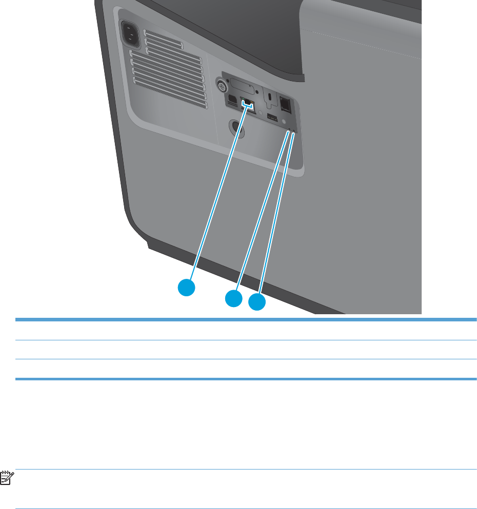
Individual component diagnostics
LED diagnostics
Understand lights on the formatter
The LEDS on the formatter indicate basic product functionality and may be used for troubleshooting.
Figure 2-9 LEDs
123
1 HP Jetdirect LEDs
2 Connectivity LED
3Heartbeat LED
Heartbeat LED
The heartbeat LED provides information about product operation. If a product error occurs, the formatter
displays a message on the control-panel display. However, error situations can occur causing the formatter
to control panel communication to be interrupted.
NOTE: HP recommends fully troubleshooting the formatter and control panel before replacing either
assembly. Use the heartbeat LED to troubleshoot formatter and control panel errors to avoid unnecessarily
replacing these assemblies.
The heartbeat LED operates according to the product state.
ENWW Tools for troubleshooting 149

Table 2-4 Heartbeat LED status
LED color Description
Green ●Solid—During part of boot up initialization and Pre-boot menu
●Slow blinking—During normal operation/sleep mode
◦Formatter is operating normally
◦Firmware is operating normally
◦Control panel is connected
Yellow ●Fast blinking—Formatter cannot connect to the control panel
◦Check control panel connections
◦Verify control panel functionality
Red ●Solid—Formatter error or failure (initially red for one second during power on)
◦Serial peripheral interface (SPI) flash memory boot error
◦Power on self test (formatter) failed
◦Diagnostic (formatter) failed
Off The power cable is disconnected, or the product power switch is in the off position.
●Firmware or system freeze. Reboot the product, or reload or upgrade the firmware
◦Check control panel for an error message
◦Control panel failure or the product power switch is in the off position
NOTE: This condition is not usually caused by a formatter failure. Turn the power off, and then on
again. If the error persists, perform a firmware upgrade.
Connectivity LED
If the connectivity LED is solid green, it indicates that the formatter assembly is correctly plugged in and
powered up.
TIP: If the connectivity LED is illuminated, the formatter is fully seated and the power is on. The pins for the
LED circuit in the formatter connector are recessed so that this LED will not illuminate unless the formatter is
fully seated.
HP Jetdirect LEDs
The embedded HP Jetdirect print server has two LEDs. The yellow LED indicates network activity, and the
green LED indicates the link status. A blinking yellow LED indicates network traffic. If the green LED is off, a
link has failed.
For link failures, check all the network cable connections. In addition, you can try to manually configure the
link settings on the embedded print server by using the product control-panel menus.
1. From the Home screen on the product control panel, scroll to and touch the Administration button.
2. Open the following menus:
150 Chapter 2 Solve problems ENWW
●Network Settings
●Embedded Jetdirect
●Link Speed
3. Select the appropriate link speed, and then touch the OK button.
Paper path test
This diagnostic test generates one or more test pages that you can use to isolate the cause of jams.
To isolate a problem, specify which input tray to use, specify whether to use the duplex path, and specify the
number of copies to print. Multiple copies can be printed to help isolate intermittent problems. The following
options become available after you start the diagnostic feature:
●Print Test Page: Run the paper-path test from the default settings: Tray 2, no duplex, and one copy. To
specify other settings, scroll down the menu, and select the setting, and then scroll back up and select
Print Test Page to start the test.
●Source Tray: Select Tray 1, Tray 2, or the optional tray.
●Test Duplex Path: Enable or disable two-sided printing.
●Number of Copies: Set the numbers of copies to be printed; the range is 1-500.
1. From the Home screen on the product control panel, scroll to and touch the Administration button.
2. Open the following menus:
●Troubleshooting
●Diagnostic Tests
●Paper Path Test
3. Select the paper-path test options for the test you want to run.
ENWW Tools for troubleshooting 151
Scanner tests (X585 only)
Use these diagnostic tests to manually test the document feeder and scanner sensors.
Scanner tests
This section lists the sensors available in the Scanner Tests.
Use the scanner tests
The Scanner Tests screen shows the sensor name, sensor state (active or inactive), and the number of times
the sensor has been toggled (activated).
1. From the Home screen on the product control panel, scroll to and touch the Administration button.
2. Open the following menus:
●Troubleshooting
●Diagnostic Tests
●Scanner Tests
●Sensors
3. Touch the sensor name on the Scanner Tests screen to display a sensor location graphic on the control-
panel display.
4. Activate the desired sensor, and then check the control-panel display to verify the sensor state (active
or inactive).
●The State virtual LED next to the sensor number and sensor name illuminates green when the
sensor is active.
●The Toggle virtual LED next to the sensor number and sensor name illuminates green after the
sensor is activated and increments by one each time the sensor is interrupted (activated or
deactivated).
For example, opening and closing the flatbed cover increments the Flatbed Cover Toggle item
count two times—once when the door is opened, and once when the door is closed.
5. Touch the Reset Sensors button to reset the Toggle count item.
-or-
Touch the Cancel button to exit the Scanner Tests screen, and then touch the Cancel button again to
return to the Diagnostic Tests menu.
Scanner sensor tests
●ADF Paper Present
●ADF Y (length)
●ADF Jam Cover
●ADF Paper Path Deskew
●ADF Paper Path Pick Success
152 Chapter 2 Solve problems ENWW
●Paper path sensor 1 (unreachable)
●Paper path sensor 2 (unreachable)
●Flatbed Y (length)
●Flatbed cover
ENWW Tools for troubleshooting 153
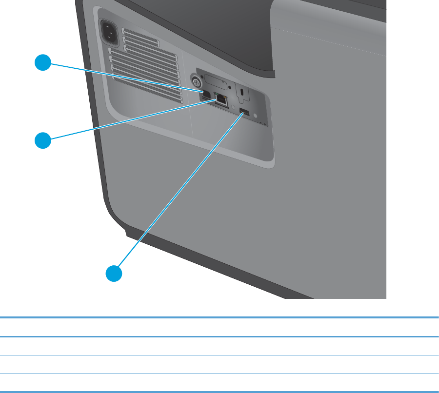
Diagrams
For diagrams showing sensors and other components, see the Theory of Operations chapter.
Plug/jack locations
Figure 2-10 Plug/jack locations (X555)
1
2
3
Table 2-5 Plug/jack locations (X555)
Item Description
1 Hi-Speed USB 2.0 printing port
2 Local area network (LAN) Ethernet (RJ-45) network port
3 USB port for connecting external USB devices
154 Chapter 2 Solve problems ENWW
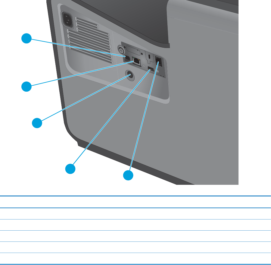
Figure 2-11 Plug/jack locations (X585)
1
2
3
45
Table 2-6 Plug/jack locations (X585)
Item Description
1 Hi-Speed USB 2.0 printing port
2 Local area network (LAN) Ethernet (RJ-45) network port
3 Foreign interface harness (for connecting third-party devices)
4 USB port for connecting external USB devices
5 Fax port (fax models only)
ENWW Tools for troubleshooting 155

Print-quality troubleshooting tools
Internal print-quality test pages
Print-quality troubleshooting pages
Use the print-quality troubleshooting pages to help diagnose and solve print-quality problems.
NOTE: To get further assistance in print-quality troubleshooting, go to www.hp.com/support/ojcolorX555
or www.hp.com/support/ojcolorMFPX585 and select PQ Troubleshooting Tools.
1. From the Home screen on the product control panel, scroll to and touch the Administration button.
2. Open the following menus:
●Troubleshooting
●Print Quality Pages
3. Select one of the following documents to print:
●Troubleshooting Guide
●Diagnostic Page
●Print Quality Report
●Print Quality Service Pages
●Printhead Diagnostic Pages
Interpret the print quality report
1. Load the product with regular, unused white paper.
2. From the Home screen on the product control panel, touch the Administration button.
3. Open the following menus:
●Troubleshooting
●Print Quality Pages
4. Select the Print Quality Report item to print it.
This page contains four bands of color, which are divided into the groups as indicated in the following
illustration. By examining each group, you can isolate the problem to a particular ink cartridge.
156 Chapter 2 Solve problems ENWW
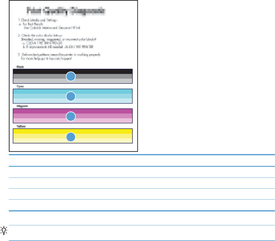
3
4
1
2
Section Ink cartridge
1Black
2Cyan
3Magenta
4 Yellow
TIP: Mark this page with a “1” in a corner. If you clean the printhead later, you will want to keep track of
which page was printed first, in order to note any progress.
In general, if the ink system is working correctly, all the color bars are present and not streaked. Each bar has
three distinct shades, but otherwise the color should not vary across the bar. The bars should also be evenly
lined up. The black text on the page should not show ink streaks.
The following table shows some representative examples of defects on the print quality report.
ENWW Tools for troubleshooting 157

Defect Example
Color variation across bar
Black
Cyan
Magenta
Yellow
Color intensity variation across bars
Black
Cyan
Magenta
Yellow
158 Chapter 2 Solve problems ENWW
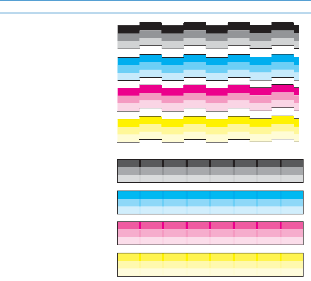
Defect Example
Uneven bars
Black
Cyan
Magenta
Yellow
Vertical dark lines
Black
Cyan
Magenta
Yellow
ENWW Tools for troubleshooting 159
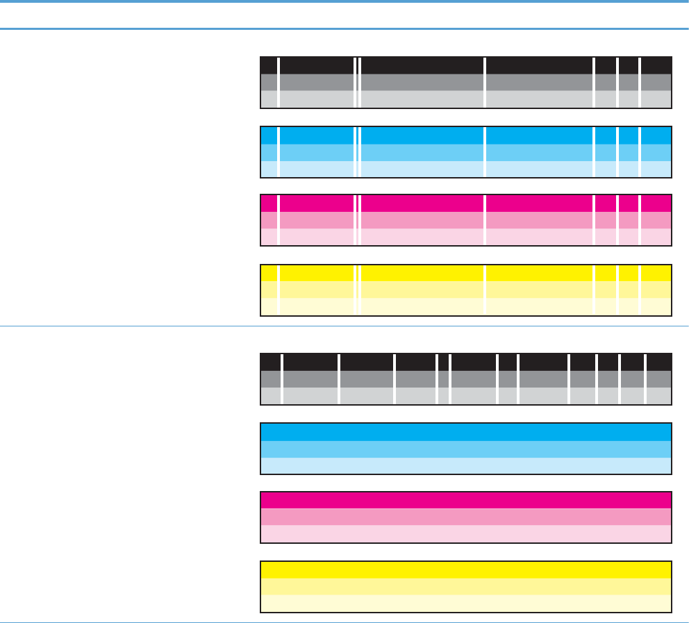
Defect Example
Vertical white lines on all bars
Black
Cyan
Magenta
Yellow
Vertical white lines on select bars
Black
Cyan
Magenta
Yellow
160 Chapter 2 Solve problems ENWW

Defect Example
Shade gradations not sharp
Black
Cyan
Magenta
Yellow
Page is blank or only partially printed
1 | 2 | 3 | 4 | 5 | 6 | 7 | 8 | 9 | 10
1 | 2 | 3 | 4 | 5 | 6 | 7 | 8 | 9 | 10
Black
Cyan
Magenta
Yellow
Print Quality Printhead Cleaning Diagnostic
XXXXXXXXXXXXXXXXXXXXXXX
XXXXXXXXXXXXXXXXXXXXX
XXXXXXXXXXXXXXXXXXXXXXXXXXXXXXXXXXXXXX
XXXXXXXXXXXXXXXXXXXXXXXXXXXXXXXXXXXXXXXX
XXXXXXXXXXXXXXXXXXXXXXXXX
XXXXXXXXXXXXXXXXXXXXXXXXXXXXX
XXXXXXXXXXXXXXXXXXXXXXXXXXXX
1
|
2
|
3
|
4
|
5
|
6
|
7
|
8
|
9
|
1
0
1
|
2
|
3
|
4
|
5
|
6
|
7
|
8
|
9
|
1
0
Bl
ac
k
C
yan
M
agenta
Y
e
ll
o
w
P
rint Qualit
y
Printhead Cleanin
g
Dia
g
nostic
X
XXXXXXXXXXXXXXXXXXXXX
X
X
XXXXXXXXXXXXXXXXXXX
X
X
XXXXXXXXXXXXXXXXXXXXXXXXXXXXXXXXXXXX
X
X
XXXXXXXXXXXXXXXXXXXXXXXXXXXXXXXXXXXXXX
X
XXXXXXXXXXXXXXXXXXXXXXXX
X
X
XXXXXXXXXXXXXXXXXXXXXXXXXXX
X
XXXXXXXXXXXXXXXXXXXXXXXXXXX
X
ENWW Tools for troubleshooting 161

If the print quality report shows defects like the ones above, clean the printhead as follows:
1. Load the product with regular, unused white paper.
2. On the control panel, touch the Device Maintenance button.
3. Open the Calibration/Cleaning menu.
4. Select the Printhead Cleaning item.
The cleaning process has several steps. After each of them, the product prints the print quality report
again. Evaluate each of these pages to determine if the original defect has been fixed – if it has, there is
no reason to go on to the next cleaning stage.
TIP: Number each of the print quality pages so you don’t lose track of the prints later.
5. If you finish the cleaning process and still see defects on the print quality report, retry cleaning,
especially if you have seen improvement in the print quality reports.
6. If the print quality report still shows defects after a second cleaning, go to the next section to service
the product.
If the defect on the print quality report is color variation across the bars (see the table of defects above), and
if the problem seems to go away after a cleaning, but then reoccurs in the same location on the color bar the
next day, complete the following procedure:
1. Check to see if any of the following conditions are true:
●Prior to the print quality problem, the product was unused for more than three weeks.
●The product was recently moved or experienced a large temperature shift.
●There was a recent paper jam.
●The print quality problem seems to be getting better as the product is used (especially if print jobs
with dense backgrounds are printed).
2. If none of the conditions above are true, the color problem is likely to reoccur, even if a cleaning fixes it
temporarily. Go to the final section of this document to service the product.
If the print quality report has no defects, then the ink system is working correctly. There is no reason to clean
the printhead, which unnecessarily wastes ink and paper. Complete the following steps:
1. Retry the original print job. Just printing the print quality report can solve some problems. If the print
job meets print quality standards, stop troubleshooting here.
2. If problems still exist on print jobs, review the earlier steps in this document: make sure the ink and
paper are appropriate, and that the print settings are correct. In addition, these suggestions may help
with some problems:
●If you are printing an image, make sure it has sufficient resolution. Images that have been
enlarged too much might appear fuzzy or blurry.
●If the problem is confined to a band near the edge of a printout, use the software you installed
with the product or another software program to rotate the image 180°. The problem might not
appear on the other end of the printout.
●Always use the power button to turn the product off. This protects the printhead from exposure to
air.
162 Chapter 2 Solve problems ENWW

●If yellow is missing from color jobs, there might be an ink sludge buildup on the orifice plate. Clean
the printhead several times and then see if print quality has improved.
●If all colors are experiencing poor print quality, there might be an issue with the web wipe not
advancing. Open the left door, and then mark the edge of the web wipe above the duplex module.
Figure 2-12 Mark the web wipe
Run the product so that it performs a wipe, and then see if the web has advanced. If it has not,
replace the print mechanism.
3. If the problem persists, contact HP to service the product.
ENWW Tools for troubleshooting 163

Cleaning page
1. From the Home screen on the product control panel, scroll to and touch the Device Maintenance button.
2. Open the following menus:
●Calibration/Cleaning
●Resolve Ink Smear
3. Touch the Start button to begin the procedure.
The cleaning process can take several minutes.
Calibrate the product to align the colors
Calibration is a product function that optimizes print quality. If you experience any image-quality problems,
calibrate the product.
1. From the Home screen on the product control panel, scroll to and touch the Device Maintenance button.
2. Open the following menus:
●Calibration/Cleaning
●Advanced Calibration Support (and then touch Continue)
●Color Density Calibration
3. Touch the Continue button to start the calibration process.
4. Wait while the product calibrates, and then try printing again.
Preboot menu options
If an error occurs while the product is initializing, an error message displays on the control-panel display. The
user can open the Preboot menus. The error menu item will not be seen if an error did not occur.
CAUTION: The Format Disk option performs a disk initialization for the entire disk. The operating system,
firmware files, and third party files (among other files) will be completely lost. HP does not recommend this
action.
Open the Preboot menu
1. Turn the product on.
2. The HP logo displays on the product control panel. When a "1/8" with an underscore displays below the
HP logo, touch the logo to open the Preboot menu.
TIP: You can also wait for the HP logo to move to the center of the control-panel display, and then
touch the logo to open the Preboot menu.
3. Use the arrow buttons on the touchscreen to navigate the Preboot menu.
4. Touch the OK button to select a menu item.
164 Chapter 2 Solve problems ENWW

Cold reset using the Preboot menu
1. Turn the product on.
2. The HP logo displays on the product control panel. When a "1/8" with an underscore displays below the
HP logo, touch the logo to open the Preboot menu.
3. Use the down arrow button to highlight the Administrator item, and then touch the OK button.
4. Use the down arrow button to highlight the Startup Options item, and then touch the OK button.
5. Use the down arrow button to highlight the Cold Reset item, and then touch the OK button.
6. Touch the Home button to highlight the Continue item, and then touch the OK button.
NOTE: The product will initialize.
Table 2-7 Preboot menu options (1 of 6)
Menu option First level Second level Third level Description
Continue Selecting the Continue item exits the Preboot menu and
continues the normal boot process.
If a selection is not made in the initial menu within 30 seconds,
the product returns to a normal boot (the same as selecting
Continue).
If the user navigates to another menu, the timeout does not
apply.
Sign In Enter the administrator PIN or service PIN if one is required to
open the Preboot menu.
ENWW Tools for troubleshooting 165

Table 2-7 Preboot menu options (1 of 6) (continued)
Menu option First level Second level Third level Description
Administrator This item navigates to the Administrator submenus.
If authentication is required (and the user is not already signed
in) the Sign In prompt displays. The user is required to sign in.
Download Network
USB
USB
Thumbdrive
This item initiates a preboot firmware download process. A USB
thumb drive option will work on all FutureSmart products. USB
or network connections are not currently supported.
Format Disk This item reinitializes the disk and cleans all disk partitions.
CAUTION: Selecting the Format Disk item removes all data.
A delete confirmation prompt is not provided.
The system is not bootable after this action and a 99.09.67
error displays on the control panel. A firmware download must
be performed to return the system to a bootable state.
Partial Clean This item reinitializes the disk (removing all data except the
firmware repository where the master firmware bundle is
downloaded and saved).
CAUTION: Selecting the Partial Clean item removes all data
except the firmware repository.
A delete confirmation prompt is not provided.
This allows a user to reformat the disk by removing the
firmware image from the active directory without having to
download new firmware code (product remains bootable).
Change Password Select this item to set or change the administrator password.
Clear Password Select the Clear Password item to remove a password from the
Administrator menu. Before the password is actually cleared, a
message will be shown asking to confirm that the password
should be cleared. Press the OK button to confirm the action.
When the confirmation prompt displays, press the OK button to
clear the password.
166 Chapter 2 Solve problems ENWW

Table 2-8 Preboot menu options (2 of 6)
Menu option First level Second level Third level Description
Administrator
continued
Manage Disk Clear Disk Select the Clear Disk item to disable using an external device for
job storage. Job storage is normally enabled only for the boot
device. This will be grayed out unless the 99.09.68 error is
displayed.
LockDisk Select the LockDisk item to lock (mate) a new secure disk to this
product.
The secure disk already locked to this product will remain
accessible to this product. Use this function to have more than
one encrypted disk accessible by the product when using them
interchangeably.
The data stored on the secure disk locked to this product
always remains accessible to this product.
Leave Unlocked Select the Leave Unlocked item to use a new secure disk in an
unlocked mode for a single service event. The secure disk that
is already locked to this product will remain accessible to this
product and uses the old disk's encryption password with the
new disk.
The secure disk that is already locked to this product remains
accessible to this product.
Clear Disk
Password
Select the Clear Disk Password item to continue using the non-
secure disk and clear the password associated with the yet-to-
be installed secure disk.
CAUTION: Data on the missing secure disk will be
permanently inaccessible.
Retain
Password
Select the Retain Password item to use the non-secure disk for
this session only, and then search for the missing secure disk in
future sessions.
Boot Device Secure Erase Select the Secure Erase item to erase all of the data on the disk
and unlock it if required.
This might take a long time.
NOTE: The system will be unusable until the system files are
reinstalled. The ATA secure-erase command is a one-pass
overwrite, which erases the entire disk including firmware. The
disk remains an encrypted disk.
Erase/Unlock Select the Erase/Unlock item to cryptographically erase all data
on the disk and unlock the disk to allow a user to gain access to
it from any product.
NOTE: The system will be unusable until the system files are
reinstalled. It erases the encryption key. The encryption key is
erased, so the disk becomes a non-encrypted disk.
Get Status This item provides disk status information if any is available.
ENWW Tools for troubleshooting 167

Table 2-9 Preboot menu options (3 of 6)
Menu option First level Second level Third level Description
Administrator
continued
Manage Disk
continued
Internal Device Select the Internal Device item to erase the internal device
or get a status about the internal device.
Secure Erase Select the Secure Erase item to erase all of the data on the
disk and unlock it if required.
This might take a long time.
NOTE: The system will be unusable until the system files
are reinstalled. The ATA secure-erase command erases the
entire disk, including firmware. The disk remains an
encrypted disk.
Erase/Unlock Select the Erase/Unlock item to cryptographically erase all
of the data on disk and unlock the disk to allow the user to
gain access to it from any product.
NOTE: The system will be unusable until the system files
are reinstalled. The HP High Performance Secure Hard Disk
is erased.
Get Status This item provides disk status information if any is available.
External Device Select the External Device item to erase the internal device
or get status about the internal device.
Secure Erase Select the Secure Erase item to erase all of the data on the
disk and unlock it if required.
This might take a long time.
NOTE: The system will be unusable until the system files
are reinstalled.
The ATA secure-erase command erases the entire disk,
including firmware. The disk remains an encrypted disk.
Erase/Unlock Select the Erase/Unlock item to cryptographically erase all
of the data on disk and unlock the disk to allow a user to
gain access to it from any product.
NOTE: The system will be unusable until the system files
are reinstalled. The encryption key is erased, so the disk
becomes a non-encrypted disk.
Get Status This item provides disk status information if any is available.
168 Chapter 2 Solve problems ENWW

Table 2-10 Preboot menu options (4 of 6)
Menu option First level Second level Third level Description
Administrator
continued
Configure LAN Select the Configure LAN item to set up the network settings for
the Preboot menu firmware upgrade.
The network can be configured to obtain the network settings
from a DHCP server or as static.
IP Mode DHCP Use this item for automatic IP address acquisition from the DHCP
server.
IP Mode Static Use this item to manually assign the network addresses.
IP Address Use this item to manually enter the IP addresses.
Subnet Mask Use this item to manually enter the subnet mask.
Default
Gateway
Use this item to manually enter the default gateway.
Save Select the Save item to save the manual settings.
Table 2-11 Preboot menu options (5 of 6)
Menu option First level Second level Third level Description
Administrator
continued
Startup
Options
Select the Startup Options item to specify options that can be set
for the next time the product is turned on and initializes to the
Ready state.
Show Revision Not currently functional: Select the Show Revision item to allow
the product to initialize and show the firmware version when the
product reaches the Ready state.
Once the product power is turned on the next time, the Show
Revision item is unchecked so that the firmware revision is not
shown.
Cold Reset Select the Cold Reset item to clear the IP address and all customer
settings. (This item also returns all settings to factory defaults.)
NOTE: Items in the Service menu are not reset.
Skip Disk Load Select the Skip Disk Load item to disable installed third-party
applications.
Skip Cal Select the Skip Cal item to initialize the product the next time the
power is turned on without calibrating.
Lock Service CAUTION: Select the Lock Service item to lock the Service menu
access (both in the Preboot menu and the Device Maintenance
menu).
Service personnel must have the administrator remove the Lock
Service setting before they can open the Service menu.
Skip FSCK Select the Skip FSCK item to disable Chkdisk/ScanVolume during
startup.
ENWW Tools for troubleshooting 169

Table 2-11 Preboot menu options (5 of 6) (continued)
Menu option First level Second level Third level Description
Administrator
continued
Startup
Options
continued
First Power Not currently functional: This item allows the product to initialize
as if it is the first time it has been turned on.
For example, the user is prompted to configure first-time settings
like date/time, language, and other settings.
Select this item so that it is enabled for the next time the product
power is turned on.
When the product power is turned on the next time, this item is
unchecked so that the pre-configured settings are used during
configuration, and the first-time setting prompt is not used.
Embedded
Jetdirect Off
Select the Embedded Jetdirect Off item to disable the embedded
HP Jetdirect.
By default this item is unchecked so that HP Jetdirect is always
enabled.
Wifi Accessory Select the Wifi Accessory item to enable the wireless accessory.
Table 2-12 Preboot menu options (6 of 6)
Menu option First level Second level Third level Description
Administrator
continued
Diagnostics Memory Do Not Run Diagnostic items are useful for troubleshooting formatter
problems. Use the options below the Do Not Run item to help
troubleshoot formatter problems.
Short
Long
Disk Do Not Run
Short
Long
Optimized
RAW
Smart
ICB
CPB
Interconnect Run
Selected
Remote Admin Start Telnet The Remote Admin item allows a service technician to gain
access to the product remotely to troubleshoot issues.
Stop Telnet
Refresh IP
170 Chapter 2 Solve problems ENWW

Table 2-12 Preboot menu options (6 of 6) (continued)
Menu option First level Second level Third level Description
System Triage Copy Logs If you cannot print the error logs, the System Triage item
allows you to copy the error logs to a flash drive on the next
startup. The files can then be sent to HP to help determine
the problem.
Service Tools This item requires the service access personal identification
number (PIN) for this product (see the service mode functions
section in the product troubleshooting manual). If the product
does not reach the Ready state, you can use this item to print
the error logs. The logs can be copied to a USB drive when the
product is initialized, and then these files can be sent to HP to
help determine what is causing the problem.
Reset Password Use this item to reset the administrator password.
Subsystems For manufacturing use only. Do not change these values.
Developer Tools Net Exec This item is for factory use only.
WARNING! HP recommends that field service personnel do
not access, or use this item. This item is for factory use only.
ENWW Tools for troubleshooting 171

Control-panel menus
Administration menu
You can perform basic product setup by using the Administration menu. Use the HP Embedded Web Server
for more advanced product setup. To open the HP Embedded Web Server, enter the product IP address or
host name in the address bar of a Web browser.
Reports menu
To display: At the product control panel, select the Administration menu, and then select the Reports menu.
Table 2-13 Reports menu
First level Second level Values Description
Configuration/Status Pages Administration Menu Map Print
View
Shows a map of the entire
Administration menu and the
selected values for each setting.
Current Settings Page Print
View
Shows a summary of the current
settings for the product. This
might be helpful if you plan to
make changes and need a record
of the present configuration.
Configuration Page Print
View
Shows the product settings and
installed accessories.
How to Connect Page Print
View
Shows the network information
typically needed to connect the
product to a network.
Supplies Status Page Print
View
Shows the approximate remaining
life for the supplies; reports
statistics on total number of pages
and jobs processed, serial number,
page counts, and maintenance
information.
HP provides approximations of the
remaining life for the supplies as a
customer convenience. The actual
remaining supply levels might be
different from the approximations
provided.
Usage Page Print
View
Shows a count of all paper sizes
that have passed through the
product; lists whether they were
simplex, duplex, monochrome, or
color; and reports the page count.
File Directory Print
View
Shows the file name and folder
name for files that are stored in
the product memory.
Web Services Status Page Print
View
Shows the detected Web Services
for the product.
172 Chapter 2 Solve problems ENWW

Table 2-13 Reports menu (continued)
First level Second level Values Description
Color Usage Job Log Print
View
Shows color jobs completed by the
product.
Fax Reports (X585 only) Fax Activity Log Print
View
Contains a list of the faxes that
have been sent from or received by
this product.
Billing Codes Report Print
View
Provides a list of billing codes that
have been used for outgoing faxes.
This report shows how many sent
faxes were billed to each code.
Blocked Fax List Print
View
A list of phone numbers that are
blocked from sending faxes to this
product.
Speed Dial List Print
View
Shows the speed dials that have
been set up for this product.
Fax Call Report Print
View
A detailed report of the last fax
operation, either sent or received.
Other Pages Demonstration Page Print Prints a demonstration page.
RGB samples Print Prints color samples for different
RGB values. Use the samples as a
guide for matching printed colors.
CMYK samples Print Prints color samples for different
CMYK values. Use the samples as a
guide for matching printed colors.
PCL Font List Print Prints the available PCL fonts.
PS Font List Print Prints the available PS fonts.
ENWW Control-panel menus 173

General Settings menu
To display: At the product control panel, select the Administration menu, and then select the General
Settings menu.
In the following table, asterisks (*) indicate the factory default setting.
Table 2-14 General Settings menu
First level Second level Third level Fourth level Values Description
Date/Time Settings Date/Time Format Date Format DD/MMM/YYYY
MMM/DD/YYYY
YYYY/MMM/DD
Use the Date/Time
Settings menu to
specify the date and
time and to configure
date/time settings.
Time Format 12 hour (AM/PM)
24 hours
Select the format that
the product uses to
show the date and
time, for example 12-
hour format or 24-
hour format.
Date/Time Time Zone Select the time zone from
a list.
Select the time zone,
date, and time that
the product uses.
Date Select the date from a
pop-up calendar.
Time Select the time from a
pop-up keypad.
Adjust for Daylight
Savings
(Checkbox) If you are in an area
that uses daylight
savings time, select
the Adjust for Daylight
Savings box.
174 Chapter 2 Solve problems ENWW

Table 2-14 General Settings menu (continued)
First level Second level Third level Fourth level Values Description
Energy Settings Sleep Schedule A list of scheduled
events displays.
+ (Add)
Edit
Delete
Use to configure the
product to
automatically wake up
or go to sleep at
specific times on
specific days. Using
this feature saves
energy.
NOTE: You must
configure the date and
time settings before
you can use this
feature.
Event Type Select whether to add
or edit a Wake event
or a Sleep event, and
then select the time
and the days for the
wake or sleep event.
Time Set the wake or sleep
event time
parameters.
Event Days Select days of the week
from a list.
Set the wake or sleep
event day parameters.
Sleep Timer Settings Sleep/Auto Off After Range: 1 to 120 minutes
Default = 60 minutes
Set the number of
minutes after which
the product enters
Sleep or Auto Off
mode. Touch the
existing number to
open the virtual
keypad, and then
increase or decrease
the number of
minutes.
Wake/Auto On to
These Events
All Events*
Network port
Power button only
ENWW Control-panel menus 175

Table 2-14 General Settings menu (continued)
First level Second level Third level Fourth level Values Description
Print Quality Image Registration Adjust Tray <X> X1 Shift
Y1 Shift
X2 Shift
Y2 Shift
-5.00 mm to 5.00 mm Shift the margin
alignment to center
the image on the page
from top to bottom
and from left to right.
You can also align the
image on the front
with the image printed
on the back.
The direction that is
perpendicular to the
way the paper passes
through the product is
referred to as X. This is
also known as the
scan direction. X1 is
the scan direction for a
single-sided page or
for the second side of
a two-sided page. X2
is the scan direction
for the first side of a
two-sided page.
The direction that the
paper feeds through
the product is referred
to as Y. Y1 is the feed
direction for a single-
sided page or for the
second side of a two-
sided page. Y2 is the
feed direction for the
first side of a two-
sided page.
Use the Adjust Tray
<X> menu to adjust
the registration
settings for each tray.
Before adjusting these
values, print a
registration test page.
It provides alignment
guides in the X and Y
directions so you can
determine which
adjustments are
necessary. You can
adjust values for X1
Shift, X2 Shift, Y1
Shift, and Y2 Shift.
176 Chapter 2 Solve problems ENWW

Table 2-14 General Settings menu (continued)
First level Second level Third level Fourth level Values Description
Print Test Page Use the Print Test
Page option to print a
page to test the image
registration. It
provides alignment
guides in the X and Y
directions so you can
determine which
adjustments are
necessary.
Jam Recovery Auto*
Off
On
This product provides
a jam recovery feature
that reprints jammed
pages. Select one of
the following options:
Auto: The product
attempts to reprint
jammed pages when
sufficient memory is
available. This is the
default setting.
Off: The product does
not attempt to reprint
jammed pages.
Because no memory is
used to store the most
recent pages,
performance is
optimal.
NOTE: When using
this option, if the
product runs out of
paper and the job is
being printed on both
sides, some pages can
be lost.
On: The product
always reprints
jammed pages.
Additional memory is
allocated to store the
last few pages printed.
This might cause a
decrease in overall
performance.
Auto Recovery Enabled
Disabled*
The product attempts
to reprint jammed
pages when sufficient
memory is available.
This is the default
setting.
Manage Stored Jobs General Stored Job
Settings
Sort Stored Jobs By Job Name*
Date
This option allows you
list the jobs either
alphabetically or
chronologically.
ENWW Control-panel menus 177

Table 2-14 General Settings menu (continued)
First level Second level Third level Fourth level Values Description
Default Folder Name Type the name for the
stored jobs folder that
is accessible to all
users.
Temporary Stored Job
Settings
Retain Temporary
Jobs After Reboot
Do not retain
Personal jobs only
All temporary jobs
Sets which temporary
jobs will be retained in
the event of a product
reboot.
Delete Temporary
Jobs After
Off*
1 Hour
4 Hours
1 Day
1 Week
Sets a maximum
storage-time limit for
stored Quick Copy and
Proof and Hold jobs. If
a stored job is not
printed during this
period, it is deleted.
Temporary Job
Storage Limit
1-300
Default = 32
Configure global
settings for jobs that
are stored in the
product memory.
The Temporary Job
Storage Limit feature
specifies the number
of temporary jobs that
can be stored on the
product. The
maximum allowed
value is 300.
Enable Retrieve from
USB
Enabled
Disabled*
Enables the product to
open a file from a USB
drive.
Hold Off Print Job Enabled*
Disabled
Enable this feature if
you want to prevent
print jobs from
starting while a user is
initiating a copy job
from the control
panel. Held print jobs
start printing after the
copy job is finished,
provided that no other
copy job is in the print
queue.
Restore Factory
Settings
Restore
Cancel
Use to restore all
product settings to
their factory defaults.
178 Chapter 2 Solve problems ENWW

Copy Settings menu (X585 only)
To display: At the product control panel, select the Administration menu, and then select the Copy Settings
menu.
In the following table, asterisks (*) indicate the factory default setting.
Table 2-15 Copy Settings menu (X585)
First level Second level Third level Values Description
Copies 1–9999
Default = 1
Configure the default
options for copy jobs. If the
user does not specify the
job options when creating
the job, the default options
are used.
Sides 1-sided original, 1-sided
output*
2-sided original, 2-sided
output
1-sided original, 2-sided
output
2-sided original, 1-sided
output
Use to indicate whether the
original document is
printed on one or both
sides, and whether the
copies should be printed on
one or both sides. For
example, select 1-sided
original, 2- sided output
when the original is printed
on one side, but you want
to make two-sided copies.
Orientation Portrait* Specify portrait or
landscape orientation and
select the way the second
sides are printed.
Portrait orientation means
the short edge of the page
is along the top.
Landscape Landscape orientation
means the long edge of the
page is along the top.
ENWW Control-panel menus 179

Table 2-15 Copy Settings menu (X585) (continued)
First level Second level Third level Values Description
2-Sided Format Book-style
Flip-style
Book-style original; Flip-
style copy
Flip-style original; Book-
style copy
If you are making two-
sided copies, select a 2-
sided format option.
Book-style: The back side
of the original is printed
right-side-up, and the back
side of the copy is printed
the same way. Use this
option for originals and
copies that are bound along
the left edge.
Flip-style: The back side of
the original is printed
upside-down, and the back
side of the copy is printed
the same way. Use this
option for originals and
copies that are to be bound
along the top edge.
Book-style original; Flip-
style copy: The back side of
the original is printed right-
side-up, but the back side
of the copy is printed
upside-down. Use this
option when the original is
bound along the left edge,
but you want the copies to
be bound along the top
edge.
Flip-style original; Book-
style copy: The back side of
the original is printed
upside-down, but the back
side of the copy is printed
right-side-up. Use this
option when the original is
bound along the top edge,
but you want the copies to
be bound along the left
edge.
180 Chapter 2 Solve problems ENWW

Table 2-15 Copy Settings menu (X585) (continued)
First level Second level Third level Values Description
Color/Black Automatically detect*
Color
Black
Select how the copy should
be printed.
Automatically detect:
Prints color documents in
color, and black and white
documents in black and
white. For mixed
documents, the product
will determine whether to
print in color or black and
white.
Color: Prints documents in
color.
Black: Prints documents in
black and white.
Collate Collate on (Sets in page
order)*
Collate off (Pages grouped)
If you are making more
than one copy, select the
Collate on (Sets in page
order) option to assemble
the pages in the correct
order in each set of copies.
Select the Collate off
(Pages grouped) option to
group the same pages
together. For example, if
you are making five copies
of an original document
that has two pages, all five
first pages would be
grouped together and all
five second pages would be
grouped together.
Reduce/Enlarge Scaling Auto*
100%
75%
50%
125%
150%
200%
Use to scale the size of the
document up or down.
Select one of the
predefined percentages, or
select the Scaling field and
type a percentage between
25 and 400. The Auto
option automatically scales
the image to fit the paper
size in the tray.
NOTE: To reduce the
image, select a scaling
percentage that is less than
100. To enlarge the image,
select a scaling percentage
that is greater than 100.
Auto Include Margins The product reduces the
image slightly to fit the
entire scanned image
within the printable area on
the page.
ENWW Control-panel menus 181

Table 2-15 Copy Settings menu (X585) (continued)
First level Second level Third level Values Description
Paper Selection Manually feed
Automatically select
Tray 1: [Type], [Size]
Tray <X>: [Type], [Size]
For the best color and
image quality, select the
appropriate paper type
from the control panel
menu or from the print
driver.
Image Adjustment Darkness Select a value using the
slide bar, or touch
Automatic.
Use to improve the overall
quality of the copy.
Adjust the Darkness setting
to increase or decrease the
amount of white and black
in the colors.
Contrast Select a value using the
slide bar, or touch
Automatic.
Adjust the Contrast setting
to increase or decrease the
difference between the
lightest and darkest color
on the page.
Background Cleanup Select a value using the
slide bar, or touch
Automatic.
Adjust the Background
Cleanup setting if you are
having trouble copying a
faint image.
Sharpness Select a value using the
slide bar, or touch
Automatic.
Adjust the Sharpness
setting to clarify or soften
the image. For example,
increasing the sharpness
could make text appear
crisper, but decreasing it
could make photographs
appear smoother.
Default Select this to make the
selected Image Adjustment
setting the default value.
Content Orientation Orientation Portrait*
Landscape
For some features to work
correctly, you must specify
the way the content of the
original document is placed
on the page. Portrait
orientation means the
short edge of the page is
along the top. Landscape
orientation means the long
edge of the page is along
the top.
Optimize Text/Picture Manually Adjust* Optimize For slider Use this setting to optimize
the output for a particular
type of content.
182 Chapter 2 Solve problems ENWW

Table 2-15 Copy Settings menu (X585) (continued)
First level Second level Third level Values Description
Text
Printed picture
Photograph
Manually Adjust: Use to
manually optimize the
setting for each document.
Printed picture: Use for line
drawings and preprinted
images, such as magazine
clippings or pages from
books. If you see bands of
irregular color or intensity
on copies, try selecting the
Printed picture setting to
improve the quality.
Photograph: Use for
photographic prints.
Pages per Sheet One (1)
Two (2)
Four (4)
Copies multiple pages onto
one sheet of paper.
NOTE: Before using this
screen, use the Content
Orientation screen to
describe the original
document orientation.
Page Order Right, then down
Down, then right
If you are printing four
pages per sheet, select the
page order. To print the
pages in rows, select the
Right, then down option. To
print the pages in columns,
select the Down, then right
option.
Add Page Borders If you are printing two or
more pages per sheet and
you want to print a border
around each page, select
the Add Page Borders
option.
Original Size Select from a list of sizes
that the product supports.
Describes the page size of
the original document.
Booklet Booklet Format (Checkbox) Use to copy two or more
pages onto one sheet of
paper so you can fold the
sheets in the center to form
a booklet. The product
arranges the pages in the
correct order. For example,
if the original document
has eight pages, the
product prints pages 1 and
8 on the same sheet.
Borders on Each Page (Checkbox) To print a border around
each page, select the
Borders on Each Page
option.
ENWW Control-panel menus 183

Table 2-15 Copy Settings menu (X585) (continued)
First level Second level Third level Values Description
Original Size Select from a list of sizes
that the product supports.
Describes the page size of
the original document.
Sides 1-sided
2-sided
Select the 1-sided option if
the original document is
printed on only one side.
Select the 2-sided option if
the original document is
printed on two sides.
Paper Selection Manually feed
Automatic
Tray 1: [Type], [Size]
Tray <X>: [Type], [Size]
For the best color and
image quality, select the
appropriate paper type
from the control panel
menu or from the print
driver.
Edge-to-Edge Normal (recommended)*
Edge-to-Edge output
Use to avoid shadows that
can appear along the edges
of copies when the original
document is printed close
to the edges. Combine with
the Reduce/Enlarge feature
to ensure that the entire
page is printed on the
copies. When the Edge-to-
Edge feature is turned on,
the product minimizes
margins and prints as close
to the edge of the paper as
possible.
Job Build Job Build off*
Job Build on
Use to combine several
original documents into
one job. Also use this
feature to scan an original
document that has more
pages than the document
feeder can accommodate
at one time. The product
temporarily saves all the
scanned images. After you
have scanned all the pages
for the job, touch the Finish
option to finish the job.
Multi-feed Detection Enabled*
Disabled
This setting stops the
scanning process if it
detects multiple-page
feeds through the
document feeder.
2–sided ID Scan ID Scan on
ID Scan off*
ID Scan mode allows the
user to scan both sides of
an identification card onto
one sheet.
Book Mode Book Mode on
Book Mode off*
This setting allows the user
to scan pages from a book.
184 Chapter 2 Solve problems ENWW

Scan/Digital Send Settings menu (X585)
To display: At the product control panel, select the Administration menu, and then select the Scan/Digital
Send Settings menu.
In the following table, asterisks (*) indicate the factory default setting.
Table 2-16 Scan/Digital Send Settings menu (X585)
First level Second level Third level Fourth level Values Description
E-mail Settings
Save to Network
Folder Options
Save to USB Options
NOTE: The same
options are available
for each of these
features, except
where noted.
E-mail Setup Wizard
NOTE: Email
Settings only
Use to configure
settings that apply to
sending documents
through email or
saving documents to a
folder on the network
or on a USB multi-
drive.
The E-mail Setup
Wizard feature
configures the
product to send
scanned images as
email attachments. To
open the product HP
Embedded Web Server
and set up the email
notification server,
enter the product IP
address into a Web
browser.
ENWW Control-panel menus 185

Table 2-16 Scan/Digital Send Settings menu (X585) (continued)
First level Second level Third level Fourth level Values Description
Default Job Options Image Preview Make optional*
Require preview
Disable preview
Defines the default
job options for each
function. If you do not
specify the job options
when creating the job,
the default options
are used. For
complete setup, go to
the HP Embedded
Web Server by typing
the IP address of the
product into a Web
browser.
Use the Image
Preview feature to
scan a document and
display a preview
before completing the
job. Select whether
this feature is
available on the
product.
Make optional: The
feature is optional,
depending on the user
who is signed in.
Require preview
Previews are required
for all users.
Disable preview:
Previews are disabled
for all users.
Default File Name The product is shipped
with a factory default
file name of [Untitled]
for any scanned files
that are sent or saved.
Use this feature to
specify a different
default file name. If
you are saving a file to
a network folder or
USB storage product
and a file with the
default file name
already exists, a
number is appended
to the file name, for
example,
[Untitled]001.
186 Chapter 2 Solve problems ENWW

Table 2-16 Scan/Digital Send Settings menu (X585) (continued)
First level Second level Third level Fourth level Values Description
Document File Type Select from a list of
file types.
PDF provides the best
overall image and text
quality.
JPEG is a good choice
for most graphics.
Most computers have
a browser that can
view .JPEG files. This
file type produces one
file per page.
TIFF is a standard file
format that many
graphics programs
support. This file type
produces one file per
page.
MTIFF: stands for
multi-page TIFF. This
file type saves
multiple scanned
pages in a single file.
XPS (XML Paper
Specification) creates
an XML file that
preserves the original
formatting of the
document and
supports color
graphics and
embedded fonts.
NOTE: OCR file types
are not supported on
this product unless
attached to DSS.
ENWW Control-panel menus 187

Table 2-16 Scan/Digital Send Settings menu (X585) (continued)
First level Second level Third level Fourth level Values Description
Optimize Text/Picture Manually Adjust*
Text
Printed picture
Photograph
Use to optimize the
output for a particular
type of content. You
can optimize the
output for text,
printed pictures, or a
mixture.
Manually Adjust: Use
to manually optimize
the setting for text or
for pictures.
Text: Use to optimize
the text portion of the
copy when text and/or
pictures are on the
original.
Printed picture: Use
for line drawings and
preprinted images,
such as magazine
clippings or pages
from books.
Photograph: Best
suited for making
copies of printed
pictures.
Output Quality High (large file)
Medium*
Low (small file)
Use to select the
quality for the output.
Higher-quality images
require a larger file
size than lower-
quality images. Larger
files take more time
to send, and some
recipients might have
trouble receiving
larger files.
Original Sides 1-sided
2-sided
Use to describe the
layout for each side of
the original document.
First select whether
the original document
is printed on one side
or both sides. Then
touch the Orientation
setting to indicate
whether the original
has portrait or
landscape orientation.
If it is printed on both
sides, also select the
2-sided format that
matches the original
document.
188 Chapter 2 Solve problems ENWW

Table 2-16 Scan/Digital Send Settings menu (X585) (continued)
First level Second level Third level Fourth level Values Description
Orientation Automatically detect
Portrait*
Landscape
For some features to
work correctly, you
must specify the way
the content of the
original document is
placed on the page.
Portrait orientation
means the short edge
of the page is along
the top. Landscape
orientation means the
long edge of the page
is along the top. In the
Orientation area,
select whether the
original document has
a portrait or
landscape orientation.
2-Sided Format Book-style
Flip-style
Book-style: The back
side of the original is
printed right-side-up,
and the back side of
the copy is printed the
same way. Use this
option for originals
and copies that are
bound along the left
edge.
Flip-style: The back
side of the original is
printed upside-down,
and the back side of
the copy is printed the
same way. Use this
option for originals
and copies that are to
be bound along the
top edge.
ENWW Control-panel menus 189

Table 2-16 Scan/Digital Send Settings menu (X585) (continued)
First level Second level Third level Fourth level Values Description
Resolution 400 dpi
300 dpi
200 dpi
150 dpi*
75 dpi
Sets the resolution for
sent documents.
Higher resolution
images have more
dots per inch (dpi), so
they show more
detail. Lower
resolution images
have fewer dots per
inch and show less
detail, but the file size
is smaller. Some file
types, for example a
file that will be
processed with OCR,
require a specific
resolution. When
these file types are
selected, the
Resolution setting
might automatically
change to a valid
value.
Content Orientation Orientation Auto Detect
Portrait*
Landscape
For some features to
work correctly, you
must specify the way
the content of the
original document is
placed on the page.
Portrait orientation
means the short edge
of the page is along
the top. Landscape
orientation means the
long edge of the page
is along the top. In the
Orientation area,
select whether the
original document has
a portrait or
landscape orientation.
2-Sided Format Book-style*
Flip-style
Use to configure the
default style for 2-
sided print jobs. If the
Book-style option is
selected, the back
side of the page is
printed the right way
up. This option is for
print jobs that are
bound along the left
edge. If the Flip-style
option is selected, the
back side of the page
is printed upside-
down. This option is
for print jobs that are
bound along the top
edge.
190 Chapter 2 Solve problems ENWW

Table 2-16 Scan/Digital Send Settings menu (X585) (continued)
First level Second level Third level Fourth level Values Description
Color/Black Automatically detect*
Color
Black/Gray
Black
Use to enable or
disable color
scanning.
Automatically detect:
Automatically scans
documents in color if
at least one page has
color.
Color: Scans
documents in color.
Black/Gray: Scans
documents in
grayscale.
Black: Scans
documents in black
and white with a
compressed file size.
Original Size Select from a list of
supported sizes.
Use to describe the
page size of the
original document.
Notification Do not notify*
Notify when job
completes
Notify only if job fails
Print
E-mail
Configure to receive
notification about the
status of a sent
document.
Do not notify: Turns
off this feature.
Notify when job
completes: Select to
receive notification
for this job only.
Notify only if job fails:
Select to receive
notification only if the
job is not sent
successfully.
Print: Select to print
the notification at this
product.
E-mail: Select to
recieve the
notification to an
email account.
Include Thumbnail NOTE: When
sending an analog fax,
select Include
Thumbnail to receive
a thumbnail image of
the first page of the
fax in your
notification.
ENWW Control-panel menus 191

Table 2-16 Scan/Digital Send Settings menu (X585) (continued)
First level Second level Third level Fourth level Values Description
Notification E-mail
address
E-mail: Select to
receive the
notification in an
email. Touch the text
box following Email
Address, and then
type the email
address for the
notification.
Image Adjustment Darkness Use to improve the
overall quality of the
copy.
Adjust the Darkness
setting to increase or
decrease the amount
of white and black in
the colors.
Contrast Adjust the Contrast
setting to increase or
decrease the
difference between
the lightest and
darkest color on the
page.
Background Cleanup Adjust the Background
Cleanup setting if you
are having trouble
copying a faint image.
Sharpness Adjust the Sharpness
setting to clarify or
soften the image. For
example, increasing
the sharpness could
make text appear
crisper, but
decreasing it could
make photographs
appear smoother.
Automatic Tone The product
automatically adjusts
the Darkness,
Contrast, and
Background Cleanup
settings to the most
appropriate for the
scanned document.
Default Select this to make
the selected Image
Adjustment setting
the default value.
192 Chapter 2 Solve problems ENWW

Table 2-16 Scan/Digital Send Settings menu (X585) (continued)
First level Second level Third level Fourth level Values Description
Job Build Job Build off*
Job Build on
Use to combine
several original
documents into one
job. Also use to scan
an original document
that has more pages
than the document
feeder can
accommodate at one
time. The product
temporarily saves all
the scanned images.
After you have
scanned all the pages
for the job, touch
Finish to finish the job.
Cropping Options Do not crop*
Crop to content
Crop to paper
Use this menu item to
automatically crop the
scan for digital
sending. Use the Crop
to content option to
scan the smallest
possible area that has
detectable content.
Erase Edges Use inches
Back side erase
Front side erase
Use this menu item to
remove blemishes,
such as dark borders
or staple marks, by
cleaning the specified
edges of the scanned
image. In each of the
text boxes enter the
measurements, in
millimeters or inches,
for how much of the
top edge, bottom
edge, left edge, and
right edge to clean.
Multi-feed Detection Disabled
Enabled*
This setting stops the
scanning process if it
detects multiple-page
feeds through the
document feeder.
Blank Page
Suppression
Disabled*
Enabled
Use to prevent blank
pages in the original
document from being
included in the output
document.
ENWW Control-panel menus 193

Table 2-16 Scan/Digital Send Settings menu (X585) (continued)
First level Second level Third level Fourth level Values Description
Digital Send Service
Setup
Allow Usage of Digital
Sending Software
(DSS) Server
Disabled
Enabled*
Configure how the
product interacts with
the HP Digital Sending
Software (DSS) server.
HP DSS handles digital
sending tasks, such as
faxing, emailing, and
sending scanned
documents to a
network folder or USB
storage device.
Use the Allow Usage
of Digital Sending
Software (DSS) Server
option to configure
the product to use
HP DSS.
Allow Transfer to New
Digital Sending
Software (DSS) Server
Disabled
Enabled*
Use the Allow
Transfer to New
Digital Sending
Software (DSS) Server
option to specify
whether DSS
management of a
product is
transferable to a
different DSS.
194 Chapter 2 Solve problems ENWW

Fax Settings menu (X585)
To display: At the product control panel, select the Administration menu, and then select the Fax Settings
menu.
In the following table, asterisks (*) indicate the factory default setting.
Table 2-17 Fax Settings menu (X585)
First level Second level Third level Fourth level Values Description
Fax Send Settings Fax Send Setup Fax Setup Wizard Configure settings for
sending faxes from
the product.
Use the Fax Setup
Wizard feature to set
up options for faxing.
NOTE: To set up LAN
fax or Internet fax,
use the HP Embedded
Web Server. To open
the HP Embedded
Web Server, type the
product network
address into a Web
browser. To configure
the fax features,
select the Fax tab.
Fax Dialing Settings Fax Dial Volume Off
Low*
High
These settings control
how the fax modem
dials the outgoing fax
number when faxes
are sent.
Dialing Mode Tone*
Pulse
Redial Interval 1-5 Minutes
Default = 5 minutes
Fax Send Speed Fast*
Medium
Slow
Dialing Prefix
Detect Dial Tone
Redial on Error Range: 0-9
Default = 2
Redial on No Answer Range: 0-2
Default = 0
Redial on Busy Range: 0-9
Default = 3
ENWW Control-panel menus 195

Table 2-17 Fax Settings menu (X585) (continued)
First level Second level Third level Fourth level Values Description
General Fax Send
Settings
Fax Number
Confirmation
Enabled
Disabled*
If this feature is
enabled, you must
enter the fax number
twice.
PC Fax Send Enabled*
Disabled
Enables users who
have the correct driver
installed to send faxes
through the product
from their computers.
JBIG Compression Enabled*
Disabled
The JBIG compression
reduces fax-
transmission time,
which can result in
lower phone charges.
However, using JBIG
compression
sometimes causes
compatibility
problems with older
fax machines. If this
occurs, turn off the
JBIG compression.
Error Correction Mode Enabled*
Disabled
When error-correction
mode is enabled and
an error occurs during
fax transmission, the
product sends or
receives the error
portion again.
Fax Header Prepend*
Overlay
Use to prepend or
overlay the fax header
page.
Fax Number Speed
Dial Matching
Enabled
Disabled*
Use this item to match
the fax number that
you type to numbers
that are saved as a
speed dial.
196 Chapter 2 Solve problems ENWW

Table 2-17 Fax Settings menu (X585) (continued)
First level Second level Third level Fourth level Values Description
Billing Codes Enable Billing Codes Off*
On
When billing codes are
enabled, a prompt
displays that asks the
user to enter the
billing code for an
outgoing fax. This
prompt does not
appear if the Allow
users to edit billing
codes check box is not
checked.
You can also use the
billing codes report in
the Reports menu to
view the list of the
billing codes that have
been used for faxes
that have been sent
from the product. The
list is grouped by
billing code and also
shows fax details. This
feature can be used
for billing or usage
tracking.
Default Billing Code Specify a default
billing code for faxing.
If you specify a
default billing code,
this code displays in
the Billing Code field
when the user sends
an outgoing fax. If this
field is blank, no
default billing code is
provided for the user.
Minimum Length Range: 1-16
Default = 1
Specify the required
length of the billing
code. Billing codes can
be between 1 and 16
characters long.
Allow users to edit
billing codes
Off
On*
ENWW Control-panel menus 197

Table 2-17 Fax Settings menu (X585) (continued)
First level Second level Third level Fourth level Values Description
Default Job Options Image Preview Make optional*
Require preview
Disable preview
Use the Image
Preview feature to
scan a document and
display a preview
before completing the
job. Select whether
this feature is
available on the
product.
Make optional: The
feature is optional,
depending on the user
who is signed in.
Require preview
Previews are required
for all users.
Disable preview:
Previews are disabled
for all users.
Resolution Standard (100 x
200dpi)*
Fine (200 x 200dpi)
Superfine (300 x
300dpi)
Select the resolution
for outgoing faxes. If
you increase the
resolution, faxes
might be clearer but
they could transmit
more slowly. Some
file types, for example
a file that will be
processed with OCR,
require a specific
resolution. When
these file types are
selected, the
Resolution setting
might be
automatically
changed to a valid
value.
Original Sides 1-sided*
2-sided
Use to describe the
layout for each side of
the original document.
First select whether
the original document
is printed on one side
or both sides. Then
touch the Orientation
setting to indicate
whether the original
has portrait or
landscape orientation.
If it is printed on both
sides, also select the
2-sided format that
matches the original
document.
198 Chapter 2 Solve problems ENWW

Table 2-17 Fax Settings menu (X585) (continued)
First level Second level Third level Fourth level Values Description
Orientation Portrait*
Landscape
For some features to
work correctly, you
must specify the way
the content of the
original document is
placed on the page.
Portrait: This setting
means the short edge
of the page is along
the top.
Landscape: This
setting means the
long edge of the page
is along the top.
2-Sided Format Book-style*
Flip-style
Book-style: The back
side of the original is
printed right-side-up,
and the back side of
the copy is printed the
same way. Use this
option for originals
and copies that are
bound along the left
edge.
Flip-style: The back
side of the original is
printed upside-down,
and the back side of
the copy is printed the
same way. Use this
option for originals
and copies that are to
be bound along the
top edge.
Notification Do not notify*
Notify when job
completes
Notify only if job fails
Use to receive
notification about the
status of a sent
document.
Do not notify: Turns
off this feature.
Notify when job
completes: Select to
receive notification
for this job only.
Notify only if job fails:
Select to receive
notification only if the
job is not sent
successfully.
ENWW Control-panel menus 199

Table 2-17 Fax Settings menu (X585) (continued)
First level Second level Third level Fourth level Values Description
Print
E-mail
Print: Select to print
the notification at this
product.
E-mail: Select to
receive the
notification in an
email. Touch the text
box following Email
Address, and then
enter the email
address for the
notification.
Include Thumbnail When sending an
analog fax, select
Include Thumbnail to
receive a thumbnail
image of the first
page of the fax in your
notification.
Notification E-mail
address
Provide the email
address that will
receive notifications.
Content Orientation Orientation Portrait*
Landscape
For some features to
work correctly, you
must specify the way
the content of the
original document is
placed on the page.
Portrait: This setting
means the short edge
of the page is along
the top.
Landscape: This
setting means the
long edge of the page
is along the top.
2-Sided Format Book-style*
Flip-style
Use to configure the
default style for 2-
sided print jobs. If the
Book-style option is
selected, the back
side of the page is
printed the right way
up. This option is for
print jobs that are
bound along the left
edge. If the Flip-style
option is selected, the
back side of the page
is printed upside-
down. This option is
for print jobs that are
bound along the top
edge.
200 Chapter 2 Solve problems ENWW

Table 2-17 Fax Settings menu (X585) (continued)
First level Second level Third level Fourth level Values Description
Original Size Select from a list of
sizes that the product
supports.
Use to describe the
page size of the
original document.
Image Adjustment Darkness Use to improve the
overall quality of the
copy.
Adjust the Darkness
setting to increase or
decrease the amount
of white and black in
the colors.
Contrast Adjust the Contrast
setting to increase or
decrease the
difference between
the lightest and
darkest color on the
page.
Background Cleanup Adjust the Background
Cleanup setting if you
are having trouble
copying a faint image.
Sharpness Adjust the Sharpness
setting to clarify or
soften the image. For
example, increasing
the sharpness could
make text appear
crisper, but
decreasing it could
make photographs
appear smoother.
Automatic Tone The product
automatically adjusts
the Darkness,
Contrast, and
Background Cleanup
settings to the most
appropriate for the
scanned document.
Default Select this to make
the selected Image
Adjustment setting
the default value.
ENWW Control-panel menus 201

Table 2-17 Fax Settings menu (X585) (continued)
First level Second level Third level Fourth level Values Description
Optimize Text/Picture Manually Adjust*Optimize For:
Text
Printed picture
Photograph
Optimizes the output
for a particular type of
content. You can
optimize the output
for text, printed
pictures, or a mixture.
Manually Adjust: Use
to manually optimize
the setting for text or
for pictures.
Text: Use to optimize
the text portion of the
copy where text and/
or pictures are on the
original.
Printed picture: Use
for line drawings and
preprinted images,
such as magazine
clippings or pages
from books.
Photograph: Best
suited for making
copies of printed
pictures.
Job Build Job Build off*
Job Build on
Use to divide a
complex job into
smaller segments.
This is useful when
you are copying or
scanning an original
document that has
more pages than the
document feeder can
hold, or when you
want to combine
pages that have
different sizes into
one job. You can use
either the glass or the
document feeder to
scan the original
documents.
Multi-feed Detection Disabled
Enabled*
Use this feature to
prevent multiple
pages being fed
through the document
feeder during
document scans.
Blank Page
Suppression
Disabled*
Enabled
Prevents blank pages
in the original
document from being
included in the output
document.
202 Chapter 2 Solve problems ENWW

Table 2-17 Fax Settings menu (X585) (continued)
First level Second level Third level Fourth level Values Description
Fax Receive Settings Fax Setup Wizard Configure settings for
receiving faxes to the
product.
Use the Fax Setup
Wizard feature to set
up options for faxing.
NOTE: To set up LAN
fax or Internet fax,
use the HP Embedded
Web Server. To open
the HP Embedded
Web Server, type the
product network
address into a Web
browser. To configure
the fax features,
select the Fax tab.
Fax Receive Setup Ringer Volume Off
Low*
High
Use to configure
settings for receiving
faxes.
Rings To Answer Range: 1-6
Default = 1
Fax Receive Speed Fast*
Medium
Slow
Ring Interval Range: 220-600 ms
Default = 600 ms
Ring Frequency Range: 1-200
Default = 68hz
Fax Printing Schedule Always store faxes
Always print faxes*
Use Fax Printing
Schedule
If you have concerns
about the security of
private faxes, use this
feature to store faxes
rather than having
them automatically
print. Open the Fax
Printing Schedule sub-
menu, and then you
can choose to always
store faxes, always
print them, or you can
set up a schedule for
each day of the week.
ENWW Control-panel menus 203

Table 2-17 Fax Settings menu (X585) (continued)
First level Second level Third level Fourth level Values Description
Schedule
Touch this to set up a
fax printing schedule
if you selected the Use
Fax Printing Schedule
option.
+ (Add)
Edit
Delete (trash can)
Print incoming faxes
Store incoming faxes
Time
Event Days
If you are using a fax
printing schedule, use
this menu to configure
when to print faxes.
Blocked Fax Numbers Fax Number to Block The blocked fax list
can contain up to 30
numbers. When the
product receives a call
from one of the
blocked fax numbers,
it deletes the
incoming fax. It also
logs the blocked fax in
the activity log along
with job-accounting
information.
Add blocked numbers:
Enter a fax number
into the Fax Number
to Block field, and
then touch the arrow
button to add a new
number to the blocked
fax list.
To remove blocked
numbers: Select a
number and touch the
Delete button to
delete it from the
blocked fax list.
To clear all blocked
numbers: Touch the
Delete All button to
clear all of the
numbers from the
blocked fax list.
You also can use the
Blocked Fax List
report in the
Information menu to
view the list of the fax
numbers that have
been blocked on this
product.
204 Chapter 2 Solve problems ENWW

Table 2-17 Fax Settings menu (X585) (continued)
First level Second level Third level Fourth level Values Description
Default Job Options Notification Do not notify*
Notify when job
completes
Notify only if job fails
Configure to receive
notification about the
status of a sent
document.
Do not notify: Turns
off this feature.
Notify when job
completes: Select to
receive notification
for this job only.
Notify only if job fails:
Select to receive
notification only if the
job is not sent
successfully.
Print
E-mail*
E-mail: Select to
receive the
notification in an
email. Touch the text
box following Email
Address, and then
enter the email
address for the
notification.
Include Thumbnail NOTE: When
sending an analog fax,
select Include
Thumbnail to receive
a thumbnail image of
the first page of the
fax in your
notification.
Notification E-mail
address
Touch this text field,
provide the email
address to which you
want notifications
sent, and then touch
the OK button..
Stamp Received Faxes Enabled
Disabled*
Use this option to add
the date, time,
sender’s phone
number, and page
number to each page
of the faxes that this
product receives.
ENWW Control-panel menus 205

Table 2-17 Fax Settings menu (X585) (continued)
First level Second level Third level Fourth level Values Description
Fit to Page Enabled*
Disabled
Use to shrink faxes
that are larger than
Letter-size or A4-size
so that they can fit
onto a Letter-size or
A4-size page. If this
feature set to
Disabled, faxes larger
than Letter or A4 will
flow across multiple
pages.
Paper Selection Automatic*
Select from a list of
the trays.
Sides 1-sided*
2-sided
Use to describe the
layout for each side of
the original document.
First select whether
the original document
is printed on one side
or both sides.
Fax Forwarding Enable Fax
Forwarding
Disabled*
Enabled
Use to forward
received faxes to
another fax machine.
Type of Fax Job to
Forward
All faxes
Sent faxes
Received faxes
Use to select the type
of fax jobs that you
want forwarded.
Fax Forwarding
Number
Provide the
forwarding phone
number, and then
touch the OK button.
Clear Fax Activity Log Clears all events from
the fax activity log.
206 Chapter 2 Solve problems ENWW

General Print Settings menu
To display: At the product control panel, select the Administration menu, and then select the General Print
Settings menu.
In the following table, asterisks (*) indicate the factory default setting.
Table 2-18 General Print Settings menu
First level Second level Values Description
Manual Feed Enabled
Disabled*
Use to enable or disable the
manual-feed feature, which allows
the user to feed paper into the
product by hand. When this feature
is enabled, the user can select
manual feed from the control
panel as the paper source for a job.
If a tray is not specified as part of a
job, manual feed is selected.
Courier Font Regular*
Dark
Select which version of the Courier
font you want to use. The factory
default setting is Regular, which
uses an average stroke width. The
Dark setting can be used if a
heavier Courier font is needed.
Wide A4 Enabled
Disabled*
Changes the printable area of A4-
size paper. If you enable this
option, eighty 10-pitch characters
can be printed on a single line of
A4 paper.
Print PS Errors Enabled
Disabled*
Use this feature to select whether
a PostScript (PS) error page is
printed when the product
encounters a PS error.
Print PDF Errors Enabled
Disabled*
Selects whether a PDF error page
is printed when the product
encounters a PDF error.
Personality Auto*
PCL
PS
PDF
Configures the default print
language or personality for the
product. Normally you should not
change the product language. If
you change the setting to a specific
product language, the product
does not automatically switch
from one language to another
unless specific software
commands are sent to it.
PCL Form Length Range: 5-128
Default = 60
Controls the PCL print-command
options. PCL is a set of product
commands that Hewlett-Packard
developed to provide access to
product features.
Use the Form Length feature to
select the user-soft default
vertical form length.
ENWW Control-panel menus 207

Table 2-18 General Print Settings menu (continued)
First level Second level Values Description
Orientation Portrait*
Landscape
Select the orientation that is most
often used for copy or scan
originals. Select the Portrait option
if the short edge is at the top or
select the Landscape option if the
long edge is at the top.
Font Source Internal* Selects the font source for the
user-soft default font. The list of
available options varies depending
on the installed product options.
Font Number Range: 0-110
Default = 0
Specifies the font number for the
user-soft default font using the
source that is specified in the Font
Source menu. The product assigns
a number to each font and lists it
on the PCL font list. The font
number displays in the Font #
column of the printout.
Font Pitch Range: 0.44-99.99
Default = 10
If the Font Source option and the
Font Number setting indicate a
contour font, then use this feature
to select a default pitch (for a
fixed-spaced font).
Font Point Size Range: 4.00-999.75
Default = 12.00
If the Font Source option and the
Font Number setting indicate a
contour font, then use this feature
to select a default point size (for a
proportional-spaced font).
Symbol Set Select from a list of symbol sets. Select any one of several available
symbol sets from the control
panel. A symbol set is a unique
grouping of all the characters in a
font. The factory default value for
this option is PC-8. Either PC-8 or
PC-850 are recommended for line-
draw characters.
Append CR to LF No*
Yes
Configure whether a carriage
return (CR) is appended to each
line feed (LF) encountered in
backwards-compatible PCL jobs
(pure text, no job control). Select
Yes to append the carriage return.
The default setting is No. Some
environments, such as UNIX,
indicate a new line by using only
the line-feed control code. This
option allows the user to append
the required carriage return to
each line feed.
208 Chapter 2 Solve problems ENWW

Table 2-18 General Print Settings menu (continued)
First level Second level Values Description
Suppress Blank Pages No*
Yes
This option is for users who are
generating their own PCL, which
could include extra form feeds that
would cause blank pages to be
printed. When the Yes option is
selected, form feeds are ignored if
the page is blank.
Media Source Mapping Standard*
Classic
Use to select and maintain input
trays by number when you are not
using the product driver, or when
the software program has no
option for tray selection. The
following options are available:
Standard: Tray numbering is based
on newer HP LaserJet models.
Classic: Tray numbering is based
on HP LaserJet 4 and older models.
ENWW Control-panel menus 209

Print Options menu
To display: At the product control panel, select the Administration menu, and then select the Print Options
menu.
In the following table, asterisks (*) indicate the factory default setting.
Table 2-19 Print Options menu
First level Second level Values Description
Number of Copies Range: 1-32000
Default = 1
Sets the default number of copies
for a copy job. This default applies
when the Copy function or the
Quick Copy function is initiated
from the product Home screen.
Default Paper Size Select from a list of sizes that the
product supports.
Configures the default paper size
used for print jobs.
Default Custom Paper Size X Dimension Range: 3-8.5 inches
Default = 8.5 inches
Configures the default paper size
that is used when the user selects
Custom as the paper size for a
print job.
Y Dimension Range: 5-14 inches
Default = 14 inches
Use Inches Enabled*
Disabled
Sides 1-sided*
2-sided
Use to indicate whether the
original document is printed on
one or both sides, and whether the
copies should be printed on one or
both sides. For example, select the
1-sided original, 2-sided output
option when the original is printed
on one side, but you want to make
two-sided copies.
2-Sided Format Book-style*
Flip-style
Configures the default style for 2-
sided print jobs. If the Book-style
option is selected, the back side of
the page is printed the right way
up. This option is for print jobs that
are bound along the left edge. If
the Flip-style option is selected,
the back side of the page is printed
upside-down. This option is for
print jobs that are bound along the
top edge.
Edge-to-Edge Normal (recommended)*
Edge-to-Edge output
Use to avoid shadows that can
appear along the edges of copies
when the original document is
printed close to the edges.
Quality Level General Office
Professional*
Presentation
Set the default print quality
setting.
210 Chapter 2 Solve problems ENWW

Display Settings menu
To display: At the product control panel, select the Administration menu, and then select the Display
Settings menu.
In the following table, asterisks (*) indicate the factory default setting.
Table 2-20 Display Settings menu
First level Second level Values Description
Display Brightness Automatic*
Manual
The Manual setting uses a slider to
manually control the display
brightness.
Use to specify the intensity of the
LCD control-panel display.
Key Press Sound On*
Off
Use to specify whether you hear a
sound when you touch the screen
or press buttons on the control
panel.
Language Settings Language Select from a list of languages that
the product supports.
Use to select a different language
for control-panel messages and
specify the default keyboard
layout. When you select a new
language, the keyboard layout
automatically changes to match
the factory default for the selected
language.
Keyboard Layout
X585 Flow only
Each language has a default
keyboard layout. To change it,
select from a list of layouts.
Select the default keyboard layout
that matches the language you
want to use.
How to Connect Button
X585 only
Display*
Hide
Use this menu item to display or
hide the How to Connect Button on
the Home screen.
Date and Time
X585 only
Show Date and Time*
Hide Date and Time
Select whether to display or hide
the date and time on the control
panel Home screen.
Inactivity Timeout Range: 10-300 seconds
Default = 60 seconds
Specifies the amount of time that
elapses between any activity on
the control panel and when the
product resets to the default
settings. When the timeout
expires, the control-panel display
returns to the Home menu, and
any user signed in to the product is
signed out.
ENWW Control-panel menus 211

Table 2-20 Display Settings menu (continued)
First level Second level Values Description
Clearable Warnings On
Job*
Use this feature to set the period
that a clearable warning displays
on the control panel. If the On
setting is selected, clearable
warnings appear until the
Clearable Warnings button is
pressed. If theJob setting is
selected, clearable warnings stay
on the display during the job that
generated the warning and
disappear from the display when
the next job starts.
Continuable Events Auto-continue (10 seconds)*
Touch OK to continue
Use this option to configure the
product behavior when the product
encounters certain errors. If the
Auto-continue (10 seconds) option
is selected, the job will continue
after 10 seconds. If the Touch OK
to continue option is selected, the
job will stop and require the user
to touch the OK button before
continuing.
212 Chapter 2 Solve problems ENWW

Manage Supplies menu
To display: At the product control panel, select the Administration menu, and then select the Manage
Supplies menu.
In the following table, asterisks (*) indicate the factory default setting.
Table 2-21 Manage Supplies menu
First level Second level Third level Fourth level Values Description
Supplies Status Print
View
Supply Settings Black Cartridge Low Threshold
Settings
1-100%
Default = 10%
Set the estimated
percentage at which
the product notifies
you when an ink
cartridge is very low.
Very Low Settings Stop
Prompt to continue*
Continue
Specifies how the
product notifies you
when an ink cartridge
is very low.
Stop: The product
stops until you replace
the cartridge.
Prompt to continue:
The product stops and
prompts you to replace
the cartridge. You can
acknowledge the
prompt and continue
printing.
Continue: The product
alerts you that a
cartridge is very low,
but it continues
printing.
Color Cartridges Low Threshold
Settings
Cyan
Magenta
Yellow
1-100%
Default = 10%
Set the estimated
percentage at which
the product notifies
you when an ink
cartridge is very low.
You can specify a
different percentage
for each color.
ENWW Control-panel menus 213

Table 2-21 Manage Supplies menu (continued)
First level Second level Third level Fourth level Values Description
Very Low Settings Stop
Prompt to continue*
Continue
Specifies how the
product notifies you
when an ink cartridge
is very low.
Stop: The product
stops until you replace
the cartridge.
Prompt to continue:
The product stops and
prompts you to replace
the cartridge. You can
acknowledge the
prompt and continue
printing.
Continue: The product
alerts you that a
cartridge is very low,
but it continues
printing.
Ink Collection Unit Low Threshold
Settings
1-100%
Default = 10%
Set the estimated
percentage at which
the product notifies
you when the ink
collection unit capacity
is very low.
Very Low Settings Stop
Prompt to continue*
Continue
Specifies how the
product notifies you
when the ink collection
unit capacity is very
low.
Stop: The product
stops until you replace
the unit.
Prompt to continue:
The product stops and
prompts you to replace
the unit. You can
acknowledge the
prompt and continue
printing.
Continue: The product
alerts you that the ink
collection unit capacity
is very low, but it
continues printing.
Document Feeder Kit
X585 only
Low Threshold
Settings
1-100%
Default = 10%
Set the percentage at
which the product
notifies you when a
document feeder kit is
needed.
214 Chapter 2 Solve problems ENWW

Table 2-21 Manage Supplies menu (continued)
First level Second level Third level Fourth level Values Description
Very Low Settings Stop
Prompt to continue*
Continue
Configure how the
product responds
when the document
feeder kit is reaching
the end of its
estimated life.
Stop: The product
stops until you replace
the document feeder
kit.
Prompt to continue:
The product stops and
prompts you to replace
the document feeder
kit. You can
acknowledge the
prompt and continue
printing
Continue: The product
alerts you that the
document feeder kit is
very low, but it
continues printing.
Restrict Color Use Enable color
Disable color
Color if allowed*
Use this feature to
enable, restrict, or
disable color printing
or copying.
Store Usage Data On supplies
Not on supplies
The Store Usage Data
menu provides a way
to suppress the
cartridges from storing
most of the
information gathered
exclusively for the
purpose of
understanding the
usage of the product.
Select the On supplies
setting to store the
data on the ink
cartridge memory chip.
Select the Not on
supplies setting to
suppress the
information from being
stored on the memory
chip.
HP Cartridge
Protection
Off*
Protect cartridges
Enable or disable the
HP Cartridge
Protection feature.
ENWW Control-panel menus 215

Table 2-21 Manage Supplies menu (continued)
First level Second level Third level Fourth level Values Description
Supply Messages Low Message On*
Off
Use to configure
whether a message
displays on the control
panel when supplies
are getting low, but
have not yet reached
the low threshold.
Reset Supplies New Ink Collection
Unit
No
Yes
Select the Yes option,
and then touch the
Save button if you
have installed a new
ink collection unit.
New Document Feeder
Kit (X585)
Reset
Cancel
Touch the Reset
button if you have
installed a new
document feeder kit.
216 Chapter 2 Solve problems ENWW

Manage Trays menu
To display: At the product control panel, select the Administration menu, and then select the Manage Trays
menu.
In the following table, asterisks (*) indicate the factory default setting.
Table 2-22 Manage Trays menu
First level Values Description
Use Requested Tray Exclusively*
First
Controls how the product handles jobs that
have specified a specific input tray. Two options
are available:
Exclusively: The product never selects a
different tray when the user has indicated that
a specific tray should be used, even if that tray
is empty.
First: The product pulls from another tray if the
specified tray is empty, even though the user
specifically indicated a tray for the job.
Manually Feed Prompt Always*
Unless loaded
Indicate whether a prompt should appear when
the type or size for a job does not match the
specified tray and the product pulls from the
multipurpose tray instead. Two options are
available:
Always: A prompt always displays before using
the multipurpose tray.
Unless loaded: A message displays only if the
multipurpose tray is empty.
Size/Type Prompt Display*
Do not display
Controls whether the tray configuration
message displays whenever a tray is closed.
Two options are available:
Display: Shows the tray configuration message
when a tray is closed. The user is able to
configure the tray settings directly from this
message.
Do not display: Prevents the tray configuration
message from automatically appearing.
Use Another Tray Enabled*
Disabled
Use to turn on or off the control panel prompt
to select another tray when the specified tray is
empty. Two options are available:
Enabled: When this option is selected, the user
is prompted either to add paper to the selected
tray or to choose a different tray.
Disabled: When this option is selected, the user
is not given the option of selecting a different
tray. The product prompts the user to add
paper to the tray that was initially selected.
ENWW Control-panel menus 217

Table 2-22 Manage Trays menu (continued)
First level Values Description
Alternative Letterhead Mode Disabled*
Enabled
Use to load letterhead or preprinted paper into
the tray the same way for all print jobs,
whether you are printing to one side of the
sheet or to both sides of the sheet. When this
option is selected, load the paper as you would
for printing on both sides. See the user
documentation that came with the product for
instructions about loading letterhead for
printing on both sides. When this option is
selected, the product speed slows to the speed
required for printing on both sides.
Duplex Blank Pages Auto*
Yes
Controls how the product handles two-sided
jobs (duplexing). Two options are available:
Auto: Enables Smart Duplexing, which instructs
the product not to process blank pages.
Yes: Disables Smart Duplexing and forces the
duplexer to flip the sheet of paper even if it is
printed on only one side. This might be
preferable for certain jobs that use paper types
such as letterhead or prepunched paper.
Override A4/Letter Yes*
No
Prints on letter-size paper when an A4 job is
sent but no A4-size paper is loaded in the
product (or to print on A4 paper when a letter-
size job is sent but no letter-size paper is
loaded). This option will also override A3 with
ledger-size paper and ledger with A3-size
paper.
218 Chapter 2 Solve problems ENWW

Network Settings menu
To display: At the product control panel, select the Administration menu, and then select the Network
Settings menu.
In the following table, asterisks (*) indicate the factory default setting.
Table 2-23 Network Settings menu
First level Values Description
I/O Timeout Range: 5 – 300 sec
Default = 15
Use to set the I/O timeout period in seconds. I/O
timeout refers to the elapsed time before a
print job fails. If the stream of data that the
product receives for a print job is interrupted,
this setting indicates how long the product will
wait before it reports that the job has failed.
Jetdirect Menu See Table 2-24 Jetdirect Menu on page 219 for
details. These menus have the same structure.
If an additional HP Jetdirect network card is
installed in the EIO slot, then both menus are
available.
Table 2-24 Jetdirect Menu
First level Second level Third level Fourth level Values Description
Information Print Sec Report Yes
No*
Yes: Prints a page that
contains the current
security settings on
the HP Jetdirect print
server.
No: A security settings
page is not printed.
TCP/IP Enable On*
Off
On: Enable the TCP/IP
protocol.
Off: Disable the TCP/IP
protocol.
Host Name Use the arrow buttons
to edit the host name.
NPIXXXXXX*
An alphanumeric
string, up to 32
characters, used to
identify the product.
This name is listed on
the HP Jetdirect
configuration page.
The default host name
is NPIxxxxxx, where
xxxxxx is the last six
digits of the LAN
hardware (MAC)
address.
ENWW Control-panel menus 219

Table 2-24 Jetdirect Menu (continued)
First level Second level Third level Fourth level Values Description
IPV4 Settings Config Method Bootp
DHCP*
Auto IP
Manual
Specifies the method
that TCP/IPv4
parameters will be
configured on the
HP Jetdirect print
server.
Bootp (Bootstrap
Protocol): Use for
automatic
configuration from a
BootP server.
DHCP (Dynamic Host
Configuration
Protocol): Use for
automatic
configuration from a
DHCPv4 server. If
selected and a DHCP
lease exists, the DHCP
Release menu and the
DHCP Renew menu
are available to set
DHCP lease options.
Auto IP: Use for
automatic link-local
IPv4 addressing. An
address in the form
169.254.x.x is
assigned
automatically.
If you set this option
to the Manual setting,
use the Manual
Settings menu to
configure TCP/IPv4
parameters.
Manual Settings
NOTE: This menu is
available only if you
select the Manual
option under the
Config Method menu.
IP Address Enter the address. (Available only if the
Config Method option
is set to the Manual
option.) Configure
parameters directly
from the product
control panel.
Subnet Mask Enter the address.
Default Gateway Enter the address.
220 Chapter 2 Solve problems ENWW

Table 2-24 Jetdirect Menu (continued)
First level Second level Third level Fourth level Values Description
Default IP Auto IP*
Legacy
Specify the IP address
to default to when the
print server is unable
to obtain an IP
address from the
network during a
forced TCP/IP
reconfiguration (for
example, when
manually configured
to use BootP or
DHCP).
NOTE: This feature
assigns a static IP
address that might
interfere with a
managed network.
Auto IP: A link-local IP
address 169.254.x.x is
set.
Legacy: The address
192.0.0.192 is set,
consistent with older
HP Jetdirect products.
Primary DNS Range: 0-255
Default =
xxx.xxx.xx.xx
Specify the IP address
(n.n.n.n) of a Primary
Domain Name System
(DNS) Server.
Secondary DNS Range: 0-255
Default = 0.0.0.0
Specify the IP address
(n.n.n.n) of a
Secondary DNS
Server.
IPV6 Settings Enable Off
On*
Use this item to
enable or disable IPv6
operation on the print
server.
Off: IPv6 is disabled.
On: IPv6 is enabled.
Address Manual Settings Enable
Address
Use this item to
enable and manually
configure a TCP/IPv6
address.
ENWW Control-panel menus 221

Table 2-24 Jetdirect Menu (continued)
First level Second level Third level Fourth level Values Description
DHCPV6 Policy Router Specified
Router Unavailable*
Always
Router Specified: The
stateful auto-
configuration method
to be used by the print
server is determined
by a router. The router
specifies whether the
print server obtains its
address, its
configuration
information, or both
from a DHCPv6 server.
Router Unavailable: If
a router is not
available, the print
server should attempt
to obtain its stateful
configuration from a
DHCPv6 server.
Always: Whether a
router is available, the
print server always
attempts to obtain its
stateful configuration
from a DHCPv6 server.
Primary DNS Range: 0-255
Default =
xxx.xxx.xx.xx
Specify the IP address
(n.n.n.n) of a Primary
Domain Name System
(DNS) Server.
Secondary DNS Range: 0-255
Default = 0.0.0.0
Specify the IP address
(n.n.n.n) of a
Secondary DNS
Server.
222 Chapter 2 Solve problems ENWW

Table 2-24 Jetdirect Menu (continued)
First level Second level Third level Fourth level Values Description
Proxy Server Select from a provided
list.
Specifies the proxy
server to be used by
embedded
applications in the
product. A proxy
server is typically
used by network
clients for Internet
access. It caches Web
pages, and provides a
degree of Internet
security for those
clients.
To specify a proxy
server, enter its IPv4
address or fully-
qualified domain
name. The name can
be up to 255 octets.
For some networks,
you might need to
contact your Internet
Service Provider (ISP)
for the proxy server
address.
Proxy Port Default = 00080 Enter the port number
used by the proxy
server for client
support. The port
number identifies the
port reserved for
proxy activity on your
network, and can be a
value from 0 to
65535.
Idle Timeout Default = 0270 The time period, in
seconds, after which
an idle TCP print data
connection is closed
(default is 270
seconds, 0 disables
the timeout).
ENWW Control-panel menus 223

Table 2-24 Jetdirect Menu (continued)
First level Second level Third level Fourth level Values Description
Security Secure Web HTTPS Required*
HTTPS Optional
For configuration
management, specify
whether the HP
Embedded Web Server
will accept
communications using
HTTPS (Secure HTTP)
only, or both HTTP
and HTTPS.
HTTPS Required: For
secure, encrypted
communications, only
HTTPS access is
accepted. The print
server will appear as a
secure site.
IPSEC Keep
Disable*
Specify the IPSec
status on the print
server.
Keep: IPSec status
remains the same as
currently configured.
Disable: IPSec
operation on the print
server is disabled.
802.1X Reset
Keep*
Specify whether the
802.1X settings on
the print server are
reset to the factory
defaults.
Reset: The 802.1X
settings are reset to
the factory defaults.
Keep: The current
802.1X settings are
maintained.
Reset Security Yes
No*
Specify whether the
current security
settings on the print
server will be saved or
reset to factory
defaults.
Yes: Security settings
are reset to factory
defaults.
No: The current
security settings are
maintained.
224 Chapter 2 Solve problems ENWW

Table 2-24 Jetdirect Menu (continued)
First level Second level Third level Fourth level Values Description
Diagnostics Embedded Tests LAN HW Test Yes
No*
Provides tests to help
diagnose network
hardware or TCP/IP
network connection
problems.
Embedded tests help
to identify whether a
network fault is
internal or external to
the product. Use an
embedded test to
check hardware and
communication paths
on the print server.
After you select and
enable a test and set
the execution time,
you must select the
Execute option to
initiate the test.
Depending on the
execution time, a
selected test runs
continuously until
either the product is
turned off, or an error
occurs and a
diagnostic page is
printed.
CAUTION: Running
this embedded test
will erase your TCP/IP
configuration.
This test performs an
internal loop-back
test. An internal loop-
back test will send
and receive packets
only on the internal
network hardware.
There are no external
transmissions on your
network.
HTTP Test Yes
No*
This test checks
operation of HTTP by
retrieving predefined
pages from the
product, and tests the
HP Embedded Web
Server.
Select the Yes option
to choose this test, or
the No option to not
choose it.
ENWW Control-panel menus 225

Table 2-24 Jetdirect Menu (continued)
First level Second level Third level Fourth level Values Description
SNMP Test Yes
No*
This test checks
operation of SNMP
communications by
accessing predefined
SNMP objects on the
product.
Select the Yes option
to choose this test, or
the No option to not
choose it.
Data Path Test Yes
No*
This test helps to
identify data path and
corruption problems
on an HP postscript
level 3 emulation
product. It sends a
predefined PS file to
the product, However,
the test is paperless;
the file will not print.
Select the Yes option
to choose this test, or
the No option to not
choose it.
Select All Tests Yes
No*
Use this item to select
all available
embedded tests.
Select the Yes option
to choose all tests.
Select the No option
to select individual
tests.
Execution Time [H] Range: 1 – 24 hours
Default = 1 hour
Specify the length of
time (in hours) that an
embedded test will be
run. If you select zero
(0), the test runs
indefinitely until an
error occurs or the
product is turned off.
Data gathered from
the HTTP, SNMP, and
Data Path tests is
printed after the tests
have completed.
Execute No*
Yes
No: Do not initiate the
selected tests.
Yes: Initiate the
selected tests.
226 Chapter 2 Solve problems ENWW

Table 2-24 Jetdirect Menu (continued)
First level Second level Third level Fourth level Values Description
Ping Test Dest Type IPv4
IPv6
This test is used to
check network
communications. It
sends link-level
packets to a remote
network host, then
waits for an
appropriate response.
Specify whether the
target product is an
IPv4 or IPv6 node.
Dest IPv4 Range: 0-255
Default = 127.0.0.1
Enter the IPv4
address.
Dest IPv6 Select from a provided
list.
Default = : : 1
Enter the IPv6
address.
Packet Size Default = 64 Specify the size of
each packet, in bytes,
to be sent to the
remote host. The
minimum is 64
(default) and the
maximum is 2048.
Timeout Default = 001 Specify the length of
time, in seconds, to
wait for a response
from the remote host.
The maximum is 100.
Count Default = 004 Specify the number of
ping test packets to
send for this test.
Select a value from 0
to 100. To configure
the test to run
continuously, select 0.
Print Results Yes
No*
Execute Yes
No*
No: Do not initiate the
selected tests.
Yes: Initiate the
selected tests.
Ping Results Packets Sent Default = 00000 Shows the number of
packets (0-65535)
sent to the remote
host since the most
recent test was
initiated or
completed.
ENWW Control-panel menus 227

Table 2-24 Jetdirect Menu (continued)
First level Second level Third level Fourth level Values Description
Packets Received Default = 00000 Shows the number of
packets (0 - 65535)
received from the
remote host since the
most recent test was
initiated or
completed. The
default is 0.
Percent Lost Default = 000 Shows the percent (0
to 100) of ping test
packets that were
sent with no response
from the remote host
since the most recent
test was initiated or
completed.
RTT Min Default = 0000 Shows the minimum
detected roundtrip-
time (RTT), from 0 to
4096 milliseconds, for
packet transmission
and response.
RTT Max Default = 0000 Shows the maximum
detected roundtrip-
time (RTT), from 0 to
4096 milliseconds, for
packet transmission
and response.
RTT Average Default = 0000 Shows the average
round-trip-time (RTT),
from 0 to 4096
milliseconds, for
packet transmission
and response.
Ping In Progress Yes
No*
Shows whether a ping
test is in progress. Yes
Indicates a test in
progress. No Indicates
that a test completed
or was not run.
Refresh Yes
No*
When viewing the ping
test results, this item
upgrades the ping test
data with current
results. Select the Yes
option to upgrade the
data, or the No option
to maintain the
existing data.
However, a refresh
automatically occurs
when the menu times
out or you manually
return to the main
menu.
228 Chapter 2 Solve problems ENWW

Table 2-24 Jetdirect Menu (continued)
First level Second level Third level Fourth level Values Description
Link Speed Auto* The link speed and
communication mode
of the print server
must match the
network. The
available settings
depend on the
product and installed
print server. Select
one of the following
link configuration
settings:
CAUTION: If you
change the link
setting, network
communications with
the print server and
network product
might be lost.
The print server uses
auto-negotiation to
configure itself with
the highest link speed
and communication
mode allowed. If
auto-negotiation fails,
either the 100TX Half
feature or the 10T
Half feature is set
depending on the
detected link speed of
the hub/switch port.
(A 1000T half-duplex
selection is not
supported.)
10T Half 10 Mbps, half-duplex
operation.
10T Full 10 Mbps, full-duplex
operation.
10T Auto 100 Mbps, half-duplex
operation.
100TX Half 100 Mbps, full-duplex
operation.
100TX Full Limits auto-
negotiation to a
maximum link speed
of 100 Mbps.
100TX Auto 1000 Mbps, full-
duplex operation.
ENWW Control-panel menus 229

Troubleshooting menu
To display: At the product control panel, select the Administration menu, and then select the
Troubleshooting menu.
In the following table, asterisks (*) indicate the factory default setting.
Table 2-25 Troubleshooting menu
First level Second level Third level Fourth level Values Description
Event Log Print Use to print a list of the
50 most recent events
in the event log. For
each event, the printed
log shows the error
number, page count,
error code, and
description or
personality.
Paper Path Page Print Shows how many
pages were printed
from each tray.
Fax
X585 only
Fax T.30 Trace Print T.30 Report Print Use to print or
configure the fax T.30
trace report. T.30 is the
standard that specifies
handshaking,
protocols, and error
correction between fax
machines.
When to Print Report Never automatically
print*
Print after every fax
Print only after fax
send jobs
Print after any fax
error
Print only after fax
send errors
Print only after fax
receive errors
Configure the T.30
report to print after
certain events. You can
choose to print the
report after every fax
job, every fax job sent,
every fax job received,
every send error, or
every receive error.
Fax V.34 Normal*
Off
Use to disable V.34
modulations if several
fax failures have
occurred or if phone
line conditions require
it.
Fax Speaker Mode Normal*
Diagnostic
Used by a technician to
evaluate and diagnose
fax issues by listening
to the sounds of fax
modulations.
230 Chapter 2 Solve problems ENWW

Table 2-25 Troubleshooting menu (continued)
First level Second level Third level Fourth level Values Description
Fax Log Entries Standard*
Detailed
The standard fax log
includes basic
information such as the
time and whether the
fax was successful. The
detailed fax log shows
the intermediate
results of the redial
process not shown in
the standard fax log.
Print Quality Pages Troubleshooting
Guide
Print Use to print a guide
that can help you
resolve problems with
print quality.
Diagnostics Page Print Use to print a
diagnostics page. The
page includes color
swatches, diagnostic
information, and
calibration information.
Print Quality Report Print Use to print a page that
helps you resolve
problems with print
quality.
Print Quality Service
Pages
Print Use to print more
detailed, service-
oriented pages that can
help you resolve
problems with print
quality.
Printhead Diagnostic
Page
Print Use to print a page that
includes printhead
statistics.
Diagnostic Tests Paper Path Test Print Test Page
Source Tray Select from a list of
the available trays.
Generates a test page
for testing paper
handling features. You
can define the path
that is used for the test
in order to test specific
paper paths.
Test Duplex Path Off*
On
Number of Copies Range: 1-500
Default = 1
Sets the default
number of copies for a
copy job. This default
applies when the Copy
or Quick Copy function
is initiated from the
product Home screen.
The factory default
setting is 1.
ENWW Control-panel menus 231

Table 2-25 Troubleshooting menu (continued)
First level Second level Third level Fourth level Values Description
Scanner Tests (X585
only)
Sensors
Continuous Scan
(X585 only)
2-sided
Advanced Diagnostic
Pages
Engine Diagnostics
Page
Servo Calibration
Page
Technical
Information Page
Motor Status Page
Data Path Page
Pen Status Page
Ink Delivery System
Page
Writing System Page
Ink Supply Report
Counters Report
Hardware Status
Page
PWM Page
These pages provide
more detailed
information about
certain components of
the product. Select the
reports you want to
print, and then touch
the Print button.
Retrieve Diagnostic
Data
Create device data
file
Create zipped debug
information file*
Include crash dump
files
Clean up debug
information
Send to E-mail
Export to USB
Create files that
contain information
about the product that
can help identify the
cause of problems.
NOTE: Send to E-
mail is available only if
Create device data file
is selected.
Generate Debug Data Start
Startup Cartridge
Substitute
Disabled*
Enabled
232 Chapter 2 Solve problems ENWW

Device Maintenance menu
Backup/Restore menu
To display: At the product control panel, select the Device Maintenance menu, and then select the Backup/
Restore menu.
In the following table, asterisks (*) indicate the factory default setting.
Table 2-26 Backup/Restore menu
First level Second level Third level Values Description
Back up Data Back up Data Back up Now
Cancel
Initiate a backup.
Restore Data Insert a USB drive that
contains the backup file.
Restore data from an
external source.
Calibrate/Cleaning menu
To display: At the product control panel, select the Device Maintenance menu, and then select the Calibrate/
Cleaning menu.
In the following table, asterisks (*) indicate the factory default setting.
Table 2-27 Calibrate/Cleaning menu
First level Second level Values Description
Printhead Cleaning Continue
Exit
Run this process to clean the
printhead.
Resolve Ink Smear Start
Cancel
Run this process to send a cleaning
page through the paper path.
Advanced Calibration Support Use this submenu to use more
advanced cleaning and calibration
processes.
Printhead Cleaning Level 1 Continue
Exit
These two items perform a more
thorough, detailed cleaning of the
printhead. Each one runs for
approximately 15 minutes.
Printhead Cleaning Level 2
Pen Align Continue
Exit
This process calibrates the pen
unit.
Color Density Calibration Continue
Exit
Adjusts the print nozzles to have a
uniform level of ink delivery and
color intensity.
Print Quality Report Print
Cancel
Produce a print quality report.
ENWW Control-panel menus 233

Table 2-27 Calibrate/Cleaning menu (continued)
First level Second level Values Description
Calibrate Scanner
X585 only
Touch Next to calibrate the
product scanner. Messages on the
control-panel display will lead you
through the calibration process.
Clean Rollers Reset
Cancel
The Maintenance History screen is
view only. There are two options:
the Reset option to reset the page
count, or the Cancel option to go
back to the previous screen.
Clean Document Feeder Settings
X585 only
Low Threshold Settings Range: 0-100%
Default = 10%
Configure cleaning settings for the
document feeder.
Very Low Settings Stop
Prompt to continue*
Continue
Configure the product action if the
document feeder requires
cleaning.
234 Chapter 2 Solve problems ENWW
USB Firmware Upgrade menu
To display: At the product control panel, select the Device Maintenance menu, and then select the USB
Firmware Upgrade menu.
Insert a USB storage device with a firmware upgrade bundle into the USB port, and follow the on-screen
instructions.
Service menu
To display: At the product control panel, select the Device Maintenance menu, and then select the Service
menu.
The Service menu is locked and requires a PIN for access. This menu is intended for use by authorized service
personnel. See the Service mode function section in the product troubleshooting manual.
ENWW Control-panel menus 235
Solve image quality problems
Clean ink smears
Print a cleaning page to remove dust and excess ink from the printhead and paper path if you are having any
of the following problems:
●Specks of ink are on the printed pages.
●Ink is smearing on the printed pages.
●Repeated marks occur on the printed pages.
Use the following procedure to clean ink smears.
1. Load the product with regular, unused white paper.
2. From the control panel, touch the Device Maintenance button.
3. Open the Calibration/Cleaning menu.
4. Select the Resolve Ink Smear item.
5. Touch the Start button to begin the cleaning process.
A page feeds through the product slowly. Retain this page for further print quality evaluation.
If the print jobs are showing ink smears on the back of the page, try the following solutions
●Remove the ink collection unit and then reinstall it. Black ink can build up on the ink collection unit after
several thousand pages.
●The platen might have an ink buildup. Run a few sheets of blank (no text / graphics) thick paper through
the product to clean the platen.
●If the error persists, send the product in for service.
Recover the printhead
If the product is producing pages with faded or fuzzy black ink at the top of the page, try recovering the
printhead.
1. Open the Device Maintenance menu.
2. Touch the Service menu.
3. Touch the Service Access Code item in the drop-down list, use the touchscreen keypad to enter the
code, and then touch the OK button.
4. Touch the Printhead Recovery, and then touch the Start button.
5. Follow the onscreen instructions to complete the process.
236 Chapter 2 Solve problems ENWW

Solve paper jam or feed problems
Product does not pick up paper or misfeeds
●The product does not pick up paper
●The product picks up multiple sheets of paper
●The document feeder jams, skews, or picks up multiple sheets of paper
The product does not pick up paper
If the product does not pick up paper from the tray, try these solutions.
1. Open the product and remove any jammed sheets of paper.
2. Load the tray with the correct size of paper for your job.
3. Make sure the paper size and type are set correctly on the product control panel.
4. Make sure the paper guides in the tray are adjusted correctly for the size of paper. Adjust the guides to
the appropriate indentation in the tray.
5. Check the product control panel to see if the product is waiting for you to acknowledge a prompt to feed
the paper manually. Load paper, and continue.
6. The rollers above the tray might be contaminated. Clean the rollers with a lint-free cloth dampened
with warm water.
The product picks up multiple sheets of paper
If the product picks up multiple sheets of paper from the tray, try these solutions.
1. Remove the stack of paper from the tray and flex it, rotate it 180 degrees, and flip it over. Do not fan
the paper. Return the stack of paper to the tray.
2. Use only paper that meets HP specifications for this product.
3. Use paper that is not wrinkled, folded, or damaged. If necessary, use paper from a different package.
4. Make sure the tray is not overfilled. If it is, remove the entire stack of paper from the tray, straighten
the stack, and then return some of the paper to the tray.
5. Make sure the paper guides in the tray are adjusted correctly for the size of paper. Adjust the guides to
the appropriate indentation in the tray.
6. Make sure the printing environment is within recommended specifications.
The document feeder jams, skews, or picks up multiple sheets of paper
●The original might have something on it, such as staples or self-adhesive notes, that must be removed.
●Check that all rollers are in place and that the roller-access cover inside the document feeder is closed.
●Make sure that the top document-feeder cover is closed.
●The pages might not be placed correctly. Straighten the pages and adjust the paper guides to center the
stack.
ENWW Solve paper jam or feed problems 237
●The paper guides must be touching the sides of the paper stack to work correctly. Make sure that the
paper stack is straight and the guides are against the paper stack.
●The document feeder input tray or output bin might contain more than the maximum number of pages.
Make sure the paper stack fits below the guides in the input tray, and remove pages from the output
bin.
●Verify that there are no pieces of paper, staples, paper clips, or other debris in the paper path.
●Clean the document-feeder rollers and the separation pad. Use compressed air or a clean, lint-free cloth
moistened with warm water. If misfeeds still occur, replace the rollers.
●From the Home screen on the product control panel, scroll to and touch the Supplies button. Check the
status of the document-feeder kit, and replace it if necessary.
Clear jams
Auto-navigation for clearing jams
The auto-navigation feature assists you in clearing jams by providing step-by-step instructions on the
control panel. When you complete a step, the product displays instructions for the next step until you have
completed all steps in the procedure.
Experiencing frequent or recurring paper jams?
To reduce the number of paper jams, try these solutions.
1. Use only paper that meets HP specifications for this product.
2. Use paper that is not wrinkled, folded, or damaged. If necessary, use paper from a different package.
3. Use paper that has not previously been printed or copied on.
4. Make sure the tray is not overfilled. If it is, remove the entire stack of paper from the tray, straighten
the stack, and then return some of the paper to the tray.
5. Make sure the paper guides in the tray are adjusted correctly for the size of paper. Adjust the guides so
they are touching the paper stack without bending it.
6. Make sure that the tray is fully inserted in the product.
7. If you are printing on heavy, embossed, or perforated paper, use the manual feed feature and feed
sheets one at a time.
8. From the Home screen on the product control panel, scroll to and touch the Trays button. Verify that the
tray is configured correctly for the paper type and size.
9. Make sure the printing environment is within recommended specifications.
238 Chapter 2 Solve problems ENWW
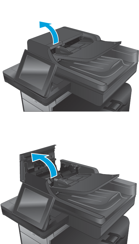
Clear jams in the document feeder
1. Lift the latch to release the document-feeder cover.
2. Open the document-feeder cover.
ENWW Solve paper jam or feed problems 239
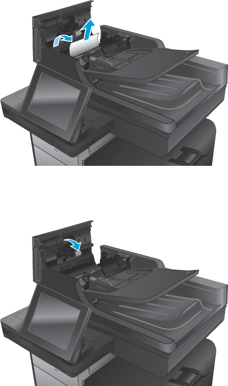
3. Lift the jam-access door, and remove any jammed paper.
If necessary, rotate the green wheel at the front of the document feeder to remove jammed paper.
4. Press on the door next to the document-feeder rollers to make sure it is closed completely.
240 Chapter 2 Solve problems ENWW
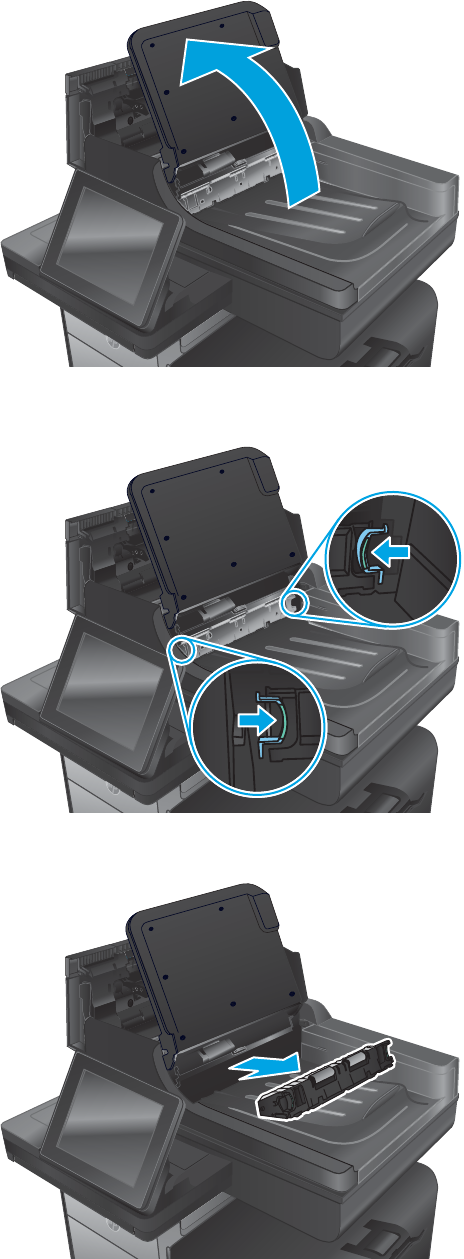
5. Flow models only: Lift the document feeder input tray.
6. Flow models only: Squeeze inward on the two slots at each end of the e-Duplex assembly.
7. Flow models only: Remove the e-Duplex assembly by pulling it out.
ENWW Solve paper jam or feed problems 241
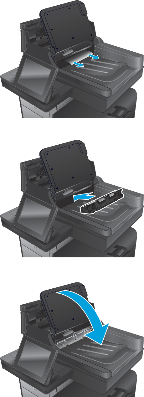
8. Flow models only: Remove any jammed paper.
9. Flow models only: Reinstall the e-Duplex assembly by sliding it in until it locks into place.
10. Flow models only: Lower the document-feeder input tray.
242 Chapter 2 Solve problems ENWW
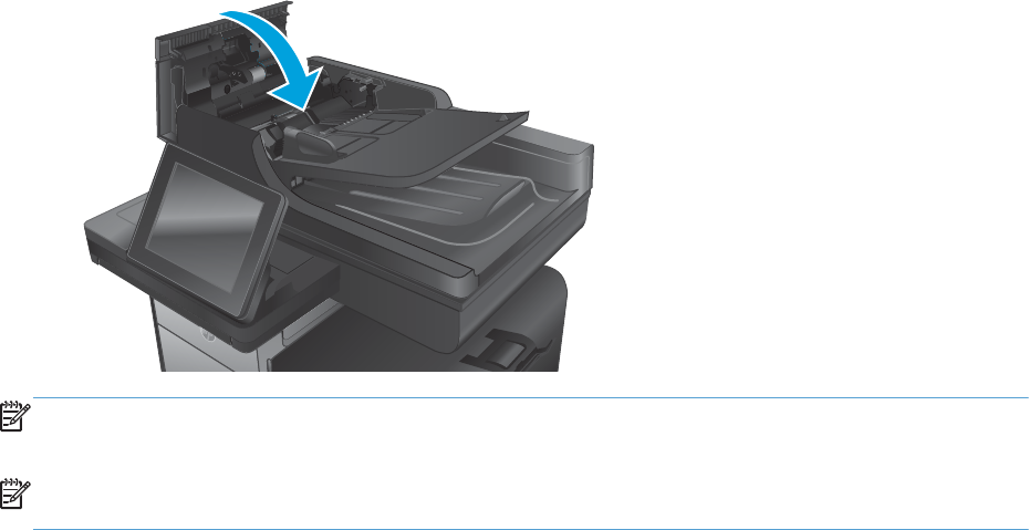
11. Close the document-feeder cover.
NOTE: To avoid jams, make sure the guides in the document feeder input tray are adjusted tightly against
the document. Remove all staples and paper clips from original documents.
NOTE: Original documents that are printed on heavy, glossy paper can jam more frequently than originals
that are printed on plain paper.
ENWW Solve paper jam or feed problems 243
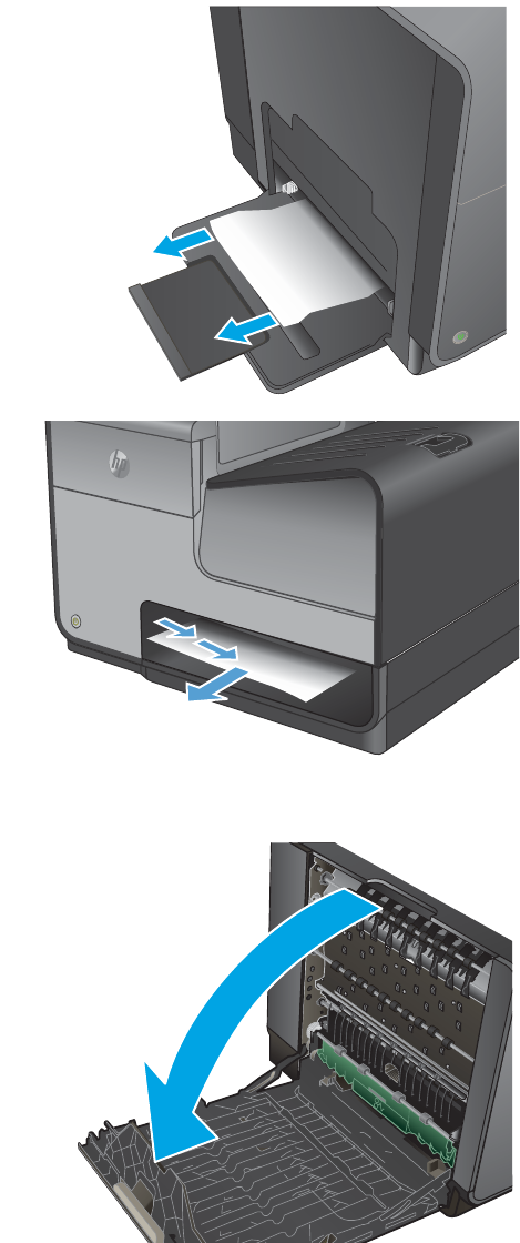
Clear jams in Tray 1 (multipurpose tray)
1. If the jammed sheet is visible and easily
accessible in Tray 1, pull it from Tray 1.
NOTE: If the sheet tears, make sure that all of
the fragments are removed before you resume
printing.
2. The jammed sheet may also be accessible by
removing Tray 2 and removing the jammed sheet
by pulling it to the right and then out of the
product.
3. If the jammed sheet is not visible or easily
accessible in Tray 1, open the left door to access
the jammed sheet.
244 Chapter 2 Solve problems ENWW
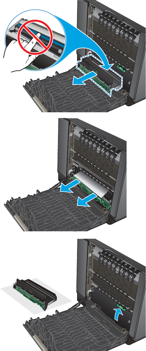
4. If the paper is still not visible or accessible,
remove the ink collection unit by pulling it out
with both hands. Set the unit aside, upright, on a
piece of paper to prevent ink spills.
CAUTION: When pulling out the ink collection
unit, avoid making direct contact with the black
cylinder to prevent ink smear on skin or clothes.
5. Lower the platen by pressing down on the green
tab. This will cause the product to try to feed the
sheet through the print zone. You may need to
gently pull on the sheet if it does not feed.
Remove the sheet.
6. Lift the green tab to place the platen back into its
operating position.
ENWW Solve paper jam or feed problems 245

7. Reinstall the ink collection unit.
8. Close the left door.
246 Chapter 2 Solve problems ENWW
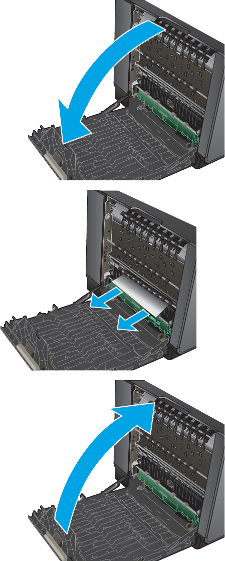
Clear jams in the left door
1. Open the left door.
2. Gently remove any visible paper from the rollers
and delivery area.
NOTE: If the sheet tears, make sure that all
fragments are removed before you resume
printing. Do not use sharp objects to remove
fragments.
3. Close the left door.
ENWW Solve paper jam or feed problems 247
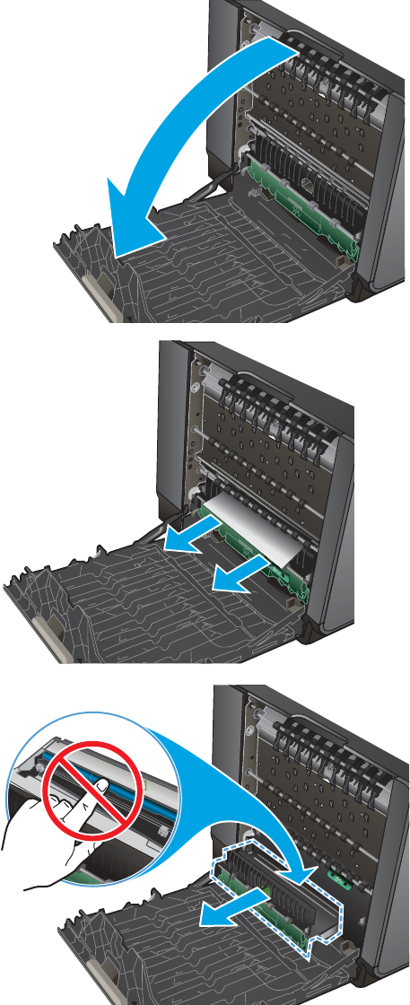
Clear jams in the ink collection unit area
1. Open the left door.
2. If you can see the trailing edge of the sheet,
remove the sheet from the product.
3. If the paper is not visible or accessible, remove
the ink collection unit by pulling it out with both
hands. Set the unit aside, upright, on a piece of
paper to prevent ink spills.
CAUTION: When pulling out the ink collection
unit, avoid making direct contact with the black
cylinder to prevent ink smear on skin or clothes.
248 Chapter 2 Solve problems ENWW
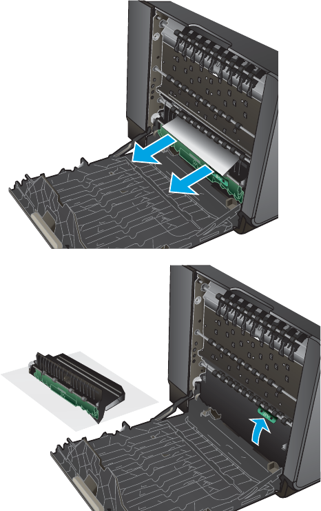
4. Lower the platen by pressing down on the green
tab. This will cause the product to try to feed the
sheet through the print zone. You might need to
gently pull on the sheet if it does not feed.
Remove the sheet.
5. Lift the green tab to place the platen back into its
operating position.
ENWW Solve paper jam or feed problems 249
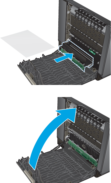
6. Reinstall the ink collection unit.
7. Close the left door.
250 Chapter 2 Solve problems ENWW
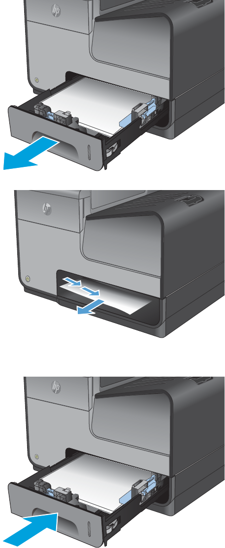
Clear jams in Tray 2
1. Open Tray 2 by pulling it out and releasing the
latch at the rear left of the tray.
2. Remove the jammed sheet by pulling it to the
right and then out of the product.
3. Close Tray 2.
NOTE: To close the tray, push in the middle or
with even pressure on both sides. Avoid pushing
on one side only.
ENWW Solve paper jam or feed problems 251
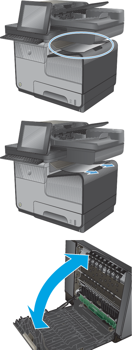
Clear jams in the output bin
1. Look for jammed paper in the output bin area.
caps lock
shift
A S D F G H J K L
Z X C V B N M
@ alt alt
shift
enter
,.
?
/
:
;
“
‘
2. Remove any visible media.
NOTE: If the sheet tears, make sure that all
fragments are removed before resuming
printing.
caps lock
shift
A S D F G H J K L
Z X C V B N M
@ alt alt
shift
enter
,.
?
/
:
;
“
‘
3. Open and then close the left door to clear the
message.
252 Chapter 2 Solve problems ENWW
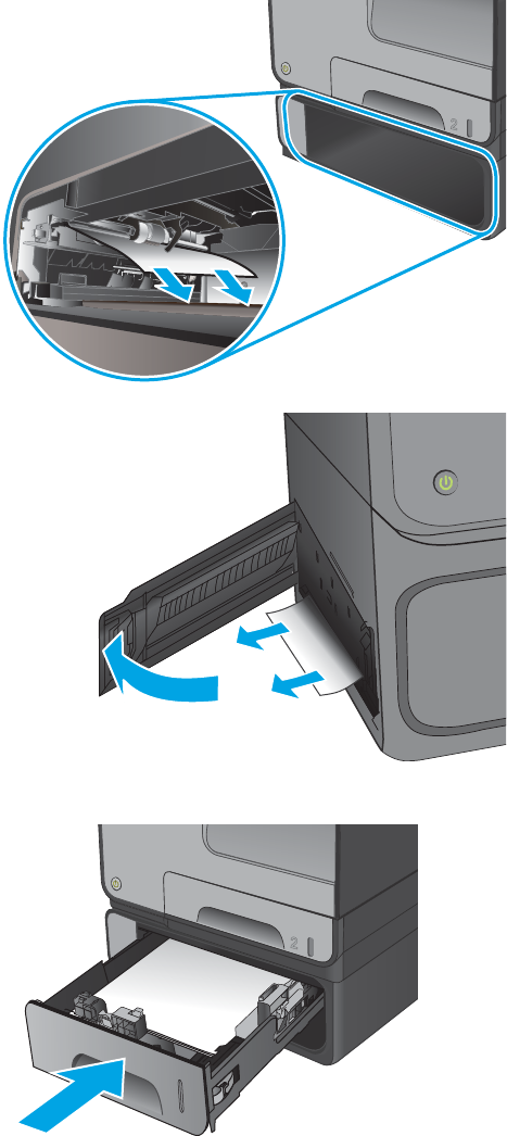
Clear jams in optional Tray 3
1. Open Tray 3.
2. Remove the jammed sheet by pulling it to the
right and then out of the product.
3
3. If the jam cannot be cleared at the tray, try
clearing the jam from the lower left door.
NOTE: If a jammed sheet tears while being
removed, paper fragments might become lodged
in the paper path between optional Tray 3 and
the product. Lift the product from optional
Tray 3, and then remove any paper fragments
from the tray assembly.
4. Close Tray 3.
NOTE: To close the tray, push in the middle or
with even pressure on both sides. Avoid pushing
on one side only.
3
ENWW Solve paper jam or feed problems 253
Solve performance problems
The product does not print
If the product does not print at all, try the following solutions.
●Make sure the product is turned on and that the control panel indicates it is ready.
◦If the control panel does not indicate the product is ready, turn the product off and then on again.
◦If the control panel indicates the product is ready, try sending the job again.
●If the control panel indicates the product has an error, resolve the error and then try to print a test page
from the control panel. If the test page prints, there may be a communication problem between the
product and the computer you are trying to print from.
●Make sure the cables are all connected correctly. If the product is connected to a network, check the
following items:
◦Check the light next to the network connection on the product. If the network is active, the light is
green.
◦Make sure that you are using a network cable and not a phone cord to connect to the network.
◦Make sure the network router, hub, or switch is turned on and that it is working correctly.
●Install the HP software from the CD that came with the product. Using generic printer drivers can cause
delays clearing jobs from the print queue.
●From the list of printers on your computer, right-click the name of this product, click Properties, and
open the Ports tab.
◦If you are using a network cable to connect to the network, make sure the printer name listed on
the Ports tab matches the product name on the product configuration page.
◦If you are using a USB cable and are connecting to a wireless network, make sure the box is
checked next to Virtual printer port for USB.
●If you are using a personal firewall system on the computer, it might be blocking communication with
the product. Try temporarily disabling the firewall to see if it is the source of the problem.
●If your computer or the product is connected to a wireless network, low signal quality or interference
might be delaying print jobs.
If the control panel displays a General Printer Failure message, turn the product off and then on. If that does
not clear the error, call HP for support.
If the product indicates that ink levels are too low, but the ink cartridges still have ink in them, make sure the
product is set on a level surface.
The product prints slowly
If the product prints, but it seems slow, try the following solutions.
254 Chapter 2 Solve problems ENWW

1. Make sure the computer meets the minimum specifications for this product. For a list of specifications,
go to this Web site: www.hp.com/support/ojcolorX555 or www.hp.com/support/ojcolorMFPX585.
2. If the paper type setting is not correct for the type of paper you are using, change the setting to the
correct paper type.
3. If your computer or the product is connected to a wireless network, low signal quality or interference
might be delaying print jobs.
4. If the product is in an environment that experiences high humidity, low temperatures, or both
conditions, the print speed might be affected.
ENWW Solve performance problems 255

Solve connectivity problems
Solve USB direct-connect problems
If you have connected the product directly to a computer, check the USB cable.
●Verify that the cable is connected to the computer and to the product.
●Verify that the cable is not longer than 5 m (16.4 ft). Try using a shorter cable.
●Verify that the cable is working correctly by connecting it with another product. Replace the cable if
necessary.
Solve network problems
Check the following items to verify that the product is communicating with the network. Before beginning,
print a configuration page from the product control panel and locate the product IP address that is listed on
this page.
●Poor physical connection
●The computer is using the incorrect IP address for the product
●The computer is unable to communicate with the product
●The product is using incorrect link and duplex settings for the network
●New software programs might be causing compatibility problems
●The computer or workstation might be set up incorrectly
●The product is disabled, or other network settings are incorrect
Poor physical connection
1. Verify that the product is attached to the correct ethernet port using the proper cable.
2. Verify that cable connections are securely attached.
3. Look at the ethernet port on the back of the product, and verify that the amber activity light and the
green link-status light are active.
4. If the problem continues, try a different cable or port on the network router, switch, or hub.
The computer is using the incorrect IP address for the product
1. On the computer, open the printer properties and click the Ports tab. Verify that the current IP address
for the product is selected. The product IP address is listed on the product configuration page or
through the control panel.
2. If you installed the product using an HP standard TCP/IP port, select the box labeled Always print to
this printer, even if its IP address changes.
3. If you installed the product using a Microsoft standard TCP/IP port, use the hostname instead of the IP
address.
If you installed the product using the CD installer, or downloaded the fully-featured installer from the
HP's web site, you can view or change the product IP address using the following steps:
256 Chapter 2 Solve problems ENWW

a. Click Start.
b. Click All Programs.
c. Click HP.
d. Click your product.
e. Click Update IP Address to open a utility that reports the known (“previous”) IP address for the
product and allows you to change the IP address, if necessary.
4. If the IP address is correct, delete the product entry from the list of installed printers, and then add it
again.
The computer is unable to communicate with the product
1. Test network communication by pinging the product.
a. Open a command-line prompt on your computer. For Windows, click Start, click Run, and then
type cmd.
b. Type ping followed by the IP address for your product.
c. If the window displays round-trip times, both the network and device are working.
2. If the ping command failed, verify that the network router, hubs, or switches are on, and then verify that
the network settings, the product, and the computer are all configured for the same network.
The product is using incorrect link and duplex settings for the network
Hewlett-Packard recommends leaving this setting in automatic mode (the default setting). If you change
these settings, you must also change them for your network.
New software programs might be causing compatibility problems
Verify that any new software programs are correctly installed and that they use the correct printer driver.
The computer or workstation might be set up incorrectly
1. Check the network drivers, printer drivers, and the network redirection.
2. Verify that the operating system is configured correctly.
The product is disabled, or other network settings are incorrect
1. Review the configuration page to check the status of the network protocol. Enable it if necessary.
2. Reconfigure the network settings if necessary.
Solve wireless network problems
●Wireless connectivity checklist
●The control panel displays the message: The wireless feature on this product has been turned off
●The product does not print after the wireless configuration completes
●The product does not print, and the computer has a third-party firewall installed
ENWW Solve connectivity problems 257

●The wireless connection does not work after moving the wireless router or product
●Cannot connect more computers to the wireless product
●The wireless product loses communication when connected to a VPN
●The network does not appear in the wireless networks list
●The wireless network is not functioning
Wireless connectivity checklist
●The product and the wireless router are turned on and have power. Also make sure the wireless radio in
the product is turned on.
●The service set identifier (SSID) is correct. Print a configuration page to determine the SSID. If you are
not sure the SSID is correct, run the wireless setup again.
●With secured networks, make sure the security information is correct. If the security information is
incorrect, run the wireless setup again.
●If the wireless network is working correctly, try accessing other computers on the wireless network. If
the network has Internet access, try connecting to the Internet over another wireless connection.
●The encryption method (AES or TKIP) is the same for the product as it is for the wireless access point,
such as a wireless router (on networks using WPA security).
●The product is within the range of the wireless network. For most networks, the product must be within
30 m (100 ft) of the wireless access point (wireless router).
●Obstacles do not block the wireless signal. Remove any large metal objects between the access point
and the product. Make sure poles, walls, or support columns containing metal or concrete do not
separate the product and wireless access point.
●The product is located away from electronic devices that might interfere with the wireless signal. Many
devices can interfere with the wireless signal including motors, cordless phones, security system
cameras, other wireless networks, and some Bluetooth devices.
●The print driver is installed on the computer.
●You have selected the correct printer port.
●The computer and product connect to the same wireless network.
The control panel displays the message: The wireless feature on this product has been turned
off
1. Touch the Administration button, and then touch the Wireless Setup menu.
2. Touch the Turn Wireless Off/On button, and then touch the On button.
The product does not print after the wireless configuration completes
1. Make sure the product is turned on and in the ready state.
2. Make sure you are connecting to the correct wireless network.
3. Make sure that the wireless network is working correctly.
258 Chapter 2 Solve problems ENWW
a. On the control panel, touch the Administration button, and then touch the Network Configuration
menu item.
b. Select the Print Wireless Network Test item to test the wireless network. The product prints a
report with the results.
4. Make sure that the correct port or product is selected.
a. For products installed without the fully-featured installer:
i. From the list of printers on your computer, right-click the name of this product, click
Properties, and then open the Ports tab.
ii. Make sure the box is checked next to Virtual printer port for USB.
b. If you installed the product using the CD installer, or downloaded the fully-featured installer from
the HP's Web site, you can view or change the product IP address using the following steps:
i. Click Start.
ii. Click All Programs.
iii. Click HP.
iv. Click your product.
v. Click Update IP Address to open a utility that reports the known (“previous”) IP address for
the product and allows you to change the IP address, if necessary.
5. Make sure that that computer is working correctly. If necessary, restart the computer.
The product does not print, and the computer has a third-party firewall installed
1. Update the firewall with the most recent update available from the manufacturer.
2. If programs request firewall access when you install the product or try to print, make sure you allow the
programs to run.
3. Temporarily turn off the firewall, and then install the wireless product on the computer. Enable the
firewall when you have completed the wireless installation.
The wireless connection does not work after moving the wireless router or product
Make sure that the router or product connects to the same network that the computer connects to.
1. From the control panel, touch the Administration button, and then touch the Reports menu.
2. Select the Network Configuration Page item to print the report.
3. Compare the service set identifier (SSID) on the configuration report to the SSID in the printer
configuration for your computer.
4. If the SSIDs are not the same, the devices are not connecting to the same network. Reconfigure the
wireless setup for the product.
ENWW Solve connectivity problems 259
Cannot connect more computers to the wireless product
1. Make sure that the other computers are within the wireless range and that no obstacles block the
signal. For most networks, the wireless range is within 30 m (100 ft) of the wireless access point.
2. Make sure the product is turned on and in the ready state.
3. Turn off any third-party firewalls on the computer.
4. Make sure that the wireless network is working correctly.
a. On the product control panel, touch the Administration button, and then touch the Network
Configuration menu.
b. Touch the Print Wireless Test Report item to test the wireless network. The product prints a report
with the results.
5. Make sure that the correct port or product is selected.
a. For products installed without the fully-featured installer:
i. From the list of printers on your computer, right-click the name of this product, click
Properties, and then open the Ports tab.
ii. Make sure the box is checked next to Virtual printer port for USB.
b. If you installed the product using the CD installer, or downloaded the fully-featured installer from
the HP's Web site, you can view or change the product IP address using the following steps:
i. Click Start.
ii. Click All Programs.
iii. Click HP.
iv. Click your product.
v. Click Update IP Address to open a utility that reports the known (“previous”) IP address for
the product and allows you to change the IP address, if necessary.
6. Make sure that the computer is working correctly. If necessary, restart the computer.
The wireless product loses communication when connected to a VPN
●Typically, you cannot connect to a VPN and other networks at the same time.
The network does not appear in the wireless networks list
●Make sure the wireless router is turned on and has power.
●The network might be hidden. However, you can still connect to a hidden network.
The wireless network is not functioning
1. To verify if the network has lost communication, try connecting other devices to the network.
2. Test network communication by pinging the network.
260 Chapter 2 Solve problems ENWW
a. Open a command-line prompt on your computer. For Windows, click Start, click Run, and then
type cmd.
b. Type ping followed by the IP address for the wireless router.
c. If the window displays round-trip times, the network is working.
3. Make sure that the router or product connects to the same network that your computer connects to.
a. From the product control panel, touch the Administration button, and then touch the Reports
menu.
b. Touch the Network Configuration Page item to print the report.
c. Compare the service set identifier (SSID) on the configuration report to the SSID in the printer
configuration for your computer.
d. If the SSIDs are not the same, the devices are not connecting to the same network. Reconfigure
the wireless setup for your product.
ENWW Solve connectivity problems 261

Service mode functions
Service menu and Secondary service menu
Product resets
Restore the factory-set defaults
CAUTION: Restoring the factory-set defaults returns all of the product and network settings to the factory
defaults, and it also clears the fax header name, phone number, and any stored faxes in the product memory.
This procedure also clears the fax phone book, and deletes any pages that are stored in the memory. The
procedure then automatically restarts the product.
1. On the product control panel, touch the Administration button.
2. Open the General Settings menu.
3. Scroll to and touch the Restore Factory Settings button, and then touch the Restore button.
The product automatically restarts.
Restore the service ID
Restore the service ID
If you replace the formatter, the date is lost. Use this menu item to reset the date to the original date that the
product was first used. The date format is YYDDD. Use the following formula to calculate the dates:
1. To calculate YY, subtract 1990 from the calendar year. For instance, if the product was first used in
2002, calculate YY as follows: 2002 - 1990 = 12. YY = 12.
2. Subtract 1 from 10 (October is the tenth month of the year): 10 - 1 = 9.
●Multiply 9 by 30: 9 x 30 = 270 or add 17 to 270: 270 + 17 = 287. Thus, DDD = 287.
Convert the service ID to an actual date
You can use the product Service ID number to determine whether the product is still under warranty. Use the
following formula to convert the Service ID into the installation date as follows:
1. Add 1990 to YY to get the actual year that the product was installed.
2. Divide DDD by 30. If there is a remainder, add 1 to the result. This is the month.
3. The remainder from the calculation in step 2 is the date.
Using the Service ID 12287 as an example, the date conversion is as follows:
1. 12 + 1990 = 2002, so the year is 2002.
2. 287 divided by 30 = 9 with a remainder of 17. Because there is a remainder, add 1 to 9 to get 10, which
represents October.
3. The remainder in step 2 is 17, so that is the date.
4. The complete date is 17-October-2002.
262 Chapter 2 Solve problems ENWW

NOTE: A six-day grace period is built into the date system.
Product cold reset
Cold reset using the Preboot menu
1. Turn the product on.
2. The HP logo displays on the product control panel. When an underscore displays below the HP logo,
touch the logo to open the Preboot menu.
3. Use the down arrow button to highlight Administrator, and then touch the OK button.
4. Use the down arrow button to highlight Startup Options item, and then touch the OK button.
5. Use the down arrow button to highlight the Cold Reset item, and then touch the OK button.
6. Touch the Home button to highlight Continue, and then touch the OK button.
NOTE: The product will initialize.
Solve fax problems
Fax reports
In addition to the product reports, the product also features several fax reports.
Fax test report
The user can use the fax test report to check the status of the product and ensure that it is set up
appropriately for faxing. Perform this test after the product is set up for faxing.
The fax test performs the following activities:
●Tests the fax hardware.
●Checks whether the fax is connected to an active telephone wall jack.
●Checks whether the phone cord is plugged into the correct port.
●Checks whether the correct type of phone cord is connected to the HP printer.
●Checks for a dial tone.
●Checks for an active fax phone line.
The fax test report shows the following information:
●Pass/fail results for each of the fax setup tests
●Current fax settings to help diagnose issues
●Instructions on how to rerun the test
Guidelines for running the fax test
Before running the fax test, ensure that the following guidelines are met:
ENWW Solve fax problems 263
●The ink cartridges are installed properly.
●Full-size paper is loaded in the main tray.
●The product is set up for faxing according to the particular home or office setup instructions.
Running the fax test
1. On the control panel, open the Administration menu.
2. Open the Tools menu, and then touch the Run Fax Test item. The product displays the status of the test
and prints a report.
3. Review the report.
●If the test passes and you are still having problems faxing, check the fax settings listed in the
report to verify the settings are correct. A blank or incorrect fax setting can cause problems faxing.
●If the test fails, review the report for more information about how to fix any problems found.
Solve fax test failure
If the fax test fails to run, the product might be busy with another task, or it may have an error condition
preventing it from running the fax test. If the test fails, check the following possible issues:
1. Verify that the product is set up properly, and connected to a power supply and to the computer. For
more information on setting up the product, see the user guide that came with the product.
2. Verify that the product is powered on. If it is not, press the power button.
3. Verify that the ink cartridges are installed correctly and the front door is closed.
4. Verify that the product is not currently busy with another task. Check the display. If the product is busy,
wait until it completes the current task and the run the fax test again.
5. Verify that the rear door is attached to the back of the product.
6. Verify that there are no error messages on the control-panel display. If there is an error message,
resolve the problem and then run the test again.
Fax confirmation report
This report provides printed confirmation that the fax was successfully sent. The default fax confirmation
setting is Off. To enable fax confirmation through the control panel, complete the following steps:
1. On the control panel, open the Administration menu.
2. Open the Fax Setup menu, and then open the Advanced Fax Setup menu.
3. Touch the Fax Confirmation item.
4. Select one of the following options:
●On (Fax Send): Prints a fax confirmation report for every fax you send.
●On (Fax Receive): Prints a fax confirmation report for every fax you receive.
264 Chapter 2 Solve problems ENWW
●On (Send and Receive): Prints a fax confirmation report for every fax you send and receive.
●Off: Does not print a fax confirmation report when you send and receive faxes successfully. This is
the default setting.
Fax error report
You can configure the product so that it automatically prints a report when there is an error during
transmission or reception. To set up the product to automatically print fax error reports, complete the
following steps:
1. On the control panel, open the Administration menu.
2. Open the Fax Setup menu, and then open the Advanced Fax Setup menu.
3. Touch the Fax Error Report item.
4. Select one of the following options:
●On (Fax Send): Prints whenever a transmission error occurs.
●On (Fax Receive): Prints whenever a receiving error occurs.
●On (Send and Receive): Prints whenever a fax error occurs. This is the default setting.
●Off: Does not print any fax error reports.
Fax last transaction report
The Fax Last Transaction Report prints the details of the last fax transaction that occurred. Details include
the fax number, number of pages, and the fax status. To print the last fax transaction report, complete the
following steps:
1. On the control panel, open the Administration menu.
2. Open the Fax Setup menu, and then open the Fax Reports menu.
3. Touch the Last Transaction item.
Fax log
The fax log lists the last 30 transactions and the results. The report includes faxes that have been sent from
the product control panel and all faxes that have been received. Each entry in the log contains the following
information:
●Transmission date and time
●Type (whether received or sent)
●Fax number
●Duration
●Number of pages
●Result (status) of transmission
To print the fax log from the product control panel, complete the following steps:
ENWW Solve fax problems 265

1. On the control panel, open the Administration menu.
2. Open the Fax Setup menu, and then open the Fax Reports menu.
3. Touch the Fax Log item.
Caller ID report
Use the following procedure to print a history of caller ID fax numbers. If there are no calls in the ID history,
the history could have been cleared during a power cycle or the user has not signed up for the caller ID
service with the user’s phone company.
1. On the control panel, open the Administration menu.
2. Open the Fax Setup menu, and then open the Fax Reports menu.
3. Touch the Caller ID Report item.
Possible fax issues
The following issues are the faxing issues that you might encounter, and the associated troubleshooting
actions.
Issue Solution
The fax test failed. If you ran a fax test and the test failed, review the report for basic information about the
error. For more detailed information, check the report to see which part of the test failed,
and then review the appropriate topic in this section for a solution.
The “Fax Hardware Test” failed.
●Power off the product by using the power button located on the product control panel
and then unplug the power cord from the back of the product. After a few seconds,
266 Chapter 2 Solve problems ENWW

Issue Solution
plug the power cord in again, and then power on the product. Run the test again. If the
test fails again, continue reviewing the troubleshooting information in this section.
●Try to send or receive a test fax. If you can send or receive a fax successfully, there
might not be a problem.
●If you are running the test from the Fax Setup Wizard (Windows) or HP Fax Setup
Utility (Mac OS), ensure that the product is not busy completing another task, such as
receiving a fax or making a copy. Check the display for a message indicating that the
product is busy. If the product is busy, wait until the job is finished and the product is
in the idle state before running the test.
●Ensure that you use the phone cord that came with the product. If you do not use the
supplied phone cord to connect the product to the telephone wall jack, you might not
be able to send or receive faxes. After you plug in the phone cord that came with the
product, run the fax test again. You might need to connect the supplied phone cord to
the adapter provided for your country/region.
●If you are using a phone splitter, this can cause faxing problems. A splitter is a two-
cord connector that plugs into a telephone wall jack. Try removing the splitter and
connecting the product directly to the telephone wall jack.
●After you resolve any problem that is found, run the fax test again to check if the
product passes the test and is ready for faxing. If the Fax Hardware Test continues to
fail and you experience problems faxing, contact HP Support at www.hp.com/support.
If prompted, choose your country/region, and then click Contact HP for information on
calling for technical support.
The “Fax Connected to Active Telephone Wall Jack” test failed.
●Check the connection between the telephone wall jack and the product to ensure that
the phone cord is secure.
●Ensure that you use the phone cord that came with the product. If you do not use the
supplied phone cord to connect the product to the telephone wall jack, you might not
be able to send or receive faxes. After you plug in the phone cord that came with the
product, run the fax test again. You might need to connect the supplied phone cord to
the adapter provided for your country/region.
●Ensure that you have correctly connected the product to the telephone wall jack.
Connect one end of the phone cord supplied with the product to your telephone wall
jack and the other end to the port labeled 1-LINE at the back of the product.
●Try connecting a working phone and phone cord to the telephone wall jack that you
are using for the product and check for dial tone. If you do not hear a dial tone, contact
your telephone company and have them check the line.
●Try sending or receiving a test fax. If you can do that successfully, there might not be
a problem.
●After you resolve any problem that is found, run the fax test again to check if the
product passes the test and is ready for faxing.
The fax test failed.
(continued)
The “Phone Cord Connected to Correct Port on Fax” test failed.
1. Connect one end of the phone cord supplied with the product to your telephone wall
jack and the other end to the port labeled 1-LINE at the back of the product.
2. After you have connected the phone cord to the port labeled 1-LINE, run the fax test
again to check if the product passes the test and is ready for faxing.
3. Try to send or receive a test fax.
ENWW Solve fax problems 267

Issue Solution
●Make sure you use the phone cord that came with the product. If you do not use
the supplied phone cord to connect from the telephone wall jack to the product,
you might not be able to send or receive faxes. After you plug in the phone cord
that came with the product, run the fax test again.
●If you are using a phone splitter, this can cause faxing problems. (A splitter is a
two-cord connector that plugs into a telephone wall jack.) Try removing the
splitter and connecting the product directly to the telephone wall jack.
The "Using Correct Type of Phone Cord with Fax" test failed.
●Make sure you used the phone cord supplied in the box with the product to connect to
the telephone wall jack. One end of the phone cord should be connected to the port
labeled 1-LINE on the back of the product, and the other end to your telephone wall
jack. If the phone cord that came with the product is not long enough, use a coupler to
extend the length.
●Check the connection between the telephone wall jack and the product to ensure the
phone cord is secure.
●Ensure that you use the phone cord that came with the product. If you do not use the
supplied phone cord to connect the product to the telephone wall jack, you might not
be able to send or receive faxes. After you plug in the phone cord that came with the
product, run the fax test again. You might need to connect the supplied phone cord to
the adapter provided for your country/region.
●If you are using a phone splitter, this can cause faxing problems. A splitter is a two-
cord connector that plugs into a telephone wall jack. Try removing the splitter and
connecting the product directly to the telephone wall jack.
268 Chapter 2 Solve problems ENWW

Issue Solution
The fax test failed.
(continued)
The “Dial Tone Detection” test failed.
Other equipment, which uses the same phone line as the product, might be causing the test
to fail. To determine if the other equipment is causing a problem, disconnect everything
from the phone line, and then run the test again. If the product passes the Dial Tone
Detection Test without the other equipment connected, then one or more pieces of the
equipment is causing problems. Try adding them back one at a time and rerunning the test
each time, until you identify which piece of equipment is causing the problem.
●Try connecting a working phone and phone cord to the telephone wall jack that you
are using for the product and check for dial tone. If you do not hear a dial tone, contact
your telephone company and have them check the line.
●Ensure that you have correctly connected the product to the telephone wall jack.
●Connect one end of the phone cord supplied with the product to your telephone wall
jack and the other end to the port labeled 1-LINE at the back of the product.
●If your telephone system is not using a standard dial tone, such as the one used by
some PBX systems, the test might fail. This will not cause a problem in sending or
receiving faxes. Try sending or receiving a test fax.
●Check to ensure that the country/region setting is set appropriately. If the country/
region setting is not set or is set incorrectly, the test might fail, and you might have
problems in sending and receiving faxes.
●Ensure that you connect the product to an analog phone line or you will not be able to
send or receive faxes. To check if your phone line is digital, connect a regular analog
phone to the line and listen for a dial tone. If you do not hear a normal sounding dial
tone, it might be a phone line set up for digital phones. Connect the product to an
analog phone line and try sending or receiving a fax.
●Ensure that you use the phone cord that came with the product. If you do not use the
supplied phone cord to connect the product to the telephone wall jack, you might not
be able to send or receive faxes. After you plug in the phone cord, run the fax test
again.
●After you resolve any problem that is found, run the fax test again to check if the
product passes the test and is ready for faxing. If the dial tone detection test
continues to fail, contact your telephone company and have them check the phone
line.
The fax test failed.
(continued)
The “Fax Line Condition” test failed.
●Ensure that you connect the product to an analog phone line or you will not be able to
send or receive faxes. To check if your phone line is digital, connect a regular analog
phone to the line and listen for a dial tone. If you do not hear a normal sounding dial
ENWW Solve fax problems 269

Issue Solution
tone, it might be a phone line set up for digital phones. Connect the product to an
analog phone line and try sending or receiving a fax.
●Check the connection between the telephone wall jack and the product to make sure
that the phone cord is secure.
●Ensure that you have correctly connected the product to the telephone wall jack.
●Connect one end of the phone cord supplied with the product to your telephone wall
jack and the other end to the port labeled 1-LINE at the back of the product. You might
need to connect the supplied phone cord to the adapter provided for your country/
region.
●Other equipment, which uses the same phone line as the product, might be causing
the test to fail. To determine if the other equipment is causing a problem, disconnect
everything from the phone line, and then run the test again.
●If the Fax Line Condition Test passes without the other equipment, then one or more
pieces of the equipment is causing problems; try adding them back one at a time and
rerunning the test each time, until you identify which piece of equipment is causing
the problem.
●If the Fax Line Condition Test fails even after removing the other connected
equipment, connect the product to a working phone line and continue reviewing the
troubleshooting information in this section.
●If you are using a phone splitter, this can cause faxing problems. A splitter is a two-
cord connector that plugs into a telephone wall jack. Try removing the splitter and
connecting the product directly to the telephone wall jack.
●Ensure that you use the phone cord that came with the product. If you do not use the
supplied phone cord to connect the product to the telephone wall jack, you might not
be able to send or receive faxes. After you plug in the phone cord that came with the
product, run the fax test again.
●After you resolve any problem that is found, run the fax test again to check if the
product passes the test and is ready for faxing. If the Fax Line Condition test continues
to fail and you experience problems faxing, contact your telephone company and have
them check the phone line.
The display always shows Phone Off
Hook.
●You are using the wrong type of phone cord. Ensure that you are using the phone cord
that came with the product to connect the product to your phone line. If the phone
cord that came with the product is not long enough, you can use a coupler to extend
the length. You can purchase a coupler at an electronics store that carries phone
accessories. You will also need another phone cord, which can be a standard phone
cord that you might already have in your home or office.
●Other equipment that uses the same phone line as the product might be in use. Ensure
that the extension phones—phones on the same phone line, but not connected to the
product—or other equipment are not in use or off the hook. For example, you cannot
use the product for sending a fax if an extension phone is off the hook, or if you are
using a computer dial-up modem to send e-mail or access the Internet.
The product is having problems sending
and receiving faxes.
●Ensure that the product is powered on. Look at the display on the product. If the
display is blank and the Power light is not lit, the product is powered off. Check if the
270 Chapter 2 Solve problems ENWW

Issue Solution
power cord is firmly connected to the product and plugged into a power outlet. Press
the power button to power on the product.
●After powering on the product, HP recommends that you wait five minutes before
sending or receiving a fax. The product cannot send or receive faxes while it is
initializing after being powered on.
●Connect one end of the phone cord supplied with the product to your telephone wall
jack and the other end to the port labeled 1-LINE at the back of the product.
●If the phone cord that came with the product is not long enough, you can use a coupler
to extend the length. You can purchase a coupler at an electronics store that carries
phone accessories. You will also need another phone cord, which can be a standard
phone cord that you might already have in your home or office.
●Try connecting a working phone and phone cord to the telephone wall jack that you
are using for the product and check for a dial tone. If you do not hear a dial tone, call
your local telephone company for service.
●Other equipment, which uses the same phone line as the product, might be in use. For
example, you cannot use the product for faxing if an extension phone is off the hook,
or if you are using a computer dial-up modem to send an e-mail or access the Internet.
●Check to see if another process has caused an error. Check the control-panel display
or your computer for an error message that provides information about the problem
and its resolution. If there is an error, the product will not send or receive a fax until
the error condition is resolved.
●The phone line connection might be noisy. Phone lines with poor sound quality (noise)
can cause faxing problems. Check the sound quality of the phone line by plugging a
phone into the telephone wall jack and listening for static or other noise. If you hear
noise, turn Error Correction Mode (ECM) off and try faxing again. For information about
changing ECM, see the onscreen Help. If the problem persists, contact your telephone
company.
The product is having problems sending
and receiving faxes.
(continued)
●If you are using a digital subscriber line (DSL) service, make sure that you have a DSL
filter connected or you will not be able to fax successfully.
●Ensure that the product is not connected to a telephone wall jack that is set up for
digital phones. To check if your phone line is digital, connect a regular analog phone to
the line and listen for a dial tone. If you do not hear a normal sounding dial tone, it
might be a phone line set up for digital phones.
●If you are using a private branch exchange (PBX) or an integrated services digital
network (ISDN) converter/terminal adapter, make sure that the product is connected
to the correct port and the terminal adapter is set to the correct switch type for your
country/region, if possible.
●If the product shares the same phone line with a DSL service, the DSL modem might
not be properly grounded. If the DSL modem is not properly grounded, it can create
noise on the phone line. Phone lines with poor sound quality (noise) can cause faxing
problems. You can check the sound quality of the phone line by plugging a phone into
the telephone wall jack and listening for static or other noise. If you hear noise, power
off your DSL modem for at least 15 minutes, after which, power on the DSL modem
again and listen to the dial tone. If the phone line is still noisy, contact your telephone
company. For information on how to power off your DSL modem, contact your DSL
provider for support.
●If you are using a phone splitter, this can cause faxing problems. (A splitter is a two-
cord connector that plugs into a telephone wall jack.) Try removing the splitter and
connecting the product directly to the telephone wall jack.
ENWW Solve fax problems 271

Issue Solution
The product is having problems sending
a manual fax.
●Ensure that the telephone you use to initiate the fax call is connected directly to the
product. To send a fax manually, the telephone must be connected directly to the port
labeled 2-EXT on the product.
●If you are sending a fax manually from a phone that is connected directly to the
product, you must use the keypad on the telephone to send the fax. You cannot use
the keypad on the product control panel.
The product cannot receive faxes, but
can send faxes.
●If you are not using a distinctive ring service, check to make sure that the Distinctive
Ring feature on the product is set to All Rings
●If Auto Answer is set to Off, you will need to receive faxes manually; otherwise, the
product will not receive the fax.
●If you have a voice mail service on the same phone number that you use for fax calls,
you must receive faxes manually, not automatically. This means that you must be
available to respond in person to incoming fax calls.
●If you have a computer dial-up modem on the same phone line as the product, check
to make sure that the software that came with your modem is not set to receive faxes
automatically. Modems that are set up to receive faxes automatically take over the
phone line to receive all incoming faxes. As a result, the product doesn’t receive fax
calls.
●If you have an answering machine on the same phone line with the product, you might
have one of the following problems:
◦Your answering machine might not be set up properly with the product.
◦Your outgoing message might be too long or too loud to allow the product to
detect fax tones, and the sending fax machine might disconnect.
◦Your answering machine might not have enough quiet time after your outgoing
message to allow the product to detect fax tones. This problem is most common
with digital answering machines.
●The following actions might help solve the above stated problems.
◦When you have an answering machine on the phone line that you use for fax
calls, try connecting the answering machine directly to the product.
◦Ensure that the product is set to receive faxes automatically. For information on
setting up the product to receive faxes automatically, see Receive a fax.
◦Ensure the Rings to Answer setting is set to a greater number of rings than the
answering machine.
◦Disconnect the answering machine and then try receiving a fax. If faxing is
successful without the answering machine, the answering machine might be
causing the problem.
◦Reconnect the answering machine and record your outgoing message again.
Record a message that is approximately 10 seconds in duration. Speak slowly
and at a low volume when recording your message. Leave at least 5 seconds of
272 Chapter 2 Solve problems ENWW

Issue Solution
silence at the end of the voice message. There should be no background noise
when recording this silent time. Try to receive a fax again.
●If the product shares the same phone line with other types of phone equipment, such
as an answering machine, a computer dial-up modem, or a multi-port switch box, the
fax signal level might be reduced. The signal level can also get reduced if you use a
splitter or connect extra cables to extend the length of your phone. A reduced fax
signal can cause problems during fax reception. To find out if other equipment is
causing a problem, disconnect everything except the product from the phone line, and
then try to receive a fax. If you can receive faxes successfully without the other
equipment connected, one or more pieces of the other connected equipment is
causing problems; try adding them back one at a time and receiving a fax each time,
until you identify which equipment is causing the problem.
●If you have a special ring pattern for your fax phone number (using a distinctive ring
service through your telephone company), make sure that the Distinctive Ring feature
on the product is set to match.
The product cannot send faxes, but can
receive faxes.
●The product might be dialing too fast or too soon. You might need to insert some
pauses in the number sequence. For example, if you need to access an outside line
before dialing the phone number, insert a pause following the access number. If your
number is 95555555, and 9 accesses an outside line, you might insert pauses as
follows: 9-555-5555. To enter a pause in the fax number you are typing, touch Redial/
Pause, or touch Space (#) repeatedly, until a dash (-) appears on the display.
●You can also send the fax by using monitor dialing. This enables you to listen to the
phone line as you dial. You can set the pace of your dialing and respond to prompts as
you dial.
●The number you entered when sending the fax is not in the proper format or the
receiving fax machine is having problems. To check this, try calling the fax number
from a telephone and listen for fax tones. If you cannot hear fax tones, the receiving
fax machine might not be powered on or connected, or a voice mail service could be
interfering with the recipient's phone line. You can also ask the recipient to check the
receiving fax machine for any problems.
Fax tones are recorded on the
answering machine.
●When you have an answering machine on the same phone line that you use for fax
calls, try connecting the answering machine directly to the product. If you do not
connect the answering machine as recommended, fax tones might be recorded on
your answering machine.
●Ensure that the product is set to receive faxes automatically and that the Rings to
Answer setting is correct. The number of rings to answer for the product should be
greater than the number of rings to answer for the answering machine. If the
answering machine and the product are set to the same number of rings to answer,
both devices answer the call and fax tones are recorded on the answering machine.
●Set your answering machine to a low number of rings and the product to answer in the
maximum number of rings supported. (The maximum number of rings varies by
country/region.) In this setup, the answering machine answers the call and the
product monitors the line. If the product detects fax tones, the product receives the
fax. If the call is a voice call, the answering machine records the incoming message.
The phone cord that came with the
product is not long enough.
●If the phone cord that came with the product is not long enough, you can use a coupler
to extend the length. You can purchase a coupler at an electronics store that carries
phone accessories. You will also need another phone cord, which can be a standard
phone cord that you might already have in your home or office.
●To extend your phone cord, complete the following steps.
ENWW Solve fax problems 273

Issue Solution
1. Using the phone cord supplied with the product, connect one end to the coupler,
then connect the other end to the port labeled 1-LINE on the back of the product.
2. Connect another phone cord to the open port on the coupler and the telephone
wall jack.
Color faxes do not print ●The Incoming Fax Printing option might be turned off. To print color faxes, make sure
that the Incoming Fax Printing option in the product control panel is turned on.
The computer cannot receive faxes (Fax
to PC or Fax to Mac)
●The computer selected to receive faxes might be turned off. Ensure that the computer
selected to receive faxes is switched on at all times.
●Different computers might be configured for setup and receiving faxes and one of
them might be switched off. If the computer receiving faxes is different from the one
used for setup, both computers should be switched on at all times.
●Fax to PC or Fax to Mac might not be activated or the computer might not be
configured to receive faxes. Activate Fax to PC or Fax to Mac and make sure the
computer is configured to receive faxes.
274 Chapter 2 Solve problems ENWW

Product upgrades
NOTE: If you are installing a replacement HDD or SSM, use this procedure to install the product firmware on
the replacement drive.
If you are removing the HDD or SSM so that it can be installed on a replacement formatter, you can skip this
procedure.
1. Locate the product support Web site.
●In the US:
◦Go to www.hp.com/support/ojcolorX555 or www.hp.com/support/ojcolorMFPX585.
●Outside the US:
a. Go to www.hp.com/support.
b. Select your country/region.
c. Select Drivers & Downloads.
d. Enter the product name, and then click Go.
e. Select your product model.
2. Select Cross operating system (BIOS, Firmware, Diagnostics, etc.).
3. Locate the firmware download, and then select Download.
4. Copy the firmware upgrade file to the root directory of a USB flash drive. The firmware upgrade file has
a .bdl extension.
5. Insert the USB flash drive into the USB port on the product control panel, and then turn the product
power on.
6. The following message displays on the control panel: Error: 99.09.63 Incorrect Disk. Touch the OK
button to continue.
7. Wait for the Pre-Boot menu to appear on the control-panel display, and then touch the down arrow
button to scroll to 3 Administrator. Touch the OK button to select it.
8. Touch the down arrow button to scroll to 6 Manage Disk. Touch the OK button to select it
9. Touch the down arrow button to scroll to + 6 Boot Device. Touch the OK button to select it.
10. Touch the down arrow button to scroll to 2 Erase / Unlock. Touch the OK button to select it
11. The message Proceed with Requested Action displays. Touch the OK button to select it.
12. Touch the back button to return to the Pre-Boot menu home screen.
13. Touch the down arrow button to scroll to 3 Administrator. Touch the OK button to select it.
14. Touch the down arrow button to scroll to 1 Download. Touch the OK button to select it.
15. Touch the down arrow button to scroll to 3 USB Thumbdrive. Touch the OK button to select it.
ENWW Product upgrades 275

16. Touch the down arrow button to scroll to the firmware upgrade file that you downloaded in step 4.
Touch the OK button to select it.
NOTE: If no .bdl files are listed, try saving the file to a different USB flash drive.
17. Wait while the file transfers. When the transfer is complete, the message Complete displays on the
screen.
18. Turn the product off, remove the USB flash drive, and then turn the product on. Wait for several minutes
while the product initializes.
276 Chapter 2 Solve problems ENWW


Hewlett-Packard limited warranty statement
HP PRODUCT DURATION OF LIMITED WARRANTY
HP Officejet Enterprise Color X555dn, X555xh, and MFP X585dn,
X585f, X585z
1 year
HP warrants to you, the end-user customer, that HP hardware and accessories will be free from defects in
materials and workmanship after the date of purchase, for the period specified above. If HP receives notice of
such defects during the warranty period, HP will, at its option, either repair or replace products which prove
to be defective. Replacement products may be either new or equivalent in performance to new.
HP warrants to you that HP software will not fail to execute its programming instructions after the date of
purchase, for the period specified above, due to defects in material and workmanship when properly installed
and used. If HP receives notice of such defects during the warranty period, HP will replace software which
does not execute its programming instructions due to such defects.
HP does not warrant that the operation of HP products will be uninterrupted or error free. If HP is unable,
within a reasonable time, to repair or replace any product to a condition as warranted, you will be entitled to
a refund of the purchase price upon prompt return of the product.
HP products may contain remanufactured parts equivalent to new in performance or may have been subject
to incidental use.
Warranty does not apply to defects resulting from (a) improper or inadequate maintenance or calibration, (b)
software, interfacing, parts or supplies not supplied by HP, (c) unauthorized modification or misuse, (d)
operation outside of the published environmental specifications for the product, or (e) improper site
preparation or maintenance.
TO THE EXTENT ALLOWED BY LOCAL LAW, THE ABOVE WARRANTIES ARE EXCLUSIVE AND NO OTHER
WARRANTY OR CONDITION, WHETHER WRITTEN OR ORAL, IS EXPRESSED OR IMPLIED AND HP SPECIFICALLY
DISCLAIMS ANY IMPLIED WARRANTIES OR CONDITIONS OF MERCHANTABILITY, SATISFACTORY QUALITY, AND
FITNESS FOR A PARTICULAR PURPOSE. Some countries/regions, states or provinces do not allow limitations
on the duration of an implied warranty, so the above limitation or exclusion might not apply to you. This
warranty gives you specific legal rights and you might also have other rights that vary from country/region to
country/region, state to state, or province to province.
HP's limited warranty is valid in any country/region or locality where HP has a support presence for this
product and where HP has marketed this product. The level of warranty service you receive may vary
according to local standards. HP will not alter form, fit or function of the product to make it operate in a
country/region for which it was never intended to function for legal or regulatory reasons.
TO THE EXTENT ALLOWED BY LOCAL LAW, THE REMEDIES IN THIS WARRANTY STATEMENT ARE YOUR SOLE
AND EXCLUSIVE REMEDIES. EXCEPT AS INDICATED ABOVE, IN NO EVENT WILL HP OR ITS SUPPLIERS BE LIABLE
FOR LOSS OF DATA OR FOR DIRECT, SPECIAL, INCIDENTAL, CONSEQUENTIAL (INCLUDING LOST PROFIT OR
DATA), OR OTHER DAMAGE, WHETHER BASED IN CONTRACT, TORT, OR OTHERWISE. Some countries/regions,
states or provinces do not allow the exclusion or limitation of incidental or consequential damages, so the
above limitation or exclusion may not apply to you.
THE WARRANTY TERMS CONTAINED IN THIS STATEMENT, EXCEPT TO THE EXTENT LAWFULLY PERMITTED, DO
NOT EXCLUDE, RESTRICT OR MODIFY AND ARE IN ADDITION TO THE MANDATORY STATUTORY RIGHTS
APPLICABLE TO THE SALE OF THIS PRODUCT TO YOU.
278 Appendix A Service and support ENWW
UK, Ireland, and Malta
The name and address of the HP entity responsible for the performance of the HP Limited Warranty in your
country is as follows:
United Kingdom: Hewlett-Packard Ltd Cain Road Bracknell GB-Berks RG12 1HN
Eire: Hewlett-Packard Ireland Limited, 63-74 Sir John Rogerson's Quay, Dublin 2
Malta: Hewlett-Packard International Trade B.V. Malta Branch, 48, Amery Street, Sliema SLM 1701, MALTA
You may have additional statutory rights against the seller based on your purchase agreement. Those rights
are not in any way affected by this HP Limited Warranty.
Austria, Belgium, Germany, and Luxemburg
Als Anlage finden Sie die Namen und Adressen der jeweiligen HP Gesellschaft, die in Ihrem Land die
HP Herstellergarantie gewährt.
Deutschland: Hewlett-Packard GmbH, Herrenberger Straße 140, D-71034 Böblingen
Österreich: Hewlett-Packard Ges.m.b.H., Wienerbergstrasse 41, A-1120 Wien
Luxemburg: Hewlett-Packard Luxembourg SCA, Vegacenter 75, Parc d'Activités Capellen, L-8308 Capellen
Belgien: Hewlett-Packard Belgium BVBA/SPRL, Hermeslaan 1A, B-1831 Brüssel
Deutschland und Österreich
Über die Herstellergarantie hinaus haben Sie gegebenenfalls Mängelansprüche gegenüber Ihrem Verkäufer
aus dem Kaufvertrag, die durch diese Herstellergarantie nicht eingeschränkt werden.
Luxemburg
Über die Herstellergarantie hinaus haben Sie gegebenenfalls gesetzliche Ansprüche gegenüber Ihrem
Verkäufer aus dem Kaufvertrag, die durch diese Herstellergarantie nicht eingeschränkt werden.
Insbesondere werden für Verbraucher folgende gesetzliche Bestimmungen von der Herstellergarantie nicht
berührt: Gesetz vom 21. April 2004 bezüglich der Vertragsmässigkeit von Verbrauchsgütern und gesetzliche
Bestimmungen des Zivilgesetzbuches bezüglich der Garantie. Die gesetzliche Garantie nach dem Gesetz vom
21. April 2004 ist auf zwei Jahren ab der Lieferung des Verbrauchgutes befristet.
Belgien
Sie haben gegebenenfalls zusätzliche Ansprüche gegenüber Ihrem Verkäufer aus dem Kaufvertrag, die durch
diese HP Herstellergarantie nicht eingeschränkt werden.
Belgium, France, and Luxemburg
Vous trouverez, ci-après, les coordonnées de l’entité HP responsable de l'exécution de la garantie fabricant
relative à votre matériel HP dans votre pays.
France:
En vertu de votre contrat d’achat, il se peut que vous disposiez de droits légaux supplémentaires à l’encontre
de votre vendeur. Ceux-ci ne sont aucunement affectés par la présente garantie du fabricant HP.
En particulier, si vous êtes un consommateur domicilié en France (départements et territoires d’outre-mer
(DOM-TOM) inclus dans la limite des textes qui leur sont applicables), le vendeur reste tenu à votre égard des
ENWW Hewlett-Packard limited warranty statement 279
défauts de conformité du bien au contrat et des vices rédhibitoires dans les conditions prévues aux articles
1641 à 1649 du Code civil.
Code de la consommation:
« Art. L. 211-4. - Le vendeur est tenu de livrer un bien conforme au contrat et répond des défauts de
conformité existant lors de la délivrance.
Il répond également des défauts de conformité résultant de l'emballage, des instructions de montage ou de
l'installation lorsque celle-ci a été mise à sa charge par le contrat ou a été réalisée sous sa responsabilité. »
« Art. L. 211-5. - Pour être conforme au contrat, le bien doit :
1° Etre propre à l'usage habituellement attendu d'un bien semblable et, le cas échéant correspondre à la
description donnée par le vendeur et posséder les qualités que celui-ci a présentées à l'acheteur sous forme
d'échantillon ou de modèle ;
- présenter les qualités qu'un acheteur peut légitimement attendre eu égard aux déclarations publiques
faites par le vendeur, par le producteur ou par son représentant, notamment dans la publicité ou
l'étiquetage ;
2° Ou présenter les caractéristiques définies d'un commun accord par les parties ou être propre à tout usage
spécial recherché par l'acheteur, porté à la connaissance du vendeur et que ce dernier a accepté. »
« Art. L.211-12. – L’action résultant du défaut de conformité se prescrit par deux ans à compter de la
délivrance du bien. »
Code civil:
« Code civil Article 1641 : Le vendeur est tenu de la garantie à raison des défauts cachés de la chose vendue
qui la rendent impropre à l’usage auquel on la destine, ou qui diminuent tellement cet usage, que l’acheteur
ne l’aurait pas acquise, ou n’en aurait donné qu’un moindre prix, s’il les avait connus. »
« Code civil Article 1648 : L’action résultant des vices rédhibitoires doit être intentée par l’acquéreur dans un
délai de deux ans à compter de la découverte du vice. »
L’entité HP responsable de l'exécution de la garantie fabricant relative à votre matériel HP est : Hewlett-
Packard France SAS, 1 Avenue du Canada 91947 LES ULIS
Belgique:
En vertu de votre contrat d’achat, il se peut que vous disposiez de droits légaux supplémentaires à l’encontre
de votre vendeur. Ceux-ci ne sont aucunement affectés par la présente garantie du fabricant HP.
L’entité HP responsable de l'exécution de la garantie fabricant relative à votre matériel HP est : Hewlett-
Packard Belgium BVBA/SPRL, Hermeslaan 1A, B-1831 Belgique
Luxembourg:
En vertu de votre contrat d’achat, il se peut que vous disposiez de droits légaux supplémentaires à l’encontre
de votre vendeur. Ceux-ci ne sont aucunement affectés par la présente garantie du fabricant HP. En
particulier, si vous êtes un consommateur la présente garantie fabricant HP ne fait pas obstacle à
l’application des dispositions de la loi du 21 avril 2004 relative à la garantie de conformité et des dispositions
du Code civil relatives à la garantie. La durée de la garantie légale en vertu de la loi du 21 avril 2004 est de
deux ans à compter de la délivrance du bien.
L’entité HP responsable de l'exécution de la garantie fabricant relative à votre matériel HP est : Hewlett-
Packard Luxembourg SCA, Vegacenter 75, Parc d'Activités Capellen, L-8308 Capellen
280 Appendix A Service and support ENWW
Italy
In allegato il cliente troverà i nomi e gli indirizzi delle Società del Gruppo HP che prestano i servizi in Garanzia
(garanzia di buon funzionamento e garanzia convenzionale) in Italia.
Italia: Hewlett-Packard Italiana S.r.L., Via G. Di Vittorio 9, 20063 Cernusco sul Naviglio
Oltre alla Garanzia del Produttore, e in modo indipendente dalla stessa, il Consumatore potrà far valere i
propri diritti di legge nei confronti del venditore tra cui il diritto di chiedere, nei primi 24 mesi dalla data di
acquisto del prodotto, la riparazione gratuita o la sostituzione del prodotto non conforme al contratto ai
sensi dell’art. 130 del Codice del Consumo (Dlgs. 206/2005) laddove ne ricorrano le condizioni.
Spain
Adjunto puede encontrar el nombre y dirección de las entidades HP que ofrecen la Garantía Limitada de HP
(garantía comercial adicional del fabricante) en su país.
España Hewlett-Packard Española S.L.U. C/Vicente Aleixandre 1 Parque Empresarial Madrid - Las Rozas,
E-28232 Madrid
La garantía comercial adicional de HP (Garantía Limitada de HP) no afecta a los derechos que usted, como
consumidor, pueda tener frente al vendedor por la falta de conformidad del producto con el contrato de
compraventa. Dichos derechos son independientes y compatibles con la garantía comercial adicional de HP y
no quedan afectados por ésta.
De conformidad con los mismos, si durante un plazo de dos años desde la entrega del producto aparece
alguna falta de conformidad existente en el momento de la entrega, el consumidor y usuario tiene derecho a
exigir al vendedor la reparación del producto, su sustitución, la rebaja del precio o la resolución del contrato
de acuerdo con lo previsto en el Título V del Real Decreto Legislativo 1/2007. Salvo prueba que demuestre lo
contrario, se presumirá que las faltas de conformidad que se manifiesten en los seis meses posteriores a la
entrega del producto ya existían cuando el producto se entregó.
Únicamente cuando al consumidor y usuario le resulte imposible o le suponga una carga excesiva dirigirse al
vendedor por la falta de conformidad con el contrato podrá reclamar directamente al fabricante con el fin de
obtener la sustitución o reparación.
Denmark
Vedhæftet finder De navn og adresse på de HP-selskaber, som yder HP’s mangeludbedring i Danmark.
Danmark: Hewlett-Packard A/S, Engholm Parkvej 8, DK-3450, Allerød
Herudover kan De have opnået rettigheder overfor sælger af HP’s produkter i henhold til Deres købsaftale.
HP’s regler om mangeludbedring begrænser ikke sådanne rettigheder.
Norway
Vedlagt finner du navn og adresse på de HP-selskaper som svarer for fabrikkgarantien i Norge.
Norge: Hewlett-Packard Norge AS, Østensjøveien 32, 0667 OSLO, Norge
Utover dette kan du ha oppnådd rettigheter gjennom kjøpsavtalen med selgeren av ditt HP-produkt dersom
du er en forbruker etter norsk forbrukerkjøpslov. Slike rettigheter innskrenkes ikke av fabrikkgarantien. Den
lengste absolutte reklamasjonsretten er 5 år for produkter som ved vanlig bruk er ment å vare vesentlig
lengre enn 2 år (med de begrensninger som følger av norsk lovgivning og rettspraksis). Overfor selgeren kan
det reklameres på ytelsen som helhet selv om garantien kun dekker deler av ytelsen som er kjøpt.
ENWW Hewlett-Packard limited warranty statement 281
Reklamasjonsretten kan tapes dersom det ikke reklameres innen rimelig tid, også innenfor den absolutte
reklamasjonsperioden.
Sweden
Av bilagda förteckning framgår namn och adress till det HP-företag som svarar för HPs begränsade garanti
(fabriksgaranti) i Sverige.
Sverige: Hewlett-Packard Sverige AB, SE-169 85 Stockholm
Ni kan utöver denna fabriksgaranti även ha tillkommande lagstadgade rättigheter, som följer av Ert avtal
med säljaren av produkten. Dessa rättigheter inskränks inte av fabriksgarantin.
Portugal
Anexa à presente declaração encontra-se uma lista das empresas HP de entre as quais consta o nome e
morada da empresa responsável pela prestação da Garantia Limitada HP (garantia do fabricante) no seu país.
Portugal: Hewlett-Packard Portugal, Lda., Edificio D. Sancho I, Quinta da Fonte, Porto Salvo, 2780-730 Paco
de Arcos, P-Oeiras
Além da referida garantia do fabricante prestada pela HP, poderá também beneficiar, nos termos da
legislação local em vigor, de outros direitos legais relativos à garantia, ao abrigo do respectivo Contrato de
Compra e Venda.
A presente garantia não representará quaisquer custos adicionais para o consumidor. A presente garantia
limitada não afeta os direitos dos consumidores constantes de leis locais imperativas, como seja o Decreto-
Lei 67/2003, de 8 de Abril, com a redação que lhe foi dada pelo Decreto-Lei 84/2008, de 21 de Maio.
Greece and Cyprus
Συνημμένα αναφέρονται οι επωνυμίες και οι διευθύνσεις των εταιρειών της ΗΡ που παρέχουν την
Περιορισμένη Εγγύηση της ΗΡ (εγγύηση κατασκευαστή) στην χώρα σας. Η εγγύηση κατασκευαστή δεν
περιορίζει τα επιπλέον νόμιμα δικαιώματα που μπορεί να έχετε έναντι του πωλητή, όπως αυτά καθορίζονται
στην σύμβαση αγοράς του προϊόντος.
Ελλάδα /Κύπρος: Hewlett-Packard Hellas Ε.Π.Ε., Βορείου Ηπείρου 76,151 25 ΜΑΡΟΥΣΙ
Hungary
Ön az alábbiakban megtalálja azon HP vállalatok nevét és címét, amelyek az egyes országokban biztosítják a
HP mint gyártó által vállalt Korlátozott Jótállást.
Hungary: - Hewlett-Packard Magyarország Kft, H-1117 Budapest, Alíz utca 1.
- Hewlett-Packard Informatikai Kft, H-1117 Budapest, Alíz utca 1.
A HP Korlátozott Jótállásán túlmenően Önt a HP terméket Önnek értékesítő kereskedővel szemben
megilletik a helyi kötelezően alkalmazandó és eltérést nem engedő jogszabályok által biztosított
szavatossági és jótállási jogok. Az Önre vonatkozó, kötelezően alkalmazandó és eltérést nem engedő
jogszabályban biztosított jogait a HP Korlátozott Jótállási nyilatkozata nem korlátozza.
Czech Republic
V příloze jsou uvedeny názvy a adresy společností skupiny HP, které poskytují omezenou záruku HP (záruku
výrobců) ve Vaší zemi.
282 Appendix A Service and support ENWW
Česká republika: Hewlett Packard s.r.o., Vyskočilova 1/1410, 140 21 Praha 4
Pokud máte na základě konkrétní kupní smlouvy vůči prodávajícímu práva ze zákona přesahující záruku
vyznačenou výrobcem, pak tato práva nejsou uvedenou zárukou výrobce dotčena.
Slovakia
V prílohe sú uvedené mená a adresy spoločností skupiny HP, ktoré zabezpečujú plnenia z obmedzenej záruky
HP (záruka výrobcu) vo vašej krajine.
Slovenská republika: Hewlett-Packard Slovakia, s.r.o., Galvaniho 7, 820 02 Bratislava
Pokiaľ máte na základe vašej kúpnej zmluvy voči predávajúcemu práva zo zákona presahujúce záruku
výrobcu, také práva nie sú uvedenou zárukou výrobcu dotknuté.
Poland
W załączeniu przedstawiamy nazwy i adresy jednostek HP, odpowiedzialnych za wykonanie ograniczonej
gwarancji HP w Państwa kraju.
Polska: Hewlett-Packard Polska Sp. z o.o., Szturmowa 2a, 02-678 Warszawa wpisana do rejestru
przedsiębiorców w Sadzie Rejonowym dla m. st. Warszawy, XIII Wydział Gospodarczy, pod numerem KRS
0000016370, E0001100WZ, kapitał zakładowy 475 000 PLN. NIP 527-020-51-28
HP informuje, że na podstawie umowy sprzedaży mogą Państwu przysługiwać wobec sprzedawcy ustawowe
prawa niezależne w stosunku do udzielanej, ograniczonej gwarancji HP. Gwarancja HP nie wyłącza, nie
ogranicza ani nie zawiesza uprawnień kupującego wynikających z niezgodności towaru z umową.
Bulgaria
Долу ще намерите името и адреса на дружеството във Вашата страна, отговорно за предоставянето на
Гаранционната поддръжка в рамките на Ограничената Гаранция предоставяна от Хюлет-Пакард /HP.
Хюлет-Пакард България ЕООД, с ЕИК 121909024, със седалище и адрес на управление: София 1766, р-
н Младост, ул. Околовръстен път № 258
Вие имате допълнителни законови права пред продавача на продукта в съответствие с договора Ви за
покупко-продажба. Тези права по-никакъв начин не се ограничават от Ограничената Гаранция
предоставяна от HP.
При необходимост, моля да се обърнете към продавача на продукта.
Romania
Mai jos am inclus numele si adresa entitatii HP care este responsabila cu indeplinirea obligatiilor aferente
Garantiei Producatorului HP in tara dvs.
Romănia: Hewlett-Packard Romănia SRL, Bd. Lascăr Catargiu nr. 47-53, Europe House Business Center, Et 3,
Sector 1, Bucureşti
Aveti drepturi legale suplimentare impotriva vanzatorului pe baza contractului de achizitie. Aceste drepturi
nu sunt afectate de Garantia Producatorului HP. Va rugam sa contactati vanzatorul.
Belgium and The Netherlands
Als bijlage ontvangt u hierbij een lijst met daarop de naam en het adres van de HP vestiging in uw land waar u
terecht kunt voor de HP fabrieksgarantie.
ENWW Hewlett-Packard limited warranty statement 283
Nederland: Hewlett-Packard Nederland BV, Startbaan 16, 1187 XR Amstelveen
België: Hewlett-Packard, BVBA/SPRL, P.O.
Naast deze fabrieksgarantie kunt u op basis van nationale wetgeving ten opzichte van uw verkoper rechten
ontlenen aan de verkoopovereenkomst. De HP-fabrieksgarantie laat de wettelijke rechten onder de
toepasselijke nationale wetgeving ongemoeid.
Finland
Oheisesta luettelosta löydätte yhteystiedot valmistajan takuusta vastaavaan HP:n edustajaan maassanne.
Suomi: Hewlett-Packard Oy, Piispankalliontie, FIN - 02200 Espoo
Teillä voi olla oikeus esittää takuun lisäksi vaatimuksia myös lain nojalla. Valmistajan takuu ei rajoita lakiin
perustuvia oikeuksianne.
Slovenia
V prilogi vam pošiljamo imena in naslove HP-jevih skupin, pri katerih lahko v svoji državi uveljavljate HP-jevo
omejeno garancijo (garancijo proizvajalca).
Slovenija: Hewlett - Packard d.o.o.,Tivolska cesta 48, 1000 Ljubljana, Slovenija
Poleg garancije proizvajalca imate lahko na osnovi nakupne pogodbe tudi z zakonom predpisane pravice do
prodajalca, ki jih ne omejuje ta garancija proizvajalca.
Croatia
Naziv i adresa HP–ovog subjekta koji je odgovoran za ispunjenje HP-ovog Ograničenog jamstva u Vašoj zemlji
su:
Hewlett-Packard d.o.o.
Radnička cesta 41
10000 Zagreb
01/60 60 200
Na temelju svog kupoprodajnog ugovora, možete imati dodatna zakonska prava u odnosu na prodavatelja.
Ovo HP-ovo Ograničeno jamstvo ni na koji način ne utječe na ta dodatna prava.
Latvia
Pielikumā ir norādīti to HP uzņēmumu nosaukumi un adreses, kas sniedz HP ierobežoto servisa
nodrošinājumu (ražotāja servisa nodrošinājumu) jūsu valstī.
Latvija: Hewlett-Packard SIA, Duntes iela 17a, Rīga, LV-1005, Latvija
Papildus ražotāja servisa nodrošinājumam likumdošanas aktos jums var būt paredzētas citas uz pirkuma
līgumu balstītas pret pārdevēju izmantojamas tiesības, kas netiek ierobežotas ar šo ražotāja servisa
nodrošinājumu.
Lithuania
Pridedami HP bendrovių, teikiančių HP garantiją (gamintojo garantiją) Jūsų šalyje, pavadinimai ir adresai.
284 Appendix A Service and support ENWW
Lietuva: UAB „Hewlett-Packard“, V. Gerulaičio g. 1, LT-08200 Vilnius
Pagal taikytinus vartojimo prekių pardavimą reglamentuojančius nacionalinius teisės aktus, jūs taip pat turite
įstatymų galios teises. Gamintojo garantija jūsų įstatymų galią turinčių teisių jokiu būdu neapriboja ir joms
poveikio neturi.
Estonia
Lisatud on nende HP üksuste nimed ja aadressid, kes teie riigis HP müügigarantiid teostavad.
Eesti: HP Oy Eesti Filiaal, A.H. Tammsaare tee 47, EE-11316 Tallinn
Lisaks HP müügigarantiile võib teil olla nõudeid müüja vastu seoses ostu lepingutingimustele
mittevastavusega. Käesolev HP müügigarantii ei piira teie nimetatud õigusi.
ENWW Hewlett-Packard limited warranty statement 285
End User License Agreement
PLEASE READ CAREFULLY BEFORE USING THIS SOFTWARE PRODUCT: This End-User License Agreement
(“EULA”) is a contract between (a) you (either an individual or the entity you represent) and (b) Hewlett-
Packard Company (“HP”) that governs your use of the software product (“Software”). This EULA does not
apply if there is a separate license agreement between you and HP or its suppliers for the Software, including
a license agreement in online documentation. The term “Software” may include (i) associated media, (ii) a
user guide and other printed materials, and (iii) “online” or electronic documentation (collectively “User
Documentation”).
RIGHTS IN THE SOFTWARE ARE OFFERED ONLY ON THE CONDITION THAT YOU AGREE TO ALL TERMS AND
CONDITIONS OF THIS EULA. BY INSTALLING, COPYING, DOWNLOADING, OR OTHERWISE USING THE SOFTWARE,
YOU AGREE TO BE BOUND BY THIS EULA. IF YOU DO NOT ACCEPT THIS EULA, DO NOT INSTALL, DOWNLOAD, OR
OTHERWISE USE THE SOFTWARE. IF YOU PURCHASED THE SOFTWARE BUT DO NOT AGREE TO THIS EULA,
PLEASE RETURN THE SOFTWARE TO YOUR PLACE OF PURCHASE WITHIN FOURTEEN DAYS FOR A REFUND OF
THE PURCHASE PRICE; IF THE SOFTWARE IS INSTALLED ON OR MADE AVAILABLE WITH ANOTHER HP PRODUCT,
YOU MAY RETURN THE ENTIRE UNUSED PRODUCT.
1. THIRD PARTY SOFTWARE. The Software may include, in addition to HP proprietary software (“HP
Software”), software under licenses from third parties (“Third Party Software” and “Third Party
License”). Any Third Party Software is licensed to you subject to the terms and conditions of the
corresponding Third Party License. Generally, the Third Party License is in a file such as “license.txt” or a
“readme” file. You should contact HP support if you cannot find a Third Party License. If the Third Party
Licenses include licenses that provide for the availability of source code (such as the GNU General Public
License) and the corresponding source code is not included with the Software, then check the product
support pages of HP's website (hp.com) to learn how to obtain such source code.
2. LICENSE RIGHTS. You will have the following rights provided you comply with all terms and conditions of
this EULA:
a. Use. HP grants you a license to Use one copy of the HP Software. “Use” means installing, copying,
storing, loading, executing, displaying, or otherwise using the HP Software. You may not modify
the HP Software or disable any licensing or control feature of the HP Software. If this Software is
provided by HP for Use with an imaging or printing product (for example, if the Software is a
printer driver, firmware, or add-on), the HP Software may only be used with such product
(“HP Product”). Additional restrictions on Use may appear in the User Documentation. You may not
separate component parts of the HP Software for Use. You do not have the right to distribute the
HP Software.
b. Copying. Your right to copy means you may make archival or back-up copies of the HP Software,
provided each copy contains all the original HP Software’s proprietary notices and is used only for
back-up purposes.
3. UPGRADES. To Use HP Software provided by HP as an upgrade, update, or supplement (collectively
“Upgrade”), you must first be licensed for the original HP Software identified by HP as eligible for the
Upgrade. To the extent the Upgrade supersedes the original HP Software, you may no longer use such
HP Software. This EULA applies to each Upgrade unless HP provides other terms with the Upgrade. In
case of a conflict between this EULA and such other terms, the other terms will prevail.
286 Appendix A Service and support ENWW
4. TRANSFER.
a. Third Party Transfer. The initial end user of the HP Software may make a one-time transfer of the
HP Software to another end user. Any transfer will include all component parts, media, User
Documentation, this EULA, and if applicable, the Certificate of Authenticity. The transfer may not
be an indirect transfer, such as a consignment. Prior to the transfer, the end user receiving the
transferred Software will agree to this EULA. Upon transfer of the HP Software, your license is
automatically terminated.
b. Restrictions. You may not rent, lease or lend the HP Software or Use the HP Software for
commercial timesharing or bureau use. You may not sublicense, assign or otherwise transfer the
HP Software except as expressly provided in this EULA.
5. PROPRIETARY RIGHTS. All intellectual property rights in the Software and User Documentation are
owned by HP or its suppliers and are protected by law, including applicable copyright, trade secret,
patent, and trademark laws. You will not remove any product identification, copyright notice, or
proprietary restriction from the Software.
6. LIMITATION ON REVERSE ENGINEERING. You may not reverse engineer, decompile, or disassemble the
HP Software, except and only to the extent that the right to do so is allowed under applicable law.
7. CONSENT TO USE OF DATA. HP and its affiliates may collect and use technical information you provide in
relation to (i) your Use of the Software or the HP Product, or (ii) the provision of support services related
to the Software or the HP Product. All such information will be subject to HP’s privacy policy. HP will not
use such information in a form that personally identifies you except to the extent necessary to enhance
your Use or provide support services.
8. LIMITATION OF LIABILITY. Notwithstanding any damages that you might incur, the entire liability of HP
and its suppliers under this EULA and your exclusive remedy under this EULA will be limited to the
greater of the amount actually paid by you for the Product or U.S. $5.00. TO THE MAXIMUM EXTENT
PERMITTED BY APPLICABLE LAW, IN NO EVENT WILL HP OR ITS SUPPLIERS BE LIABLE FOR ANY SPECIAL,
INCIDENTAL, INDIRECT, OR CONSEQUENTIAL DAMAGES (INCLUDING DAMAGES FOR LOST PROFITS, LOST
DATA, BUSINESS INTERRUPTION, PERSONAL INJURY, OR LOSS OF PRIVACY) RELATED IN ANY WAY TO THE
USE OF OR INABILITY TO USE THE SOFTWARE, EVEN IF HP OR ANY SUPPLIER HAS BEEN ADVISED OF THE
POSSIBILITY OF SUCH DAMAGES AND EVEN IF THE ABOVE REMEDY FAILS OF ITS ESSENTIAL PURPOSE.
Some states or other jurisdictions do not allow the exclusion or limitation of incidental or consequential
damages, so the above limitation or exclusion may not apply to you.
9. U.S. GOVERNMENT CUSTOMERS. Software was developed entirely at private expense. All Software is
commercial computer software within the meaning of the applicable acquisition regulations.
Accordingly, pursuant to US FAR 48 CFR 12.212 and DFAR 48 CFR 227.7202, use, duplication and
disclosure of the Software by or for the U.S. Government or a U.S. Government subcontractor is subject
solely to the terms and conditions set forth in this End User License Agreement, except for provisions
which are contrary to applicable mandatory federal laws.
10. COMPLIANCE WITH EXPORT LAWS. You will comply with all laws, rules, and regulations (i) applicable to
the export or import of the Software, or (ii) restricting the Use of the Software, including any restrictions
on nuclear, chemical, or biological weapons proliferation.
11. RESERVATION OF RIGHTS. HP and its suppliers reserve all rights not expressly granted to you in this
EULA.
© 2009 Hewlett-Packard Development Company, L.P.
Rev. 04/09
ENWW End User License Agreement 287
OpenSSL
This product includes software developed by the OpenSSL Project for use in the OpenSSL Toolkit (http://
www.openssl.org/)
THIS SOFTWARE IS PROVIDED BY THE OpenSSL PROJECT ``AS IS'' AND ANY EXPRESSED OR IMPLIED
WARRANTIES, INCLUDING, BUT NOT LIMITED TO, THE IMPLIED WARRANTIES OF MERCHANTABILITY AND
FITNESS FOR A PARTICULAR PURPOSE ARE DISCLAIMED. IN NO EVENT SHALL THE OpenSSL PROJECT OR ITS
CONTRIBUTORS BE LIABLE FOR ANY DIRECT, INDIRECT, INCIDENTAL, SPECIAL, EXEMPLARY, OR
CONSEQUENTIAL DAMAGES (INCLUDING, BUT NOT LIMITED TO, PROCUREMENT OF SUBSTITUTE GOODS OR
SERVICES;
LOSS OF USE, DATA, OR PROFITS; OR BUSINESS INTERRUPTION) HOWEVER CAUSED AND ON ANY THEORY OF
LIABILITY, WHETHER IN CONTRACT, STRICT LIABILITY, OR TORT (INCLUDING NEGLIGENCE OR OTHERWISE)
ARISING IN ANY WAY OUT OF THE USE OF THIS SOFTWARE, EVEN IF ADVISED OF THE POSSIBILITY OF SUCH
DAMAGE.
This product includes cryptographic software written by Eric Young (eay@cryptsoft.com). This product
includes software written by Tim Hudson (tjh@cryptsoft.com).
288 Appendix A Service and support ENWW
Customer self-repair warranty service
HP products are designed with many Customer Self Repair (CSR) parts to minimize repair time and allow for
greater flexibility in performing defective parts replacement. If during the diagnosis period, HP identifies that
the repair can be accomplished by the use of a CSR part, HP will ship that part directly to you for replacement.
There are two categories of CSR parts: 1) Parts for which customer self repair is mandatory. If you request HP
to replace these parts, you will be charged for the travel and labor costs of this service. 2) Parts for which
customer self repair is optional. These parts are also designed for Customer Self Repair. If, however, you
require that HP replace them for you, this may be done at no additional charge under the type of warranty
service designated for your product.
Based on availability and where geography permits, CSR parts will be shipped for next business day delivery.
Same-day or four-hour delivery may be offered at an additional charge where geography permits. If
assistance is required, you can call the HP Technical Support Center and a technician will help you over the
phone. HP specifies in the materials shipped with a replacement CSR part whether a defective part must be
returned to HP. In cases where it is required to return the defective part to HP, you must ship the defective
part back to HP within a defined period of time, normally five (5) business days. The defective part must be
returned with the associated documentation in the provided shipping material. Failure to return the defective
part may result in HP billing you for the replacement. With a customer self repair, HP will pay all shipping and
part return costs and determine the courier/carrier to be used.
ENWW Customer self-repair warranty service 289

Customer support
Get telephone support for your country/region
Have the product name, serial number, date of purchase, and
problem description ready.
Country/region phone numbers are on the flyer that was in the
box with your product or at www.hp.com/support/.
Get 24-hour Internet support ●In the US, go to www.hp.com/support/ojcolorX555 or
www.hp.com/support/ojcolorMFPX585.
●Outside the US, go to www.hp.com/support. Select your
country/region. Click Troubleshooting. Enter the product
name, and then select Search.
Download software utilities, drivers, and electronic information ●In the US, go to www.hp.com/support/ojcolorX555 or
www.hp.com/support/ojcolorMFPX585. Click Drivers &
Software.
●Outside the US, go to www.hp.com/support. Select your
country/region. Click Drivers & Software. Enter the product
name (for example, “LaserJet M575”), and then select
Search.
Order additional HP service or maintenance agreements www.hp.com/go/carepack
Register your product www.register.hp.com
290 Appendix A Service and support ENWW


Physical specifications (X555 models)
Table B-1 Physical specifications (X555 models), with ink cartridges
Product Height Depth Width Weight
X555dn 406 mm (16 in) 399 mm (15.7 in) 515 mm (20.3 in) 21.9 kg (48.2 lb)
X555xh 545 mm (21.5 in) 27.2 kg (60 lb)
Physical specifications (X585 models)
Table B-2 Physical specifications (X585 models), with ink cartridges
Product Height Depth Width Weight
X585dn 594 mm (23.4 in) 545 mm (21.5 in) 515 mm (20.3 in) 34.8 kg (76.8 lb)
X585f 34.9 kg (76.86 lb)
X585z 35.3 kg (77.9 lb)
Power consumption, electrical specifications, and acoustic
emissions
See www.hp.com/support/ojcolorX555 or www.hp.com/support/ojcolorMFPX585 for current information.
CAUTION: Power requirements are based on the country/region where the product is sold. Do not convert
operating voltages. This will damage the product and void the product warranty.
Environmental specifications
Table B-3 Operating-environment specifications
Environment Recommended Allowed
Temperature 17° to 25°C (62.6° to 77°F) 15° to 30°C (59° to 86°F)
Relative humidity 30% to 70% relative humidity (RH) 10% to 80% RH
Altitude Not applicable 0 to 3048 m (0 to 10,000 ft)
292 Appendix B Product specifications ENWW

C Regulatory information
●FCC regulations
●Environmental product stewardship program
●Declaration of conformity (X555 models)
●Declaration of conformity (X585dn model)
●Declaration of conformity (X585f and X585z models)
●Certificate of volatility (X555 models)
●Certificate of volatility (X585 models)
●Safety statements
●Additional statements for telecom (fax) products
ENWW 293

FCC regulations
This equipment has been tested and found to comply with the limits for a Class A digital device, pursuant to
Part 15 of the FCC rules. These limits are designed to provide reasonable protection against harmful
interference when the equipment is operated in a commercial environment. This equipment generates, uses,
and can radiate radio frequency energy, and if not installed and used in accordance with the instruction
manual, may cause harmful interference to radio communications. Operation of this equipment in a
residential area is likely to cause harmful interference in which case the user will be required to correct the
interference at his own expense.
NOTE: Any changes or modifications to the printer that are not expressly approved by HP could void the
user’s authority to operate this equipment.
Use of a shielded interface cable is required to comply with the Class A limits of Part 15 of FCC rules.
294 Appendix C Regulatory information ENWW

Environmental product stewardship program
Protecting the environment
Hewlett-Packard Company is committed to providing quality products in an environmentally sound manner.
This product has been designed with several attributes to minimize impacts on our environment.
Ozone production
This product generates no appreciable ozone gas (O
3
).
Power consumption
Power usage drops significantly while in Ready or Sleep mode, which saves natural resources and saves
money without affecting the high performance of this product. Hewlett-Packard printing and imaging
equipment marked with the ENERGY STAR
®
logo is qualified to the U.S. Environmental Protection Agency's
ENERGY STAR specifications for imaging equipment. The following mark will appear on ENERGY STAR
qualified imaging products:
Additional ENERGY STAR qualified imaging product model information is listed at:
www.hp.com/go/energystar
Paper use
This product’s manual/automatic duplex feature (two-sided printing) and N-up printing (multiple pages
printed on one page) capability can reduce paper usage and the resulting demands on natural resources.
Plastics
Plastic parts over 25 grams are marked according to international standards that enhance the ability to
identify plastics for recycling purposes at the end of the product’s life.
HP Officejet print supplies
HP is committed to providing inventive, high-quality products and services that are environmentally sound,
from product design and manufacturing to distribution, customer use and recycling. When you participate in
the HP Planet Partners program, we ensure your HP Officejet ink cartridges are recycled properly, processing
them to recover plastics and metals for new products and diverting millions of tons of waste from landfills.
Since this cartridge is being recycled and used in new materials, it will not be returned to you. Thank you for
being environmentally responsible!
NOTE: Go to www.hp.com/recycle for complete recycling information and to order postage paid labels,
envelopes, or boxes, for recycling.
ENWW Environmental product stewardship program 295

Return and recycling instructions
United States and Puerto Rico
Go to www.hp.com/recycle for complete recycling information and to order post-paid labels and envelopes
or boxes. Please follow the applicable instructions below.
Multiple returns (more than one cartridge)
1. Package each HP Officejet ink cartridge in its original box and bag.
2. Tape the boxes together using strapping or packaging tape. The package can weigh up to 31 kg (70 lb).
3. Use a single pre-paid shipping label.
OR
1. Use your own suitable box, or request a free bulk collection box from www.hp.com/recycle or
1-800-340-2445 (holds up to 31 kg (70 lb) of HP Deskjet ink cartridges).
2. Use a single pre-paid shipping label.
Single returns
1. Package the HP Officejet ink cartridge in its original bag and box.
2. Place the shipping label on the front of the box.
Shipping
For US and Puerto Rico HP Officejet ink cartridge recycling returns, use the pre-paid, pre-addressed shipping
label contained in the box. To use the UPS label, give the package to the UPS driver during your next delivery
or pick-up, or take it to an authorized UPS drop-off center. (Requested UPS Ground pickup will be charged
normal pick-up rates.) For the location of your local UPS drop-off center, call 1-800-PICKUPS or visit
www.ups.com.
If you are returning the package with the FedEx label, give the package to either the U.S. Postal Service
carrier or FedEx driver during your next pick-up or delivery. (Requested FedEx Ground pickup will be charged
normal pick-up rates.) Or, you can drop off your packaged ink cartridge(s) at any U.S. Post Office or any FedEx
shipping center or store. For the location of your nearest U.S. Post Office, please call 1-800-ASK-USPS or visit
www.usps.com. For the location of your nearest FedEx shipping center/store, please call 1-800-GOFEDEX or
visit www.fedex.com.
For more information, or to order additional labels or boxes for bulk returns, visit www.hp.com/recycle or call
1-800-340-2445. Information subject to change without notice.
Residents of Alaska and Hawaii
Do not use the UPS label. Call 1-800-340-2445 for information and instructions. The U.S. Postal Service
provides no-cost cartridge return transportation services under an arrangement with HP for Alaska and
Hawaii.
Non-U.S. returns
To participate in HP Planet Partners return and recycling program, just follow the simple directions in the
recycling guide (found inside the packaging of your new product supply item) or visit www.hp.com/recycle.
Select your country/region for information on how to return your HP Officejet printing supplies.
296 Appendix C Regulatory information ENWW
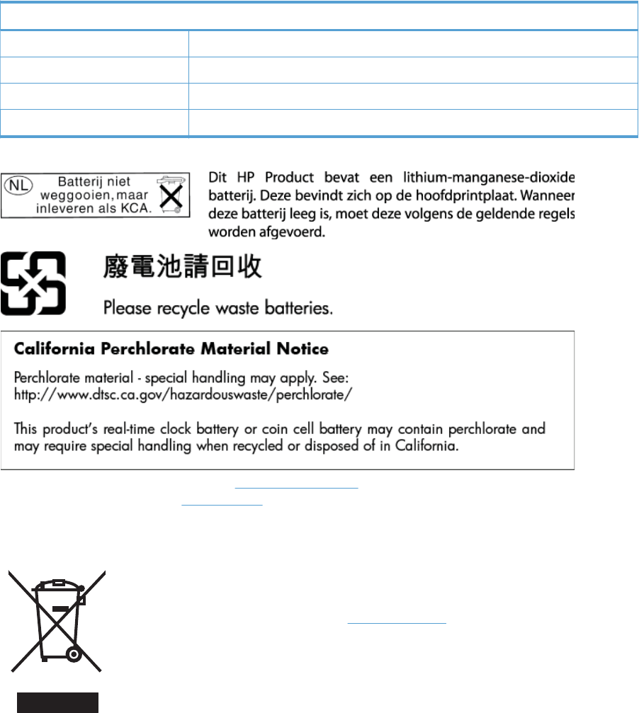
Paper
This product is capable of using recycled papers when the paper meets HP guidelines. This product is suitable
for the use of recycled paper according to EN12281:2002.
Material restrictions
This HP product does not contain added mercury.
This HP product contains a battery that might require special handling at end-of-life. The batteries contained
in or supplied by Hewlett-Packard for this product include the following:
HP Officejet Enterprise Color X555 and MFP X585 Series
Type Lithium Manganese Dioxide
Weight 3.0 g
Location On main board
User-removable No
For recycling information, you can go to www.hp.com/recycle, or contact your local authorities or the
Electronics Industries Alliance: www.eiae.org.
Disposal of waste equipment by users
This symbol means do not dispose of your product with your other household waste. Instead, you should
protect human health and the environment by handing over your waste equipment to a designated collection
point for the recycling of waste electrical and electronic equipment. For more information, please contact
your household waste disposal service, or go to: www.hp.com/recycle.
ENWW Environmental product stewardship program 297

Electronic hardware recycling
HP encourages customers to recycle used electronic hardware. For more information about recycling
programs go to: www.hp.com/recycle.
Chemical substances
HP is committed to providing our customers with information about the chemical substances in our products
as needed to comply with legal requirements such as REACH (Regulation EC No 1907/2006 of the European
Parliament and the Council). A chemical information report for this product can be found at: www.hp.com/go/
reach.
Material Safety Data Sheet (MSDS)
Material Safety Data Sheets (MSDS) for supplies containing chemical substances (for example, ink) can be
obtained by accessing the HP Web site at www.hp.com/go/msds.
EPEAT
Many HP products are designed to meet EPEAT. EPEAT is a comprehensive environmental rating that helps
identify greener electronics equipment. For more information on EPEAT go to www.epeat.net. For
information on HP's EPEAT registered products go to www.hp.com/hpinfo/globalcitizenship/environment/
pdf/epeat_printers.pdf.
For more information
To obtain information about these environmental topics:
●Product environmental profile sheet for this and many related HP products
●HP’s commitment to the environment
●HP’s environmental management system
●HP’s end-of-life product return and recycling program
●Material Safety Data Sheets
Visit www.hp.com/go/environment.
298 Appendix C Regulatory information ENWW

Declaration of conformity (X555 models)
Declaration of Conformity
according to ISO/IEC 17050-1 and EN 17050-1
Manufacturer's Name: Hewlett-Packard Company DoC#: BOISB-1300-00-R1
Manufacturer's Address: 11311 Chinden Boulevard
Boise, Idaho 83714-1021, USA
declares, that the product
Product Name: HP Officejet Enterprise Color X555dn and HP Officejet Enterprise Color X555xh
Regulatory Model:
1)
BOISB-1300-00
Product Accessory: B5L07A — HP Officejet Enterprise 500-sheet paper tray
Ink Cartridges: ●D8J03A — HP 980 STARTUP Cyan Officejet Cartridge
●D8J04A — HP 980 STARTUP Magenta Officejet Cartridge
●D8J05A — HP 980 STARTUP Yellow Officejet Cartridge
●D8J06A — HP 980 STARTUP Black Officejet Cartridge
●D8J07A — HP 980A Cyan Officejet Cartridge
●D8J08A — HP 980A Magenta Officejet Cartridge
●D8J09A — HP 980A Yellow Officejet Cartridge
●D8J10A — HP 980A Black Officejet Cartridge
conforms to the following Product Specifications and Regulations:
EMC: CISPR 22:2008 / EN55022:2010 Class A
CISPR 24:1997 +A1:2001 +A2:2002 / EN55024:2010
EN 61000-3-2:2006 +A1:2009 +A2:2009
EN 61000-3-3:2008
FCC Title 47 CFR, Part 15 Class A
2)
/ ICES-003, Issue 4
GB9254-2008, GB17625.1-2003
SAFETY: IEC 60950-1:2005 +A1:2009/ EN60950-1: 2006 +A11:2009 +A1:2010 +A12:2011
IEC 60825-1:2007 / EN 60825-1:2007 (Class 1 Laser/LED Product)
IEC 62479:2010 / EN 62479:2010
GB4943.1-2011
RoHS: EN 50581:2012
Supplementary Information:
The product herewith complies with the requirements of the EMC Directive 2004/108/EC, the Low Voltage Directive 2006/95/EC, the RoHS Directive
2011/65/EU and carries the marking accordingly.
ENWW Declaration of conformity (X555 models) 299

This device complies with part 15 of the FCC Rules. Operation is subject to the following two conditions: (1) this device may not cause harmful
interference, and (2) this device must accept any interference received, including interference that may cause undesired operation.
Additional information:
1. This product is assigned a Regulatory Model Number which stays with the regulatory aspects of the design. The Regulatory Model Number is
the main product identifier in the regulatory documentation and test reports, this number should not be confused with the marketing name or
the product numbers.
2. The product meets the requirements of EN55022 & CNS13438 Class A in which case the following applies: “Warning – This is a class A product.
In a domestic environment this product may cause radio interference in which case the user may be required to take adequate measures.”
Boise, Idaho USA
July 2013
For Regulatory Topics only, contact:
European Contact: Hewlett-Packard GmbH, HQ-TRE, Herrenberger Straße 140, D-71034 Böblingen, Germany
www.hp.eu/certificates
USA Contact: Hewlett-Packard, 3000 Hanover St., Palo Alto, CA 94304, U.S.A. 650-857-1501
300 Appendix C Regulatory information ENWW

Declaration of conformity (X585dn model)
Declaration of Conformity
according to ISO/IEC 17050-1 and EN 17050-1
Manufacturer's Name: Hewlett-Packard Company DoC#: BOISB-1300-01-R1
Manufacturer's Address: 11311 Chinden Boulevard
Boise, Idaho 83714-1021, USA
declares, that the product
Product Name: HP Officejet Enterprise Color MFP X585dn
Regulatory Model:
1)
BOISB-1300-01
Product Accessory: B5L07A - HP Officejet Enterprise 500-sheet paper tray
Ink Cartridges: ●D8J03A — HP 980 STARTUP Cyan Officejet Cartridge
●D8J04A — HP 980 STARTUP Magenta Officejet Cartridge
●D8J05A — HP 980 STARTUP Yellow Officejet Cartridge
●D8J06A — HP 980 STARTUP Black Officejet Cartridge
●D8J07A — HP 980A Cyan Officejet Cartridge
●D8J08A — HP 980A Magenta Officejet Cartridge
●D8J09A — HP 980A Yellow Officejet Cartridge
●D8J10A — HP 980A Black Officejet Cartridge
conforms to the following Product Specifications and Regulations:
EMC: CISPR 22:2008 / EN55022:2010 Class A
CISPR 24:1997 +A1:2001 +A2:2002 / EN55024:2010
EN 61000-3-2:2006 +A1:2009 +A2:2009
EN 61000-3-3:2008
FCC Title 47 CFR, Part 15 Class A
2)
/ ICES-003, Issue 4
GB9254-2008, GB17625.1-2003
SAFETY: IEC 60950-1:2005 +A1:2009/ EN60950-1: 2006 +A11:2009 +A1:2010 +A12:2011
IEC 60825-1:2007 / EN 60825-1:2007 (Class 1 Laser/LED Product)
IEC 62479:2010 / EN 62479:2010
GB4943.1-2011
RoHS: EN 50581:2012
Supplementary Information:
The product herewith complies with the requirements of the EMC Directive 2004/108/EC, the Low Voltage Directive 2006/95/EC, the RoHS Directive
2011/65/EU and carries the marking accordingly.
ENWW Declaration of conformity (X585dn model) 301

This device complies with part 15 of the FCC Rules. Operation is subject to the following two conditions: (1) this device may not cause harmful
interference, and (2) this device must accept any interference received, including interference that may cause undesired operation.
1. This product is assigned a Regulatory Model Number which stays with the regulatory aspects of the design. The Regulatory Model Number is
the main product identifier in the regulatory documentation and test reports, this number should not be confused with the marketing name or
the product numbers.
2. The product meets the requirements of EN55022 & CNS13438 Class A in which case the following applies: “Warning – This is a class A product.
In a domestic environment this product may cause radio interference in which case the user may be required to take adequate measures.”
Boise, Idaho USA
July 2013
For Regulatory Topics only, contact:
European Contact: Hewlett-Packard GmbH, HQ-TRE, Herrenberger Straße 140, D-71034 Böblingen, Germany
www.hp.eu/certificates
USA Contact: Hewlett-Packard, 3000 Hanover St., Palo Alto, CA 94304, U.S.A. 650-857-1501
302 Appendix C Regulatory information ENWW
Declaration of conformity (X585f and X585z models)
Declaration of Conformity
according to ISO/IEC 17050-1 and EN 17050-1
Manufacturer's Name: Hewlett-Packard Company DoC#: BOISB-1300-02-R1
Manufacturer's Address: 11311 Chinden Boulevard
Boise, Idaho 83714-1021, USA
declares, that the product
Product Name: HP Officejet Enterprise Color MFP X585f and HP Officejet Enterprise Color Flow MFP X585z
Regulatory Model:
1)
BOISB-1300-02
Product Accessories: BOISB-0703-00 (Fax module)
2)
B5L07A - HP Officejet Enterprise 500-sheet paper tray
Ink Cartridges: ●D8J03A — HP 980 STARTUP Cyan Officejet Cartridge
●D8J04A — HP 980 STARTUP Magenta Officejet Cartridge
●D8J05A — HP 980 STARTUP Yellow Officejet Cartridge
●D8J06A — HP 980 STARTUP Black Officejet Cartridge
●D8J07A — HP 980A Cyan Officejet Cartridge
●D8J08A — HP 980A Magenta Officejet Cartridge
●D8J09A — HP 980A Yellow Officejet Cartridge
●D8J10A — HP 980A Black Officejet Cartridge
conforms to the following Product Specifications and Regulations:
EMC: CISPR 22:2008 / EN55022:2010 Class A
CISPR 24:1997 +A1:2001 +A2:2002 / EN55024:2010
EN 61000-3-2:2006 +A1:2009 +A2:2009
EN 61000-3-3:2008
FCC Title 47 CFR, Part 15 Class A
3)
/ ICES-003, Issue 4
GB9254-2008, GB17625.1-2003
SAFETY: IEC 60950-1:2005 +A1:2009/ EN60950-1: 2006 +A11:2009 +A1:2010 +A12:2011
IEC 60825-1:2007 / EN 60825-1:2007 (Class 1 Laser/LED Product)
IEC 62479:2010 / EN 62479:2010
GB4943.1-2011
TELECOM: ES 203 021
FCC Rules and Regulations 47 CFR Part 68
RoHS: EN 50581:2012
Supplementary Information:
ENWW Declaration of conformity (X585f and X585z models) 303

The product herewith complies with the requirements of the EMC Directive 2004/108/EC, the Low Voltage Directive 2006/95/EC, the RoHS Directive
2011/65/EU and carries the marking accordingly.
This device complies with part 15 of the FCC Rules. Operation is subject to the following two conditions: (1) this device may not cause harmful
interference, and (2) this device must accept any interference received, including interference that may cause undesired operation.
1. This product is assigned a Regulatory Model Number which stays with the regulatory aspects of the design. The Regulatory Model Number is
the main product identifier in the regulatory documentation and test reports, this number should not be confused with the marketing name or
the product numbers.
2. This product uses an analog fax accessory module which Regulatory Model number is: BOISB-0703-00 as needed to meet technical regulatory
requirements for the countries/regions this product will be sold.
3. The product meets the requirements of EN55022 & CNS13438 Class A in which case the following applies: “Warning – This is a class A product.
In a domestic environment this product may cause radio interference in which case the user may be required to take adequate measures.”
4. Telecom approvals and standards appropriate for the target countries/regions have been applied to this product, in addition to those listed
above.
Boise, Idaho USA
July 2013
For Regulatory Topics only, contact:
European Contact: Hewlett-Packard GmbH, HQ-TRE, Herrenberger Straße 140, D-71034 Böblingen, Germany
www.hp.eu/certificates
USA Contact: Hewlett-Packard, 3000 Hanover St., Palo Alto, CA 94304, U.S.A. 650-857-1501
304 Appendix C Regulatory information ENWW
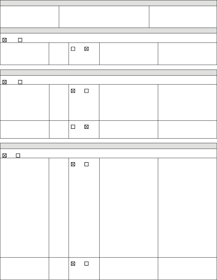
Certificate of volatility (X555 models)
Figure C-1 Certificate of volatility (X555 models) (1 of 2)
Hewlett-Packard Certificate of Volatility
Model: Part Number: Address:
HP Officejet Enterprise
color SFP X555 series
X555dn = C2S11A, X555xh = C2S12A Hewlett Packard Company
11311 Chinden Blvd
Boise, ID 83714
Volatile Memory
Does the device contain volatile memory (Memory whose contents are lost when power is removed)?
Yes No If Yes please describe the type, size, function, and steps to clear the memory below
Type (SRAM, DRAM, etc): Size: User Modifiable: Function: Steps to clear memory:
DRAM 1.25 GB Yes No Used for temporary storage of
data during scan or print job
processes, and for applications
that are running on the OS.
When the device is powered
off the memory is erased.
Non-Volatile Memory
Does the device contain non-volatile memory (Memory whose contents are retained when power is removed)?
Yes No If Yes please describe the type, size, function, and steps to clear the memory below
Type (Flash, EEPROM, etc): Size: User Modifiable: Function: Steps to clear memory:
SPI Flash 12 MB Yes No Contains boot code and factory
product configuration data
required for the device to
function. User modifications
are limited to downloading
digitally signed HP firmware
images.
There are no steps to clear this
data.
Type (Flash, EEPROM, etc): Size: User Modifiable: Function: Steps to clear memory:
EEPROM 32 KB Yes No Backup device for critical
system counters and product
configuration information.
There are no steps to clear this
data.
Mass Storage
Does the device contain mass storage memory (Hard Disk Drive, Tape Backup)?
Yes No If Yes please describe the type, size, function, and steps to clear the memory below
Type (HDD, Tape, etc): Size: User Modifiable: Function: Steps to clear memory:
HDD
(HDD is standard on xh
model)
320 GB Yes No Stores customer data, OS,
applications, digitally signed
firmware images, persistent
data, and temporary data used
for processing and system
functions.
There are several ways to
erase this:
1. Erase and Unlock
Encrypted Disk – This
changes the encryption
keys rendering all data
unreadable.
2. Secure Storage Erase –
Erases temporary files and
job data by overwriting
information one or three
times.
3. Secure Disk Erase –
Industry standard ATA
Secure Erase. Overwrites
all data on the HDD.
4. Secure File Erase –
Erases files when jobs
finish processing by
overwriting them one or
three times.
Type (HDD, Tape, etc): Size: User Modifiable: Function: Steps to clear memory:
SSD
(SSD is standard on dn
model)
8 GB Yes No See HDD function above. See HDD Steps to clear
memory above.
ENWW Certificate of volatility (X555 models) 305
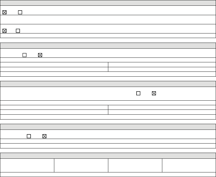
Figure C-2 Certificate of volatility (X555 models) (2 of 2)
USB
Does the item accept USB input and if so, for what purpose (i.e Print Jobs, device firmware updates, scan upload)?
Yes No If Yes please describe below
Description: Print jobs, HP digitally signed firmware upgrades, 3r
d
party application loading, Restore encrypted backed-up
system settings. USB ports can be disabled.
Can any data other than scan upload be sent to the USB device)?
Yes No If Yes please describe below
Diagnostic service logs can be uploaded. Back-up of encrypted system settings.
RF/RFID
Does the item use RF or RFID for receive or transmit of any data including remote diagnostics. (e.g. Cellular phone,
Bluetooth) Yes No If Yes please describe below
Purpose: Wireless information string.
Frequency: Bandwidth:
Modulation: Effective Radiate Power (ERP):
Specifications:
Other Transmission Capabilities
Does the device employ any other methods of non-wired access to transmit or receive any data whatsoever (e.g. anything
other than standard hard wired TCP/IP, direct USB, or parallel connections)? Yes No If Yes please describe
below:
Purpose:
Frequency: Bandwidth:
Modulation: Effective Radiate Power (ERP):
Specifications:
Other Capabilities
Does the device employ any other method of communications such as a Modem to transmit or receive any data
whatsoever? Yes No If Yes please describe below:
Purpose:
Specifications:
Author Information
Name: Title: Email: Business Unit:
Technical Marketing
Engineer
@hp.com
Date Prepared: 02-14-14
306 Appendix C Regulatory information ENWW
Certificate of volatility (X585 models)
Figure C-3 Certificate of volatility (X585 models) (1 of 2)
Hewlett-Packard Certificate of Volatility
Model: Part Number: Address:
HP Officejet Enterprise
color MFP X585 series
X585dn = B5L04A, X585f = B5L05A,
X585z = B5L06A
Hewlett Packard Company
11311 Chinden Blvd
Boise, ID 83714
Volatile Memory
Does the device contain volatile memory (Memory whose contents are lost when power is removed)?
Yes No If Yes please describe the type, size, function, and steps to clear the memory below
Type (SRAM, DRAM, etc): Size: User Modifiable: Function: Steps to clear memory:
DRAM 1.75 GB Yes No Used for temporary storage of
data during scan or print job
processes, and for applications
that are running on the OS.
When the device is powered
off the memory is erased.
Non-Volatile Memory
Does the device contain non-volatile memory (Memory whose contents are retained when power is removed)?
Yes No If Yes please describe the type, size, function, and steps to clear the memory below
Type (Flash, EEPROM, etc): Size: User Modifiable: Function: Steps to clear memory:
SPI Flash 12 MB Yes No Contains boot code and factory
product configuration data
required for the device to
function. User modifications
are limited to downloading
digitally signed HP firmware
images.
There are no steps to clear this
data.
Type (Flash, EEPROM, etc): Size: User Modifiable: Function: Steps to clear memory:
EEPROM 36 KB Yes No Backup device for critical
system counters and product
configuration information.
There are no steps to clear this
data.
Mass Storage
Does the device contain mass storage memory (Hard Disk Drive, Tape Backup)?
Yes No If Yes please describe the type, size, function, and steps to clear the memory below
Type (HDD, Tape, etc): Size: User Modifiable: Function: Steps to clear memory:
HDD, Self Encrypting,
SATA
320 GB Yes No Stores customer data, OS,
applications, digitally signed
firmware images, persistent
data, and temporary data used
for processing and system
functions.
There are several ways to
erase this:
1. Erase and Unlock
Encrypted Disk – This
changes the encryption
keys rendering all data
unreadable.
2. Secure Storage Erase –
Erases temporary files and
job data by overwriting
information one or three
times.
3. Secure Disk Erase –
Industry standard ATA
Secure Erase. Overwrites
all data on the HDD.
4. Secure File Erase –
Erases files when jobs
finish processing by
overwriting them one or
three times.
USB
Does the item accept USB input and if so, for what purpose (i.e Print Jobs, device firmware updates, scan upload)?
Yes No If Yes please describe below
Description: Print jobs, HP digitally signed firmware upgrades, 3r
d
party application loading, Restore encrypted backed-up
ENWW Certificate of volatility (X585 models) 307
Figure C-4 Certificate of volatility (X585 models) (2 of 2)
system settings. USB ports can be disabled.
Can any data other than scan upload be sent to the USB device)?
Yes No If Yes please describe below
Diagnostic service logs can be uploaded. Back-up of encrypted system settings.
RF/RFID
Does the item use RF or RFID for receive or transmit of any data including remote diagnostics. (e.g. Cellular phone,
Bluetooth) Yes No If Yes please describe below
Purpose: Wireless information string.
Frequency: Bandwidth:
Modulation: Effective Radiate Power (ERP):
Specifications:
Other Transmission Capabilities
Does the device employ any other methods of non-wired access to transmit or receive any data whatsoever (e.g. anything
other than standard hard wired TCP/IP, direct USB, or parallel connections)? Yes No If Yes please describe
below:
Purpose:
Frequency: Bandwidth:
Modulation: Effective Radiate Power (ERP):
Specifications:
Other Capabilities
Does the device employ any other method of communications such as a Modem to transmit or receive any data
whatsoever? Yes No If Yes please describe below:
Purpose: Fax modem – send/receive fax data
Specifications: 33.6 kbs
Author Information
Name: Title: Email: Business Unit:
Technical Marketing
Engineer
@hp.com
Date Prepared: 02-14-14
308 Appendix C Regulatory information ENWW
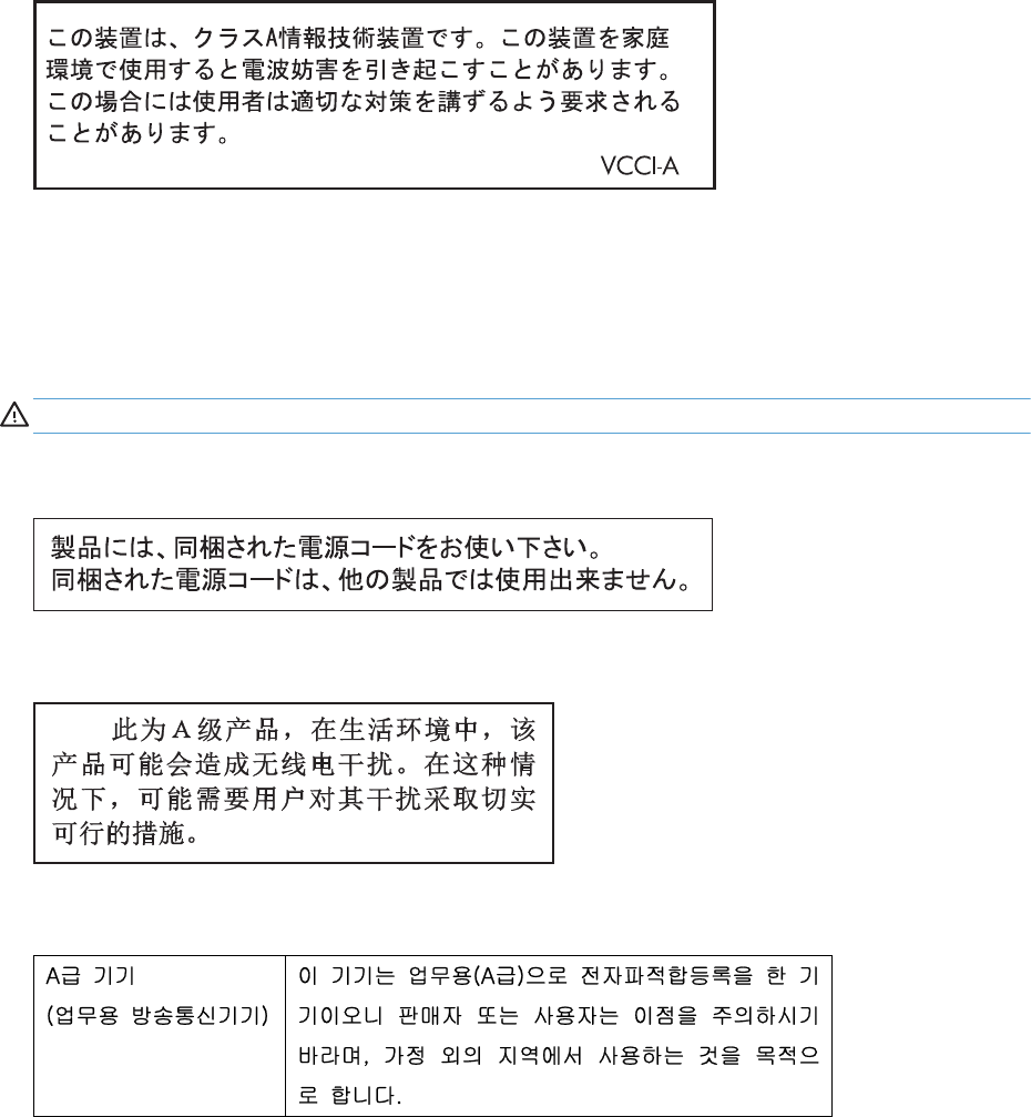
Safety statements
Canada - Industry Canada ICES-003 Compliance Statement
CAN ICES-3(A)/NMB-3(A)
VCCI statement (Japan)
Power cord instructions
Make sure your power source is adequate for the product voltage rating. The voltage rating is on the product
label. The product uses either 100-127 Vac or 220-240 Vac and 50/60 Hz.
Connect the power cord between the product and a grounded AC outlet.
CAUTION: To prevent damage to the product, use only the power cord that is provided with the product.
Power cord statement (Japan)
EMC statement (China)
EMC statement (Korea)
ENWW Safety statements 309

EMI statement (Taiwan)
310 Appendix C Regulatory information ENWW
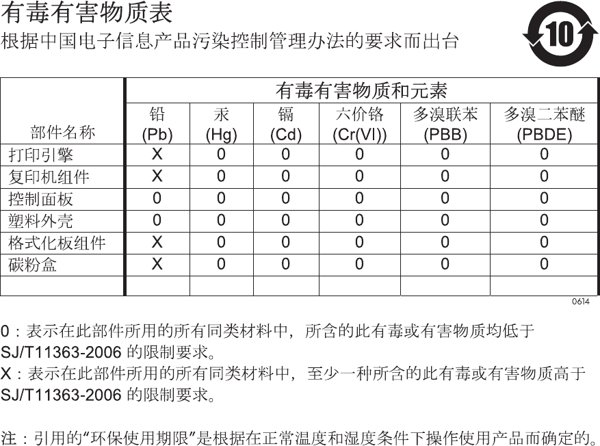
GS statement (Germany)
Das Gerät ist nicht für die Benutzung im unmittelbaren Gesichtsfeld am Bildschirmarbeitsplatz vorgesehen.
Um störende Reflexionen am Bildschirmarbeitsplatz zu vermeiden, darf dieses Produkt nicht im
unmittelbaren Gesichtsfeld platziert warden.
Das Gerät ist kein Bildschirmarbeitsplatz gemäß BildscharbV. Bei ungünstigen Lichtverhältnissen (z. B.
direkte Sonneneinstrahlung) kann es zu Reflexionen auf dem Display und damit zu Einschränkungen der
Lesbarkeit der dargestellten Zeichen kommen.
Substances Table (China)
SEPA Ecolabel User Information (China)
中国环境标识认证产品用户说明
噪声大于 63.0 dB(A)的办公设备不宜放置于办公室内,请在独立的隔离区域使用。
如需长时间使用本产品或打印大量文件,请确保在通风良好的房间内使用。
如您需要确认本产品处于零能耗状态,请按下电源关闭按钮,并将插头从电源插座断开。
您可以使用再生纸,以减少资源耗费。
ENWW Safety statements 311
Restriction on Hazardous Substances statement (India)
This product complies with the "India E-waste Rule 2011" and prohibits use of lead, mercury, hexavalent
chromium, polybrominated biphenyls or polybrominated diphenyl ethers in concentrations exceeding 0.1
weight % and 0.01 weight % for cadmium, except for the exemptions set in Schedule 2 of the Rule.
Restriction on Hazardous Substances statement (Turkey)
Türkiye Cumhuriyeti: EEE Yönetmeliğine Uygundur
Restriction on Hazardous Substances statement (Ukraine)
Обладнання відповідає вимогам Технічного регламенту щодо обмеження використання деяких
небезпечних речовин в електричному та електронному обладнанні, затвердженого постановою
Кабінету Міністрів України від 3 грудня 2008 № 1057
Eurasian Conformity (Belarus, Kazakhstan, Russia)
312 Appendix C Regulatory information ENWW
Additional statements for telecom (fax) products
EU Statement for Telecom Operation
This product is intended to be connected to the analog Public Switched Telecommunication Networks (PSTN)
of European Economic Area (EEA) countries/regions.
It meets requirements of EU R&TTE Directive 1999/5/EC (Annex II) and carries appropriate CE conformity
marking.
For more details see Declaration of Conformity issued by the manufacturer in another section of this manual.
However due to differences between individual national PSTNs the product may not guarantee unconditional
assurance of successful operation on every PSTN termination point. Network compatibility depends on the
correct setting being selected by the customer in preparation of its connection to the PSTN. Please follow the
instructions provided in the user manual.
If you experience network compatibility issues, please contact your equipment supplier or Hewlett-Packard
help desk in the country/region of operation.
Connecting to a PSTN termination point may be the subject of additional requirements set out by the local
PSTN operator.
New Zealand Telecom Statements
The grant of a Telepermit for any item of terminal equipment indicates only that Telecom has accepted that
the item complies with minimum conditions for connection to its network. It indicates no endorsement of the
product by Telecom, nor does it provide any sort of warranty. Above all, it provides no assurance that any
item will work correctly in all respects with another item of Telepermitted equipment of a different make or
model, nor does it imply that any product is compatible with all of Telecom’s network services.
This equipment may not provide for the effective hand-over of a call to another device connected to the
same line.
This equipment shall not be set up to make automatic calls to the Telecom “111” Emergency Service.
This product has not been tested to ensure compatibility with the FaxAbility distinctive ring service for New
Zealand.
Additional FCC statement for telecom products (US)
This equipment complies with Part 68 of the FCC rules and the requirements adopted by the ACTA. On the
back of this equipment is a label that contains, among other information, a product identifier in the format
US:AAAEQ##TXXXX. If requested, this number must be provided to the telephone company.
The REN is used to determine the quantity of devices, which may be connected to the telephone line.
Excessive RENs on the telephone line may result in the devices not ringing in response to an incoming call. In
most, but not all, areas, the sum of the RENs should not exceed five (5.0). To be certain of the number of
devices that may be connected to the line, as determined by the total RENs, contact the telephone company
to determine the maximum REN for the calling area.
This equipment uses the following USOC jacks: RJ11C.
An FCC-compliant telephone cord and modular plug is provided with this equipment. This equipment is
designed to be connected to the telephone network or premises wiring using a compatible modular jack,
which is Part 68 compliant. This equipment cannot be used on telephone company-provided coin service.
Connection to Party Line Service is subject to state tariffs.
ENWW Additional statements for telecom (fax) products 313

If this equipment causes harm to the telephone network, the telephone company will notify you in advance
that temporary discontinuance of service may be required. If advance notice is not practical, the telephone
company will notify the customer as soon as possible. Also, you will be advised of your right to file a
complaint with the FCC if you believe it is necessary.
The telephone company may make changes in its facilities, equipment, operations, or procedures that could
affect the operation of the equipment. If this happens, the telephone company will provide advance notice in
order for you to make the necessary modifications in order to maintain uninterrupted service.
If trouble is experienced with this equipment, please see the numbers in this manual for repair and (or)
warranty information. If the trouble is causing harm to the telephone network, the telephone company may
request you remove the equipment from the network until the problem is resolved.
The customer can do the following repairs: Replace any original equipment that came with the device. This
includes the toner cartridge, the supports for trays and bins, the power cord, and the telephone cord. It is
recommended that the customer install an AC surge arrestor in the AC outlet to which this device is
connected. This is to avoid damage to the equipment caused by local lightning strikes and other electrical
surges.
Telephone Consumer Protection Act (US)
The Telephone Consumer Protection Act of 1991 makes it unlawful for any person to use a computer or other
electronic device, including fax machines, to send any message unless such message clearly contains, in a
margin at the top or bottom of each transmitted page or on the first page of the transmission, the date and
time it is sent and an identification of the business, other entity, or individual sending the message and the
telephone number of the sending machine or such business, or other entity, or individual. (The telephone
number provided cannot be a 900 number or any other number for which charges exceed local or long
distance transmission charges).
Industry Canada CS-03 requirements
Notice: The Industry Canada label identifies certified equipment. This certification means the equipment
meets certain telecommunications network protective, operational, and safety requirements as prescribed in
the appropriate Terminal Equipment Technical Requirement document(s). The Department does not
guarantee the equipment will operate to the user’s satisfaction. Before installing this equipment, users
should ensure that it is permissible for the equipment to be connected to the facilities of the local
telecommunications company. The equipment must also be installed using an acceptable method of
connection. The customer should be aware that compliance with the above conditions may not prevent
degradation of service in some situations. Repairs to certified equipment should be coordinated by a
representative designated by the supplier. Any repairs or alterations made by the user to this equipment, or
equipment malfunctions, may give the telecommunications company cause to request the user to disconnect
the equipment. Users should ensure for their own protection that the electrical ground connections of the
power utility, telephone lines, and internal metallic water pipe system, if present, are connected together.
This precaution can be particularly important in rural areas.
CAUTION: Users should not attempt to make such connections themselves, but should contact the
appropriate electric inspection authority, or electrician, as appropriate. The Ringer Equivalence Number (REN)
of this device is 0.0.
This product meets the applicable Industry Canada technical specifications. / Le présent matériel est
conforme aux specifications techniques applicables d’Industrie Canada.
Notice: The Ringer Equivalence Number (REN) assigned to each terminal device provides an indication of the
maximum number of terminals allowed to be connected to a telephone interface. The termination on an
interface may consist of any combination of devices subject only to the requirement that the sum of the
Ringer Equivalence Number of all the devices does not exceed five (5.0). / L’indice d’équivalence de la
314 Appendix C Regulatory information ENWW

sonnerie (IES) sert à indiquer le nombre maximal de terminaux qui peuvent être raccordés à une interface
téléphonique. La terminaison d’une interface peut consister en une combinaison quelconque de dispositifs, à
la seule condition que la somme d’indices d’équivalence de la sonnerie de tous les dispositifs n’excède pas
cinq.
The standard connecting arrangement code (telephone jack type) for equipment with direct connections to
the telephone network is CA11A.
Vietnam Telecom wired/wireless marking for ICTQC Type approved products
Japan Telecom Mark
A08-0138004
ENWW Additional statements for telecom (fax) products 315
316 Appendix C Regulatory information ENWW

Index
A
accessories installed, information
59
acoustic specifications 292
Administration menu, control
panel 172
B
Backup/Restore menu, control
panel 233
batteries included 297
bin, output
jams, clearing 252
C
Calibrate/Cleaning menu, control
panel 233
calibration period 4
cautions iii
certificate of volatility 305, 307
clean the paper path
cleaning page printing 164
cleaning
paper path 236
CO operations 37
components
diagrams of 154
configuration pages
information 59
printing 57
connectivity
solving problems 256
connectivity LED 149
control panel
Administration menu 172
Backup/Restore menu 233
Calibrate/Cleaning menu 233
Copy Settings menu (X585
only) 179
Display Settings menu 211
Fax Settings menu (X585) 195
General Settings menu 174
Manage Supplies menu 213
Manage Trays menu 217
Network Settings menu 219
Print Options menu 210
Print Settings menu 207
Reports menu 172
Scan/Digital Send Settings menu
(X585) 185
Service menu 235
Troubleshooting menu 230
USB Firmware Upgrade menu
235
control panel diagnostic flowcharts
50
control-panel menus 172
conventions, document iii
Copy Settings menu (X585 only),
control panel 179
copying
sequence 36
current control, fax line 38
customer support
online 290
D
data path
fax 38
date
codes for firmware 59
manufacture 58
defaults, restoring 262
determine problem source 45
diagnostics
LED 149
networks 225
Display Settings menu, control
panel 211
disposal, end-of-life 297
document conventions iii
document feeder
jams 239
paper-feeding problems 237
E
electrical specifications 292
electronic hardware recycling 298
end of print job period 6
end-of-life disposal 297
engine control system operations 7
environmental stewardship
program 295
Eurasian conformity 312
event log
clear 60
information 59
print 59
view 59
event-log messages 59
F
factory-set defaults, restoring 262
fax
card 37
data path 38
factory-set defaults, restoring
262
flash memory storage 39
functions 37
line current control 38
operations 37
page storage 39
PSTN operations 37
ring detect 38
safety isolation 38
ENWW Index 317
safety protection circuitry 38
subsystem 37
fax card
CODEC 37
DSP 37
fax subsystem 37
regional versions 37
ring detect 38
fax security
security features, computer 37
security features, network 37
Fax Settings menu (X585), control
panel 195
fax subsystem
fax card 37
operations 37
FCC regulations 294
firmware
date codes 59
version information 58
flash memory, fax 39
flowcharts
troubleshooting 45
formatter lights 149
G
General Settings menu, control
panel 174
H
hardware integration pocket (HIP) is
not functioning 56
home button is unresponsive 55
HP Customer Care 290
HP embedded Jetdirect page 58
HP Jetdirect print server
configuration page 58
lights 149
I
individual component disagnostics
149
ink collection unit
jams 248
installation
verify for optional accessories
57
IPv4 information 58
IPv6 information 58
J
jack locations 154
jams
auto-navigation 238
causes of 238
diagnostic test for 151
document feeder 239
ink collection unit 248
output bin, clearing 252
paper path, clearing 247
Japanese VCCI statement 309
Jetdirect print server
lights 149
K
Korean EMC statement 309
L
LEDs. See lights
left door
jams, clearing 247
license, software 286
lights
formatter 149
troubleshooting with 149
line current control, fax 38
link speed settings 229
M
Manage Supplies menu, control
panel 213
Manage Trays menu, control panel
217
material restrictions 297
Material Safety Data Sheet (MSDS)
298
memory
flash, fax 39
information 57
menus, control panel
Administration 172
Backup/Restore 233
Calibrate/Cleaning 233
Copy Settings (X585 only) 179
Display Settings 211
Fax Settings (X585) 195
General Settings 174
Manage Supplies 213
Manage Trays 217
Network Settings 219
Print Options 210
Print Settings 207
Reports 172
Scan/Digital Send Settings
(X585) 185
Service 235
Troubleshooting 230
USB Firmware Upgrade 235
mercury-free product 297
model number 58
N
Network Settings menu, control
panel 219
networks
diagnostics 225
HP embedded Jetdirect
configuration page 58
link speed settings 229
security features 37
no control panel sound 54
notes iii
O
online support 290
operation sequence 4
operations
engine control system 7
fax 37
fax card in subsystem 37
fax subsystem 37
fax, PSTN 37
paper-handling system 17
PSTN 37
scanner system 35
output bin
jams, clearing 252
P
paper
jams 238
paper-handling system
operations 17
paper jams
document feeder 239
ink collection unit 248
paper path
diagnostic test 151
jams, clearing 247
paper pickup problems
solving 237
318 Index ENWW
paper-handling system
sensors 17
physical specifications 292
plug/jack locations 154
port configuration information 58
port locations 154
power
consumption 292
fax line current control 38
power subsystem 46
power supply
troubleshooting 46
power-on
scanner sequence 35
power-on troubleshooting
overview 46
preboot menu options 164
Print Options menu, control panel
210
print preparation period 5
print quality
built-in troubleshooting pages
156
test pages 156
print quality page
interpreting 156
printing 156
print quality troubleshooting 156
Print Settings menu, control panel
207
Print Test Page 177
printing period 5
problem-solving
event-log messages 59
networks 225
no response 254
slow response 254
product
fax, functions 37
product cold reset 263
PSTN operations 37
R
recycling
electronic hardware 298
HP printing supplies returns and
environmental program 296
regional versions
fax card 37
Reports menu, control panel 172
restore the service ID 262
restoring factory-set defaults 262
ring detect
fax card 38
RING operations 37
S
safety
-protection circuitry, fax 38
isolation, fax 38
Scan/Digital Send Settings menu
(X585), control panel 185
scanner
tests X585 152
security features
computer 37
network 37
security settings information 58
sensors
paper-handling operations 17
Service menu, control panel 235
servicing operations 4
settings
factory-set defaults, restoring
262
size specifications, product 292
software
software license agreement 286
solving
network problems 256
USB direct-connect problems
256
specifications
electrical and acoustic 292
physical 292
startup period 4
storing
fax pages in flash memory 39
support
online 290
T
Taiwan EMI statement 310
TCP/IP information 58
technical support
online 290
tests
networks 225
paper path 151
scanner tests 152
scanner X585 152
theory of operations
engine control system 7
paper-handling system 17
TIP operations 37
tips iii
touchscreen blank, white, or dim (no
image) 51
touchscreen has an unresponsive
zone 53
touchscreen is slow to respond 52
Tray 1
jams, clearing 244
tray 1
pickup-and-feed system
operations 17
Tray 2
jams, clearing 251, 253
tray 2
paper-handling operations 17
tray selection - use requested tray
217
trays
jams, clearing 251, 253
paper-handling system
operations 17
troubleshooting
checklist 42
clean the paper path 164
configuration pages for 57
control panel checks 47
flowchart 45
jams 238
lights, using 149
network problems 256
paper feed problems 237
power 46
process 45
scanner calibration 47
scanning subsystem (M880) 47
USB direct-connect problems
256
Troubleshooting menu, control
panel 230
U
understand lights on the formatter
formatter lights 149
ENWW Index 319
understand the lights on the
formatter
connectivity LED 150
heartbeat LED 149
HP Jetdirect LEDs 150
USB Firmware Upgrade menu, control
panel 235
Use Requested Tray 217
V
version, hardware firmware 58
W
warnings iii
warranty
customer self repair 289
license 286
product 278
waste disposal 297
Web sites
customer support 290
Material Safety Data Sheet
(MSDS) 298
320 Index ENWW

© 2014 Hewlett-Packard Development Company, L.P.
www.hp.com
