Honeywell Experion LX Series 8 Controller And I/O Specification V1 2014 01 PCNT02 HW S8IO Ds S803 150 110r1
User Manual: PCNT02
Open the PDF directly: View PDF ![]() .
.
Page Count: 30

Technical Information
S803-150-110
Release 110
January 2014, Version 1
Series 8 Controller and I/O
Specification

Series 8 Controller and I/O Specification, S803-150-110
Revision History
Revision Date Description
1.0 January 2014 Release Publication

Series 8 Controller and I/O Specification, S803-150-110
Table of Contents
1. Product Introduction ................................................................................................. 1
1.1. C300 Controller Overview............................................................................................ 1
1.2. Series 8 I/O Overview ................................................................................................. 3
2. Specifications ........................................................................................................... 7
2.1. C300 Controller Specifications ..................................................................................... 7
2.1.1. C300 Hardware ........................................................................................................... 7
2.1.2. C300 Supported Function Blocks ................................................................................. 9
2.2. Series 8 IO Specifications.......................................................................................... 10
2.2.1. TC/RTD .................................................................................................................... 10
2.2.2. Analog Input – Single Ended ..................................................................................... 12
2.2.3. Analog Input with HART – Single Ended .................................................................... 13
2.2.4. Analog Input with HART – Differential ........................................................................ 14
2.2.5. Analog Output ........................................................................................................... 15
2.2.6. Analog Output with HART.......................................................................................... 16
2.2.7. Digital Input Sequence of Events ............................................................................... 17
2.2.8. Digital Input 24VDC ................................................................................................... 19
2.2.9. Digital Input Pulse Accumulation ................................................................................ 20
2.2.10. Digital Output 24VDC ................................................................................................ 21
2.2.11. DO Relay Extension Board ........................................................................................ 23
2.2.12. Series 8 IO Function Matrix ....................................................................................... 24

Series 8 Controller and I/O Specification, S803-150-110 1
1. Product Introduction
1.1. C300 Controller Overview
Honeywell’s C300 Controller provides powerful and robust control for the distributed control system (DCS).
The C300 is a node in operating Honeywell’s field-proven deterministic Control Execution Environment (CEE)
core software. The CEE software provides a superior control execution and scheduling environment. Control
strategies for each controller node are configured and loaded through a common Control Builder, an easy and
intuitive engineering tool.
In addition to a standard and robust library of pre-built function blocks and algorithms, the C300 Controller also
supports Custom Algorithm Blocks (CABs). Custom Algorithm Blocks are similar in purpose and structure to the
standard function blocks that are distributed with Control Builder. However, CABs have user-defined algorithms
and data structures, allowing custom tailored strategies to be developed to specific requirements.
The C300 controller shares its hardware design with the Series 8 I/O, offering an innovative design that reduces
footprint and installation and maintenance costs. The C300 controller module is mounted on the C300 Input
Output Termination Assembly (IOTA). The C300 IOTA contains only passive devices such as FTE address
switches. Figure 1 below depicts the IOTA components.
Figure 1 - C300 Controller
I
/
O Termination
Assembly
FTE Address
Switches
Battery
Connection for
RAM retention
Future use
Private Redundancy
Communication Path
FTE Connectors
Redundant I
/
O
Link
#
2
Connectors
C
300
Controller
Module
I
/
O Link
#
1
Series 8 Controller and I/O Specification, S803-150-110 2
The Model Numbers of C300 controller are shown as below:
Model Number Description
8C-PCNT02 Series 8 C300 Controller, coated
8U-PCNT02 Series 8 C300 Controller, uncoated
8C-TCNTA1 Series 8 C300 Controller I/O Termination Assembly(IOTA),coated
8U-TCNTA1 Series 8 C300 Controller I/O Termination Assembly(IOTA),uncoated
51305980-836 Cable, Redundant C300 Controller
51454475 Series 8 RAM Charger Module (C300 Memory Backup)
51202330-300 Cable, Battery RAM Charger, 30 in
51202330-200 Cable, Battery RAM Charger, 84 in
Redundancy is implemented with two modules/IOTAs and a redundancy cable (51305980-836).
C300 Memory Backup is optional.

Series 8 Controller and I/O Specification, S803-150-110 3
1.2. Series 8 I/O Overview
This document provides technical information to configure the Series 8 I/O. The following Series 8 I/O items are
included in this document.
• TC/RTD
• Analog Input – Single Ended
• Analog Input with HART – Single Ended
• Analog Input with HART – Differential
• Analog Output
• Analog Output with HART
• Digital Input Sequence of Events (SOE)
• Digital Input, 24 VDC
• Digital Input Pulse Accumulation
• Digital Output, 24 VDC
• DO Relay Extension Board
Definitions
• Input Output Termination Assembly (IOTA): An assembly that holds the IOM and the connections for field
wiring;
• Input Output Module (IOM): A device that contains most of the electronics required to perform a specific I/O
function. The IOM plugs onto the IOTA.
Features
All Series 8 components feature an innovative design that supports enhanced heat management. This unique look
provides significant reduction in overall size for the equivalent function.
The unique features of Series 8 I/O include:
• I/O Module and field terminations are combined in the same area. The I/O Module is plugged into the IOTA to
eliminate the need for a separate chassis to hold the electronics assemblies
• Two level “detachable” terminals for landing the field wiring in the enclosure, providing easier plant installation
and maintenance.
• Field power is supplied through the IOTA, with no need for extra power supplies to power the field devices
and the associated craft wired marshalling
• Redundancy is accomplished directly on the IOTA without any external cabling or redundancy control
devices, by simply adding a second IOM to an IOTA
• For both IOM and IOTA, coated (module numbers starting with 8C) and uncoated (module numbers starting
with 8U) options are provided. Conformal coating material is applied to electronic circuitry to act as protection
against moisture, dust, chemicals, and temperature extremes. Coated IOM and IOTA are recommended
when electronics must withstand harsh environments and added protection is necessary.

Series 8 Controller and I/O Specification, S803-150-110 4
The Series 8 inherits the innovative styling of Series C. This styling includes features to facilitate the effective use of
control hardware in a systems environment. These features include:
• Vertical mounting allows for more effective wiring since most field wiring applications require entry from the
top or bottom of the systems cabinet.
• An “information circle” allows for a quick visual cue to draw the Maintenance Technician’s eyes to important
status information.
• “Tilted” design allows for effective heat management within the cabinet enclosure. Since Series 8 allows for
a significant increase in cabinet density, an effective heat management system is critical for high system
availability.
• Input and output circuits are protected from shorts to alleviate the need for in- line fusing, reducing installation
and maintenance costs
Series 8 IOTAs combine multiple functions into a single piece of equipment:
• Single and redundant configurations
• On-board termination of process signals
• On-board signal conditioning
• On-board connection to appropriate networks (FTE, I/O LINK)
• Field power distribution without external marshalling
• IOM plugs into the IOTA and receives power from the IOTA
• The IOTA receives its power through cables from header board.
Series 8 I/O Sizing
In virtually all configurations, the C300 controller and Series 8 I/O provides useful, maintainable process equipment
connections in a smaller footprint than traditional rack based systems. Installing Series 8 I/O modules contributes to
overall total installed cost savings.
IOTA sizes vary based on the application. In general, an analog module has 16 points and resides on a 6-inch (152mm)
IOTA for non-redundant applications and a 12-inch (304mm) IOTA for redundant applications. A discrete module has
32 points and resides on a 9-inch (228mm) IOTA for non-redundant applications and a 12-inch (304mm) IOTA for
redundant applications. Specific information on the size of a particular module can be found in the Model Number Table.
I/O Module Functions
• TC/RTD (16pt) – Provides thermocouple (TC) and resistance temperature device (RTD) inputs.
• Analog Input – Single Ended (16pt) - The Analog Input Module supports analog inputs which are typically
4-20mA DC inputs for traditional devices, such as transmitters.
• Analog Input with HART – Single Ended (16pt) – The Analog
Input Module supports both analog and HART inputs. Analog inputs
are typically 4-20mA DC for both traditional and HART devices.
HART data can be used for status and configuration. HART data,
such as the secondary and tertiary variables, can also be used as
process control variables.
• Analog Input with HART – Differential (16pt) – The Analog Input
Module supports Single Ended or Differential analog inputs, and
HART inputs.
• Analog Output (16pt) – The Analog Output Module supports
standard 4-20mA DC outputs.
• Analog Output with HART (16pt) – The Analog Output Module
supports both standard 4-20mA DC outputs and HART outputs.
Series 8 Controller and I/O Specification, S803-150-110 5
• Digital Input Sequence of Events (32pt) - Accepts 24VDC discrete signals as discrete inputs. The inputs
can be time tagged to support 1ms resolution Sequence of Events.
• Digital Input 24 VDC (32pt) – Digital input sensing for 24V signals
• Digital Input Pulse Accumulation (32pt) – Accepts 24VDC discrete signals as discrete inputs. The first
16 channels can be configured as Pulse accumulation to support Pulse Accumulation and frequency
measurement on per channel basis. Channels 17 – 32 can be configured as DI.
• Digital Output 24 VDC (32 pt) – Current sinking digital outputs. Outputs are electronically short-circuited
protected.
• DO Relay Extension Board (32 pt) – Digital output with NO or NC dry contacts. It can be used for low power
or high power applications.
Series 8 Field Connections
Series 8 Field connections use a standard modular connector. The connector modularity allows for removal and
insertion of the field wiring. This significantly reduces installation and maintenance procedures and can assist in field
check out. Series 8 field connectors accept up to 12 AWG / 2.5 mm
2
stranded wire.
IOTA Sizes
IOTA Sizing is nominal (6in = 152mm, 9in =228mm, 12in =304mm). I/O modules are associated with their respective
IOTAs in the table below. The I/O Module is supported by one or more IOTAs.
Model Number Description Channels Size Red.
TC/RTD
8C-TAIMA1 TC/RTD IOTA, Coated
16 9’’
8U-TAIMA1 TC/RTD IOTA, Uncoated
Analog Input
8C-TAIXA1 ANALOG INPUT IOTA Single Ended, Coated
16
6’’
8U-TAIXA1 ANALOG INPUT IOTA Single Ended, Uncoated
8C-TAIDA1 ANALOG INPUT IOTA Differential, Coated
9’’
8U-TAIDA1 ANALOG INPUT IOTA Differential, Uncoated
8C-TAIXB1
ANALOG INPUT IOTA Single Ended, Red,
Coated
12’’
8U-TAIXB1
ANALOG INPUT IOTA Single Ended, Red,
Uncoated
8C-TAIDB1 ANALOG INPUT IOTA Differential, Red, Coated
8U-TAIDB1 ANALOG INPUT IOTA Differential, Red,
Uncoated
Analog Output
8C-TAOXA1 ANALOG OUTPUT IOTA, Coated
16
6’’
8U-TAOXA1 ANALOG OUTPUT IOTA, Uncoated
8C-TAOXB1 ANALOG OUTPUT IOTA Red, Coated
12’’
8U-TAOXB1 ANALOG OUTPUT IOTA Red, Uncoated

Series 8 Controller and I/O Specification, S803-150-110 6
Digital Input
8C-TDILA1 DIGITAL INPUT 24V IOTA, Coated
32
9’’
8U-TDILA1 DIGITAL INPUT 24V IOTA, Uncoated
8C-TDILB1 DIGITAL INPUT 24V IOTA Red. Coated
12’’
8C-TDILB1 DIGITAL INPUT 24V IOTA Red. Uncoated
Digital Output
8C-TDODA1 DIGITAL OUTPUT IOTA, Coated
32
9’’
8U-TDODA1 DIGITAL OUTPUT IOTA, Uncoated
8C-TDODB1 DIGITAL OUTPUT IOTA Red, Coated
12’’
8U-TDODB1 DIGITAL OUTPUT IOTA Red, Uncoated

Series 8 Controller and I/O Specification, S803-150-110 7
2. Specifications
2.1. C300 Controller Specifications
2.1.1. C300 Hardware
Specification Limit
Processor PowerPC 8270
Power requirement 24 VDC (provided through cables by the Series 8 power system)
Module current rating 320mA
IOTA Dimension 220 mm (9 “) height, 120 mm (4,75 “) width
Module Removal and Insertion
Under Power Supported
Supported I/O Types Series 8
Supported I/O Links 2 I/O Links, each I/O Link configurable for Series 8.
Maximum Number of IO Modules per
Controller 80 I/O Units (Redundant or Non-Redundant IOMs)
Maximum Number of IO Modules on
each I/O link 40 I/O Units (Redundant or Non-Redundant IOMs)
Temperature
Operating
Temperature 0 to 60 °C
Storage temperature
-40 to 85 °C
Relative Humidity 5 to 95 % (non condensing)
Harsh Environment (ANSI/ISA- S71.04-
1985 corrosion standard) 8C- model number designation support the harsh environment or G3 level
Control Capacity
Execution Units 5500 Execution Units (single or redundant)
Tagged Objects 4095 objects
Memory Units 16000 Memory Units
Execution Period 50 msec – 2000 msec (adjustable per control strategy)
RAM Retention 50 hour through optional rechargeable battery pack (Optional)
Series 8 Controller and I/O Specification, S803-150-110 8
Controller Communication
Series 8 C300 Native peer to peer with other Series 8 C300s
Supervisory Control Network Fault Tolerant Ethernet
Third party devices Modbus Master
Agency certifications
Class I, Division 2, Group A, B, C, D; T4 Class I, Zone 2 AEx/ Ex nA
II C T4
Class I, Division 2, Group A, B, C, D; T4 Class I, Zone 2, Ex nA II C T4

Series 8 Controller and I/O Specification, S803-150-110 9
2.1.2. C300 Supported Function Blocks
Function Block
General Purpose (Utility)
Alarm Window
Annpanel
Dig Acq
EXECTIMER
First Out
Flag
Flag Array
Operator Message
Numeric
Numeric Array
Push
Text Array
Timer
Type Convert
PV Algorithms
(Auxiliary)
PV Calculator
Summer
Counter
Dead Time
Enhanced PV Calculator
Enhanced General
Linearization
Flow Compensation
General Linearlization
Lead / Lag
Rate of Change
Signal Selector
Totalizer
PV Handling
Data Acquisition
Auto Manual
Regulatory
Control
Regulatory Calculator
Enhanced Regulatory
Calculator
Fan Out (1 input / up to 8
outputs)
Override Selector (4
inputs)
PID (Proportional,
Integral, Derivative)
PID with External Reset
PID with Feed Forward
Function Block
Profit Loop
Positional
Proportional
Pulse Count
Pulse Length
Ramp / Soak
Ratio Bias
Ratio Control
Remote Cascade Support
Switch (8 input single
pole)
Device Control
Device Control (multi
input, multi output, multi
state)
Custom Block Types
Custom Data Block
Custom
Algorithm Block
Math
Absolute Value
Addition
Divide
Exponent
LN
LOG
Modulo
Multiply
Negate
Power
Rolling Average
Round
Square Root
Subtract
Truncate
Discrete Logic
2oo3 (2 out of 3 voting)
AND
CHECKBAD
CHECKBOOL
CHGEXEC
CONTACTMON
DELAY
EQ (Compare Equal)
FTRIG (Falling Edge
Trigger)
Function Block
GE (Compare Greater
than or Equal)
GT (Compare Greater
Than)
LE (Compare Less than or
Equal)
LIMIT
LT
MAX
MAXPULSE
MIN
MINPULSE
MUX
MUXREAL
MVOTE
NAND
NE
nOON
NOR
NOT
OFFDELAY
ONDELAY
OR
PULSE
QOR
ROL
ROR
RS
RTRIG
SEL
SELREAL
SHL
SHR
SR
STARTSIGNAL
TRIG
WATCHDOG
XOR
Power Related
GRPCAPRBK
HTMOTOR
LEVELCOMP
LTMOTOR
MAINIBV
Function Block
SOLENOID
VALVEDAMPER
Sequential Control
Functions
Step
Transition
Synchronize
Handler
Phase
Container Block Types
Control Module
Sequential Control
Module
Recipe Control Module
Unit Control Module
IO Related
Series 8 I/O
Interface Block Types
PCDI
Profibus Gateway Module

Series 8 Controller and I/O Specification, S803-xxx-110 10
2.2. Series 8 IO Specifications
Specifications for Series-8 I/O modules are shown below.
2.2.1. TC/RTD
Function
The TC/RTD IOM module supports up to 16 channels of temperature inputs.
Notable Features
• TC and RTD operation
• Remote cold junction compensation capability
• 1 Second PV scanning with OTD protection
• Configurable OTD protection (See below)
• Temperature points can be added in 16 point increments
Temperature Support
The Temperature variable is collected from all points at a 1 second rate. The 1 second update includes a
configurable check for Open Thermocouple Detection (OTD) (see below) before propagation of the
temperature variable. All TC inputs include integral Cold Junction Compensation (CJC).
Sampling and Open Sensor Detect
The TC/RTD IOM supports a configuration parameter for Open Sensor Detect before PV delivery. With the
OTD configuration active, the PV is sampled and held while an OTD cycle is performed within the same
measurement window. If the OTD is negative, the PV is propagated up through the system. If the OTD is
positive, the PV is set to NAN and the input channel soft failure is set. In this way, no inappropriate control
action occurs for PV values that are invalid due to an open thermocouple. PV sampling/reporting incurs no
added delays from OTD processing.
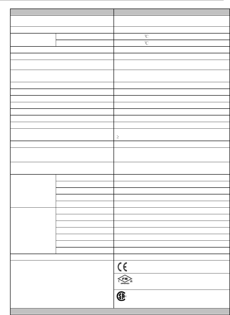
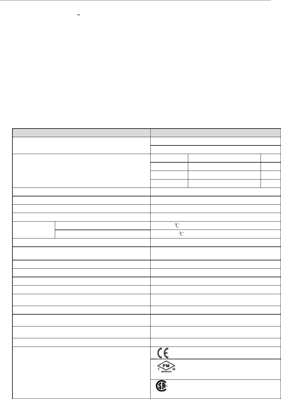
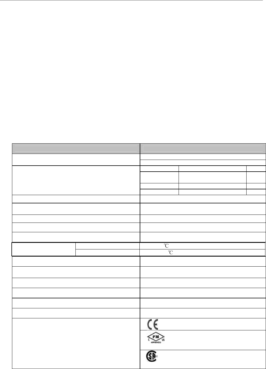
Detailed Specs – TC/RTD
Parameter Specification
Input / Output Module 8C-PAIMA1, TC/RTD, Coated
8U-PAIMA1, TC/RTD, Uncoated
IOTA (16pt) PWA 8C-TAIMA1, Coated 9’’
8U-TAIMA1, Uncoated 9’’
Input Type
Thermocouple and / or RTD
Voltage Rating 24 VDC
Module current rating 120m A
Temperature Operating Temperature 0 to 60
Storage Temperature -40 to 85
Module Removal and Insertion
Under Power Supported
Input channels 16 fully-isolated channel-to-channel, channel-to-IOL, and
channel-to-power supply common in 16 channel increments.
Input scan rate
1 Second fixed by IOM (up to 16 channels/sec max.)
Channel bandwidth
0 to 4.7 Hz (-3 dB)
Nominal input range (TC only)
-20 to +100 millivolts
Series 8 Controller and I/O Specification, S803-150-110 11
Parameter Specification
Maximum normal mode continuous input
non
-
damaging (any thermocouple type configured) -10 to +10 volts (TC)
-1 to +2 Volts @ 100 milliamps (RTD)
Gain error (-20 to +100 millivolt range)
0.050% full scale max
Temperature stability TC, Millivolt inputs
+/-20 ppm per max
RTD inputs
+/-20 ppm per max
Long term drift
500 ppm
Input impedance
1 megohm at dc (TC only)
CMV with respect to Power System common, dc to 60
Hz
+/-250 VDC or VAC RMS
CMRR, 50 or 60 Hz (with 1000 ohms source
impedance max.) 120 dB min
Voltage, channel-to-channel, dc to 60 Hz
+/-250 VDC or VAC RMS
Crosstalk, dc to 60 Hz
80 dB (120 dB at 50 and 60 Hz)
NMRR at 50/ 60 Hz
60 dB min
Line frequency integration
Fixed selection of 50 Hz or 60 Hz
RTD sensor excitation current
1 milliamp
Cold junction compensation range
-20 to +60
℃
(+/-0.5
℃
typical)
TC Linearization Accuracy (2)
± 0.05 Ω /
℃
Open Thermocouple Detection Each conversion qualified, ≤ 1000 Ω = guaranteed no-trip
1500 Ω guaranteed trip.
RTD Max Lead Resistance
15 Ω
Surge protection (sensor terminals) EN 61000-4-5 (for Industrial locations, 1kV line to line, 2kV
line to gnd.)
Surge protection (power/serial link with cable adapter
option)
EN 61000-4-5 (for Industrial locations, 1kV line to line, 2kV
line to gnd.)
Supported types
(RTD)
Pt: 100 ohm DIN 4376
-180 to +800
℃
Pt: 100 ohm JIS C-1604
-180 to +650
℃
Ni: 120 ohm ED #7
-45 to +315
℃
Cu: 10 ohm SEER
-20 to +250
℃
Cu: 50 ohm SEER -50 to +150
℃
Supported
thermocouple types
ANSI specification J
-200 to +1200
℃
ANSI specification K
-100 to +1370
℃
ANSI specification E
-200 to +1000
℃
ANSI specification T
-230 to +400
℃
ANSI specification B
+100 to +1820
℃
ANSI specification S
0 to +1700
℃
ANSI specification R
0 to +1700
℃
Supported millivolt types
-20 to +100 millivolts
Agency certifications
Class I, Division 2, Group A, B, C, D; T4
Class I, Zone 2 AEx/ Ex nA II C T4
Class I, Division 2, Group A, B, C, D; T4 Class I, Zone
2, Ex nA II C T4
(1): Linearization polynomials are 4th order and based on NIST Monograph 175, ITS90 and JIS C-1602-1995.
Series 8 Controller and I/O Specification, S803-150-110 12
2.2.2. Analog Input Single Ended
Function
The Analog Input Module accepts current inputs from transmitters and sensing devices.
Notable Features
• Extensive self diagnostics
• Optional redundancy
• Fast loop scan
• Internal or external field power selection
• On board excitation power (no need for marshalling power)
• Galvanic Isolation
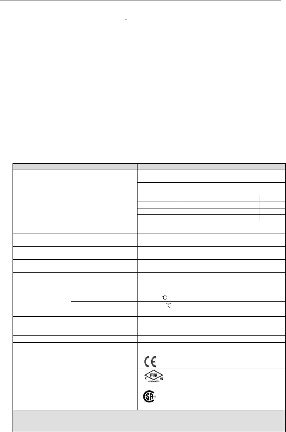
Detail Specifications – Analog Input
Parameter Specification
Input / Output Module 8C-PAINA1 - Analog Input – Single Ended, Coated
8U-PAINA1 - Analog Input – Single Ended, Uncoated
IOTA Modules
8C-TAIXA1 Non Redundant, Coated 6”
8U-TAIXA1 Non Redundant, Uncoated 6”
8C-TAIXB1 Redundant, Coated 12”
8U-TAIXB1 Redundant, Uncoated 12”
Input Type current (2-wire or self-powered transmitters)
Input Channels 16 Channels (All 16 Single Ended)
Voltage Rating 24 VDC
Module current rating 105m A
Temperature Operating Temperature 0 to 60
Storage temperature -40 to 85
A/D Converter Resolution 16 bits
Module Removal and Insertion
Under Power Supported
Input Range 4-20 mA (through 250 Ω)
Normal Mode Rejection Ratio, at 60 Hz 19 dB
Normal Mode Filter Response Single-pole RC, -3 dB @ 6.5 Hz
Crosstalk, dc to 60 Hz (channel-to-channel) -60 dB
Maximum Input Voltage (any input referenced to
common, no damage) ± 30 Volts
Input Scan Rate 50 ms
Hardware Accuracy (@ CMV = 0 V)
± 0.075% of full
-
scale (23.5°± 2°C)
± 0.15% of full-scale (0 to 60°C)
Galvanic
Isolation (any input terminal voltage referenced
to common) 1000 VAC RMS or ±1000 VDC
Isolation Technique Icoupler (in IOM)
Agency certifications
Class I, Division 2, Group A, B, C, D; T4
Class I, Zone 2 AEx/ Ex nA II C T4
Class I, Division 2, Group A, B, C, D; T4 Class
I, Zone 2, Ex nA II C T4

Series 8 Controller and I/O Specification, S803-150-110 13
2.2.3. Analog Input with HART Single Ended
Function
The Analog Input Module accepts current inputs from transmitters and sensing devices.
Notable Features
• Extensive self diagnostics
• Optional redundancy
• HART-capable
• Fast loop scan
• Internal or external field power selection
• On board excitation power (no need for marshalling power)
• Galvanic Isolation
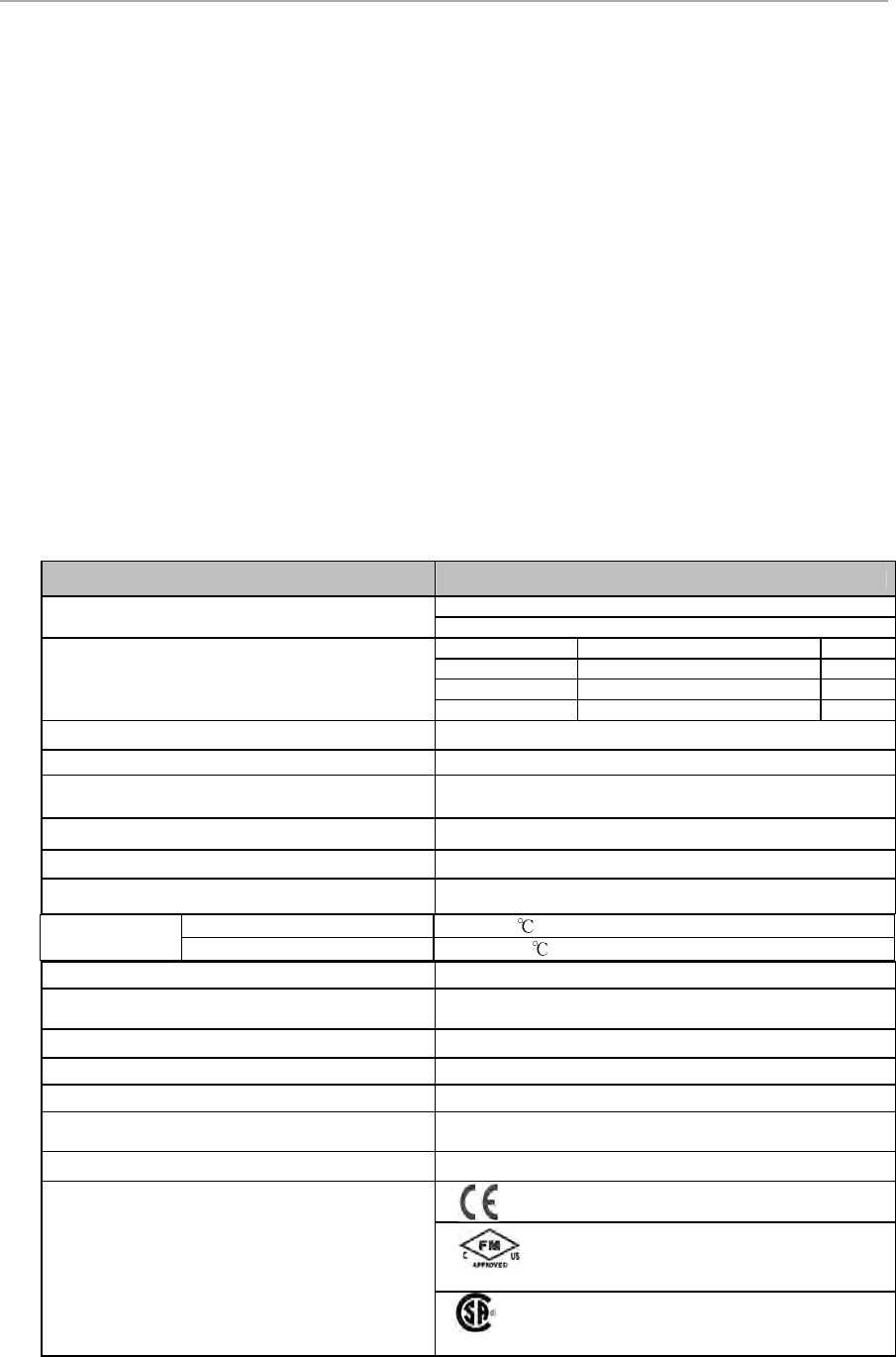
Detail Specifications – Analog Input with HART – Single Ended
Parameter Specification
Input / Output Module 8C-PAIHA1 - Analog Input with HART, Coated
8U-PAIHA1 - Analog Input with HART, Uncoated
IOTA Modules
8C-TAIXA1 Non Redundant, Coated 6”
8U-TAIXA1
Non Redundant,
Uncoated 6”
8C-TAIXB1 Redundant, Coated 12”
8U-TAIXB1 Redundant, Uncoated 12”
Input Type current (2-wire or self-powered transmitters)
Input Channels
16 Channels
(All 16 Single Ended)
A/D Converter Resolution 16 bits
Voltage Rating 24 VDC
Module current rating 110 mA
Temperature Operating Temperature 0 to 60
Storage temperature -40 to 85
Input Range 4-20 mA (through 250 Ω)
Module Removal and Insertion
Under Power Supported
Normal Mode Rejection Ratio, at 60 Hz 19 dB
Normal Mode Filter Response Single-pole RC, -3 dB @ 6.5 Hz
Crosstalk, dc to 60 Hz (channel-to-channel) -60 dB
Maximum Input Voltage (any input referenced
to
common, no damage) ± 30 Volts
Input Scan Rate 50 ms
Hardware Accuracy (@ CMV = 0 V)
± 0.075% of full
-
scale (23.5°± 2°C)
± 0.15% of full-scale (0 to 60°C)
Galvanic
Isolation (any input terminal voltage referenced
to common) 1000VAC RMS or ±1000 VDC
Isolation Technique Icoupler (in IOM)
Agency certifications
Class I, Division 2, Group A, B, C, D; T4
Class I, Zone 2 AEx/ Ex nA II C T4
Class I, Division 2, Group A, B, C, D; T4
Class I, Zone 2, Ex nA II C T4
Series 8 Controller and I/O Specification, S803-150-110 14
2.2.4. Analog Input with HART Differential
Function
The Analog Input Module accepts current inputs from transmitters and sensing devices.
Notable Features
• Extensive self diagnostics
• Optional redundancy
• No Open Wire Detection
• Supports either Single Ended / Differential Inputs
• HART-capable
• Fast loop scan
Detail Specifications – Analog Input with HART – Differential
Parameter
Specification
Input / Output Module
8C
-
PAIH5
4
-
Analog Input with HART
-
Differential (16),
Coated
8U
-
PAIH5
4
-
Analog Input with HART
-
Differential (16),
Uncoated
IOTA Modules
8C
-
TAIDA1
Non Redundant, Coated
9”
8U
-
TAIDA1
Non Redundant, Uncoated
9’’
8C
-
TAIDB1
Redundant, Coated
12”
8C
-
TAIDB1
Redundant, Uncoated
12’’
Input Type
Supports either single ended or
Differential current /
voltage inputs with one type of IOTA
Input Channels(1)
16 Channels
(All 16 Single Ended / Differential)
A/D Converter Resolution
16 bits
Input Range
1 to 5 V, 4
-
20 mA (through 250 Ω)
Voltage Rating
24 VDC
Module current
rating
310 mA
Normal Mode Rejection Ratio, at 60 Hz
19 dB
Module Removal and Insertion
Under Power Supported
Temperature Operating Temperature 0 to 60
Storage temperature -40 to 85
Normal Mode Filter Response
Single
-
pole RC,
-
3 dB @ 6.5 Hz
Crosstalk, dc to 60 Hz (channel
-
to
-
channel)
-
60 dB
Maximum Input Voltage (any input referenced to
common, no damage) ± 30 Volts
Input Scan Rate
50 ms
Hardware Accuracy (@ CMV = 0 V)
± 0.075% of full
-
scale (23.5°± 2°C)
± 0.15% of full-scale (0 to 60°C)
Agency certifications
Class I, Division 2, Group A, B, C, D; T4 Class I,
Zone 2 AEx/ Ex nA II C T4
Class I, Division 2, Group A, B, C, D; T4 Class I,
Zone 2, Ex nA II C T4
Each channel's 250-Ohm load resistor is connected to the input terminal through a wire jumper on the IOTA.
This jumper should be cut by the user on channels to be used with voltage transmitters.
Series 8 Controller and I/O Specification, S803-150-110 15
2.2.5. Analog Output
Function
The Analog Output (AO) Module delivers high-level constant current to actuators and recording/indicating devices.
Notable Features
• Extensive self diagnostics
• Optional redundancy
• Safe-state (FAILOPT) behaviors configurable on a per channel basis
FAILOPT
Series 8 AO module supports the FAILOPT parameter on a per channel basis. The user can configure each channel to
either HOLD LAST VALUE, or SHED to a SAFE VALUE. The Output will always go to zero, the safe state, if the IOM
device electronics fails.
Open-wire Detection
This Series 8 IO function can detect and annunciate open field wire with a Channel Soft Failure indication.
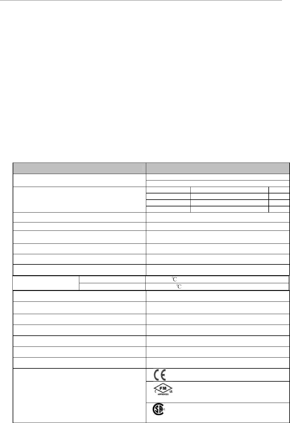
Detail Specifications – Analog Output
Parameter Specification
Input / Output Module
8C
-
PAON
A
1
-
Analog Output
, Coated
8U
-
PAON
A
1
-
Analog Output
, Uncoated
IOTA Modules
8
C
-
TAO
X
A1
Non
-
Redundant, Coated
6”
8U
-
TAO
X
A1
Non
-
Redundant, Uncoated
6”
8C
-
TAOXB1
Redundant, Coated
12”
8U
-
TAO
XB1
Redundant, Uncoated
12”
Output Type 4-20 mA
Output Channels 16
Output Ripple 100 mV peak-to-peak at power line frequency, across
250 Ω load
Load Resistance 50-800Ω
Voltage Rating 24 VDC
Module current rating 190 mA
Resolution ± 0.05% of Full Scale
Module Removal and Insertion
Under Power Supported
Calibrated Accuracy ± 0.2% of Full Scale (25
o
C) including linearity
Directly Settable Output Current Range 2.9 mA to 21.1 mA
Maximum Open Circuit Voltage 22 V
Response Time
(DAC input code to output) settles to within 1% of final value within 80 ms
Gap (0 mA) of Output to Field on Switchover 10 ms maximum (applies to Redundancy only)
Agency certifications
Class I, Division 2, Group A, B, C, D; T4 Class
I, Zone 2 AEx/ Ex nA II C T4
Class I, Division 2, Group A, B, C, D; T4 Class I,
Zone 2, Ex nA II C T4
Temperature Operating Temperature 0 to 60
Storage temperature -40 to 85
Series 8 Controller and I/O Specification, S803-150-110 16
2.2.6. Analog Output with HART
The Analog Output (AO) Module delivers high-level constant current to actuators and recording/indicating devices.
Notable Features
• Extensive self diagnostics
• Optional redundancy
• HART-capable, multivariable devices
• Safe-state (FAILOPT) behaviors configurable on a per channel basis
Safe-state Behavior (FAILOPT)
Series 8 AO module supports the FAILOPT parameter on a per channel basis. The user can configure each channel to
either HOLD LAST VALUE, or SHED to a SAFE VALUE. The Output will always go to zero, the safe state, if the IOM
device electronics fails.
Open-wire Detection
This Series 8 IO function can detect and annunciate open field wire with a Channel Soft Failure indication.
Detail Specifications – Analog Output with HART
Parameter Specification
Input / Output Module
8C
-
PAOHA1
-
Analog Output with HART, Coated
8U
-
PAOHA1
-
Analog Outp
ut with HART, Uncoated
IOTA Modules
8C
-
TAOXA1
Non
-
Redundant, Coated
6”
8U
-
TAO
XA1
Non
-
Redundant, Uncoated
6”
8C
-
TAOXB1
Redundant, Coated
12”
8U
-
TAO
XB1
Redundant, Uncoated
12”
Output Type 4-20 mA
Output Channels 16
Output Ripple < 100 mV peak-to-peak at power line freq, across 250
Ω
load
Load Resistance 50-800Ω
Voltage Rating 24 VDC
Module current rating 205 mA
Resolution ± 0.05% of Full Scale
Module Removal and Insertion
Under Power Supported
Calibrated Accuracy ± 0.2% of Full Scale (25
o
C) including linearity
Directly Settable Output Current Range 2.9 mA to 21.1 mA
Maximum Open Circuit Voltage 22 V
Response Time(DAC input code to output) settles to within 1% of final value within 80 ms
Gap (0 mA) of Output to Field on Switchover 10 ms maximum (applies to Redundancy only)
Agency certifications
Class I, Division 2, Group A, B, C, D; T4 Class
I, Zone 2 AEx/ Ex nA II C T4
Class I, Division 2, Group A, B, C, D; T4 Class I,
Zone 2, Ex nA II C T4
Temperature Operating Temperature 0 to 60
Storage temperature -40 to 85

Series 8 Controller and I/O Specification, S803-150-110 17
2.2.7. Digital Input Sequence of Events
Function
The Digital Input Sequence of Events (DISOE) accepts 24VDC discrete signals as discrete inputs. The inputs can be time
tagged to support 1ms resolution Sequence of Events
Notable Features
• Three modes of operation:
- Normal (20ms PV scan)
- Sequence of Events (1ms resolution SOE,20ms PV scan)
- Low Latency (5ms PV scan)
• Extensive internal diagnostics for data integrity
• Optional redundancy
• Internal or external field power selection
• On board excitation power (no need for marshalling power)
• Direct / Reverse Input Indication
• Galvanic Isolation
Detail Specifications – Digital Input Sequence of Events
Parameter Specification
Input / Output Module 8C-PDISA1 - Digital Input Sequence of Events, Coated
8U-PDISA1 - Digital Input Sequence of Events, Uncoated
IOTA Modules
8C-TDILA1 Non Redundant, Coated 9”
8U-TDILA1 Non Redundant, Uncoated 9”
8C-TDILB1 Redundant, Coated. 12”
8U-TDILB1 Redundant, Uncoated 12”
Input Channels 32
Input Channel Scanning (PV) Normal = 20ms ; Fast = 5ms
Digital Input Resolution for Sequence of Events (SOE) 1ms
Voltage Rating 24 VDC
Module current rating 95 mA
Galvanic Isolation (any input terminal voltage
referenced to common) 1000 VAC RMS or ±1000 VDC
Module Removal and Insertion
Under Power Supported
Isolation Technique Optical (in IOM)
DI Power Voltage Range 18 to 30 VDC
ON Sense Voltage/Current 13 VDC (min) or 3 mA (min)
Temperature Operating Temperature 0 to 60
Storage temperature -40 to 85

Series 8 Controller and I/O Specification, S803-150-110 18
OFF Sense Voltage/Current 5 VDC (max) or 1.2 mA (max)
Input Impedance 4.2 KΩ
Absolute Delay Across Input Filter and Isolation 5 ms ± 20%
Field Resistance for Guaranteed ON Condition 300 Ωmax @ 15 VDC
Field Resistance for Guaranteed OFF Condition 30 KΩmin @ 30 VDC
Agency certifications
Class I, Division 2, Group A, B, C, D; T4 Class I,
Zone 2 AEx/ Ex nA II C T4
Class I, Division 2, Group A, B, C, D; T4 Class I, Zone
2, Ex nA II C T4
Series 8 Controller and I/O Specification, S803-150-110 19
2.2.8. Digital Input 24VDC
Function
The Digital Input 24VDC accepts 24VDC signals as discrete inputs.
Notable Features
• Extensive internal diagnostics for data integrity
• Optional redundancy
• Internal / External field power selection
• Galvanic isolation (System to Field only with external user supplied power)
Detail Specifications – Digital Input 24VDC
Parameter Specification
Input / Output Module
8C
-
PDIL
A
1
-
Digital Input
24VDC, Coated
8U
-
PDIL
A
1
-
Digital Input 24VDC,
Uncoated
IOTA Modules
8C
-
TDILA1
Non Redundant, Coated
9”
8U-TDILA1
Non Redundant,
Uncoated 9”
8C
-
TDIL
B1
Redundant, Coated
12”
8U
-
TDIL
B1
Redundant, Uncoated
12”
Input Channels 32
Galvanic Isolation (any input terminal voltage
referenced to common)
1000 VAC RMS for System
–
to
–
Field isolation for
user supplied field Power
Isolation Technique Optical (In IOM)
Voltage Rating 24 VDC
Module current rating 95 mA
DI Power Voltage Range 18 to 30 VDC (For user supplied field power )
Module Removal and Insertion
Under Power Supported
ON Sense Voltage/Current 13 VDC (min) or 3 mA (min)
OFF Sense Voltage/Current 5 VDC (max) or 1.2 mA (max)
Input Impedance 4.2 KΩ
Absolute Delay Across Input Filter and Isolation 5 ms ± 20%
Agency certifications
Class I, Division 2, Group A, B, C, D; T4
Class I, Zone 2 AEx/ Ex nA II C T4
Class I, Division 2, Group A, B, C, D; T4 Class
I, Zone 2, Ex nA II C T4
Temperature Operating Temperature 0 to 60
Storage temperature -40 to 85

Series 8 Controller and I/O Specification, S803-150-110 20
2.2.9. Digital Input Pulse Accumulation
Function
The Digital Input Pulse Accumulation accepts 24VDC signals as discrete inputs. The first 16 channels can be
configured either as Digital Input or Pulse accumulation to support Pulse Accumulation and frequency measurement on
per channel basis.
Notable Features
• Extensive internal diagnostics for data integrity
• Optional redundancy
• Internal / External field power selection
• Galvanic isolation (System to Field only with external user supplied power)
• Support Pulse Accumulation & frequency measurement
• Channels 1-16 can support Pulse accumulation on per channel basis
• Channels 17-32 can be configured as DI
Detail Specifications – Digital Input Pulse Accumulation
Parameter Specification
Input / Output Module
8C-PDIPA1 - 24VDC Digital Input Pulse Accumulation, Coated
8U
-
PDIPA1
-
24VDC Digital Input Pulse Accumulation,
Uncoated
IOTA Modules
8C
-
TDILA1
Non Redundant, Coated
9”
8U-TDILA1
Non Redundant,
Uncoated 9”
8C
-
TDILB1
Redundant, Coated
12”
8U
-
TDILB1
Redundant, Uncoated
12”
Input Channels 32
Galvanic Isolation (any input terminal
voltage referenced to common)
1000 VAC RMS for System
–
to
–
Field isolation for user supplied
field Power
Isolation Technique Optical (In IOM)
Voltage Rating 24 VDC
Module current rating 105 mA
DI Power Voltage Range 18 to 30 VDC (For user supplied field power )
Module Removal and I
nsertion
Under Power Supported
Signal Type (Pulse Accumulation)
Accumulation Type (0
-
1KHz, for minimum 30% DUTY CYCLE
devices)
Minimum Pulse Width 300 uSec
Individual Channel SCAN Time 300 uSec
ON Sense Voltage/Current 13 VDC (min) or 3 mA (min)
OFF Sense Voltage/Current 5 VDC (max) or 1.2 mA (max)
Input Impedance 4.2 KΩ
Absolute Delay Across Input Filter and
Isolation 5 ms ± 20%
Agency certifications
Class I, Division 2, Group A, B, C, D; T4 Class I, Zone 2
AEx/ Ex nA II C T4
Class I, Division 2, Group A, B, C, D; T4 Class I, Zone 2, Ex
nA II C T4
Temperature Operating Temperature 0 to 60
Storage temperature -40 to 85

Series 8 Controller and I/O Specification, S803-150-110 21
2.2.10. Digital Output 24VDC
Function
The Digital Output bussed 24VDC (DO24V) module can switch reliable 24V digital output signals to control other
process equipment as well as solenoid valves and interposing relays.
Notable Features
• Extensive internal diagnostics to ensure data integrity
• Optional redundancy
• Safe-state (FAILOPT) behaviors
• Latched, pulsed or pulse-width modulated output (per channel)
• Galvanic Isolation (System to Field only with external user supplied power)
Bussed 24VDC DO
The Digital Output Bussed 24VDC has provisions for both internal and external field power excitation. As a bussed
output device, all of the outputs share a common return (ground). All outputs get their power from the same source,
which can be either the system power supply or an externally connected 24V power supply. When selection is from an
external source, outputs can be galvanically isolated from the Series 8 power system. A wiring option on the IOTA
determines if outputs are referenced to the Series 8 system power or an external field power source.
Safe-state Behavior (FAILOPT)
Series 8 DO module will support FAILOPT parameter on a per channel basis. The output can be directed by
configuration to either HOLD THE LAST VALUE, or SHED to a SAFE VALUE. The safe value can be configured by
the user.
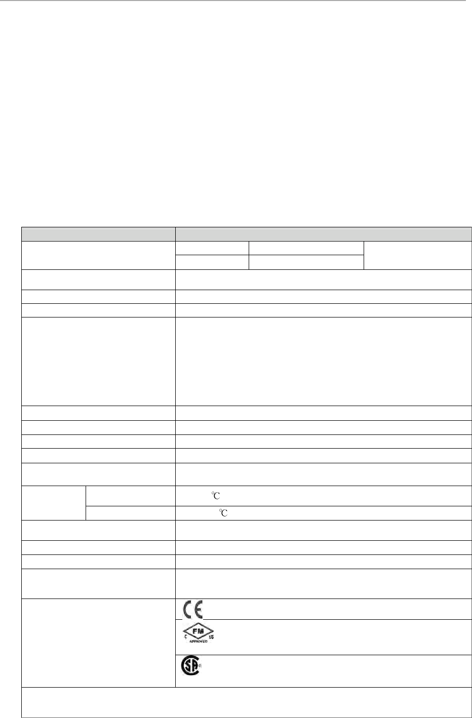
Detail Specifications – Digital Output 24VDC
Parameter Specification
Input / Output Module
8C-PDODA1 - Digital Output 24 VDC, Field Isolated, Bussed
output, Coated
8U-PDODA1 - Digital Output 24 VDC, Field Isolated, Bussed
output, Uncoated
IOTA Module Numbers
8C-TDODA1 Non Redundant, Coated 9”
8U-TDODA1 Non Redundant, Uncoated 9”
8C-TDODB1 Redundant, Coated 12”
8U
-
TDOD
B1
Redundant, Uncoated
12”
Output Channels 32
Output Type Source
Voltage Rating 24 VDC
Module current rating 105mA
Load Voltage 30 VDC Maximum
Module Re
moval and Insertion
Under Power Supported
Temperature
Operating
Temperature 0 to 60
Storage temperature -40 to 85
Series 8 Controller and I/O Specification, S803-150-110 22
Load Current
Short circuit protection for DO channel
would be using series FUSEs in the
output channel. One FUSE per Eight
channels. Total FOUR (4) fuses for 32
channels on DO IOTA
100mA per channel (Max)
Galvanic Isolation
1000 VAC RMS for System – to – Field isolation for user
supplied field Power only
No System- to-Field isolation for internal system power used for
field sensing
On-State Voltage 24 VDC (typ) (load current @ 0.1A max)
Off-State Voltage 0v VDC
Off-State Leak Current 5 µA (max)
Turn-On/Turn-Off Time 10 ms (max)
Gap (0 current) of Output to Field on
Switchover None (0ms) (applies to Redundancy only)
Agency certifications
Class I, Division 2, Group A, B, C, D; T4 Class I, Zone
2 AEx/ Ex nA II C T4
Class I, Division 2, Group A, B, C, D; T4 Class I, Zone 2,
Ex nA II C T4
Series 8 Controller and I/O Specification, S803-150-110 23
2.2.11. DO Relay Extension Board
Function
The Digital Output Relay provides a dry contact for isolated low voltage / low current or high voltage / high current
discrete output applications. Each relay supports a Form-A or Form-B output based on jumper configuration. The Relay
IOTA uses the Digital Output 24V (DO24V) IOM with a special IOTA to support the Relay IOTA. All characteristics of
the DO24V IOM are incorporated here.
Notable Features
• Galvanic isolation
• Isolated Dry Contact
• Counter EMF Snubbing Circuit
• LED indication for each channel ON condition
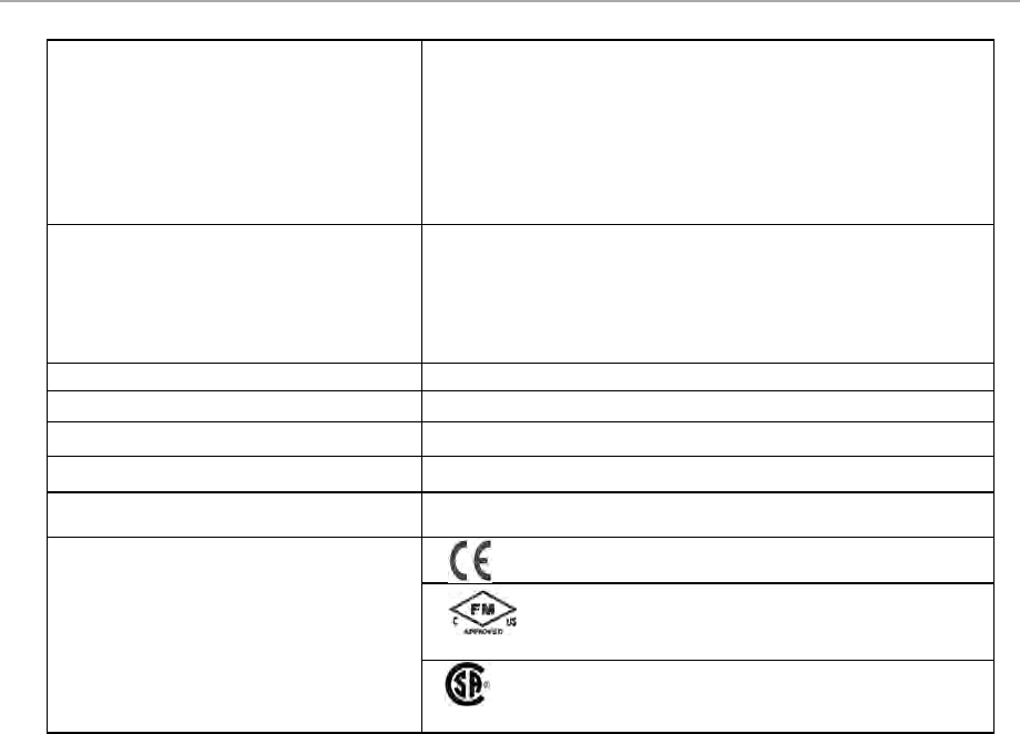
Detail Specifications – DO Relay Extension Board
Parameter Specification
IOTA Module Numbers 8C-SDOX01 Relay Extension, Coated 12”
8U-SDOX01 Relay Extension, Uncoated
Output Channels
32 isolated Form C (SPDT) or Form B (SPST/NC)
contacts (jumper
selectable per output)
Contact Type Au over AgSnO2
Maximum Load Voltage 250 VAC (RMS)/125 VDC
Maximum Steady State Load
Current per Output
Current
Voltage
5A 125 / 250 VAC (resistive)
3 A 30 VDC (resistive)
1 A 48 VDC (resistive)
0.2 A 125 VDC (resistive)
2 A 125 / 250 VAC (inductive = 0.4 power factor)
1 A 30 VAC (inductive L/R = 100 ms)
0.3 A 48 VAC (inductive L/R = 100 ms)
0.1 A 125 VAC (inductive L/R = 100 ms)
Minimum Load Voltage 5 VDC (1)
Minimum Load Current 10 mA or 100mA (1)
Voltage Rating 24 VDC
Module current rating 1010 mA
Module Removal and Insertion
Under Power Supported
Temperature
Operating
Temperature 0 to 60
Storage temperature -40 to 85
Isol
ation
(Channel
-
to
-
channel, and
channel-to-logic common) 1500 VAC RMS or ±1500 VDC
Turn On Time 20 ms maximum
Turn Off Time 20 ms maximum
Contact Life
Operations
% of Max Load
10,000,0000 (Mechanical Life)
200,000 @ 3 A (100%)
Agency certifications
Class I, Division 2, Group A, B, C, D; T4 Class I, Zone 2 AEx/ Ex
nA nC II C T4
Class I, Division 2, Group A, B, C, D; T4 Class I, Zone 2, Ex nA nC II
C T4
Note 1:
The minimum 10mA load current and 5 VDC load voltage specified are
only valid if the contact has not been
previously used in high current / high voltage applications. Once a relay contact is used in a high current / high
voltage application, the minimum load current is 100mA.
Series 8 Controller and I/O Specification, S803-150-110 24
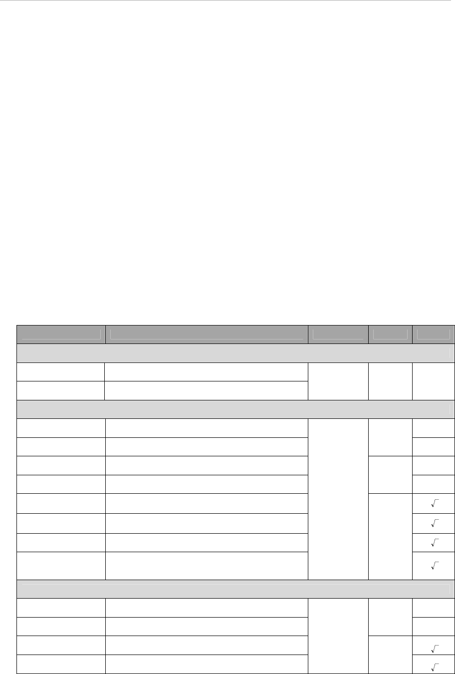
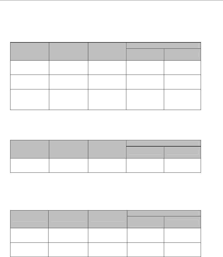
2.2.12. Series 8 IO Function Matrix
The following tables assist in selecting I/O Modules and IOTAs with similar functional characteristics:
AI Function Matrix
IOM NR IOTA Red IOTA
Function
AI
4-20 mA HART
8C-PAIHA1
8U-PAIHA1
8C-TAIXA1
8U-TAIXA1
8C-TAIXB1
8U-TAIXB1
♦
♦
♦
♦
8C-PAINA1
8U-PAINA1
8C-TAIXA1
8U-TAIXA1
8C-TAIXB1
8U-TAIXB1
♦
♦
8C-PAIH54
8U-PAIH54
8C-TAIDA1
8U-TAIDA1
8C-TAIDB1
8U-TAIDB1
♦
♦
♦
♦
TC/RTD Function Matrix
IOM NR IOTA Red IOTA
Function
TC RTD
8C-PAIMA1
8U-PAIMA1
8C-TAIMA1
8U-TAIMA1
NA
NA
♦
♦
♦
♦
AO Function Matrix
IOM NR IOTA Red IOTA
Function
AIO
4-20 mA HART
8C-PAOHA1
8U-PAOHA1
8C-TAOXA1
8U-TAOXA1
8C-TAOXB1
8U-TAOXB1
♦
♦
♦
♦
8C-PAONA1
8U-PAONA1
8C-TAOXA1
8U-TAOXA1
8C-TAOXB1
8U-TAOXB1
♦
♦

Series 8 Controller and I/O Specification, S803-150-110 25
DI Function Matrix
IOM NR IOTA Red IOTA Function
DI SOE PA
8C-PDILA1
8U-PDILA1
8C-TDILA1
8U-TDILA1
8C-TDILB1
8U-TDILB1
♦
♦
8C-PDISA1
8U-PDISA1
8C-TDILA1
8U-TDILA1
8C-TDILB1
8U-TDILB1 ♦
♦
8C-PDIPA1
8U-PDIPA1
8C-TDILA1
8U-TDILA1
8C-TDILB1
8U-TDILB1 ♦
♦
DO Function Matrix
IOM NR IOTA Red IOTA Relay
Extension Source
8C-PDODA1
8U-PDODA1
8C-TDODA1
8U-TDODA1
8C-TDODB1
8U-TDODB1
8C-SDOX01
8U-SDOX01
♦
♦

All other products and brand names shown are trademarks of their respective owners.
This document contains Honeywell proprietary information. It is published for the sole usage of Honeywell Process Solutions’
customers and prospective customers worldwide. Information contained herein is to be used solely for the purpose submitted,
and no part of this document or its contents shall be reproduced, published, or disclosed to a third party without the express
permission of Honeywell International Inc..
While this information is presented in good faith and believed to be accurate, Honeywell disclaims the implied warranties of
merchantability and fitness for a particular purpose and makes no express warranties except as may be stated in its written
agreement with and for its custom er.
In no event is Honeywell liable to anyone for any indirect, special or consequential damages. The information and
specifications in this document are subject to change without notice.

For more information
To learn more about Experion
TM
visit www.honeywellprocess.com
Or contact your Honeywell Account Manager
Process
Solutions
Honeywell
1250 W Sam Houston Pkwy S
Houston, TX 77042
Honeywell Control Systems Ltd
Honeywell House, Skimped Hill Lane
Bracknell, England, RG12 1EB
S803-150-110, Ver.1
January 2014
2014 Honeywell International Inc.
Shanghai City Centre, 100 Jungi Road
Shanghai, China 20061
www.honeywellprocess.com
Sales and Service
For application assistance, current specifications, pricing, or name of the nearest Authorized Distributor, contact one
of the offices below.
ASIA PACIFIC
Honeywell Process Solutions,
(TAC) hfs-tac-
support@honeywell.com
Australia
Honeywell Limited
Phone: +(61) 7-3846 1255
FAX: +(61) 7-3840 6481
Toll Free 1300-36-39-36
Toll Free Fax:
1300-36-04-70
China – PRC - Shanghai
Honeywell China Inc.
Phone: (86-21) 5257-4568
Fax: (86-21) 6237-2826
Singapore
Honeywell Pte Ltd.
Phone: +(65) 6580 3278
Fax: +(65) 6445-3033
South Korea
Honeywell Korea Co Ltd
Phone: +(822) 799 6114
Fax: +(822) 792 9015
EMEA
Honeywell Process Solutions,
Phone: + 80012026455 or
+44 (0)1344 656000
Email: (Sales)
FP-Sales-Apps@Honeywell.com
or
(TAC)
hfs-tac-support@honeywell.com
AMERICA’S
Honeywell Process Solutions,
Phone: (TAC) 1-800-423-9883 or
215/641-3610
(Sales) 1-800-343-0228
Email: (Sales)
FP-Sales-Apps@Honeywell.com
or
(TAC)
hfs-tac-support@honeywell.com
Specifications are subject to change without notice.
