Hacking Electronics An Illustrated DIY Guide For Makers And Hobbyists
User Manual:
Open the PDF directly: View PDF ![]() .
.
Page Count: 305 [warning: Documents this large are best viewed by clicking the View PDF Link!]
- Cover
- About the Author
- Title Page
- Copyright Page
- Contents at a Glance
- Contents
- Acknowledgments
- Introduction
- 1. Getting Started
- 2. Theory and Practice
- 3. Basic Hacks
- 4. LEDs
- How to Stop an LED from Burning Out
- How to Select the Right LED for the Job
- How to Use a LM317 to Make a Constant Current Driver
- How to Measure the Forward Voltage of an LED
- How to Power Large Numbers of LEDs
- How to Make LEDs Flash
- How to Use Stripboard (LED Flasher)
- How to Use a Laser Diode Module
- Hacking a Slot Car Racer
- Summary
- 5. Batteries and Power
- Selecting the Right Battery
- Charging Batteries (in General)
- How to Charge a NiMH Battery
- How to Charge a Sealed Lead–Acid Battery
- How to Charge a LiPo Battery
- Hacking a Cell Phone Battery
- Controlling the Voltage from a Battery
- Boosting Voltage
- Calculating How Long a Battery Will Last
- How to Design for Battery Backup
- How to Use Solar Cells
- Summary
- 6. Hacking Arduino
- How to Set up Arduino (and Blink an LED)
- How to Make an Arduino Control a Relay
- How to Hack a Toy for Arduino Control
- How to Measure Voltage with an Arduino
- How to Use an Arduino to Control an LED
- How to Play a Sound with an Arduino
- How to Use Arduino Shields
- How to Control a Relay from a Web Page
- How to Use an Alphanumeric LCD Shield with Arduino
- How to Drive a Servo Motor with an Arduino
- How to Charlieplex LEDs
- How to Type Passwords Automatically
- Summary
- 7. Hacking with Modules
- How to Use a PIR Motion Sensor Module
- How to Use Ultrasonic Rangefinder Modules
- How to Use a Wireless Remote Module
- How to Use a Wireless Remote Module with Arduino
- How to Control Motor Speed with a Power MOSFET
- How to Control DC Motors with an H-Bridge Module
- How to Control a Stepper Motor with an H-Bridge Module
- How to Make a Simple Robot Rover
- How to Use a Seven-Segment LED Display Module
- How to Use a Real-Time Clock Module
- Summary
- 8. Hacking with Sensors
- 9. Audio Hacks
- 10. Mending and Breaking Electronics
- 11. Tools
- Appendix: Parts
- Index

HowTo-Color (8) / Hacking Electronics / Simon Monk / 236-3 / Front Matter
blind folio i
00-FM.indd 1 1/24/13 10:37 AM
HowTo-Color (8) / Hacking Electronics / Simon Monk / 236-3 / Front Matter
blind folio ii
About the Author
Dr. Simon Monk (Preston, UK) has a degree in Cybernetics and Computer Science and a
PhD in Software Engineering. Monk spent several years as an academic before he returned
to industry, co-founding the mobile software company Momote Ltd. He has been an active
electronics hobbyist since his early teens and is a full-time writer on hobby electronics and
open-source hardware. Dr. Monk is the author of numerous electronics books, specializing in
open-source hardware platforms, especially Arduino and Raspberry Pi. He is also co-author
with Paul Scherz of Practical Electronics for Inventors, 3rd edition. You can follow Simon
on Twitter, where he is @simonmonk2.
00-FM.indd 2 1/24/13 10:37 AM

HowTo-Color (8) / Hacking Electronics / Simon Monk / 236-3 / Front Matter
blind folio iii
Hacking Electronics
An Illustrated DIY Guide for Makers and Hobbyists
Simon Monk
New York Chicago San Francisco Lisbon
London Madrid Mexico City Milan New Delhi
San Juan Seoul Singapore Sydney Toronto
00-FM.indd 3 1/24/13 10:37 AM
Copyright © 2013 by The McGraw-Hill Companies. All rights reserved. Except as permitted under the United States
Copyright Act of 1976, no part of this publication may be reproduced or distributed in any form or by any means, or
stored in a database or retrieval system, without the prior written permission of the publisher.
ISBN: 978-0-07-180237-6
MHID: 0-07-180237-1
The material in this e-book also appears in the print version of this title: ISBN: 978-0-07-180236-9,
MHID: 0-07-180236-3
McGraw-Hill e-books are available at special quantity discounts to use as premiums and sales promotions, or for use in
corporate training programs. To contact a representative please e-mail us at bulksales@mcgraw-hill.com.
All trademarks are trademarks of their respective owners. Rather than put a trademark symbol after every occurrence
of a trademarked name, we use names in an editorial fashion only, and to the benefit of the trademark owner, with no
intention of infringement of the trademark. Where such designations appear in this book, they have been printed with
initial caps.
Information has been obtained by McGraw-Hill from sources believed to be reliable. However, because of the possibility
of human or mechanical error by our sources, McGraw-Hill, or others, McGraw-Hill does not guarantee the accuracy,
adequacy, or completeness of any information and is not responsible for any errors or omissions or the results obtained
from the use of such information.
TERMS OF USE
This is a copyrighted work and McGraw-Hill and its licensors reserve all rights in and to the work. Use of this work is
subject to these terms. Except as permitted under the Copyright Act of 1976 and the right to store and retrieve one copy
of the work, you may not decompile, disassemble, reverse engineer, reproduce, modify, create derivative works based
upon, transmit, distribute, disseminate, sell, publish or sublicense the work or any part of it without McGraw-Hill’s prior
consent. You may use the work for your own noncommercial and personal use; any other use of the work is strictly
prohibited. Your right to use the work may be terminated if you fail to comply with these terms.
THE WORK IS PROVIDED “AS IS.” THE McGRAW-HILL COMPANIES AND ITS LICENSORS MAKE NO
GUARANTEES OR WARRANTIES AS TO THE ACCURACY, ADEQUACY OR COMPLETENESS OF OR
RESULTS TO BE OBTAINED FROM USING THE WORK, INCLUDING ANY INFORMATION THAT CAN BE
ACCESSED THROUGH THE WORK VIA HYPERLINK OR OTHERWISE, AND EXPRESSLY DISCLAIM ANY
WARRANTY, EXPRESS OR IMPLIED, INCLUDING BUT NOT LIMITED TO IMPLIED WARRANTIES OF
MERCHANTABILITY OR FITNESS FOR A PARTICULAR PURPOSE. McGraw-Hill and its licensors do not warrant
or guarantee that the functions contained in the work will meet your requirements or that its operation will be uninterrupted
or error free. Neither McGraw-Hill nor its licensors shall be liable to you or anyone else for any inaccuracy, error or
omission, regardless of cause, in the work or for any damages resulting therefrom. McGraw-Hill has no responsibility for
the content of any information accessed through the work. Under no circumstances shall McGraw-Hill and/or its licensors
be liable for any indirect, incidental, special, punitive, consequential or similar damages that result from the use of or
inability to use the work, even if any of them has been advised of the possibility of such damages. This limitation of
liability shall apply to any claim or cause whatsoever whether such claim or cause arises in contract, tort or otherwise.
HowTo-Color (8) / How to Do Everything: Hacking Electronics / Simon Monk / 236-3 /
eBook 236-3cr_pg copy.indd 1 2/14/13 4:02 PM
HowTo-Color (8) / Hacking Electronics / Simon Monk / 236-3 / Front Matter
blind folio v
To Roger, for making it possible for me to turn a hobby into an occupation.
00-FM.indd 5 1/24/13 10:37 AM
HowTo-Color (8) / Hacking Electronics / Simon Monk / 236-3 / Front Matter
blind folio vi
vii
00-FM.indd 6 1/24/13 10:37 AM
This page intentionally left blank
vii
HowTo-Color (8) / Hacking Electronics / Simon Monk / 236-3 / Front Matter
Contents at a Glance
1 Getting Started ............................................. 1
2 Theory and Practice ......................................... 19
3 Basic Hacks ............................................... 33
4 LEDs .................................................... 55
5 Batteries and Power ......................................... 83
6 Hacking Arduino ........................................... 105
7 Hacking with Modules ....................................... 149
8 Hacking with Sensors ....................................... 193
9 Audio Hacks ............................................... 213
10 Mending and Breaking Electronics . . . . . . . . . . . . . . . . . . . . . . . . . . . . . 235
11 Tools ..................................................... 245
A Parts ..................................................... 257
Index .................................................... 263
00-FM.indd 7 1/24/13 10:37 AM
HowTo-Color (8) / Hacking Electronics / Simon Monk / 236-3 / Front Matter
blind folio viii
ix
00-FM.indd 8 1/24/13 10:37 AM
This page intentionally left blank
ix
HowTo-Color (8) / Hacking Electronics / Simon Monk / 236-3 / Front Matter
Contents
Acknowledgments ........................................ xix
Introduction ............................................. xxi
CHAPTER 1 Getting Started ........................................... 1
Getting Stuff ............................................. 1
Buying Components .................................. 1
Where to Buy Things to Hack . . . . . . . . . . . . . . . . . . . . . . . . . . 2
A Basic Toolkit ..................................... 3
How to Strip a Wire ....................................... 5
You Will Need ...................................... 5
How to Join Wires Together by Twisting . . . . . . . . . . . . . . . . . . . . . . . 7
You Will Need ...................................... 7
How to Join Wires by Soldering . . . . . . . . . . . . . . . . . . . . . . . . . . . . . . 8
Safety ............................................. 8
You Will Need ...................................... 9
Soldering .......................................... 10
Joining Wires ....................................... 11
How to Test a Connection .................................. 12
You Will Need ...................................... 12
How to Hack a Computer Fan to Keep Soldering Fumes Away . . . . . 14
You Will Need ...................................... 14
Construction ........................................ 14
Summary ............................................... 18
CHAPTER 2 Theory and Practice ...................................... 19
How to Assemble a Starter Kit of Components . . . . . . . . . . . . . . . . . . 19
You Will Need ...................................... 19
How to Identify Electronic Components . . . . . . . . . . . . . . . . . . . . . . . 20
Resistors ........................................... 20
Capacitors ......................................... 22
Diodes ............................................ 23
LEDs ............................................. 23
00-FM.indd 9 1/24/13 10:37 AM
x Hacking Electronics
HowTo-Color (8) / Hacking Electronics / Simon Monk / 236-3 / Front Matter
Transistors ......................................... 24
Integrated Circuits ................................... 24
Other Stuff . . . . . . . . . . . . . . . . . . . . . . . . . . . . . . . . . . . . . . . . . 25
Surface Mount Components . . . . . . . . . . . . . . . . . . . . . . . . . . . 25
What Are Current, Resistance, and Voltage? . . . . . . . . . . . . . . . . . . . . 25
Current ............................................ 26
Resistance ......................................... 26
Voltage ............................................ 26
Ohm’s Law ......................................... 27
What Is Power? .......................................... 28
How to Read a Schematic Diagram . . . . . . . . . . . . . . . . . . . . . . . . . . . 29
The First Rule of Schematics: Positive
Voltages Are Uppermost . . . . . . . . . . . . . . . . . . . . . . . . . . . . 29
Second Rule of Schematics: Things Happen Left to Right . . . . 30
Names and Values ................................... 30
Component Symbols ................................. 30
Summary ............................................... 31
CHAPTER 3 Basic Hacks ............................................. 33
How to Make a Resistor Get Hot . . . . . . . . . . . . . . . . . . . . . . . . . . . . . 33
You Will Need ...................................... 33
The Experiment ..................................... 33
How to Use Resistors to Divide a Voltage . . . . . . . . . . . . . . . . . . . . . . 34
You Will Need ...................................... 34
How to Convert a Resistance to a Voltage
(and Make a Light Meter) .................................. 37
You Will Need ...................................... 37
Hack a Push Light to Make It Light Sensing . . . . . . . . . . . . . . . . . . . . 39
You Will Need ...................................... 39
Breadboard ......................................... 40
Construction ........................................ 41
How to Choose a Bipolar Transistor . . . . . . . . . . . . . . . . . . . . . . . . . . 45
Datasheets ......................................... 45
MOSFET Transistors ................................. 46
PNP and N-Channel Transistors . . . . . . . . . . . . . . . . . . . . . . . . 46
Common Transistors ................................. 47
How to Use a Power MOSFET to Control a Motor . . . . . . . . . . . . . . . 48
You Will Need ...................................... 48
Breadboard ......................................... 48
How to Select the Right Switch . . . . . . . . . . . . . . . . . . . . . . . . . . . . . . 50
Push-Button Switches ................................ 50
Microswitches ...................................... 51
Toggle Switches ..................................... 51
Summary ............................................... 53
00-FM.indd 10 1/24/13 10:37 AM
Contents xi
HowTo-Color (8) / Hacking Electronics / Simon Monk / 236-3 / Front Matter
CHAPTER 4 LEDs .................................................... 55
How to Stop an LED from Burning Out . . . . . . . . . . . . . . . . . . . . . . . 55
You Will Need ...................................... 55
Diodes ............................................ 56
LEDs ............................................. 56
Trying It Out ....................................... 58
How to Select the Right LED for the Job . . . . . . . . . . . . . . . . . . . . . . . 59
You Will Need ...................................... 59
Brightness and Angle ................................. 59
Multicolor ......................................... 60
IR and UV ......................................... 60
LEDs for Illumination ................................ 61
How to Use a LM317 to Make a Constant Current Driver . . . . . . . . . 62
You Will Need ...................................... 62
Design ............................................ 63
Breadboard ......................................... 64
Construction ........................................ 65
How to Measure the Forward Voltage of an LED . . . . . . . . . . . . . . . . 66
You Will Need ...................................... 67
How to Power Large Numbers of LEDs . . . . . . . . . . . . . . . . . . . . . . . 68
How to Make LEDs Flash .................................. 69
You Will Need ...................................... 69
Breadboard ......................................... 69
How to Use Stripboard (LED Flasher) . . . . . . . . . . . . . . . . . . . . . . . . . 71
Designing the Stripboard Layout . . . . . . . . . . . . . . . . . . . . . . . . 71
You Will Need ...................................... 73
Construction ........................................ 74
Troubleshooting ..................................... 77
How to Use a Laser Diode Module . . . . . . . . . . . . . . . . . . . . . . . . . . . 78
Hacking a Slot Car Racer ................................... 78
You Will Need ...................................... 78
Storing Charge in a Capacitor . . . . . . . . . . . . . . . . . . . . . . . . . . 79
Design ............................................ 80
Construction ........................................ 81
Testing ............................................ 81
Summary ............................................... 82
CHAPTER 5 Batteries and Power ...................................... 83
Selecting the Right Battery . . . . . . . . . . . . . . . . . . . . . . . . . . . . . . . . . 83
Battery Capacity ..................................... 83
Maximum Discharge Rate ............................. 84
Single-Use Batteries .................................. 84
Rechargeable Batteries ................................ 86
00-FM.indd 11 1/24/13 10:37 AM
xii Hacking Electronics
HowTo-Color (8) / Hacking Electronics / Simon Monk / 236-3 / Front Matter
Charging Batteries (in General) . . . . . . . . . . . . . . . . . . . . . . . . . . . . . . 88
C ................................................. 88
Over-Charging . . . . . . . . . . . . . . . . . . . . . . . . . . . . . . . . . . . . . . 89
Over-Discharging .................................... 89
Battery Life ........................................ 89
How to Charge a NiMH Battery . . . . . . . . . . . . . . . . . . . . . . . . . . . . . . 89
Simple Charging .................................... 90
Fast Charging ....................................... 91
How to Charge a Sealed Lead–Acid Battery . . . . . . . . . . . . . . . . . . . . 91
Charging with a Variable Power Supply . . . . . . . . . . . . . . . . . . 91
How to Charge a LiPo Battery . . . . . . . . . . . . . . . . . . . . . . . . . . . . . . . 92
Hacking a Cell Phone Battery . . . . . . . . . . . . . . . . . . . . . . . . . . . . . . . 93
Controlling the Voltage from a Battery . . . . . . . . . . . . . . . . . . . . . . . . 95
You Will Need ...................................... 96
Breadboard ......................................... 97
Boosting Voltage .......................................... 97
Calculating How Long a Battery Will Last . . . . . . . . . . . . . . . . . . . . . 98
How to Design for Battery Backup . . . . . . . . . . . . . . . . . . . . . . . . . . . 99
Diodes ............................................ 99
Trickle Charging .................................... 100
How to Use Solar Cells .................................... 101
Testing a Solar Panel ................................. 102
Trickle Charging with a Solar Panel . . . . . . . . . . . . . . . . . . . . . 103
Minimizing Power Consumption . . . . . . . . . . . . . . . . . . . . . . . . 104
Summary ............................................... 104
CHAPTER 6 Hacking Arduino ......................................... 105
How to Set up Arduino (and Blink an LED) . . . . . . . . . . . . . . . . . . . . 106
You Will Need ...................................... 106
Setting Up Arduino .................................. 106
Modifying the Blink Sketch . . . . . . . . . . . . . . . . . . . . . . . . . . . . 109
How to Make an Arduino Control a Relay . . . . . . . . . . . . . . . . . . . . . . 112
Relays ............................................. 112
Arduino Outputs ..................................... 112
You Will Need ...................................... 114
Construction ........................................ 114
Software ........................................... 115
How to Hack a Toy for Arduino Control . . . . . . . . . . . . . . . . . . . . . . . 116
You Will Need ...................................... 116
Construction ........................................ 116
The Serial Monitor ................................... 118
Software ........................................... 118
00-FM.indd 12 1/24/13 10:37 AM
Contents xiii
HowTo-Color (8) / Hacking Electronics / Simon Monk / 236-3 / Front Matter
How to Measure Voltage with an Arduino . . . . . . . . . . . . . . . . . . . . . . 119
You Will Need ...................................... 120
Construction ........................................ 120
Software ........................................... 120
How to Use an Arduino to Control an LED . . . . . . . . . . . . . . . . . . . . . 122
You Will Need ...................................... 122
Construction ........................................ 122
Software (Flashing) .................................. 123
Software (Brightness) ................................ 124
How to Play a Sound with an Arduino . . . . . . . . . . . . . . . . . . . . . . . . . 125
You Will Need ...................................... 125
Construction ........................................ 126
Software ........................................... 126
How to Use Arduino Shields . . . . . . . . . . . . . . . . . . . . . . . . . . . . . . . . 127
How to Control a Relay from a Web Page . . . . . . . . . . . . . . . . . . . . . . 128
You Will Need ...................................... 129
Construction ........................................ 130
Network Conguration ............................... 131
Testing ............................................ 131
Software ........................................... 132
How to Use a Alphanumeric LCD Shield with Arduino . . . . . . . . . . . 136
You Will Need ...................................... 137
Construction ........................................ 137
Software ........................................... 137
How to Drive a Servo Motor with an Arduino . . . . . . . . . . . . . . . . . . . 139
You Will Need ...................................... 140
Construction ........................................ 140
Software ........................................... 140
How to Charlieplex LEDs .................................. 142
You Will Need ...................................... 143
Construction ........................................ 143
Software ........................................... 143
How to Type Passwords Automatically . . . . . . . . . . . . . . . . . . . . . . . . 145
You Will Need ...................................... 146
Construction ........................................ 146
Software ........................................... 146
Summary ............................................... 147
CHAPTER 7 Hacking with Modules .................................... 149
How to Use a PIR Motion Sensor Module . . . . . . . . . . . . . . . . . . . . . . 149
You Will Need (PIR and LED) . . . . . . . . . . . . . . . . . . . . . . . . . 150
Breadboard ......................................... 150
You Will Need (PIR and Arduino) . . . . . . . . . . . . . . . . . . . . . . . 151
00-FM.indd 13 1/24/13 10:37 AM
xiv Hacking Electronics
HowTo-Color (8) / Hacking Electronics / Simon Monk / 236-3 / Front Matter
Construction ........................................ 151
Software ........................................... 152
How to Use Ultrasonic Rangender Modules . . . . . . . . . . . . . . . . . . . 153
You Will Need ...................................... 154
The HC-SR04 Rangender . . . . . . . . . . . . . . . . . . . . . . . . . . . . 155
The MaxBotix LV-EZ1 Rangender . . . . . . . . . . . . . . . . . . . . . 157
How to Use a Wireless Remote Module . . . . . . . . . . . . . . . . . . . . . . . . 159
You Will Need ...................................... 159
Breadboard ......................................... 159
How to Use a Wireless Remote Module with Arduino . . . . . . . . . . . . 161
You Will Need ...................................... 161
Software ........................................... 161
How to Control Motor Speed with a Power MOSFET . . . . . . . . . . . . 163
You Will Need ...................................... 163
Breadboard ......................................... 164
Software ........................................... 165
How to Control DC Motors with an H-Bridge Module . . . . . . . . . . . . 166
You Will Need ...................................... 170
Breadboard ......................................... 170
Using the Control Pins ................................ 171
How to Control a Stepper Motor with an H-Bridge Module . . . . . . . . 172
You Will Need ...................................... 174
Construction ........................................ 175
Software ........................................... 175
How to Make a Simple Robot Rover . . . . . . . . . . . . . . . . . . . . . . . . . . 177
You Will Need ...................................... 178
Construction ........................................ 179
Testing ............................................ 181
Software ........................................... 182
How to Use a Seven-Segment LED Display Module . . . . . . . . . . . . . . 183
You Will Need ...................................... 185
Construction ........................................ 186
Software ........................................... 187
How to Use a Real-Time Clock Module . . . . . . . . . . . . . . . . . . . . . . . 188
You Will Need ...................................... 189
Construction ........................................ 190
Software ........................................... 191
Summary ............................................... 192
CHAPTER 8 Hacking with Sensors .................................... 193
How to Detect Noxious Gas ................................. 193
You Will Need ...................................... 193
The LM311 Comparator .............................. 194
00-FM.indd 14 1/24/13 10:37 AM
Contents xv
HowTo-Color (8) / Hacking Electronics / Simon Monk / 236-3 / Front Matter
Breadboard ......................................... 195
Using a Gas Sensor with an Arduino . . . . . . . . . . . . . . . . . . . . . 196
How to Measure Something’s Color . . . . . . . . . . . . . . . . . . . . . . . . . . 197
You Will Need ...................................... 198
Construction ........................................ 199
Software ........................................... 199
How to Detect Vibration .................................... 202
You Will Need ...................................... 202
Construction ........................................ 202
Software ........................................... 203
How to Measure Temperature . . . . . . . . . . . . . . . . . . . . . . . . . . . . . . . 204
You Will Need ...................................... 205
Construction ........................................ 205
Software ........................................... 205
How to Use an Accelerometer . . . . . . . . . . . . . . . . . . . . . . . . . . . . . . . 206
You Will Need ...................................... 207
Construction ........................................ 207
Software ........................................... 208
How to Sense Magnetic Fields . . . . . . . . . . . . . . . . . . . . . . . . . . . . . . . 210
You Will Need ...................................... 211
Construction ........................................ 211
Software ........................................... 212
Summary ............................................... 212
CHAPTER 9 Audio Hacks . . . . . . . . . . . . . . . . . . . . . . . . . . . . . . . . . . . . . . . . . . . . . 213
Hacking Audio Leads ...................................... 213
General Principals ................................... 213
Soldering Audio Connectors . . . . . . . . . . . . . . . . . . . . . . . . . . . 215
Converting a Stereo Signal to Mono . . . . . . . . . . . . . . . . . . . . . 217
How to Use a Microphone Module . . . . . . . . . . . . . . . . . . . . . . . . . . . 218
How to Make an FM Bug ................................... 220
You Will Need ...................................... 221
Construction ........................................ 221
Testing ............................................ 223
Selecting Loudspeakers .................................... 223
How to Make a 1-Watt Audio Amplier . . . . . . . . . . . . . . . . . . . . . . . 224
You Will Need ...................................... 225
Construction ........................................ 226
Testing ............................................ 227
How to Generate Tones with a 555 Timer . . . . . . . . . . . . . . . . . . . . . . 227
You Will Need ...................................... 229
Construction ........................................ 229
00-FM.indd 15 1/24/13 10:37 AM
xvi Hacking Electronics
HowTo-Color (8) / Hacking Electronics / Simon Monk / 236-3 / Front Matter
How to Make a USB Music Controller . . . . . . . . . . . . . . . . . . . . . . . . 229
You Will Need ...................................... 230
Construction ........................................ 230
Software ........................................... 230
How to Make a Software VU Meter . . . . . . . . . . . . . . . . . . . . . . . . . . . 232
You Will Need ...................................... 233
Construction ........................................ 233
Software ........................................... 233
Summary ............................................... 234
CHAPTER 10 Mending and Breaking Electronics . . . . . . . . . . . . . . . . . . . . . . . . . 235
How to Avoid Electrocution ................................. 235
How to Take Something Apart AND Put It Back Together Again . . . . 236
How to Check a Fuse ...................................... 237
How to Test a Battery ...................................... 239
How to Test a Heating Element . . . . . . . . . . . . . . . . . . . . . . . . . . . . . . 240
Finding and Replacing Failed Components . . . . . . . . . . . . . . . . . . . . . 240
Testing Components .................................. 240
Desoldering ........................................ 241
Replacement ........................................ 242
How to Scavenge Useful Components . . . . . . . . . . . . . . . . . . . . . . . . . 242
How to Reuse a Cell Phone Power Adapter . . . . . . . . . . . . . . . . . . . . . 243
Summary ............................................... 244
CHAPTER 11 Tools .................................................... 245
How to Use a Multimeter (General) . . . . . . . . . . . . . . . . . . . . . . . . . . . 245
Continuity and Diode Test . . . . . . . . . . . . . . . . . . . . . . . . . . . . . 245
Resistance ......................................... 246
Capacitance ........................................ 247
Temperature ........................................ 247
AC Voltage ......................................... 248
DC Voltage ......................................... 249
DC Current ......................................... 249
AC Current ......................................... 250
Frequency .......................................... 250
How to Use a Multimeter to Test a Transistor . . . . . . . . . . . . . . . . . . . 250
How to Use a Lab Power Supply . . . . . . . . . . . . . . . . . . . . . . . . . . . . . 251
Introducing: The Oscilloscope . . . . . . . . . . . . . . . . . . . . . . . . . . . . . . . 252
Software Tools ........................................... 253
Simulation ......................................... 253
Fritzing ............................................ 253
EAGLE PCB ....................................... 254
Online Calculators ................................... 256
Summary ............................................... 256
00-FM.indd 16 1/24/13 10:37 AM
Contents xvii
HowTo-Color (8) / Hacking Electronics / Simon Monk / 236-3 / Front Matter
Appendix Parts .................................................... 257
Tools ................................................... 257
Components ............................................. 258
Component Starter Kits ............................... 258
Resistors ........................................... 258
Capacitors ......................................... 259
Semiconductors ..................................... 259
Hardware and Miscellaneous . . . . . . . . . . . . . . . . . . . . . . . . . . . 260
Modules ........................................... 261
Index .................................................... 263
00-FM.indd 17 1/24/13 10:37 AM
HowTo-Color (8) / Hacking Electronics / Simon Monk / 236-3 / Front Matter
blind folio xviii
xix
00-FM.indd 18 1/24/13 10:37 AM
This page intentionally left blank
xix
HowTo-Color (8) / Hacking Electronics / Simon Monk / 236-3 / Front Matter
Acknowledgments
Many thanks to all those at McGraw-Hill Education who have done such a great job in producing
this book. In particular, thanks to my editor Roger Stewart and to Vastavikta Sharma, Jody
McKenzie, Mike McGee, and Claire Splan.
Special thanks are due to Duncan Amos, John Heath, and John Hutchinson for their technical
review of the material and encouragement.
And last but not least, thanks once again to Linda, for her patience and generosity in giving
me space to do this.
00-FM.indd 19 1/24/13 10:37 AM
HowTo-Color (8) / Hacking Electronics / Simon Monk / 236-3 / Front Matter
blind folio xx
xxi
00-FM.indd 20 1/24/13 10:37 AM
This page intentionally left blank
xxi
HowTo-Color (8) / Hacking Electronics / Simon Monk / 236-3 / Front Matter
Introduction
This is a book about “hacking” electronics. It is not a formal, theory-based book about electronics.
Its sole aim is to equip the reader with the skills he or she needs to use electronics to make
something, whether it’s starting from scratch, connecting together modules, or adapting existing
electronic devices for some new use.
You will learn how to experiment and get your ideas into some kind of order, so that what
you make will work. Along the way, you’ll gain an appreciation for why things work and the
limits of what they can do, and learn how to make prototypes on solderless breadboard, how to
solder components directly to each other, and how to use stripboard.
You will also learn how to use the popular Arduino microcontroller board, which has become
one of the most important tools available to the electronics hacker. There are over 20 examples of
how to use an Arduino with electronics in this book.
Electronics has changed. This is a modern book that avoids theory you will likely never use
and instead concentrates on how you can build things using readymade modules when they are
available. There is, after all, no point in reinventing the wheel.
Some of the things explained and described in the book include
● Using LEDs, including high-power Lumileds
● Using LiPo battery packs and buck-boost power supply modules
● Using sensors to measure light, temperature, vibration, acceleration, sound level,
and color
● Interfacing with Arduino microcontroller boards, including using Arduino shields such as
the Ethernet and LCD display shields
● Using servo and stepper motors
00-FM.indd 21 1/24/13 10:37 AM
xxii Hacking Electronics
HowTo-Color (8) / Hacking Electronics / Simon Monk / 236-3 / Front Matter
Some of the things described in the book that you can make along the way include
● A noxious gas detector
● An Internet-controlled hacked electric toy
● A device for measuring color
● An ultrasonic rangefinder
● A remote control robotic rover
● An accelerometer-based version of the “egg and spoon” race
● A one-watt audio amplifier
● A bug made from a hacked MP3 FM transmitter
● Working brakes and head lights that can be added to a slot car
You Will Need
This is a very practical, hands-on type of book. You will therefore need some tools and components
to get the most out of it.
As far as tools go, you will need little more than a multimeter and soldering equipment.
When it comes to areas of electronics where a microcontroller would be useful, an Arduino
Uno board is best. So you may wish to buy one of these microcontroller boards before attempting
some of the projects.
Every component used in this book is listed in the Appendix, along with sources where it can
be obtained. The majority of the components can be found in a starter kit from SparkFun, but
most electronic starter kits will provide a lot of what you will need.
In many of the “how-tos,” there will be a You Will Need section. This will refer to a code in
the Appendix that explains where to get the component.
00-FM.indd 22 1/24/13 10:37 AM

Introduction xxiii
HowTo-Color (8) / Hacking Electronics / Simon Monk / 236-3 / Front Matter
How to Use This Book
The book is organized into chapters, each of which has a theme. Within each chapter, most of the
numbered sections contain a “how-to” on some topic of electronics.
The book contains the following chapters:
Chapter Title Description
Chapter 1 Getting Started The book starts off by telling you where you can buy equipment and
components, as well as things to hack. This chapter also deals with the
basics of soldering and focuses on a project to hack an old computer fan
to make a fume extractor for use while soldering.
Chapter 2 Theory and
Practice
This chapter introduces electronic components—or at least the ones you
are likely to use—and explains how to identify them and describes what
they do. It also introduces a small amount of essential theory, which you
will use over and over again.
Chapter 3 Basic Hacks This chapter contains a set of fairly basic “hacking” how-tos, introducing
concepts like using transistors with example projects. It includes hacking
a “push light” to make it automatically turn on when it gets dark and how
to control a motor using power MOSFETs.
Chapter 4 LEDs In addition to discussing regular LEDs and how to use them and make
them flash and so on, this chapter also looks at using constant current
drivers for LEDs and how to power large numbers of LEDs and laser
diode modules.
Chapter 5 Batteries and
Power
This chapter discusses the various types of battery, both single use and
rechargeable. It also covers how to charge batteries including LiPos.
Automatic battery backup, voltage regulation, and solar charging are
also explained.
Chapter 6 Hacking
Arduino
The Arduino has become the microcontroller board of choice for
electronics hackers. Its open-source hardware design makes using a
complex device like a microcontroller very straightforward. The chapter
gets you started with the Arduino and includes a few simple how-tos,
like controlling a relay, playing sounds, and controlling servo motors
from an Arduino. It also covers the use of Arduino expansion shields.
00-FM.indd 23 1/24/13 10:37 AM

xxiv Hacking Electronics
HowTo-Color (8) / Hacking Electronics / Simon Monk / 236-3 / Front Matter
Chapter Title Description
Chapter 7 Hacking with
Modules
When you want to make something, you can often use readymade
modules at least for part of the project. Modules exist for all sorts of
things, from wireless remotes to motor drivers.
Chapter 8 Hacking with
Sensors
Sensor ICs and modules are available for sensing everything from gas
to acceleration. In this chapter, we explore a good range of them and
explain how to use them and connect some of them to an Arduino.
Chapter 9 Audio Hacks This chapter has a number of useful how-tos relating to electronics and
sound. It includes making and adapting audio leads, as well as audio
amplifiers, and discusses the use of microphones.
Chapter 10 Mending and
Breaking
Electronics
Mending electronics and scavenging useful parts from dead electronics
are a worthy activity for the electronics hacker. This chapter explains
how to take things apart and sometimes put them back together again.
Chapter 11 Tools The final chapter of the book is intended as a reference to explain more
about how to get the most out of tools such as multimeters and lab
power supplies.
00-FM.indd 24 1/24/13 10:37 AM
HowTo-Color (8) / Hacking Electronics / Simon Monk / 236-3 / Front Matter
00-FM.indd 25 1/24/13 10:37 AM
This page intentionally left blank

HowTo-Color (8) / Hacking Electronics / Simon Monk / 236-3 / Front Matter
00-FM.indd 26 1/24/13 10:37 AM
HowTo-Color (8) / Hacking Electronics / Simon Monk / 236-3 / Chapter 1
blind folio 1
1
Getting Started
In this first chapter, we will investigate some of the tools and techniques needed to hack
electronics. We will start with a little soldering, and wire up an old computer fan to help keep
the solder fumes out of our lungs.
As it says in the title, this book is all about “hacking electronics.” The word “hacking” has
come to mean many things. But in this book, “hacking” means “just do it!” You don’t need a
degree in electronic engineering to create or modify something electronic. The best way to learn
is by having a go at it. You will learn as much from your mistakes as from your successes.
As you start to make things and experiment, you will likely want to understand more of the
theory behind it all. Traditional electronics textbooks are pretty terrifying unless you have a good
grasp of complex mathematics. This book strives to, above all else, enable you to do things first
and worry about the theory later.
To get started, you will need some tools, and also find out where to get components and parts
to use in your projects.
Getting Stuff
In addition to buying components and tools, there are lots of low-cost and interesting electronic
consumer items that can be hacked and used for new purposes, or that can act as donors of
interesting components.
Buying Components
Most component purchases happen on the Internet, although there are local electronic stores like
RadioShack (in the U.S.) and Maplin (in the UK) where you can buy components. At traditional
brick-and-mortar stores like those, the product range is often limited and the prices can be on
the high side. They do, after all, have a shop to pay for. These stores are invaluable, however, on
the odd occasion where you need something in a hurry. Perhaps you need an LED because you
accidentally destroyed one, or maybe you want to look at the enclosures they sell for projects.
01-ch01.indd 1 12/26/12 12:08 PM
2 Hacking Electronics
HowTo-Color (8) / Hacking Electronics / Simon Monk / 236-3 / Chapter 1
Sometimes it’s just nice to hold a box or look at tools for real,
rather than trying to size them up from pictures on a web site.
As you get into electronics, you will likely gradually
accumulate a set of components and tools that you can draw
from when you start a new project. Components are relatively
cheap, so when I need one of something, I generally order two
or three or even five if they are cheap, enough that I have extras
on hand that can be used another time. This way, you will often
find that when you start to work on something, you actually
have pretty much everything you need already.
Component buying really depends on where you are in the
world. In the U.S., Mouser and DigiKey are the largest suppliers
of electronic components to the hobby electronics market. In
fact, both of these suppliers sell worldwide. Farnell also supplies
pretty much anything you could want, anywhere in the world.
When it comes to buying ready-made electronics modules for
your projects, the SparkFun, Seeed Studio, Adafruit, and ITead
Studio web sites can help. All have a wide range of modules,
and much enjoyment can be had simply from browsing their
online catalogs.
Nearly all the components used in this book have part codes
for one or more of the suppliers I just mentioned. The only
exceptions are for a few unusual modules that are better to buy
from eBay.
There is also no end to the electronic components available
on online auction sites, many coming direct from countries in the
far east and often at extremely low prices. This is frequently the
place to go for unusual components and things like laser modules
and high-power LEDs that can be expensive in regular component
suppliers. They are also very good for buying components in
bulk. Sometimes these components are not grade A, however, so
read the descriptions carefully and don’t be disappointed if some
of the items in the batch are dead-on-arrival.
Where to Buy Things to Hack
The first thing to consider, now that you are into hacking
electronics, is an effect that your household and friends will
have on you. You will become the recipient of dead electronics.
But keep an eye open in your new role as refuse collector.
Sometimes these “dead” items may actually be candidates for
straightforward resurrection.
Another major source of useful bits is the dollar/pound/euro
(delete as appropriate) store. Find the aisle with the electronic
01-ch01.indd 2 12/26/12 12:08 PM

CHAPTER 1: Getting Started 3
HowTo-Color (8) / Hacking Electronics / Simon Monk / 236-3 / Chapter 1
stuff: flashlights, fans, solar toys, illuminated cooling laptop
bases, and so on. It’s amazing what can be bought for a single
unit of currency. Often you will find motors and arrays of LEDs
for a lower price than you would the raw components from a
conventional supplier.
Supermarkets are another source of cheap electronics that can
be hacked. Good examples of useful gadgets are cheap powered
computer speakers, mice, power supplies, radio receivers, LED
flashlights, and computer keyboards.
A Basic Toolkit
Don’t think you are going to get through this chapter without
doing some soldering. Given this, you will need some basic
tools. These do not have to be expensive. In fact, when you are
starting out on something new, it’s a good idea to learn to use
things that are inexpensive, so it doesn’t matter if you spoil
them. After all, you wouldn’t learn the violin on a Stradivarius.
Plus, what will you have to look forward to if you buy all your
high-end tools now!
Many starter toolkits are available. For our purposes, you
will need a basic soldering iron, solder, a soldering iron stand,
some pliers, snips, and a screwdriver or two. SparkFun sells
just such a kit (SKU TOL-09465), so buy that one or look for
something similar.
You will also need a multimeter (Figure 1-1). I
would suggest a low-cost digital multimeter (don’t
even think of going above USD 20). Even if you end
up buying a better one, you will still end up using
the other one since it’s often useful to measure more
than one thing at a time. The key things you need are
DC Volts, DC current, resistance, and a continuity
test. Everything else is fluff that you will only need
once in a blue moon. Again, look for something
similar to this model from SparkFun (SKU TOL-
09141) or the slightly higher specification meter
shown in Figure 1-1.
Solderless breadboards (Figure 1-2) are very
useful for quickly trying out designs before you
commit them to solder. You poke the leads of
components into the sockets, and metal clips behind
the holes connect all the holes on a row together.
They are not expensive (see T5 in the Appendix).
Figure 1-1 A digital multimeter
01-ch01.indd 3 12/26/12 12:08 PM

4 Hacking Electronics
HowTo-Color (8) / Hacking Electronics / Simon Monk / 236-3 / Chapter 1
You will also need some solid core wire in different colors
(T6) to make bridging connections on the breadboard. Another
good idea is to buy special-purpose jumper wires with little
plugs on the end—although these are useful, they are by no
means essential.
Breadboard comes in all shapes and sizes, but a big one
is probably most useful. Where I use solderless breadboard in
the book, I use the one specified in T5 in the Appendix. This
has 63 rows by 2 columns with two supply strips down each
side (Figure 1-2a). It is also mounted on an aluminum base
with rubber feet to stop it moving about on the table. This is a
very common size of breadboard and most suppliers will have
something similar.
Figure 1-2b shows how the conductive strips are arranged
underneath the plastic top surface of the board. All the holes
that share a common gray area beneath are connected together
Figure 1-2 Solderless breadboard
(a) (b)
01-ch01.indd 4 12/26/12 12:08 PM

CHAPTER 1: Getting Started 5
HowTo-Color (8) / Hacking Electronics / Simon Monk / 236-3 / Chapter 1
in rows of five connectors. The long strips down each side are
used for the power supply to the components. One positive and
one negative. They are color-coded red and green.
How to Strip a Wire
Let’s start with some basic techniques you need to know when
hacking electronics. Perhaps the most basic of these is stripping
wire.
You Will Need
Quantity Item Appendix Code
Wire to be stripped T9 or scrap
1 Pliers T1
1 Snips T1
Whenever you hack electronics, there is likely to be some
wire involved, so you need to know how to use it. Figure 1-3
shows a selection of commonly used types of wire, set beside a
matchstick to give them perspective.
On the left, next to the matchstick, are three lengths of
solid-core wire, sometimes called hookup wire. This is mostly
used with solderless breadboard, because being made of a single
core of wire inside plastic insulation, it will eventually break if
it is bent. Being made of a single strand of wire does mean it
is much easier to push into sockets when prototyping since it
doesn’t bunch up like multi-core wire.
When using it with breadboard, you can either buy already-
stripped lengths of wire in various colors as a kit (see Appendix,
T6) or reels of wire that you can cut to the lengths you want
yourself (see Appendix, T7, T8, T9). It is useful to have at least
Figure 1-3 Common types
of wire
01-ch01.indd 5 12/26/12 12:08 PM
6 Hacking Electronics
HowTo-Color (8) / Hacking Electronics / Simon Monk / 236-3 / Chapter 1
three colors: red, yellow, and black are a good choice. It makes
it easier to see how a project is connected up if you use red for
the positive power supply, black for negative, and yellow for
any other wires needed.
The top right of Figure 1-3 shows a length of multi-core wire,
as well as some twin-strand multi-core wire. Multi-core wire
is used when connecting up modules of a project. For instance,
the wires to a loudspeaker from an amplifier module might use
some twin, multi-core wire. It’s useful to have some of this wire
around. It is easily reclaimed from broken electronic devices, and
relatively cheap to buy new (see Appendix, T10 and T11).
The wire at the bottom right of Figure 1-3 is screened wire.
This is the type of wire you find in audio and headphone leads.
It has an inner core of multi-core insulated wire surrounded by a
screened wire on the outside. This type of wire is used where you
don’t want electrical noise from the environment such as mains
hum (60 Hz electrical noise from 110V equipment) to influence
the signal running through the central wire. The outer wire
screens the inner wire from any stray signals and noise. There are
variations of this where there is more than one core surrounded
by the screening—for example, in a stereo audio lead.
Insulated wire is of no use to us unless we have a way of
taking some of the insulation off it at the end, as this is where
we will connect it to something. This is called “stripping” the
wire. You can buy special-purpose wire strippers for this, which
you can adjust to the diameter of the wire you want to strip.
This implies that you know the width of the wire, however.
If you are using some wire that you scavenged from a dead
electronic appliance, you won’t know the width. Having said
that, with a bit of practice you will find you can strip wire just
as well using a pair of pliers and some wire snips.
Both of these are essential tools for the electronics hacker.
Neither tool needs to be expensive. In fact, snips tend to get notches
in them that make them annoying to use, so a cheap pair (I usually
pay about USD 2) that can be replaced regularly is a good idea.
Figures 1-4a and 1-4b show how to strip a wire with pliers
and snips. The pliers are used to hold things still with a firm
grip, while the snips do the actual stripping.
Grip the wire in the pliers, about an inch away from the end
(Figure 1-4a). Use the snips to grip the insulation where you
want to take it off. Sometimes it helps to just nip the insulation
all the way around before gripping it tightly with the snips, and
then pull the insulation off (Figure 1-4b).
01-ch01.indd 6 12/26/12 12:08 PM

CHAPTER 1: Getting Started 7
HowTo-Color (8) / Hacking Electronics / Simon Monk / 236-3 / Chapter 1
For longer lengths of wire, you can just wrap the wire around
your finger a few times instead of using pliers.
This takes a bit of practice. Sometimes you will have the
snips grip it too tightly and accidentally cut the wire all the
way through, while other times you won’t grip it hard enough
with the snips and the insulation will stay in place or stretch.
Before attempting anything important, practice with an old
length of wire.
How to Join Wires Together by Twisting
It is possible to join wires without soldering. Soldering is more
permanent, but sometimes this technique is good enough.
One of the simplest ways of joining wires is to simply twist
the bare ends together. This works much better for multi-core
wire than the single-core variety, but if done properly with the
single-core, it will still make a reliable connection.
You Will Need
To try out joining two wires by twisting (there is slightly more
to it than you might expect), you will need the following.
Quantity Item Appendix Code
2 Wires to be joined T10
1 Roll of PVC insulating tape T3
If you need to strip the wires first to get at the copper, refer
back to the section “How to Strip a Wire.”
Figures 1-5a thru 1-5d show the sequence of events in joining
two wires by twisting them.
(a) (b)
Figure 1-4 Stripping wire
01-ch01.indd 7 12/26/12 12:08 PM

8 Hacking Electronics
HowTo-Color (8) / Hacking Electronics / Simon Monk / 236-3 / Chapter 1
First, twist the strands of each wire up clockwise (Figure 1-5a).
This just tidies up any straggling strands of the multi-core wire.
Then, twist together the two pre-twisted wires (Figure 1-5b)
so they are both twisting around each other. Try to avoid the
situation where one of the wires twists around the second, while
the second remains straight. If it does this, it is very easy for the
first wire to just slip off the second. Next, twist the joined wires
up into a neat little knot (Figure 1-5c). Note that a pair of pliers
may be easier to use when making the knot, especially if the
wire is on the thick side. Lastly, cover the joint with four or five
turns of PVC insulating tape (Figure 1-5d).
How to Join Wires by Soldering
Soldering is the main skill necessary for hacking electronics.
Safety
I don’t want to put you off, but … be aware that soldering
involves melting metal at very high temperatures. Not only that,
but melting metal that’s coupled with noxious fumes. It is a law
(a) (b)
(d)
(c)
Figure 1-5 Joining wires by
twisting
01-ch01.indd 8 12/26/12 12:08 PM

CHAPTER 1: Getting Started 9
HowTo-Color (8) / Hacking Electronics / Simon Monk / 236-3 / Chapter 1
of nature that anyone who has a motorbike eventually falls off
it, and anyone who solders will burn their fingers. So be careful
and follow these safety tips:
● Always put the iron back in its stand when you are not
actually soldering something. If you leave it resting on the
bench, sooner or later it will roll off. Or you could catch
the wires with your elbow and if it falls to the floor, your
natural reflex will be to try and catch it—and chances
are you will catch the hot end. If you try and juggle it in
one hand, while looking for something or arranging some
components ready to solder, sooner or later you will either
solder your fingers or burn something precious.
● Wear safety glasses. Blobs of molten solder will
sometimes flick up, especially when soldering a wire or
component that is under tension. You do not want a blob
of molten solder in your eye. If you are long-sighted,
magnifying goggles may not look cool, but they will
serve the dual purpose of protecting your eyes and letting
you see properly.
● If you do burn yourself, run cold water over the burned
skin for at least a minute. If the burn is bad, seek
medical attention.
● Solder in a ventilated room, and ideally set up a little fan
to draw the fumes away from you and the soldering iron.
Preferably have it blowing out of a window. A fun little
project to practice your wire joining skills on is making
a fan using an old computer (see the section “How to
Hack a Computer Fan to Keep Soldering Fumes Away”).
You Will Need
To practice joining some wires with solder, you will need the
following items.
Quantity Item Appendix Code
2 Wires to be joined T10
1 Roll of PVC insulating tape T3
1 Soldering kit T1
1 Magic hands (optional) T4
1 Coffee mug (essential)
01-ch01.indd 9 12/26/12 12:08 PM

10 Hacking Electronics
HowTo-Color (8) / Hacking Electronics / Simon Monk / 236-3 / Chapter 1
Magic hands are a great help during soldering because they
solve the problem that, when soldering, you really need three
hands: one to hold the iron, one to hold the solder, and one to
hold the thing or things you are trying to solder. You generally
use the magic hands to hold the thing or things you are trying to
solder. Magic hands are comprised of a small weighted bracket
with crocodile clips that can be used to hold things in place and
off the work surface.
An alternative that works well for wires is to bend them a
little so that the end you are soldering will stick up from the
workbench. It usually helps to place something heavy like a
coffee mug on the wire to keep it from moving.
Soldering
Before we get onto the business of joining these two wires,
let’s have a look at soldering. If you haven’t soldered before,
Figures 1-6a thru 1-6c show you how it’s done.
1. Make sure your soldering iron has fully heated up.
2. Clean the tip by wiping it on the damp (not sopping wet)
sponge on the soldering iron stand.
(a) (b)
(c)
Figure 1-6 Soldering—tinning
a wire
01-ch01.indd 10 12/26/12 12:08 PM
CHAPTER 1: Getting Started 11
HowTo-Color (8) / Hacking Electronics / Simon Monk / 236-3 / Chapter 1
3. Touch a bit of solder onto the tip of the iron to “tin”
it (see Figure 1-6a). After you have done this, the tip
should be bright and shiny. If the solder doesn’t melt,
then your iron probably isn’t hot enough yet. If the
solder forms into a ball and doesn’t coat the tip of the
iron, the tip of it may be dirty, so wipe it on the sponge
and try again.
4. Hold the soldering iron to the wire and leave it there for
a second or two (Figure 1-6b).
5. Touch the solder to the wire near the soldering iron.
It should flow into the wire (Figure 1-6c).
Soldering is something of an art. Some people are naturally
very neat at soldering. So do not worry if your results are a bit
blobby at first. You will get better. The main thing to remember
is that you heat up the item you want to solder and only apply
the solder when that thing is hot enough for the solder to melt
onto it. If you are struggling, it sometimes helps to apply the
solder to the spot where the soldering iron meets the thing
being soldered.
The following section offers a bit more soldering practice
for you—in this case, by soldering wires together.
Joining Wires
To join two wires with solder, you can use the same approach
described in the section “How to Join Wires Together by Twisting”
and then flow solder into the little knot. An alternative way—
that makes for a less lumpy joined wire—is illustrated in
Figures 1-7a thru 1-7d.
1. The first step is to twist each end. If it is multi-core wire
(a), tin it with solder as shown in Figure 1-7a.
2. Hold the wires side by side and heat them with the
iron (see Figure 1-7b). Note the chopstick technique of
holding both the second wire and the solder in one hand.
3. Introduce the solder to the wires so they join together
into one wire and look something like that shown
Figure 1-7c.
4. Wrap the joint in three or four turns of insulating tape—
half an inch is probably enough (see Figure 1-7d).
01-ch01.indd 11 12/26/12 12:08 PM

12 Hacking Electronics
HowTo-Color (8) / Hacking Electronics / Simon Monk / 236-3 / Chapter 1
How to Test a Connection
For the joints that we have made in the section “How to Join
Wires by Soldering,” it is fairly obvious that they are connected.
However, especially with solid-core wire, it is not uncommon
for the wire core to break somewhere under the insulation. If
you own an electric guitar, you will probably be familiar with
the problem of a broken guitar lead.
You Will Need
Quantity Item Appendix Code
1 Multimeter T2
1 Connections to be tested
Nearly all multimeters have a “Continuity” mode. When set
in this useful mode, the multimeter will beep when the leads are
connected to each other.
(a)
(c)
(b)
(d)
Figure 1-7 Joining wires by
soldering
01-ch01.indd 12 12/26/12 12:08 PM

CHAPTER 1: Getting Started 13
HowTo-Color (8) / Hacking Electronics / Simon Monk / 236-3 / Chapter 1
Set your multimeter to “Continuity mode,”
and then try touching the leads together. Now take
a length of wire and try touching the multimeter
leads to each end of the wire (Figure 1-8). The buzzer
should sound if the wire is okay.
You can use this technique on circuit boards. If
you have an old bit of circuit board from something,
try testing between the soldered connections on the
same track (Figure 1-9).
If there is no connection where you would
expect there to be a connection, then there may be a
“dry joint,” where the solder hasn’t flowed properly
or there is a crack in the track on the circuit board
(this sometimes happens if the board gets flexed).
A dry joint is easily fixed by just applying a bit
of solder and making sure it flows properly. Cracks
on a circuit board can be fixed by scraping away
some of the protective lacquer over the track and
then soldering up the split in the track.
Figure 1-8 A multimeter in
Continuity mode
Figure 1-9 Testing a circuit board
01-ch01.indd 13 12/26/12 12:08 PM

14 Hacking Electronics
HowTo-Color (8) / Hacking Electronics / Simon Monk / 236-3 / Chapter 1
How to Hack a Computer Fan to Keep
Soldering Fumes Away
Solder fumes are unpleasant and bad for
you. If you can sit by an open window
while you solder, then great. If not, then
this is a good little construction project
to enhance your electronics hacking
skills (Figure 1-10).
Okay, so it’s not going to win any
awards for style, but attached to my
work light (which is always close to
whatever I am soldering), the fumes
will at least be directed away from
my face.
You Will Need
Quantity Item Appendix Code
1 Soldering equipment T1
1 An old computer fan (two-lead)
1 12V power supply M1
1 SPST switch K1
Construction
Figure 1-11 shows the schematic diagram for this
mini-project.
Newcomers to electronics often view schematic
diagrams like this with suspicion, thinking it better
just to show the components as they actually are,
with wires where wires need to be—just like in
Figure 1-12. It is worth learning how to read a schematic
diagram. It really isn’t that hard and in the long term it will pay
dividends. Not least because of the vast number of useful circuit
diagrams published on the Internet. It’s a bit like being able to
read music. You can get so far playing by ear, but there are more
options if you can read and write musical notation.
So, let’s examine our schematic diagram. Over on the left
we have two labels that say “+12V” and “GND.” The first is the
Figure 1-10 A homemade fume
extractor
Figure 1-11 The schematic
diagram for the fume extractor
01-ch01.indd 14 12/26/12 12:08 PM

CHAPTER 1: Getting Started 15
HowTo-Color (8) / Hacking Electronics / Simon Monk / 236-3 / Chapter 1
12V positive supply from the 12V power supply. GND actually
refers to the negative connection of the power supply. GND is
short for “ground” and just means zero volts. Voltage is relative,
so the 12V connection of the power supply is 12V above the
other connection (the GND connection). We will learn more
about voltage in the next chapter.
Moving toward the right, we have a switch. This is labeled
“S1,” and if we had more than one switch in a schematic, they
would be labeled “S2,” “S3,” and so on. The symbol for a
switch shows how it operates. When the switch is turned to the
on position, its two connections are connected together, and
when it is in the off position, they aren’t. It’s as simple as that.
The switch is just controlling the supply of electricity to the
motor of the fan (M) as if it were a faucet.
Step 1. Strip the Power Supply Leads
We have a power supply and we are going to cut the plug off
the end of it and strip the wires (see the section “How to Strip a
Wire”). Before you cut off the plug, make sure the power supply
is NOT plugged in. Otherwise, if you snip both wires at the
same time, the cutters will probably short the two connections
together, which may damage the power supply.
Step 2. Identify the Power Supply Lead Polarity
Having cut the wires, we need to know which one is the positive
one. To do this, let’s use a multimeter. Set the multimeter to its
20V DC range. Your multimeter will probably have two voltage
ranges, one for AC and one for DC. You need to use the DC
range. This is often marked by a solid line above a dotted line.
The AC range will either be marked as AC or have a picture of
a little sine wave next to it. If you select AC instead of DC, it
will not damage the meter, but you will not get a meaningful
reading. (See Chapter 11 if you need more information on
multimeters.)
Figure 1-12 The wiring diagram
for the fume extractor
01-ch01.indd 15 12/26/12 12:08 PM

16 Hacking Electronics
HowTo-Color (8) / Hacking Electronics / Simon Monk / 236-3 / Chapter 1
First making sure that the stripped leads from the power
supply are not touching, plug the power supply in and turn it on.
Now touch the two test leads from the multimeter to the
leads from the power supply (Figure 1-13). If the number on
the multimeter is not negative, then the red test lead of the
multimeter is connected to the positive lead. Mark the lead
in some way (I tied a knot in it). If the multimeter shows a
negative voltage, then the leads are swapped over, so tie a knot
in the power supply lead connected to the black test lead of
the multimeter—in this case, this is the positive lead from the
power supply.
Step 3. Connect the Negative
Leads Together
Unplug your power supply. You should
never solder anything that is powered up.
Cut any plug off the end of your
computer fan and strip the two wires.
Mine had one black (negative) and one
yellow (positive) lead. Three lead fans are
more complex and should be avoided. If
you get the leads the wrong way around,
no harm will befall you. The fan will just
rotate in the opposite direction.
We are now going to join the negative
lead of the fan to the negative lead (no
knot) of the power supply (Figure 1-14). Figure 1-14 Connecting the
negative leads together
Figure 1-13 Using a multimeter
to find the power supply polarity
01-ch01.indd 16 12/26/12 12:08 PM

CHAPTER 1: Getting Started 17
HowTo-Color (8) / Hacking Electronics / Simon Monk / 236-3 / Chapter 1
Step 4. Connect the Positive Lead to the Switch
Solder the positive lead from the power supply to one of the
outer connections on the switch (it doesn’t matter which). (See
Figure 1-15.) It will help to tin the switch connection with a
little solder before you start.
Finally, connect the remaining lead from the fan to the
center connection of the switch (see Figure 1-16).
Step 5. Try It Out
Wrap the bare connections with insulating tape, plug it in, turn
it on, and presto! When you flick the switch, the fan should
come on.
Figure 1-15 Connecting the
positive lead to the switch
Figure 1-16 Connecting the fan
to the switch
01-ch01.indd 17 12/26/12 12:08 PM
18 Hacking Electronics
HowTo-Color (8) / Hacking Electronics / Simon Monk / 236-3 / Chapter 1
Summary
Now that we have the basics and are confident about a bit
of soldering and dealing with wires and switches, we can
now move on to Chapter 2. There, we will start looking
at a few electronic components, as well as some of the
basic ideas you will need to understand to successfully
hack electronics.
01-ch01.indd 18 12/26/12 12:08 PM
HowTo-Color (8) / Hacking Electronics / Simon Monk / 236-3 / Chapter 2
blind folio 19
2
Theory and Practice
There are a few fundamentals that will help us get the most out of our electronics. I have no
intention of overloading you with theory, so you may find you come back to this chapter as
and when you need to. But before we start on any theory, let’s look at getting together some of
the components we will use.
How to Assemble a Starter Kit of Components
In Chapter 1, we assembled a few tools and did some soldering. The only thing we made used a
scavenged computer fan, an off-the-shelf power supply, and a switch.
Certain components you will find that you use over and over again. To get yourself a basic stock
of components, I recommend you buy a starter kit. SparkFun sells such a kit (see the Appendix, K1),
but it does not contain any resistors, so you will need to buy a resistor set, too (K2). Once you
have these, you will have a useful collection of components that should cover 80 percent of what
you need.
Other suppliers sell starter kits, and although none of them will contain everything you need
for this book, most will give you a very good starting point.
You Will Need
The SparkFun Starter Kit contains the following items, and the items used directly in this book
are marked with a *, so if buying an alternative kit, look for one that has the majority of these
components. Also see the Appendix for a list of other components used in the book.
02-ch02.indd 19 12/27/12 2:11 PM

20 Hacking Electronics
HowTo-Color (8) / Hacking Electronics / Simon Monk / 236-3 / Chapter 2
The separate SparkFun resistor kit (K2) contains resistors of
the following values:
0Ω, 1.5Ω, 4.7Ω, 10Ω, 47Ω
110Ω, 220Ω, 330Ω, 470Ω, 680Ω
1kΩ, 2.2kΩ, 3.3kΩ, 4.7kΩ, 10kΩ
22kΩ, 47kΩ, 100kΩ, 330kΩ, 1MΩ
How to Identify Electronic Components
So, what have we just bought here? Let’s go through the
components in the SparkFun starter kits and explain what they
do, starting with the resistors.
Resistors
Figure 2-1 shows an assortment of resistors. Resistors come
in different sizes to be able to cope with different amounts of
power. High-power resistors are physically big to cope with the
heat they produce. Since “parts getting hot” is generally a bad
thing in electronics, we will mostly avoid that. Nearly all of
the time we can use the 0.25-watt resistors as provided in the
SparkFun kit, which are perfect for general use.
As well as having a maximum power rating, resistors also
have a “resistance.” As the word suggests, resistance is actually
Quantity Item
10 0.1uF capacitor *
5 100uF capacitor *
5 10uF capacitor *
5 1uF capacitor
5 10nF capacitor
5 1nF capacitor
5 100pF capacitor
5 10pF capacitor
5 1N4148 diode
5 1N4001 diode *
5 2N3906 PNP transistor
5 2N3904 NPN transistor *
3 20-pin female header
Quantity Item
3 20-pin male header *
3 Mini power switch *
2 Push buttons *
1 10k trimpot *
2 LM358 OpAmp
2 3.3V regulator
2 5V regulator *
1 555 timer *
1 Green LED *
1 Yellow LED *
1 Red LED *
1 7-segment red LED
1 Mini photocell *
02-ch02.indd 20 12/27/12 2:11 PM

CHAPTER 2: Theory and Practice 21
HowTo-Color (8) / Hacking Electronics / Simon Monk / 236-3 / Chapter 2
resistance to the flow of current. So a high-resistance
resistor will not allow much current to flow, while a
low-value resistor will allow lots of current to flow.
Resistors are the most commonly used
component you can find. Since we will be using
them a lot, we will go into greater detail on
the subject in the section “What Are Current,
Resistance, and Voltage?” later in this chapter.
Resistors have little stripes on them that tell you
their value. You can learn to read the stripes (more in
a moment on that) or you can avoid all of this by storing them
in a bag or in the drawer of a component box with the value
written on the box or bag. If in doubt, check the value with the
resistance measurement feature of your multimeter.
However, an essential piece of geekiness is to know your
resistor color-codes. Each color has a value, as shown next:
Color Value
Black 0
Brown 1
Red 2
Orange 3
Yellow 4
Green 5
Blue 6
Violet 7
Gray 8
White 9
Gold 1/10
Silver 1/100
Gold and silver, as well as representing the fractions 1/10
and 1/100, are also used to indicate how accurate the resistor is.
So gold is ±5% and silver is ±10%.
There will generally be three of these bands grouped together
at one end of the resistor. This is followed by a gap, and then
a single band at the other end of the resistor. The single band
indicates the accuracy of the resistor value. Since none of the
projects in this book require very accurate resistors, there is no
need to select your resistors on the basis of accuracy.
Figure 2-1 Assorted
resistors
02-ch02.indd 21 12/27/12 2:11 PM
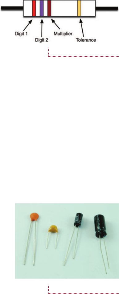
22 Hacking Electronics
HowTo-Color (8) / Hacking Electronics / Simon Monk / 236-3 / Chapter 2
Figure 2-2 shows the arrangement of the
colored bands. The resistor value uses just the
three bands. The first band is the first digit,
the second the second digit, and the third
“multiplier” band is how many zeros to put
after the first two digits.
So, a 270Ω (ohm) resistor will have first digit 2
(red), second digit 7 (violet), and a multiplier of 1 (brown).
Similarly, a 10KΩ resistor will have bands of brown, black, and
orange (1, 0, 000).
In addition to fixed resistors, there are also variable resistors
(a.k.a., potentiometers or pots). This comes in handy with
volume controls, where turning a knob changes the resistance
and alters the level of sound.
Capacitors
When hacking electronics, you will occasionally need to use
a capacitor. Luckily, you do not need to know much about
what they do. They are often used to head-off problems like
the instability of a circuit or unwanted noise. Their use is
often given a name like “decoupling capacitor” or “smoothing
capacitor.” There are simple rules you can follow about where
you need a capacitor. These will be highlighted as we encounter
them in later sections.
For the curious, capacitors store charge, a bit like a battery,
but not much charge, and they can store the charge and release it
very quickly.
Figure 2-3 shows a selection of capacitors.
If you look closely at the second capacitor
from the left, you will see the number 103. This is
actually the value of the capacitor in picofarads.
The unit of capacitance is farad, but a 1F capacitor
would be considered a huge capacitor, storing
a great deal of charge. So, while such beasts do
exist, everyday capacitors are either measured in
nanofarads (nF = 1/1,000,000,000F) or microfarads
(µF = 1/1,000,000F). You will also find capacitors in
the picofarad range (pF = 1/1,000,000,000,000F).
Returning to 103. … Rather like resistors, this means 10 and
then 3 zeros, in units of pF. So in this case that’s 10,000pF or 10nF.
Larger capacitors, like those on the right of Figure 2-3,
are called electrolytic capacitors. They are usually in the µF
Figure 2-2 Resistor stripes
Figure 2-3 Assorted capacitors
02-ch02.indd 22 12/27/12 2:11 PM

CHAPTER 2: Theory and Practice 23
HowTo-Color (8) / Hacking Electronics / Simon Monk / 236-3 / Chapter 2
range and have their value written on their side. They also
have a + and a – side, and unlike most other capacitors must be
connected the right way around.
Figure 2-4 shows a large electrolytic, with value (1000µF)
and its negative lead clearly indicated at the bottom of the
figure. If the capacitor has one lead longer than the other, the
longer one will normally be the positive lead.
The capacitor in Figure 2-4 also has a voltage written on
it (200V). This is the capacitor’s maximum voltage. So if you
put more than 200V across its leads, it will fail. Big electrolytic
capacitors like this have a reputation for failing spectacularly
and may burst, spewing forth goo.
Diodes
You will occasionally need to use diodes. They are kind
of a one-way valve, only allowing current to flow in
one direction. They are therefore often used to protect
sensitive components from accidental reverse voltage
that could damage them.
Diodes (Figure 2-5) have a stripe at one end. That
end is called the cathode, while the other end is called
the anode. We will hear more about diodes later.
As with resistors, the bigger the diode physically,
the more power it can cope with before it gets too hot
and expires. Ninety percent of the time, you will just be
using one of the two diodes on the left-hand side of the figure.
LEDs
LEDs light up, and generally look pretty. Figure 2-6
shows a selection of LEDs.
LEDs are a little sensitive, so you should not
connect them directly to a battery. Instead you
have to use a resistor to reduce the current flowing
into the LED. If you do not do this, the LED will
probably die almost instantly.
Later on, we will see how to select the right
resistor for the job.
Just like regular diodes, LEDs have a positive
and a negative lead (anode and cathode). The anode
is the longer of the two leads. There is also usually a flat side to
the LED case on the cathode side.
Figure 2-4 An electrolytic
capacitor
Figure 2-5 A selection of
diodes
Figure 2-6 Assorted LEDs
02-ch02.indd 23 12/27/12 2:11 PM
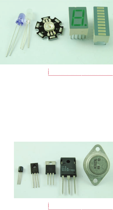
24 Hacking Electronics
HowTo-Color (8) / Hacking Electronics / Simon Monk / 236-3 / Chapter 2
As well as single LEDs, you
also get LEDs in more complicated
arrangements within a single
package. Figure 2-7 shows some
interesting-looking LEDs.
From left to right, these LEDs
are an ultraviolet LED, an LED
with both red and green LEDs in the
same package, a high-power RGB
(red, green, blue) LED that can be
controlled to produce any color of
light, a seven-segment LED display,
and an LED bar graph display.
This is just a small selection of LED types. There are many
others to choose from. In later sections, we will explore some of
these more exotic LEDs.
Transistors
While transistors can be used in audio amplifiers and in many
circumstances, for the casual electronics hacker, the transistor
can be thought of as a switch. But rather than a switch
controlled by a lever, it is a switch that switches a big current,
yet is controlled by a small current.
Generally speaking, the physical size of
the transistor (Figure 2-8) determines how
big the current that it switches can be before
it starts producing smoke.
Of the transistors in Figure 2-8, the
right-hand two are quite specialized and
employed for high power use.
Generally, the rule for a component
is that if it’s ugly and has three legs, it’s
probably some kind of transistor.
Integrated Circuits
An integrated circuit (IC), or just “chip,” is a load of transistors
and other components printed onto silicon. The purpose of the
IC varies wildly. It can be a microcontroller (mini-computer), or
an entire audio amplifier, or a computer memory, or any one of
thousands of other possibilities.
ICs make life easy, because as they say, often “there’s a chip
for that.” Indeed, if there is something you want to make, there
Figure 2-7 More LEDs
Figure 2-8 Transistors
02-ch02.indd 24 12/27/12 2:11 PM

CHAPTER 2: Theory and Practice 25
HowTo-Color (8) / Hacking Electronics / Simon Monk / 236-3 / Chapter 2
may well be a chip for it already, and if there
isn’t, then there will probably be a general-
purpose chip that takes you halfway there.
ICs look like bugs (Figure 2-9).
Other Stuff
There are so many other components out
there, some of which are very familiar, such
as batteries and switches. Others are less
familiar and include potentiometers (variable resistors found
in volume controls), phototransistors, rotary encoders, light
dependent resistors, and so on. We will explore these as they
arise later in the book.
Surface Mount Components
Let’s touch a little on the subject of surface mount devices
(SMDs). These components are just resistors, transistors,
capacitors, ICs, and so on, but in tiny packages designed to be
soldered onto the top surface of circuit boards by machines.
Figure 2-10 shows a selection of
SMDs.
The matchstick shows you just how
small these devices are. It is perfectly
possible to do surface mount soldering
by hand, but you need a steady hand
and a high-quality soldering iron. Not to
mention a lot of patience. You are also
likely to need a means of making circuit boards, as they are not
easy to use with breadboard or other prototyping tools.
In this book, we mostly look at using the conventional
“through-hole” components rather than SMDs. However, as
your experience grows and you feel you might like working
with SMDs, do not be afraid to try.
What Are Current, Resistance,
and Voltage?
Voltage, current, and resistance are three properties that are
fundamental to almost everything you will do in electronics.
They are intimately related, and if you can master the
relationship between them, you will be a wise hacker indeed.
Figure 2-9 Integrated circuits
Figure 2-10 Surface mount
components
02-ch02.indd 25 12/27/12 2:11 PM

26 Hacking Electronics
HowTo-Color (8) / Hacking Electronics / Simon Monk / 236-3 / Chapter 2
Please take the time to read and understand this little
bit of theory. Once you understand it, many other things
should automatically fall into place.
Current
The problem with electrons is that you cannot see them,
so you just have to imagine how they do things. I like to
think of electrons as little balls flowing through pipes.
Any physicists reading this will probably be clutching their
heads or hurling this book to the floor in disgust now. But it
works for me.
Each electron has a charge and it’s always the same—lots of
electrons, lots of charge, few electrons, and a little bit of charge.
Current, rather like the current in a river, is measured by
counting how much charge passes you per second (Figure 2-11).
Resistance
A resistor’s job is to provide resistance to the flow of
current. So, if we keep thinking about our river, it is like
a constriction in a river (Figure 2-12).
The resistor has reduced the amount of charge
that can pass by a point. And it doesn’t matter which
point you measure at (A, B, or C) because, if you look
upstream of the resistor, the charge is hanging around
waiting to move through the resistor. Therefore, less
is moving past A per second. In the resistor (B), it’s
restricted.
The “speed” analogy does not really hold true for electrons,
but one important point is that the current will be the same
wherever you measure it.
Imagine what happens when a resistor stops too much
current from flowing through an LED.
Voltage
Voltage is the final part of the equation (that we will come to
in a minute). If we persist with the water-in-a-river analogy,
then voltage is like the height that the river drops over a given
distance (Figure 2-13).
Figure 2-11 Current
Figure 2-12 A resistor
02-ch02.indd 26 12/27/12 2:11 PM

CHAPTER 2: Theory and Practice 27
HowTo-Color (8) / Hacking Electronics / Simon Monk / 236-3 / Chapter 2
As everyone knows, a river that loses height
quickly flows fast and furious, whereas a relatively
gently sloped river will have a correspondingly
gentle current.
This analogy helps with the concept of voltage
being relative. That is, it does not matter if the river
is falling from 10,000 ft to 5,000 ft or from 5,000 ft
to 0 ft. The drop is the same and so will be the rate
of flow.
Ohm’s Law
Before we get into the math of this, let’s think for a
moment about current, voltage, and resistance and
how they relate to each other.
Try this little quiz. Think in terms of the river if
you find it helps.
1. If the voltage increases, will the current (a) increase or
(b) decrease?
2. If the resistance increases, will the current (a) increase
or (b) decrease?
Did you get the answers (a) and (b) correct, respectively?
If you write this down as an equation, it is called Ohm’s law
and can be written as:
I = V / R
I for current (I guess “C” was already taken), V for Volts, and R
for resistance.
So, the current flowing through a resistor, or any wire
connecting to it, will be the voltage across the resistor divided
by the resistance of the resistor.
The units of resistance are in Ω (the abbreviation for ohms),
while units of current are in A (short for amps, which is short
for amperes) and in voltage V (the easy one).
So, if we have a voltage of 10V across a resistor of 100Ω the
current flowing will be:
10V / 100Ω = 0.1A
For convenience, we often use mA (1/1000 of an amp). So 0.1A
is also 100mA.
Figure 2-13 Voltage
02-ch02.indd 27 12/27/12 2:11 PM
28 Hacking Electronics
HowTo-Color (8) / Hacking Electronics / Simon Monk / 236-3 / Chapter 2
That’s enough about Ohm’s law for now, we will meet it
again later. It is the single most useful thing you can know about
electronics. In the next section, we will look at the only other
truly essential math you will need—power.
What Is Power?
Power is all about energy and time. So, in a way, it’s a bit like
current. But, instead of being the amount of charge passing
a point, it is the amount of energy transformed into heat per
second when a current passes through something that resists
the flow (like a resistor). Forget the river, it doesn’t really help
much here.
Restricting the flow of a current generates heat, and the
amount of heat generated can be calculated as the voltage across
a resistor times the current flowing through it. The units of
power are the watt (W). You would write this in math as:
P = I × V
So, in our earlier example, we had 10V across a 100Ω resistor,
so the current through the resistor was 100mA and will generate
0.1A × 10V, or 1 W of power. Given that the resistors that we have
from the SparkFun kit are 250 mW (0.25 W). Our resistor will get
hot and may eventually break.
If you don’t know the current, but you do know the resistance,
another useful formula for calculating the power is:
P = V2 / R
Or, power is voltage squared (times itself) divided by the
resistance. So, for the example earlier:
P = 10 × 10 / 100 = 1 W
That’s reassuringly the same answer as we got before.
Most components have a maximum power rating like this,
so when selecting a resistor, transistor, diode, and so on, it is
worth doing a quick check and multiplying the voltage across
the component by the current that you expect to flow through
it. Then, choose a component with a maximum power rating
comfortably greater than the expected power.
Power is the best measure of how much electricity is being
used. It is the electrical energy being used per second, and
unlike current it can be compared for devices operating from
02-ch02.indd 28 12/29/12 2:17 PM

CHAPTER 2: Theory and Practice 29
HowTo-Color (8) / Hacking Electronics / Simon Monk / 236-3 / Chapter 2
both 110 volt outlets and
low voltage. It is good to have
a basic understanding of
just how much—or how
little—electricity devices
use. Table 2-1 shows some
devices you might find around
the home and lists how much
power they use.
So, now you know why
you don’t get battery-powered
kettles!
How to Read a Schematic Diagram
Hacking electronics often involves trawling the Internet, looking
for people who have made something like the thing you want to
make or adapt. You will often find schematic diagrams that tell you
how to make and do things. So you need to be able to understand
these schematics in order to turn them into real electronics.
These may at first sight seem a little
baffling, but schematics obey a few
simple rules and tend to use the same
patterns over and over again. So there is
a lot less to learn than you might think.
Ponder Figure 2-14 while we
consider some of these rules—or more
accurately conventions—because
sometimes they are broken.
Figure 2-14 goes a long way to
explaining why we sometimes talk of
electronic circuits. It’s kind of a loop.
The current is flowing out of the battery,
through the switch (when it’s closed),
through the resistor and LED (D1), and then back to the battery.
The lines on the schematic can be thought of as perfect wires
without any resistance.
The First Rule of Schematics: Positive
Voltages Are Uppermost
A convention that most people follow when drawing a schematic
is to put the higher voltages near the top, so on the left-hand side
TABLE 2-1 Power Usage
Device Power
Battery-powered FM radio (volume down) 20 mW
Battery-powered FM radio (volume up) 500 mW
Arduino Uno microcontroller board (9V supply) 200 mW
Home WiFi router 10 W
Compact fluorescent (low-power) light bulb 15 W
Filament light bulb 60 W
LCD TV 40-inch 200 W
Electric kettle 3000 W (3 kW)
Figure 2-14 A simple
schematic
02-ch02.indd 29 12/27/12 2:11 PM
30 Hacking Electronics
HowTo-Color (8) / Hacking Electronics / Simon Monk / 236-3 / Chapter 2
of the diagram, we have a 9V battery. The bottom of the battery
is at 0V or GND (Ground), while the top of the battery will by
9V higher than that.
Notice that we draw the resistor R1 above the LED (D1).
This way, we can think of some of the voltage as being lost
across the resistor, before the remainder is lost through the
diode and flows back to the negative connection of the battery.
Second Rule of Schematics:
Things Happen Left to Right
Western civilization invented electronics and writes from left
to right. You read from left to right and, culturally, more things
happen from left to right. Electronics is no different, so it is
common to start with the source of the electricity—the battery
or power supply on the left—and then work our way from left to
right across the diagram.
So, next we have our switch, which controls the flow of the
electricity, and then the resistor and LED.
Names and Values
It is normal to give every component in a schematic a name.
So, in this case the battery pack is called B1, the switch S1, the
resistor R1, and the LED D1. This means that when you go from
a schematic to a breadboard layout and eventually a circuit board,
you can see which components on the schematic correspond to
which components on the breadboard or circuit board.
It is also normal to specify the value of each of the components
where appropriate. So, for example, the resistors’ value of 270Ω
is marked on the diagram. The rest of the components don’t need
much else said about them.
Component Symbols
Table 2-2 lists the most common circuit symbols you will
encounter. This is nothing like a complete list, but we will
discuss other symbols later in the book.
There are two main styles of circuit symbol: American
and European. Fortunately, they are similar enough to avoid
difficulties in recognizing them.
In this book, we will use the U.S. circuit symbols.
02-ch02.indd 30 12/27/12 2:11 PM

CHAPTER 2: Theory and Practice 31
HowTo-Color (8) / Hacking Electronics / Simon Monk / 236-3 / Chapter 2
Summary
In the next chapter, we get a much more practical look at some
basic hacks and hone our electronic construction skills. This
includes using prototyping boards and taking our soldering
beyond simply connecting wires to other wires.
We will also learn how to use solderless breadboard so we
can build electronics quickly and get underway.
Symbol (U.S.) Symbol (European) Photo Component Use
Resistor Resisting
Capacitor Temporary charge
storage
Capacitor
(polarized)
Transistor
(bipolar NPN)
Using a small
current to control a
larger current
Transistor
(MOSFET
N-channel)
Using a very small
current to control a
larger current
Diode Prevents current
from flowing in the
wrong direction
LED Indication and
illumination
Battery Power supply
Switch Turning things on
and off; control
TABLE 2-2 Common Schematic Symbols
02-ch02.indd 31 12/27/12 2:11 PM
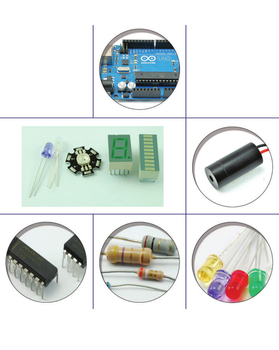
HowTo-Color (8) / Hacking Electronics / Simon Monk / 236-3 / Chapter 2
blind folio 32
02-ch02.indd 32 1/11/13 4:02 PM

HowTo-Color (8) / Hacking Electronics / Simon Monk / 236-3 / Chapter 3
blind folio 33
3
Basic Hacks
This chapter contains a set of fairly basic “hacking” how-tos. These build and use various
electronic construction techniques. So this is probably a good chapter to at least skim
through so that when you attempt more advanced how-tos, you can refer back to it if needed.
How to Make a Resistor Get Hot
Sometimes things will get hot when you are hacking electronics. It’s always better when this is
expected rather than when it’s a surprise, so it’s worth doing a little experimenting in this area.
You Will Need
Quantity Item Appendix Code
1 100Ω 0.25-watt resistor K2
1 4 × AA battery holder H1
1 4 × AA batteries (the rechargeable type is a good idea)
Figure 3-1 shows the schematic diagram.
The Experiment
All we will do is connect the 100Ω resistor across the battery terminals and see how hot it gets.
We are using a battery holder that takes four AA cells, each providing about 1.5V. They
are each connected, one after the other, providing us with 6V total. Figure 3-2 shows how the
Be careful when doing this because the resistor’s temperature will rise to about
50°C/122°F. The resistor’s leads, however, will not get very hot.
Caution
03-ch03.indd 33 12/29/12 1:56 PM

34 Hacking Electronics
HowTo-Color (8) / Hacking Electronics / Simon Monk / 236-3 / Chapter 3
batteries are actually connected within the battery box as a
schematic diagram. In this kind of arrangement, the batteries are
said to be in series.
Figure 3-3 shows the resistor heater in action.
Simply touch a finger to the resistor to confirm it’s hot.
Is this bad/good? Will the resistor eventually break because
it’s warm? No, it won’t. Resistors are designed to cope with a bit
of heat. If we do the math, the power that the resistor is burning
is the voltage squared divided by the resistance, which is:
(6 × 6) / 100 = 0.36W
If it is a 0.25-W resistor, then we are exceeding its maximum
power. This would be a foolish thing to do if we were designing
a product for mass production. However, that’s not what we are
doing, and the chances are the resistor would continue to work
like that indefinitely.
How to Use Resistors to Divide a Voltage
Sometimes voltages are too big. For example, in an FM radio,
the signal going from the radio part to the audio amplifier part
will be deliberately too large so it can be reduced using the
volume knob.
Another example might be when you have a sensor that
produces a voltage between 0 and 10V but you want to
connect it to an Arduino microcontroller that expects it to
be between 0 and 5V.
A very common technique in electronics is to use a pair of
resistors (or a single variable resistor) as a “voltage divider.”
You Will Need
Quantity Item Appendix Code
1 10kΩ trimpot (tiny variable resistor) K1, R1
1 Solderless breadboard T5
Solid-core jumper wire T6
1 4 × AA battery holder H1
1 4 × AA batteries
1 Battery clip H2
1 Multimeter T2
Figure 3-1 The schematic for
heating a resistor
Figure 3-2 The schematic
diagram for a battery holder
Figure 3-3 Making a resistor
get hot
03-ch03.indd 34 12/29/12 1:56 PM

CHAPTER 3: Basic Hacks 35
HowTo-Color (8) / Hacking Electronics / Simon Monk / 236-3 / Chapter 3
Figure 3-4 shows the schematic diagram for our
experiment. There are a couple of new schematic symbols
here. The first is the variable resistor (or pot). This looks
like a regular resistor symbol, but has a line with an
arrow connecting to the resistor. This is the moving slider
connection of the variable resistor.
The second new symbol is the circle with a “V” in it.
This is a voltmeter, which in our case is the multimeter set to its
DC voltage range.
The variable resistor we will use has three leads. One lead is
fixed at each end of a conductive track, while a third connection
to the central slider moves from one end of the track to the
other. The overall resistance of the whole track is 10kΩ.
Our voltage in is going to be supplied from the battery
pack and will be roughly 6V. We are going to use a multimeter
to measure the output voltage and see how much it is being
reduced by our voltage divider.
If you remember, the grey bars indicate where the connections
underneath the holes are connected together. Take some time
to follow the lines on the stripboard and reassure yourself
that everything is connected in the same way as the schematic
(Figure 3-4).
Plug the trimpot into the breadboard as shown, and then
wire up the battery by carefully pushing the leads into the + and
– power supply lines on the breadboard: red to +, black to –. If
you struggle to get the multi-core wires of the battery clip into
the holes, solder a bit of solid-core wire to the end of the leads.
Attach wires between the positive supply and the top
connection of the trimpot, and the negative supply and the
bottom connection of the trimpot. Finally, attach the multimeter.
If your multimeter has alligator clips, use these in preference to
the normal probes, clipping short jumper wires into the alligator
clips and then pushing the other ends into the positions shown
in Figure 3-5. When you have done all this, your breadboard
should look something like Figures 3-6a and 3-6b.
Turn the trimpot to its fully clockwise position. The multimeter
should read 0V (Figure 3-6a). Now turn it fully anti-clockwise
and it should read something around 6V (Figure 3-6b)—in
other words, the full battery voltage. Finally, turn it to roughly
the middle position and you should see that the meter indicates
about 3V (Figure 3-6c).
Think of the variable resistor as behaving a bit like two
resistors, R1 and R2, as shown in Figure 3-7.
Figure 3-4 A voltage divider
schematic diagram
03-ch03.indd 35 12/29/12 1:56 PM

36 Hacking Electronics
HowTo-Color (8) / Hacking Electronics / Simon Monk / 236-3 / Chapter 3
The formula to calculate Vout if we know Vin, R1 and R2
is as follows:
Vout = Vin * R2 / (R1 + R2)
So, if R1 and R2 are both 5 kΩ and Vin is 6V, then:
Vout = 6V * 5kΩ / (5kΩ + 5kΩ) = 30 / 10 = 3V
This ties in with what we found when we put the
trimpot to its middle position. It is exactly the same
as having two fixed resistors of 5 kΩ each.
As with many of the calculations you make in electronics,
people have made handy calculating tools. If you type “voltage
divider calculator” into a search engine, you will find them. One
such example can be found here: www.electronics2000.co.uk/
calc/potential-divider-calculator.php.
These calculators will also usually match to the nearest
available fixed resistor value.
(a) (c)(b)
Figure 3-5 A voltage divider
breadboard layout
Figure 3-6 A voltage divider
breadboard
Figure 3-7 A voltage divider with
fixed resistors
03-ch03.indd 36 12/29/12 1:56 PM

CHAPTER 3: Basic Hacks 37
HowTo-Color (8) / Hacking Electronics / Simon Monk / 236-3 / Chapter 3
How to Convert a Resistance to a Voltage
(and Make a Light Meter)
An LDR (light-dependent resistor; a.k.a., photoresistor) is a
resistor whose resistance changes depending on the amount of
light falling on its transparent window. We will use one of these
devices to demonstrate the idea of converting a resistance to a
voltage by using it as one-half of a potential divider.
You Will Need
Quantity Item Appendix Code
1 Light-dependent resistor K1, R2
1 Solderless breadboard T5
Solid-core jumper wire T6
1 4 × AA battery holder H1
1 4 × AA batteries
1 Battery clip H2
1 Multimeter T2
Before we get the breadboard out, let’s just
experiment directly with the LDR. Figure 3-8 shows
the LDR connected directly to the multimeter on
its 20kΩ resistance setting. As you can see, the
resistance of my LDR was 1.07kΩ. Putting my
hand over the LDR to screen out some of the light
increased that resistance to a few tens of kΩ. So, the
way the LDR works, the more light that reaches it,
the lower the resistance.
Microcontrollers such as the Arduino can measure
voltages and do things with them, but not directly
measure resistance. So to convert our LDR’s resistance
into a more easily used voltage, we can put it in a
voltage divider as one of the resistors (Figure 3-9).
Note that the symbol for the LDR is like a
resistor but with little arrows pointing to it to
indicate its sensitivity to light.
We can make up this schematic on our
breadboard, this time setting our multimeter to
the 20V DC range and watching how the voltage
changes as we cover the LDR to reduce the light getting to it
(Figures 3-10 and 3-11).
Figure 3-8 Measuring the LDR
resistance
03-ch03.indd 37 12/29/12 1:56 PM
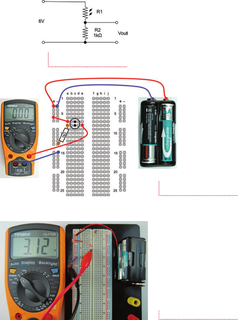
38 Hacking Electronics
HowTo-Color (8) / Hacking Electronics / Simon Monk / 236-3 / Chapter 3
Figure 3-9 Measuring light level with
an LDR and voltage divider
Figure 3-10 A breadboard layout for
light measurement
Figure 3-11 Light measurement
03-ch03.indd 38 12/29/12 1:56 PM

CHAPTER 3: Basic Hacks 39
HowTo-Color (8) / Hacking Electronics / Simon Monk / 236-3 / Chapter 3
Hack a Push Light to Make
It Light Sensing
Battery-powered push lights are one of the many glorious
bargains you are likely to find in a dollar/euro/pound store.
These are intended for use in cupboards and other dark locations
where a bit of extra light would be useful. Push them once and
they light, push them again and they turn off.
It will not surprise you to hear that we are going to use our
LDR to turn the light on and off. But we are also going to use a
transistor.
Our approach will be to get it working on breadboard first
and then solder up the design onto the push light. In fact, we
will use a single LED in place of the push lamp until we know
that it will work.
You Will Need
Quantity Name Item Appendix Code
1 R1 Light-dependent resistor K1, R2
1 T1 Transistor 2N3904 K1, S1
1 R2 Resistor 10kΩ K2
1* R3 Resistor 220Ω K2
1* D1 Red LED or high-brightness LED K1 or S2
* Solid-core jumper wire T6
1 Push light
* These components are only needed for the breadboard experiment.
We want the LDR to control an LED, so a first thought
at a circuit might be as shown in Figure 3-12.
There are two fatal flaws in this design. First, as more
light falls on the LDR its resistance decreases, allowing
more current to flow so the LED will get brighter. This is
the opposite of what we want. We want the LED to come
on when it’s dark.
We need to use a transistor.
The basic operation of a transistor is shown in
Figure 3-13. There are many different types of transistors,
and probably the most common (and the type we will use)
is called an NPN bipolar transistor.
Figure 3-12 An LED and LDR
03-ch03.indd 39 12/29/12 1:56 PM

40 Hacking Electronics
HowTo-Color (8) / Hacking Electronics / Simon Monk / 236-3 / Chapter 3
This transistor has three leads: the emitter, the collector,
and the base. The basic principal is that a small current flowing
through the base will allow a much bigger current to flow
between the collector and the emitter.
Just how much bigger the current is depends on the transistor,
but it’s typically a factor of 100.
Breadboard
Figure 3-14 shows the schematic diagram we will build
on the breadboard. To understand this circuit, let’s
consider two cases.
Case 1: When It’s Dark
In this case, the LDR R1 will have a very high resistance,
so you could almost imagine that it isn’t there at all. In
that case, current will flow through R2, through the base
and emitter of the transistor, allowing as much current
as it needs to flow through R3, the LED, and T1 into
its collector and out through the emitter. When enough
current flows into the base of a transistor to allow current
to flow from the collector to the emitter, this is called
“turning on” the transistor.
We can calculate the base current using Ohm’s law.
In this situation, the base of the transistor will be at only
about half a volt, so we can assume there is more or less the
full 6V across the 10kΩ resistor R2. Since I = V / R, the
current will be 6 / 10,000 A or 0.6mA.
Figure 3-13 A bipolar transistor
Figure 3-14 Using an LDR and
transistor to switch an LED
03-ch03.indd 40 12/29/12 1:56 PM

CHAPTER 3: Basic Hacks 41
HowTo-Color (8) / Hacking Electronics / Simon Monk / 236-3 / Chapter 3
Case 2: When It’s Light
When it is light, we have to consider the resistance of the LDR
R1. The lighter it is, the lower the resistance of R1 and the more
of the current otherwise destined for the base of the transistor
will be diverted through R1, preventing the transistor from
turning on.
I think the time has come to build the project on breadboard.
Figure 3-15 shows the breadboard layout, and Figures 3-16a and
3-16b the finished breadboard.
When placing the LED on the breadboard, make sure you
get it the right way around. The longer lead is the positive lead,
and it should be on row 10 connected to R3. (See Figure 3-16a.)
If everything is fine, you should find that when you cover
the LDR, the LED should light (Figure 3-16b).
Construction
Now that we have proved our circuit works, we can get on with
modding the push light. Figure 3-17 shows the push light the
author used. Unless you are very lucky, yours is likely to be
Figure 3-15 The light switch
breadboard layout
03-ch03.indd 41 12/29/12 1:56 PM

42 Hacking Electronics
HowTo-Color (8) / Hacking Electronics / Simon Monk / 236-3 / Chapter 3
different, so read through the following sections carefully and
you should be able to work out how to change your light. To
make life easy for yourself, try and find a push light that
operates from 6V (4 AA or AAA cells).
You will probably find screws on the back of the
push light. Remove these and put them somewhere safe.
The inside of the push light is shown in Figure 3-18. The
various connections on the light are marked. You can
find the corresponding connections on your light using a
multimeter.
Setting the multimeter to its 20V DC range will let
you determine which battery lead is positive and which is
negative. Looking at the wiring, we can draw a schematic
diagram for the light as it stands, before we start altering
it (Figure 3-19).
Figure 3-16 The light switch
breadboard
(a) (b)
Figure 3-17 A push light
Figure 3-18 Inside the push light
Yellow wires to lamp
Wire linking left and right
halves of battery box
Battery +
Battery –
Switch
03-ch03.indd 42 1/17/13 4:50 PM

CHAPTER 3: Basic Hacks 43
HowTo-Color (8) / Hacking Electronics / Simon Monk / 236-3 / Chapter 3
This light uses an old-fashioned incandescent bulb. We
will replace that with a high-brightness LED. If you don’t
have one of these, a regular LED of the color of your choice
will work, but not be very bright.
Figure 3-20 shows how we replaced the bulb with the
LED and the 220Ω resistor. Make sure the longer positive lead
of the LED is connected to the resistor and the far side of that
resistor is connected to the positive terminal of the battery.
Try pressing the switch to make sure the LED is working.
We can now draw a schematic that combines what we
have in the existing lamp and our LDR circuit (Figure 3-21).
In fact, all this really amounts to is adding in the switch to
the original LED schematic. We have already installed R3 and
D1 when we replaced the bulb with
an LED. The switch is already there,
so all we need to add is the transistor,
LDR, and R2. Figure 3-22 shows
how we will rewire the push light.
Figure 3-23 shows the sequence
of steps in soldering the extra
components onto the light.
1. Start by desoldering the lead from
the switch that isn’t connected
to the negative battery terminal
(Figure 3-23a).
2. Solder the 10kΩ resistor R2 between the middle lead of
the transistor (the base) and the positive terminal on the
battery box.
3. With the flat of the transistor facing upward, as shown
in the diagram, connect the left-hand lead of the
transistor to the wire you just disconnected from the
switch (Figure 3-23b).
4. Solder the LDR between the left and middle pins of the
transistor, and connect the combined left-hand transistor
lead and LDR lead to the connection on the switch that
the wire used to be attached to. (See Figure 3-23c.)
5. Tuck the components away neatly, bending the leads to
make sure there is no way the bare leads can touch each
other. (See Figure 3-23d.)
There you are! You have hacked some electronics.
Figure 3-19 The schematic
diagram for the original
push light
Figure 3-20 Replacing the
bulb with an LED and a resistor
Figure 3-21 The final schematic
03-ch03.indd 43 12/29/12 1:56 PM

44 Hacking Electronics
HowTo-Color (8) / Hacking Electronics / Simon Monk / 236-3 / Chapter 3
Figure 3-22 The push light
wiring diagram
Figure 3-23 Soldering the
project
(a) (b)
(d)(c)
03-ch03.indd 44 12/29/12 1:56 PM

CHAPTER 3: Basic Hacks 45
HowTo-Color (8) / Hacking Electronics / Simon Monk / 236-3 / Chapter 3
How to Choose a Bipolar Transistor
The transistor we used in the previous section, “Hack a Push
Light to Make It Light Sensing,” is a useful general-purpose
transistor. But there are many other types of transistors that we
can use for different purposes. This section is to help you find
the right transistor and try to use it in such a way that it doesn’t
die in a puff of smoke.
Datasheets
Transistors have a number of parameters we need to know
about. All transistors have an associated datasheet. This is
produced by the manufacturer and specifies everything you
could possibly want to know about the device, from the
dimensions of its leads to its electrical characteristics.
Most of the time you will use one of three or four transistors
and will not need to look into the exact details of how the
transistor behaves, but if you do need to, it’s there on the
datasheet. So, you may just want to skip to the next subsection
where we look at a few different types of transistors—just the
useful ones, nothing exotic.
Table 3-1 shows some of the data you will find on the
2N3904’s datasheet under maximum ratings.
Maximum Collector-Emitter and Collector-Base voltages
of 40V and 60V mean we do not have to worry about exceeding
them in battery-powered devices. We need to be careful that we
do not exceed the emitter-base voltage though.
The maximum collector current of 200mA is quite healthy
though. It means we could in theory control ten LEDs, all taking
20mA at the same time. If we do exceed this value, then the
transistor will get hot and eventually fail.
The one electrical characteristic we are most interested in is
DC current gain or hFE as it will be called on the datasheet. This
is listed in the electrical characteristics
section of the datasheet.
You may remember that the DC
gain is the multiplier that determines
how much more current can flow in
through the base than the collector.
Looking at Table 3-2, this means that
at a collector current of 10mA and a
collector emitter voltage of 1.0V (it’s
Absolute Maximum Ratings
Symbol Parameter Value Units
VCEO Collector-Emitter Voltage 40 V
VCBO Collector-Base Voltage 60 V
VEBO Emitter-Base Voltage 6.0 V
ICCollector Current – Continuous 200 mA
TABLE 3-1 2N3904 Maximum Ratings
03-ch03.indd 45 12/29/12 1:56 PM

46 Hacking Electronics
HowTo-Color (8) / Hacking Electronics / Simon Monk / 236-3 / Chapter 3
TABLE 3-2 2N3904 Electrical Characteristics
nearly always about that), the typical gain will be 100, meaning
that only 10mA / 100 = 100nA needs to be flowing into the base
for this amount of current to flow through the collector.
MOSFET Transistors
The 2N3904 is what is called a bipolar transistor. It’s basically a
device that amplifies current. A small current into the base controls
a much bigger current flowing through the collector. Sometimes,
the current gain of just 100 or so is not nearly enough.
There is another type of transistor that does not suffer from
this limitation called the MOSFET (Metal Oxide Semiconductor
Field Effect Transistor). You can see why it gets shortened to
MOSFET. These transistors are controlled by voltage rather
than current and make very good switches.
MOSFETs do not have emitters, bases, and collectors, they
have “sources,” “gates,” and “drains.” They turn on when the
gate voltage passes a threshold, usually about 2V. Once on,
quite large currents can flow through the “drain” to the “source”
rather like a bipolar transistor. But since the gate is isolated
from the rest of the transistor by a layer of insulating glass,
hardly any current flows into the gate. It is the voltage at the
gate that determines what current will flow.
We will meet MOSFETs again later in the section “How to
Use a Power MOSFET to Control a Motor,” and in Chapter 7 in the
section “How to Control Motor Speed with a Power MOSFET.”
PNP and N-Channel Transistors
The automated light switch of the previous section switched
on the “negative side of the load.” That is, if you go back to
Figure 3-21, you can see that the resistor and LED that make
up the light are not connected to GND except through the
Symbol Parameter Test Condition Min Max Units
ON CHARACTERISTICS
hFE DC Current Gain IC = 0.1 mA, VCE = 1.0V
IC = 1.0 mA, VCE = 1.0V
IC = 10 mA, VCE = 1.0V
IC = 50 mA, VCE = 1.0V
IC = 100 mA, VCE = 1.0V
40
70
100
60
30
300
03-ch03.indd 46 12/29/12 1:56 PM

CHAPTER 3: Basic Hacks 47
HowTo-Color (8) / Hacking Electronics / Simon Monk / 236-3 / Chapter 3
transistor. If for some reason (and this does happen)
we wanted to switch the positive side, then we
would need to use a PNP equivalent of the NPN
2N3904, such as the 2N3906. NPN stands for
Negative-Positive-Negative, and yes, you can guess
what PNP stands for. That is because transistors are
kind of semiconductor sandwiches, with material
of either N or P type as the bread. If the bread is
N type (the most common), then the base voltage
needs to be higher than the emitter voltage (by about
0.5V) before the transistor starts to turn on. On the
other hand, a PNP transistor turns on when the base
voltage is more than 0.5V lower than the emitter
voltage.
If we wanted to switch the positive side, we
could use a PNP transistor (as shown in the PNP alternative to
Figure 3-21) displayed in Figure 3-24.
MOSFETs also have their own equivalent of PNP transistors
called P-channel, their version of the more common NPN being
called N-channel.
Common Transistors
The transistors in Table 3-3 will cover a wide range of transistor
applications. There are thousands and thousands of other
transistors, but in this book we only really use them for switching,
so these will cover most “bases”!
Figure 3-24 Using a PNP
bipolar transistor
Name
Appendix
Code Type
Max Switching
Current Notes
Low/medium-current switching
2N3904 S1 NPN bipolar 200mA Current gain about 100
2N3906 S4 PNP bipolar 200mA Current gain about 100
2N7000 S3 N-channel
MOSFET
200mA 2.1V gate-source threshold
voltage; turns on when gate
is 2.1V higher than source
High-current switching
FQP30N06 S6 N-channel
MOSFET
30A 2.0V gate-source threshold
voltage; turns on when gate
is 2.0V higher than source
TABLE 3-3 Really Useful Transistors
03-ch03.indd 47 12/29/12 1:56 PM

48 Hacking Electronics
HowTo-Color (8) / Hacking Electronics / Simon Monk / 236-3 / Chapter 3
How to Use a Power MOSFET
to Control a Motor
Figure 3-25 shows the schematic symbol and the
pinout for the FQP30N06 N-channel MOSFET.
This MOSFET is capable of controlling loads of
up to 30A. We are not going to push it any way near
that far, we are just going to use it to control the power to a
small electric motor that might have a peak load of 1 or 2A.
While this would be too much for the bipolar transistors that
we have been using so far, this MOSFET will hardly notice!
You Will Need
To try out this high-power MOSFET, you will need the
following items.
Quantity Item Appendix Code
1 Solderless breadboard T5
Solid-core jumper wire T6
1 4 × AA battery holder H1
1 4 × AA batteries
1 Battery clip H2
1 Multimeter T2
1 10kΩ trimpot K1
1 FQP30N06 MOSFET S6
1 6V DC motor or gear motor H6
The DC motor can be any small motor you can find
that is around 6V. A motor rated at 12V should still turn at
6V. To test it, just connect its terminals directly to the 6V
battery.
Breadboard
The schematic diagram for what we will make is shown in
Figure 3-26.
The variable resistor will control the voltage at the
gate of the MOSFET. When that gate voltage exceeds the
gate threshold, the transistor will turn on and the motor
will start.
Figure 3-25 The FQP30N06
N-channel MOSFET
Figure 3-26 A schematic for the
MOSFET experiment
03-ch03.indd 48 12/29/12 1:56 PM

CHAPTER 3: Basic Hacks 49
HowTo-Color (8) / Hacking Electronics / Simon Monk / 236-3 / Chapter 3
The breadboard layout for the project and a photograph of the
experiment in action are shown in Figure 3-27 and Figure 3-28.
To connect the motor to the breadboard, you will probably
need to solder a pair of leads to it. It does not matter which way
around you connect the motor. The polarity just determines
which direction the motor turns. So if you swap the motor leads
over, it will turn in the opposite direction.
Try turning the knob on the variable resistor. You will see
that you do not have a great deal of control over the speed of
Figure 3-27 The breadboard
layout for the MOSFET experiment
Figure 3-28 The MOSFET
experiment
03-ch03.indd 49 12/29/12 1:56 PM
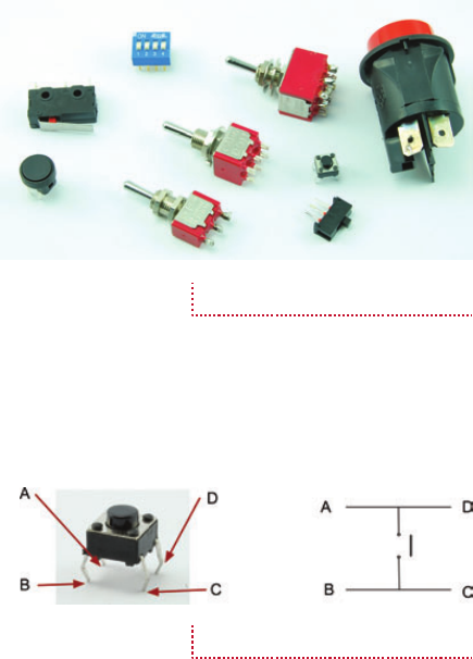
50 Hacking Electronics
HowTo-Color (8) / Hacking Electronics / Simon Monk / 236-3 / Chapter 3
the motor. If you hover around the threshold voltage, you can
control the motor speed, but you can probably see why the
MOSFET is most commonly used as a switch that is either
on or off.
This kind of MOSFET is called a logic level MOSFET,
because its gate voltage is low enough to be controlled directly
by digital output pins on a microcontroller. This is not true of all
MOSFETs. Some have gate threshold voltages of 6V or more.
In Chapter 7, you will use a MOSFET to finely control the
motor speed.
How to Select the Right Switch
On the face of it, a switch is a very simple thing. It closes two
contacts, making a connection. Often, that is all you need, but
other times you will require something
more complicated. For example, let’s
say you want to switch two things at the
same time.
There are also switches that only
make the contact while you are pressing
them, or ones that latch in one position.
Switches may be push button, toggle, or
rotary. There are many options to choose
from and in this section we will attempt
to explain the options.
Figure 3-29 shows a selection of switches.
Push-Button Switches
Where so many things use a microcontroller, a simple push switch
is probably the most common type of switch (Figure 3-30).
This kind of switch is designed to be soldered directly
onto a circuit board. It will also fit onto our
breadboard, which makes it quite handy.
The confusing thing about this switch
is that it has four connections where
you would only expect there to be two.
Looking at Figure 3-30, you can see that
connections B and C are always connected together, as are
A and D. However, when the button is pressed, all four pins
are all connected together.
This does mean that you need to be careful to find the right
pins or your switch will be connected all the time.
Figure 3-29 Switches
Figure 3-30 A push switch
03-ch03.indd 50 12/29/12 1:56 PM

CHAPTER 3: Basic Hacks 51
HowTo-Color (8) / Hacking Electronics / Simon Monk / 236-3 / Chapter 3
If there is any doubt about how the switch works, use your
multimeter set to Continuity mode to work out what is connected
to what—first without the switch pressed and then with the
switch pressed.
Microswitches
A microswitch is another type of handy switch. They are not
designed to be pressed directly, but are often used in things like
microwave ovens to detect that the door is closed, or as anti-
tamper switches that detect when the cover is removed from an
intruder alarm box.
Figure 3-31 shows a microswitch—with three pins!
The reason a microswitch has three pins rather than just two
is that it is what is known as a “double throw” or “change-over”
switch. In other words, there is one common connection C and
two other connections. The common connection will always
be connected to one of those contacts, but
never both at the same time. The normally
open (n.o.) connection is only closed when
the button is pressed; however, the normally
closed (n.c.) connection is normally closed,
and only opens when the button is released.
If you have one of these switches, you
might like to connect your multimeter to it.
Attach one lead to the common connection
and use it to find the n.c. connection, then
press the button and the beep should stop.
Toggle Switches
If you look through a component catalog (which every good
electronics hacker should), you will find a bewildering array of
toggle switches. Some will be described as DPDT, SPDT, SPST,
or SPST, momentary on, and so forth.
Let’s untangle some of this jargon, with a key for these
cryptic letters:
● D = Double
● S = Single
● P = Pole
● T = Throw
Figure 3-31 A microswitch
03-ch03.indd 51 12/29/12 1:56 PM

52 Hacking Electronics
HowTo-Color (8) / Hacking Electronics / Simon Monk / 236-3 / Chapter 3
So, a DPDT switch is double pole, double throw. The word
“pole” refers to the number of separate switch contacts that are
controlled from the one mechanical lever. So, a double pole
switch can switch two things on and off independently. A single
throw switch can only open or close a contact (or two contacts
if it is double pole). However, a double throw switch can make
the common contact be connected to one of two other contacts.
So, a microswitch is a double throw switch because it has both
normally closed and normally open contacts.
Figure 3-32 summarizes this.
Notice in Figure 3-32 that when drawing a schematic with
a double pole switch, it is normal to draw the switch as two
switches (S1a and S1b) and connect them with a dotted line to
show they are linked mechanically.
The matter is further complicated because you can have
three poles or even more on a switch, and double throw switches
are sometimes sprung, so they do not stay in one or both of
these positions. They may also have a center-off position where
the common contact is not connected to anything.
Figure 3-32 Toggle switches—
poles and throws
03-ch03.indd 52 12/29/12 1:57 PM
CHAPTER 3: Basic Hacks 53
HowTo-Color (8) / Hacking Electronics / Simon Monk / 236-3 / Chapter 3
You might see a switch described as “DPDT, On-Off-Mom.”
Well, we know what the DPDT bit means. It will have six legs
for a start. The “On-Off-Mom” part means that it also has a
center position, where the common connection is not made
to anything. Switch it one way and it will be on to one set of
contacts and stay in that position. Switch it the other way and it
will be sprung to return to the central position, allowing you to
make a “momentary” connection.
A lot of this terminology applies to other kinds of switches
in addition to toggle switches.
Summary
We now know a bit about voltage, current resistance, and power.
In the next chapter, we will use these ideas in looking at how to
use LEDs.
03-ch03.indd 53 12/29/12 1:57 PM

HowTo-Color (8) / Hacking Electronics / Simon Monk / 236-3 / Chapter 3
blind folio 54
03-ch03.indd 54 1/11/13 4:05 PM

HowTo-Color (8) / Hacking Electronics / Simon Monk / 236-3 / Chapter 4
blind folio 55
4
LEDs
LEDs (light-emitting diodes) are diodes that emit light when a current passes through them. Well
on the way to completely replacing filament light bulbs in almost all applications, they can be
used as indicators and, with the very high brightness types of LED, can provide illumination.
They are much more efficient than conventional light bulbs, producing far more light per
watt of power, and are a lot less delicate.
LEDs do, however, require a little more thought when used. They have to be powered with
the correct polarity and require circuitry to limit the current flowing through them.
How to Stop an LED from Burning Out
LEDs are delicate little things and quite easy to destroy accidentally. One of the quickest ways of
destroying an LED is to attach it to a battery without using a resistor to limit the current.
To get to grips with LEDs, we will put three different color LEDs on our breadboard (Figure 4-1).
You Will Need
Quantity Names Item Appendix Code
1 Solderless breadboard T5
1 D1 Red LED K1
1 D2 Yellow LED K1
1 D3 Green LED K1
1 R1 330Ω resistor K2
2 R2, R3 220Ω resistor K2
Jumper wires T6
1 4 × AA battery holder H1
1 Battery clip H2
4 AA batteries
04-ch04.indd 55 12/29/12 2:11 PM

56 Hacking Electronics
HowTo-Color (8) / Hacking Electronics / Simon Monk / 236-3 / Chapter 4
Diodes
We need to understand LEDs a little
better if we are to successfully use
them. LED stands for light-emitting
diode, so let’s start by looking at
what a diode is (Figure 4-2).
A diode is a component that
only lets current flow in one
direction. It has two leads, one
called the anode, and the other
called the cathode. If the anode is
at a higher voltage than the cathode
(it has to be greater by about half a
volt), then it will conduct electricity and is said to be “forward-
biased.” If on the other hand the anode isn’t at least half a volt
higher than the cathode, it is said to be “reverse-biased” and no
current flows.
LEDs
An LED is just like a regular diode except that when it is
forward-biased, it conducts and generates light. It also differs
from a regular diode in that the anode usually needs to be at
least 2V higher than the cathode for it to be forward-biased.
Figure 4-3 shows the schematic diagram for driving an LED.
The key to this circuit is to use a resistor to limit the current
flowing through the LED. A normal red LED will typically just
be lit at about 5mA and is designed to be used at around 10 to
20mA (this is called the “forward current” or IF). We will aim
for 15mA for our LED. We can also
assume that when it is conducting,
there will be about 2V across it.
This is called the “forward voltage”
or VF. That means there will be
6 – 2 = 4V across the resistor.
So, we have a resistor that has
a current flowing through it (and
the LED) of 15mA and a voltage
across it of 4V. We can use Ohm’s
law to calculate the value of
resistance we need to achieve this:
R = V / I = 4V / 0.015A = 267Ω
Figure 4-1 LEDs on a breadboard
Figure 4-2 A diode
Figure 4-3 Limiting current to
an LED
04-ch04.indd 56 12/29/12 2:11 PM

CHAPTER 4: LEDs 57
HowTo-Color (8) / Hacking Electronics / Simon Monk / 236-3 / Chapter 4
Resistors come in standard values, and the nearest higher
value in our resistor starter kit is 330Ω.
As I mentioned earlier, a red LED will almost always light
quite brightly with something like 10–20mA. The exact current
is not critical. It needs to be high enough to make the LED light,
but not exceed the maximum forward current of the LED (for a
small red LED, typically 25mA).
Table 4-1 shows a section of the datasheet for a typical
range of LEDs of different colors. Note how VF changes for
different color LEDs. This will mean you may need to use a
different resistor, but usually if the supply voltage is above
say 6V, then small variations in VF for color will not require a
different resistor value.
The other parameter you should be aware of is the
“maximum reverse voltage.” If you exceed this by, say, wiring
your LED the wrong way around, it is likely to break the LED.
Many online series resistor calculators are available that—
given the supply voltage VF and current IF for your LED—will
calculate the series resistor for you. For example:
www.electronics2000.co.uk/calc/led-series-resistor-
calculator.php
Table 4-2 is a useful rough guide, assuming a forward
current of around 15mA.
Parameter Red Green Yellow Orange Blue Units
Maximum forward current (IF) 25 25 25 25 30 mA
Typical forward voltage (VF) 1.7 2.1 2.1 2.1 3.6 V
Maximum forward voltage 2 3 3 3 4 V
Maximum reverse voltage 3 5 5 5 5 V
TABLE 4-1 An LED Datasheet
Supply Voltage
(V) Red Green, Yellow, Orange Blue
3 91Ω 60Ω none
5 220Ω 180Ω 91Ω
6 270Ω / 330Ω 220Ω 180Ω
9 470Ω 470Ω 360Ω
12 680Ω 660Ω 560Ω
TABLE 4-2 Series Resistors for LEDs
04-ch04.indd 57 12/29/12 2:11 PM

58 Hacking Electronics
HowTo-Color (8) / Hacking Electronics / Simon Monk / 236-3 / Chapter 4
Trying It Out
You might like to try out your LEDs and get them lit up on the
breadboard. So, using Figures 4-4 and 4-5 as a guide, wire up
your breadboard. Remember that the longer lead of the LED is
normally the anode (positive) and thus should be to the left of
the breadboard.
An important point to notice here is that each LED has its
own series resistor. It is tempting to use one lower value current
limiting resistor and put the LEDs in parallel, but don’t do this.
If you do, the LED with the lowest VF will hog all the current
and probably burn out, at which point the LED with the next
lowest VF will do the same, until all the LEDs are dead.
Figure 4-4 An LED’s schematic
Figure 4-5 An LED breadboard
layout
04-ch04.indd 58 12/29/12 2:11 PM

CHAPTER 4: LEDs 59
HowTo-Color (8) / Hacking Electronics / Simon Monk / 236-3 / Chapter 4
How to Select the Right LED for the Job
LEDs come in all colors, shapes, and sizes. Many times, you
just want a little indicator light, in which case a standard red
LED is usually fine. However, there are many other options,
including LEDs bright enough to be used as lamps.
You Will Need
Quantity Names Item
Appendix
Code
1 Solderless breadboard T5
1 D1 RGB common cathode LED S4
3 R1–R3 500Ω trimpot R3
1 R1 330Ω resistor K2
2 R2, R3 220Ω resistor K2
Jumper wires T6
1 4 × AA battery holder H1
1 Battery clip H2
4 AA batteries
Brightness and Angle
When selecting an LED, they may simply be described as
“standard” or “high brightness” or “ultra-bright.” These terms
are subjective and open to abuse by unscrupulous vendors. What
you really want to know is the LED’s luminous intensity, which
is how much light the LED produces. You also want to know the
angle over which the LED spreads the light.
So, for a flashlight, you would use LEDs with a high
luminous intensity and a narrow angle. Whereas for an indicator
light to show that your gadget is turned on, you would probably
use an LED with a lower luminous intensity but a wider angle.
Luminous intensity is measured in millicandela or mcd, and
a standard indicator type LED will typically be around 10 to
100 mcd, with a fairly wide viewing angle being 50 degrees. A
“high brightness” LED might be up to 2000 or 3000 mcd, and
an ultra-bright anything up to 20,000 mcd. A narrow beam LED
is about 20 degrees.
04-ch04.indd 59 12/29/12 2:11 PM

60 Hacking Electronics
HowTo-Color (8) / Hacking Electronics / Simon Monk / 236-3 / Chapter 4
Multicolor
We have already explored the more common LED colors, but
you can also get LED packages that actually contain two or
three LEDs of different colors in the same package. Common
varieties are red/green as well as full-color RGB (Red Green
Blue). By varying the proportion of each color, you can change
the color of the light produced by the LED package.
Figure 4-6 shows the schematic we can use to try out a little
experiment with an RGB LED.
We are going to use a variable resistor with each of the red,
green, and blue LEDs. The fixed resistors (R4, R5, and R6)
are to prevent too much current flowing when the slider of the
variable resistor is right at 6V.
Figure 4-7 shows the breadboard layout for this. The common
lead of the LED is the longest lead, while the other three are the
three-color anodes.
Once all the components are in the board and you have
attached the battery, you should be able to mix various colors by
changing the position of the three sliders. Figure 4-8 shows the
circuit in operation.
IR and UV
As well as visible LEDs, you can also buy LEDs whose light is
invisible. This is not as pointless as you might think. Infrared
LEDs are used in TV remote controls, and ultraviolet LEDs are
Figure 4-6 An RGB LED test
schematic
04-ch04.indd 60 12/29/12 2:11 PM

CHAPTER 4: LEDs 61
HowTo-Color (8) / Hacking Electronics / Simon Monk / 236-3 / Chapter 4
used in specialist applications such as checking the authenticity
of bank notes and making people’s white clothes light up
in clubs.
Use these LEDs just like any other
LED. They will have a recommended
forward current and voltage and will
need a series resistor. Of course,
checking that they are working is
trickier. Digital cameras are often a
little sensitive to infrared and you may
see a red glow on the screen.
LEDs for Illumination
LEDs are also finding their way into
general household lighting. This has
come about because of improvements
in LED technology that have produced
LEDs with a brightness comparable to
incandescent light bulbs—well, they
are getting there anyway. Figure 4-9
shows one such high-brightness LED.
In this case, it’s a 1-W LED, although
3-W and 5-W LED modules are also
available.
Figure 4-7 An RGB LED test
breadboard layout
Figure 4-8 An RGB test
04-ch04.indd 61 12/29/12 2:11 PM

62 Hacking Electronics
HowTo-Color (8) / Hacking Electronics / Simon Monk / 236-3 / Chapter 4
The cool-looking star shape is
thanks to the aluminum heat sink that
the LED is attached to. At full power,
these LEDs produce enough heat to
warrant such a heat sink to disperse the
heat into the air.
These LEDs can use a resistor to
limit the current, but a quick calculation
will show you that you will need quite
a high-power resistor. A better approach
to using these LEDs is to use a constant
current driver, which is the subject of the
next section.
How to Use a LM317 to Make
a Constant Current Driver
Using a resistor to limit the current is all right for small LEDs.
However, it is a bit hit or miss since it is very dependent on the
LED being used and the power being provided. So for low-
power LEDs, where the supply current is not critical it works
okay. For high-power LEDs, you can use a series resistor (it
will need to be quite high power), but a better way is to use a
constant current driver.
As the name suggests, the constant current driver will supply
the same current whatever voltage it is supplied with and whatever
the forward voltage of the LED. You just set the current and that is
how much current will flow through the high-power LED.
A very useful IC that is often used for this purpose is the
LM317. This IC is primarily intended as an adjustable voltage
regulator, but can easily be adapted for use in regulating current.
This project will start off on breadboard and then we will
cut the top off a battery clip and solder the LM317 and resistor
to it to make an emergency 1-W LED light.
You Will Need
Quantity Names Item Appendix Code
1 Solderless breadboard T5
1 D1 1-W white Lumileds LED S3
Figure 4-9 A high-power LED
04-ch04.indd 62 12/29/12 2:11 PM

CHAPTER 4: LEDs 63
HowTo-Color (8) / Hacking Electronics / Simon Monk / 236-3 / Chapter 4
Quantity Names Item Appendix Code
3 R1 4.7Ω resistor K2
1 Battery clip (to destroy) H2
1 PP3 9V battery
Jumper wires T6
Design
Figure 4-10 shows the schematic diagram for regulating the
current to a high-power LED like the one shown in Figure 4-9.
The LM317 is very easy to use in a constant current mode.
It will always strive to keep its output voltage at exactly 1.25V
above whatever voltage the Adj (adjust) pin is at.
The LED we are going to use is a 1W white light LED. It
has an If (forward current) of 300mA and a Vf (forward voltage)
of 3.4V.
The formula for calculating the right value for R1 for use
with the LM317 is:
R = 1.25V / I
so in this case, R = 1.25 / 0.3 = 4.2Ω
If we used a standard resistor value of 4.7Ω, then this would
reduce the current to:
I = 1.25V / 4.7Ω = 266 mA
Checking the power rating for the resistor, the LM317 will
always have 1.25V between Out and Adj. So:
P = V × I = 1.25V × 266mA = 0.33W
Figure 4-10 An LM317 constant
current LED driver schematic
04-ch04.indd 63 12/29/12 2:11 PM

64 Hacking Electronics
HowTo-Color (8) / Hacking Electronics / Simon Monk / 236-3 / Chapter 4
A half-watt resistor will therefore be fine.
The LM317 also needs its input to be about 3V higher
than its output to guarantee 1.25V between Adj and the output.
This means that a 6V battery would not be quite high enough
because the forward voltage is 3.4V. However, we could drive
the circuit using a 9V battery or even a 12V power supply
without modification, since whatever the input voltage, the
current will always be limited to about 260mA.
A quick calculation of the power consumed by the LM317
will reassure us that we are not going to come near exceeding
its maximum power rating.
For a 9V battery, the voltage between In and Out will be
9 – (1.25 + 3.4) = 4.35V. The current is 260mA, so the power is:
4.35 × 0.26 = 1.13W.
According to its data sheet, the maximum power handling
capability of the LM317 is 20W, and it can cope with a current
of up to 2.2A for a supply voltage of less than 15V. So we
are fine.
Breadboard
Figure 4-11 shows the breadboard layout for this, and Figure 4-12
displays the actual breadboard. These LEDs are almost painfully
bright, so avoid staring at them. When working with them, I
cover them with a sheet of paper so I can see when they are on
without being temporarily blinded! Figure 4-11 The LED constant
current driver breadboard layout
04-ch04.indd 64 12/29/12 2:11 PM

CHAPTER 4: LEDs 65
HowTo-Color (8) / Hacking Electronics / Simon Monk / 236-3 / Chapter 4
You will need to solder lengths of solid-core wire to the
LED’s terminals so it can plug into the breadboard. It is a good
idea to leave the insulation on so there is no chance of the bare
wires touching the heat sink and shorting.
Construction
We will use this to make a little emergency lantern by hacking
a battery clip to build the electronics on top of it so it can be
clipped on top of a PP3 battery in the event of a power failure
(Figure 4-13).
Figures 4-14a thru 4-14d shows the stages involved in
soldering this up.
First, remove the plastic from the back of the battery clip using
a craft knife. Then, unsolder the exposed leads (Figure 4-14a).
The next step (Figure 4-14b) is to solder the Input lead
of the LM317 to the positive terminal of the battery clip.
Remember that the positive connector on the clip will be the
opposite of the connector on the battery itself, so the positive
connector on the clip is the socket-shaped connector. Gently
bend the leads of the LM317 apart a little to make this easier.
Now solder the LED in place making sure the cathode of
the LED goes to the negative connection on the battery clip
(Figure 4-14c).
Figure 4-13 Emergency LED
lighting
Figure 4-12 The LED constant
current driver
04-ch04.indd 65 12/29/12 2:11 PM
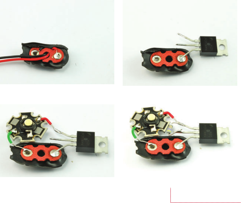
66 Hacking Electronics
HowTo-Color (8) / Hacking Electronics / Simon Monk / 236-3 / Chapter 4
Finally, solder the resistor across the two topmost leads of
the LM317 (Figure 4-14d).
How to Measure the Forward
Voltage of an LED
If you want to power lots of LEDs at the same time, it is a good
idea to test a few of the LEDs you actually intend to use and
measure the forward voltage at the current you intend to use.
Figure 4-15 shows how you would do this.
Figure 4-15a shows the schematic diagram. A variable
resistor is used to vary the current through the LED and when
the desired forward current is set, the voltage can be read.
The current and voltage do not have to be read at the same
time, but if you do have two meters, this does make life easier.
(a) (b)
(d)
(c)
Figure 4-14 Making an
emergency 1-W LED light
04-ch04.indd 66 12/29/12 2:11 PM

CHAPTER 4: LEDs 67
HowTo-Color (8) / Hacking Electronics / Simon Monk / 236-3 / Chapter 4
Set the variable resistor to its middle
point and wire up the breadboard as shown
in Figure 4-15b. You will probably have to
move the positive lead of your multimeter to a
different socket when measuring current. Select
a current range of 200mA DC. Now adjust the
variable resistor until the current reads 20mA.
We can now measure the voltage across the
LED. To do this, first disconnect the multimeter,
put the positive multimeter back in the right
socket for measuring voltage, and then change
the range to 20V DC. Wire it up as shown in
Figure 4-15c and measure the voltage. In this
case, it was 1.98V.
You Will Need
Quantity Names Item Appendix Code
1 Solderless breadboard T5
1 D1 LED K1
3 R1 500Ω trimpot R3
Jumper wires T6
1 4 × AA battery holder H1
1 Battery clip H2
4 AA batteries
(c)
(a) (b)
Figure 4-15 Measuring the
forward voltage of an LED
04-ch04.indd 67 12/29/12 2:11 PM

68 Hacking Electronics
HowTo-Color (8) / Hacking Electronics / Simon Monk / 236-3 / Chapter 4
How to Power Large Numbers of LEDs
If you use something like a 12V power supply, you can put
a number of LEDs in series, with just one LED. In fact, if
you know the forward voltages fairly
accurately, and the power supply is well
regulated, you can get away without any
series resistor at all.
So, if you have fairly standard LEDs
that have a forward voltage of 2V, then
you could just put six of them in series.
However, it will not be terribly easy to
predict how much current the LEDs
will take.
A safer approach is to arrange the
LEDs in parallel strings, each string
having its own current-limiting resistor
(Figure 4-16).
Although the math for this isn’t too
hard, there can be a fair bit of it, so you
can save yourself a lot of time by using an online calculator like
http://led.linear1.org/led.wiz (Figure 4-17). Figure 4-16 Powering multiple
LEDs
Figure 4-17 The LED wizard
04-ch04.indd 68 1/15/13 12:26 PM

CHAPTER 4: LEDs 69
HowTo-Color (8) / Hacking Electronics / Simon Monk / 236-3 / Chapter 4
In this particular designer, you enter the source voltage for
the overall supply, the LED forward voltage, the desired current
for each LED, and the number of LEDs you want to light. The
wizard then does the math and works out a few different layouts.
One consideration is that where you have a string of LEDs
in series, if any of the LEDs fail, then all the LEDs will be off.
How to Make LEDs Flash
The 555 timer IC is a useful little IC that can be used for many
different purposes, but is particularly convenient for making
LEDs flash or generating higher frequency oscillations suitable
for making audible tones (see Chapter 9).
We are going to make this design on breadboard and then
transfer it to a more permanent home on a bit of stripboard.
You Will Need
Quantity Names Item Appendix Code
1 Solderless breadboard T5
1 D1 LED red K1
1 D1 LED green K1
1 R1 1kΩ resistor K2
1 R2 470kΩ resistor K2
2 R3, R4 220Ω resistor K2
1 C1 1µF capacitor K2
1 IC1 555 timer K2
Jumper wires T6
1 4 × AA battery holder H1
1 Battery clip H2
4 AA batteries
Breadboard
The schematic for the LED flasher is shown in Figure 4-18.
The breadboard layout is shown in Figure 4-19. Make sure
you have the IC the right way up. There will be a notch in the
IC body next to the top (pins 1 and 8). The capacitor and LEDs
must both be the correct way around, too.
04-ch04.indd 69 12/29/12 2:11 PM

70 Hacking Electronics
HowTo-Color (8) / Hacking Electronics / Simon Monk / 236-3 / Chapter 4
Figure 4-20 shows the finished
breadboard. You should find that the LEDs
alternate, each staying on for about a second.
Now that we know that the design is right
and everything works, try swapping out R2
with a 100kΩ resistor and notice the effect on
the flashing.
The 555 timer is a very versatile device,
and in this configuration it oscillates at a
frequency determined by the formula:
frequency = 1.44 / ([R1 + 2 * R2] * C)
where the units of R1, R2, and C1 are in Ω
and F. Plugging in the values for this design,
we get:
frequency = 1.44 / ([1000 + 2 * 470000] * 0.000001) = 1.53 Hz
One hertz (or Hz) means one oscillation per second. When
we use the 555 timer in a later chapter to generate an audible
tone, we will be using the same circuit to generate a frequency
in the hundreds of hertz.
As with so many electronic calculations, there are also
online calculators for the 555 timer.
Figure 4-18 The LED flasher
schematic
Figure 4-19 The LED flasher
breadboard layout
04-ch04.indd 70 12/29/12 2:11 PM

CHAPTER 4: LEDs 71
HowTo-Color (8) / Hacking Electronics / Simon Monk / 236-3 / Chapter 4
How to Use Stripboard (LED Flasher)
Breadboard is very useful for trying things out, but not so useful
as a permanent home for your electronics. The problem is that
the wires tend to fall out, and it’s all a bit big and bulky.
Stripboard (Figure 4-21) is a bit
like general-purpose printed circuit
board. It is a perforated board with
conductive strips running underneath,
rather like breadboard. The board
can be cut to the size you need and
components and wires soldered onto it.
Designing the Stripboard Layout
Figure 4-22 shows the final stripboard layout for the LED
flasher that we made in the previous section. It is not easy to
explain how we got to this from the schematic and breadboard
layout. There is a certain amount of trial and error, but there are
a few principals you can follow to try and make it easier.
The first is to use a drawing tool with a stripboard template.
For Mac users, with OmniGraffle, a template is available for
download from the book’s web site (www.hackingelectronics
.com). There is also an image file that can be printed out and
used as a template to sketch out the design.
The Xs underneath the IC are breaks in the track, which we
will make with a drill bit. One of the goals of a good stripboard
Figure 4-20 The LED flasher on
breadboard
Figure 4-21 Stripboard
04-ch04.indd 71 12/29/12 2:11 PM

72 Hacking Electronics
HowTo-Color (8) / Hacking Electronics / Simon Monk / 236-3 / Chapter 4
layout is to try and avoid making too many breaks in the track.
Breaks are unavoidable for an IC like this. If we did not make
them, pin 1 would be connected to pin 8, pin 2 to pin 7, and so
on, and nothing would work.
The colored lines on the board are linking wires. So, for
instance, from the schematic diagram of Figure 4-18, we can
see that pins 4 and 8 of the IC should be connected together and
both go to the positive supply. This is accomplished by the two
red linking wires. Similarly, pins 2 and 6 need to be connected
together. This is accomplished by using the orange leads.
Although logically the stripboard layout is the same as the
schematic, the components are in rather different places. The
LEDs are on the left in the stripboard layout and on the right on
the schematic. It is not always like this, and it’s easier if they are
similar, but in this case the left-hand pins of the IC include the
output pin 3 that the LEDs need, and the pins connected to R1,
R3, and C1 are all on the right-hand side of the IC.
Try making a stripboard layout from the schematic, you
may well come up with a different and better layout than the
one I produced.
The steps I went through in designing this layout are as
follows:
1. Place the IC fairly centrally, with a bit more room above
than below and with pin 1 uppermost (convention).
2. Find a good place for R3 and R4 to be put so the strips
are at least three holes apart for one resistor lead, when
the other lead of each resistor goes to pin 3.
Figure 3-22 An LED flasher
stripboard layout
04-ch04.indd 72 12/29/12 2:11 PM

CHAPTER 4: LEDs 73
HowTo-Color (8) / Hacking Electronics / Simon Monk / 236-3 / Chapter 4
3. Pick the top track of the stripboard to be +V so it can be
close to the positive end of one of the LEDs
4. Pick row 5 to be the ground connection. This way it can
run straight on to pin 1 of the IC.
5. Add a link wire from row 5 to row 9 to provide the
negative connection for the LED D2.
6. Put a jumper wire from pin 4 of the IC to row 1 (+V).
Turning now to the right-hand side of the board:
1. Put a jumper in connecting pin 8 of the IC to row 1 (+V).
2. R1 and R2 both have one end connected to pin 7,
so put them side by side with the far end of R1 going to
row 1 (+V).
3. R2 needs to connect to pin 6, but pin 6 and pin 7 of the
IC are too close together for the resistor to lie flat, so take
that lead up to the unused row 2 instead, then put jumpers
from row 2 down to both pin 6 and pin 2 of the IC.
4. Finally, C1 needs to go between pin 6 (or pin 2, but 6
is easier) and GND (row 9).
A good way of checking that you have made all the
connections you need is to print off the schematic and then go
through each connection on the stripboard and check off its
counterpart on the schematic.
This may all seem a little like magic, but try it. It’s not as
hard to do as it is to describe.
You Will Need
You will need all the components listed in the section “How to
Make LEDs Flash,” plus the following items.
Quantity Item Appendix Code
1 Stripboard 10 strips by 17 holes H3
1 Soldering kit T1
1 Drill bit (1/8 inch)
Before we start soldering, it is worth considering what kind
of LEDs you want to use for this project. You may decide to
04-ch04.indd 73 12/29/12 2:11 PM

74 Hacking Electronics
HowTo-Color (8) / Hacking Electronics / Simon Monk / 236-3 / Chapter 4
use higher-brightness LEDs or power the project from a lower
voltage. If you do decide on this, recalculate the values for R3
and R4 and try it out on the breadboard layout. The 555 timer
IC needs a supply voltage between 4.5V and 16V, and the
output can supply up to 200mA.
Construction
Step 1. Cut the Stripboard to Size
There is no point in having a
large bit of stripboard with just
a few components on it, so the
first thing we need to do is cut
the stripboard to the right size. In
this case, it’s ten strips each of
17 holes. Stripboard doesn’t actually
cut very well. You can use a rotary
tool, but wear a mask because the
dust from the stripboard is nasty
and you really do not want it in your
lungs. I find the easiest way to cut
stripboard is actually to score it with a craft knife and metal ruler
on both sides and then break it over the edge of your work surface.
Score it across the holes, not between them. When the board
is cut, the copper underside will look like Figure 4-23.
Step 2. Make the Breaks in the Tracks
A good tip is to use a permanent marker and put a dot in the top
left corner. Otherwise, it is very easy to get the board turned
around, resulting in breaks and links being put in the wrong place.
To make the breaks, count the position in rows and columns
of the break from the top of the board layout and then push a bit
of wire so you can identify the right hole on the copper side of
the stripboard (Figure 4-24a). Using a drill bit, just “twizzle” it
between thumb and forefinger to cut through the copper track. It
usually only takes a couple of twists (Figure 4-24b and c).
When you have cut all four breaks, the bottom side of the
breadboard should look like Figure 4-25. Check very carefully
that none of the burrs from the copper have lodged between
the tracks and that the breaks are complete. Photographing the
board and then zooming in is a great way of actually checking
the board.
Figure 4-23 A stripboard cut
to size
04-ch04.indd 74 12/29/12 2:11 PM

CHAPTER 4: LEDs 75
HowTo-Color (8) / Hacking Electronics / Simon Monk / 236-3 / Chapter 4
Step 3. Make the Wire Links
A golden rule of any type of circuit board
construction, including when using stripboard, is
to start with the lowest-lying components. This
is so that when you turn the board on its back to
solder it, the thing being soldered will stay in place
through the weight of the board.
In this case, the first thing to solder is the links.
Strip and cut solid-core wire to slightly longer
than the length of the link. Bend it into a U-shape
and push it through the holes at the top, counting
the rows and columns to get the right holes
(Figure 4-26a). Some people get very skilled at
bending the wires with pliers to just the right length. I find it
easier to bend the wires with a bit of a curve so they will kind
of squash into the right holes. I find this easier than trying to
get the length just right from the start.
Turn the board over (see how the
wire is held in place) and solder the wire
by holding the iron to the point where the
wire emerges from the hole. Heat it for a
second or two and then apply the solder
until it slows along the track, covering the
hole and wire (Figure 4-26b and c).
Repeat this process for the other end
of the lead and then snip off the excess
wire (Figure 4-26d and e).
When you have soldered all the
links, your board should look like the
one in Figure 4-27.
(a) (b)
(c)
Figure 4-24 Cutting a track on
stripboard
Figure 4-25 The stripboard with
breaks cut
04-ch04.indd 75 12/29/12 2:11 PM

76 Hacking Electronics
HowTo-Color (8) / Hacking Electronics / Simon Monk / 236-3 / Chapter 4
Step 4. Resistors
The resistors are the next lowest components to the board,
so solder these next, in the same way as you did the links.
When they are all soldered, the stripboard should look
like Figure 4-28.
(a) (b)
(d)(c)
(e)
Figure 4-26 Soldering the links
04-ch04.indd 76 12/29/12 2:11 PM

CHAPTER 4: LEDs 77
HowTo-Color (8) / Hacking Electronics / Simon Monk / 236-3 / Chapter 4
Step 5. Solder the Remaining
Components
Next, solder the LED, capacitor (which can
be laid on its side as shown in Figure 4-29),
and finally the LEDs and connectors to the
battery clip.
That’s it. Now it’s time for the moment
of truth. Before you plug it in, do a very
careful inspection for any shorts on the
underside of the board.
If everything seems in order, connect
the battery clip to the battery.
Troubleshooting
If it does not work, immediately unplug it
and go back though and check everything,
especially that the LEDs, IC, and capacitor
are the correct way around. Also check that
the batteries are okay.
Figure 4-27 The stripboard with
all its links
Figure 4-28 The stripboard with
resistors in place
Figure 4-29 The LED flasher on
the stripboard
04-ch04.indd 77 12/29/12 2:11 PM

78 Hacking Electronics
HowTo-Color (8) / Hacking Electronics / Simon Monk / 236-3 / Chapter 4
How to Use a Laser Diode Module
Lasers are best bought as laser modules. The difference between
a laser module and a laser diode is that the module includes a
laser diode as well as a lens to focus the beam of laser light and
a drive circuit to control the current to the laser diode.
If you buy a laser diode, you will have to do all this
yourself.
A laser diode module, such as the 1-mW module shown
in Figure 4-30, comes with a datasheet that says it needs to be
supplied with 3V. So, all you need to do is find it a 3V battery
and connect it up.
Hacking a Slot Car Racer
Slot cars are a lot of fun, but could be improved by
adding headlights and working brake lights to the car
(Figure 4-31).
LEDs are just the right size to be fitted front and
back into a slot car.
You Will Need
You will need the following items to add lights to your slot car.
Quantity Name Item Appendix Code
1 Slot car racer for modification
1 D1 1N4001 S5, K1
2 D2, D3 High-brightness white LED 5rmm S2
2 D4, D5 Red LED 5mm S11
4 R1–4 1kΩ resistor K2
1 C1 1000µF 16V-capacitor C1
Red, yellow, and black hookup wire T7, T8, T9
1 * Two-way header plug and socket
* I used a scavenged two-way header socket and plug to make it easier to work on the two
halves of the car. This is not essential.
The slot car used here was part of a build-your-own slot car
that has plenty of room inside for the electronics. Plan ahead
and make sure you can fit everything in.
Figure 4-30 A laser diode
module
Figure 4-31 A modified slot car
racer
04-ch04.indd 78 12/29/12 2:11 PM

CHAPTER 4: LEDs 79
HowTo-Color (8) / Hacking Electronics / Simon Monk / 236-3 / Chapter 4
Storing Charge in a Capacitor
To make the brake lights stay on for a few moments after the car
has stopped, you will need a capacitor to store charge.
If you think back to the idea of electricity as water flowing
in a river, then a capacitor is a bit like a storage tank. Figure 4-32
shows how a capacitor can be used to store charge.
Figure 4-32a shows a tank (c1) being filled with water
through A. Throughout this, water will also flow along the top
and drive a water wheel, turning electrical energy into motion,
a bit like how a light bulb or LED turns electrical energy into
light. The water falls out of the bottom, returning to ground.
Imagine a pump (like a battery) pulling the water back up for
another circuit. If the water stops flowing into C1 through A,
then C1 will still be full of water that will keep the water wheel
turning until the water level in C1 drops below that of the outlet
of the water well.
Figure 4-32b shows the electronic equivalent of this circuit.
While the voltage at A is higher than GND, C1 will fill with
charge and the light will be lit.
When the voltage at A is disconnected, the capacitor will
discharge through the light bulb, lighting it. As the level of
voltage drops in the capacitor, the bulb will gradually dim until
it goes out as it reaches GND.
Figure 4-32 A capacitor as
a tank
04-ch04.indd 79 12/29/12 2:11 PM

80 Hacking Electronics
HowTo-Color (8) / Hacking Electronics / Simon Monk / 236-3 / Chapter 4
On the face of it, you can think of capacitors as being a bit
like batteries. Both store charge. However, there are some very
important differences.
● Capacitors only store a tiny fraction of the charge that
a battery of the same size can store.
● Batteries use a chemical reaction to store electrical
energy. This means their voltage remains relatively
constant until they are spent, at which time it falls off
rapidly. Capacitors, however, drop evenly in voltage as
they discharge, just like the level of water decreasing
in a tank.
Design
Figure 4-33 shows the schematic diagram for this modification.
The headlights (D2 and D3) are powered all the time from
the slot car’s connection to the track, so whenever the motor is
running the LEDs will light.
The brake lights are more interesting. These will automatically
come on when the car stops, and then go off after a few seconds.
To do this, we make use of a capacitor C1.
Figure 4-33 A schematic
diagram for the slot car
modification
04-ch04.indd 80 12/29/12 2:11 PM

CHAPTER 4: LEDs 81
HowTo-Color (8) / Hacking Electronics / Simon Monk / 236-3 / Chapter 4
When the car is powered, C1 will be
charged through D1. At this point, the brake
lights D4 and D5 will not be lit because they
will be reverse-biased—that is, the voltage
going in from the car tracks will be higher
than the voltage at the top of the capacitor.
When you release the trigger on the
controller, there will be no voltage coming
in. Now the voltage at the top of the
capacitor will be higher than the voltage
coming in, so the capacitor will discharge
through D4 and D5, making them light.
Construction
Figure 4-34 shows how the components are
laid out in the two halves of the car.
How you lay these out in your vehicle
may vary depending on how much space
you have.
Holes were drilled in the case to take the 5mm LEDs. The
LEDs are a snug fit in the holes and stay in place without any glue.
Figure 4-35 shows a wiring diagram for the arrangement
that makes it easier to see what is going on.
Use your multimeter of the 20V range to identify
which is the positive power connector on the contacts
at the front of the car. This contact is connected to
the red lead.
The longer leads of the LEDs are the positive
connections, and the capacitor’s negative lead
should be marked with a “-”.
The optional connector makes it easier to work
on the two halves of the car separately.
Testing
Testing really just involves trying out the car on the
track. If the headlight LEDs are not on as soon as
you squeeze the trigger on the controller, check
the wiring, paying special attention to the polarity
of the LEDs.
Figure 4-34 The components
inside the car
Figure 4-35 The wiring diagram
for the modified car
04-ch04.indd 81 12/29/12 2:11 PM
82 Hacking Electronics
HowTo-Color (8) / Hacking Electronics / Simon Monk / 236-3 / Chapter 4
Summary
We have learned how to use LEDs in this chapter, as well as picked
up some good building skills so we can make our creations a bit
more permanent using stripboard.
In the next chapter, we will examine sources of power,
including batteries, power supplies, and solar panels. We will
also look at how to select the right kind of battery, repurpose old
rechargeable batteries, and use them in our projects.
04-ch04.indd 82 12/29/12 2:11 PM

HowTo-Color (8) / Hacking Electronics / Simon Monk / 236-3 / Chapter 5
blind folio 83
5
Batteries and Power
Everything that you make or adapt is going to need to get its power from somewhere. This
might be from a household electricity adapter, solar panels, rechargeable batteries of various
sorts, or just standard AA batteries.
In this chapter, you will find out all about batteries and power, starting with batteries.
Selecting the Right Battery
There are many types of battery on the market. So, to simplify things, in this chapter we will just
look at the most common types of battery, those that are readily available and that will be used in
most of the devices in this book.
Battery Capacity
Whether single-use or rechargeable, batteries have a capacity—that is, they hold a certain amount
of electricity. Manufacturers of single-use batteries often don’t specify this capacity in the
batteries you buy from a supermarket. They just label them heavy duty / light duty, and so on.
This is a little like having to buy milk and being given the choice of “big bottle” or “small bottle”
without being able to see how big the bottle is or be told how many pints or liters it contains.
One can speculate as to the reasons for this. One reason might be that battery producers think
the public isn’t intelligent enough to understand a stated battery capacity. Another might be that
the longer a battery is on the shelf, the more its capacity shrinks. Still another is that the capacity
actually varies a lot with the current drawn from the battery.
Anyway, if a battery manufacturer is kind enough to tell you what you are buying, the
capacity figure will be stated in Ah or mAh. So a battery that claims to have a capacity of
3000mAh (typical of a single-use alkaline AA cell) can supply 3000mA for one hour. Or,
I use the word “battery” to describe both batteries and cells. Strictly speaking, a battery
is a collection of cells wired one after the other to give the desired voltage.
Note
05-ch05.indd 83 1/15/13 11:34 AM
84 Hacking Electronics
HowTo-Color (8) / Hacking Electronics / Simon Monk / 236-3 / Chapter 5
alternatively, 3A for an hour. But it doesn’t have to draw 3A.
If your project only uses 30mA, you can expect the battery to
last 100 hours (3000/30). In truth, the relationship is not quite
that simple, because as you draw more current, the capacity
decreases. Nevertheless, this will do as a rule of thumb.
Maximum Discharge Rate
You cannot take a tiny battery like a CR2032 with a capacity
of 200mAh and expect to power a big electric motor at 20A for
1/100 of an hour (six minutes). There are two reasons for this.
First, all batteries actually have an internal resistance. So, it is
as if there is a resistor connected to one of the terminals. This
varies depending on the current being drawn from the battery,
but may be as high as a few tens of ohms. This will naturally
limit the current.
Second, when a battery is discharged too quickly, by too
high a current, it gets hot—sometimes very hot, sometimes “on
fire” hot. This will damage the battery.
Batteries therefore also have a safe discharge rate, which is
the maximum current you can safely draw from it.
Single-Use Batteries
Although somewhat wasteful, sometimes it makes sense to
use single-use batteries that cannot be recharged. You should
consider single-use batteries if:
● The project uses very little power, so they will last a
long time anyway.
● The project will never be close to someplace where it
can be charged up.
Table 5-1 shows some common single-use batteries. These
figures are typical values and will vary a lot between actual
devices.
Especially when it comes to the maximum discharge rate,
you may get away with a lot more, or the battery may fail or get
very hot with considerably less. It will also depend on how well
ventilated a box they are in, as heating under high currents is a
big problem.
So in the spirit of hacking electronics, spend less time
planning and more time trying. See how hot it gets and how long
it lasts. After all, we are having fun here, not designing a product.
05-ch05.indd 84 1/15/13 11:34 AM

CHAPTER 5: Batteries and Power 85
HowTo-Color (8) / Hacking Electronics / Simon Monk / 236-3 / Chapter 5
Roll Your Own Battery
A single-cell battery with a voltage of just 1.5V is probably not
going to be of any use. You will normally need to put a number
of these cells in series (end to end) to produce a battery of the
desired voltage.
When you do this, you do not increase the capacity. If each
cell was 2000mAh, then if you put four 1.5V batteries in series,
the capacity would still be 2000mAh, but at 6V rather than 1.5V.
Type
Typical
Capacity Voltage
Max. Discharge
Current Features Common Uses
Lithium
button
cell (e.g.,
CR2032)
200mAh 3V 4mA with
pulses up to
12mA
High
temperature
range (–30 to
80ºC);
small
Low-power
devices;
RF remote
controls;
LED key ring
lights, etc.
Alkaline
PP3
battery
500mAh 9V 800mA Low cost;
readily available
Small portable
electronic
devices;
smoke alarms;
guitar pedals
Lithium
PP3
1200mAh 9V 400mA pulses
up to 800mA
Expensive;
light;
high-capacity
Radio receivers
AAA cell 800mAh 1.5V 1.5A
continuous
Low-cost;
readily available
Small
motorized toys;
remote controls
AA cell 3000mAh 1.5V 2A continuous Low cost;
readily available
Motorized toys
C cell 6000mAh 1.5V Probably get
away with 4A
High-capacity Motorized toys;
high-powered
flashlights
D cell 15,000mAh 1.5V Probably get
away with 6A
High-capacity Motorized toys;
high-powered
flashlights
TABLE 5-1 Single-Use Battery Types
Some of the photographs in the table are of branded batteries. The figures shown are for
batteries of that type, not specifically the batteries listed.
Note
05-ch05.indd 85 1/15/13 11:34 AM

86 Hacking Electronics
HowTo-Color (8) / Hacking Electronics / Simon Monk / 236-3 / Chapter 5
Battery holders such as the one shown
in Figure 5-1 are a great way of doing this.
Look closely at how the battery holder is
constructed and you’ll notice how the positive
of one battery is connected to the negative of
the next, and so on.
This holder is designed to take six AA
batteries so as to produce an overall voltage of
9V. Battery holders like this are available to
take two, four, six, eight, or ten cells, both in
AA and AAA.
Another advantage of using a battery
holder is that you can use rechargeable batteries
instead of single-use batteries. However, rechargeable cells
normally have a lower voltage, so you have to take this into
account when calculating the overall voltage of your battery pack.
Selecting a Battery
Table 5-2 should help you decide on a suitable battery for
your project. There is not always a best answer to the question
“Which battery should I use?” and this table is definitely in the
territory of rules of thumb.
You should also do the math and include how frequently the
battery will need replacing.
Figure 5-1 A battery holder
TABLE 5-2 Selecting a Single-Use Battery
Voltage
Power 3V 6V 9V 12V
Less than 4mA (short bursts)
or 12mA continuous
Lithium button cell
(e.g., CR2032)
2 × Lithium button
cell (e.g., CR2032)
PP3 Unlikely
Less than 3A (short bursts)
or 1.5A continuous
2 × AAA battery
pack
4 × AAA battery pack 6 × AAA
battery pack
8 × AAA
battery pack
Less than 5A (short bursts)
or 2A continuous
2 × AAA battery
pack
4 × AAA battery pack 6 × AAA
battery pack
8 × AAA
battery pack
Even more 2 × C or D battery
pack
4 × C or D battery
pack
6 × C or D
battery pack
8 × C or D
battery pack
Rechargeable Batteries
Rechargeable batteries can provide both cost and green benefits
over single-use batteries. They are available in different types
and in different capacities. Some, such as rechargeable AA or
05-ch05.indd 86 1/15/13 11:34 AM

CHAPTER 5: Batteries and Power 87
HowTo-Color (8) / Hacking Electronics / Simon Monk / 236-3 / Chapter 5
AAA batteries, are designed as replacements for single-use
batteries, and you remove them to charge in a separate charger.
Other batteries are intended to be built into your project so
all you have to do is plug a power adapter into your project
to charge the batteries without removing them. The advent
of cheap, high-capacity, low-weight lithium polymer (LiPo)
batteries has made this a common approach for many items of
consumer electronics.
Table 5-3 shows some commonly used types of
rechargeable batteries.
Although there are many more types than this, these are the
most commonly used batteries. Each type of battery has its own
needs when it comes to charging, and we will look at each in
later sections.
TABLE 5-3 Rechargeable Batteries
Type
Typical
Capacity Voltage Features Common Uses
NiMH button
cell pack
80mAh 2.4 or
3.6V
Small Battery backup
NiMH AAA
cell
750mAh 1.25V Low cost Replacement for single-
use AAA cell
NiMH AA
cell
2000mAh 1.25V Low cost Replacement for single-
use AA cell
NiMH C
cell
4000mAh 1.25V High capacity Replacement for single-
use C cell
Small LiPo
cell
50mAh 3.7V Low cost;
high capacity for weight
and size
Micro-helicopters
LC18650
LiPo cell
2200mAh 3.7V Low cost;
high capacity for weight
and size;
slightly bigger than AA
High-power flashlights;
Tesla Roadster (yes,
really—about 6800 of
them)
LiPo pack 900mAh 7.4V Low cost;
high capacity for weight
and size
Cell phones, iPods, etc.
Sealed lead–
acid battery
1200mAh 6/12V Easy to charge and use;
heavy
Intruder alarms;
small electric vehicles /
wheelchairs
05-ch05.indd 87 1/15/13 11:34 AM

88 Hacking Electronics
HowTo-Color (8) / Hacking Electronics / Simon Monk / 236-3 / Chapter 5
TABLE 5-4 Characteristics of Different Battery Technologies
Table 5-4 summarizes the features of NiMH, LiPo, and
lead–acid battery technologies.
If you want your project to charge a battery in place, then
a LiPo or sealed lead–acid battery is probably the best choice.
However, if you want the option to remove the battery and/
or use single-use batteries, then a AA battery pack is a good
compromise between capacity and size.
For ultra-high-power projects, lead–acid batteries, despite
being an ancient technology, still perform pretty well, just as
long as you don’t have to carry them around! They are also easy
to charge and are the most robust of the technologies, offering
the least chance of fire or explosion.
Charging Batteries (in General)
Certain principals apply no matter what kind of battery you are
charging. So read this section before reading those that follow it
concerning specific battery types.
C
The letter C is used to denote the capacity of a battery in Ah or
mAh. So, when people talk about charging a battery, they often
talk about charging at 0.1C or C/10. Charging a battery at 0.1C
means charging it at 1/10 of its capacity per hour. For example,
if a battery has a capacity of 2000mAh, then charging it at 0.1C
means charging it with a constant current of 200mA.
NiMH LiPo Lead–Acid
Cost per mAh Medium Medium Low
Weight per mAh Medium Low High
Self-discharge High (flat in 2–3 months) Low (6% per month) Low (4% per month)
Handling of full charge/
discharge cycles
Good Good Good
Handling of shallow
discharge/charge
Medium (regular full
discharge prolongs
battery life)
Medium (not well-
suited to trickle
charging)
Good
05-ch05.indd 88 1/15/13 11:34 AM
CHAPTER 5: Batteries and Power 89
HowTo-Color (8) / Hacking Electronics / Simon Monk / 236-3 / Chapter 5
Over-Charging
Most batteries do not respond well to being over-charged. If
you keep supplying them with a high charging current, you
will damage them. They often also get hot. In the case of LiPo
batteries, this can be “hot” in a fiery sort of way.
For this reason, chargers often charge at a low rate (called
trickle charging), so that the low current will not damage the
battery. Clearly this makes charging slow. Or, they will use a
timer or other circuitry to detect when a battery is full and either
stop charging altogether, or switch to trickle charging, which
keeps the battery topped up until you are ready to use it.
With some kinds of battery, notably LiPos and the lead–acid
variety, if you charge the battery with a constant voltage, then
as the battery becomes charged, its voltage rises to match the
charging voltage and the current naturally levels off.
Many LiPo batteries now come with a little built-in chip that
prevents over-charging automatically. Always look for batteries
with such protection.
Over-Discharging
You are probably starting to get the impression that rechargeable
batteries are fussy. If so, you’re right. Most types of battery are
equally unhappy if you over-discharge them and let them go
completely flat.
Battery Life
Anyone with a laptop more than a few years old will notice that
the capacity of the battery gradually decreases until the laptop only
works when plugged in, since the battery has become completely
useless. Rechargeable batteries (whatever the technology) can only
be recharged a few hundred (perhaps 500) times before needing to
be replaced.
Many manufacturers of consumer electronics now build
the battery into the device in such a way that it is not “user
serviceable,” with the rationale that the life of the battery is
probably longer than the attention span of the consumer.
How to Charge a NiMH Battery
If you are going to remove your batteries to charge them, this
section is pretty trivial. You take them out and put them in a
05-ch05.indd 89 1/15/13 11:34 AM

90 Hacking Electronics
HowTo-Color (8) / Hacking Electronics / Simon Monk / 236-3 / Chapter 5
commercial NiMH battery charger that will charge them until
they are full and then stop. You can then put them back into
your project and you are done.
If, on the other hand, you want to leave the batteries in place
while you charge them, then you need to understand a little
more about the best way to charge your NiMH batteries.
Simple Charging
The easiest way to charge a NiMH battery pack
is to trickle charge it, limiting the current with
a resistor. Figure 5-2 shows the schematic for
charging a battery pack of four NiMH batteries
using a 12V DC adaptor like the one we used back
in Chapter 1 to make our fume extractor.
To calculate the value of R1, we first have to
decide what current we want to charge our battery
with. Generally, a NiMH battery can be safely
trickle charged with less than 0.1C indefinitely.
If the AA batteries we have each hold a C of
2000mAh, then we can charge them at up to
200mA. To be on the safe side, and if we planned
to allow the batteries to “trickle” charge most of the time—for,
say, a battery backup project—I would probably use a lower
current of 0.05C or more conveniently C/20, which is 100mA.
Typically, the charge time for NiMH batteries is about 3C
times the charging current, so at 100mA, we could expect our
batteries to take 3 × 2000mAh / 100mA = 60 hours.
Back to calculating R1. When the batteries are discharged,
each will be at a voltage of about 1.0V, so the voltage across the
resistor will be 12V – 4V = 8V.
Using Ohm’s law, R = V / I = 8V / 0.1A = 80Ω.
Let’s be conservative and choose the convenient resistor
value of 100Ω. Feeding this back in, the actual current will be
I = V / R = 8V / 100Ω = 80mA.
When the batteries are fully charged, their voltage will rise
to about 1.3V so the current will reduce to: I = V / R = (12V –
1.3V × 4) / 100Ω = 68mA.
That all sounds just fine, our 100Ω will be great. Now we just
need to find out what maximum power rating we need for R1.
P = I V = 0.08A × 8 = 0.64W = 640 mW
So, we should probably use a 1-W resistor.
Figure 5-2 Schematic for trickle
charging a NiMH battery pack
05-ch05.indd 90 1/15/13 11:34 AM
CHAPTER 5: Batteries and Power 91
HowTo-Color (8) / Hacking Electronics / Simon Monk / 236-3 / Chapter 5
Fast Charging
If you want to charge the batteries faster than that, then it is
probably best to use a commercial charger, which will monitor
the batteries and turn itself off or reduce the charge to a trickle
when the batteries are full.
How to Charge a Sealed
Lead–Acid Battery
These batteries are the least delicate of the battery types and
could easily be trickle charged using the same approach as for
NiMH batteries.
Charging with a Variable Power Supply
However, if you want to charge them faster, then it is best to
charge them with a fixed voltage, with some current limiting
(a resistor again). For a 12V battery (halve this for a 6V battery)
until a discharged battery gets to around 14.4V, you can charge
it with almost as much current as your power supply can take.
It’s only when it gets to this voltage that you need to slow down
the charging to a trickle to prevent the battery from getting hot.
The reason we need to limit the current when the battery
first starts to charge is that even if the battery doesn’t get hot,
the wires to it might get hot and whatever is supplying the
voltage will only be able to supply a certain amount of current.
Figure 5-3 shows an adjustable power supply. Once you get
into electronics, this is one of the first pieces of test equipment
you should buy. You can use it in place of batteries while you
are working on a project, and also use it to charge up pretty
much any type of rechargeable battery.
A variable power supply lets you set both an output voltage
and a maximum current. So the power supply will try and
supply the specified voltage until the current limit is reached,
at which point, the voltage will drop until the current falls back
below the set current.
Figure 5-3a shows the power supply set to 14.4V and we have
attached the power leads to an empty 12V 1.3Ah sealed lead–acid
battery. We will start by adjusting the current setting of the power
05-ch05.indd 91 1/15/13 11:34 AM

92 Hacking Electronics
HowTo-Color (8) / Hacking Electronics / Simon Monk / 236-3 / Chapter 5
supply to minimum, so as to prevent any nasty surprises. The
voltage immediately drops to 11.4V (Figure 5-3b), so we can
gradually increase the maximum current. In actual fact, even with
no current limiting (turning the current knob to maximum), the
current only rose to 580mA and the voltage increases to 14.4V
(Figure 5-3c). After about two hours, the current has dropped to
just 200mA, indicating that our battery is getting full. Finally,
after four hours, the current is just 50mA and the battery is now
fully charged (Figure 5-3d).
How to Charge a LiPo Battery
The technique we have just used on a lead–acid battery using a
variable power supply will work just as well on a LiPo battery if
we adjust the voltage and current accordingly.
For a LiPo cell, the voltage should be set to 4.2V and the
current limited (usually to 0.5A) for a smallish cell, but currents
up to C are sometimes used in radio-controlled vehicles.
However, unlike lead–acid and NiMH batteries, you cannot
put a number of cells in series and charge the whole lot as one
battery. Instead, you have to charge them separately, or use
a “balanced charger” that monitors the voltage at each cell
separately and controls the power to each.
(d)(a) (b) (c)
Figure 5-3 Using a variable
power supply to charge a lead–
acid battery
05-ch05.indd 92 1/15/13 11:34 AM

CHAPTER 5: Batteries and Power 93
HowTo-Color (8) / Hacking Electronics / Simon Monk / 236-3 / Chapter 5
The safest and most reliable way to charge a LiPo is to use
one of the chips that exist just for that purpose. These chips
are cheap, but generally only available as surface-mounted
components. However, there are plenty of ready-made modules
available, many of which use the MCP73831 IC. Figure 5-4
shows two of these—one from SparkFun (see the Appendix, M16)
and one for just a few dollars from eBay.
Both are used in the same manner. They will charge a single
LiPo cell (3.7V) from a USB input of 5V. The SparkFun board
has space on the PCB for two other connectors, one to which
the battery is connected and the other for a second connection
to the battery—the intention is that you connect the electronics
that will use the battery to the second socket. The sockets can be
either JST connectors as are often found on the end of the leads
of a LiPo batter, or just screw terminals. The SparkFun module
allows you to select the charging current, using a connection pad.
The generic module on the right has a fixed charge rate of
500mA and just a single pair of connections for the battery.
It is not a good idea to trickle charge a LiPo. If you want
to keep them topped up, for say a battery backup solution, then
leave them attached to the charger.
Hacking a Cell Phone Battery
Most of us have a cell phone or two languishing in a drawer
somewhere, and one of the useful components that can usually
be scavenged (assuming it’s not the reason the phone is in the
drawer) is the battery. The power supply is another useful item.
Figure 5-5a shows a fairly typical vintage cell phone battery.
The battery is 3.7V (a single cell) and is 1600mAh (pretty good).
Figure 5-4 SparkFun and
generic LiPo chargers
05-ch05.indd 93 1/15/13 11:34 AM
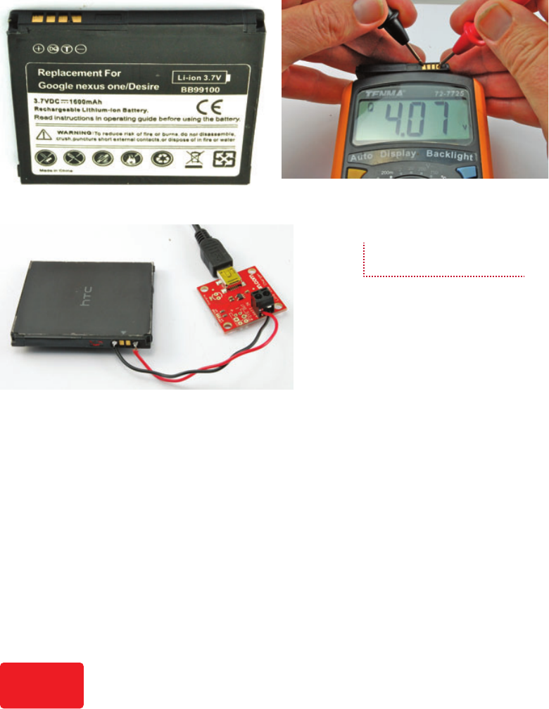
94 Hacking Electronics
HowTo-Color (8) / Hacking Electronics / Simon Monk / 236-3 / Chapter 5
Cell phone batteries normally have more than just the usual two
connections for positive and negative. So the first task must be to
identify the connections on the battery.
To identify the positive and negative connections to the
cell, just put your multimeter into the 20V DC range and
test each combination of pairs until you get the meter to read
something over 3.5V, depending on how well charged the
battery is (Figure 5-5b).
The batteries often have gold-plated contacts that make them
very easy to solder leads to. Once they have leads attached, you
can use a charger like the one described in the previous section.
Figure 5-5c shows the SparkFun charger module being used for
just that purpose.
(a) (b)
(c)
Figure 5-5 Hacking a cell phone
battery
When using a LiPo battery, remember that if you discharge them too far (below about
3V per cell), you can permanently damage them. Most new LiPo batteries will include an
automatic cut-off circuit, built into the battery package, to prevent over-discharging, but
this may not be the case for a scavenged battery.
Caution
05-ch05.indd 94 1/15/13 11:34 AM

CHAPTER 5: Batteries and Power 95
HowTo-Color (8) / Hacking Electronics / Simon Monk / 236-3 / Chapter 5
Controlling the Voltage from a Battery
The thing with batteries is that even though they may say 1.5V,
3.7V, or 9V on the package, their voltage will drop as they
discharge—often by quite a high percentage.
For example, a 1.5V alkaline AA battery when brand new
will be about 1.5V and will quickly fall to about 1.3V under load
but still deliver useful amounts of power down to about 1V. This
means that in a pack of four AA batteries, the voltage could be
anything between 6V and 4V. Most types of battery, whether
single-use or rechargeable, exhibit a similar voltage drop.
This may not matter much; it just depends on what the battery
is powering. If it is powering a motor or an LED, then the motor
will just go a bit more slowly, or the LED will be a little dimmer
as the battery discharges. However, some ICs have a very narrow
voltage tolerance. There are ICs designed to work at 3.3V that
specify a maximum working voltage of 3.6V. Similarly, if the
voltage drops too low, the device will also stop working.
In fact, many digital chips such as microcontrollers are
designed to work at a standard voltage of 3.3V or 5V.
To ensure a steady voltage, we need to use something called
a voltage regulator. Fortunately for us, voltage regulators come
as convenient three-pin, low-cost chips that are very easy to use.
In fact, the packages just look like transistors, and the bigger the
package, the more current they can control.
Figure 5-6 shows how you would use the most common of
voltage regulators, called the 7805.
Using just a voltage regulator IC and two capacitors,
any input voltage between 7V and 25V can be regulated to a
constant 5V. The capacitors provide little reservoirs of charge
that keep the regulator IC operating in a stable manner.
Figure 5-6 A voltage regulator
schematic
05-ch05.indd 95 1/15/13 11:34 AM
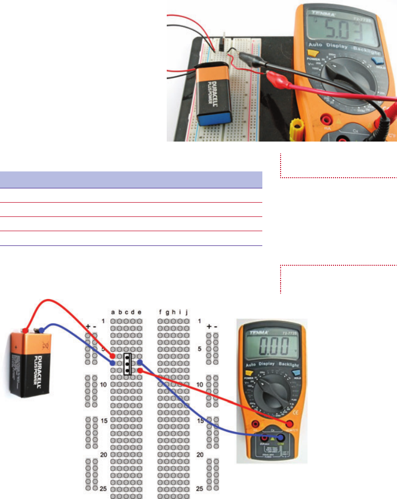
96 Hacking Electronics
HowTo-Color (8) / Hacking Electronics / Simon Monk / 236-3 / Chapter 5
In the following experiment with
a 7805, we will omit the capacitors,
as the supply voltage is a steady 9V
battery and the load on the output is
just a resistor (Figure 5-7).
The capacitors become much
more necessary when the load varies
(in other words, in the amount of
current that it draws), something that
is true of most circuits.
You Will Need
Quantity Names Item Appendix Code
1 Solderless breadboard T5
1 IC1 7805 voltage regulator K1, S4
1 Battery clip H2
1 9V PP3 battery
Wire up the breadboard as shown in Figure 5-8.
Figure 5-7 Experimenting with
the 7805
Figure 5-8 The 7805 breadboard
layout
05-ch05.indd 96 1/15/13 11:34 AM

CHAPTER 5: Batteries and Power 97
HowTo-Color (8) / Hacking Electronics / Simon Monk / 236-3 / Chapter 5
Breadboard
With the battery connected, the multimeter should display a
voltage of close to 5V.
Although 5V is a very common voltage, there
are voltage regulators for most common voltages,
as well as the LM317 voltage regulator that we
discussed in Chapter 4, that as well as providing
constant current, can also be configured as a
voltage regulator.
Table 5-5 lists some common voltage regulators
that provide different output voltages and different
current handling capabilities.
Boosting Voltage
The voltage regulator ICs in the section titled “Controlling the
Voltage from a Battery” only work if the input voltage is greater
than the output voltage. In fact, it normally has to be a couple of
volts higher, but some more expensive voltage regulators called
LDO (low drop out) regulators are available that only require
about half a volt more on the input than the output.
Sometimes, however—and cellular phones are a good
example of this—it is very convenient to use a single-cell LiPo
battery of 3.7V when we require a higher voltage (often 5V) for
the circuit.
In these situations, you can employ a very useful circuit
called a buck-boost converter. These use an IC and a small
inductor (coil of wire) and by applying pulses to the inductor,
produce a higher voltage. Actually, it’s more complex than that,
but you get the idea.
Buck-boost converters are readily available as modules on
well-known auction sites. You can find 1A adjustable modules
that will provide an adjustable output of 5V to 25V from 3.7V for
a few dollars. Try searching for “Boost Step-Up 3.7V.” The main
module suppliers also provide such boards for around USD 5.
SparkFun sells an interesting module (see the Appendix,
M17) that combines a LiPo battery charger with a buck-boost,
so you can both charge your LiPo from an external USB 5V
input and use the 3.7V LiPo cell to provide an output of 5V
using the buck-boost (Figure 5-9).
TABLE 5-5 Voltage Regulators
Output Voltage 100mA 1–2A
3.3V 78L33 LF33CV
5V 78L05 7805 (App A S4)
(7–25V in)
9V 78L09 7809
12V 78L12 7812
05-ch05.indd 97 1/15/13 11:34 AM

98 Hacking Electronics
HowTo-Color (8) / Hacking Electronics / Simon Monk / 236-3 / Chapter 5
This actually takes all the difficulties away
from using a LiPo in a situation where you
want to charge the LiPo battery in situ. Your
5V microcontroller circuit or whatever you are
using is just attached to the VCC and GND
connections, the battery is clipped into the
socket, and to charge the device, you just plug
in a USB cable.
Calculating How Long a Battery Will Last
We have already touched on the capacity of a battery—that
is, the number of mAh it can supply. However, other factors
come into play that we should think about when deciding if the
batteries we are considering for a project are going to last
long enough.
It’s really just a matter of common sense, but nevertheless
it’s easy to make false assumptions about what you need.
As an example, I recently built an automated door for my
chicken house. It opens at dawn and closes when it gets dark. It
uses an electric motor, and electric motors use a lot of current,
so I needed to decide what kind of batteries to use. My first
thought was to use big D cells or a lead–acid battery. But when
it came to do the math, I found this wasn’t really necessary.
Although the motor uses 1A each time it is in operation, it is
only in operation twice a day, and each time only for about three
seconds. I measured the control circuit as using 1mA all the
time. So, let’s work out how many mAh the control circuit and
motors each use in a day, and then see how many days various
types of battery will last.
Let’s start with the motors:
1A × 3 seconds × 2 = 6As = 6/3600Ah = 0.0016 Ah =
1.6mAh per day
On the other hand, the controller, which I had assumed was
the low power part of the project would consume:
1mA × 24 hours = 24mAh per day
This means we can pretty much ignore the power consumed
by the motor since it is less than a tenth of the juice required by
the controller. Let’s say the total requirement is 25mAh/day.
Figure 5-9 Combined LiPo
charger and booster
05-ch05.indd 98 1/15/13 11:34 AM

CHAPTER 5: Batteries and Power 99
HowTo-Color (8) / Hacking Electronics / Simon Monk / 236-3 / Chapter 5
AA batteries are typically 3000mAh, so if we powered
the project from AA batteries, we could expect them to last
3000mAh / 25mAh per day = 120 days.
So we do not really need to look much further, AAs will be
fine. In the end, I used solar power for this project, which we
will visit again in the section titled “How to Use Solar Cells”
later in this chapter.
How to Design for Battery Backup
Replacing batteries is a nuisance, and expensive, so it is often
cheaper and more convenient to power things from a wall-wart
power supply. However, this brings its own disadvantages:
● The device is now tethered to a wire.
● If the household electricity fails, the device will stop
working.
The best of both worlds can be achieved by arranging for
automatic battery backup of a device that is powered by your
household electricity. So, both batteries and a power supply
are used, but the batteries are only used if the power supply is
not available.
Diodes
What we do not want to happen is for both the batteries and
the voltage from the power supply to conflict with each other
when both are available. For instance, if the power supply is at
a higher voltage than the batteries, it would charge them. But
without anything to limit the current, this could be disastrous,
even if the batteries were of the rechargeable sort.
Figure 5-10 shows the basic schematic for this. The
power supply always needs to be a higher voltage than
the battery, so in this case it is 12V and the battery 9V.
The schematic also assumes that the battery backup is
being used to drive a light bulb.
Recall that diodes act rather like one-way valves.
They only allow current to flow in the direction of the
arrow. So, let’s look at the three possible cases of how
power could be supplied here. This is simply the power
supply: just batteries and both the battery and power
supply (Figure 5-11).
Figure 5-10 Battery backup
schematic
05-ch05.indd 99 1/15/13 11:34 AM

100 Hacking Electronics
HowTo-Color (8) / Hacking Electronics / Simon Monk / 236-3 / Chapter 5
Just the Battery
If only the battery has a voltage greater than zero (in other
words, the power supply is not plugged in), then the situation
is as shown in Figure 5-11a. The 9V from the battery will be at
the anode of D2, and the cathode of D2 will be pulled toward
ground by the load of the light bulb. This will cause D2 to be
forward-biased and conduct the current through the light bulb.
A forward-biased diode will have an almost constant voltage of
0.5V across it, which is why we can say that the voltage after
the diode is 8.5V.
On the other hand, D1 will have a higher voltage (8.5V) on
its cathode (right-hand side in the diagram) than its anode (0V),
so no current will flow through D1.
Just the Power Supply
If just the power supply is connected (Figure 5-11b), then the
role of the diodes is reversed and now the current flows through
D1 to the light bulb.
Both the Power Supply and the Battery
Figure 5-11c shows the situation where both the power supply
and the battery are connected. The 12V of the power supply will
ensure that the cathode of D2 is at 11.5V. Since the anode of D2
is at 9V from the battery, the diode will remain reverse-biased
and no current will flow through it.
Trickle Charging
As we already have a battery and a power supply, we have most
of the ingredients we need to charge the battery. We could for
example use six AA rechargeable batteries in a battery box
Figure 5-11 Diodes for battery
backup
05-ch05.indd 100 1/15/13 12:27 PM

CHAPTER 5: Batteries and Power 101
HowTo-Color (8) / Hacking Electronics / Simon Monk / 236-3 / Chapter 5
and arrange to charge them at C/20 (assuming C =
2000mAh) or 100mA from the power supply.
That way, the batteries would always be charged,
and provide light whenever the power failed. Figure 5-12
shows the schematic for this.
You may not have been expecting the extra diode D3.
This is really just to account for the fact that we do not
know exactly how the power supply is designed, so
we do not know what would happen if the battery was
connected to its output (via R1) when it was turned off.
This may discharge the battery or damage the power
supply. The diode D3 just protects it and makes sure no
current can flow back into it.
We want a charging current of 100mA to flow through R1,
and we know that when both the power supply and battery are
connected, there will be a voltage across R1 of 12V – 0.5V – 9V
or 2.5V. So, using Ohm’s law, the value of the resistor should be:
R = V / I = 2.5 / 0.1A = 25Ω
The nearest standard value to this is probably 27Ω.
Its power requirement: P = V2 / R = 2.52 / 27 = 0.23W
This means a standard half- or quarter-watt resistor will
be fine.
How to Use Solar Cells
On the face of it, solar cells seem like the perfect power source.
They convert light into electricity, and so in theory you need
never change a battery or be plugged into a wall outlet again!
However, as always, the reality is not quite so simple. Solar
cells, unless they are very large, produce fairly small amounts
of electricity and so are most suited to low-power devices and
projects that are outdoors away from household electricity.
If you are thinking of trying a solar project that will be
installed indoors, unless it will be sited against a south-facing
window, I really wouldn’t try it. Solar cells do not require direct
sunlight, but to produce any useful amounts of electricity, they
really need a good unobstructed view of the sky.
Two solar projects I have developed are a solar-powered radio
(the solar panel is as big as the radio and, yes, it needs to be next
to the window), and a solar-operated chicken house door. If you
Figure 5-12 Battery backup
and charging
05-ch05.indd 101 1/15/13 11:34 AM

102 Hacking Electronics
HowTo-Color (8) / Hacking Electronics / Simon Monk / 236-3 / Chapter 5
are lucky enough to live somewhere sunny, then
solar power is obviously a lot easier.
Figure 5-13 shows a typical solar panel.
This one was scavenged from a security light
installation. It is about six inches by four inches
and has a swivel mount that allows it to be
angled toward the sun. It is the panel I used for
the chicken house door.
Projects that use a solar panel to provide
power nearly always also use a rechargeable
battery. So the panel charges the battery and the
project draws its power from the battery.
Small solar cells generally only produce around half a volt, so
they are usually combined into panels of many cells that increase
the voltage to a level that is high enough to charge a battery.
The voltage you find on a solar panel normally refers to the
voltage of battery that the solar panel is capable of charging. So,
it is quite common to find 6V or 12V solar panels. When you
measure the voltage from these in bright sunlight, the reading
will be much higher, possibly 20V for a 12V panel. But, under
the load of charging a battery, this drops rapidly.
Testing a Solar Panel
A solar panel will have a certain number of watts and a nominal
voltage specified for it. These tend to be for ideal conditions,
so when I get a solar panel that I want to use in a project, I like
to test it to find what it is really capable of. Without knowing
how much power it can provide in a real situation where it’s
installed, it is hard to make safe
assumptions about battery capacities
and how low you need to keep the
current consumption.
When testing out a solar panel,
you should use a resistor as a “dummy
load,” and then try out the solar panel
in various locations and levels of
brightness, measuring the voltage
across the resistor. From this, you can
calculate the current being provided
by the panel.
Figure 5-14 shows such an arrangement for my “chicken
house” solar panel. The meter is showing just 0.18V with
Figure 5-13 A solar panel
Figure 5-14 Testing a solar panel
05-ch05.indd 102 1/15/13 11:34 AM

CHAPTER 5: Batteries and Power 103
HowTo-Color (8) / Hacking Electronics / Simon Monk / 236-3 / Chapter 5
a 100Ω load resistor inside the light box that I use for my
photography. That equates to just 1.8 mA.
I find a spreadsheet a useful way of recording how the
solar panel performs. Figure 5-15 shows an excerpt from the
spreadsheet, complete with graph. You can then file this away
until the next time you wish to use a solar panel in a project.
The spreadsheet can be downloaded from www
.hackingelectronics.com, but there is really nothing complex
about the math.
As you can see, the solar panel produces only 1 or 2mA
indoors even under bright artificial lighting. The results
outdoors with a clear view of the sky are better, but it really
only produces quite high power in direct sunlight.
Trickle Charging with a Solar Panel
Since the solar panels produce a reasonable voltage, even in
relatively low light conditions, they can easily be used to trickle
charge a battery. However, you should always use a diode to
protect the solar panel from the situation where the battery is
at a higher voltage than the panel (say at night), since such a
reverse flow will damage the solar panel.
A typical simple trickle charge schematic is shown in
Figure 5-16.
Figure 5-15 Solar panel data
05-ch05.indd 103 1/15/13 11:34 AM

104 Hacking Electronics
HowTo-Color (8) / Hacking Electronics / Simon Monk / 236-3 / Chapter 5
Lead–acid batteries are still a very popular
choice for trickle charging from solar. This is
mainly because they are very forgiving of gentle
over-charging and have a lower self-discharge rate
than, say, NiMH batteries.
Minimizing Power Consumption
When planning solar power for some small outdoor
project, you need to make sure the solar panel
charging the battery can keep up with demand.
If you live in southern California, the design
for using solar panels is pretty easy. You can count on quite a lot
of sun all year long. However, if you live a long way from the
equator, say, in a maritime climate where it’s often quite dull
during the day, then you will have short winter days. You may
get weeks of dull weather with short days. If your system is to
work all year long, you either need to have a large battery that
will last for a few weeks of dull weather, or use a larger solar
panel.
The sums are pretty easy. There are mAh going into the
battery from the solar panel, and mAh coming out for the device
it is powering. The device might be running all the time, but the
solar panel is only active half the time (daylight). So, you need
to work out what you think the worst case for solar input might
be for a week or two, and then design it accordingly.
It will probably be easier and cheaper to put your efforts
into minimizing the current consumed by the system rather than
increasing the size of the solar panel and battery.
Summary
In this chapter, we have learned about how to power our projects.
In the next chapter, you will learn how to use the very popular
Arduino microcontroller board.
Figure 5-16 Schematic for solar
trickle charging
05-ch05.indd 104 1/15/13 11:34 AM
HowTo-Color (8) / Hacking Electronics / Simon Monk / 236-3 / Chapter 6
blind folio 105
6
Hacking Arduino
Microcontrollers are essentially low-powered computers on a chip. They have input/
output pins to which you can attach electronics so the microcontroller can, well, control
things. Utilizing a microcontroller used to be quite a complex process, largely because the
microcontroller needed to be programmed. This was often done in assembler or complex C. But
there was a lot to learn before you could do anything useful. Because of this, it discouraged their
use in casual projects where you just wanted to hack something together.
Enter the Arduino (Figure 6-1). The Arduino is a simple-to-use, low-cost, readymade board
that lets you use a microcontroller in your projects with a minimum of fuss.
The Arduino sells in vast quantities and has become the platform of choice for makers and
hackers in need of microcontrollers.
The popularity of Arduino is due to many factors, including its:
● Low cost
● Open-source hardware design
● Easy-to-use integrated development environment (IDE) to program it with
● Plug-in shields that add features like displays and motor drivers that clip onto the top of
the Arduino
All the programs for the Arduino used in this and later chapters are available for download
from the book’s accompanying web site (www.hackingelectronics.com).
The examples in this book are designed to work with both the Arduino Uno and the Arduino
Leonardo. However, two of the projects, in the sections “How to Type Passwords Automatically”
and “How to Make a USB Music Controller” (see Chapter 9), only work with Arduino Leonardo.
The Leonardo is the newer board. You may have some compatibility problems with this
board and some Arduino shields. This includes any Ethernet Shield prior to the R3 Ethernet
Shield. So, if you have an older Ethernet Shield, then the section “How to Control a Relay from a
Web Page” will work on an Arduino Uno, but not a Leonardo, unless you have an R3 shield.
06-ch06.indd 105 1/2/13 11:55 AM

106 Hacking Electronics
HowTo-Color (8) / Hacking Electronics / Simon Monk / 236-3 / Chapter 6
How to Set up Arduino (and Blink an LED)
To be able to program an Arduino, we first have to install
the Arduino integrated development environment (IDE) on our
computer. Arduino is available for Windows, Mac, and Linux.
You Will Need
Quantity Item Appendix Code
1 Arduino Uno/Leonardo M2/M21
1 USB lead; Type B for Uno,
Micro USB for Leonardo
Setting Up Arduino
The first step is to download the software for your computer
type from the official Arduino web site here: http://arduino.cc/
en/Main/Software.
Once this is downloaded, you can find detailed instructions
for the installation of each platform here: http://arduino.cc/en/
Guide/HomePage.
One of the nice things about the Arduino is that to get started
with it, all you need is an Arduino, a computer, and a USB lead
to connect the two together. The Arduino can even be powered
Figure 6-1 An Arduino Uno board
06-ch06.indd 106 1/17/13 4:08 PM

CHAPTER 6: Hacking Arduino 107
HowTo-Color (8) / Hacking Electronics / Simon Monk / 236-3 / Chapter 6
over the USB connection to the computer. Figure 6-2
shows an Arduino Uno (the most common type
of Arduino) connected to a laptop running the
Arduino IDE.
To prove that the Arduino is working, we will
program it to flash an LED that is on the Arduino
board labeled “L” and hence known as the “L” LED.
Start by launching the Arduino IDE on your
computer. Then, from the File menu (Figure 6-3),
select Examples | 01.Basics | Blink.
In an attempt to make programming the Arduino
sound less daunting to non-programmers, programs on
the Arduino are referred to as “sketches.” Before we
can send the Blink sketch to your Arduino, we need
to tell the Arduino IDE what type of Arduino we are
using. The most common type is the Arduino Uno, and
in this chapter we will assume that is what you have.
So from the Tools | Board menu, select Arduino Uno
(Figure 6-4).
As well as selecting the board type, we also need
to select the port it is connected to. In Windows, this
is easy because it is always COM3 or COM4 (see Figure 6-5).
However, on a Mac or Linux, there will generally be more serial
Figure 6-2 The Arduino, laptop,
and chicken
Figure 6-3 Loading the “Blink”
sketch
06-ch06.indd 107 1/2/13 11:55 AM

108 Hacking Electronics
HowTo-Color (8) / Hacking Electronics / Simon Monk / 236-3 / Chapter 6
devices. However, the Arduino IDE shows them with the most
recently connected first, so your Arduino board should be at the
top of the list.
To actually upload the sketch onto the Arduino board, click
the Upload button on the tool bar. This is the second button on
the toolbar, highlighted in Figure 6-6.
Once, you press the Upload button, a few things should
happen. First, a progress bar will appear as the Arduino IDE
first compiles the sketch (converts it into a suitable form for
uploading). Then, the LEDs on the Arduino—labeled Rx and
Tx—should flicker for a while.
Finally, the LED labeled L should start to blink. The Arduino
IDE will also show a message that looks something like “Binary
sketch size: 1,084 bytes (of a 32,256 byte maximum).” This means
Figure 6-4 Selecting the
board type
Figure 6-5 Selecting the serial port
06-ch06.indd 108 1/2/13 11:55 AM

CHAPTER 6: Hacking Arduino 109
HowTo-Color (8) / Hacking Electronics / Simon Monk / 236-3 / Chapter 6
the sketch has used about 1kb of the 32k of flash memory available
for programs on the Arduino.
Note that if you are using a Leonardo, you may have to
keep the Reset button depressed until you see the message
“Uploading…” in the Arduino software.
Modifying the Blink Sketch
It may be that your Arduino was already blinking when you first
plugged it in. That is because the Arduino is often shipped with
the Blink sketch already installed.
If this is the case, you might like to prove to yourself that
you have actually done something by changing the blink rate.
We will now examine the Blink sketch and see how we could
change it to make it blink faster.
Figure 6-6 Uploading the Blink
sketch
06-ch06.indd 109 1/2/13 11:55 AM
110 Hacking Electronics
HowTo-Color (8) / Hacking Electronics / Simon Monk / 236-3 / Chapter 6
The first part of the sketch is just a comment, to tell someone
looking at the sketch what it is supposed to do. This is not actual
program code, and part of the preparation for the code being
uploaded is for all such “comments” to be stripped out. Anything
between “/*” and “*/” is ignored.
/*
Blink
Turns on an LED on for one second, then off for one
second, repeatedly.
This example code is in the public domain.
*/
We then have a couple of individual line comments that start
with //. Just like the block comments earlier, these are simply to
inform us of what is happening. In this case, it helpfully tells us
to use pin 13 as the pin we will flash. We have chosen that pin
because on an Arduino Uno that pin is connected to the built-in
“L” LED.
// Pin 13 has an LED connected on most Arduino boards.
// give it a name:
int led = 13;
The next part of the sketch is the “setup” function. Every
Arduino sketch must have a “setup” function, and this function
runs every time the Arduino is reset, either because (as the
comment says) the reset button is pressed, or the Arduino is
powered up.
// the setup routine runs once when you press reset:
void setup() {
// initialize the digital pin as an output.
pinMode(led, OUTPUT);
}
The structure of this text is a little confusing if you are new
to programming. A function is a section of code that has been
given a name (in this case, the name is “setup”). For now, simply
use the text just cited as a template and understand that it must
start with the first line “void setup() {”. Afterward, you place
each of the commands you want to issue on a line ending with
“;”, and then mark the end of the function with a “}” symbol.
In this case, the only command we expect the Arduino to
carry out is to issue the “pinMode(led, OUTPUT)” command
that not unsurprisingly sets that pin to be an output.
06-ch06.indd 110 1/2/13 11:55 AM
CHAPTER 6: Hacking Arduino 111
HowTo-Color (8) / Hacking Electronics / Simon Monk / 236-3 / Chapter 6
Next comes the juicy part of the sketch: the “loop” function.
Like the “setup” function, every Arduino sketch must have
a “loop” function. Unlike “setup” which only runs once after a
reset, the “loop” function runs continuously. That is, as soon as
all its instructions have been done, it starts again.
In the “loop” function, we first turn on the LED by issuing
the “digitalWrite (led, HIGH)” instruction. We then pause for a
second by using the command “delay(1000)”. The value is 1000
for 1000 milliseconds, or one second. We then turn the LED
back off again, and delay for another second before the whole
process starts over.
// the loop routine runs over and over again forever:
void loop() {
digitalWrite(led, HIGH); // turn the LED on (HIGH is the voltage level)
delay(1000); // wait for a second
digitalWrite(led, LOW); // turn the LED off by making the voltage LOW
delay(1000); // wait for a second
}
To modify this sketch to make the LED blink faster, change
both occurrences of 1000 to 200. These changes are both in the
“loop” function, so your function will now look like this:
void loop() {
digitalWrite(led, HIGH); // turn the LED on (HIGH is the voltage level)
delay(200); // wait for a second
digitalWrite(led, LOW); // turn the LED off by making the voltage LOW
delay(200); // wait for a second
}
If you try to save the sketch before uploading it, you will
be reminded that it is a “read-only” example sketch, but the
Arduino IDE will offer you the option to save it as a copy,
which you can then modify to your heart’s content.
You do not have to do this, of course. You can just upload
the sketch unsaved, but if you do decide to save this or any other
sketch, you will find that it then appears in the File | Sketchbook
menu on the Arduino IDE.
So, either way, click the Upload button again. When the
uploading is complete, the Arduino will reset itself and the LED
should start to blink much faster.
06-ch06.indd 111 1/2/13 11:55 AM

112 Hacking Electronics
HowTo-Color (8) / Hacking Electronics / Simon Monk / 236-3 / Chapter 6
How to Make an Arduino Control a Relay
The USB connection of an Arduino can be used for more than
just programming the Arduino. You can also use it to send data
between the Arduino and your computer. If we attach a relay to
the Arduino, we could send a command from our computer to
turn the relay on and off.
Relays
A relay (Figure 6-7) is an electromechanical switch. It’s very
old technology, but relays are cheap and very easy to use.
A relay is basically an electromagnet that closes switch
contacts. The fact that the coil and the contacts are electrically
isolated from one another makes relays great for things like
switching home-powered devices on and off from something
like an Arduino.
Whereas the coil of a relay is often energized by between 5V
and 12V, the switch contacts can control high-power, high-voltage
loads. For example, the relay photographed in Figure 6-7 claims
a maximum current of 10A at 120V AC (household power) as
well as 10A at 24V DC.
Arduino Outputs
Arduino outputs, and for that matter inputs, are referred to as
“pins,” even though if you look at the connectors along the sides
of the Arduino, they are most definitely sockets rather than pins.
The name harkens back to the pins on the microcontroller IC at
the heart of the Arduino that were connected to the sockets.
Each of these “pins” can be configured to act as either an
input or an output. When they are acting as an output, each pin
can provide up to 40mA. This is more than enough to light
Coil
Relay Schemtic Relay Package A Relay
Contact
2
5 4
3
Figure 6-7 A relay
06-ch06.indd 112 1/2/13 11:55 AM

CHAPTER 6: Hacking Arduino 113
HowTo-Color (8) / Hacking Electronics / Simon Monk / 236-3 / Chapter 6
an LED, but not enough to energize a relay coil, which typically
requires more like 100mA.
This is a problem we have already discussed. Since we want
to use a small current to control a larger one, a good way to do
this is by using a transistor.
Figure 6-8 shows a schematic diagram of what we are going
to build.
We are using a transistor just like we did when we were
controlling an LED. One difference in the schematic is that
there is a diode across the relay coil. This is
required because when you turn the relay off and
the magnetic field in the coil collapses, you get
a spike of voltage. The diode prevents this from
damaging anything.
We are going to solder the components to
the relay and then attach the necessary leads to
a header strip that will plug into the Arduino
(Figure 6-9). The header strip has 15 pins and
spans both of the connector sockets on the side
of the Arduino closer to the microcontroller chip.
There is a gap between the two connector strips,
so one of the header pins will not actually be
fitted into a socket.
5V
A0 R1
b
e
c
D1
GND
Arduino T1
2N3904
T1 from Below
c b e
1kΩ
Figure 6-8 Schematic diagram
of an Arduino-controlled relay
Figure 6-9 The Arduino relay
interface
06-ch06.indd 113 1/2/13 11:55 AM

114 Hacking Electronics
HowTo-Color (8) / Hacking Electronics / Simon Monk / 236-3 / Chapter 6
You Will Need
Quantity Names Item Appendix Code
1 Arduino Uno/Leonardo M2/M21
1 USB lead; Type B for Uno,
Micro USB for Leonardo
1 Transistor 2N3904 K1, S1
1 R1 1kΩ 0.25-W resistor K2
1 D1 1N4001 diode K1, S5
1 Relay 5V Relay H16
1 * Pin header 15-way K1, H4
1 Two-way screw terminal H5
* Pin headers are usually supplied in long lengths designed to be snapped into
whatever number of connections you need.
Construction
Figure 6-10 shows how the components are attached. First,
solder the diode to the relay coil contacts. These are the two
pins on the far side of the relay that have three pins more or less
in a row. The stripe on the diode should be to the right, as shown
in Figure 6-10.
After soldering the diode across the relay coils, bend out the
leads of the transistor and position it as shown in Figure 6-10
with the flat side against the relay. Shorten the base (middle)
lead of the transistor, shorten the leads on the resistor and attach
it to the base lead.
Finally, solder the three leads to the connector
strip. The resistor lead should go to the 6th
lead from the left, the emitter of the transistor
to the 9th from the left, and the diode lead to
the 11th from the left.
Before we attach leads to the relay contacts,
we can test our work using a multimeter in
Continuity mode, so attach the header pins to
the Arduino as shown in Figure 6-9 and clip
one lead of the multimeter (on Continuity
mode) to the middle contact of the relay (in
between the diode leads). Attach the other
lead of the multimeter to each of the two
unconnected contacts on the relay. One will
buzz and the other will not. Attach the lead to
Figure 6-10 Wiring the relay
interface
06-ch06.indd 114 1/17/13 4:12 PM

CHAPTER 6: Hacking Arduino 115
HowTo-Color (8) / Hacking Electronics / Simon Monk / 236-3 / Chapter 6
the one that does not cause the multimeter to beep—this is the
n.o. (normally open contact).
Load the sketch “relay_test” into Arduino and upload it to
the Arduino board. When the Arduino restarts, you should find
that every two seconds the relay will flip from being open to
being closed.
Software
The sketch for this is much the same as the Blink sketch.
// relay_test
int relayPin = A0;
void setup()
{
pinMode(relayPin, OUTPUT);
}
void loop()
{
digitalWrite(relayPin, HIGH);
delay(2000);
digitalWrite(relayPin, LOW);
delay(2000);
}
The only real difference is that we are using pin A0 rather
than pin 13. Arduino has a feature that allows you to use the
analog input pins A0 to A5 as digital inputs or outputs as well as
analog inputs, but you have to put the letter A in front of them
when using them as digital pins.
If all is well, then to make it easier
to attach things to the relay contacts,
we can solder some wires to them and
use a two-way screw terminal block
(Figure 6-11).
The relay module can be used to
control all sorts of things. It can be used
to control 110 or 240V home-powered
devices, but be very sure you know what
you are doing before you attempt that.
If you plan to do this, everything must
Figure 6-11 Attaching leads to
the relay contacts
06-ch06.indd 115 1/2/13 11:55 AM

116 Hacking Electronics
HowTo-Color (8) / Hacking Electronics / Simon Monk / 236-3 / Chapter 6
be insulated and the whole project enclosed in a plastic box,
especially since touching a “hot” wire can and does kill many
people every year.
In the next section, you will hack an electrical toy so it can
be turned on and off using the Arduino and relay module you
have just built.
How to Hack a Toy for Arduino Control
The great thing about a relay is that it behaves just like a switch.
This means that if you have something you want to turn on and
off from your Arduino and that item has a switch, then
all you need to do is solder some wires to the switch
and attach them to the relay. This would allow both the
relay and the switch to turn the device on and off. But
if you do not want to keep the original switch, it can be
removed, as it will be in this case.
The toy that the author chose to hack is a little
electric bug (Figure 6-12).
You Will Need
As well as the relay module built in the section “How
to Make an Arduino Control a Relay,” you will also need the
following items.
Quantity Item Appendix Code
1 Arduino Uno/Leonardo M2/21
1 USB lead; Type B for Uno, Micro
USB for Leonardo
1 An electric toy (battery-powered)
with an on–off switch
1 Twin multi-core wire
Construction
Taking the toy apart, you can see the connections to the switch
(Figure 6-13a). De-solder the switch and attach wires to the
leads that used to go to the switch (Figure 6-13b). You should
always put insulating tape around the bare wires to prevent
accidental shorts (Figure 6-13c).
Figure 6-12 The hapless electric
bug awaiting dissection
06-ch06.indd 116 1/2/13 11:55 AM

CHAPTER 6: Hacking Arduino 117
HowTo-Color (8) / Hacking Electronics / Simon Monk / 236-3 / Chapter 6
The toy can then be assembled with
the wire leaving through a gap in the case
(Figure 6-13d). If there is no suitable gap,
you will probably need to drill a hole.
Finally, the toy is ready to use, so plug
the relay interface into the Arduino and
connect the wires to its screw terminals
(Figure 6-13e). If the test sketch is still
installed, you should find that the toy
repeatedly turns on for a couple of seconds,
and then turns back off again.
This is okay, but not terribly useful. We will use another
sketch that will allow us to send commands to the Arduino from
your computer. The sketch is called “relay_remote”.
Upload this sketch to the Arduino. Then, open the Serial
Monitor by clicking the button on the right-hand side of the
Arduino IDE (circled in Figure 6-14).
(a)
(c)
(e)
(b)
(d)
Figure 6-13 Hacking the toy
06-ch06.indd 117 1/2/13 11:55 AM

118 Hacking Electronics
HowTo-Color (8) / Hacking Electronics / Simon Monk / 236-3 / Chapter 6
The Serial Monitor
The Serial Monitor is part of the
Arduino IDE that allows you to send and
receive data between your computer and
the Arduino board (Figure 6-15).
At the top of the Serial Monitor is
an area where we can type commands.
When we click the Send button, these
are sent to the Arduino. We can see any
messages that the Arduino has sent in
the area below this.
Try this out by typing in the number 1
and clicking Send. This should start your
toy. Entering “0” should turn it off again.
Software
Let’s now look at the sketch.
// relay_remote
int relayPin = A0;
void setup()
{
Serial.begin(9600);
Serial.println("1=On, 0=Off");
pinMode(relayPin, OUTPUT);
}
void loop()
{
if (Serial.available())
{
char ch = Serial.read();
if (ch == '1')
{
digitalWrite(relayPin, HIGH);
}
else if (ch == '0')
{
digitalWrite(relayPin, LOW);
}
}
}
Figure 6-14 Opening the Serial
Monitor
Figure 6-15 The Serial Monitor
06-ch06.indd 118 1/2/13 11:55 AM

CHAPTER 6: Hacking Arduino 119
HowTo-Color (8) / Hacking Electronics / Simon Monk / 236-3 / Chapter 6
Notice that the “setup” function now has two new
commands in it.
Serial.begin(9600);
Serial.println("1=On, 0=Off");
The first of these starts serial communications over the
serial port at 9600 baud. The second sends the prompt message,
so that we know what to do when the Serial Monitor opens.
The “loop” function first uses the function “Serial.
available()” to check if there is any communication from the
computer waiting to be processed. If there is, then this is read
into a character variable.
We then have two if statements. The first checks to see if the
character is a “1”, and if it is, it turns on the toy. If, on the other
hand, the character read is a “0”, it turns it off.
We have made a little bit of a leap from our first flashing
sketch, and if you need more help understanding how the sketch
works, you might consider buying the book Programming
Arduino: Getting Started with Sketches by this author.
How to Measure Voltage with an Arduino
The pins labeled A0 to A5 on an Arduino are analog inputs.
That is, you can use them to measure voltage. To demonstrate
this, you will use the variable resistor (trimpot) as a voltage
divider connected to A3 (Figure 6-16).
Figure 6-16 A variable resistor
and Arduino
06-ch06.indd 119 1/2/13 11:55 AM

120 Hacking Electronics
HowTo-Color (8) / Hacking Electronics / Simon Monk / 236-3 / Chapter 6
If you skipped the section on voltage dividers in Chapter 3
titled “How to Use Resistors to Divide a Voltage,” you probably
should go back and have a quick look now.
You Will Need
To try this example, you will need the following items.
Quantity Names Item Appendix Code
1 Arduino Uno/Leonardo M2/M21
1 USB lead; Type B for Uno,
Micro USB for Leonardo
1 R1 10kΩ variable resistor K1, R1
Construction
The construction of this project is very simple. There is no
actual soldering involved, we will just push the three pins of
the variable resistor into the Arduino sockets A2, A3, and A4.
Figure 6-17 shows the schematic diagram for this.
You may be wondering how this will work, since you would
normally expect the top of the variable resistor to be connected
to 5V and the bottom to GND. Well, since a 10kΩ resistor at 5V
will only be allowing 0.5mA of current to flow, we can use pins
A2 as digital outputs and set A2 to 0V and A4 to 5V.
Plug the variable resistor into the Arduino so that the middle
slider connection is to pin A3 and the pins on either side are
connected to A2 and A4.
Software
Load the sketch “voltmeter” into the Arduino
IDE and then program your Arduino board
with it. Open the Serial Monitor and you
should see something like Figure 6-18.
Try twiddling the knob from one end of
the range to the other. You should find that
you can set the voltage to anything between
0 and 5V.
// voltmeter
int voltsInPin = 3;
int gndPin = A2;
int plusPin = A4;
Figure 6-17 Schematic
diagram—measuring voltage with
an Arduino
Figure 6-18 The Serial Monitor
showing voltage at A3
06-ch06.indd 120 1/2/13 11:55 AM
CHAPTER 6: Hacking Arduino 121
HowTo-Color (8) / Hacking Electronics / Simon Monk / 236-3 / Chapter 6
void setup()
{
pinMode(gndPin, OUTPUT);
digitalWrite(gndPin, LOW);
pinMode(plusPin, OUTPUT);
digitalWrite(plusPin, HIGH);
Serial.begin(9600);
Serial.println("Voltmeter");
}
void loop()
{
int rawReading = analogRead(voltsInPin);
float volts = rawReading / 204.8;
Serial.println(volts);
delay(200);
}
The sketch defines the pins as usual. Note that when
referring to the analog input pins for use as analog inputs
(as with “voltsInPin”), we just use the pin number. So for A3
we specify just 3. However, because we are using A2 and A4 as
digital outputs, we have to add the letter A to the front.
The “setup” function sets the pin modes, but also sets
“gndPin” and “plusPin” to LOW and HIGH, respectively,
before starting serial communication and sending a welcome
message.
Inside the loop, we use “analogRead” to give us a raw value
of between 0 and 1023, where 0 means 0V and 1023 means
5V. To convert this into an actual voltage, we need to divide it
by 204.8 (1023/5). In dividing a raw reading that is an integer
(whole number) by a decimal number of 204.8 (called floats in
Arduino), the result will be a float, and so we specify the type of
the “volts” variable to be “float”.
Finally, we print out the voltage and then wait 200 milliseconds
before we take the next reading. We don’t have to wait before
taking the next reading, it just stops the readings from flying up
the screen too fast to read.
In the next section, we will use the same hardware with the
addition of an external LED and a slightly different sketch to
change the rate at which an external LED flashes.
06-ch06.indd 121 1/2/13 11:55 AM

122 Hacking Electronics
HowTo-Color (8) / Hacking Electronics / Simon Monk / 236-3 / Chapter 6
How to Use an Arduino to Control an LED
There are three useful things to be learned
here. The first is how to make an Arduino
drive an LED. The second is how to control
the rate of flashing using a reading from a
variable resistor, and finally we will show
how to use the Arduino to control the power
going to the LED and thus determine its
brightness (Figure 6-19).
You Will Need
To try this example, you will need the
following items.
Quantity Names Item Appendix Code
1 Arduino Uno/Leonardo M2/M21
1 USB lead; Type B for Uno,
Micro USB for Leonardo
1 R1 10kΩ variable resistor K1, R1
1 R2 220Ω Resistor K2
1 D1 LED K1
Construction
As we discussed in Chapter 4, LEDs need a resistor to stop
them drawing too much current. This means we cannot just push
one straight into an output pin of an Arduino. So, we are going
to start by taking an LED and resistor, shortening the leads,
soldering them together and making an LED resistor combo that
we can just plug into our Arduino. Figure 6-20 shows the steps
involved in making this.
Figure 6-19 An Arduino, variable
resistor, and LED
Figure 6-20 Making an LED
resistor combo
(a) (b)
06-ch06.indd 122 1/15/13 12:31 PM

CHAPTER 6: Hacking Arduino 123
HowTo-Color (8) / Hacking Electronics / Simon Monk / 236-3 / Chapter 6
To avoid confusion, put the resistor in the anode
(positive and longer) lead and keep the combined
lead the longer lead, so you know it is the positive
end of the combo.
The schematic diagram for the arrangement is
shown in Figure 6-21.
We will use pin 9 as a digital output for the
LED. The other end of the LED combo being
connected to a convenient GND connection.
Keep this Arduino-friendly LED combo. You will use it
again in several later sections.
Software (Flashing)
You will use two different sketches with this arrangement of
hardware. The first uses the variable resistor to control the speed
of the flashing, while the second will control the brightness of
the LED.
Attach the LED resistor combo, as shown in Figure 6-19,
and load the sketch “variable_led_flash” onto your Arduino
board. You should find that turning the knob controls the rate at
which the LED flashes.
// variable_led_flash
int voltsInPin = 3;
int gndPin = A2;
int plusPin = A4;
int ledPin = 9;
void setup()
{
pinMode(gndPin, OUTPUT);
digitalWrite(gndPin, LOW);
pinMode(plusPin, OUTPUT);
digitalWrite(plusPin, HIGH);
pinMode(ledPin, OUTPUT);
}
void loop()
{
int rawReading = analogRead(voltsInPin);
int period = map(rawReading, 0, 1023, 100, 500);
digitalWrite(ledPin, HIGH);
delay(period);
digitalWrite(ledPin, LOW);
delay(period);
}
Figure 6-21 Schematic for
an LED, Arduino, and a variable
resistor
06-ch06.indd 123 1/2/13 11:55 AM
124 Hacking Electronics
HowTo-Color (8) / Hacking Electronics / Simon Monk / 236-3 / Chapter 6
The sketch is quite similar to that in the previous section;
however, we no longer use the Serial Monitor, so all that code is
gone. We do need to define a new pin “ledPin” to use for the LED.
The “loop” function still reads the raw value from the analog
pin A3, but it then uses the “map” function to convert the
“rawReading” value of between 0 to 1023 to a range of 100 to 500.
The “map” function is a standard Arduino command that
adjusts the range of the value passed in as the first parameter.
The second and third parameters are the range of the raw value,
while the fourth and fifth are the desired range you want to
compress or expand the value into.
We then flash the LED using this number (100 to 500) as
the delay between turning the LED on and off. The end result of
this is that the LED will flash faster the closer A3 is to 0V.
Software (Brightness)
We can use exactly the same hardware, but with different
software to control the brightness of the LED instead of its rate
of flashing. This will use the Arduino “analogWrite” function to
vary the power going to the pin. This feature is only available for
those pins marked with a “~” on the Arduino board. Fortunately,
we thought ahead and chose such a pin to connect the LED to.
These pins can use a technique called pulse-width modulation
(PWM) to control how much power goes to the output. This
works by sending out a series of pulses, around 500 times per
second. These pulses may be high for only a short time, in which
case little power is delivered, or high until it’s nearly time for the
next pulse, in which case lots of power is delivered.
In the case of the LED, this means that in each cycle, the
LED is either off, on for some of the time, or on the whole time.
Our eyes cannot keep up with such a fast-changing event, so it
just appears that the brightness of the LED varies.
Load the sketch “variable_led_brightness” onto your Arduino.
You should find that, now, the variable resistor controls the
brightness of the LED rather than its rate of flashing.
Most of the sketch is the same as the previous one, the
difference lies in the “loop” function.
void loop()
{
int rawReading = analogRead(voltsInPin);
int brightness = rawReading / 4;
analogWrite(ledPin, brightness);
}
06-ch06.indd 124 1/2/13 11:55 AM

CHAPTER 6: Hacking Arduino 125
HowTo-Color (8) / Hacking Electronics / Simon Monk / 236-3 / Chapter 6
The function “analogWrite” expects a value between 0
and 255, so we can take our raw analog reading of between 0 and
1023 and divide it by 4 to put it into roughly the right range.
How to Play a Sound with an Arduino
The first Arduino sketch we tried at the start of this chapter
flashed an LED on and off. If we turn a digital output pin on
and off much faster than this, we can drive a sounder to create
a sound. Figure 6-22 shows a simple sound generator that plays
one of two notes when a button is pressed.
You Will Need
To have your Arduino make sounds, you will need the following
items.
Quantity Names Item Appendix Code
1 Arduino Uno/Leonardo M2/M21
1 USB lead; Type B for Uno, Micro
USB for Leonardo
2 S1, S2 Miniature push switches K1
1 Sounder Small piezo sounder M3
1 Breadboard T5
Jumper wires or solid-core wire T6
Figure 6-22 A simple Arduino
tone generator
06-ch06.indd 125 1/2/13 11:55 AM

126 Hacking Electronics
HowTo-Color (8) / Hacking Electronics / Simon Monk / 236-3 / Chapter 6
Construction
Figure 6-23 shows the schematic for the tone
generator, while Figure 6-24 displays the
breadboard layout.
Make sure the push switches are the right way
around. They should be positioned so the pins extend
out of the sides rather than the top and bottom. The
piezo sounder may have one pin indicated as positive.
Position this at the top of the breadboard.
Attach the components as shown and connect the jumper
leads to the Arduino.
Software
The sketch is quite
straightforward and follows
what should be a familiar
pattern by now.
// arduino_sounds
int sw1pin = 6;
int sw2pin = 7;
int soundPin = 8;
void setup()
{
pinMode(sw1pin, INPUT_PULLUP);
pinMode(sw2pin, INPUT_PULLUP);
pinMode(soundPin, OUTPUT);
}
void loop()
{
if (! digitalRead(sw1pin))
{
tone(soundPin, 220);
}
else if (! digitalRead(sw2pin))
{
tone(soundPin, 300);
}
else
Figure 6-23 Schematic diagram
for the tone generator
Figure 6-24 Breadboard layout
for the tone generator
06-ch06.indd 126 1/2/13 11:55 AM
CHAPTER 6: Hacking Arduino 127
HowTo-Color (8) / Hacking Electronics / Simon Monk / 236-3 / Chapter 6
{
noTone(soundPin);
}
}
First, we define the variables for the pins. The switches will
be connected to “sw1pin” and “sw2pin”. These will be digital
inputs, while the “soundPin” will be a digital output.
Note that in the setup function for the switch pins, we use
the command “pinMode” with the parameter INPUT_PULLUP.
This sets the pin to be an input, but also enables a “pull-up”
resistor built into the Arduino, which keeps the input pin HIGH,
unless we pull it LOW by pressing the button.
It is because the input pins are normally high that in the
“loop” function, when we are checking to see if a button is
pressed, we have to use the “!” (logical not). In other words,
the following will only sound the tone if the digital input pin
“sw1pin” is LOW.
if (! digitalRead(sw1pin))
{
tone(soundPin, 220);
}
The “tone” function is a useful built-in Arduino function
that plays a tone on a particular pin. The second parameter is the
frequency of the tone in Hertz (cycles per second).
If no key is pressed, then the function “noTone” is called
and stops any tone that is playing.
How to Use Arduino Shields
The success of Arduino had been in no small part due to the
wide range of plug-in shields that add useful features to a
basic Arduino board. A shield is designed to fit into the header
sockets of the main Arduino board. Most shields will then pass
through these connections in another row of header sockets,
making it possible to construct stacks of shields with an Arduino
at the bottom. Shields that have, say, a display on them, will not
normally pass through in this way. You also need to be aware
that if you stack shields like this, you need to make sure there
are no incompatibilities, such as two of the shields using the
same pin. Some shields get around this problem by providing
jumpers to add some flexibility to pin assignments.
06-ch06.indd 127 1/2/13 11:55 AM

128 Hacking Electronics
HowTo-Color (8) / Hacking Electronics / Simon Monk / 236-3 / Chapter 6
TABLE 6-1 Some Commonly Used Shields
The web site http://shieldlist.org/ will tell you which pins
are used by any particular shield.
There are shields available for almost anything you could
want an Arduino to do. They range from relay control to LED
displays and audio file players.
Most of these are designed with the Arduino Uno in mind,
but are also usually compatible with the bigger Arduino Mega
and the new Arduino Leonardo.
For an encyclopedic list, that includes useful technical
details about the pin usage of these shields, it can be found at
http://shieldlist.org/.
Some of the author’s favorite shields are listed in Table 6-1.
How to Control a Relay from a Web Page
By using an Ethernet Shield and connecting it to your home
hub, you can turn your Arduino into a tiny web server. Since it
is still an Arduino, you can still attach electronics to it. So, by
using the hacked toy we made in the section “How to Hack a
Toy for Arduino Control” and a web interface on the Arduino,
we can control our toy over our local network, or if we open up
our firewall from the Internet!
Figure 6-25 shows the toy attached to the shield and
Arduino along with the browser interface that we will use to
control it—first on our computer (Figure 6-25b) and then from a
smartphone (Figure 6-25c).
Shield Description URL
Motor Ardumoto shield. Dual H-bridge
bidirectional motor control at up
to 2A per channel.
www.sparkfun.com/products/9815
Ethernet Ethernet and SD card shield. http://arduino.cc/en/Main/ArduinoEthernetShield
Relay Controls four relays. Screw
terminals for relay contacts.
www.robotshop.com/seeedstudio-arduino-relay-shield.html
LCD 16 × 2 character alphanumeric
LCD shield with joystick.
www.freetronics.com/products/lcd-keypad-shield
06-ch06.indd 128 1/2/13 11:55 AM

CHAPTER 6: Hacking Arduino 129
HowTo-Color (8) / Hacking Electronics / Simon Monk / 236-3 / Chapter 6
You Will Need
To make your web-controlled toy, you will first need to
complete the section titled “How to Hack a Toy for Arduino
Control.” In addition, you will need the following items:
Quantity Item Appendix Code
1 Arduino Ethernet Shield M4
1 Ethernet patch cable T6
1 9V or 12V 500mA Power Supply M1
Note that this project will only work with the Arduino
Leonardo if the Ethernet Shield is the latest R3 Ethernet Shield.
If you have an older Ethernet Shield, you will either need to buy
a new Ethernet Shield or use an Arduino Uno.
(a)
(c)
(b)
Figure 6-25 A hacked toy
controllable over the network
06-ch06.indd 129 1/2/13 11:56 AM

130 Hacking Electronics
HowTo-Color (8) / Hacking Electronics / Simon Monk / 236-3 / Chapter 6
Construction
In this project, the Arduino is powered from an external power
supply rather than the USB connection to the computer. There
are two reasons for this. One is that the Ethernet Shield will
not operate just from USB power, and the other is that once the
Arduino has been programmed—there is no need for it to be
connected to your computer, so it may as well be powered from
a separate adapter.
The wiring diagram for the project is shown in Figure 6-26.
Connect everything up as shown in Figure 6-26 and load
the sketch “web_relay” into the Arduino IDE. Don’t upload it
onto the Arduino itself just yet. There are some configuration
changes we need to make first.
Figure 6-26 Wiring diagram for
remote relay control
06-ch06.indd 130 1/2/13 11:56 AM
CHAPTER 6: Hacking Arduino 131
HowTo-Color (8) / Hacking Electronics / Simon Monk / 236-3 / Chapter 6
Network Configuration
If you look at the top of the sketch, you will see the lines:
byte mac[] = { 0xDE, 0xAD, 0xBE, 0xEF, 0xFE, 0xED };
byte ip[] = { 192, 168, 1, 30 };
The first of these, the “mac address” just has to be unique
amongst all the devices connected to your network. Note that
some of the newer Ethernet Shields have a Mac address printed
on them. If you have one of these boards, enter that here. The
second one is the IP address. Most devices you connect to
your home network will have IP addresses assigned to them
automatically by a process called DHCP. That’s just fine if you
don’t really need to know the IP address of your shield and
don’t mind it changing (say, when using the shield to act like
a browser rather than a web server). But in this project, the
Arduino and Ethernet Shield are going to act like a web server,
so we need to know what the IP address is so we can type it into
the address bar of a browser.
You will manually define an IP address. This cannot
be any four numbers; they must be numbers that qualify as
being internal IP addresses and fit in the range of IP addresses
expected by your home router. Typically, the first three numbers
will be something like 10.0.1.x or 192.168.1.x, where x is some
number between 0 and 255. Some of these IP addresses will be
in use by other devices on your network. To find an unused but
valid IP address, connect to the administration page for your
home router and look for an option that says DHCP. You should
somewhere find a list of devices and their IP addresses similar
to that in Figure 6-27. Select a final number to use in your IP
address. In this case, 192.168.1.30 looked like a good bet and
indeed it worked fine.
Set the IP address in the sketch and upload it to your
Arduino board.
Testing
Open up a browser on your computer, tablet, or smartphone and
navigate to the IP address. If you used the same IP address as
the author, that would be http://192.168.1.30. You should then
see the web page of Figure 6-25b and 6-25c displayed.
Click the On button and the relay should click on, turning
the hacked toy on. The page will then reload in the browser.
Clicking “Off” will turn the relay off again.
06-ch06.indd 131 1/2/13 11:56 AM

132 Hacking Electronics
HowTo-Color (8) / Hacking Electronics / Simon Monk / 236-3 / Chapter 6
Software
This sketch is one of the most complicated in the book. However,
it is one that can easily be used as a template for other hacks
using an Arduino as a web server.
Let’s break this sketch down and look at it a section at a time.
// web_relay
#include <SPI.h>
#include <Ethernet.h>
// MAC address just has to be unique. This should work
byte mac[] = { 0xDE, 0xAD, 0xBE, 0xEF, 0xFE, 0xED };
// The IP address will be dependent on your local
network:
Figure 6-27 Selecting an IP
address to use
06-ch06.indd 132 1/2/13 11:56 AM
CHAPTER 6: Hacking Arduino 133
HowTo-Color (8) / Hacking Electronics / Simon Monk / 236-3 / Chapter 6
byte ip[] = { 192, 168, 1, 30 };
EthernetServer server(80);
int relayPin = A0;
char line1[100];
Two libraries have to be included for use with the Ethernet
Shield: “SPI” and “Ethernet.” Libraries contain a useful collection
of functions for, say, a shield. They greatly simplify the writing of
sketches as they can just make use of the library functions.
The “SPI” library is for a kind of serial communication that
the Arduino uses to send instructions to the Ethernet Shield, and
the “Ethernet” library defines some useful functions for us to
use with the Ethernet Shield.
After the two variables that define the Mac address and
IP address, the next command creates a new “EthernetServer”
object that is used every time we want to do something with the
Ethernet. We then define the “relayPin” to use and also create
a line buffer of 100 characters that is used later in the code
when reading the header that arrives from a browser when you
navigate to the page being served by the Arduino.
void setup()
{
pinMode(relayPin, OUTPUT);
Ethernet.begin(mac, ip);
server.begin();
}
The setup function initializes the Ethernet library using the
Mac and IP addresses that we set earlier. It also sets the pin
mode of the “relayPin” to be an OUTPUT.
void loop()
{
EthernetClient client = server.available();
if (client)
{
while (client.connected())
{
readHeader(client);
if (! pageNameIs("/"))
{
client.stop();
return;
}
digitalWrite(relayPin, valueOfParam('a'));
06-ch06.indd 133 1/2/13 11:56 AM
134 Hacking Electronics
HowTo-Color (8) / Hacking Electronics / Simon Monk / 236-3 / Chapter 6
client.println("HTTP/1.1 200 OK");
client.println("Content-Type: text/html");
client.println();
// send the body
client.println("<html><body>");
client.println("<h1>Relay Remote</h1>");
client.println("<h2><a href='?a=1'/>On</a></h2>");
client.println("<h2><a href='?a=0'/>Off</a></h2>");
client.println("</body></html>");
client.stop();
}
}
}
The loop function is responsible for servicing any requests
that come to the web server from a browser. If a request is
waiting for a response, then calling “server.available” will return
us a “client”. If client exists (tested by the first “if” statement),
we can then determine if it is connected to the web server by
calling “client.connected”.
We will come to the “readHeader” function later. This
function and “pageNameIs” are used to determine that the
browser is actually contacting the page for setting the relay. This
is because browsers will often send two requests to a server
page, one to try and find an icon for the web site, and a second
to the page itself. This code allows us to ignore the icon request.
The next line sets the relay pin using “digitalWrite”.
The value it sets the output to is whatever value the request
parameter “a” is set to. This will be either “1” or “0”.
The next three lines of code print out a return header. This
just tells the browser what type of content to display. In this
case, just HTML.
Once the header has been written, it simply remains to write
the remaining HTML back to the browser. This must include the
usual “<html>” and “<body>” tags, and also includes a “<h1>”
header tag and two “<h2>” tags that are also hyperlinks to this
same page, but with the request parameter “a” set to either “0”
or “1”.
Finally, “client.stop” tells the browser that the message is
complete and the browser will display the page.
06-ch06.indd 134 1/2/13 11:56 AM
CHAPTER 6: Hacking Arduino 135
HowTo-Color (8) / Hacking Electronics / Simon Monk / 236-3 / Chapter 6
void readHeader(EthernetClient client)
{
// read first line of header
char ch;
int i = 0;
while (ch != '\n')
{
if (client.available())
{
ch = client.read();
line1[i] = ch;
i ++;
}
}
line1[i] = '\0';
Serial.println(line1);
}
The final three functions in the sketch are general-purpose
functions that I tend to use over and over again when making an
Arduino web server like this.
The first, “readHeader”, reads the header of the request
coming from the browser into the buffer “line”. We can then use
this in the next two functions.
boolean pageNameIs(char* name)
{
// page name starts at char pos 4
// ends with space
int i = 4;
char ch = line1[i];
while (ch != ' ' && ch != '\n' && ch != '?')
{
if (name[i-4] != line1[i])
{
return false;
}
i++;
ch = line1[i];
}
return true;
}
The function “pageNameIs” returns true if the page name
part of the header matches the argument supplied. This is what
06-ch06.indd 135 1/2/13 11:56 AM

136 Hacking Electronics
HowTo-Color (8) / Hacking Electronics / Simon Monk / 236-3 / Chapter 6
we use in the “loop” function to ignore the icon request from
the browser.
int valueOfParam(char param)
{
for (int i = 0; i < strlen(line1); i++)
{
if (line1[i] == param && line1[i+1] == '=')
{
return (line1[i+2] - '0');
}
}
return 0;
}
The “valueOfParam” lets you read the value of the request
parameter supplied as an argument. This is much more restricted
than the kind of request parameter you will be used to if you
have done any web programming. First, the request parameter
name must be a single character, and second, its value must be a
single digit between 0 and 9. The function will return the value
or 0 if there is no parameter of that name.
This is one of those projects that can be adapted for all sorts
of purposes.
How to Use an Alphanumeric
LCD Shield with Arduino
Another commonly used Arduino shield is the LCD shield
(Figure 6-28). Figure 6-28 An LCD shield
06-ch06.indd 136 1/2/13 11:56 AM

CHAPTER 6: Hacking Arduino 137
HowTo-Color (8) / Hacking Electronics / Simon Monk / 236-3 / Chapter 6
There are many different shields
available and most use an LCD module
based on the HD44780 LCD driver
chip. The model used here is the
Freetronics LCD and Keypad Shield
(www.freetronics.com). Most other LCD
projects will work with this example
code, but you may have to change the pin
allocations (discussed later).
This project lets you send a short
message (the display is only two lines
of 16 characters) using the Serial
Monitor (Figure 6-29).
You Will Need
To experiment with an LCD display, you will need the
following items.
Quantity Item Appendix Code
1 Arduino Uno M2
1 USB Type A to Type B (as
commonly used for USB printers)
1 LCD Shield M18
Construction
There is really not very much to construct here. Just plug the
LCD shield onto the Arduino and plug in the Arduino to your
computer via a USB port.
Software
The software is pretty straightforward too. Again, most of the
work is done in the library.
// LCD_messageboard
#include <LiquidCrystal.h>
// LiquidCrystal display with:
// rs on pin 8
// rw on pin 11
Figure 6-29 Sending a
message with the Serial Monitor
06-ch06.indd 137 1/2/13 11:56 AM
138 Hacking Electronics
HowTo-Color (8) / Hacking Electronics / Simon Monk / 236-3 / Chapter 6
// enable on pin 9
// d4-7 on pins 4-7
LiquidCrystal lcd(8, 11, 9, 4, 5, 6, 7);
void setup()
{
Serial.begin(9600);
lcd.begin(2, 16);
lcd.clear();
lcd.setCursor(0,0);
lcd.print("Hacking");
lcd.setCursor(0,1);
lcd.print("Electronics");
}
void loop()
{
if (Serial.available())
{
char ch = Serial.read();
if (ch == '#')
{
lcd.clear();
}
else if (ch == '/')
{
lcd.setCursor(0,1);
}
else
{
lcd.write(ch);
}
}
}
If you are using a different LCD shield, then check the
specification to see which pins it uses for what. You may need to
modify the line:
LiquidCrystal lcd(8, 11, 9, 4, 5, 6, 7);
The parameters to this are the pins that the shield uses for
(rs, rw, e, d4, d5, d6, d7). Note that not all shields use the rw
pin. If this is the case, just pick the number of a pin not being
used for anything else.
06-ch06.indd 138 1/2/13 11:56 AM

CHAPTER 6: Hacking Arduino 139
HowTo-Color (8) / Hacking Electronics / Simon Monk / 236-3 / Chapter 6
The loop reads any input, and if it is a # character, it clears
the display. If it is a “/” character, it moves to the second row;
otherwise, it just displays the character that was sent.
For example, to send the text displayed in Figure 6-28, you
would enter the following into the Serial Monitor:
#Hacking/Electronics
Notice that the LCD library provides you with the “lcd
.setCursor” function to set the position for the next text to be
written. The text is then written using the “lcd.write” function.
How to Drive a Servo Motor
with an Arduino
Servo motors are a combination of motor, gearbox, and sensor
that are often found in remote-controlled vehicles to control
steering or the angles of surfaces on remote-controlled airplanes
and helicopters.
Unless they are special-purpose servo motors, servo motors
do not rotate continuously. They usually only rotate through
about 180 degrees, but can be accurately set to any position by
sending a stream of pulses.
Figure 6-30 displays a servo motor and shows how the
length of the pulses determines the position of the servo.
A servo will have three connections: GND, a positive
power supply (5 to 6V), and a control connection. The GND
connection is usually connected to a brown or black lead, the
Figure 6-30 Controlling a
servo motor with pulses
06-ch06.indd 139 1/15/13 12:30 PM

140 Hacking Electronics
HowTo-Color (8) / Hacking Electronics / Simon Monk / 236-3 / Chapter 6
positive connection to a red lead, and the control connection to
an orange or yellow lead.
The control connection draws very little current. The server
expects to receive a pulse every 20 ms or so. If the pulse is
1.5 ms in duration, then the servo will sit at its middle position.
If the pulse is shorter, it will settle in a position to one side, and
if the pulse is longer, it will move to a position on the other side
of the center position.
You Will Need
To experiment with a servo and Arduino, you will need the
following items.
Quantity Item Appendix Code
1 Arduino Uno/Leonardo M2/M21
1 USB lead; Type B for Uno,
Micro USB for Leonardo
1 9g servo motor H10
1 10kΩ variable resistor K1, R1
Jumper wires or solid-core wire T6
Construction
Figure 6-31 shows a servo connected to an Arduino using
a jumper.
Before you power the servo motor from the 5V supply of
an Arduino, first check that the Arduino can supply the current
requirement. Most small servos will be just fine, such as the tiny
9g servo shown in Figure 6-31.
In Figure 6-31, you can also
see the little blue trimpot used to
set the position of the servo. This is
connected to A1, but uses A0 and
A2 to provide GND and +5V to the
track ends of the variable resistor.
Software
The Arduino has a library
specifically designed for generating
the pulses that the servo needs. The
Figure 6-31 Connecting a servo to
an Arduino
06-ch06.indd 140 1/2/13 11:56 AM
CHAPTER 6: Hacking Arduino 141
HowTo-Color (8) / Hacking Electronics / Simon Monk / 236-3 / Chapter 6
following example sketch (called “servo”) will use this library
to set the position of the servo arm to follow the position of the
knob on a variable resistor.
// servo
#include <Servo.h>
int gndPin = A0;
int plusPin = A2;
int potPin = 1;
int servoControlPin = 2;
After defining the pins to be used, the servo library requires
the following line of code to set up the servo.
Servo servo;
The “setup” function sets up the pins and associates the
“servo” with the “servoControlPin”.
void setup()
{
pinMode(gndPin, OUTPUT);
digitalWrite(gndPin, LOW);
pinMode(plusPin, OUTPUT);
digitalWrite(plusPin, HIGH);
servo.attach(servoControlPin);
}
The “loop” function continuously reads A1 to determine the
position of the variable resistor (a number between 0 and 1023)
and divides this number by 6 to convert it to an angle between
0 and 170. This is the angle in degrees to which the servo is
then set.
void loop()
{
int potPosition = analogRead(potPin); // 0 to 1023
int angle = potPosition / 6; // 0 to 170
servo.write(angle);
}
06-ch06.indd 141 1/2/13 11:56 AM

142 Hacking Electronics
HowTo-Color (8) / Hacking Electronics / Simon Monk / 236-3 / Chapter 6
TABLE 6-2 Charlieplexing
How to Charlieplex LEDs
An Arduino only has so many IO pins, so when looking to
minimize the number of pins used to display a matrix of LEDs,
an interesting technique called Charlieplexing can be used. The
name comes from the inventor Charlie Allen at the company
Maxim, and the technique takes advantage of the feature of
Arduino and other microcontroller IO pins that allows them to
be changed from outputs to inputs while a sketch is running.
Figure 6-32 shows the arrangement for controlling
six LEDs with three pins.
Table 6-2 shows how the pins should be set to light
a particular LED.
The number of LEDs that can be controlled per
microcontroller pin is given by the following formula:
LEDs = n2 – n
So, if we use four pins, we can have 16 – 4 or 12
LEDs, and 10 pins would give us a massive 90 LEDs,
but an awful lot of wiring to do.
There are, however, problems with scaling Charlieplexing
up, not the least of which is that the refresh rate needs to be
fast enough to fool the eye, and a large number of pins will
need a lot of sequence steps to energize all the LEDs that need
energizing in a refresh cycle. This will also result in the LEDs
becoming dim because their duty cycle will be low. You can
compensate for this to some extent by increasing the current
through the LEDs, which will cope with fairly large peak
currents for a small duration. This does lead to the problem that Figure 6-32 Charlieplexing LEDs
LED Pin 1 Pin 2 Pin 3
AHigh Low Input
BLow High Input
CInput High Low
DInput Low High
EHigh Input Low
FLow Input High
06-ch06.indd 142 1/2/13 11:56 AM

CHAPTER 6: Hacking Arduino 143
HowTo-Color (8) / Hacking Electronics / Simon Monk / 236-3 / Chapter 6
if the microcontroller freezes for some reason, then LEDs
could burn out.
You Will Need
To Charlieplex six LEDs, you will need the following items.
Quantity Item Appendix Code
1 Arduino Uno/Leonardo M2/M21
1 USB lead; Type B for Uno, Micro
USB for Leonardo
6 LEDs S11
3 220Ω resistors K2
Jumper wires or solid-core wire T6
Construction
You will use breadboard to Charlieplex these LEDs (Figure 6-33).
The breadboard layout for this is shown in Figure 6-34.
When constructing it, take special care to get the polarity of
each LED correct.
The resistors are used to connect
Arduino pins D12, D11, and D10 to the
breadboard. The resistor leads will stay
in the Arduino sockets better if you put
a little zigzag kink in the leads using
pliers.
The LEDs are very close together, so
it is easier to make this with 3mm LEDs.
The positive leads of the LEDs (anodes)
are shown in red in Figure 6-34.
Software
Load the sketch for this (“charlieplexing”)
onto your Arduino board, and you should
see it cycle through the LEDs in the order
A to F, as per Figure 6-32.
The sketch first defines three pins to
be used as the control pins.
Figure 6-33 Six Charlieplexed
LEDs on breadboard
06-ch06.indd 143 1/2/13 11:56 AM

144 Hacking Electronics
HowTo-Color (8) / Hacking Electronics / Simon Monk / 236-3 / Chapter 6
// charlieplexing
int pin1 = 12;
int pin2 = 11;
int pin3 = 10;
The pin states that we need
to control each LED, as shown
in Table 6-2, are contained in an
array called “pinStates”. Each
element of this array is itself
an array of three elements, one
for each control pin. A value of
1 indicates that the control pin
should be HIGH for that LED, 0
for a LOW, and –1 for an INPUT.
int pinStates[][3] = {
{1, 0, -1}, // A
{0, 1, -1}, // B
{-1, 1, 0}, // C
{-1, 0, 1}, // D
{1, -1, 0}, // E
{0, -1, 1} // F
};
As we will be changing the pin mode of the control pins as we
go, there is nothing to put in the “setup” function. You do, however,
have to have the function there, even if it has nothing in it.
void setup()
{
}
The loop function steps through each of the LEDs and sets
the control pin states according to the values in the appropriate
row of the array, using the function “setPins”.
Figure 6-34 Breadboard layout
for Charlieplexing
void loop()
{
for (int i = 0; i < 6; i++)
{
setPins(pinStates[i][0], pinStates[i][1], pinStates[i][2]);
delay(1000);
}
}
06-ch06.indd 144 1/2/13 11:56 AM
CHAPTER 6: Hacking Arduino 145
HowTo-Color (8) / Hacking Electronics / Simon Monk / 236-3 / Chapter 6
The function “setPins” does not do much except
conveniently put the commands to set the state for each control
pin into a single convenient line. Most of the logic lives in the
“setPin” function that it calls.
void setPins(int p1, int p2, int p3)
{
setPin(pin1, p1);
setPin(pin2, p2);
setPin(pin3, p3);
}
The “setPin” function sets the state of the pin supplied as its
first argument. If the value of the state is –1, then the pin mode
for the pin is set to INPUT. Otherwise, it is assumed to be a 1
or a 0 and the pin is set to be an OUTPUT and set to the value
supplied with a call to “digitalWrite”.
void setPin(int pin, int value)
{
if (value == -1)
{
pinMode(pin, INPUT);
}
else
{
pinMode(pin, OUTPUT);
digitalWrite(pin, value);
}
}
How to Type Passwords Automatically
The Arduino Leonardo can be used to impersonate a USB
keyboard. Unfortunately, this is not true of the Arduino Uno, so
in this section you will need an Arduino Leonardo.
Figure 6-35 shows the device we are going to construct.
All that happens when you press the button is that the
Arduino Leonardo pretends to be a keyboard and types the
password set in the sketch, wherever the cursor happens to be.
06-ch06.indd 145 1/2/13 11:56 AM

146 Hacking Electronics
HowTo-Color (8) / Hacking Electronics / Simon Monk / 236-3 / Chapter 6
You Will Need
To build this, you will need the following items.
Quantity Item Appendix Code
1 Arduino Leonardo M21
1 Micro USB lead for the Leonardo
1 Impressive switch H15
Hookup wire T7
Construction
Solder leads to the switch, and tin the ends so they can be
pushed directly into the sockets on the Arduino. One lead from
the switch should go to digital pin 2 and the other to GND.
Program the Arduino Leonardo with the sketch “password”.
Note that when programming the Leonardo, you may have to
hold down the reset button until the message “uploading…”
appears in the Arduino software.
Software
To use the project, just position your mouse over a password
field and press the button. Please note that this project is really
just to illustrate what you can do with an Arduino Leonardo. To
find your password, all someone would have to do is press the
Figure 6-35 Entering passwords
automatically with Arduino Leonardo
06-ch06.indd 146 1/2/13 11:56 AM
CHAPTER 6: Hacking Arduino 147
HowTo-Color (8) / Hacking Electronics / Simon Monk / 236-3 / Chapter 6
button while in a word processor. So, in terms of security, it is
about as secure as writing your password on a sticky note and
attaching it to your computer monitor!
The sketch is very simple. The first step is to define a
variable to contain your password. You will need to change this
to your password. We then define the pin to use for the switch.
// password
// Arduino Leonardo Only
char* password = "mysecretpassword";
const int buttonPin = 2;
The Leonardo has access to special keyboard and mouse
features not available to other types of Arduino. So, in the
“setup” function, the Keyboard feature is started with the line
“Keyboard.begin()”.
void setup()
{
pinMode(buttonPin, INPUT_PULLUP);
Keyboard.begin();
}
In the main loop, the button is checked with a digital read. If
the button is pressed, then the Leonardo uses “Keyboard.print”
to send the password. It then waits two seconds to prevent the
password being sent multiple times.
void loop()
{
if (! digitalRead(buttonPin))
{
Keyboard.print(password);
delay(2000);
}
}
Summary
This chapter should have got you started using the Arduino
and given you some food for thought for clever hacks using it.
It has, however, only scratched the surface of what is possible
with this versatile board.
06-ch06.indd 147 1/2/13 11:56 AM
148 Hacking Electronics
HowTo-Color (8) / Hacking Electronics / Simon Monk / 236-3 / Chapter 6
For more information on programming the Arduino, you
may wish to look at some of the author’s other books on this
topic. Programming Arduino: Getting Started with Sketches
assumes no prior programming experience and will show you
how to program the Arduino from first principals. 30 Arduino
Projects for the Evil Genius is a project-based book that
explains both the hardware and programming side of Arduino,
and is illustrated with example projects, nearly all of which are
built on breadboard.
The official Arduino web site, www.arduino.cc, has a wealth
of information on using the Arduino, as well as the official
documentation for the Arduino commands and libraries.
06-ch06.indd 148 1/2/13 11:56 AM
HowTo-Color (8) / Hacking Electronics / Simon Monk / 236-3 / Chapter 7
blind folio 149
7
Hacking with Modules
There are many modules available that provide a great shortcut when hacking together a
project. These modules are usually a tiny PCB with a few components on them and some
convenient connection points. They make it very easy to use some surface-mounted ICs that
would otherwise be very difficult to solder connections to. Many of these modules are designed
to be used with microcontrollers like the Arduino.
In this chapter, you will explore some of the more fun and useful modules available from
suppliers like SparkFun and Adafruit, most of whose modules are also open-source hardware. So
you’ll get to see the schematics for them and even make your own modules using the design if
you wish.
Access to the schematics and data sheets is very useful when trying to use a module. There
are a few important things you need to know about any module before you use it:
● What is the range of supply voltage?
● How much current does it consume?
● How much current can any outputs supply?
How to Use a PIR Motion Sensor Module
PIR motion sensors are used in intruder alarms and for automatic security alarms. They detect
movement using infrared light. They are also cheap and easy to use.
In this example, you will first experiment with a PIR module using it to light an LED,
and then look at how it could be hooked up to an Arduino to send a warning message to the
Serial Console.
07-ch07.indd 149 1/2/13 12:35 PM

150 Hacking Electronics
HowTo-Color (8) / Hacking Electronics / Simon Monk / 236-3 / Chapter 7
You Will Need (PIR and LED)
Quantity Names Item Appendix Code
1 PIR module (5–9V) M5
1 D1 LED K1
1 R1 470Ω resistor K2
1 Solderless breadboard T5
Solid-core jumper wire T6
1 4 × AA battery holder H1
1 4 × AA batteries
1 Battery clip H2
Breadboard
Figure 7-1 shows the schematic diagram for this experiment.
Looking at the datasheet for this particular module, the
supply voltage range is 5V to 7V, so it will work just fine
with our four AA batteries.
The module is very easy to use. You just supply it with
power and its output goes high (to supply voltage) when
movement is detected and then back low again after a second
or two.
The datasheet also says that the output can supply up to
10mA. That isn’t a great deal, but is enough to light an LED. By
choosing a 470Ω resistor, we will be limiting the current to:
I = V / R = (6V – 2V) / 470Ω = 4 / 470 = 8.5mA
Figure 7-2 shows the breadboard layout, while Figure 7-3
offers a photograph of the actual breadboard.
Figure 7-1 Schematic diagram—
using a PIR module with an LED
Figure 7-2 Breadboard layout—
using a PIR module with an LED
07-ch07.indd 150 1/2/13 12:35 PM

CHAPTER 7: Hacking with Modules 151
HowTo-Color (8) / Hacking Electronics / Simon Monk / 236-3 / Chapter 7
The PIR module has three pins
labeled +5V, GND, and OUT. The
supplied connector lead has red,
black, and yellow leads. Hook it
up so the red lead connects to the
connection labeled +5V.
When it’s powered up,
the LED will light every time
movement is detected.
Having already discussed the
PIR sensor so we know what to
expect of it, it’s time to interface
it with an Arduino.
You Will Need (PIR and Arduino)
To interface the PIR sensor with an Arduino, you really only
need the PIR sensor and an Arduino.
Quantity Item Appendix Code
1 PIR module (5–9V) M5
1 Arduino Uno/Leonardo M2/M21
1 USB lead; Type B for Uno,
Micro USB for Leonardo
Construction
Figure 7-4 shows the schematic diagram for this, while Figure 7-5
shows how the PIR module is wired to the module. To get
the wires to stay in the Arduino sockets, it helps to put a little
zigzag bend in the tinned end of the wire lead.
Before you move onto the next stage of programming the
Arduino, temporarily remove the OUT lead from its Arduino
socket. The reason for this is that you do not know what sketch
was last running on the Arduino. It might have been something
where pin 7 was an output, and if it was, this could easily
damage the output electronics of the PIR sensor.
Figure 7-3 Using a PIR module
with an LED
Figure 7-4 Schematic diagram
for the Arduino and PIR sensor
07-ch07.indd 151 1/17/13 4:18 PM

152 Hacking Electronics
HowTo-Color (8) / Hacking Electronics / Simon Monk / 236-3 / Chapter 7
Software
Load the sketch “pir_warning” into the
Arduino IDE and onto the Arduino board,
and then plug the yellow “OUT” lead back
into pin 7 on the Arduino.
When you launch the Serial Monitor
(Figure 7-6), you will see an event appear
every time movement is detected. Imagine
leaving this running while away from your
computer—to detect snoopers!
The sketch is very straightforward.
// pir_warning
int pirPin = 7;
void setup()
{
pinMode(pirPin, INPUT);
Serial.begin(9600);
}
void loop()
{
if (digitalRead(pirPin))
{
int totalSeconds = millis() / 1000;
Figure 7-5 The Arduino and the
PIR sensor
Figure 7-6 The Serial Monitor
showing intruder alerts
07-ch07.indd 152 1/2/13 12:35 PM

CHAPTER 7: Hacking with Modules 153
HowTo-Color (8) / Hacking Electronics / Simon Monk / 236-3 / Chapter 7
int seconds = totalSeconds % 60;
int mins = totalSeconds / 60;
Serial.print(mins);
Serial.print(":");
if (seconds < 10) Serial.print("0");
Serial.print(seconds);
Serial.println("\tMOVEMENT DETECTED");
delay(10000);
}
}
The only part of the code that is a bit different than the other
sketches we have seen deals with displaying an elapsed time in
minutes and seconds next to each event.
This code uses the Arduino “millis” function, which returns
the number of milliseconds since the Arduino was last reset.
This is then separated into its minute and second components
and the various parts printed out as a message. The last part to
be displayed uses the “println” command that adds a line feed to
the end of the text so the next text starts on a new line.
The special character “\t” in this “println” is a tab character,
to line the output up neatly.
How to Use Ultrasonic
Rangefinder Modules
Ultrasonic rangefinders use ultrasound (higher frequency than
the human ear can hear) to measure the distance to a sound-
reflective object. They measure the time it takes for a pulse of
sound to travel to the object and back. Figure 7-7 shows two
different types of sonar. On the left is a low-cost sonar module
(less than USD 5) with separate ultrasonic transducers for
Figure 7-7 Ultrasonic
rangefinders
07-ch07.indd 153 1/2/13 12:35 PM

154 Hacking Electronics
HowTo-Color (8) / Hacking Electronics / Simon Monk / 236-3 / Chapter 7
sending the pulse and receiving the echo, and a much more
expensive (around USD 25) but highly specified module made
by MaxBotix Inc.
To see how to use these modules with an Arduino, we will
try out each in turn.
Ultrasonic range finding works the same as sonar used by
ships and submarines. A sound wave is sent out from a sender,
hits an object, and bounces back. Since we know the speed
of sound, the distance to the sound-reflecting object can be
calculated from the time it takes for the sound to come back to
the receiver (Figure 7-8).
The sound used is at a high frequency—hence, it is called
ultrasonic. Most units operate at a frequency of about 40 kHz.
Not many people can hear sounds above 20 kHz.
You Will Need
To try out both rangefinders, you will need the following items.
Quantity Item Appendix Code
1 Arduino Uno/Leonardo M2/M21
1 USB Lead; Type B for Uno,
Micro USB for Leonardo
1 MaxBotix LV-EZ1 rangefinder M6
1 HC-SR04 rangefinder M7
1 Solderless breadboard T5
Solid-core jumper wire T6
Figure 7-8 Ultrasonic range
finding
07-ch07.indd 154 1/17/13 4:21 PM

CHAPTER 7: Hacking with Modules 155
HowTo-Color (8) / Hacking Electronics / Simon Monk / 236-3 / Chapter 7
The HC-SR04 Rangefinder
These modules make the Arduino do
a lot of the work, which is one reason
why they are so much cheaper than the
MaxBotix modules. They do, however,
have the advantage that they can just fit
into the side connector of an Arduino if
you can spare the pins to supply them
with current using two output pins
(Figure 7-9).
Load the sketch “range_finder_
budget” onto the Arduino and then plug
the rangefinder module into the Arduino,
as shown in Figure 7-9.
When you open the Serial Monitor,
you will see a stream of distances in
inches appear (Figure 7-10). Try pointing the rangefinder in
different directions—say, a wall a few feet away—and confirm
that the reading is reasonably accurate with a tape measure.
The Arduino code for measuring the range is all contained
within the “takeSounding_cm” function. This sends a single
10-microsecond pulse to the “trigger” pin of the ultrasonic
module, which then uses the built-in Arduino function “pulseIn”
to measure the time period before the echo pin goes high.
// range_finder_budget
int trigPin = 9;
int echoPin = 10;
int gndPin = 11;
int plusPin = 8;
int lastDistance = 0;
void setup()
{
Serial.begin(9600);
pinMode(trigPin, OUTPUT);
pinMode(echoPin, INPUT);
pinMode(gndPin, OUTPUT);
digitalWrite(gndPin, LOW);
pinMode(plusPin, OUTPUT);
digitalWrite(plusPin, HIGH);
}
Figure 7-9 An HC-SR04
rangefinder on an Arduino
Figure 7-10 Distance readings
in the Serial Monitor
07-ch07.indd 155 1/2/13 12:35 PM
156 Hacking Electronics
HowTo-Color (8) / Hacking Electronics / Simon Monk / 236-3 / Chapter 7
void loop()
{
Serial.println(takeSounding_in());
delay(500);
}
int takeSounding_cm()
{
digitalWrite(trigPin, LOW);
delayMicroseconds(2);
digitalWrite(trigPin, HIGH);
delayMicroseconds(10);
digitalWrite(trigPin, LOW);
delayMicroseconds(2);
int duration = pulseIn(echoPin, HIGH);
int distance = duration / 29 / 2;
if (distance > 500)
{
return lastDistance;
}
else
{
lastDistance = distance;
return distance;
}
}
int takeSounding_in()
{
return takeSounding_cm() * 2 / 5;
}
We then need to convert that time in milliseconds into a
distance in centimeters. If there is no reflection because there
is no object that is close enough, or the object is reflecting
the sound wave away rather than letting it bounce back to the
receiver, then the time of the pulse will be very large and so the
distance will also be recorded as very large.
To filter out these long readings, we disregard any
measurement that is greater than 5m, returning that last sensible
reading we got.
The speed of sound is roughly 343 m/s in dry air at
20 degrees C, or 34,300 cm/s.
Or, put another way, 34,300 / 1,000,000 cm / microsecond.
That is, 0.0343 cm/microsecond.
07-ch07.indd 156 1/2/13 12:35 PM

CHAPTER 7: Hacking with Modules 157
HowTo-Color (8) / Hacking Electronics / Simon Monk / 236-3 / Chapter 7
Put another way, 1/0.0343 microseconds/cm.
Or, 29.15 microseconds/cm.
Thus, a time of 291.5 microseconds would indicate a
distance of 10 cm.
The “takeSounding_cm” function approximates 29.15 to
29 and then also divides the answer by 2, as we don’t want the
distance of the whole return journey, just the distance to the subject.
In actual fact, many factors affect the speed of sound, so
this approach will only ever give an approximate answer. The
temperature and the humidity of the air will both affect the
measurement.
The MaxBotix LV-EZ1 Rangefinder
The HC-SR04 rangefinder only has a single type of interface,
and we have to tell it to generate the sonar pulse, and then time
how long it takes to come back ourselves.
In contrast, the MaxBotix device does all of this for us, and
what’s more it provides us with no less than three ways to get
the distance readings:
● Serial data readings
● Analog (Vcc / 512) / inch
● Pulse width (147 µS/inch)
We will use the analog method
to test out this device. The figure of
Vcc / 512 per inch means that the
analog output will be the supply
voltage divided by 512 per inch. So
if the object was 10 inches away,
then the analog output voltage
would be:
10 inches × 5V/ 512 = 0.098V
The MaxBotix module has too
many pins to easily fit directly onto
the Arduino connectors, so you
will need to use breadboard.
Figure 7-11 shows the unit and
the Arduino on the breadboard,
while Figure 7-12 shows the
breadboard layout.
Figure 7-11 The MaxBotix
rangefinder and Arduino
07-ch07.indd 157 1/2/13 12:35 PM

158 Hacking Electronics
HowTo-Color (8) / Hacking Electronics / Simon Monk / 236-3 / Chapter 7
Load up the sketch “range_finder_
maxsonar” and then connect up the
module as shown in Figure 7-11.
The sketch is much simpler than
for the other module, and the distance
in inches is just the raw analog reading
(between 0 and 1023) divided by two.
// range_finder_maxsonar
int readingPin = 0;
int lastDistance = 0;
void setup()
{
Serial.begin(9600);
}
void loop()
{
Serial.println(takeSounding_in());
delay(500);
}
int takeSounding_in()
{
int rawReading = analogRead(readingPin);
return rawReading / 2;
}
int takeSounding_cm()
{
return takeSounding_cm() * 5 / 2;
}
Opening the Serial Monitor will produce the same stream of
distance measurements as the other module.
Note that both sketches have a metric and imperial distance
measurement flavor for your convenience.
Figure 7-12 The MaxBotix
rangefinder and Arduino
breadboard layout
07-ch07.indd 158 1/2/13 12:35 PM

CHAPTER 7: Hacking with Modules 159
HowTo-Color (8) / Hacking Electronics / Simon Monk / 236-3 / Chapter 7
How to Use a Wireless Remote Module
Radio frequency circuits usually are not worth making yourself
when extremely useful modules like the one shown in Figure 7-13
are readily available for just a few dollars.
The module shown can be easily
found on eBay and has a handy
little key-fob sized remote with four
buttons on it. These buttons can toggle
four digital pins on and off on the
corresponding receiver module.
It is worth noting that modules
like this are also available with relays
instead of digital outputs, making it
very easy to hack your own remote
control projects.
You will first experiment with the
module on breadboard, just turning
on an LED, and then in the following
section, you can try connecting it to an
Arduino.
You Will Need
To try out the wireless remote on breadboard, you will need the
following items.
Quantity Names Item Appendix Code
1 Solderless breadboard T5
Solid-core jumper wire T6
1 Wireless remote kit M8
1 D1 LED K1
1 R1 470Ω resistor K2
1 4 ×AA battery holder H1
1 Battery clip H2
4 AA batteries
Breadboard
Figure 7-14 shows the breadboard layout used to test the remote.
You could, if you wished, add three more LEDs so there was one
for each channel.
Figure 7-13 An RF module on
breadboard
07-ch07.indd 159 1/2/13 12:35 PM

160 Hacking Electronics
HowTo-Color (8) / Hacking Electronics / Simon Monk / 236-3 / Chapter 7
TABLE 7-1 RF Receiver Pinout
The datasheet for this module shows that the pins are as
shown in Table 7-1.
Put the module on the breadboard with pin 1 at the top of
the breadboard, and wire it up as shown in Figure 7-14.
That really is all there is to it. Pressing button A should
toggle the LED on and off. If you wanted to, you could add
more LEDs so there was one for each channel, or try moving
the LED to a different output to check that they all work.
Figure 7-14 Breadboard layout
for testing the RF module
Pin Number Pin Name Purpose
1 Vcc Positive supply 4.5 to 7V
2 VT Switch voltage—no connection needed
3 GND Ground
4 D3 Digital output 3
5 D2 Digital output 2
6 D1 Digital output 1
7 D0 Digital output 0
07-ch07.indd 160 1/2/13 12:35 PM

CHAPTER 7: Hacking with Modules 161
HowTo-Color (8) / Hacking Electronics / Simon Monk / 236-3 / Chapter 7
How to Use a Wireless Remote
Module with Arduino
If we are prepared to lose one of the four channels of the remote
from the section “How to Use a Wireless Remote Module,” then
we can plug the receiver straight into the Arduino socket A0 to
A5 (see Figure 7-15).
You Will Need
To try out the wireless remote with an Arduino, you will need
the following items.
Quantity Item Appendix Code
1 Arduino Uno/Leonardo M2/M21
1 USB lead; Type B for Uno,
Micro USB for Leonardo
1 Wireless Remote Kit M8
Before plugging the remote receiver into the Arduino,
upload the sketch “rf_remote”.
Software
With the software uploaded and the RF receiver attached, when
you open the Serial Monitor you should see something like
Figure 7-16.
Figure 7-15 Using a RF
remote with an Arduino
07-ch07.indd 161 1/17/13 4:23 PM

162 Hacking Electronics
HowTo-Color (8) / Hacking Electronics / Simon Monk / 236-3 / Chapter 7
The sketch displays as a 1 or 0 the current
state of the remote control channels. So button
A will not do anything (that is the button we
sacrificed), but pressing the other buttons
should toggle the appropriate column between
0 and 1.
// rf_remote
int gndPin = A3;
int plusPin = A5;
int bPin = A2;
int cPin = A1;
int dPin = A0;
void setup()
{
pinMode(gndPin, OUTPUT);
digitalWrite(gndPin, LOW);
pinMode(plusPin, OUTPUT);
digitalWrite(plusPin, HIGH);
pinMode(bPin, INPUT);
pinMode(cPin, INPUT);
pinMode(dPin, INPUT);
Serial.begin(9600);
}
void loop()
{
Serial.print(digitalRead(bPin));
Serial.print(digitalRead(cPin));
Serial.println(digitalRead(dPin));
delay(500);
}
The RF receiver uses very little current, so there is no
problem powering it from a digital output. In fact, doing so has
the added benefit that we can actually turn it off to save power
simply by setting the “plusPin” low.
Figure 7-16 Remote control
messages to your computer
07-ch07.indd 162 1/2/13 12:35 PM

CHAPTER 7: Hacking with Modules 163
HowTo-Color (8) / Hacking Electronics / Simon Monk / 236-3 / Chapter 7
How to Control Motor Speed
with a Power MOSFET
This section is a little out of place because MOSFET transistors
are not modules. However, this section does lead in nicely to the
next section on using motor controller modules.
We first used power MOSFETs in Chapter 3. They are a
kind of transistor that is particularly suited to switching high-
current loads efficiently. By efficiently, I mean that they run
pretty cool, working very well as electronic switches. They have
a very low “on” resistance and a very high “off resistance.”
Back in Chapter 6, you used a technique called PWM
(pulse-width modulation) to control the brightness of an LED
by varying the length of pulses. You can use exactly the same
trick on a DC motor. However, unlike an LED, motors use too
much current to be driven directly from an Arduino output, so
you will use a MOSFET controlled by the Arduino.
You Will Need
To build this, you will need the following items.
Quantity Name Item Appendix Code
1 Solderless breadboard T5
Solid-core jumper wire T6
1 4 × AA battery holder H1
1 4 × AA batteries
1 Battery clip H2
1 R1 10kΩ trimpot K1
1 R2 1kΩ resistor K2
1 T1 FQP30N06 MOSFET S6
1 6V DC motor or gear
motor
H6
1 Arduino Uno/Leonardo M2/M21
1 USB lead; Type B for Uno,
Micro USB for Leonardo
The DC motor can be any small motor you can find that is
around 6V.
07-ch07.indd 163 1/2/13 12:35 PM

164 Hacking Electronics
HowTo-Color (8) / Hacking Electronics / Simon Monk / 236-3 / Chapter 7
Breadboard
Figure 7-17 shows the schematic diagram.
Notice that we actually have two sources of power here. We
have the Arduino, which will be getting its power from your
computer’s USB port and a separate battery that supplied the
power to the MOSFET. This is quite a common arrangement,
because the Arduino’s 5V output is not really suitable for high-
current loads like a motor. Indeed, motors can create all sorts of
problems for delicate electronics, so it is best not to power them
from the Arduino.
There is less of a problem if the Arduino and motor share a
power supply. For example, a 9V battery provides power to the
Arduino through its power jack, and at the same time provides
the positive supply to the motor.
I have included a resistor R2 between the Arduino output
pin and the MOSFET. The circuit would work fine just
connecting D5 directly to the gate; however, the gate acts like a
capacitor, which means that when switched at very high speed it
can actually cause quite a lot of current to flow from the digital
output. This will not be a problem at the relatively slow PWM
speeds used by the Arduino, but it is considered “good practice”
to use a resistor here.
Figures 7-18 and 7-19 show the actual circuit and the
breadboard layouts, respectively.
Figure 7-17 Schematic diagram
for the MOSFET motor control
07-ch07.indd 164 1/2/13 12:35 PM

CHAPTER 7: Hacking with Modules 165
HowTo-Color (8) / Hacking Electronics / Simon Monk / 236-3 / Chapter 7
Software
Load the sketch “mosfet_motor_speed” onto the Arduino and
connect the battery. You should find that by turning the variable
resistor you have much finer control of the motor’s speed than
you did way back in Chapter 3 when you were just controlling
the gate voltage of the MOSFET.
The sketch is very similar to the sketch we used to control
the brightness of an LED from an Arduino in Chapter 6.
// mosfet_motor_speed
int voltsInPin = 0;
int motorPin = 5;
void setup()
{
pinMode(motorPin, OUTPUT);
}
void loop()
{
int rawReading = analogRead(voltsInPin);
int power = rawReading / 4;
analogWrite(motorPin, power);
}
Figure 7-18 The MOSFET
motor control
07-ch07.indd 165 1/2/13 12:35 PM

166 Hacking Electronics
HowTo-Color (8) / Hacking Electronics / Simon Monk / 236-3 / Chapter 7
In the “loop” function, the raw reading of between 0 and
1023 from the analog input is divided by 4 to give us a number
between 0 and 255 that is suitable for use with “analogWrite”.
How to Control DC Motors
with an H-Bridge Module
In the earlier section of this chapter, “How to Control Motor
Speed with a Power MOSFET,” we saw how you can use a
MOSFET to control the speed of a motor. This is fine as long as
you always want the motor to turn in the same direction. If you
Figure 7-19 Breadboard layout
for the MOSFET motor control
07-ch07.indd 166 1/2/13 12:35 PM

CHAPTER 7: Hacking with Modules 167
HowTo-Color (8) / Hacking Electronics / Simon Monk / 236-3 / Chapter 7
want to be able to reverse the direction of the motor, you need to
use something called an H-Bridge.
To change the direction in which a motor turns, you have
to reverse the direction in which the current flows. To do this
requires four switches or transistors. Figure 7-20 shows how
this works, using switches in an arrangement. You can now see
why it is called an H-Bridge.
In Figure 7-20, S1 and S4 are closed, while S2 and S3
are open. This allows current to flow through the motor with
terminal “A” positive and terminal “B” negative. If we were to
reverse the switches so that S2 and S3 are closed and S1 and S4
are open, then “B” will be positive and “A” will be negative, and
the motor will turn in the opposite direction.
You may, however, have spotted a danger with this circuit.
That is, if by some chance S1 and S2 are both closed, then the
positive supply will be directly connected to the negative supply
and we will have a short circuit. The same is true if S3 and S4
are both closed at the same time.
You can build an H-Bridge yourself using transistors, and
Figure 7-21 shows a typical H-Bridge schematic.
This schematic requires some six transistors and a good few
other components. If you wanted to control two motors, you
would need some 12 transistors, which causes everything to
become quite complicated.
Fortunately, help is on hand as there are several H-Bridge
ICs available that usually have two H-Bridges on a single
chip and make controlling motors very easy. One such chip is
S2 S4
S1 S3
M
A B
+V
–V
Figure 7-20 An H-Bridge
using switches
07-ch07.indd 167 1/2/13 12:35 PM

168 Hacking Electronics
HowTo-Color (8) / Hacking Electronics / Simon Monk / 236-3 / Chapter 7
available as a module from SparkFun (Figure 7-22). You will
find similar modules available from other module suppliers.
Figure 7-22 actually shows two of these modules so you can
see both sides. The modules are supplied without connectors
and the module on the left has pin headers soldered to it. This
makes it very easy to use with breadboard.
Table 7-2 shows the pins of this module and explains the
purpose of each. The module has two motor channels called A
B
A
GND
Motor Supply
10 KΩ
10 KΩ
10 KΩ
10 KΩ
10 KΩ
10 KΩ
M
470 μF
20V
Figure 7-21 An example
schematic for an H-Bridge
Figure 7-22 A SparkFun H-Bridge
module
07-ch07.indd 168 1/2/13 12:35 PM

CHAPTER 7: Hacking with Modules 169
HowTo-Color (8) / Hacking Electronics / Simon Monk / 236-3 / Chapter 7
and B and can drive motors with a current of 1.2A per channel
with peak currents of over twice that.
We will experiment with this module using just one of its
two H-Bridge channels (Figure 7-23).
Pin Name Purpose Purpose Pin Name
PWMA PWM input for Channel A Motor supply voltage
(VCC to 15V)
VM
AIN2 Control input 2 for A;
high for counter-clockwise
Logic supply (2.7 to 5.5V);
only requires 2mA
VCC
AIN1 Control input 1 for A;
high for clockwise
GND
STBY To connect to GND to put the
device into “standby” mode.
Motor A connection 1 A01
BIN1 Control input 1 for B;
high for clockwise
Motor A connection 2 A02
BIN2 Control input 2 for B;
high for counterclockwise
Motor B connection 2 B02
PWMB PWM input for Channel A Motor B connection 1 B01
GND GND
TABLE 7-2 The SparkFun TB6612FNG Breakout Board Pinout
Figure 7-23 Experimenting
with the SparkFun TB6612FNG
breakout board
07-ch07.indd 169 1/2/13 12:35 PM

170 Hacking Electronics
HowTo-Color (8) / Hacking Electronics / Simon Monk / 236-3 / Chapter 7
You Will Need
To build this, you will need the following items.
Quantity Name Item Appendix Code
1 Solderless breadboard T5
Solid-core jumper wire T6
1 4 × AA battery holder H1
1 4 × AA batteries
1 Battery clip H2
1 LED K1
1 SparkFun TB6612FNG Breakout Board M9
1 6V DC motor or gear motor H6
1 Header pins K1, H4
The DC motor can be any small motor around 6V.
Breadboard
Before fitting the module onto the breadboard, you need to
solder the header pins into place as shown in Figure 7-22. We
won’t use the bottom two GND connections, so you can just
solder the top seven pins on each side.
Figure 7-24 shows the schematic diagram for the
experiment, while Figure 7-25 displays the breadboard layout. Figure 7-24 Schematic diagram
for H-Bridge experiment
07-ch07.indd 170 1/2/13 12:35 PM

CHAPTER 7: Hacking with Modules 171
HowTo-Color (8) / Hacking Electronics / Simon Monk / 236-3 / Chapter 7
The 6V battery pack is actually a slightly higher voltage
than is (strictly speaking) allowed for VCC on the module. You
would probably get away with the extra half volt above the
nominal maximum voltage of 5.5V, but to play it safe, we can
use an LED to drop 2V, so that VCC will be around 4V, which is
well within its range.
This is a useful trick, but only use it when the current
flowing is less than the maximum forward current of the LED.
In fact, in this experiment, the current required for VCC is not
even enough to make the LED glow.
The PWMA pin is connected to VCC, which simulates the
PWN control signal being on all the time—in other words, there
is full power to the motor.
Next, put everything on the breadboard as shown in
Figure 7-25.
Using the Control Pins
Three of the leads from the breadboard do not actually go
anywhere. You will control the motor, touching the red lead
going to VCC to AIN1, and then to AIN2, in turn. Note how the
motor turns first in one direction and then the other.
Figure 7-25 Breadboard
layout for the H-Bridge
experiment
07-ch07.indd 171 1/2/13 12:35 PM

172 Hacking Electronics
HowTo-Color (8) / Hacking Electronics / Simon Monk / 236-3 / Chapter 7
You might be wondering why there are two control pins,
as well as the PWM pin for each motor channel. In theory, you
could have one direction pin and one PWM pin, and if the PWM
power was zero, then the motor would not turn at all.
The reason we have three pins to control each motor (PWM,
IN1, and IN2) rather than just two is that if both IN1 and IN2
are high (connected to VCC), then the H-Bridge operates in a
“braking” mode, which provides electrical braking of the motor,
slowing it down. This feature is not often used, but can be useful
if you want to stop the motor quickly.
How to Control a Stepper Motor
with an H-Bridge Module
Normal DC motors are nice and easy to use. There are just
two connections to make and if the voltage is applied one
way it turns clockwise; reverse the polarity and it turns
counterclockwise. The down side to normal DC motors is that if
you want to know what position it has turned to, you have to use
some kind of sensor.
Stepper motors are entirely different kinds of motors. They
commonly have four connections. Figure 7-26 shows how a
stepper motor works. Or more specifically, a bipolar stepper
motor, which is the one we will try out.
The motor contains a toothed rotor where each of the teeth
of the rotor are magnets, of alternating north and south poles.
2a
2b
S
S
N
N
N
N
SS
1a
1b
Figure 7-26 How a bipolar
stepper motor works
07-ch07.indd 172 1/2/13 12:35 PM

CHAPTER 7: Hacking with Modules 173
HowTo-Color (8) / Hacking Electronics / Simon Monk / 236-3 / Chapter 7
Four coils, acting as electromagnets will, when energized in
the right order, move the rotor around one step. The coils are
arranged in pairs, wired so that as one pushes, its opposite
number pulls.
Most stepper motors will have far more steps than the eight
shown in Figure 7-26, sometimes 200 or more. This makes the
motors very flexible, because they can run freely just like any
other motor, by sending the stepping pulses quickly, or they can
be controlled very precisely by just moving them forward one
step at a time. For this reason, you will find stepper motors in
inkjet printers and also 3D printers.
Because the stepper motor will only turn, if we generate a
series of pulses in the right order, and need to be able to reverse
the direction of current flow in the coils, we can use an Arduino
to generate the control signals and an H-Bridge module to
supply the power to the coils (Figure 7-27).
Figure 7-28 shows the schematic diagram for this
arrangement.
Identifying which lead is which on a stepper motor
sometimes requires a bit of trial and error. Using a multimeter,
you can measure the resistance between pairs of leads and
therefore work out which leads are connected to the same coil.
Another way of finding the leads that belong to the same
coil is to hold two of the leads together and see if it makes the
shaft of the motor more difficult to turn. Strange, but true!
Figure 7-27 Controlling a
stepper motor with an Arduino
and an H-Bridge
07-ch07.indd 173 1/2/13 12:35 PM

174 Hacking Electronics
HowTo-Color (8) / Hacking Electronics / Simon Monk / 236-3 / Chapter 7
If when you turn it on, the motor doesn’t turn, you will only
need to swap over one of the coil’s leads. The colors indicated
in Figure 7-28 match the lead colors for the Adafruit motor.
Although the motors suggested are 12V, they will still work
using the 6V supplied by the battery pack. However, do not try
and power them from the 5V supply of the Arduino. They draw
too much current.
You Will Need
To build this, you will need the following items.
Quantity Item Appendix Code
1 Solderless breadboard T5
Solid-core jumper wire T6
1 6 × AA battery holder H8
1 6 × AA batteries
1 TB6612FNG breakout board M9
1 Bipolar stepper motor H13
1 Arduino Uno/Leonardo M2/M21
1 USB lead; Type B for Uno, Micro
USB for Leonardo
Figure 7-28 Schematic diagram
for a stepper motor control
07-ch07.indd 174 1/2/13 12:35 PM

CHAPTER 7: Hacking with Modules 175
HowTo-Color (8) / Hacking Electronics / Simon Monk / 236-3 / Chapter 7
Construction
Figure 7-29 shows the breadboard layout.
Figure 7-29 Breadboard
layout for the stepper motor
Software
The example sketch (“stepper”) will first of all turn the motor
in one direction through 200 steps and then pause for a second
before turning it in the opposite direction through 200 steps. For
a 200-step motor, each turn will be a full 360 degrees.
First, the pin variables are defined and the “setup” function
sets them all to be outputs.
// stepper
int PWMApin = 9;
int AIN1pin = 7;
07-ch07.indd 175 1/2/13 12:35 PM
176 Hacking Electronics
HowTo-Color (8) / Hacking Electronics / Simon Monk / 236-3 / Chapter 7
int AIN2pin = 8;
int PWMBpin = 3;
int BIN1pin = 5;
int BIN2pin = 4;
void setup()
{
pinMode(PWMApin, OUTPUT);
pinMode(AIN1pin, OUTPUT);
pinMode(AIN2pin, OUTPUT);
pinMode(PWMBpin, OUTPUT);
pinMode(BIN1pin, OUTPUT);
pinMode(BIN2pin, OUTPUT);
}
The “loop” function then directs the motor in one direction
(forward) for 200 steps, pauses a second, and then directs the
motor back the same number of steps, but with half the delay
between steps before pausing another second. It will continue
this indefinitely.
void loop()
{
forward(10, 200);
delay(1000);
back(5, 200);
delay(1000);
}
The functions “forward” and “back” both take two
parameters. The first is the delay between each step in
milliseconds, and the second is the number of steps to take.
The “forward” and “back” functions use the function
“setStep” to set the right polarities of the two coils, in the
pattern 1010, 0110, 0101, 1001.
void forward(int d, int steps)
{
for (int i = 0; i < steps / 4; i++)
{
setStep(1, 0, 1, 0);
delay(d);
setStep(0, 1, 1, 0);
delay(d);
07-ch07.indd 176 1/2/13 12:35 PM
CHAPTER 7: Hacking with Modules 177
HowTo-Color (8) / Hacking Electronics / Simon Monk / 236-3 / Chapter 7
setStep(0, 1, 0, 1);
delay(d);
setStep(1, 0, 0, 1);
delay(d);
}
}
To make the motor turn in the opposite direction, the pattern
is just reversed.
void back(int d, int steps)
{
for (int i = 0; i < steps / 4; i++)
{
setStep(1, 0, 0, 1);
delay(d);
setStep(0, 1, 0, 1);
delay(d);
setStep(0, 1, 1, 0);
delay(d);
setStep(1, 0, 1, 0);
delay(d);
}
}
The “setStep” function actually sets the appropriate outputs
of the motor controller.
void setStep(int w1, int w2, int w3, int w4)
{
digitalWrite(AIN1pin, w1);
digitalWrite(AIN2pin, w2);
digitalWrite(PWMApin, 1);
digitalWrite(BIN1pin, w3);
digitalWrite(BIN2pin, w4);
digitalWrite(PWMBpin, 1);
}
How to Make a Simple Robot Rover
In this project, we will create a little roving robot. To do this, we
will use the RF remote control we used in the section “How to
Use a Wireless Remote Module,” with the H-Bridge module we
07-ch07.indd 177 1/2/13 12:35 PM

178 Hacking Electronics
HowTo-Color (8) / Hacking Electronics / Simon Monk / 236-3 / Chapter 7
just discussed in the section “How to Control DC Motors with
an H-Bridge Module,” along with an Arduino.
The project will demonstrate how to use an Arduino to
control a motor module.
The robot (Figure 7-30) will be built using a low-cost robot
chassis kit that includes two gear motors.
The robot is built using a small breadboard that holds both
the motor module and the RF receiver module. So apart from
putting pin headers on the motor controller, there is no soldering
to be done in this project.
You Will Need
To build this, you will need the following items.
Quantity Name Item Appendix Code
1 Small solderless breadboard H12
Solid-core jumper wire T6
1 6 × AA battery holder H8
1 6 × AA batteries
*1 Battery clip to 2.1mm DC jack adapter H9
Figure 7-30 The robot rover
07-ch07.indd 178 1/2/13 12:35 PM

CHAPTER 7: Hacking with Modules 179
HowTo-Color (8) / Hacking Electronics / Simon Monk / 236-3 / Chapter 7
Quantity Name Item Appendix Code
1 LED K1
1 SparkFun TB6612FNG breakout board M9
1 Magician chassis H7
1 Header pins K1, H4
1 C1 1000µF 16V capacitor C1
1 C2 100µF 16V capacitor C2
1 Arduino Uno/Leonardo M2/M21
1 USB lead; Type B for Uno, Micro USB
for Leonardo
* If you use the Adafruit battery box that is already terminated in a 2.1mm plug, then you do
not need this.
Construction
Figure 7-31 shows the schematic diagram for the rover.
The use of modules simplifies this greatly. The only
additional components that have been added are the two
capacitors: C1 and C2. These are necessary to prevent sudden
drops in battery voltage (as the motors start) from causing the
Arduino to reset.
Figure 7-31 Schematic
diagram for the rover
07-ch07.indd 179 1/2/13 12:35 PM

180 Hacking Electronics
HowTo-Color (8) / Hacking Electronics / Simon Monk / 236-3 / Chapter 7
Step 1. Construct the
Magician Chassis
The project is built around the
Magician Chassis (Figure 7-32).
This comes as a kit that is fixed
together with nuts and bolts.
Follow the instructions that come
with the Chassis, but do not
attach the battery box that comes
with the kit or the support pillar
that is right in the middle of the
board. This is because, to power
the Arduino, you need a bit more
than the 5V to 6V that four AAs
can supply. So, you are going to
replace the battery box with one
that takes six AA batteries rather
than just four.
Step 2. Program the Arduino
It is a good idea to program the Arduino with the sketch before
you start attaching the electronics. Load the sketch “rover” onto
the Arduino.
Step 3. Attach the Arduino and Breadboard
Find suitable mounting holes on the chassis and use small nuts
and bolts to attach the Arduino. You can also use an elastic band
for this. Some breadboards come with a self-adhesive backing,
and you can use this to attach it to the chassis. For a less
permanent way of attaching it, a rubber band will work just fine.
Step 4. Build the Breadboard
Figure 7-33 shows the breadboard layout for the project and
how it is wired up to the Arduino.
There are quite a lot of wires on this project, so check all the
connections once you think you have finished. Photocopying the
page of the book and checking off with a pencil each connection
as it’s made is a good way of ensuring they are all there.
Also, not unlike our normal large breadboard, when wiring
up this breadboard we have used the outer supply rail as GND
and the inner rail as 5V.
Figure 7-32 The Magician
Chassis
07-ch07.indd 180 1/2/13 12:35 PM

CHAPTER 7: Hacking with Modules 181
HowTo-Color (8) / Hacking Electronics / Simon Monk / 236-3 / Chapter 7
Step 5. Wire up the Motors
Each motor has a red and a black lead. So find the leads
going to the left motor and attach them to the breadboard
rows connected to the A01 and A02 connections of the motor
module. Then, do the same for the right motor, connecting
them to B01 and B02.
Step 6. Attach the Battery
If the battery box is made up of two rows of batteries, it will be
quite a snug fit and the top surface of the chassis will need to
bend out a little to accommodate it. If it is all in one row, like
the Adafruit box, then you can attach it to the bottom layer of
the chassis using small nuts and bolts.
Testing
When everything is assembled and ready to go, attach the battery
and try the project out by pressing the buttons on theremote. The
C button will set the robot running forwards, the B button will
make it rotate to the right on the spot, and D will make it turn to
the left. The A button will bring the robot to a halt.
Figure 7-33 Breadboard layout
for the rover
07-ch07.indd 181 1/2/13 12:35 PM
182 Hacking Electronics
HowTo-Color (8) / Hacking Electronics / Simon Monk / 236-3 / Chapter 7
Software
The sketch for this project is too long to list in full here, so we
will just look at some of the main points.
The RF receiver toggles the output for the button you press.
So press it once and it turns on, press it again and it turns off.
However, this is not really the way we want it to work. We just
want to know when a button has been pressed.
To do that, we keep track of the last state of each of the
outputs, and only when the output has changed do we report the
change. This uses the following array to store the output states
and another array “remotePins”:
int remotePins[] = {10, 11, 12, 13};
int lastPinStates[] = {0, 0, 0, 0};
The function that detects that a change has occurred is as
follows:
int getKeyPress()
{
// the outputs on the RF module toggle
// so see what's changed and that's the
// key that was pressed
int result = -1;
for (int i = 0; i < 4; i++)
{
int remoteInput = digitalRead(remotePins[i]);
//Serial.print(remoteInput);
if (remoteInput != lastPinStates[i])
{
result = i;
}
lastPinStates[i] = remoteInput;
}
return result;
}
The main loop calls this function to detect any key
presses and then calls the appropriate function for the
button.
void loop()
{
int keyPressed = getKeyPress();
Serial.println(keyPressed);
07-ch07.indd 182 1/2/13 12:35 PM
CHAPTER 7: Hacking with Modules 183
HowTo-Color (8) / Hacking Electronics / Simon Monk / 236-3 / Chapter 7
if (keyPressed == 3)
{
stopMotors();
}
else if (keyPressed == 0)
{
turnLeft();
}
else if (keyPressed == 2)
{
turnRight();
}
else if (keyPressed == 1)
{
forward();
}
delay(20);
}
The functions that control the movement are all very similar.
The function for turning left is shown next.
void turnLeft()
{
digitalWrite(AIN1pin, HIGH);
digitalWrite(AIN2pin, LOW);
analogWrite(PWMApin, slowPower);
digitalWrite(BIN1pin, LOW);
digitalWrite(BIN2pin, HIGH);
analogWrite(PWMBpin, slowPower);
}
This sets the AIN and BIN pins—in this case, to set the
motors turning in opposite directions. The PWM power is
controlled by a call to “analogWrite” using one of two values
held in variables (“fullPower” and “slowPower”).
How to Use a Seven-Segment
LED Display Module
Seven-segment LED displays have a nice retro feel to them.
LED displays made up of a number of LEDs contained in a
single package can be a challenge to control. Such displays will
07-ch07.indd 183 1/2/13 12:35 PM

184 Hacking Electronics
HowTo-Color (8) / Hacking Electronics / Simon Monk / 236-3 / Chapter 7
normally be controlled using a
microcontroller; however, it is not
necessary to use a microcontroller
output pin to each individual LED.
But rather, multi-LED displays are
organized as “common anode” or
“common cathode,” with all the
LED terminals of the anode or
cathode connected together and
then brought out through one pin.
Figure 7-34 shows how a common
cathode seven-segment display
might be wired internally.
In a common cathode display like this, the common cathode
would be connected to ground and each segment anode driven
by a microcontroller pin through a separate resistor. Do not be
tempted to use one resistor on the common pin, and don’t use
any resistors on the non-common connections, since the current
will be limited no matter how many LEDs are lit. Because of
this, the display will get dimmer the more LEDs are illuminated.
It is quite common for multiple displays to be contained
in the same case—for example, the three-digit, seven-segment
common cathode LED display shown in Figure 7-35.
In this kind of display, each digit of the display is like the
single-digit display of Figure 7-35, and has its own common
cathode. In addition, all the A segment anodes are connected
together, as are each segment.
Figure 7-34 A common cathode
LED display
A
F B
G
E C
DP
D
Figure 7-35 A three-digit, seven-
segment LED display
A
F B
G
E C
DP
D
A
F B
G
E C
DP
D
A
F B
G
E C
DP
D
07-ch07.indd 184 1/2/13 12:36 PM

CHAPTER 7: Hacking with Modules 185
HowTo-Color (8) / Hacking Electronics / Simon Monk / 236-3 / Chapter 7
The Arduino using the display will then activate each common
cathode in turn and then turn on the appropriate segments for
that digit, and then move onto the next digit, and so on. This
refresh happens very quickly so that the display appears to display
different numbers on each digit. This is called multiplexing.
Note the use of transistors to control the common cathodes.
This is simply to handle the current of potentially eight LEDs at
once, which would be too much for most microcontrollers.
Fortunately for us, there is a much simpler way to use multi-
digit, seven-segment LED displays. Modules ride to the rescue
once again!
Figure 7-36 shows a four-digit, seven-segment LED
display that has just four pins on its connector, and two of
them are for power.
You Will Need
To build this, you will need the following items.
Figure 7-36 A four-digit,
seven-segment I2C display
Quantity Item Appendix Code
1 Solderless breadboard T5
Solid-core jumper wire T6
1 Arduino Uno/Leonardo M2/M21
1 USB lead; Type B for Uno, Micro USB for Leonardo
1 Adafruit seven-segment display w/I2C backpack M19
07-ch07.indd 185 1/2/13 12:36 PM

186 Hacking Electronics
HowTo-Color (8) / Hacking Electronics / Simon Monk / 236-3 / Chapter 7
Construction
The module comes as a kit, so start by following the instructions
that accompany the module to assemble it.
The LED module uses a type of serial interface on the
Arduino called I2C (pronounced “I squared C”). This requires
just two pins, but they have to be the two pins above “AREF” on
the Arduino Uno. These pins are named SDA and SCL.
This means that, frustratingly, the module will not just plug
straight into the Arduino, we will need to use breadboard.
Figure 7-37 shows the breadboard layout and Figure 7-38
the breadboard itself, with the seven-segment display in action.
Figure 7-37 Breadboard layout
for using the seven-segment display
07-ch07.indd 186 1/2/13 12:36 PM

CHAPTER 7: Hacking with Modules 187
HowTo-Color (8) / Hacking Electronics / Simon Monk / 236-3 / Chapter 7
Software
Adafruit provides a library to simplify the use of the module.
You need to download this and copy the library folder into
the “libraries” folder in your Arduino documents folder. See
the instructions on Adafruit’s web site at www.adafruit.com/
products/880.
The three libraries that the module requires are loaded using
the #includes statements.
// seven_seg_display
#include <Wire.h>
#include "Adafruit_LEDBackpack.h"
#include "Adafruit_GFX.h"
The following line assigns a variable to the display object so
we can tell it what to display.
Adafruit_7segment disp = Adafruit_7segment();
The “setup” function begins serial communication on the
I2C pins and then initializes the display. The value 0x70 is the
I2C address of the display module. This is the default value for
its address, but there are solder connections on the module you
can short together to change the address. You might want to do
Figure 7-38 The seven-
segment display in action
07-ch07.indd 187 1/2/13 12:36 PM

188 Hacking Electronics
HowTo-Color (8) / Hacking Electronics / Simon Monk / 236-3 / Chapter 7
this if you need to use more than one display, since each display
must have a different address.
void setup()
{
Wire.begin();
disp.begin(0x70);
}
The “loop” function simply displays the current number
of milliseconds since the board was reset, divided by 10. The
display will therefore count up in 1/100ths of a second.
void loop()
{
disp.print(millis() / 10);
disp.writeDisplay();
delay(10);
}
How to Use a Real-Time Clock Module
You could write an Arduino sketch to keep track of the time, but
as soon as you unplugged it, it would forget the time. The way
around this problem is to use an RTC (real-time clock) like the
one shown in Figure 7-39.
Figure 7-39 An RTC module
07-ch07.indd 188 1/15/13 12:31 PM

CHAPTER 7: Hacking with Modules 189
HowTo-Color (8) / Hacking Electronics / Simon Monk / 236-3 / Chapter 7
This particular module is also an Adafruit product. There
are lots of similar modules out there, but their pin allocations
may be different.
The RTC includes a lithium battery that will last for years,
and provides enough power to keep the correct time when the
module is not powered.
We can combine the RTC module with the seven-segment
display module we used previously and make ourselves a simple
digital clock (Figure 7-40).
You Will Need
To build this, you will need the following items.
Quantity Item Appendix Code
1 Solderless breadboard T5
Solid-core jumper wire T6
1 Arduino Uno/Leonardo M2/M21
1 USB lead; Type B for Uno,
Micro USB for Leonardo
1 Adafruit seven-segment display
w/I2C backpack
M19
1 RTC module
Figure 7-40 A “simple” digital
clock
07-ch07.indd 189 1/2/13 12:36 PM

190 Hacking Electronics
HowTo-Color (8) / Hacking Electronics / Simon Monk / 236-3 / Chapter 7
Construction
The RTC module also comes as a kit, so start by following the
instructions that accompany the module to assemble it.
The RTC module also uses I2C and has a different address
to the display, so we do not need to change anything.
Figure 7-41 shows the breadboard layout for the clock.
Figure 7-41 Breadboard layout
for the clock
07-ch07.indd 190 1/2/13 12:36 PM
CHAPTER 7: Hacking with Modules 191
HowTo-Color (8) / Hacking Electronics / Simon Monk / 236-3 / Chapter 7
Software
Load up the sketch “clock” onto your Arduino. The display
should immediately start showing the time your computer is
set to.
Much of this sketch is the same as that in the section “How
to Use a Seven-Segment LED Display Module.” But there is one
additional library for the RTC module that we need to import.
Instructions for downloading this are linked from the product
page for the RTC module (www.adafruit.com/products/264).
// clock
#include <Wire.h>
#include "Adafruit_LEDBackpack.h"
#include "Adafruit_GFX.h"
#include "RTClib.h"
In addition to creating a display to use, we now have to give
the RTC a name. Let’s call it “RTC”.
RTC_DS1307 RTC;
Adafruit_7segment disp = Adafruit_7segment();
The “setup” function now has an additional command to
start the RTC so it is ready to receive commands. The “if”
statement checks to see if the clock part of the RTC is active. If
this is the first time it has been used, it will not be, so if this is
the case, it initializes it to the programming computer’s time.
void setup()
{
Wire.begin();
RTC.begin();
if (! RTC.isrunning())
{
RTC.adjust(DateTime(__DATE__, __TIME__));
}
disp.begin(0x70);
}
The main loop now reads the time from the RTC and
displays it. It also uses the display libraries’ “drawColon”
07-ch07.indd 191 1/2/13 12:36 PM
192 Hacking Electronics
HowTo-Color (8) / Hacking Electronics / Simon Monk / 236-3 / Chapter 7
function to make the colon flash by turning it on and off with a
half-second delay in between.
void loop()
{
disp.print(getDecimalTime());
disp.drawColon(true);
disp.writeDisplay();
delay(500);
disp.drawColon(false);
disp.writeDisplay();
delay(500);
}
The “getDecimalTime” function reads the hours and
minutes from the RTC and turns them into a decimal number
that can be written to the display. The first two digits will
contain the hour, and the left two digits the minute.
int getDecimalTime()
{
DateTime now = RTC.now();
int decimalTime = now.hour() * 100 + now.minute();
return decimalTime;
}
Summary
In addition to the modules here, you will find lots of other
useful modules on the web sites of companies like Adafruit
and SparkFun. The web sites also include some information
on how to use the modules and their specifications. If you find
a module you would like to make use of, the first step is to
research how you could use it. As well as the datasheets and
tutorial information on the supplier’s web site, you will often
find instructions on building the projects if you search for the
module on the Internet.
07-ch07.indd 192 1/2/13 12:36 PM

HowTo-Color (8) / Hacking Electronics / Simon Monk / 236-3 / Chapter 8
blind folio 193
8
Hacking with Sensors
Chapters 6, 7, and 8 all overlap somewhat, as many sensors are also modules and both can
often be used with an Arduino.
In this chapter, we will look at how to use a range of sensors, whether with a little supporting
electronics or as an input to an Arduino, or sometimes both.
How to Detect Noxious Gas
In this section, you will use a methane sensor (Figure 8-1).
While they look like they should be expensive, these sensors are really quite low cost.
They include a small heater (connected between the two H connections) and a catalytic sensing
element whose resistance changes depending on the concentration of methane. Although the
project will run on batteries, it will burn through them pretty quickly because these sensors have
a heating element that will consume 150 to 200 mA.
The sensing of methane does have lots of sensible scientific and industrial uses. However, we
will use this technological know-how for the puerile activity of … detecting farts.
You Will Need
To experiment with this gas sensor, you will need the following items.
Quantity Names Item Appendix Code
1 D1 LED K1
1 R1 10kΩ trimpot K1
1 R2 10kΩ resistor K2
1 R3 470Ω resistor K2
1 IC1 LM311 comparator S7
08-ch08.indd 193 1/3/13 4:11 PM

194 Hacking Electronics
HowTo-Color (8) / Hacking Electronics / Simon Monk / 236-3 / Chapter 8
Quantity Item Appendix Code
1 Methane sensor MQ-4 M11
1 Piezo buzzer (with own oscillator) M10
1 Solderless breadboard T5
Solid-core jumper wire T6
1 4 × AA battery holder H1
1 4 × AA batteries
1 Battery clip H2
1 * Arduino Uno/Leonardo M2/M21
1 * USB lead; Type B for Uno, Micro USB
for Leonardo
* Only required if you want to connect the detector to an Arduino.
The piezo sounder must be of the
type that includes its own oscillator
circuit and will work at 6V.
The LM311 Comparator
Figure 8-2 shows the schematic diagram for the gas detector.
The key to this circuit is the comparator IC (LM311).
Comparators, as the name suggests, compare voltages. If the
voltage at its “+” connection is greater than the voltage at its “–”
Figure 8-1 A methane sensor
Figure 8-2 Schematic diagram
for the gas detector
08-ch08.indd 194 1/17/13 4:26 PM

CHAPTER 8: Hacking with Sensors 195
HowTo-Color (8) / Hacking Electronics / Simon Monk / 236-3 / Chapter 8
connection, then its output turns on. In this case, that will light
the LED and sound a buzzer.
The trimpot supplies a threshold voltage to the negative
input of the comparator. To use the gas detector, the trimpot is
turned until the LED just goes out. It will come
back on if the output from the sensor increases
enough to exceed the value at the comparator’s
negative input.
The sensor has rather unusual connections.
It has six connections, but some of them are
doubled up and connected behind the scenes
(see Figure 8-1). The H connectors supply a
heating element that warms the catalyst layer
between A and B. When methane is detected,
the resistance between A and B falls. R2 forms
a voltage divider with the sensing element.
One benefit of the sensor basically being two
resistors—one acting as a heater and the other
as a sensor—is that the pin connections are
reversible.
The sensor leads are thick and at a strange
spacing, so they will not fit in breadboard.
For this reason, we solder some leads to them
(Figure 8-3).
Rather than solder wires to all the leads, we can just solder
the following connections:
● A red positive supply lead to all the pins on one side of
the sensor (the two A pins and one H connection)
● The resistor R2 between B and the GND side of the
heater
● A GND lead to the GND side of the heater (black)
● An output lead to B (yellow)
Breadboard
Figure 8-4 shows the breadboard layout for the gas detector,
while Figure 8-5 displays the project itself.
The breadboard layout is very straightforward, but do
make sure that the IC is the correct way around. When it is all
assembled, I will leave you to find your own way of testing it.
Just a note that breathing on the sensor will also set it off.
Figure 8-3 Attaching leads to
the sensor
08-ch08.indd 195 1/2/13 12:29 PM

196 Hacking Electronics
HowTo-Color (8) / Hacking Electronics / Simon Monk / 236-3 / Chapter 8
Using a Gas Sensor
with an Arduino
In soldering the three leads onto the
methane sensor, we have also made
something that we can easily attach
directly to an Arduino (Figure 8-6).
Connect the positive supply
connection from the sensor to 5V on the
Arduino, GND on the sensor to GND on
the Arduino, and the output of the sensor
to A3.
Since this sensor can use up to
200 mA, you must power it from the
real 5V and GND connections on
the Arduino and not use the trick of
powering it from a digital output.
The following sketch (“methane”)
prints the readings from the sensor into
the Serial Monitor. Again, note that if
you breathe on the sensor, the reading
will increase.
Figure 8-4 Breadboard layout for
the gas detector
Figure 8-5 The gas detector
08-ch08.indd 196 1/2/13 12:29 PM

CHAPTER 8: Hacking with Sensors 197
HowTo-Color (8) / Hacking Electronics / Simon Monk / 236-3 / Chapter 8
// methane
int analogPin = 3;
void setup()
{
Serial.begin(9600);
Serial.println("Methane Detector");
}
void loop()
{
Serial.println(analogRead(analogPin));
delay(500);
}
How to Measure Something’s Color
The TCS3200 is a handy little IC for measuring the color of
something. There are several different variations on this chip,
but they all work the same way. The chip has a transparent case,
and dotting its surface are photodiodes with different color
filters over them (red, green, and blue). You can read the relative
amounts of each primary color.
Figure 8-6 Using the gas
sensor with an Arduino
08-ch08.indd 197 1/2/13 12:29 PM

198 Hacking Electronics
HowTo-Color (8) / Hacking Electronics / Simon Monk / 236-3 / Chapter 8
TABLE 8-1 Color-Sensing Module Pinout
The easiest way to use the chip is
to buy a module like the one shown in
Figure 8-7.
This module, which cost less than
USD 10, also has four white LEDs that
illuminate the object whose color you
want to measure, as well as convenient
header pins.
Table 8-1 shows the connections on
the module and their purpose. With the
exception of the power to the LEDs, these
connections are taken straight from the
IC, so any module you find that uses the TCS3200 is likely
to have the same connections, even if they are not quite in the
same place.
The IC does not produce an analog output, but instead
varies the frequency of a train of pulses. You choose which color
the pulse frequency corresponds to by changing the values on
the digital inputs S2 and S3.
You Will Need
Quantity Item Appendix Code
1 Arduino Uno/Leonardo M2/M21
1 USB lead; Type B for Uno, Micro
USB for Leonardo
1 Color-sensing module M12
1 Male-to-female jumper set T12
Figure 8-7 A light-sensing
module
Pin Description Description Pin
S0 S0 and S1 select the frequency
range. Both should be set HIGH.
2.5V to 5.5V VCC
S1 Ground GND
S2 Red—S2 and S3 LOW
Green—S2 and S3 HIGH
Blue—S2 LOW, S3 HIGH
White—S2 HIGH, S3 LOW
Output Enable—set to LOW to
effectively turn the chip on.
OE
S3 Tie to ground with the attached
jumper to turn the LEDs on.
LED
OUT The output pulses. GND
08-ch08.indd 198 1/2/13 12:29 PM

CHAPTER 8: Hacking with Sensors 199
HowTo-Color (8) / Hacking Electronics / Simon Monk / 236-3 / Chapter 8
Construction
Construction is perhaps too strong a word for it. The module
will fit directly into the Arduino (Figure 8-8), facing outward. It
will make the following connections:
● S0 module to D3 Arduino
● S1 module to D4 Arduino
● S2 module to D5 Arduino
● S3 module to D6 Arduino
● OUT module to D7 Arduino
You will also need three male-to-female jumper leads to
connect:
● VCC module to 5V Arduino
● GND module to GND Arduino
● OE module to GND Arduino
Figure 8-9 shows the module sensing colors on a Rubik’s cube.
Software
The sketch “color_sensing”
demonstrates the use of this module.
// color_sensing
int pulsePin = 7;
int prescale0Pin = 3;
int prescale1Pin = 4;
int colorSelect0pin = 5;
int colorSelect1pin = 6;
The pins are named according to
their function rather than using the
module pin names.
The “setup” function sets the
appropriate pin modes and then sets
both the “prescale” pins that control the
Figure 8-8 A light sensor
attached to an Arduino
08-ch08.indd 199 1/2/13 12:29 PM

200 Hacking Electronics
HowTo-Color (8) / Hacking Electronics / Simon Monk / 236-3 / Chapter 8
output frequency range to HIGH, starts serial communication,
and then displays a welcome message.
void setup()
{
pinMode(prescale0Pin, OUTPUT);
pinMode(prescale1Pin, OUTPUT);
// set maximum prescale
digitalWrite(prescale0Pin, HIGH);
digitalWrite(prescale1Pin, HIGH);
pinMode(colorSelect0pin, OUTPUT);
pinMode(colorSelect1pin, OUTPUT);
pinMode(pulsePin, INPUT);
Serial.begin(9600);
Serial.println("Color Reader");
}
The “loop” function reads the three different colors (more on
that later) and displays a message depending on the dominant color.
Note that the lower the value, the brighter that particular color.
void loop()
{
long red = readRed();
long green = readGreen();
long blue = readBlue();
if (red < green && red < blue)
{
Figure 8-9 Sensing colors on a
Rubik’s cube
08-ch08.indd 200 1/2/13 12:29 PM
CHAPTER 8: Hacking with Sensors 201
HowTo-Color (8) / Hacking Electronics / Simon Monk / 236-3 / Chapter 8
Serial.println("RED");
}
if (green < red && green < blue)
{
Serial.println("GREEN");
}
if (blue < green && blue < red)
{
Serial.println("BLUE");
}
delay(500);
}
Each of the functions—“readRed”, “readGreen”, “readBlue”,
and “readWhite”—just call a function “readColor” with the
appropriate values for S2 and S3.
long readRed()
{
return (readColor(LOW, LOW));
}
The function “readColor” first sets the appropriate pins
for the color and records a start time in the variable “start”. It
then waits for 1000 pulses to happen. Afterward, it returns the
difference between the current time and the start time.
long readColor(int bit0, int bit1)
{
digitalWrite(colorSelect0pin, bit0);
digitalWrite(colorSelect1pin, bit1);
long start = millis();
for (int i=0; i< 1000; i++)
{
pulseIn(pulsePin, HIGH);
}
return (millis() - start);
}
Although not actually used, there is also a function in the
sketch that writes the color values to the Serial Monitor.
void printRGB()
{
Serial.print(readRed()); Serial.print("\t");
Serial.print(readGreen()); Serial.print("\t");
08-ch08.indd 201 1/2/13 12:29 PM

202 Hacking Electronics
HowTo-Color (8) / Hacking Electronics / Simon Monk / 236-3 / Chapter 8
Serial.print(readBlue()); Serial.print("\t");
Serial.println(readWhite());
}
How to Detect Vibration
Piezo vibration sensors, like the one from
SparkFun shown in Figure 8-10, are very easy
to use with an Arduino.
The sensors are a thin strip of piezo-
electric material with a rivet in the end acting
as a weight. When there is a vibration, the
weight moves, stressing the piezo material that
produces a spike in voltage. Measured with
the right test equipment, this spike can be as
high as 80V. However, because we are going
to connect it to an analog input on an Arduino, the resistance of
that input will be sufficient to damp the voltage to a level that
will not harm our Arduino.
You Will Need
To detect vibration with your piezo sensor, you will need the
following items.
Quantity Item Appendix Code
1 Arduino Uno/Leonardo M2/M21
1 USB lead; Type B for Uno,
Micro USB for Leonardo
1 Piezo vibration sensor M13
1 LED K1
1 220Ω resistor K2
Construction
The piezo sensor is another very Arduino-friendly sensor. It
can be just plugged into the Arduino sockets. In this case, it is
plugged into pins A0 and A1. A0 will be set to an output LOW
and used to provide the ground connection to the sensor
(Figure 8-11). Note that the module is marked with a “+” on
one side. Connect this side to “A1”.
Figure 8-10 A piezo vibration
sensor
08-ch08.indd 202 1/2/13 12:29 PM

CHAPTER 8: Hacking with Sensors 203
HowTo-Color (8) / Hacking Electronics / Simon Monk / 236-3 / Chapter 8
The LED is joined to a resistor as
described back in Chapter 6. This can
then be plugged into sockets 8 and GND
on the Arduino, with the positive
connection of the LED connected to 8.
Software
The software that follows uses the
technique of calibrating itself as it starts,
to get the “no vibration” reading from the
sensor. It then waits until the sensor reading
exceeds the threshold set, at which point it
lights the LED. Pressing the Arduino
“reset” button will cause the sensor to
detect movement again.
// vibration_sensor
int gndPin = A0;
int sensePin = 1;
int ledPin = 8;
After defining the pins to use, we then define two variables.
The variable “normalReading” is used during calibration (more
on that in a minute), and the variable “threshold” should be
set to the amount that the analog reading is allowed to exceed
“normalReading” by before the LED is turned on.
int normalReading = 0;
int threshold = 10;
The “setup” function sets the appropriate pin modes and
then calls the “calibrate” function to find the reading for the
sensor when there is no vibration.
void setup()
{
pinMode(gndPin, OUTPUT);
digitalWrite(gndPin, LOW);
pinMode(ledPin, OUTPUT);
normalReading = calibrate();
}
Figure 8-11 Sensing vibration
with an Arduino
08-ch08.indd 203 1/2/13 12:29 PM

204 Hacking Electronics
HowTo-Color (8) / Hacking Electronics / Simon Monk / 236-3 / Chapter 8
The “loop” function simply takes a reading and checks to see
if it has exceeded the threshold. If it has, it turns the LED on.
void loop()
{
int reading = analogRead(sensePin);
if (reading > normalReading + threshold)
{
digitalWrite(ledPin, HIGH);
}
}
To calibrate the sensor, 100 readings are made with a one-
millisecond delay between each reading, and the average is
returned. A variable of type “long” is used to hold the total, as
this number may be too big to fit in the usual “int” type.
int calibrate()
{
int n = 100;
long total = 0;
for (int i = 0; i < n; i++)
{
total = total + analogRead(sensePin);
delay(1);
}
return total / n;
}
How to Measure Temperature
A number of different sensor ICs are designed for measuring
temperature. Perhaps the simplest to use is the TMP36
(Figure 8-12).
You can experiment with the sensor, just printing the
temperature to the Serial Monitor, or you can combine the
sensor with the relay module we made in Chapter 6.
Figure 8-12 The TMP36
08-ch08.indd 204 1/2/13 12:29 PM

CHAPTER 8: Hacking with Sensors 205
HowTo-Color (8) / Hacking Electronics / Simon Monk / 236-3 / Chapter 8
You Will Need
To use this temperature measurement IC, you will need the
following items.
Quantity Item Appendix Code
1 Arduino Uno/Leonardo M2/M21
1 USB lead; Type B for Uno, Micro
USB for Leonardo
1 TMP36 temperature sensor IC S8
Construction
The TMP36 has just three pins, two
for the power supply and one analog
output. The power supply needs to
be between 2.7V and 5.5V, making
it ideal for use with the 5V of an
Arduino. In fact, we can supply the
power to it through digital outputs
and just plug the whole chip into
three pins on the analog connector
of the Arduino (Figure 8-13).
Software
The sketch (“temperature_sensor”) follows what should now be
a fairly familiar pattern. The pins are defined, and then in the
“setup” function the output pins that provide power to the sensor
are set to LOW for GND and HIGH for the positive supply.
// temperature_sensor
int gndPin = A1;
int sensePin = 2;
int plusPin = A3;
void setup()
{
pinMode(gndPin, OUTPUT);
digitalWrite(gndPin, LOW);
pinMode(plusPin, OUTPUT);
digitalWrite(plusPin, HIGH);
Serial.begin(9600);
}
Figure 8-13 The TMP36
attached to an Arduino
08-ch08.indd 205 1/2/13 12:29 PM

206 Hacking Electronics
HowTo-Color (8) / Hacking Electronics / Simon Monk / 236-3 / Chapter 8
The main loop reads the value from the analog input and
then does a bit of arithmetic to calculate the actual temperature.
First, the voltage at the analog input is calculated. This will
be the raw value (between 0 and 1023) divided by 205. It is
divided by 205 because a span of 1024 values occupies 5V, or
1024 / 5 = 205 per volt.
The TMP36 outputs a voltage from which the temperature
in degrees C can be calculated from the equation:
tempC = 100.0 * volts – 50
For good measure, the sketch also converts this into degrees
F and prints both out to the Serial Monitor.
void loop()
{
int raw = analogRead(sensePin);
float volts = raw / 205.0;
float tempC = 100.0 * volts - 50;
float tempF = tempC * 9.0 / 5.0 + 32.0;
Serial.print(tempC);
Serial.print(" C ");
Serial.print(tempF);
Serial.println(" F");
delay(1000);
}
How to Use an Accelerometer
Tiny accelerometer modules (Figure 8-14)
are now available at low cost. The two
models shown are very similar, both being
5V compatible and providing analog outputs
for each axis. The one on the left is from
Freetronics (www.freetronics.com/am3x)
and the one on the right is from Adafruit
(www.adafruit.com/products/163).
These modules are three axis accelerometers
that measure the force applied to a tiny weight
inside the chip. Two of the dimensions, X and
Y are parallel to the modules PCB. The third dimension (Z) is
at 90 degrees to the module’s surface. There will normally be
a constant force acting on this dimension due to gravity. So if
you tip the module, the effect of gravity starts to increase on the
dimension in which you tip it (see Figure 8-15).
Figure 8-14 Accelerometer
modules
08-ch08.indd 206 1/2/13 12:29 PM

CHAPTER 8: Hacking with Sensors 207
HowTo-Color (8) / Hacking Electronics / Simon Monk / 236-3 / Chapter 8
As a vehicle to test one of these
accelerometers, we are going to build an
electronic version of the children’s game of
egg and spoon. The idea behind this is to use
the accelerometer to detect the level of tilt of
the “spoon” and flash an LED when it starts
to be in danger of losing the egg. A buzzer
sounds when the level of tilt is extreme enough
for the egg to have fallen off (Figure 8-16).
You Will Need
To participate in an Arduino and spoon race,
you will need the following items.
Quantity Item Appendix Code
1 Arduino Uno/Leonardo M2/M21
1 USB lead; Type B for Uno, Micro
USB for Leonardo
1 Accelerometer M15
1 Piezo buzzer M3
1 LED K1
1 220Ω resistor K2
1 Battery clip to 2.1mm jack adapter H9
1 Wooden spoon
1 PP3 9V battery
Construction
With a bit of thought, both of the accelerometer modules are
capable of being plugged directly into the Arduino, as are the
buzzer and LED. You should program
the Arduino with the right sketch for
the accelerometer module you are using
before you attach the module, just in
case some of the pins on the A0 to A5
connector are set to be outputs from a
previous sketch.
Figure 8-17 shows the schematic
diagram for the Arduino Egg and Spoon.
As you can see from Figure 8-18, all
the components fit into the sockets on
Figure 8-15 The effect of
gravity on the accelerometer
Figure 8-16 An Arduino and
spoon race
08-ch08.indd 207 1/2/13 12:29 PM

208 Hacking Electronics
HowTo-Color (8) / Hacking Electronics / Simon Monk / 236-3 / Chapter 8
the Arduino. The LED/resistor combo is the same as we used in
Chapter 6. The positive end goes to digital pin 8 on the Arduino
and the negative end to GND. The buzzer fits between pins D3 and
D6—D6 being connected to the positive end of the buzzer. If the
pins on your buzzer are at a different spacing, then you can pick
other pins, but remember to change the variables “gndPin2” and
“buzzerPin” to whatever pins you end up using.
Both of the accelerometer modules will fit in the Arduino
sockets A0 to A5, as shown in Figure 8-18. However, their pin
allocations are quite different.
The project is powered from a 9V
battery using an adapter, and the Arduino
and battery are attached to the spoon with
rubber bands.
Software
There are two versions of the sketch
provided: “egg_and_spoon_adafruit” and
“egg_and_spoon_freetronics”. Make sure
you get the right one, and then program the
Arduino with it BEFORE you attach the
accelerometer.
Figure 8-17 The schematic
diagram for the Arduino Egg
and Spoon
Figure 8-18 The components
attached to the Arduino
08-ch08.indd 208 1/2/13 12:29 PM
CHAPTER 8: Hacking with Sensors 209
HowTo-Color (8) / Hacking Electronics / Simon Monk / 236-3 / Chapter 8
The only difference between the two sketches is the pin
allocations.
This is the sketch for the Adafruit version.
We start by defining the pins used.
// egg_and_spoon_adafruit
int gndPin1 = A2;
int gndPin2 = 3;
int xPin = 5;
int yPin = 4;
int zPin = 3;
int plusPin = A0;
int ledPin = 8;
int buzzerPin = 6;
The two variables “levelX” and “levelY” are used to
measure the resting values of acceleration for X and Y if the
spoon is level.
int levelX = 0;
int levelY = 0;
The “ledThreshold” and “buzzerThreshold” can be adjusted
to set the degree of wobble before the LED lights and the buzzer
sounds to indicate a “dropped egg.”
int ledThreshold = 10;
int buzzerThreshold = 40;
The “setup” function initializes the pins and then calls the
function “calibrate” that sets the values of “levelX” and “levelY”.
void setup()
{
pinMode(gndPin1, OUTPUT);
digitalWrite(gndPin1, LOW);
pinMode(gndPin2, OUTPUT);
digitalWrite(gndPin2, LOW);
pinMode(plusPin, OUTPUT);
pinMode(ledPin, OUTPUT);
pinMode(buzzerPin, OUTPUT);
digitalWrite(plusPin, HIGH);
calibrate();
}
08-ch08.indd 209 1/2/13 12:29 PM
210 Hacking Electronics
HowTo-Color (8) / Hacking Electronics / Simon Monk / 236-3 / Chapter 8
In the main loop, we read the X and Y accelerations and
see how much they have strayed from the values of “levelX”
and “levelY”. The “abs” function returns the absolute value
of a number, so if the difference is negative, it is turned into a
positive value, and it is this that is compared with the thresholds
that have been set.
void loop()
{
int × = analogRead(xPin);
int y = analogRead(yPin);
boolean shakey = (abs(x - levelX) > ledThreshold || abs(y - levelY) >
ledThreshold);
digitalWrite(ledPin, shakey);
boolean lost = (x > levelX + buzzerThreshold || y > levelY + buzzerThreshold);
if (lost)
{
tone(buzzerPin, 400);
}
}
The only complication in the “calibrate” function is that we
must wait for 200 milliseconds before we can take the readings.
This gives the accelerometer time to turn on properly.
void calibrate()
{
delay(200); // give accelerometer time to turn on
levelX = analogRead(xPin);
levelY = analogRead(yPin);
}
How to Sense Magnetic Fields
Sensing a magnetic field is made easy using a three-pin sensor
IC like the A1302 linear hall effect sensor. You can use this chip
in very much the same way as we did the TMP36 temperature
sensor in the section “How to Measure Temperature” earlier in
this chapter.
08-ch08.indd 210 1/2/13 12:29 PM

CHAPTER 8: Hacking with Sensors 211
HowTo-Color (8) / Hacking Electronics / Simon Monk / 236-3 / Chapter 8
You Will Need
To use this temperature measurement IC, you will need the
following items.
Quantity Item Appendix Code
1 Arduino Uno/Leonardo M2/M21
1 USB lead; Type B for Uno, Micro
USB for Leonardo
1 A1302 linear hall effect sensor S12
Construction
Just like the TMP36, the A1302 has just three pins, two for the
power supply and one analog output. The power supply needs to
be between 4.5V and 6V, making it ideal for use with the 5V of
an Arduino.
In fact, we can supply the power to it through digital outputs
and just plug the whole chip into three pins on the analog
connector of the Arduino (Figure 8-19). The chip should be
oriented with the dot facing outward.
Program the Arduino with the sketch before you plug in the
sensor, in case A1 is set to be an output.
Figure 8-19 The A1302
magnetic sensor attached
to an Arduino
08-ch08.indd 211 1/2/13 12:29 PM
212 Hacking Electronics
HowTo-Color (8) / Hacking Electronics / Simon Monk / 236-3 / Chapter 8
Software
The sketch for the magnetic sensor is very similar to that of the
temperature sensor.
First, the three pins are set up: digital pins 15 and 17 (A0
and A2), and A1 is set as the sensor pin.
// magnetic_sensor
int gndPin = A1;
int sensePin = 2;
int plusPin = A3;
void setup()
{
pinMode(gndPin, OUTPUT);
digitalWrite(gndPin, LOW);
pinMode(plusPin, OUTPUT);
digitalWrite(plusPin, HIGH);
Serial.begin(9600);
}
The main loop just takes the raw reading and sends it to the
Serial Monitor.
The device is not terribly sensitive, but if you hold a magnet
next to it you should see a change in the reading coming from
the Serial Monitor.
void loop()
{
int raw = analogRead(sensePin);
Serial.println(raw);
delay(1000);
}
Summary
There are many other sensors out there, and many will interface
to an Arduino quite easily using an analog input, or employing
pulse length, letting you adapt the sketches used for other
sensors to different sensors.
In the next chapter, we will change tack and look at sound
and audio electronics.
08-ch08.indd 212 1/2/13 12:29 PM
HowTo-Color (8) / Hacking Electronics / Simon Monk / 236-3 / Chapter 9
blind folio 213
9
Audio Hacks
In this chapter, you will look at audio electronics and find out how to make and amplify sounds
so you can drive a loudspeaker.
You will also discover how to hack an FM transmitter intended for use with MP3 players in
the car, so that it works as a surveillance bug.
First though, we will look at the more mundane topic of audio leads, how to use them, mend
them, and make your own.
Hacking Audio Leads
Ready-to-use audio leads are pretty cheap to buy unless you go for the high-end connectors.
Sometimes though, if you need a lead in a hurry, or an unusual lead, it helps to know how to wire
one up from parts in your junk box or from connectors you have bought.
Many items of consumer electronics are supplied with a range of leads, and you do not always
need them for use with the item you bought. Keep them in your junk box since you never know
when you might need to make some kind of lead.
Figure 9-1 shows a selection of audio plugs, some designed to have leads soldered to them,
and others that have plastic moldings around the lead and cable, which cannot be soldered to.
Plugs with plastic moldings around them are still useful, however. It just means you will have to
cut and strip the wire that leads to the plug rather than solder it to the plug itself.
General Principals
Audio leads carry audio signals, often on their way to an amplifier, and the last thing you want is
for them to pick up electrical noise that will affect the quality of the sound. For this reason, audio
leads are normally screened (see Figure 9-2).
09-ch09.indd 213 1/3/13 3:47 PM

214 Hacking Electronics
HowTo-Color (8) / Hacking Electronics / Simon Monk / 236-3 / Chapter 9
The audio signal itself (or two audio signals for stereo) is
carried on insulated multi-core wires that are then enclosed in
an outer conductive sheath of screening wire that carries the
ground connection.
Figure 9-1 A variety of audio
plugs
Figure 9-2 A screened audio lead
Outer connection
Outer layer of insulation
Inner connection to tip
Mono plug Cable
Screening
Inner layer of insulation
Inner core
09-ch09.indd 214 1/3/13 3:47 PM

CHAPTER 9: Audio Hacks 215
HowTo-Color (8) / Hacking Electronics / Simon Monk / 236-3 / Chapter 9
The exception to this is for leads to loudspeakers. These are
not screened because the signal has been amplified to such a
degree that any noise the speaker cables might pick up would be
undetectable.
Soldering Audio Connectors
Stripping audio connectors is made more difficult by the fact
that there is more than one layer of insulation. It is very easy
to accidentally cut through the shielding. Nicking the outer
insulation all around before stripping it will usually help with
this problem.
Figure 9-3 shows the sequence involved in soldering a
screened lead to a 6.3mm jack plug of the sort often used to
connect an electric guitar to its amplifier.
The first step is to strip off the outer insulation about 20mm
(a bit less than an inch) from the end of the lead and tease the
shielding wires around to one side of the lead and twist them
together. Strip about 5mm of insulation off the inner core
insulation (Figure 9-3a). Then, tin both bare ends (Figure 9-3b).
The jack plug has two solder tags: one for the outer part of
the plug and one connected to the tip. Both will usually have
holes in them. Figure 9-3c shows the screening trimmed to a
shorter length and pushed through the hole ready to solder.
Once the screening is soldered into place, solder the inner core
to the solder tag for the tip (Figure 9-3d).
These wires are quite delicate, so make sure the inner core
wire has some extra length (as shown in Figure 9-3e) so that
if the plug flexes, it will not break the connection. Notice that
the strain relief tabs at the end of the plug have been pinched
around the outer insulation. Finally, the plug will often have a
plastic sleeve that protects the connections. Slide this over the
connections and then screw in the plug casing.
If there is a plug on the other end of the lead, remember to push the new plug enclosure
and plastic sleeve onto the lead BEFORE you solder the second plug on, otherwise you
will end up having to unsolder everything to put it on. The author has made this mistake
more times than he cares to admit.
Tip
09-ch09.indd 215 1/3/13 3:47 PM

216 Hacking Electronics
HowTo-Color (8) / Hacking Electronics / Simon Monk / 236-3 / Chapter 9
Figure 9-3 Soldering a screened
lead to a 6.3mm jack plug
(a) (b)
(d)(c)
(f)(e)
09-ch09.indd 216 1/15/13 12:33 PM

CHAPTER 9: Audio Hacks 217
HowTo-Color (8) / Hacking Electronics / Simon Monk / 236-3 / Chapter 9
Converting a Stereo
Signal to Mono
Stereo audio is made up of two slightly
different audio signals that give the
stereo effect when played through two
separate speakers. Sometimes, you have
a stereo output that you want to input to
a single channel (mono) amplifier.
You could use just one of the channels
of the stereo signal (say, the left channel),
but then you will lose whatever is on the
right channel. So a better way of converting stereo to mono is to
use a pair of resistors to mix the two channels into one (Figure 9-4).
Looking at the schematic of Figure 9-4, you could be
forgiven for thinking all you need to do is connect the left and
right channels to each other directly. This is not a good idea,
because if the signals are very different, there is the potential
for a damaging current to flow from one to the other.
As an example, we could use the mono 6.3mm jack we just
soldered leads to, and combine it with a pair of resistors and a
stereo 3.5mm jack plug so we could, for example, plug an MP3
player into a guitar practice amplifier.
Figure 9-5 shows the steps involved in this. To make it easier
to photograph, the author’s lead is made very short. You will
Figure 9-4 Mixing stereo to
mono
(a) (b)
(e)
(c) (d)
Figure 9-5 Making a lead
09-ch09.indd 217 1/3/13 3:47 PM

218 Hacking Electronics
HowTo-Color (8) / Hacking Electronics / Simon Monk / 236-3 / Chapter 9
probably want to make yours longer. This is not a problem, unless
you plan to make it longer than a few yards or meters.
The 3.5mm plug is of the plastic molded variety, reclaimed
from some unwanted lead. The first step is to strip both leads
(Figure 9-5a). Note that the stereo plug has two screened
connections in one twin cable. The screened ground connections
of both channels of the stereo plug can be twisted together.
Tin the ends of all the leads, and then solder the resistors
together, as shown in Figure 9-5b.
Next, solder the stereo and mono leads to the resistors, as
shown in Figure 9-5c, and cut and tin a short length of wire to
bridge the ground connections. Solder it into place (Figure 9-5d)
and then wrap everything in insulating tape, taking care to put
tape in between any places where wires could short together
(Figure 9-5e).
How to Use a Microphone Module
Microphones (mics) respond to sound waves, but
sound waves are just small changes in air pressure,
so it is not surprising that the signal you get from a
mic is usually very faint. It requires amplification to
bring it up to a useable level.
While it is perfectly possible to make a little
amplifier to boost the signal from your mic, you can
also buy a mic module that has an amplifier built in.
Figure 9-6 shows such a module.
The mic module just requires
a supply voltage between 2.7V
and 5.5V. This makes it ideal for
interfacing with an Arduino.
In Chapter 11, you will find out
a bit more about oscilloscopes. But
for now, here is a sneak preview of
what an oscilloscope will display (see
Figure 9-7) when connected to the
mic module while a constant tone is
being generated and the module is
supplied with 5V.
Figure 9-6 A microphone module
Figure 9-7 The output of the
microphone module
09-ch09.indd 218 1/3/13 3:47 PM

CHAPTER 9: Audio Hacks 219
HowTo-Color (8) / Hacking Electronics / Simon Monk / 236-3 / Chapter 9
The oscilloscope is displaying the sound. In this case, a
constant and rather irritating tone of 7.4 kHz. The horizontal
axis is time, and each blue square represents 100 microseconds.
The vertical axis is the voltage and each square is 1V. The output
of the mic module is a voltage that varies very quickly between
about 1.8V and 3.5V. If you draw a horizontal line straight down
the middle of the waveform, it would be at about 2.5V. This is
halfway between 0V and 5V. So if there is no sound at all, there
will just be a flat line at 2.5V, and as the sound gets louder, the
waveform will swing further and further either way. It will not,
however, go higher than 5V
or lower than 0V. Instead, the
signal will clip and become
distorted.
The mic module shown is
sold by SparkFun (BOB-09964).
The schematic for this, along
with all its design files have
been made public. Figure 9-8
shows a schematic for a typical
microphone pre-amp.
The chip at the center
of this design has a similar
circuit symbol to the comparator
you used in the “How to
Detect Noxious Gas” section
at the beginning of Chapter 8.
However, it is not a comparator;
it is an amplifier IC of a type
known as an “operational amplifier” (or “op amp” for short).
Whereas a comparator turns its output on when the “+”
input is higher than the “–” input, an op amp amplifies the
difference between the “+” and “–” inputs. Left to its own
devices, it amplifies this by a factor of millions. This means
that the tiniest signal or noise on the input would be turned
into meaningless thrashing of the output from 0 to 5V. To tame
the op amp and reduce its amplification factor (called “gain”),
something called “feedback” is used.
The trick is to take a portion of the output and feed it
into the negative input of the op amp. This reduces the gain
to an amount determined by the ratio of R1 to R2, shown in
Figure 9-8. In this case, R1 is 1MΩ and R2 is 10kΩ, so the gain
is 1,000,000 / 10,000 or 100.
Figure 9-8 The schematic
diagram for a mic module
09-ch09.indd 219 1/3/13 4:23 PM

220 Hacking Electronics
HowTo-Color (8) / Hacking Electronics / Simon Monk / 236-3 / Chapter 9
The signal from the microphone is being amplified by
a factor of 100. This shows just how weak the signal is in the
first place.
The “+” input to the op amp is held halfway between GND
and 5V (2.5V) by using R3 and R4 as a voltage divider. C1 helps
to keep this constant.
From the schematic, you can see how you could build the
module yourself on, say, stripboard. Op amps like the one used
(which is a surface-mounted device) are also available in the
eight-pin DIP form. However, a module like this will save you
a lot of effort and may even turn out cheaper than buying and
building a module from scratch.
I realize this is a rather cursory introduction to op amps.
These are very useful devices, but unfortunately require more
space to explain fully than this book can accommodate. You
will find good information on op amps at the Wikipedia site,
as well as in books with a more theoretical bent like Practical
Electronics for Inventors, Third Edition, by Paul Sherz and
Simon Monk, which has a chapter devoted exclusively to
op amps.
In the next section, we will
combine this module with a hacked
FM transmitter of the sort used
to let you play your MP3 player
through your car radio, thus creating
an audio “bug.”
How to Make an FM Bug
To make an FM transmitter that
will broadcast sound picked up
from a microphone to a nearby FM
radio receiver would require a lot
of effort. We are hackers, so we are
going to cheat and take apart an FM
transmitter and wire it up to a mic
module. Figure 9-9 shows the end
result of this hack.
Figure 9-9 An FM radio bug
09-ch09.indd 220 1/3/13 3:47 PM

CHAPTER 9: Audio Hacks 221
HowTo-Color (8) / Hacking Electronics / Simon Monk / 236-3 / Chapter 9
You Will Need
To build the bug, you will need the following.
Quantity Item Appendix Code
1 Microphone module M5
1 * FM transmitter for MP3 players
1 FM radio receiver
* For suitable FM transmitters, try searching on eBay using the search terms
“fm transmitter mp3 car.” Expect to pay about USD 5 and look for the most
basic of models. You do not need remote control or an SD card interface.
You just want something that has an audio input lead, and for simplicity
purposes runs on two AA or AAA batteries (3V).
Construction
This is a very easy project to make.
Figure 9-10 shows the schematic
diagram for the bug.
The 3V battery of the FM transmitter
is used to provide power to the mic
module, and the single output of the
mic module is connected to both the left and right inputs of the
stereo FM transmitter.
Figure 9-11 shows how the FM transmitter is modified to
connect the mic module to it.
The first step is to unscrew any screws that hold the case
together and pull it apart. Then, chop off the plug, leaving most
of the lead in place since the lead often doubles as an antenna
in these devices. Strip and tin the three wires inside the lead
(Figure 9-11a).
Looking at the three wires, in Figure 9-11a, the red wire is
the right signal, the white the left, and the black ground. This is
a common convention, but if you are not sure it applies to your
transmitter, you can check by stripping the wires on the plug
end of the lead you cut off and using the continuity setting on
your multimeter to see which lead is connected to what on the
plug. The farthest tip and next ring should be the left and right
signals, and the metal nearest the plastic should be the ground
connection.
We are going to leave the ground and left connections
as they are, but disconnect the wire and connect it to the 3V
connection of the battery (Figure 9-11b). In this transmitter,
the positive terminal of the battery box underneath the PCB is
soldered to the top surface of the PCB.
Figure 9-10 Schematic
diagram for the radio bug
09-ch09.indd 221 1/3/13 3:47 PM

222 Hacking Electronics
HowTo-Color (8) / Hacking Electronics / Simon Monk / 236-3 / Chapter 9
(a) (b)
(c) (d)
(e)
Figure 9-11 Modding the FM
transmitter
09-ch09.indd 222 1/3/13 3:47 PM

CHAPTER 9: Audio Hacks 223
HowTo-Color (8) / Hacking Electronics / Simon Monk / 236-3 / Chapter 9
To find the positive connection, look carefully at the battery
box. In Figure 9-11c, you can see that the metal piece on the
left of the figure links the negative of the top cell to the positive
of the bottom cell. The 3V connection will therefore be the top
right connection of the battery box, so trace where this comes
out on the top of the PCB. If it is attached by wires, then find an
appropriate place for the red wire of the audio jack lead to be
joined to it.
Referring back to the schematic diagram of Figure 9-10, we
need to make a little wire just to link the left and right channels
(Figure 9-11d). When all the changes are complete, it should
look like Figure 9-11e.
Testing
Note that the on/off button of the transmitter will have no effect
on the power going to the mic module. So to fully turn off the
bug, remove the batteries.
To test the module out, set the frequency of the FM transmitter
to one not occupied by a radio station and then set the radio
receiver to the same frequency. You may well hear the howl of
feedback through the radio. To prevent that, take the radio receiver
to a different room. You should find that you can hear what is
happening in the room with the bug in it pretty clearly.
Figure 9-12 How a loudspeaker
works Selecting Loudspeakers
Loudspeakers have remained largely unchanged in design
since the early days of radio. Figure 9-12 shows how a
loudspeaker works.
The cone (often still made of paper) has a light coil
around the end that sits within a fixed magnet attached
to the frame of the loudspeaker. When the coil is driven
by an amplified audio signal, it moves toward and away
from the magnet in time with the audio. This creates
pressure waves in the air, producing a sound.
Electronically speaking, a loudspeaker just looks like
a coil. When you buy a speaker like this, it will have a
number of ohms associated with it. Most speakers are 8Ω,
but you can also commonly find 4Ω and 60Ω speakers. If
you measure the resistance of the coil of an 8Ω speaker,
you should find that it is indeed about 8Ω.
09-ch09.indd 223 1/3/13 3:47 PM

224 Hacking Electronics
HowTo-Color (8) / Hacking Electronics / Simon Monk / 236-3 / Chapter 9
Another figure that is normally stated with the speaker
is the power. This specifies how hard the loudspeaker can be
driven before the coil will get too hot and burn out. For a small
loudspeaker such as one you might put in a small radio receiver,
values of 250 mW and up are not untypical. As you progress
toward the kind of speakers you would use with a hi-fi set, you
will see figures in the tens of watts, or even hundreds of watts.
It is very hard to build speakers that can cover the whole
range of audio frequencies, which is generally standardized
as 20 Hz up to 20 kHz. So you will often find hi-fi speakers
that group a number of speakers into a single box. This might
be a “woofer” (for low frequencies) and a “tweeter” (for high
frequencies). Because woofers cannot keep up with the high
frequencies, a module called a “crossover network” is used to
separate the low and high frequencies and drive the two types of
speakers separately. Sometimes this is taken a step further and
three drive units are used: one for bass, one for mid-range tones,
and a tweeter for high frequencies.
The human ear can pick out the direction of a high-frequency
sound very easily. If you hear a bird tweeting in a tree, you will
probably be able to look straight at it without having to think
about where it is. The same is not true of low frequencies. For
this reason, surround-sound systems often have a single low-
frequency “woofer” and a number of other speakers that handle
midrange and higher frequencies. This makes life easier, because
bass speakers have to be much larger than higher-frequency units
in order to push large amounts of air about relatively slowly to
produce bass sounds.
How to Make a 1-Watt Audio Amplifier
Building a small amplifier
to drive a loudspeaker
is made easier by an IC
like the TDA7052, which
contains pretty much all the
components you need, on a
chip costing less than $1. In
this section, you will make
a little amplifier module on
stripboard (Figure 9-13).
Figure 9-13 A 1-watt amplifier
module
09-ch09.indd 224 1/3/13 3:47 PM

CHAPTER 9: Audio Hacks 225
HowTo-Color (8) / Hacking Electronics / Simon Monk / 236-3 / Chapter 9
An alternative to making
your own amplifier is to buy a
ready-made module. You will find
these available for a wide range of
different powers and in mono and
stereo configurations. eBay is a
good source for such modules, as
are SparkFun (BOB-11044) and
Adafruit (product ID 987). These
modules often use an advanced
type of design called “class-D,”
which is far more efficient in its use
of energy than the module we are
going to build.
Figure 9-14 shows the typical
schematic for a TDA7052 amplifier.
R1 acts as a volume control,
reducing the signal before
amplification.
C1 is used to pass the audio signal on to the input to the
amplifier IC without passing on any bias voltage that the signal
may have from the audio device producing the signal. For this
reason, when you use a capacitor like this, it is called a coupling
capacitor.
C2 is used to provide a reservoir of charge that can be
drawn on quickly by the amplifier when it needs it for very
rapid changes in the power supplied to the speaker. This
capacitor should be positioned close to the IC.
You Will Need
To build the amplifier module, you will need the following.
Quantity Name Item Appendix Code
1 IC1 TDA7052 S9
1 R1 10kΩ variable resistor K1, R1
1 C1 470nF capacitor C3
1 C2 100µF capacitor K1, C2
1 8Ω speaker H14
1 Stripboard H3
Figure 9-14 A typical
TDA7052 amplifier schematic
09-ch09.indd 225 1/3/13 3:47 PM

226 Hacking Electronics
HowTo-Color (8) / Hacking Electronics / Simon Monk / 236-3 / Chapter 9
Construction
Figure 9-15 shows the stripboard layout for the amplifier
module. If you have not used stripboard before, read through
the section titled “How
to Use Stripboard (LED
Flasher)” in Chapter 4.
To build the module,
follow the steps shown in
Figure 9-16.
First, cut the
stripboard to size and
make the three cuts in
the tracks using a drill bit
(Figure 9-16a).
Figure 9-15 The stripboard layout
for an amplifier module
(a) (b)
(c) (d)
Figure 9-16 Building the audio
amplifier module
09-ch09.indd 226 1/3/13 3:47 PM

CHAPTER 9: Audio Hacks 227
HowTo-Color (8) / Hacking Electronics / Simon Monk / 236-3 / Chapter 9
The next step is to solder the link
into place, and then the IC, C1, C2, and
R1 in that order (Figure 9-16b). It is
easiest to solder the components that are
lowest to the board first.
Attach leads to the speaker
(Figure 9-16c) and finally attach
the battery clip and a lead ending in a
3.5mm stereo jack plug (Figure 9-16d).
Note that only one channel of the audio
lead is used. If you want to use both left
and right channels, you should use a pair
of resistors (see the section “Hacking
Audio Leads” at the beginning of this
chapter).
Testing
You can try the amplifier out by
plugging it into an MP3 player, or,
if you have an Android phone or an
iPhone, download a signal generator
app like the one shown in Figure 9-17.
There are a number of such apps, many
of them free, including this one for
Android from RadonSoft.
With this, you can play a tone at a
frequency you select. By noting when
the volume of the speaker starts to
drop off, you can work out the useful
frequency range of your amplifier
module.
How to Generate Tones with
a 555 Timer
Back in Chapter 4, you used a 555 timer to blink a pair of
LEDs. In this section, we will see how to use a 555 timer IC
oscillating at much higher frequencies to generate audio tones.
The pitch will be controlled using a light-dependent
resistor (LDR) so that as you wave your hand over the light
sensor, the pitch will change in a theremin-like manner.
Figure 9-17 A signal
generator app
09-ch09.indd 227 1/3/13 3:47 PM

228 Hacking Electronics
HowTo-Color (8) / Hacking Electronics / Simon Monk / 236-3 / Chapter 9
Figure 9-18 shows the tone generator built
onto breadboard.
Figure 9-19 shows the schematic diagram
for the tone generator.
This is similar to the design of the LED
flasher in Chapter 4. In this case, instead of
two fixed resistors and a capacitor setting the
frequency, R1 is the LDR, whose resistance will
vary between about 1kΩ and 4kΩ depending on
the light falling on it. We need a much higher
frequency than our LED flashing circuit—in
fact, if we aim for a maximum frequency of
around 1 kHz, we need a frequency of about
1000 times what we had before.
The 555 timer oscillates at a frequency determined by the
formula:
frequency = 1.44 / ((R1 + 2 * R2) * C)
where the units of R1, R2, and C1 are in Ω and F.
So, if we use a 100nF capacitor for C1, and R2 is 10kΩ, and
R1 (the LDR) has a minimum frequency of 1kΩ, then we can
expect a frequency of:
1.44 / ((1000 + 20000) * 0.0000001) = 686 Hz
Figure 9-19 Schematic diagram
for a 555 tone generator
Figure 9-18 Generating tones
with a 555 timer IC
09-ch09.indd 228 1/3/13 3:47 PM

CHAPTER 9: Audio Hacks 229
HowTo-Color (8) / Hacking Electronics / Simon Monk / 236-3 / Chapter 9
If the LDR’s resistance increases to 4kΩ, then the frequency
will drop to:
1.44 / ((4000 + 20000) * 0.0000001) = 320 Hz
To calculate the frequency and when deciding what values
of R1, R2, and C1 to use, there are online calculators like this
one at www.bowdenshobbycircuits.info/555.htm that will
calculate the frequency for you.
You Will Need
To build the amplifier module, you will need the following.
Quantity Name Item Appendix Code
1 IC1 555 timer IC K1, S10
1 R1 LDR K1, R2
1 R2 10kΩ resistor K2
1 C1 100nF capacitor K1, C4
1 C2 10µF capacitor K1, C5
1 8Ω speaker H14
Construction
Figure 9-20 shows the breadboard
layout for the tone generator.
It would be quite
straightforward to build this
design onto stripboard. The
stripboard layout in the section
“How to Use Stripboard (LED
Flasher)” in Chapter 4 would
be a good starting point.
How to Make a USB
Music Controller
Music software like Ableton
Live™ is designed to allow
USB controllers that emulate a keyboard to control virtual
musical instruments and do all kinds of exciting things.
Figure 9-20 A signal
generator app
09-ch09.indd 229 1/3/13 3:47 PM

230 Hacking Electronics
HowTo-Color (8) / Hacking Electronics / Simon Monk / 236-3 / Chapter 9
You can use the USB
keyboard emulation features
of the Arduino Leonardo
with an accelerometer so that
tilting the board produces
a key press of a number
between 0 and 8, with 4
being pressed if the board
is level, 0 if tilted almost
vertically to the right, and 8
being pressed when it is tilted
the other way.
The only hardware on the
Arduino is the accelerometer
(Figure 9-21).
You Will Need
To build this controller, you will need the following items.
Construction
There is actually very little to construct in this project. The
schematic is actually the same as in the section titled “How to
Use an Accelerometer” in Chapter 8. The Freetronics accelerator
will also work, but you will need to change the pin assignments
before attaching the accelerometer.
Software
The software for the music controller combines code for sensing
the angle of tilt on the X-axis with emulating a keyboard press.
The first step is to assign the pins to be used. As in the
section “How to Use an Accelerometer” in Chapter 8, the
accelerometer module is powered from output pins.
// music_controller
int gndPin = A2;
int xPin = 5;
Figure 9-21 A USB music
controller
Quantity Item Appendix Code
1 Arduino Leonardo M21
1 Micro USB for Leonardo
1 Accelerometer M15 (Adafruit version)
09-ch09.indd 230 1/3/13 3:47 PM
CHAPTER 9: Audio Hacks 231
HowTo-Color (8) / Hacking Electronics / Simon Monk / 236-3 / Chapter 9
int yPin = 4;
int zPin = 3;
int plusPin = A0;
The variable “levelX” is used during calibration and holds
the analog value when the accelerometer is flat.
The “oldTilt” variable contains the old value of the tilt of
the board, which is a value between 0 and 8, where 4 means
level. The old value is remembered, so that a key press is only
sent if the tilt angle changes.
int levelX = 0;
int oldTilt = 4;
The “setup” function sets the output pins to power the
accelerometer, calls “calibrate”, and starts the Leonardo
keyboard emulation mode.
void setup()
{
pinMode(gndPin, OUTPUT);
digitalWrite(gndPin, LOW);
pinMode(plusPin, OUTPUT);
digitalWrite(plusPin, HIGH);
calibrate();
Keyboard.begin();
}
In the main loop, the accelerometer reading is converted to
a number between 0 and 8, and if it has changed since the last
reading, a key press is generated.
void loop()
{
int x = analogRead(xPin);
// levelX-70 levelX levelX + 70
int tilt = (x - levelX) / 14 + 4;
if (tilt < 0) tilt = 0;
if (tilt > 8) tilt = 8;
// 0 left, 4 is level, 8 is right
if (tilt != oldTilt)
{
Keyboard.print(tilt);
oldTilt = tilt;
}
}
09-ch09.indd 231 1/3/13 3:47 PM

232 Hacking Electronics
HowTo-Color (8) / Hacking Electronics / Simon Monk / 236-3 / Chapter 9
How to Make a Software VU Meter
The mic module you used in the section “How to Make an FM
Bug” is also perfectly suited for
use with microcontrollers like
the Arduino. Figure 9-22 shows
the module with pins attached
to it and pushed into the analog
connector strip of the Arduino.
The mic module can be
used to measure the sound level
and write a number of “*”s to
the Serial Monitor to indicate
the loudness of the sound
(Figure 9-23).
Figure 9-22 Attaching a mic
module to an Arduino
Figure 9-23 The Serial Monitor
as a VU meter
The “calibrate” function takes an initial reading of the
acceleration on the X-axis, after waiting 200 milliseconds for
the accelerometer to turn on properly.
void calibrate()
{
delay(200); // give accelerometer time to turn on
levelX = analogRead(xPin);
}
09-ch09.indd 232 1/3/13 3:47 PM

CHAPTER 9: Audio Hacks 233
HowTo-Color (8) / Hacking Electronics / Simon Monk / 236-3 / Chapter 9
You Will Need
To build this VU meter, you will need the following items.
Quantity Item Appendix Code
1 Arduino Uno/Leonardo M2, M21
1 USB lead; Type B for Uno, Micro USB for
Leonardo
1 Mic module M14
1 Header pins (three-way) H4
Construction
Upload the sketch “vu_meter” before attaching the mic module.
Solder the header pins to the module so they will fit into
the Arduino sockets A0 to A2 with the microphone facing
outward, as shown in Figure 9-22.
Software
The mic module uses very little current, so for convenience we
can use A0 and A1 to provide the power to it.
The sketch begins by defining the pins to use and setting
them up in the “setup” function. Serial communication is also
started here.
// vu_meter
int gndPin = A1;
int plusPin = A0;
int soundPin = 2;
void setup()
{
pinMode(gndPin, OUTPUT);
digitalWrite(gndPin, LOW);
pinMode(plusPin, OUTPUT);
digitalWrite(plusPin, HIGH);
Serial.begin(9600);
}
The loop function reads the raw value for the analog
input A2. The mic module produces an output of 2.5V when
there is no signal, and swings above and blows that with
09-ch09.indd 233 1/3/13 3:47 PM
234 Hacking Electronics
HowTo-Color (8) / Hacking Electronics / Simon Monk / 236-3 / Chapter 9
the sound’s waveform. So to find the “loudness” we need to
first subtract 511 from the raw value—511 being equivalent
to the 2.5V offset in the raw analog reading that spans from
0 to 1023.
The “abs” function makes any negative number positive and
then divides the whole result by 10 to give us a number between
0 and 51 and assigns it to the variable “topLED”. We are not
actually using LEDs, but you could think of each “*” as being
an LED illuminated on a bar graph display.
The “for” loop then prints a number of “*”s equal to the
value held in “topLED”. Finally, a new line is printed and we
delay for 1/10th of a second.
void loop()
{
int value = analogRead(soundPin);
int topLED = 1 + abs(value - 511) / 10;
for (int i = 0; i < topLED; i++)
{
Serial.print("*");
}
Serial.println();
delay(100);
}
Summary
In addition to the how-tos just covered, there are lots of audio
modules you can make use of. Low-cost stereo power amplifiers
are available from eBay and suppliers like SparkFun and Adafruit.
You can also buy ultra-low-cost amplified speakers intended
for computers and reuse them in your projects.
09-ch09.indd 234 1/3/13 3:47 PM
HowTo-Color (8) / Hacking Electronics / Simon Monk / 236-3 / Chapter 10
blind folio 235
10
Mending and Breaking
Electronics
In this chapter, we will look at taking things apart and putting them back together again, or just
taking them apart to salvage components.
In today’s throw-away society, many consumer electronics items that stop working go directly
into the garbage. Economically, they are simply not worth paying someone to repair. However,
that does not mean it is not worth trying to repair them. Even if the attempt fails, some serviceable
components may be scavenged for use in your projects.
How to Avoid Electrocution
When working on something that is powered by household electricity, NEVER work on it when
it is plugged into the outlet. I actually like to have the electrical plug for the appliance right in
front of me, so that I know it is not plugged in. Household electricity kills many people every
year. Take it seriously!
Some devices, such as switch mode power supplies, contain high-value capacitors that will
hold their charge for hours after the device has been unplugged. These capacitors are simply
biding their time, waiting for some unsuspecting fingers to complete the circuit.
Unless it is a very small capacitor, it should not be discharged by shorting the leads with a
screwdriver. A large capacitor at high voltage can supply huge amounts of charge in a fraction of
a second, melting the end of the screwdriver and flinging molten metal around. People have been
blinded by capacitors exploding in this manner, so don’t do it.
Figure 10-1 shows the safe way to discharge a capacitor.
10-ch10.indd 235 1/7/13 1:35 PM

236 Hacking Electronics
HowTo-Color (8) / Hacking Electronics / Simon Monk / 236-3 / Chapter 10
The legs of a 100Ω resistor are bent to the right fit for the
capacitor contacts and held in the teeth of a pair of pliers for a
few seconds. You can use the highest setting of your voltmeter
to check that the capacitor has discharged to a safe level (say,
50V). If you have a high-wattage resistor, all the better. If it is
not high enough power, it will break, but not in as spectacular
a way as a capacitor being discharged dangerously.
Some devices that can pack a painful and sometimes lethal
punch are:
● Old glass CRT TVs
● Switch-mode power supplies
● Camera flash guns and disposable cameras with a flash
How to Take Something Apart AND
Put It Back Together Again
It is often said that “any fool can take something apart, but
putting it back together is a totally different matter.”
Figure 10-1 Safely discharging
a capacitor
10-ch10.indd 236 1/7/13 1:35 PM
CHAPTER 10: Mending and Breaking Electronics 237
HowTo-Color (8) / Hacking Electronics / Simon Monk / 236-3 / Chapter 10
Just remember that taking things apart usually voids their
warranty.
By following a few simple rules, you shouldn’t have any
problems.
● Have a clear working area with lots of room.
● As you take out the screws, place them in the same
pattern on your worktop as they were in the case they
came out of. Sometimes the screws can be different
sizes. If they are likely to be knocked or roll about on
the surface, then push them into a piece of expanded
polystyrene or something similar.
● After undoing the screws, when you come to take the
case apart, watch out for any little plastic bits like switch
buttons that might fall out. Try and keep them in place
until you are ready to remove them.
● If something looks tricky, draw a sketch or take a
photograph. (I tend to take a lot of photographs when
repairing things, like with a hair dryer or straighteners,
that have a large mechanical design component.)
● Try not to force things apart. Look to see where the
clips are.
● If all else fails, try cutting the case apart with a handsaw
(something your author has resorted to in the past), and
then later glue the case back together.
How to Check a Fuse
The most convenient problem to fix in an appliance is the fuse.
It’s convenient because it is easy to test and easy to fix. Fuses are
basically just wires designed to burn out when the current flowing
through them gets too high. This prevents further damage to more
expensive components, or can stop a fire from starting.
Sometimes fuses are clear, so you can see that the wire
inside them has broken and that they have “blown.” Fuses
are rated in amps and will generally be labeled to show the
maximum current in A or mA they can take. Fuses also come
as “fast blow” and “slow blow.” As you would expect, this
determines how fast the fuses react to over-current.
Some household electrical plugs contain a fuse holder, and
you can also find fuses on PCBs. Figures 10-2a-c show the
10-ch10.indd 237 1/7/13 1:35 PM

238 Hacking Electronics
HowTo-Color (8) / Hacking Electronics / Simon Monk / 236-3 / Chapter 10
inside of a UK fused plug and also a fuse holder on the PCB for
the author’s multimeter.
You have used your multimeter in Continuity mode enough
times now that you can probably guess how to test a fuse
(Figure 10-3).
If a fuse has blown, there may be a good reason for this.
Occasionally, however, they blow for other reasons, such as a
momentary spike in the electric power lines or when turning
on a heating element on a particularly cold day. So, generally,
if there is no obvious sign of a problem with the device
(a) (b)
(c)
Figure 10-2 Fuses
10-ch10.indd 238 1/7/13 1:35 PM

CHAPTER 10: Mending and Breaking Electronics 239
HowTo-Color (8) / Hacking Electronics / Simon Monk / 236-3 / Chapter 10
(look for wires that have come lose, or any sign of charring),
then try replacing the fuse.
If the fuse immediately blows again, don’t try another. You
should instead find the source of the problem.
How to Test a Battery
Spent batteries are, of course, another common reason for
something not working. Simply measuring the voltage will tell
you very quickly if the battery is empty.
During testing, if a 1.5V
battery like an AA or AAA is
showing less than 1.2V, or a 9V
battery is showing less than 8V, it
is probably time to throw it away.
However, the voltage of a battery
shown when it is not powering
anything can be a little misleading.
For a more accurate picture, use a
100Ω resistor as a “dummy” load.
Figure 10-4 shows a resistor and
multimeter being used to assess
the state of the battery.
Figure 10-3 Testing a fuse
with a multimeter
Figure 10-4 Testing a battery
using a resistor and multimeter
10-ch10.indd 239 1/7/13 1:35 PM
240 Hacking Electronics
HowTo-Color (8) / Hacking Electronics / Simon Monk / 236-3 / Chapter 10
How to Test a Heating Element
If you have a suspect heating element from an oven, hair dryer,
or so on, you can check it by measuring its resistance. As with
anything using household electricity, only do this when the
appliance is completely disconnected.
It’s a good idea to roughly work out what you think the
resistance should be before you measure it. So, for example, if
you have a 2-kW 220V heating element, then rearrange:
P = V2 / R
to
R = V2 / P = 220 × 220 / 2000 = 24Ω
Calculating what you expect before you measure it is always
a good idea, because if you measure it first, it is all too easy
to convince yourself that it was what you were expecting. For
instance, one time your humble author convinced himself that
a suspect element was fine because it was showing a resistance
of a few hundred ohms. Eventually, it transpired that there was
a light bulb in parallel with the heating element and that the
element itself was instead broken.
Finding and Replacing
Failed Components
When something stops working on a PCB, it is often the result
of something burning out. This sometimes leads to charring
around the component. Resistors and transistors are common
culprits.
Testing Components
Resistors are easy to test with a multimeter set to its resistance
range. Although the results can be misleading, you can test them
without removing them. Most of the time, you are looking for
an open circuit, very high resistance, or sometimes a short (0Ω).
If your multimeter has a capacitance range, these too can
easily be tested.
Other components are less easily identified. It is usually
possible to make out some kind of device name on the case.
10-ch10.indd 240 1/7/13 1:35 PM

CHAPTER 10: Mending and Breaking Electronics 241
HowTo-Color (8) / Hacking Electronics / Simon Monk / 236-3 / Chapter 10
A magnifying glass is sometimes useful, as is taking a digital
photograph and then zooming in to a high magnification.
Having found some kind of identifying mark, type it into your
favorite search engine.
Bipolar transistors can also be tested (see the section
“How to Use a Multimeter to Test a Transistor” in Chapter 11).
However, if you have a spare, it is often easier just to replace it.
Desoldering
There is definitely a knack to desoldering. You often have to add
more solder to get the solder to flow. I find it quite effective
to draw the solder off onto the tip of the soldering iron, which
I keep cleaning using the sponge.
Desoldering braid (Appendix – code T13) is also quite
effective. Figure 10-5 shows the steps involved in using
desoldering braid to remove the solder from around a component
lead so it can be removed.
(a) (b)
(c) (d)
Figure 10-5 Using desoldering
braid
10-ch10.indd 241 1/15/13 12:35 PM
242 Hacking Electronics
HowTo-Color (8) / Hacking Electronics / Simon Monk / 236-3 / Chapter 10
Desoldering braid (Figure 10-5a) is supplied in small
lengths on a small reel. You do not need much. It is braided
wire impregnated with flux that encourages the solder to flow
into it and off the PCB or stripboard copper.
Figure 10-5b shows the joint (circled in yellow) that we are
going to remove the solder from. Press the braid onto the joint
with the soldering iron (Figure 10-5c) and you should feel the
blob of solder on the joint start to melt into the braid. Remove
the braid while everything is hot and you should see a nice clean
joint with the solder transferred to the braid (Figure 10-5d).
Cut off the section of the braid with solder on it and throw
it away.
You may have to do this a couple of times to remove enough
solder to release the component.
Replacement
Soldering in the replacement component is straightforward, you
just have to make sure you get it the right way around. This is
where photographing the board before making the replacement
can be a good idea.
How to Scavenge Useful Components
Dead consumer electronics are a good source of components.
But be selective, because some components are really not worth
saving. Resistors are so cheap that it is really not worth the
effort of removing them.
Here is what I look for when scavenging:
● Any kind of motors
● Connectors
● Hookup wire
● Seven-segment LED displays
● Loudspeakers
● Switches
● Large transistors and diodes
● Large or unusual capacitors
● Screws nuts and bolts
10-ch10.indd 242 1/7/13 1:35 PM

CHAPTER 10: Mending and Breaking Electronics 243
HowTo-Color (8) / Hacking Electronics / Simon Monk / 236-3 / Chapter 10
Figure 10-6 shows the insides of a dead video cassette
recorder, with some of the more interesting parts for scavenging
labeled.
The easiest way to remove a lot of components, and things
like hookup wire, is simply to snip them with wire cutters. The
same applies to large electrolytic capacitors and other items, as
long as they still leave leads long enough to use. Alternatively,
you can desolder the items.
How to Reuse a Cell Phone
Power Adapter
Everything you make in electronics requires a power source of
some sort. Sometimes this will be batteries, but often it is more
convenient to power the device from your household electricity.
Given that most of us have drawers stuffed with obsolete
mobile phones and their charges, it makes sense to be able to
reuse an old mobile phone charger. If they are newish phones,
they may well have some kind of standard connector on them
like a mini-USB or micro-USB, but many older phone models
had a proprietary plug, used only by that phone manufacturer.
Figure 10-6 Scavenging from
a VCR
UHF TV Modulator.
Arduino Pong??
Tactile push switches –
just about worth the effort
Nice display with
long leads
Interesting motor
Useful DC
motor
Some large
electrolytics
Power lead and
strain relief grommet
IR receiver
module
10-ch10.indd 243 1/7/13 1:35 PM

244 Hacking Electronics
HowTo-Color (8) / Hacking Electronics / Simon Monk / 236-3 / Chapter 10
There is nothing to stop us
from taking such an adapter and
putting a more standard plug on
the end of it, or even connecting
the bare wires to screw terminals.
Figure 10-7 shows the steps
involved in putting a different
type of connector, such as a
2.1mm barrel jack, on the end of
an old cell phone charger.
The charger is of the “wall-
wart” type that plugs directly into an electrical outlet. The
connector is of a type long since discontinued (Figure 10-7a).
The charger has a label saying that it can supply 5V at 700mA,
so the first step is (making sure the charger is unplugged) to
chop off the existing connector and strip the bare wires. There
should be two wires, and if one is black and one is red, then the
red one is usually positive and
the black negative. In this case,
the wires are red and yellow.
Whatever colors the wires are,
it is always a good idea to use a
multimeter to check the polarity
(Figure 10-7b).
Remember to put the lead
through the plastic body of the
barrel jack before you start soldering!
You can then solder on a barrel jack plug (Appendix–code
H11). This is much the same procedure we used for an audio
lead in the section “Hacking Audio Leads” in Chapter 9.
Figure 10-7c shows the plug ready to solder, while Figure 10-7d
displays the final lead ready to use.
Summary
In this chapter, we have discovered some of the treasures that
can be rescued from dead electronic equipment and also briefly
looked at testing and mending.
If you want to learn more about mending things, I recommend
the book How to Diagnose and Fix Everything Electronic by
Michael Geier (McGraw-Hill/TAB, 2011).
(a) (b)
(c) (d)
Figure 10-7 Attaching a barrel
jack to a cell phone charger
10-ch10.indd 244 1/15/13 2:00 PM
HowTo-Color (8) / Hacking Electronics / Simon Monk / 236-3 / Chapter 11
blind folio 245
11
Tools
This chapter is mainly for reference. You have already met some of the techniques described
here while working your way through the book.
How to Use a Multimeter (General)
Figure 11-1 shows a close-up of the range selector of my multimeter.
This is typical of a medium-range multimeter costing around USD 20. We have probably
only used four or five of the settings during the course of this book, so it is worth pointing out
some of the other features of a multimeter like this.
Continuity and Diode Test
Starting at 6 o’clock, we have the Continuity mode, represented by a little music symbol and also
a diode symbol. We have used the Continuity mode many times. It just beeps when there is very
low resistance between the leads.
The reason a diode symbol appears here is because this mode also doubles for testing diodes.
With some multimeters, this feature will also work on LEDs, allowing you to measure the
forward voltage.
Connect the anode of the diode (the end without a stripe in a normal diode, and with a longer
lead on an LED) to the red test lead of the multimeter, and then the other end of the diode to the
black lead. The meter will then tell you the forward voltage of the diode. So, expect to see about
0.5V for a normal diode and 1.7V to 2.5V for an LED. You will probably also find that the LED
glows a little.
11-ch11.indd 245 1/7/13 10:32 AM

246 Hacking Electronics
HowTo-Color (8) / Hacking Electronics / Simon Monk / 236-3 / Chapter 11
Resistance
The multimeter in Figure 11-1 has six resistance ranges, from
200MΩ down to 200Ω. If you pick a range that has a maximum
resistance lower than the resistor you are measuring, then the
meter will indicate this. Mine does so by displaying a “1” on its
own without any further digits. This tells me I need to switch
to a higher resistance range. Even better, start at the maximum
range and work your way down until you get a precise reading.
For the most precise reading, you need the meter to be on the
range above the one that tells you it’s out of range.
When measuring high-
value resistors of 100kΩ
and up, remember that
you yourself are also a big
resistor, so if you hold the
test lead to the resistor at
both ends (see Figure 11-2),
you are measuring both the
resistor in question and your
own resistance.
Use test leads with
crocodile clips, or pin the
resistor to your work surface
with the flat of the test leads.
Figure 11-1 Multimeter range
selection
Figure 11-2 How not to measure
high-value resistors
11-ch11.indd 246 1/7/13 10:32 AM

CHAPTER 11: Tools 247
HowTo-Color (8) / Hacking Electronics / Simon Monk / 236-3 / Chapter 11
Capacitance
Some multimeters include a capacitance range. While not
particularly useful for finding the value of unknown capacitors
(capacitors have their value written on them), being able to test
a capacitor and make sure it still has a capacitance something
close to its stated value is useful.
The capacitance range on most meters is quite inaccurate, but
then the values of actual capacitors—especially electrolytics—
often have quite a wide tolerance.
In other words, if your meter tells you that your 100µF
capacitor is actually 120µF, then that is to be expected.
Temperature
If your multimeter has a temperature range, it probably also
comes with a special set of leads for measuring it, such as those
shown in Figure 11-3.
The leads are actually a thermocouple that can measure
the temperature of the tiny metal bead on the end of the
leads. This thermometer is a lot more useful than your
average digital thermometer. Check the manual for your meter,
but the range of temperature is likely to be something like
–40°C to 1000°C (–40°F to 1832°F).
So, you can use it to check how hot your soldering iron is
getting, or if you have a component in a project that seems to
be getting a bit toasty, you can use this to check just how hot it
is getting.
Figure 11-3 Thermocouple leads
for temperature measurement
11-ch11.indd 247 1/7/13 10:32 AM

248 Hacking Electronics
HowTo-Color (8) / Hacking Electronics / Simon Monk / 236-3 / Chapter 11
AC Voltage
We have not talked about AC very much in this book. AC stands
for alternating current and refers to the type of electricity you get
in a home wall socket’s 110V or 220V supply. Figure 11-4 shows
how 110V AC household electricity voltage varies over time.
From Figure 11-4, it is apparent that the voltage actually
reaches a peak of 155V and swings all the way negative to
–155V. So you might be wondering why it is referred to as
110V at all.
The answer is that since a lot of the time, the voltage is
quite low, at those times, it delivers very little power. So the
110V is a kind of average. It’s not the normal average voltage,
because that would be (110 – 110) / 2 = 0V, and because half
the time it is negative.
110V is the RMS voltage (root mean squared). This is the
peak positive voltage divided by the square root of 2 (1.4). You
can think of this as the DC equivalent voltage. So a light bulb
running on 110V AC would appear to be the same brightness as
if it were running on 110V DC.
You are unlikely to need to measure AC unless you are
doing something exotic and dangerous, and you should not
do that unless you are very sure about what you are doing and
therefore probably already knew what I just told you.
Figure 11-4 Alternating current
11-ch11.indd 248 1/7/13 10:32 AM

CHAPTER 11: Tools 249
HowTo-Color (8) / Hacking Electronics / Simon Monk / 236-3 / Chapter 11
DC Voltage
We have already measured DC voltage quite a lot—mostly at
the 0 to 20V range.
There is nothing much more to say about this, except to
always start with the highest voltage range you believe you are
about to measure and then work your way down.
DC Current
When measuring current, you will probably find that for all current
ranges you will need to use different sockets on the multimeter for
the positive probe lead. There is usually one connection for low
currents and a separate one for the high-current ranges (20A on
the author’s multimeter; see Figure 11-5).
There are two important points to consider here. First, if
you exceed the current range, your meter will not just give you
a warning, it may well blow a fuse within the meter.
The second point is that when the probe leads are in the
sockets for current measurement, there is a very low resistance
between them. After all, they need to allow as much of the
original current as possible to flow through them. So, if you
forget that the leads are in these sockets and go to measure a
voltage elsewhere in the circuit, you will effectively short-out
your circuit and probably blow the fuse on your multimeter at
the same time.
So, just to reiterate, if you have been using your multimeter
to measure current, ALWAYS put the probe leads back to their
Figure 11-5 High-current
measurement
11-ch11.indd 249 1/7/13 10:32 AM
250 Hacking Electronics
HowTo-Color (8) / Hacking Electronics / Simon Monk / 236-3 / Chapter 11
voltage sockets, as these are more likely to be used next. If you
try and measure current with the leads in the voltage sockets,
then all that will happen is that you get a reading of zero.
AC Current
The same argument that we gave for measuring AC voltage
probably applies here. Exercise extreme caution.
Frequency
If your multimeter has a frequency setting, this can be useful.
For example, in the section “How to Generate Tones with a
555 Timer” in Chapter 9 where we create an audio tone using
a 555 timer, you could use this feature to measure the frequency
of the tone being produced. This can be handy if you do not
have access to an oscilloscope.
How to Use a Multimeter
to Test a Transistor
Some multimeters actually have a transistor test socket where
you can plug in a transistor. The multimeter will not only tell you
if the transistor is alive or dead, but also what its gain (Hfe) is.
If your multimeter does not have such a feature, you can
use the diode test feature to at least tell you if the transistor is
undamaged.
Figure 11-6 shows the steps involved in testing an NPN
bipolar transistor like the 2N3906.
Put the multimeter into diode test mode and attach the
negative lead of the meter to the center base connection of the
transistor, and the positive lead to one of the other leads of
the transistor. It does not matter if it is the emitter or collector
(check the transistor’s pinout to find the base). You should get
a reading, somewhere between 500 and 900. This is the forward
voltage in mA between the base and whichever other connection
you chose (Figure 11-6a). Then, move the positive lead to the
other lead of the transistor (Figure 11-6b) and you should see a
similar figure. If either reading is zero, either your transistor is
dead, or it is a PNP type of transistor, in which case you need to
carry out the same procedure but with the positive and negative
leads to the multimeter reversed.
11-ch11.indd 250 1/7/13 10:32 AM

CHAPTER 11: Tools 251
HowTo-Color (8) / Hacking Electronics / Simon Monk / 236-3 / Chapter 11
How to Use a Lab Power Supply
We came across a lab power supply back in Chapter 5. If you
have your soldering equipment and a multimeter, then a lab
power supply (Figure 11-7) is probably the next item to invest
in. It will get a lot of use.
The power supply shown in Figure 11-7 is a simple-to-use
basic design. In the figure, it is being used to charge a lead–acid
battery. You will find that you use it to power your projects
while developing them. You should be able to get something
similar for under USD 100.
It plugs into your home electrical socket and can deliver up
to 20V at 4A, which is more than enough for most purposes.
The screen displays the voltage at the top, and the current being
consumed at the bottom.
The reasons why it is more convenient than using batteries
or a fixed power supply are:
Figure 11-6 Testing a transistor
(a) (b)
11-ch11.indd 251 1/7/13 10:32 AM

252 Hacking Electronics
HowTo-Color (8) / Hacking Electronics / Simon Monk / 236-3 / Chapter 11
● It displays how much current is being consumed.
● You can limit the current consumption.
● You can use it in constant current mode when
testing LEDs.
● You can adjust the voltage easily.
The control panel has an Output switch that turns the output
voltage on and off, and two knobs that control the voltage
and current.
If I am powering up some project for the first time, I will
often follow this procedure:
1. Set the current to its minimum setting.
2. Set the desired voltage.
3. Turn on the output (the voltage will probably drop).
4. Increase the current and watch the voltage rise, making
sure that the current isn’t rising to an unexpected level.
Introducing: The Oscilloscope
Oscilloscopes (Figure 11-8) are an indispensable tool for any
kind of electronics design or test where you are looking at a
signal that changes over time. They are a relatively expensive
Figure 11-7 A lab power supply
Figure 11-8 A low-cost digital
oscilloscope
11-ch11.indd 252 1/7/13 10:32 AM
CHAPTER 11: Tools 253
HowTo-Color (8) / Hacking Electronics / Simon Monk / 236-3 / Chapter 11
bit of equipment (from USD 200 on up) and there are various
kinds. One of the most cost-effective types does not have any
display at all, but connects to your computer over USB. If you
don’t want to risk blobs of solder on your laptop, or wait for it
to boot up, then a dedicated oscilloscope is probably best.
Entire books have been written about using an oscilloscope
effectively, and every oscilloscope is different, so we will just
cover the basics here.
As you can see from Figure 11-8, the waveform is displayed
over the top of a grid. The vertical grid is in units of some
fraction of volts, which on this screen is 2V per division. So the
voltage of the square wave in total is 2.5 × 2 or 5V.
The horizontal axis is the time axis, and this is calibrated
in seconds. In this case, 500 microseconds (μS) per division.
So the length of one complete cycle of the wave is 1000 μS—or
1 millisecond—indicating a frequency of 1 KHz.
The other advantage of an oscilloscope is that the test leads
are very high impedance, which means that they have very little
effect on the thing you are trying to measure.
Software Tools
As well as hardware tools for hacking electronics, there are lots
of useful software tools that can help us out.
Simulation
If you like the idea of trying out electronic designs in a virtual
world, you should try one of the online simulators like CircuitLab
(www.circuitlab.com). This online tool (Figure 11-9) allows you
to draw your circuits online and simulate how they will behave.
You will have to pick up a bit more theory than this book
covers, but a tool like this can save you a lot of effort.
Fritzing
Fritzing (www.fritzing.org) is a really interesting open-source
software project that lets you design projects. It is intended
11-ch11.indd 253 1/7/13 10:32 AM

254 Hacking Electronics
HowTo-Color (8) / Hacking Electronics / Simon Monk / 236-3 / Chapter 11
primarily for breadboard design and includes libraries of
components and modules, such as an Arduino, that can all be
wired up (Figure 11-10).
EAGLE PCB
If you want to start creating your own PCBs for your electronics
designs, then look for the most popular tool for this, which is
called EAGLE PCB (Figure 11-11). It allows you to draw a
schematic diagram and then switch to a PCB view where you
can route the connections between components before creating
the CAM (computer-aided manufacturing) files, which you can
then send off to a PCB fabrication shop.
Creating PCBs is a subject in its own right. For more
information on this, take a look at the book Make Your Own
PCBs with EAGLE: From Schematic Designs to Finished
Boards by Simon Monk (TAB, 2013).
Figure 11-9 The CircuitLab
simulator
11-ch11.indd 254 1/7/13 10:32 AM

CHAPTER 11: Tools 255
HowTo-Color (8) / Hacking Electronics / Simon Monk / 236-3 / Chapter 11
Figure 11-10 Fritzing
Figure 11-11 EAGLE PCB
11-ch11.indd 255 1/7/13 10:32 AM
256 Hacking Electronics
HowTo-Color (8) / Hacking Electronics / Simon Monk / 236-3 / Chapter 11
Online Calculators
Online calculators can make your electronics math a whole lot
easier. Some of the more useful ones are:
● http://led.linear1.org/1led.wiz A series resistor
calculator for LEDs
● http://led.linear1.org/led.wiz Designed for driving
large numbers of LEDs
● www.bowdenshobbycircuits.info/555.htm A 555 timer
IC component calculator
Summary
This is the last chapter in this book and I hope it will help you
get started “hacking electronics.” There is much satisfaction in
making something physical, or modifying a device so it does
just what you want.
The line between producer and consumer is blurring more
and more today as people start designing and building their own
electronic devices.
The Internet offers many useful resources. The following
web sites are worth a special mention:
● www.hacknmod.com
● www.instructables.com
● www.arduino.cc (for Arduino)
● www.sparkfun.com (modules and interesting
components)
● www.adafruit.com (more cool stuff)
● www.dealextreme.com (bargains; search for LEDs, etc.)
● www.ebay.com (search for the same items as that in the
other URLs in this list)
See also the components suppliers mentioned in the
Appendix.
11-ch11.indd 256 1/7/13 10:32 AM

HowTo-Color (8) / Hacking Electronics / Simon Monk / 236-3 / Appendix
blind folio 257
Appendix
Parts
Prices of components vary enormously, so please treat the following lists as a guide and shop
around.
I know some people who buy almost everything on eBay. But beware. Though things are
often very cheap there, occasionally they are much more expensive than at other suppliers.
I have listed part codes for the tools, modules, and so on from SparkFun and Adafruit,
as these suppliers are very accessible to hobbyists and also provide good accompanying
documentation. They also have distributors throughout the world, so you do not have to buy
direct from either company if you live outside the U.S.
For other components, I have tried to list product codes for Mouser and DigiKey since these
predominate as suppliers to hobbyists in the U.S., and also Farnell, who are UK-based but will
ship to anywhere.
Please also see the book’s web site (www.hackingelectronics.com) as updates for component
availability will appear here.
Tools
Book Code Description SparkFun Adafruit
T1 Beginner toolkit (soldering kit,
pliers, snips)
TOL-09465
T2 Multimeter TOL-09141
T3 PVC insulating tape PRT-10688
T4 Helping hands TOL-09317 ID: 291
T5 Solderless breadboard PRT-00112 ID: 239
T6 Solid-core jumper wire set PRT-00124 ID: 758
T7 Red hookup wire (22 AWG) PRT-08023 ID: 288
T8 Black hookup wire (22 AWG) PRT-08022 ID: 290
12-App.indd 257 1/7/13 1:35 PM

258 Hacking Electronics
HowTo-Color (8) / Hacking Electronics / Simon Monk / 236-3 / Appendix
Components
To get yourselves a basic stock of components, you are strongly
recommended to buy a starter kit of components. SparkFun
sells such a set, but it doesn’t include resistors, so you will need
to buy a resistor set, too. Once you have these, you will own a
useful collection of components that should cover the majority
of what you need.
Component Starter Kits
The SparkFun Beginner Parts Kit and Resistor Kit will give you
a good initial stock of parts.
Resistors
Book Code Description SparkFun Adafruit
T9 Yellow hookup wire (22 AWG) PRT-08024 ID: 289
T10 Red multi-core wire (22 AWG) PRT-08865
T11 Black multi-core wire (22 AWG) PRT-08867
T12 Male-to-female jumper set PRT-09385 ID: 825
T13 Desoldering braid / wick TOL-09327 ID: 149
Book Code Description SparkFun
K1 SparkFun Beginner Parts Kit (KIT-10003) KIT-10003
K2 SparkFun Resistor Kit COM-10969
Book Code Description SparkFun Adafruit Other
R1 10kΩ trimpot, 0.1-inch
pitch
(also in K1)
COM-09806 ID: 356 DigiKey: 3362P-103LF-ND
Mouser: 652-3362P-1-103LF
Farnell: 9354301
R2 also in K1 LDR (also in K1) SEN-09088 ID: 161 DigiKey: PDV-P8001-ND
Farnell: 1652637
R3 500Ω trimpot DigiKey: CT6EP501-ND
Mouser: 652-3386P-1-501LF
Farnell: 9355103
12-App.indd 258 1/7/13 1:35 PM

APPENDIX: Parts 259
HowTo-Color (8) / Hacking Electronics / Simon Monk / 236-3 / Appendix
Capacitors
Book Code Description SparkFun Other
C1 1000µF 16V electrolytic DigiKey: P10373TB-ND
Mouser: 667-ECA-1CM102
Farnell: 2113031
C2 100µF 16V electrolytic
(also in K1)
COM-00096 DigiKey: P5529-ND
Mouser: 647-UST1C101MDD
Farnell: 8126240
C3 470nF capacitor DigiKey: 445-8413-ND
Mouser: 810-FK28X5R1E474K
Farnell: 1179637
C4 100nF capacitor
(also in K1)
COM-08375 DigiKey: 445-5258-ND
Mouser: 810-FK18X7R1E104K
Farnell: 1216438
Adafruit: 753
C5 10µF capacitor
(also in K1)
COM-00523 DigiKey: P14482-ND
Mouser: 667-EEA-GA1C100
Farnell: 8766894
Semiconductors
Book Code Description SparkFun Adafruit Other
S1 2N3904
(also in K1)
COM-00521 756 DigiKey: 2N3904-APTB-ND
Mouser: 610-2N3904
Farnell: 9846743
S2 High-brightness
white LED (5mm)
COM-00531 754 DigiKey: C513A-WSN-CV0Y0151-ND
Mouser: 941-C503CWASCBADB152
Farnell: 1716696
S3 1-W Lumiled LED
on heatsink
BOB-09656 518 DigiKey: 160-1751-ND
Mouser: 859-LOPL-E011WA
Farnell: 1106587
S4 7805 voltage
regulator
(also in K1)
COM-00107 DigiKey: 296-13996-5-ND
Mouser: 512-KA7805ETU
Farnell: 2142988
S5 1N4001 diode
(also in K1)
COM-08589 755 DigiKey: 1N4001-E3/54GITR-ND
Mouser: 512-1N4001
Farnell: 1651089
S6 FQP30N06 COM-10213 355 DigiKey: FQP30N06L-ND
Mouser: 512-FQP30N06
Farnell: 1695498
12-App.indd 259 1/7/13 1:35 PM

260 Hacking Electronics
HowTo-Color (8) / Hacking Electronics / Simon Monk / 236-3 / Appendix
Hardware and Miscellaneous
Book Code Description SparkFun Adafruit Other
S7 LM311
comparator
DigiKey: 497-1570-5-ND
Mouser: 511-LM311N
Farnell: 9755942
S8 TMP36
Temperature IC
SEN-10988 165 DigiKey: TMP36GT9Z-ND
Farnell: 1438760
S9 TDA7052 DigiKey: 568-1138-5-ND
Mouser: 771-TDA7052AN
Farnell: 526198
S10 NE555 timer IC
(also in K1)
COM-09273 DigiKey: 497-1963-5-ND
Mouser: 595-NE555P
Farnell: 1467742
S11 Red LED 5mm COM-09590 297 DigiKey: 751-1118-ND
Mouser: 941-C503BRANCY0B0AA1
Farnell: 1249928
S12 Linear hall effect
sensor
DigiKey: 620-1022-ND
Mouser: 785-SS496B
Farnell: 1791388
Book Code Description SparkFun Adafruit Other
H1 4 × AA battery holder PRT-00550 830 DigiKey: 2476K-ND
Mouser: 534-2476
Farnell: 4529923
H2 Battery clip DigiKey: BS61KIT-ND
Mouser: 563-HH-3449
Farnell: 1183124
H3 Stripboard eBay—search for “stripboard”
Farnell: 1201473
H4 Pin header strip PRT-00116 392
H5 2A two-way screw
terminal
eBay—search for “terminal block”
Mouser: 538-39100-1002
H6 6V gear motor Part of H7
eBay—search for “gear motor” or
“gearmotor”
H7 Magician chassis ROB-10825
H8 6 × AA battery holder 248 DigiKey: BH26AASF-ND
Farnell: 3829571
12-App.indd 260 1/7/13 1:35 PM

APPENDIX: Parts 261
HowTo-Color (8) / Hacking Electronics / Simon Monk / 236-3 / Appendix
Modules
Book Code Description SparkFun Adafruit Other
H9 Battery clip to 2.1mm
jack adapter
80
H10 9g servo motor ROB-09065 169
H11 2.1mm barrel jack
plug
DigiKey: CP3-1000-ND
Farnell: 1737256
H12 Small solderless
breadboard
PRT-09567 64
H13 12V bipolar stepper
motor
ROB-09238 324
H14 8Ω speaker COM-09151
H15 Large pushbutton
switch
COM-09336 559
H16 5V relay COM-00100 Digikey: T7CV1D-05-ND
Book Code Description SparkFun Adafruit Other
M1 12V 500mA power
supply
TOL-09442 798 Note: U.S. model listed here.
M2 Arduino Uno R3 DEV-11021 50
M3 Piezo sounder COM-07950 160
M4 Arduino Ethernet
Shield
DEV-09026 201
M5 PIR module SEN-08630 189
M6 MaxBotix LV-EZ1
rangefinder
SEN-00639 172
M7 HC-SR04 rangefinder eBay—search for “HC-SR04”
M8 AK-R06A RF Kit eBay—search for “433MHZ 4 Channel
RF Radio”
M9 SparkFun
TB6612FNG breakout
board
ROB-09457
M10 Piezo sounder (built-
in oscillator)
eBay—search for “Active Buzzer 5V”
M11 Methane sensor MQ-4 SEN-09404
M12 Color sensing module eBay—search for “TCS3200D Arduino”
M13 Piezo vibration sensor SEN-09199
12-App.indd 261 1/17/13 4:32 PM

262 Hacking Electronics
HowTo-Color (8) / Hacking Electronics / Simon Monk / 236-3 / Appendix
Book Code Description SparkFun Adafruit Other
M14 SparkFun mic module BOB-09964
M15 Accelerometer module 163 Freetronics: AM3X
M16 USB LiPo charger PRT-10161 259
M17 Combined LiPo
charger, Buck-booster
PRT-11231
M18 Arduino LCD shield Freetronics: LCD Keypad Shield
M19 4-digit, 7-segment
display w/I2C
backpack
880
M20 RTC module 264
M21 Arduino Leonardo DEV-11286 849
12-App.indd 262 1/7/13 1:35 PM

263
HowTo-Color (8) / How to Do Everything: Hacking Electronics / Simon Monk / 236-3 / Index
1-watt audio amplifier, 224–227
30 Arduino Projects for the Evil Genius
(Monk), 148
555 timer IC, 69, 70, 227–229
7805 voltage regulator, 95, 96
A
A1302 magnetic sensor, 210, 211
Ableton Live software, 229
AC current, 250
AC voltage, 248
accelerometer, 206–210
construction of, 207–208
items needed for, 207
music controller with, 230–232
schematic diagram, 208
software sketch, 208–210
Adafruit
accelerometer module, 206
amplifier module, 225
module library, 187
part codes, 257–262
RTC module, 189
web site, 187, 256
alkaline batteries, 85
Allen, Charlie, 142
amperes, 27
amplifier module, 224–227
construction of, 226–227
items needed for, 225
schematic diagram, 225
testing process, 227
amplifiers
building 1-watt, 224–227
mic module, 218–220
analogWrite function, 124–125
angle/brightness of LEDs, 59
anodes and cathodes, 56
Arduino, 105–148
accelerometer module and, 207–208
Blink sketch changes and, 109–111
Charlieplexing LEDs with, 142–145
color-sensing module and, 199
electric toy project, 116–119
Ethernet shield for, 128–136
explanation and overview, 105
gas sensor used with, 196–197
input/output pins, 112
keyboard emulation, 145–147, 229–232
LCD shield for, 128, 136–139
LED control project, 122–125
magnetic field sensor with, 211
mic module attached to, 232
MOSFET motor control project,
163–166
passwords typed using, 145–147
PIR module used with, 151
playing sounds with, 125–127
relay control projects, 112–116,
128–136
schematic diagrams, 113
Index
13-Index.indd 263 1/24/13 4:49 PM

264 Hacking Electronics
HowTo-Color (8) / How to Do Everything: Hacking Electronics / Simon Monk / 236-3 / Index
Arduino (Cont.)
Serial Monitor, 118, 232
servo motor project, 139–141
setting up, 106–109
shields used by, 127–128
temperature sensor with, 205
tone generator project, 125–127
ultrasonic rangefinders and, 155–158
vibration sensor with, 202–204
voltage measurement, 119–121
web-controlled relays, 128–136
web resources for, 106, 128, 148
wireless remote modules and, 161–162
Arduino Leonardo, 105, 128, 129,
145–147, 230
Arduino Uno, 107, 128, 129
auction sites, 2
audio frequencies, 224
audio hacks, 213–234
amplifier module, 224–227
audio leads, 213–218
microphone module, 218–220
software VU meter, 232–234
tone generator, 227–229
USB music controller, 229–232
audio leads, 213–218
general principles of, 213–215
soldering audio connectors, 215, 216
stereo-to-mono conversion, 217–218
automatic battery backup, 99–101
B
barrel jack, 244
batteries, 83–101
automatic backup with, 99–101
boosting voltage from, 97–98
calculating requirements for, 98–99
capacitors compared to, 80
capacity of, 83–84, 88, 98
charging guidelines for, 88–93
controlling voltage from, 95–97
hacking cell phone, 93–94
holders for, 85–86
life of, 89
maximum discharge rate of, 84
rechargeable, 86–93
single-use, 84–86
testing, 239
trickle charging, 89, 90, 100–101
types/characteristics of, 85, 86, 87, 88
See also power; solar panels
battery backup, 99–101
diodes for, 99–100
schematic diagram, 99
trickle charging, 100–101
bipolar transistors, 39–40
commonly used, 47
datasheets, 45–46
MOSFET, 46
N-channel, 47
NPN, 39–40, 47
operational diagram, 40
PNP, 46–47
Blink sketch, 107, 109–111
boosting voltage, 97–98
braid, desoldering, 241–242
breadboard, solderless, 3–5
breadboard layouts
Charlieplexed LEDs, 143
constant current driver, 64–65
flashing LEDs, 69–71
gas detector, 195–196
H-Bridge experiment, 171
LED lighting, 58, 61
light switch, 41–42
MaxBotix rangefinder and
Arduino, 158
MOSFET motor control, 49, 166
PIR motion sensor module,
150–151
real-time clock, 190
robot rover, 181
seven-segment LED display, 186
13-Index.indd 264 1/24/13 4:49 PM

Index 265
HowTo-Color (8) / How to Do Everything: Hacking Electronics / Simon Monk / 236-3 / Index
stepper motor control, 175
tone generator, 126, 229
voltage divider, 36
voltage regulator, 96
brightness of LEDs, 59, 124–125
buck-boost converters, 97–98
buying
components, 1–2
electronics to hack, 2–3
solderless breadboard, 3–5
starter toolkit, 3
C
calculators
frequency, 229
LED wizard, 68
online, 256
resistor, 57
voltage divider, 36
calibrate function, 232
capacitance range, 247
capacitors, 22–23
batteries vs., 80
part codes for, 259
safely discharging, 235–236
storing charge in, 79
testing with multimeters, 247
capacity of batteries, 83–84, 88
cathodes and anodes, 56
cell phones
hacking batteries of, 93–94
reusing power adapters from, 243–244
charging batteries, 88–89
lead-acid batteries, 91–92
LiPo batteries, 92–93
NiMh batteries, 89–91
Charlieplexed LEDs project, 142–145
construction of, 143
explanation of, 142–143
items needed for, 143
software sketch, 143–145
chips. See integrated circuits
circuit boards
stripboards and, 71, 75
testing connections on, 13
CircuitLab simulator, 253, 254
color codes for resistors, 21
colors of LEDs, 60
color-sensing module, 197–202
attaching to an Arduino, 199
pin purposes table, 198
software sketch, 199–202
TCS3200 IC and, 197–198
common anode LED display, 184
common cathode LED display, 184
comparators, 194–195, 219
components, 258–262
buying, 1–2
capacitors, 22–23, 259
desoldering, 241–242
diodes, 23
hardware, 260–261
identifying, 20–25
integrated circuits, 24–25
LEDs, 23–24
modules, 261–262
part codes for, 258–262
replacing, 242
resistors, 20–23, 258
scavenging, 242–243
semiconductors, 259–260
starter kits, 19–20, 258
surface mount, 25
symbols used for, 30–31
testing, 240–241
transistors, 24
computer fan fume extractor, 14–17
connections, testing, 12–13
constant current driver, 62–66
breadboard layout, 64–65
construction process, 65–66
design overview, 63–64
LM317 IC used for, 62, 63
schematic diagram, 63
See also voltage regulators
13-Index.indd 265 1/24/13 4:49 PM

266 Hacking Electronics
HowTo-Color (8) / How to Do Everything: Hacking Electronics / Simon Monk / 236-3 / Index
Continuity mode, 12–13, 245
crossover network, 224
current, 26, 249–250
D
datasheets
LED, 57
transistor, 45–46
DC current, 249–250
DC motor control, 166–172
breadboard layout, 171
H-Bridge module, 167–169
items needed for, 170
schematic diagram, 170
DC voltage, 249
desoldering process, 241–242
digitalWrite function, 134
diodes, 23
battery backup, 99–100
forward- vs. reverse biased, 56
laser diode modules, 78–81
testing with multimeters, 245
discharge rate, 84
discharging capacitors, 235–236
double pole switches, 52
double throw switches, 52
DPDT switches, 52, 53
drawColon function, 191–192
dry joints, 13
E
EAGLE PCB, 254, 255
eBay, 2, 221, 225, 256, 257
electric toy project, 116–119
construction of, 116–117
items needed for, 116
software sketch, 118–119
See also web-controlled
toy project
electrocution avoidance, 235–236
electrolytic capacitors, 23
electronics
buying to hack, 2–3
rules for taking apart, 237
toolkit for hacking, 3–5
emergency lantern project, 65–66
Ethernet library, 133
Ethernet shield, 128–136
F
fast charging, 91
fixed resistors, 22
flashing LEDs, 69–77
breadboard project, 69–71
stripboard project, 71–77
FM radio bug, 220–223
construction of, 221–223
items needed for, 221
schematic diagram, 221
testing process, 223
FM transmitters, 220–223
forward current, 56
forward voltage, 56, 66–67
forward-biased diode, 56
Freetronics
accelerometer module, 206
LCD and Keypad Shield, 137
frequency
calculating, 229
measuring, 250
fritzing, 253–254, 255
fume extractor project, 14–17
hacking process, 15–17
items needed for, 14
schematic diagram, 14
wiring diagram, 15
fuses, checking, 237–239
G
gas detector, 193–197
Arduino used for, 196–197
breadboard layout, 195–196
13-Index.indd 266 1/24/13 4:49 PM

Index 267
HowTo-Color (8) / How to Do Everything: Hacking Electronics / Simon Monk / 236-3 / Index
items needed for, 193–194
LM311 comparator for, 194–195
schematic diagram, 194
Geier, Michael, 244
getDecimalTime function, 192
H
hacking
basic toolkit for, 3–5
buying electronics for, 2–3
hackingelectronics.com web site, 71, 105, 257
hardware part codes, 260–261
H-Bridge module, 166–177
control pin usage, 171–172
DC motor control, 166–172
pin purposes table, 169
schematic diagrams, 168, 170
stepper motor control, 172–177
HC-SR04 rangefinder, 155–157
heating element test, 240
hertz (Hz), 70
high-value resistors, 246
How to Diagnose and Fix Everything
Electronic (Geier), 244
I
I2C serial interface, 186
infrared LEDs, 60–61
insulated wire, 6
integrated circuits (ICs), 24–25
555 timer, 69, 70, 227–229
A1302 magnetic sensor, 210, 211
LM311 comparator, 194–195
LM317 voltage regulator, 62–66, 97
MCP73831 chip, 93
TCS3200 chip, 197–198
TDA7052 chip, 224, 225
integrated development environment (IDE),
105, 106
Internet resources. See web resources
IP addresses, 131, 132
J
joining wires, 7–12
by soldering, 11–12
by twisting, 7–8
jumper wires, 4
K
keyboard emulation
automatic password entry, 145–147
USB music controller, 229–232
L
lab power supply, 251–252
laser diode modules, 78–81
LCD display project, 136–139
construction of, 137
items needed for, 137
software sketch, 137–139
LCD shield, 128, 136–139
LDO voltage regulators, 97
LDRs (light dependent resistors), 37
LEDs controlled using, 39–44
multimeter measurement of, 37
tones controlled using, 227–229
lead-acid batteries
characteristics of, 87, 88
how to charge, 91–92
LEDs (light-emitting diodes), 23–24, 55–82
Arduino for controlling, 122–125
brightness and angle of, 59
burnout prevention for, 55–58
calculator for using, 68
Charlieplexing with Arduino, 142–145
constant current driver for, 62–66
datasheet example, 57
flashing projects, 69–77, 123–124
forward voltage measurement, 66–67
high-brightness, 61–62
infrared and ultraviolet, 60–61
laser diode modules and, 78–81
LDRs for controlling, 39–44
13-Index.indd 267 1/24/13 4:49 PM

268 Hacking Electronics
HowTo-Color (8) / How to Do Everything: Hacking Electronics / Simon Monk / 236-3 / Index
LEDs (Cont.)
mixing colored lights, 60
PIR module used with, 150–151
powering large numbers of, 68–69
resistors used with, 56–57, 122–123
schematic diagrams, 56, 58
selecting for jobs, 59–62
seven-segment display, 183–188
slot car racer project, 78–81
libraries, 133, 187
light dependent resistors. See LDRs
light meter project example, 37–38
light sensing push light, 39–44
construction process, 41–44
items needed for, 39
schematic diagrams, 40, 43
situational considerations, 40–41
wiring diagram, 44
light-emitting diodes. See LEDs
light-sensing module, 198
LiPo batteries
characteristics of, 87, 88
how to charge, 92–93
over-charging, 89
over-discharging, 94
lithium batteries, 85
LM311 comparator, 194–195
LM317 voltage regulator, 62–66, 97
loop function, 111, 124, 134, 141, 144
loudspeakers, 223–224
luminous intensity, 59
M
magic hands, 10
Magician Chassis, 180
magnetic field sensor, 210–212
construction of, 211
software sketch, 212
Make Your Own PCBs with
EAGLE (Monk), 254
map function, 124
MaxBotix LV-EZ1 rangefinder, 157–158
maximum discharge rate, 84
MCP73831 IC, 93
measurements
AC current, 250
AC voltage, 248
Arduino voltage, 119–121
capacitance, 247
DC current, 249–250
DC voltage, 249
frequency, 250
LED forward voltage, 67
resistance, 37, 246
temperature, 247
methane detector. See gas detector
microcontrollers, 105
microphone module, 218–220
attached to Arduino, 232
FM radio bug hack, 220–223
oscilloscope display, 218–219
schematic diagram, 219
VU meter creation, 232–234
microswitches, 51
modules, 149–192, 261–262
accelerometer, 206–210
amplifier, 224–227
H-Bridge, 166–177
light-sensing, 198
microphone, 218–220
part codes for, 261–262
PIR motion sensor, 149–153
real-time clock, 188–192
seven-segment LED display, 183–188
ultrasonic rangefinder, 153–158
wireless remote, 159–162
See also sensors
mono-from-stereo conversion, 217–218
mosfet_motor_speed sketch, 165–166
MOSFET transistors, 46, 163–166
Arduino software sketch, 165–166
breadboard layouts using, 49, 166
13-Index.indd 268 1/24/13 4:49 PM

Index 269
HowTo-Color (8) / How to Do Everything: Hacking Electronics / Simon Monk / 236-3 / Index
motor control experiments, 48–50,
163–166
schematic diagrams using, 48, 164
motion sensor. See PIR motion sensor module
motor controllers
Arduino shield, 128
H-Bridge module, 166–177
MOSFET transistor, 48–50, 163–166
multi-core wire, 6
multimeters, 245–251
battery test using, 239
capacitance range on, 247
Continuity mode, 12–13, 245
current measurements, 249–250
diode test using, 245
frequency setting on, 250
fuse test using, 238, 239
LDR resistance measurement, 37
LED forward voltage measurement, 67
polarity test using, 15–16
resistance ranges on, 246
suggestions for buying, 3
temperature range on, 247
testing connections with, 12–13
transistor test using, 250–251
voltage measurements, 248–249
N
N-channel transistors, 47
network configuration, 131
NiMh batteries
characteristics of, 87, 88
how to charge, 89–91
NPN transistors, 39–40, 47
O
Ohm’s law, 27–28
OmniGraffle software, 71
online tools
calculators, 256
fritzing, 253–254, 255
simulators, 253, 254
See also software tools; web resources
operational amplifier (op amp), 219–220
oscilloscope, 218–219, 252–253
over-charging batteries, 89
over-discharging batteries, 89, 94
P
pageNameIs function, 134, 135
part codes
for capacitors, 259
for components, 258–262
for hardware/miscellaneous,
260–261
for modules, 261–262
for resistors, 258
for semiconductors, 259–260
for starter kits, 258
for tools, 257–258
See also components
password typing project, 145–147
construction of, 146
items needed for, 146
software sketch, 146–147
PCBs, creating, 254
photoresistor, 37
piezo buzzer/sounder, 194
piezo vibration sensor, 202
pins, Arduino, 112
PIR motion sensor module, 149–153
breadboard layout, 150–151
construction process, 151–152
interfacing with an Arduino, 151
LED experiment, 150–151
schematic diagrams, 150, 151
software sketch, 152–153
pliers, 6–7
PNP transistors, 46–47
potentiometers (pots), 22
power, 28–29
batteries used for, 83–101
formula for calculating, 28
13-Index.indd 269 1/24/13 4:49 PM

270 Hacking Electronics
HowTo-Color (8) / How to Do Everything: Hacking Electronics / Simon Monk / 236-3 / Index
power (Cont.)
household device usage of, 29
solar panels used for, 101–104
power adapter hack, 243–244
power rating, 28
power supplies
battery backup and, 100
lab power supply, 251–252
polarity test for, 15–16
variable power supply, 91–92
Practical Electronics for Inventors
(Sherz and Monk), 220
Programming Arduino: Getting Started with
Sketches (Monk), 119, 148
pulse-width modulation (PWM), 124
push light hacking project. See light
sensing push light
push-button switches,
50–51
R
radio bug. See FM radio bug
range_finder_budget sketch, 155
readColor function, 201
readHeader function, 134, 135
real-time clock (RTC) module,
188–192
construction of, 190
items needed for, 189
software sketch, 191–192
rechargeable batteries, 86–88
battery life, 89
characteristics of, 88
commonly used types of, 87
guidelines for charging,
88–93
lead-acid, 87, 88, 91–92
LiPo, 87, 88, 89, 92–93
NiMh, 87, 88, 89–91
See also single-use batteries
regulating voltage, 95–97
Relay shield, 128
relays
Arduino-controlled, 112–116, 128–136
controlling from a web page, 128–136
description/illustration, 112
relay_test sketch, 115
resistance, 26
converting to voltage, 37–38
ranges on multimeters, 246
resistors, 20–22
calculators for, 57
color codes for, 21
dividing voltage with, 34–36
experiment on heating, 33–34
LEDs and, 56–57, 122–123
measuring with multimeter, 246
part codes for, 258
reading stripes on, 22
reverse-biased diode, 56
RF modules. See wireless remote modules
RGB LEDs, 60
breadboard layout, 61
test schematic, 60
robot rover project, 177–183
construction of, 179–181
items needed for, 178–179
schematic diagram, 179
software sketch, 182–183
testing process, 181
S
safety glasses, 9
scavenging components, 242–243
schematic diagrams
basic rules of, 29–30
component symbols on, 30–31
names and values on, 30
reading, 14, 29–31
schematic diagrams (specific)
accelerometer, 208
amplifier module, 225
Arduino-controlled relay, 113
battery backup, 99
13-Index.indd 270 1/24/13 4:49 PM
Index 271
HowTo-Color (8) / How to Do Everything: Hacking Electronics / Simon Monk / 236-3 / Index
constant current driver, 63
FM radio bug, 221
fume extractor, 14
gas detector, 194
H-bridge module, 168, 170
LED light generation, 56, 58
light sensing push light, 40, 43
microphone module, 219
modified slot car, 80
MOSFET motor control, 48, 166
PIR motion sensor module, 150, 151
resistor heater, 34
robot rover, 179
seven-segment LED display, 184
solar trickle charging, 104
stepper motor control, 174
tone generator, 126, 228
voltage divider, 35
voltage regulator, 95
See also wiring diagrams
screened wire, 6
semiconductors, 259–260
sensors, 193–212
color, 197–202
gas, 193–197
magnetic field, 210–212
motion, 149–153
temperature, 204–206
vibration, 202–204
See also modules
Serial Monitor, 118, 232
servo motor project, 139–141
construction of, 140
items needed for, 140
software sketch, 140–141
setPins function, 145–146
setup function, 110, 121, 141, 144
seven-segment LED display module, 183–188
construction of, 186–187
description of, 183–185
items needed for, 185
schematic diagram, 184
software sketch, 187–188
shields (Arduino), 127–128
commonly used, 128
Ethernet, 128–136
LCD, 128, 136–139
signal generator app, 227
simulation tools, 253, 254
single throw switches, 52
single-use batteries, 84–86
battery holders for, 85–86
types/characteristics of, 85, 86
See also rechargeable batteries
sketches (Arduino), 107
accelerometer, 208–210
Blink sketch, 107, 109–111
Charlieplexed LEDs project, 143–145
color-sensing module, 199–202
electric toy project, 118–119
LCD display, 137–139, 187–188
LED control project, 123–125
magnetic field sensor, 212
MOSFET motor speed, 165–166
password typing project, 146–147
PIR motion sensor module, 152–153
real-time clock module, 191–192
robot rover project, 182–183
servo motor project, 140–141
stepper motor control, 175–177
temperature sensor, 205–206
tone generator project, 126–127
ultrasonic rangefinder module,
155–156, 158
USB music controller, 230–232
voltmeter sketch, 120–121
web-controlled toy, 132–136
wireless remote module, 161–162
slot car racer project, 78–81
capacitor used in, 79–80
construction of, 81
design overview, 80–81
items needed for, 78
schematic diagram, 80
testing, 81
wiring diagram, 81
13-Index.indd 271 1/24/13 4:49 PM

272 Hacking Electronics
HowTo-Color (8) / How to Do Everything: Hacking Electronics / Simon Monk / 236-3 / Index
snips, wire, 6–7
software sketches. See sketches
software tools, 253–256
EAGLE PCB, 254, 255
fritzing, 253–254, 255
online calculators, 256
simulation, 253
software VU meter, 232–234
construction of, 233
software sketch, 233–234
solar panels, 101–104
overview of using, 101–102
power consumption issues, 104
spreadsheet for monitoring, 103
testing the performance of,
102–103
trickle charging with, 103–104
See also batteries; power
soldering, 8–12
audio connectors, 215, 216
dangers related to, 8–9
desoldering and, 241–242
hacking a fan for, 14–17
items needed for, 9–10
joining wires by, 11–12
process overview, 10–11
safety tips for, 9
solderless breadboard, 3–5
solid-core wire, 4, 5–6
sounds
audio frequencies and, 224
playing with Arduino, 125–127
See also audio hacks
SparkFun
amplifier module, 225
H-Bridge module, 168–169
LiPo battery charger, 93
mic module, 219
part codes, 257–262
Starter Kits, 3, 19–20, 258
SPDT/SPST switches, 52
SPI library, 133
starter kits
component, 19–20, 258
toolkit, 3, 257
stepper motor control, 172–177
Arduino used in, 173
construction of, 175
description of, 172–174
H-bridge module, 173
items needed for, 174
schematic diagram, 174
software sketch, 175–177
stereo-to-mono conversion,
217–218
stripboard, 71
amplifier module layout, 226
component soldering, 77
cutting to size, 74
LED flasher layout, 71–77
making track breaks, 74–75
resistor placement, 76, 77
wire link soldering, 75–76
stripping wire, 5, 6–7
suppliers, 1–2, 3, 257
surface mount devices (SMDs), 25
switches, 50–53
H-bridge using, 167
labeled on diagrams, 15
microswitches, 51
push-button, 50–51
toggle, 51–53
symbols, component, 30–31
T
TCS3200 IC, 197–198
TDA7052 IC, 224, 225
temperature
measuring with multimeters, 247
sensor for measuring, 204–206
temperature sensor, 204–206
construction of, 205
software sketch, 205–206
templates, stripboard, 71
13-Index.indd 272 1/24/13 4:49 PM

Index 273
HowTo-Color (8) / How to Do Everything: Hacking Electronics / Simon Monk / 236-3 / Index
testing
amplifier module, 227
batteries, 239
components, 240–241
connections, 12–13
FM radio bug, 223
fuses, 237–239
heating elements, 240
power supply polarity, 15–16
robot rover, 181
slot car racer, 81
solar panels, 102–103
transistors, 250–251
web-controlled relays, 131
TMP36 sensor, 204–206
toggle switches, 51–53
tone generator, 125–127, 227–229
555 timer-based, 227–229
Arduino-based, 125–127
construction of, 126, 229
items needed for, 125, 229
schematic diagrams, 126, 228
software sketch, 126–127
toolkits, 3–5
tools, 3–5, 245–256
EAGLE PCB, 254, 255
fritzing, 253–254, 255
lab power supply, 251–252
multimeter, 245–251
online calculators, 256
oscilloscope, 252–253
part codes for, 257–258
simulation, 253, 254
software, 253–256
toy hacking projects
Arduino-controlled toy, 116–119
web-controlled toy, 128–136
transistors, 24
bipolar, 39–40, 45–47
commonly used, 47
datasheets for, 45–46
MOSFET, 46, 163–166
NPN, 39–40, 47
PNP, 46–47
testing, 250–251
trickle charging, 89, 90
battery backup, 100–101
solar panels for, 103–104
tweeters and woofers, 224
twisting wires together, 7–8
U
ultrasonic range finding, 154
ultrasonic rangefinder modules,
153–158
general description of, 153–154
HC-SR04 rangefinder, 155–157
MaxBotix LV-EZ1 rangefinder,
157–158
ultraviolet LEDs, 60–61
USB music controller, 229–232
construction of, 230
software sketch, 230–232
V
valueOfParam function, 136
variable power supply, 91–92
variable resistors, 22
variable_led_brightness sketch, 124–125
variable_led_flash sketch, 123–124
VCR scavenging, 243
vibration detector, 202–204
construction of, 202–203
items needed for, 202
software sketch, 203–204
voltage, 26–27
Arduino for measuring, 119–121
boosting from batteries, 97–98
controlling from batteries, 95–97
converting a resistance to, 37–38
determining for LEDs, 66–67
dividing with resistors, 34–36
measuring with multimeters,
248–249
voltage dividers, 36, 119–121
13-Index.indd 273 1/24/13 4:49 PM

274 Hacking Electronics
HowTo-Color (8) / How to Do Everything: Hacking Electronics / Simon Monk / 236-3 / Index
voltage regulators, 95–97
breadboard layout, 96
common types of, 97
sample schematic, 95
See also constant current driver
voltmeter sketch, 120–121
VU meter, 232–234
construction of, 233
software sketch, 233–234
W
watts, 28
web resources, 256
Arduino-related, 106, 128, 148, 256
Hacking Electronics book, 71,
105, 257
software tools, 253–256
web-controlled toy project, 128–136
construction of, 130
items needed for, 129
network configuration, 131, 132
software sketch, 132–136
testing process, 131
wiring diagram, 130
See also electric toy project
wire
desoldering, 241–242
joining, 7–8, 11–12
multi-core, 6
part codes for, 257–258
purchasing, 4
screened, 6
soldering, 11–12
solid-core, 4, 5–6
stripping, 5, 6–7
twisting, 7–8
types of, 5–6
wire snips, 6–7
wire strippers, 6
wireless remote modules, 159–162
breadboard layout, 159–160
items needed for, 159, 161
software sketch, 161–162
using with Arduino, 161–162
wiring diagrams
fume extractor, 15
light sensing push light, 44
modified slot car, 81
remote relay control, 130
See also schematic diagrams
woofers and tweeters, 224
13-Index.indd 274 1/24/13 4:49 PM
HowTo-Color (8) / How to Do Everything: Hacking Electronics / Simon Monk / 236-3 / Index
13-Index.indd 275 1/24/13 4:49 PM
This page intentionally left blank

HowTo-Color (8) / How to Do Everything: Hacking Electronics / Simon Monk / 236-3 / Index
13-Index.indd 276 1/24/13 4:49 PM
HowTo-Color (8) / How to Do Everything: Hacking Electronics / Simon Monk / 236-3 / Index
13-Index.indd 277 1/24/13 4:49 PM
This page intentionally left blank

HowTo-Color (8) / How to Do Everything: Hacking Electronics / Simon Monk / 236-3 / Index
13-Index.indd 278 1/24/13 4:49 PM
