Hagar Circuit Protection
User Manual: Hagar-circuit-protection
Open the PDF directly: View PDF ![]() .
.
Page Count: 66
INT-05
Circuit protection devices
2005 - 2006
MCBs, RCCBs, RCBOs, ELRs, fuse carriers,
isolating switches, surge protective devices
http://waterheatertimer.org/How-to-program-Hagar-timer.html

Welcome to the new edition of our general catalogue
For easy reference purposes, Hager general catalogue has
been divided into three separate catalogues each
representing the following product groups :
1. Enclosures and Connection Systems
2. Circuit Protection Devices
3. Modular Automation and Control Devices
A technical section, at the end of each catalogue provides
detailed information of the products and its applications.
1
The success is in the system

2
With more than 7500 employees worldwide and a line of
innovative products, the Hager Group is one of the leading
manufacturers of electrical equipment for homes, business
premises and office buildings.
Our mission
Our primary mission is to
contribute to a safe and efficient
distribution of electrical energy
and actively participate in the
improvement of building
comfort.
In line with this mission
statement, our ambition is to
offer the market a complete
range of products and services
needed for the design and the
implementation of a fully
integrated electrical installation
in homes, business premises
and office buildings.
Despite its growth in recent
years, the Hager Group today
remains essentially a family and
independent Group of
companies, with its founders still
managing the business with the
help of the Executive Team.
the Hager Group
A global company
The expansion of the Hager
Group worldwide was not solely
limited to creating commercial
agencies, but included the set up
of a global industrial organisation
with full design and production
capabilities to offer the various
markets suitable products.
ISO 9OO1
Today the Hager Group is
present in 60 countries with more
than 2300 points of sale and
offers various products and
systems meeting very different
needs.
Quality and Human Resources
Although Hager’s success was
based on the relevance of its
offer and the performance of its
industrial organization, Human
Resources are its basic and
fundamental assets. Hager’s
renowned quality for products,
services and sales organisation
was made possible by the use of
advanced equipment and a
Quality Assurance System
registered to ISO 9001. But it
was made possible first and
foremost by the involvement of
the highly qualified men and
women of the Company using
such equipment and implemen-
ting such Quality Organisation.
Telford - UK
Obernai - France
Ensheim - Germany
Tehalit headquarters in
Heltersberg - Germany
3
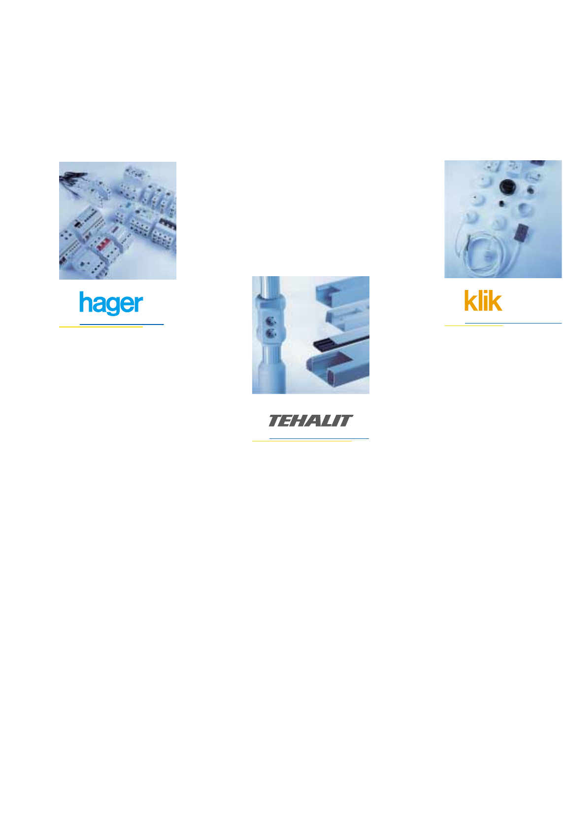
Hager product brands
Hager products form a fully
integrated system for safe,
efficient and effective
protection and control of
electrical distribution
systems.
•Consumer units system.
•Distribution board
system.
•Enclosures.
•Busbars and connections.
•Protection devices.
•Modular control devices.
•Intelligent installation
system for control of
lighting, heating and
shutters.
•Wiring accessories.
Tehalit products cover the
complete spectrum of cable
management and include
systems for domestic,
commercial and industrial
applications.
•Skirting systems.
•Multi - compartment
dado systems.
•Architectural systems.
•Island systems.
•Industrial trunking
systems.
•Panel trunkings.
•Fire resistant trunkings.
KLIK secure
connection systems
provide an innovative
solution to a variety of
connection requirements.
Systems are available for
power and lighting
distribution applications.
•KLIK lighting
•KLIK AX
•KLIK Power
•KLIK LV.
•Lighting distribution
systems.
•Occupancy sensors.

Numerical index
4
Cat.ref. Page No. Cat.ref. Page No. Cat.ref. Page No. Cat.ref. Page No. Cat.ref. Page No. Cat.ref. Page No.
AF125Z 26
AF132Z 26
AF140Z 26
AF956B 25
AF956J 25
AF960B 25
AF960J 25
AF966B 25
AF966J 25
AF970B 25
AF970J 25
AF975B 25
AF975J 25
AF982B 25
AF982J 25
AF990B 25
AF990J 25
AN150Z 26
AP150Z 26
B
BC226 15
BD225 16
BD226 15
BD240 16
BD241 15
BD263 16
BD264 15
BD284 18
BD285 18
BD325 16
BD326 15
BD340 16
BD341 15
BD363 16
BD364 15
BD384 18
BD385 18
BD425 16
BD426 15
BD441 15
BD463 16
BD464 15
BD484 18
BD485 18
BE264 15
BE464 15
BF225 16
BF226 15
BF240 16
BF241 15
BF263 16
BF264 15
BF284 18
BF285 18
BF325 16
BF326 15
BF340 16
BF341 15
BF363 16
BF364 15
BF384 18
BF385 18
BF425 16
BF426 15
BF440 16
BF441 15
BF463 16
BF464 15
BF484 18
BF485 18
BN264 15
BN464 15
BP264 15
BP285 18
BP364 15
BP385 18
BP464 15
BP485 18
BS264 15
BS364 15
BS464 15
C
CC217J 23
CC217Z 23
CD225J 23
CD226J 23
CD226Z 23
CD227T 23
CD240J 23
CD241J 23
CD241Z 23
CD242T 23
CD263J 23
CD264J 23
CD264Z 23
CD265T 23
CD281Z 23
CD285Z 23
CD425J 23
CD426J 23
CD426Z 23
CD427T 23
CD440J 23
CD441J 23
CD441Z 23
CD442T 23
CD463J 23
CD464J 23
CD464Z 23
CD465T 23
CD480Z 23
CD485Z 23
CE226J 23
CE226Z 23
CE241J 23
CE241Z 23
CE264J 23
CE264Z 23
CE281Z 23
CE285Z 23
CE426J 23
CE426Z 23
CE441J 23
CE441Z 23
CE464J 23
CE464Z 23
CE481Z 23
CE485Z 23
CF225J 23
CF225U 23
CF226J 23
CF240J 23
CF241J 23
CF241Z 23
CF263J 23
CF264J 23
CF264Z 23
CF281Z 23
CF285Z 23
CF425J 23
CF426Z 23
CF440J 23
CF441J 23
CF441Z 23
CF426J 23
CF463J 23
CF464J 23
CF464Z 23
CF481Z 23
CF485Z 23
CG481Z 23
CG485Z 23
CP265F 23
CP441J 23
CP445F 23
CP464J 23
CP465F 23
CZ001 24
CZ005 24
CZ006 24
CZ007 24
CZ008 24
CZN005 24
CZN006 24
H
HR400 27
HR402 27
HR410 27
HR420 27
HR425 27
HR800 28
HR801 28
HR802 28
HR803 28
HR804 28
HR805 28
HR820 28
HR821 28
HR822 28
HR823 28
HR824 28
HR830 28
HR831 28
HR832 28
L
L022 20
L023 20
L024 20
L025 20
L053 20
L055 20
L065 22
L104 19
L105 19
L106 19
L107 19
L108 19
L109 19
L124 19
L125 19
L126 19
L127 19
L128 19
L147 19
L304 19
L305 19
L306 19
L307 19
L308 19
L324 19
L325 19
L326 19
L327 19
L328 19
L401 20
L402 20
L403 20
L404 20
L406 20
L412 20
L431 20
L432 20
L501 20
L502 20
L503 20
L504 20
L506 20
L512 20
L531 20
L532 20
LF138 19
LF139 19
LF140 19
LF141 19
LF142 19
LR601 21
LR602 21
LR603 21
LR604 21
LR612 21
LR701 22
LR702 22
LR703 22
LR704 22
LR712 22
LS601 21
LS602 21
LS603 21
LS604 21
LS612 21
LS670 21
LS671 21
LS672 21
LS672 22
LS701 22
LS702 22
LS703 22
LS704 22
LS712 22
LS770 22
LS771 22
M
MB106A 10
MB110A 10
MB116A 10
MB120A 10
MB125A 10
MB132A 10
MB140A 10
MB150A 10
MB163A 10
MB206A 10
MB210A 10
MB216A 10
MB220A 10
MB225A 10
MB232A 10
MB240A 10
MB250A 10
MB263A 10
MB306A 10
MB310A 10
MB316A 10
MB320A 10
MB325A 10
MB332A 10
MB340A 10
MB350A 10
MB363A 10
MB406A 10
MB410A 10
MB416A 10
MB420A 10
MB425A 10
MB432A 10
MB440A 10
MB450A 10
MB463A 10
MC100A 10
MC101A 10
MC102A 10
MC103A 10
MC104A 10
MC106A 10
MC110A 10
MC116A 10
MC120A 10
MC125A 10
MC132A 10
MC140A 10
MC150A 10
MC163A 10
MC200A 10
MC201A 10
MC202A 10
MC203A 10
MC204A 10
MC206A 10
MC210A 10
MC216A 10
MC220A 10
MC225A 10
MC232A 10
MC240A 10
MC250A 10
MC263A 10
MC300A 10
MC301A 10
MC302A 10
MC303A 10
MC304A 10
MC306A 10
MC310A 10
MC316A 10
MC320A 10
MC325A 10
MC332A 10
MC340A 10
MC350A 10
MC363A 10
A
AD106Z 26
AD110Z 26
AD116Z 26
AD120Z 26
AD125Z 26
AD127 26
AD128 26
AD132Z 26
AD140Z 26
AD184 26
AD185 26
AD187 26
AD188 26
AD189 26
AD190 26
AD191 26
AD806J 25
AD810J 25
AD816J 25
AD820J 25
AD825J 25
AD832J 25
AD840J 25
AD856J 25
AD860J 25
AD866J 25
AD870J 25
AD875J 25
AD882J 25
AD890J 25
AD906B 25
AD906J 25
AD910B 25
AD910J 25
AD910J 25
AD916B 25
AD916J 25
AD920B 25
AD920J 25
AD920J 25
AD925B 25
AD925J 25
AD932B 25
AD932J 25
AD940B 25
AD940J 25
AD956B 25
AD956J 25
AD960B 25
AD960J 25
AD966B 25
AD966J 25
AD970B 25
AD970J 25
AD975B 25
AD975J 25
AD982B 25
AD982J 25
AD990B 25
AD990J 25
AE106Z 26
AE110Z 26
AE116Z 26
AE120Z 26
AE125Z 26
AE132Z 26
AE140Z 26
AF120Z 26

Numerical index
5
Cat.ref. Page No. Cat.ref. Page No. Cat.ref. Page No. Cat.ref. Page No. Cat.ref. Page No. Cat.ref. Page No.
MU132A 9
MU140A 9
MU150A 9
MU163A 9
MU206A 9
MU210A 9
MU216A 9
MU220A 9
MU225A 9
MU232A 9
MU240A 9
MU250A 9
MU263A 9
MU306A 9
MU310A 9
MU316A 9
MU320A 9
MU325A 9
MU332A 9
MU340A 9
MU350A 9
MU363A 9
MU406A 9
MU410A 9
MU416A 9
MU420A 9
MU425A 9
MU432A 9
MU440A 9
MU450A 9
MU463A 9
MV106 8
MV110 8
MV116 8
MV120 8
MV125 8
MV132 8
MV140 8
MV206 8
MV210 8
MV216 8
MV220 8
MV225 8
MV232 8
MV240 8
MV306 8
MV310 8
MV316 8
MV320 8
MV325 8
MV332 8
MV340 8
MV406 8
MV410 8
MV416 8
MV420 8
MV425 8
MV432 8
MV440 8
MW106 8
MW110 8
MW116 8
MW120 8
MW125 8
MW132 8
MW140 8
MW206 8
MW210 8
MW216 8
MW220 8
MW225 8
MW232 8
MW240 8
MW306 8
MW310 8
MW316 8
MW320 8
MW325 8
MW332 8
MW340 8
MW406 8
MW410 8
MW416 8
MW420 8
MW425 8
MW432 8
MW440 8
MZ176 14
MZ201 14
MZ202 14
MZ203 14
MZ204 14
MZ205 14
MZ206 14
MZ520N 35
MZ521N 35
MZ522N 35
MZ523N 35
MZ527N 35
MZ528N 35
MZ529N 35
MZ530N 35
MZ531N 35
MZN175 14
MZN176 14
N
NC100A 11
NC101A 11
NC102A 11
NC103A 11
NC104A 11
NC106A 11
NC110A 11
NC116A 11
NC120A 11
NC125A 11
NC132A 11
NC140A 11
NC150A 11
NC163A 11
NC200A 11
NC201A 11
NC202A 11
NC203A 11
NC204A 11
NC206A 11
NC210A 11
NC216A 11
NC220A 11
NC225A 11
NC232A 11
NC240A 11
NC250A 11
NC263A 11
NC300A 11
NC301A 11
NC302A 11
NC303A 11
NC304A 11
NC306A 11
NC310A 11
NC316A 11
NC320A 11
NC325A 11
NC332A 11
NC340A 11
NC350A 11
NC363A 11
NC400A 11
NC401A 11
NC402A 11
NC403A 11
NC404A 11
NC406A 11
NC410A 11
NC416A 11
NC420A 11
NC425A 11
NC432A 11
NC440A 11
NC450A 11
NC463A 11
ND100A 11
ND101A 11
ND102A 11
ND103A 11
ND104A 11
ND106A 11
ND110A 11
ND116A 11
ND120A 11
ND125A 11
ND132A 11
ND140A 11
ND150A 11
ND163A 11
ND180 17
ND184 17
ND200A 11
ND201A 11
ND202A 11
ND203A 11
ND204A 11
ND206A 11
ND210A 11
ND216A 11
ND220A 11
ND225A 11
ND232A 11
ND240A 11
ND250A 11
ND263A 11
ND280 17
ND284 17
ND300A 11
ND301A 11
ND302A 11
ND303A 11
ND304A 11
ND306A 11
ND310A 11
ND316A 11
ND320A 11
ND325A 11
ND332A 11
ND340A 11
ND350A 11
ND363A 11
ND380 17
ND384 17
ND400A 11
ND401A 11
ND402A 11
ND403A 11
ND404A 11
ND406A 11
ND410A 11
ND416A 11
ND420A 11
ND425A 11
ND432A 11
ND440A 11
ND450A 11
ND463A 11
ND480 17
ND484 17
NM180 17
NM184 17
NM190 17
NM280 17
NM284 17
NM290 17
NM380 17
NM384 17
NM390 17
NM480 17
NM484 17
NM490 17
NR100A 12
NR101A 12
NR102A 12
NR103A 12
NR104A 12
NR106A 12
NR110A 12
NR116A 12
NR120A 12
NR125A 12
NR132A 12
NR140A 12
NR150A 12
NR163A 12
NR200A 12
NR201A 12
NR202A 12
NR203A 12
NR204A 12
NR206A 12
NR210A 12
NR216A 12
NR220A 12
NR225A 12
NR232A 12
NR240A 12
NR250A 12
NR263A 12
NR300A 12
NR301A 12
NR302A 12
NR303A 12
NR304A 12
NR306A 12
NR310A 12
NR316A 12
NR320A 12
NR325A 12
NR332A 12
NR340A 12
NR350A 12
NR363A 12
NR400A 12
NR401A 12
NR402A 12
NR403A 12
NR404A 12
NR406A 12
NR410A 12
NR416A 12
NR420A 12
NR425A 12
NR432A 12
NR440A 12
NR450A 12
NR463A 12
S
SB116 29
SB125 29
SB125V 29
SB132 29
SB132V 29
SB140 29
SB163 29
SB180 29
SB199 29
SB216 29
SB216V 29
SB225 29
SB225V 29
SB232 29
SB232V 29
SB240 29
SB263 29
SB280 29
SB299 29
SB316 29
SB325 29
SB332 29
SB332Q 29
SB340 29
SB363 29
SB380 29
SB399 29
SB416 29
SB416F 29
SB425 29
SB425F 29
SB432 29
SB432F 29
SB440 29
SB440F 29
SB463 29
SB463F 29
SB480 29
SB480F 29
SB499 29
SB499F 29
SF115 30
SF118F 30
SF119F 30
SF119G 30
SF218F 30
SF219F 30
SF219G 30
MC406A 10
MC410A 10
MC416A 10
MC420A 10
MC425A 10
MC432A 10
MC440A 10
MC450A 10
MC463A 10
MJ702 13
MJ706 13
MJ710 13
MJ716 13
MJ720 13
MJ725 13
MJ732 13
MJ740 13
ML706 13
ML710 13
ML716 13
ML720 13
ML725 13
ML732 13
ML740 13
MM501N 34
MM502N 34
MM503N 34
MM504N 34
MM505N 34
MM506N 34
MM507N 34
MM508N 34
MM509N 34
MM510N 34
MM511N 34
MM512N 34
MM513N 34
MT106A 9
MT110A 9
MT116A 9
MT120A 9
MT125A 9
MT132A 9
MT140A 9
MT150A 9
MT163A 9
MT206A 9
MT210A 9
MT216A 9
MT220A 9
MT225A 9
MT232A 9
MT240A 9
MT250A 9
MT263A 9
MT306A 9
MT310A 9
MT316A 9
MT320A 9
MT325A 9
MT332A 9
MT340A 9
MT350A 9
MT363A 9
MU106A 9
MU110A 9
MU116A 9
MU120A 9
MU125A 9

Numerical index
6
Cat.ref. Page No. Cat.ref. Page No. Cat.ref. Page No. Cat.ref. Page No. Cat.ref. Page No. Cat.ref. Page No.
SF319G 30
SF419G 30
SPA212A 31
SPA412A 31
SPN015D 32
SPN015R 32
SPN040C 32
SPN040D 32
SPN040N 32
SPN040R 32
SPN065N 32
SPN065R 32
SPN140C 32
SPN208S 33
SPN215D 32
SPN215R 32
SPN240D 32
SPN240R 32
SPN265R 31
SPN408S 33
SPN415D 32
SPN415R 32
SPN440D 32
SPN440R 32
SPN465R 31
SPN504 33
SPN505 33
SZ011 30

8 Miniature circuit breakers - MV, MW, MT, MU
10 Miniature circuit breakers - MB, MC
11 Miniature circuit breakers - NC, ND
12 Miniature circuit breakers - NR
13 Miniature circuit breakers - MJ, ML
14 Auxiliaries and accessories for devices
15 RCCB add on blocks
17 Miniature circuit breakers- NM, ND
80, 100 and 125A
18 RCCB add on blocks - type AC/A
19 HRC fuse carrier range - LB, LBX, L and LX
20 HRC fuse carrier range - L31, L38, L51, L58
23 RCCBs 2 and 4 poles
25 RCBOs (residual circuit breaker with overload)
27 Earth leakage relays
29 Isolating switches
30 2 way/centre-off changeover modular switches
31 Surge protective devices
34 Motors starters
Protection devices
7
Single pole MCB 6112MV 106 MW 106
10 1 12 MV 110 MW 110
16 1 12 MV 116 MW 116
20 1 12 MV 120 MW 120
25 1 12 MV 125 MW 125
32 1 12 MV 132 MW 132
40 1 12 MV 140 MW 140
Triple pole MCB 634MV 306 MW 306
10 3 4 MV 310 MW 310
16 3 4 MV 316 MW 316
20 3 4 MV 320 MW 320
25 3 4 MV 325 MW 325
32 3 4 MV 332 MW 332
40 3 4 MV 340 MW 340
Four pole MCB 643MV 406 MW 406
10 4 3 MV 410 MW 410
16 4 3 MV 416 MW 416
20 4 3 MV 420 MW 420
25 4 3 MV 425 MW 425
32 4 3 MV 432 MW 432
40 4 3 MV 440 MW 440
Double pole MCB 626MV 206 MW 206
10 2 6 MV 210 MW 210
16 2 6 MV 216 MW 216
20 2 6 MV 220 MW 220
25 2 6 MV 225 MW 225
32 2 6 MV 232 MW 232
40 2 6 MV 240 MW 240
Designation In/A Width in
I
Pack B curve C curve
17.5mm qty. cat. ref. cat. ref.
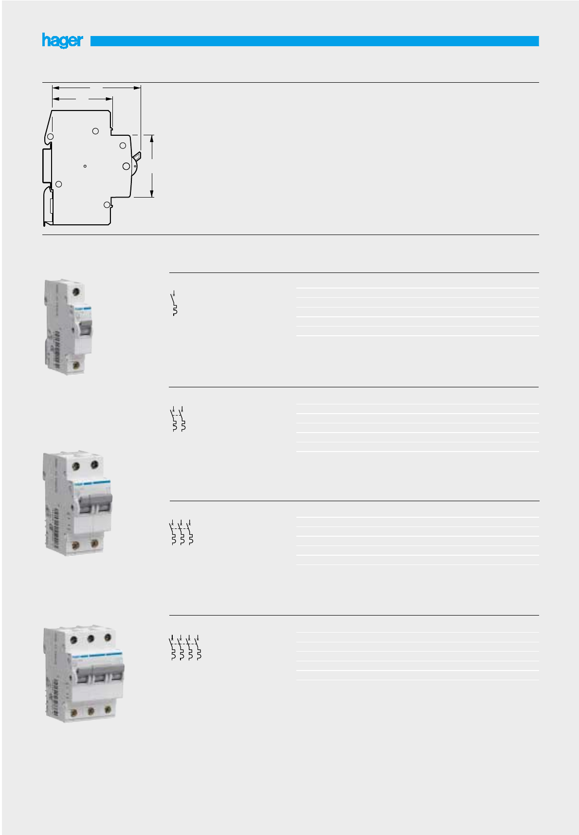
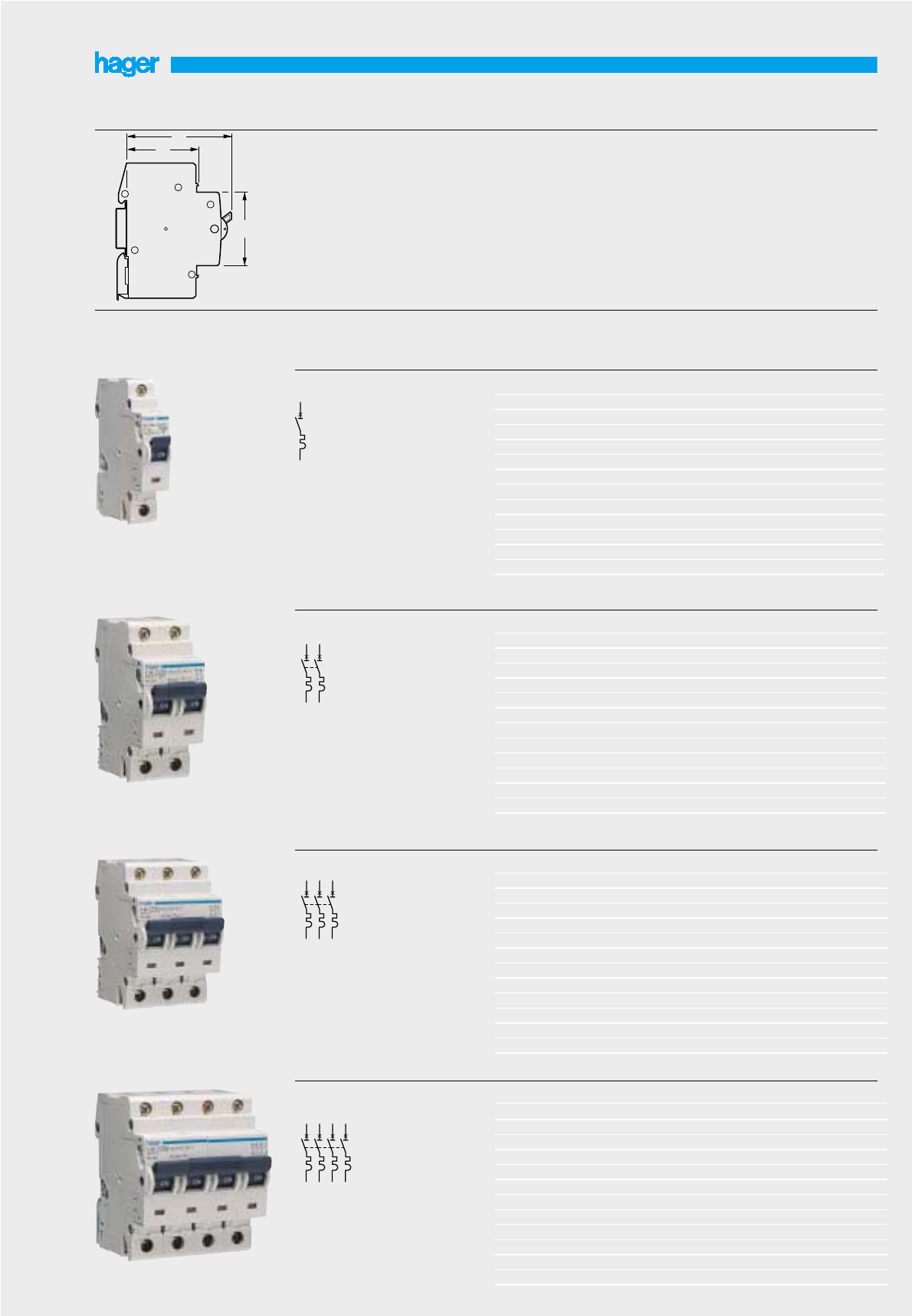
Miniature circuit breakers
3kA Type B and C - MV, MW
8
Description
Protection and control of
circuits against overloads
and short circuits.
Technical data
Type B and C tripping
characteristics
Tropicalisation T2
Breaking capacity :
3000A to IEC898
Voltage rating : 230-400 V
Current rating : 6-40A
IP2X
Connection capacity
25▫ rigid cables
16▫ flexible cables
- will not accept accessories
Voltage marking as per IEC38
can be used on 240/415V
50Hz without derating
For technical details
see pages 40-43
45
68
44
MW 110
MW 220
MW 316

Triple pole MCB 634MT 306A MU 306A
10 3 4 MT 310A MU 310A
16 3 4 MT 316A MU 316A
20 3 4 MT 320A MU 320A
25 3 4 MT 325A MU 325A
32 3 4 MT 332A MU 332A
40 3 4 MT 340A MU 340A
50 3 4 MT 350A MU 350A
63 3 4 MT 363A MU 363A
Four pole MCB 643 MU 406A
10 4 3 MU 410A
16 4 3 MU 416A
20 4 3 MU 420A
25 4 3 MU 425A
32 4 3 MU 432A
40 4 3 MU 440A
50 4 3 MU 450A
63 4 3 MU 463A
Single pole MCB 6112MT 106A MU 106A
10 1 12 MT 110A MU 110A
16 1 12 MT 116A MU 116A
20 1 12 MT 120A MU 120A
25 1 12 MT 125A MU 125A
32 1 12 MT 132A MU 132A
40 1 12 MT 140A MU 140A
50 1 12 MT 150A MU 150A
63 1 12 MT 163A MU 163A
Double pole MCB 626MT 206A MU 206A
10 2 6 MT 210A MU 210A
16 2 6 MT 216A MU 216A
20 2 6 MT 220A MU 220A
25 2 6 MT 225A MU 225A
32 2 6 MT 232A MU 232A
40 2 6 MT 240A MU 240A
50 2 6 MT 250A MU 250A
63 2 6 MT 263A MU 263A
Designation In/A Width in
I
Pack B curve C curve
17.5mm qty. cat. ref. cat. ref.
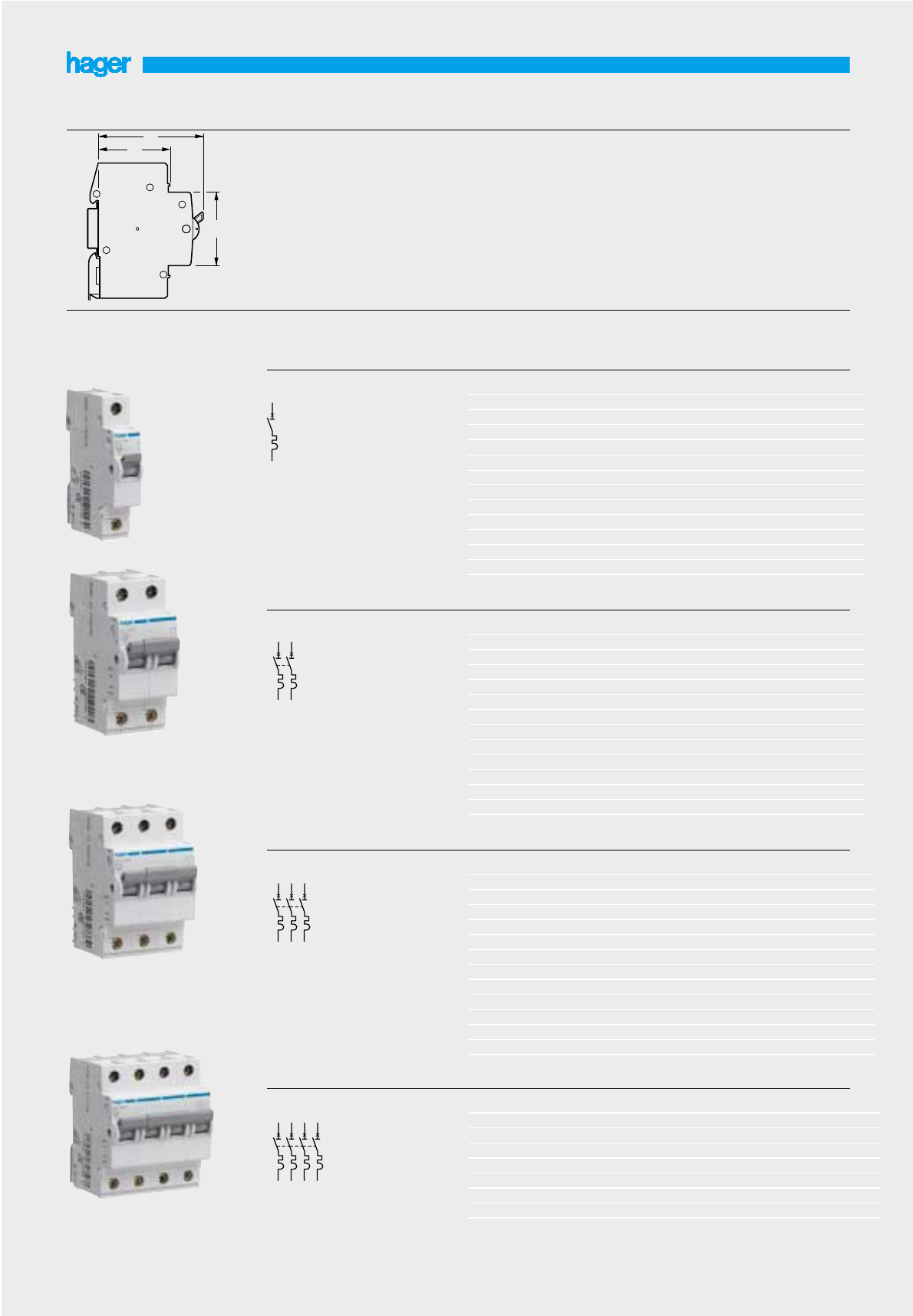
Miniature circuit breakers
6kA Type B and C - MT, MU
9
Description
Protection and control of
circuits against overloads
and short circuits.
Technical data
Type B and C tripping
characteristics
Tropicalisation T2
Breaking capacity :
6000A to IEC898
10000A to IEC947-2
Voltage rating : 230-400 V
Current rating : 6-63A
IP2X
Connection capacity
25▫ rigid cables
16▫ flexible cables
- will not accept accessories
Voltage marking as per IEC38
can be used on 240/415V
50Hz without derating
For technical details
see pages 40-43
45
68
44
MT 116A
MT 216A
MT 320A
Four pole MCB 643MB 406A MC 406A
10 4 3 MB 410A MC 410A
16 4 3 MB 416A MC 416A
20 4 3 MB 420A MC 420A
25 4 3 MB 425A MC 425A
32 4 3 MB 432A MC 432A
40 4 3 MB 440A MC 440A
50 4 3 MB 450A MC 450A
63 4 3 MB 463A MC 463A
Triple pole MCB 0.5 3 4 MC 300A
134 MC 301A
234 MC 302A
334 MC 303A
434 MC 304A
634MB 306A MC 306A
10 3 4 MB 310A MC 310A
16 3 4 MB 316A MC 316A
20 3 4 MB 320A MC 320A
25 3 4 MB 325A MC 325A
32 3 4 MB 332A MC 332A
40 3 4 MB 340A MC 340A
50 3 4 MB 350A MC 350A
63 3 4 MB 363A MC 363A
Single pole MCB 0.5 1 12 MC 100A
1112 MC 101A
2112 MC 102A
3112 MC 103A
4112 MC 104A
6112MB 106A MC 106A
10 1 12 MB 110A MC 110A
16 1 12 MB 116A MC 116A
20 1 12 MB 120A MC 120A
25 1 12 MB 125A MC 125A
32 1 12 MB 132A MC 132A
40 1 12 MB 140A MC 140A
50 1 12 MB 150A MC 150A
63 1 12 MB 163A MC 163A
Double pole MCB 0.5 2 6 MC 200A
126 MC 201A
226 MC 202A
326 MC 203A
426 MC 204A
626MB 206A MC 206A
10 2 6 MB 210A MC 210A
16 2 6 MB 216A MC 216A
20 2 6 MB 220A MC 220A
25 2 6 MB 225A MC 225A
32 2 6 MB 232A MC 232A
40 2 6 MB 240A MC 240A
50 2 6 MB 250A MC 250A
63 2 6 MB 263A MC 263A
Designation In/A Width in
I
Pack B curve C curve
17.5mm qty. cat. ref. cat. ref.
Miniature circuit breakers
6kA Type B and C - MB, MC
Description
Protection and control of
circuits against overloads
and short circuits.
Technical data
Type B and C tripping
characteristics
Tropicalisation T2
Breaking capacity :
6000A to IEC898
10000A to IEC947-2
Voltage rating : 230-400 V
Current rating : 0.5 - 63A
IP2X
Connection capacity
25▫ rigid cables
16▫ flexible cables
- will accept accessories
see page 14
Voltage marking as per IEC38
can be used on 240/415V
50Hz without derating
For technical details
see pages 40-43
10
45
68
44
1
2
3
4
5
6
7
8
1
2
3
4
5
6
1
2
3
4
1
2
MC 216A
MC 332A
MC 432A
MC 132A
Four pole MCB 0,5 4 3 NC 400A ND 400A
143NC 401A ND 401A
243NC 402A ND 402A
343NC 403A ND 403A
443NC 404A ND 404A
643NC 406A ND 406A
10 4 3 NC 410A ND 410A
16 4 3 NC 416A ND 416A
20 4 3 NC 420A ND 420A
25 4 3 NC 425A ND 425A
32 4 3 NC 432A ND 432A
40 4 3 NC 440A ND 440A
50 4 3 NC 450A ND 450A
63 4 3 NC 463A ND 463A
Triple pole MCB 0.5 3 4 NC 300A ND 300A
134NC 301A ND 301A
234NC 302A ND 302A
334NC 303A ND 303A
434NC 304A ND 304A
634NC 306A ND 306A
10 3 4 NC 310A ND 310A
16 3 4 NC 316A ND 316A
20 3 4 NC 320A ND 320A
25 3 4 NC 325A ND 325A
32 3 4 NC 332A ND 332A
40 3 4 NC 340A ND 340A
50 3 4 NC 350A ND 350A
63 3 4 NC 363A ND 363A
Single pole MCB 0.5 1 12 NC 100A ND 100A
1112NC 101A ND 101A
2112NC 102A ND 102A
3112NC 103A ND 103A
4112NC 104A ND 104A
6112NC 106A ND 106A
10 1 12 NC 110A ND 110A
16 1 12 NC 116A ND 116A
20 1 12 NC 120A ND 120A
25 1 12 NC 125A ND 125A
32 1 12 NC 132A ND 132A
40 1 12 NC 140A ND 140A
50 1 12 NC 150A ND 150A
63 1 12 NC 163A ND 163A
Double pole MCB 0.5 2 6 NC 200A ND 200A
126NC 201A ND 201A
226NC 202A ND 202A
326NC 203A ND 203A
426NC 204A ND 204A
626NC 206A ND 206A
10 2 6 NC 210A ND 210A
16 2 6 NC 216A ND 216A
20 2 6 NC 220A ND 220A
25 2 6 NC 225A ND 225A
32 2 6 NC 232A ND 232A
40 2 6 NC 240A ND 240A
50 2 6 NC 250A ND 250A
63 2 6 NC 263A ND 263A
Designation In/A Width in
I
Pack C curve D curve
17.5mm qty. cat. ref. cat. ref.
Miniature circuit breakers
10kA Type C and D - NC, ND
Description
Protection and control of
circuits against overloads
and short circuits.
Technical data
Type C and D tripping
characteristics
Tropicalisation T2
Breaking capacity :
10000A to IEC898
15000A to IEC947-2
Voltage rating : 230-400 V
Current rating : 0.5 - 63A
Positive contact indication :
red - contacts closed
green - contacts open
- will accept accessories
see page 14
Connection capacity
25▫ rigid cables
16▫ flexible cables
Voltage marking as per IEC38
can be used on 240/415V
50Hz without derating
For technical details
see pages 40-43
11
1
2
3
4
5
6
7
8
1
2
3
4
5
6
1
2
3
4
1
2
45
68
44
NC 116A
NC 232A
NC 363A
NC 463A

Triple pole MCB 25 0,5 3 4 NR 300A
25 1 3 4 NR 301A
25 2 3 4 NR 302A
25 3 3 4 NR 303A
25 4 3 4 NR 304A
25 6 3 4 NR 306A
25 10 3 4 NR 310A
25 16 3 4 NR 316A
25 20 3 4 NR 320A
20 25 3 4 NR 325A
20 32 3 4 NR 332A
20 40 3 4 NR 340A
15 50 3 4 NR 350A
15 63 3 4 NR 363A
Single pole MCB 25 0,5 1 12 NR 100A
25 1 1 12 NR 101A
25 2 1 12 NR 102A
25 3 1 12 NR 103A
25 4 1 12 NR 104A
25 6 1 12 NR 106A
25 10 1 12 NR 110A
25 16 1 12 NR 116A
25 20 1 12 NR 120A
20 25 1 12 NR 125A
20 32 1 12 NR 132A
20 40 1 12 NR 140A
15 50 1 12 NR 150A
15 63 1 12 NR 163A
Designation Breaking In/A Width in
I
Pack Cat.
capacity kA 17.5mm qty. ref.
Miniature circuit breakers
15 to 25 kA Type C - NR
Description
Protection and control of circuits
against overloads and short
circuits.
Technical data
Type C tripping characteristics
Tropicalisation T2
Breaking capacity :
25000A (≤20A)
20000A (25 to 40A)
15000A (50 - 63A)
to IEC947-2
Voltage rating : 230-400 V
Current rating : 0.5 - 63A
Positive contact indication :
red - contacts closed
green - contacts open
Connection capacity
25▫ rigid cables
16▫ flexible cables
- will accept accessories
see page 14
Voltage marking as per IEC38
can be used on 240/415V
50Hz without derating
For technical details
see pages 40-43
12
Double pole MCB 25 0,5 2 6 NR 200A
25 1 2 6 NR 201A
25 2 2 6 NR 202A
25 3 2 6 NR 203A
25 4 2 6 NR 204A
25 6 2 6 NR 206A
25 10 2 6 NR 210A
25 16 2 6 NR 216A
25 20 2 6 NR 220A
20 25 2 6 NR 225A
20 32 2 6 NR 232A
20 40 2 6 NR 240A
15 50 2 6 NR 250A
15 63 2 6 NR 263A
Four pole MCB 25 0,5 4 3 NR 400A
25 1 4 3 NR 401A
25 2 4 3 NR 402A
25 3 4 3 NR 403A
25 4 4 3 NR 404A
25 6 4 3 NR 406A
25 10 4 3 NR 410A
25 16 4 3 NR 416A
25 20 4 3 NR 420A
20 25 4 3 NR 425A
20 32 4 3 NR 432A
20 40 4 3 NR 440A
15 50 4 3 NR 450A
15 63 4 3 NR 463A
45
68
44
1
2
3
4
5
6
7
8
1
2
3
4
5
6
1
2
3
4
1
2
NR 116A
NR 232A
NR 340A
NR 440A

Single pole and 2112MJ 702
switched neutral - 4,5kA 6112MJ 706
SP&N 10 1 12 MJ 710
16 1 12 MJ 716
20 1 12 MJ 720
25 1 12 MJ 725
32 1 12 MJ 732
40 1 12 MJ 740
Single pole and 6112ML 706
switched neutral - 6kA 10 1 12 ML 710
SP&N 16 1 12 ML 716
20 1 12 ML 720
25 1 12 ML 725
32 1 12 ML 732
40 1 12 ML 740
Designation In/A Width in
I
Pack Cat.
17.5mm qty. ref.
Miniature circuit breakers
4,5 - 6kA Type C SP&N - MJ and ML
Description
Protection and control of
circuits against overloads
and short circuits.
Technical data
Type C tripping characteristics
Tropicalisation T2
Breaking capacity :
4 500A, 6 000A to IEC898
Voltage rating : 230V
Current rating : 2-40A
IP2X
Connection capacity
16▫ rigid cables
10▫ flexible cables
+ busbars
Voltage marking as per IEC38
can be used on 240/415V
50Hz without derating
For technical details
see pages 40-43
13
45
68
44
ML 716
MJ 716
N
N
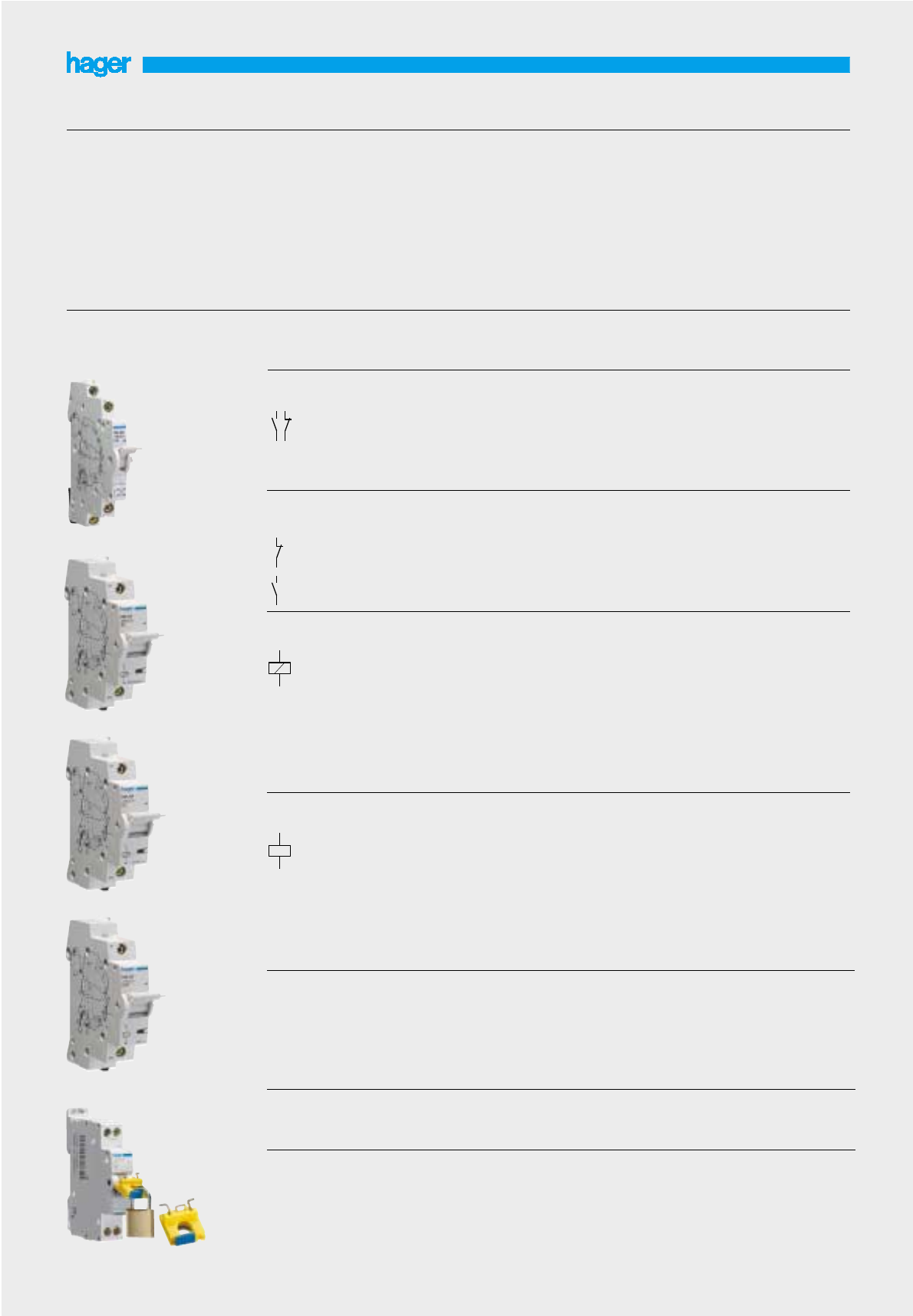
Alarm contacts SD contact indicates a fault 1/2 1 MZ 202
condition (e.g. MCB tripped overcurrent (e.g. MCB tripped)
on overload or short circuit).
Shunt trip allows remote tripping
of the device.
24Vac - 415Vac 1 1 MZ 203
12V - 130Vdc
24 - 48Vac 1 1 MZ 204
12 - 48Vdc
Under voltage release allows MCB to be closed only
when voltage is above 70% of
Un. MCB will automatically trip
when voltage falls by 35% of Un
48Vdc 1 1 MZ 205
230Vac 1 1 MZ 206
Locking kit allows locking of the device 1 MZN 175
for the dolly of the device dolly in the on/off position.
supplied without padlock. will accept two padlocks with
hasps of 4.75mm diameter max.
Sealing Kit MZN 176
Label kit set of 12 labels for circuit 10 sets MZ 176
indication.
for multi-pole MCB’s only.
Auxiliary contacts 1NO + 1NC auxiliary contact 1/2 1 MZ 201
5A - 230V~ indication of main contact
status.
Designation Description Width in
I
Pack Cat.
17.5mm qty. ref.
Auxiliaries and accessories for devices
MB, MC, NC, ND, NR MCBs and RCCBs
All auxiliaries are common to
both single and multi-pole
circuit breakers.
These auxiliaries are fitted to
the left hand side of devices.
Shunt trips, and under-voltage
releases are fitted with a reset
button that indicates the
automatic/remote tripping of
the device.
Connection capacity
6▫ rigid cables
4▫ flexible cables
For fitting to RCCB
- see page 45
Use of MZ 203 - MZ 206 on
RCCBs requires the use of
interface auxiliary CZ 001
For technical details
see page 44
14
MZ 201
MZ 203
MZ 204
MZ 205
MZN 175
21
13
22
14
91
92
93
94
C 1
C 2
D 1
D 2
U <

2 poles RCCB add-on blocks 10 mA 25A 2 1 BC 226
30 mA 25A 2 1 BD 226
40A 2 1 BD 241
63A 2 1 BD 264
100 mA 63A 2 1 BE 264
300 mA 25A 2 1 BF 226
40A 2 1 BF 241
63A 2 1 BF 264
time delayed 100 mA 63A 2 1 BN 264
time delayed 300 mA 63A 2 1 BP 264
time delayed 1A 63A 2 1 BS 264
3 poles RCCB add-on blocks 30 mA 25A 2 1 BD 326
40A 3 1 BD 341
63A 3 1 BD 364
300 mA 25A 2 1 BF 326
40A 3 1 BF 341
63A 3 1 BF 364
time delayed 300 mA 63A 3 1 BP 364
time delayed 1A 63A 3 1 BS 364
4 poles RCCB add-on blocks 30 mA 25A 2 1 BD 426
40A 3 1 BD 441
63A 3 1 BD 464
100 mA 63A 3 1 BE 464
300 mA 25A 2 1 BF 426
40A 3 1 BF 441
63A 3 1 BF 464
time delayed 100 mA 63 3 1 BN 464
time delayed 300 mA 63A 3 1 BP 464
time delayed 1A 63A 3 1 BS 464
Designation Sensitivity In/A Width in
I
Pack Cat.
I n 17.5mm qty. ref.
RCCB add-on blocks for MCB devices - Type AC -
MB, MC, NC, ND, NR
Description
RCD add-on blocks for use with
MCB ranges MB, MC, NC, ND,
NR.
(manufactured since 01.01.00)
Technical data :
High sensitivity :
10-30 mA instant tripping
Medium sensitivity :
100-300 mA instant tripping
300 - 1A selective (time delay)
These devices are designed to
be fitted on the right hand side
of the 2, 3 and 4 poles MCB’s.
The combination device than
provides protection against
overload, short circuits and
earth leakage faults.
All devices have a test facility
All devices are type AC,
protected against nuisance
tripping and transient voltages
Nominal voltage : - 20, + 10%
2 poles 230V
3 and 4 poles : 230/400V
Test button : 230/400V
Comply with IEC1009
Connection capacities :
25 A : 6▫flexible cable
10▫rigid cable
40, 63 A : 16▫flexible cable
25▫rigid cable
For technical details
see page 46
15
3
2
1
4
5
3
42
1
6
7
3
642
5
1
8
BD 426
BD 226
BD 364
45
62
44

2 poles RCCB add-on blocks 30 mA 25A 2 1 BD 225
40A 2 1 BD 240
63A 2 1 BD 263
300 mA 25A 2 1 BF 225
40A 2 1 BF 240
63A 2 1 BF 263
3 poles RCCB add-on blocks 30 mA 25A 2 1 BD 325
40A 3 1 BD 340
63A 3 1 BD 363
300 mA 25A 2 1 BF 325
40A 3 1 BF 340
63A 3 1 BF 363
4 poles RCCB add-on blocks 30 mA 25A 2 1 BD 425
63A 3 1 BD 463
300 mA 25A 2 1 BF 425
40A 3 1 BF 440
63A 3 1 BF 463
16
RCCB add-on blocks for MCB devices - Type A
MB, MC, NC, ND, NR
3
2
1
4
RCBO = association of 2 poles MCB 63 A + 2 poles add-on block
5
3
42
1
6
7
3
642
5
1
8
BD 463
BD 225
BD 325
Designation Sensitivity In/A Width in
I
Pack Cat.
I n 17.5mm qty. ref.
Description
RCD add-on blocks for use with
MCB ranges MB, MC, NC, ND,
NR.
(manufactured since 01.01.00)
Technical data :
High sensitivity :
30 mA instant tripping
Medium sensitivity :
300 mA instant tripping
These devices are designed to
be fitted on the right hand side
of the 2, 3 and 4 poles MCB’s
The combination device than
provides protection against
overload, short circuits and
earth leakage faults.
All devices have a test facility
All devices are type A
Highly immunized against
nuisance tripping for circuits
which need continuity in supply
(hospitals, computers, electronic
ballasts...)
All devices integrate as well
detection of nuisance tripping
and transient voltages for AC
and pulsating DC fault currents.
Nominal voltage : - 20, +10%
2 poles 230V
3 and 4 poles : 230/400V
Test button : 230/400V
Comply with IEC1009
Connection capacities :
25 A : 6▫ flexible cable
10▫rigid cable
40, 63 A : 16▫flexible cable
25▫rigid cable
For technical details
see page 46
45
62
44

Double pole MCB 80 3 1 NM 280 ND 280
100 3 1 NM 284 ND 284
125 3 1 NM 290*
Triple pole MCB 80 4.5 1 NM 380 ND 380
100 4.5 1 NM 384 ND 384
125 4.5 1 NM 390*
Four pole MCB 80 6 1 NM 480 ND 480
100 6 1 NM 484 ND 484
125 6 1 NM 490*
* will not accept accessories (125A)
Single pole MCB 80 1.5 1 NM 180 ND 180
100 1.5 1 NM 184 ND 184
125A 1.5 1 NM 190*
Designation In/A Width in
I
Pack Curve C Curve D
17.5mm qty. Cat. ref. Cat. ref.
MCB - NM, ND
Type C, 80 to 125A - Type D, 80 & 100A
Description
Protection and control of circuits
against overloads and short
circuits.
- in commercial and industrial
electrical distribution systems.
Technical data
Type C and D tripping
characteristics
Tropicalisation T2
Breaking capacity :
10 000A to IEC 947-2
Voltage rating - 230V-400V
Current rating :
type C : 80, 100A & 125A
type D : 80, 100A
Positive contact indication :
red - contacts closed
green - contacts open
Connection capacity
50▫ rigid cables
35▫ flexible cables
Voltage marking as per IEC38
can be used on 240/415V
50Hz without derating
For technical details
see pages 40-43
17
45
68
44
NM 280
NM 380
NM 480
1
2
3
4
5
6
7
8
1
2
3
4
5
6
1
2
3
4
1
2
30mA 4.5 1 BD 485 BD 484
suitable only for 300mA 4.5 1 BF 485 BF 484
NM 480-NM 484 time delayed 300mA 4.5 1 BP 485
example below: 2 pole MCB + 2 pole RCD add-on block.
4 pole RCCB
add-on blocks
30mA 2.5 1 BD 285 BD 284
suitable only for 300mA 2.5 1 BF 285 BF 284
NM 280-NM 284 time delayed 300mA 2.5 1 BP 285
2 pole RCCB
add-on blocks
30mA 2.5 1 BD 385 BD 384
suitable only for 300mA 2.5 1 BF 385 BF 384
NM 380-NM 384 time delayed 300mA 2.5 1 BP 385 time
3 pole RCCB
add-on blocks
Designation Sensitivity Width in
I
Pack Cat.ref. Cat.ref.
I
▲▲
n 17.5mm qty. stand. stand.
type AC type A
RCCB add-on blocks - Type AC / A
for use with 80/100A MCBs (NM)
RCCB add-on blocks
These devices are designed to
be fitted to the right hand side
of 2, 3, or 4 pole 80 and 100A
circuit breakers.
The combination device then
provides protection against
overloads, short circuits and
earth leakage faults.
Nuisance tripping
As with all Hager devices the
add on blocks are protected
against nuisance tripping caused
by transient voltages
Connection capacity
35▫flexible cables
50▫rigid cables
All devices have a test facility.
For technical details
see page 46
18
BD 285
BD 385
3
2
1
4
5
3
42
1
6
7
3
642
5
1
8

Fuse carrier L 1 PH “L” “LX”
10 A - 250 V 112 L 104 L 304
16 A - 250 V 112 L 105 L 305
Fuse carrier LX 1 PH
with lighting push button 20 A - 400 V 112 L 106 L 306
25 A - 400 V 112 L 107 L 307
Fuse carrier neutral 32 A - 400 V 112 L 108 L 308
with unreamovable 1 12 L 109
neutral cartridge
Fuse carrier LB, 1 Ph + N 10 A - 250 V 112L 124 L 324
16 A - 250 V 112L 125 L 325
Fuse carrier LBX, 1 Ph + N 20 A - 400 V 112L 126 L 326
with lighting push button 25 A - 400 V 112L 127 L 327
32 A - 400 V 112L 128 L 328
Cartridge fuses 10A - 8,5 x 23mm 10 LF 138
domestic, type gF 16A - 10,3 x 25,8mm 10 LF 139
breaking capacity : 20A - 8,5 x 31,5mm 10 LF 140
- 4000 A : from 10 to 20 A
- 8000 A : from 25 to 32 A 25A - 10,3 x 31,5mm 10 LF 141
32A - 10,3 x 38mm 10 LF 142
Box for spare cartridge fuses delivered empty 1 10 L 147
fixing on the DIN rail next to the
fuse carrier without removing
enclosure cover
insulating material, unbreakable,
with drawer for cartridge fuses
Designation Characteristics Width in
I
Pack LB LBX.
17.5mm qty. cat.ref. cat.ref.
HRC fuse carrier range - LB, LBX, L and LX
Description
Protection and control of
circuits against overloads and
short-circuits in domestic
electrical distribution systems.
Fuse carriers for domestic
cylindrical cartridge fuses,
type B.
Technical data
Delivered without cartridge fuse.
The LBX and LX series are
delivered with a lighting push
button to check the status of
the cartridge fuse.
Comply with IEC 269
Connection capacity :
10▫ flexible cables
16▫ rigid cables
19
L 147
L 105 L 305
L 125 L 325
LF 142
45
58
44

Single pole fuse carrier 1 phase 1 12 L 401 L 501
1 phase + indic.light 1 12 L 431 L 531
Triple pole fuse carrier 3 phases 3 4 L 403 L 503
Four pole fuse carrier 3 phases + neutral 4 3 L 404 L 504
Double pole fuse carrier 1 phase + neutral 1 12 L 402 L 502
1 phase + neutral 1 12 L 432 L 532
+ indic. light
1 phase + neutral 1 12 L 406 L 506
2 phases 1 12 L 412 L 512
Indication labelling labels : ratings 10 L 055
for fuse carrier L31, L38, L51 stripes
stripes of 50 stickers : 1 L 055 =
1 stripe
- with ratings 0.16 to 32A
- with letters and figures : letters and 3 kits L 053
2 stripes N, PE, L1, L3 figures kit
1 stripe 1 to 100 1 L 053 =
1 stripe 101 to 200 1 kit
Handle link pin for : 2
I
20 L 022
for single units
(to enable you to switch 3
I
20 L 023
several circuits
simultaneously) 4
I
20 L 024
5
I
20 L 025
Designation Description Width in
I
Pack L31 L38.
17.5mm qty. cat.ref. cat.ref.
HRC fuse carrier range - L31, L38
Description
Protection and control of
circuits against overloads and
short-circuits in commercial and
light industrial electrical distribu-
tion systems.
Fuse carrier L31
for cylindrical cartridge fuses
8.5 x 31.5mm
Max 16A- 400V~
Fuse carrier L38
for cylindrical cartridge fuses
10.3 x 38mm
Max 20A- 500V~
Max 32A- 400V~
- Comply with IEC269-2
Connection capacity :
16▫rigid cables
10▫flexible cables
For technical details
see page 47
20
45
58
44
B
12
16 A
letter
figure
rating
L 022
L 404
L 055
L 053
L 406 L 402
L 401 L 431
Four pole carrier 3 phases 6 1 LR 604 LS 604
+neutral link
Auxiliary switch 5A - 250V~
1 c/o contact
for fuses 14 x 51 single pole 1 LS 670
with striker pins
for fuses 14 x 51 three pole 1 LS 671
with striker pins
Indicating light 230V~ 1 LS 672
indication of blown
or missing fuse link
Three pole carrier 3 phases 4.5 1 LR 603 LS 603
Single pole carrier 1 phase 1 1/2 1 LR 601 LS 601
Designation Description Width in
I
Pack LR 6xx LS 6xx
17.5mm qty. cat.ref. cat.ref.
HRC fuse carrier range - L51
Description
Protection and control of
circuits against overloads and
short-circuits in commercial and
industrial distribution systems.
Technical data
For cylindrical fuses
14 x 51mm
50A- 690V AC
50-60 Hz
Comply with IEC947-3
Fuse carriers type LS 6xx can be
equipped with following
accessories :
- indicating light : for indication
of the fuse status.
- auxiliary switch : for indication
of fuse blown condition
LR type will not accept
accessories
Connection capacity :
35▫rigid cables
25▫flexible cables
For technical details
see page 47
21
Two pole carrier 2 phases 3 1 LR 602 LS 602
1 phase
+ neutral link 3 1 LR 612 LS 612
LS 601
LS 672
LS 604

HRC fuse carrier range - L58
Description
Protection and control of
circuits against overloads and
short-circuits in commercial and
industrial distribution systems.
Technical data
For cylindrical fuses
22 x 58mm
125A- 690V AC
50-60 Hz
Comply with IEC947-3
Fuse carriers type LS 7xx can be
equipped with following
accessories :
- indicating light : for indication
of the fuse status.
- auxiliary switch : for indication
of fuse blown condition
LR type will not accept
accessories
Connection capacity :
50▫rigid cables
35▫flexible cables For technical details
see page 47
22
Four pole carrier 3 phases
+neutral link 8 1 LR 704 LS 704
Auxiliary switch 5A - 250V ~
1 c/o contact
for fuses 22 x 58 single pole 1 LS 770
with striker pins
for fuses 22 x 58 three pole 1 LS 771
with striker pins
Indicating light 230V ~ 1 LS 672
indication of blown
or missing fuse link
Adaptor for assymetric 20 L 065
rails for series L51 and L58
Three pole carrier 3 phases 6 1 LR 703 LS 703
Single pole carrier 1 phase 2 1 LR 701 LS 701
Designation Description Width in
I
Pack LR 7xx LS 7xx
17.5mm qty. cat.ref. cat.ref.
Two pole carrier 2 phases 4 1 LR 702 LS 702
1 phase
+ neutral link 4 1 LR 712 LS 712
LS 701
LS 703
LS 770
LS 672
L 065

30mA 25A 1 CD 226J CD 226Z CD 426J CD 426Z
40A 1 CD 241J CD 241Z CD 441J CD 441Z
63A 1 CD 264J CD 264Z CD 464J CD 464Z
80A 1 CD 281Z CD 480Z
100A 1 CD 285Z CD 485Z
30mA - Type A 25A 1 CD 225J CD 227T CD 425J CD 427T
AC and pulsating DC 40A 1 CD 240J CD 242T CD 440J CD 442T
residual current 63A 1 CD 263J CD 265T CD 463J CD 465T
300mA 25A 1 CF 226J CF 225U CF 426J CF 426Z
40A 1 CF 241J CF 241Z CF 441J CF 441Z
40A 1 CP 441J CP 445F
63A 1 CF 264J CF 264Z CF 464J CF 464Z
63A 1 CP 265F
63A 1 CP 464J CP 465F
80A 1 CF 281Z CF 481Z
100A 1 CF 285Z CF 485Z
300mA - Type A 25A 1 CF 225J CF 425J
AC and pulsating DC 40A 1 CF 240J CF 440J
residual current 63A 1 CF 263J CF 463J
100mA 25A 1 CE 226J CE 226Z CE 426J CE 426Z
40A 1 CE 241J CE 241Z CE 441J CE 441Z
63A 1 CE 264J CE 264Z CE 464J CE 464Z
80A 1 CE 281Z CE 481Z
100A 1 CE 285Z CE 485Z
10mA 16A 1 CC 217J CC 217Z
500mA 80A 1 CG 481Z
100A 1 CG 485Z
Sensitivity Current Pack Ref Ref Ref Ref
rating qty 2 pole 2 pole 4 pole 4 pole
avai. from current avai. from current
1.09.05 range 1.09.05 range
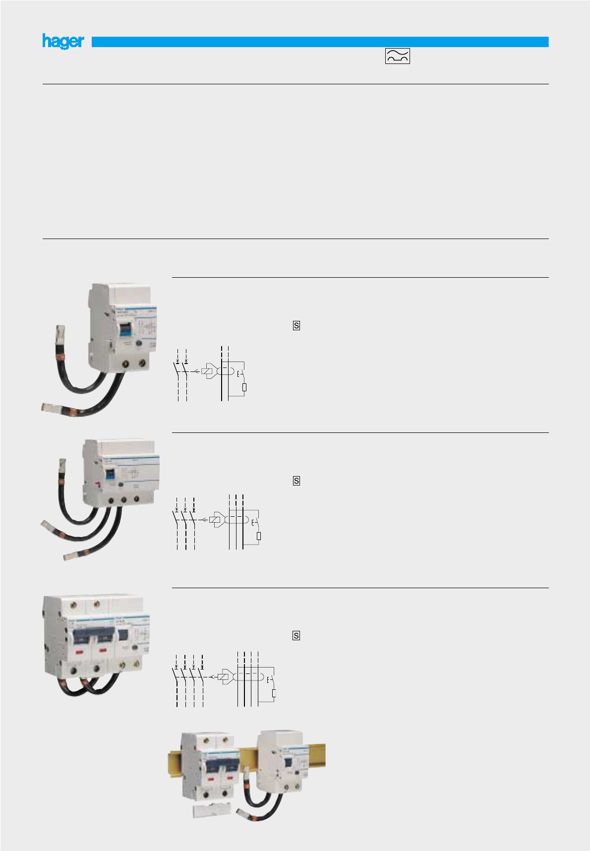
2 pole and 4 pole RCCBs
Description
To open a circuit automatically in
the event of an earth fault
between phase and earth,
and/or neutral and earth.
A wide range of current ratings
and sensitivities are available.
Suitable for domestic,
commercial, industrial
applications.
Technical data
Specification IEC1008
Tropicalisation T2
Sensitivities (fixed) :
10, 30, 100, 300mA and 500mA
Terminal capacities :
16-63A rigid 25▫
flexible 16▫
80&100A rigid 50▫
flexible 35▫
Features
Positive contact indication is
provided by the rectangular flag
indicator
Red = closed
Green = open.
Indication of trip is provided by
the oval flag indicator
Yellow = tripped.
All RCCB’s have trip free
mechanisms and can be
padlocked either ‘on’ or ‘off’.
Operating voltage
2P - 127-230V AC 50Hz
(+6%,-10%)
4P - 230 - 400V AC 50Hz
(+6%,-10%)
Voltage marking as per IEC38
can be used on 240/415V
50Hz without derating
Width in 17.5mm modules
I
2P - 2
I
4P - 4
I
For technical details
see pages 48-51
23
45
68
44
CD 241J
CD 441J
S
S

Accessories for 2 pole and 4 pole RCCBs
24
Accessories 16A-63A 10 sets CZN 005 CZ 005 CZN 006 CZ 006
terminal covers 80A-100A 10 sets CZ 007 CZ 008
Auxiliary + 1
I
wide for ON/OFF CZ 001
alarm switch & trip indication
locking kit this allows locking of MZN 175
for the dolly of the device dolly in the
the device supplied on/off position.
without padlock. will accept two padlocks
with hasps of 4.75mm
diameter max.
Sensitivity Current Pack Ref Ref Ref Ref
rating qty 2 pole 2 pole 4 pole 4 pole
avai. from avai. from
1.09.05 1.09.05
MZN 175
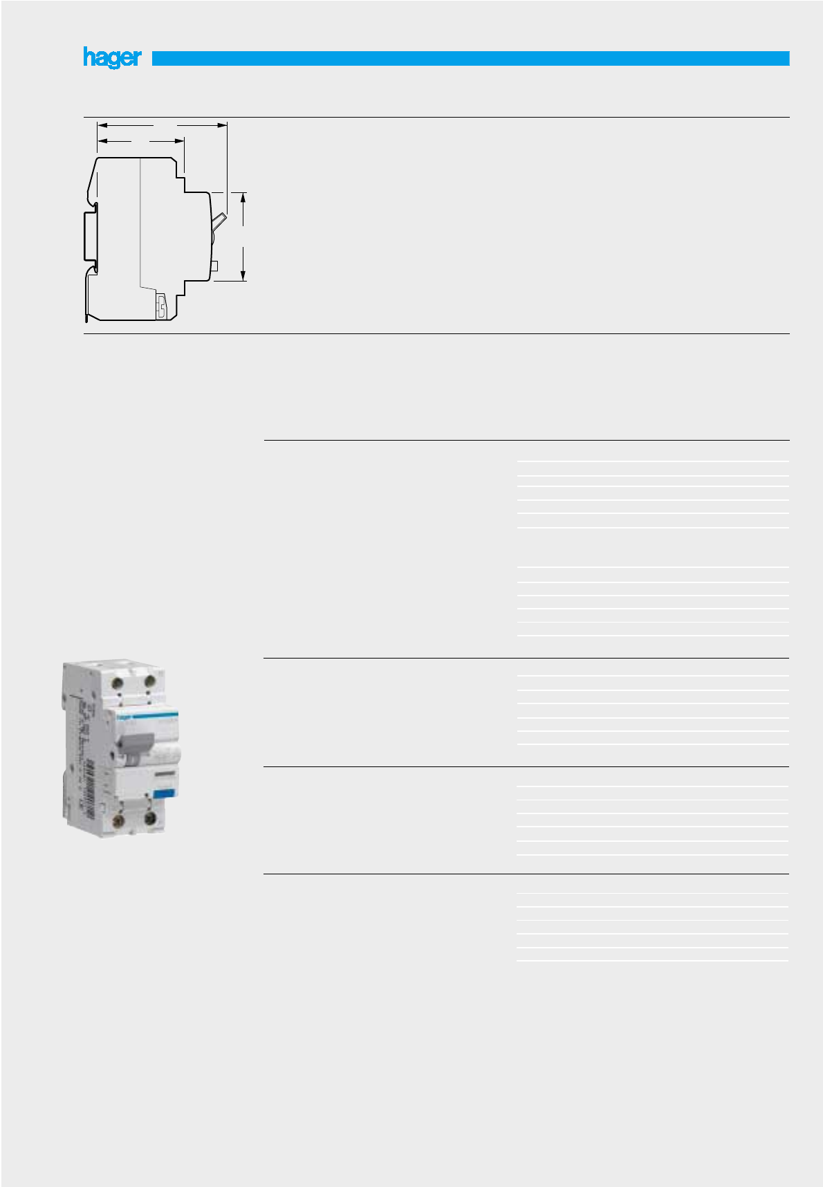
RCBO 6kA 6A 2 1 AD906J AD956J
Type A - 30mA 10A 2 1 AD910J AD960J
16A 2 1 AD916J AD966J
20A 2 1 AD920J AD970J
25A 2 1 AD925J AD975J
32A 2 1 AD932J AD982J
40A 2 1 AD940J AD990J
RCBO 6kA 6A 2 1 AF956J
Type A - 300mA 10A 2 1 AF960J
16A 2 1 AF966J
20A 2 1 AF970J
25A 2 1 AF975J
32A 2 1 AF982J
40A 2 1 AF990J
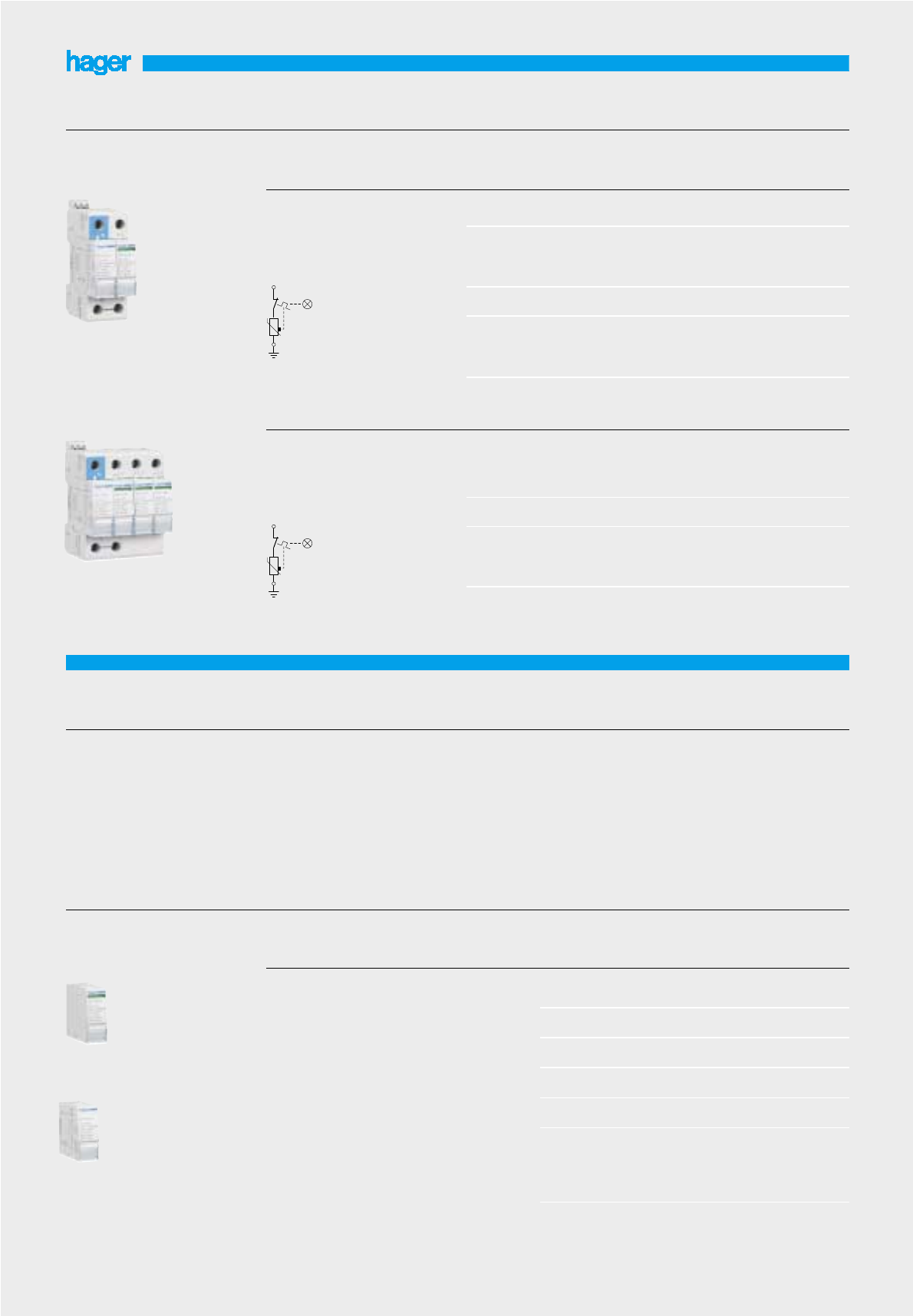
RCBO (residual circuit breaker with overload)
Type B and C SP&N with neutral lead
Description
Compact protection devices
which provide MCB overcurrent
protection and RCD earth
leakage protection in a single
unit.
Complies to IEC1009
Technical data
The units are available with
current ratings of 6A, 10A, 16A,
25A, 32A and 40A. The device
switches both the phase and
neutral conductors. All ratings
have 30mA and 300mA earth
leakage protection. The units
feature indicators which show
whether tripping is due to an
overcurrent or earth leakage
fault.
Voltage rating - 110-230V
50/60Hz
Current rating – 6-40A.
Mechanical life :
20 000 operations.
Breaking capacity : 4 500A and
6 000A
Connection capacity
25▫rigid cables
16▫flexible cables
25
Designation Breaking In/A Width in
I
Pack Ref. Ref.
capacity 17.5mm qty. type B type C
available available
as from as from
01.09.05 01.09.05
RCBO 4,5kA 6A 2 1 AD806J AD856J
Type AC - 30mA 10A 2 1 AD810J AD860J
16A 2 1 AD816J AD866J
20A 2 1 AD820J AD870J
25A 2 1 AD825J AD875J
32A 2 1 AD832J AD882J
40A 2 1 AD840J AD890J
6kA 6A 2 1 AD906B AD956B
10A 2 1 AD910B AD960B
16A 2 1 AD916B AD966B
20A 2 1 AD920B AD970B
25A 2 1 AD925B AD975B
32A 2 1 AD932B AD982B
40A 2 1 AD940B AD990B
RCBO 6kA 6A 2 1 AF956B
Type AC - 300mA 10A 2 1 AF960B
16A 2 1 AF966B
20A 2 1 AF970B
25A 2 1 AF975B
32A 2 1 AF982B
40A 2 1 AF990B
45
68
44
AD 916J
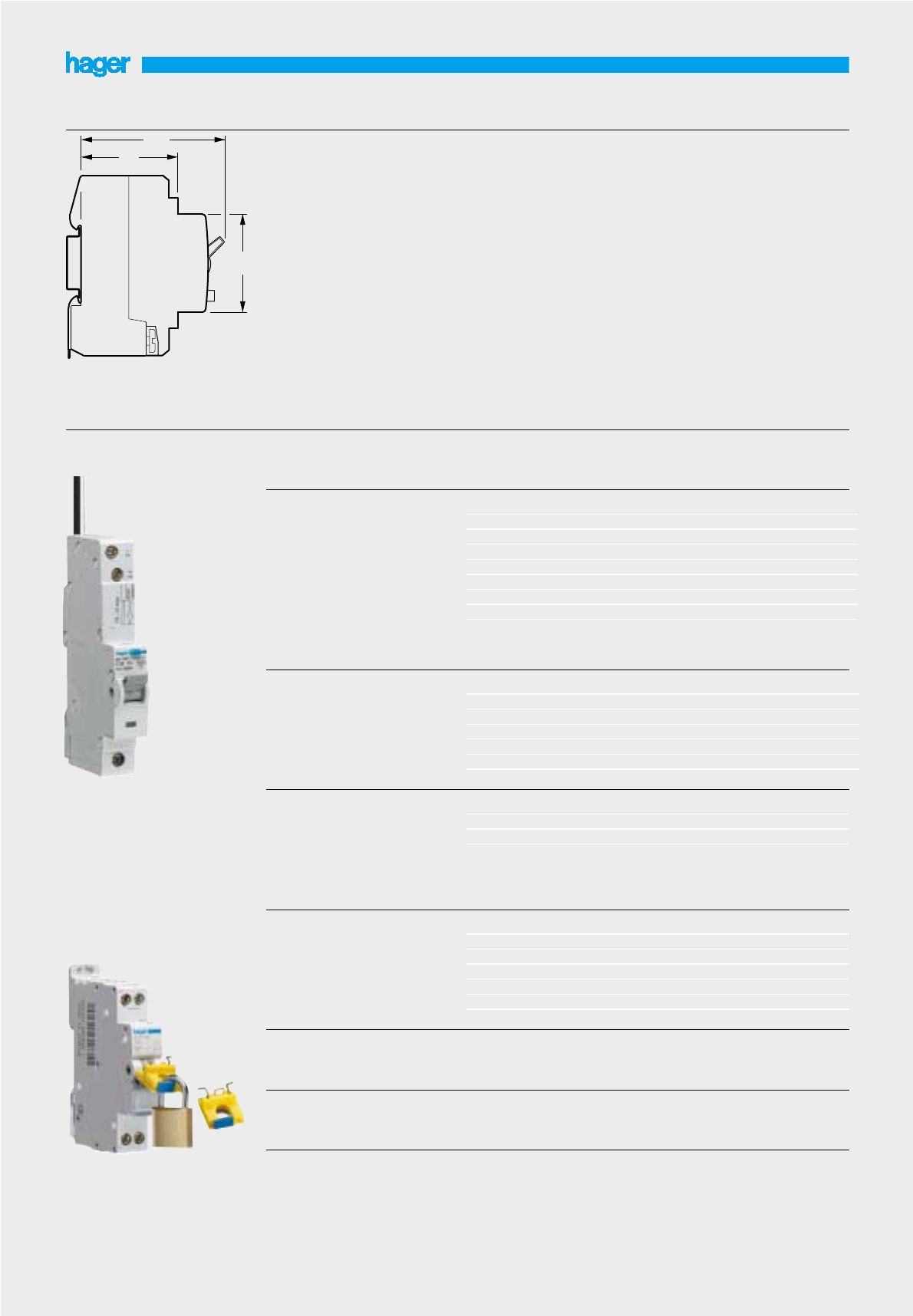
RCBO, 6000A to IEC 898, 611AD 106Z
C curve, 30mA sensitivity 10 1 1 AD 110Z
16 1 1 AD 116Z
20 1 1 AD 120Z
25 1 1 AD 125Z
32 1 1 AD 132Z
40 1 1 AD 140Z
45 1 1 AD 127
50 1 1 AD 128
RCBO, 6000A to IEC 898, 611AE 106Z
C curve, 100mA sensitivity 10 1 1 AE 110Z
16 1 1 AE 116Z
20 1 1 AE 120Z
25 1 1 AE 125Z
32 1 1 AE 132Z
40 1 1 AE 140Z
RCBO, 10000A to IEC 898, 611AD 184
C curve, 30mA sensitivity 10 1 1 AD 185
16 1 1 AD 187
20 1 1 AD 188
25 1 1 AD 189
32 1 1 AD 190
40 1 1 AD 191
RCBO, 6000A to IEC 898, 20 1 1 AF 120Z
C curve, 300mA sensitivity 25 1 1 AF 125Z
32 1 1 AF 132Z
40 1 1 AF 140Z
Designation In/A Width in
I
Pack C curve
17.5mm qty. cat. ref.
RCBO - single pole
Description
Compact protection devices
which combine the overcurrent
functions of an MCB with the
earth fault functions of an RCD
in a single unit. A range of
sensitivity and current ratings are
available for use in domestic
commercial and industrial
applications
Technical data
Specification complies
to IEC1009
Sensitivities :
Fixed : 30mA, 100mA and
300mA
Selectivite : 100mA, 300mA
Terminal capacities
16▫rigid, 10▫flexible
Features
1 module devices provide a
compact solution for installation
in consumer units & distribution
boards, for individual
installations. These devices are
1P & solid neutral.
Operating voltage
110-230V AC 50/60Hz
Flying neutral lead length
700mm
26
RCBO, 6000A to IEC 898, 50 1 1 AN 150Z
C curve, 100mA sensitivity
selective version
RCBO, 6000A to IEC 898, 50 1 1 AP 150Z
C curve, 300mA sensitivity
selective version
Locking kit this allows the locking of the MZN 175
device dolly in ON/OFF positions.
It is possible to padlock the
device with 2 padlocks.
45
68
44
MZN 175
AD 110Z

27
Common characteristics
positive security : relay
tripping when break in relay/core
link, and blinking of default LED
Default storage with control of
tripping sequence (reset),
test-button for default
simulation with control of
tripping sequence.
Nuisance tripping protection
and immunity type A and HI
Tripping on DC default current
Display of default current by
LED,
LED for power supply
Earth leakage relays
Designation Characteristics
Earth leakage relays
standard version 1 C/O
Barograph version:
Signalisation of default current
by a barograph, display in % the
level of current before setting of
relay (5 to 75%). An output
contact prealarm to remote every
overflow of 50% of In .
Supply voltage : 230 V
frequency : 50/60 Hz
Connection capacity :
- rigid 1,5 to 10
- flexible 1 to 6
max. length of wires :
remote test and reset : 20 m
According to electromagnetic
compatibility (CEM)
According to standards :
CEI 60947-2 annex B
CEI 60755 CEI 61008 - 1
CEI 61543
For technical details
see pages 52
instant strip,
adjustable sensitivity,
In : 30 mA
300 mA
Width in ❚
17,5 mm
2
2
Ref.
HR 400
HR 402
Earth leakage relays
standard version 1 C/O
adjustable sensitivity
In : 0,03 - 0,1 - 0,3 - 0,5 - 1 - 3
5 - 10A
adjustable time delay : 0 - 0,1 -
0,3 - 0,4 - 0,5 - 1s - 3s
standard version 1 OF
- display of earth leakage current
- positive safety output
- 50% default output with optical
scale display
- display of earth leakage current
- positive safety output
- 50% default output with optical
scale display
- external test and reset
3
3
5
HR 410
HR 420
HR 425
HR 410
HR 400
Earth leakage relays with
separate detection torroids.
These devices ensure protection
of electrical installations and the
protection of persons against
direct and indirect contacts.
Transform circuit breakers and
free-tripping switches with
voltmeter triggers into earth
leakage devices.
HR 420

28
Installation instruction :
- fix torroid on rectilineal part of
cables
- put cables or bars inside the
torroid
- PE conductor must not run
through the torroid
Torroids
Designation Characteristics
Circular section torroids
Mounting :
- either directly on cable or metal
strip
- or on perforated kits in Univers
and Quadro.
- HR 800 can be cliped on DIN
rail
Connection of cables
- rigid1,5 to 4
- flexible 1 to 6
max. length core/relay
- 50 m max with twisted cable of
1,5 mm2
For technical details
see pages 53-54
Ø 30 mm
Ø 35 mm
Ø 70 mm
Ø 105 mm
Ø 140 mm
Ø 210 mm
Ref.
HR 800
HR 801
HR 802
HR 803
HR 804
HR 805
Rectangular section torroids
- closed
- opening
70 x 175 mm
115 x 305 mm
150 x 350 mm
20 x 30 mm
50 x 80 mm
80 x 80 mm
80 x 120 mm
80 x 160 mm
HR 830
HR 831
HR 832
HR 820
HR 821
HR 822
HR 823
HR 824
HR 830
HR 802
Detection torroid
Torroids can be associated with
all differential relays of HR range.
They meet all requirements of
electrical distribution.
6 circular section torroids of Ø
30 to Ø 210 mm
3 closed rectangular torroids
5 rectangular section torroids
opening for renovation (can be
installed without disconnecting
cables).
HR 820
HR 822
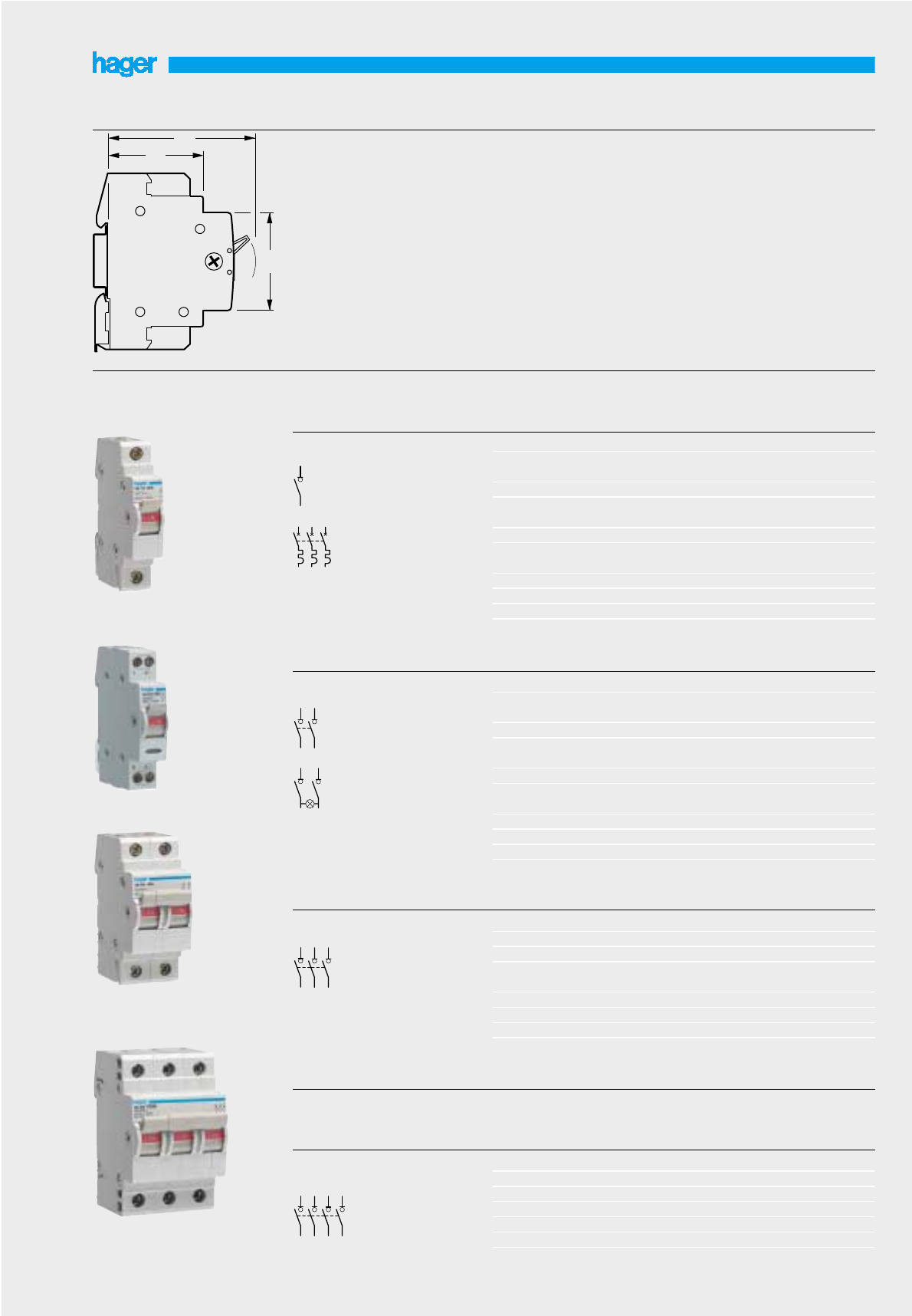
4 x 16A 400V~ 2 1 SB 416 SB 416F
4 x 25A 400V~ 2 1 SB 425 SB 425F
4 x 32A 400V~ 2 1 SB 432 SB 432F
4 x 40A 400V~ 4 1 SB 440 SB 440F
4 x 63A 400V~ 4 1 SB 463 SB 463F
4 x 80A 400V~ 4 1 SB 480 SB 480F
4 x 100A 400V~ 4 1 SB 499 SB 499F
Four pole
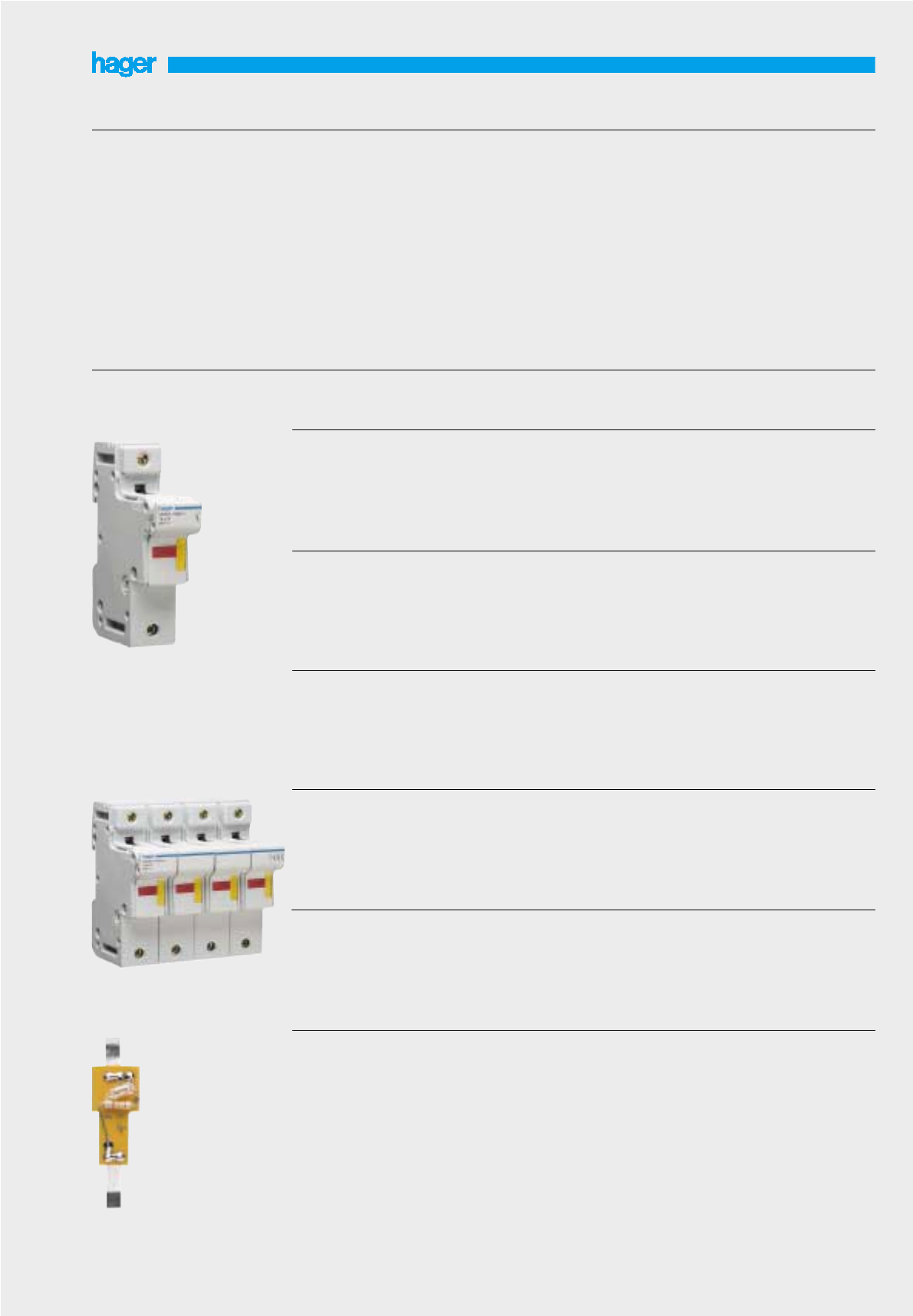
Isolating switches
Description
for use as a switch
disconnector in all types of
circuit.
Complies with :
- IEC 60947-3 (In 16 to 100A)
- EN 669.1 (In 16 to 63A)
Technical data
In : 16, 25, 32A
AC 21A duty specification
connection capacity:
10▫rigid cables
6▫flexible cables
In : 40, 63, 80A (1 pole)
AC 22B duty specification
connection capacity:
25▫rigid cables
16▫flexible cables
In : 80A (2 to 4 poles), 100A
AC 22B duty specification
connection capacity:
50▫rigid cables
35▫flexible cables
29
Designation Characteristics Width in
I
Pack Cat.
17.5mm qty. ref.
Single pole 1 x 16A 250V~ 1 12 SB 116
1 x 16A 250V~ 1 1 SB 116V
with pilot light
1 x 25A 250V~ 1 12 SB 125
1 x 25A 250V~ 1 1 SB 125V
with pilot light
1 x 32A 250V~ 1 1 SB 132
1 x 32A 250V~ 1 1 SB 132V
with pilot light
1 x 40A 250V~ 1 1 SB 140
1 x 63A 250V~ 1 1 SB 163
1 x 80A 250V~ 1 12 SB 180
1 x 100A 250V~ 1 1 SB 199
Double pole 2 x 16A 250V~ 1 1 SB 216
2 x 16A 250V~ 1 1 SB 216V
with pilot light
2 x 25A 250V~ 1 12 SB 225
2 x 25A 250V~ 1 1 SB 225V
with pilot light
2 x 32A 250V~ 1 1 SB 232
2 x 32A 250V~ 1 1 SB 232V
with pilot light
2 x 40A 250V~ 1 1 SB 240
2 x 63A 250V~ 1 6 SB 263
2 x 80A 250V~ 1 1 SB 280
2 x 100A 250V~ 1 1 SB 299
Triple pole 3 x 16A 400V~ 2 1 SB 316
3 x 25A 400V~ 2 1 SB 325
3 x 32A 400V~ 2 1 SB 332
3 x 32A 400V~ 3 1 SB 332Q
large terminals
3 x 40A 400V~ 3 1 SB 340
3 x 63A 400V~ 3 1 SB 363
3 x 80A 400V~ 3 1 SB 380
3 x 100A 400V~ 3 1 SB 399
Designation Characteristics Width in
I
Pack Cat. ref. Cat. ref.
17.5mm qty. neutral neutral
right left
45
68
44
SB 140
SB 232
SB 240
SB 399
N

1 set includes 1 set SZ 011
5 pins 2 mod width
5 pins 3 mod width
5 pins 4 mod width
Handle link pin
for switch handles
2 x 25A 250V~ 2 6 SF 219F
2 x 40A 250V~ 2 6 SF 219G
3 x 40A 250V~ 3 4 SF 319G
4 x 40A 250V~ 4 3 SF 419G
double pole
1 x 25A 250V~ 1 12 SF 119F
1 x 40A 250V~ 1 12 SF 119G
Switches
centre - off changeover
single pole
2 x 25A 250V~ 2 6 SF 218F
Double pole
2 x 25A 250V~ 1 12 SF 115
Double pole
1 x 25A 250V~ 1 12 SF 118F
Switch, 2 ways
single pole
Designation Characteristics Width in
I
Pack Cat.
17.5mm qty. ref.
2 way / centre - off changeover modular switches
30
SF 118F
SF 219F
SZ 011
1
24
1
24
3
1
24
5
68
1
24
1
24
5
68
31
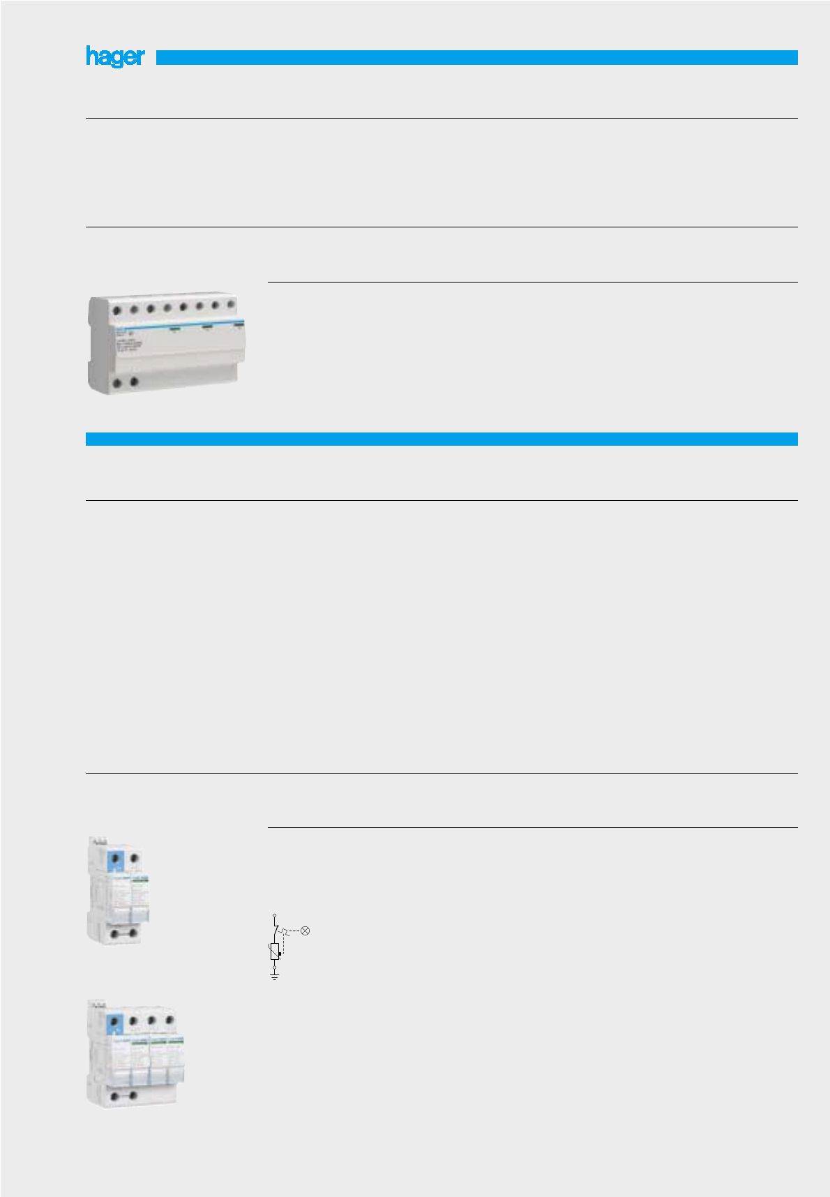
Surge protective devices
type 1
SPN 265R
SPA 412A
SPDs with plug in cartridge with
very high, high and medium
discharge current capacity
(65 kA, 40 kA and 15 kA).
SPDs with plug in cartridge
ensure :
- general protection of electric
equipment,
- protection in common and
differential mode for domestic,
industrial and commercial
buildings.
Common characteristics :
SPDs with base and cartridges.
Available in 2 versions :
SPDs with base and plug in
cartridges with an end of life
indication LED
SPDs with base and auxiliary
contact for remote signallings
and plug in cartridges with
reserve protection indicator .
This version, with reserve
indicator, shows the intermediary
state, with indication of the need
to change the cartridge before
disconnection, but keeps the
maximal protection capacity till
the end.
For remote signalling, an
auxiliary contact (R version) is
used to report the information of
condition indication until the end
of life of the product.
The cartridge allows simple
replacement without the need to
cut-off the power supply
SPDs are equipped with
integrated thermic and dynamic
disconnection
connection capacity of
terminal blocks, (L, N/E) :
- 16flexible conductor,
- 25rigid conductor
for auxiliary contact :
- 0,5mini
- 1,5maxi
degree of protection : IP 203
(in enclosure).
For technical details
see pages 55-59
This type of surge protective
devices are recommended on
electric installations where the
buildings are fitted with lightning
conductor. The minimavalue of
shock current is I imp =12,5 kA.
With a discharge current wave
10/350 s (I imp) which is similar
to lightning current on direct
impact, those SPD’s must have
the capacity to flow out this
energizing wave.
Monobloc SPD’s type 1 have a
LED for well functioning for each
phase on the front.
connection capacity:
- 35flexible conductor,
- 50rigid conductor
complies with
EN 61-643.11
For technical details
see pages 55-59
2 poles 1 Ph + N
with reserve indicator and
remote signalling
Up : 1,3 kV at In
4 poles 3 Ph + N
with reserve indicator and
remote signalling
Up : 1,5 kV at In
SPDs with plug in cartridge
I max. 65 kA
Un : 230/400 V
50/60 Hz
2
4
SPN 265R
SPN 465R
Designation Characteristics Width in ❚
17,5 mm Ref.
2 pole 1 Ph + N
Up : 2,5 kV at In
4 poles 3 Ph + N
Up : 2,5 kV at In
SPD’s type 1
I imp. 12,5 kA
Un : 230/400 V
50/60 Hz
4
8
SPA 212A
SPA 412A
Designation Characteristics Width in ❚
17,5 mm Ref.
SPN 465R
Surge protective devices
for general protection
32
Surge protective devices
for general protection
Cartridges are available for all
discharge currents (65 kA, 40
reserve protection indication.
Replacement cartridges
The cartridge allows simple
replacement without the need to
cut-off the power supply.
A keying system exists to
prevent a line cartridge being
interchanged by mistake with a
neutral and visa versa
For technical details
see pages 55-59
- single pole 1 Ph
Up : 2 kV at In
- 2 poles 1 Ph + N
with reserve indicator and
remote signalling
Up : 1,2 kV at In
- 2 poles 1 Ph + N
Up : 1,2 kV at In
- 4 poles 3 Ph + N
with reserve indicator and
remote signalling
Up : 1,2 kV at In
- 4 poles 3 Ph + N
Up : 1,2 kV at In
SPDs with plug in cartridge
I max. 40 kA
Un : 230/400 V
50/60 Hz
1
2
2
4
4
SPN 140C
SPN 240R
SPN 240D
SPN 440R
SPN 440D
SPN 215R
SPN 215D
SPN 415R
SPN 415D
Designation Characteristics Width in ❚
17,5 mm Ref.
Designation Characteristics Width in ❚
17,5 mm Ref.
- 2 poles 1 Ph + N
with reserve indicator and
remote signalling
Up : 1,0 kV at In
- 2 poles 1 Ph + N
Up : 1,0 kV at In
- 4 poles 3 Ph + N
with reserve indicator and
remote signalling
Up : 1,0 kV at In
- 4 poles 3 Ph + N
Up : 1,0 kV at In
SPDs with plug in cartridge
I max. 15 kA
Un : 230/400 V
50/60 Hz
2
2
4
4
Replacement cartridges
for SPDs with plug in cartridge
SPN 415R
SPN 240R
Phase for : SPN 265R, SPN 465R
SPN 140C
SPN 240R, SPN 440R
SPN 240D, SPN 440D
SPN 215R, SPN 415R
SPN 215D, SPN 415D
Neutral for: SPN 265R, SPN 465R,
SPN 240R, SPN 440R,
SPN 215R, SPN 415R
SPN 240D, SPN 440D,
SPN 215D, SPN 415D
Replacement cartridges
Remark : for a replacement of
cartridges, choose only the
same reference as the
previous cartridge.
SPN 065R
SPN 040C
SPN 040R
SPN 040D
SPN 015R
SPN 015D
SPN 065N
SPN 040N
SPN 065R
SPN 065N

33
Surge protective devices
for fine protection
Designation Characteristics Width in❚
17,5 mm
Protection is assured in both
common and differential modes.
Discharge current :
I max. 8 kA (8/20 wave).
A green LED on the front face
indicates the status of the SPD
connected in series with the
equipment that needs to be
protected.
Connected in series with the
equipment that needs to be
protected.
SPDs with low valotage
protection level
To protect very sensitive
electronic equipment.
The fine protection completes
the main protection and can
protect 1 or several electronic
devices.
Optimal coordination is obtained
when cascaded with a main
protection device (lower Up see
table below)
Suitable for every earthing
system.
Connection capacity :
- 6flexible conductor
- 10rigid conductor .
Degree of protection : IP 20
(in enclosure).
complies with
NF EN 61-643-11
september 2002
For technical details
see pages 55-59
2 poles 1 Ph + N
4 poles 3 Ph + N
SPD
with low voltage protection level
Un : 230/400 V
50/60 Hz
Up (Ph/ N/) : 1,2 kV at In
Up (Ph/N) : 1 kV at In
2
3
Ref.
SPN 208S
SPN 408S
SPDs
for telephone lines
Voltage protection level with a
main + fine protection :
Up ≤800 V
In-line connection on telephone
line with receiver to be
protected.
SPDs for telephone lines.
For the protection of receiver
against transient current surge
vehicled by telephone lines (fax,
modem, etc...)
Protection is assured in both
common and differential modes
Discharge current :
I max 10 kA (8/20 wave).
Connection capacity
- 0,5 à 2,5flexible conductor
- 0,5 à 2,5rigid conductor
Degree of protection : IP 10
(in enclosure).
Complies with
IEC 61643-21
For technical details
see pages 55-59
Un : 130 V
Up : 600 V
Un : 40 V
Up : 600 V
Voltage surge protection for
analog telephone lines
Voltage surge protection for
digital telephone lines
1
1
SPN 505
SPN 504
Designation Characteristics Width in ❚
17,5 mm Ref.
SPN 505
SPN 408S

Motor starters
Description
to ensure localised control and
protection of single and three
phase motors.
Technical data
– adjustable thermal relay
– AC3 utilisation category
Connection capacity
2 conductors
max size 1 to 4▫flexible
1.5 to 6▫rigid
Options
under voltage release: MZ 528N,
MZ 529N
auxiliary contacts: MZ 520N,
MZ 527N
alarm contact: MZ 527N,
Complies with IEC 947-1,
IEC 947-2
For technical details,
see page 60
34
Designation current Stand.power Ratings of Width in
I
Pack Cat.
setting motors 3 phase 17.5mm qty. ref.
50/60Hz (AC3 category)
Motors starters 230V (kW) 400V (kW)
0.1 - 0.16A - - 2 1/21MM 501N
0.16 - 0.24A - 0.06 2 1/21MM 502N
0.24 - 0.4A 0.06 0.09 2 1/21MM 503N
0.4 - 0.63A 0.09 0.12 2 1/21MM 504N
0.63 - 1A 0.12 0.25 2 1/21MM 505N
1 - 1.6A 0.25 0.55 2 1/21MM 506N
1.6 - 2.5A 0.37 0.75 2 1/21MM 507N
2.5 - 4A 0.75 1.5 2 1/21MM 508N
4 - 6.3A 1.1 2.2 2 1/21MM 509N
6.3-10A 2.7 4 2 1/21MM 510N
10-16A 4 7.5 2 1/21MM 511N
16-20A 5.5 9 2 1/21MM 512N
20-25A 7.5 12.5 2 1/21MM 513N
MM 501N
Breaking capacity :
Ic (kA)
230 V 400 V
0,16 à 10 A 100 100
16 à 25 A 16 16

MZ 520N
MZ 522N
35
MZ 520N
Accessories for motor starters
Designation Characteristics Width in ❚
17,5 mm
1 C + 1 O 3,5 A - 230 V
2 A - 400 V
1 C 1 A - 230 V
400 V
Auxiliary contacts
connection of MZ520N on he
right side of motor starter,
MZ522N connected directly on
front of motor starter and cannot
be mounted behind modular
plates.
1/2
1/2
Ref.
1 C : short- 3,5 A - 230 V
circuit 2 A - 400 V
1 C :overload 1 short-circuit
Default signal contact
mounting on the right side of
motor starter
1/2MZ 527N
230 V - 50 HzShunt trip
mounting on the left side of
motor starter
1MZ 523N
230 V - 50 Hz
400 V - 50 Hz
Under voltage release
mounting on the left side of
motor starter
1
1
MZ 528N
MZ 529N
with external rotary handle
actives motor starter without
opening the enclosure
4 x M25
Surface mounting enclosure
for waterproof motor starter
l. 80 x h. 158 x p. 125,5 mm
MZ 521N
allow remote “emergency stop”
of motor starter via tripping auxi-
liary
3 x M20 + 2 x M25
1 C + 1 O 230 / 400 V
Emergency stop button
emergency stop : IP 65
Remote emergency stop
button with key synchronizing
unlocking with key IP67
MZ 530N
MZ 531N
13
14
21
22
MZ 527N
MZ 528N
MZ 521N
MZ 530N MZ 531N

This “made by hager” symbol is
your guarantee to receive the
very best that hager has to offer.
Over time, it will replace the
hologram which will be
progressively withdrawn.
Every MCB, RCCB and RCBO
that bears this new symbol has
been carefully crafted in one of
our hager owned factories.
the success is in the system
=+
38 Circuit protection
40 Miniature circuit breakers
44 Auxiliaries for MCBs and RCDs
45 Transformer protection and lighting circuits
46 RCD add on blocks
47 HRC fuse carriers
48 RCCBs
52 Earth fault protection relays
53 Torroids for earth fault protection relays
55 Surge protective device
60 Motor starters
Technical information
37
Basic Principles
The proper selection of the correct circuit protective device requires
an understanding of the potential hazards against which protection
for safety is required. The Wiring Regulations identify several
hazards:
• electric shock
• thermal effects
• overcurrent
• undervoltage
• isolation
Electric shock - is divided into two parts:
• direct contact: contact with parts which result in an electric
shock in normal service
• indirect contact: contact with exposed conductive parts which
result in an electric shock in case of a fault.
To protect against direct contact the Wiring Regulations
suggest the following basic measures should be taken:
(1) by insulation of live parts
(2) by enclosures or barriers
(3) by obstacles
(4) by placing out of reach
To protect against indirect contact the Wiring Regulations suggest
the following basic measures should be taken:
(1) earthed equipotential bonding and automatic disconnection of
supply
(2) use of class II equipment or equivalent insulation
(3) non-conducting location
(4) earth-free local equipotential bonding
(5) electrical separation
Of these five measures, the first is by far the most commonly used -
(1) earthed equipotential bonding and automatic disconnection of
supply:
In each installation main equipotential bonding conductors shall
connect the main earthing terminal of the installation; this metalwork
comprises exposed conductive parts which are part of the electrical
installation itself and extraneous conductive parts including the
following:
• main water pipes
• gas installation pipes
• other service pipes and ducting
• risers of central heating and air conditioning systems
• exposed metal parts of the building structure
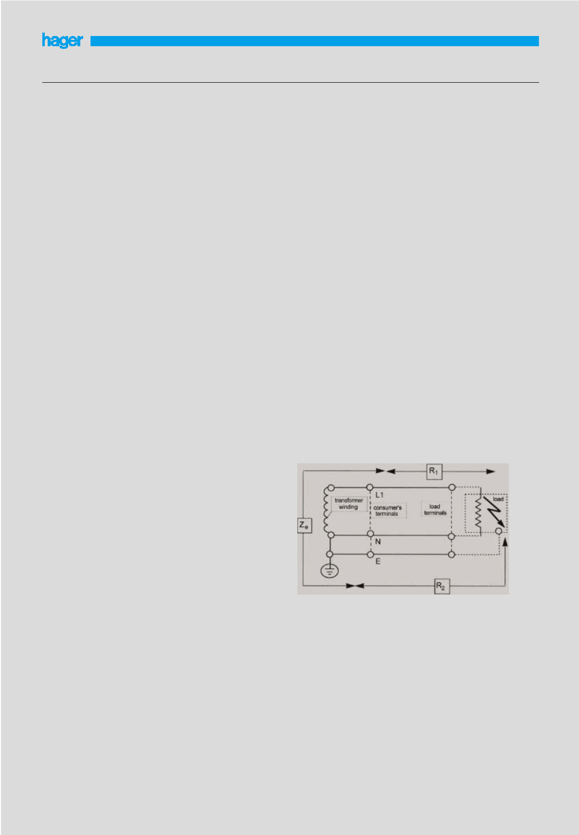
This bonding creates a zone within which any voltages appearing
between exposed conductive parts and extraneous conductive parts,
are minimised; the earth fault loop impedance must have an value
low enough to allow sufficient current to flow for the circuit protective
device to operate rapidly to disconnect the supply; disconnection
must be sufficiently fast so that voltages appearing on the bonded
metalwork cannot persist long enough to cause danger; depending
on the operating characteristics of the protective device and the
earth impedance, such disconnection may be achieved either by
overcurrent devices, Fuses, Miniature Circuit Breakers, (i.e. MCBs) or
by Residual Current Devices, (i.e. RCDs).
Thermal Effect - refers to heat generated by the electrical
equipment in normal use and under fault conditions. The proper
selection of equipment complying with the latest product standards
is essential in providing protection against thermal effects.
Overcurrent - is defined as a current exceeding the rated value of
the circuit components. It may be caused by the overloading of a
healthy circuit or it may take the form of a short-circuit current,
defined as an "overcurrent resulting from a fault of negligible
impedance between live conductors having a difference in potential
under normal operating conditions". Overcurrent protection may be
provided by using fuses or circuit breakers singly or in combination.
Undervoltage - refers to the dangers that could be caused by the
reduction or loss in voltage and the subsequent restoration, such as
the unexpected re-starting of motors or the automatic closing of
protective devices. The proper selection of control and protective
devices must take the protection against undervoltage into
consideration.
Isolation - every circuit shall be provided with means of isolation
(except in certain cases) to prevent or remove hazards associated
with the installation, equipment and machines. The new standards
for circuit breakers and switch-fuses now take this into account.
Protection against shock by indirect contact
Indirect contact - is the contact of persons or livestock with exposed
conductive parts made live by a fault and which may result in electric
shock. An example would be where the insulation of an electric
heater has broken down resulting in a live conductor internally
touching the casing. This could result in the heater casing being
raised to a hazardous voltage level, causing electric shock to a
person touching it.
Two important measures must be taken to prevent this hazard:
• the impedance of circuit conductors is kept to a minimum. The
earth fault loop impedance (Zs) is used as a measure of the
circuit impedance under fault conditions.
• the overcurrent device protecting the circuit is selected to rapidly
disconnect an earth fault.
The effect of these two measures is inter-related.
1. By ensuring that the circuit protective conductor is of a low
impedance, the voltage to which the live casing is raised, under
fault conditions, is kept to a minimum.
2. The low impedance path provided by the circuit conductors and
the circuit protective conductor will result in a high level of
current in the event of an earth fault. This high fault current
ensures that the overcurrent protective device will disconnect the
fault in a short time, reducing the interval during which the casing
of the faulty equipment is live.
Components of earth fault loop impedance (Zs) in a system.
(Earth fault at load between conductor and casing).
Zs= Ze+ (R1+R2)
Earth fault loop impedance (Zs)
To ensure the impedance of conductors in a circuit is sufficiently low
the system designer has to establish the value of the earth fault loop
impedance.
Zs- is a measure of the earth fault current loop, comprising the
phase conductor and the earth conductor. It comprises the
complete loop including the winding of the transformer from which
the circuit is supplied as defined by the following:
Ze- is the part of the earth fault loop impedance external to the
installation, its value can be measured or a nominal value can be
obtained from the supply authority.
Circuit protection
38

(R1+R2) - where R1is the resistance of the phase
conductor within the installation and R2is the resistance of the
circuit protective conductor. These two components constitute the
loop impedance within the installation.
Therefore: Zs= Ze+ (R1+ R2)
Once the value of Zshas been established a suitable overcurrent
protective device has to be selected to ensure disconnection of an
earth fault within the specified time.The times are:
• 5 seconds for fixed equipment.
• For portable equipment and for fixed equipment installed outside
the equipotential bonding zone, the
disconnection times are dependent on the nominal
voltage to earth, i.e. 220 to 277 volts = 0.4 seconds.
Zsby calculation
To establish whether the relevant disconnection time can be
achieved a simple calculation must be made, based on Ohm's law:
Uo (open circuit voltage)*
If(fault current) = Zs(earth fault loop)
* voltage between phase and earth (240V)
The fault current (If) must be high enough to cause the
circuit protective device to trip in the specified time. This can be
established by consulting the time/current characteristic for the
protective device. If the maximum trip time for the fault current
calculated is less than or equal to the relevant value (5s for fixed
equipment; 0.4s for portable equipment) then compliance is
achieved. It is important that when consulting the characteristic
curve the worst case is used, i.e. the maximum tripping time
including any tolerance. An example is shown in Figs 1 and 2.
Zsby tables
The above procedure can be used for any type of protective device
providing a time/current characteristic curve is available. Frequently,
however, a much simpler method is available using tables listing
maximum Zsvalues which have been interpreted from the
characteristic curves for the relevant devices. Providing the system
Zsis equal to or less than the value given in the table, compliance is
achieved. Tables for a number of 'standard' devices (certain fuses
and MCBs) are given in the Wiring Regulations.
Zs too high
If the system Zsvalue is too high to achieve rapid enough
disconnection with the overcurrent protective devices available then
it is necessary to use one of the two following methods:
• fit a cable with a larger cross-section and consequently a lower
impedance. This may be a very expensive solution especially
when the installation is complete before the problem is
discovered.
• use a Hager residual current device (RCD). Subject to certain
conditions being met this provides a simple and economical
solution.
Example
Fig 2
Fig 2 shows a fixed circuit with an earth loop impedance
Zsof 0.7 ohms protected with an MT 132. The fault current (If) will
therefore be Uo/Zs= 240/0.7 = 343A
By referring to the characteristic for MT132 (see Fig 3) it can be seen
that the breaker will disconnect in 0.02 seconds for this
current. The breaker therefore easily satisfies the requirement for
disconnection in 5 seconds.
If the circuit Zswas 2.0 ohms then the fault current would be:
240/2 = 120A
and the disconnection time would be 10 seconds, in which case
compliance would not be achieved.
Fig 3
Protection against overcurrent
Overcurrent - "A current exceeding the rated value. For conductors
the rated value is the current-carrying capacity"
Overload Current - "An overcurrent occurring in a circuit which is
electrically sound"
Short-Circuit Current - "An overcurrent resulting from a fault of
negligible impedance between live conductors having a difference in
potential under normal operating conditions."
Protection against Overload Current
For the protection against overload current, protective devices must
be provided in the circuit to break any overload current
flowing in the circuit conductors before it can cause a temperature
rise which would be detrimental to insulation, joints, terminations or
the surroundings of the conductors.
In order to achieve this protection the nominal current of the
protective device Inshould be not less than the design current of the
circuit Iband that Inshould not exceed the current-carrying capacity
of the conductors Iz, and that the current causing
effective operation of the protective device I2 does not exceed 1.45
times the current-carrying capacity of the conductor Iz, expressed as
Ib≤In≤Iz
I2≤1.45Iz
Protection against Short-Circuit Current
Protective devices must be provided to break any short-circuit
current before it can cause danger due to thermal and mechanical
(electro-dynamic) effects produced in the conductors and
connections. The breaking capacity of the protective device shall not
be less than the prospective short-circuit current at the point at
which the device is installed. However a lower breaking capacity is
permitted provided that a properly co-ordinated back-up device
having the necessary breaking capacity is installed on the supply
side.
Positioning of Overcurrent Devices
Devices for the protection against overload and short-circuit must be
placed at the point where a reduction occurs in the
current-carrying capacity of the conductors. This reduction could be
caused by a change in the environmental conditions as well as the
more obvious change in the cross-sectional area of the cable.
There are of course exceptions to this general rule which relate to a
very few special applications. These are set out in detail in the the
Wiring Regulations.
Circuit protection
39
An earth fault current of 343A causes a trip
of the magnetic protection in 20mS.
An earth fault current of 120A causes a trip
of the thermal protection in 10 seconds.

Both of the new International Standards covering Low Voltage Circuit
Breakers provide the user with a better assurance of quality and
performance by taking into account the actual operating conditions
of the breaker. New definitions and symbols have been introduced
which should be committed to memory. Some of those most
frequently used are:
Ue: rated service voltage
Ui: rated insulation voltage (> Uemax)
Uimp : rated impulse withstand
Icm : rated short circuit making capacity
Icn : rated short circuit capacity
Ics : rated service short circuit breaking capacity
Icu : rated ultimate short circuit breaking capacity
I∆n: rated residual operating current (often called
residual sensitivity)
In: rated current = maximum value of current used for the
temperature rise test
∆t: trip delay of residual current devices
In addition IEC 898 sets out to provide a greater degree of safety to
the uninstructed users of circuit breakers. It is interesting to note that
the description "miniature circuit breaker" or MCB is not used at all
in this standard, but no doubt both manufacturers and users will
continue to call circuit breakers complying with IEC 898 miniature
circuit breakers or MCBs for some time to come.
The scope of this standard is limited to ac air break circuit breakers
for operation at 50Hz or 60Hz, having a rated current not exceeding
125A and a rated short-circuit capacity not exceeding 25kA.
A rated service short-circuit breaking capacity Ics is also included
which is equal to the rated short-circuit capacity Icn for short-circuit
capacity values up to and including 6kA, and 50% of Icn above 6kA
with a minimum value of 7.5kA. As the circuit- breakers covered by
this standard are intended for household and similar uses, Ics is of
academic interest only. The rated short-circuit capacity of a MCB
(Icn) is the alternating component of the prospective current
expressed by its r.m.s. value, which the MCB is designed to make,
carry for its opening time and to break under specified conditions.
Icn is shown on the MCB label in a rectangular box without the suffix
‘A’ and is the value which is used for application purposes. Icn (of
the MCB) should be equal to or greater than the prospective
short-circuit current at the point of application.
You will see from the curves that the inverse time delay characteristic
which provides overload protection is the same on all three. This is
because the Standards requires the breaker to carry 1.13 times the
rated current without tripping for at least one hour and when the test
current is increased to 1.45 times the rated current, it must trip within
one hour, and again from cold if the last current is increased to 2.55
times the rated current the breaker must trip between 1 and
120 seconds. The inverse time delay characteristic of all MCBs
claiming compliance with IEC 898 must operate within these limits.
The difference between the three types of characteristic curves
designated 'B', 'C' and 'D' concerns only the magnetic
instantaneous trip which provides short-circuit protection.
• For type 'B' the breaker must trip between the limits of 3 to 5
times rated current
• For type 'C" the breaker must trip between the limits of 5 to 10
times rated current, and
• For type 'D' the breaker must trip between the limits of 10 to 20
times rated current.
Often manufacturers publish their MCB tripping characteristics
showing the limits set by the standard and guarantee that any
breaker that you purchase will operate within these limits. So great
care should be taken when working with characteristic curves
showing lower and higher limits - on no account should you take a
mean point for application design purposes.
For cable protection applications you should take the maximum
tripping time and some manufacturers publish single line
characteristic curves which show the maximum tripping time. If the
design problem is nuisance tripping then the minimum tripping time
should be used and for desk top co-ordination studies, both lower
and upper limits have to be taken into account.
Energy limiting
Energy is measured in Joules. *James Prescott Joule proved that
thermal energy was produced when an electric current flowed
through a resistance for a certain time, giving us the formula :-
Joules = I2x R x t or because we know that watts = I2R
Joules = watts x seconds
Therefore we can say that :-
One Joule = one watt second
or energy = watts x seconds = I2R t
If the resistance (R) remains constant or is very small compared with
the current (I) as in the case of short-circuit current, then energy
becomes proportional to I2t. Which is why the energy let-through of a
protective device is expressed in ampere squared seconds and
referred to as I2t
I≈t (Joule Integral) is the integral of the square of the current over a
given time interval (t0, t1)
The I2t characteristic of a circuit breaker is shown as a curve giving
the maximum values of I2t as a function of the prospective current.
Manufacturers are required by the Standard to produce the I≈t
characteristic of their circuit breakers.
See page 39.
The energy limiting characteristics of modern MCBs greatly reduce
the damage that might otherwise be caused by short-circuits. They
protect the cable insulation and reduce the risk of fire and other
damage. Knowledge of the energy limiting characteristic of a circuit
breaker also helps the circuit designer calculate discrimination with
other protective devices in the same circuit.
Because of the importance of the energy limiting characteristic the
Standards for circuit breakers for household and similar
installations suggests three energy limiting classes based on the
permissible I2t (let-through) values for circuit breakers up to 32A;
class 3 having the highest energy limiting performance.
All Hager MCBs are well within the limits of energy let-through set by
IEC 898 for energy limiting class 3.
Miniature circuit breakers
40

Characteristic curve B C
Magnetic trip 50Hz dc 50Hz dc
Irm1 3In 4.5 In 5In 7.5 In
Irm2 5In 7.5 In 10In 15In
No. of poles 1 pole 2 poles in series
Range Max Breaking capacity Max Breaking capacity
voltage L/R=15ms voltage L/R=15ms
MT, MU,
MB, MC 60V 6kA 125V 6kA
NC, ND 60V 10kA 125V 10kA
Electrical References
characteristics MJ ML MV MW MT MU MB MC NC ND NR NM*
Poles SP+N SP+N 1,2,3,4 1,2,3,4 1,2,3,4 1,2,3,4 1,2,3,4 1,2,3,4 1,2,3,4 1,2,3,4 1,2,3,4 1,2,3,4
Rated operational 230 230 230/400 230/400 230/400 230/400230/400 230/400 230/400 230/400 230/400 230/400
voltage Ue(V) **
Nominal current 2-40A 6-40A 6-40A 6-40A 6-63A 6-63A 0.5-63A 0.5-63A 0.5-63A 0.5-63A 0.5-63A 80-100A
Breaking capacity 4.5kA 6kA 3kA 3kA 6kA 6kA 6kA 6kA 10kA 10kA - -
to IEC 898
Breaking capacity - - - - 10kA 10kA 10kA 10kA 15kA 15kA 25/20/15kA 10kA
to IEC 947-2
Rated insulation 500V 500V 500V 500V 500V 500V 500V 500V 500V 500V 500V 500V
voltage Ui(V)
Rated impulse 2500V 2500V 2500V 2500V 2500V 2500V 2500V 2500V 2500V 2500V 2500V 2500V
voltage Uimp (kV)
Electrical endurance 10000 10000 20000 20000 20000 20000 20000 20000 20000 20000 20000 20000
* din rail mount only, not for use in fixed busbar distribution boards.
** As per IEC38. Can be installed in 240/415V system without derating. Voltage tolerances -20% to +10%
MCB rated 0.512346101620253240506380100
current (A)
Watts loss per 1.3 1.5 1.7 2.1 2.4 2.7 1.8 2.6 2.8 3.3 3.9 4.3 4.8 5.2 8 10
pole (W)
Miniature circuit breakers
41
Power loss
The power loss of MCB’s is closely controlled by the standards and
is calculated on the basis of the voltage drop across the main
terminals measured at rated current. The power loss of Hager circuit
breakers is very much lower than that required by the Standard, so
in consequences run cooler and are less affected when mounted
together.
The table below gives the watts loss per pole at rated current.
For use with DC
Because of their quick make and break design and excellent arc
quenching capabilities Hager circuit breakers are suitable for DC
applications.
The following parameters must be considered.
1 system voltage:
Determined by the number of poles connected in series
2 short circuit current:
3 tripping characteristics:
- the thermal trip remains unchanged
- the magnetic trip will become less sensitive requiring derating
by 2 the ac value.
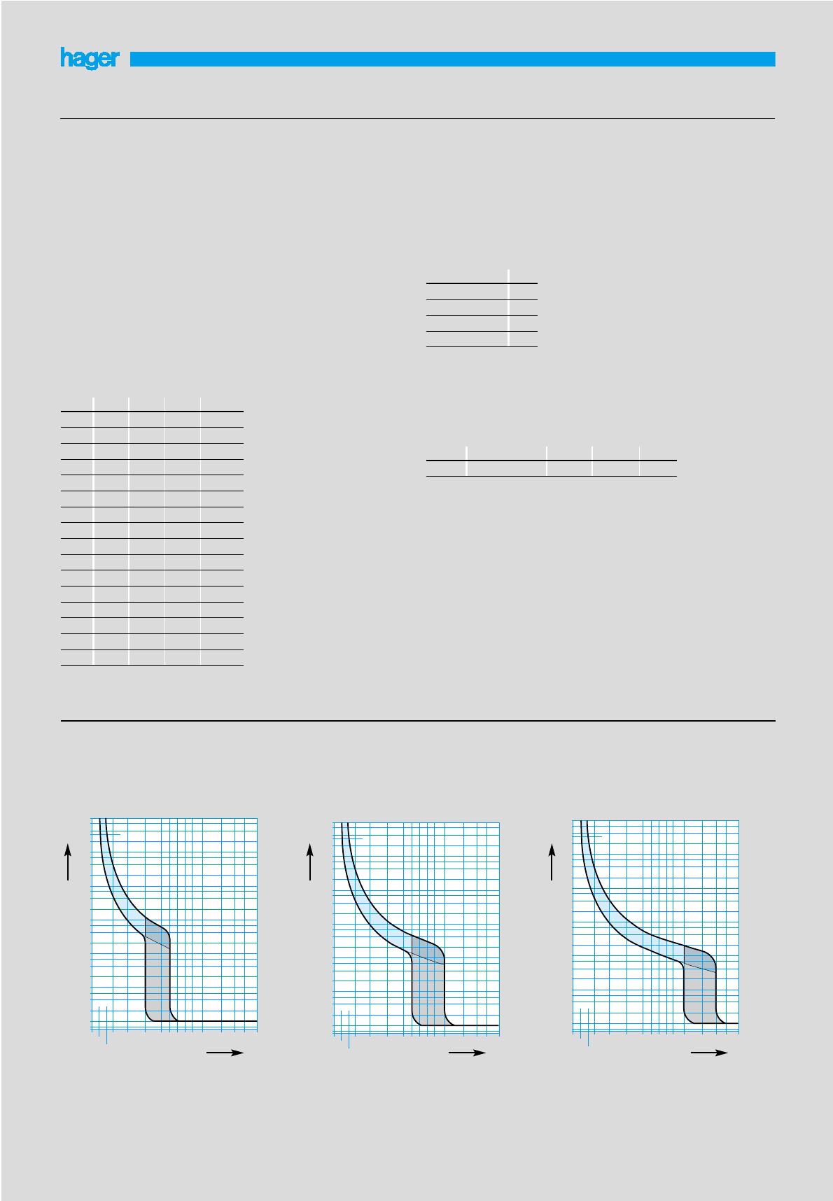
F (Hz) 17Hz – 60Hz 100Hz 200Hz 400Hz
K1 1.1 1.2 1.5
Grouping factors
Consideration should also be given to the proximity heating effect of
the breakers themselves when fully loaded and mounted together in
groups. There is a certain amount of watts loss from each breaker
depending on the trip rating which may well elevate the ambient air
temperature of the breaker above the ambient air temperature of the
enclosure.
grouping factor (rated current reduce by factor K)
In (A) 45°C 50°C 55°C 60°C
0.5 0.48 0.46 - -
10.96 0.92 0.88 0.84
21.92 1.84 1.76 1.68
32.88 2.76 2.64 2.9
43.3 3 2.8 2.52
65.76 5.52 5.28 5.04
10 9.6 9.2 8.8 8.4
16 15.4 14.7 14.1 13.4
20 19.2 18.4 17.6 16.8
25 24 23 22 21
32 30.7 29.4 28.2 26.9
40 38.4 36.8 35.2 33.6
50 48 46 44 42
63 60.5 58.0 55.4 52.9
80 76.8 73.6 70.4 67.2
100 96 92 88 84
Miniature circuit breakers
42
No. of units n K
n = 1 1
2 ≤n < 4 0.95
4 ≤n < 6 0.9
6 ≤n 0.85
Frequency
thermal – unchanged
magnetic – value multiplied by coefficient K
Note : the circuit breaker can have the line\load connected to either
the top or bottom terminals
Temperature Derating
MCBs are designed and calibrated to carry their rated
current and to operate within their designated thermal time/current
zone at 40oC. Testing is carried out with the breaker mounted singly
in a vertical plane in a controlled environment. Therefore if the circuit
breaker is required to operate in conditions which differ from the
reference conditions, certain factors have to be applied to the
standard data. For instance if the circuit breaker is required to
operate in a higher ambient temperature than 40oC it will require
progressively less current to trip within the designated time/current
zone.
correction factor
The breaker is calibrated at a temperature of 400C.
Temperature correction
‘B’ curve (IEC 898)
MCBs: MT rated 6 - 63A
MV rated 6 - 40A
MB rated 0.5 - 63A
‘C’ curve (IEC 898)
MCBs :NC rated 0.5 - 63A MW rated 6-40A
MJ rated 2 - 40A MU rated 6-63A
NM rated 80 - 125A MC rated 0.5-63A
ML rated 6 - 40A
‘D’ curve (IEC 898)
MCBs: ND rated 1 – 100A
10000
6000
4000
3600
2000
1000
600
400
200
100
60
40
20
10
6
4
2
1
0,6
0,4
0,2
0,1
0,04
0,02
0,01
0,004 1 1,5 2 3 4 6 8 10 15 20 30 40
1,13
1,45
B
multiples of In
time in seconds
C
10000
6000
4000
3600
2000
1000
600
400
200
100
60
40
20
10
6
4
2
1
0,6
0,4
0,2
0,1
0,04
0,02
0,01
0,004 1 1,5 2 3 4 6 8 10 15 20 30 40
1,13
1,45
multiples of In
time in seconds
D
10000
6000
4000
3600
2000
1000
600
400
200
100
60
40
20
10
6
4
2
1
0,6
0,4
0,2
0,1
0,04
0,02
0,01
0,004 1 1,5 2 3 4 6 8 10 15 20 30 40
1,13
1,45
multiples of In
time in seconds

0,4 1 4 10 40 100 1000 10000 100000
0,0001
0,0004
0,001
0,004
0,01
0,04
0,1
0,4
10
40
100
400
1000
4000
10000
1
4
50 A, 63 A 32 A, 40 A
20 A, 25 A
13 A, 16 A
10 A
6 A
100 500 50001000 10000 40000
100
1000
500
5000
10000
50 A, 63 A32 A, 40 A
20 A, 25 A
16 A
10 A
6 A
3 A, 4 A
1 A, 2 A
0,5 A
0,0001
0,0004
0,001
0,004
0,01
0,04
0,1
0,4
10
100
1000
10000
1
40
400
4000
4
0,5 1 4 10 40 100 1000 10000010000
0,5 A
1 A,2 A
3 A,4 A
6 A
10 A
13 A, 16 A
20 A, 25 A
32 A, 40 A
50 A, 63 A
Miniature circuit breakers
43
MT, MB, MC, MU, MV, MW, NC, ND, NR NM 80 - 100A
100 500 50001000 10000 40000
100
1000
500
5000
10000
100 A
80 A
short circuit current
short circuit current
short circuit current short circuit current
peak current in kA
peak current in kAenergy let through in kA≈S
energy let through in kA≈S
current limiting at 400V
MW, MU, MC, NC, NR MV, MT, MB
NM 80 - 100A
0,0001
0,0004
0,001
0,004
0,01
0,04
0,1
0,4
10
100
1000
10000
1
40
400
4000
4
0,5 1 4 10 40 100 1000 10000010000
80 A,100 A
short circuit current
energy let through in kA2s
I2t characteristics

Auxiliaries for MCBs and RCCBs
44
Functions
Tripping and indication auxiliary contacts are common to the range
of multi-pole MCBs.
They should be mounted on the left hand side of the device.
Auxiliary contact MZ 201
Allows remote indication of the status of the device contacts to
which it is associated.
Alarm contact MZ 202
The alarm contact will provide indication if the breaker trips under
fault conditions.
Shunt trip MZ 203 - MZ 204
Allows tripping of the device by feeding the coil. It is fitted with
internal contacts which allow it to be fed by an impulse or latched
feed.
MZ 203 - 230V to 415V ac / 110V to 130V dc
MZ 204 - 24V to 48V ac / 12 to 48V dc
Under voltage release MZ 205 - MZ 206
Allows the MCB to trip when the voltage drops or by pressing a
remote off switch (ie emergency stop).
MZ 205 - 48V dc
MZ 206 - 230V ac
Wiring diagram
MZ 201 auxiliary contact MZ 206 under voltage release
22
21
14
13 MZ 201
Ph
N
D1
D2
MZ 206
U <
Ph
N
Mounting of auxiliaries
No tools is necessary for the mounting of the auxiliaries. The
auxiliaries click onto the left side of the breakers and are held in
place with special designed fixing points. The whole operation is
performed within seconds. It is possible to fit the auxiliary without
removing the associated device from the din rail.
Combination of auxiliaries with circuit breakers and RCDs
It is possible to combine 4 auxiliaries with miniature circuit breakers,
however the following must be observed :
- only one protection auxiliary is allowed.
- the trip contact MZ 202 must be mounted first.
- all auxiliaries are left mounted.
Electrical characteristics MZ 201 MZ 202 MZ 203 MZ 204 MZ 205 MZ 206
Contact 1NO+1NC 1NO+1NC ----
Rating of contact 6A 230V AC 6A 230V AC
Coil voltage Un - - 230 to 415V AC 24 to 48V AC 48V DC 230V AC
110 to 130V DC 12 to 48V DC
Energising power --8VA8VA- -
Voltage tolerances - - -15% of Un -15% of Un - -
Undervoltage - - - - 0.35 to 0.7Un 0.35 to 0.7Un
5
4
3
1
2
4
MZ 203 + MZ 201+ MZ 201+ MZ 202+ circuit breaker
MZ 206 + MZ 201+ MZ 201+ MZ 201
MZ 203.. + CZ 001 + RCCBs
MZ 206
Transformer Protection
When a transformer is switched on, a high inrush current occurs in
the primary circuit of the transformer irrespective of the load on the
secondary side. Correct selection of the primary circuit protective
device will avoid the risk of nuisance tripping due to this inrush
current. Tables below show the recommended MCB’s for the
protection of single phase (230V) and three phase (400V)
transformers.
Single Phase 230V
Three Phase 400V
Lighting circuits
Although the MCBs prime function is the protection of lighting
circuits, they are often used as local control switches as well,
conveniently switching on and off large groups of luminaries in shops
and factories. The MCB is well able to perform this additional task
safely and effectively. Hager MCBs have an electrical endurance of
20,000 on/off operations for rated trips up to and including 32A and
10,000 on/off operations for 40, 50 and 63A rated trips.
For the protection of lighting circuits the designer must select the
circuit breaker with the lowest instantaneous trip current compatible
with the inrush currents likely to develop in the circuit.
High Frequency (HF) ballasts are often singled out for their high
inrush currents but they do not differ widely from the conventional
50Hz. The highest value is reached when the ballast is switched on
at the moment the mains sine wave passes through zero. However,
because the HF system is a "rapid start" system whereby all lamps
start at the same time, the total inrush current of an HF system
exceeds the usual values of a conventional 50Hz system. Therefore
where multiple ballasts are used in lighting schemes, the peak
current increases proportionally.
Mains circuit impedance will reduce the peak current but will not
affect the pulse time.
The problem facing the installation designer in selecting the correct
circuit breaker is that the surge characteristic of HF ballasts vary
from manufacturer to manufacturer. Some may be as low as 12A
with a pulse time of 3mS and some as high as 35A with a pulse time
of 1mS. Therefore it is important to obtain the expected inrush
current of the equipment from the manufacturer in order to find out
how many HF ballasts can safely be supplied from one circuit
breaker without the risk of nuisance tripping.
This information can then be divided into the minimum peak tripping
current of the circuit breaker, shown in Table below
Minimum peak tripping current
Example:
How many HF ballasts, each having an expected inrush of 20A can
be supplied by a 16A type C circuit breaker? From table above, 16A
type C we have a minimum peak tripping current of 113A.
Therefore 113
20
i.e. 5 ballasts can be supplied by a 16A type C circuit breaker.
Transformer Primary Recommended MCB
Rating (VA) Current (A) NC ND
500 0.72 3 6
750 1.08 4 6
1000 1.44 6 6
2000 2.88 10 6
3000 4.33 16 10
4000 5.77 20 10
5000 7.21 25 16
7500 10.82 32 20
10000 14.43 50 25
15000 21.64 63 32
20000 28.86 50
25000 36.07 63
Transformer Primary Recommended MCB
Rating (VA) Current (A) NC ND
50 0.22 1 6
100 0.43 2 6
200 0.87 3 6
250 1.09 4 6
300 1.30 4 6
400 1.74 6 6
500 2.17 10 6
750 3.26 10 6
1 000 4.35 16 10
2 500 10.87 40 20
5 000 21.74 63 32
7 500 32.60 50
10 000 43.48 63
Transformer protection and lighting circuits
45
Circuit
breaker Circuit breaker rated current
type 6A 10A 16A 20A 25A 32A 40A 50A 63A
B 26 43 68 85 106 136 170 212 268
C 43 71 113 142 177 223 283 354 446
D 85 142 226 283 354 453 566 707 891
5

RCCB add-on blocks
46
Assembly of the RCCB add-on blocks 63 A
E
In
Assembly of the add-on blocks 80 - 100 A
Dimensions of associated MCB / RCCB add-on block
a
b
the inviolability is
ensured by as sealable
terminal cover
note : the MCB and
RCCB add-on block
handles must be in
the OFF position for
assembly
By pushing the “lock” button it
will bolt both devices together
mechanically, thus forbidding a
dismantling of the products
without deteriorating the RCCB
add-on block (compliance to
annex G of standard EN 61-009) .
A specific keying
system will
prevent assembly
of an add-on
block of a rating
lower than the
one of the MCB.
E
E
2 P.P. 6 to 63 A 4 ❚
2 P.P. 80 to 100 A 5,5 ❚
3 P.P. 6 to 25 A 5 ❚
3 P.P. 32 to 63 A 6 ❚
3 P.P. 80 to 100 A 9 ❚
4 P.P. 6 to 25 A 6 ❚
4 P.P. 32 to 63 A 7 ❚
4 P.P. 80 to 100 A 10,5 ❚
RCCB add-on blocks 25, 40 et 63 A RCCB add-on blocks 80-100 A
incoming
Wiring diagram for MCB+Add-on block from 25 to 100A
Test
use
1313
24
Connection capacities :
for assembled products from 6 to 25A : 6▫/ 10▫
for assembled products from 32 to 63 A : 10▫/ 25▫
for assembled products from 80 to 100A : 35▫/ 50▫
If the supply of the RCCB add-on block is done from the bottom it
should be clearly indicated.

HRC fuse carriers
47
Auxiliary changeover contact
Identical mounting on L 51 and L 58 - SP and multipole type LS
Function of auxiliary contact
- possible to disconnect the supply to the motor by wiring the
auxiliary to the coil of the contactor.
- remote indication of the fuse blown status by wiring the auxiliary
to an indicating lamp
Note :
to use the auxiliary for remote indication it is necessary to use fuse
links with striker pins.
2 A
L 633
NONC
C
m
3
Clic !
Correction chart for admissable current
A - ambient temperature effect.
B - mutual temperature effect.
In conditions where both conditions are combined
(ambient temperature > 20°C and 3 juxtaposed phases
simultaneously on load) both coefficients A and B are applicable.
Type L 31
fuse size 8.5x31.5 L 38
10,3 x 38 L 51
14 x 51 L 58
22 x 58
In for Un 400 V20A 32 A 50 A 125 A
In for Un 500 V16A 20 A 40 A 80 A
20° 1 1 1 1
A30° 0.95 0,95 0,95 0,95
40° 0.9 0,90 0,90 0,90
50° 0.8 0,80 0,80 0,80
1 to 3 Ph 1 1 1 1
B4 to 6 Ph 0.8 0,8 0,8 0,8
7 to 9 Ph 0.7 0,7 0,7 0,7 Application drawing
Isolation and padlocking in open position
Indicating light
mounting on L 51 and L 58
1
2
ø 4,5 mm
> 10 Ph 0.6 0,6 0,6 0,6
connection by
5 mm push on
terminals
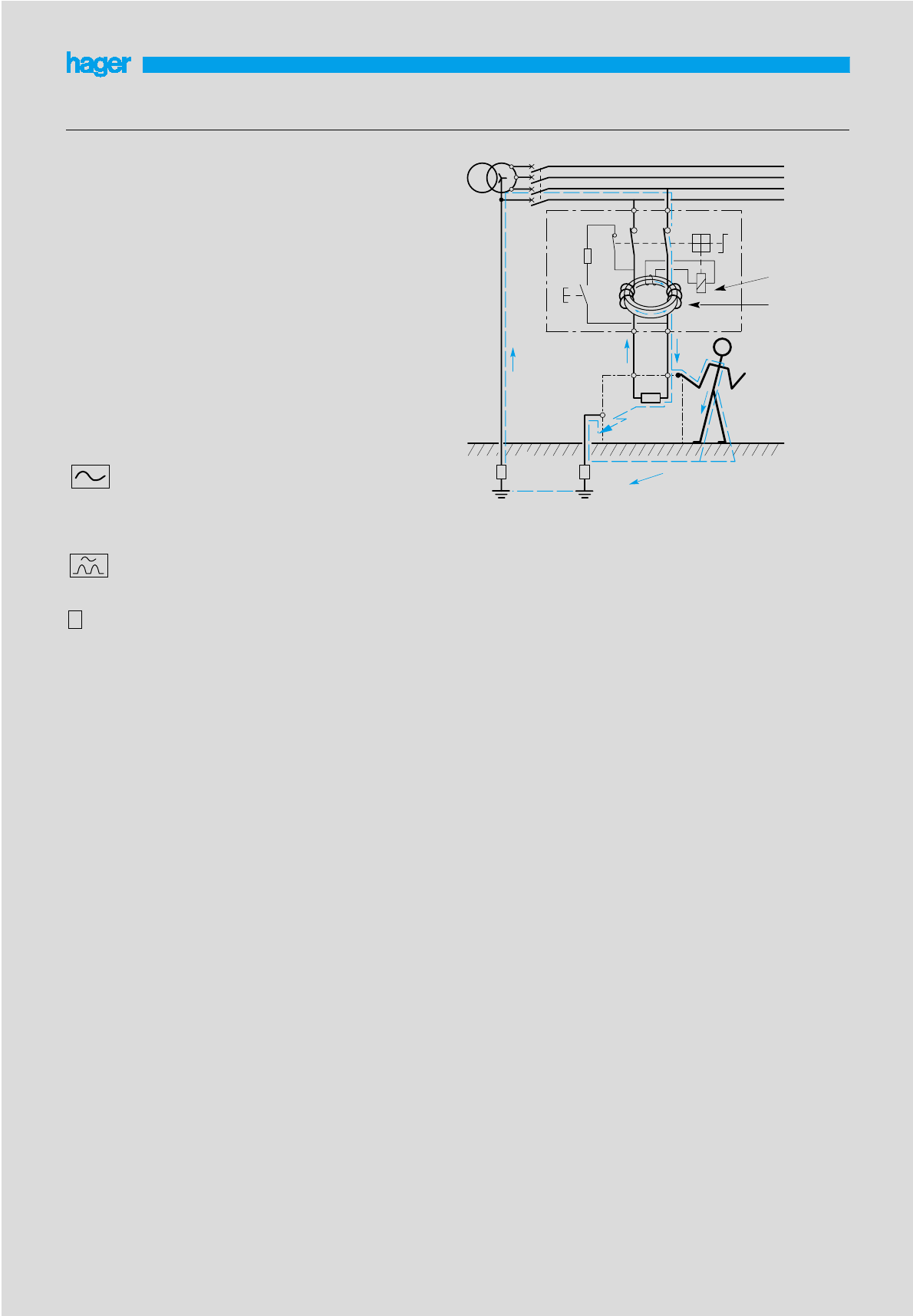
RCCBs
48
Residual current devices
A residual current device (RCCBS) is the generic term for a device
which simultaneously performs the functions of detection of the
residual current, comparison oF this value with the rated residual
operating value and opening the protected circuit when the residual
current exceeds this value.
For fixed domestic installations and similar applications we have two
types :-
• Residual current operated circuit-breaker without integral
over-current protection (RCCB’s) which should comply with the
requirements of IEC 1008
• Residual current operated circuit-breaker with integral
overcurrent protection (RCBO’s) which should comply with the
requirements of IEC 1009
Both RCCB’s and RCBO’s are further divided into types depending
on their operating function :
Type AC For which tripping is ensured for residual sinusoidal
alternating currents, whether suddenly applied or slowly rising.
Marked with the symbol.
Type A For which tripping is ensured for residual sinusoidal
alternating currents and residual pulsating direct currents, whether
suddenly applied or slowly rising . Marked with the symbol.
Type S For selectivity, with time-delay. Marked with the symbol.
RCCB’s must be protected against short-circuits by means of
circuit-breakers or fuses
RCBO’s have their own in built short-circuit protection, up to it’s
rated value
The drawing opposite shows how a torroid is located around the line
and neutral conductors to measure the magnetic fields created by
the current flowing in these conductors. The sum of the magnetic
fields set up by these currents (which takes into consideration both
the magnitude and phase relationship of the currents) is detected by
the torroid.
In a normal healthy circuit the vector sum of the current values
added together will be zero. Current flowing to earth, due to a line
earth fault, will return via the earth conductor, and regardless of load
conditions will register as a fault. This current flow will give rise to a
residual current (Ires) which will be detected by the device.
It is most important that the line and neutral conductors are passed
through the torroid. A common cause of nuisance operation is the
failure to connect the neutral through the device.
RCCBSs work just as well on three phase or three phase and neutral
circuits, but when the neutral is distributed it must pass through the
torroid.
RCCBs are not suitable for use on DC systems and unearthed
networks.
RCCBSs – domestic installation
RCCBs can be installed in two ways:
1. whole house protection.
2. selective protection.
Whole house protection is provided typically by a consumer unit
where the RCCBs device serves as the main switch. Although very
popular this suffers from a disadvantage: all circuits are
disconnected in the event of fault. Selective protection can be
provided by associating the RCCBs with identified high risk circuits
by adopting one or more of the following :
S
Current flowing through torroid in healthy circuit
Ires = I1+I2= 0
Current flowing through torroid in circuit with earth fault I3
Ires = I1+I2+I3= I3
• Split busbar consumer unit:
All circuits are fed via an overall isolator and selected circuits fed
additionally via the RCCBs. Typical circuits fed direct are lighting,
freezer, storage heating: and circuits fed via the RCCBs are socket
outlets, garage circuits. This concept minimises inconvenience in the
event of fault.
• Whole ring circuit
A 30mA device adjacent to the consumer unit, which provides
protection for the downstairs ring circuit, provides an easy
installation with protection for all associated socket outlets. This
represents the best solution for upgrading existing installations.
Nuisance tripping
All Hager RCCBs incorporate a filtering device preventing the risk of
nuisance tripping due to transient voltages (lightning, line
disturbances on other equipment...) and transient currents (from high
capacitive circuit).
Pulsating DC fault current sensitive
Increasingly, semi-conductors are also extensively used in
computers, VDUs, printers, plotters... all of which may be fed from
the mains electrical supply. The presence of semi-conductors may
result in the normal sinusoidal AC waveform being modified. For
example, the waveform may be rectified or, as in asymmetric phase
control devices, the waveform may be chopped. The resulting
waveforms are said to have a pulsating DC component.
In the event of an earth fault occurring in equipment containing
semi-conductor devices, there is a probability that the earth fault
current will contain a pulsating DC component.
Standard type AC may not respond to this type of earth fault current
and the intended degree of protection will not be provided.
Principle
Id
I2
Id
I1
Ic
RB RA
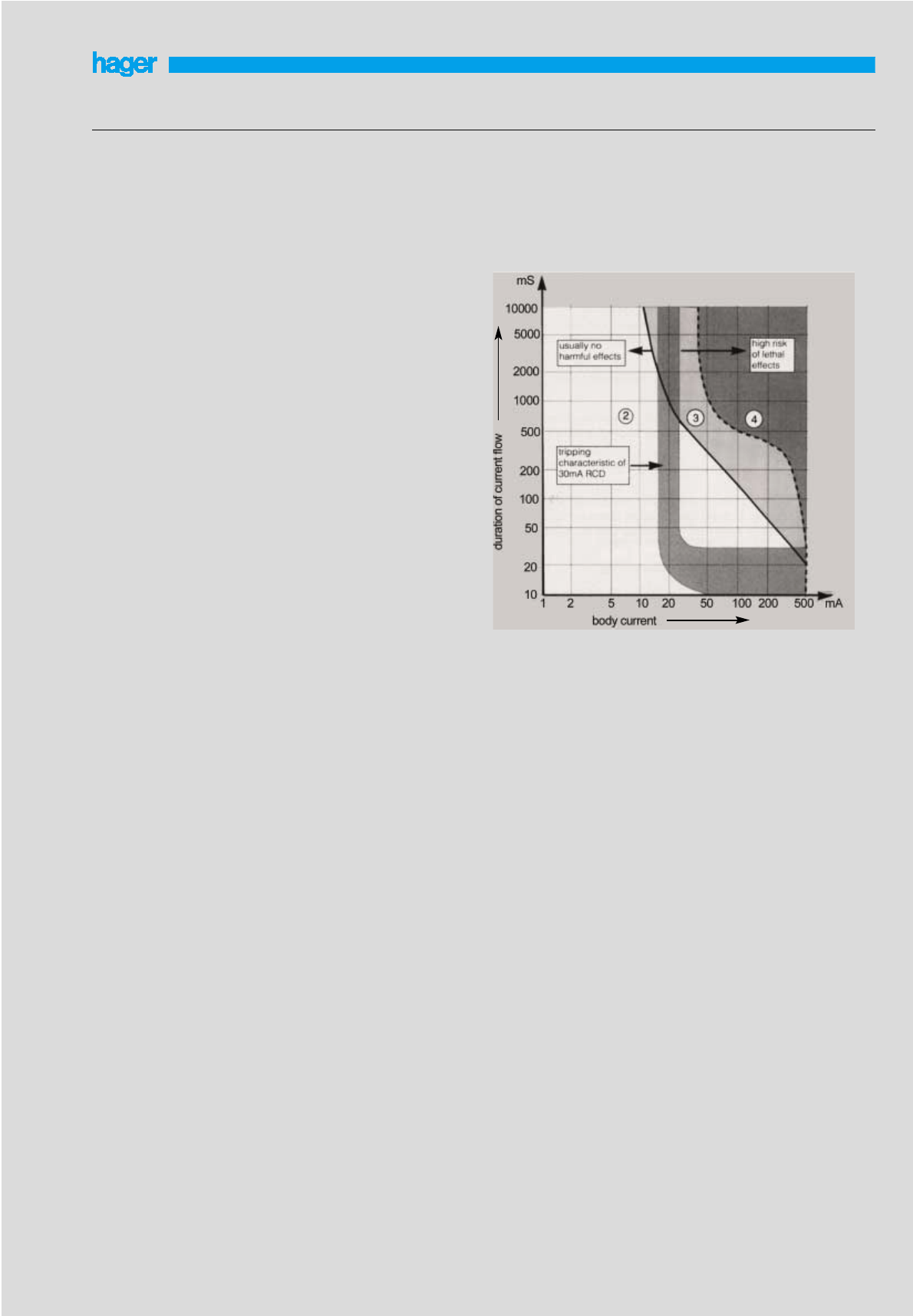
RCCBs
49
Use of RCCBs
RCCBs offer excellent protection against earth fault currents; the
main areas of application being as follows:
• Zs value too high to allow disconnection in the required time
Where the overcurrent protection or a circuit breaker cannot provide
disconnection within the specified time because the earth fault loop
impedance is too high the addition of RCCBs protection may well
solve the problem without any other change in the system. Because
of its high sensitivity to earth fault current and its rapid operating
time, in most cases the RCCBs will ensure disconnection within the
specified time. This is achieved without any detriment to overcurrent
discrimination because, unlike the situation in a fuse based system,
the increased sensitivity is obtained without increasing sensitivity to
overcurrent faults. Use of RCCBs in this way can be particularly
useful for construction sites and bathrooms where disconnection
times are more stringent than for standard installations.
(Construction sites - 0.2s at 220-277V, bathrooms - 0.4s).
The limitation to this technique is the requirement that the rated
residual operating current multiplied by Zs should not exceed 50V.
This is to avoid the danger of exposed conductive parts reaching an
unacceptably high voltage level.
Residual current protection can even be added to a completed
distribution system where the value of Zs is excessive, either
because of a design oversight or subsequent wiring modification.
• Protection against shock by direct contact
So far we have considered shock by indirect contact only.
Direct contact is defined thus:
Direct contact - contact of persons or livestock with live parts
which may result in electric shock. The consideration here is not the
hazard of parts becoming live as a result of a fault but the possibility
of touching circuit conductors which are intentionally live.
RCCBs, although affording good protection against the potentially
lethal effects of electric shock, must not be used as a the sole
means of protection against shock by direct contact. The Electricity
at Work Act recommends the use of RCCBs, “....danger may be
reduced by the use of a residual current device but states that this
should be ”....considered as a second line of defence”. The Wiring
Regulations defines the other measures that should be taken i.e.
- insulation of live parts.
- barriers or enclosures.
- obstacles.
- placing live parts out of reach.
Additionally an RCCB used for this purpose should have:
- a sensitivity of 30mA
- an operating time not exceeding 40mS at a residual current of
150mA.
The specified sensitivity is based on research that has been carried
out to estimate the effect various levels and duration of current can
have on the human body. This experience is summarised in a graph
shown in ‘IEC 479-1: Effects of current passing through the human
body’. A simplified version of this graph is shown. It shows that very
small currents can be tolerated for reasonably long periods and
moderate currents for very short periods. It can be seen, for
instance, that 100mA for 100mS or 20mA for 500mS will not
normally cause any harmful effect. 200mA for 200mS or 50mA for
500mS which are in Zone 3, would be more dangerous; and shock
levels in Zone 4 carry a risk of lethal consequences.
The tripping characteristic for a 30mA RCCBs is also shown in the
graph. It shows the level of current required to cause the RCCBs to
trip, for example; 50mA will cause a trip but not 10mA. Comparing
its characteristic with the various zones on the graph it can be seen
that the 30mA RCCBs gives a very good measure of protection
against the hazards associated with electric shock. Where a higher
level of protection is required, for example in laboratories, 10mA
devices are available.
IEC 479-1
Note :
Although RCCBs are extremely effective devices they must never be
used as the only method of protection against electric shock. With or
without RCCBs protection all electrical equipment should be kept in
good condition and should never be worked on live.
• Protection against shock outside the equipotential bonding
zone
Bonding conductors are used in an installation to maintain
metallic parts, as near as possible, to the same potential as earth.
Working with portable equipment outside this equipotential
bonding zone, e.g. in the car park of a factory, introduces
additional shock hazards. Socket outlets rated 32A or less
‘which may be reasonably expected to supply portable
equipment for use outdoors’ should have at least one socket
nominated for outdoor use. This socket should be equipped with
RCCBs protection unless fed from an isolating
transformer or similar device, or fed from a reduced voltage.
• Protection in special situations
The use of RCCBs is obligatory or recommended in the following
situations:
- caravans: 30mA RCCBs should be used.
- TT systems.
- swimming pools: 30mA RCCBs for socket outlets in Zone B
obligatory; recommended in Zone C.
- agricultural and horticultural: 30mA RCCBs for socket outlets
and for the purpose of protection against fire,
RCCBS ≤0.5A sensitivity.
- construction sites: 30mA RCCBs recommended.
• Portable equipment
With the exception mentioned above, where a socket is
specifically designated for work outside the equipotential bonding
zone, the Wiring Regulations demand the use of RCCBs to pro-
tect the users of portable equipment. It is widely recognised that
their use has made a significant contribution to safety in the
workplace and the home.
• Protection against fire hazards
The provisions in the Wiring Regulations for protection against
shock by indirect contact ensure rapid disconnection under earth
fault assuming the fault has negligible impedance. Under such
conditions the fault current, as we have seen, is sufficiently great
to cause the overcurrent protection device to quickly disconnect
the fault. However high impedance faults can arise where the
fault current is sufficient to cause considerable local heat without
being high enough to cause tripping of the overcurrent protective
device. The heat generated at the point of the fault may initiate a
fire long before the fault has deteriorated into a low impedance
connection to earth.
The provision of residual current protection throughout a system or
in vulnerable parts of a system will greatly reduce the hazard of fire
caused by such faults.
• PEN conductors
The use of RCCBSs with PEN conductors is prohibited. A PEN
conductor is a single conductor combining the functions of
neutral conductor and protective conductor. This being so, when
the PEN conductor is taken through the torroid of an RCCBS,
earth faults will go undetected because the return path for the
earth fault current is included in the residual sum.
• Auxiliary contacts
A range of auxiliaries, alarm and shunt contacts are available for
Hager RCCBs.
• Supply entry
Top or bottom feed.
CB/RCCBs co-ordination
With MCB’s
Short circuit MT MU MC NC ND
RCCBs current capacity 6-63A 6-63A 0.5-63A 0.5-63A 1-63A
of the RCCBS only BCCCD
2 poles
16A 1500A 6kA 6kA 6kA 10kA 6kA
25A 1500A 6kA 6kA 6kA 10kA 6kA
40A 1500A 6kA 6kA 6kA 10kA 6kA
63A 1500A 6kA 6kA 6kA 10kA 6kA
80A 1500A 6kA 6kA 6kA 10kA 6kA
4 poles
16A 1500A 6kA 6kA 6kA 6kA 4.5kA
25A 1500A 6kA 6kA 6kA 6kA 4.5kA
40A 1500A 6kA 6kA 6kA 6kA 4.5kA
63A 1500A 6kA 6kA 6kA 6kA 4.5kA
80A 1500A 6kA 6kA 6kA 6kA 4.5kA
100A 1500A 6kA 6kA 6kA 6kA 4.5kA
RCCBs
50
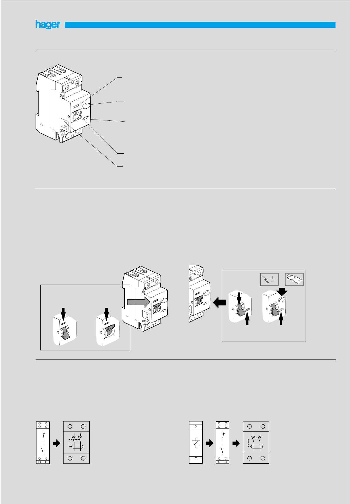
RCCBs
51
Product presentation
Test
contact position indicator
“Test” button
(large dimensions)
trip indication
ergonomic operating
handle
side mounting of auxiliary
Contact positioning indicator
The mechanical indicator on the front of RCCB shows the physical
position of the contacts.
- Red indication for closed contacts
- Green indication for open contacts
The green indication is the guarantee that the contacts are open and
that the terminals are not live.
Trip indicator
The status of the RCCB can be visualised by the colour of the trip
indicator in addition to the position of the operating lever.
- Grey indication for normal conditions (even when operating lever is
in ON/OFF position)
- Yellow indication for tripped condition, operating lever in OFF
position.
Similar condition exists when TEST button is pushed or RCCB is
remotely tripped via protection auxiliaries.
Test
Test
Test
Test
OFF
green ON
red
grey yellow
OFF
Mounting of auxiliaries
Iit is possible to mount two auxiliaries on RCCB.
- Auxiliary CZ 001 for ON/OFF status and TRIP indication is mounted
first on the left hand side of the RCCB.
- Additional protection auxiliary MZ 203 to MZ 206 can be mounted
besides CZ 001.
Positive contact indication
Auxiliaries association possibilities
Earth leakage fault indication
CZ 001
(CA+SD) MZ 203... + CZ 001
MZ 206 (CA+SD)

52
operating temperature -10 to +55 °C
storage temperature -25 to +70 °C
Technical specifications
Earth Leakage relays
non adjustable earth leakage relays adjustable earth leakage relays
Electrical connections
HR 400 HR 402 HR 410 HR 420 HR 425
power supply voltage 50/60 Hz 230 V ± 20%
controlled main voltage 50/60 Hz 50 to 700 V
imput power 3 VA 5 VA 5 VA
control output inverter free of potential
breaking capacity (standard output, 6 A / 250 V AC1
positive security, pre-alarm 50%)
sensitivity In 0,03 A 0,3 A 0 / 0,03 A / 0,1 A / 0,3 A / 0,5 A / 1 A / 3 A / 10 A
tripping (± 20%) instantaneous instantaneous; delayed 0,1 s / 0,3 s / 0,4 s / 0,5 s / 1 s / 3 s
memory storage of default by “reset” button
acceptable overload at torroid level 30 kA / 100 ms
relay connect. : cage terminals rigid 1,5to 4
flexible 1to 2,5
connect. torroid rigid 1,5to 4
flexible 1to 6
max. length of torroid/relay connection 50 m maxi with twisted cables of 1,5 mm- 25m non twisted cable
Product presentation
N
L1 L2 L3
test reset
11 12 13 14
1234
15 16 18 19 20
5 6
HR425
11 12 13 14
1234
15 16 18 19 20
5 6
On
5
15
30
45
60
75
Test Reset
∆t(s)
0
0,1
0,3
0,4 0,5 1 3
I∆n(A)
0,03
0,1
0,3
0,5 1 3 10
4
7
5
3
6
1
2
8
9
10
11
10
NPh N
main characteristics
➀“reset” button : in case of tripping, output remains switched and
return to normal position is obtained either :
- by pressing the “reset” clear pushbutton
- or cutting off the power supply
➁“test” button : pressing the “test” button allows a fault simulation
which operates the relay and the output contacts.
➂fault signal LED : switched on when a fault is detected, intermit-
tent light when break in connection relay/core.
➃power indicator :
indicates well working of product.
➄In selector : 0,03 / 0,1 / 0,3 / 0,5 / 1 / 3 / 10 A
➅time delay selector t : 0 / 0,1 / 0,3 / 0,4 / 0,5 / 1 / 3 s (± 20 %)
➆standard output (1 OF) : tripping at 85 % of In ± 15 %
goes from 0 to 1 when :
- failure of the torroid/core connection,
- fault current in the monitored installation.
➇positive safety outlet (1 OF) :
switching to state 1 : by switching on of the power :
- switching to state 0 : failure of the torroid/relay connection,
- fault current in installation,
- fault supply or fault on internal relay.
➈safety output (1 F) : contact closes at 50 % of In (± 15 %)
➉remote test and reset
optical scale display : indicates permanently the value of leakage
current, 5 to 15 %, 15 to 30 %, 30 to 45 %, 45 to 60 % and 60 to 75 %
de In.
sealable settings : a sealable cover prevents interference once
the settings have been made.
11
voltage of test and reset buttons 100 to 250 V
max. length of test/reset connection 200 m
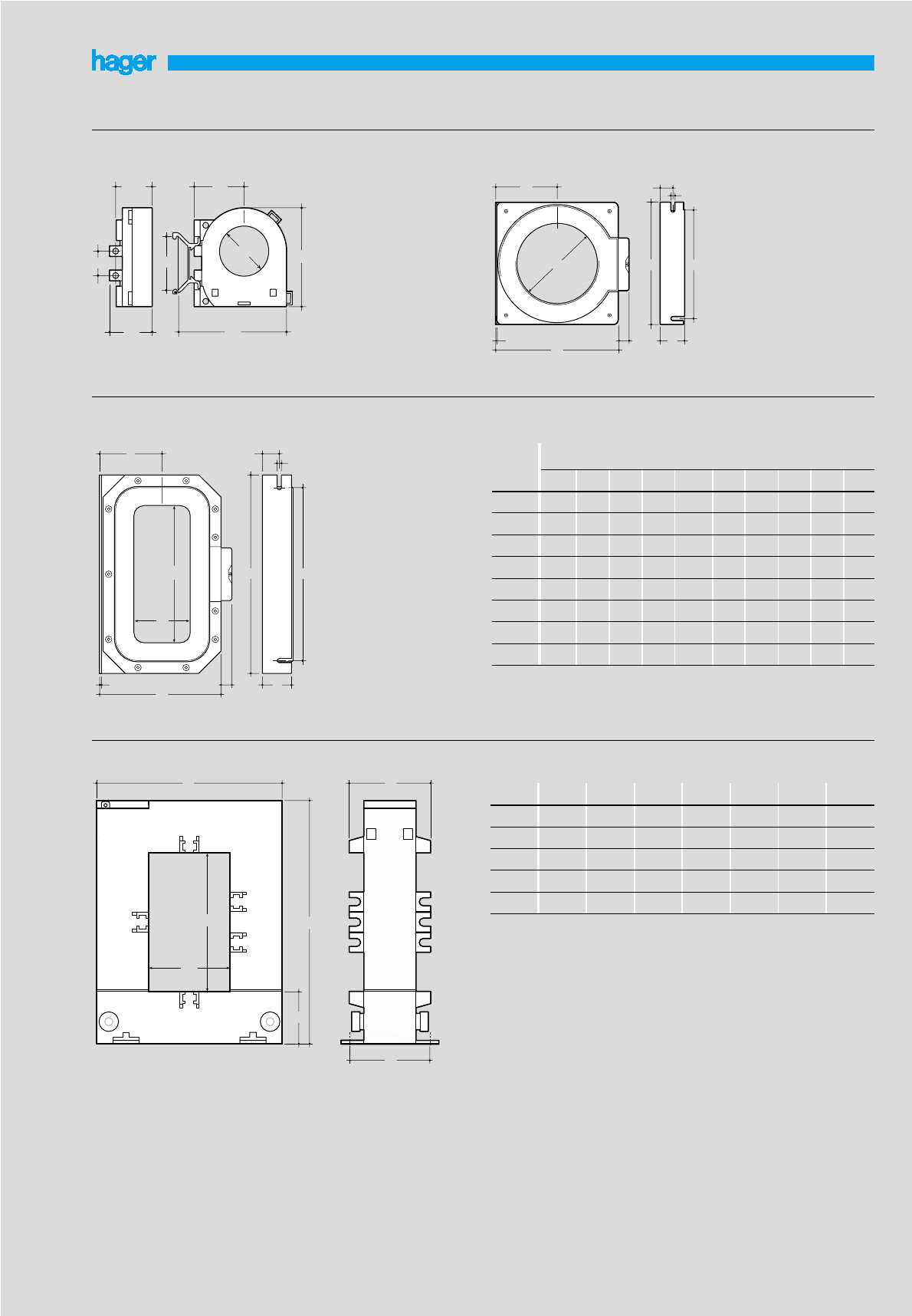
53
86
refe-
rences
Rectangular torroids : Dimensions for circular and rectangular torroids
HR 830, HR 831, HR 832
Torroids for earth leakage relays
Circular torroids:
HR 800 HR 801 to HR 805
16
24,5 34
29 74
65
30
35
A1 A2 B C D E F G H
HR 801 - - 92 43,5 74 17 32,5 5,5
HR 802 - - 115 118 60,5 97 17 32,5 5,5
HR 832 150 350 460 270 140 415 28 48 8,5
A2
A1
B D
EC
F
C
1,5
A
14
DFH
BE
G
C
A1
A2
2,5 14 G
EB
DH
F
HR 803 - - 158 162,5 84,5 140 15 32,5 5,5
HR 804 - - 202 203 103,5 178 21 32,5 7,5
HR 805 - - 290 295 150 265 23 32,5 7,5
HR 830 70 175 260 162 85 225 22 40 7,5
HR 831 115 305 400 225 116 360 25 48 8,5
A
ø 105
ø 35
ø 70
-
ø 140
ø 210
-
-
size (en mm)
Opening rectangular torroids : Dimensions for opening rectangular torroids
A1 A2 B C D E F
HR 820 20 30 89 110 41 32 46
HR 821 50 80 114 145 50 32 46
HR 822 80 80 145 145 50 32 46
HR 823 80 121 145 185 50 32 46
HR 824 80 161 184 244 70 37 46

54
Torroids for earth leakage relays
Torroids capacity
on copper
cables
Ø torroid
inside
U 1000 R2V
cable
single pole
U 1000 R2V
cable
single pole
U 1000 R2V
cable
2 poles
U 1000 R2V
cable
4 poles
U 1000 R2V
cable 4 pole
partially stripped
multipole
U 1000 R2V
cable 2 pole
partially stripped
multipole
30 4 x 162 x 5035353550
35 4 x 252 x 7035503570
70 4 x 1852 x 400ou 4 x 1503524035300
105 4 x 5002 x 630 ou 4 x 1853530035300
140 4 x 6302 x 630 ou 4 x 2403530035300
210 4 x 6302 x 630 ou 4 x 2403530035300
70 x 175 4 x 6302 x 630 ou 4 x 2403530035300
115 x 305 4 x 6302 x 630 ou 4 x 24035300300
150 x 350 4 x 6302 x 630 ou 4 x 2403530035300
20 x 30 4 x 162 x 7035103516
50 x 80 4 x 2402 x 630 ou 4 x 1853512035150
80 x 80 4 x 5002 x 630 ou 4 x 1853530035300
80 x 120 4 x 6302 x 630 ou 4 x 2403530035300
80 x 160 4 x 6302 x 630 ou 4 x 2403530035300
tore tore tore tore tore tore
35
on copper
cables
Ø torroid
inside
H07 V - U
1 pole H07 V - U
1 pole
30 4 x 352 x 70
35 4 x 502 x 95
70 4 x 2402 x 400ou 4 x 185
105 4 x 4002 x 400 ou 4 x 240
140 4 x 4002 x 400 ou 4 x 240
210 4 x 4002 x 400 ou 4 x 240
70 x 175 4 x 4002 x 400 ou 4 x 240
115 x 305 4 x 4002 x 400 ou 4 x 240
150 x 350 4 x 4002 x 400 ou 4 x 240
20 x 30 4 x 102 x 35
50 x 80 4 x 1852 x 240
80 x 80 4 x 4002 x 400 ou 4 x 240
80 x 120 4 x 4002 x 400 ou 4 x 240
80 x 160 4 x 4002 x 400 ou 4 x 240
tore tore
HR 800
HR 801
HR 802
HR 803
HR 804
HR 805
HR 830
HR 831
HR 832
HR 820
HR 821
HR 822
HR 823
HR 824
HR 800
HR 801
HR 802
HR 803
HR 804
HR 805
HR 830
HR 831
HR 832
HR 820
HR 821
HR 822
HR 823
HR 824

55
SPDs
Installation example
500 mA
S
D.B.
32 A max.
SPN 208S
SPN 408S
C1
F
SPN 504
SPN 505
L1
Some installation rules for SPDs
- General SPD protects the whole installation by flowing the lightning
current out to the earth. Fitted in directly dowstream the type S diffe-
rential function or delayed for system TT and TN-S.
- The cable length L1 must be reduced to less than 0,5m
- The resistance of the earth connection must be weakest possible
(approx. 10 Ω) and only one is requested by installation,
- SPDs SPN 208S and SPN 408S protect very sensitive devices of
class I and class II.
- A cable length of at least 1m is requested between general and
secondary SPD to ensure a minimum impedance in order to avoid
the simultaneous bringing into conduction of both SPDs,
- SPDs SPN 504 and SPN 505 protect analog or digital telephone
lines from very sensitive receivers.
sensitive equipment very sensitive equipment class I or class II
N.b. : when SPD is fitted downstream of differential system, the
system should preferably be selectif to avoid inopportune setting
of.
Choice of disconnection device
The choosen device is an MCB
Selection chart for disconnection device according to the SPD
type
Distressing of SPD
Successive discharging of current due to lightning reduces progressi-
vely the performance of SPD’s, with the consequence of a possible
short circuit for the installation.
For this reason, all our SPDs are fitted with an automatic thermic and
dynamic disconnection device
LED on front indicates the good working of the device :
- for normal version :
green = OK red = replacement
- for version with reserve indicator :
green = OK yellow = caution red = replacement
- for version with electric LED for SPDs for fine protection
green = OK LED off = replacement
general SPD C1 (1)
SPN 265R
SPN 465R 32 A curve C
SPN 140C
SPN 240R - SPN 240D
SPN 440R - SPN 440D
32 A curve C
SPN 215R - SPN 215D
SPN 415R - SPN 415D 32 A curve C
(1) The breaking capacity of MCB must be choosen according to the
short circuit intensity at the head of the installation and according to
the number of poles (1,2 or 4)
general SPD
with plug on
cartridge
telephone line
Warranty
Warranty can not be applied for SPDs as their life expectancy
depends on the perturbation level absorbed to protect the electric
installation.

56
SPDs with plug in cartridge
Presentation of 1 pole and multi pole SPDs :
available in two versions :
- base with an auxiliay contact and cartridges with reserve indicator
- base without auxiliary contact and cartridges with end of life LED
On the front of the cartridge, a mechanical LED indicates the state of
SPD
Surge protective devices
OK
base
plug in
cartrige
with reserve indicator
end of life LED
end of life
LED
Keying system for fitting of neutral and phase cartridge
111412
11 14 12
11 14 12
Auxiliary contact for signalling transfert
2 poles or
4 poles base
Neutral plug in cartridges can not be fitted in slots for phase
cartridges and visa versa
auxiliary contact mini
connection capacity maxi 0,5 mm
1,5 mm
remote signalling voltage
ominal current 230 V250 V ...
1 A 0,1 A
auxiliary contact
reserve
indicator
Connection diagrams
Single pole SPDs : SPN 140C
protection only in common mode
PEN
L
d1
d2
PEN
L1 L2 L3
IT / TN-C
d1 + d2 ≤50 cm
PE
N
d1
L
N
L1
L2
L3
PE
TT / TN-S
Multi pole SPDs : SPN 215D ... SPN 465R
protection is assured in both common and differential modes without adding
devices
d1 ≤50 cm
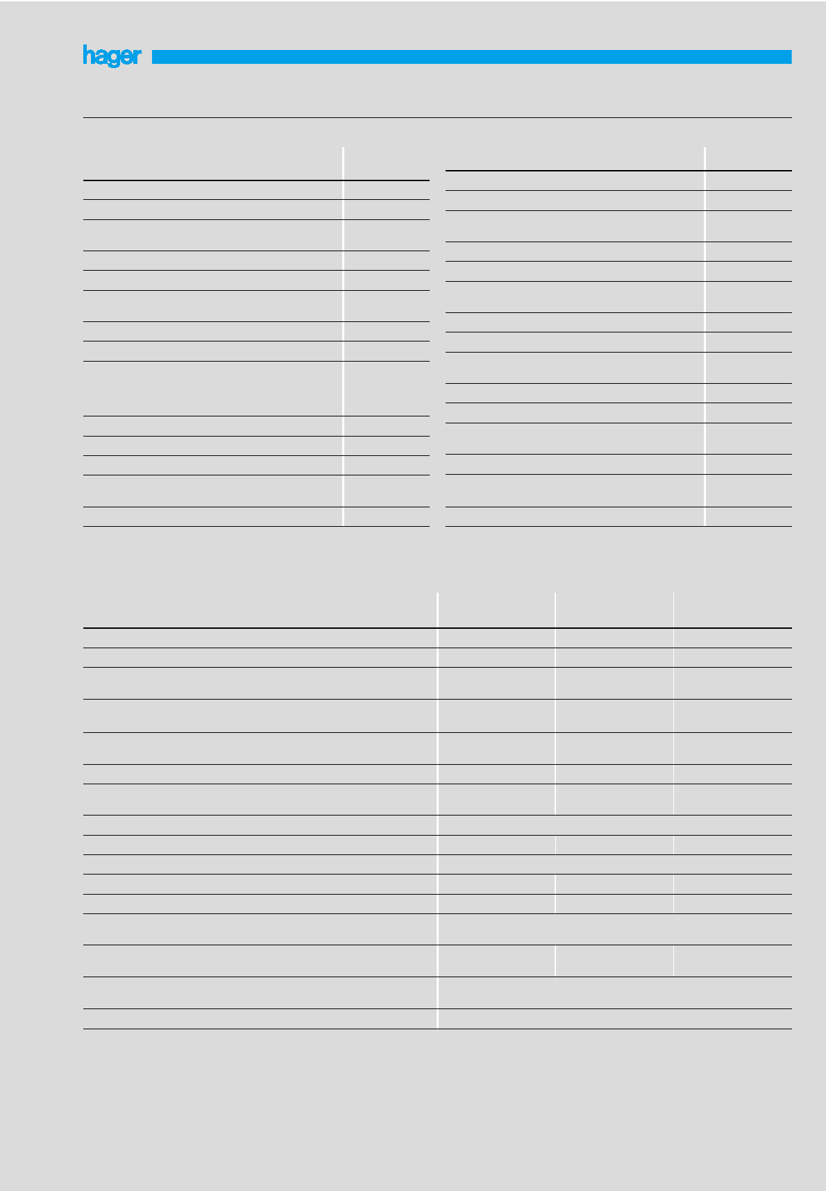
57
Surge protective devices
Technical characteristics of single pole SPDs
références SPN 140C
installation exposure level (risk medium
installation of SPDs in parallel
nominal voltage Un
frenquency 230 V
50/60 Hz
Max. continuous operating voltage Uc 440 V
voltage protection level Up 2 kV
discharge current capacity nominal current In
8/20 µs wave max. current Imax 15 kA
40 kA
degree of protection IP 20
short circuit resistance Icc (MCB - curve C) 20 kA - 32 A
temperature working
storage -20 à + 60°C
-40 à +70°C
end of live LED SPN 140C
reserve indicator + auxiliary contact -
domestic building collective/individual
industrial/commercial yes
yes
earthing systems IT, TN-C
max. connection capacity flexible
(Ph, N, E) rigid 25 mm
35 mm
screw head PZ2
technical characteristics of multipole SPDs
references SPN 265R-SPN 465R SPN 240R, SPN 440R
SPN 240D, SPN 440D SPN 215R, SPN 415R
SPN 215D, SPN 415D
installation exposure level (risk) very high medium low
installation of SPDs in parallel in parallel in parallel
nominal voltage Un
frenquency 230/400 V
50/60 Hz 230/400 V
50/60 Hz 230/400 V
50/60 Hz
Max. continuous operating voltage Uc between Phase / Neutral
between Neutre / PE 255 V
275 V 255 V
275 V 255 V
275 V
protection mode common
differential yes
yes yes
yes yes
yes
voltage protection level Up 1,5 kV 1,2 kV 1,0 kV
discharge current capacity nominal current In
8/20 µs wave maxial current Imax 20 kA
65 kA 15 kA
40 kA 5 kA
15 kA
degree of protection IP 20
short circuit resistance Icc (MCB - curve C) 20 kA - 32 A 20 kA - 32 A 10 kA - 32 A
working temperature -40°C à +60°C
end of life LED - SPN 240D - SPN 440D SPN 215D - SPN 415D
reserve indicator + auxiliary contact SPN 265R - SPN 465R SPN 240R - SPN 440R SPN 215R - SPN 415R
domestic buildings collective / individual
industrial / commercial yes
yes
earthing systems TT
TN - S TT
TN - S TT
TN - S
connection capacity flexible
(Ph, N, E) rigid 25 mm
35 mm
screw head PZ2
references SPA 212A
SPA 412A
installation exposure level (risk) very high
installation of SPDs in parallel
nominal voltage Un
frequency 230 V
50/60 Hz
Max. continuous operating voltage Uc 255 V
voltage protection level Up 2,5 kV
protection mode common
differential
shock current Iimp 12,5 kA
disconnection value Ifi 12,5 kA
resistance to short-circuit Icc alone
with associated protect°
of max. 125 A in series
or 315 A in parrallel
12,5 kA
25 kA
working temperature -40 à + 60 °C
end of life LED yes
earthing systems TT - TNS
max.connection capacity flexible
rigid 25 mm
35 mm
screw head PZ3
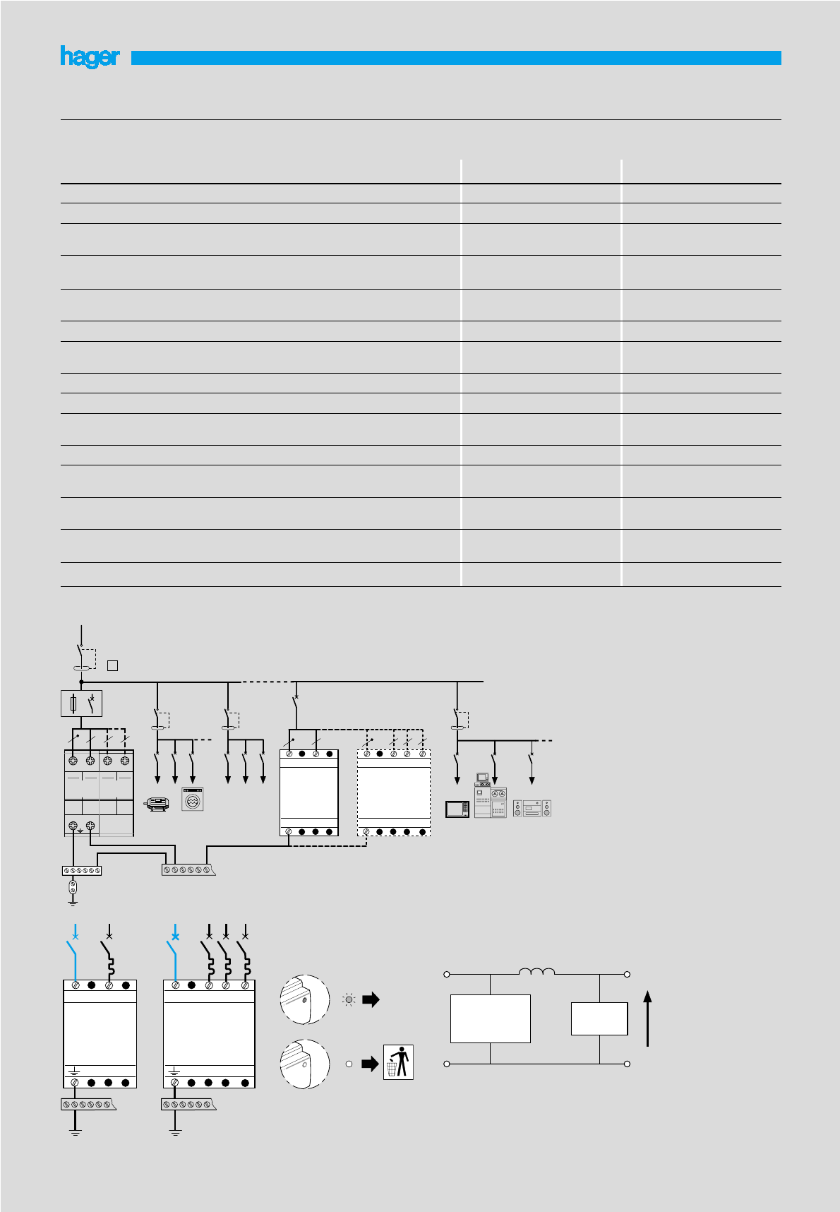
NL
NL
SPN 208S
32
A
NL1 L2
NL1
L3
SPN 408S
L2 L3
32
A
OK
58
Surge protective devices
references SPN 208S SPN 408S
installation exposure level (risk) low low
installation of SPDs in parallel in parallel
nominal voltage Un
frequency 230 V
50/60 Hz 230/400 V
50/60 Hz
Max. continuous operating voltage Uc between N / PE
between Phase and Neutral 255 V
255 V 255 V
255 V
protection mode common
differential yes
yes yes
yes
voltage protection level Up 1,0 kV 1,0 kV
discharge current capacity nominal current In
8/20 µs wave maximal current Imax 2 kA
8 kA 2 kA
8 kA
degree of protection IP 20 IP 20
short ciruit resistance Icc (with fuse or associated MCB) 6 kA - 32 A 6 kA - 32 A
temperature working
storage -25°C à +40°C
-25°C à +40°C -25°C à +40°C
-25°C à +40°C
well functioning indicator green LED green LED
domestic buildings collective / individual
industrial / commercial yes
yes yes
yes
earthing systems TT, IT,
TN - S TT, IT,
TN - S
connection capacity flexible min./max.
(Ph, N, E) rigid min./max. 2,5/6 mm
6/10 mm
2,5/6 mm
6/10 mm
Technical characteristics of secondary SPDs (fine protection)
screw head PZ1
SPDs SPN 208S and SPN 408S
PE
NL1L2L3
SPN 2xxx SPN 4xxx
15 / 90 A
500 mA
S
PE
F1 C1 C2
NL
SPN 208S
PE
NL1 L2 L3
SPN 408S
PE
SPN 208S
SPN 408S Up = 800 V
SPN x 15 kA x
SPN x 40 kA x
SPN x 65 kA x
N
L
Coordination : between main SPD and secondary level SPDs, this
coordination allows to reduce the protection level Up to ≤800 V

59
Surge Protective devices
Technical characteristics of the SPDs for telephone line
references SPN 504 SPN 505
applications
surge protective device digital line (Numéris, RNIS,
ISDN...) analog line
digital line
ISDN, RNIS
installation of SPDs in series in series
analog line
ingress protection IP 10 IP 10
nominal voltage Un 5 V / 40 V 130 V
maximum continious operating voltage Uc 7,5 V / 60 V 170 V
voltage protection level Up 600 V 600 v
voltage protection level common mode
differential mode yes
yes yes
yes
series impedence 1,0 Ω4,7 Ω
discharge current wave In (total)
In (line) 10 kA
5 kA 5 kA / 10 kA (RJ 45 / vis)
2,5 / 5 kA (RJ 45 / vis)
working temperature -40°C + 60°C -40°C + 60°C
connection in
out screw
screw / RJ 45 screw / RJ 45
screw / RJ 45
connection capacity flexible min./max.
(Ph, N, T) rigid min./max. 0,08 mm
2,5 mm
0,08 mm
2,5 mm
Electrical connection
SPN 504 SPN 505
PE
SPN 504
a1a2 b1 b2
a1a2 b1 b2
IN
OUT
wire
wire RJ45
RJ 45
PE
or
SPN 504SPN 504
ININ
or
a2 a1 b1 b2
OUT
a2 a1 b1 b2
cables
cables
PE
a1 b1
a1 b1
IN
OUT
RJ45
RJ45
or
or
SPN 505SPN 505
cables
cables
V1
A1
a1 b1
a1 b1
12345678
12345678
R1 R2
a1
A2
V1 V2 V3 V4
V5
A1
b1
a2 b2
a1 b1
a2 b2
12345678
R1 R2 R3 R4

60
● under voltage release : MZ 528N 230 V, MZ 529N 400 V
maintain voltage 0,85 x Un
fall voltage 0,7 à 0,35 x Un
Auxiliaries
● auxiliary contacts 1O + 1F : MZ 520N
7200
1200
600
300
120
60
40
20
10
5
2
1
0,2
0,05
0,02
0,005
0,002
1 1,5 2 3 4 6 8 10 15 20 30
14
Electrical characteristics
- electrical supply : 230 V / 400 V
- ambiant temperature range : from -25 to +55 °C
- working life : 100 000 operations - categorie : AC3
- maximum : 40 operations / hour
- tropicalized : normale all climates (TC)
- connection capacity :
flexible wire : from 1 to 4rigid wire : from 1,5 to 6
- insulation voltage : 6000 V
- frequency : 40 - 60 Hz
Single phase connection diagram
Motor starters
tripping curve
M
2
M
2
M
2
Breaking capacity
U <
13 21
14 22
multiple of Ir ➝
t (s) ➝
Ph
N
change state on
short-circuit
(magnectic tripping)
change state on overload
and short-circuit (magnetic
and thermic tripping)
230 V 3,5 A
400 V 2 A
230 - 400 V 1 A
● cauxiliary contacts 1 F : MZ 522N
● default signal contact 2 F : MZ 527N
● release : MZ 523N
230 V
de 0,7 à 1,1 Un
230 V 400 V 230/400 V
+ fuse gl
MM 501N
MM 502N
MM 503N
MM 504N
MM 505N
MM 506N
MM 507N
MM 508N
MM 509N
MM 510N
100 kA 100 kA 100 kA
MM 511N
MM 512N
MM 513N
16 kA 16 kA 50 kA
●waterproof enclosure IP 55 : MZ 521N
allows to control the motor starter via external rotary handle
●emergency stop button : MZ 530N
- synchronized
- synchronized unlocking by key : MZ 531N
allows the emergency stop of motors by tripping auxiliary
connected to MCB . (MZ 523N - MZ 528N - MZ 529N)
Connection of auxiliaries (without tool)
2
3
Clic !
1
OFF
2
Clic !
1
1
OFF
2
13
14
13
14
23
24

61
AUSTRIA :
Hager Electro Ges. m. b. H.
Dieselgasse, 3
2333 Leopoldsdorf / AUSTRIA
Tel. (43) 02235 / 44600
Fax (43) 02235 / 44545
BELGIUM :
S.A. Hager Modulec N.V.
Boulevard Industriel 61
BRUXELLES 1070 / BELGIUM
Tel. (32) 2 529 47 11
Fax (32) 2 527 12 61
CZECH REPUBLIC :
Hager Electro s.r.o.
Podebradská 186/56
18066 Praha 9 - Hloubetin
CZECH REPUBLIC
Tel. (42) 02 66 10 73 08
Fax (42) 02 66 10 73 10
CYPRUS :
N.P. LANITIS LTD
106 Gladstonos Street
3032 LIMASSOL
CYPRUS
Tel. (357)-25 819030
Fax (357)-25 819075
e.mail : info@nplanitis.com
DENMARK :
ELPEFA A/S
Postbox 180
2670 GREVE / DENMARK
Tel. (45) 43 95 95 95
Fax (45) 43 95 95 90
ESTONIA :
Hager Süsteemid OÜ
Türi 10d
11313 TALLINN
Tél. +372 655 61 46
Fax +372 655 61 68
FINLAND :
URHO TUOMINEN Oy
Palopellonkatu 7 - PL 33
04250 KERAVA / FINLAND
Tel. (358) 9 274 6411
Fax (358) 9 274 641 41
IRELAND :
Hager Nolan Ltd
Techna House
Terenure Road East
DUBLIN 6 / IRELAND
Tel. (353) 1 - 490 6611
Fax (353) 1 - 490 1274
ITALY :
Hager Lume S.p.A.
Via Battistotti Sassi n. 11
20133 MILANO / ITALY
Tel. (39) 02 70 10 74 40
Fax (39) 02 70 10 74 30
LATVIA :
SIA Hager Sistémas
Bauskas 58
1004 RIGA
Tél. +371 780 86 80
Fax +371 780 86 81
LITHUANIA :
Hager Polo UAB
Laisves pr 77
2600 VILNIUS
Tél. +370 5 274 28 27
Fax +370 5 274 28 38
MALTA :
International Trading Co.
White House Buildings
Mountbatten Street
BLATA L-BAJDA / MALTA
Tel. (356) 21 2402 91
Fax (356) 21 2431 86
http://www.itc-malta.com
NETHERLANDS :
Hager Electro b.v.
Larenweg 36
5234 KA’s Hertogenbosch
NETHERLANDS
Tel. (31) 73 6428 584
Fax (31) 73 6442 674
NORWAY :
Hager Systemer A/S.
Industriveien 8b
Postboks 391
1473 SKÅRER / NORWAY
Tel. (47) 67 97 50 11
Fax (47) 67 97 20 55
FRANCE :
Hager Electro S.A.
132, Bld d’Europe
B.P. n° 3
67215 OBERNAI Cedex
FRANCE
Tel. (33) 03 88 49 50 50
Fax (33) 03 88 49 50 03
GERMANY :
Hager Electro GmbH
Im Hofgarten
66131 SAARBRÜCKEN
GERMANY
Tel. (49) 68 93 94 50
Fax (49) 68 93 94 53 76
Hager Electro GmbH
Zum Gunterstal
66440 BLIESKASTEL
GERMANY
Tel. (49) 68 42 94 50
Fax (49) 68 42 94 56 76
GREAT BRITAIN :
Hager Ltd
Hortonwood 50
TELFORD, Shropshire
TF1 4FT / U.K.
Tel. (44) 1952 - 677 899
Fax (44) 1952 - 670 271
http://www.hagergroup.com.uk
GREECE :
Hager Hellas
lapetou Street 33
11364 ATHENS / GREECE
Tel. (30) 1 864 50 90
Fax (30) 1 865 09 56
HUNGARY :
Hager Kft
Aradi utca 16
1043 BUDAPEST
Tél. +361 36 95 689
Fax +361 36 93 601
ICELAND :
Johan RÖNNING Hf
Sundaborg 15
104 REYKJAVIK / ICELAND
Tel. (354) 5 20 08 00
Fax (354) 5 20 08 88
POLAND :
Hager Polo Sp.zo.o.
ul. Domaniewska 39A
02-672 WARSZAWA
Tél. +48 22 640 28 80
Fax +48 22 640 28 81
PORTUGAL :
Hager SEM SA
(Sistemas Electricos Modulares)
Estrada para Polima
Complexo Meramar
Armazem C
Abóboda
2775 PAREDE / PORTUGAL
Tel. (351) 21 445 84 50
Fax (351) 21 445 84 54
RUMANIA :
Hager Romania SRL
B-dul Precizei 32, Sect. 6
cod 062204
BUCURESTI Romania
Tél. +40 21 434 09 37
Fax +40 21 434 16 60
SPAIN :
Hager Sistemas S.A.
Paratge Coll-Blanc s/n
Apartado 39
08430 LA ROCA DEL VALLES
SPAIN
Tel. (34) 902 42 2232
(34) 93 842 4730
Fax (34) 93 842 2132
SWEDEN :
Hager Elektro AB
Box 9040
400 91 GÖTEBORG / SWEDEN
Tel. (46) 31 706 39 00
Fax (46) 31 706 39 50
SWITZERLAND :
Hager Tehalit AG
Moosweg 8,
Postfach 431
8501 FRAUENFELD
SWITZERLAND
Tel. (41) 052 723 24 00
Fax (41) 052 723 24 05
Hager worldwide - Europe

62
Hager worldwide - Overseas
AUSTRALIA
Hager B&R Ltd
Unit 14 Riverside Centre
148 James Ruse Drive
(cnr River Road West)
North Parramatta NSW 2150
AUSTRALIA
Tel. (61) 2 - 9687 0077
Fax (61) 2 - 9687 0011 or 22
http://www.hagergroup.com.au
BAHRAIN, KUWAIT, OMAN,
QATAR, SAUDI ARABIA, U.A.E.,
IRAN, EGYPT, PAKISTAN,
AFGHANISTAN, IRAK and
INDIA
Hager Tehalit Systems
M.E. FZE
POB 61056
JEBEL ALI
DUBAI / U.A.E.
Tel. (971) 4 - 883 63 64
Fax (971) 4 - 883 79 93
e-mail : htsme@emirates.net.ae
http://www.hagergroup.com.ae
CHINA
Hager Beijing Office
N° 308, He Qiao Building
8A Guang Hua Road
Chaoyang District
100026 BEIJING / CHINA
Tel. (86) 10-6503 5170
Fax (86) 10-6503 5173
EGYPT
M.B. for Engineeering &
Contracting
10, Omar Ebnel Khattab Street
Dokky, Giza
EGYPT
Tel. (20) 2-3375283/7490592
Fax (20) 2-7490592
e-mail : tbshalaby@link.net
ERITREA
Electrolight Pvt. Ltd.
PO Box 4642
ASMARA / ERITREA
Tel. (291) 1 121265
Fax (291) 1 126759
e-mail : elelight@gemel.com.er
GHANA
Grand Pacific Ltd.
PO Box 140
KORLE-BU
ACCRA / GHANA
Tel. (233) 21 667037, 665778
Fax (233) 21 670316
e-mail : gpacific@ucomgh.com
HONG KONG
Hager Electro Ltd
Suite 310 Chinachem Golden
Plaza
77 Mody Road
Tsimshatsui East, Kowloon
HONG KONG
Tel. (852) 2688.0228
and 0234
Fax (852) 2688.0336
JORDAN
Dasouki Trading Corp.
PO Box 815422
11180 AMMAN / JORDAN
Tel. (962) 6 465 27 11
Fax (962) 6 464 74 72
e-mail : dasouki@index.com.jo
LEBANON
Cesar Debbas & Fils
Imm. Debbas
Corniche El-Nahr
BEIRUT 2069 6810
LEBANON
Tel. (961) 1 44 27 40
Fax (961) 1 44 75 62
e-mail : cdf@debbas.com.lb
LYBIA
ALWAQAEA Co.
Saadum Street
MISURATA
LYBIA
Tel. (218) 51 613471
Fax (961) 51 612390
KENYA
Nabico Enterprises Ltd.
PO Box 39639, 00623
Kirinyaga Road
NAIROBI / KENYA
Tel. (254) 20 336445, 224088
Fax (254) 20 225952
e-mail : nabico@africaonline.co.ke
MALAYSIA
Hager Engineering (M)
SDN BHD
N° 12, Jalan 4/91A
Taman Shamelin Perkasa
Cheras
56100 KUALA LUMPUR /
MALAYSIA
Tel. (60) 3 - 983 33 53
Fax (60) 3 - 983 23 35
http://www.hagergroup.com.my
MAURITIUS
Simelec
116 Royal Road, G.R.N.W.
PO Box 739
Bell Village, PORT LOUIS
MAURITIUS
Tel. (230) 212 10 73
Fax (230) 212 87 62
e-mail : simelec@intnet.mu
SINGAPORE :
Hager Electro Systems
PTE Ltd
23, New Industrial Road
04/04 Century Industrial
Building
SINGAPORE 536209
Tel. (65) 383 1030
Fax (65) 383 0230
http://www.hagergroup.com.sg
SOUTH AFRICA
Electromechanica
(Gauteng)
9/11 Data Crescent, Ormonde Ext. 8
PO Box 38980
BOOYSENS 2016
SOUTH AFRICA
Tel. (27) 11 249 5000
Fax (27) 11 496 2779
http://www.em.co.za
Electromechanica
(Cape Province)
44 Freeway Park
cnr Upper Camp & Berkley Rd.
PO Box 267
MAITLAND
SOUTH AFRICA
Tel. (27) 21 510 5030
Fax (27) 21 510 5050
Electromechanica
(Kwazulu Natal)
17 Mc Donald Road
PO Box 17317
CONGELLA 4013
SOUTH AFRICA
Tel. (27) 31 205 1571
Fax (27) 31 205 1625
SYRIA
Constructions Electriques Hanino
PO Box 5236
Abbara Al - Hamra
ALEPPO / SYRIA
Tel. (963) 21 211 33 73
Fax (963) 21 211 33 76
OTHER COUNTRIES
Hager Electro S.A.S.
PO Box 3
67215 OBERNAI Cedex
FRANCE
Tel. (33) 3 88 49 50 50
Fax (33) 3 88 49 51 44
e-mail : hageroverseas@hager.fr

63
Notes

64
Notes

The success is in the system
Hager Electro S.A.S
132, boulevard d’Europe
B.P. 3
67215 Obernai cedex
France
Tel +33 (0)3 88 49 50 50
Fax +33 (0)3 88 49 51 44
e-mail : hageroverseas@hager.fr
http://www.hager.com
ZD 102 INT-05
